EGarG Idaho - International Nuclear Information System (INIS)
262
r,i If NU FlEGICR-4375 EGG-2415 .I o National E Operated by the U.S. De Steven R. Adams October 1985 ared for the uclear R atory Commission EGarG Idaho Under DOE Contract No. DE- 6t' ;s ~~~~
-
Upload
khangminh22 -
Category
Documents
-
view
1 -
download
0
Transcript of EGarG Idaho - International Nuclear Information System (INIS)
r,i If NU FlEGICR-4375
EGG-2415
.I
o National E Operated by the U.S. De
Steven R. Adams
October 1985
ared for the
uclear R atory Commission EGarG Idaho Under DOE Contract No. DE-
6t' ;s ~~~~

DISCLAIMER
This report was prepared as an account of work sponsored by an agency of the United States Government. Neither the United States Government nor any agency Thereof, nor any of their employees, makes any warranty, express or implied, or assumes any legal liability or responsibility for the accuracy, completeness, or usefulness of any information, apparatus, product, or process disclosed, or represents that its use would not infringe privately owned rights. Reference herein to any specific commercial product, process, or service by trade name, trademark, manufacturer, or otherwise does not necessarily constitute or imply its endorsement, recommendation, or favoring by the United States Government or any agency thereof. The views and opinions of authors expressed herein do not necessarily state or reflect those of the United States Government or any agency thereof.

DISCLAIMER Portions of this document may be illegible in electronic image products. Images are produced from the best available original document.
DISCLAIMER
This report was prepared as an account of work sponsored by an agency of the United States Government. Neither the United States Government nor any agency thereof, nor any of their employees, makes any warranty, express or implied, or assumes any legal liability or responsi- bility for the accuracy, completeness, or usefulness of any information, apparatus, product, or process disclosed, or represents that its use would not infringe privately owned rights. Refer- ence herein to any specific commercial product, process, or service by trade name, trademark, manufacturer, or otherwise does not necessarily constitute or imply its endorsement, recom- mendation, or favoring by the United States Government or any agency thereof. The views and opinions of authors expressed herein do not necessarily state or reflect those of the United States Government or any agency thereof.
N U R EGlC R-4375 EGG-241 5
Distribution Category: R1, R 7 7---
NUREG/CR--Q 3 75
TI86 004392
THEORY, DESIGN, AND OPERATION OF LIQIJID METAL FAST BREEDER REACTORS,
INCLUDING OPERATIONAL HEALTH PHYSICS
Steven R. Adams
Published October 1985
Idaho National Engineering Laboratory EG&G Idaho, Inc.
Idaho Falls, Idaho 83415
Alan K. Roecklein NRC Project Manager
. Prepared for the Division of Facility Operations
Office of Nuclear Regulatory Research U.S. Nuclear Regulatory Commission
Washington, D.C. 20555 Under Contract No. DE-AC07-761D01570
FIN No. A6314
~~~~~~~~~j~ 1 8 I I Oi 'if25 Gu"3fE3ii IS ~~~

ABSTRACT
A comprehensive evaluation was conducted of the radiation protection practices and programs at prototype LMFBRs with long operational experience. Installations evaluated were the Fast Flux Test Facility (FFTF), Richland, Washington; Experimen- tal Breeder Reactor I1 (EBR-11) Idaho Falls, Idaho; Prototype Fast Reactor (PFR) Dounreay, Scotland; Phenix, Marcoule, France; and Kompakte Natriumgekuhlte Kernreak Toranlange (KNK II), Karlsruhe, Federal Republic of Germany. The evalua- tion included external and internal exposure control, respiratory protection proce- dures, radiation surveillance practices, radioactive waste management, and engineering controls for confining radiation contamination. The theory, design, and operating experience at LMFBRs is described. Aspects of LMFBR health physics different from the LWR experience in the United States are identified. Suggestions are made for modifications to the NRC Standard Review Plan based on the differences.
FIN No. A6314-Occupational H P at LMFBRs
11
EXECUTIVE SUMMARY
.
A study funded by the Nuclear Regulatory Com- mission (NRC) was conducted to identify and describe the differences between Light Water Reac- tor (LWR) and Liquid Metal Fast Breeder (LMFBR) health physics programs. The NRC will use the information to update the Standard Review Plan. The Nuclear Regulatory Commission’s Standard Review Plan (SRP) is prepared for the guidance of the Office of Nuclear Reactor Regula- tion’s staff responsible for review of applications to construct and operate nuclear power plants. The SRP provides the NRC review staff sufficient information to evaluate the applications to ensure that the nuclear power plant can be constructed and operated without undue risk to the health and safety of the public.
In a coordinated work effort with Argonne National Laboratory-West (ANL-W) in 1983, health physics programs at operating LMFBR facil- ities in the United States, Scotland, France, and the Federal Republic of Germany were evaluated. An extensive literature review was also made concern- ing the theory, design, and operating experience at past and present LMFBRs.
The health physics evaluation included defining the radiological source terms at LMFBRs and char- acterizing them qualitatively and quantitatively throughout the reactor systems. Investigated were radiation surveillance or monitoring methods, radiation protection practices and programs deal- ing with external and internal exposure control, waste management, respiratory protection proce- dures, and engineering controls for confining radi- ation and contamination. Elements of the health physics programs unique to LMFBRs have been identified.
The primary differences in the operational health physics programs at LMFBRs are principally owing to the use of sodium as a coolant. Use of sodium introduces unique radiological source terms, Na-24 and Na-22. Sodium also presents distinct chal- lenges in the handling of radioactive waste and in doing maintenance on sodium-wetted equipment. Personnel at LMFBRs require training in sodium technology to meet the special challenges. Since the power density is higher in an LMFBR than in an LWR, and the neutrons in an LMFBR are not slowed down to thermal energies by the sodium, the potential for high energy neutron leakage from the
... 111
core is greater in an LMFBR than in ai? LWR. Operational health physics experience at L MFBRs with radiation and contamination control has been highly satisfactory. Personnel exposure are very low in comparison to LWRs.
Gaseous radionuclides present in LMFBR efflu- ents are Ne-23, Ar-39, Ar-41, noble gases, and trit- ium. The only gaseous radionuclide produced in LMFBRs that exceeds that of an LWR at compara- ble thermal power is tritium. Comparison c’f liquid radioactive waste produced at LMFBRs with that produced at LWRs shows that the volume and activity released at LMFBRs to be orders of magni- tude smaller. However, solid waste disposal at LMFBRs will require more research and develop- ment for converting contaminated sodium to inert compounds suitable for disposal.
Methods used for monitoring liquid and gaseous effluents at LMFBRs were not found to be different than at LWRs. Process monitoring of sodium purity, measuring and recording of radioactive con- centrations in plant sodium, and the use of cold traps for maintaining control of sodium impurities in the liquid coolant system were found to be very different from the analogous LWR water chemistry technology. The potential role of cold trapping for removing radioactive products from the coolant of LMFBRs has not been fully explored. A systematic study of cold trapping performance in operating reactors is highly desirable.
Sections of the NRC Standard Review Plan (NUREG-0800) pertaining to occupational health physics will require substantial modification before they can be applied to LMFBRs. The modifications are owing mainly to the use of sodium coolant. Regulatory Guides 1.8, 1.33, 8.8 , 1.112, 8.2, and 8.10 will require changes in order to be applicable to LMFBRs. Other acceptance criteria used in the Standard Review Plan that will have to be modified for use in licensing LMFBRs are NURECi-0718, -0737, -0103, -0123, and -0212.
Future research and development needs for LMFBRs are related to health physics instrumenta- tion, secondary containment studies, radiological source term kinetics in containment and the envi- ronment, and the use of probabilistic risk assess- ment for dose optimization.
Appendix A discusses i n depth the theory, design, and operating experience of LMFBRs. I t discusses the physics of breeding, major design objectives, and mechanical and thermal systems
design. The review of operational experience includes the reactor features and operating history of early experimental LMFBRs, early power and test reactors, and the prototype reactors.
iv

CONTENTS
ABSTRACT . . . . . . . . . . . . . . . . . . . . . . . . . . . . . . . . . . . . . . . . . . . . . . . . . . . . . . . . . . . . . . . . . . . . . . . . . . . ii
EXECUTIVE SUMMARY ... . . . . . . . . . . . . . . . . . . . . . . . . . . . . . . . . . . . . . . . . . . . . . . . . . . . . . . . . . . . . . . 111
n .
. m
THE BREEDER REACTOR AND NUCLEAR POWER . . . . . . . . . . . . . . . . . . . . . . . . . . . . . . . . . . . . 1
RADIATION PROTECTION AT LIQUID METAL FAST BREEDER REACTOR PLANTS . . . . . . 2
Operational Health Physics Program Responsibilities . . . . . . . . . . . . . . . . . . . . . . . . . . . . . . . . . . . . . . 2
ALARAPrograms . . . . . . . . . . . . . . . . . . . . . . . . . . . . . . . . . . . . . . . . . . . . . . . . . . . . . . . . . . . . . . . . . 2
Shielding . . . . . . . . . . . . . . . . . . . . . . . . . . . . . . . . . . . . . . . . . . . . . . . . . . . . . . . . . . . . . . . . . . . . . . . . . . . 10
Radiological Source Terms . . . . . . . . . . . . . . . . . . . . . . . . . . . . . . . . . . . . . . . . . . . . . . . . . . . . . . . . . . 14
Ventilation 18 . . . . . . . . . . . . . . . . . . . . . . . . . . . . . . . . . . . . . . . . . . . . . . . . . . . . . . . . . . . . . . . . . . . . . . . . . .
Design Objectives . . . . . . . . . . . . . . . . . . . . . . . . . . . . . . . . . . . . . . . . . . . . . . . . . . . . . . . . . . . . . . . . . . 18 SourceTerms . . . . . . . . . . . . . . . . . . . . . . . . . . . . . . . . . . . . . . . . . . . . . . . . . . . . . . . . . . . . . . . . . . . . . 19
Radioactive Waste Management . . . . . . . . . . . . . . . . . . . . . . . . . . . . . . . . . . . . . . . . . . . . . . . . . . . . . . . . 23
Liquid Waste Management . . . . . . . . . . . . . . . . . . . . . . . . . . . . . . . . . . . . . . . . . . . . . . . . . . . . . . . . . . 23 Gaseous Wastesystems . . . . . . . . . . . . . . . . . . . . . . . . . . . . . . . . . . . . . . . . . . . . . . . . . . . . . . . . . . . . . 24 Solid Waste System . . . . . . . . . . . . . . . . . . . . . . . . . . . . . . . . . . . . . . . . . . . . . . . . . . . . . . . . . . . . . . . . 29 Process and Effluent Radiological Monitoring Systems . . . . . . . . . . . . . . . . . . . . . . . . . . . . . . . . . . 33
Sodium Impurity Monitoring and Analysis Systems . . . . . . . . . . . . . . . . . . . . . . . . . . . . . . . . . . . . . . . 39
SodiumCoolant . . . . . . . . . . . . . . . . . . . . . . . . . . . . . . . . . . . . . . . . . . . . . . . . . . . . . . . . . . . . . . . . . . . 39 Sodium Cold Trap Technology . . . . . . . . . . . . . . . . . . . . . . . . . . . . . . . . . . . . . . . . . . . . . . . . . . . . . . . 40
Training . . . . . . . . . . . . . . . . . . . . . . . . . . . . . . . . . . . . . . . . . . . . . . . . . . . . . . . . . . . . . . . . . . . . . . . . . 50
COMPARISON OF LMFBR HEALTH PHYSICS PROGRAM WITH THE REQUIREMENTS OF THE USNRC STANDARD REVIEW PLAN . . . . . . . . . . . . . . . . . . . . . . . . . . . . . . . . . . . . . . . . . . . . 53
FUTURE RESEARCH REQUIREMENTS . . . . . . . . . . . . . . . . . . . . . . . . . . . . . . . . . . . . . . . . . . . . . . . . 56
REFERENCES . . . . . . . . . . . . . . . . . . . . . . . . . . . . . . . . . . . . . . . . . . . . . . . . . . . . . . . . . . . . . . . . . . . . . . . . 57
APPENDIX A-LIQUID METAL FAST BREEDER REACTOR: THEORY. DESIGN. ANDOPERATIONALEXPERIENCE .................................................. A-1
FIGURES
1 . Tritium and hydrogen concentration in EBR-I1 sodium coolant systems ...................... 28
2 . GLASS activities data failure of a metal-fueled driver element at EBR-11 ..................... 34
V
3 . Three-dimensional plot of xenon gas tag nodes for the experimental subassemblies in EBR-I1 during Run 111 . . . . . . . . . . . . . . . . . . . . . . . . . . . . . . . . . . . . . . . . . . . . . . . . . . . . . . . . . . . . . . . . . . . . . 37
42 4 . Schematic of a sodium cold trap for MASCOT calculations . . . . . . . . . . . . . . . . . . . . . . . . . . . . . . . .
TABLES
1 . Man-rem expenditures per year [MW/y(t)] for LMFBRs and LWRs ......................... 5
Man-rem expenditures at the Dounreay Nuclear Power Development Establishment . . . . . . . . . . . .
3 . CY-82 personnel exposure summary . . . . . . . . . . . . . . . . . . . . . . . . . . . . . . . . . . . . . . . . . . . . . . . . . . . . 6
2 . 5
4 .
5 .
Summary of routine radiation survey data during FFTF Cycle 1
Exposure histories for EBR-I1 work groups . . . . . . . . . . . . . . . . . . . . . . . . . . . . . . . . . . . . . . . . . . . . . .
6 . EBR-I1 annual exposure summaries . . . . . . . . . . . . . . . . . . . . . . . . . . . . . . . . . . . . . . . . . . . . . . . . . . . . 10
............................ 8
9
. . . . . . . . . . . . . . . . . . . . . . . . . . . . . . . . . . . . . . . . 7 Experimental program related to CRBRP shielding 13
8 . Corrosion product radionuclides . . . . . . . . . . . . . . . . . . . . . . . . . . . . . . . . . . . . . . . . . . . . . . . . . . . . . . . 16
9 . FFTF design basis cover gas activity . . . . . . . . . . . . . . . . . . . . . . . . . . . . . . . . . . . . . . . . . . . . . . . . . . . . 19
ANL-WEST and EBR-I1 radioactive gaseous releases, 1968-1978 ...........................
Comparison of LMFBR liquid radioactive waste production with U.S. PWRs . . . . . . . . . . . . . . . .
12 . EBR-I1 radioactive airborne effluents . . . . . . . . . . . . . . . . . . . . . . . . . . . . . . . . . . . . . . . . . . . . . . . . . . 26
Summary of EBR-I1 data of tritium distribution . . . . . . . . . . . . . . . . . . . . . . . . . . . . . . . . . . . . . . . . .
Methods used to identify sources of fission-product release in EBR-I1 .......................
15 . Intercomparison of FBR coolants . . . . . . . . . . . . . . . . . . . . . . . . . . . . . . . . . . . . . . . . . . . . . . . . . . . . . . 41
16 . General guidelines for IHTS cold trap design . . . . . . . . . . . . . . . . . . . . . . . . . . . . . . . . . . . . . . . . . . .
Radionuclides detected in primary circuit cold traps of FMFBRs ...........................
18 . Purification coefficients for the BOR-60 cold trap 46
19 . Accident conditions categorized by ANS standards . . . . . . . . . . . . . . . . . . . . . . . . . . . . . . . . . . . . . . 55
10 .
11 .
20
24
13 .
14 .
26
36
44
45 17 .
. . . . . . . . . . . . . . . . . . . . . . . . . . . . . . . . . . . . . . .
n
4
vi

. . . .. . . . . . . . . . . . . . . . . . . . .. . . . . . . . . . . . . . . . . . . -.. -
/ \ THEORY, DESIGN, AND OPERATION OF LIQUID METAL FAST BREEDER REACTORS,
INCLUDING OPERATIONAL HEALTH PHYSICS;
THE BREEDER REACTOR AND NUCLEAR POWER
Early nuclear physicists often speculated on reac- tors of the future in terms of their being a source of commercial power. One of their concerns was the long-range availability of U-235 and Pu-239. Fermi and Zinn, especially, became intrigued with the idea of breeding plutonium from U-238, and as early as the spring of 1944 they discussed the possi- bility of building a fast-neutron breeder reactor to demonstrate the feasibility of the breeding concept. Eventually this interest resulted in the development of the world’s first fast neutron reactor, Clementine, at Los Alamos, New Mexico in 1946. By December 20, 195 1, the first usable amounts of electricity to be generated from a nuclear power reactor were produced from a liquid metal fast breeder reactor (LMFBR), EBR-1, at Arco, Idaho.
In the 34 years after EBR-1, four LMFBRs in the 250- to 600-We power range began producing elec- tricity and desalinizing water in three European coun- tries, and construction on a 1200-MWe LMFBR neared completion. By the end of this decade it is expected that LMFBRs in the 1200- to 1600-MWe range will be under construction in four countries-the United Kingdom, France, West Germany, and the U.S.S.R. Eight nations on three continents will be operating LMFBR power reactors or fast test reactors within the next ten years. For many countries with few indigenous energy resources, the dream that began in the middle of the 20th century of a safe, economical, inexhaustive, and practically independent energy source appears likely to become a reality early in the 2 1 st century.
In the development of LMFBRs, it wits recog- nized that the potential for accidental release of radiation and radioactive materials is present as it is in any nuclear reactor system. A considerable por- tion of the overall technical effort expended within the nuclear industry in LMFBR development has been allocated to minimize the potential releases. This safety awareness, which consciously, perme- ates the process from conceptual design of i i reactor through the licensing process and long-term opera- tion, ensures that LMFBRs will be operated so as to minimize any undue risk to the health and safety of facility personnel and the public, and prevent harm to the environment.
One element of the safety program at LMFBRs is health physics. Operational Health Physics is con- cerned with radiological engineering and protec- tion, personnel and environmental montoring, and plant chemistry.
This NUREG reviews the operational health phys- ics programs at LMFBRs and compares and contrasts them with the programs at light water reactors (LWRs). The body reviews LMFBR opei-ational health physics program objectives, radiation shield- ing, air contamination control, waste programs, sodium chemistry, and training. The extensive appen- dix reviews the theory, design, and operationail experi- ence at LMFBRs during the last 34 years.
1

RADIATION PROTECTION AT LIQUID METAL FAST BREEDER REACTOR PLANTS
Operational Health Physics Program Responsibilities
Radiation protection management at nuclear generating stations is responsible for operational health physics activities at the plant. Radiation management ensures enforcement of radiation standards and procedures, reviews proposed methods of plant operation, participates in devel- opment of plant documents, and assists in the plant training program by providing specialized training in radiation protection. During preoperational tests and after plant start-up, it provides health physics coverage for all operations, including maintenance, fuel handling, waste disposal, and decontamina- tion. It is responsible for personnel and in-plant radiation monitoring, environmental surveys and monitoring, and health physics instrument calibra- tion, and maintains records of personal exposures, and in-plant radiation and contamination levels. It is responsible for ensuring that plant personnel exposures are maintained as low as is reasonably achievable (ALARA) through implementation of an established ALARA program.
Operational Health physics management is responsible for providing an adequate program of health surveillance for all plant operations involv- ing potential radiation hazards. They inform the plant manager of all radiation hazards and condi- tions relating to potential exposures, contamina- tion of plant and equipment, or contamination of site and environs. Their responsibilities include training and supervising health physics technicians, planning and scheduling monitoring and surveil- lance services, scheduling technicians to around- the-clock shift coverage as required, and maintaining current data files on radiation and contamination levels, personal exposures, and work restrictions. They ensure that operations are carried out within the provisions of the appropriate radiological hygiene standards and procedures; they establish an ALARA program to maintain the occupational radiation doses as low as reasonably achievable; and they provide assistance and advice to the plant manager during radiological emergen- cies. These responsibilities are implemented by an operational health physics program.
The primary responsibilities and objectives of the operational health physics programs at an LMFBR facility are no different than those at a light water reactor (LWR) plant. However, the organization, personnel, and training required to meet these responsibilities are somewhat different at the LMFBR facility.
The differences in operational health physics programs at LMFBRs principally result from the use of sodium as the reactor coolant. A few sub- stantive modifications in the organization and administration of a health physics program designed for a LWR are required for its use at an LMFBR. An LMFBR health physics program necessitates the factoring of industrial hygiene and safety in the use of sodium into radiation protec- tion, modifying training requirements to include sodium technology, reviewing the analytical models used in preoperational siting studies to determine the quantitative effects sodium has on releases to the environment, and modifying, if necessary, the environmental monitoring program.
Personnel education, experience, and training requirements for an LMFBR operational health physics program differ only slightly from those at an LWR. LMFBRs require personnel trained in handling and decontaminating sodium wetted sur- faces, sodium chemistry, and monitoring sodium purity.
Radiation protection procedures associated with bioassay, instrument design, health physics sur- veys, waste disposal of contaminated sodium, and fire protection engineering are also different at an LMFBR.
Differences in the operational health physics pro- grams at LMFBR facilities are discussed below with respect to ALARA, shielding, radiological source terms, waste management, process and effluent monitoring, sodium impurity monitoring, and training.
ALARA Programs. The primary responsibility of operational health physics management is to reduce the radiation dose to workers to as low as is
2
4
i
b
.
practicable, commensurate with sound economics and operating practices. Paragraph 20.1 (c) of 10 CFR 20, “Standards for Protection Against Radiation,” states, in part, that NRC licensees should make every reasonable effort to maintain radiation exposure as far below the limits specified in that part as practicable. NRC Regulatory Guide 8.8 (RG 8.8), “Information Relevant to Maintaining Occupational Radiation Exposure as Low as is Reasonably Achievable (Nuclear Power Reactors),” is addressed to applicants for a license and tells them what information is relevant and should be included in their application with respect to keeping occupational radiation exposure to employees to as low as is reasonably achievable (ALARA). RG 8.8 applies only to nuclear power reactors. RG 8.10 describes to all specific licensees the general operating philosophy, which is the necessary basis for a program of maintaining occu- pational exposures ALARA.
Operational health physics management has established formal programs at nuclear generating stations to ensure that occupational radiation expo- sures to employees are kept ALARA. An ALARA program has full management commitment to the overall objectives of ALARA. It publishes for the design and operating group’s specific administra- tive documents and procedures that emphasize the importance of ALARA throughout the design, testing, start-up, operation, and maintenance phases of the reactor. The program continually appraises management of radiological conditions in the operating reactor by its on-site health physics staff. The effectiveness of the ALARA program is reviewed and appraised at a corporate ALARA committee consisting of representatives from the design, operations, and radiation protection groups. The committee consists of key manage- ment and technical staff who have extensive back- grounds in reactor radiation control, including such areas as reactor layout, shielding, personnel access control, ventilation, waste management, area and personnel monitoring, reactor operations, and reactor maintenance. The committee periodi- cally evaluates the overall ALARA program by assessing trends in occupational exposures or other radiation control problems, by _reviewing .reactor operating reports and radiation exposure profiles, and by conducting on-site audits of the ALARA effort.
Specific authority and responsibilities of the ALARA committee include the following:
e
e
0
e
0
e
e
0
e
Authority from upper management for implementing an ALARA program with the organizational freedom to ensure d eve1 o pm en t and imp1emeni:a t i o n o f ALARA policies
Responsibility to ensure that the ALARA program incorporates ALARA manage- ment philosophy and regulatory require- ments, with specific goals and objectives for their implementation
Responsibility to ensure that the ALARA program has an effective measurcmment sys- tem, periodically reviewing the measure- ment system’s results and determining the degree of the system’s success.
Authority for producing procedures and practices by which specific ALARA goals and objectives will be achieved.
Authority to obtain resources needed to achieve goals and objectives necessary to maintain ALARA occupational radiation exposures
Responsibility to ensure that the ALARA program is implemented from initial plan- ning through decommissioning of the plant
Responsibility to review plant design fea- tures, operating procedures, and mainte- nance practices, and to audit the on-site radiation control program, to ensure that the objectives of the ALARA pro,, oram are attained
Responsibility to ensure that experience gained during the operation of nuclear power plants relative to in-plant radiation control is factored into revisions of operat- ing procedures, where necessary to ensure that procedures indeed do meet the objec- tives of the ALARA program
Responsibility to evaluate trends: in the exposure of station personnel, and if found adverse to take action to correct them.
Findings of the ALARA committee are promptly reported to top management, with appropriate recommendations for improvement or correction.
3
Responsibilities of radiation protection manage- ment with respect to the ALARA program include the following:
Personnel are made aware of manage- ment’s commitment, their group’s ALARA goals, and their personal respon- sibilities
A well supervised radiation protection pro- gram exists, with well defined responsibili- ties
Workers receive sufficient training
Modification to equipment and mainte- nance procedure is made when it will sub- stantially reduce exposure at reasonable cost
Adequate staff exists to determine the location, operation, and job categories associated with radiation exposure in the facility
Radiation protection staff examine ways to reduce exposure
Adequate equipment and supplies for radi- ation protection is provided.
ALARA activities associated with the design, fabrication, construction, and preoperational test- ing activities involve the interaction of multiple engineering disciplines, such as radiation analysis, shielding, system, and component designers. Although radiation fields at LMFBR facilities may differ qualitatively and quantitatively from an LWR, the same analytical techniques can be applied. Health physics management establish review and control procedures designed to incorpo- rate and evaluate specific ALARA features. Review and controls include the following:
0 Established acceptable radiation exposure levels
0 Components and systems designed to achieve exposure and shielding objectives
Appropriate documentation available to the ALARA committee so they can evalu- ate and manage the achieving of radiation exposure objectives
0 Reviews by experienced health physicists to ensure the use of applicable current LMFBR information.
Plant management is responsible for develop- ing plant radiation exposure objectives for specific functions and systems. Allocations are developed for estimated radiation exposure, which are based on the consideration of the total staff required to operate and maintain the facility, and the radiation exposure objectives for individuals as well as the group. Objectives are also developed for radiation exposures of contract and utility personnel.
After radiation exposure objectives, shielding criteria, radiation source terms, and time-access requirements are identified, system designers pro- ceed with the objective to reduce total annual radia- tion exposure associated with the system to a level as low as reasonably achievable.
Management is assisted in its control of individ- ual system design features that influence radiation exposure at an LMFBR by the performance of col- lective occupational radiation assessment. This assessment is described in RG 8.19 for LWRs. The dose assessment process consists of the following evaluations:
0 Dose for specific categories of cells (pri- mary heat transfer cells, reactor contain- ment building, reactor service building, etc.)
Dose by skill classification (operators, mechanical maintenance, electrical main- tenance, etc.)
Dose by system (auxiliary sodium, etc.)
Dose by individual piece of major equip- ment.
This information is compiled from input data provided by the following: the component, man- hours of operation and maintenance required for each significant system component, frequency of activity, and the cell or building number. This, together with the predicted cell dose rate forms the basis of radiation exposure studies.
A.
.
‘Radiation exposure information is periodically reviewed and updated as the system and component
4

design and analysis are developed. Using this sys- tem, the significant contributors to radiation expo- sure can be identified, and appropriate ALARA action can be taken. The cognizant radiation pro- tection engineers and the shielding designers from each reactor manufacturer and the architect engi- neer participate in the reviews by approving the shielding design of each component. All changes to plant design are reviewed and the impact on ALARA determined. An ALARA program for normal operations, refueling, in-service inspection, and maintenance activities at LMFBRs can be developed that fully meet the intent of NRC Regulatory Guides 8.8 and 8.10, and 10 CFR 20.
The review of operational health physics pro- grams discerned no differences between LMFBR and LWR facilities in their organization and admin- istration of ALARA programs that can be credited solely to the type of reactor involved. Evaluation of the ALARA programs at the five LMFBRs visited in this investigation showed that differences of LMFBR organization and administration are more a function of licensing agency priorities and coun- try of origin than of reactor type.
The review found more noteworthy the differ- ences between LMFBR and LWR facilities in their implementation of ALARA programs. During both normal and off-normal operations during the lifetime of the plant, the LMFBR presents radio- logical hazards that stand apart from the LWR. Examples are potentially very large beta-gamma dose rate ratios during maintenance, tritium instead of noble gases as the primary source term to the environment, handling of contaminated sodium, and training of plant personnel in sodium technology. Specific differences are discussed throughout the rest of this Section.
has been highly satisfactory, having extremely low levels of personnel exposure and only limited need for restrictions on access. As shown in Table 1, the man-rem expenditures per MW/y(t) compares very favorably with LWRs.
Dounreay-Radiation doses received by the staff at the Dounreay Nuclear Power De\.elopment Establishment are extremely low, as indicated in Table 2. Doses are assessed by measurement of film badges, which are changed each month. Doses are compared with the film threshold and are seldom distinguishable from it. In no year has the total dose above film threshold (film threshold is 0.01 rad per film), excluding deemed doses as described below, amounted to more than 3.3 man-rem. Plant operations contributing most to this dose are repairs to hot cell windows and component decon- tamination. For example, work on hot cell windows in 1980 contributed a total of 1.1 man-rem, or nearly 50% of the dose actually measured above threshold. To achieve this low level, steel shield locks were placed above the fuel storage tank and a
Table 1. Man-rem expenditures per year [MWyltIl for LMFBRs and' LWRs
Reactor Type Man-Rem/MWy(t)
BWR PWR
LMFBRs
Phenix FFTF DFR
0.92 0.5
0.32 0.99 0.45
Experience at Operating LMFBRs. Experience with radiation and contamination control at LMFBRs
Table 2. Man-rem expenditures at the Dounreay Nuclear Power Development Establishment
- Year
1980 - 1981 1982 - ___
Average rem/year for radiation workers at the reactor facility 0.23 0.15 0.2.2
Total man-rem at the establishment 83.0 59.0 77. r3
5
portable lead shield was suspended behind the win- dow being maintained. As another example, the total dose was 0.3 man-rem when maintenance work was done on the fuel charge machine. This does not include preparatory decontamination, which was estimated to have contributed a further dose no greater than 0.3 man-rem.
A single-barrier contamination control zone is established on the reactor top when access is gained during shutdown to the primary circuit. No signifi- cant contamination problems have arisen. Experi- ence in other areas of the plant has been similar. Only on few occasions has it been necessary to set up an active area with a double-barrier enclosure.
The total registered dose annually, although low in comparison with that for other types of nuclear reactors, is dominated by components that are attr ibuted rather than actually measured. “Deemed” doses are attributed at the maximum rate allowable (0.42 rem/month) per every film lost or damaged, and is assumed that every member of the workforce receives the film threshold dose (0.01 rem). The threshold dose is the minimum detectable dose that can be measured with the film badge. Clearly, these aspects become even more important as doses are reduced. Attention is being given to ways of reducing the attributed compo- nents, so that the actual dose can be more precisely quantified.
Shielding of the reactor top has proven very sat- isfactory with general levels of radiation in microrad per hour range at full power. Some addi- tions have been made to the shielding in localized areas, and consequently there are now only a very few places where radiation fields are even a few tens of a millirad per hour. The secondary sodium pipe- work, which links the intermediate heat exchangers in the reactor tank with the steam generators in an adjacent building, is unshielded. In localized areas of low occupancy, the radiation level from this pipework is up to 3 millirad per hour. Radiation levels from fuel and active handling hardware are similarly low.
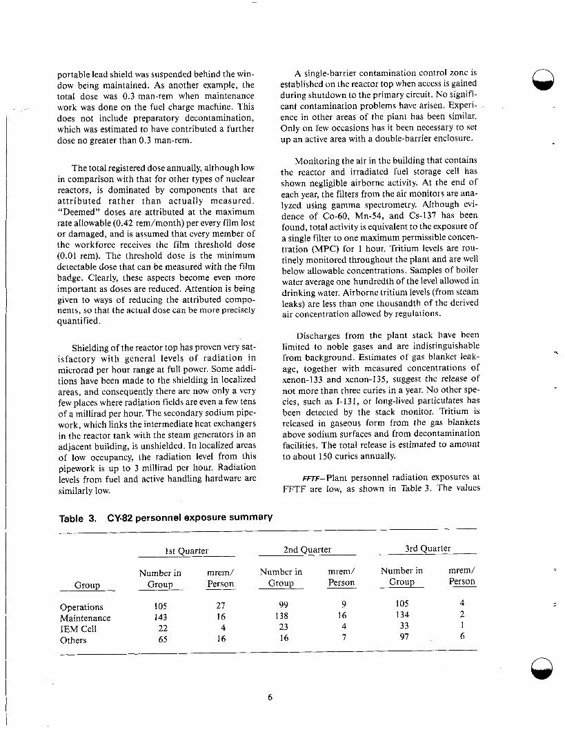
Table 3. CY-82 personnel exposure summary
Monitoring the air in the building that contains the reactor and irradiated fuel storage cell has shown negligible airborne activity. At the end of each year, the filters from the air monitors are ana- lyzed using gamma spectrometry. Although evi- dence of Co-60, Mn-54, and Cs-137 has been found, total activity is equivalent to the exposure of a single filter to one maximum permissible concen- tration (MPC) for 1 hour. Tritium levels are rou- tinely monitored throughout the plant and are well below allowable concentrations. Samples of boiler water average one hundredth of the level allowed in drinking water. Airborne tritium levels (from steam leaks) are less than one thousandth of the derived air concentration allowed by regulations.
Discharges from the plant stack have been limited to noble gases and are indistinguishable from background. Estimates of gas blanket leak- age, together with measured concentrations of xenon-I33 and xenon-135, suggest the release of not more than three curies in a year. No other spe- cies, such as 1-131, or long-lived particulates has been detected by the stack monitor. Tritium is released in gaseous form from the gas blankets above sodium surfaces and from decontamination facilities. The total release is estimated to amount to about 150 curies annually.
FnF-Plant personnel radiation exposures at FFTF are low, as shown in Table 3. The values
1 st Quarter - 2nd Ouarter 3rd Quarter
Number in mrem/ Number in mrem/ Number in mrem/ Group Person Group Person Group Person Group
27 99 9 105 4 143 16 138 16 134 2
4 23 4 33 1
Operations 105 Maintenance IEM Cell 22 Others 65 16 16 7 97 . 6
n
6
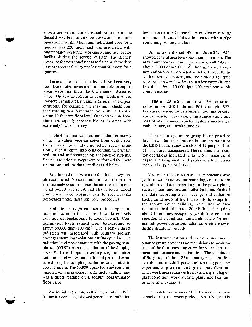
shown are within the statistical variation in the dosimetry system for very low doses, and are at pre- operational levels. Maximum individual dose for a quarter was 220 mrem and was associated with maintenance personnel working at another reactor facility during the second quarter. The highest exposure for personnel not associated with work at another reactor facility was less than 50 mrem for a quarter.
General area radiation levels have been very low. Dose rates measured in routinely occupied areas were less than the 0.2 mrem/h designed value. The few exceptions to design levels involved low-level, small area streaming through shield pen- etrations. For example, the maximum shield con- tact reading was 8 mrem/h on a shield located about 10 ft above floor level. Other streaming loca- tions are equally inaccessible or in areas with extremely low occupancy.
Table 4 summarizes routine radiation survey data. The values were extracted from weekly rou- tine survey reports and do not reflect special situa- tions, such as entry into cells containing primary sodium and maintenance on radioactive systems. Special radiation surveys were performed for these operations and the data are discussed below.
Routine radioactive contamination surveys are also conducted. No contamination was detected in the routinely occupied areas during the first opera- tional period (cycles 1A and 1B) at FFTF. Local contamination control areas exist for specific tasks performed under radiation work procedures.
Radiation surveys conducted in support of radiation work in the reactor show direct levels ranging from background to about 1 rem/h. Con- tamination levels ranged from background to about 60,000 dpm/100 cm2. The 1 rem/h direct radiation was associated with primary sodium cover gas sampling evolutions during cycle 1A. The radiation level was at contact with the gas tag sam- ple trap (GTST) prior to installation of the shipping cover. With the shipping cover'in place, the contact radiation level was 80 mrem/h, and personal expo- sure during the sampling evolution was limited to about 5 mrem. The 60,000 dpm/100 cm2 contami- nation level was associated with fuel handling, and was a direct reading on a sodium contaminated floor valve.
An initial entry into cell 489 on July 8, 1982 (following cycle 1 A), showed general area radiation
levels less than 0.5 mrem/h. A maximum reading of 1 mrem/h was obtained in contact with a pipe containing primary sodium.
An entry into cell 490 on June 26, 1982, showed general area levels less than 1 mrem/h. The maximum loose contamination level in cell 490 was about 5,000 dpm/100 cm2. Radiation and con- tamination levels associated with the IEM cell, the sodium removal system, and the radioactive liquid waste system were low, less than a few mn:m/h, and less than about 10,000 dpm/100 cm2 removable contamination.
EBR-//-Table 5 summarizes the radiation exposure for EBR-I1 during 1970 through 1977. Data are provided for personnel in four major cate- gories: reactor operations, instrumentation and control maintenance, reactor systems mechanical maintenance, and health physics.
The reactor operations group is coniposed of four crews that man the continuous operation of the EBR-11. Each crew consists of 14 people, three of which are management. The remainder of reac- tor operations indicated in Table 5 is made up of dayshift management and professionals in direct technical support of EBR-11.
The operating crews have 11 technicians who perform water and sodium sampling, control room operation, and data recording for the power plant, reactor plant, and sodium boiler building. Each of the data recording areas have general radiation background levels of less than 5 mR/h, c,xcept for the sodium boiler building, which has an area radiation field of about 20 mR/h and requires about 10 minutes occupancy per shift by one data recorder. The conditions stated above ar t for nor- mal full-power operation; radiation levels are lower during shutdown periods.
The instrumentation and control system main- tenance group provides two technicians to work on each of the four operating crews for routine instru- ment maintenance and calibration. The remainder of the group of about 25 are management, profes- sionals, and dayshift personnel who sup'port the experiments program and plant modification. Their work area radiation levels vary, depending on plant condition, work routine, plant modification, or experiment support.
The reactor crew was staffed by six or less per- sonnel during the report period, 1970-1977, and is
7

n Table 4. Summary of routine radiation survey data during FFTF Cycle 1
Dose Rate (mrem/h)
Dose Rate Dependent On Reactor
Power
No
No
No
No
No
No
No
Yes
Yes
Yes
No
No
No
Yes
Yes
No
No
Yes
No
No
Yes
Yes
Yes
Maximum Local During
Cycle
4
1
0.2
0.2
0.2
4
0.2
2
3
3
Maximum Local On 10/30/82
0.5
1
0.2
0.2
0.2
0.2
0.2
2
2
1
0.2
6
0.2
0.6
0.5
0.2
0.2
9
0.2
0.2
6
0.5
0.5
General Area Average
During Cycle
0.5
0.2
0.2
0.2
0.2
0.2
0.2
0.2
0.2
0.2
Comments
4 mrem/h due to temporary storage of IEM Cell components.
1 mrem/h due to floor valve adapter.
Looking for potential leaking to secondary chilled water from IEM Cell Removal System.
Local dose could be dependent on cladding breach & release of fission gasses.
Same comment as for 4.
4 mrem/h due to small leak of 41Ar from RAPS instrument line.
Location
I .
2.
3.
4.
5.
6.
7.
8.
9.
IO.
RSB, 500, Radioactive
RSB, 550, General Area
RSB, 520, Rm. 204
RSB, 520, General Area
RSB, 543, General Area
RSB, 533, General Area
HTS-S, 550, General Area
HTS-S, Room 481, 493, and 482
2 mrem/h due to valve stem penetration and 482(P-622) into Cell 489, reactor at 100% Source Na.
2 & 3 mrem/h due to 24Na radiation stream- ing around shield plug to Cell 492-E, reactor at 100%.
1 & 3 mrem/h due to contact measurement on low level flux monitor cooling system. Sourc is transported activation products and I'N.
General area dose rates in RCB at full power are not significantly different from back- ground. 0.5 mrem/h in Primary Sodium Pump 1 Pit.
6 mrem/h due to depleted uranium shielding in two small local areas. General area 0.2 mrem/h.
HTS-S, 550, Room 485
RCB, 580 Mezzanine
1 I . RCB, 550, General Area 0.2 0.5
12. RCB, Head Compartment 0.2 6
13.
14.
1s.
RCB, 520, Room 540
RCB, Stairway 517 West
RCB, 520 Room 564
0.2
0.2
0.2
0.2
0.6
0.5 0.5 mrem.h at locked barrier to restricted access radiation zone.
RCB, 520, Room 5548
RCB, 500, Room 562
RCB, 500, Room 570
0.2
0.2
0.2
0.2
0.2
9
16.
17.
18. 9 mre/h due to 24Na radiation streaming around shield plug to Cell 567 (EM pump cell), reactor at 100% power.
19.
20.
21.
RCB, 520, Room 5538
RCB, 500, Room 565
RCB, 520, Room 5368
0.2
0.2
0.2
0.2
0.2
8 8 mrem/h due to 24Na radiation streaming through penetrationin a small, localized area about 10 feet above floor.
0.5 mrem/h due to 24Na radiation streaming around shield door to 532C.
"Na radiation streaming into 552A from HTS (521)
5 mem/h at locked gate to 552A2, source is
22. RCB, 500, Room 561 0.2 0.5
RCB, 520, Room 522B 0.2 0.5 23.
n
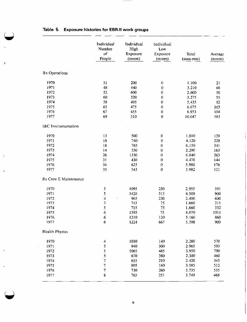
Table 5. Exposure histories for EBR-II work groups
Individual Individual Individual Number High LOW
of Exposure Exposure Total Average People (mrem) (mrem) (man-rem) (mrem)
Rx Operations
b
1970 1971 1972 1973 1974 1975 1976 1977
I&C Instrumentation
1970 1971 1972 1973 1974 1975 1976 1977
Rx Crew E Maintenance
1970 1971 1972 1973 1974 1975 1976 1977
Health Physics
1970 1971 1972 1973 1974 1975 1976 1977
51 48 52 60 58 65 67 69
13 18 18 14 26 31 34 33
5 5 4 3 5 6 6 6
4 5 5 5 7 7 7 8
200 440 600 320 495 475 455 510
500 740 765 350
1330 430 625 543
1095 1420 965 715 715
1595 1210 1224
1030 940
1065 670 655 805 730 765
250 315 230 75 75 75
120 667
140 300 485 380 210 160 260 25 1
1.100 3.210 2.600 3.275 5.435 6.675 6.953
10.047
1.810 4.120 6.150 2.290 6.840 4.470 5.980 3.982
2.955 4.500 2.400 1.660 1.660 6.070 5.160 5.398
2.280 2.965 3.950 2.300 2.420 3.585 3.735 3.749
21 66 50 5 5 92
103 104 183
139 228 341 163 263 144 176 121
591 900 600 315 332
101 1 860 900
570 593 790 460 345 512 535 468
9
the highest exposure group. The group inserts and removes all highly radioactive experiments, and performs the maintenance of fuel handling equip- ment. The group also handles deposition of irradiation test hardware.
The health physics group provides the necessary radiological controls for routine operation and for the protection of personnel while they are perform- ing their tasks. This is accomplished by four techni- cians on day shift and one technician on each off-shift.
Health Physics technicians normally perform routine surveillance, conduct radiation level mea- surement, and perform surveys to assess contami- nation. The day shift technicians also support the mechanical and electrical maintenance activities, and experimental activities as required.
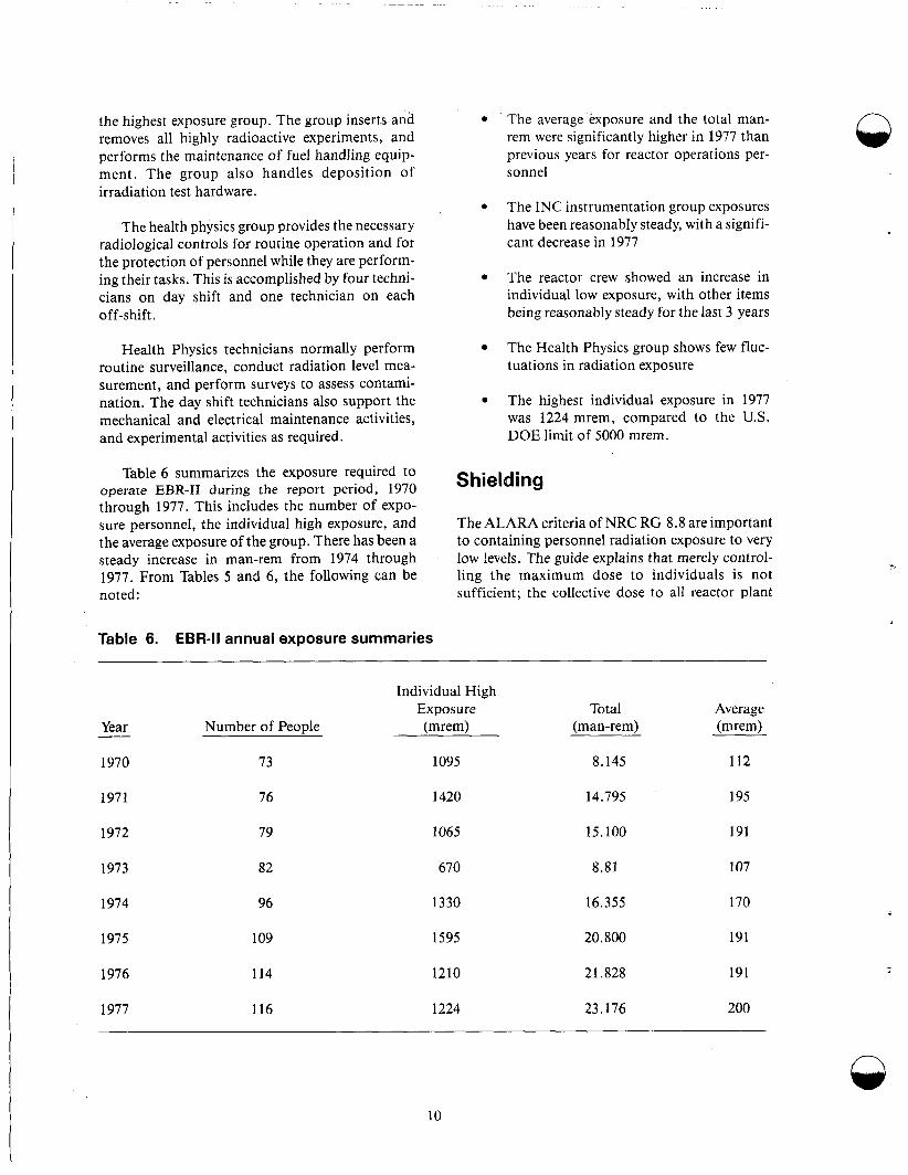
Table 6 summarizes the exposure required to operate EBR-I1 during the report period, 1970 through 1977. This includes the number of expo- sure personnel, the individual high exposure, and the average exposure of the group. There has been a steady increase in man-rem from 1974 through 1977. From Tables 5 and 6, the following can be noted:
Table 6. EBR-II annual exposure summaries
The average exposure and the total man- rem were significantly higher in 1977 than previous years for reactor operations per- sonnel
The INC instrumentation group exposures have been reasonably steady, with a signifi- cant decrease in 1977
The reactor crew showed an increase in individual low exposure, with other items being reasonably steady for the last 3 years
The Health Physics group shows few fluc- tuations in radiation exposure
The highest individual exposure in 1977 was 1224 mrem, compared to the U.S. DOE limit of 5000 mrem.
Shielding
The ALARA criteria of NRC RG 8.8 are important to containing personnel radiation exposure to very low !evels. The guide explains that merely control- ling the maximum dose to individuals is not sufficient; the collective dose to all reactor plant
Individual High Exposure Total Average
Year Number of People (mrem) (man-rem) (mrem) -
1970
1971
1972
1973
1974
1975
1976
1977
73
76
79
82
96
09
14
16
095
420
065
670
330
595
210
224
8.145 112
14.795 195
15.100 191
8.81 107
16.355 170
20.800 191
21.828 191
23.176 200
10
- -
personnel must also be kept ALARA. This is an important point; the total man-rem collective dose could increase because of inefficiencies involved in having to use a large number of individuals to accomplish such tasks as maintenance and repairs. RG 8.8 mentions numerous exposure reduction techniques that can be used to lower dose rates and occupational exposures. Many of the techniques are concerned with minimizing the radiological source terms. Where this is not possible, shielding is an effective way to reduce the effect the radiologi- cal source term has on occupational exposure.
Shielding is designed to provide radiation protec- tion to operating personnel, the general public, and plant equipment. Shield design must perform a variety of functions to provide this radiological protection under normal operating conditions. These functions are as follows:
To permit operating personnel access to required portions of the plant in order that they may operate the reactor and its associ- ated systems at rated power and normal capacity (including routine inspections and maintenance of accessible equipment)
To permit personnel to refuel the reactor (including those functions required to pre- pare new fuel for reactor service and ship spent fuel for reprocessing or storage)
To permit access within a reasonable time after reactor shutdown to the high radia- tion portions of the restricted area (which are maintained as exclusion areas during normal operation)
0 To limit the neutron activation of second- ary and intermediate sodium, such that the induced radiation dose rates from this radioactive source will not require estab- lishing restricted areas
To maintain as continuous access areas dur- ing normal operations all areas of the site outside of the reactor containment building, reactor service buildings, cells in the plant service buildings, and any secondary sodium piping penetration cells at the intermediate/ reactor containment building interface
To protect structural components, equip- ment, and nuclear instruments in order
that required functions are safely provided throughout the lifetime of the pliint
To limit the radiation exposure of operat- ing personnel and the general public to that less than required by applicable sec- tions of 10 CFR 20, 50, and 100.
The thickness of shield walls are set by both shielding and structural requirements. 'Walls are usually constructed of ordinary concrete. LMFBR concrete shield walls can be errected according to the standards used for LWRs (see Regulatcry Guide 1.69 and ANSI N101.6). In some local areas, other shielding materials, such as steel, are used. Shield walls constructed of block have usually been avoided, for seismic considerations. Shield walls or portions of shield walls subject to removal to per- mit access for equipment repair or replacement are designed to be knocked out and replaced, or pro- vided with removable access plugs. In ordw to min- imize the number of areas in the plant with high radiation levels, cells that contain significant radio- active sources are grouped.
Shielding calculations for determining wall thickness can be performed by a computer code with a detailed geometric model that represents the significant three-dimensional aspects of the sources and shields. Codes used in the shielding arialysis of LWRs are adequate for LMFBRs. Outside the reac- tor cavity, the sources present are activated sodium, fission, and corrosion products.
Computer programs employed in the d!esign of shield walls use the discrete ordnance transport or point kernel integration techniques to analyze the bulk shielding provided by the walls. In areas of the shield containing discontinuities, such as ducts and penetrations, the design methods employ transport and point kernel scattering methods to provide shielding equivalent to the surrounding bulk shield- ing in the vicinity of the duct or penetration.
Shield walls with locked access doors arc: used to isolate high radiation areas of the plant. In addi- tion, these areas are equipped with audible or visi- ble alarms that signal to a control point that a high radiation area is being entered. All locked radiation areas are equipped such that no individual can be prevented from leaving them.
Access to cells containing radioactive.-bearing components are provided through the wall!; or ceil- ing. The effectiveness of the shielding in meeting
11
the design dose rates external to the cells is main- tained by use of shield doors or shield plugs, which, if made of concrete have the same thickness as the shield wall penetrated. If other shielding materials are used, the design thickness provides shielding equivalent to that of the wall. Steps and off-sets are provided in all shielding doors and plugs to mini- mize radiation streaming. For areas requiring mul- tiple penetrations, shielded cavities and chaseways are provided.
Shield performance and design, and basic nuclear data, are being verified to support LMFBR systems. A series of experimental configurations simulating portions of LMFBR shield systems have been designed and experiments have been con- ducted. The principal experimental program has been conducted at Oak Ridge National Laboratory. A number of other experiments related to shielding have been conducted in the Argonne National Lab- oratory and support the Clinch River Breeder Reac- tor Project (CRBRP) nuclear design. The latter program, which provides data useful in evaluating neutron flux and gamma flux distributions in LMFBRs, is described below.
In general, three types of experiments have been conducted to support shielding design: (a) experi- ments to measure the basic neutron and gamma atten- uation characteristics of candidate materials for use in LMFBR shields, (b) experiments to parametrically define shield configuration and dimensional effects on shielding performance, and (c) prototypic or sim- ulation experiments of portions of LMFBR shield systems. In addition to these three types of experi- ments, measurements of neutron cross section data in the candidate LMFBR shield materials have been conducted. The LMFBR shielding experiment pro- gram has progressed from experiments designed to support the FFTF system, to experiments to support the CRBRP system. The scope of experimental pro- grams conducted on FFTF shielding have provided a sound base of experimental data for method and nuclear data verification. FFTF experiments were conducted from 1969 through 1973; LMFBR shield- ing experiments were initiated in 1973 with emphasis on CRBRP shielding beginning in 1974.1-12
The ORNL shielding experiment program was con- ducted at the ORNL power shielding facility. Experi- mental configurations employed a collimated beam of neutrons from the TSR reactor configuration as an approximate planar source of neutrons incident on slab simulations of LMFBR shield systems. Simula-
tions of experiments used either the bare beam or sim- ulations of calculated neutron energy spectrum incident on the specific portion of the LMFBR shield system, for example, at the reactor core-blanket inter- face. The design of spectrum modifiers to simulate incident spectrum have been used extensively in TSF programs.
Experiments related to CRBR shield design and conducted in the FFTF program on the TSF were (a) mock-up experiments of the lower shield region of the fuel assemblies, which included representa- tion of the streaming paths between assemblies and through-shield orifice holes, (b) mock-up experi- ments of the reactor vessel closure assembly pene- tration gaps, which included parametric investigation of offsets and gap widths for annual gaps and slits in iron, (c) deep-penetration neutron attenuation experiments in sodium, carbon steel, and stainless steel, (d) mock-up experiments to define neutron streaming in the primary inlet and outlet piping penetrations of the reactor cavity wall, the isolation valve cell, and the shield walls adjacent to the heat transport system (HTS) cells, and (e) mock-up experiments of the reactor closure head and head compartment shield system to define neutron and gamma shield effectiveness. These experiments employed spectrum modifiers to obtain prototypic neutron spectra incident on shield systems. The CRBR shielding program has expanded from this original FFTF program to include a number of experiments simulating the material and laminar configurations of tentative LMFBR radial, upper axial, and lower axial shields, and provide tests of calculation methods in prototypic shield configurations. Table 7 describes the scope (completed and planned) of program experiments to support LMFBR shielding design.
In addition to the experiments conducted at the ORNL power shielding facility, an extensive pro- gram of experimental analysis has been conducted by ONRL with the reactor manufacturers. These programs were employed to test methodology and basic nuclear data in terms of design solutions of LMFBR shields. The purpose of experimental analysis program was manifold in that it has pro- vided (a) guidance in experiment planning, to ensure adequate data for testing methods and basic nuclear data, (b) guidance in planning the develop- ment of design methods required to design shield- ing for LMFBRs, (c) reactor manufacturers with the vehicle to test and use the methodology prior n
12

I \ Table 7. Experimental program related to CRBRP shielding
Experiment Sponsora Objective
Radial blanket and shield simulation
Near core gamma
Upper axial shield
Reactor vessel support area
Concrete rebar
LLFM
Sodium pipe chaseway
Effect of shield heterogeneities- upper axial and radial shields
Duct streaming- lower axial shield
Annular gap and slit streaming
Core assembly shield streaming
LMFBR
CRBR
CRBR
CRBR
CRBR
FFTF, CRBR
LMFBR
LMFBR
FFTF
FFTF
Provide experimental verification of neutron flux attenuation through radial blanket and radial shield simulationa
Provide experimental verification of gamma heating rate distributions in (1) stainless steel and Inconel radi a1 shield configurations and (2) at core- blanket and blanket-shield interfaces
Provide experimental verification of neutron attenuation methods based on the CRBR reactor closure head siinula- tion with sodium pool simulation
Provide experimental verification of methods used to analyze reactor vessel support area neutron streaming
Provide experimental verification of neutron flux attenuation and secondary gamma production of reinforced concrete
Provide experimental verification of ex- vessel LLFM neutron flux and count rate
Provide experimental verification of neutron streaming in sodium pipe chaseway
Provide experimental determination of streaming effects due to compositimon heterogeneities (Upper Axial and Radial Shields)
Provide experimental determination of streaming effects due to composition heterogeneities (Lower Axial Shield)
Measure neutron streaming through iron shields with annular gaps or slits simu- lating closure head shielding.
Provide experimental verification cf streaming through coolant holes of' core shields.
/ \
13

Table 7. (continued) n
Experiment Sponsora Objective
Sodium penetration
Inconel penetration
Gamma ray experiment
FFTF
FFTF
FFTF
Measure shielding effectiveness of sodium pool attenuation through up to 15 feet of sodium.
Measure neutron shielding effectiveness of Inconel shielding material.
Provide experimental verification of neutron transmission through 34 inches of carbon and provide verification of transmitted gamma spectra and dose.
a. LMFBR experiments are through efforts of reactor manufacturers.
Sponsor of experimental involved in providing guidance to AEC-RRD for the specific project.
to, or in parallel with, design analyses, and (d) cor- relation of the design analysis of portions of the CRBR shield system in order to experiment and provide realistic estimates of the uncertainties and experimental-to-calculated bias associated with shield performance. The last item provides a sound basis for shield design in that the detailed design support calculations performed by reactor manu- facturers and the independent support calculations performed by ORNL used the techniques and methods demonstrated in the experiment analysis effort.
Results from the LMFBR experiment and experi- ment analyses programs have demonstrated the validity of the analytical techniques and shield design methods. Detailed results and comparisons of these structures are documented in References 3 through 13.
Radiological Source Terms. In an LMFBR, clad- ding and in-vessel structural materials become radioactive from the neutron flux. Radioactive spe- cies build up in the primary circuit external to the core, caused by neutron activated material corrod- ing out of the piping walls and subsequently being transported in the primary liquid sodium to the pri- mary components (for example, pumps, heat exchangers, valves, and sodium purification sys- tems). The deposition of these radioactive species gives rise to gamma radiation fields intense enough to cause difficulties in maintenance and repair operations. Moreover, such repairs have required large amounts of manpower and have resulted in
long plant shutdowns, neither of which is economi- cally favorable. The corrosion product transport (or “crud transport” problem as it is called in water reactor technology) is well known, and considera- ble maintenance experience has been gained on both water and sodium-cooled reactors.
Calculations made for reactor plants operating with long fuel cycles and at high core outlet temper- atures (600°C) predict radiation levels above 1 R/h adjacent to the rimary system after decay of the sodium 24. 1 4 - l g
Present reactors, with lower outlet temperatures and shorter fuel cycles, substantially reduce corro- sion product transport, to produce radiation levels of about 100 mR/h is being observed. Extrapola- tion of calculations to the existing reactor situation results in reasonable agreement 1 7 .
Reactor experience and test loop data show that both the release of irradiated material and its distri- bution within the circuit are nonuniform. The most abundant corrosion product in LMFBR nuclides is Mn-54. CO-60 and Co-58 are also produced but are not released at as high a rate as Mn-54, nor are they transported throughout the circuit to the same degree. A major fraction of the deposited corrosion product activity adheres to the deposition site and is not removed by sodium draining or sodium removal processes.
No one control method has been shown suffi- cient to solve all of the activated corrosion product n
14
. .. - - .. . . . . . .. . . . . . . .- . . .
transport problem; a combination of methods is required. Methods under investigation have to do with the effect of oxygen concentration in the sodium, and sodium temperature on nuclide release, development of traps, improved fuel clad- ding alloys, and removing deposited activity (decontamination). Trapping and decontamination show promising early results. Reduction of the oxy- gen level of the sodium to correspond with the 115°C cold trap temperature is only partially effec- tive at reducing Mn-54 and Co-60 release.
Table 8 presents information concerning the sig- nificant radionuclides and activated corrosion product transport. The most prevalent nuclides seen in LMFBRs are Mn-54 and Co-60; others are observed in smaller quantities. It can be seen from the Table that little can be done to eliminate Mn-54, whereas some control over (20-60 formation is pos- sible by restricting the cobalt content of fuel clad- ding and ducts to 0.05‘70, and by restricting the use of cobalt-based bearing and hard-facing materials.
LMFBR Experience. At the Dounreay fast reactor, repair of a leak that took place in a radiation field equal to that predicted for high-temperature LMFBR operation required several hundred people and several months downtime for repair. At the BR-5 LMFBR in the USSR, fission products, Mn-54, and Co-60 were observed on piping. Treatment of the piping with acid etches was necessary to removal all of the deposited radioactivity. 19-20 At the BOR-60 reactor in the USSR, radiation levels of up to 100 mR/h adjacent to primary system piping was observed after 3 years of operation. The core outlet temperature varied between 510 and 550°C. The Co-60 and Mn-54 radioactivity was spread throughout the circuit with greater nuclide deposition in the cold leg.21 At the KNK-I1 reactor in Germany, radiation levels of 100 mR/h were measured near the heat exchangers after 146 days of full power operation. The core outlet temperature was 550°C. The radiation level was reduced only about 15% by draining the sodium. The principal nuclides were Mn54, Co-60, Zn-65, and Ag-1 1Om. Mn-54 tended to preferentially deposit on a nickel rich surface in the hot leg but not the cold leg.22 It is noteworthy that consid- erable Ta-182 was produced in the KNK-I1 core, but only small amounts were detected in the piping. At the Rapsodie reactor in France, radioactive in Mn-54 was observed throughout the piping system, particularly in the cold leg. Very little Co-60 was observed. Radiation levels up to 200 mR/h were observed on the pump and piping. Washing with water and alcohol, and treatment with a relatively mild nitric-phosphoric acid solution
were all ineffective at removing deposited radioactivity; the acid etch was somewhat more effective than the other At the EBR-I1 reactor, depos- ited Mn-54 and Co-60 have been observed on the pump and heat exchanger and in the cold trap. E:xamination of 316 SS fuel cladding from a high temperature fuel test showed substantial preferential corrosicin of Mn-54 and preferential retention of (20-58 and Co-60 at 650”C, but very little at 510”C.25-26
The radiation levels observed in the plants above are in reasonable agreement by a factor 01’ three with those predicted using the techniques of References 14 and 27. A significant result is that the contribution of “nuclear corrosion” (recoil ejection plus eist neutron sputtering) has been shown unimportant, in apparent disagreement with earlier hypothesis.28 Using the techniques of References 14 and 27, it has been calcu- lated that a uniform removal rate of 25 p/yr by fast neutron sputtering will lead to primary system radia- tion levels well in excess of 10 R/h, which is contrary to actual observations in operating reactors.
Before operational data on LMFBRs became avail- able, investigators in the United States, Germany, Japan, and the United Kingdom began nuclide release and deposition studies in small test loop sys- tems. The need for mass transport data, in addition to that generated from the more conventional corrosion studies of steel and sodium, has arisen for two rea- sons: (a) it can be shown that an average m,aterial cor- rosion rate of 5- 10 p/yr for fuel cladding (completely satisfactory with a wall-thinning standpoint) will give rise to intolerable radiation levels near the primary system components, and (b) the problem nuclides (Mn and Co) are present as only minor constituents of the cladding alloys. Existing corrosion theories do not treat minor alloying element behavior in suffic- ient detail.
Most corrosion and deposition studies (such as found in References 25, 29-34) investigated the release and deposition of Co-60, Mn-54, Fe-59, Cr-51, and Co-50, at temperatures between 550°C arid 600°C. The oxygen level in sodium was controlled by cold trap- ping and measured by a variety of methods: cold trap temperatures were in the range of 115- 160°C. These studies agreed with reactor observations and with each other; the most significant similarities and differences are as follows:
Mn-54 was the most abundanii nuclide reduced from irradiated stainless steel; Cr-5 1,
15
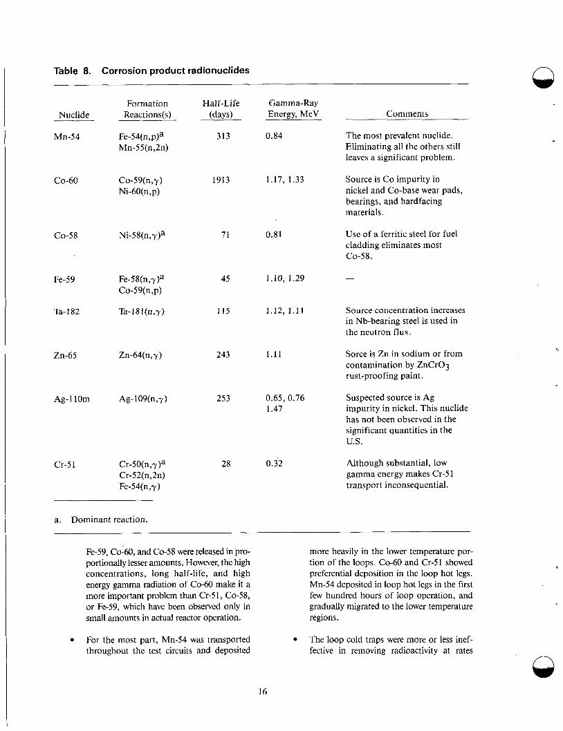
Table 8. Corrosion product radionuclides n
Formation Half-Life Gamma-Ray Reactions(s) (days) Energy, MeV
F e - 5 4 ( n , ~ ) ~ 313 0.84 Mn-55(n,2n)
Comments Nu c 1 id e
Mn-54
CO-60
CO-58
Fe-59
Ta- 1 82
Zn-65
Ag-l10m
Cr-5 1
The most prevalent nuclide. Eliminating all the others still leaves a significant problem.
1913 1.17, 1.33 Co-59(n,y) Ni-60(n, p)
Source is Co impurity in nickel and Co-base wear pads, bearings, and hardfacing materials.
71 0.81 Use of a ferritic steel for fuel cladding eliminates most CO-58.
45 1.10, 1.29
115 1.12, 1 . 1 1 Source concentration increases in Nb-bearing steel is used in the neutron flux.
243 1.11 Sorce is Zn in sodium or from contamination by ZnCr03 rust-proofing paint.
Suspected source is Ag impurity in nickel. This nuclide has not been observed in the significant quantities in the U.S.
253 0.65, 0.76 1.47
28 0.32 Although substantial, low gamma energy makes Cr-5 1 transport inconsequential.
a. Dominant reaction.
Fe-59, Co-60, and Co-58 were released in pro- portionally lesser amounts. However, the high concentrations, long half-life, and high energy gamma radiation of Co-60 make it a more important problem than Cr-51, Co-58, or Fe-59, which have been observed only in small amounts in actual reactor operation.
more heavily in the lower temperature por- tion of the loops. CO-60 and Cr-51 showed preferential deposition in the loop hot legs. Mn-54 deposited in loop hot legs in the first few hundred hours of loop operation, and gradually migrated to the lower temperature regions.
For the most part, Mn-54 was transported throughout the test circuits and deposited
The loop cold traps were more or less inef- fective in removing radioactivity at rates
16
/ \
more than proportional to the cold trap frac- tional flow. They did, however, act as irre- versible sinks for whatever cobalt and manganese deposited in them. The concen- tration of Mn-54 in cold traps apparently depends on how much Mn-54 has deposited upstream of the cold trap branch line. This suggests that to be most effective as a radio- nuclide sink, the cold trap branch line should come from a reactor hot leg or above the core.
in the case of CO-60 deposition patterns. Proportionately more Co-60 is reported in reactor cold legs and cold traps than in the test loops. Also, examination of fuel pins at the top of an EBR-I1 fuel assembly (0.5 m above the fuel zone) showed no preferential deposition of Co-58 or Co-60 on the fuel pin surface.
Usually, radionuclide behavior is the same in loop and pool reactors. However, distinctive behaviors are sometimes observed, for example, the behavior of
sodium is the primary coolant for all of the reactors
ality: a vented fuel element. This causes the fission
The behavior of radionuclides in the DFR's primary system, therefore, cannot always be compared with the results of other reactors.
Reducing the Oxygen level by reducing particulates in sodium. This is important I,ecause trap temperature in an apparent
small decrease in the Mn-54 source term.
have shown Mn-54 to be preferential1y
retained from irradiated 3 16 SS speci- mens.25535
in the c0-60 Source rate but Only a except DFR, where it is NaK. DFR has another speci-
Quantitative determination Of Source rates product inventory ofthe DFR coolant to be ve1.y high.
and c0-60 to be
0 At all locations in the test loop, deposition was enhanced at regions of increased fluid turbulence, where the hydrodynamic boundary layer thickness is reduced. The significance of this data is that increased nuclide deposition can be expected on pumps, valves, and other locations where additional turbulence is introduced. Unfortunately, maintenance problems are expected to occur at these regions. On the other hand, the data can aid in the design of nuclide traps to enhance deposition of the nuclides and prevent their spread into the reactor primary system.
Radioactive material was firmly deposited on the test system piping at temperatures above 400°C; sodium removal processes such as draining, water, steam, or alcohol rinse removed very little activity. Use of acid solutions was necessary to remove deposited activity (described in References 20, 23, 24, and 34). Significant penetration of activity large than 10 p into the pipe wall has been observed even at 400°C. Under certain con- ditions, deposits build up to a limiting thick- ness and then are sheared off.34 The phenomenon could have practical implica- tions for removing deposits from an interme- diate heat exchanger in a pool reactor.
Good agreement does not exist between test loop data and reactor operating experience
Experience with radionuclides in operating reactors has had varying degrees of importance to health phys- ics in particular systems and at different times. A s men- tioned, activated corrosion products are most important for system contamination, in particular Mn- 54, Co-60, and Co-58. Fission products becom: more important after operation with defective fuel elements; of these, next to (3-137, (3-134, and 1-131, the nuclides Zr/Nb-95, Ba/La-140, Ce-141 and Ce- 144 are of most concern. It has been reported that the r d' a ioac- tivities of the corrosion products Co-60 and bdn-54, and of the fission products Ba/La-140 and Nb-'95, are comparable to each other in reactor operations where 0.1 to 0.2% of the fuel elements are defective, artd that the deposited corrosion product activity has been con- stant over three years.36 Published tables present the radionuclides detected in reactor systems.37 Research programs have investigated the behavior of racfonu- clides in primary systems for ~0~-60,38339 DFR,m EBR-II,41 RAPSODIE and PHENIX,42 and KNK- K43 Additional information is available on radionu- clide transport for PHENIX4 and the effect (of the special run beyond cladding breach (RBCB) program on radionuclides in the primary system at EBR-II.45- 48
Summarizing all corrosion and deposition experi- ence gained with operating LMFBRs, it can bc con- cluded that, so far, activation product radionuclides in primary systems have not been a serious problem for operation. Extended downtime because of large radiation doses has been reported only from D17R.49 However, knowledge of the behavior of radionuclides
17
in primary systems is very important in order to be prepared for difficulties arising from system contami- nation.
There are two major sources of fissile materials in an LMFBR reactor system. The first is surface contamination of new fuel elements during their fabrication. Generally, g of fissile material per cm2 of surface is found, the fissile material usually reported in U-235 equivalents. The second source of fissile material is fuel released from defective fuel elements. Even if the amount of fuel released cannot be predicted, and assuming very small releases of fuel, after operation of a reactor with defective fuel pins, the released fuel will dominate other contamination.
U02, Pu02, and (U, Pu)02 react with sodium if the oxygen potential of the fuel or sodium is large
Because the oxides themselves are stable in clean sodium, transport of fissile materials by sodium will be either in the form of oxide particles, because of the extremely low solubility of the oxides, or of reac- tion products with sodium, such as Na3M04 (with M = U or Pu). In any case, as with other oxide- forming nuclides, the fissile material concentration in sodium will be very low, and rapid deposition or pla- teout will occur.51
Observations of operating reactors confirm the plateout of fissile material. The concentration of plutonium and uranium in the sodium at EBR-I1 has always been below detection levels: less than 0.5 pCi/g sodium of Pu-239/240, and less than 1 ppb U.41 947 Similar low values were reported for RAPSODIE. However, higher concentrations were found for this reactor after cladding failures. Val- ues of up to 200 pCi/g sodium for Pu-239/240 and up to 2 ppm for uranium were found.52 There is a wide scattering of the measured data (a factor of lo), probably because the transport is primarily of particulates. Widely scattered data were again observed during investigations of the cold trap bas- kets of DFR. It is estimated of DFR that the pri- mary system contains less than 10 g uranium and less than 10 mg plutonium.40 The special condi- tion of vented fuel elements at DFR have to be kept in mind, however, when attempting to transfer these data to other reactor systems.
In an experiment that purposely used defective fuel pins with artificial cladding defects of 30 mm2, about 4 mg of fuel were released to the sodium from a fresh pin and 1.4 g from a preir-
radiated pin that had 10.6% burnup. Over 97% of the released fuel was firmly bound to the SS surface of the system and could only be removed with strong
The expression “tramp fuel” is often used in the nuclear industry and is defined as the amount of fuel in a reactor system in the core region responsi- ble for the background level of fission products in the primary system. Reported values are in the range of a few mg U-235 equivalent. Such a value can be explained by the surface contamination of fresh fuel elements mentioned above. Data from EBR-I1 indicate, however, that the tramp fuel is in particulate form.55 The literature does not report an increasing amount of tramp fuel in reactors. This is probably a result of improved fuel manage- ment procedures.
It is concluded from thermodynamic consider- ations and from observations of sodium systems that the concentration of fissile materials in the cir- culating sodium is very small. Strong deposition on the walls of the system and particulate transport to the cold traps will occur. All available information from operating reactors are, however, very meager, indicating that fuel in the primary system has not been a problem for operating reactors.
Ventilation Design Objectives. As they relate to radiation protection, the design objectives of the heating, ventilating, and air conditioning system (HVAC) are the same for LMFBRs as LWRs during normal operations, including anticipated operational occurrences. The design objectives are as follows:
To limit in-plant buildup of airborne radio- activity during normal plant operations so that exposure to a person from radioactive materials in the air will not exceed the design radiation dose rate for a specific habitable zone; plant ventilation complies with the requirements of 10 CFR 20, Appendix B, Table 1
To limit the migration of airborne radioac- tivity from areas of high radiation poten- tial to areas of low radiation potential
To ensure habitability of the main control room during any postulated abnormal condition, to enable control or shutdown of the plant
Q
..
n
18
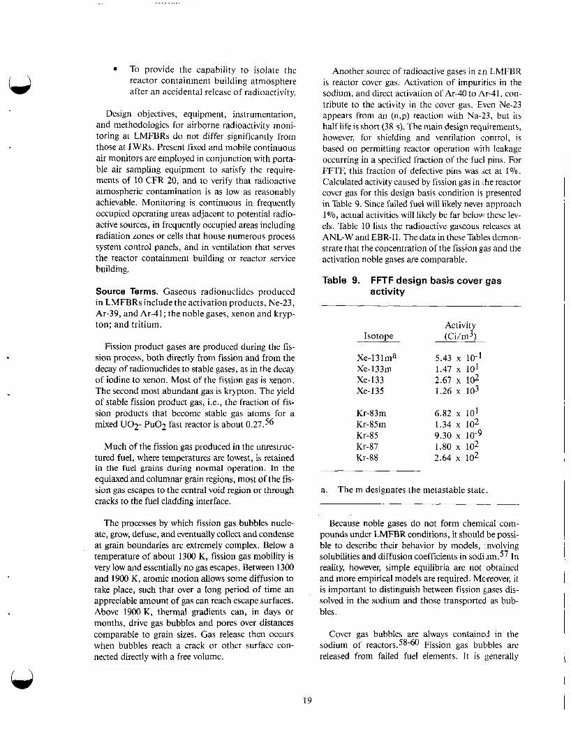
To provide the capability to isolate the reactor containment building atmosphere after an accidental release of radioactivity.
Design objectives, equipment, instrumentation, and methodologies for airborne radioactivity moni- toring at LMFBRs do not differ significantly from those at LWRs. Present fixed and mobile continuous air monitors are employed in conjunction with porta- ble air sampling equipment to satisfy the require- ments of 10 CFR 20, and to verify that radioactive atmospheric contamination is as l ow as reasonably achievable. Monitoring is continuous in frequently occupied operating areas adjacent to potential radio- active sources, in frequently occupied areas including radiation zones or cells that house numerous process system control panels, and in ventilation that serves the reactor containment building or reactor service building.
Source Terms. Gaseous radionuclides produced in LMFBRs include the activation products, Ne-23, Ar-39, and Ar-41; the noble gases, xenon and kryp- ton; and tritium.
Fission product gases are produced during the fis- sion process, both directly from fission and from the decay of radionuclides to stable gases, as in the decay of iodine to xenon. Most of the fission gas is xenon. The second most abundant gas is krypton. The yield of stable fission product gas, Le., the fraction of fis- sion products that become stable gas atoms for a mixed U02- Pu02 fast reactor is about 0.27.56
Much of the fission gas produced in the unrestruc- tured fuel, where temperatures are lowest, is retained in the fuel grains during normal operation. In the equiaxed and columnar grain regions, most of the fis- sion gas escapes to the central void region or through cracks to the fuel cladding interface.
The processes by which fission gas bubbles nucle- ate, grow, defuse, and eventually collect and condense at grain boundaries are extremely complex. Below a temperature of about 1300 K, fission gas mobility is very low and essentially no gas escapes. Between 1300 and 1900 K, atomic motion allows some diffusion to take place, such that over a long period of time an appreciable amount of gas can reach escape surfaces. Above 1900 K, thermal gradients can, in days or months, drive gas bubbles and pores over distances comparable to grain sizes. Gas release then occurs when bubbles reach a crack or other surface con- nected directly with a free volume.
Another source of radioactive gases in an LMFBR is reactor cover gas. Activation of impurities in the sodium, and direct activation of Ar-40 to Ar-41, con- tribute to the activity in the cover gas. E,ven Ne-23 appears from an (n,p) reaction with Na-23, but its half life is short (38 s). The main design requirements, however, for shielding and ventilation control, is based on permitting reactor operation with leakage occurring in a specified fraction of the fuel pins. For FFTF, this fraction of defective pins was jet at 1 Yo. Calculated activity caused by fission gas in the reactor cover gas for this design basis condition is presented in Table 9. Since failed fuel will likely never' approach 1 Yo, actual activities will likely be far below these lev- els. Table 10 lists the radioactive gaseous releases at ANL-W and EBR-11. The data in these Tables demon- strate that the concentration of the fission gas and the activation noble gases are comparable.
Table 9. FFTF design basis cover gas activity
Activity Isotope ( ~ i / m 3 )
Xe-13 1 ma Xe-133m 1.47 x IO1 Xe-133 2.67 x lo2 Xe-135 1.26 x lo3
5.43 x 10⁻¹
Kr-83m 6.82 x IO1 Kr-85m 1.34 x lo2
Kr-87 1.80 x lo2 Kr-88 2.64 x lo2
Kr-85 9.30 10-9
a. The m designates the metastable state.
Because noble gases do not form chemical com- pounds under LMFBR conditions, it should be possi- ble to describe their behavior by models, involving solubilities and diffusion coefficients in In reality, however, simple equilibria are not obtained and more empirical models are required. Moreover, it is important to distinguish between fission gases dis- solved in the sodium and those transported as bub- bles.
Cover gas bubbles are always contained in the sodium of r e a c t o r ~ . ~ ~ - ~ O Fission gas butibles are released from failed fuel elements. It is generally
19
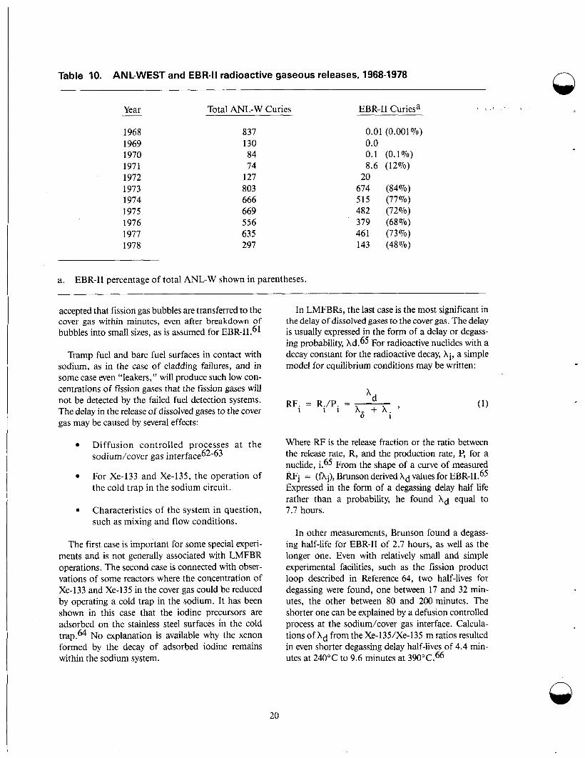
Table 10. ANL-WEST and EBR-II radioactive gaseous releases, 1968-1978
Total ANL-W Curies EBR-I1 Curiesa , Year __
1968 1969 1970 1971 1972 1973 1974 1975 1976 1977 1978
837 130 84 74
127 803 666 669 556 635 297
a. EBR-I1 percentage of total ANL-W shown in parentheses.
0.01 (0.001 070) 0.0 0.1 (0.1%) 8.6 (12%)
674 (84%) 515 (77%) 482 (72%) 379 (68%) 461 (73%) 143 (48%)
20
accepted that fission gas bubbles are transferred to the cover gas within minutes, even after breakdown of bubbles into small sizes, as is assumed for EBR-IL61
Tramp fuel and bare fuel surfaces in contact with sodium, as in the case of cladding failures, and in some case even “leakers,” will produce such low con- centrations of fission gases that the fission gases will not be detected by the failed fuel detection systems. The delay in the release of dissolved gases to the cover gas may be caused by several effects:
Diffusion controlled processes at the sodium/cover gas i n t e r f a ~ & ~ - ~ ~
For Xe-133 and Xe-135, the operation of the cold trap in the sodium circuit.
0 Characteristics of the system in question, such as mixing and flow conditions.
The first case is important for some special experi- ments and is not generally associated with LMFBR operations. The second case is connected with obser- vations of some reactors where the concentration of Xe-133 and Xe-135 in the cover gas could be reduced by operating a cold trap in the sodium. It has been shown in this case that the iodine precursors are adsorbed on the stainless steel surfaces in the cold trap.64 No explanation is available why the xenon formed by the decay of adsorbed iodine remains within the sodium system.
In LMFBRs, the last case is the most significant in the delay of dissolved gases to the cover gas. The delay is usually expressed in the form of a delay or degass- ing probability, Ad.65 For radioactive nuclides with a decay constant for the radioactive decay, Xi, a simple model for equilibrium conditions may be written:
RF. = R./P. = ’d 1 1 1 A6 + A . ’
1
Where RF is the release fraction or the ratio between the release rate, R, and the production rate, P, for a nuclide, i.65 From the shape of a curve of measured RFi = (fAi), Brunson derived Ad values for EBR-II.65 Expressed in the form of a degassing delay half life rather than a probability, he found Ad equal to 7.7 hours.
In other measurements, Brunson found a degass- ing half-life for EBR-I1 of 2.7 hours, as well as the longer one. Even with relatively small and simple experimental facilities, such as the fission product loop described in Reference 64, two half-lives for degassing were found, one between 17 and 32 min- utes, the other between 80 and 200 minutes. The shorter one can be explained by a defusion controlled process at the sodium/cover gas interface. Calcula- tions of hd from the Xe-135/Xe-135 m ratios resulted in even shorter degassing delay half-lives of 4.4 min- utes at 240°C to 9.6 minutes at 390”C.66
n
20
The measured delay is actually delay of the total system, including releases from the fuel to the sodium, transport within the sodium system, and often even the delay within the cover gas system itself.67 The values given for delay times are therefore always only valid for the system investigated. The cover gas bubble concentration in the sodium will influence the release behavior very strongly, because the exchange of dissolved gases within the bubble is very intense and the transport of the bubble to the cover gas is rapid. For example, the EIR-5 reactor con- tained large amounts of argon cover gas in the circu- lating sodium and no delay for the degassing of fission gases was reported. The BOR-60 and BN-350 reactors, on the other hand, did not have such a bub- ble problem, and delay half-lives of about 5.5 and 15 hours, respectively, have been published.38, 69 In all other operating reactors investigated, the delay half-lives are in the range of hours, with the exception of DFR, because of its vented fuel elements.
Tritium. Tritium generated in the reactor core is of concern because it is extremely mobile and will dif- fuse in the fuel and control rod cladding and migrate through the liquid sodium coolant systems. Production of tritium in an LMFBR is greater than that in an LWR at comparable thermal power. The primary means by which tritium is produced in nuclear power plants are by neutron absorption in boron and through ternary fission.
Three boron reactions that produce tritium in nuclear reactors are as follows:
10 B (n, CY) T
9 B1’(n, T) Be
10 7 B (n, CY) Li (n, na)T.
The first reaction is the most common in both ther- mal and fast reactors. The other two are not as favor- able; Bll(n, T) Be9 has a high neutron threshold energy of approximately 9.6 MeV, BIO(n, a) Li7 has a small cross section for both fast and thermal neu- trons. All three reactions have higher cross sections for high energy neutrons than for thermal neutrons, and tritium production by boron reactions will be greater in fast than in thermal reactors. Tritium pro- duced by irradiation of boron may be the predomi- nant source of tritium activity in an LMFBR containing boron control rods.70
Ternary fission is the fissioning of an atom into one minor and two major fission products. The minor fis-
sion product is generally tritium. The average thermal fission yield for tritium in atoms per fission is about 0.01 Vo (0.8 x T / f i s ~ i o n ) . ~ I - ~ ~ The major spe- cies released from a thermal reactor is ~ ~ 0 . ~ 1 - 7 2
An 82-MWt pressurized water reactor produces 11000 Ci of tritium by ternary fission and 1380 Ci by boron reactions per ~ e a r . ~ ( ) T h e fast fission yield for tritium from U-235 anlj Pu-239 was measured to be 2 x T per fission, which is 2 to 3 times the ternary fission yield for thermal neutrons.71 Other calculations and measurements have shown that tritium yield by fast fission for Pu-239 is 2.25 x that of U-235.70
Two of the potentially more troublesoine paths for tritium escape from an LMFBR are the heat transfer surfaces of the steam generator syijtem and the walls of the containment piping for primary sodium. Oxide coatings on these surfaces may sig- nificantly reduce the permeability of hydrogen isotopes by as much as 2 or 3 orders 01‘ magni- tude.73-76 Directly measured tritium permeation data for unoxidized and oxide coated metal and alloys are scarce. In early tritium transport calcula- tions, the permeation inhibiting nature of oxide coatings was not taken into account when lcomput- ing permeation losses.77-78 Since, an ctxtensive series of measurements has been made on the per- meation rate of tritium through unoxidized “clean” and steam oxidized Croloy (Fe-225 Cr-1 M0).7~-80 The material is a leading candidate for clmstruc- tion of LMFBR steam generators. Recent tritium permeation data for oxidized Types 304 and 316 SS, from which the sodiu’m containment ves- sels and piping will be fabricated, have also been incorporated into newer transport models for trit- ium.81 Oxide coating to inhibit tritium permeation through structural materials is a major feature. Under normal conditions, all exterior sodium con- tainment surfaces will be oxidized to some degree. Therefore, accurate tritium permeation data are needed for both oxidized and unoxidized metals and alloys in an LMFBR environment. Protective oxide barriers are expected to be the second most effective means of controlling tritium relea $e, cold trapping being the most important.
The efficiency of tritium removal by cold trap- ping strongly depends on hydrogen sources in the sodium coolant.82 Because of the predaminant coprecipitation mechanism in cold traps, large hydrogen influxes from the steam generator are beneficial; however, these same large influxes also shorten cold trap lifetime. Thus, accurate experi- mental data for hydrogen influx rates are vital. The
21
data would allow cold trap designs to be optimized, and the complex interrelationship between hydro- gen and tritium in the sodium coolant in tritium and hydrogen transport models to be characterized completely. At CRBR, production of tritium in the B4C control rods as a function of rod position was calculated using the computer code CRSSA (Con- trol Rod Steady State Analysis). The production rate of tritium was calculated to vary from 37 to 92 Ci/d, depending on reactivity control require- ments. The average during a fuel cycle from the source was calculated to be about 62 Ci/d.
At CRBR, the tritium yield rates from ternary fission were calculated to be 1.7 x and 2.2 x 10⁻⁴ tritium atoms for fission of plutonium and uranium, respectively. The estimated produc- tion rate from this source is 22 Ci/d.
The third significant source of tritium at CRBR is from neutron interaction with the lithium con- taminant in the primary coolant. Two reactions are present, Li6(n, a) H3 and Li7(n, n a) H3. The first of the reactions dominates. The estimated produc- tion rate from this source is 5 Ci/d.
The average production of tritium for CRBR from all sources over one fuel cycle is approxi- mately 89 Ci/d.83
Steady state in the cover gas system at EBR-I1 exists when there is no excess cover gas leakage and the activity of tritium at that time in the cover gas is within la of the norm (2.97 f 0.86 x pCi/ mL.84 The norm was determined by averaging the measured activity of tritium in the cover gas over a 9-month period. The cover gas leak rate was deter- mined by measuring the activity of the gaseous fis- sion product Xe-133 in the cover gas relative to the reactor building air. During normal operating con- ditions, the cover gas leak is %lo mL/s, the Xe-133 activity in the reactor building is below 1.1 x
pCi/mL, and the Xe-133 activity in the cover gas remains fairly constant.
Xe-133, but not tritium, is one of the fission gases released from a ruptured element. The Xe-133 activity in the cover gas, and therefore the reactor building air, increases rapidly during the release, whereas tritium activity in the reactor building air and cover gas remain steady. In some instances, the activities of Xe-133 and tritium in the reactor building air have
increased simultaneously because of excess cover gas leakage caused by extensive fuel handling. 84 Q
The average activity of tritium in the reactor build- ing air at the 1 m level measured under steady state condition was 7.34 f 0.59 x pCi/mL; the maximum and minimum activities measured under steady state were 1.08 f 0.32 x pCi/mL and 4.77 f 0.18 x pCi/mL re~pectively.~~
The tritium that leaks into the EBR-I1 reactor building air from the cover gas is mostly unoxidized (T2 and HT), because of the low oxygen concentra- tion in the cover gas and the primary sodium. Greater than 99% of the tritium in air is naturally converted by isotope exchange and oxidation to HTO. The percentage of HTO in the reactor build- ing air from cover gas leakage varies with the resi- dence time of the tritium in the air before sampling. 84 The occupational and general public exposure limits for tritium is based on the chemical form HTO, which is %25000 times more hazardous than T2 or HT.85 The average concentration of trit- ium activity measured in the EBR-I1 reactor build- ing air was approximately four orders of magnitude below the occupational limits for the HTO species. The highest tritium activity measured in EBR-I1 reactor building air was approximately three orders of magnitude below the occupational limits.84
Tritium activity in EBR-I1 reactor building air is not currently monitored but can be calculated from the cover gas leakage rate and cover gas tritium activity, which are both measured routinely. The tritium activity can also be inferred by monitoring other fission products in the reactor building air. ~
The activities of Xe-135 and Xe-133 are regularly monitored and will exceed occupational limits well before occupational limits of tritium are exceeded. For example, the occupational limits for Xe-135 and tritium would be exceeded in 0.41 days and 5.2 days, respectively, during reactor building iso- lation if the activities of Xe-135 and tritium and cover gas are at background levels and the cover gas leak rate is 400 times steady state.84 If the Xe-133 and Xe-135 activities in the cover gas are decreased an order of magnitude below the equilibrium back- ground levels by decay after shutdown and by selec- tive removal during purification of the cover gas, tritium activity in the reactor building air cannot be inferred from the Xe-133 or Xe-135 activity in the reactor building air.
22

Radioactive Waste Management
Liquid Waste System
Design Objectives. An LMFBR liquid radiological waste system is designed to process contaminated liquids prior to reuse or release into the environ- ment. As with an LWR, design objectives of an LMFBR are to purify and reuse waste liquids where possible and to minimize the total activity in liquid effluents in the total volume of concentrates that will require drum or other storage. The basic approach is to process liquid rad waste so that vir- tually all radioactive materials are contained in solid material, to load all the solid radioactive material into containers that meet Department of Transportation regulations, and to transfer the con- tainers to a licensed contractor for processing or disposal. Under normal operating conditions, any radioactive waste released will be as low as is rea- sonably achievable and less than the limits sets by 10 CFR 20.
The source of low level waste at LMFBRs are drains for floors, equipment, laboratories, per- sonal decontamination showers, and maintenance shop. Sources of intermediate level waste are fis- sion products, fuel, and corrosion products having plated out or deposited on components cleaned in decontamination facilities.
Releases from LMFBRs. The liquid radioactive waste from PHENIX consists of wash water from the washing of fuel elements prior to shipment to the reprocessing plant, and the washing of compo- nents withdrawn from the reactor core prior to repair or storage. These liquid wastes are trans- ported by special tank trucks to the waste treatment station at Marcoule. As of April 1980, shipments to the Marcoule plant represented some 2700 m3, corresponding to an activity of 580 Ci. Liquid waste from the PHENIX plant represents '~1500 L/MWyt or 0.18 mCi/MWyt of liquid waste production.
No radioactive liquid waste is produced by oper- ation of the EBR-I1 reactor or within the contain- ment building except for controlled liter batch quantities of water/alcohol used for component decontamination.86 Therefore, no liquid waste sys- tem has been installed within the containment building. Components and equipment t o be repaired or discarded are cleaned to remove or react the attending sodium. Radioactive liquid is pro-
duced by the reaction of water/alcohol with the radioactive sodium that adheres to items. The cleaning is done in the sodium component mainte- nance shop.
Tritium is produced in EBR-I1 and Nwentually released in the liquid ~ t r e a m . ~ ~ - ~ ~ Ternary fission is the major source of the tritium, which is released to the primary sodium coolant. Althoggh more tritium is generated in the boron carbide control rods and is present in materials studied in experi- mental subassemblies, it is quantitatively retained in the boron carbide at the temperatures reached in EBR-I1 and is not released to the coolant. Approxi- mately 90-95'70 of the tritium produced in ternary fission is released from the fuel through the SS cladding to the primary sodium coolant.t16
The level of tritium in the steam-turbine conden- sate averages about 10 pCi/cm3. The makeup rate for the steam system is 38 m3 of water/day; there- fore, the tritium release through the steam system is about 380 pCi/d. At a plant factor of 70%, this totals about 0.1 Ci/y.
The Prototype Fast Reactor (PFR), the Fast Reactor Fuel Processing Building, and associated laboratories and support facilities at the Dounreay Nuclear Power Development Establishment pro- duce low to high level liquid radioactive waste. The high level liquid radioactive waste contains fission products from the fast reactor fuel reprocessing building. They are transferred to shielded tanks in the reprocessing plant for sampling and analysis and then dispatched to underground storage tanks that are continuously cooled to remove the heat generated by the decaying fission products. The activity of these liquid radioactive wastes is reduced by a factor of about 500 during the first five years of storage. All remaining aqueous wastes are col- lected in storage tanks in the solvent extraction plant where they are monitored, sampled, rind ana- lyzed. They are then piped to vessels for treatment by a flocculation process. A slurry containing the radioactive material is produced and separated from the water, and is transferred to settling tanks where it is stored for eventual recycling. The liquid residue is piped and held in tanks, where its activity is monitored to ensure that it is within the liimits set by the Secretary of State for Scotland before being discharged to sea through an underground pipe- line. The liquid releases are limited to less than 6000 Ci of alpha and beta emitters in any three con- secutive months, and in which no more than 600 Ci
23

can be strontium-90 or 60 Ci transuranics. Studies show that release of these liquid aqueous wastes become associated with fine suspended nonorganic particulate material, which adheres to the nets of fishermen. The fishermen dry their nets on the beach for a period of 36 h, which allows beta emit- ters, Ce/Pr-144 and Run/Rh-106 to become fixed to the nets. The maximum calculated dose to the fisherman’s hands from these fixed beta emitters is 5 rem.88
Current operating procedures at LMFBRs for liquid rad waste systems are analogous to those being used at LWRs. The basic operations in the systems are evaporation and ion exchange. These, and ancillary collection, storage, and fluid trans- port operations, separate the activity from the liq- uid waste. The detailed procedures that are part of the LWR technology and found in Reference Safety Analysis Reports for standardized LWR plants, and in-plant procedures for operating LWRs, are adequate also for LMFBRs. Types of components in LMFBR liquid waste systems, including capac- ity, flow rate, size, weight, design code, and seismic classification are similar to those normally used in LWR plants. Process and radiation instrumenta- tion used to measure the flow, pressure, tempera- ture, liquid level, radiation level, and pH of the liquid rad waste stream at LMFBRs were found to be the same as those used at L W R S . ~ ~ Table 11 compares radioactive liquid releases from LMFBRs with those from the average US commercial LWR. Caution should always be taken against making simplistic comparisons of radioactive releases with the energy generated, because of the many factors that affect the amount of radioactive materials released, such as the condition of the fuel, primary system integrity, effluent and radioactive waste
treatment systems, and the extent to which these systems are used. EBR-11, for example, generates liquid waste not on the basis of power produced, but on the number of subassemblies removed and washed. The data for the Phenix reactor includes the period during which repair work and changes were made to the damaged intermediate heat exchanger, which produced large quantities of liq- uid waste during a reactor shutdown. Nevertheless, the overall environmental release from liquid waste per unit of energy generated is considered to be a reasonable index for comparing an LMFBR with a commercial LWR. The data in Table 11 demon- strate that present LMFBRs produce orders of magnitude less liquid waste quantities per mega- watt year thermal power production, and one to several orders of magnitude less activity in their liq- uid waste, as a function of power produced.
Gaseous Waste Systems
Design objectives. LMFBR design objectives for a gaseous waste system at, like those of LWRs, are to keep the level of radioactive material in the plant effluence to the environment as low as reasonably achievable. Extensive effort has been made in developing system designs that have resulted in minimizing or eliminating gaseous release of radio- active material to the environment during normal plant operations. LMFBR plant design objectives in the United States include conformance with the requirements of 10 CFR 20. The radioactive gas- eous releases at LMFBRs compare favorably with those at commercial nuclear power plants. Radio- active airborne effluence from LMFBRs consist of ,noble gas fission products (which include isotopes of xenon and krypton and their daughter prod- ucts), activation products entrained in the argon
Table 11. Comparison of LMFBR liquid radioactive waste production with U.S. PWRs
Radioactive Waste Produced
Volume of Liquid Reactor [L/MWY(t)l [Ci/M Wy( t)]
Activity of Liquid
Phenix 1,372.0 0.29
FFTF 71.5 1.58E-5
EBR-I1 3,811.0 3.07E-3
U. S . P W R (average) 54,000.0 2.795
24

, \
cover gas, and tritium. Tritium is the most signifi- cant radioactive gaseous effluent at an LMFBR. Tritium is generated during operation primarily by ternary fission and by activation of B4C control rods. A small amount of tritium is generated by neutron activation of lithium and boron, which are impurities in both the sodium coolant and the core and blanket fuel. Tritium behaves much like hydro- gen and, at the elevated temperatures found in LMFBRs, diffuses in stainless steel and other reac- tor containment material. It is, therefore, of partic- ular importance to closely monitor the tritium in the coolant system and to discern the relationship between the tritium concentration and the various reactor operating parameters. Tritium transport through an LMFBR, and the performance of trit- ium control methods, must be carefully monitored to minimize tritium release to the environment.
Releases of Gaseous Radioactive Waste. The major portion of EBR-I1 gaseous waste releases prior to 1970 originated from the argon cover gas system. The reactor core is immersed in a primary contain- ment vessel that contains approximately 325 m3 of molten sodium. Immediately above the surface of the sodium is an 18-m3 plenum region filled with argon. Because of a positive pressure differential, any leakage gas is combined with the atmosphere in the containment building. Approximately 2.5 m3/s of the building atmosphere is withdrawn through the shield cooling system and through HEPA fil- ters, and combined with another 0.75 m3/s that is withdrawn through the thimble-cooling system and also passed through HEPA filters. The combined flow of 3.2 m3/s is then passed through a radiation monitor and through a blower to the 60-m high stack. Approximately 2.1 L/min of argon cover gas from the cover glass plenum is discharged through monitoring devices into the radioactive gaseous waste disposal system downstream of the HEPA filters. Table 12 presents annual releases of radioactive gases from the reactor containment building for the years 1979 through 1981.
From 1970 to 1976, there was an expansion of the testing of fuel elements in the run-to-cladding- breach (RTCB) program. Such operation produced breached fuel elements, and the fission product and noble gas concentrations increased. In order to establish the identity of the subassembly containing the failed elements, continued reactor operation was sometimes necessary, thereby increasing fission product concentrations in the argon cover gas and the containment building. It then became necessary to purge the cover gas system to reduce the fission
product concentration in the reactor building. The purge-discharge rate (a maximum of 0.08 m3/min) was determined by identifying the nature and con- centration in the containment, so that discharges did not exceed acceptable limits. The purge exhaust during this time bypassed the HEPA filters and went directly into the stack.
The concentration of radionuclides in the con- tainment building increased in proportion to the activity of the argon cover gas. Under off-normal conditions of cover gas activity, samples from the containment building were taken and analyzed. If the activity level was within predetermined accept- able limits, the containment building atmosphere was purged directly to the outside atmosphere through a 3 m3/s centrifugal blower. (This was in addition to that processed through the HEP4 filters.)
In 1977, anticipation that breached elements in the run beyond-cladding-breach (RBCB) program would release substantial quantities of fission prod- ucts to the primary system, especially fission gases, the cover gas cleanup system (CGCS) was installed. The system processes primary cover gas to remove fission gases in a cryogenic column. Effectiveness of the system, and substantial reductions in the gas leakage rate through the primary tank col'er to the building containment, sharply reduced the release of fission gases to the environment via the waste gas stack, as shown in Table 12. This reduction applies to both the RBCB and RTCB programs, which are being conducted simultaneously.
The CGCS became operational in June 1977. Releases from EBR-I1 in 1977 prior to CGCS oper- ation totaled 41 1 curies. Although the RBCB pro- gram results in greater fission gas releases to the cover gas, releases after the startup of the CGCS totaled only 50 curies. Prior to June 1977, Xe-135 and Xe-133 comprised the large majority of the radionuclides releases to the environment via the EBR stack. Since that time, approximatt:ly three fourths of the radioactive gaseous effluent has con- sisted of Xe-135 and Xe-133, and one foiirth has consisted of Kr-85, as shown in Table 12.
Tritium is produced in EBR-I1 by ternary fissions in the core, and by neutron bombardment of the B4C portion of the control rods. Tritium production from B4C can be ignored when evaluating tritium transport in EBR-11, since essentially 100% of the tritium pro- duced from B4C is retained in the control rods at EBR-I1 temperature^.^^ The ternary fast fission yield
25

I Table 12. EBR-II radioactive airborne effluents
I 77
Nuclide
Xe-133 Xe-135 Kr-85
T1/2
5.3 d 9.2 h
10.7 y
Total 1981 Ci
39 13 15
1979-100 Ci 1980-130 Ci 1981- 77 Ci
in EBR-I1 for U-235 is reported to be 2 x T/ fission, or 1 atom of tritium per 5000 fissions. The thermal fission rate is 2.7 x lgl fissions/MWd, so the production rate of tritium at EBR-I1 at full power (62.5 MWt) is 3.4 x atoms of tritium/day, or 1.65 Ci/d.77,84
As shown in Table 13,90-95% of the tritium pro- duced by ternary fission in EBR-I1 is transferred to the primary sodium and is dispersed throughout the primary circuit by bulk transport of the cool- ant. From the primary circuit, tritium may (a) per- meate through the SS sodium containment into the
inert cells surrounding the piping, (b) permeate through the intermediate heat exchanger (IHX) tubes into the secondary circuit, (c) escape by leak- age from the primary system cover gas, (d) copre- cipitate with hydrogen in the primary cold traps, and (e) decay to He-3. Tritium that reaches the sec- ondary circuit through the IHX may (a) permeate through the secondary sodium containment walls into the surrounding air cells, (b) permeate through the walls of a steam generator tubes into the water/steam system, (c) escape by leakage from the secondary system cover gas, (d) coprecipitate with hydrogen in the secondary cold traps, and
Table 13. Summary of EBR-II dataa of tritium distribution
Location
Fuel
Primary sodium
Primary coldtrap
Areas outside primary sodium system:
Primary argon Secondary sodium Secondary argon Steam system
Tritium Typical Sample Activity (VO) (Ci)
5-10 -
4 15.5
83-88 -
0.0015 0.083 0.00018 0.0005 8
n
a. Data taken between 1972 and 1974.
26

L.$ -.
(e) decay to He-3. Approximately 83438% of the produced tritium is removed by the primary cold trap .84
The rate of permeation through the sodium con- tainment walls is a function of wall thickness, the surface area exposed to tritium, the tritium concen- tration in the sodium coolant, the Sievert’s law con- stant for tritium in sodium, and the permeability of tritium through the reactor construction materi-
The rate of tritium permeation through the walls of the IHX is also a function of these same variables; however, the driving force for the process is caused by the difference in tritium concentration in the primary and secondary sodium circuits. Two of the potentially more troublesome paths for trit- ium escape from an LMFBR are the heat transfer surfaces of the steam generator system and the walls of the containment piping for the primary sodium. It is well known that the outside coating on these surfaces may significantly reduce the permea- bility of hydrogen isotopes by as much as two or three orders of m a g n i t ~ d e . ~ ~ - ~ ~ , ~ ~ However, directly measured tritium permeation data for unoxidized and oxidized coated metals and alloys are scarce.
An experiment was carried out at EBR-I1 to pro- vide data for which the tritium permeation rate across the IHX was determined. The intermediate heat transport system cold trap of EBR-I1 was bypassed from May 20 to June 8, 1977, and trit- ium concentration increases in the primary heat transport systems (PHTS) and the intermediate heat transport system (IHTS) sodium were recorded with in-sodium tritium meters (ISTM) that had been recently installed in the r e a ~ t o r . ~ O - ~ l The tritium flux across the tube wall was calculated from the physical properties of the construction material, such as area, thickness, and tritium per- meability in Type 304 SS.
The tritium and hydrogen distributions were pre- dicted for the 9 days during which data were recorded. The calculation represented a transient case, since the secondary cold trap was off-line dur- ing the entire period. Figure 1 compares the results of this simulation with the experimental data for tritium and hydrogen levels in the PHTS and IHTS sodium of EBR-11. The solid lines represent the profiles predicted with the transport model; the symbols represent the actual operating data. Hydrogen concentration data of the PHTS were not available. Agreement between the calculated and experimental values is good for the time inter- val studied.
Previous to the experiment, because data was lacking, the Sievert’s constant for tritium and sodium was assumed to be equal to that for hydro- gen and sodium.77 The Sievert’s constant for trit- ium in sodium has been estimated on the basis of decomposition pressure in the analogous LiH, LID, and LiT systems, and the associatcd isotope effects .92
A transport model has been used to predict trit- ium and hydrogen distribution in CRBR. Rates of tritium loss from reactor containment materials have also been calculated.82 The predict1:d tritium and hydrogen profiles and release rates are strongly affected by two factors: (a) the permeation- retarding nature of oxide coatings, particularly on stream generator tubes and sodium coolant piping, and (b) the rate of hydrogen ingress to the second- ary coolant circuit caused by steam gene rator cor- rosion. In regard to the first factor, a reference case was established in which all structural and heat transfer surfaces were assumed to be oxide free. Maximum tritium and hydrogen permeai ion rates through the construction materials were obtained, as well as upper limit values for tritium release rates from reactor subsystems. In regard to the second factor, the effectiveness of cold traps directly depends on the hydrogen ingress rate from the steam generator. Since tritium is most el’fectively removed from the coolant by coprecipitate with hydrogen in the cold traps, large hydrogen influxes from the steam generator should produce high cold trapping efficiency. However, the useful lifetime of sodium cold traps is greatly reduced by large hydro- gen influxes. Cold trap designs must be optimized, and anticipated tritium and hydrogen burden in both primary and secondary cold traps must be determined.
At the Phenix reactor, the gaseous waste dis- charge from 1974 to 1981 totaled only 970 c i , for an average value of about 0.5 Ci/day. Nearly all of this activity was owing to Xe-135. In 1953, Phenix began testing a cryogenic cleanup system for xenon radioisotopes. Currently, the Phenix off-gar; system includes only a delay line. The volume of the cover gas in the Phenix reactor is only about 40 m3, with a radionuclide concentration of approximately 5 Ci/m3, most of which is from xenon and lcrypton radioisotopes. The only activation products detected were Ne-23, 1.5 x 10⁻¹ mCi/niL and Ar-41, at 5 x mCi/mL. At this time the Phenix reactor does not have a cover gas cleanup system.93
27
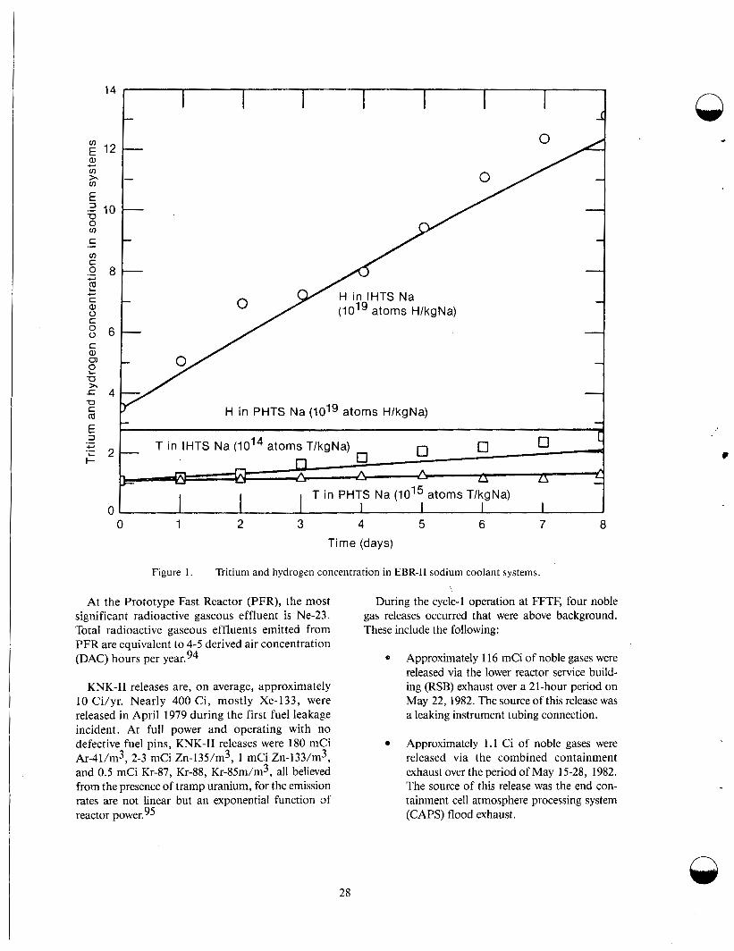
Time (days)
Figure 1. Tritium and hydrogen concentration in EBR-I1 sodium coolant systems.
At the Prototype Fast Reactor (PFR), the most significant radioactive gaseous effluent is Ne-23. Total radioactive gaseous effluents emitted from PFR are equivalent to 4-5 derived air concentration (DAC) hours per year.94
KNK-I1 releases are, on average, approximately 10 Ci/yr. Nearly 400 Ci, mostly Xe-133, were released in April 1979 during the first fuel leakage incident. At full power and operating with no defective fuel pins, KNK-I1 releases were 180 mCi Ar-41/m3, 2-3 mCi Zn-135/m3, 1 mCi Zn-133/m3, and 0.5 mCi Kr-87, Kr-88, Kr-85m/m3, all believed from the presence of tramp uranium, for the emission rates are not linear but an exponential function of reactor power. 95
During the cycle-1 operation at FFTF, four noble gas releases occurred that were above background. These include the following:
Q Approximately 1 16 mCi of noble gases were released via the lower reactor service build- ing (RSB) exhaust over a 21-hour period on May 22, 1982. The source of this release was a leaking instrument tubing connection.
Approximately 1.1 Ci of noble gases were released via the combined containment exhaust over the period of May 15-28, 1982. The source of this release was the end con- tainment cell atmosphere processing system (CAPS) flood exhaust.
28
, 9
About 60 mCi of noble gases were released from a cover gas leak in a gas tank sample trap connection. The release occurred inter- mittently over a 15-hour period on September 28, 1982. The total release time was 5 hours.
Approximately 12 mCi of noble gases were released when an O-ring was inadvertently omitted from a reactor cover gas grab sam- ple cylinder connection. This release occurred over a 3-hour period on October 29, 1982.
The tritium concentration in the primary cover gas and interim decay storage cover gas at FFTF is in the range of 10-1 to Ci/mL. Samples of the secondary cover gas impurities at FFTF have tritium concentrations in the range of to
Ci/mL.96 Radioactive gaseous effluents at FFTF since Cycle 1 have averaged %O. 11 7 Ci/ MWy thermal.
During the years 1963 to 1979, EBR-I1 has emitted an average of 19.6 Ci of noble gases per/MWy, and 39.18 Ci tritium/MWy. Since the start of the run-to- cladding-breach (RTCB) program in 1973, total radio- active gaseous releases have increased to about 120 Ci/MWy. In anticipation that the breached ele- ments in the run-beyond-cladding-breach (RBCB) program would release significantly higher quantities of radioactive gaseous effluents to the primary sys- tem, the cover gas system, and the environment, a cover gas cleanup system was installed in 1979. Subse- quent to installation of the cleanup system, radioac- tive gaseous effluents from EBR-I1 have dropped considerably, to about 18.6 Ci/MWy.
Radioactive gaseous effluents at commercial nuclear plants from the years 1960 through 1976, have averaged 35.8 Ci/MWy. This is significantly higher than the radioactive gaseous effluents emitted from LMFBRs.
Solid Waste System
Design Objectives. Solid rad waste systems should be designed to process and package solid wastes that are to be shipped off site for disposal. Packag- ing must be such that the surface dose rate will be in compliance with the Department of Transportation regulations.
The system should be designed to handle, pack- age, and store three sources of wastc concen- trated liquids, compactible solids, and noncom- pactible solids. It should be designed to perform its function with radiation hazards to plant personnel as low as reasonably achievable through the use of proper layout and arrangement, coupled with ade- quate shielding. Equipment should be selected, arranged, and shielded to permit operation, inspec- tion, and maintenance, with minimal exposure to personnel. All operations should be monitored to ensure that radiation concentrations in accessible areas are below the exposure 1imii.s set by 10 CFR 20.
The design of solid rad waste systems are based on widespread experience in the nuclear industry, spanning more than two decades. Reference 97 contains a review of solid rad waste practices at nuclear power plants. In particular, the imorpora- tion of concentrated liquid rad waste in cement is widely and routinely used in power reactor plants. The packaging of solid material for disposal by burial is also standard practice.
The operating procedures for handling the five types of input streams in a solid rad waste system at an LMFBR are as follows:
Concentrated liquids, which include evap- orator bottoms, spent resins, sodium con- taminated ethyl alcohol, and tritiated water, are solidified. A fixed amount of liquid rad waste can be metered into 55-gallon drums that have been preloaded with cement. The drum can be capped, thoroughly mixed by tumbling, decontam- inated by rinsing, monitored, stared tem- porarily if need be, and transferred to a licensed contractor for disposal.
Compactible solids such as rag!;, paper, and rubber seals, can be collected at vari- ous points throughout the plant and trans- ferred to a solid rad waste system, as is done at LWR plants.
-
Noncompactible solids include used sup- port tools, contaminated filters, metal from cutting operations such as an inter- mediate heat exchanger tube bundle, valves, and vapor traps. The low activity
/ \
29
noncompactible solids can be placed in 55- gallon drums, capped, decontaminated, monitored, and placed in temporary stor- age. Spent filter cartridges from the liquid rad waste system can be remotely placed in concrete line 55-gallon drums and placed in storage prior to shipment in the same manner as other noncompactible solids.
Radioactive sodium will be present as a result of fuel handling. This metallic sodium can be transferred to the rad waste system in 55-gallon drums. Since no waste disposal site will accept sodium, it is placed in temporary storage on site or processed into a nonmetalic form, such as a carbonate or carbide, and stored on site.
The primary and intermediate cold traps are the sources of sodium bearing waste. Pri- mary cold traps should be designed for the life of a plant and not expected to be removed. If replacement of a cold trap becomes necessary, it can be drained of bulk sodium and stored in a designated location. Intermediate cold traps are not designed for the life of the plant, will require removal, and storage must be provided.
Solid Waste System Experience at LMFBRs. At EBR-11, a small quantity of solid waste is produced. A major portion (by volume but not by radioactivity) of this solid radioactive waste is the accumulation of wipe rags, plastic containers, shoe covers, and other industrial solids associated with working with radioactive materials during maintenance. Reactor components such as thermocouples, nuts and bolts, and other hardware are disposed of as solid radioactive waste. Radiation from these com- ponents is generally low level (< 10 mR/h).
Another source of solid waste is elemental sodium in bulk form, which is produced in small quantities during maintenance. This sodium is col- lected in 3.8-L cans, which are placed in metal drums and covered with sand. Because of low radi- ation levels, these drums are stored in a covered trailer until the sodium can be treated. Approxi- mately 500 L of elemental sodium are presently in
~ cold traps used in the reactor coolant system to con- trol oxygen. The traps are removed from the system when their efficiency has dropped below preset lev- els, and they are stored in a radioactive storage building if the levels are low, less than 100 mR/h. When the radioactivity is high, they are stored with
shielding in a metal container underground in an interim storage facility at Argonne National Laboratory-West (ANL-W), designated as the radioactive scrap and waste facility. Storage of the cold traps is awaiting development of a treatmect process.
Most of the solid radioactive waste is generated at the hot fuels examination facility (HFEF). This waste results from the disassembly, assembly, and inspec- tion activities of EBR-I1 subassemblies, discarding of used experimental hardware, preparation of reactor blanket subassemblies for storage, and inspection activities of LMFBR related tests that are performed by other organizations. Solid waste is also produced when the evaporator bottoms are solidified. The solid wastes are of the following categories: low-level non- transuranic, intermediate nontransuranic (up to 10,OOO R/h), low-level transuranic, intermediate level transuranic (up to lo00 R/h), low and intermediate level transuranic, and nontransuranic waste with sodium, and bulk sodium at the intermediate level.
The chemistry laboratories that support EBR-I1 produce solid waste from maintenance and opera- tions. These wastes comprise low and intermediate levels but the volume is low and there is no elemental sodium.
Radioactive solid waste is handled by several differ- ent methods, depending on the radiation levels and the content of the waste. Low-level nontransuranic compactible waste is collected in plastic bags and hand carried to and placed in specific strategically located dumpsters. The dumpsters are then trucked to the INEL Radioactive Waste Management Complex (RWMC) operated by EG&G, Idaho, where the waste is compacted prior to storage. EG&G Idaho has reported compaction greater than 10: 1.
Prior to December 1977, low-level nontransuranic, noncompatible waste was placed in cardboard boxes; the boxes were placed in dumpsters and sent to the RWMC. Bulky or heavy items were boxed in wooden boxes. These boxes were then sent to the RWMC for storage. Since December 1977, this low-level waste has been collected in 208-L steel drums. The drums are held in a cupboard van until the van is full and then sent to the RWMC. Items too large for the drum are placed in standard-sized plastic lined wooden boxes painted with fire retarded paint. The boxes are available in sizes up to 1.2 x 1.2 x 2.4 m.
.
30
Low-level transuranic waste is placed in Depart- ment of Transportation (DOT) specification 17C drums equipped with a 2.3-mm rigid poly liner, or in fiberglass DOT specification 19A boxes. The filled containers are sent to the RWMC for storage. However, no transuranic waste has yet been gener- ated as a result of EBR-I1 operations.
Intermediate level waste with radiation levels up to 10,OOO R/h is generated within HFEF as a result of the disassembly of EBR-I1 driver subassemblies prior to inspection or shipment of fuel to the reprocessing plant. Intermediate waste from HFEF is remotely packaged in 1.8-m long, 295-mm ID carbon steel cans. These cans are then inserted into a stainless steel outer can and either seal-welded or gasket-closed. The cans that do not contain elemental sodium are sent to the RWMC for interim storage. Cans containing ele- mental sodium are sent to ANGW, RSWF, for stor- age. No intermediate level transuranic waste is generated by EBR-11.
A total of 9.7 m3 of solid radioactive waste, with a total activity of 19.8 mCi, was transformed from FFTF to the 300 area at Hanford for processing. The waste originated from the following activities:
Interim examination and maintenance (IM) cell decontamination and mainte- nance
Maintenance and storage facility decon- tamination and maintenance
Sodium removal system maintenance
Heat transport system south sampling and maintenance
Miscellaneous maintenance in the plant
Radioactive liquid waste sampling and load out station.
At the Phenix reactor, low level waste is handled essentially like as it is at EBR-11. Intermediate waste is transported to the Marcoule center and stock- piled in pits. The total quantity of these trans- ported intermediate wastes to date amounts to about 60 tons, and corresponds to an activity of about 8 million Ci. The irradiated fuel is trans- ported to the chemical reprocessing plant at La Haque or a t Marcoule. Approximately 100 metric tons of solid sodium is storaged on site.
Attempts have been made to reprocess the sodium from the Rhapsodie reactor to remove the fission products, but with very little success.93
Whether sodium waste is disposed of in a landfill or in a permanent depository, it will be necessary to convert it to a nonmetallic, stable compound to minimize its subsequent reaction and transport in the environment. Various types of glasses contain- ing silica and sodium monoxide may be suitable as such stable compound. For example, the composi- tion of ordinary window glass is 17% Na20, 6V0 CaO, 1% Al2O3, the remainder being Si02. The volume of this glass made from a given mass of elemental sodium is approximately 3 times the original volume of the sodium.
Ordinary window glass is not ideal for disposal of radioactive sodium from the standpoint of leaching of fission products by water. ]However, other glass compositions have been developed as candidate materials for encapsulation of high-level waste from fuel reprocessing.98
These glasses typically contain both silica and sodium monoxide in various Si:Na ratios. 1 t may be efficient to use the sodium monoxide from sodium waste disposal as one of the feed materials for pro- duction of special purpose glasses in the disposal of radioactive sodium.
The processes that would be suitable for convert- ing radioactive sodium to an acceptable compound for waste disposal must meet certain performance criteria related to the presence of radioactive con- taminants and transuranics. These criteria include (a) low cost, (b) simplicity, to allow remote opera- tion, (c) safety, to prevent uncontrolled Ieaction, (d) suitability for incorporation into a disposable form, and (e) minimum release of radioaci ivity.
Disposal of sodium and other alkali metals have been accomplished by a variety of methods, depending on the requirements of each situation.
The most frequently used methods have been (a) reaction with alcohol, (b) reaction with steam or water vapor, (c) reaction with concentrated caustic solutions, and (d) burning. The alcohol reaction processes have been used extensively for removing sodium from reactor components, but the quantities processed have been small to moderate, in the 0.1- to 50-kg masse^.^^-^^ Data were obtained on reaction rates and solubility of sodium in alcohol. The initial
31

reaction rate increases exponentially with tempera- ture; at 335 K the rate is 0.064-k sodium/m2-s on a horizontal sodium surface. 99-108 However, the rate decreases precipitously to essentially zero when the sodium concentration in alcohol reaches 5 wt%.
Some factors that could limit the use of the alco- hol reaction process are as follows. The sodium content of the alcohol must be kept low, thereby requiring continuous regeneration of alcohol by distillation during the reaction. The insoluble pre- cipitates from the distillation must be further proc- essed, and difficulties arise in reducing the product to ' a solid because of the presence of a variety of organic compounds. Disposal of liquid waste con- taining radioactive isotopes by landfill burial is not acceptable; therefore, disposal of the waste from the alcohol process presents formidable problems. Other factors include the flammability of the alco- hol and the necessity for processing the sodium in batches.
c I
In the early days of sodium technology, some quantities of sodium were reacted directly with water by dumping the sodium into a large outdoor water pool. This method, although effective and rapid, is obviously unsatisfactory for radioactive sodium. An improvement in the dumping method of the sodium in water was developed for disposal of large quantities of sodium under water. lol Liq- uid sodium was sprayed into water at a sufficiently high Reynolds number (greater than 45,000) to ensure disposal of the sodium. The depth of injec- tion was approximately 3 m, to ensure complete reaction before the metallic sodium could reach the surface. Adaptation of this process for use in a shielded, alpha containment facility, may be diffi- cult because of the need to control gas and water flows and to handle the hydrogen and water evolution.
The sodium water reaction can be controlled by diluting the water and thus controlling the rate of access of water to the sodium. Two methods of water dilution have been used successfully, namely, the use of steam and the use of water vapor and nitrogen. lo2 These processes have been widely used throughout the world, primarily for removal of residual sodium from components to be reused in the reactors. Methods of this type include (a) the use of moist argon or nitrogen at EBR-11, (b) the use of an atomized water spray in France, (c) steam cleaning in the U.S., Germany, the UK, and the USSR, and (d) the use of water vapor in nitrogen as practices in the U.S., UK, and Germany. A wide
range of experience has been gained in actual sodium-cleaning operation at reactor facilities using this diluted water method. 'The disadvantages of the method include the liquid waste (NaOH solution in water) that must be dried for disposal, and the evolution of hydrogen and carry-over of moisture in the gas stream. This hydrogen and moisture must be treated appropriately to remove fission products before venting to the environment.
Third is reaction with a concentrated caustic solution and is related to the process developed for direct reaction of sodium with water.lol Liquid sodium (or NaK) is dispersed in a pool of concen- trated (14 M) NaOH while water is periodically injected to control the caustic concentrations. This caustic solution process was used to dispose of the NaK from the decommissioned EBR-I reactor.lo3- lo4 The NaK was injected into the caustic with a spray nozzle designed to atomize the NaK in a stream of nitrogen. The disposal operation was accomplished smoothly. However, converting the process for operation in a shielded, alpha contain- ment facility would present difficulties relating to moisture, hydrogen handling, and liquid waste disposal.
The sodium burning process has been used exten- sively, both in open areas where the smoke was released to the environment and in closed facilities where the smoke was removed by water scrub- bing.101*105,106 Although the burning process is effective in consuming metallic sodium, the sodium monoxide smoke necessitates cleaning operations after the burning is complete. Large volumes of gas must be treated to remove fission products and liq- uid waste from the scrubber. Products from the wash down operations must be treated to form solid waste. The burning chamber also requires periodic cleaning to avoid accumulation of prohibitively high activity levels; this cleaning introduces an additional difficulty into the method.
Dissolution of sodium in a heavy metal such as lead or mercury, used in the USSR for cleaning reactor components. A process using this concept was pat- ented in the United States as a method for dis osing of large quantities of contaminated sodium. lJ7 The process is designed to divide the large heat of reaction into three approximately equal energy steps: (a) dis- solution of sodium in lead, (b) contacting the lead- sodium alloy with molten NaOH and sparging with oxygen to drive the sodium (as Na20) into solution in the NaOH, and (c) injecting steam into the molten NaOH to convert the dissolved Na20 into NaOH. n
32
i The molten NaOH is then drawn off periodically for disposal as solid waste. An attractive feature of this process is that there are theoretically no effluent gases and no aqueous waste to be processed. However, the process requires high temperatures (> 700 K) and complicated liquid flow manipulations.
At Argonne National Laboratory West, two methods have been developed and tested on a small scale for converting sodium waste to inert com- pounds suitable for disposal. The first method is direct oxidation of the sodium after dispersal in a silica matrix. The sodium is mixed with silica and oxidized in a rotary drum reactor. The product is suitable for making glass when other stabilizing compounds are added. The second method is the reaction of elemental sodium with molten NaOH at 450°C and subsequent injection of steam into the melt to convert the reaction products (Na20 and NaH) to additional NaOH. The reaction is smooth and easily controlled, with a low probability of run- away reaction. The end product is molten NaOH, which can be cast into drums for further treatment or disposal. The advantages of these two methods over more conventional aqueous processes are the elimination of aqueous wastes and the elimination or minimization of gaseous effluents. lo* Another methodology being investigated at EBR-I1 for the disposal of radioactive sodium waste is based on converting it to a carbonate or carbide form.lo9
Process and Effluent Radiological Monitoring Systems
Design Objectives. Process radiation monitors are placed at LMFBRs to evaluate plant equipment performance and to measure, indicate, and record the radioactive concentration in plant process and effluent streams during normal operation and anticipated operational occurrences. Radiation monitoring of process systems provides early warn- ing of equipment malfunctions indicative of poten- tial radiological hazards. Monitoring of liquid and gaseous effluents under normal operating condi- tions are done in accordance with NRC Regulatory Guide 1.21. The number, sensitivities, ranges, and locations of the radiation detectors can be deter- mined by requirements of the specific monitored process during normal and postulated abnormal conditions. All radiation monitors should be designed so that saturation of detectors during severe accident conditions will not cause errone- ously low readings. Continuous radiation monitors presently found at LMFBRs are equipped with
power supplies, microprocessor and accessories, and indication and local alarm indicator lights. Each monitor is capable of transmitting riidioactiv- ity level and alarm status information for display and logging in the control room with redundant display and logging equipment, and are designed in compliance with IEEE 279-1971. Peric'dic sam- pling of primary sodium, secondary sodium, ex- vessel sodium, and cover gases is conducted to alert the operator of any abnormal conditions that may be developing. Both local and remote liquid sam- ples are taken. Isotopic analysis of process samples at LMFBRs in the United States is performed by automated spectrum analysis systems that satisfy the reporting requirements of Regulatory Guide 1.21.
LMFBR Experience. The fission products released from a fuel element with breached cladding in EBR-I1 have been monitored in several ways. Before 1972, the fuel element failures were caused by defective closure wells and the like. Although xenon tags were included in experimental elements after 1969, none of the early failed elements had them. The early period was characterized by lengthy searches for sources of fission gas release.
From 1973, intentional endurances, or run-to- cladding-breach (RTCB) tests produced an increas- ing number of failures. Generally, however, these failures were well separated in time and did release xenon tags. Experience was gained in correcting the tag compositions or changes caused by in-reactor exposure, and identification was quite rapid.
From about 1977, when reference FFrF fuels tests approached radiation exposure goals, RTCB tests of advanced fuel element design we re begun and run-beyond-cladding breach (RBCB) testing was started, and incidents of failure sharply increased. During this period, an average of 10-15 failures occurred per year. The period wa:, charac- terized by an increasing number of occasiclns when several failures occurred in the reactor at 1 he same time.
The ways in which breached elements have been identified and removed from EBR-I1 from 1967 to April 1979 are described in References 1 1 C1 to 12 1.
The main cover gas activity monitor now in use at EBR-I1 is the germanium lithium argon ?.canning system, or GLASS, which was developed from pre- vious ~ y s t e m s . l ~ ~ - l ~ ~ Argon is extracted from a
33
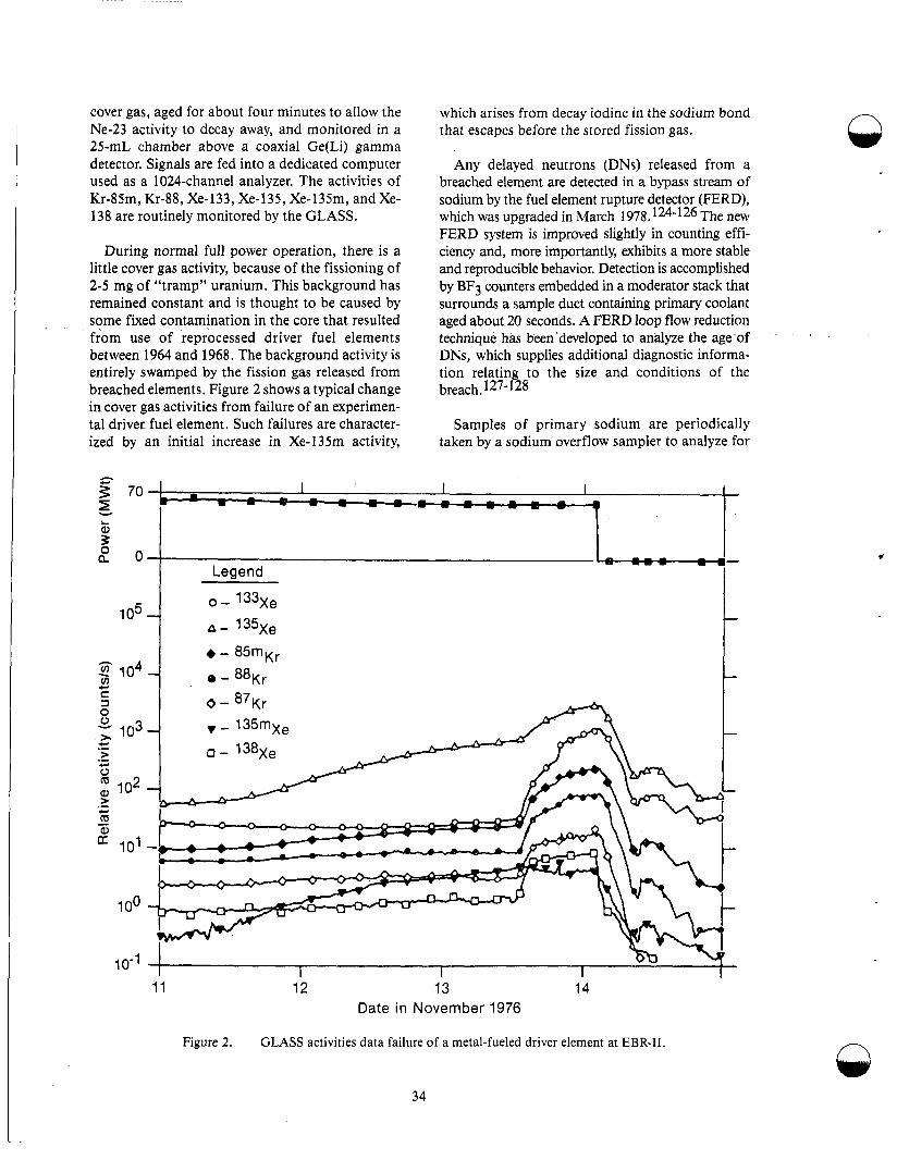
cover gas, aged for about four minutes to allow the Ne-23 activity to decay away, and monitored in a 25-mL chamber above a coaxial Ge(Li) gamma detector. Signals are fed into a dedicated computer used as a 1024-channel analyzer. The activities of Kr-85m, Kr-88, Xe-133, Xe-135, Xe-l35m, and Xe- 138 are routinely monitored by the GLASS.
During normal full power operation, there is a little cover gas activity, because of the fissioning of 2-5 mg of “tramp” uranium. This background has remained constant and is thought to be caused by some fixed contamination in the core that resulted from use of reprocessed driver fuel elements between 1964 and 1968. The background activity is entirely swamped by the fission gas released from breached elements. Figure 2 shows a typical change in cover gas activities from failure of an experimen- tal driver. fuel element. Such failures are character- ized by an initial increase in Xe-135m activity,
which arises from decay iodine in the sodium bond that escapcs before the stored fission gas.
Any delayed neutrons (DNs) released from a breached element are detected in a bypass stream of sodium by the fuel element rupture detector (FERD), which was upgraded in March 1978.124-126 The new FERD system is improved slightly in counting effi- ciency and, more importantly, exhibits a more stable and reproducible behavior. Detection is accomplished by BF3 counters embedded in a moderator stack that surrounds a sample duct containing primary coolant aged about 20 seconds. A FERD loop flow reduction technique has been ‘developed to andyze the age ‘of DNs, which supplies additional diagnostic informa- tion relating to the size and conditions of the breach. 127-128
Samples of primary sodium are periodically taken by a sodium overflow sampler to analyze for
I I I I I
--/
I I
I 1 I I 11 12 13 14
Date in November 1976
Figure 2. GLASS activities data failure of a metal-fueled driver element at EBR-11. n
34

the presence of 1-131, 0-137, U-235, and Pu-237. In this device, up to four IO-mL Pyrex beakers are filled to overflowing with sodium in an inert atmos- phere; after five days of cooling, the beakers are removed and their contents analyzed. Throughout the course of EBR-I1 history, plutonium has never been detected by the overflow sampler at the limit of detectability of 5 pg/g of sodium. Similarly, only twice has uranium been detected above the detectability limit of 1 ng/g. This experience con- firms that exposure of metal or ceramic fuels to the primary sodium has been minimal.
With the advert of limit RBCB testing, a more sensitive device, the only distillation unit, or OLDU was installed and made operational in 1978. In the OLDU, a sample of about 150 g of primary sodium is heated and volatilized. Nonvolatile impurities are left in the sample cup and may be analyzed immediately, since decay of Na-24 activity is not required. With OLDU operational, pluto- nium in the primary sodium has been occasionally measured above its detection limit. 129
Eleven methods developed at EBR-I1 are being used for the identification of fuel element failures; Table 14 lists and briefly describes them. The first five methods in the Table were used in EBR-I1 oper- ations from 1965 to 1973, when there was no accompanying release of a xenon tag. With one exception, these methods involved the measure- ment of fission gas activity in the cover gas and were nonspecific. The fourth method predicted failures on the basis of experience; it was of use for homogeneous groups of fuel elements such as the EBR-I1 metal driver fuel in which there was a well- defined mode of failure. 30 Identification fre- quently involved many reactor shutdowns and startups and 5 to 10 days of lost operating time. Confirmation of an identification was always the absence of short-lived fission gas activity upon resumption of full power.
The remaining methods of identification in the table were, in general, developed and used in EBR-I1 operations since 1973. The predominant method in the table is No. 8, the identification of a xenon tag from a failed fuel pin assembly. However, all 11 meth- ods have been used when appropriate. For example, the Xe-l31/Xe-134 ratio has proven useful in distin- guishing between failure of a uranium fissioning metal driver-fuel element and failure of a plutonium- bearing experimental element. 129
The xenon tags used at EBR-I1 consisi of about 1 mL of a unique mixture of the stable xenon iso- topes, Xe-124, Xe-126, Xe-128, and Xe-129, which is added to all elements in a given fuel assembly. The tags are blended from three components: natu- ral xenon, natural xenon 5% enriched in Xe-124, and pure Xe-128. One hundred forty tag composi- tions have been produced, with Xe-129/Xe-124 ratio increments of 1.25 and Xe-128/Xe-124 ratio increments of 4. Figure 3 shows a typi1:al three- dimensional plot of the tag nodes that correspond to the experimental subassemblies in the reactor during reactor Run 11 1.
Whenever a failure occurred before 1977, the xenon content in about 0.5 m3 (I-20th) of the argon-cover-gas volume was adsorbed on a cooled charcoal trap, later released by heating, and col- lected for analysis on a laboratory mass splectrome- ter. In this “manual mode,” sampling WEIS limited to once every 10 h and was complicated by the need to prevent personal exposure. Neverthelesr,, consid- erable accuracy was obtained, and released tag vol- umes of 0.04 mL could be readily used for identification.
In 1978, when the cover gas cleanup system (CGCS) became fully operational, a 7.5-ctn radius, 60” sector, mass spectrometer was installed on line with the tag trap analysis systern.l3l Although the instrument functioned well and reliably, it had an inadequate resolution for Xe-133, which is an important isotope in determining subassembly fail- ures, and the instrument was also difficult to main- tain at optimum performance. In May 19EI0, it was replaced with a new 15-cm radium spectrometer that had been specially designed to have an abun- dant sensitivity of greater than one in 30,000 at 133 atomic mass units, to be sensitive to anlalysis of very small samples, and to be more easily main- tained. The performance of this new inr,trument has been extremely gratifying. It has allowed, for example, the routine analysis of background sam- ples that contain less than 0.002-mL xencln tag in the cover gas volume of about lo7 mL, and in which Xe-124 can be measured with a precision of 1% at a low fraction of 0.0015 of the xenon iso- topes. 128 This value exceeds the best sensitivity that could be obtained by the use of a manual method by an order of magnitude, whereas the 7.5-cm instrument was worse by a factor of’ four or five.
35
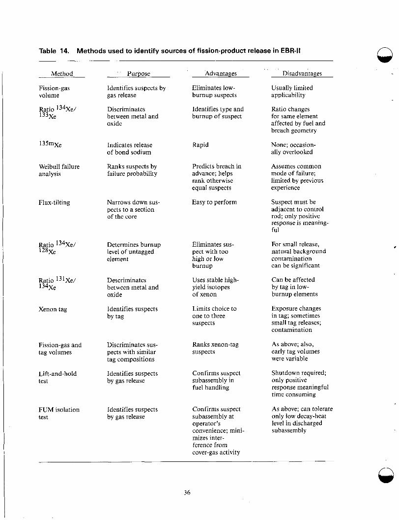
Table 14. Methods used to identify sources of fission-product release in EBR-II n
Advantages Disadvantages Purpose Method
Fission-gas volume
Ratio 134Xe/ 133xe
Identifies suspects by gas release
Eliminates low- burnup suspects
Usually limited applicability
Discriminates between metal and oxide
Identifies type and burnup of suspect
Ratio changes for same element affected by fuel and breach geometry
135mxe Indicates release of bond sodium
Rapid None; occasion- ally overlooked
Weibull failure analysis
Ranks suspects by failure probability
Predicts breach in advance; helps rank otherwise equal suspects
Assumes common mode of failure; limited by previous experience
Flux-tilting Narrows down sus- pects to a section of the core
Easy to perform Suspect must be adjacent to control rod; only positive response is meaning- ful
Ratio 134Xe/ 128xe
Eliminates sus- pect with too high or low burnup
Uses stable high- yield isotopes of xenon
For small release, natural background contamination can be significant
Determines burnup level of untagged element
c
Ratio 131Xe/ 134xe
Can be affected by tag in low- burnup elements
Descriminates between metal and oxide
Limits choice to one to three suspects
Exposure changes in tag; sometimes small tag releases; contamination
Xenon tag Identifies suspects by tag
Fission-gas and tag volumes
Discriminates sus- pects with similar tag compositions
Ranks xenon-tag suspects
As above; also, early tag volumes were variable
Shutdown required; only positive response meaningful time consuming
Lift-and-hold test
Identifies suspects by gas release
Confirms suspect subassembly in fuel handling
Confirms suspect subassembly at operator’s convenience; mini- mizes inter- ference from cover-gas activity
As above; can tolerate only low decay-heat level in discharged subassembly
FUM isolation test
Identifies suspects by gas release
36
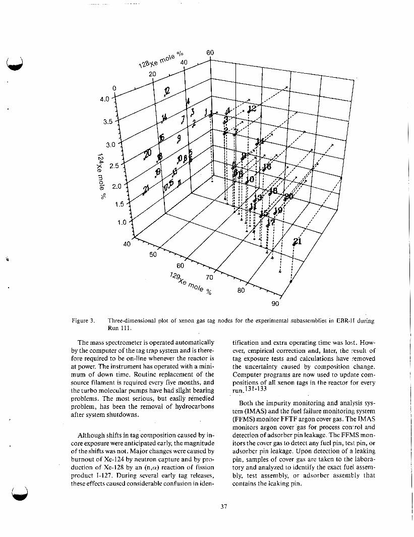
90
Figure 3. Three-dimensional plot of xenon gas tag nodes for the experimental subassemblies in EBR-11 during Run 1 1 1 .
The mass spectrometer is operated automatically by the computer of the tag trap system and is there- fore required to be on-line whenever the reactor is at power. The instrument has operated with a mini- mum of down time. Routine replacement of the source filament is required every five months, and the turbo molecular pumps have had slight bearing problems. The most serious, but easily remedied problem, has been the removal of hydrocarbons after system shutdowns.
Although shifts in tag composition caused by in- core exposure were anticipated early, the magnitude of the shifts was not. Major changes were caused by burnout of Xe-124 by neutron capture and by pro- duction of Xe-128 by an (n,a) reaction of fission product 1-127. During several early tag releases, these effects caused considerable confusion in iden-
37
tification and extra operating time was lost. How- ever, empirical correction and, later, the result of tag exposure tests and calculations have removed the uncertainty caused by composition change. Computer programs are now used to update com- positions of all xenon tags in the reactor for every
Both the impurity monitoring and analysis sys- tem (IMAS) and the fuel failure monitoring system (FFMS) monitor FFTF argon cover gas. The IMAS monitors argon cover gas for process coni:rol and detection of adsorber pin leakage. The FFh4S mon- itors the cover gas to detect any fuel pin, test pin, or adsorber pin leakage. Upon detection of a leaking pin, samples of cover gas are taken to the labora- tory and analyzed to identify the exact fuel assem- bly, test assembly, or adsorber assembly that contains the leaking pin.
run. 13 1-1 33

The IMAS is used to perform the following argon monitoring and sampling functions:
Continuous monitoring of concentrations of oxygen, hydrogen, nitrogen, methane, and carbon monoxide in all primary argon cover gas systems, with on-line gas chro- matographs for process control
Monitoring concentrations of helium in the heat transport system (HTS) because the presence of significant quantities of helium at nominal zero reactor power indi- cate an adsorber pin leak
Providing argon to the FFMS for on-line fuel failure monitoring
Obtaining periodic bulk samples of argon cover gas from the primary and secondary HTS and closed loop systems (CLS) for laboratory analysis.
The argon cover gas for the primary coolant sys- tems is directly sampled from the gas equalization line connecting the reactor vessel and the sodium overflow vessel, and from each primary CLS surge tank. A continuous closed-loop circulating flow is provided to a gas chromatograph, located in the HTS service building-south. The chromatograph sampling head selects each gas sequentially for analysis. Argon compressors circulate the sample gas.
Pneumatically operated isolation valves are automatically closed by the plant protection system (PPS) when required, to ensure containment isola- tion of lines from the primary systems.
Argon cover gas in the secondary system is sam- pled manually from the HTS secondary expansion tanks and the CLS secondary surge tanks, using grab sample cylinders.
The FFMS provides the following:
On-line monitoring to detect escape of fis- sion gas from a leaking fuel assembly into the cover gas, or the escape of activated tag gas from a leaking absorber assembly
Sampling equipment and analytical proce- dures to locate the leaking assembly.
Cover gas used for the reactor heat transport pri- mary system is scanned continuously with an intrinsic germanium diode gamma detector. Fission gas iso- topes are .monitored to detect fuel failures, and Xe-125 is monitored to detected an absorber pin fail- ure when the reactor is at power. An alarm is activated in the reactor control room if an abnormal activity level is detected for any of these isotopes.
The level of activity detected by the monitor var- ies from a background of 1 to 10 counts per second to as high as lo5 counts/s during a rapid gas escape.
Cover gas is monitored in the cover gas monitor module by passing a continuous controlled flow through a small, liquid-nitrogen cooled, activated charcoal, sample column adjacent to the gamma sensitive germanium diode. Use of the sample column and thin detector permits accurate moni- toring under conditions of high background radiation.
The technique for locating a failed fuel or absorber assembly is based on the use of a unique mixture of xenon and krypton in fuel and adsorber pins. These tag gas mixtures are loaded into the pins at the time of fabrication.
All individual pins of a given fuel assembly con- tain the same unique isotopic mixture consisting of one standard cm3 of xenon and one standard cm3 of krypton. All individuals pins of a given absorber assembly contain the same uni ue isotopic mixture
standard cm3 of krypton. Over 106 unique mix- tures are used for the driver, open test, the absorber assemblies of the core. Each time a fuel or absorber pin failure is detected, cover gas samples are obtainFd with a tag gas sampling trap.
Failure assemblies are identified by matching the results of a mass spectrometer analysis with previ: ously determined analysis of all tag gas mixtures in the reactor, suitably corrected for burnup and background.
consisting of two standard cm 9 of xenon and two
Unlike EBR-11, the FFTF, FFMS is not auto- mated and, it takes approximately 6 h for the segre- gation of the xenon, krypton, and argon isotopes. Few tag samples exceed 25 pCi/cm3. An ion chamber-type survey instrument (JUNO) is used to determine if the tag gas sample bomb exceeds the operational safety limit of 500 mrem/h. 134
9 38
Sodium Impurity Monitoring and u Analysis Systems
Sodium Coolant. The choice of coolant for a fast breeder reactor probably has a greater effect on the overall physical plant layout and on operational health physics than any other design selection. Whereas the coolant strongly influences the neu- tronic behavior of the core and provides a direct framework for the consideration of cladding mate- rials, the most recognizable effect of the coolant selection is its effect on major components such as pumps, steam generators, heat exchangers, shield- ing, and instrumentation.
Liquid metal sodium has been selected as the coolant for all major fast breeder power reactor projects underway around the world. As a conse- quence, the properties of sodium and its implica- tion for design must be given particular attention. As options having received attention to date the gas coolants, helium and steam, have been given lim- ited attention, as have other metal coolants.
The very high power density in an LMFBR core of %400 wattdliter compared to %lo0 wattdliter for an LWR places very stringent requirements on the heat transfer properties of a coolant candidate. A large heat transfer coefficient is desirable for optimum heat removal. Sodium is superior from the standpoint of heat transfer characteristics, though helium and steam can be driven hard enough, given sufficient driving pressure, to accomplish the required tasks.
Whereas any coolant has some moderating effect on the neutron spectrum, the degree of moderation taking place is proportional to the atomic mass and the density. Sodium, with a mass of 23, is clearly heavier than either helium or steam, but when the density effect is taken into account, the helium- cooled reactor yields the hardest spectrum; steam yields the softest spectrum because of its hydrogen content; and sodium provides an intermediate spec- trum. Because of the spectrum differences, helium has a slight intrinsic advantage in terms of achieva- ble breeding ratios. Another neutronic consider- ation is the effect of coolant activation. Helium, having a neutron capture cross section of essen- tially zero, is not activated. Steam becomes some- what radioactive by the neutron activation of oxygen, but the impact on design is minor. Sodium activation, however, attains a high degree of short half-life activation. Na-23 is activated to Na-24,
which decays through a beta emission with an attendant release of 1.37 and 2.75 MeV gammas to Mn-24. This activation has led to the inclusion of an intermediate coolant loop for sodium cooled systems to ensure that all radiation is confined to the primary loop. Other reasons for incluljing an intermediate loop in LMFBR systems are to protect the core from possible pressure surges or ,oositive reactivity effects caused by hydrogen modleration should a steam generator leak occur and result in a sodium water reaction, and to protect thc steam generator from radioactive corrosion and fission products.
A final neutronics consideration concerns the reactivity effect of coolant loss during an accident. The large density change associated with sodium loss can cause an appreciable change in the neutron spectrum and associated positive reactivity feed- back. None of the gas cooling media exhibits such a characteristic, though a thorough safety analysis of such systems does cover the very remote possibility of water entering the core as a result of a major break or depressurization. Under such conditions, similar variations in reactivity could occur.
In order for a reactor coolant to perform its heat removal function, a fraction of the total power output must be used to pump the coolant through the core. Hence, it is of interest to compare pumping require- ments for the various coolant candidates. For a typi- cal size plant, sodium coolant requires the least, and helium requires the most, pumping power. Other liq- uid metals are written off, largely because of their much larger pumping requirements. 135
Sodium is quite compatible with the preferred cladding candidates. However, because sodium has been chosen as the coolant, much research has been directed to every facet of its in-core environment, in order to determine any long-term deleterious effects. Summarized below are the main categories where effort has been focused to isolate pxsible problem areas.
The principal metallic elements in the clad- ding, such as iron, chromium and nickel, are very slowly dissolved in sodium from the hot core region and deposited in the cooler areas. This long-term uniform attack is called cladding thinning or wast- age. Although this amounts to only tens of micrometers/y at 700°C, it must bl: con- sidered in the overall load-bearing capacity of the cladding, which is stressed by inter- nal fission gas pressure.
39
Each of the principal metallic elements mentioned above has a different dissolu- tion rate in sodium. Hence, selective leach- ing occurs, and the composition of the steel at the outer surface is eventually altered. The effect, though small, is nor- mally deleterious, since chromium and nickel are removed faster than iron. Some of the more significant problems arising from the dissolution of minor constituents or activation products from the steel in the core are discussed below.
The dissolved metal deposited in the colder regions of the intermediate heat exchanger can lead to high heat transfer resistance or reduced heat exchanger efficiency. The deposits can become thick enough that coolant driving pressure must be increased in order to maintain desired flow. Some long-term silicon de osits have been
nating as a minor constituent in the steel, forms a compound with sodium which, if precipitated in core assembly coolant channels, can influence pumping power or local flow conditions.
observed at EBR-11. 1 3 9 The silicon, origi-
,
Though small in quantity, sodium trans- port and deposition of manganese and cobalt in the intermediate heat exchanger and other primary system components, can cause high enough radiation fields to affect routine maintenance.
In LMFBR secondary sodium systems that incorporate dissimilar materials in differ- ent regions of the circuit, nonmetallic ele- ments such as carbon and nitrogen are known to migrate as a result of chemical activity differences. Ferritic steel is suscep- tible to decarbonization when exposed to high-temperature sodium because of its inherently high carbon activity and large carbon defusion coefficient. The carbon loss from this material in a sodium envi- ronment leads to a significant reduction in tensile strength and stress rupture life. Fur- thermore, the carbon transferred to the sodium can carbonize the austenitic stain- less steel used in the intermediate heat exchangers and piping in the same circuit, with a resultant loss in ductility of the stainless steel. Because sodium is the trans-
port media for the general corrosion of cladding, the selective leaching of metallic elements, the transport and deposition of dissolved metals and radioactive species, and the transport of carbon, samples of sodium are usually extracted regularly and analyzed during normal operations at LMFBRs. On-line instruments have been developed to monitor sodium purity for both the primary and secondary systems. In addition to determining oxygen and car- bon content, it is useful to monitor hydro- gen levels, since this provides an indication of the tritium level in the cover gas of the primary system or steam generator leaks in the secondary system.
A principal advantage of sodium, beyond its excellent heat transfer properties, is that it does not require pressurization to prevent coolant boiling. This feature contrasts sharply with the thick-walled high-pressure systems required for helium or steam-cooled systems. Table 15 shows the pros and cons of sodium coolant and other items that bear on coolant selection.
Sodium Cold Trap Technology. In the operation of LMFBRs, it is necessary to maintain control of the amount of impurities in the liquid metal coolant sys- tem. The health physics department usually has the responsibility for sodium quality. Control of the level of such impurities as hydrogen and oxygen is required because of in-core metalic elements. Oxygen is sodium enhances the corrosion rate of austenitic stainless steel and the rate of embrittlement of refrac- tory metals. Hydrogen may cause embrittlement of refractory metals. Both of these impurities form com- pounds with sodium whose solubility in sodium decreases with decreasing temperature, leading to pre- cipitation and deposition of the compounds. All of these effects can increase maintenance requirements at the plant and thereby increase the radiation expo- sure to plant personnel. Many methods of treatment of the sodium to remove the impurities has been pro- posed and investigated. Among them are filtration, settling, centrifugation, distillation, chemical reac- tion, soluble gettering, and cold trapping. 137
The most widely used method for control of the hydrogen and oxygen impurities in operating LMFBRs has been the use of cold traps because of their simplicity, economy of operation, and relative effectiveness. Optimization of cold trap design and operation can increase capacity and lifetime, thereby improving the overall economics of the system.
Q
40
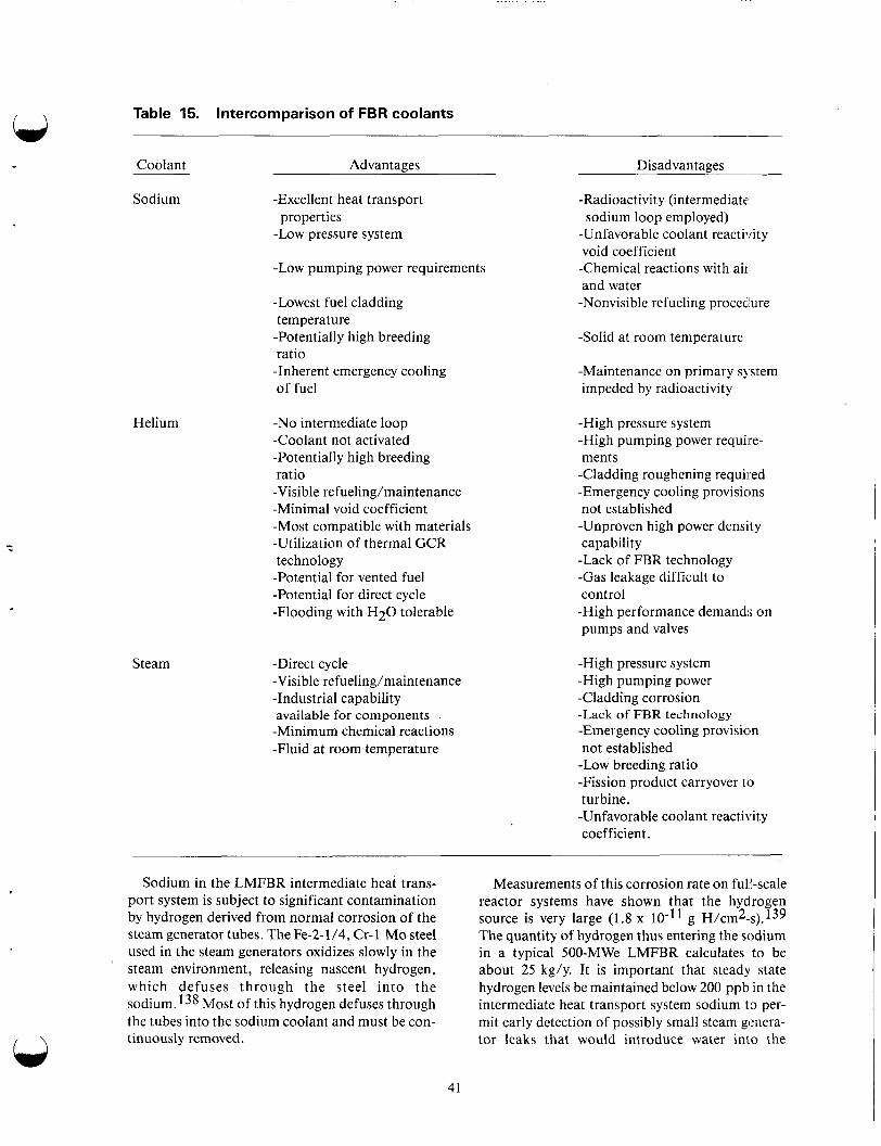
Table 15. Intercomparison of FBR coolants
Coolant Advantages Disadvantages
Sodium
Helium
-Excellent heat transport
-Low pressure system properties
-Low pumping power requirements
-Lowest fuel cladding temperature -Potentially high breeding ratio -Inherent emergency cooling of fuel
-No intermediate loop -Coolant not activated -Potentially high breeding ratio -Visible refueling/maintenance -Minimal void coefficient -Most compatible with materials -Utilization of thermal GCR technology -Potential for vented fuel -Potential for direct cycle -Flooding with H 2 0 tolerable
-Radioactivity (intermediate, sodium loop employed)
-Unfavorable coolant reactivity void coefficient
-Chemical reactions with ail, and water -Nonvisible refueling procedure
-Solid at room temperature
-Maintenance on primary sq'stem impeded by radioactivity
-High pressure system -High pumping power require- ments
-Cladding roughening required -Emergency cooling provisicins not established -Unproven high power density capability -Lack of FBR technology -Gas leakage difficult to control
-High performance demand:; on pumps and valves
Steam -Direct cycle -High pressure system -Visible refueling/maintenance -High pumping power -Industrial capability -Cladding corrosion available for components -Minimum chemical reactions -Fluid at room temperature
-Lack of FBR technology -Emergency cooling provisicn not established -Low breeding ratio -Fission product carryover to turbine. -Unfavorable coolant reactility coefficient.
Sodium in the LMFBR intermediate heat trans- port system is subject to significant contamination by hydrogen derived from normal corrosion of the steam generator tubes. The Fe-2- 1 /4, Cr- 1 Mo steel used in the steam generators oxidizes slowly in the steam environment, releasing nascent hydrogen, which defuses through the steel into the sodium. 138 Most of this hydrogen defuses through the tubes into the sodium coolant and must be con- tinuously removed.
Measurements of this corrosion rate on full-scale reactor systems have shown that the hydrogen source is very large (1.8 x g H / ~ m ~ - s ) . l ~ ~ The quantity of hydrogen thus entering the sodium in a typical 500-MWe LMFBR calculates to be about 25 kg/y. It is important that steady state hydrogen levels be maintained below 200 ppb in the intermediate heat transport system sodium to per- mit early detection of possibly small steam genera- tor leaks that would introduce water into the
41
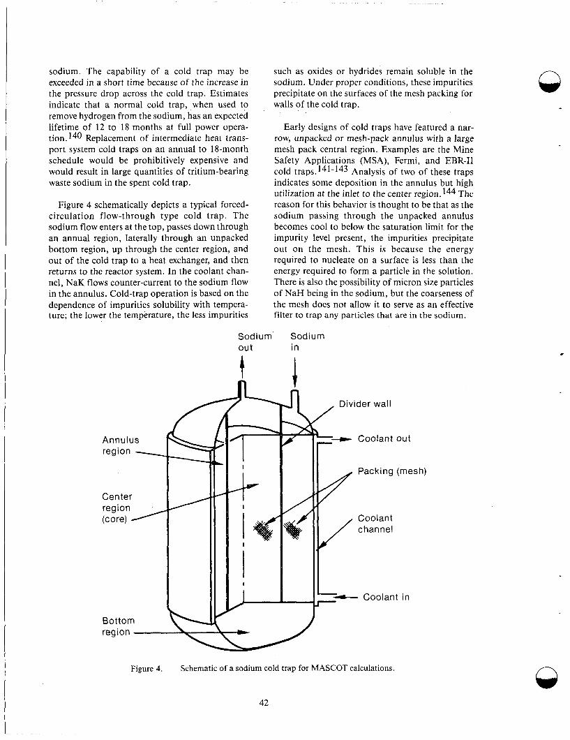
sodium. The capability of a cold trap may be exceeded in a short time because of the increase in the pressure drop across the cold trap. Estimates indicate that a normal cold trap, when used to remove hydrogen from the sodium, has an expected lifetime of 12 to 18 months at full power opera- tion. Replacement of intermediate heat trans- port system cold traps on an annual to 18-month schedule would be prohibitively expensive and would result in large quantities of tritium-bearing waste sodium in the spent cold trap.
Figure 4 schematically depicts a typical forced- circulation flow-through type cold trap. The sodium flow enters at the top, passes down through an annual region, laterally through an unpacked bottom region, up through the center region, and out of the cold trap to a heat exchanger, and then returns to the reactor system. In the coolant chan- nel, NaK flows counter-current to the sodium flow in the annulus. Cold-trap operation is based on the dependence of impurities solubility with tempera- ture; the lower the temperature, the less impurities
such as oxides or hydrides remain soluble in the sodium. Under proper conditions, these impurities precipitate on the surfaces of the mesh packing for walls of the cold trap.
Early designs of cold traps have featured a nar- row, unpacked or mesh-pack annulus with a large mesh pack central region. Examples are the Mine Safety Applications (MSA), Fermi, and EBR-I1 cold traps. 141-143 Analysis of two of these traps indicates some deposition in the annulus but high utilization at the inlet to the center region. 144 The reason for this behavior is thought to be that as the sodium passing through the unpacked annulus becomes cool to below the saturation limit for the impurity level present, the impurities precipitate out on the mesh. This is because the energy required to nucleate on a surface is less than the energy required to form a particle in the solution. There is also the possibility of micron size particles of NaH being in the sodium, but the coarseness of the mesh does not allow it to serve as an effective filter to trap any particles that are in the sodium.
Sodium Sodium out in
I I I Ib
Packing (mesh) I
Coolant channel
Figure 4. Schematic of a sodium cold trap for MASCOT calculations.
42
n
.
n
-.. . . . . .
.
The achieved capacity of cold traps has histori- cally been low. Typically, only 10% of the total capacity of the cold trap is used before the pressure drop across the trap is too great, necessitating replacement of the trap. The increase in pressure drop is caused by local depositions of impurities, which occupy up to 90% of the available flow vol- ume. A goal of 40 to 50% average use of cold pack- ing capacity is theoretically attainable. 145
Parameters judged to be important factors in influencing the lifetime of a sodium cold trap are as follows:
Sodium inlet flow rate
Sodium inlet temperature
Minimum sodium temperature in the cold trap
Impurity present in the inlet sodium and its concentration level
Mesh packing density
Mesh packing wire diameter
Location of the mesh packing
Length-to-diameter ratio of mesh packing section
Frontal flow area ratio (annulus/center section).
The length-to-diameter ratio is the ratio of the length of the annulus region to the outer diameter of the annulus region. The flow area ratio is the ratio of the total frontal area of the annulus region to the total frontal area of the center region.
There are many possible approaches to the choice of a system design for large-scale LMFBRs. The number and size of secondary systems on the reactor will guide the selection of the number and, to a degree, the size of the intermediate heat transport sys- tem cold traps. General guidelines given in Table 16 will aid the designer in the area of intermediate heat transport system cold trap design. These guidelines apply to forced circulation flow through type IHTS cold traps, calculated using the M A S C m code.145
It should be emphasized that verification of the performance of a proposed cold trap design will be
required by operational testing prior to installation in a system. Because the performance of the cold trap is closely tied to inlet sodium temperature and impurity concentrations, the manner of control of this temperature and measurement of the impurity concentration must be addressed in the design of the cold trap system.
Though the principal role of the cold lrap in the primary circuit is to control the concentration of dissolved oxygen impurity and, in the intermediate heat transport system, to control the concentration of hydrogen impurities, a number of radioactive impurities have been observed to be cold trapped also. Cold traps are not designed with this inten- tion, and in the case of many such species it is not clear that the mechanism of cold trapping is precip- itation from solution. The parameters that affect the phenomena of crystal nucleation, growth, and mass transfer, which are fundamental to cold trap performance, have been defined. 146 The perform- ance of a cold trap in relationship to a given radio- active species cannot be described simply, in terms of precipitation, and will be markedly sensitive to design and operating parameters. In addition to providing a site for crystal nucleation and growth, a cold trap is characterized by high residence time of the sodium, heat exchange, and flow conditions, which may be conducive to pait iculate deposition-depending on the design, on the high surface areas of steel in the trap internals and diso- dium monoxide at low temperatures compared to the remainder of the primary circuit on which dep- osition may occur preferentially, and on the struc- tures conducive to the filtration of particulate material. The last aspect, in particular, may be sen- sitive to operating mode; it has been suggested that the PFR cold trap will only become an zffective filtration unit for particles below 100 microns when the trap has a considerable inventory of diso- dium monoxide-type impurity through the mesh packing. 147
The potential role of cold trapping as a means of removing radioactive products from the coldant of LMFBRs has not been explored fully. Thcre have been few systematic studies of cold trapping per- formance in operating reactors, possibly as a result of the difficulty of carrying out such analysis; the information available is fragmentary and does not lead itself to generalization. Furthermore, ihe per- formance of the cold trap in removing radiioactive products will be intrinsically related to the deposi- tion behavior of these species in the remainder of the primary circuit, and this deposition bzhavior
43
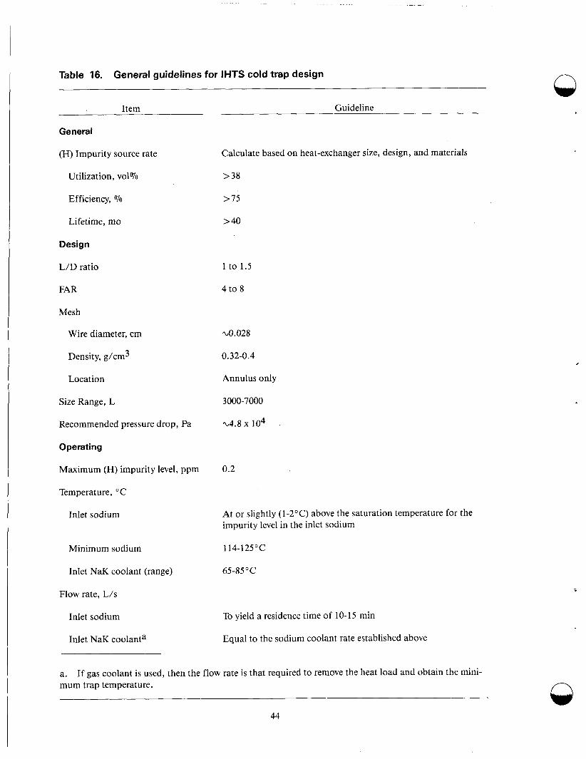
Table 16. General guidelines for IHTS cold trap design n Item
General
(H) Impurity source rate
Utilization, vol%
Efficiency, Vo
Lifetime, mo
Design
L/D ratio
FAR
Mesh
Wire diameter, cm
Density, g/cm3
Location
Size Range, L
Recommended pressure drop, Pa
Operating
Maximum (H) impurity level, ppm
Temperature, "C
Inlet sodium
Minimum sodium
Inlet NaK coolant (range)
Flow rate, LIS
Inlet sodium
Inlet NaK coolanta
Guideline
Calculate based on heat-exchanger size, design, and materials
> 38
> 75
> 40
1 to 1.5
4 to 8
~0.028
0.32-0.4
Annulus only
3000-7000
-4.8 x 10⁴
0.2
At or slightly (1-2°C) above the saturation temperature for the impurity level in the inlet sodium
114-125°C
6545°C
To yield a residence time of 10-15 min
Equal to the sodium coolant rate established above
a. mum trap temperature.
If gas coolant is used, then the flow rate is that required to remove the heat load and obtain the mini- n
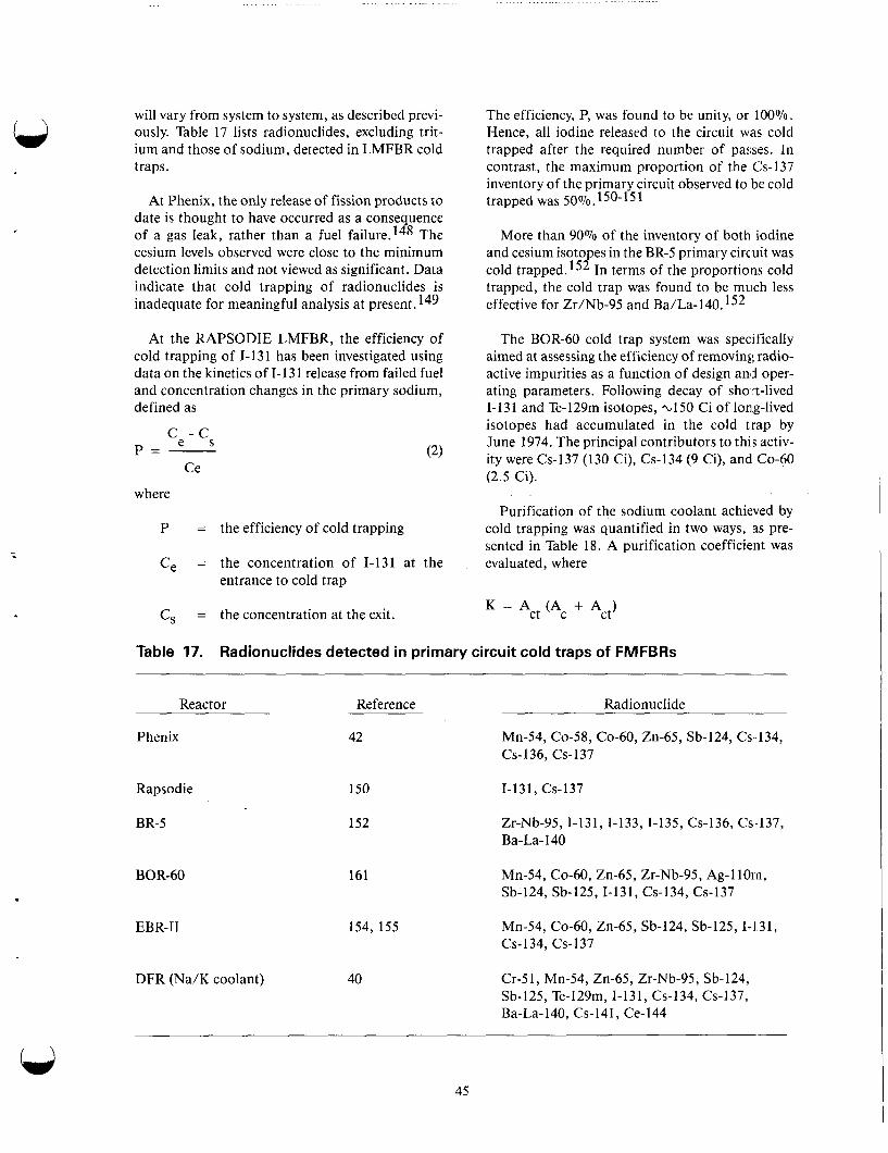
....... ........... ...... - - ~~
will vary from system to system, as described previ- ously. Table 17 lists radionuclides, excluding trit- ium and those of sodium, detected in LMFBR cold traps.
At Phenix, the only release of fission products to date is thought to have occurred as a consequence of a gas leak, rather than a fuel f a i 1 ~ r e . l ~ ~ The cesium levels observed were close to the minimum detection limits and not viewed as significant. Data indicate that cold trapping of radionuclides is inadequate for meaningful analysis at present. 149
At the RAPSODIE LMFBR, the efficiency of cold trapping of 1-1 3 1 has been investigated using data on the kinetics of 1-1 3 1 release from failed fuel and concentration changes in the primary sodium, defined as
‘e - ‘s
Ce p = -
where
P = the efficiency of cold trapping
Ce = the concentration of 1-131 at the entrance to cold trap
Cs = the concentration at the exit.
The efficiency, P, was found to be unity, or 100%. Hence, all iodine released to the circuit was cold trapped after the required number of passes. In contrast, the maximum proportion of the (3-137 inventory of the primary circuit observed to be cold trapped was 50%.150-151
More than 90% of the inventory of both iodine and cesium isotopes in the BR-5 primary circuit was cold trapped.152 In terms of the proportions cold trapped, the cold trap was found to be much less effective for Zr/Nb-95 and Ba/La-140. 152
The BOR-60 cold trap system was specifically aimed at assessing the efficiency of removing radio- active impurities as a function of design anld oper- ating parameters. Following decay of short-lived 1-131 and Te-129m isotopes, ~ 1 5 0 Ci of long-lived isotopes had accumulated in the cold trap by June 1974. The principal contributors to this activ- ity were Cs-137 (130 Ci), Cs-134 (9 Ci), and Co-60 (2.5 Ci).
Purification of the sodium coolant achieved by cold trapping was quantified in two ways, as pre- sented in Table 18. A purification coefficient was evaluated, where
K = A (A + A ) ct c ct
Table 17. Radionuclides detected in primary circuit cold traps of FMFBRs
Reactor Reference Radionuclide
Phenix 42 Mn-54, Co-58, Co-60, Zn-65, Sb-124, Cs-134, CS-136, CS-137
Rapsodie 150 1-131, CS-137
BR-5
BOR-60
152
161
Zr-Nb-95, 1-131, 1-133, 1-135, (3-136, Cs-137, Ba-La- 140
Mn-54, Co-60, Zn-65, Zr-Nb-95, Ag-1 lorn, Sb-124, Sb-125,1-131, CS-134, CS-137
EBR-I1 154, 155 Mn-54, CO-60, Zn-65, Sb-124, Sb-125, 1-1 31, (3-134, (3-137
DFR (Na/K coolant) 40 Cr-51, Mn-54, Zn-65, Zr-Nb-95, Sb-124, Sb-125, Te-l29m, 1-131, Cs-134, (3-137, Ba-La-140, Cs-141, Ce-144
45
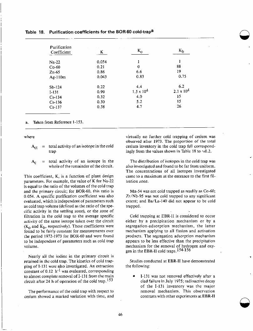
Table 18. Purification coefficients for the BOR-60 cold-trapa n
Purification Coefficient K K, Kb
Na-22
Zn-65 Ag-l10m
CO-60
Sb-124 1-131 (3-134 CS-136 CS-137
a. Taken from Reference 1-153.
0.054 1 0.21 0 0.86 6.6 0.043 0.83
0.22 0.99 0.32 0.30 0.38
1 88 19 0.75
4.4 6.2
4.0 15 5.2 15 4.7 26
1.5 104 2.1 104
where virtually no further cold trapping of cesium was observed after 1973. The proportion of the total cesium inventory in the cold trap fell correspond- ingly from the values shown in Table 18 to ~ 0 . 2 .
Act = total activity of an isotope in the cold trap
A, = total activity of an isotope in the whole of the remainder of the circuit.
This coefficient, K, is a function of plant design parameters. For example, the value of K for Na-22 is equal to the ratio of the volumes of the cold trap and the primary circuit; for BOR-60, this ratio is 0.054. A specific purification coefficient was also evaluated, which is independent of parameters such as cold trap volume (defined as the ratio of the spe- cific activity in the settling zone), or the zone of filtration in the cold trap to the average specific activity of the same isotope taken over the circuit (K, and Kb, respectively). These coefficients were found to be fairly constant for measurements over the period 1972-1973 for BOR-60 and were found to be independent of parameters such as cold trap volume.
Nearly all the iodine in the primary circuit is retained in the cold trap. The kinetics of cold trap- ping of 1-131 were also investigated. An extraction constant of 0.12 h-l was evaluated, corresponding to almost complete removal of I- 13 1 from the main circuit after 24 h of operation of the cold trap.153
The performance of the cold trap with respect to cesium showed a marked variation with time, and
The distribution of isotopes in the cold trap was also investigated and found to be far from uniform. The concentrations of all isotopes investigated came to a maximum at the entrance to the first fil- tration zone.
Mn-54 was not cold trapped as readily as Co-60; Zr/Nb-95 was not cold trapped to any significant extent; and Ba/La-140 did not appear to be cold trapped.
Cold trapping at EBR-I1 is considered to occur either by a precipitation mechanism or by a segregation-adsorption mechanism, the latter mechanism applying to all fission and activation products. The segregation adsorption mechanism appears to be less effective than the precipitation mechanism for the removal of hydrogen and oxy- gen in the EBR-I1 cold traps.154-156
Studies conducted at EBR-I1 have demonstrated the following:
1-131 was not removed effectively after a clad failure in July 1975; radioactive decay of the 1-131 inventory was the major removal mechanism. This observation contrasts with other experiments at EBR-I1
.
46
where lowering of the sodium temperature produces a quantitative segregation of 1-131 to metal surfaces. This segregation process provides the basis for an analytical method for 1-131 used at EBR-11.
During the first year of operation of the cold trap (1968-1969), 30% of the total Cs-137 inventory was located in the cold trap. Sub- sequently, the absolute quantity of Cs-137 in the cold trap has remained effectively con- stant, and further cold trapping of the iso- tope does not appear to have occurred.
The cold trap is extremely effective for Mn-54 removal, removing ~ 6 0 % per pass. However, the benefits derived from effi- ciency in this respect are dubious for con- tinuously produced corrosion products such as Mn-54. This removal in the cold trap will not influence deposition on com- ponents upstream; most of the Mn-54 will deposit in the primary circuit and not enter the cold trap circuit.
Generally, radioactivity was not uniformly dis- tributed in the cold trap. The level of activity was at a maximum at a point close to the inlet for the external cooling (employing NaK alloy) where most precipitation is thought to occur.
The cold trap at DFR was found to be highly effective for the removal of 1-131 and Tc-l29m; Ba/La-140 also segregated markedly to the cold trap. However, the efficiency of the cold trap in removing Cs- 137 was deemed to be disappointingly low. The behavior of antimony was variable, and association with fuel particles was postulated.
The ease with which 1-131 in the cold trap was removed by steam cleaning suggested it to be present as precipitated sodium iodine, whereas the acid cleaning required to remove Te-129m was taken to indicate some weak chemical binding to the surface of the steel mesh cold trap basket. The decontamination behavior of Ba/La-140 (and the species Zr/Nb-95, Ce-141, and Ce-144) appeared indicative of fine surface oxide deposition. How- ever, cesium appeared strongly bound to the steel of the cold trap, and penetration of the steel was pos- tulated to explain the resistance of the cesium to decontamination procedures.
-- . - 4” -
Observations on the cold trapping behavior of radionuclides are often in conflict, and the discrepan-
cies remain largely unresolved. Before assessing the contribution that might be made by cold trapping to the removal of radioactive products from LMFBR primary circuits, it is desirable to consider the mecha- nism of cold trapping of specific radionuclides.
Appreciable segregation of Cs-137 in cold traps has been reported under certain condition:. How- ever, the conditions that will optimize cold trapping of Cs-137 have not been identified. Varialions in the nature of steel surfaces, flow conditions, and the coolant chemistry within the cold trap may all account for the observable differences in cold trap efficiency at LMFBRs. A number of workers have conducted experiments in order to improve the understanding of cesium deposition behavior in sodium/stainless steel systems. Classically, ii distri- bution coefficient, K, is obtained to describe the distribution of cesium between its deposited form on a steel surface and its dissolved stage in siDdium, where
-L (3)
It has been demonstrated for a variety of steel surfaces, cesium concentrations, and oxygen levels in sodium, that the log of K is inversely propor- tional to the absolute temperature. 157-165 ]Hence, cesium will deposit preferentially on the cold steel surfaces in the cold trap. However, even taking the strongest temperature dependence reported does not offer a practical route for significant (cesium removal from the coolant of an operating LR4FBR, since the much greater surface area of the reactor will result in deposition of too high a proportion of the cesium outside the cold trap.160 This conclu- sion is similar to that reached in the context of the BOR-60 cold trap.161
atoms Cs/cm steel surface
atoms Cs/cm Na K = -3
The distribution coefficient, K , has been found to strongly depend on the nature of the steel surface. 57-160 Pretreatments such as polishing or preexposure to sodium at high temperature l(about 600°C) resulted in smaller values for K. This is ascribed to the removal of oxide films, at the steel surface, on which cesium deposition occur:, more favorably than on ~ t e e 1 . I ~ ~ Nickel and alumina have been shown to be more efficient cold trap packing materials for cesium removal. :i79 159 Investigation has shown that disodium monoxide adsorbed cesium more effectively than steel. Hence, enhanced cesium removal could be obtained in a primary circuit cold trap in which oxygen is cold trapped continually. Such a sy:,tem is
47
penalized by the intrinsic requirement of periodic regeneration or replacement of the cold trap and by interactions with the aspects of coolant chemistry. Investigations of this effect have proven inconclu- sive.161
The dissolved oxygen in the sodium influences cesium deposition on steel by the interaction of oxygen with the steel 166 Cesium may be incorporated in corrosion products at steel sur- f a c e ~ . ~ ~ ~ Some evidence suggests that there is little correlation between the enhancement of cesium cold t rap ing and the oxygen level of the sodium. 16f- 164
Cesium adsorption at low temperatures may be controlled by interactions with nonmetallic impuri- ties, and the strongest interaction occurs with hydrogen. 167 A phase distribution coefficient, D, has been evaluated, where
D = atoms Cs/g hydrogen in deposit
atoms Cs/g sodium
At 120"C, D has a value of 8 . 5 x lo-? 'This seems to indicate that hydrogen additions to the primary circuit, with subsequent cold trapping, will enhance the cesium removal.
Although distribution coefficient measurements for a range of concentrations of Cs-137 in sodium have been made,159 there remains a lack of long-term data obtained under controlled, representative condi- tions on the cold trapping behavior of cesium. The effects of indigenous levels of nonactive cesium impu- rity in the original sodium charge have been largely ignored. The nature of active cesium trapping sites remains obscure. Experience from BOR-60 and EBR- I1 suggests that such sites might have to be produced continually for regeneration of the cold traps.
Evidence indicates that cesium adsorption on surfaces is reversible and highly sensitive to a num- ber of variables that may not be controlled suitably during LMFBR operation. These findings suggest that a trap for cesium should bind the cesium more strongly than the forces involved in adsorption, and that the nature of the bond should be insensitive to other concomitant phenomena.
The stabilities of cesium-graphite intercalation compounds and the sorption of cesium by graphite in liquid sodium have been investigated, 83-1 84 and it is concluded from them that cesium was trapped in two stages, the first involving a surface
adsorption compound that subsequently yielded a more stable intercalation compound. The effi- ciency of trapping was further proved by using a high surface area charcoal (gas adsorption char- coal) that was thought to enhance the formation of the intercalation compound. Short-term experi- ments showed no adverse effects of preexposure to a sodium environment on trapping performance. The use of carbonaceous material for trapping cesium in the sodium coolant of an LMFBR pri- mary circuit might give rise to unacceptable levels of carbon on steel components, as a consequence of carbon transfer. However, many forms of pure carbon are inefficient carbon sources for steel car- burization in sodium, and the performance of high surface area graphite for charcoal in a sodium/ stainless steel system appears worthy of further investigation. 185 Carbon trapped materials have functioned efficiently in the cover gas space above the sodium, though in this mode the occurrence of steel carburization may not be precluded.
In the EBR-I1 primary circuit sodium, the per- formance of reticulated vitreous carbon (RVC), a highly porous foam-like glassy carbon manufac- tured by Chemotronics, International, has been investigated for use in removing cesium from sodium. 185 Favorable results have been obtained in the laboratory, and reactor tests conducted on graphite indicate that RVC is preferred for use in the reactor in view of its greater surface-to-volume ratio. RVC specimens were exposed at various tem- peratures to flowing sodium taken from the pri- mary tank, which was maintained at 371°C and contained 0.3 pCi Cs-l37/g sodium throughout. Over the temperature range of 177-371°C, it was found that RVC traps Cs-137 according to a rela- tionship given as
Log C = 3,00O/T - 9.889,
where
C = C-137 saturation (Ci/cm2)
T = temperature (K).
The trapping mechanism remains obscure; if the active surface involved is estimated correctly, then 75 molecular layers of (3-137 will be present at the RVC surface at 177°C. Furthermore, the material is said to be effective for Cs-134 and presumably for nonactive cesium. Therefore, it seems likely that a mechanism other than adsorption applies.
48
Grs The RVC for EBR-I1 that will handle the present
Cs-137 inventory and the further release caused by the run-beyond-cladding-breach program will operate at 193°C and contain m3 RVC, giving an effective surface area of 320 m2. 146 The cesium trapped is placed within the cold trap and consists of an economizer, RVC, and crystallizer, and is sur- rounded by a 4-in. lead shield. The normal sodium flow through this cesium trap is 12-15 gal/min, which at this flow takes approximately four to five days to clean the entire sodium system at EBR-11. When the cesium trap was first in place, the total cesium inventory in the sodium was in the range of 120-150 Ci. Presently, the maximum cesium inven- tory in the sodium is 10 Ci and is normally in the range of 2-3 Ci.136
Halogens released into liquid sodium are con- verted to sodium halides, which have a well-defined solubility in sodium, and have been measured experimentally. 68 The solubility of sodium iodide shows a very strong temperature dependence, but precipitation from solution of sodium iodide at low temperature in the cold trap of a primary circuit cannot be proposed as a method for 1-1 3 1 removal, since iodine levels above the solubility limit, even at cold trap temperatures, are unlikely to be attained.
Generally, iodine appears to be amenable to cold trapping, but by adsorption rather than precipita- tion. The temperature dependence of a distribution coefficient, K, defined for the case of cesium, has been evaluated for iodine by several investiga- tors. 162-164, 1 6 8 y 169 There is some evidence that K is concentration-dependent. 168-169 The increase in values of K for decreasing temperature is suffi- ciently great that adsorption on steel surfaces in the cold trap will be significant in removing 1-131 from the primary circuit of a reactor. 1679 169 The cold trapping efficiency will be further increased when disodium monoxide or sodium hydride are being precipitated in the cold trap because of a strong interaction between iodine and the hydride deposits. 169 The observation from EBR-I1 con- trasts with this conclusion, and it must be postu- lated that the surfaces in the EBR-I1 cold trap were deactivated, with respect to iodine adsorption, by the concomitant processes. 54-155
A number of important fission products will be released into the sodium in the form of stable oxides. These include Zr/Nb-95 and Ba/La-40. Examination of the cold trapping behavior of these isotopes is effectively a treatment of small particle
behavior. Assuming small particle sizes of 1t:ss than 1 micron, the deposition behavior of Zr/Nb-95 and Ba/La-140 from sodium on steel surfaces might be described adequately in terms of liquid- phase mass transfer control. However, the strong temperature dependence of Ba/La- 140 deposition in BOR-160, implies the use of various liquid-phase mass transfer coefficients at different tempera- tures. 170 These observations suggest that adsorp- tion of Ba/La-140 on steel surfaces i s more favorable at low temperatures; a similar observa- tion has been made for strontium.171 In a practical system, these higher adsorptions at low tempera- tures will allow only a small proportion of the Ba/ La-140 inventory to be cold trapped. This is in good agreement with observations on BR-5 and BOR-60, and with experimental data.152,171,174
Analysis of sodium/stainless steel system:. shows that Co-60 deposition
Is approximately proportional to sodium velocity at all temperatures
Decreases with downstream distant':
Shows little variation with temperature above that from downstream behav- ior.172,175
In contrast, analysis of sodium/stainless steel systems has shown that Mn-54 deposition
Shows no velocity dependence at high tem- peratures
Increases with reducing temperature, espe- cially approaching the minimum ternpera- ture in the system
Shows a velocity dependence at low temperatures. 1729 174-176
Co-60 deposition behavior is found to be con- trolled by laminar boundary layer, and Mn-5 4 dep- osition behavior is controlled by solid state diffusion at high temperatures and by bulk deposi- tion at low temperatures. These findings indicate that cold trapping will be ineffective for cobalt iso- topes, but that Mn-54 might be cold trapped quite effectively on cold steel surfaces. Such concliisions are borne out by observations on RAPSODIE, EBR-11, and the KNK reactor, but contradicied by data from ~0~-60 .154 ,1659 171,187-188
49
A further phenomenon, which might enhance cold trapping of these transition metal species, is formation of complex oxides as a result of interac- tion between the metal in solution and the oxide at saturation in the cold trap sodium.
Analysis of the controlling atomic diffusion processes confirms that enhanced diffusion of some elements into nickel should occur. 179 Hence, use of a trap fabricated in nickel mesh, rather than stainless steel, and placed at the core outlet, should prove effective for Mn-54. Possible difficulties are the higher rate of bulk corrosion of nickel, com- pared with stainless steel, and the modification of the nickel surface by concomitant mass transfer of other elements. The use of a nickel substrate does not greatly influence cobalt deposition. 1433 177
In screening tests on a wide variety of materials, mostly pure metals and alloys, it has been shown that pure nickel is the most effective getter for Mn-54 of the materials tested.180 A number of traps using nickel foil have been fabricated and tested. These are made by rolling the foil onto a cylindrical form, with the spacing between succes- sive layers of the foil being determined by a design embossed in the foil.
In application of this type of trap to a reactor, traps are situated at the end of subassemblies, downstream of corroding core components. Tests on prototypical designs have been carried out accordingly.
Initially, traps with very narrow interlaying spac- ing IO maximize surface area were tested and found 82-92% efficient for Mn-54 removal in terms of activity retained in the trap, compared with that released to the remainder of the downstream test circuit. In order to reduce a very high pressure drop associated with this design, traps with wider inter- layer spacings in different embossed patterns have been tested. Traps with twice the initial spacing have been shown to have equally high efficiency for Mn-54 removal, suggesting that trap surface area is not of overriding importance, and that lower sur- face area may be compensated by the increased sodium half length and turbulence. The efficiency of Co-60 removal is reduced on going to lower sur- face area, as would be expected.
The pressure drop associated with this design is acceptable in an EBR-I1 subassembly channel, and subsequent to satisfactory performance in hydrau- lic tests. An EBR-I1 test was successfully finished
after 1 year of operation.181 Still wider spacings will have to be incorporated into this type of trap before the pressure drop would be acceptable in a commercial LMFBR.
The nickel used in fabrication of the traps has a very low cobalt impurity level ( < 5 ppm) to avoid adding significantly to the CO-60 inventory in the reactor. Moreover, the corrosion rate of the nickel in the traps was not found excessive. The finding is based on weight change data, however, and estima- tion of corrosion losses by this method for a mate- rial that shows a strong tendency to pick up other materials (particularly iron) may be misleading. 82 Release of nickel in subsequent deposition, and cooler parts of the reactor circuit, may lead to sec- ondary trapping of Mn-54, in the long term, at the surface of the components that the traps were intended to protect.
Trai n i ng The development of LMFBRs has required a vast
design and experimental program in the field of sodium technology. Training and qualification pro- grams in sodium technology, sodium systems, and components particular to LMFBRs are needed. The programs should address the selection, train- ing, and retention of all individuals involved in operational health physics. In Europe, LMFBR operating experience demonstrated the specific needs for sodium and LMFBR simulator-based training courses. This section is essentially based on information gathered from the training pro- grams set up in France by the Commissariat a I’Energie Atomique for the European LMFBR community and the sodium technology course of Atomics International.
Personnel such as reactor operators, radioactive waste operators, supervisors, radiological engi- neers, ALARA engineers, health physics techni- cians and supervisors, radiation contamination control engineers, chemists and chemical techni- cians, and other technical support should have extensive sodium training courses. These courses should cover the following:
The chemical, physical, and nuclear prop- erties of sodium.
The solubilities of metals, gases, and non- metals in liquid sodium, and factors that affect these solubilities, and the reactions of sodium with inorganic, ceramic, and organic materials.
Q
n
50
. . . . . . . . . . . . . . . . . . . . . . . . . . . -. . . . - . . . . . . . . . . . . . . . . . . . . .. . . -. . -
The mechanisms of corrosion and mass transfer phenomena in sodium, their limit- ing factors, their measurement techniques, the corrosion behavior of metals in sodium, carbon, nitrogen, hydrogen, and oxygen transport in sodium, corrosion product deposition, and fission product transport.
The purification, sampling, analysis, and the analytical instrumentation used on sodium systems.
A study of the various process systems that make up an operating LMFBR, such as the sodium pumps, intermediate heat exchangers, valves, steam generators, air- cooled heat dump exchangers, cold traps, vapor traps, and plugging meters.
The mechanical properties of sodium sys- tems, including their high-temperature properties, how these properties are deter- mined, how they are interpreted, and how they are used as a basis for design, and the radiation effects on materials, and the metallurgical phenomena such as stress corrosion cracking.
Sodium instrumentation and electrical sys- tems such as flowmeters, level instru- ments, pressure instruments, temperature instruments, and leak detectors.
The operational considerations in the use of sodium systems such as maintenance, storage and handling,
Fire safety, and sodium-water reactions. The significant chemical and physical properties of sodium that should be stud- ied due to their importance in the safe design and operation of LMFBR systems includes:
- Heat capacity of liquid and solid sodium as a function of temperature.
- The vapor pressure of sodium and its variation with temperature.
- The heat of vaporization, the latent heat of vaporization, the vapor heat capacity, and the relative contribu- tions of sodium monomers and dimers as a function of temperature.
51
- The critical temperature, pressure, and volume of sodium.
- The electrical resistivity of sodlum as a function of temperature.
- The density of liquid and solid sodium as a function of temperature.
a function of temperature and pressure.
- The isothermal compressibility of liquid sodium as a function of pressurc:.
- The thermal conductivity and diffu- sivity of sodium as a function of temperature.
- The kinematic and dynamic viscosity, surface tension, and Prandtl nuinber of sodium as a function of temperature.
The most important nuclear properties of sodium are the neutron capture cross section of sodium reactions as a function of neutron energy, the associated neutron reaction, the products formed, their half-lives, and emissions. The chemi- cal interactions that should be studied include the solubility of metals, gases, and nonmetals in liquid sodium, and the factors affecting their soluliilities.
The reactive nature of sodium and the r a d’ ioac- tive content of the coolant demand special si.udy of the potential hazards involved in operating sodium systems. The subjects of particular concern include the following:
The characteristics of sodium po801 and spray fires, fire extinguishing methods, and detector types for both sodium leaks and fires
Sodium water reactions, their detlxtion, their effects, and results of studies and tests carried out in this field.
The effective, safe, and economical use of sodium systems requires special knowledge for operation and maintenance. Repair and modifica- tion of a sodium system require special consider- ations, such as checking whether the system is completely drained, as well as checking the temper- ature distribution, the amount of oxide or other

impurities present, and the need for an inert gas cover. Major work on a sodium system involving the cutting and replacing of pipe will require train- ing distinctive from that for LWRs.
LMFBR simulators need to be designed for studies of operating rules, checking of operating procedures, and the training of reactor operators. The LMFBR simulators are able to model the fol- lowing components:
e
e
e
0
0
0
The core, including all types of subassem- blies, and a neutron kinetics systems, which takes into account the majority of thermal feedbacks
The primary sodium circuit, including all types of pumps
Intermediate heat exchangers
Secondary sodium circuits
Steam generators
The regulations systems, including any main safety alarm action positions.
Training on the LMFBR simulator should include the following:
Core incidents, such as the rising or lower- ing of the control rod
Tripping of one or more pumps with or without inertia acceleration or decelera- tion, in both the primary and secondary circuits
Tripping of the valves actuating heat exchangers in the secondary circuit
Cold startup and the use of the procedures allowing the passage from one power set up to another
Normal and emergency procedures for reactor shutdown.
The sodium technology and LMFBR simulator-based courses described above are of the type taught at Cadarache, France, by the Commis- sariat a ['Energie Atomique for training personnel from Super Phenix. The Nersa Company, incorpo- rating utilities from France, the Federal Republic of Germany, and Italy, also has its personnel trained at Cadarache. The training needs were originally defined for model testing and setting up of reactor component prototypes, operation of test facilities, and the commissioning and operation of the Rap- sodie and Phenix Reactors. Since 1975, the school has taught designers, manufacturers, safety staff, and reactor operators in specialized courses in sodium technology and LMFBR operator training.
Sodium technology courses, such as the pro- gram at Cadarache, can be an excellent way to teach the fundamentals in understanding and working with a sodium system; sodium system design and application; and the operation, maintenance, and safety of sodium systems.
52
COMPARISON OF THE LMFBR HEALTH PHYSICS PROGRAM WITH THE REQUIREMENTS OF THE USNRC STANDARD REVIEW PLAN
The Standard Review Plan for LWRs, NUREG- 0800, provides guidance for the USNRC Office of Nuclear Reactor Regulation staff responsible for review of applications to construct and operate nuclear power plants. The SRP defines the areas of review, acceptance criteria, review procedures, eval- uation findings, and implementation requirements for the applicant’s safety analysis report.
Those parts of the plan pertaining to occupa- tional health physics were reviewed in this study to evaluate the Plan’s requirements in light of experi- ence gained at operating LMFBRs. The following sections of the SRP were reviewed Section 12.1, which discusses how the SAR is reviewed as it relates to ensuring that occupational radiation exposures (ORE) will be as low as is reasonably achievable; Section 12.2, which relates to radiation sources in normal operations, anticipated opera- tional occurrences, and accident conditions affect- ing in-plant radiation protection; Sections 12.3 and 12.4, which relate to radiation protection design features described in the SAR, taking into account design dose rates, anticipated operational occurrences, and accident conditions; and Section 12.5, which relates to the operational radi- ation protection program.
The acceptance criteria for Section 12.1 are included in various subsections of 10 CFR 19 and 20, and several regulatory guides and NUREGs that provide information, recommendations, and guidance, and in general describe a basis acceptable to the NRC staff for implementing the require- ments of 10 CFR 19 and 20.
The requirements for notices, instructions, and reports by licensees to individuals participating in license activities are established in 10 CFR 19. Standards for protection against radiation are dis- cussed in 10 CFR 20. The REG Guides and NUREGs used for implementing the requirements of 10 CFR 19 and 20 will require modification for the licensing of LMFBRs.
Regulatory Guide 1.8, Personnel Selection and Training, used as a basis to the NRC staff for com- plying with the commission’s regulations with regard to qualifications of radiation protection per- sonnel, will need some modification to entail requirements for the training of personnel in sodium technology.
Regulatory Guide 1.33, Quality Assurali ce Pro- gram Requirements (Operational), will also need some modification for implementation in LMFBRs. With the Regulatory Guide modifica- tion, the supporting NUREGs and ANSI Stand- ards that address the quality requirements for PWRs and BWRs will need to be modified hecause of the sodium circuits in LMFBRs.
Regulatory Guide 8.8, Information Relevant to Insuring that Occupational Radiation Exposures at Nuclear Power Plants will be As Low As ReaAonably Achievable, will need very little modification for implementing reference to LMFBRs. For example, Section 2, “Facility and Equipment Design Fea- tures,” will need additional information on fission product source term estimates for LMFBRs. Sec- tion 2E, “Crud Control,” will need guidance applicable to LMFBRs. Section 2F, “Isolation and Decontamination,” will require guidance on the decontamination of sodium wetted materials and equipment. Section 2H, “Resin and Sludge Treat- ment Systems, ” has very little applicability to LMFBRs, as it mostly applies to water circuits. It would be desirable to have information in this sec- tion on guidance for handling contaminated sodium. Sections 3 and 4 of Regulatory Guide 8.8 will not require extensive modifications for its implementation in LMFBRs. However, Section 4D on “Protective Equipment” should providc guid- ance for the protective clothing, equipment, and respiratory protective equipment for work ing in sodium aerosols or around sodium fires.
Section 12.2 of the SRP describes the require- ments in the SAR as they relate to radiation sources in normal operations, anticipated operational occurrences, and accident conditions. It requires in the SAR a description of contained sources, air- borne radioactive material sources, and the accept- ance criteria that must be met in controlling these sources. Additional recommendations and guid- ance will be needed for the licensing of LMFBRs in this area. Specific guidance will be required for evaluating the potential radiological consequences of loss of fluid in core disruptive accidents in LMFBRs. Sufficient operating experience has been gained in the test, experimental, and demonstra- tion LMFBRs to provide the typical long-term con- centrations of principal radionuclides In the various circuits of the LMFBR power plants and the release of radioactive materials from LMFBRs.
53
The basis used in developing shielding and ventila- tion design fission product source terms in the SRP will have to be modified to include LMFBRs.
Specific REG Guides and NUREGs need to be developed for providing information, recommen- dations, and guidance concerning the assumptions to be used for evaluating radiological consequences of postulated accidents at LMFBRs. Examples of accidents at LMFBRs to be considered are steam generator leaks, Na/water reactions, fuel failure propagation, rupture of primary pumping, pump failure or reactivity transient with the Plant Protec- tion System operating, and successive failures of normally provided and maintained multiple barri- ers. Specific acceptance criteria for LMFBRs are necessary as required for LWRs in Regulatory Guide 1.112 and ANSI N237-1976 with regard to radiological source terms. As was done for LWRs in NUREG-07 18 and 0737, the basis for acceptable shielding and ventilation design fission product source terms needs to be developed.
In Sections 12.3-12.4, “Radiation Protection Design Features in the SRP,” the radiation zone designations during accident conditions are defined based on Regulatory Guides 1.3, 1.4, and 1.7. Regulatory positions need to be developed to provide future licensees with assumptions to be used for evaluating the potential radical conse- quences of loss-of-coolant accidents or other high- consequence accidents applicable to LMFBRs. Table 19 describes accident conditions categorized by ANS Standards.
Ventilation requirements in Sections 12.3-12.4 of the SRP will need to be modified with regard to their component design criteria and qualification testing to ensure compatibility with sodium sys- tems. Additional criteria for component design and qualification testing need to be developed for the engineered safety features of the atmospheric cleanup system air filtration of LMFBRs. Criteria need to be developed for instrumentation for LMFBRs to assess plant conditions during and fol- lowing an accident. The criteria should include the following:
Variables to be monitored
Design basis accident events
The duration various instruments are qual- ified to function
The variable ranges for monitoring.
Standard technical specifications for LMFBRs as they relate to radiation protection considerations and the applicability, format, and implementation of the technical specification package need to be developed. The ANSI standards and NUREGs listed in the SRP as recommendations, guidances, or information for LMFBR licensing should be acceptable for implementing the requirements of Sections 12.3-12.4 with respect to sampling air- borne radioactivity, location and design criteria for area radiation monitors, criticality accident alarm system, concrete radiation shields, and general reactor shielding at LMFBRs.
Standard technical specifications for LMFBR designs as they relate to radiation protection con- siderations in the applicability, format, and imple- mentation of the LMFBR construction firms technical specification package will need to be writ- ten, as they were for LWRs in NUREG-0103, -0123, -0212, and -0718.
The administrative organization of the radia- t ion protection program (described in SRP Section 12.5), including the experience and qualifi- cation of the personnel and the information described for the implementation of Regulatory Guides 1.8, 8.2, 8.8, and 8.10, will not be signifi- cantly different for LMFBRs. The description of the bases and methods for monitoring and control of surface contamination for personnel and equip- ment, including the reporting practices for normal and off-normal or accident conditions, may need to be modified. Special air sampling and the issu- ance and use of respiratory equipment will be dif- ferent at LMFBRs because of the effects of sodium. The description of physical and adminis- trative measures for controlling access and stay times in radiation areas, the procedures and meth- ods of operation for ensuring that occupational radiation exposure will be as low as reasonably achievable; and the description of methods, fre- quency, and procedures for conducting radiation surveys will not be significantly different at LMFBRs. Personnel protection equipment may have to be modified to be applicable to LMFBRs, because of the potential sodium spill and fires. Facilities and equipment to clean, sanitize, repair, and decontaminate personal protective equipment, monitoring equipment respirators, and other equipment involved in radiation protection, may need to be different at LMFBRs. These differences again are based on the use of sodium instead of water in the cooling system.
n
54

Table 19. Accident conditions categorized by ANS standards
Category
PWR and BWRa
I. Normal Operation
Expected frequently during normal course of oper- ation and maintenance
11. Incidents of Moderate Frequency
Any one may occur during a calendar year for a particular plant
111. Infrequent Events
May occur during the lifetime of a particular plant
IV. Limiting Faults
Not expected to occur, but postulated because of potential for significant radioactive release; most drastic faults that must be designed against
I. Normal Operation
Expected frequently during normal course of oper- ation and maintenance
11. Anticipated Operational Occurrences
May individually occur one or more times during the lifetime of the plant
111. Postulated Accidents
Not expected to occur, but included in the design basis to provide additional margins to ensure no undue risk to the health and safety of the public
a. For a PWR, see Reference 187.
For a BWR, see Reference 188.
For an LMFBR, see References 189 and 190. b.
Examples
Startup, shutdown, standby, power ascension from partial load to full power, cladding defects within tech specs, refueling
Inadvertent control rod group withdrawal, partial loss of core cooling, moderate cool-down, loss of off-site power, single error of operator
LDSS of reactor coolant (with normal coolant makeup system only), secondary pipe break, fuel assembly in violation of tech specs, control rod withdrawal in violation of tech specs, unexplained reactivity insertion, complete loss of core flaw (excluding pump locked rotor)
Major pipe rupture (up to and including double- ended rupture of largest pipe), fuel or structure movement due to core damage, ejection of single control rod, major secondary system pipe rupture (double-ended), coolant pump locked rotor
Startup, normal shutdown, standby, load follow- ing, cladding defect with tech specs, refueling
Tripping of Na pumps, failure of all off-site power, tripping of TurbineGenerator set, inadvertent con- trol rod withdrawal
Spectrum of events appropriate to a specific design considering both the probability and conseqiiences of the events (e.g., pipe rupture, large Na fire, large Na-water reactor, rupture of radwaste system tank)
55
FUTURE RESEARCH REQUIREMENTS n Further research and development are still neces-
sary in the field of occupational health physics. Developmental needs related to LMFBRs are health physics instrumentation, secondary contain- ment studies, studies external to containment, and probabilistic risk analysis.
Health physics instrumentation and personnel dosimetry techniques will need to be perfected for use in the extremely high beta-gamma radiation fields that can be encountered during maintenance on LMFBR components. During repair and main- tenance on sodium pumps at EBR-11, the beta- gamma dose rates in air were found to be 10,000: 1 . The source for this high beta dose rates was Sr/Y-90 that was impinged upon the impeller of the pump. The Sr/Y-90 was not removed during the normal steam/alcohol/water cleaning process. The typical health physics instrumentation used in surveying the pump components was not able to measure the intensity of the beta fields. Improved technology and applied techniques, as well as clear guidance, will be necessary to provide the worker with suffi- c ient protection. Current dosimeters, instruments, and field control techniques for detecting, evaluat- ing, and measuring nonpenetrating dose in high beta fields are deficient.
Secondary containment studies with regard to sodium leaks and fires will require study. Develop- ment is needed of ventilation systems and filter sys- tems for sodium aerosols produced during fires. Prefilters like aqueous scrubbers and the perform- ance of HEPA filters need to be studied. Sensors with faster response than the presently used hydro- gen detector for small sodium leaks, less than 50 gal/% are needed.
Studies external to containment are required for a better understanding of the radiological source term for accidents and off-normal operations at LMFBRs. The present knowledge on sodium aerosols has shown that their inherent attenuation capability could be very important within containment. Trapping of gaseous and volatile fission products by the aerosols and high aerosol deposition studies have been shown to be significant. The engineered attenuation systems are very efficient in reducing the overall radioactivity release through the containment. Codes used in mod- eling the transfer of aerosols to the atmosphere need to be adapted to LMFBRs. The consequences of plume depletion, ground deposition, resuspension, and sodium aerosol chemistry, and the kinetics of transformation to flora and fauna and personnel dose must be studied.
Probabilistic risk assessment for optimization of radiation exposures to workers and the public needs to be developed for LMFBRs. Analytical tech- niques are needed for quantifying the implementa- t ion of ALARA programs so that proper cost-effectiveness criteria can be defined. Such techniques are presently being developed for opti- mizing the balance of worker dose versus increment reductions of public exposure and costs. These techniques are needed for LMFBRs.
The effects of sodium chemistry on the physio- logical behavior of activation and fission products should be studied. Recommendations by the National Council on Radiation Protection and Measurement (NCRP) and the International Com- mission on Radiological Protection assume certain physiochemical states for many radionuclides as a basis for estimating the doses to tissues and organs. There may be significant differences in these states for particular radionuclides because of the sodium coolant at an LMFBR.
56
REFERENCES
i 1.
2.
3.
4.
5 .
6.
7.
8.
9.
10.
11.
12.
13.
14.
15.
16.
17.
L. P. Abagyan et al., Group Constant for Nuclear Reactor Calculations, Consultants Bureau Enter- prises, Inc., New York, New York, 1964.
E. Storm and H. I. Israel, Photon Cross Sections from 0.001 to 100 MeVforElements 1 throlrgh 100, Los Alamos National Laboratory, LA-3753, 1967.
The ORNL Benchmark Experiment for Neutron Transport in Thick Sodium, Oak Ridge National Laboratory, ORNLTM-3969.
Final Report on a Benchmark Experiment for Neutron Transport through Iron and Stainless Steel, Oak Ridge National Laboratory, ORNL-4892, 1973.
R. Rittenberger, J. Gibson, and J. Ritts, Radial Blanket and Shield Simulation Experiments-A nalysis of Experimental Reports, Topical Report, Westinghouse, WARD-SS-3045-3, 1973.
FAST Reactor Experimental Shielding Monthly Progress Report, Oak Ridge National Labclratory, ORNL-TM-4364, 1973.
FAST Reactor Experimental Shielding Monthly Progress Report, Oak Ridge National Laboratory, ORNL-TM-4420, 1973.
FAST Reactor Experimental Shielding Monthly Progress Report, Oak Ridge National Laboratory, ORNLTM-4469, October 1973.
FAST Reactor Experimental Shielding Monthly Progress Report, Oak Ridge National Laboratory, ORNL-TM-45 14, November/December 1973.
FAST Reactor Experimental shielding Monthly Progress Report, Oak Ridge National Laboratory, ORNL-TM-4592, January 1974.
FAST Reactor Experimental Shielding Monthly Progress Report, Oak Ridge National Lab0 ratory, ORNL-TM-4611, February 1974.
FAST Reactor Experimental Shielding Monthly Progress Report, Oak Ridge National Lab0 ratory, ORNL-TM-4402, July/AUgust 1973.
FAST Reactor Analytical Shielding Monthly Progress Report, Oak Ridge National Lab0 ratory, ORNL-TM-4482, July/August 1973.
W. L. Kuhn, A Computational Technique for Estimating Corrosion Product Releases in an LMFBR, Hanford Engineering Development Laboratory, HEDL-SA-1077, 1976.
A. Merkel and G. Menken, “Estimation of the Radiation Levels Near the Components in the SNR-300 Primary System Induced by Deposition of Corrosion Products, ” Proceedings of the BNES Interniztional Conference on Liquid Alkali Metals, Nottingham, UK, 1973.
T. Yanagisawa, “Design Considerations of Fission and Corrosion Products in Primary System of MONJU,” Paper No. 1 1, IAEA Specialists Meeting on Fission and Corrosion Products in Primary Systems of LMFBRs, Dimitrovgrad, USSR, 1975.
W. E Brehm, “Radioactive Corrosion Product Transport and Control,’’ Proceedings of the Znterna- tional Conference on Liquid Metal Technology in Energy Production, Champion, Pennsylvania, 1976.
/ \
57

18.
. 19.
20.
21.
22.
23.
24.
25.
26.
27.
28.
29.
30.
31.
32.
33.
34.
35.
R. Mathews, “Location and Repair of a Leak in the Dounreay FAST Reactor Primary Circuit,” J; British Nuclear Energy Society, 1969.
A. E. Leypunski, “Study of the Five-Year Operation of the BR-5 Reactor,” Paper No. 312, Third Geneva Conference on Peaceful Uses of Atomic Energy, Geneva, Switzerland, 1964.
I. A. Efimov, “BR-5 Primary Circuit Decontamination,” Paper No. 17, IAEA Specialists Meeting, Demitrovgrad, USSR, 1975.
V. D. Kizin, “Studies of Radioactivity Buildup and Distribution in the BOR-60 Circuit,” Paper No. 15, IAEA Specialists Meeting, Dimitrovgrad, USSR, 1975.
H. H. Stamm ,and K. C. Stade, “Corrosion Product Behavior in the Primary Circuit of the KNK Nuclear Reactor Facility, ” Paper No. 5 , IAEA Specialists Meeting, Dimitrovgrad, USSR, 1975.
R. DeFremont, “Decontamination Experience on Rapsodie, ” IAEA Specialists Meeting on Fission and Corrosion Products in Primary Systems of LMFBRs, Bensburg, Germany, in USERDA Report CONF-7 10959, 1971.
L. Costa, “Corrosion and Activity in the Primary Circuit of a Sodium Reactor-Code CORONA,” Paper No. 3, IAEA Specialists Meeting, Dimitrovgrad, USSR, 1975.
W. F. Brehm, “Effect of Oxygen in Sodium upon Radionuclide Release from Austenitic Stainless Steel, ” HEDGSA-985, Paper No. 29, IAEA Specialists Meeting, Dimitrovgrad, USSR, 197.5.
J. R. Humphreys, “Problem Considerations in the U.S. Radioactivity Control Technology Pro- gram,” Paper No. 20, IAEA Specialists Meeting, Dimitrovgrad, USSR, 1975.
n
T. J. Kabele, Activated Corrosion Product Transport Radiation Level Near FFTF Reactor and Closed Loop Primary System Component, Hanford Engineering Development Laboratory, HEDL-TME-72- 71, 1972.
J. N. Anno and J. A. Walowit, “Analysis of Corrosion of Stainless Steel in a Sodium and High Radiation Environment,” Nuclear Echnology, 10, 1971, pp. 67ff.
W. F. Brehm, “Radioactive Material Transport and Flowing Sodium System,” in Corrosion by Liq- uid Metals, Plenum Press, New York, New York, 1970.
P. Roy, USERDA Report GEAP-10394, 197 1.
R. P. Colburn, “Transport of Activated Corrosion Product in Sodium Loops,” Transactions of the American Nuclear Society, 17, 1973, pp. 165ff.
G. Menken and H. Reichel, “Corrosion and Deposition Behavior of Co-60 and Mn-54 in the SNR Mockup Loop,” Paper No. 6, IAEA Specialists Meeting, Dimitrovgrad, USSR, 1979.
N. Sekiguchi, “Behavior of Corrosion Products from Irradiated Stainless Steel and Flowing Sodium,” Paper No. 8, IAEA Specialists Meeting, Dimitrovgrad, USSR, 1975.
K. T. Claxton and J. G. Collier, “Effects of Corrosion Product Transport in FAST Reactors,” BNES Conference, Nottingham, England, 1973.
W. F. Brehm, “Techniques for Studying Corrosion and Deposition of Radioactive Materials in Sodium Loops, ” HEDL-SA-986, Paper No. 18, IAEA Specialists Meeting, Dimitrovgrad, USSR, 1975.
5 8
n
36.
37.
38.
39.
40.
41.
42.
43.
44.
45.
46.
47.
48.
49.
50.
51.
52.
B. D. Kizin et al., “Radioactivity in the Primary Circuit of the BOR-60 Fast Reactor,” AT Ehnerg. 44, 1978, pp. 492ff.
C. A. Erdman and A. B. Reynolds, “Radionuclide Behavior During Normal Operation of Liquid Metal Cooled Fast Breeder Reactors, Part 1, Production,” Nuclear Safety, 16, 1975, pp. 43ff.
N. Z. Krasnoyarov, V. I. Polyakov, and Y. V. Chechetkin, “Radioactive Product Behavior :During the Operation of Sodium Cooled Reactors of the USSR,” Proceedings of the International Conference on Liquid Metal Technology in Energy Production, Champion, Pennsylvania, May 3-6, 1976.
B. D. Kizin et al., Deposition of Radionuclides by Cold napping in the BOR-60, Kernforschungszentrum, Karlsruhe, KFK-TR-575, NIIAR-P-2‘(296), 1977.
C. G. Allan, and T. A. H. Taylor, “Activity Deposition in DFR Primary Cold Trap,” Proceedings of the International Conference on Liquid Metal Technology in Energy Production, Champion, Pennsylvania, May 3-6, 1976.
C. R. F. Smith and J. T. Holmes, Purity of EBR-11 Sodium, 1967-1974, ANL-75-26, Chicago, Illinois, 1975.
J. Krenser and A. Lacroix, “Some Aspects of Sodium Technology Issues from the Operating Experi- ence of Rapsodie and PHENIX,” Proceedings of the International Conference on Liquid Metd Tech- nology and Energy Production, Champion, Pennsylvania, 1976.
H. H. Stamm, “Sorption of Radionuclides on Sodium Sampling Vessels,” Proceedings of the Inter- national Conference on Liquid Metal Technology in Energy Production, Champion, Pennsylvania, 1976.
M. Boutrais, “Sodium Analysis and Purification: Aerosols Trapping in PHENIX Reactor,” Pro- ceedings of the BNES International Conference on the Fast Reactor Power Station, London, UK, 1974.
D. F. Washburn et al., “Mixed Oxide Run Beyond Cladding Breach Test at EBR-11,” Proceedings of the International Conference on Fast Breeder Reactor Fuel Performance, Monterey, California, 1979.
J. I. Sackett et al., “Preparations at EBR-I1 for Breached Element Operation,” Transactions of the American Nuclear Societx 27, 1977, pp. 823ff.
J. D. B. Lambert, E S. Kim, and E. R. Ebersole, “Experience with Breached Elements at EBR-11,” Transactions of the American Nuclear Society, 27, 1977, pp. 820ff.
L. R. Monson et al., “Fission Product Control at EBR-11,” Transactions of the American Nuclear Society, 27, 1977, pp. 822ff.
R. R. Matthews and K. J. Henry, ‘‘Location and Repair of a Leak in the Dounreay Fast Reactor Primary Circuit,” J. Br. Nucl. Energy Soc. 8, 1969, pp. 168ff.
M. J. Adamson, Sodium-Fuel Reaction Studies: Fuel Pellet Swelling Behavior and Alkali Metal-Oxide Fuel Reaction Thermodynamics, General Electric Company, GEAP- 14093, 1976.
P. E. Bohaboy et al., “Performance of Failed Fuel in Fast Reactors,” Proceedings of the biterna- tional Conference on Fast Reactor Power Stations, London, 1974, pp. 349ff.
A. Tibi, J. Misraki, and J. P. Broutin, “La Contamination Alpha A Rapsodie,” Fission and Corro- sion Product Behavior in Primary Circuits of LMFBR ’S, Proc. Meeting Dimitrovgrad, USSR, 1975, IAEA Report IWGFR/7, Vienna 12, 1976.
59

53.
54.
55.
56.
57.
58.
59.
60.
61.
62.
63.
64.
65.
66.
67.
68.
69.
~-
W. Glauner et al., “Das Defekstavprogramm in SILOE, 1978,” ReaklorErgebnkse Des Ersten I/ersuches, KFK Nacher: 2,21.
S. Jacobi and G. Schmitl, “Release of Fission Products From Artificially Defected MFBR Oxide Fuel Pins,” Proceedings of the International Conference on FAST Breeder Reactor Fuel Performance, Monterey, 1979, pp. 607ff.
R. M. Fryer, L. A. Reyes, and R. V. Strain, “Response of EBR-I1 Delayed Neutron Monitor to Tramp Uranium and a Fission Product Source,” Trans. Am. Nucl. SOC., 28, 1978, pp. 710ff.
A. E. Waltar and A. B. Reynolds, Fast Breeder Reactors, Pergamon Press, Elmsford, New York, 1981.
A. Cafasso et al., “The Solubilities of the Noble Gases in Liquid Sodium,” Proceedings of the Interna- tional Conference on Liquid Metal Technology in Energy Production, Champion, Pennsylvania, 1976, pp. 619ff.
R. H. S. Winterton, “Cover-Gas Bubbles in Recirculating Sodium Primary Coolant ,” Nuclear Engi- neering Design, 22, 1972, pp. 262ff.
J. Saroul and R. Michael, Transfer of Rare Gases Through Liquid Sodium, Experiments ATENA, Commissariat A 1’Energie Atomique, CEA-R-4579, 1974.
N. Aubert and M. Merle, “Gas Entrainment Problems in Sodium Cooled Nuclear Reactors,” Pmceed- ings of the Symposium on Two-Phase Flow and Cavitation in Power Generating Systems, Grenoble, 1976, pp. 293ff.
N. V. Polley, Bubbling from LMFBR Fuel Failures and Its Relevance to Failed Fuel Location, Central Electric Generating Board, Harwell, England, CEGB-RD/B/N 2837, 1973.
R. W. Kessie, Inert Gas Sodium Contracters, Argonne National Laboratory, ANL-7817, 1971, pp. 44ff.
N. R. Chellew et al., “A Method for Detecting Fuel Cladding Penetration in LMFBR’s by Monitor- ing the Sodium Coolant for 1-135,” Nucl. Technol, 21, pp. 125ff.
N. Mitsutsuka et al., “Fission Product Measurement in the In-Pile Fission Product Loop,” Proceed- ings of the International Conference on Liquid Metal Technology in Energy Production, Champion, Pennsylvania, 1976, pp. 284ff.
G. S. Brunson, “Monitoring Fission Gas in EBR-I1 by High Resolution Gamma Spectrometry,” Nucl. Technol, 25, 1975, pp. 553ff.
N. Mitsutsuka, “Method for Determining Degassing Constant of Xenon in Liquid Sodium,” J Nucl. Sci. Technol., 15, 1978, pp. 678ff.
W. B. Brenner and A. €3. G. Washington, “Measurement of Fission Gas Release Rates From a U02 Fuel Pin During Irradiation in a Fast Reactor,” J Br. Nucl. Energy SOC., 12, 1973, pp. 449ff.
J. R. Findlay, “The Migration of Fission Products Through Reactor Fuel Materials,” Proceedings of Panel on Behavior and Chemical State of Irradiated Ceramic Fuels, IAEA, Vienna, 1974, pp. 21 Iff.
N. V. Krasnoyarov, “Release of Gaseous Fission Products From Defect Fuel Pins of the Reactor BOR-60,”At. Ehnerg., 38, 1975, pp. 67ff.
60
70. B. R. Sehgal and R. H. Rempert, Trans. Am. Nucl. SOC., 14, 1971, pp. 779ff.
71. R. J. Budnitz, “Tritium Instrumentation for Environmental and Occupational Monitor ing-A Review,” Health Physics Journal, 26, 1974, pp. 165ff.
72. J. T. Holmes and M. M. Wrightson, Plan for Studying Tritium Transport, Unpublished Argonne National Laboratory Report, 1975.
73. J. T. Bell and J. D. Redman, “Tritium Permeation Through Metals Under Steam Conditions,” Pro- ceedings of the Ninth Symposium on Fusion Technology, Commission of the European Comniunica- tions, Pergamon Press, Oxford and New York, 1976, pp. 345ff.
74. R. A. Strehlow and H. C . Savage, “The Permeation of Hydrogen Isotopes Through Structured Metals at Low Pressures and Through Metals With Oxide Film Barriers,” Nucl. Technol., 22, 1974, pp. 127ff.
75. R. A. Strehlow and H. C. Savage, “Formation and Use of Oxide Films to Impede Outgassing of Metals,” 1 Nucl. Master, 53, 1974, pp. 323ff.
76. J. T. Bell, J. D. Redman, and F, J. Smith, “Oxides as Barriers to Tritium Permeation in Stearn Gen- erators and Tritium Content in Controlled Thermonuclear Reactor Coolants, ” Proceeding of the 24th Conference on Remote Systems Echnologj 1976, pp. 3ff.
77. R. Kumar, Tritium Transport in an LMFBR, Argonne National Laboratory, ANL-80/89, 1974.
78. T. J. Kabele, Parametric Study of the Tritium Distribution in the FFTF, Hanford Engineering Devel- opment Laboratory, HEDL-TME 1974, pp. 74-6.
79. T. A. Renner, D. J. Raue, and C . C. McPheeters, “Tritium Permeation Through Steam Generator Materials,” Trans. Amer. Nucl. SOC., 126, 1977, pp. 216ff.
80. V. A. Maroni et al., “Defects of Surface Environment and Bulk Composition on the Permealion of Hydrogen Isotopes Through Iron and Nickel Based Alloys,” Symposium on Tritium in Nuclem Sys- tems, 107th AIME Annual Meeting, Denver, Colorado, February 26-March 2, 1978.
81. J. C . McGuire, “Tritium Permeation Through Oxidized 304 and 316 Stainless Steel,” Symposium on Tritium in Nuclear Systems, 107th AIME Annual Meeting, Denver, Colorado, February 26-March 2.
82. T. A. Renner and C. C. McPheeters, Tritium and Hydrogen Transport in LMFBR Systems: EBR-11, CRBR, and FFTF, Argonne National Laboratory, ANL-78-64, 1978.
83. Project Management Corporation, Clinch River Breeder Reactor Project Preliminary Safety A.rzalysis Report, vol. 11, see. 11.1.4, Amendment 67, March 1982.
84. H. I. McCreery, A Study of Tritium Activity in the EBR-11 Reactor Building Air, University of Idaho Master’s Thesis, 1977.
85. D. J. Gorman, A n Assessment of the Relative Hazards of T2, and T20, Ontario Hydro Report, HPD- 78-1, Toronto, Canada, 1978.
86. L. C. Witbeck and R. M. Fryer, Waste Production and Management at EBR-II, Argonne National Laboratory Report 79-14, 1979.
87. E. R. Ebersole, Tritium Control Technology, WASH 1269, 1973, pp. 286ff.
61
88.
89.
90.
91.
92.
’ 93.
94.
95.
96.
97.
98.
99.
100.
101.
102.
103.
104.
105.
106.
Dr. Graham Tyler, Private Communication, Dounreay Nuclear Power Development Association, June 29, 1983.
C. S. Abrams, Private Communication, Argonne National Laboratory-West, May 11 , /983.
C. C. McPheeters, S. D. Skladzien, and M. M. Osterhout, “Development and Testing of a Tritium Meter for Sodium Systems,” Trans. Amer: Nucl. SOC., 28, 1977, pp, 787ff.
S. B. Sklabzien et al., Tritium Meters for Use in LMFBR Sodium Coolant, Argonne National Lubora- tory, ANL78-30, 1978.
B. A. Maroni et al., “Solution Behavior of Hydrogen Isotopes and Other Non-Metallic Elements in Liquid Lithium,” Proceedings of the International Conference on Liquid Metal Technology and Energy Production, Champion, Pennsylvania, May 3-6, 1976, pp. 437ff.
P. Coulon, Private Communication, PHENIX, July 5, 1983.
Graham Tyler, Private Communication, Central Station, PFR, June 29, 1983.
K. C. Stade, Private Communication, KNK2, July 8, 1983.
P. R. Prevo and G. D. Carpenter, private communication, Hanford Engineering Development Labo- ratory, May 17, 1983.
A. H. Kibbey and H. W. Godbee, Critical Review of Solid Radioactive Waste Practices at Nuclear Power Plants, Oak Ridge National Laboratory, ORNL4924, 1974.
W. A. Ross, “Characteristics of High Level Radioactive Waste Gasses,” Trans. Amer. Nucl. SOC., 28, 1978, pp. 357ff.
J. G. Asquith et al., “Sodium Removal Technology-The Alcohol Process,” Proceedings of the Inter- national Con ference on Liquid Metal Technology and Energy Production, Champion, Pennsylvania, May3-6, 1976, 1976, pp. 548ff.
H. Richard et al., “Experience From Purification of S0diu.m Wetted Components at the KNK Facil- ity,” Proceedings of the International Conference on Liquid Metal Technology and Energy Production, Champion, Pennsylvania, May 3-6, 1976, 1976, pp. 561ff.
C. B. Johnson (ed.), “Sodium (NaK) Supplement, ” Liquid Metals Handbook, TID-5277.
C. W. Funk, “Review of Sodium Removal Processes Using Water,” Proceedings of the International Conference on Liquid Metal Technology and Energy Production, Champion, Pennsylvania, May 3-6, 1976, 1976, pp. 554ff.
J. C. Commander et al., Decontamination and Decommissioning of the EBR-I Complex, Topical Report No. 3 NaK Disposal Pilot Test, Aerojet Nuclear Company, ANCR-11700, 1975.
E. W. Kendall and C. K. Wang, Decontamination and Decommissioning of the EBR-I Complex, Final Report, Aerojet Nuclear Company, ANCR-1242, 1975.
M. Sittig, Sodium: Its Manufacture, Properties, and Uses, Reinhold Publishing Corporation, New York, 1956, pp. 149ff.
DuPont Sodium Handling and Properties, E. I. duPont DeNemours and Company, Inc., Wilmington, Delaware.
62

. . . . . . . . . . . . . . . . . -. . . . . . . . . . . . . . . . - .. . .. - . . . . . . . . . . . . . . .
107. T. R. Johnson, Method for the Safe Disposal of Alkali Metals, U.S. Patent No. 4,320,615, .lune 28, 1977.
108. C. C. McPheeters, and R. D. Wolson, Disposal of Radioactive Sodium Waste, Argonne National Laboratory, ANL-78-87, 1978.
109. L. Whitback, Private Communication, Argonne National Laboratory-West, May 10, 1983.
110. K . C. Gross, Fission Product Releases to the Primary System of EBR-IIfrom May 1979 to March 1980, Argonne National Laboratory, ANL-81-64, 1981.
11 1. R. R. Smith et al., LocatingandIdentifyingtheSourceof theMay24, 1967, Fission Product Release to EBR-II, Argonne National Laboratory, ANL-75-43, 1969.
112. R. R. Smith, Origin of Fission Product Releases in EBR-11, November 23, 1967 to May 6, 1968, Argonne National Laboratory, ANL-7604, 1970.
11 3. R. M. Fryer et al., Symptoms and Detection of a Fission Product Release from an EBR-II Fuel Ele- ment: Case I , Defect Above Fuel Elevation, Argonne National Laboratory, ANL-7605, 1970.
114. R. M. Fryer et al., Symptoms and Detection of a Fission Product Release from an EBR-II Eye1 Ele- ment: Case 2, Defect Below Fuel Elevation, Argonne National Laboratory, ANL-7676, 1970.
115. G. S. Brunson, R. M. Fryer, and R. V. Strain, Experimental Irradiations of Fuel Elements Having Known Cladding Defects in EBR-II, Argonne National Laboratory, ANL-7782, 197 1.
116. R. R. Smith et al., Fission Product Releases to the Primary System of EBR-IIDuring 1971, Argonne National Laboratory, ANL-7956, 1972.
117. D. Y. C. So et al., Fission Product Releases to the Primary System of EBR-II from January 1974 to March 1975, Argonne National Laboratory, ANL-76-65, 1976.
1 18. B. Y. C. So et al., Fission Product Releases to the Primary System of EBR-II from April 1975 to March 1977, Argonne National Laboratory, ANL-79-26, 1979.
119. J. D. B. Lambert et al., “Recent Improvements in Identifying Fission Product Sources in the Experi- mental Breeder Reactor-11,” Nucf. Technol, 39, 1978, pp. 275ff.
120. B. Y. C. So et al., Fission Product Releases to the Primary System of EBR-II from April 1977 f o May 1978, Argonne National Laboratory, ANL79-27, 1979.
B. Y. C. So et al., Fission Product Releases to the Primary System of EBR-11 from June 1978 to April 1979, Argonne National Laboratory, ANL-80-102.
121.
122. G. S. Brunson, “Monitoring Fission Gas in EBR-I1 by High Resolution Gamma Spectrometry,” Nucl. Technol. 26, 1975, pp. 553ff.
123. G. S . Brunson, Germanium-Lithium Argon Scanning System (GLASS): Design and Experience Through 1974, Argonne National Laboratory, ANL-76-74, 1976.
124. K. G. Porges, EBR-II Fuel Element Failure Detectors, Reactor Physic.s Division Annual Rqgort- July I , 1963 to June 30, 1964, Argonne National Laboratory, ANL-7010, 1965, pp. 231ff.
125. R. M. Fryer et al., Efficiency of the EBR-II FERD System as an Automatic Trip Device, Argonne National Laboratory, ANL-76-94, 1977.
63

126.
127.
128.
129.
130.
131.
132.
133.
134.
135.
136.
137.
138.
139.
140.
141.
142.
143.
144.
-.
K. C. Gross et al., Development of a Methodology for Analysis of Delayed Neutron Signals, Argonne National Laboratory, ANL-79-67, 1980.
K. C. Gross and R. V. Strain, “Delayed Neutron Siqnal Characterization in a Fast Reactor,” Nucl. Sci. Eng. 76, 1980, pp. 163ff.
K. C. Gross et al., Fission Product Releases to the Primary System of EBR-II from April 1980 to March 1981, Argonne National Laboratory, ANL-83-80, 1983.
R. Villarreal, Private Communications, Argonne National Laboratory-West, May 1 1, 1983.
D. R. Seidel and R. E. Einziger, “In-Reactor Cladding Breach of EBR-I1 Driver Fuel Elements,” Proceedings of the International Conference on Radiation Effects in Breeder Reactor Structural Materi- als, Scottsdale, Arizona, June 23, 1977, Metallurgical SOC. of AIME, New York, 1977.
L. R. Monson et al., “The EBR-I1 Cover Gas Cleanup System,’’ IAEA, Symposium on Design, Construction, and Operating Experience of Demonstration Fast Breeder Reactors, Bologna, April 10- 14, 1978, p. 465.
B. Y. C. So and G. W. Stauffer, “MIXTAG-A Code to Identify the Components of a Mixture of Xenon Tags,” Trans. Am. Nucl. SOC., 26, 1977, pp. 522ff.
K. C. Gross, POLYFAIL: A Program for Identification of Multiple Fuel Failures with Gas Tagging, Argonne National Laboratory, ANL80-87, 1980.
F. Holze, Private Communications, Westinghouse, Hanford, FFTF, May 19, 1983.
K. Wirtz, Lectures on Fast Reactors, Kernforschungszentrum, Karlsruhe, 1973.
H. Olson, Private Communication, EBR-11, May 10, 1983.
0. J. Foust (ed.), Sodium-NaK Engineering Handbook, Vols. 1 and 5, Gordon and Breach, Science Publishers, Inc., New York, 1972.
C. C. McPheeters et al., Chemical Engineering Division, Sodium Technology Program Annual Pro- gress Report, October 1979 September 1979, Argonne National Laboratory, ANL-81-21, 1981.
P. Roy and D. N. Rogers, “Hydrogen Burden from the Steam Side Corrosion in Sodium Heated Steam Generators,” Nucl. Technol. 39, 1978, pp. 213ff.
C. C. McPheeters et al., Impurity Control Coolant Technology Program Semiannual Progress Report for Period Ending October 31, 1981, Oak Ridge National Laboratory, ORNL/MSP/1.9-82/1, 1981.
S. J. Rogers, Topical Report No. 9-Analysis of High Oxygen and High Carbon Cold Traps, MSA Research Corporation, Evans City, Pennsylvania, MSAR 67-203, 1967.
J. Herb et al., Examination of the Enrico Fermi Sodium Cold Trap, Westinghouse Electric Corporation, Pittsburg, WCAP-43-21, 1965.
M. M. Osterhout, “Control of Oxygen, Hydrogen, and Tritium in Sodium Systems at Experimental Breeder Reactor-11,” Trans. Am. Nucl. SOC. 30, 1978, pp. 159ff.
C. C. McPheeters and D. J. Raue, Computer Model for Analyzing Sodium Cold Traps, Argonne National Laboratory, ANL-83-36, 1983.
Q
n
64

145. V. M. Kolda and R. D. Wolson, A Design Study of High Performance Cold Traps for Removal of Hydrogen from Liquid Sodium, Argonne National Laboratory, ANL-83-83, 1983.
146. D. J. Hebditch et al., Sodium Purity Controlin CRF-MechanismsandRates of CrystalNucleatron and Growth, Central Electric Generating Board, Harwell, England, R/M/N 775, 1974.
147. D. J. Hebditch and B. J. Gliddon, “Impurity Crystallization in Liquid Sodium Systems,” Proceed- ings of the International Conference on Liquid Metal Technology in Energy Production, Champion, Pennsylvania, 1976, pp. 43ff.
148. J. Kremser, “Discussion, ” Proceedings of the International Conference on Liquid Metal Technology in Energy Production, Champion, Pennsylvania, 1976, pp. 58ff.
149. P. Coulon, Private Communication, PHENIX Nuclear Plant, Avignon, July 5, 1983.
150. M. Berlin and M. Cauvin, “Comporement des Radioiodides Dans le Circuit Primaire D’un Rcacteur Rapide, ” Fission and Corrosion Product Behavior in Primary Circuits of LMFBRs, IAEA Report IWGFR/7, 1976, pp. 6ff.
15 1. R. Passcard, verbal presentation, IAEA Specialists Meeting on Fission and Corrosion Product Behav- ior in Primary Circuits of LMFBRs, Dimitrovgrad, USSR, 1975.
152. V. V. Orlov et al., “Some Problems of Safe Operation of the BR-5 Plant ,” Proceedings of the Interna- tional Conference on Safety of Fast Reactors, Aix-en Provence, 1967, Bull. In$ Sei. Tech., 1968, pp. 75ff.
153. B. I. Polyakov et al., “Efficiency of the Purification of the Sodium Coolant in the BOR-60 Reactor from Radioactive Impurities by Means of a Cold Oxide Trap,” At. Ehnerg. 38, 1975, pp. 171f’f.
154. J. T. Holmes et al., “Sodium Technology at EBR-11,” Proceedings of the International Conference on Liquid Metal Technology in Energy Production, Champion, Pennsylvania, 1976, pp. 12ff.
155. J. T. Holmes et al., “Sodium Purification by Cold Trapping at the EBR-11,” Nucl. Technol. 32: 1977, pp. 304ff.
156. C. C. McPheeters and D. J. Raue, Computer Model for Analyzing Sodium Cold Traps, Argonne National Laboratory, ANL-83-36, 1983.
157. M. H. Cooper and G. R. Taylor, “Cesium Sorption from Liquid Sodium,” Trans. Am. Nucl. Soc. 11, 1968, pp. 526ff.
158. M. H. Cooper and G. R. Taylor, “Cesium Cold Trapping in a Forced-Convection Sodium System,” Trans. Am. Nucl. SOC. 12, 1969, pp. 611ff.
159. M. H. Cooper and G. R. Taylor, “Measurement of Cesium Sorption Isotherms in Liquid Sodium,” Nucl. Technol. 12, 1971, pp. 83ff.
160. J. Guon, “Studies of Cesium Deposition in a Sodium/Stainless Steel System,” Trans. Am. Nucl. Soc., 12, 1969, pp. 612ff.
161. J. Guon, “Effect of Surface/Liquid Partition on the Analysis of Impurities in a Sodium System,” Trans. Am. Nucl. Soc. 14, 1971, pp. 625ff.
162. H. Shinojima et al., “Fission Products Deposition in a Stainless Steel Sodium System,” Fission and Corrosion Product Behavior in Primary Circuits of LMFBRs, IAEA Report IWGFR/7, 1976, pp. 96ff.
65
163.
164.
165.
166.
167.
168.
169.
170.
171.
172.
173.
174.
175.
176.
177.
N. Mitsutsuka et al., “Fission Product Deposition in a Stainless Steel Sodium System,” Proceedings of the International Conference on Liquid Metal Technology in Energy Production, Champion, Pennsylvania, 1976, pp. 291ff.
N. Mitsutsuka, et al., “Cold Trapping of Fission Products in a Stainless Steel Sodium Loop,” J. Nucl. Sei. Technol. 14, 1977, pp. 135ff.
N. Sagawa et al., “Transport and Deposition of Metals in a Sodium Stainless Steel System: 111. Deposition of Cesium in Stainless Steel Capsules under a Large Temperature Gradient,” J. Nucl. Sei. Technol. 12, 1975, pp. 413ff.
G. D. Zwetziq et al., “The Distribution of Fission Products in LMFBR Sodium Systems,” Proceed- ings of the International Conference on Sodium Technology in Large Fast Reactor Designs, Argonne National Laboratory, ANL-7520, Part 1, 1968, pp. 527ff.
R. P. Colburn, “Fission Product Removal from Sodium by Hydride Slagging,” Trans. Am. Nucl. SOC. 15, 1972, pp. 235ff.
C. G. Allan, “Solubility and Deposition Behavior of Sodium Bromide and Sodium Iodide in Sodium/Stainless Steel Systems,” Proceedings of the BNESZnternational Conference on LiquidAlkali Metals, Nottingham, 1973, pp. 159ff.
N. H. Cooper et al., “Behavior of Iodine in Sodium Systems,” Trans. Am. Nucl. SOC. IS, 1972, p. 232.
B. D. Kizin et al., “Studies on Radioactivity Buildup and Distribution in the BOR-60 Circuit,” Fission and Corrosion Product Behavior in Primary Systems of LMFBRs, IAEA Report IWGFR/7, 1976, pp. 150ff.
J. C. Clifford et al., “Behavior of Fission Products in Sodium,” ZAEA Symposium on Alkali Metal Coolants, Vienna, 1966, pp. 759ff.
G. Menken and H. Reichel, “Corrosion and Deposition Behavior of CO-60 and Mn-54 in the SNR Mockup Loop for the Primary Sodium System,’’ Fission and Corrosion Product Behavior in Primary Systems of LMFBRs, IAEA Report IWGFR/7, 1976, pp. 63ff.
N. Sekiguchi et al., “Behavior of Corrosion Product from Irradiated Stainless Steel in Flowing Sodium,” Fission and Corrosion Product Behavior in Primary Systems in LMFBRs, IAEA Report IWGFR/7, 1976, pp. 82ff.
W. F. Brehm et al., 1970, “Radioactive Material Transport in Flowing Sodium Systems,” Corrosion by Liquid Metals, Plenum Press, New York, pp. 97ff.
W. F. Brehm et al., “Techniques for Studying Corrosion and Deposition of Radioactive Materials in Sodium Loops,” Fission and Corrosion Product Behavior in Primary Circuits of LMFBRs, IAEA Report IWGFR/7, 1976, pp. 172ff.
K. T. Claxton and J. G. Collier, “Mass Transport of Stainless Steel Corrosion Products in Flowing Liquid Sodium,” J. Br. Nucl. Energy Soc. 12, 1973, pp. 63ff.
H. H. Stamm and K. C. Stade, “Corrosion Product Behavior in the Primary Circuit of the KNK Nuclear Reactor Facility, ” Fission and Corrosion Product Behavior in Primary Circuits of LMFBRs, IAEA Report IWGFR/7, 1976, pp. 36ff.
66

178.
179.
180.
181.
182.
183.
184.
185.
186.
187.
188.
189.
190.
L. Costa et al., “Corrosion et activative dans le circuit primaire d’un reactor au sodium-code,” Corona, Fission and Corrosion Product Behavior in Primary Circuits of LMFBRs, IAEA Report IWGFR/7, 1976, pp. 17ff.
S. B. Fisher, “Atomic Diffusion in Alloys Exposed to Liquid Sodium,’’ J. Nucl. Mater. 62, 1!>76, pp. 247ff.
J. C. McGuire and W. E Brehm, Progress in Radionuclide Trap Development, Hanford Engineering Development Laboratory, HEDL-TME-77-85, 1977.
J. C. McGuire and W. F. Brehm, “A Radionuclide Trap for Liquid Metal Cooled Reactors,” Rzns. Am. Nucl. SOC. 30, 1978, pp. 189ff.
A. J. Hooper, “Application of Physical Examination Techniques in the Study of Corrosion and Dep- osition in Liquid Metals,” Proceedings of the BNES International Conference on Liquid Aikali Metals, Nottingham, 1973, pp. 201ff.
E J. Salzano and S. Aronson, “Kinetic Study of the Decomposition of Cesium-Graphite Lamdlar Compounds,” J. Chem. Phys., 42, 1966, pp. 1323ff.
W. S . Clough and S. W. Wade, 1971, “Cesium Behavior in Liquid Sodium-The Effect of Carbon,” J. Nucl. Energy. 25, pp. 445ff.
A. W Thorley and C. Tyzack, “The Carborization of Stainless Steels in Sodium Containing Carbon Impurities and Its Effect on Mechanical Properties, ” DNES International Conference on the Efects of Environment on Material Properties in Nuclear Systems, London, 1971.
L. R. Monson et al., “Fission Product Control at EBR-11,” Trans. Am. Nucl. SOC. 27, 1977, pp. 822ff.
Nuclear Safety Criteria for the Design of Stationary Pressurized Water Reactor Plants, American Nuclear Society, La Grange Park, Illinois, ANS-51.1, N18.2, 1973.
Nuclear Safety Criteria for the Design of Stationary Boiling Water Reactor Plants, American Nuclear Society, La Grange Park, Illinois, ANSI/ANS-52.1, 1978.
General Safety Design Criteria for an LMFBR Nuclear Power Plant, American Nuclear Society, La Grange Park, Illinois, ANS-54.1, Trial Use Draft, April 1975.
LMFBR Safety Classification and Related Requirements, American Nuclear Society, La Grange Park, Illinois, ANS-54.6, Trial Use Draft, October 1979.
67

APPENDIX
THEORY AND DESIGN OF LIQUID METAL FAST BREEDER REACTORS
A- 1

CONTENTS
THEORY AND DESIGN OF LIQUID METAL FAST BREEDER REACTORS . . . . . . . . . . . . . . . A-1
Physicsof Breeding . . . . . . . . . . . . . . . . . . . . . . . . . . . . . . . . . . . . . . . . . . . . . . . . . . . . . . . . . . . . . . A-9
Major Design Objectives . . . . . . . . . . . . . . . . . . . . . . . . . . . . . . . . . . . . . . . . . . . . . . . . . . . . . . . . . A-11
Mechanical and Thermal Systems Design . . . . . . . . . . . . . . . . . . . . . . . . . . . . . . . . . . . . . . . . . . . A-11
Core and Blanket Arrangements . . . . . . . . . . . . . . . . . . . . . . . . . . . . . . . . . . . . . . . . . . . . . . A-11
Fuel Assembly . . . . . . . . . . . . . . . . . . . . . . . . . . . . . . . . . . . . . . . . . . . . . . . . . . . . . . . . . . . . . A- 14 Vessel Internals . . . . . . . . . . . . . . . . . . . . . . . . . . . . . . . . . . . . . . . . . . . . . . . . . . . . . . . . . . . . . a-14 System Heat Transfers . . . . . . . . . . . . . . . . . . . . . . . . . . . . . . . . . . . . . . . . . . . . . . . . . . . . . . . A-15
Shielding . . . . . . . . . . . . . . . . . . . . . . . . . . . . . . . . . . . . . . . . . . . . . . . . . . . . . . . . . . . . . . . . . . A-29 Instrumentation . . . . . . . . . . . . . . . . . . . . . . . . . . . . . . . . . . . . . . . . . . . . . . . . . . . . . . . . . . . . A-35 Auxiliary Systems . . . . . . . . . . . . . . . . . . . . . . . . . . . . . . . . . . . . . . . . . . . . . . . . . . . . . . . . . . A-41
Fuel Lattice . . . . . . . . . . . . . . . . . . . . . . . . . . . . . . . . . . . . . . . . . . . . . . . . . . . . . . . . . . . . . . . . A-13
Components . . . . . . . . . . . . . . . . . . . . . . . . . . . . . . . . . . . . . . . . . . . . . . . . . . . . . . . . . . . . . . . A-21
OPERATIONAL EXPERIENCE AT LMFBRS .......................................... A-44
Early Experimental LMFBRs ..................................................... A-44
Clementine ................................................................ A-44 EBR-I .................................................................... A-47 LAMPRE-I ............................................................... A-56 SEFOR ................................................................... A-63 USSRBR-5 ................................................................ A-74
Early Power and Test Reactors ..................................................... A-79
Federal Republic of Germany ................................................. A-80
United Kingdom ........................................................... A-92 United States . . . . . . . . . . . . . . . . . . . . . . . . . . . . . . . . . . . . . . . . . . . . . . . . . . . . . . . . . . . . . . . A-99 Japan ..................................................................... a-159
France .................................................................... A-87
Prototype Reactors .............................................................. A-167
PHENIX ................................................................... a-167
REFERENCES ...................................................................... a-177
FIGURES
A-1 . Uranium-238 Plutonium-239 conversion chain ..................................... A- 10
A.2 . Neutrons produced per absorption as a function of energy for fissile isotopes . . . . . . . . . . . A-IO
A.3 . External and internal breeding configuration ...................................... a-12
A.4 . Typical homogeneous and heterogeneous LMFBR core/blanket arrangements incorporating internal breeding . . . . . . . . . . . . . . . . . . . . . . . . . . . . . . . . . . . . . . . . . . . . . . . . . . A-13
A-3
A.5 . Typical LMFBR fuel assembly system . . . . . . . . . . . . . . . . . . . . . . . . . . . . . . . . . . . . . . . . . . . . A-15
A.6 . Typical loop-type LMFBR vessel internals . . . . . . . . . . . . . . . . . . . . . . . . . . . . . . . . . . . . . . . . . A-16 n
A.7 . LMFBR heat transport system . . . . . . . . . . . . . . . . . . . . . . . . . . . . . . . . . . . . . . . . . . . . . . . . . . A-17
A.8 . Plain view of Super Phenix pool. showing the four loops. four primary pumps. and eight intermediate heat exchangers . . . . . . . . . . . . . . . . . . . . . . . . . . . . . . . . . . . . . . . . . . . . . . . A-20
A.9 . LMFBR steam cycles . . . . . . . . . . . . . . . . . . . . . . . . . . . . . . . . . . . . . . . . . . . . . . . . . . . . . . . . . . A-21
A.10 . The Clinch River Breeder Reactor project design for plant control .................... A-22
A-1 1 .
A.12.
Reactor vessel for the loop system of SNR-300 . . . . . . . . . . . . . . . . . . . . . . . . . . . . . . . . . . . . .
Reactor tank for the pool system of Super Phenix . . . . . . . . . . . . . . . . . . . . . . . . . . . . . . . . . .
A-23
A-24
A.13 . Details of the Super Phenix reactor tank and internals .............................. A-25
A.14 . Super Phenix’s intermediate heat exchanger penetration into an insulated internal tank . . A-26
A.15 . Construction of Super Phenix’s roof/shield deck ................................... A-26
A.14 . Intermediate heat exchanger designs for the Super Phenix pool system and for the CRBRPloopsystem . . . . . . . . . . . . . . . . . . . . . . . . . . . . . . . . . . . . . . . . . . . . . . . . . . . . . . . . . . . A-28
A.17 . Temperature distributions in an integral superheater ................................ A-29
A.18 . Steam generator designs . . . . . . . . . . . . . . . . . . . . . . . . . . . . . . . . . . . . . . . . . . . . . . . . . . . . . . . . A-30
Instability in rise in wall temperature at the transition from nucleate to film boiling . . . . . . A.19 . A-32
A.20 . Key shielding areas in CRBRP reactor and reactor enclosure system . . . . . . . . . . . . . . . . . . . A-34
A-2 1 . Closure head assembly configuration of CRBRP ................................... A-35
A.22 . Flux monitoring set for CRBRP design . . . . . . . . . . . . . . . . . . . . . . . . . . . . . . . . . . . . . . . . . . . A-37
A.23 . A typical thermowell assembly incorporating a resistance temperature detector (RDT) for measuring sodium temperatures . . . . . . . . . . . . . . . . . . . . . . . . . . . . . . . . . . . . . . . . A-38
A.24 . Magnetic flowmeter and flow tube for large sodium coolant piping . . . . . . . . . . . . . . . . . . . A-38
A.25 . Simplified diagram of eddy current flowmeter ..................................... A-38
A.26 . Pressure sensor installation . . . . . . . . . . . . . . . . . . . . . . . . . . . . . . . . . . . . . . . . . . . . . . . . . . . . . A-39
A.27 . FFTF cover gas monitoring system . . . . . . . . . . . . . . . . . . . . . . . . . . . . . . . . . . . . . . . . . . . . . . . A-40
A.28 . Induction sodium level probe schematic . . . . . . . . . . . . . . . . . . . . . . . . . . . . . . . . . . . . . . . . . . A-41
A.29 . Trace heating and insulation for 1- to 6.in . pipe .................................... A-42
A.30 . A typical sodium cold trap ...................................................... A-43
A-4
n
.
A-3 1 . Cross section to the CLEMENTIN E reactor shield . . . . . . . . . . . . . . . . . . . . . . . . . . . . . . . . A-46
A.32 . EBR-I heat transport system . . . . . . . . . . . . . . . . . . . . . . . . . . . . . . . . . . . . . . . . . . . . . . . . . . . . A-47
A.33 . EBR-I Horizontal cross section at midpoint of MARK-I1 core ........................ A-48
A.34 . EBR-I Mark-I1 reactor-cutaway view . . . . . . . . . . . . . . . . . . . . . . . . . . . . . . . . . . . . . . . . . . . . A-49
A.35 . EBR-I Mark-111 fuel rod . . . . . . . . . . . . . . . . . . . . . . . . . . . . . . . . . . . . . . . . . . . . . . . . . . . . . . . A-52
A.36 . EBR-I Mark-I11 fuel and blanket assemblies . . . . . . . . . . . . . . . . . . . . . . . . . . . . . . . . . . . . . . . A-52
A.37 . EBR-I Mark-I11 core cross section . . . . . . . . . . . . . . . . . . . . . . . . . . . . . . . . . . . . . . . . . . . . . . . A-53
A.38 . EBR-I Mark-I11 inner tank assembly . . . . . . . . . . . . . . . . . . . . . . . . . . . . . . . . . . . . . . . . . . . . . A-54
A.39 . LAMPRE-Iplanview . . . . . . . . . . . . . . . . . . . . . . . . . . . . . . . . . . . . . . . . . . . . . . . . . . . . . . . . . A-57
A.40 . LAMPRE-I elevation . . . . . . . . . . . . . . . . . . . . . . . . . . . . . . . . . . . . . . . . . . . . . . . . . . . . . . . . . . A-58
A.41 . LAMPRE-I horizontal cross section . . . . . . . . . . . . . . . . . . . . . . . . . . . . . . . . . . . . . . . . . . . . . A-58
A.42 . LAMPRE-I vertical cross section . . . . . . . . . . . . . . . . . . . . . . . . . . . . . . . . . . . . . . . . . . . . . . . . A-59
A.43 . LAMPRE-I fuel capsule and slug . . . . . . . . . . . . . . . . . . . . . . . . . . . . . . . . . . . . . . . . . . . . . . . . A-60
A.44 . LAMPRE-I fuel subassembly . . . . . . . . . . . . . . . . . . . . . . . . . . . . . . . . . . . . . . . . . . . . . . . . . . . A-60
A.45 . LAMPRE-I shield, vertical cross shielding . . . . . . . . . . . . . . . . . . . . . . . . . . . . . . . . . . . . . . . . A-61
A.46 . Reactivity loss during LAMPRE-I operation ...................................... A-62
A.47 . LAMPRE-I core power and inlet and outlet temperature changes from 45 kW(t)vs . time . . . . . . . . . . . . . . . . . . . . . . . . . . . . . . . . . . . . . . . . . . . . . . . . . . . . . . . . . . . . A-62
A.48 . LAMPRE-I transfer functions for various power levels .............................. A-62
A.49 . LAMPRE-I plutonium-iron fuel density vs . temperature ............................ A-63
A-50 . SEFOR reactor building, elevation view ........................................... A-64
A-5 1 . SEFOR reactor vessel. elevation ................................................. A-66
A.52 . SEFOR reactor vessel. plan view ................................................. A-67
A.53 . SEFOR coolant system ......................................................... A-67
A.54 . SEFOR reactor vessel nozzle elevation . . . . . . . . . . . . . . . . . . . . . . . . . . . . . . . . . . . . . . . . . . . . A-68
A.55 . SEFOR reflector control system ................................................. A-70
A.56 . SEFOR reflector control drive . . . . . . . . . . . . . . . . . . . . . . . . . . . . . . . . . . . . . . . . . . . . . . . . . . . A-71
A.57 . General arrangement of the USSR fast reactor BR-5 . . . . . . . . . . . . . . . . . . . . . . . . . . . . . . . . A-75
A- 5

A.58 .
A.59 .
A.60 .
A.61 .
A.62 .
A.63 .
A.64 .
A.65 .
A.66 .
A.67 .
A.68 .
A.69 .
A.70 .
A.71 .
A.72 .
A.73 .
A.74 .
A.75 .
A.76 .
A.77 .
A.78 .
A.79 .
A.80 .
A.81 .
BR-5 fuel assembly . . . . . . . . . . . . . . . . . . . . . . . . . . . . . . . . . . . . . . . . . . . . . . . . . . . . . . . . . . . .
Vertical cross section of RAPSODIE reactor
Horizontal cross section of RAPSODIE reactor . . . . . . . . . . . . . . . . . . . . . . . . . . . . . . . . . . . .
Horizontal cross section of RAPSODIE reactor and shield
RAPSODIE fuel subassembly . . . . . . . . . . . . . . . . . . . . . . . . . . . . . . . . . . . . . . . . . . . . . . . . . . .
Dounreay plant elevation . . . . . . . . . . . . . . . . . . . . . . . . . . . . . . . . . . . . . . . . . . . . . . . . . . . . . . .
Details of Dounreay core tube nest ................................................
Details of Dounreay fuel subassembly ............................................
Arrangement of Dounreay primary circuit pipe work
Cutaway view of the Dounreay reactor vessel and rotating shields .....................
EBR-I1 major reactor components and reactor primary tank .........................
. . . . . . . . . . . . . . . . . . . . . . . . . . . . . . . . . . . . . .
..........................
...............................
EBR-IIgridplenumassembly . . . . . . . . . . . . . . . . . . . . . . . . . . . . . . . . . . . . . . . . . . . . . . . . . . .
EBR-I1 reactor vessel assembly . . . . . . . . . . . . . . . . . . . . . . . . . . . . . . . . . . . . . . . . . . . . . . . . . .
EBR-IIprimaryneutronshield . . . . . . . . . . . . . . . . . . . . . . . . . . . . . . . . . . . . . . . . . . . . . . . . . .
EBR-I1 safety rod drive system
EBR-I1 control and safety rod drive systems .......................................
. . . . . . . . . . . . . . . . . . . . . . . . . . . . . . . . . . . . . . . . . . . . . . . . . .
EBR-I1 steamgenerator . . . . . . . . . . . . . . . . . . . . . . . . . . . . . . . . . . . . . . . . . . . . . . . . . . . . . . . .
EBR-I1 principal fuel handling components
Vertical cross section of EBR-I1 reactor building
EBR-I1 blast shield and biological shield . . . . . . . . . . . . . . . . . . . . . . . . . . . . . . . . . . . . . . . . . .
Perspective view of FERMI reactor
FERMI plant layout . . . . . . . . . . . . . . . . . . . . . . . . . . . . . . . . . . . . . . . . . . . . . . . . . . . . . . . . . . .
.......................................
...................................
. . . . . . . . . . . . . . . . . . . . . . . . . . . . . . . . . . . . . . . . . . . . . .
FERMIreactorvessel . . . . . . . . . . . . . . . . . . . . . . . . . . . . . . . . . . . . . . . . . . . . . . . . . . . . . . . . . .
FERMI meltdown section . . . . . . . . . . . . . . . . . . . . . . . . . . . . . . . . . . . . . . . . . . . . . . . . . . . . . .
A-76
A-88
A-89
A-89
A-90
A-93
A-94
A-95
A-95
A-97
A-101
A- 102
A- 102
A-103
A- 104
A-105
A- 106
A- 107
A- 108
A- 109
A-115
A-116
A-117
A-118
A.82 . FERMI.reactor cross section . . . . . . . . . . . . . . . . . . . . . . . . . . . . . . . . . . . . . . . . . . . . . . . . . . . . A-118
A.83 . Isometric view of FERMI fuel assembly . . . . . . . . . . . . . . . . . . . . . . . . . . . . . . . . . . . . . . . . . . A-119
A.84 . FERMI fuel subassembly (external side view) . . . . . . . . . . . . . . . . . . . . . . . . . . . . . . . . . . . . . . A-120
A.85 . FERMI radial blanket subassemblies . . . . . . . . . . . . . . . . . . . . . . . . . . . . . . . . . . . . . . . . . . . . . A-122
A-6
n
........... ...................
A.86 . FERMI reactor vessel arrangement . . . . . . . . . . . . . . . . . . . . . . . . . . . . . . . . . . . . . . . . . . . . . . .
A.87 . Vertical cross section of FERMI reactor building . . . . . . . . . . . . . . . . . . . . . . . . . . . . . . . . . . .
A.88 . Perspective view of the segment removal operation . . . . . . . . . . . . . . . . . . . . . . . . . . . . . . . . .
A.89 . FFTF reactor cutaway .........................................................
A.90 . FFTF reactor internals . . . . . . . . . . . . . . . . . . . . . . . . . . . . . . . . . . . . . . . . . . . . . . . . . . . . . . . . .
A.91 . FFTF instrument tree schematic . . . . . . . . . . . . . . . . . . . . . . . . . . . . . . . . . . . . . . . . . . . . . . . . .
A.92 . FFTF nuclear control system . . . . . . . . . . . . . . . . . . . . . . . . . . . . . . . . . . . . . . . . . . . . . . . . . . . .
A.93 . FFTF core support structure and core barrel .......................................
A.94 . Arrangement of core strain mechanisms around core ...............................
A.95 . Location of in-vessel storage modules . . . . . . . . . . . . . . . . . . . . . . . . . . . . . . . . . . . . . . . . . . . .
A.96 . In-vessel storage module . . . . . . . . . . . . . . . . . . . . . . . . . . . . . . . . . . . . . . . . . . . . . . . . . . . . . . .
A.97 . Low-level flux monitor assembly . . . . . . . . . . . . . . . . . . . . . . . . . . . . . . . . . . . . . . . . . . . . . . . . .
A.98 . Dump heat exchanger module . . . . . . . . . . . . . . . . . . . . . . . . . . . . . . . . . . . . . . . . . . . . . . . . . . .
A.99 . Sodium flow through FFTF reactor vessel .........................................
A.100 . Heat transfer system primary loop piping .........................................
A.101 . Heat transfer system primary pump with guard vessel ...............................
A.102 . HTS intermediate heat exchanger and guard vessel .................................
A.103 . HTS secondary loop schematic . . . . . . . . . . . . . . . . . . . . . . . . . . . . . . . . . . . . . . . . . . . . . . . . . .
A.104 . HTSsecondarypump ..........................................................
A.105 . HTS DHX Air flow diagram ....................................................
A.106 . Typical plan of internal structures within the containment vessel ......................
Typical cross section of internal structures within the containment vessel . . . . . . . . . . . . . . . A.107 .
A.108 . JOYOcutawayview ..........................................................
A.109 . Vertical cross section of reactor and core configuration of JOYO ....................
A- 1 10 . JOYO core diagram ...........................................................
A-1 11 . Fuel handling, charge/discharge mechanism . . . . . . . . . . . . . . . . . . . . . . . . . . . . . . . . . . . . . .
A-1 12 . Fuel handling and storage facility . . . . . . . . . . . . . . . . . . . . . . . . . . . . . . . . . . . . . . . . . . . . . . . .
A-1 13 . Plant logitudinal section . . . . . . . . . . . . . . . . . . . . . . . . . . . . . . . . . . . . . . . . . . . . . . . . . . . . . . .
a-i23
A- 124
A-130
A-136
A-137
A-138
A-139
A- 140
A-141
A-142
A- 142
A- 143
A- 145
A-146
A- 147
A-148
A-150
A-151
A-152
A-153
A-154
A-154
A- 160
A-161
A- 162
A-164
A- 165
A-168
A-I
A.114 . PHENIX reactor block-cutaway view . . . . . . . . . . . . . . . . . . . . . . . . . . . . . . . . . . . . . . . . . . . A-168
A.115 . PHENIX fuel assembly . . . . . . . . . . . . . . . . . . . . . . . . . . . . . . . . . . . . . . . . . . . . . . . . . . . . . . . . A-169
A.116 . Primarypump . . . . . . . . . . . . . . . . . . . . . . . . . . . . . . . . . . . . . . . . . . . . . . . . . . . . . . . . . . . . . . . . A-172
A.117 . Expansion tank and secondary pump . . . . . . . . . . . . . . . . . . . . . . . . . . . . . . . . . . . . . . . . . . . . A-173
A- 1 18 . PHENIX steam generator . . . . . . . . . . . . . . . . . . . . . . . . . . . . . . . . . . . . . . . . . . . . . . . . . . . . . . A-174
A.119 . PHENIX intermediate heat exchanger ............................................ A-175
I
A.1 .
A.2 .
A.3 .
A.4 .
A.5 .
A.6 .
A-I .
A.8 .
A.9 .
A.10 .
A.11 .
A.12 .
TABLES
Goals and design objectives for the breeder reactor . . . . . . . . . . . . . . . . . . . . . . . . . . . . . . . .
Comparison of homogeneous and heterogeneous cores [IO00 MW(e) design] . . . . . . . . . .
Main design parameters for large fast breeder reactors ..............................
Calculated cover gas activity for the FFTF design basis. 1 Yo pin failure . . . . . . . . . . . . . . .
Contaminants monitored by a typical sodium purification system ....................
Early experimental LMFBRs ...................................................
Reactivity control requirements . . . . . . . . . . . . . . . . . . . . . . . . . . . . . . . . . . . . . . . . . . . . . . . . .
Early power and test reactors . . . . . . . . . . . . . . . . . . . . . . . . . . . . . . . . . . . . . . . . . . . . . . . . . . .
Gamma spectrum six days after sampling . . . . . . . . . . . . . . . . . . . . . . . . . . . . . . . . . . . . . . . .
Reactor plant control systems . . . . . . . . . . . . . . . . . . . . . . . . . . . . . . . . . . . . . . . . . . . . . . . . . . .
Summary of routine radiation survey data during FFTF Cycle 1 ......................
FFTF personnel exposure summary during Cycle 1 operations ........................
A- 8
A-12
A-14
A-18
A-33
A-43
A-45
A-69
A-81
A-99
A- 144
A-157
A-159
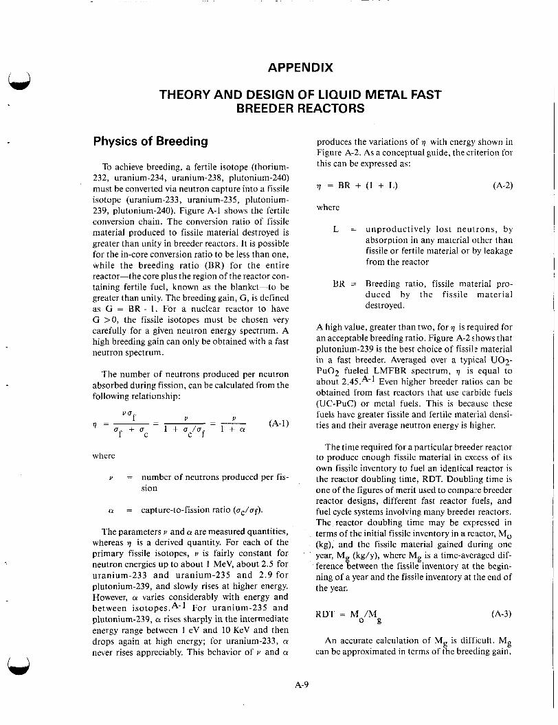
APPENDIX
THEORY AND DESIGN OF LIQUID METAL FAST BREEDER REACTORS
Physics of Breeding
To achieve breeding, a fertile isotope (thorium- 232, uranium-234, uranium-238, plutonium-240) must be converted via neutron capture into a fissile isotope (uranium-233, uranium-235, plutonium- 239, plutonium-240). Figure A-1 shows the fertile conversion chain. The conversion ratio of fissile material produced to fissile material destroyed is greater than unity in breeder reactors. It is possible for the in-core conversion ratio to be less than one, while the breeding ratio (BR) for the entire reactor-the core plus the region of the reactor con- taining fertile fuel, known as the blanket-to be greater than unity. The breeding gain, G, is defined as G = BR - 1. For a nuclear reactor to have G >0, the fissile isotopes must be chosen very carefully for a given neutron energy spectrum. A high breeding gain can only be obtained with a fast neutron spectrum.
The number of neutrons produced per neutron absorbed during fission, can be calculated from the following relationship:
where
v = number of neutrons produced per fis- sion
CY = capture-to-fission ratio (ac/af).
The parameters v and CY are measured quantities, whereas 7 is a derived quantity. For each of the primary fissile isotopes, v is fairly constant for neutron energies up to about 1 MeV, about 2.5 for uranium-233 and uranium-235 and 2.9 for plutonium-239, and slowly rises at higher energy. However, CY varies considerably with energy and between isotopes.*-l For uranium-235 and plutonium-239, a rises sharply in the intermediate energy range between 1 eV and 10 KeV and then drops again at high energy; for uranium-233, a never rises appreciably. This behavior of v and CY
produces the variations of 7 with energy shown in Figure A-2. As a conceptual guide, the criterion for this can be expressed as:
7 = BR + (1 + L) 64-21
where
L = unproductively lost neulrons, by absorption in any material other than fissile or fertile material or by leakage from the reactor
BR = Breeding ratio, fissile material pro- duced by the fissile material destroyed.
A high value, greater than two, for 7 is required for an acceptable breeding ratio. Figure A-2 shows that plutonium-239 is the best choice of fissi18: material in a fast breeder. Averaged over a typical U02- P u 0 2 fueled LMFBR spectrum, 7 is equal to about 2.45.A-1 Even higher breeder ratios can be obtained from fast reactors that use carbide fuels (UC-PuC) or metal fuels. This is because these fuels have greater fissile and fertile material densi- ties and their average neutron energy is higher.
The time required for a particular breeder reactor to produce enough fissile material in excess of its own fissile inventory to fuel an identical reactor is the reactor doubling time, RDT. Doubling time is one of the figures of merit used to compare breeder reactor designs, different fast reactor fuels, and fuel cycle systems involving many breeder reactors. The reactor doubling time may be expressed in terms of the initial fissile inventory in a re,actor, Mo (kg), and the fissile material gained during one year, M (kg/y), where Mg is a time-averaged dif- ference tetween the fissile inventory at the begin- ning of a year and the fissile inventory at the end of the year.
RDT = Mo/M (A-3) g
An accurate calculation of Mg is difficult. Mg can be approximated in terms of the breeding gain,
A- 9
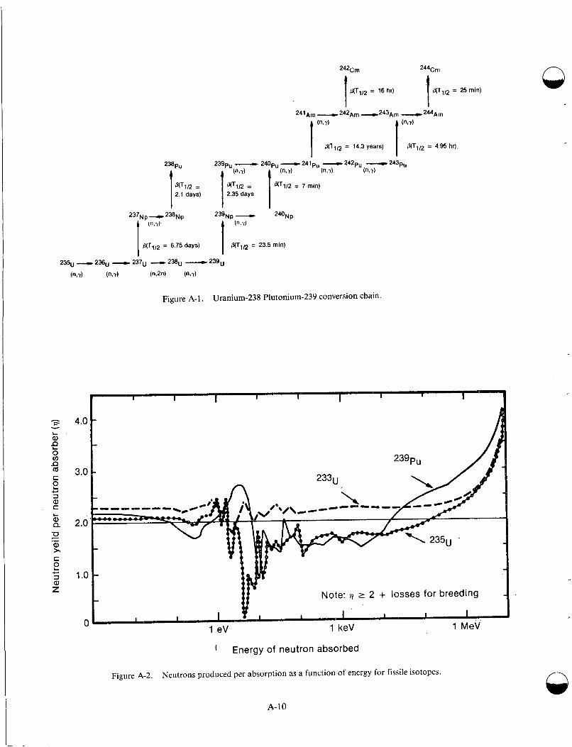
2%PU
N112 = 2.1 days) 1
237Np -238Np (",?)
B(TlI2 = 6.75 days) I
h - d
0(TlI2 = 4.95 hr) 1 (n,u)
O(TlI2 = 14.3 years)
L a, Q
2 .- a, > c 2 c 3 a, z
Figure A-1 . Uranium-238 Plutonium-239 conversion chain.
4.0
3.0
2.0
1 .o Note: 17 2 2 + losses for breeding
0
1 Energy of neutron absorbed
Figure A-2. Neutrons produced per absorption as a function of energy for fissile isotopes.
A-10

. . - - -. . . . . .. .. . . . . . . . . . . . . . . . . . . . . . . . . . . . . . . . . . . . . . . . . . . . . . , .
G, reactor power in megawatts, P, fraction of time at rated power, f, and a as
(A-4)
hence,
2.7 M
GPf (1 + a ) (A-5) 0 . RDT =
The doubling time is then measured in years and is proportional to the fissile specific inventory, Mo/P, and inversely proportional to the breeding gain, G. Although Equation (A-5) is a simple model and has no provisions for time spent by the fuel in the fuel cycle outside the reactor, fuel cycle losses, fissions in fertile material, and variations during the burnup cycle, it describes the sensitivity of the doubling time to the breeding gain and fissile specific inventory. More exact definitions of the doubling time, includ- ing system or fuel cycle inventory doubling time and compound system doubling time for equilibrium fuel cycles, are described in References A-2, A-3.
Major Design Objectives
The principal goals of breeder reactor design are safe operation, high breeding ratio, low doubling time, and low cost. Safe operations, in terms of design objectives, prescribe a conscious awareness of safety at every stage of design, and the attendant provision of reliable components and adequate safety margins for all normal and off-normal oper- ations. A high breeding ratio is needed to reduce fuel doubling time. Fuel doubling times must be shorter than the doubling time of increasing electri- cal demand. Another important objective of any energy generating system is low cost. Overall fuel cycle considerations are of paramount importance. High burnup optimizes the use of high-fissile fuel and minimizes down time for refueling. An addi- tional cost objective is the coordination of the breeder fuel cycle with that of the light water reac- tor (LWR) cycle. Minimizing capital cost, which is directly related to hardware requirements, puts a premium on systems that require the least expensive capital equipment commensurate with meeting the criteria for a safe and reliable operation. The spe- cific reactor design objectives required to accom- plish these goals are listed in Table A-I.
'
Mechanical and Thermal Systems Design
This section provides brief descriptions of core and blanket arrangements, fuel configurations, vessel internals, heat transfer systems, shielding, instrumentation, and auxiliary systems. Discus- sions relate to several design operations presently being used or under consideration for us(:.
Core and Blanket Arrangements. Two choices exist regarding the arrangement of fertile and fissile fuels in the reactor to optimize breeding potential. In the external breeding concept, all fertile material is contained in the blanket surrounding the core; hence, all breeding takes place external tci the core. In the internal, or in-core breeding concept, some fertile fuel pins are interspaced with fissile fuel within the core fuel economics. Figure A-3. illus- trates the two choices.
The external breeding configuration results in a very hard spectrum, a low fissile inventory, and a good breeding ratio. Lack of in-core breeding results in a rapid reactivity loss with burnup, which requires frequent fuel changes, low burnup, a small doppler effect, few fast fissions in fertile material, a high fissile enrichment, and a thick bl;mket.A-4 Thus, design of prototype and demonstration LMFBRs allows for considerable internal or in- core breeding.
Internal breeding core designs can be either homogeneous or heterogeneous. Figure A-4 shows top and side views of typical homogeneou!; and het- erogeneous core designs . Figure A-4a exemplifies a homogeneous core design because all of' the fuel assemblies containing pure fertile fuel are located in the radial and axial blanket regions. Therefore, a relatively uniform or homogeneous mixture of fis- sile and fertile fuel is spread throughout the core. The central region indicates the core itself, which contains the initial load of fissile/fertile fuel. The outer region represents the radial blanket and shielding arrangement. The core typically contains two enrichment zones. The outer zone incorporates a higher fissile fuel content than the inner zone in order to effect a flatter radial power distribution. Control rods are normally boron-10, in the form of B4C.
A-1 1
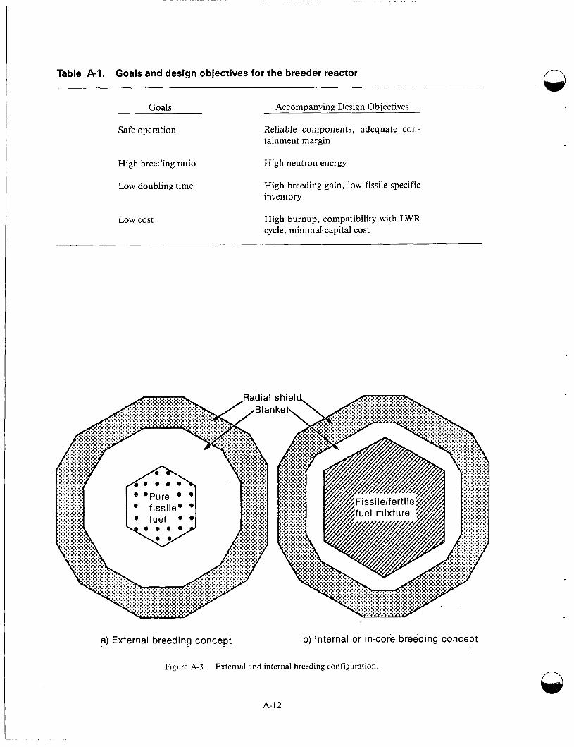
Table A-1. Goals and design objectives for the breeder reactor
Goals
Safe operation
High breeding ratio
Low doubling time
Low cost
Accompanying Design Objectives
Reliable components, adequate con- tainment margin
High neutron energy
High breeding gain, low fissile specific inventory
High burnup, compatibility with LWR cycle, minimal capital cost
a) External breeding concept b) Internal or in-core breeding concept
Figure A-3. External and internal breeding configurat ion.
A-12
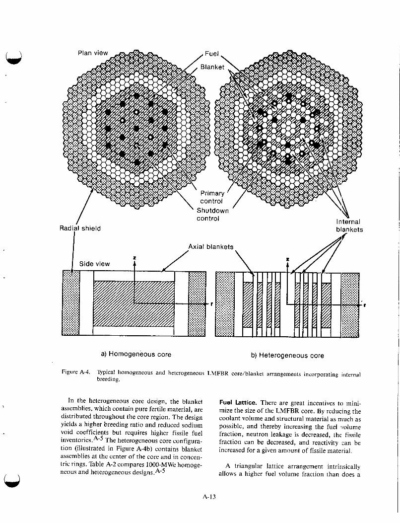
/ I
Radial shield1 control Internal
blankets
a) Homogeneous core b) Heterogeneous core
Figure A-4. Typical homogeneous and heterogeneous LMFBR core/blanket arrangements incorporating internal breeding.
In the heterogeneous core design, the blanket assemblies, which contain pure fertile material, are distributed throughout the core region. The design yields a higher breeding ratio and reduced sodium void coefficients but requires higher fissile fuel i n ~ e n t o r i e s . ~ - ~ The heterogeneous core configura- tion (illustrated in Figure A-4b) contains blanket assemblies at the center of the core and in concen- tric rings. Table A-2 compares 1000-MWe homoge- neous and heterogeneous designs .A-5
Fuel Lattice. There are great incentives to mini- mize the size of the LMFBR core. By reducing the coolant volume and structural material as niuch as possible, and thereby increasing the fuel volume fraction, neutron leakage is decreased, the fissile fraction can be decreased, and reactivity can be increased for a given amount of fissile material.
A triangular lattice arrangement intrinsically allows a higher fuel volume fraction than does a
A-13

Table A-2. Comparison of homogeneous and heterogeneous cores [IOOO-MW(e) designla
Homogeneous Heterogeneous
Number of fuel assembliesb 276 252
Number of in-core blanket assemblies - 97
Number of ex-core blanket assembliesC 168 144
Number of control assemblies 19 18
Number of enrichment zones
Fissile mass (kg)
Pu fraction by zone (wt%)
3 1
3682 4524
13.5/14.9/20.3 20.2
a. From Reference A-4.
b.
c.
271 pins/fuel assembly, 1.22-m core height, 7.9-mm pin diameter, 0.36-m axial blankets.
127 pindblanket assembly, 12-mm pin diameter.
square lattice. The higher fuel volume fraction min- imizes fissile loading mainly by reducing neutron leakage from the reactor. The triangular lattice or hexagonal structure has been selected for breeder reactor design. An LWR typically employs a square lattice because relatively larger spaces between fuel rods are needed to optimize the water-to-fuel ratio. The square lattice provides the space with relatively easy mechanical assembly.
Fuel Assembly. For the standard triangular pitch lattice, the pins are separated by a spiral wire wrap and assembled as a cluster of 217 pins within an assembly Alternatively, grid spacers can be used to separate the fuel pins. Fuel pellets make up the active core region, and blanket pellets pro- vide the axial boundaries. Fission gas plenums can be above or below the upper blanket region. Figure A-5 shows the geometric arrangement of the fuel, structure, and coolant. A table in the figure references the relationship between concentric (hexagonal) rows of pins and the number of pins in an assembly.
Vessel Internals. The core of an LMFBR is located on top of a core support structure, which is
normally hung from the reactor vessel, or reactor tank, as shown in Figure A-6. An LMFBR does not require pressurization to keep the coolant in a liq- uid state; outlet pressures are near atmospheric. Consequently, the reactor vessel need only be thick enough to satisfy standard weight-bearing struc- tural and safety requirements. A typical thickness may be on the order of 30 mm, as compared to 300 mm for LWR systems.
Assemblies are slotted into positioning holes in the core support structure, and radial core restraints are normally provided at two axial loca- tions. These locations are generally just above the active core near the top of the assemblies. Control rods enter from the top of the core, with the drive mechanisms located atop the vessel closure head. The vessel normally hangs from a support ledge, and the head is bolted to this structure. However, several variations in vessel support design have been used.
Sodium enters the lower inlet plenum, traverses up through the core and blanket regions, and col- lects in a large reservoir above the core before exit- ing to the intermediate heat exchanger (IHX). An
n
A-14
C

V (See enlargement below)
Row 2
Fuel assembly cross section
Pin
blanket '
Bottom - end cap
Driver fuel pin Subassembly
L
Fuel pin -7 diameter '
' y., ROY 2 ROW 1
row
1 2 3 4 5 6 7 8 9
-
10
12 1/12 assembly cutaway 11
Pins Total per row pins
1 1 6 7
12 19 18 27 24 61 30 91 36 127 42 169 48 21 7
a 54 271 60 331 66 397
Figure A-5. Typical LMFBR fuel assembly system.
inert gas, usually argon, separates the sodium pool from the closure head.
pool system, the second the loop system. In the loop system, there is a sequential series of compo- nents between the reactor and the turbine:, each
System Heat Transfers
Pool and Loop System. Neutron activation of the sodium coolant in the primary heat transport sys- tem of an LMFBR requires that a secondary or intermediate heat transport system also be employed.
Two different arrangements have been devised to accomplish this; the IHX and the primary pump can be located inside the reactor tank, or they can be in adjacent hot cells with pipes connecting them to the reactor vessel. The first option is called the
operating independently of the other loops in the system. Each loop consists of a single primary and secondary pump and one or more IHXs and sec- ondary sodium system; there is no requirement that the number of primary pumps and loops be the same. Figure A-7 illustrates the heat transport sys- tems for both the loop and pool designs. Table A-3 lists the systems selected for different plant designs. LMFBRs using the pool design include EBR-11, PHENIX, PFR, BN-600, Super PHENIX, CDFR, and BN-1600. Those using the loop design include DFR, Fermi, Rapsodie, BOR-60, KNK-2, IFBTR,
CRBRP, and SNR-2. JOYO, FFTF, PEC, BN-350, SNR-300, MONJU,
A-15
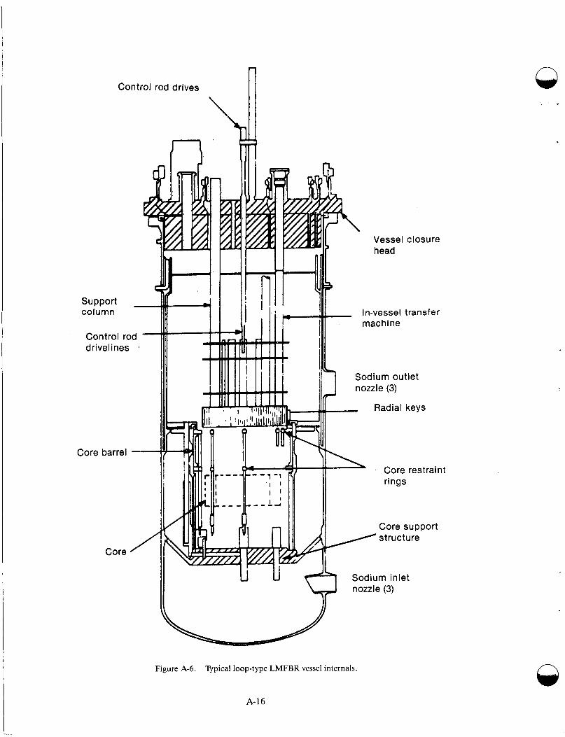
a Control rod drives
n
1
n
Sodium inlet nozzle (3)
Figure A-6. Typical loop-type LMFBR vessel internals.
A-16

- C 1 --111---
Tu rb i ne
Figure A-7. LMFBR heat transport system.
Primary Pump 3 -
- r 1
There are advantages to both the loop and pool design. Loop designs include the following:
system I I I
---------I
Maintenance is simpler because compo- nents can be isolated in cells. The feature also allows greater flexibility in making system modifications and providing main- tenance during reactor operation.
f ,
Core
Less neutron shielding is required to pre- v e n t n e u t r o n a c t i v a t i o n of t h e s e c o n d a r y shielding.
Steam generator
The structural design of the vessel head is simpler than the deck roof of a pool reactor.
The larger difference in vertical elevation of the IHX relative to the core in loop design enhances natural circulation over that of pool design. The difference allows more reliable prediction of the natural cir- culation in the primary coolant flow path.
Because of the smaller mass of sodium in the primary system in the loop design, there is a quicker response of the secondary sodium and steam sys- tems to changes in the reactor and the primary sodium system. This influences the control and load following characteristics of the overall heat
A-17
transport and steam system. Whether thi,s is a net advantage relative to pool design is still unclear.A-6
Advantages of the pool design are as follows:
There is lower probability of a primary sys- tem being broken
Leakage of primary system components and piping does not result in leakage from t h e p r i m a r y s y s t e m o u t s i d e the: r e a c t o r tank
Sodium mass in the primary system is about three times that in a loop design, 'thus pro- viding three times the heat capacity
Temperature rise during off-normal tran- sients is lower and time to reach boiling is longer if a heat sink is isolated
The pool's large thermal inertia tends to dampen transient thermal effects in other parts of the system
The cover gas system can be simpler, because the only free surface need8:d is that in the tank, an exception being the super PHENIX, where an actively controlled
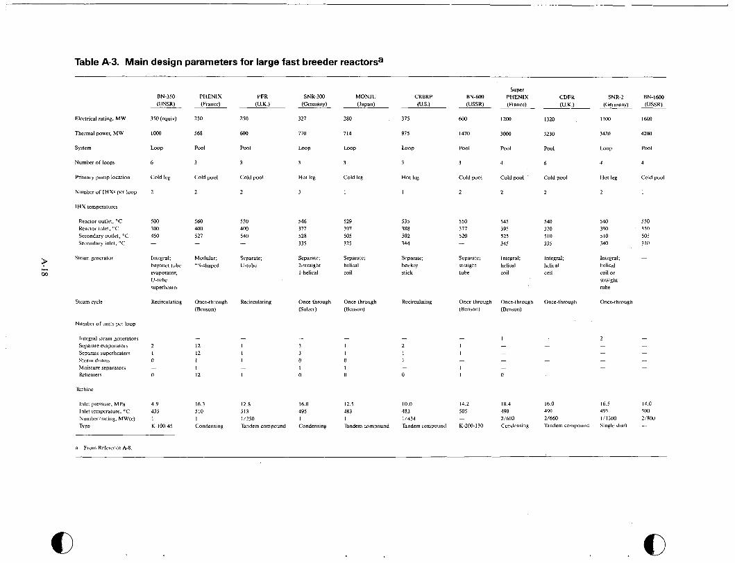
Table A-3. Main design parameters for large fast breeder reactorsa
Electrical rating, MW
Thermal power, MW
System
Number of loops
Primary pump location
Number of IHXs per loop
I H X temperatures
Reactor outlet, "C Reactor inlet, "C Secondary outlet, "C Secondary inlet, "C
Steam generator 9 L
m
Steam cycle
Number of units per loop
Integral steam generators Separate evaporators Separate superheaters Steam drums Moisture separators Reheaters
Turbinc
Inlet pressure, MPa Inlet temperature, "C Number/rating, MW(e) Type
BN-350 (USSR)
350 (equiv)
1000
LOOP
6
Cold leg
2
500 300 450 -
Integral; bayonet tube evaporator, U-tube superheater
Recirculating
~
2 I 0
0 -
4.9 435 I K-100-45
PHENIX (France)
250
568
Pool
3
Cold pool
2
560 400 527 -
Modular; "S-shaped
Once-through (Benson)
-
I2 12 I I 12
16.3 510 I Condensing
PFR (U.K.)
250
600
Pool
3
Cold pool
2
550 400 540 -
Separate; U-tube
Recirculating
-
I I I
I -
12.8 513 11250 Tandem comoound
SNR-300 (Germany)
327
770
LOOP
3
Hot leg
3
546 377 528 335
Separate; 2-straight I-helical
Once-through (Sulzer)
-
3 3 0 I 0
16.0 495 I Condensing
MONJU (Japan)
280
714
LOO0
3
Cold leg
1
529 397 505 325
Separate; helical coil
Once-through (Benson)
-
I I 0 1 0
12.5 483 1 Tandem comoound
CRBRP (US.)
375
91 5
LOOP
3
Hot leg
I
535 388 502 344
Separate; hockey stick
Recirculating
L
1 1
0 -
10.0 483 1/434 Tandem comvound
Super BN-MX) PHENIX (USSR) (France)
600 I200
1470 3000
Pool Pool
3 4
Cold pool Cold pool
2 2
550 545 377 395 520 525
345 -
Separate; Integral; straight helical tube coil
Once-through Once-through (Benson) (Benson)
14.2 18.4 505 490 - 2/600 K-200-130 Condensing
CDFR (U.K.)
1320
3230
Pool
6
Cold pool
2
540 370 510 335
Integral; helical coil
Once-through
16.0 490 2/660 Tandem compound
SNR-2 BN-I600 (Germany) IUSSR) ~-
I300 1600
3420 4200
LOOP Pool
4 4
Hot leg Cold pool
2 1
540 550 390 350 510 505 340 310
Integral; helical coil or straight tube
Once-through -
16.5 14.0 495 500 1/1300 2/R00 Single shaft -
a. From Reference A-8.
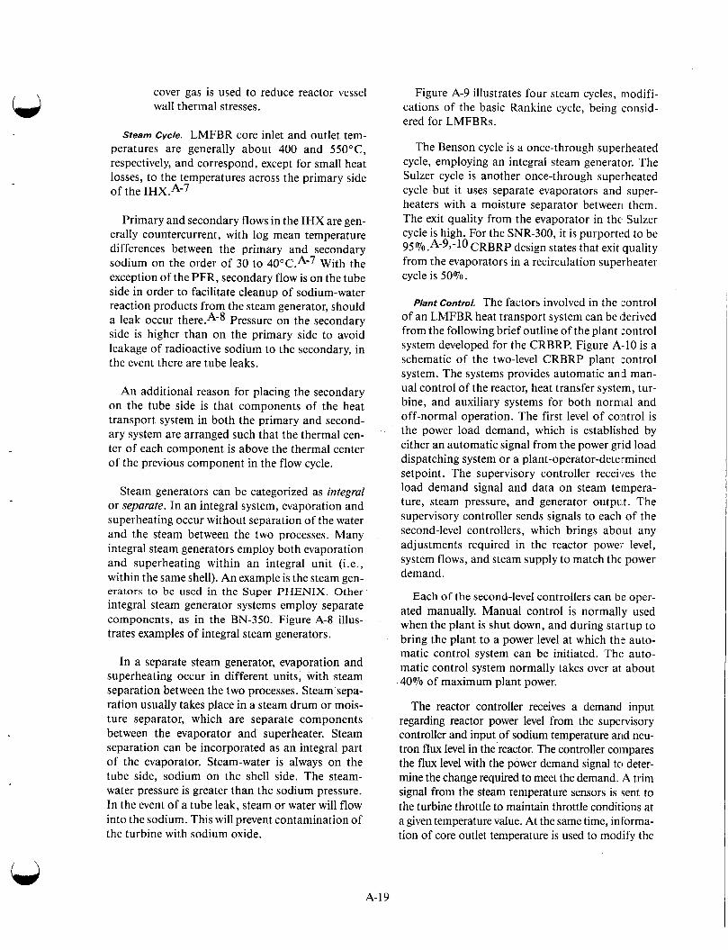
cover gas is used to reduce reactor vessel wall thermal stresses.
Steam cycle. LMFBR core inlet and outlet tem- peratures are generally about 400 and 550°C, respectively, and correspond, except for small heat losses, to the temperatures across the primary side of the IHX.A-7
Primary and secondary flows in the IHX are gen- erally countercurrent, with log mean temperature differences between the primary and secondary sodium on the order of 30 to 40°C.A-7 With the exception of the PFR, secondary flow is on the tube side in order to facilitate cleanup of sodium-water reaction products from the steam generator, should a leak occur Pressure on the secondary side is higher than on the primary side to avoid leakage of radioactive sodium to the secondary, in the event there are tube leaks.
An additional reason for placing the secondary on the tube side is that components of the heat transport system in both the primary and second- ary system are arranged such that the thermal ten- ter of each component is above the thermal center of the previous component in the flow cycle.
Steam generators can be categorized as integral or separate. In an integral system, evaporation and superheating occur without separation of the water and the steam between the two processes. Many integral steam generators employ both evaporation and superheating within an integral unit (i.e., within the same shell). An example is the steam gen- erators to be used in the Super PHENIX. Other integral steam generator systems employ separate components, as in the BN-350. Figure A-8 illus- trates examples of integral steam generators.
In a separate steam generator, evaporation and superheating occur in different units, with steam separation between the two processes. Steam sepa- ration usually takes place in a steam drum or mois- ture separator, which are separate components between the evaporator and superheater. Steam separation can be incorporated as an integral part of the evaporator. Steam-water is always on the tube side, sodium on the shell side. The steam- water pressure is greater than the sodium pressure. In the event of a tube leak, steam or water will flow into the sodium. This will prevent contamination of the turbine with sodium oxide.
Figure A-9 illustrates four steam cycles, modifi- cations of the basic Rankine cycle, being consid- ered for LMFBRs.
The Benson cycle is a once-through superheated cycle, employing an integral steam generator. The Sulzer cycle is another once-through superheated cycle but it uses separate evaporators and super- heaters with a moisture separator between them. The exit quality from the evaporator in the: Sulzer cycle is high. For the SNR-300, it is purported to be 95%.A-93-10 CRBRP design states that exit quality from the evaporators in a recirculation superheater cycle is 50%.
Plant Control. The factors involved in the control of an LMFBR heat transport system can be (derived from the following brief outline of the plant control system developed for the CRBRP. Figure A-10 is a schematic of the two-level CRBRP plant control system. The systems provides automatic and man- ual control of the reactor, heat transfer system, tur- bine, and auxiliary systems for both normal and off-normal operation. The first level of control is the power load demand, which is established by either an automatic signal from the power grid load dispatching system or a plant-operator-determined setpoint. The supervisory controller receives the load demand signal and data on steam tempera- ture, steam pressure, and generator output. The supervisory controller sends signals to each of the second-level controllers, which brings about any adjustments required in the reactor power level, system flows, and steam supply to match the power demand.
Each of the second-level controllers can be oper- ated manually. Manual control is normally used when the plant is shut down, and during startup to bring the plant to a power level at which the auto- matic control system can be initiated. The auto- matic control system normally takes over at about 40% of maximum plant power.
The reactor controller receives a demand1 input regarding reactor power level from the supervisory controller and input of sodium temperature arid neu- tron flux level in the reactor. The controller coinpares the flux level with the power demand signal to deter- mine the change required to meet the demand. A trim signal from the steam temperature sensors is sent to the turbine throttle to maintain throttle conditions at a given temperature value. At the same time, in forma- tion of core outlet temperature is used to modlify the
A-19
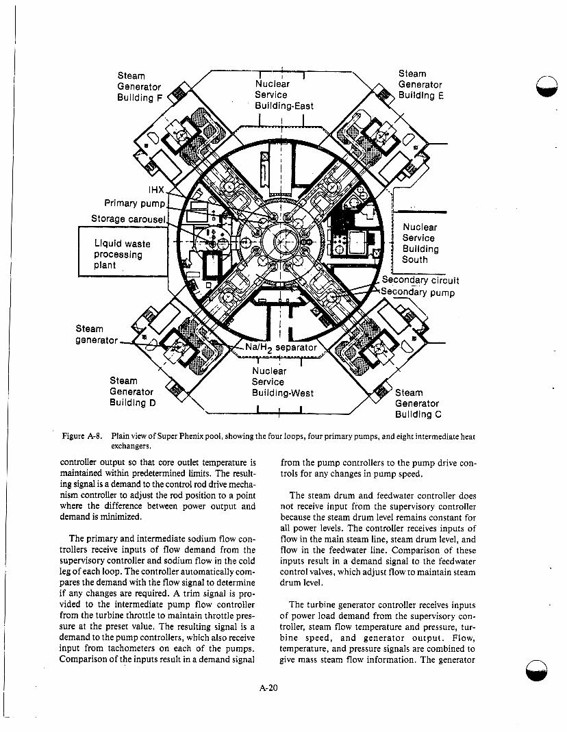
Figure A-8. Plain view of Super Phenix pool, showing the four loops, four primary pumps, and eight intermediate heat
controller output so that core outlet temperature is from the pump controllers to the pump drive con- maintained within predetermined limits. The result- trols for any changes in pump speed.
exchangers.
ing signal is a demand to the control rod drive mecha- nism controller to adjust the rod position to a point where the difference between power output and demand is minimized.
The steam drum and feedwater controller does not receive input from the supervisory controller because the steam drum level remains constant for all power levels. The controller receives inputs of
The primary and intermediate sodium flow con- trollers receive inputs of flow demand from the supervisory controller and sodium flow in the cold leg of each loop. The controller automatically com- Dares the demand with the flow signal to determine
flow in the main steam line, steam drum level, and flow in the feedwater line. Comparison of these inputs result in a demand signal to the feedwater control valves, which adjust flow to maintain steam drum level.
if any changes are required. A trim signal is pro- vided to the intermediate pump flow controller from the turbine throttle to maintain throttle pres- sure at the preset value. The resulting signal is a demand to the pump controllers, which also receive input from tachometers on each of the pumps. Comparison of the inputs result in a demand signal
The turbine generator controller receives inputs of power load demand from the supervisory con- troller, steam flow temperature and pressure, tur- bine speed, and generator ou tput . Flow, temperature, and pressure signals are combined to give mass steam flow information. The generator
A-20
-
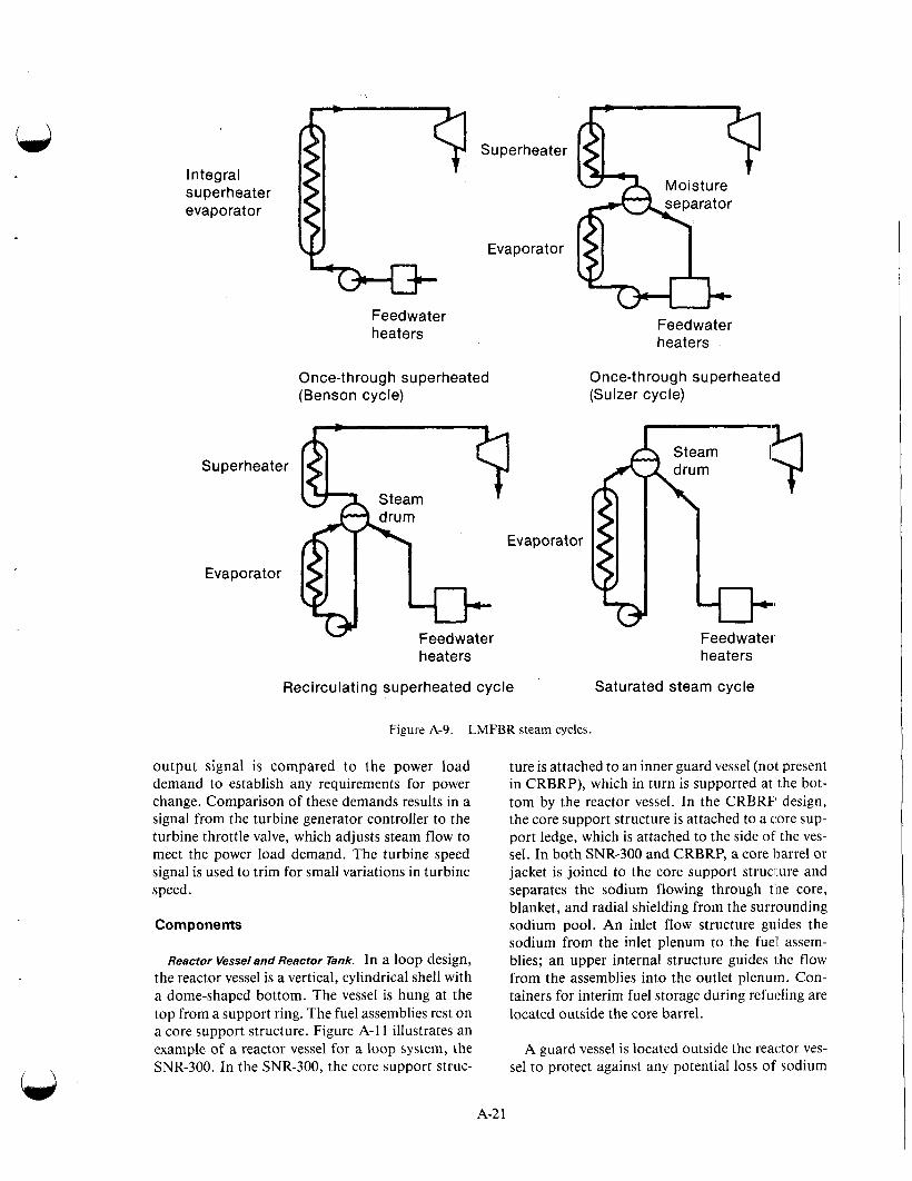
Integral superheater evaporator
Feedwater heaters
Once-throug h superheated (Benson cycle)
Steam
Superheater
Evaporator
Feedwater heaters
Evaporator
Feedwater heat e rs
Once-t hrough superheated (Sulzer cycle)
I Feed w a t e I' heaters
Recirculating superheated cycle Saturated steam cycle
Figure A-9. LMFBR steam cycles.
output signal is compared to the power load demand to establish any requirements for power change. Comparison of these demands results in a signal from the turbine generator controller to the turbine throttle valve, which adjusts steam flow to meet the power load demand. The turbine speed signal is used to trim for small variations in turbine speed.
Components
Reactor Vesseland Reactor Tank. In a loop design, the reactor vessel is a vertical, cylindrical shell with a dome-shaped bottom. The vessel is hung at the top from a support ring. The fuel assemblies rest on a core support structure. Figure A-1 1 illustrates an example of a reactor vessel for a loop system, the SNR-300. In the SNR-300, the core support struc-
ture is attached to an inner guard vessel (not present in CRBRP), which in turn is supported at the bot- tom by the reactor vessel. In the CRBRF' design, the core support structure is attached to a tore sup- port ledge, which is attached to the side of the ves- sel. In both SNR-300 and CRBRP, a core barrel or jacket is joined to the core support struci.ure and separates the sodium flowing through the core, blanket, and radial shielding from the surrounding sodium pool. An inlet flow structure guides the sodium from the inlet plenum to the fuel assem- blies; an upper internal structure guides 1 he flow from the assemblies into the outlet plenum. Con- tainers for interim fuel storage during refueling are located outside the core barrel.
A guard vessel is located outside the reactor ves- sel to protect against any potential loss of sodium
A-2 1
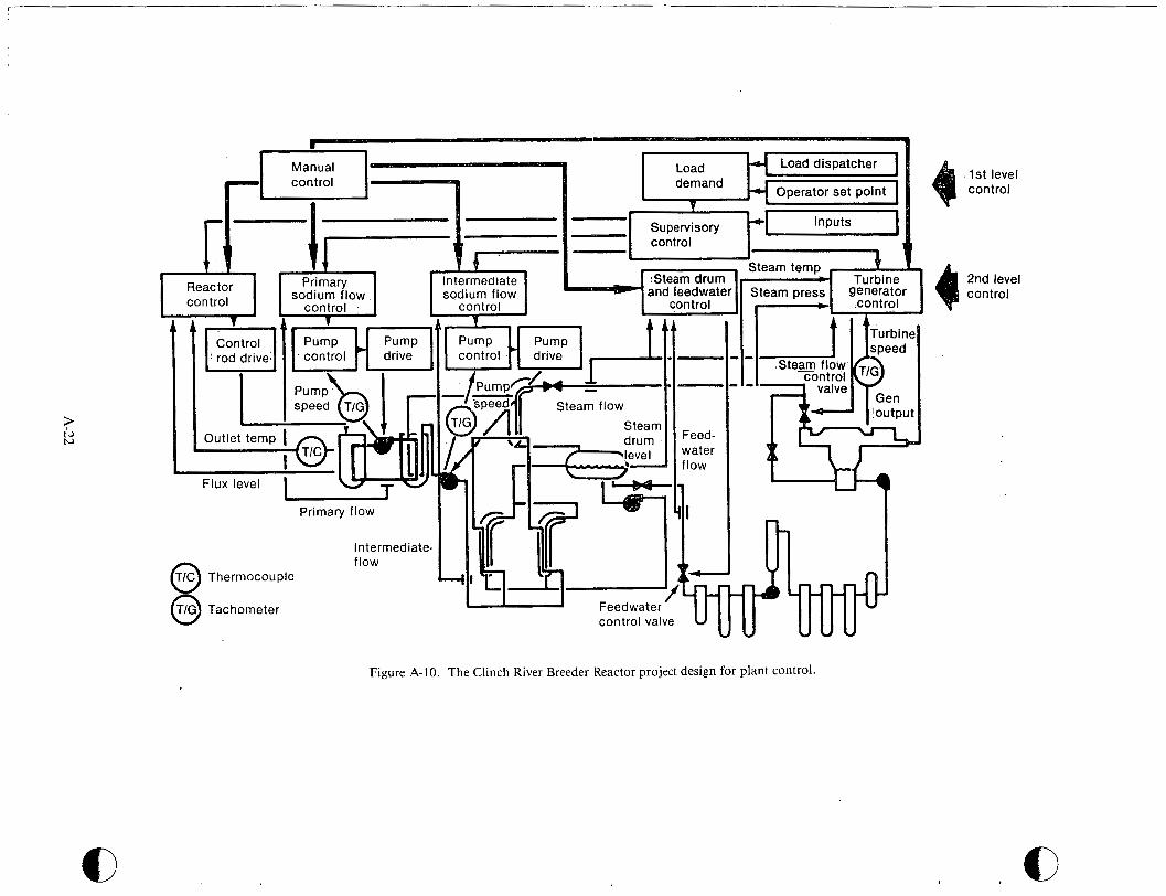
Primary flow
Intermediate- TIC Thermocouple - 1 flow 0 0 TIG Tachometer
Steam press :L
1st level control
2nd level control
Figure A-10. The Clinch River Breeder Reactor project design for plant control.
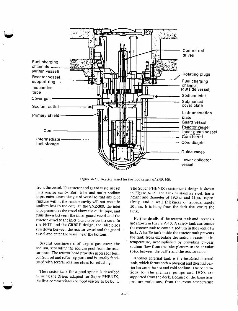
Figure A-1 1 . Reactor vessel for the loop system of SNR-300.
from the vessel. The reactor and guard vessel are set in a reactor cavity. Both inlet and outlet sodium pipes enter above the guard vessel so that any pipe rupture within the reactor cavity will not result in sodium loss to the core. In the SNR-300, the inlet pipe penetrates the vessel above the outlet pipe, and runs down between the inner guard vessel and the reactor vessel to the inlet plenum below the core. In the FFTF and the CRBRP design, the inlet pipes run down between the reactor vessel and the guard vessel and enter the vessel near the bottom.
Several centimeters of argon gas cover the sodium, separating the sodium pool from the reac- tor head. The reactor head provides access for both control rod and refueling ports and is usually fabri- cated with several rotating plugs for refueling;
The reactor tank for a pool system is described by using the design adapted for Super PHENIX, the first commercial-sized pool reactor to be built.
Control roc1 drives
Rotating plugs
Fuel charging ~
channel (outside vessel)
Sodium inlet Submersed cover plate
Instrumentation plate GuGd v<SS~EF ~
Reactor ~ ~ ve5;sel Inner guard1 vess Core barre I Core diagritl
Guide vanes
Lower collector vessel
el
The Super PHENIX reactor tank design is shown in Figure A-12. The tank is stainless steel, has a height and diameter of 19.5 m and 21 m, respec- tively, and a wall thickness of approxiinately 50 mm. It is hung from the deck that covm the tank.
Further details of the reactor tank and ini:ernals are shown in Figure A-13. Asafety tank surrounds the reactor tank to contain sodium in the event of a leak. A baffle tank inside the reactor tank prevents the tank from exceeding the sodium reactor inlet temperature, accomplished by providing by-pass sodium flow from the inlet plenum to the aiinular space between the baffle and the reactor tanks.
Another internal tank is the insulated internal tank, which forms both a physical and thermal bar- rier between the hot and cold sodium. The penetra- tions for the primary pumps and IHXs are supported from the deck. Because of the large tem- perature variations, from the room temperature
A-23
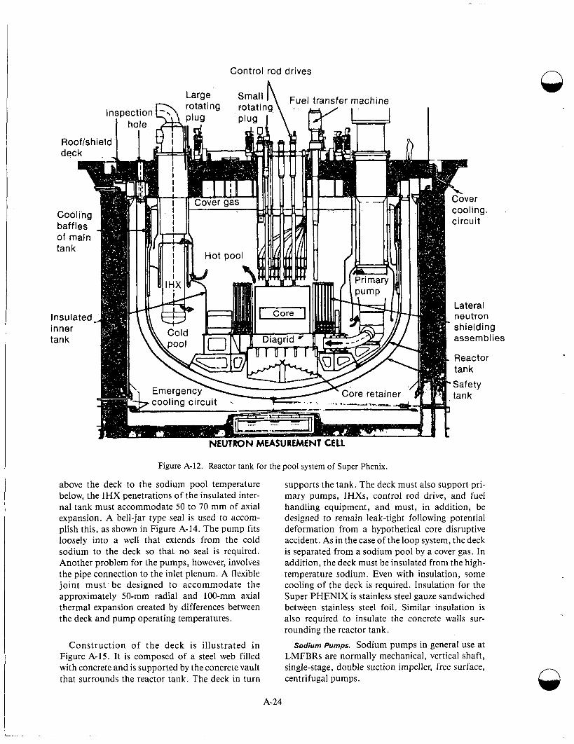
Control rod drives n
Figure A-12. Reactor tank for the pool system of Super Phenix.
above the deck to the sodium pool temperature below, the IHX penetrations of the insulated inter- nal tank must accommodate 50 to 70 mm of axial expansion. A bell-jar type seal is used to accom- plish this, as shown in Figure A-14. The pump fits loosely into a well that extends from the cold sodium to the deck so that no seal is required. Another problem for the pumps, however, involves the pipe connection to the inlet plenum. A flexible joint must be designed to accommodate the approximately 50-mm radial and 100-mm axial thermal expansion created by differences between the deck and pump operating temperatures.
supports the tank. The deck must also support pri- mary pumps, IHXs, control rod drive, and fuel handling equipment, and must, in addition, be designed to remain leak-tight following potential deformation from a hypothetical core disruptive accident. As in the case of the loop system, the deck is separated from a sodium pool by a cover gas. In addition, the deck must be insulated from the high- temperature sodium. Even with insulation, some cooling of the deck is required. Insulation for the Super PHENIX is stainless steel gauze sandwiched between stainless steel foil, Similar insulation is also required to insulate the concrete walls sur- rounding the reactor tank.
Construction of the deck i s ' illustrated in Sodium Pumps. Sodium pumps in general use at LMFBRs are normally mechanical, vertical shaft, single-stage, double suction impeller, free surface, centrifugal pumps.
Figure A-15. It is composed of a steel web filled with concrete and is supported by the concrete vault that surrounds the reactor tank. The deck in turn
A-24

In a pool system, the primary pump i,; always located in the cold sodium. In a loop system, how- ever, location of the primary pump can be either on the hot or the cold leg. The pump is located in the cold leg of all secondary systems because the advantages of a hot leg location existing for the pri- mary loop are not present and also because it is important to pressurize the secondary sodium in the IHX in order to force flow from leaking tubes in the direction from the nonradioactive secondary to the radioactive primary.
l
In the loop design, there are some obvious advantages to seals and bearings, for exarnple, of placing the primary pump in the colder sodium environment of the cold leg. This was Idone in MONJU, BN-350, and most of the early experi- mental loop reactors. The hot leg has been selected for several loop designs, SNR-300, SNR-2, FFTF, and CRBRP. The main reason for choosing the hot leg involves suction requirements for primary sys- tem pumps. These requirements are stringent to accommodate the full range of anticipated tran- sients. The basic argument can be explained briefly, however, by examining conditions during normal steady state operation.
Figure A-13. Details of the Super Phenix reactor tank and internals.
Choices affecting pump design involve differ- ences between primary pumps for the loop and pool systems, minor differences between primary and secondary pumps, and pump location. Impor- tant design choices include seal, bearings, impeller, and by-pass flow arrangements.
Electromagnetic pumps have also been used for LMFBRs, because sodium is an excellent electrical conductor. An electromagnetic pump is being used for the secondary sodium in EBR-11, and they have been used in SEFOR, in the primary circuit of the Dounreay fast reactor, and in the SLSF test train at ETR in Idaho. They are not used in the main loops in large LMFBR power plants, but they are being used in some back-up decay heat removal systems, for example in SNR-300 and Super PHENIX.
Only mechanical pumps are being used in large LMFBRs. Testing is underway in the United States on the use of a relatively small inducer-type mechanical pumping element in series with a large centrifugal pump to assist in meeting the strict suc- tion requirements of an LMFBR centrifugal pump.
The net positive suction head (NPSH) of a pump is the difference between the absolute pressure of the pump suction and the vapor pressure of the fluid pumped. Any pump has, inhereni. in its design, a minimum required NPSH at any given flow rate, to prevent cavitation. The available NPSH must, therefore, always be greater than this minimum value. The available NPSH can be obtained from the following relationship:
NPSH = H + H, - HI - Hv ('4-6) P
where
Hp = pressure at the liquid surface of the source from which the pump takes suction, in this case the cover gas pres- sure
H, = hydrostatic head of the liquid source above the impeller
H1 = pressure drop losses in the piping and equipment upstream of the pump
Hv = vapor pressure of the fluid at the suc- tion.
A-25
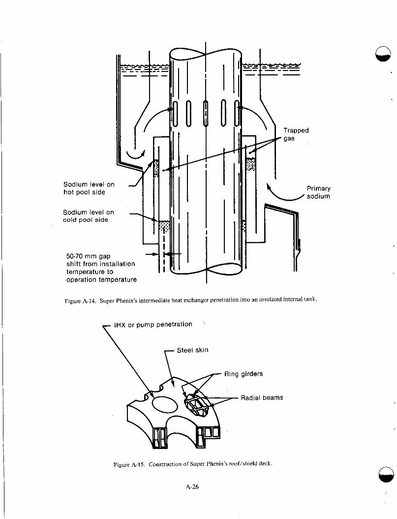
-1-
operation temperature I
Figure A-14. Super Phenix’s intermediate heat exchanger penetration into an insulated internal tank.
IHX or pump penetration ’\\ \ Steel skin
girders
Radial beams
Figure A-15. Construction of Super Phenix’s roof/shield deck
A-26
n
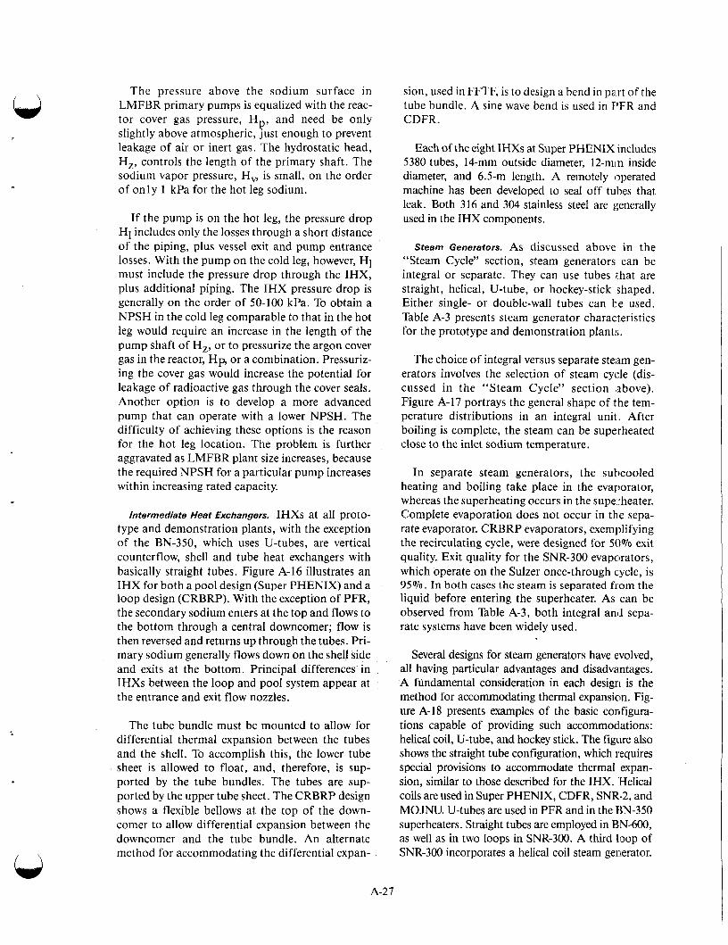
, \
The pressure above the sodium surface in LMFBR primary pumps is equalized with the reac- tor cover gas pressure, H and need be only slightly above atmospheric, just enough to prevent leakage of air or inert gas. The hydrostatic head, H,, controls the length of the primary shaft. The sodium vapor pressure, H , is small, on the order of only 1 kPa for the hot leg sodium.
P’
Intermediate Heat Exchangers. IHXs at all proto- type and demonstration plants, with the exception of the BN-350, which uses U-tubes, are vertical counterflow, shell and tube heat exchangers with basically straight tubes. Figure A-16 illustrates an IHX for both a pool design (Super PHENIX) and a loop design (CRBRP). With the exception of PFR, the secondary sodium enters at the top and flows to the bottom through a central downcomer; flow is then reversed and returns up through the tubes. Pri- mary sodium generally flows down on the shell side and exits at the bottom. Principal differences in IHXs between the loop and pool system appear at the entrance and exit flow nozzles.
If the pump is on the hot leg, the pressure drop Hi includes only the losses through a short distance of the piping, plus vessel exit and pump entrance losses. With the pump on the cold leg, however, HI must include the pressure drop through the IHX, plus additional piping. The IHX pressure drop is generally on the order of 50-100 kPa. To obtain a NPSH in the cold leg comparable to that in the hot leg would require an increase in the length of the pump shaft of H,, or to pressurize the argon cover gas in the reactor, H p or a combination. Pressuriz- ing the cover gas would increase the potential for leakage of radioactive gas through the cover seals. Another option is to develop a more advanced pump that can operate with a lower NPSH. The difficulty of achieving these options is the reason for the hot leg location. The problem is further aggravated as LMFBR plant size increases, because the required NPSH for a particular pump increases within increasing rated capacity.
A-27
The tube bundle must be mounted to allow for differential thermal expansion between the tubes and the shell. To accomplish this, the lower tube sheet is allowed to float, and, therefore, is sup- ported by the tube bundles. The tubes are sup- ported by the upper tube sheet. The CRBRP design shows a flexible bellows at the top of the down- comer to allow differential expansion between the downcomer and the tube bundle. An alternate method for accommodating the differential expan-
sion, used in FFTF, is to design a bend in pa.rt of the tube bundle. A sine wave bend is used in E’FR and CDFR.
Each of the eight IHXs at Super PHENIX includes 5380 tubes, 14-mm outside diameter, 12-min inside diameter, and 6.5-m length. A remotely operated machine has been developed to seal off tubes that leak. Both 316 and 304 stainless steel are generally used in the IHX components.
Steam Generators. AS discussed above in the “Steam Cycle” section, steam generators can be integral or separate. They can use tubes #that are straight, helical, U-tube, or hockey-stick shaped. Either single- or double-wall tubes can be used. Table A-3 presents steam generator characteristics for the prototype and demonstration plant:;.
The choice of integral versus separate steam gen- erators involves the selection of steam cycle (dis- cussed in the “Steam Cycle” section above). Figure A-17 portrays the general shape of the tem- perature distributions in an integral unit. After boiling is complete, the steam can be superheated close to the inlet sodium temperature.
In separate steam generators, the subcooled heating and boiling take place in the evaporator, whereas the superheating occurs in the superheater. Complete evaporation does not occur in the sepa- rate evaporator. CRBRP evaporators, exemplifying the recirculating cycle, were designed for 50% exit quality. Exit quality for the SNR-300 evapcrators, which operate on the Sulzer once-through cycle, is 95%. In both cases the steam is separated from the liquid before entering the superheater. As can be observed from Table A-3, both integral and sepa- rate systems have been widely used.
Several designs for steam generators have evolved, all having particular advantages and disadvantages. A fundamental consideration in each design is the method for accommodating thermal expansion. Fig- ure A-1 8 presents examples of the basic configura- tions capable of providing such accommodations: helical coil, U-tube, and hockey stick. The figure also shows the straight tube configuration, which requires special provisions to accommodate thermal expan- sion, similar to those described for the IHX. Helical coils are used in Super PHENIX, CDFR, SNR-2, and MOJNU. U-tubes are used in PFR and in the EIN-350 superheaters. Straight tubes are employed in BN-600, as well as in two loops in SNR-300. A third loop of SNR-300 incorporates a helical coil steam generator.

C 0
L
al n
* v) :: a 0 0
- a e? m
d u
0
Y
C a
al U
Q,
C
c
L
E
.a, ,
C
5!
?%
X
C
.- .-
r
.- o
x
c-
A-28
0
0 a
I.. W
a
s rn W
5
P I..
n
n

0 x2 x3
Figure A-17. Temperature distributions in an integral superheater.
Either helical coils or straight tubes will be used in SNR-2. In the United States, the hockey stick was selected and tested for the CRBRP. Design and devel- opment of both helical coil and straight tube designs are also underway. Another type of tube is used in the BN-350 evaporator called bayonet tubes. These tubes have a central tube surrounded by an annulus. Water flows down the central tube and a water-steam mix- ture flows back up the annulus.
Tube integrity is far more important for the LMFBR steam generator than for the LWR because of the potential chemical reaction between sodium and water. Early consideration was given to the use of double-walled tubes in which leaks could be detected from gas conditions between the two walls. Double-walled tubes are used, for example, in EBR-I1 and Dounreay fast reactor steam genera- tors. However, when experiments demonstrated that sodium-water reactions could be adequately contained, the emphasis shifted to the simpler single-wall tube design, and all prototype and dem- onstration plants now use a single-wall tube. Some interest in double-wall tubes is being revived, but the argument that they might lead to greater steam generator reliability was more especially important for the early generator plant. Whereas experience with LMFBR steam generators has been reasona- bly encouraging, BN-350, PFR, and the Fermi reactor have all experienced difficulties with leaks.
Most steam generators, both tube and shell, are made of ferrite steel containing 2.25% chromium and 1% molybdenum, selected to minimize chlo- ride stress corrosion. In some cases the material is stabilized with 1070 niobium to reduce carbon loss to the sodium. Exceptions to this are the selection of Incalloy-800@ for Super PHENIX, and the use
of austenitic stainless steel for the original PFR superheaters and reheaters.
An important condition in steam generator design is the transition between nucleate boiling and film boiling, or the departure from nucleate boiling. At this point, the temperature of the tube wall rises sharply and an instability in tube wall temperature occurs in the transition zone. This temperature behav- ior is illustrated schematically in Figure A-19. The transition occurs between X1 and X2. In this region, the tube wall is intermittently in contact with water or steam, and the wall temperature fluctuate rapidly. Such fluctuation, if too large a magnitude, can cause thermal fatigue of the tube, or structural changes that enhance water-side corrosion.
Shielding. Requirements for shield design are greater for fast reactors than for thermal reactors. The high energy neutron flux in an LMFI3R is con- siderably higher than in an LWR, as is the high- energy neutron leakage from the core. Although the neutron production rate for an LMFBR and LWR have the same power level, or are cornparable, the power density (kW per liter) is higher for the LMFBR. Also, the neutrons in an LWR are slowed down to thermal energies close to the fission source, so that the high-energy leakage source for radiation of surrounding structures is relatively low.
LMFBR shielding can be discussed according to areas that require extensive shielding analysis and design. For both pool and loop designs, these areas include in-vessel radial shielding, the closure head assembly and its penetrations, and neutron flux monitors. For pool designs, special attention is required for the intermediate heat exchangers, where secondary sodium can be activated by neu- trons. For loop designs, other key areas include the reactor vessel support area and the primary heat transport system pipeways. Other areas that require shielding include auxiliary piping penetrations, heating and venting system penetrations, shielding for cover gas and coolant purification systems, fuel handling equipment shielding, and biological shielding for areas that require personal access dur- ing normal pool operations.
I
Coolant and Cover Gas Radioactivity. Thi: use of sodium as coolant in the LMFBR inh-oduces shielding problems different from those in the LWR, as a result of neutron activation of the sodium. Sodium in nature is composed eritirely of sodium-23. The (7 , y) reaction in sodium ~xoduces
A-29

Water inlet
Steamlwater outlet
rs/ f?
Closure head
Sod iumlwater Sodium outlet
Sodium inlet from reheater Sodium inlet
from superheater
-%&-Sodium mixing
Sodium - - drain - - ---4 chamber
Figure A-18. Steam generator designs.
A-30

Argon
Sodium inlet
Water inlet
Sodium
- Rupture disk (to separator tank)
,Bleed vent
-,A:..-
- ' Tubes
L
/ Shell
Tube spacer
Y I w
Hockey stick (C R B R P)
Sodium outlets
Inspection openiiig and sodium drain1
Water I
Figure A-18. (continued) inlet
A-3 1
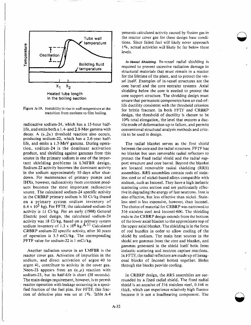
1 1 I 1 x1 x2
Heated tube length in the boiling section
Figure A-19. Instability in rise in wall temperature at the transition from nucleate to film boiling.
radioactive sodium-24, which has a 15-hour half- life, and emits both a 1.4- and 2.8-Mev gamma with decay. A (77 ,277) threshold reaction also occurs, producing sodium-22, which has a 2.6-year half- life, and emits a 1.3-MeV gamma. During opera- t ion, sodium-24 is the dominant activation product, and shielding against gammas from this source in the primary sodium is one of the impor- tant shielding problems in LMFBR design. Sodium-22 activity becomes the dominant activity in the sodium approximately 10 days after shut- down. For maintenance of primary pumps and IHXs, however, radioactivity from corrosion prod- ucts becomes the most important radioactive source. The calculated sodium-24 specific activity in the CRBRP primary sodium is 30 Ci/kg (based on a primary system sodium inventory of 6.4 x lo5 kg). For FFTF, the calculated sodium-24 activity is 11 Ci/kg. For an early (1968) General Electric pool design, the calculated sodium-24 activity was 18 Ci/kg, based on a rimary system
CRBRP sodium-22 specific activity, after 30 years of operation is 3.5 mCi/kg. The corresponding FFTF value for sodium-22 is 1 mCi/kg.
sodium inventory of 1.3 x 10⁶ kg. 1 - 1 1 Calculated
Another radiation source in an LMFBR is the reactor cover gas. Activation of impurities in the sodium, and direct activation of argon 40 to argon 41, contribute to activity in the cover gas. Neon-23 appears from an ( q , p ) reaction with sodium-23, but its half-life is short (38 seconds). The main design requirement, however, is to permit reactor Gperation with leakage occurring in a speci- fied fraction of the fuel pins. For FFTF, this frac- tion of defective pins was set at 1%. Table A-4
A-32
presents calculated activity caused by fission gas in the reactor cover gas for these design base condi- tions. Since failed fuel will likely never approach 1070, actual activities will likely be far below these levels.
In- Vessel Shielding. In-vessel radial shielding is required to prevent excessive radiation damage to structural materials that must remain in a reactor for the lifetime of the plant, and to protect the ves- sel itself. Examples of in-vessel structures are the core barrel and the core restraint systems. Axial shielding below the core is needed to protect the core support structure. The shielding design must ensure that permanent components have an end-of- life ductility consistent with the threshold criterion for brittle fracture. In both FFTF and CRBRP design, the threshold of ductility is chosen to be 10% total elongation, the level that ensures a duc- tile mode of deformation up to failure, and permits conventional structural analysis methods and crite- ria to be used in design.
The radial blanket serves as the first shield between the core and the radial structure. FFTF has no blanket but uses removable radial reflectors to protect the fixed radial shield and the radial sup- port structure and core barrel. Beyond the blanket are located removable radial shielding (RRS) assemblies. RRS assemblies contain rods of stain- less steel or of nickel-based alloys compatible with sodium, such as Inconel. They have a high inelastic scattering cross section and are particularly effec- tive in degrading the energy of fast neutrons. Iron is also effective, but less effective than nickel. Stain- less steel is less expensive, however, than Inconel. The choice of material for CRBRP was narrowed to 316 stainless steel and Inconel-600. The shielding rods in the CRBRP design extends from the bottom of the lower axial blanket to the approximate top of the upper axial blanket. The shielding is in the form of rod bundles in order to allow cooling of the shield by sodium. The main heat sources in the shield are gammas from the core and blanket, and gammas generated in the shield itself both from inelastic scattering and neutron capture reactions. In FFTF, the radial reflectors are made up of hexag- onal blocks of Inconel bolted together. Holes through the blocks provide cooling.
In CRBRP design, the RRS assemblies are sur- rounded by a fixed radial shield. The fixed radial shield is an annulus of 3 16 stainless steel, 0.146 m thick, which can experience relatively high fluence because it is not a loadbearing component. The
Q

Ir) Table A-4. Calculated cover gas activity for the FFTF design basis, 1% pin failure
Isotope
Kr-83m
Kr-85m
Kr-85
Kr-87
Kr-88
Xe-133m
Xe-133m
Xe-133
Xe-135
Activity ( ~ i / m 3 )
6 . 8 2 ~ lo1
1.34 x lo2
9.30 10-9
1.80 x lo2
2 . 6 4 ~ lo2
5.43 x 10⁻¹
1.47 x lo1
2.67 x lo2
1.26 x 10³
FFTF fixed radial shield is formed from flat plates to create a 12-sided shield between the core and the core barrel.
In the pool design, graphite is usually incorpo- rated into the radial shielding to moderate neutrons and allow them to be absorbed before reaching the IHX. B4C shielding is used near each IHX and pri- mary pump in order to reduce activation of the structural material, thereby allowing maintenance as well as reducing secondary sodium activation by thermal neutrons in the IHXs.
An axial shield is located below the lower axial blanket to protect the core support structure and lower inlet modules. In CRBRP, this shield consists of a 0.51-m-long, 316 stainless steel shield block in each fuel, blanket, and control assembly. In FFTF, a lower shield and inlet orifice assembly is 0.54 m long. No special upper axial shielding is required for either FFTF or CRBRP because of the shielding provided by the upper sodium pool.
Pathways for neutron streaming from in-vessel components in CRBRP include the clearance gaps required in the design of the fixed radial shield, the cooling channels of the axial shielding set in each core assembly, the fission gas plenum of each core assem- bly, and interfaces between invessel components.
Reactor Enclosure System Shielding. Areas requir- ing shielding of the reactor enclosure system include component penetrations and interfaces in a closure head assembly, the reactor vessel support area, and the ex-vessel flux monitors in the reactor cavity. Figure A-20 illustrates these areas for CRBRP, which has a typical loop design. For a pool design, neutron flux levels at the tank support area and reactor cavity walls are lower than for the loop design, so shielding problems in thest: areas are less severe.
The CRBRP design solutions in these areas indi- cate the types of shielding problems encountered.
Figure A-21 shows the CRBRP closure head assembly (CHA). The main penetrations invohe refu- eling components, control drive mechanisms, and the upper internals lifting mechanism. Radiation source terms that affect the CHA shielding design iiiclude neutron and gamma streaming of the step annuluses of the CHA penetrations or component interfaces, the radioactive cover gas below the CHA pmetra- tions, and neutron and gamma penetrations through the CHA bulk shielding.
The sodium dip seals around the refueling ]plugs, shown in Figure A-21, presents the major shield design problem for the closure head assembly.
A-33

Closure head assembly
Reactoi
vessel area and ledge
1 Figure A-20. Key shielding areas in CRBRP reactor and reactor enclosure system.
These seals form the barrier for the cover gas in the C H A rotating plug annuluses. CRBRP was designed to operate with 1 Yo failed fuel. Radioac- tive fission product gases and the cover gas from this failed fuel requires about 0.3 m of steel shield-
tion of the support ledge to stop thermal neutrons, and a carbon steel collar reduces the streaming gap at the vessel flange elevation. A concrete shield ring above the support ledge reduces radiation stream- ing into the head access area.
ing for personal access to the head access area. Dip- seal tradeoff studies resulted in the location of the seals in the closure head, as shown in Figure A-21. Radiation through these dip seals is the largest con- tributor to the dose rate in the head access area.
The source range flux monitor (SRFM), which monitors the core during shutdown and refueling, is located in the reactor cavity of the CRBRP. The neutron flux from the core that reaches the flux monitors must be great enough to allow monitoring
In both FFTF and CRBRP designs, a canned B4C radiological shield is placed at the lower eleva-
of changes in core subcriticality, whereas neutron fluxes from extraneous sources and gamma dose
A-34

Upper internals Control rod drive structure support Intermediate column nozz!e \ rotating plug
[ mech :-ism n-OkZ!.g Liquid level monitor
Ex-vessel tran achine nozzle
plate column
Figure A-21. Closure head assembly configuration of CRBRP.
rates must be sufficiently low. These objectives are accomplished by shielding at the SRFM. The shielding consists of a graphite moderator block, 0.51 m by 0.63 m, surrounded by lead and B4C background shields. Neutron background, caused by fuel-in-transfer or fuel storage in the fuel trans- fer and storage assembly, is reduced by B4C shields in the reactor cavity. The gamma background at the SRFM is reduced to acceptable levels by surround- ing the moderator block with lead to reduce gamma levels from the vessel, guard vessel, and sodium, a n d by u s i n g a h i g h - p u r i t y a l u m i n u m a l loy a s t h e structural material for the SRFM to minimize its neutron activation gamma background.
Heat Transport System. The intermediate heat exchanger in the loop design system must be shielded from neutrons in order to prevent activa- tion of the secondary sodium. In CRBRP, second- ary sodium activation is held below 0.07 mCi/kg. Ordinary concrete structural walls of the equip- ment cells provide the bulk shielding. Considerable design effort was required to reduce neutron streaming through the pipeways into the cells. Delayed neutron monitors for detecting fuel clad- ding failure were also placed in the CRBRP heat transport piping system; hence, the background neutron flux levels at these monitors must be mini- mized. A problem encountered in shielding design is the photoneutron production in the concrete cell walls. Photoneutrons are generated by the interac-
tion of gamma rays from sodium-24 in the primary coolant pipes with deuterium in the concrete. In the CRPRP design, more than 80% of the no &u t ron background at the delayed neutron monitors could be attributed to photoneutrons from the concrete. Nonhydrogeneous materials were specified for neu- tron background shielding around the moniiiors to minimize the neutron flux levels.
Instrumentation. All nuclear reactor systems incorporate a high degree of instrumentat ion in o r d e r to p r o v i d e c o n t i n u o u s m o n i t o r i n g n e c e s s a r y for plant control. Much of the instrumentation, such as radiation monitoring, is common to all reactor types. The presence of a liquid metal., how- ever, poses a few instrumentation challenges unique to LMFBR systems.
COR rnrameter Monitoring. Variables such a:, flux, temperature, flow, and pressure must be determined in any nuclear reactor, but the sodium environment requires measurement techniques somewhat different from those of light water systems.
It was noted in the section on “Reactor Elnclo- sure System Shielding” above that flux monii.oring for a typical LMFBR system consists of a number of neutron detectors located in the reactor cavity external to the reactor vessel. In-core or in-vessel detectors may be used for initial start-up operation, but the neutron source from spontaneous fission of
A-35
plutonium-240 is normally present and is strong enough to activate such remotcly located detectors. An appreciable neutron source is also possible from americium-242, especially if recycled fuel is used.
Figure A-22 shows a flux monitoring set for the CRBRP design. The highly sensitive BF3 detectors are used for low-power operation, such as start-up and refueling. Uranium-235 fission chambers are employed for mid-range operations. And compen- sated ion chambers are used for power range mea- surements. Three sets, identical to that shown in Figure A-22, provide an overlapping range of flux monitoring to continuously record neutron flux from shutdown to more than full power. Electrical signals from these detectors, which are propor- tional to reactor power, are used for both reactor control and the plant protection system (PPS). Such signals also feed the data logging system and provide annunciator trips from the control room for out-of-limit conditions.
Sodium temperatures must be measured rou- tinely throughout the primary and secondary cir- cuits to calculate thermal power and determine loop operating conditions. Two types of detectors are in common use: resistant temperature detec- tors (RTDs) and thermocouples. The RTDs provide a highly accurate and reliable measurement to ensure that the plant is operating within design lim- its. The sensor for such a device typically consists of a double element of platinum contained within a sheet that is spring-loaded against the bottom of a thermowell, as illustrated in Figure A-23. Insertion of this sensor raises the possibility of a sodium leakage from the penetration in the event of ther- mowell failure. Whereas well failures in such devices appear to be rare, a backup cable penetra- tion seal (as shown by the seal connection pad in Figure A-23) can prevent such leakage.
Coolant flow measurement must be made to complete the thermal power calculations and loop operating characteristics. Both the standard venturi flowmeter and a magnetic flowmeter are often used on liquid metal systems. The magnetic flowmeter is unique to liquid metal systems owing to the electric properties of the liquid metal coolant (see Figure A-24):The Venturi meter is highly accurate but suffers from a response time that is often too slow for control system and PPS use. The magnetic flowmeter, on the other hand, tends to be less accu- rate but exhibits rapid response. When the two are used in series, the Venturi meter can be used to achieve in-place calibration of the rapid-response
Q magnetic flowmeter. It is possible to calibrate both types of meters by activating the sodium with a pulse neutron device and using a time-of-flight recording technique. The procedure was success- fully employed in FFTF.
Another type of flowmeter made possible by the unique properties of the liquid metal is an eddy cur- rent flowmeter. Figure A-25 is a diagram of such a device used in measuring the rate of coolant dis- charge from an assembly into the upper sodium pool.
Liquid pressure measurements are normally made by routing a small column of the high-pressure liquid onto one side of a sensing diaphragm. This causes a complication when measuring sodium pressure because sodium solidifies well above room tempera- ture. Trace heating could be provided to ensure liquid sodium conditions, but this has become unreliable for many applications. An alternative method often employed is to interface the sodium with NaK via a bellow system, as illustrated in Figure A-26. The NaK is a liquid at room temperature and can be used in a close tolerance pressure transducer assembly.
Fuel Failure Detection. The detection of a cladding breach in a fuel element can be normally accom- plished by monitoring increased cover gas activity or by detecting the presence of delayed neutrons in the sodium leaving the reactor. Locating the fuel assembly containing the leaking fuel element is more difficult. Gas tagging offers one means for such identification.
A cover gas monitoring system normally exists to indicate the presence of fission products that escape the fuel pin. The most abundant fission products that escape are isotopes of the noble gases, xenon and krypton. Many of the fission products emit gamma rays with relatively low energy, around 100 KeV, and detection of such activity in a prevailing background of high energy neon-23 (440 KeV) and argon-41 (1300 KeV) gam- mas presents difficulties. The neon-23 activity is considerably less in a pool type reactor, relative to a loop-type system, because of the larger holdup time, which allows the 38s half-life neon-23 to decay, and less turbulence in the pool level. How- ever, numerous xenon isotopes emit relatively high energy gammas, and experience at EBR I1 and FFTF indicates detection of cladding failure for an LMFBR system is readily attainable.A-12,-13 n
A-36
1 .
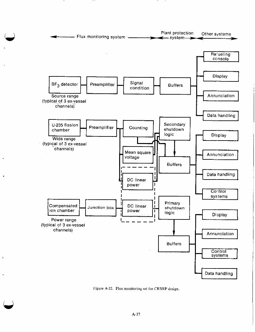
Plant protection Other systems 4- Flux monitoring system - -8 s ys t e mh---*
BF3 detector - B u f f e rs - Preamplifier I Signal condition
- (typical of 3 ex-vessel
c han ne I
A Annitnciation
. U-235 fission Preamplifier chamber
I
, - ,
c ' I Primary - Junction box - shutdown DC linear I
. ion chamber I power ' logic
L c r Data hand I ing
Display F1 I Annunciation
k1 Data handling
Figure A-22. Flux monitoring set for CRBRP design.
A-37
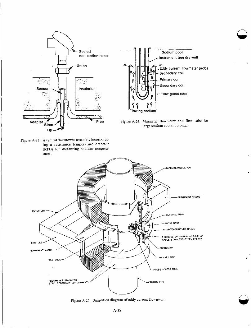
Sealed connection
Union
head
:. ".:, .:. ..: . ' ..... ':I )--( p-
Figure A-23. A typical thermowell assembly incorporat- ing a resis tance t e m p e r a t u r e de tec tor (RTD) for measuring sodium tempera- tures.
n
,Instrument tree dry well
ddy current flowmeter probe
Flow guide tube
IlQ9 P f u Flowing sodium
Figure A-24. Magnet ic flowmeter and flow tube for large sodium coolant piping.
n Figure A-25. Simplified diagram of eddy current flowmeter.
A-38
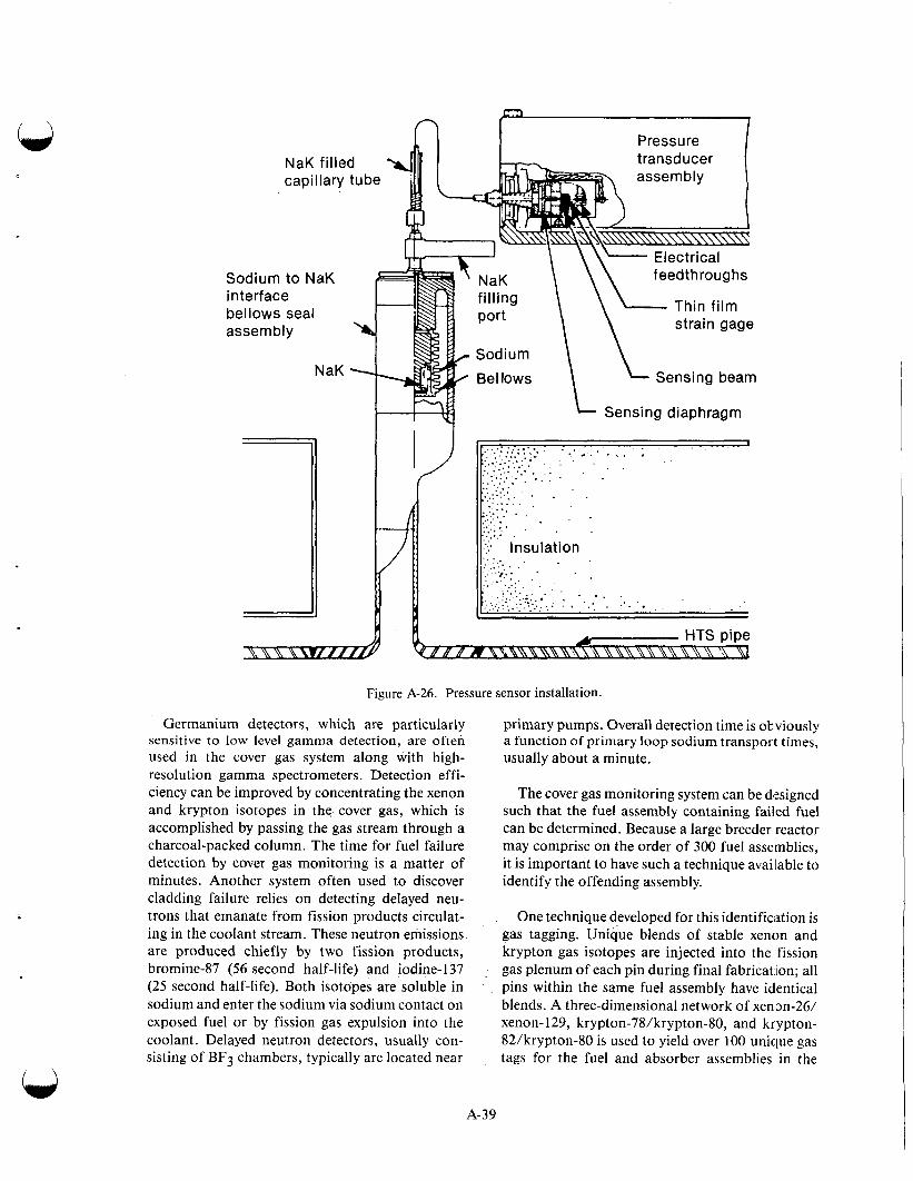
NaK filled capillary tube
Sodium to NaK interface bellows seal assembly h
NaK -
I Sensing diaphragm
r i ' .. .: :..: :.... . . . . . , . . .
...;...:.:... '
..',.. . . * . . . '..:.:.. . . . . .,.,."' .';' . ::.;.: .
. . . a . . . . . : . . . :... . - :.. .....' * . . . . . . . .
' ... ... .. . :: : .
. . . . . . . . . . . ...... . .!: Insulation
Figure A-26. Pressure sensor installation.
Germanium detectors, which are particularly sensitive to low level gamma detection, are often used in the cover gas system along with high- resolution gamma spectrometers. Detection effi- ciency can be improved by concentrating the xenon and krypton isotopes in the cover gas, which is accomplished by passing the gas stream through a charcoal-packed column. The time for fuel failure detection by cover gas monitoring is a matter of minutes. Another system often used to discover cladding failure relies on detecting delayed neu- trons that emanate from fission products circulat- ing in the coolant stream. These neutron emissions are produced chiefly by two fission products, bromine-87 (56 second half-life) and iodine-137 (25 second half-life). Both isotopes are soluble in sodium and enter the sodium via sodium contact on exposed fuel or by fission gas expulsion into the coolant. Delayed neutron detectors, usually con- sisting of BF3 chambers, typically are located near
primary pumps. Overall detection time is obviously a function of primary loop sodium transport times, usually about a minute.
The cover gas monitoring system can be designed such that the fuel assembly containing failed fuel can be determined. Because a large breeder reactor may comprise on the order of 300 fuel assemblies, it is important to have such a technique available to identify the offending assembly.
One technique developed for this identifimtion is gas tagging. Unique blends of stable xenon and krypton gas isotopes are injected into the fission gas plenum of each pin during final fabrication; all pins within the same fuel assembly have identical blends. A three-dimensional network of xenon-26/ xenon-129, krypton-78/krypton-80, and krypton- 82/krypton-80 is used to yield over 100 unique gas tags for the fuel and absorber assemblies in the
A-39
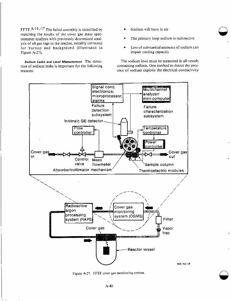
FFTEA-l49-l7 The failed assembly is identified by matching the results of the cover gas mass spec- trometer analysis with previously determined anal- ysis of all gas tags in the reactor, suitably corrected, for burnup and background (illustrated in Figure A-27). impair cooling capacity.
e
Sodium will burn in air
The primary loop sodium is radioactive
Loss of substantial amounts of sodium can
Sodium Leaks and Level Measurement. The detec- tion of sodium leaks is important for the following reasons:
The sodium level must be measured in all vessels containing sodium. One method to detect the pres- ence of sodium exploits the electrical conductivity
\Signal cond. 1
t- electronics; I microprocessor; [alarms Fai I ure detection subsystem
Intrinsic GE detector.
controller 7 I
Failure characterization subsystem
:over ga In
valve flowmeter ,/ \ ‘Sample column Absorberkol I imator mechanism Thermoelectric modules
* \ \ \ \
/’ /
/ \ \ \ \ \ \
Reactor vessel
Figure A-27. FFTF cover gas monitoring system.
A-40
n
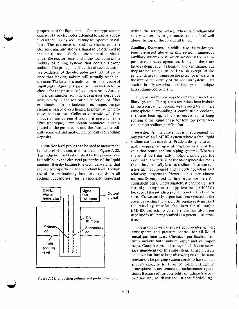
properties of the liquid metal. Contact type sensors consist of two electrodes extended to gap at a loca- tion where leaking sodium may be expected to col- lect. The presence of sodium shorts out the electrode gap and allows a signal to be delivered to the control room. Such detectors are often placed under the reactor vessel and at any low point in the vicinity of piping systems that contain flowing sodium. The principal difficulties of such detectors are oxidation of the electrodes and lack of assur- ance that leaking sodium will actually reach the detector. The latter is a major concern in the case of small leaks. Another type of sodium leak detector checks for the presence of sodium aerosol. Atmos- pheric gas samples from the area in question can be analyzed by either ionization detection or filter examination. In the ionization technique, the gas stream is passed over a heated filament, which pro- duces sodium ions. Collector electrodes will then induce an ion current if sodium is present. In the filter technique, a replaceable submicron filter is placed in the gas stream, and the filter is periodi- cally removed and analyzed chemically for sodium deposits.
Induction level probes can be used to measure the liquid level of sodium, as illustrated in Figure A-28. The induction field established by the primary coil is modified by the electrical properties of the liquid coolant, thereby leading to a secondary signal that is directly proportional to the sodium level. Though useful for maintaining inventory records in all sodium repositories, this is especially important
signal generator
Signal j-k output signal
Figure A-28. Induction sodium level probe schematic.
within the reactor vessel, where a funciamental safety concern is to guarantee coolant level well above the top of the core at all times.
Auxiliary Systems. In addition to the major sys- tems discussed above in this section, niimerous auxiliary systems exist, which are necessary to sup- port overall plant operation. Many of these are large systems, such as heating and ventilating, but they are not unique to the LMFBR except for the general desire to minimize the presence of water in the immediate vicinity of the sodium system. This section briefly describes auxiliary systems unique to a sodium-cooled plant.
There are numerous ways to categorize such aux- iliary systems. The systems described here include (a) inert gas, which recognizes the need for an inert atmosphere surrounding a combustible coolant, (b) trace heating, which is necessary to keep sodium in the liquid phase for low core power lev- els, and (c) sodium purification.
Inert Gas. An inert cover gas is a requirement for any part of an LMFBR system where a fre: liquid sodium surface can exist. Prudent design a1 so nor- mally requires an inert atmosphere in any of the cells that house sodium piping systems. Whereas the word inert normally implies a noble gas, the essential characteristic of the atmosphere desired is that it be chemically inert to sodium. Nitrogen sat- isfies this requirement and is both abundant and relatively inexpensive. Hence, it has been almost universally employed as the inert atmosphere for equipment cells. Unfortunately, it cannot be used for high-temperature application (> 400°C) because of t h e n i t r i d i n g p r o b l e m s in t h e steel e n c l o - sures. Consequently, argon has been selected as the cover gas within the vessel, the piping systems, and the refueling transfer chambers for all major LMFBR projects to date. Helium has also been used and is still being studied as a potential alterna- tive.
The argon cover gas subsystem provides an inert atmosphere and pressure control for all liquid metal-gas interfaces. Chemical purification fea- tures include both sodium vapor and oil vapor traps. Compressors and storage facilities are neces- sary ingredients of this subsystem, as are pressure equalization lines to keep all cover gases at the same pressure. The purging system needs to have a high enough capacity to allow complete changes of atmosphere to accommodate maintenance opera- tions. Because of the possibility of radioactive con- tamination, as discussed in the “Shielding”
A-4 1
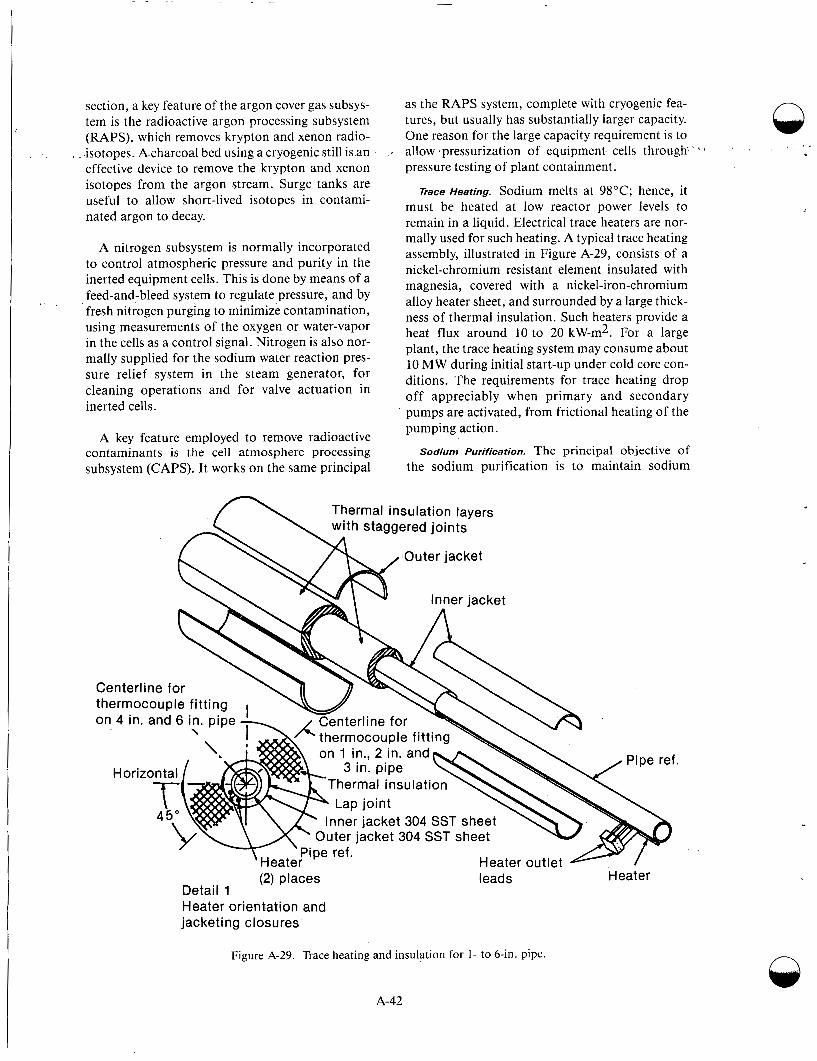
section, a key feature of the argon cover gas subsys- tem is the radioactive argon processing subsystem (RAPS), which removes krypton and xenon radio-
. .isotopes. A charcoal bed using a cryogenic still is an effective device to remove the krypton and xenon isotopes from the argon stream. Surge tanks are useful to allow short-lived isotopes in contami- nated argon to decay.
A nitrogen subsystem is normally incorporated to control atmospheric pressure and purity in the inerted equipment cells. This is done by means of a feed-and-bleed system to regulate pressure, and by fresh nitrogen purging to minimize contamination, using measurements of the oxygen or water-vapor in the cells as a control signal. Nitrogen is also nor- mally supplied for the sodium water reaction pres- sure relief system in the steam generator, for cleaning operations and for valve actuation in inerted cells.
A key feature employed to remove radioactive contaminants is the cell atmosphere processing subsystem (CAPS). It works on the same principal
. *
as the RAPS system, complete with cryogenic fea- tures, but usually has substantially larger capacity. One reason for the large capacity requirement is to allow pressurization of equipment cells through pressure testing of plant containment.
pace Heating. Sodium melts at 98°C; hence, it must be heated at low reactor power levels to remain in a liquid. Electrical trace heaters are nor- mally used for such heating. A typical trace heating assembly, illustrated in Figure A-29, consists of a nickel-chromium resistant element insulated with magnesia, covered with a nickel-iron-chromium alloy heater sheet, and surrounded by a large thick- ness of thermal insulation. Such heaters provide a heat flux around 10 to 20 kW-m2. For a large plant, the trace heating system may consume about 10 MW during initial start-up under cold core con- ditions. The requirements for trace heating drop off appreciably when primary and secondary pumps are activated, from frictional heating of the pumping action.
sodium Purification. The principal objective of the sodium purification is to maintain sodium
'
Thermal insulation layers ( \ with staggered joints
Centerline for
Centerline for thermocouple fitting on 4 in. and 6 in. pipe I
\ .,AA thermocouple fitting \ \
Inner jacket 304 SST shet Outer jacket 304 SST sheel
Heater Heater outlet Pipe ref. * (2) Dlaces leads Heater , , .
Detail 1 Heater orientation and jacketing c I osu res
Figure A-29. Trace heating and insulation for 1- to 6-in. pipe. n
A-42
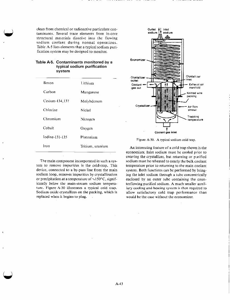
clean from chemical or radioactive particulate con- taminants. Several trace elements from in-core structural materials dissolve into the flowing sodium coolant during normal operations. Table A-5 lists elements that a typical sodium puri- fication system may be designed to monitor.
Table A-5. Contaminants monitored by a typical sodium purification system
Boron Lithium
Carbon Manganese
Cesium-134,137 Molybdenum
Chlorine Nickel
Chromium Nitrogen
Cobalt Oxygen
Iodine-1 3 1-1 35 Plutonium
Iron Tritium, uranium
The main component incorporated in such a sys- tem to remove impurities is the cold-trap. This device, connected to a by-pass line from the main sodium loop, removes impurities by crystallization or precipitation at a temperature of .~150"C, signif- icantly below the main-stream sodium tempera- ture. Figure A-30 illustrates a typical cold trap. Sodium oxide crystallizes on the packing, which is replaced when it begins to plug. .
Outlet sodlum tC _ _ sodium Inlet
Trapping tempeiature
t Coolant gas inlet
Figure A-30. A typical sodium cold trap.
An interesting feature of a cold trap shown is the economizer. Inlet sodium must be cooled prior to entering the crystallizer, but returning or purified sodium must be reheated to nearly the bulk coolant temperature prior to returning to the main coolant system. Both functions can be performed by bring- ing the inlet sodium through a tube concentrically enclosed by an outer tube containing the coun- terflowing purified sodium. A much smaller auxil- iary cooling and heating system is then required to allow satisfactory cold trap performancc than would be the case without the economizer.
A-43

n OPERATIONAL EXPERIENCE AT LMFBWs
Early Experimental LMFBWs .
The first reactor to generate electricity was the U-235-fueled, fast Experimental Breeder Reactor 1 (EBR-l), which started operating in the United States in 1951. This reactor, cooled by a molten sodium-potassium alloy, had an electrical output of 200 kilowatts. Most effort devoted to fast reactors since that time has continued on the liquid-metal- cooled concept: Much of the development on LMFBRs was carried out with early experimental reactor plants in the United States (Clementine, EBR-1, Lampre, Sefor) and the Soviet Union (BR-1, BR-2, BR-5, BR-10). Table A-6 lists the characteristics of these early experimental reactors.
Clementine. Clementine, the first fast reactor and the first to use plutonium-239 as fuel, was devel- oped at the Los Alamos Scientific Laboratory. Although it served primarily as a source of fast neutrons for experimental purposes, it also demon- strated the.feasibility of plutonium as a fast reactor fuel. Operations began in November 1946 with a power of one watt. In March 1949, the power was increased to 25 kWt. After several years of satisfac- tory operation, failure of at least one fuel element and resulting contamination of the mercury cool- ant led to the decision to dismantle the reactor. This was effected in 1953. Although the operating tem- peratures were too low for power production, the reactor was used for research and it did demon- strate the feasibility of plutonium as a fuel for fast power reactors. Sufficient plutonium for such a reactor existed solely at Los Alamos during this period. Figure A-3 1 is a cross-sectional view of the reactor, a rectangular block-like structure.
The 15-cm diameter core contained 55 fuel and blanket elements. The fuel rods, of delta-phase plu- tonium, were 1.64 cm in diameter and 14 cm long, were clad with a type 1020 steel, 0.5 m thick, and assembled in a vertical
Control of the reactor was effected by several components. A reflector, consisting of a large block of uranium immediately below the active region, could be raised into position and increase the reactivity, and could be quickly dropped out to reduce it. llvo safety rods, located in positions immediately outside the central region, were com- posed of a section of uranium in a section of
q I B.10 poison. For shutdown, in one motion the ura- nium section was dropped out and the B-10 section was inserted into the region. In addition, the reac- tor had two uranium rods that acted as control rods . A-9
The reactor was primarily a research facility, with 25 kWt at full power, so requirements for heat removal were quite modest. The mercury coolant was pumped by an eddy-current type of electro- magnetic pump at a rate of 0.15 L/s through the core and then through a mercury-to-water heat exchanger. In the two heat exchangers, mercury flowed through a helical core of 2.22-mm-ID steel tubing inside a solid water-cooled copper cylinder.
A 117-cm-long 15.8-cm-OD and 15.2-cm-ID mild-steel cylinder served as the core container, the fuel cage resting on the bottom of the cylinder. Immediately above the case, and filling the space to the top of the pot, or vessel, was a removable reflec- tor and shield plug. The plug contained a number of layers of various materials, all in a steel cylinder of 0.64-cm wall thickness (Figure A-31). A steel shield, consisting of a permanent assembly of lami- nations and concrete, also served as a supporting and retaining wall for the reactor parts.
In addition to the 35 plutonium fuel rods, the central active core contained 20 reflector rods of natural uranium, having the same dimensions and cladding as the fuel rods. A 15-cm-thick reflector/ blanket of natural uranium surrounded the core. A 0.64-cm-thick aluminum jacket, containing a water-cooling tube, removed the heat generated in the uranium blanket. The core and blanket were surrounded by a 15.2-cm steel reflector and a 10-cm thickness of lead shielding. The top shielding was made of a series of blocks that could be removed to give access to the reactor.A-18 Since an important purpose of this reactor was to provide fast neutrons for experimental purposes, a number of holes were provided for radiation work. Four horizontal holes ran completely through the reactor. In addition, three reentrant horizontal holes and 10 vertical holes were provided.
Following attainment of criticality in November 1946, the reactor was operated as a critical assem- bly; considerable information was obtained con- cerning the physics of fast reactors. During n
A-44
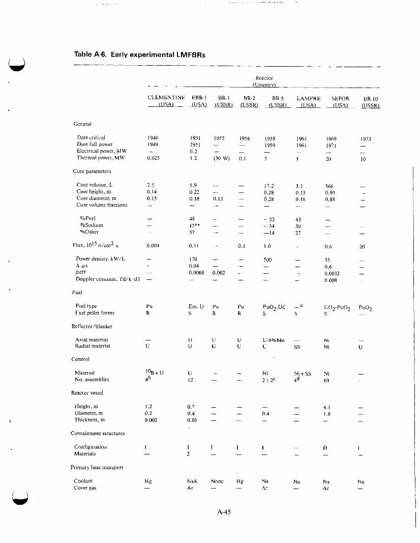
Table A-6. Early experimental LMFBRs
Reactor (Country)
CLEMENTINE EBR-1 (USA) (USA)
BR-1 BR-2 BR-5 LAMPRE SEFOR BR-IO (USSR) (USSR) (USSR) (USA) (USA) - (USSR)
General
Date critical Date full power Electrical power, MW Thermal power, MW
1946 1949
0.025 -
2.5 0.14 0.15 -
- - -
0.004
- - -
1951 1951 0.2 1.2
5.9 0.22 0.18 -
48 15* * 37
0.11
170 0.04 0.0068 -
Enr. U S
U U
U 12
0.7 0.4 0.01 .
I 2
1958 1961 1959 1961
5 1 - -
1969 1973 1971 -
20 10 - -
Core parameters
Core volume, L Core height, rn Core diameter, m Core volume fractions
566 -
0.93 - 0.88 -
17.2 3.1 0.28 0.15 0.28 0.16
%Fuel %Sodium %Other
F I ~ X , 1015 n/cm’.s
-52 43 -34 30 -14 27
0.6 20
35 - 0.6 - 0.0032 - 0.008 -
1 .o -
Power denisty, kW/L A .F*S Peff Doppler constant, Td/k.dT -
Fuel
Fuel type Fuel pellet forms
Reflector/blanket
Axial material Radial material
Control
Material No. assemblies
Reactor vessel
Height, m Diameter, m Thickness, m
Containment structures
Configuration Materials
Primary heat transport
Coolant Cover gas
Pu R
-
U
l0B+U 4b
1.2 0.2 0.002
I -
PuO2,UC -a S S
Ni - Ni U
Ni Ni + SS 2+2c 4d
Ni - 10 -
D I - -
Hg NaK None Hg Na Ar - - Ar -
Na Na Ar -
Na -
A-45

Table A-6. (continued1
Reactor (Country)
CLEMENTINE EBR-1 BR-1 BR-2 BR-5 LAMPRE SEFOR BR-10 (USA) (USA) (USSR) (USSR) (USSR) (USA) (USA) _(USSR)
Type Loop No. loops 1 Pump type E Total flow, kg/s 2
Outlet core temp.,"C 121 Inlet core temp.,"C 38
Max fuel temp.,"(= 135
- Loop Loop Loop Loop Loop - 1 E 36 230 . - 322 -
- - 2 2 le 2 - - C E E E - - 60 7 - -
- - 430 450 370 60 500 560 430 -
- - 477 - - 1300 870
a. Molten plutonium alloy.
b. Radial uranium reflector also used.
c. 2 Control rods + 2 cylindrical reflectors.
d . 4 Control rods + annular reflector.
e. Auxiliary loop also used.
a Cwret .
~ o m n Plastic
'sa Steel
L e d Brick
0 Tut.dloy
Bismuth
b o n i t o
0 Thorium
Concrete M d L e d Shot
Figure A-31. Cross section to the CLEMENTINE reactor shield
A-46 I

low-power operation of the reactor from February 1947 to January 1949, measurements were made of the critical mass, effectiveness of reactor control, temperature coefficient, neutron spectrum, and general behavior. The information obtained was valuable in establishing the feasibility of fast reac- tor operations, including the demonstration of control by delayed n e ~ t r o n s . ~ - l ~
From March 1949 to December 1952, when the rupture of a plutonium fuel rod was noted, the reactor was used for fast-neutron radiation research, as well as for a continuing program of reactor physics research. As a result of the fuel rod rupture, plutonium was released into the mercury coolant circuit, and since the primary objectives of the experiment had by then been achieved, the reac- tor was dismantled.A-20
EBR-1. The Argonne National Laboratory Experi- mental Breeder Reactor-1 (EBR-1) is located at the Idaho National Engineering Laboratory, Idaho. It was designed to demonstrate fast reactor breeding and to prove the use of liquid-metal coolants for power production. As a model, a power level of 1 MW thermal was chosen. Electrical power gener- ated about 200 kW(e).A-21
EBR-1 was based on concepts proposed in 1945. The research and development program was approved early in 1945, and the Manhattan Engi- neer District approved construction in November 1945. Design and construction occupied the years from 1948 to 1951. Criticality with the Mark-1 core was reached in August 1951, and electricity was generated on December 22, 1951. The Mark-II core was installed in 1954. A series of kinetic exper- iments led to its meltdown on November 20, 1955.A-22-26
The Mark-I and Mark-11 cores were similar, with the exception of some changes in spacing ribs and composition, as described in References A-17 through A-31. The Mark-I11 core was designed pri- marily to investigate the stability of the fast reactor. The Mark-IV core, loaded in 1962, used plutonium as a fuel and provided a facility in which the general operating characteristics of a solid-plutonium fueled reactor could be in~es t iga t ed .* -~ l -~~
Reactor features. Design of EBR-1 was a pioneer- ing effort; much of the present nuclear reactor tech- nology had not yet developed. Figure A-32 is a drawing of the reactor installation. The Mark-I core had a power density of 170 kWt/liter, and an
Control
Electromagnetic ’ pump
Figure A-32. EBR-I heat transport systern.
average heat flux of 690 W/m2. Although these values have been exceeded in more recently designed fast reactors, EBR-1 may be considered the first high-power density reactor. Initia 1 plans called for a conservative design that would permit operation at power levels greater than 1 MW, but heat generation in the outer blanket proved greater than anticipated, and limited operating p o w , ~ r . ~ - ~ ~
Core Arrangement. Figures A-33 and A-34 show the Mark-I1 core arrangement. The inner fuel rods, 1.14-cm OD, were separated without spacer ribs by 1.7 cm (the Mark-1 core used spacer ribs). Enriched fuel was used in the middle of each rod, and natural uranium was used at the top arid bot- tom to form an axial blanket. An inner blanket con- sisted of natural-uranium slugs, 2.58 cm in diameter and 51.44 cm long, jacketed in 0.0.56-cm- thick stainless steel. The core itself and the inner blanket were cooled by circulating sodium- potassium (NaK) alloy.
An air-cooled outer blanket is located outside the reactor tank. It consists of 84 keystone-shaped natural-uranium bricks, each weighing 45 .5 kg, clad with stainless steel 0.051 cm thick. This sec- tion is movable and contains the control rods Mov- ing parts are kept outside the liquid metal. Air cooling of the blanket proved to be the limitation on the operating power available for the reactor. Surrounding the external blanket is a graphite reflector 48.3 cm thick, followed by 2.74 m of con- crete shielding. Six experimental beam holes pierce the concrete shield and graphite reflector. A ther- mal column and “rabbit hole” also provide facili- ties for experiments.
A-47
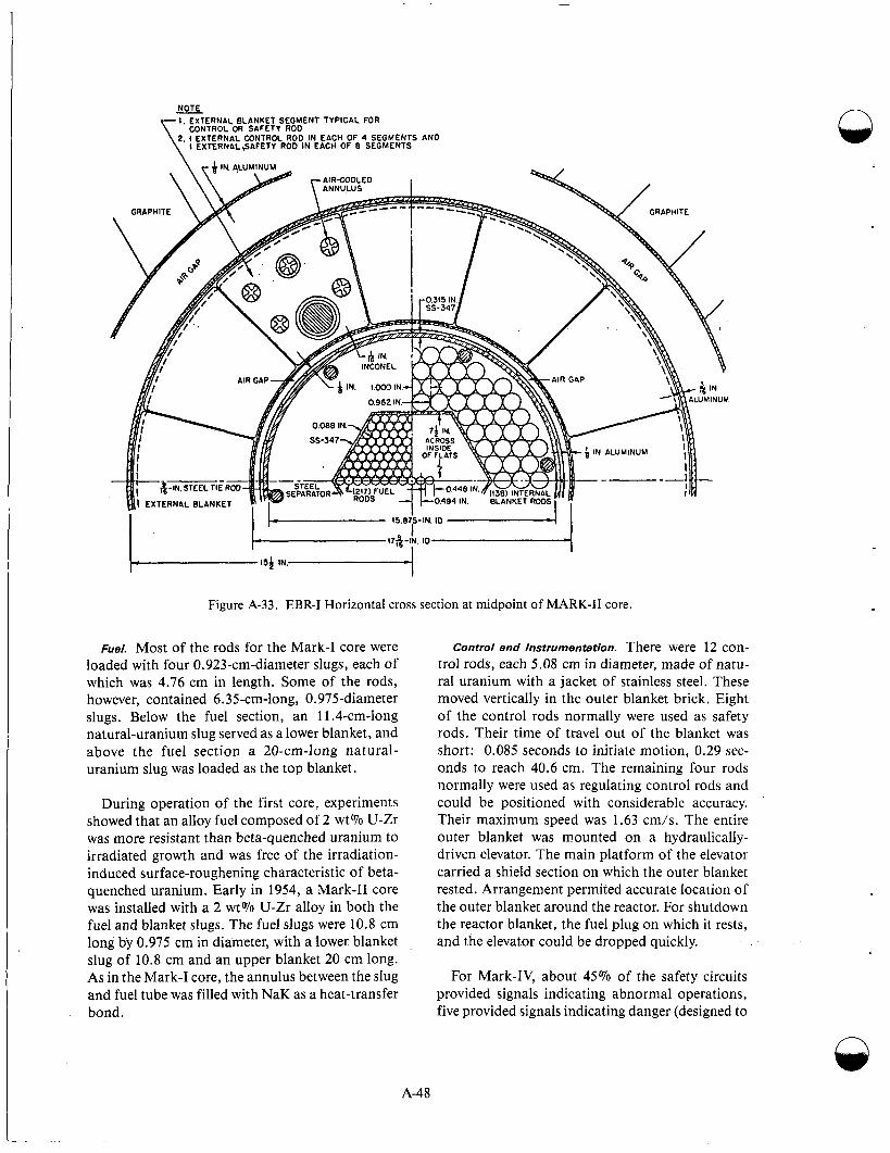
NOTE I , EXTERNAL BLANKET SEGMENT TYPICAL FOR
2. I EXTERNAL CONTROL ROO IN EACH OF 4 SEGMENTS AN0
- CONTROL OR SAFETY ROD
I EXTERNAL,SAFETY ROD IN EACH OF 8 SEGMENTS
IN ALUMINUM
----
Figure A-33. EBR-I Horizontal cross section at midpoint of MARK-I1 core.
Fuel. Most of the rods for the Mark-I core were loaded with four 0.923-cm-diameter slugs, each of which was 4.76 cm in length. Some of the rods, however, contained 6.35-cm-long, 0.975-diameter slugs. Below the fuel section, an 11.4-cm-long natural-uranium slug served as a lower blanket, and above the fuel section a 20-cm-long natural- uranium slug was loaded as the top blanket.
During operation of the first core, experiments showed that an alloy fuel composed of 2 wt% U-Zr was more resistant than beta-quenched uranium to irradiated growth and was free of the irradiation- induced surface-roughening characteristic of beta- quenched uranium. Early in 1954, a Mark-I1 core was installed with a 2 wt% U-Zr alloy in both the fuel and blanket slugs. The fuel slugs were 10.8 cm long by 0.975 cm in diameter, with a lower blanket slug of 10.8 cm and an upper blanket 20 cm long. As in the Mark-I core, the annulus between the slug and fuel tube was filled with NaK as a heat-transfer bond.
Control and Instrumentation. There were 12 con- trol rods, each 5.08 cm in diameter, made of natu- ral uranium with a jacket of stainless steel. These moved vertically in the outer blanket brick. Eight of the control rods normally were used as safety rods. Their time of travel out of the blanket was short: 0.085 seconds to initiate motion, 0.29 sec- onds to reach 40.6 cm. The remaining four rods normally were used as regulating control rods and could be positioned with considerable accuracy. Their maximum speed was 1.63 cm/s. The entire outer blanket was mounted on a hydraulically- driven elevator. The main platform of the elevator carried a shield section on which the outer blanket rested. Arrangement permited accurate location of the outer blanket around the reactor. For shutdown the reactor blanket, the fuel plug on which it rests, and the elevator could be dropped quickly.
For Mark-IV, about 45% of the safety circuits provided signals indicating abnormal operations, five provided signals indicating danger (designed to
A-48
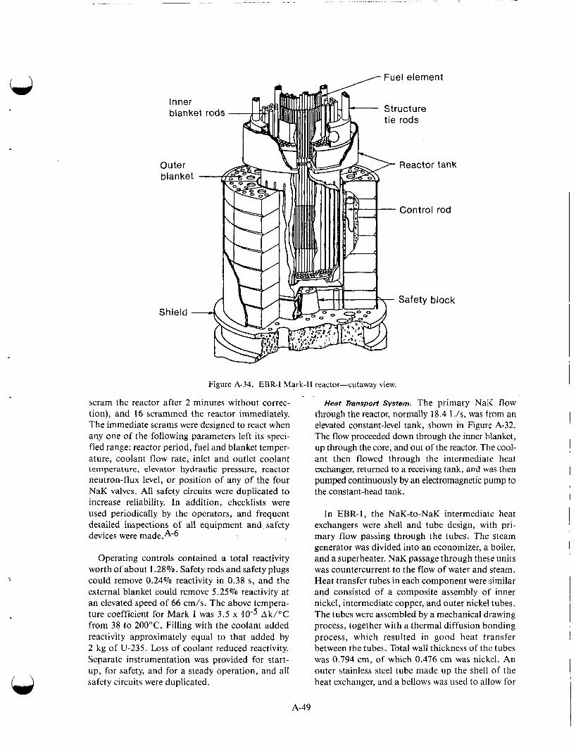
I \ Fuel element
Figure A-34. EBR-I Mark-I1 reactor-cutaway view. ~.
scram the reactor after 2 minutes without correc- tion), and 16 scrammed the reactor immediately. The immediate scrams were designed to react when any one of the following parameters left its speci- fied range: reactor period, fuel and blanket temper- ature, coolant flow rate, inlet and outlet coolant temperature, elevator hydraulic pressure, reactor neutron-flux level, or position of any of the four NaK valves. All safety circuits were duplicated to increase reliability. In addition, checklists were used periodically by the operators, and frequent detailed inspections of all equipment and safety devices were
Operating controls contained a total reactivity worth of about 1.28%. Safety rods and safety plugs could remove 0.24% reactivity in 0.38 s, and the external blanket could remove 5.25% reactivity at an elevated speed of 66 cm/s. The above tempera- ture coefficient for Mark I was 3.5 x Ak/"C from 38 to 200°C. Filling with the coolant added reactivity approximately equal to that added by 2 kg of U-235. Loss of coolant reduced reactivity. Separate instrumentation was provided for start- up, for safety, and for a steady operation, and all safety circuits were duplicated.
'uc t u re rods
Reactor
Control
Safety b
tank
rod
lock
Heat Transport System. The primary Nali flow through the reactor, normally 18.4 L/s, was from an elevated constant-level tank, shown in Figure A-32. The flow proceeded down through the inner tilanket, up through the core, and out of the reactor. The cool- ant then flowed through the intermediate heat exchanger, returned to a receiving tank, and was then pumped continuously by an electromagnetic pump to the constant-head tank.
In EBR-1, the NaK-to-NaK intermediate heat exchangers were shell and tube design, with pri- mary flow passing through the tubes. The steam generator was divided into an economizer, a boiler, and a superheater. NaK passage through these units was countercurrent to the flow of water and steam. Heat transfer tubes in each component were similar and consisted of a composite assembly of' inner nickel, intermediate copper, and outer nickel tubes. The tubes were assembled by a mechanical drawing process, together with a thermal diffusion bonding process, which resulted in good heat transfer between the tubes. Total wall thickness of the tubes was 0.794 cm, of' which 0.476 cm was nickel. An outer stainless steel tube made up the shell of the heat exchanger, and a bellows was used to allow for
A-49

differential thermal expansion. Thus, each heat exchanger was a single-tube-in-a-shell type, for NaK flow was on the shell side, and water or steam was in the tube.
A forced-air circulation falling-film boiler was used to limit the quantity of water in the system and to increase the heat-transfer rate. Heat exchangers were vertical. A baffle was used to establish a water film at the upper end of the internal tube on its inner surface. The film ran to the bottom where excess water and generated steam were piped into a drum. Steam was led through a separator in the drum out to the superheater, which consisted of horizontal heat exchangers with NaK in the shell side. The economizer was horizontal and served to heat the feedwater from the deaerating tank to steam temperatures before injection into the boiler drum.
Reactor VesselandShielding. The reactor vessel, or tank, was double-walled and extended through the reactor shield. The section of the reactor vessel sur- rounding the reactor core had an inside diameter of 90.3 cm and a length of 71.1 crn. Above this small section, the vessel increased in diameter and was filled with shielding material, mostly steel. The whole reactor vessel rested on the shoulder formed by the change in diameter; thus, the reactor core itself projected below the point of support as a smooth cylinder.
The small diameter part of the reactor tank con- sisted of a stainless-steel vessel with a 0.794-cm- thick wall, made by deep drawing. I t was surrounded by a second tank made of Inconel, 0.16 cm thick, which fit snugly on the ribs formed in the Inconel. The upper portion of the reactor vessel also was double-walled. The gas space between the two walls provided some thermal insu- lation and provided a method for testing vessel integrity. In the event that the inner vessel should develop a leak, the outer vessel would prevent com- plete loss of sodium.
A 46.7-cm-thick 89-cm-high section of graphite surrounded the outer blanket in the radial direc- tion. Its cooling-air gap is shown in Figure A-33. This graphite layer, in addition to serving as a mod- erator for fast neutrons for shielding purposes, acted as a reflector to improve the breeding in the outer blanket. Although ordinary concrete was the basic shielding material, a 10.2-cm layer of iron was provided between the graphite and the 2.59-m- thick concrete cylinder; this served as a thermal
shield by absorbing gamma rays. In the axial direc- tion above the core, layers of steel and NaK were followed by a 33-cm-thick steel plate, a 5.7-cm plate, a 61-cm thickness of concrete, and finally, 20.3-cm thickness of laminated masonite and iron. The bottom shield consisted of a 1.52-m-thick layer of ordinary concrete. Since the elevator room was the only area below the reactor, and since it was a limited access area, the bottom shield design was not considered critical. Additional details of the EBR-1 shield system are given in Reference 19.
,4t the time EBR-1 was designed, much shield design theory had not been developed. One of the purposes of the reactor was to improve the concept of fast reactor physics and permit experimental measurements of neutron source distribution and other parameters. Flexibility was incorporated in the design to permit addition of more shield thick- ness if necessary. Since the EBR-1 was of modest power and was located in an unpopulated area, a containment type building was not used.
Operating Experience. When the Mark I reactor was started up in 1951, radiation levels around the reactor were found higher than anticipated. An additional 76.2 cm of concrete shielding was installed, and operation was resumed. In June 1952, a NaK leak was discovered in the primary heat exchanger, and the reactor was shut down for repair. During the shutdown, 16 fuel elements were removed for examination and were replaced by new elements. More than 1500 MWt hours of operation had been accumulated by April 15, 1953.
During the four-year period, EBR-1 gave essen- tially trouble-free operation. Operation of EBR-1 demonstrated, among other things, that breeding was technically achievable with a measured conver- sion ratio of 1.01 k 0.05, that the use of liquid metal coolant (sodium-potassium alloy) was com- patible with breeding economy, and that the system was metallurgically and mechanically feasible. Breeding, based on U-235 fuel, was demonstrated in the first cores. Breeding in a plutonium cycle was demonstrated with operation of the Mark-IV core.37 The EBR-1 operation and theoretical deter- minations also showed that neutron behavior below prompt critical is the same in both fast and thermal reactors.
Under normal operating conditions, the reactor was very stable and did not exhibit a prompt, posi- tive temperature coefficient or a resonance. Under
n
n
A-50
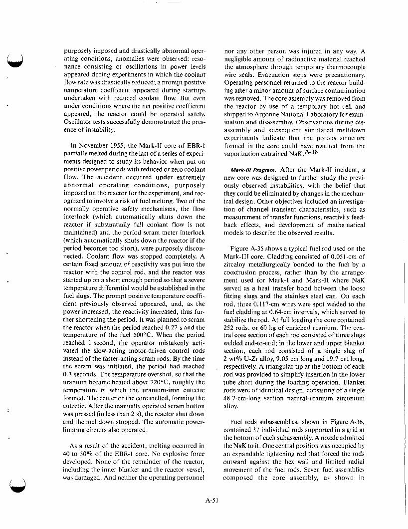
.
purposely imposed and drastically abnormal oper- ating conditions, anomalies were observed: reso- nance consisting of oscillations in power levels appeared during experiments in which the coolant flow rate was drastically reduced; a prompt positive temperature coefficient appeared during startups undertaken with reduced coolant flow. But even under conditions where the net positive coefficient appeared, the reactor could be operated safely. Oscillator tests successfully demonstrated the pres- ence of instability.
In November 1955, the Mark-I1 core of EBR-1 partially melted during the last of a series of experi- ments designed to study its behavior when put on positive power periods with reduced or zero coolant flow. The accident occurred under extremely abnormal operating conditions, purposely imposed on the reactor for the experiment, and rec- ognized to involve a risk of fuel melting. Two of the normally operative safety mechanisms, the flow interlock (which automatically shuts down the reactor if substantially full coolant flow is not maintained) and the period scram meter interlock (which automatically shuts down the reactor if the period becomes too short), were purposely discon- nected. Coolant flow was stopped completely. A certain fixed amount of reactivity was put into the reactor with the control rod, and the reactor was started up on a short enough period so that a severe temperature differential would be established in the fuel slugs. The prompt positive temperature coeffi- cient previously observed appeared, and, as the power increased, the reactivity increased, thus fur- ther shortening the period. It was planned to scram the reactor when the period reached 0.27 s and the temperature of the fuel 500°C. When the period reached 1 second, the operator mistakenly acti- vated the slow-acting motor-driven control rods instead of the faster-acting scram rods. By the time the scram was initiated, the period had reached 0.3 seconds. The temperature overshot, so that the uranium became heated above 720°C, roughly the temperature in which the uranium-iron eutectic formed. The center of the core melted, forming the eutectic. After the manually operated scram button was pressed (in less than 2 s), the reactor shut down and the meltdown stopped. The automatic power- limiting circuits also operated.
As a result of the accident, melting occurred in 40 to 50% of the EBR-1 core. No explosive force developed. None of the remainder of the reactor, including the inner blanket and the reactor vessel, was damaged. And neither the operating personnel
nor any other person was injured in any way. A negligible amount of radioactive material reached the atmosphere through temporary therm'xouple wire seals. Evacuation steps were precautionary. Operating personnel returned to the reactor build- ing after a minor amount of surface contamination was removed. The core assembly was removed from the reactor by use of a temporary hot c,ell and shipped to Argonne National Laboratory fc'r exam- ination and disassembly. Observations during dis- assembly and subsequent simulated meltdown experiments indicate that the porous structure formed in the core could have resulted from the vaporization enirained NaK.A-38
Mark-/// Program. After the Mark-I1 incident, a new core was designed to further study thl: previ- ously observed instabilities, with the belief that they could be eliminated by changes in the niechan- ical design. Other objectives included an investiga- tion of channel transient characteristics, such as measurement of transfer functions, reactivi1.y feed- back effects, arid development of mathematical models to describe the observed results.
Figure A-35 shows a typical fuel rod used on the Mark-Ill core. Cladding consisted of 0.051-cm of zircaloy metallurgically bonded to the fuc:l by a coextrusion process, rather than by the arrange- ment used for lvlark-I and Mark-I1 where NaK served as a heat transfer bond between the loose fitting slugs and the stainless steel can. On each rod, three 0.117-cm wires were spot welded to the fuel cladding at 0.64-cm intervals, which served to stabilize the rod. At full loading the core contained 252 rods, or 60 1:g of enriched uranium. The cen- tral core section of each rod consisted of three slugs welded end-to-end; in the lower and upper blanket section, each rod consisted of a single slug of 2 wt% U-Zr alloy, 9.05 cm long and 19.7 cni long, respectively. A triangular tip at the bottom of each rod was provided to simplify insertion in the lower tube sheet during the loading operation. Eilanket rods were of identical design, consisting of a single 48.7-cm-long section natural-uranium zirconium alloy.
Fuel rods subassemblies, shown in Figure A-36, contained 37 individual rods supported in a grid at the bottom of each subassembly. A nozzle admitted the NaK to it. One central position was occupied by an expandable tightening rod that forced the rods outward against the hex wall and limited radial movement of the fuel rods. Seven fuel assemblies composed the core assembly, as shown in
A-5 1
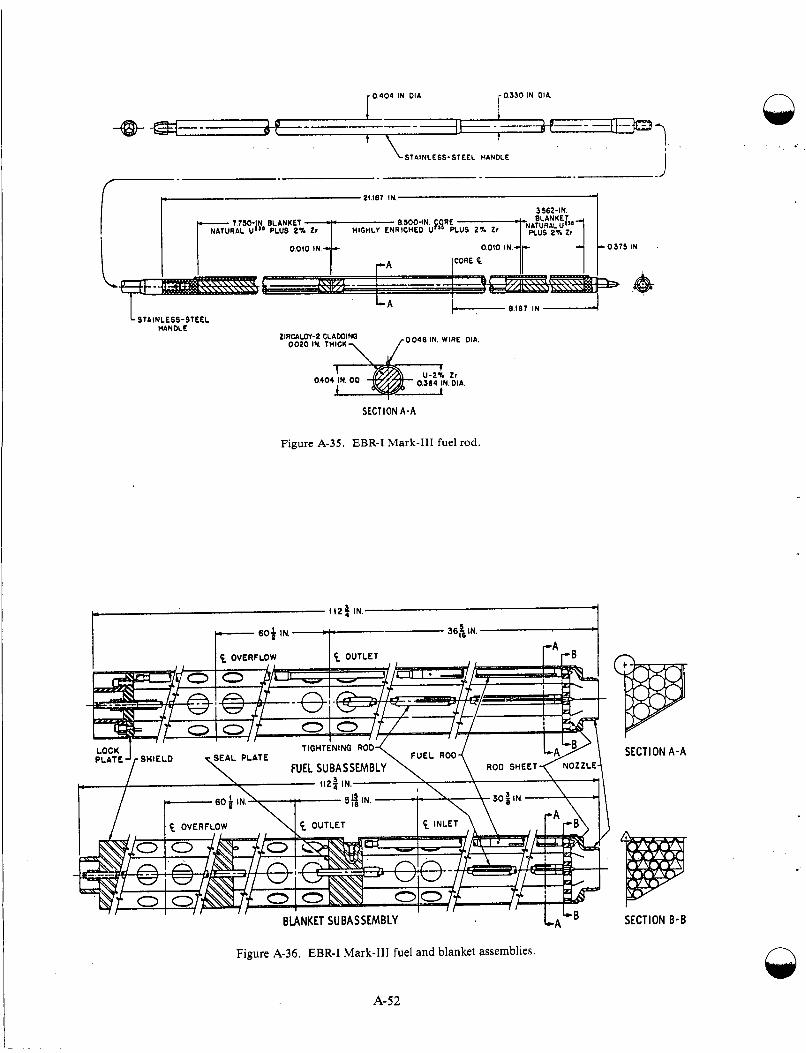
n
. i
\-STAINLESS-STLEL HANDLE
-- 24 (87 IN a?
L A j- 8.187 IN STAINLESS-STEEL
HANDLE LIRCALOY-2 CLAWINQ 10046 IN. WIRE DIA. 0020 IN. T H I C K 1
Zr OkO . DIA.
SECTION A-A
Figure A-35. EBR-I Mark-I11 fuel rod.
SECTION A-A
SECTION B-B
Figure A-36. EBR-I Mark-I11 fuel and blanket assemblies.
A-52
n

Tie rod Downcomer
plenum restricted by-pass leakage between the tank and the outer edge plate. Restriction was accomplished by two expandable Inconel seal rings. Seal
subassemblies subassemblies -J
Figure A-37. EBR-I Mark-I11 core cross section.
occurring of the seal a system of plate shoes
Figure A-37. Blanket subassemblies, each contain- ing 37 rods, had a different design for coolant flow. Twelve of the blanket subassemblies surrounded the core. Double-wedge clamps were located on each of the six flaps at the outer periphery of the assemblies at the core center line, and served to force the outer assemblies inward against the center assembly. A second set of six shoe-type clamps mounted along the inner edge of the seal plate limited the by-pass leakage rate and served to lock fuel and blanket assemblies into a rigid array. Also shown in Figure A-37 are the twelve downcomers through which the coolant passed in parallel flow. The six tie-rods held rigid the lower structure, the antimony-beryllium source, and the oscillator rod and thimble.
located between the inner edge of the seal phte and the blanket assemblies restricted the leakage.
The coolant, in series flow, entered the annular inlet plenum located immediately below the seal plate and flowed into the outer ring of the twelve blanket assemblies. At the bottom of the blanket assemblies, the flow was reversed 180 dN:grees, directed up three to seven fuel assemblies, through the outlet holes at the top, and then radially out through the perforated portion of the tdanket assemblies into the outlet plenum. The coolant, in parallel flow, flowed into a lower annular plenum located immediately above the mounting plate. Here the coolant was distributed to the twelve downcomers through which it flowed to the lower plenum. Upward flow through fuel and hlanket assemblies was partitioned by a series of throttle valves. The actual flow through the core, both in series and parallel, was less than the flow indicated through the metering of a primary inlet. Of a nomi- nal metered flow of 18.3 L/s, approximately 16% was bypassed as leakage and for seal plate cooling in series flow. The remaining 84% passed through the blanket and core. For a metered flow cif 11.8
I A-53
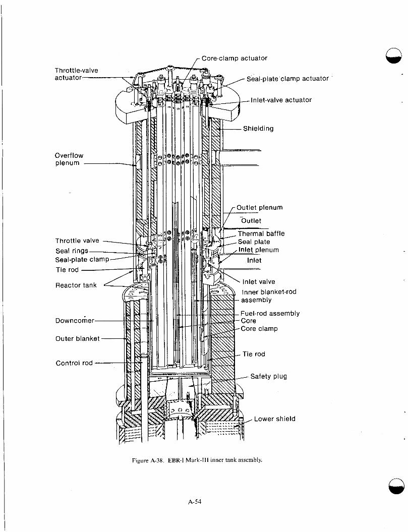
Throttle valve
Reactor tank
Outer blanket
~
r / , re-clamp actuator
Seal-plate clamp act1
Inlet-valve actuator
Inner blanket-rod
Lower shield
Jator
Figure A-38. EBR-I Mark-I11 inner tank assembly.
n
A-54
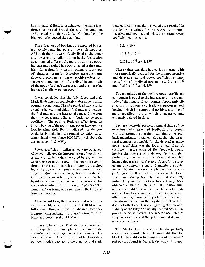
L/s in parallel flow, approximately the same frac- tion, 84070, passed through the core; the remaining 16% passed through the blanket. Coolant from the blanket outlet cooled the seal plate.
The effects of rod bowing were explored by sys- tematically removing part of the stiffening ribs. Although the rods were rigidly fixed at the upper and lower end, a radial motion in the fuel section accompanied differential expansion during a power increase and resulted in a bow directed at the center high-flux region. In 14 tests involving various types of changes, transfer function measurements showed a progressively larger positive effect con- sistent with the removal of the ribs. The amplitude of the power feedback decreased, and the phase lag increased as ribs were removed.
It was concluded that the fully-ribbed and rigid Mark-I11 design was completely stable under normal operating conditions. The ribs provided strong radial coupling between individual fuel rods and between the fuel rods and the hexagonal can, and therefore they provided a large radial contribution to the power coefficient. The positive feedback effect from the inward bowing of the rods during power increases was likewise eliminated. Testing indicated that the core could be brought into a resonant condition at an extrapolated power above lo00 MWt, well above the design value of 1.2 MWt.
,
Power coefficient nonlinearities were observed, which complicated the interpretation of test data in terms of a single model that could be applied over wide ranges of power, flow, and temperature condi- tions. These nonlinearities apparently resulted from the power and temperature sensitive clear- ances existing between rods, between rods and hexes, and between hexes, which are complicated by differences in the coefficient of expansion of the materials involved. Furthermore, the power coeffi- cient itself was found to be sensitive to the tempera- ture inlet cooling.
At one-third flow, the reactor would reach reso- nant instability at a power of about 10 MWt. At full coolant flow, with the ribs sheared, feedback measurements indicate a probable resonant insta- bility at a power level of 1 l MWt.
It has also been shown that rib shearing results in an unexpected and unexplained increase in the magnitude of the delayed structural power coeffi- cient component. An empirical fit of feedback data between models describing the dynamic and static
behaviors of the partially sheared core resulted in the following values for the respective prompt- negative, rod bowing, and delayed structural power coefficient components:
-2.21 x 10⁻⁶
+0.543 x
-0.873 x Ak/k-kW.
These values correlate in a curious manner with those empirically deduced for the prompt-negative and delayed structural power coefficient compo- nents for the fully ribbed core, namely, -2.21 x and -0.330 x Ak/k-kW.
The magnitude of the positive power coefficient component is equal to the increase and the magni- tude of the structural component. Apparently rib shearing introduces two feedback processes, rod bowing, which is prompt and positive, and one of an unspecified nature, which is negative and extremely delayed in time.
Because the model predicts a general shape of the experimentally measured feedback and comes within a reasonable margin of explaining the feed- back magnitude, it was concluded that the struc- tural member responsible for the delayed negative power coefficient was the lower shield plate. A credible interpretation of the feedback would involve the concept of a delayed feedback that probably originated at some structural member located downstream of the core. A careful scrutiny of all downstream structural members supple- mented by attenuation concepts narrows the sus- pect region to that included between the lower shield and seal plates. The fact that thermally induced ligamenta1 motion has actually been observed in such a plate, and that the maximum temperature differential across the shield plate occurs close to the natural resident frequency of other reactors, strongly supports this conclusion. The strong increase in the negative structur: term does not affect conclusions regarding the resonant stability at the fully or partially sheared cores. The process acted so slowly-the reactor oscillated at frequencies as low as 0.02 cycleds- that it cannot sense the feedback.
The Mark-111 core, even with ribs partially sheared, was found to be much more stable than the Mark 11. In addition to elimination of the inward rod bowing found in Mark-I, the Mark-I11 (design
A-55

resulted in a negative prompt power coefficient contributed by both axial and radial expansion of the rods. In Mark-11, the negative coefficient asso- ciated with axial fuel expansion and coolant expul: sion was insufficiently large to cancel the pkompt component from rod bowing. It was therefore con- cluded that the instabilities noted in Mark I1 were completely the result of the design peculiarities and not an inherent feature of the reactor concept itself. After conclusion of the stability test in 1960, the reactor was used on a part-time basis to study vari- ous loading arrangements, radiation effects of dif- ferent types of fuel elements, and fuel isotopic changes.
Mark-IVCore. The full potential of breeding with a fast spectrum is realized only when plutonium, rather than U-235, is used as the fuel in the core. The EBR-1, Mark-IV core, loaded in 1962, was the first use in this country of plutonium for the full core of a fast breeder power reactor. Operation of this reactor facility with plutonium loading had as its objectives the determination of general operat- ing characteristics, the measurement of breeding gain, and the determination of radiation effects and nuclear parameters.
An alloy of plutonium with 1.25 wt% aluminum was used in the core. Slugs of the material, 0.59 cm in diameter and 5.4 cm long, are contained in zircaloy-fuel tubes, 0.76 in. OD with a 0.053-cm wall thickness. Three full-length ribs served to cen- ter the slug and the jacket tube. Each fuel rod con- tained a lower depleted uranium blanket slug 8.95 cm long, four plutonium alloy fuel slugs total- ing 21.6 cm, and a single 19.67-cm-long upper blanket depleted uranium slug. A 0.0318-cm NaK layer bonds the cladding to the fuel. A number of rods had a 0.2-cm-diameter zircaloy thermocouple tube attached. Blanket rods were similar to those used in the fuel section; depleted uranium slugs were substituted for the plutonium alloy.
At shutdown, the Mark-I11 core had operated for 3,220 MW/hr. The core was completely unloaded by November 8, 1962, and the Mark-IV loading went critical on November 27, 1962, with 27 kg of plutonium-239 (327 fuel rods). Initial loading con- sisted of 60 fuel rods in the central assembly. Ten subsequent loadings, four of 42 rods each, two of 24 each, two of 18 each, one of 8, and a final one of 7 rods were made to reach criticality. Foil irradi- ation runs at low power were carried out in early 1963 to determine constants necessary for the cal- culation of breeding ratios. After transfer function
A-56
runs at low and moderate power indicated that the reactor was quite stable, the system was gradually brought up to power, 900 kW thermal, during April 1963. Although operation was very satisfac- tory, some loss of reactivity was noted.
EBR-1 was shut down and secured on December 3, 1963. Total power produced by the Mark 1V loading was 577 MW/hrs. Eleven fuel rods were removed from the reactor for return to the metallurgical division of Argonne National Laboratory for examination of the irradiated pluto- nium fuel plugs.
The reactor was secured subcritically by 1.75% Ak/k with the controls in their most reac- tive position, and the reactor temperature at 30°C. Surveillance of the reactor blanket gas was main- tained during this indefinite, extended shutdown period.
LAMPRE-I
Molten Plutonium Core Concept. Interest in the development of plutonium fuels for fast breeder reactor applications continued at the Los Alamos Scientific Laboratory after the dismantlement of Clementine (see previous section on Clementine, p. A-44. Parallel to this effort has been the develop- ment of homogeneous reactors wherein the fissile material was dissolved in an aqueous system. Reac- tors of this type include the water-boiler series, as well as LAMPRE-I and LAMPRE-11. The resulting specialization in plutonium-fueled fast breeder reac- tors on the one hand and the homogeneous concept on the other logically led to the concept of using plutonium in the molten state as fuel for a fast breeder system. An early reactor design, for exam- ple, called for the plutonium fuel to be obtained in a cylindrical vessel through which tubes carrying sodium coolant would flow in a typical calandria arrangement. However, the need for additional information regarding the behavior of container and fuel material led to the decision to first build a mol- ten plutonium fueled reactor; within such a reactor, the fuel would be contained in cylindrical capsules with the sodium coolant flowing outside. This arrangement, used in LAMPRE-I, could be readily adapted to the testing of a variety of fuel and con- tainer material combinations. A cell in an existing building, which had previously been used for the LAMPRE-I reactor, was available for LAMPRE. The limitations of this location fixed the reactor power at 1 MW(t).A-30-51
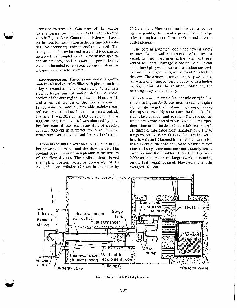
Reactor Features. A plain view of the reactor installation is shown in Figure A-39 and an elevated view in Figure A-40. Component design was based on the need for installation in the existing cell facili- ties. No secondary sodium coolant is used. The heat generated is exchanged to air and is exhausted up a stack. Although thermal performance specifi- cations are high, specific power and power density were not intended to represent optimum values for a larger power reactor system.
Core Arrangement. The core consisted of approxi- mately 140 fuel capsules filled with plutonium iron alloy surrounded by approximately 60 stainless steel reflector pins of similar design. A cross- section of the core region is shown in Figure A-41, and a vertical section of the core is shown in Figure A-42. An annual, moveable stainless steel reflector was contained in an inner vessel outside the core. It was 50.8 cm in OD by 27.3 cm ID by 40.6 cm long. Final control was obtained by mov- ing four control rods, each consisting of a nickel cylinder 9.65 cm in diameter and 9.46 cm long, which move vertically in a stainless steel reflector.
Coolant sodium flowed down to a 0.95-cm annu- lus between the vessel and the flow divider. The coolant stream reversed in a plenum at the bottom of the flow divider. The sodium then flowed through a bottom reflector consisting of an Armco@ iron cylinder 17.5 cm in diameter by
15.2 cm high. Flow continued through a locator plate assembly, then finally passed the fuel cap- sules, through a top reflector region, and into the outlet plenum.
The core arrangement contained several safety features. Double-wall construction of the reactor vessel, with no pipes entering the lower part, pre- vented accidental drainage of coolant. A catch-pot and diluent plug were designed to contain any fuel, in a noncritical geometry, in the event of a leak in the core. The Armco@ iron diluent plug would dis- solve in molten fuel to form an alloy with a higher melting point. As the solution continuzd, the resulting alloy would solidify.
Fuel Elements. A single fuel capsule or “pin, ” as shown in Figure A-43, was used in each complete element shown in Figure A-44. The components of the capsule assembly shown are the thimble, fuel slug, closure, plug, and adapter. The capsule fuel thimble was constructed of various tantalum types, depending upon the desired materials test. A typi- cal thimble, fabricated from tantalum of 0.1 wt% tungsten, was 1.08 cm OD and 20.1 cm in overall length, with an ID tapered from 0.955 cm at the top to 0.919 cm at the cone end. Solid plutonium iron alloy fuel slugs were machined immediately before assembly into the thimbles. These fuel s1u.g were 0.909 cm in diameter, and lengths varied depending on the fuel weight required. However, the lengths averaged 16.1 cm.
Figure A-39, LAMPRE-I plan view.
A-57
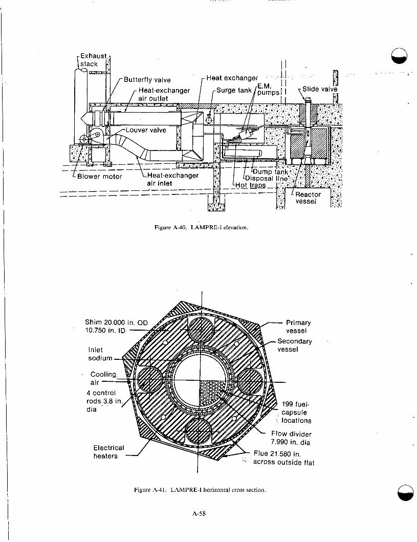
Figure A-40. LAMPRE-I elevation.
Figure A-41. LAMPRE-I horizontal cross section.
A-58

- S 'odi
-
un
-
I inlet
-Borated- graphite cylinder
-Shim
T c .-
L
Figure A-42. LAMPRE-I vertical cross section.
A-59
m I
-
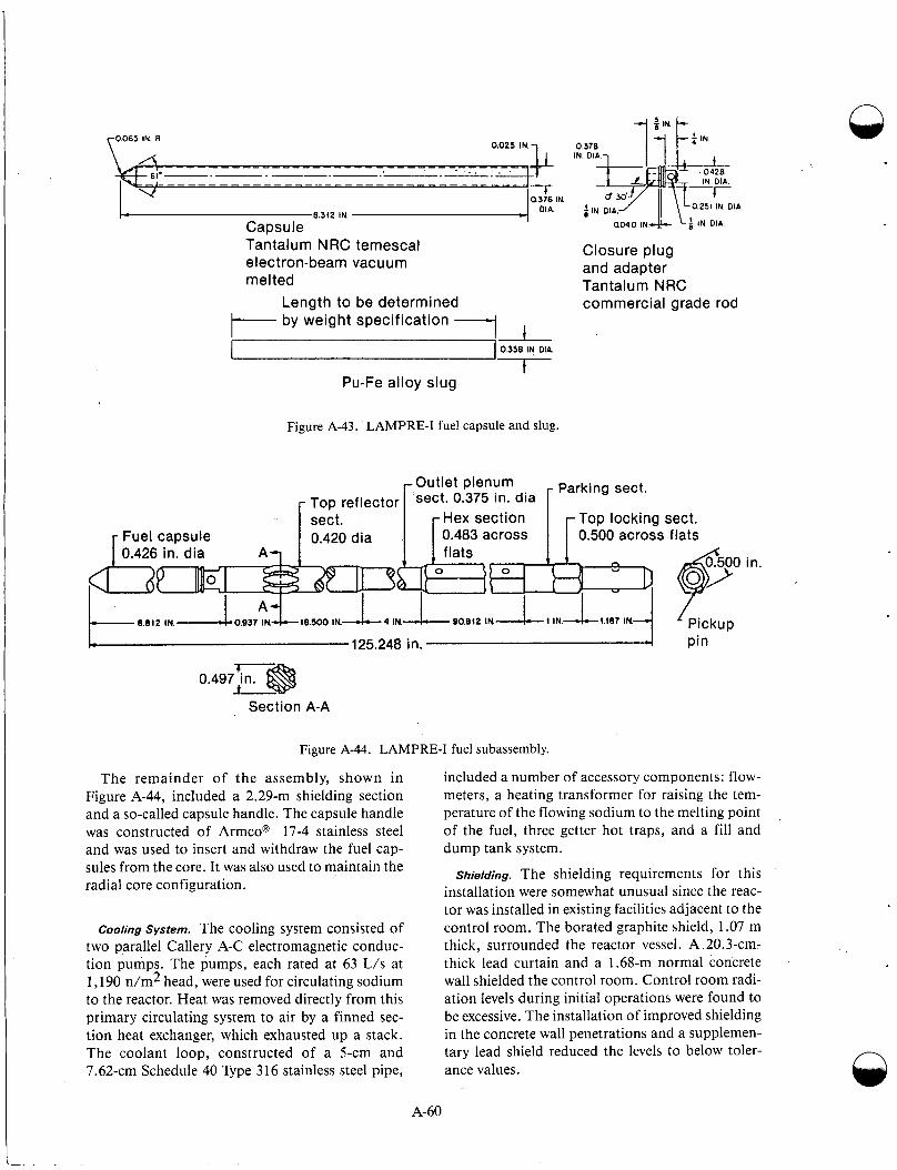
Tantalum NRC temescal Closure plug elec tron-beam vacuum and adapter melted Tantalum NRC
Length to be determined commercial grade rod
-1 I- by weight specification
-1 0358 IN DIA
f Pu-Fe alloy slug
Figure A-43. LAMPRE-I fuel capsule and slug.
Top locking sect. 0.483 across 0.500 across flats
Section A-A
Figure A-44. LAMPRE-I fuel subassembly.
The remainder of the assembly, shown in Figure A-44, included a 2.29-111 shielding section and a so-called capsule handle. The capsule handle was constructed of Armco@ 17-4 stainless steel and was used to insert and withdraw the fuel cap- sules from the core. It was also used to maintain the radial core configuration.
Cooling System. The cooling system consisted of two parallel Callery A-C electromagnetic conduc- tion pumps. The pumps, each rated at 63 L/s at 1,190 n/m2 head, were used for circulating sodium to the reactor. Heat was removed directly from this primary circulating system to air by a finned sec- tion heat exchanger, which exhausted up a stack. The coolant loop, constructed of a 5-cm and 7.62-cm Schedule 40 Type 316 stainless steel pipe,
included a number of accessory components: flow- meters, a heating transformer for raising the tem- perature of the flowing sodium to the melting point of the fuel, three getter hot traps, and a fill and dump tank system.
Shielding. The shielding requirements for this installation were somewhat unusual since the reac- tor was installed in existing facilities adjacent to the control room. The borated graphite shield, 1.07 m thick, surrounded the reactor vessel. A 20.3-cm- thick lead curtain and a 1.68-m normal concrete wall shielded the control room. Control room radi- ation levels during initial operations were found to be excessive. The installation of improved shielding in the concrete wall penetrations and a supplemen- tary lead shield reduced the levels to below toler- ance values.
A-60

. . -. . . . .. .
A vertical cross-section of the shielding is shown in Figure A-45. The shield below the core was based on a design specification of 2-mrem/h dose rate in the exclusion area in the shadow of the shield. In addition, the shield consisted of a 40.6-cm-thick iron bottom reflector in a 2.13-m-long floor shield plug filled with lead shot in the bottom 30 cm, and magnetite aggregate in the remainder.
i
The fuel-capsule handles alone provided approx- imately 2.7 m of iron shielding directly above the core. A ceiling shield plug of heavy concrete and steel shot provided the access through the 1.68-m concrete ceiling. During initial low-power opera- tion, it was necessary to add an additional lami- nated iron masonite shield on top of the shield plug and a concrete shield around and on top of the fuel transfer area.
Operation. The LAMPRE-I reactor was designed as a facility for the study of molten plutonium fuels
and containers, and investigation of operating problems that might be unique to the fluid nature of the fuel. The reactor started in 1961 with dry critical and low-power operations. It was brought up to its design power of 1 MW in early 1961. In April 1962, the reactor was reloaded with a h4ark-I1 core. After capsule failure in September 1962, which permitted 75 g of plutonium iron fuel to enter the coolant, the power level was temporarily limited to 500 kW.
Stabilityand Control. Although bubbles of fission- produced gases tend to rise to the surface of the fuel, some separation of large portions of the fuel regions apparently result in reactivity changes with time, as shown in Figure A-46. In the Mark-I load- ing, solid additives of carbon or plutonium carbide used to inhibit corrosive attack on a tantalum cap- sule were believed to interfere with the release of the accumulated gas, accentuating this reactivity loss.
Sod i u rn eq u i prnen t room
14-in. steel cover 7 Ceiling shield plug \ 6 in. Steel
0 3 6 u
Feet
Figure A-45. LAMPRE-I shield, vertical cross shielding.
A-6 1

0 10 20 30 40 50 60 70 80 90 100110 120 Integrated power [MW(T)]
Figure A-46. Reactivity loss during LAMPRE-I opera- t ion.
Although approximately $10 of reactivity was lost in the Mark-I loading, there was never any indi- cation of instability caused by the froth or low den- sity portion of the fuel. In the Mark-I1 loading, the disengagement of evolved gases was cleaner, with a smaller reactivity loss; this resulted as a function of integrated power, as shown in Figure A-46. During operation the dynamic characteristics of the reactor were evaluated. Temperature coefficients, power coefficients, and reactor transfer functions were measured. Figures A-47 and A-48 show typical results. Substantial negative temperature coeffi- cients provide a high degree of operational stability.
Fuel Test Program. LAMPRE-I fuel consisted of 24 g of plutonium alloy, 90 at .% plutonium, 10 at.% iron. The rather unusual density characi teristics of this alloy (Figure A-49) can lead to a plug during solidification because the lower density solid material tends to float to the top of the remaining fluid portion. In the initial loading, pres- ence of a few hundred ppm of carbon and a pluto- nium fuel alloy was believed to be effective in reducing the inter-granular attack on tantalum. Subsequent tests, however, indicated that fuel made with pure iron was less corrosive than fuel with added impurities. Likewise, the pure system has the advantage of reducing the froth region formation with its resulting reactivity loss. The fuel alloy used in the Mark-I and Mark-I1 cores has a high pluto- nium concentration and is not particularly suitable for high performance reactors because of the heat removal limitation. Attention has therefore been given to ternary alloys, Le., plutonium-cobalt- cerium and plutonium-copper-cerium, which per- mit plutonium concentrations from 2 to 4 g/cm2 at
0 2 4 6 8 1 0 1 2 Time (min)
Figure A-47. LAMPRE-I core power and inlet and out- let temperature changes from 45 kW(t) vs. time.
- 6 w i I I111111 I I 1 1 1 1 -8 102 IO' 1 10
Frequency (radiansls)
Figure A-48. LAMPRE-I transfer functions for various power levels.
operating temperatures. Some test capsules con- taining the former alloy have been irradiated in the LAMPRE core.
Following fuel leakage from several elements, the LAMPRE-I was shut down and unloaded. Deci- sion not to reload the reactor was based on a find- ing that little, if any, new information could accrue from continued operation of the reactor. The maxi- mum fuel exposure obtained was 0.5 at.% burnup of the plutonium at a maximum specific rating of 60 W/g. Because of the concentrated nature of the fuel, these modest figures do not emphasize the sig- nificant aspects of the fuel experience that had been obtained.
The LAMPRE operation successfully demon- strated satisfactory fuel performance at levels of up to 1 kW/cm3 of fuel. This figure, translated to more dilute fuel (4-g plutonium/cm3) more appro- priate for larger reactor systems, predicted no prob- lems from fission gas evolution at 250 W/g. The fuel exposure level of 2.4 x 10²⁰ fissions per cubic
A-62

15.2 15.0 0 5 100 200 300 400 500 600 700 800
Temperature ("c)
Figure A-49. LAMPRE-I plutonium-iron fuel density vs. temperature.
centimeter also translates to the same fission prod- uct density present with a 2.5 to 3 at.% burnup of the plutonium in the dilute fuel. Thus, with a com- paratively modest and inexpensive first experiment with molten plutonium fuel, highly satisfactory control, reactivity behavior, and successful gas dis- engagement from the fuel was demonstrated. In addition, there were no significant effects observed on the containment from appreciable concentra- tions of fission products in the fuel.
SEFOR
Concept. On March 27, 1964, the Atomic Energy Commission, Karlsruhe Laboratory a t West Germany, EURATOM, Southwest Atomic Energy Associates, and the General Electric Company for- mally embarked on a program to construct and operate a 20-MW ceramic-fueled, sodium-cooled, fast flux reactor. The test program to be carried out with this reactor was intended to verify calculations that would indicate that fast ceramic power reac- tors can be designed to be stable and have desirable operating characteristic^.^-^^-^^ The Southwest Experimental Fast Oxide Reactor (SEFOR) was
designed to have physics characteristics similar to those calculated for large fast ceramic power reac- tors. SEFOR was also designed to be operated with fuel composition, temperatures, and cryhtalline states characteristic of proposed fast ceramic power reactors. SEFOR was intended to provide experi- mental data to promote understanding of the behavior of the Doppler effect under operating reactor conditions. It was recognized early in the planning of SEFOR that, in addition to the general concern associated with the design of a then rela- tively undeveloped reactor system, such as the sodium-cooled fast reactor, unique problems would be involved in SEFOR because of the nature of the experimental program. Requirements for suppres- sion of fuel and core expansion coefficients 1.0 per- mit accurate measurements of the Doppler coefficient and forced stability of the core during the entire testing program, including the power transient experiments, strongly influenced the design of the core and vessel internal hardware.
Reactor Building. An elevation view of the reactor building is given in Figure A-50. The reactor build- ing is divided into two containment barriers. The
A-63

Figure A-SO. SEFOR reactor building, elevation view.
A-64
n
n

outer containment structure is an all-welded steel cylinder 15.2 m in diameter and 32.2 m high, designed for a pressure of 2.63 x lo3 Pa. The outer containment region is normally accessible.
The reactor equipment is located below grade in a refueling cell that extends above grade. The reac- tor core is contained within a steel liner which forms an inner containment barrier in the event there is a release of fission products. The area below grade contains a nitrogen atmosphere during operation, whereas the refueling cell contains high purity argon. The inner containment barrier, was designed for a pressure of 600 Pa.
During operation of the reactor, the first con- tainment barrier is sealed in the sense that all pene- trations to and from this area contain valves or doors in the “closed” position. Fluids required, such as nitrogen and argon, are transferred by pairs of batch tanks arranged such that when fluid is being transferred from a batch tank to an area within the first containment barrier, the batch tank is valved off from external supplies of fluid. Simi- larly, when the batch tank is being charged with fluid, it is valved off from the inner containment area. A similar scheme is used to remove waste gas from the inner containment. The nitrogen within the first containment barrier is cooled by means of freon refrigeration units arranged so that only closed coils penetrate the first containment barrier. The air region between the steel-lined cells and the outer containment vessel is also cooled by a freon refrigeration unit, but it is normally ventilated via a 15-cm air intake line, and a 15-cm air exhaust line that exhausts to the atmosphere through a small stack.
Reactor ve.sse/. The general arrangement of the ves- sel and internal structure is shown in Figures A-51 and A-52. The vessel consists of a lower, small diameter core section and an upper, large diameter shielding section. Design pressure and temperature are 5.3 kPa and 570°C, respectively. The reactor will normally operate at a positive pressure of approximately 15.2 cm of water pressure relative to the refueling cell. The vessel head is designed in two pieces: the outer peripheral head which is seal- welded to the vessel flange and the center head which is normally held in place by its static weight. The center head can be removed for refueling the core. The outer head needs to be removed only in the event that major repairs are required in the core support structure. Special accident hold-on struc- tures are provided for both the outer and center
A-65
heads. The center head contains a fuel clxe that permits several fuel rods to be removed for inspec- tion without the need for removing the cent’x head.
Coolant System. A simplified diagram of the SEFOR coolant system is shown in Figures A-53 and A-54. The system comprises two parallel loops, each consisting of two loops in series. The numbers in the figures are the elevations of the indi- cated points relative to the core center. The primary sodium loop transports reactor heat from the reac- tor vessel to the intermediate heat exchangers. The secondary sodium loop, in turn, transfers the heat to the air blast heat exchangers, where it is dumped into the atmosphere. The main coolant loop was designed for a coolant flow of 315 L/s, whereas the auxiliary loop was designed for 15.8 L/s . Type 304 stainless steel piping was used throughout the coolant system.
The loops were designed so a rupture in one loop would not affect the operating ability of the other. This was done by locating the vessel’s main coolant system nozzles at an elevation such that a break in the main loop could not drain the vessel’s !;odium below a point well above the reactor core. To guard against leaks in the reactor vessel itself, a safkty ves- sel in the form of a cuff was placed around the vessel in near the core as shown in Figure A-54. The safety vessel extends up to the main coolant system nozzles, keeping the sodium level well below the auxiliary loop dip tubes in case a vessel leak develops below this elevation. The safety vessel is welded and hermetically sealed to the reactor ves- sel. Provisions were made to periodically pull a vac- uum on the volume between the two vessels to verify the leak tightness of the safety vessel. Sodium leak detectors continuously monil or for sodium leakage into the safety vessel.
Precautions were taken to minimize probable loss of pumping power during an accident. Because electromagnetic pumping systems have low inertia characteristics, the sodium coolant flow would drop suddenly if pumping power were lost. To pre- vent this, two independent motor-generator sets with built-in flywheel inertia units were used to power the main primary coolant system pump. Each set is connected to one of the two coils operat- ing the pump and is driven by the external power obtained from the incoming 69-kV line. If external power is suddenly lost, these sets coast down on their flywheel inertia and maintain sufficienlt flow to prevent an increase in the coolant temperature. The flywheels were sized such that the coolant flow
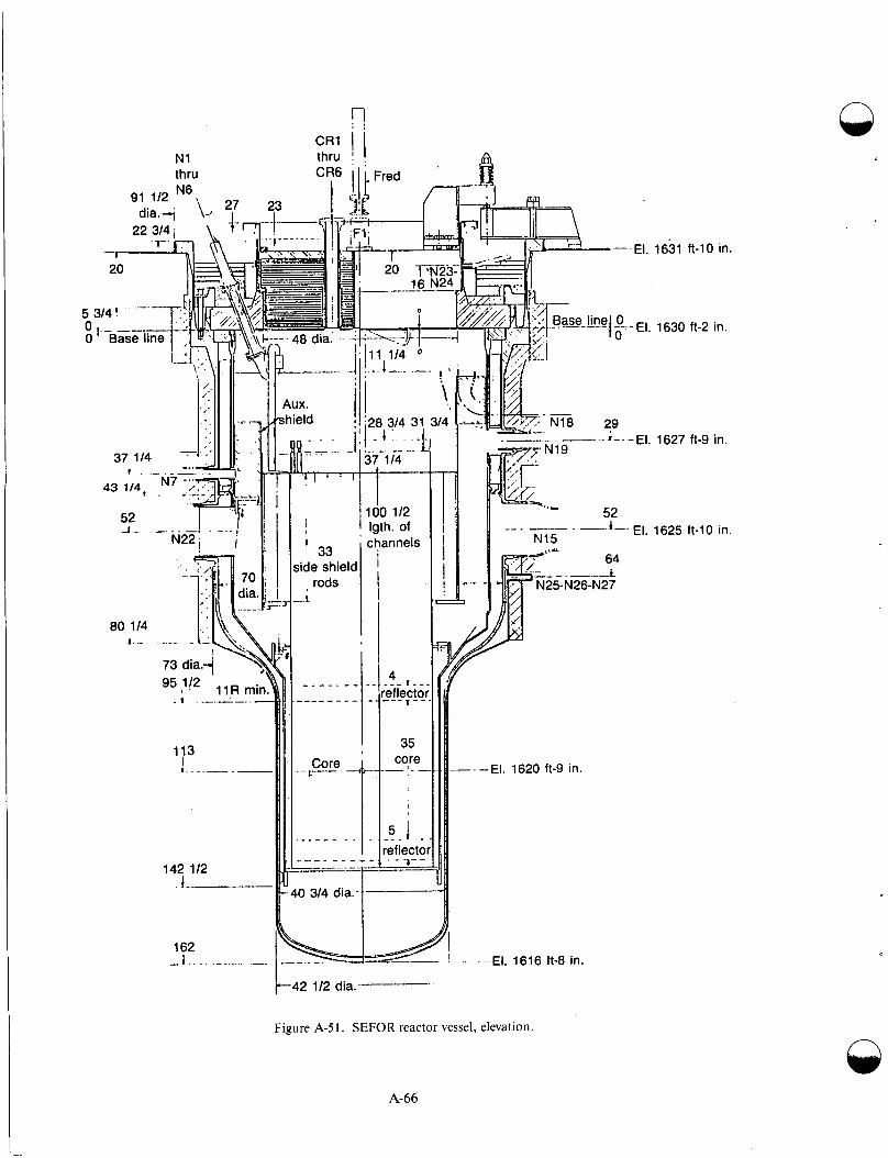
N1 thru
91 112 N6 d i a . 4 \ - p
27 I
CR1 thru CR6
?3 I
r 1
80 114 1.-
- 48 dia.' - -
_A_C.-.
4ux. hield
1 I! i
. I 1 - - - .. - ~-
--- -- . --I==
7. of innels
4 1 . -
ef!e:Cto
35 core - - -
I .5 - 1 .. - ,eflecto ~ - 7 - -
1631 ft-10 in.
1630 ft-2 in.
1627 ft-9 in.
1625 ft-10 in.
E 4 2 112 dia.---
Figure A-51. SEFOR reactor vessel, elevation.
A-66

Figure A-52. SEFOR reactor vessel, plan view.
- -4
5 ux pump
t 1 Main pump
Approx. elevations in feet with respect to core
Piping lengths (feet) Main Aux
Reactor to IHX 50 34
Pump to reactor 92 28
26
IHX to pump 57 1
Figure A-53. SEFOR coolant system.
A-67
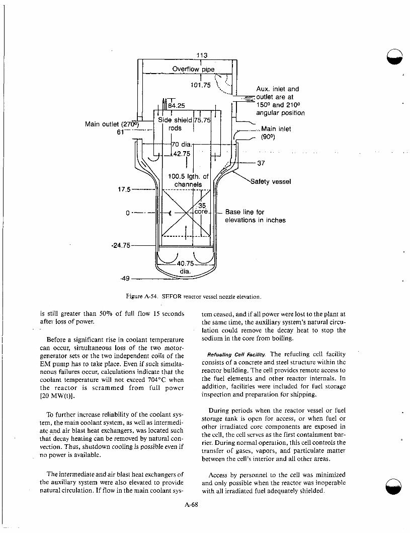
Main
Aux. inlet and - .=..outlet are at 1500 and 2100 angular position
elevations in inches
Figure A-54. SEFOR reactor vessel nozzle elevation.
is still greater than 50% of full flow 15 seconds after loss of power.
Before a significant rise in coolant temperature can occur, simultaneous loss of the two motor- generator sets or the two independent coils of the EM pump has to take place. Even if such simulta- neous failures occur, calculations indicate that the coolant temperature will not exceed 704°C when the reactor is scrammed from full power [20 MW(t)].
To further increase reliability of the coolant sys- tem, the main coolant system, as well as intermedi- ate and air blast heat exchangers, was located such that decay heating can be removed by natural con- vection. Thus, shutdown cooling is possible even if no power is available.
The intermediate and air blast heat exchangers of the auxiliary system were also elevated to provide natural circulation. If flow in the main coolant sys-
tem ceased, and if all power were lost to the plant at the same time, the auxiliary system’s natural circu- lation could remove the decay heat to stop the sodium in the core from boiling.
Refueling Cell Facility. The refueling cell facility consists of a concrete and steel structure within the reactor building. The cell provides remote access to the fuel elements and other reactor internals. In addition, facilities were included for fuel storage inspection and preparation for shipping.
During periods when the reactor vessel or fuel storage tank is open for access, or when fuel or other irradiated core components are exposed in the cell, the cell serves as the first containment bar- rier. During normal operation, this cell controls the transfer of gases, vapors, and particulate matter between the cell’s interior and all other areas.
Access by personnel to the cell was minimized and only possible when the reactor was inoperable with all irradiated fuel adequately shielded.
n
A-68
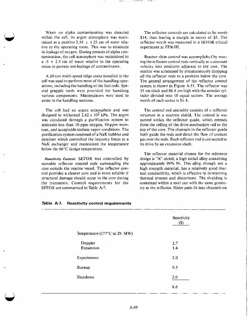
When no alpha contamination was detected within the cell, its argon atmosphere was main- tained at a positive 2.54 f 1.25 cm of water rela- tive to the operating room. This was to minimize in-leakage of oxygen. During periods of alpha con- tamination, the cell atmosphere was maintained in a -5 + 2.5 cm of water relative to the operating room to prevent out-leakage of contaminants.
A 10-ton multi-speed ridge crane installed in the cell was used to perform most of the handling oper- ations, including the handling of the fuel rods. Spe- cial grapple tools were provided for handling various components. Manipulators were used to assist in the handling motions.
The cell had an argon atmosphere and was designed to withstand 2.62 x lo2 kPa. The argon was circulated through a purification system to maintain less than 10-ppm oxygen, 10-ppm mois- ture, and acceptable sodium vapor conditions. The purification system consisted of a NaK bubbler and demister which controlled the impurity limits in a NaK exchanger and maintained the temperature below the 66°C design temperature.
Reactivity Control. SEFOR was controlled by movable reflector control rods surrounding the core outside the reactor vessel. The reflector con- trol provides a cleaner core and is more reliable if structural damage should occur to the core during the transients. Control requirements for the SEFOR are summarized in Table A-7.
Table A-7. Reactivity control requirements
The reflector controls are calculated to be worth $14, thus leaving a margin in excess of $ 5 . The reflector worth was measured in a SEFOR critical experiment at ZPR-111.
Reactor shim control was accomplished by mov- ing the reflector control rods vertically at a constant velocity into positions adjacent to the core. The reactor was scrammed by simultaneously dropping all the reflector rods to a position below the core. The general arrangement of the reflector control system is shown in Figure A-55. The reflector was 15 cm thick and 86.4 cm high with the annular cyl- inder divided into 10 equal sectors. The average worth of each sector is $1.4.
The control rod assembly consists of a reflector structure in a neutron shield. The control is was moved within the reflector guide, which extends from the ceiling of the drive mechanism cell to the top of the core. The channels in the reflector guide both guide the rods and direct the flow of coolant gas over the rods. Each reflector rod is connected to its drive by an extension shaft.
The reflector material chosen for the reference design is “A” nickel, a high nickel alloy containing approximately 99% Ni. This alloy, though not a high strength material, has a relatively good ther- mal conductivity, which is effective in milnimizing thermal stresses and distortions. The shielding is contained within a steel can with the same geome- try as the reflector. Slider pads fit into channels on
Temperature (177OC to 29 MW)
Doppler Expansion
Experiments
Burnup
Shutdown
Reactivity ($1
2.7 1.6
2.0
0.3
2.0
8.6
A-69

T 34 in.
4 22 112
0 1
17
T- 1 ft-5 in.
in. 1 Iy
.12 ft-0 in.
-143 in. floor level
Core
Reflector
Vessel
Instrument tubes (1 2)
Plug;
Reflector shaft
-- Coupling .- Drive control area
- Twin screw drive
- Coarse drive
--.Cylinder (40 in. stroke)
--- Position indicator
-- Motor dirve
n 1 2 3 4 5 6
Figure A-55. SEFOR reflector control system.
Graphic scale in feet
n
A-70
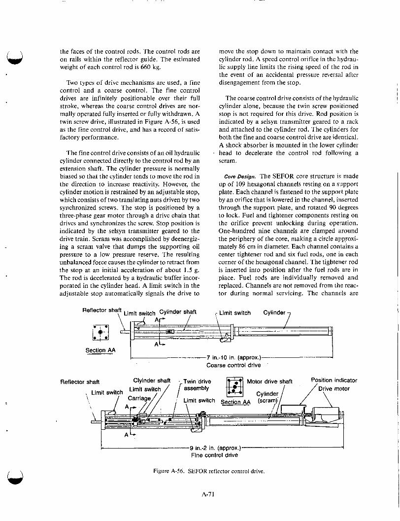
the faces of the control rods. The control rods are on rails within the reflector guide. The estimated weight of each control rod is 660 kg.
Two types of drive mechanisms are used, a fine control and a coarse control. The fine control drives are infinitely positionable over their full stroke, whereas the coarse control drives are nor- mally operated fully inserted or fully withdrawn. A twin screw drive, illustrated in Figure A-56, is used as the fine control drive, and has a record of satis- factory performance.
The fine control drive consists of an oil hydraulic cylinder connected directly to the control rod by an extension shaft. The cylinder pressure is normally biased so that the cylinder tends to move the rod in the direction to increase reactivity. However, the cylinder motion is restrained by an adjustable stop, which consists of two translating nuts driven by two synchronized screws. The stop is positioned by a three-phase gear motor through a drive chain that drives and synchronizes the screw. Stop position is indicated by the selsyn transmitter geared to the drive train. Scram was accomplished by deenergiz- ing a scram valve that dumps the supporting oil pressure to a low pressure reserve. The resulting unbalanced force causes the cylinder to retract from the stop at an initial acceleration of about 1.5 g. The rod is decelerated by a hydraulic buffer incor- porated in the cylinder head. A limit switch in the adjustable stop automatically signals the drive to
move the stop down to maintain contact with the cylinder rod. A speed control orifice in the hydrau- lic supply line limits the rising speed of the rod in the event of an accidental pressure reversal after disengagement from the stop.
The coarse control drive consists of the hydraulic cylinder alone, because the twin screw positioned stop is not required for this drive. Rod position is indicated by a selsyn transmitter geared to a rack and attached to the cylinder rod. The cylinders for both the fine and coarse control drive are identical. A shock absorber is mounted in the lower c,ylinder head to decelerate the control rod following a scram.
core Design. The SEFOR core structure is made up of 109 hexagonal channels resting on a support plate. Each channel is fastened to the support plate by an orifice that is lowered in the channel, inserted through the support plate, and rotated 90 degrees to lock. Fuel and tightener components resting on the orifice prevent unlocking during operation. One-hundred nine channels are clamped around the periphery of the core, making a circle approxi- mately 86 cm in diameter. Each channel contains a center tightener rod and six fuel rods, one in each corner of the hexagonal channel. The tightener rod is inserted into position after the fuel rods are in place. Fuel rods are individually removed and replaced. Channels are not removed from the reac- tor during normal servicing. The channds are
Ref lector
\ 7 ,- Limit switch Cylinder Ref'ector sha\ft Limit switch Cylinder shaft
7 in.-10 in. (approx.) Coarse control drive I- Section AA
shaft Clyinder shaft - Twin drive , Limit switch Limit switch / [ assembly
Motor drive shaft Position indicator Cylinder 1 / ~ r \ v e n iotor
mit switch Section AA (scra '>
4 L- 9 in.-2 in. (approx.) 4
Fine control drive
Figure A-56. SEFOR reflector control drive.
A-7 1
approximately 254 cm long. The top of the channel is 20.3 cm below the top of the fuel rods to provide for the routing of instrument leads from the instru- mented fuel rods.
The fuel rod assembly consists of two pieces: a fuel rod and an extension rod. The two sections are pinned together to form the fuel rod assembly.
The active fuel column in the core is 85.9 cm long. A 10.2-cm nickel reflector is located above and below the fuel. Both fuel and reflector are con- tained inside Spe-3 16 stainless steel tubing, 2.54-cm OD, 1.4-m wall thickness. The lower end of the fuel rod fits into a rod sheet in the channel assembly. The upper end provides a connector for attachment to the extension rod.
The fuel extension rod consists of borated graph- ite pellets contained in 2.22-cm-OD tubing. A socket at the upper end provides a grapple tool attachment. The upper end of the extension rod and fuel rod are identical so a single grapple tool can handle either section after detachment. Splined regions enlarged the diameter to 2.54 cm at eleva- tions where the tightening springs are needed. Splines are necessary for passage of adequate coolant.
Development Testing. Early in the planning of the SEFOR program it became obvious that several areas of the reactor would need development test- ing to ensure satisfactory performance. The variety of power transients, ranging from oscillatory exper- iments to prompt power excursions, placed unusual operating conditions on the reactor components. It was desirable to have information on core behavior to help interpret the experiments during operation. Consequently, a development test program was planned covering critical experiments: in-pile and out-of-pile testing of fuel assemblies and core; refueling cell mock-up; instrumentation; and spe- cial reactivity controls.
A series of critical experiments was conducted with a mock-up of the SEFOR core and the ZPR- 111 critical facility at the Idaho National Engineer- ing Laboratory. Measurements included the plutonium requirement, Doppler coefficient, and reflector control strength. Results of these experi- ments were used to check the calculational tech- niques used in the SEFOR a n a l y ~ i s . * - ~ ~ - ~ ~
The mock-up represented four main sections:
e Core
Radial and axial reflector . I
Sodium and steel structure between core and reflector
Boron carbide neutron shielding sur- rounding the radial reflector.
Experimental Program. The experiments per- formed at SEFOR were to obtain power coefficient information applicable to large fast power reactors at steady state conditions and during fast tran- sients. Experiments between these two domains, i.e., for slowly varying oscillatory operations, were also carried out with SEFOR to provide further information. The goal of the SEFOR test program was to make it possible to predict with confidence the safety characteristics of future large fast ceramic power reactors.
It was shown that a low-power experimental reac- tor, with large-diameter fuel rods, can give informa- tion on power coefficients directly applicable to high-power reactors with small-diameter fuel rods under steady state and fast transient conditions .A-58
SEFOR experiments indicate that the reactivity effect caused by the change between two steady state power levels with unchanged fuel clad temper- ature is independent of fuel rod radius. This reac- tivity effect is the product of the change in power per unit length of rod and a parameter, G, or
Ak = GA(P/nH), (A-7)
where n is the number of rods, P is the power, and H is the rod length. For a given fuel material, G depends only on P/nH and the fuel temperature coefficients.
A similar result was obtained at SEFOR for fast transients during the period when power is chang- ing fast enough that heat conduction of the fuel rod can be ignored. For this case the time-dependent feedback reactivity is
Ak = YA(E/Vf),
n
A-72
. ..
where E is the excess energy produced during the excursion to time t and Vf is the fuel volume. For a given fuel material, Y is a function only of the fuel temperature coefficient (Po/nH), and (E/Vf), where Po is the power level at the start of the excur- sion. Again, the radius of the fuel rod did not enter explicitly.
Three types of steady state tests were made at SEFOR. The purpose of these was to measure the following:
The power coefficient associated with changes in fuel temperature only
The coolant temperature coefficient
The combined fuel and coolant tempera- ture coefficient
The flow coefficient and effect of minor changes in structure geometry.
The first test was the reactivity measurement described by Equation (A-7). The reactivity effect caused by changing the steady state power level while holding the average coolant and structure temperature constant was measured. The average coolant temperature was held constant by variation of the primary flow rate and variation in secondary coolant conditions. The channel and Be0 tempera- tures follow the coolant temperature. Second order corrections were made for small changes in average clad temperature. In these steady state tests, the Parameter, G , of Equation (A-7) was measured as a function of P/nH for the SEFOR oxide fuel up to P/nH equals 11 kW/ft, the value at 20 MW.
To the extent that the thermal conductivity of the SEFOR fuel was known, the Parameter G could be related to the fuel temperature coefficient. SEFOR fuel was designed to minimize the axial fuel expan- sion coefficient so that the Doppler effect accounts for most of the fuel temperature coefficient. In this way, the first type of steady state test provides a measurement of a Doppler coefficient.
, 1
The coolant temperature coefficient can then be measured independently of fuel temperature effects. While operating at a fixed power level, the reactivity effect caused by changing the average sodium temperature is measured. The sodium tem- perature can be changed either by altering the pri- mary flow rate or by altering the secondary coolant conditions. The effect of radial expansion of the
structure is included in the coolant cocfficient because the structure temperature follow the sodium temperature. Radial expansion is not con- trolled by the grid plate in SEFOR so a grid plate coefficient was not included.
The combined fuel and coolant uniform temper- ature coefficient was measured at zero power by externally heating the sodium. Provisioiis were made to heat the sodium to 540°C. The response to reactivity oscillations from zero power to high power was measured to determine the feedback transfer function. At low frequencies, the feedback reactivity provides a measure of a steady state Parameter, G [Equation (A-7)] which involves the Doppler coefficient and the fuel conductivity, k. These oscillator results in effect duplicate and ver- ify the steady state measurement. At high frequen- cies the feedback reactivity provides a measure of a transient parameter [Equation (A-8)], which involves the Doppler coefficient and the heat capacity, or pCp. The high frequency results pro- vided an independent measurement of the parame- ters important to the transient behavior of the reactor and permitted a prediction of its transient performance prior to the transient tests. At inter- mediate frequencies, the feedback reactivity is characteristic of neither steady state nor fa:a tran- sient operation alone; the results depend on both k and pCp.
Fast transient tests were made to obtain informa- tion about the energy coefficient Y of Equa- tion (A-8), a parameter relating fuel tempera.ture to the heat capacity. The transient experiments came after a thorough analysis of the steady state and oscillator tests.
Both subprompt critical transient (Ak < $1) and prompt critical transients were run. Reactivity ramps were introduced by injecting poison from the center of the core by means of a fast reactivity excursion device (FRED). Maximum ramp rates and maximum values for FRED depend on the val- ues obtained for the Doppler coefficient from the steady state and oscillator tests. The transient test program was not intended to approach the regime where fuel damage would result.
Demonstration of Equipment Reliability in Operating
Lifetime. Two designs measured the sodium kvel in the SEFOR reactor vessel. The reliability of either design was satisfactory for short periods, 5:everal months, the number of months depending on serv- ice conditions during the time. However, without
A-7 3
frequent cleaning or special care, the performance of either was inadequate for operating periods of several years .A-59
During the more than three years of operation, the electromagnetic sodium pumps operated with- out a malfunction. Some malfunctions of pump power supply and controllers did occur, but these components were easily and quickly repaired. The reliability of fuel grapples for nearly 4,000 fuel transfers was very good.
USSR BR-5
The first USSR fast reactor, BR-1, was built in 1955 as a zero energy assembly; it was fueled with plutonium and was used to investigate fast reactor physics. The work was extended by BR-2, a pluto- nium filled, mercury-cooled reactor built in 1956 and operated to 100 kW(t). The BR-2 provided the facilities for physics experiments and irradiation of materials in fast neutron fluxes at 1014 neutrons/ cm2/s, and furnished experience in operating at temperatures to 160"C.A-60361
The BR-2 was dismantled in parts, such as shield- ing, for use in construction of the BR-5 reactor which was completed in 1958. It went cold critical in the summer of 1958 and was in operation the sum- mer of 1959. The BR-5 operated at a power of 5 MW(t), was fueled by plutonium oxide, and had sodium inlet and outlet temperatures of 375 and 450"C, respectively. The main purpose of the reac- tor was to gain burnup data on fuel elements, to gain experience operating radioactive sodium cir- cuits and to irradiate various materials. Since it was not considered necessary to obtain further data on breeding gain, the design was simplified by omit- ting the normal blanket of natural or depleted uranium .A42963
The reactor started up at zero power July 1958. From July 1958 to January 1959, the assembly of the primary loop was completed and startup modi- fications were accomplished. In January 1959, the reactor was started up with sodium coolant. From January to July 1959, the reactor operated to 1 MW. On July 21, 1959, full power of 5 MW(t) was reached. Later, the reactor was operated at var- ious levels to 5 MW(t) to obtain a 450°C sodium outlet temperature. The sodium temperature in the primary loop was raised to 500°C in December 1960. During 1960 and 1961, the reactor was used for experiments: (a) calibration of control rods, (b) determination of circulating sodium's effect on
reactivity, (c) measurement of temperature and power coefficients, (d) determination of spatial neutron-energy distribution and heat generation, (e) measurements of neutron flux in experimental channel sections of the reactor, and ( f ) determina- tion of radioactivity effects and safety aspects.
The general arrangement of the reactor is shown in Figure A-57. An unusual feature is the horizon- tal graphite column, 3.1 m long, which penetrates one side of the shield and provides a number of locations for horizontal and vertical experiments. Maximum power density was 500 kW(t)/L corre- sponding to a maximum heat flux of 1.39 MW/ m2.
Core Assembly. The core consisted of 88 hexago- nal fuel assemblies, 2.6 cm across flats and 83.8 cm long, surrounded by two rows of blanket subassemblies. Each fuel subassembly, shown in Figure A-58, contained 19 stainless steel clad pins filled with plutonium oxide pellets and sealed after they had been charged with helium gas. The pins were 0.5 cm OD. The fuel itself was about 0.41 cm in diameter, and the cladding was 0.041 cm thick. The pins were separated by spiral wire spacers. Sub- assemblies were supported at the bottom by a per- forated plate. The core subassemblies and a ring of tubes loaded with natural uranium were enclosed in a stainless steel vessel approximately 36 cm in diameter. Clearance between subassemblies was 0.05 cm. The core itself was approximately 28 cm by 28 cm. There was no top plate, and no positive lateral restraint was provided at the center or top. Sodium flowed up through the core from a single inlet at the bottom of the central sodium tube to a single outlet above the core that supplied two cool- ing circuits.
Control Elements. Movement of an inner and outer cylindrical reflector was used to control the reactor. The inner nickel cylinder, 5.1 cm thick, was raised or lowered by cables; the outer 10-cm-thick nickel cylinder had two movable sections that pro- vided fine control. Emergency shutdown was accomplished by electromagnetically releasing these two cylinders. In addition, two controls oper- ating in the outer cylinder provided shim adjust- ment. Heat generated in the reflector was removed
by air. Startup instrumentation was located in the water tank outside the reflector, as shown in Figure A-57.
When the assembly was heated from 40 to 600"C, the radioactive gas release rate increased by
A-I4
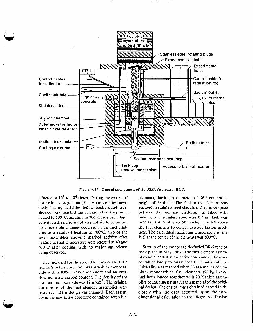
Figure A-57. General arrangement of the USSR fast reactor BR-5.
a factor of lo3 to lo4 times. During the course of testing in a storage hood, the two assemblies previ- ously having activities below background level showed very marked gas release when they were heated to 500°C. Heating to 700°C revealed a high activity in the majority of assemblies. To be certain no irreversible changes occurred in the fuel clad- ding as a result of heating to 700"C, two of the seven assemblies showing marked activity after heating to that temperature were retested at 40 and 400°C after cooling, with no major gas release being observed.
The fuel used for the second loading of the BR-5 reactor's active core zone was uranium monocar- bide with a 90% U-235 enrichment and an over- stoichiometric carbon content. The density of the uranium monocarbide was 12 g/cm3. The original dimensions of the fuel element assemblies were retained, but the design was changed. Each assem- bly in the new active core zone contained seven fuel
elements, having a diameter of 76.5 cm and a height of 38.0 cm. The fuel in the element was encased in stainless steel cladding. Clearance space between the fuel and cladding was filled with helium, and stainless steel wire 0.4 m thick was used as a spacer. A space 50 mm high was left above the fuel elements to collect gaseous fission prod- ucts. The calculated maximum temperature of the fuel at the center of the elements was 800°C.
Startup of the monocarbide-fueled BR-5 reactor took place in May 1965. The fuel element :assem- blies were loaded in the active core zone of the reac- tor which had previously been filled with sodium. Criticality was reached when 83 assemblies of ura- nium monocarbide fuel elements (99 kg IU-235) had been loaded together with 20 blanket assem- blies containing natural uranium metal of the origi- nal design. The critical mass obtained agreed fairly closely with the data acquired using tht: two- dimensional calculation in the 18-group diffusion
A-75

Figure A-58. BR-5 fuel assembly.
Section A-A
Fuel pin
approximation, which predicted a critical mass of 89 assemblies.
To conduct further studies on fuel burnup in the reactor, four assemblies of plutonium oxide ele- ments were loaded; these elements previously had been in the facility and had reached a burnup of approximately 6%. At the same time, two assem- blies of plutonium dioxide elements and two assem- blies of uranium dioxide elements with a burnup to 1% were inserted in the reactor. The plutonium dioxide was also used as a startup neutron source by using the (alpha, n) oxygen reaction and the spon- taneous fission of plutonium-240.
After the fuel had been loaded, studies were car- ried out on the reactor characteristics. Heat genera- tion over the radius and height of the active core zone was calculated on the basis of gamma activity distribution in the fuel element assemblies that were mounted at different radii. The effect of the drainage of sodium from the active zone was mea- sured by emptying all the sodium from the central reactor pipe under subcritical conditions. The reac- tor temperature coefficient, which is related to the uniformed heating of the elements in the active zone and the increase in the temperature of the sodium at the reactor inlet, was measured at differ- ent power levels ranging from 10 to 4000 kW. The temperature coefficient was found to be constant for sodium inlet temperatures ranging from 180 to 430°C. The steady state power coefficient, which is a function of the nonhomogeneous heating of the reactor elements, was measured on the basis of the change in reactivity as power increased at the con- stant sodium inlet temperature. The steady state power coefficient was constant throughout the power range measured. The reactor power effect was measured by observing the reactivity curve after power was stepped up by 10% at a starting value for various sodium flow rates. In each mea- surement, the inlet temperature of the sodium rose by 75°C.
Two temperature coefficients of reactivity were measured in BR-5, one relative to the inlet tempera- ture and the second relative to the outlet tempera- ture. These agreed with predictions and were both negative. The fuel elements, supported .in a lower support plate, were free to move at the top to take up any tolerances in the lower plate. The pins within the subassemblies were welded together at the bottom. Alternate pins were wound spirally with stainless steel wires, which acted as spacers. Bowing of pins in the subassemblies tended to
A-76
. . . . - - . - .. -. . . -. . . . - . . . - . . . . . .
cause the outer element tubes to move outward to reduce reactivity. An increase in coolant flow had a similar effect.
Coolant System. The coolant system was split into two IO-cm-diameter primary loops. The pump seal and bearings operated in argon cover gas continu- ously circulated through a silica gel dryer and then through copper-coated silica gel heated to 250°C. The totally enclosed pump motor was likewise maintained under an argon gas pressure slightly higher than that of the system, so any possible leak- age was through the gland into the system.
Heat was transferred from the primary loops by two intermediate heat exchangers to two secondary loops. One of these NaK-filled secondary loops was provided with a 1.69-MPa steam generator having duplex tubes. Mercury was used as a heat transfer medium in the space between the inner and outer tubes. An air-cooled heat exchanger and a blower, delivering 11 m3/s of air, were used to reject the heat in the other loop through a 24.4-m stack. Residual heat after shutdown was also removed in this loop by natural convection.
Shielding, Components, and Structures. A water tank surrounded the core and provided a 51-cm shielding annulus. Surrounding this was a 41-cm- thick cast iron ring followed by a concrete wall with an average thickness of 109 cm, as shown in Figure A-57. Composing the upper shield were a boron carbide plug, two rotating steel plugs, and finally a removable top plug (consisting of layers of parafin wax and iron).
The lower shield consisted of a 20-cm-deep water layer, which allowed entry to the cell under the reac- tor only during shutdown.
Fuel loading was accomplished through a double eccentric rotating plug arrangement. During refuel- ing, the reactor was shut down, and sodium circula- tion in a primary loop was stopped. Decay heat was removed by natural convection. A transfer cask unit was used for charging fuel, uranium, and experimen- tal units. The reactor had no outer containment build- ing. The primary loops were housed in separate concrete cells, and the secondary circuit equipment was contained within a single compartment.
Experimental Facilities. The reactor had been designed not only to permit sample radiation under fast flux conditions but also to allow the insertion of special fuel subasse\mblies in the core in place of
A-77
normal elements. A 2.54-cm-diameter reentrant tube in the center of the core, designed for testing fuel elements, was cooled with a separate NaK cooling system. In this central loop, a peak flux of
neutrons/cm2.s was available. A flux of one- half this value was available in the exposure holes at the end of the core.
Operating Experience. Pump life was mainly deter- mined by ball bearing capabilities; it averaged 8,000 h. Replacement of primary equipment, including cold traps, usually started a week after shutdown following sodium gamma dlxay. The cold traps in the primary system were repllaced four times during the first 4 years of operation.
In October 1960, with about 2.5% inaximum plutonium burnup, the leakage of fission products into the sodium became pronounced. By September 1961, the cesium activity in the sodium was 70% of total cesium. At this time, the fuel burnup had reached 4.85%. The reactor was unloaded, and the subassemblies weie steam- blasted clean. During cleaning, some of the subas- semblies showed considerable increase of radioactivity in the steam condensate owing to increased failure of fuel pin cladding. Steam clean- ing was discontinued, and a leak test, with an ion- ization chamber, was then made to check each subassembly to measure fission gas activity. Of the 81 subassemblies tested, 8 had been washed with steam; of the remainder, 63 showed normal sodium impurity activity, and 10 had a gas activity higher by a factor of 1,000. Examination of the 4.85% burnup pins showed longitudinal cracks in the clad- ding caused by fuel swelling. The cracks showed up with a clearance between cladding and fuel that was at a minimum.
After fuel removal, the primary system was drained clean with steam at 'LO. 1 MPa and %120"C by injecting the steam into vent lines and removing the sodium from the low points in the reactor sys- tem. The system was kept at about 150°C' prior to steam injection. About 9,000 kg of steam was used, and no violent reactions occurred. Contami- nation of the primary system was reduced 50%. The system was then filled with pure water twice, with no circulation, and drained. There was no decrease in activity. Each section of the primary system, excepting a nickel basket in the real:tor, was then cleaned with a solution of 5% nitric: acid at about 70"C, with three successive flushes to reduce the activity by a factor of two to three. N[oreover, two sections were subjected to a 0.5% KMn04

solution flush for 24 h at about 70"C, a 5% nitric acid and 1% oxalic acid mixture flush for 3 to 4 h at 70"C, and a pure water flush for 1 h at about 70°C. The three flushes were repeated five times. Activity was reduced to a value low enough so that repair work could begin. A total of 21 flushes per section were performed, including the steam flush. This indicates the possible consequences of plating out fission products on system components. Radio- chemical analysis showed plutonium, zirconium, and cesium as the residual activity. After the final drain, the primary system was dried using vacuum and heat. Following repairs the system was filled with distilled sodium. The reactor was placed back in operation in March 1962 after a 7 month shut- down. Eighty percent of the original bundles were placed back in the reactor. Subsequent reports indi- cate some of these began to leak soon after startup.A-62-65
After March 1962, the charge in the BR-5 active core zone was replaced by plutonium dioxide and uranium dioxide assemblies. For further operation, the reactor was loaded with 80% plutonium dioxide assemblies from the original charge, with a maxi- mum burnup of 4.85% and uranium dioxide assemblies of similar design. P u 0 2 assemblies were concentrated in the central part of the active core zone. While loading the assemblies they were rear- ranged in order to equalize their burnup during subsequent operation of the reactor.A-66
During 1962 and 1963, BR-5 operated at 20 and 40% of its rated power. In 1964, the output was stepped up to 3 MW and then 3.5 MW, set equal to 70% of the rated power. After operating 3 years with fuel elements that had reached high burnup and had leaks in the cladding, it was possible to acquire some experience and information about the contamination of the coolant, inert gas, and pri- mary circuit equipment, because of the radioactive fission products. It was found that the release of gaseous and volatile solid fission products from the fuel elements to the coolant was mainly dependent on the reactor power, and therefore on the tempera- ture of the fuel elements. At a power of 1 MW, there was virtually no release of fission products from the fuel elements, and a contamination of the circuit was found to consist of Cs-137. The Cs-137 in the coolant was approximately 0.3 mCi/g of sodium and was caused by the residual contamina- tion of the primary coolant; in addition, the quan- tity of cesium removed from the sodium by the cold trap was extremely small. At a reactor power level of 3.5 MW, the release of fission products
increased considerably. The radioactive contamina- tion of the primary circuit, after the decay of the sodium-24, consisted of relatively short-lived fis- sion products: iodine-13 1, barium-140, lanthanum-140, cesium-136, and cesium-137. The activity of the iodine-131 was greater than that of the other isotopes amounting to 30 mCi/g of sodium. At the same time, it was found that the amount of iodine-131 released from the leaking fuel elements was usually lower than that of the cesium-137 release. Fission products such as iodine- 13 1, cesium- 136, and cesium- 137 were effi- ciently retained by the oxide cold trap. For exam- ple, a sodium oxide cold trap that had been in use for 2 years, was cut out of the circuit in the middle of 1964. The total activity of the cesium-137 in this cold trap was found to be 10 times that of the cesium then present in the primary ~ i r c u i t . ~ - ~ ~
The cold trap did not possess any great efficiency with regard to the retention of isotopes such as zirconium-95, niobium-95, barium- 140, and lanthanum- 140; these radionuclides were mainly deposited on the walls of the equipment and the piping. In 1964, when the reactor was running at 3.5 MW, special studies were performed to examine the influence of the cold trap on activity of the fis- sion products in the coolant and on the walls of the primary circuit piping. With the aid of of a gamma- ray scintillation spectrometer, measurements were made on the bypass section of the primary circuit. The measurements showed that when the cold trap was working, activity of the coolant in the pipe wells attributable to cesium-137 and iodine-13 1 were only one-tenth of that when the cold trap was not in use.
Activity of gaseous fission products in the gas spaces markedly depended on the power level. At a power of 1 MW, the xenon-133 and xenon-135 activ- ity was of the order of a few tenths of a millicurie per liter; however, at 3 MW it amounted to 20 and 5 mil- licuries per liter and at 3.5 MW, to 250 millicurie per liter, respectively. Despite different conditions for the release of gas from the sodium to gas spaces in the circuit (pumps, central reactor pipe) the average xenon-133 activity in the gas blankets was roughly the same. Yet the ratio of xenon-133 to xenon-135 in them was quite different.
At a fairly high iodine-13 1 content in the coolant and on the walls of the flow equipment, the release of iodine-131 to the gas spaces in the primary cir- cuit was not very marked. The iodine-131 activity in the gas did not exceed millicuries/liter,
A-78
which was lower than the xenon-'133 and xenon-135 activity by a factor of lo3 to lo4.
Measurement of circulating gas activity revealed the presence of neon-23 [formed from sodium-23 by the (n,p) reaction] in the inert gas of the primary circuit. Total activity of the neon in the circuit's gas spaces was about 50 curies. Circulating sodium activity in the bypass section was measured a few minutes after reactor power was increased because at that time there would be low sodium 24 activity. It was therefore possible to determine the neon activity in the coolant which was equal to 0.6Ci/L or about 1,000 curies for the entire circuit.
In November 1964, additional leaks in the pluto- nium dioxide fuel elements resulted in major increases in gaseous and solid fission products in the sodium circuit. Consequently, BR-5 was shut down to allow loading of monocarbide fuel into the active core zone. At the time the reactor was shut down for reloading, the maximum burnup in the plutonium dioxide fuel element forming part of the original charge was 6.5% and that of the 90% enriched uranium oxide elements 1.4%. At this time, the fuel elements and some of the uranium monocarbide assemblies placed in the reactor in 1964 to study their efficiency had reached a total burnup of 0.8%. Loading the reactor's active core zone was followed by completion of maintenance work, mainly directed at replacing leaky drainage valves in the primary circuit loops. Cables in vari- ous control systems associated with the main cir- cuits were replaced, owing to their unsatisfactory electrical insulating properties and the need to attach additional experimental devices to the reactor.
In January 1965, the active core zone was entirely unloaded in 9 d and placed in the spent fuel storage area. Unloading was carried out without cooling of the assemblies. The sodium and its oxides were not washed from the bundles removed from the active core zone.
In an attempt to examine the possibility of unloading high activity fuel assemblies into molten lead, 10 assemblies which had just been removed from the active zone were immersed in casks con- taining molten lead at approximately 500°C. No external signs of a reaction were observed when the sodium on the surface of the assembly dissolved in the lead. The residual sodium was washed off the assemblies when they were replaced in the lead; in addition, the source of any radioactive contamina-
A-79
tion was localized in the event that any fuel ele- ments in the assembly were defective. The assemblies removed and placed in molten lead con- sisted of 8 plutonium dioxide assemblies with a maximum burnup of 6.2% and 2 uranium dioxide assemblies with a maximum burnup of 1.4%. A month after fuel unloading, a check was conducted on the leak tightness of the fuel elements' cladding and all the assemblies in storage. Gas was drawn off into an ionization chamber through a pipe mounted in a space between the hood of the storage area and the bundle in it. The temperature of the assemblies was determined on the basis of the after- heat (approximately 40 watts per assembly) and the temperature of the surrounding air. The activity of the gas drawn off the assemblies provided an indi- cation of the leak tightness of the fuel cladding. In this way, checks were carried out on 59 assemblies containing plutonium dioxide element,;. with a burnup of up to 6.5'70, and 21 assemblies contain- ing uranium dioxide and uranium monocarbide with a burnup of up to 1.5%. In the COUI-se of the check performed, all the uranium assemblies and 32 of those containing plutonium were found to be leak tight; activity of the gas released from them did not exceed that of the gas from tht: dummy assemblies containing metallurgical sl: ecimens. These specimens were removed from the active core zone and, like the hot assemblies, had not been washed free of sodium. Gas activity from the 17 plutonium assemblies with a burnup of more than 5.1% was greater than the background by a factor of 10-1,000. Measurement of a gamma spec- trum of a gas from the assemblies showed the activ- ity was made up of krypton435 (measurements were performed 4 months after shutdown of the reactor).
To study the active gas released from leaking fuel elements, tests were made on two of the leaking assemblies and 15 assemblies emitting bazkground activity. The tests were performed in a special hood fitted with an electric heating element and a ther- mocouple. In both leaking assemblies, sa marked correlation was observed between the gas release and the assembly temperature.
Early Power and Test Reactors. The early power and test reactors were develop1:d in the Federal Republic of Germany, France, Italy, Japan, United Kingdom, United States, and the Union of Soviet Socialist Republic. They were primarily intended to demonstrate an integrated LhlFBR sys- tem, including the capability for electrical genera-
tion. Experiments were conducted on the dynamic behavior of the various reactor systems under oper- ating conditions comparable to those existing in a large-scale power plant. A great number of data have been gathered with respect to fuel-cladding- coolant capability, performance limits of ceramic, alloy, and metallic fuels, reprocessing and recycling technology, basic nuclear data, Doppler coeffi- cients, sodium buoyancy effects, component devel- opment, instrumentation and control, and sodium technology. These reactors have provided the per- formance data needed for the safe design, siting, construction, and operation of prototype and dem- onstration LMFBRs. The characteristics of the early power and test reactors are summarized in Table A-8:
KNK-2 Operating Experience. Konpakte Natrigume- kuhlte Kernreaktoranlage (KNK) at Karlsruhe was the first liquid sodium-cooled power station in Germany. KNK was a turnkey project with Gesellschaft Fur Kernforschung being the owner, Interatom the manu- facturer, and KBG the operating company. It has a power rating of 60 MW(t) and 19 MW(e). Construc- tion began in May 1966, and sodium filling was com- pleted by November 1969. The first criticality was achieved in August 1971, and the first electricity was fed into the public grid in August 1972. Because of problems encountered, operation was partially inter- rupted during the summer of 1973, and granting of the power operating license was delayed. The prob- lems included sodium frost deposits in the gaps of the rotating shield system and in the second shutdown rods; radiation resistant grease showed insufficient lifetime under certain mechanical loads in the main valve drives; and an intermediate-size leak in the steam generator caused a Na/H20 reaction. The leak was not strong enough to break the rupture disk in the steam generator. In addition, a transient partial blockage of one fuel element remained unexplained. After December 1973, the KNK was operated accord- ing to schedule. The operating and 100% power license was achieved in February 1974.A-68-71
The transformation of a KNK into a fast reactor during 1976 and 1977 necessitated changes to the reactor vessel’s internals, the fuel handling system, and the reactivity control system. It also required a new licensing procedure. This procedure posed spe- cial problems, as newer safety criteria were being applied to an existing installation; consequently, the decay heat removal capabilities and the redun- dancy of instrumentation cabling had to be improved.
Federal Republic of Germany
A-80
The core of the KNK-I1 experimental breeder power plant was designed as a two-zone core. The reactor power was 58 MW(t) and 28 MW(e) with a rod power of 450 W/cm. This first core of KNK-I1 has fuel rods with 6-mm-diameter and spark- eroded grid type spacers. Surrounding the test zone are 22 fuel elements of the dragger zone, as well as the five units of the primary and three units of the secondary shutdown systems.
The first core of KNK-I1 was decommissioned on August 30, 1982, after an inpile time of 400 equivalent full-power days. The fuel elements of the test ,zone had-obtained peak burnups up to 100,000 MWd/t, exceeding the design level by nearly 20%.
Failed Fuel Rod Detection-In KNK-11, failed fuel elements are detected by continuous global moni- toring of the reactor cover gas, of the argon cover gas for fission products, and of the primary cool- ant for delayed neutrons. Gas monitoring is per- formed using a gas chromotograph, a xenon absorption bed with an activated carbon filter, three different precipitators, and an on-line gamma spectrometer with a Ge(Li) detector. The system immediately detected the two fuel element failures of 1979 and 1980. Localization of a failed element is done in the following manner:
Detection of different count rates of the delayed neutron signal in the two circuits, which allows the failed fuel element to be assigned to either the western or eastern sections of the cooler.
Comparison of the calculated and the measured xenon 13l/xenon 134 ratios, which allows the distinction between a test element and a driver element.
Behavior of the delayed neutron signal during skewed load operation, which allows the failed fuel element to be assigned to a core quadrant. Localization proper is then carried out by the dry sip- ping method in the refueling machine.
Disassembly and Postirradiation Examination -The two failed KNK-I1 fuel elements for the SNR 300 were dismantled in a hot cell without difficulty in a reasonably short time. The postirradiation exami- nation (PIE) of the two fuel rods involved in the 1979 fuel element failure indicated the defects were not caused by design errors. Most probably, the defects were caused by fabrication techniques,
n
n
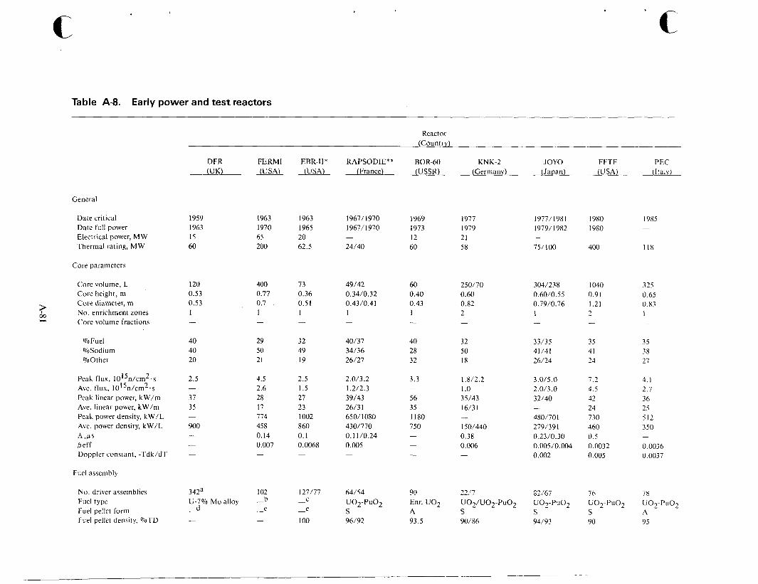
' c Table A-8. Early power and test reactors
Reactot (Countrv)
DFR FERMI EBR-II* RAPSODIE** BOR-60 KNK-2 JOY0 FFTF PEC (UK) (USA) (USA) (France) (USSR) (Germanv) (Japan) (USA) (Italy)
General
Date critical Date full power Electrical power, M W Thermal rating, MW
1959 1963 15 60
1963 1970 65 200
1963 1965 20 62.5
1967/ I970 1967/ 1970
24/40 -
1969 I977 1977/198 1 I980 I985 I 973 1979 1979/ 1982 1980 -
12 21 60 58 75/100 400 118
- - -
Core parameters
Core volume, L Core height, rn Core diameter, m
tp No. enrichment zones 22 Core volume fractions
120 0.53 0.53 1
400 0.77 0.7 1
73 0.36 0.51 1
49/42 0.34/0.32 0.43/0.4 1 I
60 250/70 304/238 1040 325 0.40 0.60 0.60/0.55 0.91 0.65 0.43 0.82 0.7910.76 1.21 0.83 1 2 1 2 I
%Fuel %Sodium %Other
Peak flux, I015n/cm2.s Ave. flux, 1015n/cm2.s Peak linear power, kW/m Ave. linear power, kW/m Peak power density, kW/L Ave. power density, kW/L A 4 s Peff Doppler constant, -Tdk/dT
40 40 20
29 50 21
32 49 19
40/37 34/36 26/27
40 32 28 50 32 18
33/35 35 35 41/41 41 38 26/24 24 21
2.5
37 35
- 4.5 2.6 28 17 714 458 0. I4 0.007
2.5 1.5 27 23 I002 860 0. I 0.0068
2.0/3.2 1.212.3 39/43 26/3 I 650/1080 4301770 0.1 1 /0.24 0.005 -
3.3
56 35 1180 750
-
-
1.U2.2 1 .o 35/43 16/31
150/440 0.38 0.006
-
-
3.0/5.0 2.0l3.0 32/40
480/701 279/391 0.23/0.30 0.005 /0.004 0.002
-
7.2 4.5 42 24 730 460 0.5 0.0032 0.005
4.1 2.1 36 25 512 350 900
0.0036 0.0037
Fuel assembly
342a U-7% Mo alloy
d -
No. driver assemblies Fuel type Fuel pellet form Fuel pellet density, %TD
102 b e
- - -
127/77
e
I O 0
C -
-
64/54
S 96/92
U02-PuO2 Enr. U 0 2 U O ~ / U O ~ - P U O ~ UO2-PuO2 UO2-PuO2 UO2-PuO2 A S S S A 93.5 90/86 94/93 90 95
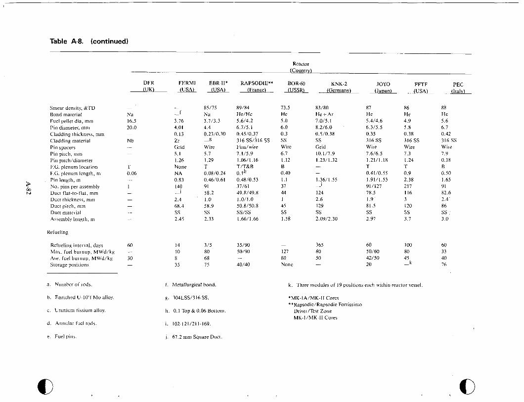
Table A-8. (continued)
Smear density, &TD Bond material Fuel pellet dia, mm Pin diameter, mm Cladding thickness, mm Cladding material Pin spacers Pin pitch, mm Pin pitch/diameter F.G. plenum location F.G. plenum length, m Pin length, m No. pins per assembly Duct flat-to-flat, mm Duct thickness, mm Duct pitch, m m Duct material Assembly length, m
Refueling
Refueling interval, days Max. fuel burnup, MWd/kg Ave. fuel burnup, MWd/kg Storage positions
a. Number of rods.
b. Enriched U-lO'f Mo alloy.
c . Uranium fissium alloy.
d. Annular fuel rods.
e. Fuel pins.
Reactor (Country)
DFR FERMI EBR-11* RAPSODIE** BOR-60 KNK-2 JOY0 FFTF PEC (France) (USSR) (Germany) (Japan) (USA) (Italy) (UK) (USA) (USA)
-
Na 16.5 20.0
Nb -
-
T 0.06
1 -
-
60
30 -
-
- f
3.76 4.01 0.13 Zr Grid 5.1 1.26 None NA 0.83 140 -J 2.4 68.4 SS 2.45
- 85/75 Na 3.7/3.3 4.4 0.23/0.30 -g Wire 5.7 1.29 T 0.08/0.24 0.46/0.61 91 58.2 1 .o 58.9 ss 2.33
89/84 He/He 5.6/4.2 6.7/5.1 0.45/0.37 316 SS1316 SS Findwire 7.1/5.9 1.06/1.16 T/T&B
0.4W0.53 37/61 49.8/49.8 1.0/1.0 50.8/50.8 ss/ss 1.66/1.66
O.lh
14 315 35/90 10 80 50/90 8 68 35 75 40/40
-
f. Metallurgical bond.
g. 304LSS/316 SS.
h. 0.1 Top & 0.06 Bottom.
i. 102-121/211-169.
j . 67.2 mm Square Duct.
73.5 He 5.0 6.0 0.3 ss Wire 6.7 1.12 B 0.40 1.1 37 44 1 45 ss 1.58
83/80 He + Ar 7.0/5.1 8.2/6 .O 0.5/0.38 ss Grid 10.1/7.9 1.23/1.32
1.36/1.55
124 2.6 129 ss 2.09/2.30
I -
365 -
127 80 80 50 None -
87 He 5.4/4.6 6.3/5.5 0.35 316 SS Wire 7.6/6.5 1.21/1.18 T 0.41/0.55 1.91/1.53 91/127 78.5 1.9 81.5 ss 2.97
86 He 4.9 5.8 0.38 316 SS Wire 7.3 1.24 T 0.9 2.38 217 116 3 120 ss 3.7
88 He 5.6 6.7 0.42 316 SS Wire 7.9 0.18 B 0.50 I .65 91 82.6 2.4' 86 ss : 3.0
60 100 60 50/60 80 33 42/50 45 40
76 k 20 -
k . Three modules of 19 positions each within reactor vessel.
*MK-IA/MK-I1 Cores **Rapsodie/Rapsodie Fortissimo
Driver/Test Zone MK-I/MK-I1 Cores
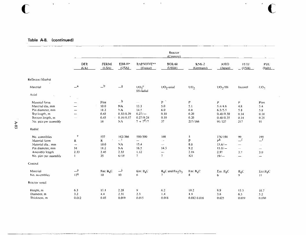
c Table A-8. (continued)
Reactor
DFR FERMI EBR-11* RAPSODIE** BOR-60 KNK-2 JOY0 (UK) (USA) (USA) (France) (USSR) (Germanv) (Japan)
FFTF (USA)
Inconel
P 4.8 5.8 0.14 0.14 217
99 f -
-
-
3.7 -
B4C 9
PEC (Italy)
u o 2
Pins 5.4 5.8 0.18 0.25 91
199 f -
-
-
3 .0 -
Enr.B4C I 1
Reflectoriblanket
- b -g u 0 2 c SS-radial
U02-axial Material a - u o 2 i s s
Axial
- b Pins -
10.0 NA 13.3 11.2 NA 14.5
0.43 0.16/0.57 0.27/0.24 0.43 0.35/0.39 0.27/-
16 NA 7 + 7d/7
P P 5 .O 5.1 6.0 6.0 0.10 0.20 0.10 0.20 37 217/166
Material form Material dia, mm Pin diameter, mm Top length, m Bottom length, m No. pins per assembly ;P
00 w Radial
P 5.4/4.6 6.3/5.5 0.40/0.30 0.40/0.35 91/127
No. assemblies Material form Material dia., mm Pin diameter, mm Assembly length No. pins per assembly
e -
R 537 1621366 500/300 R 10.0 NA 15.4 11.2 NA 16.5 2.45 2.33 1.12 25 6/19 7
1 - - 168 5
P 8.0
14.5 9.2 - 2.14 7 121
- -
176/ 191 Pk 13.6/- 15 .O/- 2.97 19/-
34 2.33 1
Control
-P 124
Enr.B4C -J Enr. B4C I O 10 6
Material No. assemblies
B4C and Et1203 Enr. B4C 7 8
Enr. B4C 6
Reactor vessel
Height, m Diameter, m Thickness, m
6.3 3.2 0.012
11.1 2.28 9 4.4 2.31 2.3 0.05 0.019 0.015
6.2 10.2 9.9 1.4 1.9 3.6 0.018 0.012-0.016 0.025
13.3 10.7 6.3 3.2 0.019 0.030
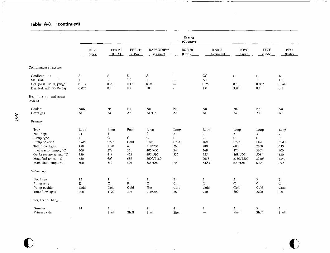
Table A-8. (continued)
Reactor - (Country)
DFR FERMI EBR-II* RAPSODIE** BOR-60 KNK-2 JOY0 FFTF PEC (UK) (USA) (USA) (France) (USSR) (Germany) (Jauan) (USA) (Italv)
Containment structures
Configuration Materials Des. press., MPa, gauge Des. leak rate, vol%/day
S S S S I cc S S D I 1 3 .O 1 - 2/ 1 1 I 1 / 1 0.137 0.22 0.17 0.24 - 0.25 0.13 0.067 0. I49 0.075 0.1 0.2 101 - 1 .o 3.0m 0.1 0.5
Heat transport and steam systems
Coolant Cover gas P
00 P Primary
NaK Na Na Na Na Na Ar Ar Ar Ar/He Ar Ar
Na Na Na Ar Ar Ar
Loop 3 C Cold I120 279 418 602 552
Pool 1 C Cold 48 1 37 1 473 688 599
Loop Loop 2 C Cold 260 340 520
Loop 2 C Hot 280 360 525 2055 ~ 6 8 5
Loop Loop 3 C Hot 2200 360" 503" 2250" 670"
Loop 2 C Cold 630 400 550 2340 650
Type No. loops Pump type Pump position Total flow, kg/s Inlet reactor temp., "C Outlet reactor temp., "C Max. fuel temp., "C Max. clad. temp., "C
Loop 24 E Cold 450 200 350 650 5 00
C Cold 210/230 405/400 49515 10 2000/2 I80 585/650
C Cold 600 370 468/500 2330/2500 6201650 700
Secondary
No. loops Pump type Pump position Total flow, kg/s
3 C Cold 2200
2 C Cold 624
12 E Cold 900
3 1 2 2 2 C E C C C Cold Cold Hot Cold Cold 1120 3 02 210/200 260 250
2 C Cold 600
Inter, heat exchanger
Number Primary side
3 I 2 4 2 Shell Shell Shell Shell -
2 Shell
3 Shell
24 -
L
Shell
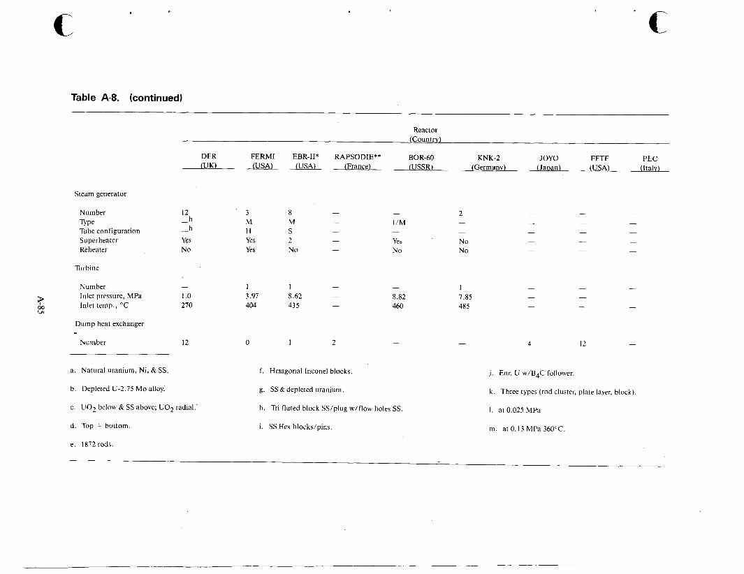
c Table A-8. (continued)
Reactor (Country)
BOR-60 KNK-2 JOY0 FFTF PEC (Franc e ) (USSR) (Germany) (Japan) (USA) (Italv)
DFR FERMI EBR-11* RAPSODIE** NJK) (USA) (USA)
Steam generator
Number
Tube configuration Superheater Reheat er
Type
Turbine
12 h - h
Yes No
-
Number - Inlet pressure, MPa 1 .o Inlet temp., "C 270 ;P m
ul
Dump heat exchanger - Number 12
3 M H Yes Yes
8 M S 2 No
- 1 1 3.97 8.62 -
404 435 -
I/M
Yes No
-
- 8.82 460
0 I 2 -
2 - -
No No
1 7.85 485
4 12
a . Natural uranium, Ni, & SS.
b. Depleted U-2.75 Mo alloy:
c. U02 below & SS above; UO2 radial.
d. Top + bottom.
e. 1872rods.
f. Hexagonal Inconel blocks.
g. SS & depleted uranium.
h. Tri-fluted block SS/plug w/flow holes SS.
i. SS Hex blocks/pins.
j. Enr. U w/B4C follower.
k . Three types (rod cluster, plate layer, block).
1. at 0.025 MPa
m. at 0.13 MPa 360°C.

which have since been changed. Friction marks such as material abrasion between the cladding tube and the spacers were not considered to be asso- ciated with the defects. Disassembly of* the I9803 failed fuel element, which had been run with a fuel rod failure for about 4 weeks, revealed clear marks on the rods adjacent to the defective one and seemed to indicate some interaction. However, detailed investigations have shown there had been no failure propagati0n.A-72
Thirty-five fuel rods from each of the two failed fuel elements were reprocessed in the Milli facility. The extracted fuel was used for fabrication of the fuel rods of the second core. Thus, in Germany, the breeder fuel cycle has been closed on a kilogram scale. In dissolving the fuel in 7 M nitric acid, some 10% remained undissolved and had to be retreated with hydrofluoric acid. The low solubility of the fuel is owing to its method of fabrication; highly soluble fuel will be used in the first reload core.
From the beginning, the reactivity signal of KNK-I1 showed harmonic oscillations of less than - 0.5 cents, Sensitive methods of correlation between the reactivity signal and the measured fuel element temperature proved these oscillations were caused by individual fuel elements. Additional measure- ments performed under various operating condi- tions and theoretical considerations seem to indicate the reactivity oscillations are initiated by flow-induced mechanical vibrations. Most proba- bly, these are vibrations of entire fuel elements gen- erated by vortex shedding or non-steady fluid jet formati0n.A-72
Reactor Chemistry- Radial chemical measure- ments of primary sodium show that the bulk gamma activity after 9,600 effective full power hours of KNK-I1 operation was 1.9 mCi/g. This is considerably below the primary coolant activation normally found in boiling water and pressurized
Reactor Instruments- Performance capability was examined of temperature measurement probes and two acoustic transducer probes, magnetostrictive and piezoelectric, which were inserted in KNK-I1 over a period of 4310 and 6635 h, respectively. These probes are planned for use in the safety system of the German prototype LMFBR, SNR-300. The linearity and temperature errors were demonstrated to be below 2%. Drift errors over a 4 week operating per- iod were less than 2.5% at sodium flow rates of less than or equal to 1 m/s. Drift errors were less than 2%, with a sodium flow rate greater than 1
. .
A-86
water reactors. The fission product releases from the two failed fuel elements are relatively slight for the iodine and cesium remain in the sodium. The
‘’,sodium’ represents an additional barrier to fission product releases to the environment.
More precise analyses are conducted on the pri- mary sodium to detect the activation products sodium-24, sodium-22, Ag-1 10 m, and zinc-65, the activated corrosion products manganese-54, cobalt-58, cobalt-60, iron-59, chromium-51, tantalum-182, antimony-124, the fission products, cesium-1 37, cesium-1 34, antimony-125, barium/ lanthanum-140, and iodine-13 1. Because these radionuclides give rise to radiation exposure of per- sonnel during repair and maintenance work, attempts are being made to remove these products, except sodium-24 and sodium-22, from the primary system. In KNK-11, investigations are concentrat- ing on removal of manganese-54, zinc-65, and tantalum-1 82 isotopes. These nuclides have been shown to preferentially precipitate on specific metal surfaces. Nickel, for example, lends itself particu- larly well for use as a radionuclide trap for zinc-65 and m a n g a n e ~ e - 5 4 . ~ - ~ ~
A stable evaporation zone is formed in LMFBR steam generators caused by the much smaller tem- perature gradients between the secondary sodium and the water vapor in comparison to the tempera- ture gradient of fossil-fueled heated plants. In addi- tion, there are no pulsating evaporation processes from local superheating. Impurities in the boiler feedwater can become enriched in this stable evapo- ration zone and produce changes in the protective coating. An extensive measurement program is being conducted at KNK-I1 in the steam water cir- cuit to determine what effects conductivity and the concentration of oxygen, iron, copper, silicic acid, and sodium have on this phenomenon.
Measurements conducted at KNK-I1 while work- ing without hydrazine have shown that hydrazine cannot be used to reduce the oxygen concentration to less than 50 ppm when there is increased oxygen content in steam in the presence of hydrazine. Future investigations at KNK-I1 will be done with- out hydrazine added but in a combined mode of operation involving an elevated oxygen content and a reduced ph.
Experience with the Heat Transfer System - The sodium systems of KNK-I1 were started up in 1972. The primary system has since been continuously filled with sodium, even during the KNK-I/KNK-I1

conversion phase. The sodium pumps have oper- ated uninterrupted and have accumulated some 85,000 h. Systems, temperatures, and pressures have remained at the designed level for about 17,500 h. During this entire time, there have been no major malfunctions.
A dip tube has been built that extends vertically through the primary cell. In this dip tube a cali- brated ionization chamber can be positioned at var- ious points. The ion chamber is used to measure the radiation dose rate after the sodium-24 decays to background values, about 10 d subsequent to reac- tor shutdown. The residual radiation field is caused by activated corrosion products and fission prod- ucts plated out on the walls of the primary system. More than 10 years of operating experience has shown the radiation exposure both of personnel and of the environment is less than it is in compara- ble water-cooled reactors. For instance, KNK-I1 was operated in 1982 using 44 man-rem with 43.9 man-rem acquired during maintenance on the primary system. Greater than 75% of the radiation workers received less than 0.15 rem, and only 5% received greater than 0.4 rem.
The steam generators of KNK-I1 consist of paral- lel helical double tube systems. In 1972, a leakage in a steam generator caused by a weld pore was con- trolled safely and without any impacts on the envi- ronment. One of the steam generators was removed in early 1981 and replaced by a new one having a sampling point in the transition region between water and steam. This afforded an opportunity for metallagraphic reexamination. In the evaporator region of the steam generator, a coating roughly 100 microns thick had developed; in the super- heater region, a coating roughly 40 microns thick had developed. The coatings consist of an inner layer of oxidized metal and an outer layer of magnetite. The magnetite is generated whenever the solubility of iron in water is exceeded. Pitting corrosion with a maximum penetration depth of 250 microns is caused by the quality of water which is not controlled in outage periods. The reduction in wall thickness caused by pitting corresponds to 8.6% of the wall thickness.
France
Rapsodie. The French LMFBR programs first major milestone occurred in 1967 with the commis- sioning of Rapsodie. This was originally a 20-MW(t) unit later increased to 24 MW(t) and then to
40 MW(t). The reactor provided design information and fuel performance for use in France’s prototype reactor, PHENIX.
Reactorfeatures-A view of the reactor assembly is shown in Figure A-59. The fuel assemblies, which contain both a fuel section and an axial blan- ket section, are in a central region surrounded by radial blanket subassemblies. Removable subas- semblies outside this region serve as reflectors. The concentric steel cylinder assembly, as shown in Fig- ure A-60, is used for both a nonremovable reflector and thermal shield.
A jacket located outside the reactor vessel circu- lates gas for preheating. It also serves for cooling the reactor during shutdown. Steel containers filled with thermal insulation are located outside the pre- heating jacket. Additional structures consist of a containment tank and a biological shield. An outer blast shield consists of three concentric layers: borated graphite, lightweight cellular concrete, and reinforced concrete. Additional features are shown in Figure A-61. A single sodium inlet pipe is shown with two sodium outlet pipes located in ii vertical plane perpendicular to the plane of the injet pipe.
Core Arrangement-The fuel subassemblies are illustrated in Figure A-62. In the core regicln are the subassemblies, comprised of 37 fuel rods assem- bled in a stainless steel container with a hexagonal cross-section. Each individual element consists of a number of sintered pellets of mixed uranium and plutonium oxide (25 wt% Pu02) contained in a stainless steel tube. A spring arrangement main- tains contact between the various pellets in the column, and provision is made in the upper region of the element to collect fission gases. Separation between pins is maintained by a wire ~ p i r a l . ~ - ~ ~
Both the upper and lower blanket sections con- sist of a cluster of seven large-diameter elements of depleted uranium. A lower base plate is provided to distribute the coolant. The lower end of the subas- semblies shaped in the form of a nozzle with an internal venturi section reduces upward forces induced by the coolant flow and aids in position- ing. The upper end of the subassembly is provided with a handling lug pierced with three holes for the sodium coolant outlet. The radial blanket subas- semblies are similar to the fuel subassemblies, but they contain a continuous seven-rod internal struc- ture of large-diameter depleted uranium elements. Removable stainless steel reflector subassemblies
A-87
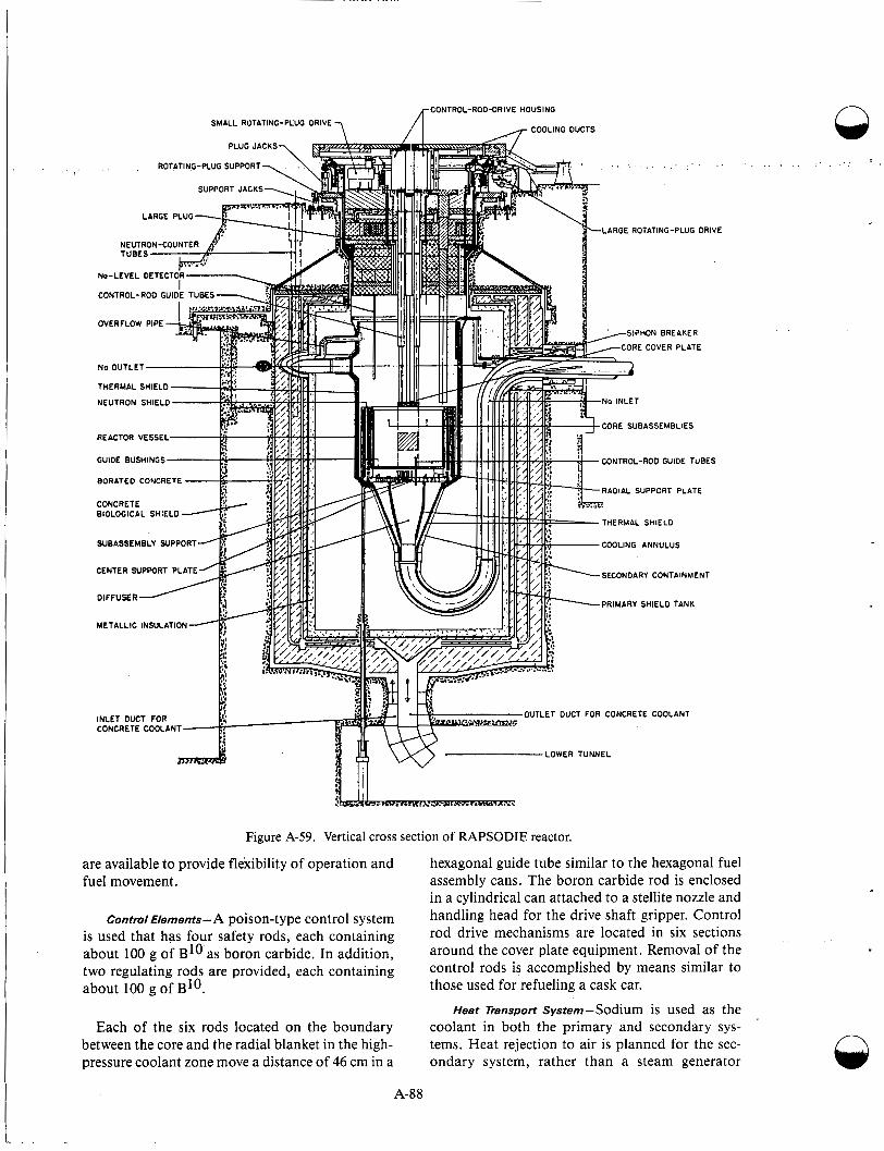
are available to provide flexibility of operation and fuel movement.
Control Elements-A poison-type control system is used that has four safety rods, each containing about 100 g of B1o as boron carbide. In addition, two regulating rods are provided, each containing about 100 g of BIO.
Each of the six rods located on the boundary between the core and the radial blanket in the high- pressure coolant zone move a distance of 46 cm in a
A-88
I _ . .
VE
S
!- .. .._ , r ..- ..,
Figure A-59. Vertical cross section of RAPSODIE reactor.
hexagonal guide tube similar to the hexagonal fuel assembly cans. The boron carbide rod is enclosed in a cylindrical can attached to a stellite nozzle and handling head for the drive shaft gripper. Control rod drive mechanisms are located in six sections around the cover plate equipment. Removal of the control rods is accomplished by means similar to those used for refueling a cask car.
Heat Transport system-Sodium is used as the coolant in both the primary and secondary sys- tems. Heat rejection to air is planned for the sec- ondary system, rather than a steam generator
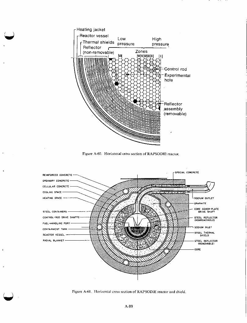
r Heating jacket Reactor vessel
Low High pressure Thermal shields pressure
Reflector ~
Zones I I I (non-removable)
- Figure A-60. Horizontal cross section of RAPSODIE reactor.
. [SPECIAL CONCRETE REINFORCED CONCRETE ---. I
Figure A-61. Horizontal cross section of RAPSODIE reactor and shield.
A-89

Blanket rod -
+J
Fuel pin
b1.96 in. 4
I wire Sect i 0 n A- A
Figure A-62. RAPSODIE fuel subassembly.
n
A-90
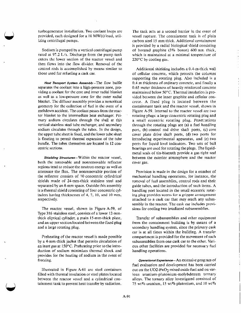
turbogenerator installation. Two coolant loops are provided, each designed for a 10 MW(t) load, util- izing centrifugal pumps.
Sodium is pumped by a vertical centrifugal pump rated at 97.2 L/s. Discharge from the pump tank enters the lower section of the reactor vessel and then flows into the flow divider. Removal of the control rods is accomplished by means similar to those used for refueling a cask car.
Heat Tmnsport System Assembly-The flow baffle separates the coolant into a high-pressure zone, pro- viding a coolant for the core and inner radial blanket as well as a low-pressure zone for the outer radial blanket. The diffuser assembly provides a noncritical geometry for the collection of fuel in the event of a meltdown accident. The coolant passes from the reac- tor blanket to the intermediate heat exchanger. Pri- mary sodium circulates through the shell at this vertical stainless steel tube exchanger, and secondary sodium circulates through the tubes. In the design, the upper tube sheet is fixed, and the lower tube sheet is floating to permit thermal expansion of the tube bundle. The tubes themselves are located in 12 con- centric sections.
Shielding Structures-Within the reactor vessel, both the removable and nonremovable reflector regions tend to reduce the neutron energy as well as attenuate the flux. The nonremovable portion of the reflector consists of 10 concentric cylindrical shields made of 24-mm-thick stainless steel and separated by an 8-mm space. Outside this assembly is a thermal shield consisting of four concentric cyl- inders having thicknesses of 4, 7 , 10, and 10 mm, respectively.
The reactor vessel, shown in Figure A-59, of Type 316 stainless steel, consists of a lower 12-mm- thick eliptical cylinder, a main 15-mm-thick plate, and an upper section located between the fixed plug and a large rotating plug.
Preheating of the reactor vessel is made possible by a 4-mm-thick jacket that permits circulation of an inert gas at 150°C. Preheating prior to the intro- duction of sodium minimizes thermal shock and provides for the heating of sodium in the event of freezing.
Illustrated in Figure A-61 are steel containers filled with thermal insulation or steel plates located between the reactor vessel and a cylindrical con- tainment tank to prevent heat transfer by radiation.
The tank acts as a second barrier in the event of vessel rupture. The containment tank is of plain carbon steel 15 mm thick. Additional containment is provided by a radial biological shield consisting of borated graphite (3% boron) 600 mrri thick, which is maintained at a minimal temperature of 220°C by cooling gas.
Additional shielding includes a 0.4-m-thi ck wall of cellular concrete, which protects the columns supporting the rotating plug. Also included is a 0.4 m thickness of ordinary concrete, and finally a 0.65 meter thickness of heavily reinforced concrete maintained below 50°C. Thermal insulation is pro- vided between the inner graphite and cellular con- crete. A fixed plug is located between the containment tank and the reactor vessel, shown in Figure A-59. Internal to the reactor vessel are two rotating plugs: a large concentric rotating plug and a small eccentric rotating plug. Peneti-ations through the rotating plugs are (a) a fuel handling port, (b) control rod drive shaft ports, (c) core cover plate drive shaft ports, (d) two ports for introducing experimental apparatus, and (e) two ports for liquid level indicators. Two sets of ball bearings are used for rotating the plugs. The liquid- metal seals of tin-bismuth provide a gas tig,ht seal between the exterior atmosphere and the reactor cover gas.
Provision is made in the design for a number of mechanical handling operations, for instance, the removal of fuel assemblies, control rods and their guide tubes, and the introduction of such items. A handling port located in the small eccentric: rotat- ing plug provides access for a gripper arrangement attached to a cask car that may reach any subas- sembly in the reactor. The cask car includes provi- sions for cooling two irradiated subassemblies.
Transfer of subassemblies and other equipment from the containment building is by means of a secondary handling system, since the primary cask car is at all times within the building. A transfer compartment is provided for the movement of such subassemblies from one cask car to the other. Vari- ous other facilities are provided for necessary fuel handling operations.
Operational Experience- An extensive prog.ram of fuel evaluation and development has been carried out on the UO2-PuO2 mixed oxide fuel and on var- ious uranium-plutonium-molybdenum ternary alloys. The ternary alloy investigated consisted of 75 wt% uranium, 15 wt% plutonium, and 10 wt%
A-9 1
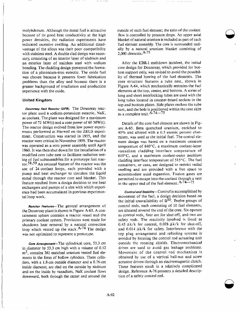
molybdenum. Although the metal fuel is attractive because of its good heat conductivity at the high power densities, the radiation experiments have indicated excessive swelling. An additional disad- vantage of the alloys was their poor compatibility with stainless steel. A double clad design was neces- sary, consisting of an interior layer of niobium and an exterior layer of stainless steel with sodium bonding. The cladding design prevented the forma- tion of a plutonium-iron eutectic. The oxide fuel was chosen because it presents fewer fabrication problems than the alloy and because there is a greater background of irradiation and production experience with the oxide.
United Kingdom
Dounreay Fast Reactor IDFRI. The Dounreay reac- tor plant used a sodium-potassium eutectic, NaK, as coolant. The plant was designed for a maximum power of 72 MW(t) and a core power of 60 MW(t). The reactor design evolved from low power experi- ments performed at Harwell on the ZEUS experi- ment. Construction was started in 1955, and the reactor went critical in November 1959. The reactor was operated as a zero power assembly until April 1960. It was then shut down for the installation of a modified core tube nest to facilitate radiation test- ing of fuel subassemblies for a prototype fast reac- tor.58959 An unusual feature of the reactor was the use of 24 coolant loops, each provided with a pump and heat exchanger to circulate the liquid metal through the reactor core and blanket. This feature resulted from a design decision to use heat exchangers and pumps of a size with which experi- ence had been accumulated in previous experimen- tal loop work.
Reactor matures-The general arrangement of the Dounreay plant is shown in Figure A-63. A con- tainment sphere contains a reactor vessel and the primary coolant system. Provisions were made for shutdown heat removal by a natural convection loop which vented up the tack.^-^^ The design was not optimized to represent a prototype.
Core Arrangement-The cylindrical core, 53.3 cm in diameter by 53.3 cm high with a volume of 0.12 m3, contains 361 enriched uranium vented fuel ele- ments in the form of hollow cylinders. These cylin- ders, with a 1.8-cm outside diameter and a 0.76-cm inside diameter, are clad on the outside by niobium and on the inside by vanadium. NaK coolant flows downward, both through the center and around the
outside of each fuel element; the ratio of the coolant flow is controlled by pressure drops. An upper axial blanket of natural uranium is included as part of each fuel element assembly. The core is surrounded radi- ally by a natural uranium blanket consisting of 2,000 e1ements.A-75
After the EBR-I meltdown incident, the initial core design for Dounreay, which provided for bot- tom support only, was revised to avoid the possibil- ity of thermal bowing of the fuel elements. The core structure features a tube nest, shown in Figure A-64, which mechanically restrains the fuel elements at the top, center, and bottom. A series of long and short interlocking tubes are used with the long tubes located in counter-board sockets in the top and bottom plates. Side plates enclose the tube nest, and the hole is positioned within the core skirt as a complete unit .A-74-75
Details of the core fuel element are shown in Fig- ure A-65. Beta quenched uranium, enriched to 45% and alloyed with a 0.5 atomic percent chro- mium, was used as the initial fuel. The central ele- ment design was based on a maximum uranium temperature of 840" C, a maximum coolant-inner vanadium cladding interface temperature of 610°C, and a maximum coolant-outer neobium cladding interface temperature of 5 15°C. The fuel containers, or cans, are designed to restrict radial swelling and are provided with a free space to accommodate axial expansion. Fission gases are permitted to escape into the coolant through a vent in the upper end of the fuel element.A-74-75
Controland Stability- Control is accomplished by movement of the fuel, a design decision based on the initial unavailability of BIO. Twelve groups of control rods, each consisting of 10 fuel elements, are situated around the end of the core. Six operate as control rods, four are for shut-off, and two are safety rods. The reactivity involved is listed as 0.43 Ak/k for control, 0.028 Ak/k for shut-off, and 0.014 Ak/k for safety. Interference with the top plug arrangement and refueling systems is avoided by locating the control rod actuating unit outside the rotating shields. Electromechanical drives are used to avoid gas leakage problems. Movement of the control rod mechanism is obtained by use of a vertical ball-nut and screw actuator driven through an electromagnetic clutch. These features result in a relatively complicated design. Reference A-76 presents a detailed descrip- tion of a safety control rod.
n
A-92
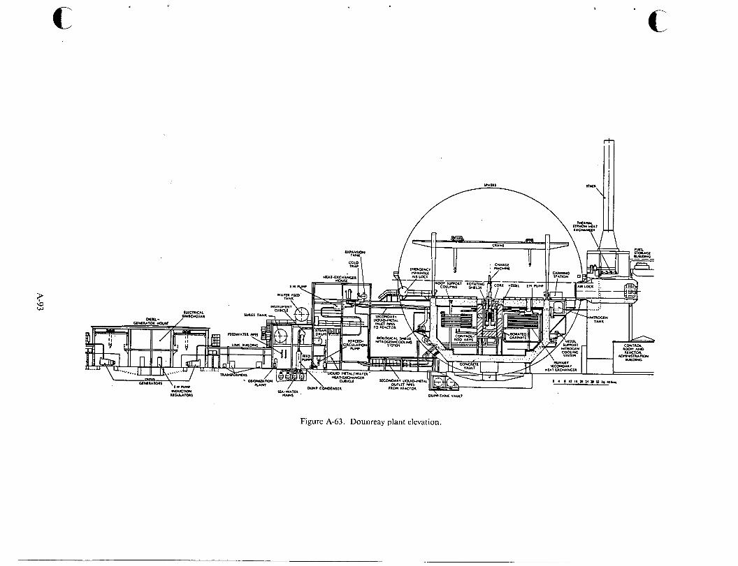
c
Figure A-63. Dounreay plant elevation.

Section A-A
Figure A-64. Details of Dounreay core tube nest
Heat Transport system-Because the primary objective of the.Dounreay reactor was to demon- strate the feasibility of fast reactor core operation, the heat transfer system was not designed as a suit- able prototype of an economical system. Instead, it was the most reliable combination of available components that would accomplish the purpose. The coolant loops were constructed of piping vary- ing in diameter from 1.9 to 15.2 cm without the use of valves. Concentric tube construction was used for the intermediate heat exchangers. These various restrictions led to the design requirement of 24 pri- mary loops. A detailed discussion of the heat trans- port system is given in Reference A-76. An unusual feature of this heat transport design is the down- ward flow of coolant through the core. This per- mits various components at the top of the reactor to operate in cooler regions and simplifies the struc- tural design of the core, since the coolant does not tend to lift the fuel elements.
The 24-loop primary system was designed to remove 60 MW(t) from the core and 12 MW(t) from the breeder blanket. As shown in Figure A-66, the
a
a
C .- - L
c
Enlarged view at F
3 special tubes occuring at . center only
F Enlarged part plan on E-E -
'i
Section D-D
coolant leaves the bottom of the reactor vessel at 350"C, leaves the intermediate heat exchanger at 200"C, then passes through the electromagnetic pump in a thermal siphon heat exchanger before reen- tering the vessel. The pump was installed in the cooler part of the circuit because the coolant operating tem- perature was restricted at 200°C to prevent overheat- ing at the windings. Each secondary loop removes heat from two primary loops, necessitating 12 inde- pendent secondary units, each complete with a steam generator. The intermediate heat exchangers, each designed for a 3 MW(t), consist of an inner stainless steel pipe, 91 m long and 10 cm in diameter, sur- rounded by an outer stainless steel pipe of 15 cm diameter which is formed into seven loops. Each of the 12 secondary loops contains two electromagnetic pumps installed in parallel in a cool return leg from the steam generator. The steam generators, in turn, each have 6 MW(t) capacity and consist of 13 rows of 20 heat transfer elements each. These elements were constructed by spirally winding copper laminations onto stainless steel tubes. Because the tubes contain- ing sodium are connected to the steam generating tube by copper lamination, heat transfer is by conduc- tion from one tube to another via the copper. The n
A-94

t-48.35 in. overall length I
I
Core-bottom plate support plate
Niobium
S.S. bottom outer tube end fitting
Niobium 1 \ 4 . S . top end Vanad i um Niobium
inner tube /adapter washer fitting
Enlarged view at X Enlarged view at Z Enlarged view at Y
Figure A-65. Details of Dounreay fuel subassembly.
Figure A-66. Arrangement of Dounreay primary circuit pipe work.
A-95
possibility of leakage from the NaK to the water sys- tem is therefore minimized. The heat transport system includes the usual array of accessory equipment; for example, cold traps, hot traps, sampling equipment, filling stations, and an inert gas (nitrogen) system. A thermal siphon system requiring no electrical power was installed to remove the shutdown heat of the core from the primary circuits to a convection air-cooled heat exchanger outside the containment sphere.
Structural and Shielding Components- A view Of
the reactor vessel assembly with its associated com- ponents and shielding is shown in Figure A-67. The core and blanket, weighing approximately 90,000 kg, are supported by an inner structure within the vessel. This system, built up from a flange mounted on the inner skirt of the reactor vessel itself, includes the core skirt, various plates, and other members. In addition to providing the necessary support, the system separates the coolant flow to the core, inner blanket, and outer blanket breeder. A system of rotating plugs forms the clo- sure for the top of the vessel and permits access by the refueling machine to any fuel or blanket ele- ment. Details are shown in Figure A-67. The plugs are removed only during shutdown. During normal operation, O-rings prevent leakage of the cover gas. During refueling, a leak-tight seal around the plugs is accomplished by two concentric metal rings dip- ping into a trough (a) of sodium-mercury amal- gam, in the case of the inner seal, and (b) of mercury in the case of the outer seal. Such a seal is possible during refueling because the reactor pres- sure is reduced to less than 3.5 kPa. When the ves- sel is pressurized, the liquid metal in these seals is discharged to a dump tank located on the plugs.
The reactor vessel and the primary coolant loop, which contains sodium-24 activated by a passage through the reactor, is contained in a 41.2-m- diameter steel sphere, shown in Figure A-63. The primary coolant system and the intermediate heat exchanger are within the containment sphere (see Figure A-66). Because the secondary NaK coolant is neither radioactive nor likely to contain fission products in the event of a fuel element failure, the secondary loop system, including the steam genera- tors, is not within this sphere. Reference 58 describes the shielding in detail. The design is based on a reactor output of 100 MW(t). Fast neutrons leaking from the vessel are thermalized in a 1.2-m- thick graphite shield containing 0.3 wt% of boron which surround the reactor vessel. The graphite is cooled by recirculating nitrogen. Zones of pure graphite in the thermal shield allow neutron flux
A-96
Q measurements by ion and fission chambers. An outer annulus of 5 wt% boron in graphite surround these regions. The top shield includes layers of borated graphite and steel plates in a rotating plug and removable concrete block assembly. A 25-cm- thick jabroc and steel shield covers the reactor top and is removable for shutdown operations. Second- ary shielding was provided by a 1.5-m-thick layer of concrete on the inside of the containing sphere, which encloses the reactor and primary heat trans- port system.
Operating Experience-A number of difficulties were encountered during the initial start-up proce- dures of DFR.A-77-*4 Contamination of the NaK with oxide proved much higher than antici- pated and required considerable cleanup effort. The cold traps installed in each of the coolant loops failed to operate effectively, and installation of a better trap system and more satisfactory impurity measurement instrumentation were found neces- sary. Starting in late 1961, there was considerable stress corrosion in the 321 stainless steel superheat- ers and evaporators. The contributory causes were chlorides in the water, aerated conditions, and car- bide precipitation, particularly at the surface of the scale. Extensive repairs were made to the steam generators, and careful control of water purity was instituted. Repairs were not completed until April 1963.
Niobium and vanadium fuel cladding failures occurred as a result of hydrogen embrittlement induced by hydride in the coolant. This contamina- tion was believed to have been introduced with the first charge of fuel. Carbon in the system may also have contributed to the embrittlement of the clad- ding. Considerable work was done to determine the cause. Loops were in operation with a hot trap and specimens of zirconium, zircaloy, Nimonic, and three types of low-carbon stainless steel. Addi- tional efforts were made in the United States to determine the effects of carbon on structural mate- rial. An extensive cold and hot trap system was installed to reduce oxygen, hydrogen, nitrogen, and carbon concentrations in the coolant to very low levels. Excessive niobium corrosion was reported as late as March 1963. Considerable gas entrainment in the coolant circuits required a number of modifi- cations. These included changes in the expansion tanks and a separate gas enclosure for the control rod mechanism.
Problems encountered with the control rod thrust head were traced to the pickup of scum from n
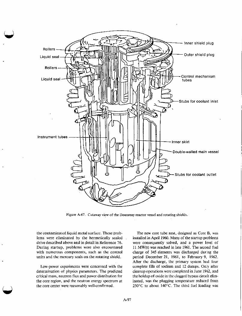
I
In
Figure A-67. Cutaway view of the Dounreay reactor vessel and rotating shields.
the contaminated liquid metal surface. These prob- lems were eliminated by the hermetically sealed drive described above and in detail in Reference 76. During startup, problems were also encountered with numerous components, such as the control units and the mercury seals on the rotating shield.
Low-power experiments were concerned with the determination of physics parameters. The predicted critical mass, neutron flux and power distribution for the core region, and the neutron energy spectrum at the core center were reasonably well-confirmed.
The new core tube nest, designed as Core B, was installed in April 1960. Many of the startup problems were consequently solved, and a power level of 1 1 MW(t) was reached in late 1961. The second fuel charge of 345 elements was discharged during the period December 21, 1961, to February 9, 1962. After the discharge, the primary system had four complete fills of sodium and 12 dumps. Odly after cleanup operations were completed in June 19152, and the holdup of oxide in the clogged bypass circuit elim- inated, was the plugging temperature reduced from 230°C to about 140°C. The third fuel loading was
A-97

uranium-10 wt% molybdenum, and the loading was completed in the period from June to July 1962. Dur- ing this loading, the roller bearings on the charge machine were replaced with ball bearings to prevent further bearing seizure previously experienced. Criti- cality was reached July 26, 1962, and operation at 30 MW(t) was realized August 7, 1962. During this period, the NaK rose in the rotating plug owing to unbalance in the gas line, contaminating the mercury dip seal and requiring about 590 kg of mercury to free the seal. New balance lines were added to eliminate this problem. Plugging temperatures were further reduced to 110°C while isolating the rotating plug graphite from the reactor cover gas. Testing of uranium-1 8-at. %-molybdenum, uranium-20-at. 070-
molybdenum, and uranium-25-at. %-molybdenum indicated that the uranium-1 8-at. %-molybdenum transformation from gamma to gamma + alpha started in 40 to 45 min at 480"C, with completion of transformation in 150 to 250 h. Uranium-20-at. %- molybdenum at 430°C took 5 to 7 h to initiate the same transformation and over 1,OOO h to complete it. But at 550"C, it took 1 to 2 h to initiate and 200 to 300 h to complzte. The uranium-25-at.%- molybdenum at 430 C took 50 to 70 h to initiate and was only 5% complete in 500 h. Examination of the uranium-molybdenum alloy fuels indicated fuel slugs irradiated to burnup at 0.3% had cracks that increased with fuel temperature, up to 450°C. Crack- ing was greatest in slugs that had the large fuel clad- ding clearances. Increase of molybdenum content from 20 at.% to 25 at.% showed how improvement in irradiation behavior had burned up 0.48 to 0.6%. It was hypothesized that steep temperature gradients occurred as high as 790°C per cm in the fuel. Center swelling, produced by gas pressures in the high tem- perature center of the fuel, acted against the restrained, cooler outer layers. The combined action resulted in the cracks.
The need for shielding the exposed blanket gas pipes had been very well established during 30-MW 0perat ions.*-8~-~~ It became evident that a very high standard of leak tightness was required of the more than 80 joints associated with the instrumen- tation and gas blanket connections on the rotating shields. For example, during 30-MW operations in August 1962, the airborne activity level in the sphere was a factor of a hundred greater than back- ground, namely lo2 Bq/m3, and during the follow- ing run rose to lo4 Bq/m3, which exceeded the maximum permissible concentrations. Gamma spectroscopy showed that the greatest component of the activity was Rb-88, with the other major component being 0-138. Many of the joints were modified to include double rings. As a result, the
'
airborne contamination level during operation was reduced to about eight percent of the maximum permissible concentration.
During the early high power runs,' operators dis- covered a slow but steady movement of gas from the top of the reactor vessel to the outer gas ring main. Closing certain gas valves so as to divide the blanket into two separate sections confirmed the phenomenon. It was believed that fission product gas was accumulating above the core and diffusing into the ring main to produce the observed high radiation levels. Isolating the two sections of the blanket system by retaining the more highly active gas within the shielding effected a general reduction in radiation levels by a factor of ten. Regular com- moning of the sections was necessary to prevent the buildup of excessive pressure differentials, which would lead to undesirable coolant level variations throughout the system. Further pipe work modifi- cations were made, resulting in a considerable delay being introduced into the time between gas collec- tion over the reactor and its appearance in the ring mains. Except for one or two highly localized areas into which access was normally denied during oper- ation, the net effect of these modifications and the extra shielding, which was installed on the ring main, was to reduce the radiation to within accept- able levels.
Samples of the gas blanket indicate that the main constituents were xenon-1 33 and xenon-1 34- typical on-power values being lo8 and 6.2 x lo7 Bq/L, and associated argon activity being 2 to 3 x lo5 Bq/L. Variation by factors of 100 were pos- sible in these values, depending on the sample point chosen. Whenever changes were made in individual primary pump loads, large variations in gas blanket radiation levels were observed, indicating that gas was moving about the system. It became impracti- cal, without the installation of much more shield- ing, to transfer the gas blanket to the storage tanks immediately upon reactor shutdown. Normal shut- down procedures were modified to include a delay of about 48 h before depressurization.
The coolant obviously contained considerable quantities of primary fission products. The coolant monitors servey a small proportion of the primary coolant for delayed neutron emitters, giving a high continuous signal, which was calculated to be equivalent to the exposure of 4 x lo4 m3 of ura- nium in the core (i.e., 25% of the fuel surface). The sensitivity of these monitors as indicators of fur- ther fueI exposure, namely by element failure, was
n
A-98
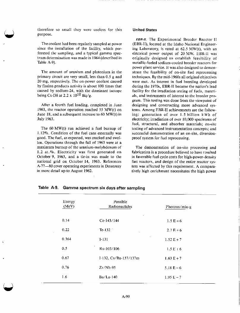
therefore so small they were useless for this purpose.
The coolant had been regularly sampled at power since the installation of the facility, which per- formed the sampling, and a typical gamma spec- trum determination was made in 1964 (described in Table A-9).
The amount of uranium and plutonium in the primary circuit are very small, less than 0.5 g and 20 mg, respectively. The on-power coolant caused by fission products activity is about 100 times that caused by sodium-24, with the dominant isotope being Cs-138 at 2.2 x 1O1O Bq/g.
After a fourth fuel loading, completed in June 1963, the reactor operation reached 55 MW(t) on June 18, and a subsequent increase to 60 MW(t) in July 1963.
The 60 MW(t) run achieved a fuel burnup of 1.12%. Condition of the fuel cans externally was good. The fuel, as expected, was cracked and swol- len. Operations through the fall of 1963 were at a maximum burnup of the uranium-molybdenum of 1.2 a t .%. Electricity was first generated on October 9, 1963, and a tie-in was made to the national grid on October 14, 1963. References A-77-80 cover operating experiments in Dounreay in more detail up to August 1962.
United States
EBR-I/. The Experimental Breeder Reactor I1 (EBR-11), located at the Idaho National Erigineer- ing Laboratory, is rated at 62.5 MW(t), with an electrical power output of 20 MW. EBR-I1 was originally designed to establish feasibility of metallic-fueled sodium-cooled breeder reaci ors for power plant service. It was also designed to demon- strate the feasibility of on-site fuel reprocessing techniques. By the mid-1960s all original ob.iectives were met. As interest in fuel breeding developed during the 1970s, EBR-I1 became the nation’s lead facility for the irradiation testing of fuels, materi- als, and instruments of interest to the breeder pro- gram. This testing was done from the viewpoint of designing and constructing more advanced sys- tems. Among EBR-I1 achievements are the follow- ing: generation of over 1 .5 billion k’vlrh of electricity; irradiation of over 10,000 specimens of fuel, structural, and absorber materials; on-site testing of advanced instrumentation concepts; and successful demonstration of an on-site, diversion- proof system for fuel reprocessing.
The demonstration of on-site processing and fabrication is a procedure believed to have r1:sulted in favorable fuel cycle costs for high-power-density fast reactors, and design of the entire reactor sys- tem was affected by this requirement. A compara- tively high enrichment necessitates the high power
Table A-9. Gamma spectrum six days after sampling
Energy Possible (MeV) Radionuclides Photons/min-g
0.14 Ce- 143/ 144
0.22 Te- 132
0.364 1-131
0.5 Ru- 103/ 106
0.67 1-132, Cs/Ba-l37/137m
0.76 Zr/Nb-95
1.6 Ba/La-140
1.5 E + 6
2 . 7 E + 6
1 .52E+7
1.5 E + 6
I .63 E + 7
5 .18E+6
1.95 E + 7
A-99
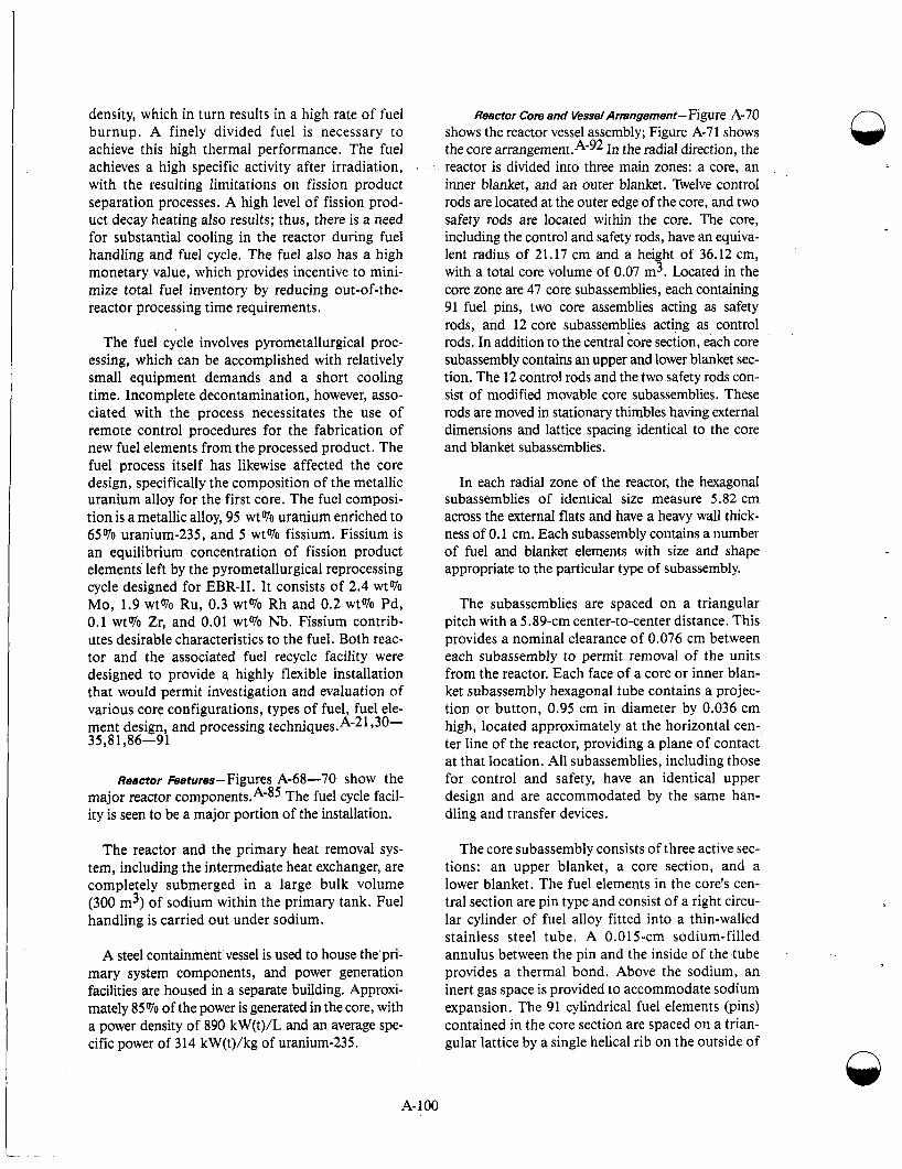
The fuel cycle involves pyrometallurgical proc- essing, which can be accomplished with relatively small equipment demands and a short cooling time. Incomplete decontamination, however, asso- ciated with the process necessitates the use of remote control procedures for the fabrication of new fuel elements from the processed product. The fuel process itself has likewise affected the core design, specifically the composition of the metallic uranium alloy for the first core. The fuel composi- tion is a metallic alloy, 95 wt% uranium enriched to 65% uranium-235, and 5 wt% fissium. Fissium is an equilibrium concentration of fission product elements left by the pyrometallurgical reprocessing cycle designed for EBR-11. It consists of 2.4 wt% Mo, 1.9 wt% Ru, 0.3 wt% Rh and 0.2 wt% Pd, 0.1 wt% Zr, and 0.01 wt% Nb. Fissium contrib- utes desirable characteristics to the fuel. Both reac- tor and the associated fuel recycle facility were designed to provide a highly flexible installation that would permit investigation and evaluation of various core configurations, types of fuel, fuel ele- ment design, and processing techniques.A-21 y30- 35,81,86-91
Re8ctor Fe8tures-Figures A-68-70 show the major reactor component^.^-^^ The fuel cycle facil- ity is seen to be a major portion of the installation.
The reactor and the primary heat removal sys- tem, including the intermediate heat exchanger, are completely submerged in a large bulk volume (300 m3) of sodium within the primary tank. Fuel handling is carried out under sodium.
A steel containment vessel is used to house the'pri- mary system components, and power generation facilities are housed in a separate building. Approxi- mately 85% of the power is generated in the core, with a power density of 890 kW(t)/L and an average spe- cific power of 314 kW(t)/kg of uranium-235.
density, which in turn results in a high rate of fuel burnup. A finely divided fuel is necessary to achieve this high thermal performance. The fuel achieves a high specific activity after irradiation, with the resulting limitations on fission product separation processes. A high level of fission prod- uct decay heating also results; thus, there is a need for substantial cooling in the reactor during fuel handling and fuel cycle. The fuel also has a high monetary value, which provides incentive to mini- mize total fuel inventory by reducing out-of-the- reactor processing time requirements.
A- 100
Reactor Core and Vessel Arrengement-Figure A-70 shows the reactor vessel assembly; Figure A-71 shows the core a r r a n g e m e ~ ~ t . ~ - ~ ~ In the radial direction, the reactor is divided into three main zones: a core, an inner blanket, and an outer blanket. Twelve control rods are located at the outer edge of the core, and two safety rods are located within the core. The core, including the control and safety rods, have an equiva- lent radius of 21.17 cm and a height of 36.12 cm, with a total core volume of 0.07 m3. Located in the core zone are 47 core subassemblies, each containing 91 fuel pins, two core assemblies acting as safety rods, and 12 core subassemblies acting as control rods. In addition to the central core section, each core subassembly contains an upper and lower blanket sec- tion. The 12 control rods and the two safety rods con- sist of modified movable core subassemblies. These rods are moved in stationary thimbles having external dimensions and lattice spacing identical to the core and blanket subassemblies.
In each radial zone of the reactor, the hexagonal subassemblies of identical size measure 5.82 cm across the external flats and have a heavy wall thick- ness of 0.1 cm. Each subassembly contains a number of fuel and blanket elements with size and shape appropriate to the particular type of subassembly.
The subassemblies are spaced on a triangular pitch with a 5.89-cm center-to-center distance. This provides a nominal clearance of 0.076 cm between each subassembly to permit removal of the units from the reactor. Each face of a core or inner blan- ket subassembly hexagonal tube contains a projec- tion or button, 0.95 cm in diameter by 0.036 cm high, located approximately at the horizontal cen- ter line of the reactor, providing a plane of contact at that location. All subassemblies, including those for control and safety, have an identical upper design and are accommodated by the same han- dling and transfer devices.
The core subassembly consists of three active sec- tions: an upper blanket, a core section, and a lower blanket. The fuel elements in the core's cen- tral section are pin type and consist of a right circu- lar cylinder of fuel alloy fitted into a thin-walled stainless steel tube. A 0.015-cm sodium-filled annulus between the pin and the inside of the tube provides a thermal bond. Above the sodium, an inert gas space is provided to accommodate sodium expansion. The 91 cylindrical fuel elements (pins) contained in the core section are spaced on a trian- gular lattice by a single helical rib on the outside of

Cover4 i f t i n g me(: han i s m
Subassembly gripper mechanism S torage-rac k mechanism
Control mechanisms
Subassembly transfer mechanism
.
Shield-cooling duct
Primary tank cove
'Mechanical pump
Reactor vessel
/ \
Figure A-68. EBR-I1 major reactor components and reactor primary tank.
each element. The lower ends of the pin are fas- tened to a parallel strip support grid with the upper ends unrestrained.
lar lattice. The pins are unalloyed depleted ura- nium, 0.8 cm in diameter, and 45.7 cm long. They are contained within a stainless steel tube having a 0.02-cm sodium-filled annulus to provide the nec- essary thermal bond. Bond ends of the blanket ele- ments are positioned in the subassembly by a
The identical upper and lower blanket sections consist of 19 pin type elements spaced on a triangu-
A-101
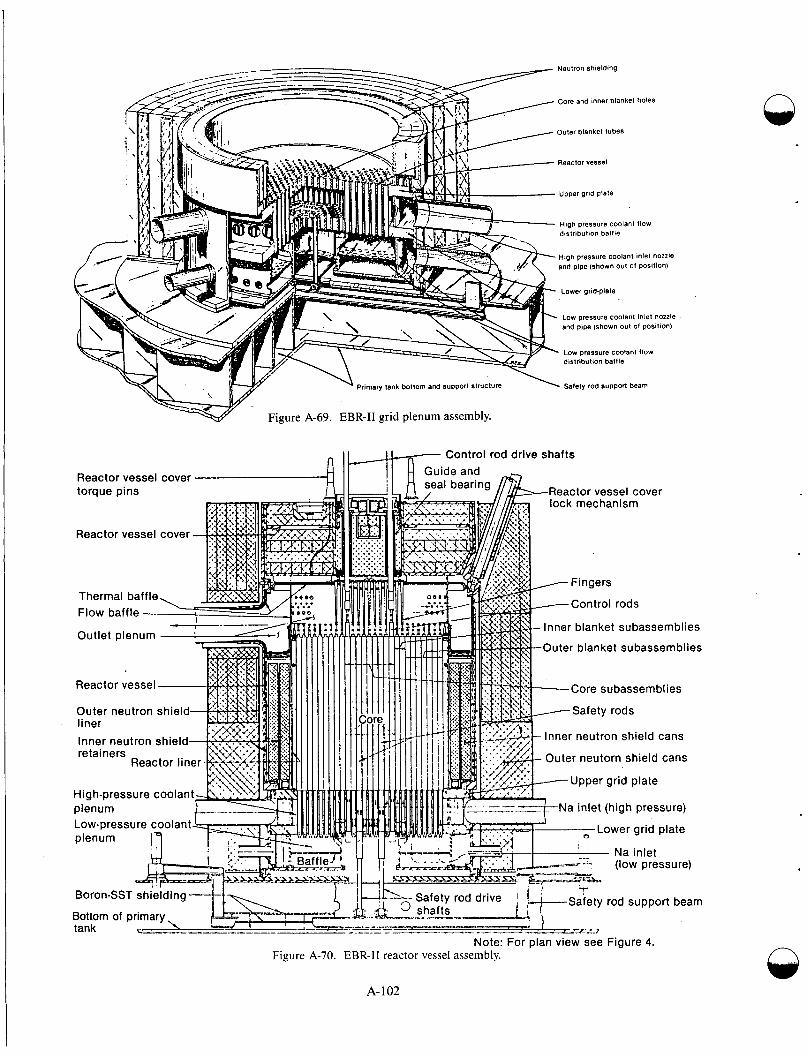
n
Reactor vessel cover - torque pins
Reactor vessel cover
1 Thermal baffle Flow baffle - Outlet plenum
Reactor vessel
Outer neutron shield liner
Inner neutron shield retainers
Reactor l iner-
High-pressure coolant plenum
7 Control rod drlve shafts
Reactor vessel cover lock mechanism
Inner blanket subassemblies
Outer blanket subassemblies
-Core subassemblies
Inner neutron shield cans
Outer neutorn shield cans
Upper grid plate
Note: For plan view see Figure 4. Figure A-70. EBR-I1 reactor vessel assembly.
A- 102
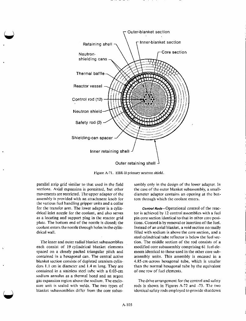
W Outer-blanket section
I n ner- blan ket sect ion
r Core section
Retaining shell
Neutron-
Thermal baffle
Reactor vessel
Neutron shield
Shield i ng-can spacer
\ Inner retaining shell ’ Outer retaining shell
Figure A-71. EBR-I1 primary neutron shield.
parallel strip grid similar to that used in the field sections. Axial expansion is permitted, but other movements are restricted. The upper adapter of the assembly is provided with an attachment knob for the various fuel handling gripper units and a collar for the transfer arm. The lower adapter is a cylin- drical inlet nozzle for the coolant, and also serves as a locating and support plug in the reactor grid plate. The bottom end of the nozzle is closed; the coolant enters the nozzle through holes in the cylin- drical wall.
The inner and outer radial blanket subassemblies each consist of 19 cylindrical blanket elements spaced on a closely packed triangular pitch and contained in a hexagonal can. The central active blanket section consists of depleted uranium cylin- ders 1 . 1 cm in diameter and 1.4 m long. They are contained in a stainless steel tube with a 0.03-cm sodium annulus as a thermal bond and an argon gas expansion region above the sodium. The enclo- sure unit is sealed with welds. The two types of blanket subassemblies differ from the core subas-
sembly only in the design of the lower adapter. In the case of the outer blanket subassembly, a small- diameter adapter contains an opening at the bot- tom through which the coolant enters.
Control Rods-Operational control of thc reac- tor is achieved by 12 control assemblies with a fuel pin core section identical to that in other core posi- tions. Control is by removal or insertion of the fuel. Instead of an axial blanket, a void section normally filled with sodium is above the core section, and a steel cylindrical tube reflector is below the fuel sec- tion. The middle section of the rod consists of a modified core subassembly comprising 61 fulel ele- ments identical to those used in the other core sub- assembly units. This assembly is encased in a 4.85-cm-across hexagonal tube, which is smaller than the normal hexagonal tube by the equivalent of one row of fuel elements.
The drive arrangement for the control and safety rods is shown in Figures A-72 and -73. The two identical safety rods employed to provide shutdown
A- 103
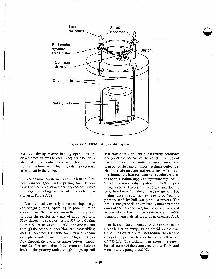
Limit Shock n
Rod-position synchro transmitter
Common drive unit -
Drive shafts
Safety rods
reactivity during reactor loading operations are driven from below the core. They are essentially identical to the control rods except for modifica- tions at the lower end which provide the necessary attachment to the drives.
Heat Transport Systems-A unique feature of the heat transport system is the primary tank. It con- tains the reactor vessel and primary coolant system submerged in a large volume of bulk sodium, as shown in Figure A-68.
Two identical vertically mounted single-stage centrifugal pumps, operating in parallel, force coolant from the bulk sodium in the primary tank through the reactor at a rate of about 536 L/s. Flow through the reactor itself is 517 L/s. Of that flow, 440 L/s move from a high-pressure plenum through the core and inner blanket subassemblies; 44 L/s flow from a separate low pressure plenum through the outer blanket subassembly; and 32 L/s flow through the clearance spaces between subas- semblies. The remaining 19 L/s represent leakage back to the primary tank through the pump ball
seat disconnects and the subassembly holddown devices at the bottom of the vessel. The coolant passes into a common outlet plenum chamber and then out of the reactor through a single outlet noz- zle to the intermediate heat exchanger. After pass- ing through the heat exchanger, the coolant returns to the bulk sodium supply at approximately 370°C. This temperature is slightly above the bulk temper- ature, since it is necessary to compensate for the small heat losses from the primary system tank. For maintenance, the pumps may be removed from the primary tank by ball seat pipe disconnects. The heat exchanger shell is permanently attached to the cover of the primary tank, but the tube bundle and associated structure are removable as a unit. Addi- tional component details are given in Reference A-93.
In the secondary system, an A-C electromagnetic linear induction pump, which provides close con- trol of the flow rate, circulates sodium through the tubes of the primary heat exchanger at a flow rate of 780 L/s. The sodium then enters the super- heated section of the steam generator at 470°C and returns to the pump at 320°C. n
j_ Figure A-72. EBR-I1 safety rod drive system.
A- 104
I.
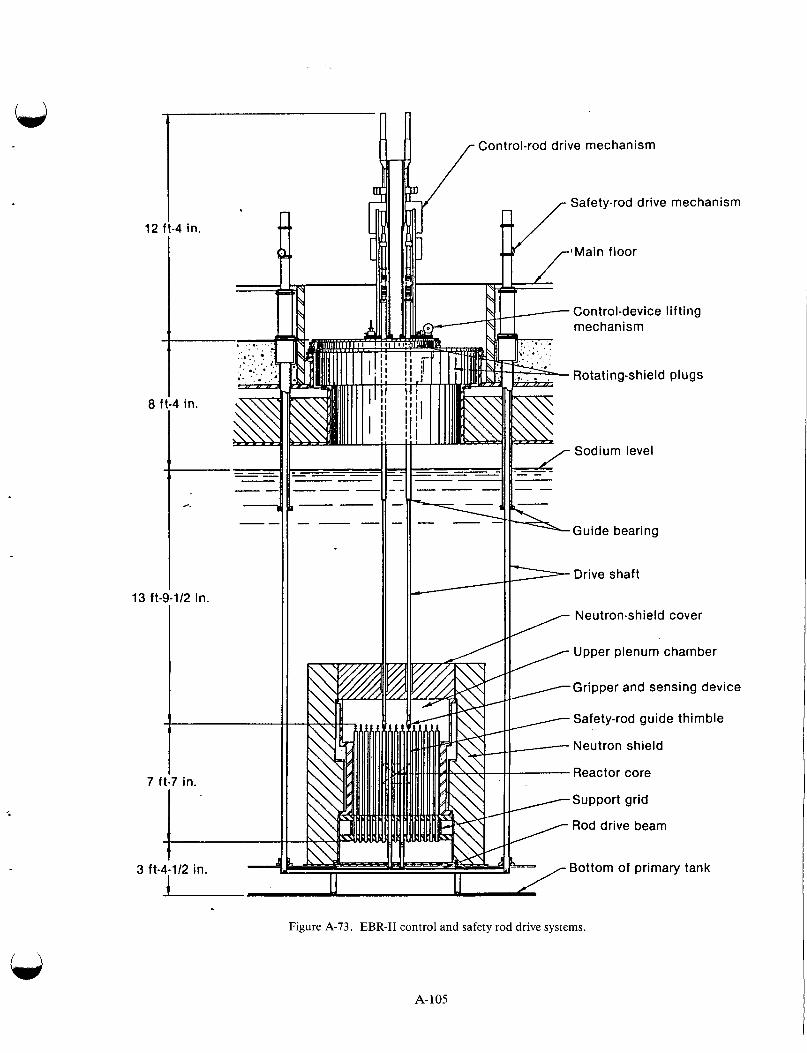
Ls I I
12 ft-4 in. I
13 ft-9-112 in.
1
7 ft:7 in.
3 ft-4-112 c, I in.
R Control-rod drive mechanism
Safety-rod drive mechanism
'Main floor
Control-device I i f t i ng mechanism
Rotating-shield plugs
E Sodium level
Guide bearing
> Drive shaft
Neutron-shield cover
Upper plenum chamber / / /Gripper and sensing device
Safety-rod guide thimble
--- Neutron shield
Reactor core
/Support grid
Rod drive beam
Bottom of primary tank -/ L L Figure A-73. EBR-I1 control and safety rod drive systems.
A-105

The steam generator, shown in Figure A-74, is one of the natural recirculation types with separate superheaters and evaporator sections connected to a single steam drum. Each evaporator unit is con- nected to the steam drum by a single downcomer and riser. Dry and saturated steam from the steam drum passes down through the superheater unit. Double-walled tube construction is used for both the evaporator and superheater units; no welds are used in the portion in contact with the ~ o d i u m . ~ - ~ ~
At full load [62.5 MW(t)], when the generator produces 20,700 kW electrical gross, the steam sys- tem flow includes 0.63 kg/s of steam bypass to the condenser. A full-capacity automatic steam bypass system permits reactor operation without turbine generator operation or with turbine load at any fraction of reactor power. This bypass system pre- vents major load changes from effecting changes in
the secondary system. Feedwater heating is accom- plished by extraction from the main turbine, by exhaust from the feedwater pump turbine, and by high-pressure steam from the main steam line.
Structures and Shielding Components- In EBR-11, the reactor vessel assembly is completely sub- merged within a large volume of bulk sodium con- tained in the primary tank. The assembly itself is mounted on the bottom structure of the tank in such a manner that the distance from the top of the reactor vessel to the free surface of the bulk sodium is approximately 3.6 m. The reactor vessel assem- bly, as shown in Figure A-70, includes the lower grid plenum with inlet nozzles and safety-rod drives, an inner radial neutron shield, the subas- sembly holddown and flow-baffle structure with outlet plenum and outlet nozzles, the vessel cover and hold down structure, thermal baffles, the
Sodium inlet 1 -
Figure A-74. EBR-I1 steam generator.
A- 106
n
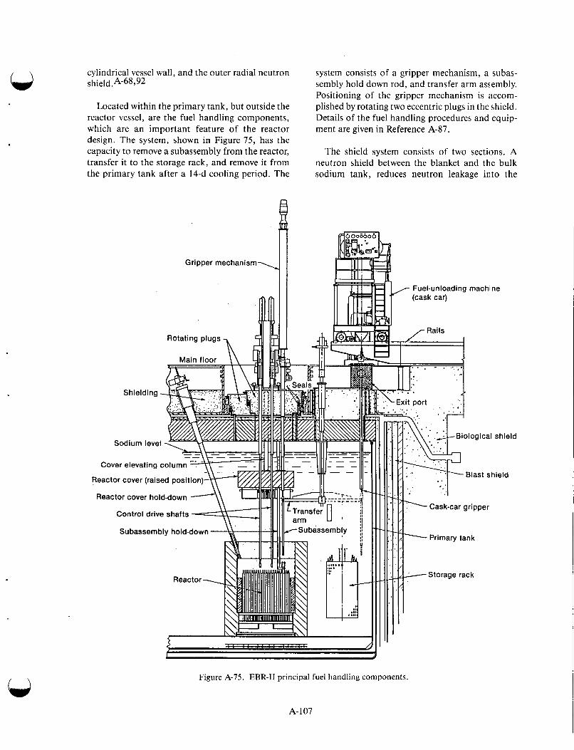
cylindrical vessel wall, and the outer radial neutron shield .A-68992
Located within the primary tank, but outside the reactor vessel, are the fuel handling components, which are an important feature of the reactor design. The system, shown in Figure 75, has the capacity to remove a subassembly from the reactor, transfer it to the storage rack, and remove it from the primary tank after a 14-d cooling period. The
' , I Gripper mechanism
system consists of a gripper mechanism, a subas- sembly hold down rod, and transfer arm assembly. Positioning of the gripper mechanism is itccom- plished by rotating two eccentric plugs in the shield. Details of the fuel handling procedures and equip- ment are given in Reference A-87.
The shield system consists of two sections. A neutron shield between the blanket and the bulk sodium tank, reduces neutron leakage into the
Fuel-unloading machi ne
Sodium level
Reactor cover (raised position)
Reactor cover hold-down
Control drive shafts
Subassembly hold-down
Figure A-75. EBR-I1 principal fuel handling components
A- 107
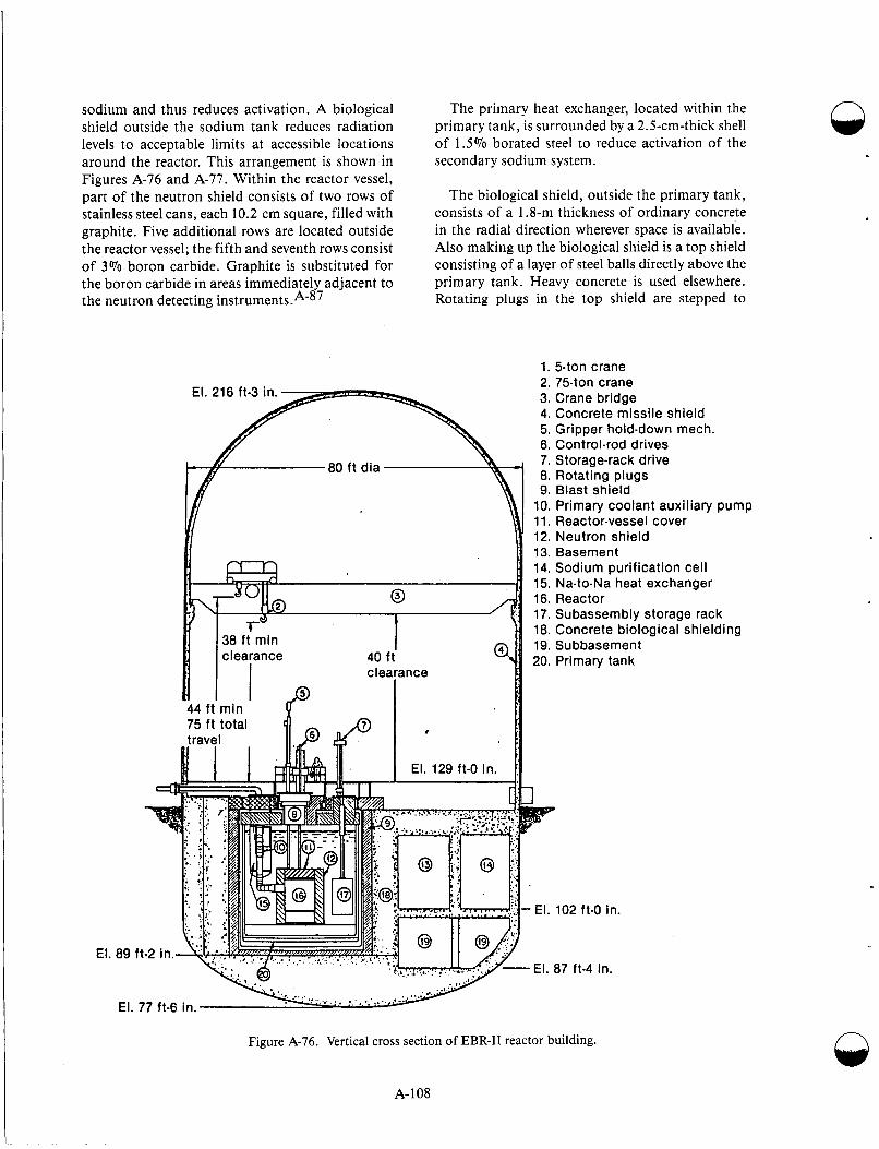
sodium and thus reduces activation. A biological shield outside the sodium tank reduces radiation levels to acceptable limits at accessible locations around the reactor. This arrangement is shown in Figures A-76 and A-77. Within the reactor vessel, part of the neutron shield consists of two rows of stainless steel cans, each 10.2 cm square, filled with graphite. Five additional rows are located outside the reactor vessel; the fifth and seventh rows consist of 3% boron carbide. Graphite is substituted for the boron carbide in areas immediately adjacent to the neutron detecting instrument^.^-^^
The primary heat exchanger, located within the primary tank, is surrounded by a 2.5-cm-thick shell of 1.5% borated steel to reduce activation of the secondary sodium system.
The biological shield, outside the primary tank, consists of a 1.8-m thickness of ordinary concrete in the radial direction wherever space is available. Also making up the biological shield is a top shield consisting of a layer of steel balls directly above the primary tank. Heavy concrete is used elsewhere. Rotating plugs in the top shield are stepped to
1. 54017 crane 2. 75-ton crane 3. Crane bridge 4. Concrete missile shield 5. Gripper hold-down mech. 6. Control-rod drives 7. Storage-rack drive 8. Rotating plugs 9. Blast shield
10. Primary coolant auxiliary pump 11. Reactor-vessel cover 12. Neutron shield 13. Basement 14. Sodium purification cell 15. Na-to-Na heat exchanger 16. Reactor 17. Subassembly storage rack 18. Concrete biological shielding 19. Subbasement 20. Primary tank
n
1
. El. 102 ft-0 in.
' El. 87 ft-4 in. El. 89
El
Figure A-76. Vertical cross section of EBR-I1 reactor building.
A- 108
9
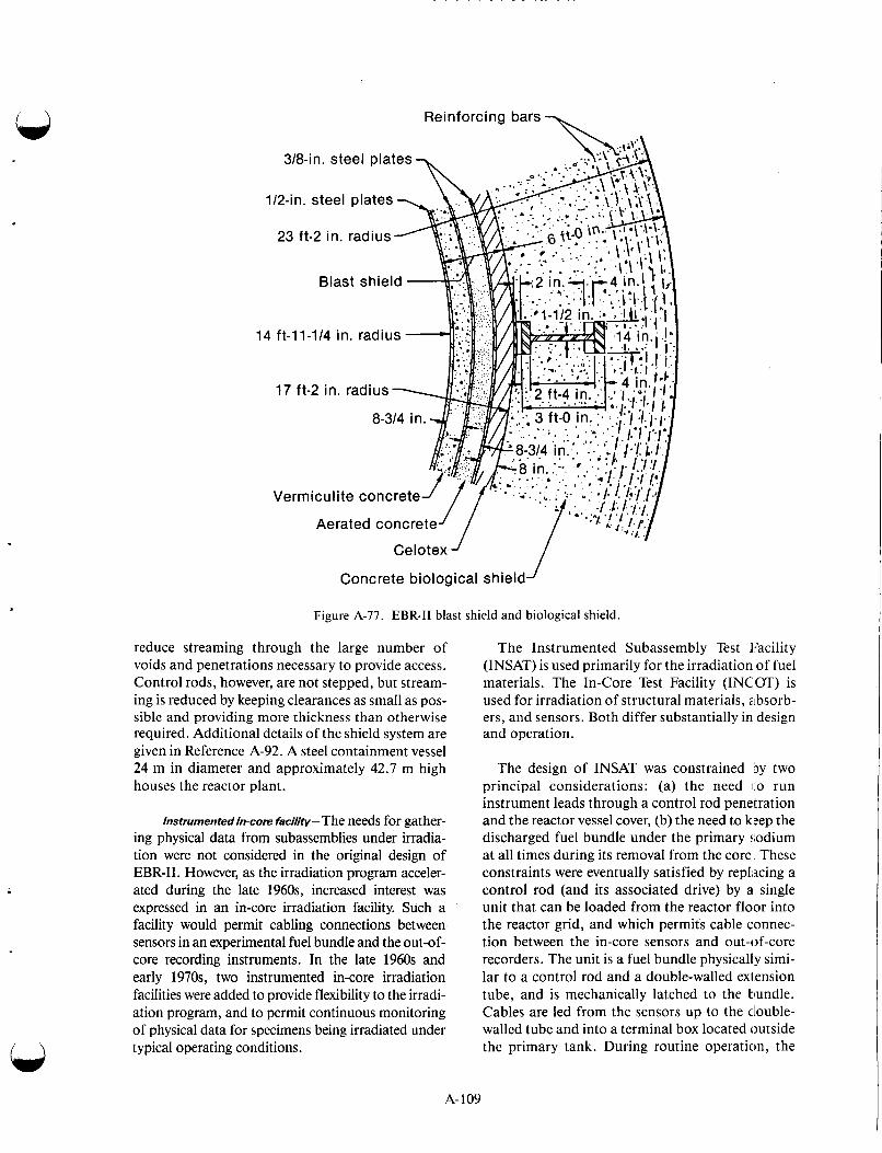
\ Reinforcing bars
1
14
Celotex J
Concrete biological shield
Figure A-77. EBR-I1 blast shield and biological shield.
reduce streaming through the large number of voids and penetrations necessary to provide access. Control rods, however, are not stepped, but stream- ing is reduced by keeping clearances as small as pos- sible and providing more thickness than otherwise required. Additional details of the shield system are given in Reference A-92. A steel containment vessel 24 m in diameter and approximately 42.7 m high houses the reactor plant.
Instrumented In-core hciIity-The needs for gather- ing physical data from subassemblies under irradia- tion were not considered in the original design of EBR-11. However, as the irradiation program acceler- ated during the late 1960s, increased interest was expressed in an in-core irradiation facility. Such a facility would permit cabling connections between sensors in an experimental fuel bundle and the out-of- core recording instruments. In the late 1960s and early 1970s, two instrumented in-core irradiation facilities were added to provide flexibility to the irradi- ation program, and to permit continuous monitoring of physical data for specimens being irradiated under typical operating conditions.
The Instrumented Subassembly Test 1:acility (INSAT) is used primarily for the irradiation of fuel materials. The In-Core Test Facility (INCOT) is used for irradiation of structural materials, absorb- ers, and sensors. Both differ substantially in design and operation.
The design of INSAT was constrained by two principal considerations: (a) the need 1.0 run instrument leads through a control rod penetration and the reactor vessel cover, (b) the need to b:ep the discharged fuel bundle under the primary $;odium at all times during its removal from the core These constraints were eventually satisfied by replacing a control rod (and its associated drive) by a single unit that can be loaded from the reactor floor into the reactor grid, and which permits cable connec- tion between the in-core sensors and out-of-core recorders. The unit is a fuel bundle physically simi- lar to a control rod and a double-walled exlension tube, and is mechanically latched to the tlundle. Cables are led from the sensors up to the ciouble- walled tube and into a terminal box located outside the primary tank. During routine operation, the
A- 109
fuel bundle occupies the same position as that nor- mally occupied by a control rod. During fuel han- dling operations, the entire in-core assembly is raised to an elevation that permits normal function- ing of fuel handling equipment. Following fuel handling operations, the assembly is lowered back into the core for subsequent irradiation.
When test bundles reach their target burnup and are ready for removal from the core, a special cutting tool is lowered through the extension tube. Rotation of the tool cuts the instrument leads. The extension tube and cutting tool are then drawn up into a pulling pipe, leaving the fuel bundle ready for transfer with the standard fuel handling equipment.
Depending on the needs of the experimenter, as few as one and as many as 61 other specimens may be accommodated in the test vehicle. As of December 31, 1982, seven individual sets of instru- mented fuel specimens had been irradiated in the INSAT facility. Typical information derived from the tests include temperature, coolant flow rate, gas pres- sure, creep rate, and neutron flux.
Test specimens in the INCOT facility may be inserted or removed from the reactor floor area. The distinction between the two facilities is one of use. Because of decay heat considerations, fueled specimens must be kept submerged in the primary sodium following irradiation. Such a constraint is more easily satisfied by treating the test section dur- ing its discharge as a spent fuel assembly. Further- more, attempts to discharge irradiated fuel specimens via the reactor floor would pose major shielding problems.
For nonfuel test specimens, decay heat problems are essentially nonexistent. Associated radiation fields are such that shielding requirements during discharge through the reactor top can be satisfied.
The INCOT facility is, in its simplest form, a thimble assembly that extends upward from the reactor grid (below the core) through the core, reac- tor vessel cover, and small rotating plug, to the reac- tor floor level. Instrument leads run directly from test specimens or sensors up the thimble to a top mounted terminal box. Special handling systems permit removal of irradiated test bundles from the facility, reinsertion of reworked irradiated test bun- dles into the facility, or removal of the facility itself. Removal operations involve the withdrawal of the test bundle into a handling container 11.3 m long, which is suspended from the building crane. Opera-
tion of the container is remotely controlled from a shielded booth. As for INSAT facilities, the entire assembly is lifted prior to fuel handling operations.
Since 1972, the INCOT facility has been used to irradiate 10 principal series of instrumented experi- ments. Among these were the irradiation of absorber materials (B4C and Eu-02), self-powered neutron detectors, eddy current flow sensors, acoustical monitors, and biaxial creep specimens.
A more recent in-core instrumented facility, the Breached Fuel Test Facility (BFTF), has been installed. This facility was designed to test the fis- sion product characteristics of breached fuel under normal operating conditions. BFTF consists of a device that monitors the exit sodium from a test vehicle located immediately underneath. The test vehicle, in turn, can contain any one or more of a variety of experimental fuel elements, either intact or intentionally breached. BFTF is equipped with two flowmeters, a delayed neutron detector, and a deposition sodium sampler used to study the plate- out of fission products.
Another in-core instrumented facility, the Fuel Performance Test Facility (FPTF), has been installed. Principal features of FPTF include the following: a throttle valve for changing and con- trolling the coolant flow rate through the facility, a sodium flowmeter, thermocouples, and a delayed neutron detector. Because its coolant flow rate can be changed during operation, FPTF can be used to cycle temperatures in fuel element specimens. FPTF can, of course, be used to study the effects of transient operation in both intact and intentionally breached fuel elements.
At the nuclear Instrument Test Facility (NITF), capability exists for on-site performance testing of nuclear instruments under LMFBR conditions. Two of eight existing instrument thimbles are used for this purpose. In the original configuration, EBR-I1 was fitted with four J-type nuclear instru- ment thimbles that extend down from the upper shielding to the primary tank and into the neutron shield around the vessel. Four other 0-type thim- bles similarly extend down from the upper shielding to terminate outside the neutron shield. One 0 thimble and one J thimble have been converted to instrumented test facilities.
The NITF thimbles are 8.5 m long and 38 cm in diameter at the lower ends. Instruments are usually located at core mid-plane elevation. Leads from the
A-1 10
instruments are led up through the thimble to the reactor operating floor.
Test temperatures ranging from 66 to 370°C are made possible by varying the amount of cooling air circulating through the facility. If higher tempera- tures are needed, thermostatically controlled ovens may be used for instrument heating. Data taken under operating conditions allow the experimenter to evaluate effects of high temperature and intense radiation fields on the performance of various neu- tron detectors and instrument cables.
The Radioactive Sodium Chemistry Loop (RSCL) is a facility that permits development test- ing of techniques to measure impurity levels and primary sodium. The facility consists of five shielded cells, a 5 . I-cm-diameter main loop, and smaller branch lines that deliver primary sodium to and from the various cells. Coolant is pumped through the main loop by a dc electromagnetic pump at flow rates and pressure variable up to 1.9 L/s and 0.11 MPa, respectively.
Each cell may be isolated from the main loop, and, after a suitable decay period, physical access is permitted for the installation and maintenance of equipment. Extensive precautions have been taken to prevent, annunciate, and minimize the impact of sodium leakage throughout the entire facility.
The facility has been used extensively as a test bed for proving the application of various on-line impurity measuring devices. Among devices tested in the RSCL are a plugging temperature indicator, tritium monitor, vacuum distillation sampler, oxy- gen and hydrogen meters, segregated iodine sam- pler, graphite-cesium trap, and an equilibrium module for carbon analysis.
Fuel cycle--Because a very important objective of this reactor is the demonstration of an integral fuel processing facility, some features associated with the fuel reprocessing are given here and are found in more detail in References 94-109. The first fissium core consisted of stainless steel jack- eted pins containing 50% enriched uranium alloyed with 5% noble-metal fission product elements. Irradiated fuel assemblies were allowed to cool 14 d in the primary tank and were then removed to the Fuel Cycle Facility (FCF). Transfer operations were relatively simple. Spent fuel subassemblies were placed in the air cell for disassembly operations, using a system of shielded casks, airlocks (between the reactor building and the FCF), and cranes. The
operation consisted mainly of slitting the wrapper can and removing individual elements from the fuel bundle. Fuel elements, in turn, were loaded into magazines and moved to the argon cell via im inter- connecting lock.
Initial operations in the argon cell consisted of the following: shearing upper and lower ends from the fuel elements, removing spacer wires, removing the cladding, and chopping the spent fuel pins into 3.5-cm lengths. Chopped fuel in amounts (of 10 to 12 kg, along with precalculated amounts of enriched uranium, were melted in CaO-coated zir- conia crucibles and held for 3 h at a temperature of %I ,400”C. During this period, approximatdy two- thirds of the fission products-those wiirh high vapor pressure, such as xenon, krypton, iodine, bromine, cesium, and cadmium-left the melt through volatilization. Less volatile electropositive fission products, such as yttrium, barium, stron- tium, and the rare earths, reacted with the i:irconia to form an oxide that remained within the crucible after pouring operations. The volatized fission products were collected by a Fiberfax cover over the crucible, which also collected sodium used as a thermal bond in the fuel. The purified alloy was poured into the mold to provide the ingot for fabri- cation; the oxidized fission products, principally the rare earths, were left behind in a sci-called “skull” retained by the crucible.
The pouring operations were never totally effi- cient. Inevitably, a relatively small but corisistent amount of fuel, . ~ 6 - 8 % , remained in the crucible with the dross. These skulls were set aside in hot storage for subsequent uranium recovery.
The process contemplated for recovering the skull material is to convert it to an oxide powder suspended in a molten chloride flux, the noble metals to be removed by reduction and extraction by zinc. A dilute magnesium-zinc alloy wouid then reduce the uranium oxides and other fissiori prod- uct oxides. A uranium zinc intermetallic compound would be precipitated from this metallic s o h tion by cooling, and the desired uranium recovered in sev- eral additional reprocessing steps. Although the melt-refining separation itself is quite simple, the need for the skull recovery process may result in a complicated overall operation.
The first step in fuel pin casting operatioris con- sisted of remelting a melt-refined ingot in a thoria- coated graphite crucible with an induction heated vacuum furnace. Also located in the furnace in a
A-1 11
vertical attitude above the crucible was a cluster of approximately 100 Vycor molds. After the charge was melted, the crucible was raised to a position that immersed the lower end of the mold cluster to a depth of 3.8 cm. The furnace was then rapidly pressurized to 0.17 MPa to drive the melt up into the evacuated molds. After a few seconds, the melt froze and the crucible was lowered to its original position. Following a 4-h programmed cooling per- iod, the furnace was opened and the molds were removed. Unused fuel material in the crucible was broken up and returned to the fuel stream.
The first step in fuel pin processing operations consisted of breaking the Vycor molds away from the castings with a pneumatically actuated crushing system. Pins, collected in trays, were fed by gravity to a shear that cropped the pins to required lengths. Following cropping, the pins were subjected to non- destructive tests that consisted principally of mea- surements for weight, length, diameter, and porosity. Rejects were fed back to the melt refining operation.
Acceptable pins were loaded into stainless steel tubes containing solid sodium wire (%0.65 to 0.85 g). The sodium was melted and the fuel pins settled by gravity. End-plugs were inserted into the jackets and peripherally welded to the jackets with a remotely operated capacitor-discharge welder. To ensure void free sodium bonds, the finished ele- ments, clustered 50 to a magazine, were heated in a furnace 1 h at 500°C. The elements were then sub- jected to %l,OOO vertical impacts (under 500°C conditions) at the rate of 100 impacts per min. The finished elements were then inspected for bond, flaws, and sodium level. The final step consisted of monitoring the elements on a grid system and incorporating the resultant fuel bundle in a fresh hexagonal wrapper can for subsequent return to the reactor.
After nearly 5 years of successful operation, the FCF was shut down in 1969. Subsequent core changes have been made, either by vendors in the commercial sector or by on-site personnel in a companion “cold” line facility. Currently, the argon cell is on standby status. The cell has been stripped of equipment and is in the process of decontamination.
Operating Experience-Operating run lengths of EBR-I1 are nominally 2,800 MWd or 4 0 full- power d. Two factors determine the run length: the need to discharge the radiation experiments at
scheduled intervals and the need to replace spent fuel with fresh fuel. Approximately 7 d are needed between runs to accommodate refueling operations and perform minor maintenance activities that cannot be carried out with the plant running. Each year the plant is shut down for four to six weeks to carry out comprehensive modification, mainte- nance, and inspection.
The operation of EBR-I1 has always been kineti- cally stable. A prompt negative power coefficient of reactivity from the expansion of coolant and fuel effectively damp the effects of small reactivity changes from inlet temperature variations and con- trol rod motion. The amplitude of the prompt power coefficient component is occasionally mea- sured by rapidly withdrawing reactivity from the system, dropping a special rod, and analyzing the shape of the power decay curve.
During the period from 1976 to 1982, EBR-I1 operated with plant availability factors greater than 70%. A peak value of 77.1% was reached during 1980. Plant availability factors in this range com- pare favorably with those of commercial nuclear and conventional fossil fuel power plants. If down time required by the experimental programs is dis- counted, the actual plant availability factor during the 1976 to 1982 period exceeded 80%.
Refueling time between runs is not a serious con- straint. The capability of interim in-tank storage permits the pre-shutdown transfer of fresh fuel assemblies to the storage basket. Approximately 4 h after shutdown, spent subassemblies may be transferred from the core to a storage basket and replaced with fresh subassemblies. The turnaround time per subassembly amounts to approximately 1 h. In the absence of problems, the time required for end of run refueling operations amounts to approximately 24 to 48 h. The interim fuel storage feature is beneficial in another important respect. After fulfilling minimum cooling requirements, spent subassemblies may be transferred into and out of storage baskets while the reactor is running.
n
Routine operations are occasionally interrupted by the release of gaseous fission products from a failed fuel element. The majority of the releases are the result of endurance tests in which fuel elements are intentionally irradiated to failure and beyond. On other occasions, the failure may be the result of a faulty weld or a premature failure of cladding. More recently, the effects of sustained operation
n
A-112
under breached cladding conditions have been investigated. Fuel elements that failed under irradi- ation were permitted to remain in the core for peri- ods up to a few weeks to evaluate the effects of sustained operation on the fuel element. Also eval- uated were the consequences of releasing fission products for the primary coolant and cover gas system.
A portion of the EBR-I1 irradiation program is concerned with effects of 'fission products on the primary sodium and cover gas systems. Species related to the coolant are removed, in part, by means of an externally located cold trap. Gaseous fission products released to the cover gas system are removed by a combination of cryogenic trapping and absorption using liquid nitrogen-cooled char- coal beds.
The origin of a given fission product release may be identified by means of a xenon-tagging tech- nique developed at EBR-11. The gas plenums of all experimental fuel elements are inoculated with small quantities of various but unique mixtures of xenon. Under failure conditions, gaseous fission products and a portion of the xenon tag mixture are released to the cover gas system. An on-line 'device concentrates the xenon component of the cover gas by cryogenic trapping and analyzes the xenon frac- tion with a mass spectrometer. A comparison of the measured isotopic ratios with those of library sam- ples provides positive identification of a source.
Various techniques are used to measure impuri- ties in the sodium and the cover gas system. On-line analytical equipment is used to monitor levels of hydrogen, oxygen, and tritium in the primary and secondary sodium systems. The primary cover gas system is continuously monitored for carbona- ceous materials-principally methane, carbon monoxide, and carbon dioxide. Routine samples of primary and secondary sodium are chemically ana-
Several on-line techniques are used to detect, annunciate, and measure releases of fission prod- ucts from failed elements to the primary sodium and cover gas systems. The fuel element rupture detector (FRED) is used to monitor a small bypass stream of primary coolant for the presence of delayed neutron emitters in the exit coolant. Another device-the germanium-lithium, argon scanning system (GLASS)-analyzes a flowing cover gas stream by means of gamma pulse height spectrometry with a GeLi semiconductor detector.
A-1 13
. .
lyzed for a wide variety of fission product and cor- rosion species.
Many years of operating experience have demon- strated the feasibility of conducting routine and specific maintenance on LMFBR systems and com- ponents. Considerable maintenance experience with unconventional, relatively accessible, and moderately radioactive components has been achieved. A typical component falling into 1 his cat- egory is the transfer arm (part of the fuel handling system). Precautionary measures associated with such an activity is to maintain an argon atmosphere around the component to prevent any leakage of air to the cover gas system. The measure also prevents leakage of cover gas to the reactor buildin,g. Such an activity is based on pulling the component into a rubberized nylon bag sealed by a flange to a pene- tration in the primary containment tank.
The most difficult components to mainlain are those under unconventional, relatively inxcessi- ble, intrinsically radioactive, and radioactively contaminated conditions. Examples of such com- ponents are control rod drives, the main core grip- per, and the subassembly hold down fixture. Such components penetrate the reactor vessel cover and, as a result, become highly radioactive through neu- tron activation. The problem of intrinsic r,%dioac- tivity, sodium contamination, and fission product plateout make direct repair virtually impossible. In such a situation-for example, a malfunctioning control rod drive, the entire unit is removed and replaced. When such components are being removed, the system must be decayed for a,Dproxi- mately 5 d because of the sodium 24. The compo- nent is then pulled into a shielded pipe is handled by the building crane.
EBR-I1 has been the only operating LMFBR in the world with metallic driver fuel. Several consid- erations affected the initial design of the IEBR-I1 driver fuel during the early and mid-1950s: relative ease of fabrication, success of prior metallic fuel loadings in EBR-I, excellent heat transfer proper- ties of metals, and superior breeding characteristics of metallic fuels.
As operating experience accumulated, hurnup limits were incrementally increased from the origi- nalvalueof 1 at.% establishedin 1961, to 1.12 at.% in 1966, to 1.8 at.% in 1969, and to 2.6 at .% in 1975. Beyond 3 at. '70, fuel swelling became a prob- lem. Pressures exerted at the fuel cladding interface
were so large that cladding strain and subsequent rupture seemed likely. Such limitations were always evident, even in the early days of design. The inevi- table penalties were short operating cycles and inef- ficient use of fuel. However, the impact of the penalties was reduced by the rapid on-site reproc- essing of discharged fuel. On certain occasions, discharged fuel was reprocessed and returned to the core within 29 d.
Despite the successful implementation of short turnaround reprocessing techniques, considerable effort was devoted to the development of fuels that could be operated to much higher burnup levels. One concept that seemed particularly promising in the early days of operation was the permissive swelling principle. This concept was premised on the contention that if the fuel material was permit- ted to swell unconstrained, a point would be reached at ~ 3 0 % AV/V when pores in the fuel matrix become interconnected. This permits the release of trapped fission product gases to the fuel element plenum. The fuel, in a weakened condi- tion, tends to deform into the pores rather than straining the cladding. Proof of the principle appeared in the form of an improved fuel element design, the MARK-11. The cladding thickness was increased from 0.23 mm to 0.31 mm to strengthen the cladding; the pin diameter was reduced from 3.66 to 3.3 mm; the sodium-filled annulus was increased from 0.15 to 0.25 cm; and the gas plenum above the fuel was increased to accommo- date the increased release of fission product gases. The uranium-235 enrichment was increased to 67 wt%, and the cladding was changed to annealed Type 3 16 stainless steel. Intensive irradiation sur- veillance studies on test specimens were conducted, and, as a result, it was shown that the fuel materials swelled rapidly and made contact with the cladding at approximately 2 at.% burnup. At this point, the fuel lattice becomes sufficiently porous to permit relatively free flow of fission product gases to the fuel element plenum. Beyond this point, fuel mate- rial remains in contact with the inner wall of the cladding. But because the fuel is then porous and “weak,” and because the driving force for diame- tral swelling is low, the cladding strain rate is low. Consequently, the lower stress on the jacket permits much higher burnups to be realized.
Currently the burnup limit for the MARK-I1 fuel is 8 at. Yo. A continuing irradiation surveillance program implies that even higher levels are possi- ble; since endurance testing at EBR-11, up to 18.9 at.% has been successfully completed. Of con-
siderable interest are the following statistics: of approximately 10,000 MARK-I1 elements irradi- ated to the burnup level of 6 at.% and an addi- tional 17,000 irradiated to 8 at.%, none has failed, that is, suffered cladding rupture.
The first use of EBR-I1 as an irradiation facility began in May 1965 with the insertion of two experi- mental subassemblies that contained various struc- tural specimens and prototypal fuel rods (PuO2-UO2 and U-Pu alloys). Since that time, the compliment of elements, capsules, and other speci- mens may be broken down as follows: mixed U-Pu oxide fuels, 3 189; driver fuel elements (surveillance and run to failure program) 5173; other LMFBR fuels (principally mixed U-Pu nitrides and car- bides), 755; cladding and structural specimens, 1343; absorber materials, 219; and miscellaneous, 360. Mixed U-Pu oxide fuels have been irradiated to a heavy atom burnup of 19.9%; cladding tem- peratures of greater than 800°C have been achieved; and neutron fluences of 2.1 x neutrons/cm2 have been accumulated in structural materials. Absorber materials have been irradiated to 16.5 x 10²¹ neutron captures/cm3, and EBR-I1 driver fuel has been irradiated to heavy atomic burnup of 18.9%.
Enrico Fermi Atomic Power Plant. The Enrico Fermi Atomic Power Plant was the first full-scale industrial fast reactor power plant in the United States. Some features of the FERMI reactor are similar to those of EBR-11. However, EBR-I1 is of lower capacity, 20 MW(e); the FERMI reactor, although developmental, was designed for an ulti- mate capacity of 65 MW(e), comparable to an average-size conventionally fueled unit of its time.
Reactor Features- The arrangement of compo- nents within the primary reactor tank is illustrated in Figure A-78. The reactor core and blanket, as well as the fuel transfer system, were contained within an irregularly shaped lower section of the reactor vessel. Attention is drawn to the open region between the reactor vessel and the primary tank, which was filled with graphite shielding. The upper section of the reactor vessel contained a large sodium pool above the core and blanket. Access to the core was accomplished by a rotating top shield plug arrangement.
The location of other plant equipment is shown in Figure A-79. Several connected buildings adja- cent to the reactor building contained steam gener- ators, a turbo generator, and control equipment. n
A-1 14

G ra not
A-1 15
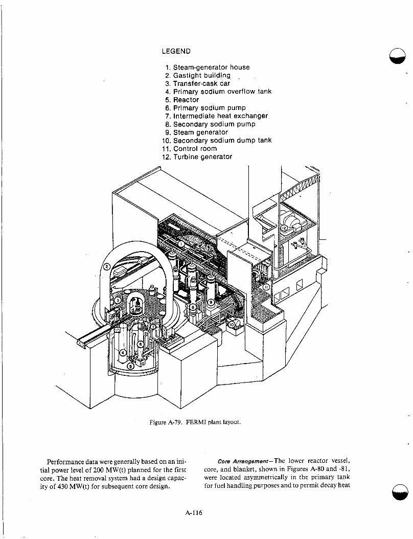
LEGEND n
1. Steam-generator house 2. Gastight building, 3. Transfer-cask car 4. Primary sodium overflow tank 5. Reactor 6. Primary sodium pump 7. Intermediate heat exchanger 8. Secondary sodium pump 9. Steam generator
10. Secondary sodium dump tank 11. Control room 12. Turbine generator
Figure A-79. FERMI plant layout.
Performance data were generally based on an ini- tial power level of 200 MW(t) planned for the first core. The heat removal system had a design capac- ity of 430 MW(t) for subsequent core design.
core Arrangement-The lower reactor vessel, core, and blanket, shown in Figures A-80 and -81, were located asymmetrically in the primary tank for fuel handling purposes and to permit decay heat
A-116

i Sweep mechanism
Hold-down drive mechanism Offset handling drive mechanism,
Shot tank -
Exit port
Offset handling mechanism
Thermal shield
Deposit port Exit port
Rotor support assembly
Subassembly-transfer pot
Transfer-rotor container
Primary shield tank
Vessel fler
Transfer-rotor Plug drive mechanism drive mechanism
Deck structure
Rotating-plug container
Sodium level (normal o3eration)
Sodium level (refueling)
30-in. outlet
Hold-down column Alignment spider Hold-down plate 6-in. radial-blanket inlet 44-in. core inlet Core support plates Radial-blanket support plates
Thermal shield
Radial-blanket inlet plenum
Core inlet plenum :-plate supports
Radial-blanket i
Figure A-80. F E R M I reactor vessel.
removal during shutdown by natural circulation. The coolant flow was upward in its natural circula- tion system; the large supply of sodium in the pri- mary system (1 36,000 kg) provided the heat capacity needed to reduce transients.
A cylindrical section in the lower reactor vessel, 2 meters in diameter and 1.78 m high, contained the core and square blanket subassemblies. The central core region, which was surrounded by the breeder blanket, was in the form of a 78.7-cm- diameter cylinder, also 78.7 cm high. Figure A-82 is a reactor cross-section plan view illustrating the core and blanket subassembly arrangement. For 200-MW(t) power level operation, 105 central lat- tice positions contained fuel subassemblies. Within this region, 10 positions were provided for control
rods. Each of the core subassemblies (Figure A-83) contained an upper and lower axial blanket section in addition to the central fuel bearing core region.
An inner radial blanket region, with prcivisions for 34 subassemblies, was provided outs (de the core. These positiods, identical in design to those in the core, could be used for additional fuel subas- semblies if needed. The orifice design in ea:h type of subassembly, however, controlled the amount of coolant received.
The fuel region of each core subassembly con- sisted of 140 fuel pins, each having a nominal length of 83.26 cm. Each pin also had an an outer diameter of 0.401 cm, consisting of uranium- 10 wt% molybdenum alloy with an uranium
A-1 17

Support-plate support structure l-
Figure A-81. F E R M I meltdown section.
SUBASSEMBLY CLEARANCE
THERMAL BAFFLES
THERMAL SHIELD INSTALLED IN SEGMENTS
Pasibls Storage for Core or Inner-rodiol-blanket Subossemblier
FOR HOLD-DOWN ASSEMBLY ALIGNMENT
GUIDE (31 REQUIRED Thermal Shielding in Form of Steel AS SHOWN 0 TRANSFER Rods Used For Surveillonco Tubes
1 N
,/ROTOR CONTAINER Neutron-source Location NOSNO4
DATUM LINE 'r MECHANISM Surveillance Subosrembly Locolion
Totol Subwremblier
@ Oscillator-rod Temporory Localion
Oumtity - 2 8
I os
32
5a)
24
195
3
I
I
871 -
Figure A-82. FERMI reactor cross section.
A-1 18

Strainer - al Y C m - n e I.: .- -
73 m
al 0 m Q v)
a L
140 fuel pins
M Section through core
I rHand l ing head
Match line 'B'
9 c? 7
l M a t c h line 'A' - .
Figure A-83. Isometric view of FERMI fuel assembly.
\4 Fuel pin
A-119
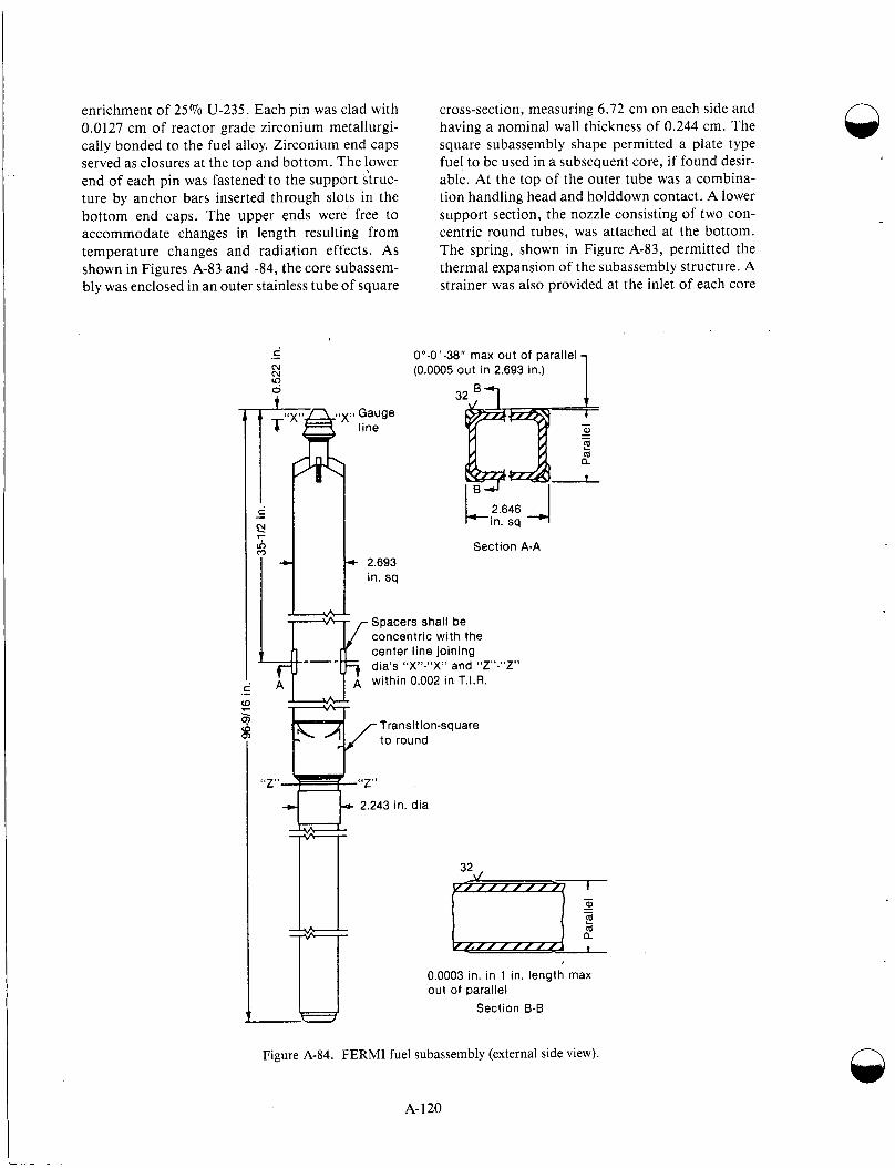
enrichment of 25% U-235. Each pin was clad with 0.0127 cm of reactor grade zirconium metallurgi- cally bonded to the fuel alloy. Zirconium end caps served as closures at the top and bottom. The !ewer end of each pin was fastened to the support struc- ture by anchor bars inserted through slots in the bottom end caps. The upper ends were’ free to accommodate changes in length resulting from temperature changes and radiation effects. As shown in Figures A-83 and -84, the core subassem- bly was enclosed in an outer stainless tube of square
cross-section, measuring 6.72 cm on each side and having a nominal wall thickness of 0.244 cm. The square subassembly shape permitted a plate type fuel to be used in a subsequent core, if found desir- able. At the top of the outer tube was a combina- tion handling head and holddown contact. A lower support section, the nozzle consisting of two con- centric round tubes, was attached at the bottom. The spring, shown in Figure A-83, permitted the thermal expansion of the subassembly structure. A strainer was also provided at the inlet of each core
0”-0‘-38” max out of parallel (0.0005 out in 2.693 in.) 1
3 ‘zx7v Gauge
line
n
L 2 . 6 4 6 4 in. sq
Section A-A * 2.693
in. sq
Spacers shall be concentric with the center line joining
within 0.002 in T.I.R.
dia’s “X9?-$<XS9 and &CZ3!-6<z!V
Transition-square to round
“2”
2.243 in. dia
“Z”
u rT- 32
h-
0.0003 in. in 1 in. length max out of parallel
Section B-B
Figure A-84. FERMI fuel subassembly (external side view).
A- 120
n
drs subassembly. The upper and lower axial blanket regions of the core subassemblies contained 16 ura- nium rods 1.0 cm in diameter-3 wtol’o molybde- num alloy, with the uranium depleted to 0.35% U-235. A 0.025-cm-thick stainless steel cladding was used for these rods. Both the inner and outer blanket subassemblies used a lattice of 25 rods, each having the same diametral dimensions as the axial blanket rods. In the case of the inner blanket subassemblies, the support structure included a thermal expansion spring arrangement identical to that used in the core units (Figure A-84). Outer radial blanket subassemblies could fill the remaining 500 positions, shown in Figure A-82. These had a simple support structure, as indicated in Figure A-84.
Control Elements-In this reactor, poison con- trol was used rather than fuel or reflector control. Details on the control rods can be found in Refer- ences A-1 10-1 13. Available excess reactivity was intentionally kept small. Furthermore, the fuel management scheme minimized the reactivity changes caused by fuel burnup. The eight safety rods and two operating control rods used Boron,l0 in boron carbide as the absorber. One of the operat- ing control rods used for regulating purposes had a maximum reactivity insertion rate of 0.67 $ I s . The other, used for shim control, was designed for 1 4 / min insertion. The eight safety rods, spaced uni- formly as shown in Figure A-82, provided a shutdown reactivity of over $8, and the two operat- ing rods had a total worth of 92P.
Each of the control elements was housed in a cylindrical guide tube which, in turn, was mounted inside a square tube having the same outside dimensions as a core assembly. Heat generated by a control rod was removed by sodium flowing from the core inlet plenum through pressure breakdown orifices inserted in the section between the two sup- port planes. Flow was directed up through the con- trol rod assembly and then through the annulus formed by the control rod assembly and inner round guide tube.
During reactor operation, the safety rods were held just above the upper axial blanket by a latch on each safety rod drive unit. Reactivity adjustment for startup, power level changes, and burnup com- pensation were made by means of the two operating control rods. These two rods were raised and low- ered at different rates, as mentioned above.
Hear Transport System-In the primary coolant system, three coolant loops were used. Each con-
tained a pump and intermediate heat exchanger. The pump-a vertical shaft, single-stage centrifu- gal pump rated at 745 L/s and driven by a 1,000 hp motor-circulated sodium to the core through a 35.6-cm-diameter pipe. About 13% of the total flow was pumped through a 15.2-cm pipe to the radial blanket (Figure A-85). Core coolant flowed up from the lower inlet plenum of the cole, both through the reactor core itself, and then to the upper reactor vessel, which served as an exit plenum, shown in Figure A-86. The hot sodium then flowed by gravity from this pool to the shell side of the intermediate heat exchanger through a 76.2-cm line. The intermediate heat exc nangers were counterflow shell and tube units constructed of Type 304 stainless steel. The primary sodium stream, by this time at lower temperature, r-turned to the primary pump. Additional details on the pri- mary cooling system are given in Reference A-1 14. A system of secondary containment for 1 he pri- mary system consisted of a welded, leIk-type enclosure for the reactor vessel, primary system, pump tanks, and the intermediate heat exchanger shells. This structure, which protects againsi loss of sodium, is described in detail in References A-1 14 and 115.
Three secondary coolant loops were provided, each corresponding to a primary loop. Hlzat was transferred from the intermediate heat exchanger to the shell side of a steam generator by sodiuin. This sodium was circulated by an 840 L/s pump driven by a 350 hp motor. The steam generators were verti- cal shell and tube exchangers of single-wall tube construction arranged for a combination of cross- flow and counterflow. A number of design i’eatures provided protection against any leaks within the unit. The tube to tube sheet joints, for example, were located in an inert gas space above the sodium to reduce thermal shock.
Structural and Shielding Components-Th e reac- tor vessel and internal components are shown in Figure A-78. Core and blanket subassemblies were contained within the lower reactor vessel; the upper reactor vessel section, at approximately atmos- pheric pressure, served as a mixing pool for the hot sodium. The upper section contained a core hold- down device and offset fuel handling mechanisms. The holddown device maintained radial alignment of the core assembly’s upper end and prevented subassembly movement induced by the uplil’t force of the sodium flow.
A-121
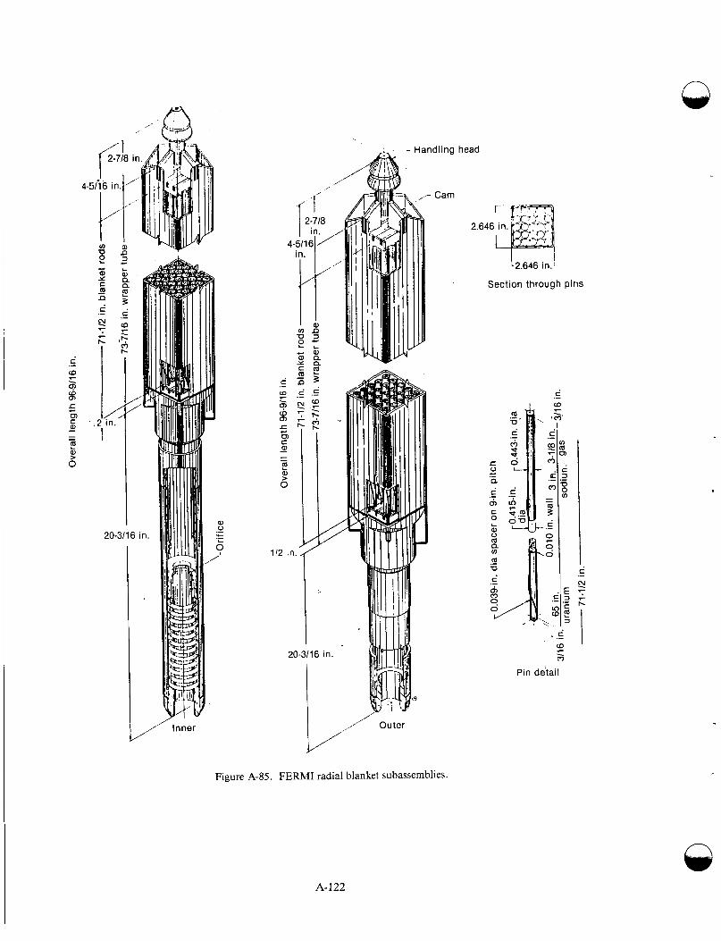
Ove
rall
leng
th 9
6-9/
16 in
. P
-L
.
71-1
12 in
. bla
nket
rod
s
s-
\ A ' a &
73
-7/1
6 in
. wra
pper
tub
e ,\,
/\
y
.A
Ove
rall
leng
th 9
6-9\
16 in
. i3
-.
h)
71-1
12 in
. bla
nket
rod
s 73
-7/1
6 in
. wra
pper
tube
\
0.03
9-in
. dia
spa
cer
on 9
-in. p
itch
0
?
71-1
12 in
.
I
nl 3
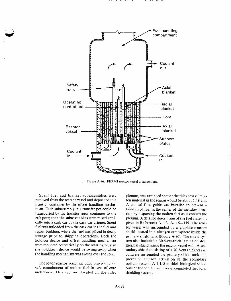
Figure A-86. FERMI reactor vessel arrangement.
Spent fuel and blanket subassemblies were removed from the reactor vessel and deposited in a transfer container by the offset handling mecha- nism. Each subassembly in a transfer pot could be transported by the transfer rotor container to the exit port; then the subassemblies were raised verti- cally into a cask car by the cask car gripper. Spent fuel was unloaded from the cask car in the fuel and repair building, where the fuel was placed in decay storage prior to shipping operations. Both the hold-on device and offset handling mechanism were mounted eccentrically on the rotating plug so the holddown device would be swung away when the handling mechanism was swung over the core.
The lower reactor vessel included provisions for safe containment of molten fuel in case of core meltdown. This section, located in the inlet
plenum, was arranged so that the thickness of mol- ten material in the region would be about 3. 18 cm. A conical flow guide was installed to prevent a buildup of fuel in the center of the meltdown sec- tion by dispersing the molten fuel as it enteIed the plenum. A detailed description of the fuel system is given in References A-1 13, A- 1 16- 1 19. The reac- tor vessel was surrounded by a graphite n1:utron shield located in a nitrogen atmosphere inside the primary shield tank (Figure A-80). The shield sys- tem also included a 30.5-cm-thick laminated steel thermal shield inside the reactor vessel wall. A sec- ondary shield consisting of a 76.2-cm thickness of concrete surrounded the primary shield tank and prevented neutron activation of the secondary sodium system. A 1-1 /2-m-thick biological shield outside the containment vessel completed the radial shielding system.
A- 123
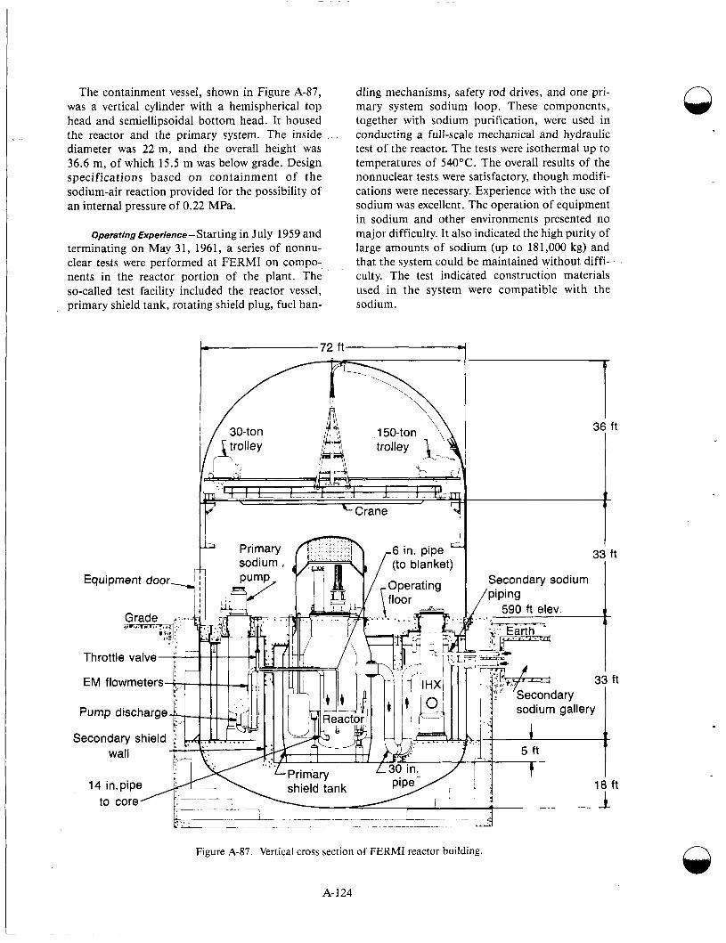
The containment vessel, shown in Figure A-87, was a vertical cylinder with a hemispherical top head and semiellipsoidal bottom head. It housed the reactor and the primary system. The inside diameter was 22 m, and the overall height was 36.6 m, of which 15.5 m was below grade. Design specifications based on containment of the sodium-air reaction provided for the possibility of an internal pressure of 0.22 MPa.
Operating Experience- Starting in July 1959 and terminating on May 31, 1961, a series of nonnu- clear tests were performed at FERMI on compo-, nents in the reactor portion of the plant. The so-called test facility included the reactor vessel, primary shield tank, rotating shield plug, fuel han-
dling mechanisms, safety rod drives, and one pri- mary system sodium loop. These components, together with sodium purification, were used in conducting a full-scale mechanical and hydraulic test of the reactor. The tests were isothermal up to temperatures of 540°C. The overall results of the nonnuclear tests were satisfactory, though modifi- cations were necessary. Experience with the use of sodium was excellent. The operation of equipment in sodium and other environments presented no major difficulty. It also indicated the high purity of large amounts of sodium (up to 181,000 kg) and that the system could be maintained without diffi- culty. The test indicated construction materials used in the system were compatible with the sodium.
Figure A-87. Vertical cross section of FERMI reactor building. n
A-124
. . . . .. .. . . . .
Starting July 1, 1961, the FERMI plant was incorporated around the test facility and preopera- tional tests began preparatory to nuclear testing. Testing to 538°C for a period of about 1 week checked out the operation of safety rods, fuel han- dling mechanisms, and sodium pumps. In general, the system performed satisfactorily. Following the 538°C test, tests of graphite directly around the reactor vessel (inside the insulation) indicated that the material failed to withstand the high tempera- ture test. Tests indicated the borated graphite did not conform to design specifications and would have to be replaced. Tests on the remainder of mate- rial outside the insulation in the primary shield tank indicated this graphite material also needed replacement. It was apparent that moisture and oxygen control was a must in the use of high- temperature graphite. All graphite in the primary shield tank was replaced with high-density, high- temperature reactor grade graphite. Any boron used was in the form of boron carbide. The rein- stallation of the graphite shield was a primary fac- tor in delaying the reactor’s completion.
During the test of the offset fuel handling mech- anism (OHM), it became jammed by malfunction and misoperation. The OHM became bent when an inadvertent attempt was made to move it laterally before it was delatched from a partially raised dummy subassembly. An innerlock had been dis- connected for the purpose of carrying out the test. The OHM was removed with a lightweight remov- able container such as not to violate the inert gas integrity of the reactor. After disassembly, it was found that the gripper and stabilizer foot were not in their proper positions. After removal of the OHM and reduction of the sodium level, observa- tion of the core and blanket subassembly indicated a number of displaced subassemblies. Investigation showed the subassembly heads had stuck to the holddown plate fingers when the holddown was raised. When the plug was rotated with the heads engaged with the fingers, the fingers and other sub- assemblies were bent. Subsequent lowering of the holddown resulted in further damage and in unseating some subassemblies in the support plate, causing further flow erosion of the support plate holds. For repairs, the reactor vessel was drained of sodium, and personnel in protective suits entered the reactor. They removed the center support plate and the holddown plate with its fingers, and rede- signed the holddown finger sockets. Other modifi- cations were made to the control and safety rod guide tubes, The center support plate had stellite bushings inserted into the holes to prevent further
possibility of erosion. The OHM was modified to strengthen the gripper linkage. The modification ensured enough strength would be available to per- mit application of impact loads and force the grip- per open. The stabilizer foot was redesigned to ensure the OHM would not be locked over a parti- ally raised subassembly. The stabilizer assembly and its attachment to the rotating tube was strengthened to withstand higher lateral loads. The possibility of obstructions interfering with future operations was avoided by installing a new mecha- nism called a sweep arm; it was used to check for obstructions in the upper plenum above the core and blanket. About 2,000 man hours were expended in the vessel by personnel using protective suits within the argon atmosphere to accomplish results .A-120
In July 1961, a series of hydrostatic iests at 5.86 MPa on the No. 2 steam generator tubes indi- cated leaks. Subsequent checks indicated 7 1 tubes were cracked through the tube wall. All of them were located opposite one of the two sodium inlets. Testing the tubes indicated that residual stresses, corrosion effects, and elevated temperatures induced stress corrosion cracking. The entire tube bundle of No. 2 steam generator was retubed at the fabricator. All three units were stress relieked and inspected prior to reassembly.
In December 1962, a sodium water reaction took place in the No. 1 steam generator, blowing the rupture disk installed for just such an event. The water was dumped manually by an operator to pre- vent further introduction of water. The No. 1 sec- ondary loop was drained, and the tube bundle was removed and cleaned in ~3 m3 of alcohol. The largest cleaning operation to 1963 to remove sodium from one component was performelj with- out incident. Examination showed extensive tube damage caused by vibration of the tube against the support structures, as well as erosion from the sodium water reaction during the period between a reaction and the rupture disk blowout. Smadl- and full-scale models in water of the tube bundle and its baffle indicated vibration of the tubes at the sodium inlet had been as high as 0.635 cni. Baf- fling and lacing of the tubes were carried out to reduce this vibration to a negligible quantit):
A program was initiated to modify the check valves in the primary system. The 40.6-cm check valves induced high-pressure surges when lone of the loops was shut down with either one or two of the loops operating. A program was carried out to
A-125
install new check valves-modified to include dash pots and springs-to reduce the surge pressure to negligible values.
Each of the more than 3,000 cans in the rotating plug containing graphite was vented by 0.16-cm holes to the argon cover gas above the sodium in the reactor. The primary system tests at 538°C and at lower temperatures released material in the graphite binder to the primary system. This release resulted in carbon and other contamination of the primary system. Extensive programs of sodium sampling, analysis, and filtration were carried out to deter- mine what contaminants were present and how they affected the system. Tests of the materials in the primary system indicated some degree of carboni- zation but not sufficient to affect operation of the reactor.
Three operational tests prior to criticality on August 23, 1963, were successfully completed; only minor modifications of the control safety rods and control drives were required.
The low-power nuclear test program for FERMI was originally scheduled for 182 d of reactor time. The program was to verify the soundness of the basic physics design of the fast breeder. Each indi- vidual test was completed within the allotted time. However, delays caused by systems external to the reactor, extended testing throughout 1964. The sys- tems primarily responsible for the delays were the cask car and the steam generators. Twenty-seven tests were scheduled at low power; all but two were completed by the end of 1964. The reactor was taken critical over 250 times, using 500 different core configurations that required movement of 1,400 subassemblies and more than 3,500 move- ments of the fuel handling mechanism and rotating shield plug.A-122
Throughout the tests, the plant operated very stabIy and was easiIy controlled. Predictions of the reactor’s parameters were, in general, substanti- ated. The predicted isothermal coefficient was reduced by 7%. Reactivity worths of the control rods were found to be 8% lower than predicted, and safety rod worths were 15% lower than predicted .*-l 23
The test plan for the nuclear program during high power ascension comprised the oscillator, pulse, power coefficient, automatic reactor pro- gramming, and scram tests. Results of all tests through 20 MW(t) showed satisfactory operation.
It was decided to interrupt the test program because hydrogen levels in the No. 3 steam generator indi- cated possible leaks. Inspection showed numerous leaks existed at the welded joints between the tube and tube sheet. In addition, feedwater control for the steam generator was noted to be a problem because of fluctuation in the sodium outlet temper- atures but with a temperature amplitude of about 5°C. Relocation of the temperature detectors elimi- nated most fluctuations, thus averting any poten- tial single circuit shutdown while on automatic contro1.A-124
The ,tests. of greatest interest were the reactor’s stability tests. The test program was developed to answer whether an operating characteristic could make the reactor unstable and whether the reactor fuel bowed inward enough to cause a significant positive bowing coefficient. Oscillator tests through 100 MW(t) showed no evidence of insta- bility or positive bowing coefficient. After the power run August 5 through 7, onIy a few other tests at 67 MW(t) were conducted later in the month. Testing was conducted primarily for obtaining plant test data, as opposed to nuclear testing, in such tests as shielding, reactor vessel tem- perature differentials, and core subassembly outlet temperatures.A-125-128
Fuel Melting Incident-During a 100,000-kW power run in August, temperature measurements were made of sodium flowing out of the top of sev- eral of the 103 core subassemblies. This was accom- plished by reading the output of thermocouples installed in the holddown finger. The thermocou- ples were installed just above the subassembly han- dling heads in about one-fifth of the core and inner radial blanket subassemblies. Such measurements allowed increased sodium heat to be determined as the sodium flowed through and reduced the heat in a given subassembly. This increase in heat content could then be checked against the calculated heat generation rate of a given subassembly for consist- ency. Such comparisons were not taken to be pre- cise. High precision would also require an accurate determination of the sodium flow rate through individual subassemblies-something that was not directly measurable.
Abnormal temperatures first appeared in June, when the outlet sodium temperature for one subas- sembly was as much as 19°C higher than expected. The temperature returned to normal during the July run and then ran high again during the August runs. While unexplained phenomena are always of n
A- 126
concern, the higher-than-expected temperature readings were in all cases lower than the normal sodium outlet temperature of the hot test subas- sembly located at the center of the core. Therefore, observed temperatures were all well within designed margins of the subassemblies and 480°C below the boiling point of sodium. It was decided to continue the test program but to shift the misbehaving subas- semblies to different locations. It could then be determined whether the temperature anomalies were the result of a fault in the fuel subassembly itself, a fault in the thermocouple, or a fault in the associated environment.
As part of the continuing plant test program, it was planned on October 5 to bring the reactor to an indicated thermal power level of 74,000 kW, a level surpassed several times before. Several tests were to be performed, including checking a new pressure control adjustment on the main steam bypass line, adjusting the automatic feedwater control, and measuring temperatures on the troublesome No. 1 steam generator, across the core outlet, and near the transfer rotor. In addition, oscillator tests were planned because operation was to involve a particu- lar combination of two loops that had not been tested at this power level. Information was to be obtained on the previously observed unexpected subassembly outlet temperatures by observing the temperature of the three deviant subassemblies in their new locations under thermocouples that had previously indicated normal temperature readings.
The reactor was started up the night before and kept at a 1.0 MW(t) over night. It was intended to begin a power ascent at 8 a.m. on October 5 , but a malfunction in a steam generator valve postponed beginning the power increase until 1:45 p.m. At 2:15 p.m., with the power at 5 MW(t), difficulty was experienced in the control system of the east boiler feedwater pump, and the power was reduced to 2 MW(t) to start another pump. At 2:20 p.m., the rise in power was began and continued until 8 MW(t) was reached, when there was a brief hold to put the reactor on automatic control. An auto- matic system took the reactor up in power at a con- trolled rate and involved a somewhat ' complex withdraw pattern of the two operating control rods.
During the automatic startup, the meter record- ing the time and rate of change of power (dn/dt) gave erratic signals. A similar but independent device was connected to the safety system so that if the measured power decrease exceeded 6 MW/s the safety rods would drop into the core, thereby shut-
ting down the reactor. Experience at other facilities indicated that several of the previous reactclr mal- functions involved anomalous negative rea'ztivity. Erratic behavior of the dn/dt meter that had been experienced before was only 1 or 2 MW/min, and was thought to be a noise pickup in the contr,ol sys- tem. Indeed, it soon disappeared. During the inci- dent, the reactor was placed on manual control, but was returned to automatic following a clearup of the dn/dt signal .A-1 29
At 3:05 p.m., the feedwater flow control 'system was put on automatic. Variations on the dn/dt meter were observed. It was noted that the two operating control rods appeared to be withdrawn further than normal for the approximately 30 MW(t) power level that the reactor had now attained. This indicates an unexplained source of negative reactivity; one possible cause would be higher-than-expected heating. So, the power increase was halted, and a check was made of sub- assembly outlet temperatures. During this :heck, alarms sounded from the radiation monitors in the upper reactor building ventilation exhaust ducts, resulting in automatic isolation of the containment building. The area radiation monitor in the Fission product detector building also exceeded its set- point, isolating the fission product detector system. A Class-I radiation emergency was announced. Reactor power reduction was begun in accordance with operating procedures, and by 3:2CI p.m. assessment of the reactor information was com- plete and the reactor was shut down by a manual scram, with insertion of all six safety rods into the core, terminating the chain reactions within s e ~ o n d s . ~ - l 29
The following information was developed during the first few days after the accident, which demon- strated that the extent of fuel damage was low.
Freedom of movement of the six safety rods was verified the next day. The overall structural integrity of the core was not damaged enough to cause gross destruc- tion of the safety rod guide tubes.
Primary coolant system flow was main- tained without primary coolant leakage, indicating no credible mechanism for mas- sive core melting.
A subcritical reactivity check performed on October 7 indicated there musi: have been some net fuel motion away from the
A-127
center of the core, and that the movement was equivalent to the complete removal of about half the fuel of an average sub,assembly.
Review of the chart of the core subassem- bly outlet temperature recorded suggested that overheating and corresponding fuel melting were located in or near one core assembly (M- 140).
0 On October 20, samples of the core cover gas were extracted and sent to Argonne National Laboratory for analysis. Based on the analysis, it was concluded that the amount of fuel melted was almost equiva- lent to that contained within one complete s u b a ~ s e m b l y . ~ - ~ ~ ~
Recovery operations must include removal of the subassemblies, and normal subassembly removal requires raising the holddown mechanism. This device is mounted on top of the rotating plug and extends all the way to the top of the core, for indi- vidual fingers exert a downward force against each core subassembly, holding them in place against the upward force of the flowing coolant (Figure A-80). Such operation might have caused core movement.
In November of 1966, shortly after the pressure drop measurements were completed and chances for a secondary criticality situation were assessed as negligible, the holddown mechanism (HDM) was raised. A special procedure was used incorporating strain gauges and acoustic and reactivity readings to detect any irregularities as the HDM was raised in small increments.
The mechanical arm of the sweep mechanism was operated manually and passed over the top of the core and then over the blanket subassemblies. No protruding subassemblies were indicated.
An offset handling mechanism (OHM) was used to confirm that all subassembly handling heads
Two more investigations were conducted to shed further light on the extent of core damage and to assess the potential for secondary criticality acci- dents before subassembly removal procedures were begun. One investigation involved a pressure drop measurement, which was carried out on October 21, 1966; it was concluded that flow blockage in the core ranged between zero and six subassemblies completely plugged.
. $
A-128
were in their correct position to within the tolerance of the OHM and the subassemblies. Then, by out- fitting the OHM with a dial indicating lighter spring gauges, it was used to establish the pulling force required to lift each subassembly a specified distance.
n
Very high lifting forces were required in the area of the two subassemblies shown by thermocouple readings to be running hot during the October 5 run. It was determined that the two subassemblies were stuck together.
'After the decay heat had diminished to a point where the sodium was no longer needed, the sodium was drained from the reactor vessel by a siphon procedure to a level 2.5 cm below the under- side of the top core support plate. The core was viewed through a boroscope inserted through one of the access ports of the rotating plug at the top of the vessel. A sharp wedge on an extension handle was lowered between the subassemblies to chisel the subassemblies apart. On July 1967, the bond between the subassemblies that were stuck together was broken and the subassemblies were removed and shipped to a hot cell for examination.
Surface examination of these two subassemblies revealed definite damage. They were bent and there were holes in the wrapper can. Though the weights had not changed, the center of gravity had shifted downward, 1.75 cm in one subassembly and 3 cm in the other.
One subassembly was cut longitudinally; the other was cut transversely in four places. A signifi- cant portion of the fuel was found to have melted and sloughed downward, though a number of fuel pins remained intact. No evidence could be found to indicate that molten fuel had flowed from one subassembly to another.
In August 1967, the sodium was drained further to below the level of the primary meltdown section, which effectively emptied the inlet plenum of sodium. In September, a boroscope viewing device and light were lowered through access ports in the rotating plug down to the meltdown pan located 10.7 m below the operating floor.
On the zirconium liner of the meltdown section was an object appearing as a crumpled, folded piece of sheetmetal. Stereoscopically viewed, a three-dimensional map of the object was devel- oped. And from the map, a model was made of n

. . . . . . . . - . - . - . .
what the object probably looked like before crum- pling. The unfolded version appeared to be flat, pie-shaped piece of sheetmetal about 1 ft long, which was identified as one of six zirconium liners of the conical flow guide. It had become detached and was thrust up against the inlet flow nozzle of the effected subassemblies by the force of the flow- ing liquid sodium coolant.
Repair of FERMI I- Removal operations were conducted in two phases. The first phase involved removal of the detached zirconium segment. The second involved both detachment and removal of the remaining five segments still believed to be bolted to the conical flow guide.
Plans for the first phase were initiated immedi- ately on discovery of the object, even before it was identified. The approach taken was to retrieve the object intact through the 35.6-cm primary line, aided by a manipulator inserted through the rotat- ing plug and support plate holes. The spine tool manipulator, resembled a human spine. It con- sisted of a 91.4-cm length of a series of round disks with egg-shaped cross sections. A series of cables allowed bending in any desired direction and con- trolled a jaw at the far end that was used for grasp- ing the object. Control was at the operating floor level, some 12.2 m away from the jaw end.
The retrieval device was a 1.5-m section of 12.7-cm- diameter flexible metal hose attached to a 12.2-m length of helical spring cable. A remotely controlled grabber was mounted on a trolley within the flexible hose. The retrieval device was inserted into the 35.6-cm primary sodium line through a 15.2 x 17.8-cm hole cut into the pipe just outside the secondary shield wall, 10.7 m from the object to be removed. A spe- cially designed glove box was attached at the position of the opening in the pipe to maintain the inert atmo- sphere of the primary system. Figure A-88 shows the relative location of these devices.
The tools and procedures were all checked in a full-scale mockup of the lower plenum and the 35.6-cm inlet sodium line.
In March 1968, the first phase of retrieval began. Tool operators were positioned at the top of the rotating plug and at the glove box over the opening in the 35.6-cm sodium pipe. These operators were separated and were not in visual contact (see Figure A-88). Only the spine tool operator atop the rotating plug could view the lower plenum region;
communication with the other operator was by phone. The object was pulled by the retrieval tool up 10.7 m of the 35.6-cm line at a rate of 1.5 m every 20 min to allow cooling of the segment so it would not burn the plastic glove box. Examination confirmed its tentative identification as a zirco- nium segment, originally installed in the conical flow guide.
The remaining five zirconium segments were detached by removing the three tack welded screw heads holding each plate and melting them with an electric arc. Following detachment, the segments were then retrieved by the same method used for the first segment. An arc melt tool was designed that fit through the same 4. l-cm holes in the support plate, that could be remotely operated in a hot argon atmosphere, and that could be sufficiently articu- lated to allow positioning over each of the screw heads. Such a tool was successfully tested on the full-scale mockup in August 1968.
In November 1968, the arc melting tool was low- ered into the inlet plenum and the screw removal process began. The proper gap between the elec- trode and the arc melting tool and the screw to be melted was determined optically by obserking the length of a high-frequency low-current spark dis- charged from the electrode. When the propx posi- tion was obtained, a 1350-amp dc arc was initiated for 14 seconds. All of the screw heads were thus melted without incident before any of the segments were retrieved. Following screw head removal, the segments remained in position, slightly welded to the flow guide by the arc melting operation It was necessary to insert a special chisel between the seg- ments in the conical flow guide and to slightly twist them to pry them free. Removal of the segments from the vessel was then accomplished without incident by an retrieval device improved from the earlier retrieval experience. On December 16, 1968, about three weeks after the first screw was removed, the last of the six zirconium segments was retrieved.
Following retrieval of the segments, the arc melt- ing. tool was used to weld the zirconium screw shanks to the conical flow guide. The inlet plenum region was inspected for debris and cleaned by a vacuum. The primary system was again filkd with sodium, followed by cold trapping operations that caused impurities to precipitate in the cold trap, thus maintaining acceptable sodium purity. In a very real sense, damage to the reactor caused by the
A-129
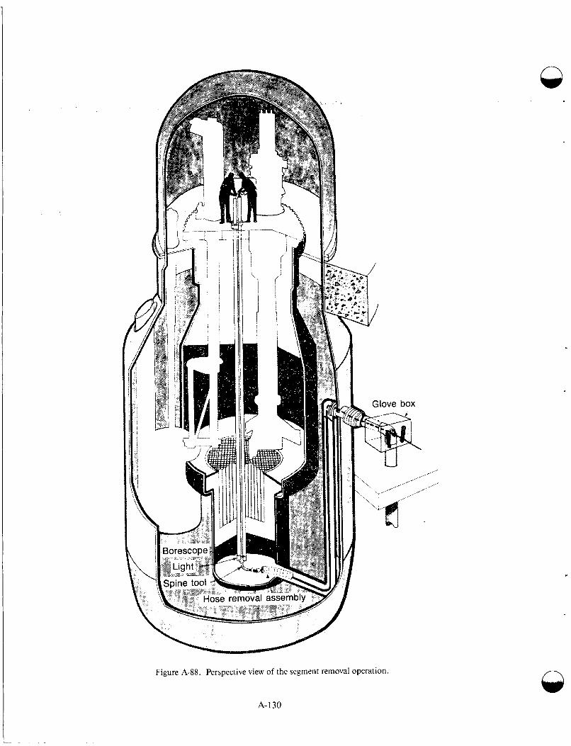
Figure A-88. Perspective view of the segment removal operation.
A-130
n
October 5, 1966, fuel melting incident was now repaired. Before resuming operations, the follow- ing was done:
A photographic examination of the metal- lic fingers of the holddown mechanism assured that distortion of the damaged subassemblies had not damaged the hold- down mechanism
All core subassemblies in the reactor dur- ing the melting incident were replaced by new subassemblies stored on site
Added to the instrument system to aid in the operation and detection of steady state reactor anomalies were a digital computer (malfunction detection analyzer), two delayed neutron detectors that could detect a high power level failure area equal to 3% of 1 fuel pin, a very accurate ammeter con- nected to the reactor power monitors, and digital readouts for the thermocouple accurate to 0.06"C.
The accident demonstrated that thoughtful prep- aration for malfunctions, coupled with a design philosophy that incorporates redundancy and in- depth defense, provides a safeguards envelope that will adequately respond to a real accident and pro- vides an ample margin between actual conse- quences and public harm, even though reactor accidents seldom progress exactly as envisioned during design. The maximum credible accident defined for FERMI I is complete blockage of one subassembly at full power; the AEC staff defined it as blockage of two subassemblies. The predicted, most likely cailse of the accident, is rapid melting and injection of fuel from the core, followed by automatic scram from the resulting rapid power drop. Consequences of such an accident poses no hazard to public or plant personnel. The real acci- dent involved a slower, partial melting of only part of the fuel in two adjacent subassemblies. It was detected by anomalous reactivity loss and radiation release to the containment followed by manual scram. The consequences posed no public or plant personnel hazard. The containment system was designed to accommodate a secondary criticality accident involving collapse of one half of the total core into the other half. The real accident resulted in melting less than 1% of the core.
Inserts were designed for the bottom flow nozzle of each subassembly. When a modified subassem-
bly was loaded into the core, these inserts, called flow guards, extended approximately 2 inches below the support plate. These flow guards were basically a hollow cross with a pointed tiottom. Design studies showed that the possibility of an object blocking flow through these inserts was nil.
The steam generators presented a problem dur- ing the preincident test: gross instability whenever the temperature of the sodium entering the steam generator reached the saturation temperature of the water. This instability caused severe thermal cycling at the water header and twice caused the plant to shutdown. The problem was solved by inserting smaller tubes inside the original downcomei- tubes. With water flowing inside the smaller tubes, heat transfer resistance from sodium was increas1:d such that boiling could not start until the water entered the risers. The steam generators showed no indica- tion of instability in all the tests after modification.
Once the cause of the fuel melting incident was determined, and modifications were instadled to ensure that such an incident could not happen again, planning began for resumption O F plant operation.
One of the first items to be determined was which fuel subassemblies should be used. There were three types of fuel for the ongoing program: (a) fresh, unused fuel, (b) fuel with recorded proof that it was not overheated, and (c) fuel that was exfamined by metallurgically analyzing a tip cut from the end cap on a fuel can and carefully measuring the sub- assembly for distortion (called requalified fuel). These three types of fuel were of sufficient quantity to operate the reactor for a substantial period.
It was decided that after completing a power escalation program, the plant would be operated to do the following:
Demonstrate plant operability
Further debug and tune the equipment
Obtain revenues from the sale of electricity
Develop and demonstrate the tec:hnique for routine fuel reloading and removal from the sodium-filled system.
To ensure operational readiness, all equipment underwent a formal, complete calibration and operational check before plant operation was
A-131
resumed. More than 50 preoperational tests were written, reviewed, conducted, reported, and approved in this program. By the end of June 1970, all preoperational testing was completed; 93 core subassemblies had been loaded into the core; seven central core positions were temporarily occupied by blanket subassemblies; and 12 core subassemblies were in storage ready for exchanging with those in the core lattice, all to provide reactivity necessary for criticality in the 200-MW(t) operation and dem- onstration program.
The power demonstration program began on November 20, 1970, with a 5-1/2-d continuous operation period. During the run, 8 160 000 kWh of electricity were generated. Following the run, the plant operated on an intermittent basis for contin- ued testing of equipment. By June 28, 1971, the decrease in core reactivity owing to burnup had reached the point where the maximum power attainable with all rods withdrawn was 163 MW(t). At this time, the maximum burnup in the central core subassembly was 0.28 at.%.
It was decided that it was too early to send the sub- assembly for the examination scheduled for 0.4 at.% burnup. Rather, changes first were made to the core configuration to increase its reactivity, so that 0.4 at.% burnup could be attained while operating at full power. Up to this point, the plant had generated 23 370 000 kWh of electricity. Changes included adding several new subassemblies and removing the oscillator equipment. Because some evidence of sub- assembly bowing was observed following the 1966 fuel melting incident, the decision was made to mea- sure the degree of bowing in every subassembly prior to lowering the holddown mechanism.
Additional information drawn from the melting incident follows:
Distributed and redundant safety rod capability is basic to ensuring shutdown during an accident. The scram following the meltdown involved insertion of six safety rods; one rod would have been suf- ficient to shut the reactor down. However, there could well have been rod binding in the safety rod channel near the meltdown region. Whereas even partial insertion of the rod during the FERMI incident could probably have shut the reactor down, it is reasonable to assume that subassembly melting could produce sufficient distor- tion to preciude insertion of a nearby rod.
Last minute design changes must be sub- ject to the same design quality and review as the original design. The basic cause of the FERMI m,elFdown was the detachment of one of' the' zirconium segments added after construction was well underway. Had there been more careful design review and model testing of this late addition, tech- niques could have been used to preclude their detachment-or they might not have been added at all.
Despite environmental extremes within the core of a sodium-cooled reactor following operation, perseverance and ingenuity and special tool design can permit extensive in- reactor repairs.
Considerable thought should be given in designing nuclear plants to provide access for major repairs, should they be necessary.
Reactor accidents usually are preceded by anomalous, though sometimes complex, reactor behavior. If a plant instrumentation system is designed to detect and help inter- pret such behavior, the probability of occur- rence of such accidents can be reduced. For example, the anomalous temperatures and reactivity preceding the FERMI meltdown led to subsequent installation of a malfunc- tion detector analyzer.
The ability to preserve a continuing record of plant data is a valuable tool for diagno- sis and assessment of plant system response in the event of an accident. Proc- ess computers offer immense capability for such a task.
Local geometry and off-normal operating conditions should be carefully considered in designing thermocouple installations and interpreting their output.
During the incident, the maximum temperature reading of 379°C was below the normal full-power bulk outlet sodium temperature of 428"C, and far below the sodium.boiling point of 882°C. One sub- assembly melted, yet a neighboring subassembly did not. Heat conduction to neighboring subas- semblies, rather than convection through the low- flow partially blocked subassembly, became the predominant heat removal mechanism.
c
n
A-132

The outlet sodium temperature was further reduced by conduction of the surrounding sodium as it flowed through the hole in the subassembly handling head to the thermocouple; thus, the tem- perature rise through a partially blocked subassem- bly as measured by an outlet thermocouple is no longer inversely proportional to the flow rate for low flows. As the flow to such a subassembly is decreased, the measured coolant temperature will reach a peak and then drop. Thus, whereas depar- tures from normally observed temperatures at a given power are indicative of flow abnormalities, such temperature readings in FERMI could not directly indicate a condition of sodium boiling or fuel melting.
Renewed Operation at FERMI-During the recov- ery phase, one of the basic decisions was to modify the plant so as to be absolutely certain that a condi- tion resulting in fuel melting could not occur again. The problem was attacked by removing the possi- bility of a flow blockage, and equipping the control room with instrumentation to detect such a block- age at a very early stage, before melting could take place. After completing the plant changes, the power demonstration program was resumed.
The measurements were completed on August 26, 1971; the holddown mechanism was lowered on August 3 1 ; reactor operations resumed on September 1. The period culminated with a 10-d high-power run, from November 20 to December 1, 1971. Total power generated by the plant from critically in 1970 to this point was 32 260 000 kWh. At completion of the run, the maximum burnup in the core reached 0.4 at.%.
After its best operating run to date, the FERMI reactor shut down December 1, 1971, for a 2- to 3-month period for destructive examination of a fuel subassembly and application for a license to go from 0.4 to 0.6 at.% burnup, a probable core limit. The reactor supplied 9 million kWh to the Michigan power grid from November 19 through December 1, 1971. Of the 142 h of operation in that period, 80% was at the full 200 MW(t) licensed power level.
Decommissioning of FERMI-The major retire- ment activities and plan for maintaining the plant in perpetuity formed the framework of the decom- missioning program. The buildings, reactor vessel, major primary sodium piping, and many auxiliary facilities remained intact. Blanket elements were sent to the Idaho Chemical Processing Plant at the
Idaho National Engineering Laboratory (INEL) near Idaho Falls, Idaho. Radioactive primary sodium remains at the site awaiting delivery to the Clinch River Breeder Reactor project. Noni-adioac- tive secondary sodium was sold and shipped to West Virginia and processed into sodium methyl- ate; the primary cold and hot traps, including mis- cellaneous piping, were shipped to Beatty, Nevada, for burial; the least enriched uranium was sent to the Savannah River Plant; the blanket subassem- blies were sent to the subsurface storage area of the Radioactive Waste Management Com plex at INEL; other miscellaneous radioactive or contami- nated items were buried. The last category includes dummy subassemblies, oscillator rods, neutron sources, special reactor and pool handling tools, etc. Whenever possible, miscellaneous hardware, such as pool racks, were decontaminated and sold as scrap. When this was not possible, they were shipped for burial.
The plant boundary was revised to exclude many nonradioactive areas, such as the office and turbine buildings. The new boundary is marked by a 7-ft- high chain link fence, and building walls that enclose the fuel and repair building, reactor build- ing, health physics building, sodium storage build- ing, and cold trap room. The cold trap room contains some contaminated piping. The sodium storage building contains three 57-m3 tanks of pri- mary sodium. The health physics building will remain functional and within the enclosed area until the primary sodium has been shipped off site. There are also 630 barrels of primary sodium tem- porarily stored in the reactor building. The reactor vessel contains a nitrogen and carbon dioxide cover gas. This atmosphere extends to caps on secondary sodium pipes external to the reactor building, to piping within the reactor building, and into the pri- mary shield tank. Cover gas pressure is maintained by a bottled gas system. The overflow tank was iso- lated on the surface system, passivated with C 0 2 and opened to the air atmosphere of the lower reac- tor building. The sodium service system piping was cut in the cold trap room and in the reactor bidding and caps were welded onto the pipes where they connect to the primary system. Sodium service pip- ing between the reactor building and the co Id trap room was closed by valves at one end and by welded caps at the other end, wherever they were cut. The insides of the pipes are Contaminated with a very thin layer of sodium. One of the tunnel lines con- tained sodium and this line was sealed with a welded cap in the lower reactor building. The auxil- iary fuel storage facility was sealed after
A-133

100 pounds of C 0 2 were added to passivate any residual sodium that may have drifted from the fuel storage pots.
Because all irradialed structural materials and all large quantities of sodium that cannot be drained are behind shielding, there were no radiation levels in the above-floor region of the reactor building above 0.1 mR/h, except from the barrels of sodium, and none in the below-floor region above 0.3 mR/h. The fuel and repair building transfer tank and overflow tank were drained, sealed, and passivated with C02, then opened to the air atmo- sphere of the tank room. If the building is disman- tled, these tanks will require special handling since they still contain a small yield of residual sodium. The four circulation cold trap systems associated with the transfer tank have been completely removed, disassembled, and shipped for burial.
The three 57-m3 tanks in the sodium storage build- ing contain a total of 144 m3 of sodium. The maxi- mum radiation level in December 1973 was 9 mR/h at the installation surface. Once the sodium was transferred to drums, the tanks were passivated with C02. At some future date, the tanks may be cut up, scraped, or shipped for burial, depending on the difficulty of decontamination. The cold trap room is vacant except for sections of service piping. Radiation levels in the cold t rap room in December 1973 were 2 mR/h, and contamination was less than 100 d/m/decimeter2. Access to the tunnel between the reactor building and the cold trap room can only be obtained by removing a welded cover. From the cold trap room, the tunnel is closed off by a concrete barrier. Radiation levels in the tunnel have not been measured, but contami- nation levels in December 1973 were less than 100 d/m/decimeter2. The liquid waste in sump pump system has been deactivated but left intact so any potential ground water leakage can be pumped from the sump to the fuel and repair building liquid waste storage tanks for later discharge when a suf- ficient quantity has accumulated.
Access to the FERMI facility is through locked gates and fencing within the exclusion area of the present nuclear and fossil power plant. All gates are locked except when personnel are inside, and a vis- ual inspection of the fence and building is made weekly to determine that all gates and doors are properly closed.
The moisture detector in the biological shield wall cavity in the reactor building was modified to
A- 134
respond to water levels by the insertion of copper probes 3 inches into the floor drain. A similar mod- ification was made to the moisture detector in the fuel and repair building hot sump. The moisture monitor in the lower reactor building remains intact.
A carbon dioxide cover gas is maintained in most systems containing residual radioactive sodium. Cover gas pressure is maintained above atmos- pheric pressure and below 35 KPa. The cover gas system is checked during inspection of the facility. A backup supply of gas is available to supply the system for eight days under normal conditions. Extensive details on the deactivation and surveil- lance of FERMI I can be found in Reference A-131.
It is a notable achievement that no worker was ever exposed to an excessive effluent release during the life of the FERMI project. This is in the face of the extensive maintenance and repair work required in an extremely difficult environment following the 1966 fuel melting incident.
FFTE The Fast Flux Test Facility (FFTF) is a 400 MW(t) LMFBR designed and constructed for irradiation testing of breeder reactor fuels and materials. The reactor provides extensive capability for in-core irradiation testing, including eight core positions that may be used with contract instru- mentation attached to all or part of the test speci- men. Four of these positions may be used for independently cooled (closed) loops.
In addition to irradiation testing capabilities, the FFTF provides long-term testing and evaluation of plant components and systems for liquid metal fast breeder reactors. The fast test reactor is equipped with structures for heat removal, containment, core component handling and examination, instrumen- tation and control, and for supplying utilities and other essential services. The reactor is located in a shielded cell in the center of the containment. Heat is removed from the reactor and liquid sodium cir- culated by three primary loops including primary pumps, piping, and intermediate heat exchangers (also located in containment). The secondary sodium loop transports the reactor heat from the intermediate heat exchangers to the air cooled tubes “dump” heat exchangers (DHX). Heat from the two closed loops is removed by similar but much smaller heat transport systems.
The FTFF has capabilities for receipt, condition- ing, and storage of a reactor core, and core compo- nent and test assemblies are routinely installed and
n
n

. . . .. . .. . . . -. ..
removed. Unlimited examination and packaging are also available (for outside shipment). For a detailed description of the FFTF facility, see Reference A-132.
Reactor Features-The reactor vessel is con- structed of Type 304 stainless steel. It is approxi- mately 13.1 m high and has a 6.1-m inside diameter. Its wall thickness varies from 6 to 7 cm. A pool of liquid sodium fills the reactor vessel from the bottom to the apron cover gas zone near the top. Sodium coolant enters the reactor vessel through three 40.6-cm nozzles in the lower part of the vessel, flows through the core and other equip- ment, and then out directly through three 71.1-cm outlet nozzles located approximately at the vessel mid-height (Figure A-89).
The reactor vessel is suspended from its upper section and nested in a bottom-mounted Type 304 stainless steel reactor guard vessel whose pur- pose is to ensure that the reactor vessel nozzle remains submerged in sodium in the event of a leak. The reactor head is the closure for the reactor vessel and is 7.62 m in diameter, about 56 cm thick, and weighs 195 tonnes. Equipment mounted on the head includes drive mechanisms for in-vessel com- ponents, seals, and shielding for openings, thus providing access to the vessel interior and coolant piping for independently cooled test loops.
core Arrangements-The FFTF reactor core generates up to 7 x 10¹⁵ n/cm2s of neutron flux (60 to 65% greater than 0.1 MeV) at a power level of 400 MW(t).
The core comprises 199 core assemblies. The design includes 74 positions for PuO2-UO2 driver fuel assemblies, which generate the nuclear flux; nine boron carbide control rod absorber assem- blies; and eight positions that may be used for inde- pendently instrumented tests of fuel specimens or reactor core materials. All eight independently instrumented positions may be used for open tests cooled by the reactor primary coolant system. Four of these positions may be used for independently cooled closed loops. In these closed loops the cool- ant system is completely separated from the FFTF heat transport system. This permits testing of fuels and materials over a wide range of temperatures in a controlled environment.
In addition to the testing capabilities of the open test and closed loops, the 74 positions designed for driver fuel may be used for statistical testing of
fuels. These positions are cooled by the main reac- tor coolant. For each of these positions, coolant output flow and temperature are measured by instrumentation suspended above the position.
Nonfissioning materials may be tested in the fueled portion of the core and also in some of the 108 core positions surrounding the fueled zone. The neutron flux in these peripheral positions vary from 0.5 to 4 x IOl5 n/cm2/s. Nominally, the 108 positions contain Inconel reflectors.
The core periphery positions may also irclude a variable number (up to 15) absorber assemblies. They remain fixed in the core periphery for reactiv- ity adjustment during a particular fuel cycle. The other peripheral positions are occupied by Inconel reflectors, which are surrounded by radial shielding contained in a core barrel. The core barrel supports six core restraint mechanisms that hold the core assemblies in proper orientation during nuclear operation. The core barrel is supported by a core support structure welded to the reactor vesel. The reactor internals consist of the reactor core, three instrument trees that support flow and temperature measuring instruments over the core, nine nuclear control drive mechanisms, radial shielding around the core, the core support structure, a core barrel that contains the core, six core restraint mecha- nisms, a horizontal baffle and seal to (control sodium flow in the reactor vessel, three low level flux monitor thimbles, and three in-vessel storage modules. The locations of these components are shown in Figure A-90.
The reactor core and other reactor interrials are immersed in a pool of liquid sodium. The liquid sodium fills the free volume inside the reactor vessel from the bottom to a cover gas zone near the top of the vessel. The sodium coolant enters the reactor vessel through three 40.6-cm inlet nozzles, flows through the core and other equipment, and out through three 71.1-cm outlet nozzles.
Each driver fuel assembly, which consists of 217 individual fuel pins, can be used for statistical testing of fuel pins under actual operating conditions. Each assembly can also be used for operational test- ing of alternative designs and materials for the nonfis- sioning components of fuel assemblies.
The core will also accommodate up to eighst inde- pendently instrumented test assemblies. They may be used for testing either fissioning maierials,
A-135

structure
Figure A-89. FFTF reactor cutaway.
A-136

Figure A-90. F F T F reactor internals
A-137
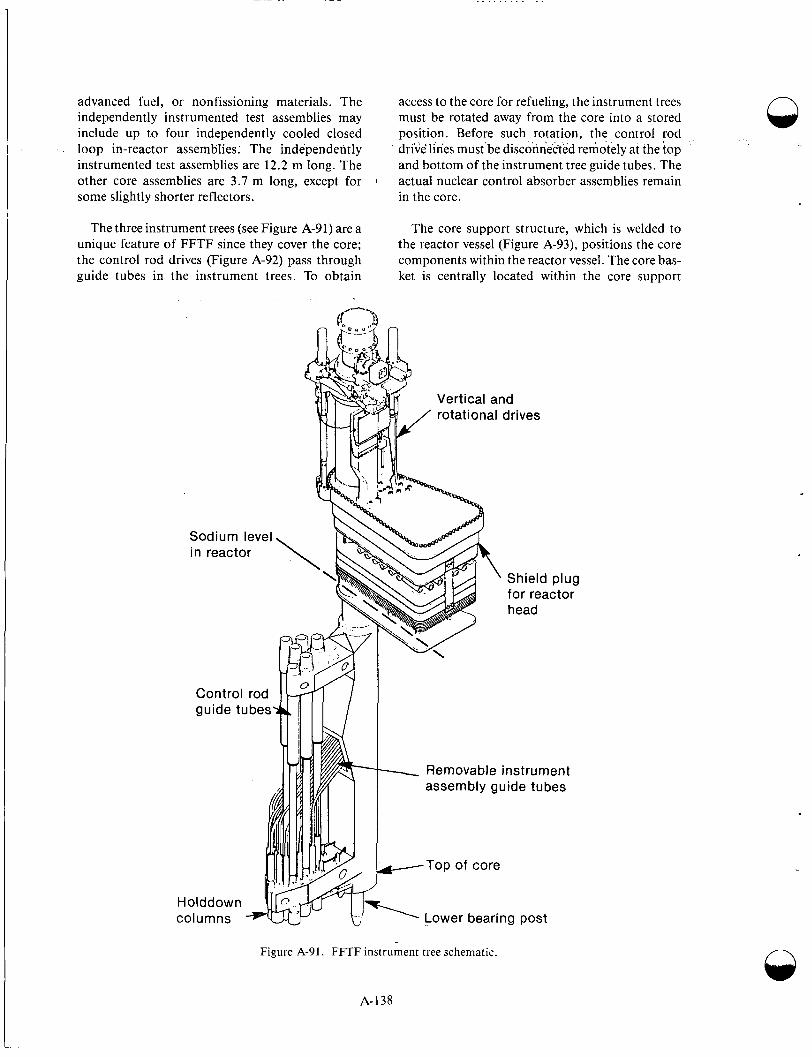
advanced fuel, or nonfissioning materials. The independently instrumented test assemblies may include up to four independently cooled closed
.. loop in-reactor assemblies; The independently instrumented test assemblies are 12.2 m long. The other core assemblies are 3.7 m long, except for some slightly shorter reflectors.
1
The three instrument trees (see Figure A-91) are a unique feature of FFTF since they cover the core; the control rod drives (Figure A-92) pass through guide tubes in the instrument trees. To obtain
access to the core for refueling, the instrument trees must be rotated away from the core into a stored position. Before such rotation, the control rod dr:ve lines must'be disconnected remotely at the top and bottom of the instrument tree guide tubes. The actual nuclear control absorber assemblies remain in the core.
The core support structure, which is welded to the reactor vessel (Figure A-93), positions the core components within the reactor vessel. The core bas- ket is centrally located within the core support
vo 4
rotational drives
Removable instrument assembly guide tubes
-Top of core
Figure A-91. FFTF instrument tree schematic.
A-138
0
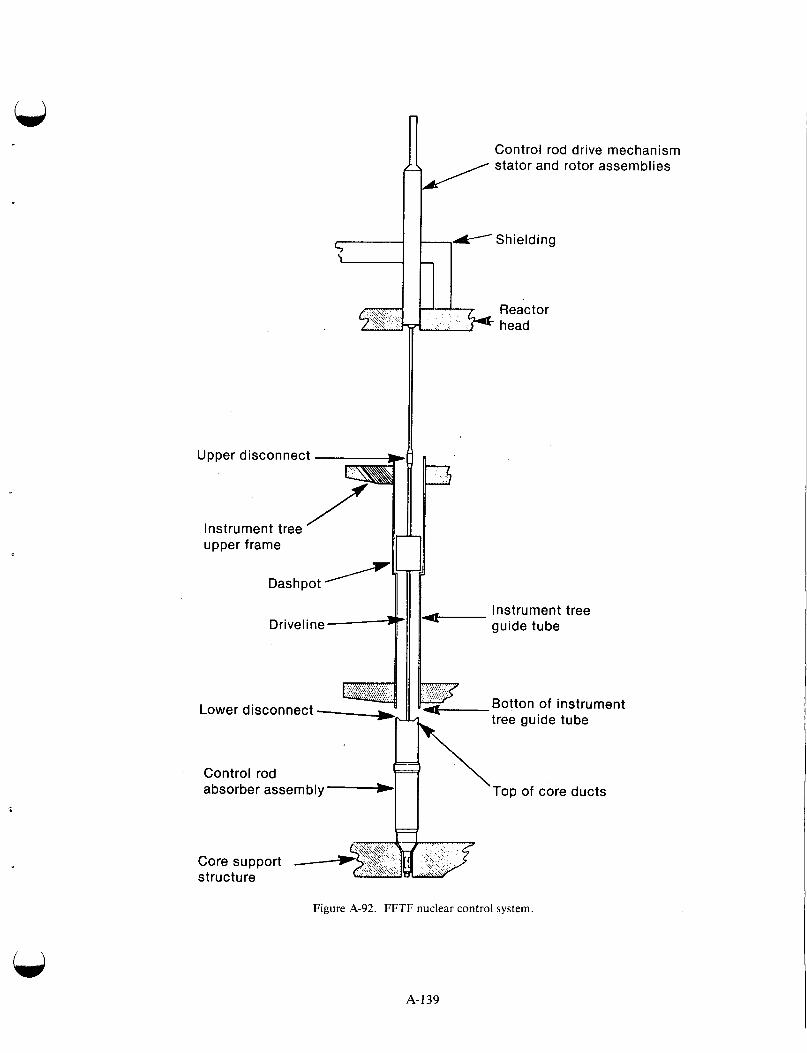
Control rod drive mechanism
tl- Shielding
1 1
Upper disconnect
Instrument tree upper frame
Instrument tree
Botton of instrument tree guide tube
Lower disconnect
Control rod absorber assembly - Top of core ducts
Figure A-92. F F T F nuclear control system.
A-139

structure and provides vertical support for the driver fuel, test, absorber, and inner reflector assemblies. The basket is a closed cylinder with 15 1 tubular receptacles connecting the upper and lower tube sheets.
Different sizes and shapes of receptacles are used to ensure that the core assemblies are properly placed. The cylindrical section of the basket has 12 rectangular flow slots fitted with flow strainers through which the incoming sodium flows. The core support structure and core basket are made of Type 304 stainless steel.
The core barrel is a Type 304 stainless steel cylin- der about 0.35 m high and 3.5 m in diameter. The core barrel surrounds the radial shield of the core and is supported by and welded to the core support structure.
The radial shield consists of six inner blocks and six outer shield blocks arranged around the periphery of the radial reflector region. The inner and outer shield blocks are composed of vertical Standing-Type 304 stainless steel plates. The radial shielding is supported by the core support structure.
The core restraint mechanisms (Figure A-94) apply radial force to the load pad of the core assem- blies to hold them in position for power operation.
Reactor vessel
/wall . _
Core -support structure
The core restraint mechanisms are mounted on the core barrel. Six mechanisms are equally spaced around the periphery of the core and are actuated by shafts extending through the reactor head.
The horizontal baffle mounted at the upper end of the core barrel acts as a thermal insulator and flow barrier between the hot outlet plenum of the reactor vessel and the relatively cool inlet plenum. The baffle is sealed to the reactor vessel liner by the baffle liner interface seal.
In-vessel storage modules are located in three sections of the annular region between the core bar- rel and the reactor vessel thermal liner. Each mod- ule (Figure A-95) has 19 natural convection-cooled Type 304 stainless steel receptacles for core compo- nents and one transfer port position for the core component top.
Assemblies from material surveillance samples are also located in the in-vessel storage modules. During reactor operations, these samples are exposed to the sodium, thermal, and radiation environment. Figure A-96 shows the location of two of the in-vessel storage modules.
The low-level flux monitoring (LLFM) instru- mentation for determining the reactor’s reactivity status during subcritical and low-power conditions n
A- 140

. . - . . . . . -. . . . . -. . . . -.
Horizontal baffle standoff
1 A
Yoke shank
I
I inner module
Core barrel
Figure A-94. Arrangement of core strain mechanisms around core.
comprises three assemblies. The assemblies are located 120 degrees apart in the reactor vessel. Each assembly (Figure A-97) is made up of a com- position thimble, a sensor drive unit, a sensor with cable, and a nitrogen gas cooling system that main- tains the neutron sensor in its cabling below 150°C.
The drive mechanism, mounted above the vessel head, positions the neutron sensor axially within the thimble. The sensor is located at the core mid- plane during reactor shutdown and startup opera- tions. Prior to full power operation, the sensor is retracted to a higher elevation.
The FFTF core contains PuO2-UO2 driver fuel assemblies, positions for independently instrumented
Outer module
inner shield plates
\ Lower Static yoke ring
open test assemblies, positions for independently instrumented and independently cooled closed loop assemblies, boron carbide neutron absorblm for nuclear control, and Inconel@ connectors.
Whereas the general design of all 199 core assemblies is similar, details of the handling sockets and nozzles differ to ensure proper location of vari- ous types of assemblies in the core.
The core is arranged in concentric hexagonal rings of assemblies surrounding a central assembly. Rows one through four are known as the inner enrichment zone, rows 5 and 6 the outer enrich- ment zone. These first six rows constitute the core’s fueled zone, which is 0.91 m in axial leng,th and
A-I41
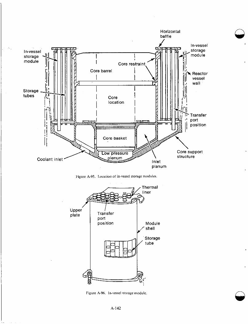
Horizon tal baffle
n
planum
Figure A-95. Location of in-vessel storage modules.
Thermal liner
Transfer port position Module
shell
Storage tube
Core support structure
Figure A-96. In-vessel storage module.
A- 142
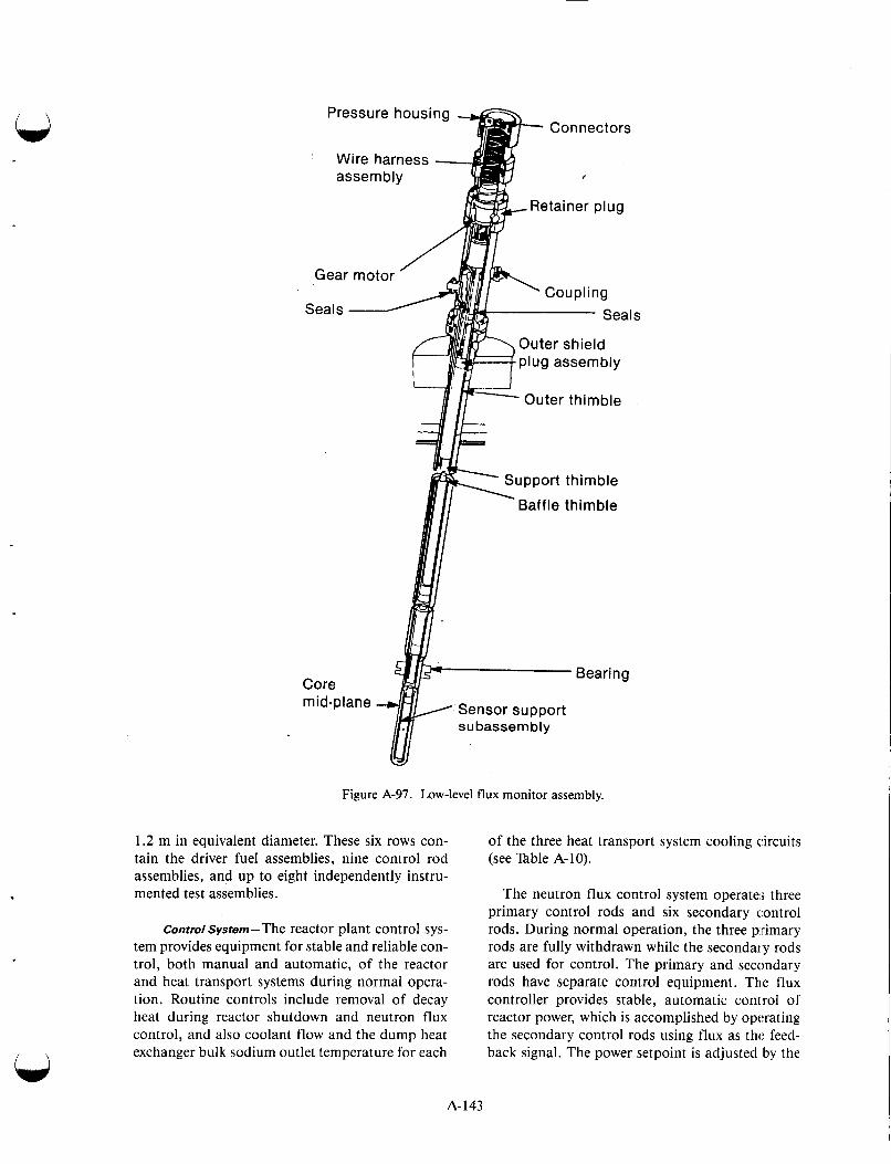
& Connectors Pressure housing -
Wire harness - assembly
Gear motor
Seals
Core mid-plane
%!.,Retainer Dlua
Seals ' coup1 i ng
Outer shield 'plug assembly
! r 7 p4- Outer thimble
Support thimble
Baffle thimble
Bearing
-'Sensor support subassembly
Figure A-97. Low-level llux monitor assembly.
1.2 m in equivalent diameter. These six rows con- tain the driver fuel assemblies, nine control rod assemblies, and up to eight independently instru- mented test assemblies.
control System-The reactor plant control sys- tem provides equipment for stable and reliable con- trol, both manual and automatic, of the reactor and heat transport systems during normal opera- tion. Routine controls include removal of decay heat during reactor shutdown and neutron flux control, and also coolant flow and the dump heat exchanger bulk sodium outlet temperature for each
of the three heat transport system cooling circuits (see Table A-10).
The neutron flux control system operate:; three primary control rods and six secondary c,ontrol rods. During normal operation, the three primary rods are fully withdrawn while the secondary rods are used for control. The primary and secondary rods have separate control equipment. The flux controller provides stable, automatic control of reactor power, which is accomplished by operating the secondary control rods using flux as thc feed- back signal. The power setpoint is adjusted by the
A-143
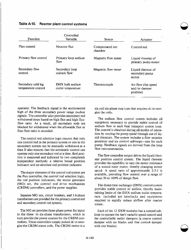
Table A-10. Reactor plant control systems n
Controlled Function Variable Sensor Actuator
Flux control Neutron flux Compensated ion Control rod chamber
Primary flow control Primary loop sodium Magnetic flow meter Liquid rheostat of flow primary pump motor
Secondary flow Secondary loop Magnetic flow meter Liquid rheostat of control sodium flow secondary pump
motor
Secondary cold leg DHX bulk sodium Thermocouple Air flow (fan speed temperature control outlet temperature and/or damper
position)
operator. The feedback signal is the auctioneered high of the three secondary power range nuclear signals. The controller also provides secondary rod withdrawal stops based on high flux and high flux- flow ratio. As a result, all secondary rods are blocked for withdrawal when the allowable flux or flux-flow ratio is exceeded.
The control rod selection logic ensures that only one control rod in the primary system or one in the secondary system can be manually withdrawn at a time It also ensures that the automatic control can operate only one secondary rod at a time. Rod posi- tion is measured and indicated by two completely independent methods: a relative broad position indicator and an absolute rod position indicator.
The major elements of the control rod system are the flux controller, the control rod selection logic, the rod position indicators, the motor generator (MG) set, the control rod drive mechanism (CRDM) controllers, and the power supplies.
Separate MG sets, circuit breakers, and 3.6-phase transformers are provided for the primary control rod and secondary control rod systems.
The MG set provides three-phase power for input to the three- to six-phase transformers, which in turn provide the power sources for the CRDM con- trollers. These controllers supply pulsed dc to ener- gize the CRDM stator coils. The CRDM motor is a
six-coil six-phase step type that requires dc to ener- gize the coils.
The sodium flow control system includes all equipment necessary to provide stable control of sodium flow in each heat transport system loop. The control is obtained during all modes of opera- tion by varying the pump speed through use of liq- uid rheostats. The system includes a flow setpoint generator and six control subloops-one for each pump. Feedback signals are derived from the loop flow instrumentation.
The flow controller output drives the liquid rheo- stat position control system. The liquid rheostat provides the capability to vary the motor resistance of a wound rotor motor, thereby changing motor speed. A speed ratio of approximately 2:3:1 is available, providing flow control over a range of about 50 to 100% of design flow.
The dump heat exchanger (DHX) control system provides stable control of airflow, thereby main- taining limits of the DHX sodium outlet tempera- ture. Included are interlocks and equipment required to rapidly reduce airflow after reactor scram.
Each of the 12 DXH modules has a control sub- loop to operate the fan’s variable speed control and the controllable outlet dampers (a coarse control damper with six blades and fine control damper with two blades). n
A- 144

The reactor plant control system provides an integrated design to monitor, control, and coordi- nate the decay heat removal process for plant shut- down operations. Following a scram or shutdown to refueling temperature, the decay heat of the reac- tor and stored heat in the HTS are dissipated by the primary and secondary loops at pony motor flow conditions. The DHX modules (Figure A-98) are cooled by natural air circulation.
The reactor plant control system also provides the monitoring control and coordination functions necessary to ensure decay heat removal under com- pletely natural circulation conditions if all electri- cal power (off-site power and on-site emergency power) were lost. Special instrumentation, separate from the normal control system, has operated from a Class IE battery power source. Manual control of the fine damper is provided from the control room for each of the 12 modules; the DHX outlet tem- perature for each module is displayed adjacent to the manual controller.
Heat Transport System- Heat generated by the 400-MW(t) reactor is removed via the heat trans- port system (HTS). The HTS pumps 27 400 L/s of sodium through the reactor vessel at a nominal inlet
temperature of 360"C, inlet pressure of about 0.917 MPa, and a nominal outlet temperature of 530°C. The actual inlet and outlet temperatures depend on the operating conditions selected.
Dry argon cover gas is used to blanket the sodium in the reactor vessel and throughout the heat transport system to avoid contact between sodium and air. The heat transport system has three 133-MW stainless steel circuits (Figure A-99). Each circuit consists of both a primary (radioactive) and a secondary (nonradioactive) loop. The reacior ves- sel and its head are part of each primary loop; addi- tional primary loop equipment consists of a primary pump with two motors, two isolation valves, one check valve, required piping, and a shell side of the intermediate heat exchanger (IHX). The IHX isolates radioactive primary sodium from the secondary loop.
Each main component and each vertical run of piping in the primary loops are provided with a guard vessel. The primary loops transport reactor heat to the intermediate heat exchangers that ther- mally link the primary and secondary loops. The three primary loops have common flow paths
cs
odium inlet
Variable damper
Sodium outlet
Preheater Fan
solation doors Variable speed dr
Figure A-98. Dump heat exchanger module.
A-145
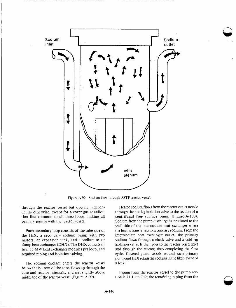
I
c
, c, 2 Inlet
plenum
Figure A-99. Sodium flow through FFTF reactor vessel.
through the reactor vessel but operate indepen- dently otherwise, except for a cover gas equaliza- tion line common to all three loops, linking all primary pumps with the reactor vessel.
Each secondary loop consists of the tube side of the IHX, a secondary sodium pump with two motors, an expansion tank, and a sodium-to-air dump heat exchanger (DHX). The DHX consists of four 33-MW heat exchanger modules per loop, and required piping and isolation valving.
The sodium coolant enters the reactor vessel below the bottom of the core, flows up through the core and reactor internals, and out slightly above midplane of the reactor vessel (Figure A-99).
- I Sodium outlet
P
Heated sodium flows from the reactor outlet nozzle through the hot leg isolation valve to the section of a centrifugal free surface pump (Figure A-1 00). Sodium from the pump discharge is circulated to the shell side of the intermediate heat exchanger where the heat is transferred to secondary sodium. From the intermediate heat exchanger outlet, the primary sodium flows through a check valve and a cold leg isolation valve. It then goes to the reactor vessel inlet and through the reactor, thus completing the flow cycle. Covered guard vessels around each primary pump and IHX retain the sodium in the likely event of a leak.
Piping from the reactor vessel to the pump sec- tion is 7 1.1 cm OD; the remaining piping from the
1 A-146
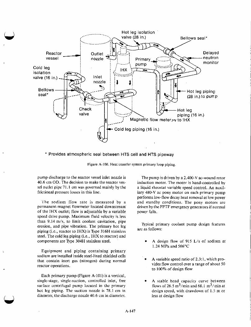
Cold leg piping (16 in.)
* Provides atmospheric seal between HTS cell and HTS pipeway
Figure A-100. Heat transfer system primary loop piping.
pump discharge to the reactor vessel inlet nozzle is 40.6 cm OD. The decision to make the reactor ves- sel outlet pipe 71.1 cm was governed mainly by the frictional pressure losses in this line.
The sodium flow rate is measured by a permanent-magnet flowmeter located downstream of the IHX outlet; flow is adjustable by a variable speed drive pump. Maximum fluid velocity is less than 9.14 m/s, to limit coolant cavitation, pipe erosion, and pipe vibration. The primary hot leg piping (Le., reactor to IHX) is Type 316H stainless steel. The cold leg piping (Le., IHX to reactor) and components are Type 304H stainless steel.
Equipment and piping containing primary sodium are installed inside steel-lined shielded cells that contain inert gas (nitrogen) during normal reactor operations.
Each primary pump (Figure A-101) is a vertical, single-stage, single-suction, controlled inlet, free surface centrifugal pump located in the primary hot leg piping. The suction nozzle is 78.1 cm in diameter, the discharge nozzle 40.6 cm in diameter.
The pump is driven by a 2,400-V ac-wound rotor induction motor. The motor is hand-controlled by a liquid rheostat variable speed control. An auxil- iary 480-V ac pony motor on each primary pump performs low-flow decay heat removal at low power and standby conditions. The pony motors are driven by the FFTF emergency generators if normal power fails.
Typical primary coolant pump design features are as follows:
A design flow of 915 L/s of sodjum at 1.24 MPa and 566°C
A variable speed ratio of 2.3: 1, which pro- vides flow control over a range of about 50 to 100% of design flow
A stable head capacity curve between flows of 26.5 m3/min and 68.1 m3/min at design speed, with drawdown of l.!i m or less at design flow
A- 147
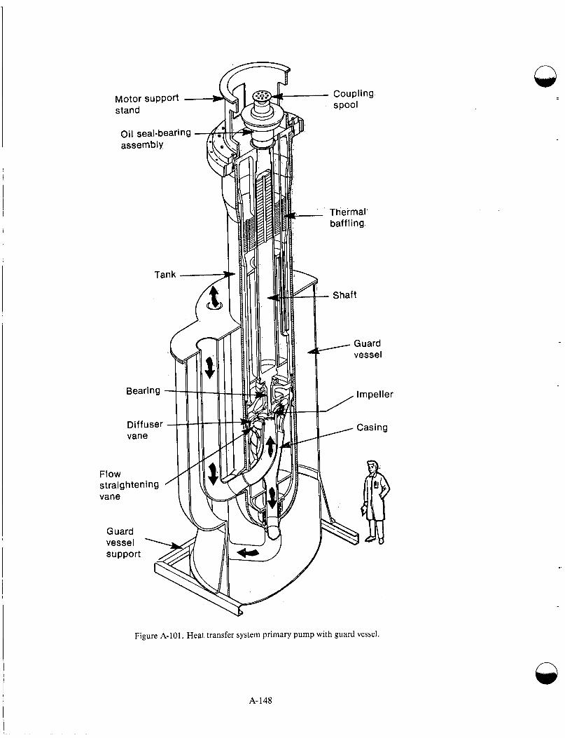
Oil seal-bearing
-
Q
Figure A-101. Heat transfer system primary pump with guard vessel.
n
A-148

A seal system to prevent escape of radioac- tive argon from the primary system, or in- flow of lubricants or fluids to the pump
Optimized coastdown characteristics to minimize thermal transients and to pro- vide adequate reactor core cooling after a scram
Pony motor drive to provide about 7.5% of design flow at 9.9 kPa with automatic takeover from main motor to pony motor during coast down, preventing any flow interruption
Completely drainable system.
Each HTS pump has a lubrication circulation system to carry away heat generated by frictional losses in the seals and bearings.
The IHX (Figure A-102) is a vertical counterflow design. It transfers reactor heat from the primary loop to the secondary loop. This is achieved via the primary flow outside the tubes and secondary flow inside the tubes.
Primary sodium enters the IHX below the top of the upper tube sheet and is directed around the tube bundles down along the outside of the tubes. A small percentage of flow (about 1%) is continu- ously returned to the primary pump tank through a 5.1-cm orificed line. As a result of this return, gas collection in the upper regions of the primary (shell) side of the IHX is prevented. The primary sodium leaves the bundle area just above the bot- tom tube sheet. It then flows into the annulus between the shell and bottom plenum and out the nozzle in the shell hemisphere.
Secondary sodium enters the top of the unit, flows down through the central downcomer into the lower hemispherical plenum, and up through the inside of the tubes into the upper plenum area. The secondary flow then leaves the IHX through the horizontal outlet nozzle.
One IHX is located in each of the three HTS cir- cuits downstream of the primary pump and ahead of the check valve.
To meet the system operating requirements, typi- cal design features in the IHX are as follows:
Design pressure of 1.65 MPa on the pri- mary side and 1.82 MPa on the seEondary side
Maximum pressure of 70 kPa on the pri- mary side and 100 kPa on the se1:ondary side at design flow rate
Effective tube length geometric center of at least 4.6 m above the reactor core gc:ometric center, ensuring adequate thermal driving head for natural convection cooling
The three secondary loops, shown in Figure A-103, circulate nonradioactive sodium coolant to transport heat from the tube side of the IHX to the air-cooled dump heat exchangers (DHX). No direct sodium interconnection exists among the loops.
Heated secondary sodium leaving the IHX flows to the air-cooled DHX through 40.6-cm-diameter piping via a containment penetration. Near the DHX, the piping branches and reduces to :!0.3 cm diameter and connects to a 20.3-cm-diameter hot leg DHX isolation valve. From this valve, the pipe connects to an inlet header of an individual DHX module (of which there are four to each secondary loop, 12 total for the heat transport system).
Cooled sodium from the outlet of each module flows through a 20-cm-diameter cold leg DHX iso- lation valve; the piping then expands from 20 to 40 cm. Finally, it connects to the 71.1-cm-diameter suction line of the secondary pump. From the pump discharge, the sodium piping enters the HTS cell through a penetration in the reactor contain- ment building and connects to the IHX. At that point, the flow path is completed. Sodium flow rate is measured by a permanent-magnetic flowmeter located downstream of the pump discharge. The flow rate is adjustable by a variable speed pump drive. A Venturi flowmeter, located upstream of the secondary pump, is used for flow calibration of a secondary-loop permanent-magnetic flowmeter.
0
The 40.6-cm-diameter secondary hot leg piping and the section of 71.1 cm cold leg piping at the inlet to the secondary pump are of Typc: 316H stainless steel. The 40.6-cm cold leg and the 20-cm piping and components are of Type 304H stainless steel.
The secondary piping loops are designed for a pressure of 1.72 MPa throughout. This design
A- 149
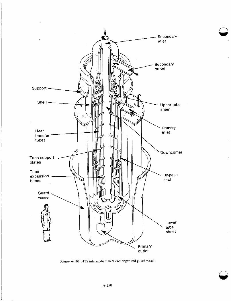
Figure A-102. HTS intermediate heat exchanger and guard vessel.
A-150
n
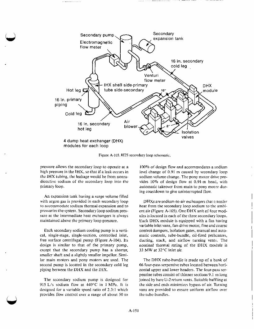
. ..... . ...
Secondary pump
16 in. secondary
IHX shell side-primary tube side-secondary
4 dump heat exchanger (DHX) modules for each loop
Figure A-103. HTS secondary loop schematic.
pressure allows the secondary loop to operate at a high pressure in the IHX, so that if a leak occurs in the IHX tubing, the leakage would be from nonra- dioactive sodium of the secondary loop into the primary loop.
An expansion tank having a surge volume filled with argon gas is provided in each secondary loop to accommodate sodium thermal expansion and to pressurize the system. Secondary loop sodium pres- sure at the intermediate heat exchangers is always maintained above the primary loop pressure.
Each secondary sodium cooling pump is a verti- cal, single-stage, single-suction, controlled inlet, free surface centrifugal pump (Figure A-104). Its design is similar to that of the primary pump, except that the secondary pump has a shorter, smaller shaft and a slightly smaller impellor. Simi- lar main motors and pony motors are used. The second pump is located in the secondary cold leg piping between the DHX and the IHX.
The secondary sodium pump is designed for 915 L/s sodium flow at 440°C in 1 MPa. It is designed for a variable speed ratio of 2.3:l which provides flow control over a range of about 50 to
100% of design flow and accommodates a sodium level change of 0.91 m caused by seconda1,y loop sodium volume change. The pony motor drive pro- vides 10% of design flow at 0.91-m head, with automatic takeover from main to pony motlx dur- ing coastdown to give uninterrupted flow.
DHXs are sodium-to-air exchangers that transfer heat from the secondary loop sodium to the ambi- ent air (Figure A-105). One DHX unit of four mod- ules is located in each of the three secondary loops. Each DHX module is equipped with a fan having variable inlet vans, fan-drive motor, fine and coarse control dampers, isolation gates, manual and auto- matic controls, tube-bundle, oil-fired preheaters, ducting, stack, and airflow turning vents. The nominal thermal rating of the DHX module is 33 MW at 32°C inlet air.
The DHX tube-bundle is made up of a biink of 66 four-pass serpentive tubes located between hori- zontal upper and lower headers. The four-pass ser- pentine tubes consist of thinner sections 9.1 rn long joined by bare U-2 return vents. Suitable baffling at the side and ends minimizes bypass of air. Turning vans are provided to ensure uniform airflow over the tube-bundles.
A-151
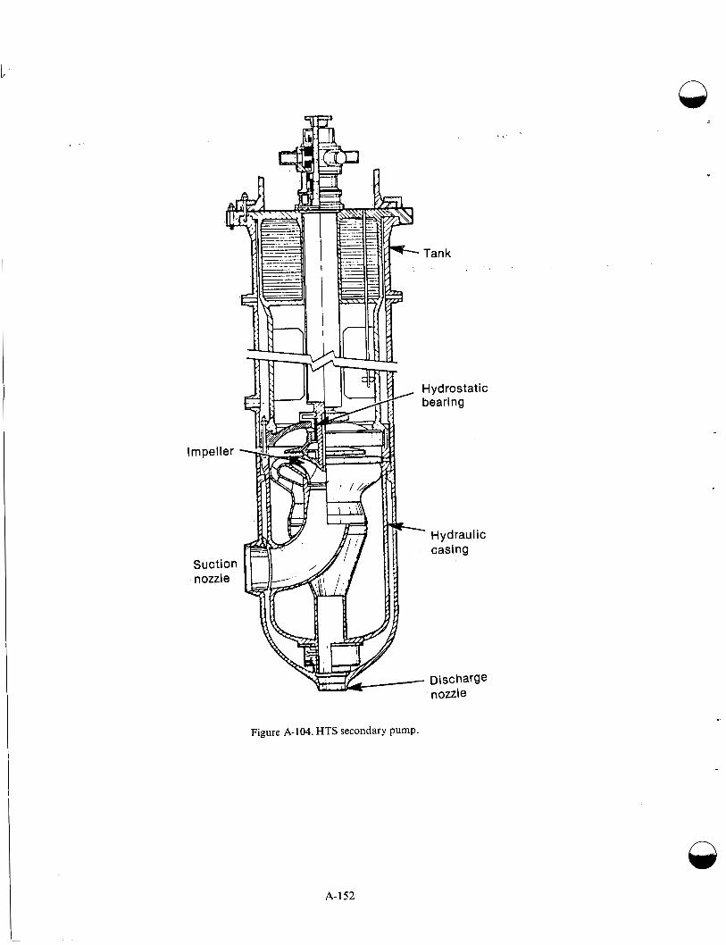
Figure A-104, HTS secondary pump.
A-152
n
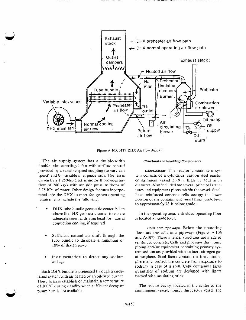
. . . . . . . . . . . . . . . . .. . . . . . . . . . . . . . . . . . . . . -. . .. . . . - . . .- . . - .. - - .
w I .:::::st I - 'DHX preheater air flow path
.f- DHX normal operating air flow path
urn blower air flow Oil
return
Figure A-105. HTS DHX Air flow diagram.
The air supply system has a double-width double-inlet centrifugal fan with airflow control provided by a variable speed coupling (to vary van speed) and by variable inlet guide vans. The fan is driven by a 1,250-hp electric motor It provides air- flow of 280 kg/s with air side pressure drops of 2.75 kPa of water. Other design features incorpo- rated into the DHX to meet the system operating requirements include the following:
DHX tube-bundle geometric center 9.1 m above the IHX geometric center to ensure adequate thermal driving head for natural convection cooling, if required
Structural and Shielding Components
Containment-The reactor containment sys- tem consists of a cylindrical carbon steel reactor containment vessel 56.9 m high by 41.2 m in diameter. Also included are several principa 1 struc- tures and equipment pieces within the vessel. Steel- lined reinforced concrete cells occupy the lower portion of the containment vessel from grade level to approximately 78 ft below grade.
In the operating area, a shielded operating floor is located at grade level.
Cells and Pipeways-Below the operating floor are the cells and pipeways (Figures A-106
Sufficient air draft through the and A-107). These internal structures are made of tube to dissipate a Of reinforced concrete. Cells and pipeways thai. house
piping and/or equipment containing primary sys- 10% of design power
tem sodium are provided with an inert nitrogen gas atmosphere. Steel liners contain the inert atmos- phere and protect the concrete from expo,jure to sodium in case of a spill. Cells containin,: large quantities of sodium are designed with liners backed with insulating brick.
Instrumentation to detect any sodium leakage.
Each DHX bundle is preheated through a circu- lation system with air heated by an oil-fired burner. These heaters establish or maintain a temperature of 200°C during standby when sufficient decay or pump heat is not available.
The reactor cavity, located in the center of the containment vessel, houses the reactor vesyel, the
A-153

. '
Primary Na vessel cell
Contai nme
Figure A- 106. Typica! plan of internal structures within the containment vessel.
Containment y vessel
Figure A-107. Typical cross section of internal structures within the containment vessel.
A-154

. . - . . . . - .. - . . . - .. .
guard vessel, the main reactor support structure, associated shielding, and reactor pi$ng. The cavity is insulated and temperature controlled to maintain allowable temperatures for concrete. Three HTS cells are adjacent to the reactor cavity on the east, south, and west sides. These three cells house the primary sodium pump and intermediate heat exchangers as well as associated equipment, piping and instrumentation for each of the three primary heat transport system loops.
Four closed loop systems (CLS) cells and associ- ated pipeways are located between the east and south HTS cells and between the west and south HTS cells. The CLS cells are designed to contain pumps, heat exchangers, piping, equipment, and instrumentation associated with the CLS primary removal systems.
The northwest quadrant of the containment, below the operating floor, is the location for the interim decay storage (IDS) vessel cell. Also found in this area are cells for the auxiliary liquid metal system equipment, piping, and valves.
Cell access closure consists of shielding access plugs, rolling shield plugs and steel shielding doors, and soft shielding plugs or shielding blocks, as applicable.
Shielding access plugs are steel-lined (sides and bottom), tapered, and stepped concrete plugs that fit into an embedded steel frame in cell or pipeway ceilings. These plugs are equipped with seals to contain the inert cell atmosphere.
Rolling shield plugs are steel lined, tapered, and stepped concrete plugs mounted on wheels that roll on tracks in the floor. Cells utilizing rolling plugs have bulkhead type, gas tight doors behind the plugs to contain the inert cell atmosphere.
Soft shielding plugs are made of concrete cast into a steel plug frame in a cell wall. The soft plug is removed by breaking up the concrete mechanically and is replaced by casting new concrete in place. The cell liner is continuous and must be cut out to secure cell entry. Soft plugs provide for future access to areas that have no present requirements for maintenance access.
An equipment air lock and two personnel air locks are provided for access. Each lock has two doors in series. Each door is equipped with redun- dant seals and a pressure equalization valve. Inter-
locks are provided so that neither a door nor its equalizing valve can be opened unless the other door is locked and sealed. Also, a welded construc- tion hard patch on the containment vessel can be cut open if needed.
The equipment air lock is used for all transfers of fuel into and out of containment. It will also be used for transfer of large equipment if it is needed for maintenance.
The equipment air lock is approximately 7.6 m in diameter with doors at opposite ends, each with a clear opening 3.4 m wide by 5.1 m high. An emergency escape hatch in the air lock provides an opening 61 cm in diameter. This air lock (extends into the reactor service building.
The personnel air lock is 3.05 m in diameter and 3.66 m long, with doors 2.03 m high and 1.07 m wide. This air lock extends into the Auxiliary Equipment Building East in an area convenient to the control room.
The emergency air lock is 1.83 m in diameter and 3.66 m long doors 0.62 m in diameter. This air lock extends into the HTS Service Building West, below grade level.
Operating History-FFTF initiated its first oper- ating cycle April 16, 1982. Full power, steady state operation began April 23 following a planned 36 h hold at 92% power to allow restructuring of new fuel in the core. On May 14, a small fission gas leak was detected and subsequent analysis identified the faulty element. After 30 d of continuous opera- tion, the plant was automatically shut down due to an inadvertent valve operation during routine maintenance. During the shutdown period alter the scram and during a routine start of primary sodium pump, P-1, a flashover occurred in the bru!;h/slip ring of the pump motor. The resulting pump over- speed and flow imbalance among the three primary coolant loops forced the sodium into the shaft annulus. This contributed to the shaft binding on the primary sodium pump, P-3. The upper portion of the pump was disassembled, revealing a reduced shaft clearance in the pump baffle area. The reduced clearance was attributed to sodium residue in this area. The residue came from an unplanned transient caused by a high sodium level in the pump tank. The pump was freed by heating the shield plug and pump tank. After reassembly, vibration and coast down measurements were taken to verify no additional problems existed.
A-155

On August 26, the FFTF returned to power oper- ation to complete the first operational cycle, Cycle 1. During the startup some DHX fan speed control problems occurred resulting in an isolation of a DHX module. A shutdown was conducted to return the DHX module to service. After returning to power, a reactor scram occurred during a routine calibration of the primary system flowmeters. On September 12, the reactor obtained 100% power and remained at full power until November. In November, a special shutdown evolution was con- ducted to investigate the phenomena of the reac- tor’s pressure drop. On November 11, 1982, after 53 consecutive days at full power, the FFTF’s first operating cycle was completed with a planned reac- tor shutdown.
During the early part of Cycle 1, the pressure drop around the primary system began to increase slowly. This increase continued throughout the operating portion of the cycle. An engineering and operations effort was expended evaluating and test- ing this anomaly. No cause has yet been identified, and investigation will continue into Cycle 2.A-133
On May 13, the cover gas monitoring system detected a small burst of fission gas released to the cover gas volume. This initial signal was not large enough to trip the fission gas high alarm; a cover gas sample taken later in the day was found not to contain any detectable fission gases. The next day, at approximately 1800 h, a much larger burst of fission gas was observed; this event was large enough to trip the fission gas high alarm, and follow-up action was taken. Plant operators took three cover gas samples, and the failed element location team (FELT) was notified. FELT was com- posed of members from physics and irradiation testing, chemistry and analysis, nuclear analysis, core evaluation, and FFTF plant operations. The FELT was responsible for coordinating leaker- locating activities. Another of its responsibilities was making recommendations to the FFTF plant manager regarding identification of the leaking subassembly and follow-up actions. Cover gas sam- ples taken on May 14 failed to give a definitive indi- cation of tag gas or fission gas from the leaking pin.
On May 15, a third and still larger burst of fis- sion gas was observed beginning at about 300 h. This burst was approximately three times larger than the May 14 event. A cover gas sample was taken and analyzed; the amount of detectable tag in this sample was only one-tenth of the amount con- sidered necessary to make a tag identification. By
supplementing the standard tag isotopic ratios with fission product ratios and by using a novel probabi- listic treatment, a tentative location of the leaking test pin was made. .
Fission gases continued to be released from the leaking pin. But amounts were too small to make a positive tag identification until May 21 at approxi- mately 1500 h, when another large spike of fission gas was released. This gas release occurred about 1 h after reactor power was reduced to 98% because of high ambient temperature. This time, tag gas,concentrations were large enough to make an absolute determination of the tag; tag T-12 was confirmed in two successive cover gas samples. Upon making an identification, FELT drafted a statement of results and recommendations to present to the plant manager. In addition to identi- fying the test assembly as containing the leaking pin, FELT recommended some supplementary sur- veillance activities to be performed while operating with a known leaker in a core.
Plant operations continued until 1320 h on May 24, when the pump controller failure scrammed the plant. Concurrent with the scram, an extremely large burst of fission gas (roughly 25 times greater xenon-I33 activity than the May 21 burst) was observed. Analysis of cover gas samples taken at this time showed only tag T-12 was present; this confirmed the AB-1 test assembly contained the leaker. During the shutdown, the AB-1 test, which contained the leaking fuel pin, was replaced by a driver fuel assem- bly. (Reference A-134 describes the event in detail).
During Cycle I a total of 9.69 rn3 of solid radio- active waste with a total activity of 19.8 mCi was transferred from FFTF for processing. The waste originated from the following activities:
Q
Interim examination and maintenance cell decontamination and maintenance
Maintenance and storage facility decon- tamination and maintenance
Sodium removal system maintenance
Heat transport system south sampling and maintenance
Miscellaneous maintenance in the plant
Radioactive liquid waste sampling and load out station.
A-156

Also transported were 8 m3 of liquid waste with a total activity of 1.76 nCi. This liquid was gener- ated from maintenance activities on the sodium removal station in the reactor service building.
General area radiation levels during Cycle 1 were very low with dose rates measured in routinely occupied areas less than 0.2 mrem/h. The few exceptions to the design levels involved low level, small area streaming through shield penetrations. For example, the maximum shield contact rating was 8 mrem/h on a shield located about 3 m above lower level. Other streaming locations were equally inaccessible o r in areas with extremely low occupancy.
Routine radiation survey data are summarized in Table A-1 1. The values presented were extracted from weekly routine survey reports. These values do not reflect special situations such as entry into cells containing primary sodium and maintenance on radioactive systems. Special radiation surveys were performed for these operations, and the data are discussed below. Routine radiation contamina- tion surveys were also conducted. No contamina- tion was detected in the routinely occupied areas. Local contamination control areas were established for special tasks being performed under radiation work procedures.
Radiation surveys conducted in support o f radia- tion work in the plant showed direct levels ranging from background to about 1 rem/h. Contan9iination levels ranged from background to about 60,OCD dpm/ dm2. The 1 rem/h direct radiation was associated with primary sodium cover gas sampling evolutions. The radiation level was at contact with the gas tag sample trap prior to installation of the shipping cover. With the shipping cover in place, the contact radia- tion level was 80 mrem/h, and personnel exposure during the sampling evolution was limited to about 5 mrem. The 60,000 dpm/dm2 contamination level was associated with fuel handling and was a direct reading on a sodium contaminated floor valve. Removable contamination on the floor valve was 5,000 dpm/dm2.
An entry into Cell 489 on July 8, 1982 showed general area radiation levels t o be less than 0.5 mrem/h. A maximum reading of 1 rnrem/h was obtained in contact with a pipe containing pri- mary sodium.
An entry into Cell 490 on June 26, 1982 showed general area levels to be less than 1 mrem/’h. The maximum loose contamination level in Cell 490 was about 5,000 dpm/dm2. Radiation arid con- tamination levels associated with the interim exami- nation and maintenance cell, the sodium removal
Table A-1 1. Summary of routine radiation survey data during FFTF Cycle 1
Dose Rate (mrem/h)
Dose Rate General Area Maximum Maximum Dependent
Average Local During Local On On Reactor Location . During Cycle Cycle 10/30/82 Power
I . RSB, 500, Radioactive 0.5 4 0.5 No
2. RSB, 550, General Area 0.2 1 1 No
3. RSB, 520, Rm 204 0.2 0.2 0.2 No
4. RSB, 520, General Area 0.2 0.2 0.2 No
5. RSB, 543, General Area 0.2 0.2 0.2 No
6. RSB, 533, General Area 0.2 4 0.2 No
Comments
4 mrem/h due to temporary storage of IEM Cell components.
1 mrem/h due to floor valve adapter.
Looking for potential leakage to secondary chilled water from IEM Cell Removal System.
Local dose could be dependent on cladding breach and release o f fission gasses.
Same comment as for 4.
4 mrem/h due to small leak o f 41Ar from RAPS instrument line.
A- 157
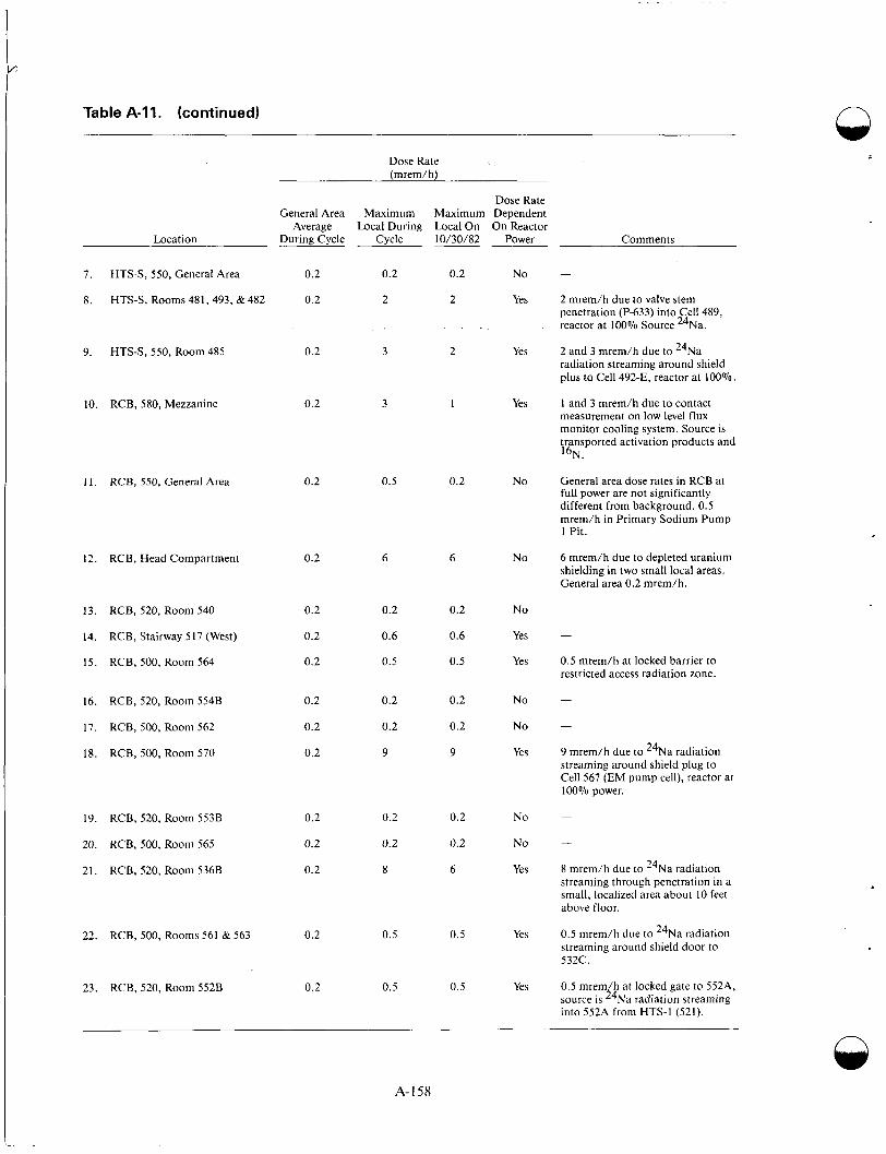
Table A-11. (continued) n
Dose Rate (mrem/h)
Dose Rate General Area Maximum Maximum Dependent
Average Local During Local On On Reactor Location During Cycle Cycle 10/30/82 Power Comments
7. HTS-S, 550, General Area 0.2 0.2 0.2 NO -
8. HTS-S, Rooms 481, 493, & 482 0.2 2 2 Yes 2 mrem/h due to valve stem penetration (P-633) into Cell 489, reactor at 100% Source 24Na.
9. HTS-S, 550, Room 485 0.2 3 2 Yes 2 and 3 mrem/h due to 24Na radiation streaming around shield plus to Cell 492-E, reactor at 100%.
0.2 3 1 Yes 1 and 3 mrem/h due to contact measurement on low level flux monitor cooling system. Source is transported activation products and 16N.
10. RCB, 580, Mezzanine
1 1 . RCB, 550, General Area 0.2 0.5 0.2 No General area dose rates in RCB at full power are not significantly different from background. 0.5 mrem/h in Primary Sodium Pump 1 Pit.
6 mrem/h due to depleted uranium shielding in two small local areas. General area 0.2 mrem/h.
No
NO -
Yes -
Yes 0.5 mrem/h at locked barrier to restricted access radiation zone.
12. RCB, Head Compartment 0.2 6 6
13. RCB, 520, Room 540
14. RCB, Stairway 517 (West)
15. RCB, 500, Room 564
0.2
0.2
0.2
0.2
0.6
0.5
0.2
0.6
0.5
16. RCB, 520, Room 554B
17. RCB, 500, Room 562
18. RCB, 500, Room 570
0.2
0.2
0.2
0.2
0.2
9
0.2
0.2
9
NO -
NO -
Yes 9 mrem/h due to 24Na radiation streaming around shield plug to Cell 567 (EM pump cell), reactor at 100% power.
19. RCB, 520, Room 553B 0.2 0.2 0.2 NO -
20. RCB, 500, Room 565 0.2 0.2 0.2 NO -
21. RCB, 520, Room 5368 0.2 8 6 Yes 8 mrem/h due to 24Na radiation streaming through penetration in a small, localized area about I O feet above floor.
22. RCB, 500, Rooms 561 & 563 0.2 0.5 0.5 Yes 0.5 mrem/h due to 24Na radiation streaming around shield door to 532C.
23. RCB, 520, Room 5528 0.2 0.5 0.5 Yes 0.5 mrem/h at locked gate to 552A. source is 24Na radiation streaming into 552A from HTS-1 (521).
A-158
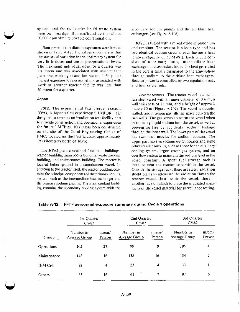
system, and the radioactive liquid waste system were low-less than 18 mrem/h and less than about 10,000 dprn/dm2 removable contamination.
secondary sodium pumps and the air blast heat exchangers (see Figure A-108).
JOYO is fueled with a mixed oxide of plutonium and uranium. The reactor is a loop type and has two identical cooling circuits, each having a heat removal capacity of 50 MW(t). Each circuit con- sists of a primary loop, intermediatl? heat exchanger, and secondary loop. The heat generated in the core is finally dissipated to the atmosphere through sodium to the airblast heat exchangers. Reactor power is controlled by two regulation rods and four safety rods.
Plant personnel radiation exposures were low, as shown in Table A-12. The values shown are within the statistical variation in the dosimetry system for very little doses and are at preoperational levels. The maximum individual dose for a quarter was 220 mrem and was associated with maintenance personnel working at another reactor facility. The highest exposure for personnel not associated with work at another reactor facility was less than 50 mrem for a quarter.
Reactor Features-The reactor vessel is :I stain- less steel vessel with an inner diameter of 3 6 m, a wall thickness of 25 mm, and a height of approxi- mately 10 m (Figure A-109). The vessel is tlouble- walled, and nitrogen gas fills the space between the two walls. The gas serves to warm the vessel when introducing liquid sodium into the vessel, as well as preventing fire by accidental sodium leakage through the inner wall. The lower part of the vessel has two inlet nozzles for sodium coolant. The upper part has two sodium outlet nozzles and some other smaller nozzles, such as those for an auxiliary cooling system, argon cover gas system, iind an overflow system to maintain the sodium level in the vessel constant. A spent fuel storage rack is installed near the reactor core within the vessel. Outside the storage rack, there are steel irradiation shield plates to attenuate the radiation flux to the reactor vessel. Just inside the vessel, there is another rack on which to place the irradiated speci- mens of the vessel material for surveillance lesting.
Japan
JOYO. The experimental fast breeder reactor, JOYO, is Japan’s first experimental LMFBR. It is designed to serve as an irradiation test facility and to provide construction and operational experience for future LMFBRs. JOYO has been constructed on the site of the Oarai Engineering Center of PMC, located on the Pacific coast approximately 193 kilometers north of Tokyo.
The JOYO plant consists of four main buildings: reactor building, main cooler building, waste disposal building, and maintenance building. The reactor is located below ground in a containment vessel. In addition to the reactor itself, the reactor building con- tains the principal components of the primary cooling system, such as the intermediate heat exchanger and the primary sodium pumps. The main coolant build- ing contains the secondary cooling system with the
Table A-12. FFTF personnel exposure summary during Cycle 1 operations
1st Quarter CY-82
2nd Quarter CY-82
3rd Quarter CY-82
Number in mrem/ Number in rnrem/ Average Group Person --
Number in mrem/ Average Group Person Group Average Group Person
Operations 105 27 99 9 105 4
Maintenance 143 16 138 16 134 2
33 1 IEM Cell 22 4 23 4
61 7 Others 65 16 97 6
A-159

n
IF GL* 200
c
0 2F GL- I%O(
GL-ZO.O(
A. 6. C. PRI. dump tank I D. PRI. overflow tank E. Fuel handling machine F. Large rotating plug L. Main control room G. Control rod drives H. Fuel chargeldischarge machine I. Cold trap 0. Blower J. EM flowmeter P. SEC. dump tank K. Transfer rotor Q. SEC. main pump
M. AUX. air blast cooler N. Main air blast cooler
Figure A-108. JOY0 cutaway view.
Thermocouples are located above the reactor core for measuring coolant temperatures at each core fuel subassembly outlet. A double rotating plug serves as the lid of the reactor vessel. The function of the plug is to shield radiation emanating from the core and also to position various devices such as the refueling machine. The large plug has a diame- ter of approximately 4.7 m that can be rotated & 180 degrees. The small plug has a diameter of 2.9 m and rotates from 0 to 180 degrees. Both plugs have freeze metal seals to keep gas tightness during reactor operation. The plugs are designed for pressure and shock equivalent to an explosion of 50 kilograms of TNT. Total thickness of the plugs are 2.5 m and the upper part of each plug is cooled by nitrogen gas.
All control rod drive mechanisms are mounted on the small plug and extend down to the core region for driving the neutron absorbers. Refueling and inspecting inside the vessel are accomplished through holes in the small plug. Outside the reactor
vessel, there is a graphite shield approximately 1 m thick. A steel safety vessel surrounds the graphite shield and the reactor vessel and will contain the reactor core under sodium coolant during any pos- sible accident condition.
Core Arrangement-The reactor core consists of core fuels, blanket fuels, control rods, and a neu- tron source all made up of subassemblies 2.9 cm long of identical hexagonal cross sections. Integral type core fuel subassemblies are employed; the length of the core fuel zone is 60 cm, and the length of the upper and lower blanket fuel zone are both 40 cm. The core fuel subassembly contains 91 fuel pins, 6.3 mm OD, 1.91 m long, separated from each other with a wrapping wire. The blanket sub- assembly contains 19 fuel pins, 15 mm OD, and an effective link of 1.4 m. The fuel pins contain fuel pellets of mixed plutonium and uranium dioxide, and the blanket pins contain fuel pellets of depleted uranium. The control rod subassembly (two regula- tion rods and four safety rods) contains a neutron
A- 160

Large I driving
Safety vessel
Coolant inlet - -
. I
. . . .
.. . C .
.._ ..
_.
Fuel charge-discharge
Control rod drive
plug driving unit 'otating plug . . unit
,I Coolant (outlet
. - ..- Reactor vessel
.. *. Core support
. .
. * ,. .
. * - ' - . . . . : *. . 1- 7. ' . . . '. . .
. . . . ' * :. . . . - . . . Figure A-109. Vertical cross section of reactor and core configuration of JOYO.
A-161

absorber of boron carbide enriched 91 070 with boron.1° The neutron source subassembly is of antimony-beryllium and located in the radial blan- ket region. For proper neutron economy and shield- ing, reflectors are arranged in the outermost region of the core (Figure A-110).
Control System- JOYO's core is so designed that the reactivity coefficients from Doppler, sodium void, and thermal bowing effects are nega- tive. The reactor power level is controlled manually by means of control rods.
The coolant temperature at the reactor inlet is automatically controlled so as to be constant regardless of the reactor power level. The heat bal- ance in the plant system is regulated by the flow rate of the airblast heat exchangers.
The reactor protection system is designed to secure the safety and to prevent damage of the plant from malfunction or misoperation. According to the level of anomaly, two classes of protective actions can take place.
The most severe protective action taken to shut down the reactor is a scram. A scram is accom- plished by the prompt insertion of the safety rods to prevent an excursion and prevent any damage to the
facility. It is initiated by the detection of a high neu- tron flux level, short reactor power oscillations, low coolant flow in the primary loops, loss of power, an earthquake, or whenever the reactor containment isolation mode is automatically tripped. The con- tainment isolation mode is initiated by the detec- tion of high temperatures, high pressure, or high radiation levels in the reactor containment vessel. This is done to prevent the spread of high levels of radioactive contamination.
The next level of protective action is insertion of the control rods at normal speed to prevent a seri- ous reactor condition. This action is initiated by high coolant temperatures, low coolant flow at the secondary loops, or a pump trip of the secondary loops.
Neutron detectors are installed to measure neu- tron flux and the reactor period over a dynamic range of 10 decades from source level to full power. This wide range is subdivided into three ranges: source range, intermediate range, and power range, which are monitored by two, three, and three detec- tors, respectively.
Fission detectors are used in the source and inter- mediate ranges and are embedded in a graphite neu- tron shield outside the reactor vessel. They can be
0 Regulating rod
0 Safety rod @ Inner blanket subassembly
6J Outer blanket subassembly
@ Reflector
0 I Core fuel subassembly
n
Figure A-110. JOY0 core diagram.
A- 162
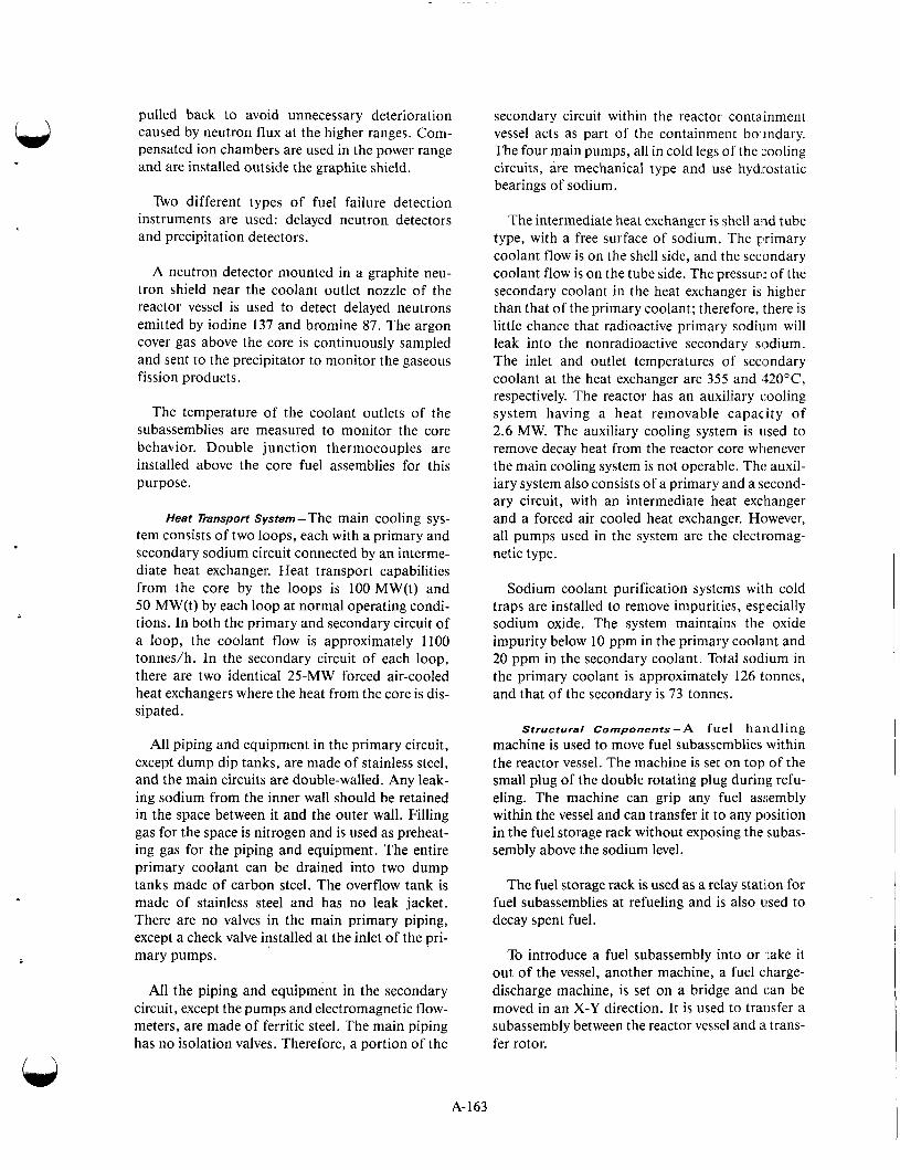
pulled back to avoid unnecessary deterioration caused by neutron flux at the higher ranges. Com- pensated ion chambers are used in the power range and are installed outside the graphite shield.
Two different types of fuel failure detection instruments are used: delayed neutron detectors and precipitation detectors.
A neutron detector mounted in a graphite neu- tron shield near the coolant outlet nozzle of the reactor vessel is used to detect delayed neutrons emitted by iodine 137 and bromine 87. The argon cover gas above the core is continuously sampled and sent to the precipitator to monitor the gaseous fission products.
The temperature of the coolant outlets of the subassemblies are measured to monitor the core behavior. Double junction thermocouples are installed above the core fuel assemblies for this purpose.
Heat Transport System-The main cooling sys- tem consists of two loops, each with a primary and secondary sodium circuit connected by an interme- diate heat exchanger. Heat transport capabilities from the core by the loops is 100 MW(t) and 50 MW(t) by each loop at normal operating condi- tions. In both the primary and secondary circuit of a loop, the coolant flow is approximately 1100 tonneslh. In the secondary circuit of each loop, there are two identical 25-MW forced air-cooled heat exchangers where the heat from the core is dis- sipated.
All piping and equipment in the primary circuit, except dump dip tanks, are made of stainless steel, and the main circuits are double-walled. Any leak- ing sodium from the inner wall should be retained in the space between it and the outer wall. Filling gas for the space is nitrogen and is used as preheat- ing gas for the piping and equipment. The entire primary coolant can be drained into two dump tanks made of carbon steel. The overflow tank is made of stainless steel and has no leak jacket. There are no valves in the main primary piping, except a check valve installed at the inlet of the pri- mary pumps.
All the piping and equipment in the secondary circuit, except the pumps and electromagnetic flow- meters, are made of ferritic steel. The main piping has no isolation valves. Therefore, a portion of the
secondary circuit within the reactor containment vessel acts as part of the containment boundary. The four main pumps, all in cold legs of the 'cooling circuits, are mechanical type and use hydrostatic bearings of sodium.
The intermediate heat exchanger is shell and tube type, with a free surface of sodium. The primary coolant flow is on the shell side, and the secondary coolant flow is on the tube side. The pressurl: of the secondary coolant in the heat exchanger is higher than that of the primary coolant; therefore, there is little chance that radioactive primary sodium will leak into the nonradioactive secondary sodium. The inlet and outlet temperatures of seclmdary coolant at the heat exchanger are 355 and 420"C, respectively. The reactor has an auxiliary cooling system having a heat removable capacity of 2.6 MW. The auxiliary cooling system is used to remove decay heat from the reactor core whenever the main cooling system is not operable. Tht: auxil- iary system also consists of a primary and a second- ary circuit, with an intermediate heat exchanger and a forced air cooled heat exchanger. However, all pumps used in the system are the electromag- netic type.
Sodium coolant purification systems with cold traps are installed to remove impurities, especially sodium oxide. The system maintains the oxide impurity below 10 ppm in the primary coolant and 20 ppm in the secondary coolant. Total sodium in the primary coolant is approximately 126 tonnes, and that of the secondary is 73 tonnes.
Structural Components-A fuel handling machine is used to move fuel subassemblies within the reactor vessel. The machine is set on top of the small plug of the double rotating plug during refu- eling. The machine can grip any fuel assembly within the vessel and can transfer it to any position in the fuel storage rack without exposing the subas- sembly above the sodium level.
The fuel storage rack is used as a relay station for fuel subassemblies at refueling and is also used to decay spent fuel.
To introduce a fuel subassembly into or take it out of the vessel, another machine, a fuel charge- discharge machine, is set on a bridge and can be moved in an X-Y direction. It is used to transfer a subassembly between the reactor vessel and a trans- fer rotor.
A-163
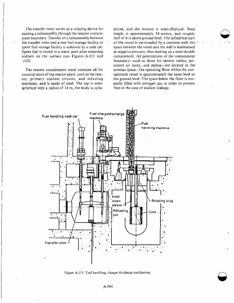
The transfer rotor serves as a relaying device for passing a subassembly through the reactor contain- ment boundary. Transfer of a subassembly between the transfer rotor and a. new fuel storage facility or spent fuel storage facility is achieved by a cask car. Spent fuel is stored in a water pool after removing sodium on the surface (see Figures A-111 and -1 12).
The reactor containment vessel contains all the essential parts of the reactor plant, such as the reac- tor, primary coolant circuits, and refueling machines, and is made of steel. The top is semi- spherical with a radius of 14 m, the body is cylin-
, <
Fuel
drical, and the bottom is semi-elliptical. Total height is approximately 54 meters, and roughly half of it is above ground level. The cylindrical part of the vessel is surrounded by a concrete7wall; the space between the vessel and the wall is maintained at negative pressure, thus making up a semi-double containment. All penetrations of the containment boundary-such as those for electric cables, per- sonnel air locks, and piping-are located in the annular space. The operating floor within the con- tainment vessel is approximately the same level as the ground level. The space below the floor is nor- mally filled with nitrogen gas in order to prevent fires in the case of sodium leakage.
TJ *
. ' . . . . . . . . . . . . .
Transfer rotor " ' . .. ... . . . i
Figure A-1 11. Fuel handling, charge/discharge mechanism.
.* . . .. 0 . ' . .*
e
A- 164
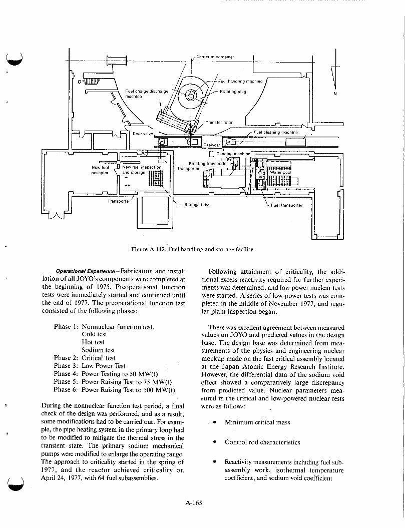
Figure A-1 12. Fuel handling and storage facility.
Operational Experience- Fabrication and instal- lation of all JOYO’s components were completed at the beginning of 1975. Preoperational function tests were immediately started and continued until the end of 1977. The preoperational function test consisted of the following phases:
Phase 1 : Nonnuclear function test. Cold test Hot test Sodium test
Phase 2: Critical Test Phase 3: Low Power Test Phase 4: Power Testing to 50 MW(t) Phase 5: Power Raising Test to 75 MW(t) Phase 6: Power Raising Test to 100 MW(t).
During the nonnuclear function test period, a final check of the design was performed, and as a result, some modifications had to be carried-out. For exam- ple, the pipe heating system in the primary loop had to be modified to mitigate the thermal stress in the transient state. The primary sodium mechanical pumps were modified to enlarge the operating range. The approach to criticality started in the spring of 1977, and the reactor achieved criticality on April 24, 1977, with 64 fuel subassemblies.
Following attainment of criticality, the addi- tional excess reactivity required for further experi- ments was determined, and low power nuclear tests were started. A series of low-power tests was com- pleted in the middle of November 1977, and regu- lar plant inspection began.
There was excellent agreement between measured values on JOY0 and predicted values in the design base. The design base was determined from mea- surements of the physics and engineering nuclear mockup made on the fast critical assembly located at the Japan Atomic Energy Research Institute. However, the differential data of the sodium void effect showed a comparatively large discrepancy from predicted value. Nuclear parameters mea- sured in.the critical and low-powered nuclear tests were as follows:
Minimum critical mass
Control rod characteristics
Reactivity measurements including fuel sub- assembly work, isothermal temperature coefficient, and sodium void coefficient
A- 165
Reactor kinetic parameters
Reaction rate distribution.
The minimum critical mass requiring 61 k five fuel subassemblies was predicted from measurements on the mockup using the fast critical assembly and cor- recting for temperature and heterogenetic terms. The measured value of a minimum critical mass was 63.2 fuel subassemblies. Measurements of control rod worth was made using positive period and substi- tution methods. Rod drop and neutron multiplication methods were also used. All of these results agreed with each other to within 10%. The design value of the control rod worth underestimated the measured value by 12%. No discrepancy was observed between measured and predicted reactivity worths caused by replacement of the blanket fuel subassembly with the core fuel subassembly. However, the change in reactiv- ity caused by replacing a blanket or core fuel subas- sembly with sodium showed a somewhat different value from the corresponding predicted value. The kinetic parameter beta/L was measured by the neu- tron noise method. This parameter was measured while on the fast critical assembly using the pulsed neutron method. Agreement was excellent. During the initial power ascension test to 50 MW in 1978, up to 75 MW in 1979, and nominal power operation cycles at 50 MW, activity coefficient measurements were carried out, as were a number of plant perform- ance and reactor surveillance tests.
The wire-wrap parameters, i.e., the wrapping wire pitch and bundle porosity (defined as the bundle-duct clearance divided by the number of hexagonal rings), were selected for three modified assemblies. The irradiation was conducted in
When post irradiation examinations were made on fuel assemblies that had been irradiated during this second cycle of 15 MW(t) and the first cycle at 75 MW(t), wear marks were found on the surface of several fuel pins. These wear marks were appar- ently caused by spacer wires wrapped on the adja- cent fuel pins. The depth of the wear marks was at most 0.06 mm. Because this phenomena had not been anticipated in the fuel design, the potential effect of these wear marks on the inner pressure stresses of the fuel elements was examined, and adequate operational margins to proceed with the second and third 75 MW(t) duty cycle- were con- firmed. Postirradiation tests were also conducted after the third, fourth, and fifth 75 MW(t) cycles, and similar wear marks of about the same size as the initial wear marks were also observed.
A- 1 66
Row 1 of the core. Detailed postirradiation exami- nation and evaluation showed that no significant wear marks were observed on the modified fuel assemblies:
Unexpected power coefficient behavior was observed when the power was initially raised from 50 to 75 .MW(t) after two cycle operations at 50 MW(t). The cumulative burnup at this time was approximately 10 000 MWd/t. The following characteristics were observed:
A larger reactivity loss than predicted occurred when power was initially increased from 50 to 75 MW(t)
This anomaly occurred only once and has not been observed in any subsequent power increases from 50 to 75 MW(t)
This reactivity loss was approximately 40sZ at 250°C isothermal conditions.
This phenomena was not anticipated from core design or from low-power core characteristic test results. To investigate the cause of the anomaly, sev- eral factors were considered:
Composition change of fuel pellet
Cracking of fuel pellet
Elongation of effective fuel length
Abnormal behavior of control rod drive mechanism or control rod
Increase in the effective diameter of the core.
Through detailed investigation and analysis, the second and third items above were considered as the most probable causes of anomaly. This judgment was based on the fact that the postirradiation exam- ination of the irradiated fuel in JOY0 showed that the pellets crack and elongated to between 3 and 5 mm, which corresponds to a 40e reactivity loss. In addition, the fuel pellet cracking increased significantly after the 75 MW(t) power ascension. The mechanism causing the anomaly could be explained as follows:
1. The fuel burnup reached about 10,000 MWd/t at the end of the 50 MW(t) second duty cycle, and the resulting fission
/ \
2.
3.
4.
gas was almost entirely retained in the fuel pellets.
On the occasion of the initial power ascen- sion from 50 to 75 MW(t), fission gas release from the fuel pellets began increas- ing at a power level slightly above 50 MW(t).
The release of fission gas reduced the gap conductance and caused an increase in fuel pellet temperature and the appearance of pellet cracks. These phenomena induced the fuel pellet’s length to elongate abruptly. The fuel temperature increase and fuel pellet length elongation induced the fuel expansion reactivity effect. This caused the Doppler reactivity effect to increase, resulting in the anomalous behavior of the power coefficient.
After the initial 75 MW(t) power level, the fuel pellet length did not respond to the reactor power change as it had before the 75 MW(t) operation. As a result, the mag- nitude of the power coefficient became smaller. At the shutdown of the reactor, the core average fuel stack length became elongated, and the reactivity of about 40G was lost from the core.
On July 26, 1981, a slow scram occurred, and the reactor was shut down automatically from a 75 MW(t) power level. An electromagnetic pump of the sodium overflow system tripped in the proc- ess of a sodium draining operation prior to operat- ing the fuel failure detection (FFD) system. As a result, a plant protection signal of “overflow sys- tem pump trip” was generated. This signal caused the reactor to scram. It was found that the sodium draining procedure might have caused argon cover gas internment into the overflow pump, resulting in a trip of the pump. The procedure was revised to eliminate this occurrence. On November 16, 1981, a “Loop A Secondary Flow Rate Low” signal was observed when the reactor was in operation at 75 MW(t). The reason for this signal activation was excessive wear of one of the three sets of resistor brushes in the secondary main pump. Thus, there was a drop of motor power. The reactor was shut down, and maintenance work on the pump was performed.
The faulty pump had been in use for more than one year, which is the period for replacement designated
by the pump manual. The brush conditions had been fair when checked in the annual inspection. It was decided to replace all brushes with new ones at annual inspections regardless of their condition.
Prototype Reactors Prototype plants are intermediate plants of a par-
ticular type, generally in the 250-350 MW(e) range, built to provide data and experience to scale up to commercial size plants. Presently there are four oper- ating prototype LMFBRs: BN-350 and BN-600 in Russia, PFR in the United Kingdom, and PHENIX in France.
PHENIX. The PHENIX nuclear plant, built and operated by the Commissariat a 1’Energie Atomi- que and Electricite de France, is located at the Mar- coule center in the south of France. It is an exact prototype of the power reactors in the French reac- tor system with a rated power of 563 ME(t) and 250 MW(e). Construction started at the end of 1968. The first reactor criticality was carried out on August 31, 1973, and the system was first con- nected into the network of the Electricite de France on December 13, 1973. On July 14, 1974, it was declared to be an industrial operation. The entire construction and testing phase, therefore, took place over a period of 5.5 years.
Reactor Features. The reactor building is a con- trolled leakage structure capable of containing an overpressure of 40 kPa, in which the internal atmosphere is maintained at a negative pressure of 5 kPa.
All primary radioactive circuits (sodium and argon) are contained in basement cells of the reac- tor building. Within the basement, the reactor block lies north to south and slightly to one side of the building’s center line-toward the special han- dling building The handling building is joined to the reactor of the fuel handling system and is where the fuel storage drum is located (Figures A-113 and -1 14).
The sodium and argon systems are situated with respect to the reactor at levels that eliminate the risk of accidental draining or filling.
Neither the mechanical handling system linking the reactor block with the fuel storage drum nor the equipment handling building can tolerate any dif- ferential settling of the two structures; hence, the concrete supporting them is common to both.
A-167
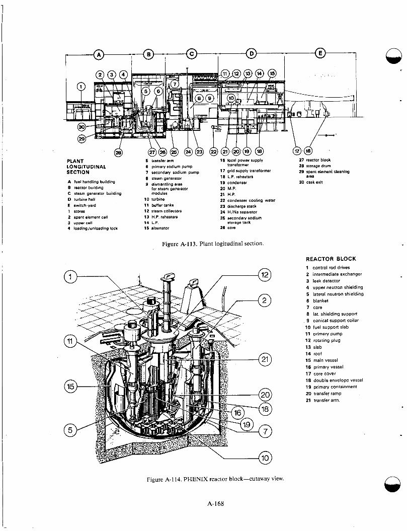
,-@--I+{-@--/- 1-
PLANT LONGITUDINAL SECTION
A fuel handling building B reactor building C steam generator building D turbine hall E switch-yard 1 stores 2 spent element cell 3 upper cell 4 loadinglunloading lock
6 transfer arm 6 primary sodium pump 7 secondary sodium pump 8 steam generator 9 dismantling area
for steam generator modules
10 turbine 11 buffer tanks 12 steam collectors 13 H.P. reheaters 14 L.P. 16 alternator
16 locel power supply
17 grid supply transformer 18 L.P. reheaters area 19 condenser 30 cask exit 20 M.P. 21 H.P. 22 condenser cooling water 23 discharge stack 24 t i /Na separator 26 secondary sodium
storage tank 26 core
27 reactor block transformer 28 storage drum
29 spent element cleaning
Figure A-1 13. Plant logitudinal section.
REACTOR BLOCK
1 control rod drives 2 intermediate exchanger 3 leak detector 4 upper neutron shielding 5 lateral neutron shielding 6 blanket 7 core 8 lat. shielding support 9 conical support collar 10 fuel support slab 11 primary pump 12 rotating plug 13 slab 14 roof 15 main vessel 16 primary vessel 17 core cover 18 double envelope vessel 19 primary containment 20 transfe! ramp 21 transfer arm.
Figure A-1 14. P H E N I X reactor block-cutaway view.
A- 168
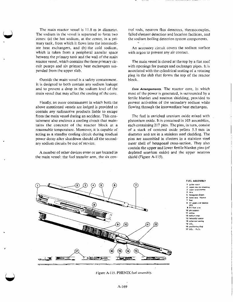
The main reactor vessel is 11.8 m in diameter. The sodium in the vessel is separated to form two zones: (a) the hot sodium, at the center, in a pri- mary tank, from which it flows into the intermedi- ate heat exchangers, and (b) the cold sodium, which is taken from a peripheral annular space between the primary tank and the wall of the main reactor vessel, which contains the three primary cir- cuit pumps and six primary heat exchangers sus- pended from the upper slab.
Outside the main vessel is a safety containment. It is designed to both contain any sodium leakage and to prevent a drop in the sodium level of the main vessel that may affect the cooling of the core.
Finally, an outer containment in which both the above mentioned vessels are lodged is provided to contain any radioactive products liable to escape from the main vessel during an accident. This con- tainment also encloses a cooling circuit that main- tains the concrete of the reactor block at a reasonable temperature. Moreover, it is capable of acting as a standby cooling circuit during residual power decay after shutdown should all the second- ary sodium circuits be out of service.
A number of other devices enter or are located in the main vessel: the fuel transfer arm, the six con-
trol rods, neutron flux detectors, thermocouples, failed element detection and location facilities, and the sodium boiling detection system components.
An accessory circuit covers the sodium surface with argon to prevent any air contact.
The main vessel is closed at the top by a flat roof with openings for pumps and exchanger pipes. It is associated with the cylindrical seating of a rotating plug in the slab that forms the top of the reactor block.
Core Arrangements. The reactor core, in which most of the power is generated, is surrounded by a fertile blanket and neutron shielding, proirided to prevent activation of the secondary sodium while flowing through the intermediate heat exchanges.
The fuel is enriched uranium oxide mixed with plutonium oxide. It is contained in 103 assemblies, each containing 217 pins. The pins, in turn, consist of a stack of centered oxide pellets 5.5 mm in diameter and are in a stainless steel cladding. The pins are assembled in clusters in a stainless steel outer shell of hexagonal cross-section. They also contain the upper and lower fertile blanket pins (of depleted uranium oxide) and the upper neutron shield (Figure A-1 15).
FUEL ASSEMBLY 1 guide notch 2 upper neulron shielding 3 upwi a m blanket
4 core
5 hexagonal sheath 6 lower #mal blanket 7 toot 8 37 upwr t xidl blankel
pins 9 217 luel pins
10 pin suppoit 11 orifice 12 rcdlum ,"Ill 13 helicoidal spacer 14 spherical tearing 15 UO, 16 porilionm(i slug 17 UO, . Pullr .
Figure A-1 15. PHENIX fuel assembly.
A- 1 69
The following are within the fuel assemblies:
A foot at the lower end for engagement with the sodium flow distribution plenum (a disk-shaped manifold) through which the sodium is fed by the primary pumps
A notched head at the top to facilitate introduction and removal by the fuel han- dling gripper.
The lateral blanket is composed of depleted ura- nium oxide in the shape of pellets measuring 12.15 mm in diameter in 90 assemblies having 61 pins each.
The structural components of these assemblies are identical to those of the fissile assemblies, sodium flow being through the foot engaged in the sodium plenum.
Lateral neutron shielding, distributed from the blanket outward, consists of the following:
Rows of steel elements of the same hexago- nal cross section as the fuel assemblies
Rows of circular cross section elements of graphite, steel, and boron-doped graphite, respectively.
Forty-one holdup pins are provided in the lateral shielding for fuel elements removed from the core before they go to the discharging ramp.
Control System. The operational characteristics of each subassembly in the core are first calculated and then measured while the reactor is in opera- tion, essentially by means of thermocouples.
Calculations are made using a core management program, which takes into account flux perterba- tions caused by each core component. This code gives an evaluation of the power and of the sodium temperature increase through each subassembly.
The outlet sodium temperature of each subas- sembly is continuously monitored by two thermo- couples and handled through two independent computers. A temperature increase of more than 3% with respect to the average core temperature increase triggers an alarm. A scram is triggered if the increase is greater than 7.5%.
Loss of cladding integrity can be detected by a fission product detection system, either through measuring the fission product integrity in the argon gas or in the sodium. Failures are localized by a system based upon measurements of the fission products in the sodium.
The joints between the roof and the vessel, fitted with power-regulated heated panels, are closely monitored; during transient operations, thermal gradients must not exceed 600°C per meter.
Three different devices are used to make the sodium level measurements:
The primary sodium level is measured using eddy current probes
The main vessel protection baffle sodium is monitored using argon bubbling and sodium bubblers along with pressure measurements
Inlet pump sodium flowrate is monitored using a magnetic flowmeter.
From these measurements, structural temperatures can be deduced and cross checked.
Reactor power is regulated by a remote adjust- ment of the primary sodium pumps. The difference in temperature of the primary sodium at the inlet and outlet of the core is maintained steady at 160°C by insertion or removal of the six control rods. Steam temperature at the evaporator outlet is main- tained steady at 375°C by automatic regulation of the feedwater. The temperature of the superheat steam is maintained steady at 5 12°C by adjustment of the secondary sodium circulating pumps. The temperature of the resuperheat steam is maintained at 512°C and follows the superheat steam tempera- ture, the distribution of the sodium flow to the superheater and resuperheater being predeter- mined. This temperature may vary slightly with the load (between 512 and 490°C). Steam pressure at the boiler outlet is maintained at 168 kPa by auto- matic regulation of the admission valves. Any mal- function in the primary or secondary sodium circuits (e.g., seizure of a pump) automatically ini- tiates reactor shutdown.
Heat Transport system. The three primary circulat- ing pumps are variable speed units (150 to 970 rpm)
n
A- 170

delivering about 950 kg of sodium per second at 825 rpm, which is their normal service speed. The circulating sodium enters the core at 400°C and leaves the core at 560°C to six heat exchangers that are asso- ciated in pairs with the three independent secondary circuits. Auxiliary circuits are provided for storage, filling, draining, and purification of primary sodium. The primary sodium is purified by the use of cold trap precipitators.
Each secondary loop is connected to a steam gen- erator consisting of an evaporator, superheater, and resuperheater, in 12 modules. Each module has seven tubes in a cylinder containing water in coun- terflow to the sodium pumped through the cylinder. The sodium flows to the superheater and resu- perheater in parallel, from which steam at 512°C and a pressure of 165 and 34 kPa respectively is obtained. The total sodium flow then goes to the evaporator, which is fed water at 246°C and sup- plies steam at 375°C.
The steam generators are equipped with a water- to-sodium leakage detection system operating on the basis of sodium/hydrogen concentration meas- urements. As a safeguard against the pressure effects of sodium leaks, rupture disks in the sodium manifold will burst and discharge sodium water reaction products to a separator, from which the reaction hydrogen can escape into the atmosphere. Fast-closing valves are provided for automatic rapid shutoff of the steam generators from both the water and sodium circuits. Pollution of the entire secondary circuits is thereby prevented, and the quantity of waste involved in a possible reaction is limited. Figures A-1 16-1 18 illustrate the primary pump, the expansion tank and secondary pump, and the generator respectively.
61 Operational Experience. The nature of the startup
testing carried out for PHENIX was .the result of both the prototype nature of the plant and its size. The startup testing took place over a three-year per- iod, and the tests were grouped into four phases delineated by the following major events: loading the main circuits with sodium, loading the reactor core, and the onset of power buildup.
The first phase included the testing of circuits related to the reactor vessel, the testing of sodium and argon auxiliary circuits, and the loading of sodium in the main circuits. This phase was com- pleted in January 1973. The second phase began at that time, with the filling of the sodium circuits and
was continued until the end of July 1973, with iso- thermic and inactive sodium testing. The first buildup of temperature to 450°C was carried out during March. The temperature was built up by progressive stages to enable testing for arty failed elements, hydrogen detection, measurements of pressure and flow rates, and very thorough testing of fuel handling at 250°C.
The third phase began with replacing the dummy fuel with actual fuel. The first criticality took place on August 31, with a core of 91 assemblies. Low- power nuclear testing took place throughout the entire month of September. The steam generators were put into service in October 1973.
The fourth phase started in November 19173 with a low-power buildup. It proceeded in stages, obtaining as rapidly as possible a period of opera- tions approaching nominal operating conlditions. The initial connection to the electrical network was carried out on December 13, 1973. Successively increasing power, full power was achieved on March 12, 1974. The principal reactor operating parameters were then compared to those of lihe pre- liminary design phase. Additional testing under power then took place until June.
The first phase of operation was characterized by a load factor of 69.5% and an availability rate of 75.5%. The gross electrical output exceeded 265 MW against a planned 250 MW. Gross efficiency was 45%. This period of operation was marked by a few minor sodium leaks in the secondary circuits and water leakage in the steam generators.
On three occasions small cracks appeared in a joint weld of a large diameter valve on a steam gen- erator sodium inlet pipe. The amount of sodium lost was approximately one liter and was accompa- nied in each case by the slow and spontaneous com- bustion of insulation material. The sodium circuits were not pressurized at the time, so were drained in order to stop the leak and carry out repairs. These leaks were eliminated by a modification in the steam generator.
As mentioned in the previous section, the modu- lar steam generators are made of seven exchange tubes filled with water-steam and are located inside larger tubes conveying sodium. The flow rate distri- bution in the seven tubes is regulated by a diaphram system on the side of the steam generators. IDistur- bances in the fluid flow caused by the diapnrams, and the flow rate of highly pressurized water,
A-171

n
Figure A-116. Primary pump.
caused wear in these tubes. On four occasions this wear resulted in sodium leaking into the water- steam tubes. These incidents involved an unavaila- bility during the last month of 1975. The modifications made to remove these troubles con- sisted in an improvement in the geometry of the components, the addition of a protective skirting, and a jet baffle screen downstream of the diaphram. The inlets into the steam generator mod- ified in this manner have caused no further' problems.
The second phase of PHENIX operations from July 1 , 1976 to April 20, 1978, was characterized by repair work and modifications made to the
PRIMARY P U M P '
1 pony motor 2 reduction gearing and
freewheel 3 motor 4 flywheel 5 brake 6 sliding support 7 thrust bearing and
rotating seals 8 sodium inlet 9 electromagnetic
flowmeters 10 non-return valve 11 articulated sleeve 12 sodium outlet
1 )
intermediate heat exchangers. There were very few periods of reactor operation.
The first major sodium leak occurred July 10, 1976. It occurred on a component whose internal detector was not functioning. The leak was therefore only detected when it flowed over to the outside. It was situated on the top of the heat exchanger, above the reactor slab, under the sheet- metal floor of the reactor hall (see Figure A-119). A fire started in some insulation but was quickly brought under control by the systems provided for that purpose. The second incident, on October 5, 1976, was detected at the very outset before the sodium was able to reach the outside. The progress n
A-172

n EXPANSION TANK A N D SECONDARY P U M P
....... .......
9
1 pony motor 2 reduction gearing 3 freewheel 4 motor 5 thrust bearing and
rotating seals 6 expansion tank 7 pump inlet 8 impellor 9 sealing rings
10 sodium outlet 11 sodium inlet
Figure A-117. Expansion tank and secondary pump.
and development of that leak was monitored for two days, and the leak and fire were brought under control immediately.
The leak occurred in a joint weld of the plate closing off the secondary sodium outlet at the top of the exchanger. This rigid plate connects two very long barrel plates of different temperatufes; the dif- ferential expansion of these two plates caused a crack in the weld. The temperature differential in the sodium was caused by nonturbulent mixing that had not been anticipated in the computer mod- eling of the sodium in the intermediate heat
exchangers. The rigid plate was replaced by a flexi- ble closure.
All six heat exchangers were removed from the reactor core, using the existing handling transfer cask, and were then transferred into a washing pit installed at the time of construction. The first oper- ation consisted of removing the remaining sc I d' ium. This procedure was performed by sweeping with nitrogen gas, containing an ever-higher moisture content, then with steam, and finally by immersion in water. Decontamination entailed a sequence con- sisting of an acid wash, an alkaline wash, and rins- ing. The maximum dose rate from the exchanger at
A- 173

S T E A M G EN E R A T 0 R 1 sodium inlet
2 outlet collector 3 water separator
4 sodium outlet 5 to hydrogen
separator 6 rupture disk 7 water drain valve 8 water inlet
9 insulated casing 10 superheated
steam 11 to reheater 12 reheated steam
A reheater B superheater C economiser-evaporator
-@
Figure A-1 18. PHENIX steam generator.
the outset of decontamination was 10 rem/h; at the end of decontamination, the rate was brought down to 10 mrem/h. At that point, repairs on the heat exchanger became an operation consisting of standard sheetmetal work machining.
Following these preliminary steps, the disassem- bly of the heat exchangers went routinely. The first heat exchanger to be withdrawn was completely dis- mantled with the exception of the bundle of tubes itself. This bundle of tubes was very carefully inspected and found acceptable. The other heat exchangers did not need to be disassembled so extensively, and work was devoted to slowly replac- ing the upper parts.
The washing and decontamination of the two units produced 440 m3 of liquid waste, represent- ing an activity of 68 Ci. This waste was shipped for treatment at the Marcoule Center.
The doses received by the personnel responsible for the decontamination and repair work on the heat exchangers was an average of 69 mrem/ person, for a total of 6.3 man-rem.
There were very few losses of material on the tubes in the heat exchanger as shown by analysis of the washing products and ultrasonic measurements of tube thickness.
n 5
.
A- 174

LEAK
Figure A-1 19.
Primary. outlet
PHENIX intermediate heat exchanger.
Secondary outlet
I-- Sodium level
Primary b \ inlet
I A-175
The heat exchanger components were rinsed to remove all washing products, and checks were made at several points to ensure they were clean. Checks were also made by operating the IHXs inpile for over 1,000 h in hot sodium. After repair, the IHXs were radiographed and ultrasonically examined.
Work performed in radiation fields is very strictly controlled at PHENIX. Each work site is inspected prior to the beginning of work, and all necessary pro- tective systems are set up so as to avoid exceeding a dose rate greater than 10 mrem/h. Any work involved in a radiation exposure area greater than 10 mrem/h needs higher management approval. An indication of the effectiveness of this system is shown by examina- tion of the dosimetry records of the PHENIX plant during its first 9 years of operation. The number of employees working at the plant generally vary between 200 and 400. The total dose received by all persons working in the plant from its commissioning through the end of calendar year 1982 was less than
68 man-rem. The average annual dose per person never exceeded 40 mrem. The maximum dose received by the most exposed individual in any year was.1.8 rem. This latter figure is exceptional, and by I
way of indication, only five employees have ever exceeded 0.5 rem during any one year. Another way to compare the radiation exposure at the PHENIX plant with other types of nuclear generating stations is to examine the total gross dose equivalent per unit of energy produced per calendar year. The PHENIX plant produced 7 450 697 MWh(e) during the years 1974 through 1980 at a cost of 46 man-rems. This is equivalent to 0.054 man-rems/MWy(e). The average total dose equivalent per unit'o f energy produced per calendar year for boiling water reactors is approxi- mately 1.8 man-rem/MWy(e), whereas for pressur- ized water reactors it is %l.l man-rems/MWy(e). These light water reactor plants then cost %20 to 30 times more collective dose equivalent per unit power of energy in a calendar year than does the PHENIX LMl7BR.A-135-137
n .. . .
A-I76
REFERENCES
A-I. G. R. Keepin, Physics of Nuclear Kinetics, Additon-Wesley Publishing Co., Inc., F.eading, Massachusetts. 1965.
A-2. K . Ott, “An Improved Definition of the Breeding Ratio for Fast Reactors,” Transactions of the American Nuclear Society, 12, 1969, pp. 719ff.
A-3. H. L. Wyckoff and Greebler, “Definition of Breeding Ratio and Doubling Time,” Nucleor Ech- nology, 21, 1974, pp. 158ff.
A-4. E. Paxon (ed.), Radial Parfait Core Design Study, Westinghouse Advanced Reactors Division, WARD-353, Waltz Mill, Pennsylvania, 1977.
A-5. D. C. King, and R. A. Sunderland, “Comparison of the Neutronic Performance of Honiogene- ous and Heterogeneous designs for 1300 MWE LMFBR,” in Fast Reactor Fuel Cycles, British Nuclear Energy Society, London.
A-6. A. K. Agrawal and M. Khatib-Rahbar, “Dynamic Simulation of LMFBR Systems,” Atomic Energy Review, 18, 2, IAEA, Vienna, 1980.
A-7. M. Aubert et al., “Temperature conditions in an LMFBR Power Plant from Primary Sodium to Steam Circuits,” Optimization of Sodium-Cooled Fast Reactors, British Nuclear Energy Society, London, 1978.
A-8. A. E. Waltar and A.B. Reynolds, Fast Breeder Reactors, Pergamon Press, New York, 1981
A-9. S. Dryer, “The Heat Transfer System of SNR-300,” Nuclear Engineering International 21, 1976, pp. 246ff.
A-10. A. A. H. Dorsser von, “Man Heat Transfer Components for SNR-300,” Nuclear Engi,rzeering International, 21, Clinch River Breeder Reactor PSAR, 1976, pp. 246ff.
A-11. A. S. Gibson, P. M. Murphy, and W. R. Gee, Jr., System Description and Cost for a 1000 MW(e) Sodium Cooled Fast Reactor, Task IZ Report, AEC Follow-On Study, General Electric Coinpany, GEAP-5678, 1968.
A-12. K . C . Gross et al., Fission-Product Releases to the Primary System of EBR-IZ from April 1980 to March 1981, Argonne National Laboratory, ANL-83-80, Chicago, Illinois, 1983.
A-13. G. E. Meadows et al., FFTF Sodium and Cover Gas Characterization 1978-1980, Westin,ighouse Hanford Co., Richland, Washington, HEDL-TME 80-75, 1981.
A-14. W. C . Miller and E E. Holt, FFTF Fuel Failure Detection and Characterization by Cover Gas Monitoring, Hanford Engineering Development Laboratory, Richland, Washington, HEDL-SA- 1183, 1977.
A-15. J. A. Figg and R. Sanchez, Reactor Assembly Failure Location Analysis Program (FLAP,, Users Guide, Hanford Engineering Development Laboratory, Richland, Washington, HEDLTME-82- 36, 1983.
A-16. R. Schmittroth, “A Probabilistic Method for Identifying Failed Fuel Elements Using a Gas Tag System,” Nucl. Sci & Eng., 52, 1973, pp. 95ff.
A- 177
A-17.
A-18.
A-19
A-20.
A-21.
A-22.
A-23.
A-24.
A-25.
A-26.
A-27.
A-28.
A-29.
A-30.
A-31.
A-32.
A-33.
F. E. Holt, “On-Line Radiometric Analysis of FFTF’s Cover Gas-Basic Analytical Features,’’ n International Conference on Liquid Metal Technology in Energy Production, Champion, Pennsylvania, 19 76.
E. T. Jurney et al. (eds.), Los Alamos Fast Plutonium Reactor, Los Alamos Scientific Laboratory, Los Alamos, New Mexico, US AEC Report TID 10048, 1954.
w
J. G. Yevick and A. Amorosi (eds.), Fast Reactor Technology: Plant Design, MIT Press, Cambridge, Massachusetts, 1966.
G. T. Arnold et al., Disassembly of the Los Alamos Fast Reactor, Los Alamos Scientific Labora- tory, Los Alamos, New Mexico, US AEC Report LA-1575, 1953.
Civilian Power Reactor Program, Status Report on Fast Reactors as of 1959, Book 1, Part 111, US AEC Report TID-85 I8 (BK-l), Superintendent of Documents, U.S. Government Printing Office, Washington.
R. R. Schmidt et al., Instability Studies with EBR-Z, MARK 111, US Argonne National Labora- tory, Argonne, Illinois, USAEC ANL-6266, 1963.
R. 0. Haroldsen et a]., Safety Analysis Report, EBR-I, Mark ZV, Argonne National Laboratory, Argonne, Illinois, USAEC ANL-6411, 1963.
H. V. Lichtenberger et al., “Operating Experience and Experimental Results Obtained from a NaK Cooled Fast Reactor, Proceedings of the First United Nations International Conference on the Peaceful Uses of Atomic Energy, Geneva, 1955, Vol. 3, pp. 345-360, United Nations, New York, 1956.
“EBR-I Operating Experience,” Nuclear Safety, 3, 2, 1961.
N. Grotenhuis, “EBR-I Shield Design,” Notes, International School of Nuclear Science and Engi- neering, Argonne National Laboratory, Argonne, Illinois, 1961.
R. R. Smith et al., A Mechanism Explaining the Instability of EBR-I, Mark-III, Argonne National Laboratory, Argonne, Illinois, USAEC ANL-6354, 1961.
R. E. Rice et al., EBR-I, Mark ZII-Design Report, Argonne National Laboratory, Argonne, Illinois, USAEC ANL-5836, 1958.
Experimental Power and Test Reactors, A Technical and Pictorial Summary, USAEC TID-4562, 1956.
S. Lawroski et al., Reactor Development Program Progress Report, Argonne National Laboratory, Argonne, Illinois, USAEC ANL-6233, 1960.
S, Lawroski et al., Reactor Development Program Progress Report, Argonne National Laboratory, Argonne, Illinois, USAEC ANL-6269, 1960.
S. Lawroski et al., Reactor Development Program Progress Report, Argonne National Laboratory, Argonne, Illinois, USAEC ANL-6328, 1961.
S. Lawroski et al., Reactor Development Program Progress Report, Argonne National Laboratory, Argonne, Illinois, USAEC ANL-6343, 1961.
.
n
A- 178

A-34.
A-35.
A-36.
A-37.
A-38.
A-39.
A-40.
A-41.
A-42.
A-43.
A-44.
A-45.
A-46.
A-47.
A-48.
A-49.
A-50.
S. Lawroski et al., Reactor Development Program Progress Report, Argonne National Laboratory, Argonne, Illinois, USAEC ANL-6355, 1961.
S. Lawroski et al., Reactor Development Program Progress Report, Argonne National Labciratory, Argonne, Illinois, USAEC ANL6433, 1961.
L. J. Koch et al., Experimental Breeder Reactor II (EBR-II, Hazard Summary Report, Argonne National Laboratory, USAEC ANL-5719, May 1947, and Addendum, USAEC ANL-5719 (ADD), 1964.
G. Fischer et al. (eds.), Proceedings of the Conference on the Physics of Breeding, Argonne National Laboratory, Argonne, Illinois, USAEC ANL-6122, 1959.
R. 0. Brittan, “Analysis of the EBR I Core Meltdown,” Proceedings of the Second UnitedNations International Conference on the Peaceful Uses of Atomic Energy, Geneva, Switzerland, 1958.
H. G. Barkman et al., Los Alamos Molten Plutonium Reactor Experiment, LAMPRE, ffazard Report, Los Alamos Scientific Laboratory, Los Alamos, New Mexico, USAEC LA-2327, 1959.
S. Glasston (ed.), Quarterly Status Report on LAMPRE Program for a Period Ending May 20, 1960, Los Alamos Scientific Laboratory, Los Alamos, New Mexico, USAEC LAMS- 2438, 1960.
S. Glasston (ed.), Quarterly Status Report on LAMPRE Programs for a Period Ending August 20, 1960, Los Alamos Scientific Laboratory, Los Alamos, New Mexico, USAEC LAMS- 2462, 1960.
Quarterly Status Report on LAMPRE Programs for a Period Ending November 20, 1960, Los Alamos Scientific Laboratory, Los Alamos, New Mexico, USAEC LAMS-2487.
Quarterly Status Report on LAMPRE Program for Period Ending February 20, 1961, Los Alamos Scientific Laboratory, Los Alamos, New Mexico, USAEC LAMS-2531.
Quarterly Status Report on LAMPRE Programs for a Period Ending May 20, 1961, Los AJamos Scientific Laboratory, Los Alamos, New Mexico, USAEC LAMS-2564.
Quarterly Status Report on LAMPRE Program for Period Ending August 20, 1961, Los A.lamos Scientific Laboratory Los Alamos, New Mexico, USAEC LAMS-2620.
Quarterly Status Report on LAMPRE Program for Period Ending November 20, 1961, Lm A.1amos Scientific Laboratory, Los Alamos, New Mexico, USAEC LAMS-2647.
B. M. Carmichael and G. L. Ragan, “The Startup of the First Molten Plutonium Reactor,” Trans- actions of the American Nuclear Societx 4, 2, 1961.
B. M. Carmichael and G.L. Ragan, “Some Effects Peculiar to Liquid Metal Fuel of LAMPRE-1,” Transactions of the American Nuclear Societx 4, 2, 1961.
I
Quarterly Status Report on LAMPRE Program for Period Ending May 20, 1962, Los Alamos Scientific Laboratory, Los Alamos, New Mexico, USAEC LAMS-2681.
Quarterly Status Report on LAMPRE Program for Period Ending May 20, 1962, Los Alamos Scientific Laboratory, Los Alamos, New Mexico, USAEC LAMS-2720.
A-179
A-5 1.
A-52.
A-53.
A-54.
A-55.
A-56.
A-57.
A-58.
A-59.
A-60.
A-61.
A-62.
A-63.
A-64.
A-65.
A-66.
LAMPRE-I Final Design Status Report, Los Alamos Scientific Laboratory, Los Alamos, New Mexico, USAEC LA-2833.
D. B. Hall, “Los Alamos Molten Plutonium Program,” Proceedings of the National TopicalMeet- ing on Fast Reactor Technology, American Nuclear Society, Detroit, Michigan, 1965.
Horst, Hutchins, Leitz, and Wolfe, CoreDesign for a500 MW(e) Fast Oxide Reactor, GEAP-3721, 1961.
Q .
M. J. McNelly, Liquid Metal Fast Breeder Reactor Design Study [IO00 MW(e) UO2-PUO2 Fuel Plant], GEAP-4418, 1965.
K. N. Horst, Southwest Experimental Fast Oxide Reactor Development Program, Second Quar- terly Report, July-September 1964, GEAP-4742, 1964.
K. M. Horst, Southwest Experimental Fast Oxide Reactor Development Program, Third Quarterly Report, October, 1964-January 1965, GEAP-4799, 1964.
L. R. Kelman, H.V. Rhude, and H. Savage, “Development of a Metal Fuel Alloy for the SEFOR Fast Crjtical for ZPPR,” ANS Transactions, 1964.
Hafele et al., “Static and Dynamic Measurements on the Doppler Effect in an Experimental Fast Reactor,” Third United Nations Conference on the Peaceful Uses of Atomic Energy, Geneva, Switzerland, 1964.
J. 0. Arterburn and K. Hikido, SEFOR Operating Experience and Significance to LMFBRs, Engi- neering of Fast Reactors for Safe and Reliable Operation, Kernforschungszentrum Karlsruhe, Germany, 1972.
A. I. Leipunsky et al., “Experimental Fast Reactors in the Soviet Union,” Proceedings of the Second United Nations International Conference on the Peaceful Uses of Atomic Energy, Geneva, 1958, 9, United Nations, New York, 1959, p. 348.
A. I. Leipunsky et al., “Experimental Fast Reactors in the Soviet Union, in Physics and Fast Intermediate Reactors,” Proceedings of the IAEA Seminar in Vienna, August 3-11, 1961, 3, Series STI-PUB-49, Vienna, Austria, 1962.
R. R. Matthews, “Soviet Fast Reactors-BR-5,” Nuclear Engineering, 4, 41, and “Fast Reactors: A Soviet Outlook,” Nuclear Energy, 7, 71, 1962
M. C. Pinchasik, “Operating Experience with the BR-5 Reactor, in Power Reactor Experiments,” Proceedings of the ZAEA Symposium in Vienna, October 23-27, 1961, I , Series STI-PUB-5 1, Vienna, Austria, 1962.
M. S. Pinkhasik et al., “Certain Problems Relating to Operating Experience of the BR-5 Fast Reactor, ” Seminar on Fast and Intermediate Reactor Physics, Paper No. SM21-29, Vienna, Austria, 1961.
A. I. Leipunskii et al., “The Physical Characteristics at the BR-5,” Seminar on Fast and Interna- tional Reactor Physics, Paper No. SM18/82, Vienna, Austria, 1962.
A. I. Leipunskii et al., “Operating Experience of the BR-5 Reactor,’’ Conference on Operating Experience of Power Reactors, Paper No. CN15/40, Vienna, Austria, 1963.
n
A-180
A-67. I \
A-68.
c
A-69.
A-70.
A-71.
A-72.
A-73.
A-74.
A-75.
A-76.
A-77.
A-78.
A-79.
A-80.
A-81.
A. I. Leipunskii et al., “Experience Gained from the Operation of the BR-5 Reactor, 1964-5,” Proceedings of the London Conference Organized by the British Nuclear Energy Society, 17-19th May, 1966, Paper No. 2-3, Pergamon Press, Oxford, England, 1966.
G. Brudermuller et al., “Operating Experience with the KNK Reactor and Preparations for a Fast Mix Oxide Core (KNK II) ,” Proceedings of the International Conference Organized by the’ British Nuclear Energy Society 11-14 March 1974, Institution of Civil Engineers, British Nuclear Energy Society, London, 1974.
G. Brudermuller, W. Marth, and H. Tebbert, “Erfahrungen Bei der Durchfuhrung Des Projektes KNK,” Atomwirtschaft, 18, 841973.
W. Marth and K. Dumn, “Problems Associated with Sodium Steam Generators as Discussed by the Example of a Leak in the Steam Generator of a Sodium Cooled Power Station KNK,” Proceed- ings: Experience from Operating and Fueling Nuclear Power Plants, IAEA, V Wien, Federal Republic of Germany, 1973.
H. Andrae and W. Marth, “Das Projekt KNK 11,” Atomwirtschaft, 18, 93, 1973.
R. Huper, Status of Fast Breeder Reactor Development in the Federal Republic of Germany, Llelgium and the Netherlands, prepared for the International Working Group on Fast Reactors of thl: Inter- national Atomic Energy Agency, Vienna, and for the Fast Reactor Coordinating Commiti:ee at a Commission of the European Communities, Brussels, Kernforschungszentrum Karlsruhe GmbH Karlsruhe, Federal Republic of Germany, 1983.
F. Sebilleau and C. P. Zalesski, “Plutonium as a Fuel for the Fast Reactor RAPSODIE,” P,roceed- ings of the American Nuclear Society Topical Meeting, Richland, Washington, September 13-14, 1962, Paper 15 in Plutonium as a Power Reactor Fuel, General Electric Company, USAEC.
H. Cartwright et al., “The Dounreay Fast Reactor-Basic Problems in Design, Proceedings of the Second United Nations International Conference on the Peaceful Uses of Atomic Energy, Geneva, Z958, 9, United Nations, New York, 1959, pp. 316ff.
Proceedings of the Symposium on the Counreay Fast Reactor, London, December 7, 1960, arranged by the Institution of Mechanical Engineers under Aegis of the British Nuclear Energy Conference, Institution of Mechanical Engineers, London.
Fast Reactor Descriptive Manual: Dounreay, the Control System and Electrical Supplies and Reac- tor Instrumentation, Sections A.2.4, A S and A.7, British Report IC-170 (D).
J. Allen, “Coolant Cleanup in DFR,” Nuclear Engineering, 7, 76, 1962.
D. C . D. Smith and K. W. Brindley, “Physics Experiments at DFR,” Nuclear Engineering, 7,76, 1962.
J. L. Phillips, “Operating Experience with the Dounreay Fast Reactor-I,” Nuclear Power, 7, 75, 1962.
J. L. Phillips, “Operating Experience with the Dounreay Fast Reactor-11,” Nuclear Power, Vol. 7, 76, 1962.
F. G. Dawson, “Plutonium as a Power Reactor Fuel,” Proceedings of American Nuclear Society Topical Meeting, Richland, Washington, September 13-14, 1962, General Electric Company, USAEC HW-75007, 1962.
A-181

A-82.
A-83.
A-84.
A-85.
A-86.
A-87.
A-88.
A-89.
A-90.
I A-91.
A-92.
A-93.
A-94.
A-95.
A-96.
A-97.
A-98.
J. L. Phillips, “Achievement of Full Power Operation at the Dounreay Fast Reactor,’’ Nuclear Engineering, August 1964.
J. L. Phillips, “Instrumentation of Fast Reactors,” New Scientist, August 24, 1961.
D. C. G. Smith et al., Third International Conference on the Peaceful Uses of Atomic Energy, Geneva, Switzerland, Paper 173, 1964.
Meeting of the Advisory Committee on Reactor Safety, EBR-II, Arco, Idaho, March 17-18, selected illustrations distributed by Argonne National Laboratory 1961.
“Physics of Fast and Intermediate Reactors,” Proceedings of the IAEA Seminar Held in Vienna August 3-11, 1961, Proceedings Series STVPUB-49, Vol. 3, Vienna, Austria.
L. J. Koch et al., Experimental Breeder Reactor II (EBR-11) Hazard Summary Report, Argonne National Laboratory, Argonne, Illinois, USAEC ANL-57 19, 1957; and Addendum to Hazard Summary Report, Experimental Breeder Reactor-II (EBR-Io, USAEC ANL-5719 (ADD), 1964.
J. R. Dietrich and W. H. Zinn, Solid Fuel Reactors, Addison-Wesley, Publishing Company, Inc., Cambridge, Massachusetts, 1958.
Power Reactor Technology, 4,4, September 1961.
M. Grotenhuis, A. E. McArthy, and A.D. Rossin, Experimental Breeder Reactor-II (EBR-II) Shield Design, Argonne National Laboratory, Argonne, Illinois, USAEC ANL-6614, 1962.
W. B. Lowenstein, “The Physics Design of EBR-11, and Physics of Fast and Intermediate Reac- tors,” Proceedings of the IAEA Seminar Held in Vienna August 3-11, 1961, Proceedings Series STI/PUB-49, Vol. 3, Vienna, Austria, 1962.
J. Adamson, AERE, private communication to H. E. Hungerford, APDA, 1961.
L. J. Koch, W. B. Lowenstien, and H. 0. Monson, Addendum to Hazard Summary Report Exper- imental Breeder Reactor-II (EBR-II), Argonne National Laboratory, Argonne, Illinois, USAEC ANL-5719, 1962.
“Pyrometallurgical Fuel Processing,” Reactor Fuel Processing, a Quarterly Technical Progress Review, 3, 1, January 1960, p. 25; 3, 2, April 1960, p. 27; 3 , 3, July 1960, p. 24; 4 , 1, January 1961, p. 25; 4, 2, April 1961, p. 38; 4, 3, July 1961, p. 30; 4, 4, October 1961, p. 37; 5 , 1, January 1982, p. 38; 5 , 2, April 1962, p. 27-33.
L. Burris et al., “Recent Advances in Pyrometallurgical Processes,’’ Transactions of the American Nuclear Society, 4, 2, 1961, pp. 192ff.
V. G. Trice and N. R. Chellew, “The Melt Refining of Irradiated Uranium: Application to EBR- I1 Fast Reactor Fuel: VI. The Behavior of Plutonium in the Melt Refining Process,” Nuclear Science Engineering, 9, 1, 1961, pp. 55ff.
A. Schneider and N. R. Chellew, “The Melt .Refining of Irradiated Uranium: Application to EBR-I1 Fast Reactor Fuel: VII. The Evolution of Xenon and Krypton,” Nuclear Science Engineer- ing, 9, 1, 1961, pp. 59ff.
N. R. Chellew, G. A. Bennett, and V. G. Trice, “The Melt Refining of Irradiated Uranium: Application to EBR-I1 Fast Reactor Fuel: VIII. The Behavior of Rare Earth, Yttrium, Barium, Strontium, and Cesium,” Nuclear Science and Engineering, 9, 1, 1961, p. 64.
A-182

. . . . . . . . . . . . . . . . . . . . . . . , . . . . . . . . . . . . . .. . . . . . . . . . . . . . . . . .
e
*.
/ i
A-99. J. Wolkoff and A. A. Chilenskas, “The Melt Refining of Irradiated Uranium: Application to EBR-I1 Fast Reactor Fuel: IX. Absorption and Retention of Sodium and Cesium Vapor on Sta- tionary Beds at Elevated Temperature,” Nuclear Science and Engineering, 9, No. I , p. 71.1961.
N. R. Chellew and V. G. Trice, 1961. “The Melt Refining of Irradiated Uranium: Appliciition to EBR-11 Fast Reactor Fuel: X. The Behavior of Zirconium,” Nuclear Science and Engineering, 9, 1, pp. 78ff.
A-100.
A-101. N. R. Chellew and N. Ader, “The Melt Refining of Irradiated Uranium: Application to EBR-I1 Fast Reactor Fuel: XI. Behavior of Iodine in Melt Refining,” Nuclear Science andEngineering, 9, I , 1961, pp. 82ff.
A-102. N. R. Chellew and G. A. Bennett, “The Melt Refining of Irradiated Uranium: Application to EBR-I1 Fast Reactor Fuel: XII. The Behavior of Ruthenium, Molybdenum, Polladium, Techne- tium, Antimony, Cadmium, Rhodium, and Tellurium,” Nuclear Science and Engineering, 9, 1, 1961, pp. 87ff.
A-103. L. Burris et al., “The Melt Refining of Irradiated Uranium: Application to EBR-I1 Fast Reactor Fuel: I. Introduction,” Nuclear Science and Engineering, 6, 6, 1959, pp. 493ff.
A-104. G. J. Bernstein et al., “The Melt Refining of Irradiated Uranium: Application to EBR-I1 Fast Reactor Fuel: 11. Experimental Furnaces,” Nuclear Science and Engineering, 6, 6, 1959, pp. 496ff.
A-105. D. (3. Hampton et al., “The Melt Refining of Irradiated Uranium: Application to EBR-I1 Fast Reactor Fuel: 111. Preparation of Experimental Alloys, ” Nuclear Science and Engineerin,?, 6, 6 , 1959, p. 501.
A-106. C. L. Rosen et al., “The Melt Refining of Irradiated Uranium: Application to EBR-I1 Fast Reac- tor Fuel: IV. Interaction of Uranium and its Alloys with Refractory Oxides,” Nuclear Scierrce and Engineering, 6, 6, 1959, pp. 504ff.
A-107. G. A. Bennett et al., “The Melt Refining of Irradiated Uranium: Application to EBR-[I Fast Reactor Fuel: V. Yield of Fissionable Material Upon Pouring,” Nuclear Science and Engineering, 6, 6, 1959, pp. 511ff.
A-108. M. Gazith, Literature Survey in Pyrometallurgical Purification of Metals, Israel Atomic Energy Commission, Israel LF-93, 1961.
A-109. EBR-11 Since 1964, Argonne National Laboratory-West, Idaho Falls, Idaho, 1983.
A-110. Power Reactor Development Company, Technical Information and Hazards Summary Report, ENRICO FERMI Atomic Power Plant, 1962.
A-1 1 1. Analysis and Simulation Study of the Operating Control System for the ENRICO FERMI Atomic Power Plant, Holly Carburetor Company, 1959.
A-112. ENRICO FERMI Atomic Power Plant, Atomic Power Development Associates, Inc., Report APDA-124, 1959.
A- 1 13. Specifications for the Main Instrumentation and Controls of the ENRICO FERMI Atomic Power Plant, Revision No. 1 , Atomic Power Development Associates, Inc., 1958.
A-114. ENRICO FERMI Atomic Power Plant Technical Information and Hazards Summary R’eport, Vol. 1, 2, and 3 , Power Reactor Development Company, 1962.
A-183
A- 1
A- 1
A- 1
5 .
6. I ,
7.
A-118.
A-119.
A-120.
A-121.
A-122.
A-123.
A-124.
A-125.
A-126.
A-127.
A-128.
A-129.
A-130.
A-131.
J. G. Yevick and A. Amorosi (eds.), Fast Reactor Technology: Plant Design, MIT Press, Cambridge, Massachusetts, 1966.
H. E. Hungerford and R. F. Mantey, “Shielding the ENRICO FERMI Fast Breeder Reactor,” Nucleonics, 16, 11, 1958.
T
L ..,
ENRICO FERMI Atomic Power Plant, Technical Information and Hazards Summary Report, No. 3 , Power Reactor Development Company, 1961.
H. E. Hungerford, R. I . Beaudry, and W. F. Chaltron, “Detailed Conceptual Design of a Graph- ite Primary Shield for the ENRICO FERMI Fast Breeder Reactor,” APDA Technical Memoran- dum No. 23, Atomic Power Development Associates, Inc., 1959.
“Replacement of a Modification to the Primary Shield Graphite in the ENRICO FERMI Reac- tor,” Exhibit T-60 to the 15th Quarterly Report to the United States Atomic Energy Commission, 1962.
“Effects of Release of Carbonaceous Gases from the Graphite in the ENRICO FERMI Reactor Rotating Shield Plug,” Exhibit T-61 to the 15th Quarterly Report to the United States Atomic Energy Commission.
E. P. Alexanderson (ed.), FERMI-I, New Age for Nuclear Power, American Nuclear Society, LaGrange Park, Illinois, 1979.
G. Ball, Results of the Low Power Nuclear Test Program for the EFBR, Atomic Power Development Associates, APDA-302, 1967.
E. L. Alexanderson et al., “Operating Experience at the ENRICO FERMI Atomic Power Plant,” ANS-100, 1956.
“Unit 1 Operating Experience Through 200 MW(t),”ENRICO FERMI Atomic Power Plant, EFAPP-200-1, 1971.
H. A. Bethe, Reactor Safety and Oscillator Tests, Atomic Power Development Associates, APDA- 117, 1956.
H . E. Hungerford, Phase E: Preoperational Shield Test Program for EFAPP, H-62-11-0702, 1962.
R. J. Beaudry, Phase A: Preoperational Shield Test Program for EFAPP, pp. 63-6, 1963.
R. J. Beaudry, Operational Shield Test for EFAPP, Atomic Power Development Associates, APDA-221, 1968.
Fuel Damage Incident at the ENRICO FERMI Atomic Power Plant October 5, 1966, Status as of February 24, 1967, Atomic Power Development Associates, Power Reactor Development Company.
Report on the Fuel Melting Incident in the ENRICO FERMI Atomic Plant on October 5, 1966, Atomic Power Development Associates, APDA-233, 1968.
Retirement of the ENRICO FERMI Atomic Power Plant, Power Reactor Development Company, DNP-200047 and NP-200479 (Supplement l), March 1974 and October 1975; reports on file at the U.S. DOE Office of Public Affairs, Technical Information Center, Oak Ridge, Tennessee.
A- 184
A-132. C. P. Cabell, A Summary Description of the Fast Flux Test Facility, Hanford Engineering Develop- ment Laboratory, Westinghouse Hanford Company, Westinghouse Electric Company, Richland, Washington, HEDL400, 1980.
A-133. A. D. Gadeken (ed.), FFTF Operating Report, April 16-November 11, 1982, Cycle I , Hanford Engineering Development Laboratory, operated by Westinghouse Hanford Company, Rich land, Washington, HEDL-401, 1983,
A-134. D. M. Lucoff, Report of the Failed Element Location Team-May 14, 1982: Fission Gas High Alarm, Hanford Engineering Development Laboratory, operated by Westinghouse Hanford Com- pany, Richland, Washington, HEDLTC-2236, 1982.
A-135. IAEA/NEA International Symposium on Occupational Radiation Exposure in Nuclear Fuel Cycle Facilities, Los Angeles, June 1979.
A-136. SFRP International Workshop on Provisions Taken at Design and During Operation to Reduce Occupational Exposure at LWRs, Paris, December 1979.
A-137. F. Conte, “Chapter 3: Radiation Protection at LMFBRs,” The PHENIXNuclear Plant afkr Six Years of Operation, Centrale Phenix, Bagnols Sur Ceze, France, 1980.
e
A-185

drs Y
16 SECURITY CLASSIFICATION L I1 NUMBER OF PA-
- IThcr -1
Un l im i ted Un 1 i m i tled l l h i r wor t1
4
18 PRICE r- SEFOR
NRC FORM l 3 6 I2 841 NRCM 1101 3101 3102
U S NUCLEAR REOULATORV C O u y I ~ I O N
BIBLIOGRAPHIC DATA SHEET NUREG/CR-4375 SEE INSTRUCTIONSON THE REVERSE EGG-2415 2 TITLE A N 0 SUBTITLE J LEAVEBLANK
Theory, Design, and Operat ion of L i q u i d Metal Fast Breeder Reactors , I n c l u d i n g Operat ional
5 AUTUORISI October 1985
October 1985
4 DATE REPORT COMPLETE0
Heal th Physics MONTU YEAR
Steven R. Adams MONTH YEAR
8 PROJECTITASKIWORK UNIT NUMBER 1 PERFORMING ORGAN12ATION NAME AND MAILING ADDRESS Ilnclud.Zw C d l
Idaho ‘Nat ional Engineer ing Laboratory EG&G Idaho, Inc. Idaho F a l l s , Idaho 83415 ‘FIN No. A6314
D i v i s i o n o f F a c i l i t y Operations Formal
U.S. Nuclear Regulatory Commission Washington, D.C. 20555
10 SPONSORING ORGANIZATION NAME A N 0 MAILING ADORESS flmclud.Zop Codel 11. TYPE OF REPORT
Off ice o f Nuclear Regulatory Research 8 PER100 COVERED Ilncluriw d.mI
I1 SUPPLEMENTARY NOTES
ABSTRACT
A comprehensive evaluation was conducted of the radiation protection practices and programs at prototype LMFBRs with long operational experience. Installations evaluated were the Fast Flux Test Facility (FFTF), Richland, Washington; Experimen- tal Breeder Reactor I1 (EBR-11) Idaho Falls, Idaho; Prototype Fast Reactor (PFR) Dounreay, Scotland; Phenix, Marcoule, France; and Kompakte Natriumgekuhlte Kernreak Toranlange (KNK II), Karlsruhe, Federal Republic of Germany. The evalua- tion included external and internal exposure control, respiratory protection proce- dures, radiation surveillance practices, radioactive waste management, and engineering controls for confining radiation contamination. The theory, design, and operating experience at LMFBRs is described. Aspects of LMFBR health physics different from the LWR experience in theunited States are identified. Suggestions are made for modifications to the NRC Standard Review Plan based on the differences.
FIN No. A6314-Occupational HP at LMFBRs
15 AVAILABILITY STATEMENT
4 OOCUMtNT ANALYSIS KEIWORDS OESCRIPTOHS
Uncl ass i f i ed L l q u i d Metal FFTF Fast Breeder Reactor P r o t o t w e Fast Reactor BR-5 - . Hea l th Physics PFR Fast F lux Test F a c i l i t y ZRheni x IOENTIFIERSIOPEN ENDED’TERMS KNK I 1
.Experimental Breeder EBR LAMPRE