EFFICIENT PRODUCTION OF TINPLATE PACKAGING ...
44
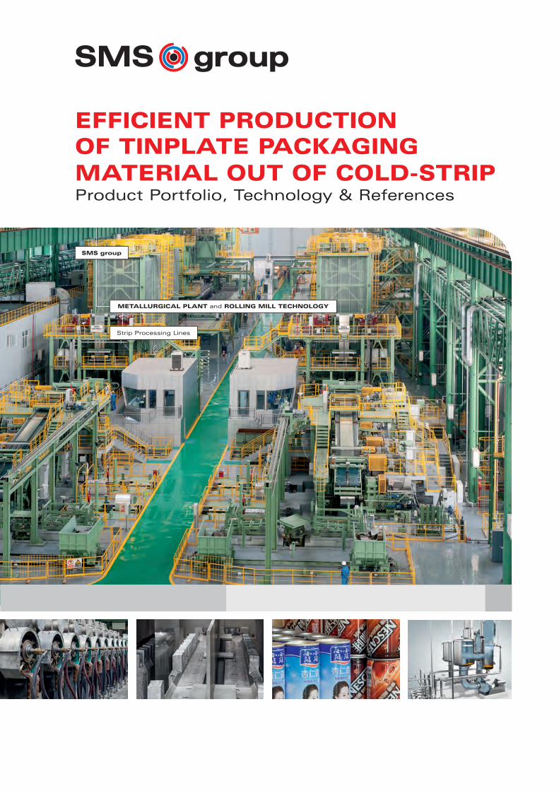
Strip Processing Lines METALLURGICAL PLANT and ROLLING MILL TECHNOLOGY EFFICIENT PRODUCTION OF TINPLATE PACKAGING MATERIAL OUT OF COLD-STRIP Product Portfolio, Technology & References SMS group
-
Upload
khangminh22 -
Category
Documents
-
view
1 -
download
0
Transcript of EFFICIENT PRODUCTION OF TINPLATE PACKAGING ...
Strip Processing Lines
METALLURGICAL PLANT and ROLLING MILL TECHNOLOGY
EFFICIENT PRODUCTION OF TINPLATE PACKAGING MATERIAL OUT OF COLD-STRIPProduct Portfolio, Technology & References
SMS group
W7-321E_Tinplate_Neutral 07.12.15 11:16 Seite 1
Tinplate ProductionSMS group
2
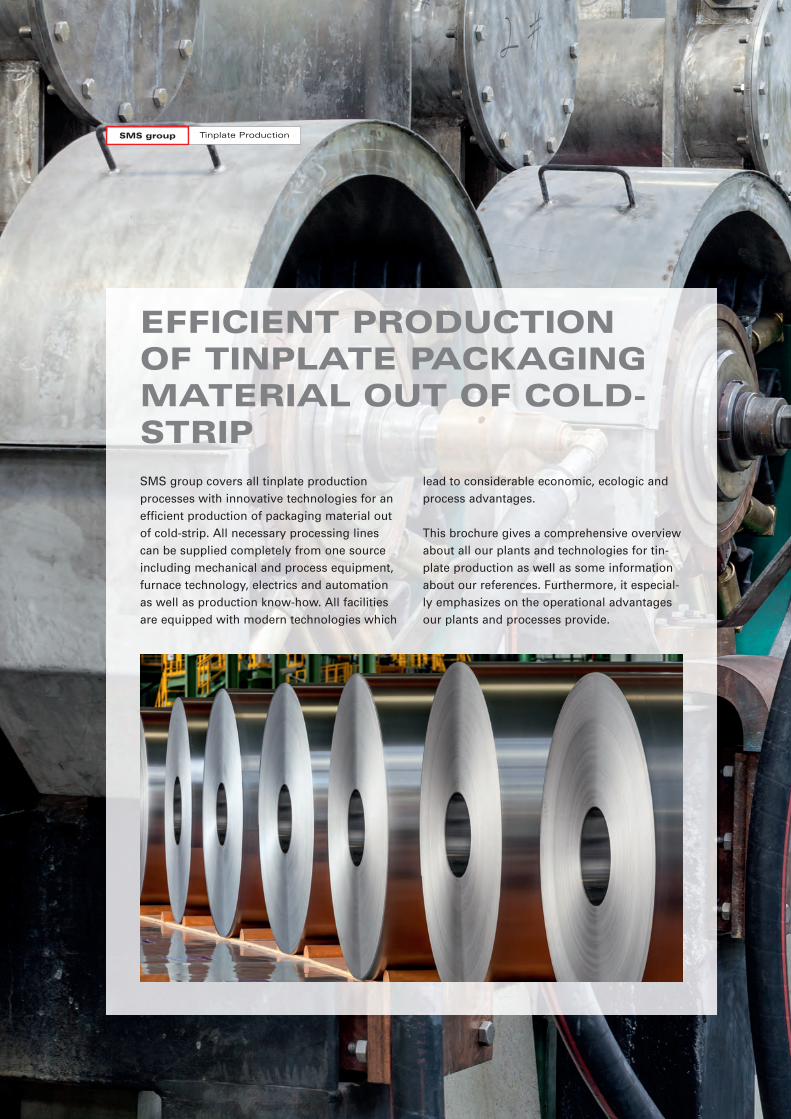
SMS group covers all tinplate productionprocesses with innovative technologies for anefficient production of packaging material outof cold-strip. All necessary processing linescan be supplied completely from one sourceincluding mechanical and process equipment,furnace technology, electrics and automationas well as production know-how. All facilitiesare equipped with modern technologies which
lead to considerable economic, ecologic andprocess advantages.
This brochure gives a comprehensive overviewabout all our plants and technologies for tin-plate production as well as some informationabout our references. Furthermore, it especial-ly emphasizes on the operational advantagesour plants and processes provide.
EFFICIENT PRODUCTION OF TINPLATE PACKAGINGMATERIAL OUT OF COLD-STRIP
W7-321E_Tinplate_Neutral 07.12.15 11:16 Seite 2
3
CONTENTS
Introduction 2
Tinplate 4
Material Flow 6
Electrolytic Cleaning Lines 8
Batch Annealing Furnaces 10
DCR & Temper Mill 12
Continuous Annealing Lines 14
Furnace Technology 16
Electrolytic Tinning Lines 18
Tinning Technology 20
Soluble Anodes & Preconditioning Cell 22
Thickness Control & Anode Monitoring 24
Reflow Technology 26
Evaporator Technology 28
Anode Caster 30
References 32
ThyssenKrupp Steel Rasselstein 34
Shougang Jingtang 36
Shagang Group 38
Tosyali Toyo 40
Electric & Automation 42
W7-321E_Tinplate_Neutral 07.12.15 11:16 Seite 3
Tinplate ProductionSMS group
4
100% RECYCLABLE VERSATILE PACKAGING
MATERIAL
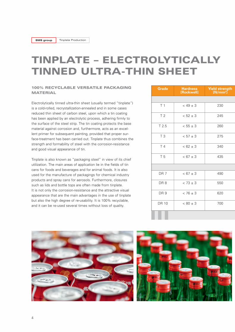
Electrolytically tinned ultra-thin sheet (usually termed “tinplate”) is a cold-rolled, recrystallization-annealed and in some casesreduced thin sheet of carbon steel, upon which a tin coatinghas been applied by an electrolytic process, adhering firmly tothe surface of the steel strip. The tin coating protects the basematerial against corrosion and, furthermore, acts as an excel-lent primer for subsequent painting, provided that proper sur-face-treatment has been carried out. Tinplate thus combines thestrength and formability of steel with the corrosion-resistanceand good visual appearance of tin.
Tinplate is also known as “packaging steel” in view of its chiefutilization. The main areas of application lie in the fields of tincans for foods and beverages and for animal foods. It is alsoused for the manufacture of packagings for chemical industryproducts and spray cans for aerosols. Furthermore, closuressuch as lids and bottle tops are often made from tinplate. It is not only the corrosion-resistance and the attractive visualappearance that are the main advantages in the use of tinplatebut also the high degree of re-usability. It is 100% recyclable,and it can be re-used several times without loss of quality.
TINPLATE – ELECTROLYTICALLYTINNED ULTRA-THIN SHEET
Grade Hardness[Rockwell]
Yield strength[N/mm2]
T 1 < 49 ± 3 230
T 2 < 52 ± 3 245
T 2.5 < 55 ± 3 260
T 3 < 57 ± 3 275 C
T 4 < 62 ± 3 340
T 5 < 67 ± 3 435
DR 7 < 67 ± 3 490
DR 8 < 73 ± 3 550
DR 9 < 76 ± 3 620
DR 10 < 80 ± 3 700
W7-321E_Tinplate_Neutral 07.12.15 11:16 Seite 4
5
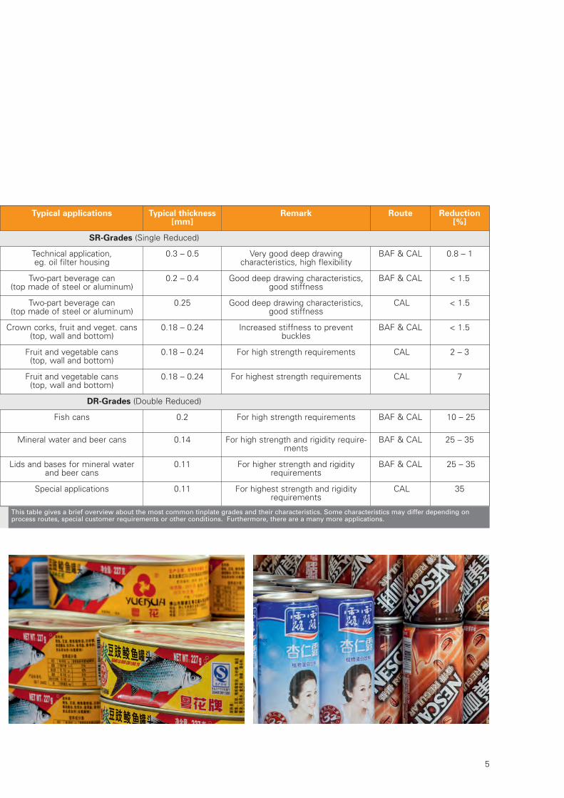
Typical applications Typical thickness[mm]
Remark Route Reduction[%]
SR-Grades (Single Reduced)
Technical application, eg. oil filter housing
0.3 – 0.5 Very good deep drawing characteristics, high flexibility
BAF & CAL 0.8 – 1
Two-part beverage can (top made of steel or aluminum)
0.2 – 0.4 Good deep drawing characteristics,good stiffness
BAF & CAL < 1.5
Two-part beverage can (top made of steel or aluminum)
0.25 Good deep drawing characteristics,good stiffness
CAL < 1.5
Crown corks, fruit and veget. cans(top, wall and bottom)
0.18 – 0.24 Increased stiffness to prevent buckles
BAF & CAL < 1.5
Fruit and vegetable cans (top, wall and bottom)
0.18 – 0.24 For high strength requirements CAL 2 – 3
Fruit and vegetable cans (top, wall and bottom)
0.18 – 0.24 For highest strength requirements CAL 7
DR-Grades (Double Reduced)
Fish cans 0.2 For high strength requirements BAF & CAL 10 – 25
Mineral water and beer cans 0.14 For high strength and rigidity require-ments
BAF & CAL 25 – 35
Lids and bases for mineral waterand beer cans
0.11 For higher strength and rigidityrequirements
BAF & CAL 25 – 35
Special applications 0.11 For highest strength and rigidityrequirements
CAL 35
This table gives a brief overview about the most common tinplate grades and their characteristics. Some characteristics may differ depending onprocess routes, special customer requirements or other conditions. Furthermore, there are a many more applications.
W7-321E_Tinplate_Neutral 07.12.15 11:16 Seite 5
Tinplate ProductionSMS group
6
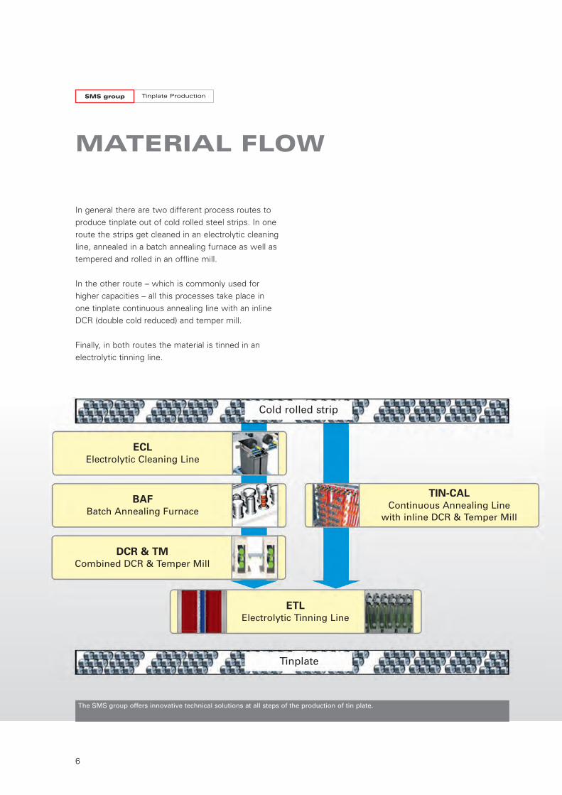
MATERIAL FLOW
In general there are two different process routes toproduce tinplate out of cold rolled steel strips. In oneroute the strips get cleaned in an electrolytic cleaningline, annealed in a batch annealing furnace as well astempered and rolled in an offline mill.
In the other route – which is commonly used forhigher capacities – all this processes take place inone tinplate continuous annealing line with an inlineDCR (double cold reduced) and temper mill.
Finally, in both routes the material is tinned in anelectrolytic tinning line.
The SMS group offers innovative technical solutions at all steps of the production of tin plate.
Cold rolled strip
Tinplate
TIN-CALContinuous Annealing Linewith inline DCR & Temper Mill
ECLElectrolytic Cleaning Line
BAFBatch Annealing Furnace
DCR & TMCombined DCR & Temper Mill
ETLElectrolytic Tinning Line
W7-321E_Tinplate_Neutral 07.12.15 11:16 Seite 6
7
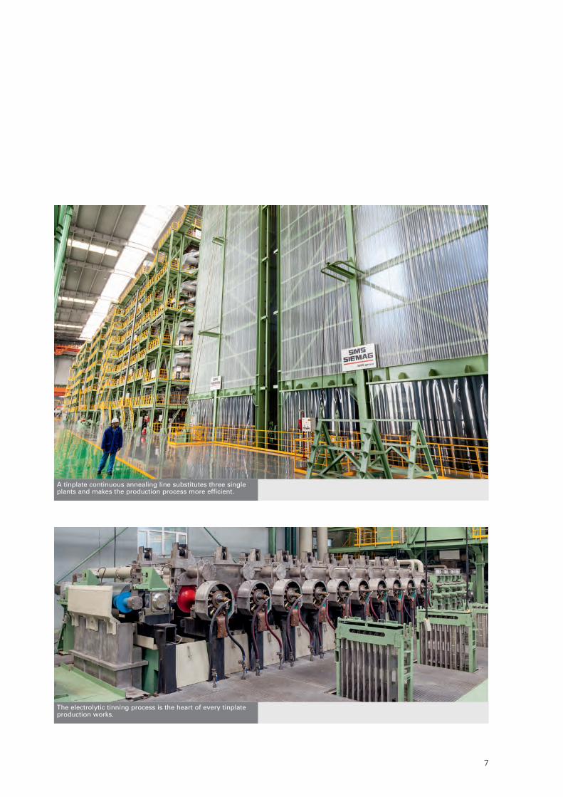
A tinplate continuous annealing line substitutes three singleplants and makes the production process more efficient.
The electrolytic tinning process is the heart of every tinplateproduction works.
W7-321E_Tinplate_Neutral 07.12.15 11:16 Seite 7
Tinplate ProductionSMS group
8
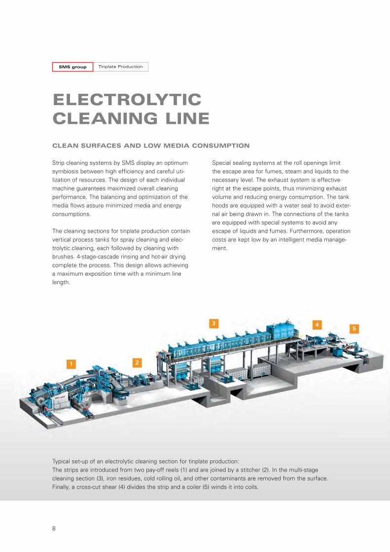
Strip cleaning systems by SMS display an optimumsymbiosis between high efficiency and careful uti-lization of resources. The design of each individualmachine guarantees maximized overall cleaning performance. The balancing and optimization of themedia flows assure minimized media and energyconsumptions.
The cleaning sections for tinplate production containvertical process tanks for spray cleaning and elec-trolytic cleaning, each followed by cleaning withbrushes. 4-stage-cascade rinsing and hot-air dryingcomplete the process. This design allows achieving a maximum exposition time with a minimum linelength.
ELECTROLYTIC CLEANING LINE
Special sealing systems at the roll openings limit the escape area for fumes, steam and liquids to thenecessary level. The exhaust system is effectiveright at the escape points, thus minimizing exhaustvolume and reducing energy consumption. The tankhoods are equipped with a water seal to avoid exter-nal air being drawn in. The connections of the tanksare equipped with special systems to avoid anyescape of liquids and fumes. Furthermore, operationcosts are kept low by an intelligent media manage-ment.
1 2
3 45
Typical set-up of an electrolytic cleaning section for tinplate production: The strips are introduced from two pay-off reels (1) and are joined by a stitcher (2). In the multi-stagecleaning section (3), iron residues, cold rolling oil, and other contaminants are removed from the surface.Finally, a cross-cut shear (4) divides the strip and a coiler (5) winds it into coils.
CLEAN SURFACES AND LOW MEDIA CONSUMPTION
W7-321E_Tinplate_Neutral 07.12.15 11:17 Seite 8
9
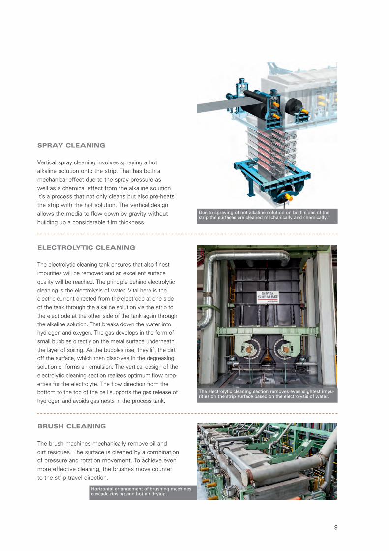
Horizontal arrangement of brushing machines,cascade-rinsing and hot-air drying.
Due to spraying of hot alkaline solution on both sides of thestrip the surfaces are cleaned mechanically and chemically.
The electrolytic cleaning section removes even slightest impu-rities on the strip surface based on the electrolysis of water.
SPRAY CLEANING
Vertical spray cleaning involves spraying a hot alkaline solution onto the strip. That has both amechanical effect due to the spray pressure as well as a chemical effect from the alkaline solution.It’s a process that not only cleans but also pre-heatsthe strip with the hot solution. The vertical designallows the media to flow down by gravity withoutbuilding up a considerable film thickness.
ELECTROLYTIC CLEANING
The electrolytic cleaning tank ensures that also finestimpurities will be removed and an excellent surfacequality will be reached. The principle behind electrolyticcleaning is the electrolysis of water. Vital here is theelectric current directed from the electrode at one sideof the tank through the alkaline solution via the strip tothe electrode at the other side of the tank again throughthe alkaline solution. That breaks down the water intohydrogen and oxygen. The gas develops in the form ofsmall bubbles directly on the metal surface underneaththe layer of soiling. As the bubbles rise, they lift the dirtoff the surface, which then dissolves in the degreasingsolution or forms an emulsion. The vertical design of theelectrolytic cleaning section realizes optimum flow prop-erties for the electrolyte. The flow direction from thebottom to the top of the cell supports the gas release ofhydrogen and avoids gas nests in the process tank.
BRUSH CLEANING
The brush machines mechanically remove oil and dirt residues. The surface is cleaned by a combinationof pressure and rotation movement. To achieve evenmore effective cleaning, the brushes move counter to the strip travel direction.
W7-321E_Tinplate_Neutral 07.12.15 11:17 Seite 9
Tinplate ProductionSMS group
10
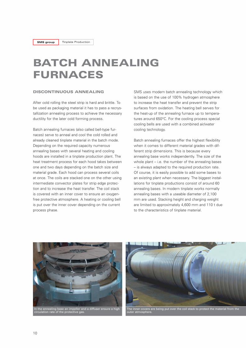
BATCH ANNEALINGFURNACES
SMS uses modern batch annealing technology whichis based on the use of 100% hydrogen atmosphereto increase the heat transfer and prevent the stripsurfaces from oxidation. The heating bell serves forthe heat-up of the annealing furnace up to tempera-tures around 650°C. For the cooling process specialcooling bells are used with a combined air/watercooling technology.
Batch annealing furnaces offer the highest flexibilitywhen it comes to different material grades with dif-ferent strip dimensions. This is because everyannealing base works independently. The size of thewhole plant – i.e. the number of the annealing bases– is always adapted to the required production rate.Of course, it is easily possible to add some bases toan existing plant when necessary. The biggest instal-lations for tinplate productions consist of around 60annealing bases. In modern tinplate works normallyannealing bases with a useable diameter of 2,100mm are used. Stacking height and charging weightare limited to approximately 4,600 mm and 110 t dueto the characteristics of tinplate material.
DISCONTINUOUS ANNEALING
After cold rolling the steel strip is hard and brittle. Tobe used as packaging material it has to pass a recrys-tallization annealing process to achieve the necessaryductility for the later cold forming process.
Batch annealing furnaces (also called bell-type fur-naces) serve to anneal and cool the cold rolled andalready cleaned tinplate material in the batch mode.Depending on the required capacity numerousannealing bases with several heating and coolinghoods are installed in a tinplate production plant. Theheat treatment process for each hood takes betweenone and two days depending on the batch size andmaterial grade. Each hood can process several coilsat once. The coils are stacked one on the other usingintermediate convector plates for strip edge protec-tion and to increase the heat transfer. The coil stackis covered with an inner cover to ensure an oxygen-free protective atmosphere. A heating or cooling bellis put over the inner cover depending on the currentprocess phase.
In the annealing base an impeller and a diffuser ensure a highcirculation rate of the protective gas.
The inner covers are being put over the coil stack to protect the material from theouter atmosphere.
W7-321E_Tinplate_Neutral 07.12.15 11:17 Seite 10
11
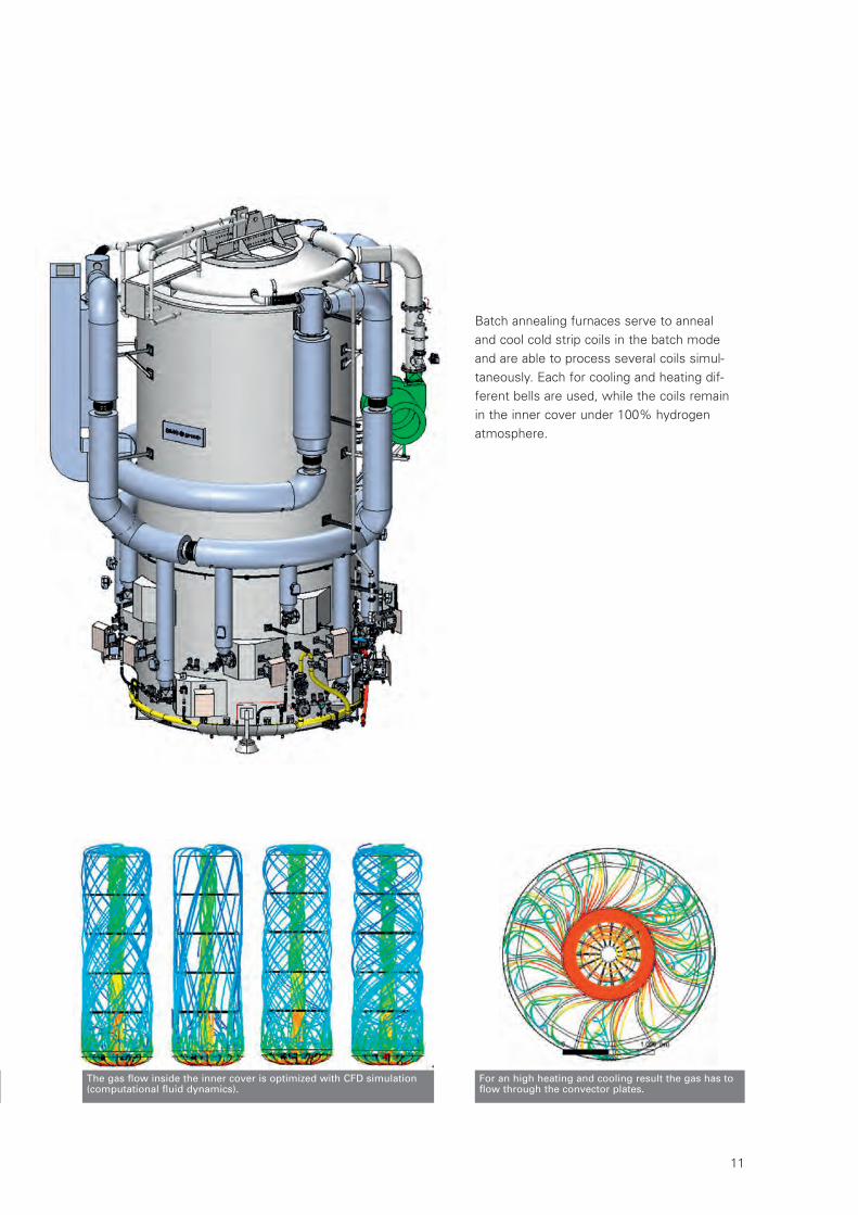
The gas flow inside the inner cover is optimized with CFD simulation(computational fluid dynamics).
For an high heating and cooling result the gas has toflow through the convector plates.
Batch annealing furnaces serve to annealand cool cold strip coils in the batch modeand are able to process several coils simul-taneously. Each for cooling and heating dif-ferent bells are used, while the coils remainin the inner cover under 100% hydrogenatmosphere.
W7-321E_Tinplate_Neutral 07.12.15 11:17 Seite 11
Tinplate ProductionSMS group
12
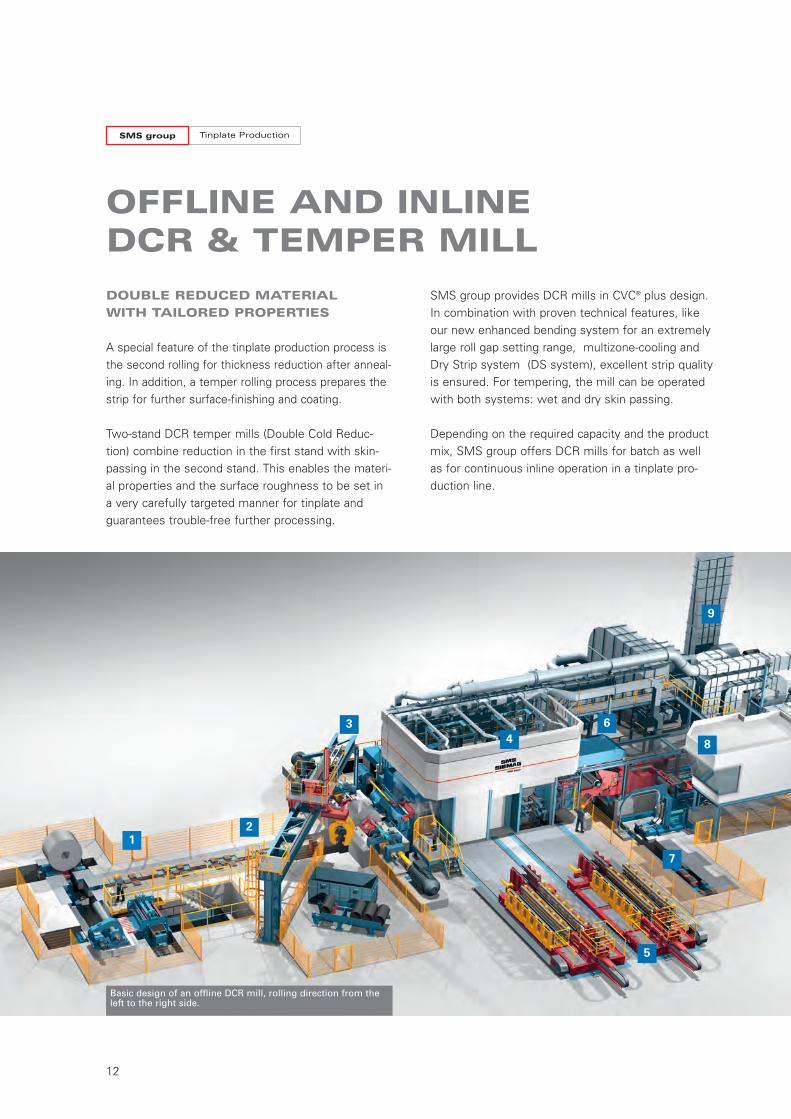
OFFLINE AND INLINE DCR & TEMPER MILL
DOUBLE REDUCED MATERIAL
WITH TAILORED PROPERTIES
A special feature of the tinplate production process isthe second rolling for thickness reduction after anneal-ing. In addition, a temper rolling process prepares thestrip for further surface-finishing and coating.
Two-stand DCR temper mills (Double Cold Reduc-tion) combine reduction in the first stand with skin-passing in the second stand. This enables the materi-al properties and the surface roughness to be set ina very carefully targeted manner for tinplate andguarantees trouble-free further processing.
SMS group provides DCR mills in CVC® plus design.In combination with proven technical features, likeour new enhanced bending system for an extremelylarge roll gap setting range, multizone-cooling andDry Strip system (DS system), excellent strip qualityis ensured. For tempering, the mill can be operatedwith both systems: wet and dry skin passing.
Depending on the required capacity and the productmix, SMS group offers DCR mills for batch as well as for continuous inline operation in a tinplate pro-duction line.
Basic design of an offline DCR mill, rolling direction from theleft to the right side.
12
34
6
7
8
9
5
W7-321E_Tinplate_Neutral 07.12.15 11:17 Seite 12
13
Inline DCR mill and offline DCR mill , both Shougang Jingtang,China
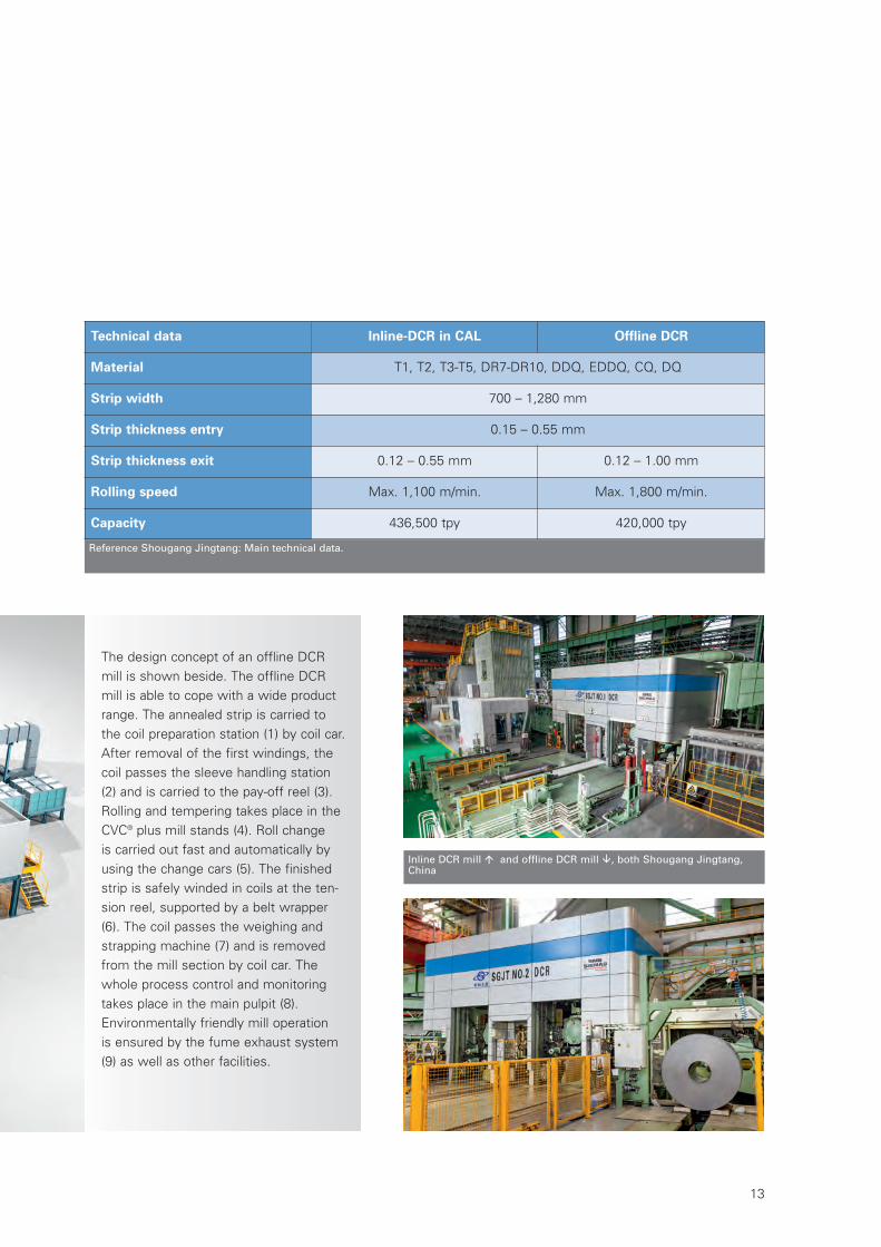
Technical data Inline-DCR in CAL Offline DCR
Material T1, T2, T3-T5, DR7-DR10, DDQ, EDDQ, CQ, DQ
Strip width 700 – 1,280 mm
Strip thickness entry 0.15 – 0.55 mm
Strip thickness exit 0.12 – 0.55 mm 0.12 – 1.00 mm
Rolling speed Max. 1,100 m/min. Max. 1,800 m/min.
Capacity 436,500 tpy 420,000 tpy
The design concept of an offline DCRmill is shown beside. The offline DCRmill is able to cope with a wide productrange. The annealed strip is carried tothe coil preparation station (1) by coil car.After removal of the first windings, thecoil passes the sleeve handling station(2) and is carried to the pay-off reel (3).Rolling and tempering takes place in theCVC® plus mill stands (4). Roll change is carried out fast and automatically byusing the change cars (5). The finishedstrip is safely winded in coils at the ten-sion reel, supported by a belt wrapper(6). The coil passes the weighing andstrapping machine (7) and is removedfrom the mill section by coil car. Thewhole process control and monitoringtakes place in the main pulpit (8). Environmentally friendly mill operation is ensured by the fume exhaust system(9) as well as other facilities.
Reference Shougang Jingtang: Main technical data.
W7-321E_Tinplate_Neutral 07.12.15 11:17 Seite 13
Tinplate ProductionSMS group
14
FAST PROCESSING OF THIN STRIPS
The annealing of the cleaned strip followed byreduction and surface treatment provides the mate-rial in the annealing line with the material and sur-face properties necessary for tinning and subse-quent processing.
The very thin material (up to 0.1 mm) is processedat very high speeds (up to 750 m/min). The productrange comprises all grades and also contains thequalities T2.5, T5 and DR 10, which cannot be pro-duced by batch annealing.
TINPLATE CONTINUOUSANNEALING LINE
The strip cleaning section has efficient process com-ponents including spray and electrolytic cleaningcells.
The radiant tube furnace is the heart of the plant and is recognized for its low resource consumption.Due to precise furnace control, the process followsthe specified annealing curve exactly.
Two 4-high skin-pass mill stands are integrated forpost-treatment. The first skin-pass mill stand adjuststhe mechanical-engineering characteristics of thestrip by a thickness reduction. The second creates a defined strip surface structure.
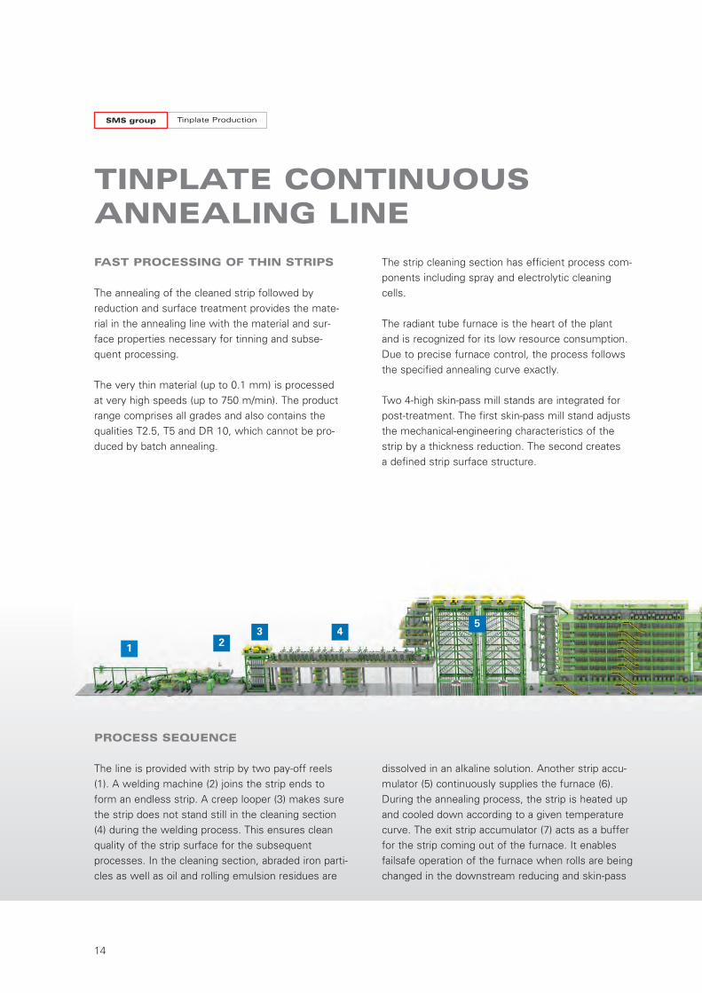
PROCESS SEQUENCE
The line is provided with strip by two pay-off reels(1). A welding machine (2) joins the strip ends toform an endless strip. A creep looper (3) makes surethe strip does not stand still in the cleaning section(4) during the welding process. This ensures cleanquality of the strip surface for the subsequentprocesses. In the cleaning section, abraded iron parti-cles as well as oil and rolling emulsion residues are
dissolved in an alkaline solution. Another strip accu-mulator (5) continuously supplies the furnace (6).During the annealing process, the strip is heated upand cooled down according to a given temperaturecurve. The exit strip accumulator (7) acts as a bufferfor the strip coming out of the furnace. It enablesfailsafe operation of the furnace when rolls are beingchanged in the downstream reducing and skin-pass
1 23 4
5
W7-321E_Tinplate_Neutral 07.12.15 11:17 Seite 14
15
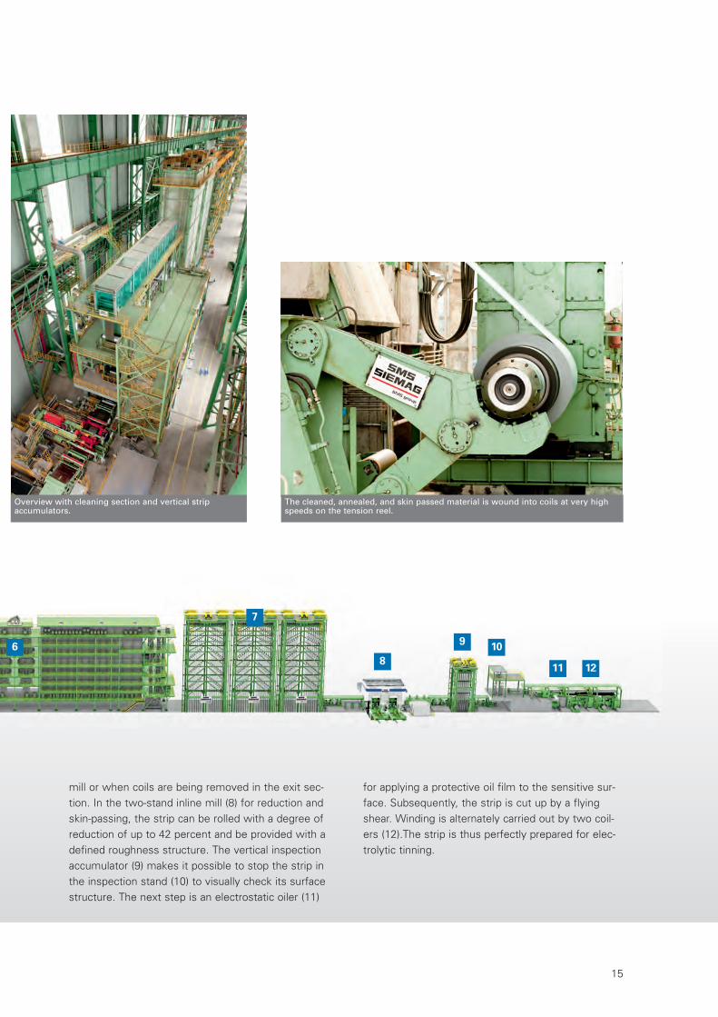
Overview with cleaning section and vertical strip accumulators.
mill or when coils are being removed in the exit sec-tion. In the two-stand inline mill (8) for reduction andskin-passing, the strip can be rolled with a degree ofreduction of up to 42 percent and be provided with adefined roughness structure. The vertical inspectionaccumulator (9) makes it possible to stop the strip inthe inspection stand (10) to visually check its surfacestructure. The next step is an electrostatic oiler (11)
6
7
8
9 10
11 12
for applying a protective oil film to the sensitive sur-face. Subsequently, the strip is cut up by a flyingshear. Winding is alternately carried out by two coil-ers (12).The strip is thus perfectly prepared for elec-trolytic tinning.
The cleaned, annealed, and skin passed material is wound into coils at very highspeeds on the tension reel.
W7-321E_Tinplate_Neutral 07.12.15 11:17 Seite 15
Tinplate ProductionSMS group
16
DREVER RADIANT TUBE FURNACE
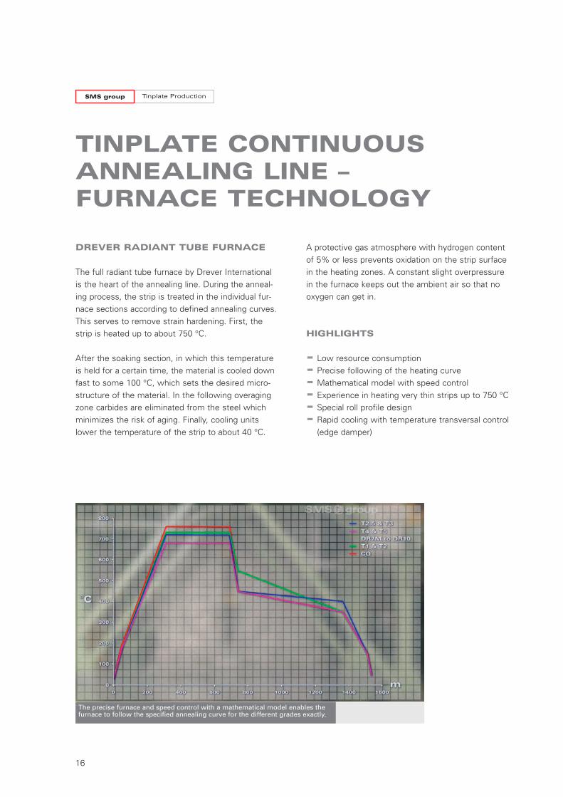
The full radiant tube furnace by Drever Internationalis the heart of the annealing line. During the anneal-ing process, the strip is treated in the individual fur-nace sections according to defined annealing curves. This serves to remove strain hardening. First, thestrip is heated up to about 750 °C.
After the soaking section, in which this temperatureis held for a certain time, the material is cooled downfast to some 100 °C, which sets the desired micro -structure of the material. In the following overagingzone carbides are eliminated from the steel whichminimizes the risk of aging. Finally, cooling unitslower the temperature of the strip to about 40 °C.
TINPLATE CONTINUOUSANNEALING LINE –FURNACE TECHNOLOGY
A protective gas atmosphere with hydrogen contentof 5% or less prevents oxidation on the strip surfacein the heating zones. A constant slight overpressurein the furnace keeps out the ambient air so that nooxygen can get in.
HIGHLIGHTS
- Low resource consumption
- Precise following of the heating curve
- Mathematical model with speed control
- Experience in heating very thin strips up to 750 °C
- Special roll profile design
- Rapid cooling with temperature transversal control(edge damper)
The precise furnace and speed control with a mathematical model enables the furnace to follow the specified annealing curve for the different grades exactly.
W7-321E_Tinplate_Neutral 07.12.15 11:17 Seite 16
17
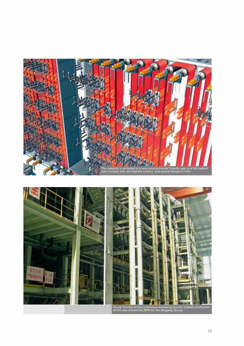
The material is annealed in a very environmental friendly way in a full-radianttube furnace with atmosphere control and special designed rolls.
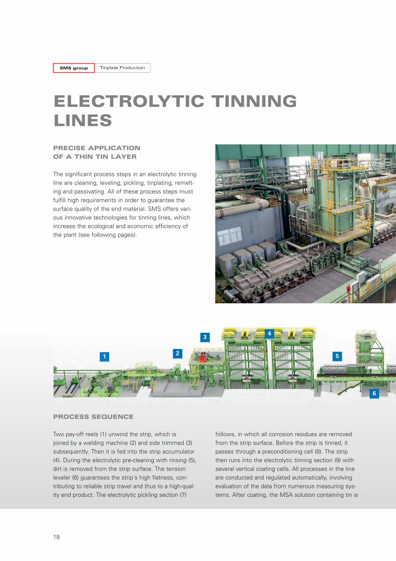
Drever-furnace in the continuous annealing line for tinplate productionwhich was erected by SMS for the Shagang Group.
W7-321E_Tinplate_Neutral 07.12.15 11:17 Seite 17
1 2
34
6
75
Tinplate ProductionSMS group
18
PRECISE APPLICATION
OF A THIN TIN LAYER
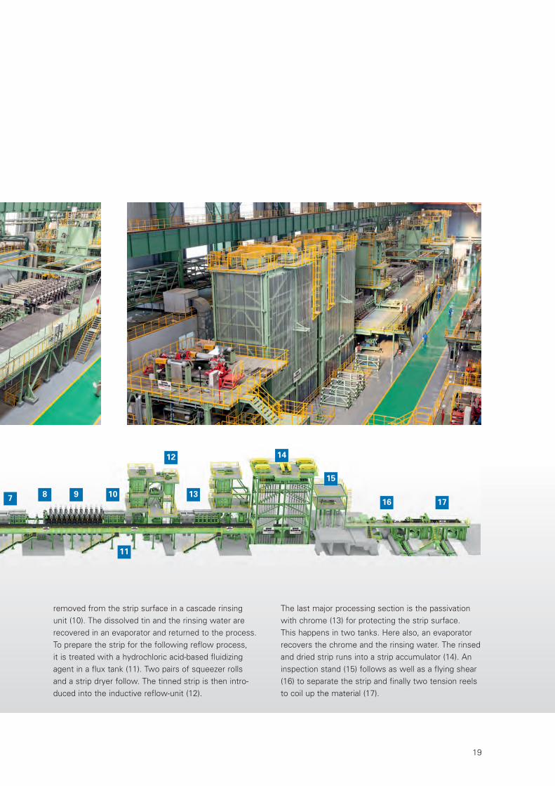
The significant process steps in an electrolytic tinningline are cleaning, leveling, pickling, tinplating, remelt-ing and passivating. All of these process steps mustfulfill high requirements in order to guarantee thesurface quality of the end material. SMS offers vari-ous innovative technologies for tinning lines, whichincrease the ecological and economic efficiency ofthe plant (see following pages).
ELECTROLYTIC TINNINGLINES
PROCESS SEQUENCE
Two pay-off reels (1) unwind the strip, which is joined by a welding machine (2) and side trimmed (3)subsequently. Then it is fed into the strip accumulator(4). During the electrolytic pre-cleaning with rinsing (5),dirt is removed from the strip surface. The tension leveler (6) guarantees the strip's high flatness, con-tributing to reliable strip travel and thus to a high-qual -ity end product. The electrolytic pickling section (7)
follows, in which all corrosion residues are removedfrom the strip surface. Before the strip is tinned, itpasses through a preconditioning cell (8). The stripthen runs into the electrolytic tinning section (9) withseveral vertical coating cells. All processes in the lineare conducted and regulated automatically, involvingevaluation of the data from numerous measuring sys-tems. After coating, the MSA solution containing tin is
W7-321E_Tinplate_Neutral 07.12.15 11:18 Seite 18
7 8 9 10
11
12
13
14
15
16 17
19
removed from the strip surface in a cascade rinsingunit (10). The dissolved tin and the rinsing water arerecovered in an evaporator and returned to the process.To prepare the strip for the following reflow process, it is treated with a hydrochloric acid-based fluidizingagent in a flux tank (11). Two pairs of squeezer rollsand a strip dryer follow. The tinned strip is then intro-duced into the inductive reflow-unit (12).
The last major processing section is the passivationwith chrome (13) for protecting the strip surface. This happens in two tanks. Here also, an evaporatorrecovers the chrome and the rinsing water. The rinsedand dried strip runs into a strip accumulator (14). Aninspection stand (15) follows as well as a flying shear(16) to separate the strip and finally two tension reelsto coil up the material (17).
W7-321E_Tinplate_Neutral 07.12.15 11:18 Seite 19
Tinplate ProductionSMS group
20
ELECTROLYTIC TINNING WITH
SOLUBLE ANODES
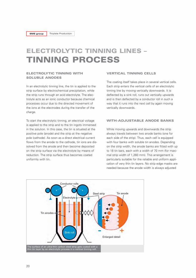
In an electrolytic tinning line, the tin is applied to thestrip surface by electrochemical precipitation, whilethe strip runs through an acid electrolyte. The elec-trolyte acts as an ionic conductor because chemicalprocesses occur due to the directed movement ofthe ions at the electrodes during the transfer of thecharge.
To start the electrolytic tinning, an electrical voltageis applied to the strip and to the tin ingots immersedin the solution. In this case, the tin is situated at thepositive pole (anode) and the strip at the negativepole (cathode). As soon as a direct electrical currentflows from the anode to the cathode, tin ions are dis-solved from the anode and then become depositedon the strip surface via the electrolyte by means ofreduction. The strip surface thus becomes coateduniformly with tin.
ELECTROLYTIC TINNING LINES –
TINNING PROCESS
The surface of an ultra-thin carbon steel strip gets coated with athin tin layer by an electrolytic process in a vertical tinning cell.
VERTICAL TINNING CELLS
The coating itself takes place in several vertical cells.Each strip enters the vertical cells of an electrolytictinning line by moving vertically downwards. It isdeflected by a sink roll, runs out vertically upwardsand is then deflected by a conductor roll in such away that it runs into the next cell by again movingvertically downwards.
WITH-ADJUSTABLE ANODE BANKS
While moving upwards and downwards the stripalways travels between two anode banks (one foreach side of the strip). Thus, each cell is equippedwith four banks with soluble tin anodes. Dependingon the strip width, the anode banks are fitted with upto 18 tin bars, each with a width of 70 mm (for maxi-mal strip width of 1,260 mm). This arrangement isparticularly suitable for the reliable and uniform appli-cation of very thin tin layers. No strip edge masks areneeded because the anode width is always adjusted
Tin anode
Tin anodes
Steel strip
Sink roll
Enlarged detail
Conductor rolls
Electrolyte
W7-321E_Tinplate_Neutral 07.12.15 11:37 Seite 20
21
to the strip width. In one cell, one pair of anode banksis equipped with insoluble anodes, thus enablingcompensation of any excessive dissolved tin. Thelocation at which the insoluble anodes can be insert-ed is variable.
PRECISE APPLICATION
OF THIN LAYERS
The thickness of the tin layer can very easily be adjust-ed via the magnitude of the electric current and viaprocessing time, which depends directly on the stripspeed. Depending on the strip width and speed, thequantity of current is set in conformity with Faraday'slaw such as to enable the desired layer thickness to beapplied. Each anode stand has its own rectifier, whichis connected with the anode carrier and with the con-ductor roll. Very thin layers of just a few µm can thusbe applied very precisely. Depending on requirements,differing layer thicknesses can also be applied to thestrip sides. Altogether, the material consumption isextremely low thanks to the very precise application
of very thin layers, which proves to be an essentialadvantage of the process over the hitherto customaryhot-dip tinning, i.e. coating by immersion in liquid tin.
ELECTROLYTE WITH HIGH
CONDUCTIVITY
Owing to its higher conductivity, methanesulfonateacid (MSA) is used as the electrolyte in the tinningtanks of SMS lines, resulting in reduced energy costsand in the achievement of greater flexibility due to the higher current density. Since the MSA electrolyteis for the most part biodegradable, it can be disposedof in an environment-friendly manner.
Each tinning cell is equipped with four banks with soluble tin anodesand the width of the anode banks is always adjusted to the strip width.
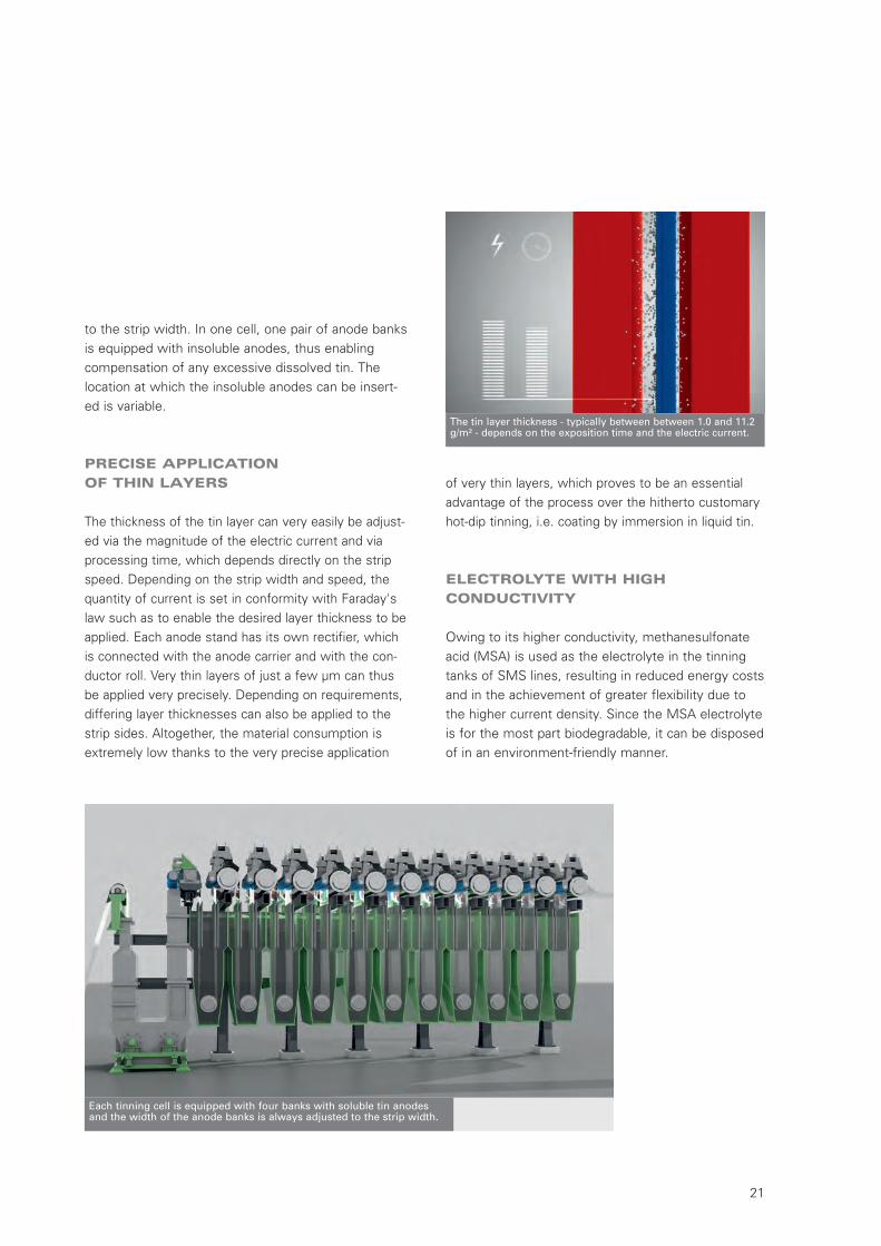
The tin layer thickness - typically between between 1.0 and 11.2g/m² - depends on the exposition time and the electric current.
W7-321E_Tinplate_Neutral 07.12.15 11:18 Seite 21
Tinplate ProductionSMS group
22
HIGH COST EFFICIENCY THROUGH
THE USE OF SOLUBLE ANODES
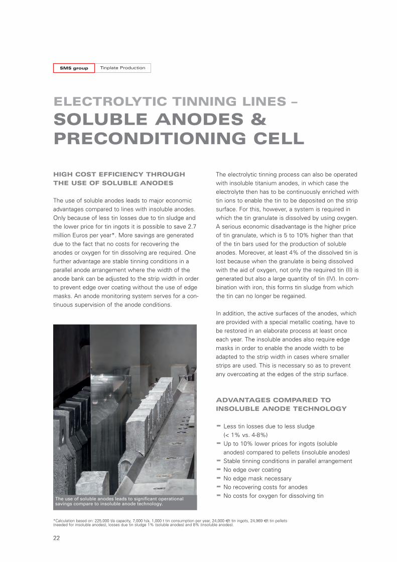
The use of soluble anodes leads to major economicadvantages compared to lines with insoluble anodes.Only because of less tin losses due to tin sludge andthe lower price for tin ingots it is possible to save 2.7million Euros per year*. More savings are generateddue to the fact that no costs for recovering theanodes or oxygen for tin dissolving are required. Onefurther advantage are stable tinning conditions in aparallel anode arrangement where the width of theanode bank can be adjusted to the strip width in orderto prevent edge over coating without the use of edgemasks. An anode monitoring system serves for a con-tinuous supervision of the anode conditions.
ELECTROLYTIC TINNING LINES –
SOLUBLE ANODES & PRECONDITIONING CELL
The electrolytic tinning process can also be operatedwith insoluble titanium anodes, in which case theelectrolyte then has to be continuously enriched withtin ions to enable the tin to be deposited on the stripsurface. For this, however, a system is required inwhich the tin granulate is dissolved by using oxygen.A serious economic disadvantage is the higher priceof tin granulate, which is 5 to 10% higher than thatof the tin bars used for the production of solubleanodes. Moreover, at least 4% of the dissolved tin islost because when the granulate is being dissolvedwith the aid of oxygen, not only the required tin (II) isgenerated but also a large quantity of tin (IV). In com-bination with iron, this forms tin sludge from whichthe tin can no longer be regained.
In addition, the active surfaces of the anodes, whichare provided with a special metallic coating, have tobe restored in an elaborate process at least onceeach year. The insoluble anodes also require edgemasks in order to enable the anode width to beadapted to the strip width in cases where smallerstrips are used. This is necessary so as to preventany overcoating at the edges of the strip surface.
ADVANTAGES COMPARED TO
INSOLUBLE ANODE TECHNOLOGY
- Less tin losses due to less sludge (< 1% vs. 4-8%)
- Up to 10% lower prices for ingots (solubleanodes) compared to pellets (insoluble anodes)
- Stable tinning conditions in parallel arrangement
- No edge over coating
- No edge mask necessary
- No recovering costs for anodes
- No costs for oxygen for dissolving tinThe use of soluble anodes leads to significant operational savings compare to insoluble anode technology.
*Calculation based on: 225,000 t/a capacity, 7,000 h/a, 1,000 t tin consumption per year, 24,000 €/t tin ingots, 24,969 €/t tin pellets(needed for insoluble anodes), losses due tin sludge 1% (soluble anodes) and 8% (insoluble anodes).
W7-321E_Tinplate_Neutral 07.12.15 11:18 Seite 22
23
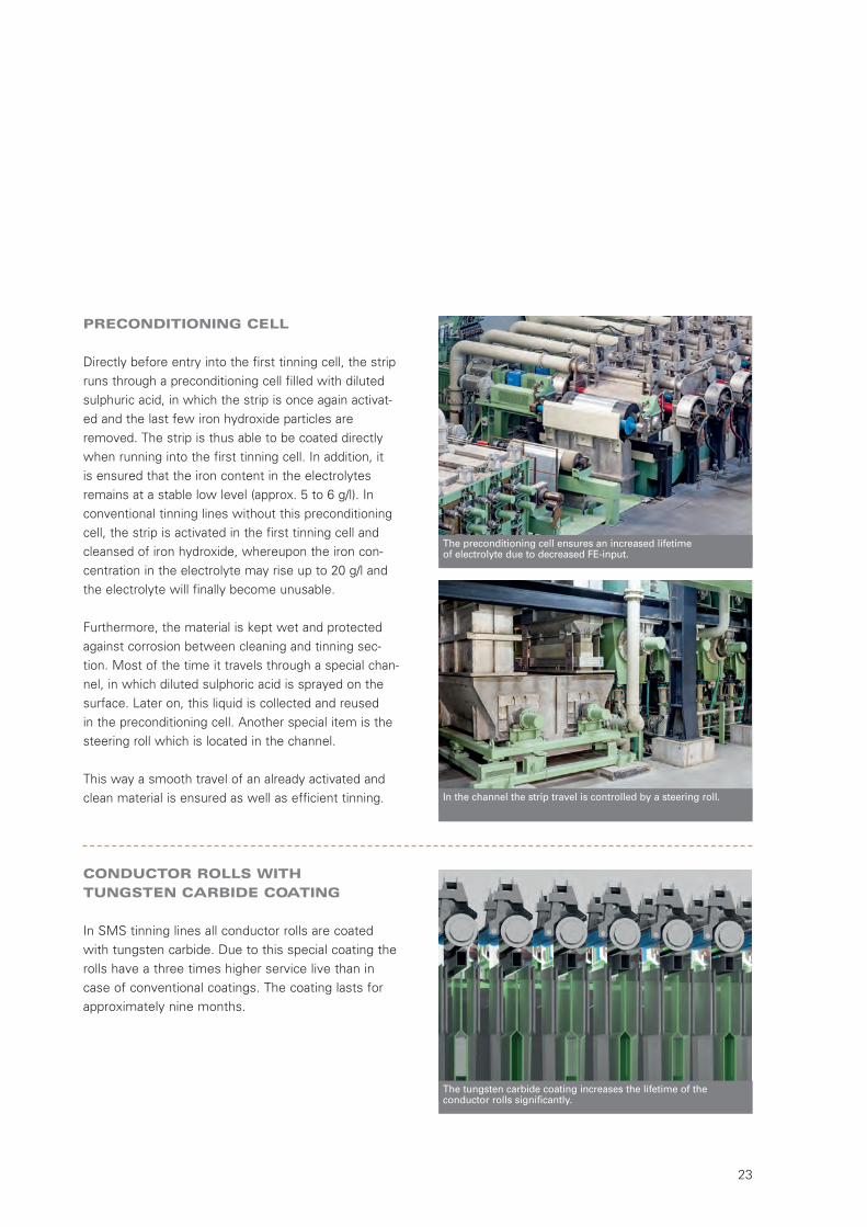
PRECONDITIONING CELL
Directly before entry into the first tinning cell, the stripruns through a preconditioning cell filled with dilutedsulphuric acid, in which the strip is once again activat-ed and the last few iron hydroxide particles areremoved. The strip is thus able to be coated directlywhen running into the first tinning cell. In addition, it is ensured that the iron content in the electrolytesremains at a stable low level (approx. 5 to 6 g/l). Inconventional tinning lines without this preconditioningcell, the strip is activated in the first tinning cell andcleansed of iron hydroxide, whereupon the iron con-centration in the electrolyte may rise up to 20 g/l andthe electrolyte will finally become unusable.
Furthermore, the material is kept wet and protectedagainst corrosion between cleaning and tinning sec-tion. Most of the time it travels through a special chan-nel, in which diluted sulphoric acid is sprayed on thesurface. Later on, this liquid is collected and reused in the preconditioning cell. Another special item is thesteering roll which is located in the channel.
This way a smooth travel of an already activated andclean material is ensured as well as efficient tinning.
The tungsten carbide coating increases the lifetime of the conductor rolls significantly.
In the channel the strip travel is controlled by a steering roll.
CONDUCTOR ROLLS WITH
TUNGSTEN CARBIDE COATING
In SMS tinning lines all conductor rolls are coatedwith tungsten carbide. Due to this special coating therolls have a three times higher service live than incase of conventional coatings. The coating lasts forapproximately nine months.
The preconditioning cell ensures an increased lifetime of electrolyte due to decreased FE-input.
W7-321E_Tinplate_Neutral 07.12.15 11:18 Seite 23
Tinplate ProductionSMS group
24
ELECTROLYTIC TINNING LINES –
THICKNESS CONTROLAND ANODE MONITORING
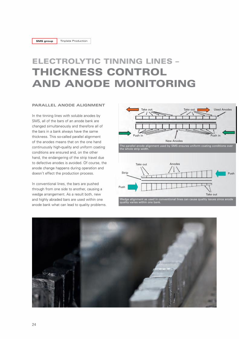
The parallel anode alignment used by SMS ensures uniform coating conditions overthe whole strip width.
PARALLEL ANODE ALIGNMENT
In the tinning lines with soluble anodes bySMS, all of the bars of an anode bank arechanged simultaneously and therefore all ofthe bars in a bank always have the samethickness. This so-called parallel alignment of the anodes means that on the one handcontinuously high-quality and uniform coatingconditions are ensured and, on the otherhand, the endangering of the strip travel dueto defective anodes is avoided. Of course, theanode change happens during operation anddoesn’t effect the production process.
In conventional lines, the bars are pushedthrough from one side to another, causing awedge arrangement. As a result both, newand highly abraded bars are used within oneanode bank what can lead to quality problems.
Wedge alignment as used in conventional lines can cause quality issues since anodequality varies within one bank.
Take out
Push in
Push
Push
Push in
Take out
Take out
Take out
Strip
Used Anodes
New Anodes
Anodes
W7-321E_Tinplate_Neutral 07.12.15 11:18 Seite 24
25
CLOSED-LOOP LAYER THICKNESS
CONTROL
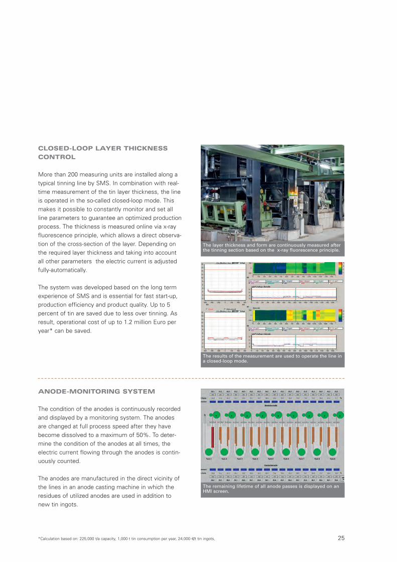
More than 200 measuring units are installed along atypical tinning line by SMS. In combination with real-time measurement of the tin layer thickness, the lineis operated in the so-called closed-loop mode. Thismakes it possible to constantly monitor and set allline parameters to guarantee an optimized productionprocess. The thickness is measured online via x-rayfluorescence principle, which allows a direct observa-tion of the cross-section of the layer. Depending onthe required layer thickness and taking into accountall other parameters the electric current is adjustedfully-automatically.
The system was developed based on the long termexperience of SMS and is essential for fast start-up,production efficiency and product quality. Up to 5percent of tin are saved due to less over tinning. Asresult, operational cost of up to 1.2 million Euro peryear* can be saved.
The layer thickness and form are continuously measured after
the tinning section based on the x-ray fluorescence principle.
The results of the measurement are used to operate the line ina closed-loop mode.
The remaining lifetime of all anode passes is displayed on anHMI screen.
*Calculation based on: 225,000 t/a capacity, 1,000 t tin consumption per year, 24,000 €/t tin ingots,
ANODE-MONITORING SYSTEM
The condition of the anodes is continuously recordedand displayed by a monitoring system. The anodesare changed at full process speed after they havebecome dissolved to a maximum of 50%. To deter-mine the condition of the anodes at all times, theelectric current flowing through the anodes is contin-uously counted.
The anodes are manufactured in the direct vicinity ofthe lines in an anode casting machine in which theresidues of utilized anodes are used in addition tonew tin ingots.
W7-321E_Tinplate_Neutral 07.12.15 11:18 Seite 25
Tinplate ProductionSMS group
26
ELECTROLYTIC TINNING LINES –
REFLOW TECHNOLOGY
VERTICALLY ADJUSTABLE
REFLOW UNIT
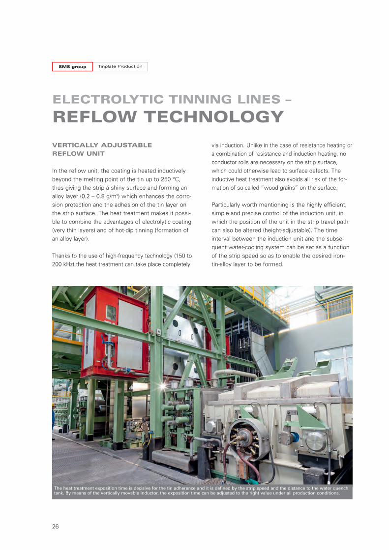
In the reflow unit, the coating is heated inductivelybeyond the melting point of the tin up to 250 °C,thus giving the strip a shiny surface and forming analloy layer (0.2 – 0.8 g/m2) which enhances the corro-sion protection and the adhesion of the tin layer onthe strip surface. The heat treatment makes it possi-ble to combine the advantages of electrolytic coating(very thin layers) and of hot-dip tinning (formation ofan alloy layer).
Thanks to the use of high-frequency technology (150 to200 kHz) the heat treatment can take place completely
via induction. Unlike in the case of resistance heating ora combination of resistance and induction heating, noconductor rolls are necessary on the strip surface,which could otherwise lead to surface defects. Theinductive heat treatment also avoids all risk of the for-mation of so-called “wood grains” on the surface.
Particularly worth mentioning is the highly efficient,simple and precise control of the induction unit, inwhich the position of the unit in the strip travel pathcan also be altered (height-adjustable). The timeinterval between the induction unit and the subse-quent water-cooling system can be set as a functionof the strip speed so as to enable the desired iron-tin-alloy layer to be formed.
The heat treatment exposition time is decisive for the tin adherence and it is defined by the strip speed and the distance to the water quenchtank. By means of the vertically movable inductor, the exposition time can be adjusted to the right value under all production conditions.
W7-321E_Tinplate_Neutral 07.12.15 11:18 Seite 26
27
The strip it is provided with a hydrochloric acid-based fluidizing agentin a flux tank.
After heat treatment in the induction unit a water quench cools downthe material in a controlled way.
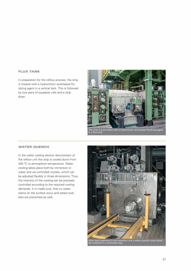
FLUX TANK
In preparation for the reflow process, the stripis treated with a hydrochloric acid-based flu-idizing agent in a vertical tank. This is followedby two pairs of squeezer rolls and a stripdryer.
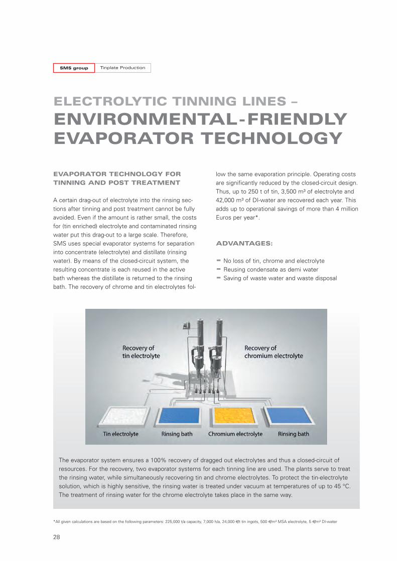
WATER QUENCH
In the water cooling section downstream ofthe reflow unit the strip is cooled down from250 °C to atmosphere temperature. Watercooling takes place both by immersion inwater and via controlled nozzles, which canbe adjusted flexibly in three dimensions. Thus,the intensity of the cooling can be preciselycontrolled according to the required coolingdemands. It is made sure, that no water-stains on the surface occur and steam bub-bles are prevented as well.
W7-321E_Tinplate_Neutral 07.12.15 11:18 Seite 27
Tinplate ProductionSMS group
28
EVAPORATOR TECHNOLOGY FOR
TINNING AND POST TREATMENT
A certain drag-out of electrolyte into the rinsing sec-tions after tinning and post treatment cannot be fullyavoided. Even if the amount is rather small, the costsfor (tin enriched) electrolyte and contaminated rinsingwater put this drag-out to a large scale. Therefore,SMS uses special evaporator systems for separationinto concentrate (electrolyte) and distillate (rinsingwater). By means of the closed-circuit system, theresulting concentrate is each reused in the activebath whereas the distillate is returned to the rinsingbath. The recovery of chrome and tin electrolytes fol-
ELECTROLYTIC TINNING LINES –
ENVIRONMENTAL-FRIENDLYEVAPORATOR TECHNOLOGY
low the same evaporation principle. Operating costsare significantly reduced by the closed-circuit design.Thus, up to 250 t of tin, 3,500 m³ of electrolyte and42,000 m³ of DI-water are recovered each year. Thisadds up to operational savings of more than 4 millionEuros per year*.
ADVANTAGES:
- No loss of tin, chrome and electrolyte
- Reusing condensate as demi water
- Saving of waste water and waste disposal
The evaporator system ensures a 100% recovery of dragged out electrolytes and thus a closed-circuit ofresources. For the recovery, two evaporator systems for each tinning line are used. The plants serve to treatthe rinsing water, while simultaneously recovering tin and chrome electrolytes. To protect the tin-electrolytesolution, which is highly sensitive, the rinsing water is treated under vacuum at temperatures of up to 45 °C.The treatment of rinsing water for the chrome electrolyte takes place in the same way.
*All given calculations are based on the following parameters: 225,000 t/a capacity, 7,000 h/a, 24,000 €/t tin ingots, 500 €/m³ MSA electrolyte, 5 €/m³ DI-water
W7-321E_Tinplate_Neutral 07.12.15 11:18 Seite 28
29
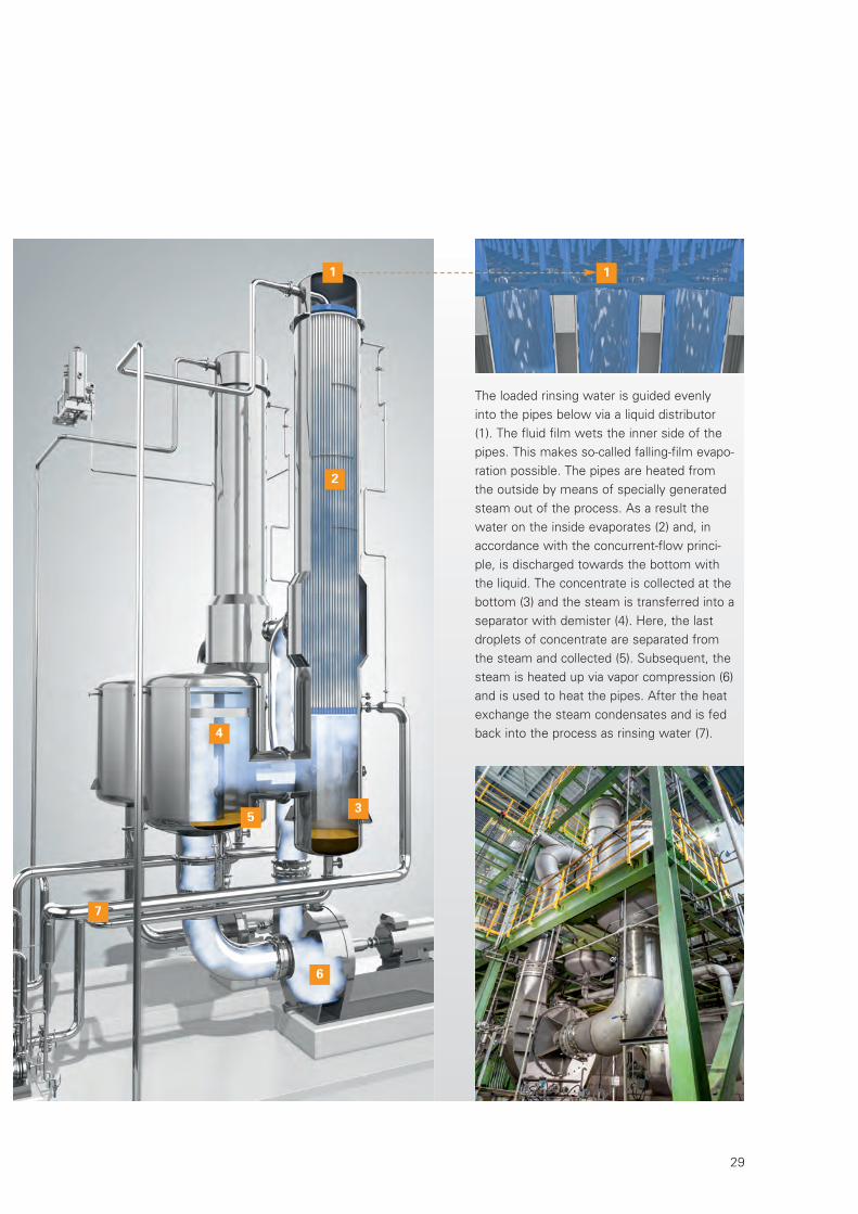
The loaded rinsing water is guided evenlyinto the pipes below via a liquid distributor(1). The fluid film wets the inner side of thepipes. This makes so-called falling-film evapo-ration possible. The pipes are heated fromthe outside by means of specially generatedsteam out of the process. As a result thewater on the inside evaporates (2) and, inaccordance with the concurrent-flow princi-ple, is discharged towards the bottom withthe liquid. The concentrate is collected at thebottom (3) and the steam is transferred into aseparator with demister (4). Here, the lastdroplets of concentrate are separated fromthe steam and collected (5). Subsequent, thesteam is heated up via vapor compression (6)and is used to heat the pipes. After the heatexchange the steam condensates and is fedback into the process as rinsing water (7).
1 1
2
3
4
6
7
5
W7-321E_Tinplate_Neutral 07.12.15 11:18 Seite 29
Tinplate ProductionSMS group
30
ANODE CASTER
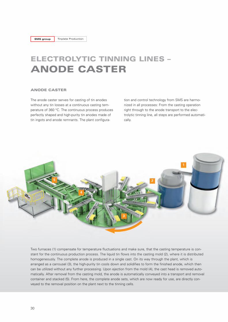
The anode caster serves for casting of tin anodeswithout any tin losses at a continuous casting tem-perature of 360 °C. The continuous process producesperfectly shaped and high-purity tin anodes made oftin ingots and anode remnants. The plant configura-
ELECTROLYTIC TINNING LINES –
ANODE CASTER
tion and control technology from SMS are harmo-nized in all processes: From the casting operationright through to the anode transport to the elec-trolytic tinning line, all steps are performed automati-cally.
Two furnaces (1) compensate for temperature fluctuations and make sure, that the casting temperature is con-stant for the continuous production process. The liquid tin flows into the casting mold (2), where it is distributedhomogeneously. The complete anode is produced in a single cast. On its way through the plant, which isarranged as a carrousel (3), the high-purity tin cools down and solidifies to form the finished anode, which thencan be utilized without any further processing. Upon ejection from the mold (4), the cast head is removed auto-matically. After removal from the casting mold, the anode is automatically conveyed into a transport and removalcontainer and stacked (5). From here, the complete anode sets, which are now ready for use, are directly con-veyed to the removal position on the plant next to the tinning cells.
1
2
3
4
5
W7-321E_Tinplate_Neutral 07.12.15 11:18 Seite 30
31
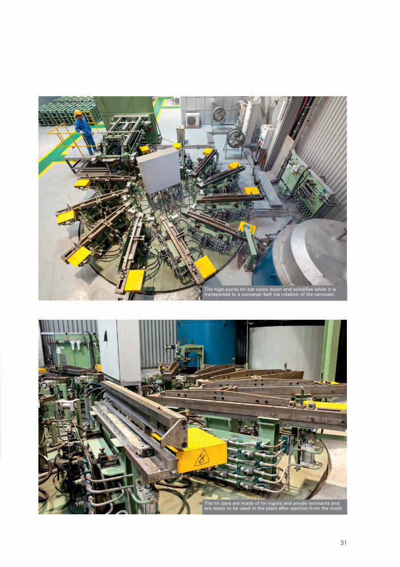
The tin bars are made of tin ingots and anode remnants andare ready to be used in the plant after ejection from the mold.
The high-purity tin bar cools down and solidifies while it istransported to a conveyer belt via rotation of the carousel.
W7-321E_Tinplate_Neutral 07.12.15 11:18 Seite 31
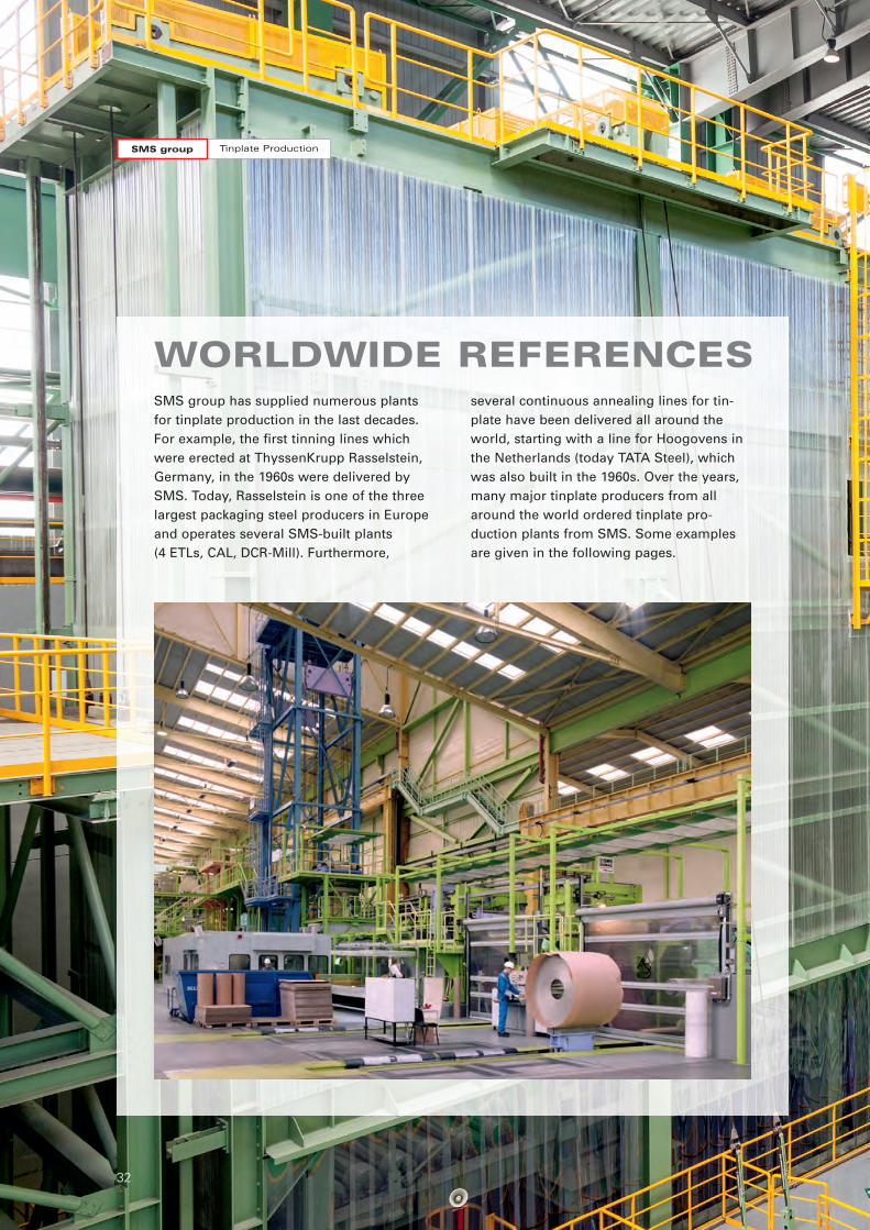
SMS group has supplied numerous plants for tinplate production in the last decades.For example, the first tinning lines whichwere erected at ThyssenKrupp Rasselstein,Germany, in the 1960s were delivered bySMS. Today, Rasselstein is one of the threelargest packaging steel producers in Europeand operates several SMS-built plants (4 ETLs, CAL, DCR-Mill). Furthermore,
several continuous annealing lines for tin-plate have been delivered all around theworld, starting with a line for Hoogovens inthe Netherlands (today TATA Steel), whichwas also built in the 1960s. Over the years,many major tinplate producers from allaround the world ordered tinplate pro -duction plants from SMS. Some examplesare given in the following pages.
WORLDWIDE REFERENCES
Tinplate ProductionSMS group
32
W7-321E_Tinplate_Neutral 07.12.15 11:18 Seite 32
33
W7-321E_Tinplate_Neutral 07.12.15 11:18 Seite 33
Tinplate ProductionSMS group
34
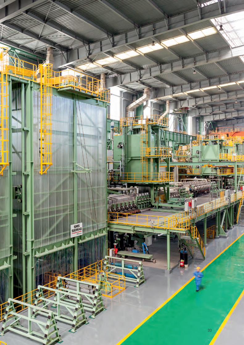
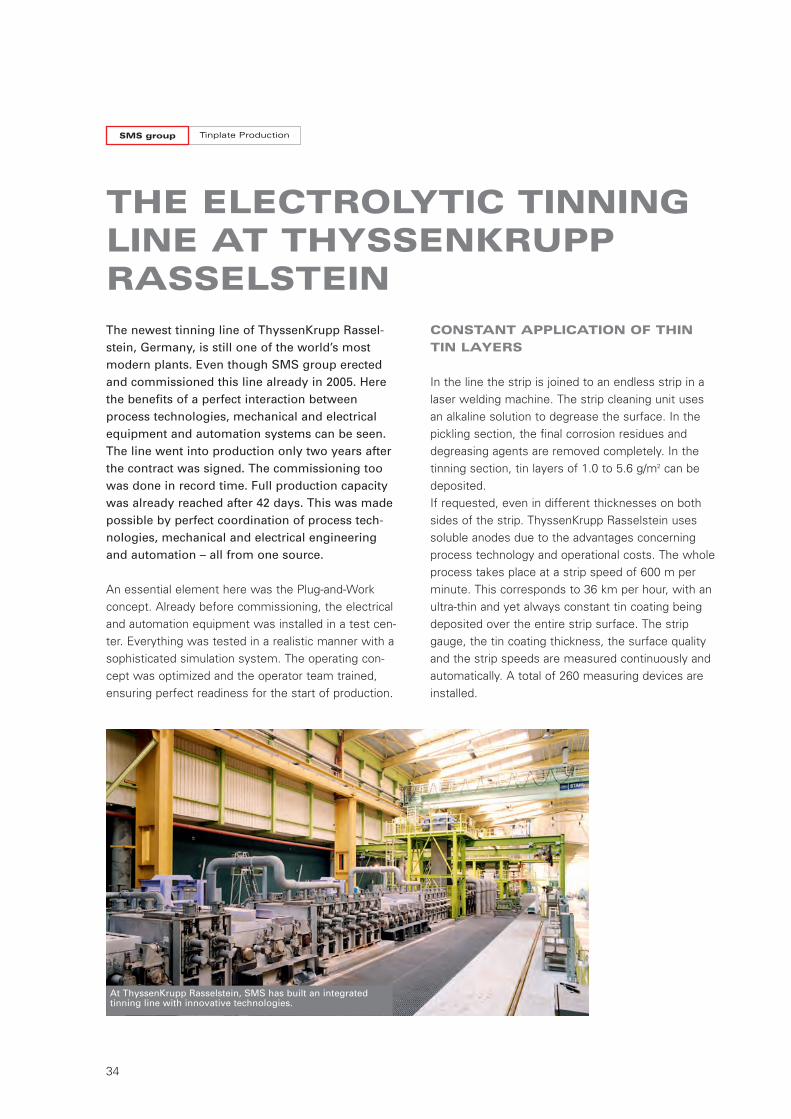
The newest tinning line of ThyssenKrupp Rassel-stein, Germany, is still one of the world’s mostmodern plants. Even though SMS group erectedand commissioned this line already in 2005. Herethe benefits of a perfect interaction betweenprocess technologies, mechanical and electricalequipment and automation systems can be seen.The line went into production only two years afterthe contract was signed. The commissioning toowas done in record time. Full production capacitywas already reached after 42 days. This was madepossible by perfect coordination of process tech-nologies, mechanical and electrical engineeringand automation – all from one source.
An essential element here was the Plug-and-Workconcept. Already before commissioning, the electricaland automation equipment was installed in a test cen-ter. Everything was tested in a realistic manner with asophisticated simulation system. The operating con-cept was optimized and the operator team trained,ensuring perfect readiness for the start of production.
THE ELECTROLYTIC TINNINGLINE AT THYSSENKRUPPRASSELSTEIN
CONSTANT APPLICATION OF THIN
TIN LAYERS
In the line the strip is joined to an endless strip in alaser welding machine. The strip cleaning unit usesan alkaline solution to degrease the surface. In thepickling section, the final corrosion residues anddegreasing agents are removed completely. In thetinning section, tin layers of 1.0 to 5.6 g/m2 can bedeposited. If requested, even in different thicknesses on bothsides of the strip. ThyssenKrupp Rasselstein usessoluble anodes due to the advantages concerningprocess technology and operational costs. The wholeprocess takes place at a strip speed of 600 m perminute. This corresponds to 36 km per hour, with anultra-thin and yet always constant tin coating beingdeposited over the entire strip surface. The stripgauge, the tin coating thickness, the surface qualityand the strip speeds are measured continuously andautomatically. A total of 260 measuring devices areinstalled.
At ThyssenKrupp Rasselstein, SMS has built an integrated tinning line with innovative technologies.
W7-321E_Tinplate_Neutral 07.12.15 11:18 Seite 34
35
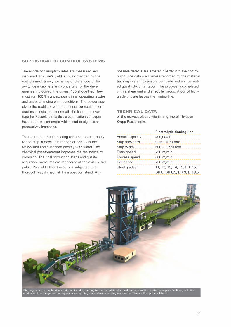
Starting with the mechanical equipment and extending to the complete electrical and automation systems, supply facilities, pollutioncontrol and acid regeneration systems, everything comes from one single source at ThyssenKrupp Rasselstein.
SOPHISTICATED CONTROL SYSTEMS
The anode consumption rates are measured and displayed. The line’s yield is thus optimized by thewell-planned, timely exchange of the anodes. Theswitchgear cabinets and converters for the driveengineering control the drives, 185 altogether. Theymust run 100% synchronously in all operating modesand under changing plant conditions. The power sup-ply to the rectifiers with the copper connection con-ductors is installed underneath the line. The advan-tage for Rasselstein is that electrification conceptshave been implemented which lead to significantproductivity increases.
To ensure that the tin coating adheres more stronglyto the strip surface, it is melted at 235 °C in thereflow unit and quenched directly with water. Thechemical post-treatment improves the resistance tocorrosion. The final production steps and qualityassurance measures are monitored at the exit controlpulpit. Parallel to this, the strip is subjected to a thorough visual check at the inspection stand. Any
possible defects are entered directly into the controlpulpit. The data are likewise recorded by the materialtracking system to ensure complete and uninterrupt-ed quality documentation. The process is completedwith a shear unit and a recoiler group. A coil of high-grade tinplate leaves the tinning line.
TECHNICAL DATA
of the newest electrolytic tinning line of Thyssen -Krupp Rasselstein.
Electrolytic tinning lineAnnual capacity 400,000 tStrip thickness 0.15 – 0.70 mmStrip width 600 – 1,220 mmEntry speed 750 m/minProcess speed 600 m/minExit speed 750 m/minSteel grades T1, T2, T3, T4, T5, DR 7.5,
DR 8, DR 8.5, DR 9, DR 9.5
W7-321E_Tinplate_Neutral 07.12.15 11:18 Seite 35
Tinplate ProductionSMS group
36
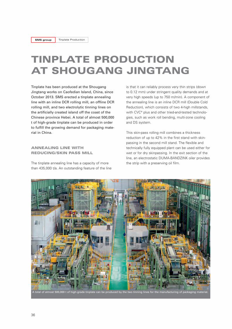
Tinplate has been produced at the ShougangJingtang works on Caofedian Island, China, sinceOctober 2013. SMS erected a tinplate annealingline with an inline DCR rolling mill, an offline DCRrolling mill, and two electrolytic tinning lines onthe artificially created island off the coast of theChinese province Hebei. A total of almost 500,000t of high-grade tinplate can be produced in orderto fulfill the growing demand for packaging mate-rial in China.
ANNEALING LINE WITH
REDUCING/SKIN PASS MILL
The tinplate annealing line has a capacity of morethan 435,000 t/a. An outstanding feature of the line
TINPLATE PRODUCTION AT SHOUGANG JINGTANG
is that it can reliably process very thin strips (down to 0.12 mm) under stringent quality demands and atvery high speeds (up to 750 m/min). A component ofthe annealing line is an inline DCR mill (Double ColdReduction), which consists of two 4-high millstands,with CVC® plus and other tried-and-tested technolo-gies, such as work roll bending, multi-zone coolingand DS system.
This skin-pass rolling mill combines a thicknessreduction of up to 42% in the first stand with skin-passing in the second mill stand. The flexible andtechnically fully equipped plant can be used either forwet or for dry skinpassing. In the exit section of theline, an electrostatic DUMA-BANDZINK oiler providesthe strip with a preserving oil film.
A total of almost 500,000 t of high-grade tinplate can be produced by the two tinning lines for the manufacturing of packaging material.
W7-321E_Tinplate_Neutral 07.12.15 11:18 Seite 36
37
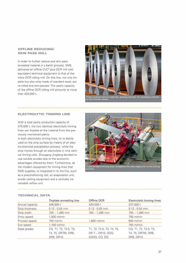
OFFLINE REDUCING/
SKIN PASS MILL
In order to further reduce and skin passannealed material in a batch process, SMSdelivered an offline CVC® plus DCR mill withequivalent technical equipment to that of theinline DCR rolling mill. On this line, not only tin-plate but also strip made of standard steel, arere-rolled and skin-passed. The yearly capacityof the offline DCR rolling mill amounts to morethan 420,000 t.
ELECTROLYTIC TINNING LINE
With a total yearly production capacity of475,000 t, the two identical electrolytic tinninglines can tinplate all the material from the pre-viously mentioned plants.In both electrolytic tinning lines, tin is distrib-uted on the strip surface by means of an elec-tro-chemical precipitation process, while thestrip moves through an electrolyte in nine verti-cal tinning cells. Shougang Jingtang decided touse soluble anodes due to the economicadvantages offered by them. Furthermore, allthe modern equipment for tinning lines thatSMS supplies, is integrated in to the line, suchas a preconditioning cell, an evaporation unit,anode casting equipment and a vertically tra-versable reflow unit.
TECHNICAL DATA
These products serve to meet the growing demand for packaging materialon the Chinese market.
A special side-trimming shear straightens the strip edges prior to the tinningprocess.
Tinplate annealing line Offline DCR Electrolytic tinning linesAnnual capacity 436,000 t 420,000 t 237,500 tStrip thickness 0.12 - 0.55 mm 0.12 - 0.55 mm 0.12 - 0.55 mmStrip width 700 – 1,280 mm 700 – 1,280 mm 700 – 1,280 mmEntry speed 1,000 m/min 750 m/minProcess speed 750 m/min 1,800 m/min 600 m/minExit speed 1,100 m/min 750 m/minSteel grades CQ, T1, T2, T2.5, T3, T1, T2, T2.5, T3, T4, T5, CQ, T1, T2, T2.5, T3,
T4, T5, DR7M, DR8, DR 7 – DR10, DDQ, T4, T5, DR7M, DR8,DR9, DR10 EDDQ, CQ, DQ DR9, DR10
W7-321E_Tinplate_Neutral 07.12.15 11:18 Seite 37
Tinplate ProductionSMS group
38
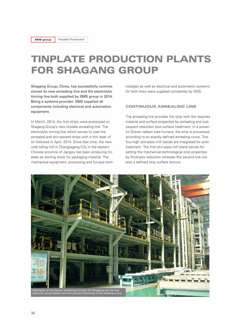
TINPLATE PRODUCTION PLANTSFOR SHAGANG GROUP
Shagang Group, China, has successfully commis-sioned its new annealing line and the electrolytictinning line both supplied by SMS group in 2014.Being a systems provider, SMS supplied all components including electrical and automationequipment.
In March, 2014, the first strips were processed onShagang Group’s new tinplate annealing line. Theelectrolytic tinning line which serves to coat theannealed and skin-passed strips with a thin layer oftin followed in April, 2014. Since that time, the newcold rolling mill in Zhangjiagang City in the easternChinese province of Jiangsu has been producing tin-plate as starting stock for packaging material. Themechanical equipment, processing and furnace tech-
nologies as well as electrical and automation systemsfor both lines were supplied completely by SMS.
CONTINUOUS ANNEALING LINE
The annealing line provides the strip with the requiredmaterial and surface properties by annealing and sub-sequent reduction plus surface treatment. In a power-ful Drever radiant tube furnace, the strip is processedaccording to an exactly defined annealing curve. Twofour-high skin-pass mill stands are integrated for post-treatment. The first skin-pass mill stand serves forsetting the mechanical-technological strip propertiesby thickness reduction whereas the second one cre-ates a defined strip surface texture.
Highlights of the Drever annealing furnace for Shagang are the lowresource consumption and the precise following of the heating curve.
W7-321E_Tinplate_Neutral 07.12.15 11:18 Seite 38
39
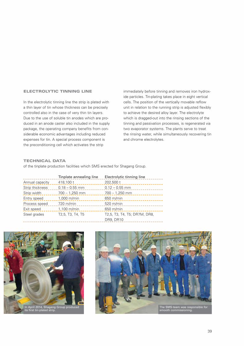
ELECTROLYTIC TINNING LINE
In the electrolytic tinning line the strip is plated witha thin layer of tin whose thickness can be preciselycontrolled also in the case of very thin tin layers. Due to the use of soluble tin anodes which are pro-duced in an anode caster also included in the supplypackage, the operating company benefits from con-siderable economic advantages including reducedexpenses for tin. A special process component is the preconditioning cell which activates the strip
The SMS-team was responsible forsmooth commissioning.
Tinplate annealing line Electrolytic tinning lineAnnual capacity 418,100 t 202,500 tStrip thickness 0.18 – 0.55 mm 0.12 – 0.55 mmStrip width 700 – 1,250 mm 700 – 1,250 mmEntry speed 1,000 m/min 650 m/minProcess speed 720 m/min 520 m/minExit speed 1,100 m/min 650 m/minSteel grades T2,5, T3, T4, T5 T2,5, T3, T4, T5; DR7M, DR8,
DR9, DR10
TECHNICAL DATA
of the tinplate production facilities which SMS erected for Shagang Group.
immediately before tinning and removes iron hydrox-ide particles. Tin-plating takes place in eight verticalcells. The position of the vertically movable reflowunit in relation to the running strip is adjusted flexiblyto achieve the desired alloy layer. The electrolytewhich is dragged-out into the rinsing sections of thetinning and passivation processes, is regenerated viatwo evaporator systems. The plants serve to treatthe rinsing water, while simultaneously recovering tinand chrome electrolytes.
In April 2014, Shagang Group producedits first tin-plated strip.
W7-321E_Tinplate_Neutral 07.12.15 11:18 Seite 39
Tinplate ProductionSMS group
40
TOSYALI TOYO ORDERS ACUTTING-EDGE TINNING LINEWITH SOLUBLE ANODES
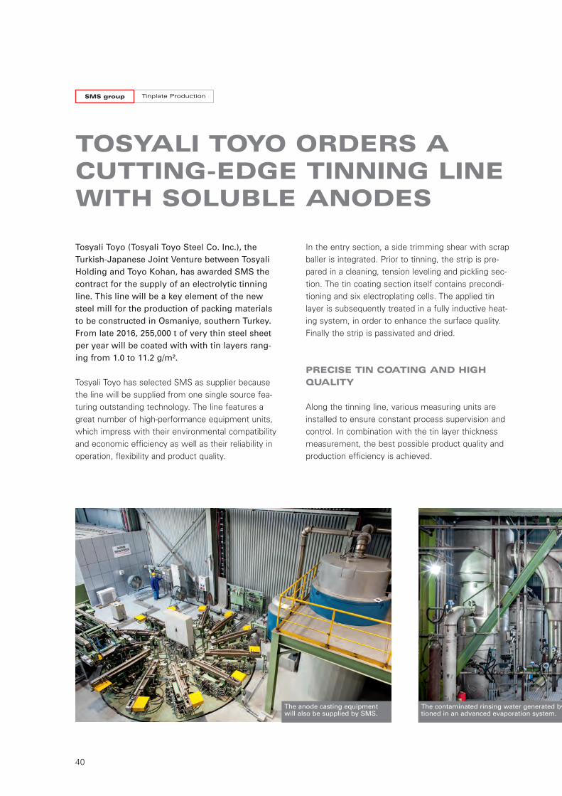
Tosyali Toyo (Tosyali Toyo Steel Co. Inc.), theTurkish-Japanese Joint Venture between TosyaliHolding and Toyo Kohan, has awarded SMS thecontract for the supply of an electrolytic tinningline. This line will be a key element of the newsteel mill for the production of packing materialsto be constructed in Osmaniye, southern Turkey.From late 2016, 255,000 t of very thin steel sheetper year will be coated with with tin layers rang-ing from 1.0 to 11.2 g/m².
Tosyali Toyo has selected SMS as supplier becausethe line will be supplied from one single source fea-turing outstanding technology. The line features agreat number of high-performance equipment units,which impress with their environmental compatibilityand economic efficiency as well as their reliability inoperation, flexibility and product quality.
In the entry section, a side trimming shear with scrapballer is integrated. Prior to tinning, the strip is pre-pared in a cleaning, tension leveling and pickling sec-tion. The tin coating section itself contains precondi-tioning and six electroplating cells. The applied tinlayer is subsequently treated in a fully inductive heat-ing system, in order to enhance the surface quality.Finally the strip is passivated and dried.
PRECISE TIN COATING AND HIGH
QUALITY
Along the tinning line, various measuring units areinstalled to ensure constant process supervision andcontrol. In combination with the tin layer thicknessmeasurement, the best possible product quality andproduction efficiency is achieved.
The anode casting equipmentwill also be supplied by SMS.
The contaminated rinsing water generated by th tioned in an advanced evaporation system.
W7-321E_Tinplate_Neutral 07.12.15 11:18 Seite 40
41
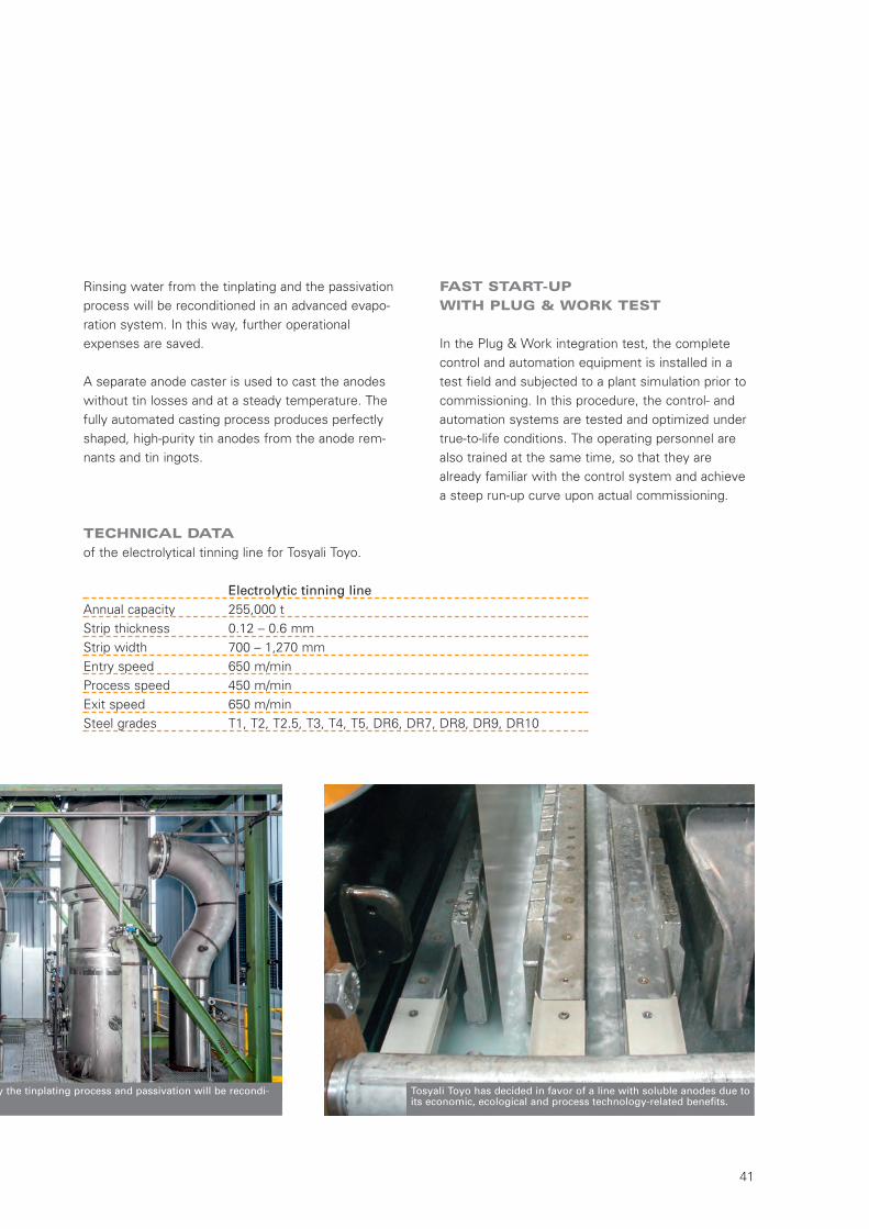
Rinsing water from the tinplating and the passivationprocess will be reconditioned in an advanced evapo-ration system. In this way, further operationalexpenses are saved.
A separate anode caster is used to cast the anodeswithout tin losses and at a steady temperature. Thefully automated casting process produces perfectlyshaped, high-purity tin anodes from the anode rem-nants and tin ingots.
by the tinplating process and passivation will be recondi- .
Tosyali Toyo has decided in favor of a line with soluble anodes due toits economic, ecological and process technology-related benefits.
Electrolytic tinning lineAnnual capacity 255,000 tStrip thickness 0.12 – 0.6 mmStrip width 700 – 1,270 mmEntry speed 650 m/minProcess speed 450 m/minExit speed 650 m/minSteel grades T1, T2, T2.5, T3, T4, T5, DR6, DR7, DR8, DR9, DR10
TECHNICAL DATA
of the electrolytical tinning line for Tosyali Toyo.
FAST START-UP
WITH PLUG & WORK TEST
In the Plug & Work integration test, the completecontrol and automation equipment is installed in atest field and subjected to a plant simulation prior tocommissioning. In this procedure, the control- andautomation systems are tested and optimized undertrue-to-life conditions. The operating personnel arealso trained at the same time, so that they arealready familiar with the control system and achievea steep run-up curve upon actual commissioning.
W7-321E_Tinplate_Neutral 07.12.15 11:18 Seite 41
Tinplate ProductionSMS group
42
ELECTRICS AND AUTOMATION
INTEGRATED SOLUTIONS
SMS group provides integrated solutions includingelectrics and automation for all tinplate productionfacilities. They will be jointly designed to implementthe advanced technology required for the productionof the envisaged first class tinplate material.
Therefore the electrical and automation team is inte-grated in all activities regarding engineering, commis-sioning or research and development. The same mod-els which are used to design the line are within theprocess automation used to operate the line. This isan essential benefit for our customers especially withregard to after sales service and for future productdevelopment.
X-PACT® MODULAR AUTOMATION
PACKAGES
Electric and automation is a crucial success factor inthe realization of complex plants. This is where every-thing comes together for controlling, monitoring,checking, evaluating, and coordinating the plant. As a holistic electrics and automation package, X-Pact®
makes sure all plant parts mesh with each other andwork smoothly together: from energy supply and dis-
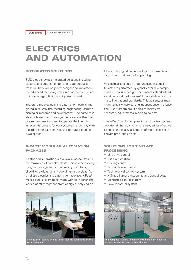
The customer staff is trained under realistic conditions prior tocommissioning .
The compact cabinets with the CPU’s handle the data andensure the process control operations..
tribution through drive technology, instruments andautomation, and production planning.
All electrical and automated functions included in X-Pact® are performed by globally available compo-nents of modular design. That ensures standardizedsolutions for all tasks – carefully worked out accord-ing to international standards. This guarantees maxi-mum reliability, service, and independence in produc-tion. And furthermore, it helps to make anynecessary adjustments in next to no time.
The X-Pact® production planning and control systemprovides all the tools which are needed for effectiveplanning and quality assurance of the processes intinplate production plants.
SOLUTIONS FOR TINPLATE
PROCESSING
- Line drive control
- Basic automation
- Coating control
- Tension leveler model
- Technological control system
- X-Shape flatness measuring and control system
- Elongation control system
- Level 2 control system
W7-321E_Tinplate_Neutral 07.12.15 11:18 Seite 42
43
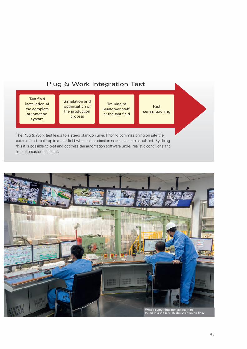
Where everything comes together:Pulpit in a modern electrolytic tinning line.
Plug & Work Integration Test
The Plug & Work test leads to a steep start-up curve. Prior to commissioning on site theautomation is built up in a test field where all production sequences are simulated. By doingthis it is possible to test and optimize the automation software under realistic conditions andtrain the customer’s staff.
Test fieldinstallation ofthe completeautomationsystem
Simulation andoptimization ofthe production
process
Training ofcustomer staffat the test field
Fastcommissioning
W7-321E_Tinplate_Neutral 07.12.15 11:18 Seite 43

W7-321E
© SMS group · Published on 07.12.2015 · C
irculation 500 · P
rinted in Germany · K
y
SMS group GmbH
Processing Lines and Furnace Technology
Walder Strasse 5340724 Hilden, Germany
Phone: +49 211 881-5100Telefax: +49 211 881-4212
E-mail: [email protected]: www.sms-group.com
“The information provided in this brochure contains a general description of the performance characteristics of the products concerned. The actual products may not always have thesecharacteristics as described and, in particular, these may change as a result of further developments of the products. The provision of this information is not intended to have and willnot have legal effect. An obligation to deliver products having particular characteristics shall only exist if expressly agreed in the terms of the contract.”
W7-321E_Tinplate_Neutral 07.12.15 11:18 Seite 44