Effects of saccharin and anions
11
ORIGINAL PAPER Effects of saccharin and anions (SO 4 2- , Cl - ) on the electrodeposition of Co–Ni alloys Liliana Altamirano-Garcia & Jorge Vazquez-Arenas & Mark Pritzker & Rosa Luna-Sánchez & Román Cabrera-Sierra Received: 15 May 2014 /Revised: 14 August 2014 /Accepted: 17 August 2014 # Springer-Verlag Berlin Heidelberg 2014 Abstract The electrodeposition of Co–Ni alloys is investi- gated to examine the mechanistic effects of chloride, sulfate and saccharin on the resulting alloy composition, deposition current efficiency and partial current densities of the cathodic reactions. When deposition is carried out in chloride, sulfate or mixed sulfate-chloride solutions without saccharin, the influ- ence of hydrogen evolution (HER) becomes dominant and deleterious at higher overpotentials, leading to very low metal deposition current efficiency and the formation of a hydroxide/oxide film on the substrate. This problem is signif- icantly reduced when saccharin is added to the mixed sulfate- chloride plating bath and to a lesser extent the sulfate-only solution. Although saccharin is ineffective in suppressing H + reduction at low overpotentials, it is very effective at inhibiting H 2 O reduction at high overpotentials and enabling metal deposition to more easily occur. The system follows anomalous behavior at all current densities both in the absence and presence of saccharin, although it approaches nor- mal behavior as the current density increases toward −1,000 A m −2 due to Co(II) reduction being mass transfer-controlled. Keywords Electrodeposition . Reaction mechanism . Co–Ni alloys . Electrolyte . Saccharin Introduction The control of the composition of Co–Ni alloys formed by electrodeposition is challenging due to its anomalous behavior whereby the less noble metal (Co) deposits preferentially over the more noble metal (Ni) even when its bulk concentration in the plating solution is lower [1, 2]. Thus, control of its com- position becomes critical in order to enhance specific proper- ties. Another complicating factor for the effectiveness of elec- trodeposition as a method for producing Co–Ni alloys with controllable composition is the occurrence of the hydrogen evolution reaction (HER), which decreases the current effi- ciency of plating [3, 4]. In order to better control the composition and properties of Co–Ni alloy films, additives are typically added to the plating solution. The use of the organic additive saccharin on the deposition of alloys containing iron-group metals and alloys has been studied [5–11], although Co–Ni alloys have received much less attention than other systems. Although saccharin is often added as a brightener, it can also act to inhibit the HER during deposition due to adsorptive effects [8]. If the saccharin concentration in the bulk solution becomes high enough, it adsorbs on the electrode to such an extent that both metal deposition and the HER are inhibited and the cathode is effectively passivated [5]. However, to our knowledge, no mechanistic information has been reported on the behavior of saccharin during Co–Ni formation. This information is crucial to exploit the advantages of this reagent and determine the proper amounts to be added to increase the efficiency of electrodeposition and control deposit morphology. Thus, the primary objective of this investigation is to analyze the role of the electrolyte and saccharin on the L. Altamirano-Garcia : R. Luna-Sánchez Depto. Energía, Universidad Autónoma Metropolitana Azcapotzalco, Av. San Pablo, No. 180, 02200 Mexico, DF, Mexico J. Vazquez-Arenas (*) Depto. de Química, Universidad Autónoma Metropolitana Iztapalapa, San Rafael Atlixco No. 186, 09340 Mexico, DF, Mexico e-mail: [email protected] M. Pritzker Chemical Engineering Department, University of Waterloo, 200 University Avenue West, Waterloo, ON N2L 3G1, Canada R. Cabrera-Sierra Depto. Ing. Química Industrial, Instituto Politécnico Nacional -ESIQIE, UPALM Ed. 7, Mexico 07738, DF, Mexico J Solid State Electrochem DOI 10.1007/s10008-014-2616-7
Transcript of Effects of saccharin and anions

ORIGINAL PAPER
Effects of saccharin and anions (SO42−, Cl−)
on the electrodeposition of Co–Ni alloys
Liliana Altamirano-Garcia & Jorge Vazquez-Arenas &Mark Pritzker & Rosa Luna-Sánchez &
Román Cabrera-Sierra
Received: 15 May 2014 /Revised: 14 August 2014 /Accepted: 17 August 2014# Springer-Verlag Berlin Heidelberg 2014
Abstract The electrodeposition of Co–Ni alloys is investi-gated to examine the mechanistic effects of chloride, sulfateand saccharin on the resulting alloy composition, depositioncurrent efficiency and partial current densities of the cathodicreactions.When deposition is carried out in chloride, sulfate ormixed sulfate-chloride solutions without saccharin, the influ-ence of hydrogen evolution (HER) becomes dominant anddeleterious at higher overpotentials, leading to very low metaldeposition current efficiency and the formation of ahydroxide/oxide film on the substrate. This problem is signif-icantly reduced when saccharin is added to the mixed sulfate-chloride plating bath and to a lesser extent the sulfate-onlysolution. Although saccharin is ineffective in suppressing H+
reduction at low overpotentials, it is very effective atinhibiting H2O reduction at high overpotentials and enablingmetal deposition to more easily occur. The system followsanomalous behavior at all current densities both in the absenceand presence of saccharin, although it approaches nor-mal behavior as the current density increases toward−1,000 A m−2 due to Co(II) reduction being masstransfer-controlled.
Keywords Electrodeposition . Reactionmechanism . Co–Nialloys . Electrolyte . Saccharin
Introduction
The control of the composition of Co–Ni alloys formed byelectrodeposition is challenging due to its anomalous behaviorwhereby the less noble metal (Co) deposits preferentially overthe more noble metal (Ni) even when its bulk concentration inthe plating solution is lower [1, 2]. Thus, control of its com-position becomes critical in order to enhance specific proper-ties. Another complicating factor for the effectiveness of elec-trodeposition as a method for producing Co–Ni alloys withcontrollable composition is the occurrence of the hydrogenevolution reaction (HER), which decreases the current effi-ciency of plating [3, 4].
In order to better control the composition and properties ofCo–Ni alloy films, additives are typically added to the platingsolution. The use of the organic additive saccharin on thedeposition of alloys containing iron-group metals and alloyshas been studied [5–11], although Co–Ni alloys have receivedmuch less attention than other systems. Although saccharin isoften added as a brightener, it can also act to inhibit the HERduring deposition due to adsorptive effects [8]. If the saccharinconcentration in the bulk solution becomes high enough, itadsorbs on the electrode to such an extent that both metaldeposition and the HER are inhibited and the cathode iseffectively passivated [5]. However, to our knowledge, nomechanistic information has been reported on the behaviorof saccharin during Co–Ni formation. This information iscrucial to exploit the advantages of this reagent and determinethe proper amounts to be added to increase the efficiency ofelectrodeposition and control deposit morphology.
Thus, the primary objective of this investigation is toanalyze the role of the electrolyte and saccharin on the
L. Altamirano-Garcia : R. Luna-SánchezDepto. Energía, Universidad Autónoma MetropolitanaAzcapotzalco, Av. San Pablo, No. 180, 02200 Mexico, DF, Mexico
J. Vazquez-Arenas (*)Depto. de Química, Universidad Autónoma MetropolitanaIztapalapa, San Rafael Atlixco No. 186, 09340 Mexico, DF, Mexicoe-mail: [email protected]
M. PritzkerChemical Engineering Department, University of Waterloo, 200University Avenue West, Waterloo, ON N2L 3G1, Canada
R. Cabrera-SierraDepto. Ing. Química Industrial, Instituto Politécnico Nacional-ESIQIE, UPALM Ed. 7, Mexico 07738, DF, Mexico
J Solid State ElectrochemDOI 10.1007/s10008-014-2616-7

electrodeposition of Co–Ni alloys. The plating baths consist ofsynthetic solutions that match the levels in leach liquorsgenerated from spent Ni–Cd battery components [12, 13].Previous experiments have shown that the composition ofCo–Ni and other iron-group alloys produced by electrodepo-sition is strongly affected by whether the process is carried outin a sulfate or chloride electrolyte [14, 15]. Consequently, weinvestigate the influence of sulfate, chloride and mixedchloride-sulfate electrolytes on the composition of theresulting Co–Ni alloy coatings and current efficiency.Particular attention is also focused on the effect of saccharinon the electrodeposition of Co–Ni alloys from these baths,something which has not been investigated to date. As part ofthis study, the electrode response during galvanostatic depo-sition is examined in detail to gain further insight into theeffects of the electrolyte components on the processesinvolved.
Experimental
Electrochemical experiments were conducted at room temper-ature in solutions containing 1,000 mol m−3 Na2SO4 (99.3 %purity, Fisher) as supporting electrolyte and NiSO4 (99.3 %purity, Fisher), NiCl2 (98.1 % purity, J. T. Baker), CoSO4
(99.3 % purity, Fisher), CoCl2 (98.1 % purity, J. T. Baker)and sodium saccharinate salt (99 % purity, Cedrosa) at theconcentrations given in Table 1. The pH in each bath wasadjusted to be 3.0 by the addition of the appropriate amount ofconcentrated acid. The total dissolved Co(II) and Ni(II) con-centrations in baths 1–5 were set to 18 and 400 mol m−3,respectively, to match the levels in solutions obtained by ourgroup after leaching Ni–Cd battery components with H2SO4
and purifying the resulting leach liquors to remove cadmium[16]. All solutions were freshly prepared in deionized water(∼pH 6.8) and deoxygenated with N2 (Praxair, grade 4.8) priorto experiments.
A conventional three-electrode rotating disk cell was usedto conduct the electrochemical experiments at room tempera-ture. The reference electrode for this cell was a saturatedmercury/mercurous sulfate electrode (Hg/Hg2SO4, 0.64 V vsSHE), while the counter electrode was a graphite bar (Alfa
Aesar, 99.99 % purity). All the potential values reportedherein correspond to the SHE scale. The rotating disk workingelectrode was a copper rod embedded in nylon that exposed acircular face with area 0.126 cm2 to the solution. Furtherdetails of the preparation of the working electrode have beenreported in Refs. [5, 17–21]. The duration of plating at eachcurrent density was adjusted to ensure that a total of 1.5 C ofcharge was passed over the course of each experiment.Following deposition, the composition of the resulting alloycoatings was determined utilizing a high-dispersion inductive-ly coupled plasma (ICP) spectrometer (Teledyne LeemanTM
model Prodigy) for the dissolved cobalt and nickel content [5,17–21]. With this information known, the partial current den-sities for Ni(II) reduction, Co(II) reduction, and HER could bedetermined.
Results
Linear potential scans
Figure 1 presents the linear voltammetry responses obtainedon a copper substrate rotating at 1,000 rpm in solutionscontaining a supporting electrolyte (SE, 1,000 mol m−3
Na2SO4) and Ni(II) and Co(II) at the following concentra-tions: (a) 0 mol m−3 (SE), (b) 400 mol m−3 NiSO4+18 mol m−3 CoSO4 (bath 1) and (c) 400 mol m−3 NiSO4+18mol m−3 CoSO4+24mol m−3 saccharin (bath 2). As shownin previous studies on the Co–Ni system [18], the first processthat occurs as the scan proceeds in the negative direction bothin the absence and presence of the dissolved metals is H+
reduction at a potential of approximately −0.8 V (label I inFig. 1). However, when saccharin is present as in bath 2, theresponse in this region of the scan differs and a steeper rise inthe cathodic current is observed at potentials between −0.8and −1.0 V. This potential region coincides closely with wheresaccharin has been observed to adsorb most strongly on Co–Fe–Ni [22] alloy and Ni [23] surfaces. One likely explanationis that the increase in current in this region can be attributed tometal deposition (region II, at approximately −0.95 V).Enough saccharin may adsorb on the surface to slow downthe reduction of H+ or H2O and enhance metal deposition.
Table 1 Synthetic electrolytes simulating leach liquors generated from spent Ni-Cd batteries used to electrodeposit Co–Ni alloys at pH 3
Bath [Na2SO4] (mol m−3) [NiSO4] (mol m−3) [NiCl2] (mol m−3) [CoSO4] (mol m−3) [CoCl2] (mol m
−3) Saccharin (mol m−3)
SE 1,000 0 0 0 0 0
1 1,000 400 0 18 0 0
2 1,000 400 0 18 0 24
3 0 0 400 0 18 24
4 0 300 100 18 0 24
5 0 300 100 18 0 0
J Solid State Electrochem

As the scan continues to more negative potentials in baths 1and 2, both H+ and H2O reduction presumably continue tooccur along with alloy deposition. These side reactions notonly reduce the current efficiency for metal deposition, butalso raise the surface pH during the co-deposition of Co andNi. Eventually, if the surface pH increases enough, surfacehydroxides and oxides are formed along with the alloy at morenegative potentials [24], as also reported for single cobaltdeposition [25]. As shown previously from X-ray analysisand modeling [18], the rise in surface pH becomes highenough during the scan that nickel oxide or hydroxide formson the electrode surface, leading to the appearance of a peak atapproximately −1.2 V (labeled as III). Since the solution isbeing stirred when this scan is obtained, the onset of this peakis not attributed to limitations of the transport of anelectroactive species to the electrode. Further support for thisinterpretation comes from the results of LSV scans in bath 2conducted at 100 and 1,500 rpm (not included here) showingthat this peak remains unchanged regardless of the electroderotation speed.
Instead, the formation of an oxide or hydroxide on thesurface would be expected to have a passivating effect onthe electrode and cause the sharp drop in current at potentialsbetween −1.2 and −1.3 Vobserved in the scans for both baths1 and 2 in Fig. 1. However, the oxide layer is not thick orprotective enough to completely passivate the electrode and asmuch as −600 A m−2 current density can still flow. Once thepotential becomes more negative than about −1.3 V, thecurrent abruptly rises again, presumably due to breakdownof the passive oxide layer and reactivation of the surface dueto water reduction [3, 18]. As shown previously [18, 3], thecurrent densities that flow in this portion of the voltammo-grams far exceed the sum of the limiting current densities forthe reduction of Co(II), Ni(II), and H+ reduction for theconditions of this study. Thus, this rapid rise in current labeledas IV is attributed to water reduction in the scans shown inFig. 1.
Although analysis for the presence of metal hydrides wasnot conducted in the present study, one cannot rule out thepossibility of their formation on the surface of the depositsduring the linear potential scan and other electrochemicalexperiments due to the affinity of Co or Ni and nascenthydrogen. A number of previously reported electrochemical,chemical and microscopy analyses have provided evidence ofthe formation of metastable fcc hydrides of Ni (−0.80 V onglassy carbon) and Co (at applied current density of100 A m−2 on annealed copper or approximately −0.86 Vonquartz crystal coated with Pt) under conditions similar to thoseof the present study [25–30]. These metal hydrides wereshown to be unstable under ordinary temperature and pressureand slowly release hydrogen over period of time ranging from20 min to 40 h to form a martensitic Ni or Co phase.
The influence of saccharin on the formation of Co–Nialloys was further examined by carrying out linear scans insolutions containing two different concentrations of this addi-tive (24 and 48 mol m−3), but with fixed Ni(II) and Co(II)concentrations. Although not shown here, the two scans showvery similar features. Perhaps the most significant differenceis the observation that the current density is slightly largerfrom −0.8 to −1.0 V (region I–II) at the higher saccharinconcentration. This result is consistent with the trend observedin Fig. 1 that the current in this very same region is greater inbath 2 which contains 24 mol m−3 saccharin than in bath 1 inwhich saccharin is absent. To be sure, these findings provideevidence that this additive is not acting as a blocking agentthat passivates the electrode surface at these concentrations.Nevertheless, only inferences regarding the influence of sac-charin during Co–Ni deposition can be made on the basis ofthese linear potential scans. The possible effects of oxideformation and saccharin adsorption on Co–Ni deposition arefurther analyzed in the “Galvanostatic deposition” section.
The addition of chloride ions is known to enhance theformation kinetics of Co–Ni alloys due to complexing effectsthat accelerate the discharge of both ions and enhance elec-trolyte conductivity [31, 19, 32]. Some evidence of the influ-ence of chloride can be gleaned in Fig. 2 which presents thepotential scans obtained in baths 3–5, all of which containchloride. Unlike the solutions considered in Fig. 1, baths 3–5contain no Na2SO4. As expected, comparison of these scanswith those in Fig. 1 indicates that a lower overpotential isrequired to initiate the reduction processes in the presence ofchloride.
A peak appears in the scans for baths 3–5 (Fig. 2), butsignificant differences are evident in the three cases. The fast-rising portion of the response is most prominent in the case ofthe chloride-only solution (bath 3), leading to the appearanceof the peak at higher current densities As before, this oxidelayer does not completely passivate the electrode and a currentdensity of at least −600 A m−2 still flows. Interestingly, thisminimum current density that the oxide permits is virtually
-1800
-1500
-1200
-900
-600
-300
0
-1.7 -1.4 -1.1 -0.8 -0.5 -0.2
III
III
IV
E / V vs SHE
SEBath 2Bath 1
j (A
m-2
)
Fig. 1 Voltammograms obtained on a copper disk electrode rotating at1,000 rpm in the following baths described in Table 1: SE (red line), bath1 (black line), bath 2 (blue line) at pH 3. Scan rate=100 mV s−1
J Solid State Electrochem

identical in baths 3 and 4 and very similar to that observed inbaths 1 and 2 (Fig. 1) which contain no chloride. The effect ofsaccharin in the mixed sulfate-chloride electrolyte can beexamined by comparing the electrode responses obtained inbaths 4 and 5 in Fig. 2. Cathodic current begins to flow earlierduring the scan when saccharin is absent (bath 5) than when itis present (bath 4).
The influence of saccharin on the scans obtained in themixed sulfate-chloride electrolyte appears to be complex. Thepresence of saccharin has a very large effect by shifting thepeak as much as 0.45 V in the negative direction (comparewith bath 5). On the other hand, when saccharin is added tothe sulfate-only bath, the effect is small (baths 1 and 2 inFig. 1). It is well known that chloride ions interact much morestrongly with metal surfaces during deposition than do sulfateor water [33]. The difference in the effect of saccharin in thetwo types of baths suggests that the additive may interact withchloride in a way that significantly alters the electrode re-sponse during the scan.
Galvanostatic deposition
In order to more fully investigate Co–Ni deposition in thepresence of saccharin, chronopotentiometry experiments oncopper disk substrates rotating at 1,000 rpm were carried outin baths 1–5 over a range of current densities from −50 to−1,000 A m−2. Figures 3 and 4 show the variation of the alloycontent and the current efficiencies with applied current den-sity obtained in baths 1–5. As expected and commonly ob-served [18], the Ni content in the alloy films formed in allbaths increases as the applied current density is raised. Sincethe Co(II) concentration is very low, its reduction rate be-comes strongly influenced by mass transport even when rela-tively small currents are applied. This is reflected by the verylarge differences in the limiting current densities for Co(II)reduction and Ni(II) reduction that are estimated to be −179and −3,716.1 A m−2, respectively, at these bath compositions
and a rotation speed of 1,000 rpm using the Levich equationand literature values for the diffusion coefficients of theelectroactive species [32]. Thus, as the current is increasedfurther, it is distributed to Ni deposition and H2 evolution andenriches the coating in Ni. Also, as evident from Fig. 3, thesystem follows anomalous behavior at all current densities inevery bath, although it approaches normal behavior as thecurrent density increases toward −1,000 A m−2.
A comparison of the variation of the alloy depositioncurrent efficiency with current density in baths 1–5 shown inFig. 4 reveals a few trends. The mixed sulfate-chloride solu-tion containing saccharin (bath 4) can maintain current effi-ciencies above ∼90 % over a very wide range of currentdensities, which is better performance than that achieved in asulfate-only solution containing saccharin (bath 2), a chloride-only solution containing saccharin (bath 3), a mixed sulfate-chloride solution containing no additive (bath 5) or a sulfate-only solution containing no additive (bath 1). The currentefficiencies in all baths rise sharply to levels exceeding 80 %as the current density is raised from −50 to −300 A m−2. Once
-1800
-1500
-1200
-900
-600
-300
0
-1.7 -1.4 -1.1 -0.8 -0.5 -0.2
E / V vs SHE
Bath 3Bath 4Bath 5
I
II
IIIIV
j (A
m-2
)
Fig. 2 Voltammograms obtained on a copper disk electrode rotating at1,000 rpm in the following baths described in Table 1: bath 3 (black line),bath 4 (red line), bath 5 (blue line) at pH 3. Scan rate=100 mV s−1
40
50
60
70
80
90
100
-1100 -900 -700 -500 -300 -100 100
wt%
Ni
j / A m 2
Bath 2Bath 3Bath 4Bath 5Bath 1
Fig. 3 Variation of weight percentage of nickel with applied currentdensity in Co–Ni alloys formed on a copper disk electrode rotating at1,000 rpm in the following baths described in Table 1: bath 1 (blue exsymbol), bath 2 (red filled circle), bath 3 (green filled upright triangle),bath 4 (black filled square), bath 5 (yellow filled diamond) at pH 3
0
20
40
60
80
100
-1100 -900 -700 -500 -300 -100 100
curre
nt ef
ficien
cy %
j / A m 2
Bath 1Bath 2Bath 3Bath 4Bath 5
Fig. 4 Variation of deposition current efficiency with applied currentdensity in Co–Ni alloys formed on a copper disk electrode rotating at1,000 rpm in the following baths described in Table 1: bath 1 (blue exsymbol), bath 2 (red filled circle), bath 3 (green filled upright triangle),bath 4 (black filled square), bath 5 (yellow filled diamond) at pH 3
J Solid State Electrochem

cathodic current densities larger than approximately−600Am−2
are applied, larger differences in the current efficiencies amongthe baths are observed. The current efficiencies obtained in bath1, 3 and 5 in particular and bath 2 to a lesser extent decreasesignificantly at these higher current densities.
Effect of saccharin in sulfate-only solution
A comparison of the results obtained in baths 1 and 2 indicatesthat the presence of saccharin tends to promote more anoma-lous Co–Ni electrodeposition from sulfate-only solutions.Although earlier studies have found saccharin to have a smallinfluence on the composition of other electrodeposited iron-group alloy films [8, 10, 34, 20, 35, 36], anomalous behaviorwas observed in some cases [10, 34, 36] and more normalbehavior in others [8, 20, 35, 37]. It is difficult tomake definiteconclusions regarding these differences since the experimentalconditions used for these studies (e.g., identity of iron-groupmetals and anions in electrolyte, metal ion concentration,saccharin concentration) vary widely.
Whereas the current density has very little effect on alloycomposition depending on whether saccharin is present orabsent, the trend observed with the corresponding currentefficiency is more complex (Fig. 4). More insight into thebehavior of the system in baths 1 and 2 can be gained byexamining the variation of the partial current densities for Codeposition (jCo), Ni deposition (jNi), and H2 evolution ( jH2
)with the steady state potential measured at each applied cur-rent density. These partial current densities can be readilycalculated using Faraday’s law as follows:
jNi ¼mNi � F � zNi
MNi � tð1Þ
jCo ¼mCo � F � zCo
MCo � tð2Þ
jH2¼ j− jNi− jCo ð3Þ
where mi is the mass of species i (Ni, Co) deposited (g)determined from ICP, F is the Faraday constant(96,485.5 C mol−1), zi is the number of electrons transferred(2) to metal I in the electrochemical reaction,Mi is the molec-ular weight of metal i (g mol−1) and t is the electrolysis time(s). It should be noted that jH2
is obtained from the differencebetween the overall applied current density and the sum of thepartial current densities jCo and jNi and so is a combination ofthe current associated with the reduction of both H+ and H2O.
Thus, jCo and jNi are determined independently from eachother and directly from the ICP measurements, whereas jH2
is only indirectly obtained using Eq. (3) with knowledge of j,jCo, and jNi. As will be discussed later, any saccharin that isreduced would do so at potentials similar to where H2Oreduction also occurs. Given that the amount of H2O presentis effectively unlimited, the current associated with saccharinelectroreduction is considered to be negligible relative to jH2
in Eq. (3).The variation of the total current density and partial current
density in baths 1 and 2 is presented in Fig. 5a and b, respec-tively. At the lowest applied current density of −50 A m−2 inthis study (Fig. 5a), jH2
has a magnitude of ∼20 A m−2 andexceeds that of jCo and jNi, consistent with the conclusionreached in previous studies and the “Linear potential scans”section that H+ reduction is the first electrode reaction to occurduring cathodic scans. The steady state electrode potential of−0.59 V is close to where faradaic current is first observed tooccur during the scan obtained in bath 1 (Fig. 1). However, ifcathodic polarization is conducted at a higher current densityof −100 or −200 A m−2, the additional current is utilizedalmost exclusively by metal deposition and jH2
remainsessentially constant between −20 and −30 A m−2. This value
-1200
-1000
-800
-600
-400
-200
0-1.6 -1.4 -1.2 -1 -0.8 -0.6
E / V vs SHE
b jCojNijH2
Total current density
a
j (
(
A m
-2j (
(
A m
-2
Fig. 5 Variation of total and partial current densities jCo, jNi, and jH2with
steady state potential calculated respectively with Eqs. (1–3) for Co–Nialloys formed on a copper disk electrode rotating at 1,000 rpm in thefollowing baths described in Table 1: a bath 1 and b bath 2 at pH 3
J Solid State Electrochem

is very close to the limiting current density for H+ reductionestimated by the Levich equation to be approximately−27.1 A m−2 at pH 3. Thus, H+ reduction appears to rapidlyreachmass transport-limiting conditions at low overpotentials.
When the total current density is raised to between −200and −300 A m−2, jH2
rises in magnitude once again, signify-ing that H2O reduction is beginning to occur. The onset of thisreaction is accompanied by a small jump in the polarization ofthe cathode from −0.68 to −0.82 V (note flattening in thisregion of the curves in Fig. 5a). Once H2O reduction isoccurring, the resistance to charge transfer appears to dropand both jNi and jH2
rise more steeply with respect to thesteady state potential when the deposition is carried out atcurrent densities between −300 and −600 Am−2. Interestingly,Co(II) reduction does not respond similarly and jCo remainsconstant between approximately −60 and −70 A m−2 regard-less of the potential during deposition.
A dramatic change in the response of the system occurswhen the applied current density is raised from −600 to−800 A m−2. This involves a large jump in the polarizationand flattening of the current-potential curves from −0.89 to−1.34 V. Examination of the cathodic scan for bath 1 in Fig. 1reveals that this potential range encompasses the region con-taining peak III attributed to the formation of an oxide layer ina previous study [17]. It occurs only under conditions whereH2O reduction which generates OH− ions at the cathodesurface is already occurring. At an applied current density of−600 A m−2 and a steady state potential of −0.89 V where theoxide film appears to first affect the electrode response, jH2
ismeasured to be approximately −151 Am−2. Assuming that H+
reduction is proceeding at its limiting level of −27.1 A m−2,the current density for H2O reduction at this critical pointcorresponds to −124.3 A m−2. Consequently, the generationof OH− at a rate of 1.29×10⁻³ mol m−2 s−1 is sufficient tocause a metal oxide film to occur during cathodic polarizationin bath 1. Unlike the response during the LSV scan in bath 1(Fig. 1), the current does not decrease in magnitude in thepotential region between −0.89 and −1.34 V. This difference isalso consistent with expectations if an oxide layer has formedon the electrode surface during polarization. Not only will therates of the cathodic reactions be slowed by such a layer butthey will also become much less sensitive to the electrodepotential. Over the limited time span (∼4.5 s) that the potentialis between −0.89 and −1.34 V during the scan, the reactionswill not be able to keep pace and so the current will drop. Onthe other hand, when enough time is allowed for steady stateto be reached, this limitation is removed. Another feature ofthe curves in Fig. 5a consistent with the formation of an oxidelayer is that jCo, jNi and jH2
each remain relatively constant inthe potential region between −0.89 and −1.34 V, suggestingthat the rate of each of these reactions is strongly affected (butnot completely controlled) by mass transport through theoxide layer. If Ni(II) and Co(II) reduction were entirely mass
transfer-controlled, then the ratios of their currents shouldmatch the ratios of their concentrations.
When a current density of −900 A m−2 is applied, twosignificant changes in the steady state response occur. Metaldeposition effectively ceases and the extent of H2O reductionjumps sharply so that it consumes virtually all of the appliedcurrent. The observation that an increase in the current densityfrom −800 to −900 A m−2 occurs without any change in thesteady state potential suggests that these changes in the ca-thodic reactions are associated with some sort of structuralchange to the oxide layer that rapidly reactivates the electrode.This presumably corresponds to the IV region in the LSV scanin Fig. 1 just after the electrode is reactivated. Unfortunately,this structural change prevents any metal deposition fromoccurring. The cessation of metal deposition also underscoresthe important consequence that the oxide layer appears to haveon metal deposition in this additive-free bath. With a furtherincrease in current density to −1,000 A m−2, H2O reductioncontinues to be dominant, with a significant increase in polar-ization to −1.74 V.
The steady state current-potential curves obtained in bath 2are presented in Fig. 5b. Comparison of this response with thatshown in Fig. 5a reveals that the effect of saccharin on Co–Nideposition changes depending on the current and potential. Atlow current densities of −50 and −100 A m−2, the polarizationis very similar to that obtained in the absence of the additive,but the distribution of the partial current densities is altered.The deposition of both metals is inhibited while the HER isenhanced in the presence of saccharin, particularly at−50 A m−2. The magnitude of jH2
is between −30 and−40 A m−2, suggesting that H+ reduction has reached masstransfer limiting conditions.
However, when the applied current densities is raised to−200 A m−2 and above, some differences in the electroderesponse from that observed in the absence of saccharin areexhibited. The polarization of the working electrode is higherby ∼0.1 Vat each applied current density up to and including−700 A m−2 in the presence of saccharin than in its absence.jCo remains constant over a wide range of currents at interme-diate and high overpotentials, as in the additive-free bath, butat levels between −80 and −100 A m−2, about a 40 % increasein the presence of saccharin. At the same time, jNi decreases inmagnitude by ∼10 % until a current density of −600 A m−2 isreached, whereupon it becomes much larger than observed inthe additive-free solution (bath 1). Perhaps the most strikingeffect of saccharin is the inhibition of jH2
once currentdensities of −400 A m−2 are applied. In particular, the HERis strongly suppressed at potentials between −0.9 and −1.1 Vwhich are reached when current densities between −400 and−600 A m−2 are applied.
These effects on Co and Ni deposition and the HER atpotentials from approximately −0.8 to −1.1 V (current densi-ties from approximately −200 to −600 A m−2) to the
J Solid State Electrochem

adsorption of saccharin on the electrode. Kwon and Gewirthpresented evidence from surface enhanced Raman scatteringspectroscopy (SERS) that saccharin can adsorb onto Ni sur-faces at all potentials during cathodic polarization from ap-proximately −0.5 to −1.0 V whereupon it desorbs [23]. Thispotential range from −0.8 to −1.1 V is also in excellentagreement with the region where Brankovic et al. foundsaccharin to adsorb on Co–Fe–Ni alloy surfaces [22].Furthermore, on the basis of double-layer capacitance mea-surements, Brankovic et al. observed that saccharin moststrongly adsorbs and forms condensed films on the substrateat potentials between −0.9 and −1.1 V. As observed in Fig. 5b,the curve for the total current density flattens out signifying anincrease in polarization at precisely these same potentials.Such an effect would be expected if saccharin is forming acondensed film on the electrode under these conditions.Another important observation reported by Brankovic et al.is that the current efficiency increases at the very potentialswhere saccharin adsorbs most strongly, presumably due to thesuppression of the HER. A comparison of Fig. 5a, b confirmssimilar behavior for Co–Ni deposition at these potentials. Atthe same time, metal deposition is at the very least uninhibitedand in fact may be enhanced under these conditions. Theincrease in polarization between −1.0 and −1.1 V observedin Fig. 5b is not likely due to oxide layer formation since it isnot accompanied with the large rise in jH2
, as observed in bath1.
Given that the partial currents show no inhibition of theHER at very low overpotentials where H+ reduction is dom-inant, the additive appears to act primarily on H2O reduction.This conclusion is reasonable when one considers the struc-ture(s) believed to formwhen saccharin adsorbs on iron-groupmetal surfaces. Evidence from SERS, IR, and NMR studies onNi surfaces indicates that structures in which the carbonyloxygen and imide ring nitrogen are bound to the metal andthe benzene ring is oriented toward the solution can form [38,23]. One would therefore expect the adsorption of saccharin toincrease the hydrophobicity of the cathode surface which inturn should impede H2O reduction in particular.
On the whole, our results indicate that Co–Ni depositionexhibits somewhat more anomalous behavior in the presenceof saccharin. Saccharin forms both soluble and solid com-plexes with divalent iron-group metal ions. A factor contrib-uting to the increased anomalous behavior could be the dif-ferences in the ability of Co(II) and Ni(II) to form thesesaccharinate complexes. It is known that Co(II) forms suchcomplexes more readily than Ni(II) [39, 40]. This may favorthe adsorption of Co(II)-containing complexes on the elec-trode and ultimately the deposition rate of cobalt.
The appearance of peak III in the scan for bath 2 in Fig. 1indicates that an oxide layer forms on the cathode surfacewhen it is sufficiently polarized despite the presence of sac-charin. This is confirmed in the steady state current-potential
curves for bath 2 when a current density of −800 A m−2 isapplied. As in the additive-free case, the rise in jNi and jH2
with potential becomes steeper as the current at which theoxide layer forms is approached. However, other features ofthe response suggest that the oxide layer differs in somerespects and is less disruptive to metal deposition than in theadditive-free bath. For one thing, higher currents and morecathodic potentials are required in order for the oxide layer toform when saccharin is present. The regions in the j–E curvesfor bath 2 in Fig. 5b where the oxide layer is present are lessflat and prominent than they are for bath 1 (Fig. 5a). Thepresence of the oxide layer also appears to have a less polar-izing effect in bath 2. Assuming that H+ reduction is proceed-ing under mass transfer limiting conditions, the generation rateof OH− due to H2O reduction at the onset of the formation ofthe oxide layer is estimated to be 1.76×10⁻³ mol m−2 s−1,which is about 36 % higher than the value obtained in theabsence of saccharin. This suggests that it is more difficult forthe oxide layer to form when the solution contains the addi-tive. Interestingly, the reactivation of the oxide layer at−900 A m−2 occurs at the same potential (−1.35 V) as it doesin bath 1. However, unlike the previous case, this does notlead to the termination of metal deposition and to dominationby the HER. In fact, at −1,000 A m−2, jNi reaches a highervalue than at any other current and the electrode is much lesspolarized than in the additive-free solution.
Effect of saccharin in chloride-only solution
Bath 3 is unique among the solutions in this study in that it issulfate-free. As shown in Fig. 3, the Ni content in the coatingsproduced in bath 3 is slightly, but consistently, lower than thatin bath 2 at virtually all current densities. The current efficien-cies rise steeply to ∼90 % as the current density is raised from−50 to −200 A m−2. Over this range, the current efficienciesare larger in the chloride-only solution than in the correspond-ing sulfate-only solution (bath 2), similar to the effect reportedby Horkans for Fe-Ni co-deposition over a similar currentrange [21]. This effect has usually been ascribed to the generalability of chloride to enhance metal deposition by forming anion bridge between the metal ion and electrode. The study byHorkans did not involve current densities larger than−200 A m−2. However, when the applied current for the Co–Ni system in this study is raised above −200 A m−2, thebehavior changes and the current efficiency declines as theapplied current density is increased. The drop-off becomescatastrophic when current densities reach −1,000 A m−2.
Examination of the steady state current-potential curvesobtained in bath 3 shows that the electrochemical reactionsare affected differently in the chloride-only solution (Fig. 6).The working electrode in bath 3 is more polarized than inbaths 1 and 2 at all current densities up to and including−800 A m−2, a somewhat surprising result given that metal
J Solid State Electrochem
deposition tends to be accelerated when conducted in chloridesolutions rather than sulfate solutions. The most likely expla-nation for the increased polarization in bath 3 is that it does notcontain a supporting electrolyte, unlike baths 1 and 2. Of thethree reactions, Co(II) reduction is affected the least relative tothat observed in the sulfate solution (bath 2) up to currentdensities of ∼−900 A m−2. On the other hand, a change in thebehavior of Ni(II) and the HER is observed when the steadystate potential during deposition reaches approximately−1.0 V (current density approximately −400 A m−2). At morepositive potentials, jNi is close inmagnitude to that observed inbath 2, whereas jH2
remains between −25 and −35 A m−2,suggesting that the HER proceeds principally as H+ reduction.However, when the potential becomes more negative thanapproximately −1.0 V, Ni(II) reduction is suppressed, whilethe HER is enhanced, suggesting that H2O reduction becomesthe dominant source of H2 evolution at approximately −1.0 V.These effects lead to the somewhat lower Ni content in thecoatings (Fig. 3) and the significant decline in current effi-ciency (Fig. 4) observed in the case of bath 3.
The change in behavior at −1.0 V is consistent with thefindings reported by Kwon and Gewirth [23] who showedfrom SERS analysis that saccharin desorbs from Ni electrodesin a chloride-only electrolyte at this same potential. Asdiscussed in the “Effect of saccharin in sulfate-only solution”section and in previous studies [22, 38], one of the particulareffects of the presence of saccharin on the electrode surface isto suppress H2O reduction. Thus, it is not surprising that H2Oreduction would be enhanced and the current efficiency dropsharply at potentials more negative than −1.0 V where sac-charin no longer adsorbs on the cathode.
Other factors may make saccharin less effective in thechloride-only solution than in the sulfate-only solution at highoverpotentials. From detailed analysis of the reaction productsof saccharin reduction during Ni deposition, Mockute et al.[41] found that the presence of Cl− in the plating bath affectsthe manner in which the additive interacts with the electrode
by promoting adsorption via its carbonyl group and hinderingadsorption via its sulfonyl group. The ability of Cl− andsaccharinate to form anionic complexes with both Ni(II) andCo(II) and adsorb onto the metal surface during electrodepo-sition is not likely to be a significant factor in this study sincethe electrode potential during electrodeposition is usuallymore negative than the potential-of-zero charge of polycrys-talline copper estimated to be −0.64 V vs SHE at pH 3.2 [42].
The formation of both chloride and saccharinate complexesof Ni(II) and Co(II) also tends to lower the concentration and/or the net charge of cations bound to H2O ligands (i.e.,Ni(H2O)6
2+ (H2O)62+, Co(H2O)6
2+) and the ion-pairs NiSO4
and CoSO4. Also, since Cl− and C7H4NO3S− are negatively
charged, the Ni(II) and Co(II) complexes will either be anionicor less positively charged than the Ni(II) and Co(II) speciespresent in the sulfate-only or mixed sulfate-chloride solutions.This would have the effect of raising the energy barrier,between the negative working electrode and the anionic orless positively charged Ni(II) and Co(II) species during ca-thodic polarization particularly at high overpotentials and tendto slow metal deposition relative to that occurring in sulfate-only solutions. Since H2O reduction is not similarly affected,the current efficiency particularly at high overpotentialsshould be reduced, as observed in bath 3 (Fig. 4).
As with baths 1 and 2, the features in the steady state j-Ecurve in Fig. 6 from −1.1 to −1.2 V are consistent with thepresence of an oxide layer, in agreement with the drop incurrent following peak III in the potential scans for bath 3 inFig. 2. As in the other cases, the oxide layer occurs only whenH2O reduction is also occurring and is the dominant HER. Thegeneration rate of OH− due to H2O reduction at the onset ofoxide layer formation which appears to occur at a currentdensity of approximately −600 A m−2 on the basis of Fig. 6is estimated to be 1.91×10⁻³ mol m−2 s−1 and is close to thevalue obtained in bath 2. Once the steady state potentialreaches approximately −1.2 V, the electrode is reactivated,but H2O reduction becomes dominant and metal depositionceases almost entirely when a current density of −1,000 Am−2
is applied, similar to the situation in the additive-free solution(bath 1).
Effect of saccharin in mixed sulfate-chloride solutions
The variation in alloy content with applied current densityobtained in the mixed sulfate-chloride bath 4 is compared tothat of the other baths in Fig. 3. The trend observed in bath 4 issimilar to that in the other solutions since the total metalconcentrations in bath 4 are the same and Co(II) is present atmuch lower levels than Ni(II). Although the Ni content in thecoating is somewhat higher than in the other saccharin-containing solutions at current densities up to −300 A m−2,the effect is not large. Thus, the dissolved Ni(II) and Co(II)concentrations in these solutions appears to play a larger role
-1200
-1000
-800
-600
-400
-200
0-1.6 -1.4 -1.2 -1 -0.8 -0.6
E / V vs SHE
jCojNijH2
Total current density
j (A
m-2
)
Fig. 6 Variation of total and partial current densities jCo, jNi, and jH2with
steady state potential calculated respectively with Eqs. (1–3) for Co–Nialloys formed on a copper disk electrode rotating at 1,000 rpm in bath 3 atpH 3
J Solid State Electrochem
in determining the alloy content than does the type of electro-lyte or the presence or absence of saccharin.
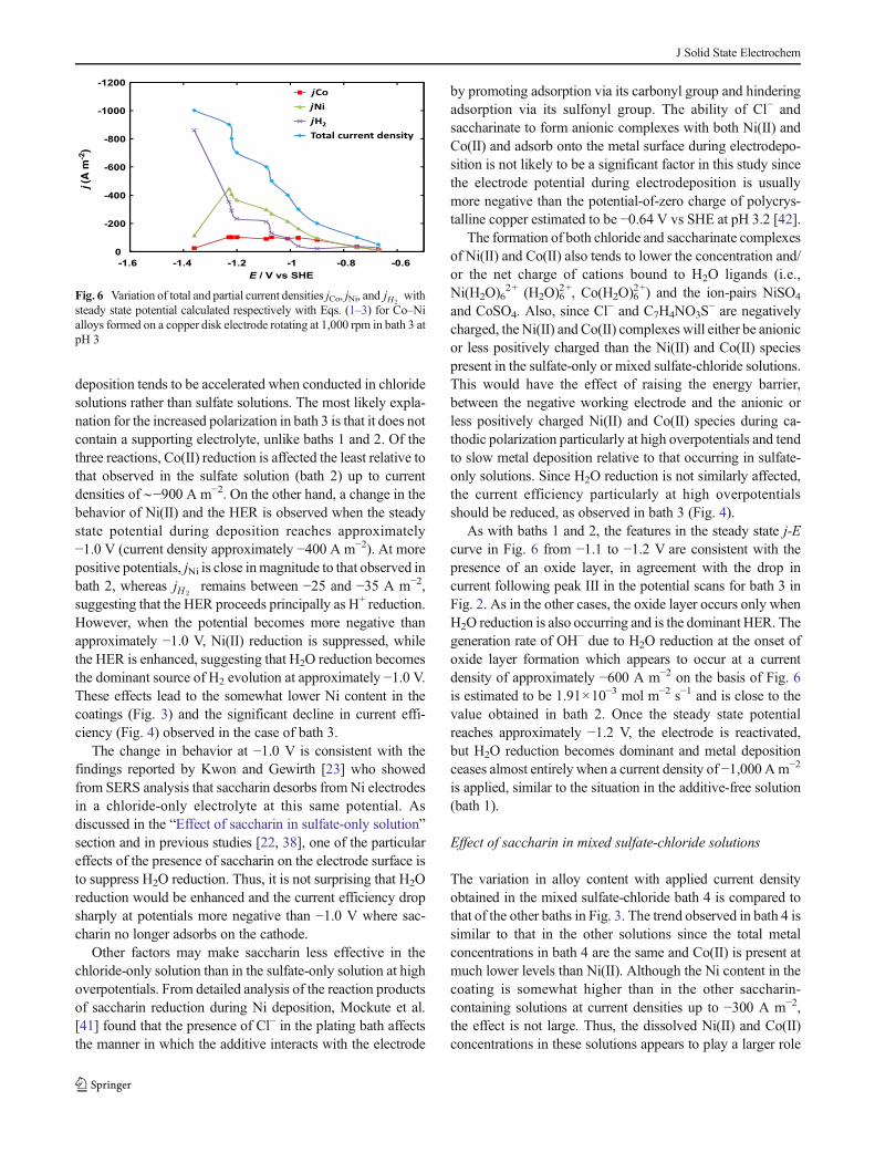
On the other hand, bath 4 stands out above the othersolutions with regard to the current efficiency. A higher cur-rent efficiency is attained in bath 4 than in any other bath atcurrent densities above −50 A m−2 (Fig. 4), reaching ∼80 % at−100 A m−2 and ∼90 % at −200 Å m−2. Particularly notewor-thy is its ability to maintain the current efficiency close to andabove 90 % at all current densities up to and including−1,000 A m−2. The significant improvement achieved in bath4 becomes clearer upon examination of the steady statecurrent-potential curve obtained during Co–Ni deposition(Fig. 7a) which exhibits 3 distinct regions at lowoverpotentials (−0.55 to −0.95 V), intermediate overpotentials(−0.95 to −1.2 V), and high overpotentials (−1.2 to −1.36 V).In the low overpotential region, jCo remains approximately thesame as in the other saccharin-containing baths 2 and 3,whereas jNi is significantly higher (from ∼15 to 50 % moredepending on the current). This rise in jNi comes at theexpense of jH2
which never exceeds −25 A m−2 over thiscurrent range, suggesting that the HER proceeds predominant-ly via H+ reduction.
The intermediate overpotential region is marked by a sig-nificant increase in electrode polarization. Although suchbehavior is observed in the other baths, some differences areevident in this case. Very little H2O reduction is occurring inthis region and neither Ni(II) nor Co(II) reduction is sup-pressed. Thus, it is most reasonable to conclude that the effectsin this intermediate region can be attributed to an adsorbedsaccharin film. Such a conclusion is supported by the resultsof Brankovic et al. [22] showing that saccharin forms a con-densed film on Co–Fe–Ni alloy surfaces at these potentials.
The most significant difference in the behavior of thesystem in bath 4 is observed in the high overpotential region.As in the previous baths, when enough current is applied, thepolarizing effects that dominate in the intermediate region areovercome to reactivate the electrode. However, unlike theprevious cases, it is not water reduction that consumes themajority of the additional current applied in the highoverpotential region. Instead, the water reduction remainssuppressed and jH2
never exceeds −100 Am−2 even at currentdensities as high as −1,000 A m−2. On the other hand, Ni(II)reduction in particular and Co(II) reduction to a lesser extentrise significantly and reach levels not reached in the otherbaths. No evidence of desorption of saccharin at highoverpotentials is observed on the basis of these electroderesponses and alloy composition, unlike the situation in thechloride-only bath 3.
Bath 5 is a mixed sulfate-chloride solution without anysaccharin. Comparison of the deposit composition, currentefficiency and partial current densities in baths 4 and 5 shouldenable the role of saccharin in this mixed electrolyte to bemore clearly delineated. Coatings produced in the absence ofsaccharin in the mixed sulfate-chloride solution are richer inNi than those generated in its presence (bath 4) at all currentdensities of −200 A m−2 and above, a similar trend to thatobserved in the sulfate-only solutions (baths 1 and 2) in Fig. 3.In the case of current efficiency, the behavior of Co–Nideposition in bath 5 up to approximately −400 A m−2 differsmarkedly from that observed at higher current densities(Fig. 4). Similar current efficiencies in baths 4 and 5 areattained at lower currents. However, when the currentdensity is raised to −500 A m−2 and above, the currentefficiency drops to 40–50 % which is well below thatmaintained in bath 4.
Further evidence of this abrupt change in behavior comesfrom the steady state j-E curves obtained in bath 5 (Fig. 7b). Atpotentials more positive than ∼−1.0 V, the partial currents areapproximately the same as in bath 4. However, once thepotentials becomes more negative than approximately−1.0 V, both jCo and jNi are reduced approximately in half toapproximately −35 and approximately −180 A m−2, respec-tively, and jH2
rises sharply to close to ∼−300 A m−2,reflecting that a significant amount of H2O reduction is nowoccurring. This rapid onset of H2O reduction occurs when jCo
b-1200
-1000
-800
-600
-400
-200
0-1.6 -1.4 -1.2 -1 -0.8 -0.6
E / V vs SHE
jCojNijH2
Total current density
a-1200
-1000
-800
-600
-400
-200
0-1.6 -1.4 -1.2 -1 -0.8 -0.6
E / V vs SHE
jCojNijH2
Total current density
j (A
m-2
) j (
A m
-2)
Fig. 7 Variation of total and partial current densities jCo, jNi, and jH2with
steady state potential calculated respectively with Eqs. (1–3) for Co–Nialloys formed on a copper disk electrode rotating at 1,000 rpm in thefollowing baths described in Table 1: a bath 4 and b bath 5 at pH 3
J Solid State Electrochem

and jNi are still relatively low and well below their masstransport-limiting levels. Thus, it is not necessary that Co(II),Ni(II), and H+ reduction all become rate-limited before therate of H2O reduction becomes significant. Although jNi riseswith a further increase in the applied current, it always remainsbelow −400 A m−2 even at the highest current. No significantchange in jCo is measured, on the other hand, so that it remainsbetween −30 and −40 A m−2. However, only jH2
risessignificantly with further rise in current so that H2O reductionbecomes the dominant cathodic reaction at highoverpotentials. This behavior contrasts strongly with that ob-served in bath 4 where H2O reduction is strongly suppressedand metal deposition is enhanced at intermediateoverpotentials. Such a difference is consistent with that ob-served in the sulfate-only solutions (baths 1 and 2) and find-ings from previous studies that saccharin interacts moststrongly with the working electrode at potentials close to−1.0 V, acts primarily to suppress H2O reduction and in factmay facilitate metal deposition. Another consistent trend ev-ident from the differences observed in baths 4 and 5 is theeffect of saccharin on Co(II) reduction. As observed in thesulfate-only solutions, Co(II) reduction is consistently en-hanced by the presence of saccharin in the mixed sulfate-chloride bath, particularly at intermediate and highoverpotentials.
The results shown in Figs. 3 and 4 are promising from apractical point of view. By carrying out electrodeposition insolutions with the same composition as bath 4, one canachieve high current efficiencies that are largely independentof the applied current density over a wide range from approx-imately −200 to −1,000 A m−2. The choice of the currentdensity can then be used to control the composition of theresulting coating. As indicated in Fig. 3, any desired alloycomposition between ∼70 and 90 wt% Ni can be obtained byselection of the appropriate current density between −200 and−1,000 A m−2.
Conclusions
This study focused on the effects of sulfate, chloride andsaccharin on the electrodeposition of Co–Ni alloy films insynthetic solutions with metal concentrations similar to thatproduced by leaching of spent Ni–Cd battery components.The electrode responses during galvanostatic deposition pro-vide evidence supporting findings from previous studies thatsaccharin adsorbs on the surface at potentials of approximate-ly −1.0 V. From analysis of the amount and composition ofdeposited metal, the main effect of this adsorption is to inhibitH2O reduction at higher overpotentials, thereby facilitatingmetal deposition and widening the potential and current
ranges over which the electrodeposition of Co–Ni alloys canbe effectively accomplished.
Regardless of the nature of the electrolyte and the presenceor absence of saccharin, deposition follows anomalous behav-ior at all current densities in every bath, although it approachesnormal behavior as the current density increases toward−1,000 A m−2 and Co(II) reduction becomes mass transfer-controlled. The presence of saccharin tends to lower the Nicontent and promote more anomalous behavior to a relativelysmall extent that remains essentially constant across a widerange of current densities from −100 to −1,000 A m−2. Higherdeposition current efficiencies are achieved in a mixed sulfate-chloride solution containing saccharin than in a sulfate-onlysolution containing saccharin, a chloride-only solution con-taining saccharin or a sulfate-only solution containing noadditive. Differences in the effect of the current density onthe current efficiency are evident at intermediate-to-highoverpotentials depending on the bath composition.
Acknowledgments The authors are indebted to the CONACyT(Mexico) Grants No. 2012–183230 and 205416–2013 for financialsupport to carry out this research.
References
1. Dahms H, Croll IM (1965) Anomalous codeposition of iron-nickelalloys. J Electrochem Soc 112:771–775
2. Golodnitsky D, Rosenberg Y, Ulus A (2002) The role of anionadditives in the electrodeposition of nickel-cobalt alloys fromsulfamate electrolyte. Electrochim Acta 47:2707–2714
3. Vazquez-Arenas J, Altamirano-Garcia L, Pritzker M, Luna-SanchezR, Cabrera-Sierra R (2011) Experimental and modeling study ofnickel electrodeposition including H+ and water reduction and ho-mogeneous reactions. J Electrochem Soc 158:D33–D41
4. Epelboin I, Joussellin M, Wiart R (1981) Impedance measurementsfor nickel deposition in sulfate and chloride electrolytes. J ElectroanalChem 119:61–71
5. Bielinski J, Przyluski J (1979) Selected problems in the continuouselectrodeposition of Ni-Fe alloys. Surf Technol 9:53–64
6. Lallemand F, Ricq L, Bercot P, Pagetti J (2002) Effects of thestructure of organic additives in the electrochemical preparation andcharacterization of CoFe film. Electrochim Acta 47:4149–4156
7. Kim SH, Sohn HJ, Joo YC, Kim YW, Yim TH, Lee HY, Kang T(2005) Effect of saccharin addition on the microstructure of electro-deposited Fe-36 wt.% Ni alloy. Surf Coat Technol 199:43–48
8. Burzynska L, Rudnik E (2000) The influence of electrolysis param-eters on the composition and morphology of Co–Ni alloys.Hydrometallurgy 54:133–149
9. Lallemand F, Ricq L, Deschaseaux E, De Vettor L, Bercot P (2005)Electrodeposition of cobalt-iron alloys in pulsed current from elec-trolytes containing organic additives. Surf Coat Technol 197:10–17
10. Tabakovic I, Riemer S, Inturi V, Jallen P, Thayer A (2000) Organicadditives in the electrochemical preparation of soft magnetic CoNiFefilms. J Electrochem Soc 147:219–226
11. Bhandari A, Hearne SJ, Sheldon BW, Soni SK (2009)Microstructural origins of saccharin-induced stress reduction in elec-trodeposited Ni. J Electrochem Soc 156:D279–D282
J Solid State Electrochem
12. Pietrelli L, Bellomo B, Fontana D, Montereali M (2005)Characterization and leaching of NiCd and NiMH spent batteriesfor the recovery of metals. Waste Manage (Oxford) 25:221–226
13. Rudnik E, Nikiel M (2007) Hydrometallurgical recovery of cadmiumand nickel from spent Ni-Cd batteries. Hydrometallurgy 89:61–71
14. Matlosz M (1993) Competitive adsorption effects in the electrodepo-sition of iron-nickel alloys. J Electrochem Soc 140:2272–2279
15. ZechN, Landolt D (2000) The influence of boric acid and sulfate ionson the hydrogen formation in Ni-Fe plating electrolytes. ElectrochimActa 45:3461–3471
16. Altamirano-Garcia L (2010) Estudio cinético de la deposición deníquel en solución de sulfatos utilizando la técnica devoltamperometría lineal UAM-Azcapotzalco, México D. F
17. Vazquez-Arenas J, Pritzker M (2012) Steady-state model for anom-alous Co–Ni electrodeposition in sulfate solutions. Electrochim Acta66:139–150
18. Vazquez-Arenas J, Altamirano-Garcia L, Treeratanaphitak T, PritzkerM, Luna-Sanchez R, Cabrera-Sierra R (2012) Co–Ni alloy electro-deposition under different conditions of pH, current and composition.Electrochim Acta 65:234–243
19. Vazquez-Arenas J, Pritzker M (2013) Effect of electrolyte andagitation on the anomalous behavior and morphology of elec-trodeposited Co–Ni alloys. J Solid State Electrochem 17:419–433
20. Ricq L, Lallemand F, Gigandet MP, Pagetti J (2001) Influence ofsodium saccharin on the electrodeposition and characterization ofCoFe magnetic film. Surf Coat Technol 138:278–283
21. Horkans J (1981) Effect of plating parameters on electrodepositedNiFe. J Electrochem Soc 128:45–49
22. Brankovic SR, Vasiljevic N, Klemmer TJ, Johns EC (2005) Influenceof additive adsorption on properties of pulse deposited CoFeNialloys. J Electrochem Soc 152:C196–C202
23. Kwon H, Gewirth AA (2007) SERS examination of saccharin ad-sorption on Ni electrodes. J Electrochem Soc 154:D577–D583
24. Bai A, Hu CC (2002) Effects of electroplating variables on thecomposition and morphology of nickel-cobalt deposits platedthrough means of cyclic voltammetry. Electrochim Acta 47:3447–3456
25. Nakahara S, Mahajan S (1980) The influence of solution pH onmicrostructure of electrodeposited cobalt. J Electrochem Soc 127:283–288
26. Szklarska-Smialowska Z, Smialowski M (1963) Electrochemicalstudy of the nickel-hydrogen system. J Electrochem Soc 110:444–448
27. Baranowski B (1978) Metal-hydrogen systems at high hydrogenpressures. In: Alefeld G, Völkl J (eds) Hydrogen in Metals II, vol29. Topics in Applied Physics. Springer Berlin Heidelberg
28. Boniszewski T, Smith GC (1961) A note on nickel hydride. J PhysChem Solids 21:115–118
29. Matsushima JT, Trivinho-Strixino E, Pereira EC (2006) Investigationof cobalt deposition using the electrochemical quartz crystal micro-balance. Electrochim Acta 51:1960–1966
30. Fleischmann M, Sarabyreintjes A (1984) The simultaneous deposi-tion of nickel and hydrogen on vitreous carbon. Electrochim Acta29:69–75
31. Datta M, Landolt D (1980) On the role of mass-transport in high-ratedissolution of iron and nickel in ECM electrolytes. 1. Chloridesolutions. Electrochim Acta 25:1255–1262
32. Lide DR (2004) CRC Handbook of Chemistry and Physics, 85thEdition. Taylor & Francis
33. Orinakova R, Streckova M, Trnkova L, Rozik R, Galova M (2006)Comparison of chloride and sulphate electrolytes in nickel electrode-position on a paraffin impregnated graphite electrode. J ElectroanalChem 594:152–159
34. Yin KM (1997) Potentiostatic deposition model of iron-nickel alloyson the rotating disk electrode in the presence of organic additive. JElectrochem Soc 144:1560–1566
35. Lallemand F, Ricq L, Wery A, Bercot P, Pagetti J (2004) Theinfluence of organic additives on the electrodeposition of iron-group metals and binary alloy from sulfate electrolyte. Appl SurfSci 228:326–333
36. Hassani S, Raeissi K, Golozar MA (2008) Effects of saccharin on theelectrodeposition of Ni-Co nanocrystalline coatings. J ApplElectrochem 38:689–694
37. Lallemand F, Comte D, Ricq L, Renaux P, Pagetti J, Dieppedale C,Gaud P (2004) Effects of organic additives on electroplated softmagnetic CoFeCr films. Appl Surf Sci 225:59–71
38. Mockute D, Bernotiene G (2000) The interaction of additives withthe cathode in a mixture of saccharin, 2-butyne-1,4-diol and phthal-imide during nickel electrodeposition in aWatts-type electrolyte. SurfCoat Technol 135:42–47
39. Haider SZ, Malik KMA, Ahmed KJ, Hess H, Riffel H, HursthouseMB (1983) X-ray crystal-structures of metal saccharin complexes ofgeneral formula [M(C7H4NO3S)2(H2O)4]-2H2O, where M = Fe(II),Co(II), Ni(II) and Cu(II). Inorg Chim Acta 72:21–27
40. Chomakova M, Vitkova S (1989) Metal microdistribution during Ni-Fe alloy deposition. Electrochim Acta 34:1197–1203
41. Mockute D, Butkiene R, NivinskieneO (2001) Effect of chloride ionson the behavior of saccharin, N-methylsaccharin, and 2-butyne-1,4-diol during electrodeposition of nickel from acid electrolytes. Russ JElectrochem 37:376–381
42. Lukomska A, Sobkowski J (2004) Potential of zero charge of mono-crystalline copper electrodes in perchlorate solutions. J ElectroanalChem 567:95–102
J Solid State Electrochem


![Variation of Heterometallic Structural Motifs Based on [W(CN)8]3− Anions and MnII Ions as a Function of Synthetic Conditions](https://static.fdokumen.com/doc/165x107/633cb3f0d29b8ed9200c9646/variation-of-heterometallic-structural-motifs-based-on-wcn83-anions-and-mnii.jpg)