Effects of Processing Parameters on Direct Laser Deposited ...
295
January 2022 EFFECTS OF PROCESSING PARAMETERS ON DIRECT LASER DEPOSITED MATERIALS FOR INDUSTRIAL COMPONENTS REPAIR ANDRÉ ALVES FERREIRA Doctoral Thesis in Metallurgical and Materials Engineering, in the field of Engineering Sciences and Technologies - Materials Engineering, supervised by Professor Doctor Manuel Fernando Gonçalves Vieira and Professor Doctor Ana Rosanete Lourenço Reis, submitted to the Faculty of Engineering of the University of Porto. D 2022
-
Upload
khangminh22 -
Category
Documents
-
view
0 -
download
0
Transcript of Effects of Processing Parameters on Direct Laser Deposited ...

January 2022
EFFECTS OF PROCESSING PARAMETERS ON
DIRECT LASER DEPOSITED MATERIALS FOR
INDUSTRIAL COMPONENTS REPAIR
ANDRÉ ALVES FERREIRA
Doctoral Thesis in Metallurgical and Materials Engineering, in the field of Engineering
Sciences and Technologies - Materials Engineering, supervised by Professor Doctor
Manuel Fernando Gonçalves Vieira and Professor Doctor Ana Rosanete Lourenço Reis,
submitted to the Faculty of Engineering of the University of Porto.
D 2022

Faculty of Engineering of the University of Porto
ANDRÉ ALVES FERREIRA
Doctoral Thesis in Metallurgical and Materials Engineering, in the field of Engineering
Sciences and Technologies - Materials Engineering, supervised by Professor Doctor
Manuel Fernando Gonçalves Vieira and Professor Doctor Ana Rosanete Lourenço
Reis, submitted to the Faculty of Engineering of the University of Porto.
January 2022
EFFECTS OF PROCESSING PARAMETERS ON
DIRECT LASER DEPOSITED MATERIALS FOR
INDUSTRIAL COMPONENTS REPAIR

i ____________________________________________________________________________________________________
Effects of Processing Parameters on Direct Laser Deposited Materials for Industrial Components Repair
“You are my God, and I will give you praise; my God, and I will give
honour to your name. O give praise to the Lord, for he is good: for his
mercy is unchanging for ever.” Psalms 118 : 28-29

ii ____________________________________________________________________________________________________
Effects of Processing Parameters on Direct Laser Deposited Materials for Industrial Components Repair
Acknowledgements
First of all, I would like to thank God for allowing us to reach the end of this long
journey. Thank you, Lord, for Your mercy is infinite.
I´m very grateful to my wife, Lidiane Ferreira and my sons Caetano Ferreira and Pedro
Ferreira, whose constant support and prayers helped me complete it successfully. I
would also like to thank my dear parents, Laci Ferreira and Vania Ferreira, for
believing in and helping me to achieve what I have dreamed of in my life so far. I
thank all my relatives and friends for their support over the years.
I want to express my deepest gratitude to my advisor Prof. Dr Manuel Fernando
Gonçalves Vieira, for his support during all these years. He was a caring and
dedicated supervisor who always helped me with his time, advice, insights; he
encouraged me to publish my research and inspired my growing passion for science.
He provided all the necessary resources for my investigation. I am particularly
grateful for the opportunity and confidence he placed with me when he agreed to
supervise me even before we met in person when the first contact was made in Brazil.
I also sincerely appreciate the support of my co-advisor, Prof. Dr Ana Rosanete Reis.
Her support and discussions have been fundamental throughout all these years.
Thank you for providing the resources to complete this PhD thesis.
I thank Prof. Dr Luis Filipe Malheiros and Prof. Dr Laura Ribeiro, for all the
opportunities and advice given to me during this journey. It was, is, and will greatly
contribute to my professional and academic life.
It is essential to thank Prof. Dr Filomena Viana for the advice and all the scientific
discussions that enriched this doctoral thesis.

iii ____________________________________________________________________________________________________
Effects of Processing Parameters on Direct Laser Deposited Materials for Industrial Components Repair
I also express my thanks to all Professors and Technicians in the Department of
Metallurgical and Materials Engineering who made the work environment very
positive every day in addition to their excellent work at the university.
I am extremely grateful to the SERMEC Group that, through Eng. João Cruz and Dr.
Mário Duarte, it was possible to develop all the experimental activities and technical
discussions that enriched this doctoral thesis. I am also grateful for the opportunity to
be part of this group that has helped me in my technical-scientific growth throughout
these years.
I express my deep gratitude to the GEAR3D project (POCI-01-0247-FEDER-039848)
and to the Associate Laboratory in Energy, Transport and Aeronautics (LAETA), for
their assistance on many fronts, such as finance (experiences, conferences, raw
materials, and so on), for the equipment and resources that were indispensable for the
PhD completion.
I thank the ADDing (reference POCI-01-0145-FEDER-030490) and the Add.Additive
(reference POCI-01-0247-FEDER-024533) projects for all the support given throughout
my PhD.
I am grateful to Dr Omid Emadinia, Dr Rubem Santos and Dr Rui Rocha for countless
discussions, conversations and help along the way. All of our discussions helped me
in the course of this investigation.
It is also essential to thank my colleagues MSc. Aida Beatriz, MSc. Iris Carneiro, MSc.
Marcionilo Neri and MSc. Tânia Peixoto at the Department of Metallurgical and
Materials Engineering for their friendship and companionship.
I thank my colleagues at INEGI, MSc. Diogo Fula, MSc. João Sousa, MSc. Ricardo
Cardoso, MSc. Roya Darabi, Dr Rui Amaral and MSc. Rui Soares for his friendship,
conversations, assistance, and exchange of experiences were fundamental throughout
this journey.

iv ____________________________________________________________________________________________________
Effects of Processing Parameters on Direct Laser Deposited Materials for Industrial Components Repair
Finally, I thank the professors at PUC-Rio: Prof. Dr Fernando Rizzo, Prof. Dr Ivani
Bott, Prof. Dr José Roberto D'almeida, Prof. Dr Maurício de Jesus, Prof. Dr Roberto de
Avillez, Prof. Dr Sydney Parcionik and Prof. Dr Valter Rocha; EQ/UFRJ: Prof. Dr
Eliana Flávia (EQ/ UFRJ) and INT: Prof. Dr Márcia Lutterbach, for inspiring me
throughout my academic life.

v ____________________________________________________________________________________________________
Effects of Processing Parameters on Direct Laser Deposited Materials for Industrial Components Repair
Abstract
The world's ambitious renewable energy goals push wind energy to become a
mainstream energy source. Wind turbines are subject to harsh/hostile environments,
which shorten the life cycle considerably. In many cases, gears are replaced with only
one or two pinion teeth with total or partial breakage, or even worse, with only
excessive wear on one or two teeth. In these cases, the repair would avoid complete
pinion replacement, substantially reducing costs and downtime.
Motivated by this emerging need, this PhD project aimed to explore an additive direct
laser deposition (DLD) technology, derived from the laser cladding technique (i.e.
laser cladding), for the repair/rebuild process of large industrial components, such as
the teeth of gears used in machine organs of wind generator gearboxes. The
introduction of additive manufacturing technologies for repair/rebuild procedures, as
opposed to replacement, will result in a radical and disruptive innovation in the area
of industrial maintenance. A repair procedure with additive manufacturing will
potentially be faster, thus reducing downtime due to breakdown.
The material deposition procedures must allow the deposition of small successive
layers compatible with the dimensions of the pinion teeth. The additive materials
(powders) must be completely compatible with the materials present in the original
teeth to ensure a good metallurgical bond. The bonding properties between the
additive material and the substrate must transfer loads.
The research promoted the process's optimisation and evaluation of preheating
conditions by deposition of single lines of Inconel 625 and AISI 431 powders on
42CrMo4 structural steel substrate. Functionally Graded Materials (FGM) production
aimed to seek the best chemical composition promoted by the powder mixture,
varying the mass composition of powder gradually and initiating the deposition with
pure Inconel 625. Through the characterisations of the FGM, it was possible to
vi ____________________________________________________________________________________________________
Effects of Processing Parameters on Direct Laser Deposited Materials for Industrial Components Repair
determine the ideal composition of powder mixture (Inconel 625 + 50% AISI 431). The
production of this innovative material can meet different demands of the wind power
sector and the most diverse industrial sectors.
In order to evaluate the 3D construction by additive manufacturing, bulks were
produced using powders of AISI 431 or Inconel 625, and with the composition Inconel
625 + 50% AISI 431, allowing the comparison of mechanical and microstructural
properties.
However, matching the carburised layer hardness of the gear teeth with the teeth
produced by additive manufacturing is a challenge to be answered in the GEAR3D
project. A new innovative FGM was produced to respond to this task mixing Inconel
625 with a nickel-superalloy, type NiCrWMo. The metallurgical, chemical and
mechanical characterisations, and the correlation with processing parameters, are
established and discussed throughout this investigation.
Keywords: Additive Manufacturing; Direct Laser Deposition; Functionally Graded
Materials; Mechanical Properties; Microstructure; Nickel Superalloys; Repair; Steel.

vii ____________________________________________________________________________________________________
Effects of Processing Parameters on Direct Laser Deposited Materials for Industrial Components Repair
Resumo
As ambiciosas metas mundiais da energia renovável estão pressionando a energia
eólica a se tornar uma fonte de energia convencional. As turbinas eólicas estão sujeitas
a ambientes severos/hostis que podem encurtar consideravelmente o ciclo de vida de
um componente. Frequentemente, engrenagens são substituídas com apenas um ou
dois dentes do pinhão com rotura total ou parcial, ou ainda pior, com apenas desgaste
excessivo em um ou dois dentes. Nestes casos, a reparação evitaria a substituição
completa do pinhão, reduzindo substancialmente os custos e tempo de paragem.
Motivada por esta necessidade emergente, este projeto de doutoramento visou a
exploração de uma tecnologia aditiva de deposição direta por laser (DLD), derivada
da técnica de revestimento por laser (i.e., laser cladding), para o processo de
reparação/ reconstrução de componentes industriais de grandes dimensões, como os
dentes de engrenagens utilizadas em órgãos de máquina de redutores de geradores
eólicos. A introdução de tecnologias de manufatura aditiva para os procedimentos de
reparação/reconstrução em detrimento da substituição resultará numa inovação
radical e disruptiva na área da manutenção industrial. Um procedimento de reparação
com manufatura aditiva, potencialmente será mais rápido, reduzindo assim o tempo
inoperacional devido a avaria.
Os procedimentos de deposição de material devem permitir a deposição de camadas
sucessivas de pequena dimensão, de forma a serem compatíveis com as dos dentes
dos pinhões, e os materiais de adição (pós) devem ser compatíveis com os materiais
presentes nos dentados originais, de forma a garantir uma boa ligação metalúrgica.
As propriedades de ligação entre o material aditivo e o substrato devem ser tais que
permitam a transmissão de carregamentos.
A investigação realizada promoveu a otimização do processo e a avaliação das
condições de pré-aquecimento através da deposição de monocamadas de pós de

viii ____________________________________________________________________________________________________
Effects of Processing Parameters on Direct Laser Deposited Materials for Industrial Components Repair
Inconel 625 e AISI 431 em substrato de aço estrutural 42CrMo4. A produção de
Materiais em Gradiente Funcional (FGM), teve como objetivo selecionar a melhor
composição química promovida pela mistura do pós, variando gradualmente a
composição mássica de pó e iniciando a deposição com 100% Inconel 625. Através da
caracterização do FGM, foi possível determinar a composição ideal de mistura de pó
(Inconel 625 + 50% AISI 431), sendo produzido um material inovador que pode
atender diferentes demandas do setor eólico, como também dos mais diversos setores
industriais.
Com o objetivo de avaliar a construção 3D por fabricação aditiva, foram produzidos
maciços com os pós de AISI 431, Inconel 625 e Inconel 625 + 50% AISI 431, permitindo
a comparação das propriedades mecânicas e microestruturais.
Entretanto, tentar igualar a dureza da capa cementada do dentado, com o dentado
produzido por fabricação aditiva é um desafio a ser respondido no projeto GEAR3D.
Para isto, um inovador FGM foi produzido através da mistura de Inconel 625 com
uma superliga de níquel do tipo NiCrWMo. As caracterizações metalúrgicas, químicas
e mecânicas e a correlação com os parâmetros do processo foram determinadas e
discutidas nesta investigação.
Palavras-chave: Aço; Fabricação Aditiva; Deposição Direta por Laser; Materiais
Funcionalmente Graduados; Reparação; Microestrutura; Propriedades Mecânicas;
Superligas de Níquel.

ix ____________________________________________________________________________________________________
Effects of Processing Parameters on Direct Laser Deposited Materials for Industrial Components Repair
Summary
Abstract ................................................................................................................................................. v
Resumo ................................................................................................................................................ vii
Background .......................................................................................................................................... 2
Direct Laser Deposition ................................................................................................................. 2
Process Parameters .......................................................................................................................... 6
Characteristics of a Cladding Produced by Direct Laser Deposition .................................... 7
Dilution ......................................................................................................................................... 7
Microstructure features ............................................................................................................... 8
Repair of Industrial Components by Direct Laser Deposition ........................................... 12
Proposed Solution Concept ......................................................................................................... 14
Thesis Outline ............................................................................................................................... 18
References....................................................................................................................................... 20
Article 1 - Functionally graded materials (FGM) fabricated by Direct Laser Deposition: A
Review. ................................................................................................................................................ 29
Abstract ........................................................................................................................................... 29
Introduction ................................................................................................................................... 30
Production and Characteristics of FGMs .................................................................................. 33
Solidification and Microstructure Formation .......................................................................... 39
Defects ............................................................................................................................................. 45
Mechanical Characterisation....................................................................................................... 48
Conclusions .................................................................................................................................... 55
Article 2 - Effects of Processing Parameters on Functionally Graded Materials for Industrial
Components Repair .......................................................................................................................... 67
Abstract ........................................................................................................................................... 67
Mini-Review .................................................................................................................................. 67
Article 3 - Optimization of Direct Laser Deposition of a Martensitic Steel Powder (Metco
42C) on 42CrMo4 Steel ..................................................................................................................... 78
Abstract ........................................................................................................................................... 78
Introduction ................................................................................................................................... 79
Materials and Methods ................................................................................................................ 81
Results ............................................................................................................................................. 85

x ____________________________________________________________________________________________________
Effects of Processing Parameters on Direct Laser Deposited Materials for Industrial Components Repair
Microstructural and Mechanical Characterization ............................................................. 85
Influence of Processing Conditions ......................................................................................... 91
Optimization of Processing Conditions ................................................................................. 95
Conclusions .................................................................................................................................. 102
Article 4 - Deposition of Nickel-Based Superalloy Claddings on Low Alloy Structural Steel
by Direct Laser Deposition ........................................................................................................... 108
Abstract ......................................................................................................................................... 108
Introduction ................................................................................................................................. 109
Materials and Methods .............................................................................................................. 112
DLD System Setup ................................................................................................................... 112
Feedstock Powder and Substrate ........................................................................................... 113
Process Parameters .................................................................................................................. 114
Mechanical and Microstructural Characterisation ............................................................ 115
Results and Discussion .............................................................................................................. 116
Processing Effects .................................................................................................................... 116
Microstructures and Mechanical Characterisation of the DLD Samples ....................... 121
Microhardness Measurements ............................................................................................... 128
Conclusions .................................................................................................................................. 129
Article 5 - Thermal Study of a Cladding Layer of Inconel 625 in Directed Energy Deposition
(DED) Process Using a Phase-Field Model ................................................................................ 136
Abstract ......................................................................................................................................... 136
Introduction ................................................................................................................................. 138
Proposed Numerical Approaches ............................................................................................ 141
Governing equation of thermal energy balance ................................................................... 141
Material Properties Module ................................................................................................... 144
Heat Source Model ................................................................................................................... 147
Experimental procedure ............................................................................................................. 148
Numerical implementation with finite element method (FEM) ........................................ 152
Finite element solution for heat transfer .............................................................................. 152
Implementation ........................................................................................................................ 154
Time and space discretization ............................................................................................... 154
Initial and Thermal boundary condition ............................................................................. 155
Result and discussion ................................................................................................................. 157

xi ____________________________________________________________________________________________________
Effects of Processing Parameters on Direct Laser Deposited Materials for Industrial Components Repair
Sensitivity analysis to the time and space discretization ................................................ 157
Numerical model validation .................................................................................................. 159
Transient heat model associated with phase field approach ............................................ 162
Local temperature gradient and solidification rate (𝑮, 𝑹) ................................................ 165
Conclusion .................................................................................................................................... 168
Article 6 - Mechanical and Microstructural Characterisation of Bulk Inconel 625 Produced
by Direct Laser Deposition ........................................................................................................... 176
Abstract ......................................................................................................................................... 176
Introduction ................................................................................................................................. 177
Experimental Procedure ............................................................................................................. 180
DLD System Setup ................................................................................................................... 180
Powder and Substrate Characteristics ................................................................................. 180
Samples Production ................................................................................................................. 181
Microstructural and Mechanical Characterisation ............................................................ 183
Results and Discussion .............................................................................................................. 185
Microstructure .......................................................................................................................... 185
Uniaxial Tensile Test ............................................................................................................... 189
Fracture Surface Analysis ....................................................................................................... 195
Microhardness .......................................................................................................................... 197
Wear Analysis .......................................................................................................................... 199
Conclusions .................................................................................................................................. 201
Article 7 - Inconel 625 / AISI 413 Stainless Steel Functionally Graded Material Produced by
Direct Laser Deposition ................................................................................................................. 210
Abstract ......................................................................................................................................... 210
Introduction ................................................................................................................................. 211
Experimental Procedure ............................................................................................................. 213
Results and discussion ............................................................................................................... 216
Microstructural and Chemical Evaluations ........................................................................ 216
Microhardness Mapping ......................................................................................................... 226
Conclusions .................................................................................................................................. 228
Article 8 - Mechanical and Microstructural Characterisation of Inconel 625 - AISI 431 Steel
Bulk produced by Direct Laser Deposition ............................................................................... 235
Abstract ......................................................................................................................................... 235
Introduction ................................................................................................................................. 236

xii ____________________________________________________________________________________________________
Effects of Processing Parameters on Direct Laser Deposited Materials for Industrial Components Repair
Experimental Procedure ............................................................................................................. 239
Results and Discussion .............................................................................................................. 244
Microstructure of the bulk material ...................................................................................... 244
Computerised Tomography .................................................................................................... 245
Uniaxial Tensile Test ............................................................................................................... 247
Abrasion wear characteristics ............................................................................................... 256
Conclusions .................................................................................................................................. 257
Preliminary tooth reconstruction ............................................................................................. 264
New Materials Development .................................................................................................... 267
General Conclusions ...................................................................................................................... 272
Appendix A – Oral Presentation in 2nd International Conference on Advanced Joining
Processes ........................................................................................................................................... 277
Appendix B – Oral Presentation in 14th World Congress in Computational Mechanics
(WCCM) ............................................................................................................................................ 278

xiii ____________________________________________________________________________________________________
Effects of Processing Parameters on Direct Laser Deposited Materials for Industrial Components Repair
Acronyms and Symbols
φ Laser spot size
γ Surface tension gradient
ρc Molten powder density [kg/m3]
ρs Substrate material density [kg/m3]
Ɵ wetting angle
AM Additive manufacturing
AC Clad Area
b Crater diameter
CL Cladding layer
CTE Coefficient of thermal expansion
D Dendrites
d depth
D4006 Diamalloy 4006 - NiCrWMo
DED Directed Energy Deposition
DLD Direct Laser Deposition
DM Digital microscope
EBSD Electron Backscatter Diffraction
EDX Energy-dispersive X-ray spectroscopy
EG Equiaxed grains
Especific Specific energy
et Total elongation
eu Uniform elongation
FEM Finite Element Method
FGAM Functionally Graded Additive Manufacturing
FL Fusion line

xiv ____________________________________________________________________________________________________
Effects of Processing Parameters on Direct Laser Deposited Materials for Industrial Components Repair
FR Feed Rate
G Thermal gradient at the solid-liquid interface
Gp Powder density
h height
HAZ Heat-affected zone
HRC Rockwell C Hardness
HV Vickers Hardness
HVOF High-Velocity Oxygen Fuel
K Abrasive Wear Rate
LBAM Laser-based additive manufacturing
M42C Martensitic stainless steel – AISI 431
M625 Inconel 625
MA Melting Area
MSWR Mean Specific Wear Rates
OM Optical microscope
P or LP Laser Power
PDD Powder Deposition Density
PHT Preheating
R Ball radius
R Cooling rate
Rm Ultimate tensile strength
RMSE Root Mean Squared Error
Rp0.2 Yield stress
RSM Response Surface Model
S Sliding distance
SEM Scanning Electron Microscopy
SS Scanning Speed
xv ____________________________________________________________________________________________________
Effects of Processing Parameters on Direct Laser Deposited Materials for Industrial Components Repair
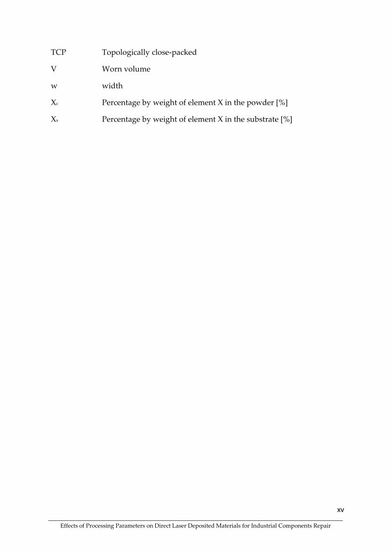
TCP Topologically close-packed
V Worn volume
w width
Xc Percentage by weight of element X in the powder [%]
Xs Percentage by weight of element X in the substrate [%]

1 ____________________________________________________________________________________________________
Effects of Processing Parameters on Direct Laser Deposited Materials for Industrial Components Repair
Chapter 1
BACKGROUND

2 ____________________________________________________________________________________________________
Effects of Processing Parameters on Direct Laser Deposited Materials for Industrial Components Repair
Background
Direct Laser Deposition (DLD) is an additive manufacturing (AM) technology capable
of creating net-shaped parts from powders or wires, depositing them in the desired
geometry, ensuring excellent bonding and metallurgical properties [1]–[4]. Due to its
geometric freedom, scalability and adaptability to different scenarios, which other
metals AM technologies cannot offer, this technique is often used to repair industrial
components and confer improved mechanical properties throughout. However, the
most significant advantage of this technology is the expandability of the material
feeders, allowing the processing of various materials in the same operation. Therefore,
this technology can be assumed as a method of deposition of multimaterial and
gradient materials, since it can deposit different materials in sequential layers or
combine them in the same layer.
Previous studies on FGM type processes focus on all additive manufacturing
technologies that can produce them [5]. In this PhD research, an in-depth analysis was
performed on the production of gradient materials and process optimisation to obtain
the best mechanical and microstructural properties for the realisation of the
remanufacturing of industrial components, mainly large gears. This work aims to
describe the approaches adopted by other authors, categorising the advances made in
the process and comparing them with others.
Direct Laser Deposition
Direct laser deposition (DLD) is a kind of advanced rapid manufacturing technology,
which can produce near net shape parts by depositing metal powders layer by layer
[6]. DLD technology is an emerging laser aided manufacturing technology based on a
new additive manufacturing principle, which combines laser cladding with rapid
prototyping into a solid freeform fabrication process that can be used to manufacture

3 ____________________________________________________________________________________________________
Effects of Processing Parameters on Direct Laser Deposited Materials for Industrial Components Repair
near net shape components from their CAD files [7]. Recent studies have indicated
that DLD can repair deep or internal cracks and defects in metallic industrial
components. Metal deposition by DLD is also referenced with an additive
manufacturing process because, compared to other processes, the formation rates and
processing time are high. The mixture of powders creating their alloys increases
resistance (fatigue, corrosion, wear, mechanical) following the component's specificity
and current standards.
DLD is an additive manufacturing process featuring in the industrial context, which
uses metal alloys in powder and is melted by a source of energy, the laser beam. It is
a technique that can be used in cladding production for repair and components
reconstruction. Compared to conventional processes, it has many advantages, such as
arc welding, due to better coatings with controlled heat input producing better surface
quality and resistance to wear and corrosion [8]–[10].
Many components are operated under extreme conditions involving impact, abrasion,
high temperature and pressure, making them prone to fracture. The main failure
modes, such as wear, local corrosion, crack formation and fracture, are directly related
to loading during service. Equipment failures cause significant economic losses to
businesses. Repair of industrial components is an effective way to favourably reduce
a large part of primary resource use and energy consumption, and emissions of
pollutants into the environment. If a successful repair cannot be achieved, the
damaged components will have to be disposed of, and a significant loss will be caused.
The conventional repair methods currently include mechanical machining, arc
welding, and thermal spraying processes such as High-Velocity Oxygen Fuel (HVOF).
Although these methods have different advantages, there are still many
disadvantages in this repair, such as being time-consuming and laborious, having a
limited thickness of deposition layers, low metallurgical bonding, formation of a large
number of porosities and cracks, and distortion of substrates (caused by excessive
components heating). Therefore, it is of great industrial interest to develop high
4 ____________________________________________________________________________________________________
Effects of Processing Parameters on Direct Laser Deposited Materials for Industrial Components Repair
efficiency and precision repair technologies aiming at increasing the lifetime of the
components.
DLD deposition is one of the appropriate techniques for developing these processes
when producing high-quality repairs. With proper addition material, structures with
mechanical properties similar or superior to those of the substrate can be obtained.
These structures present an excellent metallurgical bond, the formation of a small
heat-affected zone (HAZ) by the control of heat transfer and minimum dilution. The
localised repair of components in necessary positions with high precision, associated
with low distortion that minimises machining time after the repair, are major
attractions for different industrial sectors for the use of laser processing [11]–[14].
Moreover, innovative material systems can be produced by gradually changing the
chemistry of the individual layers, thus adjusting the composition of the materials to
the desired properties of the component [15]. DLD is advantageous with high
precision, allowing high economic gain, and due to its unique characteristics, the laser
enables material processing with high efficiency and ease of automation.
Due to these factors, DLD is one of the most attractive and competitive component
repair processes. This technique consists of an effective way to minimise monetary
losses and environmental impacts resulting from the transformation of resources (raw
materials, water and energy) by repairing or rebuilding components that have
suffered breakdowns, putting them back into service.
The growing demands for quality and reliability/reproducibility of results have
contributed to the increasing use of automated special welding processes. DDL has
occupied a space in the most diverse industrial sectors. Numerous industrial
applications demonstrate the technological and economic feasibility of repairing
components by laser in sectors as diverse as aeronautics, petrochemicals (offshore),
energy, rail, maritime transport, steelmaking, among others. Examples of products
that DLD can repair are gearboxes, gears, blowers, combustion engine parts,

5 ____________________________________________________________________________________________________
Effects of Processing Parameters on Direct Laser Deposited Materials for Industrial Components Repair
couplings, extruders, pumps, shafts, turbine parts, rollers, winches, among other
components [16].
The process can produce high energy densities, forming a melt pool that will allow
the powder deposition. High cooling rates are characteristic of this process, where the
laser beam promotes a localised thermal delivery, and the dimensions of the structures
are an industrial problem. Preheating (PHT) of the substrate is one of the processes
that allow the reduction of the cooling rate. PHT decreases the hardness in HAZ [17],
reduces accentuated thermal gradients and increases the laser absorption rate in a
substrate, improving the stress distribution and avoiding the formation of hard
structures that are harmful to the cladding mechanical properties [18].
The efficiency of the process depends mainly on the formation of the melt pool, which
allows the capture of the injected powder particles. In particular, the material
efficiency is strongly dependent on the melt size relative to the size of the impact area
of the powder flow [19], [20]. Many operational parameters and physical phenomena
determine the cladding quality produced by laser processing, such as geometry,
microstructure, dilution, defects, residual stresses, distortion, surface roughness, and
metallurgical changes in the substrate the efficiency of the process. The functional
properties and quality of the claddings produced with laser are strongly dependent
on the final microstructure. The first prerequisite for a successful laser cladding
process is the homogenisation of the melt, which is guaranteed by convection.
The relationships between processing conditions and material responses are not well
established or understood. There is a need for further research in this area to optimise
the process allowing for generalisation.
6 ____________________________________________________________________________________________________
Effects of Processing Parameters on Direct Laser Deposited Materials for Industrial Components Repair
Process Parameters
Many operational parameters and physical phenomena determine the quality of the
cladding produced by DLD, such as the geometry, microstructure, dilution, defects,
residual stresses, distortion, surface roughness, metallurgical changes in the substrate
and the efficiency of the process.
The DLD process is determined by beam characteristics, materials and operating
parameters. Beam and feed rate parameters are generally fixed and dictated by
equipment, laser, and optics. Materials parameters relate to the choice of additive
material and substrate and include the properties of the powder particles (particle size
and morphology, chemical composition, thermophysical and optical properties) and
the properties of the substrate (geometry and mass, chemical composition, surface
condition, thermophysical and optical properties) [19][21].
Operating parameters can be changed, and their variation affects the process results.
Among these, laser power (P), scanning speed (V) and feed rate (F) are considered the
main parameters as they have the greatest effect on the cladding characteristics. The
cladding height increases proportionally with increasing feed rate. In DLD, the
correlations between height and feed rate (F) and height and powder feed rate per
unit length (F/V) are generally linear. In addition to height, the coating cross-sectional
area (A) increases with increasing F and F/V. Above a feed rate threshold value, the
increment of A can accelerate due to the multiple scattering of the laser beam caused
by the dense powder cloud [21][22].
While other parameters are held constant, an increase in laser power increases the
bead height. The cladding width is mainly dictated by the focal point of the laser beam.
However, a width greater than the spot size can be obtained at very low processing
speeds and high laser powers. In general, the cladding width increases with
decreasing scanning speed and increasing laser power. These correlations are linear
in the laser cladding process using a coaxial nozzle [23]–[25].

7 ____________________________________________________________________________________________________
Effects of Processing Parameters on Direct Laser Deposited Materials for Industrial Components Repair
Characteristics of a Cladding Produced by Direct Laser Deposition
According to the information previously mentioned, the properties of claddings
produced by DLD can be determined by a wide variety of factors. In this point, the
main characteristics of cladding will be discussed.
Dilution
The laser cladding process requires achieving a strong metallurgical bond between
the cladding material and the substrate, which in turn requires the formation of a melt
pool on the substrate. However, the depth of this melt (additive material + substrate)
should be as small as possible to obtain a pure surface layer that is not fully diluted
by the base material [26].
Dilution is considered an important factor in controlling the contamination of the
cladding by the substrate material and can be used to characterise the deposition
quality. Indeed, although a minimum level of mixing is required to ensure a good
metallurgical bond to the substrate, as noted above, excessive dilution can negatively
influence cladding properties [27], [28]. Dilution can be measured in two ways. The
first method is based on the cladding geometry layer (Figure 1).
Figure 1. Schematic representation of the cross-sectional area emerging from the original
surface of the plate (AN) and submerged part of the cross-sectional area (AD). Adapted from
[29].

8 ____________________________________________________________________________________________________
Effects of Processing Parameters on Direct Laser Deposited Materials for Industrial Components Repair
This geometric approach assumes a homogeneous distribution of elements in the
cross-section. The dilution is given by Equation 1, being the ratio of the depth of the
coating on the substrate (A1) to the total height (A1 + A2) [29]. It is important to
highlight that dilution increases with increasing laser power but decreases with
increasing scanning speed.
𝑫 (%) =𝑨𝑵
(𝑨𝑫 + 𝑨𝑵)𝒙𝟏𝟎𝟎 Equation 1
In alternative to Equation 1, dilution can be calculated by the percentage of the total
volume of the surface layer that results from substrate fusion, as indicated by Equation
2 [30].
𝑫 = 𝝆𝒄(𝑿𝒄+𝒔 − 𝑿𝒄)
𝝆𝒔(𝑿𝒔 − 𝑿𝒄+𝒔) + 𝝆𝒄(𝑿𝒄+𝒔 − 𝑿𝒄) Equation 2
Where ρc is the density of the molten powder [kg/m3], ρs is the density of the substrate
material [kg/m3], Xc + s is the percentage by weight of element X in the total surface area
of the coating region [%], Xc is the percentage by weight of element X in the powder
[%], and Xs is the percentage by weight of element X in the substrate [%].
Microstructure features
The functional properties and quality of the claddings produced with laser cladding
technology are strongly dependent on the final microstructure. The first prerequisite
for a successful laser cladding process is the homogenisation of the melt, which is
ensured by convection.
The melting pool material flow in processes such as laser cladding directly affects the
bead penetration and width, the solidification structure and the probability of porosity

9 ____________________________________________________________________________________________________
Effects of Processing Parameters on Direct Laser Deposited Materials for Industrial Components Repair
and lack of melting. Surface tension and buoyancy force are two of the most important
driving forces for flow in the melting pool. The surface tension force produces
thermocapillary flow due to temperature changes [31], [32]. The material flow driven
by surface tension is also known as Marangoni convection or the Marangoni effect,
where large thermal gradients within the melt generate intense convection. The
buoyancy force is also considered a gravitational force and manifests itself due to
differences in density originating temperature gradients within the melting pool [33]–
[35]. The Marangoni effect is illustrated in Figure 2.
Figure 2. Marangoni flow in weld pool during single weld bead pass [36].
Surface tension gradients are present on the surface of the melting pool due to
temperature differences. In these situations, a material flow is induced where the
material moves from locations with lower surface tension to locations with higher
surface tension [37]. Surface tension gradients are generally dependent on the
presence of temperature gradients, as noted above, and the surface tension gradient
can be negative (i.e. decrease with increasing temperature); in this case, there is a
radial flow out of the molten metal, promoting the formation of a wider and shallower
melting pool [33]. Conversely, the gradient leads to radial inward flow for a positive
tension surface, producing a deeper and narrower melt pool [38]. Marangoni

10 ____________________________________________________________________________________________________
Effects of Processing Parameters on Direct Laser Deposited Materials for Industrial Components Repair
convection creates a whirlpool at the laser beam periphery, but as the velocity
increases, the maximum velocity of the liquid moves from the sides of the melting
pool to the back of the pool [39], [40].
The solidification microstructure for a given alloy depends on the local solidification
conditions determined by the cooling rate (R) and the thermal gradient at the solid-
liquid interface (G). Specifically, the growth morphology of rapidly solidified layers
is controlled by the parameter G/R. If G/R is higher than a critical value (G/R)* a planar
solidification front occurs. Otherwise, if G/R is lower than this critical value, the planar
solid-liquid interface is destabilised, and cellular or dendritic solidification occurs
[41]–[44]. The G/R effect on the microstructure can be schematically represented in
Figure 3.
Figure 3. Influence of temperature gradient and solidification rate on the
solidification process [45].
These solidification conditions (G and R) are a function of the size and geometry of
the melting zone, which in turn is influenced by the laser processing conditions, such
as laser power, scanning speed, feed rate, beam diameter or substrate temperature. In
contrast to R, the thermal gradient G is at a maximum at the bottom of the melt pool
and progressively decreases towards the surface [46].

11 ____________________________________________________________________________________________________
Effects of Processing Parameters on Direct Laser Deposited Materials for Industrial Components Repair
In cases where solidification occurs without nucleation, solidification is epitaxial,
starts by growth from the substrate and proceeds unidirectionally towards the top. At
the beginning of solidification, at the bottom of the melt pool, a flat solidification zone
appears as the liquid metal maintains contact with the solid substrate (the
solidification rate is 0, and the value of G/R is infinite) [47], [48]. As the solid-liquid
interface propagates, R increases rapidly, and G decreases, leading to a lower value of
G/R: the planar front evolves to a cellular interface and eventually to a dendritic when
G/R decreases further. Due to the rapid variation of G/R, the planar interface is very
narrow [45].
G/R decreases with the evolution of the solidification process until it reaches a value
that remains practically constant during the final solidification phase: in this region,
which follows the cellular interface zone, dendritic solidification appears [47]. The
cellular and dendritic solidifications are generally columnar and grow perpendicular
to the substrate-cladding interface (or perpendicular to isothermal lines) since the
substrate mainly dissipates the heat and, in this direction, the thermal gradient is
greater. Near the surface of the cladding layer, the heat is mainly dissipated through
the surrounding atmosphere, which significantly decreases the G value, and the
dendrites become very thin and disoriented [48], [49]. G/R determines the
solidification morphology, and GxR impacts the scale of solidification microstructure.
The cladding production requires an understanding of thermal and thermophysical
properties: coefficient of thermal expansion (CTE), melting temperature and thermal
conductivity. The inequality in heat flow is due to the faster dissipation at the material
interface that presents higher thermal conductivity, resulting in distortion and the
possibility of lack of fusion formed in material with lower thermal conductivity,
promoted by insufficient heat [50]. Multiple layers reduce the CTE difference and the
mesh misalignment between the consecutive layers. As the number of layers increases,
an analytical solution for thermal stresses makes the system more complex and
promotes residual stresses formation [51].

12 ____________________________________________________________________________________________________
Effects of Processing Parameters on Direct Laser Deposited Materials for Industrial Components Repair
In order to relieve the residual stresses, preheating treatment is a solution, reducing
the cooling rate of both the substrate and the cladding and thus preventing the
formation of fragile phases in the bonding area and gradient minimizing the
likelihood of crack formation. In steels, increasing preheating temperature (PHT)
decreases the cooling rate, thus promoting the decomposition of granular bainite and
increasing the percentage of ferrite [52]. Preheated substrates present a lower
susceptibility cracks formation, decreasing the cooling rate and formation of residual
stresses [53]–[55]. Preheating promotes control of the thermal gradients between the
substrate and the deposited layers as in the case of FGM's, decreasing cooling rate and
residual stresses, promoting better mechanical properties [56].
Repair of Industrial Components by Direct Laser Deposition
In addition to part repair, laser deposition by a powder injection technique has been
widely used in other industrial applications such as rapid manufacturing, surface
coating and innovative alloy development. The ability to mix two or more powders
and control each powder feed rate makes laser cladding a flexible process for
manufacturing heterogeneous and gradient components at the microstructure level.
Materials can be tailored for flexible, functional performance in particular
applications. The inherently rapid heating and cooling rates associated with this
process allow the production of materials with extended solid solubility and out-of-
equilibrium (metastable) phases, offering the possibility of creating new materials
with advanced properties [22].
However, to achieve a successful laser cladding process, a precise and controllable
method of applying filler material at the edge of the melt zone created by the laser
beam is required. Additionally, using an uncontrolled method or inadequate filler
materials results in poor deposition of this often costly material. DLD process for
detail repair on components, such as turbine blades and gears, requires high control

13 ____________________________________________________________________________________________________
Effects of Processing Parameters on Direct Laser Deposited Materials for Industrial Components Repair
in powder deposition, leading to innovation in the development of highly controlled
methods [57].
The component repair by DLD follows a series of steps to obtain a structure similar to
the original. Figure 4 describes the sequences of activities involved in the repair
process.
Figure 4. The industrial component repair process sequence via Direct Laser Deposition
(DLD).
The major challenges of the component repair operation are:
(i) removing the damaged layer due to the high surface hardness of these transmission
elements;
ii) ensure the metallurgical bond between the additive material and the substrate;

14 ____________________________________________________________________________________________________
Effects of Processing Parameters on Direct Laser Deposited Materials for Industrial Components Repair
(iii) produce a new surface coating with high surface hardness and ensure a high
contact fatigue resistance of the repaired element; and
(iv) machining the repaired regions without compromising the area that was not laser-
processed.
Currently, the DLD process is one of the main means of remanufacturing components.
It is an effective way to minimise monetary losses and environmental impacts
resulting from transforming inputs (raw materials, water and energy) by repairing or
rebuilding components that have suffered breakdowns and putting them back into
service [8]. The adoption of new technologies, such as laser, allows remanufactured
components to equal or exceed the performance of new traditionally manufactured
products [58].
Several authors have developed studies to physically model the DLD process [59]–
[62]. However, it is very complex to provide a comprehensive description of the
process due to the interactions in the laser/ powder/ substrate system and the various
physical, chemical and metallurgical phenomena involved in the process [63]–[65].
The remanufacturing of components is also considered a technique of additive
manufacturing to generate complete parts of components and the combination of
different manufacturing processes [16], [66]–[68]. The creation of own and specific
alloys is one of the innovations sought throughout this study.
Proposed Solution Concept
The maintenance of wind turbine gearboxes follows a standardised procedure
consisting of 6 main steps:
i. On-site inspection and disassembly (lead time ≈ two days): Determination of
gearbox condition, bearing settings, gear backlash and size and crack check. The exact
condition of the gearbox is identified, with backlash, contact patterns and bearing

15 ____________________________________________________________________________________________________
Effects of Processing Parameters on Direct Laser Deposited Materials for Industrial Components Repair
settings all being carefully recorded before the gearbox is disassembled. This stage
may include tasks such as visual inspection, vibration measurement and analysis;
alignments; replacement of bearings in the wind turbine generator; replacement of
bearings in the gearboxes' high-speed shaft; oil replacement, among others.
ii. Transport to the workshop (lead time ≈ two days): The damaged parts of the
gearbox are transported to the company's premises.
iii. Gearbox disassembly, inspection report and failure analysis (lead time ≈ three
days): The gearbox is disassembled, and an inspection report and damage analysis
will be carried out.
iv. Rapid gearbox reconditioning and accessory parts manufacturing (lead time ≈
three weeks): The gearbox will be overhauled, and spare parts can be manufactured
or purchased. This step involves several technologies and tools: machining centres,
milling machines, internal grinding machines, gear grinding machines, reverse
engineering systems, butchers and surface treatment (surface tempering, thermal
spraying, HVOF, laser cladding).
v. Gearbox assembly and advanced test on test bench (lead time ≈ four days): The
gearbox with new parts will be assembled. Bearing and gear backlash are adjusted,
and contact patterns are recorded and checked against specifications. Once correctly
assembled, the gearbox will be bench tested.
vi. Transportation and on-site assembly of the gearbox and accessory parts (lead
time ≈ six days).
The actual service life of wind turbine gearboxes is generally shorter than the projected
20 years, and the warranty for these components is only seven years (on average).
Failures can be found in several bearing locations, i.e. in the planetary ones, those of
the intermediate shafts and those of the high-speed shafts.

16 ____________________________________________________________________________________________________
Effects of Processing Parameters on Direct Laser Deposited Materials for Industrial Components Repair
The most common gearboxes in wind turbines consist of three stages: one planetary
stage and two cylindrical shafts or two planetary stages and one cylindrical shaft. The
high-speed output shaft and its bearings are the most susceptible to failure in both
architectures. These failures often start in one of the bearings, are followed by
misalignment between the shafts and off-centre loading (overloading) at the contact
between teeth, resulting in gear contact fatigue or gear tooth failure (total or partial).
These failures result in costly maintenance interventions due to high repair costs and
equipment downtime. Given the position of the gearbox on the wind generator, its
dismantling and transport to the repair shop represent a considerable effort and cost
as well.
Wind turbines are subject to widely varying temperatures, speeds and loads.
Combined with contamination, moisture, and the chemical effects of lubricants highly
doped with anti-wear agents lead to harsh/hostile environments that can sometimes
considerably shorten a component's life cycle. Much premature damage in wind
gearbox bearings results from failure modes caused by classical rotating contact
fatigue (RCF) mechanisms. Generally, the first cracks occurred in the first and three-
year operating time or 5 to 10% of the calculated nominal service life.
The repair of wind generator gearboxes typically consists of replacing all bearings
(invariant of their damage condition) with new ones, re-fabricating the bearing
housings to meet the imposed geometric tolerance requirements, replacing damaged
gears with new ones and possibly re-finishing gear teeth to correct minor defects and
remove wear marks. Replacement of damaged gears is costly due to their high
dimensions (modules ranging from 6 mm to 20 mm and pitch diameters greater than
500 mm), high-cost alloyed steel alloys and complex and time-consuming
manufacturing processes. In many cases, gears are replaced with only one or two
pinion teeth with total or partial breakage, or even worse, with only excessive wear
on one or two teeth. In these cases, the repair would avoid complete pinion
replacement, substantially reducing costs and downtime.

17 ____________________________________________________________________________________________________
Effects of Processing Parameters on Direct Laser Deposited Materials for Industrial Components Repair
The operation and maintenance (O&M) cost for a wind turbine can easily represent
20-25% of the total cost per kWh produced over the turbine's lifetime. If the turbine is
relatively new, the share may only be 10-15%, but this can increase to at least 20-35%
towards the end of the turbine's life. Thus, manufacturers and maintenance service
providers are willing to adopt any costly technology that reduces maintenance costs
and downtime.
Motivated by this emerging need, the present PhD project explores an additive direct
laser deposition (DLD) technology derived from the laser cladding technique for the
3D reconstruction of gear teeth used in machine organs of wind generator gearboxes.
The introduction of additive manufacturing technologies for the repair/rebuild
procedures concerned and repair/rebuild instead of replacement will result in a
radical and disruptive innovation in the field of industrial maintenance, more
specifically in the repair of wind power generators. In the case of an unscheduled
repair due to failure of the gearbox's mechanical parts, the generator downtime can be
quite significant due to the need to manufacture the crowns and the replacement of
the shaft bearings and repair the remaining mechanical elements. Since, unlike the
bearings, the worm gears are not off-the-shelf components, and given their size,
geometric and tolerance complexity, manufacturing them from scratch can be time-
consuming. A repair procedure with additive manufacturing will potentially be faster,
thus reducing downtime due to failure. However, the repair of individual gear teeth
is a complex operation, and several aspects must be considered:
i. The methodology to be adopted to remove the damaged cemented layer due to
its high surface hardness;
ii. The material deposition procedures must allow the deposition of small
successive layers to be compatible with the gear teeth dimensions (modules between
6 mm and 20 mm).

18 ____________________________________________________________________________________________________
Effects of Processing Parameters on Direct Laser Deposited Materials for Industrial Components Repair
The powders must be completely compatible with the materials present in the original
teeth to ensure a good metallurgical bond. The adhesion properties between the
materials must be such that load transmission is possible. Transition zones between
original and repaired materials and between added materials and surface coatings are
the potential weak points of repaired teeth from a mechanical point of view. The
surface hardness has to be similar to that existing in the original teeth (≥60 HRC),
which are normally hardened via carburising (or other similar treatments). This
requirement may require the deposition of different surface materials for the repaired
tooth. The machinability of the added material and its hardened coating must be
guaranteed, as machining and finishing are required to ensure geometric tolerances.
The load-carrying capacity of the additive material and its hardened coating must
withstand the contact pressures between tooth flanks and the stresses at the tooth
sockets to ensure a long fatigue life. The wear of the additive material and its hardened
coating shall be similar to the original material. They should minimise tangential loads
and the coefficient of friction between tooth flanks.
The mechanical requirements and complex loads to which large gears are subjected
were considered in this study, in which innovative and potentially disruptive
procedures were developed. The ability of the repaired machine organs to meet the
imposed requirements was also sought. However, considering the reliability
requirements of this equipment and the general conservatism of the wind power
industry (without the approval of this procedure), there is a need to, in addition to
developing the repair/rebuild methodologies, create a high level of confidence in the
solutions developed.
Thesis Outline
The thesis is composed of papers produced throughout the development of this PhD
thesis in an industrial environment. Chapter 2 comprises two review articles, one

19 ____________________________________________________________________________________________________
Effects of Processing Parameters on Direct Laser Deposited Materials for Industrial Components Repair
published as a book chapter and the other as a mini-review. This chapter focuses on
Functionally graded materials (FGMs) and the main characteristics promoted by the
interaction of the laser beam on the substrate. Besides the fundamental characteristics
for the production of FGMs, such as the essential process parameters, the solidification
process, the microstructures formed during the laser processing of materials, and the
main associated defects are described. It is highlighted throughout the text the
influence of the essential parameters (laser power, scanning speed and feed rate), as
well as the effect of substrate preheating that has been intensively investigated.
Chapter 3 presents three studies concerning the processing conditions for AISI 431
martensitic stainless steel (M42C) and Inconel 625 nickel superalloy powders on
42CrMo4 steel substrate. The production of single lines was carried out with the
variation of parameters, allowing the optimisation of the process. In this chapter, the
PHT influence in the different conditions used during the processing of the single lines
and the effect on the microstructural, mechanical properties of the produced claddings
are investigated. Samples were produced with and without preheating to evaluate this
effect. Chapter 3 also presents the simulation of a thermal deposition evolution of
M625 powder to DED process using the commercial FEM software ABAQUS. The
transient heat transfer model associated with the phase-field concept is implemented
through user coding in FORTRAN language, taking into account the latent heat of
fusion and vaporisation.
The production of the FGM, produced with the mixture of M42C and M625 powders,
is described in Chapter 4. In this chapter, the microstructural and mechanical analyses
performed to define the best powder mixture composition are described.
In Chapter 5, the properties and microstructures of bulks produced with the
composition of 100% M42C, 100% M625 and one with the mixture of 50% M625 + 50%
M42C were described, allowing a competitive analysis. The composition of the
mixture was selected based on the studies presented on the previous chapter.

20 ____________________________________________________________________________________________________
Effects of Processing Parameters on Direct Laser Deposited Materials for Industrial Components Repair
Chapter 6 introduces future and ongoing work focused on producing a new FGM by
mixing Inconel 625 (M625) and NiCrWMo (D4006) powders, leading to an FGM with
an enhanced mechanical response.
General Conclusions are presented in Chapter 7.
Scientific disseminations are shown in the appendices.
References
[1] A. Saboori, G. Piscopo, M. Lai, A. Salmi, and S. Biamino, “An investigation on
the effect of deposition pattern on the microstructure, mechanical properties
and residual stress of 316L produced by Directed Energy Deposition,” Mater.
Sci. Eng. A, vol. 780, no. March, p. 139179, 2020, doi: 10.1016/j.msea.2020.139179.
[2] W. Paatsch, “Energy turnaround – a challenge for surface technology,” Trans.
Inst. Met. Finish., vol. 94, no. 5, pp. 228–230, 2016, doi:
10.1080/00202967.2016.1209295.
[3] Y. Gao, D. Xiong, C. Wang, and Y. Chen, “Influences of laser powers on
microstructure and properties of the coatings on the AZ91HP magnesium
alloy,” Acta Metall. Sin. (English Lett., vol. 22, no. 3, pp. 167–173, 2009, doi:
https://doi.org/10.1016/S1006-7191(08)60085-X.
[4] J. Chen, S.-H. Wang, and L. Xue, “On the development of microstructures and
residual stresses during laser cladding and post-heat treatments,” J. Mater. Sci.,
vol. 47, no. 2, pp. 779–792, 2012, doi: 10.1007/s10853-011-5854-4.
[5] G. H. Loh, E. Pei, D. Harrison, and M. D. Monzón, “An overview of functionally
graded additive manufacturing,” Addit. Manuf., vol. 23, no. May, pp. 34–44,
2018, doi: 10.1016/j.addma.2018.06.023.
[6] Q. Wang et al., “Functionally graded stainless steel fabricated by direct laser
deposition: Anisotropy of mechanical properties and hardness,” Acta Metall.
Sin. (English Lett., vol. 31, no. 1, pp. 19–26, 2018, doi: 10.1007/s40195-017-0668-2.
[7] G. P. Dinda, A. K. Dasgupta, and J. Mazumder, “Laser aided direct metal
deposition of Inconel 625 superalloy: Microstructural evolution and thermal
stability,” Mater. Sci. Eng. A, vol. 509, no. 1–2, pp. 98–104, 2009, doi:
10.1016/j.msea.2009.01.009.
[8] M. Alimardani, V. Fallah, A. Khajepour, and E. Toyserkani, “The effect of
localised dynamic surface preheating in laser cladding of Stellite 1,” Surf.

21 ____________________________________________________________________________________________________
Effects of Processing Parameters on Direct Laser Deposited Materials for Industrial Components Repair
Coatings Technol., vol. 204, no. 23, pp. 3911–3919, 2010, doi:
10.1016/j.surfcoat.2010.05.009.
[9] J. Leunda, V. García Navas, C. Soriano, and C. Sanz, “Effect of laser tempering
of high alloy powder metallurgical tool steels after laser cladding,” Surf.
Coatings Technol., vol. 259, no. PC, pp. 570–576, 2014, doi:
10.1016/j.surfcoat.2014.10.028.
[10] A. Dass and A. Moridi, “State of the Art in Directed Energy Deposition: From
Additive Manufacturing to Materials Design,” Coatings, vol. 9, no. 7, p. 418, Jun.
2019, doi: 10.3390/coatings9070418.
[11] R. Vilar, E. C. Santos, P. N. Ferreira, N. Franco, and R. C. da Silva, “Structure of
NiCrAlY coatings deposited on single-crystal alloy turbine blade material by
laser cladding,” Acta Mater., vol. 57, no. 18, pp. 5292–5302, 2009, doi:
10.1016/j.actamat.2009.06.049.
[12] F. Fu, Y. Zhang, G. Chang, and J. Dai, “Analysis on the physical mechanism of
laser cladding crack and its influence factors,” Optik (Stuttg)., vol. 127, no. 1, pp.
200–202, 2016, doi: 10.1016/j.ijleo.2015.10.043.
[13] N. Hutasoit, V. Luzin, A. Blicblau, W. Yan, M. Brandt, and R. Cottam, “Fatigue
life of laser clad hardfacing alloys on AISI 4130 steel under rotary bending
fatigue test,” Int. J. Fatigue, vol. 72, pp. 42–52, 2015, doi:
10.1016/j.ijfatigue.2014.11.001.
[14] J. Y. Chen, K. Conlon, L. Xue, and R. Rogge, “Experimental study of residual
stresses in laser clad AISI P20 tool steel on pre-hardened wrought P20
substrate,” Mater. Sci. Eng. A, vol. 527, no. 27–28, pp. 7265–7273, 2010, doi:
10.1016/j.msea.2010.07.098.
[15] E. Brandl, V. Michailov, B. Viehweger, and C. Leyens, “Deposition of Ti-6Al-4V
using laser and wire, part II: Hardness and dimensions of single beads,” Surf.
Coatings Technol., vol. 206, no. 6, pp. 1130–1141, 2011, doi:
10.1016/j.surfcoat.2011.07.094.
[16] P. Zhang and Z. Liu, “On sustainable manufacturing of Cr-Ni alloy coatings by
laser cladding and high-efficiency turning process chain and consequent
corrosion resistance,” J. Clean. Prod., vol. 161, pp. 676–687, 2017, doi:
10.1016/j.jclepro.2017.05.169.
[17] J. Jiang, G. Lian, M. Xu, C. Li, B. Chen, and B. Li, “Influence of Preheating
Temperature on Mechanical Properties of Laser Cladding Layer,” no. June,
2016, doi: 10.1115/msec2016-8718.
[18] J. Su, X. Qiu, F. Xing, and Y. Ruan, “Effect of preheating temperature on
microstructure and properties of 42CrMo4/38mnvs6 heterogeneous laser
welded joint,” Metals (Basel)., vol. 9, no. 8, 2019, doi: 10.3390/met9080870.

22 ____________________________________________________________________________________________________
Effects of Processing Parameters on Direct Laser Deposited Materials for Industrial Components Repair
[19] E. Toyserkani, A. Khajepour, and S. Corbin, “Laser Cladding,” New York, vol.
11, no. 2, p. 221, 2017, doi: 10.2351/1.521888.
[20] H. L. Wei, J. Mazumder, and T. DebRoy, “Evolution of solidification texture
during additive manufacturing,” Sci. Rep., vol. 5, pp. 1–7, 2015, doi:
10.1038/srep16446.
[21] W. Steen and Jyotirmoy Mazumder, Laser Material Processing. 2008.
[22] R. M. Mahamood, Laser Metal Deposition of Metals and Alloys. 2018.
[23] S. M. Yusuf and N. Gao, “Influence of energy density on metallurgy and
properties in metal additive manufacturing,” Mater. Sci. Technol. (United
Kingdom), vol. 33, no. 11, pp. 1269–1289, 2017, doi:
10.1080/02670836.2017.1289444.
[24] U. de Oliveira, V. Ocelík, and J. T. M. De Hosson, “Analysis of coaxial laser
cladding processing conditions,” Surf. Coatings Technol., vol. 197, no. 2–3, pp.
127–136, 2005, doi: 10.1016/j.surfcoat.2004.06.029.
[25] S. M. Kelly and S. L. Kampe, “Microstructural evolution in laser-deposited
multilayer Ti-6Al-4V builds: Part II. Thermal Modeling,” Metall. Mater. Trans. A
Phys. Metall. Mater. Sci., vol. 35 A, no. 6, pp. 1869–1879, 2004, doi: 10.1007/s11661-
004-0095-7.
[26] S. Kou, Welding Metallurgy, 2nd ed. John Wiley & Sons, 2003.
[27] T. E. Abioye, J. Folkes, and A. T. Clare, “A parametric study of Inconel 625 wire
laser deposition,” J. Mater. Process. Technol., vol. 213, no. 12, pp. 2145–2151, 2013,
doi: 10.1016/j.jmatprotec.2013.06.007.
[28] T. E. Abioye, P. K. Farayibi, and A. T. Clare, “A comparative study of Inconel
625 laser cladding by wire and powder feedstock,” Mater. Manuf. Process., vol.
32, no. 14, pp. 1653–1659, 2017, doi: 10.1080/10426914.2017.1317787.
[29] S. Zanzarin, S. Bengtsson, and A. Molinari, “Study of dilution in laser cladding
of a carbon steel substrate with Co alloy powders,” Powder Metall., vol. 59, no. 1,
pp. 85–94, 2016, doi: 10.1080/00325899.2015.1118842.
[30] E. Toyserkani, A. Khajepour, and S. Corbin, Laser Cladding Laser Cladding, no. 2.
2005.
[31] A. Joshi, A. Patnaik, B. Gangil, and S. Kumar, “Laser assisted rapid
manufacturing technique for the manufacturing of functionally graded
materials,” 2012 Students Conf. Eng. Syst. SCES 2012, pp. 12–14, 2012, doi:
10.1109/SCES.2012.6199074.
[32] A. Kumar and S. Roy, “Effect of three-dimensional melt pool convection on
process characteristics during laser cladding,” Comput. Mater. Sci., vol. 46, no. 2,

23 ____________________________________________________________________________________________________
Effects of Processing Parameters on Direct Laser Deposited Materials for Industrial Components Repair
pp. 495–506, 2009, doi: 10.1016/j.commatsci.2009.04.002.
[33] J. M. Drezet and S. Mokadem, “Marangoni Convection and Fragmentation in
LASER Treatment,” Mater. Sci. Forum, vol. 508, no. January 2006, pp. 257–262,
2006, doi: 10.4028/www.scientific.net/msf.508.257.
[34] J. C. Heigel, P. Michaleris, and T. A. Palmer, “In situ monitoring and
characterisation of distortion during laser cladding of Inconel® 625,” J. Mater.
Process. Technol., vol. 220, pp. 135–145, 2015, doi:
10.1016/j.jmatprotec.2014.12.029.
[35] Y. P. Lei, H. Murakawa, Y. W. Shi, and X. Y. Li, “Numerical analysis of the
competitive influence of Marangoni flow and evaporation on heat surface
temperature and molten pool shape in laser surface remelting,” Comput. Mater.
Sci., vol. 21, no. 3, pp. 276–290, 2001, doi: 10.1016/S0927-0256(01)00143-4.
[36] M. M. Francois et al., “Modeling of additive manufacturing processes for metals:
Challenges and opportunities,” Curr. Opin. Solid State Mater. Sci., vol. 21, no. 4,
pp. 198–206, 2017, doi: 10.1016/j.cossms.2016.12.001.
[37] C. L. Chan, J. Mazumder, and M. M. Chen, “Effect of surface tension gradient
driven convection in a laser melt pool: Three-dimensional perturbation model,”
J. Appl. Phys., vol. 64, no. 11, pp. 6166–6174, 1988, doi: 10.1063/1.342121.
[38] C. Limmaneevichitr and S. Kou, “Experiments to simulate effect of Marangoni
convection on weld pool shape,” Weld. J. (Miami, Fla), vol. 79, no. 8, 2000.
[39] Q. Chen, G. Guillemot, C. A. Gandin, and M. Bellet, “Numerical modelling of
the impact of energy distribution and Marangoni surface tension on track shape
in selective laser melting of ceramic material,” Addit. Manuf., vol. 21, pp. 713–
723, 2018, doi: 10.1016/j.addma.2018.03.003.
[40] Y. Jiang, Y. Cheng, X. Zhang, J. Yang, X. Yang, and Z. Cheng, “Simulation and
experimental investigations on the effect of Marangoni convection on thermal
field during laser cladding process,” Optik (Stuttg)., vol. 203, no. December 2019,
p. 164044, 2020, doi: 10.1016/j.ijleo.2019.164044.
[41] A. Frenk and W. Kurz, “High speed laser cladding: solidification conditions and
microstructure of a cobalt-based alloy,” Mater. Sci. Eng. A, vol. 173, no. 1–2, pp.
339–342, 1993, doi: 10.1016/0921-5093(93)90240-F.
[42] E. Kannatey, Materials Processing Principles of Laser. 2009.
[43] Z. Gan, H. Liu, S. Li, X. He, and G. Yu, “Modeling of thermal behavior and mass
transport in multi-layer laser additive manufacturing of Ni-based alloy on cast
iron,” Int. J. Heat Mass Transf., vol. 111, pp. 709–722, 2017, doi:
10.1016/j.ijheatmasstransfer.2017.04.055.
[44] T. N. Le and Y. L. Lo, “Effects of sulfur concentration and Marangoni convection

24 ____________________________________________________________________________________________________
Effects of Processing Parameters on Direct Laser Deposited Materials for Industrial Components Repair
on melt-pool formation in transition mode of selective laser melting process,”
Mater. Des., vol. 179, p. 107866, 2019, doi: 10.1016/j.matdes.2019.107866.
[45] Y. Lee, M. Nordin, S. S. Babu, and D. F. Farson, “Effect of Fluid Convection on
Dendrite Arm Spacing in Laser Deposition,” 2014, doi: 10.1007/s11663-014-0054-
7.
[46] L. Song, G. Zeng, H. Xiao, X. Xiao, and S. Li, “Repair of 304 stainless steel by
laser cladding with 316L stainless steel powders followed by laser surface
alloying with WC powders,” J. Manuf. Process., vol. 24, pp. 116–124, 2016, doi:
10.1016/j.jmapro.2016.08.004.
[47] Y. S. Lee, M. Nordin, S. S. Babu, and D. F. Farson, “Influence of fluid convection
on weld pool formation in laser cladding,” Weld. J., vol. 93, no. 8, 2014.
[48] Z. Zhang, P. Farahmand, and R. Kovacevic, “Laser cladding of 420 stainless steel
with molybdenum on mild steel A36 by a high power direct diode laser,”
JMADE, vol. 109, pp. 686–699, 2016, doi: 10.1016/j.matdes.2016.07.114.
[49] S. Bontha, N. W. Klingbeil, P. A. Kobryn, and H. L. Fraser, “Thermal process
maps for predicting solidification microstructure in laser fabrication of thin-wall
structures,” J. Mater. Process. Technol., vol. 178, no. 1–3, pp. 135–142, 2006, doi:
10.1016/j.jmatprotec.2006.03.155.
[50] A. Reichardt et al., “Advances in additive manufacturing of metal-based
functionally graded materials,” Int. Mater. Rev., vol. 0, no. 0, pp. 1–29, 2020, doi:
10.1080/09506608.2019.1709354.
[51] A. Bhattacharyya and D. Maurice, “Residual stresses in functionally graded
thermal barrier coatings,” Mech. Mater., vol. 129, no. November 2018, pp. 50–56,
2019, doi: 10.1016/j.mechmat.2018.11.002.
[52] C. Ding, X. Cui, J. Jiao, and P. Zhu, “Effects of substrate preheating temperatures
on the microstructure, properties, and residual stress of 12CrNi2 prepared by
laser cladding deposition technique,” Materials (Basel)., vol. 11, no. 12, 2018, doi:
10.3390/ma11122401.
[53] K. Dai, X. X. Li, and L. L. Shaw, “Comparisons between thermal modeling and
experiments: Effects of substrate preheating,” Rapid Prototyp. J., vol. 10, no. 1,
pp. 24–34, 2004, doi: 10.1108/13552540410512507.
[54] B. Zheng, Y. Zhou, J. E. Smugeresky, J. M. Schoenung, and E. J. Lavernia,
“Thermal behavior and microstructural evolution during laser deposition with
laser-engineered net shaping: Part I. Numerical calculations,” Metall. Mater.
Trans. A Phys. Metall. Mater. Sci., vol. 39, no. 9, pp. 2228–2236, 2008, doi:
10.1007/s11661-008-9557-7.
[55] A. Sadhu et al., “A study on the influence of substrate preheating on mitigation

25 ____________________________________________________________________________________________________
Effects of Processing Parameters on Direct Laser Deposited Materials for Industrial Components Repair
of cracks in direct metal laser deposition of NiCrSiBC-60%WC ceramic coating
on Inconel 718,” Surf. Coatings Technol., vol. 389, no. January, p. 125646, 2020,
doi: 10.1016/j.surfcoat.2020.125646.
[56] G. Bidron, A. Doghri, T. Malot, F. Fournier-dit-Chabert, M. Thomas, and P.
Peyre, “Reduction of the hot cracking sensitivity of CM-247LC superalloy
processed by laser cladding using induction preheating,” J. Mater. Process.
Technol., vol. 277, no. January 2019, p. 116461, 2020, doi:
10.1016/j.jmatprotec.2019.116461.
[57] K. F. Walker, J. M. Lourenço, S. Sun, M. Brandt, and C. H. Wang, “Quantitative
fractography and modelling of fatigue crack propagation in high strength
AerMet®100 steel repaired with a laser cladding process,” Int. J. Fatigue, vol. 94,
pp. 288–301, 2017, doi: 10.1016/j.ijfatigue.2016.06.031.
[58] V. Kumar, P. S. Shirodkar, J. A. Camelio, and J. W. Sutherland, “Value flow
characterisation during product lifecycle to assist in recovery decisions,” Int. J.
Prod. Res., vol. 45, no. 18–19, pp. 4555–4572, 2007, doi:
10.1080/00207540701474633.
[59] H. Zhang, S. Liu, H. Lu, H. Zhang, and Y. Hu, HandBook of Manufacturing
Engineering and Technology. 2015.
[60] P. Nie, O. A. Ojo, and Z. Li, “Modeling analysis of laser cladding of a nickel-
based superalloy,” Surf. Coatings Technol., vol. 258, pp. 1048–1059, 2014, doi:
10.1016/j.surfcoat.2014.07.030.
[61] M. F. Gouge, J. C. Heigel, P. Michaleris, and T. A. Palmer, “Modeling forced
convection in the thermal simulation of laser cladding processes,” Int. J. Adv.
Manuf. Technol., vol. 79, no. 1–4, pp. 307–320, 2015, doi: 10.1007/s00170-015-6831-
x.
[62] I. Tabernero, A. Lamikiz, E. Ukar, S. Martínez, and A. Celaya, “Modeling of the
geometry built-up by coaxial laser material deposition process,” Int. J. Adv.
Manuf. Technol., vol. 70, no. 5–8, pp. 843–851, 2014, doi: 10.1007/s00170-013-5284-
3.
[63] S. Y. Wen, Y. C. Shin, J. Y. Murthy, and P. E. Sojka, “Modeling of coaxial powder
flow for the laser direct deposition process,” Int. J. Heat Mass Transf., vol. 52, no.
25–26, pp. 5867–5877, 2009, doi: 10.1016/j.ijheatmasstransfer.2009.07.018.
[64] I. Tabernero, A. Lamikiz, E. Ukar, L. N. López De Lacalle, C. Angulo, and G.
Urbikain, “Numerical simulation and experimental validation of powder flux
distribution in coaxial laser cladding,” J. Mater. Process. Technol., vol. 210, no. 15,
pp. 2125–2134, 2010, doi: 10.1016/j.jmatprotec.2010.07.036.
[65] C. Y. Liu and J. Lin, “Thermal processes of a powder particle in coaxial laser
cladding,” Opt. Laser Technol., vol. 35, no. 2, pp. 81–86, 2003, doi: 10.1016/S0030-

26 ____________________________________________________________________________________________________
Effects of Processing Parameters on Direct Laser Deposited Materials for Industrial Components Repair
3992(02)00145-7.
[66] E. Toyserkani, A. Khajepour, and S. Corbin, “3-D finite element modeling of
laser cladding by powder injection: Effects of laser pulse shaping on the
process,” Opt. Lasers Eng., vol. 41, no. 6, pp. 849–867, 2004, doi: 10.1016/S0143-
8166(03)00063-0.
[67] K. Salonitis, L. D’Alvise, B. Schoinochoritis, and D. Chantzis, “Additive
manufacturing and post-processing simulation: laser cladding followed by high
speed machining,” Int. J. Adv. Manuf. Technol., vol. 85, no. 9–12, pp. 2401–2411,
2016, doi: 10.1007/s00170-015-7989-y.
[68] V. Infante, L. Reis, and M. de Freitas, “Failure analysis of landing gears
trunnions due to service,” Eng. Fail. Anal., vol. 41, pp. 118–123, 2014, doi:
10.1016/j.engfailanal.2014.02.011.

27 ____________________________________________________________________________________________________
Effects of Processing Parameters on Direct Laser Deposited Materials for Industrial Components Repair
Chapter 2
INTRODUCTION

28 ____________________________________________________________________________________________________
Effects of Processing Parameters on Direct Laser Deposited Materials for Industrial Components Repair
Book Chapter - Functionally Graded Materials (FGM) Fabricated by Direct Laser
Deposition: A Review
Prime Archives in Material Science: 3rd Edition
ISBN: 978-81-953047-9-0

29 ____________________________________________________________________________________________________
Effects of Processing Parameters on Direct Laser Deposited Materials for Industrial Components Repair
Article 1 - Functionally graded materials (FGM) fabricated by
Direct Laser Deposition: A Review.
Ferreira, A. A.1,2*; Romio, P.C.1; Sousa, J. P.2; Omid, E.2; Cruz, J.3;
Reis, A. R. 1,2; Vieira, M.F.1,2*
1Faculty of Engineering of the University of Porto, 4200-465 Porto, Portugal
2LAETA/INEGI—Institute of Science and Innovation in Mechanical and Industrial Engineering, 4200-
465 Porto, Portugal
3SERMEC-Group, 4425-348 Folgosa-Maia, Portugal
*Corresponding Authors: André Alves Ferreira and Manuel Fernando Gonçalves Vieira, Faculty of
Engineering of the University of Porto, 4200-465, Porto, Portugal.
Funding: This research was funded by FEDER through the program P2020|COMPETE, Projetos em
Copromoção (project POCI-01-0247-FEDER-039848).
Acknowledgements: The authors are grateful to CEMUP (Centro de Materiais da Universidade do
Porto) for expert assistance with SEM analysis.
Abstract
This review article analyses recent advances in developing functionally graded
materials (FGM) produced by Direct Laser Deposition (DLD). Industrial development
has supported the production of new materials that are more efficient and effective,
including this new class of composite materials. Initially conceived for the aerospace
and nuclear sectors, their application has been extended to several other industrial
sectors, such as automotive, biomedical, energy, and military. In addition, FGM
manufacturing technologies have evolved from manufacturing conceptual prototypes
to creating full-scale end-use components. This article discusses the principal
mechanical and metallurgical characteristics of an FGM, the manufacturing processes,
with an emphasis on Direct Laser Deposition, material selection, and associated
defects. The main challenges in the production of gradient materials are also
addressed.

30 ____________________________________________________________________________________________________
Effects of Processing Parameters on Direct Laser Deposited Materials for Industrial Components Repair
Keywords: Additive Manufacturing; Functionally Graded Materials; Direct Laser
Deposition; Microstructure; Mechanical Characterisation.
Introduction
Functionally graded materials (FGMs) are characterised by presenting a gradual
change in, density, composition, or microstructure from one side to another. This
combination is associated with a gradient of properties, either mechanical, thermal,
magnetic, chemical, or electrical. FGMs are considered advanced materials that can
have excellent properties, not attainable by the materials used alone. With FGMs it is
possible to tailor the microstructures/properties leading to the desired performance
[1], [2]. This non-uniform set of properties across the whole part makes it attractive for
a wide range of applications. Aerospace industry use FGMs for rocket components
capable of withstanding high loads, presenting a high thermal dissipation capability
[3]–[5]. The automotive industry resources these materials to promote surface wear
resistance in engine cylinders [6], [7]. Biomedical applications are also a point of
interest for FGM materials through the porosity grading of parts, allowing bone or
tissue generation [8]. Overall, properties such as corrosion, wear, and oxidation
resistance can be added to materials in which properties such as mechanical strength
and toughness would prevail [9].
FGM was initially developed for thermal barrier applications by the Japanese space
project [10]. It was intended that the material would be able to withstand a gradient
of 2000K to 1000K through a 10 mm thickness section. The development of a gradient
material was propelled by the constant crack failure of traditional laminate composite
materials due to improper interfacial adhesion between materials. The solution for
this problem was reducing sharp interfaces by decreasing the particle size and
gradually adding the second material, minimizing high-stress concentration points
and consequently the failure of the material [7].

31 ____________________________________________________________________________________________________
Effects of Processing Parameters on Direct Laser Deposited Materials for Industrial Components Repair
FGM can be divided into distinct categories. The joining of different materials, from
now on named multi-material FGM, consists in one hand on the fabrication of a part
with a mixture of two or more materials, benefiting from their performance result.
Also, graded parts can be created in the multi-material category by adding distinct
materials in separate layers. The other category is referred to the single material
graded parts. Post-processing is applied, getting its microstructural behaviour
modified locally (usually at surface level) to promote distinct surface properties [11].
The development of additive manufacturing has expanded the possibilities in the
production of these materials, namely allowing FGMs with density gradient [12].
FGMs processing methods are traditionally divided into two groups that depend on
the cross-section of material to be produced: thin films and bulk graded materials.
Thin films or coatings are produced by methods such as physical vapor deposition
(PVD) and chemical vapor deposition (CVD), which are the most common to
introduce a gradient of properties without significantly altering the part geometry.
These methods are often used to improve mechanical properties at the surface level,
distinguishing them from the interior ones. Powder metallurgy and casting
fabrication methods such as centrifugal casting, slip casting, and tape casting, unlike
coatings, allow the part to be created with a full gradient of properties throughout its
entire thickness. Additive manufacturing, specifically Direct Laser Deposition (DLD)
technology, brings the opportunity of an alternative and flexible process, enabling the
production and repair of components with this type of functionality, either in bulk,
through the deposition of several layers, or on the surface, depositing few layers [2][6].
DLD is an additive manufacturing (AM) technique capable of creating near net shape
parts from powder or wire, melting them into the desired geometry, ensuring
excellent bonding and metallurgical properties [13]–[16]. Due to its geometric
freedom, scalability, and adaptability to distinct scenarios, that other metal AM
technologies cannot offer, DLD is often used for the production of complex and
custom parts, and coating/repairing of metal components [17]–[19]. Yet, the greatest
advantage of this technology is the possibility of processing several materials in the

32 ____________________________________________________________________________________________________
Effects of Processing Parameters on Direct Laser Deposited Materials for Industrial Components Repair
same operation, granted with the use of several powder feeders. Therefore, this
technology can be assumed to be a multi-material/graded deposition method, as it can
simultaneously take advantage of using different powders enabling the deposition of
distinct materials in consequent layers or the combination of different amounts of each
material in each layer. The DLD equipment, an example of which is shown in Figure
1, is versatile and modular, allowing the manufacture of components with different
geometries, including structures with functional gradients, as already mentioned, by
a single process, without the use of additional equipment [20].
Figure 1. Direct laser deposition (DLD) equipment. (a) Schematic representation of a coaxial
configuration with two powder feeders and (b) equipment during processing.
Recently, several works have reviewed the knowledge about the production of FGMs
by different AM technologies [7], [12], [17], [21]. In this study, an in-depth analysis is
made only on the FGMs produced by DLD, the metallurgical and mechanical
properties obtained, and the phenomena involved. This review intends to describe the
different approaches adopted, categorizing, and comparing the various advances
achieved in the process.
This review is organized into five sections. After the introductory section, there is a
section that addresses the state of the art and classification of FGM studies produced
with DLD. The description of phenomena involved in the solidification process and
the microstructures formed are summarized in the following section. The most

33 ____________________________________________________________________________________________________
Effects of Processing Parameters on Direct Laser Deposited Materials for Industrial Components Repair
common defects in FGMs are described in session four. Finally, the mechanical
properties of the FGMs fabricated by DLD are given in the last section.
Production and Characteristics of FGMs
The production of FGM by AM has been the object of study by several research groups
[22]–[24]. From these studies it is evident that production is generally limited to small
samples. Extending the construction to larger components with functional gradient
properties depends on optimizing the process parameters. These are fundamental for
controlling microstructure and improving properties. High-performance and versatile
FGMs can meet performance requirements and be used successfully in a variety of
industries [3], [25].
The ability to mix two or more types of powders and control the feed rate of each flow
makes DLD a flexible process for manufacturing complex components, for the
innovative development of alloys, and to produce materials with a gradient of
functionality [7], [22], [26]. DLD uses a deposition system equipped with two or more
powder feeders that make it possible to create gradients that are traditionally difficult
to achieve. This technology makes it possible to produce materials with a gradient at
the microstructure level; this gradient is achieved due to localized melting and strong
mixing movement in the melt. Thus, materials can be tailored for functional
performance in particular applications.
Using DLD, it is possible to gradually change the composition of a component by
controlling the powder feed rate, as shown in Figure 2. The production of these multi-
materials improves the interfacial bond between dissimilar materials, minimising
chemical and metallurgical incompatibility through the formation of smooth
gradients, avoiding the formation of common defects such as porosities and cracks
[27], [28]. In addition, FGM promotes a better homogenization of the thermal
expansion coefficients of two or more different metallic alloys and even other types of

34 ____________________________________________________________________________________________________
Effects of Processing Parameters on Direct Laser Deposited Materials for Industrial Components Repair
material, such as ceramics, where the direct union could lead to the failure of the
deposit.
Figure 2. A layered deposition scheme with chemical composition gradient for fabricating an
FGM. Adapted from [23].
One of the main factors for producing FGMs by DLD is the proper selection of the
mixing of powders that must be in accordance with the metallurgical, mechanical,
chemical, and tribological requirements of the components, which is an aspect that
promotes innovation [29]. Powders present different densities, and the lighter and
smaller particles are carried by the gas flow more easily than the heavy and larger
ones, promoting an uneven distribution in particle gradient, thus reducing the
performance of the component. The control of the particle size, finding the optimum
mixing condition, promotes the manufacture of gradient materials with great control
of the chemical composition and microstructure [30], [31].
As the composition of the material varies throughout the FGM, several phases with
different chemical compositions will form. These phases help to achieve the intended
performance of the FGM for the selected application. The different phases formed
depend on the composition of the materials (powders and substrate) and the
manufacturing conditions, such as laser power, feed rate, scanning speed, cooling rate,
and treatments conducted on the material, emphasizing preheating.
Traditionally, the manufacturing process of an FGM can be divided into two stages:
gradation, which consists of building a spatially non-homogeneous structure, and

35 ____________________________________________________________________________________________________
Effects of Processing Parameters on Direct Laser Deposited Materials for Industrial Components Repair
consolidation, which is the transformation of this structure into a bulk material [2]. In
turn, the gradation processes can be classified as constitutive, homogenizing, or
segregating, depending on the manufacturing process. FGMs produced by DLD have
a constitutive gradation process. The graded structure is gradually built up by the
precursor materials (usually the powders), and the consolidation process occurs
almost simultaneously. DLD is the technology that makes it possible to manufacture
a greater variety of FGMs in a single step and is the result of advances in additive
manufacturing technology that made it technologically and economically viable.
Table 1 presents an overview of the materials used in the production of FGMs in
different studies, as well as the main results and expected applications for these
innovative materials.
From the analysis of Table 1, the importance of steels as a substrate material is
highlighted. This is related to the industrial implementation of steels and the ability
of FGMs to improve the behavior of gears. As for the material of the FGMs, the
highlight goes to nickel superalloys, steels and, in general, materials that can provide
high hardness and resistance to wear or other surface degradation processes.
The selection of austenitic stainless steel (316L or 304L) as the material of choice for
the substrate is due to the fact that this material does not undergo martensitic
transformation unless under very special conditions, such as cryogenic treatments.
Thus, this steel withstands the melting of a superficial layer of the substrate, the rapid
expansion and contraction that substrate suffers, and the high cooling rates from high
temperatures usually imposed on the substrates, without significant microstructural
changes. This allows it to minimize one of the main problems in using DLD, which is
the appearance of high residual stresses in both the clad and the substrate.
In fact, producing FGMs requires an understanding of thermal and thermophysical
properties: coefficient of thermal expansion (CTE), melting temperature, and thermal
conductivity. The inequality in the heat flow is due to its faster dissipation at the
material interface that presents higher thermal conductivity, resulting in distortion

36 ____________________________________________________________________________________________________
Effects of Processing Parameters on Direct Laser Deposited Materials for Industrial Components Repair
and the possibility of lack of fusion in the material with lower thermal conductivity,
promoted by insufficient heat [32].
High residual stresses in FGMs can be due to the thermal expansion differences and
to lattice misfit. In DLD, the extremely high thermal gradient enhances thermal
stresses; these are related with the expansion associated with the melting pool and the
contraction during rapid cooling [33]. These mismatches can arise between the first
layers of the FGM and the substrate and through the FGM and be the cause of cracking
or interfacial delamination between the clad and the substrate or between the FGM
layers. The distribution of these stresses is highly dependent on the substrate and on
the FGM materials and can be tensile on the substrate and compressive on the FGM
or vice versa. However, experimental and numerical results have proven that
increasing the number of layers, with a composition gradient to reduce the CTEs
difference and lattice misalignment, can minimize this effect [34][35]. The thickness
and composition of each layer are also critical factors in the residual stress profile [36].
Processing conditions are also determinant in the magnitude of residual stresses, this
being particularly important in processes such as DLD in which thermal energy is
transferred to the cold substrate quickly. For example, in the deposition of an Fe-V-Cr
powder (CPM 9V) on tool steel (H13), it was observed that the normal residual stresses
increase with an increase in laser power and decrease with an increase in scanning
speed [37].
Preheat treatment is a solution to relieve the residual stresses in FGMs. Preheating
reduces the thermal mismatch between the melt pool and the solid material (substrate
or newly solidified clad), thus decreasing the cooling rate of both the substrate and
the cladding and the formation of residual thermal stresses [38]–[40]. The slower
cooling rate also prevents the formation of brittle phases in the FGM and in the
substrate, minimizing the likelihood of cracking. In steels, increasing preheat
temperature prevents the formation of brittle martensite and can promote bainite
decomposition and increase the percentage of ferrite, leading to a reduction of
hardness and residual stresses [41].
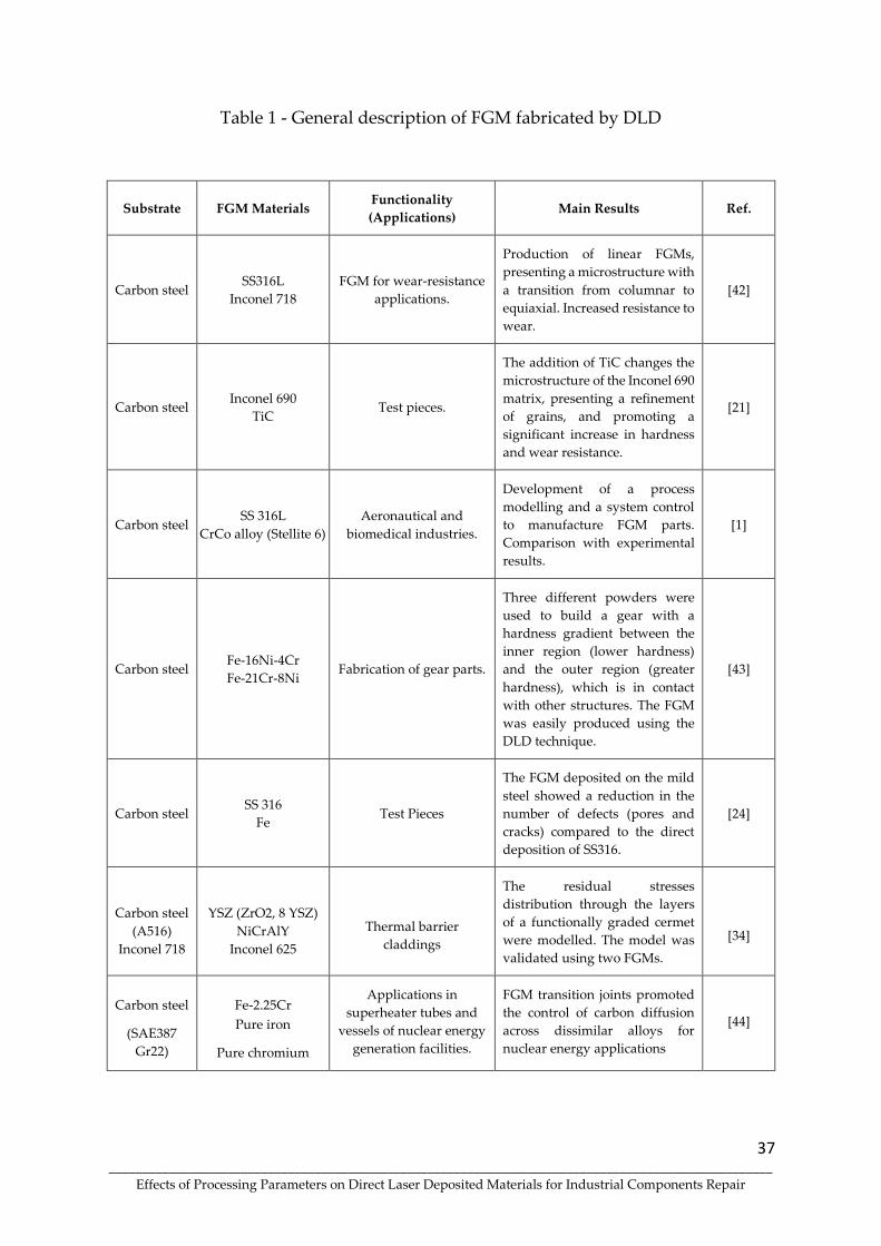
37 ____________________________________________________________________________________________________
Effects of Processing Parameters on Direct Laser Deposited Materials for Industrial Components Repair
Table 1 - General description of FGM fabricated by DLD
Substrate FGM Materials Functionality
(Applications) Main Results Ref.
Carbon steel SS316L
Inconel 718
FGM for wear-resistance
applications.
Production of linear FGMs,
presenting a microstructure with
a transition from columnar to
equiaxial. Increased resistance to
wear.
[42]
Carbon steel Inconel 690
TiC Test pieces.
The addition of TiC changes the
microstructure of the Inconel 690
matrix, presenting a refinement
of grains, and promoting a
significant increase in hardness
and wear resistance.
[21]
Carbon steel SS 316L
CrCo alloy (Stellite 6)
Aeronautical and
biomedical industries.
Development of a process
modelling and a system control
to manufacture FGM parts.
Comparison with experimental
results.
[1]
Carbon steel Fe-16Ni-4Cr
Fe-21Cr-8Ni Fabrication of gear parts.
Three different powders were
used to build a gear with a
hardness gradient between the
inner region (lower hardness)
and the outer region (greater
hardness), which is in contact
with other structures. The FGM
was easily produced using the
DLD technique.
[43]
Carbon steel SS 316
Fe Test Pieces
The FGM deposited on the mild
steel showed a reduction in the
number of defects (pores and
cracks) compared to the direct
deposition of SS316.
[24]
Carbon steel
(A516)
Inconel 718
YSZ (ZrO2, 8 YSZ)
NiCrAlY
Inconel 625
Thermal barrier
claddings
The residual stresses
distribution through the layers
of a functionally graded cermet
were modelled. The model was
validated using two FGMs.
[34]
Carbon steel
(SAE387
Gr22)
Fe-2.25Cr
Pure iron
Pure chromium
Applications in
superheater tubes and
vessels of nuclear energy
generation facilities.
FGM transition joints promoted
the control of carbon diffusion
across dissimilar alloys for
nuclear energy applications
[44]

38 ____________________________________________________________________________________________________
Effects of Processing Parameters on Direct Laser Deposited Materials for Industrial Components Repair
Table 1 - General description of FGM fabricated by DLD (continuation)
SS 316L
SS 316L
Inconel 625
Ti6Al4V
Components that require
both high corrosion
resistance and a high
strength-to-weight ratio.
Synchronous preheating
proved to be fundamental for
the production of crack-free
FGMs by altering the formed
phases.
[52]
SS 304L
SS 304L
Inconel 625
Extreme-environment
applications such as in
aerospace or nuclear power
generation.
Cracks were observed in the
gradient zone and are
associated with small amounts
of transition metal carbides
particles.
[7]
SS 304L SS 316L
Inconel 625
Engineering fields:
aerospace, biological,
nuclear and photoelectric.
FGMs with continuous
composition gradient show
strong metallurgical bond
between each deposition. Wear
resistance increased with
increasing Inconel 625 amount.
Higher hardness was obtained
for 50% Inconel 625 + 50% 316L..
[3]
SS 304L
SS 316L
Inconel 625
(50%/50%)
Test Pieces
The FGM has been successfully
produced with no defects. Yield
strength and tensile strength of
FGMs are close to that of pure
Inconel 625 and pure SS 316L,
respectively.
[53]
AISI 304L SS 316L
Inconel 728
Components to harsh
situations, such as nuclear
power plants and oil
refineries.
The brittle Laves phase was
detected when the content of
Inconel 718 exceeded 40 %. The
fracture mechanism of the
FGMs was the microporous
aggregation fracture, induced
by the Laves phase.
[54]
Nodular
cast iron
Inconel 625
SS 420
Repair of components for
different industries.
Repair of nodular cast iron
structures using FGM's is
appropriate. The FGM has good
wear resistance.
[55]
Inconel 718 NiCrSiBC
WC
Protective ceramic-metal
composite coatings.
Controlling process parameters
did not prevent cracking.
Crack-free coatings could only
be obtained by pre-heating the
substrate (300 °C and 500 °C).
[40]

39 ____________________________________________________________________________________________________
Effects of Processing Parameters on Direct Laser Deposited Materials for Industrial Components Repair
Table 1 - General description of FGM fabricated by DLD (continuation)
Ti6Al4V
Ti6Al4V
Mo
Inconel 718
Test Pieces
The importance of using a
buffer material (transition layer)
and controlling the different
cooling speeds of the FGM
materials to obtain a sound
FGM is emphasized.
[56]
TI6Al4V TI6Al4V
Ti48Al2Cr2Nb
Materials for blisks of
turbine blades
(Ti48Al2Cr2Nb) and turbine
disks (TI6Al4V) on aero
engines.
FGM without cracks or
metallurgical defects has been
successfully manufactured.
FGM reduces the sensitivity to
cracking, particularly in
titanium aluminide.
[57], [58]
Solidification and Microstructure Formation
The functional properties and quality of claddings produced by DLD are strongly
dependent on the final microstructure. Rapid solidification in additive manufacturing
can lead to solute segregation and the formation of unwanted, and unexpected, brittle
phases. In fact, the DLD process promotes very high cooling rates, in the range of 5x10³
- 106 K/s, and diffusive transformations in the solid-state are usually suppressed. For
this reason, homogenisation and control of the solidification process are fundamental
to obtain the desired microstructure. Thus, one of the prerequisites for a successful
process is homogenizing the melt in each layer. Several physical phenomena act in the
melt pool; however, the fluid flow is dominated by Marangoni convection [59]–[61].
The melt pool is well-mixed due to this intense Marangoni convection that directly
affects the shape and penetration of the pool, the chemical composition, the
microstructure, and therefore the final properties of the FGM [62]–[64]. This
convection, in which the surface tension gradient drives the material flow, also
determines the formation of defects, such as porosities and cracks [61], [65]–[68].
Process parameters and material properties influence the Marangoni convection [61],
[66]. An example is shown in Figure 3, which presents computed results evidencing
the influence of laser scanning speed on liquid velocity; as the speed increases, the

40 ____________________________________________________________________________________________________
Effects of Processing Parameters on Direct Laser Deposited Materials for Industrial Components Repair
maximum liquid velocity moves from the sides to the rear of the pool, affecting the
extension and the shape of the liquid pool [66]. This directly influences the
microstructure, as illustrated in Figure 4, which shows EBSD images of a Ni superalloy
processed with three different scanning speeds.
Figure 3. Simulation of Marangoni convection. The figures represent computed liquid pool
and flow fields for two scanning speeds: (a) 3.5 and (b) 100 mm/sec [66].

41 ____________________________________________________________________________________________________
Effects of Processing Parameters on Direct Laser Deposited Materials for Industrial Components Repair
Figure 4. EBSD maps (right) for three scanning speeds [66].
Another example of the influence of processing parameters is shown in Figure 5. The
cross-section analysis shows the influence of laser power on the shape and dimensions
of the melt pool, modification of grain orientations, layer thickness, and surface
finishing. All these modifications are direct effects of the influence of laser power on
Marangoni flow [69].

42 ____________________________________________________________________________________________________
Effects of Processing Parameters on Direct Laser Deposited Materials for Industrial Components Repair
Figure 5. Influence of laser power on the microstructure of Ti6Al4V clads. Cross sections of
clads produced with laser powers of (a) 320 W and (b) 500 W [69].
Figure 5 is a typical microstructure of a clad produced by DLD. In this process, the
solidification modes evolve rapidly due to changes in solidification rate (R) and
temperature gradient at the solid-liquid interface (G). These changes lead to the
development of different microstructures that can be observed in laser additive
manufacturing [68], [70], [71]. For a given alloy, the microstructure depends on the
local solidification conditions. Specifically, the morphology of rapidly solidified layers
is controlled by the G/R parameter. If G/R is greater than a critical value, a planar
solidification front occurs, while if G/R is smaller than this critical value, the planar
solid-liquid interface is destabilised, and cellular or dendritic solidification occurs [60],
[68], [72].
At the beginning of the solidification, the planar solidification zone appears at the
bottom of the melt pool, where the liquid metal maintains contact with the solid
substrate (solidification rate is 0, and the G/R is infinite). With the propagation of the

43 ____________________________________________________________________________________________________
Effects of Processing Parameters on Direct Laser Deposited Materials for Industrial Components Repair
solid-liquid interface, R rapidly increases, and G decreases, leading to a lower G/R
value: the planar front evolves into a cellular interface and eventually to a dendritic
one when G/R decreases even more. In the DLD process, due to the fast variation of
G/R, the planar zone is very narrow [61], [73], [74], as seen in Figure 6.
Figure 6. SEM micrograph of the cross section of a layer of Inconel 625 deposited on 42CrMo4
steel in which the planar zone and columnar grains can be observed.
With the evolution of the solidification process, the decrease in G/R slows down until
reaching a value that remains practically constant. In this region, which follows the
cellular interface zone, dendritic solidification appears. Cellular and dendritic
solidifications are generally columnar and grow perpendicular to the
substrate/solidified layers. This is due to the rapid heat dissipation by the substrate
and solidified layers, the thermal gradient being higher in this direction. Near the
surface of the cladding layer, heat is also dissipated through the surrounding
atmosphere, which significantly decreases the G value. In this region, dendrites
become very thin and disoriented [61], [73], [75]. For a detailed description of G and

44 ____________________________________________________________________________________________________
Effects of Processing Parameters on Direct Laser Deposited Materials for Industrial Components Repair
R influence in solidification modes and microstructure development, see, for instance
[76], [77].
The laser processing conditions and the clad building direction are factors that
influence the microstructure and, therefore, the functional properties of claddings
[78], [79].
In FGMs with composition gradients, the microstructure is also influenced by
different materials characteristics, making solidification control more complex. An
example of the microstructure formed in FGMs materials with a gradual change in
composition is present in Figure 7. This figure shows the microstructure of an Inconel
625/ NiCrWMo superalloy (D4006) FGM. The first layers deposited are 100% Inconel
625, which gradually changes up to 100% D4006. Three intermediate zones have been
sequentially deposited (75% Inconel 625 + 25% D4006, 50% Inconel 625 + 50% D4006,
25% Inconel 625 + 75% D4006).
Figure 7. SEM images of the microstructure of an Inconel 625 (M625)/ NiCrWMo superalloy
(D4006) FGM. (a) Microstructure evolution along the FGM, and (b) EBSD inverse pole figures
(IPF).
From the analysis of the figure, some columnar grains that cross several layers stand
out. These grains do not seem to be influenced by compositional changes, indicating
the possibility of epitaxial growth. This type of microstructure occurs because the
deposition of a new layer implies the remelting of part of the previous one, allowing
the grains to function as nucleation sites for subsequent solidification. Despite this

45 ____________________________________________________________________________________________________
Effects of Processing Parameters on Direct Laser Deposited Materials for Industrial Components Repair
epitaxial growth, the IPF images do not show the formation of a strong preferential
orientation (texture).
Defects
The most frequently detected defects in claddings produced using the DLD technique
are cracks [80], porosity [81], chemical segregation [82], formation of intermetallics
[83], and unmelted powder particles [84], all of which promote the deterioration of the
mechanical properties of the components. Some of these defects, even if of a
submicrometric dimension, can have serious consequences. In fact, micro segregation,
and the formation of brittle phases, like intermetallics, enhance the nucleation of
microcracks, leading to component collapse. Defect reduction is therefore essential so
that the FGMs do not fail in service.
The main causes of the development of defects are associated with processing
parameters, as in most manufacturing processes. Laser power, powder feed rate,
scanning speed, and powder particle size are factors that can promote cracking and
pore formation. The optimization of processing conditions will allow a good
metallurgical bond between the deposit and the substrate, and an adequate dilution.
Dilution is an essential aspect of DLD clads and assesses the contribution of the
substrate area that is melted by the laser to the total area of the clad, controlling clad
contamination by the substrate and affecting the deposition yield. This optimization
minimizes defects such as cracks and porosities, which can act as stress concentrators
and nucleate fatigue cracks [29], [85]. For some materials, it has been shown that
increasing laser power intensifies residual stresses, cracks formation, and the
deterioration of mechanical properties [33], [86].
The formation of cracks can also be associate with phases that locally introduce high
discontinuity in the hardness, brittleness, and thermal stability of the FGMs (see
Figure 8). Attention has been paid to the formation of intermetallic compounds [58],
eutectics (low melting point) and borides [87], and Laves phase [82], [88]–[93].

46 ____________________________________________________________________________________________________
Effects of Processing Parameters on Direct Laser Deposited Materials for Industrial Components Repair
Figure 8. SEM images of the microstructure of an Inconel 625 (M625)/martensitic stainless-
steel (M42C) FGM showing cracking formation in the 25% Inconel 625 + 75% M625 layer.
The formation of the Laves phase in nickel-based superalloys has been widely studied
since this material is one of the most manufactured using DLD, including in the
production of FGMs. The brittle intermetallic Laves phase is formed due to the
interdendritic segregation of chemical elements of the matrix. This phase is a product
of the eutectic reaction, L→(γ + Laves), is dependent on local elements concentration
during non-equilibrium solidification [84], [90], and leads to the reduction of useful
alloying elements (Ni, Fe, Cr, Nb, Mo, Ti) in the matrix, as shown in Figure 9 for
niobium. The formation of Laves phase is highly undesirable, as it deteriorates the
mechanical properties of the cladding, such as ductility, tensile strength, and fatigue
life [88], [92]. Furthermore, it increases the susceptibility to hot cracking [89]. The
amount of this phase is higher in FGM regions processed with higher energy density
[91]. A high cooling rate promotes less redistribution of elements, forming larger
Laves phase particles, with a detrimental effect in mechanical response [82], [92]. The
addition of vanadium inhibits niobium segregation, thus reducing Laves phase
formation, positively influencing the microstructure. In addition, vanadium changes
the morphology of the Laves phase from a rod-like to particle-like shape [93].

47 ____________________________________________________________________________________________________
Effects of Processing Parameters on Direct Laser Deposited Materials for Industrial Components Repair
Figure 9. SEM images showing the morphologies of Laves phase particles and Nb element
distributions in the interdendritic regions.
Porosity is another extremely harmful defect to the performance of the FGMs. It is
mainly the result of gases encapsulated in the powder feed system or powder particles
and by an inadequate selection of process parameters [22], [81], [85]. Porosity may also
be associated with high melt pool cooling rates [94].
Unmelted powder particles are another defect that induces the degradation of FGMs
performance. This defect is formed due to insufficient energy density, causing low
absorption of laser energy and promoting the non-fusion of the powder, favouring the
formation of cracks due to low metallurgical bond [95], [96]. In the production of
FGMs, this problem increases since the different powders have different
thermophysical properties [56].
One procedure that promotes the reduction of residual stresses and defects, such as
cracks, is the preheating of the substrate and the maintenance of this preheating
during the deposition process [56]. Preheating also inhibits the formation of harmful
phases such as eutectics and borides [87], thus reducing defects in FGMs. Preheating
is also essential in controlling thermal gradients between the substrate and the
deposited layers, by decreasing the cooling rate and residual stresses [40], [97] and
attenuating the difference in thermal expansion coefficients between the several

48 ____________________________________________________________________________________________________
Effects of Processing Parameters on Direct Laser Deposited Materials for Industrial Components Repair
powders [58], thus inhibiting the formation of cracks and promoting better mechanical
properties.
In summary, to overcome the current challenges to FGMs production by DLD on
different substrates, it is necessary to develop integrated methodologies that consider
and integrate all processing phases, such as parameter definition, process
optimization, and thermomechanical simulations.
Mechanical Characterisation
Undoubtedly, one of the main objectives of the production of FGMs is to obtain
different mechanical properties from the combination of materials. Another objective
is to ensure gradual and crack-free transition between substrate and last cladding
layers, which also translates into the variation of mechanical properties. This section
highlights some of the most important mechanical properties of several FGMs, such
as microhardness, tensile properties, and wear resistance. As already mentioned, one
of the main groups of FGMs produced results from combinations of steels with nickel
superalloys. This review of the mechanical properties of FGMs begins with the
analysis of this combination.
An FGM with a composition gradient between pure stainless-steel 316L (SS316L) and
pure Inconel 718 (IN718), with three intermediate layers (25%, 50%, and 75 of IN718)
deposited on SS 316L was manufactured [47]. The influence of laser power (LP) and
powder feed rate (FR) on the mechanical performance of the material was studied.
Crack-free FGMs were produced for the four laser powers and two feed rates tested.
Tensile tests on the specimens revealed reduced ductility with the fracture starting in
the steel. The tensile strength decreases with the increase in laser power and the
decrease in the feed rate, being 596 MPa for LP = 450 W and FR = 0.834 g/s and 527
MPa for and LP = 750 W and FR = 0.632 g/s.
The Vickers microhardness analysis along the FGM shows an approximately
parabolic hardness distribution with an initial decrease as the amount of steel

49 ____________________________________________________________________________________________________
Effects of Processing Parameters on Direct Laser Deposited Materials for Industrial Components Repair
decreases, a minimum for the layer with an equal amount of both powders and
increasing to a maximum corresponding to the last layer of pure Inconel, the only non-
reheated layer [47]. As with tensile strength, an increase in laser power leads to a
decrease in hardness.
The Mean Specific Wear Rates (MSWR) of constant composition layers, produced with
the four laser powers and the two powder feed rates, were also determined [47].
MSWR is lower in pure steel for all conditions, goes through a maximum for the 75%
SS 316L + 25% Inconel 718 composition, and decreases with the increasing amount of
Inconel. The highest MSWR values were obtained for the highest laser power and
lower feed rate.
This evolution of the mechanical properties, related to the spacing of the secondary
dendritic arms and carbide formation, shows that tailored mechanical properties can
be obtained by optimizing the processing parameters and composition, allowing the
adequate selection to fulfil the FGMs requirements.
The SS316 L/Inconel718 FGM with different composition gradients were also
fabricated by DLD [54]. The composition changed from pure SS316L to pure IN718,
increasing by 5%, 10%, or 20% the IN718 amount every ten layers. This composition
gradient affects the mechanical response of the FGMs. The fracture of the tensile
sample occurred at layers corresponding to 20–40%, 50–60%, and 25%–30% IN718, for
the composition gradients of 20%, 10%, and 5%, respectively. The best tensile
properties, with the highest tensile strength (527 MPa) and the highest elongation
(26%), were obtained by the FGM with a composition gradient of 10 %. These results
evidenced that the gradient variation is essential for FGMs fabricated by additive
manufacturing.
316L stainless steel (SS316L) and Inconel 625 (IN625) powders have also been mixed
to make FGMs [98]. In this study, FGMs produced with an abrupt transition between
SS316L and IN625, and with a transition zone, where the relative amount of IN625
gradually increases by 12.5% every two layers, were analysed. Mechanical properties
were compared with those of pure materials produced under the same conditions.

50 ____________________________________________________________________________________________________
Effects of Processing Parameters on Direct Laser Deposited Materials for Industrial Components Repair
The mechanical response of the FGMs was determined by the softest material (SS316L)
and, assuming that the toughest IN625 has negligible plastic deformation, the tensile
properties of both FGMs are almost identical to those of SS316, with no noticeable
differences in mechanical strength and ductility [98]. This means that, in this case, a
good interfacial resistance between the two materials has been achieved and the
transition zone, which makes the manufacture of the FGM much more complex, is not
necessary. Recently, another SS316L/IN625 FGM, deposited on the same substrate
(SS304), was produced with other processing conditions, and the mechanical
properties were investigated [3]. The FGM produced had a transition zone in which
the relative amount of IN625 increased by 10% in each region. In this FGM the tensile
specimens also showed a noticeable plastic deformation and ductile fracture. An
analysis of the fracture surfaces indicated that the fracture occurred in layers with 60%
SS316L + 40% IN625. In this analysis, particles rich in Nb were detected at the bottom
of the dimples, indicating that fragile particles resulting from the segregation of this
element, eventually phase Laves, maybe at the origin of the fracture.
The average yield strength obtained for five samples were 823 MPa and the average
tensile strenght 1030 MPa [3]. These values are much higher than the average values
reported in [98] (310 and 540 MPa for yield strength and tensile strenght, respectively)
and even higher than typical of 316L stainless steel.
The microhardness along the transition zone showed a gradual upward trend, with a
maximum of 347 HV for the deposited layer with 50% SS316L + 50% IN625. The wear
of samples with various compositions was also analyzed. It was determined that the
wear resistance first decreases slightly with an increasing percentage of IN625 but
then increases significantly, approaching that of the superalloy for 20% SS316L + 80%
IN625 (as can be seen in the Table 2) [3].

51 ____________________________________________________________________________________________________
Effects of Processing Parameters on Direct Laser Deposited Materials for Industrial Components Repair
Table 2. Wear rate for FGM samples and pure materials [3].
Sample composition Wear rate (x10-3cm-³.N.m-1)
100% SS316l 1.58
80% SS316L + 20% IN625 1.60
60% SS316L + 40% IN625 1.32
40% SS316L + 60% IN625 1.15
20% SS316L + 80% IN625 0.79
100% IN625 0.74
The microhardness evolution of an FGM fabricated using two nickel superalloys
powders, Inconel 625 (IN625) and NiCrWMo (D4006), is shown in Figure 10. This
FGM has five different regions; the first layers of the FGM were 100% IN625, and the
amount of the NiCrWMo superalloy increase by 25% in each of the three intermediate
regions, ending the deposition with 100% NiCrWMo. The microhardness increase as
the amount of NiCrWMo powder is increasing. This factor is related to the
strengthening effect of alloying elements (Cr, W, Mo).
Figure 10. Vickers microhardness mapping of an FGM along the sample. The composition of
the regions is: 1 - 100% IN625; 2 - 75% IN625 + 25% NiCrWMo; 3 - 50% IN625 + 50% NiCrWMo;
4 - 75% IN625 + 75% NiCrWMo; 5 - 100% NiCrWMo.
Another group of FGMs that has been studied a lot is the one that uses Ti6Al4V
powders and powders of a much harder material. An example is a FGM deposited by
DLD on a Ti6Al4V substrate, with composition changing from 100% Ti6Al4V to 50%
Ti6Al4V + 50% TiC, and with a gradual increase in composition of 5% TiC in each zone

52 ____________________________________________________________________________________________________
Effects of Processing Parameters on Direct Laser Deposited Materials for Industrial Components Repair
[99]. One FGM was produced with constant processing parameters (FGM A) and the
other with parameters optimized for each condition (FGM B). The results presented
in Table 3 showed that the optimized FGM has the best wear-resistance behaviour,
with a reduction of 82.5% in the wear volume compared with the substrate. The last
layers of this FGM (with a composition of 50% Ti6Al4V + 50% TiC) has a
microhardness value (1200 VHN) which is four times that of the Ti6Al4V.
Table 3. Wear volume for FGMs and substrate [99].
Sample designation Wear volume (mm³)
FGM A 0.033
FGM B 0.021
Substrate 0.120
These results show how the proper selection of the processing conditions for each zone
(each composition) can be decisive in obtaining an optimized FGM behaviour.
Ti6Al4V/TiC FGM production with a 1% TiC increase in each of the 50 layers of up
50% TiC has also been tested [100]. The FGM microhardness gradually increases from
380 HV in the Ti6Al4V layer to 737 HV in the top layer (with 50% TiC), which means
it almost doubles. This hardness variation is less important than reported in [99],
emphasizing the effect of processing parameters and powders characteristics.
To analyse the tensile properties of this Ti6Al4V/TiC FGM, samples with fixed
composition were deposited (each sample was the result of the deposition of ten
layers). Six compositions were produced, with 0, 10, 20, 30, 40, and 50% TiC. The last
two compositions were not tested as cracks appeared during the FGMs production.
The ultimate tensile strength of the FGM with a TiC amount of 5% is improved by 12%
compared to Ti6Al4V. Contrary to what was expected considering the hardness
evolution, further increase of the TiC amount decreases the tensile strength, and the
elongation drops to less than 1%. This unexpected behaviour was explained by
increasing unmelted TiC particles and dendritic TiC phases, which promote
premature damage of FGMs [100].

53 ____________________________________________________________________________________________________
Effects of Processing Parameters on Direct Laser Deposited Materials for Industrial Components Repair
The brittleness of the Ti6Al4V/TiC FGM is a problem that should be carefully
considered during its manufacture by DLD technology. The effect of laser power and
scan speed on hardness of Ti6Al4V/TiC FGM deposited in a Ti6Al4V substrate was
analyzed [101]. FGMs were deposited with increase of TiC through three zones, with
10, 20, and 30% TiC, and laser power ranging from 400 to 700 W and scan speeds of
200, 300, and 400 mm/min. The Vickers hardness gradually increases from 300 HV to
600 HV with the increase of TiC amount. No significant differences were observed for
the set of processing parameters tested. Samples with constant composition (0, 10, 20,
and 30% TiC) were produced for tensile tests [101]. Ultimate tensile strength and
elongation decreases with increasing TiC amount, being this more noticeable for 20
and 30% TiC, which confirms the results reported in [100].
Ti6Al4V and Invar 36 (64 wt% Fe, 36 wt% Ni) powers were used to produce an FGM
[102]. The FGM started with the deposition of 21 layers of Ti6Al4V powder onto a
Ti6Al4V substrate, followed by a 32 layers gradient region with a 3% decrease in
Ti6Al4V per layer (replaced by 3% Invar powder), and, finally, 22 layers of pure Invar.
Hardness shows a noticeable increase for layers with 40-60% Invar. In these layers,
values close to 900 HV were measured, being much higher than the average values of
Ti6Al4V and Invar, which are 380 and 141 HV, respectively. These significantly higher
hardness values were associated with the formation of iron and nickel titanides in the
FGM. These intermetallic phases are very hard but also very brittle, which may
explain the macroscopic cracking of the FGM. Although hardness values measured in
the FGM central region are excellent, the defects preclude Ti6Al4V/Invar from being
used in industrial applications.
Ti/SiC was another metal/ceramic FGM produced by DLD with a combination of
powders similar to the one described above, a ductile titanium alloy gradually
reinforced with a carbide. In this FGM, a layer of 100% Ti was first deposited on a
Ti6Al4V substrate, then eight more layers were deposited with a constant decrease of
10% Ti (an increase of 10% SiC), with the final layer having the composition of 20% Ti
+ 80 % SiC [103].

54 ____________________________________________________________________________________________________
Effects of Processing Parameters on Direct Laser Deposited Materials for Industrial Components Repair
One of the main challenges of these FGMs is to successfully achieve a high volume
content of the ceramic constituent at the exterior layer, surmounting the problems
caused by the great brittleness and the poor melting fluidity of most ceramics. To
achieve this goal, the composition and thickness of the Ti/SiC FGMs layers were
optimized, first eliminating the layers with a greater tendency to cracking (namely the
layer with 70% Ti + 30% SiC), and then halving the thickness of the layers. After this
optimization, it was possible to avoid forming the more cracking and microcracking
inducing phases and producing an FGM without evident defects. In this optimized
FGM, the hardness continuously increases from 339 HV in the Ti layer to 1608 HV in
the outer layer (10% Ti+90% SiC), and average three-point bending strength of 286
MPa was measured at room temperature [103].
These mechanical properties show that it is possible to produce metal/ceramic FGMs
with the proper selection of the layer construction strategy. In summary, some aspects
related to mechanical properties can be highlighted:
• Final mechanical properties are not necessarily a combination of the mechanical
properties of the materials used in the FGM and may vary significantly across the
deposited zone.
• The variation of mechanical properties along the FGM is not necessarily gradual or
linear and is strongly related to the microstructure.
• In some cases, defects induced by the FGM process, such as cracks and porosities,
can negatively affect the mechanical properties, making its industrial application
unfeasible.
• The production of FGMs has often proven to be able to improve mechanical
properties such as wear-resistance and hardness.
• The deposition parameters, including the composition and thickness of the various
layers, play a significant role in the final properties and must be optimized to achieve
the intended requirements.

55 ____________________________________________________________________________________________________
Effects of Processing Parameters on Direct Laser Deposited Materials for Industrial Components Repair
Conclusions
Functional Gradient Materials (FGM) combine materials with different compositions,
leveraging the best properties of each and exploring reactions that can give rise to
unexpected properties. FGMs respond to the growing demand from various industrial
sectors for materials with better performance, allowing them to produce components
with unique characteristics and a gradient of properties along a specific direction. The
production of FGMs by Direct Laser Deposition (DLD) is an attractive solution for
many engineering applications, thus opening new perspectives for several industrial
sectors, such as aerospace, automotive, nuclear, and biomedical. In this review, the
current status of research on using the DLD process for manufacturing FGMs has been
summarized. The main characteristics of this manufacturing process, the
microstructures and mechanical properties of FGMs, and their main defects, were
described. DLD is the technology that makes it possible to manufacture the widest
range of FGMs and results from additive manufacturing progress that makes it
technologically and economically viable. This process provides freedom to design
more complex components, built layer by layer, with strategically controlled
compositional variations that enable the directionality of properties. The production
of FGM by DLD has been widely used as it opens up the possibility of blending
different types of materials, such as metals (steel, superalloys, and titanium alloys)
and ceramics. This review also highlights the need for more studies in producing these
materials, expanding the analyzed systems, optimizing processing conditions, and
properly establishing the correlation of microstructures, phase changes, and defects
with the properties of the FGM, thus enhancing its performance in service.

56 ____________________________________________________________________________________________________
Effects of Processing Parameters on Direct Laser Deposited Materials for Industrial Components Repair
References
[1] P. Muller, P. Mognol, and J. Y. Hascoet, “Modeling and control of a direct laser
powder deposition process for Functionally Graded Materials (FGM) parts
manufacturing”, J. Mater. Process. Technol., vol. 213, no. 5, pp. 685–692, 2013, doi:
10.1016/j.jmatprotec.2012.11.020.
[2] B. Kieback, A. Neubrand, and H. Riedel, “Processing techniques for functionally
graded materials”, Mater. Sci. Eng. A, vol. 362, no. 1–2, pp. 81–106, 2003, doi:
10.1016/S0921-5093(03)00578-1.
[3] B. Chen, Y. Su, Z. Xie, C. Tan, and J. Feng, “Development and characterization
of 316L/Inconel625 functionally graded material fabricated by laser direct metal
deposition”, Opt. Laser Technol., vol. 123, no. May 2019, 2020, doi:
10.1016/j.optlastec.2019.105916.
[4] H. P. Qu, P. Li, S. Q. Zhang, A. Li, and H. M. Wang, “Microstructure and
mechanical property of laser melting deposition (LMD) Ti/TiAl structural
gradient material”, Mater. Des., vol. 31, no. 1, pp. 574–582, 2010, doi:
10.1016/j.matdes.2009.07.004.
[5] X. Lin, T. M. Yue, H. O. Yang, and W. D. Huang, “Microstructure and phase
evolution in laser rapid forming of a functionally graded Ti-Rene88DT alloy”,
Acta Mater., vol. 54, no. 7, pp. 1901–1915, 2006, doi:
10.1016/j.actamat.2005.12.019.
[6] R. M. Mahamood and E. T. Akinlabi, Laser Additive Manufacturing. 2016
[7] B. E. Carroll, R. A. Otis, J. P. Borgonia, J. Suh, R. P. Dilon, A. A. Shapiro, D. C.
Hofmann, Z. Liu and A. M. Beese, “Functionally graded material of 304L
stainless steel and inconel 625 fabricated by directed energy deposition:
Characterization and thermodynamic modeling”, Acta Mater., vol. 108, pp. 46–
54, 2016, doi: 10.1016/j.actamat.2016.02.019.
[8] C. Petit, L. Montanaro, and P. Palmero, “Functionally graded ceramics for
biomedical application: Concept, manufacturing, and properties”, Int. J. Appl.
Ceram. Technol., vol. 15, no. 4, pp. 820–840, 2018, doi: 10.1111/ijac.12878.
[9] N. Radhika, K. Teja, K. Rahul, and A. Shivashankar, “Fabrication of Cu-Sn-Ni
/SiC FGM for Automotive Applications: Investigation of its Mechanical and
Tribological Properties”, Silicon, vol. 10, no. 4, pp. 1705–1716, 2018, doi:
10.1007/s12633-017-9657-3.
[10] M. Koizumi, “FGM activities in Japan”, Compos. Part B Eng., vol. 28, no. 1–2, pp.
1–4, 1997, doi: 10.1016/s1359-8368(96)00016-9.

57 ____________________________________________________________________________________________________
Effects of Processing Parameters on Direct Laser Deposited Materials for Industrial Components Repair
[11] M. Soodi, S. H. Masood, and M. Brandt, “Thermal expansion of functionally
graded and wafer-layered structures produced by laser direct metal
deposition”, Int. J. Adv. Manuf. Technol., vol. 69, no. 9–12, pp. 2011–2018, 2013,
doi: 10.1007/s00170-013-5157-9.
[12] Y. Li, Z. Feng, L. Hao, L. Huang, C. Xin, Y. Wang, E. Bilotti, K. Essa, H. Zhang,
Z. Li, F. Yan and T. Peijs, “A Review on Functionally Graded Materials and
Structures via Additive Manufacturing: From Multi-Scale Design to Versatile
Functional Properties”, Adv. Mater. Technol., vol. 1900981, 2020, doi:
10.1002/admt.201900981.
[13] A. Saboori, G. Piscopo, M. Lai, A. Salmi, and S. Biamino, “An investigation on
the effect of deposition pattern on the microstructure, mechanical properties
and residual stress of 316L produced by Directed Energy Deposition”, Mater.
Sci. Eng. A, vol. 780, no. March, p. 139179, 2020, doi: 10.1016/j.msea.2020.139179.
[14] W. Paatsch, “Energy turnaround - a challenge for surface technology”, Trans.
{IMF}, vol. 94, no. 5, pp. 228–230, 2016, doi: 10.1080/00202967.2016.1209295.
[15] Y. Gao, D. Xiong, C. Wang, and Y. Chen, “Influences of laser powers on
microstructure and properties of the coatings on the AZ91HP magnesium
alloy”, Acta Metall. Sin. (English Lett., vol. 22, no. 3, pp. 167–173, 2009, doi:
https://doi.org/10.1016/S1006-7191(08)60085-X.
[16] J. Chen, S.-H. Wang, and L. Xue, “On the development of microstructures and
residual stresses during laser cladding and post-heat treatments”, J. Mater. Sci.,
vol. 47, no. 2, pp. 779–792, 2012, doi: 10.1007/s10853-011-5854-4.
[17] S. M. Thompson, L. Bian, N. Shamsaei, and A. Yadollahi, “An overview of Direct
Laser Deposition for additive manufacturing; Part I: Transport phenomena,
modeling and diagnostics”, Addit. Manuf., vol. 8, pp. 36–62, 2015, doi:
10.1016/j.addma.2015.07.001.
[18] E. P. Cardozo, G. R. Pardal, S. Ríos, S. Ganguly, and A. S. C. M. D’oliveira,
“Additive techniques to refurbish Ni based components”, Soldag. e Insp., vol. 24,
pp. 1–11, 2019, doi: 10.1590/0104-9224/SI24.03.
[19] Q. Guo, S. Chen, M. Wei, J. Liang, C. Liu, and M. Wang, “Formation and
Elimination Mechanism of Lack of Fusion and Cracks in Direct Laser Deposition
24CrNiMoY Alloy Steel”, J. Mater. Eng. Perform., vol. 29, no. 10, pp. 6439–6454,
2020, doi: 10.1007/s11665-020-05163-4.
[20] V. Promakhov, A. Zhukov, M. Ziatdinov, I. Zhukov, N. Schulz, S. Kovalchuk,
Y. Dubkova, D. Korsmik, O. Klimova-Korsmik, G. Turichin and A. Perminov,
“Inconel 625/TiB 2 metal matrix composites by direct laser deposition”, Metals
(Basel)., vol. 9, no. 2, pp. 1–15, 2019, doi: 10.3390/met9020141.
[21] J. M. Wilson and Y. C. Shin, “Microstructure and wear properties of laser-

58 ____________________________________________________________________________________________________
Effects of Processing Parameters on Direct Laser Deposited Materials for Industrial Components Repair
deposited functionally graded Inconel 690 reinforced with TiC”, Surf. Coatings
Technol., vol. 207, pp. 517–522, 2012, doi: 10.1016/j.surfcoat.2012.07.058.
[22] A. Dass and A. Moridi, “State of the art in directed energy deposition: From
additive manufacturing to materials design”, Coatings, vol. 9, no. 7, 2019, doi:
10.3390/COATINGS9070418.
[23] L. Yan, Y. Chen, and F. Liou, “Additive manufacturing of functionally graded
metallic materials using laser metal deposition”, Addit. Manuf., vol. 31, no.
November 2019, p. 100901, 2020, doi: 10.1016/j.addma.2019.100901.
[24] S. Nam, H. Cho, C. Kim, and Y. M. Kim, “Effect of process parameters on
deposition properties of functionally graded STS 316/Fe manufactured by laser
direct metal deposition”, Metals (Basel)., vol. 8, no. 8, 2018, doi:
10.3390/met8080607.
[25] R. M. Mahamood, Laser Metal Deposition of Metals and Alloys. 2018.
[26] G. H. Loh, E. Pei, D. Harrison, and M. D. Monzón, “An overview of functionally
graded additive manufacturing”, Addit. Manuf., vol. 23, no. May, pp. 34–44,
2018, doi: 10.1016/j.addma.2018.06.023.
[27] G. H. Loh, E. Pei, D. Harrison, and M. D. Monzón, “An overview of functionally
graded additive manufacturing”, Addit. Manuf., vol. 23, no. c, pp. 34–44, 2018,
doi: 10.1016/j.addma.2018.06.023.
[28] D. T. Sarathchandra, S. Kanmani Subbu, and N. Venkaiah, “Functionally graded
materials and processing techniques: An art of review”, Mater. Today Proc., vol.
5, no. 10, pp. 21328–21334, 2018, doi: 10.1016/j.matpr.2018.06.536.
[29] K. F. Walker, J. M. Lourenço, S. Sun, M. Brandt, and C. H. Wang, “Quantitative
fractography and modelling of fatigue crack propagation in high strength
AerMet®100 steel repaired with a laser cladding process”, Int. J. Fatigue, vol. 94,
pp. 288–301, 2017, doi: 10.1016/j.ijfatigue.2016.06.031.
[30] W. Li, J. Zhang, X. Zhang, and F. Liou, “Effect of optimizing particle size on
directed energy deposition of Functionally Graded Material with blown Pre-
Mixed Multi-Powder”, Manuf. Lett., vol. 13, pp. 39–43, 2017, doi:
10.1016/j.mfglet.2017.07.001.
[31] M. Naebe and K. Shirvanimoghaddam, “Functionally graded materials: A
review of fabrication and properties”, Appl. Mater. Today, vol. 5, pp. 223–245,
2016, doi: 10.1016/j.apmt.2016.10.001.
[32] A. Reichardt, “Additive Manufacturing of Metal-based Functionally Graded
Materials. UC Berkeley. ProQuest ID: Reichardt_berkeley_0028E_17635. Merritt
ID: ark:/13030/m5zh1phm. Retrieved from
https://escholarship.org/uc/item/32h5c2vp”, 2017, [Online]. Available:

59 ____________________________________________________________________________________________________
Effects of Processing Parameters on Direct Laser Deposited Materials for Industrial Components Repair
https://escholarship.org/uc/item/32h5c2vp.
[33] S. Zhou, X. Zeng, Q. Hu, and Y. Huang, “Analysis of crack behavior for Ni-
based WC composite coatings by laser cladding and crack-free realization”,
Appl. Surf. Sci., vol. 255, no. 5 PART 1, pp. 1646–1653, 2008, doi:
10.1016/j.apsusc.2008.04.003.
[34] A. Bhattacharyya and D. Maurice, “Residual stresses in functionally graded
thermal barrier coatings”, Mech. Mater., vol. 129, no. November 2018, pp. 50–56,
2019, doi: 10.1016/j.mechmat.2018.11.002.
[35] X. C. Zhang, B. S. Xu, H. D. Wang, Y. Jiang, and Y. X. Wu, “Modeling of thermal
residual stresses in multilayer coatings with graded properties and
compositions”, Thin Solid Films, vol. 497, no. 1–2, pp. 223–231, 2006, doi:
10.1016/j.tsf.2005.09.184.
[36] K. Z. Uddin and B. Koohbor, “Gradient optimization of transversely graded Ti-
TiB structures for enhanced fracture resistance”, Int. J. Mech. Sci., vol. 187, no.
June, p. 105917, 2020, doi: 10.1016/j.ijmecsci.2020.105917.
[37] P. Kattire, S. Paul, R. Singh, and W. Yan, “Experimental characterization of laser
cladding of CPM 9V on H13 tool steel for die repair applications”, J. Manuf.
Process., vol. 20, pp. 492–499, 2015, doi: 10.1016/j.jmapro.2015.06.018.
[38] K. Dai, X. X. Li, and L. L. Shaw, “Comparisons between thermal modeling and
experiments: Effects of substrate preheating”, Rapid Prototyp. J., vol. 10, no. 1,
pp. 24–34, 2004, doi: 10.1108/13552540410512507.
[39] B. Zheng, Y. Zhou, J. E. Smugeresky, J. M. Schoenung, and E. J. Lavernia,
“Thermal behavior and microstructural evolution during laser deposition with
laser-engineered net shaping: Part I. Numerical calculations”, Metall. Mater.
Trans. A Phys. Metall. Mater. Sci., vol. 39, no. 9, pp. 2228–2236, 2008, doi:
10.1007/s11661-008-9557-7.
[40] A. Sadhu, A. Choudhary, S. Sarkar, A. M. Nair, P. Nayak, S. D. Pawar, G.
Muvvala, S. K. Pal, andr A. K. Nath, “A study on the influence of substrate pre-
heating on mitigation of cracks in direct metal laser deposition of NiCrSiBC-
60%WC ceramic coating on Inconel 718”, Surf. Coatings Technol., vol. 389, no.
March, p. 125646, 2020, doi: 10.1016/j.surfcoat.2020.125646.
[41] C. Ding, X. Cui, J. Jiao, and P. Zhu, “Effects of substrate preheating temperatures
on the microstructure, properties, and residual stress of 12CrNi2 prepared by
laser cladding deposition technique”, Materials (Basel)., vol. 11, no. 12, 2018, doi:
10.3390/ma11122401.
[42] X. Liang, D. Wu, Q. Li, and L. Jiang, “Laser rapid manufacturing of stainless
steel 316L/Inconel718 functionally graded materials: Microstructure evolution
and mechanical properties”, Int. J. Opt., vol. 2010, pp. 1–6, 2010, doi:

60 ____________________________________________________________________________________________________
Effects of Processing Parameters on Direct Laser Deposited Materials for Industrial Components Repair
10.1155/2010/802385.
[43] W. J. Ji and Y. H. Moon, “Fabrication of functionally graded properties by direct
laser melting of compositionally selective metallic powder”, ICCAS 2015 - 2015
15th Int. Conf. Control. Autom. Syst. Proc., pp. 1955–1957, 2015, doi:
10.1109/ICCAS.2015.7364686.
[44] J. S. Zuback, T. A. Palmer, and T. DebRoy, “Additive manufacturing of
functionally graded transition joints between ferritic and austenitic alloys”, J.
Alloys Compd., vol. 770, pp. 995–1003, 2019, doi: 10.1016/j.jallcom.2018.08.197.
[45] D. K. Kim, W. Woo, E. Y. Kim, and S. H. Choi, “Microstructure and mechanical
characteristics of multi-layered materials composed of 316L stainless steel and
ferritic steel produced by direct energy deposition”, J. Alloys Compd., vol. 774,
pp. 896–907, 2019, doi: 10.1016/j.jallcom.2018.09.390.
[46] L. D. Bobbio, B. Bocklund, A. Reichardt, R. Otis, J. P. Borgonia, R. P. Dillon, A.
A. Shapiro, B. W. McEnerney, P. Hosemann, Z. Liu and A. M. Beese, “Analysis
of formation and growth of the σ phase in additively manufactured functionally
graded materials”, J. Alloys Compd., vol. 814, p. 151729, 2020, doi:
10.1016/j.jallcom.2019.151729.
[47] K. Shah, I. ul Haq, A. Khan, S. A. Shah, M. Khan, and A. J. Pinkerton,
“Parametric study of development of Inconel-steel functionally graded
materials by laser direct metal deposition”, Mater. Des., vol. 54, pp. 531–538,
2014, doi: 10.1016/j.matdes.2013.08.079.
[48] R. Koike, I. Unotoro, Y. Kakinuma, T. Aoyama, Y. Oda, T. Kuriya and M.
Fujishima, “Evaluation for mechanical characteristics of Inconel625-SUS316L
joint produced with direct energy deposition”, Procedia Manuf., vol. 14, pp. 105–
110, 2017, doi: 10.1016/j.promfg.2017.11.012.
[49] J. del Val, A. Arias-González, O. Barro, A. Riveiro, R. Comesaña, J. Penide, L.
Lusquiños, M. Bountinguiza, F. Quintero and J. Pou, “Functionally graded 3D
structures produced by laser cladding”, Procedia Manuf., vol. 13, pp. 169–176,
2017, doi: 10.1016/j.promfg.2017.09.029.
[50] A. Bayode, S. Pityana, and E. Titilayo Akinlabi, “4. Fabrication of stainless steel-
based FGM by laser metal deposition”, Hierarchical Compos. Mater., pp. 55–72,
2019, doi: 10.1515/9783110545104-004.
[51] S. M. Banait, C. P. Paul, A. N. Jinoop, H. Kumar, R. S. Pawade, and K. S. Bindra,
“Experimental investigation on laser directed energy deposition of functionally
graded layers of Ni-Cr-B-Si and SS316L”, Opt. Laser Technol., vol. 121, no. May
2019, p. 105787, 2020, doi: 10.1016/j.optlastec.2019.105787.
[52] W. Meng, W. Zhang, W. Zhang, X. Yin, L. Guo, and B. Cui, “Additive fabrication
of 316L/Inconel625/Ti6Al4V functionally graded materials by laser synchronous

61 ____________________________________________________________________________________________________
Effects of Processing Parameters on Direct Laser Deposited Materials for Industrial Components Repair
preheating”, Int. J. Adv. Manuf. Technol., vol. 104, no. 5–8, pp. 2525–2538, 2019,
doi: 10.1007/s00170-019-04061-x.
[53] X. Zhang, Y. Chen, and F. Liou, “Fabrication of SS316L-IN625 functionally
graded materials by powder-fed directed energy deposition”, Sci. Technol. Weld.
Join., vol. 24, no. 5, pp. 504–516, 2019, doi: 10.1080/13621718.2019.1589086.
[54] Y. Su, B. Chen, C. Tan, X. Song, and J. Feng, “Influence of composition gradient
variation on the microstructure and mechanical properties of 316 L/Inconel718
functionally graded material fabricated by laser additive manufacturing”, J.
Mater. Process. Technol., vol. 283, no. January, 2020, doi:
10.1016/j.jmatprotec.2020.116702.
[55] Y. Liu, F. Weng, G. Bi, Y. Chew, S. Liu, G. Ma and S. K. Moon, “Characterization
of wear properties of the functionally graded material deposited on cast iron by
laser-aided additive manufacturing”, Int. J. Adv. Manuf. Technol., vol. 105, no. 10,
pp. 4097–4105, 2019, doi: 10.1007/s00170-019-03414-w.
[56] A. Thiriet, C. Schneider-Maunoury, P. Laheurte, D. Boisselier, and L. Weiss,
“Multiscale study of different types of interface of a buffer material in powder-
based directed energy deposition: Example of Ti6Al4V/Ti6Al4V - Mo/Mo -
Inconel 718”, Addit. Manuf., vol. 27, no. February, pp. 118–130, 2019, doi:
10.1016/j.addma.2019.02.007.
[57] R. Ma, Z. Liu, W. Wang, G. Xu, and W. Wang, “Laser deposition melting of
TC4/TiAl functionally graded material”, Vacuum, vol. 177, no. April, p. 109349,
2020, doi: 10.1016/j.vacuum.2020.109349.
[58] R. Ma, Z. Liu, W. Wang, G. Xu, and W. Wang, “Microstructures and mechanical
properties of Ti6Al4V-Ti48Al2Cr2Nb alloys fabricated by laser melting
deposition of powder mixtures”, Mater. Charact., vol. 164, no. April, p. 110321,
2020, doi: 10.1016/j.matchar.2020.110321.
[59] D. Dai and D. Gu, “Thermal behavior and densification mechanism during
selective laser melting of copper matrix composites: Simulation and
experiments”, Mater. Des., vol. 55, pp. 482–491, 2014, doi:
10.1016/j.matdes.2013.10.006.
[60] T. N. Le and Y. L. Lo, “Effects of sulfur concentration and Marangoni convection
on melt-pool formation in transition mode of selective laser melting process”,
Mater. Des., vol. 179, p. 107866, 2019, doi: 10.1016/j.matdes.2019.107866.
[61] Y. S. Lee, M. Nordin, S. S. Babu, and D. F. Farson, “Influence of fluid convection
on weld pool formation in laser cladding”, Weld. J., vol. 93, no. 8, 2014.
[62] Y. P. Lei, H. Murakawa, Y. W. Shi, and X. Y. Li, “Numerical analysis of the
competitive influence of Marangoni flow and evaporation on heat surface
temperature and molten pool shape in laser surface remelting”, Comput. Mater.

62 ____________________________________________________________________________________________________
Effects of Processing Parameters on Direct Laser Deposited Materials for Industrial Components Repair
Sci., vol. 21, no. 3, pp. 276–290, 2001, doi: 10.1016/S0927-0256(01)00143-4.
[63] B. Bocklund, L. D. Bobbio, R. A. Otis, A. M. Beese, and Z. K. Liu, “Experimental
validation of Scheil–Gulliver simulations for gradient path planning in
additively manufactured functionally graded materials”, Materialia, vol. 11, no.
April, 2020, doi: 10.1016/j.mtla.2020.100689.
[64] T. DebRoy, H. L. Wei, J. S. Zuback, T. Mukherjee, J. W. Elmer, J. O. Milewski, A.
M. Beese, A. Wilson-Heid, A. De, W. Zhang, “Additive manufacturing of
metallic components – Process, structure and properties”, Prog. Mater. Sci., vol.
92, pp. 112–224, 2018, doi: 10.1016/j.pmatsci.2017.10.001.
[65] A. Reichardt, A. A. Shapiro, R. Otis, R. P. Dillon, J. P. Borgonia, B. W.
McEnerney, P. Hosemann and A. M. Beese, “Advances in additive
manufacturing of metal-based functionally graded materials”, Int. Mater. Rev.,
vol. 0, no. 0, pp. 1–29, 2020, doi: 10.1080/09506608.2019.1709354.
[66] J. M. Drezet and S. Mokadem, “Marangoni Convection and Fragmentation in
LASER Treatment”, Mater. Sci. Forum, vol. 508, no. January 2006, pp. 257–262,
2006, doi: 10.4028/www.scientific.net/msf.508.257.
[67] L. Aucott, H. Dong, W. Mirihanage, R. Atwood, A. Kidess, S. Gao, S. Wen, J.
Marsden, S. Feng, M. Tong, T. Connolley, M. Drakopoulos, C. R. Kleijn, I. M.
Richardson, D. J. Browne, R. H. Mathiesen and H. V. Atkinson, “Revealing
internal flow behaviour in arc welding and additive manufacturing of metals”,
Nat. Commun., vol. 9, no. 1, pp. 1–7, 2018, doi: 10.1038/s41467-018-07900-9.
[68] E. Kannatey, Materials Processing Principles of Laser. 2009.
[69] M. Gharbi, P.Peyre, C. Gorny, M. Carin, S. Morville, P. Le Masson, D. Carron
and R. Fabbro, “Influence of various process conditions on surface finishes
induced by the direct metal deposition laser technique on a Ti-6Al-4V alloy”, J.
Mater. Process. Technol., vol. 213, no. 5, pp. 791–800, 2013, doi:
10.1016/j.jmatprotec.2012.11.015.
[70] L. Song, G. Zeng, H. Xiao, X. Xiao, and S. Li, “Repair of 304 stainless steel by
laser cladding with 316L stainless steel powders followed by laser surface
alloying with WC powders”, J. Manuf. Process., vol. 24, pp. 116–124, 2016, doi:
10.1016/j.jmapro.2016.08.004.
[71] R. Acharya, J. A. Sharon, and A. Staroselsky, “Prediction of microstructure in
laser powder bed fusion process”, Acta Mater., vol. 124, pp. 360–371, 2017, doi:
10.1016/j.actamat.2016.11.018.
[72] Z. Gan, H. Liu, S. Li, X. He, and G. Yu, “Modeling of thermal behavior and mass
transport in multi-layer laser additive manufacturing of Ni-based alloy on cast
iron”, Int. J. Heat Mass Transf., vol. 111, pp. 709–722, 2017, doi:
10.1016/j.ijheatmasstransfer.2017.04.055.

63 ____________________________________________________________________________________________________
Effects of Processing Parameters on Direct Laser Deposited Materials for Industrial Components Repair
[73] Z. Zhang, P. Farahmand, and R. Kovacevic, “Laser cladding of 420 stainless steel
with molybdenum on mild steel A36 by a high power direct diode laser”,
JMADE, vol. 109, pp. 686–699, 2016, doi: 10.1016/j.matdes.2016.07.114.
[74] Y. Lee, M. Nordin, S. S. Babu, and D. F. Farson, “Effect of Fluid Convection on
Dendrite Arm Spacing in Laser Deposition”, 2014, doi: 10.1007/s11663-014-0054-
7.
[75] S. Bontha, N. W. Klingbeil, P. A. Kobryn, and H. L. Fraser, “Thermal process
maps for predicting solidification microstructure in laser fabrication of thin-wall
structures”, J. Mater. Process. Technol., vol. 178, no. 1–3, pp. 135–142, 2006, doi:
10.1016/j.jmatprotec.2006.03.155.
[76] J. C. Lippold, Welding metallurgy and weldability. 2014.
[77] E. Toyserkani, A. Khajepour, and S. Corbin, Laser Cladding Laser Cladding, vol.
11, no. 2. 2017.
[78] I. Hemmati, V. Ocelík, and J. T. M. De Hosson, “Microstructural characterization
of AISI 431 martensitic stainless steel laser-deposited coatings”, J. Mater. Sci.,
vol. 46, no. 10, pp. 3405–3414, 2011, doi: 10.1007/s10853-010-5229-2.
[79] P. Guo, B. Zou, C. Huang, and H. Gao, “Study on microstructure, mechanical
properties and machinability of efficiently additive manufactured AISI 316L
stainless steel by high-power direct laser deposition”, J. Mater. Process. Technol.,
vol. 240, pp. 12–22, 2017, doi: 10.1016/j.jmatprotec.2016.09.005.
[80] X. Luo, J. Li, and G. J. Li, “Effect of NiCrBSi content on microstructural
evolution, cracking susceptibility and wear behaviors of laser cladding WC/Ni-
NiCrBSi composite coatings”, J. Alloys Compd., vol. 626, pp. 102–111, 2015, doi:
10.1016/j.jallcom.2014.11.161.
[81] C. Zeng, W. Tian, W. H. Liao, and L. Hua, “Microstructure and porosity
evaluation in laser-cladding deposited Ni-based coatings”, Surf. Coatings
Technol., vol. 294, pp. 122–130, 2016, doi: 10.1016/j.surfcoat.2016.03.083.
[82] Y. Chen, Q. Zhang, Z. Chen, L. Wang, J. Yao, and V. Kovalenko, “Study on the
element segregation and Laves phase formation in the carbon nanotubes
reinforced IN718 superalloy by laser cladding”, Powder Technol., vol. 355, pp.
163–171, 2019, doi: 10.1016/j.powtec.2019.07.063.
[83] J. J. Candel, V. Amigó, J. A. Ramos, and D. Busquets, “Sliding wear resistance of
TiCp reinforced titanium composite coating produced by laser cladding”, Surf.
Coatings Technol., vol. 204, no. 20, pp. 3161–3166, 2010, doi:
10.1016/j.surfcoat.2010.02.070.
[84] H. Kim, W. Cong, H. C. Zhang, and Z. Liu, “Laser engineered net shaping of
nickel-based superalloy inconel 718 powders onto aisi 4140 alloy steel

64 ____________________________________________________________________________________________________
Effects of Processing Parameters on Direct Laser Deposited Materials for Industrial Components Repair
substrates: Interface bond and fracture failure mechanism”, Materials (Basel).,
vol. 10, no. 4, 2017, doi: 10.3390/ma10040341.
[85] C. Huang, X. Lin, F. Liu, H. Yang, and W. Huang, “High strength and ductility
of 34CrNiMo6 steel produced by laser solid forming”, J. Mater. Sci. Technol., vol.
35, no. 2, pp. 377–387, 2019, doi: 10.1016/j.jmst.2018.09.062.
[86] Y. Kakinuma, M. Mori, Y. Oda, T. Mori, M. Kashihara, A. Hansel and M.
Fujishima, “Influence of metal powder characteristics on product quality with
directed energy deposition of Inconel 625”, CIRP Ann. - Manuf. Technol., vol. 65,
no. 1, pp. 209–212, 2016, doi: 10.1016/j.cirp.2016.04.058.
[87] A. Ramakrishnan and G. P. Dinda, “Direct laser metal deposition of Inconel
738”, Mater. Sci. Eng. A, vol. 740–741, no. October 2018, pp. 1–13, 2019, doi:
10.1016/j.msea.2018.10.020.
[88] H. Xiao, S. Li, X. Han, J. Mazumder, and L. Song, “Laves phase control of Inconel
718 alloy using quasi-continuous-wave laser additive manufacturing”, Mater.
Des., vol. 122, pp. 330–339, 2017, doi: 10.1016/j.matdes.2017.03.004.
[89] H. Xiao, S. M. Lia, W. J. Xiao, Y. Q. Lia, L. M. Cha, J. Mazumder and L. J. Song,
“Effects of laser modes on Nb segregation and Laves phase formation during
laser additive manufacturing of nickel-based superalloy”, Mater. Lett., vol. 188,
no. November 2016, pp. 260–262, 2017, doi: 10.1016/j.matlet.2016.10.118.
[90] G. Singh, H. Vasudev, A. Bansal, S. Vardhan, and S. Sharma, “Microwave
cladding of Inconel-625 on mild steel substrate for corrosion protection”, Mater.
Res. Express, vol. 7, no. 2, 2020, doi: 10.1088/2053-1591/ab6fa3.
[91] V. A. Popovich, E. V. Borisov, A. A. Popovich, V. S. Sufiiarov, D. V. Masaylo,
and L. Alzina, “Functionally graded Inconel 718 processed by additive
manufacturing: Crystallographic texture, anisotropy of microstructure and
mechanical properties”, Mater. Des., vol. 114, pp. 441–449, 2017, doi:
10.1016/j.matdes.2016.10.075.
[92] H. Xie, K. Yang, F. Li, C. Sun, and Z. Yu, “Investigation on the Laves phase
formation during laser cladding of IN718 alloy by CA-FE”, J. Manuf. Process.,
vol. 52, no. December 2019, pp. 132–144, 2020, doi: 10.1016/j.jmapro.2020.01.050.
[93] K. Yang, H. Xie, C. Sun, X. Zhao, and F. Li, “Influence of vanadium on the
microstructure of IN718 alloy by laser cladding”, Materials (Basel)., vol. 12, no.
23, pp. 1–12, 2019, doi: 10.3390/ma122333839.
[94] A. Yadollahi, N. Shamsaei, S. M. Thompson, and D. W. Seely, “Effects of process
time interval and heat treatment on the mechanical and microstructural
properties of direct laser deposited 316L stainless steel”, Mater. Sci. Eng. A, vol.
644, pp. 171–183, 2015, doi: 10.1016/j.msea.2015.07.056.

65 ____________________________________________________________________________________________________
Effects of Processing Parameters on Direct Laser Deposited Materials for Industrial Components Repair
[95] C. Tan, K. Zhou, and T. Kuang, “Selective laser melting of tungsten-copper
functionally graded material”, Mater. Lett., vol. 237, pp. 328–331, 2019, doi:
10.1016/j.matlet.2018.11.127.
[96] E. O. Olakanmi, M. Sepako, J. Morake, S. E. Hoosain, and S. L. Pityana,
“Microstructural Characteristics, Crack Frequency and Diffusion Kinetics of
Functionally Graded Ti-Al Composite Coatings: Effects of Laser Energy Density
(LED)”, Jom, vol. 71, no. 3, pp. 900–911, 2019, doi: 10.1007/s11837-018-3272-7.
[97] G. Bidron, A. Doghri, T. Malot, F. Fournier-dit-Chabert, M. Thomas, and P.
Peyre, “Reduction of the hot cracking sensitivity of CM-247LC superalloy
processed by laser cladding using induction preheating”, J. Mater. Process.
Technol., vol. 277, no. January 2019, p. 116461, 2020, doi:
10.1016/j.jmatprotec.2019.116461.
[98] U. Savitha, G. Jagan Reddy, A. Venkataramana, A. Sambasiva Rao, A. A.
Gokhale, and M. Sundararaman, “Chemical analysis, structure and mechanical
properties of discrete and compositionally graded SS316-IN625 dual materials”,
Mater. Sci. Eng. A, vol. 647, pp. 344–352, 2015, doi: 10.1016/j.msea.2015.09.001.
[99] R. M. Mahamood and E. T. Akinlabi, “Laser metal deposition of functionally
graded Ti6Al4V/TiC”, Mater. Des., vol. 84, pp. 402–410, 2015, doi:
10.1016/j.matdes.2015.06.135.
[100] L. Li, J. Wang, P. Lin, and H. Liu, “Microstructure and mechanical properties of
functionally graded TiCp/Ti6Al4V composite fabricated by laser melting
deposition”, Ceram. Int., vol. 43, no. 18, pp. 16638–16651, 2017, doi:
10.1016/j.ceramint.2017.09.054.
[101] J. Zhang, Y. Zhang, W. Li, S. Karnati, F. Liou, and J. Newkirk, “Microstructure
and properties of functionally graded materials Ti6Al4V/TiC fabricated by
direct laser deposition”, Rapid Prototyp. J., vol. 10, no. 1, pp. 5–6, 2004.
[102] L. D. Bobbio, R. A. Otis, J. P. Borgonia, R. P. Dillon, A. A. Shapiro, Z. Liu and A.
M. Beese, “Additive manufacturing of a functionally graded material from Ti-
6Al-4V to Invar: Experimental characterization and thermodynamic
calculations”, Acta Mater., vol. 127, pp. 133–142, 2017, doi:
10.1016/j.actamat.2016.12.070.
[103] S. N. Li, H. P. Xiong, N. Li, B. Q. Chen, C. Gao, W. J. Zou and H. S. Ren,
“Mechanical properties and formation mechanism of Ti/SiC system gradient
materials fabricated by in-situ reaction laser cladding”, Ceram. Int., vol. 43, no.
1, pp. 961–967, 2017, doi: 10.1016/j.ceramint.2016.10.026.

66 ____________________________________________________________________________________________________
Effects of Processing Parameters on Direct Laser Deposited Materials for Industrial Components Repair
Article 2 - Effects of Processing Parameters on Functionally Graded Materials for
Industrial Components Repair
Modern Concepts in Material Science
DOI: 10.33552/MCMS.2021.04.000583

67 ____________________________________________________________________________________________________
Effects of Processing Parameters on Direct Laser Deposited Materials for Industrial Components Repair
Article 2 - Effects of Processing Parameters on Functionally
Graded Materials for Industrial Components Repair
André Alves Ferreira1,2*, Ana Rosanete Reis1,2, João Manuel Cruz3,
Manuel Fernando Vieira1,2*
1Faculty of Engineering of the University of Porto
2LAETA/INEGI—Institute of Science and Innovation in Mechanical and Industrial Engineering
3SERMEC-Group
*Correspondence: André Alves Ferreira; Manuel Fernando Vieira
Abstract
The production of functional gradient materials (FGM) is an option for the various
industrial sectors and a solution for many engineering applications, including
components repair. FGM's are a class of materials that can also be characterized as
metal composites that gradually change composition and structure, where the
properties are not uniform throughout the material, depending on the spatial position
in the bulk structure of the material. This article is a brief approach presenting FGM
as new material and emphasizing the processing parameters and optimization.
Keywords: additive manufacturing; functionally graded material; direct laser
deposition; optimization.
Abbreviations: FGM: Functionally Graded Materials; FGAM: Functionally Graded
Additive Manufacturing; AM: Additive Manufacturing; SEM: Scanning Electron
Microscopy; BSE: Backscattered Electrons; DLD: Direct Laser Deposition; CTE:
Coefficient of Thermal Expansion
Mini-Review
Functionally Graded Materials (FGMs) are a particular class of metal composites with
a spatial variation of properties along a specific direction. By choosing the FGMs, one

68 ____________________________________________________________________________________________________
Effects of Processing Parameters on Direct Laser Deposited Materials for Industrial Components Repair
can meet material requirements impossible to be achieved other than in this way.
Among the FGMs advantages, one can cite: (1) connection of two complex and
incompatible materials, thereby improving the bond strength; (2) diminishing of the
internal residual stresses; and (3) reduction of the crack driving force developed
within the materials [1].
In recent years, Additive Manufacturing (AM) technologies evolved from making
conceptual prototypes to creating full-scale end-use components. The technological
advancement of AM systems associated with the FGM approach led some authors to
coin the term Functionally Graded Additive Manufacturing (FGAM). This layer-by-
layer fabrication technique involves gradationally varying the material organization
within a component to meet an intended function [2]. Figure 1 illustrates a higher
magnification of FGM and the compositional transition regions. In the same plane of
the image, a continuous chemical composition gradient is observed throughout the
FGM.
Figure 1. SEM/BSE obtained microstructural evolution along the longitudinal section of the
FGM sample and in the same plane the linear chemical analysis (EDX). M625 – Nickel-based
superalloy (Inconel 625); M42C – Martensitic Stainless Steel (SS 431).
According to the manufacturing processes, FGM's can be divided into constructing
the non-homogeneous structure, also called "gradation" and transforming this
structure into a bulk material, called "consolidation". The gradation is subdivided into
constitutive, homogenizing and segregating processes. Constitutive use powders as
precursors for gradual construction of FGM's structure. Homogenization is related to
the transport and mixing of two or more materials. Segregation is when the material

69 ____________________________________________________________________________________________________
Effects of Processing Parameters on Direct Laser Deposited Materials for Industrial Components Repair
starts homogeneous and is later converted into a gradient due to a change in the
feeding rate. The homogenization and segregation processes produce continuous
gradients but limit the types of gradients produced [3].
The main limitations in FGMs are related to thermal and mechanical stresses where
analyses are performed using the laminate composites theory. The properties of
materials are, however, continuous position functions, and therefore, there are some
objections to the analogy of materials functionally classified as composites [4], [5].
Additive Manufacturing (AM) becomes an important approach to build Metallic
FGMs [6]. Metallic FGMs consists of two (or more) different metals, or their alloys,
combined into a melt pool generated by a heat source. In FGMs produced by Direct
Laser Deposition (DLD), an AM process widely used in metallic materials, a laser is
used as the energy input. DLD has the advantage of local synthesizing of alloys by
mixing different powders with the desired composition. By gradually varying the
mixing at various locations, parts with graded material properties can be generated
using DLD [7].
The newest DLD machines may have up to four nozzles (or more) with inert gas
protection, allowing different combinations of alloys and minimizing the oxidization
resulting from the elevated temperature on metal processing. The laser plays an
essential role in DLD, and its development in terms of power and efficiency has
impacted the growth of metal AM technologies. However, besides the laser choice,
one must consider several other parameters during DLD, named: substrate, laser
power, speed scanning; laser scanning pattern; laser beam diameter; hatch spacing;
powder feed rate; powders composition, powder gradient variation, and preheating
conditions [7], [8]. The selection of processing conditions that ensures a clad without
defects, bonded to the substrate and with good material yield, is an essential and
challenging task because the various variables interact. Their simultaneous
optimization is difficult because they often act in opposite directions.

70 ____________________________________________________________________________________________________
Effects of Processing Parameters on Direct Laser Deposited Materials for Industrial Components Repair
Hereupon, even though DLD appears as a real practical option for Metallic FGMs
manufacturing, the inherent processes complexity must be adequately addressed. It is
known that laser deposited materials experience complicated thermal history,
presenting rapid solidification, high cooling rates, steep thermal gradients, and cyclic
reheating and cooling. These phenomenons produce non-equilibrium microstructures
and significant variations in structure from layer to layer and within individual layers.
Furthermore, the final microstructure and properties are intimately connected to the
cited process parameters that must be optimized on a material-specific basis [9], [10].
In fact, producing FGMs requires understanding thermal and thermophysical
properties: coefficient of thermal expansion (CTE), melting temperature, and thermal
conductivity. The inequality in the heat flow is due to its faster dissipation at the
material interface that presents higher thermal conductivity, resulting in distortion
and the possibility of lack of fusion in the material with lower thermal conductivity,
promoted by insufficient heat [11].
High residual stresses in FGMs can be due to the thermal expansion differences and
to lattice misfit. In DLD, the extremely high thermal gradient enhances thermal
stresses; these are related to the expansion of the melting pool and the contraction
during rapid cooling [12]. These mismatches can arise between the FGM first layers
and the substrate and through the FGM, causing cracks or interfacial delamination
between the clad and the substrate or between the FGM layers. The distribution of
these stresses is highly dependent on the substrate and the FGM materials and can be
tensile on the substrate and compressive on the FGM or vice versa.
However, experimental and numerical results have proven that increasing the
number of layers with a composition gradient reduces the CTEs difference, and lattice
misalignment can minimize this effect [13], [14]. The thickness and composition of
each layer are also critical factors in the residual stress profile [15]. Processing
conditions are also determinant in the magnitude of residual stresses, particularly

71 ____________________________________________________________________________________________________
Effects of Processing Parameters on Direct Laser Deposited Materials for Industrial Components Repair
important in processes such as DLD in which thermal energy is quickly transferred to
the cold substrate.
However, to relieve the residual stresses in FGM's, the preheat treatment is a solution
that reduces the cooling rate of both the substrate and the cladding, preventing the
formation of fragile phases in the bonding area and gradient, minimizing the
likelihood of crack formation. Preheating is also essential in controlling thermal
gradients between the substrate and the deposited layers by decreasing the cooling
rate and residual stresses [16], [17] and attenuating the difference in thermal
expansion coefficients between the several powders [18], thus inhibiting the formation
of cracks and promoting better mechanical properties. Preheated substrates present a
lower susceptibility cracks formation, decreasing the cooling rate and formation of
residual stresses, promoting the hardness reduction and residual stress [19]–[22].
One procedure that promotes reducing residual stresses and defects, such as cracks,
is preheating the substrate and the maintenance of this preheating during the
deposition process [23]. Preheating also inhibits the formation of harmful phases such
as eutectics and borides [24], thus reducing defects in FGMs. Preheating is also
essential in controlling thermal gradients between the substrate and the deposited
layers by decreasing the cooling rate and residual stresses [16], [17] and attenuating
the difference in thermal expansion coefficients between the several powders [18],
thus inhibiting the formation of cracks and promoting better mechanical properties.
Additive manufacturing, specifically DLD technology, brings the opportunity of an
alternative and flexible process, enabling the production and repair of components
with this type of functionality, either in bulk, through the deposition of several layers,
or on the surface, depositing few layers [3], [25].
Meanwhile, this technique can create near net shape parts from powder or wire,
melting them into the desired geometry, ensuring excellent bonding and metallurgical
properties [26]–[29]. Due to its geometric freedom, scalability, and adaptability to

72 ____________________________________________________________________________________________________
Effects of Processing Parameters on Direct Laser Deposited Materials for Industrial Components Repair
distinct scenarios, which other metals AM technologies cannot offer, DLD is often
used to produce complex and custom parts and coating/repairing of metal
components [8], [30], [31]. Yet, the greatest advantage of this technology is the
possibility of processing several materials in the same operation, granted with several
powder feeders. Therefore, this technology can be assumed to be a multi-
material/graded deposition method. It can simultaneously use different powders,
enabling the deposition of distinct materials in consequent layers or combining
different amounts of material in each layer.
Funding
This research was funded by FEDER through the Operational Programme for
Competitiveness and Internationalization (COMPETE 2020), Projetos em
Copromoção (project POCI-01-0247-FEDER-039848).
Acknowledgements
The authors are grateful to CEMUP (Centro de Materiais da Universidade do Porto)
for expert assistance with SEM.
Conflicts of Interest
The authors declare no conflict of interest.
References
[1] D. T. Sarathchandra, S. Kanmani Subbu, and N. Venkaiah, "Functionally graded
materials and processing techniques: An art of review," Mater. Today Proc., vol.
5, no. 10, pp. 21328–21334, 2018, doi: 10.1016/j.matpr.2018.06.536.
[2] G. H. Loh, E. Pei, D. Harrison, and M. D. Monzón, "An overview of functionally
graded additive manufacturing," Addit. Manuf., vol. 23, no. May, pp. 34–44,
2018, doi: 10.1016/j.addma.2018.06.023.
[3] B. Kieback, A. Neubrand, and H. Riedel, "Processing techniques for functionally
graded materials," Mater. Sci. Eng. A, vol. 362, no. 1–2, pp. 81–106, 2003, doi:
10.1016/S0921-5093(03)00578-1.
[4] M. Jabbari, S. Sohrabpour, and M. R. Eslami, "General solution for mechanical
and thermal stresses in a functionally graded hollow cylinder due to

73 ____________________________________________________________________________________________________
Effects of Processing Parameters on Direct Laser Deposited Materials for Industrial Components Repair
nonaxisymmetric steady-state loads," J. Appl. Mech. Trans. ASME, vol. 70, no. 1,
pp. 111–118, 2003, doi: 10.1115/1.1509484.
[5] D. Dai and D. Gu, "Thermal behavior and densification mechanism during
selective laser melting of copper matrix composites: Simulation and
experiments," Mater. Des., vol. 55, pp. 482–491, 2014, doi:
10.1016/j.matdes.2013.10.006.
[6] L. Yan, Y. Chen, and F. Liou, "Additive manufacturing of functionally graded
metallic materials using laser metal deposition," Addit. Manuf., vol. 31, no.
November 2019, p. 100901, 2020, doi: 10.1016/j.addma.2019.100901.
[7] R. M. Mahamood, Laser Metal Deposition of Metals and Alloys. 2018.
[8] S. M. Thompson, L. Bian, N. Shamsaei, and A. Yadollahi, "An overview of Direct
Laser Deposition for additive manufacturing; Part I: Transport phenomena,
modeling and diagnostics," Addit. Manuf., vol. 8, pp. 36–62, 2015, doi:
10.1016/j.addma.2015.07.001.
[9] L. Costa, "Laser powder deposition," vol. 4, no. January, pp. 264–279, 2009, doi:
10.1108/13552540910979785.
[10] A. Reichardt, "Additive Manufacturing of Metal-based Functionally Graded
Materials by Ashley Reichardt A dissertation submitted in partial satisfaction of
the requirements for the degree of Doctor of Philosophy in Engineering –
Nuclear Engineering in the Graduate Divisi," 2017.
[11] A. Reichardt, “Additive Manufacturing of Metal-based Functionally Graded
Materials. UC Berkeley. ProQuest ID: Reichardt_berkeley_0028E_17635. Merritt
ID: ark:/13030/m5zh1phm. Retrieved from
https://escholarship.org/uc/item/32h5c2vp,” 2017, [Online]. Available:
https://escholarship.org/uc/item/32h5c2vp.
[12] S. Zhou, X. Zeng, Q. Hu, and Y. Huang, "Analysis of crack behavior for Ni-based
WC composite coatings by laser cladding and crack-free realization," Appl. Surf.
Sci., vol. 255, no. 5 PART 1, pp. 1646–1653, 2008, doi:
10.1016/j.apsusc.2008.04.003.
[13] A. Bhattacharyya and D. Maurice, "Residual stresses in functionally graded
thermal barrier coatings," Mech. Mater., vol. 129, no. November 2018, pp. 50–56,
2019, doi: 10.1016/j.mechmat.2018.11.002.
[14] X. C. Zhang, B. S. Xu, H. D. Wang, Y. Jiang, and Y. X. Wu, "Modeling of thermal
residual stresses in multilayer coatings with graded properties and
compositions," Thin Solid Films, vol. 497, no. 1–2, pp. 223–231, 2006, doi:
10.1016/j.tsf.2005.09.184.
[15] K. Z. Uddin and B. Koohbor, "Gradient optimization of transversely graded Ti-

74 ____________________________________________________________________________________________________
Effects of Processing Parameters on Direct Laser Deposited Materials for Industrial Components Repair
TiB structures for enhanced fracture resistance," Int. J. Mech. Sci., vol. 187, no.
June, p. 105917, 2020, doi: 10.1016/j.ijmecsci.2020.105917.
[16] G. Bidron, A. Doghri, T. Malot, F. Fournier-dit-Chabert, M. Thomas, and P.
Peyre, "Reduction of the hot cracking sensitivity of CM-247LC superalloy
processed by laser cladding using induction preheating," J. Mater. Process.
Technol., vol. 277, no. January 2019, p. 116461, 2020, doi:
10.1016/j.jmatprotec.2019.116461.
[17] A. Sadhu et al., "A study on the influence of substrate preheating on mitigation
of cracks in direct metal laser deposition of NiCrSiBC-60%WC ceramic coating
on Inconel 718," Surf. Coatings Technol., vol. 389, no. March, p. 125646, 2020, doi:
10.1016/j.surfcoat.2020.125646.
[18] R. Ma, Z. Liu, W. Wang, G. Xu, and W. Wang, "Microstructures and mechanical
properties of Ti6Al4V-Ti48Al2Cr2Nb alloys fabricated by laser melting
deposition of powder mixtures," Mater. Charact., vol. 164, no. April, p. 110321,
2020, doi: 10.1016/j.matchar.2020.110321.
[19] C. Ding, X. Cui, J. Jiao, and P. Zhu, "Effects of substrate preheating temperatures
on the microstructure, properties, and residual stress of 12CrNi2 prepared by
laser cladding deposition technique," Materials (Basel)., vol. 11, no. 12, 2018, doi:
10.3390/ma11122401.
[20] K. Dai, X. X. Li, and L. L. Shaw, "Comparisons between thermal modeling and
experiments: Effects of substrate preheating," Rapid Prototyp. J., vol. 10, no. 1, pp.
24–34, 2004, doi: 10.1108/13552540410512507.
[21] B. Zheng, Y. Zhou, J. E. Smugeresky, J. M. Schoenung, and E. J. Lavernia,
"Thermal behavior and microstructural evolution during laser deposition with
laser-engineered net shaping: Part I. Numerical calculations," Metall. Mater.
Trans. A Phys. Metall. Mater. Sci., vol. 39, no. 9, pp. 2228–2236, 2008, doi:
10.1007/s11661-008-9557-7.
[22] A. A. Ferreira, R. Darabi, J. P. Sousa, J. M. Cruz, A. R. Reis, and M. F. Vieira,
"Optimization of direct laser deposition of a martensitic steel powder (Metco
42c) on 42crmo4 steel," Metals (Basel)., vol. 11, no. 4, pp. 1–18, 2021, doi:
10.3390/met11040672.
[23] A. Thiriet, C. Schneider-Maunoury, P. Laheurte, D. Boisselier, and L. Weiss,
"Multiscale study of different types of interface of a buffer material in powder-
based directed energy deposition: Example of Ti6Al4V/Ti6Al4V - Mo/Mo -
Inconel 718," Addit. Manuf., vol. 27, no. February, pp. 118–130, 2019, doi:
10.1016/j.addma.2019.02.007.
[24] A. Ramakrishnan and G. P. Dinda, "Direct laser metal deposition of Inconel 738,"
Mater. Sci. Eng. A, vol. 740–741, no. October 2018, pp. 1–13, 2019, doi:
75 ____________________________________________________________________________________________________
Effects of Processing Parameters on Direct Laser Deposited Materials for Industrial Components Repair
10.1016/j.msea.2018.10.020.
[25] R. M. Mahamood and E. T. Akinlabi, Laser Additive Manufacturing. .
[26] A. Saboori, G. Piscopo, M. Lai, A. Salmi, and S. Biamino, "An investigation on
the effect of deposition pattern on the microstructure, mechanical properties
and residual stress of 316L produced by Directed Energy Deposition," Mater.
Sci. Eng. A, vol. 780, no. March, p. 139179, 2020, doi: 10.1016/j.msea.2020.139179.
[27] W. Paatsch, "Energy turnaround - a challenge for surface technology," Trans.
{IMF}, vol. 94, no. 5, pp. 228–230, 2016, doi: 10.1080/00202967.2016.1209295.
[28] Y. Gao, D. Xiong, C. Wang, and Y. Chen, "Influences of laser powers on
microstructure and properties of the coatings on the AZ91HP magnesium
alloy," Acta Metall. Sin. (English Lett., vol. 22, no. 3, pp. 167–173, 2009, doi:
https://doi.org/10.1016/S1006-7191(08)60085-X.
[29] J. Chen, S.-H. Wang, and L. Xue, "On the development of microstructures and
residual stresses during laser cladding and post-heat treatments," J. Mater. Sci.,
vol. 47, no. 2, pp. 779–792, 2012, doi: 10.1007/s10853-011-5854-4.
[30] E. P. Cardozo, G. R. Pardal, S. Ríos, S. Ganguly, and A. S. C. M. D'oliveira,
"Additive techniques to refurbish Ni based components," Soldag. e Insp., vol. 24,
pp. 1–11, 2019, doi: 10.1590/0104-9224/SI24.03.
[31] Q. Guo, S. Chen, M. Wei, J. Liang, C. Liu, and M. Wang, "Formation and
Elimination Mechanism of Lack of Fusion and Cracks in Direct Laser Deposition
24CrNiMoY Alloy Steel," J. Mater. Eng. Perform., vol. 29, no. 10, pp. 6439–6454,
2020, doi: 10.1007/s11665-020-05163-4.

76 ____________________________________________________________________________________________________
Effects of Processing Parameters on Direct Laser Deposited Materials for Industrial Components Repair
Chapter 3
PROCESSING CONDITIONS FOR MARTENSITIC STEEL POWDER
(METCO 42C) AND NICKEL-BASED SUPERALLOY (METCOCLAD
625) DEPOSITION ON LOW ALLOY STRUCTURAL STEEL

77 ____________________________________________________________________________________________________
Effects of Processing Parameters on Direct Laser Deposited Materials for Industrial Components Repair
Article 3 - Optimization of Direct Laser Deposition of a Martensitic Steel Powder
(Metco 42C) on 42CrMo4 Steel
METALS
https://doi.org/10.3390/met11040672

78 ____________________________________________________________________________________________________
Effects of Processing Parameters on Direct Laser Deposited Materials for Industrial Components Repair
Article 3 - Optimization of Direct Laser Deposition of a
Martensitic Steel Powder (Metco 42C) on 42CrMo4 Steel
André A. Ferreira 1,2,*, Roya Darabi 1,2, João P. Sousa 2, João M. Cruz 3,
Ana R. Reis 1,2 and Manuel F. Vieira 1,2,*
1Faculty of Engineering of the University of Porto, 4200-465 Porto, Portugal; [email protected] (R.D.);
[email protected] (A.R.R.)
2LAETA/INEGI—Institute of Science and Innovation in Mechanical and Industrial Engineering, 4200-
465 Porto, Portugal; [email protected]
3SERMEC-Group, 4425-348 Folgosa-Maia, Portugal; [email protected]
*Correspondence: [email protected] (A.A.F.); [email protected] (M.F.V.); Tel.: +3519-1046-1480
(A.A.F.)
Abstract
In this study, the deposition of martensitic stainless-steel (Metco 42C) powder on
42CrMo4 structural steel by direct laser deposition (DLD) was investigated. Clads
were produced by varying the laser power, scanning speed, feed rate, and preheating.
The effect of these processing variables on the microstructure and microhardness of
the clads was analyzed, as well as their soundness, yield (measured by dilution), and
geometric characteristics (height, width, and depth). The complex interaction of the
evaluated processing variables forced the application of complex parameters to
systematize their effect on the clads. A genetic optimization algorithm was performed
to determine the processing conditions warranting high-quality clads, that is, sound
clads, metallurgically bonded to the substrate with required deposition yield.
Keywords: direct laser deposition; microstructure; EBSD; martensitic stainless steel;
preheating; optimization

79 ____________________________________________________________________________________________________
Effects of Processing Parameters on Direct Laser Deposited Materials for Industrial Components Repair
Introduction
Direct Laser Deposition (DLD) is one of the laser-based additive manufacturing
(LBAM) processes investigated for additive metal part manufacture, repair, and
reconstruction. DLD uses a laser beam as an energy source to melt metallic powders,
manufacture parts layer by layer, and repair or cladding components by depositing
one or a few layers. This technique has many advantages compared to conventional
processes, such as arc welding, due to the production of better bead/layers with the
controlled thermal distribution, promoting a lower heat-affected zone (HAZ), less
dilution, minimum distortion, and better surface quality, which ensures a superior
resistance to wear and corrosion [1–4].
The repair/remanufacturing of metallic components is one of the main applications of
DLD. The use of suitable addition materials and process parameters allows the
production of precise, durable, and high-quality repairs with properties similar or
superior to those of the substrate, contributing to sustainable industrial development.
The deposited layers have excellent metallurgical bonding, the heat-affected zone
(HAZ) is small with adequate heat transfer control, dilution is minimal (evaluated
through the extension of the remelted region with mixing between cladding and
substrate materials) and allows localized repair of parts in difficult-to-reach places [5–
8]. Moreover, innovative material systems can be used to produce complex
components in which the chemical composition of the individual layers is gradually
changed, adjusting them to the desired properties of the component [9].
Due to its characteristics, DLD is one of the most attractive and competitive
component repair processes, being applied in industrial sectors as diverse as
aeronautics, petrochemical (offshore), energy, transport, and defense, among others.
Examples of products that can be repaired by DLD include gearboxes, gears, blowers,
combustion engine parts, couplings, pumps, shafts, turbine parts, and rollers [10].

80 ____________________________________________________________________________________________________
Effects of Processing Parameters on Direct Laser Deposited Materials for Industrial Components Repair
The geometry of the cladding (height, depth, and length) is directly related to physical
phenomena, such as the Marangoni effect in the melt pool, which results from the
interaction of the laser beam with the powder and the substrate [10,11]. Several studies
correlated the thermal effects, in the melt pool and in the heat-affected zone (HAZ),
with the structure and the mechanical and tribological properties of the laser cladding
[12–14]. Although theoretical and experimental studies have developed relevant
information about DLD, there are still many challenges, such as process optimization,
3D reconstruction of highly complex structures, and substrate preheating, which need
to be clarified.
The laser processing parameters, laser power, scanning speed, and feed rate, directly
correlate with melt pool geometry, strongly influencing claddings properties. Of the
most important processing parameters in DLD processes, the laser power has the
largest influence on melt pool size, with its size increasing almost linearly with laser
power [15]. There is no formation of the melt pool for low laser power and high feed
rate due to the absorption of the laser beam energy by the powder particles. However,
for low feed rate and high laser power, significant melting of the substrate occurs,
which compromises the cladding properties [16–18]. The laser power also significantly
affects the HAZ [19]. The scanning speed and the powder feed rate have an interactive
effect on the melt pool geometry and the HAZ, weakening the primary impact of laser
power [15,19,20]. However, the interaction among the processing parameters is highly
affected by the characteristics of the powder/substrate system.
DLD still has a way to go for broader industrial sectors. The application of wear-
resistant steel beads on substrates of low and medium carbon steels is an aspect that
may be extensively used, either in component repair or in its cladding with a more
resistant layer. The use of steel entails a careful analysis of the processing conditions.
The high cooling rates that are characteristic of this process, due to the localized heat
inputs by the laser beam, are responsible for metallurgical defects associated with
metastable phases both in the deposited material and in the HAZ. Preheating (PHT)
of the substrate is one of the processes able to reduce the cooling rate. PHT decreases

81 ____________________________________________________________________________________________________
Effects of Processing Parameters on Direct Laser Deposited Materials for Industrial Components Repair
hardness in HAZ [9], reduces the sharp thermal gradients [3], and increases the laser
absorption rate by the substrate, improving the stress distribution and preventing the
formation of hard structures that are harmful to the mechanical properties of the
cladding [11]. As the best knowledge of authors, few studies in the literature on these
steel/steel systems correlate the process parameters with the dilution, structure, and
hardness of the cladding and base materials [21–27]. In these studies, the influence of
processing conditions on wear resistance and corrosion of the clads produced was also
analyzed.
In this study, martensitic stainless-steel powder, type AISI 431, was deposited on
42CrMo4 steel, varying the process parameters, with and without performing
preheating. 42CrMo4 steel is often used to produce components, such as gears and
main-shafts, and martensitic steel powder 431 is used in the repair/remanufacturing
of these components by the SERMEC-Group. Single clad tracks were formed to
evaluate the metallurgical and mechanical characteristics of the deposits. The
influence of several process parameters, such as laser power, scanning speed, powder
feed rate, and preheating, was analyzed to achieve the desired clad quality without
cracking and structural imperfections. A genetic algorithm was used to optimize the
height, depth, and dilution values and overcome the complex nature of the effects of
the involved parameters on each other. Strategies were developed to guarantee the
compatibility and the metallurgical bond between cladding and substrate, taking into
account avoiding the structural defects like cracks, and exploring synergies between
the properties of the utilized materials.
Materials and Methods
Water atomized martensitic stainless-steel powder (Metco 42C), similar to AISI 431,
was used for deposition. Scanning electron microscopy (SEM) images show powder
particles have an irregular (non-spheroidal) morphology with particles size range
between 45 to 106 µm (Figure 1).

82 ____________________________________________________________________________________________________
Effects of Processing Parameters on Direct Laser Deposited Materials for Industrial Components Repair
42CrMo4 steel was utilized as the substrate for depositions. 42CrMo4 is medium
carbon steel with excellent fatigue and impact resistance, high mechanical strength
and toughness, and good machinability. This material is classified as a low-alloy
structural steel type and has a widespread application in manufacturing critical
industrial components, such as gears, automotive parts, drilling joints for deep wells,
and wind generators [28,29]. Its mechanical and chemical properties are described in
standard EN 10269 [30]. Chemical analysis of the Metco 42C powder and 42CrMo4
steel are shown in Table 1.
Figure 1. Scanning electron microscopy (SEM) images of martensitic stainless-steel
powder (Metco 42C).
Table 1. Chemical composition of Metco 42C and 42CrMo4 steel (wt. %).
Materials C Cr Ni Mn Mo Si P S Fe
Metco 42C 0.18 17.3 1.9 - - 2.1 - - Bal.
42CrMo4 0.42 1.11 - 0.67 0.19 0.28 0.025 0.015 Bal.
Before deposition, the substrates were cleaned with pure acetone and preheated to
approximately 300 °C by oxy torch, to decrease the cooling rate in melt pool and HAZ
regions and eliminate moisture. The temperature was selected following welding
practices for 42CrMo4 steel and controlled with a digital pyrometer gauge. The effect

83 ____________________________________________________________________________________________________
Effects of Processing Parameters on Direct Laser Deposited Materials for Industrial Components Repair
of preheating treatment (PHT) on microstructures, grain size, and formation of
metastable phases (martensite) was evaluated.
The DLD machine consists of a modular coaxial processing head (Figure 2) and
equipped with a fibre-coupled laser diode, model Laserline LDF 3000–100, with a
nominal beam power of 6000 W. The powder nozzle is mounted on a KUKA KR 90
R3100 industrial robot, with six axes connected to the robot control unit.
The data of experiments was aquired through changes in the following
parameters: laser power, scanning speed, powder feed rate, and preheating (PHT) as
can be seen in Table 2. The terminology M_P_SS_FR was used to identify the samples,
being: M—powder Metco 42C; P—laser power (kW); SS—scanning speed (mm/s);
FR—feed rate (g/min). Then, the feed-driven results from experiments were employed
on the implementation of the Genetic algorithm in order to the optimization of the
process.
In all the tests, a spot size of 2.5 mm, and an offset in the Z-axis of 0.2 mm were
applied. High purity argon (99.99%), with a 5.5 L/min flow rate, was used as the
shielding gas to prevent contamination and oxidation of the melt pool during the DLD
process. Samples with and without PHT were cooled in air.
Figure 2. Coaxial configuration for powder feed.

84 ____________________________________________________________________________________________________
Effects of Processing Parameters on Direct Laser Deposited Materials for Industrial Components Repair
Table 2. Samples and parameters used to optimize the DLD process.
Sample P (kW) SS (mm/s) FR (g/min)
M_1_2_15 1 2 15
M_1_6_15 1 6 15
M_1.5_10_10 1.5 10 10
M_1.5_10_15 1.5 10 15
M_2_2_15 2 2 15
M_2_4_15 2 4 15
M_2_6_10 2 6 10
M_2_6_15 2 6 15
M_2_6_20 2 6 20
M_2_10_10 2 10 10
M_2_10_15 2 10 15
M_2.5_10_10 2.5 10 10
M_2.5_10_15 2.5 10 15
M_3_2_15 3 2 15
M_3_4_15 3 4 15
M_3_6_10 3 6 10
M_3_6_15 3 6 15
M_3_6_20 3 6 20
Samples from each deposition were cut for microstructural and mechanical
characterization using a metallographic cut-off machine with refrigeration, to avoid
substrate and cladding overheating. Samples were mounted in resin and polished
down to 1 μm diamond suspension, and Kalling’s No. 2 chemical etching (CuCl2—5
g, Hydrochloric acid —100 mL, Ethanol—100 mL) was used to reveal the
microstructures. The measurements of height, depth and width of the claddings
produced by the DLD technique were performed using a Leica DVM6 A 2019 digital
microscope (DM) (Wetzlar, Germany). Leica DM 4000M optical microscope (OM)
(Wetzlar, Germany) was used for the microstructural characterization of samples. OM
analysis at low magnifications allows a global characterization of clads to evaluate, for
example, the size of the heat-affected zone.
A scanning electron microscope (FEI Quanta 400 FEG ESEM, Hillsboro, OR, USA)
equipped with Energy Dispersive X-Ray Spectroscopy (EDX) (EDAX Genesis X4M,
Oxford Instrument, Oxfordshire, UK) and Electron backscatter diffraction (EBSD)

85 ____________________________________________________________________________________________________
Effects of Processing Parameters on Direct Laser Deposited Materials for Industrial Components Repair
(EDAX-TSL OIM EBSD, Mahwah, NJ, USA) units, was used for higher magnification
observation and phase identification.
For EBSD evaluation, samples went through an additional polishing step, using a 0.06
μm silica colloidal suspension, for a superior surface finish and removal of polishing
induced plastic deformation. This additional polishing is essential for obtaining
Kikuchi patterns [31]. The EBSD allows obtaining information on microstructural
characteristics with a small volume of interaction and high resolution. For all raw data,
a dilatation clean-up routine was performed, with a grain tolerance angle of 15° and
minimum grain size of 10 points, to avoid any spurious results from the incorrectly
indexed patterns.
Vickers microhardness tests made the mechanical characterization. The tests were
performed using a test force of 300 g for 15 s in a Struers Duramin 5 Vickers hardness
tester. Each hardness value corresponds to the average of three indentations.
Results
Microstructural and Mechanical Characterization
The deposited clads characterization started with a macrographic observation to
evaluate the effect of the processing conditions on the substrate and, mainly, on the
geometry of the clad, its dilution, and eventual cracking (Figure 3). Different regions
of this layer can be observed in Figure 3, such as the cladding layer (CL), the fusion
line (FL), and the heat-affected zone (HAZ). The claddings produced must be strongly
bonded to the substrate and free of discontinuities and cracks and must not induce
them in the HAZ of the substrate.

86 ____________________________________________________________________________________________________
Effects of Processing Parameters on Direct Laser Deposited Materials for Industrial Components Repair
Figure 3. Optical microscopy image showing the morphology of a single-track clad produced
by the DLD technique depositing Metco 42C powder on a 42CrMo4 steel substrate. CL—
Cladding Layer; FL—Fusion Line; HAZ—Heat-affected Zone.
DM images allow the measurement of the clad (AC) and melting (AM) areas using
ImageJ software. Tables 3 and 4 show the measurements made by DM of the length,
height, and depth of the clad layers, for conditions with and without PHT,
respectively.
The microstructure of a clad deposited by the DLD process (Figure 4) is typical of this
laser process, showing a thin zone of planar growth composed of equiaxed grains (EG)
close to the fusion line that are replaced by dendrites (D) in the central region of the
clad area. This microstructure is directly related to the process and thermal convection
phenomena: the planar zone forms due to the high-temperature gradient, which
reduced with deposition, increasing the solidification rate (super-cooling), and the
microstructure evolves to a dendritic/columnar type, as reported in other studies
[22,31]. The PHT affects the size of dendrites, and samples with PHT showed
dendrites of greater thickness.

87 ____________________________________________________________________________________________________
Effects of Processing Parameters on Direct Laser Deposited Materials for Industrial Components Repair
Table 3. Dimensional analysis and dilution of clads produced by DLD without PHT.
AC—Clad Area; AM—Melting Area.
Sample Width
(mm)
Height
(mm)
Depth
(mm)
AC
(mm2)
AM
(mm2) Dilution
(%) Cracks
M1_2_15 3.420 2.360 0.000 6.76 0.00 0.0 No
M1_6_15 3.410 0.930 0.000 2.48 0.00 0.0 No
M1.5_10_10 3.200 0.520 0.120 1.16 0.22 16.0 No
M1.5_10_15 3.190 0.760 0.044 1.75 0.16 8.4 No
M2_2_15 3.510 2.860 1.330 9.47 3.00 24.1 No
M2_4_15 3.560 1.790 1.140 5.34 2.60 32.8 No
M2_6_10 3.370 0.880 1.170 2.20 2.29 51.1 No
M2_6_15 3.820 0.926 0.956 2.79 2.20 44.1 No
M2_6_20 3.580 1.083 0.970 3.07 1.74 36.2 No
M2_10_10 3.300 0.530 0.940 2.06 1.25 37.8 Yes
M2_10_15 3.350 0.790 0.680 1.19 1.64 58.0 Yes
M2.5_10_10 3.400 0.560 1.190 1.40 2.60 65.0 Yes
M2.5_10_15 3.340 0.770 1.050 1.91 2.11 52.4 No
M3_2_15 5.000 2.436 2.590 9.16 8.55 48.3 No
M3_4_15 4.950 1.282 1.673 3.64 4.14 53.2 No
M3_6_10 4.130 0.646 1.927 3.59 4.21 54.0 Yes
M3_6_15 3.870 1.061 1.910 2.17 6.15 74.0 Yes
M3_6_20 4.810 1.191 1.574 2.95 4.66 61.3 Yes
The localized cooling rate in the DLD process promotes significant microstructural
alteration in the HAZ region with the formation of Martensite (M). PHT at 300 °C
reduced the temperature gradient (and the resulting cooling rate) and induces
microstructural changes at HAZ, allowing the martensite laths to have larger
dimensions and the formation of a higher amount of ferrite.
To evaluate the PHT effect, mechanical and microstructural analyses were
concentrated in the interface region between CL and HAZ. The microstructure in these
regions was characterized by SEM observations. The clad is mainly composed of
martensite, with a random crystallographic orientation, and vermicular δ-ferrite
surrounding the martensite laths (Figure 5). A low percentage of retained austenite
was detected by the EBSD analysis.
The effect of δ-ferrite is already known and widely studied by researchers linked to
the welding process, but not much researched in laser material processing. According
to Niessen et al. [32], the presence of the δ-ferrite phase promotes a severe reduction
of toughness and ductility. This phase increases ductile-to-brittle transition

88 ____________________________________________________________________________________________________
Effects of Processing Parameters on Direct Laser Deposited Materials for Industrial Components Repair
temperature (DBTT), deteriorating impact properties, and the formation of brittle
cracks in the martensitic matrix [33]. This can be a determining factor in clad cracking
(Figure 6), which is dependent on the processing conditions, mainly on the laser
power, being more frequent and more extensive in samples with PHT (Figure 7).
Table 4. Dimensional analysis and dilution of clads produced by DLD with PHT
(300 °C). AC—Clad Area; AM—Melting Area.
Sample Width
(mm)
Height
(mm)
Depth
(mm)
AC
(mm2)
AM
(mm2) Dilution
(%) Cracks
M1_2_15 3.720 2.224 0.000 7.43 0.00 0.0 No
M1_6_15 3.910 0.936 0.000 2.41 0.00 0.0 No
M1.5_10_10 3.430 0.490 0.074 1.21 1.36 53.0 No
M1.5_10_15 3.590 0.700 0.130 1.81 0.27 13.2 Yes
M2_2_15 4.180 2.830 1.890 10.38 4.84 31.8 No
M2_4_15 3.910 1.610 1.520 5.06 3.79 42.8 No
M2_6_10 3.600 0.890 1.550 2.33 3.31 58.7 No
M2_6_15 4.050 0.968 1.369 2.86 2.91 50.5 Yes
M2_6_20 3.780 1.241 1.312 3.52 2.83 44.5 Yes
M2_10_10 3.490 0.550 1.210 1.90 1.53 44.6 No
M2_10_15 3.460 0.760 0.880 1.39 2.38 63.2 Yes
M2.5_10_10 3.460 0.590 1.510 1.49 3.29 68.8 Yes
M2.5_10_15 3.460 0.790 1.320 1.92 2.58 57.4 Yes
M3_2_15 4.960 2.540 3.263 9.15 10.25 52.8 Yes
M3_4_15 5.190 1.342 2.289 4.66 8.18 63.7 Yes
M3_6_10 3.810 0.815 2.287 3.72 5.92 61.4 Yes
M3_6_15 3.860 1.105 2.018 2.29 6.24 73.1 Yes
M3_6_20 4.890 1.123 1.929 3.13 5.17 62.3 Yes
Figure 4. Optical microscopy image showing the solidification structure in the M2_6_15
sample. D—Dendrites; EG—Equiaxed Gains; FL—Fusion Line; HAZ—Heat-affected Zone.

89 ____________________________________________________________________________________________________
Effects of Processing Parameters on Direct Laser Deposited Materials for Industrial Components Repair

90 ____________________________________________________________________________________________________
Effects of Processing Parameters on Direct Laser Deposited Materials for Industrial Components Repair
Figure 5. Electron backscatter diffraction (EBSD) images showing the microstructure
of M2_6_15 samples (A) with and (B) without PHT.
Figure 6. SEM images of cracks formed in the M2_6_15 sample with PHT.
Figure 7. OM images of cracks formed in the centre of the cladding in M3_6_10
samples (A) with and (B) without PHT.
The influence of the PHT in microstructure has a direct consequence on mechanical
behaviour. Microhardness profiles were determined to evaluate this influence on the
mechanical response. Figure 8 shows microhardness evolution across the clad and
substrate, including HAZ.
PHT reduces the hardness of both the clad areas near the substrate and HAZ. In fact,
in HAZ a maximum hardness of 652HV0.3 and 524HV0.3 were measured in the
samples without and with PHT, respectively, showing a significant decrease in
hardness due to substrate preheating. This hardness variation can be explained by the

91 ____________________________________________________________________________________________________
Effects of Processing Parameters on Direct Laser Deposited Materials for Industrial Components Repair
lower cooling rate of PHT samples and its effect on microstructure, mainly increasing
the quantity of ferrite formed and allowing martensite tempering. A smooth hardness
gradient in HAZ is crucial to increase the substrate crack propagation resistance.
The presented microstructures in Figures 4 and 5 are representative of all produced
clads and it was difficult to select the best processing conditions based on
microstructural or mechanical analysis.
Figure 8. Microhardness profile of M2_6_15 samples with and without PHT.
Influence of Processing Conditions
According to the information described in Tables 2–4, all the processing parameters,
such as laser power, scanning speed, powder feed rate, and preheating strongly
influence the production, bonding, and quality of the cladding. The selection of
processing conditions that ensures a clad without defects, bonded to the substrate and
with good material yield, is an essential and challenging task because the various
variables interaction. Their simultaneous optimization is difficult because they often
act in opposite directions.

92 ____________________________________________________________________________________________________
Effects of Processing Parameters on Direct Laser Deposited Materials for Industrial Components Repair
Dilution, which assesses the contribution of the substrate (area of the substrate that is
melted by the laser) to the total area of the clad, is an important aspect of DLD clads.
It allows the control of contamination of the clad by the substrate and affects the
deposition yield. High dilutions can compromise the quality of the clad and increase
distortion [34], but some dilution is necessary to ensure the metallurgical bond of the
cladding to the substrate. With the measured clad and melting areas (Tables 3 and 4),
dilution was determined using Equation (1). The dilution values are also shown in
Tables 3 and 4.
Dilution (%) = AM/(AC+AM) x 100 (1)
These results show that a laser power of 1 kW is enough to melt the powder and
produce a clad. However, it is not sufficient to guarantee the metallurgical bonding of
the clad to the substrate (dilution equal to 0%). The results in Tables 3 and 4 evidence
that dilution increases with laser power.
However, the increase in laser power must be carefully performed because of its
negative effect on clad soundness. Overheating, caused by an excessive energy input
per unit area of the substrate, which is preheated, leads to an increase in residual
stresses favouring the appearance of cracks in the cladding [34]. This also facilitates
the formation of eutectic compounds resulting from the segregation of elements, such
as silicon, for grain boundaries, and interdendritic regions [35]. In short, the thermal
stresses generated by the PHT at 300 °C, high laser power and the presence of δ-ferrite
most often cause cracks in samples with PHT, as evidenced in Tables 3 and 4.
Analysis of these data shows that keeping all other parameters equal, an increase in
the feed rate causes an increase in the cladding height and usually a decrease in its
depth. A higher feed rate implies a more significant amount of powder ejected from
the coaxial nozzle in the same period; the powder particles will form a denser cloud,
absorbing more of the beam energy of the laser resulting in a higher deposition rate
(higher clads).

93 ____________________________________________________________________________________________________
Effects of Processing Parameters on Direct Laser Deposited Materials for Industrial Components Repair
For the same feed rate, PHT produces clads with greater height and depth in most
cases. This effect can be explained by the forced thermal convection phenomenon,
with the samples with PHT having a higher internal heat and, consequently, allowing
greater powder melting. Another contribution of PHT is the increase in the laser
absorption rate by the substrate [36], making the melt pool more fluid, which allows
a more significant deposition of the powder and increases the penetration depth, thus
increasing the dilution.
Scanning speed affects the morphology of claddings produced by DLD, depending on
the specific energy of the laser and the interaction with powder cloud. When the
scanning speed is small, the mass of deposited powder per unit of length, and
consequently the volume of the formed clad, is quite large due to the interaction for a
more extended period between the laser beam and the powder. However, if the speed
is higher, the interaction between the laser beam and the powder cloud will be less,
decreasing the amount of deposited material. Increasing the scanning speed decreases
the powder, and the energy deposited per unit length and melt pool volume [18].
Tables 3 and 4 show that lower scanning speed typically produces coatings with
greater heights and depths. The greater depth is due to the more extended interaction
of the laser beam with the substrate. PHT also increases the depth due to the
Marangoni convection effect. This effect is caused by the surface tension gradient,
which becomes more evident with increasing substrate temperature [11].
Although this detailed analysis of the individual effect of these three variables
(scanning speed, laser power, and feed rate) is essential to clarify their role in the
deposition of Metco42C on a 42CrMo4 steel substrate, the effect of each is difficult to
isolate. It is necessary to apply combined parameters to obtain a more accurate
relationship between processing and clad characteristics.
Powder Deposition Density (PDD) is a widely used parameter that can express the
combined influence of feed rate, scanning speed, and laser spot size (φ) [37,38]. The
powder deposition density is defined by Equation (2). Figure 9 shows that the

94 ____________________________________________________________________________________________________
Effects of Processing Parameters on Direct Laser Deposited Materials for Industrial Components Repair
cladding area increases linearly with the increase in the PDD parameter and that PHT
has a negligible influence on this relationship.
PDD (g/mm2) = FR/(SS * φ) (2)
Figure 9. Relationship between the cladding area and the value of the PDD parameter.
A similar analysis was performed in which the three analyzed processing parameters
(Laser power—P, Scanning speed—SS, and Feed rate—FR) were merged in an
empirical combined parameter P*SS/FR [16] and correlated with the dilution (Figure
10).
As shown in Figure 10, PHT promoted a greater dilution compared to samples
without PHT. As discussed above, this influence is mainly controlled by the
Marangoni convection effect caused by the surface tension gradient.
It was more challenging to find a complex parameter that would allow the processing
conditions to be associated with the appearance of cracks. This relationship was
achieved when using P4.SS2/FR as a complex parameter (Figure 11). The limit values
of 2000 and 5000 (kW)4.(mm/s)2/(g/s) allow the production of sound clads in samples
with and without PHT, respectively.

95 ____________________________________________________________________________________________________
Effects of Processing Parameters on Direct Laser Deposited Materials for Industrial Components Repair
Figure 10. Dependence of dilution on the value of complex parameter P*SS/FR.
Figure 11. Relationship between the processing parameters expressed by the P4.SS2/FR
complex parameter in the formation of cracks.
Optimization of Processing Conditions
The complex interaction between the processing parameters, which implied the
need to use complex parameters that must be adjusted to each process, makes it

96 ____________________________________________________________________________________________________
Effects of Processing Parameters on Direct Laser Deposited Materials for Industrial Components Repair
essential to apply an optimization algorithm. Optimization is an approach towards
the best state among possible solutions that involves selection among many responses.
Since there are constraints in real problems, generally just a better response is selected
instead of the best one.
The interaction and interdependence of the different process variables led to
applying a Genetic Optimization Algorithm to select a response in which the objective
functions obtain the best-desired response. This multi-objective optimization problem
is dynamic and is supported and validated with the experimental results [39,40].
In this study, the Response Surface Model (RSM) was used to calculate the ideal
combination of laser power and scanning speed that minimizes the values of the
height and depth of the clad and ensures a 10% dilution while guaranteeing sound
clads with bonding to the substrate. These conditions make it possible to produce
strands with a good wettability (minimizing height) and maximizing the yield of the
deposition process (minimizing depth and dilution). The presented results are for a
constant feed rate of 15 g/min. This feed rate was selected as the best after the first
series of experimental results.
In the Response Surface Model (RSM), objective functions are derived considering
different laser powers (x) and scanning speeds (y) as inputs, and using genetic
algorithms, optimum values for these functions are specified, considering the
constraints. Two polynomial models were defined, without and with preheating
condition, the objective functions are shown in Equations (3)–(5) and Equations (6)–
(8), respectively.
Without preheating:
𝑜𝑏𝑗ℎ𝑒𝑖𝑔ℎ𝑡(𝑥, 𝑦) = 2560 + 1770 ∗ x − 723.6 ∗ y − 434.2 ∗ x2 − 190.7 ∗ x ∗ y + 70.4 ∗ y2
+ 41.1 ∗ x2 ∗ y + 2.976 ∗ x ∗ y2 − 1.851 ∗ y3
(3)
𝑜𝑏𝑗𝑑𝑒𝑝𝑡ℎ(𝑥, 𝑦) = −1774 + 2597 ∗ x − 145.2 ∗ y − 258.7 ∗ x2 − 368.8 ∗ x ∗ y + 92.09
∗ y2 + 43.44 ∗ x2 ∗ y + 12.62 ∗ x ∗ y2 − 6.433 ∗ y3
(4)
𝑜𝑏𝑗𝑑𝑖𝑙𝑢𝑡𝑖𝑜𝑛(𝑥, 𝑦) = 791.3 − 1806 ∗ 𝑥 − 4.99 ∗ 𝑦 + 1424 ∗ 𝑥2 + 7.405 ∗ 𝑥 ∗ 𝑦 − 463.8
∗ 𝑥 3 − 2.844 ∗ 𝑥2 ∗ 𝑦 + 54.08 ∗ 𝑥4 + 0.3654 ∗ 𝑥3 ∗ 𝑦
(5)

97 ____________________________________________________________________________________________________
Effects of Processing Parameters on Direct Laser Deposited Materials for Industrial Components Repair
With preheating:
The fitted curves for Equations (3)–(5) are shown in Figures 12–14, respectively. Data
validation is verified using the Matlab software and curve-fitting toolbox. When
variables are selected, the mentioned toolbox can calculate validation statistics such
as Root Mean Squared Error (RMSE), and the best fitting has the least amount of
RMSE. The same approach was used to fit the curves for the condition of without
preheating.
𝑜𝑏𝑗ℎ𝑒𝑖𝑔ℎ𝑡(𝑥, 𝑦) = 2117 + 2917 ∗ 𝑥 − 1046 ∗ 𝑦 − 670.3 ∗ 𝑥2 − 470.2 ∗ 𝑥 ∗ 𝑦 + 184.8
∗ 𝑦2 + 104.7 ∗ 𝑥2 ∗ 𝑦 + 3.83 ∗ 𝑥 ∗ 𝑦2 − 8.149 ∗ 𝑦3 (6)
𝑜𝑏𝑗𝑑𝑒𝑝𝑡ℎ(𝑥, 𝑦) = −2352 + 3157 ∗ 𝑥 − 199.2 ∗ 𝑦 − 226 ∗ 𝑥2 − 248.2 ∗ 𝑥 ∗ 𝑦 + 82.54
∗ 𝑦2 − 29.85 ∗ 𝑥2 ∗ 𝑦 + 26.23 ∗ 𝑥 ∗ 𝑦2 − 7.545 ∗ 𝑦3 (7)
𝑜𝑏𝑗𝑑𝑖𝑙𝑢𝑡𝑖𝑜𝑛(𝑥, 𝑦) = −35.85 + 34.75 ∗ 𝑥 − 10.71 ∗ 𝑦 − 1.294 ∗ 𝑥2 + 15.89 ∗ 𝑥 ∗ 𝑦 + 0.1334 ∗ 𝑦2 − 4.257 ∗ 𝑥2 ∗ 𝑦 + 0.2834 ∗ 𝑥 ∗ 𝑦2 − 0.08753 ∗ 𝑦3
(8)

98 ____________________________________________________________________________________________________
Effects of Processing Parameters on Direct Laser Deposited Materials for Industrial Components Repair
(A)
(B)
Figure 12. (A) The best curved surface (R-square: 0.9908; Adjusted R-square: 0.9539;
RMSE: 0.1347) and (B) contour plot for the height (in micrometers) of deposited clad
regarding the combination of the laser power and scanning speed.

99 ____________________________________________________________________________________________________
Effects of Processing Parameters on Direct Laser Deposited Materials for Industrial Components Repair
(A)
(B)
Figure 13. (A) The best curved surface (R-square: 0.9904; Adjusted R-square: 0.952; RMSE:
0.1674) and (B) contour plot for the depth (in micrometers) of deposited clad regarding
the combination of the laser power and scanning speed.

100 ____________________________________________________________________________________________________
Effects of Processing Parameters on Direct Laser Deposited Materials for Industrial Components Repair
(A)
(B)
Figure 14. (A) The best curved surface (R-square: 0.9728; Adjusted R-square: 0.8641;
RMSE: 0.347) and (B) contour plot for the dilution (in %) of deposited clad regarding the
combination of the laser power and scanning speed.

101 ____________________________________________________________________________________________________
Effects of Processing Parameters on Direct Laser Deposited Materials for Industrial Components Repair
Figures 15 and 16 illustrate derived Pareto frontiers [38] minimizing the three objective
functions simultaneously for samples without preheating and with 300 °C preheating,
respectively.
Figure 15. 3D Pareto frontier of the three objective functions including depth, dilution,
and height of clads, with a feed rate of 15 g/min and without pre-heating.
Figure 16. 3D Pareto frontier of the three objective functions including depth, dilution,
and height of clads, with a feed rate of 15 g/min and with 300 °C pre-heating.
In this study, L3 norm Minimization technique [41] is used to minimize the distance
from the Pareto set to an ideal solution, utopia point. Table 5 shows the best values for
minimized outputs based on the inputs. For a feed rate of 15 g/min, the best processing

102 ____________________________________________________________________________________________________
Effects of Processing Parameters on Direct Laser Deposited Materials for Industrial Components Repair
conditions are a scan speed of 10 mm/s and a laser power of 1.5 and 1.7 kW for samples
with and without preheating, respectively. These values correspond to 3340 and
2025 (kW)4.(mm/s)2/(g/s), which are in accordance with those determined by using the
empirical complex parameter P4.SS2/FR.
Table 5. Optimized value of the inputs and outputs for a feed rate of 15 g/min.
Conditions Laser Power
(kW)
Scan Speed
(mm/s)
Height
(μm)
Depth
(μm)
Dilution
(%)
Without preheating 1.70 10.000 719 348 28.3
With preheating 1.49 9.999 734 123 16.7
Conclusions
The present study analyzed the effect of laser power, scan speed, and feed rate on the
deposition of AISI 431 steel powder (Metco 42C) on a 42CrMo4 steel substrate. The
analysis of the clads revealed a martensitic structure with delta ferrite. This structure
is susceptible to the appearance of cracks in the cladding area, this cracking being
more common when the substrates were preheated to 300 °C. The metallurgical
bonding of the clad to the substrate requires a power greater than 1 kW. Laser powers
greater than 2 or 1.5 kW, for samples without or with preheating, respectively, induce
dilutions greater than 30% with the consequent decrease in the yield of the deposition
process. The increase in laser power and scan speed increases the possibility of
cracking. The use of experimental complex parameters made it possible to define the
conditions that prevent cracking and guarantee a sound clad with good deposition
yield. The values obtained are 2000 and 5000 (kW)4.(mm/s)2/(g/s) in samples with and
without PHT, respectively. The use of a genetic optimization algorithm indicated that
the best processing conditions were obtained with speeds of 10 mm/s, feed rate of 15
g/min, and laser powers of 1.5 and 1.7 kW for samples with and without preheating,
respectively. These conditions agree with the ones resulting from the application of
the complex parameters.

103 ____________________________________________________________________________________________________
Effects of Processing Parameters on Direct Laser Deposited Materials for Industrial Components Repair
Author Contributions: A.A.F., M.F.V. and A.R.R. proposed the methodology and
results data analyses followed in this research, A.A.F., J.P.S. and J.M.C. carried out the
experimental tests, R.D. performed the genetic optimization and all authors
participated in the discussion of results and writing of the manuscript. All authors
have read and agreed to the published version of the manuscript.
Funding: This research was funded by FEDER through the program
P2020|COMPETE, Projetos em Copromoção (project POCI-01-0247-FEDER-039848).
Institutional Review Board Statement: Not applicable
Informed Consent Statement: Not applicable
Data Availability Statement: Not applicable
Acknowledgements: The authors are grateful to CEMUP (Centro de Materiais da
Universidade do Porto) for expert assistance with SEM, and to Project ADDing (POCI-
01-0145-FEDER-030490), co-financed by FEDER through P2020|COMPETE and
national funds through Fundação para a Ciência e a Tecnologia.
Conflicts of Interest: The authors declare no conflict of interest.
References
1. Alimardani, M.; Fallah, V.; Khajepour, A.; Toyserkani, E. The effect of localized
dynamic surface preheating in laser cladding of Stellite 1. Surf. Coat. Technol. 2010,
204, 3911–3919, doi:10.1016/j.surfcoat.2010.05.009.
2. Leunda, J.; Navas, V.G.; Soriano, C.; Sanz, C. Effect of laser tempering of high alloy
powder metallurgical tool steels after laser cladding. Surf. Coat. Technol. 2014, 259,
570–576, doi:10.1016/j.surfcoat.2014.10.028.
3. Dass, A.; Moridi, A. State of the Art in Directed Energy Deposition: From Additive
Manufacturing to Materials Design. Coatings 2019, 9, 418,
doi:10.3390/coatings9070418.
4. Thompson, S.M.; Bian, L.; Shamsaei, N.; Yadollahi, A. An overview of Direct Laser
Deposition for additive manufacturing; Part I: Transport phenomena, modeling
and diagnostics. Addit. Manuf. 2015, 8, 36–62, doi:10.1016/j.addma.2015.07.001.

104 ____________________________________________________________________________________________________
Effects of Processing Parameters on Direct Laser Deposited Materials for Industrial Components Repair
5. Vilar, R.; Santos, E.; Ferreira, P.; Franco, N.; Da Silva, R. Structure of NiCrAlY
coatings deposited on single-crystal alloy turbine blade material by laser cladding.
Acta Mater. 2009, 57, 5292–5302, doi:10.1016/j.actamat.2009.06.049.
6. Fu, F.; Zhang, Y.; Chang, G.; Dai, J. Analysis on the physical mechanism of laser
cladding crack and its influence factors. Optik 2016, 127, 200–202,
doi:10.1016/j.ijleo.2015.10.043.
7. Hutasoit, N.; Luzin, V.; Blicblau, A.; Yan, W.; Brandt, M.; Cottam, R. Fatigue life
of laser clad hardfacing alloys on AISI 4130 steel under rotary bending fatigue test.
Int. J. Fatigue 2015, 72, 42–52, doi:10.1016/j.ijfatigue.2014.11.001.
8. Chen, J.-Y.; Conlon, K.; Xue, L.; Rogge, R. Experimental study of residual stresses
in laser clad AISI P20 tool steel on pre-hardened wrought P20 substrate. Mater.
Sci. Eng. A 2010, 527, 7265–7273, doi:10.1016/j.msea.2010.07.098.
9. Brandl, E.; Michailov, V.; Viehweger, B.; Leyens, C. Deposition of Ti–6Al–4V using
laser and wire, part II: Hardness and dimensions of single beads. Surf. Coat.
Technol. 2011, 206, 1130–1141, doi:10.1016/j.surfcoat.2011.07.094.
10. Le, T.-N.; Lo, Y.-L. Effects of sulfur concentration and Marangoni convection on
melt-pool formation in transition mode of selective laser melting process. Mater.
Des. 2019, 179, 107866, doi:10.1016/j.matdes.2019.107866.
11. Jiang, Y.; Cheng, Y.; Zhang, X.; Yang, J.; Yang, X.; Cheng, Z. Simulation and
experimental investigations on the effect of Marangoni convection on thermal
field during laser cladding process. Optik 2020, 203, 164044,
doi:10.1016/j.ijleo.2019.164044.
12. Ju, J.; Zhou, Y.; Kang, M.; Wang, J. Optimization of Process Parameters,
Microstructure, and Properties of Laser Cladding Fe-Based Alloy on 42CrMo Steel
Roller. Material 2018, 11, 2061, doi:10.3390/ma11102061.
13. Huang, C.; Lin, X.; Yang, H.; Liu, F.; Huang, W. Microstructure and Tribological
Properties of Laser Forming Repaired 34CrNiMo6 Steel. Material 2018, 11, 1722,
doi:10.3390/ma11091722.
14. Dai, Q.-L.; Luo, C.-B.; You, F.-Y. Crack Restraining Methods and their Effects on
the Microstructures and Properties of Laser Cladded WC/Fe Coatings. Material
2018, 11, 2541, doi:10.3390/ma11122541.
15. Ocylok, S.; Alexeev, E.; Mann, S.; Weisheit, A.; Wissenbach, K.; Kelbassa, I.
Correlations of Melt Pool Geometry and Process Parameters During Laser Metal
Deposition by Coaxial Process Monitoring. Phys. Procedia 2014, 56, 228–238,
doi:10.1016/j.phpro.2014.08.167.
16. Ocelík, V.; De Oliveira, U.; De Boer, M.; De Hosson, J.T.M. Thick Co-based coating
on cast iron by side laser cladding: Analysis of processing conditions and coating
properties. Surf. Coat. Technol. 2007, 201, 5875–5883,
doi:10.1016/j.surfcoat.2006.10.044.
17. de Oliveira, U.; Ocelík, V.; De Hosson, J. Analysis of coaxial laser cladding
processing conditions. Surf. Coat. Technol. 2005, 197, 127–136,
doi:10.1016/j.surfcoat.2004.06.029.

105 ____________________________________________________________________________________________________
Effects of Processing Parameters on Direct Laser Deposited Materials for Industrial Components Repair
18. Huang, Y. Characterization of dilution action in laser-induction hybrid cladding.
Opt. Laser Technol. 2011, 43, 965–973, doi:10.1016/j.optlastec.2010.12.005.
19. Gao, J.; Wu, C.; Hao, Y.; Xu, X.; Guo, L. Numerical simulation and experimental
investigation on three-dimensional modelling of single-track geometry and
temperature evolution by laser cladding. Opt. Laser Technol. 2020, 129, 106287,
doi:10.1016/j.optlastec.2020.106287.
20. Zhao, Y.; Guan, C.; Chen, L.; Sun, J.; Yu, T. Effect of process parameters on the
cladding track geometry fabricated by laser cladding. Optik 2020, 223, 165447,
doi:10.1016/j.ijleo.2020.165447.
21. Bi, G.; Gasser, A.; Wissenbach, K.; Drenker, A.; Poprawe, R. Identification and
qualification of temperature signal for monitoring and control in laser cladding.
Opt. Lasers Eng. 2006, 44, 1348–1359, doi:10.1016/j.optlaseng.2006.01.009.
22. Hemmati, I.; Ocelík, V.; De Hosson, J.T.M. Microstructural characterization of
AISI 431 martensitic stainless steel laser-deposited coatings. J. Mater. Sci. 2011, 46,
3405–3414, doi:10.1007/s10853-010-5229-2.
23. Altuncu, E.; Tarım, M. Laser Cladding of Martensitic Stainless Steels on Armor
Steels. Emerg. Mater. Res. 2020, 9, 1–4, doi:10.1680/jemmr.18.00120.
24. Hemmati, I.; Ocelík, V.; De Hosson, J.T.M. The effect of cladding speed on phase
constitution and properties of AISI 431 stainless steel laser deposited coatings.
Surf. Coat. Technol. 2011, 205, 5235–5239, doi:10.1016/j.surfcoat.2011.05.035.
25. Li, L.; Shen, F.; Zhou, Y.; Tao, W. Comparative study of stainless steel AISI 431
coatings prepared by extreme-high-speed and conventional laser cladding. J. Laser
Appl. 2019, 31, 042009, doi:10.2351/1.5094378.
26. Ravi, G.; Hao, X.; Wain, N.; Wu, X.; Attallah, M. Direct laser fabrication of three
dimensional components using SC420 stainless steel. Mater. Des. 2013, 47, 731–736,
doi:10.1016/j.matdes.2012.12.062.
27. Shen, F.; Tao, W.; Li, L.; Zhou, Y.; Wang, W.; Wang, S. Effect of microstructure on
the corrosion resistance of coatings by extreme high speed laser cladding. Appl.
Surf. Sci. 2020, 517, 146085, doi:10.1016/j.apsusc.2020.146085.
28. Sun, C.; Fu, P.-X.; Liu, H.-W.; Liu, H.-H.; Du, N.-Y. Effect of Tempering
Temperature on the Low Temperature Impact Toughness of 42CrMo4-V Steel.
Metals 2018, 8, 232, doi:10.3390/met8040232.
29. International Conference on Recent Trends in Physics 2016 (ICRTP2016). J. Phys.
Conf. Ser. 2016, 755, 011001, doi:10.1088/1742-6596/755/1/011001.
30. BS EN 10269:2013. Steels and Nickel Alloys for Fasteners with Specified Elevated
and or Low Temperature. BSI Standards Limited. ISBN 978 0 580 76784 5, 2013.
31. Kurz, W.; Bezençon, C.; Gäumann, M. Columnar to equiaxed transition in
solidification processing. Sci. Technol. Adv. Mater. 2001, 2, 185–191,
doi:10.1016/s1468-6996(01)00047-x.
32. Niessen, F.; Tiedje, N.S.; Hald, J. Kinetics modeling of delta-ferrite formation and
retainment during casting of supermartensitic stainless steel. Mater. Des. 2017, 118,
138–145, doi:10.1016/j.matdes.2017.01.026.

106 ____________________________________________________________________________________________________
Effects of Processing Parameters on Direct Laser Deposited Materials for Industrial Components Repair
33. Tabernero, I.; Lamikiz, A.; Martínez, S.; Ukar, E.; de Lacalle, L.L. Modelling of
energy attenuation due to powder flow-laser beam interaction during laser
cladding process. J. Mater. Process. Technol. 2012, 212, 516–522,
doi:10.1016/j.jmatprotec.2011.10.019.
34. Bennett, J.; Dudas, R.; Cao, J.; Ehmann, K.; Hyatt, G. Control of heating and cooling
for direct laser deposition repair of cast iron components. In Proceedings of the
2016 International Symposium on Flexible Automation (ISFA), Cleveland, OH,
USA, 1–3 August 2016; pp. 229–236.
35. Chen, Y.; Lu, F.; Zhang, K.; Nie, P.; Hosseini, S.R.E.; Feng, K.; Li, Z. Dendritic
microstructure and hot cracking of laser additive manufactured Inconel 718 under
improved base cooling. J. Alloy. Compd. 2016, 670, 312–321,
doi:10.1016/j.jallcom.2016.01.250.
36. Su, J.; Qiu, X.; Xing, F.; Ruan, Y. Effect of Preheating Temperature on
Microstructure and Properties of 42CrMo4/38MnVS6 Heterogeneous Laser
Welded Joint. Metals 2019, 9, 870, doi:10.3390/met9080870.
37. Toyserkani, E.; Khajepour, A.; Corbin, S.F. Laser Cladding; CRC Press: Boca Raton,
FL, USA, 2004.
38. Farshidianfar, M.H.; Khajepour, A.; Gerlich, A.P. Effect of real-time cooling rate
on microstructure in Laser Additive Manufacturing. J. Mater. Process. Technol.
2016, 231, 468–478, doi:10.1016/j.jmatprotec.2016.01.017.
39. Nikam, S.H.; Jain, N.K.; Sawant, M.S. Optimization of parameters of micro-plasma
transferred arc additive manufacturing process using real coded genetic
algorithm. Int. J. Adv. Manuf. Technol. 2020, 106, 1239–1252, doi:10.1007/s00170-
019-04658-2.
40. Zhang, K.; Chen, Y.; Zheng, J.; Huang, J.; Tang, X. Adaptive filling modeling of
butt joints using genetic algorithm and neural network for laser welding with filler
wire. J. Manuf. Process. 2017, 30, 553–561, doi:10.1016/j.jmapro.2017.10.025.
41. Kasprzak, E.; Lewis, K. Pareto analysis in multiobjective optimization using the
collinearity theorem and scaling method. Struct. Multidiscip. Optim. 2001, 22, 208–
218, doi:10.1007/s001580100138.

107 ____________________________________________________________________________________________________
Effects of Processing Parameters on Direct Laser Deposited Materials for Industrial Components Repair
Article 4 - Deposition of Nickel-Based Superalloy Claddings on Low Alloy Structural
Steel by Direct Laser Deposition
METALS
https://doi.org/10.3390/met11081326

108 ____________________________________________________________________________________________________
Effects of Processing Parameters on Direct Laser Deposited Materials for Industrial Components Repair
Article 4 - Deposition of Nickel-Based Superalloy Claddings
on Low Alloy Structural Steel by Direct Laser Deposition
André A. Ferreira 1,2,*, Rui L. Amaral 2, Pedro C. Romio 1, João M. Cruz 3,
Ana R. Reis 1,2 and Manuel F. Vieira 1,2,*
1Faculty of Engineering,University of Porto, R. Dr Roberto Frias, 4200-465 Porto, Portugal;
[email protected] (P.C.R.); [email protected] (A.R.R.)
2LAETA/INEGI—Institute of Science and Innovation in Mechanical and Industrial Engineering, R. Dr
Roberto Frias, 4200-465 Porto, Portugal; [email protected] (R.L.A.)
3SERMEC-Group, R. de Montezelo 540, 4425-348 Porto, Portugal; [email protected] (J.M.C.)
*Correspondence: [email protected] (A.A.F.); [email protected] (M.F.V.); Tel.: +351-910-461-480
(A.A.F.)
Abstract
In this study, direct laser deposition (DLD) of nickel-based superalloy powders
(Inconel 625) on structural steel (42CrMo4) was analysed. Cladding layers were
produced by varying the main processing conditions: laser power, scanning speed,
feed rate, and preheating. The processing window was established based on
conditions that assured deposited layers without significant structural defects and a
dilution between 15 and 30%. Scanning electron microscopy, energy dispersive
spectroscopy, and electron backscatter diffraction were performed for microstructural
characterisation. The Vickers hardness test was used to analyse the mechanical
response of the optimised cladding layers. The results highlight the influence of
preheating on the microstructure and mechanical responses, particularly in the heat-
affected zone. Substrate preheating to 300 °C has a strong effect on the
cladding/substrate interface region, affecting the microstructure and the hardness
distribution. Preheating also reduced the formation of the deleterious Laves phase in
the cladding and altered the martensite microstructure in the heat-affected zone, with
a substantial decrease in hardness.

109 ____________________________________________________________________________________________________
Effects of Processing Parameters on Direct Laser Deposited Materials for Industrial Components Repair
Keywords: direct laser deposition; Inconel 625; parametrisation; microstructure;
microhardness; preheating
Introduction
The laser-based additive manufacturing (LBAM) technologies applied in the
production and repair of industrial components emerged in the late 1990s. Their use
continues to extend to many industrial sector applications for components that
operate in extreme conditions. LBAM technologies are unique and versatile in the
manufacturing of parts with complex geometry, functionally graded or customised,
producing an im-provement in properties that can be used for a variety of industrial
applications, such as within the aerospace, metallurgy, energy, and automotive
industries [1,2]. Direct laser deposition (DLD) is an LBAM technology used for the
additive manufacturing of metal parts, reconstructions, and repairs. DLD consists of
the supply, through a nozzle, of metallic powder (or wire) processed by a focused
laser, creating a melt pool on the surface of a metallic substrate. Several processing
variables directly or indirectly affect the quality and structural integrity of
components, dictated by solidification and metallurgical bonding [3].
DLD involves interactions between the laser beam, powder, and substrate in an
environment with local protection from inert gas. Laser power, scanning speed, beam
size, and powder feed rate are parameters that play a dominant role in cladding
geometry (height, width, and length), dilution, and metallurgical properties. Clad
overlapping, gas flow rate, powder flow profile, powder quality (size, shape, and
density), and preheating are important secondary parameters [4,5].
The success of DLD depends on the selection of processing conditions that guar-antee
an effective bonding of the deposited material. This proper bonding produces
adequate thermal delivery control, dense layers, a small heat-affected zone (HAZ),
low dilution, minimal distortion, and good surface quality, with an attractive set of

110 ____________________________________________________________________________________________________
Effects of Processing Parameters on Direct Laser Deposited Materials for Industrial Components Repair
me-chanical properties as well as resistance to wear and corrosion [6–8]. A controlled
DLD process can replace conventional processes (i.e., electric arc welding and thermal
spraying) in order to repair industrial components. Traditional approaches present
drawbacks in component repairs, such as the time required, the limited thickness of
the deposition layers, the low metallurgical bond, the formation of porosities and
cracks, and the distortion of substrates (caused by overheating of the components).
Therefore, it is of industrial interest to develop high-efficiency and precision repair
technologies to increase component life.
This additive manufacturing technology is considered the best strategy for
reconstructing and repairing damaged components in terms of environmental benefit
and economic feasibility. However, it is regarded as a complex process due to
uncertainties in the quality and reliability of recovered industrial components [9],
requiring further investigation to consolidate the results reported in this area.
Although the equipment cost is high, DLD has successfully repaired dies, moulds,
turbines, and gears. Adaptability for automation, ease of assembly of the laser on a
CNC machine or robotic arm, and lower post-processing requirements are additional
advantages of the DLD process [10,11].
DLD still has a way to go for broader industrial applications. Theoretical and
experimental studies have developed relevant information about DLD; however,
there are still many challenges, such as process optimisation, 3D reconstruction of
highly complex structures, and substrate preheating effects, which need to be clarified.
The production of wear-resistant claddings on low and medium carbon steel
substrates is an application that can have many industrial applications, both in
component repair and protective coating with a thick resistant layer.
Nickel-based superalloys are an excellent option for producing this wear-resistant
layer. These alloys have been adopted in multiple applications due to their properties,
such as mechanical behaviour at high temperatures, hardness, mechanical resistance,
and good fatigue resistance, creep, and corrosion [12,13]. These properties are con-

111 ____________________________________________________________________________________________________
Effects of Processing Parameters on Direct Laser Deposited Materials for Industrial Components Repair
ferred by the structure and chemical composition of the alloy, mainly by elements
such as molybdenum (Mo) and niobium (Nb), which form a solid solution in a nickel–
chromium matrix [14]. While conventional manufacturing with these high-
performance alloys has been difficult due to excessive tool wear and low material
deposition rates, LBAM technologies can overcome these constraints, improving
delivery times, and reducing manufacturing costs [15].
The use of nickel-based superalloys in DLD must consider the high cooling rates of
the process, promoted by the localised thermal delivery induced by the laser beam,
which can lead to the formation of metastable phases and the segregation of elements.
These microstructural effects reduce the toughness and hardness of the coated
components [16–19]. Preheating (PHT) is essential to control the cooling rate,
minimising this effect. Increasing PHT temperature promotes the growth of the melt
pool (depth and width), melting more substrate, thus increasing dilution [20–24]. PHT
also prevents cladding delamination or cracking and reduces distortion and residual
stresses due to the lower thermal gradient between the cladding and substrate
[7,25,26].
In this study, Inconel 625, a nickel-based superalloy, powder was deposited on
42CrMo4 steel, while the process parameters were varied. 42CrMo4 steel is often used
to produce components, such as gears and main shafts, and Inconel 625 is employed
in the repair/remanufacturing of these components by SERMEC Group. Single layers
were produced to evaluate the metallurgical bonding with a substrate; the influence
of several processing parameters, such as laser power, scanning speed, and powder
feed rate on the cladding quality, was evaluated considering the absence of cracks and
structural imperfections. Preheating was performed on an optimised cladding
condition in order to moderate the microstructure and mechanical responses.
Microhardness profiles of claddings were obtained and correlated with the
microstructures.

112 ____________________________________________________________________________________________________
Effects of Processing Parameters on Direct Laser Deposited Materials for Industrial Components Repair
Materials and Methods
DLD System Setup
A laser system, LDF 3000–100, was used to produce DLD claddings. The system has a
high-power fibre-coupled laser diode (wavelength 900–1030 nm, depending on the
power), with a nominal beam power of 6000 W. The machine concept is a KUKA KR90
R3100 industrial robot, based on a 6-axis industrial robot. All axes are connected to
the robot and laser control units, which command the temperature of the melt pool as
well as the laser power. The powder was fed during the deposition process by a
coaxial feeding system, as illustrated in Figure 1. The substrate was preheated (PHT)
to 300 °C with a manual gas system. The temperature control of the preheated
substrate was done by a digital pyrometer, for verification of the uniformity of the
substrate surface temperature distribution. Preheating is intended to decrease the
cooling rate in the melt pool and HAZ regions as well as eliminate moisture. Tests
were performed on substrates after the production of clads, with and without PHT, to
evaluate suscepti-bility to cracking and eventual formation of metastable phases.
Figure 1. (A) Schematic representation of the direct laser deposition system with two feeders;
(B) system in operation.

113 ____________________________________________________________________________________________________
Effects of Processing Parameters on Direct Laser Deposited Materials for Industrial Components Repair
Feedstock Powder and Substrate
A nickel-based superalloy (MetcoClad 625 from Oerlikon), similar to Inconel 625,
produced by the gas- atomisation process, was used in this study. This powder was
developed specifically for laser processing and presents a spherical morphology as
well as particle sizes ranging between 45 and 90 µm. Figure 2 shows scanning electron
microscopy (SEM) images of the morphology of the MetcoClad 625 powder.
Figure 2. SEM images of MetcoClad 625 powder.
42CrMo4 steel, in the quenched and tempered condition, was used as a substrate for
the DLD deposition. Specimens with dimensions of 100 mm × 120 mm × 15 mm were
prepared for depositions. This steel is classified as a low alloy structural steel with
high mechanical strength and toughness as well as good fatigue resistance and
machinability, being widely used in the manufacturing of critical industrial
components, such as gears, automotive components, wing generators, and drilling
joints for deep wells [27]. Its mechanical and chemical properties are described in
standard EN 10,269 [28]. The chemical composition of the MetcoClad 625 (M625)
powder and 42CrMo4 steel are shown in Table 1.

114 ____________________________________________________________________________________________________
Effects of Processing Parameters on Direct Laser Deposited Materials for Industrial Components Repair
Table 1. Chemical composition of M625 powder and 42CrMo4 steel (wt.%).
Material Ni Cr Mo Nb Si Mn C Fe
M625 60.8 21.3 9.2 4.6 - - - 4.1
42CrMo4 - 1.1 0.2 - 0.3 0.7 0.4 97.3
Process Parameters
The main process parameters (laser power, scanning speed, and feed rate) were
considered to evaluate the effect of processing conditions on clads. The evaluation of
the clad quality depends on clad characteristics, namely, absence of cracks or pores,
good metallurgical bond (interfaces without microcracks, pores, and fragile phases,
exhibiting good wettability), and dilution between 15 and 30%. The values of the
tested parameters are shown in Table 2. All results are representative of single-layer
samples. The terminology ILP_SS_FR was used to identify the samples, being I—M625
powder (Inconel powder); LP—laser power (kW); SS—scanning speed (mm/s); FR—
feed rate (g/min). Eighteen combinations of different processing conditions were
tested, with and without preheating (see Table 3). Before deposition, the substrates
were cleaned with pure acetone.
Table 2. Process parameters tested for M625 deposition on 42CrMo4 substrate.
Process Parameters Values
Laser power (LP) 1.0, 1.5, 2.0, 2.5, and 3.0 kW
Scanning speed (SS) 2.0, 4.0, 6.0, and 10.0 mm/s
Feed rate (FR) 10, 15, and 20 g/min
In all tests, a spot size of 2.5 mm and an offset in the Z-axis of 0.2 mm were used. High-
purity argon (99.99%), with a 5.5 L/min flow rate, was used as the shielding gas for
minimising contamination of the melt pool during the DLD process. Samples with and
without PHT were cooled in air.

115 ____________________________________________________________________________________________________
Effects of Processing Parameters on Direct Laser Deposited Materials for Industrial Components Repair
Mechanical and Microstructural Characterisation
Samples from each deposition were cut for microstructural and mechanical
characterisation using a metallographic cut-off machine with refrigeration in order to
avoid substrate and cladding overheating. Samples were mounted in resin and
polished down to a 1 μm diamond suspension. Kalling’s N°. 2 chemical etching
(CuCl2—5 g, hydrochloric acid—100 mL, and ethanol—100 mL) was used to reveal the
micro-structures.
The measurements of the height, depth, and width of the claddings produced by the
DLD technique were performed using a Leica DVM6 A 2019 digital microscope (DM)
(Wetzlar, Germany). The Leica DM 4000 M optical microscope (OM) (Wetzlar,
Germany) allowed for a microstructural analysis at low magnifications to evaluate,
for example, the size of the heat-affected zone. A scanning electron microscope, FEI
Quanta 400 FEG (ESEM, Hillsboro, OR, USA), equipped with energy-dispersive X-ray
spectroscopy (EDX) (EDAX Genesis X4M, Oxford Instrument, Oxfordshire, UK) and
electron backscatter diffraction (EBSD) (EDAX-TSL OIM EBSD, Mahwah, NJ, USA)
was used for higher magnification observation and phase identification. For EBSD
evaluation, the samples went through an additional polishing step, using a 0.06 μm
silica colloidal suspension, for a superior surface finish and to remove polish-ing-
induced plastic deformations, allowing Kikuchi patterns to be obtained [29]. EBSD
allows for the obtaining of information on microstructural characteristics with a small
interaction volume and a high resolution, for which TSL OIM Analysis 5.2 software
was used. For all raw data obtained by EBSD, a dilatation clean-up routine was per-
formed, with a grain tolerance angle of 15° and a minimum grain size of 10 points.
Quantitative image analysis was employed on optical images using the ImageJ
software, version 1.51p (National Institutes of Health, Bethesda, MD, USA).
Vickers microhardness tests gave the mechanical characterisation. The tests were
performed using a test force of 300 g for 15 s in a Struers Duramin 5 (Struers Inc.,

116 ____________________________________________________________________________________________________
Effects of Processing Parameters on Direct Laser Deposited Materials for Industrial Components Repair
Cleveland, OH, USA) Vickers hardness tester. Each hardness value corresponds to the
average of three indentations.
Results and Discussion
Processing Effects
The quality of cladding was first evaluated by inspection with a digital micro-scope
(DM). The microstructural analysis of all the claddings produced did not detect cracks,
pores, or inclusions of significant dimensions, an essential requirement for ob-taining
high-performance deposits.
SEM characterisation confirmed the observations made by the DM. Figure 3 shows an
SEM image of the cross-section of an M625 clad deposited on 42CrMo4 steel,
representing the geometric aspects of cladding: height (h), width (w), depth (d), clad
area (AC), melting area (AM), and wetting angle (Ɵ). These geometric aspects were
measured on all claddings using the ImageJ software. The results are shown in Table
3.
Figure 3. Cross-section of a single layer of M625 deposited on 42CrMo4: d—depth; h—
height; w—width; Ɵ—contact angle; AC—clad area; and AM—melting area.

117 ____________________________________________________________________________________________________
Effects of Processing Parameters on Direct Laser Deposited Materials for Industrial Components Repair
This analysis of the geometry of the single-track deposits is critical as it provides
information on process yield and cladding performance. For example, the contact an-
gle is an essential parameter in assessing the quality of the cladding [30,31]. Higher
beads can promote low wettability during the deposition of multi-tracks, hindering
overlapping and generating discontinuities in the hatch spacing of the overlapping
deposits, thus facilitating crack propagation. Typically, a contact angle greater than
90° is associated with lower-quality claddings [32]. Table 3 shows that depositions
with higher heights have a high contact angle, as samples I1_2_15, I2_2_15, and
I3_2_15 demonstrate.
Table 3. Dimensional analysis of claddings produced by DLD.
Sample
Cladding Dimensional Analysis
W
(mm)
H
(mm)
D
(mm)
(°)
AC
(mm2)
AM
(mm2)
D
(%)
I1_2_15 2.79 3.07 0.25 121 9.9 0.3 2.6
I1_6_15 3.07 1.22 0.06 64 3.0 0.0 1.3
I1.5_10_10 3.09 0.71 0.43 47 5.8 2.1 26.5
I1.5_10_15 3.11 1.03 0.23 64 2.3 0.2 7.3
I2_2_15 3.62 3.66 1.28 107 15.2 3.0 16.6
I2_4_15 3.50 2.47 1.12 88 7.2 2.4 25.0
I2_6_10 3.38 1.39 1.16 53 3.3 2.3 40.6
I2_6_15 3.61 1.47 0.51 65 4.5 1.3 22.0
I2_6_20 3.63 1.71 0.56 74 4.9 1.2 19.5
I2_10_10 3.20 1.20 0.72 58 2.7 1.1 29.1
I2_10_15 3.36 0.81 0.88 40 1.9 1.5 45.1
I2.5_10_10 3.33 0.86 1.04 49 2.1 2.3 52.1
I2.5_10_15 3.36 1.23 1.00 51 2.9 1.9 39.8
I3_2_15 5.05 3.40 2.06 99 15.4 6.6 29.9
I3_4_15 4.64 2.06 0.89 70 7.5 2.5 25.3
I3_6_10 3.89 1.85 1.08 74 6.2 2.8 30.8
I3_6_15 4.71 0.78 0.68 37 2.8 2.6 48.0
I3_6_20 3.94 1.55 1.34 69 4.6 3.3 41.6
The results presented in Table 3 show that the analysed processing parameters (laser
power, scanning speed, powder feed rate, and preheating) strongly influence the
production of the cladding and its bonding to the substrate. The selection of a pro-
cessing window that guarantees a metallurgically bonded clad with good material
yield is a fundamental task. This selection is difficult since the mutual interaction of
the various parameters is complex. Thus, it is common to apply combined parameters

118 ____________________________________________________________________________________________________
Effects of Processing Parameters on Direct Laser Deposited Materials for Industrial Components Repair
in the DLD process to obtain a more accurate relationship between processing param-
eters and the clad characteristics [33].
One of the most used complex parameters is powder deposition density (PDD), which
expresses the combined effect of feed rate, scanning speed, and laser spot size (φ)
(Equation (1)) [34–36]. Figure 4 exposes the linear growth of the cladding area with
the increase in the PDD parameter.
PDD (g/mm2) = FR/(SS x φ)
(1)
Figure 4. Dependence of cladding area on the value of the PDD complex parameter.
This parameter shows that by increasing the feed rate or decreasing the scanning
speed, we can obtain claddings with a larger area, which was expected since both
situations result in more powder supply in the same period of time. PDD is a valuable
parameter, but this relationship is only valid for the cladding area and not for the total
area of the deposit, including the area of the substrate that has been melted. This last
area is vital because it affects the quality of the cladding.

119 ____________________________________________________________________________________________________
Effects of Processing Parameters on Direct Laser Deposited Materials for Industrial Components Repair
Additionally, with the measured areas (Table 3), it was possible to calculate the
dilution, which quantifies the relative amount of melted substrate during laser
processing, according to Equation (2).
Dilution (%) = AM/(AC + AM) × 100 (2)
A dilution ratio between 15 and 30% is sufficient to allow a good metallurgical bond
between the substrate and the cladding. Higher dilution, which means a greater
melting of the substrate, is undesirable since it reduces the deposition yield and
induces considerable changes in the chemical composition of the deposited material,
modifying the expected properties of the cladding.
The results obtained, and presented in Table 3, indicate that dilution increases with
increased laser power, keeping the other processing variables constant. A laser power
of 1.5 kW is enough to guarantee a dilution higher than 15% for almost all conditions
(the only exception is the I1.5_10_15 sample).
Despite this apparent direct relation between laser power and dilution, the effect of
other critical processing variables, namely the scanning speed and the feed rate, makes
the establishment of relationships between processing condition and dilution
complex. To overcome this difficulty, it is common to apply complex parameters,
empirically adjusted, to the clad/substrate set under analysis to define the processing
window [33,37,38].
Figure 5 shows a process window map, which associates laser power with the
scanning speed and feeding rate ratio, as well as the dilution that is correlated with
the laser power through complex parameter LP (SS/FR)0.5; it is represented by two
curves, one for 15% and the other for 30%. Additionally, as was also considered in the
map, a vertical line that corresponds to the acceptable limit for the wetting angle is
present.

120 ____________________________________________________________________________________________________
Effects of Processing Parameters on Direct Laser Deposited Materials for Industrial Components Repair
Figure 5. DLD process window map of M625 for additive manufacturing of single tracks. Red
point represents the experimental I2_6_20 condition.
As seen in Figure 5, the shaded area, delimited by the previous conditions (dilution
range, acceptable wetting angle, and process parameters), reveals the desirable
practical manufacturing processing window of Inconel 625. In addition, the dilution
increases proportionally with the increase in laser power and decreases with the ratio
between scanning speed and feeding rate [39]. The flow of liquid metal in the melt
pool is dominated by Marangoni’s convection effect, caused by the surface tension
gradient. As the temperature of the substrate increases, this effect becomes more
evident. How-ever, in practice, the surface tension gradient (γ) dγ/dT depends on
both temperature (T) and composition. In this case, the most significant influence
factor is the thermal gradient promoted between laser beam and substrate, as Le et al.
[40] demonstrated, where the increase in the substrate temperature becomes more
evident.

121 ____________________________________________________________________________________________________
Effects of Processing Parameters on Direct Laser Deposited Materials for Industrial Components Repair
Laser power control allows the required good metallurgical integrity and dilution to
be achieved [41], producing a cladding with a good metallurgical bond and uniform
properties. Increasing the power of the laser promotes increased energy density as
well as greater dilution and mixing between the substrate and the deposited powder,
which is characteristic of the laser alloy process [42].
Considering the analyses performed, the I2_2_15, I2_4_15, I2_6_15, I2_6_20, I2_10_10,
I3_2_15, and I3_4_15 conditions showed dilutions within the established range,
between 16.6% and 29.9%, but a lower dilution value is preferable. Nevertheless, the
I2_2_15, I2_4_15, and I3_2_15 samples presented poor wettability angles (107°, 88°,
and 99°, respectively) that may lead, in future, to claddings with overlapping defects
between strands. On the other hand, the four remaining conditions presented good
wetting angles, but taking into account not only the quality of the process but also its
efficiency, condition I2_6_20 (Figure 5 red point) is the only one that allows for the
possibility of manufacturing a larger cladding area and consequently a higher
cladding high, which has an inverse linear relationship with the SS/FR ratio.
Considering this evaluation, the I2_6_20 condition will be used to perform the
analyses throughout the following sections.
Microstructures and Mechanical Characterisation of the DLD Samples
Figure 6 shows the cladding microstructure formed adjacent to the substrate by the
deposition of M625 on 42CrMo4 steel. This microstructure consists of columnar grains,
mainly dendrites, and cellular morphologies in a few regions.

122 ____________________________________________________________________________________________________
Effects of Processing Parameters on Direct Laser Deposited Materials for Industrial Components Repair
Figure 6. Microstructure of cladding produced by the I2_6_20 cladding condition on the
preheated substrate, showing (A) substrate interface cladding zone. (B) A higher
magnification illustration of the interface.
As shown in Figure 6B, on solidification a continuous thin layer, < 10 µm, consist-ing
of planar grains formed in the vicinity of the substrate. This morphology evolves into
columnar grains with continued solidification of the cladding. This microstructure is
consistent with the results of a similar study in which martensitic stainless steel is
deposited [43]. The very high thermal gradient in the contact zone of the melt pool
with the cold substrate contributed to the formation of planar grains. The
microstructure evolves into a columnar/dendritic structure due to a rapid decrease in
the thermal gradient when more material solidifies. Moreover, columnar grains grow
perpendicular to the substrate/solidified material, i.e., in the opposite direction of the
primary heat dissipation source, as is usual in DLD solidification [44]. As seen in
Figure 7, this columnar/dendritic structure is the characteristic microstructure of the
cladding.

123 ____________________________________________________________________________________________________
Effects of Processing Parameters on Direct Laser Deposited Materials for Industrial Components Repair
Figure 7. SEM image of the I2_6_20 cladding microstructure.
Figure 8 shows a high-magnification SEM image and elemental mapping of the
microstructure of the I2_6_20 cladding. This microstructure consists of the γ matrix,
bright zones (surrounded by a segregation zone), and rounded dark particles. The
elemental mapping indicates that the bright zones are rich in Mo and Nb, indicating
the formation of the Laves phase located at an the interdendritic region. Rounded dark
particles are complex oxides dispersed in the γ matrix. Table 4 shows the chemical
composition obtained by EDX analysis of the zones indicated in Figure 8.
The γ dendrites are formed during the solidification of nickel-based superalloys
processed by DLD, segregating Nb and Mo into the liquid, thus creating the local
conditions for forming the Laves phase. The final stage of non-equilibrium
solidification thus gives rise to this microstructure consisting mainly of the γ matrix
and Laves phase. A similar microstructure has been found in other nickel-based
superalloy solidi-fication studies [45–51].

124 ____________________________________________________________________________________________________
Effects of Processing Parameters on Direct Laser Deposited Materials for Industrial Components Repair
Figure 8. SEM image and the elemental maps obtained by EDX microanalysis showing
segregation zones associated with the Laves phase and complex oxides.
Table 4. Chemical composition (%) of the zones indicated in Figure 8.
Phases Zones Ni Cr Mo Nb Si Fe Mn Al Ca C O
Laves phase Z1 42.16 17.39 10.97 10.88 3.17 15.43 - - - - -
Z2 42.29 17.91 10.62 10.34 2.63 16.21 - - - - -
Oxide Z3 0.33 4.24 - 1.11 13.00 - 2.44 15.83 4.70 2.58 55.77
Z4 0.71 4.38 - 1.18 14.71 - 1.78 14.58 6.91 - 55.75
Laves phase formation promotes the initiation and propagation of cracks, with a
detrimental effect in mechanical response, reducing ductility, ultimate tensile
strength, fracture resistance, and fatigue life [52,53]. Thus, this phase reduces the
performance of Inconel 625, requiring control of morphology and distribution in the
cladding.
A similar analysis was performed at the cladding/substrate interface, Figure 9. In the
continuous thin layer adjacent to the substrate, characterized by planar grains (see
Figure 6), the thermal gradient and growth rate are significantly different from those
of the dendritic region, and the Laves phase was not detected.
Figure 9 shows that DLD deposition of M625 on the 42CrMo4 substrate led to cladding
with a flat interface, with a thin continuous layer of planar γ grains, followed by γ
dendrites and a dispersed Laves phase. As already mentioned, the appearance of the
Laves phase in this region has a detrimental effect and should be minimized.

125 ____________________________________________________________________________________________________
Effects of Processing Parameters on Direct Laser Deposited Materials for Industrial Components Repair
Therefore, another cladding was performed with the substrate preheated to 300 °C.
This procedure leads to a decrease in the thermal gradient of the deposited layer,
influencing the microstructure. Preheating (PHT) increases the interdiffusion of
constit-uents of M625 and 42CrMo4 at the bonding interface and, by decreasing the
substrate cooling rate, can also affect the microstructure and properties in the heat-
affected zone.
Figure 9. SEM image and elemental maps obtained by EDX microanalysis of M625 deposited
on 42CrMo4 substrate. An EBSD image shows the phase distribution in this region: FCC
phases in green and BCC phases in red.
The influence of PHT application on the cladding/substrate interface is shown in
Figure 10. The thin layer of planar grains was not formed. Substrate heating
significantly reduced the thermal gradient in the initial solidification phase of the melt
pool, leading to the formation of dendrites throughout the cladding. Furthermore, it
appears that PHT slightly increases the interdendritic spacing from 5–7 µm to 6–9 µm,
meas-ured by ImageJ software in Figures 6 and 10, respectively. This observation
confirms the decrease in the cooling rate allowing the growth of the interdendritic

126 ____________________________________________________________________________________________________
Effects of Processing Parameters on Direct Laser Deposited Materials for Industrial Components Repair
spacing. This feature is consistent with a study that indicates that lower cooling rates
promote dendrite growth and decrease cellular grain formation in the initial stages of
solidification [54].
Besides, the application of PHT has led to the reduction in Laves phases, this effect
highlighted at the interface zone, as seen in Figure 11. A lower cooling rate effectively
maintained the Nb and Mo in the γ matrix, avoiding segregation. Moreover, the
elemental mapping and EBSD image in Figure 11 confirm a more intense
interdiffusion at the interface, which is not as plane as it was without PHT, Figure 9.
Diffusion of nickel, which is a gamma-phase stabilizer, to steel is associated with a
greater amount of re-sidual austenite in this region. Thus, the application of
preheating seems helpful for reducing the deleterious Laves phase and for enhancing
metallurgical bonding.
The HAZ of 42CrMo4 steel is also a critical region, as substrate heating by the laser
followed by rapid cooling leads to martensite formation, which can create cracks and
allow for rapid crack propagation. Microstructural differences in HAZ caused by PHT
were analysed by EBSD, as illustrated in Figure 12. This figure shows that PHT affects
the HAZ microstructure, with larger (longer and wider) martensite laths caused by a
slower cooling rate. Martensite with wider laths is associated with lower mechanical
strength which, together with the more significant amount of residual austenite
determined when using PHT, can reduce the brittleness of this region.

127 ____________________________________________________________________________________________________
Effects of Processing Parameters on Direct Laser Deposited Materials for Industrial Components Repair
Figure 10. Microstructure of cladding produced by the I2_6_20 cladding condition on the
preheated substrate, showing (A) substrate interface cladding zone. (B) A higher magnification
illustration of the interface.
Figure 11. SEM image and elemental maps obtained by EDX microanalysis of M625 deposited on
preheated (PHT) 42CrMo4 substrate. An EBSD image shows the phase distribution in this region:
FCC phases in green and BCC phases in red.

128 ____________________________________________________________________________________________________
Effects of Processing Parameters on Direct Laser Deposited Materials for Industrial Components Repair
Figure 12 also shows that no preferential crystalline orientation was formed in the
HAZ of claddings without or with PHT.
Figure 12. EBSD images of the I2_6_20/substrate interface region. (A) Without PHT; (B) with
PHT.
Microhardness Measurements
The microhardness profile shown in Figure 13 shows that the hardness distribution in
the cladding zone is uniform and independent of PHT, with an average hardness of
258 ± 2 HV and 253 ± 2 HV for the samples with and without preheating, respectively.
A sharp transient zone with a pronounced hardness increase is measured in the HAZ
of the sample without PHT (maximum hardness of 491 ± 23 HV). The application of
PHT to the substrate before deposition produced a more uniform distribution of
hardness in the HAZ (368 ± 25 HV), with a less sharp transient near the interface.
Furthermore, the hardness peak has been eliminated, and the hardness values show
less dispersion. These differences in hardness are attributed to changes in the
microstructure induced by PHT, as seen in Figure 12, and its influence on chemical
composition distribution, seen in Figures 9 and 11, and indicate that the HAZ region
is less prone to cracking.

129 ____________________________________________________________________________________________________
Effects of Processing Parameters on Direct Laser Deposited Materials for Industrial Components Repair
Figure 13. Microhardness profile of cladded samples applying the I2_6_20 condition with and
without PHT.
Conclusions
The deposition of Inconel 625 claddings onto a 42CrMo4 steel substrate was
performed using direct laser deposition (DLD) and varying processing conditions:
laser power, scanning speed, feed rate, and preheating. Macro- and microstructural
analysis, in addition to the hardness measurements, led to the following main
conclusions:
• A DLD process window map considering processing variables shows that
several combinations can be used. However, the cladding produced with 2 kW of laser
power, a scanning speed of 6 mm/s, and a 20 g/min feed rate presented adequate
dilution and wettability.
• The deposited layers were produced without significant structural defects such
as cracks, pores, or other types of discontinuities.
• Substrate preheating to 300 °C influences the microstructure of the
cladding/substrate interface, reducing the formation of the deleterious Laves phase.
• PHT also alters the hardness profile, mainly in the heat-affected zone, due to
modification of the martensite microstructure and increased residual austenite.

130 ____________________________________________________________________________________________________
Effects of Processing Parameters on Direct Laser Deposited Materials for Industrial Components Repair
Author Contributions: A.A.F., M.F.V., and A.R.R. proposed the methodology and
results data analyses followed in this research; A.A.F., J.M.C., P.C.R., and R.L.A.
carried out the experimental tests. All authors participated in the discussion of results
and writing of the manuscript. All authors have read and agreed to the published
version of the manuscript.
Funding: This research was funded by FEDER through the Operational Programme
for Competitiveness and Internationalization (COMPETE 2020), Projetos em
Copromoção (project POCI-01-0247-FEDER-039848).
Institutional Review Board Statement: Not applicable.
Informed Consent Statement: Not applicable.
Data Availability Statement: Not applicable.
Acknowledgments: The authors give their thanks to the CEMUP (Centro de Materiais
da Universidade do Porto) for expert assistance with SEM.
Conflicts of Interest: The authors declare no conflict of interest.
References
1. Bian, L.; Shamsaei, N.; Usher, J.M. Laser-Based Additive Manufacturing of
Metal Parts, 1st ed.; CRC Press: Boca RatonTaylor & Francis Group, FL, USA, 2018.
2. Ur Rahman, N.; Matthews, D.T.; de Rooji, M.; Khorasani, A.M.; Gibson, I.;
Cordova, L.; Römer, G. An Overview: La-ser-Based Additive Manufacturing for High
Temperature Tribology. Front. Mech. Eng. 2019, 5, 1–15,
doi:10.3389/fmech.2019.00016.
3. Thompson, S.M.; Bian, L.; Shamsaei, N.; Yadollahi, A. An overview of Direct
Laser Deposition for additive manufacturing; Part I: Transport phenomena, modeling
and diagnostics. Addit. Manuf. 2015, 8, 36–62, doi:10.1016/j.addma.2015.07.001.
4. Song, L.; Bagavath-Singh, V.; Dutta, B.; Mazumder, J. Control of melt pool
temperature and deposition height during direct metal deposition process. Int. J. Adv.
Manuf. Technol. 2012, 58, 247–256, doi:10.1007/s00170-011-3395-2.
5. Petrat, T.; Graf, B.; Gumenyuk, A.; Rethmeier, M. Laser metal deposition as
repair technology for a gas turbine burner made of inconel 718. Phys. Procedia 2016,
83, 761–768, doi:10.1016/j.phpro.2016.08.078.

131 ____________________________________________________________________________________________________
Effects of Processing Parameters on Direct Laser Deposited Materials for Industrial Components Repair
6. Alimardani, M.; Fallah, V.; Khajepour, A.; Toyserkani, E. The effect of localised
dynamic surface preheating in laser cladding of Stellite 1. Surf. Coatings Technol.
2010, 204, 3911–3919, doi:10.1016/j.surfcoat.2010.05.009.
7. Leunda, J.; García Navas, V.; Soriano, C.; Sanz, C. Effect of laser tempering of
high alloy powder metallurgical tool steels after laser cladding. Surf. Coatings
Technol. 2014, 259, 570–576, doi:10.1016/j.surfcoat.2014.10.028.
8. Dass, A.; Moridi, A. State of the art in directed energy deposition: From
additive manufacturing to materials design. Coatings 2019, 9, 418,
doi:10.3390/COATINGS9070418.
9. Lahrour, Y.; Brissaud, D. A Technical Assessment of Product/Component Re-
manufacturability for Additive Remanufactur-ing. Procedia CIRP 2018, 69, 142–147,
doi:10.1016/j.procir.2017.11.105.
10. Kush, M. Advanced Manufacturing Technologies Modern Machining
Advanced Joining Sustainable Manufacturing; Springer Inter-national Publishing:
New York, NY, USA, 2018; p. 294, doi:10.1007/978-3-319-56099-1.
11. Pinkerton, A.J.; Wang, W.; Li, L. Component repair using laser direct metal
deposition. Proc. Inst. Mech. Eng. B J. Eng. Manuf. 2008, 222, 827–836,
doi:10.1243/09544054JEM1008.
12. Vilar, R.; Almeida, A. Repair and manufacturing of single crystal Ni-based
superalloys components by laser powder deposi-tion—A review. J. Laser Appl. 2015,
27, S17004, doi:10.2351/1.4862697.
13. Abioye, T.E.; McCartney, D.G.; Clare, A.T. Laser cladding of Inconel 625 wire
for corrosion protection. J. Mater. Process. Technol. 2015, 217, 232–240,
doi:10.1016/j.jmatprotec.2014.10.024.
14. Marchese, G.; Colera, X.G.; Calignano, F.; Lorusso, M.; Biamino, S.; Minetola,
P.; Manfredi, D. Characterization and Com-parison of Inconel 625 Processed by
Selective Laser Melting and Laser Metal Deposition. Adv. Eng. Mater. 2017, 19, 1–9,
doi:10.1002/adem.201600635.
15. Gonzalez, J.A.; Mireles, J.; Stafford, S.W.; Perez, M.A.; Terrazas, C.A.; Wicker,
R.B. Characterization of Inconel 625 fabricat-ed using powder-bed-based additive
manufacturing technologies. J. Mater. Process. Technol. 2019, 264, 200–210,
doi:10.1016/j.jmatprotec.2018.08.031.
16. Long, Y.T.; Nie, P.L.; Li, Z.G.; Huang, J.; Li, X.; Xu, X.M. Segregation of niobium
in laser cladding Inconel 718 superalloy. Trans. Nonferrous Met. Soc. China 2016, 26,
431–436, doi:10.1016/S1003-6326(16)64131-6.
17. Xiao, H.; Li, S.; Han, X.; Mazumder, J.; Song, L. Laves phase control of Inconel
718 alloy using quasi-continuous-wave laser additive manufacturing. Mater. Des.
2017, 122, 330–339, doi:10.1016/j.matdes.2017.03.004.
18. Singh, G.; Vasudev, H.; Bansal, A.; Vardhan, S.; Sharma, S. Microwave cladding
of Inconel-625 on mild steel substrate for corrosion protection. Mater. Res. Express
2020, 7, doi:10.1088/2053-1591/ab6fa3.
19. Feng, K.; Feng, K.; Chena, Y.; Denga, P.; Li, Y.; Zhao, H.; Lu, F.; Li, R.; Jian, H.;
Li, Z. Improved high-temperature hardness and wear resistance of Inconel 625
132 ____________________________________________________________________________________________________
Effects of Processing Parameters on Direct Laser Deposited Materials for Industrial Components Repair
coatings fabricated by laser cladding. J. Mater. Process. Technol. 2017, 243, 82–91,
doi:10.1016/j.jmatprotec.2016.12.001.
20. Farahmand, P.; Kovacevic, R. Laser cladding assisted with an induction heater
(LCAIH) of Ni-60%WC coating. J. Mater. Process. Technol. 2015, 222, 244–258,
doi:10.1016/j.jmatprotec.2015.02.026.
21. Wang, Z.; Zhao, J.; Zhao, Y.; Zhang, H.; Shi, F. Microstructure and
microhardness of laser metal deposition shaping K465/stellite-6 laminated material.
Metals 2017, 7, 512, doi:10.3390/met7110512.
22. Bennett, J.; Dudas, R.; Cao, J.; Ehmann, K.; Hyatt, G. Control of Heating and
Cooling for Direct Laser Deposition Repair of Cast Iron Components. In Proceedings
of the International Symposium on Flexible Automation, ISFA 2016, Cleveland, OH,
USA, 1–3 August 2016.
23. The Laser Repair Process of High-Speed Gear Transmission Body with Better
Wear Resistance and Higher Hardness. CN 106222651 A, 14 December 2016.
24. Sadhu, A.; Choudhary, A.; Sarkar, S.; Nair, A.M.; Nayak, P.; Pawar, S.D.;
Muvvala, G.; Pal, S.K.; Nath, A.K. A study on the influence of substrate preheating on
mitigation of cracks in direct metal laser deposition of NiCrSiBC-60%WC ceramic
coat-ing on Inconel 718. Surf. Coatings Technol. 2020, 389, 125646,
doi:10.1016/j.surfcoat.2020.125646.
25. Shim, D.S.; Baek, D.S.; Lee, S.B.; Yu, J.H.; Choi, Y.S.; Park, S.H. Influence of heat
treatment on wear behavior and impact toughness of AISI M4 coated by laser melting
deposition. Surf. Coatings Technol. 2017, 328, 219–230,
doi:10.1016/j.surfcoat.2017.08.059.
26. He, W.; Shi, W.; Li, J.; Xie, H. In-situ monitoring and deformation
characterisation by optical techniques; part I: Laser-aided direct metal deposition for
additive manufacturing. Opt. Lasers Eng. 2019, 122, 74–88,
doi:10.1016/j.optlaseng.2019.05.020.
27. Sun, C.; Fu, P.X.; Liu, H.W.; Liu, H.H.; Du, N.Y. Effect of tempering
temperature on the low temperature impact toughness of 42CrMo4-V steel. Metals
2018, 8, 232, doi:10.3390/met8040232.
28. Steels and Nickel Alloys for Fasteners with Specified Elevated and/or Low
Temperature.; BSI. Standard, ISBN 978 0 580 76784 5, 2013. ; 2006.
29. Engler, O.; Randle, V. Introduction to texture analysis: Macrotexture,
Microtexture and Orientation Mapping. 2010, 2st edi-tion, CRC Press: Taylor &
Francis Group, FL, USA. Davies, E.R. Introduction to texture analysis. In Handbook
of Texture Anal-ysis; Mirmehdi, M., Xie, X., Suri, J, Eds. Imperial College Press:
London, UK, 2008.
30. Abioye, T.E.; Folkes, J.; Clare, A.T. A parametric study of Inconel 625 wire laser
deposition. J. Mater. Process. Technol. 2013, 213, 2145–2151,
doi:10.1016/j.jmatprotec.2013.06.007.
31. Toyserkani, E.; Khajepour, A.; Corbin, S. Laser Cladding.; 2004, 1st edition,
CRC Press: Taylor & Francis Group, FL, USA. CRC Press: Boca Raton, FL, USA, 2017;
vol. 11, no. 2.

133 ____________________________________________________________________________________________________
Effects of Processing Parameters on Direct Laser Deposited Materials for Industrial Components Repair
32. Li, C.; Guo, Y.B.; Zhao, J.B. Interfacial phenomena and characteristics between
the deposited material and substrate in selec-tive laser melting Inconel 625. J. Mater.
Process. Technol. 2017, 243, 269–281, doi:10.1016/j.jmatprotec.2016.12.033.
33. Ferreira, A.A.; Darabi, R.; Sousa, J.P.; Cruz, J.M.; Reis, A.R.; Vieira, M.F.
Optimization of direct laser deposition of a marten-sitic steel powder (Metco 42c) on
42CrMo4 steel. Metals 2021, 11, 672, doi:10.3390/met11040672.
34. Emamian, A.; Corbin, S.F.; Khajepour, A. In-Situ Deposition of Metal Matrix
Composite in Fe-Ti-C System Using Laser Clad-ding Process. Met. Ceram. Polym.
Compos. Var. Uses 2011, doi:10.5772/10593.
35. Farshidianfar, M.H.; Khajepour, A.; Gerlich, A.P. Effect of real-time cooling rate
on microstructure in Laser Additive Manu-facturing. J. Mater. Process. Technol. 2016,
231, 468–478, doi:10.1016/j.jmatprotec.2016.01.017.
36. Emamian, A.; Corbin, S.F.; Khajepour, A. Effect of laser cladding process
parameters on clad quality and in-situ formed mi-crostructure of Fe-TiC composite
coatings. Surf. Coatings Technol. 2010, 205, 2007–2015,
doi:10.1016/j.surfcoat.2010.08.087.
37. Ocelík, V.; de Oliveira, U.; de Boer, M.; de Hosson, J.T.M. Thick Co-based
coating on cast iron by side laser cladding: Analysis of processing conditions and
coating properties. Surf. Coatings Technol. 2007, 201, 5875–5883,
doi:10.1016/j.surfcoat.2006.10.044.
38. de Oliveira, U.; Ocelík, V.; De Hosson, J.T.M. Analysis of coaxial laser cladding
processing conditions. Surf. Coatings Technol. 2005, 197, 127–136,
doi:10.1016/j.surfcoat.2004.06.029.
39. Liu, J.; Li, J.; Cheng, X.; Wang, H. Effect of dilution and macrosegregation on
corrosion resistance of laser clad AerMet100 steel coating on 300M steel substrate.
Surf. Coatings Technol. 2017, 325, 352–359, doi:10.1016/j.surfcoat.2017.04.035.
40. Le, T.N.; Lo, Y.L. Effects of sulfur concentration and Marangoni convection on
melt-pool formation in transition mode of selective laser melting process. Mater. Des.
2019, 179, 107866, doi:10.1016/j.matdes.2019.107866.
41. Marya, M.; Singh, V.; Hascoet, J.-Y.; Marya, S. Metallurgical Investigation of the
Direct Energy Deposition Surface Repair of Ferrous Alloys. J. Mater. Eng. Perform.
2018, 27, 813–824, doi:10.1007/s11665-017-3117-5.
42. Ocelík, V.; Hemmati, I.; De Hosson, J.T.M. The influence of processing speed
on the properties of laser surface deposits. Surf. Contact Mech. Incl. Tribol. XII 2015,
1, 93–103, doi:10.2495/secm150091.
43. Hemmati, I.; Ocelík, V.; De Hosson, J.T.M. Microstructural characterisation of
AISI 431 martensitic stainless steel la-ser-deposited coatings. J. Mater. Sci. 2011, 46,
3405–3414, doi:10.1007/s10853-010-5229-2.
44. Dinda, G.P.; Dasgupta, A.K.; Mazumder, J. Laser aided direct metal deposition
of Inconel 625 superalloy: Microstructural evolution and thermal stability. Mater. Sci.
Eng. A 2009, 509, 98–104, doi:10.1016/j.msea.2009.01.009.
45. Naghiyan Fesharaki, M.; Shoja-Razavi, R.; Mansouri, H.A.; Jamali, H.
Microstructure investigation of Inconel 625 coating obtained by laser cladding and

134 ____________________________________________________________________________________________________
Effects of Processing Parameters on Direct Laser Deposited Materials for Industrial Components Repair
TIG cladding methods. Surf. Coatings Technol. 2018, 353, 25–31,
doi:10.1016/j.surfcoat.2018.08.061.
46. Xiao, H.; Li, S.M.; Xiao, W.J.; Li, Y.Q.; Cha, L.M.; Mazumder, J.; Song, L.J. Effects
of laser modes on Nb segregation and Laves phase formation during laser additive
manufacturing of nickel-based superalloy. Mater. Lett. 2017, 188, 260–262,
doi:10.1016/j.matlet.2016.10.118.
47. Knorovsky, G.A.; Cieslak, M.J.; Headley, T.J. Inconel 718 A Solidification
Diagram. Metall. Transactions A 1989, 20, 2149–2158.
48. Wang, L.; Dong, J.; Tian, Y.; Zhang, L. Microsegregation and Rayleigh number
variation during the solidification of superal-loy Inconel 718. Mineral. Metall. Mater.
2008, 15, 594–599, doi:10.1016/S1005-8850(08)60111-5.
49. Dupont, J.N. Solidification of an Alloy 625 Weld Overlay. Metall. Mater. Trans.
A 1996, 27, 3612–3620, doi:10.1007/bf02595452.
50. Cieslak, M.J.; Headley, T.J.; Kollie, T.; Romig, A.D. A Melting and Solidification
Study of Alloy 625. Met. Mater. Trans. A 1988, 19, 2319–2331, doi:10.1007/bf02645056.
51. Nie, P.; Ojo, O.A.; Li, Z. Numerical modeling of microstructure evolution
during laser additive manufacturing of a nick-el-based superalloy. Acta Mater. 2014,
77, 85–95, doi:10.1016/j.actamat.2014.05.039.
52. Xie, H.; Yang, K.; Li, F.; Sun, C.; Yu, Z. Investigation on the Laves phase
formation during laser cladding of IN718 alloy by CA-FE. J. Manuf. Process. 2020, 52,
132–144, doi:10.1016/j.jmapro.2020.01.050.
53. Chen, Y.; Guo, Y.; Xu, M.; Ma, C.; Zhang, Q.; Wang, L.; Yao, J.; Li, Z. Study on
the element segregation and Laves phase formation in the laser metal deposited IN718
superalloy by flat top laser and gaussian distribution laser. Mater. Sci. Eng. A 2019,
754, 339–347, doi:10.1016/j.msea.2019.03.096.
54. Porter, D.A.; Easterling, K.E.; Sherif, M.Y. Phase Transformations in Metals and
Alloys. 2009, 3rd edition, CRC Press: Taylor & Francis Group, FL, USA.; CRC Press:
Boca Raton, FL, USA, 2019, 53, 9.

135 ____________________________________________________________________________________________________
Effects of Processing Parameters on Direct Laser Deposited Materials for Industrial Components Repair
Article 5 - Thermal Study of a Cladding Layer of Inconel 625 in Directed Energy
Deposition (DED) Process Using a Phase-Field Model
The International Journal of Advanced Manufacturing Technology
https://doi.org/10.1007/s00170-021-08376-6

136 ____________________________________________________________________________________________________
Effects of Processing Parameters on Direct Laser Deposited Materials for Industrial Components Repair
Article 5 - Thermal Study of a Cladding Layer of Inconel 625
in Directed Energy Deposition (DED) Process Using a Phase-
Field Model
Roya Darabi*1,2, André Ferreira1,2, Erfan Azinpour2, Jose Cesar de Sa1,
Ana Reis1,2
1Institute of Science and Innovation in Mechanical and Industrial Engineering (INEGI),
FEUP campus, Rua Dr. Roberto Frias, 400, 4200-465, Porto, Portugal
2Faculty of Engineering of University of Porto (FEUP), Rua Dr. Roberto Frias, 4200-465,
Porto, Portugal
*Corresponding Author: [email protected]
Abstract
In an effort to simulate the involved thermal physical effects that occur in direct
energy deposition (DED) a thermodynamically-consistent phase-field method is
developed. Two state parameters, characterizing phase change and consolidation, are
used to allocate the proper material properties to each phase. The numerical transient
solution is obtained via a finite element analysis. A set of experiments for single tracks
scanning were carried out to provide dimensional data of the deposited cladding lines.
By relying on a regression analytical formulation to establish the link between process
parameters and geometries of deposited layers from experiments, an activation of
passive elements in the finite element discretization is considered. The single-track
cladding of Inconel 625 powder on tempered steel 42CrMo4 was printed with
different power, scanning speed and feed-rate to assess their effect on the morphology
of the melt pool and the solidification cooling rate. The forecast capability of the
developed model is assessed by comparison of the predicted dimensions of melt pools
with experiments reported in the literature. In addition, this research correlated the
used process parameter in the modelling of localized transient thermal with
solidification parameters, namely, the thermal gradient (G) and the solidification rate
(R). The numerical results report an inverse relationship between R with G, and

137 ____________________________________________________________________________________________________
Effects of Processing Parameters on Direct Laser Deposited Materials for Industrial Components Repair
microstructure transition from the planar to dendrite by moving from the boundary
to the interior of melt pool, which agree well with experimental measurements.
Keywords: Direct energy deposition. Additive manufacturing. Finite element
method. Phase-field method. Melt pool morphology. Solidification
Nomenclature
𝑒 Energy density 𝑇𝑠 Solidus temperature
𝑘 Thermal conductivity 𝐴 Steepness changing phase parameter
𝑈 Volumetric heat source 𝑇𝑣𝑝 Vaporized temperature
𝒏 Outward unit normal vector 𝑇𝑣𝑙 Temperature at the liquid-vapor
transition
ℎ Heat convection 𝑇𝑣 Average vaporization temperature
𝜀 Emissivity of the material 𝑘𝑝 Thermal conductivity of powder
𝜎 Stefan-Boltzmann constant 𝑘𝑑 Thermal conductivity of dense
material
𝐶𝑠 Volumetric heat capacities in the
solid state 𝐶𝑑
Volumetric heat capacities in the dense
state
𝜙𝑓 Fusion phase parameter 𝜀0 Initial powder porosity
𝜙𝑣 Vaporization phase parameter 𝑓 Distribution of laser power
𝜓 Consolidation parameter 𝑃 Laser power
𝑇 Temperature 𝑟𝑙 Laser beam radius
𝑝(𝜙𝑣) Vaporization thermodynamically
consistent phase-field parameter 𝑣 Laser scanning speed
𝑝(𝜙𝑓) Fusion thermodynamically
consistent phase-field parameter 𝐸 Specific energy
𝐿𝑓 Latent heat of fusion 𝐷 Powder density
𝐿𝑣 Latent heat of vaporization 𝐻 Height of cladding lines
𝐶𝑙 Volumetric heat capacities in the
liquid state 𝑊 Width of cladding lines
𝑇𝑚 Average melting temperature 𝑤(𝒙) Weighting function
𝑇𝑙 Liquidus temperature ∆𝑡 Time increment
∆𝑥 Mesh size

138 ____________________________________________________________________________________________________
Effects of Processing Parameters on Direct Laser Deposited Materials for Industrial Components Repair
Introduction
Additive manufacturing (AM) is a transformative approach to industrial production
that enables the creation of lighter and stronger parts with higher flexibility in the
design to achieve desirable mechanical properties and high dimensional accuracy. The
AM processes consolidate feedstock materials such as powder, wire or sheets into a
dense metallic part by melting and solidification with the aid of an energy source such
as laser, electron beam or electric arc, in a layer by layer manner[1][2]. Directed Energy
Deposition (DED) covers a range of terminology including laser engineered net
shaping products, directed light fabrication, direct metal deposition and 3D laser
cladding [3]. DED is a complex printing process commonly used to repair or add
additional material to existing components [4][5]. DED involves injecting a stream of
metallic powder that is melted by a laser beam as a heat source in order to deposit
material layer-by-layer on a built platform [6]. In DED process, solidification and
solid-state transformations, upon heating and cooling, deeply affect the mechanical
properties of deposited layer induced by the high-energy input and high cooling rate
during the process [7]. The control of the involved physical phenomena like melting,
phase changing, vaporization, and Marangoni convection is extremely difficult and
sometimes impossible exclusively by means of experimental analyses [8].
Furthermore, it is rather time-consuming and expensive to produce DED fabricated
parts. Computational simulation can give precious information on the complex
process–structure–property relations and therefore be useful to its design and
optimization. The phenomenon has a multi-scale inherent nature which is
computationally complex and challenging that, so far, must be tackled at different
stages. Temperature prediction and solid-liquid phase fields detection can be defined
as the initial stage in the process simulation, that can then be utilized subsequently in
thermal-mechanical and material microstructure evolution. The model needs to
properly consider the material properties with respect to solid-liquid phase changing,
powder-dense material status. Lee et al. presented enhanced models for temperature

139 ____________________________________________________________________________________________________
Effects of Processing Parameters on Direct Laser Deposited Materials for Industrial Components Repair
evolution and phase-dependent thermal conductivity and heat capacity in selective
laser melting (SLM) process [9][10]. Roy et al. proposed a purely thermal model which
explicitly incorporates two state variables for both the phase and the porosity in SLM.
Their model has the ability to capture the consolidation of the material and allowed
them to investigate the phase-dependent laser absorptivity [11]. It is worth noting that
although a broad number of numerical modeling approaches for selective laser
melting (SLM) can be found in recent years, capable of predicting the temperature
field, melting and solidification [12] [13], there is a lack of the detailed studies on phase
detecting on DED. The origin of this inattention comes from another existing challenge
in DED simulation, including the dynamic incorporation of the additive material as
the deposited layer into the numerical model. Through activation of a new set of
elements in each time step of the finite element solution. Moreover, DED process has
a highly localized thermal behavior which leads to undesirable microstructural
features [14] and inconsistent mechanical properties of the fabricated parts.
Nevertheless, some significant efforts have been made to simulate solidification
kinetics [15] and investigation results on the correlation microstructural features and
mechanical properties between thermal characterization of melt pool and
solidification parameters, including thermal gradient 𝐺 and solidification rate, have
been reported [16]. The effect of increasing the laser speed and decreasing the power
simultaneously on the melt pool size, thermal gradients and cooling rates were
illustrated in [17]. Correlation between solidification parameters which can be derived
from numerical thermal models based on the Finite Element Method (FEM) were
reported in [18][19]. Subsequently, the microstructure was predicted using the
solidification map of the specific material. Finally, indirect microstructure control was
achieved by relating the predicted micro-structure to the derived melt pool
dimensional map. In order to improve the accuracy of the analysis results for
continuum-based simulation of the DED process, proper models for effective material
properties are required. The thermal properties, including the conductivity and the
specific heat capacity of the powder and dense material may be involved with the

140 ____________________________________________________________________________________________________
Effects of Processing Parameters on Direct Laser Deposited Materials for Industrial Components Repair
phase material characterization. Previous researches for effective modeling of material
phase focused on the selective laser melting (SLM) process [9][11] [20][21]. At present,
many scholars have carried out DED forming mechanism, microstructure and
performance research on Inconel alloy, which is very common in aerospace
applications. Ni-based alloy Inconel 625 has excellent thermal corrosion resistance,
fatigue resistance, wear resistance and excellent strength at high temperatures for
cladding purposes [22][23]. Clad layers exhibit good bonding between substrate and
clad material, when at least a thin layer of the base material is melted. Accordingly, a
layer-wise melt pool temperature tracking is beneficial in manipulating the process
parameters and therefore adjusting the melt pool temperature[24][25].
To the best of the authors’ knowledge, very little attention has been given, so far, to
the development of a transient heat numerical model on DED process involving phase
changing to predict of the melt pool boundary with varying laser power to extract the
solidification parameters.
The present article focuses on the development of a thermal powder deposition
evolution for DED process using the commercial FEM software ABAQUS. The
transient heat transfer model associated with the phase field concept is implemented
by user coding in FORTRAN language, taking into consideration the latent heat of
fusion and vaporization. In the present model, the volume fraction of the deposited
material is modeled based on the synergistic interactions from experiment-driven
equations. Subsequently, the validation procedure is carried out based on
experimentally measured melt pool dimensions related to single track fabrication of
IN 625 on a 42CrMo4 baseplate. Then the calculated solidification parameters (𝐺, 𝑅)
were compared across the melt pool by changing laser power to shed light on its effect
on the microstructure map.
The paper is organized as follows. Section 2 contains the numerical approach
consisting of governing equations, describing the transient heat transfer model
associated with the phase change concept, material allocations for both deposition and

141 ____________________________________________________________________________________________________
Effects of Processing Parameters on Direct Laser Deposited Materials for Industrial Components Repair
substrate with the concept of the phase-field model and heat source modeling. Section
3 presents the experimental study for single-track lines of IN625 on the tempered
substrate 42CrMo4 with different power, scanning speed and feed rate to achieve
various penetrations. In section 4, the thermal phenomena based on finite element
formulation is implemented in ABAQUS through relevant user interface routines.
Subsequently, in section 5 the results from the proposed numerical method are
compared with experimental data to assess the efficiency of the model. In Section 6,
conclusions are drawn and summarized.
Proposed Numerical Approaches
The direct energy deposition (DED) process modelling is presented in detail in the
following sections, in terms of heat transfer constitutive equations, allocated material
properties with respect to temperature and material states and energy source
modelling;
Governing equation of thermal energy balance
The thermal energy balance equation based on first law of thermodynamic states that
change in the total energy equals to the rate of work, which is done on the volumetric
boundary of Ω . The adaption of energy balance considering the phase parameters,
temperature, flux boundary and initial conditions are represented in Equations.1-3
[9][11][26];
𝑑𝑒
𝑑𝑡= ∇. [𝑘(𝜓)∇(𝑇)] + 𝑈(𝒙, 𝑡) in Ω (1)
−[𝑘(𝜓)∇(𝑇)]. 𝒏 = �̂� on Γ2 (2)
�̂� = ℎ(𝑇 − 𝑇0) + 𝜀𝜎(𝑇4 − 𝑇04) (3)
where 𝑒, 𝑘, 𝑈 are energy density, thermal conductivity and the volumetric heat source
delivered from laser beam. with �̂� prescribed heat flux vector on the surface boundary,
which can include the heat loss for convection and radiation terms and 𝒏 is the

142 ____________________________________________________________________________________________________
Effects of Processing Parameters on Direct Laser Deposited Materials for Industrial Components Repair
outward unit normal vector. The parameters 𝜀 = 0.28 , ℎ = 10 (𝑊
𝑚2𝐾) 𝑎𝑛𝑑 𝜎 = 5.67 ×
10−8 (𝑊
𝑚2𝐾4) are the emissivity of the material, heat convection and coefficient Stefan-
Boltzmann constant respectively. In addition, the value of, 10 and 5.67 × 10⁻⁸ are
dedicated to these values.
The energy density is expressed in terms of the temperature and state variables as
below[9][11][26];
Here 𝐶𝑠 , 𝐶𝑙 and 𝐿𝑓 , 𝐿𝑣 are the volumetric heat capacities in the solid and liquid states,
the latent heat of fusion-melting [27][28] and latent heat of vaporization respectively.
𝑇𝑚 is the average melting temperature, taken as 𝑇𝑚 = 0.5 ∗ (𝑇𝑠 + 𝑇𝑙), where 𝑇𝑙 and 𝑇𝑠
are liquidus and solidus temperatures [29].
The used function 𝑝(𝜙𝑓 𝑜𝑟 𝑣) in Equation 4 is defined based on the thermodynamically
consistent phase-field approach proposed by Wang et al. [26] such that 𝑝(0) = 0 and
𝑝(1) = 1 and 𝑑𝑝
𝑑𝜙𝑓 𝑜𝑟 𝑣=
𝑑2𝑝
𝑑2𝜙𝑓 𝑜𝑟 𝑣= 0 𝑎𝑡 𝜙𝑓 𝑜𝑟 𝑣 = 0 and 𝜙𝑓 𝑜𝑟 𝑣 = 1 [29], where 𝜙𝑓 𝑜𝑟 𝑣 is
the phase parameter. It takes the following form:
𝑝(𝜙𝑓 𝑜𝑟 𝑣) = (𝜙𝑓 𝑜𝑟 𝑣)3[10 − 15(𝜙𝑓 𝑜𝑟 𝑣) + 6(𝜙𝑓 𝑜𝑟 𝑣)2] (5)
In Equation 5 the phase parameters 𝜙𝑓 , 𝜙𝑣 are defined as [9]:
𝜙𝑓 = 1
2(tanh (𝐴 (
𝑇 − 𝑇𝑚
𝑇𝑙 − 𝑇𝑠) + 1)) (6)
𝜙𝑣 = 1
2(tanh (𝐴 (
𝑇 − 𝑇𝑣
𝑇𝑣𝑝 − 𝑇𝑣𝑙) + 1)) (7)
where 𝑇𝑣𝑝 is the vaporized temperature, 𝑇𝑣𝑙 is the temperature at the liquid-vapor
transition and 𝑇𝑣 is the average vaporization temperature taken as 𝑇𝑣 = 0.5 ∗ (𝑇𝑣𝑙 +
𝑇𝑣𝑝).
Some conditions are considered: 𝜙𝑓 = 0 if 𝑇 < 𝑇𝑠 and 𝜙𝑓 = 1 if 𝑇𝑙 < 𝑇. When 𝑇𝑠 ≤
𝑇 ≤ 𝑇𝑙 then 0 < 𝜙𝑓 < 1 , representing the mushy region. Moreover, 𝜙𝑣 = 1 if 𝑇𝑣𝑝 < 𝑇 ,

143 ____________________________________________________________________________________________________
Effects of Processing Parameters on Direct Laser Deposited Materials for Industrial Components Repair
indicating whether the material is vaporized or not. The parameter 𝐴 determines the
steepness of change transition [10]. The effect of the choice of 𝐴 on the profile of the
phase parameter 𝑝(𝜙𝑓) (for sharp transition 𝐴 = 10 and for diffuse transition 𝐴 = 5)
is shown in Figure. 1.
Figure 1. Effect of sharpness of transition in phase parameter
Regarding Equation 1, the thermal properties of the material, including volumetric
heat capacity and thermal conductivity, are defined based on the consolidation
parameter 𝜓 as in Equation 8. This parameter always keeps the maximum values of
𝜙𝑓 to characterize the thermal history at each material point [9][10].
𝜓(𝒙, 𝑡) = 𝑚𝑎𝑥{𝜙𝑓(𝒙, 𝑡 + 𝑑𝑡), 𝜓 (𝒙, 𝑡)} (8)
When 𝜓 = 0 the material is still in the powder state and 𝜓 = 1 refers to the fully dense
region. Table 1 shows the material state relation with the state variables.
0
0.2
0.4
0.6
0.8
1
1.2
800 1300 1800 2300
Ph
ase
par
amet
er 𝑝
(𝜙)
Temp (C)
A=1
A=5
A=10

144 ____________________________________________________________________________________________________
Effects of Processing Parameters on Direct Laser Deposited Materials for Industrial Components Repair
Table 1. 𝜙𝑓(𝑇), 𝜓(𝑇) values for different states of the material
Powder Solid porous Mushy powder-
melt Liquid melt
Mushy melt-
dense Solid dense
𝜙𝑓(𝑇) = 0 𝜙𝑓(𝑇) = 0 0 < 𝜙𝑓(𝑇) ≤ 1 𝜙𝑓(𝑇) = 1 0 ≤ 𝜙𝑓(𝑇) ≤ 1 𝜙𝑓(𝑇) = 0
𝜓(𝑇) = 0 0 < 𝜓(𝑇) < 1 0 < 𝜓(𝑇) ≤ 1 𝜓(𝑇) = 1 𝜓(𝑇) = 1 𝜓(𝑇) = 1
According to Equation 8, 𝜓 which is related to the history of the fusion phase
parameter at each material point. The mentioned volumetric heat capacity 𝐶𝑠(𝜓) and
thermal conductivity 𝑘(𝜓) in Equations 1 and 2 are determined by the degree of
consolidation (𝜓) defined in Equations 9-10 [9][11]:
𝑘(𝜓) = (1 − 𝜓)𝑘𝑝 + 𝜓𝑘𝑑 (9)
𝐶𝑠(𝜓) = (1 − 𝜀0(1 − 𝜓))𝐶𝑑 (10)
where 𝑘𝑝 and 𝑘𝑑 are the thermal conductivity in the powder and dense material,
respectively. The volumetric heat capacity depends on the consolidation 𝜓 and 𝐶𝑑, the
latter being the heat capacity of the fully dense material and 𝜀0 represents the initial
porosity of powder and assumed 0.6. In general, the thermal conductivity and heat
capacity are also temperature dependent. In the next section, the correlation between
materials' thermo-physical properties with state variables are presented.
Material Properties Module
Nickel-based super alloy powder (MetcoClad625®) as cladding powder and 42CrMo4
tempering steel as substrate are considered in this research. MetcoClad625 is used as
a blown powder cladding layer and tempering steel is employed as a solid substrate
part. Figures 2 and 3 along with the Table 2 represent the thermo-physical material
properties dependence on the temperature for MetcoClad625 (both powder and solid
phase) and steel 42CrMo4. In the DED process, a great part of the blown powder

145 ____________________________________________________________________________________________________
Effects of Processing Parameters on Direct Laser Deposited Materials for Industrial Components Repair
particle undergoes a phase change and turns into a liquid state by a heat source, while
the rest of the material remains in mushy powder-melt state. Thereafter, as the
material cools down, the melted parts change to a solid state. Since the difference of
material properties between the liquid area with mushy zones and the solid state is
very large, the current state of the material should be identified in order to utilize
appropriate properties according to the phase change history.
(a)
(b)
(c)
Figure 2. Temperature-dependent material properties of MetcoClad625 : (a) Density
(𝑘𝑔/ 𝑚3), (b)Specific Heat Capacity (𝐽/𝑘𝑔. 𝐾), (c) Thermal Conductivity (𝐽/𝑚. 𝑠. 𝐾)
0
2000
4000
6000
8000
10000
0 1000 2000
Temp(K)
Powder Solid
0.0E+00
5.0E+08
1.0E+09
1.5E+09
2.0E+09
2.5E+09
3.0E+09
3.5E+09
0 1000 2000 3000
Spe
cifi
c H
eat
Cap
acit
y (J
/Kg.
K)
Temp (K)
0
10
20
30
40
0 500 1000 1500 2000 2500
The
rmal
Co
nd
uct
ivit
y (J
/m.s
.K)
Temp (K)
Powder Solid
De
nsi
ty (
𝑲𝒈
/𝒎𝟑
)

146 ____________________________________________________________________________________________________
Effects of Processing Parameters on Direct Laser Deposited Materials for Industrial Components Repair
(a)
(b)
(c)
Figure 3 Temperature-dependent material properties of 42CrMo4 tempered Steel: (a)
Density (𝑘𝑔/ 𝑚3), (b)Specific Heat Capacity (𝐽/𝑘𝑔. 𝐾), (c) Thermal Conductivity
(𝐽/𝑚. 𝑠. 𝐾)
Table 2. Thermo-physical properties of the material
𝑇𝑠(𝐾) 𝑇𝑙(𝐾) 𝐿𝑓(𝑘𝐽/𝑘𝑔) 𝑇𝑣𝑝(𝐾) 𝑇𝑣𝑙(𝐾) 𝐿𝑣(𝑘𝐽/𝑘𝑔)
MetcoClad625 1563 1723 44.34 3580 3650 91.3
42CrMo4 1770 1920 25.72 3560 3680 104
Figure 4 shows the different phases throughout deposition process between solid and liquid
phases.
5500
6000
6500
7000
7500
8000
8500
0 1000 2000
Temp(K)
De
nsi
ty (
𝑲𝒈
/𝒎𝟑
)
0.0E+00
5.0E+08
1.0E+09
1.5E+09
2.0E+09
2.5E+09
0 1000 2000 3000
Spe
cifi
c H
eat
Cap
acit
y (J
/Kg.
K)
Temp (K)
20
25
30
35
40
45
50
200 700 1200
The
rmal
Co
nd
uct
ivit
y (J
/m.s
.K)
Temp (K)

147 ____________________________________________________________________________________________________
Effects of Processing Parameters on Direct Laser Deposited Materials for Industrial Components Repair
Figure 4. Intersection of different phases during direct energy deposition process
Heat Source Model
It is important to establish an appropriate heat source model of laser deposition
simulations since the heat source not only influences the geometries of melt pools, but
also it may have an impact on the mechanical performance of final products. Heat
source models used in DED simulations are typically assumed [30][31], as the
following two-dimensional exponentially decaying function of Equation 11 which is
schematically represented in Figure 5,
𝑈(𝑥, 𝑦, 𝑧, 𝑡) = 𝑓𝑃
𝜋𝑟𝑙2
exp (−𝑓𝑥2 + (𝑦 − 𝑣 ∙ 𝑡)2
𝑟𝑙2
) (11)
Coaxial nozzle
Laser Beam
Scanning Direction
Molten Pool
Mushy melt-dense
Deposited Track
Powder Stream
Marangoni Convection
Liquid-Gas interface
Substrate plate
Solid-Liquid interface
Mushy powder-melt

148 ____________________________________________________________________________________________________
Effects of Processing Parameters on Direct Laser Deposited Materials for Industrial Components Repair
Figure 5. The schematic of heat source with exponentially decaying method
where 𝑃 is the laser power, 𝑓 is the distribution of power factor, 𝑟𝑙 is laser beam radius
corresponding to the distance between the beam center and the point at coordinates
(𝑥, 𝑦), 𝑣 is the laser speed moving. Figure 6 illustrates the schematic profile of power
density with respect to the distribution factor.
Figure 6 The power density distribution with a laser power of 2 𝑘𝑊 according to different
distribution factors
Experimental procedure
A tempered steel (42CrMo4) plate with size of 100𝑚𝑚 × 120𝑚𝑚 × 15𝑚𝑚 was used as
a substrate. In the preparation process, the surface was machined and then cleaned by
ethanol. The used powder is commercially the gas-atomised Nickel-based super alloy
(MetcoClad 625), similar to Inconel 625. Figure 7 shows the micrography of the
(𝑟𝑟𝑙⁄ )
𝑃𝑜𝑤𝑒𝑟 𝐷𝑒𝑛𝑠𝑖𝑡𝑦 (𝑊𝑚𝑚2⁄ )
𝑓 = 3
𝑓 = 1
x y
z
𝑞0
𝑟𝑙

149 ____________________________________________________________________________________________________
Effects of Processing Parameters on Direct Laser Deposited Materials for Industrial Components Repair
powder. Laser cladding experiments were performed by a coaxial laser machine “LDF
3000 – 100” with a fibre-coupled high power laser diode (adjustable wavelength 900-
1030 nm that changes depend on power), with 6000 W maximum beam power output.
The laser machine was equipped with a 6-axes KUKA KR90 R3100 industrial robot.
Based on Table 3, 18 different single tracks, 15 mm in length, were produced by
altering three process parameters, namely laser powers P (1, 1.5, 2, 2.5 ,3 kW),
scanning speeds 𝑣 (2, 4, 6, 10 𝑚𝑚/𝑠) and powder feed rates 𝐹(10, 15, 20 𝑔𝑟/𝑚𝑖𝑛). All
other parameters remained constant throughout the experiments: the laser spot
diameter was 2.5 𝑚𝑚 with a top-hat beam profile. A high purity argon (99.99%) as the
shield gas, with a flow rate equal to 5.5 𝐿/𝑚𝑖𝑛, was utilized to minimize contamination
and oxidisation. The single tracks were cross-sectioned, mounted in resin and
polished down to 1 𝜇𝑚 diamond suspension as a last stage. The geometry
measurements of height, depth and width of the cladding lines produced by the DED
technique were achieved using a Leica DVM6 A 2019 digital microscope. Figure 8 (a -
f) shows the geometrical measures of the clad section of the molten pool for some
samples using software ImageJ. Table 3 presents the measured value from designed
experiments for Inconel 625 single tracks cladded on 42CrMo4 entirely.
Figure 7. SEM micrograph of MetcoClad 625 powder

150 ____________________________________________________________________________________________________
Effects of Processing Parameters on Direct Laser Deposited Materials for Industrial Components Repair
(a)
(b)
(c)
(d)
(e)
(f)
Figure 8 (a-e). Selection of the cross sections of Inconel 625 single tracks cladded on
42CrMo4 substrate
P=
1 W
,V=
6m
m s,F
=1
5 g
r/m
in
P=
2 W
,V=
6m
m s,F
=1
5 g
r/m
in
P=
2 W
,V=
6m
m s,F
=2
0 g
r/m
in
P=
1 W
,V=
2m
m s,F
=1
5 g
r/m
in
P=
2.5
W,V
=1
0m
m s,F
=1
5 g
r/m
in
P=
3 W
,V=
4m
m s,F
=1
5 g
r/m
in

151 ____________________________________________________________________________________________________
Effects of Processing Parameters on Direct Laser Deposited Materials for Industrial Components Repair
Table 3. Measured value sets for width, height and penetration depth in single clads
Inconel 625 on 42CrMo4 substrate
#Set 1 2 3 4 5 6 7 8 9
Power-Velocity-Feed rate
(P-V-F) 1_2_15 1_6_15 1.5_10_10 1.5_10_15 2_2_15 2_4_15 2_6_10 2_6_15 2_6_20
w (mm) 2.79 3.07 3.09 3.11 3.62 3.5 3.38 3.61 3.63
h (mm) 3.07 1.22 0.71 1.03 3.66 2.47 1.39 1.47 1.71
d (mm) 0.25 0.06 0.43 0.23 1.28 1.12 1.16 0.51 0.56
#Set 10 11 12 13 14 15 16 17 18
Power-Velocity-Feed rate
(P-V-F) 2_10_10 2_10_15 2.5_10_10 2.5_10_15 3_2_15 3_4_15 3_6_10 3_6_15 3_6_20
w (mm) 3.2 3.36 3.33 3.46 5.05 4.64 3.89 4.71 3.94
h (mm) 1.2 0.81 0.86 1.23 3.4 2.06 1.85 0.78 1.55
d (mm) 0.72 0.88 1.04 1 2.06 0.89 1.08 0.68 1.34
The specific energy 𝐸 and powder density 𝐷 are calculated via Equations 12 and 13,
where 𝑃, 𝐷𝑙, 𝑣 and 𝐹 are laser power, laser diameter, scanning speed and scanning feed
rate respectively.
𝐸(𝑘𝑊 𝑚𝑚2⁄ ) = 𝑃𝐷𝑙 ∗ 𝑣⁄ (12)
𝐷(𝑔𝑟 𝑚𝑚2⁄ ) = 𝐹𝐷𝑙 ∗ 𝑣⁄ (13)
Then, the synergistic interaction between regression-based specific energy and
powder density can be represented by Equations 14 and 15. Adjusted R-square values
are 86.55% and 75.07% respectively for 𝐻 (height of cladding layer) and 𝑊 (width of
cladding layer).
𝐻 (𝑚𝑚) = 0.51761 + 0.00025 𝐸 + 0.01083 𝐷 (14)
𝑊 (𝑚𝑚) = 3.12365 + 0.00127 𝐸 − 0.00654 𝐷 (15)

152 ____________________________________________________________________________________________________
Effects of Processing Parameters on Direct Laser Deposited Materials for Industrial Components Repair
Numerical implementation with finite element method (FEM)
To obtain the thermal model for DED process, including subsequent results such as
temperature, melt pool dimensions, interfacial phenomena, and a thermal finite
element analysis framework was built using the commercial software
ABAQUS/Standard. ABAQUS provides the interface for mesh designing,
programming user-defined material behavior and boundary conditions. Hereby, the
specific features and numerical models of DED introduced in Section 2 associated with
experimental results, in section 3, are implemented using provided user subroutines
as follows.
Finite element solution for heat transfer
Using the Galerkin weighted residual method it is possible to obtain from Equations
1 and 2 the following classical integral (weak) form as Equation 16;
∫ (𝑤 �̇�(𝑇) + ∇𝑤 . 𝑘(𝑇) 𝛻𝑇 − 𝑤 𝑈)𝑑ΩΩ
+ ∫ 𝑤. �̂� 𝑑Γ2Γ2
= 0 (16)
where 𝑤 = 𝑤(𝒙) is a weighting function, and from which, utilizing the finite element
method, a system of ordinary differential equations can be written, in a matrix form
as Equation 17:
𝑪(𝑻) �̇� + 𝑲(𝑻) 𝑻 = 𝑭 (17)
In Equation 17, 𝑻 is the nodal temperature vector, �̇� its time derivative, 𝑪(𝑻) a
temperature dependent equivalent capacity matrix, resulting terms that include
temperature time derivative in Equation 16, 𝑲(𝑻) is the equivalent conductivity
matrix, resulting from terms that include temperature in Equation 16 and 𝑭 is the
equivalent time dependent heat source, resulting from independent terms in Equation
16.

153 ____________________________________________________________________________________________________
Effects of Processing Parameters on Direct Laser Deposited Materials for Industrial Components Repair
Using an implicit time integration scheme to solve Equation 17, in which it is assumed
that
�̇�𝑡+∆𝑡 =1
∆𝑡( 𝑻𝑡+∆𝑡 − 𝑻𝑡) (18)
Then final nonlinear system of equations to be solved results in Equation 19;
𝑪 𝑻𝑡+∆𝑡 + ∆𝑡 𝑲 𝑻𝑡+∆𝑡 = ∆𝑡 𝑭𝑡+∆𝑡 + 𝑪 𝑻𝑡 (19)
The nonlinear system of equations is iteratively solved, within each time step,
resorting to the Newton method, in a three-step procedure at each iteration 𝑖 as below;
𝑹𝑖 = 𝑪 𝑻𝑖𝑡+∆𝑡 + ∆𝑡 𝑲 𝑻𝑖
𝑡+∆𝑡 − ∆𝑡 𝑭𝑡+∆𝑡 − 𝑪 𝑻𝑡 (20)
(𝜕𝑪
𝜕𝑻+ ∆𝑡
𝜕𝑲
𝜕𝑻) ∆𝑻𝑖 = −𝑹𝑖 (21)
𝑻𝑖+1𝑡+∆𝑡 = 𝑻𝑖
𝑡+∆𝑡 + ∆𝑻𝑖 (22)
Information on the residual force vector of Equation 20 and on the Jacobian matrix in
Equation 22 must be given in the implementation of the method in ABAQUS. In
particular a special care must be taken on the information from the definition of the
terms resulting from the variation of internal energy density with temperature, 𝑑𝑒
𝑑𝑇, as
depending on whether the value of 𝜓 parameter is updated or not, the following
energy density equations should be utilized as Equations 23 and 24:
𝑑𝑒
𝑑𝑇= 𝐶𝑠(𝜓) +
𝑑𝑝(𝜙𝑓)
𝑑𝑇{𝐿𝑓 + [𝐶𝑙 − 𝐶𝑠(𝜓)](𝑇 − 𝑇𝑚)} + 𝑝(𝜙𝑓)(𝐶𝑙 − 𝐶𝑠(𝜓))
+ 𝐿𝑣
𝑑𝑝(𝜙𝑣)
𝑑𝑇
(23)
𝑑𝑒
𝑑𝑇=
𝑑𝐶𝑠(𝜙𝑓)
𝑑𝑇𝑇 + 𝐶𝑠(𝜙𝑓) +
𝑑𝑝(𝜙𝑓)
𝑑𝑇{𝐿𝑓 + [𝐶𝑙 − 𝐶𝑠(𝜙𝑓)](𝑇 − 𝑇𝑚)}
− 𝑝(𝜙𝑓)𝑑𝐶𝑠(𝜙𝑓)
𝑑𝑇(𝑇 − 𝑇𝑚) + 𝑝(𝜙𝑓)(𝐶𝑙 − 𝐶𝑠(𝜙𝑓))𝐿𝑣
𝑑𝑝(𝜙𝑣)
𝑑𝑇
(24)

154 ____________________________________________________________________________________________________
Effects of Processing Parameters on Direct Laser Deposited Materials for Industrial Components Repair
Implementation
At present, there is no ready constitutive model in ABAQUS suitable for additive
manufacturing simulation. The material phase change and taking into account the
latent heat whether for fusion or vaporization into the thermal analysis, adding the
deposited layers and the moving laser heat source are applied by resorting to the user-
coded subroutines programmed in FORTRAN language. The user subroutine
UEPACTIVATIONVOL is utilized to prescribe and update the following variables:
height and width of cladding layer. Then, the user-defined subroutine DFLUX is
called to define the non-uniform distributed heat source (𝑈). In line with purpose of
apply thermal constitutive behavior, UMATHT subroutine is used and following
variables are needed to be updated incrementally;
- Internal thermal energy (enthalpy) per unit of mass: 𝑒
- Derivative of internal energy with respect to the temperature: 𝑑𝑒
𝑑𝑇
- Heat flux vector with respect to temperature: �̂� = −𝑘(𝜓)∇(𝑇)
- Variation of heat flux vector to temperature: 𝜕�̂�
𝜕𝑇
- Variation of heat flux vector to the spatial gradient of temperature: 𝜕�̂�
𝜕𝜕𝑇
𝜕𝑥
(𝑖 = 1,2,3)
Therefore, the material state can be defined by the state variables 𝜙𝑓 𝑜𝑟 𝑣, 𝜓 with
respect to temperature. Finally, a USDFLD subroutine is developed to manage the
material states at the end of each time increment. In Figure 9, a general flowchart
summarizes the structure combination of used subroutines in ABAQUS.
Time and space discretization
The dimensional size of the modeled substrate is 100mm×120mm×15mm and the
cladding lines are modeled with 5 mm×5 mm×100mm dimensions above the substrate
as shown schematically in Figure 9. During the simulation, only a specific volume of
the cladding line is activated based on the fed process parameters. This methodology

155 ____________________________________________________________________________________________________
Effects of Processing Parameters on Direct Laser Deposited Materials for Industrial Components Repair
makes the affordable balance for the computational time with the resolution of the
results, thus making the simulation times reasonable. In this research, for both
deposition layer and substrate, 3D thermal finite element mesh DC3D8 is utilized. The
resolution of FEM model was selected to be high enough guarantee stabilization as
well as an accurate cooling rate but keeping an affordable computational time. Thus
artificial dispersion control introduces a stability limit on the size of the time
increment and mesh size such that the local Courant number as Equation 25 [32].
𝐶 = |𝑣|∆𝑡
∆𝑥 𝑚𝑒𝑎𝑛𝑤ℎ𝑖𝑙𝑒 𝐶 ≤ 1 (25)
where |𝑣| is the velocity and ∆𝑡 and ∆𝑥 represent the time increment and characteristic
element size in the direction of flow respectively. The larger elements were used far
away from the scanned region to reduce calculation time in the substrate. Meanwhile,
to ensure a good link between the clad layers surface and the substrate, the mesh is
refined as much as to avoid numerical temperature fluctuation due to very high
temperature gradient.
Initial and Thermal boundary condition
All the surfaces of the cladding welding line and the substrate were initially fixed at
𝑇0 = 298.15 𝐾 and the sink temperature was also fixed at 𝑇0 in the bottom of the
baseplate. Besides, the tie constraint is applied between the top surface of baseplate
and bottom surface of cladding layer to transfer the temperature between the
contacted nodes.

156 ____________________________________________________________________________________________________
Effects of Processing Parameters on Direct Laser Deposited Materials for Industrial Components Repair

157 ____________________________________________________________________________________________________
Effects of Processing Parameters on Direct Laser Deposited Materials for Industrial Components Repair
Result and discussion
In this research, a numerical technique for the thermal part of DED process simulation
using ABAQUS was proposed based on the phase-field concept. To demonstrate the
thermal model and finite element implementation, firstly the data from experiments
was used to predict of height and width of clad geometries, then compared the
simulation in the area of melt pool with the experiments of the single laser tracks
presented in section 3. The estimation of the temperature field, the spatial variation of
the melt pool morphology, the effect of the process parameters on the phase changing,
and interfacial solidification were investigated. The analysis of the calculation results
are summarized in the following sections.
Sensitivity analysis to the time and space discretization
The direct energy deposition (DED) processes commonly produce materials with
heterogeneities on different length scales, which calls for a requirement of adopting
adequate meshes and timescales in simulations in order to achieve accurate results.
Previous studies [33][34] showed the effect of the mesh size and time increment in
additive manufacturing simulation resolution results. Discretization with finer
meshes improves the accuracy but increases the cost of computation and therefore
assigning the proper mesh size and time-step is an essential requirement. Hereby,
mesh sensitivity analysis is conducted for a cladding line with 𝑃 = 1.5𝑘𝑊 , 𝑆𝑆 =
10𝑚𝑚
𝑠𝑎𝑛𝑑 𝐹𝑅 = 15 𝑔𝑟/𝑚𝑖𝑛. Figure 10 (a-b) shows a comparative temperature-
location for the points of interest in the building direction and the width of cladding
lines at a distance of 1 mm from the edge of the starting point of printing (𝑦 = 1 𝑚𝑚).
Figure 10 (c) shows the temperature distribution, with time, for two grid refinement
sizes with two time-steps. It reveals that sensitivity is greatly influenced by spatial
discretization. The element size and Courant number were restricted to 0.2 𝑚𝑚 and 1
respectively for the success of the simulation.

158 ____________________________________________________________________________________________________
Effects of Processing Parameters on Direct Laser Deposited Materials for Industrial Components Repair
(a)
(b)
0
0.5
1
1.5
2000 2100 2200 2300 2400 2500
Z (m
m)
Temp. (K)
P1:3 for mesh size= 0.5mm- dt=0.05 s
Q1:7 for mesh size= 0.2mm- dt=0.02 s
Q1
2000
2200
2400
2600
2800
3000
3200
3400
0 0.5 1 1.5 2
Tem
p. (
K)
X (mm)
Q7:15 for mesh size=0.2 mm- dt=0.02 s
P3:7 for mesh size=0.5 mm- dt= 0.05 sQ15
P7
P3
Q7
P1-3
P3-7
Q7 P3
P1
P1-3 P3-7

159 ____________________________________________________________________________________________________
Effects of Processing Parameters on Direct Laser Deposited Materials for Industrial Components Repair
(c)
Figure 10. Comparison of the temperature distribution (a) in the building direction
with respect to mesh size, (b) in the width direction with respect to mesh size, (c)
effect of time-space sensitivity in the temperature distributing over time
Numerical model validation
Three single-track laser scans are simulated firstly to validate the proposed numerical
model using the experimentally measured melt pool dimensions. The processing
parameters used in the simulation of is shown in Table 3. The real scanning speed,
feed rate, laser power are used in the numerical model to better mimic the real
phenomena. The predicted melt pool dimension using the described numerical model
and the experimental results are shown in Figures 11 and 12. The results show that
both melt pool dimensions including width and depth increase as more laser power
is used. In other words, by increasing the laser power, the heat per unit time increases
as well, and so the melt pool volume increases. The predicted results are also in good
agreement with the experimental data-driven. In particular, Table 4 illustrates the
comparison between width, depth of melt pool area and height of cladding lines
0
500
1000
1500
2000
2500
3000
3500
4000
4500
0.49 0.69 0.89 1.09 1.29 1.49
Tem
p (
K)
Time (s)
Mesh size=0.2 mm, time increment =0.01 s
Mesh size=0.5 mm, time increment=0.025 s
Mesh size=0.2 mm, time increment=0.02 s
Mesh size=0.5 mm, time increment=0.05 s
T= 1563 k Solidus T= 1723 k Melting

160 ____________________________________________________________________________________________________
Effects of Processing Parameters on Direct Laser Deposited Materials for Industrial Components Repair
derived from associated regression-based information experimentally and
numerically.
(a) (b) (c)
Figure 11. predicted melt pool morphology in Z direction for single-track with 𝑆𝑆 =
10 𝑚𝑚/𝑠, 𝐹𝑅 = 15𝑔𝑟/𝑚𝑖𝑛 (a) 𝑷 = 𝟏. 𝟓 𝒌𝑾, (b) 𝑷 = 𝟐 𝒌𝑾, (c) 𝑷 = 𝟐. 𝟓 𝒌𝑾
Figure 12. Predicted melt pool dimensions and the experimental results for single-
track scan with the fixed scanning speed 𝑆𝑆 = 10 𝑚𝑚/𝑠and feed rate 𝐹𝑅 =
15𝑔𝑟/𝑚𝑖𝑛 and varying the laser power
0
0.5
1
1.5
2
2.5
3
3.5
4
1.2 1.4 1.6 1.8 2 2.2 2.4 2.6 2.8
Mel
t P
oo
l Dim
ensi
on
(m
m)
Laser Power (kW)
Width-Num.
width-Exp.
Depth-Num.
Depth-Exp.
𝟓𝟎 𝝁𝒎 𝟓𝟎 𝝁𝒎 𝟓𝟎 𝝁𝒎

161 ____________________________________________________________________________________________________
Effects of Processing Parameters on Direct Laser Deposited Materials for Industrial Components Repair
Table 4. Comparison of simulation results with experimental results
Process Parameters Width (Exp.) Width (Num.) Depth (Exp.) Depth (Num.) Height (Exp.) Height (Num.)
𝑃 = 1.5 𝑘𝑊, 𝑆𝑆 = 10𝑚𝑚
𝑠, 𝐹𝑅 = 15 𝑔𝑟/𝑚𝑖𝑛 3.11 mm 2.41 mm 0.23 mm 0.35 mm 1.03 mm 1.10
𝑃 = 2.0 𝑘𝑊, 𝑆𝑆 = 10𝑚𝑚
𝑠, 𝐹𝑅 = 15 𝑔𝑟/𝑚𝑖𝑛 3.36 mm 3.25 mm 0.88 mm 0.85 mm 0.81 mm 0.8
𝑃 = 2.5 𝑘𝑊, 𝑆𝑆 = 10𝑚𝑚
𝑠, 𝐹𝑅 = 15 𝑔𝑟/𝑚𝑖𝑛 3.46 mm 3.26 mm 1 mm 0.814 mm 1.23 mm 1.14
The red triangles and purple squares in Figure 13 show the average widths and depths
of the simulated melt tracks at different scanning speeds. In the Figure, results from
the simulation illustrate that both the width and depth of the melt track decrease with
increasing scanning speed. Figure 14 provides evidence that by increasing the laser
velocity the volume of the melt pool decrease. When the scanning speed is low, the
laser remains longer around a local point, thereby generating more heat and resulting
in a larger melt volume.
Figure 13. Predicted melt pool dimensions numerically for single-track scan with
the fixed laser power 𝑃 = 1.5 𝑘𝑊 and feed rate 𝐹𝑅 = 15𝑔𝑟/𝑚𝑖𝑛 and varying the
scan speed
0
1
2
3
4
5
6
4 6 8 10 12 14 16
Mel
t P
oo
l Dim
ensi
on
(m
m)
Scanning Speed (mm/s)
Width- Num
Depth- Num

162 ____________________________________________________________________________________________________
Effects of Processing Parameters on Direct Laser Deposited Materials for Industrial Components Repair
Figure 14. Melt pool volume in DED with different scanning speeds and powers
Transient heat model associated with phase field approach
The presented graphs in Figure 15 (a-c) show the obtained results from the proposed
model with a phase-field approach for various laser power from 1.5 kW to 2.5 kW.
The results indicate that by increasing the laser power the temperature value
remarkably increases and even material vaporization occurs. For two laser powers
2𝑘𝑊 and 2.5𝑘𝑊 the temperature reaches vaporization.
The material phase variables include : 𝜙𝑓 , with red dotted lines, which represents the
time of material changes from liquid to the solid phase, the parameter 𝜙𝑣 with purple
dotted line which presents a time period of vaporization phase existence, and lastly,
dedicated parameter 𝜓 (black solid line) for tracking consolidation, between powder
and melt states. Before laser reaches and starts melting 𝜓 𝑎𝑛𝑑 𝜙𝑓 = 0 , after melting
the temperature rises and material state variable 𝜙𝑓 changes to 1 which means the
material state is liquid.

163 ____________________________________________________________________________________________________
Effects of Processing Parameters on Direct Laser Deposited Materials for Industrial Components Repair
Figure 15. Temperature profile and material state variables with 𝑆𝑆 = 10 𝑚𝑚/𝑠, 𝐹𝑅 =
15𝑔𝑟/𝑚𝑖𝑛 (a) 𝑷 = 𝟏. 𝟓 𝒌𝑾, (b) 𝑷 = 𝟐 𝒌𝑾, (c) 𝑷 = 𝟐. 𝟓 𝒌𝑾
Melt pool lifetime refers to the period of time the liquid phase is present. The melt
pool lifetime can be observed in Figure 16 for three different laser power values,
which is an important parameter that determines the stability of the track formation
during the process [35]. This graph illustrates when the scanning speed and feed rate
are fixed and the laser power increases, the melt pool life time increases, the reason is
0
1000
2000
3000
0.98 1.48 1.98
Tem
p. (
k)
Time (s)
0
0.5
1
0.8 1.3 1.8
Mat
eria
l sta
te v
aria
ble
s
Time (s)
ϕ_f
ϕ_v
ψ
0
1000
2000
3000
4000
0.98 1.48 1.98
Tem
p. (
k)
Time (s)
0
0.5
1
0.8 1.3 1.8
Mat
eria
l sta
te v
aria
ble
s
Time (s)
ϕ_v
ϕ_f
ψ
0
1000
2000
3000
4000
0.98 1.48 1.98
Tem
p. (
k)
Time (s)
0
0.5
1
0.8 1.3 1.8
Mat
eria
l sta
te v
aria
ble
s
Time (s)
ψ
ϕ_f
ϕ_v
( a) :
P=
1.5
kW
,V=
10
mm s
,F=
15
gr/
min
( b
) : P
=2
kW
,V=
10
mm s
,F=
15
gr/
min
(
c): P
=2
.5 k
W,V
=1
0m
m s,F
=1
5 g
r/m
in

164 ____________________________________________________________________________________________________
Effects of Processing Parameters on Direct Laser Deposited Materials for Industrial Components Repair
liquid phase lifetime is not only depended on the scanning speed but also to the heat
supply and volume of the melt pool. The liquid phase lifetime for laser power 1.5 𝑘𝑊
is 54 𝑚𝑠 and increases to 64 𝑚𝑠 with laser power 2.5 𝑘𝑊.
Figure 16. Liquid phase life-time comparison for changing laser powers from 1.5kW
to 2.5kW versus time with the fixed scanning speed 𝑆𝑆 = 10 𝑚𝑚/𝑠and feed rate 𝐹𝑅 = 15𝑔𝑟/𝑚𝑖𝑛
From Figure 17, the different lifetime of melt pool by varying the scanning speed while
the laser power and feed rate keep fixed can be obtained. The results indicate that the
melt pool lifetime tends to decrease gradually as the speed increase from 30 𝑚𝑠 to
92 𝑚𝑠 for 15 𝑚𝑚/𝑠 and 5𝑚𝑚/𝑠 respectively.
Figure 17. Liquid phase life-time comparison for changing laser scanning speed
from 5 mms to 15 mm/s versus time with the fixed laser power 𝑃 = 1.5𝑘𝑊 and feed
rate 𝐹𝑅 = 15𝑔𝑟/𝑚𝑖𝑛
0
0.5
1
0.8 1 1.2 1.4 1.6 1.8 2
Time (s)
ϕ_f- P=1.5kW
ϕ_f- P=2kW
ϕ_f- P=2.5kW
𝜑𝑓
0
0.5
1
0.8 1.3 1.8
𝜑𝑓
Time (s)
ϕ_f- V=5mm/s
ϕ_f- V=10mm/s
ϕ_f- V=15mm/s
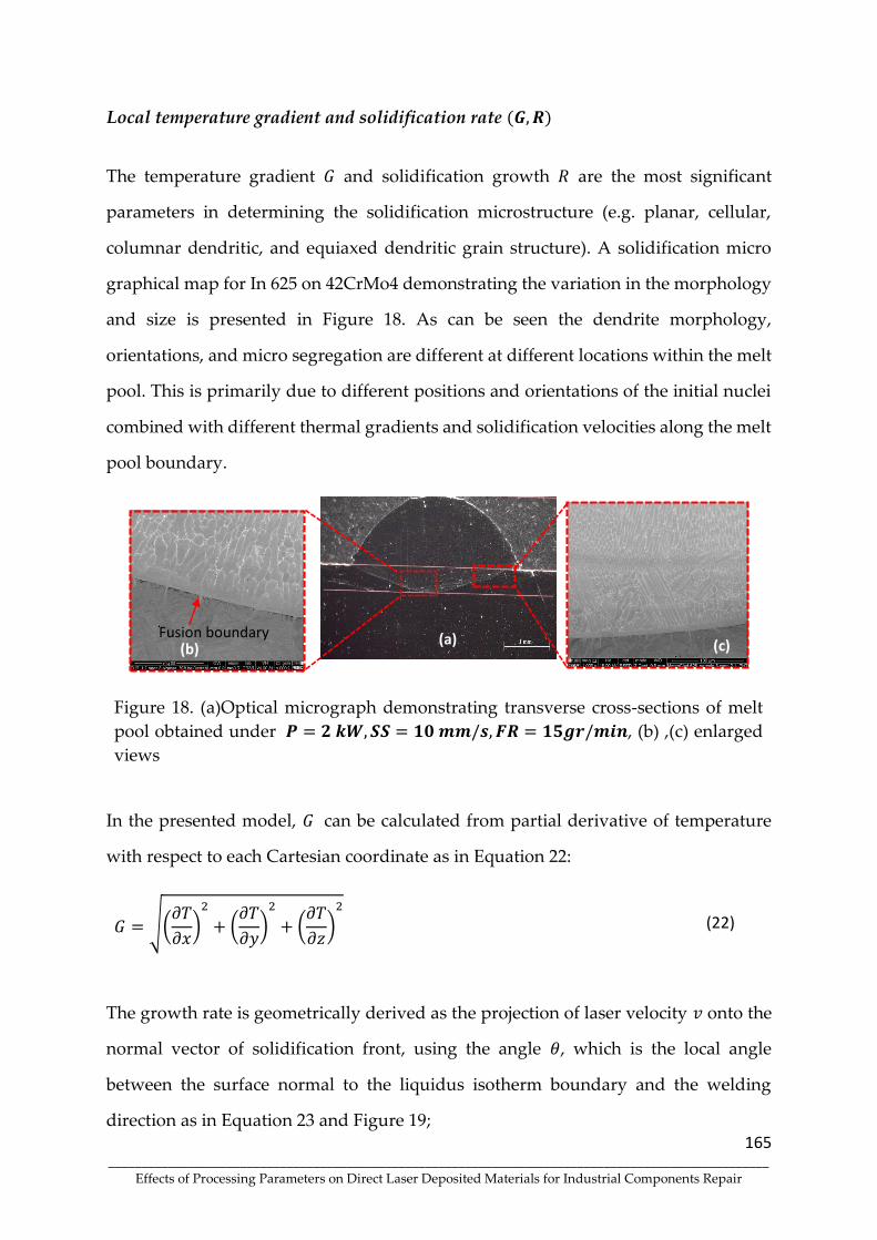
165 ____________________________________________________________________________________________________
Effects of Processing Parameters on Direct Laser Deposited Materials for Industrial Components Repair
Local temperature gradient and solidification rate (𝑮, 𝑹)
The temperature gradient 𝐺 and solidification growth 𝑅 are the most significant
parameters in determining the solidification microstructure (e.g. planar, cellular,
columnar dendritic, and equiaxed dendritic grain structure). A solidification micro
graphical map for In 625 on 42CrMo4 demonstrating the variation in the morphology
and size is presented in Figure 18. As can be seen the dendrite morphology,
orientations, and micro segregation are different at different locations within the melt
pool. This is primarily due to different positions and orientations of the initial nuclei
combined with different thermal gradients and solidification velocities along the melt
pool boundary.
Figure 18. (a)Optical micrograph demonstrating transverse cross-sections of melt
pool obtained under 𝑷 = 𝟐 𝒌𝑾, 𝑺𝑺 = 𝟏𝟎 𝒎𝒎/𝒔, 𝑭𝑹 = 𝟏𝟓𝒈𝒓/𝒎𝒊𝒏, (b) ,(c) enlarged
views
In the presented model, 𝐺 can be calculated from partial derivative of temperature
with respect to each Cartesian coordinate as in Equation 22:
𝐺 = √(𝜕𝑇
𝜕𝑥)
2
+ (𝜕𝑇
𝜕𝑦)
2
+ (𝜕𝑇
𝜕𝑧)
2
(22)
The growth rate is geometrically derived as the projection of laser velocity 𝑣 onto the
normal vector of solidification front, using the angle 𝜃, which is the local angle
between the surface normal to the liquidus isotherm boundary and the welding
direction as in Equation 23 and Figure 19;
(a) (b) (c)
Fusion boundary

166 ____________________________________________________________________________________________________
Effects of Processing Parameters on Direct Laser Deposited Materials for Industrial Components Repair
𝑅 = |𝑣|. cos ( 𝜃 ) (23)
Figure 19. Schematic of solidification growth rate 𝑅 in the melt pool with laser
scanning 𝑉
The values of 𝐺 and 𝑅 were extracted from macro-scale simulation. The points of
interested were selected on the trailing half of the melt pool which is the portion
subject to solidification as the melt pool domain. In Figure 20 (a, b), the variation of
the 𝐺 and 𝑅 along with the centerline of melt pool boundary with increasing depth is
explicitly shown. The results reveal that there is an inverse relationship between 𝑅 and
𝐺. The maximum 𝑅 is calculated near the top of the melt pool (with a low solidification
front depth) while the minimum is found near the bottom of the melt pool (with a
high solidification front depth). In contrast, the maximum 𝐺 is calculated at the bottom
of the melt pool as the minimum 𝐺 is observed at the top. In the bottom region is
exposed at high 𝐺 and low 𝑅 and hence corresponds to the planar grains as shown in
Figure 18 (b) SEM microstructure evidence. On the other hand, the top regions tend
relatively lower 𝐺 and higher 𝑅 with the dendrite structure from Figure 18 (c).
Scanning Direction
Heat Source
Mushy Solid - Liquid
V R 𝜽
Solid
Melt Pool
Z
Y

167 ____________________________________________________________________________________________________
Effects of Processing Parameters on Direct Laser Deposited Materials for Industrial Components Repair
(a)
(b)
Figure 20. The calculated (a): 𝐺 and (b): 𝑅, along the centerline of the melt pool
surface; Variation in relation with the solidification front depth for one set of
parameters 𝑷 = 𝟐 𝒌𝑾, 𝑺𝑺 = 𝟏𝟎 𝒎𝒎/𝒔, 𝑭𝑹 = 𝟏𝟓𝒈𝒓/𝒎𝒊𝒏
Figure 21 (a,b) illustrates the cooling rate for two set of parameters including (a): 𝑷 =
𝟐 𝒌𝑾, 𝑺𝑺 = 𝟏𝟎 𝒎𝒎/𝒔, 𝑭𝑹 = 𝟏𝟓𝒈𝒓/𝒎𝒊𝒏 and (b): 𝑷 = 𝟏. 𝟓 𝒌𝑾, 𝑺𝑺 = 𝟏𝟎 𝒎𝒎/𝒔, 𝑭𝑹 =
𝟏𝟓𝒈𝒓/𝒎𝒊𝒏. It can be seen how the cooling rate, �̇� = 𝐺 × 𝑅, varies as a function of the
melt pool depth for both cases; the dotted rectangular views emphasize the highest
and lowest cooling rate along with the location of the melt pool boundary. Simulation
results show that cooling rate increases from bottom to top along the melt pool
boundary. The predicted cooling rate varies by changing the laser power. The cooling
rate increases with decreasing the laser power [26][36] and consequently differences
in cooling rate leads to variety of solidified microstructures.
R² = 0.9404
0
200
400
600
800
1000
-1.2 -0.7 -0.2
Tem
pre
ture
gra
die
nt
G (
K/m
m)
Solidification front depth (mm)
R² = 0.8502
0
2
4
6
8
-1.2 -0.7 -0.2
Gro
wth
Rat
e (m
m/s
)
Solidification front depth (mm)
B
A
A
B B
Z
B

168 ____________________________________________________________________________________________________
Effects of Processing Parameters on Direct Laser Deposited Materials for Industrial Components Repair
(a)
(b)
Figure 21. The predicted cooling rates at varying solidification front depths for two
sets of process parameters; (a) 𝑷 = 𝟐 𝒌𝑾, 𝑺𝑺 = 𝟏𝟎 𝒎𝒎/𝒔, 𝑭𝑹 = 𝟏𝟓𝒈𝒓/𝒎𝒊𝒏, (b) 𝑷 =
𝟏. 𝟓 𝒌𝑾, 𝑺𝑺 = 𝟏𝟎 𝒎𝒎/𝒔, 𝑭𝑹 = 𝟏𝟓𝒈𝒓/𝒎𝒊𝒏
Conclusion
In the present study, a computational framework for the transient heat phenomena in
DED process is developed by coupling a finite element based on phase-field model.
In the proposed model three state variables 𝜙𝑓, 𝜙𝑣 ,and 𝜓 are defined to track and
capture the phase of materials between molten, solid, and even vaporized conditions
to allocate the proper thermal-physical material properties. The proposed model is
implemented in the commercial finite element software ABAQUS-standard. The
capability of numerical model is investigated by comparing melt pool dimensions,
including width and depth from simulation for single cladding lines, with the
experimental data. Three different laser power values were applied to quantify their
effect on the melt pool morphology. The melt pool width and depth have a tendency
of becoming greater when a higher laser power is applied. Moreover, the numerical
results showcases the inverse correlation between the scanning speed the melt pool
volume. The investigation is further proceeded to detect the solidification parameters,
the temperature gradient and the growth rate. To achieve this goal, the temperature
variation as well as the liquidus isotherm boundary surface information is utilized to
R² = 0.9662
-1.2
-1
-0.8
-0.6
-0.4
-0.2
0
0 5000 10000 15000Solid
ific
atio
n f
ron
t d
epth
(m
m)
Cooling Rate (K/s)
R² = 0.943
-0.6
-0.5
-0.4
-0.3
-0.2
-0.1
0
0 5000 10000 15000Solid
ific
atio
n f
ron
t d
epth
(m
m)
Cooling Rate (K/s)
9950 11450

169 ____________________________________________________________________________________________________
Effects of Processing Parameters on Direct Laser Deposited Materials for Industrial Components Repair
calculate these parameters along the solidification front depth path. The planar to
dendrite transition was predicted by moving from melt pool boundary to the interior
of melt pool. Furthermore, an inverse relationship between 𝑅 and 𝐺, can be seen and
maximum 𝑅 is calculated near the top of the melt pool, while the minimum is found
near the bottom of the melt pool, which is in agreement with a solidification map
obtained by SEM. Finally, the cooling rate increases from the bottom to the top of melt
pool and decreasing laser power leads to an increase of the range of the cooling rate.
Acknowledgements - The corresponding author would like to thank Professor
Manuel F. Vieira and Dr. Omid Emadinia for supporting experiments and
constructive comments on the solidifcation concept.
Author contribution - Roya Darabi: conceptualization, investigation, writing—
original draft, writing—review and editing. Andre Ferreira: Conceiving, planning and
conducting the experiments. Erfan Azinpour: writing—review and editing. Jose Cesar
de Sa: conceptualization, investigation, review and editing, funding acquisition. Ana
Reis: conceptualization, investigation, review and editing, funding acquisition
Funding - This work was supported by Fundo Europeu de Desenvolvimento Regional
(FEDER) through Programa Operacional Competitividade e Internacionalização
(COMPETE 2020) and national funds through Fundação para a Ciência e a Tecnologia
(FCT), Portugal, Grant number: ADDing (POCI-01-0145-FEDER-030490) and Project
GEAR3D (POCI-01-0247-FEDER-039848), co-financed by FEDER through
P2020|COMPETE
Availability of data and materials - It has been confirmed that data is open and
transparent.
Declarations
Ethics approval - Not applicable.
Consent to participate - Not applicable.
Consent for publication - Not applicable.
Conflict of interest - The authors declare no competing interests.

170 ____________________________________________________________________________________________________
Effects of Processing Parameters on Direct Laser Deposited Materials for Industrial Components Repair
References
1. DebRoy T, Wei HL, Zuback JS, et al (2018) Additive manufacturing of metallic
components – Process, structure and properties. Progress in Materials Science
92:112–224. doi: 10.1016/j.pmatsci.2017.10.001
2. Azinpour E, Darabi R, Cesar de Sa J, et al (2020) Fracture analysis in directed
energy deposition (DED) manufactured 316L stainless steel using a phase-field
approach. Finite Elements in Analysis and Design 177:103417. doi:
10.1016/j.finel.2020.103417
3. Gardan J (2016) Additive manufacturing technologies: State of the art and
trends. International Journal of Production Research 54:3118–3132. doi:
10.1080/00207543.2015.1115909
4. Gibson DG, Glass JI, Lartigue C, et al (2010) Creation of a bacterial cell controlled
by a chemically synthesized genome. Science 329:52–56. doi:
10.1126/science.1190719
5. Somashekara MA, Naveenkumar M, Kumar A, et al (2017) Investigations into
effect of weld-deposition pattern on residual stress evolution for metallic
additive manufacturing. International Journal of Advanced Manufacturing
Technology 90:2009–2025. doi: 10.1007/s00170-016-9510-7
6. Gu DD, Meiners W, Wissenbach K, Poprawe R (2012) Laser additive
manufacturing of metallic components: Materials, processes and mechanisms.
International Materials Reviews 57:133–164. doi:
10.1179/1743280411Y.0000000014
7. Feenstra DR, Banerjee R, Fraser HL, et al (2021) Critical review of the state of the
art in multi-material fabrication via directed energy deposition. Current
Opinion in Solid State and Materials Science 25:100924. doi:
10.1016/j.cossms.2021.100924
8. Fallah V, Alimardani M, Corbin SF, Khajepour A (2011) Temporal development
of melt-pool morphology and clad geometry in laser powder deposition.
Computational Materials Science 50:2124–2134. doi:
10.1016/j.commatsci.2011.02.018
9. Lee KH, Yun GJ (2020) A novel heat source model for analysis of melt Pool
evolution in selective laser melting process. Additive Manufacturing 36:101497.
doi: 10.1016/j.addma.2020.101497
10. Lee KH, Yun GJ (2021) Prediction of melt pool dimension and residual stress
evolution with thermodynamically-consistent phase field and consolidation
models during re-melting process of SLM. Computers, Materials and Continua
66:87–112. doi: 10.32604/cmc.2020.012688

171 ____________________________________________________________________________________________________
Effects of Processing Parameters on Direct Laser Deposited Materials for Industrial Components Repair
11. Roy S, Juha M, Shephard MS, Maniatty AM (2018) Heat transfer model and
finite element formulation for simulation of selective laser melting.
Computational Mechanics 62:273–284. doi: 10.1007/s00466-017-1496-y
12. Markl M, Körner C (2016) Multiscale Modeling of Powder Bed-Based Additive
Manufacturing. Annual Review of Materials Research 46:93–123. doi:
10.1146/annurev-matsci-070115-032158
13. Proell SD, Wall WA, Meier C (2020) On phase change and latent heat models in
metal additive manufacturing process simulation. Advanced Modeling and
Simulation in Engineering Sciences. doi: 10.1186/s40323-020-00158-1
14. Darabi R, Azinpour E (2021) Fracture Prediction Based on Evaluation of Initial
Porosity Induced By Direct Energy Deposition. doi: 10.13052/ejcm2642-
2085.29233
15. Wolff SJ, Lin S, Faierson EJ, et al (2017) A framework to link localized cooling
and properties of directed energy deposition (DED)-processed Ti-6Al-4V. Acta
Materialia 132:106–117. doi: 10.1016/j.actamat.2017.04.027
16. Farshidianfar MH, Khajepour A, Gerlich AP (2016) Effect of real-time cooling
rate on microstructure in Laser Additive Manufacturing. Journal of Materials
Processing Technology 231:468–478. doi: 10.1016/j.jmatprotec.2016.01.017
17. Wang Z, Palmer TA, Beese AM (2016) Effect of processing parameters on
microstructure and tensile properties of austenitic stainless steel 304L made by
directed energy deposition additive manufacturing. Acta Materialia 110:226–
235. doi: 10.1016/j.actamat.2016.03.019
18. Hagenlocher C, Fetzer F, Weller D, et al (2019) Explicit analytical expressions
for the influence of welding parameters on the grain structure of laser beam
welds in aluminium alloys. Materials and Design 174:107791. doi:
10.1016/j.matdes.2019.107791
19. Karayagiz K, Johnson L, Seede R, et al (2020) Finite interface dissipation phase
field modeling of Ni–Nb under additive manufacturing conditions. Acta
Materialia 185:320–339. doi: 10.1016/j.actamat.2019.11.057
20. Ho S, Eun J, Park G, et al (2021) Thermal Analysis for Simulation of Metal
Additive Manufacturing Process Considering Temperature- and History-
Dependent Material Properties. International Journal of Aeronautical and Space
Sciences 22:52–63. doi: 10.1007/s42405-020-00283-6
21. Kundakcioglu E, Lazoglu I, Rawal S (2016) Transient thermal modeling of laser-
based additive manufacturing for 3D freeform structures. The International
Journal of Advanced Manufacturing Technology 493–501. doi: 10.1007/s00170-
015-7932-2

172 ____________________________________________________________________________________________________
Effects of Processing Parameters on Direct Laser Deposited Materials for Industrial Components Repair
22. Liu J, Xu Y, Ge Y, et al (2020) Wire and arc additive manufacturing of metal
components: a review of recent research developments. International Journal of
Advanced Manufacturing Technology 111:149–198. doi: 10.1007/s00170-020-
05966-8
23. Qiu Z, Wu B, Zhu H, et al (2020) Microstructure and mechanical properties of
wire arc additively manufactured Hastelloy C276 alloy. Materials and Design.
doi: 10.1016/j.matdes.2020.109007
24. Hofman JT, De Lange DF, Pathiraj B, Meijer J (2011) FEM modeling and
experimental verification for dilution control in laser cladding. Journal of
Materials Processing Technology 211:187–196. doi:
10.1016/j.jmatprotec.2010.09.007
25. Rezaeifar H, Elbestawi MA (2021) On-line melt pool temperature control in L-
PBF additive manufacturing. International Journal of Advanced Manufacturing
Technology 112:2789–2804. doi: 10.1007/s00170-020-06441-0
26. S.L.Wang, R.F.Sekerka, A.A.Wheeler, B.T.Murray, S.R.Coriell, R.J.Braun GBM
(1993) Thermodynamically-Consistent Phase-Field Models for Solidification.
Physica D: Nonlinear Phenomena 69:189–200. doi: https://doi.org/10.1016/0167-
2789(93)90189-8
27. Reis A, Xu Z, Tol R V., Neto R (2012) Modelling feeding flow related shrinkage
defects in aluminum castings. Journal of Manufacturing Processes 14:1–7. doi:
10.1016/j.jmapro.2011.05.003
28. Reis A, Houbaert Y, Xu Z, et al (2008) Modeling of shrinkage defects during
solidification of long and short freezing materials. Journal of Materials
Processing Technology 202:428–434. doi: 10.1016/j.jmatprotec.2007.10.030
29. Guo Z, Lin P (2015) A thermodynamically consistent phase-field model for two-
phase flows with thermocapillary effects. Journal of Fluid Mechanics 766:226–
271. doi: 10.1017/jfm.2014.696
30. Zhang Z, Huang Y, Rani Kasinathan A, et al (2019) 3-Dimensional heat transfer
modeling for laser powder-bed fusion additive manufacturing with volumetric
heat sources based on varied thermal conductivity and absorptivity. Optics and
Laser Technology 109:297–312. doi: 10.1016/j.optlastec.2018.08.012
31. Roberts IA, Wang CJ, Esterlein R, et al (2009) A three-dimensional finite element
analysis of the temperature field during laser melting of metal powders in
additive layer manufacturing. International Journal of Machine Tools and
Manufacture 49:916–923. doi: 10.1016/j.ijmachtools.2009.07.004
32. Katopodes ND, Method EE, Size S, et al low-Water Flow Methods for Two-
Dimensional Shal- Courant Number.

173 ____________________________________________________________________________________________________
Effects of Processing Parameters on Direct Laser Deposited Materials for Industrial Components Repair
33. Deering RA (2018) Additive Manufacturing Part Level Distortion Sensitivity
Analysis within Abaqus on a Thin Walled, Tubular Structure. Additive
Manufacturing Symposium 14.
34. Yashchuk I (2018) A multiscale finite element framework for additive
manufacturing process modeling.
35. Haley JC, Zheng B, Bertoli US, et al (2019) Working distance passive stability in
laser directed energy deposition additive manufacturing. Materials and Design
161:86–94. doi: 10.1016/j.matdes.2018.11.021
36. Ali H, Ghadbeigi H, Mumtaz K (2018) Processing Parameter Effects on Residual
Stress and Mechanical Properties of Selective Laser Melted Ti6Al4V. Journal of
Materials Engineering and Performance 27:4059–4068. doi: 10.1007/s11665-018-
3477-5

174 ____________________________________________________________________________________________________
Effects of Processing Parameters on Direct Laser Deposited Materials for Industrial Components Repair
Chapter 4
MECHANICAL AND MICROSTRUCTURAL PROPERTIES OF
INCONEL 625 PRODUCED BY DIRECT LASER DEPOSITION (DLD)

175 ____________________________________________________________________________________________________
Effects of Processing Parameters on Direct Laser Deposited Materials for Industrial Components Repair
Article 6 - Mechanical and Microstructural Characterisation of Bulk Inconel 625
Produced by Direct Laser Deposition
Journal Materials Science and Enginnering: A
https://doi.org/10.1016/j.msea.2022.142777
176 ____________________________________________________________________________________________________
Effects of Processing Parameters on Direct Laser Deposited Materials for Industrial Components Repair
Article 6 - Mechanical and Microstructural Characterisation of
Bulk Inconel 625 Produced by Direct Laser Deposition
André A. Ferreira1,2, Ana R. Reis1,2, Rui L. Amaral2, João M. Cruz3,
Pedro C. Romio1, Jorge O. Seabra1,2, Manuel F. Vieira1,2
1Faculty of Engineering of the University of Porto, 4200-465 Porto, Portugal 2LAETA/INEGI—Institute of Science and Innovation in Mechanical and Industrial Engineering, 4200-
465 Porto, Portugal 3SERMEC-Group, 4425-348 Folgosa-Maia, Portugal
*Corresponding author: Department of Metallurgical and Materials Engineering, University of Porto,
Porto, 4200-465 Portugal E-mails addresses: [email protected] (A. A. Ferreira) and
[email protected] (M. F. Vieira).
Abstract
Direct laser deposition (DLD) is an advanced additive manufacturing (AM)
technology with growing industrial importance. In the present study, the mechanical
and microstructural characterisation of a bulk produced by DLD depositing a nickel
superalloy (type Inconel 625) on 42CrMo4 structural steel was performed. Optimised
processing parameters (laser power, scanning speed and feed rate) were used for
deposition and remained constant during bulk production. The bulk showed
structural integrity, with no cracking or unmelted particles. Successive layers were
deposited on a pre-heated substrate to reduce the cooling rate and minimise both the
formation of metastable phases in the heat-affected zone and the dimensions of the
deleterious phases in bulk. The bulk microstructure mainly consists of a coarse
columnar/dendritic structure, and the longitudinal section microstructure revealed
the layer-by-layer deposition pattern. Microstructural and mechanical
characterisation demonstrated that a sound bulk was formed, with mechanical
properties similar to wrought Inconel 625. These results contribute to the recognition
of DLD as a suitable technique for the repair and remanufacturing of industrial
components.

177 ____________________________________________________________________________________________________
Effects of Processing Parameters on Direct Laser Deposited Materials for Industrial Components Repair
Keywords: Inconel 625; direct laser deposition; additive manufacturing; pre-heating;
microstructure; mechanical evaluation
Introduction
Laser-Based Additive Manufacturing (LBAM) are emerging technologies with
applications for various industrial sectors, including medical implants, automotive
and aerospace parts, with complex geometries and structures [1]. Direct Laser
Deposition (DLD) is an LBAM technology used to manufacture, reconstruct, or repair
metal parts. DLD consists of the supply, through a nozzle, of metallic powder (or wire)
processed by a focused laser, creating a melt pool on the surface of a metallic substrate
that interacts with the substrate to form a cladding. Several processing variables
directly or indirectly affect the quality and structural integrity of the cladding, dictated
by solidification and metallurgical bonding [2]. DLD is a process that also enables the
production of functionally graded materials [3]. Unlike conventional coating/repair
production techniques such as welding, DLD can fabricate 3-D components with
complex features directly from the CAD model. The goal of the process is the
controlled melting of metal powders and their layered deposition, producing
claddings with excellent metallurgical bonding and density, small heat-affected zone
(HAZ), low dilution, minimal distortion, and precise deposition, making the
technique fundamental in the repair of high value-added components [4], [5]. Deposits
produced by DLD exhibit an attractive set of mechanical properties and wear and
corrosion resistance [6]. The production of wear-resistant coatings on low- and
medium-carbon steel substrates is an application that can have many industrial
applications, both in component repair and in protective coating with a thick, tough
layer.
Nickel-based superalloys, such as Inconel 625, have been widely adopted in multiple
fields due to their versatile capabilities and their wide range of applications. These

178 ____________________________________________________________________________________________________
Effects of Processing Parameters on Direct Laser Deposited Materials for Industrial Components Repair
materials are used primarily in power generation aircraft and turbines, rocket engines
and other challenging environments, including industrial furnace components,
chemical power plants, marine systems, nuclear power plants and many other fields
where high temperature corrosion resistance is generally required [7], [8].
Conventional component manufacturing using these high-performance alloys is
difficult due to excessive tool wear and low material removal rates. In fact, nickel-
based superalloys are very attractive materials for various industrial sectors due to
their high-temperature ductility, hardness, mechanical strength, fatigue and creep
resistance, and excellent oxidation and corrosion resistance in aggressive
environments [9], [10]. Powder-based LBAM technologies can remove these
constraints, improving lead times and reducing manufacturing costs [11].
Inconel 625 is one of the main nickel superalloys whose properties are mainly derived
from the addition of elements such as molybdenum (Mo) and niobium (Nb), which
strengthen by solid solution the nickel-chromium matrix [12]–[14]. Further
strengthening is achieved by intermetallic phases, namely the gamma double prime
(γ"-Ni3Nb), and by carbide precipitation [12], [15]. The formation of topologically
close-packed (TCP) phases, such as σ (FeCr, FeCrMo, CrCo), μ and Laves, is
detrimental for nickel superalloys application. These phases are brittle and
detrimental to these superalloys' mechanical properties and creep resistance [16]. A
high refractory elements content can cause the extensive formation of TCP phases
during prolonged exposure to high temperatures; this formation is dependent on the
material's microstructure [17]. Laser processing of Inconel 625 alloy shows complex
structures involving cellular grains, typical columnar dendrites and equiaxial grains
[18].
The use of nickel-based superalloys in DLD must consider the effect of high cooling
rates promoted by the localised thermal delivery induced by the laser beam. However,
the rapid cooling rate and repeated heating/cooling cycles during laser processing
induce intense thermal stresses that can exceed the yield point of cladding materials

179 ____________________________________________________________________________________________________
Effects of Processing Parameters on Direct Laser Deposited Materials for Industrial Components Repair
[19]. The high temperature of the laser beam creates a large temperature gradient
between the centre and edges of the weld pool, producing surface tension gradients
that are similar to those observed during laser welding [20]. This effect can influence
the formation of intermetallics and TCP phases. The cooling rate directly influences
the resulting microstructure and mechanical properties of the deposited component,
being more dependent on the scanning speed than laser power [21]. High cooling rate
and low G/R ratio (temperature gradient to growth rate ratio)promotes the formation
of dendrites with smaller arms and discrete Laves phase particles. In contrast, low
cooling rate and high G/R ratio tend to produce coarse dendrites and particles of
continuously distributed Laves phase [22]–[24]. Similar effects of metastable phases
(martensite) formation in the heat-affected some (HAZ) and near the melt line were
observed for depositions performed on structural steel [25].
Pre-heating (PHT) the substrate is essential to control the cooling rate, minimising this
detrimental effect. Increasing the PHT temperature also promotes melt pool growth
(depth and width), melting more substrate, thus increasing dilution [26]–[28]. PHT
also prevents cladding delamination or cracking and reduces distortion and residual
stresses due to the lower thermal gradient between the coating and substrate [6], [29],
[30]. Another factor to be observed is that the deposition of multiple layers of Inconel
625 by DLD allows the minimization of distortion, reducing the deflection of the
coating [31].
The industrial importance of the Inconel 625 alloy and its complexity being
unquestionable, it is essential to determine the conditions for its deposition by DLD.
The influence of process parameters, such as laser power, scanning speed, powder
feed rate, and pre-heating on single layers, was analysed in a previous study [25]. This
work explores the deposition of multiple layers of Inconel 625 superalloy powder,
forming a bulk, on a pre-heated steel substrate. The quality of the bulk was evaluated
by the absence of cracks and structural imperfections, and its mechanical properties

180 ____________________________________________________________________________________________________
Effects of Processing Parameters on Direct Laser Deposited Materials for Industrial Components Repair
were determined to assess the feasibility of using these bulks for the
repair/remanufacturing of industrial components.
Experimental Procedure
DLD System Setup
A laser system, LDF 3000 - 100, was used to produce the DLD claddings. The system
has a high power fibre-coupled laser diode (wavelength 900-1030 nm, depending on
power), with a nominal beam power of 6000 W. The machine concept is based on a
six-axis industrial robot, a KUKA KR90 R3100, which can be placed on a linear table
with a 4 m working range. All axes are connected to the robot and laser control units,
which control the temperature in the molten pool and the laser power. A coaxial
feeding system supplied the addition powder during the deposition process.
Powder and Substrate Characteristics
Nickel-based superalloy powder, supplied by the Oerlikon company under the trade
designation MetcoClad 625 (Inconel 625), produced by the gas atomised process, was
used in this study. The powders present a spherical morphology and particle size with

181 ____________________________________________________________________________________________________
Effects of Processing Parameters on Direct Laser Deposited Materials for Industrial Components Repair
a nominal range from 45 to 90 µm. Figure 1 shows an image of the powder obtained
by scanning electron microscopy (SEM).
.
Figure 1. SEM micrograph of MetcoClad 625 powder.
42CrMo4 steel was the substrate for the cladding deposition. The steel was machined
in plates with dimensions equal to 100 mm x 120 mm x 15 mm. Mechanical and
chemical properties and additional information are described in the standard in EN
10269 [32]. Table 1 shows the chemical composition of MetcoClad 625 (M625) powder
and 42CrMo4 steel.
Table 1. Chemical composition of M625 powder and 42CrMo4 steel (wt.%).
Raw Material C Cr Ni Mn Mo Nb Si P S Fe
M625 - 21.3 60.8 - 9.2 4.6 - - - 4.1
42CrMo4 0.42 1.11 - 0.67 0.19 - 0.28 0.025 0.015 Balance
Samples Production
The successive depositions of M625 for the bulk production were carried out with a
coaxial nozzle. The deposition conditions were defined in previous study [25], in

182 ____________________________________________________________________________________________________
Effects of Processing Parameters on Direct Laser Deposited Materials for Industrial Components Repair
which the influence of the following three independent processing variables was
analysed: laser power (LP), scanning speed (SS), and powder feed rate (FR).
Processing optimisation allowed selecting the conditions for the production of the
M625 bulk, expressed as values of two combined process parameters (parameters
based on previous studies [33], [34], allowing a more general approach, and non-
machine specific). The two parameters selected were the specific energy, Especific (= LP
/ φ*SS), and the powder density, G (= FR / φ*SS);φ is the spot size diameter of the laser
beam on the substrate. The optimized combined parameters for M625 solid
production through DLD are Especific = 133.3 J/mm2 and G = 16.7 x 10⁻³ g/mm2. Before
deposition, the substrates were cleaned with pure acetone and pre-heated to
approximately 300 °C by an oxy torch to eliminate moisture and decrease the cooling
rate in the melt pool and adjacent regions of the substrate (thus reducing the
detrimental effect of the HAZ). The temperature was selected following welding
practices for 42CrMo4 steel and controlled with a digital pyrometer. Furthermore, for
bulk production, the M625 powder deposition strategy selected was the zigzag-XY
tool path, as shown in Figure 2. This deposition strategy was chosen due to minimize
the possibility of porosity formation and allow obtaining good mechanical properties
[35].
Figure 2. Schematic diagram of the strategy for the M625 bulk production by DLD.

183 ____________________________________________________________________________________________________
Effects of Processing Parameters on Direct Laser Deposited Materials for Industrial Components Repair
In all tests, a spot size of 2.5 mm, and an offset in the Z-axis of 0.2 mm were used. High
purity argon (99.99%) was applied as shielding gas, with a flow rate of 5.5 L/min,
minimising the contamination of the melt pool during the DLD process. During the
deposition and production of the M625 bulk, the distance between substrate and
nozzle was 13 mm. The samples were air-cooled to room temperature. Figure 3 shows
a bulk produced by the DLD technique with the respective measurements.
Figure 3. Bulk produced by direct laser deposition (DLD) using Inconel 625 powder deposited
on 42CrMo4 steel substrate.
Microstructural and Mechanical Characterisation
The M625 bulk was cut for microstructural and mechanical characterisation using a
metallographic cut-off machine with refrigeration to avoid substrate and cladding
overheating. Samples were mounted in resin and polished down to 1 μm diamond
suspension. An additional polishing step was performed with 0.06 μm silica colloidal
suspension for a superior surface finishing and polishing-induced plastic deformation
removal.

184 ____________________________________________________________________________________________________
Effects of Processing Parameters on Direct Laser Deposited Materials for Industrial Components Repair
Chemical and microstructural characterisations were performed using a scanning
electron microscope (SEM) equipped with Energy Dispersive X-Ray Spectroscopy
(EDX) and a Digital Microscope (DM).
Vickers microhardness evaluation was performed on a fully automated microindenter
. The HV hardness maps were obtained from a sample taken from the bulk, applying
a load of 300 g and a dwell time of 15 s. This procedure scanned a 10 × 2.4 mm area of
with 0.5 mm as the distance between the centres of two adjacent indentations.
Uniaxial tension tests were carried out on an electromechanical uniaxial testing
system with a 5 kN load cell and a 0.5 mm/min strain rate. The surface strains were
measured by digital image correlation (DIC), a non-contact method, using correlation
softwareVIC-2D 6. The DIC images were captured with a telecentric lens and a 5
MPixel camera (acA2440-75um, 2448x2048 pixels. The experimental work plan was
carried out using a 5 kN electromechanical testing system designed expressly for this
type of request (Figure 4) [36]. The specimens were tested at room temperature with
a constant crosshead speed of 0.5 mm/min, which corresponds to an initial strain rate
of 0.0037 s-1. Wire electrical discharge machining was used to extract the specimens
with a thickness of 1.4 mm, according to the geometry indicated in Figure 4.
Figure 4. Uniaxial tensile test setup and sample dimensions (in mm).

185 ____________________________________________________________________________________________________
Effects of Processing Parameters on Direct Laser Deposited Materials for Industrial Components Repair
Micro-abrasion wear tests evaluated the bulk wear rate with a micro-scale abrasion
tester, using a fixed rotating ball configuration. The wear craters were measured with
a 3D Optical profilometer, and the volume of the worn material was calculated.
Results and Discussion
Microstructure
The bulk deposited by DLD evidenced a layered macrostructure appearance, as
shown in Figure 2. From the cladding/substrate set, sections perpendicular to the
substrate were prepared for microstructural observation. The observation of these
sections revealed that the bulk was free from cracks, voids between the deposited
layers, and no unmelted particles were observed along with the structure. No
porosities with deleterious dimensions were identified during the DM and SEM
analysis. It also presented an excellent metallurgical bonding to the substrate, as
illustrated in Figure 5.
Figure 5. Microstructure obtained by scanning electron microscopy (SEM) of the M625 solid
produced by direct laser deposition (DLD).

186 ____________________________________________________________________________________________________
Effects of Processing Parameters on Direct Laser Deposited Materials for Industrial Components Repair
As indicated in previous studies [25][37], PHT promotes the formation of cellular or
equiaxial grains in the region adjacent to the substrate (as illustrated in Figure 3), a
condition not observed in samples without PHT, where the formation of planar grains
occurs. The microstructure in the bulk consists mainly of a columnar/dendritic
structure, which exhibits a coarse grain, and the longitudinal section microstructure
revealed the layer-by-layer deposition pattern. The dendritic growth is approximately
parallel to the direction of heat flow, showing similar direction in all single layers. A
more detailed description of the microstructure of claddings produced with M625 is
presented in [25]. The transition region between two depositions produced by DLD
and the columnar/dendritic microstructure evolution characteristic of these regions
are shown in Figure 6.
Figure 6. Microstructure images of M625 claddings obtained by (A) Digital Microscopy and
(B) Scanning Electron Microscopy. Red lines indicate transition regions between consecutive
claddings.
Figure 4 shows no discontinuities between layers and a small dilution zone, a
consequence of the remelting provoked by the deposition of the new layer. Figure 4B
illustrates columnar/dendritic grains continuity across the interface, evidencing
epitaxial growth. The material on which the layer is deposited (substrate or previously
deposited layer) acts as a heat sink during the laser processing of materials. Due to
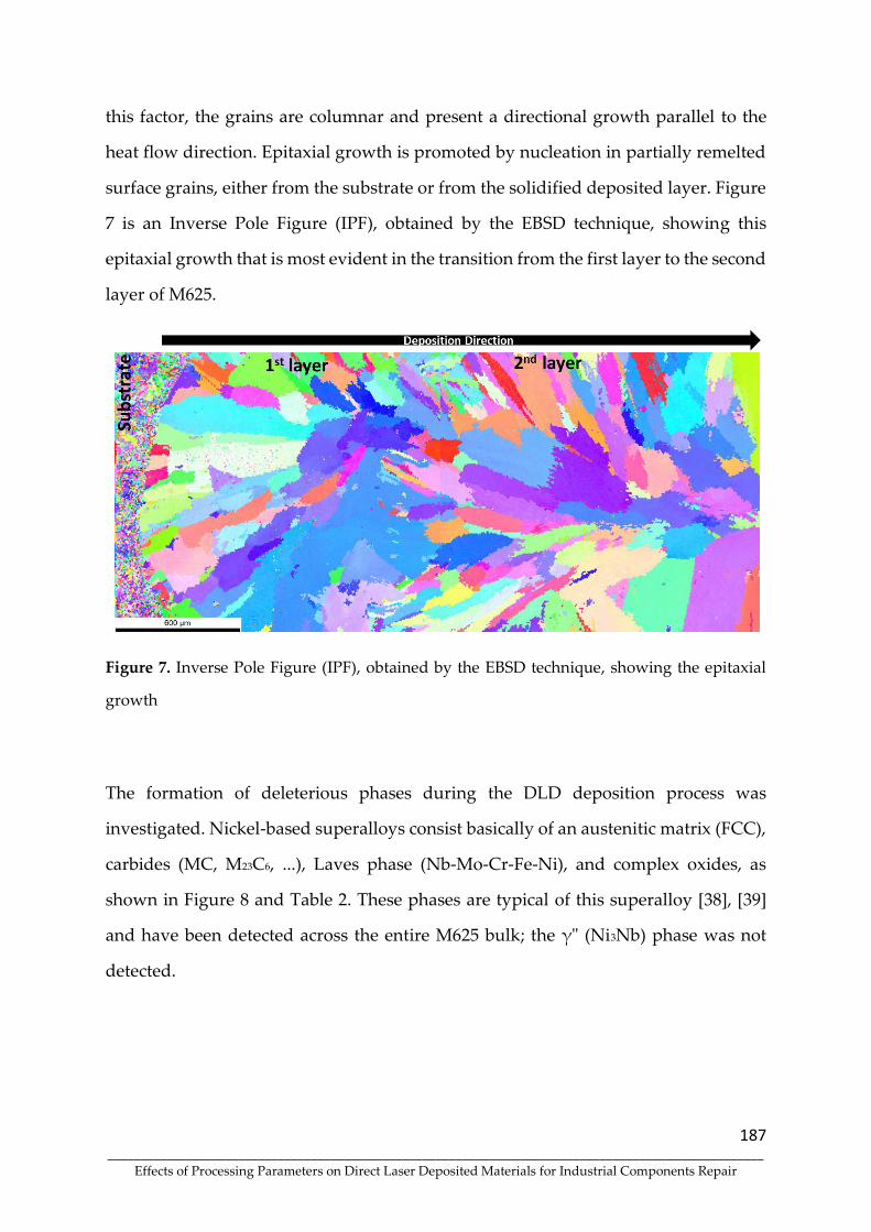
187 ____________________________________________________________________________________________________
Effects of Processing Parameters on Direct Laser Deposited Materials for Industrial Components Repair
this factor, the grains are columnar and present a directional growth parallel to the
heat flow direction. Epitaxial growth is promoted by nucleation in partially remelted
surface grains, either from the substrate or from the solidified deposited layer. Figure
7 is an Inverse Pole Figure (IPF), obtained by the EBSD technique, showing this
epitaxial growth that is most evident in the transition from the first layer to the second
layer of M625.
Figure 7. Inverse Pole Figure (IPF), obtained by the EBSD technique, showing the epitaxial
growth
The formation of deleterious phases during the DLD deposition process was
investigated. Nickel-based superalloys consist basically of an austenitic matrix (FCC),
carbides (MC, M23C6, ...), Laves phase (Nb-Mo-Cr-Fe-Ni), and complex oxides, as
shown in Figure 8 and Table 2. These phases are typical of this superalloy [38], [39]
and have been detected across the entire M625 bulk; the γ" (Ni3Nb) phase was not
detected.

188 ____________________________________________________________________________________________________
Effects of Processing Parameters on Direct Laser Deposited Materials for Industrial Components Repair
Figure 8. Microstructural constituents in the matrix and interdendritic zones of M625 bulk.
Table 2. Chemical composition of the phases identified in solid M625 by EDX.
Phases Chemical Composition (at%)
Ni Fe Cr Mo Nb Si Al O C
Matrix (Z1) 51.91 23.19 19.76 4.39 - 0.75 - - -
Laves phase (Z2) 42.2 15.64 17.91 10.54 10.19 3.52 - - -
Complex Oxide (Z3) 20.86 9.11 14.68 7.1 4.97 5.41 4.96 27.15 5.76
NbC (Z4) - - - - 56.3 - - - 43.7
Superalloy solidification begins with the formation of γ dendrites, which during their
formation, reject elements, like niobium, molybdenum and carbon to the liquid,
resulting in the formation of carbides and Laves phase during the final stage of
solidification [40]. The segregation of niobium is much more pronounced when
compared to molybdenum and is, therefore, the main problem related to superalloy
solidification [41].
Laves phase formation (Zone Z2) is highly undesirable since it promotes cracking,
deteriorating mechanical properties and fatigue life [42]. As mentioned in a previous
study [25], the PHT promotes a lower cooling rate, allowing higher diffusion of Nb

189 ____________________________________________________________________________________________________
Effects of Processing Parameters on Direct Laser Deposited Materials for Industrial Components Repair
and Mo to the γ matrix, thus reducing segregation and decreasing the size of this
phase.
The formation of complex oxides was also detected across the bulk (Z3 zone). The
presence of these inclusions is not necessarily detrimental because the chromium
content in the complex oxides is not higher than in the matrix, thus maintaining the
possibility of the formation of chromium oxides that increase the resistance to hot
corrosion [43].
Zone Z4 is formed by the precipitation of NbC in the intragranular region of the
austenitic matrix. The formation of NbC in higher proportions provides an
opportunity to selectively control the hardness and wear resistance [44].
Uniaxial Tensile Test
The mechanical characterisation of the M625 material was obtained by performing
uniaxial tensile tests on miniaturised specimens. Specimens were obtained in two
different loading directions, horizontal and vertical, which are parallel and
perpendicular to the base plane, respectively. Several tests were also performed for
each direction to guarantee that the results were repeatable. The experimental
conditions of the test are listed in Table 3.
Table 3. Experimental conditions of uniaxial tensile tests.
Property Value
Loading direction 2
Crosshead speed (grip) [mm/min] 0.5
Data acquisition [Hz] 10
Clip gage initial length – l0 [mm] 3
Temperature [°C] 21
Relative humidity [%] 52

190 ____________________________________________________________________________________________________
Effects of Processing Parameters on Direct Laser Deposited Materials for Industrial Components Repair
The digital image correlation (DIC) technique was used to determine the material
strains by measuring the elongation in the uniform section of the specimen. The DIC
system comprises a camera connected to a software application that analyses the
collected images and calculates the strain field. As shown in Figure 4, the first step is
to set the camera in the test environment at a certain distance from the specimen.
The average speckle size is less than 15 μm due to the size of the in-plane uniform
area. The strain field (logarithmic Hencky strains) was computed using the
commercial software, with a step size of 7 and a set size of 25 for the chosen region of
interest. Figure 9 shows the engineering and true stress-strain flow curves acquired
from the executed uniaxial tensile tests.
Figure 9. Miniaturised uniaxial tensile test results for Inconel 625 considering different
loading directions: engineering (left) and true (right) stress-strain curves.
As seen in Figure 9, the obtained results from the uniaxial tensile tests suggest that the
mechanical properties, more specific the material yield and ultimate tensile strength,
are dependent on the loading direction relative to the deposition strategy. The samples
taken perpendicularly to the layer deposition plane exhibit lower yield stress values
and ultimate tensile strength. Although there is a difference of around 60 MPa in
strength for the entire strain range, the amount of ductility is not much affected,
showing good plastic deformation capacity, characteristic of this type of alloy and
already reported in previous studies [45], [46].

191 ____________________________________________________________________________________________________
Effects of Processing Parameters on Direct Laser Deposited Materials for Industrial Components Repair
Table 4 summarises the fundamental mechanical properties obtained from the
uniaxial tensile tests. It contains the mean values of properties, such as yield stress
(Rp0.2), and ultimate tensile strength (Rm), as well as the uniform (eu) and total
elongation (et) calculated for each loading direction (horizontal and vertical).
Additionally, Figure 10 presents the strain field contours obtained from the digital
image correlation of the horizontal and vertical specimens, at different stages of the
miniaturised uniaxial tensile tests.
Table 4. Summary of Inconel 625 mechanical properties (average values and
corresponding standard deviation).
Loading direction Rp0.2 [MPa] Rm [MPa] eu [%] et [%]
Horizontal 512.4 (0.26) 860.1 (0.25) 39.1 (0.29) 42.3 (0.51)
Vertical 449.1 (1.16) 807.1 (2.43) 40.5 (2.55) 46.8 (1.73)
The obtained values demonstrate a good agreement of the tensile characteristics over
the whole bulk and repeatability between different tests. As previously stated, the
specimens oriented vertically yielded significantly lower than the horizontally
extracted ones but had comparable elongation values. This anisotropic behaviour
between in-build direction (vertical) and horizontal direction was already reported in
prior work [47].

192 ____________________________________________________________________________________________________
Effects of Processing Parameters on Direct Laser Deposited Materials for Industrial Components Repair
Figure 10. Digital image correlation results (contours correspond to logarithmic Hencky strain
along loading direction): a-e) horizontal specimen; f-j) vertical specimen.
A comparison was also done with the mechanical properties specified in standards
for different applications of this nickel-based superalloy to evaluate the deposited
material's performance in this study. The minimum values specified in the standards
for the forging and casting processes are listed in Table 5. Regarding the M625
material, only the lowest obtained value from the two loading directions was
considered.

193 ____________________________________________________________________________________________________
Effects of Processing Parameters on Direct Laser Deposited Materials for Industrial Components Repair
Table 5. Comparison of M625 mechanical properties with forging and casting
standard requirements.
Material Rp0.2 [MPa] Rm [MPa] A [%]
M625 (present study) 449 807 42
NW6625 (forging) [48] 415 830 30
NC6625 (casting) [49] 275 485 25
As can be seen, the mechanical properties of M625 deposited material are significantly
superior than those required for the equivalent casting alloy, but at the same level
regarding the specifications of the forging alloy. Through this comparison and the
experimental tests, it is possible to demonstrate that using the defined process and
conditions will result in a final product with good quality and excellent mechanical
characteristics.
When employing the additive manufacturing process, good adhesion and bonding to
the material substrate is another goal. However, to assess this characteristic, samples
were taken in the transition zone between the substrate and M625. The transition zone
is positioned in the centre area of the uniform section of the miniaturised specimen,
as illustrated in Figure 11. The evolution of force with the specimen elongation is
presented in Figure 12, and a comparison with the engineering stress-strain curves is
already shown in Figure 9.
(A) Extraction scheme of interface specimen (b) Experimental specimen
Figure 11. Definition of interface specimen between substrate and M625.

194 ____________________________________________________________________________________________________
Effects of Processing Parameters on Direct Laser Deposited Materials for Industrial Components Repair
Figure 12. (A) Evolution of force (F) with elongation (Δl) obtained from interface specimen
between the substrate and Inconel M625 and (B) comparison of engineering stress-strain
curves.
Usually, one of the output results of this standardised test is the stress-strain curve,
however since the deformation of the specimen is not uniform (Figure 13) due to
different mechanical properties (e.g. modulus of elasticity, yield stress, etc.) and the
material that undergoes plastic deformation is only M625, an extensometer was
consider only in such zone (Figure 11).
As shown in Figure 12B, the mechanical behaviour of the interface specimen is
identical to the behaviour of the vertical specimen, because both were taken from the
bulk sample in the same orientation. However, due to the geometric constraints, the
material's plastic deformation is more localized. Similar low elongation values were
also exhibited by the welded joints with strength mismatch to localized plastic
deformation [50]. Also, the fracture only occurs in the M625 (Figure 13h), which means
that the adhesion and bonding to the substrate is very good, since the fracture
occurred outside the transition zone, validating the used conditions and process
parameters. This mechanical response of the tensile specimens is an excellent
indication of the correct choice of processing parameters and of the influence of pre-

195 ____________________________________________________________________________________________________
Effects of Processing Parameters on Direct Laser Deposited Materials for Industrial Components Repair
heating the substrate, minimising the probability of brittle metastable phases in the
bonding zone and HAZ.
Figure 13. Digital image correlation results obtained for the interface specimen (contours
correspond to logarithmic Hencky strain along loading direction).
Fracture Surface Analysis
Fracture surface analysis was performed on the specimens for the two different
loading directions, horizontal and vertical. Figure 14 shows micrographs obtained by
SEM to determine the fracture mode of the specimens produced from the bulk of M625
produced by DLD. Table 6 shows the chemical composition of the zones identified in
Figure 14.

196 ____________________________________________________________________________________________________
Effects of Processing Parameters on Direct Laser Deposited Materials for Industrial Components Repair
Figure 14. Tensile specimen fractography tested to failure. A1 and A2 are SEM micrographs
of the fracture surface for the horizontal sample. B1 and B2 for vertical sample.
Table 6. Phase chemical analysis by EDX – horizontal and vertical fractography.
samples.
Elements
Horizontal (A2) Vertical (B2)
Z1 Z2 Z3 Z1 Z2 Z3
Ni 67.26 54.84 22.44 68.36 58.64 4.26
Cr 23.83 24.65 30.28 24.22 25.51 26.85
Mn - - 7.19 - - 9.41
Mo 5.98 7.78 1.66 4.12 5.93 0.49
Nb 1.97 11.89 3.64 1.53 9.29 1.88
Fe 0.96 0.84 0 0.71 0.63 -
Si - - 6.61 1.06 - 15.4
O - - 28.18 - - 41.71

197 ____________________________________________________________________________________________________
Effects of Processing Parameters on Direct Laser Deposited Materials for Industrial Components Repair
The micrographs of the fracture surfaces, show microvoids (dimples) which are
typical of ductile failure mode (ductile fracture), corroborating the ductility values
measured in the tensile tests. Figures 14 A1 and B1 show, in the red hatched regions,
the presence of micro-cracks in regions of elemental micro-segregation. According to
Table 6, the main phases observed in these regions are the Laves phase (Z2) and
complex oxides (Z3).
The micrographs indicate that some dimples start in complex oxides, which are
particles of high mechanical resistance and non-deformable surrounded by a ductile
matrix, leading to decohesion in the interface zone. Subsequent microcracking
propagates through the Laves phase that is an intermetallic harder and less suitable
for plastic deformation than the matrix.
Microhardness
To analyse the microhardness variation, a sample was taken from the centre of the
M625 bulk, approximately 16 mm long and 12 mm wide. As a reference, the end
closest to the top of the bulk was designated as the top of the specimen. After
polishing, three series of indentations were performed. In each series, 20 hardnesses
were performed 0.5 mm apart, thus analysing the hardness in different layers. The
results obtained are shown in Figure 15.

198 ____________________________________________________________________________________________________
Effects of Processing Parameters on Direct Laser Deposited Materials for Industrial Components Repair
Figure 15. Microhardness profile on samples taken from the M625 solid. a, b and c indicates
three series of indentations tests.
The results reveal sample microhardness in the range of 251-286 HV0.3 in most of the
indentations performed. The microhardness average and standard deviation were 271
HV0.3 and 27.5 HV0.3, respectively, indicating a rather homogeneous hardness
throughout the bulk. However, two indentations with values equal to 393 and 426
HV0.3 were obtained, related to regions with a higher concentration of secondary
phases, such as the Laves phase, which increases the bulk hardness.
This distribution of hardness is consistent with the results of tensile tests, particularly
with the homogeneous distribution of strain in the bulk. Microhardness analysis at
the M625/substrate interface and adjacent areas was reported in a previous study [25].
The microhardness obtained in the M625 bulk is in agreement with the references
[51][52][53].

199 ____________________________________________________________________________________________________
Effects of Processing Parameters on Direct Laser Deposited Materials for Industrial Components Repair
Wear Analysis
The wear test performance was evaluated using the Abrasive Wear Rate (see Equation
3).
K =V
S ∙ N (1)
where, K is the Abrasive Wear Rate [mm3.N-1.mm-1], V is the worm volume [mm3], S
is the sliding distance [mm], and N is the normal load [N]. Both the calculated worm
volume (V) (Equation 4) and the measured value obtained by optical profiler
characterisation were used.
V =𝜋 ∙ b4
64 ∙ R (2)
where, b is the crater diameter [mm], and R is the radius of the ball [mm].
The micro-abrasion tests used a slurry of SiC powder (F1000) with 2% v/v
concentration. The ball used on the tests was a 25.4 mm diameter hardened steel (SAE
52100), with rotation speed fixed at 85 rpm and a constant load of 0.25 N [54]. Three
different test times were selected (15, 30 and 60 minutes) to evaluate the wear
behaviour. Table 7 summarises the results.
Table 7. Micro-abrasion wear test results
Calculated Volume Measured Volume
Tests
[𝐦𝐢𝐧]
S
[mm]
b
[mm]
V
[mm3]
K [mm3 ∙ N−1 ∙ mm−1]
V
[mm3]
K
[mm3 ∙ N−1 ∙ mm−1]
15 min 203480.956 1.400 0.014857 5.841 × 10⁻⁷ 0.009060 3.562 × 10⁻⁷
30 min 406962.912 1.558 0.022800 4.482 × 10⁻⁷ 0.014980 2.945 × 10⁻⁷
60 min 813924.825 1.917 0.052236 5.134 × 10⁻⁷ 0.036650 3.602 × 10⁻⁷
Figure 16 presents the volume of worn material as a function of the sliding distance
(S) and normal load (N), considering the volume calculated by Equation (2) and the
volume obtained by the optical profiler characterisation, illustrated in Figures 17 and
18 for 15 and 60 minutes test, respectively. As expected, the wear behaviour showed

200 ____________________________________________________________________________________________________
Effects of Processing Parameters on Direct Laser Deposited Materials for Industrial Components Repair
a linear development, representing a constant wear rate throughout the tests.
Nevertheless, the Abrasive Wear Rate (K) for the volume calculated by Equation (1)
was 45% higher than the value measured, which might be related to the assumption
that the worm region is perfectly spherical, while in practice, there is a slight deviation
and not uniform wear [54]. Microstructural observations evidenced that scratching
was the abrasive wear mode.
Figure 56. Volume of worn material as a function of the sliding distance (S) and normal load
(N)
Figure 17. Worn crater optical characterisation for 15 minutes test

201 ____________________________________________________________________________________________________
Effects of Processing Parameters on Direct Laser Deposited Materials for Industrial Components Repair
Figure 18. Worn crater optical characterisation for 60 minutes test
Conclusions
In the present study, a nickel superalloy bulk was successfully produced using a direct
laser deposition technique. To construct the bulk, successive Inconel 625 (M625)
powder layers were deposited on a 42CrMo4 structural steel substrate pre-heated to
300 °C. The main conclusions, which were drawn from the microstructural and
mechanical analyses, are the following:
The bulk produced by DLD did not present relevant defects, such as cracks or
porosities, which could compromise its structural integrity.
Columnar dendrites are the main microstructural feature seen throughout the
entire bulk. Laves phase, carbides and complex oxides resulting from
microsegregation were detected.
Expressive hardness variations were not observed along the samples taken
from the bulk.
Tensile tests demonstrated that the ductility and tensile strength were similar
to a forged Inconel 625. The metallurgical bonding of the bulk to the substrate
is continuous and without metastable phases (martensite). Tensile samples

202 ____________________________________________________________________________________________________
Effects of Processing Parameters on Direct Laser Deposited Materials for Industrial Components Repair
with an M625/steel interface in the central region suffer rupture by the M625
(less resistant material) away from the interface.
Tensile samples with their length parallel to the substrate surface are slightly
more strong and less ductile than those with length perpendicular to that
surface, indicating a texture effect, which can be correlated to the epitaxial
growth of columnar grains.
The wear behaviour showed a linear development, representing a constant
wear rate throughout the tests, and the worn surfaces showed abrasive wear.
These conclusions are excellent indications of the high quality of deposited layers that
can be used for the repair/remanufacturing of components.
Funding: This research was funded by FEDER through the program
P2020|COMPETE, Projetos em Copromoção (project POCI-01-0247-FEDER-039848).
Institutional Review Board Statement: Not applicable
Informed Consent Statement: Not applicable
Data Availability Statement: Not applicable
Acknowledgements: The authors are grateful to CEMUP (Centro de Materiais da
Universidade do Porto) for expert assistance with SEM.
Conflicts of Interest: The authors declare no conflict of interest.
References
[1] L. E. Criales, Y. M. Arısoy, T. Özel, Sensitivity analysis of material and process
parameters in finite element modeling of selective laser melting of Inconel 625,
Int. J. Adv. Manuf. Technol.,vol. 86 (2016) 2653–2666,
https://doi.org/10.1007/s00170-015-8329-y.
[2] S. M. Thompson, L. Bian, N. Shamsaei, A. Yadollahi, An overview of Direct
Laser Deposition for additive manufacturing; Part I: Transport phenomena,
modeling and diagnostics, Addit. Manuf., 8 (2015) 36–62,
https://doi.org/10.1016/j.addma.2015.07.001.
[3] N. Shamsaei, A. Yadollahi, L. Bian, S. M. Thompson, An overview of Direct
Laser Deposition for additive manufacturing; Part II: Mechanical behavior,

203 ____________________________________________________________________________________________________
Effects of Processing Parameters on Direct Laser Deposited Materials for Industrial Components Repair
process parameter optimization and control, Addit. Manuf., 8 (2015) 12–35,
https://doi.org/10.1016/j.addma.2015.07.002.
[4] C. P. Paul, P. Ganesh, S. K. Mishra, P. Bhargava, J. Negi, A. K. Nath,
Investigating laser rapid manufacturing for Inconel-625 components, Opt. Laser
Technol., 39, (4) (2007) 800–805, https://doi.org/10.1016/j.optlastec.2006.01.008.
[5] L. Costa, Laser powder deposition, 4 (2009) 264–279,
https://doi.org/10.1108/13552540910979785.
[6] J. Leunda, V. García Navas, C. Soriano, C. Sanz, Effect of laser tempering of high
alloy powder metallurgical tool steels after laser cladding, Surf. Coatings
Technol., 259 (2014) 570–576, https://doi.org/10.1016/j.surfcoat.2014.10.028.
[7] G. R. Thellaputta, P. S. Chandra, C. S. P. Rao, Machinability of Nickel Based
Superalloys: A Review, Mater. Today Proc., 4 (2) (2017) 3712–3721,
https://doi.org/10.1016/j.matpr.2017.02.266.
[8] G. Li, J. Huang, Y. Wu, An investigation on microstructure and properties of
dissimilar welded Inconel 625 and SUS 304 using high-power CO2 laser, Int. J.
Adv. Manuf. Technol., 76 (2015) 1203–1214, https://doi.org/10.1007/s00170-014-
6349-7.
[9] R. Vilar, A. Almeida, Repair and manufacturing of single crystal Ni-based
superalloys components by laser powder deposition—A review, J. Laser Appl.,
27 (2015) S17004, https://doi.org/10.2351/1.4862697.
[10] T. E. Abioye, D. G. McCartney, A. T. Clare, Laser cladding of Inconel 625 wire
for corrosion protection, J. Mater. Process. Technol., 217 (2015) 232–240,
https://doi.org/10.1016/j.jmatprotec.2014.10.024.
[11] J. A. Gonzalez, J. Mireles, S. W. Stafford, M. A. Perez, C. A. Terrazas, R. B.
Wicker, Characterization of Inconel 625 fabricated using powder-bed-based
additive manufacturing technologies, J. Mater. Process. Technol., 264 (2019) 200–
210, https://doi.org/10.1016/j.jmatprotec.2018.08.031.
[12] G. Marchese, X. G. Colera, F. Calignano, M. Lorusso, S. Biamino, P. Minetola, D.
Manfredi, Characterization and Comparison of Inconel 625 Processed by
Selective Laser Melting and Laser Metal Deposition, Adv. Eng. Mater., 19 (3)
(2017) 1–9, https://doi.org/10.1002/adem.201600635.
[13] G. P. Dinda, A. K. Dasgupta, J. Mazumder, Laser aided direct metal deposition
of Inconel 625 superalloy: Microstructural evolution and thermal stability,
Mater. Sci. Eng. A, 509 (2009) 98–104, https://doi.org/10.1016/j.msea.2009.01.009.
[14] K. Löhnert , F. Pyczak, Microstructure evolution in the nickel base superalloy
Allvac® 718PlusTM, 7th Int. Symp. Superalloy 718 Deriv. 2010, 2 (2010) 877–891,
https://doi.org/10.1002/9781118495223.ch67.

204 ____________________________________________________________________________________________________
Effects of Processing Parameters on Direct Laser Deposited Materials for Industrial Components Repair
[15] G. Marchese, E. Bassini, M. Calandri, E. P. Ambrosio, F. Calignano, M. Lorusso,
D. Manfredi, M. Pavese, S. Biamino, P. Fino, Microstructural investigation of as-
fabricated and heat-treated Inconel 625 and Inconel 718 fabricated by direct
metal laser sintering: contribution of Politecnico di Torino and Istituto Italiano
di Tecnologia (IIT) di Torino, Met. Powder Rep., 71 (4) (2016) 273–278,
https://doi.org/10.1016/j.mprp.2016.06.002.
[16] J. Belan, GCP and TCP Phases Presented in Nickel-base Superalloys, Mater.
Today Proc., 3 (4) (2016) 936–941, https://doi.org/10.1016/j.matpr.2016.03.024.
[17] R. Sowa, S. Arabasz, M. Parlinska-Wojtan, Classification and microstructural
stability of high generation single crystal Nickel-based superalloys, Zast. Mater.,
57 (2) (2016) 274–281, https://doi.org/10.5937/zasmat1602274s.
[18] X. Xu et al., “Research on microstructures and properties of Inconel 625 coatings
obtained by laser cladding with wire,” J. Alloys Compd., 715 (2017) 362–373,
https://doi.org/10.1016/j.jallcom.2017.04.252.
[19] Y. Li, K. Chen, R. L. Narayan, U. Ramamurty, Y. Wang, J. Long, N. Tamura, X.
Zhou, Multi-scale microstructural investigation of a laser 3D printed Ni-based
superalloy, Addit. Manuf., 34 (2020) 101220,
https://doi.org/10.1016/j.addma.2020.101220.
[20] M. Scendo, K. Staszewska-Samson, H. Danielewski, Corrosion behavior of
inconel 625 coating produced by laser cladding, Coatings, 11 (7) (2021)
https://doi.org/10.3390/coatings11070759.
[21] G. Muvvala, D. Patra Karmakar, A. K. Nath, Online monitoring of thermo-cycles
and its correlation with microstructure in laser cladding of nickel based super
alloy, Opt. Lasers Eng., 88 (2017) 139–152,
https://doi.org/10.1016/j.optlaseng.2016.08.005.
[22] Y. C. Zhang, Z. G. Li, P. L. Nie, and Y. X. Wu, Effect of ultrarapid cooling on
microstructure of laser cladding IN718 coating, Surf. Eng., 29 (6) (2013) 414–418,
https://doi.org/10.1179/1743294413Y.0000000142.
[23] Y. T. Long, P. L. Nie, Z. G. Li, J. Huang, X. Li, X. M. Xu, Segregation of niobium
in laser cladding Inconel 718 superalloy, Trans. Nonferrous Met. Soc. China
(English Ed.), 26 (2) (2016) 431–436, https://doi.org/10.1016/S1003-6326(16)64131-
6.
[24] P. Nie, O. A. Ojo, Z. Li, Numerical modeling of microstructure evolution during
laser additive manufacturing of a nickel-based superalloy, Acta Mater., 77 (2014)
85–95, https://doi.org/10.1016/j.actamat.2014.05.039.
[25] A. A. Ferreira, R. L. Amaral, P. C. Romio, J. M. Cruz, A. R. Reis, M. F. Vieira,
Deposition of nickel-based superalloy claddings on low alloy structural steel by
direct laser deposition, Metals., 11, (8) (2021),

205 ____________________________________________________________________________________________________
Effects of Processing Parameters on Direct Laser Deposited Materials for Industrial Components Repair
https://doi.org/10.3390/met11081326.
[26] A. Sadhu, A. Choudhary, S. Sarkar, A. M. Nair, P. Nayak, S. D. Pawar, G.
Muvvala, S. K. Pal, A. K. Nath, A study on the influence of substrate pre-heating
on mitigation of cracks in direct metal laser deposition of NiCrSiBC-60%WC
ceramic coating on Inconel 718, Surf. Coatings Technol., 389 (2020) 125646,
https://doi.org/10.1016/j.surfcoat.2020.125646.
[27] K. H. G. Bennett, Jennifer; Dudas, Rory; Cao, Jian; Ehmann, Control of Heating
and Cooling for Direct Laser Deposition Repair of Cast Iron Components, Int.
Symp. Flex. Autom. ISFA 2016, (2016) 1–3,
https://doi.org/10.1109/ISFA.2016.7790166
[28] A. A. Ferreira, R. Darabi, J. P. Sousa, J. M. Cruz, A. R. Reis, and M. F. Vieira,
Optimization of direct laser deposition of a martensitic steel powder (Metco
42C) on 42CrMo4 steel, Metals, 11 (4) (2021) 1–18,
https://doi.org/10.3390/met11040672.
[29] W. He, W. Shi, J. Li, H. Xie, In-situ monitoring and deformation characterization
by optical techniques; part I: Laser-aided direct metal deposition for additive
manufacturing, Opt. Lasers Eng., 122 (2019) 74–88,
https://doi.org/10.1016/j.optlaseng.2019.05.020.
[30] D. S. Shim, G. Y. Baek, S. B. Lee, J. H. Yu, Y. S. Choi, S. H. Park, Influence of heat
treatment on wear behavior and impact toughness of AISI M4 coated by laser
melting deposition, Surf. Coatings Technol., 328 (2017) 219–230,
https://doi.org/10.1016/j.surfcoat.2017.08.059.
[31] J. C. Heigel, P. Michaleris, T. A. Palmer, In situ monitoring and characterization
of distortion during laser cladding of Inconel® 625, J. Mater. Process. Technol., 220
(2015) 135–145, https://doi.org/10.1016/j.jmatprotec.2014.12.029.
[32] British Standard, BS EN 10269:2006 Steels and nickel alloys for fasteners with
specified elevated and / or low temperature, (2006).
[33] X. Wu, B. Zhu, X. Zeng, X. Hu, K. Cui, Critical state of laser cladding with
powder auto-feeding, Surf. Coatings Technol., 79 1–3 (1996) 200–204,
https://doi.org/10.1016/0257-8972(95)02452-2.
[34] E. Toyserkani, A. Khajepour, and S. Corbin, “Laser Cladding,” New York, 11 (2)
(2017) 221, https://doi.org/10.2351/1.521888.
[35] L. Thivillon, P. Bertrand, B. Laget, I. Smurov, Potential of direct metal deposition
technology for manufacturing thick functionally graded coatings and parts for
reactors components, J. Nucl. Mater., 385 (2) (2009) 236–241,
https://doi.org/10.1016/j.jnucmat.2008.11.023.
[36] D. J. Cruz, S. P. Shamchi, A. D. Santos, R. L. Amaral, P. J. Tavares, P. M. G. P.

206 ____________________________________________________________________________________________________
Effects of Processing Parameters on Direct Laser Deposited Materials for Industrial Components Repair
Moreira, Development of a mini-tensile approach for sheet metal testing using
Digital Image Correlation, Procedia Struct. Integr., 25 (2020) 316–323,
https://doi.org/10.1016/j.prostr.2020.04.036.
[37] M.-S. Pham, B. Dovgyy, P. A. Hooper, C. M. Gourlay, A. Piglione, The role of
side-branching in microstructure development in laser powder-bed fusion, Nat.
Commun., (2020) 1–12, https://doi.org/10.1038/s41467-020-14453-3.
[38] M. Naghiyan Fesharaki, R. Shoja-Razavi, H. A. Mansouri, H. Jamali,
Microstructure investigation of Inconel 625 coating obtained by laser cladding
and TIG cladding methods, Surf. Coatings Technol., 353 (2018) 25–31,
https://doi.org/10.1016/j.surfcoat.2018.08.061.
[39] H. Xiao, S. M. Li, W. J. Xiao, Y. Q. Li, L. M. Cha, J. Mazumder, L. J. Song, Effects
of laser modes on Nb segregation and Laves phase formation during laser
additive manufacturing of nickel-based superalloy, Mater. Lett., 188 (2017) 260–
262, https://doi.org/10.1016/j.matlet.2016.10.118.
[40] G. A. Knorovsky, M. J. Cieslak, T. J. Headley, “INCONEL 718: A Solidification
Diagram,” Metall Mater Trans A, 20 (1989) 2149–2158,
https://doi.org/10.1007/BF02650300.
[41] L. Wang, J. Dong, Y. Tian, L. Zhang, “Microsegregation and Rayleigh number
variation during the solidification of superalloy Inconel 718,” J. Univ. Sci.
Technol. Beijing (Mineral Metall. Mater)., 15 (5) (2008) 594–599,
https://doi.org/10.1016/S1005-8850(08)60111-5.
[42] H. Xie, K. Yang, F. Li, C. Sun, Z. Yu, Investigation on the Laves phase formation
during laser cladding of IN718 alloy by CA-FE, J. Manuf. Process., 52 (2020) 132–
144, https://doi.org/10.1016/j.jmapro.2020.01.050.
[43] M. Naghiyan Fesharaki, R. Shoja-Razavi, H. A. Mansouri, H. Jamali, Evaluation
of the hot corrosion behavior of Inconel 625 coatings on the Inconel 738 substrate
by laser and TIG cladding techniques, Opt. Laser Technol., 111 (2019) 744–753,
https://doi.org/10.1016/j.optlastec.2018.09.011.
[44] K. Shah, I. ul Haq, A. Khan, S. A. Shah, M. Khan, A. J. Pinkerton, Parametric
study of development of Inconel-steel functionally graded materials by laser
direct metal deposition, Mater. Des., 54 (2014) 531–538,
https://doi.org/10.1016/j.matdes.2013.08.079.
[45] J. R. Poulin, V. Brailovski, P. Terriault, Long fatigue crack propagation behavior
of Inconel 625 processed by laser powder bed fusion: Influence of build
orientation and post-processing conditions, Int. J. Fatigue, 116 (2018) 634–647,
https://doi.org/10.1016/j.ijfatigue.2018.07.008.
[46] J. Nguejio, F. Szmytka, S. Hallais, A. Tanguy, S. Nardone, M. Godino Martinez,
“Comparison of microstructure features and mechanical properties for additive

207 ____________________________________________________________________________________________________
Effects of Processing Parameters on Direct Laser Deposited Materials for Industrial Components Repair
manufactured and wrought nickel alloys 625, Mater. Sci. Eng. A, 764 (2019)
138214, https://doi.org/10.1016/j.msea.2019.138214.
[47] Y. Hu, X. Lin, Y. Lib, Y. Ou, X. Gao, Q. Zhang, W. Li, W. Huang, Microstructural
evolution and anisotropic mechanical properties of Inconel 625 superalloy
fabricated by directed energy deposition, J. Alloys Compd., 870 (2021) 159426,
https://doi.org/10.1016/j.jallcom.2021.159426.
[48] ISO Standard, ISO 9725:2017 Nickel and nickel alloy forgings, (2017).
[49] ISO Standard, ISO 12725:2019 Nickel and nickel alloy castings, (2019).
[50] A. Moteshakker, I. Danaee, S. Moeinifar, A. Ashrafi, Hardness and tensile
properties of dissimilar welds joints between SAF 2205 and AISI 316L, Sci.
Technol. Weld. Join., 21, (1) (2016) 1–10,
https://doi.org/10.1179/1362171815Y.0000000062.
[51] W. Yangfan, C. Xizhang, S. Chuanchu, Microstructure and mechanical
properties of Inconel 625 fabricated by wire-arc additive manufacturing, Surf.
Coatings Technol., 374 (2019) 116–123,
https://doi.org/10.1016/j.surfcoat.2019.05.079.
[52] K. Feng, Y. Chen, P. Deng, Y. Li, H. Zhao, F. Lu, R. Li, J. Huang, Z. Li, Improved
high-temperature hardness and wear resistance of Inconel 625 coatings
fabricated by laser cladding, J. Mater. Process. Technol., 243 (2017) 82–91,
https://doi.org/10.1016/j.jmatprotec.2016.12.001.
[53] Q. Jiang, P. Zhang, Z. Yu, H. Shi, S. Li, D. Wu, H. Yan, X. Ye, J. Chen,
Microstructure and Mechanical Properties of Thick-Walled Inconel 625 Alloy
Manufactured by Wire Arc Additive Manufacture with Different Torch Paths,
Adv. Eng. Mater., 23 (1) (2021) 1–13, https://doi.org/10.1002/adem.202000728.
[54] British Standard, BS EN 1071-6:2007 Advanced technical ceramics - Ceramic
composites - Methods of test for reinforcements - Part 6: Determination of the
abrasion resistance of coatings by a micro-abrasion wear test, (2007).

208 ____________________________________________________________________________________________________
Effects of Processing Parameters on Direct Laser Deposited Materials for Industrial Components Repair
Chapter 5
FUNCTIONALLY GRADED MATERIAL PRODUCED BY DIRECT
LASER DEPOSITION (DLD)

209 ____________________________________________________________________________________________________
Effects of Processing Parameters on Direct Laser Deposited Materials for Industrial Components Repair
Article 7 - Inconel 625 / AISI 413 Stainless Steel Functionally Graded Material
Produced by Direct Laser Deposition
Materials
https://doi.org/10.3390/ma14195595

210 ____________________________________________________________________________________________________
Effects of Processing Parameters on Direct Laser Deposited Materials for Industrial Components Repair
Article 7 - Inconel 625 / AISI 413 Stainless Steel Functionally
Graded Material Produced by Direct Laser Deposition André Alves Ferreira1,2, Omid Emadinia2, João Manuel Cruz3, Ana Rosanete Reis1,2, Manuel Fernando
Vieira1,2
1Faculty of Engineering, University of Porto, R. Dr. Roberto Frias, 4200-465 Porto, Portugal;
[email protected] (A.R.R.)
2LAETA/INEGI—Institute of Science and Innovation in Mechanical and Industrial Engineering, R. Dr.
Roberto Frias, 4200-465 Porto, Portugal; [email protected] (O.E.)
3SERMEC-Group, R. de Montezelo 540, 4425-348 Maia, Portugal; [email protected] (J.M.C)
*Correspondence: [email protected] (A.A.F.); [email protected] (M.F.V.); Tel.: +3519-1046-1480
(A.A.F.)
Abstract
Functionally graded material (FGM) based on Inconel 625 and AISI 431 stainless steel
powders was produced applying the direct laser deposition (DLD) process. The FGM
starts with layers of Inconel 625 and ends with layers of 431 stainless steel having three
intermediate zones with the composition (100-X)% Inconel 625-X% 431 stainless steel,
X = 25, 50, and 75, in that order. This FGM was deposited on a 42CrMo4 steel substrate,
with and without preheating. Microstructures of these FGMs were evaluated
considering the distribution of chemical composition and grain structure.
Microstructures mainly consisted of columnar grains independent of preheating
condition; epitaxial growth was observed. The application of a non-preheated
substrate caused the formation of planar grains in the vicinity of the substrate. In
addition, hardness maps were produced. The hardness distribution across these
FGMs confirmed a smooth transition between deposited layers; however, the heat-
affected zone was greatly influenced by preheating condition. This study suggests that
an optimum Inconel 625/AISI 431 FGM obtained by DLD should not exceed 50% AISI
431 stainless steel.
Keywords: functionally graded material; direct laser deposition; microstructure;
chemical composition; hardness.

211 ____________________________________________________________________________________________________
Effects of Processing Parameters on Direct Laser Deposited Materials for Industrial Components Repair
Introduction
Functionally Graded Materials (FGMs) can be considered as a particular class of
composites with a spatial variation of composition/microstructure along a specific
direction. However, FGMs may not encompass sharp distinguishable interfaces as
observed in traditional composite materials [1]. The application of FGMs can
overcome challenges that exist in conventional materials and processing. It enables
designers to use two complex materials that would be difficult to bond, creating
compositional gradients that allow for a gradual transition between both materials
without discontinuities that jeopardize the structural integrity of the component. This
setting leads to fewer internal stresses and cracking, consequently improving strength
[2,3].
Functionally Graded Additive Manufacturing (FGAM) concept can be developed, i.e.,
the production of FGMs that are different in distribution or composition through a
layer-by-layer approach [4,5]. Regarding this concept, the application of direct laser
deposition (DLD), also designated by laser metal deposition (LMD), will be noticeable
for depositing gradients of metals and alloys on a substrate. Densification will be
obtained by solidifying consecutive melt pools generated by the laser [6]. This
technique has the advantage of locally synthesizing metal/alloy gradients by mixing
different powders with the desired compositions, gradually varying the mixture at
intended locations [7]. However, the production of FGM components can face
challenges such as the control of mixing, melting, and cooling rate, subsequently
forming intermetallic phases and cracking. The lack of bonding between tracks/layers
may happen, that is, caused by un-melted particles due to using dissimilar powders
that have different properties.
Regarding the DLD process, laser/substrate relative velocity; laser scanning pattern;
laser power; laser beam diameter; hatch spacing; powder feed rate; powders
composition, powder gradient variation, and preheating conditions are vital
parameters that must be considered [7,8]. Moreover, laser deposited materials

212 ____________________________________________________________________________________________________
Effects of Processing Parameters on Direct Laser Deposited Materials for Industrial Components Repair
experience complicated thermal history, presenting rapid solidification, high cooling
rates, steep thermal gradients, and cyclic reheating and cooling. These conditions can
produce non-equilibrium microstructures with variations layer to layer or even within
individual layers. Therefore, the deposition process should be optimised considering
the characteristics of input materials [9,10].
The production of FGM by DLD has been the subject of study by several research
groups. However, these products are currently limited to small samples. The
construction of a component with functional gradient properties depends not only on
the position of materials but also on optimising process parameters required to control
the microstructure and improve the mechanical properties in multi-material with
functional gradient. High performance and versatility FGMs can meet performance
requirements and have been widely used in the fields of aerospace, biological,
electromagnetic, nuclear, and photoelectric engineering [7,11].
This process uses a deposition system equipped with two or more powder feeders and
can create dissimilar gradients traditionally difficult to reach. The ability to mix two
or more types of powders and control the feed rate of each flow makes DLD a flexible
process for manufacturing complex components for the innovative development of
alloys and formation of materials with a gradient of functionality [4,12,13]. This
method makes it possible to produce materials with a gradient at the microstructure
level; this gradient achieved due to the reduced and localised melting and the strong
mixing movement in the melt. Thus, materials can be adapted for flexible, functional
performance in particular applications. Besides, additive manufacturing technology
(AM) has surpassed the prototyping concept to produce solid components for end-
users.
Regarding the production of FGM by the DLD technique, some studies mentioned the
use of different systems. For the SS316/ Inconel 625 system, there was an increase of
mechanical and wear resistance due to the formation of secondary phases with the
increase of Inconel 625 alloy content [11,14–16]. The increase in wear and hardness
was also observed in the SS316/ Inconel 718 system [17]. The FGM produced using

213 ____________________________________________________________________________________________________
Effects of Processing Parameters on Direct Laser Deposited Materials for Industrial Components Repair
SS410/ Inconel 625 materials demonstrated that the depositions were defected free and
with good integrity along with the entire interface [18]. The effect of preheating on
FGM was evaluated using the Inconel 625/ Ti6Al4V system, which was shown to
promote the formation of thinner and more uniform secondary phases and free of
cracks [19]. It is worth noting that there are many investigations producing FGMs
using nickel superalloys in recent years. For these alloys, a percentage increase of
alloying elements, such as Cr and Mo, promote the increase of mechanical strength
and wear and corrosion resistance.
Recognising the importance of Metallic FGM and its complexity, this article explores
the deposition of Inconel 625 superalloy powder gradually mixed with 431 stainless
steel alloy, evaluating the influence of compositional variation as well as preheating
on the microstructure and mechanical proprieties. The former condition was
performed by preheating the substrate metal used for deposition. Although several
investigations allocated the production of gradient materials using Inconel 625
superalloy with other alloys [14–16], to the knowledge of authors, the production of
FGM consisting of Inconel 625 and SS431 has not been reported yet.
Experimental Procedure
This study included the production of compositional gradients as functionally graded
material (FGM) using Inconel 625 powder (a nickel-based superalloy supplied as
MetcoClad 625 by Oerlikon Metco, so-called M625 in this study) mixed with AISI 431
stainless steel powder (a martensitic stainless steel supplied as Metco 42C from the
same supplier, so-called M42C) in gradient. According to the supplier's data sheets,
M625 has particle size range of 45 - 90 µm, M42C is in a size range of 45 - 106 µm, the
chemical composition of these alloys being presented in Table 1. Moreover, Figure 1
illustrates the morphology of these powders, the M625 particles are seen in spherical
form, and M42C particles have irregular shape (non-spherical). Microscopic
characterizations in this study involved a scanning electron microscopy (SEM), FEI-

214 ____________________________________________________________________________________________________
Effects of Processing Parameters on Direct Laser Deposited Materials for Industrial Components Repair
Quanta 400 FEG equipment FEG (ESEM, Hillsboro, OR, USA), using secondary
electron (SEM/SE) and backscattered electron (SEM/BSE) imaging modes. Moreover,
semi-quantitative chemical analysis was performed by energy dispersive X-ray
spectroscopy (EDX) (EDAX Genesis X4M, Oxford Instrument, Oxfordshire, UK).
Structural analysis such as crystallographic information was performed by electron
backscatter diffraction (EBSD) (EDAX-TSL OIM EBSD, Mahwah, NJ, USA) technique
applying inverse pole figure (IPF) maps.
In this study, the substrate used for deposition was 42CrMo4 steel, machined plates
in 100 x 120 x 15 mm, supplied in quenched and tempered condition. This steel is a
low alloy structural steel, presenting high strength and toughness, with good fatigue
behaviour and machinability [20,21]. Thus, it is widely used for manufacturing
industrial components such as gears, automotive components, and drilling joints
[21,22]. In the current study, the production of FGM was performed on two substrates:
1) one substrate in room temperature, 2) another one preheated to 300 °C by a manual
gas system. For the latter condition, the temperature was controlled by a digital
thermometer since it is essential to have a uniform temperature distribution in the
substrate surface. The application of without and with preheating procedures (so-
called without and with PHT in this study) aimed to evaluate the effect of cooling rate
on the evolution of microstructure in deposited layers and substrate.
Table 1. Chemical composition (wt. %) of the FGM powder alloys used in this study.
Powders Fe Ni Cr Mo Nb Si C
M42C 78.6 1.9 17.3 - - 2.0 0.2
M625 4.1 60.8 21.3 9.2 4.6 - -

215 ____________________________________________________________________________________________________
Effects of Processing Parameters on Direct Laser Deposited Materials for Industrial Components Repair
Figure 1. The morphology of (A) M625 and (B) M42C powders illustrated by SEM/BSE
technique.
The consolidation of powders, required for the FGM production, was achieved by
direct laser deposition (DLD) technique using a six-axis robot (KUKA KR90 R3100
model) connected to robotic and laser control units, this arrangement provided the
temperature control in the melt pool. This system was equipped with a Laser system
(LDF 3000 – 100), a fibre-coupled laser diode providing a wavelength range of 900-
1030 nm reaching a nominal beam power of 6000 W.
The depositions started with 100% M625 on the 42CrMo4 substrates (without PHT
and PHT conditions), followed by depositing layers of 75% M625-25% M42C, 50%
M625-50% M42C, 25% M625-75% M42C, and ended to 100% M42C. Feeding of powder
mixtures was performed in a coaxially delivering mode for constructing
compositional gradients. Moreover, argon shield gas, with 99.99% purity, was used as
protection gas with a flow rate equal to 5.5 l/min to minimise contamination and
oxidation of the melt pool during the DLD process. For the deposition of M625 layers,
the following processing conditions were used: laser power (LP) = 2000 W, scanning
speed (SS) = 6 mm/s, and feeding rate (FR) = 15 g/min. The last layers (100% M42C)
were deposited with the condition: LP = 1500 W, SS = 10 mm/s, and FR = 15 g/min.
These procedures were carried out applying a spot size equal to 2.5 mm; the trajectory

216 ____________________________________________________________________________________________________
Effects of Processing Parameters on Direct Laser Deposited Materials for Industrial Components Repair
of depositions involved continuously parallel depositing applying a 40% overlapping
between tracks, followed by depositing successive layers rotated in 90° in each layer.
Afterwards, printed specimens, without PHT and PHT conditions, were cooled down
to room temperature. The application of these conditions were based on previous
studies [23,24]. Process optimisation is essential since FGMs produced by laser
deposition present microstructural variations across layers affected by different
parameters such as thermal gradients, these effects are caused by remelting and
reheating cycles or cooling rate [9].
Regarding microscopic characterisations, FGM specimens, with and without PHT,
were prepared using conventional metallographic techniques. However, an
additional polishing step, using a 0.06 μm silica colloidal suspension, was needed for
EBSD analysis, allowing to obtain Kikuchi patterns [25].
Similar FGM specimens were used for microhardness test using a fully automated
DURASCAN 70 microindenter - EMCO TEST (EMCO-TEST PRÜFMASCHINEN
GMBH, Kuchl, Austria). The HV hardness maps were produced by 700 indentations,
applying a load of 300 g, considering 0.1 mm as the distance between the centres of
every two adjacent indentations. This procedure scanned an area of 5.7 x 1.1 mm.
Results and discussion
Microstructural and Chemical Evaluations
The microstructure of a FGM specimen, from 100% M625 to 100% M42C, is illustrated
in Figure 2. In this microstructure are observed some inclusions and porosities,
apparently reduced by the increase in M42C alloy. However, this addition has ended
up with the formation of cracks; the morphology of these defects reveal that they
formed in the last layers, 100% M42C, and propagated to the layers beneath, that is
25% M625-75%M42C.
M42C deposits are prone to cracking, and strict control of processing conditions is
mandatory [23,26]. The main reason for cracking is the stresses caused by processing

217 ____________________________________________________________________________________________________
Effects of Processing Parameters on Direct Laser Deposited Materials for Industrial Components Repair
conditions, namely the different coefficients of thermal expansion, nucleating
microcracks in the brittle martensite. In this case, this was even more critical as the
first layers remelted the top surface of 25% M625-75% M42C layer, and unexpected
phases may have formed, increasing the brittle character of this region.
The inclusions (round black spots) are mainly complex oxides formed along the FGM,
and the irregular porosities are likely caused by elemental segregation [27,28].
Figure 3 illustrates a higher magnification of the black rectangle in Figure 2 where an
irregular porosity was detected. The morphology of the microstructure shown in the
SEM image of Figure 3 consists of a dendritic structure embedding interdendritic
regions. The elemental maps show a matrix homogeneous in Fe, Ni and Cr and zones
rich in Nb and Mo (white regions in SEM image). In regions with higher segregation,
remelting occurs during the next deposition, since every layer is highly affected by the
heat conducted from successive deposition, and liquation cracks formed and
remained in the FGM [28,29]. This can explain why this defect decrease with
increasing amount of M42C powder.
Figure 2. Microstructural evolution across the longitudinal section of the FGM specimen,
SEM/BSE image.

218 ____________________________________________________________________________________________________
Effects of Processing Parameters on Direct Laser Deposited Materials for Industrial Components Repair
Figure 3. SEM image and EDS elemental maps of a discontinuity observed in 75% M625 + 50%
M42C layer, illustrated as black square inset in Figure 2.
This second phase can be Laves phase resulting from the microstructural segregation
of Nb and Mo elements from the liquid due to rapid solidification during deposition.
The formation of Laves phase, or even of carbides, in the austenitic matrix has been
observed in several studies [30-34]. Its presence was also revealed by microscopic
observations and EDS analysis in a similar study on laser cladding of Inconel 625 alloy
[24]. The amount of Laves phase can be reduced by post-deposition heat treatments
that homogenize the material by reducing chemical composition gradients [35].
The formation of secondary phases in FGM depends on the processing history [36],
being possible to minimize the proportion of Laves phase in the microstructure by
preheating the substrate [24]. The application of PHT reduces the cooling rate of the
deposited material, allowing the diffusion of Nb and Mo elements in the matrix, thus
reducing the amount of Laves phase. The effect of Laves phase in the dendritic
structure on the material hardness is not consensual. It has been reported that phase
Laves can either increase hardness [32] or decrease it [37], in this case, due to the
reduction of carbides in the matrix as a consequence of Nb and Mo segregation.
Figure 4 illustrates several details of the FGM microstructure. The images show that
the microstructure is predominantly composed of columnar dendrites, a characteristic

219 ____________________________________________________________________________________________________
Effects of Processing Parameters on Direct Laser Deposited Materials for Industrial Components Repair
of laser-deposited structures [38,39]. This structure is formed since the thermal
gradient and the solidification rate favour columnar-dendritic solidification
morphology. There are two narrow zones of the cladding where planar and equiaxed
morphologies can occur; a planar zone forms at the interface with the substrate due to
the very high thermal gradient, and equiaxed morphology can be observed near the
surface of the melt pool, resulting from the decreasing thermal gradient as the
cladding solidifies. Typically, in this process, columnar grains grow parallel to the
main flow of heat across the material being solidified.
Figure 4. Microstructural evolution in the transversal cross section of FGMs produced (A)
without, and (B) with the application of PHT (SEM/BSE images).
During the deposition of several layers of the same material, each new layer remelts
the surface of the last deposited, replacing the zone of equiaxed grains with columnar
ones. As a result, the equiaxed region is limited to the upper surface of the cladding.
However, Figures 4.A4 and 4.B4 evidenced some equiaxed grains appearing inside

220 ____________________________________________________________________________________________________
Effects of Processing Parameters on Direct Laser Deposited Materials for Industrial Components Repair
the FGM, mainly in the upper region of the 50% M625 + 50% M42C zone. This effect
can be explained by the composition of the liquid formed and the difficulty in solute
redistribution, which can cause the appearance of equiaxed morphology, as reported
in other studies [33,40].
SEM images of Figures 4.A1 and 4.B1 reveal a dilution zone resulting from the melting
of the substrate during laser processing and ensuring the bonding between cladding
and substrate. Moreover, well-bonded layers are seen all across the FGM, Figure 4.A2
to 4.A6 and 4.B2 to 4.B6. The remelting of the upper region of the last deposited layer
and the mixing with melted powders ensure the bonding between these layers and a
continuous chemical composition gradient across the entire FGM, as shown in Figure
5.
Figure 5. FGM linear chemical analysis - (A) without PHT and (B) with PHT. The composition
of each FGM zone is (100-X)% M625 + X% M42C.

221 ____________________________________________________________________________________________________
Effects of Processing Parameters on Direct Laser Deposited Materials for Industrial Components Repair
The presence of Fe from the substrate in the first M625 layers is more pronounced in
the PHT condition. This difference is caused by the thermal energy having caused a
higher dilution of the preheated substrate, with more Fe incorporating the melt pool,
as observed in other studies [23]. As shown in Figure 5, the fluctuation of Fe
concentration in the PHT condition implies the depletion of the Ni, Cr, and Mo.
However, Fe from the substrate melt depletes at about 1.5 mm of the FGM regardless
of preheating conditions; afterward, the Fe concentration increases with increasing
M42C powder. Regarding other elements, the Cr distribution seems constant
throughout the FGM, this homogeneity resulting from this element existing in both
M625 and M42C powders in similar amounts. Some fluctuations in Nb and Mo
profiles are stronger for the PHT condition in layers close to the substrate, up to about
1.5 mm; as expected, concentrations of these elements decrease with increasing M42C.
This increment in steel powder is also associated with a decrease in Ni.
Figures 6.A and 6.B revealed an influence of PHT on the microstructure of the first
M625 layers, i.e., in the substrate vicinity. Without PHT, a layer with almost 50 µm of
planar grains was formed, while with PHT, only columnar structures are observed.
As already mentioned, this zone of planar grains is formed due to the very high
thermal gradient in the contact zone of the melt pool with the cold substrate; PHT
significantly reduces this gradient, and solidification conditions lead to the formation
of columnar structures. These observations are consistent with similar studies [41,24].
This layer with planar grains has been interrupted by proceeding the solidification,
that means, the solid-liquid interface growth rate and thermal gradient in the melt
pool changed in favour of columnar-dendritic growth.
The microstructural evolution in the FGM were evaluated in detail through localized
chemical analysis using EDS. The EDS analysis of zones illustrated in Figures 6.A and
6.B and presented in Table 2, also confirmed that preheating caused the increase of Fe
in the 100% M625 layers of the FGM (zones Z1 and Z3), and strongly promoted the
diffusion of alloying elements of the M625 layer into the substrate with PHT (zones
Z2 and Z4). This diffusion of Ni, Mo, Nb and Cr into the preheated substrate,

222 ____________________________________________________________________________________________________
Effects of Processing Parameters on Direct Laser Deposited Materials for Industrial Components Repair
associated with the depletion of Fe, can affect the mechanical properties, such as
hardness, of the substrate in the diffused zone.
Figures 6.C and 6.D give more details into the formation of secondary phases in FGMs.
The EDS analysis of the round dark zones, identified as zones Z5 and Z8, are complex
oxides with a composition (Cr, Ni, Fe, Nb, Mo, Mn, Si)xOy. The microstructures also
reveal the presence of lighter (white and grey) regions. The results of Table 2 confirm
that these regions are mainly Laves phase and carbides. Comparison of the chemical
composition of the zones indicated in figures 6.C (Z6 and Z7) and 6.D (Z9) shows that
preheating affects their composition by increasing the iron content and decreasing the
nickel content, in accordance with Figure 5.
PHT effect on the segregation for the interdendritic zones of Nb and Mo elements,
which are the main compositional elements of the Laves phase, is not apparent
throughout the FGM. However, close to the interface, this variation seems evident due
to the decrease of Laves phase by PHT effect, as observed comparing Zones 1 in
Figures 6.A and 6.B. This effect is, in part, is explained by the increase in Fe content in
the cladding. Furthermore, the volume fraction of the Laves phase depends on the
alloy solidification process, and higher cooling rates in this region, typical of the
cladding without PHT, reduce the time for Nb and Mo diffusion and lead to their
accumulation in the interdendritic spaces.
Typically, in the DLD process, the interface and heat-affected zone (HAZ) are critical
regions. In fact, the heat input in these regions is much smaller than in conventional
welding processes due to the localized molten region created by the laser.
Consequently, the cooling rate is very high at the beginning of cladding solidification,
promoting a significant microstructural change in the HAZ. This change can increase
the hardness and decrease the toughness in the substrate HAZ.
In this study, preheating the substrate to a temperature of 300 °C promoted not only
a microstructural change at the interface, inhibiting the formation of the planar grain
layer (Figure 6), but also in the HAZ, causing the formation of coarser structures and
reducing the formation of martensite, as shown in Figure 7. Thus, PHT leads to a

223 ____________________________________________________________________________________________________
Effects of Processing Parameters on Direct Laser Deposited Materials for Industrial Components Repair
microstructure that can reduce crack formation/propagation conditions during the in-
service use of the coated steel. Figure 7 also showed a more intense diffusion at the
interface of the FGM produced with a pre-heated substrate, with the mutual
interpenetration of the substrate and cladding leading to a diffuse interface.
Previous studies confirmed that PHT positively influenced the microstructure and the
mechanical properties in substrates processed by DLD [42]. In addition, it promoted
a reduction of residual stresses of about 40%, as well as the reduction and attenuation
of distortions [43], permitting a better distribution of stresses between the cladding
and the substrate, as well as preventing the formation of intermetallic phases (as
secondary phases), decreasing hardness, and improving mechanical properties.
Figure 6. SEM/BSE images showing: (A) and (B) the FGM/substrate interface; (C) and (D)
higher magnification images for secondary phases analysis from the 50% M625 + 50% M42C
layers. (A) and (C) are from FGM produced without PHT, and (B) and (D) with PHT.

224 ____________________________________________________________________________________________________
Effects of Processing Parameters on Direct Laser Deposited Materials for Industrial Components Repair
An EBSD analysis was performed to observe the morphology and grain distribution
of the FGMs, as illustrated in Figure 8. As expected, considering SEM/BSE images of
Figures 6.A and 6.B, there is a layer with smaller and equiaxed grains in the vicinity
of the substrate. This smaller grain size is more evident in the sample without PHT
due to the influence of the cold substrate. However, the microstructure in both FGMs
is mainly composed of columnar grains that grow perpendicular to the substrate, i.e.,
in the direction of deposition and heat flow. The growth of columnar-dendritic
structures along the deposition direction occurs when the temperature gradient
component in that direction is larger than other temperature components in the melt
pool [44,45].
Table 2. The EDS analysis (wt.%) performed on the FGMs zones illustrated in Figure
6.
Figure_Zone C O Si Nb Mo Cr Fe Ni Mn
Z1 0.9 - 0.5 2.9 7.8 16.6 22.3 49.0 -
Z2 0.9 - 0.3 0.0 0.0 1.5 97.3 0.0 -
Z3 0.7 - 0.5 2.7 6.2 13.6 37.1 39.2 -
Z4 0.7 - 0.4 1.2 3.2 6.9 69.1 18.5 -
Z5 0.7 16.9 0.4 9.2 5.2 28.2 8.8 22.5 8.1
Z6 1.8 - 2.3 12.0 24.4 14.3 10.5 34.7 -
Z7 0.7 - 2.4 11.8 24.3 15.3 10.0 35.5 -
Z8 1.1 12.9 8.3 6.3 6.4 19.9 12.0 27.5 5.6
Z9 1.0 - 1.8 5.2 26.2 16.0 13.9 35.9 -

225 ____________________________________________________________________________________________________
Effects of Processing Parameters on Direct Laser Deposited Materials for Industrial Components Repair
Figure 7. Morphology of the cladding/substrate interface with substrate and HAZ observed
by EBSD technique: (A1 and A2) without PHT and (B1 and B2) with PHT, showing grain maps
and SEM images, respectively.
In the layers deposited with the 50% M625 + 50% M42C powder mixture, there is a
zone with equiaxed grains, probably formed by the complex chemical composition
and the heat accumulation, which induced a partial reduction of the high thermal
gradient. However, this localized microstructural alteration is again replaced by
columnar grains, not being maintained until the last deposited layers, contrary to what
has been seen in other studies [41]. It should also be noted that the size of columnar
grains decreases as more layers are deposited.
For the first two compositions (100% Mg25 and 75% M625 + 25% M42C), the grains of
the FGM without PHT, Figure 8A, are thicker and longer than those of the FGM with
PHT, Figure 8B, which shows another effect of reducing the thermal gradient by the
application of PHT.
EBSD images also show that some grains form in one region and spread to the next,
with different compositions. This indicates epitaxial growth in successive layers. This
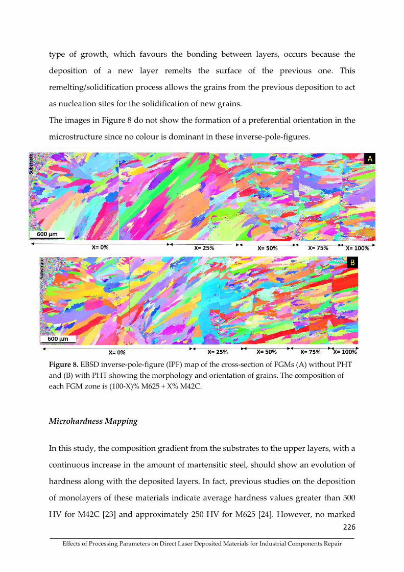
226 ____________________________________________________________________________________________________
Effects of Processing Parameters on Direct Laser Deposited Materials for Industrial Components Repair
type of growth, which favours the bonding between layers, occurs because the
deposition of a new layer remelts the surface of the previous one. This
remelting/solidification process allows the grains from the previous deposition to act
as nucleation sites for the solidification of new grains.
The images in Figure 8 do not show the formation of a preferential orientation in the
microstructure since no colour is dominant in these inverse-pole-figures.
Figure 8. EBSD inverse-pole-figure (IPF) map of the cross-section of FGMs (A) without PHT
and (B) with PHT showing the morphology and orientation of grains. The composition of
each FGM zone is (100-X)% M625 + X% M42C.
Microhardness Mapping
In this study, the composition gradient from the substrates to the upper layers, with a
continuous increase in the amount of martensitic steel, should show an evolution of
hardness along with the deposited layers. In fact, previous studies on the deposition
of monolayers of these materials indicate average hardness values greater than 500
HV for M42C [23] and approximately 250 HV for M625 [24]. However, no marked

227 ____________________________________________________________________________________________________
Effects of Processing Parameters on Direct Laser Deposited Materials for Industrial Components Repair
variation in hardness was measured across the FGMs, as illustrated in the
microhardness maps shown in Figure 9. The figure also shows no significant
differences in FGMs processed with and without PHT, which proves that the influence
of PHT on the microstructure is not very significant, except for the planar morphology
of the first deposited layers.
The relatively low hardness of the M42C-rich layers is explained by a slower cooling
rate in these layers, which are the last to be deposited, inhibiting an extensive
martensitic transformation, and by these layers having about 10 wt.% Ni, which, being
one austenite stabilizer, also hinders the martensitic transformation. Finally, except
for the last layer, all others undergo a self-tempering process of the martensite that
may have formed.
Figure 9 reveals that the hardest zone obtained is in the heat-affected zone (HAZ) of
the FGM produced without PHT, meaning that preheating application promoted a
reduction in the cooling rate in the substrate, reducing the formation of martensite in
this zone, as already discussed.
The higher hardness of the FGM with PHT (indicated by a red arrow) was measured
in the M625 region, which can be attributed to compositional fluctuations leading to a
local concentration of hard Laves phase/carbides.
This evolution of hardness shows that up to 50% of M42C powder, which is
significantly less expensive, can be added to M625 powder without inducing
significant changes in hardness and microstructure, as discussed above. Larger
amounts of M42C should not be added as they can lead to cracking.

228 ____________________________________________________________________________________________________
Effects of Processing Parameters on Direct Laser Deposited Materials for Industrial Components Repair
Figure 9. FGM microhardness mapping - (A) without PHT and (B) with PHT.
Conclusions
In this study, the production of functionally graded material (FGM) by direct laser
deposition (DLD) technique was evaluated. The deposition started with layers of
nickel-based superalloy (M625 powders) and ended with layers of martensitic
stainless steel (M42C powders). Three mixtures of powders were used in intermediate
deposits, sequentially increasing by 25 wt. % the amounts of M42C powder. Moreover,
the influence of preheating the 42CrMo4 steel substrate on the microstructural and
hardness evolution in FGMs were evaluated. The main conclusions of this study are
as follows:
Cracking-free production of the Inconel 625/AISI 431 steel FGM, applying DLD,
is only verified up to a certain composition. The addition of stainless steel cannot
exceed 50 wt. %.

229 ____________________________________________________________________________________________________
Effects of Processing Parameters on Direct Laser Deposited Materials for Industrial Components Repair
The metallurgical bonding of deposits to substrates and between the various
layers of the FGM is ensured by the diffusion in the liquid state of the alloy
constituents, the remelting effect, and epitaxial growth.
The grain microstructure in Inconel 625/AISI 431 FGM is essentially columnar,
regardless of preheating.
Preheating influenced the microstructural evolution and microhardness in the
substrate and the first deposited layers; the region of planar grains observed in the
vicinity of the substrate only formed without preheating. A marked increase in grain
size and a reduction in martensite was observed in the preheated substrate HAZ,
decreasing the hardness of this region.
Author Contributions: Conceptualisation, A.A.F, A.R.R. and M.F.V.; methodology,
A.A.F and J.M.C; validation, O.E. and M.F.V.; formal analysis, A.A.F.; investigation,
A.A.F and M.F.V.; resources, A.R.R., M.F.V. and J.M.C.; writing—original draft
preparation, A.A.F; review and editing, O.E. and M.F.V.; visualisation, A.A.F.;
supervision, A.R.R. and M.F.V.; project administration, M.F.V. and J.M.C.; funding
acquisition, A.R.R., M.F.V. and J.M.C. All authors have read and agreed to the
published version of the manuscript.
Funding: This research was funded by FEDER through the program
P2020|COMPETE, Projetos em Copromoção (project POCI-01-0247-FEDER-039848).
Acknowledgements: The authors are grateful to CEMUP (Centro de Materiais da
Universidade do Porto) for expert assistance with SEM.
Conflicts of Interest: The authors declare no conflict of interest.

230 ____________________________________________________________________________________________________
Effects of Processing Parameters on Direct Laser Deposited Materials for Industrial Components Repair
References
42. Sobczak, J. J.; Drenchev, L. Metallic Functionally Graded Materials: A Specific Class of Advanced Composites. J. Mater. Sci. Technol., 2013, 29, 297–316, doi:
10.1016/j.jmst.2013.02.006.
43. Durejko, T.; Zietala, M.; Polkowski, W.; Czujko, T. Thin wall tubes with
Fe3Al/SS316L graded structure obtained by using laser engineered net shaping technology. Mater. Des., 2014, 63, 766–774, doi: 10.1016/j.matdes.2014.07.011.
44. Sarathchandra, D. T.; Kanmani Subbu, S.; Venkaiah, N. Functionally graded
materials and processing techniques: An art of review. Mater. Today Proc., 2018, 5,
21328–21334, doi: 10.1016/j.matpr.2018.06.536.
45. Zhang, B.; Jaiswal, P.; Rai, R.; Nelaturi, S. Additive Manufacturing of Functionally Graded Material Objects: A Review. J. Comput. Inf. Sci. Eng., 2018, vol. 18, 1215–
1231, doi: 10.1115/1.4039683.
46. Loh, G. H.; Pei, E.; Harrison, D.; Monzón, M. D. An overview of functionally
graded additive manufacturing. Addit. Manuf., 2018, 23, 34–44, doi:
10.1016/j.addma.2018.06.023.
47. Yan, L.; Chen, Y.; Liou, F. Additive manufacturing of functionally graded metallic materials using laser metal deposition. Addit. Manuf., 2020, 31, 100901, doi:
10.1016/j.addma.2019.100901.
48. Mahamood, R. M. Laser Metal Deposition of Metals and Alloys. Springer
International Publishing, 2018.
49. Thompson, S. M.; Bian, L.; Shamsaei, N.; Yadollahi, A. An overview of Direct
Laser Deposition for additive manufacturing; Part I: Transport phenomena, modeling and diagnostics. Addit. Manuf., 2015, 8, 36–62, doi:
10.1016/j.addma.2015.07.001. 50. Costa, L.; Vilar, R. Laser powder deposition. Rapid Prototyping Journal, 2009, 4, 264–
279, doi: 10.1108/13552540910979785.
51. Reichardt, A. Additive Manufacturing of Metal-based Functionally Graded
Materials by Ashley Reichardt A dissertation submitted in partial satisfaction of
the requirements for the degree of Doctor of Philosophy in Engineering – Nuclear Engineering in the Graduate Division. 2017.
52. Chen, B.; Su, Y.; Xie, Z.; Tan, C.; Feng, J. Development and characterization of
316L/Inconel625 functionally graded material fabricated by laser direct metal deposition. Opt. Laser Technol., 2020, 123, doi: 10.1016/j.optlastec.2019.105916.
53. Carroll, B. E.; Otis, R. A.; Borgonia, J. P.; Suh, J.; Dillon, R. P.; Shapiro, A. A.;
Hofmann, D. C.; Liu, Z; Beese, A. M. Functionally graded material of 304L
stainless steel and inconel 625 fabricated by directed energy deposition:
Characterization and thermodynamic modeling. Acta Mater., 2016, 108, 46–54, doi:
10.1016/j.actamat.2016.02.019.
54. Dass, A.; Moridi, A. State of the art in directed energy deposition: From additive manufacturing to materials design. Coatings, 2019, 7, doi:
10.3390/COATINGS9070418.
55. Koike, R.; Unotoro, I.; Kakinuma, Y.; Aoyama, T.; Oda, Y.; Kuriya, T.; Fujishima,
M. Evaluation for mechanical characteristics of Inconel625-SUS316L joint

231 ____________________________________________________________________________________________________
Effects of Processing Parameters on Direct Laser Deposited Materials for Industrial Components Repair
produced with direct energy deposition. Procedia Manuf., 2017, 14, 105–110, doi:
10.1016/j.promfg.2017.11.012.
56. Meera Mirzana, I.; Krishana Mohana Rao, G.; Ur Raheman, S.; Zaki Ahmed, M.
Fabrication and Micro-structural study of Functionally Graded Material Disc of
SS316/IN625. Mater. Today Proc., 2016, 3, 4236–4241, doi:
10.1016/j.matpr.2016.11.103.
57. Zhang, X.; Chen, Y.; Liou, F. Fabrication of SS316L-IN625 functionally graded materials by powder-fed directed energy deposition. Sci. Technol. Weld. Join., 2019,
24, 504–516, doi: 10.1080/13621718.2019.1589086.
58. Liang, X.; Wu, D.; Li, Q.; Jiang, L. Laser rapid manufacturing of stainless steel
316L/Inconel718 functionally graded materials: Microstructure evolution and
mechanical properties. Int. J. Opt., 2010, 1–6, doi: 10.1155/2010/802385.
59. Weng, F.; Liu, Y.; Chew, Y.; Wang, L.; Lee, B. Y.; Bi, G. Repair feasibility of SS416
stainless steel via laser aided additive manufacturing with SS410/Inconel625 powders. IOP Conf. Ser. Mater. Sci. Eng., 2020, 744, doi: 10.1088/1757-
899X/744/1/012031.
60. Meng, W.; Zhang, W.; Zhang, W.; Yin, X.; Guo, L.; Cui, B. Additive fabrication of
316L/Inconel625/Ti6Al4V functionally graded materials by laser synchronous
preheating. Int. J. Adv. Manuf. Technol., 2019, 104, 2525–2538, doi: 10.1007/s00170-
019-04061-x.
61. Su, J.; Qiu, X.; Xing, F.; Ruan, Y. Effect of preheating temperature on
microstructure and properties of 42CrMo4/38mnvs6 heterogeneous laser welded
joint. Metals (Basel)., 2019, 9, doi: 10.3390/met9080870.
62. Sun, C.; Fu, P. X.; Liu, H. W.; Liu, H. H.; Du, N. Y. Effect of tempering temperature
on the low temperature impact toughness of 42CrMo4-V steel. Metals (Basel).,
2018, 8, doi: 10.3390/met8040232.
63. B. Standard, “Steels and nickel alloys for fasteners with specified elevated and /
or low temperature,” 2006.
64. Ferreira, A. A.; Darabi, R.; Sousa, J. P.; Cruz, J. M.; Reis, A. R.; Vieira, M. F.
Optimization of direct laser deposition of a martensitic steel powder (Metco 42c)
on 42CrMo4 steel. Metals (Basel)., 2021, 11, 1–18, doi: 10.3390/met11040672.
65. Ferreira, A. A.; Amaral, R. L.; Romio, P. C.; Cruz, J. M.; Reis, A. R.; Vieira, M. F.
Deposition of Nickel-Based Superalloy Claddings on Low Alloy Structural Steel by Direct Laser Deposition. Metals (Basel)., 2021, 11, 1326, doi:
10.3390/met11081326. 66. Davies, E. R. Introduction to texture analysis. Taylor & Francis Group, 2008.
67. Ocelík, V.; Hemmati, I.; De Hosson, J. T. M. The influence of processing speed on
the properties of laser surface deposits. Surf. Contact Mech. Incl. Tribol. XII, 2015, 1,
93–103, doi: 10.2495/secm150091.
68. Guo, Q.; Chen, S.; Wei, M.; Liang, J.; Liu, C.; Wang, M. Formation and Elimination
Mechanism of Lack of Fusion and Cracks in Direct Laser Deposition 24CrNiMoY Alloy Steel. J. Mater. Eng. Perform., 2020, 29, 6439–6454, doi: 10.1007/s11665-020-
05163-4.
69. Chen, Y.; Lu, F.; Zhang, K. Nie, P. Hosseini, S. R. E.; Feng, K.; Li, Z. Dendritic
microstructure and hot cracking of laser additive manufactured Inconel 718 under
232 ____________________________________________________________________________________________________
Effects of Processing Parameters on Direct Laser Deposited Materials for Industrial Components Repair
improved base cooling. J. Alloys Compd., 2016, 670, 312–321, doi:
10.1016/j.jallcom.2016.01.250.
70. Chen, Y. Guo, Y.; Xu, M.; Ma, C.; Zhang, Q.; Wang, L.; Yao, J.; Li, Z. Study on the
element segregation and Laves phase formation in the laser metal deposited
IN718 superalloy by flat top laser and gaussian distribution laser. Mater. Sci. Eng.
A, 2019, 754, 339–347, doi: 10.1016/j.msea.2019.03.096.
71. Long, Y. T.; Nie, P. L.; Li, Z. G.; Huang, J.; Li, X.; Xu, X. M. Segregation of niobium in laser cladding Inconel 718 superalloy. Trans. Nonferrous Met. Soc. China, 2016,
English Ed., 26, 431–436, doi: 10.1016/S1003-6326(16)64131-6.
72. Xiao, H.; Li, S.; Han, X.; Mazumder, J.; Song, L. Laves phase control of Inconel 718
alloy using quasi-continuous-wave laser additive manufacturing. Mater. Des.,
2017, 122, 330–339, doi: 10.1016/j.matdes.2017.03.004.
73. Singh, G.; Vasudev, H.; Bansal, A.; Vardhan, S.; Sharma, S. Microwave cladding
of Inconel-625 on mild steel substrate for corrosion protection. Mater. Res. Express, 2020, 7, doi: 10.1088/2053-1591/ab6fa3.
74. Wang, L.; Dong, J.; Tian, Y.; Zhang, L. Microsegregation and Rayleigh number
variation during the solidification of superalloy Inconel 718. Mineral Metall. Mater., 2008, 15, 594–599, doi: 10.1016/S1005-8850(08)60111-5.
75. Knorovsky, G. A.; Cieslak, M. J.; Headley, T. J. INCONEL 718 A Solidification Diagram. 1989, vol. 20.
76. Petrzak, P.; Kowalski, K.; Blicharski, M. Analysis of phase transformations in
Inconel 625 alloy during annealing. Acta Phys. Pol. A, 2016, 130, 1041–1044, doi:
10.12693/APhysPolA.130.1041.
77. Reichardt; A.; Shapiro, A. A.; Otis, R.; Dillon, R. P.; Borgonia, J. P.; McEnerney, B.
W.; Hosemann, P.; Beese, A. M. Advances in additive manufacturing of metal-
based functionally graded materials. Int. Mater. Rev., 2020, 0, 1–29, doi:
10.1080/09506608.2019.1709354.
78. Feng, K.; Feng, K.; Chena, Y.; Denga, P.; Li, Y.; Zhao, H.; Lu, F.; Li, R.; Jian, H.; Li,
Z. Improved high-temperature hardness and wear resistance of Inconel 625 coatings fabricated by laser cladding. J. Mater. Process. Technol., 2017, 243, 82–91,
doi: 10.1016/j.jmatprotec.2016.12.001.
79. Li, S.; Wei, Q.; Shi, Y.; Chua, C. K.; Zhu, Z.; Zhang, D. Microstructure
Characteristics of Inconel 625 Superalloy Manufactured by Selective Laser Melting. J. Mater. Sci. Technol., 2015, 31, 946–952, doi: 10.1016/j.jmst.2014.09.020.
80. Zhaoyang, L.; Jiayang, S. Characterization of Microstructure, Precipitations and
Microsegregation in Laser Additive Manufactured Nickel-Based Single-Crystal Superalloy,” Materials (Basel)., 2020, 13, 2300; https://doi.org/10.3390/ma13102300
81. Kurz, W.; Bezençon, C.; Gäumann, M. Columnar to equiaxed transition in solidification processing. Sci. Technol. Adv. Mater., 2001, 2, 185–191, doi:
10.1016/S1468-6996(01)00047-X.
82. Hemmati, I.; Ocelík, V.; De Hosson, J. T. M. Microstructural characterization of AISI 431 martensitic stainless steel laser-deposited coatings. J. Mater. Sci., 2011, 46,
3405–3414, doi: 10.1007/s10853-010-5229-2.
83. Ding, C.; Cui, X.; Jiao, J.; Zhu, P. Effects of substrate preheating temperatures on
the microstructure, properties, and residual stress of 12CrNi2 prepared by laser

233 ____________________________________________________________________________________________________
Effects of Processing Parameters on Direct Laser Deposited Materials for Industrial Components Repair
cladding deposition technique,” Materials (Basel)., vol. 11, no. 12, 2018, doi:
10.3390/ma11122401.
84. Corbin, D. J.; Nassar, A. R.; Reutzel, E. W.; Beese, A. M.; Michaleris, P. Effect of
substrate thickness and preheating on the distortion of laser deposited Ti-6Al-4V.
J. Manuf. Sci. Eng. Trans. ASME, 2018, 140, 6, doi: 10.1115/1.4038890.
85. Guo, P.; Zou, B.; Huang, C.; Gao, H. Study on microstructure, mechanical
properties and machinability of efficiently additive manufactured AISI 316L
stainless steel by high-power direct laser deposition. J. Mater. Process. Technol., 2017, 240, 12–22, doi: 10.1016/j.jmatprotec.2016.09.005.
86. Wang, Q.; Zhang, S.; Zhang, C.; Wu, C.; Wang, J.; Chen, J.; Sun, Z. Microstructure
evolution and EBSD analysis of a graded steel fabricated by laser additive
manufacturing. Vaccum, 2017, 141, 68–81, doi: 10.1016/j.vacuum.2017.03.021.

234 ____________________________________________________________________________________________________
Effects of Processing Parameters on Direct Laser Deposited Materials for Industrial Components Repair
Article 8 - Mechanical and Microstructural Characterisation of Inconel 625 - AISI 431
Steel Bulk produced by Direct Laser Deposition
Journal of Materials Processing Technology
https://doi.org/10.1016/j.jmatprotec.2022.117603

235 ____________________________________________________________________________________________________
Effects of Processing Parameters on Direct Laser Deposited Materials for Industrial Components Repair
Article 8 - Mechanical and Microstructural Characterisation of
Inconel 625 - AISI 431 Steel Bulk produced by Direct Laser
Deposition André A. Ferreira1,2, Omid Emadinia2 , Rui L. Amaral2, João M. Cruz3, Ana R. Reis1,2, Manuel
F. Vieira1,2
1Faculty of Engineering of the University of Porto, 4200-465 Porto, Portugal 2LAETA/INEGI—Institute of Science and Innovation in Mechanical and Industrial Engineering, 4200-
465 Porto, Portugal 3SERMEC-Group, 4425-348 Folgosa-Maia, Portugal
*Corresponding author: Department of Metallurgical and Materials Engineering, University of Porto,
Porto, 4200-465 Portugal E-mails addresses: [email protected] (A. A. Ferreira)
Abstract
The direct laser deposition process successfully produced a bulk material by mixing
50% Inconel 625 powders (M625) with 50% AISI 431 steel powders (M42C). The
properties of this new material, such as tensile strength and wear resistance, were
evaluated. The microstructure was also analysed using scanning electron microscopy.
Moreover, the formation of defects and second phases in the bulk material were
investigated by applying a tomography analysis. M625-M42C bulk material shows
tensile strength and abrasive wear behaviour similar to Inconel 625 alloy, suggesting
a potential replacement material for the more expensive Inconel 625. This study is
focused on an innovative material, which had not yet been produced as a bulk,
allowing the evaluation of the mechanical and metallurgical characteristics promoted
by this mixture of powders. In addition, this deposition methodology seems very
interesting for cladding or repair objectives since the failure did not happen at the
transition interface between deposited bulk and substrate.
Keywords: bulk, Inconel 625, AISI 431, powder mixing; direct laser deposition;
microstructure; chemical composition; hardness.

236 ____________________________________________________________________________________________________
Effects of Processing Parameters on Direct Laser Deposited Materials for Industrial Components Repair
Introduction
Direct Laser Deposition (DLD), as an additive manufacturing process, is a technique
that has been investigated in depth in recent years. Hu et al. (2021) demonstrated that
the DLD technique provides a high laser power density, enabling the production of
unlimited-sized components. Thompson et al. (2015) showed that the technique
provides the potential to (i) rapidly prototype metal parts, (ii) produce complex and
customised parts and (iii) coat/repair metal components. This advanced process
produces components layer by layer, and, according to Zhang et al., 2018, it enables
fabricating new materials to meet an intended function. Densification is achieved by
solidifying consecutive melt pools generated by laser as a heat source. Walker et al.
(2017) cites that the DLD process is an innovative factor for the production of novel
materials., where the proper mixing of powders that must be in accordance with the
components metallurgical, mechanical, chemical, and tribological requirements.
Recently, Yan et al. (2020) provided an overview of the progress in metallic
Functionally Graded Materials (FGM) fabricated by DLD emphasizing the complexity
of the process.
DLD depositions are, in fact, a complex process that involves the interaction between
laser and metal (powders, wire or a combination of both), melt pool movements, rapid
unbalanced solidification and phase transformations, as evidenced in the study of
Wang et al. (2017). Mahamood (2018) demonstrated that the technique has the
advantage of locally synthesising compositional gradients by mixing different
powders, gradually varying the mixture at intended locations, thus generating parts
with graded material properties. In the DLD process, high cooling rates caused by the
localised heat inputs of the laser beam are observed. This rapid cooling causes
metallurgical defects associated with metastable phases in the deposited material and
the heat-affected zone (HAZ). Martin et al. (2022) demonstrated that the DLD

237 ____________________________________________________________________________________________________
Effects of Processing Parameters on Direct Laser Deposited Materials for Industrial Components Repair
technique could be combined with other additive manufacturing processes, such as
Powder Bed Fusion (PBF), to produce hybrid structures.
Brandl et al. (2011) demonstrated that preheating (PHT) of the substrate is one of the
processes to reduce the cooling rate and decrease the hardness in HAZ. Dass and
Morid (2019) proved that PHT reduces the sharp thermal gradients. The laser
absorption rate by the substrate is higher when there is preheating, according to
research conducted by Su et al., (2019). As stated by Jiang et al. (2020), PHT improves
stress distribution and prevents the formation of hard structures that are detrimental
to the mechanical properties of the cladding. Meng et al. (2019) analysed the
production of a gradient material using the Inconel 625/Ti6Al4V system. They
demonstrated that preheating promotes the formation of thinner, more uniform and
free of cracks secondary phases. The effect of preheating was discussed in two
previous studies. According to Ferreira et al. (2021c), PHT promotes an increase in
dilution in relation to samples without PHT, and this increase causes a decrease in the
yield of the deposition process. Ferreira et al. (2021a) analysed the influence of
substrate preheating to 300 ˚C on the microstructure of the cladding/substrate
interface, showing that it reduces formation of hard and brittle phase and the hardness
profile, mainly in the heat-affected zone.
The production of Functionally Graded Additive Manufacturing (FGAM) materials
is, as mentioned, one of the major advantages of DLD. FGAM allow achieving
spatially variable properties through gradual changes in composition or structure. The
design, development, and applicability of FGAM by Direct Laser Deposition (DLD) is
an important alternative for producing high-performance materials, mainly for the
aerospace, automotive, medical, and energy sectors. FGAM can provide settings
impossible to be achieved by traditional materials and processing. Allowing bonding
two complex and incompatible materials by creating compositional gradients that
function as transition layers between the two materials, this process minimises
internal stresses and cracks, consequently improving mechanical strength, as

238 ____________________________________________________________________________________________________
Effects of Processing Parameters on Direct Laser Deposited Materials for Industrial Components Repair
evidenced by Durejko et al. (2014). FGAM allow the production of materials with
mechanical (Su et al., 2020), magnetic (Zhang et al., 2018) or thermal (Soodi et al., 2013)
properties varying throughout the component. Popovich et al. (2017) concluded that
microstructural and chemical changes promote physical and mechanical properties
alterations in the FGAM during DLD. Sarathchandra et al. (2018) recently reviewed
this topic and identified that there is still a gap to understand microstructure, phase
transformations, manufacturing process modelling and process optimisation in order
to achieve better results.
Several studies have analysed the production of gradient materials using Inconel 625
superalloy with steels, mainly austenitic stainless steel. Mirzana et al. (2016) produced
sound discs through the DLD process with two different materials, AISI 316 steel and
Inconel 625, obtaining a microstructure that revealed a uniform variation of properties
in the interface region, low distortion. The mechanical properties of an Inconel 625 -
AISI 316L gradient material were evaluated by Koike et al. (2017) who showed that
the bonding interface presented comparative mechanical strength and hardness
similar to those of AISI 316L. An analogous mechanical behaviour was obtained by
Zhang et al. (2019), when analyzing a FGM produced using AISI 316L and Inconel 625
powders. Clare et al. (2022) reviewed the metallurgical and mechanical characteristics
of mixtures of materials by different additive manufacturing techniques; these new
materials could respond to challenges posed by different industrial sectors. However,
bulk production with tailored composition for the repair or remanufacturing of
components is an approach that has not yet been studied. A new combination of
powders can produce less expensive materials with enhanced mechanical strength
and wear and corrosion resistance.
In this sense and recognising the importance and complexity of developing this type
of solution, this study explores the production of a bulk composed of 50% Inconel 625
(M625) and 50% AISI 431 steel (M42C) deposited on a preheated substrate. In a
previous study by Ferreira et al. (2021a), an FGAM using the same powders was
239 ____________________________________________________________________________________________________
Effects of Processing Parameters on Direct Laser Deposited Materials for Industrial Components Repair
produced, with deposition of initial layers of M42C, followed by layers of M625-25%
M42C, M625-50% M42C, M625-75% M42C and ending in 100 % M42C. A metallurgical
and mechanical analysis of the FGAM allowed the selection of the best composition
for industrial applications. The microstructural analysis shows that several phases,
with different chemical compositions, are formed as the mixture of powders varies,
being also dependent on the manufacturing conditions. Inconel 625 + 50% AISI 431
steel ensures a cladding free of cracks and porosities, with a hardness similar to that
of Inconel 625, and with less amount of this material, being, therefore, the least
expensive. In this study, this composition was selected to produce a massif to analyse
the structural integrity of this new material, its mechanical response and wear
resistance.
Experimental Procedure
Direct laser deposition (DLD) technique, assembled with a six-axis robot (KUKA KR90
R3100 model), and equipped with a Laser system (LDF 6000 – 100), a fibre-coupled
laser diode providing a wavelength range of 900-1030 nm and reaching a nominal
beam power of 6000 W, was applied for the powder consolidation and production of
blocks. The laser beam was delivered through an optical fiber of 1.0 mm in diameter,
and with a beam quality of 100 mm*rad. The materials produced in this study include
blocks of equimassic mixture of Inconel 625, so-called M625, and AISI 431 stainless
steel, as M42C; and of individual alloys as references. The particles range size for M625
and M42C are 45 - 90 µm and 45 - 106 µm, respectively. Figure 1 illustrates the
morphology of these powders, the M625 particles are seen in spherical form, and
M42C particles have an irregular shape (non-spherical). Powders and steel substrates
chemical composition is presented in Table 1. The particle size and chemical
composition of the powders referred to are those indicated in the supplier's
datasheets.

240 ____________________________________________________________________________________________________
Effects of Processing Parameters on Direct Laser Deposited Materials for Industrial Components Repair
Table 2. Chemical composition (in wt%) of M625, M42C powders and 42CrMo4 steel.
Raw Material C Cr Ni Mn Mo Nb Si P S Fe
M625 - 21.3 60.8 - 9.2 4.6 - - - 4.1
M42C 0.18 17.3 1.9 - - - 0.24 - - Balance
42CrMo4 0.42 1.11 - 0.67 0.19 - 0.28 0.025 0.015 Balance
Figure 1. SEM/BSE technique illustrates the morphology of (A) M625 and (B) M42C powders.
Before deposition, the substrates, 42CrMo4, were cleaned with pure acetone and
heated to approximately 300 °C by an oxy torch. This preheating condition was
applied to eliminate moisture and decrease the cooling rate in the melt pool and
adjacent regions of the substrate (thus reducing the detrimental effect of the HAZ).
Successive depositions of an equimassic mixture of M625 and M42C powders (M625-
M42C) were made to produce a bulk material. The powders were mixed and
transported by a mixer attached to the feeders. Deposition was carried out through a
one-step process with a coaxial powder nozzle. The nozzle had a self-contained
powder feeder, a shield gas channel and four carrier gas channels. In addition, argon
gas with 99.998% purity was used as shielding gas with a flow rate equal to 9.1667x10-
5 m3/seg (5.5 l/min) to minimise the contamination and oxidation of the melt pool
during the DLD process. Furthermore, for bulk production, the Inconel 625 (M625) +

241 ____________________________________________________________________________________________________
Effects of Processing Parameters on Direct Laser Deposited Materials for Industrial Components Repair
50% AISI 431 (M42C) powder deposition strategy selected was the zigzag-XY tool
path, as shown in Figure 2.
Figure 2. Schematic diagram of the strategy for the Inconel 625 (M625) + 50% AISI 431 (M42C)
bulk production by DLD. An image during the production of a bulk is also shown.
These two combined parameters, specific energy [J/mm2] and powder density G
[g/mm2], lead to a simpler and more general (non-machine specific) approach to the
process, where LP is the laser power on the substrate [W], SS is the scanning speed
[mm/s], φ is the radius of the laser beam on the substrate [mm], and FR the powder
feed rate [g/min]:
𝐸specific =LP
φ ∗ 𝑆𝑆 (1)
𝐺 =FR
φ ∗ 𝑆𝑆 (2)
The combined parameters applied for depositing in the current study are presented
in Table 2. These combined parameters were applied based on a previous study
developed by Toyserkani et al. (2017). Nonetheless,in all tests, a spot size of 2.5 mm,
and an offset in the Z-axis of 0.2 mm were applied; the coaxial powder flow had a focal

242 ____________________________________________________________________________________________________
Effects of Processing Parameters on Direct Laser Deposited Materials for Industrial Components Repair
distance of 13 mm. The trajectory of depositions involved continuously parallel
depositing applying a 40% overlapping between tracks, followed by depositing
successive layers rotated at 90° in each layer. The depositions were carried out in order
to produce layers with similar thicknesses; the average layer thickness is 1.47 mm.
Figure 3 shows a block produced by the DLD technique.
Table 3. Combined parameters for bulk production by DLD.
Combined parameters 50% M625 + 50% M42C
Especific [J/mm2] 60
G [g/mm2] 0.01
Figure 3. New material M625-M42C bulk, produced by DLD on 42CrMo4 substrate.
The bulk was cut for microstructural characterisation using a metallographic cut-off
machine with refrigeration to avoid substrate and cladding overheating. Samples
were mounted in resin and polished down to 1 μm diamond suspension. An
additional polishing step was performed, using a 0.06 μm silica colloidal suspension
for a superior surface finish and polishing-induced plastic deformation removal.
Chemical compositions and microstructure were systematically investigated using
scanning electron microscope (SEM) FEI Quanta 400 FEG (ESEM, Hillsboro, OR, USA)

243 ____________________________________________________________________________________________________
Effects of Processing Parameters on Direct Laser Deposited Materials for Industrial Components Repair
equipped with Energy Dispersive X-Ray Spectroscopy (EDX) (EDAX Genesis X4M,
Oxford Instrument, Oxfordshire, UK).
Uniaxial tension tests were performed accordingly to Džugan et al. (2015), using an
electromechanical uniaxial testing system (MSTD, INEGI, Portugal) with a 5 kN load
cell at a 0.5 mm/min strain rate. Digital image correlation (DIC), a non-contact method
to measure surface strains, was used to calculate surface strains using correlation
software (VIC-2D 6, Correlated Solutions, Inc., USA). The DIC images were captured
with a telecentric lens (Infaimon OPE-TC-23-09, 45 mm) and a 5 MPixel camera (Basler
acA2440-75um, 2448x2048 pixels). Hardness tests were carried out, applying a load of
30 kgf per indentation, using EMCO M4U Universal machine (EMCO-TEST
PRÜFMASCHINEN GMBH, Kuchl, Austria).
The abrasive resistance analysis was performed (1071-6:2007, 2010) applying the ball-
cratering method, considered as a micro-abrasion test. A homogeneous slurry of SiC
in distilled water, 2 vol.%, was used, continuously stirred during the test to ensure the
dispersion of particles in the slurry. The ball test was a 25.4 mm diameter hardened
steel (SAE 52100), the rotation was performed at a fixed speed of 85 rpm applying a
constant load of 0.25 N, delivering the slurry at the contact surface through a roller
pump. The specimens were subjected to this test in four individual rotations, for 30,
60, 120 and 240 minutes, corresponding to 203.48 m, 406.96 m, 813.92 m, and 1627.85
m of sliding distances. Micro-abrasion wear tests were performed to evaluate the bulk
wear rate with the PLINT TE 66 Micro-Scale Abrasion Wear Tester (Phoenix
Tribology, England) with a fixed rotating ball configuration. The worn surfaces were
observed using LEICA DMV6 digital microscopy, equipped with LAS X software for
image viewing and extracting crater profiles. The measurements were made using
image processing software (ImageJ). Afterwards, the worn volume, V in mm3, was
calculated using V=π×b4/(64×R) equation in which "b" is the crater mean diameter
(mm) and R is the steel ball radius (mm). The abrasive wear rate, K in mm3∙N−1∙mm−1,

244 ____________________________________________________________________________________________________
Effects of Processing Parameters on Direct Laser Deposited Materials for Industrial Components Repair
was calculated through K=VxS−1×N−1 where S is the sliding distance (mm) and N is
the applied load (N) (1071-6:2007, 2010).
X-ray computed tomography (X-Ray CT) (Nikon XT H 225, England) was used to
investigate the distribution and size of discontinuities along with three cylindrical
samples, with approximate dimensions of 9.93 x 23.68 mm, taken from the bulk
produced with M625 + 50% M42C. The scanning time for each sample was 2 h and 12
min, using a 1mm silver filter. The source was an X-ray tube using an accelerated
voltage of 225 kV and amperage of 116 µA. For this experiment, the effective voxel
resolution was 17 mm. The dataset obtained from the X-Ray CT test was reconstructed
using the manufacturers Inspect-X software. In addition, the data was imported into
the myVGL 3.4.1 software (Volume Graphics GmbH, Germany), allowing three-
dimensional visualisation, segmentation and quantification of the distribution of
discontinuities.
Results and Discussion
Microstructure of the bulk material
Figure 4 illustrates the microstructure of the produced bulk material in different
regions, consisting of dendrites, cellular and elongated morphologies, and
discontinuities smaller than 0.1 mm. Microscopic observations did not detect non-
fused particles that could act as weak points and diminish the mechanical properties
of the produced material. According to Figure 4, with different magnificato, the main
discontinuities observed in the bulk microstructure were inclusions of oxides,
carbides and second phases precipitated in the interdendritic spaces, described in
detail in the previous study by Ferreira et al. (2021b). Inclusions are typically
submicrometer and may reach a few micrometres.4. The formation of these inclusions
is directly related to the metallurgical interactions that occurred between the

245 ____________________________________________________________________________________________________
Effects of Processing Parameters on Direct Laser Deposited Materials for Industrial Components Repair
constituents. However, microscopic observations did not reveal the presence of any
porosity in the microstructure of the bulk material.
Figure 4. SEM images from the bulk material, M625 + 50% M42C produced by DLD, showing
the microstructure and some inclusions.
Computerised Tomography
The structural integrity of the bulk material produced in the current study was
confirmed by performing a 3D computerised tomography, X-ray scanning CT.

246 ____________________________________________________________________________________________________
Effects of Processing Parameters on Direct Laser Deposited Materials for Industrial Components Repair
According to Du Plessis et al. (2018), this analysis is a non-destructive evaluation
technique that allows the identification of internal discontinuities in components, the
3D images from the internal structure of the specimens are obtained applying X-ray
radiation passing through the object and then being detected by an adequate detector.
Proper radiations include the electromagnetic spectrum from microwaves to gamma
rays or particles including protons, neutrons and electrons, which can produce 3D
images with a spatial resolution larger than 1 micron (De Chiffre et al., 2014). The
specimen preparation is not critical, and multiple scans can be performed for the same
specimen under different conditions.
Discontinuities observed in the microstructure, Figure 5, are not detected by X-ray CT
analysis. Figure 5A shows the generated profile from the bulk material, a cylindrical
specimen approximately 23.68 mm long and 9.93 mm in diameter. The top view that
corresponds to the volume obtained from the cylindrical body is shown in Figure 5B.
Thus, it is possible to observe that a high-dense bulk has been produced, free of cracks
and with a small distribution of discontinuities in volume.
Figure 5. 3D visualisation of the bulk material produced in the current study: (A) a cylindrical
specimen (B) the top view of the specimen.

247 ____________________________________________________________________________________________________
Effects of Processing Parameters on Direct Laser Deposited Materials for Industrial Components Repair
According to data obtained from the myVGL software, the total analysed volume of
the bulk specimen was 1130.15 mm3, with a defect volume of 0.0085 mm3. The detected
discontinuities, with dimensions greater than 0.1 mm and with maximum sphericity
of 0.66, can include porosities and/or inclusions, though microscopy observations did
not reveal any porosity, Figure 4. The formation of these discontinuities is related to
the interaction of elements susceptible to oxidation during laser processing. Porosities
and inclusions can contribute to the occurrence of an early fracture, reducing ductility,
thus decreasing the mechanical properties.
Uniaxial Tensile Test
Figure 6 illustrates the geometry of the specimens and the uniaxial tensile test setup,
a 5 kN testing system developed by Cruz et al. (2020). The tests were performed at
room temperature with a constant crosshead speed of 0.5 mm/min, corresponding to
an initial strain rate of 3.7x10⁻³ s-1.
(A) (B)
Figure 6. (A) The design of the tensile specimens, dimensions are in mm, and (B) the uniaxial
tensile test equipment and sample
Figure 7 presents the tensile specimen preparation from produced bulk material.
Tensile specimens with a thickness of 1.4 mm were extracted using wire electrical
discharge machining process, parallel and perpendicular to the building direction.

248 ____________________________________________________________________________________________________
Effects of Processing Parameters on Direct Laser Deposited Materials for Industrial Components Repair
Moreover, a set of specimens was prepared consisting of bulk material and the
substrate, with the interface in the middle of the gauge length (Figure 7B). Several tests
were conducted for each direction to ensure the repeatability of the results. Table 3 list
the test conditions.
Table 3. Uniaxial test conditions.
Property Value
Maximum load [kN] 5
Crosshead speed (grip) [mm/min] 0.5
Data acquisition [Hz] 10
Clip gage initial length – l0 [mm] 3
Temperature [°C] 23
Relative humidity [%] 54
The measurement of elongation in the gauge length applying the digital image
correlation (DIC) approach allowed the determination of material strain during the
tensile test. A camera is coupled with dedicated software analysing the collected
images and computing the strain field captured by the DIC system. The strain field
(logarithmic Hencky strains) in the filmed area was computed using a commercial
software VIC-2D 6 with a step size of 7 and a set size of 25.
(A) (B)
Figure 7. The strategy used to produce specimens from the bulk material: (A) extraction
scheme and (B) a real image of a specimen encompassing interface in the gauge length.

249 ____________________________________________________________________________________________________
Effects of Processing Parameters on Direct Laser Deposited Materials for Industrial Components Repair
The engineering and true stress-strain flow curves obtained from the uniaxial tensile
tests are shown in Figure 8. In addition, Figure 9 presents the mean values of
fundamental properties calculated for each loading direction (horizontal and vertical).
As shown in Figure 8, the acquired data indicates a high consistency in mechanical
characteristics across the entire bulk, with identical hardening behaviour observed in
different tests. The vertically extracted specimens have a slightly lower yield stress
than the horizontally oriented specimens; however, they have a greater ultimate
tensile strength and better reproducibility. The difference in ultimate tensile strength
(UTS), which is larger than 60 MPa, can be explained by the lower elongation of
horizontal specimens (Figure 9), resulting in early fracture and lower UTS values.
Figure 10 presents several images illustrating the strain field evolution of a horizontal
sample during the tensile test.
Additionally, a comparison of these specimens flows stress-strain curves (Figure 11)
with the behaviour of additive manufactured M625 and M42C specimens, was
performed for a better interpretation of the acquired data. The specimens were
extracted from a similar 3D feature to the Figure 3 and produced under identical
experimental conditions by Ferreira et al. (2021c) and Ferreira et al. (2021a).
(A) (B)
Figure 8. Engineering (A) and true (B) stress-strain curves of bulk material obtained from the
uniaxial tensile test for different loading directions.

250 ____________________________________________________________________________________________________
Effects of Processing Parameters on Direct Laser Deposited Materials for Industrial Components Repair
Figure 9. Mechanical properties of bulk material obtained from tensile tests for different
loading directions (average values): yield stress (YS), UTS, uniform elongation (eu) and total
elongation (et).
As seen in Figure 11, the results of the uniaxial tensile tests indicate that the
mechanical hardening behaviour of this new bulk material is comparable with that of
M625, when subjected along the vertical direction. The M625 has a predominant
mechanical advantage over the M42C. The bulk shows a lower plastic deformation
capacity before fracture compared with M625, which is consistent with the lack of
ductility in M42C.
The anisotropic response is another characteristic that can be observed when these
materials are evaluated separately, dependent on the loading direction relative to the
deposition building direction. However, the M625-M42C bulk material shows a closer
trend for both types, taken perpendicular (vertical) and parallel (horizontal) to the
building deposition, especially in yield stress. Concerning the plastic deformation of
vertical specimens, the new bulk material has a closer value to the M625 alloy. The
primary mechanical parameters obtained from the uniaxial tensile tests are
summarised in Table 4.

251 ____________________________________________________________________________________________________
Effects of Processing Parameters on Direct Laser Deposited Materials for Industrial Components Repair
Figure 10. Logarithmic strain field illustrated along loading direction on a horizontal
specimen: a) e=0%, b) e=3.5% c) e=10.6% d) e=18.1% e) e=22.6%.
(A) (B)
Figure 11. Comparison of (A) engineering and (B) true stress-strain curves for different
loading directions of three materials: the bulk (M625-M42C) material, M42C and M625 alloys.
DLD process is reliable for cladding purposes, requiring an adequate metallurgical
bonding to the substrate material. Hence, the uniaxial test was performed for
specimens that include the bonding interface in the gauge length, shown in Figure 7.
Figure 12A exhibits the force vs elongation in a specimen that includes this interface.
The corresponding stress-strain curve is compared with the bulk material in
horizontal and vertical conditions. As seen in Figure 12B, the mechanical response of
this specimen is an intermediate. The vertical and interface specimens present a
similar behaviour because both were extracted from the bulk material in the same

252 ____________________________________________________________________________________________________
Effects of Processing Parameters on Direct Laser Deposited Materials for Industrial Components Repair
orientation. Moreover, the strain field of this specimen, for different moments of the
tensile test, illustrates that the failure occurred out of the interface region, Figure 13.
Thus, the bonding between the bulk material and the substrate is acceptable.
Table 4. Mechanical properties of M42C and M625 alloys and of the bulk material.
Material Loading
direction
YS
[MPa]
UTS
[MPa]
eu
[%]
et
[%]
M42C Horizontal 173.1 186.1 1.2 2.4
Vertical 298.8 375.9 1.2 1.4
M625 Horizontal 512.4 860.1 39.1 42.3
Vertical 449.1 807.1 40.5 46.8
Bulk
(M625-M42C)
Horizontal 467.4 641.9 11.0 20.2
Vertical 428.6 703.0 22.3 30.8
(A) (B)
Figure 12. (A) Evolution of force (F) with elongation (Δl) obtained from the specimen
containing interface between the substrate and the bulk material; (B) comparison of
engineering stress-strain curves.

253 ____________________________________________________________________________________________________
Effects of Processing Parameters on Direct Laser Deposited Materials for Industrial Components Repair
Figure 13. Logarithmic strain field along loading direction obtained for the interface sample:
a) e=0%, b) e=3.3% c) e=10.5% d) e=17.9% e) e=23.6%.
The fracture surfaces of tensile specimens, taken horizontally and vertically, were
analysed using a scanning electron microscope (SEM). Figure 14 shows the
morphology of the fracture surfaces. Fractography analysis was performed on the
M42C alloy (Figures 13A and 14B), M625 (Figures 14C and 14D), and the bulk material
(Figures 14E and 14F) produced in the current study. This analysis aimed to determine
the fracture mode occurred during the uniaxial tensile test.
According to BS EN 10088-5:2009, for martensitic stainless steel such as AISI 431
(X17CrNi16-2), the minimum values to be considered are 600 MPa of yield strength
(YS), 800-950 MPa of the tensile strength (UTS) and 14% of elongation at failure. These
properties were not obtained in this material processed by DLD, presented in Table 4.
The fracture surface of 100% M42C alloy, Figures 14A and 14B, shows cleavages that
are characteristics of transgranular fracture, representing a brittle failure. The failure
in M42C alloy was independent of sample direction. Although the vertical specimen
of this alloy presented higher yield strength than the sample obtained from the
horizontal direction, the material at both directions shows similar elongation. The
difference in the Ys and UTS can be attributed to the stronger integrity obtained in the
building direction. Moreover, the weak properties of the horizontal specimen can be

254 ____________________________________________________________________________________________________
Effects of Processing Parameters on Direct Laser Deposited Materials for Industrial Components Repair
assigned to discontinuities such as complex oxides, cracks, and slag accumulation in
the overlapping zones. The performance of EDX local analysis, Table 5, on some zones
at the fracture surfaces, yellow insets are shown in Figure 14A and 14B, confirms the
presence of complex oxides (Fe, Cr, Si)xOy.
Figure 14. Fractography of tensile specimens: (A) horizontal and (B) vertical M42C specimens;
(C) horizontal and (D) vertical of M625; (E) horizontal and (F) vertical of the bulk material.

255 ____________________________________________________________________________________________________
Effects of Processing Parameters on Direct Laser Deposited Materials for Industrial Components Repair
Table 5. Chemical composition obtained by EDX analysis from the zones highlighted
by yellow insets in Figure 13.
Zones Chemical composition (at %)
Ni Fe Cr Mo Mn Nb Si Al Ca O
Z1 1.02 50.15 14.85 13.73 20.25
Z2 1.84 76.63 19.05 2.48
Z3 0.5 25.62 17.17 2.07 17.38 37.26
Z4 1.8 77.58 17.78 2.84
Z5 52.08 0.84 24.65 7.78 11.89 2.76
Z6 22.44 30.28 1.66 7.19 3.64 6.61 28.18
Z7 65.66 0.75 24.51 5.88 1.85 1.35
Z8 58.63 0.63 25.51 5.93 7.11 2.19
Z9 16.03 30.82 1.06 10.13 1.2 11.62 29.14
Z10 65.37 0.96 23.83 5.98 1.97 1.89
Z11 5.85 9.12 14.27 1.03 3.49 2.41 18.87 0.32 44.64
Z12 30.05 39.9 21.56 3.95 1.41 2.36 0.77
Z13 1.49 2.63 10.28 3.59 26.86 0.69 2.08 52.38
Z14 68.35 0.72 24.22 4.12 1.53 1.06
Regarding the fractography of the 100% M625 alloy produced and tested in this study,
Figure 14C and 14D, respectively horizontal and vertical directions, dimples are
observed as the characteristic of ductile failure mode, associated with good bulk
toughness and tensile strength, as presented in Table 4.
The insets are shown in Figures 14C, and 14D represent the matrix (Z7 and Z10) and
Laves phase (Z5 and Z8), as their chemical compositions are presented in Table 5,
appearing adjacent to the dimples. It is possible that these microconstituents, with
high hardness, act as stress concentration zones and crack initiation under stress. Sui
et al. (2019) demonstrated that the finer the dimension of the Laves phase, the better
the material behaviour in tension. Complex multimetallic oxides (Z6 and Z9) were
also identified in this alloy. EDX analysis of these oxides identified a high amount of
chromium, silicon, manganese, and niobium, which is related to the affinity of these
elements with oxygen. However, Wang et al. (2019) demonstrated that these complex
oxides are not necessarily detrimental since they can promote an increase in bulk

256 ____________________________________________________________________________________________________
Effects of Processing Parameters on Direct Laser Deposited Materials for Industrial Components Repair
resistance at high temperatures. Matrix chemical composition is described by Z7 and
Z10 zones (Table 5).
The information provided in Table 4 presented that the new bulk material, M625 +
50% M42C, is stronger with more capacity for withstanding plastic deformation in the
vertical direction than the horizontal one. Figures 14E and 14F illustrate the
fractography consistent with this characteristic, appearing larger dimples in the
vertical specimen. Nevertheless, the new bulk material showed a ductile failure mode
in both directions, similar to the M625 alloy. Although large oxide particles are seen
in the fractured surface, zone Z13 in Figure 14F, the bulk material in a vertical direction
withstander tensile stresses near the M625 alloy.
Abrasion wear characteristics
According to hardness measurements (M42C 508 ± 4 HV30, M625 319 ± 8 HV30, and
Bulk 222 ± 9 HV30), it is expected that the harder the material, the smaller the worn
volume. Abrasive wear analysis was performed on similarly produced M42C alloy,
M625 and the bulk materials. Figure 15A and 15B shows the craters that appeared on
the surface of the bulk after 4h. As seen in Figures 16A and 16B, this behaviour is
influenced by the chemical composition and the sliding distance. In the current study,
the hardest material, M42C, did not show a good wear abrasive resistance to sliding
distance, whereas the bulk material appears as good as Inconel 625 alloy. The former
behaviour can be attributed to the alloy microstructure, such as cracking, as presented
in a previous study by Ferreira et al. (2021b). As seen in Figure 16A, the Inconel 625
alloy and the bulk material tend to erode less than the M42C alloy within long
distances. Although the worn volume increases continuously with sliding distance,
Figure 16B confirms that the wear rate decreases with this distance.
These results are noteworthy since the bulk material shows an abrasive wear
resistance behaviour similar to the M625 alloy, a more expensive material. Thus, the

257 ____________________________________________________________________________________________________
Effects of Processing Parameters on Direct Laser Deposited Materials for Industrial Components Repair
bulk material produced in the current study is proposed to substitute Inconel for the
repair and remanufacturing of components.
(A) (B)
Figure 15. Worn craters of 1627.8 m sliding distance (equivalent to 4h) for the bulk (A) OM
image, and (B) a 3D image of the similar crater.
(A) (B)
Figure 16. (A) the worn volume and (B) wear rate as a function of the sliding distance under
0.25 N, constant load.
Conclusions
A bulk material composed of 50% Inconel 625 mixed with AISI 431 alloy was
successfully produced by laser direct deposition process. Moreover, individual blocks
of Inconel 625 and AISI 431 alloys were similarly produced and served as references.

258 ____________________________________________________________________________________________________
Effects of Processing Parameters on Direct Laser Deposited Materials for Industrial Components Repair
The 41CrMo4 steel was used as deposition substrates, preheated to 300 ℃. Uniaxial
tensile test was conducted, and a digital image correlation methodology was
implemented to evaluate plastic deformation behaviours. Abrasive wear resistance
was performed using ball cratering analysis. Microstructure observations were
performed for microstructure analysis, such as fracture surface, wear measurements,
and phase formations. The formation of defects and second phases in the bulk material
was investigated by tomography analysis. The achievements of this study are
summed up as follows:
• The mechanical behaviour of the bulk deposited material is not very far from
the Inconel 625; the worst results were obtained for the M42C alloy.
• The UTS and elongation of the bulk material are higher in the direction parallel
with building construction than in the horizontal direction.
• Fracture analysis supports the plastic deformation behaviour of the M625 and
of the bulk materials when exposed to uniaxial stress respectively in parallel with the
building direction, and perpendicular direction, i.e., the presence of dimples seemed
more dominant than cleavages face in these materials.
• The bulk material has good bonding with the substrate alloy since the fracture
happed to the deposited material.
• The bulk material illustrates a similar behaviour in the abrasive wear test as the
M625 alloy.
• Tomography analysis detected a few discontinuities having a dimension less
than 0.1 mm.
• Scanning electron microscopy analyses revealed the presence of
submicrometer second phases such as oxides or carbides precipitated at the
interdendritic spaces.

259 ____________________________________________________________________________________________________
Effects of Processing Parameters on Direct Laser Deposited Materials for Industrial Components Repair
Funding: This research was funded by FEDER through the program
P2020|COMPETE, Projetos em Copromoção (project POCI-01-0247-FEDER-039848).
Institutional Review Board Statement: Not applicable
Informed Consent Statement: Not applicable
Data Availability Statement: Not applicable
Acknowledgements: The authors are grateful to CEMUP (Centro de Materiais da
Universidade do Porto) for expert assistance with SEM.
Conflicts of Interest: The authors declare no conflict of interest.
References
Brandl, E., Michailov, V., Viehweger B., Leyens, C., 2011. Deposition of Ti-6Al-4V using laser
and wire, part II: Hardness and dimensions of single beads. Surface and Coatings Technology,
206(6), 1130–1141. https://doi.org/10.1016/j.surfcoat.2011.07.094.
British Standards Institution 1071-6, 2007. Advanced technical ceramics - Ceramic composites
- Methods of test for reinforcements - Part 6: Determination of the abrasion resistance of
coatings by a micro-abrasion wear test.
British Standards Institution EN 10088-5, 2009. Stainless Steels - Part 5: Technical delivery
conditions for bars, rods, wire, sections and bright products of corrosion resisting steels for
construction purposes.
De Chiffre, L., Carmignato, S., Kruth, J.-P., Schmitt, R., Weckenmann, A., 2014. Industrial
applications of computed tomography. CIRP Annals - Manufacturing Technology, 63(2), 655–
677. https://doi.org/10.1016/j.cirp.2014.05.011.
Clare, A. T., Mishra, R. S., Merklein, M., Tan, H., Todd, I., Chechik, L., Li, J., Bambach, M.,
2022. Alloy design and adaptation for additive manufacture. Journal of Materials Processing
Technology, 299. https://doi.org/10.1016/j.jmatprotec.2021.117358
Cruz, D. J., Shamchia, S.P., Santosa, A.D., Amaral, R. L., Tavares, P. J., Moreira, P.M.G.P, 2020.
Development of a mini-tensile approach for sheet metal testing using Digital Image
Correlation. Procedia Structural Integrity, 25(2019), 316–323.
https://doi.org/10.1016/j.prostr.2020.04.036.
Dass, A., Moridi, A., 2019. State of the art in directed energy deposition: From additive
manufacturing to materials design. Coatings, 9(7), 1–26.
https://doi.org/10.3390/coatings9070418.
Du Plessis, A., Yadroitsev, I., Yadroitsava, I., Le Roux, S.G., 2018. X-Ray Microcomputed
Tomography in Additive Manufacturing: A Review of the Current Technology and
Applications. 3D Printing and Additive Manufacturing, 5(3), 227–247.
https://doi.org/10.1089/3dp.2018.0060.
Durejko, T., Zietala, M., Polkowski, W., Czujko, T., 2014. Thin wall tubes with Fe3Al/SS316L

260 ____________________________________________________________________________________________________
Effects of Processing Parameters on Direct Laser Deposited Materials for Industrial Components Repair
graded structure obtained by using laser engineered net shaping technology. Materials and
Design, 63, 766–774. https://doi.org/10.1016/j.matdes.2014.07.011.
Džugan, J., Prochazka, R., Konopik, P., 2015. Micro-Tensile Test Technique Development and
Application to Mechanical Property Determination, ASTM International, STP157620140022.
https://doi.org/10.1520/STP157620140022
Ferreira, A.A., Amaral, R.L., Romio, P.C., Reis, A.R., Vieira, M.F., 2021a. Deposition of nickel-
based superalloy claddings on low alloy structural steel by direct laser deposition. Metals,
11(8). https://doi.org/10.3390/met11081326.
Ferreira, A.A., Emadinia, O., Cruz, J.M., Reis, A.R., Vieira, M.F., 2021b. Inconel 625/AISI 413
Stainless Steel Functionally Graded Material Produced by Direct Laser Deposition. Materials,
14(19), 5595. https://doi.org/10.3390/ma14195595.
Ferreira, A.A., Darabi, R., Sousa, J.P. Cruz, J.M., Reis, A.R., Vieira, M.F., 2021c. Optimisation
of direct laser deposition of a martensitic steel powder (Metco 42c) on 42crmo4 steel. Metals,
11(4), 1–18. https://doi.org/10.3390/met11040672.
Hu, J., Zhu, H., Zhang, J., Ouyang, M., Qiu, C., Duan, J., 2021. Effects of TiC addition on
microstructure, microhardness and wear resistance of 18Ni300 maraging steel by direct laser
deposition. Journal of Materials Processing Technology, 296, 117213.
https://doi.org/10.1016/j.jmatprotec.2021.117213.
Jiang, Y., Cheng, Y., Zhang, X., Yang, J., Yang, J., Cheng, Z., 2020. Simulation and experimental
investigations on the effect of Marangoni convection on thermal field during laser cladding
process. Optik, 203(December 2019), 164044. https://doi.org/10.1016/j.ijleo.2019.164044.
Koike, R., Unotoro, I., Kakinum, Y., Aoyama, T., Oda, Y., Kuriya, T., Fujishima, M., 2017.
Evaluation for mechanical characteristics of Inconel625-SUS316L joint produced with direct
energy deposition. Procedia Manufacturing, 14, 105–110.
https://doi.org/10.1016/j.promfg.2017.11.012.
Mahamood, R. M., 2018. Laser Metal Deposition of Metals and Alloys. DOI:
https://doi.org/10.1007/978-3-319-64985-6.
Martin, N., Hor, A., Copin, E., Lours, P., Ratsifandrihana, L., 2022. Correlation between
microstructure heterogeneity and multi-scale mechanical behavior of hybrid LPBF-DED
Inconel 625. Journal of Materials Processing Technology, 303, 117542.
https://doi.org/10.1016/j.jmatprotec.2022.117542.
Meera Mirzana, I., Rao, G.K.M., Rahemana, S., Ahmeda, M.Z., 2016. Fabrication and Micro-
structural study of Functionally Graded Material Disc of SS316/IN625. Materials Today:
Proceedings, 3(10), 4236–4241. https://doi.org/10.1016/j.matpr.2016.11.103.
Meng, W., Zhang, W., Zhang, W., Yin, X., Guo, L., Cui, B., 2019. Additive fabrication of
316L/Inconel625/Ti6Al4V functionally graded materials by laser synchronous preheating.
International Journal of Advanced Manufacturing Technology, 104(5–8), 2525–2538.
https://doi.org/10.1007/s00170-019-04061-x.
Popovich, V. A., Borisov, E.V., Popovich, A.A., Sufiiarov, V.Sh., Masaylo, D.V., Alzina, L.,
2017. Functionally graded Inconel 718 processed by additive manufacturing: Crystallographic

261 ____________________________________________________________________________________________________
Effects of Processing Parameters on Direct Laser Deposited Materials for Industrial Components Repair
texture, anisotropy of microstructure and mechanical properties. Materials and Design, 114,
441–449. https://doi.org/10.1016/j.matdes.2016.10.075.
Sarathchandra, D. T., Kanmani Subbu, S., Venkaiah, N., 2018. Functionally graded materials
and processing techniques: An art of review. Materials Today: Proceedings, 5(10), 21328–
21334. https://doi.org/10.1016/j.matpr.2018.06.536.
Soodi, M., Masood, S. H., Brandt, M., 2013. Thermal expansion of functionally graded and
wafer-layered structures produced by laser direct metal deposition. International Journal of
Advanced Manufacturing Technology, 69(9–12), 2011–2018. https://doi.org/10.1007/s00170-
013-5157-9.
Su, J., Qiu, X., Xing, F., Ruan, Y., 2019. Effect of preheating temperature on microstructure and
properties of 42CrMo4/38MnVS6 heterogeneous laser welded joint. Metals, 9(8).
https://doi.org/10.3390/met9080870.
Su, Y. Chen, B., Tan, C., Song, X., Feng, J., 2020. Influence of composition gradient variation
on the microstructure and mechanical properties of 316 L/Inconel718 functionally graded
material fabricated by laser additive manufacturing. Journal of Materials Processing
Technology, 283 (January). https://doi.org/10.1016/j.jmatprotec.2020.116702.
Sui, S. Tan, H., Chen, J., Zhong, C., Li, Z., Fan, W., Gasser, A., Huang, W., 2019. The influence
of Laves phases on the room temperature tensile properties of Inconel 718 fabricated by
powder feeding laser additive manufacturing. Acta Materialia, 164, 413–427.
https://doi.org/10.1016/j.actamat.2018.10.032.
Thompson, S. M., Bian, L., Shamsaei, N., Yadollahia, A., 2015. An overview of Direct Laser
Deposition for additive manufacturing; Part I: Transport phenomena, modeling and
diagnostics’, Additive Manufacturing, 8, 36–62. https://doi.org/10.1016/j.addma.2015.07.001.
Toyserkani, E., Khajepour, A., Corbin, S., 2017. Laser Cladding. New York, 11(2), 221. ISBN 0-
8493-2172-7.
Walker, K. F., Lourenço, J.M., Sun, S., Brand, M., Wang, C.H., 2017. Quantitative fractography
and modelling of fatigue crack propagation in high strength AerMet®100 steel repaired with
a laser cladding process. International Journal of Fatigue, 94, 288–301.
https://doi.org/10.1016/j.ijfatigue.2016.06.031.
Wang, Q., Zhang, S., Zhang, C., Wu, C., Wang, J., Chen, J., Sun, Z., 2017. Microstructure
evolution and EBSD analysis of a graded steel fabricated by laser additive manufacturing.
Vaccum, 141, 68–81. https://doi.org/10.1016/j.vacuum.2017.03.021.
Wang, R., Dong, T., Di, Y., Wang, H., Li, G., Liu, L., 2019. High temperature oxidation
resistance and thermal growth oxides formation and growth mechanism of double-layer
thermal barrier coatings. Journal of Alloys and Compounds, 798, 773–783.
https://doi.org/10.1016/j.jallcom.2019.05.052.
Yan, L., Chen, Y., Liou, F., 2020. Additive manufacturing of functionally graded metallic
materials using laser metal deposition. Additive Manufacturing, 31(November 2019), 100901.
https://doi.org/10.1016/j.addma.2019.100901.
Zhang, B., Jaiswal, P., Rai, R., Nelaturi, S., 2018. Additive Manufacturing of Functionally

262 ____________________________________________________________________________________________________
Effects of Processing Parameters on Direct Laser Deposited Materials for Industrial Components Repair
Graded Material Objects: A Review. Journal of Computing and Information Science in
Engineering, 18(4), 1215–1231. https://doi.org/10.1115/1.4039683.
Zhang, X., Chen, Y., Liou, F., 2019. Fabrication of SS316L-IN625 functionally graded materials
by powder-fed directed energy deposition. Science and Technology of Welding and Joining,
24(5), 504–516. https://doi.org/10.1080/13621718.2019.1589086.

263 ____________________________________________________________________________________________________
Effects of Processing Parameters on Direct Laser Deposited Materials for Industrial Components Repair
Chapter 6
ONGOING WORKS AND PROPOSALS FOR FURTHER RESEARCH

264 ____________________________________________________________________________________________________
Effects of Processing Parameters on Direct Laser Deposited Materials for Industrial Components Repair
Ongoing Works and Proposals for Further Research
Preliminary tooth reconstruction
In order to validate the concept developed throughout this research, rebuilding tests
of a previously selected gear were initiated. This step aims to evaluate the
reconstruction process of spur gears through the characterization of geometric
properties, mechanical properties and functional aspects. Figure 1 shows the gear
(FZG pinion type C14) chosen for the laboratory tests for rebuilding the teeth.
Figure 1. Schematic of the FZG Pinion Type C14.
The gear used for the development of the laboratory scale research is manufactured
in 42CrMo4 and carburized to produce a 60 HRC surface hardness. The mating wheel
is of the same type but with 24 teeth, and the Pinion geometric characteristics are
shown in Table 1.

265 ____________________________________________________________________________________________________
Effects of Processing Parameters on Direct Laser Deposited Materials for Industrial Components Repair
Table 1. FZG Pinion Type C14
Tooth Characteristic Value
Module 4,5 mm
Number of Teeth 16
Reference Chainring ISO53 – 20°
Primary Cut Diameter 72,000 mm
Tooth Offset Coefficient +0,1817
Tangential dimension k Teeth (k = 3) 34,779−0,141−0,017 mm
Class DIN 5b24
Between Shaft 91,5 ± 0,01 mm
Number of Teeth Mating Whee 24
The gear repair process is shown in Figure 2. Figure 2A shows the cuts performed on
the gear, where region 1 was machined to remove all the tooth. In region 2, partial
tooth removal was performed. Meanwhile, in region 3, total removal and deepening
of the cut allowed for greater interaction and dilution of the material deposited with
the substrate. Figure 2B shows the repair via Direct Laser Deposition, and Figure 2C
shows the restored geometry after machining.
Figure 2. FZG Type C14 Pinion. (A) cuts, (B) repair via Direct Laser Deposition and (C)
geometry restoration.
Initially, the reconstruction was made using Inconel 625 (M625), deposited with the
conditions and parameters described in chapters 3 and 4. The tests are being carried
out at the Tribology, Vibrations and Industrial Management Unit of the Mechanical

266 ____________________________________________________________________________________________________
Effects of Processing Parameters on Direct Laser Deposited Materials for Industrial Components Repair
Engineering Department of the Faculty of Engineering of the University of Porto.
After these tests, similar procedure will be performed with the 50% M625 + 50% M42C
powder mixture, using the same type of gear.
Initial laboratory-scale testing allows project risk to be mitigated by iteratively
producing successive test elements and validating them. Laboratory
specimens/prototypes of a more functional character will be built throughout the
project to verify structures, materials, manufacturing procedures and connection
between systems. The final tests will be executed on an industrial scale, reconstructing
one or more gear teeth to be tested on SERMEC Group's test bench, as shown in Figure
3.
Figure 3. Test bench SERMEC Group.
SERMEC has a 2 MW test bench capable of testing transmission elements (gears,
shafts, etc.) in accordance with standards and thus comparing performances between
new and repaired components. This comparison will attest to the compliance with the
imposed safety criteria and industrial validation

267 ____________________________________________________________________________________________________
Effects of Processing Parameters on Direct Laser Deposited Materials for Industrial Components Repair
New Materials Development
The development of innovative materials for the various industrial sectors to repair
large components pushes the boundaries of material properties to extreme levels,
being one of the motivations throughout this research. Another factor is the hardness
that the gearing must have on the outer layer, and the neighbouring teeth have a
hardness around 60 HRC, obtained through thermochemical treatments.
Due to this fact, a new FGM was produced by mixing M625 and NiCrWMo alloy. The
FGM was characterized by microstructural analysis and microhardness mapping, and
some results are presented below.
Figure 1. Powder morphology. (A) MetcoClad 625 – M625; (B) NiCrWMo – D4006.
Table 1. Powders chemical composition.
Powders C Cr Fe Mo Nb B Cu W Ni
M625 - 21.3 4.1 9.2 4.6 - - - Balance
D4006 0.75 20.5 0.9 9.0 - 0.75 4.0 10.0 Balance

268 ____________________________________________________________________________________________________
Effects of Processing Parameters on Direct Laser Deposited Materials for Industrial Components Repair
Figure 2. EBSD maps of the as-built Functionally Graded Materials (FGM): (A)
without PHT and (B) With PHT.
Figure 3. Microscopic morphology obtained by scanning microscopy (SEM) of the
FGM produced by direct laser deposition (DLD). Image taken in the transition from
M625-25% D4006 to M625-50% D4006.

269 ____________________________________________________________________________________________________
Effects of Processing Parameters on Direct Laser Deposited Materials for Industrial Components Repair
Figure 4. Microstructural constituents in the matrix and interdendritic zones of FGM.
Table 2. EDX chemical composition (in at%) and possible phases, based on phase diagrams
[58]–[61], EDX and EBSD analysis of the different zones presented in the SEM images in
Figure 8.
Zone Chemical Composition in (At %)
B C O Al Si W Nb Mo Mn Cr Fe Ni Cu
Z1 - 4.0 - - - 1.2 1.3 5.2 - 22.3 3.4 61.0 1.7
Z2 - 44.6 - - - - 55.4 - - - - - -
Z3 - 26.9 - - 12.4 - 19.6 41.1 - - - - -
Z4 - 2.9 60.4 3.3 18.0 - 2.5 1.5 11.4 - - - -
Z5 - 13.0 - - - - 22.9 - 18.4 9.3 36.5 -
Z6 - 5.6 - - - 2.1 5.1 17.6 - 30.9 2.1 36.6 -
Z7 - 3.4 30.3 0.7 7.3 - 3.0 6.6 - 22.9 - 25.8 -
Z8 - 4.1 - - - 1.3 1.6 8.8 - 37.6 0.7 45.9 -
Z9 - 10.9 - - - 5.7 4.9 17.6 - 22.3 0.8 37.7 -
Z10 6.8 3.2 43.4 - - 0.7 1.1 6.1 - 33.5 - 5.3 -
Z11 - 5.6 - - - 3.9 1.8 16.0 - 36.6 - 36.0 -

270 ____________________________________________________________________________________________________
Effects of Processing Parameters on Direct Laser Deposited Materials for Industrial Components Repair
Figure 5. FGM microhardness mapping - (A) without PHT and (B) with PHT. Microhardness
regions: 1 – HAZ; 2 – 100% M625; 3 – M625 + 25% D4006; 4 – M625 + 50% D4006; 5 – M625 +
75% D4006; 6 – 100% D4006.
For future work, bulks were produced that will allow the evaluation of the mechanical
and microstructural properties of each layer. Tests are underway to determine the
fatigue resistance of bulks produced with M625 + M42C and M625 + NiCrMoW
selected compositions. For the latter combination (M625 + NiCrMoW), mixing the
powders is essential because 100% NiCrMoW exhibits low metallurgical bonding to
the steel substrate, with deposited material detachment, even with changes in
processing parameters.

271 ____________________________________________________________________________________________________
Effects of Processing Parameters on Direct Laser Deposited Materials for Industrial Components Repair
Chapter 7
GENERAL CONCLUSIONS

272 ____________________________________________________________________________________________________
Effects of Processing Parameters on Direct Laser Deposited Materials for Industrial Components Repair
General Conclusions
This PhD thesis was established to demonstrate the industrial applicability in
producing innovative materials for the repair/reconstruction process of industrial
components such as gears. Throughout this investigation, emphasis was given to
evaluating the mechanical, microstructural and fractographic characterization of
single lines, FGM's and bulks. Synergies of different properties of these innovative
materials were also explored to obtain a repair/reconstruction with the required
characteristics. The main conclusions obtained in this investigation are presented
below.
The analysis of the deposition of AISI 431 steel powder (Metco 42C) clads on a
42CrMo4 steel substrate revealed a martensitic structure with delta ferrite. This
structure is susceptible to the appearance of cracks in the cladding area, this
cracking being more common when the substrates were pre-heated to 300 °C.
Increasing laser power and scan speed increases the possibility of cracking. The
use of complex experimental parameters made it possible to define the
conditions that prevent cracking and guarantee a sound clad with a good
deposition yield. The use of a genetic optimization algorithm indicated that the
best processing conditions were obtained with speeds of 10 mm/s, feed rate of
15 g/min, and laser powers of 1.5 and 1.7 kW for samples with and without pre-
heating, respectively.
The deposition of Inconel 625 claddings onto a 42CrMo4 steel substrate was
performed under varying processing conditions: laser power, scanning speed,
feed rate, and pre-heating. A DLD process window map considering
processing variables shows that several combinations can be used. However,
the cladding produced with 2 kW of laser power, a scanning speed of 6 mm/s,
and a 20 g/min feed rate presented adequate dilution and wettability. The

273 ____________________________________________________________________________________________________
Effects of Processing Parameters on Direct Laser Deposited Materials for Industrial Components Repair
deposited layers were produced without significant structural defects such as
cracks, pores, or other types of discontinuities. Substrate pre-heating to 300 °C
influences the microstructure of the cladding/substrate interface, reducing the
formation of the deleterious Laves phase. PHT also alters the hardness profile,
mainly in the heat-affected zone, due to modification of the martensite
microstructure and increased residual austenite.
The bulk produced with M625 powder by DLD did not present relevant
defects, such as cracks or porosities, which could compromise its structural
integrity. Columnar dendrites are the main microstructural feature seen
throughout the entire bulk. Laves phase, carbides and complex oxides resulting
from microsegregation were detected. The metallurgical bonding of the bulk to
the substrate is continuous and without stress concentrations. Tensile samples
with an M625/steel interface in the central region suffer rupture by the M625
(less resistant material) away from the interface. Tensile samples with their
length parallel to the substrate surface are slightly more strong and less ductile
than those with length perpendicular to that surface, indicating a texture effect,
which can be correlated to the epitaxial growth of columnar grains. The wear
behaviour showed a linear development, representing a constant wear rate
throughout the tests, and the worn surfaces showed abrasive wear.
Functional Gradient Materials (FGM) combine materials with different
compositions, leveraging the best properties of each and exploring reactions
that can give rise to unexpected properties. FGMs respond to the growing
demand from various industrial sectors for materials with better performance,
allowing them to produce components with unique characteristics and a
gradient of properties along a specific direction. The production FGM by the
DLD technique was evaluated. The deposition started with layers of nickel-
based superalloy (M625 powders) and ended with layers of martensitic
stainless steel (M42C powders). Three mixtures of powders were used in
intermediate deposits, sequentially increasing by 25 wt.% the amounts of M42C

274 ____________________________________________________________________________________________________
Effects of Processing Parameters on Direct Laser Deposited Materials for Industrial Components Repair
powder. Cracking-free production of the Inconel 625/AISI 431 steel FGM,
applying DLD, is only verified up to a certain composition. The addition of
stainless steel cannot exceed 50 wt.%. The grain microstructure in Inconel
625/AISI 431 FGM is essentially columnar, regardless of pre-heating. Pre-
heating influenced the microstructural evolution and microhardness in the
substrate and the first deposited layers; the region of planar grains observed in
the vicinity of the substrate only formed without pre-heating. A marked
increase in grain size and a reduction in martensite were observed in the pre-
heated substrate HAZ, decreasing the hardness of this region.
A bulk material composed of 50% Inconel 625 mixed with AISI 431 alloy was
successfully produced by laser direct deposition process. Moreover, individual
blocks of Inconel 625 and AISI 431 alloys were similarly produced and to be
used as references. The 42CrMo4 steel was selected as substrate pre-heated to
300 ℃. Uniaxial tensile test was conducted, and a digital image correlation
methodology was implemented to evaluate plastic deformation behaviours.
Abrasive wear resistance was performed using ball cratering analysis.
Microstructure observations were performed for microstructure analysis, such
as fracture surface, wear measurements, and phase formations. The mechanical
behaviour of the bulk deposited material is not very far from the Inconel 625;
the worst results were obtained for the M42C alloy. The UTS and elongation of
the bulk material are higher in the direction in parallel with building
construction than in the horizontal direction. Fracture analysis supports the
plastic deformation behaviour of the M625 and the bulk materials when
exposed to uniaxial stress, respectively, in parallel with the building direction
and perpendicular direction, i.e. the presence of dimples seemed more
dominant than cleavages face in these materials. The bulk material has good
bonding with the substrate alloy since the fracture happed to the deposited
material. The bulk material illustrates a similar behaviour in the abrasive wear
test as the M625 alloy.

275 ____________________________________________________________________________________________________
Effects of Processing Parameters on Direct Laser Deposited Materials for Industrial Components Repair
A crack-free, high-density, quality FGM structure was produced according to
the transition route: 42CrMo4 → M625 → M625 + 25% D4006 → M625 + 50%
D4006 → M625 + 75% D4006→ D4006. The elemental concentration gradient
was detected by performing linear chemical analysis along the FGM, for both
processing (with and without PHT), by EDX technique. It is clearly observed
that Ni compositional decreases with the increase in the composition of the
elements Nb, Mo, W and Cr. The elemental distribution maps show the
elemental segregation and the heterogeneity of the alloy formed, allowing us
to observe the interdendritic zones and the core dendrites. The phase-detection
made it possible to observe the compositional diversity and the influence on
the gradient hardness. The microhardness mapping showed that with the
compositional increase of D4006, there was a significant increase in hardness,
mainly due to the alloying elements W, Mo and Cu, driving the formation of
carbides, TCP phases, oxides and solid-solution strengtheners. With the
substrate pre-heating, there was a decrease in hardness in the HAZ, promoted
by the formation of self-tempering martensite. PHT also allowed the Fe
diffusion to M625 and Ni, Mo to the substrate, increasing the percentage of
austenite in the HAZ.

276 ____________________________________________________________________________________________________
Effects of Processing Parameters on Direct Laser Deposited Materials for Industrial Components Repair
APPENDIX
SCIENTIFIC DISSEMINATION

277 ____________________________________________________________________________________________________
Effects of Processing Parameters on Direct Laser Deposited Materials for Industrial Components Repair
Appendix A – Oral Presentation in 2nd International
Conference on Advanced Joining Processes
Functionally Graded Materials Fabricated by Direct Laser Deposition for Gear Repair
A. A. Ferreira1,2, A. R. Reis1,2, J. P. Sousa2, P.C. Romio1, J. Cruz, J.H. Seabra1,2, M.F.
Vieira1,2
1Faculty of Engineering of the University of Porto, 4200-465 Porto, Portugal.
2LAETA/INEGI—Institute of Science and Innovation in Mechanical and Industrial
Engineering, 4200-465 Porto, Portugal.
3SERMEC-Group, 4425-348 Folgosa-Maia, Portugal.
Functionally Graded Materials (FGM) production is an option for various industrial sectors
and many engineering applications. FGMs are materials that gradually change composition and
structure. In this study, FGMs were produced by Direct Laser Deposition (DLD) to repair gears.
These gears are subject to various chemical and mechanical solicitations during their life cycle.
These phenomena can lead to surface defects or cracks, compromising the structural integrity
of the component and the entire structure to which it is attached. Repairing these components
is a common practice and necessary to make them viable again. In addition, DLD component
repair offers great potential for saving time and cost compared to conventional manufacturing
technologies such as casting, plastic forming, and cutting or joining processes. Two different
types of functionally graded FGMs were produced by mixing nickel superalloy powders, type
Inconel 625, with martensitic stainless-steel powders, type AISI 431, or with NiCrWMo
powders. Metallurgical, chemical, and mechanical characterizations of the FGMs and repaired
components were performed, and their correlation with process parameters was determined and
discussed. Microstructural characterization and phase identification were performed by
scanning electron microscopy, chemical analysis by energy-dispersive X-ray spectroscopy, and
electron backscatter diffraction. The microhardness mapping and tensile tests supported the
mechanical characterization. The compositions of the FGMs and the processing conditions that
guarantee an effective repair of the gear were selected.

278 ____________________________________________________________________________________________________
Effects of Processing Parameters on Direct Laser Deposited Materials for Industrial Components Repair
Appendix B – Oral Presentation in 14th World Congress in
Computational Mechanics (WCCM)