Effective dose study CBCT - fis-uke.de › login
10
Experimental Determination of the Effective Dose from Dental CBCT Scans Jonathan Waschkewitz Caroline Buss Dr. Elisabetta Gargioni Dr. Christian Scheifele July The quantication of radiation exposure plays an important role in the dental eld. Therefore, the aim of this work was to determine the effective dose experimentally, using a standardised anthropomorphic head phantom and a wide selection of CBCT programs. These programs cover all available eld sizes as well as the three modes, high denition (HD), standard denition (SD), and low dose (Low). Materials and Methods Summary The dose measurements were done by using optically stimulated luminescence dosimeters made from beryllium oxide (BeO-OSL dosimeter), placing calibrated dosimeters in an anthropomorphic Alderson head phantom (table , gure , gure ), and determining the organ doses per scan at these positions. Subsequently, the effective dose was determined. Both, the determination of the effective dose, as well as the positioning of the dosimeters were carried out in accordance with Ludlow and Walker []. Dosimetry System and Calibration The BeO-OSL dosimeters were used in combination with the reader "myOSLchip" (RadPro International GmbH, Wermelskirchen, Germany). Important characteristics of these dosimeters are a reproducibility of less than ± % and linearity in the dose range Gy - Gy. The sensitivity of each individual dosimeter is dependent on the exact compo- sition of the material and can vary by a factor . Furthermore, the dosimeters energy dependence in the range of diagnostic x-ray spectra needs to be accounted for. Therefore, every dosimeter was calibrated at the utilised beam quality. The calibration of the dosimeters was done with an FC6-G Farmer-chamber (gure a) in combination with a "Dose" electrometer (both: IBA Dosimetry, Schwarzenbruck, Germany). This was carried out sep- arately (gure b) with the respective CBCT systems and the required beam qualities (i.e.: 8kV;,/ mm Cu, <,mm Al for HD/SD/LOW mode Orthophos, Dentsply Sirona, Bensheim, Germany). Working Paper
-
Upload
khangminh22 -
Category
Documents
-
view
0 -
download
0
Transcript of Effective dose study CBCT - fis-uke.de › login

Experimental Determination of the Effective Dosefrom Dental CBCT Scans
Jonathan Waschkewitz Caroline [email protected] [email protected]
Dr. Elisabetta Gargioni Dr. Christian [email protected] [email protected]
July 2020The quantification of radiation exposure plays an important role in the dental field. Therefore, the aimof this work was to determine the effective dose experimentally, using a standardised anthropomorphichead phantom and a wide selection of CBCT programs. These programs cover all available field sizesas well as the three modes, high definition (HD), standard definition (SD), and low dose (Low).
Materials and Methods
SummaryThe dose measurements were done by using optically stimulated luminescence dosimeters made fromberyllium oxide (BeO-OSL dosimeter), placing 24 calibrated dosimeters in an anthropomorphic Aldersonhead phantom (table 1, figure 2, figure 3), and determining the organ doses per scan at these positions.Subsequently, the effective dose was determined.Both, the determination of the effective dose, as well as the positioning of the dosimeters were carriedout in accordance with Ludlow and Walker [4].Dosimetry System and CalibrationThe BeO-OSL dosimeters were used in combination with the reader "myOSLchip" (RadPro InternationalGmbH, Wermelskirchen, Germany).Important characteristics of these dosimeters are a reproducibility of less than ± 5% and linearity in thedose range 50 µGy - 10 Gy. The sensitivity of each individual dosimeter is dependent on the exact compo-sition of the material and can vary by a factor 3. Furthermore, the dosimeters energy dependence in therange of diagnostic x-ray spectra needs to be accounted for. Therefore, every dosimeter was calibratedat the utilised beam quality.The calibration of the dosimeters was done with an FC65-G Farmer-chamber (figure 1a) in combinationwith a "Dose1" electrometer (both: IBA Dosimetry, Schwarzenbruck, Germany). This was carried out sep-arately (figure 1b) with the respective CBCT systems and the required beam qualities (i.e.: 85kV;0,3/1mm Cu, <2,5mm Al for HD/SD/LOW mode Orthophos, Dentsply Sirona, Bensheim, Germany).
1
Working Paper
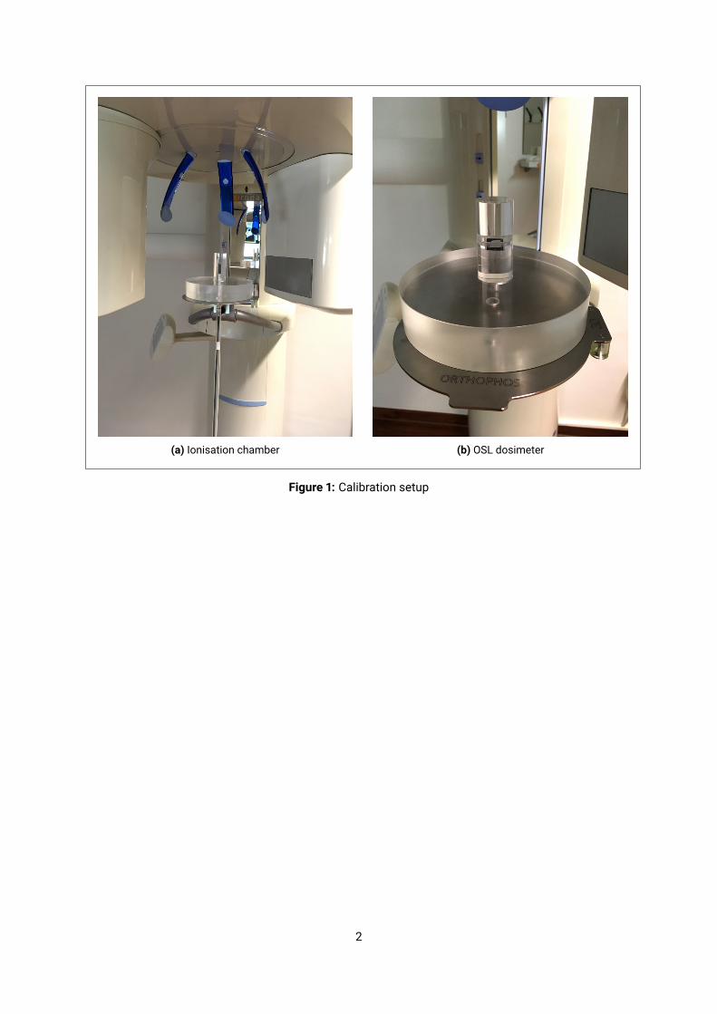
(a) Ionisation chamber (b) OSL dosimeter
Figure 1: Calibration setup
2

Anthropomorphic Head PhantomAn anthropomorphic adult head phantom (Alderson-Rando, RSD Inc, CA, USA) was used for the dosemeasurements. The phantom consists of a human skull embedded in a tissue equivalent material andis divided into 10 horizontal layers (numeration: 0-9, see figure 2). 24 BeO-based OSL dosimeters wereplaced at anatomically representative sites inside the phantom (listed in table 1). The exact positioningcan be seen in figure 3.
Number Layer Position1 1 Calvarium anterior2 1 Mid brain3 2 Calvarium left4 2 Mid brain5 3 Calvarium Posterior6 3 Pituitary7 3 Right lens of eye8 3 Left lens of eye9 4 Etmoid10 5 Left maxillariy sinus11 6 Oropharyngeal airway12 6 Right parotid13 6 Left parotid14 6 Right ramus15 6 Left ramus16 7 Left back of neck17 7 Right submandibular gland18 7 Left submandibular gland19 7 Center sublingual gland20 7 Center C spine21 8 Lateral neck - left22 9 Thyroid - left23 9 Thyroid - right24 9 Esophagus
Table 1: Dosimeter positions Figure 2: Alderson phantom
CBCT Systems and Measurement ProgrammeThe measurements were done with three different CBCT systems (Orthophos XG, Orthophos SL andAxeos (Dentsply Sirona, Bensheim, Germany)). An overview of the measurements is given in table 2.
3
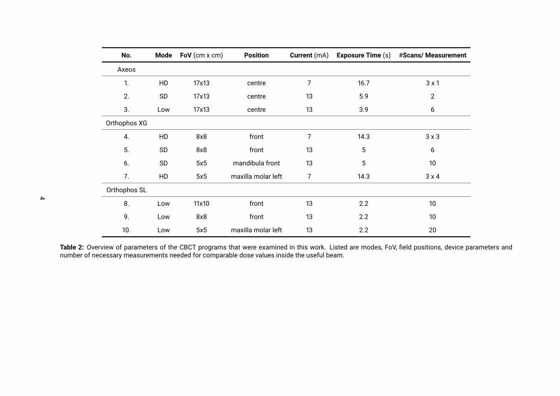
No. Mode FoV (cm x cm) Position Current (mA) Exposure Time (s) #Scans/ Measurement
Axeos1. HD 17x13 centre 7 16.7 3 x 12. SD 17x13 centre 13 5.9 23. Low 17x13 centre 13 3.9 6
Orthophos XG4. HD 8x8 front 7 14.3 3 x 35. SD 8x8 front 13 5 66. SD 5x5 mandibula front 13 5 107. HD 5x5 maxilla molar left 7 14.3 3 x 4
Orthophos SL8. Low 11x10 front 13 2.2 109. Low 8x8 front 13 2.2 1010. Low 5x5 maxilla molar left 13 2.2 20
Table 2: Overview of parameters of the CBCT programs that were examined in this work. Listed are modes, FoV, field positions, device parameters andnumber of necessary measurements needed for comparable dose values inside the useful beam.
4

1
2
(a) Layer 1
34
(b) Layer 2
5
6
(c) Layer 3
9
(d) Layer 4
10
(e) Layer 5 (f) Layer 5 (underneath)
1112 1314 15
(g) Layer 6
17 1819
20
(h) Layer 7
21
(i) Layer 8
222324
(j) Layer 9Figure 3: Positions of the dosimeters inside the phantom layers.
Determination of the Effective DoseAt least 3 scans were performed for every measurement to compensate for tolerances in the x-ray gener-ation process. The number of scans was chosen so that the dosimeters inside the useful beam receivedat least 10 mGy to guarantee a high reproducibility of the measured values. Thus, the number of scansper measurement varied between 3 and 10.
5

Organ/Tissue Irradiated fraction [%] OSL number ICRP 2007 wT
Bone marrow 12.2 0.12Mandible 0.8 14, 15Calvaria 7.7 1, 3, 5Cervical spine 3.8 20
Thyroid 100 22, 23 0.04Esophagus 10 24 0.04Skin 5 7, 8, 16 0.01Bone surface 16.5 0.01
Mandible 1.3 14, 15Calvaria 11.8 1, 3, 5Cervical spine 3.4 20
Salivary glands 100 0.01Parotid 100 12, 13Submandibular 100 17, 18Sublingual 100 19
Brain 100 2, 4, 6 0.01Remainder 0.12
Lymphatic Nodes 5 11-13, 17-19, 21-24Muscles 5 11-13, 17-19, 21-24Extrathoracic Region 100 9-13, 17-19, 21-24Oral Mucosa 100 11-13, 17-19
Table 3: Irradiated fraction of tissue/organs and tissue weighting factors wT
According to the number of iterations of the scan program, evaluated dose values were normalised toone scan. Using the ICRP 2007 tissue weighting factors (Table 3 [4]), the ED was calculated from theindividual dose values per scan in the following way:Dose valueswere averaged ifmeasurementswere taken atmultiple positions of one type of organ/tissue(e.g. left and right side), in order to get the average dose per tissue type.In accordance with Ludlow and Walker a correction factor, the bone-to-muscle attenuation coefficientµBM = −0.0618 · kV p · 2/3 + 6.9406, was applied to the components mandibular, skull and cervical ver-tebra to estimate the dose applied to the bone surface.The organ/tissue doses of bone marrow (components: mandibular, skull, cervical vertebra), bone sur-face (component: mandibular, skull, cervical vertebra) and salivary glands (components: parotid, sub-mandibular, sublingual) were calculated as the sum of the doses to the individual components.The equivalent dose was estimated from the product of the organ doses with the fractions (Table 3)of the organs/tissues which were irradiated.The equivalent doses HT were multiplied by the ICRP weight factors wT and summed over all organs,which resulted in the ED:
E =∑
wT ·HT
6

Results
NrProtocol
Patient*1 2 3 4 5 6 7
Orthophos XG1 HD 8 x 8 front 115 144 173 202 - - -2 SD 8 x 8 front 31 48 70 90 - - -3 SD 5 x 5 front mandibula 16 24 35 45 - - -4 HD 5 x 5 left maxilla molar 71 89 107 125 - - -Orthohos SL1 Low 11 x 10 front 12 14 20 27 - - -2 Low 8 x 8 front 8 9 13 17 - - -3 Low 5 x 5 left maxilla molar 3 4 5 7 - - -Axeos1 HD 17 x 13 center 98 122 147 171 196 244 293
2 SD 17 x 13 center 39 51 73 95 - - -3 Low 17 x 13 center 13 15 21 28 - - -4 HD 17 x 13 center collimated to 17 x 7.5 28 35 42 49 56 70 845 HD 17 x 13 center collimated to 17 x 10 89 111 133 155 177 222 2666 SD 17 x 13 center collimated to 17 x 7.5 11 15 21 27 - - -7 SD 17 x 13 center collimated to 17 x 10 37 49 70 91 - - -8 Low 17 x 13 center collimated to 17 x 7.5 4 4 6 8 - - -9 Low 17 x 13 center collimated to 17 x 10 12 14 21 27 - - -
Table 4: Effective dose in µSv. The measured values are emphasized, all others were calculated fromthese. (*see table 5, 6 & 7)The Orthophos XG programs chosen were selected to examine the agreement with available literaturevalues [1], [2], [3]. At the systems newer systems, Orthophos SL and Axeos, the additionally availablemodes were examined (Status: July 2020).
7

Mode LOW
kV mA Effective beam-on time (s)Level 1 85 6 3.9Level 2 85 7 3.9Level 3 85 10 3.9Level 4 85 13 3.9
Mode SD
kV mA Effective beam-on time (s)Level 1 85 7 4.5Level 2 85 7 5.9Level 3 85 10 5.9Level 4 85 13 5.9
Mode HD
kV mA Effective beam-on time (s)Level 1 85 4 16.7Level 2 85 5 16.7Level 3 85 6 16.7Level 4 85 7 16.7Level 5 85 8 16.7Level 6 85 10 16.7Level 7 85 12 16.7
Table 5: Device parameters of the different levels for the FoV 17x13, Axeos (source: Dentsply Sirona)
8
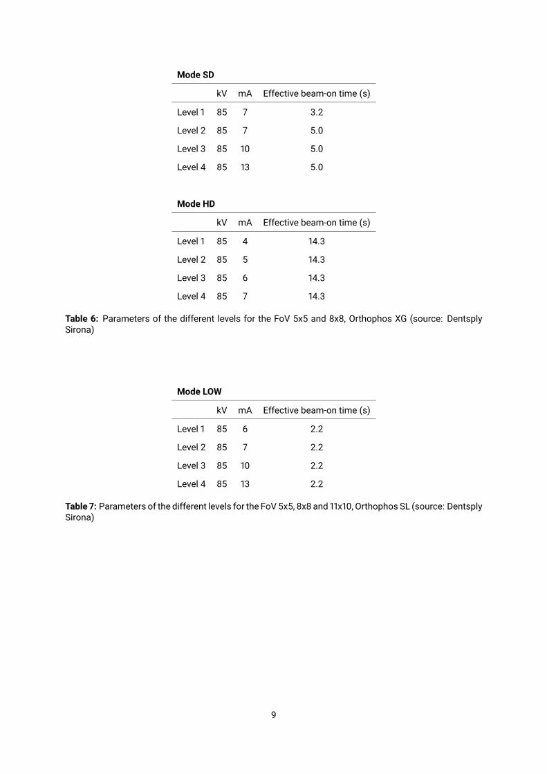
Mode SD
kV mA Effective beam-on time (s)Level 1 85 7 3.2Level 2 85 7 5.0Level 3 85 10 5.0Level 4 85 13 5.0
Mode HD
kV mA Effective beam-on time (s)Level 1 85 4 14.3Level 2 85 5 14.3Level 3 85 6 14.3Level 4 85 7 14.3
Table 6: Parameters of the different levels for the FoV 5x5 and 8x8, Orthophos XG (source: DentsplySirona)
Mode LOW
kV mA Effective beam-on time (s)Level 1 85 6 2.2Level 2 85 7 2.2Level 3 85 10 2.2Level 4 85 13 2.2
Table 7: Parameters of the different levels for the FoV 5x5, 8x8 and 11x10, Orthophos SL (source: DentsplySirona)
9

References[1] Rottke, D., Patzelt, S., Poxleitner, P. & Schulze, D., Effective dose span of ten different cone beam CT
devices, Dentomaxillofac. Radiol. 42, 20120417 (2013).[2] Soares, M. R., Batista, W. O., Antonio, P. de L., Caldas, L. V. E. & Maia, A. F, Study of effective dose of
various protocols in equipment cone beam CT, Appl. Radiat. Isot. 100, 21–26 (2015).[3] Ludlow, J. B. et al, Effective dose of dental CBCT-a meta analysis of published data and additional data
for nine CBCT units, Dentomaxillofac. Radiol. 44, 20140197 (2015).[4] J.B. Ludlow and C. Walker, Phantom dosimetry and image quality of i-CAT FLX cone-beam computed
tomography, Am J Orthod Dentofacial Orthop, 2013 Dec, 144(6): 802–817.
10