Effect of vacuum-treatment on deformation properties of PMMA bone cement
10
JOURNAL OF THE MECHANICAL BEHAVIOR OF BIOMEDICAL MATERIALS 5 (2012) 129–138 Available online at www.sciencedirect.com journal homepage: www.elsevier.com/locate/jmbbm Research paper Effect of vacuum-treatment on deformation properties of PMMA bone cement Fatima Zivic a,∗ , Miroslav Babic a , Nenad Grujovic a , Slobodan Mitrovic a , Gregory Favaro b , Mihaela Caunii b a Faculty of Mechanical Engineering, Kragujevac, Serbia b CSM Instruments, Switzerland ARTICLE INFO Article history: Received 16 June 2011 Received in revised form 26 July 2011 Accepted 2 August 2011 Published online 2 September 2011 Keywords: Biomaterials Polymethyl methacrylate (PMMA) Bone cement Microindentation Deformation behavior ABSTRACT Deformation behavior of polymethyl methacrylate (PMMA) bone cement is explored using microindentation. Two types of PMMA bone cement were prepared. Vacuum treated samples were subjected to the degassing of the material under vacuum of 270 mbar for 35 s, followed by the second degassing under vacuum of 255 mbar for 35 s. Air-cured samples were left in ambient air to cool down and harden. All samples were left to age for 6 months before the test. The samples were then subjected to the indentation fatigue test mode, using sharp Vickers indenter. First, loading segment rise time was varied in order to establish time-dependent behavior of the samples. Experimental data showed that viscous part of the deformation can be neglected under the observed test conditions. The second series of microindentation tests were realized with variation of number of cycles and indentation hardness and modulus were obtained. Approximate hardness was also calculated using analysis of residual impression area. Porosity characteristics were analyzed using CellC software. Scanning electron microscopy (SEM) analysis showed that air-cured bone cement exhibited significant number of large voids made of aggregated PMMA beads accompanied by particles of the radiopaque agent, while vacuum treated samples had homogeneous structure. Air-cured samples exhibited variable hardness and elasticity modulus throughout the material. They also had lower hardness values (approximately 65–100 MPa) than the vacuum treated cement (approximately 170 MPa). Porosity of 5.1% was obtained for vacuum treated cement and 16.8% for air-cured cement. Extensive plastic deformation, microcracks and craze whitening were produced during indentation of air- cured bone cement, whereas vacuum treated cement exhibited no cracks and no plastic deformation. c ⃝ 2011 Elsevier Ltd. All rights reserved. ∗ Corresponding author. E-mail addresses: [email protected] (F. Zivic), [email protected] (M. Babic), [email protected] (N. Grujovic), [email protected] (S. Mitrovic), [email protected] (G. Favaro), [email protected] (M. Caunii). 1751-6161/$ - see front matter c ⃝ 2011 Elsevier Ltd. All rights reserved. doi:10.1016/j.jmbbm.2011.08.015
-
Upload
independent -
Category
Documents
-
view
1 -
download
0
Transcript of Effect of vacuum-treatment on deformation properties of PMMA bone cement
J O U R N A L O F T H E M E C H A N I C A L B E H AV I O R O F B I O M E D I C A L M A T E R I A L S 5 ( 2 0 1 2 ) 1 2 9 – 1 3 8
Available online at www.sciencedirect.com
journal homepage: www.elsevier.com/locate/jmbbm
Research paper
Effect of vacuum-treatment on deformation properties ofPMMA bone cement
Fatima Zivica,∗, Miroslav Babica, Nenad Grujovica, Slobodan Mitrovica, Gregory Favarob,Mihaela Cauniib
a Faculty of Mechanical Engineering, Kragujevac, SerbiabCSM Instruments, Switzerland
A R T I C L E I N F O
Article history:
Received 16 June 2011
Received in revised form
26 July 2011
Accepted 2 August 2011
Published online 2 September 2011
Keywords:
Biomaterials
Polymethyl methacrylate (PMMA)
Bone cement
Microindentation
Deformation behavior
A B S T R A C T
Deformation behavior of polymethyl methacrylate (PMMA) bone cement is explored using
microindentation. Two types of PMMA bone cement were prepared. Vacuum treated
samples were subjected to the degassing of the material under vacuum of 270 mbar for
35 s, followed by the second degassing under vacuum of 255 mbar for 35 s. Air-cured
samples were left in ambient air to cool down and harden. All samples were left to age
for 6 months before the test. The samples were then subjected to the indentation fatigue
test mode, using sharp Vickers indenter. First, loading segment rise time was varied in
order to establish time-dependent behavior of the samples. Experimental data showed
that viscous part of the deformation can be neglected under the observed test conditions.
The second series of microindentation tests were realized with variation of number of
cycles and indentation hardness and modulus were obtained. Approximate hardness was
also calculated using analysis of residual impression area. Porosity characteristics were
analyzed using CellC software.
Scanning electron microscopy (SEM) analysis showed that air-cured bone cement
exhibited significant number of large voids made of aggregated PMMA beads accompanied
by particles of the radiopaque agent, while vacuum treated samples had homogeneous
structure. Air-cured samples exhibited variable hardness and elasticity modulus
throughout the material. They also had lower hardness values (approximately 65–100 MPa)
than the vacuum treated cement (approximately 170 MPa). Porosity of 5.1% was
obtained for vacuum treated cement and 16.8% for air-cured cement. Extensive plastic
deformation, microcracks and craze whitening were produced during indentation of air-
cured bone cement, whereas vacuum treated cement exhibited no cracks and no plastic
deformation.c⃝ 2011 Elsevier Ltd. All rights reserved.
i@
d
∗ Corresponding author.E-mail addresses: [email protected] (F. Zivic), [email protected] (M. Bab
[email protected] (G. Favaro), Mihaela.CAUNII
1751-6161/$ - see front matter c⃝ 2011 Elsevier Ltd. All rights reservedoi:10.1016/j.jmbbm.2011.08.015
c), [email protected] (N. Grujovic), [email protected] (S. Mitrovic),csm-instruments.com (M. Caunii).
.
130 J O U R N A L O F T H E M E C H A N I C A L B E H AV I O R O F B I O M E D I C A L M A T E R I A L S 5 ( 2 0 1 2 ) 1 2 9 – 1 3 8
1. Introduction
Polymethyl methacrylate (PMMA) bone cement was largelyused in orthopedics to anchor artificial joints. Approximately50% of all orthopedic implants utilize bone cement to achieveimplant fixation (Katti et al., 2008). Bone cement does notact as an adhesive, but rather as space filler (Reddy, 2009;Zandparsa, 2009). PMMA based materials are used for boneimplants (Stojkovic et al., 2010), intraocular lenses (Kuhn,2005), to augment the vertebral body in vertebroplastyprocedure (Provenzano et al., 2004), for membranes fordialysis and complete and partial dentures (Reddy, 2009;Zandparsa, 2009). However, local tissue damage due tochemical reactions during polymerization, the high shrinkageof the cement after polymerization, the stiffness mismatchbetween the bone and the cement are some drawbacksassociated with PMMA-based bone cements (Katti et al.,2008). Loose cement particles also mediate osteolysis of thebone. Loosening is recognized as one of the primary sourcesof total hip replacement failure. The fatigue failure of theimplant–bone cement and bone cement–bone interface isconsidered to be one of the main reasons. Clinical failure ofthe cement occurs over long periods of time (ten years ormore), and this implies that the crack growth rate is very low,perhaps as low as 10−12 m/cycle (Evans, 2006; Müller et al.,1997; Mohler et al., 1995; Nguyen et al., 1997; Ries et al., 2006).
Characterization of the bone cement to cyclic loadingis extremely significant and is a subject of many ongoingstudies (Arola et al., 2005; Briscoe et al., 2000; Evans, 2006;Gorham et al., 2003; Lewis, 2003; Stolarski and Williams,1996). For instance, if total hip replacement is considered,daily activities involve many cycles of different alternatingloading patterns (e.g. walking). Studies have shown that oneof the main reasons of cement failure mechanism is relatedto fatigue failure and fatigue crack propagation due to cyclicstresses that can cause fatigue crack initiation and growth,further leading to the loss of structural integrity (Buckleyet al., 2003; Evans, 2006; Hoey and Taylor, 2008; Lewis, 2003;Nguyen et al., 1997). However, crack propagation has not beenwidely studied (Buckley et al., 2003; Evans, 2006; Nguyen et al.,1997; Sinnett-Jones et al., 2005, 2008). Fatigue occurs when amaterial is subjected to a repeated loading and unloading. Ifthe loads are above a certain threshold, microscopic crackswill begin to form at the surface. Eventually the crack willreach critical size, and the structure will suddenly fracture.The shape of the structure will significantly affect thefatigue life. In smooth samples, cracks initiate from pores,at the stress concentrations formed between previouslypolymerized PMMA beads, and there is a correlation betweenporosity and fatigue life (Evans, 2006; Ries et al., 2006).Fracture surfaces are formed as a consequence of the crazingprocess ahead of the crack tip and micromechanisms offracture in PMMA are related to an energy dissipation zonesurrounding the crack (Buckley et al., 2003; Nguyen et al.,1997). Cracks typically propagate through the PMMA beads,but in some cases it is found that the beads pull out of thematrix. It is not clear why this occurs (Evans, 2006). Despiteextensive research the fatigue behavior of bone cements isnot well understood.
The role of the cement is directly related to themechanicalproperties of the cement, especially the resistance to fractureof the cement in the mantle at the cement–prosthesisinterface or the cement–bone interface. The method ofcement mixing is very important since porosity is one ofthe crucial characteristics that determine its resistance tofracture (Lewis, 2003; Ries et al., 2006; Sinnett-Jones et al.,2005). Inadequately mixed cement exhibits a high degree ofporosity. High porosity means that a number of pores arepresent acting as stress raisers and initiating sites for cracks,further promoting early fatigue failure.
Vacuum mixing of the PMMA bone cement is one of themeans to effectively reduce cement porosity. A number ofstudies have shown the benefits of this procedure over hand-mixing technique and investigated different parametersaffected by the application of vacuum mixing (Hoey andTaylor, 2008; Lelovics and Liptakova, 2010; Lewis, 2011).However, the optimum level of vacuum and the optimumporosity in the cement are still under debate. For instance,Hoey and Taylor (2008) reported that vacuum mixingtechnique, even though it reduced porosity, resulted in nosignificant improvement of fatigue strength. Sinnett-Joneset al. (2008) showed that large agglomerations of additionalconstituents in bone cement (such as particle size additives)are subject to microcracking during fatigue, although in themajority of cases, these are not the primary cause of failure.They concluded that even though pores acted as stress raisersand initiating sites for cracks, porosity and local additivesdistribution acted together in crack formation.
Depth-sensing indentation techniques are used routinelyto measure mechanical properties. They offer experimentalcontrol allowing investigation of a variety of differentdeformation modes by changing experimental time scale,indenter tip geometry, and loading conditions (Bhuhsanand Li, 2003; Gouldstone et al., 2007; Myshkin, 2004; Oyen,2006; Oyen and Cook, 2009). Microindentation techniqueis an already established method, in which the load, F,and displacement, h, are monitored during the contact ofan indenter tip with a known geometry and a materialsurface.When reaching a pre-setmaximumvalue, the normalload is reduced until partial or complete relaxation occurs.Indentation with the constant multicycle mode representsthe fatigue mode of testing. However, it is very importantto determine the appropriate analysis of indentation dataaccording to the material deformation modes which occurduring indentation (Bhuhsan and Li, 2003; Oyen, 2006; Oyenand Cook, 2009).
We report some experimental work regarding the prepara-tion procedure of PMMA bone cement and investigate the in-fluence of the vacuum treatment of hand-mixed PMMA bonecement on its deformation behavior duringmicroindentation.We analyzed deformation modes of PMMA bone cement pre-pared in two different ways: vacuum treated and air-curedsamples.
2. Material and methods
2.1. Materials
Commercially available PMMA bone cement for orthopedicsurgery (Palacos R, Schering Corporation, Kenilworth, New
J O U R N A L O F T H E M E C H A N I C A L B E H AV I O R O F B I O M E D I C A L M A T E R I A L S 5 ( 2 0 1 2 ) 1 2 9 – 1 3 8 131
Table 1 – Composition of PMMA bone cement.
Polymer powder components Liquid components (monomer)Constituent Mass (g) Constituent Mass (g)
Methylacrylate—Copolymer 33.80 MMA (Methylmethacrylate), stabilized with Hydroquinone 18.4Benzylperoxide 0.20 N, N-Dimethyl-p-toluidine 0.4Zirconiumdioxide 6.00 Chlorophyll 0.005Chlorophyll 0.008
Table 2 – The phases of the preparation procedure of the vacuum treated and the air-cured bone cement.
Phase Preparation procedure Time
1. Hand mixing by using spatula 1 min 35 s2. Mixing by using hand mixer 2 min 45 s3. Degassing of the material in a vacuum chamber (450 mbar) 35 s
Vacuum treated bone cement Air-cured bone cement
4. Degassing of the material in a vacuum chamber (270 mbar)for 35 s
Curing of the cement (ambient air, temperature of 25 ◦Cand relative humidity of 40%)
5. Degassing of the material in a vacuum chamber (255 mbar)for 35 s
6. Curing of the cement (ambient air, temperature of 25 ◦C andrelative humidity of 40%)
Jersey, USA) was used as a test material. PMMA is anisotropic, showing no crystallinity, elasto-viscoplastic solidand an amorphous polymer. Composition of used PMMA bonecement is given in Table 1.
Bone cement was mixed according to the manufacturer’sinstructions. Polymer powder was poured into a stainlesssteel container and liquid monomer was added after that.Powder component stayed in open air for 2 min before beingmixed with the liquid component. At the beginning, mixingof the two components was done using a spatula (1 min 35 sduration) and then by using a small handmixer in ambient air(2 min 45 s total mixing time). After that, the material was oflight dough consistency. Then, stainless steel container withthe material was held in a vacuum chamber for 35 s (undervacuum of 450 mbar). Extensive light gray smoke comingout of the container indicated degassing of the material. Thevacuum chamber of Vacuum casting system MCP 5.01 (MTTTechnologies GmbH, Lübeck, Germany) was used to degasprepared material.
Plastic molds (according to ASTM F451-99 “StandardSpecifications for Acrylic Bone Cements”) were filled with thematerial to form samples. One set of plastic molds containingthe material was then returned into the vacuum chamber:(1) under vacuum of 270 mbar for 35 s and (2) under vacuumof 255 mbar for 35 s. After that, molds with the material wereleft in ambient air (temperature of 25 ◦C and relative humidityof 40%) to cool and harden. Further in the text, this group ofsamples is referred to as vacuum treated bone cement, VT.The second group of molds was just left in ambient air tocool and harden. Further in the text, this group of samplesis referred to as air-cured bone cement, AC. Total time ofpreparation after opening the powder and liquid componentswas 10 min 9 s. Table 2 shows phases of the preparationprocedure of two groups of bone cements.
All samples were left to age for 6 months before the test.The properties of PMMA bone cements as a function of agingtime are important (Lewis et al., 2007; Provenzano et al., 2004).
Passage of time reduces creep rate (Lee et al., 2002; Lewis,2011). In the case of some laboratory-prepared bone cements,the aging time of one month produced steady state values ofelasticity modulus and hardness (Lewis et al., 2007; Nottrottet al., 2007). However, there is a lack of consensus on the in-fluence of either real-time in vitro or in vivo aging on the prop-erties of PMMA bone cement (Lewis et al., 2007; Lewis, 2011).
Samples were stored in a closed desiccator, at approximate22 ◦C. Prior to the tests, all samples were polished to theroughness of Ra = 10.5 µm. The morphological study ofthe control samples was carried out by using a low vacuumJeol JSM-6610LV scanning electron microscope equippedwith Everhart–Thornley detector for Secondary Electron (SE)imaging, Backscatter electron (BSE) detector, and EnergyDispersive (EDS) detector (X-Max Large Area Analytical SiliconDrift connected with INCAEnergy 350 Microanalysis System).Resulting SEM images were digitally processed (with free-ware CellC software for spot analysis) to determine theaverage size, number and density of voids. Density of voids(number/µm2) was determined for three control surfaces andaveraged, for each sample. Porosity was calculated for bothtypes of samples according to the data obtained from CellCsoftware analysis.
2.2. Instrumented indentation testing
Indentations were performed on each sample using the Mi-cro Indentation Tester (CSM Instruments SA, Peseux, Switzer-land). The tests were performed with a maximum normalload of 15 N and a minimum load of 5 N, using sharp in-dentation (Vickers indenter). Large (deep) indentations wereanalyzed, avoiding effects due to the tip shape uncertainty.There was no pause at maximum load before unloading (fa-tigue mode of testing). Two series of tests were realized. First,the time to maximum load was changed (loading segmentrise time) under the same number of cycles (100 cycles) to de-termine time dependent properties of prepared bone cement
132 J O U R N A L O F T H E M E C H A N I C A L B E H AV I O R O F B I O M E D I C A L M A T E R I A L S 5 ( 2 0 1 2 ) 1 2 9 – 1 3 8
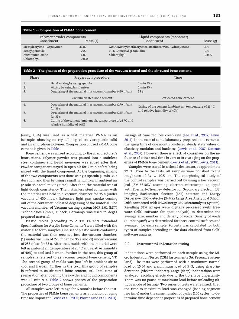
Fig. 1 – SEM photographs. (a) Sample surface of the vacuum treated bone cement. (b) Partially dissolved surface of sphericalpre-polymerized PMMA beads. (c) One of the largest voids on the surface of the vacuum-treated cement. (d) Large void onthe surface of the air-cured cement.
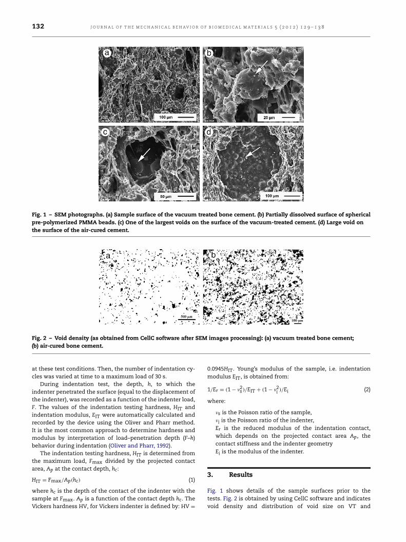
Fig. 2 – Void density (as obtained from CellC software after SEM images processing): (a) vacuum treated bone cement;(b) air-cured bone cement.
at these test conditions. Then, the number of indentation cy-cles was varied at time to a maximum load of 30 s.
During indentation test, the depth, h, to which theindenter penetrated the surface (equal to the displacement ofthe indenter), was recorded as a function of the indenter load,F. The values of the indentation testing hardness, HIT andindentation modulus, EIT were automatically calculated andrecorded by the device using the Oliver and Pharr method.It is the most common approach to determine hardness andmodulus by interpretation of load–penetration depth (F–h)behavior during indentation (Oliver and Pharr, 1992).
The indentation testing hardness, HIT is determined fromthe maximum load, Fmax divided by the projected contactarea, Ap at the contact depth, hc:
HIT = Fmax/Ap(hc) (1)
where hc is the depth of the contact of the indenter with thesample at Fmax. Ap is a function of the contact depth hc. TheVickers hardness HV, for Vickers indenter is defined by: HV =
0.0945HIT. Young’s modulus of the sample, i.e. indentationmodulus EIT, is obtained from:
1/Er = (1 − ν2s )/EIT + (1 − ν2i )/Ei (2)
where:
νs is the Poisson ratio of the sample,νi is the Poisson ratio of the indenter,Er is the reduced modulus of the indentation contact,which depends on the projected contact area Ap, thecontact stiffness and the indenter geometryEi is the modulus of the indenter.
3. Results
Fig. 1 shows details of the sample surfaces prior to thetests. Fig. 2 is obtained by using CellC software and indicatesvoid density and distribution of void size on VT and
J O U R N A L O F T H E M E C H A N I C A L B E H AV I O R O F B I O M E D I C A L M A T E R I A L S 5 ( 2 0 1 2 ) 1 2 9 – 1 3 8 133
Table 3 – Average size, number and density of voids.
Size of the voids (µm) Vacuum-treated bone cement Porosity: 5.1% (inaverage, 114 voids/mm2)
Air-cured bone cement Porosity: 16.8% (inaverage, 1414 voids/mm2)
Distribution of voids: 674 voids per 5.9 mm2
(control surface)Distribution of voids: 1980 voids per
1.4 mm2 (control surface)Number of voids Average void size
(µm)Number of voids Average void
size (µm)
<10 222 6 1422 5>10 and <50 415 21 465 21>50 and <100 28 66 66 71>100 9 124 27 140
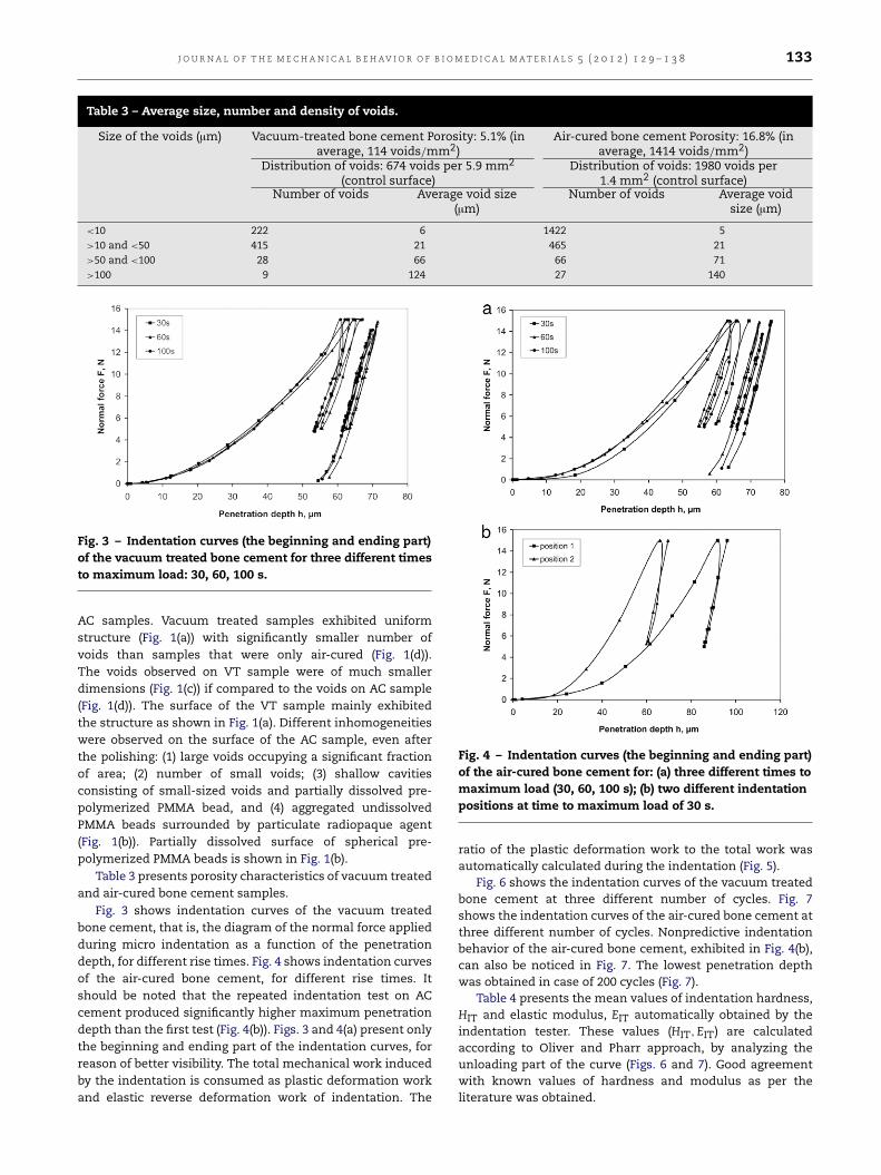
Fig. 3 – Indentation curves (the beginning and ending part)of the vacuum treated bone cement for three different timesto maximum load: 30, 60, 100 s.
AC samples. Vacuum treated samples exhibited uniformstructure (Fig. 1(a)) with significantly smaller number ofvoids than samples that were only air-cured (Fig. 1(d)).The voids observed on VT sample were of much smallerdimensions (Fig. 1(c)) if compared to the voids on AC sample(Fig. 1(d)). The surface of the VT sample mainly exhibitedthe structure as shown in Fig. 1(a). Different inhomogeneitieswere observed on the surface of the AC sample, even afterthe polishing: (1) large voids occupying a significant fractionof area; (2) number of small voids; (3) shallow cavitiesconsisting of small-sized voids and partially dissolved pre-polymerized PMMA bead, and (4) aggregated undissolvedPMMA beads surrounded by particulate radiopaque agent(Fig. 1(b)). Partially dissolved surface of spherical pre-polymerized PMMA beads is shown in Fig. 1(b).
Table 3 presents porosity characteristics of vacuum treatedand air-cured bone cement samples.
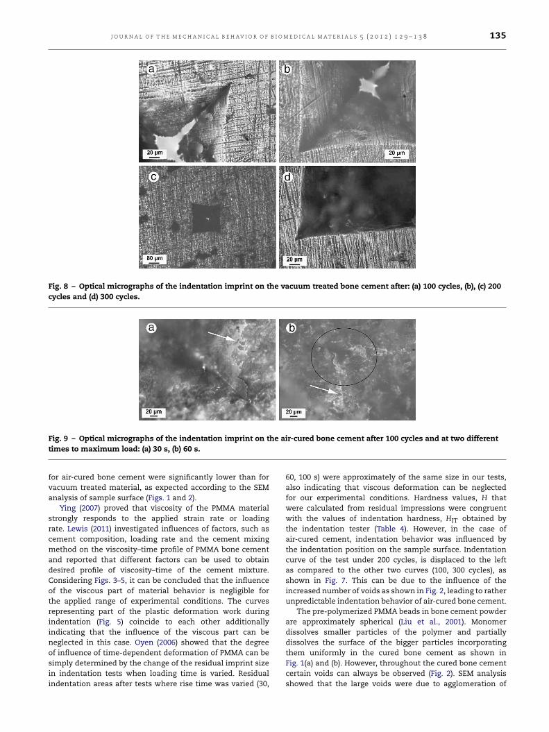
Fig. 3 shows indentation curves of the vacuum treatedbone cement, that is, the diagram of the normal force appliedduring micro indentation as a function of the penetrationdepth, for different rise times. Fig. 4 shows indentation curvesof the air-cured bone cement, for different rise times. Itshould be noted that the repeated indentation test on ACcement produced significantly higher maximum penetrationdepth than the first test (Fig. 4(b)). Figs. 3 and 4(a) present onlythe beginning and ending part of the indentation curves, forreason of better visibility. The total mechanical work inducedby the indentation is consumed as plastic deformation workand elastic reverse deformation work of indentation. The
Fig. 4 – Indentation curves (the beginning and ending part)of the air-cured bone cement for: (a) three different times tomaximum load (30, 60, 100 s); (b) two different indentationpositions at time to maximum load of 30 s.
ratio of the plastic deformation work to the total work wasautomatically calculated during the indentation (Fig. 5).
Fig. 6 shows the indentation curves of the vacuum treatedbone cement at three different number of cycles. Fig. 7shows the indentation curves of the air-cured bone cement atthree different number of cycles. Nonpredictive indentationbehavior of the air-cured bone cement, exhibited in Fig. 4(b),can also be noticed in Fig. 7. The lowest penetration depthwas obtained in case of 200 cycles (Fig. 7).
Table 4 presents the mean values of indentation hardness,HIT and elastic modulus, EIT automatically obtained by theindentation tester. These values (HIT,EIT) are calculatedaccording to Oliver and Pharr approach, by analyzing theunloading part of the curve (Figs. 6 and 7). Good agreementwith known values of hardness and modulus as per theliterature was obtained.

134 J O U R N A L O F T H E M E C H A N I C A L B E H AV I O R O F B I O M E D I C A L M A T E R I A L S 5 ( 2 0 1 2 ) 1 2 9 – 1 3 8
Table 4 – Mean values of indentation hardness, HIT elastic modulus, EIT and hardness, H of the bone cement samples(time to maximum load of 30 s).
Number of indentation cycles Vacuum treated bone cement Air-cured bone cement100 200 300 100 200 300
Hardness (as obtained by the indenter), HIT (MPa) 178.99 175.45 162.84 89.33 96.95 65.49Hardness, H calculated from imprint area size (MPa) 174.4 171.5 151.2 104.4 93.75 81.7Elastic modulus, EIT (GPa) 2.90 2.91 2.74 2.10 2.96 2.08
Fig. 5 – (a) Ratio of the plastic deformation work to the totalwork during indentation for VT and AC samples at differentrise times (60, 100 s). (b) Enlarged portion of the curve.
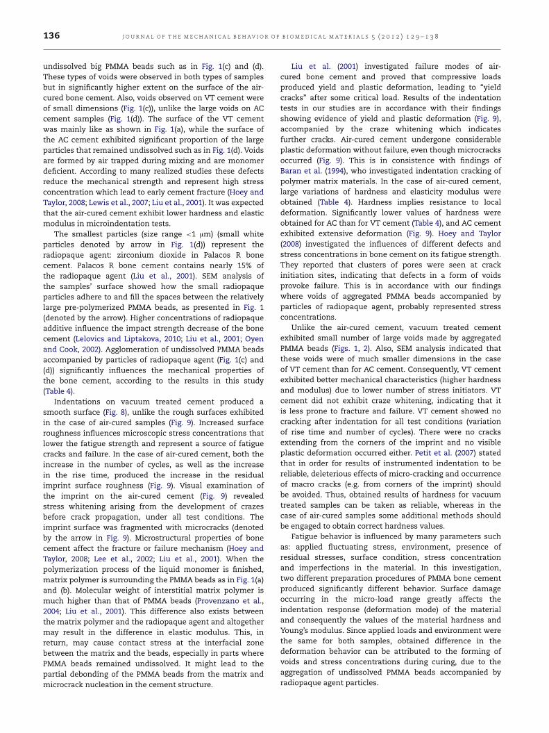
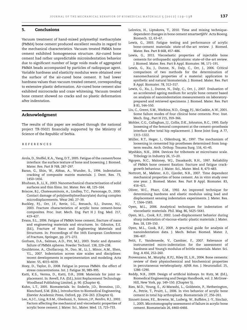
Fig. 8 shows optical micrographs of the indentationimprints on the vacuum treated bone cement, afterindentation. Typical pattern produced by Vickers indentationis clearly seen. The imprints are well shaped with clearlydeveloped edges and no microcracks along edges. Fig. 9presents optical micrographs of the indentation imprints onthe air-cured bone cement, after indentation. Indentationimprints in Figs. 8 and 9 are significantly different.Extensive plastic deformation is exhibited in Fig. 8, especiallypronounced in the corner areas (denoted by the circle inFig. 9(b)). Also, stress whitening and microcracks can beobserved along the imprint edges (denoted by arrows inFig. 9).
The length of each side of the quadratic residualimpressions (Figs. 8, 9) was measured from the optical imagesand averaged for each imprint. An approximate area, A wascalculated, assuming the quadrant area with side lengthequal to the average of the four measured lengths. Table 4shows approximate hardness values, H calculated by H =
Fmax/A.
4. Discussion
Figs. 6 and 7 indicate that substantial energy dissipation ina single cycle was realized for both tested samples of bone
Fig. 6 – Indentation curves of the vacuum treated bonecement at time to maximum load of 30 s, for three differentnumbers of cycles: 100, 200, 300 cycles.
Fig. 7 – Indentation curves of the air-cured bone cement attime to maximum load of 30 s, for three different numberof cycles: 100, 200, 300 cycles.
cement, but it was larger for air-cured samples than forvacuum treated material. Hardness and modulus are bothinfluenced by time-dependent effects and cannot be simplydetermined using standard techniques, e.g. Oliver and Pharr(Lee et al., 2002; Lewis et al., 2006; Oyen and Cook, 2002; Oyen,2006; Oyen and Cook, 2009; Provenzano et al., 2004). However,in case of experimental conditions in our study, the unloadingsegments of the F–h curve for both bone cement samples didnot exhibit time-dependent responses (Figs. 3 and 4), that is,a forward-displacing “nose” (Lee et al., 2002; Oyen and Cook,2002; Oyen, 2006; Oyen and Cook, 2009). It means that in thecase of our experimental conditions, hardness and moduluscan be calculated according to Oliver and Pharr approach. Inthe case of air-cured cement, these values should probablybe taken with some uncertainty due to uneven distributionwithin the material (Figs. 1(d) and 2(b)). Hardness values
J O U R N A L O F T H E M E C H A N I C A L B E H AV I O R O F B I O M E D I C A L M A T E R I A L S 5 ( 2 0 1 2 ) 1 2 9 – 1 3 8 135
Fig. 8 – Optical micrographs of the indentation imprint on the vacuum treated bone cement after: (a) 100 cycles, (b), (c) 200cycles and (d) 300 cycles.
Fig. 9 – Optical micrographs of the indentation imprint on the air-cured bone cement after 100 cycles and at two differenttimes to maximum load: (a) 30 s, (b) 60 s.
for air-cured bone cement were significantly lower than forvacuum treated material, as expected according to the SEManalysis of sample surface (Figs. 1 and 2).
Ying (2007) proved that viscosity of the PMMA materialstrongly responds to the applied strain rate or loadingrate. Lewis (2011) investigated influences of factors, such ascement composition, loading rate and the cement mixingmethod on the viscosity–time profile of PMMA bone cementand reported that different factors can be used to obtaindesired profile of viscosity–time of the cement mixture.Considering Figs. 3–5, it can be concluded that the influenceof the viscous part of material behavior is negligible forthe applied range of experimental conditions. The curvesrepresenting part of the plastic deformation work duringindentation (Fig. 5) coincide to each other additionallyindicating that the influence of the viscous part can beneglected in this case. Oyen (2006) showed that the degreeof influence of time-dependent deformation of PMMA can besimply determined by the change of the residual imprint sizein indentation tests when loading time is varied. Residualindentation areas after tests where rise time was varied (30,
60, 100 s) were approximately of the same size in our tests,also indicating that viscous deformation can be neglectedfor our experimental conditions. Hardness values, H thatwere calculated from residual impressions were congruentwith the values of indentation hardness, HIT obtained bythe indentation tester (Table 4). However, in the case ofair-cured cement, indentation behavior was influenced bythe indentation position on the sample surface. Indentationcurve of the test under 200 cycles, is displaced to the leftas compared to the other two curves (100, 300 cycles), asshown in Fig. 7. This can be due to the influence of theincreased number of voids as shown in Fig. 2, leading to ratherunpredictable indentation behavior of air-cured bone cement.
The pre-polymerized PMMA beads in bone cement powderare approximately spherical (Liu et al., 2001). Monomerdissolves smaller particles of the polymer and partiallydissolves the surface of the bigger particles incorporatingthem uniformly in the cured bone cement as shown inFig. 1(a) and (b). However, throughout the cured bone cementcertain voids can always be observed (Fig. 2). SEM analysisshowed that the large voids were due to agglomeration of
136 J O U R N A L O F T H E M E C H A N I C A L B E H AV I O R O F B I O M E D I C A L M A T E R I A L S 5 ( 2 0 1 2 ) 1 2 9 – 1 3 8
undissolved big PMMA beads such as in Fig. 1(c) and (d).These types of voids were observed in both types of samplesbut in significantly higher extent on the surface of the air-cured bone cement. Also, voids observed on VT cement wereof small dimensions (Fig. 1(c)), unlike the large voids on ACcement samples (Fig. 1(d)). The surface of the VT cementwas mainly like as shown in Fig. 1(a), while the surface ofthe AC cement exhibited significant proportion of the largeparticles that remained undissolved such as in Fig. 1(d). Voidsare formed by air trapped during mixing and are monomerdeficient. According to many realized studies these defectsreduce the mechanical strength and represent high stressconcentration which lead to early cement fracture (Hoey andTaylor, 2008; Lewis et al., 2007; Liu et al., 2001). It was expectedthat the air-cured cement exhibit lower hardness and elasticmodulus in microindentation tests.
The smallest particles (size range <1 µm) (small whiteparticles denoted by arrow in Fig. 1(d)) represent theradiopaque agent: zirconium dioxide in Palacos R bonecement. Palacos R bone cement contains nearly 15% ofthe radiopaque agent (Liu et al., 2001). SEM analysis ofthe samples’ surface showed how the small radiopaqueparticles adhere to and fill the spaces between the relativelylarge pre-polymerized PMMA beads, as presented in Fig. 1(denoted by the arrow). Higher concentrations of radiopaqueadditive influence the impact strength decrease of the bonecement (Lelovics and Liptakova, 2010; Liu et al., 2001; Oyenand Cook, 2002). Agglomeration of undissolved PMMA beadsaccompanied by particles of radiopaque agent (Fig. 1(c) and(d)) significantly influences the mechanical properties ofthe bone cement, according to the results in this study(Table 4).
Indentations on vacuum treated cement produced asmooth surface (Fig. 8), unlike the rough surfaces exhibitedin the case of air-cured samples (Fig. 9). Increased surfaceroughness influences microscopic stress concentrations thatlower the fatigue strength and represent a source of fatiguecracks and failure. In the case of air-cured cement, both theincrease in the number of cycles, as well as the increasein the rise time, produced the increase in the residualimprint surface roughness (Fig. 9). Visual examination ofthe imprint on the air-cured cement (Fig. 9) revealedstress whitening arising from the development of crazesbefore crack propagation, under all test conditions. Theimprint surface was fragmented with microcracks (denotedby the arrow in Fig. 9). Microstructural properties of bonecement affect the fracture or failure mechanism (Hoey andTaylor, 2008; Lee et al., 2002; Liu et al., 2001). When thepolymerization process of the liquid monomer is finished,matrix polymer is surrounding the PMMA beads as in Fig. 1(a)and (b). Molecular weight of interstitial matrix polymer ismuch higher than that of PMMA beads (Provenzano et al.,2004; Liu et al., 2001). This difference also exists betweenthe matrix polymer and the radiopaque agent and altogethermay result in the difference in elastic modulus. This, inreturn, may cause contact stress at the interfacial zonebetween the matrix and the beads, especially in parts wherePMMA beads remained undissolved. It might lead to thepartial debonding of the PMMA beads from the matrix andmicrocrack nucleation in the cement structure.
Liu et al. (2001) investigated failure modes of air-cured bone cement and proved that compressive loadsproduced yield and plastic deformation, leading to “yieldcracks” after some critical load. Results of the indentationtests in our studies are in accordance with their findingsshowing evidence of yield and plastic deformation (Fig. 9),accompanied by the craze whitening which indicatesfurther cracks. Air-cured cement undergone considerableplastic deformation without failure, even though microcracksoccurred (Fig. 9). This is in consistence with findings ofBaran et al. (1994), who investigated indentation cracking ofpolymer matrix materials. In the case of air-cured cement,large variations of hardness and elasticity modulus wereobtained (Table 4). Hardness implies resistance to localdeformation. Significantly lower values of hardness wereobtained for AC than for VT cement (Table 4), and AC cementexhibited extensive deformation (Fig. 9). Hoey and Taylor(2008) investigated the influences of different defects andstress concentrations in bone cement on its fatigue strength.They reported that clusters of pores were seen at crackinitiation sites, indicating that defects in a form of voidsprovoke failure. This is in accordance with our findingswhere voids of aggregated PMMA beads accompanied byparticles of radiopaque agent, probably represented stressconcentrations.
Unlike the air-cured cement, vacuum treated cementexhibited small number of large voids made by aggregatedPMMA beads (Figs. 1, 2). Also, SEM analysis indicated thatthese voids were of much smaller dimensions in the caseof VT cement than for AC cement. Consequently, VT cementexhibited better mechanical characteristics (higher hardnessand modulus) due to lower number of stress initiators. VTcement did not exhibit craze whitening, indicating that itis less prone to fracture and failure. VT cement showed nocracking after indentation for all test conditions (variationof rise time and number of cycles). There were no cracksextending from the corners of the imprint and no visibleplastic deformation occurred either. Petit et al. (2007) statedthat in order for results of instrumented indentation to bereliable, deleterious effects of micro-cracking and occurrenceof macro cracks (e.g. from corners of the imprint) shouldbe avoided. Thus, obtained results of hardness for vacuumtreated samples can be taken as reliable, whereas in thecase of air-cured samples some additional methods shouldbe engaged to obtain correct hardness values.
Fatigue behavior is influenced by many parameters suchas: applied fluctuating stress, environment, presence ofresidual stresses, surface condition, stress concentrationand imperfections in the material. In this investigation,two different preparation procedures of PMMA bone cementproduced significantly different behavior. Surface damageoccurring in the micro-load range greatly affects theindentation response (deformation mode) of the materialand consequently the values of the material hardness andYoung’s modulus. Since applied loads and environment werethe same for both samples, obtained difference in thedeformation behavior can be attributed to the forming ofvoids and stress concentrations during curing, due to theaggregation of undissolved PMMA beads accompanied byradiopaque agent particles.
J O U R N A L O F T H E M E C H A N I C A L B E H AV I O R O F B I O M E D I C A L M A T E R I A L S 5 ( 2 0 1 2 ) 1 2 9 – 1 3 8 137
5. Conclusions
Vacuum treatment of hand-mixed polymethyl methacrylate(PMMA) bone cement produced excellent results in regard tothe mechanical characteristics. Vacuum treated PMMA bonecement exhibited homogeneous structure. Air-cured bonecement had rather unpredictable microindentation behaviordue to significant number of large voids made of aggregatedPMMA beads accompanied by particles of radiopaque agent.Variable hardness and elasticity modulus were obtained overthe surface of the air-cured bone cement. It had lowerhardness values than vacuum treated cement, correspondingto extensive plastic deformation. Air-cured bone cement alsoexhibited microcracks and craze whitening. Vacuum treatedbone cement showed no cracks and no plastic deformationafter indentation.
Acknowledgment
The results of this paper are realized through the nationalproject TR-35021 financially supported by the Ministry ofScience of the Republic of Serbia.
R E F E R E N C E S
Arola, D., Stoffel, K.A., Yang, D.T., 2005. Fatigue of the cement/boneinterface: the surface texture of bone and loosening. J. Biomed.Mater. Res. Part B 76B, 287–297.
Baran, G., Shin, W., Abbas, A., Wunder, S., 1994. Indentationcracking of composite matrix materials. J. Dent. Res. 73,1450–1456.
Bhuhsan, B., Li, X., 2003. Nanomechanical characterisation of solidsurfaces and thin films. Int. Mater. Rev. 48, 125–164.
Briscoe, B.J., Chateauminois, A., Lindley, T.C., Parsonage, D., 2000.Contact damage of poly(methylmethacrylate) during complexmicrodisplacements. Wear 240, 27–39.
Buckley, P.J., Orr, J.F., Revie, I.C., Breusch, S.J., Dunne, N.J.,2003. Fracture characteristics of acrylic bone cement–bonecomposites. Proc. Inst. Mech. Eng. Part H J. Eng. Med. 217,419–427.
Evans, S.L., 2006. Fatigue of PMMA bone cement, fracture of nanoand engineering materials and structures. In: Gdoutos, E.E.(Ed.), Fracture of Nano and Engineering Materials andStructures. In: Proceedings of the 16th European Conferenceof Fracture, Springer, pp. 271–272.
Gorham, D.A., Salman, A.D., Pitt, M.J., 2003. Static and dynamicfailure of PMMA spheres. Powder Technol. 138, 229–238.
Gouldstone, A., Chollacoop, N., Dao, M., Li, J., Minor, A.M., Shen,Y.L., 2007. Indentation across size scales and disciplines:recent developments in experimentation and modeling. ActaMater. 55, 4015–4039.
Hoey, D., Taylor, D., 2008. Fatigue in porous PMMA: the effect ofstress concentrations. Int. J. Fatigue 30, 989–995.
Katti, K.S., Verma, D., Katti, D.R., 2008. Materials for joint re-placement. In: Revell, P.A. (Ed.), Joint Replacement Technology.Woodhead Publishing Limited, p. 90. (Chapter 4).
Kuhn, L.T., 2005. Biomaterials. In: Enderle, J.D., Bronzino, J.D.,Blanchard, S.M. (Eds.), Introduction to Biomedical Engineering.Elsevier Academic Press, Oxford, pp. 256–263. (Chapter 6).
Lee, A.J.C., Ling, R.S.M., Gheduzzi, S., Simon, J.P., Renfro, R.J., 2002.Factors affecting the mechanical and viscoelastic properties ofacrylic bone cement. J. Mater. Sci., Mater. Med. 13, 723–733.
Lelovics, H., Liptakova, T., 2010. Time and mixing technique-dependent changes in bone cement smartset§HV. Acta Bioeng.Biomech. 12, 63–67.
Lewis, G., 2003. Fatigue testing and performance of acrylicbone–cement materials: state-of-the-art review. J. Biomed.Mater. Res. Part B 66B, 457–486.
Lewis, G., 2011. Viscoelastic properties of injectable bonecements for orthopaedic applications: state-of-the-art review.J. Biomed. Mater. Res. Part B Appl. Biomater. 98, 171–191.
Lewis, G., Xu, J., Dunne, N., Daly, C., Orr, J., 2006. Criticalcomparison of two methods for the determination ofnanomechanical properties of a material: application tosynthetic and natural biomaterials. J. Biomed. Mater. Res. PartB Appl. Biomater. 78, 312–317.
Lewis, G., Xu, J., Dunne, N., Daly, C., Orr, J., 2007. Evaluation ofan accelerated ageing medium for acrylic bone cement basedon analysis of nanoindentation measurements on laboratory-prepared and retrieved specimens. J. Biomed. Mater. Res. PartB 81, 544–550.
Liu, C., Green, S.M., Watkins, N.D., Gregg, P.J., McCaskie, A.W., 2001.Some failure modes of four clinical bone cements. Proc. Inst.Mech. Eng., Part H 215, 359–366.
Mohler, C.G., Callaghan, J.J., Collis, D.K., Johnston, R.C., 1995. Earlyloosening of the femoral component at the cement–prosthesisinterface after total hip replacement. J. Bone Joint Surg. A 77,1315–1322.
Müller, R.T., Heger, I., Oldenburg, M., 1997. The mechanism ofloosening in cemented hip prostheses determined from long-term results. Arch. Orthop. Trauma Surg. 116, 41–45.
Myshkin, N.K., 2004. Devices for tribotests at micro/nano scale.Tribology in Industry 26, 15–20.
Nguyen, N.C., Maloney, W.J., Dauskardt, R.H., 1997. Reliabilityof PMMA bone cement fixation: fracture and fatigue crack-growth behaviour. J. Mater. Sci., Mater. Med. 8, 473–483.
Nottrott, M., Mølster, A.O., Gjerdet, N.R., 2007. Time dependentmechanical properties of bone cement. An in vitro study overone year. J. Biomed. Mater. Res. Part B Appl. Biomater. 83,416–421.
Oliver, W.C., Pharr, G.M., 1992. An improved technique fordetermining hardness and elastic modulus using load anddisplacement sensing indentation experiments. J. Mater. Res.7, 1564–1583.
Oyen, M.L., 2006. Analytical techniques for indentation ofviscoelastic materials. Phil. Mag. 86, 5625–5641.
Oyen, M.L., Cook, R.F., 2002. Load–displacement behavior duringsharp indentation of viscous-elastic-plastic materials. J. Mater.Res. 18, 139–150.
Oyen, M.L., Cook, R.F., 2009. A practical guide for analysis ofnanoindentation data. J. Mech. Behav. Biomed. Mater. 2,396–407.
Petit, F., Vandeneede, V., Cambier, F., 2007. Relevance ofinstrumented micro-indentation for the assessment ofhardness and Young’s modulus of brittle materials. Mater. Sci.Eng. A 456, 252–260.
Provenzano, M., Murphy, K.P.J., Riley III, L.H., 2004. Bone cements:review of their physiochemical and biochemical propertiesin percutaneous vertebroplasty. AJNR Am. J. Neuroradiol. 25,1286–1290.
Reddy, N.R., 2009. Design of artificial kidneys. In: Kutz, M. (Ed.),Biomedical Engineering and Design Handbook, vol. 2. McGraw-Hill, New York, pp. 149–150. (Chapter 5).
Ries, M.D., Young, E., Al-Marashi, L., Goldstein, P., Hetherington,A., Petrie, T., Pruitt, L., 2006. In vivo behavior of acrylic bonecement in total hip arthroplasty. Biomaterials 27, 256–261.
Sinnett-Jones, P.E., Browne, M., Ludwig, W., Buffiére, J.-Y., Sinclair,I., 2005. Microtomography assessment of failure in acrylic bonecement. Biomaterials 26, 6460–6466.
138 J O U R N A L O F T H E M E C H A N I C A L B E H AV I O R O F B I O M E D I C A L M A T E R I A L S 5 ( 2 0 1 2 ) 1 2 9 – 1 3 8
Sinnett-Jones, P.E., Browne, M., Moffat, A.J., Jeffers, J.R.T., Saffari,N., Buffiére, J.Y., Sinclair, I., 2008. Crack initiation processesin acrylic bone cement. J. Biomed. Mater. Res. Part A 89A,1088–1097.
Stojkovic, M., Milovanovic, J., Vitkovic, N., Trajanovic, M., Grujovic,N., Milivojevic, V., Milisavljevic, S., Mrvic, S., 2010. Reversemodeling and solid free-form fabrication of sternum implant.Australas. Phys. Eng. Sci. Med. 33, 243–250.
Stolarski, T.A., Williams, H., 1996. Mode of loading and contactconfiguration effects in the wear of polymers. J. Appl. Polym.Sci. 61, 1217–1222.
Ying, S., 2007. Rheologic fracture of PMMA material at differentstrain rates. J. Cent. South. Univ. Technol. 14, 342–345.
Zandparsa, R., 2009. Dental biomaterials. In: Kutz, M. (Ed.),Biomedical Engineering and Design Handbook, vol. 1. McGraw-Hill, New York, p. 405. (Chapter 17).