Effect of substrate modulus difference on dislocation formation in an epitaxial film
16
Eect of substrate modulus dierence on dislocation formation in an epitaxial film Shing-Dar Wang a , Sanboh Lee b, * , Chun-Hway Hsueh c a Department of Mechanical Engineering, Chung Chou Junior College of Technology and Commerce, Chang-Hua, Taiwan, ROC b Department of Materials Science and Engineering, National Tsing Hua University, 101, Sec. 2, Kuang Fu Road, Hsinchu 30013, Taiwan, ROC c Metals and Ceramics Division, Oak Ridge National Laboratory, Oak Ridge, TN 37831-6068, USA Received 7 October 1999; received in revised form 2 February 2000 Abstract The eect of substrate modulus dierence on dislocation formation in an epitaxial film is derived in the present study. The analysis is based on the energy approach, in which the self-energy of the dislocation and the interaction energy between the dislocation and the mismatch strain are calculated. The elastic stress field due to the interface dislocation is derived by superposition of the elastic stress fields of the film/substrate system with the following two configurations: (i) a dislocation at the interface assuming the film is also semi-infinite, and (ii) prescribed traction on the film surface which are the negative of those calculated from the first configuration at the location equivalent to the film surface in the second configuration. The results show that the critical film thickness for forming interface dislocation increases with the decrease in the shear modulus ratio of the film to the substrate. Ó 2001 Elsevier Science Ltd. All rights reserved. Keywords: Epitaxial film; Substrate; Dislocation; Critical thickness 1. Introduction The performance of many electronic devices and high temperature superconducting films depends on the quality of crystalline films grown epitaxially on substrates of dierent crystals. Because of the dierence in lattice parameter between the film and the substrate, the lattice mismatch exists at the film/substrate in- terface which, in turn, induces internal stresses in the system. These internal stresses could be relaxed by the formation of misfit dislocations at the interface (Frank and van der Merwe, 1949; Freund, 1990, 1993; Freund and Nix, 1996; Gosling and Willis, 1994; Mattews and Blakeslee, 1974; Willis et al., 1990, 1991; Zhang, 1996; Zhang et al., 1999). However, the interface dislocations inevitably degrade the device per- formance. Hence, the study of the condition for the interface dislocation to form in the epitaxial film/ substrate system becomes crucial in the materials design. Due to the complexity of the problem, the early analyses assumed that the film and the substrate are isotropic elastic materials and have the same elastic constants. Matthews and Blakeslee (MB) (1974) considered a thin epitaxial film on an semi-infinitely thick Mechanics of Materials 33 (2001) 105–120 www.elsevier.com/locate/mechmat * Corresponding author. Tel.: +886-35-719-677; fax: +886-35-722-366. E-mail address: [email protected] (S. Lee). 0167-6636/01/$ - see front matter Ó 2001 Elsevier Science Ltd. All rights reserved. PII: S 0 1 6 7 - 6 6 3 6 ( 0 0 ) 0 0 0 5 8 - 2
-
Upload
independent -
Category
Documents
-
view
1 -
download
0
Transcript of Effect of substrate modulus difference on dislocation formation in an epitaxial film

E�ect of substrate modulus di�erence on dislocation formationin an epitaxial ®lm
Shing-Dar Wang a, Sanboh Lee b,*, Chun-Hway Hsueh c
a Department of Mechanical Engineering, Chung Chou Junior College of Technology and Commerce, Chang-Hua, Taiwan, ROCb Department of Materials Science and Engineering, National Tsing Hua University, 101, Sec. 2, Kuang Fu Road, Hsinchu 30013,
Taiwan, ROCc Metals and Ceramics Division, Oak Ridge National Laboratory, Oak Ridge, TN 37831-6068, USA
Received 7 October 1999; received in revised form 2 February 2000
Abstract
The e�ect of substrate modulus di�erence on dislocation formation in an epitaxial ®lm is derived in the present study.
The analysis is based on the energy approach, in which the self-energy of the dislocation and the interaction energy
between the dislocation and the mismatch strain are calculated. The elastic stress ®eld due to the interface dislocation is
derived by superposition of the elastic stress ®elds of the ®lm/substrate system with the following two con®gurations: (i)
a dislocation at the interface assuming the ®lm is also semi-in®nite, and (ii) prescribed traction on the ®lm surface which
are the negative of those calculated from the ®rst con®guration at the location equivalent to the ®lm surface in the
second con®guration. The results show that the critical ®lm thickness for forming interface dislocation increases with
the decrease in the shear modulus ratio of the ®lm to the substrate. Ó 2001 Elsevier Science Ltd. All rights reserved.
Keywords: Epitaxial ®lm; Substrate; Dislocation; Critical thickness
1. Introduction
The performance of many electronic devices and high temperature superconducting ®lms depends on thequality of crystalline ®lms grown epitaxially on substrates of di�erent crystals. Because of the di�erence inlattice parameter between the ®lm and the substrate, the lattice mismatch exists at the ®lm/substrate in-terface which, in turn, induces internal stresses in the system. These internal stresses could be relaxed by theformation of mis®t dislocations at the interface (Frank and van der Merwe, 1949; Freund, 1990, 1993;Freund and Nix, 1996; Gosling and Willis, 1994; Mattews and Blakeslee, 1974; Willis et al., 1990, 1991;Zhang, 1996; Zhang et al., 1999). However, the interface dislocations inevitably degrade the device per-formance. Hence, the study of the condition for the interface dislocation to form in the epitaxial ®lm/substrate system becomes crucial in the materials design. Due to the complexity of the problem, the earlyanalyses assumed that the ®lm and the substrate are isotropic elastic materials and have the same elasticconstants. Matthews and Blakeslee (MB) (1974) considered a thin epitaxial ®lm on an semi-in®nitely thick
Mechanics of Materials 33 (2001) 105±120www.elsevier.com/locate/mechmat
* Corresponding author. Tel.: +886-35-719-677; fax: +886-35-722-366.
E-mail address: [email protected] (S. Lee).
0167-6636/01/$ - see front matter Ó 2001 Elsevier Science Ltd. All rights reserved.
PII: S 0 1 6 7 - 6 6 3 6 ( 0 0 ) 0 0 0 5 8 - 2
substrate, analyzed the force exerted by the mismatch strain and the approximate tension in the dislocationline, and used the force approach to predict the critical thickness of the ®lm for the interface dislocation toform. The MB model was subsequently improved by others using the energy approach, in which the workof forming the dislocation due to the presence of internal stresses and the self-energy of the dislocation wereanalyzed. Recently, the MB criterion for a ®lm on an semi-in®nitely thick substrate was generalized byFreund and Nix (FN) (1996) using the energy approach to the case of a ®lm deposited on a substrate with a®nite thickness. Because of the complexity of the interaction between the interface dislocation and the twofree surfaces, a ®rst-order approximation was used in analyzing the self-energy of the dislocation and thefree-surface condition was not satis®ed in the FN model. The FN model was further improved by Zhanget al. (1999) using the superposition principle and Fourier transformation to derive a complete analysis forthe dislocation self-energy and to satisfy the free-surface condition.
The analyses described above assumed the ®lm and the substrate having the same isotropic elasticconstants in order to simplify the analysis. Considering the di�erence in elastic constants between the ®lmand the substrate or the elastic anisotropy of the constituents, the analyses have also been performed usingFourier transformation; however, the solutions were approximate. For example, the stress ®eld and energyarising from an array of dislocations (Willis et al., 1991) and dislocation dipoles (Gosling and Willis, 1994)distributed uniformly on the perfectly bonded interface between an epitaxial ®lm and a semi-in®nite sub-strate of di�erent isotropic elastic constants were derived. Gosling and Willis (1994) analyzed the energy ofarrays of dislocations located periodically at the perfectly bonded interface between an epitaxial ®lm and asemi-in®nite substrate of the same anisotropic elastic constants. It is noted that the core energy was notincluded in the above analyses (Willis et al., 1991; Gosling and Willis, 1994). Including the core energy, thecritical thickness of an epitaxial ®lm on a semi-in®nite substrate of di�erent isotropic elastic constants wasanalyzed by Zhang (1995). However, it is noted that the displacement and the shear stress used in derivingthe core energy in Zhang's analysis (Zhang, 1995) did not satisfy the continuity condition at the interface.
The purpose of the present study is to re®ne Zhang's analysis (Zhang, 1995) of the epitaxial ®lm de-posited on a semi-in®nite substrate with di�erent isotropic elastic constants to satisfy the continuity con-dition at the interface. To achieve this, the stress ®eld due to the interface dislocation was derived bysuperposition of (1) the stress due to two semi-in®nite medium and (2) the stress due to the prescribedtraction on the ®lm surface which were the negative of those calculated from the ®rst component at ®lmsurface. This stress ®eld satis®es the free-surface condition and the stress continuity condition at the ®lm/substrate interface. Then, the predicted stress ®elds due to an edge and a screw dislocations are presented,respectively. Also, the critical ®lm thickness for the interface dislocation to form is predicted and comparedwith existing solutions. Finally, it is noted that depending on the temperature and friction force, the dis-location will move from the hard medium to soft medium through the interface (Gutkin and Romanov,1992) after it nucleates in the hard medium or at the interface. However, it is beyond the scope of thepresent study.
2. Analysis
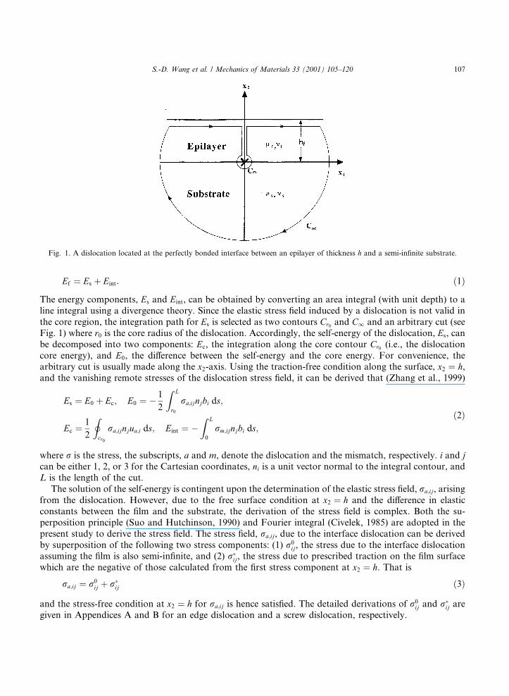
The present model considers a ®lm of thickness h deposited epitaxially on a semi-in®nite substrate asshown in Fig. 1. Both shear modulus and Poisson's ratio of the ®lm and the substrate are lf , mf and ls, ms,respectively. The Cartesian coordinates, x1, x2, and x3 are used with the x1-axis parallel to the in-planeinterface, the x2-axis perpendicular to the interface and the origin located at the interface. A dislocationwith a Burgers vector b � �b1; b2; b3� is located at the origin. In the following analyses, the energies arecalculated per unit length of the dislocation line or per unit depth of the ®lm/substrate system. The for-mation energy, Ef , of the dislocation consists of two components: Es, the self-energy of the dislocation andEint, the interaction energy between the dislocation and mismatch strain, such that
106 S.-D. Wang et al. / Mechanics of Materials 33 (2001) 105±120
Ef � Es � Eint: �1�The energy components, Es and Eint, can be obtained by converting an area integral (with unit depth) to aline integral using a divergence theory. Since the elastic stress ®eld induced by a dislocation is not valid inthe core region, the integration path for Es is selected as two contours Cr0
and C1 and an arbitrary cut (seeFig. 1) where r0 is the core radius of the dislocation. Accordingly, the self-energy of the dislocation, Es, canbe decomposed into two components: Ec, the integration along the core contour Cr0
(i.e., the dislocationcore energy), and E0, the di�erence between the self-energy and the core energy. For convenience, thearbitrary cut is usually made along the x2-axis. Using the traction-free condition along the surface, x2 � h,and the vanishing remote stresses of the dislocation stress ®eld, it can be derived that (Zhang et al., 1999)
Es � E0 � Ec; E0 � ÿ 1
2
Z L
r0
ra;ijnjbi ds;
Ec � 1
2
Icr0
ra;ijnjua;i ds; Eint � ÿZ L
0
rm;ijnjbi ds;�2�
where r is the stress, the subscripts, a and m, denote the dislocation and the mismatch, respectively. i and jcan be either 1, 2, or 3 for the Cartesian coordinates, ni is a unit vector normal to the integral contour, andL is the length of the cut.
The solution of the self-energy is contingent upon the determination of the elastic stress ®eld, ra;ij, arisingfrom the dislocation. However, due to the free surface condition at x2 � h and the di�erence in elasticconstants between the ®lm and the substrate, the derivation of the stress ®eld is complex. Both the su-perposition principle (Suo and Hutchinson, 1990) and Fourier integral (Civelek, 1985) are adopted in thepresent study to derive the stress ®eld. The stress ®eld, ra;ij, due to the interface dislocation can be derivedby superposition of the following two stress components: (1) r0
ij, the stress due to the interface dislocationassuming the ®lm is also semi-in®nite, and (2) r�ij, the stress due to prescribed traction on the ®lm surfacewhich are the negative of those calculated from the ®rst stress component at x2 � h. That is
ra;ij � r0ij � r�ij �3�
and the stress-free condition at x2 � h for ra;ij is hence satis®ed. The detailed derivations of r0ij and r�ij are
given in Appendices A and B for an edge dislocation and a screw dislocation, respectively.
Fig. 1. A dislocation located at the perfectly bonded interface between an epilayer of thickness h and a semi-in®nite substrate.
S.-D. Wang et al. / Mechanics of Materials 33 (2001) 105±120 107

The mismatch stress and strain ®elds, r and e, in the ®lm and substrate can be derived from the forcebalance condition, and the compatibility condition.
Considering a semi-in®nite substrate and using Eq. (2), the mismatch strain energy can be obtained, suchthat
Eint � Me0mb1h; �4�
where M � 2l�1� m�=�1ÿ m� is the biaxial modulus, e0m � �as ÿ af�=af is the unrelaxed mismatch strain,
and as and af are the stress-free lattice parameters of the substrate and the ®lm, respectively.The strain energy, E0, obtained from Eq. (2) and the stress ®elds, r0
ij and r�ij, shown in Appendices A andB with the assumption of the core radius much smaller than the ®lm thickness is
E0 ��1� a� b2
1 � b22
ÿ �pcs�1ÿ b2�
"� leffb
23
4p
#ln
hr0
� �� leff b
23
4pln�2�"
�X1n�1
l1 ÿ l2
l1 � l2
� �n
ln1� n
n
� �#� E0;e1
� E0;e2� E0;e3
; �5�where
E0;e1� ÿ 1� a
pcs�1ÿ b2�X1n�0
Xn
p�0
d�0
�ÿ B21b2
1 � A21b22
ÿ �c1 � 1
� �B41 ÿ B22�b21 ÿ �A41 � A22�b2
2
c1 ÿ 1
� B42b21 ÿ A42b2
2
ÿ �c1 ÿ 3
� ln�c1 � 1� B11�� ÿ B21�b21 � A11b2
2
�� ln�c1� B21�� � B31 � B41 ÿ B11�b2
1 ÿ �A11 � A31�b22
�� ln c1� ÿ 1� B12�� ÿ B22 ÿ B31 ÿ B41�b2
1 � �A12 � A31�b22
�� ln c1� ÿ 2� �B22
� � B32 � B42 ÿ B12�b21 ÿ �A12 � A32�b2
2
�� ln c1� ÿ 3� A32b2
2
� ÿ �B32 � B42�b21
��; �6a�
E0;e2� ÿ �1� a�
pcs�1ÿ b2�X1n�1
Xn
p�1
Xp
q�1
d0 �f(ÿ 1�! �B11
" ÿ 2B21�b21 ÿ A21� ÿ A11�b2
2
� 1
cf2
*ÿ 1
�c2 � 1�f+
� B12� ÿ 2B22�b21 ÿ A22� ÿ A12�b2
2
� 1
�c2 ÿ 2�f*
ÿ 1
�c2 ÿ 1�f+
ÿ B31� � 2B41�b21 ÿ A31� � A41�b2
2
� 1
cf2
*ÿ 1
�c2 ÿ 1�f+
ÿ B32� � 2B42�b21 ÿ A32� � A42�b2
2
� 1
�c2 ÿ 2�f*
ÿ 1
�c2 ÿ 3�f+
� B21b21
ÿ � A21b22
� 1
cf2
*ÿ f
�c2 � 1�f�1ÿ 1
�c2 � 1�f+
� B41b21
ÿ ÿ A41b22
� 1
cf2
*� f
�c2 ÿ 1�f�1ÿ 1
�c2 ÿ 1�f+
108 S.-D. Wang et al. / Mechanics of Materials 33 (2001) 105±120
� B22b21
ÿ � A22b22
� 1
�c2 ÿ 2�f*
ÿ f
�c2 ÿ 1�f�1ÿ 1
�c2 ÿ 1�f+
� B42b21
ÿ ÿ A42b22
� 1
�c2 ÿ 2�f*
� f
�c2 ÿ 3�f�1ÿ 1
�c2 ÿ 3�f+#)
; �6b�
E0;e3� ÿ �1� a�
pcs�1ÿ b2�X1n�0
Xn
p�0
Xp
q�0
d0 f ! B13�"(ÿ 2B23�b2
1 ÿ A23� ÿ A13�b22
� 1
�c2 ÿ 2�f�1
*
ÿ 1
�c2 ÿ 1�f�1
+ÿ �B33
� 2B43�b21 ÿ A33� � A43�b2
2
� 1
�c2 ÿ 2�f�1
*ÿ 1
�c2 ÿ 3�f�1
+
� B23b21
ÿ � A23b22
� 1
�c2 ÿ 2�f�1
*ÿ f � 1
�c2 ÿ 1�f�2ÿ 1
�c2 ÿ 1�f�1
+
� B43b21
ÿ ÿ A43b22
� f � 1
�c2 ÿ 3�f�2
*� 1
�c2 ÿ 2�f�1ÿ 1
�c2 ÿ 3�f�1
+#
� �f � 1�! �B14
" ÿ 2B24�b21 ÿ �A24 ÿ A14�b2
2
� 1
�c2 ÿ 2�f�2
*ÿ 1
�c2 ÿ 1�f�2
+
ÿ B34b21
ÿ ÿ A34b22
� 1
�c2 ÿ 2�f�2
*ÿ 1
�c2 ÿ 3�f�2
+
� B24b21
ÿ � A24b22
� 1
�c2 ÿ 2�f�2
*ÿ f � 2
�c2 ÿ 1�f�3ÿ 1
�c2 ÿ 1�f�2
+#); �6c�
kf � 3ÿ 4mf ; ks � 3ÿ 4ms; �6d�
a � lf�ks � 1� ÿ ls�kf � 1�lf�ks � 1� � ls�kf � 1� ; b � lf�ks ÿ 1� ÿ ls�kf ÿ 1�
lf�ks � 1� � ls�kf � 1� ; �6e�
leff � 2lslf=�ls � lf�; �6f�
d�0 �2nÿpn!
p!�nÿ p�!dnÿp
2 dp4
dn�11
; �6g�
d0 � 2nÿp�2qn!
q!�p ÿ q�!�nÿ p�!dnÿp
2 dq3 dpÿq
4
dn�11
; �6h�
d1 � �lf ÿ ls�2 � lfls�lf ÿ ls��cf ÿ cs� ÿ l2f l
2s cfcs; �6i�
d2 � �lf ÿ ls�2 � lfls�lf ÿ ls��cf ÿ cs� � 1
2l2
f l2s cf�cf ÿ cs�; �6j�
S.-D. Wang et al. / Mechanics of Materials 33 (2001) 105±120 109

d3 � �lf ÿ ls�2 ÿ lfls�lf ÿ ls�cs; �6k�
d4 � ÿ�lf ÿ ls�2 ÿ lfls�lf ÿ ls��cf ÿ cs�; �6l�
f � 2q; �6m�
c1 � 2�n� p � 2�; c2 � 2�n� p ÿ q� 2�; �6n�
cf � �kf � 1�=lf ; cs � �ks � 1�=ls: �6o�
The ®rst term in Eq. (5) arises from the stress ®eld, r0ij, of the dislocation. The second term in Eq. (5)
corresponds to the stress ®eld, r�ij, of the screw component of dislocation calculated via the Fourier integral(see Appendix B). The last three terms in Eq. (5) are induced by the stress ®eld, r�ij, of the edge componentof dislocation calculated via the Fourier integral (see Appendix A for details). It can be seen from Eqs. (5),(6a)±(6o) that only the ®rst term be related to the ®lm thickness.
When the cut is along the x2-axis, strain energy, Ec, due to the core traction derived from Eq. (2) is (seeAppendix C)
Ec � ÿ 1
4pc2f
2�b21
(� b2
2�1� K1� �2
lf
"ÿ �1� K2�2
ls
#� �b2
1 ÿ b22��1� K1�
lf
kf�h�
ÿ 1�K1 � 2K2 ÿ 3ÿ 3kfi
� �1� K2�ls
2K1h � �ks ÿ 1�K2 � 1� ksi�)
; �7�
where
K1 � ls ÿ lf
lf � kfls
; K2 � lskf ÿ lfks
ls � lfks
: �8�
Combining Eqs. (4), (5) and (7), the formation energy, Ef , for the isolated interface dislocation can beobtained. The critical thickness, h0, of the ®lm for the interface dislocation to form can be derived from zeroformation energy, such that
b21 � b2
2
ÿ ��1� a�pcs 1ÿ b2ÿ � ln
h0
r0
� �� leff b
23
4pln
2h0
r0
� �"�X1n�1
lf ÿ ls
lf � ls
� �n
ln1� n
n
� �#
ÿ 1
4pc2f
2�b21
(� b2
2�1� K1� �2
lf
"ÿ �1� K2�2
ls
#
� �b21 ÿ b2
2��1� K1�
lf
kf�h�
ÿ 1�K1 � 2K2 ÿ 3ÿ 3kfi � �1� K2�ls
2K1h � �ks ÿ 1�K2 � 1� ksi�)
� E0;e1� E0;e2
� E0;e3� 2lf�1� mf�
1ÿ mf
�0mb1
�� ��h0: �9�
When the ®lm and the substrate have the same elastic constants, Eq. (9) can be reduced to
lf
4p�1ÿ mf� b21
� � b22 � �1ÿ mf�b2
3
�ln
2h0
r0
� �ÿ lf b
22
4p�1ÿ mf� �2lf�1� mf�
1ÿ mf
�0mb1
�� ��h0: �10�
110 S.-D. Wang et al. / Mechanics of Materials 33 (2001) 105±120
Furthermore, when the core energy, Ec � lf�b21 ÿ b2
2�=8p�1ÿ mf�, is ignored, Eq. (10) becomes the same asthat obtained in the literature (Freund, 1993; Zhang, 1996; Zhang et al., 1999).
3. Results
In order to verify the free-surface condition and the continuity condition at the interface, the contours ofpredicted stress ®elds near an edge dislocation and a screw dislocation located at the origin on the interface(see Fig. 1) are shown, respectively. The predicted critical ®lm thickness for the interface dislocation to formis then presented and compared with that from Zhang's analysis (Zhang, 1995).
3.1. Stress ®elds
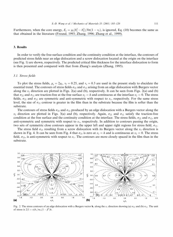
To plot the stress ®elds, ls � 2lf , mf � 0:25, and ms � 0:3 are used in the present study to elucidate theessential trend. The contours of stress ®elds r22 and r12 arising from an edge dislocation with Burgers vectoralong the x1 direction are plotted in Figs. 2(a) and (b), respectively. It can be seen from Figs. 2(a) and (b)that r22 and r12 are traction-free at the free surface x2 � h and continuous at the interface x2 � 0. The stress®elds, r22 and r12 are symmetric and anti-symmetric with respect to x1, respectively. For the same stresslevel, the size of r12 contour is greater in the ®lm than in the substrate because the ®lm is softer than thesubstrate.
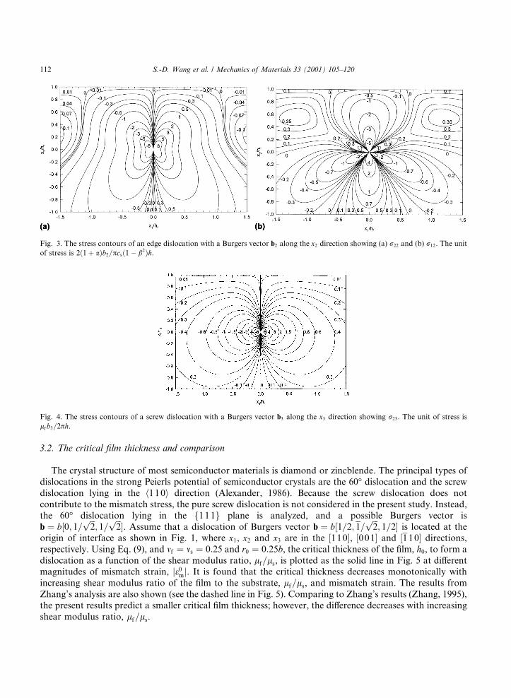
The contours of stress ®elds r22 and r12 produced by an edge dislocation with a Burgers vector along thex2 direction are plotted in Figs. 3(a) and (b), respectively. Again, r22 and r12 satisfy the traction-freecondition at the free surface and the continuity condition at the interface. The stress ®elds, r22 and r12, areanti-symmetric and symmetric with respect to x1, respectively. In addition to contours passing the origin,two sets of symmetric close contours appear in the upper left and upper right regions for stress ®eld, r12.
The stress ®eld r23 resulting from a screw dislocation with its Burgers vector along the x3 direction isshown in Fig. 4. It can be seen from Fig. 4 that r23 is zero at x2 � h and is continuous at x2 � 0. The stress®eld, r23, is anti-symmetric with respect to x1. The contours are more closely spaced in the ®lm than in thesubstrate.
Fig. 2. The stress contours of an edge dislocation with a Burgers vector b1 along the x1 direction showing (a) r22 and (b) r12. The unit
of stress is 2�1� a�b1=pcs�1ÿ b2�h.
S.-D. Wang et al. / Mechanics of Materials 33 (2001) 105±120 111
3.2. The critical ®lm thickness and comparison
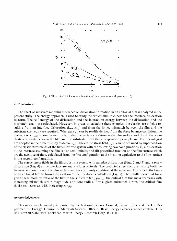
The crystal structure of most semiconductor materials is diamond or zincblende. The principal types ofdislocations in the strong Peierls potential of semiconductor crystals are the 60° dislocation and the screwdislocation lying in the h110i direction (Alexander, 1986). Because the screw dislocation does notcontribute to the mismatch stress, the pure screw dislocation is not considered in the present study. Instead,the 60° dislocation lying in the f1 11g plane is analyzed, and a possible Burgers vector isb � b�0; 1= ���
2p
; 1=���2p �. Assume that a dislocation of Burgers vector b � b�1=2; 1=
���2p
; 1=2� is located at theorigin of interface as shown in Fig. 1, where x1, x2 and x3 are in the �110�, �001� and �110� directions,respectively. Using Eq. (9), and mf � ms � 0:25 and r0 � 0:25b, the critical thickness of the ®lm, h0, to form adislocation as a function of the shear modulus ratio, lf=ls, is plotted as the solid line in Fig. 5 at di�erentmagnitudes of mismatch strain, je0
mj. It is found that the critical thickness decreases monotonically withincreasing shear modulus ratio of the ®lm to the substrate, lf=ls, and mismatch strain. The results fromZhang's analysis are also shown (see the dashed line in Fig. 5). Comparing to Zhang's results (Zhang, 1995),the present results predict a smaller critical ®lm thickness; however, the di�erence decreases with increasingshear modulus ratio, lf=ls.
Fig. 3. The stress contours of an edge dislocation with a Burgers vector b2 along the x2 direction showing (a) r22 and (b) r12. The unit
of stress is 2�1� a�b2=pcs�1ÿ b2�h.
Fig. 4. The stress contours of a screw dislocation with a Burgers vector b3 along the x3 direction showing r23. The unit of stress is
lf b3=2ph.
112 S.-D. Wang et al. / Mechanics of Materials 33 (2001) 105±120
4. Conclusions
The e�ect of substrate modulus di�erence on dislocation formation in an epitaxial ®lm is analyzed in thepresent study. The energy approach is used to study the critical ®lm thickness for the interface dislocationto form. The self-energy of the dislocation and the interaction energy between the dislocation and themismatch strain are calculated. However, in order to calculate these energies, the elastic stress ®elds re-sulting from an interface dislocation (i.e., ra;ij) and from the lattice mismatch between the ®lm and thesubstrate (i.e., rm;ij) are required. Whereas rm;ij can be readily derived from the force balance condition, thederivation of ra;ij is complicated by both the free surface condition at the ®lm surface and the di�erence inelastic constants between the ®lm and the substrate. Both the superposition principle and Fourier integralare adopted in the present study to derive ra;ij. The elastic stress ®eld, ra;ij, can be obtained by superpositionof the elastic stress ®elds of the ®lm/substrate system with the following two con®gurations: (i) a dislocationat the interface assuming the ®lm is also semi-in®nite, and (ii) prescribed traction on the ®lm surface whichare the negative of those calculated from the ®rst con®guration at the location equivalent to the ®lm surfacein the second con®guration.
The elastic stress ®elds in the ®lm/substrate system with an edge dislocation (Figs. 2 and 3) and a screwdislocation (Fig. 4) at the interface are analyzed, respectively. The predicted stress contours satisfy both thefree-surface condition at the ®lm surface and the continuity condition at the interface. The critical thicknessof an epitaxial ®lm to form a dislocation at the interface is calculated (Fig. 5). The results show that for agiven shear modulus ratio of the ®lm to the substrate (i.e., lf=ls), the critical ®lm thickness decreases withincreasing mismatch strain magnitude and core radius. For a given mismatch strain, the critical ®lmthickness decreases with increasing lf=ls.
Acknowledgements
This work was ®nancially supported by the National Science Council, Taiwan (SL), and the US De-partment of Energy, Division of Materials Science, O�ce of Basic Energy Sciences, under contract DE-AC05-96OR22464 with Lockheed Martin Energy Research Corp. (CHH).
Fig. 5. The critical thickness as a function of shear modulus with parameter e0m.
S.-D. Wang et al. / Mechanics of Materials 33 (2001) 105±120 113

Appendix A. The stress ®eld, ra;ij , due to an edge dislocation at the interface
For an isotropically elastic problem, in-plane and anti-plane elastic deformation can be solved sepa-rately. An edge dislocation of Burgers vector �b1; b2; 0� is located at the perfectly bonded interface betweenan epitaxial ®lm of thickness h and a semi-in®nite substrate as shown in Fig. 1. This problem can be solvedby superposition of (1) a dislocation at the ®lm/substrate interface assuming the ®lm is also semi-in®niteand (2) the actual ®lm/substrate system without dislocations but with traction prescribed along the ®lmsurface as the negative of those calculated along x2 � h in case (1). Combination of the stress ®elds from theabove two cases results in a traction-free surface at x2 � h.
The case (1) has been solved by Suo and Hutchinson (1989), such that
r022 � ir0
12 � B2x1
q2
�� i
2b�x2
q2
�� B�1� b�� 4x1x2
2
q4
�� i
2x2
q2
�ÿ 4x3
2
q4
��for x2 6� 0
� B2
x1
�� i2pbd x1� �
�for x2 � 0; �A:1a�
r011 � r0
22 �2�1� b��
q2B�x1
� ÿ ix2� � B�x1 � ix2��; �A:1b�
where
q2 � x21 � x2
2; �A:2a�
B � �1� a� b1 � ib2� �ipcs 1ÿ b2
ÿ � ; �A:2b�
b� � b for x2 > 0;
b� � ÿb for x2 < 0;�A:2c�
where a and cs are de®ned by Eqs. (6e) and (6o), and d is the Dirac delta function.The solutions for case (2) can be obtained using the Fourier transform method (Civelek, 1985). Two
potentials, U�x1; x2� and v�x1; x2�, are used which satisfy:
D2U � 0; Dv � 0;o2v
ox1 ox2
� 1
4DU ; �A:2c�
where D � o2=ox21 � o2=ox2
2. The stresses and the displacements can be obtained from U�x1; x2� and v�x1; x2�,such that
r�11 �o2Uox2
2
; r�22 �o2Uox2
1
; r�12 �ÿo2Uox1ox2
; �A:4a�
2lu�1 � ÿoUox1
� k� � 1� ovox2
; 2lu2 � ÿ oUox2
� k� � 1� ovox1
; �A:4b�
where k is expressed in Eq. (6d). The solutions of stresses and displacements from Eq. (A.4a) and (A.4b) arecontingent upon the solutions of the two potentials, U�x1; x2� and v�x1; x2�.
It is noted that the solution of U�x1; x2� can be separated into two parts: one is symmetric and the other isantisymmetric in changing x1 to ÿx1. The stress ®eld due to an edge dislocation with a Burgers vector b1
along the x1 direction is an example resulting from U�x1; x2� of the symmetric part. In this case, the twopotentials can be represented by Fourier integrals, such that
114 S.-D. Wang et al. / Mechanics of Materials 33 (2001) 105±120
U1 �Z 1
0
B1
x2
��� B2
xx2
�eÿxx2 � B3
x2
�� B4
xx2
�exx2
�cos xx1� � dx; �A:5a�
v1 �Z 1
0
1
2x2�B2eÿxx2 � B4exx2� sin�xx1� dx �A:5b�
for h P x2 P 0 and
U2 �Z 1
0
B5
x2
�� B6
xx2
�exx2 cos xx1� � dx; �A:5c�
v2 �Z 1
0
B6
2x2exx2 sin xx1� � dx �A:5d�
for x26 0 where the coe�cients, Bi �i � 1; 2; 3; 4; 5; 6�, are determined by the boundary conditions. Usingthe traction-free condition at the free surface and the continuity conditions for the stress, r12 and r22, andthe displacements, u1 and u2, at the interface, solutions of Bi �i � 1; 2; 3; 4; 5; 6� are:
Bi � 2ik1
DBi1
� � Bi2
ÿ � hxBi3 � h2x2Bi4
�e2hx
; �A:6a�
D � d1e4hx ÿ �2d2 � 4d3x2h2�e2hx ÿ d4; �A:6b�
where
ik1 � �1� a�b1
pcs 1ÿ b2ÿ � ; �A:7�
B11 � ÿb�lf ÿ ls� lf� ÿ ls � �cf ÿ cs�lfls�; �A:8a�
B12 � ÿ�1ÿ b�cflfls lf
�ÿ ls �
cf ÿ cs� �2
lfls
�� b�lf ÿ ls� lf� ÿ ls ÿ cslfls�; �A:8b�
B13 � �1� b�cflfls 2�lf� ÿ ls� � cf� ÿ cs�lfls� � 2b�lf ÿ ls� lf� ÿ ls ÿ cslfls�; �A:8c�
B14 � 2�1� b��lf ÿ ls� lf� ÿ ls ÿ cslfls�; �A:8d�
B21 � ÿ�1� b��lf ÿ ls� lf� ÿ ls � cf� ÿ cs�lfls�; �A:8e�
2B22 � ÿ 1� b1ÿ b
B23 � B24
2� 2 1� b� �
1ÿ bB41 � B14; �A:8f�
B31 � B13=2; �A:8g�
B32 � ÿb�lf ÿ ls � cflfls��lf ÿ ls ÿ cslfls�; �A:8h�
B33 � 2B32 � b1� b
B34 � 2b1ÿ b
B42 � ÿb1� b
B43; �A:8i�
S.-D. Wang et al. / Mechanics of Materials 33 (2001) 105±120 115

B44 � B64 � 0; �A:8j�
B51 � cflfls
2�2�lf ÿ ls� � �1� b��cf ÿ cs�lfls�; �A:8k�
B52 � cflfls
2� ÿ 2�lf ÿ ls� ÿ �cf ÿ cs�lfls � blfls�cf � cs��; �A:8l�
B53 � cflfls�2�lf ÿ ls� � �1� b�cflfls ÿ �1ÿ b�cslfls�; �A:8m�
B54 � ÿ2�1� b�cflfls�lf ÿ ls ÿ cslfls�; �A:8n�
B61 � ÿ�1ÿ b�cflfls�lf ÿ ls�; �A:8o�
B62 � �1ÿ b�cflfls�lf ÿ ls � cflfls�; �A:8p�
B63 � ÿ 2�1� b�1ÿ b
B62: �A:8q�
The stress ®eld due to an edge dislocation with a Burgers vector b2 along the x2 direction is an exampleresulting from U�x1; x2� of the antisymmetric part. In this case, the two potentials used are:
U3 �Z 1
0
A1
x2
��� A2x2
x
�eÿxx2 � A3
x2
�� A4x2
x
�exx2
�sin�xx1� dx; �A:9a�
v3 �Z 1
0
ÿ 1
2x2�A2eÿxx2 � A4exx2� cos�xx1� dx �A:9b�
for h P x2 P 0 and
U4 �Z 1
0
A5
x2
�� A6
xx2
�exx2 sin�xx1� dx �A:9c�
v4 � ÿ1
2
Z 1
0
A6
x2exx2 cos�xx1� dx �A:9d�
for x26 0. Using the traction-free conditions at the free surface and the continuity conditions at the in-terface, solutions of Ai �i � 1; 2; 3; 4; 5; 6� are
Ai � 2k2
DAi1
� � Ai2
ÿ � hxAi3 � h2x2Ai4
�e2hx
; �A:10�
where
k2 � �1� a�b2
pcs�1ÿ b2� ; �A:11�
A11 � A21=�1� b� � ÿB11=b; �A:12a�
116 S.-D. Wang et al. / Mechanics of Materials 33 (2001) 105±120

A12 � ÿ�lf ÿ ls�2 ÿ �cf ÿ cs�lfls�lf ÿ ls� ÿ�1ÿ b�
2cf�cf ÿ cs�l2
f l2s � bcflfls�lf ÿ ls�; �A:12b�
A13 � ÿ2�lf ÿ ls�2 ÿ 2�cf ÿ cs�lfls�lf ÿ ls� ÿ �1� b�cf�cf ÿ cs�l2f l
2s ÿ 2bcflfls�lf ÿ ls�; �A:12c�
A14 � ÿ2�1� b��lf ÿ ls�2 � 2�1� b�cslfls�lf ÿ ls�; �A:12d�
2A22 � 1� b1ÿ b
A23 � A24
2� ÿ 2�1� b�
�1ÿ b� A41 � A14; �A:12e�
A31 � A13=2; �A:12f�
A32 � A11 ÿ cfcsl2f l
2s ; �A:12g�
A33
2� A34
2�1� b� �A42
bÿ 1� ÿ A43
2�1� b� � A32; �A:12h�
A44 � A64 � 0; �A:12i�
A51 � ÿbcflfls�lf ÿ ls� ÿ1� b
2cf�cf ÿ cs�l2
f l2s ; �A:12j�
A52 � bcflfls�lf ÿ ls� �b2
cf�cf ÿ cs�l2f l
2s ÿ
cf
2�cf � cs�l2
f l2s ; �A:12k�
A53 � ÿ2bcflfls�lf ÿ ls� ÿ cf�cf � cs�l2f l
2s ÿ bcf�cf ÿ cs�l2
f l2s ; �A:12l�
A54 � 2�1� b� cflfls�lf
� ÿ ls� ÿ cfcsl2f l
2s
�; �A:12m�
A61 � �bÿ 1�cflfls�lf ÿ ls�; �A:12n�
A62 � �1ÿ b� cflfls�lf
� ÿ ls� � c2f l
2f l
2s
�; �A:12o�
A63 � 2�1� b��1ÿ b� A62: �A:12p�
The stress ®eld, r�ij, can be obtained by combining Eqs. (A.4a),(A.5a)±(A.5d), (A.8a)±(A.8q), (A.9a)±(A.9d),(A.12a)±(A.12p).
Appendix B. The stress ®eld, ra;ij , due to a screw dislocation at the interface
A screw dislocation of Burgers vector �0 0 b3� located at the perfectly bounded interface of the ®lm/substrate system is considered. The procedure for analyzing the elastic stress ®eld is similar to that of anedge dislocation. Alternatively, the solutions can also be obtained by reducing Chou's solutions (Chou,
S.-D. Wang et al. / Mechanics of Materials 33 (2001) 105±120 117

1966), in which a screw dislocation in a three-phase medium is considered. Hence, without listing thederivation procedures, the stress components, r�23 and r�13, are summarized as follows:
r�23 �leffb3x1
2p
X1n�1
lnfs
x21 � �x2 � 2nh�2
"ÿ lnÿ1
fs
x21 � �x2 ÿ 2nh�2
#; �B:1a�
r�13 �leffb3
2p
X1n�1
lnÿ1fs �x2 ÿ 2nh�
x21 � �x2 ÿ 2nh�2
"ÿ ln
fs�x2 � 2nh�x2
1 � �x2 � 2nh�2#
�B:1b�
for h P x2 P 0, and
r�23 � ÿl2
effb3x1
2plf
X1n�1
lnÿ1fs
x21 � �x2 ÿ 2nh�2
( ); �B:1c�
r�13 �l2
effb3
2plf
X1n�1
lnÿ1fs �x2 ÿ 2nh�
x21 � �x2 ÿ 2nh�2 �B:1d�
for x26 0, where
lfs �lf ÿ ls
lf � ls
: �B:1e�
Appendix C. The core energy
The stress and displacement ®elds due to two semi-in®nite medium are used to calculate the core energy,Ec. The core energy in polar coordinate system is expressed as
Ec � 1
2
Ir0
ijnju0i ds � ÿ 1
2
Z h0�2p
h0
r0rru
0r
ÿ � r0rhu0
h � r0rzu
0z
�r0 dh; �C:1�
where h0 is the cutting angle. u0r , u0
h and r0rr, r0
rh are due to the edge component, and u0z and r0
rz are due to thescrew component. Since r0
rz arising from the screw component is zero along the circle of dislocation core,only the edge component contributes to the core energy. Assume that the Burgers vector of edge componentin complex form is
be � b1 � ib2: �C:2�
The stress and displacements arising from the edge component in the polar coordinate system are obtainedfrom the Cartesian coordinate as
r0rr ÿ ir0
rh � ÿi2�1� K1�bee
ÿih
pcfr0
ÿ i�K2 ÿ K1�beeih
pcfr0
; �C:3a�
2p�kf � 1��u1 � iu2� � i ln�r0��1� K2 ÿ kf�1� K1��be � hbe�1� K2 � �1� K1�kf �� i�1� K1�be�1ÿ ei2h� ÿ 2pbe�kfK1 � K2� � h0be�K2 ÿ 1� kf�K1 ÿ 1�� �C:3b�
118 S.-D. Wang et al. / Mechanics of Materials 33 (2001) 105±120

for h06 h < p,
r0rr ÿ ir0
rh � ÿi2�1� K2�bee
ÿih
pcfr0
� i�K2 ÿ K1�beeih
pcfr0
; �C:3c�
2p�1� kf��u1 � iu2� � lf
ls
i ln�r0�be 1�� � K1 ÿ ks�1� K2�� � �hÿ h0�be 1� � K2 � �1� K1�kf �
� ibe�1� K2��1ÿ ei2h� �C:3d�for p6 h < 2p, and
2p�kf � 1� u01
ÿ � iu02
� � i ln�r0�be 1� � K2 ÿ kf�1� K1�� � hbe 1� � K2 � �1� K1�kf �� i�1� K1�be�1ÿ ei2h� ÿ 4pbe�kfK1 � K2� � h0be K2� ÿ 1� kf�K1 ÿ 1�� �C:3e�
for 2p6 h < 2p� h0. be is the complex conjugate of be. The expression of �r0rr ÿ ir0
rh� in 2p6 h < 2p� h0 isthe same as that in h06 h < p shown in Eq. (C.3a). The displacement in the polar coordinate system can beobtained from the Cartesian coordinate as
u0r � iu0
h � u01
ÿ � iu02
�eÿih: �C:4�
Note that the displacement and stress are continuous at the interface and displacement jump is located ath � h0. These conditions were not satis®ed in Zhang's analysis (Zhang, 1995). After lengthy calculation, thecore energy is
Ec � ÿ 1
4plf c2f
4�1(
� kf��1� K1�b1b2 sin�2h0� � �1� K1� b21
ÿ ÿ b22
�2�1� � kf� cos 2h0 � kfK1
� K2 ÿ kf ÿ 1� ÿ 1
4pc2f
2 b21
ÿ � b22
� �1� K1�2lf
"ÿ �1� K2�2
ls
#
� b21
ÿ ÿ b22
� �1� K2�ls
ks�1� � K2� � 1� K1� � b21
ÿ ÿ b22
�K2� ÿ K1� 1� K1
lf
�ÿ 1� K2
ls
�): �C:5�
If the cutting path is along h0 � p=2, then Eq. (C.5) is reduced to Eq. (7).
References
Alexander, H., 1986. Dislocations in covalent crystals. In: Nabarro, F.R.N. (Ed.), Dislocations in Solids, vol. 7. Elsevier Science,
Amsterdam, pp. 115±234.
Chou, Y.T., 1966. Screw dislocations in and near lamellar inclusions. Phys. Stat. Sol. 17, 509±516.
Civelek, M.B., 1985. Stress intensity factor for a system crack in an in®nite strip. In: Kanninen M.F., Hopper, A.T. (Eds.), Fracture
Mechanics: Sixteenth Symposium, ASTM STP 868. pp. 1±28.
Frank, F.C., Merwe, J.H., 1949. One dimensional dislocations: I. Static theory. Proc. R. Soc. Lond., A 198, 205±216.
Freund, L.B., 1990. The driving force for glide of a threading dislocation in a strained epitaxial layer on a substrate. J. Mech. Phys.
Solids 38, 657±679.
Freund, L.B., 1993. The mechanics of dislocations in strained-layer semiconductor materials. Adv. Appl. Mech. 30, 1±66.
Freund, L.B., Nix, W.D., 1996. A critical thickness condition for a strained complaint substrate/epitaxial ®lm system. Appl. Phys. Lett.
69, 173±175.
Gosling, T.J., Willis, J.R., 1994. The energy of an array of dislocations in an anisotropic half-space. Philos. Mag. A 69, 65±90.
Gutkin, M.Yu., Romanov, A.E., 1992. Screw dislocations in a thin-phase heteroepitaxial plate. Phys. Stat. Sol. 129, 117±126.
Mattews, J.W., Blakeslee, J.W., 1974. Defects in epitaxial multilayers. J. Cryst. Growth 27, 118±125.
S.-D. Wang et al. / Mechanics of Materials 33 (2001) 105±120 119

Suo, Z., Hutchinson, J.W., 1989. Steady state cracking in brittle substrates beneath adherent ®lms. Int. J. Solids Struct. 25, 1337±1353.
Suo, Z., Hutchinson, J.W., 1990. Interface crack between two elastic layers. Int. J. Fract. 43, 1±18.
Willis, J.R., Jain, S.C., Bullough, R., 1990. The energy of an array of dislocations: implications for strain relaxation in semiconductor
heterostructures. Philos. Mag. A 62, 115±129.
Willis, J.R., Jain, S.C., Bullough, R., 1991. The energy of an array of dislocations: II. Consideration of a capped epitaxial layer. Philos.
Mag. A 64, 629±640.
Zhang, T.Y., 1995. E�ect of elastic constants on the critical thickness of an epilayer. Phys. Stat. Sol. (a) 152, 415±429.
Zhang, T.Y., 1996. Isotropic and anisotropic elasticity studies of mismatch dislocations, critical thickness and work hardening in
epilayers. Defect and Di�usion Forum 136&137, 61±106.
Zhang, T.Y., Lee, S., Guido, L.J., Hsueh, C.H., 1999. Criteria for formation of interface dislocations in a ®nite thickness epilayer
deposited on a substrate. J. Appl. Phys. 85, 7579±7586.
120 S.-D. Wang et al. / Mechanics of Materials 33 (2001) 105±120