Effect of loading rate on crack velocities in HSC
12
Author's personal copy Effect of loading rate on crack velocities in HSC Xiao Xin Zhang a, b , Rena C. Yu b , Gonzalo Ruiz b, * , Manuel Tarifa b , Miguel A. Camara b a Harbin Engineering University, Harbin 150001, China b E.T.S. de Ingenieros de Caminos, C. y P., Universidad de Castilla-La Mancha,13071 Ciudad Real, Spain article info Article history: Received 10 July 2009 Received in revised form 23 September 2009 Accepted 4 October 2009 Available online 14 October 2009 Keywords: Crack velocity Crack initiation time Strain incubation rate Strain relaxation rate abstract This paper presents the recent results of an experimental program aimed at disclosing the loading rate (loading-point-displacement rate) effect on the crack velocity in high-strength concrete (HSC). Eighteen three-point-bend tests were conducted using either a servo-hydraulic machine or a self-designed drop- weight impact device. Four strain gauges mounted along the ligament of the specimen were used to measure the crack velocity. Six different loading rates were applied, from 10 4 mm/s to 10 3 mm/s (average strain rate from 10 6 to 10 1 s 1 ), i.e., a low loading-rate range (5.50 10 4 mm/s, 0.55 mm/s and 17.4 mm/s) and a high loading-rate range (8.81 10 2 mm/s, 1.76 10 3 mm/s and 2.64 10 3 mm/s). At low loading rates, the crack propagates with increasing velocity. Under high loading rates, the crack propagates with slightly decreasing velocity, though the maximum crack speed reached up to 20.6% of the Rayleigh wave speed of the tested HSC. In addition, the loading-rate effect on crack velocities is pronounced within the low loading-rate regime, whereas it is minor under the high loading-rate range. Ó 2009 Elsevier Ltd. All rights reserved. 1. Introduction Time-dependent fracture in normal strength concrete (NSC) has been the focus of many researchers for several decades, see [1–31] and the references within for an incomplete list. It is commonly accepted that, according to Wu and Bazant [16], the time-depen- dence of fracture is caused by three phenomena: (a) the inertia effect in the neighborhood of the crack tip, (b) the rate dependence bond-breakage process which produces the fracture surfaces, and (c) viscoelastic behavior or creep in the bulk material. The third phenomenon is negligible for very fast dynamic fracture, whilst the first one is negligible for very slow, static fracture. This has been confirmed by the fact that cohesive models endorsed with static cohesive laws successfully reproduce the dynamic fracture in quasi- brittle materials like concrete [32,33] and ceramics [34], but failed to do so in specimens loaded at low loading rates [35]. For rate- dependent fracture in HSC, however, relative little experimental data is available [36–51]. In order to gain more insight into time- dependent fracture in HSC, we will concentrate on the first and second phenomenon, and endeavor to examine the fracture behavior in HSC from quasi-static to impact loading conditions. Therefore, the competing influences between the inertia effect around the crack tip and the rate-dependent process at the fracture surface is going to be our focus. Since a characteristic and difficult feature of the rate depen- dence in concrete is that it is almost equally pronounced over many orders of magnitude of the loading rate, we employed a servo- hydraulic machine and a drop-weight impact machine to cover loading rates of seven orders of magnitude (from 10 4 mm/s to 10 3 mm/s). In order to measure the crack-propagation velocity, we chose strain-gauge technology, which has been extensively used to investigate the deformation and crack propagation in concrete structures [14,15,28,52,53]. Even though other common techniques, such as high-speed photography [5,54,18] and acoustic emission [55] are also available, they are more complicated. In particular, to cover crack propagation varying from a decimal of a mili-second to some hundreds of seconds, strain-gauge technology appears to be a more feasible solution. An additional advantage of strain-gauge technology is that, from the strain history records, we can also obtain peak strains, average strain rates and crack velocities. Such detailed information over a wide range of loading rates will undoubtedly facilitate the validation of numerical models aimed at disclosing rate dependency. The rest of the paper is structured as follows: the experimental procedure is given in Section 2, in Section 3 observations on strain rates and crack velocities, are presented and discussed. Finally, in Section 4 conclusions are drawn from the results obtained. 2. Experimental procedure 2.1. Material characterization A single HSC was used throughout the experiments, made with porphyry aggregates of 12 mm maximum size and ASTM type IV * Corresponding author. E-mail address: [email protected] (G. Ruiz). Contents lists available at ScienceDirect International Journal of Impact Engineering journal homepage: www.elsevier.com/locate/ijimpeng 0734-743X/$ – see front matter Ó 2009 Elsevier Ltd. All rights reserved. doi:10.1016/j.ijimpeng.2009.10.002 International Journal of Impact Engineering 37 (2010) 359–370
Transcript of Effect of loading rate on crack velocities in HSC

Author's personal copy
Effect of loading rate on crack velocities in HSC
Xiao Xin Zhang a,b, Rena C. Yu b, Gonzalo Ruiz b,*, Manuel Tarifa b, Miguel A. Camara b
a Harbin Engineering University, Harbin 150001, Chinab E.T.S. de Ingenieros de Caminos, C. y P., Universidad de Castilla-La Mancha, 13071 Ciudad Real, Spain
a r t i c l e i n f o
Article history:Received 10 July 2009Received in revised form23 September 2009Accepted 4 October 2009Available online 14 October 2009
Keywords:Crack velocityCrack initiation timeStrain incubation rateStrain relaxation rate
a b s t r a c t
This paper presents the recent results of an experimental program aimed at disclosing the loading rate(loading-point-displacement rate) effect on the crack velocity in high-strength concrete (HSC). Eighteenthree-point-bend tests were conducted using either a servo-hydraulic machine or a self-designed drop-weight impact device. Four strain gauges mounted along the ligament of the specimen were used tomeasure the crack velocity. Six different loading rates were applied, from 10�4 mm/s to 103 mm/s(average strain rate from 10�6 to 10�1 s�1), i.e., a low loading-rate range (5.50� 10�4 mm/s, 0.55 mm/sand 17.4 mm/s) and a high loading-rate range (8.81� 102 mm/s, 1.76� 103 mm/s and 2.64� 103 mm/s).At low loading rates, the crack propagates with increasing velocity. Under high loading rates, the crackpropagates with slightly decreasing velocity, though the maximum crack speed reached up to 20.6% ofthe Rayleigh wave speed of the tested HSC. In addition, the loading-rate effect on crack velocities ispronounced within the low loading-rate regime, whereas it is minor under the high loading-rate range.
� 2009 Elsevier Ltd. All rights reserved.
1. Introduction
Time-dependent fracture in normal strength concrete (NSC) hasbeen the focus of many researchers for several decades, see [1–31]and the references within for an incomplete list. It is commonlyaccepted that, according to Wu and Bazant [16], the time-depen-dence of fracture is caused by three phenomena: (a) the inertiaeffect in the neighborhood of the crack tip, (b) the rate dependencebond-breakage process which produces the fracture surfaces, and(c) viscoelastic behavior or creep in the bulk material. The thirdphenomenon is negligible for very fast dynamic fracture, whilst thefirst one is negligible for very slow, static fracture. This has beenconfirmed by the fact that cohesive models endorsed with staticcohesive laws successfully reproduce the dynamic fracture in quasi-brittle materials like concrete [32,33] and ceramics [34], but failedto do so in specimens loaded at low loading rates [35]. For rate-dependent fracture in HSC, however, relative little experimentaldata is available [36–51]. In order to gain more insight into time-dependent fracture in HSC, we will concentrate on the first andsecond phenomenon, and endeavor to examine the fracturebehavior in HSC from quasi-static to impact loading conditions.Therefore, the competing influences between the inertia effectaround the crack tip and the rate-dependent process at the fracturesurface is going to be our focus.
Since a characteristic and difficult feature of the rate depen-dence in concrete is that it is almost equally pronounced over many
orders of magnitude of the loading rate, we employed a servo-hydraulic machine and a drop-weight impact machine to coverloading rates of seven orders of magnitude (from 10�4 mm/s to103 mm/s). In order to measure the crack-propagation velocity, wechose strain-gauge technology, which has been extensively used toinvestigate the deformation and crack propagation in concretestructures [14,15,28,52,53]. Even though other common techniques,such as high-speed photography [5,54,18] and acoustic emission[55] are also available, they are more complicated. In particular, tocover crack propagation varying from a decimal of a mili-second tosome hundreds of seconds, strain-gauge technology appears to bea more feasible solution. An additional advantage of strain-gaugetechnology is that, from the strain history records, we can alsoobtain peak strains, average strain rates and crack velocities. Suchdetailed information over a wide range of loading rates willundoubtedly facilitate the validation of numerical models aimed atdisclosing rate dependency.
The rest of the paper is structured as follows: the experimentalprocedure is given in Section 2, in Section 3 observations on strainrates and crack velocities, are presented and discussed. Finally, inSection 4 conclusions are drawn from the results obtained.
2. Experimental procedure
2.1. Material characterization
A single HSC was used throughout the experiments, made withporphyry aggregates of 12 mm maximum size and ASTM type IV
* Corresponding author.E-mail address: [email protected] (G. Ruiz).
Contents lists available at ScienceDirect
International Journal of Impact Engineering
journal homepage: www.elsevier .com/locate/ i j impeng
0734-743X/$ – see front matter � 2009 Elsevier Ltd. All rights reserved.doi:10.1016/j.ijimpeng.2009.10.002
International Journal of Impact Engineering 37 (2010) 359–370
Author's personal copy
cement, I42.5L/SR. Micro-silica-fume slurry and super plasticizer(Glenium ACE 325, B255) were added to the concrete composition.The mixing proportions by weight were1:0.336:3.52:1.62:0.3:0.043 (cement: water: coarse aggregate:sand: micro-silica-fume slurry: super plasticizer).
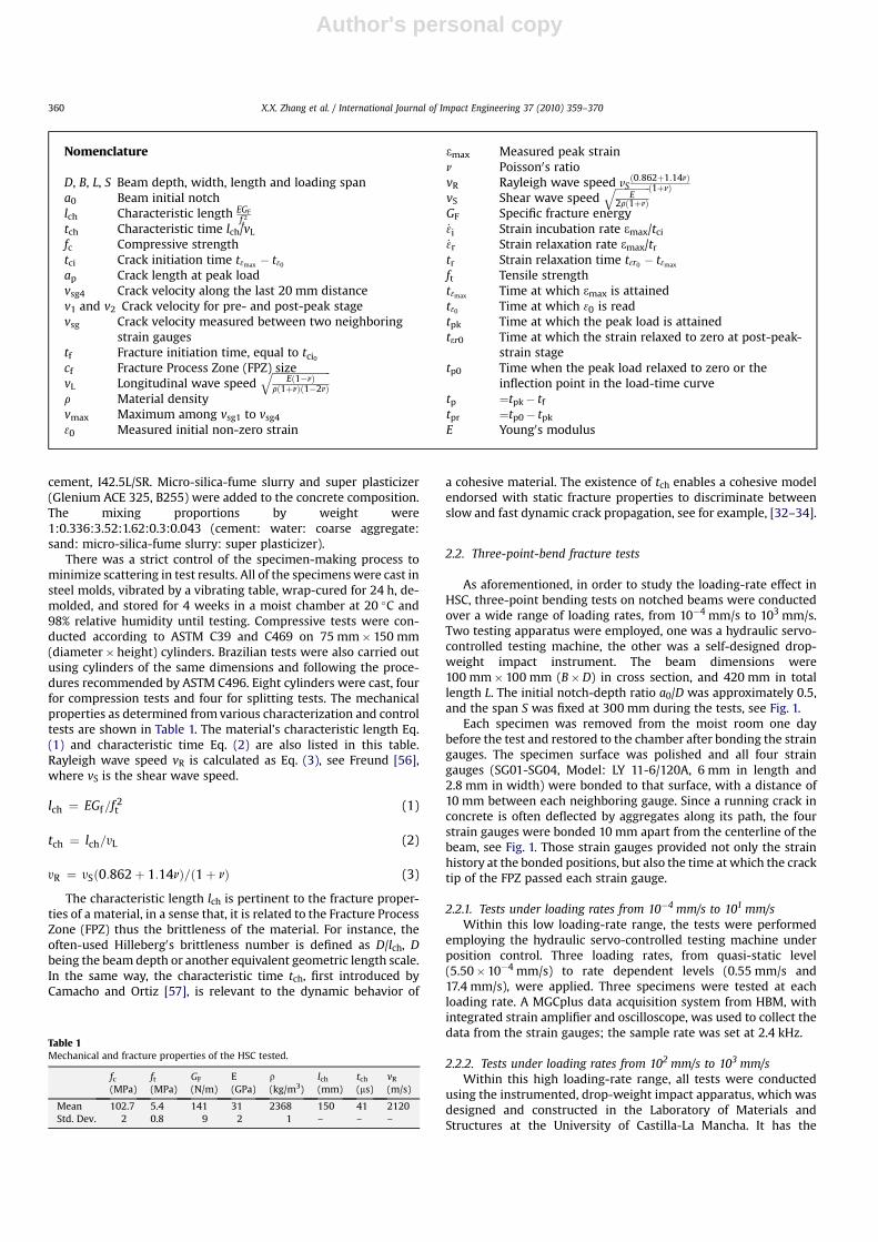
There was a strict control of the specimen-making process tominimize scattering in test results. All of the specimens were cast insteel molds, vibrated by a vibrating table, wrap-cured for 24 h, de-molded, and stored for 4 weeks in a moist chamber at 20 �C and98% relative humidity until testing. Compressive tests were con-ducted according to ASTM C39 and C469 on 75 mm� 150 mm(diameter�height) cylinders. Brazilian tests were also carried outusing cylinders of the same dimensions and following the proce-dures recommended by ASTM C496. Eight cylinders were cast, fourfor compression tests and four for splitting tests. The mechanicalproperties as determined from various characterization and controltests are shown in Table 1. The material’s characteristic length Eq.(1) and characteristic time Eq. (2) are also listed in this table.Rayleigh wave speed vR is calculated as Eq. (3), see Freund [56],where vS is the shear wave speed.
lch ¼ EGf=f 2t (1)
tch ¼ lch=yL (2)
yR ¼ ySð0:862þ 1:14nÞ=ð1þ nÞ (3)
The characteristic length lch is pertinent to the fracture proper-ties of a material, in a sense that, it is related to the Fracture ProcessZone (FPZ) thus the brittleness of the material. For instance, theoften-used Hilleberg0s brittleness number is defined as D/lch, Dbeing the beam depth or another equivalent geometric length scale.In the same way, the characteristic time tch, first introduced byCamacho and Ortiz [57], is relevant to the dynamic behavior of
a cohesive material. The existence of tch enables a cohesive modelendorsed with static fracture properties to discriminate betweenslow and fast dynamic crack propagation, see for example, [32–34].
2.2. Three-point-bend fracture tests
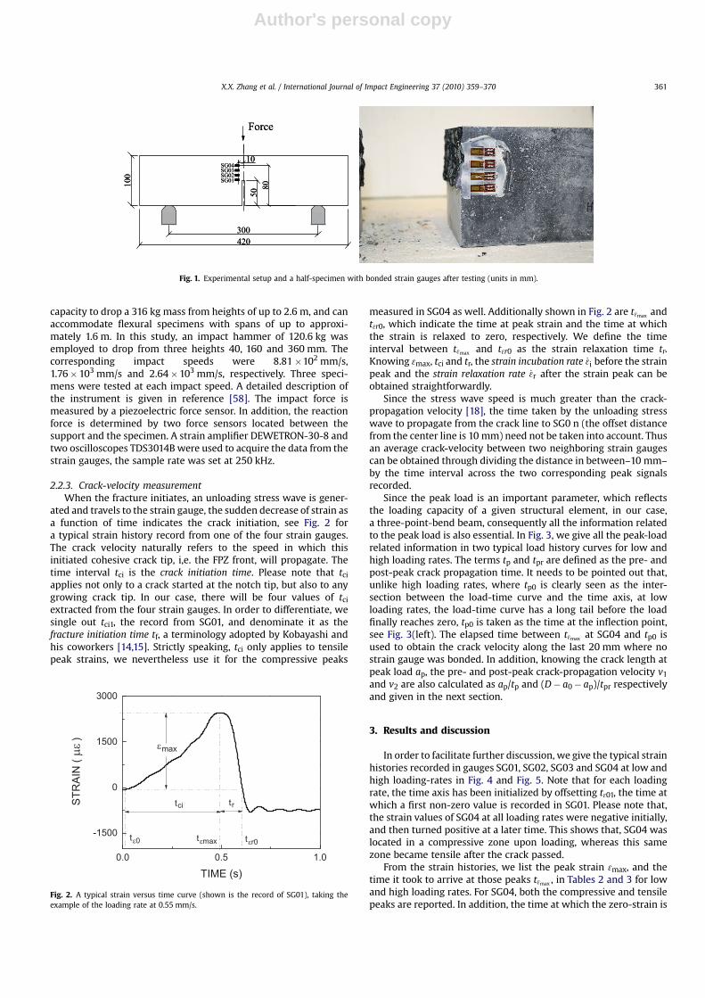
As aforementioned, in order to study the loading-rate effect inHSC, three-point bending tests on notched beams were conductedover a wide range of loading rates, from 10�4 mm/s to 103 mm/s.Two testing apparatus were employed, one was a hydraulic servo-controlled testing machine, the other was a self-designed drop-weight impact instrument. The beam dimensions were100 mm� 100 mm (B�D) in cross section, and 420 mm in totallength L. The initial notch-depth ratio a0/D was approximately 0.5,and the span S was fixed at 300 mm during the tests, see Fig. 1.
Each specimen was removed from the moist room one daybefore the test and restored to the chamber after bonding the straingauges. The specimen surface was polished and all four straingauges (SG01-SG04, Model: LY 11-6/120A, 6 mm in length and2.8 mm in width) were bonded to that surface, with a distance of10 mm between each neighboring gauge. Since a running crack inconcrete is often deflected by aggregates along its path, the fourstrain gauges were bonded 10 mm apart from the centerline of thebeam, see Fig. 1. Those strain gauges provided not only the strainhistory at the bonded positions, but also the time at which the cracktip of the FPZ passed each strain gauge.
2.2.1. Tests under loading rates from 10�4 mm/s to 101 mm/sWithin this low loading-rate range, the tests were performed
employing the hydraulic servo-controlled testing machine underposition control. Three loading rates, from quasi-static level(5.50�10�4 mm/s) to rate dependent levels (0.55 mm/s and17.4 mm/s), were applied. Three specimens were tested at eachloading rate. A MGCplus data acquisition system from HBM, withintegrated strain amplifier and oscilloscope, was used to collect thedata from the strain gauges; the sample rate was set at 2.4 kHz.
2.2.2. Tests under loading rates from 102 mm/s to 103 mm/sWithin this high loading-rate range, all tests were conducted
using the instrumented, drop-weight impact apparatus, which wasdesigned and constructed in the Laboratory of Materials andStructures at the University of Castilla-La Mancha. It has the
Nomenclature
D, B, L, S Beam depth, width, length and loading spana0 Beam initial notchlch Characteristic length EGF
f 2t
tch Characteristic time lch/vL
fc Compressive strengthtci Crack initiation time t3max � t30
ap Crack length at peak loadvsg4 Crack velocity along the last 20 mm distancev1 and v2 Crack velocity for pre- and post-peak stagevsg Crack velocity measured between two neighboring
strain gaugestf Fracture initiation time, equal to tci0
cf Fracture Process Zone (FPZ) sizevL Longitudinal wave speed
ffiffiffiffiffiffiffiffiffiffiffiffiffiffiffiffiffiffiffiffiffiffiffiEð1�nÞ
rð1þnÞð1�2nÞ
q
r Material densityvmax Maximum among vsg1 to vsg4
30 Measured initial non-zero strain
3max Measured peak strainn Poisson0s ratiovR Rayleigh wave speed vS
ð0:862þ1:14nÞð1þnÞ
vS Shear wave speedffiffiffiffiffiffiffiffiffiffiffiffiffiffi
E2rð1þnÞ
q
GF Specific fracture energy_3i Strain incubation rate 3max/tci
_3r Strain relaxation rate 3max/tr
tr Strain relaxation time t3r0 � t3max
ft Tensile strengtht3max Time at which 3max is attainedt30 Time at which 30 is readtpk Time at which the peak load is attainedt3r0 Time at which the strain relaxed to zero at post-peak-
strain stagetp0 Time when the peak load relaxed to zero or the
inflection point in the load-time curvetp ¼tpk� tf
tpr ¼tp0� tpk
E Young0s modulus
Table 1Mechanical and fracture properties of the HSC tested.
fc(MPa)
ft(MPa)
GF
(N/m)E(GPa)
r(kg/m3)
lch
(mm)tch
(ms)vR
(m/s)
Mean 102.7 5.4 141 31 2368 150 41 2120Std. Dev. 2 0.8 9 2 1 – – –
X.X. Zhang et al. / International Journal of Impact Engineering 37 (2010) 359–370360
Author's personal copy
capacity to drop a 316 kg mass from heights of up to 2.6 m, and canaccommodate flexural specimens with spans of up to approxi-mately 1.6 m. In this study, an impact hammer of 120.6 kg wasemployed to drop from three heights 40, 160 and 360 mm. Thecorresponding impact speeds were 8.81�102 mm/s,1.76�103 mm/s and 2.64�103 mm/s, respectively. Three speci-mens were tested at each impact speed. A detailed description ofthe instrument is given in reference [58]. The impact force ismeasured by a piezoelectric force sensor. In addition, the reactionforce is determined by two force sensors located between thesupport and the specimen. A strain amplifier DEWETRON-30-8 andtwo oscilloscopes TDS3014B were used to acquire the data from thestrain gauges, the sample rate was set at 250 kHz.
2.2.3. Crack-velocity measurementWhen the fracture initiates, an unloading stress wave is gener-
ated and travels to the strain gauge, the sudden decrease of strain asa function of time indicates the crack initiation, see Fig. 2 fora typical strain history record from one of the four strain gauges.The crack velocity naturally refers to the speed in which thisinitiated cohesive crack tip, i,e. the FPZ front, will propagate. Thetime interval tci is the crack initiation time. Please note that tci
applies not only to a crack started at the notch tip, but also to anygrowing crack tip. In our case, there will be four values of tci
extracted from the four strain gauges. In order to differentiate, wesingle out tci1, the record from SG01, and denominate it as thefracture initiation time tf, a terminology adopted by Kobayashi andhis coworkers [14,15]. Strictly speaking, tci only applies to tensilepeak strains, we nevertheless use it for the compressive peaks
measured in SG04 as well. Additionally shown in Fig. 2 are t3max andt3r0, which indicate the time at peak strain and the time at whichthe strain is relaxed to zero, respectively. We define the timeinterval between t3max and t3r0 as the strain relaxation time tr.Knowing 3max, tci and tr, the strain incubation rate _3i before the strainpeak and the strain relaxation rate _3r after the strain peak can beobtained straightforwardly.
Since the stress wave speed is much greater than the crack-propagation velocity [18], the time taken by the unloading stresswave to propagate from the crack line to SG0 n (the offset distancefrom the center line is 10 mm) need not be taken into account. Thusan average crack-velocity between two neighboring strain gaugescan be obtained through dividing the distance in between–10 mm–by the time interval across the two corresponding peak signalsrecorded.
Since the peak load is an important parameter, which reflectsthe loading capacity of a given structural element, in our case,a three-point-bend beam, consequently all the information relatedto the peak load is also essential. In Fig. 3, we give all the peak-loadrelated information in two typical load history curves for low andhigh loading rates. The terms tp and tpr are defined as the pre- andpost-peak crack propagation time. It needs to be pointed out that,unlike high loading rates, where tp0 is clearly seen as the inter-section between the load-time curve and the time axis, at lowloading rates, the load-time curve has a long tail before the loadfinally reaches zero, tp0 is taken as the time at the inflection point,see Fig. 3(left). The elapsed time between t3max at SG04 and tp0 isused to obtain the crack velocity along the last 20 mm where nostrain gauge was bonded. In addition, knowing the crack length atpeak load ap, the pre- and post-peak crack-propagation velocity v1
and v2 are also calculated as ap/tp and (D� a0� ap)/tpr respectivelyand given in the next section.
3. Results and discussion
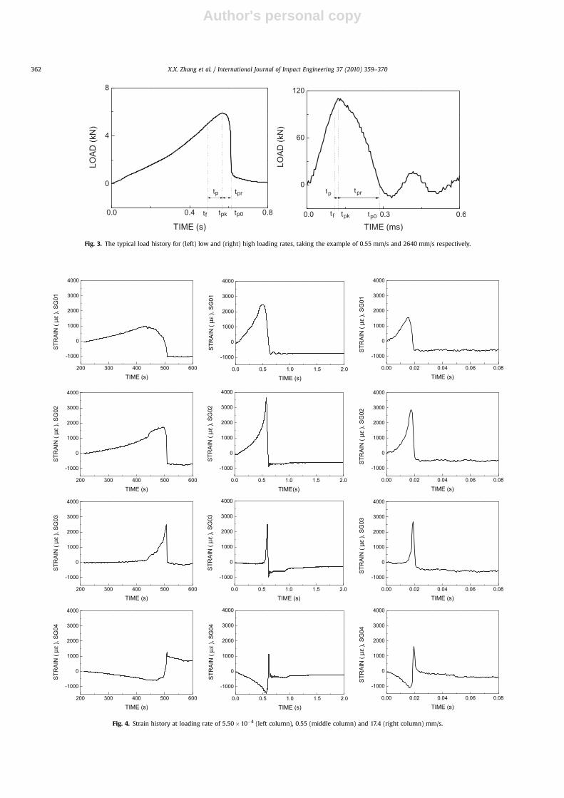
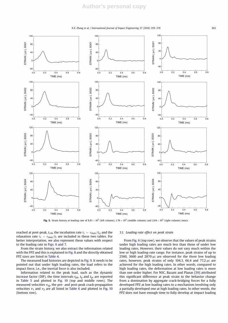
In order to facilitate further discussion, we give the typical strainhistories recorded in gauges SG01, SG02, SG03 and SG04 at low andhigh loading-rates in Fig. 4 and Fig. 5. Note that for each loadingrate, the time axis has been initialized by offsetting t301, the time atwhich a first non-zero value is recorded in SG01. Please note that,the strain values of SG04 at all loading rates were negative initially,and then turned positive at a later time. This shows that, SG04 waslocated in a compressive zone upon loading, whereas this samezone became tensile after the crack passed.
From the strain histories, we list the peak strain 3max, and thetime it took to arrive at those peaks t3max , in Tables 2 and 3 for lowand high loading rates. For SG04, both the compressive and tensilepeaks are reported. In addition, the time at which the zero-strain is
Fig. 2. A typical strain versus time curve (shown is the record of SG01), taking theexample of the loading rate at 0.55 mm/s.
420
100
Force
SG01
50
300
SG02SG03SG04
10
80
420
100
Force
SG01
50
300
SG02SG03SG04
10
80Fig. 1. Experimental setup and a half-specimen with bonded strain gauges after testing (units in mm).
X.X. Zhang et al. / International Journal of Impact Engineering 37 (2010) 359–370 361
Author's personal copy
200 300 400 500 600
-1000
0
1000
2000
3000
4000
STR
AIN
(με )
,SG
01
TIME (s)
200 300 400 500 600
-1000
0
1000
2000
3000
4000
STR
AIN
(με)
,SG
02
TIME (s)
200 300 400 500 600
-1000
0
1000
2000
3000
4000
STR
AIN
(με)
,SG
03
TIME (s)
200 300 400 500 600
-1000
0
1000
2000
3000
4000
STR
AIN
(με)
,SG
04
TIME (s)
0.0 0.5 1.0 1.5 2.0
-1000
0
1000
2000
3000
4000
STR
AIN
(με)
,SG
01
TIME (s)
0.0 0.5 1.0 1.5 2.0
-1000
0
1000
2000
3000
4000
STR
AIN
( με)
,SG
02
TIME(s)
0.0 0.5 1.0 1.5 2.0
-1000
0
1000
2000
3000
4000
STR
AIN
( με)
,SG
03
TIME (s)
0.0 0.5 1.0 1.5 2.0
-1000
0
1000
2000
3000
4000
STR
AIN
(με )
,SG
04
TIME (s)
0.00 0.02 0.04 0.06 0.08
-1000
0
1000
2000
3000
4000
STR
AIN
( με)
,SG
01
TIME (s)
0.00 0.02 0.04 0.06 0.08
-1000
0
1000
2000
3000
4000
STR
AIN
( με)
,SG
02
TIME (s)
0.00 0.02 0.04 0.06 0.08
-1000
0
1000
2000
3000
4000
STR
AIN
(με)
,SG
03
TIME (s)
0.00 0.02 0.04 0.06 0.08
-1000
0
1000
2000
3000
4000
STR
AIN
( με)
,SG
04
TIME (s)
Fig. 4. Strain history at loading rate of 5.50�10�4 (left column), 0.55 (middle column) and 17.4 (right column) mm/s.
Fig. 3. The typical load history for (left) low and (right) high loading rates, taking the example of 0.55 mm/s and 2640 mm/s respectively.
X.X. Zhang et al. / International Journal of Impact Engineering 37 (2010) 359–370362
Author's personal copy
reached at post-peak, t3r0, the incubation rate _3i ¼ 3max=tci and therelaxation rate _3r ¼ 3max=tr are included in these two tables. Forbetter interpretation, we also represent these values with respectto the loading rate in Figs. 6 and 7.
From the strain history, we also extract the information relatedwith the FPZ and this is explained in Fig. 8 and the directly obtainedFPZ sizes are listed in Table 4.
The measured load histories are depicted in Fig. 9. It needs to bepointed out that under high loading rates, the load refers to theimpact force, i.e., the inertial force is also included.
Information related to the peak load, such as the dynamicincrease factor (DIF), the time intervals tpk, tp and tpr are reportedin Table 5 and plotted in Fig. 10 (top and middle rows). Themeasured velocities vsg, the pre- and post-peak crack-propagationvelocities v1 and v2 are all listed in Table 6 and plotted in Fig. 10(bottom row).
3.1. Loading-rate effect on peak strain
From Fig. 6 (top row), we observe that the values of peak strainsunder high loading rates are much less than those of under lowloading rates. However, their values do not vary much within thelow or high loading-rate range. For instance, peak strains of up to2560, 3660 and 2870 m3 are observed for the three low loadingrates, however, peak strains of only 104.3, 66.4 and 77.2 m3 areachieved for the high loading rates. In other words, compared tohigh loading rates, the deformation at low loading rates is morethan one order higher. For NSC, Bazant and Planas [59] attributedthis significant difference at peak strain to the behavior changefrom a domination by aggregate crack-bridging forces for a fullydeveloped FPZ at low loading rates to a mechanism involving onlya partially developed one at high loading rates. In other words, theFPZ does not have enough time to fully develop at impact loading
0.0 0.2 0.4 0.6 0.8
-40
0
40
80
120
STR
AIN
( με
), SG
01
TIME (ms)
0.0 0.2 0.4 0.6 0.8
-40
0
40
80
120
STR
AIN
( με
), SG
02
TIME (ms)
0.0 0.2 0.4 0.6 0.8
-40
0
40
80
120
STR
AIN
( με
), SG
03
TIME (ms)
0.0 0.2 0.4 0.6 0.8
-40
0
40
80
120
STR
AIN
( με
), SG
04
TIME (ms)
0.0 0.2 0.4 0.6 0.8
-40
0
40
80
120
STR
AIN
( με
), SG
01
TIME (ms)
0.0 0.2 0.4 0.6 0.8
-40
0
40
80
120
STR
AIN
( με
), SG
03
TIME (ms)
0.0 0.2 0.4 0.6 0.8
-40
0
40
80
120
STR
AIN
( με
), SG
04
TIME (ms)
0.0 0.2 0.4 0.6 0.8
-40
0
40
80
120
STR
AIN
( με
), SG
01
0.4 0.6 0.8
-40
0
40
80
120
TIME (ms)
0.0 0.2
STR
AIN
( με
), SG
02
0.4 0.6 0.8
-40
0
40
80
120
0.0 0.2 0.4 0.6 0.8
-40
0
40
80
120
STR
AIN
( με
), SG
02
TIME (ms)TIME (ms)
0.0 0.2
STR
AIN
( με
), SG
03
0.4 0.6 0.8
-40
0
40
80
120
TIME (ms)
0.0 0.2
STR
AIN
( με
), SG
04
TIME (ms)
Fig. 5. Strain history at loading rate of 8.81�102 (left column), 1.76� 103 (middle column) and 2.64�103 (right column) mm/s.
X.X. Zhang et al. / International Journal of Impact Engineering 37 (2010) 359–370 363

Author's personal copy
conditions compared with that at quasi-static loading conditions.In HSC, however, we are going to see in Section 3.3, that this is notthe case.
3.2. Loading-rate effect on strain rates
From Fig. 6 (middle row), we observe that, at low loading rates,tci is inversely proportional to the loading rate, while at highloading rates, it remains almost constant. This is the main reasonthat the incubation rate _3i calculated for a strain gauge located atthe same distance to the notch tip, is proportional to the appliedloading-rate within the low loading-rate range, while it remainspractically the same under high loading-rates, see Fig. 6 (bottomrow). It needs to be pointed out that, at high loading rates, at late-stages of the crack propagation, the crack initiation time is of thesame order as the intrinsic time tch. This indicates that a rate-independent or static cohesive model would be able to catch theobserved rate effects. Actually, the numerical results in [35] for NSChave confirmed this aspect.
It is also noteworthy that, the strain incubation rate at SG04 isone or two orders higher than at SG01 through SG03. For example,at 5.5�10�4 mm/s, it covers three orders of magnitude. But underhigh loading rates, the measured incubation rates remain withinthe same order. Taking into consideration the crack velocity
information in Section 3.5, we anticipate that the strain rates, notpeak strains, are closely related to the crack propagation.
In quasi-static conditions, the difference between the appliedand the actually achieved strain rate reaches two orders ofmagnitude, while in the low loading-rate range, this differencedrops to one order, and in the high loading-rate range it falls withinthe same order. In other words, the strain rate becomes lesssensitive to the increase in the loading rate.
As a by product of the compressive strain measurements inSG04, we additionally observe that the compressive strain rate isproportional to the loading rate, this confirms that the compressivebehavior always falls within the elastic domain.
Fig. 7 shows that, at low loading rates, the strain relaxation rate_3r reaches more than one-order higher than the incubation rate,while under high loading rates, the incubation and relaxation strainrates are of the same order, even though the relaxation is almostalways faster. Bazant and Gettu [13] attribute a faster relaxationthan incubation to the creep effect in the FPZ, this experimentalobservation confirms that only a cohesive law with a viscous termwould be able to capture such rate effects.
3.3. Loading-rate effect on the FPZ size
Available methods to measure the extension of the FPZ includeoptical method [60] and multi-cutting technique [40], to give two
Table 2Measured peak strain and strain rates for low loading-rates.
Loading rate (mm/s) Strain Gauges t30 (s) t3max (s) tci (s) m3max _3i (10�6/s) t3r0 (s) tr (s) _3r (10�6/s)
5.5� 10�4 SG01 0 432.5 432.5 1010 2.34 498.7 66.2 15SG02 0 494.3 494.3 1750 3.54 507.9 13.6 129SG03 425.8 506.3 80.5 2560 31.8 509.3 3.0 853SG04c 0 465.9 465.9 �605 �1.3 501.5 35.6 �17SG04t 501.5 507.9 6.4 1890 295 509.6 1.7 1112
(ms) (ms) (ms) m3max (10�3/s) (ms) (ms) (10�3/s)
5.5� 10�1 SG01 0 490 490 2460 5.02 605.8 115.8 21SG02 40 580 540 3660 6.78 615 35 105SG03 540 600 60 2480 41.3 617.5 17.5 142SG04c 46 570 524 �1460 �2.79 600 30 �49SG04t 600 611 11 1120 102 630.4 19.4 58
1.74� 101 SG01 0 15.8 15.8 1570 99.4 18.75 2.95 532SG02 0 17.5 17.5 2870 164 19.90 2.4 1200SG03 13.8 19.2 5.4 2670 494 20.48 1.28 2090SG04c 0 16.7 16.7 �1100 �65.9 18.80 2.1 �524SG04t 18.8 19.6 0.8 1620 2025 21.67 2.07 783
Note: c Data in the compressive zone; t data in the tensile zone.
Table 3Measured strain rates for high loading-rates.
Loading rate (mm/s) Strain Gauges t30 (ms) t3max (ms) tci (ms) m3max _3i (10�3/s) t3r0 (ms) tr (ms) _3r (10�3/s)
881 SG01 0 168 168 47.9 285 252 84 570SG02 0 196 196 74.1 378 288 92 805SG03 16 236 220 104.3 474 324 88 1185SG04c 60 188 128 �10.5 �82 220 32 �328SG04t 220 284 64 83.7 1308 320 36 2325
1760 SG01 0 128 128 53.6 419 176 48 1117SG02 0 156 156 66.4 426 220 64 1038SG03 104 192 88 55.9 635 252 60 932SG04c 32 172 140 �41.6 �300 208 36 �1156SG04t 208 224 16 18.7 1169 244 20 935
2640 SG01 0 108 108 61.6 570 160 52 1185SG02 0 132 132 77.2 585 196 64 1206SG03 76 156 80 59.4 742 200 44 1350SG04c 0 128 128 �47.0 �367 168 40 �1175SG04t 168 184 16 20.3 1269 220 36 564
Note: c Data in the compressive zone; t data in the tensile zone.
X.X. Zhang et al. / International Journal of Impact Engineering 37 (2010) 359–370364

Author's personal copy
examples. Here, we explore the advantage of the strain-gaugetechnology, having in mind that the attainment of peak strainssignals passing of the cohesive crack tip, and strain values relaxedto zero represent a traction-free crack tip. To our knowledge, thisway of measuring the FPZ has not been applied by any otherresearchers in the literature. We explain this methodology todetermine the growth and development of the FPZ in Fig. 8, takingthe example of the loading rate at 2640 mm/s. The upper half of thefigure gives four strain histories recorded in the four strain gauges,with the time at peak strain t3max and the time when the strain
relaxed to zero t3r0 marked with filled squares and circles respec-tively. The time at peak load tpk is also shown to distinguish the preand post-peak crack propagations. The lower half of Fig. 8 showsthe FPZ evolution with time during loading.
The upper limit of the shaded zone shows the evolution of thecohesive crack tip, while the lower one represents the traction-freecrack tip. For instance, in order to know the FPZ ended at SG02, i.e.,when s¼ 0 is reached at t3r02, one needs to know the currentlocation of the cohesive crack tip. From the upper part of Fig. 8, wefind the intersection point between the line t¼ t3r02 and the upper
Fig. 6. Peak strain (top), crack initiation time (middle), and strain incubation rate (bottom) versus loading-rate for low (left column) and high (right column) loading rates.
X.X. Zhang et al. / International Journal of Impact Engineering 37 (2010) 359–370 365

Author's personal copy
Fig. 7. Ratio between the strain incubation and relaxation rate versus loading rate at low (left) and high (right) loading rates.
Fig. 8. Methodology to estimate the development and growth of FPZ. Filled square symbols represent time at peak strain, whereas filled circles stand for time when the strainrelaxed to zero. The upper half shows the strain histories recorded in the four strain gauges; the lower part illustrates the initiation and propagation of the main crack, where theshaded zone is the evolution of the FPZ during loading. The dashed-line-surrounded shadow indicates unconfirmed information due to lack of further measurements. Shown is thecase of the loading rate at 2640 mm/s.

Author's personal copy
limit of the dark shaded zone, the distance between this intersec-tion point and SG02 is the sought FPZ size. Note that, the FPZ wasnot completely developed either within the first nor the last 20 mmdue to boundary effects. Since four strain gauges were employed tomeasure the strain history, at most three FPZ sizes can be directlyobtained, more values can be obtained through interpolation as inFig. 8. We nevertheless list only those directly obtained FPZ sizes inTable 4 separated by a dash ‘‘–’’ sign. If we exclude the possibleboundary effects of the notch and final ligament of each specimen,the central FPZ size in Table 4 should be considered as the materialFPZ size. Surprisingly, the FPZ size remained almost the same whenthe loading rate varied seven orders of magnitude. This is clearlydifferent from NSC, in which the FPZ size actually decreased with
loading rate, see Du et al. [15] and Wittman [61]. As mentionedbefore, this small variation in FPZ size cannot explain the significantdifference in peak strain at different loading rates.
3.4. Loading-rate effect on peak loads
From Fig. 9, note that the peak load increases proportionallywith the loading rate, such rate effect is minor at low loading rateswhile it is pronounced at high loading rates. We define the dynamicincrease factor (DIF) as the ratio of peak load and its correspondingquasi-static value (5.50�10�4 mm/s in this case). The DIF for peakloads are 1.4 and 25.0, for the loading rates of 17.4 mm/s and2.64�103 mm/s, respectively. In other words, the DIF at highloading rates is approximately one-order higher than that at lowloading rates. This trend can be clearly seen in Fig. 10 (top row).
It also needs to be pointed out that in Fig. 9 (bottom row), wehave scaled the load-axis by a factor proportional to its loading rate.Note that the peak load increases slightly faster than its loadingrate. This is mainly due to the significant increase of inertia forces,see [35].
It is noteworthy that, at low loading rates, when the load peak isachieved, the crack length increased from 10 mm and 4 mm(5.5�10�4 and 5.5�10�1 mm/s) to 37 mm (17.4 mm/s); while at
Table 4FPZ size.
Loading rate (mm/s) FPZ size (mm)
5.5� 10�4 14–20–175.5� 10�1 25–471.74� 101 17–21–148.81� 102 23–21–161.76� 103 16–19–152.64� 103 18–21–16
0 250 500 750 1000
0.0
1.4
2.8
4.2
5.6
7.0
SG04SG03
SG02
LOAD
(kN
)
TIME (s)
SG01
0.00 0.02 0.04 0.06 0.08 0.10
0.0
1.4
2.8
4.2
5.6
7.0
SG01
SG02
SG03SG04
LOAD
(kN
)
TIME (s)0.0 0.5 1.0 1.5 2.0
0.0
1.4
2.8
4.2
5.6
7.0
SG04
SG03
SG02
SG01
LOAD
(kN
)
TIME (s)
0.0 0.2 0.4 0.6 0.8-20
0
20
40
SG01
S 2SG04
SG03
IMPA
CT
LOAD
(kN
)
TIME (ms)0.0 0.2 0.4 0.6 0.8
-40
0
40
80
SG04SG03
SG02SG01
IMPA
CT
LOAD
(kN
)
TIME (ms)0.0 0.2 0.4 0.6 0.8
-60
0
60
120 SG02SG03
SG01
SG04
IMPA
CT
LOAD
(kN
)
TIME (ms)
G0
Fig. 9. Load history for low loading rates (top row): 5.50� 10�4 (left), 0.55 (middle) and 17.4 (right) mm/s, and high loading rates (bottom row): 8.81�102 (left), 1.76� 103 (middle)and 2.64�103 (right) mm/s, where SG0 n marks the time at which the strain peak is obtained for strain gauge SG0 n (n¼ 1, 2, 3, 4). Note that for the bottom row, the load-axis isproportionally scaled to its loading rate.
Table 5Peak load and information related to peak load.
Loading rate _3i0 Peak load DIF tf tpk tp (tpk� tf) tp0 tpr (tp0� tpk) ap
(mm/s) (s�1) (kN) (s) (s) (s) (s) (s) (mm)
5.5� 10�4 2.3� 10�6 4.4 1.0 432 494 62 512 18 10
(mm/s) (s�1) (kN) – (ms) (ms) (ms) (ms) (ms) (mm)
5.5� 10�1 5.0� 10�3 5.9 1.3 490 567 77 614 47 41.74� 101 9.9� 10�2 6.3 1.4 15.8 21 5.2 23.8 2.8 37
(mm/s) (s�1) (kN) – (ms) (ms) (ms) (ms) (ms) (mm)
8.81� 102 0.29 30.3 6.9 168 200 32 428.5 228.5 111.76� 103 0.42 63.4 14.4 128 172 44 331.0 159 142.64� 103 0.57 209.9 25.0 108 120 12 284 164 5
X.X. Zhang et al. / International Journal of Impact Engineering 37 (2010) 359–370 367

Author's personal copy
high loading rates, the crack length varied from between 5 and14 mm for all three cases, see Table 5. In particular, for the loadingrate of 17.4 mm/s, t when the peak load is achieved at tpk of 21 ms,SG02 is deformation free at t3r02 of 19.9 ms, this shows the first 10-mm stretch from the notch tip is already traction free.
3.5. Loading-rate effect on crack-propagation velocity
We list the crack velocities in Table 6 and represent the crackvelocity versus loading rate for low and high loading rates in thelogarithmic scale in Fig. 10 (bottom row).
Fig. 10. DIF for peak load (top), time to peak load (middle) and crack-propagation velocity (bottom) versus loading rate for low (left) and high (right) loading-rate range.
Table 6Average crack velocity evolution.
Loading Rate (mm/s) vsg1 SG01-SG02 (m/s) vsg2 SG02-SG03 (m/s) vsg3 SG03-SG04 (m/s) vsg4 (m/s) vmax/vR % Pre-peak v1 (m/s) Post-peak v2 (m/s)
5.50� 10�4 1.9� 10�4 2.7� 10�4 7.3� 10�3 2.1� 10�3 – 2.3� 10�4 1.2� 10�3
5.50� 10�1 0.78 0.73 1.05 3.1 – 0.58 0.731.74� 101 11.2 12.6 16 4.2 – 6.8 4.28.81� 102 292 250 208 138 14.4 344 1711.76� 103 357 278 357 187 17.6 327 2242.64� 103 417 417 387 200 20.6 417 275
X.X. Zhang et al. / International Journal of Impact Engineering 37 (2010) 359–370368

Author's personal copy
In the low loading rate range, on the one hand, for each loadingrate, the crack advances with increasing speed; on the other hand,as the loading rate increases, the crack velocity increases propor-tionally. For instance, at 5.5�10�4 mm/s, the crack velocityincreased by a factor of 38 from 0.19 mm/s for vsg1 to 7.3 mm/s forvsg3; while at the loading rate of 2640 mm/s, the crack speed variedfrom 417 m/s to 357 m/s. When the loading rate increased bya factor of 1000 (from 5.5�10�4 mm/s to 0.55 mm/s), the first-stage crack velocity vsg1 increased by 4100, while the late-stagevelocities vsg3 and vsg4 only increased by a factor of 1369 and 1476respectively. This indicates that, when the loading conditionchanges from quasi-static to low loading rates, the loading rateeffect on the early-stage crack velocity is almost three timesstronger than its effect on the late-stage crack propagation;however, within the low loading rate range, when the loading rateincreased by 34, from 0.55 mm/s to 17.4 mm/s, the increase factorfrom vsg1 to vsg3 remained practically the same (from 14.4 to 17.3).Within the high loading rate range, on the contrary, the crackadvances with decreasing speed, and as loading rate increases, thecrack propagation speed tends to be uniform, this is clearly seenfrom the pre- and post-peak crack velocities. The maximum crackvelocity reached approximately 20.6% of the Rayleigh wave speed.
Comparing the numerically-predicted two-stage crack propa-gation in [35], the experimentally observed pre- and post-peakvelocities in Table 6 suggest that, at low loading rates, pre-peakcrack propagation is stable in a sense that, continuous loading isnecessary for continuous crack advancing, whereas post-peak oneis unstable, since less external load leads to faster crack propaga-tion. On the contrary, at high loading rates, impact loads result fastcrack propagation from the very beginning, less external load atpost-peak is accompanied by a slower crack extension. This is alsodemonstrated in Fig. 10 (middle row), where at low loading rates,the pre-peak crack propagation time tp is more than the post-peakone tpr, whereas the trend is reversed at high loading rates.
3.6. Comparison with published data
Bazant and Gettu [17] studied the fracture process for tpk, thetime to peak load, which varied from 1 s to 250,000 s (2.5 days).Since the initial CMOD rate is difficult to control, they used tpk asa measure of the applied CMOD rate. In the case of time to peak loadof 1 s, the DIF was 1.25, which is consistent with our case of loadingrate at 0.55 mm/s. We list in Table 7 the range of tpk covered bydifferent researchers. Additionally, the observed range of crackvelocities v and the initial strain rate _3i0 are also listed in Table 7.
It bears emphasis that, from Fig. 10 (middle row), it is tp, the timefrom crack initiation to peak load, not tpk, the time from zero load topeak load, that measures the cohesive crack propagation timebefore peak load. Consequently, it is tp not tpk, that determines thepre-peak crack velocity. In other words, tp strictly represents thecrack mouth opening due to the crack growth, whereas tpk alsoembeds the elastic opening of the crack mouth before the crackinitiation.
4. Conclusions
Using strain-gauge technology, employing a servo-hydraulicmachine and a drop-weight impact device, we have measured peakstrains, average strain rates and crack-propagation velocities fora HSC loaded over a wide range of loading rates, from 10�4 mm/s to103 mm/s. The following conclusions can be drawn. (a) Even thoughthe applied loading rates covered seven orders of magnitude, theresultant initial strain rates varied from 10�6 to 10�1/s, five orders ofmagnitude, while the maximum strain rate actually achieved onlyreached four orders of magnitude (10�4 to 100/s). (b) Unlike normalstrength concrete, the FPZ size varied only slightly for strain rates ofsix orders of magnitude. (c) The peak load is sensitive to the loadingrate. Under low loading rates, the rate effect on the peak load isminor, while it is pronounced under high loading rates. (d) Themeasured time to peak load tpk, a measure of the initial CMOD rate,varied from 0.12 m to 494 s. (e) Under low loading rates, the maincrack advances with increasing velocity, the late-stage velocity isone-order higher than the early-stage one; the rate effect on thecrack velocity is remarkable. At high loading rates, the main crackpropagates with a decreasing crack velocity of several hundred m/s,the rate effect on crack velocity is minor. In addition the crack-propagation velocity in the high loading-rate range reached 20% ofthe material’s Rayleigh wave speed. This detailed informationregarding peak strain, strain rates and crack velocities wouldundoubtedly facilitate the validation of numerical models aimed atevaluating the rate dependence of the fracture behavior of HSC.
Acknowledgement
The authors acknowledge the financial support from the Min-isterio de Fomento, (FOM/3856/2006, BOE 19/12/2006,C34/06) andthe Ministerio de Ciencia e Innovacion, MAT2006-09105, Spain.
References
[1] Shah SP, Chandra S. ‘‘Fracture of concrete subjected to cyclic and sustainedloading,’’. ACI Journal 1970;67(10):816–25.
[2] Birkimer D, Lindemann R. ‘‘Dynamic tensile test of concrete materials,’’. ACIMaterials Journal 1971;68:47–9.
[3] Zielinski AJ. ‘‘Model for tensile fracture of concrete at high-rates of loading,’’.Cement and Concrete Research 1984;14(2):215–24.
[4] Biolzi L, Tognon G. ‘‘Strain rate effect on crack-propagation in concrete,’’.Theoretical and Applied Fracture Mechanics Jun 1987;7(3):201–6.
[5] Mindess S, Bentur A. ‘‘A preliminary study of the fracture of concrete beamsunder impact loading, using high-speed photography,’’. Cement and ConcreteResearch 1985;15(3):474–84.
[6] Kormeling H, Rheinhardt H. ‘‘Strain rate effects on steel fiber reinforcedconcrete in uniaxial tension,’’. International Journal of Cement CompositeLight Weight Concrete 1987;9:197–204.
[7] Wittmann PE, Roelfstra PE, Mihashi H, Huang Y-Y, Zhang X-H, Nomura N.‘‘Influence of age of loading, water-cement ratio and rate of loading on fractureenergy of concrete,’’. Materials and Structures 1987;20:103–10.
[8] Banthia N, Mindess S, Bentur A, Pigeon M. ‘‘Impact testing of concrete usinga drop-weight impact machine,’’. Experimental Mechanics Mar1989;29(1):63–9.
[9] Oh BH. ‘‘Fracture-behaviour of concrete under high-rates of loading,’’. Engi-neering Fracture Mechanics 1990;35(1–3):327–32.
Table 7Comparison with published experimental results.
Yon et al. [14] NSC Mindess el al. [18] NSC Bazant and Gettu [13] NSC Current work HSC
B�D� L(mm3) 50� 95� 406 100� 125� 400 38�D� 2.5D 100� 100� 420D/S 4 2.5 2.5 3a/D 0.13 0.0 0.17 0.5tpk (s) 0.0014–0.6 0.002–0.003 1.2–250,000 0.00012–494v (m/s) 0.061–154 �254 �1a 0.00016–417_3i0ðs�1Þ 0.0004–0.24 – – 2.3� 10�6–0.57
a The crack velocity was not measured in the experiments of Bazant and Gettu, since the case of 1.2 s is of the same order as our case for loading-rate of 0.55 mm/s, the 1 m/sfigure given is our estimation.
X.X. Zhang et al. / International Journal of Impact Engineering 37 (2010) 359–370 369

Author's personal copy
[10] Bischoff PH, Perry SH. ‘‘Compressive behavior of concrete at high-strain rates,’’.Materials and Structures Nov 1991;24(144):425–50.
[11] Fu HC, Erki MA, Seckin M. ‘‘Review of effects of loading rate on reinforced-concrete,’’. Journal of Structural Engineering ASCE Dec 1991;117(12):3660–79.
[12] Reinhardt HW, Weerheijm J. ‘‘Tensile fracture of concrete at high loading ratestaking into account inertia and crack velocity effects,’’. International Journal ofFracture Sep 1 1991;51(1):31–42.
[13] Ba�zant Z, Gettu R. ‘‘Rate effects and load relaxation in static fracture ofconcrete,’’. ACI Materials Journal Sep–Oct 1992;89(5):456–68.
[14] Yon J-H, Hawkins NM, Kobayashi AS. ‘‘Strain-rate sensitivity of concretemechanical-properties,’’. ACI Materials Journal Mar–Apr 1992;89(2):146–53.
[15] Du J, Yon J-H, Hawkins NM, Arakawa K, Kobayashi AS. ‘‘Fracture process zonefor concrete for dynamic loading,’’. ACI Materials Journal May–Jun1992;89(3):252–8.
[16] Wu ZS, Ba�zant Z. Finite element modeling of rate effect in concrete fracture withinfluence of creep. In: Bazant, Carol, editors. ‘‘Creep and shrinkage of concrete’’,Proceedings of the fifth international RILEM symposium. London: E & FN Spon;1993. p. 426–32 [ISBN 0419 18630 1].
[17] Ba�zant Z, Gu WH, Faber KT. Softening reversal and other effects of a change inloading rate on fracture of concrete. ACI Materials Journal Jan–Feb1995;92(1):3–9.
[18] Mindess S. Crack velocities in concrete subjected to impact loading. CanadianJournal of Physics May–Jun 1995;73(5-6):310–4.
[19] Ba�zant Z, Li YN. Cohesive crack with rate-dependent opening and viscoelas-ticity: I. mathematical model and scaling. International Journal of Fracture1997;86(3):247–65.
[20] Rossi P, Van Mier JGM, Toutlemonde F, Le Maou F, Boulay C. Effect of loadingrate on the strength of concrete subjected to uniaxial tension. Materials andStructures Jun 1994;27(169):260–4.
[21] Rossi P, Toutlemonde F. Effect of loading rate on the tensile behaviour ofconcrete: description of the physical mechanisms. Materials and StructuresMar 1996;29(186):116–8.
[22] Rossi P. Strain rate effects in concrete structures: the LCPC experience.Materials and Structures Mar 1997:54–62.
[23] Takahashi K, Aggag G, Mada T. Rate dependent impact fracture toughnessanalysis for brittle materials. Journal de Physique IV Aug 1997;7(C3):1033–8.
[24] Kulkarni SM, Shah SP. Response of reinforced concrete beams at high strainrates. ACI Structural Journal Nov–Dec 1998;95(6):705–15.
[25] Lu Y, Xu K. Modelling of dynamic behaviour of concrete materials under blastloading. International Journal of Solids and Structures Jan 2004;41(1):131–43.
[26] Sukontasukkul P, Nimityongskul P, Mindess S. Effect of loading rate on damageof concrete. Cement and Concrete Research Nov 2004;34(11):2127–34.
[27] Denarie E, Cecot C, Huet C. Characterization of creep and crack growthinteractions in the fracture behavior of concrete. Cement and ConcreteResearch Mar 2006;36(3):571–5.
[28] May IM, Chen Yi, Owen DRJ, Feng Y, Thiele PJ. Reinforced concrete beamsunder drop-weight impact loads. Computers and Concrete Apr–Jun 2006;3(2–3):79–90.
[29] Schuler H, Mayrhofer C, Thoma K. Spall experiments for the measurement ofthe tensile strength and fracture energy of concrete at high strain rates.International Journal of Impact Engineering 2006;32:1635–50.
[30] Vegt Il, van Breugel K, Weerheijm J. Failure mechanisms of concrete underimpact loading. In: Carpinteri A, Gambarova PG, Ferro G, Plizzari GA, editors.Fracture mechanics of concrete and concrete structures. Proceedings andmonographs in engineering, water and earth sciences, vol.1–3. London: Taylor &Francis Ltd; 2007. p. 579–87.
[31] Weerheijm J, Van Doormaal A. Tensile failure of concrete at high loading rates:new test data on strength and fracture energy from instrumented spallingtests. International Journal of Impact Engineering Mar 2007;34(3):609–26.
[32] Ruiz G, Ortiz M, Pandolfi A. Three-dimensional finite-element simulation ofthe dynamic brazilian tests on concrete cylinders. International Journal forNumerical Methods in Engineering 2000;48:963–94.
[33] Ruiz G, Pandolfi A, Ortiz M. Three-dimensional cohesive modeling of dynamicmixed-mode fracture. International Journal for Numerical Methods in Engi-neering 2001;52:97–120.
[34] Yu RC, Ruiz G, Pandolfi A. Numerical investigation on the dynamic behavior ofadvanced ceramics. Engineering Fracture Mechanics 2004;71:897–911.
[35] Yu RC, Zhang XX, Ruiz G. Cohesive modeling of dynamic fracture in reinforcedconcrete. Computers and Concrete Aug 2008;5(4):389–400.
[36] Carrasquillo RL, Nilson AH, Slate FO. Properties of high-strength concretesubject to short-term loads. Journal of the American Concrete Institute1981;78(3):171–8.
[37] Smadi MM, Slate FO. Microcracking of high and normal strength concretesunder short-term and long-term loadings. ACI Materials Journal Mar–Apr1989;86(2):117–27.
[38] Comite Euro international du Beton. State of the art report, high strengthconcrete, 197, CEB Bulletin d’Information 1990.
[39] De Larrard F, Acker P. Creep in high and very high performance concrete. In:Malier Y, editor. High performance concrete- from material to structure. Paris:Spon, E. & F.N.; 1992. p. 115–26.
[40] Hu XZ, Wittmann FH. Experimental method to determine extension of frac-ture process zone. Journal of Materials in Civil Engineering 1990;2:15–23.
[41] Jensen JJ. ‘‘Ductility of high strength concrete at high rate loading.’’ In: 3rdInternational symposium on utilization of high strength concrete/highperformance concrete. Norway: Lillehammer; 1993. p. 241–50.
[42] Imam M, Vandewalle L, Mortelmans F. Are current concrete strength testssuitable for high-strength concrete? Materials and Structures Aug–Sep1995;28(181):384–91.
[43] Comite Euro International du Beton. State of the art report, high strengthconcrete, Recommended extensions to the Model Code 90, Research needs,228. CEB Bulletin d’Information, 1995.
[44] Muller HS, Kuttner CH. Characteristics and prediction of creep of highperformance concrete. In: Wittmann FH, Schwesinger P, editors. Highperformance concrete: material properties and design. Proc.of the 4 th Wei-mar workshop on high performance concrete. Freiburg und Unterengstringen:Verlag; 1995. p. 145–62.
[45] Kovler K, Igarashi S, Bentur A. Tensile creep behavior of high strengthconcretes at early ages. Materials and Structures Jun 1999;32(219):383–7.
[46] Le Roy R, De Larrard F, Pons G. ‘‘The AFREM code type model for creep andshrinkage of high performance concrete.’’ In: 4th International symposium onutilization of high strength/high performance concrete. Paris, France; 1996. p.387–96.
[47] Gettu R, Garcia-Alvarez VO, Aguado A. Effect of aging on the fracture char-acteristics and brittleness of a high-strength concrete. Cement and ConcreteResearch Mar 1998;28(3):349–55.
[48] Persson B. ‘‘Quasi-instantaneous and long-term deformations of high-perfor-mance concrete,’’ Doctoral dissertations, Report TVBM.1016: Lund University.Lund, Sweden; 1998.
[49] Rinder T, Reinhardt HW. High strength concrete under sustained tensileloading. In: . Banthia N, . Sakai K, . Gjørv OE, editors. Concrete under severeconditions 3; 2001. p. 1514–21.
[50] Mueller H. Constitutive modelling of high strength/high performanceconcrete-state of the art report. CEB FIP Bulletin 2008;42.
[51] Zhang XX, Ruiz G, Yu RC, Tarifa M. Fracture behavior of high-strength concreteat a wide range of loading rates. International Journal of Impact Engineering2009;36(10–11):1204–9.
[52] Xu S, Reinhardt HW. Determination of double-K criterion for crack propaga-tion in quasi-brittle fracture, Part II: analytical evaluating and practicalmeasuring methods for three-point bending notched beams. InternationalJournal of Fracture 1999;98(2):151–77.
[53] Beppu M, Miwa K, Itoh M, Katayama M, Ohno T. Damage evaluation ofconcrete plates by high-velocity impact. International Journal of ImpactEngineering Dec 2008;35(12):1419–26.
[54] Zehnder AT, Rosakis AJ. Dynamic fracture initiation and propagation in 4340steel under impact loading. International Journal of Fracture 1990;43:271–85.
[55] Maji AK, Ouyang C, Shah SP. Fracture mechanics of quasi-brittle materialsbased on acoustic emission. Materials Research Society 1990;5(1):206–17.
[56] Freund LB. Dynamic fracture mechanics. Cambridge: The Press Syndicate ofthe University of Cambridge; 1998.
[57] Camacho GT, Ortiz M. Computational modelling of impact damage in brittlematerials. International Journal of Solids and Structures 1996;33(20–22):2899–938.
[58] Zhang XX, Ruiz G, Yu RC. A new drop weight impact machine for studyingfracture processes in structural concrete. Strain [Published online: Nov 24,2008], doi:10.1111/j.1475-1305.2008.00574.x.
[59] Ba�zant Z, Planas J. Fracture and size effect in concrete and quasibrittlematerials. Boca Raton, Florida (USA): CRC Press; 1998.
[60] Cedolin L, Poli SD, Iori D. Experimental determination of the fracture processzone in concrete. Cement and Concrete Research 1983;13:557–67.
[61] Wittmann FH. Crack formation and fracture energy of normal and highstrength concrete. Sadhana-Academy Proceedings in Engineering SciencesAug 2002;27(4):413–23.
X.X. Zhang et al. / International Journal of Impact Engineering 37 (2010) 359–370370