
Effect of loading rate on crack velocities in HSC
25
HAL Id: hal-00657568 https://hal.archives-ouvertes.fr/hal-00657568 Submitted on 7 Jan 2012 HAL is a multi-disciplinary open access archive for the deposit and dissemination of sci- entific research documents, whether they are pub- lished or not. The documents may come from teaching and research institutions in France or abroad, or from public or private research centers. L’archive ouverte pluridisciplinaire HAL, est destinée au dépôt et à la diffusion de documents scientifiques de niveau recherche, publiés ou non, émanant des établissements d’enseignement et de recherche français ou étrangers, des laboratoires publics ou privés. Effect of loading rate on crack velocities in HSC Xiaoxin Zhang, Rena C. Yu, Gonzalo Ruiz, Manuel Tarifa, Miguel A. Camara To cite this version: Xiaoxin Zhang, Rena C. Yu, Gonzalo Ruiz, Manuel Tarifa, Miguel A. Camara. Effect of loading rate on crack velocities in HSC. International Journal of Impact Engineering, Elsevier, 2010, 37 (4), pp.359. 10.1016/j.ijimpeng.2009.10.002. hal-00657568
-
Upload
khangminh22 -
Category
Documents
-
view
0 -
download
0
Transcript of Effect of loading rate on crack velocities in HSC
HAL Id: hal-00657568https://hal.archives-ouvertes.fr/hal-00657568
Submitted on 7 Jan 2012
HAL is a multi-disciplinary open accessarchive for the deposit and dissemination of sci-entific research documents, whether they are pub-lished or not. The documents may come fromteaching and research institutions in France orabroad, or from public or private research centers.
L’archive ouverte pluridisciplinaire HAL, estdestinée au dépôt et à la diffusion de documentsscientifiques de niveau recherche, publiés ou non,émanant des établissements d’enseignement et derecherche français ou étrangers, des laboratoirespublics ou privés.
Effect of loading rate on crack velocities in HSCXiaoxin Zhang, Rena C. Yu, Gonzalo Ruiz, Manuel Tarifa, Miguel A. Camara
To cite this version:Xiaoxin Zhang, Rena C. Yu, Gonzalo Ruiz, Manuel Tarifa, Miguel A. Camara. Effect of loading rateon crack velocities in HSC. International Journal of Impact Engineering, Elsevier, 2010, 37 (4), pp.359.�10.1016/j.ijimpeng.2009.10.002�. �hal-00657568�
Accepted Manuscript
Title: Effect of loading rate on crack velocities in HSC
Authors: XiaoXin Zhang, Rena C. Yu, Gonzalo Ruiz, Manuel Tarifa, Miguel A.Camara
PII: S0734-743X(09)00183-3
DOI: 10.1016/j.ijimpeng.2009.10.002
Reference: IE 1840
To appear in: International Journal of Impact Engineering
Received Date: 10 July 2009
Revised Date: 23 September 2009
Accepted Date: 4 October 2009
Please cite this article as: Zhang XX, Yu RC, Ruiz G, Tarifa M, Camara MA. Effect of loadingrate on crack velocities in HSC, International Journal of Impact Engineering (2009), doi: 10.1016/j.ijimpeng.2009.10.002
This is a PDF file of an unedited manuscript that has been accepted for publication. As a service toour customers we are providing this early version of the manuscript. The manuscript will undergocopyediting, typesetting, and review of the resulting proof before it is published in its final form. Pleasenote that during the production process errors may be discovered which could affect the content, and alllegal disclaimers that apply to the journal pertain.

MANUSCRIP
T
ACCEPTED
ARTICLE IN PRESS
Effect of loading rate on crack velocities in HSC
XiaoXin Zhang1,2, Rena C. Yu2, Gonzalo Ruiz2,∗, Manuel Tarifa2, Miguel A. Camara2
1Harbin Engineering University,
Harbin 150001, China2 E.T.S. de Ingenieros de Caminos, C. y P., Universidad de Castilla-La Mancha,
13071 Ciudad Real, Spain∗Corresponding Author: [email protected] (E-mail)
September 23, 2009
Abstract
This paper presents the recent results of an experimental program aimed at disclosingthe loading rate (loading-point-displacement rate) effect on the crack velocity in high-strength concrete (HSC). Eighteen three-point-bend tests were conducted using either aservo-hydraulic machine or a self-designed drop-weight impact device. Four strain gaugesmounted along the ligament of the specimen were used to measure the crack velocity. Sixdifferent loading rates were applied, from 10−4 mm/s to 103 mm/s (average strain ratefrom 10−6 to 10−1 s−1), i.e., a low loading-rate range (5.50×10⁻⁴ mm/s, 0.55 mm/s and17.4 mm/s) and a high loading-rate range (8.81×102 mm/s, 1.76×103 mm/s and 2.64×10³
mm/s). At low loading rates, the crack propagates with increasing velocity. Under highloading rates, the crack propagates with slightly decreasing velocity, though the maximumcrack speed reached up to 20.6% of the Rayleigh wave speed of the tested HSC. In addi-tion, the loading-rate effect on crack velocities is pronounced within the low loading-rateregime, whereas it is minor under the high loading-rate range.
Keywords: Crack velocity, crack initiation time, strain incubation rate, strain relaxation rate
Nomenclature
• E Young′s modulus
• ν Poisson′s ratio
• ρ Material density
• GF Specific fracture energy
• ft Tensile strength
• fc Compressive strength
1

MANUSCRIP
T
ACCEPTED
ARTICLE IN PRESSZhang et al Crack velocities HSC
• vL Longitudinal wave speed√
E(1−ν)ρ(1+ν)(1−2ν)
• vS Shear wave speed√
E2ρ(1+ν)
• vR Rayleigh wave speed vS(0.862+1.14ν)
(1+ν)
• lch Characteristic length EGF
f2t
• tch Characteristic time lch/vL
• εmax Measured peak strain
• tεmax Time at which εmax is attained
• ε0 Measured initial non-zero strain
• tε0 Time at which ε0 is read
• tci Crack initiation time tεmax − tε0
• tf Fracture initiation time, equal to tci0
• tεr0 Time at which the strain relaxed to zero at post-peak-strain stage
• tr Strain relaxation time tεr0 − tεmax
• tpk Time at which the peak load is attained
• tp0 Time when the peak load relaxed to zero or the inflection point in the load-time curve
• tp = tpk − tf
• tpr = tp0 − tpk
• ap Crack length at peak load
• εi Strain incubation rate εmax/tci
• εr Strain relaxation rate εmax/tr
• vsg Crack velocity measured between two neighboring strain gauges
• vsg4 Crack velocity along the last 20 mm distance
• D,B,L, S Beam depth, width, length and loading span
• a0 Beam initial notch
• cf Fracture Process Zone (FPZ) size
• v1 and v2 Crack velocity for pre- and post-peak stage
• vmax Maximum among vsg1 to vsg4
2
MANUSCRIP
T
ACCEPTED
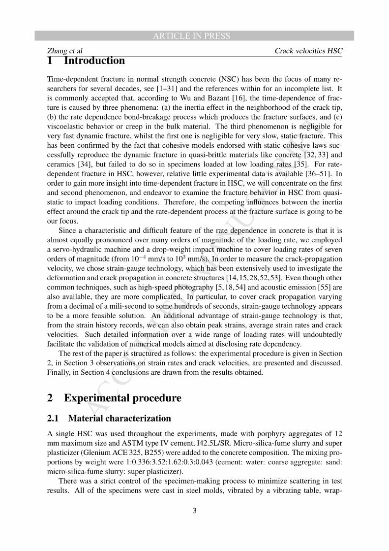
ARTICLE IN PRESSZhang et al Crack velocities HSC1 IntroductionTime-dependent fracture in normal strength concrete (NSC) has been the focus of many re-searchers for several decades, see [1–31] and the references within for an incomplete list. Itis commonly accepted that, according to Wu and Bazant [16], the time-dependence of frac-ture is caused by three phenomena: (a) the inertia effect in the neighborhood of the crack tip,(b) the rate dependence bond-breakage process which produces the fracture surfaces, and (c)viscoelastic behavior or creep in the bulk material. The third phenomenon is negligible forvery fast dynamic fracture, whilst the first one is negligible for very slow, static fracture. Thishas been confirmed by the fact that cohesive models endorsed with static cohesive laws suc-cessfully reproduce the dynamic fracture in quasi-brittle materials like concrete [32, 33] andceramics [34], but failed to do so in specimens loaded at low loading rates [35]. For rate-dependent fracture in HSC, however, relative little experimental data is available [36–51]. Inorder to gain more insight into time-dependent fracture in HSC, we will concentrate on the firstand second phenomenon, and endeavor to examine the fracture behavior in HSC from quasi-static to impact loading conditions. Therefore, the competing influences between the inertiaeffect around the crack tip and the rate-dependent process at the fracture surface is going to beour focus.
Since a characteristic and difficult feature of the rate dependence in concrete is that it isalmost equally pronounced over many orders of magnitude of the loading rate, we employeda servo-hydraulic machine and a drop-weight impact machine to cover loading rates of sevenorders of magnitude (from 10−4 mm/s to 103 mm/s). In order to measure the crack-propagationvelocity, we chose strain-gauge technology, which has been extensively used to investigate thedeformation and crack propagation in concrete structures [14,15,28,52,53]. Even though othercommon techniques, such as high-speed photography [5,18,54] and acoustic emission [55] arealso available, they are more complicated. In particular, to cover crack propagation varyingfrom a decimal of a mili-second to some hundreds of seconds, strain-gauge technology appearsto be a more feasible solution. An additional advantage of strain-gauge technology is that,from the strain history records, we can also obtain peak strains, average strain rates and crackvelocities. Such detailed information over a wide range of loading rates will undoubtedlyfacilitate the validation of numerical models aimed at disclosing rate dependency.
The rest of the paper is structured as follows: the experimental procedure is given in Section2, in Section 3 observations on strain rates and crack velocities, are presented and discussed.Finally, in Section 4 conclusions are drawn from the results obtained.
2 Experimental procedure
2.1 Material characterizationA single HSC was used throughout the experiments, made with porphyry aggregates of 12mm maximum size and ASTM type IV cement, I42.5L/SR. Micro-silica-fume slurry and superplasticizer (Glenium ACE 325, B255) were added to the concrete composition. The mixing pro-portions by weight were 1:0.336:3.52:1.62:0.3:0.043 (cement: water: coarse aggregate: sand:micro-silica-fume slurry: super plasticizer).
There was a strict control of the specimen-making process to minimize scattering in testresults. All of the specimens were cast in steel molds, vibrated by a vibrating table, wrap-
3

MANUSCRIP
T
ACCEPTED
ARTICLE IN PRESSZhang et al Crack velocities HSCcured for 24 hours, de-molded, and stored for 4 weeks in a moist chamber at 20◦C and 98%relative humidity until testing. Compressive tests were conducted according to ASTM C39 andC469 on 75 mm ×150 mm (diameter × height) cylinders. Brazilian tests were also carried outusing cylinders of the same dimensions and following the procedures recommended by ASTMC496. Eight cylinders were cast, four for compression tests and four for splitting tests. Themechanical properties as determined from various characterization and control tests are shownin Tab.1. The material′s characteristic length (Eq.1) and characteristic time (Eq.2) are alsolisted in this table. Rayleigh wave speed vR is calculated as Eq.3, see Freund [56], where vS isthe shear wave speed.
lch = EGf/f2t (1)
tch = lch/vL (2)vR = vS(0.862 + 1.14ν)/(1 + ν) (3)
The characteristic length lch is pertinent to the fracture properties of a material, in a sensethat, it is related to the Fracture Process Zone (FPZ) thus the brittleness of the material. Forinstance, the often-used Hilleberg′s brittleness number is defined as D/lch, D being the beamdepth or another equivalent geometric length scale. In the same way, the characteristic time tch,first introduced by Camacho and Ortiz [57], is relevant to the dynamic behavior of a cohesivematerial. The existence of tch enables a cohesive model endorsed with static fracture propertiesto discriminate between slow and fast dynamic crack propagation, see for example, [32–34].
Table 1: Mechanical and fracture properties of the HSC tested
fc ft GF E ρ lch tch vR(MPa) (MPa) (N/m) (GPa) (kg/m3) (mm) (µs) (m/s)
Mean 102.7 5.4 141 31 2368 150 41 2120Std. Dev. 2 0.8 9 2 1 - - -
2.2 Three-point-bend fracture testsAs aforementioned, in order to study the loading-rate effect in HSC, three-point bending testson notched beams were conducted over a wide range of loading rates, from 10−4 mm/s to 103
mm/s. Two testing apparatus were employed, one was a hydraulic servo-controlled testingmachine, the other was a self-designed drop-weight impact instrument. The beam dimensionswere 100 mm ×100 mm (B×D) in cross section, and 420 mm in total length L. The initialnotch-depth ratio a0/D was approximately 0.5, and the span S was fixed at 300 mm during thetests, see Fig.1.
Each specimen was removed from the moist room one day before the test and restored tothe chamber after bonding the strain gauges. The specimen surface was polished and all fourstrain gauges (SG01-SG04, Model: LY 11-6/120A, 6 mm in length and 2.8 mm in width) werebonded to that surface, with a distance of 10 mm between each neighbouring gauge. Since arunning crack in concrete is often deflected by aggregates along its path, the four strain gaugeswere bonded 10 mm apart from the centerline of the beam, see Fig.1. Those strain gauges
4

MANUSCRIP
T
ACCEPTED
ARTICLE IN PRESSZhang et al Crack velocities HSC
420
100
Force
SG01
50300
SG02SG03SG04
10
80420
100
Force
SG01
50300
SG02SG03SG04
10
80
Figure 1: Experimental setup and a half-specimen with bonded strain gauges after testing (unitsin mm).
provided not only the strain history at the bonded positions, but also the time at which the cracktip of the FPZ passed each strain gauge.
2.2.1 Tests under loading rates from 10−4 mm/s to 101 mm/s
Within this low loading-rate range, the tests were performed employing the hydraulic servo-controlled testing machine under position control. Three loading rates, from quasi-static level(5.50×10⁻⁴ mm/s) to rate dependent levels (0.55 mm/s and 17.4 mm/s), were applied. Threespecimens were tested at each loading rate. A MGCplus data acquisition system from HBM,with integrated strain amplifier and oscilloscope, was used to collect the data from the straingauges; the sample rate was set at 2.4 kHz.
2.2.2 Tests under loading rates from 102 mm/s to 103 mm/s
Within this high loading-rate range, all tests were conducted using the instrumented, drop-weight impact apparatus, which was designed and constructed in the Laboratory of Materialsand Structures at the University of Castilla-La Mancha. It has the capacity to drop a 316 kgmass from heights of up to 2.6 m, and can accommodate flexural specimens with spans of up toapproximately 1.6 m. In this study, an impact hammer of 120.6 kg was employed to drop fromthree heights 40, 160 and 360 mm. The corresponding impact speeds were 8.81×102 mm/s,1.76×103 mm/s and 2.64×103mm/s, respectively. Three specimens were tested at each impactspeed. A detailed description of the instrument is given in reference [58]. The impact force ismeasured by a piezoelectric force sensor. In addition, the reaction force is determined by twoforce sensors located between the support and the specimen. A strain amplifier DEWETRON-30-8 and two oscilloscopes TDS3014B were used to acquire the data from the strain gauges,the sample rate was set at 250 kHz.
2.2.3 Crack-velocity measurement
When the fracture initiates, an unloading stress wave is generated and travels to the straingauge, the sudden decrease of strain as a function of time indicates the crack initiation, seeFig.2 for a typical strain history record from one of the four strain gauges. The crack velocity
5

MANUSCRIP
T
ACCEPTED
ARTICLE IN PRESSZhang et al Crack velocities HSC
Figure 2: A typical strain versus time curve (shown is the record of SG01), taking the exampleof the loading rate at 0.55 mm/s.
Figure 3: The typical load history for (left) low and (right) high loading rates, taking the exam-ple of 0.55 mm/s and 2640 mm/s respectively.
6

MANUSCRIP
T
ACCEPTED
ARTICLE IN PRESSZhang et al Crack velocities HSCnaturally refers to the speed in which this initiated cohesive crack tip, i,e. the FPZ front, willpropagate. The time interval tci is the crack initiation time. Please note that tci applies notonly to a crack started at the notch tip, but also to any growing crack tip. In our case, therewill be four values of tci extracted from the four strain gauges. In order to differentiate,we single out tci1, the record from SG01, and denominate it as the fracture initiation time tf ,a terminology adopted by Kobayashi and his coworkers [14, 15]. Strictly speaking, tci onlyapplies to tensile peak strains, we nevertheless use it for the compressive peaks measured inSG04 as well. Additionally shown in Fig.2 are tεmax and tεr0, which indicate the time at peakstrain and the time at which the strain is relaxed to zero, respectively. We define the timeinterval between tεmax and tεr0 as the strain relaxation time tr. Knowing εmax, tci and tr, thestrain incubation rate εi before the strain peak and the strain relaxation rate εr after the strainpeak can be obtained straightforwardly.
Since the stress wave speed is much greater than the crack propagation velocity [18], thetime taken by the unloading stress wave to propagate from the crack line to SG0n (the offsetdistance from the center line is 10 mm) need not be taken into account. Thus an average crack-velocity between two neighboring strain gauges can be obtained through dividing the distancein between–10 mm– by the time interval across the two corresponding peak signals recorded.
Since the peak load is an important parameter, which reflects the loading capacity of a givenstructural element, in our case, a three-point-bend beam, consequently all the informationrelated to the peak load is also essential. In Fig.3, we give all the peak-load related informationin two typical load history curves for low and high loading rates. The terms tp and tpr aredefined as the pre- and post-peak crack propagation time. It needs to be pointed out that,unlike high loading rates, where tp0 is clearly seen as the intersection between the load-timecurve and the time axis, at low loading rates, the load-time curve has a long tail before theload finally reaches zero, tp0 is taken as the time at the inflection point, see Fig.3(left). Theelapsed time between tεmax at SG04 and tp0 is used to obtain the crack velocity along the last20 mm where no strain gauge was bonded. In addition, knowing the crack length at peak loadap, the pre- and post-peak crack propagation velocity v1 and v2 are also calculated as ap/tpand (D − a0 − ap)/tpr respectively and given in the next section.
3 Results and discussionIn order to facilitate further discussion, we give the typical strain histories recorded in gaugesSG01, SG02, SG03 and SG04 at low and high loading-rates in Fig.4 and Fig.5. Note that foreach loading rate, the time axis has been initialized by offsetting tε01, the time at which a firstnon-zero value is recorded in SG01. Please note that, the strain values of SG04 at all loadingrates were negative initially, and then turned positive at a later time. This shows that, SG04 waslocated in a compressive zone upon loading, whereas this same zone became tensile after thecrack passed.
From the strain histories, we list the peak strain εmax, and the time it took to arrive at thosepeaks tεmax, in Tab.2 and Tab.3 for low and high loading rates. For SG04, both the compressiveand tensile peaks are reported. In addition, the time at which the zero-strain is reached at post-peak, tεr0, the incubation rate εi = εmax/tci and the relaxation rate εr = εmax/tr are includedin these two tables. For better interpretation, we also represent these values with respect to theloading rate in Fig.6 and Fig.7.
7

MANUSCRIP
T
ACCEPTED
ARTICLE IN PRESSZhang et al Crack velocities HSC
From the strain history, we also extract the information related with the FPZ and this isexplained in Fig.8 and the directly obtained FPZ sizes are listed in Tab.4.
The measured load histories are depicted in Fig.9. It needs to be pointed out that under highloading rates, the load refers to the impact force, i.e., the inertial force is also included.
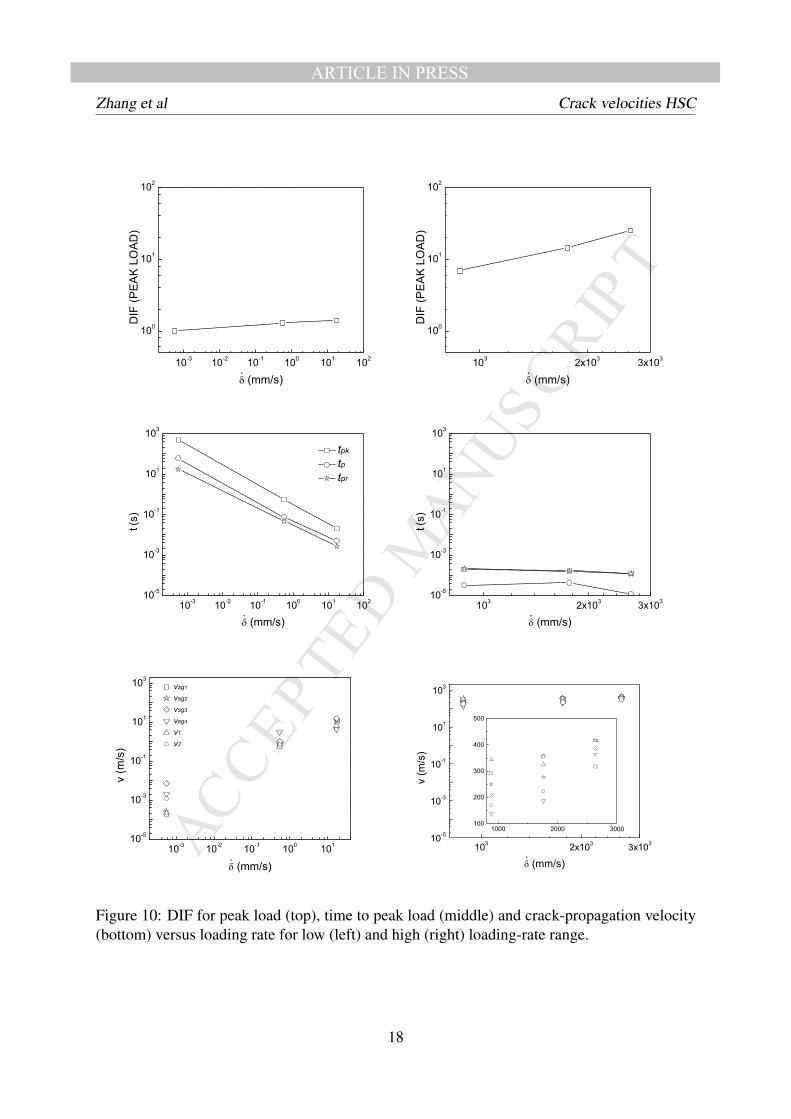
Information related to the peak load, such as the dynamic increase factor (DIF), the timeintervals tpk, tp and tpr are reported in Tab.5 and plotted in Fig.10 (top and middle rows). Themeasured velocities vsg, the pre- and post-peak crack propagation velocities v1 and v2 are alllisted in Tab.6 and plotted in Fig.10 (bottom row).
200 300 400 500 600
-1000
0
1000
2000
3000
4000
ST
RA
IN (
µ!
),
SG
01
TIME (s)
200 300 400 500 600
-1000
0
1000
2000
3000
4000
ST
RA
IN (
µ!
),
SG
02
TIME (s)
200 300 400 500 600
-1000
0
1000
2000
3000
4000
ST
RA
IN (
µ!
),
SG
03
TIME (s)
200 300 400 500 600
-1000
0
1000
2000
3000
4000
ST
RA
IN (
µ!
),
SG
04
TIME (s)
0.0 0.5 1.0 1.5 2.0
-1000
0
1000
2000
3000
4000
ST
RA
IN (
µ!
),
SG
01
TIME (s)
0.0 0.5 1.0 1.5 2.0
-1000
0
1000
2000
3000
4000
ST
RA
IN (
µ!
),
SG
02
TIME(s)
0.0 0.5 1.0 1.5 2.0
-1000
0
1000
2000
3000
4000
ST
RA
IN (
µ!
),
SG
03
TIME (s)
0.0 0.5 1.0 1.5 2.0
-1000
0
1000
2000
3000
4000
ST
RA
IN (
µ!
),
SG
04
TIME (s)
0.00 0.02 0.04 0.06 0.08
-1000
0
1000
2000
3000
4000
ST
RA
IN (
µ!
),
SG
01
TIME (s)
0.00 0.02 0.04 0.06 0.08
-1000
0
1000
2000
3000
4000
ST
RA
IN (
µ!
),
SG
02
TIME (s)
0.00 0.02 0.04 0.06 0.08
-1000
0
1000
2000
3000
4000
ST
RA
IN (
µ!
),
SG
03
TIME (s)
0.00 0.02 0.04 0.06 0.08
-1000
0
1000
2000
3000
4000
ST
RA
IN (
µ!
),
SG
04
TIME (s)
Figure 4: Strain history at loading rate of 5.50×10⁻⁴ (left column), 0.55 (middle column) and17.4 (right column) mm/s.
8

MANUSCRIP
T
ACCEPTED
ARTICLE IN PRESSZhang et al Crack velocities HSC
0.0 0.2 0.4 0.6 0.8
-40
0
40
80
120
ST
RA
IN (
με
), S
G0
1
TIME (ms)
0.0 0.2 0.4 0.6 0.8
-40
0
40
80
120
ST
RA
IN (
με
), S
G0
2
TIME (ms)
0.0 0.2 0.4 0.6 0.8
-40
0
40
80
120
ST
RA
IN (
με
), S
G0
3
TIME (ms)
0.0 0.2 0.4 0.6 0.8
-40
0
40
80
120
ST
RA
IN (
με
), S
G0
4
TIME (ms)
0.0 0.2 0.4 0.6 0.8
-40
0
40
80
120
ST
RA
IN (
με
), S
G01
TIME (ms)
0.0 0.2 0.4 0.6 0.8
-40
0
40
80
120
ST
RA
IN (
με
), S
G0
3
TIME (ms)
0.0 0.2 0.4 0.6 0.8
-40
0
40
80
120
ST
RA
IN (
με
), S
G04
TIME (ms)
0.0 0.2 0.4 0.6 0.8
-40
0
40
80
120
ST
RA
IN (
με
), S
G01
0.4 0.6 0.8
-40
0
40
80
120
TIME (ms)
0.0 0
.2
ST
RA
IN (
με
), S
G02
0.4 0.6 0.8
-40
0
40
80
120
0.0 0.2 0.4 0.6 0.8
-40
0
40
80
120
ST
RA
IN (
με
), S
G02
TIME (ms)
TIME (ms)
0.0 0
.2
ST
RA
IN (
με
), S
G03
0.4 0.6 0.8
-40
0
40
80
120
TIME (ms)
0.0 0.2
ST
RA
IN (
με
), S
G04
TIME (ms)
Figure 5: Strain history at loading rate of 8.81×10² (left column), 1.76×10³ (middle column)
and 2.64×10³ (right column) mm/s.
9

MANUSCRIP
T
ACCEPTED
ARTICLE IN PRESSZhang et al Crack velocities HSC3.1 Loading-rate effect on peak strain
Table 2: Measured peak strain and strain rates for low loading-rates.
Loading Strain tε0 tεmax tci µεmax εi tεr0 tr εrrate (mm/s) Gauges (s) (s) (s) (10−6/s) (s) (s) (10−6/s)5.5×10−4 SG01 0 432.5 432.5 1010 2.34 498.7 66.2 15
SG02 0 494.3 494.3 1750 3.54 507.9 13.6 129SG03 425.8 506.3 80.5 2560 31.8 509.3 3.0 853SG04c 0 465.9 465.9 -605 -1.3 501.5 35.6 -17SG04t 501.5 507.9 6.4 1890 295 509.6 1.7 1112
(ms) (ms) (ms) µεmax (10−3/s) (ms) (ms) (10−3/s)5.5×10−1 SG01 0 490 490 2460 5.02 605.8 115.8 21
SG02 40 580 540 3660 6.78 615 35 105SG03 540 600 60 2480 41.3 617.5 17.5 142SG04c 46 570 524 -1460 -2.79 600 30 -49SG04t 600 611 11 1120 102 630.4 19.4 58
1.74×101 SG01 0 15.8 15.8 1570 99.4 18.75 2.95 532SG02 0 17.5 17.5 2870 164 19.90 2.4 1200SG03 13.8 19.2 5.4 2670 494 20.48 1.28 2090SG04c 0 16.7 16.7 -1100 -65.9 18.80 2.1 -524SG04t 18.8 19.6 0.8 1620 2025 21.67 2.07 783
Note: c Data in the compressive zone; t data in the tensile zone.
From Fig.6 (top row), we observe that the values of peak strains under high loading ratesare much less than those of under low loading rates. However, their values do not vary muchwithin the low or high loading-rate range. For instance, peak strains of up to 2560, 3660 and2870 µε are observed for the three low loading rates, however, peak strains of only 104.3, 66.4and 77.2 µε are achieved for the high loading rates. In other words, compared to high loadingrates, the deformation at low loading rates is more than one order higher. For NSC, Bazant andPlanas [59] attributed this significant difference at peak strain to the behavior change from adomination by aggregate crack-bridging forces for a fully developed FPZ at low loading ratesto a mechanism involving only a partially developed one at high loading rates. In other words,the FPZ does not have enough time to fully develop at impact loading conditions comparedwith that at quasi-static loading conditions. In HSC, however, we are going to see in Section3.3, that this is not the case.
3.2 Loading-rate effect on strain ratesFrom Fig.6 (middle row), we observe that, at low loading rates, tci is inversely proportionalto the loading rate, while at high loading rates, it remains almost constant. This is the mainreason that the incubation rate εi calculated for a strain gauge located at the same distance tothe notch tip, is proportional to the applied loading-rate within the low loading-rate range, whileit remains pratically the same under high loading-rates, see Fig.6 (bottom row). It needs to bepointed out that, at high loading rates, at late-stages of the crack propagation, the crack initiation
10

MANUSCRIP
T
ACCEPTED
ARTICLE IN PRESSZhang et al Crack velocities HSC
Figure 6: Peak strain (top), crack initiation time (middle), and strain incubation rate (bottom)versus loading-rate for low (left column) and high (right column) loading rates.
11
MANUSCRIP
T
ACCEPTED
ARTICLE IN PRESSZhang et al Crack velocities HSC
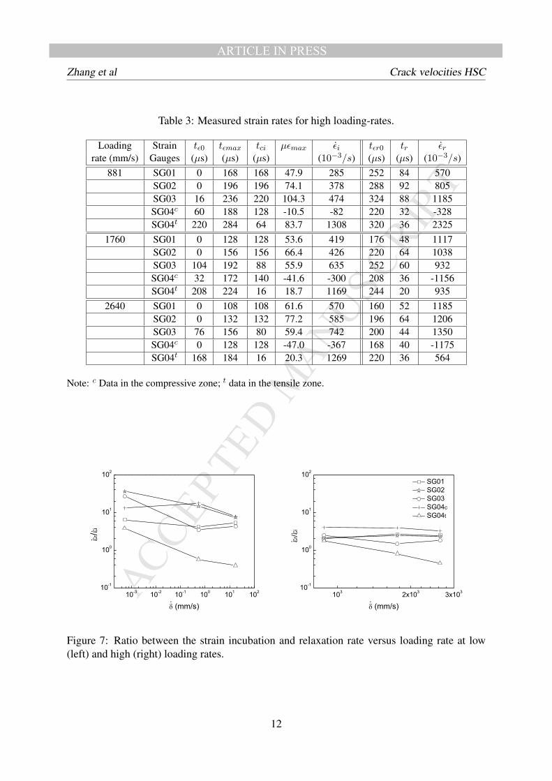
Table 3: Measured strain rates for high loading-rates.
Loading Strain tε0 tεmax tci µεmax εi tεr0 tr εrrate (mm/s) Gauges (µs) (µs) (µs) (10−3/s) (µs) (µs) (10−3/s)
881 SG01 0 168 168 47.9 285 252 84 570SG02 0 196 196 74.1 378 288 92 805SG03 16 236 220 104.3 474 324 88 1185SG04c 60 188 128 -10.5 -82 220 32 -328SG04t 220 284 64 83.7 1308 320 36 2325
1760 SG01 0 128 128 53.6 419 176 48 1117SG02 0 156 156 66.4 426 220 64 1038SG03 104 192 88 55.9 635 252 60 932SG04c 32 172 140 -41.6 -300 208 36 -1156SG04t 208 224 16 18.7 1169 244 20 935
2640 SG01 0 108 108 61.6 570 160 52 1185SG02 0 132 132 77.2 585 196 64 1206SG03 76 156 80 59.4 742 200 44 1350SG04c 0 128 128 -47.0 -367 168 40 -1175SG04t 168 184 16 20.3 1269 220 36 564
Note: c Data in the compressive zone; t data in the tensile zone.
Figure 7: Ratio between the strain incubation and relaxation rate versus loading rate at low(left) and high (right) loading rates.
12

MANUSCRIP
T
ACCEPTED
ARTICLE IN PRESSZhang et al Crack velocities HSCtime is of the same order as the intrinsic time tch. This indicates that a rate-independent or staticcohesive model would be able to catch the observed rate effects. Actually, the numerical resultsin [35] for NSC have confirmed this aspect.
It is also noteworthy that, the strain incubation rate at SG04 is one or two orders higher thanat SG01 through SG03. For example, at 5.5×10⁻⁴ mm/s, it covers three orders of magnitude.But under high loading rates, the measured incubation rates remain within the same order.Taking into consideration the crack velocity information in Section3.5, we anticipate that thestrain rates, not peak strains, are closely related to the crack propagation.
In quasi-static conditions, the difference between the applied and the actually achievedstrain rate reaches two orders of magnitude, while in the low loading-rate range, this differencedrops to one order, and in the high loading-rate range it falls within the same order. In otherwords, the strain rate becomes less sensitive to the increase in the loading rate.
As a by product of the compressive strain measurements in SG04, we additionally observethat the compressive strain rate is proportional to the loading rate, this confirms that the com-pressive behavior always falls within the elastic domain.
Figure 7 shows that, at low loading rates, the strain relaxation rate εr reaches more thanone order higher than the incubation rate, while under high loading rates, the incubation andrelaxation strain rates are of the same order, even though the relaxation is almost always faster.Bazant and Gettu [13] attribute a faster relaxation than incubation to the creep effect in the FPZ,this experimental observation confirms that only a cohesive law with a viscous term would beable to capture such rate effects.
3.3 Loading-rate effect on the FPZ sizeAvailable methods to measure the extension of the FPZ include optical method [60] and multi-cutting technique [40], to give two examples. Here, we explore the advantage of the strain-gauge technology, having in mind that the attainment of peak strains signals passing of thecohesive crack tip, and strain values relaxed to zero represent a traction-free crack tip. To ourknowledge, this way of measuring the FPZ has not been applied by any other researchers inthe literature. We explain this methodology to determine the growth and development of theFPZ in Fig. 8, taking the example of the loading rate at 2640 mm/s. The upper half of thefigure gives four strain histories recorded in the four strain gauges, with the time at peak straintεmax and the time when the strain relaxed to zero tεr0 marked with filled squares and circlesrespectively. The time at peak load tpk is also shown to distinguish the pre and post-peak crackpropagations. The lower half of Fig.8 shows the FPZ evolution with time during loading.
The upper limit of the shaded zone shows the evolution of the cohesive crack tip, while thelower one represents the traction-free crack tip. For instance, in order to know the FPZ endedat SG02, i.e., when σ = 0 is reached at tεr02, one needs to know the current location of thecohesive crack tip. From the upper part of Fig. 8, we find the intersection point between the linet = tεr02 and the upper limit of the dark shaded zone, the distance between this intersectionpoint and SG02 is the sought FPZ size. Note that, the FPZ was not completely developedeither within the first nor the last 20 mm due to boundary effects. Since four strain gaugeswere employed to measure the strain history, at most three FPZ sizes can be directly obtained,more values can be obtained through interpolation as in Fig. 8. We nevertheless list onlythose directly obtained FPZ sizes in Tab. 4 separated by a dash “-” sign. If we excludethe possible boundary effects of the notch and final ligament of each specimen, the central
13

MANUSCRIP
T
ACCEPTED
ARTICLE IN PRESSZhang et al Crack velocities HSC
Figure 8: Methodology to estimate the development and growth of FPZ. Filled square symbolsrepresent time at peak strain, whereas filled circles stand for time when the strain relaxed tozero. The upper half shows the strain histories recorded in the four strain gauges; the lower partillustrates the initiation and propagation of the main crack, where the shaded zone is the evo-lution of the FPZ during loading. The dashed-line-surrounded shadow indicates unconfirmedinformation due to lack of further measurements. Shown is the case of the loading rate at 2640mm/s.
14
MANUSCRIP
T
ACCEPTED
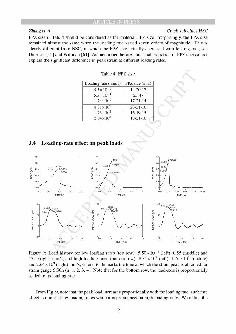
ARTICLE IN PRESSZhang et al Crack velocities HSCFPZ size in Tab. 4 should be considered as the material FPZ size. Surprisingly, the FPZ sizeremained almost the same when the loading rate varied seven orders of magnitude. This isclearly different from NSC, in which the FPZ size actually decreased with loading rate, seeDu et al. [15] and Wittman [61]. As mentioned before, this small variation in FPZ size cannotexplain the significant difference in peak strain at different loading rates.
Table 4: FPZ size
Loading rate (mm/s) FPZ size (mm)5.5×10⁻⁴ 14-20-175.5×10⁻¹ 25-471.74×101 17-21-148.81×10² 23-21-161.76×10³ 16-19-152.64×10³ 18-21-16
3.4 Loading-rate effect on peak loads
0 250 500 750 1000
0.0
1.4
2.8
4.2
5.6
7.0
SG04
SG03
SG02
LO
AD
(kN
)
TIME (s)
SG01
0.00 0.02 0.04 0.06 0.08 0.10
0.0
1.4
2.8
4.2
5.6
7.0
SG01
SG02
SG03SG04
LO
AD
(kN
)
TIME (s)
0.0 0.5 1.0 1.5 2.0
0.0
1.4
2.8
4.2
5.6
7.0
SG04
SG03
SG02
SG01
LO
AD
(kN
)
TIME (s)
0.0 0.2 0.4 0.6 0.8-20
0
20
40
SG01
S 2
SG04
SG03
IMP
AC
T L
OA
D (
kN
)
TIME (ms)
0.0 0.2 0.4 0.6 0.8-40
0
40
80
SG04SG03
SG02SG01
IMP
AC
T L
OA
D (
kN
)
TIME (ms)
0.0 0.2 0.4 0.6 0.8-60
0
60
120SG02SG03
SG01
SG04
IMP
AC
T L
OA
D (
kN
)
TIME (ms)
G0
Figure 9: Load history for low loading rates (top row): 5.50×10⁻⁴ (left), 0.55 (middle) and17.4 (right) mm/s, and high loading rates (bottom row): 8.81×10² (left), 1.76×10³ (middle)and 2.64×10³ (right) mm/s, where SG0n marks the time at which the strain peak is obtained forstrain gauge SG0n (n=1, 2, 3, 4). Note that for the bottom row, the load-axis is proportionallyscaled to its loading rate.
From Fig. 9, note that the peak load increases proportionally with the loading rate, such rateeffect is minor at low loading rates while it is pronounced at high loading rates. We define the
15

MANUSCRIP
T
ACCEPTED
ARTICLE IN PRESSZhang et al Crack velocities HSCdynamic increase factor (DIF) as the ratio of peak load and its corresponding quasi-static value(5.50×10⁻⁴ mm/s in this case). The DIF for peak loads are 1.4 and 25.0, for the loading ratesof 17.4 mm/s and 2.64×103mm/s, respectively. In other words, the DIF at high loading rates isapproximately one order higher than that at low loading rates. This trend can be clearly seen inFig.10 (top row).
It also needs to be pointed out that in Fig.9 (bottom row), we have scaled the load-axis by afactor proportional to its loading rate. Note that the peak load increases slightly faster than itsloading rate. This is mainly due to the significant increase of inertia forces, see [35].
It is noteworthy that, at low loading rates, when the load peak is achieved, the crack lengthincreased from 10 mm and 4 mm (5.5×10⁻⁴ and 5.5×10⁻¹ mm/s) to 37 mm (17.4 mm/s); whileat high loading rates, the crack length varied from between 5 to 14 mm for all three cases, seeTab. 5. In particular, for the loading rate of 17.4 mm/s, when the peak load is achieved at tpk of21 ms, SG02 is deformation free at tεr02 of 19.9 ms, this shows the first 10-mm stretch from thenotch tip is already traction free.
Table 5: Peak load and information related to peak load.
Loading εi0 Peak tf tpk tp tp0 tpr aprate load DIF (tpk- tf ) (tp0- tpk)
(mm/s) (s−1) (kN) (s) (s) (s) (s) (s) (mm)5.5×10⁻⁴ 2.3×10⁻⁶ 4.4 1.0 432 494 62 512 18 10
(mm/s) (s−1) (kN) - (ms) (ms) (ms) (ms) (ms) (mm)5.5×10⁻¹ 5.0×10⁻³ 5.9 1.3 490 567 77 614 47 41.74×101 9.9×10⁻² 6.3 1.4 15.8 21 5.2 23.8 2.8 37
(mm/s) (s−1) (kN) - (µs) (µs) (µs) (µs) (µs) (mm)8.81×10² 0.29 30.3 6.9 168 200 32 428.5 228.5 111.76×10³ 0.42 63.4 14.4 128 172 44 331.0 159 142.64×10³ 0.57 209.9 25.0 108 120 12 284 164 5
3.5 Loading-rate effect on crack propagation velocityWe list the crack velocities in Tab.6 and represent the crack velocity versus loading rate for lowand high loading rates in the logarithmic scale in Fig.10 (bottom row).
In the low loading rate range, on the one hand, for each loading rate, the crack advances withincreasing speed; on the other hand, as the loading rate increases, the crack velocity increasesproportionally. For instance, at 5.5×10⁻⁴ mm/s, the crack velocity increased by a factor of38 from 0.19 mm/s for vsg1 to 7.3 mm/s for vsg3; while at the loading rate of 2640 mm/s, thecrack speed varied from 417 m/s to 357 m/s. When the loading rate increased by a factor of1000 (from 5.5 ×10⁻⁴ mm/s to 0.55 mm/s), the first-stage crack velocity vsg1 increased by4100, while the late-stage velocities vsg3 and vsg4 only increased by a factor of 1369 and 1476respectively. This indicates that, when the loading condition changes from quasi-static to lowloading rates, the loading rate effect on the early-stage crack velocity is almost three timesstronger than its effect on the late-stage crack propagation; however, within the low loadingrate range, when the loading rate increased by 34, from 0.55 mm/s to 17.4 mm/s, the increase
16

MANUSCRIP
T
ACCEPTED
ARTICLE IN PRESSZhang et al Crack velocities HSCfactor from vsg1 to vsg3 remained practically the same (from 14.4 to 17.3). Within the highloading rate range, on the contrary, the crack advances with decreasing speed, and as loadingrate increases, the crack propagation speed tends to be uniform, this is clearly seen from the pre-and post-peak crack velocities. The maximum crack velocity reached approximately 20.6% ofthe Rayleigh wave speed.
Comparing the numerically-predicted two-stage crack propagation in [35], the experimen-tally observed pre- and post-peak velocities in Tab. 6 suggest that, at low loading rates, pre-peak crack propagation is stable in a sense that, continuous loading is necessary for continu-ous crack advancing, whereas post-peak one is unstable, since less external load leads to fastercrack propagation. On the contrary, at high loading rates, impact loads result fast crack prop-agation from the very beginning, less external load at post-peak is accompanied by a slowercrack extension. This is also demonstrated in Fig. 10 (middle row), where at low loading rates,the pre-peak crack propagation time tp is more than the post-peak one tpr, whereas the trend isreversed at high loading rates.
Table 6: Average crack velocity evolution.
Loading vsg1 vsg2 vsg3 vsg4 vmax/vR Pre-peak Post-peakrate SG01-SG02 SG02-SG03 SG03-SG04 v1 v2
(mm/s) (m/s) (m/s) (m/s) (m/s) % (m/s) (m/s)5.50×10−4 1.9×10⁻⁴ 2.7×10⁻⁴ 7.3×10⁻³ 2.1×10⁻³ - 2.3×10⁻⁴ 1.2×10⁻³
5.50×10⁻¹ 0.78 0.73 1.05 3.1 - 0.58 0.731.74×101 11.2 12.6 16 4.2 - 6.8 4.28.81×102 292 250 208 138 14.4 344 1711.76×103 357 278 357 187 17.6 327 2242.64×103 417 417 387 200 20.6 417 275
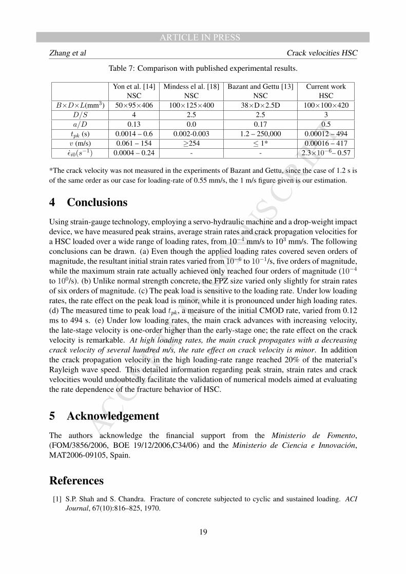
3.6 Comparison with published dataBazant and Gettu [17] studied the fracture process for tpk, the time to peak load, which variedfrom 1 s to 250,000 s (2.5 days). Since the initial CMOD rate is difficult to control, they usedtpk as a measure of the applied CMOD rate. In the case of time to peak load of 1s, the DIF was1.25, which is consistent with our case of loading rate at 0.55 mm/s. We list in Table 7 the rangeof tpk covered by different researchers. Additionally, the observed range of crack velocities vand the initial strain rate εi0 are also listed in Tab.7.
It bears emphasis that, from Fig.10 (middle row), it is tp, the time from crack initiationto peak load, not tpk, the time from zero load to peak load, that measures the cohesive crackpropagation time before peak load. Consequently, it is tp not tpk, that determines the pre-peak crack velocity. In other words, tp strictly represents the crack mouth opening due to thecrack growth, whereas tpk also embeds the elastic opening of the crack mouth before the crackinitiation.
17
MANUSCRIP
T
ACCEPTED
ARTICLE IN PRESSZhang et al Crack velocities HSC
Figure 10: DIF for peak load (top), time to peak load (middle) and crack-propagation velocity(bottom) versus loading rate for low (left) and high (right) loading-rate range.
18
MANUSCRIP
T
ACCEPTED
ARTICLE IN PRESSZhang et al Crack velocities HSC
Table 7: Comparison with published experimental results.
Yon et al. [14] Mindess el al. [18] Bazant and Gettu [13] Current workNSC NSC NSC HSC
B×D×L(mm3) 50×95×406 100×125×400 38×D×2.5D 100×100×420D/S 4 2.5 2.5 3a/D 0.13 0.0 0.17 0.5tpk (s) 0.0014 – 0.6 0.002-0.003 1.2 – 250,000 0.00012 – 494v (m/s) 0.061 – 154 ≥254 ≤ 1* 0.00016 – 417εi0(s−1) 0.0004 – 0.24 - - 2.3×10⁻⁶– 0.57
*The crack velocity was not measured in the experiments of Bazant and Gettu, since the case of 1.2 s isof the same order as our case for loading-rate of 0.55 mm/s, the 1 m/s figure given is our estimation.
4 ConclusionsUsing strain-gauge technology, employing a servo-hydraulic machine and a drop-weight impactdevice, we have measured peak strains, average strain rates and crack propagation velocities fora HSC loaded over a wide range of loading rates, from 10−4 mm/s to 103 mm/s. The followingconclusions can be drawn. (a) Even though the applied loading rates covered seven orders ofmagnitude, the resultant initial strain rates varied from 10−6 to 10−1/s, five orders of magnitude,while the maximum strain rate actually achieved only reached four orders of magnitude (10−4
to 100/s). (b) Unlike normal strength concrete, the FPZ size varied only slightly for strain ratesof six orders of magnitude. (c) The peak load is sensitive to the loading rate. Under low loadingrates, the rate effect on the peak load is minor, while it is pronounced under high loading rates.(d) The measured time to peak load tpk, a measure of the initial CMOD rate, varied from 0.12ms to 494 s. (e) Under low loading rates, the main crack advances with increasing velocity,the late-stage velocity is one-order higher than the early-stage one; the rate effect on the crackvelocity is remarkable. At high loading rates, the main crack propagates with a decreasingcrack velocity of several hundred m/s, the rate effect on crack velocity is minor. In additionthe crack propagation velocity in the high loading-rate range reached 20% of the material’sRayleigh wave speed. This detailed information regarding peak strain, strain rates and crackvelocities would undoubtedly facilitate the validation of numerical models aimed at evaluatingthe rate dependence of the fracture behavior of HSC.
5 AcknowledgementThe authors acknowledge the financial support from the Ministerio de Fomento,(FOM/3856/2006, BOE 19/12/2006,C34/06) and the Ministerio de Ciencia e Innovacion,MAT2006-09105, Spain.
References[1] S.P. Shah and S. Chandra. Fracture of concrete subjected to cyclic and sustained loading. ACI
Journal, 67(10):816–825, 1970.
19

MANUSCRIP
T
ACCEPTED
ARTICLE IN PRESSZhang et al Crack velocities HSC
[2] D. Birkimer and R. Lindemann. Dynamic tensile test of concrete materials. ACI Materials Journal,68:47–49, 1971.
[3] A.J. Zielinski. Model for tensile fracture of concrete at high-rates of loading. Cement and ConcreteResearch, 14(2):215–224, 1984.
[4] L. Biolzi and G. Tognon. Strain rate effect on crack-propagation in concrete. Theoretical andApplied Fracture Mechanics, 7(3):201–206, Jun 1987.
[5] S. Mindess and A. Bentur. A preliminary study of the fracture of concrete beams under impactloading, using high-speed photography. Cement and Concrete Research, 15(3):474–484, 1985.
[6] H. Kormeling and H. Rheinhardt. Strain rate effects on steel fiber reinforced concrete in uniaxialtension. International Journal of Cement Composite Light Weight Concrete, 9:197–204, 1987.
[7] P.E. Wittmann, P.E. Roelfstra, H. Mihashi, Y.-Y. Huang, X.-H. Zhang, and N. Nomura. Influenceof age of loading, water-cement ratio and rate of loading on fracture energy of concrete. Materialsand Structures, 20:103–110, 1987.
[8] N. Banthia, S. Mindess, A. Bentur, and M. Pigeon. Impact testing of concrete using a drop-weightimpact machine. Experimental Mechanics, 29(1):63–69, Mar 1989.
[9] B.H. Oh. Fracture-behaviour of concrete under high-rates of loading. Engineering Fracture Me-chanics, 35(1-3):327–332, 1990.
[10] P. H. Bischoff and S. H. Perry. Compressive behavior of concrete at high-strain rates. Materialsand Structures, 24(144):425–450, Nov 1991.
[11] H.C. Fu, M.A. Erki, and M Seckin. Review of effects of loading rate on reinforced-concrete.Journal of Structural Engineering ASCE, 117(12):3660–3679, Dec 1991.
[12] H.W. Reinhardt and J. Weerheijm. Tensile fracture of concrete at high loading rates taking intoaccount inertia and crack velocity effects. International Journal of Fracture, 51(1):31–42, Sep 11991.
[13] Z. Bazant and R. Gettu. Rate effects and load relaxation in static fracture of concrete. ACI Mate-rials Journal, 89(5):456–468, Sep-Oct 1992.
[14] J.-H. Yon, N. M. Hawkins, and A.S. Kobayashi. Strain-rate sensitivity of concrete mechanical-properties. ACI Materials Journal, 89(2):146–153, Mar-Apr 1992.
[15] J. Du, J.-H. Yon, N.M. Hawkins, K. Arakawa, and A. S. Kobayashi. Fracture process zone forconcrete for dynamic loading. ACI Materials Journal, 89(3):252–258, May-Jun 1992.
[16] Z.S. Wu and Z. Bazant. Finite element modeling of rate effect in concrete fracture with influenceof creep, In “Creep and shrinkage of concrete”. Proceedings of the Fifth International RILEMSymposium, Editors, Bazant and Carol, pages 427–432, 1993.
[17] Z. Bazant, W.H. Gu, and K. T. Faber. Softening reversal and other effects of a change in loadingrate on fracture of concrete. ACI Materials Journal, 92(1):3–9, Jan-Feb 1995.
[18] S. Mindess. Crack velocities in concrete subjected to impact loading. Canadian Journal of Physics,73(5-6):310–314, May-Jun 1995.
[19] Z. Bazant and Y.N. Li. Cohesive crack with rate-dependent opening and viscoelasticity: I. mathe-matical model and scaling. International Journal of Fracture, 86(3):247–265, 1997.
20
MANUSCRIP
T
ACCEPTED
ARTICLE IN PRESSZhang et al Crack velocities HSC[20] P. Rossi, J.G.M. Van Mier, F. Toutlemonde, F. Le Maou, and C. Boulay. Effect of loading rate on
the strength of concrete subjected to uniaxial tension. Materials and Structures, 27(169):260–264,Jun 1994.
[21] P. Rossi and F. Toutlemonde. Effect of loading rate on the tensile behaviour of concrete: descriptionof the physical mechanisms. Materials and Structures, 29(186):116–118, Mar 1996.
[22] P. Rossi. Strain rate effects in concrete structures: the LCPC experience. Materials and Structures,pages 54–62, Mar 1997.
[23] K. Takahashi, G. Aggag, and T. Mada. Rate dependent impact fracture toughness analysis forbrittle materials. Journal de Physique IV, 7(C3):1033–1038, Aug 1997.
[24] S. M. Kulkarni and S. P. Shah. Response of reinforced concrete beams at high strain rates. ACIStructural Journal, 95(6):705–715, Nov-Dec 1998.
[25] Y. Lu and K. Xu. Modelling of dynamic behaviour of concrete materials under blast loading.International Journal of Solids and Structures, 41(1):131–143, Jan 2004.
[26] P. Sukontasukkul, P. Nimityongskul, and S. Mindess. Effect of loading rate on damage of concrete.Cement and Concrete Research, 34(11):2127–2134, Nov 2004.
[27] E. Denarie, C. Cecot, and C. Huet. Characterization of creep and crack growth interactions in thefracture behavior of concrete. Cement and Concrete Research, 36(3):571–575, Mar 2006.
[28] I. M. May, Yi Chen, D.R.J. Owen, Y. Feng, and P. J. Thiele. Reinforced concrete beams underdrop-weight impact loads. Computers and Concrete, 3(2-3):79–90, Apr-Jun 2006.
[29] H. Schuler, C. Mayrhofer, and K. Thoma. Spall experiments for the measurement of the tensilestrength and fracture energy of concrete at high strain rates. International Journal of Impact Engi-neering, 32:1635–1650, 2006.
[30] Il. Vegt, K. van Breugel, and J. Weerheijm. Failure mechanisms of concrete under impact loading.In Carpinteri, A and Gambarova, PG and Ferro, G and Plizzari, GA, editor, Fracture Mechanics ofConcrete and Concrete Structures, volume 1-3 of Proceedings and Monographs in Engineering,Water and Earth Sciences, pages 579–587, 2007.
[31] J. Weerheijm and A. Van Doormaal. Tensile failure of concrete at high loading rates: New test dataon strength and fracture energy from instrumented spalling tests. International Journal of ImpactEngineering, 34(3):609–626, Mar 2007.
[32] G. Ruiz, M. Ortiz, and A. Pandolfi. Three-dimensional finite-element simulation of the dynamicbrazilian tests on concrete cylinders. International Journal for Numerical Methods in Engineering,48:963–994, 2000.
[33] G. Ruiz, A. Pandolfi, and M. Ortiz. Three-dimensional cohesive modeling of dynamic mixed-modefracture. International Journal for Numerical Methods in Engineering, 52:97–120, 2001.
[34] R.C. Yu, G. Ruiz, and A. Pandolfi. Numerical investigation on the dynamic behavior of advancedceramics. Engineering Fracture Mechanics, 71:897–911, 2004.
[35] R. C. Yu, X.X. Zhang, and G. Ruiz. Cohesive modeling of dynamic fracture in reinforced concrete.Computers and Concrete, 5(4):389–400, Aug 2008.
21

MANUSCRIP
T
ACCEPTED
ARTICLE IN PRESSZhang et al Crack velocities HSC[36] R.L. Carrasquillo, A.H. Nilson, and F.O. Slate. Properties of high-strength concrete subject to
short-term loads. Journal of the American Concrete Institute, 78(3):171–178, 1981.
[37] M.M. Smadi and F.O. Slate. Microcracking of high and normal strength concretes under short-termand long-term loadings. ACI Materials Journal, 86(2):117–127, Mar-Apr 1989.
[38] Comite Euro international du Beton. State of the art report, high strength concrete. 197. CEBBulletin d’Information, 1990.
[39] F. De Larrard and P. Acker. Creep in high and very high performance concrete. In Y. Malier, editor,High performance concrete- From material to structure, pages 115–126. Spon, E. & F.N., Paris,1992.
[40] X.Z. Hu and F.H. Wittmann. Experimental method to determine extension of fracture process zone.Journal of Materials in Civil Engineering, 2:15–23, 1990.
[41] J.J. Jensen. Ductility of high strength concrete at high rate loading. 3rd International Symposiumon Utilization of High Strength Concrete/High Performance Concrete, pages 241–250, 1993.
[42] M. Imam, L. Vandewalle, and F. Mortelmans. Are current concrete strength tests suitable forhigh-strength concrete? Materials and Structures, 28(181):384–391, Aug-Sep 1995.
[43] Comite Euro International du Beton. State of the art report, high strength concrete, RecommendedExtensions to the Model Code 90, Research Needs. 228. CEB Bulletin d’Information, 1995.
[44] H.S. Muller and C.H. Kuttner. Characteristics and prediction of creep of high performance con-crete. In F.H. Wittmann and P. Schwesinger, editors, High Performance Concrete: Material Prop-erties and Design, Proc. of the 4th Weimar Workshop on High Performance Concrete, pages 145–162, Verlag, Freiburg und Unterengstringen, 1995.
[45] K. Kovler, S. Igarashi, and A. Bentur. Tensile creep behavior of high strength concretes at earlyages. Materials and Structures, 32(219):383–387, Jun 1999.
[46] R. Le Roy, F. De Larrard, and G. Pons. The AFREM code type model for creep and shrinkageof high performance concrete. 4th International Symposium on Utilization of High Strength/HighPerformance Concrete, pages 387–396, 1996.
[47] R. Gettu, V.O. Garcia-Alvarez, and A. Aguado. Effect of aging on the fracture characteristics andbrittleness of a high-strength concrete. Cement and Concrete Research, 28(3):349–355, Mar 1998.
[48] B. Persson. Quasi-instantaneous and long-term deformations of high-performance concrete. Doc-toral dissertations, Report TVBM.1016, Lund University, Lund, Sweden, 1998.
[49] T. Rinder and H.W. Reinhardt. High strength concrete under sustained tensile loading. In Concreteunder severe conditions 3, pages 1514–1521. N. Banthia and K. Sakai and O.E. Gjørv, 2001.
[50] H. Mueller. Constitutive modelling of high strength / high performance concrete-state of the artreport. CEB FIP Bulletin 42, 2008.
[51] X.X. Zhang, G. Ruiz, R. C. Yu, and M. Tarifa. Fracture behavior of high-strength con-crete at a wide range of loading rates. International Journal of Impact Engineering,doi:10.1016/j.ijimpeng.2009.04.007, 2009.
[52] S. Xu and H.W. Reinhardt. Determination of double-K criterion for crack propagation in quasi-brittle fracture, Part II: Analytical evaluating and practical measuring methods for three-point bend-ing notched beams. International Journal of Fracture, 98(2):151–177, 1999.
22

MANUSCRIP
T
ACCEPTED
ARTICLE IN PRESSZhang et al Crack velocities HSC[53] M. Beppu, K. Miwa, M. Itoh, M. Katayama, and T. Ohno. Damage evaluation of concrete plates
by high-velocity impact. International Journal of Impact Engineering, 35(12):1419–1426, Dec2008.
[54] A.T. Zehnder and A.J. Rosakis. Dynamic fracture initiation and propagation in 4340 steel underimpact loading. International Journal of Fracture, 43:271–285, 1990.
[55] A. K. Maji, C. Ouyang, and S. P. Shah. Fracture mechanics of quasi-brittle materials based onacoustic emission. Materials Research Society, 5(1):206–217, 1990.
[56] L.B. Freund. Dynamic fracture mechanics. The Press Syndicate of the University of Cambridge,1998.
[57] G. T. Camacho and M. Ortiz. Computational modelling of impact damage in brittle materials.International Journal of Solids and Structures, 33 (20-22):2899–2938, 1996.
[58] X.X. Zhang, G. Ruiz, and R. C. Yu. A new drop weight impact machine for studying fractureprocesses in structural concrete. Strain, doi: 10.1111/j.1475-1305.2008.00574.x, 2008.
[59] Z. Bazant and J. Planas. Fracture and size effect in concrete and quasibrittle materials. CRC Press,Boca Raton, Florida (USA), 1998.
[60] L. Cedolin, S. D. Poli, and D. Iori. Experimental determination of the fracture process zone inconcrete. Cement and Concrete Research, 13:557–567, 1983.
[61] F.H. Wittmann. Crack formation and fracture energy of normal and high strength concrete.Sadhana-Academy Proceedings in Engineering Sciences, 27(Part 4):413–423, Aug 2002.
23