EFFECT OF IRREGULARITY SHAPE ON FLAT SLAB ...
10
EFFECT OF IRREGULARITY SHAPE ON FLAT SLAB MULTISTOREY BUILDING UNDER LATERAL LOADING USING ETABS Khaja Ateequddin 1 , waseemsohail 2 1 M.Tech, Lords institute of engineering & technology, Himayathsagar, Hyderabad, Telangana, India. Mail Id: [email protected] 2 M. Tech. Asst pro.. Lords institute of engineering & technology, Himayathsagar, Hyderabad, Telangana, India. Mail Id: waseemsohail79@lords.ac.in I. ABSTRACT In order to compete in the ever growing competent market it is very important for a structural engineer to save time, as a sequel to this an attempt is made to analyze and design multistoried building by using a software package Etabs. In the construction industry the need of flat slabs supported on columns in an irregular layout is raising design methods valuated by experimental evidence for flat slabs supported on non rectangular grid or however scarce. To fill thus vacuum different irregular shaped flat slab models are being tested. The building analyzed for the following models: Model 1 : 10 Storey Building with Regular plan Model 2 : 10 Storey Building with Re-entrant corners Model 3 : 10 Storey Building with Re-entrant corner L- Shape Model 4: 10 Storey Building with Vertical Irregularity on one side Model 5: 10 Storey Building with Vertical Irregularity on both side Model 6: 10 Storey Building with Rectangle shape as Diaphragm discontinuity Model 7: 10 Storey Building with Inverse-T as Diaphragm Irregularity For analyzing a multi storied building one has a consider all possible loading and see that the structure is safe against all possible loading conditions. There are several methods for analysis of different frames like kani’s method, cantilever method, portal method, and Matrix method. The present project deals with the analysis of irregular flat slab multistory building under lateral loads like seismic ,wind loads. and to evaluate seismic conditions of a building like lateral displacement, storey drift, base shear, time period. From structural engineering point of view, that challenges to built such taller and taller structures are wind and seismic forces. On taller structure ETAB Pro with its new features surpassed its predecessors , and compotators with its data sharing capabilities with other major software like AutoCAD and MS Excel. We conclude that ETAB is a very powerful tool which can save much time and is very accurate in designs. Thus it is concluded that ETAB package is suitable for the design of a multistoried building. INTRODUCTION The rapid growth of the urban population needs to construct big prestigious buildings for companies and industrial purpose. The construction of multi-storey buildings and large span structures is becoming a necessary part of our living style. A flat slab is a one- way or two-way system with thickenings in the slab at the columns and load bearing walls called „drop panels‟. A JOURNAL OF COMPOSITION THEORY Volume XII Issue VII JULY 2019 ISSN : 0731-6755 Page No: 482
-
Upload
khangminh22 -
Category
Documents
-
view
0 -
download
0
Transcript of EFFECT OF IRREGULARITY SHAPE ON FLAT SLAB ...

EFFECT OF IRREGULARITY SHAPE ON FLAT SLAB MULTISTOREY
BUILDING UNDER LATERAL LOADING USING ETABS
Khaja Ateequddin1, waseemsohail
2
1M.Tech, Lords institute of engineering & technology, Himayathsagar, Hyderabad, Telangana, India.
Mail Id: [email protected]
2 M. Tech. Asst pro.. Lords institute of engineering & technology, Himayathsagar, Hyderabad, Telangana, India.
Mail Id: [email protected]
I. ABSTRACT
In order to compete in the ever growing competent
market it is very important for a structural engineer to
save time, as a sequel to this an attempt is made to
analyze and design multistoried building by using a
software package Etabs. In the construction industry the
need of flat slabs supported on columns in an irregular
layout is raising design methods valuated by
experimental evidence for flat slabs supported on non
rectangular grid or however scarce. To fill thus vacuum
different irregular shaped flat slab models are being
tested. The building analyzed for the following models:
Model 1 : 10 Storey Building with Regular plan
Model 2 : 10 Storey Building with Re-entrant corners
Model 3 : 10 Storey Building with Re-entrant corner L-
Shape
Model 4: 10 Storey Building with Vertical Irregularity
on one side
Model 5: 10 Storey Building with Vertical Irregularity
on both side
Model 6: 10 Storey Building with Rectangle shape as
Diaphragm discontinuity
Model 7: 10 Storey Building with Inverse-T as
Diaphragm Irregularity
For analyzing a multi storied building one has a consider
all possible loading and see that the structure is safe
against all possible loading conditions. There are several
methods for analysis of different frames like kani’s
method, cantilever method, portal method, and Matrix
method.
The present project deals with the analysis of irregular
flat slab multistory building under lateral loads like
seismic ,wind loads. and to evaluate seismic conditions
of a building like lateral displacement, storey drift, base
shear, time period. From structural engineering point of
view, that challenges to built such taller and taller
structures are wind and seismic forces. On taller
structure
ETAB Pro with its new features surpassed its
predecessors , and compotators with its data sharing
capabilities with other major software like AutoCAD
and MS Excel. We conclude that ETAB is a very
powerful tool which can save much time and is very
accurate in designs. Thus it is concluded that ETAB
package is suitable for the design of a multistoried
building.
INTRODUCTION
The rapid growth of the urban population needs to
construct big prestigious buildings for companies and
industrial purpose. The construction of multi-storey
buildings and large span structures is becoming a
necessary part of our living style. A flat slab is a one-
way or two-way system with thickenings in the slab at
the columns and load bearing walls called „drop panels‟.
A JOURNAL OF COMPOSITION THEORY
Volume XII Issue VII JULY 2019
ISSN : 0731-6755
Page No: 482

Drop panels act as T-beams over the supports. This form
of construction has become popular in recent years
because of the large spans of about 10 m for reinforced
slabs and about 12 m for pre-stressed slabs. Reinforced
flat slabs may need to be sensibly pre-cambered (not
overdone) to control deflection.
EFFECT OF STRUCTURAL IRREGULARITIES
Earthquake resistant design of reinforced concrete
buildings is a continuing area of research. In spite of all
the weaknesses in the structure, either code
imperfections or error in analysis and design, the
structural configuration system has played a vital role in
catastrophe. The IS 1893(Part 1):2002 has recommended
building configuration system in Section 7 for the better
performance of RC buildings during earthquakes.
Vertical discontinuities in load path
One of the major contributors to structural damage
in structures during strong earthquake is the
discontinuities/ irregularities in the load path or
load transfer. The diaphragms distribute these
forces to vertical resisting components such as
columns, shear walls, frames and other vertical
elements in the structural system which transfer the
forces into the foundation. The diaphragms must
have adequate stiffness to transmit these forces.
Irregularities in strength and stiffness
A “weak” story is defined as one in which the
story’s lateral strength is less than 80 percent of
that in the storey above. A “soft storey” is one in
which the lateral stiffness is less than 70% of that
in the story immediately above, or less than 80%
of the combined stiffness of the three stories
above. The essential characteristic of a “weak” or
“soft” storey consists of a discontinuity of strength
or stiffness which occurs at the second storey
connections.
Mass irregularities
Mass irregularities are considered to exist where the
effective mass of any storey is more than 200% of the
effective mass of an adjacent storey. The effective mass
is the real mass consisting of the dead weight of the floor
plus the actual weight of partition and equipment.
Vertical geometric irregularity
A vertical setback is a geometric irregularity in a
vertical plane. It is considered, when the horizontal
dimension of the lateral force resisting system in
any storey is more than 15% of that in an adjacent
storey.
Figure 1.1 Vertical Geometric Irregularities
A JOURNAL OF COMPOSITION THEORY
Volume XII Issue VII JULY 2019
ISSN : 0731-6755
Page No: 483

Re-entrant corners
The re-entrant, lack of continuity or “inside”
corner is the common characteristic of overall building
configurations that, in plan, assume the shape of an L, T,
H, +, or combination of these shapes occurs due to lack
of tensile capacity and force concentration.
Diaphragm discontinuity
The diaphragm is a horizontal resistance element that
transfers forces between vertical resistance elements.
The diaphragm discontinuity may occur with abrupt
variations in stiffness, including those having cut-out or
open areas greater than 50% of the gross enclosed
diaphragm area, or change in effective diaphragm
stiffness of more than 50% from one storey to the next
storey.
II. EARTHQUAKE RELATED
TERMINOLOGY
Earthquake: An earthquake is a spasm of ground shaking
caused by a sudden release of energy in the earth’s
lithosphere (i.e. the crest plus of the upper mantle).
Focus: It is also termed as hypocenter. The point
on the fault where the slip starts is focus. The
depth of focus from the ground is called focal
depth.
SEISMICITY AND SEISMIC ZONING MAPS
The geographic distribution of past earthquakes is not
uniform over the globe. Also, in one region only small
earthquakes may occur, whereas in another region bigger
ones may take place. It is this aspect of earthquake
occurrence that is covered by the term seismicity.
OBJECTIVES OF THESTUDY
To evaluate the response of irregular flat slabs
structure subjected to lateral loads.
To identify the values of lateral displacement,
storey drift, time period and base shears subjected to
seismic and wind loads.
To compare the variation in maximum lateral
displacement for different types of irregular flat slabs.
To compare the values of all the above
parameters among irregular flat slabs under lateral
loading.
SCOPE OF THEPROJECT
The present study is limited to reinforced concrete
(RC) multi-storied building with different irregular
flat slabs.
The RC building used in this study is eleven
storied (G+10) building have different floor plans
with 5 bays having 7 m distance along longitudinal
direction and 7 bays having3.57 m distance along
transverse direction as shown in figure. The floor
slabs are modeled as rigid diaphragms.
ORGANIZATION OF THE REPORT
Chapter 1: This introductory chapter has presented
the earthquake related terminology, wind
performance on irregular flat slabs, seismicity and
seismic zoning of maps, objective and scope of the
present study.
Chapter 2: This chapter deals with literature
review. It discusses the previous work done in the
area of study.
Chapter 3: This chapter deals with the methodology
adopted for the present study.
Chapter 4: This deals with the modeling and analysis of
the structure considerations.
Chapter 5: Deals with analysis of results.
Chapter 6: Conclusions are arrived based on the results.
Chapter 7: References
Chapter 8: Appendix
A JOURNAL OF COMPOSITION THEORY
Volume XII Issue VII JULY 2019
ISSN : 0731-6755
Page No: 484

III.METHODOLOGY
When a structure is subjected to earthquake, it responds
by vibrating. An earthquake can be resolved in any three
mutually perpendicular directions-the two horizontal
directions (x andy) and the vertical direction (z).
A number of methods are available for the earthquake
analysis of buildings; two of them are presented here:
• Equivalent Static Lateral Force Method (pseudo
static method)
• Dynamic analysis
i) Response spectrum method.
ii) Time history method.
IMPORTANCE OF SEISMIC DESIGNCODES
Ground vibrations during earthquakes cause forces and
deformations in structures. Structures need to be
designed to withstand such forces and deformations.
Countries around the world have procedures
outlined in seismic codes to help design engineers
in the planning, designing, detailing and
constructing of structures. An earthquake-resistant
building has four virtues in it, namely:
1. Good Structural Configuration: Its size, shape
and structural system carrying loads are such
that they ensure a direct and smooth flow of inertia forces to theground.
2. Lateral Strength: The maximum lateral
(horizontal) force that it can resist is such that
the damage induced in it does not result in
collapse.
3. Adequate Stiffness: Its lateral load resisting
system is such that the earthquake induced
deformations in it do not damage its contents
under low to moderate shaking.
4. Good Ductility: Its capacity to undergo large
deformations under severe earthquake shaking even
after yielding is improved by favorable design and
detailing strategies.
IV. MODELLING AND ANLYSIS
Modeling of column ends at foundation
The column end at foundation can be modeled by
considering the degree of fixity provided by the
foundation. Depending on the type of footing the
end condition is modeled as follows:
i) Isolated footing: A hinge can be provided at
the column end at the bottom of the foundation.
When it is founded on hard rock, column end may
be modeled as fixed.
ii) Raft foundation: The column end can be modeled as
fixed.
iii) Combined footing: Engineering judgment
must be exercised in modeling the fixity provided
by the combined footings. If the footings are
adequately restrained by tie beams, the column end
can be modeled as fixed.
iv) Single pile: Fixity of column at a depth of five
times to ten times the diameter of pile depending
upon the type of soil, from the top of pile cap.
v) Multiple piles: Assume fixity of column at top of pile
cap.
The column-end support for buildings under
consideration the following considerations are
made in the analysis:
1. 1. The supports are assumed to be fixed. Wherever slab
is modeled as plate element, element is connected at four
nodes only.
2. Soil structure interaction is not taken into
consideration.
3. Accidental eccentricity is not considered
A JOURNAL OF COMPOSITION THEORY
Volume XII Issue VII JULY 2019
ISSN : 0731-6755
Page No: 485

ABOUT ETABS
The modeling and the analysis of the building frames
were carried out using commercial software ETABS.
The important features of this software are as follows:
ETABS is widely used software package from
Computers and Structures, Inc for building
structures.
ETABS is fully graphical user interface: it is
used to generate the model, which can then be
analyzed.
The ETABS engine: It is a general –purpose
calculation engine for structural analysis &
integrated steel, concrete, timber & aluminum.
Using ETABS a ten storey RC structure with various
types of steel bracing is modeled analyzed.
DESCRIPTION OFBUILDING
Model 1 : 10 Storey Building with Regular plan
Model 2 : 10 Storey Building with Re-entrant corners
Model 3 : 10 Storey Building with Re-entrant corner L-
Shape
Model 4: 10 Storey Building with Vertical Irregularity
on one side
Model 5: 10 Storey Building with Vertical Irregularity
on both side
Model 6: 10 Storey Building with Rectangle shape as
Diaphragm discontinuity
Model 7: 10 Storey Building with Inverse-T as
Diaphragm Irregularity
MODEL DATA OF THEBUILDINGS
BASIC DATA OF THE STRUCTURE
Basic Data Of The Structure
MATERIAL PROPERTIES
Table 4.2: Material Properties
MEMBER PROPERTIES
Table 4.3: Member properties
Table 4.4: Loads Considered
The load cases considered in the seismic analysis are as
per IS 1893– 2002
Figure 4.3: Plan of the Building
A JOURNAL OF COMPOSITION THEORY
Volume XII Issue VII JULY 2019
ISSN : 0731-6755
Page No: 486

Figure 4.4: Elevation of ten storey building
ETABS MODELINGPICTURES
Figure 4.5: ETABS Model with regular plan (Model
1)
Figure 4.6: ETABS Model with Re-entrant corners
(Model 2)
Figure 4.7: ETABS Model with Re-entrant corner L-
Shape (Model 3)
Figure 4.8: ETABS Model with vertical irregularity
on one side (Model 4)
Figure 4.9: ETABS Model with vertical irregularity
on both side (Model 5)
Figure 4.10: ETABS Model with Rectangle shape as
Diaphragm discontinuity (Model 6)
A JOURNAL OF COMPOSITION THEORY
Volume XII Issue VII JULY 2019
ISSN : 0731-6755
Page No: 487
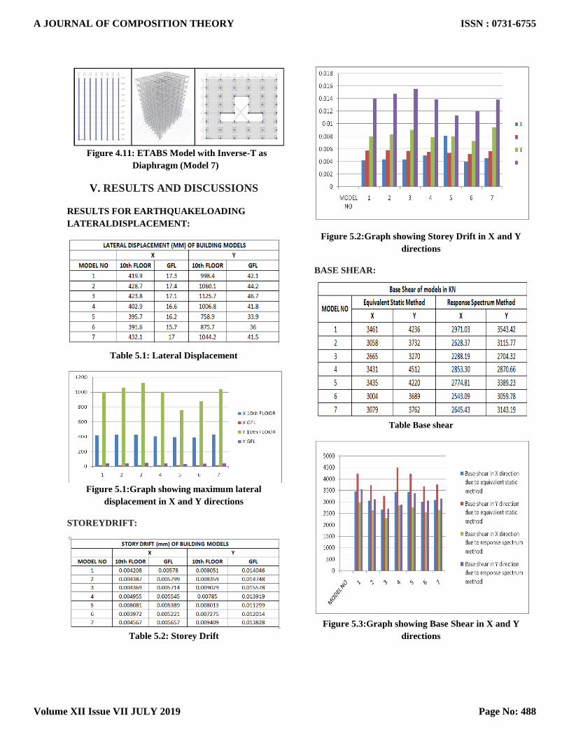
Figure 4.11: ETABS Model with Inverse-T as
Diaphragm (Model 7)
V. RESULTS AND DISCUSSIONS
RESULTS FOR EARTHQUAKELOADING
LATERALDISPLACEMENT:
Table 5.1: Lateral Displacement
Figure 5.1:Graph showing maximum lateral
displacement in X and Y directions
STOREYDRIFT:
Table 5.2: Storey Drift
Figure 5.2:Graph showing Storey Drift in X and Y
directions
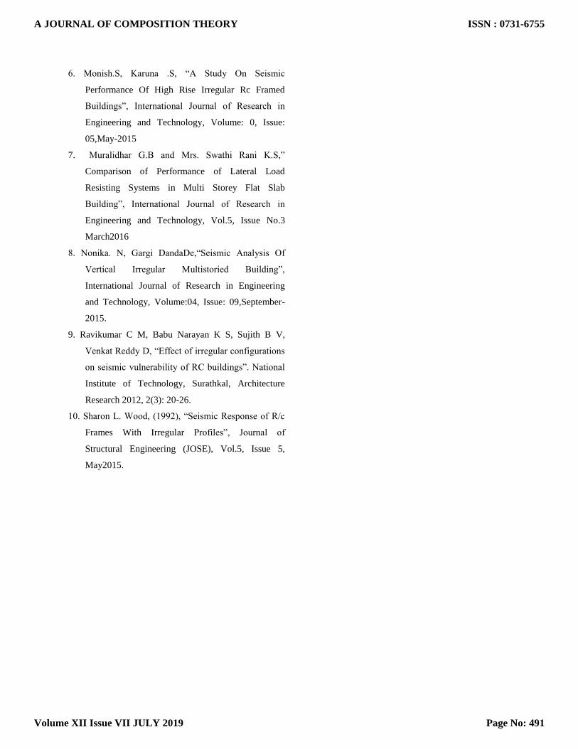
BASE SHEAR:
Table Base shear
Figure 5.3:Graph showing Base Shear in X and Y
directions
A JOURNAL OF COMPOSITION THEORY
Volume XII Issue VII JULY 2019
ISSN : 0731-6755
Page No: 488

TIME PERIOD:
Table 5.4: Time Period
Figure 5.4: Graph showing Time Period in X and Y
directions
RESULTS FOR WINDLOADING
LATERALDISPLACEMENT:
Table 5.5: Lateral Displacement
Figure 5.5: Graph showing maximum lateral
displacement in X and Y directions
STOREY DRIFT:
Table 5.6: Storey Drift
Figure 5.6: Graph showing Storey Drift in X and Y
directions
BASE SHEAR:
Table 5.7: Base Shear
Figure 5.7:Graph showing Base Shear in X and Y
directions
A JOURNAL OF COMPOSITION THEORY
Volume XII Issue VII JULY 2019
ISSN : 0731-6755
Page No: 489

VI. CONCLUSIONS
1. From the above graph5.1 it is observed that the
lateral displacement is reduced in X direction
compared to Y direction by 58% as the width of
the building in X direction is more than the
width of the building in Y-direction.
2. From the above graph 5.2 it is observed
that the storey drift in X direction for is less
compared to Y direction. And the values
obtained from the table above shows us that the
model 5 among all the other irregular models has
least amount of storey drift in Y-direction.
3. According to the cl.7.8.2 IS 1893-2002
part1, says that the minimum base shear should
be that of response spectrum when compared to
static analysis. From above table we can
conclude that the base shear for response
spectrum is less than the base shear for static
analysis which is found true.
From the above graph 5.3 it is observed that base
shear is minimum for model 3 among all the
models for both the analysis results.
4. From the above graph 5.4it is observed
that the least amount of time period occurs at
mode 3 for model with vertical irregularity on
both side. Maximum time period occurs at mode
1 for model with Re-entrant corner L-Shape.
5. From the above graph 5.5 it can be
observed that the maximum displacement for
tenth floor is found to be in X direction for
model III with Re-entrant corners L-Shape. And
also the minimum displacement for ground floor
is in Y direction for model V.
6. From the above graph5.6 it is observed
that the Storey drift due to wind loading for
G+10 building is hardly considered because of
very low values obtained.
7. From the above graph 5.7 it is observed
that the base shear for models without vertical
irregularity is same. For model IV and V with
vertical irregularity on one side and two side
respectively are relatively low compared to other
models.
SCOPE FOR FUTUREWORK
1. A non rectangular building has to be studied with
G+25floors.
2. The present study is based on linear static analysis
and dynamic analysis. The results need to be verified
with the push-over analysis results.
3. The study can be extended to find out a method to
control irregularity in such buildings.
REFERENCES 1. IS 456-2000 “Code of Practice for Plain and
Reinforced Concrete”, Bureau of Indian Standards,
NewDelhi
2. IS 1893-2002 “Criteria for earthquake resistant
design of structures”, Bureau of Indian Standards,
NewDelhi
3. IS: 875-part-3 (1987), “Indian standard code of
practice for design loads (other than earthquake) for
buildings and structures”, Bureau of Indian
Standards, New Delhi
4. DubeyS.K., P.D. Sangamnerkar. “Seismic behaviour
of asymmetric RC buildings”, International Journal
of Advanced Engineering Technology E-ISSN
0976- 3945, Professor & Head Dept of Civil
Engineering, MANIT, Bhopal.
5. CassiJ. H. s and Cornejo- E, “Influence of Vertical
Irregularities in the Response of Earthquake
Resistant Structures”.
A JOURNAL OF COMPOSITION THEORY
Volume XII Issue VII JULY 2019
ISSN : 0731-6755
Page No: 490
6. Monish.S, Karuna .S, “A Study On Seismic
Performance Of High Rise Irregular Rc Framed
Buildings”, International Journal of Research in
Engineering and Technology, Volume: 0, Issue:
05,May-2015
7. Muralidhar G.B and Mrs. Swathi Rani K.S,”
Comparison of Performance of Lateral Load
Resisting Systems in Multi Storey Flat Slab
Building”, International Journal of Research in
Engineering and Technology, Vol.5, Issue No.3
March2016
8. Nonika. N, Gargi DandaDe,“Seismic Analysis Of
Vertical Irregular Multistoried Building”,
International Journal of Research in Engineering
and Technology, Volume:04, Issue: 09,September-
2015.
9. Ravikumar C M, Babu Narayan K S, Sujith B V,
Venkat Reddy D, “Effect of irregular configurations
on seismic vulnerability of RC buildings”. National
Institute of Technology, Surathkal, Architecture
Research 2012, 2(3): 20-26.
10. Sharon L. Wood, (1992), “Seismic Response of R/c
Frames With Irregular Profiles”, Journal of
Structural Engineering (JOSE), Vol.5, Issue 5,
May2015.
A JOURNAL OF COMPOSITION THEORY
Volume XII Issue VII JULY 2019
ISSN : 0731-6755
Page No: 491