Effect of Crystal Structure and Morphology on Na3V2(PO4 ...
9
1 2 3 4 5 6 7 8 9 10 11 12 13 14 15 16 17 18 19 20 21 22 23 24 25 26 27 28 29 30 31 32 33 34 35 36 37 38 39 40 41 42 43 44 45 46 47 48 49 50 51 52 53 54 55 56 57 Effect of Crystal Structure and Morphology on Na 3 V 2 (PO 4 ) 2 F 3 Performances for Na-Ion Batteries Ayan Mukherjee + , [a, b] Tali Sharabani + , [a, b] Rosy Sharma, [a, b] Sivan Okashy, [a, b] and Malachi Noked* [a, b] Na-ion batteries (SIB) are considered promising systems for energy storage devices, however diversity of available cathode materials is lower compared to lithium ion batteries. Recently, Na 3 V 2 (PO 4 ) 2 F 3 (NVPF) has been demonstrated as promising cathode material for SIB owing to high specific capacity and electrochemical reversibility. However, most of reports demon- strates capacities lower than theoretical value and optimization of electrochemical performances by controlled morphology and crystal structure was not demonstrated yet. Here, we demon- strate a scalable synthesis strategy to tailor the crystal structure and morphology of NVPF and showed that our approach enables to optimize the Na + ion accommodation, diffusion and stability. A flower morphology (NVPF-F) crystalizes in tetragonal structure, demonstrates discharge capacity of 109.5 mA.h.g 1 and 98.1% columbic efficiency whereas a hollow spherical morphology (NVPF-S) with orthorhombic structure exhibits discharge capacity of 124.8 mA.h.g 1 (very close to theoretical value) and 99.5% columbic efficiency. The observed discharge capacity for NVPF-S is highest reported value which is ascribed due to stable crystal structure and monodispersed morphology. Long term stability with negligible capacity loss is demon- strated over 550 cycles. Our findings shed light on importance of crystal structure and morphology of NVPF on electrochemical response, and realization as cathode material for SIB. 1. Introduction Secondary battery systems are a promising technology for large scale energy storage due to its economic viability, high round trip efficiency, and ease of maintenance. [1–5] Lithium ion batteries (LIB), since their commercialization in 1990 conquered the portable electronic market [6] and brought it to a new age due to its longevity and energy storage capabilities. However, the limited supply, and heavy demand of lithium, and the relevant transition oxides (e.g. Co) strongly effect the price of electronic devices powered by LIB. [7–9] For large energy storage units, there is a dire need for cheaper active materials, even on the account of gravimetric\volumetric energy densities. In order to reduce the cost without compromising the round trip efficiency, the search for alternatives stepped to sodium, which is the fourth most abundant element in earth crust . [10] Sodium ion batteries (SIB), however, possess a less negative standard reduction potential for the Na + aq /Na (-2.7 V vs SHE) as compared to Li + aq /Li (-3.04 V vs SHE), larger ionic radius for Na + (1.07 Å) as compared to Li + (0.76 Å), which cause long term structural instability, lower gravimetric capacity, lower energy density and slow ion diffusivity (due to sluggish sodium mobility). [11–13] In order to optimize SIB performances and to overcome part of these challenges, the scientific community focused on design of new electrode materials (EMs) and precise controlled architecture of EMs. [14–21] These EMs were engineered to facilitate highly reversible sodiation/desodiation with high kinetics and energy density. Among various candidates, layered transition metal oxides, [22,23] transition metal sulfides [24,25] and fluorides [16,26] were extensively studied. Prussian blue analogues and polymers have attracted considerable attention globally in terms of higher specific capacity but delivers poor cycling stability. [22,27] Recently, a polyanionic compound (Na 3 V 2 (PO 4 ) 3 ) with a Na super ionic conductor (NASICON) structure possessing stable 3D open framework for the rapid Na-ion migration attracted tremendous attention in the search of cathode materials for SIBs as it facilitated stable structure, high voltage profile, excellent reversible capacity and cycling performance. [28–33] When one of the (PO4) 3 ion in Na 3 V 2 (PO 4 ) 3 is substituted by three F ions, a typical fluorophosphate, Na 3 V 2 (PO 4 ) 2 F 3 (NVPF) can be obtained with higher theoretical energy density (about 507 W.h. kg 1 ), average potential (3.95 V) and theoretical capacity (128 mA.h.g 1 ) than that of Na 3 V 2 (PO 4 ) 3 . The NVPF structure consist of V 2 O 8 F 3 bi-octahedra connected to PO 4 tetrahedra periodically which endows with large tunnels along the [110] and [110] crystallographic directions and the open 3D cage produces large interstitial spaces for facilitating Na + diffusion. [34] [a] Dr. A. Mukherjee, + T. Sharabani, + Dr. R. Sharma, Dr. S. Okashy, Dr. M. Noked Department of Chemistry Bar Ilan University, Ramat Gan, 5290002, Israel E-mail: [email protected] [b] Dr. A. Mukherjee, + T. Sharabani, + Dr. R. Sharma, Dr. S. Okashy, Dr. M. Noked Bar-Ilan Institute of Nanotechnology and Advanced Materials Ramat Gan, Israel [ + ] These authors contributed equally to this work. Supporting information for this article is available on the WWW under https://doi.org/10.1002/batt.201900202 © 2020 The Authors. Published by Wiley-VCH Verlag GmbH & Co. KGaA. This is an open access article under the terms of the Creative Commons Attri- bution License, which permits use, distribution and reproduction in any medium, provided the original work is properly cited. Batteries & Supercaps Articles doi.org/10.1002/batt.201900202 510 Batteries & Supercaps 2020, 3, 510 – 518 © 2020 The Authors. Published by Wiley-VCH Verlag GmbH & Co. KGaA
-
Upload
khangminh22 -
Category
Documents
-
view
5 -
download
0
Transcript of Effect of Crystal Structure and Morphology on Na3V2(PO4 ...
1
2
3
4
5
6
7
8
9
10
11
12
13
14
15
16
17
18
19
20
21
22
23
24
25
26
27
28
29
30
31
32
33
34
35
36
37
38
39
40
41
42
43
44
45
46
47
48
49
50
51
52
53
54
55
56
57
Effect of Crystal Structure and Morphology on Na3V2(PO4)2F3 Performances for Na-Ion BatteriesAyan Mukherjee+,[a, b] Tali Sharabani+,[a, b] Rosy Sharma,[a, b] Sivan Okashy,[a, b] andMalachi Noked*[a, b]
Na-ion batteries (SIB) are considered promising systems forenergy storage devices, however diversity of available cathodematerials is lower compared to lithium ion batteries. Recently,Na3V2(PO4)2F3 (NVPF) has been demonstrated as promisingcathode material for SIB owing to high specific capacity andelectrochemical reversibility. However, most of reports demon-strates capacities lower than theoretical value and optimizationof electrochemical performances by controlled morphology andcrystal structure was not demonstrated yet. Here, we demon-strate a scalable synthesis strategy to tailor the crystal structureand morphology of NVPF and showed that our approachenables to optimize the Na+ ion accommodation, diffusion and
stability. A flower morphology (NVPF-F) crystalizes in tetragonalstructure, demonstrates discharge capacity of 109.5 mA.h.g� 1
and 98.1% columbic efficiency whereas a hollow sphericalmorphology (NVPF-S) with orthorhombic structure exhibitsdischarge capacity of 124.8 mA.h.g� 1 (very close to theoreticalvalue) and 99.5% columbic efficiency. The observed dischargecapacity for NVPF-S is highest reported value which is ascribeddue to stable crystal structure and monodispersed morphology.Long term stability with negligible capacity loss is demon-strated over 550 cycles. Our findings shed light on importanceof crystal structure and morphology of NVPF on electrochemicalresponse, and realization as cathode material for SIB.
1. Introduction
Secondary battery systems are a promising technology for largescale energy storage due to its economic viability, high roundtrip efficiency, and ease of maintenance.[1–5] Lithium ionbatteries (LIB), since their commercialization in 1990 conqueredthe portable electronic market[6] and brought it to a new agedue to its longevity and energy storage capabilities. However,the limited supply, and heavy demand of lithium, and therelevant transition oxides (e.g. Co) strongly effect the price ofelectronic devices powered by LIB.[7–9] For large energy storageunits, there is a dire need for cheaper active materials, even onthe account of gravimetric\volumetric energy densities. In orderto reduce the cost without compromising the round tripefficiency, the search for alternatives stepped to sodium, whichis the fourth most abundant element in earth crust .[10] Sodiumion batteries (SIB), however, possess a less negative standardreduction potential for the Na+
aq/Na (-2.7 V vs SHE) as
compared to Li+aq/Li (-3.04 V vs SHE), larger ionic radius for Na+
(1.07 Å) as compared to Li+ (0.76 Å), which cause long termstructural instability, lower gravimetric capacity, lower energydensity and slow ion diffusivity (due to sluggish sodiummobility).[11–13] In order to optimize SIB performances and toovercome part of these challenges, the scientific communityfocused on design of new electrode materials (EMs) and precisecontrolled architecture of EMs.[14–21] These EMs were engineeredto facilitate highly reversible sodiation/desodiation with highkinetics and energy density.
Among various candidates, layered transition metaloxides,[22,23] transition metal sulfides[24,25] and fluorides[16,26] wereextensively studied. Prussian blue analogues and polymershave attracted considerable attention globally in terms ofhigher specific capacity but delivers poor cycling stability.[22,27]
Recently, a polyanionic compound (Na3V2(PO4)3) with a Nasuper ionic conductor (NASICON) structure possessing stable3D open framework for the rapid Na-ion migration attractedtremendous attention in the search of cathode materials forSIBs as it facilitated stable structure, high voltage profile,excellent reversible capacity and cycling performance.[28–33]
When one of the (PO4)� 3 ion in Na3V2(PO4)3 is substituted bythree F� ions, a typical fluorophosphate, Na3V2(PO4)2F3 (NVPF)can be obtained with higher theoretical energy density (about507 W.h. kg� 1), average potential (3.95 V) and theoreticalcapacity (128 mA.h.g� 1) than that of Na3V2(PO4)3. The NVPFstructure consist of V2O8F3 bi-octahedra connected to PO4
tetrahedra periodically which endows with large tunnels alongthe [110] and [110] crystallographic directions and the open 3Dcage produces large interstitial spaces for facilitating Na+
diffusion.[34]
[a] Dr. A. Mukherjee,+ T. Sharabani,+ Dr. R. Sharma, Dr. S. Okashy,Dr. M. NokedDepartment of ChemistryBar Ilan University, Ramat Gan, 5290002, IsraelE-mail: [email protected]
[b] Dr. A. Mukherjee,+ T. Sharabani,+ Dr. R. Sharma, Dr. S. Okashy, Dr. M. NokedBar-Ilan Institute of Nanotechnology and Advanced MaterialsRamat Gan, Israel
[+] These authors contributed equally to this work.Supporting information for this article is available on the WWW underhttps://doi.org/10.1002/batt.201900202© 2020 The Authors. Published by Wiley-VCH Verlag GmbH & Co. KGaA. Thisis an open access article under the terms of the Creative Commons Attri-bution License, which permits use, distribution and reproduction in anymedium, provided the original work is properly cited.
Batteries & SupercapsArticlesdoi.org/10.1002/batt.201900202
510Batteries & Supercaps 2020, 3, 510–518 © 2020 The Authors. Published by Wiley-VCH Verlag GmbH & Co. KGaA
Wiley VCH Montag, 24.08.2020
2006 - closed* / 160143 [S. 510/518] 1

1
2
3
4
5
6
7
8
9
10
11
12
13
14
15
16
17
18
19
20
21
22
23
24
25
26
27
28
29
30
31
32
33
34
35
36
37
38
39
40
41
42
43
44
45
46
47
48
49
50
51
52
53
54
55
56
57
Despite the high potential of NVPF, limited reversiblecapacity, poor electronic conductivity, low sodium-ion diffusiv-ity and cycling stability hinders its realization as cathode in SIB.To address these issues, rational designing of the electrodematerial with control over the morphology and crystal structureis essential to tailor the specific capacity, cycling performanceand energy density. Recently, few studies focused on thesynthesis of different morphologies of NVPF microstructures byhydro/(solvo)thermal and conventional solid state reactionapproaches that enabled to get controllable microstructure,and cation doping. These modifications and efforts ended inimproving the performance and stability to some extent .[35–41]
Previous studies suggest that the electronic conductivity ofNVPF can be improved greatly from its pristine counterpart bysuitably coating with carbon,[15] CMK-3,[42] graphene,[43] RuO2,
[44]
carbon-polytetrahydrofuran[45] or compositing withMWCNT.[46,47] However, the volume expansion during repeatedNa+ ion intercalation/deintercalation accounted for wobblyinterface between NVPF and coated material and lead toseparation of the coating in long cycling which hinders itscycling stability and rate capability. So, rational designing ofpristine NVPF with controlled crystal engineering is essentialwhich can deliver cycling performance similar or even betterthan reported coated or composite NVPF electrode till now tomeet the requirement of commercial SIB. Further adopting thesurface modification, coating and compositing strategies mightaccount for some improvement in the stability of NVPF. Also,the relationship between morphology and crystal structure andEMs performance still remains unexplored in NVPF anddemands close attention for optimization and realization of thismaterial.
In the present work, a unique synthesis approach enabledto tailor the crystal structure and morphology of NVPF. Weshow how our approach, enabled to optimize the electro-chemical response in terms of sodium accommodation capacityand diffusivity in NVPF which is without any support andcoating. Specifically, a facile one step solvothermal route isdemonstrated for synthesis of NVPF in two different micro-structures; (1) micro-hollow-spherical (MHS) morphology con-sist of sub-micron plates which crystallizes in orthorhombicstructure and (2) micro-flower (MF) morphology composed ofsub-micron flakes which crystallizes in tetragonal structure.Both the architecture exhibit excellent electrochemical per-formance as cathodes for SIBs but the MHS displays superiordischarge capacity (124.8 mA.h.g� 1), rate performance, stabilityand columbic efficiency (99.5%) than the MF morphology andto any previously reported NVPF. We show that the 3D openstructure in orthorhombic phase (in MHS EM) facilitate facile Naintercalation/deintercalation and faster kinetics without notice-able degradation. We believe that our orthorhombic NVPF withMHS morphology would be the most promising EM in SIBwhich could be improved further through selective surfacemodification, coating and compositing strategies in near future.
Experimental Section
Synthesis
All the precursors were procured from Sigma-Aldrich and usedwithout further purification.
Synthesis of NVPF flowers
In a typical synthesis, 157.30 mg VCl3, 359.94 mg NaH2PO4.2H2Oand 70.12 mg NaF were dissolved in 5 ml ultra-pure water (MilliQ18.2 MΩ) and stirred for 6 h. The above solution was sealed in a30 ml Teflon lined stainless steel autoclave and kept in a mufflefurnace at 200 °C for 12 h at a heating rate of 5 °C min� 1. After thereaction, the autoclave was allowed to cool naturally inside thefurnace to room temperature. The product was centrifuged andwashed repeatedly with ultrapure water and ethanol to removethe aqueous and alcohol soluble inorganic impurities completelyand dried in a hot-air oven at 60 °C for 12 h to obtain the NVPFflower (NVPF-F). The formation of microflower is achieved by theaggregation and densification of nanoflakes allowing significantutilization of active material.
Synthesis of NVPF hollow microsphere
In order to synthesize NVPF hollow microspheres (NVPF-S),167.96 mg NaF, 719.88 mg NaH2PO4.2H2O were dissolved in mixedsolution of 6 ml H2O and 24 ml tetraethylene glycol and stirredvigorously for 18 h. To the above solution, 233.96 mg NH4VO3 and768.48 mg citric acid were added and stirred for 6 h so that all theprecursors were dissolved completely. The mixed solution wasautoclaved in a 50 ml Teflon lined stainless steel autoclave andkept in a muffle furnace at 200 °C for 10 h at a heating rate of 8 °Cmin� 1. The rest of the procedure is same as that of NVPF-F. Theformation of hollow microsphere is governed by the orientedaggregation and densification of nanoparticles and nanoplatesassembly through Oswald ripening, which allows better utilizationof the active material.
Characterization
Physical characterization
The x-ray diffraction (XRD) measurements was carried in a BrukerD8 Advanced X-ray diffractometer using Cu Kα radiation (λ=
1.5414 Å) within the 2θ range from 10° to 80° to study the crystalstructure of the prepared samples. The surface morphology wasanalyzed by environmental scanning electron microscope (SEM,Quanta 2000, from FEI) operating at 3 keV, and high resolutionscanning electron microscope (HRSEM, FEI, Magellan 400 L) at thevoltage of 5 kV and current of 0.4nA. The High resolutiontransmission electron microscope (HR-TEM, JEM 2100, JEOL,Accelerating Voltage 200 kV, Gatan USC 4000 4×4k camera)images were taken to study the morphology and crystallinity of theprepared samples. TEM samples were prepared by grinding anddispersing the powder samples in ultra-pure water and cast on alacey carbon-coated Cu grids. The specific surface area of NVPFpowder was measured using the NOVA 3200E QuantachromeBrunauer-Emmett-Teller (BET) instrument. The final composition ofNVPF was measured in Inductively coupled plasma atomic emissionspectrometry (ICP-AES) technique with an Ultima-2 spectrometer(JobinYvon Horiba). X-ray photoelectron spectroscopy (XPS) studywas done by Thermo Scientific Nexsa spectrometer.
Batteries & SupercapsArticlesdoi.org/10.1002/batt.201900202
511Batteries & Supercaps 2020, 3, 510–518 www.batteries-supercaps.org © 2020 The Authors. Published by Wiley-VCH Verlag GmbH & Co. KGaA
Wiley VCH Montag, 24.08.2020
2006 - closed* / 160143 [S. 511/518] 1

1
2
3
4
5
6
7
8
9
10
11
12
13
14
15
16
17
18
19
20
21
22
23
24
25
26
27
28
29
30
31
32
33
34
35
36
37
38
39
40
41
42
43
44
45
46
47
48
49
50
51
52
53
54
55
56
57
Electrode preparation
Composite electrodes were prepared by mixing 70% of the activematerial (NVPF), 20% of Super P carbon black and 10% of poly(vinylidene fluoride) (PVDF) in N-methyl-2-pyrrolidone (NMP).Mixing of the composite electrode was carried out using a Thinkymixer (ARV-310/ARV-310LED) at 2000 rpm, 30 kPa for 3 minutes.The 60-micron thick layer of the prepared slurry was then coatedon a clean and polished Al foil using doctors blade and dried forovernight at 100 °C. After rolling, 14 mm of the electrode waspunched and dried overnight under vacuum at 120 °C.
Electrochemical measurements
NVPF electrodes (ø 14 mm) were assembled in a two-electrodecells configuration using standard coin-type cells versus Na metal(ø 14 mm) counter electrodes in electrolyte solution of 45μL ofNaPF6 (1 M) in propylene carbonate (PC) with 2% of fluoroethylenecarbonate (FEC). The cell preparation was done in a gloveboxunder Argon atmosphere. Two polypropylene separators(ø 18 mm) were placed between NVPF and Na electrodes. The cellwas taken out of the glovebox for electrochemical measurements,which was tested with galvanostatic discharge-charge cycling at35 °C (Bio-logic Science instruments) in a potential window of 2.5–4.3 V. All the currents were normalized by mass of the activematerial in the study. The post mortem study was done bydisassembling the cells inside the glovebox and rinsing theelectrodes with dimethyl carbonate (DMC) and dried for overnight.
2. Results and Discussion
The X-ray diffraction (XRD) patterns of NVPF-F and NVPF-S areshown in Figure 1a and b respectively. These patterns matchwell (#01-089-8485) without the presence of any other phases.The structural and microstructural parameters are obtained byrefining the powder XRD data using Rietveld powder structurerefinement method. The experimental data is simulated withrespect to the standard pattern while the background is fittedwith a polynomial of degree 4 till convergence (goodness offitting (χ2) ~1).[48] All the diffraction peaks of NVPF-F indexedinto tetragonal crystal system with P42/mnm space group, a =
b=9.047 Å, c=10.7050 Å[37,40] while the diffraction peaks ofNVPF-S indexed into orthorhombic crystal system with Pnnmspace group, a =9.1665 Å, b =9.1976 Å, c=10.9237 Å.[49] Byextracting the parameters of Rietveld refinement (Table S1) andlooking into the structure deeply, it is observed that bothNVPF-F (Figure S1a) and NVPF-S (Figure S1b) exhibits an open3D bridged structure where the V2O8F3 octahedral unit isconnected by PO4 tetrahedral unit, consistent with previousreport.[34] However, the Na occupies two interstitial position(Na1 and Na2) in NVPF-F along the [100] and [010] directionsfrom each bioctahedral unit as shown in Figure 1c whereas theNVPF-S exhibit Na3 site together with Na1 and Na2 along the[110] direction shown in Figure 1d. The Pnnm phase is thebroken symmetry structure of P42mnm, where the Na+ ions aredistributed anisotropically along the [110] direction.[49] The
Figure 1. XRD pattern of a) NVPF-F, b) NVPF-S. Position of Na ion in the unit cell in c) NVPF-F, d) NVPF-S.
Batteries & SupercapsArticlesdoi.org/10.1002/batt.201900202
512Batteries & Supercaps 2020, 3, 510–518 www.batteries-supercaps.org © 2020 The Authors. Published by Wiley-VCH Verlag GmbH & Co. KGaA
Wiley VCH Montag, 24.08.2020
2006 - closed* / 160143 [S. 512/518] 1
1
2
3
4
5
6
7
8
9
10
11
12
13
14
15
16
17
18
19
20
21
22
23
24
25
26
27
28
29
30
31
32
33
34
35
36
37
38
39
40
41
42
43
44
45
46
47
48
49
50
51
52
53
54
55
56
57
position of Na+ ions are shifted from the minimum symmetryposition due to electrostatic repulsion between Na� Na,[50]
hence, available for intercalation/de-intercalation more easilythan P42/mnm.
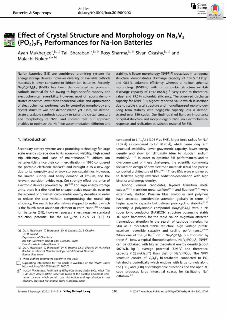
The morphology of NVPF-F and NVPF-S is depicted by SEMimage, presented in Figure 2a–b, c–d, respectively. The NVPF-Fshows flower-like morphology with an average diameter of3 μm composed of several thin flakes, while the NVPF-S showsuniform hollow spherical morphology with an average diame-ter of 2 μm composed of sub-micron plates. The formation ofboth NVPF-F and NVPF-S is governed by oriented aggregationof nanoparticles assembly followed by Oswald ripening.[51,52]
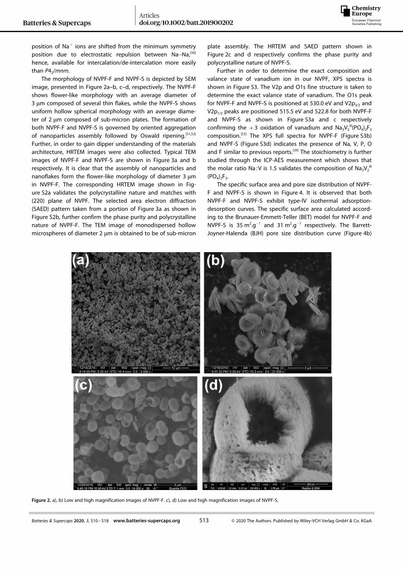
Further, in order to gain dipper understanding of the materialsarchitecture, HRTEM images were also collected. Typical TEMimages of NVPF-F and NVPF-S are shown in Figure 3a and brespectively. It is clear that the assembly of nanoparticles andnanoflakes form the flower-like morphology of diameter 3 μmin NVPF-F. The corresponding HRTEM image shown in Fig-ure S2a validates the polycrystalline nature and matches with(220) plane of NVPF. The selected area electron diffraction(SAED) pattern taken from a portion of Figure 3a as shown inFigure S2b, further confirm the phase purity and polycrystallinenature of NVPF-F. The TEM image of monodispersed hollowmicrospheres of diameter 2 μm is obtained to be of sub-micron
plate assembly. The HRTEM and SAED pattern shown inFigure 2c and d respectively confirms the phase purity andpolycrystalline nature of NVPF-S.
Further in order to determine the exact composition andvalance state of vanadium ion in our NVPF, XPS spectra isshown in Figure S3. The V2p and O1s fine structure is taken todetermine the exact valance state of vanadium. The O1s peakfor NVPF-F and NVPF-S is positioned at 530.0 eV and V2p3/2 andV2p1/2 peaks are positioned 515.5 eV and 522.8 for both NVPF-Fand NVPF-S as shown in Figure S3a and c respectivelyconfirming the +3 oxidation of vanadium and Na3V2
III(PO4)2F3
composition.[53] The XPS full spectra for NVPF-F (Figure S3b)and NVPF-S (Figure S3d) indicates the presence of Na, V, P, Oand F similar to previous reports.[39] The stoichiometry is furtherstudied through the ICP-AES measurement which shows thatthe molar ratio Na :V is 1.5 validates the composition of Na3V2
III
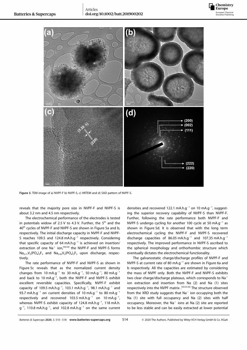
(PO4)2F3.The specific surface area and pore size distribution of NVPF-
F and NVPF-S is shown in Figure 4. It is observed that bothNVPF-F and NVPF-S exhibit type-IV isothermal adsorption-desorption curves. The specific surface area calculated accord-ing to the Brunauer-Emmett-Teller (BET) model for NVPF-F andNVPF-S is 35 m2.g� 1 and 31 m2.g� 1 respectively. The Barrett-Joyner-Halenda (BJH) pore size distribution curve (Figure 4b)
Figure 2. a), b) Low and high magnification images of NVPF-F. c), d) Low and high magnification images of NVPF-S.
Batteries & SupercapsArticlesdoi.org/10.1002/batt.201900202
513Batteries & Supercaps 2020, 3, 510–518 www.batteries-supercaps.org © 2020 The Authors. Published by Wiley-VCH Verlag GmbH & Co. KGaA
Wiley VCH Montag, 24.08.2020
2006 - closed* / 160143 [S. 513/518] 1
1
2
3
4
5
6
7
8
9
10
11
12
13
14
15
16
17
18
19
20
21
22
23
24
25
26
27
28
29
30
31
32
33
34
35
36
37
38
39
40
41
42
43
44
45
46
47
48
49
50
51
52
53
54
55
56
57
reveals that the majority pore size in NVPF-F and NVPF-S isabout 3.2 nm and 4.5 nm respectively.
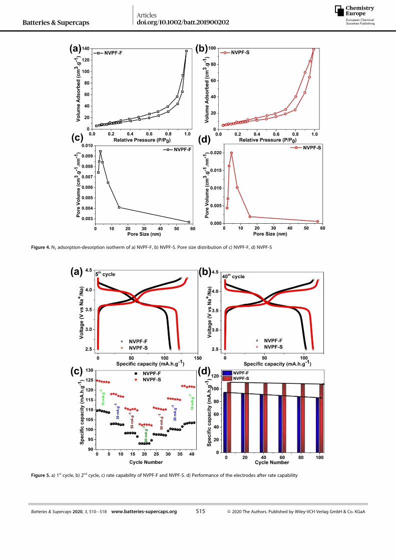
The electrochemical performance of the electrodes is testedin potentials widow of 2.5 V to 4.3 V. Further, the 5th and the40th cycles of NVPF-F and NVPF-S are shown in Figure 5a and b,respectively. The initial discharge capacity in NVPF-F and NVPF-S reaches 109.5 and 124.8 mA.h.g� 1 respectively. Consideringthat specific capacity of 64 mA.h.g� 1 is achieved on insertion/extraction of one Na+ ion,[50,54] the NVPF-F and NVPF-S formsNa2.71V2(PO4)2F3 and Na2.95V2(PO4)2F3 upon discharge, respec-tively.
The rate performance of NVPF-F and NVPF-S as shown inFigure 5c reveals that as the normalized current densitychanges from 10 mA.g� 1 to 30 mA.g� 1, 50 mA.g� 1, 80 mA.g� 1
and back to 10 mA.g� 1, both the NVPF-F and NVPF-S exhibitexcellent reversible capacities. Specifically, NVPF-F exhibitcapacity of 109.5 mA.h.g� 1, 103.1 mA.h.g� 1, 98.1 mA.h.g� 1 and93.7 mA.h.g� 1 on current densities of 10 mA.g� 1 to 80 mA.g� 1
respectively and recovered 103.5 mA.h.g� 1 on 10 mA.g� 1,whereas NVPF-S exhibit capacity of 124.8 mA.h.g� 1, 118 mA.h.g� 1, 110.8 mA.h.g� 1, and 102.8 mA.h.g� 1 on the same current
densities and recovered 122.1 mA.h.g� 1 on 10 mA.g� 1, suggest-ing the superior recovery capability of NVPF-S than NVPF-F.Further, following the rate performance both NVPF-F andNVPF-S undergo cycling for another 100 cycle at 50 mA.g� 1 asshown in Figure 5d. It is observed that with the long termelectrochemical cycling the NVPF-F and NVPF-S recovereddischarge capacities of 86.05 mA.h.g� 1 and 107.35 mA.h.g� 1
respectively. The improved performance in NVPF-S ascribed tothe spherical morphology and orthorhombic structure whicheventually dictates the electrochemical functionality.
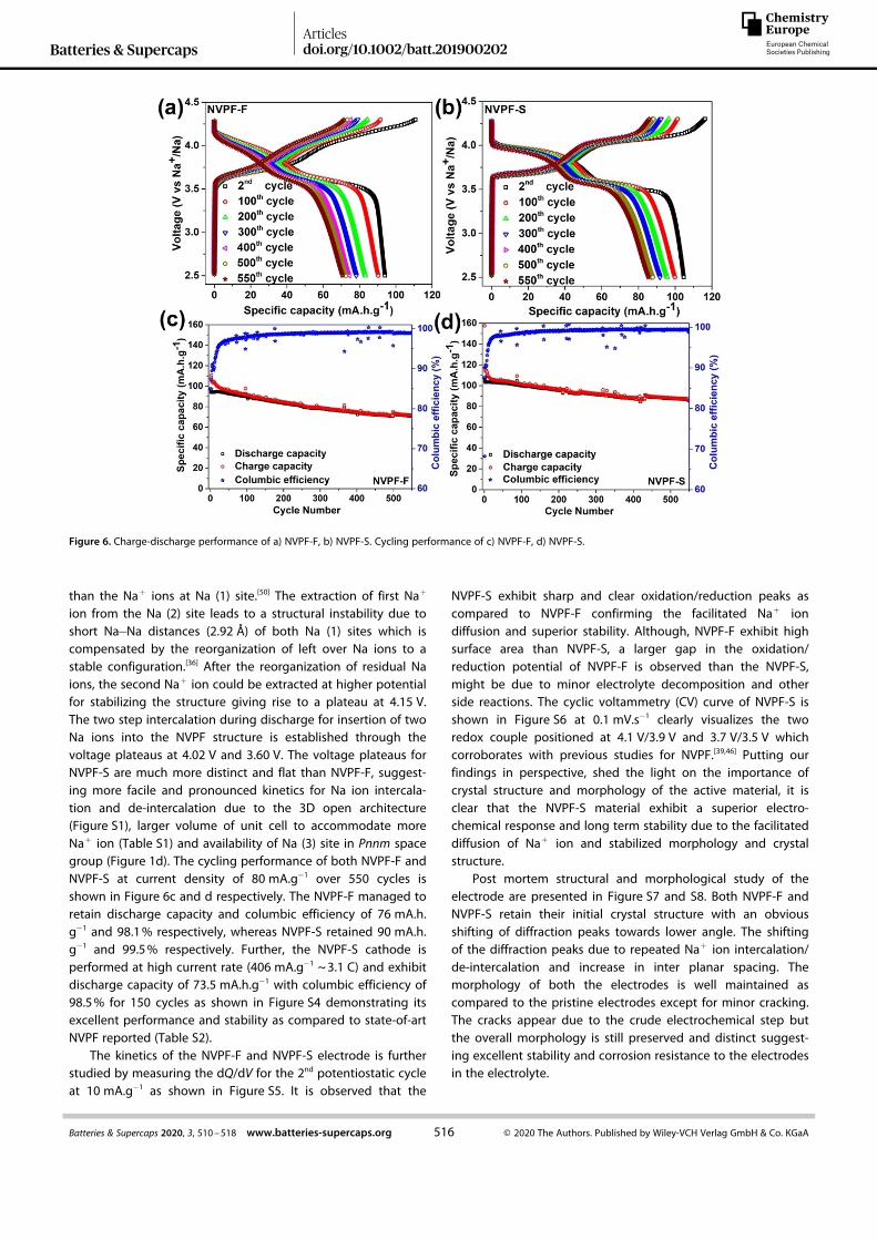
The galvanostatic charge/discharge profiles of NVPF-F andNVPF-S at current rate of 80 mA.g� 1 are shown in Figure 6a andb respectively. All the capacities are estimated by consideringthe mass of NVPF only. Both the NVPF-F and NVPF-S exhibitstwo clear charge/discharge plateaus, which corresponds to Na+
ion extraction and insertion from Na (2) and Na (1) sitesrespectively into the NVPF matrix .[50,55,56] The structure observedfrom the XRD study suggests that Na+ ion occupying both theNa (1) site with full occupancy and Na (2) sites with halfoccupancy. Moreover, the Na+ ions at Na (2) site are reportedto be less stable and can be easily extracted at lower potential
Figure 3. TEM image of a) NVPF-F b) NVPF-S, c) HRTEM and d) SAD pattern of NVPF-S.
Batteries & SupercapsArticlesdoi.org/10.1002/batt.201900202
514Batteries & Supercaps 2020, 3, 510–518 www.batteries-supercaps.org © 2020 The Authors. Published by Wiley-VCH Verlag GmbH & Co. KGaA
Wiley VCH Montag, 24.08.2020
2006 - closed* / 160143 [S. 514/518] 1
1
2
3
4
5
6
7
8
9
10
11
12
13
14
15
16
17
18
19
20
21
22
23
24
25
26
27
28
29
30
31
32
33
34
35
36
37
38
39
40
41
42
43
44
45
46
47
48
49
50
51
52
53
54
55
56
57
Figure 4. N2 adsorption-desorption isotherm of a) NVPF-F, b) NVPF-S. Pore size distribution of c) NVPF-F, d) NVPF-S
Figure 5. a) 1st cycle, b) 2nd cycle, c) rate capability of NVPF-F and NVPF-S. d) Performance of the electrodes after rate capability
Batteries & SupercapsArticlesdoi.org/10.1002/batt.201900202
515Batteries & Supercaps 2020, 3, 510–518 www.batteries-supercaps.org © 2020 The Authors. Published by Wiley-VCH Verlag GmbH & Co. KGaA
Wiley VCH Montag, 24.08.2020
2006 - closed* / 160143 [S. 515/518] 1
1
2
3
4
5
6
7
8
9
10
11
12
13
14
15
16
17
18
19
20
21
22
23
24
25
26
27
28
29
30
31
32
33
34
35
36
37
38
39
40
41
42
43
44
45
46
47
48
49
50
51
52
53
54
55
56
57
than the Na+ ions at Na (1) site.[50] The extraction of first Na+
ion from the Na (2) site leads to a structural instability due toshort Na� Na distances (2.92 Å) of both Na (1) sites which iscompensated by the reorganization of left over Na ions to astable configuration.[36] After the reorganization of residual Naions, the second Na+ ion could be extracted at higher potentialfor stabilizing the structure giving rise to a plateau at 4.15 V.The two step intercalation during discharge for insertion of twoNa ions into the NVPF structure is established through thevoltage plateaus at 4.02 V and 3.60 V. The voltage plateaus forNVPF-S are much more distinct and flat than NVPF-F, suggest-ing more facile and pronounced kinetics for Na ion intercala-tion and de-intercalation due to the 3D open architecture(Figure S1), larger volume of unit cell to accommodate moreNa+ ion (Table S1) and availability of Na (3) site in Pnnm spacegroup (Figure 1d). The cycling performance of both NVPF-F andNVPF-S at current density of 80 mA.g� 1 over 550 cycles isshown in Figure 6c and d respectively. The NVPF-F managed toretain discharge capacity and columbic efficiency of 76 mA.h.g� 1 and 98.1% respectively, whereas NVPF-S retained 90 mA.h.g� 1 and 99.5% respectively. Further, the NVPF-S cathode isperformed at high current rate (406 mA.g� 1 ~3.1 C) and exhibitdischarge capacity of 73.5 mA.h.g� 1 with columbic efficiency of98.5% for 150 cycles as shown in Figure S4 demonstrating itsexcellent performance and stability as compared to state-of-artNVPF reported (Table S2).
The kinetics of the NVPF-F and NVPF-S electrode is furtherstudied by measuring the dQ/dV for the 2nd potentiostatic cycleat 10 mA.g� 1 as shown in Figure S5. It is observed that the
NVPF-S exhibit sharp and clear oxidation/reduction peaks ascompared to NVPF-F confirming the facilitated Na+ iondiffusion and superior stability. Although, NVPF-F exhibit highsurface area than NVPF-S, a larger gap in the oxidation/reduction potential of NVPF-F is observed than the NVPF-S,might be due to minor electrolyte decomposition and otherside reactions. The cyclic voltammetry (CV) curve of NVPF-S isshown in Figure S6 at 0.1 mV.s� 1 clearly visualizes the tworedox couple positioned at 4.1 V/3.9 V and 3.7 V/3.5 V whichcorroborates with previous studies for NVPF.[39,46] Putting ourfindings in perspective, shed the light on the importance ofcrystal structure and morphology of the active material, it isclear that the NVPF-S material exhibit a superior electro-chemical response and long term stability due to the facilitateddiffusion of Na+ ion and stabilized morphology and crystalstructure.
Post mortem structural and morphological study of theelectrode are presented in Figure S7 and S8. Both NVPF-F andNVPF-S retain their initial crystal structure with an obviousshifting of diffraction peaks towards lower angle. The shiftingof the diffraction peaks due to repeated Na+ ion intercalation/de-intercalation and increase in inter planar spacing. Themorphology of both the electrodes is well maintained ascompared to the pristine electrodes except for minor cracking.The cracks appear due to the crude electrochemical step butthe overall morphology is still preserved and distinct suggest-ing excellent stability and corrosion resistance to the electrodesin the electrolyte.
Figure 6. Charge-discharge performance of a) NVPF-F, b) NVPF-S. Cycling performance of c) NVPF-F, d) NVPF-S.
Batteries & SupercapsArticlesdoi.org/10.1002/batt.201900202
516Batteries & Supercaps 2020, 3, 510–518 www.batteries-supercaps.org © 2020 The Authors. Published by Wiley-VCH Verlag GmbH & Co. KGaA
Wiley VCH Montag, 24.08.2020
2006 - closed* / 160143 [S. 516/518] 1
1
2
3
4
5
6
7
8
9
10
11
12
13
14
15
16
17
18
19
20
21
22
23
24
25
26
27
28
29
30
31
32
33
34
35
36
37
38
39
40
41
42
43
44
45
46
47
48
49
50
51
52
53
54
55
56
57
The superior performance of NVPF-S (charge/dischargecapacities, rate performance, cyclability) without any coating (C,CNT, RGO) or doping (Mn, Al) in Na-ion battery govern itsprominence in high voltage battery, which attributed to thenegligible volume expansion, structural and morphologicalstability upon long and crude cycling leading to facile Na-iondiffusion, which opens up the possibility in the field for furtherimprovement through coating and doping.
3. Conclusions
In summary, we demonstrate a facile strategic synthesisapproach to tailor the crystal structure and morphology ofNVPF. We synthesized two different morphologies and crystalstructure of NVPF: (1) a flower morphology consist of nanoflakes which crystalizes in tetragonal structure and (2) microhollow spherical morphology consist of nanoplates crystalizesin orthorhombic structure. The electrochemical cycling resultsdemonstrate that the flower morphology exhibit dischargecapacity of 109.5 mA.h.g� 1 at 10 mA.g� 1 and 98.1% columbicefficiency even at 80 mA.g� 1 whereas the micro hollowspherical morphology exhibit discharge capacity of 124.8 mA.h.g� 1 at 10 mA.g� 1 and 99.5% columbic efficiency at 80 mA.g� 1.Both the morphologies exhibit excellent capacity retentionover 550 cycles. The voltage plateaus suggest that the MHSmorphology exhibit easy and pronounces Na+ ion diffusionduring deintercalation/intercalation as compared to flowermorphology which is accounted for the orthorhombic struc-ture. Further the post mortem structural and morphologicalstudies suggested that electrodes remain invariant during Na+
ion diffusion in different current rates validate the stabilitypreciously.
Acknowledgements
The authors acknowledge financial support through EuropeanUnion’s Horizon 2020 research and innovation program undergrant agreement No 824066, and BINA center, BIU for instrumen-tation facilities. Ayan and Rosy acknowledges Planning andBudget Committee Israel for fellowship.
Conflict of Interest
The authors declare no conflict of interest.
Keywords: sodium-ion battery · cathode material · Na3V2
(PO4)2F3 · energy storage
[1] H. Pan, Y. S. Hu, L. Chen, Energy Environ. Sci. 2013, 6, 2338.[2] D. Bruce, K. Haresh, T. Jean-Marie, Science 2011, 334, 928.[3] M. N. E. Evenstein, Rosy, S. Haber, H. Sclar, L. Houben, K. Leung, M.
Leskes, Energy Storage Mater. 2018, 1.[4] M. Salama, R. Attias, B. Hirsch, R. Yemini, Y. Gofer, M. Noked, D. Aurbach,
ACS Appl. Mater. Interfaces 2018, 10, 36910.
[5] K. N. Wood, M. Noked, N. P. Dasgupta, ACS Energy Lett. 2017, 2, 664.[6] Y. Nishi, J. Power Sources 2001, 100, 101.[7] A. C. Kozen, A. J. Pearse, C.-F. Lin, X. Han, M. Noked, M. A. Schroeder, S.-
B. Lee, G. W. Rubloff, L. Hu, ACS Nano 2015, 9, 5884.[8] Rosy, S. Akabayov, M. Leskes, M. Noked, ACS Appl. Mater. Interfaces
2018, 10, 29622.[9] H. Cha, J. Kim, Y. Lee, J. Cho, M. Park, Small 2018, 14, 1.
[10] E. De La Llave, V. Borgel, K. J. Park, J. Y. Hwang, Y. K. Sun, P. Hartmann,F. F. Chesneau, D. Aurbach, ACS Appl. Mater. Interfaces 2016, 8, 1867.
[11] X. Xiang, K. Zhang, J. Chen, Adv. Mater. 2015, 27, 5343.[12] G. Hu, L. Zeng, Z. Yang, Y. Jiang, Y. Yu, W. Li, L. Gu, X. Wei, F. Pan, M.
Wang, Adv. Energy Mater. 2015, 5, 1402104.[13] Y. Dong, S. Li, K. Zhao, C. Han, W. Chen, B. Wang, L. Wang, B. Xu, Q. Wei,
L. Zhang, X. Xu, L. Mai, Energy Environ. Sci. 2015, 8, 1267.[14] Y. Sun, Y. Lin, D. Zhang, M. Peng, D. Xia, G. Guo, L. Zheng, X. Wang,
Nano Energy 2016, 31, 64.[15] Q. Liu, D. Wang, X. Yang, N. Chen, C. Wang, X. Bie, Y. Wei, G. Chen, F.
Du, J. Mater. Chem. A 2015, 3, 21478.[16] F. Wang, S. W. Kim, D. H. Seo, K. Kang, L. Wang, D. Su, J. J. Vajo, J. Wang,
J. Graetz, Nat. Commun. 2015, 6, 1.[17] Y. Liu, X. Li, W. Shen, Y. Dai, W. Kou, W. Zheng, X. Jiang, G. He, Small
2019, 1804737, 1.[18] A. Manthiram, X. Yu, Small 2015, 11, 2108.[19] Z. Tong, R. Yang, S. Wu, D. Shen, T. Jiao, K. Zhang, W. Zhang, C. S. Lee,
Small 2019, 1901272, 1.[20] Q. Wang, C. Zhao, Y. Lu, Y. Li, Y. Zheng, Y. Qi, X. Rong, L. Jiang, X. Qi, Y.
Shao, D. Pan, B. Li, Y. S. Hu, L. Chen, Small 2017, 13, 1.[21] L. Yu, L. P. Wang, H. Liao, J. Wang, Z. Feng, O. Lev, J. S. C. Loo, M. T.
Sougrati, Z. J. Xu, Small 2018, 14, 1.[22] S. Zheng, G. Zhong, M. J. McDonald, Z. Gong, R. Liu, W. Wen, C. Yang, Y.
Yang, J. Mater. Chem. A 2016, 4, 9054.[23] K. Kaliyappan, J. Liu, B. Xiao, A. Lushington, R. Li, T. K. Sham, X. Sun,
Adv. Funct. Mater. 2017, 27, 13.[24] H. F. Wang, C. Tang, B. Wang, B. Q. Li, Q. Zhang, Adv. Mater. 2017, 29, 1.[25] X. Xu, W. Liu, Y. Kim, J. Cho, Nano Today 2014, 9, 604.[26] N. Zhang, X. Xiao, H. Pang, Nanoscale Horiz. 2018, 4, 99.[27] D. Yang, J. Xu, X. Z. Liao, Y. S. He, H. Liu, Z. F. Ma, Chem. Commun. 2014,
50, 13377.[28] A. Mukherjee, M. Banerjee, S. Basu, M. Pal, AIP Conf. Proc. 2014.[29] S. Hu, L. Scudiero, S. Ha, Electrochim. Acta 2012, 83, 354.[30] N. Schumacher, K. Andersson, L. C. Grabow, M. Mavrikakis, Surf. Sci.
2008, 602, 702.[31] M. Simões, S. Baranton, C. Coutanceau, Appl. Catal. B 2011, 110, 40.[32] A. Serov, C. Kwak, Appl. Catal. B 2010, 97, 1.[33] X. Zhong, Z. Yang, Y. Jiang, W. Li, L. Gu, Y. Yu, ACS Appl. Mater. Interfaces
2016, 8, 32360.[34] W. Song, H. Hou, Z. Wu, X. Ji, K. Ye, Y. Zhu, M. Jing, C. E. Banks, J. Chen,
Phys. Chem. Chem. Phys. 2015, 17, 159.[35] W. Liu, H. Yi, Q. Zheng, X. Li, H. Zhang, J. Mater. Chem. A 2017, 5, 10928.[36] R. A. Shakoor, D. H. Seo, H. Kim, Y. U. Park, J. Kim, S. W. Kim, H. Gwon, S.
Lee, K. Kang, J. Mater. Chem. 2012, 22, 20535.[37] Y. Qi, L. Mu, J. Zhao, Y. S. Hu, H. Liu, S. Dai, J. Mater. Chem. A 2016, 4,
7178.[38] Q. Liu, X. Meng, Z. Wei, D. Wang, Y. Gao, Y. Wei, F. Du, G. Chen, ACS
Appl. Mater. Interfaces 2016, 8, 31709.[39] Y. Zhang, S. Guo, H. Xu, J. Mater. Chem. A 2018, 6, 4525.[40] Y. Cai, X. Cao, Z. Luo, G. Fang, F. Liu, J. Zhou, A. Pan, S. Liang, Adv. Sci.
2018, 5, DOI 10.1002/advs.201800680.[41] J. Sheng, P. Zhang, Q. Li, L. Zhou, Q. Wei, C. Xu, Y. Xu, Q. An, L. Mai, Adv.
Energy Mater. 2016, 6, 1600389.[42] Q. Liu, X. Meng, Z. Wei, D. Wang, Y. Gao, Y. Wei, F. Du, G. Chen, ACS
Appl. Mater. Interfaces 2016, 8, 31709.[43] M. Xu, L. Wang, X. Zhao, J. Song, H. Xie, Y. Lu, J. B. Goodenough, Phys.
Chem. Chem. Phys. 2013, 15, 13032.[44] M. Peng, B. Li, H. Yan, D. Zhang, X. Wang, D. Xia, G. Guo, Angew. Chem.
Int. Ed. 2015, 54, 6452.[45] H. S. H. Xiong, Y. Liu, Y. Yang, J. Electrochem. Soc. 2018, 165, A746.[46] C. Shen, H. Long, G. Wang, W. Lu, L. Shao, K. Xie, J. Mater. Chem. A
2018, 6, 6007.[47] P. R. Kumar, Y. H. Jung, J. E. Wang, D. K. Kim, J. Power Sources 2016, 324,
421.[48] M. Banerjee, A. Mukherjee, A. Banerjee, D. Das, S. Basu, New J. Chem.
2017, 41, 10985.[49] F. W. Y.-U. Park, J. Bai, L. Wang, G. Yoon, W. Zhang, H. Kim, S. Lee, S.-W.
Kim, J. P. Looney, K. Kang, J. Am. Chem. Soc. 2017, 139, 12504.
Batteries & SupercapsArticlesdoi.org/10.1002/batt.201900202
517Batteries & Supercaps 2020, 3, 510–518 www.batteries-supercaps.org © 2020 The Authors. Published by Wiley-VCH Verlag GmbH & Co. KGaA
Wiley VCH Montag, 24.08.2020
2006 - closed* / 160143 [S. 517/518] 1
1
2
3
4
5
6
7
8
9
10
11
12
13
14
15
16
17
18
19
20
21
22
23
24
25
26
27
28
29
30
31
32
33
34
35
36
37
38
39
40
41
42
43
44
45
46
47
48
49
50
51
52
53
54
55
56
57
[50] X. J. Weixin Song, X. Cao, Z. Wu, J. Chen, Y. Zhu, H. Hou, Q. Lan,Langmuir 2014, 30, 12438.
[51] H. Yang, X.-L. Wu, M.-H. Cao, Y.-G. Guo, J. Phys. Chem. C 2009, 113,3345.
[52] Y. Xiao, S. Liu, F. Li, A. Zhang, J. Zhao, S. Fang, D. Jia, Adv. Funct. Mater.2012, 22, 4052.
[53] G. Silversmit, D. Depla, H. Poelman, G. B. Marin, R. De Gryse, J. ElectronSpectrosc. Relat. Phenom. 2004, 135, 167.
[54] A. Mukherjee, T. Sharabani, I. Perelshtein, M. Noked, Batter. Supercaps2020, 3, 52.
[55] Y. Fang, L. Xiao, X. Ai, Y. Cao, H. Yang, Adv. Mater. 2015, 27, 5895.
[56] W. Song, X. Ji, Z. Wu, Y. Yang, Z. Zhou, F. Li, Q. Chen, C. E. Banks, J.Power Sources 2014, 256, 258.
Manuscript received: December 4, 2019Revised manuscript received: February 6, 2020Accepted manuscript online: February 19, 2020Version of record online: March 10, 2020
Batteries & SupercapsArticlesdoi.org/10.1002/batt.201900202
518Batteries & Supercaps 2020, 3, 510–518 www.batteries-supercaps.org © 2020 The Authors. Published by Wiley-VCH Verlag GmbH & Co. KGaA
Wiley VCH Montag, 24.08.2020
2006 - closed* / 160143 [S. 518/518] 1