EE-6253E/6254E - Autosfera.lt
31
EE-6253E/6254E Floor Plate Two Post Lift Electrical Release Lifting Capacity: 3200KG/4000 KG INSTALLATION, OPERATION AND MAINTENANCE MANUAL Read this entire manual carefully and completely before installation or operation of the lift. Tireline
-
Upload
khangminh22 -
Category
Documents
-
view
4 -
download
0
Transcript of EE-6253E/6254E - Autosfera.lt

EE-6253E/6254E Floor Plate Two Post Lift Electrical Release Lifting Capacity: 3200KG/4000 KG
INSTALLATION, OPERATION
AND MAINTENANCE MANUAL
Read this entire manual carefully and completely before installation or operation of the lift.
Tirelin
e

VEHICLE LIFT SPECIALIST
2
INDEX
1. Important safety instructions……………………………….…3~4
1.1 Important notices 1.2 Qualified personnel 1.3 Danger notices 1.4 Warning signs 1.5 Sound level 1.6 Training
2. Overview of the lift………………………………………………..5~5
2.1 General descriptions 2.2 Technical data 2.3 Construction of the lift
3. Installation instructions………………………………………….6~10
3.1 Preparations before installation 3.1.1 Tools and equipments needed 3.1.2 A list for parts checking 3.1.3 Ground conditions 3.2 Precautions for installation 3.3 Installation 3.4 Items to be checked after installation
4. Operation instructions…………………………………………10~13
4.1 Precautions 4.2 Descriptions of control box 4.3 Flow chart for operation 4.4 Operating instructions 4.5 Emergency lowering in case of no power
5. Trouble shooting………………….…………………………… 14
6. Maintenance……………………………………………………..15
7. Annex…………………………………………………….………..16~29
Annex1, Packing list of the whole lift Annex2, Overall diagram Annex3, Diagram for ground fixing Annex4, Hydraulic working system Annex5, Wiring diagram Annex6, Separate diagrams for the lift Annex7, Spare parts list Annex8, Size and weight requirement for vehicles
Tirelin
e

VEHICLE LIFT SPECIALIST
3
1.Important safety instructions
1.1 Important notices Ever-Eternal will offer one-year's quality warranty for the whole machine,during which any quality problem will be properly
solved to the user's satisfaction. However, we will not take any responsibility for whatever bad consequence resulted from
improper installation and operation, overload running or unqualified ground condition.
This 2-posts lift is specially designed for lifting motor vehicles that weighs within its outmost lifting capacity. Users are not
allowed to use it for any other purposes. Otherwise, we, as well as our sales agency, will not bear any responsibility for
accidents or damages of the lift. Make sure to pay careful attention to the label of the lifting capacity attached on the lift and
never try to lift cars with its weight beyond.
Read this manual carefully before operating the machine so as to avoid economic loss or personnel casualty incurred by
wrong operation.
Without our professional advice, users are not permitted to make any modification to the control unit or whatever
mechanical unit.
1.2 Qualified personnel 1.2.1 Only these qualified staff, who have been properly trained, can operate the lift.
1.2.2 Electrical connection must be done by a competent electrician.
1.2.3 People who are not concerned are not allowed in the lifting area.
1.3 Danger notices
1.3.1 Do not install the lift on any asphalt surface.
1.3.2 Read and understand all safety warnings before operating the lift.
1.3.3 The lift, if is not specially designed upon customer’s request, is not fit for outdoor use.
1.3.4 Keep hands and feet away from any moving parts. Keep feet clear of the lift when lowering.
1.3.5 Only these qualified people, who have been properly trained, can operate the lift.
1.3.6 Do not wear unfit clothes such as large clothes with flounces, tires, etc, which could be caught by moving parts of the lift.
1.3.7 To prevent evitable incidents, surrounding areas of the lift must be tidy and with nothing unconcerned.
1.3.8 The lift is simply designed to lift the entire body of vehicles, with its maximum weight within the lifting capacity.
1.3.9 Always insure the safety latches are engaged before any attempt to work near or under the vehicle.
1.3.10 Make sure to place the lifting pads to the positions as suggested by vehicle makers and when gradually lift the vehicle to the desired height, operators should be certain that the vehicle will not slant, roll-over or slide in lifting process.
1.3.11 Check at any time the parts of the lift to ensure the agility of moving parts and the performance of synchronization. Ensure regular maintenance and if anything abnormal occurs, stop using the lift immediately and contact our dealers for help.
1.3.12 Lower the lift to its lowest position and do remember to cut off the power source when service finishes.
1.3.13 Do not modify any parts of the lift without manufacturer’s advice.
1.3.14 If the lift is going to be left unused for a long time, users are required to:
a. Disconnect the power source;
b. Empty the oil tank;
c. Lubricate the moving parts with hydraulic oil.
Attention: For environment protection, please dispose the disused oil in a proper way.
Tirelin
e

VEHICLE LIFT SPECIALIST
4
1.4 Warning signs All safety warning signs attached on the machine are for the purpose of drawing the user’s attention to safety operation.
The labels must be kept clean and need to be replaced when they are worn-out or have dropped. Read the explanations of
the labels carefully and try to memorize them.
1.5 Sound Level The sound emitted from the lift should not exceed 75DB. For the sake of your health, we suggest putting a noise detector in
your working area.
1.6 Training Only these qualified people, who have been properly trained, can operate the lift. We are quite willing to provide
professional training for the users when necessary.
Tirelin
e

VEHICLE LIFT SPECIALIST
5
2. Overview of the lift
2.1 General descriptions This floor plate two posts lift is composed of posts, carriages, lifting arms, cylinders and motor unit, etc.
The lift is driven by an electro-hydraulic system. The gear pump delivers hydraulic oil to oil cylinders and pushes upwards
its piston. The piston drives the chain to raise the carriage and the lifting arms. During lifting process,
the safety latch will automatically and firmly bite with the safety teeth block in the posts. Therefore, no slipping will happen
in case the hydraulic system beaks down.
Safety structure:
2.2 Technical data
Model Lifting capacity Lifting time Lifting height Height Width Width between posts
EE-6253E 3200kg 50 Sec 1900mm 2904mm 3420mm 2830mm
EE-6254E 4000kg 50 Sec 1900mm 2904mm 3420mm 2830mm
2.3 Construction of the lift
Tirelin
e

VEHICLE LIFT SPECIALIST
6
3. Installation instructions
3.1 Preparations before installation 3.1.1 Tools and equipments needed Appropriate lifting equipment
Anti-abrasion hydraulic oil.
Rotary Hammer Drill with 3/4’’ drill bit.
Chalk and tape measure, magnetic plump, 8 metersФ15 level pipe.
Sockets and open wrenches, a set of inside hex wrenches, cross and straight screw drivers.
Hammer, 4pounds, sharp nose pliers, Ф17,Ф19,Ф22 socket spanners。
3.1.2 List for parts checking ---Annex 1(Packing list)
Unfold the package and check if any parts missed as per Annex 1. Do not hesitate to contact us in case any parts missed,
but if you do not contact us and insist installing upon the lack of some parts, Ever-eternal as well as our dealers will not
bear any responsibility for this and will charge for any parts subsequently demanded by the buyer.
3.1.3 Ground conditions The lift should be fixed on a smooth and solid concrete ground with its strength more than 3000psi, tolerance of flatness
less than 5mm and minimum thickness of 200mm. In addition, newly built concrete ground must undergo more than
28days’ cure and reinforcement. 3.2 Precautions for installation 3.2.1 Make sure the two posts stand paralleled and are vertical to the ground. No slanting.
3.2.2 Joints of oil hose and steel cable must be firmly connected in order to avoid the looseness of steel cable and leakage
of oil hose.
3.2.3 All bolts should be firmly screwed up.
3.2.4 Do not place any vehicle on the lift in the case of trial running.
3.3 Installation
Step 1: Remove the packaging, take out the carton for accessories and cover plate.
Step 2:Firstly, put something supporting between the two posts or suspend one of the posts by a crane and then
remove the bolts on the package.
Attention:Please pay special attention not to let the post fall down for it may cause casualty or bring damages to the
accessories fixed in the post.
Step 3:When the first post has been taken away, place something supporter under the second post and then
remove the bolts on the package.
Step 4: Fix the standing position for the two posts and erect the main and assistant post, with a width of 2830mm
Tirelin
e

VEHICLE LIFT SPECIALIST
7
between them.
1. Unfold the package and decide on which post the power unit will be mounted.
2. Draw an outline of the base plate on the ground with chalk and ascertain the position for the post.
Step 5: Erect the posts, main post first and then the assistant post.
1. Drill anchor holes for each plug bolts on the ground with an electrical drill. Make sure to drill vertically.
2. After holes have been drilled, remove thoroughly the debris and dust in them and ascertain that the posts stay upon
the circle previously drew by chalk.
Step 6:Install the bottom trough plate.
Step7: Connect the steel cable.
1. Raise carriages on both sides approximately 800mm above the ground.
2. Make sure that the safety locks on each column are fully engaged before attempting to route equalizer cables.
3. Carriages must be on the same height from the floor before proceeding.
4. Install according to the diagram of steel cable.
5. After the steel cable has been fixed, adjust and make rope at both sides be with the same tightness which could be
judged by the sound emitted during lifting process. If currently installers can not ascertain, they can make adjustment
in trial running process.
6. Grease the steel cable and chain after they have been fixed. (It is a must.)
Bolt to adjust the tightness of
the steel cable
Tirelin
e
VEHICLE LIFT SPECIALIST
8
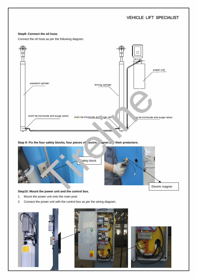
Step8: Connect the oil hose.
Connect the oil hose as per the following diagram.
Step 9: Fix the four safety blocks, four pieces of electric magnet and their protectors.
Step10: Mount the power unit and the control box.
1. Mount the power unit onto the main post.
2. Connect the power unit with the control box as per the wiring diagram.
Safety block
Electric magnet Tirelin
e

VEHICLE LIFT SPECIALIST
9
3. Connect the limit switch.
Step 11: Install the oil hose protector.
Step12: Install the lifting arms.
Connect the lifting arm and the carriage by pins. Install the swing arms on the carriages and make sure the safety lock and
safety teeth are well matched.
Step13: Fill with hydraulic oil
The volume of oil tank is 10L.To insure the lift work normally, the amount of oil in it should reach 4/5 of the tank’s total volume.
32#anti-abrasion hydraulic oil for winter, 46# for summer.
Step14: Trial running.
1. Do refer to the operation instructions in advance and keep in mind that no vehicle left on the lift in the process of trial
running.
2. Check if all the connections are in good condition.
Limit switch
Oil hose protector
Tirelin
e

VEHICLE LIFT SPECIALIST
10
Step 15: Install the chain protection and door-opening protection.
Step16: Install the cover plate.
3.4 Items to be checked after installation.
S/N Check items YES NO1 Are the posts vertical to the floor?
2 Are the two posts paralleled?
3 Is the oil hose well connected?
4 Is the steel cable well connected?
5 Are all lifting arms well fixed?
6 Are electrical connections right?
7 Are the rest joints firmly screwed?
8 Are all items need lubricating added with grease?
4. Operation instructions
4.1 Precautions
4.1.1 Check all the joints of oil hose. Only when there is no leakage, the lift can start work.
4.1.2 The lift, if its safety device malfunctions, shall not be used.
4.1.3 The machine shall not lift or lower an automobile if its center of gravity is not positioned midway of the swing arms.
Otherwise, the Ever-Eternal as well as our dealers will not bear any responsibility for any consequence resulted thereby.
4.1.4 Operators and other personnel concerned should stand in a safety area during lifting and lowering process.
4.1.5 When lifting arms rise to the desired height, switch off the power at once to prevent any mal-operation done by
unconcerned people.
4.1.6. Make sure the safety lock of the lift is engaged before start working under the vehicle and no people under the
vehicle during lifting and lowering process.
Chain protection Door-opening protection
Tirelin
e

VEHICLE LIFT SPECIALIST
11
Start
Turn on the power switch
Press UP button
Motor drives the gear pump work
Cylinder piston drives the chain work
Chain drives the carriage rise
The lift is raised
Start
Turn on the power switch
Press the DOWN button
The lift is lowered
4.2 Descriptions of control box
4.3 Flow chart for operation
Description Function
Power Switch Control power
Power lamp Indicate if power being connected
UP button Raise the lift
Safety lock button Ensure safety in operation process
DOWN button Lower the lift
Emergency stop Ensure safety
Raising Lowering
Tirelin
e

VEHICLE LIFT SPECIALIST
12
4.4 Operation instructions Raise the lift
1. Make sure that you have read and understood the operation manual before operation.
2. Park the vehicle between two posts.
3. Adjust the lifting arms until they reach the supporting positions of the vehicle and make sure the gravity of vehicle
located in the center of four lifting arms.
4. Switch on and insure to operate as per requirements on the nameplate attached.
5. Press the”UP”button on the control box until pads of lifting arms touched the prop-position of vehicle.
6. Keep on raising the vehicle to let it have a bit clearance from the ground and check again its stability.
7. Raise the vehicle to the desired height, check it is safe or not, press the “Safety Lock” button on the control panel to
have the safety lock engaged, turn off the power and then perform maintenance or repair work underneath.
Lower the lift
1. Turn on the emergency stop button.
2. Press the DOWN button on the control box. Meanwhile the lifting arms automatically go upwards about 5CM which
releases the safety lock and makes the electric magnet start working. The lift lowers accordingly.
3. After the swing arms lower to the lowest position, pull them to the horizontal position and clear up all the obstacles.
4. Drive the vehicle away.
4.5 Emergency lowering in case of no power The carriage is not engaged:
a. Draw out at the same time the four pieces of electric magnet installed in the two posts.
b. Screw loose the e-magnetic unloading valve to lower the carriage.
The carriage is engaged:
a. Screw off the fitting (opposite to the oil out-let) to connect the manual hydraulic pump.
Tirelin
e

VEHICLE LIFT SPECIALIST
13
b.Press the handle of the hydraulic pump to supply oil to the cylinder and release the lock.
(Note that this hydraulic pump is not an essential part of our lift and we will make extra charge if buyers want to buy
one from us.)
c. Draw out at the same time the four pieces of electric magnet installed in the two posts.
d.Screw loose the e-magnetic unloading valve to lower the carriage.
Tirelin
e

VEHICLE LIFT SPECIALIST
14
5. Trouble Shooting
ATTENTION: If the trouble could not be fixed by yourself, please do not hesitate to contact us for help .We will offer our
service at the earliest time we can. By the way, your troubles will be judged and solved much faster if you could provide us
more details or pictures of the trouble.
TROUBLES CAUSE SOLUTION
Abnormal noise Abrasion exists on insider surface of the posts. Grease the inside of the post.
Trash in the post. Clear the trash
Motor does not run
and will not rise
The wire connection is loose. Check and make a good connection.
The motor is blown. Replace it.
The limit switch is damaged or the wire connection is
loose.
Connect it or adjust or replace the
limit switch.
Motor runs but will not
raise
The motor run reversely. Check the wire connection.
Overflow valve is loose or jammed. Clean or adjust it.
The gear pump is damaged. Replace it.
Oil level is too low. Add oil.
The oil hose became loose or dropped off. Tighten it.
The cushion valve became loose or jammed. Clean or adjusts it.
Carriages go down
slowly after being
raised
The oil hose leaks. Check or replace it.
The oil cylinder is not tightened. Replace the seal.
The single valve leaks. Clean or replace it.
E-magnetic valve fails to work well. Clean or replace it.
Steel cable is loose or not with same tightness Check and adjust the tightness.
Raising too slow
The oil filter is jammed. Clean or replace it.
Oil level is too low. Add oil.
The overflow valve is not adjusted to the right position. Adjust it.
The hydraulic oil is too hot ( above 45°). Change the oil.
The seal of the cylinder is abraded. Replace the seal.
Inside surface of the posts is not well greased. Add grease.
Lowering too slow
The throttle valve jammed. Clean or replace.
The hydraulic oil is dirty. Change the oil.
The anti-surge valve jammed. Clean it.
The oil hose jammed. Replace it.
The steel cable is
abraded No grease when installation or out of lifetime Replace it.
Tirelin
e

VEHICLE LIFT SPECIALIST
15
6. Maintenance
Easy and low cost routine maintenance can ensure the lift work normally and safely. Following are requirements for routine
maintenance. You may choose the frequency of routine maintenance by consulting your lift’s working conditions and time.
THE FOLLOWING PARTS ARE NEEDED TO BE LUBRICATED
6.1. Daily checking items before operation
The user must perform daily check. Daily check of safety latch system is very important – the discovery of device failure
before action could save your time and prevent you from great loss, injury or casualty.
·Before operation, judge whether the safety latch in engaged by sound.
·Check whether oil hose well connected and whether it leaks or not.
·Check the connections of chain and steel cable and check the power unit.
·Check whether plug bolts firmly screwed.
·Check if safety teeth and safety block matched well or not.
6.2. Weekly checking items
·Check the flexibility of moving parts.
·Check the working conditions of safety parts.
·Check the amount of oil left in the oil tank. Oil is enough if the carriage can be raised to highest position. Otherwise, oil is
insufficient.
·Check whether plug bolts firmly screwed.
6.3. Monthly checking items
·Check whether plug bolts firmly screwed.
·Check the tightness of the hydraulic system and screw firm the joints if it leaks.
·Check the lubrication and abrasion circumstance of axial pins, carriages, lifting arms and other related parts and replace in
time with new ones if they failed to work well.
·Check the lubrication and abrasion circumstance of steel cable.
6.4. Yearly checking items
·Empty the oil tank and check the quality of hydraulic oil.
·Wash and clean the oil filter.
If users strictly follow the above maintenance requirements, the lift will keep in a good working condition and
meanwhile accidents could be avoided to a large extent.
S/N Description
1 Upper wheel
2 Steel cable
3 Chain wheel
4 Chain
5 Sliding block
6 Pin
7 Arm block
8 Lifting arm
9 Tray
10 Down wheel
Tirelin
e

VEHICLE LIFT SPECIALIST
16
7. ANNEX
Annex 1, Packing List of the whole lift S/N Name Drawing#/Size Description QTY
1 Posts 6254E-A1 Component 2
2 Carriage 6254EA2 Component 2
3 Hydraulic power unit(manual or electrical) 6254E-A7 Component 1 left and 1 right
4 Assistant cylinder 6254E-A8 Component 1 left and 1 right
5 Driving cylinder 6254E-A30-B1 Component 1
6 Electrical system 6254E-A5 Component 1
7 Carton for electrical parts
8 Carton for magnetic parts
9 Steel cable L=8785mm 6254-A6 Component 1
10 Long arm 6254EA7 Component 1
11 Short arm 6254E-A8 Component 1
12 Cover plate 6254E-A10 Welding piece 1
13 Bottom trough plate 6254E-A9 Q235A 1
14 Right packing frame 6254E-A30-B2 Welding piece 1
15 Top plate protector 6254E-A16 ABS 2
16 The carton includes the following parts
16.1 Axis pin 6214E-A12 Component 4
16.2 Height adapter 6254E-A11 Q235A 4
16.3 Short foot protector 6254S-A9-B3 Welding piece 2
16.4 Foot protector 6254-A7-B5 Component 2
16.5 Tray 6254E-A7-B4 Component 4
16.6 Chain protection hook 6254E-A2-B1 Component 4
167 Short oil hose L=2550mm 6254E-B4-B1 Component 1
16.8 Long oil hose L=2880mm 6254E-B4-B2 Component 1
16.9 Safety block 6254E-A13 45 4
16.10 E-magnet protector 6254E-A15 ABS 4
1611 Locating block 6254E-A17 Q235A 4
16.12 Wire cover 6254E-A18 Q235A 6
16.13 Chain protection 6254-A1-B5 2
16.14 Pull pole 6254-A1-B6 Welding piece 4
16.15 Rubber buffer 6254-A7-B10 Rubber 2
16.16 Outside-Hex Screw M10*30 Standard piece 4
16.17 Inside-Hex Screw M8*12 Standard piece 8
16.18 Cross round head screw M5*10 Standard piece 24
16.19 Cross round head screw M5*20 Standard piece 12
16.20 Cross round head screw M6*8 Standard piece 4
16.21 Cross round head screw M6*16 Standard piece 4
16.22 Cross countersunk head screw M8*25 Standard piece 4
16.23 Flat washer Φ6 Standard piece 8
Tirelin
e

VEHICLE LIFT SPECIALIST
17
S/N Name Drawing#/Size Description QTY
16.24 Flat washer Φ10 Standard piece 4
16.25 Spring washer Φ10 Standard piece 4
1626 Nut M6 Standard piece 8
16.27 Nut M10 Standard piece 4
16.28 Circlip for shaft Φ50 Standard piece 4
16.28 Expansion bolt M188*160 Standard piece 10
Tirelin
e

VEHICLE LIFT SPECIALIST
18
Annex2, Overall diagram
Tirelin
e

VEHICLE LIFT SPECIALIST
19
Annex3, Diagram for ground fixing
Annex 4, Hydraulic working system
1. Main cylinder
2. Assistant cylinder
3. E-magnetic unloading valve
4. Throttle valve
5. Motor
6. Coupling
7. Gear pump
8. Single-way valve
9. Overflow valve
10. Anti-surge valve
11. Cushion valve
12. Emergent unloading valve
Tirelin
e

VEHICLE LIFT SPECIALIST
20
Annex5, Wiring diagram
Single phase
Tirelin
e

VEHICLE LIFT SPECIALIST
21
Three phase
Tirelin
e

VEHICLE LIFT SPECIALIST
22
Tirelin
e

VEHICLE LIFT SPECIALIST
23
Tirelin
e

VEHICLE LIFT SPECIALIST
24
Tirelin
e
VEHICLE LIFT SPECIALIST
25
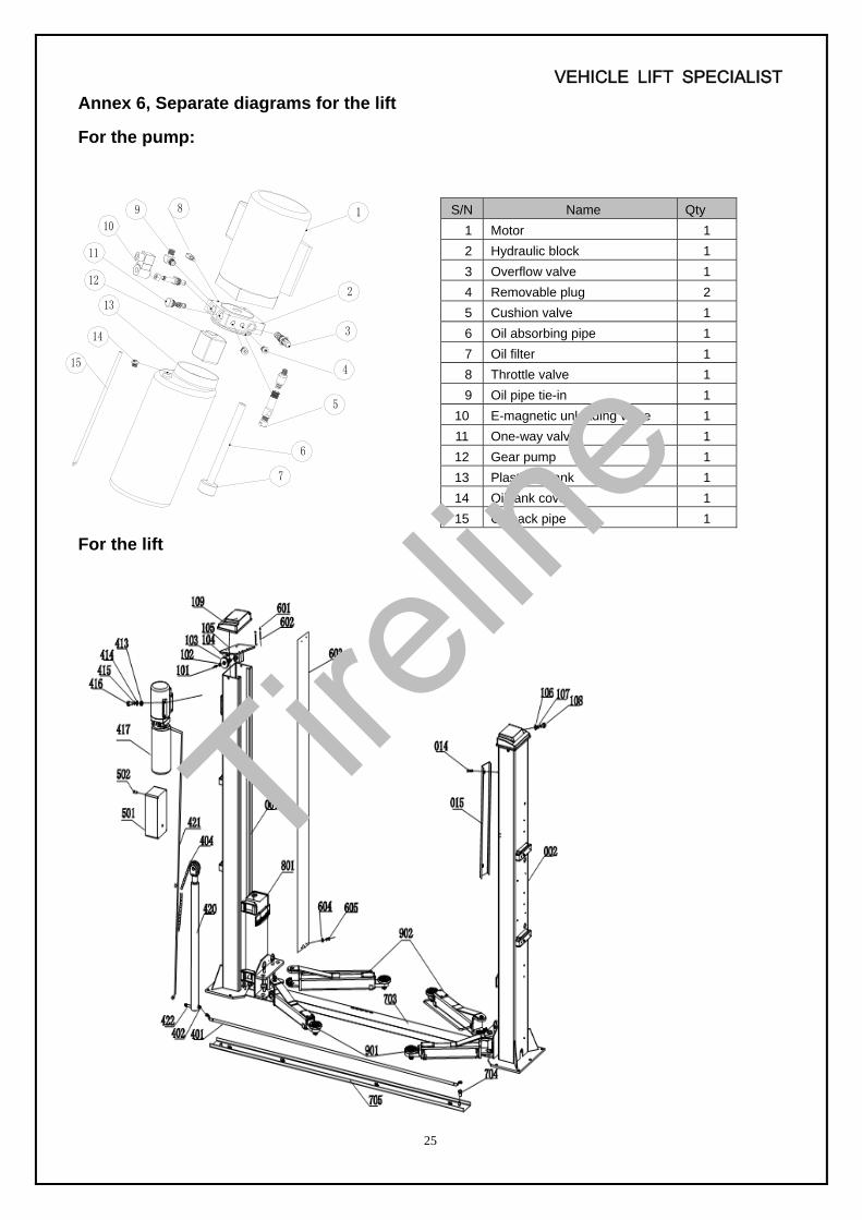
Annex 6, Separate diagrams for the lift
For the pump: For the lift
S/N Name Qty
1 Motor 1
2 Hydraulic block 1
3 Overflow valve 1
4 Removable plug 2
5 Cushion valve 1
6 Oil absorbing pipe 1
7 Oil filter 1
8 Throttle valve 1
9 Oil pipe tie-in 1
10 E-magnetic unloading valve 1
11 One-way valve 1
12 Gear pump 1
13 Plastic oil tank 1
14 Oil tank cover 1
15 Oil back pipe 1
Tirelin
e

VEHICLE LIFT SPECIALIST
26
S/N Material No. Name Drawing#/Size Qty Description Remark
001 603001 Main post EE-6254E-A1 1 Welding piece
002 603002 Assistant post EE-6254E-A2 Welding piece
007 220001 Oil less bearing SF-1 2512 4 Standard piece
008 401001 Spacer EE-6254-A1-B2 4 Q235A
009 219002 Circlip for shaft GB/T894.1-1986 25 2 Standard piece
012 241063 Down wheel EE-6254E-A1-B1 1 45#
013 241071 Height adapter EE-6254E-A11 4 Welding piece 130MM
014 215023 Screw GB/818-2000 M5*20 16 Standard piece
015 403009 Oil hose cover EE-6254E-A18 8 Q235A
016 264002 Safety plate EE-6254E-A13 4 45#
017 403008 Positioning block EE-6254E-A17 4 Q235A
018 215002 Screw GB/818-2000 M6*16 4 Standard piece
019 215008 Screw GB/818-2000 M5*10 16 Standard piece
020 403006 Electromagnet EE-6254E-A14 4 Component
021 428036 Electromagnet cover EE-6254E-A15 4 Plastic
022 215008 Screw GB/818-2000. M5*10 8 Standard piece
101 211001 Screw M8*12 2 Standard piece
102 241050 Screen EE-6254-A3-B3 2 Q235A
103 241008 Up wheel EE-6254-A3-B1 2 45#
104 220002 Oil less bearing SF-1 2518 2 Standard piece
105 603005 Topper plate EE-6254E-A3-B1 2 Welding piece
106 217005 Flat washer GB/T93-2000 Φ12 4 Standard piece
107 218005 Spring washer GB/T93-2000 Φ12 4 Standard piece
108 212002 Bolt GB/T5781-2000 M 12*20 4 Standard piece
109 242024 Topper plate cover EE-6254E-A16 2 Plastic
Tirelin
e

VEHICLE LIFT SPECIALIST
27
S/N Material No. Name Drawing#/Size Qty Description Remark
801 603004 Carriage EE-6254E-A2-B2 2 Welding piece
814 241007 Pulling rod EE-6254E-A2-B1 4 Welding piece
815 255002 Compression spring EE-6214F-A3-B5 4 Standard piece
816 254015 Teeth block EE-6214F-A3-B3 4 Q235A
817 219012 Circlip for shaft Φ22 4 Standard piece
818 224054 Spring pin 5*35 4 Standard piece
222 214003 Screw M8*25 4 Standard piece
223 242002 Door-opening EE-6254-A7-B10 2 Rubber
224 242003 Sliding block EE-6254-A7-B1 16 Nylon 1010
225 241021 Steel cable release EE-6254-A6 2 Component L=8785mm
901 Short arm EE-6254E-A8 1 Component
902 Long arm EE-6254E-A7 2 Component
903 241016 Pin EE-6254E-A12 4 Component
904 603019 Foot protector EE-6254S-A8-B5 2 Welding piece
905 603008 Long extensive arm EE-6254E-A7-B3 2 Welding piece
906 603007 Long arm EE-6254E-A7-B1 2 Welding piece
907 603013 Short arm EE-6254E-A8-B1 2 Welding piece
908 214001 Screw M5*10 16 Standard piece
909 242018 Rubber pad EE-6254E-A7-B2 4 Rubber
910 219014 Circlip for shaft Φ26 4 Standard piece
911 242014 Round rubber pad EE-6254E-A7-B4-C4 4 Rubber
912 603009 Tray EE-6254E-A7-B4-C1 4 Welding piece
913 219015 Circlip for shaft Φ38 8 Standard piece
914 241065 Casing EE-6254E-A7-B4-C2 4 Q235A
915 241064 Inner casing EE-6254E-A7-B4-C3 4 Q235A
916 219009 Circlip for shaft GB/T894.1-1986 Φ50 4 Standard piece
917 603010 Short extensive arm EE-6254E-A8-B2 2 Welding piece
918 601018 Foot protector EE-6254S-A9-B3 2 Welding piece
919 211001 Screw M8*12 8 Standard piece
920 211074 Screw M10*20 12 Standard piece
921 254016 Teeth block EE-6214F-A4-B3 4 Q235A
401 242004 Oil hose EE-6254E-A4-B2 1 Component 2880mm
402 241043 Short tie-in EE-6254-A5-B10 1 35# With anti-surge valve
403 241002 Assistant cylinder EE-6254-A5-B-4 1 Component
404 241003 Leaf chain LH1234-127 2 Component
405 601005 Chain wheel seat EE-6254-A5-B1 2 Welding piece
406 219002 Circlip for shaft GB/T894.2-1986 Φ25 4 Standard piece
407 241009 Chain wheel shaft EE-6254-A5-B2 2 45#
408 220003 Oil less bearing SF-1 2548 2 Standard piece
409 241010 Chain wheel EE-6254-A5-B3 2 45#
410 241051 Screen plate EE-6254-A5-B11 2 Q235A
411 218002 Spring washer M6 4 Standard piece
412 211028 Screw M6*20 4 Standard piece
413 216005 Nut M10 4 Standard piece
414 217004 Flat washer M10 4 Standard piece
415 218004 Spring washer M10 4 Standard piece
416 212008 Bolt M10*30 4 Standard piece
417 Power unit EE-6254-A5-B6 1 Component
420 241001 Main cylinder EE-6254-A5-B5 1 Component
Tirelin
e

VEHICLE LIFT SPECIALIST
28
S/N Material No. Name Drawing#/Size Qty Description Remark
421 241082 Main oil hose EE-6254E-A4-B1 1 Component 2555mm
422 243002 Long tie-in EE-6214-A5-B4 1 Component With anti-surge valve
501 Electrical system EE-6254-A4 1 Component
502 215032 Screw GB/T70.8-1885 M5*12 4 Standard piece
601 216003 Nut M6 8 Standard piece
602 241026 Chain protection hook EE-6254-A1-B6 4 Welding piece
603 242009 Chain protection EE-6254-A1-B5 2 Q235A L=2700mm
604 217001 Flat washer Φ6 8 Standard piece
605 215003 Screw M6*8 4 Standard piece
703 403002 Cover plate EE-6254E-A10 1 Q235A
704 211066 Screw GB/T70.3-2000 M12*16 2 Standard piece
705 603011 Bottom trough plate EE-6254E-A9 1 Welding piece
Annex 7.Spare parts list Spare parts list---electrical system
S/N Material No. Name Spec. Unit Qty Note
1 321001 Power
switch LW26GS-20/04 Pcs 1
2 322003 Button Y090 Pcs 3
3 324021 Power
Indicator AD17-22G-AC24 Pcs 1
4 320009 Transformer JBK-160VA220V-24V Pcs 1 Same outlook as item7 5 320098 Transformer JBK-160VA230V-24V Pcs 1 Same outlook as item7 6 320054 Transformer JBK-160VA240V-24V Pcs 1 Same outlook as item7
7 320057 Transformer JBK-160VA380V-24V Pcs 1
8 320090 Transformer JBK-160VA400V-24V Pcs 1 Same outlook as item7 9 320061 Transformer JBK-160VA415V-24V Pcs 1 Same outlook as item7
10 330004 AC contactor CJX2-1210/AC24 Pcs 1
Tirelin
e

VEHICLE LIFT SPECIALIST
29
S/N Material No. Name Spec. Unit Qty Note
11 327004 Circuit
breaker DZ47-63 C16 /3P Pcs 1
12 327002 Circuit
breaker DZ47-63 C32 /2P Pcs 1
13 327003 Circuit
breaker DZ47-63 C3 /1P Pcs 1
14 327010 Circuit
breaker DZ47-63 C6 /1P Pcs 1 Same outlook as item13
15 321024 Limit switch ME8104 Pcs 1
16 336012 Bridge
rectifier KBPC5A-35A Pcs 1
17 335007 Capacitor 4700UF/50V Pcs 1
18 328021 Control box Bigger one Pcs 1
19 326010 Relay LY2NJ/AC24 Pcs 1
20 326011 Relay holder PTF-08A Pcs 1
Tirelin
e

VEHICLE LIFT SPECIALIST
30
S/N Material No. Name Spec. Unit Qty Note
21 326005 Time relay ST6PA-5S/AC24V Pcs 1
22 326006 Time relay
holder PYF-08A Pcs 1
Spare parts list---machine part
S/N Name Drawing# Qty Material Note
012 Down wheel EE-6254E-A1-B1 1 45#
013 Height adapter EE-6254E-A11 4 Welding piece 130MM
016 Safety plate EE-6254E-A13 4 45#
017 Positioning block EE-6254E-A17 4 Q235A
020 Electromagnet EE-6254E-A14 4 Component
103 Up wheel EE-6254-A3-B1 2 45#
815 Compression spring EE-6214F-A3-B5 4 Standard piece
816 Teeth block EE-6214F-A3-B3 4 Q235A
223 Door-opening protection EE-6254-A7-B10 2 Rubber
224 Sliding block EE-6254-A7-B1 16 Nylon 1010
909 Rubber pad EE-6254E-A7-B2 4 Rubber
911 Round rubber pad EE-6254E-A7-B4-C4 4 Rubber
921 Teeth block EE-6214F-A4-B3 4 Q235A
401 Oil hose EE-6254E-A4-B2 1 Component 2880mm
402 Short tie-in EE-6254-A5-B10 1 35# With anti-surge
403 Assistant cylinder EE-6254-A5-B-4 1 Component
409 Chain wheel EE-6254-A5-B3 2 45#
417 Power unit EE-6254-A5-B6 1 Component
420 Main cylinder EE-6254-A5-B5 1 Component
421 Main oil hose EE-6254E-A4-B1 1 Component 2555mm
422 Long tie-in EE-6214-A5-B4 1 Component With anti-surge
603 Chain protection EE-6254-A1-B5 2 Q235A L=2700mm
Tirelin
e
VEHICLE LIFT SPECIALIST
31
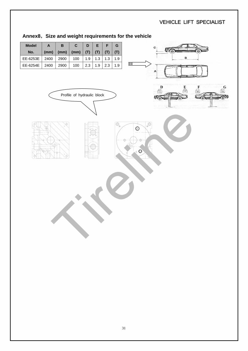
Annex8,Size and weight requirements for the vehicle
Model
No.
A
(mm)
B
(mm)
C
(mm)
D
(T)
E
(T)
F
(T)
G
(T)
EE-6253E 2400 2900 100 1.9 1.3 1.3 1.9
EE-6254E 2400 2900 100 2.3 1.9 2.3 1.9
D E F G
Profile of hydraulic block
Tirelin
e