TECH-EE SERIES CONTROL VALVES
24
S AFE W ATER T ECHNOLOGIES , I NC . OPERATION & INSTRUCTION MANUAL TECH-EE SERIES CONTROL VALVES FILTERS, SOFTENERS, CONDITIONERS 1 INCH TECH-EE SERIES CONTROL VALVE MODEL: WS1EE, WS1EE TWIN 1.25 INCH TECH-EE SERIES CONTROL VALVE MODEL: WS1.25EE 1.5 INCH TECH-EE SERIES CONTROL VALVE MODEL: WS1.5EE 2 INCH TECH-EE SERIES CONTROL VALVE MODEL: WS2EE MARCH 2016
-
Upload
khangminh22 -
Category
Documents
-
view
1 -
download
0
Transcript of TECH-EE SERIES CONTROL VALVES

S a f e W a t e r t e c h n o l o g i e S , i n c .
O P E R A T I O N & I N S T R U C T I O N M A N U A L
TECH-EE SERIES CONTROL VALVESF I L T E R S , S O F T E N E R S , C O N D I T I O N E R S
1 INCH TECH-EE SERIES CONTROL VALVE MODEL: WS1EE, WS1EE TWIN
1.25 INCH TECH-EE SERIES CONTROL VALVE MODEL: WS1.25EE
1.5 INCH TECH-EE SERIES CONTROL VALVE MODEL: WS1.5EE
2 INCH TECH-EE SERIES CONTROL VALVE MODEL: WS2EE
MARCH 2016

Table of Contents
3. Button Operation and Function 3. Regeneration, Pending, Standby, and Error Screens 4. Regeneration Cycles and Times 5. User Displays 5. General Operation: User Displays 1 – 5 5. Setting Time of Day 6. Configuration Settings 6. Step 1-CF. Enter Configuration Settings 6. Step 2-CF. Set Valve Type 6. Step 3-CF. Set Meter Size 6. Step 4-CF. Set Differential Pressure (dP) Switch 7. Step 5-CF. Set Control Valve Operation 7. Configuring the Control Valve for No Hard Water Bypass Operation [nHbP] 8. Configuring the Control Valve for Separate Source Operation [SEPS] 8. Configuring the Control Valve for System Controller Operation [SYS] 8. Configuring the Control Valve to Act as an Alternator [ALT A] [ALT b] 10. Step 6-CF. Set Fill Units 11. Softener System Setup 11. Step 1-SS. Enter Softener System Setup 11. Step 2-SS. Set Softening Operation 11. Step 3-SS. Set Brining Direction 11. Step 4-SS. Set Refill Location 11. Steps 5-SS thru 9-SS. Set Cycle Times 12. Step 10-SS. Set System Capacity 12. Step 11-SS. Set Volume Capacity 12. Step 12-SS. Set Regeneration Time Option 13. Step 13-SS. Set Relay Operation 13. Step 14-SS. Set Relay Actuation Time or Gallons 13. Step 15-SS. Set Relay Deactivation Time 14. Table 1. Softener and Filter Setting Options 15. Filter System Setup 15. Step 1-FS. Enter Filter System Setup15. Step 2-FS. Set Filtering Operation15. Steps 3-FS thru 4-FS. Set Cycle Times15. Step 5-FS. Set Volume Capacity15. Step 6-FS. Set Regeneration Time Option16. Step 7-FS. Set Relay Operation16. Step 8-FS. Set Relay Actuation Time or Gallons16. Step 9-FS. Set Relay Deactivation Time 17. Installer Display Settings 17. Step 1-NA. Enter Installer Display Settings 17. Step 2-NA. Set Hardness 17. Step 3-NA. Set Day Override 17. Steps 4-NA thru 5-NA. Set Next Regeneration Time 18. Diagnostics 21. Drawings and Part Numbers22. Tech-EE Setup Sheets for User Records
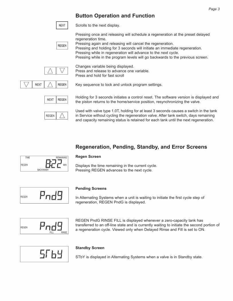
Button Operation and FunctionScrolls to the next display.
Pressing once and releasing will schedule a regeneration at the preset delayed regeneration time.Pressing again and releasing will cancel the regeneration.Pressing and holding for 3 seconds will initiate an immediate regeneration.Pressing while in regeneration will advance to the next cycle.Pressing while in the program levels will go backwards to the previous screen.
Changes variable being displayed. Press and release to advance one variable.Press and hold for fast scroll
Key sequence to lock and unlock program settings.
Holding for 3 seconds initiates a control reset. The software version is displayed and the piston returns to the home/service position, resynchronizing the valve.
Used with valve type 1.0T, holding for at least 3 seconds causes a switch in the tank in Service without cycling the regeneration valve. After tank switch, days remaining and capacity remaining status is retained for each tank until the next regeneration.
Regeneration, Pending, Standby, and Error ScreensRegen Screen
Displays the time remaining in the current cycle. Pressing REGEN advances to the next cycle.
Pending Screens
In Alternating Systems when a unit is waiting to initiate the first cycle step of regeneration, REGEN PndG is displayed.
REGEN PndG RINSE FILL is displayed whenever a zero-capacity tank has transferred to an off-line state and is currently waiting to initiate the second portion of a regeneration cycle. Viewed only when Delayed Rinse and Fill is set to ON.
Standby Screen
STbY is displayed in Alternating Systems when a valve is in Standby state.
Page 3
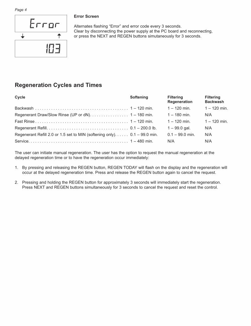
Error Screen
Alternates flashing “Error” and error code every 3 seconds. Clear by disconnecting the power supply at the PC board and reconnecting, or press the NEXT and REGEN buttons simutaneously for 3 seconds.
Regeneration Cycles and Times
Cycle Softening Filtering Filtering Regeneration BackwashBackwash . . . . . . . . . . . . . . . . . . . . . . . . . . . . . . . . . . . . . . . . . 1 – 120 min. 1 – 120 min. 1 – 120 min.Regenerant Draw/Slow Rinse (UP or dN) . . . . . . . . . . . . . . . . . 1 – 180 min. 1 – 180 min. N/AFast Rinse . . . . . . . . . . . . . . . . . . . . . . . . . . . . . . . . . . . . . . . . . 1 – 120 min. 1 – 120 min. 1 – 120 min.Regenerant Refill . . . . . . . . . . . . . . . . . . . . . . . . . . . . . . . . . . . . 0.1 – 200.0 lb. 1 – 99.0 gal. N/ARegenerant Refill 2.0 or 1.5 set to MIN (softening only) . . . . . . 0.1 – 99.0 min. 0.1 – 99.0 min. N/AService. . . . . . . . . . . . . . . . . . . . . . . . . . . . . . . . . . . . . . . . . . . . 1 – 480 min. N/A N/A
The user can initiate manual regeneration. The user has the option to request the manual regeneration at the delayed regeneration time or to have the regeneration occur immediately:
1. By pressing and releasing the REGEN button, REGEN TODAY will flash on the display and the regeneration will occur at the delayed regeneration time. Press and release the REGEN button again to cancel the request.
2. Pressing and holding the REGEN button for approximately 3 seconds will immediately start the regeneration. Press NEXT and REGEN buttons simultaneously for 3 seconds to cancel the request and reset the control.
Page 4
User DisplaysGENERAL OPERATION
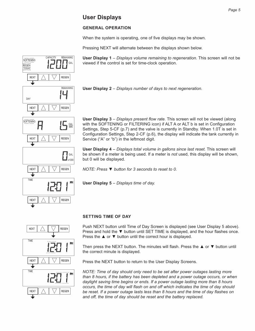
When the system is operating, one of five displays may be shown.
Pressing NEXT will alternate between the displays shown below.
User Display 1 – Displays volume remaining to regeneration. This screen will not be viewed if the control is set for time-clock operation.
User Display 2 – Displays number of days to next regeneration.
User Display 3 – Displays present flow rate. This screen will not be viewed (along with the SOFTENING or FILTERING icon) if ALT A or ALT b is set in Configuration Settings, Step 5-CF (p.7) and the valve is currently in Standby. When 1.0T is set in Configuration Settings, Step 2-CF (p.6), the display will indicate the tank currently in Service (“A” or “b”) in the leftmost digit.
User Display 4 – Displays total volume in gallons since last reset. This screen will be shown if a meter is being used. If a meter is not used, this display will be shown, but 0 will be displayed.
NOTE: Press ▼ button for 3 seconds to reset to 0.
User Display 5 – Displays time of day.
SETTING TIME OF DAY
Push NEXT button until Time of Day Screen is displayed (see User Display 5 above). Press and hold the ▼ button until SET TIME is displayed, and the hour flashes once. Press the ▲ or ▼ button until the correct hour is displayed.
Then press the NEXT button. The minutes will flash. Press the ▲ or ▼ button until the correct minute is displayed.
Press the NEXT button to return to the User Display Screens.
NOTE: Time of day should only need to be set after power outages lasting more than 8 hours, if the battery has been depleted and a power outage occurs, or when daylight saving time begins or ends. If a power outage lasting more than 8 hours occurs, the time of day will flash on and off which indicates the time of day should be reset. If a power outage lasts less than 8 hours and the time of day flashes on and off, the time of day should be reset and the battery replaced.
Page 5

Configuration SettingsStep 1-CF – Enter Configuration Settings: Press NEXT and ▼ buttons simultaneously for 5 seconds and release. Again, press NEXT and ▼ buttons simultaneously for 5 seconds and release. If screen in Step 2-CF does not appear, the lock on the valve is activated. To unlock press ▼, NEXT, ▲, REGEN in sequence, then press NEXT and ▼ buttons simultaneously for 5 seconds and release. Then again, press NEXT and ▼ buttons simultaneously for 5 seconds and release.
Step 2-CF – Set Valve Type: Press the ▲ or ▼ button to select 1.0 for 1 inch valve, 1.0T for twin valve, 1.25 for 1.25 inch valve, 1.5 for 1.5 inch valve, 2.0 for 2 inch valve.
If 1.0, 1.0T, or 1.25 are selected, press NEXT to go to Step 4-CF. If 1.5 or 2.0 are selected, press NEXT to go to Step 3-CF. Press REGEN to exit Configuration Settings.
Step 3-CF – Set Meter Size: Press the ▲ or ▼ button to select 1.5, 2.0, 3.0, 1.0r (1.0 Remote Meter), or PUL (Variable Meter Calibration).
If PUL is selected, variable meter pulses of 0.1 to 150.0 PPG can be selected by using the ▲ or ▼ buttons.
Press NEXT to go to Step 4-CF. Press REGEN to return to previous step.
Step 4-CF – Set Differential Pressure (dP) Switch: Press the ▲ or ▼ button to select the use of an outside signal to initiate a regeneration.
If oFF is not selected, a connection must be made to the two-pin connector labeled DP SW located on the upper right corner of the printed circuit board (see photo left).
— oFF: Feature not used.
— on 0: If the dP switch is closed for an accumulative time of two (2) minutes, a regeneration will be signaled to the unit. In a twin alternating system the MAV will transition first to switch units so that the signaled unit can start regeneration. After the MAV has fully transitioned, the regeneration begins immediately.
NOTE: For 1 inch thru 1.5 inch control valves programmed for twin alternating, the Delayed Rinse and Fill feature is not available if “on 0” is set.
— dEL: If the dP switch is closed for an accumulative time of two (2) minutes, a regeneration will occur at the scheduled delayed regeneration time. In a twin alternating system, once the dP switch is triggered the PC board will display REGEN TODAY, and when the delayed regeneration time comes, the control will switch tanks and the triggered unit will then go into regeneration.
NOTE: For 1 inch thru 1.5 inch control valves programmed for twin alternating, the Delayed Rinse and Fill feature is not available if “dEL” is set
— HoLd: If the dP switch is closed, a regeneration will be prevented from occurring while there is switch closure. In a twin alternating system the regeneration of a unit can be prevented upon switch closure. If the unit depletes the capacity down to zero (0), it will not be allowed to switch tanks to regenerate until the switch is open.
NOTE: For 1 inch thru 1.5 inch control valves programmed for twin alternating, the Delayed Rinse and Fill feature is available if "HoLd" is set.
Press NEXT to go to Step 5-CF. Press REGEN to return to previous step.
Page 6
Step 1-CF
Step 2-CF
Step 3-CF
Step 4-CF
NOTE: In a twin alternating system each control must have a separate dP signal or dP switch. One dP signal or one dP switch cannot be used for more than one control.
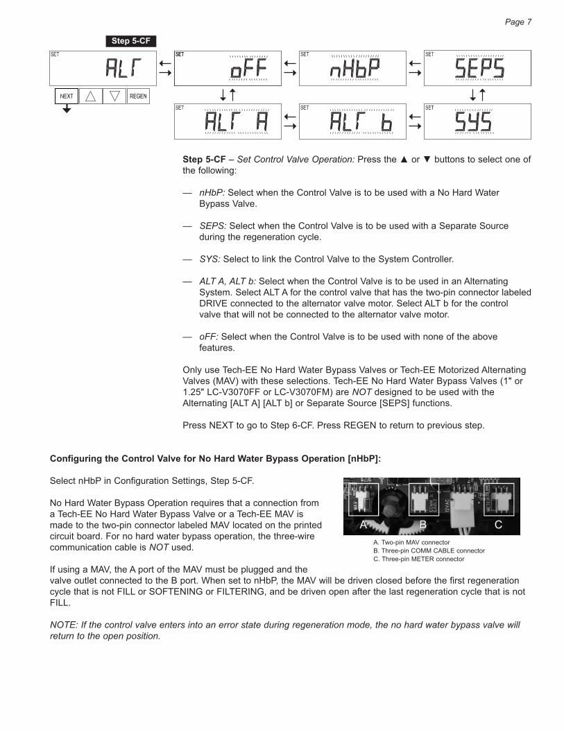
Step 5-CF – Set Control Valve Operation: Press the ▲ or ▼ buttons to select one of the following:
— nHbP: Select when the Control Valve is to be used with a No Hard Water Bypass Valve.
— SEPS: Select when the Control Valve is to be used with a Separate Source during the regeneration cycle.
— SYS: Select to link the Control Valve to the System Controller.
— ALT A, ALT b: Select when the Control Valve is to be used in an Alternating System. Select ALT A for the control valve that has the two-pin connector labeled DRIVE connected to the alternator valve motor. Select ALT b for the control valve that will not be connected to the alternator valve motor.
— oFF: Select when the Control Valve is to be used with none of the above features.
Only use Tech-EE No Hard Water Bypass Valves or Tech-EE Motorized Alternating Valves (MAV) with these selections. Tech-EE No Hard Water Bypass Valves (1" or 1.25" LC-V3070FF or LC-V3070FM) are NOT designed to be used with the Alternating [ALT A] [ALT b] or Separate Source [SEPS] functions.
Press NEXT to go to Step 6-CF. Press REGEN to return to previous step.
Configuring the Control Valve for No Hard Water Bypass Operation [nHbP]:
Select nHbP in Configuration Settings, Step 5-CF.
No Hard Water Bypass Operation requires that a connection from a Tech-EE No Hard Water Bypass Valve or a Tech-EE MAV is made to the two-pin connector labeled MAV located on the printed circuit board. For no hard water bypass operation, the three-wire communication cable is NOT used.
If using a MAV, the A port of the MAV must be plugged and the valve outlet connected to the B port. When set to nHbP, the MAV will be driven closed before the first regeneration cycle that is not FILL or SOFTENING or FILTERING, and be driven open after the last regeneration cycle that is not FILL.
NOTE: If the control valve enters into an error state during regeneration mode, the no hard water bypass valve will return to the open position.
Page 7
Step 5-CF
A. Two-pin MAV connectorB. Three-pin COMM CABLE connectorC. Three-pin METER connector
BA CA B C

Configuring the Control Valve for Separate Source Operation [SEPS]:
Select SEPS in Configuration Settings, Step 5-CF (p.7).
Separate Source Operation requires that a connection from a Tech-EE MAV is made to the two-pin connector labeled MAV located on the printed circuit board. For Separate Source Operation, the three-wire communication cable is NOT used.
The C port of the MAV must be connected to the valve inlet and the A port connected to the separate source used during regeneration. The B port must be connected to the feed water supply.
When set to SEPS, the MAV will be driven closed before the first regeneration cycle and be driven open after the last regeneration cycle.
NOTE: If the control valve enters into an error state during regeneration mode, the MAV will return to the open position.
Configuring the Control Valve for System Controller Operation [SYS]:
Select SYS in Configuration Settings, Step 5-CF (p.7).
For communication between the Control Valve and the System Controller, a three-wire communication cable is required.
System Controller Operation requires that a connection from a Tech-EE No Hard Water Bypass (LC-V3070FF or LC-V3070FM) be made to the two-pin connector labeled MAV located on the printed circuit board for WS1EE and WS1.25EE control valves. For WS1.5EE and WS2EE valves, a connection from a Tech-EE No Hard Water Bypass (LC-V3097/BSPT or LC-V3098/BSPT) to the two-pin connector labeled MAV located on the printed circuit board is required.
Configuring the Control Valve to Act as an Alternator [ALT A] [ALT b]:
Prior to starting the programming steps, connect each end of the three-pin communication cable1 to the three-pin connector labeled COMM CABLE on both the ALT A and ALT b control valves. Also connect the meter cord to either control valve’s three-pin connector labeled METER.
1. Software Version 519.0 and higher = Use 3-wire interconnect cable for all communication between units. Software Version 518.3 and lower = Use 2-wire interconnect cable for twin alternators with independent flow meters.
Page 8
1" OR 1.25"CONTROL
VALVE
“C”PORT
“A”PORT
“B”PORT
SEPARATEREGENERATION
SOURCEUNTREATEDWATER
TREATEDWATER OUT
TREATED WATER REGENERATIONSeparate Source Operation
A. Two-pin MAV connectorB. Three-pin COMM CABLE connectorC. Three-pin METER connector
BA CA B C
“A”PORT
“B”PORT
UNTREATEDWATER
IN1" OR 1.25"METEREDCONTROL
VALVEALTA
1" OR 1.25"METEREDCONTROL
VALVEALTb
TREATED WATER REGENERATIONTwin Alternating System
TREATEDWATER OUT
TREATEDWATER
OUT
UNTREATEDWATER IN
UNTREATED WATER REGENERATIONTwin Alternating System
“A”PORT
“B”PORT
1" OR 1.25" METEREDCONTROL
VALVEALTb
1" OR 1.25" METEREDCONTROL
VALVEALTA
Alternating Softener Valve Programming Steps:
— Configuration Settings, Step 5-CF (p.7): ALT A Valve: Set to ALT A. Connect the outlet
plumbing of the ALT A valve to the MAV’s A port and connect the MAV’s two-pin wire connector to the two-pin connector labeled MAV on the ALT A valve.
ALT b Valve: Set to ALT b. Connect the outlet plumbing of the ALT b valve to the MAV’s B port. No electrical connections are required between the ALT b valve and the MAV.
— Softener System Setup Settings, Step 10-SS (p.12): ALT A Valve: Set System Capacity. ALT b Valve: Set System Capacity.
— Softener System Setup Settings, Step11-SS (p.12): ALT A Valve: Set Volume Capacity to AUTo. ALT b Valve: Set Volume Capacity to AUTo. — Softener System Setup Settings, Step 12-SS (p.12): ALT A Valve: Set Regeneration Time Option to on 0. ALT b Valve: Set Regeneration Time Option to on 0.
— Installer Display Settings, Step 3-NA (p.17): ALT A Valve: Set Day Override to oFF ALT b Valve: Set Day Override to oFF
NOTE: If the control valve is in an error state during regeneration mode, the MAV will close the B port and keep the A port open until the error is corrected and reset.
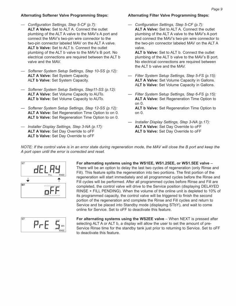
For alternating systems using the WS1EE, WS1.25EE, or WS1.5EE valve – There will be an option to delay the last two cycles of regeneration (only Rinse and Fill). This feature splits the regeneration into two portions. The first portion of the regeneration will start immediately and all programmed cycles before the Rinse and Fill cycles will be performed. After all programmed cycles before Rinse and Fill are completed, the control valve will drive to the Service position (displaying DELAYED RINSE + FILL PENDING). When the volume of the online unit is depleted to 10% of its programmed capacity, the control valve will be triggered to finish the second portion of the regeneration and complete the Rinse and Fill cycles and return to Service and be placed into Standby mode (displaying STbY), and wait to come online for Service. Set to oFF to deactivate this feature.
For alternating systems using the WS2EE valve – When NEXT is pressed after selecting ALT A or ALT b, a display will allow the user to set the amount of pre-Service Rinse time for the standby tank just prior to returning to Service. Set to oFF to deactivate this feature.
Page 9
Alternating Filter Valve Programming Steps:
— Configuration Settings, Step 5-CF (p.7): ALT A Valve: Set to ALT A. Connect the outlet
plumbing of the ALT A valve to the MAV’s A port and connect the MAV’s two-pin wire connector to the two-pin connector labeled MAV on the ALT A valve.
ALT b Valve: Set to ALT b. Connect the outlet plumbing of the ALT b valve to the MAV’s B port. No electrical connections are required between the ALT b valve and the MAV.
— Filter System Setup Settings, Step 5-FS (p.15): ALT A Valve: Set Volume Capacity in Gallons. ALT b Valve: Set Volume Capacity in Gallons.
— Filter System Setup Settings, Step 6-FS (p.15): ALT A Valve: Set Regeneration Time Option to
on 0. ALT b Valve: Set Regeneration Time Option to
on 0.
— Installer Display Settings, Step 3-NA (p.17): ALT A Valve: Set Day Override to oFF ALT b Valve: Set Day Override to oFF

Tech-EE Twin Alternator Operations
Twin alternating systems can be programmed with a day override setting combined with the normal volume based regeneration programming. A twin alternating system in this configuration will then regenerate based on the volume used or the day override if there is a period of low water usage.
Twin alternating systems can be programmed as a time clock only based regenerating system. In this configuration, the days remaining are counted only on the unit that is in Service. The unit in Standby mode only notes days in diagnostics, which results in time clock only twin regeneration initiation.
Twin alternating systems can be programmed for a delayed regeneration time. The system will allow an immediate transfer of the MAV to switch tanks and place a fully regenerated unit in Service once a unit becomes exhausted. The exhausted unit will then be placed into Standby mode and allowed to have a delayed regeneration at the pre-set time.
Step 6-CF – Set Fill Units: If the Control Valve is set as a Softener in Step 2-SS (p.11), if Step 2-CF (p.6) is set to 1.5, and FILL is part of the Regeneration Cycle Sequence, press the ▲ or ▼ button to select Fill Units of minutes [MIN] or pounds [LBS]. Refers to Step 9-SS (p.12).
Press NEXT to exit Configuration Settings. Press REGEN to return to previous step.
Page 10
EXTENDED MAV Piston Rod (Valve “B” in Service Position)
RETRACTED MAV Piston Rod (Valve “A” in Service Position)
EXIT TO DISPLAY SCREENS
Step 6-CF

Softener System SetupStep 1-SS - Enter Softener System Setup: Press NEXT and ▼ simultaneously for 5 seconds and release. If screen in Step 2-SS does not appear, the lock on the valve programming has been activated. To unlock press ▼, NEXT, ▲, REGEN in sequence, then press NEXT and ▼ simultaneously for 5 seconds and release.
Step 2-SS – Set Softening Operation: Press ▲ or ▼ to select SOFTENING.
Press NEXT to go to Step 3-SS. Press REGEN to exit Softener System Setup.
Step 3-SS – Set Brining Direction: Press ▲ or ▼ to select up [UP] or down [dn].
Press NEXT to go to Step 4-SS. Press REGEN to return to the previous step.
Step 4-SS – Set Refill Location: Press ▲ or ▼ to select one of the following:
— PoST: Refills the brine tank after the final rinse.
— PrE: Refills the brine tank four (4) hours before the regeneration time set.
Press NEXT to go to Step 5-SS. Press REGEN to return to the previous step.
Step 5-SS – Set First Cycle: Press ▲ or ▼ to select the length of the first Backwash cycle from 1 to 120 minutes. For WS1.5EE and WS2EE valves, “oFF” is also available.
Press NEXT to go to Step 6-SS. Press REGEN to return to the previous step.
Step 6-SS – Set Second Cycle: Press ▲ or ▼ to select the length of the Regenerant/Brine Draw cycle from 1 to 180 minutes. For WS1.5EE and WS2EE valves, “oFF” is also available.
Press NEXT to go to Step 7-SS. Press REGEN to return to the previous step.
Step 7-SS – Set Third Cycle: Press ▲ or ▼ to select the length of the second Backwash cycle from 1 to 120 minutes. For WS1.5EE and WS2EE valves, “oFF” is also available.
Press NEXT to go to Step 8-SS. Press REGEN to return to the previous step.
Step 8-SS – Set Fourth Cycle: Press ▲ or ▼ to select the length of the Fast Rinse cycle from 1 to 120 minutes. For WS1.5EE and WS2EE valves, “oFF” is also available.
Press NEXT to go to Step 9-SS. Press REGEN to return to the previous step.
Page 11
Step 1-SS
Step 2-SS
Step 3-SS
Step 4-SS
Step 5-SS
Step 6-SS
Step 7-SS
Step 8-SS
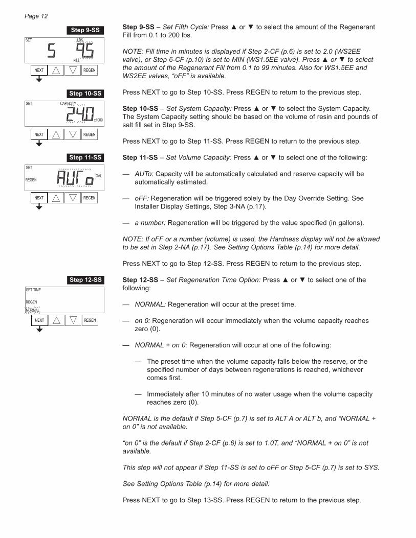
Step 9-SS – Set Fifth Cycle: Press ▲ or ▼ to select the amount of the Regenerant Fill from 0.1 to 200 lbs.
NOTE: Fill time in minutes is displayed if Step 2-CF (p.6) is set to 2.0 (WS2EE valve), or Step 6-CF (p.10) is set to MIN (WS1.5EE valve). Press ▲ or ▼ to select the amount of the Regenerant Fill from 0.1 to 99 minutes. Also for WS1.5EE and WS2EE valves, “oFF” is available.
Press NEXT to go to Step 10-SS. Press REGEN to return to the previous step.
Step 10-SS – Set System Capacity: Press ▲ or ▼ to select the System Capacity. The System Capacity setting should be based on the volume of resin and pounds of salt fill set in Step 9-SS.
Press NEXT to go to Step 11-SS. Press REGEN to return to the previous step.
Step 11-SS – Set Volume Capacity: Press ▲ or ▼ to select one of the following:
— AUTo: Capacity will be automatically calculated and reserve capacity will be automatically estimated.
— oFF: Regeneration will be triggered solely by the Day Override Setting. See Installer Display Settings, Step 3-NA (p.17).
— a number: Regeneration will be triggered by the value specified (in gallons).
NOTE: If oFF or a number (volume) is used, the Hardness display will not be allowed to be set in Step 2-NA (p.17). See Setting Options Table (p.14) for more detail.
Press NEXT to go to Step 12-SS. Press REGEN to return to the previous step.
Step 12-SS – Set Regeneration Time Option: Press ▲ or ▼ to select one of the following:
— NORMAL: Regeneration will occur at the preset time.
— on 0: Regeneration will occur immediately when the volume capacity reaches zero (0).
— NORMAL + on 0: Regeneration will occur at one of the following:
— The preset time when the volume capacity falls below the reserve, or the specified number of days between regenerations is reached, whichever comes first.
— Immediately after 10 minutes of no water usage when the volume capacity reaches zero (0).
NORMAL is the default if Step 5-CF (p.7) is set to ALT A or ALT b, and “NORMAL + on 0” is not available.
“on 0” is the default if Step 2-CF (p.6) is set to 1.0T, and “NORMAL + on 0” is not available.
This step will not appear if Step 11-SS is set to oFF or Step 5-CF (p.7) is set to SYS.
See Setting Options Table (p.14) for more detail.
Press NEXT to go to Step 13-SS. Press REGEN to return to the previous step.
Page 12
Step 9-SS
Step 10-SS
Step 11-SS
Step 12-SS
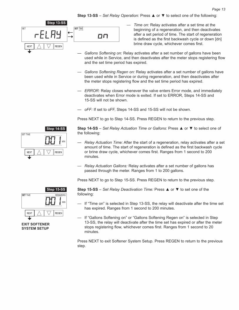
Step 13-SS – Set Relay Operation: Press ▲ or ▼ to select one of the following:
— Time on: Relay activates after a set time at the beginning of a regeneration, and then deactivates after a set period of time. The start of regeneration is defined as the first backwash cycle or down [dn] brine draw cycle, whichever comes first.
— Gallons Softening on: Relay activates after a set number of gallons have been used while in Service, and then deactivates after the meter stops registering flow and the set time period has expired.
— Gallons Softening Regen on: Relay activates after a set number of gallons have been used while in Service or during regeneration, and then deactivates after the meter stops registering flow and the set time period has expired.
— ERROR: Relay closes whenever the valve enters Error mode, and immediately deactivates when Error mode is exited. If set to ERROR, Steps 14-SS and 15-SS will not be shown.
— oFF: If set to oFF, Steps 14-SS and 15-SS will not be shown.
Press NEXT to go to Step 14-SS. Press REGEN to return to the previous step.
Step 14-SS – Set Relay Actuation Time or Gallons: Press ▲ or ▼ to select one of the following:
— Relay Actuation Time: After the start of a regeneration, relay activates after a set amount of time. The start of regeneration is defined as the first backwash cycle or brine draw cycle, whichever comes first. Ranges from 1 second to 200 minutes.
— Relay Actuation Gallons: Relay activates after a set number of gallons has passed through the meter. Ranges from 1 to 200 gallons.
Press NEXT to go to Step 15-SS. Press REGEN to return to the previous step.
Step 15-SS – Set Relay Deactivation Time: Press ▲ or ▼ to set one of the following:
— If “Time on” is selected in Step 13-SS, the relay will deactivate after the time set has expired. Ranges from 1 second to 200 minutes.
— If “Gallons Softening on” or “Gallons Softening Regen on” is selected in Step 13-SS, the relay will deactivate after the time set has expired or after the meter stops registering flow, whichever comes first. Ranges from 1 second to 20 minutes.
Press NEXT to exit Softener System Setup. Press REGEN to return to the previous step.
Page 13
Step 13-SS
Step 14-SS
EXIT SOFTENER SYSTEM SETUP
Step 15-SS

Table 1Softener and Filter Setting Options
* Reserve Capacity estimate is based on history of water usage. Reserve Capacity estimate is not available with Alternating Systems or Twin Tank Valve.
NOTE:
SOFTENERS: Volume Capacity is set in Step 11-SS (p.12); Regeneration Time Option is set in Step 12-SS (p.12); Day Override is set in Step 3-NA (p.17).
FILTERS: Volume Capacity is set in Step 5-FS (p.15); Regeneration Time Option is set in Step 6-FS (p.15); Day Override is set in Step 3-NA (p.17).
Page 14
VolumeCapacity
Regeneration Time Option
DayOverride Result *
AUTO NORMAL oFFReserve capacity automatically estimated. Regeneration occurs when volume capacity falls below the reserve capacity at the next Regen Set Time.
AUTO NORMAL Any number
Reserve capacity automatically estimated. Regeneration occurs at the next Regen Set Time when volume capacity falls below the reserve capacity or the specified number of days between regenerations is reached.
Any number NORMAL oFF Reserve capacity not automatically estimated.
Regeneration occurs at the next Regen Set Time when volume capacity reaches zero (0).
oFF NORMAL Any number
Reserve capacity not automatically estimated. Regeneration occurs at the next Regen Set Time when the specified number of days between regenerations is reached.
Any number NORMAL Any
number
Reserve capacity not automatically estimated. Regeneration occurs at the next Regen Set Time when volume capacity reaches zero (0) or the specified number of days between regenerations is reached.
AUTO on 0 oFF
Reserve capacity not automatically estimated. Regeneration occurs immediately when volume capacity reaches zero (0). Time of regeneration will not be allowed to be set because regeneration will always occur when volume capacity reaches zero (0).
Any number on 0 oFF
Reserve capacity not automatically estimated. Regeneration occurs immediately when volume capacity reaches zero (0). Time of regeneration will not be allowed to be set because regeneration will always occur when volume capacity reaches zero (0).
AUTO NORMAL +on 0 oFF
Reserve capacity automatically estimated. Regeneration occurs when gallons capacity falls below the reserve capacity at the next Regen Set Time or regeneration occurs after 10 minutes of no water usage when volume capacity reaches zero (0).
AUTO NORMAL +on 0
Any number
Reserve capacity automatically estimated. Regeneration occurs at the next Regen Set Time when volume capacity falls below the reserve capacity or the specified number of days between regenerations is reached or regeneration occurs after 10 minutes of no water usage when volume capacity reaches zero (0).
Anynumber
NORMAL +on 0
Any number
Reserve capacity not automatically estimated. Regeneration occurs at the next Regen Set Time when the specified number of days between regenerations is reached or regeneration occurs after 10 minutes of no water usage when volume capacity reaches zero (0).
NOTE: Filters should only use the shaded options.
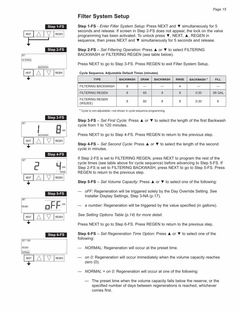
Filter System SetupStep 1-FS - Enter Filter System Setup: Press NEXT and ▼ simultaneously for 5 seconds and release. If screen in Step 2-FS does not appear, the lock on the valve programming has been activated. To unlock press ▼, NEXT, ▲, REGEN in sequence, then press NEXT and ▼ simultaneously for 5 seconds and release.
Step 2-FS – Set Filtering Operation: Press ▲ or ▼ to select FILTERING BACKWASH or FILTERING REGEN (see table below).
Press NEXT to go to Step 3-FS. Press REGEN to exit Filter System Setup.
Step 3-FS – Set First Cycle: Press ▲ or ▼ to select the length of the first Backwash cycle from 1 to 120 minutes.
Press NEXT to go to Step 4-FS. Press REGEN to return to the previous step.
Step 4-FS – Set Second Cycle: Press ▲ or ▼ to select the length of the second cycle in minutes.
If Step 2-FS is set to FILTERING REGEN, press NEXT to program the rest of the cycle times (see table above for cycle sequence) before advancing to Step 5-FS. If Step 2-FS is set to FILTERING BACKWASH, press NEXT to go to Step 5-FS. Press REGEN to return to the previous step.
Step 5-FS – Set Volume Capacity: Press ▲ or ▼ to select one of the following:
— oFF: Regeneration will be triggered solely by the Day Override Setting. See Installer Display Settings, Step 3-NA (p.17).
— a number: Regeneration will be triggered by the value specified (in gallons).
See Setting Options Table (p.14) for more detail.
Press NEXT to go to Step 6-FS. Press REGEN to return to the previous step.
Step 6-FS – Set Regeneration Time Option: Press ▲ or ▼ to select one of the following:
— NORMAL: Regeneration will occur at the preset time.
— on 0: Regeneration will occur immediately when the volume capacity reaches zero (0).
— NORMAL + on 0: Regeneration will occur at one of the following:
— The preset time when the volume capacity falls below the reserve, or the specified number of days between regenerations is reached, whichever comes first.
Page 15
Cycle Sequence, Adjustable Default Times (minutes)
TYPE BACKWASH DRAW BACKWASH RINSE BACKWASH * FILL
FILTERING BACKWASH 8 — — 4 — —
FILTERING REGEN 8 60 8 8 0:30 .95 GAL
FILTERING REGEN (WS2EE) 8 60 8 8 0:30 6
* Cycle is non-adjustable—not shown in cycle sequence programming.
Step 1-FS
Step 2-FS
Step 3-FS
Step 4-FS
Step 5-FS
Step 6-FS
Page 16
— Immediately after 10 minutes of no water usage when the volume capacity reaches zero (0).
NORMAL is the default if Step 5-CF (p.7) is set to ALT A or ALT b, and “NORMAL + on 0” is not available.
“on 0” is default if Step 2-CF (p.6) is set to 1.0T, and “NORMAL + on 0” is not available.
This step will not appear if Step 5-FS is set to oFF or Step 5-CF (p.7) is set to SYS.
See Setting Options Table (p.14) for more detail.
Press NEXT to go to Step 7-FS. Press REGEN to return to the previous step.
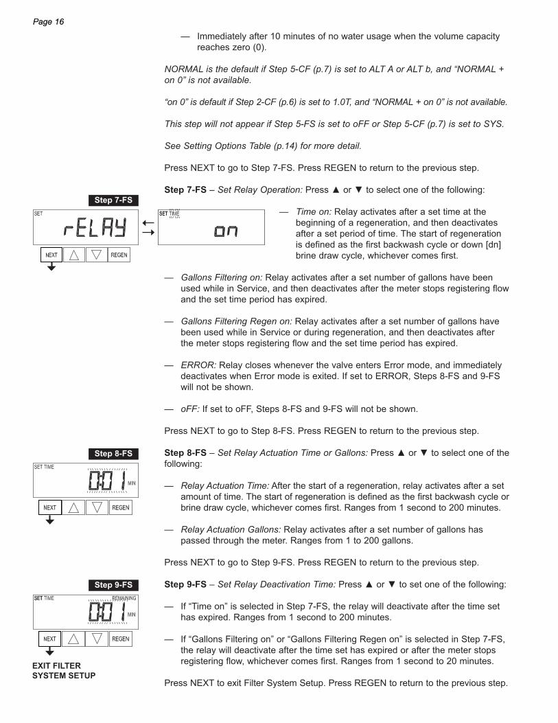
Step 7-FS – Set Relay Operation: Press ▲ or ▼ to select one of the following:
— Time on: Relay activates after a set time at the beginning of a regeneration, and then deactivates after a set period of time. The start of regeneration is defined as the first backwash cycle or down [dn] brine draw cycle, whichever comes first.
— Gallons Filtering on: Relay activates after a set number of gallons have been used while in Service, and then deactivates after the meter stops registering flow and the set time period has expired.
— Gallons Filtering Regen on: Relay activates after a set number of gallons have been used while in Service or during regeneration, and then deactivates after the meter stops registering flow and the set time period has expired.
— ERROR: Relay closes whenever the valve enters Error mode, and immediately deactivates when Error mode is exited. If set to ERROR, Steps 8-FS and 9-FS will not be shown.
— oFF: If set to oFF, Steps 8-FS and 9-FS will not be shown.
Press NEXT to go to Step 8-FS. Press REGEN to return to the previous step.
Step 8-FS – Set Relay Actuation Time or Gallons: Press ▲ or ▼ to select one of the following:
— Relay Actuation Time: After the start of a regeneration, relay activates after a set amount of time. The start of regeneration is defined as the first backwash cycle or brine draw cycle, whichever comes first. Ranges from 1 second to 200 minutes.
— Relay Actuation Gallons: Relay activates after a set number of gallons has passed through the meter. Ranges from 1 to 200 gallons.
Press NEXT to go to Step 9-FS. Press REGEN to return to the previous step.
Step 9-FS – Set Relay Deactivation Time: Press ▲ or ▼ to set one of the following:
— If “Time on” is selected in Step 7-FS, the relay will deactivate after the time set has expired. Ranges from 1 second to 200 minutes.
— If “Gallons Filtering on” or “Gallons Filtering Regen on” is selected in Step 7-FS, the relay will deactivate after the time set has expired or after the meter stops registering flow, whichever comes first. Ranges from 1 second to 20 minutes.
Press NEXT to exit Filter System Setup. Press REGEN to return to the previous step.
Page 16
Step 7-FS
Step 8-FS
EXIT FILTER SYSTEM SETUP
Step 9-FS

Page 17
Installer Display SettingsStep 1-NA – Enter Installer Display Settings: Press NEXT and ▲ buttons simultaneously for 5 seconds and release. If screen in Step 2-NA does not appear, the lock on the valve is activated. To unlock press ▼, NEXT, ▲, REGEN in sequence, then press NEXT and ▲ simultaneously for 5 seconds and release.
Step 2-NA – Set Hardness: Press the ▲ or ▼ button to select the hardness level.
NOTE: This display will not be viewed if FILTERING BACKWASH or FILTERING REGEN is selected in Step 2-FS (p.15) or if “oFF” or a number (volume) was selected in Step 11-SS (p.12).
Press NEXT to go to Step 3-NA. Press REGEN to exit Installer Display Settings.
Step 3-NA – Set Day Override: Press the ▲ or ▼ to select one of the following:
— Number of days between regeneration (1 to 28): Regeneration initiation will be called for on that day regardless of actual water usage.
— oFF: Regeneration initiation is triggered solely by volume used.
NOTE: When Volume Capacity is set to “oFF” in Step 11-SS (p.12), the number of days between regenerations is selected. When Volume Capacity is set to AUTO or to a number (volume) in Step 11-SS (p.12), the maximum number of days between regenerations is selected.
See Setting Options Table (p.14) for more detail.
Press NEXT to go to step 4-NA. Press REGEN to return to previous step.
Step 4-NA – Next Regeneration Time (hour): Press the ▲ or ▼ button to select the the hour of the day for regeneration. The default time is 2:00am.
NOTE: This display will show “REGEN on 0 GAL” if “on 0” is selected in Step 12-SS (p.12) or Step 6-FS (p.15).
Step 5-NA – Next Regeneration Time (minutes): Press the ▲ or ▼ button to select the the minutes of the day for regeneration.
NOTE: This display will not be shown if “on 0” is selected in Step 12-SS (p.12) or Step 6-FS (p.15).
Press NEXT to exit Installer Display Settings. Press REGEN to return to previous step.
Step 1-NA
Step 2-NA
Step 3-NA
Step 4-NA
EXIT INSTALLER DISPLAY SETTINGS
Step 5-NA

Page 18
DiagnosticsStep 1-DA – Enter Diagnostics: Press ▲ and ▼ simultaneously for 5 seconds and release. If screen in Step 2-DA does not appear, the lock on the valve is activated. To unlock press ▼, NEXT, ▲, REGEN in sequence, then press ▲ and ▼ simultaneously for 5 seconds and release.
Step 2-DA – Display shows Software Version.
Press NEXT to go to Step 3-DA. Press REGEN to exit Diagnostics.
Step 3-DA – Display shows the volume of treated water in gallons since startup.
This screen will display zero (0) if a water meter is not installed.
Press NEXT to go to Step 4-DA. Press REGEN to return to previous step.
Step 4-DA – Display shows the number of days in service since startup.
Press NEXT to go to Step 5-DA. Press REGEN to return to previous step.
Step 5-DA – Display shows the number of regeneration cycles since startup.
Press NEXT to go to Step 6-DA. Press REGEN to return to previous step.
Step 6-DA – Display shows a history of the last 10 errors generated by the control valve during operation. Press ▲ or ▼ to view each recorded error.
Press NEXT to go to Step 7-DA. Press REGEN to return to previous step.
Step 7-DA – Display shows the number of days since the last regeneration.
Press NEXT to go to Step 8-DA. Press REGEN to return to previous step.
Step 8-DA – Display shows the volume of treated water in gallons since the last regeneration.
This screen will display zero (0) if a water meter is not installed.
Press NEXT to go to Step 9-DA. Press REGEN to return to previous step.
Step 1-DA
Step 2-DA
Step 3-DA
Step 4-DA
Step 5-DA
Step 6-DA
Step 7-DA
Step 8-DA

Page 19
Step 9-DA – Display shows the volume of reserve capacity in gallons used for last seven (7) days.
If the valve is set up as a softener, a meter is installed, and the Set Volume Capacity in Step 11-SS (p.12) is set to AUTO, this display shows day 0 (for today) and flashes the reserve capacity. Pressing ▲ will show day 1 (which would be yesterday) and flashes the reserve capacity for that day. Pressing ▲ again will show day 2 (the day before yesterday) and that day’s reserve capacity. Keep pressing ▲ to show the reserve capacity for days 3, 4, 5, and 6. Press ▼ to move backwards in the day series.
NOTE: This display does not appear if 1.0T is set in Step 2-CF (p.6), if ALT A or ALT b are selected in Step 5-CF (p.7), or anytime the reserve capacity is not determined by the control valve.
Press NEXT to go to Step 10-DA. Press REGEN to return to previous step.
Step 10-DA – Display shows the volume of treated water in gallons used for last 63 days.
This display shows day 0 (for today) and flashes the volume of water treated today. Pressing ▲ will show day 1 (which would be yesterday) and flashes the volume of water treated on that day. Continue to press ▲ to show the maximum volume of water treated for the last 63 days. If a regeneration occurred on a day, REGEN will also be displayed. This display will show dashes if a water meter is not installed.
Press NEXT to go to Step 11-DA. Press REGEN to return to previous step.
Step 11-DA – Display shows Twin Tank Valve transfer history.
This screen will only appear when 1.0T was selected in Step 2-CF (p.6). Use ▲ or ▼ to scroll through the last 10 tank transfers. The first position in the display ranges from 0 to 9, with the lowest number being the most recent transfer. The second position in the display will be either “A” or “b.” If “A,” then the tank with the valve on it was in service. If “b,” the tank with the in/out head on it was in service. The next three digits represent the number of hours ago that the transfer occurred. The display alternates with the volume that was treated before the tank transferred.
Press NEXT to go to Step 12-DA. Press REGEN to return to previous step.
Step 9-DA
Step 10-DA
Step 11-DA
Page 20
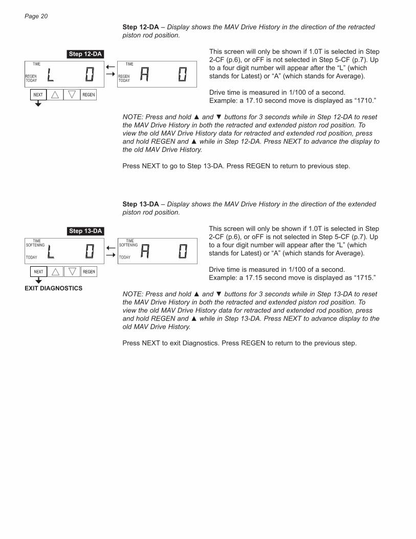
Step 12-DA – Display shows the MAV Drive History in the direction of the retracted piston rod position.
This screen will only be shown if 1.0T is selected in Step 2-CF (p.6), or oFF is not selected in Step 5-CF (p.7). Up to a four digit number will appear after the “L” (which stands for Latest) or “A” (which stands for Average).
Drive time is measured in 1/100 of a second. Example: a 17.10 second move is displayed as “1710.”
NOTE: Press and hold ▲ and ▼ buttons for 3 seconds while in Step 12-DA to reset the MAV Drive History in both the retracted and extended piston rod position. To view the old MAV Drive History data for retracted and extended rod position, press and hold REGEN and ▲ while in Step 12-DA. Press NEXT to advance the display to the old MAV Drive History.
Press NEXT to go to Step 13-DA. Press REGEN to return to previous step.
Step 13-DA – Display shows the MAV Drive History in the direction of the extended piston rod position.
This screen will only be shown if 1.0T is selected in Step 2-CF (p.6), or oFF is not selected in Step 5-CF (p.7). Up to a four digit number will appear after the “L” (which stands for Latest) or “A” (which stands for Average).
Drive time is measured in 1/100 of a second. Example: a 17.15 second move is displayed as “1715.”
NOTE: Press and hold ▲ and ▼ buttons for 3 seconds while in Step 13-DA to reset the MAV Drive History in both the retracted and extended piston rod position. To view the old MAV Drive History data for retracted and extended rod position, press and hold REGEN and ▲ while in Step 13-DA. Press NEXT to advance display to the old MAV Drive History.
Press NEXT to exit Diagnostics. Press REGEN to return to the previous step.
Step 12-DA
Step 13-DA
EXIT DIAGNOSTICS

Page 21
Front Cover and Drive Assembly
AC Adapter US InternationalSupply Voltage 120 VAC 230 VACSupply Frequency 60 Hz 50 HzOutput Voltage 12 VAC 12 VACOutput Current 500 mA 500 mA
Drawing No. Part No. Description Quantity
1 LC-V3175EE-01 WS1EE Front Cover Assembly 1
2 LC-V3107-01 WS1 Motor Assembly 1
3 LC-V3106-01 WS1 Drive Bracket and Spring Clip 1
4 LC-V3408EE-04BOARD WS1EE thru WS2EE PC Board 5-Digit Replacement 1
5 LC-V3110 WS1 Drive Reducing Gear 12 x 36 3
6 LC-V3109 WS1 Drive Gear Cover 1
Not Shown
LC-V3186 WS1 AC Adapter 120V-12V 1
LC-V3186-01 WS1 AC Adapter Cord Only, 15 Ft 1
LC-V3178 WS1 Drive Back Plate 1
1
4
6
5
3
2
BATTERY FULLY SEATED
When replacing the battery, alignpositives and push down to fully seat.
CorrectBattery
Orientation
Battery replacement is 3 VoltLithium Coin Cell Type 2032.
PC Board RelayTerminal Block
Wiring for Correct On/Off OperationPC Board Relay Terminal Block . . . . . RelayRLY 1 . . . . . . . . . . . . . . . . . . . . . . . . . Coil –+ COM . . . . . . . . . . . . . . . . . . . . . . . . Coil +
Relay Specifications: 12 VDC Relay with a coil resistance not less than 80 ohms. If mounting relay under the cover, check for proper mounting dimensions on the backplate.

Page 22
Tech-EE Setup Sheet – Softener System
Model Unit No. Job Software Revision 520.1
Configuration Settings (Pages 6 – 10)
Enter Settings, Step 1-CF Press NEXT & ▼ for 5 seconds and release, then Press NEXT & ▼ again for 5 seconds and release Set Valve Type, Step 2-CF 1.0, 1.0T, 1.25, 1.5, 2.0 Set Meter Size, Step 3-CF 1.5, 2.0, 3.0, 1.0r, PUL (For 1.5 and 2.0 only) Set Variable Meter Pulses, Step 3-CF 0.1 – 150.0 Pulses Per Gallon (For PUL only) Set dP, Step 4-CF oFF, on 0, dEL, HoLd Set Control Valve Operation, Step 5-CF nHbP, SEPS, SYS, ALT A, ALT b, oFF Set Delayed Rinse and Fill, Step 5-CF oFF, on (For 1.0 – 1.5 with ALT A or ALT b only) Set Special Rinse Duration, Step 5-CF oFF, 1 – 95 Minutes (For 2.0 with ALT A or ALT b only) Set Fill Units, Step 6-CF LBS, MIN (For 1.5 only)
Softener System Setup Settings (Page 11– 13)
Enter Settings, Step 1-SS Press NEXT & ▼ for 5 seconds and release Set Softening Operation, Step 2-SS SOFTENING Set Brining Direction, Step 3-SS dn, UP Set Refill Location, Step 4-SS PoST, PrE Set Backwash, Step 5-SS 1 – 120 Minutes (See Note 1 below) Set Draw, Step 6-SS 1 – 180 Minutes (See Note 1 below) Set 2nd Backwash, Step 7-SS 1 – 120 Minutes (See Note 1 below) Set Rinse, Step 8-SS 1 – 120 Minutes (See Note 1 below) Set Fill, Step 9-SS 0.1 – 200 Lbs, 0.1 – 99 Minutes (See Note 1 below) Set System Capacity, Step 10-SS x 1000 Set Volume Capacity, Step 11-SS AUTo, oFF, 20 – 1,500,000 Gallons Set Regeneration Time, Step 12-SS NORMAL, on 0, NORMAL + on 0 Set Relay Operation, Step 13-SS Time, Gallons, Gallons Regen, Error, oFF Set Relay Actuation, Step 14-SS 1 Second – 200 Minutes, 1 – 200 Gallons Set Relay Deactivation, Step 15-SS 1 Second – 200 Minutes, 1 Second – 20 Minutes
Installer Display Settings (Page 17)
Enter Settings, Step 1-NA Press NEXT & ▲ for 5 seconds and release Set Hardness, Step 2-NA Set Day Override, Step 3-NA 1 – 28, oFF Set Regeneration Time, Step 4-NA & 5-NA Hour & Minutes
Notes: 1. For 1.5 and 2.0 Valves, “oFF” is also available.

Page 23
Tech-EE Setup Sheet – Filter System
Model Unit No. Job Software Revision 520.1
Configuration Settings (Pages 6 – 10)
Enter Settings, Step 1-CF Press NEXT & ▼ for 5 seconds and release, then Press NEXT & ▼ again for 5 seconds and release Set Valve Type, Step 2-CF 1.0, 1.0T, 1.25, 1.5, 2.0 Set Meter Size, Step 3-CF 1.5, 2.0, 3.0, 1.0r, PUL (For 1.5 and 2.0 only) Set Variable Meter Pulses, Step 3-CF 0.1 – 150.0 Pulses Per Gallon (For PUL only) Set dP, Step 4-CF oFF, on 0, dEL, HoLd Set Control Valve Operation, Step 5-CF nHbP, SEPS, SYS, ALT A, ALT b, oFF Set Delayed Rinse and Fill, Step 5-CF oFF, on (For 1.0 – 1.5 with ALT A or ALT b only) Set Special Rinse Duration, Step 5-CF oFF, 1 – 95 Minutes (For 2.0 with ALT A or ALT b only)
Filter System Setup Settings (Page 15– 16)
Enter Settings, Step 1-FS Press NEXT & ▼ for 5 seconds and release Set Filtering Operation, Step 2-FS FILTERING BACKWASH, FILTERING REGEN Set Backwash, Step 3-FS 1 – 120 Minutes Set Draw, Step 4-FS 1 – 180 Minutes (For FILTERING REGEN only) Set 2nd Backwash, Step 4-FS 1 – 120 Minutes (For FILTERING REGEN only) Set Rinse, Step 4-FS 1 – 120 Minutes Set Fill, Step 4-FS 1 – 99 Gallons (For FILTERING REGEN only) Set Volume Capacity, Step 5-FS oFF, 20 – 1,500,000 Gallons Set Regeneration Time, Step 6-FS NORMAL, on 0, NORMAL + on 0 Set Relay Operation, Step 7-FS Time, Gallons, Gallons Regen, Error, oFF Set Relay Actuation, Step 8-FS 1 Second – 200 Minutes, 1 – 200 Gallons Set Relay Deactivation, Step 9-FS 1 Second – 200 Minutes, 1 Second – 20 Minutes
Installer Display Settings (Page 17)
Enter Settings, Step 1-NA Press NEXT & ▲ for 5 seconds and release Set Day Override, Step 3-NA 1 – 28, oFF Set Regeneration Time, Step 4-NA & 5-NA Hour & Minutes

S A F E W A T E R T E C H N O L O G I E S , I N C .9 9 6 B L U F F C I T Y B O U L E V A R D , E L G I N , I L 6 0 1 2 0 U S A
T E L E P H O N E 8 4 7 8 8 8 6 9 0 0 • F A C S I M I L E 8 4 7 8 8 8 6 9 2 4E M A I L : i n f o @ s w t w a t e r . c o m • W E B S I T E : w w w . s w t w a t e r . c o m
FORM TECHEE-MANUALEFFECTIVE
MARCH 2016