Easy Peripherals for the Internet of Things
149
FACULDADE DE E NGENHARIA DA UNIVERSIDADE DO P ORTO Easy Peripherals for the Internet of Things António Miguel Baldaia Moreira de Sousa Mestrado Integrado em Engenharia Eletrotécnica e de Computadores Supervisor: João Carlos Viseu Oliveira (Fraunhofer AICOS Portugal) Supervisor: Luis Miguel Pinho de Almeida (FEUP) July 22, 2016
-
Upload
khangminh22 -
Category
Documents
-
view
0 -
download
0
Transcript of Easy Peripherals for the Internet of Things

FACULDADE DE ENGENHARIA DA UNIVERSIDADE DO PORTO
Easy Peripherals for theInternet of Things
António Miguel Baldaia Moreira de Sousa
Mestrado Integrado em Engenharia Eletrotécnica e de Computadores
Supervisor: João Carlos Viseu Oliveira (Fraunhofer AICOS Portugal)
Supervisor: Luis Miguel Pinho de Almeida (FEUP)
July 22, 2016

c© António Miguel Baldaia Moreira de Sousa , 2016
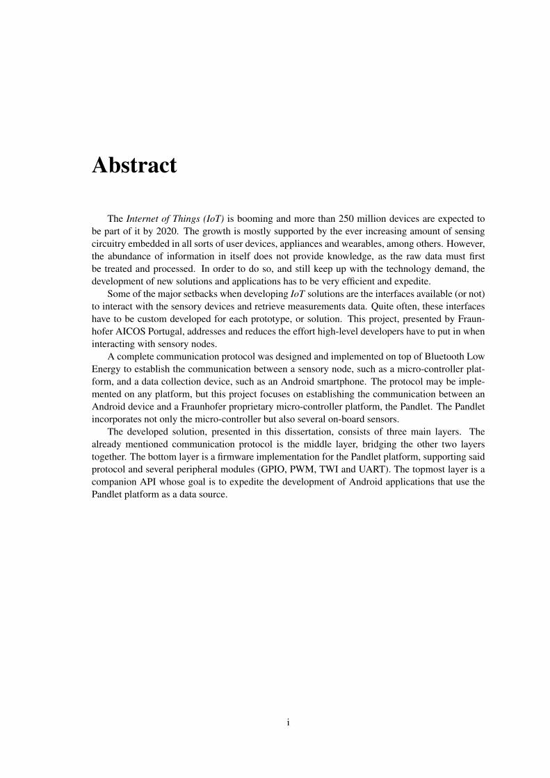
Abstract
The Internet of Things (IoT) is booming and more than 250 million devices are expected tobe part of it by 2020. The growth is mostly supported by the ever increasing amount of sensingcircuitry embedded in all sorts of user devices, appliances and wearables, among others. However,the abundance of information in itself does not provide knowledge, as the raw data must firstbe treated and processed. In order to do so, and still keep up with the technology demand, thedevelopment of new solutions and applications has to be very efficient and expedite.
Some of the major setbacks when developing IoT solutions are the interfaces available (or not)to interact with the sensory devices and retrieve measurements data. Quite often, these interfaceshave to be custom developed for each prototype, or solution. This project, presented by Fraun-hofer AICOS Portugal, addresses and reduces the effort high-level developers have to put in wheninteracting with sensory nodes.
A complete communication protocol was designed and implemented on top of Bluetooth LowEnergy to establish the communication between a sensory node, such as a micro-controller plat-form, and a data collection device, such as an Android smartphone. The protocol may be imple-mented on any platform, but this project focuses on establishing the communication between anAndroid device and a Fraunhofer proprietary micro-controller platform, the Pandlet. The Pandletincorporates not only the micro-controller but also several on-board sensors.
The developed solution, presented in this dissertation, consists of three main layers. Thealready mentioned communication protocol is the middle layer, bridging the other two layerstogether. The bottom layer is a firmware implementation for the Pandlet platform, supporting saidprotocol and several peripheral modules (GPIO, PWM, TWI and UART). The topmost layer is acompanion API whose goal is to expedite the development of Android applications that use thePandlet platform as a data source.
i

ii

Agradecimentos
Antes de mais, quero agradecer à Fraunhfer AICOS pela oportunidade de realização desteprojecto num ambiente de investigação fértil e de renome. Um agradecimento especial ao Eng.João Oliveira, meu orientador, pelos conselhos indispensáveis e apoio sempre presente.
Agradeço também ao Prof. Dr. Luís Almeida, também meu orientador, pelo acompanhamentoprestado ao longo de todo o projecto de dissertação.
À minha família, o maior agradecimento de todos, por me ter proporcionado as condições eambiente para não só aprender, mas também descobrir e explorar aquilo que verdadeiramente meentusiasma. Ao meu irmão, obrigado pelo apoio, pelos conselhos, pelas opiniões e sugestões,mas acima de tudo, pela paciência e empenho necessários para ler cada palavra desta dissertação,várias vezes.
Um grande agradecimento também aos meus amigos e colegas que me acompanharam nestaaventura de introdução à Engenharia, em especial ao José Valente, companheiro de longa data nosmais variados projectos.
Por fim, gostaria de agradecer à Faculdade de Engenharia da Universidade do Porto por estes5 anos de aprendizagem e crescimento pessoal.
A. Miguel Sousa
iii

iv

“Pass on what you have learned.”
Master Yoda, Star Wars Episode VI - Return of the Jedi
v

vi

Contents
1 Introduction 11.1 Motivation and Context . . . . . . . . . . . . . . . . . . . . . . . . . . . . . . . 11.2 Project Presentation . . . . . . . . . . . . . . . . . . . . . . . . . . . . . . . . 21.3 Project Objectives . . . . . . . . . . . . . . . . . . . . . . . . . . . . . . . . . 31.4 Document Structure . . . . . . . . . . . . . . . . . . . . . . . . . . . . . . . . . 3
2 State of the Art 52.1 The Internet of Things . . . . . . . . . . . . . . . . . . . . . . . . . . . . . . . 5
2.1.1 Overview . . . . . . . . . . . . . . . . . . . . . . . . . . . . . . . . . . 52.1.2 Enabling Factors and Technologies . . . . . . . . . . . . . . . . . . . . 62.1.3 Areas of Application . . . . . . . . . . . . . . . . . . . . . . . . . . . . 92.1.4 Future Developments . . . . . . . . . . . . . . . . . . . . . . . . . . . . 102.1.5 Remarks . . . . . . . . . . . . . . . . . . . . . . . . . . . . . . . . . . 11
2.2 Wireless Communication Technologies . . . . . . . . . . . . . . . . . . . . . . 112.2.1 Overview . . . . . . . . . . . . . . . . . . . . . . . . . . . . . . . . . . 112.2.2 Cellular . . . . . . . . . . . . . . . . . . . . . . . . . . . . . . . . . . . 122.2.3 Wi-Fi . . . . . . . . . . . . . . . . . . . . . . . . . . . . . . . . . . . . 122.2.4 ZigBee . . . . . . . . . . . . . . . . . . . . . . . . . . . . . . . . . . . 122.2.5 Bluetooth . . . . . . . . . . . . . . . . . . . . . . . . . . . . . . . . . . 132.2.6 6LoWPAN . . . . . . . . . . . . . . . . . . . . . . . . . . . . . . . . . 132.2.7 Remarks . . . . . . . . . . . . . . . . . . . . . . . . . . . . . . . . . . 13
2.3 Seamless Micro-controller Integration . . . . . . . . . . . . . . . . . . . . . . . 142.3.1 Overview . . . . . . . . . . . . . . . . . . . . . . . . . . . . . . . . . . 142.3.2 Firmata Protocol . . . . . . . . . . . . . . . . . . . . . . . . . . . . . . 152.3.3 IOIO Board . . . . . . . . . . . . . . . . . . . . . . . . . . . . . . . . . 162.3.4 Particle Boards . . . . . . . . . . . . . . . . . . . . . . . . . . . . . . . 172.3.5 Remarks . . . . . . . . . . . . . . . . . . . . . . . . . . . . . . . . . . 18
2.4 Implementations Platforms . . . . . . . . . . . . . . . . . . . . . . . . . . . . . 182.4.1 Overview . . . . . . . . . . . . . . . . . . . . . . . . . . . . . . . . . . 182.4.2 Arduino based solutions . . . . . . . . . . . . . . . . . . . . . . . . . . 182.4.3 Single Board Computers . . . . . . . . . . . . . . . . . . . . . . . . . . 192.4.4 ESP8266 . . . . . . . . . . . . . . . . . . . . . . . . . . . . . . . . . . 202.4.5 Fraunhofer Pandlet . . . . . . . . . . . . . . . . . . . . . . . . . . . . . 202.4.6 Remarks . . . . . . . . . . . . . . . . . . . . . . . . . . . . . . . . . . 21
2.5 Android . . . . . . . . . . . . . . . . . . . . . . . . . . . . . . . . . . . . . . . 212.5.1 Overview . . . . . . . . . . . . . . . . . . . . . . . . . . . . . . . . . . 212.5.2 Android as a Gateway . . . . . . . . . . . . . . . . . . . . . . . . . . . 222.5.3 Java Libraries . . . . . . . . . . . . . . . . . . . . . . . . . . . . . . . . 23
vii

viii CONTENTS
3 Bluetooth Low Energy 253.1 Overview . . . . . . . . . . . . . . . . . . . . . . . . . . . . . . . . . . . . . . 253.2 Protocol Basics and Stack Overview . . . . . . . . . . . . . . . . . . . . . . . . 263.3 Link Layer . . . . . . . . . . . . . . . . . . . . . . . . . . . . . . . . . . . . . 283.4 Security Manager . . . . . . . . . . . . . . . . . . . . . . . . . . . . . . . . . . 30
3.4.1 Security Procedures . . . . . . . . . . . . . . . . . . . . . . . . . . . . 303.4.2 Security Mechanisms . . . . . . . . . . . . . . . . . . . . . . . . . . . . 31
3.5 General Access Profile (GAP) . . . . . . . . . . . . . . . . . . . . . . . . . . . 323.5.1 Roles, Modes and Procedures . . . . . . . . . . . . . . . . . . . . . . . 323.5.2 Device Discovery and Connection Establishment . . . . . . . . . . . . . 333.5.3 Bonding and Security . . . . . . . . . . . . . . . . . . . . . . . . . . . . 353.5.4 GAP Service . . . . . . . . . . . . . . . . . . . . . . . . . . . . . . . . 36
3.6 Attributes, ATT and GATT . . . . . . . . . . . . . . . . . . . . . . . . . . . . . 363.6.1 Attributes and Attribute Access . . . . . . . . . . . . . . . . . . . . . . 363.6.2 Client/Server architecture and Data Exchange . . . . . . . . . . . . . . . 373.6.3 Grouping Attributes into Services and Characteristics . . . . . . . . . . . 383.6.4 Discovering Services and Characteristics . . . . . . . . . . . . . . . . . 403.6.5 Accessing Services and Characteristics . . . . . . . . . . . . . . . . . . 403.6.6 GATT Service . . . . . . . . . . . . . . . . . . . . . . . . . . . . . . . 41
3.7 Profiles . . . . . . . . . . . . . . . . . . . . . . . . . . . . . . . . . . . . . . . 413.8 Key Limitations . . . . . . . . . . . . . . . . . . . . . . . . . . . . . . . . . . . 42
3.8.1 Data Throughput . . . . . . . . . . . . . . . . . . . . . . . . . . . . . . 423.8.2 Operation Range . . . . . . . . . . . . . . . . . . . . . . . . . . . . . . 43
4 Fraunhofer Pandlet 454.1 Overview . . . . . . . . . . . . . . . . . . . . . . . . . . . . . . . . . . . . . . 454.2 Hardware and Peripherals . . . . . . . . . . . . . . . . . . . . . . . . . . . . . . 46
4.2.1 Circuit level communication protocols . . . . . . . . . . . . . . . . . . . 464.2.2 Core module . . . . . . . . . . . . . . . . . . . . . . . . . . . . . . . . 504.2.3 Sensing+ module . . . . . . . . . . . . . . . . . . . . . . . . . . . . . . 51
4.3 Firmware . . . . . . . . . . . . . . . . . . . . . . . . . . . . . . . . . . . . . . 514.4 Data Throughput Limitations . . . . . . . . . . . . . . . . . . . . . . . . . . . . 52
5 Bluetooth Low Energy Data Throughput 535.1 Communication Methodologies . . . . . . . . . . . . . . . . . . . . . . . . . . . 53
5.1.1 Peripheral update . . . . . . . . . . . . . . . . . . . . . . . . . . . . . . 565.1.2 Central update . . . . . . . . . . . . . . . . . . . . . . . . . . . . . . . 575.1.3 Request/Response . . . . . . . . . . . . . . . . . . . . . . . . . . . . . 58
5.2 Distance . . . . . . . . . . . . . . . . . . . . . . . . . . . . . . . . . . . . . . . 605.3 Interference from other devices . . . . . . . . . . . . . . . . . . . . . . . . . . . 625.4 Remarks . . . . . . . . . . . . . . . . . . . . . . . . . . . . . . . . . . . . . . . 63
6 Pandlet Firmware 656.1 Overview . . . . . . . . . . . . . . . . . . . . . . . . . . . . . . . . . . . . . . 656.2 Transactions . . . . . . . . . . . . . . . . . . . . . . . . . . . . . . . . . . . . . 656.3 Structure . . . . . . . . . . . . . . . . . . . . . . . . . . . . . . . . . . . . . . . 65
6.3.1 Incoming Transactions . . . . . . . . . . . . . . . . . . . . . . . . . . . 666.3.2 Dispatcher . . . . . . . . . . . . . . . . . . . . . . . . . . . . . . . . . 666.3.3 Outgoing Data, Reports and Notifications . . . . . . . . . . . . . . . . . 67

CONTENTS ix
6.4 Modules . . . . . . . . . . . . . . . . . . . . . . . . . . . . . . . . . . . . . . . 686.4.1 Two Wire Interface (TWI) . . . . . . . . . . . . . . . . . . . . . . . . . 686.4.2 Universal Asynchronous Receiver/Transmitter (UART) . . . . . . . . . . 696.4.3 General Purpose Input/Output (GPIO) . . . . . . . . . . . . . . . . . . . 696.4.4 Pulse Width Modulation (PWM) . . . . . . . . . . . . . . . . . . . . . . 70
6.5 Remarks . . . . . . . . . . . . . . . . . . . . . . . . . . . . . . . . . . . . . . . 70
7 Communication Protocol 737.1 Overview . . . . . . . . . . . . . . . . . . . . . . . . . . . . . . . . . . . . . . 737.2 Profile, Services and Characteristics . . . . . . . . . . . . . . . . . . . . . . . . 73
7.2.1 BLE Connection Parameters . . . . . . . . . . . . . . . . . . . . . . . . 757.3 Packet and Transaction Structures . . . . . . . . . . . . . . . . . . . . . . . . . 767.4 Report and Error Codes . . . . . . . . . . . . . . . . . . . . . . . . . . . . . . . 787.5 Module Specific Payloads . . . . . . . . . . . . . . . . . . . . . . . . . . . . . . 78
7.5.1 TWI CONFIG . . . . . . . . . . . . . . . . . . . . . . . . . . . . . . . 797.5.2 TWI WRITE . . . . . . . . . . . . . . . . . . . . . . . . . . . . . . . . 807.5.3 TWI READ . . . . . . . . . . . . . . . . . . . . . . . . . . . . . . . . . 807.5.4 GPIO CONFIG . . . . . . . . . . . . . . . . . . . . . . . . . . . . . . . 817.5.5 GPIO GET . . . . . . . . . . . . . . . . . . . . . . . . . . . . . . . . . 827.5.6 GPIO SET . . . . . . . . . . . . . . . . . . . . . . . . . . . . . . . . . 837.5.7 UART CONFIG . . . . . . . . . . . . . . . . . . . . . . . . . . . . . . 837.5.8 UART SEND and UART RECEIVE . . . . . . . . . . . . . . . . . . . . 847.5.9 PWM CONFIG MODULE . . . . . . . . . . . . . . . . . . . . . . . . . 857.5.10 PWM CONFIG CHANNEL . . . . . . . . . . . . . . . . . . . . . . . . 86
7.6 Remarks . . . . . . . . . . . . . . . . . . . . . . . . . . . . . . . . . . . . . . . 86
8 Android API 878.1 Overview . . . . . . . . . . . . . . . . . . . . . . . . . . . . . . . . . . . . . . 878.2 Blocking vs Non-blocking Operation . . . . . . . . . . . . . . . . . . . . . . . . 878.3 Overall Structure . . . . . . . . . . . . . . . . . . . . . . . . . . . . . . . . . . 888.4 Back-end - Transaction Manager . . . . . . . . . . . . . . . . . . . . . . . . . . 89
8.4.1 Queuing . . . . . . . . . . . . . . . . . . . . . . . . . . . . . . . . . . . 918.4.2 Dispatcher . . . . . . . . . . . . . . . . . . . . . . . . . . . . . . . . . 91
8.5 Front-end - Features and Classes . . . . . . . . . . . . . . . . . . . . . . . . . . 928.5.1 Core . . . . . . . . . . . . . . . . . . . . . . . . . . . . . . . . . . . . . 928.5.2 Peripherals and Drivers . . . . . . . . . . . . . . . . . . . . . . . . . . . 968.5.3 Pandlet . . . . . . . . . . . . . . . . . . . . . . . . . . . . . . . . . . . 998.5.4 BLEDeviceFinder . . . . . . . . . . . . . . . . . . . . . . . . . . . . . 100
8.6 Documentation and Usage Examples . . . . . . . . . . . . . . . . . . . . . . . . 1008.7 Remarks . . . . . . . . . . . . . . . . . . . . . . . . . . . . . . . . . . . . . . . 101
9 Performance Tests 1039.1 GPIO Sensing . . . . . . . . . . . . . . . . . . . . . . . . . . . . . . . . . . . . 1039.2 TWI Read with GPIO Sensing . . . . . . . . . . . . . . . . . . . . . . . . . . . 1049.3 TWI Read with Request/Response . . . . . . . . . . . . . . . . . . . . . . . . . 1069.4 Remarks . . . . . . . . . . . . . . . . . . . . . . . . . . . . . . . . . . . . . . . 107

x CONTENTS
10 Demo application 10910.1 Full featured demo application . . . . . . . . . . . . . . . . . . . . . . . . . . . 10910.2 Functionality specific demo applications . . . . . . . . . . . . . . . . . . . . . . 110
11 Conclusion and Future Work 11511.1 Pros and Cons . . . . . . . . . . . . . . . . . . . . . . . . . . . . . . . . . . . . 11511.2 Future Work . . . . . . . . . . . . . . . . . . . . . . . . . . . . . . . . . . . . . 116
A API Usage Examples 117A.1 Pandlet . . . . . . . . . . . . . . . . . . . . . . . . . . . . . . . . . . . . . . . 117A.2 TWI Bus . . . . . . . . . . . . . . . . . . . . . . . . . . . . . . . . . . . . . . . 118A.3 UART Bus . . . . . . . . . . . . . . . . . . . . . . . . . . . . . . . . . . . . . . 119A.4 PWM . . . . . . . . . . . . . . . . . . . . . . . . . . . . . . . . . . . . . . . . 120A.5 GPIO . . . . . . . . . . . . . . . . . . . . . . . . . . . . . . . . . . . . . . . . 121A.6 MCP73832 - USB Charger . . . . . . . . . . . . . . . . . . . . . . . . . . . . . 122A.7 MAX17048 - Fuel Gauge . . . . . . . . . . . . . . . . . . . . . . . . . . . . . . 123A.8 BME280 - EMU . . . . . . . . . . . . . . . . . . . . . . . . . . . . . . . . . . 123
References 125
List of Figures
1.1 New Computing Cycle Characteristics. Adapted from [1] . . . . . . . . . . . . . 1
2.1 Internet of Things as the convergence of three perspectives of the same paradigm[13]. . . . . . . . . . . . . . . . . . . . . . . . . . . . . . . . . . . . . . . . . . 6
2.2 Internet usage and coverage from 2000 to 2015. Adapted from [17]. . . . . . . . 72.3 Predictions for IoT devices by 2020 [40, 41, 5, 42]. . . . . . . . . . . . . . . . . 112.4 Typical Iot use case device stack. . . . . . . . . . . . . . . . . . . . . . . . . . . 142.5 IOIO-OTG board. Adapted from [53]. . . . . . . . . . . . . . . . . . . . . . . . 162.6 Particle boards. From left to right: P0, Photon, Electron. [55] . . . . . . . . . . 182.7 Arduino UNO and chipKIT Uno32 side by side. Adapted from [56]. . . . . . . . 192.8 Raspberry Pi 2 [57] . . . . . . . . . . . . . . . . . . . . . . . . . . . . . . . . . 192.9 BeagleBone Black [58] . . . . . . . . . . . . . . . . . . . . . . . . . . . . . . . 192.10 A variety of ESP8266 based devices. Adapted from [59]. . . . . . . . . . . . . . 202.11 Pandlet and all of its modules. [60]. . . . . . . . . . . . . . . . . . . . . . . . . 212.12 Abstraction provided by the library and API. . . . . . . . . . . . . . . . . . . . . 23
3.1 Bluetooth versions device compatibility [65]. . . . . . . . . . . . . . . . . . . . 253.2 World market forecast of standalone Classic Bluetooth and BLE dual-mode ship-
ments. Forecast from 2012. [66]. . . . . . . . . . . . . . . . . . . . . . . . . . 263.3 Bluetooth Low Energy stack. [11]. . . . . . . . . . . . . . . . . . . . . . . . . 273.4 Connection events. [65] . . . . . . . . . . . . . . . . . . . . . . . . . . . . . . . 303.5 BLE pairing and bonding sequences. [65]. . . . . . . . . . . . . . . . . . . . . 313.6 Attribute structure. . . . . . . . . . . . . . . . . . . . . . . . . . . . . . . . . . 373.7 Example Client/Server architecture and available operations. . . . . . . . . . . . 373.8 GATT Heart Rate Service [65]. . . . . . . . . . . . . . . . . . . . . . . . . . . 393.9 GATT Heart Rate Profile. . . . . . . . . . . . . . . . . . . . . . . . . . . . . . 423.10 BLE encrypted data packet. Adapted from [68]. . . . . . . . . . . . . . . . . . . 43
4.1 Plandlet with debugger attached . . . . . . . . . . . . . . . . . . . . . . . . . . 454.2 UART communication bits. [69] . . . . . . . . . . . . . . . . . . . . . . . . . . 474.3 UART communication connections. [69] . . . . . . . . . . . . . . . . . . . . . 474.4 UART communication with flow control enabled. Adapted from [69] . . . . . . 474.5 UART communication with flow control disabled. Adapted from [69] . . . . . . 474.6 SPI simple master/slave topology [70]. . . . . . . . . . . . . . . . . . . . . . . 484.7 SPI daisy-chain topology. Adapted from [70] . . . . . . . . . . . . . . . . . . . 494.8 SPI parallel topology. Adapted from [70] . . . . . . . . . . . . . . . . . . . . . 494.9 I2C master/slave topology [70]. . . . . . . . . . . . . . . . . . . . . . . . . . . 494.10 Abstraction provided by the use of a SoftDevice [11]. . . . . . . . . . . . . . . 52
xi

xii LIST OF FIGURES
5.1 Android application developed to perform data throughput tests using differentcommunication methodologies. . . . . . . . . . . . . . . . . . . . . . . . . . . . 54
5.2 Peripheral update communication methodology. . . . . . . . . . . . . . . . . . . 565.3 Packets received by the Motorola phone during the Peripheral update test. . . . . 565.4 Central update communication methodology. . . . . . . . . . . . . . . . . . . . 575.5 Packets sent by the Motorola phone during the Central update test.. . . . . . . . . 585.6 Request/Response communication methodology. . . . . . . . . . . . . . . . . . 595.7 Packets exchanged by the Motorola phone during the Request/Response test. . . 595.8 Test results regarding the distance between peer devices. . . . . . . . . . . . . . 615.9 Free-space path loss. . . . . . . . . . . . . . . . . . . . . . . . . . . . . . . . . 615.10 Test results regarding the presence of an interfering device. . . . . . . . . . . . . 63
6.1 Pandlet firmware structure. . . . . . . . . . . . . . . . . . . . . . . . . . . . . . 67
7.1 Successful and failed Characteristic updates. . . . . . . . . . . . . . . . . . . . . 747.2 BLE Profile used to implement the communication protocol. . . . . . . . . . . . 757.3 Packet and Transaction structures. . . . . . . . . . . . . . . . . . . . . . . . . . 767.4 Payload to enable and configure the TWI bus. . . . . . . . . . . . . . . . . . . . 797.5 Payload to disable a module. . . . . . . . . . . . . . . . . . . . . . . . . . . . . 797.6 Payload to send data through the TWI bus. . . . . . . . . . . . . . . . . . . . . . 807.7 Payload to read data from the TWI bus. . . . . . . . . . . . . . . . . . . . . . . 807.8 Payload to forward received TWI data to the Android device. . . . . . . . . . . . 807.9 Payload to configure a GPIO port as an input. . . . . . . . . . . . . . . . . . . . 817.10 Payload to configure a GPIO port as an output. . . . . . . . . . . . . . . . . . . 827.11 Payload to request a status measurement on a GPIO port. . . . . . . . . . . . . . 827.12 Payload to set the value of an output GPIO port, and to return the result of the
GPIO_GET operation. . . . . . . . . . . . . . . . . . . . . . . . . . . . . . . . 837.13 Payload to enable and configure the UART bus. . . . . . . . . . . . . . . . . . . 837.14 Payload to exchange data to send, or that has been received, through the UART bus. 857.15 Payload to configure the PWM module. . . . . . . . . . . . . . . . . . . . . . . 857.16 Payload to configure the PWM module channels. . . . . . . . . . . . . . . . . . 86
8.1 Pandlet API layered structure. . . . . . . . . . . . . . . . . . . . . . . . . . . . 898.2 Class diagram presenting the major classes in each package. . . . . . . . . . . . 898.3 Android side of the Transaction Manager. . . . . . . . . . . . . . . . . . . . . . 908.4 Transaction classes available on the API. . . . . . . . . . . . . . . . . . . . . . . 908.5 Callback classes available on the API. . . . . . . . . . . . . . . . . . . . . . . . 908.6 Class diagram of the major API classes. . . . . . . . . . . . . . . . . . . . . . . 928.7 MicroController class. . . . . . . . . . . . . . . . . . . . . . . . . . . . . . . . 938.8 TWIBus class. . . . . . . . . . . . . . . . . . . . . . . . . . . . . . . . . . . . . 948.9 UARTBus class. . . . . . . . . . . . . . . . . . . . . . . . . . . . . . . . . . . . 948.10 PWM class. . . . . . . . . . . . . . . . . . . . . . . . . . . . . . . . . . . . . . 958.11 GPIO class. . . . . . . . . . . . . . . . . . . . . . . . . . . . . . . . . . . . . . 958.12 LED class. . . . . . . . . . . . . . . . . . . . . . . . . . . . . . . . . . . . . . . 968.13 Servo class. . . . . . . . . . . . . . . . . . . . . . . . . . . . . . . . . . . . . . 968.14 MCP73832 class. . . . . . . . . . . . . . . . . . . . . . . . . . . . . . . . . . . 978.15 MAX17048 class. . . . . . . . . . . . . . . . . . . . . . . . . . . . . . . . . . . 988.16 BME280 class. . . . . . . . . . . . . . . . . . . . . . . . . . . . . . . . . . . . 998.17 Pandlet class. . . . . . . . . . . . . . . . . . . . . . . . . . . . . . . . . . . . . 100
LIST OF FIGURES xiii
8.18 BLEDeviceFinder class. . . . . . . . . . . . . . . . . . . . . . . . . . . . . . . . 1008.19 Overview of the Javadoc documentation. . . . . . . . . . . . . . . . . . . . . . . 101
9.1 Results of the GPIO sensing test. . . . . . . . . . . . . . . . . . . . . . . . . . . 1049.2 Results of the TWI test using GPIO sensing. . . . . . . . . . . . . . . . . . . . . 1059.3 Results of the TWI test using Request/Response . . . . . . . . . . . . . . . . . . 1069.4 Test results comparison. . . . . . . . . . . . . . . . . . . . . . . . . . . . . . . . 107
10.1 Android demo app. . . . . . . . . . . . . . . . . . . . . . . . . . . . . . . . . . 10910.2 PWM and GPIO demo app. . . . . . . . . . . . . . . . . . . . . . . . . . . . . . 11110.3 I2C demo app. . . . . . . . . . . . . . . . . . . . . . . . . . . . . . . . . . . . . 11110.4 PWM and GPIO demo app hardware setup. . . . . . . . . . . . . . . . . . . . . 11110.5 UART1 demo app, phone 1. . . . . . . . . . . . . . . . . . . . . . . . . . . . . 11210.6 UART2 demo app, phone 2. . . . . . . . . . . . . . . . . . . . . . . . . . . . . 11210.7 UART demo app hardware setup. . . . . . . . . . . . . . . . . . . . . . . . . . . 112

xiv LIST OF FIGURES

List of Tables
2.1 Typical data rates for cellular technologies. [43] . . . . . . . . . . . . . . . . . . 122.2 Comparison of air data rate and application throughput, as measured in [45] . . . 14
3.1 Roles defined by the Link Layer . . . . . . . . . . . . . . . . . . . . . . . . . . 293.2 Advertising packet properties. [65] . . . . . . . . . . . . . . . . . . . . . . . . . 293.3 Advertising packet types. [65] . . . . . . . . . . . . . . . . . . . . . . . . . . . 293.4 Modes and their applicable roles. . . . . . . . . . . . . . . . . . . . . . . . . . . 323.5 Procedures and their applicable roles. . . . . . . . . . . . . . . . . . . . . . . . 333.6 ATT operations. . . . . . . . . . . . . . . . . . . . . . . . . . . . . . . . . . . . 373.7 Messages for attribute access and corresponding operations. . . . . . . . . . . . 38
4.1 GAP roles available in each supported SoftDevice . . . . . . . . . . . . . . . . . 52
5.1 Devices used in BLE data throughput tests. . . . . . . . . . . . . . . . . . . . . 545.2 BLE data throughput tests communication methodologies. . . . . . . . . . . . . 545.3 Test results for Peripheral update communication methodology. . . . . . . . . . . 565.4 Test results for Central update communication methodology. . . . . . . . . . . . 585.5 Test results for Request/Response communication methodology. . . . . . . . . . 595.6 Comparison between measured and expected throughput when using Request/Re-
sponse methodology. . . . . . . . . . . . . . . . . . . . . . . . . . . . . . . . . 605.7 Test results regarding the distance between peer devices. . . . . . . . . . . . . . 605.8 Test results regarding the present of interfering devices. . . . . . . . . . . . . . . 62
7.1 Transaction Characteristic - Operation Codes (OpCodes). . . . . . . . . . . . . . 787.2 Existing report codes and associated event. . . . . . . . . . . . . . . . . . . . . . 787.3 Supported TWI bus frequencies. . . . . . . . . . . . . . . . . . . . . . . . . . . 797.4 Supported GPIO Pull modes. . . . . . . . . . . . . . . . . . . . . . . . . . . . . 817.5 Supported GPIO Sense modes. . . . . . . . . . . . . . . . . . . . . . . . . . . . 817.6 Possible GPIO Drive modes. . . . . . . . . . . . . . . . . . . . . . . . . . . . . 827.7 Supported UART Parity modes. . . . . . . . . . . . . . . . . . . . . . . . . . . 847.8 Supported UART baudrates. . . . . . . . . . . . . . . . . . . . . . . . . . . . . 847.9 Supported PWM channel polarity. . . . . . . . . . . . . . . . . . . . . . . . . . 85
9.1 Results of the GPIO sensing test. . . . . . . . . . . . . . . . . . . . . . . . . . . 1039.2 Results of the TWI test using GPIO sensing. . . . . . . . . . . . . . . . . . . . . 1059.3 Results of the TWI test using Request/Response. . . . . . . . . . . . . . . . . . 106
xv

xvi LIST OF TABLES

Abbreviations and Symbols
PC Personal ComputerIoT Internet of ThingsDIY Do-It-YourselfSBC Single Board ComputerAPI Application Programming InterfaceBLE Bluetooth Low EnergyI2C Inter-Integrated CircuitSPI Serial Peripheral InterfaceUART Universal Asynchronous Receiver/TransmitterGPIO General Purpose Input/OutputPWM Pulse Width ModulationWSN Wireless Sensor NetworkSD SoftDevicekb/s Kilobit per secondMb/s Megabit per secondkB/s Kilobyte per second
xvii


Chapter 1
Introduction
1.1 Motivation and Context
There was a time when computer systems were of such rarity and so expensive that the com-
mon citizen could only dream of using one. Such systems were designated Mainframes and could
only be accessed by high profile research facilities and military applications. As predicted by
Moore’s Law, processors speed, size and cost were object of huge improvements over the last
quarter of the 20th century, eventually reaching a status that allowed singular consumers to own
their personal computing machines, signalling the start of the Personal Computer (PC) era, as can
be seen in figure 1.1 [1, 2]. As devices became ever smaller, computing started to pull away from
the static desk computer, and adopting more mobile solutions such as laptops and smartphones.
Today, Ubiquitous computing [3] is taking over the technological development worldwide, pow-
ered by micro-controllers and sensors of all sorts, interconnected through wireless technologies
that feed streams of data and information. This new paradigm has become known as the Internet
of Things (IoT) [4].
Figure 1.1: New Computing Cycle Characteristics. Adapted from [1]
1

2 Introduction
According to Cisco [5], there are 25 billion devices connected to the Internet as of today. Con-
sidering that approximately 3.2 billion people have Internet access in 2015 [6], we can determine
that the number of connected devices per person with Internet access is of about 8 devices (7.8 to
be exact). If we take into account the world population instead (7.3 billion [7]), that number de-
creases to 3.4 devices per person. Other entities such as the Intel Corporation and Gartner Group
report different numbers, but always staying above 2 devices per person (considering the world
population). This matter is discussed further in section 2.1.
All of these devices have the ability to either acquire, evaluate or transmit data (or even a
combination of those). Initially, a single device may have a very narrow field of view, as only
its own perspective is available to it. However, through a network of device intercommunication
(IoT), it can report the collected data to other devices, and even receive information from them.
This exchange of information provides a broader context that can be used to better assess situations
and decide which actions to take when certain events occur. However, all of this data has to be
processed, analysed and interpreted, in order to become useful and later be applied in areas such
as logistics, health, home automation, education, agriculture and environment, among others [8].
As devices availability increases and price decays, the Do-It-Yourself (DIY) world has been
taken by storm by micro-controller platforms such as the Arduino [9], and the Single Board
Computers (SBC) Beaglebone and Raspberry Pi. These platforms provide interfaces that allow
users with no technical background to develop systems and solutions that were previously only
to the reach of professionals. Through a process of layering and abstraction, programming these
platforms has become so accessible that a huge community has been established around them,
which has contributed massively to the growth of the Internet of Things.
This project aims to implement this concept of high level abstraction in a specific micro-
controller platform and environment, the Pandlet (studied in chapter 4).
1.2 Project Presentation
Fraunhofer Portugal Research Center for Assistive Information and Communication Solutions
(Fraunhofer AICOS) has developed a processing platform that integrates sensors, a processing unit
and a Bluetooth Low Energy (also referred to as Bluetooth Smart) wireless module. This platform
is called the Pandlet, and has been designed to allow seamless integration with mobile platforms
such as Android and work as the foundation for new wearables and IoT devices [10].
As discussed in section 1.1, the IoT revolves around devices intercommunication, and the
Pandlet is no exception. The Pandlet can be seen as a wireless sensor node [11], a thing, that relies
on another device with higher capabilities to retrieve information from it. This device, known as
gateway, can then use that information, or even upload it to the Internet, to be used elsewhere. In
order to exchange data with remote devices and the gateway, the Pandlet has a built in Bluetooth
Smart module, which allows it to communicate with any other devices that comply with Bluetooth
4.0 or above.

1.3 Project Objectives 3
Since the Pandlet is envisioned to be used as a framework for future development, it would
be extremely useful to have a set of tools that provided a degree of abstraction, so that the Pan-
dlet would be seen as an extension of the gateway, hiding the underlying firmware specificities,
communications handling and implementation. This project aims to develop such tools, more
specifically “a set of Bluetooth Smart profiles and a companion API that will allow the interaction
of a gateway with the peripherals of the Pandlet seamlessly”.
These tools would allow higher level developers to create complete solutions and applica-
tions using data retrieved from sensors, by taking advantage of hardware interfaces like I2C, SPI,
UART and GPIO’s (section 4.2), but without having to worry about their lower level details and
implementations.
1.3 Project Objectives
The proposed objectives for this project are presented below. These were used as guidelines
and milestones during the development.
1. Literature review of technologies of interest
(a) The Internet of Things
(b) Wireless Communication Technologies
(c) Seamless Micro-controller Integration
(d) Android OS and applications
(e) Bluetooth Low Energy
(f) Fraunhofer Pandlet
2. Project Development
(a) Bluetooth Smart (BLE) profile design
(b) Communication protocol design, using BLE as a carrier
(c) Pandlet firmware development, supporting multiple modules (GPIO, TWI, UART,
PWM)
(d) Android API development
(e) Android demo application development
1.4 Document Structure
This document is structured in a way to highlight how each topic relates to the ones presented
previously and immediately after. That way, each chapter and section builds upon the contents and
information of the preceding ones.

4 Introduction
• Chapter 1 introduces the project, along with its context and objectives.
• Chapter 2 presents and reviews existing technologies and solutions that may be of interest
to the project.
• Chapter 3 contains a detailed study of the Bluetooth Low Energy technology and involved
protocols.
• Chapter 4 explores the Fraunhofer Pandlet hardware and interfaces.
• Chapter 5 presents tests and results regarding the achievable Bluetooth Low Energy through-
put using different communication methodologies, and testing the influence of certain ex-
ternal parameters.
• Chapter 6 presents the details of the firmware implemented on the Pandlet platform to
support the previously described features.
• Chapter 7 contains an in-depth description of the protocol implemented on top of BLE to
establish the communication between the Pandlet and an Android device.
• Chapter 8 presents the implemented Android API. The API allows a developer to quickly
implement an Android solution using the Pandlet platform.
• Chapter 9 presents test that were carried out to evaluate the performance of different im-
plementation approaches using the API.
• Chapter 10 presents an Android application developed to showcase the system capabilities
and provide an implementation reference for those that wish to use the API.
• Chapter 11 contains the final remarks and conclusion of the project, and also presents topics
for future work and development.
• Appendix A contains usage examples of the API presented in chapter 8.

Chapter 2
State of the Art
2.1 The Internet of Things
2.1.1 Overview
The Internet of Things (IoT) can be described as a network of devices, with embedded sen-
sors, connected to the Internet by the means of standard communication protocols. However,
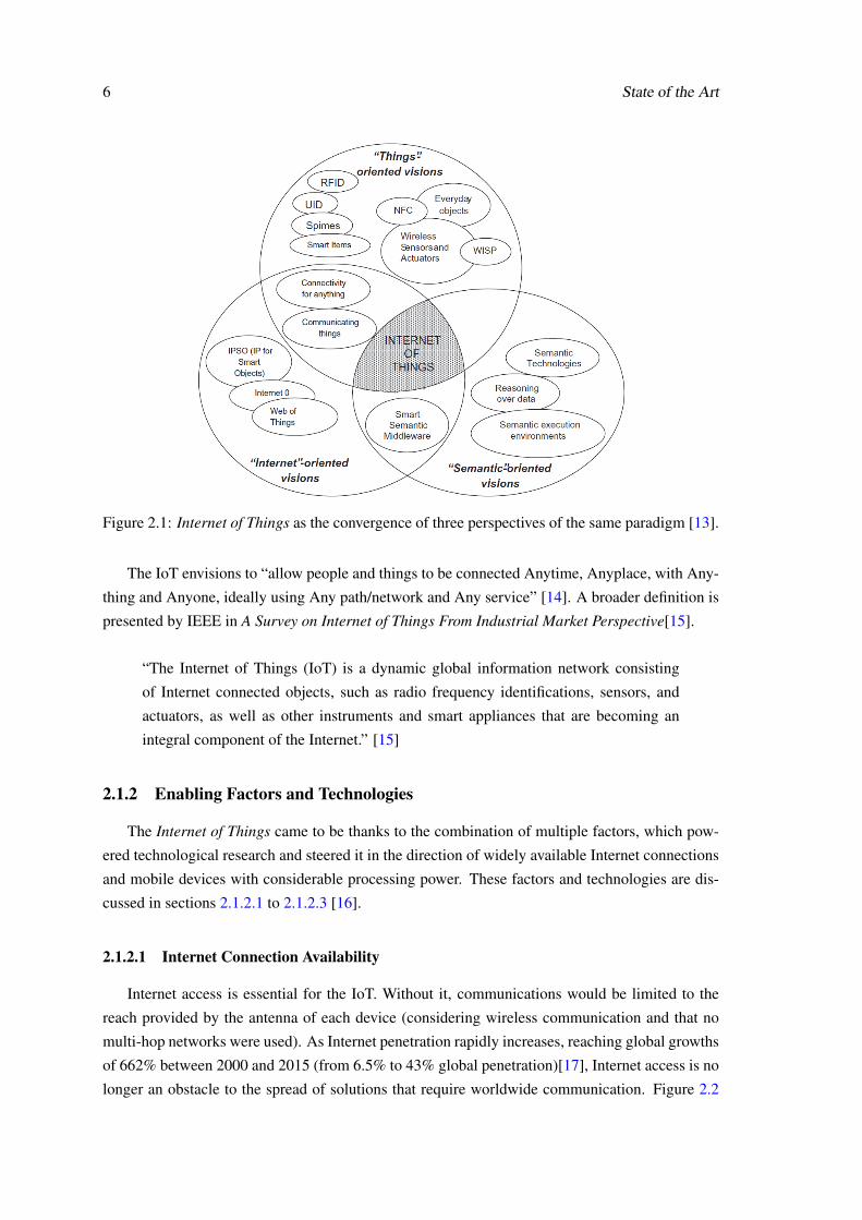
there is still no common agreement on a complete and standard definition, as this concept can be
realized from three perspectives — “Internet-oriented (middleware), things oriented (sensors) and
semantic-oriented (knowledge)” [12]. Figure 2.1 represents these perspectives, which picture the
IoT as seen from each one of its composing layers. Analogies are a very useful tool to explain
and understand abstract concepts, and as such, a chocolate chip cookie analogy will be used to
illustrate the three layers.
Things - Devices, sensors, actuators or any other active participants and data providers. “Things”
obtain contextual data for their own use or for future transmission. These can be though of
as the chocolate chips of the IoT.
Communication - Data sharing is the foundation of the IoT. By defining and using standardized
communication protocols and channels, “things” can communicate between themselves and
with other devices using sensor and actuator networks, along with publicly available APIs.
Communication is the dough of the IoT, holding “things” as chocolate chips together.
Applications - Raw data is not useful on its own, it has to be filtered, analysed and interpreted,
in order to become a source of knowledge and information. This is usually done by ap-
plications running on devices with a higher level of processing power and with increased
communication capabilities (detailed study in section 2.5.2). Applications have a purpose
somewhat similar to the oven in our analogy, they “bake” the data and make it ready for
consumption.
5
6 State of the Art
Figure 2.1: Internet of Things as the convergence of three perspectives of the same paradigm [13].
The IoT envisions to “allow people and things to be connected Anytime, Anyplace, with Any-
thing and Anyone, ideally using Any path/network and Any service” [14]. A broader definition is
presented by IEEE in A Survey on Internet of Things From Industrial Market Perspective[15].
“The Internet of Things (IoT) is a dynamic global information network consisting
of Internet connected objects, such as radio frequency identifications, sensors, and
actuators, as well as other instruments and smart appliances that are becoming an
integral component of the Internet.” [15]
2.1.2 Enabling Factors and Technologies
The Internet of Things came to be thanks to the combination of multiple factors, which pow-
ered technological research and steered it in the direction of widely available Internet connections
and mobile devices with considerable processing power. These factors and technologies are dis-
cussed in sections 2.1.2.1 to 2.1.2.3 [16].
2.1.2.1 Internet Connection Availability
Internet access is essential for the IoT. Without it, communications would be limited to the
reach provided by the antenna of each device (considering wireless communication and that no
multi-hop networks were used). As Internet penetration rapidly increases, reaching global growths
of 662% between 2000 and 2015 (from 6.5% to 43% global penetration)[17], Internet access is no
longer an obstacle to the spread of solutions that require worldwide communication. Figure 2.2

2.1 The Internet of Things 7
presents some statistics related to Internet coverage through the years. The increase in mobile-
cellular telephone subscriptions is notorious, as well as the number of households with Internet
access. However, the statistic with the most impact in the context of the Internet of Things, is
the population covered by 2G mobile-cellular network, as the high coverage ensures an Internet
connection is available in the majority of cases[17]. When a faster connection is required, 3G
mobile-broadband may be used, if available. The global population coverage for this technology
is of 29% for rural areas and 89% for urban areas, resulting in a total coverage of 69% of the global
population [17].
Figure 2.2: Internet usage and coverage from 2000 to 2015. Adapted from [17].
2.1.2.2 Manufacturing, Processing Power and Integration
As semiconductor lithography manufacturing processes and technologies evolve, devices with
14nm gate lengths are now a reality. Intel Skylake architecture, unveiled in September 2015, fea-
tures 14nm FinFET devices (3D multi-gate transistors) [18], as well as AMD’s Zen architecture,
which is expected to be released in 2016 [19]. However, despite the recent advances in manu-
facturing, the great majority of devices used on the IoT have not immediately benefited from a
decrease in transistor size as much as desktop systems. This is mainly due to the cost involved
in advanced processes. Micro-controllers used in IoT applications do not require the same level
of performance as desktop systems, instead they are designed to perform simpler tasks with a low
power consumption. Static leakage current in advanced processes is still relatively high when
compared to 180nm processes [20], which leads to higher power consumptions and defeats the
purpose of a low power micro-controller. Furthermore, embedded processors require pads for
bonding wires in its periphery, which take a relatively large amount of space. This would make
the total area of the processor increase drastically, increasing its cost to non-viable values. Current

8 State of the Art
micro-controllers utilize fabrication nodes from 90nm [21] to 130nm [22], and even 210nm or
350nm in some cases. These values will predictably get lower as fabrication nodes that are quite
expensive today, become more affordable.
Another way to take advantage of more advanced nodes is by providing a greater level of
integration. Instead of having separate circuit-boards for the micro-controller, sensors and com-
munication modules, producing a single device integrating all of the needed modules on the same
PCB allows the use of smaller packages, providing a chance for more advanced nodes to be used in
micro-processors. Single-board computers (SBC) such as the Beaglebone Black and the Raspberry
Pi 2, already feature more advanced fabrication nodes of 45nm [23] and 40nm [24], respectively.
These devices incorporate a plethora of communication modules and other utility modules on the
same board. By using a smaller fabrication node, the micro-processors contained on these devices
can also achieve higher frequencies and performance.
2.1.2.3 Communication, Standards and Interoperability
Inter-device communications are the pillar of the IoT. Protocols for such type of wireless
communications can be divided into three major groups, based on the provided range - short,
medium and long range. NFC (Near Field Communication) [25] enables short range (around
20 cm) bidirectional interaction between devices. NFC operates at shorter ranges than its parent
technology RFID [26] due to the protocol being designed to offer increased security and data
protection over the traditional RFID tags. Medium range communication technologies include Wi-
Fi, Zigbee [27] and Bluetooth. These technologies naturally present higher power consumptions,
but also allow for a wider variety of uses. Low power versions of such technologies are now
becoming more available, such as Bluetooth Low Energy, analysed in chapter 3. When no access
points are available, long range technologies and infrastructures must be used, such as mobile
networks.
Wi-Fi enabled devices have the capability of connecting to almost any of nowadays home
routers that are Wi-Fi compliant, becoming a possible gateway to forward locally gathered in-
formation to remote locations. A big part of currently produced mobile phones already include
NFC readers, allowing a wide-spread use of such technology for payments in retail stores. Blue-
tooth enabled devices have become part of our everyday lives, from wireless headphones and
mouse/keyboard systems to watches, sport shoes or simply tags. The use of standardized proto-
cols powered the integration of such devices into a complete network of information sharing. Such
a thing would not be possible if manufacturers kept using in-house developed, obfuscated and non-
public solutions. The Internet of Things only became a realizable concept because developers and
managers realized the potential of inter-brand device communication and interoperability.
2.1.2.4 Energy
Power consumption is one of the biggest factors to consider when implementing small au-
tonomous devices. Energy storage solutions tend to be quite big and heavy, negatively impacting

2.1 The Internet of Things 9
the overall size of IoT devices. Advances in low power and efficient electronics have enabled
the design of small sized solutions featuring processing power and capabilities that previously
required big packaging. Nowadays, compact batteries present energy storage capabilities that al-
low devices to stay powered on for weeks, months or even years, depending on the device and
associated task. To add on to the low power consumption electronics and protocols (BLE), en-
ergy harvesting solutions from alternative sources, such as solar and wind power, are now widely
available, and reaching performances to where they become of interest for IoT applications. Such
energy sources may be used to continually recharge devices, reducing the need for maintenance.
2.1.3 Areas of Application
The power of the IoT comes from enabling the use of widespread, low power and modular
sensing devices to collect data from virtually any mensurable source. Once this information has
been processed, it can be used for multiple purposes. Libelium [28] has elaborated a list of the
fifty most common uses of IoT devices, some of these are presented below.
Smart Cities and Environmental Monitoring
In Smart Cities, devices are used to monitor traffic congestion, control weather adaptation
public lighting, manage parking spaces available in the city and even help in waste manage-
ment. IoT devices are also being used to monitor several environmental parameters, which
provide vital information on what courses of action should be taken to avoid harm to the
population or how to proceed in the case of a natural disaster. Applications include moni-
toring the levels of CO2, other harmful emissions, and the presence of combustible gases in
fire prone areas such as forests and parks.
Example Projects:
• Porto Future Cities project [29]
• Amsterdam smart traffic management [30]
• London pilot project for precise forecast of air pollution [31]
Logistics and Retail
One of the original application ideas for the IoT was to replace bar codes. Although this so-
lution is not yet implemented in every day retail stores, it is already being used in large scale
storage facilities and through supply chains, to manage and monitor stocks and resource
tracking. NFC (Near Field Communication) payments are also starting to be supported by
multiple businesses and retailers as current smartphones support that functionality.
Example Projects:
• Smart logistics and realtime tracking and sensing of goods in California (USA) and
Zaragoza (Spain) [32]
• MasterCard Contactless [33]

10 State of the Art
Home, Agricultural and Industrial Automation
The most wide spread use of the IoT is home automation. Also know as Smart Home,
these technologically advanced buildings are interactive, as they allow the user to configure
parameters and behaviours of some house appliances, such as the lighting and blindfolds
position. Precision agriculture has also benefited from the use of the IoT, as sensors are
used to closely monitor soil and air parameters to prevent harmful conditions and provide
the best possible conditions for success. These same possibilities also apply to industrial
environments.
Example Projects:
• Smart home applications [34]
• Assistive Environment for Hydroponic Farming [35]
Health, Wearables and Assisted Living
Health monitoring may be one of the most positive applications of IoT devices. From doc-
tors being able to access real time data of patients, to autonomously triggered alerts in situ-
ations of danger, the ability to warn emergency services as soon as they are needed greatly
improves their response and hence efficiency. The sensors and devices used in such applica-
tion may even be embedded in wearables, as the some clothes of today already incorporate
sensing capabilities. Wearables have also become quite popular for their use in sports for
athlete condition tracking and evaluation.
Example Projects:
• Cardiac monitoring using wearable textiles [36]
• Continuous glucose monitoring [37]
• Fall Prevention [38]
2.1.4 Future Developments
The rapid growth in the number of connected devices enables new possibilities and use cases
that were previously unachievable. Self driving cars are a goal that is closer than ever to be
achieved. The Google Self-Driving Car Project [39] is one of the most advanced projects in that
area. The information harvesting capabilities of the IoT are extremely useful for applications that
need to be constantly aware of their surroundings, such as self driving vehicles.
Figure 2.3 presents forecasts from multiple entities regarding the number IoT devices by 2020.
It is clear that the predictions of three of the entities are somewhat close to each other and in
the same ballpark, while the forth one is a whole order of magnitude above the others. This is
mostly due to the type of devices that each prediction considers. While some entities only take
into account user devices, such as smartphones, tablets and laptops, other also consider the data
gathering devices such as sensors. Sensors represent by far the largest cut of IoT devices, however,
they usually do not possess a direct connection to the Internet, relying on a gateway device to

2.2 Wireless Communication Technologies 11
collect and forward the gathered data, such as a smartphone. Both approaches are hence valid and
present different perspectives of the development of the Internet of Things.
Figure 2.3: Predictions for IoT devices by 2020 [40, 41, 5, 42].
2.1.5 Remarks
The Internet of Things has the power to change the way people and devices communicate and
interact. This is an ongoing change as several projects are already exploring the opportunities
offered by wide spread connectivity. From industrial to domestic application, from urban to rural
landscapes, the integration of sensing devices with environment provides the opportunity to collect
information and adapt to certain identified needs, or even construct predictive behavioural models.
The key aspect for the sucess of the IoT is seamless integration and standardized interaction,
and as such, devices and architectures that provide a higher degree of abstraction and integration
are discussed in section 2.3.
2.2 Wireless Communication Technologies
2.2.1 Overview
Over the years, several wireless technologies and protocols have emerged. From long range
communications, to very sort ranges, with high or low throughput, there are technologies for
virtually every use case. They also present a variety of power demands and provide different
degrees of security. This section will go over some of the wireless technologies of interest, having
the Internet of Things as the target environment.

12 State of the Art
2.2.2 Cellular
Cellular networks are ideal for very long range applications. As presented is section 2.1.2.1,
3G technology has a coverage of 69% of the global population, making it very interesting for
when no other means of connectivity are available, as in many rural environments. Several cel-
lular technologies are available, each presenting different carrier frequencies, protocols and range
capabilities. The technologies can be divided into three generations - 2G (GSM/GPRS/EDGE),
3G (UMTS/HSPA) and 4G (LTE). While GSM provide a maximum range of 25km, HSPA goes as
far as 200km. In terms of throughput, the actual download data rates vary with the technology used
and signal strength. Typical values are presented in table 2.1. The downside of these technologies
is the power consumption they imply, when compared to other wireless technologies.
Generation Technology Data rate (Mb/s)2.5G GPRS 0.035 - 0.172.75G EDGE 0.12 - 0.384
3G UMTS 0.384 - 23.5G HSPA 0.6 - 104G LTE 3 - 10
Table 2.1: Typical data rates for cellular technologies. [43]
2.2.3 Wi-Fi
Wi-Fi was developed as a wireless replacement of the popular wired Ethernet standard, the
IEEE 802.3. Due to this, Wi-Fi was developed having in mind data throughputs that could handle
file transfers and reliable Internet connectivity. The most common Wi-Fi standard is the 802.11n,
which offers data rates in the range of hundreds of megabits per second. Typical data rates are
of 150 to 200 Mb/s, depending on the channel usage and signal strength [43]. This technology
is present in the great majority, if not all, of today smartphones, tables and laptops. And since
this technology is most often used through Access Points (AP), most homes and buildings are
also equipped with Wi-Fi AP devices. Wi-Fi also features and Ad-Hoc mode, which allows two
devices to be connected directly, with no need for an AP. Connection ranges vary with the number
of antennas of the devices and their topology, but the quality of regular connections severely
decreases after 50m of distance between the AP and the connected device [43].
2.2.4 ZigBee
ZigBee is a “low-throughput, low-power and low-cost technology” [44]. This technology is
useful for multiple applications and is mostly used in industrial solutions. The scalability, and
mesh oriented topologies of ZigBee networks make it a very good option for Wireless Sensor
Networks. Due to its low power character, the range of ZiggBee connections does not go further
than 100m in line of sight, dropping to around 10m if obstacles are introduced [43]. The maximum
data rate is of 250kb/s [44], although it is commonly used with much lower rates.

2.2 Wireless Communication Technologies 13
2.2.5 Bluetooth
Bluetooth was primarily designed to establish standard wireless communication between phones
and computers, and it became so popular that every phone nowadays has Bluetooth connectivity.
As the use cases became more demanding, the Bluetooth specification evolved. Bluetooth 1.2
supported data rates of up to 1Mb/s, and when it became insufficient Bluetooth Enhanced Data
Rate (2.0) was developed featuring 3Mb/s connections. Bluetooth High-Speed (3.0) represented a
huge leap in data rates, with an optimal speed of 24Mb/s. With the introduction of Bluetooth 4.0,
the Low Energy mode was introduced. The new mode takes data rates back to the original 1Mb/s,
but it does so with extremely low power consumptions. Due to this, Bluetooth 4.0 became known
as BLE (Bluetooth Low Energy) and Bluetooth Smart. From all of the Bluetooth technologies
family, BLE is the one that stands out for IoT applications, as it “enables years of operation using
coin cell batteries” [44]. BLE connections have typical ranges of 50 to 100m. Bluetooth Low
Energy is further explored in chapter 3.
2.2.6 6LoWPAN
6LoWPAN (IPv6 over Low power Wireless Personal Area Networks) aims to “apply IP to
the smallest, lowest-power and most limited processing power device” [44]. This connectivity
standard was developed specifically for IoT devices. 6LoWPAN is not a complete data transmis-
sion technology, in the sense that it does not specify a frequency band to operate in, or a physical
layer. Instead, it only defines encapsulation and compression mechanisms for a layer between
the IEEE 802.15.4 link layer and a TCP/IP stack. Since 6LoWPAN operated over IPv6, only a
IP-layer gateway is necessary to connect the devices to the Internet, unlike BLE, where an appli-
cation layer gateway is needed. The range and data rates depend on the physical layer hardware
implementation.
2.2.7 Remarks
Cellular networks and Wi-Fi connections are useful for devices that require relatively large
bandwidths. Due to the high power consumption of such solution, they are not the best fit for
small IoT devices, but are still relevant as technologies to be used in gateway devices to connect a
local network to the Internet.
The remaining solutions - ZigBee, BLE and 6LoWPAN - all have their own advantages and
drawbacks. The data rates mentioned on the previous sections represent air data rate, but do not
correspond to the application data throughput. Table 2.2 presents a comparisson of data rates on
the application level for the mentioned technologies. ZigBee presents the lowest data rate of the
three technologies, and although it is quite usefull for mesh networks, IoT devices usually rely
on a direct connection with a gateway, in a star topology. 6LoWPAN has the advantage of being
able to directly connect a device, or a network of devices, to the Internet, but the number or imple-
mented solutions using this technology is still reduced. In the future however, this may prove to be
the dominating IoT communication technology. Bluetooth Low Energy presents a good balance
14 State of the Art
between data rates, connection range and power consumption, and is furthermore supported by a
vast legacy of the Bluetooth technology, which eased its entrance onto the market. Most current
smartphones are BLE compatible, making this technology a solid choice as the communication
technology for IoT devices.
Technology Air Data Rate Application ThroughputBLE 1Mb/s 305kb/s
ZigBee 250kb/s 100kb/s6LowPAN 10-200kb/s
(based on IEEE 250kb/s depending on802.15.4) configuration
Table 2.2: Comparison of air data rate and application throughput, as measured in [45]
2.3 Seamless Micro-controller Integration
2.3.1 Overview
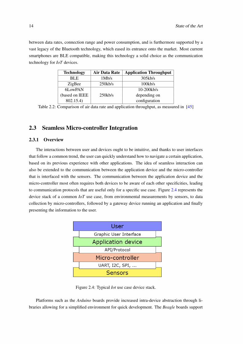
The interactions between user and devices ought to be intuitive, and thanks to user interfaces
that follow a common trend, the user can quickly understand how to navigate a certain application,
based on its previous experience with other applications. The idea of seamless interaction can
also be extended to the communication between the application device and the micro-controller
that is interfaced with the sensors. The communication between the application device and the
micro-controller most often requires both devices to be aware of each other specificities, leading
to communication protocols that are useful only for a specific use case. Figure 2.4 represents the
device stack of a common IoT use case, from environmental measurements by sensors, to data
collection by micro-controllers, followed by a gateway device running an application and finally
presenting the information to the user.
Figure 2.4: Typical Iot use case device stack.
Platforms such as the Arduino boards provide increased intra-device abstraction through li-
braries allowing for a simplified environment for quick development. The Beagle boards support

2.3 Seamless Micro-controller Integration 15
the BoneScript [46] library which is a Node.js [47] library that features Arduino like function
calls to facilitate the usage of the Beagle platforms, which run Linux operating system. Even
though these libraries expedite firmware development, additional protocols are still required for
inter-device communication.
Some protocols have been developed to standardize the interaction between applications and
well known micro-controllers, which enables high level developers to take advantage of devices
that require low level programming. Other devices have been explicitly developed to allow for
easy interaction and usage of the micro-controllers from within the application development envi-
ronment, by providing APIs that seamlessly integrate the boards as extensions of the application
device. Since this project aims to develop a solution that provides similar functionality, some of
these protocols and APIs are discussed on the following sections.
2.3.2 Firmata Protocol
The Firmata protocol, developed by Hans-Christoph Steiner [48], is a “generic protocol for
communicating with microcontrollers from software on a host computer”. The original, and still
main, development platform for Firmata are the Arduino boards [49]. The protocol defines a set
of command codes and messages to be transferred between devices. The messages are based on
the MIDI (Musical Instrument Digital Interface) message format.
As the protocol only defines a message format, how this format is used is up to the end de-
velopers, and two main usage models have risen. The first type of models allow both devices to
initiate a message transfer. The second type of models define the host device as a communication
controller, and all communications are initiated by this device. To use the second protocol model
type, the user has first to upload a standard Firmata implementation sketch onto the Arduino board.
The sketch is available on Arduino IDE as an example. Once the board is running the Firmata pro-
tocol, it may be connected to a host device (computer, smartphone, table, etc.) through a USB
cable. The application side of the protocol comes in the form of libraries or classes, depending
on what programming language is used to develop the application. The protocol has been imple-
mented in a variety of languages such as Processing Python, Ruby, Java, JavaScript, Flash, PHP
and iOS, among others [50]. Once the libraries have been added to the application environment,
the Arduino board acts as an extension of the host device.
1 <dependency>
2 <groupId>com.github.kurbatov</groupId>
3 <artifactId>firmata4j</artifactId>
4 <version>2.3.2</version>
5 </dependency>
Code snippet 2.1: Firmata Java library installation using Maven [51].

16 State of the Art
1 //Initiallize2 IODevice device = new FirmataDevice("/dev/ttyUSB0");3 device.start();4 device.ensureInitializationIsDone();5 //Do work6 Pin pin = device.getPin(2);7 pin.setMode(Pin.Mode.OUTPUT);8 pin.setValue(1);9 //Finish
10 device.stop();
Code snippet 2.2: Firmata Java implementation example usage [51].
Code 2.1 presents a way to include a Firmata implementation in Java [51], developed by Oleg
Kurbatov. Code 2.2 presents how to turn on an LED connected to pin 2 of an Arduino board
running Firmata.
2.3.3 IOIO Board
The IOIO boards provide “a host machine the capability of interfacing with external hardware
over a variety of commonly used protocols” [52]. While the Firmata protocol does not define
target device architectures and can be implemented in any device, IOIO boards are a complete,
closed solution. The boards are sold pre-programmed with firmware that enables a functionality
similar to the second model type of the Firmata protocol. It is possible to flash new firmware to
the boards, but the boards are not primarily intended for that purpose. Figure 2.5 presents the latest
IOIO-OTG (On-The-Go) boards.
Figure 2.5: IOIO-OTG board. Adapted from [53].
Host devices may be computers or Android devices, and a Java API is provided to interface
the host device with the boards. Communication between the host and the IOIO boards can be
established using a direct USB cable connection, or by standard Bluetooth, using an external
dongle. Code 2.3 is a usage example presented in a page of one the IOIO board developers. The

2.3 Seamless Micro-controller Integration 17
code snippet would allow an Android application to control the position of a servo motor (pin 12)
given the position of a potentiometer (pin 40).
1 ioio.waitForConnect();2 AnalogInput input = ioio.openAnalogInput(40);3 PwmOutput pwmOutput = ioio.openPwmOutput(12, 100); // 100Hz4 while (true) {5 float reading = input.read();6 pwmOutput.setPulseWidth(1000 + Math.round(1000 * reading));7 sleep(10);8 }
Code snippet 2.3: IOIO board usage example [54].
2.3.4 Particle Boards
Particle boards [55] provide an extra level of flexibility over the previously presented solu-
tions. The boards can either be programmed by the user to perform a specific task, or they can run a
standard code and be completely controlled by another device, like the IOIO boards. Furthermore,
the boards are made to connect not to a device, but to the cloud, through Wi-Fi or 2G/3G. Instead
of issuing command directly to the device, applications send commands to a cloud, where all the
particles belonging to a user are registered. The board is constantly listening to the cloud, and once
a command arrives, the board reads it and executes it. To access the cloud, the user has to create
an account, and associate all its Particle with it. When sending a command, these credentials must
be sent as well, allong with the target device identifier. Thanks to this feature, the interaction with
Particle boards is not limited to the provided APIs, but instead its open to anything that has an
Internet connection. The boards can be controlled by an Android device, through a web page by a
user half way across the globe, or by any other means of web communication.
There are two Particle development kits, the Photon and the Electron. The Photon is a very
small board that includes a Wi-Fi module, while the Electron is slightly bigger and feature a 2G/3G
module. The P0 device is as the core of the Photon development kit, but is available separately for
application deployment. The three devices are presented in figure 2.6

18 State of the Art
Figure 2.6: Particle boards. From left to right: P0, Photon, Electron. [55]
2.3.5 Remarks
The presented technologies allow the development of solutions by an extended range of people.
By abstracting the two lower layers of the device stack (figure 2.4), and as a result the complex-
ity of firmware design, developers can focus on exploring useful applications for a multitude of
sensors. This sort of blackbox design is beneficial not only for professional developers, whose
focus can be moved to more important aspects, but also the occasional developer and hobbyist,
who wishes to develop a quick and functional solution, without dwelling into the fields of micro-
controller architectural specificities.
2.4 Implementations Platforms
2.4.1 Overview
Section 2.3 introduced platforms that offer a high degree of integration and abstraction. There
are however other platforms that are also viable for IoT devices implementation. Some of these
platforms will be discussed in this section.
2.4.2 Arduino based solutions
The Arduino boards have become extremely popular among professional and amateur devel-
opers as they can be used for fast implementations and prototyping. Recently, Arduino boards
where re-branded as Genuino when sold outside the USA, but they offer similar functionalities as
the USA Arduino boards. The Arduino family boards offer a wide range of base hardware im-
plementations and architectures, some boards even featuring two distinct micro-controllers, and

2.4 Implementations Platforms 19
others have integrated FPGAs. By using standard or custom designed shields, the user may ex-
tend the board functionality even further. A variety of shields are available, such as LCD screens,
Ethernet, Bluetooth and GSM connectivity, among others.
The success of the Arduino boards led to the rise of a whole generation of micro-controller
based products that followed the same concept. Examples of such boards are the chipKIT boards,
that feature a PIC micro-controller instead of the Arduino ATMEL micro-controllers, as presented
in figure 2.7.
Figure 2.7: Arduino UNO and chipKIT Uno32 side by side. Adapted from [56].
2.4.3 Single Board Computers
Single Board Computers represent a different kind of solution when compared to the Arduino
based solutions. SBCs feature complete operative systems (OS) and possess increased processing
power. Two well know SBC are the Raspberry Pi (figure 2.8) and the Beaglebone (figure 2.9).
These platforms are roughly the same size as an Arduino UNO board, but vastly more powerful.
Besides the usual inter-circuit communication protocols (I2C, SPI, UART, etc) these two platforms
also natively support USB devices compatibility, Ethernet communication and HDMI video out-
put. Since they are able to run complete OS (typically Linux) most of the software developed for
desktop systems is able to run on these platforms, with the expected performance differences.
However, these systems power consumptions are greater than the ones from less powerful
devices, but that are still able to perform the basic tasks required for simple IoT devices. Therefore,
SBCs usually perform the role of gateway devices, and not of sensing devices.
Figure 2.8: Raspberry Pi 2 [57]Figure 2.9: BeagleBone Black [58]

20 State of the Art
2.4.4 ESP8266
The ESP8266 is a very small System-On-Chip (SoC) that features embedded Wi-Fi communi-
cation and on-board antenna. Due to its low cost and high use case applicability, this platform has
received lots of attention. The system supports all the major inter-circuit communication protocols,
along with an integrated temperature sensor. The native support of Wi-Fi communication allows
this device to connect directly to the Internet, with no need of a gateway device. The SoC has
been used in multiple variants of boards, each containing slightly different added functionalities,
as presented in figure 2.10.
Even though the size and cost of this platform make it very appealing for IoT applications, the
use of Wi-Fi becomes a restriction when it comes to power consumption, as discussed in section
2.2.
Figure 2.10: A variety of ESP8266 based devices. Adapted from [59].
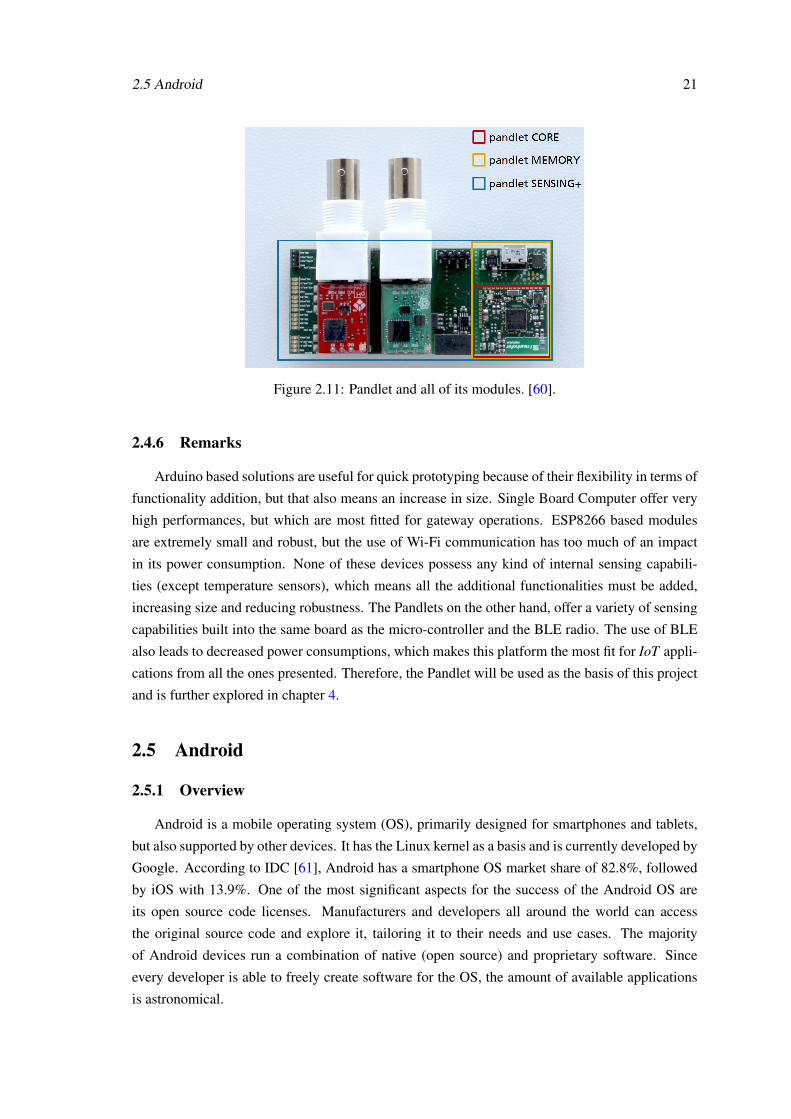
2.4.5 Fraunhofer Pandlet
The Fraunhofer Pandlet is platform that, in its CORE module, integrates a processing unit,
several sensing devices (Inertial Measurement Unit and Environmental Measurement Unit) and a
Bluetooth Low Energy radio. Furthermore, the module is also QI compliant, for induced charging.
The Inertial Measurement Unit (IMU) includes an accelerometer, a gyroscope and a magnetome-
ter, while the Environmental Measurement Unit (EMU) includes humidity, pressure and temper-
ature sensors. The Pandlet is built around the Nordic nRF51822 SoC, which was specifically
designed to used in BLE solutions.
The Pandlet may also include other modules, such as the MEMORY module, which adds
the possibility of using a microSD card and wired charging, and the SENSING+ module, which
features and ADC (Analogue to Digital Converter), GPIOs (General Purpose I/O) and and I2C in-
terface for external sensing devices. Figure 2.11 presents a Pandlet will all of its modules attached.
2.5 Android 21
Figure 2.11: Pandlet and all of its modules. [60].
2.4.6 Remarks
Arduino based solutions are useful for quick prototyping because of their flexibility in terms of
functionality addition, but that also means an increase in size. Single Board Computer offer very
high performances, but which are most fitted for gateway operations. ESP8266 based modules
are extremely small and robust, but the use of Wi-Fi communication has too much of an impact
in its power consumption. None of these devices possess any kind of internal sensing capabili-
ties (except temperature sensors), which means all the additional functionalities must be added,
increasing size and reducing robustness. The Pandlets on the other hand, offer a variety of sensing
capabilities built into the same board as the micro-controller and the BLE radio. The use of BLE
also leads to decreased power consumptions, which makes this platform the most fit for IoT appli-
cations from all the ones presented. Therefore, the Pandlet will be used as the basis of this project
and is further explored in chapter 4.
2.5 Android
2.5.1 Overview
Android is a mobile operating system (OS), primarily designed for smartphones and tablets,
but also supported by other devices. It has the Linux kernel as a basis and is currently developed by
Google. According to IDC [61], Android has a smartphone OS market share of 82.8%, followed
by iOS with 13.9%. One of the most significant aspects for the success of the Android OS are
its open source code licenses. Manufacturers and developers all around the world can access
the original source code and explore it, tailoring it to their needs and use cases. The majority
of Android devices run a combination of native (open source) and proprietary software. Since
every developer is able to freely create software for the OS, the amount of available applications
is astronomical.

22 State of the Art
The latest Android version is named Marshmallow, which corresponds to Android 6.0 (API
23). Bluetooth Low Energy has been supported by Android since version 4.3 (API 18). The BLE
Android API suffered some changes as of Android 5.0, and the feature became a lot more stable
than in previous releases of Android. Having in mind the distribution of platform version from all
the currently operation Android devices [62], 74.2% of such devices have BLE support. However,
to use BLE the device hardware also has to support this type of connectivity.
2.5.2 Android as a Gateway
The majority of IoT sensors and devices do not possess forms of connectivity that allow a
direct connection to the Internet, nor do they possess the required processing power to treat and
interpret the collected data. This is where a gateway device becomes useful. A gateway is a
device whose primary function is to take data collected by another device, and either store and
process it locally, or forward it to another location. Most Android devices have Internet access
through cellular networks or by Wi-Fi connections, and a decent amount of local storage capacity.
These characteristics, allied to the increased processing power and open development licenses
make Android devices ideal to act as gateways for smaller, low power IoT devices.
The aim of this project is not to develop an Android application to work as a gateway, but
instead to create tools that other developers may use to implement their own solutions for specific
use cases. This functionally is offered by the means of a library package that exposes an API for
interaction, and abstracts the lower layers of implementation from the high level developers, in
this case, the ones implementing a complete Android application.
There are two main tools available to develop applications for Android, the SDK (Software
Development Kit) and the NDK (Native Development Kit). The NDK allows developers to imple-
ment solutions using native-code languages such as C ad C++, which are useful for use cases that
load the CPU heavily. However, most applications do not benefit from being developed using the
NDK, and are instead developed using the SDK, which allows developers to use the Java language
as the means of implementation. Since the tools developed in this project should be as accessible
as possible, the libraries and APIs will be developed using Java and the SDK.
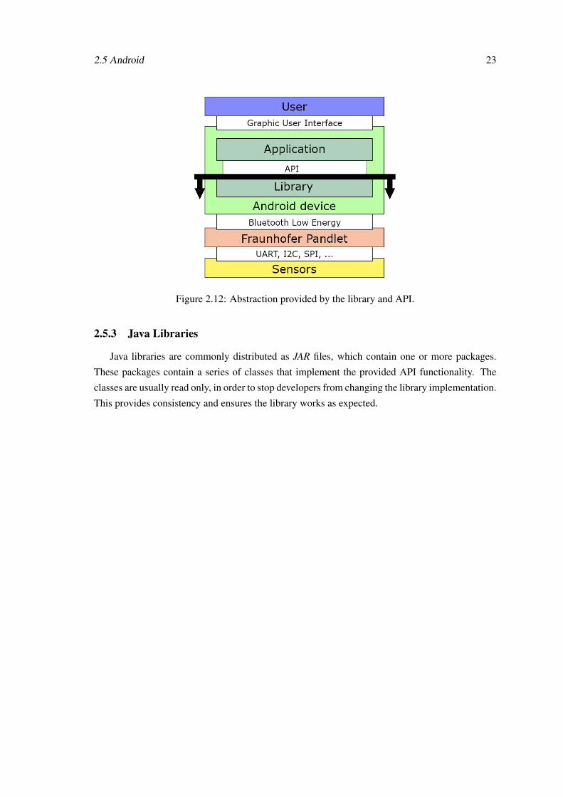
The developed API should provide its users the tools to seamlessly communicate with the
Pandlet peripheral devices, abstracting the BLE communication layers and the Pandlet itself, as if
the peripherals were part of the Android device, as presented in figure 2.12. The objective of the
API is for the application developer to not have to worry about the implementation of the part of
the stack below the represented black line.
2.5 Android 23
Figure 2.12: Abstraction provided by the library and API.
2.5.3 Java Libraries
Java libraries are commonly distributed as JAR files, which contain one or more packages.
These packages contain a series of classes that implement the provided API functionality. The
classes are usually read only, in order to stop developers from changing the library implementation.
This provides consistency and ensures the library works as expected.

24 State of the Art

Chapter 3
Bluetooth Low Energy
3.1 Overview
Bluetooth Low Energy (BLE), also known as Bluetooth Smart or Bluetooth 4.0, is a technology
designed to be the “lowest possible power wireless technology” [63], requiring only a button-cell
battery to operate. Although BLE makes use of the Bluetooth brand and some of the classic
Bluetooth technology, it addresses a different purpose. While classic Bluetooth is mostly used for
data streaming (such as cellphone to headset audio link), BLE data rates restrain its applications to
sporadic, short range, data transmissions, while accomplishing very low power consumption (1%
to 50% of classic Bluetooth, depending on use case [64]).
This technology was designed having in mind not only the goal of low power consumption,
but also some of the original goals of Bluetooth, such as standardized communication, low imple-
mentation cost and robustness. These specifications make BLE ideal to establish communication
between IoT devices as it was designed to accomplish that purpose. Modularity was also a main
concern while designing BLE, the technology can successfully keep up with the evolution of the
IoT, requiring minimum of future adjustments, and successfully accommodating the ones that may
be needed.
Figure 3.1: Bluetooth versions device compatibility [65].
25

26 Bluetooth Low Energy
Bluetooth LE (Low Energy) does not support backwards compatibility, as devices supporting
only classic Bluetooth communications are not able to interact with BLE devices. However, cur-
rent smartphones often support both technologies, as illustrated in figure 3.1. To do so, dual mode
devices implement the protocol stack from classic and low energy Bluetooth. The most avail-
able device featuring dual mode communication are smarthphones, as manufacturers recognize
the potential of BLE in the context of the IoT and implement both solutions (classic Bluetooth for
communication with legacy equipments) on their devices, as represented in figure 3.2. The use
case for this project only requires communication between BLE compliant devices, and as such,
the BLE stack is presented in section 3.2.
Figure 3.2: World market forecast of standalone Classic Bluetooth and BLE dual-mode shipments.Forecast from 2012. [66].
This chapter presents an extended summary of BLE, largely based on the information pre-
sented in the books “Getting Started with Bluetooth Low Energy” [65] and “Bluetooth Low En-
ergy - The Developer’s Handbook‘” [63].
3.2 Protocol Basics and Stack Overview
The Bluetooth LE architecture is divided into several layers, that can be grouped into 3 main
parts: controller, host, and applications. The two lowest layers (Physical and Link) make up the
controller, a physical device dedicated to transmit, receive, demodulate the radio signals and ag-
gregate the received information into packets, that will be interpreted by the upper layers. The host
is a group of software layers that manage several parameters of the connection between devices,
and provide basic tools for the application to be built upon. Between the host and the controller
there is an interface that establishes a communication protocol for the two parts. On the top of
the stack are the applications, that use profiles and the services provided by them to implement a
certain functionality. The BLE stack is represented in figure 3.3 and a short description of each
layer is presented.

3.2 Protocol Basics and Stack Overview 27
Figure 3.3: Bluetooth Low Energy stack. [11].
Physical Layer (PHY)This layer contains the analogue circuitry to transmit and receive the radio signal, using the
2.4GHz ISM (Industrial, Scientific and Medical) band, which is divided into 40 channels
(from 2.40000GHz to 2.4835GHz), spaced 2MHz apart from each other. The last three
channels (37, 38 and 39) are reserved to advertising purposes only, such as setting up con-
nections and sending broadcast data. A technique called frequency hopping spread spectrum
is used to minimize the interference from other radio sources, such as Wi-Fi devices. By
using this technique the communication channel is changed on each connection event, ac-
cording to equation 3.1. The hop value is communicated when the connection is created.
The bit stream is encoded using Gaussian Frequency Shift Keying (GFSK).
channelnext = (channelcurrent +hop) mod 37 (3.1)
Link Layer (LL)The Link Layer is directly interfaced with the Physical Layer, and is the only layer with
hard real-time constraints, as it has to comply with all the timing requirements set by the
specification and abstracts the real-time requirements from the upper layers. This layer
defines roles that devices can take and advertising packet types depending on the use case,
as is further explored in section 3.3.
Host-Controller Interface (HCI)The Bluetooth specification allows a variety of possible hardware implementations, which
leads to different controller configurations. To overcome the difficulties presented by differ-
ent controller architectures, the Host Controller Interface (HCI) establishes a serial interface

28 Bluetooth Low Energy
that allows standardized communication between host and controller.
Logic Link Control and Adaptation Protocol (L2CAP)The L2CAP is responsible for encapsulating protocols from upper layers, such as ATT and
SMP, into standard BLE packets, as well as the opposite operation. This layer also performs
fragmentation and recombination, where it takes larger packets from upper layers and splits
them into several packets to be transmitted, and recombined by the L2CAP layer of the
recipient.
Security Manager (SM)The Security Manager provides a protocol and security algorithms for device pairing and
secure communication over an encrypted link.
Attribute Protocol (ATT)The ATT defines rules for accessing data on peer devices. Data is stored on a server, in the
form of attributes, which can be accessed by a client. The ATT also defines Read/Write
permissions, that control the access to the attributes.
Generic Attribute Profile (GATT)The Generic Attribute Profile makes use of the Attribute Protocol and defines the types of
attributes and how they may be used. It introduces concepts such as services and character-
istics, the relationships between them and procedures to discover and access them.
Generic Access Profile (GAP)The Generic Access Profile specifies procedures for device discovery and connection, by
establishing sets of rules that regulate the operation of lower level layers.
ProfilesProfiles is where all of the previous protocols and procedures come together to serve a well
defined use case or application. Further more, profiles describe the services available on the
devices.
The following sections contain a more in-depth discussion of the layers that are of greater
importance to this project.
3.3 Link Layer
The Link Layer defines roles that devices can take according to what type or communication
is desired as well as to who initiates said communication. The four defined roles are presented in
table 3.1.

3.3 Link Layer 29
Role DescriptionAdvertiser A device that sends advertising packetsScanner A device that scans for advertising packetsMaster A device that initiates, manages and may terminate a connectionSlave A device that receives a connection, and may also terminate it
Table 3.1: Roles defined by the Link Layer
The Bluetooth device address is a fundamental 48-bit device identifier, however, it can be
of two types - Public or Random. Public device address is a fixed, factory-programmed device
address, while the Random device address can be pre-programmed or generated at run time. The
choice between which address to use in each communication is done by the Host. The BLE packet
structure is also defined by the Link Layer and is further discussed in section 3.8.1.
There are three different properties by which advertising packets can be classified, presented
in table 3.2. That information is contained in the payload section of the advertising packet. By
combining those properties, four types of advertising packets are defined (table 3.3) and used by
upper layer such as GAP (General Access Profile).
Property Variants Description
Connectability
Connectable A scanner may initiate a connection upon receivingthe advertising packet.
Non-connectable A scanner cannot initiate a connection. Used forbroadcast purposes.
ScannabilityScannable A scanner may issue a scan request upon receiving the
advertising packet.Non-scannable A scanner cannot issue a scan request
DirectabilityDirected The packet contains only the advertiser’s and the target
address in its payload. The packet is connectable.Undirected There is no defined target.
Table 3.2: Advertising packet properties. [65]
Advertising Packet Type Connectable Scannable Directed GAP Advertising NameADV_IND Yes Yes No Connectable UndirectedADV_DIRECT_IND Yes No Yes Connectable DirectedADV_NONCONN_IND No No No Non-connectable UndirectedADV_SCAN_IND No Yes No Scannable Undirected
Table 3.3: Advertising packet types. [65]
When a master wishes to start a connection, once it finds a suitable advertising slave (adver-
tising packets can be filtered by Bluetooth Address and by advertising data), it sends a connection
request. If the slave responds, a connection is established. The connection request packet con-
tains several vital information, such as the frequency hop, connection interval, slave latency and
connection supervision timeout.

30 Bluetooth Low Energy
Frequency Hop:
Value to be considered by the Physical Layer in equation 3.1.
Connection Interval:
Time between the initial instant of consecutive connection events (7.5ms to 4s).
Slave Latency:
Maximum number of events a slave can skip before the central considers the connection as
lost.
Connection Supervision Timeout:
Maximum time between two received and validated packets before considering the connec-
tion as lost.
Once a connection is established, data exchange between master and slave occurs periodi-
cally, as represented in figure 3.4. When a new packet is received the LL checks it against a
24-bit CRC and requests a retransmission if needed with no upper bound to the number of retrans-
missions. Therefore, the data provided by the LL to the upper layers is considered valid. Data
encryption/decryption is also performed by the LL, using keys provided by the Security Manager.
Figure 3.4: Connection events. [65]
3.4 Security Manager
The Security Manager (SM) provides peers the ability to securely communicate over an en-
crypted link, as well as establishing mechanisms to access trust levels between devices. A Link
Layer master device is always an Initiator, which is responsible for triggering procedures. The
other device is a Responder, and although it cannot initiate procedures, it may request the Initiator
to do so (which may or may not comply).
3.4.1 Security Procedures
The SM supports three security procedures - Pairing, Bonding and Encryption Re-establishment
- two of which are illustrated in figure 3.5.
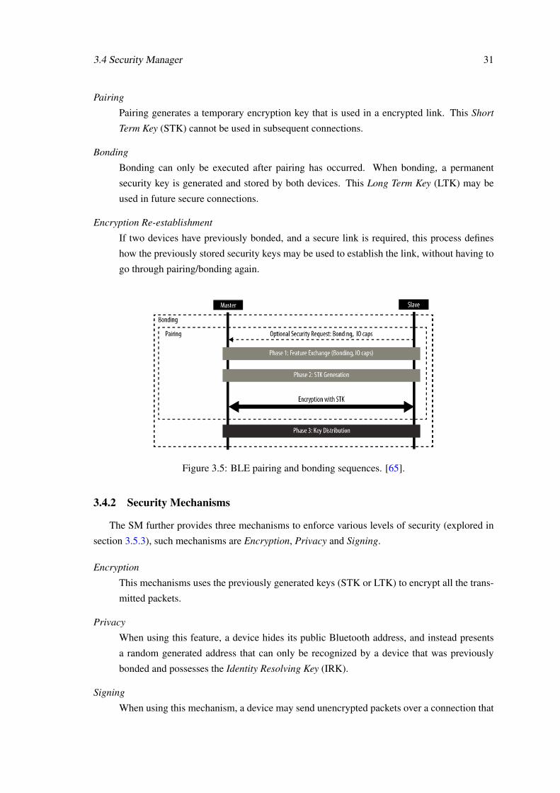
3.4 Security Manager 31
Pairing
Pairing generates a temporary encryption key that is used in a encrypted link. This Short
Term Key (STK) cannot be used in subsequent connections.
Bonding
Bonding can only be executed after pairing has occurred. When bonding, a permanent
security key is generated and stored by both devices. This Long Term Key (LTK) may be
used in future secure connections.
Encryption Re-establishment
If two devices have previously bonded, and a secure link is required, this process defines
how the previously stored security keys may be used to establish the link, without having to
go through pairing/bonding again.
Figure 3.5: BLE pairing and bonding sequences. [65].
3.4.2 Security Mechanisms
The SM further provides three mechanisms to enforce various levels of security (explored in
section 3.5.3), such mechanisms are Encryption, Privacy and Signing.
Encryption
This mechanisms uses the previously generated keys (STK or LTK) to encrypt all the trans-
mitted packets.
Privacy
When using this feature, a device hides its public Bluetooth address, and instead presents
a random generated address that can only be recognized by a device that was previously
bonded and possesses the Identity Resolving Key (IRK).
Signing
When using this mechanism, a device may send unencrypted packets over a connection that

32 Bluetooth Low Energy
is signed, meaning its source can be verified. This is done using a Connection Signature
Resolving Key (CSRK).
3.5 General Access Profile (GAP)
3.5.1 Roles, Modes and Procedures
The Generic Access Profile (GAP) defines four roles a device can take. These roles have a
direct connection with the roles defines by the Link Layer and presented in section 3.3. A single
device may operate in more than one role at a time, or even change role completely at runtime.
Broadcaster:
By periodically sending advertising packets with data, this role is ideal for devices and
applications that regularly share information, with no restrictions as too whom may acquire
such information. This role is related to the Link Layer advertiser role.
Observer:
A device or application with this role constantly listens for advertising packets, and acquires
the information contained in them. This role is related to the Link Layer scanner role.
Central:
A central device is capable of initiating, establishing and managing connections to one or
multiple other devices. A central device has a higher demand for computing power than a
peripheral device. This roles corresponds to the master role of the Link Layer.
Peripheral:
Peripheral devices use advertising packet to announce their presence and wait for a central
device to initiate a connection. This roles corresponds to the Link Layer slave role.
Modes further refine the behaviour of devices with a determined role. Procedures are a set
of actions available to a device in a certain mode. Their execution often triggers a mode change.
Table 3.4 presents the available modes and the applicable role, and table 3.5 presents the available
procedures and the related role. The modes have a direct connection with the advertising packet
types and properties discussed in section 3.3.
Mode Applicable RolesBroadcast Broadcaster
Non-discoverable PeripheralLimited discoverable PeripheralGeneral discoverable Peripheral
Non-connectable Peripheral, Broadcaster, ObserverDirected connectable Peripheral
Undirected connectable PeripheralTable 3.4: Modes and their applicable roles.

3.5 General Access Profile (GAP) 33
Procedure Applicable RolesObservation Observer
Limited discovery CentralGeneral discovery CentralName discovery Peripheral, central
Auto connection establishment CentralGeneral connection establishment CentralSelective connection establishment Central
Direct connection establishment CentralConnection parameter update Peripheral, central
Terminate connection Peripheral, centralTable 3.5: Procedures and their applicable roles.
3.5.2 Device Discovery and Connection Establishment
Device discovery and connectable modes are higly dependent on the advertising packet types
used by peripheral devices. The available packet types and properties have already been discussed
in section 3.3, and are presented in tables 3.2 and 3.3.
Device discoverability is related to how a peripheral device advertises its presence and how a
central device may detect it. A device with the peripheral role can advertise its presence in three
discoverability modes - non-discoverable, limited discoverable and general discoverable.
Non-discoverable:
As implied, when using this mode a device does not wish to be found by a central device.
However, a device using this discoverability mode may still send advertising packets con-
taining data, but they must be of the appropriate type and the advertising packet flags must
be adjusted accordingly.
Limited discoverable:
This mode mode allows a device to be discoverable only for a limited period of time.
General discoverable:
This is the most widely used discoverability mode, which sets no upper bound for how long
a device may be discoverable. This mode is often used by peripherals that wish to form a
connection with a central device.
For a central device to be able to connect to a peripheral device, more than being discoverable,
the peripheral device needs to be in a connectable mode. The possible connectability modes are
presented in table table 3.4 and described below.
Non-connectable:
When in this mode, no central device may establish a connection with the peripheral.

34 Bluetooth Low Energy
Undirected connectable:
A peripheral in this mode sends advertising packets containing the Bluetooth Address of the
target central device, and only the specified central device receives them.
Directed connectable:
The most common connection establishment mode is the directed connectable mode, where
the peripheral is connectable for a long period of time and no rules are set as to whom may
try to establish a connection.
To establish a connection, a central device executes one, or several, of the connection estab-
lishment procedures presented in table 3.5. A description of such procedures is presented below.
Auto connection establishment:
This procedure allows a central device to connect the first device it detects, provided the
detected peripheral device is part of a previously populated white list.
General connection establishment:
When executing this procedure, every time the central detects a connectable peripheral, the
application must decide what course of action to take. It can choose the detected device as
the one to connect to, and the connection establishment procedure terminates, or it ignores
that device, and the procedure continues to the next device. Once a peripheral device is
chosen, the direct connection establishment procedure is executed to form the connection.
Selective connection establishment:
This procedure is similar to the general connection establishment procedure, but it adds an
extra step to establish the connection. Instead of prompting the application for a course
of action for every single detected device, only the devices that are part of a previously
populated white list trigger the prompt, all the others are ignored by the central device.
Direct connection establishment:
This procedure is a single step procedure where the central device attempts to connect to a
peripheral device given its Bluetooth Address. The central device may attempt to establish a
connection using this procedure without previous knowledge of the presence of a peripheral.
If the target peripheral is not present, or in non connectable mode, the procedure fails.
Once a connection is established, three more procedures become available - name discovery,
connection parameter update and terminate connection. The name discovery procedure may be
used to retrieve a human- readable string containing the Device Name. To do so, a GATT trans-
action is used. The central device is responsible for managing a connection, which includes con-
trolling a variety of parameters (presented in section 3.3) to achieve the best possible connection.
When these parameters should be adjusted, either by initiative of the central device, or because
the peripheral device requested the central to do so, the connection parameter update procedure
is executed. The terminate connection procedure can be used by both the central and peripheral
device to terminate a connection at any given time.

3.5 General Access Profile (GAP) 35
3.5.3 Bonding and Security
Safe data transmission is ensured by the Security Manager (section 3.4) and the GAP. Similarly
to discoverability and connectivity, the GAP defines modes and a (single) procedure for device
bonding.
Non-bondable mode:
A device in this mode does not accept bonding at the time. This is a device’s default mode.
Bondable mode:
A device in bondable mode accepts bonding requests from peer devices.
Bondable procedure:
This procedure may be used to establish a bond between two devices in bondable mode.
Building on top of the security mechanisms provided by the SM and presented in section 3.4.2,
the GAP defines two security modes, each one containing several levels. Mode 1 offers security
through encryption, and the second mode achieves a safe link by using data signing. The levels
from each mode are differentiated by the presence (or not) of Authentication during device pairing.
For an authenticated link to be established, the pairing algorithm used has to ensure protection
against man-in-the-middle (MITM) attacks. From the available SM pairing algorithms, the ones
that provide such protection are the Passkey Display and Out of Band. The Just Works algorithm
does not ensure protection against MITM attacks.
Mode 1 Level 1:
No security.
Mode 1 Level 2:
Unauthenticated pairing with encryption.
Mode 1 Level 3:
Authenticated pairing with encryption.
Mode 2 Level 1:
Unauthenticated pairing with data signing.
Mode 2 Level 2:
Authenticated pairing with data signing.
Every connection starts with security mode 1 and level 1, which can be upgraded to any of the
available levels at any time.

36 Bluetooth Low Energy
3.5.4 GAP Service
The concept of Services will be discussed in section 3.6, but it is important to note that every
device must contain the mandatory GAP service. This service contains characteristics that allows
devices to retrieve basic information about each other. The service contains three characteristics
- Device Name, Appearance and Peripheral Preferred Connection Parameters. The Device Name
has already been mentioned in section 3.5.2. It contains a human readable string that describes
a device. The appearance characteristic contains information about the generic type of device
such as a laptop, smartphone, watch or sensor. The Peripheral Preferred Connection Parame-
ters characteristic contains information about the connection parameters that maximize the device
performance. A central device may access this information and execute a connection parameter
update procedure to match the peripheral preferred parameters.
3.6 Attributes, ATT and GATT
3.6.1 Attributes and Attribute Access
An attribute is the foundation of the Attribute Protocol and the basic data structure of the whole
protocol. It can be defined as a “piece of labelled, addressable data”[63]. An attribute is comprised
of three fields - Handle, Type and Value - as illustrated in figure 3.6.
The attribute handle is a 16-bit address used to uniquely identify attributes in a server. Valid
handles go from 0x0001 to 0xFFFF.
The attribute type identifies the type of data the attribute represents through the means of a
Universally Unique Identifier (UUID). UUIDs are 128-bit long, and transferring such long identi-
fiers is not efficient. To cope with this, the Bluetooth SIG defined the Bluetooth Base UUID which
acts as a common base to other derived UUIDs. By using the common UUID, only a 16-bit num-
ber has to be transfered when considering UUIDs derived from the common UUID. This value is
then recombined with the base UUID to form the complete UUID.
The attribute value is where the state data is available. Some attributes may be access re-
stricted, and to control the accesses each attribute has a set of permissions associated with it.
These permissions apply only to the attribute value. Permissions can be divided into three cate-
gories - access, authentication and authorization - each checking a different aspect of the access
attempt. Access permissions check whether an attribute can be read, written, or both. Authenti-
cation permissions check if the client trying to access the attribute has the required authentication,
if one is required. Authorization permissions check if the attribute can be accessed at all. Even if
the client is authenticated the access may be denied if access to the attribute is not authorized.

3.6 Attributes, ATT and GATT 37
Figure 3.6: Attribute structure.
3.6.2 Client/Server architecture and Data Exchange
Figure 3.7: Example Client/Server architecture and available operations.
The Attribute Protocol (ATT) defines a Client/Server architecture that is used by devices (Cen-
tral and Peripheral) to exchange information. The Client and Server roles are defined by the ATT
should not be confused with the Peripheral (Link Layer Slave) and Central (Link Layer Master)
roles defined by the Generic Access Profile (GAP). A Central device may act as a Client, and a
Peripheral device may act as a Server. Some devices may even act as Client and Server at the same
time, independently of their GAP role. To exchange information between a Client and a Server, six
basic operations have been defined and are presented in table 3.6 and figure 3.7. These operations
can be divided into three types, one to ask for information, one to answer with such information,
and another to send information without expecting a reply. The names of these operations change
according to what device, Client or Server, initiated the information exchange.
Operation From To Preceding Operation Follow-up OperationRequest Client Server - ResponseResponse Server Client Request -Command Client Server - -Notification Server Client - -Indication Server Client - ConfirmationConfirmation Client Server Indication -
Table 3.6: ATT operations.
To access attributes, six message types have been defined, based on the previously presented
operations, as represented in table 3.7. Find Requests are used by a client to find attributes on

38 Bluetooth Low Energy
a server, so handle-based requests can be used in future. Read Requests are used by a client to
retrieve the value of one or more attributes. Write Requests are used by a client to write an attribute
value to one or more attributes. A Write Command is used by a client to write an attribute value
without receiving a reply message from the server. A Notification is used by a server to send
attribute values unprompted to a client without receiving a reply message. Indications offer the
same functionality as Notifications but the server expects a reply from the client, similarly to Write
Requests.
Operations Involved Messages
Request/ResponseFind RequestsRead RequestsWrite Requests
Command Write CommandNotification Notification
Indication/Confirmation IndicationTable 3.7: Messages for attribute access and corresponding operations.
Each access message (including request and response) is part of a single transaction. An im-
portant aspect of the transaction model is that a new transaction can only be initiated after the
previous transaction has completed. This is a limitation regarding a single device, as a device
that started a transaction cannot start a new transaction while the previous one hasn’t finished, but
it can process requests from other devices. However, there are mechanisms to work around this
limitation. In order to send data while waiting for a transaction to finish, a device must use Com-
mand and Notification messages, as they do not require a response. Due to this, Request/Response
and Indication/Confirmation messages can be said to be blocking operations, while Command and
Notification messages can be said to be non-blocking operations. When it is needed to perform a
long write, the Prepare Write Request and Execute Write Request messages can be used. These
messages allow a client to perform multiple write to the server under one single transaction. This
is done by issuing multiple Prepare Write Request (which trigger a Prepare Write Response with
the echoed data) and a single Execute Write Request to trigger the write of the previously queued
writes.
3.6.3 Grouping Attributes into Services and Characteristics
The ATT defines the basic unit of data, an attribute. The GATT takes groups of attributes
and defines structures and hierarchies that represent data in a more practical manner. User data
is contained in Characteristics. A Service then contains multiple characteristics, and represents a
collection conceptually related characteristics. A Profile may contain multiple services. This hier-
archy is represented in figure 3.8 (available in [65]), which will be used to illustrate the concepts
presented below..

3.6 Attributes, ATT and GATT 39
Figure 3.8: GATT Heart Rate Service [65].
The first attribute of every structure (services and characteristics) is a descriptor attribute,
which contains metadata about the following data. The attributes with handles 0x0021, 0x0024
and 0x002A represented in figure 3.8 are examples of declaration attributes.
The UUID field of a service declaration attribute, such as the one with handle 0x0021, contains
a SIG-assigned UUID that introduces a service as either a primary or secondary service. A primary
service is the standard type of GATT service, while a secondary service is a service intended
to be referenced by other primary services, only, as behaviour modifiers and not as standalone
services. To include a service in another service, an Include declaration may be used, which
consists of a single attribute placed after the service declaration attribute. The value field of a
service declaration contains a UUID that identifies the actual service declared by that declaration
attribute.
A characteristic is a container for user data, and they include two or more attributes. The
first attribute is the declaration attribute, such as the ones with handles 0x0024 and 0x002A. The
UUID field of this attribute contains a standard UUID used to identify a characteristic declaration.
The value field of a characteristic declaration attribute contains multiple informations - Properties,
Value Handle and UUID. The first part of the value field contains information related to the per-
mitted operations the characteristic. The addressed operations are Broadcast, Read, Write without
response, Write, Notify, Indicate and Signed Write Command. These operations are related to the
messages presented in table 3.7. The second and third parts of the value field of a characteristic
declaration attribute contains information about the characteristic value attribute, more specifically
its handle and UUID. A characteristic value attribute (handle 0x0027) contains the actual user data.
If there is the need to include more metadata related to a characteristic, Descriptor attributes may
be used, as the one with handle 0x0028, which is a Client Characteristic Configuration Descrip-
tor. Other types of descriptors include Extended Properties Descriptor and Characteristic User
Description Descriptor.

40 Bluetooth Low Energy
3.6.4 Discovering Services and Characteristics
When a connection is formed, the client device has no knowledge of the services present on
the GATT server. To gain such knowledge, GATT defines a group of operations to perform service
and characteristic discovery. These operations are based on the Find Request message defined by
the ATT.
Discover all primary services:
This feature allows the client to retrieve a full list of all primary services available in a
GATT server. When using this feature, the client is able to determine a handle range where
the search should be carried out. To perform a full search, the range must be set to 0x0001-
0xFFFF.
Discover primary service by UUID:
When the client is looking for a specific service, it may use this feature to look for all the
instances of a particular service. This feature also supports the specification of a handle
range.
Find included services:
Once the client is aware of a primary service, it can perform a relationship discovery to
determined what service are included in a determined primary service.
Discover all characteristics of a service:
After acknowledging the existence of a service, and knowing its handle range, the client
can retrieve a list of all the characteristics contained in the service. The client provides
the handle range of the service, and the server retrieves the handle and value of all the
characteristic declaration attributes of the service.
Discover characteristic by UUID:
This procedure is similar to the discovery of all the characteristic of a service, except the
client filters out the characteristics whose UUIDs do not match the specified UUID.
Discover all characteristic descriptors:
Once the client knows the handle range and UUID of a determined characteristic, it can
obtain a list of all the descriptors associated with it.
3.6.5 Accessing Services and Characteristics
To write to and read from a characteristic, the client has access to a group of operations that
are derived from the ATT operations and messages presented in section 3.6.2.
Read characteristic value or descriptor:
This feature allows the client to retrieve the value of a characteristic or descriptor with a
specified handle. If the value it too long for this feature, the Read Long characteristic value
or descriptor feature can be used.

3.7 Profiles 41
Read characteristic value using characteristic UUID:
If the client does not know the handle of the characteristic it is interested in, but is aware of
its UUID, it may use this feature to retrieve an array of values from all the characteristics
(in a determined range) whose UUIDs match the specified one.
Read multiple characteristic values:
If the client wishes to obtain the value of multiple characteristics, and know the handle
of all of them, it may use this feature. The server returns an array with the value of the
characteristics with the specified handles.
Write characteristic value or descriptor:
This feature may be used to write to a characteristic value or descriptor, provided the client
knows the handles of such attributes. When using this feature, the client should expect
an acknowledge message from the server. If the value to be written is too long for this
operation, the Write long characteristic value or descriptor operation may be used.
Write without response:
If the client wishes to write to a characteristic value without any flow control or acknowledge
mechanism, it may use this feature. When using this feature, the write command may be
discarded by the server for whatever reason, without notifying the client.
Reliable writes:
This feature enables the client to write to multiple characteristic values at once, by queuing
write request operations and issuing a single execute write packet.
Characteristic value notification:
This feature utilizes Notification packets that include a characteristic value attribute handle
and value, and can be used by a server to send unrequested data to a client.
Characteristic value indication:
This feature is similar to the characteristic value notification in the way that it is server-
initiated, but instead of using a Notification message, it uses a Indication messages, which
requires the client to respond with a Confirmation message signalling the information re-
ception.
3.6.6 GATT Service
All GATT servers must contain a GATT service, which is used to inform the client of structural
changes in the architecture of the server attributes, and needs to be rediscovered by the client.
3.7 Profiles
A profile is a collection of services and roles that enable a specific use case. Profile roles
are associated with the devices that take part on the use case, and when two profile roles are
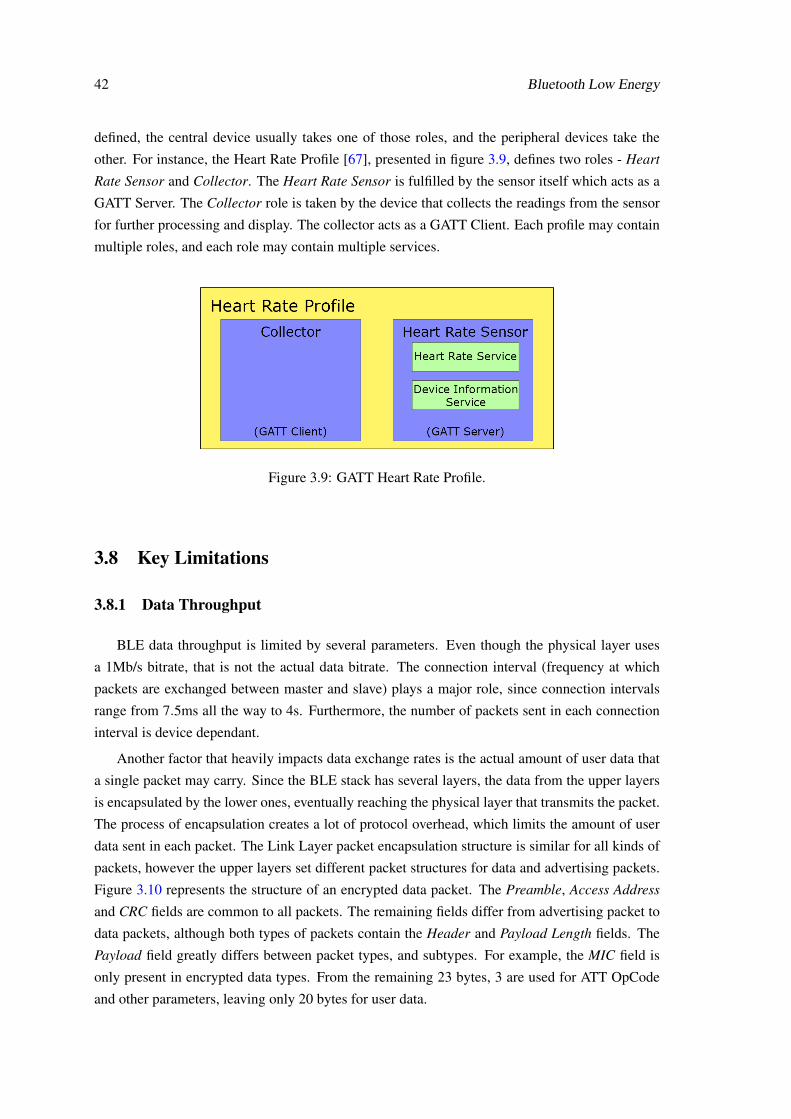
42 Bluetooth Low Energy
defined, the central device usually takes one of those roles, and the peripheral devices take the
other. For instance, the Heart Rate Profile [67], presented in figure 3.9, defines two roles - Heart
Rate Sensor and Collector. The Heart Rate Sensor is fulfilled by the sensor itself which acts as a
GATT Server. The Collector role is taken by the device that collects the readings from the sensor
for further processing and display. The collector acts as a GATT Client. Each profile may contain
multiple roles, and each role may contain multiple services.
Figure 3.9: GATT Heart Rate Profile.
3.8 Key Limitations
3.8.1 Data Throughput
BLE data throughput is limited by several parameters. Even though the physical layer uses
a 1Mb/s bitrate, that is not the actual data bitrate. The connection interval (frequency at which
packets are exchanged between master and slave) plays a major role, since connection intervals
range from 7.5ms all the way to 4s. Furthermore, the number of packets sent in each connection
interval is device dependant.
Another factor that heavily impacts data exchange rates is the actual amount of user data that
a single packet may carry. Since the BLE stack has several layers, the data from the upper layers
is encapsulated by the lower ones, eventually reaching the physical layer that transmits the packet.
The process of encapsulation creates a lot of protocol overhead, which limits the amount of user
data sent in each packet. The Link Layer packet encapsulation structure is similar for all kinds of
packets, however the upper layers set different packet structures for data and advertising packets.
Figure 3.10 represents the structure of an encrypted data packet. The Preamble, Access Address
and CRC fields are common to all packets. The remaining fields differ from advertising packet to
data packets, although both types of packets contain the Header and Payload Length fields. The
Payload field greatly differs between packet types, and subtypes. For example, the MIC field is
only present in encrypted data types. From the remaining 23 bytes, 3 are used for ATT OpCode
and other parameters, leaving only 20 bytes for user data.

3.8 Key Limitations 43
Figure 3.10: BLE encrypted data packet. Adapted from [68].
Data throughput is also affected by the operations used for data transmission. In order to
eliminate the overhead created by acknowledge mechanisms, Write Command and Notification
operations should be used. This eliminates the need to transfer a packet back to the data source to
report to the application layer that the packet has been transmitted. However, link layer acknowl-
edge is performed despite the operation used, ensuring a reliable data connection.
Having the above mentioned parameters in mind, the maximum data throughput of a connec-
tion can be estimated through equation 3.2. A device specific calculation is performed in section
4.4.
Datathroughput(Bps) = 20×Npackets×1
Connectioninterval(seconds)(3.2)
3.8.2 Operation Range
The operation range of a BLE connection varies with a variety of factors, from the antenna
design, to the operating environment and even the device orientation. The range is configurable to
some extent, by controlling the transmission power. However, higher transmission power leads to
shorter battery autonomies. Although it is possible to establish connection of over 20m (line-of-
sight), a typical operation range is of around 2 to 5 meters.

44 Bluetooth Low Energy

Chapter 4
Fraunhofer Pandlet
4.1 Overview
Figure 4.1: Plandlet with debugger attached
Pandlets, pictured in figure 4.1, are small wireless sensing devices whose architecture has
been developed by Fraunhofer AICOS Portugal to be used in wearables and IoT solutions. As
mentioned in section 2.4, this platform features not only the vital microprocessor, but also several
other peripherals that are very useful in most IoT applications, as well as the a Bluetooth Low
Energy radio and antenna. Having the modules of interest integrated by design allows the device
to be smaller than if such were to be added later on, as discussed in section 2.1.2.2. The device is
divided into three parts - CORE, MEMORY and SENSING+, each adding functionality on top of
the previous one.
Core module
As the name implies, this is the main module of the device. This module is completely
self reliant, as the other two modules only add features to the core. The module includes
the micro-controller, an IMU, an EMU, the BLE radio and antenna, and is Qi compliant,
45
46 Fraunhofer Pandlet
for wireless charging. Section 4.2.2 goes over the features available in this module in more
detail.
Memory module
If the device is expected to collect data for a long period of time, the memory module
becomes very useful as it features a microSD card interface and a microUSB plug for wired
battery charging.
Sensing+ module
This module allows the use of sensors and peripherals that are not originally included in the
board. It does so by providing an isolated I2C interface, along with General Purpose I/O
(GPIO) and an Analog to Digital Converter (ADC). The features are further discussed in
section 4.2.3.
Current applications of this device include ambient assisted living, assisted environment for
hydroponic farming and fall detection [11].
4.2 Hardware and Peripherals
4.2.1 Circuit level communication protocols
Even though the several peripherals featured on the Pandlet are on the same board, they still
need to communicate with the processor. To do so, several protocols are available, such Serial
Peripheral Interface (SPI) and Inter-Circuit Communication (I2C). Furthermore, Universal Asyn-
chronous Receiver/Transmitter is also available, to communicate with external devices. As it is
needed to understand how these protocols operate, a brief overview of each on is presented below.
4.2.1.1 Universal Asynchronous Receiver/Transmitter (UART)
Universal Asynchronous Receiver/Transmitter is a serial communication protocol used to send
data, asynchronously, from a transmitter to a receiver device. In serial communications the data
bits are transferred one after the other over a single signal line, but without sharing the clock
signal, as illustrated in figure 4.2. The communication is full-duplex, as two separate lines are
used to send and receive data. The total minimum number of signal lines to implement UART
communication is 2 - Transmit (TX) and Receive (RX). Figure 4.3 illustrates the typical wiring for
a UART communication bus. Although the bits are synchronized to a clock, the clock signal is not
shared between the two connected devices, so the communication is considered asynchronous.
TX: Transmit signal through which data is sent to a peer device.
RX: Receive signal through which data is received from a peer device.

4.2 Hardware and Peripherals 47
Figure 4.2: UART communication bits. [69]Figure 4.3: UART communication connec-tions. [69]
One of the biggest limitations of UART communication is that an independent UART port is
required for each connected device. It is possible to connect multiple RX lines to a single TX line
but that topology is prone to unpredictable behaviour and should be avoided. Two TX lines should
never be connected to each other as short circuits may occur (whenever transmitting opposing
bits).
Besides the essential RX and TX signals, some devices support two additional signals -RTS
and CTS - which may be used to perform flow control on the communication.
RTS: Request to Send: this is an output port that is used to inform the peer device if new data
may be transmitted. The port name is slightly misleading as it does not clearly describe the
signal functionality. Instead of RTS, a more appropriate name would be Ready to Receive,
as what this port does is inform the peer device if the local device is ready to receive new
data. When RTS is at a logic HIGH value, data transmission should not be initiated. When
the signal is set to logic LOW the peer device may send new data.
CTS: Clear to Send: this is an input port that is connected to the RTS port of the peer device.
Whenever the peer device sets its RTS port to logic LOW, the other device will detect that
change through its CTS port and proceed to send new data.
Figure 4.4 represents a typical UART connection with enabled flow control. If the UART
module requires the use of a flow control mechanism but the user does not wish to use it, the
topology represented in figure 4.5 may be used.
Figure 4.4: UART communication with flowcontrol enabled. Adapted from [69]
Figure 4.5: UART communication with flowcontrol disabled. Adapted from [69]

48 Fraunhofer Pandlet
4.2.1.2 Serial Peripheral Interface (SPI)
Serial Peripheral Interface (SPI) is a full-duplex synchronous communication protocol based
on a master/slave topology that uses 4 signal wires - SCLK, MOSI, MISO, SS.
SCLK: Serial Clock signal controlled by the master. Every bit transaction is synchronized to this
signal.
SS: Slave Selection signal that enables the master to select to which slave it wishes to transfer
data to.
MOSI: Master Output, Slave Input is the signal wire through which the master sends data to the
slaves.
MISO: Master Input, Slave Output is the signal wire through which the slaves send data to the
master.
The working principle of the protocol is that the master sends a bit to the slave, through MOSI,
at every clock pulse (SCLK), being the clock controlled by the master. The slave device usually
contains a shift register (but its not mandatory), that is shifted at every clock tick, and the value
that enters the slave shift register is the one the master sent. The bit that was shifted out, is sent
back to the master, through one of the MISO lines. Figure 4.6 shows a typical SPI communication
device layout, where the previously presented behaviour is represented. More than one slave can
be used at a time through a daisy-chain process, where the MISO signal of a slave is connected to
the MOSI of the next slave, and only the last slave of the chain is connected back to the master,
as represented in figure 4.7. This topology greatly increases the number of clock cycles needed
for the master to retrieve information from a determined slave device, because the data has to go
through the whole chain first. Figure 4.8 shows the use of parallel slave devices by using a slave
selection signal (SS), which presents better response times, but requires a separate SS signal for
each slave device.
Figure 4.6: SPI simple master/slave topology [70].

4.2 Hardware and Peripherals 49
Figure 4.7: SPI daisy-chain topology. Adaptedfrom [70]
Figure 4.8: SPI parallel topology. Adaptedfrom [70]
4.2.1.3 Inter-Integrated Communication (I2C)
Inter-Integrated Communication (I2C) is a half-duplex synchronous communication protocol
based on master/slave topologies. It also supports topologies with multiple slaves, and actually
presents several benefits over SPI by allowing fast directed access to any slave device. Unlike SPI,
that needs 4 signal wires, I2C only needs two - SCL and SDA.
SCL: Serial Clock signal.
SDA: Slave Data signal.
Figure 4.9 represents a tipical I2C topolgy. All of the slaves are connected to the same SCL
and SDA signals. Since I2C device use open-drain circuits, pull-up resistors are required.
Figure 4.9: I2C master/slave topology [70].
I2C uses the SDA signal and sends to all the connected slave devices the address of the slave
it wishes to communicate with. The slave devices compare the received address with its own,
and if the address matches, the slave sends an acknowledgement (ACK) signal to the master to
inform it of its presence. All the remaining slaves, whose comparison turned out negative, ignore
all the data that is transferred through the bus, as they are not the intended destination. Along with
the device address, one more bit is sent to the slaves. This bit informs the slave devices of the
operation type (read or write). If the operation is of read type, the slave should send back to the
master the information that has been requested. If the operation is of write type, the slave should
store the received information in the appropriate internal register.

50 Fraunhofer Pandlet
4.2.2 Core module
4.2.2.1 Processor and BLE
The core module of the Pandlet is built around the Nordic nRF51822 SoC (system-on-chip),
which features an ARM Cortex-M0 processor, at 16MHz, and an embedded 2.4GHz transceiver
that supports both the Bluetooth Low Energy and Nordic Gazell protocol stacks. Chapter 3 dis-
cusses the BLE stack in detail.
The processor further features an SPI interface, as well as a UART and Two-wire interface
(TWI). The TWI interface is capable of clock stretching and supports data rates of 100kB/s and
400 kB/s, making it compatible with I2C devices.
General Purpose I/O (GPIO) are ports that can work either as an output or input for digital
signals (High/Low). The Nordic nRF51822 has 31 configurable General Purpose I/O (GPIO) pins
and a built-in Analog-to-Digital Converter (ADC), but since the Sensing+ module offers similar
functionality with increased performance and functionality, not all of these built-in features are
available on the Pandlet. Such features of the Sensing+ module are discussed in sections 4.2.3.2
and 4.2.3.3. From the 31 available GPIOs, only some are wired, such as the ones used for the
I2C and SPI bus, as well as the ones labeled as GPIO1-4. Some GPIOs are connected to sensors
specific pins, in order to provide interrupt based data read events. However, other iterations of the
Pandlet platform may utilize different GPIO ports, and as such all 31 ports should be addressable
through the developed BLE protocol and API.
4.2.2.2 Inertial Measurement Unit
An Inertial Measurement Unit is a device the measures forces of several natures that are ap-
plied to a body. These often include acceleration, angular rate and magnetic field. The InvenSense
MPU-9250 featured in the Pandlet senses all of the previously mentioned forces. It does so by the
means of an accelerometer, a gyroscope and a magnetometer. This specific IMU also features an
Internal Digital Motion Processing engine that performs on chip sensor fusion and enables gesture
recognition and programmable interrupts. The IMU supports SPI and I2C communication, on the
Pandlet case I2C is used.
4.2.2.3 Environmental Measurement Unit
The core module of the Pandlet also features an Environmental Measurement Unit, the Bosch
BME280. This device contains sensors that enable the measurement of environmental parameters
such as humidity, pressure and temperature. Similarly to the IMU, the device supports both SPI
and I2C communication, and I2C is the one being used.
4.2.2.4 Qi charging
To charge the Pandlet battery, which is external to the module board, Qi charging is available.
Qi is an inductive electrical power standard for power transmission over very small distances
4.3 Firmware 51
(around 4cm) developed by the Wireless Power Consortium. This standard is already implemented
in several current smartphones and chargers. The technology is supported by companies such as
Samsung, Toshiba, Microsoft, HTC, LG, Nokia and Philips, among others.
4.2.3 Sensing+ module
4.2.3.1 External sensing I2C bus
Since the I2C interface uses pull-up resistors, the HIGH voltage can be what ever the system
requires it to be, however, this must be adapted to the specification of all the devices connected to
the bus. In order to isolate the sensing devices from the core module, from the ones that may be
connected in the Sensing+ module, an I2C isolator is used, the ISO1541. This allows the devices
from each side of the isolator to have different HIGH voltages, by using different power supplies
for each side.
4.2.3.2 General Purpose I/O
The external sensing module features a PCA9538 I/O expander, which adds a maximum of
8 GPIO ports, although only 4 are wired. The I/O expander can be accessed through an I2C
interface, which is connected to the external sensing I2C bus.
4.2.3.3 Analog-to-Digital Converter
An analog-to-digital converter (ADC) is a device that samples a signal and outputs a digital
code that encodes the amplitude of the sampled signal, as best it can (given its resolution). The
resolution of an ADC is related to the number of bits contained in the digital output code, as they
limit the maximum number of intervals that may be represented. The resolution determines the
smallest voltage change the ADC is able to detect and encode.
The Sensing+ module of the Pandlet features a Maxim MAX11613 device, a 4 channel, 12-
bit ADC with an I2C interface, which is connected to the external sensing I2C bus. The ADC
becomes usefull when analog sensors are used, as the output of the sensor is an analog signal that
has to be converted to a digital code, before the micro-controller can use it.
4.3 Firmware
To expedite the development of BLE applications, the nRF51822 supports the use of a Soft-
Device, which implements the BLE stack on the device and exposes an API for application level
interaction, as represented in figure 4.10. There are multiple SoftDevice implementations, each
with different features. The nRF51822 supports the S110, S120 and S130 SoftDevices, and the
major differences between each are the BLE GAP roles that a device using the SoftDevice may
take, as presented in table 4.1.

52 Fraunhofer Pandlet
Figure 4.10: Abstraction provided by the use of a SoftDevice [11].
Peripheral Broadcaster Central ObserverS110 Yes Yes No NoS120 No No Yes YesS130 Yes Yes Yes Yes
Table 4.1: GAP roles available in each supported SoftDevice
Considering that this project aims to use the Pandlet as a data collection hub, that exposes sen-
sor reading to a gateway device, the SoftDevice that best suits the use case is the S110. However,
as of the release of nRF5 SDK version 11, the support for SoftDevice S110 has been dropped, and
as such the S130 will be used on this project. The S130 SoftDevice also becomes useful when
multi-hop communication is required, thanks to its ability to act as both Central/Observer and
Peripheral/Broadcaster, although those features are not on the scope of this project.
4.4 Data Throughput Limitations
As discussed in section 3.8.1, data throughput is heavily dependant on both peer devices. Since
the S130 SoftDevice supports the minimum connection interval (7.5ms) and up to 6 packets per
connection interval (each way), by ignoring the limitations of the peer device, these parameters
lead to a theoretical unidirectional throughput of 16kB/s. However, these settings leave close to
no room for other CPU computations.
To further explore the data throughput available, some tests where conducted and the results
are presented in chapter 5.
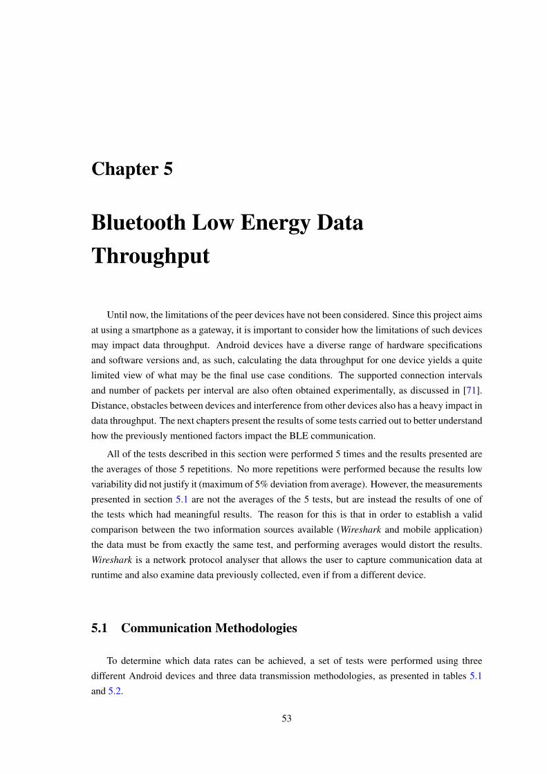
Chapter 5
Bluetooth Low Energy DataThroughput
Until now, the limitations of the peer devices have not been considered. Since this project aims
at using a smartphone as a gateway, it is important to consider how the limitations of such devices
may impact data throughput. Android devices have a diverse range of hardware specifications
and software versions and, as such, calculating the data throughput for one device yields a quite
limited view of what may be the final use case conditions. The supported connection intervals
and number of packets per interval are also often obtained experimentally, as discussed in [71].
Distance, obstacles between devices and interference from other devices also has a heavy impact in
data throughput. The next chapters present the results of some tests carried out to better understand
how the previously mentioned factors impact the BLE communication.
All of the tests described in this section were performed 5 times and the results presented are
the averages of those 5 repetitions. No more repetitions were performed because the results low
variability did not justify it (maximum of 5% deviation from average). However, the measurements
presented in section 5.1 are not the averages of the 5 tests, but are instead the results of one of
the tests which had meaningful results. The reason for this is that in order to establish a valid
comparison between the two information sources available (Wireshark and mobile application)
the data must be from exactly the same test, and performing averages would distort the results.
Wireshark is a network protocol analyser that allows the user to capture communication data at
runtime and also examine data previously collected, even if from a different device.
5.1 Communication Methodologies
To determine which data rates can be achieved, a set of tests were performed using three
different Android devices and three data transmission methodologies, as presented in tables 5.1
and 5.2.
53
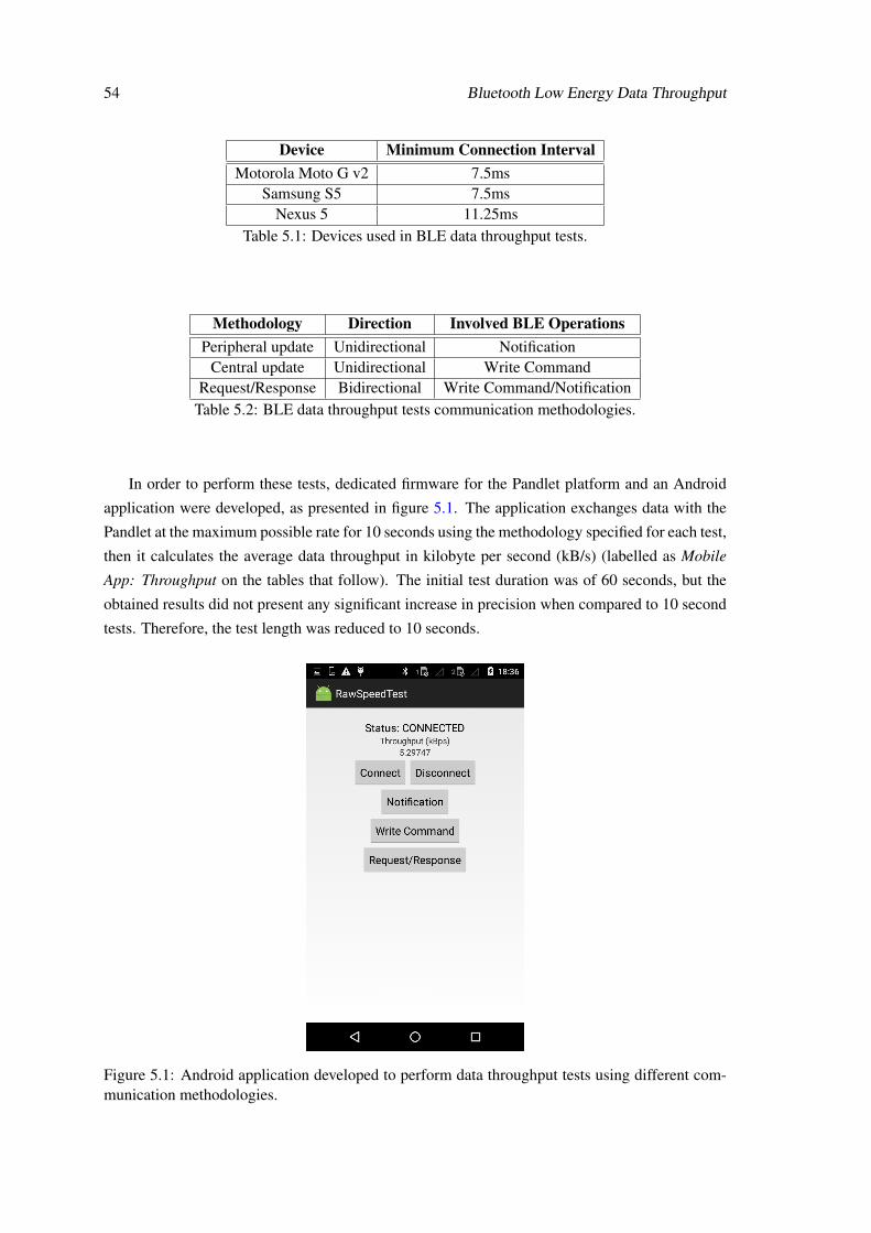
54 Bluetooth Low Energy Data Throughput
Device Minimum Connection IntervalMotorola Moto G v2 7.5ms
Samsung S5 7.5msNexus 5 11.25ms
Table 5.1: Devices used in BLE data throughput tests.
Methodology Direction Involved BLE OperationsPeripheral update Unidirectional Notification
Central update Unidirectional Write CommandRequest/Response Bidirectional Write Command/Notification
Table 5.2: BLE data throughput tests communication methodologies.
In order to perform these tests, dedicated firmware for the Pandlet platform and an Android
application were developed, as presented in figure 5.1. The application exchanges data with the
Pandlet at the maximum possible rate for 10 seconds using the methodology specified for each test,
then it calculates the average data throughput in kilobyte per second (kB/s) (labelled as Mobile
App: Throughput on the tables that follow). The initial test duration was of 60 seconds, but the
obtained results did not present any significant increase in precision when compared to 10 second
tests. Therefore, the test length was reduced to 10 seconds.
Figure 5.1: Android application developed to perform data throughput tests using different com-munication methodologies.
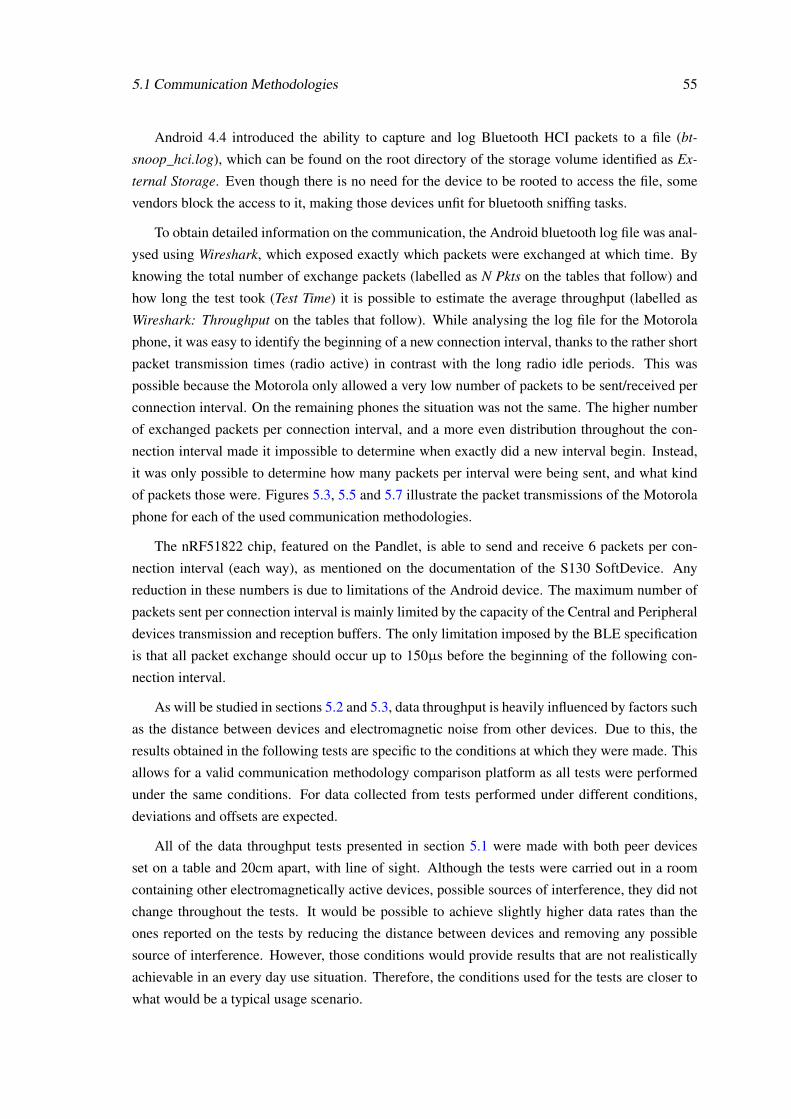
5.1 Communication Methodologies 55
Android 4.4 introduced the ability to capture and log Bluetooth HCI packets to a file (bt-
snoop_hci.log), which can be found on the root directory of the storage volume identified as Ex-
ternal Storage. Even though there is no need for the device to be rooted to access the file, some
vendors block the access to it, making those devices unfit for bluetooth sniffing tasks.
To obtain detailed information on the communication, the Android bluetooth log file was anal-
ysed using Wireshark, which exposed exactly which packets were exchanged at which time. By
knowing the total number of exchange packets (labelled as N Pkts on the tables that follow) and
how long the test took (Test Time) it is possible to estimate the average throughput (labelled as
Wireshark: Throughput on the tables that follow). While analysing the log file for the Motorola
phone, it was easy to identify the beginning of a new connection interval, thanks to the rather short
packet transmission times (radio active) in contrast with the long radio idle periods. This was
possible because the Motorola only allowed a very low number of packets to be sent/received per
connection interval. On the remaining phones the situation was not the same. The higher number
of exchanged packets per connection interval, and a more even distribution throughout the con-
nection interval made it impossible to determine when exactly did a new interval begin. Instead,
it was only possible to determine how many packets per interval were being sent, and what kind
of packets those were. Figures 5.3, 5.5 and 5.7 illustrate the packet transmissions of the Motorola
phone for each of the used communication methodologies.
The nRF51822 chip, featured on the Pandlet, is able to send and receive 6 packets per con-
nection interval (each way), as mentioned on the documentation of the S130 SoftDevice. Any
reduction in these numbers is due to limitations of the Android device. The maximum number of
packets sent per connection interval is mainly limited by the capacity of the Central and Peripheral
devices transmission and reception buffers. The only limitation imposed by the BLE specification
is that all packet exchange should occur up to 150µs before the beginning of the following con-
nection interval.
As will be studied in sections 5.2 and 5.3, data throughput is heavily influenced by factors such
as the distance between devices and electromagnetic noise from other devices. Due to this, the
results obtained in the following tests are specific to the conditions at which they were made. This
allows for a valid communication methodology comparison platform as all tests were performed
under the same conditions. For data collected from tests performed under different conditions,
deviations and offsets are expected.
All of the data throughput tests presented in section 5.1 were made with both peer devices
set on a table and 20cm apart, with line of sight. Although the tests were carried out in a room
containing other electromagnetically active devices, possible sources of interference, they did not
change throughout the tests. It would be possible to achieve slightly higher data rates than the
ones reported on the tests by reducing the distance between devices and removing any possible
source of interference. However, those conditions would provide results that are not realistically
achievable in an every day use situation. Therefore, the conditions used for the tests are closer to
what would be a typical usage scenario.

56 Bluetooth Low Energy Data Throughput
5.1.1 Peripheral update
Peripheral updates are used to send data from the Peripheral to the Central device. The test
consists on the Pandlet (Peripheral device) sending as many packets as possible in each connection
interval, using the minimum connection intervals supported, as represented in figure 5.2. This
ensured that the highest data rate would be achieved.
Figure 5.2: Peripheral update communication methodology.
For this project, since the Peripheral device will be running the BLE server, the BLE operation
used to send a Peripheral update to the Central is the Notification. This operation does not require
the Central device to issue an application layer acknowledgement packet (although one is issued
on the link layer). That way, all the packets sent may contain user information, as illustrated in
figure 5.3.
Figure 5.3: Packets received by the Motorola phone during the Peripheral update test.
Table 5.3 presents the data collected from the tests. While the Motorola phone only received,
on average, close to 3 packets per connection interval, the remaining devices received close to 4
packets. This is clearly a limitation imposed by the BLE implementation of the Motorola phone.
Wireshark Mobile AppDevice Conn. Int. N Pkts Test Time Pkt/CI Throughput Throughput
Motorola Moto G v2 7.5 ms 3776 9.9986 s 2.83 7.55 kB/s 7.53 kB/sSamsung S5 7.5 ms 5134 10.0154 s 3.84 10.25 kB/s 10.23 kB/s
Nexus 5 11.25 ms 3253 9.8575 s 3.71 6.60 kB/s 6.50 kB/sTable 5.3: Test results for Peripheral update communication methodology.

5.1 Communication Methodologies 57
The obtained results confirm the expected behaviour of the communication, as only Notifi-
cation packets are exchanged between the devices. It is noticeable that the number of packets
exchanged per connection interval is close, but never quite reaching, the expected theoretical max-
imum. Taking the Samsung device as an example, the expected maximum throughput would be
10.66kB/s, as given by equation 3.2, which is very close to the measured value. The reduction in
measured throughput, when compared to a perfect transmission, is mainly due to the retransmis-
sion of some packets that may have been corrupted during transmission. Referring still to the case
of the Samsung phone, on each connection interval 3.84 Notification packets were exchanged (on
average), which is slightly less than the expected 4 packets. The phenomenon becomes more no-
ticeable when other signal sources are close by, such as other BLE devices or even Wi-Fi devices,
since both operate in the 2.4GHz frequency range. As expected, noisier environments translate
into lower data rates due to packet corruption, as studied in section 5.3.
It is further interesting to notice how the Nexus 5 achieves lower data throughput than the
Motorola, even though it is able to receive more packets per connection interval. This is due to the
usage of a longer connection interval. According to equations 5.1 and 5.2, for the Nexus 5 phone
to achieve the same data throughput as the Motorola phone, it would have to support a connection
interval of at least 9.8ms
20× 1CI×N = 20× 1
CI′×N′ (5.1)
CIN5 =CIMG×NN5
NMG=
7.5m×3.712.83
= 9.8ms (5.2)
5.1.2 Central update
The Central update test is equivalent to the Peripheral update test, being the only difference the
direction of the communication, as shown in figure 5.4. Considering the current project, the Write
Command BLE operation should be used to send data from the Central device to the Peripheral
device. This operation does not require an ATT layer acknowledgement packet to be issued (but
one is issued on the link layer).
Figure 5.4: Central update communication methodology.

58 Bluetooth Low Energy Data Throughput
Figure 5.5: Packets sent by the Motorola phone during the Central update test..
Unlike with the Notification packets, where the Motorola phone was receiving 3 packets per
connection interval, during the Central update test the Motorola only issued one packet per con-
nection interval, as illustrated in figure 5.5. The remaining Android devices also registered a lower
number of exchanged packets per connection interval when compared to the Peripheral update test.
Wireshark Mobile AppDevice Conn. Int. N Pkts Test Time Pkt/CI Throughput Throughput
Motorola Moto G v2 7.5 ms 1357 10.7254 s 0.95 2.53 kB/s 2.43 kB/sSamsung S5 7.5 ms 3304 9.9893 s 2.48 6.62 kB/s 6.60 kB/s
Nexus 5 11.25 ms 1932 10.7954 s 2.01 3.58 kB/s 3.86 kB/sTable 5.4: Test results for Central update communication methodology.
The throughput difference between the use of Write Command packets and Notification pack-
ets could have several roots. It could be due a BLE server delay caused by the execution of
additional procedures to ensure no data corruption on write. Or it could simply be an Android
write limitation, since in the performed tests Android was always the limiting factor. To test the
previously mentioned scenarios, it would be necessary to perform throughput tests using two Pan-
dlet devices, instead of a Pandlet and an Android device. If the throughput difference was no
longer noticeable, the Android device was the limiting factor. If the difference was still present,
further testing would be required, possibly using a third BLE device of a different type.
5.1.3 Request/Response
Unlike the previous test, where unidirectional communication throughput was evaluated, this
communication methodology implies bidirectional packet exchange, as illustrated in figure 5.6.
Hence, the measured throughput will be expectedly higher than the previously measured, since
both incoming and outgoing packets are being monitored.

5.1 Communication Methodologies 59
Figure 5.6: Request/Response communication methodology.
Figure 5.7 shows the packets exchanged between the Motorola phone and the Pandlet. The
figure does not represent the initial packet exchange, which contains only one Write Command
packet. The particularity occurs because, right before the beginning of a new connection interval,
the BLE transmission buffer is read and the packets to be sent are replicated to the output buffer.
The buffer is then locked and may not be altered until the next connection interval. Due to this,
the response packet for a given request packet is only transmitted in the next connection interval,
as represented in figure 5.7.
Figure 5.7: Packets exchanged by the Motorola phone during the Request/Response test.
Wireshark Mobile AppDevice Conn. Int. N Pkts Test Time Pkt/CI Throughput Throughput
Motorola Moto G v2 7.5 ms 2726 10.7898 s 1.89 5.05 kB/s 5.29 kB/sSamsung S5 7.5 ms 6612 9.9936 s 4.96 13.23 kB/s 13.21 kB/s
Nexus 5 11.25 ms 3440 11.0320 s 3.51 6.24 kB/s 6.57 kB/sTable 5.5: Test results for Request/Response communication methodology.
Table 5.5 presents the test results. Considering the methodology used, where for each Write
Command issued a Notification packet should follow, it is expected for the total throughput to be
double of what was achieved on the Central update test. Table 5.6 presents a comparison between
the results from this test and the expected results considering the data gathered from the Central
update test.

60 Bluetooth Low Energy Data Throughput
Throughput (kB/s)Device Wireshark Mobile App Expected
Motorola Moto G v2 5.05 5.29 5.06Samsung S5 13.23 13.21 13.23
Nexus 5 6.24 6.57 7.16Table 5.6: Comparison between measured and expected throughput when using Request/Responsemethodology.
The measured throughput, both through Wireshark and the Android App, are very close to the
expect results, confirming that indeed one Notification packet was issued for each Write Com-
mand. Only the Nexus 5 presents a slight deviation from the expected value.
5.2 Distance
Some factors that further impact data throughput are the distance between devices and the ex-
istence of obstacles between them, as previously mentioned. Table 5.7 presents the results from
some tests carried out using the Motorola phone and the developed mobile application. Notifica-
tions were used for the test, so 3 packets per connection interval (7.5ms) should be exchanged.
These conditions lead to a maximum throughput of 8kB/s. The test was carried out by measuring
the data throughput while increasing the distance between the peer devices, with line of sight. No
tests were performed regarding the influence of obstacles because the obstacle properties (such as
material and density) heavily influence the results, providing no base for conclusions.
Distance (cm) Throughput (kB/s)<5 7.9620 7.5350 7.33150 7.11300 6.98600 6.79
Table 5.7: Test results regarding the distance between peer devices.
Considering the results of the distance test with line of sight, it is clear that data throughput
is affected by the distance between devices, but not linearly. In the conditions the tests were
performed, the difference in measured throughput between a distance of less than 5cm to 150cm
(1.45m difference) is of 0.85kB/s, while the difference from a distance of 150cm to 300cm (1.50m
difference) is of 0.39kB/s. Data throughput degradation occurred mostly in the first meters of
separation between devices, as represented in figure 5.8.

5.2 Distance 61
Figure 5.8: Test results regarding the distance between peer devices.
Figure 5.9: Free-space path loss.
When the distance between the two devices increases, so does the free-space path loss (FSPL).
The FSPL is the loss in signal strength resulting from the propagation of an electromagnetic wave

62 Bluetooth Low Energy Data Throughput
through free space (air), and can be calculated through equation 5.3 [72]. Considering the signal
frequency in hertz and the distance in meters, equation 5.4 may be used to estimate the signal
power of a 0dB signal source at multiple distances.
FSPL(db) = 20log10(d)+20log10( f )+20log10
(4π
c
)(5.3)
Signal power(db)≈ 0− (20log10(d)+20log10(2.4G)−147.55) (5.4)
By comparing figures 5.8 and 5.9 it becomes clear that there is a relation between signal power
in dB and achievable throughput in kB/s, both exhibiting a similar variation with distance. As the
signal attenuation increases, so does packet loss and corruption, leading to more retransmission of
packets and resulting in lower throughput.
5.3 Interference from other devices
To evaluate the effects of an electromagnetically noisy environment, a third device (smart-
phone2) was used. The new smartphone was connected to the Internet through WiFi, which oper-
ates at the same frequency range as BLE (2.4GHz). The phone was performing upload bandwidth
tests, in order to ensure relatively high amounts of data were being exchanged and that the con-
nection was active. The Pandlet was placed 20cm away from the smartphone it was connected to
(smartphone1), and regular throughput tests were performed (using Notifications). While the Pan-
dlet and smartphone1 were stationary, maintaining the distance between themselves, smartphone2
was moved in order to evaluate the impact of the interfering device at multiple distances. Table
5.8 and figure 5.10 present the test results.
To ensure that the difference in throughput was due to the presence of smartphone2, a set of
reference measurements were taken, with smartphone2 completely turned off.
Distance to interference (cm) Throughput (kB/s)<5 6.3820 6.6450 6.74150 6.78300 6.85600 6.86
Reference 7.78Table 5.8: Test results regarding the present of interfering devices.

5.4 Remarks 63
Figure 5.10: Test results regarding the presence of an interfering device.
Considering the result for the interference test, it becomes clear that a noisy environment has
a huge impact in communication performance. Even when the interfering device is 600cm(6m)
away, it heavily reduces data throughput, from 7.78kB/s (no interference) to 6.86kB/s.
5.4 Remarks
While the information provided by sections 5.2 and 5.3 can only be used to estimate what
impact to expect from certain factors, section 5.1 provides useful information as to what commu-
nication methodology should be favoured between the Pandlet and the Android device. Notifica-
tion packets consistently achieved higher throughput when compared to Write Command packets,
from where it is possible to conclude that Notification packets should be used whenever possible,
and that Write Command use should be limited to situations where no other options are available.
These guidelines have been considered when designing the communication protocol between Pan-
dlet and Android phone, as well as when designing the companion API.

64 Bluetooth Low Energy Data Throughput

Chapter 6
Pandlet Firmware
6.1 Overview
The goal of this project is to give the high level developer access to as many low level features
as possible, using the API described in chapter 8. To do so the firmware must be generalist, as
it will not implement any specific functionality on its own, but must be able to be configured, at
runtime, to perform as many tasks as possible.
6.2 Transactions
The whole system is built around the notion of a Transaction. A Transaction is a set of data
that describes an action, which must be performed in order to achieve a certain goal. The Android
device encapsulates the user action requests into Transactions and sends them to the Pandlet to be
processed. For example, in order to turn on an LED, a GPIO_SET transaction is used. All the
available Transactions are discussed in chapter 7.
The Pandlet must be able to receive a BLE packet filled with Transactions, isolate each one,
and process them in the same order they were issued. Once a Transaction has been processed, the
result should be returned to the Android device (if required). The following sections describe the
structure of the firmware (section 6.3) and module specific implementation details (section 6.4).
6.3 Structure
Figure 6.1 represents the structure of the Pandlet firmware, from receiving the BLE Trans-
actions packet to sending the results back to the Android device. The system that handles data
exchange between the Pandlet and the Android device is called the Transaction Manager and is
split in two parts - Pandlet side and Android side. The example presented in the figure showcases
the reception, queuing and processing of some Transactions (GPIO and TWI), along with the asyn-
chronous reception and retrieval of UART data. Sections 6.3.1 to 6.3.3 describe the actions taken
in detail.
65

66 Pandlet Firmware
6.3.1 Incoming Transactions
When a BLE packet is received, it must be identified as either a Transactions Service packet,
or a Status Service packet. That is done by identifying through which characteristic the packet was
received, as there are distinct characteristics for each Service. If it is indeed a Transactions packet,
it will then be parsed, in order to isolate each of the multiple Transactions that are transmitted in a
single packet.
Since the rate of incoming Transactions is highly variable, and because the time it takes to
process a Transaction is different for each Transaction type, the incoming Transactions must be
queued while waiting to be processed. There are NMod + 1 queues, where NMod is the number of
implemented modules (e.g. GPIO, TWI). Each module specific queue stores the Transactions that
should be processed by that module. The additional queue holds the order by which the module
specific queues should advance. This guarantees that the Transactions are processed (Dispatched)
in the same order they were issued.
The queues have a limited number of Transactions they can hold, so once 90% of total capacity
is reached, a notification is sent to the Android device (through the Status Service), signalling it
to stop sending new Transactions. Whenever the queues occupation reaches a safe value (60% of
total capacity), a new Notification is sent to the Android device, in order to resume data exchange.
This operation is invisible to the user, as it is part of the Transaction Manager data exchange pro-
cess. Both the 90% and 60% limits were obtained experimentally, as they provided good results.
The notification is sent before the buffer reaches full occupation because if the communication
channel is saturated, it will take some time for the Android to receive the warning and stop send-
ing Transactions. Therefore, a 10% offset is used, in order to be able to receive any Transactions
that were sent before the Android device processed the warning.
It would be possible to utilize a single queue to hold all the incoming Transactions, by storing
the complete Transactions, without parsing them. A single common queue presents advantages
related to scalability, as there is no need to develop a queue tailored to each specific module,
which expedites the development of new modules. Furthermore, it provides better memory usage,
as the common queue would only be considered full when the sum of all types of Transactions
would equal the queue capacity. In contrast, the sorted Transaction queue is considered to be full if
any of the module specific queues becomes full, wasting any free space that may still be available
on other modules queues. In conclusion, for the same memory space, the common queue is more
efficient in its use. A common queue is not being used because the early versions of the system
followed the sorted queue methodology, and since it did not present a significant impact in the
development of the rest of the system, it was not changed. This methodology update should be
done in order to optimize the system, in a future version.
6.3.2 Dispatcher
Once the Transactions are stored in the corresponding queues, the Dispatcher is in charge of
signalling the appropriate module to process them at the right time. The Dispatcher checks if a

6.3 Structure 67
new Transaction can be processed, and if so, signals the corresponding module to carry out the
Transaction. A new Transaction is only processed when the previous one has been completed (fol-
lowing the Dispatch order), this ensures that the order in which the user requested the Transactions
to take place will be the one followed during dispatch. When no more Transactions are available,
the Dispatcher enters sleep mode, until another Transaction arrives.
Figure 6.1: Pandlet firmware structure.
6.3.3 Outgoing Data, Reports and Notifications
When a Transaction is processed, depending on the type of Transaction, some data may have
to be sent back to the Android device. This data could carry information from sensors or a report
code. Furthermore, whenever a module triggers an interrupt action, some data could also have to
be transmitted. Since modules can issue notifications on their own, unrelated to the Transaction
currently being processed by the Dispatcher, a Notification queue has to be used. The use of a
notification queue ensures that the BLE stack is not interrupted while sending a Notification by
other concurrently generated Notification request, and also allows multiple Transaction results to
be sent in a single BLE packet. Figure 6.1 illustrates a situation where the UART module received
some data, and generated a Notification request while other Transactions were being processed by

68 Pandlet Firmware
the Dispatcher. The UART Notification was then added to the queue and sent to the Android in
due time.
The report codes are used to inform the Android device what was the outcome of processing
a certain Transaction. These codes may simply indicate that the Transaction was executed as
expected, or they may contain an error code, if something did not go as expected. The API,
described in chapter 8, forwards these error codes to the user application for handling to take
place. The existing error codes are listed in section 7.4.
6.4 Modules
6.4.1 Two Wire Interface (TWI)
The Two Wire Interface (TWI) featured on the nRF51822 System on Chip (SoC) is completely
compatible with I2C (Inter-Integrated Circuit) communication and may be used without restric-
tions to exchange data with I2C devices. The working principle of the I2C protocol is discussed
in section 4.2.1.3.
Most of the Nordic Software Development Kit (SDK) 11 is divided into three major abstrac-
tion layers. They are, in ascending order of abstraction, the HAL (Hardware Abstraction Layer),
Drivers and Libraries. Libraries provide the fastest application development, as several procedures
are already condensed in easy to use functions. However, they also present limitations that rend
them unfit for the job. Since the SDK TWI drivers are implemented in a non-blocking fashion,
the TWI library provides a queuing mechanism to hold several TWI Transactions and executes
them in order. Unfortunately, the library functions expect the Transactions to be known and well
defined at compilation time, as they must receive constant arguments. The library uses constant
function arguments because it must ensure that the memory location and content associated with
the Transactions being queued does not change while waiting to be processed. This presents a big
limitation regarding the use of the library in this project because, at compilation time, there is no
knowledge regarding what TWI Transactions the Android device may request.
To mitigate the limitation presented by the SDK TWI library, a complete new queuing system
was developed. The system performs Transaction queuing, like the library, but uses a different
method to ensure memory consistency over the waiting time. Instead of requesting constant input
parameters, the library itself copies the Transaction data to a new memory location and then uses
that copy. This way, the memory location that initially held the Transaction data may be modified
to hold a new incoming Transaction. This system was later expanded and eventually became the
global queuing mechanism, which holds all the Transactions requested by the Android device.
When the Pandlet platform boots, the TWI module is disabled, and before requesting TWI
Transactions to be carried out, the Android device must request the module to be enabled. This
procedure allows the API user to completely configure the module to its preference, including
TWI bus operation frequency and to which GPIO ports the SDA (Serial Data) and SCL (Serial
Clock) lines should be connected to. When a TWI write or receive Transaction is being processed,

6.4 Modules 69
the dispatcher waits for it to terminate before processing a new Transaction. The termination of
a TWI Transaction is detected by the use of a callback function, through which the result of the
Transaction is also retrieved. This callback is responsible for requesting a Notification packet to
be sent to the Android device, carrying the data collected by the Transaction, or simply to inform
that the Transaction has been completed.
6.4.2 Universal Asynchronous Receiver/Transmitter (UART)
The Universal Asynchronous Receiver/Transmitter (UART) module is implemented in such
a way that it may be completely configured, enabled and disabled at will, similarly to the TWI
module. Multiple baudrates and parity configurations are available. The UART module further
supports flow control, which may or may not be used, depending on how the user wires the Clear
to Send (CTS) port (see section 4.2.1.1).
The configuration process for the UART module is identical to the one of the TWI module.
When a configuration packet is received and processed, the module becomes enabled and opera-
tional. The module sends data through the UART bus on request from the Android device, and
once the module is configured and enabled, it will continuously receive data through the UART
bus. However, it will not send a Notification to the Android device for every character received.
Instead, it uses a local buffer to save the received data, and only flushes the buffer to the Android
device when the maximum packet size is reached, or when a new line character is received. When
an incomplete sentence is sent to the Android device, the Android API is then responsible for
holding that piece of data until the missing part of the sentence is received. Only then does it
notify the user that new data is available.
6.4.3 General Purpose Input/Output (GPIO)
The Nordic SDK 11 also offers libraries to interact with the GPIO ports, but, once more, these
are not flexible enough to support all of the features intended to be implemented. So, instead of
using the SDK library layer, the driver layer is used.
Besides the basic configuration, read input and set output GPIO operations, one more useful
feature was implemented. This featured was called Sensing, and its implementation was only
possible through the direct access to the interrupt routines of the GPIO module. The SDK library
did not offer such access. The Sensing feature allows the user to define a collection of actions
(sensing actions) that should be carried out when a GPIO sensing event is detected. A sensing
event can be a rising-edge, falling-edge or a value change on an input configured GPIO. The
actions to be triggered are transmitted to the Pandlet on the same packet as the GPIO configuration
Transaction. The actions are formatted as Transactions themselves, and are locally stored until a
new GPIO configuration replaces them. Once a sensing event is triggered, the sensing Transactions
are processed as if they had just been received by the Pandlet.

70 Pandlet Firmware
6.4.4 Pulse Width Modulation (PWM)
Unlike the Nordic nRF52 SoCs, the nRF51 SoC family, to which the nRF51822 chip belongs
to, does not feature a dedicated PWM module. So, in order to implement a simulated PWM
module, the Nordic SDK 11 contains a PWM library that utilizes generic timers and regular GPIO
ports to perform PWM actions. A software implementation of PWM can lead to the existence of
jitter, as the generation and switching of the PWM signal can be blocked and influenced by higher
priority interrupts. This effect is minimized when the PWM period and duty cycle lead to time
intervals much larger than the time it takes to process an interrupt routine.
To implement the PWM functionalities, the SDK library utilizes the GPIO interrupt routine in
order to control the level of the GPIO ports. However, these routines are also being used to control
the sensing feature of the GPIO ports. This creates a conflict between the two interrupt routines.
To solve the incompatibility, a new GPIO interrupt routine was developed, which contains both
interrupt procedures. The new routine identifies which module triggered the interrupt (GPIO or
PWM) and executes the appropriate sub-routine. This way, both modules may operate simulta-
neously and without interference. Since the SDK PWM library had to be imported and slightly
modified, once a new SDK revision is released, the PWM library has to be imported and adjusted
once again.
The nRF51 has three internal timers available (0, 1 and 2). Timer 0 is used by the BLE
SoftDevice (SD), and cannot be used for anything else if the SD device is enabled (which always
is, for this project). Timer 1 is being used by the Dispatcher, to perform Transaction processing.
Therefore, only timer 2 was still available, and so, only one PWM instance could be implemented.
However, this PWM instance has two available channels, which provides added flexibility over
single channel PWM modules. While the PWM base frequency is shared among all the channels
of a PWM instance, different channels may have different duty cycles and polarities. For example,
PWM instance 1 channel 1 could be working at a 50Hz frequency, with 50% duty cycle and active
high polarity, while PWM instance 1 channel 2 could be working at 50Hz with 80% duty cycle
and active low polarity. The highest available PWM frequency is 11µs = 1MHz, and the lowest
available PWM frequency is 1232µs ≈ 232.8× 10⁻⁶Hz. However, and as previously mentioned,
software generated PWM signals with high frequencies suffer a heavier impact from jitter than
PWM signals with lower frequencies.
6.5 Remarks
The implementation presented in this chapter provides a reliable way to receive Transaction
requests, process them and return the result to the Android device. Several modules support has
been implemented, covering most of the features a developer may require. On a future release of
the firmware, it would be interesting to support the Serial Peripheral Interface (SPI) module as it
offers yet more flexibility to the developer. The optimization offered by using a single common

6.5 Remarks 71
queue would also be a good addition to the firmware, although it does not provide any added
functionality, just performance improvement.

72 Pandlet Firmware

Chapter 7
Communication Protocol
7.1 Overview
In order to establish the communication between the Pandlet and an Android device, while
supporting the features presented on the previous section, a communication protocol was devel-
oped. The protocol uses a BLE profile as a carrier. The profile contains two BLE services, with
multiple Characteristics each (section 7.2).
The data exchanged through the BLE Characteristics follows a specific formatting, and is
organized in Transactions. Each Transaction contains a header, whose bit-fields are common to
all Transaction types (section 7.3), and a module specific payload (section 7.5).
7.2 Profile, Services and Characteristics
In BLE profiles, it is usual for a Characteristic to store data related to a single measurement,
like the Heart Rate Measurement from the Heart Rate Service. Since the Pandlet supports multiple
measuring units, following the same architecture would lead to a very large number of Character-
istics. Such an approach would have little advantage as it would still be limited to exchange data
from one Characteristic at a time. Therefore, in the chosen profile architecture, the same Charac-
teristic is used to exchange information related to multiple modules of the system.
The profile contains two services:
Transactions ServiceThis service is used to send and receive data related to Transactions. This is the Service
through which user action requests are transmitted from the Android device to the Pandlet,
and back.
Status ServiceThis service provides mechanism to assess the status of the Pandlet device.
On the first version of the profile, a single Characteristic was being used to exchange data
both ways (send and receive). This approach presented a problem and had to be abandoned. The
73

74 Communication Protocol
problem that arose was caused by how data is stored in a Characteristic and how an update is sent
to the peer device. To send a new Characteristic value to a peer, a device first updates its local
value of that Characteristic, and only then sends the update to the peer. This two stage process is
non-atomic and became a fragility of the system, because if a new value was received in between
the two stages, the second stage update would contain the same information that had just been
received, instead of the value it was supposed to send, as illustrated in figure 7.1. To avoid this
situation, on the current version of the profile, two Characteristics are used. The Transfer to An-
droid Characteristic is used to send data to the Android, and the Transfer to Pandlet Characteristic
is used to send data to the Pandlet.
Figure 7.1: Successful and failed Characteristic updates.
The Buffer Status Characteristic is used to inform the Android device that the Pandlet reception
buffers are full, and that no more transactions should be transmitted until further notice. Once the
buffers have a good amount of free space, this Characteristic is used again to inform the Android
device that it may resume transmitting data.
Figure 7.2 illustrates the complete profile.
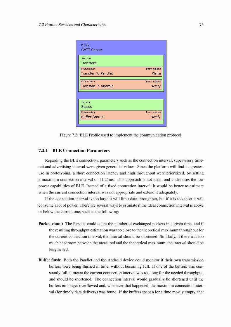
7.2 Profile, Services and Characteristics 75
Figure 7.2: BLE Profile used to implement the communication protocol.
7.2.1 BLE Connection Parameters
Regarding the BLE connection, parameters such as the connection interval, supervisory time-
out and advertising interval were given generalist values. Since the platform will find its greatest
use in prototyping, a short connection latency and high throughput were prioritized, by setting
a maximum connection interval of 11.25ms. This approach is not ideal, and under-uses the low
power capabilities of BLE. Instead of a fixed connection interval, it would be better to estimate
when the current connection interval was not appropriate and extend it adequately.
If the connection interval is too large it will limit data throughput, but if it is too short it will
consume a lot of power. There are several ways to estimate if the ideal connection interval is above
or below the current one, such as the following:
Packet count: The Pandlet could count the number of exchanged packets in a given time, and if
the resulting throughput estimation was too close to the theoretical maximum throughput for
the current connection interval, the interval should be shortened. Similarly, if there was too
much headroom between the measured and the theoretical maximum, the interval should be
lengthened.
Buffer flush: Both the Pandlet and the Android device could monitor if their own transmission
buffers were being flushed in time, without becoming full. If one of the buffers was con-
stantly full, it meant the current connection interval was too long for the needed throughput,
and should be shortened. The connection interval would gradually be shortened until the
buffers no longer overflowed and, whenever that happened, the maximum connection inter-
val (for timely data delivery) was found. If the buffers spent a long time mostly empty, that
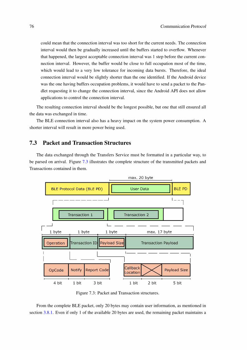
76 Communication Protocol
could mean that the connection interval was too short for the current needs. The connection
interval would then be gradually increased until the buffers started to overflow. Whenever
that happened, the largest acceptable connection interval was 1 step before the current con-
nection interval. However, the buffer would be close to full occupation most of the time,
which would lead to a very low tolerance for incoming data bursts. Therefore, the ideal
connection interval would be slightly shorter than the one identified. If the Android device
was the one having buffers occupation problems, it would have to send a packet to the Pan-
dlet requesting it to change the connection interval, since the Android API does not allow
applications to control the connection interval.
The resulting connection interval should be the longest possible, but one that still ensured all
the data was exchanged in time.
The BLE connection interval also has a heavy impact on the system power consumption. A
shorter interval will result in more power being used.
7.3 Packet and Transaction Structures
The data exchanged through the Transfers Service must be formatted in a particular way, to
be parsed on arrival. Figure 7.3 illustrates the complete structure of the transmitted packets and
Transactions contained in them.
Figure 7.3: Packet and Transaction structures.
From the complete BLE packet, only 20 bytes may contain user information, as mentioned in
section 3.8.1. Even if only 1 of the available 20 bytes are used, the remaining packet maintains a
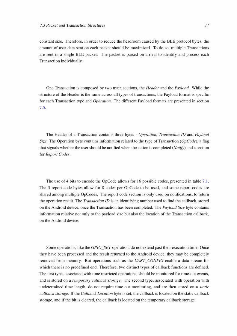
7.3 Packet and Transaction Structures 77
constant size. Therefore, in order to reduce the headroom caused by the BLE protocol bytes, the
amount of user data sent on each packet should be maximized. To do so, multiple Transactions
are sent in a single BLE packet. The packet is parsed on arrival to identify and process each
Transaction individually.
One Transaction is composed by two main sections, the Header and the Payload. While the
structure of the Header is the same across all types of transactions, the Payload format is specific
for each Transaction type and Operation. The different Payload formats are presented in section
7.5.
The Header of a Transaction contains three bytes - Operation, Transaction ID and Payload
Size. The Operation byte contains information related to the type of Transaction (OpCode), a flag
that signals whether the user should be notified when the action is completed (Notify) and a section
for Report Codes.
The use of 4 bits to encode the OpCode allows for 16 possible codes, presented in table 7.1.
The 3 report code bytes allow for 8 codes per OpCode to be used, and some report codes are
shared among multiple OpCodes. The report code section is only used on notifications, to return
the operation result. The Transaction ID is an identifying number used to find the callback, stored
on the Android device, once the Transaction has been completed. The Payload Size byte contains
information relative not only to the payload size but also the location of the Transaction callback,
on the Android device.
Some operations, like the GPIO_SET operation, do not extend past their execution time. Once
they have been processed and the result returned to the Android device, they may be completely
removed from memory. But operations such as the UART_CONFIG enable a data stream for
which there is no predefined end. Therefore, two distinct types of callback functions are defined.
The first type, associated with time restricted operations, should be monitored for time-out events,
and is stored on a temporary callback storage. The second type, associated with operation with
undetermined time length, do not require time-out monitoring, and are then stored on a static
callback storage. If the Callback Location byte is set, the callback is located on the static callback
storage, and if the bit is cleared, the callback is located on the temporary callback storage.

78 Communication Protocol
Code Operation0x00 TWI_CONFIG0x01 TWI_WRITE0x02 TWI_READ0x03 GPIO_CONFIG0x04 GPIO_SET0x05 GPIO_GET0x06 UART_CONFIG0x07 UART_SEND0x08 UART_RECEIVE0x09 PWM_CONFIG_MODULE0x0A PWM_CONFIG_CHANNEL
0x0B - 0x0F Not UsedTable 7.1: Transaction Characteristic - Operation Codes (OpCodes).
7.4 Report and Error Codes
Some operations, from table 7.1, do not require any data to be sent back to the Android device.
However, a report code system is implemented, to retrieve the result of the Transaction execution,
independently from the operation. These code are sent to the Android device through a Notifica-
tion that carries only the Transaction Header, and no additional Payload. The report codes can be
found on the Operation byte of the Transaction Header, and are encoded by a combination of the
OpCode and Report Code bits. Table 7.2 presents the existing report codes.
Module OpCode Report Code Event Reported
All All0x00 Success0x01 Timeout0x02 Queue Full
TWI 0x00 to 0x02
0x03 Internal Error0x04 Address Not ACK0x05 Data Not ACK0x06 Failed Start
GPIO 0x03 to 0x05 0x03 Port Invalid State
UART 0x07 to 0x080x03 Failed Start0x04 Failed To Send
PWM 0x09 to 0xA0x03 Not Initialized0x04 Failed Start
Table 7.2: Existing report codes and associated event.
7.5 Module Specific Payloads
As previously mentioned, the Transaction payload varies according to the Transaction type
and Operation to perform (OpCode). The following sections present the payload structures for the
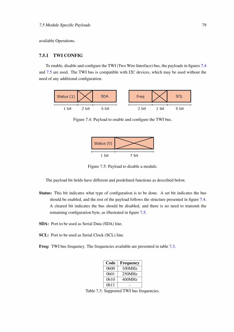
7.5 Module Specific Payloads 79
available Operations.
7.5.1 TWI CONFIG
To enable, disable and configure the TWI (Two Wire Interface) bus, the payloads in figures 7.4
and 7.5 are used. The TWI bus is compatible with I2C devices, which may be used without the
need of any additional configuration.
Figure 7.4: Payload to enable and configure the TWI bus.
Figure 7.5: Payload to disable a module.
The payload bit fields have different and predefined functions as described below.
Status: This bit indicates what type of configuration is to be done. A set bit indicates the bus
should be enabled, and the rest of the payload follows the structure presented in figure 7.4.
A cleared bit indicates the bus should be disabled, and there is no need to transmit the
remaining configuration byte, as illustrated in figure 7.5.
SDA: Port to be used as Serial Data (SDA) line.
SCL: Port to be used as Serial Clock (SCL) line.
Freq: TWI bus frequency. The frequencies available are presented in table 7.3.
Code Frequency0b00 100MHz0b01 250MHz0b10 400MHz0b11 -
Table 7.3: Supported TWI bus frequencies.

80 Communication Protocol
7.5.2 TWI WRITE
The TWI write operation may be used to send data to a peripheral device connected to the
TWI bus. The length of this payload varies according to the data to be sent, up to a maximum of
16 byte as represented in figure 7.6. This is imposed by the maximum BLE packet length, as cross
packet transactions are not yet supported.
Figure 7.6: Payload to send data through the TWI bus.
Device Address: 7-bit address of the device to send the data to.
Data: Data to be sent.
7.5.3 TWI READ
To get data from a peripheral device that is connected to the TWI bus, the TWI read operation
may be used. This operation most often follows a TWI write operation. The payload from a TWI
read Transaction follows the structure represented in figure 7.7. The collected information is then
sent to the Android device using the payload in structure 7.8.
Figure 7.7: Payload to read data from the TWI bus.
Figure 7.8: Payload to forward received TWI data to the Android device.
Device Address: 7-bit address of the device to received data from.
# bytes to read: Number of byte to read from the TWI bus. Once again, since cross packet Trans-
actions are not yet supported, the maximum number of bytes to read is limited to 17.
Data: Received data.

7.5 Module Specific Payloads 81
7.5.4 GPIO CONFIG
To use a port of the nRF51822 chip as a GPIO, it must first be configured as such. The
configuration data differs according to the direction the port should take, and, as such, the payloads
also differ. Figure 7.9 represents the configuration payload of an input GPIO.
Figure 7.9: Payload to configure a GPIO port as an input.
Direc: Direction of the GPIO port. A set bit indicates the port is to be configured as an input.
Pull: Selects if an internal pull resistor should be used, and what kind. Table 7.4 presents the
available options.
Port Number: Number of the port to be configured.
Sense: Selects if the port should be monitored for events. When an event is triggered, an action
may be taken (Sense Transaction). The available sensing configurations are presented in
table 7.5.
Sense Transaction: When a Sense event is detected, a predefined transaction may be triggered.
The Transaction to trigger is user defined, as is transmitted and stored on the Pandlet mem-
ory at the time of GPIO configuration. This Transaction is processed as if it had just been
received by the Pandlet. These Transactions always have the Callback Location bit set.
Code Pull0b00 None0b01 Pull-up0b10 Pull-down0b11 -
Table 7.4: Supported GPIO Pull modes.
Code Sense0b00 Disabled0b01 Rising-edge0b10 Falling-edge0b11 Change
Table 7.5: Supported GPIO Sense modes.
The payload to configure a GPIO as an output is different from the one previously presented.
Its structure is represented in figure 7.10.

82 Communication Protocol
DriveCode Logic Low Logic High0b000 Disconnected Standard0b001 Disconnected High0b010 Standard Disconnected0b011 Standard Standard0b100 Standard High0b101 High Disconnected0b110 High Standard0b111 High HighTable 7.6: Possible GPIO Drive modes.
Figure 7.10: Payload to configure a GPIO port as an output.
Direc: Direction of the GPIO port. A cleared bit indicates the port is to be configured as an output.
Drive: The nRF51822 chip offers multiple drive configurations for GPIO output ports. The pos-
sible combinations are presented in table 7.6. Although the protocol supports this feature,
there still is no support for it on the firmware level.
Stat: Selects the status of the newly configured output port.
Port Number: Number of the port to be configured.
7.5.5 GPIO GET
This operation, whose payload is represented in figure 7.11, may be used to retrieve the current
value of any GPIO port, independently of its direction (input or output). The result is sent back to
the Android device using the same payload format as the GPIO_SET operation (section 7.5.6).
Figure 7.11: Payload to request a status measurement on a GPIO port.
Port Number: Number of the port to retrieve the value from.

7.5 Module Specific Payloads 83
7.5.6 GPIO SET
Once a GPIO port has been configured as an output, its value may be changed by using the
GPIO set operation. The associated payload is illustrated in figure 7.12. If the user tries to set the
value of a pin that is not configured as an output, an error code is returned. This payload structure
is also used to return the result of the GPIO_GET operation.
Figure 7.12: Payload to set the value of an output GPIO port, and to return the result of theGPIO_GET operation.
Stat: Status to attribute to the GPIO port.
Port Number: Number of the port to set.
7.5.7 UART CONFIG
Before sending and receiving data through the UART (Universal Asynchronous Receiver/-
Transmitter) bus, it must first be enabled. The payload presented in figure 7.13 allows the bus
to be enabled and configured. To disable the UART module, only a single byte is required, as
represented in figure 7.5.
Figure 7.13: Payload to enable and configure the UART bus.
Stat: This bit determines whether the bus should be enabled or disabled. A set bit indicates the
bus should be enabled.
Parity: This bit selects the parity to be used when sending and receiving information through the
bus. The supported modes are presented in table 7.7.
Baud: This bit group selects the baudrate to be used on the bus. The available options are pre-
sented in table 7.8.

84 Communication Protocol
RTS: Port number to which the Request to Send line is connected.
CTS: Port number to which the Clear to Send line is connected.
RX: Port number to which the Reception line is connected.
TX: Port number to which the Transmission line is connected.
Code Parity0b00 None0b01 Even
Table 7.7: Supported UART Parity modes.
Code Baudrate0b0000 12000b0001 24000b0010 48000b0011 96000b0100 144000b0101 192000b0110 288000b0111 384000b1000 576000b1001 768000b1010 1152000b1011 2304000b1100 2500000b1101 4608000b1110 9216000b1111 1000000
Table 7.8: Supported UART baudrates.
7.5.8 UART SEND and UART RECEIVE
These operations share the same payload formatting (figure 7.14), in which the actual data to
be exchanged is carried. The direction of the operation (send/receive) is contained on the OpCode
bits of the Transaction header. The UART_SEND operation is used to transfer to the Pandlet the
data that it should send the UART bus. On the other hand, the UART_RECEIVE operation is used
by the Pandlet to forward data it has received, through the UART bus, to the Android device.

7.5 Module Specific Payloads 85
Figure 7.14: Payload to exchange data to send, or that has been received, through the UART bus.
Data: Data to send through the UART bus, or data received through the UART bus, depending on
the OpCode bits of the Transaction header.
7.5.9 PWM CONFIG MODULE
The configuration of the PWM module is made simultaneously for both channels of the mod-
ule. However, this configuration is not complete, and a channel specific configuration must follow
the module configuration. The module configuration sets the PWM base frequency, the ports to
which the channels should be connected to, and the channels polarity, as illustrated in figure 7.15.
Figure 7.15: Payload to configure the PWM module.
Status: This bit determines whether the PWM module should be enabled or disabled. A set bit
indicates the module should be enabled, while a cleared bit indicates the module should be
disabled.
Chan 0/Chan 1 Port: Port number to which the PWM channels should be connected to.
Chan 0/Chan 1 Polar: Polarity to configure the channels with. The available options are pre-
sented in table 7.9.
Period: PWM base frequency period in microseconds.
Code Polarity0b0 Active LOW0b1 Active HIGH
Table 7.9: Supported PWM channel polarity.

86 Communication Protocol
7.5.10 PWM CONFIG CHANNEL
The payload illustrated in figure 7.16 performs the remaining configuration for each PWM
channel. This operation may be carried multiple times, without having to re-configure the whole
module.
Figure 7.16: Payload to configure the PWM module channels.
Channel: PWM channel to configure.
Duty cycle: Duty cycle for the specified PWM channel, from 0 to 100 (active percentage of duty
cycle);
7.6 Remarks
The communication protocol was developed in a modular way, so that new operations can be
added in a timely manner. If more than 16 operations are needed, the available bits in the Payload
Size byte may be used. The modular design of the protocol allows any two compliant devices to
successfully communicate and take advantage of the sensing capabilities of one of them, be it the
Pandlet platform or any other compliant micro-controller platform. The BLE Central device can
be an Android device or just another micro-controller platform with higher privileges. In summary,
the presented protocol offers a way to establish a communication channel between any compliant
devices and expose the functionalities of any micro-controller platform.
The implemented fixed parameters for the BLE communication do not present the best possi-
ble solution regarding power consumption, and should be the object of further investigation and
optimization.

Chapter 8
Android API
8.1 Overview
The Pandlet Application Programming Interface (PAPI) is the topmost layer of the system
presented in this dissertation. It enables developers to quickly connect to a Pandlet device and
extract information from it.
8.2 Blocking vs Non-blocking Operation
When communicating with a device and following a request/response methodology (which is
commonly used in the API), the device issuing the request has two alternatives regarding the wait
for the response - blocking and non-blocking operation.
Blocking operationThe thread that issued the request waits for the response to arrive before continuing.
Non-blocking operationAfter issuing the requests, the thread does not wait for the response to arrive and continues
working. The response is delivered to the thread through a callback function, at a later time.
It is possible to implement blocking behaviour using a natively non-blocking operations.
However, it is not possible to do the opposite.
The implementation of blocking operation is simpler and more straight forward. In terms of
API usage, a blocking API would allow the developer to retrieve data with a single variable attri-
bution. However, the Android thread that performed such attribution would be non-responsive for
the time it would take to receive the response. If it happened to be the User Interface (UI) thread,
it would result in a temporarily ’frozen’ interface and an inferior user experience. Furthermore,
only one Transaction per BLE packet would be able to be sent, since the system would wait for
one Transaction to be completely processed before sending a new one to the Pandlet. Overall, a
blocking API would impose heavy restrictions on the developed applications.
87

88 Android API
A non-blocking API allows the host application to continue working while the data is being
exchanged through BLE. It also allows multiple Transactions to be sent in each BLE packet since
the API is able to receive new Transaction requests while processing the previously requested
Transactions. As non-blocking operation presents several advantages in comparison to the block-
ing operation, the API was developed as a non-blocking system. This characteristic motivated
the development of the Transaction Manager (sections 6.3 and 8.4), which performs Transaction
queuing and manages data exchange.
8.3 Overall Structure
The API itself is also made of several layers, each offering an additional level of abstrac-
tion. The lowest API layer is the Android side of the previously mentioned Transaction Manager
(sections 6.3 and 8.4), and the user cannot access it. The Transaction Manager and the BLE
communication procedures are implemented on the MicroController class.
The middle layer of the API, already accessible to the user, is composed of the MicroController
class, along with classes to manage the use of each available module (TWI, UART, GPIO and
PWM). These classes belong to the Core package and allow direct interaction with the Pandlet
modules and micro-processor.
The API features one more layer, composed by classes that implement device drivers on top of
the classes from the Core package. These classes are part of the Peripherals package and contain
instances from multiple Core classes.
The central class of the API is the Pandlet, which contains instances of the classes that belong
to the Core and Peripherals packages. All of the interactions with the Pandlet platform should be
done through this class. A developer can use such classes to implement a driver for a new device.
The only requisite is that all the communications are done through an instance of the Pandlet class.
Figure 8.1 presents the API layered structure, and figure 8.2 presents a package diagram of the
API along with the most important classes.

8.4 Back-end - Transaction Manager 89
Figure 8.1: Pandlet API layered structure.
Figure 8.2: Class diagram presenting the major classes in each package.
8.4 Back-end - Transaction Manager
Figure 8.3 illustrates the structure of the Android side of the Transaction Manager. This side
of the manager is responsible for translating the user action requests into Transactions and transfer
them safely to the Pandlet. When the Pandlet processes the Transactions and returns the result to
the Android device, the manager must identify to which Transaction the result is associated with
and call the correct callback function.

90 Android API
Figure 8.3: Android side of the Transaction Manager.
Each module has a specific Transaction class, extended from the main Transaction class. The
available classes are presented in figure 8.4. These classes are only used to exchange information
between API layers, and only the classes from the Core package may create instances of them.
Similarly, not all Operations (section 7.3) have the same callback class. Since different classes
return different structures and values, several callback classes were defined, all extended from a
main callback class. Figure 8.5 illustrates the available callback classes.
Figure 8.4: Transaction classes available on theAPI.
Figure 8.5: Callback classes available on theAPI.

8.4 Back-end - Transaction Manager 91
8.4.1 Queuing
Whenever the user requests a Transaction, the class associated with the module creates a Trans-
action class instance and initializes it with the information that describes the requested Transaction.
This Transaction is then forwarded to the Transaction Manager. Since the API is non-blocking,
the manager performs Transaction queuing, holding Transactions that wait to be transferred to
the Pandlet. When the Transaction is being added to the queue, the user receives a return code
describing whether the Transaction was added successfully or if some error occurred.
When the Transaction is being added to the queue, the manager assigns it an identification
number (ID), which identifies the Transaction and will be used to find the corresponding callback
when the Transaction is processed. Since there is a limitation to the available unique identification
numbers, whenever the user tries to add a new Transaction, the manager checks if there are free
IDs and only accepts the Transaction if one is available. If not, an error code is returned. The
ID numbers are freed and recycled when a Transaction result is returned to the Android and the
callback finishes executing.
8.4.2 Dispatcher
Once the Transactions have been added to the queue, the Dispatcher is responsible for taking
those Transactions and send them to the Pandlet. To so do, the Transaction must first be converted
into an array of bytes that will be transferred through BLE. The arrays are built by a set of Builders,
to whom the user does not have access. There is a Builder for each Transaction class. Since a single
Transaction may not occupy the 20 bytes available, several Transactions may be sent on a single
BLE packet (if there is space for them).
At dispatch time, the Transaction Manager stores a reference to the callback of each Trans-
action, according to the ID previously assigned. When a Notification packet arrives, the manager
parses it (to isolate each individual Transaction result, as per section 6.3.3) and looks for the corre-
sponding callback on the Callback Storage. The found callback is then executed in a new thread.
The use of a separate thread allows the Transaction Manager to quickly process all the incom-
ing Notification packets. If all the callbacks were executed on the Transaction Manager main
thread, the API performance would vary greatly with the actions the developer chose to run on the
callback functions.
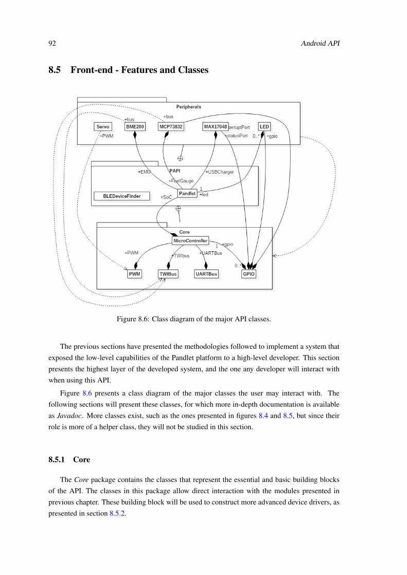
92 Android API
8.5 Front-end - Features and Classes
Figure 8.6: Class diagram of the major API classes.
The previous sections have presented the methodologies followed to implement a system that
exposed the low-level capabilities of the Pandlet platform to a high-level developer. This section
presents the highest layer of the developed system, and the one any developer will interact with
when using this API.
Figure 8.6 presents a class diagram of the major classes the user may interact with. The
following sections will present these classes, for which more in-depth documentation is available
as Javadoc. More classes exist, such as the ones presented in figures 8.4 and 8.5, but since their
role is more of a helper class, they will not be studied in this section.
8.5.1 Core
The Core package contains the classes that represent the essential and basic building blocks
of the API. The classes in this package allow direct interaction with the modules presented in
previous chapter. These building block will be used to construct more advanced device drivers, as
presented in section 8.5.2.

8.5 Front-end - Features and Classes 93
8.5.1.1 MicroControler
The MicroController class, represented in figure 8.7, is where all the communication logic and
the Transaction Manager are implemented. It provides methods to connect to and disconnect from
the Pandlet device, as well as methods to perform one or multiple Transactions.
All of the classes belonging to the Core package, when requested to do an action, do not
actually perform it. Instead, they return a Transaction object, that contains the data that describes
the requested action. When the user wishes to actually perform the action, the perform methods of
the MicroController class should be used, along with the previously retrieved Transaction object.
This mechanism allows the user to define actions without actually performing them, and save them
for later use. This feature is especially useful in programming automatically triggered interrupt
actions, as will discussed in section 8.5.1.5.
The class further contains instances of the available communication buses, as well as the PWM
module class. These objects should be initialized whenever the corresponding modules are re-
quired, as presented in sections A.2, A.3 and A.4.
Figure 8.7: MicroController class.
8.5.1.2 TWI Bus
The TWIBus class, represented in figure 8.8, should be used whenever Two Wire Interface
(TWI) or Inter-Integrated Circuit (I2C) communication is required. A TWIBus object must be
initialized, and the bus must be enabled before use. This class provides the methods to do that, as
well as writing and reading data from the bus.
When the TWIbus object is initialized, the user may configure to what ports of the micro-
controller the Serial Data (SDA) and Serial Clock (SCL) lines should be connected to. When the
bus is enabled, the user may also choose the bus clock frequency.

94 Android API
Figure 8.8: TWIBus class.
8.5.1.3 UART Bus
The UARTBus class, represented in figure 8.9, may be used to send and receive data through
the Pandlet UART bus. Before use, a UARTBus object must be initialized and the bus must be
enabled, time at which the user is able to choose to which micro-controller port the bus lines
should be connected to, as well as the communication baudrate and parity.
There is no option to perform a UART read. Instead, if the user wishes the receive data from the
UART bus, a reception callback must be defined, which will be executed every time a new com-
plete sentence is received by the micro-controller chip. A sentence is considered to be complete
when a New Line character is received.
Figure 8.9: UARTBus class.
8.5.1.4 PWM
The PWM module may be used through the PWM class, represented in figure 8.10. The PWM
module supports two channels, but both must have the same base frequency. The PWM base
frequency, the ports to which the channels should be connected to, and their respective polarities
are defined when the module is enabled. The channels may then be individually configured by
setting the duty cycle.

8.5 Front-end - Features and Classes 95
Figure 8.10: PWM class.
8.5.1.5 GPIO
The GPIO class, represented in figure 8.11, allows for the interaction with the GPIO ports of
the micro-controller chip. When a GPIO is configured as an output, the only option available to
the user is to set the port logic value. However, when the port is configured as an input, multiple
configurations are available. One of those configuration is the use of a pull resistor. The user may
choose to use a pull-up resistor, a pull-down resistor, or no resistor at all.
The other option, is the Sensing configuration. An input GPIO with enabled sensing reacts
to input signal changes. If the port is configured to sense RISE, it will perform an action when a
rising-edge is detected on the input. And if the port is configured to sense FALL, it will perform
an action when a falling-edge is detected on the input. It is further possible to configure the port
to sense a change, be it rising-edge or falling-edge.
When the user configures a port as an input, there is the possibility to define a set of Transac-
tions as the sense Transactions. These Transactions are transmitted to the Pandlet at configuration
time, and are locally stored for later use. When a sense event is detected, the sense Transaction
associated with the port at which the event was detected is executed. The Transaction is executed
every time a sense event is detected, and will only be removed if the GPIO is reconfigured with a
different sense Transaction.
Even thought the Sensing mechanism may be useful to perform tasks based on interrupts, it is
still possible to poll the port for it current status.
Figure 8.11: GPIO class.

96 Android API
8.5.2 Peripherals and Drivers
Even though it is already of great help to be able to seamlessly interact with the micro-
controller modules, it would be even more useful to have device drivers ready to be used and
extract sensory information. The classes presented in this section contain device drivers that uti-
lize instances of the classes presented on the previous section to retrieve information and interact
with the Pandlet on-board sensors.
Not all of the on-board Pandlet sensors have implemented device drivers. The drivers that have
been implemented should act as a reference point to develop the remaining drivers, in the future.
8.5.2.1 LED
The LED class, represented in figure 8.12, contains a driver for an LED. It is the simplest of all
the implemented drivers, as it only encapsulates a single GPIO port and controls its output value.
Figure 8.12: LED class.
8.5.2.2 Servo
The Servo class allows the control of a servo motor, through the use of one of the channels
from the PWM module. This class is represented in figure 8.13.
Figure 8.13: Servo class.

8.5 Front-end - Features and Classes 97
8.5.2.3 MCP73832 - USB Charger
The MCP73832 class, represented in figure 8.15, contains the driver for the corresponding
device, which is the controller for USB powered battery charging. This driver, like the LED
driver, is composed by a single GPIO port. However, they are different in the port direction.
The USB charger has a port that indicates what is the charging status (charging or not charg-
ing), so a GPIO port, configured as input, may be connected to it in order to retrieve information
related to the charge status. Since the driver contains a GPIO object that the user may choose to
connect to the charge status port, it is possible to program the micro-controller device to execute a
predetermined Transaction whenever a charger is plugged in/out.
Unlike the previously presented device drivers, this driver requires an initialization routine to
be carried out before interacting with the device.
Figure 8.14: MCP73832 class.
8.5.2.4 MAX17048 - Fuel Gauge
The MAX17048 class, represented in figure 8.15, implements the driver for the Pandlet fuel
gauge. The driver allows the user to retrieve data concerning the state of charge (SoC) of a battery,
and its current voltage. Besides containing a GPIO port to detect sensor generated interrupts, it
also allows for the communication through the TWI bus to retrieve data from the device.
The drivers for TWI and I2C devices usually have an intermediate step between reading the
data from the device and delivering it to the user. This is required because most often the data of
such devices is stored in multiple registers and in an encoded manner. Therefore, it must be treated
before being delivered to the user. Before requesting information from the device, the user must
set a callback, by using a specific method. After the driver receives the raw data and processes it,
that callback will be executed, and the user may retrieve the measured data through it.
The user can execute the measurement at a later time, as a GPIO sense action for example, by
retrieving the Transactions that represent the measurements, using the appropriate driver methods.
Once the micro-controller executes the Transactions, the driver will process the received data and
the predefined callback will be executed.

98 Android API
Figure 8.15: MAX17048 class.
8.5.2.5 BME280 - EMU
The BME280 class, represented in figure 8.16, implements the driver for the Environmental
Measurement Unit featured on the Pandlet. This device performs temperature, pressure and hu-
midity measurements. Like with the fuel gauge driver, the retrieval of data from this device is done
through a predefined callback, and by calling the appropriate measurement methods.
This EMU has a characteristic that none of the previously presented ones had. Besides having
to be initialized, it also has to be calibrated, and the driver already contains a method to calibrate
the sensor. The implemented driver compensates the pressure and humidity measurements with
the result from the temperature . Therefore, if compensation is to be done, it is mandatory to
perform a temperature measurement before requesting pressure and humidity data.

8.5 Front-end - Features and Classes 99
Figure 8.16: BME280 class.
8.5.3 Pandlet
All of the previously presented modules, devices and drivers come together on the Pandlet
class, represented in figure 8.17. This class contains one instance for each of the Pandlet sensors
with implemented drivers. However, if the user needs to use more GPIO ports, or directly interact
with some communication bus, he is still able to, through the MicroController object.
The class also has methods to forward operations to some of its objects. Consider the con-
nect(...) method for instance. The class responsible for performing this operation is the Micro-
Controller, but the Pandlet class also has a connect(...) method. Whenever the Pandlet connect(...)
method is called, the request is forwarded to the corresponding MicronController instance.

100 Android API
Figure 8.17: Pandlet class.
8.5.4 BLEDeviceFinder
Figure 8.18: BLEDeviceFinder class.
The device finder represented in figure 8.18 is more of a utility class than a device representing
class. Its use is not mandatory in order to connect to or interact with the Pandlet. However, it does
provide a fast way to connect the Pandlet object to Pandlet device.
8.6 Documentation and Usage Examples
Javadoc documentation is available for all the API classes and methods a developer may use.
Figure 8.19 represents the overview of the Javadoc documentation.

8.7 Remarks 101
Appendix A presents usage examples for every module available on the API, along with ex-
amples on how the device drivers may be used.
Figure 8.19: Overview of the Javadoc documentation.
8.7 Remarks
The presented API provides a good balance between implementation flexibility and ease of
use. It would be possible to further simplify the API, but that would require the removal of options
and features, and ultimately leading a very limited system.
The implementation of new device drivers and addition new modules is also straightforward,
as the API has been designed in a modular fashion, in order to support future adjustments.

102 Android API

Chapter 9
Performance Tests
To test the firmware, communication protocol and API performance, some tests were carried
out. All of the executed test are based in counting the number of received Notifications, and
comparing the result with the expected value.
9.1 GPIO Sensing
This test consisted in configuring a GPIO port with sensing capabilities, and connecting the
GPIO to a signal generator. The generator would create a square signal with a given frequency,
and the edges of the wave would trigger the sensing event, which was programmed to send a
GPIO_READ Notification to the Android device. Since the GPIO port was configured to trigger
a sensing event on both rising-edge and falling-edge, the frequency at which the Notifications
should be received is double the frequency of the input signal. Table 9.1 and figure 9.1 present the
obtained results according to the frequency at which the Notifications should be received.
Frequency (Hz) Received (Notif/s)40 40.21
66.66 66.93200 200.57250 250.16
266.67 266.74363.63 363.79
400 400.10444.444 444.87470.59 461.40
500 434.37Table 9.1: Results of the GPIO sensing test.
103

104 Performance Tests
Figure 9.1: Results of the GPIO sensing test.
The system is able to report 100% of the triggered events up to 450Hz, where it can no longer
keep up with the signal. However, the achieved result is below what would be expected, if the
Pandlet had no processing power limitations. The smartphone used was the Motorola Moto G
v2, which supports a minimum connection interval of 7.5ms, and is able to send 3 packets per
connection interval. Since a GPIO_READ packet is 4 bytes in length (3+1), through equation 9.1
we can determine that the maximum achievable number of GPIO_READ Notifications per second
is 2000. The difference between this theoretical maximum and the obtained values is due to the
processing power required to operate both the BLE and still process the interrupt events. The use
of a very short connection interval leads to very little free CPU time, resulting in delayed operation
processing, and ultimately limiting the system throughput.
MaxGPIO_READ =1
7.5ms×3×
⌊204
⌋= 2000meas/s (9.1)
9.2 TWI Read with GPIO Sensing
Since the majority of the Pandlet sensors communicate through TWI, it is important to know
what measurement rates can be achieved. The sensors that should be read at high frequencies
usually have an interrupt port, which informs the micro-controller that a new reading is ready.
This behaviour was simulated by using a GPIO connected to a signal generator, as in the previous
test, but now, the sensing Transaction is to read the value of the battery state of charge, through
the Fuel Gauge. Table 9.2 and figure 9.2 present the obtained results.

9.2 TWI Read with GPIO Sensing 105
Frequency (Hz) Received (Notif/s)40 39.95
66.67 66.96200 201.02
222.22 223.54235.29 209.19
250 164.60266.67 112.46
Table 9.2: Results of the TWI test using GPIO sensing.
Figure 9.2: Results of the TWI test using GPIO sensing.
In this test, besides having to process the GPIO interrupt, the nRF51822 also has to request
a measurement from the fuel gauge and wait for the response to arrive. This leads to a lower
maximum measurement throughput, when compared with the previous test. At around 225Hz the
system stops being able to process the measurements on time. From that point on, not only is
the system incapable of keeping up with the measurements, but its performance also deteriorates
considerably. This is because even though no more measurement requests are being issued to the
fuel gauge, the nRF51822 still processes the GPIO interrupts and wastes CPU time.
A state of charge measurement Notification is made up of 5 bytes (3+2). Using this informa-
tion, and knowing the Android device used was the previously mentioned Motorola, the maximum
theoretical measurement rate can be calculated through equation 9.2, resulting in a maximum of

106 Performance Tests
1600 measurements per second. Again, the result is well below the theoretical rates due to the
already presented CPU usage limitation.
MaxTWI_READ_INT =1
7.5ms×3×
⌊205
⌋= 1600meas/s (9.2)
9.3 TWI Read with Request/Response
The GPIO sensing mechanism was developed mostly because it would be inefficient to con-
stantly use the request/response mechanism. To evaluate how much worse that mechanism is, one
more test was performed. The test is similar to that of section 9.2, except the measurements are
trigged by an Android request, instead of a GPIO sensing event. The obtained results are presented
in table 9.3 and figure 9.3.
Frequency (Hz) Received (Notif/s)40 39.70
66.67 65.73200 156.33
222.22 0235.29 0
250 0266.67 0
Table 9.3: Results of the TWI test using Request/Response.
Figure 9.3: Results of the TWI test using Request/Response

9.4 Remarks 107
As expected, not only is the method much slower, it completely stops returning data above
200Hz.
The theoretical maximum measurement rate of this topology must be calculated in two steps,
since bidirectional communication is required. From chapter 5 it is know that while the Motorola
phone is able to receive 3 Notifications per connection interval, it is only able to send 1 Write
Command per connection interval. To retrieve the state of charge measurement, several operations
are required. The first operation a TWI_WRITE, takes 5 bytes to encode (3+2). The second opera-
tion is a TWI_READ, which also takes 5 bytes (3+2). So, the Android device has to write 10 bytes
to the Pandlet. Using this information in equation 9.3, it is possible to conclude that the theoretical
maximum number of measurement requests per second is of approximately 267. The smartphone
is able to send 1600 measurement responses per second (equation 9.2), but not enough requests
can be issued to reach that rate.
MaxTWI_REQ/RESP = min(
17.5ms
×3×⌊
205
⌋;
17.5ms
×1×⌊
2010
⌋)= 267meas/s (9.3)
9.4 Remarks
Figure 9.4: Test results comparison.
Figure 9.4 presents a performance comparison of the tested operations. As can be seen, the
system performance varies greatly with the methodology used to perform measurements. Due

108 Performance Tests
to this, a developer that uses the Pandlet API and system should be aware of such performance
differences and design the application having them in mind.
The performed tests, and most specifically the ones presented in sections 9.2 and 9.3, confirm
that the implementation of the GPIO sensing feature is of extreme importance, making the whole
system much more capable and flexible.

Chapter 10
Demo application
10.1 Full featured demo application
In order to demonstrate the system capabilities, as well as provide a reference Android appli-
cation implementation, a demo application was developed. The app screen is presented in figure
10.1, and it provides a way of testing and interacting with most of the supported features of the
API.
Figure 10.1: Android demo app.
The application features the following functionalities:
Connect and DisconnectThe application connects to the Pandlet device using the BLEConnectionManager.
109

110 Demo application
TWI/I2CThe TWI module, referenced as I2C on the application, can be enabled and disabled when-
ever the user wishes to do so. It is also possible to request reading form the Fuel Gauge
using the two available buttons. The stress button may be used to stress the system BLE
communication, by issuing several Fuel Gauge measurements every second, according to
the test results presented in chapter 9.
GPIO and SensingThe simplest mechanism of the demo application is the button to toggle the red LED. To test
the sensing feature, a button may be used to monitor the status of the Pandlet USB charger.
UARTIn order to test the UART module using a single device, Pandlet GPIO4 (used as Tx) and
GPIO3 (used as Rx) ports must be connected together, in a loop-back topology. Further-
more, GPIO2 (used as CTS) must be connected to ground. The module may be enabled and
disabled at the user will. The Send button triggers a message to be sent through the UART,
which is also displayed on the Sent text field. When connected in the loop-back topology,
the same message will be received by the Pandlet and presented on the Received text field.
The Flush button may be used to force the Pandlet to send whatever cached UART message
is stored in its memory, in case no new line character has been received.
PWMThe user is able to enable and disable the PWM module at will. It should be noted that even
though the module may be enabled, the signal only starts to be generated once a duty cycle
has been defined, by using the available seekbar. The channels of the PWM module are
connected to GPIO1 and to the green LED.
This application may be used for several purposes. Even though its main purpose is to demon-
strate the features made available by the API, the application may also be used to quickly test a
Pandlet device and evaluate if there is some hardware malfunctioning.
10.2 Functionality specific demo applications
In order to simply the adoption of the API by the Android developers, functionality specific
demo applications were developed - I2C communication, GPIO and PWM features, and UART
communication.
Figure 10.2 represents the screen for the PWM and GPIO demo application. The seekbar
simultaneously controls the angle of a connected servo motor, and the duty cycle of a connected
LED. The user is further able to enable and disable USB charger sensing. Figure 10.4 shows the
hardware configuration to support the features exposed by the application.
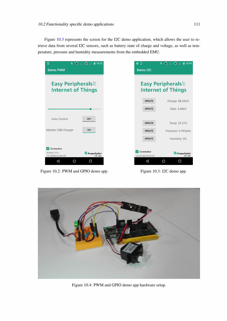
10.2 Functionality specific demo applications 111
Figure 10.3 represents the screen for the I2C demo application, which allows the user to re-
trieve data from several I2C sensors, such as battery state of charge and voltage, as well as tem-
perature, pressure and humidity measurements from the embedded EMU.
Figure 10.2: PWM and GPIO demo app. Figure 10.3: I2C demo app.
Figure 10.4: PWM and GPIO demo app hardware setup.

112 Demo application
Figure 10.5: UART1 demo app, phone 1. Figure 10.6: UART2 demo app, phone 2.
Figure 10.7: UART demo app hardware setup.
Figures 10.5 and 10.6 represent the screen of the UART demo apps. By connecting the UART
ports of two Pandlet devices, as shown in figure 10.7, it was possible to create a chat between
two Android devices. Android device 1 sends a UART Transaction to Pandlet 1, which performs
the Transaction and sends the string through the UART port. On the other side of the UART is

10.2 Functionality specific demo applications 113
Pandlet 2, which receives the string and forwards it to Android device 2, effectively transmitting
information between Android devices 1 and 2.
The application implementations presented in this section may be used as extended examples
on how to implement a solution using the Pandlet API.

114 Demo application

Chapter 11
Conclusion and Future Work
In this dissertation project, a large portion of a layered software system was analysed, dis-
cussed and developed.
The bottom-most studied and developed layer was the Pandlet platform firmware, along with
all the relevant communication protocols (TWI and UART) and available features (GPIO and
PWM). Most of the Pandlet on-board sensors were also studied, in order to implement the appro-
priate device drivers.
The communication protocol, developed to be carried through Bluetooth Low Energy (BLE),
can be considered as the middle layer of the system, above the firmware and below the API. In
order to design an efficient protocol, and understand which limitations were imposed by using
BLE as a carrier, several tests were performed. These tests evaluated how BLE throughput varied
according to multiple factors such as the communication methodology used (Write Command,
Notification, and both), the distance between two peer devices, and the effect a third interfering
device may have on the communication.
The topmost layer of the studied system is composed by the Android companion API and the
demo application. The companion API provides an interface that allows any developer to quickly
implement a prototype or solution using the Pandlet platform. The developed demonstration ap-
plication also provides an implementation reference for other developers.
11.1 Pros and Cons
During the design of the whole system, special care was taken to make the developed solution
as modular and flexible as possible. The result was a well defined layered system, in which any
layer may be implemented in a different platform and integrated in the system. If, for some pur-
pose, there is the need to use the Pandlet API with a different low-level platform, say an Arduino,
it is possible to programme the Arduino to support the implemented communication protocol and
use the Pandlet API to communicate with it. Conversely, if there is the need to use the Pandlet
platform with another gateway device, the two devices may communicate using the developed
protocol, without the need of the API.
115

116 Conclusion and Future Work
The flexibility of the developed solution extends even further than the previously presented sit-
uations. Since all of the nRF51822 port are addressable, and all the modules are user configurable,
any platform that uses the nRF51822 chip is supported by the firmware, protocol and API.
However, flexibility comes at a cost. The presented solution is ideal for prototyping and de-
veloping systems that do not require lots of processing power or very high data throughput. When
such characteristics are desired, it is better to implement dedicated firmware, as it is significantly
faster than the presented solution. Yet another advantage of a custom designed system is lower
power consumption, as the BLE communication parameters may be adjusted to better support the
required data throughput, without wasting energy.
11.2 Future Work
As with any system, there are aspects that may be improved, and new features to be added.
This system is no exception.
Throughout this document, several aspects have been presented regarding improvements, some
of them are the firmware common queue (chapter 6) and the currently static BLE communication
parameters (chapter 7). These represent improvements for the already implemented system, but
provide no additional functionality. Another improvement to the system would be the support
of multi packet Transactions, which would enable longer Transaction to be exchanged between
devices.
There are, however, more functionalities to be supported. One of them is the Serial Peripheral
Interface (SPI) communication protocol, studied in section 4.2.1.2. This protocol is widely used
by several peripheral devices and sensors, but regarding the Pandlet on-board sensors, only the mi-
croSD card slot uses SPI. Perhaps the biggest source of underused functionality are the on-board
sensors themselves. The currently implemented device drivers offer a rather limited number of
configurations for the sensors. Other peripherals sensors, such as the on-board Inertial Measure-
ment Unit, still have no developed drivers.
Yet another aspect that deserves to be studied further is how the power consumption of BLE
connections varies with several parameters, such as the connection interval and the direction of
the communication. Furthermore, it would be interesting to determine if BLE is always a better
solution when compared to standard Bluetooth, when considering power consumption in high
throughput applications.
This project, which can still be further expanded, resulted in the development and implemen-
tation of a set of software tools that have the potential to not only speed up the development of
IoT based solutions, but also to capture the attention and interest of newcomers to the incredible
world of Engineering. Testing new ideas and concepts is the pillar of research and investigation
work, and this dissertation aims to encourage just that.

Appendix A
API Usage Examples
A.1 Pandlet
Code snippet A.1 presents the procedure to connect to a Pandlet device. The user may de-
clare callback functions to be executed whenever the connection is established or terminated. The
method shown uses the BLEDeviceFinder class to expedite the connection, but it is not required
to do so. The developer may opt to implement the BLE connection process himself, with no
repercussions the Pandlet API usage.
1 String MAC = "DD:A5:17:A2:57:A6";2 Pandlet pandlet = null;3 BLEDeviceFinder deviceFinder = null;4
5 //Declare connection events callbacks6 public Runnable onConnect = new Runnable() {7 @Override8 public void run() {9 System.out.println("Pandlet connected.");
10 }11 };12
13 public Runnable onDisconnect = new Runnable() {14 @Override15 public void run() {16 System.out.println("Pandlet disconnected.");17 }18 };19
20 BooleanCallback enableBLECallback = new BooleanCallback() {21 @Override22 public void run(boolean[] values) {23 if (values.length>0 && values[0]){24 deviceFinder.setFindDeviceCallback(deviceFoundCallback);25 deviceFinder.findDevice(MAC);26 }27 }28 };
117
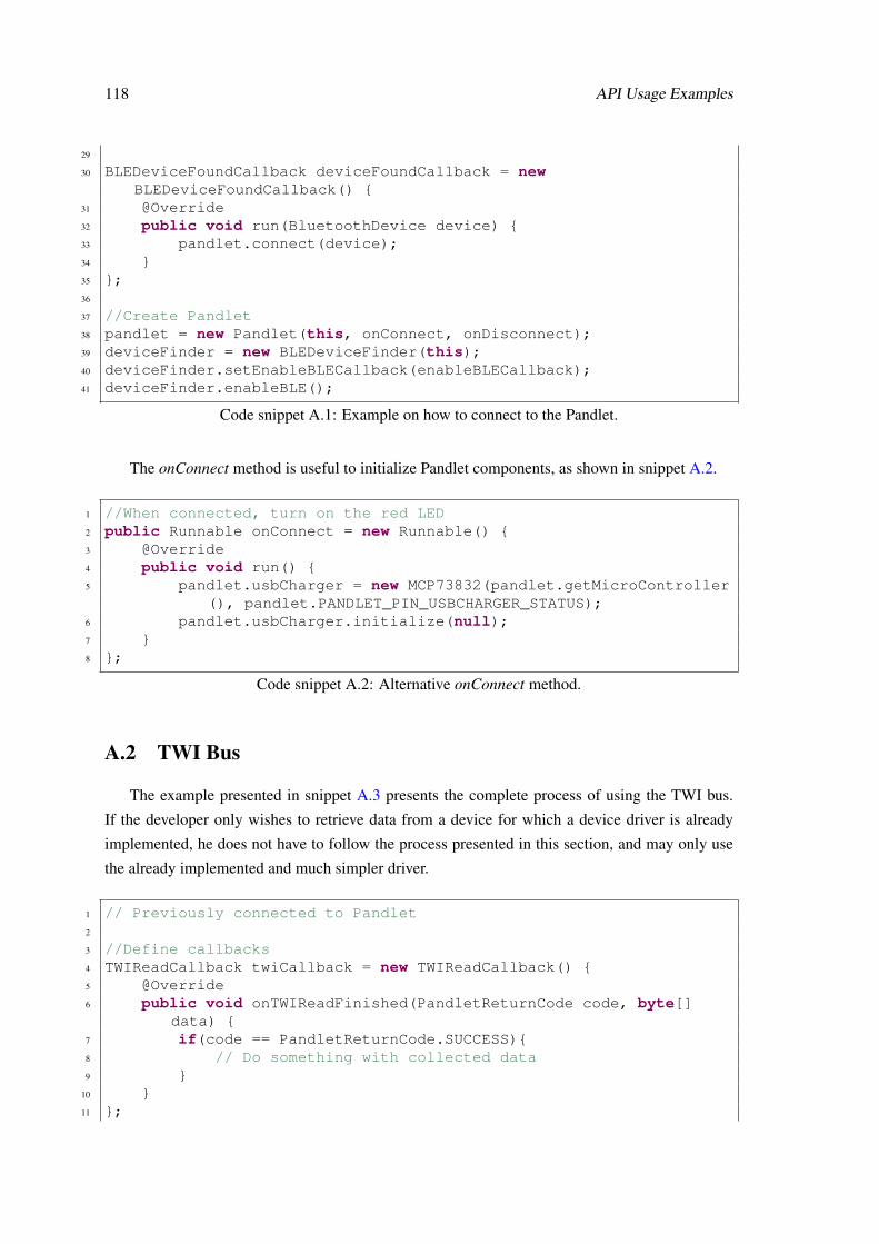
118 API Usage Examples
29
30 BLEDeviceFoundCallback deviceFoundCallback = newBLEDeviceFoundCallback() {
31 @Override32 public void run(BluetoothDevice device) {33 pandlet.connect(device);34 }35 };36
37 //Create Pandlet38 pandlet = new Pandlet(this, onConnect, onDisconnect);39 deviceFinder = new BLEDeviceFinder(this);40 deviceFinder.setEnableBLECallback(enableBLECallback);41 deviceFinder.enableBLE();
Code snippet A.1: Example on how to connect to the Pandlet.
The onConnect method is useful to initialize Pandlet components, as shown in snippet A.2.
1 //When connected, turn on the red LED2 public Runnable onConnect = new Runnable() {3 @Override4 public void run() {5 pandlet.usbCharger = new MCP73832(pandlet.getMicroController
(), pandlet.PANDLET_PIN_USBCHARGER_STATUS);6 pandlet.usbCharger.initialize(null);7 }8 };
Code snippet A.2: Alternative onConnect method.
A.2 TWI Bus
The example presented in snippet A.3 presents the complete process of using the TWI bus.
If the developer only wishes to retrieve data from a device for which a device driver is already
implemented, he does not have to follow the process presented in this section, and may only use
the already implemented and much simpler driver.
1 // Previously connected to Pandlet2
3 //Define callbacks4 TWIReadCallback twiCallback = new TWIReadCallback() {5 @Override6 public void onTWIReadFinished(PandletReturnCode code, byte[]
data) {7 if(code == PandletReturnCode.SUCCESS){8 // Do something with collected data9 }
10 }11 };
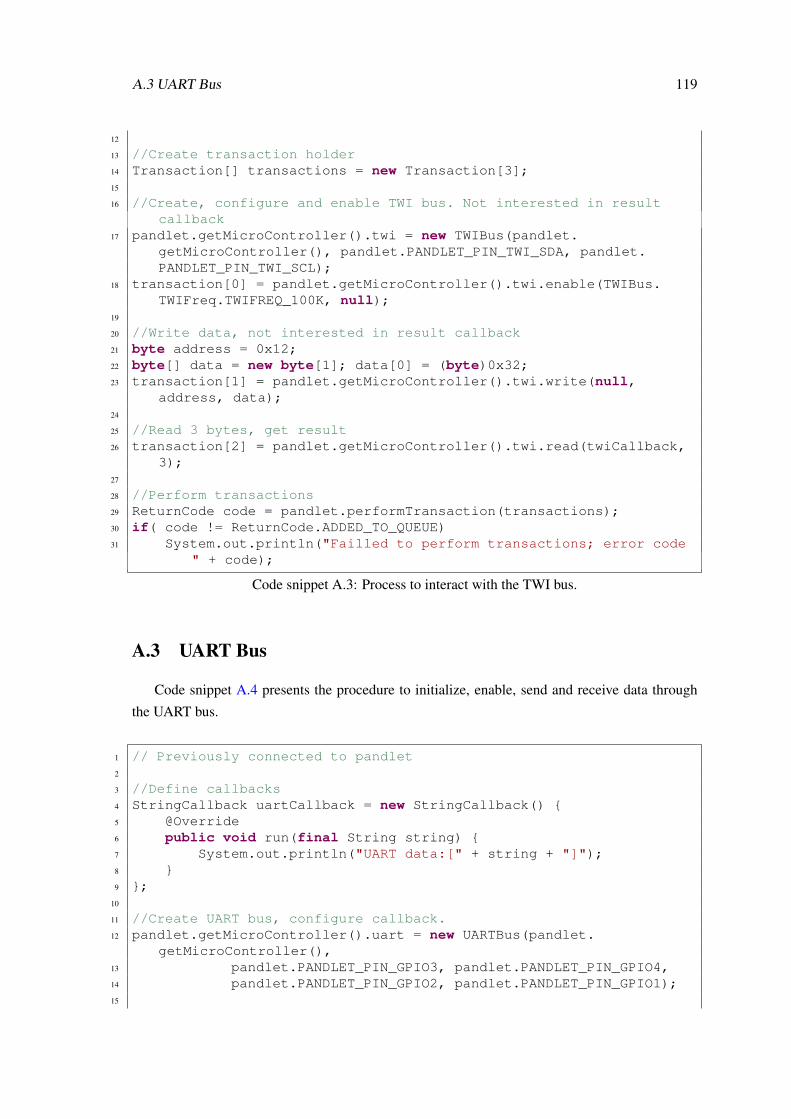
A.3 UART Bus 119
12
13 //Create transaction holder14 Transaction[] transactions = new Transaction[3];15
16 //Create, configure and enable TWI bus. Not interested in resultcallback
17 pandlet.getMicroController().twi = new TWIBus(pandlet.getMicroController(), pandlet.PANDLET_PIN_TWI_SDA, pandlet.PANDLET_PIN_TWI_SCL);
18 transaction[0] = pandlet.getMicroController().twi.enable(TWIBus.TWIFreq.TWIFREQ_100K, null);
19
20 //Write data, not interested in result callback21 byte address = 0x12;22 byte[] data = new byte[1]; data[0] = (byte)0x32;23 transaction[1] = pandlet.getMicroController().twi.write(null,
address, data);24
25 //Read 3 bytes, get result26 transaction[2] = pandlet.getMicroController().twi.read(twiCallback,
3);27
28 //Perform transactions29 ReturnCode code = pandlet.performTransaction(transactions);30 if( code != ReturnCode.ADDED_TO_QUEUE)31 System.out.println("Failled to perform transactions; error code
" + code);
Code snippet A.3: Process to interact with the TWI bus.
A.3 UART Bus
Code snippet A.4 presents the procedure to initialize, enable, send and receive data through
the UART bus.
1 // Previously connected to pandlet2
3 //Define callbacks4 StringCallback uartCallback = new StringCallback() {5 @Override6 public void run(final String string) {7 System.out.println("UART data:[" + string + "]");8 }9 };
10
11 //Create UART bus, configure callback.12 pandlet.getMicroController().uart = new UARTBus(pandlet.
getMicroController(),13 pandlet.PANDLET_PIN_GPIO3, pandlet.PANDLET_PIN_GPIO4,14 pandlet.PANDLET_PIN_GPIO2, pandlet.PANDLET_PIN_GPIO1);15

120 API Usage Examples
16 pandlet.getMicroController().uart.setReceiveCallback(uartCallback);17
18 //Enable and configure UART bus. Not interestes in result callback.19 int parity = 0;20 Transaction transation;21 transaction = pandlet.getMicroController().uart.enable(UARTBus.
Baudrate.BAUD9600, parity, null);22
23 //Perform transaction24 ReturnCode code = pandlet.performTransaction(transaction);25 if( code != ReturnCode.ADDED_TO_QUEUE)26 System.out.println("Failled to perform transactions; error code
" + code);
Code snippet A.4: Process to interact with the UART bus.
A.4 PWM
Code snippet A.5 presents an example on how to interact with the PWM module.
1 // Previously connected to pandlet2
3 //Create transaction holder4 Transaction[] transactions = new Transaction[3];5
6 //Configure PWM module7 int period = 1000000; //microseconds8 transactoins[0] = pandlet.getMicroController().pwm.turnOn(period,9 //Port 0
10 PWM.Polarity.ACTIVE_HIGH, pandlet.PANDLET_PIN_GPIO4,11 //Port 112 PWM.Polarity.ACTIVE_LOW, pandlet.PANDLET_PIN_LED_RED
,13 null);14
15 //Configure PWM channels. Not interested in result callback16 int dutyCycle = 50;17 transactino[1] = pandlet.getMicroController().pwm.setDutyCycle(PWM.
Channel.CHANNEL0, dutyCycle, null);18 transactino[2] = pandlet.getMicroController().pwm.setDutyCycle(PWM.
Channel.CHANNEL0, dutyCycle, null);19
20 //Perform transaction21 ReturnCode code = pandlet.performTransaction(transaction);22 if( code != ReturnCode.ADDED_TO_QUEUE)23 System.out.println("Failled to perform transactions; error code
" + code);
Code snippet A.5: Process to interact with the PWM module.

A.5 GPIO 121
A.5 GPIO
Code snippet A.6 presents the procedure to declare a GPIO and configure it as and output port.
1 // Previously connected to pandlet2
3 //Create GPIO4 GPIO gpioOutput = new GPIO(pandlet.getMicroController(), pandlet.
PANDLET_PIN_GPIO3);5
6 //Configure GPIO as output and logic HIGH7 Transaction transaction = gpioOutput.setModeOutput(true, null);8
9 //Perform transaction10 ReturnCode code = pandlet.performTransaction(transaction);11 if( code != ReturnCode.ADDED_TO_QUEUE)12 System.out.println("Failled to perform transactions; error code
" + code);
Code snippet A.6: Process to interact with a GPIO output port.
Example A.7 shows how to declare and configure a GPIO port as an input. It is also shown how
to configure the Sensing feature. In the snippet presented, whenever a sense event is detected, the
Android device will receive a port status update (through a GPIO read operation) and the Pandlet
will also send a string through the UART, autonomously.
1 // Previously connected to pandlet, UART previously enabled andconfigured
2
3 //Create GPIOs4 GPIO gpioInput1 = new GPIO(pandlet.getMicroController(), pandlet.
PANDLET_PIN_GPIO1);5
6 //Define callbacks7 GPIOReadCallback readCallback = new GPIOReadCallback() {8 @Override9 public void onValueRead(PandletReturnCode code, int portNumber,
boolean status) {10 if( code == PandletReturnCode.SUCCESS)11 System.out.println("Port " + portNumber + " has value "
+ status );12 }13 };14
15 //Define sense Transactions16 Transaction[] senseTransactions = Transaction[2];17 senseTransactions[0] = gpio.getStatus(readCallback);18 senseTransactions[1] = pandlet.getMicroController().uart.send("H\n",
null);19
20 //Configure GPIO as input which HIGH value sensing

122 API Usage Examples
21 Transaction transaction = gpio.setModeInput(GPIO.Pull.NONE, GPIO.Sense.HIGH, senseTransactions, null);
22
23 //Perform transaction24 ReturnCode code = pandlet.performTransaction(transaction);25 if( code != ReturnCode.ADDED_TO_QUEUE)26 System.out.println("Failled to perform transactions; error code
" + code);
Code snippet A.7: Process to interact with a GPIO input port.
A.6 MCP73832 - USB Charger
Snippet A.8 shows how to use the USB charger driver, as well as how to configure it to send a
notification to the Android device whenever the charger is connected or disconnected.
1 // Previously connected to pandlet, UART previously enabled andconfigured
2
3 //Define callbacks4 GPIOReadCallback readCallback = new GPIOReadCallback() {5 @Override6 public void onValueRead(PandletReturnCode code, int portNumber,
boolean status) {7 if( code == PandletReturnCode.SUCCESS)8 System.out.println("USB charging status: " + status );9 }
10 };11
12 //Declare USBCharger13 pandlet.usbCharger = new MCP73832(pandlet.getMicroController(),
pandlet.PANDLET_PIN_USBCHARGER_STATUS);14
15 //Setup USBCharger16 pandlet.usbCharger.initialize(null);17
18 //Define sense Transactions19 Transaction[] senseTransactions = Transaction[1];20 senseTransactions[0] = pandlet.usbCharger.
getChargingStatusTransaction(readCallback);21
22 //Configure USBCharger to alert on charging status change23 Transaction transaction = pandlet.usbCharger.setSenseTransactions(
GPIO.Sense.CHANGE, senseTransactions, null);24
25 //Perform transaction26 ReturnCode code = pandlet.performTransaction(transaction);27 if( code != ReturnCode.ADDED_TO_QUEUE)28 System.out.println("Failled to perform transactions; error code
" + code);
Code snippet A.8: Process to interact with the USB Charger.

A.7 MAX17048 - Fuel Gauge 123
A.7 MAX17048 - Fuel Gauge
Example A.8 presents the procedure to interact with the Fuel Gauge, by initializing it, defining
the callback functions, and performing periodic measurements.
1 // Previously connected to pandlet2
3 //Setup callbacks.4 FloatCallback socCallback = new FloatCallback() {5 @Override6 public void run(float[] values) {7 if( values.length =! 0)8 System.out.println("SoC is " + values[0] + "%");9 }
10 };11
12 FloatCallback vcellCallback = new FloatCallback() {13 @Override14 public void run(float[] values) {15 if( values.length =! 0)16 System.out.println("VCell is " + values[0] + "V");17 }18 };19
20 //Declare FuelGauge21 pandlet.fuelGauge = new MAX17048(pandlet.getMicroController(),
pandlet.getMicroController().twi,22 pandlet.PANDLET_PIN_FUELGAUGE_INTERRUPT)
;23
24 //Setup FuelGauge25 pandlet.fuelGauge.setSoCCallback(socCallback);26 pandlet.fuelGauge.setVCellCallback(vcellCallback);27
28 //Schedule periodic measurements29 Timer timer = new Timer();30 timer.schedule(new TimerTask() {31 @Override32 public void run() {33 pandlet.fuelGauge.getVCell();34 pandlet.fuelGauge.getSoC();35 }36 }, 0, 1000);
Code snippet A.9: Process to interact with the Fuel Gauge.
A.8 BME280 - EMU
Example A.10 presents the procedure to interact with the EMU. It shows how to initialize, de-
fine callbacks and calibrate the EMU. It also demonstrates hoe to perform periodic measurements.

124 API Usage Examples
1 // Previously connected to pandlet2
3 //Setup callbacks. In this case, use the same for all measurements.4 FloatCallback callback = new FloatCallback() {5 @Override6 public void run(float[] values) {7 for(int i=0; i<values.length; i++)8 System.out.println("Float[" + i+ "]:" + values[i]);9 }
10 };11
12 //Declare EMU13 pandlet.emu = new BME280(pandlet.getMicroController(), pandlet.
getMicroController().twi);14
15 //Setup EMU16 pandlet.emu.setPressureCallback( callback );17 pandlet.emu.setTemperatureCallback( callback );18 pandlet.emu.setHumidityCallback( callback );19 pandlet.emu.calibrate();20
21 //Schedule periodic measurements22 Timer timer = new Timer();23 timer.schedule(new TimerTask() {24 @Override25 public void run() {26 pandlet.emu.getTemperature();27 pandlet.emu.getPressure();28 pandlet.emu.getHumidity();29 }30 }, 0, 1000);
Code snippet A.10: Process to interact with the EMU.

References
[1] Mary Meeker, Scott Devitt, and Liang Wu. Internet Trends.April 2010. URL: http://pt.slideshare.net/fred.zimny/morgan-staneley-internet-trends-ri041210 [last accessed 2015-11-23].
[2] Ilkka Tuomi. The Lives and Death of Moore’s Law. First Monday, 7(11), Novem-ber 2002. URL: http://firstmonday.org/ojs/index.php/fm/article/view/1000 [last accessed 2015-11-23].
[3] Weiser. Ubiquitous Computing. March 1996. URL: http://www.ubiq.com/weiser/UbiHome.html [last accessed 2015-11-23].
[4] Y.P. Rainwani. Internet of Things: A New Paradigm. International Journal of Scien-tific and Research Publications, 3(4), April 2013. URL: http://www.ijsrp.org/research-paper-0413/ijsrp-p1656.pdf [last accessed 2015-11-23].
[5] Dave Evans. The Internet of Things: How the Next Evolution of the Internet Is Chang-ing Everything. Technical report, Cisco Internet Business Solutions Group (IBSG),April 2011. URL: https://www.cisco.com/web/about/ac79/docs/innov/IoT_IBSG_0411FINAL.pdf [last accessed 2015-11-23].
[6] Number of Internet Users (2015) - Internet Live Stats. URL: http://www.internetlivestats.com/internet-users/ [last accessed 2015-11-26].
[7] World Population Clock: 7.3 Billion People (2015) - Worldometers. URL: http://www.worldometers.info/world-population/ [last accessed 2015-11-26].
[8] Daniel Minoli. Building the Internet of Things with IPv6 and MIPv6: The Evolv-ing World of M2M Communications. John Wiley & Sons, June 2013. URL:http://media.johnwiley.com.au/product_data/excerpt/77/11184734/1118473477-20.pdf.
[9] David Kushner. The Making of Arduino. October 2011. URL: http://spectrum.ieee.org/geek-life/hands-on/the-making-of-arduino [last accessed 2015-11-26].
[10] Fraunhofer Pandlets. 2015. URL: http://www.fraunhofer.pt/en/fraunhofer_aicos/projects/internal_research/pandlets.html [last accessed 2015-11-23].
[11] Manuel Monteiro. Bluetooth Smart: Introduction to low-level development using pandlets.Faculdade de Engenharia da Universidade do Porto, December 2015.
125

126 REFERENCES
[12] Jayavardhana Gubbi, Rajkumar Buyya, Slaven Marusic, and Marimuthu Palaniswami.Internet of Things (IoT): A vision, architectural elements, and future directions. Fu-ture Generation Computer Systems, 29(7):1645–1660, September 2013. URL: http://www.sciencedirect.com/science/article/pii/S0167739X13000241 [lastaccessed 2015-12-30], doi:10.1016/j.future.2013.01.010.
[13] Luigi Atzori, Antonio Iera, and Giacomo Morabito. The Internet of Things: Asurvey. Computer Networks, 54(15):2787–2805, October 2010. URL: http://www.sciencedirect.com/science/article/pii/S1389128610001568 [lastaccessed 2015-12-30], doi:10.1016/j.comnet.2010.05.010.
[14] Harald Sundmaeker, Patrick Guillemin, Peter Friess, and Sylvie Woelfflé. Vi-sion and Challenges for Realising the Internet of Things. Technical report,March 2010. URL: http://www.internet-of-things-research.eu/pdf/IoT_Clusterbook_March_2010.pdf [last accessed 2015-11-23].
[15] C. Perera, C.H. Liu, S. Jayawardena, and Min Chen. A Survey on Internet of Things FromIndustrial Market Perspective. IEEE Access, 2:1660–1679, January 2015. URL: http://ieeexplore.ieee.org/stamp/stamp.jsp?tp=&arnumber=7004894 [last ac-cessed 2015-11-23], doi:10.1109/ACCESS.2015.2389854.
[16] Internet of Things in 2020 - A Roadmap for the Future. Technical report, RFIDWorking Group of the European Technology Platform on Smart Systems Integra-tion (EPoSS), May 2008. URL: http://www.smart-systems-integration.org/public/documents/publications/Internet-of-Things_in_2020_EC-EPoSS_Workshop_Report_2008_v3.pdf [last accessed 2015-12-30].
[17] ICT Facts & Figures - The world in 2015. Technical report, International TelecommunicationUnion (ITU).
[18] Intel R© 14 nm Technology. URL: http://www.intel.com/content/www/us/en/silicon-innovations/intel-14nm-technology.html [last accessed 2016-01-03].
[19] Monica Chen and Joseph Tsai. AMD Zen architecture set for 4q16. Digitimes, September2015. URL: http://www.digitimes.com/news/a20150910PD202.html.
[20] Eitan N. Shauly. CMOS Leakage and Power Reduction in Transistors and Circuits: Processand Layout Considerations. Journal of Low Power Electronics and Applications, 2(1):1–29,January 2012. URL: http://www.mdpi.com/2079-9268/2/1/1 [last accessed 2016-01-04], doi:10.3390/jlpea2010001.
[21] NXP. LPC3180fel320: 16/32-bit ARM microcontroller; hardware floating-point co-processor, USB On-The-Go, and SDRAM memory interface. URL: http://www.nxp.com/products/microcontrollers-and-processors/arm-processors/lpc-arm7-arm9-mcus/lpc-arm9-microcontrollers/lpc3100-200-series/16-32-bit-arm-microcontroller-hardware-floating-point-coprocessor-usb-on-the-go-and-sdram-memory-interface:LPC3180FEL320.
[22] Atmel Corporation . Atmel Extending 8-bit MCU Leadership With Launch of New AVRProducts; Reveals Global Winners for AVR Hero Design Contest. February 2014. URL:http://ir.atmel.com/releasedetail.cfm?releaseid=828058.

REFERENCES 127
[23] Texas Instruments Announcements Span the Processor Spectrum. BDTi, November 2011.URL: http://www.bdti.com/InsideDSP/2011/11/17/TI.
[24] Vegator. Linux on Flash blog: A look at Raspberry Pi 2 performance andoverclocking. URL: http://linuxonflash.blogspot.pt/2015/02/a-look-at-raspberry-pi-2-performance.html [last accessed 2016-01-04].
[25] NearFieldCommunication.org. About Near Field Communication. URL: http://www.nearfieldcommunication.org/about-nfc.html.
[26] RFID Journal. RFID FAQs. URL: http://www.rfidjournal.com/site/faqs.
[27] ZigBee Alliance. What is ZigBee. URL: http://www.zigbee.org/what-is-zigbee/.
[28] Libelium. 50 Sensor Applications for a Smarter World. URL: http://www.libelium.com/top_50_iot_sensor_applications_ranking/ [last accessed 2016-02-08].
[29] Future Cities » An Ecosystem for Future Smarter Cities. URL: http://futurecities.up.pt/site/ [last accessed 2016-07-08].
[30] Smart traffic management, July 2013. URL: http://amsterdamsmartcity.com/projects/detail/id/58/slug/smart-traffic-management?lang=en [lastaccessed 2016-02-09].
[31] Siemens. Air Pollution Forecasting Models. URL:http://www.siemens.com/innovation/en/home/pictures-of-the-future/infrastructure-and-finance/smart-cities-air-pollution-forecasting-models.html [last accessed2016-02-09].
[32] Libelium. Libelium enables Smart Logistics offering Realtime Track-ing and Sensing of Goods. URL: http://www.libelium.com/smart-logistics-realtime-geolocation-3g-gps-gprs-tracking-sensing-goods/[last accessed 2016-02-08].
[33] Mastercard. Just Tap & Go. URL: http://www.mastercard.com/contactless/[last accessed 2016-09-02].
[34] Green Peak. Building the Smart Home, February 2016. URL: http://www.greenpeak.com/Application/SmartHome.html.
[35] Fraunhofer Portugal. Hydroponics. URL: http://www.fraunhofer.pt/en/fraunhofer_aicos/projects/government_contractresearch/hydroponics.html [last accessed 2016-02-09].
[36] Produtos. URL: http://www.vitaljacket.com/?page_id=860&lang=pt-pt[last accessed 2016-07-08].
[37] Medtronic. Continuous Glucose Monitoring, February 2016. URL: http://www.medtronicdiabetes.com/products/continuous-glucose-monitoring.
[38] Fraunhofer Portugal. Fall Prevention. URL: http://www.fraunhofer.pt/en/fraunhofer_aicos/projects/internal_research/fall_prevention.html[last accessed 2016-02-09].

128 REFERENCES
[39] Google. Google Self-Driving Car Project. URL: http://www.google.com/selfdrivingcar [last accessed 2016-02-09].
[40] Gartner Says the Internet of Things Will Transform the Data Center. URL: http://www.gartner.com/newsroom/id/2684616 [last accessed 2015-11-26].
[41] IoT Connected Devices Triples To 38 Billion By 2020. URL:http://www.mediapost.com/publications/article/256678/iot-connected-devices-triples-to-38-billion-by-202.html [lastaccessed 2015-11-26].
[42] The Internet of Things Is Poised to Change Everything, Says IDC | Business Wire, Octo-ber 2013. URL: http://www.businesswire.com/news/home/20131003005687/en/Internet-Poised-Change-IDC [last accessed 2015-12-29].
[43] RS Components. 11 Internet of Things (IoT) Protocols You Need to Know About. URL:http://www.rs-online.com/designspark/electronics/knowledge-item/eleven-internet-of-things-iot-protocols-you-need-to-know-about[last accessed 2016-02-11].
[44] Gil Reiter. Wireless connectivity for the Internet of Things. Texas Instru-ments. URL: http://www.ti.com/lit/wp/swry010/swry010.pdf?DCMP=ep-con-wcs-cmtech&HQS=ep-con-wcs-cmtech-bn-whip-de [last accessed2016-02-11].
[45] Farid Touati Rohan Tabish. A Comparative Analysis of BLE and IEEE802.15.4 (6low-pan) For U-HealthCare Applications. 2013. URL: https://www.researchgate.net/publication/259484715_A_Comparative_Analysis_of_BLE_and_IEEE802154_6LoWPAN_For_U-HealthCare_Applications.
[46] beagleboard.org. BoneScript Library. URL: http://beagleboard.org/support/bonescript [last accessed 2016-02-10].
[47] nodejs.org. Node.js. URL: https://nodejs.org/en/ [last accessed 2016-02-10].
[48] Hans-Christoph Steiner. Firmata: Towards making microcontrollers act like extensions ofthe computer. In New Interfaces for Musical Expression, pages 125–130, 2009.
[49] firmata/arduino. 2015. URL: https://github.com/firmata/arduino [last accessed2015-11-21].
[50] firmata/protocol. 2015. URL: https://github.com/firmata/protocol [last ac-cessed 2015-11-21].
[51] Oleg Kurbatov. kurbatov/firmata4j. URL: https://github.com/kurbatov/firmata4j [last accessed 2016-02-10].
[52] ytai/ioio. 2015. URL: https://github.com/ytai/ioio [last accessed 2015-11-21].
[53] Sparkfun. IOIO-OTG, February 2016. URL: https://www.sparkfun.com/products/12633.
[54] Ytai Ben-Tsvi. Microcontrollers, Electronics & Robotics: Meet IOIO -I/O for Android. URL: http://ytai-mer.blogspot.pt/2011/04/meet-ioio-io-for-android.html [last accessed 2016-02-10].
http://www.ti.com/lit/wp/swry010/swry010.pdf?DCMP=ep-con-wcs-cmtech&HQS=ep-con-wcs-cmtech-bn-whip-de

REFERENCES 129
[55] Particle. Particle. URL: https://docs.particle.io/guide/getting-started/intro/photon/ [last accessed 2016-02-11].
[56] embeddedcomputing.weebly.com/. chipKIT Uno32 and uC32. URL: http://embeddedcomputing.weebly.com/chipkit-uno32-and-uc32.html [last ac-cessed 2016-02-12].
[57] Mini PC Raspberry Pi 2 Model B 1gb. URL: http://www.globaldata.pt/mini-pc-raspberry-pi-2-model-b-1gb.html [last accessed 2016-02-12].
[58] LinuxUser&Developer. BeagleBone Black Review. URL: http://www.linuxuser.co.uk/reviews/beaglebone-black-review [last accessed 2016-02-12].
[59] ESP8266 ESP-12. URL: https://gist.github.com/tegila/e05acb8f4c6b662c82b3 [last accessed 2016-02-12].
[60] Manuel Monteiro. Pandlets: Hardware Overview. Faculdade de Engenharia da Universidadedo Porto, December 2015.
[61] IDC. IDC: Smartphone OS Market Share. URL: http://www.idc.com/prodserv/smartphone-os-market-share.jsp [last accessed 2016-02-12].
[62] Android Developers. Dashboards - platform versions. URL: http://developer.android.com/about/dashboards/index.html [last accessed 2016-02-12].
[63] Robin Heydon. Bluetooth Low Energy: The Developer’s Handbook. Prentice Hall, 2012.
[64] Bluegiga Technologies. Classic Bluettoth vs. Bluetooth Low Energy. Technical re-port. URL: http://www.alcom.be/binarydata.aspx?type=doc/Bluegiga_Bluetooth_LE_comparison.pdf [last accessed 2016-01-28].
[65] Kevin Townsend, Carles Cufí, Akiba, and Robert Davidson. Getting Started with BluetoothLow Energy: Tools and Techniques for Low-Power Networking. "O’Reilly Media, Inc.",April 2014.
[66] LitePoint. Bluetooth Low Energy. Technical report, 2012. URL: http://www.litepoint.com/wp-content/uploads/2014/02/Bluetooth-Low-Energy_WhitePaper.pdf [last accessed 2016-01-28].
[67] Bluetooth Developer Portal, February 2016. URL: https://developer.bluetooth.org/gatt/profiles/Pages/ProfileViewer.aspx?u=org.bluetooth.profile.heart_rate.xml.
[68] Bluetooth SIG. Bluetooth Low Energy Technology Training, April 2010.
[69] Sparkfun. Serial Communication - learn.sparkfun.com. URL: https://learn.sparkfun.com/tutorials/serial-communication [last accessed 2016-06-20].
[70] João Paulo Sousa. Device-level Communications – SPI, I2c, 1wire, October 2015.
[71] How do I calculate throughput for a BLE link? URL: https://devzone.nordicsemi.com/question/3440/how-do-i-calculate-throughput-for-a-ble-link/#reply-3441 [last accessed 2016-02-29].
[72] Derivation the dB version of the Path Loss Equation for Free Space. URL: http://www.ece.uvic.ca/~peterd/35001/ass1a/node1.html [last accessed 2016-07-08].