Easy Series - image
130
Easy Series Easy Pact ™ MVS Catalog 2021 LV air circuit breakers from 630 to 4000A
-
Upload
khangminh22 -
Category
Documents
-
view
4 -
download
0
Transcript of Easy Series - image

Easy Series
EasyPact™ MVSCatalog 2021LV air circuit breakers from 630 to 4000A

CO2 and P&L impact through… Resource PerformanceGreen Premium brings improved resource efficiency throughout an asset’s lifecycle. This includes efficient use of energy and natural resources, along with the minimization of CO2 emissions.
Cost of ownership optimization through… Circular PerformanceWe’re helping our customers optimize the total cost of ownership of their assets. To do this, we provide IoT-enabled solutions, as well as upgrade, repair, retrofit, and remanufacture services.
Peace of mind through… Well-being PerformanceGreen Premium products are RoHS and REACh compliant. We’re going beyond regulatory compliance with step-by-step substitution of certain materials and substances from our products.
Improved sales through… DifferentiationGreen Premium delivers strong value propositions through third-party labels and services. By collaborating with third-party organizations we can support our customers in meeting their sustainability goals such as green building certifications.
The Green Premium program stands for our commitment to deliver customer valued sustainable performance. It has been upgraded with recognized environmental claims and extended to cover all offers including Products, Services and Solutions.
Discover what we mean by greenCheck your products!
An industry leading portfolio of offers delivering sustainable value
Green PremiumTM
More than 75% of our product sales offer superior transparency on the material content, regulatory information and environmental impact of our products:
• RoHS compliance• REACh substance information• Industry leading # of PEP’s*• Circularity instructions
*PEP: Product Environmental Profile (i.e. Environmental Product Declaration)

3
EasyPact MVS rangeThe easy choice for reliable performanceOne family and two frame sizes
> Performance without compromise
> Assured quality and safety you can trust
> Deliver exceptional reliability and flexibility in its class
> Outstanding value for an optimized feature set
> Precision engineered to meet your needs
> Unbeatable value throughout its lifecycle
> Simple to choose and easy to install
MVS Frame 1: 630 to 1600A
MVS Frame 2: 800 to 4000A
2 sizes:
H 65kAN 50kA
800A 1000A 1250A 1600A 2000A 2500A 3200A 4000A
C 50kA630A 800A 1000A 1250A 1600A

4
Choose the leader
> 630 to 4000A ratings
> Breaking capacity: 50 & 65kA
> Suitable for 690V applications
> Complete selectivity with Ics=Icu
> Intelligent ET range of trip system with display
> Fully protected neutral on 4 pole breakers
> Full accessories with modular design
> Conforms to IEC 60947- 2 & 3
Performance Level Communication
Eco COMb EasyPact in a communication network.b BCM-ULP COM option inside breakerb IFM: Modbus interface module.b I/O application module.
Transmission signalb Breaker signal:OF, SDE, PF and CH.b Cradel signal:CD, CT, CEb Measurements ways:Instantaneous,maximum/minimum,demandb Measurements value: current, voltage,power, power factor,energyb Protection settingsb Trip causes
EasyCom Communicationb Independent Modbus interface moduleb Digital Input: 3 sets of OF, SDE, PFb Digital output: 3 sets of MX & XFb Analog Input: 1 set of 4-20mA
M2C programmable contactsb Two programmable contactsb Signal events:Ir, Isd, Alarm Ir, Alarm Ig, Igv
b Ratings:v Frame 1: 630 to 1600Av Frame 2: 800 to 4000A.b Breaking capacity: 50 & 65kAb Suitable for 690V applicationsb Complete selectivity with Ics=100%Icub Circuit breakers type C,N,Hb Switch-disconnectors type CA,NA,HAb 3 or 4 poles.b Fixed or drawout versions.b Conforms to IEC 60947- 2 & 3
ET range of trip system
Type of measurementb ET for basice protectionb ETA for “current”b ETV for “Energy”
Type of protectionb 2.0 for basice protectionb 5.0 for seletive protectionb 6.0 for selective + earth-fault protection
PB11
9234
.eps
94253052
65479
ET6G94253052
65579
ETA6G
94253052
MVS15503
ETV6G

5
EasyPact MVS06 to MVS40
EasyPact MVSBenefits for every customer
Panel builders/contractors
End Users Designers
> Suitable for copper & Aluminium termination with the pole pitch of 70 or 115 mm
> Terminal orientation can be converted from horizontal to vertical and vice-versa at workshop
> Direct mounting Door frames (escutcheon) without drilling any holes
> Front fitted accessories like under-volt release, shunt release & closing coil for complete range
> Conversion of manual operated breaker in to electrical operated, with single bolt fixing
EasyPact MVS wwith modular design helps to increase the shop floor efficiency,enabling faster delivery of swith boards.
> Conforms to IEC60947-2 for breakers & IEC60947-3 for disconnectors
> Designed and manufactured using advanced manufacturing methods to match your quality expectations and the needs of each project.
> Continuous rated coils helps in simple interlocking schemes
> Extensive choice of software tools & documentation to reduce design time.
> EasyPact MVS respects the environment throughout their life cycle
EasyPact MVS is designed to meet the needs of your customers with flexibility to achieve system efficiency during the design phase
> Moulded case design ensures high endurance without maintenance
> Intelligent ET range of trip system with thermal memory.
> Overload run alarm & individual LED indications enable fault identification
> lcu=lcs=50kA & 65kA ensures complete selectivity
> Inbuilt safety shutter & interlocks
> Designed to provide utmost user safety during installation, during use, and while under maintenance.
> All 4 pole breakers are with fully rated neutral and protected with adjustable settings at OFF – 50%-100%
EasyPact MVS answers even to the most stringent application with most reliable distribution systems assuring continuity of service

6
The Key values
90%
100%
30%
of applications are
covered
Commitment to
quality
Reduce stock by up
to
The performance you need
With the quality you demand
At a cost-effective investment
EasyPact MVS provides the ideal level of capability for your installation from 630 to 4000 A.
Designed and manufactured by Schenider Electric using advanced manufacturing methods and pre-mium materials.
Pay for what you need: Get outstanding durability with the features you need, with the benefit of easy to order and stock.

Gain peace ofmind and optimised cost for every installation

1
Performancewithout compromise
Exceptionalreliability,flexibilityand convenience
Quality and safetyyou can trust
Outstanding value for an optimized feature set
Buildings Industry Panelbuilders

EasyPact™ MVSGeneral contents
Functionsand characteristics A-1
Installationrecommendations B-1
Dimensionsand connection C-1
Electrical diagrams D-1
Additionalcharacteristics E-1
Catalogue numbers and order form F-1

Functions and characteristics

Functions and characteristics
General overview A-2Detailed contents A-2
Circuit breakers and switch-disconnectors A-4MVS06 to MVS16( Frame 1) A-4
Circuit breakers and switch-disconnectors A-6MVS08 to MVS40( Frame 2) A-6
Identifying ET range of trip system A-8
Overview of functions A-10 ET trip system A-10ETA trip system A-12ETV trip system A-14
ET range of trip system A-16 Accessories and test equipment A-16
Eco Com Communication A-17
IFM Modbus Communication Interface A-18
EasyCom Communication Interface A-24
Connections A-28Overview of solutions and accessories A-28Accessories and auxiliaries A-30
Locking A-32 On the device A-32On the chassis A-33
Indication contacts A-34
Remote operation A-36 Remote ON / OFF A-36Remote tripping A-38
Source-changeover systems A-39Mechanical interlocking A-39
Electrical interlocking A-40IVE unit A-40
Controller selection A-41
Accessories A-42
Installation recommendations B-1Dimensions and connection C-1Electrical diagrams D-1Additional characteristics E-1Catalogue numbers and order form F-1
EasyPact MVS
A-1

Functionsand characteristics
General overviewDetailed contents
This overview describes all the functions offered byEasyPact MVS devices.
Circuit breakers and switch-disconnectors page A-4 b Ratings: v EasyPact MVS 630 to 4000 A b Circuit breakers type C, N, H b Switch-disconnectors type CA, NA, HA b 3 or 4 poles b Fixed or draw-out versions
ET trip system page A-8 b 2I basic protection b 5S selective protection b 6G selective + earth-fault protection b Standard long-time rating plug: v Current setting (A) 0.4 to 1 x In
ETA trip system with current measurement page A-10 b 2I basic protection b 5S selective protection b 6G selective + earth-fault protection b Standard long-time rating plug: v Current setting (A) 0.4 to 1 x In b External power-supply module
ETV trip system with energy measurement page A-12 b 2I basic protection b 5S selective protection b 6G selective + earth-fault protection b Standard long-time rating plug: v Current setting (A) 0.4 to 1 x In b External power-supply module
Connections page A-15 b Rear connection: v Horizontal v Vertical b Optional accessories: v Interphase barriers v Safety shutters and shutter locking blocks
Locking page A-18 b Pushbutton locking by padlockable transparent cover
b OFF-position locking by keylock b Chassis locking in disconnected position by keylock
b Chassis locking in connected, disconnected and test positions
b Door interlock (inhibits door opening with breaker in ‘connected’ or ‘test’ position
CP
B10
0000
CD
B50
0000
ET2I trip system. ET5S trip system. ET6G trip system.
CD
B50
0001
CD
B50
0002
DB
1011
09
Door interlock
DB
1011
10
Chassis key lock
E46
459
Safety shutters
DB
1011
49
Interphase barriers
A-2

Indication contacts page A-20 b Standard: v ON/OFF indication (OF) v “Fault” trip indication (SDE) b Optional: v Additional ON/OFF indication (OF) v Ready-to-close contact (PF) v Carriage switches for connected (CE) disconnected (CD) and test (CT) positions
Remote operation page A-21 b Remote ON/OFF: v Gear motor v XF closing or MX opening voltage releases
b Remote tripping function: v MN voltage release
- Standard - Adjustable or non-adjustable
delay
Accessories page A-25 b Auxiliary terminal shield b Operation counter b Escutcheon (Door sealing frame) b Transparent cover for escutcheon b Escutcheon blanking plate
Source-changeover systems page A-24 b Mechanical interlocking using cables: v Interlocking between two devices v Interlocking between three devices
Functionsand characteristics
General overviewDetailed contents
PB
1043
54A
40C
PB
1000
03C
PB
1000
15C
PB
1000
16
DB
1011
13
Gear motor
DB
1011
14
MX, XF and MN volagereleases
E46
438
DB
1011
12
Ready-to-close contact
OF contact
CD
B50
0053
Interlocking of two devices
E46
669
E46
668
DB
1011
15
Mechanical operation counter
Escutcheon Transparent cover
A-3

Common characteristicsNumber of poles 3/4Rated insulation voltage (V) Ui 1000Impulse withstand voltage (kV) Uimp 12Rated operational voltage (V AC 50/60 Hz) Ue 440Suitability for isolation IEC 60947-2 YesDegree of pollution IEC 60664-1 3
Basic circuit-breaker MVS06 MVS08 MVS10 MVS12 MVS16Circuit-breaker as per IEC 60947-2Rated current (A) In at 40°C(1) 630 800 1000 1250 1600
Rating of 4th pole (A) 630 800 1000 1250 1600Sensor ratings (A) 630 800 1000 1250 1600Type of circuit breaker C C C C CUltimate breaking capacity (kA rms) Icu 220...440V 50 50 50 50 50Rated service breaking capacity (kA rms) Ics % Icu 100% 100% 100% 100% 100%Utilisation category B B B B BRated short-time withstand current (kA rms) Icw 1s 220...440 V 35 35 35 35 35V AC 50/60 Hz 3s 440V 20 20 20 20 20Rated making capacity (kA peak) Icm 220...440 V 105 105 105 105 105Integrated instantaneous protection(DIN KA instantaneous ±10%) 105 105 105 105 105Breaking time (ms) between tripping order and arc extinction(ms) 25 25 25 25 25Closing time (ms) <50 <50 <50 <50 <50
Switch-disconnector as per IEC60947-3 and Annex A MVS06 MVS08 MVS10 MVS12 MVS16Type of switch-disconnector CA CA CA CA CAOperational current AC23A 630 800 1000 1250 1600Rated making capacity (kA peak) Icm 75 75 75 75 75Rated short-time withstand current (kA rms) Icw 1s 35 35 35 35 35
3s 20 20 20 20 20
Maintenance/Connection/InstallationService life Mechanical with maintenance 20 20 20 20 20C/O cyclesx1000 without maintenance 10 10 10 10 10
Electrical without maintenance 440 V 5 5 5 5 5Connection Horizontal Yes
Vertical YesDimensions (mm) Draw-out 3P 322x288x277
(H x W x D) 4P 322x358x277Fixed 3P 301x276x196
4P 301x346x196 Weight (kg) (approximate)
Draw-out 3P/4P 30/39Fixed 3P/4P 14/18
Functionsand characteristics
Circuit breakersand switch-disconnectorsMVS06 to MVS16(Frame 1)
CP
B10
0000
Circuit breaker.
(1) Refer page no. B-12 for details on temperature derating.
A-4

Common characteristicsNumber of poles 3/4Rated insulation voltage (V) Ui 1000Impulse withstand voltage (kV) Uimp 12Rated operational voltage (V AC 50/60 Hz) Ue 440Suitability for isolation IEC 60947-2 YesDegree of pollution IEC 60664-1 3
Basic circuit-breaker MVS06 MVS08 MVS10 MVS12 MVS16Circuit-breaker as per IEC 60947-2Rated current (A) In at 40°C(1) 630 800 1000 1250 1600
Rating of 4th pole (A) 630 800 1000 1250 1600Sensor ratings (A) 630 800 1000 1250 1600Type of circuit breaker C C C C CUltimate breaking capacity (kA rms) Icu 220...440V 50 50 50 50 50Rated service breaking capacity (kA rms) Ics % Icu 100% 100% 100% 100% 100%Utilisation category B B B B BRated short-time withstand current (kA rms) Icw 1s 220...440 V 35 35 35 35 35V AC 50/60 Hz 3s 440V 20 20 20 20 20Rated making capacity (kA peak) Icm 220...440 V 105 105 105 105 105Integrated instantaneous protection(DIN KA instantaneous ±10%) 105 105 105 105 105Breaking time (ms) between tripping order and arc extinction(ms) 25 25 25 25 25Closing time (ms) <50 <50 <50 <50 <50
Switch-disconnector as per IEC60947-3 and Annex A MVS06 MVS08 MVS10 MVS12 MVS16Type of switch-disconnector CA CA CA CA CAOperational current AC23A 630 800 1000 1250 1600Rated making capacity (kA peak) Icm 75 75 75 75 75Rated short-time withstand current (kA rms) Icw 1s 35 35 35 35 35
3s 20 20 20 20 20
Maintenance/Connection/InstallationService life Mechanical with maintenance 20 20 20 20 20C/O cyclesx1000 without maintenance 10 10 10 10 10
Electrical without maintenance 440 V 5 5 5 5 5Connection Horizontal Yes
Vertical YesDimensions (mm) Draw-out 3P 322x288x277
(H x W x D) 4P 322x358x277Fixed 3P 301x276x196
4P 301x346x196 Weight (kg) (approximate)
Draw-out 3P/4P 30/39Fixed 3P/4P 14/18
A-5

Common characteristicsNumber of poles 3/4Rated insulation voltage (V) Ui 1000Impulse withstand voltage (kV) Uimp 12Rated operational voltage (V AC 50/60 Hz) Ue 690Suitability for isolation IEC 60947-2 YesDegree of pollution IEC 60664-1 4
Basic circuit-breaker MVS08 MVS10 MVS12 MVS16 MVS20 MVS25 MVS32 MVS40Circuit-breaker as per IEC 60947-2Rated current (A) In at 40°C(1) 800 1000 1250 1600 2000 2500 3200 4000Rating of 4th pole (A) 800 1000 1250 1600 2000 2500 3200 4000Sensor ratings (A) 800 1000 1250 1600 2000 2500 3200 4000Type of circuit breaker N H N H N H N H N H N H N H N HUltimate breaking capacity (kA rms) Icu 220...440V 50 65 50 65 50 65 50 65 50 65 50 65 50 65 55 65V AC 50/60 Hz 690 V 42 50 42 50 42 50 42 50 42 50 42 50 42 50 42 50Rated service breaking capacity (kA rms) Ics % Icu 100% 100% 100% 100% 100% 100% 100% 100%Utilisation category B B B B B B B BRated short-time withstand current (kA rms) Icw 1s 220...440 V 50 65 50 65 50 65 50 65 50 65 50 65 50 65 55 65V AC 50/60 Hz 690V 42 50 42 50 42 50 42 50 42 50 42 50 42 50 42 50
3s 440/690V 25 36 25 36 25 36 25 36 25 36 25 36 25 36 30 36Rated making capacity (kA peak) Icm 220...440 V 105 143 105 143 105 143 105 143 105 143 105 143 105 143 121 143V AC 50/60 Hz 690 V 88 105 88 105 88 105 88 105 88 105 88 105 88 105 88 105Breaking time (ms) between tripping order and arc extinction 25 25 25 25 25 25 25 25Closing time (ms) <70 <70 <70 <70 <70 <70 <70 <70
Switch-disconnector as per IEC60947-3 and Annex A MVS08 MVS10 MVS12 MVS16 MVS20 MVS25 MVS32 MVS40Type of switch-disconnector NA HA NA HA NA HA NA HA NA HA NA HA NA HA NA HAOperational current AC23A 800 1000 1250 1600 2000 2500 3200 4000Rated making capacity (kA peak) Icm 105 143 105 143 105 143 105 143 105 143 105 143 105 143 121 143Rated short-time withstand current (kA rms) Icw 1s 50 65 50 65 50 65 50 65 50 65 50 65 50 65 55 65
3s 25 36 25 36 25 36 25 36 25 36 25 36 25 36 30 36
Maintenance/Connection/InstallationService life Mechanical with maintenance 20 20 20 20 20 20 20 20C/O cyclesx1000 without maintenance 10 10 10 10 10 10 10 10
Electrical without maintenance 440 V 6000 6000 6000 6000 6000 5000 5000 5000690 V 4000 4000 4000 4000 4000 2500 2500 2500
Connection Horizontal YesVertical Yes
Dimensions (mm) Draw-out 3P 439 x 441 x 395(H x W x D) 4P 439 x 556 x 395
Fixed 3P 352 x 422 x 2974P 352 x 537 x 297
Weight (kg) (approximate)
Draw-out 3P/4P 70/85 90/120Fixed 3P/4P 40/50 60/80
Functionsand characteristics
Circuit breakersand switch-disconnectorsMVS08 to MVS40( Frame 2)
CP
B10
0003
_QR
CP
B10
0014
Circuit breaker.
Switch disconnector.
(1) Refer page no. B-12 for details on temperature derating.
A-6

Common characteristicsNumber of poles 3/4Rated insulation voltage (V) Ui 1000Impulse withstand voltage (kV) Uimp 12Rated operational voltage (V AC 50/60 Hz) Ue 690Suitability for isolation IEC 60947-2 YesDegree of pollution IEC 60664-1 4
Basic circuit-breaker MVS08 MVS10 MVS12 MVS16 MVS20 MVS25 MVS32 MVS40Circuit-breaker as per IEC 60947-2Rated current (A) In at 40°C(1) 800 1000 1250 1600 2000 2500 3200 4000Rating of 4th pole (A) 800 1000 1250 1600 2000 2500 3200 4000Sensor ratings (A) 800 1000 1250 1600 2000 2500 3200 4000Type of circuit breaker N H N H N H N H N H N H N H N HUltimate breaking capacity (kA rms) Icu 220...440V 50 65 50 65 50 65 50 65 50 65 50 65 50 65 55 65V AC 50/60 Hz 690 V 42 50 42 50 42 50 42 50 42 50 42 50 42 50 42 50Rated service breaking capacity (kA rms) Ics % Icu 100% 100% 100% 100% 100% 100% 100% 100%Utilisation category B B B B B B B BRated short-time withstand current (kA rms) Icw 1s 220...440 V 50 65 50 65 50 65 50 65 50 65 50 65 50 65 55 65V AC 50/60 Hz 690V 42 50 42 50 42 50 42 50 42 50 42 50 42 50 42 50
3s 440/690V 25 36 25 36 25 36 25 36 25 36 25 36 25 36 30 36Rated making capacity (kA peak) Icm 220...440 V 105 143 105 143 105 143 105 143 105 143 105 143 105 143 121 143V AC 50/60 Hz 690 V 88 105 88 105 88 105 88 105 88 105 88 105 88 105 88 105Breaking time (ms) between tripping order and arc extinction 25 25 25 25 25 25 25 25Closing time (ms) <70 <70 <70 <70 <70 <70 <70 <70
Switch-disconnector as per IEC60947-3 and Annex A MVS08 MVS10 MVS12 MVS16 MVS20 MVS25 MVS32 MVS40Type of switch-disconnector NA HA NA HA NA HA NA HA NA HA NA HA NA HA NA HAOperational current AC23A 800 1000 1250 1600 2000 2500 3200 4000Rated making capacity (kA peak) Icm 105 143 105 143 105 143 105 143 105 143 105 143 105 143 121 143Rated short-time withstand current (kA rms) Icw 1s 50 65 50 65 50 65 50 65 50 65 50 65 50 65 55 65
3s 25 36 25 36 25 36 25 36 25 36 25 36 25 36 30 36
Maintenance/Connection/InstallationService life Mechanical with maintenance 20 20 20 20 20 20 20 20C/O cyclesx1000 without maintenance 10 10 10 10 10 10 10 10
Electrical without maintenance 440 V 6000 6000 6000 6000 6000 5000 5000 5000690 V 4000 4000 4000 4000 4000 2500 2500 2500
Connection Horizontal YesVertical Yes
Dimensions (mm) Draw-out 3P 439 x 441 x 395(H x W x D) 4P 439 x 556 x 395
Fixed 3P 352 x 422 x 2974P 352 x 537 x 297
Weight (kg) (approximate)
Draw-out 3P/4P 70/85 90/120Fixed 3P/4P 40/50 60/80
A-7

Functionsand characteristics
Identifying ET range of trip system
EasyPact MVS circuit breakers equipped with ET range of trip system are designed to protect power circuit and connected loads.Measurement of current and Energy helps users to maintain continuity of service and optimize installation.
DependabilityIntegration of protection functions in an ASIC electronic component used in all trip units guarantees a high degree of reliability and immunity to conducted or radiated disturbances.On ET range, measurement functions are managed by an independent microprocessor. Protection functions are independent of measurement functions, ensure system protection even at very low load currents.
AccessoriesCertain functions require the addition of trip unit accessories, described on page A-14.
DB
1011
16
CP
B10
0011
DB
1011
17D
B10
1117
Trip unit name codesType of protection
b 2I for basic protection b 5S for selective protection b 6G for selective + earth-fault protection
Type of measurement b ET for basic b ETA for “Current” b ETV for “Current” and “Energy”
94253052
65479
ET6G94253052
65579
ETA6G
94253052
MVS15503
ETV6G
ET2I: basic protection
Protection:long time+ instantaneous
2I
CD
B50
0000 2I
CD
B50
0028 2I
CD
B50
0035
ET5S: selective protection
Protection:long time+ short time+ instantaneous
5S
CD
B50
0001 5S
CD
B50
0029 5S
CD
B50
0030
ET6G: selective + earth-fault protection
DB
1011
18
Protection:long time+ short time+ instantaneous+ earth fault
6G
CD
B50
0002 6G
CD
B50
0003 6G
CD
B50
0004
A-8

Protection and measurement functionsET ETA ETV
b Fault indications b Settings in amperes and in seconds
b I1, I2, I3, IN, Iearth-fault, and maximeter for these measurements:
v Fault indications v Settings in amperes and in seconds
b Incorporates all the rms measurements of ETA trip unit, plus voltage,power factor, power and energy metering measurements:
v Calculates the current demand value v “Quickview” function for the automatic cyclical display of the most useful values
ET2I: basic protection
Protection:long time+ instantaneous
2I
CD
B50
0000 2I
CD
B50
0028 2I
CD
B50
0035
ET5S: selective protection
Protection:long time+ short time+ instantaneous
5S
CD
B50
0001 5S
CD
B50
0029 5S
CD
B50
0030
ET6G: selective + earth-fault protection
DB
1011
18
Protection:long time+ short time+ instantaneous+ earth fault
6G
CD
B50
0002 6G
CD
B50
0003 6G
CD
B50
0004
A-9

Functionsand characteristics
Overview of functionsET trip system
ProtectionProtection thresholds and delays are set using the adjustment dials.Overload protectionTrue rms long-time protection.Protects cables (phase and neutral) against overloadsThermal memory(1): thermal image before and after tripping.Short-time protection
b The short-time protection function protects the distribution system against impedant short-circuits
b The short-time tripping delay can be used to ensure discrimination with downstream circuit breaker
b The I2t ON and I2t OFF options enhance discrimination with a downstream protection devices
b Use of I2t curves with short-time protection: v I2t OFF selected: the protection function implements a constant time curve v I2t ON selected: the protection function implements an I2t inverse-time curve up to 10 lr. Above 10 lr, the time curve is constant
Earth-fault protection on ET6G trip systemResidual earth fault protection.Selection of I2t type (ON or OFF) for delay.A ground fault in the protection conductors can provoke local temperature rise at the site of the fault or in the conductors. The purpose of the ground-fault protection function is to eliminate this type of fault.Type DescriptionResidual b The function determines the zero-phase sequence current, i.e.
the vectorial sum of the phase and neutral currents b It detects faults downstream of the circuit breaker
Instantaneous protectionThe Instantaneous-protection function protects the distribution system against solid short-circuits. Contrary to the short-time protection function, the tripping delay for instantaneous protection is not adjustable. The tripping order is sent to the circuit breaker as soon as current exceeds the set value, with a fixed time delay of 20 milliseconds.Neutral protectionOn three-pole circuit breakers, neutral protection is not possible.On four-pole circuit breakers, neutral protection may be set using a three-positionswitch: neutral unprotected (4P 3d), neutral protection at 0.5 Ir (4P 3d + N/2), neutralprotection at Ir (4P 4d).Zone selective interlocking (ZSI)A ZSI(2) terminal block may be used to interconnect a number of control units to provide total discrimination for short-time and earth-fault protection, without a delay before tripping.
Overload alarmA yellow alarm LED goes on when the current exceeds the long-time trip threshold.
Fault indicationsLEDs indicate the type of fault:
b Overload (long-time protection Ir) b Short-circuit (short-time Isd or instantaneous li protection) b Earth fault (Ig) b Internal fault (Ap)
Battery powerThe fault indicating LEDs are powered by an in-built battery. The fault indication LEDs remain on until the test/reset button is pressed.
TestA hand-held test kit may be connected to the test connector on the front to check circuit-breaker operation. For ET6G trip unit, the operation of earth-fault protection can be checked by pressing the test button located above the test connector.
Note: ET trip control units come with a transparent leadseal cover as standard.
CD
B50
0002
1 Long-time threshold and tripping delay.2 Overload alarm (LED) at 1,125 Ir.3 Short-time pick-up and tripping delay.4 Instantaneous pick-up.5 Earth-fault pick-up and tripping delay.6 Earth-fault test button.7 Long-time rating plug screw.8 Test connector.9 Lamp test, reset and battery test.10 Indication of tripping cause.
7
(1) The thermal memory continuously accounts for the amount of heat in the cables , both before and after tripping , whatever the value of the current(presence of an overload or not).The thermal memory optimises the long-time protection function of the circuit breaker by taking into account the temperature rise in the cables .The thermal memory assumes a cable cooling time of approximately 20 minutes.(2) Refer to page D-5 for more details on ZSI.
ET trip unit protect power circuits, under overload & short-circuit conditions. They are equipped with individual fault trip indication LEDs. ET6G provides earth-fault protection.
A-10

Protection ET2ILong time ET2I
DB
1011
26
Current setting (A) Ir = In x ... 0.4 0.5 0.6 0.7 0.8 0.9 0.95 0.98 1Tripping between 1.05 and 1.20 x IrTime setting tr (s) 0.5 1 2 4 8 12 16 20 24Time delay (s) Accuracy: 0 to -30 % 1.5 x Ir 12.5 25 50 100 200 300 400 500 600
Accuracy: 0 to -20 % 6 x Ir 0.7(1) 1 2 4 8 12 16 20 24Accuracy: 0 to -20 % 7.2 x Ir 0.7(2) 0.69 1.38 2.7 5.5 8.3 11 13.8 16.6
Thermal memory 20 minutes before and after tripping(1) 0 to -40 % - (2) 0 to -60 %InstantaneousPick-up (A) Isd = Ir x … 1.5 2 2.5 3 4 5 6 8 10Accuracy: ±10 %Time delay Max resettable time: 20 ms
Max break time: 80 ms
Protection ET5S/ET6GLong time ET5S/ET6G
DB
1011
27
Current setting (A) Ir = In x … 0.4 0.5 0.6 0.7 0.8 0.9 0.95 0.98 1Tripping between 1.05 and 1.20 x IrTime setting tr (s) 0.5 1 2 4 8 12 16 20 24Time delay (s) Accuracy: 0 to -30 % 1.5 x Ir 12.5 25 50 100 200 300 400 500 600
Accuracy: 0 to -20 % 6 x Ir 0.7(1) 1 2 4 8 12 16 20 24Accuracy: 0 to -20 % 7.2 x Ir 0.7(2) 0.69 1.38 2.7 5.5 8.3 11 13.8 16.6
Thermal memory 20 minutes before and after tripping(1) 0 to -40 % - (2) 0 to -60 %Short timePick-up (A) Isd = Ir x … 1.5 2 2.5 3 4 5 6 8 10Accuracy: ±10 %Time setting tsd (s) Settings I2t Off 0 0.1 0.2 0.3 0.4
I2t On - 0.1 0.2 0.3 0.4Time delay (ms) at 10 x Ir tsd (max resettable time) 20 80 140 230 350(I2t Off or I2t On) tsd (max break time) 80 140 200 320 500InstantaneousPick-up (A) Ii = In x … 2 3 4 6 8 10 12 15 offAccuracy: ±10 %Time delay Max resettable time: 20 ms
Max break time: 50 msEarth fault ET6G
DB
1011
28
Pick-up (A) Ig = In x … A B C D E F G H JAccuracy: ±10 % In y 400 A 0.3 0.3 0.4 0.5 0.6 0.7 0.8 0.9 1
400 A < In y 1000 A 0.2 0.3 0.4 0.5 0.6 0.7 0.8 0.9 1In u 1250 A 500 640 720 800 880 960 1040 1120 1200
Time setting tg (s) Settings I2t Off 0 0.1 0.2 0.3 0.4I2t On - 0.1 0.2 0.3 0.4
Time delay (ms) tg (max resettable time) 20 80 140 230 350at In or 1200 A (I2t Off or I2t On) tg (max break time) 80 140 200 320 500
Note: All current-based protection functions require no auxiliary source.The test / reset button, clears the tripping indication and tests the battery.
A-11

Functionsand characteristics
Overview of functionsETA trip system
CD
B50
0003
ETA trip units include all functions offered by ET trip unit. In addition, they also offer measurements, display and current maximeters.
1 Long-time threshold and tripping delay.2 Overload alarm (LED) at 1,125 Ir.3 Short-time pick-up and tripping delay.4 Instantaneous pick-up.5 Earth-fault pick-up and tripping delay.6 Earth-fault test button.7 Long-time rating plug screw.8 Test connector.9 Lamp test, reset and battery test.10 Indication of tripping cause.11 Digital display.12 Three-phase bargraph and ammeter.13 Navigation button to view menu contents.14 Navigation button to change menu.
Note: ETA trip units come with a transparent leadseal cover as standard.
7
1314
“Ammeter” measurementsETA trip units measure the true (rms) value of currents.They provide continuous current measurements from 0.2 to 1.2 In and are accurateto within 1.5 % (including the sensors).A digital LCD screen continuously displays the most heavily loaded phase (Imax) ordisplays the I1, I2, I3, IN, Ig, stored-current (maximeter) and setting values bysuccessively pressing the navigation button.The optional external power supply makes it possible to display currents < 20 % In.Below 0.1 In, measurements are not significant. Between 0.1 and 0.2 In, accuracychanges linearly from 4 % to 1.5 %.
ProtectionProtection thresholds and delays are set using the adjustment dials.Overload protectionTrue rms long-time protection.Protects cables (phase and neutral) against overloadsThermal memory(1): thermal image before and after tripping.Short-time protection
b The short-time protection function protects the distribution system against impedant short-circuits
b The short-time tripping delay can be used to ensure discrimination with downstream circuit breaker
b The I2t ON and I2t OFF options enhance discrimination with a downstream protection devices
b Use of I2t curves with short-time protection: v I2t OFF selected: the protection function implements a constant time curve v I2t ON selected: the protection function implements an I2t inverse-time curve up to 10 lr. Above 10 lr, the time curve is constant
Earth-fault protection on ETA6G trip systemResidual earth fault protection.Selection of I2t type (ON or OFF) for delay.A ground fault in the protection conductors can provoke local temperature rise at the site of the fault or in the conductors. The purpose of the ground-fault protection function is to eliminate this type of fault.Type DescriptionResidual b The function determines the zero-phase sequence current, i.e.
the vectorial sum of the phase and neutral currents b It detects faults downstream of the circuit breaker
Instantaneous protectionThe Instantaneous-protection function protects the distribution system against solid short-circuits. Contrary to the short-time protection function, the tripping delay for instantaneous protection is not adjustable. The tripping order is sent to the circuit breaker as soon as current exceeds the set value, with a fixed time delay of 20 milliseconds.Neutral protectionOn three-pole circuit breakers, neutral protection is not possible.On four-pole circuit breakers, neutral protection may be set using a three-positionswitch: neutral unprotected (4P 3d), neutral protection at 0.5 Ir (4P 3d + N/2), neutralprotection at Ir (4P 4d).Zone selective interlocking (ZSI)A ZSI(2) terminal block may be used to interconnect a number of control units to provide total discrimination for short-time and earth-fault protection, without a delay before tripping.
Overload alarmA yellow alarm LED goes on when the current exceeds the long-time trip threshold.
Fault indicationsLEDs indicate the type of fault:
b Overload (long-time protection Ir) b Short-circuit (short-time Isd or instantaneous li protection) b Earth fault (Ig) b Internal fault (Ap)
Battery powerThe fault indicating LEDs are powered by an in-built battery. The fault indication LEDs remain on until the test/reset button is pressed.
TestA hand-held test kit may be connected to the test connector on the front to check circuit-breaker operation. For ETA6G trip unit, the operation of earth-fault protection can be checked by pressing the test button located above the test connector.
(1) The thermal memory continuously accounts for the amount of heat in the cables , both before and after tripping , whatever the value of the current(presence of an overload or not).The thermal memory optimises the long-time protection function of the circuit breaker by taking into account the temperature rise in the cables .The thermal memory assumes a cable cooling time of approximately 20 minutes.(2) Refer to page D-5 for more details on ZSI.
A-12

Protection ETA2ILong time ETA2I
DB
1011
26
Current setting (A) Ir = In x ... 0.4 0.5 0.6 0.7 0.8 0.9 0.95 0.98 1Tripping between 1.05 and 1.20 x IrTime setting tr (s) 0.5 1 2 4 8 12 16 20 24Time delay (s) Accuracy: 0 to -30 % 1.5 x Ir 12.5 25 50 100 200 300 400 500 600
Accuracy: 0 to -20 % 6 x Ir 0.7(1) 1 2 4 8 12 16 20 24Accuracy: 0 to -20 % 7.2 x Ir 0.7(2) 0.69 1.38 2.7 5.5 8.3 11 13.8 16.6
Thermal memory 20 minutes before and after tripping(1) 0 to -40 % - (2) 0 to -60 %InstantaneousPick-up (A) Isd = Ir x … 1.5 2 2.5 3 4 5 6 8 10Accuracy: ±10 %Time delay Max resettable time: 20 ms
Max break time: 80 ms
Protection ETA5S/ETA6GLong time ETA5S/ETA6G
DB
1011
27
Current setting (A) Ir = In x … 0.4 0.5 0.6 0.7 0.8 0.9 0.95 0.98 1Tripping between 1.05 and 1.20 x IrTime setting tr (s) 0.5 1 2 4 8 12 16 20 24Time delay (s) Accuracy: 0 to -30 % 1.5 x Ir 12.5 25 50 100 200 300 400 500 600
Accuracy: 0 to -20 % 6 x Ir 0.7(1) 1 2 4 8 12 16 20 24Accuracy: 0 to -20 % 7.2 x Ir 0.7(2) 0.69 1.38 2.7 5.5 8.3 11 13.8 16.6
Thermal memory 20 minutes before and after tripping(1) 0 to -40 % - (2) 0 to -60 %Short timePick-up (A) Isd = Ir x … 1.5 2 2.5 3 4 5 6 8 10Accuracy: ±10 %Time setting tsd (s) Settings I2t Off 0 0.1 0.2 0.3 0.4
I2t On - 0.1 0.2 0.3 0.4Time delay (ms) at 10 x Ir tsd (max resettable time) 20 80 140 230 350(I2t Off or I2t On) tsd (max break time) 80 140 200 320 500InstantaneousPick-up (A) Ii = In x … 2 3 4 6 8 10 12 15 offAccuracy: ±10 %Time delay Max resettable time: 20 ms
Max break time: 50 msEarth fault ETA6G
DB
1011
28
Pick-up (A) Ig = In x … A B C D E F G H JAccuracy: ±10 % In y 400 A 0.3 0.3 0.4 0.5 0.6 0.7 0.8 0.9 1
400 A < In y 1000 A 0.2 0.3 0.4 0.5 0.6 0.7 0.8 0.9 1In u 1250 A 500 640 720 800 880 960 1040 1120 1200
Time setting tg (s) Settings I2t Off 0 0.1 0.2 0.3 0.4I2t On - 0.1 0.2 0.3 0.4
Time delay (ms) tg (max resettable time) 20 80 140 230 350at In or 1200 A (I2t Off or I2t On) tg (max break time) 80 140 200 320 500
Ammeter ETA 2I/ETA5S/ETA6GType of measurements Range Accuracy
Instantaneous currents I1, I2, I3, IN 0.2 x In to 1.2 x In ±1.5 %Ig (ETA6G) 0.2 x In to In ±10 %
Current maximeters of I1, I2, I3, IN 0.2 x In to 1.2 x In ±1.5 %
Note: All current-based protection functions require no auxiliary source.The test / reset button resets maximeters, clears the tripping indication and tests the battery.
A-13
Functionsand characteristics
Overview of functionsETV trip system
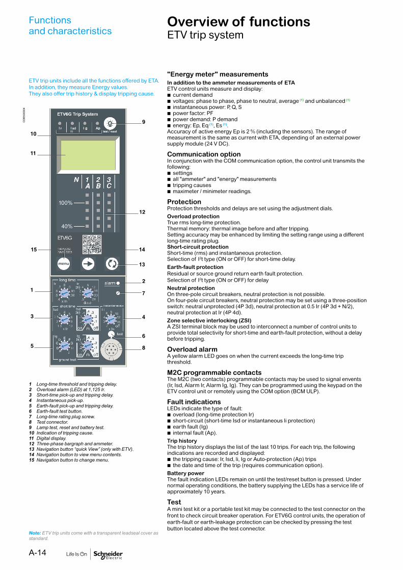
ETV trip units include all the functions offered by ETA.In addition, they measure Energy values.They also offer trip history & display tripping cause.
1 Long-time threshold and tripping delay.2 Overload alarm (LED) at 1,125 Ir.3 Short-time pick-up and tripping delay.4 Instantaneous pick-up.5 Earth-fault pick-up and tripping delay.6 Earth-fault test button.7 Long-time rating plug screw.8 Test connector.9 Lamp test, reset and battery test.10 Indication of tripping cause.11 Digital display.12 Three-phase bargraph and ammeter.13 Navigation button “quick View” (only with ETV).14 Navigation button to view menu contents.15 Navigation button to change menu.
Note: ETV trip units come with a transparent leadseal cover as standard.
CD
B50
0004
7
13
1415
"Energy meter" measurementsIn addition to the ammeter measurements of ETAETV control units measure and display:
b current demand b voltages: phase to phase, phase to neutral, average (1) and unbalanced (1)
b instantaneous power: P, Q, S b power factor: PF b power demand: P demand b energy: Ep, Eq (1), Es (1).
Accuracy of active energy Ep is 2 % (including the sensors). The range of measurement is the same as current with ETA, depending of an external power supply module (24 V DC).
Communication optionIn conjunction with the COM communication option, the control unit transmits the following:
b settings b all "ammeter" and "energy" measurements b tripping causes b maximeter / minimeter readings.
ProtectionProtection thresholds and delays are set using the adjustment dials.Overload protectionTrue rms long-time protection.Thermal memory: thermal image before and after tripping.Setting accuracy may be enhanced by limiting the setting range using a different long-time rating plug. Short-circuit protectionShort-time (rms) and instantaneous protection. Selection of I2t type (ON or OFF) for short-time delay.Earth-fault protectionResidual or source ground return earth fault protection.Selection of I2t type (ON or OFF) for delayNeutral protectionOn three-pole circuit breakers, neutral protection is not possible.On four-pole circuit breakers, neutral protection may be set using a three-position switch: neutral unprotected (4P 3d), neutral protection at 0.5 Ir (4P 3d + N/2), neutral protection at Ir (4P 4d).Zone selective interlocking (ZSI)A ZSI terminal block may be used to interconnect a number of control units to provide total selectivity for short-time and earth-fault protection, without a delay before tripping.
Overload alarmA yellow alarm LED goes on when the current exceeds the long-time trip threshold.
M2C programmable contactsThe M2C (two contacts) programmable contacts may be used to signal envents (Ir, Isd, Alarm Ir, Alarm Ig, Ig). They can be programmed using the keypad on the ETV control unit or remotely using the COM option (BCM ULP).
Fault indicationsLEDs indicate the type of fault:
b overload (long-time protection Ir) b short-circuit (short-time Isd or instantaneous li protection) b earth fault (Ig) b internal fault (Ap).
Trip historyThe trip history displays the list of the last 10 trips. For each trip, the following indications are recorded and displayed:
b the tripping cause: Ir, Isd, li, Ig or Auto-protection (Ap) trips b the date and time of the trip (requires communication option).
Battery powerThe fault indication LEDs remain on until the test/reset button is pressed. Under normal operating conditions, the battery supplying the LEDs has a service life of approximately 10 years.
TestA mini test kit or a portable test kit may be connected to the test connector on the front to check circuit breaker operation. For ETV6G control units, the operation of earth-fault or earth-leakage protection can be checked by pressing the test button located above the test connector.
A-14

Protection ETV2ILong time ETV2I
DB
1011
26
Current setting (A) Ir = In x ... 0.4 0.5 0.6 0.7 0.8 0.9 0.95 0.98 1Tripping between 1.05 and 1.20 x IrTime setting tr (s) 0.5 1 2 4 8 12 16 20 24Time delay (s) Accuracy: 0 to -30 % 1.5 x Ir 12.5 25 50 100 200 300 400 500 600
Accuracy: 0 to -20 % 6 x Ir 0.7(1) 1 2 4 8 12 16 20 24Accuracy: 0 to -20 % 7.2 x Ir 0.7(2) 0.69 1.38 2.7 5.5 8.3 11 13.8 16.6
Thermal memory 20 minutes before and after tripping(1) 0 to -40 % - (2) 0 to -60 %InstantaneousPick-up (A) Isd = Ir x … 1.5 2 2.5 3 4 5 6 8 10Accuracy: ±10 %Time delay Max resettable time: 20 ms
Max break time: 80 ms
Protection ETV5S/ETV6GLong time ETV5S/ETV6G
DB
1011
27
Current setting (A) Ir = In x … 0.4 0.5 0.6 0.7 0.8 0.9 0.95 0.98 1Tripping between 1.05 and 1.20 x IrTime setting tr (s) 0.5 1 2 4 8 12 16 20 24Time delay (s) Accuracy: 0 to -30 % 1.5 x Ir 12.5 25 50 100 200 300 400 500 600
Accuracy: 0 to -20 % 6 x Ir 0.7(1) 1 2 4 8 12 16 20 24Accuracy: 0 to -20 % 7.2 x Ir 0.7(2) 0.69 1.38 2.7 5.5 8.3 11 13.8 16.6
Thermal memory 20 minutes before and after tripping(1) 0 to -40 % - (2) 0 to -60 %Short timePick-up (A) Isd = Ir x … 1.5 2 2.5 3 4 5 6 8 10Accuracy: ±10 %Time setting tsd (s) Settings I2t Off 0 0.1 0.2 0.3 0.4
I2t On - 0.1 0.2 0.3 0.4Time delay (ms) at 10 x Ir tsd (max resettable time) 20 80 140 230 350(I2t Off or I2t On) tsd (max break time) 80 140 200 320 500InstantaneousPick-up (A) Ii = In x … 2 3 4 6 8 10 12 15 offAccuracy: ±10 %Time delay Max resettable time: 20 ms
Max break time: 50 msEarth fault ETV6G
DB
1011
28
Pick-up (A) Ig = In x … A B C D E F G H JAccuracy: ±10 % In y 400 A 0.3 0.3 0.4 0.5 0.6 0.7 0.8 0.9 1
400 A < In y 1000 A 0.2 0.3 0.4 0.5 0.6 0.7 0.8 0.9 1In u 1250 A 500 640 720 800 880 960 1040 1120 1200
Time setting tg (s) Settings I2t Off 0 0.1 0.2 0.3 0.4I2t On - 0.1 0.2 0.3 0.4
Time delay (ms) tg (max resettable time) 20 80 140 230 350at In or 1200 A (I2t Off or I2t On) tg (max break time) 80 140 200 320 500
Ammeter ETV2I/ETV5S/ETV6GType of measurements Range Accuracy
Instantaneous currents I1, I2, I3, IN 0.2 x In to 1.2 x In ±1.5 %Ig (ETV6G) 0.05 x In to In ±10 %
Current maximeters of I1, I2, I3, IN 0.2 x In to 1.2 x In ±1.5 %Demand currents of I1, I2, I3, Ig 0.2 x In to 1.2 x In ±1.5 %Voltages V12, V23, V31, V1N, V2N, V3N 100 to 690 V ±0.5 %Active power P 30 to 2000 kW ±2 %Power factor PF 0 to 1 ±2 %Demand power P demand 30 to 2000 kW ±2 %Active energy Ep -1010 GWh to 1010 GWh ±2 %
Note: All current-based protection functions require no auxiliary source.The test / reset button resets maximeters, clears the tripping indication and tests the battery.
A-15

Functionsand characteristics
ET range of trip systemAccessories and test equipment
External sensorsExternal sensor for earth-fault protectionThe sensors, used with the 3P circuit breakers, are installed on the neutral conductor for:
b Residual type earth-fault protection (with 6G trip units)The rating of the sensor (CT) must be compatible with the rating of the circuit breaker:
b MVS 06 to MVS16(frame 1): TC 400/1600 b MVS 08 to MVS 20(frame 2): TC 400/2000 b MVS25 to MVS40: TC 1000/4000
Voltage measurement inputs(1)
As standard, the control unit is supplied by internal voltage measurement inputs placed downstream of the pole for voltages between 220 and 690 V AC.
External 24 V DC power-supply module (AD)The external power-supply module makes it possible:
b to use the display even if the circuit breaker is open or not supplied (for the exact conditions of use, see the “electrical diagrams” part of this catalogue)
b to display fault currents after tripping b to modify settings when the circuit breaker is open (OFF position)
An external 24 V DC power supply is required for installation with communication, whatever the type of trip unit.This module is not designed to power on 24 V DC voltage releases and electric motor mechanism.This module powers both the control unit and the M2C programmable contacts.We recommended using the AD power supply due to its low stray primary secondary capacitance. Good operation of the Micrologic control unit in noisy environment is not guaranteed with other power supplies.If the COM option is used, a second dedicated power supply shall be used.This module powers both the control unit and the M2C programmable contacts.
Characteristics b Power supply AC-to-DC or DC-to-DC b Output voltage: 24 V DC ±5 %. b Output current: 1 A. b DIN rail or platine Fixing with Acti9 form factor b Conducted emissions power line: class B per EN 61000-6-3.
M2C programmable contacts These contacts are optional equipment for the ETV control units.They are described with the indication contacts for the circuit breakers.
Micrologic Type ETVCharacteristics M2C
Minimum load 100 mA/24 VBreaking capacity (A) p.f.: 0.7 V AC 240 5
380 3V DC 24 1.8
48 1.5125 0.4250 0.15
M2C: 24 V DC power supplied by control unit (consumption 100 mA).
Spare partsLead-seal coversA lead-seal cover controls access to the adjustment dials.When the cover is closed:
b The test connector remains accessible b The test button for the earth-fault protection function remains accessible
Characteristics b Transparent cover for all trip units
Spare batteryA battery supplies power to the LEDs identifying the tripping causes.The healthiness of the battery to be checked periodically. A test button on the front of the control unit is used to check the battery condition. The battery may be replaced on site when discharged.
DB
1015
24P
B10
0775
-32
PB
1010
26-3
2A
External sensor (CT).
Lead-seal cover.
External 24 V DC power supply module.
M2C.
(1) Refer to EasyPact MVS user manual on using 3 pole circuit breakers in 4 wire system with ETV trip system for Energy measurement.
A-16

Functionsand characteristics
Eco COM Communication
Eco COM transmits metering data and status. It is not used to communicate controls.
For fixed and Drawout devices, the common communication option is made up of:
b a BCM ULP module, installed behind the Trip System and supplied with its set of sensors (OF, SDE, PF and CH micro switches) and its COM terminal block (inputs E1 to E6). This module is independent of the control unit. It receives and transmits information on the communication network. An infra-red link transmits data between the control unit and the communication module. Consumption: 30 mA, 24 V.
b IFM, this module required for connection to the network, contains the Modbus address (1 to 99) declared by the user via the two dials in front. It automatically adapts (baud rate, parity) to the Modbus network in which it is installed.
For drawout device the Cradle Management option must be added:I/O (Input/Output) application module for LV breaker, the I/O application module is delivered with withdrawable devices ordered with the COM option, for cradle management. It must be installed on a DIN rail near the device. It must be connected to the ULP system and to the position contacts (CD, CT, CE) that transmit the position of the device in the cradle.
PB
1066
74-2
0.ep
s
BCM ULP.
PB
1192
34.e
ps
I/O application module.
A-17

Functions and characteristics
A Modbus screw clamp connector.
B Modbus address switches.
C Modbus traffic LED.D Modbus locking pad.
FunctionA IFM - Modbus communication interface - is required for connection of a Masterpact or Easypact to a Modbus network as long as this circuit breaker is provided with a ULP (Universal Logic Plug) port. The port is available on respectively a BCM ULP.The IFM is defined as an IMU (Intelligent Modular Unit) in the ULP connection System documentation.
Once connected, the circuit breaker is considered as a slave by the Modbus master. Its electrical values, alarm status, open/close signals car be monitored or controlled by a Programmable Logic Controller or any other system.
CharacteristicsULP port2 RJ45 sockets, internal parallel wiring.
b Connection of a single circuit breaker (eventually via its I/O application module).
b A ULP line terminator must be connected to the second RJ45 ULP socket.The RJ45 sockets deliver a 24 VDC supply fed from the Modbus socket.Built-in test function, for checking the correct connection to the circuit breaker.
Modbus slave port b Top socket for screw-clamp connector, providing terminals for: v 24 VDC input supply (0 V, +24 V) v Modbus line (D1, D2, Gnd). b Lateral socket, for Din-rail stackable connector.
Both top and lateral sockets are internally parallel wired. b Multiple IFM can be stacked, thus sharing a common power supply and
Modbus line without individual wiring. b On the front face: v Modbus address setting (1 to 99): 2 coded rotary switches v Modbus locking pad: enables or disable the circuit breaker remote control
and modification of IFM parameters. b Self adjusting communication format (Baud rate, parity).
IFM Modbus communication interface.Ref.: LV434000.
E ULP activity LED.F Test button.G Mechanical lock.H ULP RJ45 connectors.I Stacking accessory
connection.
PB
1191
11_L
17.e
ps
DB
4307
53.e
ps
x10
COM
1234
0
5
9876
x1
1234
0
5
9876
Modbus0V 24V
COM
1
A
B
CD
E
F
GHI
IFM Modbus communication interface
A-18

Technical characteristicsIFM Modbus communication interface
Dimensions 18 x 72 x 96 mmMaximum number of stacked IFM 12Degree of protection of the installed module
Part projecting beyond the escutcheon
IP4x
Other module parts IP3xConnectors IP2x
Operating temperature
-25...+70 °C
Power supply voltage 24 V DC -20 %/+10 % (19.2...26.4 V DC)Consumption Typical 21 mA/24 V DC at 20 °C
Maximum 30 mA/19.2 V DC at 60 °C
CertificationCE IEC/EN 60947-1UL UL 508 - Industrial Control EquipmentCSA No. 142-M1987 - Process Control
Equipment b CAN/CSA C22.2 No. 0-M91 -
General requirements - Canadian Electrical Code Part
b CAN/CSA C22.2 No. 14-05 - Industrial Control Equipment
Simplified IFM installationStaking IFM
DB
4307
54.e
ps
Test
TestTest
DB
4307
55.e
ps
Stacking accessories Up to 12 stacked IFM
A-19

Communication architectureFunctionsand characteristics
Electrical operatedFixed device Drawout device
ULP system
Modbus
Test
OFSD SDEPFCH
B
A
C
E
H
DB
4307
50_N
T.ep
s
ULP system
Modbus
Test
H
D
A
B
C
CTCECD
F
G
E
OFSDEPFCH
+24VDC
13O1
+I1
24VDC
I2I3
I4I5
I6
C
C
C
1423 24
33 34T1 T2
O2
O3
A1
LV434063
IO
I1
A1
O1O2O3I2
I3I4I5I6
APP
I1I2
I3I4
I5I6
C
C
C
DB
4325
64_N
T.ep
s
A BCM ULPB OF, SDE ... microswitchesC COM terminal block (E1 to E6)D CE, CD and CT contacts
E Breaker ULP cordF I/O application moduleG ULP cableH IFM module
A-20

Functionsand characteristics
I/O application moduleP
B11
9234
.eps
DescriptionThe I/O input/output application module for LV breaker is part of an ULP system with built-in functionalities and applications to enhance the application needs. The ULP system architecture can be built without any restrictions using the wide range of circuit breakers.The I/O application is compliant with the ULP system specifications. Two I/O application module can be connected in the same ULP network.
The ranges of LV circuit breakers enhanced by the I/O are: b Masterpact NT/NW b EasyPact MVS b Compact NS1600b-3200 b Compact NS630b-1600 b Compact NSX100-630 A.
I/O input/output interface for LV breaker resourcesThe I/O application module ressources are:
b 6 digital inputs that are self powered for either NO and NC dry contact or pulse counter
b 3 digital outputs that are bistable relay (5 A maximum) b 1 analog input for Pt100 temperature sensor.
Pre-defined applicationsPre-defined application adds new functions to the IMU in a simple way:
b selection by the application rotary switch on the I/O, defining the application with pre-defined input/output assignment and wiring diagram.
b no additional setting with the customer engineering tool required.The resources not assigned to the pre-defined application are free for additional user-defined applications:
b cradle management b breaker operation b light and load control b custom.
User-defined applicationsUser-defined applications are processed by the I/O in addition to the pre-defined application selected.The user-defined applications are available depending on:
b the pre-defined application selected b the I/O resources (inputs and outputs) not used by the application.
The resources required by user-defined applications are assigned using the customer engineering tool:
b protection b control b energy management b monitoring.
MountingThe I/O is a DIN rail mounting device.
Application rotary switchThe application rotary switch enables the selection of the pre-defined application. It has 9 positions and each position is assigned to a pre-defined application. The factory set position of the switch is pre-defined application 1.
Setting locking padThe setting locking pad on the front panel of the I/O enables the setting of the I/O by the customer engineering tool.
123
4 5 678
9
DB
4168
27.e
psD
B41
6828
.eps
DB
4168
28.e
ps
A-21

Functionsand characteristics
I/O application module
I1 I2 I3 I4 I5 I6C C C
A B
DB
4192
33.e
ps
13 14 23 24 33 34 T1
12
T2
NO
DB
4192
35.e
ps
13O1 O2 O3 A1
I1 I2 I3 I4 I5 I6C C C
14 23 24 33 34 T1 T2
24VDC
1APP
23
4 5 678
9
I1 AI
O1
O2
O3
I2
I3
I4
I5
I6
LV434063IO
T
C
D
E
F
G
MLKJ
HI
DB
4325
36.e
ps
A 24 Vdc power supply terminal block.
B Digital input terminal block: 6 inputs, 3 commons and 1 shield.
C 6 input status LEDs.
D Analog input status LED.
E 3 output status LEDs.
F I/O application module identification labels.
G Sealable transparent cover.
H Analog input terminal block.
I Digital output terminal blocks.J ULP status LED.
K Test/reset button (accessible with cover closed).
L Setting locking pad.
M Application rotary switch: 1 to 9.
N Switch for I/O addressing (I/O 1 or I/O 2).
O ULP connectors.
General characteristicsEnvironmental characteristics
Conforming to standards UL 508, UL 60950, IED 60950, 60947-6-2
Certification cUIUs, GOST, FCC, CE
Ambient temperature -20 to +70 °C (-4 to +158 °F)
Relative humidity 5–85 %
Level of pollution Level 3
Flame resistance ULV0
Mechanical characteristics
Shock resistance 1000 m/s2
Resistance to sinusoidal vibrations 5 Hz < f < 8.4 Hz
Electrical characteristics
Resistance to electromagnetic discharge
Conforming to IEC/EN 61000-4-3
Immunity to radiated fields 10 V/m
Immunity to surges Conforming to IEC/EN 61000-4-5
Consumption 165 mA
Physical characteristics
Dimensions 71.7 x 116 x 70.6 mm (2.83 x 4.56 x 2.78 in.)
Mounting DIN rail
Weight 229.5 g (0.51 lb)
Degree of protection of the installed I/O application module
b On the front panel (wall mounted enclosure): IP4x b IO parts: IP3x b Connectors: IP2x
Connections Screw type terminal blocks
Technical characteristics - 24 V DC power supply
Power supply type Regulated switch type
Rated power 72 W
Input voltage 100–120 V AC for single phase200–500 V AC phase-to-phase
PFC filter With IEC 61000-3-2
Output voltage 24 V DC
Power supply out current 3 A
Note: it is recommended to use an UL listed/UL listed recognized limited voltage/Limited current or a class 2 power supply with a 24 V DC, 3 A maximum.
Digital inputs
Digital input type Self powered digital input with current limitations as per IEC 61131-2 type 2 standards (7 mA)
Input limit values at state 1 (close) 19.8–25.2 V DC, 6.1–8.8 mA
Input limit values at state 0 (open) 0–19.8 V DC, 0 mA
Maximum cable length 10 m (33 ft)
Note: for a length greater than 10 m (33 ft) and up to 300 m (1,000 ft), it is mandatory to use a shielded twisted cable. The shield cable is connected to the I/O functional ground of the I/O application module.
Digital outputs
Digital output type Bistable relay
Rated load 5 A at 250 V AC
Rated carry current 5 A
Maximum switching voltage 380 V AC, 125 V DC
Maximum switch current 5 A
Maximum switching power 1250 VA, 150 W
Minimum permissible load 10 mA at 5 V DC
Contact resistance 30 mΩ
Maximum operating frequency b 18000 operations/hr (Mechanical) b 1800 operations/hr (Electrical)
Digital output relay protection by an external fuse
External fuse of 5 A or less
Maximum cable length 10 m (33 ft)
Analog inputs
The I/O application module analog input can be connected to a Pt100 temperature sensor
Range -30 to 200 °C -22 to 392 °F
Accuracy ±2 °C from -30 to 20 °C±1 °C from 20 to 140 °C±2 °C from 140 to 200 °C
±3.6 °F from -22 to 68 °F±1.8 °F from 68 to 284 °F±3.6 °F from 284 to 392 °F
Refresh interval 5 s 5 s
A-22

Functionsand characteristics
Connection of the IFM & I/O module to a fixed or drawout Easypact MVS
Connect the IFM to a fixed electrically operated EasyPact MVS or circuit breaker using the breaker ULP cord
Connect the IFM to a drawout EasyPact MVS or circuit breaker using the breaker ULP cord
Test
Modbus
A
B
D
C
E
DB
4325
68.e
ps
Test
Modbus
+24VDC
13
O1
+
I1
24VDC
I2I3
I4I5
I6
C
C
C
1423
2433 34
T1 T2
O2
O3
A1
LV434063
IO
I1
A1
O1
O2
O3I2I3
I4I5
I6
APP
A
B
C
D
E
G
K
J
HI
F
DB
4325
66.e
ps
A IFM Modbus interface for LV circuit breakerB Breaker ULP cordC Fixed terminal blockD BCM ULP communication moduleE Fixed electrically operated circuit breaker
A IFM Modbus interface for LV circuit breaker
B ULP cableC Breaker ULP cordD Circuit breaker disconnected position
contact (CD)E Circuit breaker cradle
F BCM ULP communication moduleG Drawout circuit breakerH Drawout terminal blockI Circuit breaker connected position
contact (CE)J Circuit breaker test
position contact (CT)K I/O (Input/Output) application module
for LV circuit breaker
A-23

Functionsand characteristics
EasyCom Communication interface
EasyCom Communication
Overview
EasyCom Communication module allows you to connect and control the air circuit breakers over Modbus communication architecture.
Resources(Inputs/Outputs)
The Communication module resources are:
p Nine digital inputs p Six digital outputs p One analog inout
Key Features
The main features of the communication module are:
p Ensures to make communication architechture affordable and easily maintainable
p Connects,controls, and manages up to three circuit breakers.
O connect:Breaker ON/OFF status(OF),Breaker Trip status(SDE), Ready Tc Close status(PF) O Control: Remote Oper/Close of EasyPact air circuit breakers O Manage: One Analog Input for temperature measurement(4...20mA)
Safety Operation
The communication module keeps safety as its top priority while you controlthe communication architecture.
p During maintenance, the local operator can switch off the remote operation module locally. The remote operator can see the status of the air circuit breaker from remot, but cannot give the ON/OFF command.
p The communication module provides ‘ready-to-close’ indication on the communication network,keeping the safety of the operator and installation on priority.
p The operator must check the following status of the air breaker before the ON command is given to the circuit breaker through the communication architecture.
O The circuit breaker is in the OFF position. O The Spring mechanism is charged. O A maintained opening order is not present. O The tripping command is not present through shunt, under voltage. O The air circuit breaker is completely rack in or not. O The air circuit breaker is locked in the Off position or is mechanically interlock with any other
air circuit breaker.The EasyPact air circuit breaker is equipped witha ‘ready-to-cloase’ accessory that helps to check these conditions from remote on the communication architecture. Once it is fulfilled, the ON command is given to the circuit breaker.
A-24

Functionsand characteristics
EasyCom Communication interface
Commnuication Architecture
A Customer Scope Modbus Master/SCADA SupervisorB Customer Scope Modubus communication cable ( RS 485 cable)C Custmer Scope Modbus to USB/convertorD EasyCom Communication moduleE Digital input/Digital Output wiresF EasyPact MVS
A-25

Functionsand characteristics
EasyCom Communication interface
Module Power LED
Markeing on the product LED Indication Status Description
PWRON Module is powered
OFF Module is not powered
MountingEasyCom Communication module mounts on a DIN rail( Reference: Top hat rail EN50022/TS35).Pull the sliders provided with the unit towards the outward direction. Rest the unit on the DIN rail plate. Pull down the slider again so that the unit gets fixed on the DIN rail plate
24 Vdc Power SupplyIt is recoomended to use UL listed/UL recognized limited voltage/limited cuuert or a Class 2 Power supply with a 24 Vdc, 3A maxmum and with the shield pin connection.
Hardware Description
Description
A Modbus ConnectorB DIN ClipC Module Power LEDD Module Communication Status LEDE Digital Inputs Status LEDF Digital Inputs ConnectorG Analog Inputs ConnectorH Analog Input LEDI 24V Power Supply ConnectorJ Digital Outputs ConnectorK Digital Outputs Status LEDL Circuit breaker 1,2 and 3
A-26

Functionsand characteristics
EasyCom Communication interface
Module Communication Status LED
Markeing on the product LED Indication Status Description
COM
ON Commnuncation established
Blink Commnuncation established
OFF No Commnuncation
Digital Input status LED
Markeing on the product LED Indication Status Description
3X(OF,SDE,PF)ON Input is high
OFF Input is low
Digital Output status LED
Markeing on the product LED Indication Status Description
3X(OF,SDE,PF)ON Relay output is CLOSE
OFF Relay output is OPEN
Analog Input status LED
Markeing on the product LED Indication Status Description
AI
ON 4...20 mA range Input
OFF No sensor
1s ON, 1s OFF Out of range input
Module Power LED
Markeing on the product LED Indication Status Description
PWRON Module is powered
OFF Module is not powered
Hardware Description
Description
A-27

ConnectionsOverview of solutions and accessories
Available connection: b Rear connections: horizontal, vertical and mixed
The solutions presented are similar in principle for allEasyPact MVS fixed and draw-out devices.
Rear connectionHorizontal Vertical
Mixed
Simply turn a horizontal rear connector 90° to make it a vertical connector.
PB
1043
55A
40
PB
1043
59A
40P
B10
4354
A40
A-28

Functionsand characteristics
ConnectionsOverview of solutions and accessories
Interphase barriers EIPThese barriers are flexible insulated partitions used to reinforce isolation ofconnection points in installations with busbars, whether insulated or not.For EasyPact MVS devices, they are installed vertically between rear connection terminals. They are not compatible with spreaders.
Safety shutters VOMounted on the chassis, the safety shutters automatically block access to thedisconnecting contact cluster when the device is in the disconnected or test positions(degree of protection IP 20) When the device is removed from its chassis, no liveparts are accessible.The shutter-locking system is made up of a moving block (optional device) that can be padlocked (padlock not supplied). The block:
b Prevents connection of the device b Locks the shutters in the closed position
For EasyPact MVS06 to MVS40A support at the bottom of the chassis is used to store the blocks when they are not used:
b 2 blocks for MVS06 to MVS40
CP
B10
0010
PB
1043
64A
50
A-29

Accessories and auxiliaries
Type of accessory EasyPact MVS06 to MVS40Fixed breaker Draw-out breakerRear connection Rear connection
Interphasebarriers
DB
1011
49
Optional
DB
1011
49
OptionalSafety shutters
DB
1011
53
StandardSafety shutters locking blocks
E46
460
OptionalDoor interlock
E46
452
OptionalPushbutton locking device E
4666
6
OptionalE
4666
6Optional
OFF position locking
CD
B50
0039
Optional
CD
B50
0039
Optional“Disconnected” position locking
DB
1174
58
OptionalON/OFF indication contacts(OF) E46
689
Standard
E46
689
StandardAdditional ON/OFF indication contacts(OF)not incl MVS frame 1
E46
689
Optional
E46
689
Optional“Fault trip” indication contact(SDE)
CD
B50
0040
Standard
CD
B50
0040
Standard
A-30

Type of accessory EasyPact MVS06 to MVS40Fixed breaker Draw-out breakerRear connection Rear connection
“Connected, disconnected, test position”indication contact(CE,CD,CT)
E46
661
Optional“Ready to close” contact(PF) E
4643
8
Optional
E46
438
OptionalEscutcheon(CDP)
CD
B50
0061
Standard
CD
B50
0061
StandardMechanical operation counter(CDM)not incl MVS frame 1 D
B12
5617
Optional
DB
1256
17
OptionalEscutcheon blanking plate
E46
670
Optional
E46
670
OptionalAuxiliary terminal shield(CB) E
4645
8
OptionalTransparent cover (IP54)
E46
669
Optional
Functionsand characteristics
Accessories and auxiliaries
A-31

LockingOn the device
Pushbutton locking VBPThe transparent cover blocks access to the pushbuttons used to open and close the device.It is possible to independently lock the opening button and the closing button.The locking device is often combined with a remote operating mechanism.The pushbuttons may be locked using either:
b Three padlocks (not supplied) b Lead seal b Two screws
Device locking in the OFF position by keylocks VSPOThe circuit breaker is locked in the OFF position by physically maintaining theopening pushbutton pressed down:
b Using keylocks (one or two keylocks, supplied)Keys may be removed only when locking is effective (Profalux or Ronis type locks).The keylocks are available in any of the following configurations:
b One keylock b One keylock mounted on the device + one identical keylock supplied separately for interlocking with another device
A locking kit (without locks) is available for installation of one or two keylocks (Ronis,Profalux).
Access to pushbuttons protected by transparent cover.
PB
1008
11-3
2P
B10
0810
-32
Pushbutton locking using a padlock.
CP
B10
0007
OFF position locking using a keylock.
CD
B50
0036
Profaulx Ronis
Door interlock catch VPECMounted on the right or left-hand side of the chassis, this device inhibits opening ofthe cubicle door when the circuit breaker is in “connected” or “test” position. It thebreaker is put in the “connected” position with the door open, the door may be closedwithout having to disconnect the circuit breaker.
Automatic spring discharge before breaker removal DAEThis option discharges the springs before the breaker is removed from the chassis.
CD
B50
0006
1 Reset button for mechanical trip indication.2 OFF pushbutton.3 OFF position lock.4 Door interlock.5 ON pushbutton.6 Spring charge indication.7 Pushbutton locking.8 Contact position indication.9 Operation counter.
MVS08 N
IEC 60947-2 50/60H
delay
short time
on I2t
.2
.3.4 .4
.1
.2
.10
long time
alarm
ground fault
setting
4
test
.4.5.6
.7.8 .9
.95
.981
Ir
x In
.512
48 12
1620
tr(s)
at 6 Ir24
x Ir
22.5
34 5
68
10
Isd
1.5
tsd(s)
x In3
68 10
1215
off2
BC
DE F
GH
I
Ig
Aon I
2t.2.3.4
.4
.1
.2.3
.10off
tg(s)
.3
instantaneous
I i
ET6G Trip System
alarm
Ir
ground fault
test
onoff
onoff
off
(s)
(s)
(s)
long time
short time
instantaneous
ET6G Trip System
Door interlock.
CP
B10
0008
A-32

LockingOn the chassis
CD
B50
0007
1 Door interlock.2 Keylock locking.3 Padlock locking.4 Position indicator.5 Chassis front plate (accessible with cubicle door closed).6 Racking-handle entry.7 Release button.8 Racking-handle storage.
“Connected”, “disconnected” and “test” position racking interlockThe “connected”, “disconnected” and “test” positions are shown by an indicator andare mechanically indexed. The exact position is obtained when the racking handleblocks. A release button is used to free it.
“Disconnected” position locking by padlocks or keylocks VSPDMounted on the chassis and accessible with the door closed, these devices lock thecircuit breaker in the “disconnected” position in two manners:
b Using padlocks (standard), up to three padlocks (not supplied) b Using keylocks (optional), one or two different keylocks are available
Profalux and Ronis keylocks are available in different options: b One keylock b Two identical key locks - one keylock mounted on the device + one identical keylock supplied separately for interlocking with another device
A locking kit (without locks) is available for installation of one or two keylocks (Ronis, Profalux).
Padlock
CP
B10
0006
CP
B10
0017
“Disconnected” position locking by padlock.
Circuit breaker in “disconnected” position.
Insert the shackle (max. diameter 5 to 8 mm) of the padlock(s).
Pull out the tab.
The crank connot be inserted.
Keylock
Circuit breaker in “disconnected” position.
Remove the key(s)
Turn the key(s).
The crank cannot be inserted.
1
8
3
7 5
6
4
2
“Disconnected” position locking by keylock.
Functionsand characteristics
A-33

Indication contacts
“Fault-trip” indication contact (SDE).
ON/OFF indication contacts(OF) (rotary type).
Indication contacts are available: b in the standard version for relay applications
ON/OFF indication contacts OFIndication contacts indicate the ON or OFF position of the circuit breaker:
b Rotary type changeover contacts directly driven by the mechanism for EasyPact MVS. These contacts trip when the minimum isolation distance between the main circuit-breaker contacts is reached
OF Frame 1 Frame 2Supplied as standard 4 4Maximum number 4 12Breaking capacity (A)p.f.: 0.3AC12/DC12
Standard Minimum load: 100 mA/24 VV AC 240/380 6 10/6 (1)
480 6 10/6 (1)
690 6 6V DC 24/48 2.5 10/6 (1)
125 0.5 10/6 (1)
250 0.3 3Low-level Minimum load: 2 mA/15 V
V AC 24/48 5 6240 5 6380 5 3
V DC 24/48 5/2.5 6125 0.5 6250 0.3 3
(1) Standard contacts: 10 A; optional contacts: 6 A.
“Fault-trip” indication contacts SDECircuit-breaker tripping due to a fault is signalled by:
b A red mechanical fault indicator (reset) b One changeover contact SDE
Following tripping, the mechanical indicator must be reset before the circuit breakermay be closed. One SDE is supplied as standard.
SDE MVSSupplied as standard 1Breaking capacity (A)p.f.: 0.3AC12/DC12
Standard Minimum load: 100 mA/24 VV AC 240/380 6
480 2V DC 24/48 3
125 0.3250 0.15
Low-level Minimum load: 2 mA/15 V V AC 24/48 3
240 3380 3
V DC 24/48 3
125 0.3250 0.15
A-34

Indication contactsP
B10
0817
-32.
eps “Connected”, “disconnected” and “test” position carriage
switches CE, CD & CTThree series of optional auxiliary contacts are available for the chassis:
b Changeover contacts to indicate the “connected” position CE b Changeover contacts to indicate the “disconnected” position CD. This position is indicated when the required clearance for isolation of the power and auxiliary circuits is reached
b Changeover contacts to indicate the “test” position CT. In this position, the power circuits are disconnected and the auxiliary circuits are connected
CE, CD and CT “connected/disconnected/test” position carriage switches.
MVS frame 1 MVS Frame 2Contacts CE/CD/CT CE/CD/CT
Maximum number Standard with additional actuators
3 2 1 3 3 39 0 06 3 06 0 33 6 0
Breaking capacity (A)p.f.: 0.3AC12/DC12
Standard Minimum load: 100 mA/24 VV AC 240 8 8
380 8 8480 8 8690 6 6
V DC 24/48 2.5 2.5125 0.8 0.8250 0.3 0.3
Low-level Minimum load: 2 mA/15 V V AC 24/48 5 5
240 5 5380 5 5
V DC 24/48 2.5 2.5125 0.8 0.8250 0.3 0.3
M2C programmable contactsThese contacts, used with the ETV control units, may be programmed via the control unit keypad or via a supervisory station with the COM communication option. They require an external power supply module. The M2C (two contacts) auxiliary contacts may be used to signal threshold overruns or status changes. They can be programmed using the COM option (BCM ULP).
Micrologic Type ETVM2C programmable contacts: circuit breaker internal relay with two contacts.
Characteristics M2CMinimum load 100 mA/24 VBreaking capacity (A)p.f.: 0.7
V AC 240 5
380 3V DC 24 1.8
48 1.5125 0.4250 0.15
DB
1170
38.e
ps M2C: 24 V DC power supplied by control unit (consumption 100 mA).
PB
1007
78-3
2.ep
s
A-35

Remote operationRemote ON / OFF
PB
1043
49A
68
DB
1117
83
The remote ON / OFF function is used to remotely open and close the circuit breaker.It is made up of:
b An electric motor MCH equipped with a “springs charged” limit switch contact CH
b Two voltage releases: v A closing release XF v An opening release MX
Optionally, other function may be added: b A “ready to close” contact PF
A remote-operation function is generally combined with: b Device ON / OFF indication OF b “Fault-trip” indication SDE
Wiring diagram of a point-to-point remote ON / OFF function
A point-to-point solution for remote operation of EasyPact MVS
Note: An opening order always takes priority over a closing order.If opening and closing orders occur simultaneously, themechanism discharges without any movement of the maincontacts. The circuit breaker remains in the open position(OFF).In the event of maintained opening and closing orders, thestandard mechanism provides an anti-pumping function byblocking the main contacts in open position.Anti-pumping function. After fault tripping or intentionalopening using the manual or electrical controls, the closingorder must first be discontinued, then reactivated to close thecircuit breaker.
Functionsand characteristics
A-36

Electric motor MCHThe electric motor automatically charges and recharges the spring mechanism whenthe circuit breaker is closed. Instantaneous reclosing of the breaker is thus possiblefollowing opening. The spring-mechanism charging handle is used only as a backupif auxiliary power is absent.The electric motor MCH is equipped as standard with a limit switch contact CH thatsignals the “charged” position of the mechanism (springs charged).CharacteristicsPower supply V AC 50/60 Hz 100/130 - 200/240 - 380/415
V DC 24/30 - 48/60 - 100/125 - 200/250Operating threshold 0.85 to 1.1 UnConsumption (VA or W) 180Motor overcurrent 2 to 3 In for 0.1 sCharging time Maximum 4 sOperating frequency Maximum 3 cycles per minuteCH contact 10 A at 240 V
Voltage releases XF and MXTheir supply can be maintained or automatically disconnected.Closing release XFThe XF release remotely closes the circuit breaker if the spring mechanism is charged.Opening release MXThe MX release instantaneously opens the circuit breaker when energised. It locks the circuit breaker in OFF position if the order is maintained.Characteristics XF MXPower supply V AC 50/60 Hz 24 - 48 - 100/130 - 200/250 - 380/480
V DC 12 - 24/30 - 48/60 - 100/130 - 200/250Operating threshold 0.85 to 1.1 Un 0.7 to 1.1 UnConsumption (VA or W) Hold: 4.5 Hold: 4.5
Pick-up: 200 (200 ms) Pick-up: 200 (200 ms)Circuit-breaker response time at Un
70 ms ±10 50 ms ±10
“Ready to close” contact PFThe “ready to close” position of the circuit breaker is indicated by a mechanical indicator and a PF changeover contact. This signal indicates that all the following are valid:
b The circuit breaker is in the OFF position b The spring mechanism is charged b A maintained opening order is not present: v MX energised v Fault trip v Remote tripping MN v Device not completely racked in v Device locked in OFF position v Device interlocked with a second device
CharacteristicsMaximum number 1Breaking capacity (A) Standard Minimum load: 100 mA/24 Vp.f.: 0.3 V AC 240/380 5AC12/DC12 480 5
690 3V DC 24/48 3
125 0.3250 0.15
PB
1008
09-1
6P
B10
0818
-16
DB
1170
37P
B10
0808
-32
MX voltage releases. XF voltage release.
“Ready to close” contacts PF.
Electric motor MCH forEasyPact MVS.
Remote operationRemote ON / OFF
A-37

Remote operationRemote tripping
DB
1008
09-1
605
6422
N
MN voltage release.
MN delay unit.
Instantaneous voltage releases MNThe MN release instantaneously opens the circuit breaker when its supply voltagedrops to a value between 35 % and 70 % of its rated voltage. If there is no supply onthe release, it is impossible to close the circuit breaker, either manually or electrically.Any attempt to close the circuit breaker has no effect on the main contacts. Circuit breaker closing is enabled again when the supply voltage of the release returns to 85% of its rated value.CharacteristicsPower supply V AC 50/60 Hz 24 - 48 - 100/130 - 200/250 - 380/480
V DC 24/30 - 48/60 - 100/130 - 200/250Operating threshold Opening 0.35 to 0.7 Un
Closing 0.85 UnConsumption (VA or W) Pick-up: 200 (200 ms) Hold: 4.5MN consumption Pick-up: 200 (200 ms) Hold: 4.5with delay unit (VA or W)Circuit-breaker response time at Un 90 ms ±5
MN delay unitsTo eliminate circuit-breaker nuisance tripping during short voltage dips, operation ofthe MN release can be delayed. This function is achieved by adding an externaldelay unit in the MN voltage-release circuit. Two versions are available, adjustableand non-adjustable.CharacteristicsPower supply Non-adjustable 100/130 - 200/250V AC 50-60 Hz /DC Adjustable 48/60 - 100/130 - 200/250 - 380/480Operating threshold Opening 0.35 to 0.7 Un
Closing 0.85 UnDelay unit consumption Pick-up: 200 (200 ms) Hold: 4.5Circuit-breaker response time at Un Non-adjustable 0.25 s
Adjustable 0.5 s - 0.9 s - 1.5 s - 3 s
Functionsand characteristics
A-38

Source-changeover systemsMechanical interlocking
Interlocking of two EasyPact MVS or up to three EasyPact MVS devices using cablesFor cable interlocking, the circuit breakers may be mounted one above the other orside-by-side. The interlocked devices may be fixed or draw-out, three-pole or four-pole, and have different ratings.Interlocking between two MVS frame 1 or two MVS frame 2This function requires:
b An adaptation fixture on the right side of each device b A set of cables with no-slip adjustments
The maximum distance between the fixing planes (vertical or horizontal) is 2000 mm.Interlocking between three MVS frame 2This function requires:
b A specific adaptation fixture for each type of interlocking, installed on the right side of each device
b Two or three sets of cables with no-slip adjustments b The use of a mechanical operation counter CDM is compulsory
The maximum distance between the fixing planes (vertical or horizontal) is 1000 mm.InstallationThe adaptation fixtures, sets of cables and circuit breakers or switch-disconnectorsare supplied separately, ready for assembly by the customer.
Installation conditions for cable interlocking systems: b Cable length: 2.5 m b Radius of curvature: 100 mm b Maximum number of curves: 3
Possible combinations of “Normal” and “Replacement” source circuit breakers“Normal N” “Replacement” RMVS06 to MVS40 MVS Frame 1 or Frame 2Ratings 630...4000A b
Possible combinations of three deviceMVS08 to MVS40 MVS Frame 2Ratings 800...4000A b
CP
B10
0009
Interlocking of two EasyPact circuit breakers using cable.
A-39

Electrical interlockingIVE unit
Functionsand characteristics
Electrical interlocking is used with a mechanical interlocking system.
Morover, the relays controlling the closing order to the “S1” and “S2” circuit breakers must be mechanically and/or electrically interlocked to prevent them from giving simultaneous closing commands.
Electrical interlocking is carried out by an electrical control device.For EasyPact & Masterpact, this function can be implemented in one of two ways:
b using the IVE unit b by an electrician based on the diagrams in accordance with the chapter “Electric
diagrams” of this catalogue.
Characteristics of the IVE unit b External connection terminal block: v inputs: circuit breaker control signals v outputs: status of the SDE contacts on the “S1” and “S2” source circuit
breakers. b 2 connectors for the two “S1” and “S2” source circuit breakers: v inputs:
- status of the OF contacts on each circuit breaker (ON or OFF) - status of the SDE contacts on the “S1” and “S2” source circuit breakers
v outputs: power supply for operating mechanisms. b Control voltage: v 24 to 250 V DC v 48 to 415 V 50/60 Hz - 440 V 60 Hz.
The IVE unit control voltage must be same as that of the circuit breaker operating mechanisms.
PB
1191
74.e
ps
IVE unit.
Necessary equipmentFor MVS, each circuit breaker must be equipped with:
b a remote-operation system made up of: v MCH gear motor v MX or MN opening release v XF closing release v PF “ready to close” contact v CDM mechanical operation counter b an available OF contact b one to three CE connected-position contacts (carriage switches) on drawout
circuit breakers (depending on the installation).
A-40

Controller selection
By combining a remote-operated source-changeover system with an integrated BA or UA automatic controller, it is possible to automatically control source transfer according to user-selected sequences.These controllers can be used on source-changeover systems comprising 2 circuit breakers.For source-changeover systems comprising 3 circuit breakers, the automatic control diagram must be prepared by the installer as a complement to to diagrams provided in the “electrical diagrams” section of this catalogue.
Controller BA UACompatible circuit breakers All Masterpact & EasyPact
circuit breakers4-position switch
Automatic operation b b Forced operation on “Normal” source b b Forced operation on “Replacement” source b b Stop (both “Normal” and “Replacement” sources off) b b Automatic operation
Monitoring of the “Normal” source and automatic transfer b b Generator set startup control b Delayed shutdown (adjustable) of generator set b Load shedding and reconnection of non-priority circuits b Transfer to the “Replacement” source if one of the phases of the “Normal” phase is absent
b
DB
4038
09.e
ps
TestBy opening the P25M circuit breaker supplying the controller b By pressing the test button on the front of the controller b Indications
Circuit breaker status indication on the front of the controller: on, off, fault trip
b b
Automatic mode indicating contact b b Other functions
Selection of type of “Normal” source (single-phase or three-phase) (1) b Voluntary transfer to “Replacement” source (e.g. energy management commands)
b b
During peak-tariff periods (energy management commands) forced operation on “Normal” source if “Replacement” source not operational
b
Additional contact (not part of controller). Transfer to “Replacement” source only if contact is closed. (e.g. used to test the frequency of UR).
b b
BA controller. Setting of maximum startup time for the replacement source b Options
DB
4038
10.e
ps Communication optionPower supply
Control voltages (2) 110 V b b 220 to 240 V 50/60 Hz b b 380 to 415 V 50/60 Hz and 440 V 60 Hz
b b
Operating thresholdsUndervoltage 0.35 Un y voltage y 0.7 Un b b Phase failure 0.5 Un y voltage y 0.7 Un b Voltage presence voltage u 0.85 Un b b IP degree of protection (EN 60529) and IK degree of protection against external mechanical impacts (EN 50102)
Front IP40 b b Side IP30 b b Connectors IP20 b b
UA controller. Front IK07 b b Characteristics of output contacts (dry, volt-free contacts)
Rated thermal current (A) 8Minimum load 10 mA at 12 VOutput contacts:Position of the Auto/Stop switch b b Load shedding and reconnection order b Generator set start order b
AC DCUtilisation category (IEC 947-5-1) AC12 AC13 AC14 AC15 DC12 DC13Operational current (A) 24 V 8 7 5 5 8 2
48 V 8 7 5 5 2 -110 V 8 6 4 4 0.6 -220/240 V 8 6 4 3 - -250 V - - - - 0.4 -380/415 V 5 - - - - -440 V 4 - - - - -660/690 V - - - - - -
(1) For example, 220 V single-phase or 220 V three-phase.(2) The controller is powered by the ACP control plate. The same voltage must be used for the ACP plate, the IVE unit and the circuit-breaker operating mechanisms. If this voltage is the same as the source voltage, then the “Normal” and “Replacement” sources can be used directly for the power supply. If not, an isolation transformer must be used.
A-41

AccessoriesP
B10
4740
PB
1043
82A
32D
B10
1173
PB
1007
76-4
2
Escutcheon CDP with blanking plate.
Transparent cover CP for escutcheon.
Auxiliary terminal shield CBOptional equipment mounted on the chassis, the shield prevents access to theterminal block of the electrical auxiliaries.
Operation counter CDMThe operation counter sums the number of operating cycles and is visible on the front panel. It is compatible with manual and electrical control functions.This option is compulsory for all the source-changeover systems.
Escutcheon CDPStandard equipment mounted on the door of the cubicle, the escutcheon increasesthe degree of protection to IP 40 (circuit breaker installed free standing: IP30) .It is available in fixed and draw-out versions.
Blanking plate for escutcheon OPUsed with the escutcheon, this option closes off the door cut-out of a cubicle not yetequipped with a device. It may be used with the escutcheon for both fixed anddraw-out devices.
Transparent cover for escutcheon CPOptional equipment mounted on the escutcheon, the cover is hinged and secured bya screw. It increases the degree of protection to IP54, IK10. It adapts to draw-outdevices.
Functionsand characteristics
A-42

A-43

Installationrecommendations

Installation recommendations
Functions and characteristics A-1
Operating conditions B-2
Installation in switchboard B-3
Door interlock catch B-5
Control wiring B-6
Power connection B-7
Recommended busbars drilling B-9
Busbar sizing B-11
Temperature deratingPower dissipation B-13
Dimensions and connection C-1Electrical diagrams D-1Additional characteristics E-1Catalogue numbers and order form F-1
EasyPact MVS
B-1

Installationrecommendations
Operating conditions
EasyPact MVS circuit breakers have been tested for operation in industrial atmospheres. It is recommended that the equipment be cooled or heated to the proper operating temperature and kept free of excessive vibration and dust.
CD
B50
0008 Ambient temperature
EasyPact MVS devices can operate under the following temperature conditions: b The electrical and mechanical characteristics are stipulated for an ambient temperature of -5°C to +60°C
b Circuit-breaker closing is guaranteed down to -35°CStorage conditions are as follows:
b -40 to +85°C for a Easypact MVS device without its control unit b -25°C to +85°C for the control unit
CD
B50
0011
CD
B50
0012
AltitudeAt altitudes higher than 2000 metres, the modifications in the ambient air (electricalresistance, cooling capacity) lower the following characteristics as follows:
Altitude (m) 2000 3000Impulse withstand voltage uimp (kV) 12 11Rated insulation voltage (Ui) 1000 900Maximum rated operationnalvoltage 50/60 Hz Ue (V)
690 5901000 890
Rated current 40°C 1 x In 0.99 x In
Intermediate values may be obtained by interpolation.
Electromagnetic disturbancesEasyPact MVS devices are protected against:
b Overvoltages caused by devices that generate electromagnetic disturbances b Overvoltages caused by atmospheric disturbances or by a distribution-system outage (e.g. failure of a lighting system)
b Devices emitting radio waves (radios, walkie-talkies, radar, etc.) b Electrostatic discharges produced by users
EasyPact MVS devices have successfully passed the electromagnetic-compatibilitytests (EMC) defined by the following international standards:
b IEC 60947-2, appendix FThe above tests guarantee that:
b No nuisance tripping occurs b Tripping times are respected
MVS08 N
IEC 60947-2 50/60H
delay
short time
on I2t
.2
.3.4 .4
.1
.2
.10
long time
alarm
ground fault
setting
4
test
.4.5
.6
.7
.8 .9
.95
.98
1
Ir
x In
.51
2
4
8 12
16
20
tr(s)
at 6 Ir24
x Ir
2
2.5
34 5
6
8
10
Isd
1.5
tsd
(s)
x In
3
6
8 10
12
15
off
2
B
C
DE F
G
H
I
Ig
Aon I
2t
.2
.3.4 .
4
.1
.2.3
.10off
tg
(s)
.3
instantaneous
I i
ET6G Trip System
alarm
Ir
ground fault
test
onoff
onoff
off
(s)
(s)
(s)
long time
short time
instantaneous
ET6G Trip System
2000
(m)
MVS08 N
IEC 60947-2 50/60H
delay
short time
on I2t
.2
.3.4 .4
.1
.2
.10
long time
alarm
ground fault
setting
4
test
.4.5
.6
.7
.8 .9
.95
.98
1
Ir
x In
.51
2
4
8 12
16
20
tr(s)
at 6 Ir24
x Ir
2
2.5
34 5
6
8
10
Isd
1.5
tsd
(s)
x In
3
6
8 10
12
15
off
2
B
C
DE F
G
H
I
Ig
Aon I
2t
.2
.3.4 .
4
.1
.2.3
.10off
tg
(s)
.3
instantaneous
I i
ET6G Trip System
alarm
Ir
ground fault
test
onoff
onoff
off
(s)
(s)
(s)
long time
short time
instantaneous
ET6G Trip System
B-2

Installation in switchboard
CD
B50
0013
CD
B50
0016
CD
B50
0017
CD
B50
0018
CD
B50
0014
CD
B50
0015
Possible positions
Power supplyEasyPact MVS devices can be supplied either from the top or from the bottom without reduction in performance, in order to facilitate connection when installed in a switchboard.
Mounting the circuit-breakerIt is important to distribute the weight of the device uniformily over a rigid mountingsurface such as rails or a base plate.This mounting plane should be perfectly flat (tolerance on support flatness: 2 mm).This eliminates any risk of deformation which could interfere with correct operationof the circuit breaker.EasyPact devices can also be mounted on a vertical plane using the special brackets.
Mounting on rails.
MVS08 N
IEC 60947-2 50/60H
delay
short time
on I2t
.2
.3.4 .4
.1
.2
.10
long time
alarm
ground fault
setting
4
test
.4.5.6
.7.8 .9
.95
.981
Ir
x In
.512
48 12
1620
tr(s)
at 6 Ir24
x Ir
22.5
34 5
68
10
Isd
1.5
tsd
(s)
x In
3
68 10
1215
off2
BC
DE F
GH
I
Ig
Aon I
2t.2.3
.4 .4
.1
.2.3
.10off
tg
(s)
.3
instantaneous
I i
ET6G Trip System
alarm
Ir
ground fault
test
onoff
onoff
off
(s)
(s)
(s)
long time
short time
instantaneous
ET6G Trip System
MVS08 N
IEC 60947-2 50/60H
delay
short time
on I2t
.2
.3.4 .4
.1
.2
.10
long time
alarm
ground fault
setting
4
test
.4.5
.6
.7
.8 .9
.95
.98
1
Ir
x In
.51
2
4
8 12
16
20
tr(s)
at 6 Ir24
x Ir
2
2.5
34 5
6
8
10
Isd
1.5
tsd
(s)
x In
3
6
8 10
12
15
off
2
B
C
DE F
G
H
I
Ig
Aon I
2t
.2
.3.4 .
4
.1
.2.3
.10off
tg
(s)
.3
instantaneous
I i
ET6G Trip System
alarm
Ir
ground fault
test
onoff
onoff
off
(s)
(s)
(s)
long time
short time
instantaneous
ET6G Trip System
B-3

DB
1014
34D
B10
1435
A : Non magnetic material.
PartitionsSufficient openings must be provided in partitions toensure good air circulation around the circuit breaker;Any partition between upstream and downstreamconnections of the device must be made of nonmagnetic material.For high currents, of 2500 A and upwards, the metalsupports or barriers in the immediate vicinity of aconductor must be made of non-magnetic material A.Metal barriers through which a conductor passes mustnot form a magnetic loop.
DB
1170
45
DB
1014
36BusbarsThe mechanical connection must be exclude thepossibility of formation of a magnetic loop around a conductor.
CD
B50
0041
DB
1014
39
453
Interphase barrierIf the insulation distance between phases is notsufficient (y 14 mm), it is advised to install phasebarriers (taking into account the safety clearances).
Installationrecommendations
Installation in switchboard
B-4

Door interlock catchInstallationrecommendations
Door interlock VPECMounted on the right or left-hand side of the chassis, this device inhibits opening of the cubicle door when the circuit breaker is in “connected” or “test” position. It the breaker is put in the “connected” position with the door open, the door may be closed without having to disconnect the circuit breaker. X
Y
2
11.5
61
(1) (2)
DB
4180
08.e
ps
Catch not supplied.Dimensions (mm)Type (1) (2)
MVS frame 1 (3P) 135 168MVS frame 1 (4P) 205 168MVS frame 2 (3P) 215 215MVS frame 2 (4P) 330 215
MVS frame 1
17 (1) (2)
X
Y
58
15
DB
4180
09.e
ps
Catch not supplied.
MVS frame 2
Breaker in “connected” or “test” positionDoor cannot be opened
DB
4180
11.e
ps
F (1)Door(2)
DB
4180
12.e
ps
MVS frame 1 MVS frame 2.
Breaker in “disconnected” positionDoor can be opened
DB
4180
11.e
ps
DB
4180
13.e
ps
MVS frame 1. MVS frame 2.
Dimensions (mm)Type (1) (2)
MVS frame 1 5 23MVS frame 2 87 103
B-5

Control wiring
Wiring of voltage releasesDuring pick-up, the power consumed is approximately 150 to 200 VA. For low controlvoltages (12, 24, 48 V), maximum cable lengths are imposed by the voltage and thecross-sectional area of cables.Recommended maximum cable lengths (meter).
12 V 24 V 48 V2,5 mm2 1,5 mm2 2,5 mm2 1,5 mm2 2,5 mm2 1,5 mm2
MN U source 100 % – – 58 35 280 165U source 85 % – – 16 10 75 45
MX-XF U source 100 % 21 12 115 70 550 330U source 85 % 10 6 75 44 350 210
Note: The indicated length is that of each of the two wires.
24 V DC power-supply moduleExternal 24 V DC power-supply module (F1-, F2+)
b Do not connect the positive terminal (F2+) to earth b The negative terminal (F1-) can be connected to earth b A number of trip units can be connected to the same 24 V DC power supply (the consumption of a trip unit is approximately 100 mA)
b Do not connect any devices other than a trip unit b The maximum length for each conductor is ten metres. For greater distances, it is advised to twist the supply wires together
b The 24 V DC supply wires must cross the power cables perpendicularly. If this is difficult, it is advised to twist the supply wires together
b The technical characteristics of the external 24 V DC power-supply module are indicated on page A-14.
Note: Wiring of ZSI: it is recommended to use twisted shielded cable. The shield must be connected to earth at both ends.
Installationrecommendations
B-6

Power connection
Cables connectionsIf cables are used for the power connections, make sure that they do not apply excessive mechanical forces to the circuit breaker terminals.For this, make the connections as follows:
b Extend the circuit breaker terminals using short bars designed and installed according to the recommendations for bar-type power connections:
v For a single cable, use solution B opposite v For multiple cables, use solution C opposite b In all cases, follow the general rules for connections to busbars:
v Position the cable lugs before inserting the bolts v The cables should firmly secured to the framework E
DB
1014
48
DB
1014
49
DB
1014
50D
B10
1453
DB
1014
51
DB
1014
52Busbars connectionsThe busbars should be suitably adjusted to ensure thatthe connection points are positioned on the terminalsbefore the bolts are inserted BThe connections are held by the support which is solidly fixed to the framework of the switchboard, such that the circuit breaker terminals do not have to support its weight C. (This support should be placed close to the terminals).
Electrodynamic stressesThe first busbar support or spacer shall be situated within a maximum distance fromthe connection point of the breaker (see table below). This distance must berespected so that the connection can withstand the electrodynamic stressesbetween phases in the event of a short circuit.
Maximum distance A between busbar to circuit breaker connection and the first busbarsupport or spacer with respect to the value of the prospective short-circuit current.
Isc (kA) 30 50 65Distance A (mm) 350 300 250
B-7

DB
1014
54 ClampingCorrect clamping of busbars depends amongst other things, on the tighteningtorques used for the nuts and bolts. Over-tightening may have the sameconsequences as under-tightening.For connecting busbars (Cu ETP-NFA51-100) to the circuit breaker, the tighteningtorques to be used are shown in the table below.These values are for use with copper busbars and steel nuts and bolts, class 8.8. The same torques can be used with AGS-T52 quality aluminium bars (French standardNFA 02-104 or American National Standard H-35-1).Examples
1 Terminal screw factory-tightened to 16 Nm.2 Breaker terminal.3 Busbar.4 Bolt.5 Washer.6 Nut.
DB
1014
55
DB
1014
56
DB
1014
57
Tightening torquesØ (mm)Nominal
Ø (mm)Drilling
Tightening torques (Nm)with grower or flat washers
Tightening torques (Nm)with contact or corrugatecwashers
10 11 37.5 50
Busbar drillingExamples
DB
1014
58
DB
1014
59
DB
1014
60
DB
1014
61D
B10
1462
Isolation distance
Dimensions (mm)Ui X min600 V 8 mm1000 V 14 mm
Busbar bendingWhen bending busbars maintain the radius indicated below(a smaller radius would cause cracks).
Dimensions (mm)e Radius of curvature r
Min Recommended5 5 7.510 15 18 to 20
Installationrecommendations
Power connection
B-8

Installationrecommendations
Recommended busbars drilling Easypact MVS Frame 1: 630-1600A
Rear connection Rear connection with spreaders
DB
1014
63.e
ps
DB
1014
63.e
ps
DB
1014
64.e
ps
Db1
0146
5.ep
s
Middle left or middle right spreader for 4P
Middle spreader for 3P Left or right spreader for 4P
Left or right spreader for 3P
Db1
0146
6.ep
s
Db1
0146
7.ep
s
Db1
0148
0.ep
s
Db1
0146
8.ep
s
Db1
0146
9.ep
s
Vertical rear connection
Db1
0147
1.ep
s
B-9

Recommended busbars drillingEasyPact MVS Frame 2: 800-4000A
Horizontal rear connection MVS08 to MVS32
Vertical rear connection MVS08 to MVS32
MVS40
MVS40
DB
1014
63
DB
1014
64
DB
1014
65
CD
B50
0042
CD
B50
0054
CD
B50
0055
CD
B50
0056
CD
B50
0043
DB
1014
74D
B10
1476
DB
1014
77
B-10

Installationrecommendations
Busbar sizing
Basis of tables: b Maximum permissible busbars temperature: 100 ºC
b Ti: temperature around the ciruit breaker and its connection
b Busbar material is unpainted Copper / Aluminium
ExampleConditions:
b Drawout version b Horizontal busbars b Ti: 50ºC b Service current: 1600A
Solution:For Ti = 50ºC, use an MVS16 which can be connected with 2 bars-63x10mm copper (or) 3 bars-80x10mm Aluminium.
Rear horizontal connection
Note: The values indicated in these tables have been extrapolated from test data and theoretical calculations. These tables are only intended as a guide and cannot replace industrial experience or a temperature rise test.
Unpainted Copper( Rear Horizontal connection)EasyPact Maximum
service current(A)
Ti: 40°C Ti: 50°CNo. of 5mm thick bars
No. of 10mm thick bars
No. of 5mm thick bars
No. of 10mm thick bars
MVS06 630 2b.40x5 1b. 40x10 2b.40x5 1b. 40x10MVS08 800 2b.50x5 1b. 50x10 2b.50x5 1b. 50x10MVS10 1000 3b.50x5 1b. 63x10 3b.50x5 2b. 50x10
MVS12 12503b.50x5
2b. 40x103b.50x5
2b. 50x102b.80x5 2b 80 x5
MVS16 1600 3b.80x5 2b. 63x10 3b.80x5 2b. 63x10MVS20 2000 3b.100x5 2b. 63x10 3b.100x5 2b. 80x10MVS25 2500 4b.100x5 2b. 80x10 4b.100x5 2b. 100x10MVS32 3200 6b.100x5 3b. 100x10 8b.100x5 3b. 100x10MVS40 4000 - 5b. 100x10 - 5b. 100x10
Unpainted AluminumEasyPact Maximum
service current(A)
Busbar Orientation Ti: 50°CNo. of 10mm thick bars
MVS06 630 Horizontal 2b. 40 X10MVS08 800 Horizontal 2b. 40 X10MVS10 1000 Horizontal 2b. 50 X10MVS12 1250 Horizontal 2b. 80 X10MVS16 1600 Horizontal 3b. 80 X10
B-11

Busbar sizing
Basis of tables: b Maximum permissible busbars temperature: 100 ºC
b Ti: temperature around the ciruit breaker and its connection
b Busbar material is unpainted Copper / Aluminium
ExampleConditions:
b Drawout version b Hertical connections b Ti: 40 °C b Service current: 1100 A.
Solution:For Ti = 40 °C use an MVS12 which can be connected with two 63 x 5 mm bars or with one 63 x 10 mm bar.
Rear vertical connection
Note: The values indicated in these tables have been extrapolated from test data and theoretical calculations. These tables are only intended as a guide and cannot replace industrial experience or a temperature rise test.
Unpainted AluminumEasyPact Maximum
service current(A)
Busbar Orientation Ti: 50°CNo. of 10mm thick bars
MVS06 630 Vertical 2b. 40 X10MVS08 800 Vertical 2b. 40 X10MVS10 1000 Vertical 2b. 50 X10MVS12 1250 Vertical 2b. 80 X10MVS16 1600 Vertical 3b. 80 X10MVS20 2000 Vertical 4b. 80 X10MVS25 2500 Vertical 4b. 100 X10MVS32 3200 Vertical 4b. 150 X10MVS40 4000 Vertical 5b. 150 X10
Unpainted Copper( vertical connection)EasyPact Maximum
service current(A)
Ti: 40°C Ti: 50°CNo. of 5mm thick bars
No. of 10mm thick bars
No. of 5mm thick bars
No. of 10mm thick bars
MVS06 630 2b.40x5 1b. 40x10 2b.40x5 1b. 40x10MVS08 800 2b.50x5 1b. 50x10 2b.50x5 1b. 50x10MVS10 1000 2b.50x5 1b. 50x10 2b.50x5 1b. 50x10MVS12 1250 2b.63x5 2b. 40x10 3b.50x5 2b. 40x10MVS16 1600 3b.63x5 2b. 50x10 3b.63x5 2b. 50x10MVS20 2000 3b.100x5 2b. 63x10 3b.100x5 2b. 63x10MVS25 2500 4b.100x5 2b. 80x10 4b.100x5 2b. 80x10MVS32 3200 6b.100x5 3b. 100x10 6b.100x5 3b. 100x10MVS40 4000 - 4b. 100x10 - 4b. 100x10
B-12

Temperature deratingPower dissipation
Temperature deratingThe table below indicates the maximum current rating,for each connection type, as a function of Ti around thecircuit breaker and the busbars.For Ti greater than 60°C, consult us.Ti: temperature around the circuit breaker and its connection.
Version Draw-out FixedConnection Rear horizontal Rear vertical Rear horizontal Rear verticalTemp. Ti 40
°C45 °C
50 °C
55 °C
60 °C
40 °C
45 °C
50 °C
55 °C
60 °C
40 °C
45 °C
50 °C
55 °C
60 °C
40 °C
45 °C
50 °C
55 °C
60 °C
MVS (50kA)MVS06C 630 630 630 630MVS08C 800 800 800 800MVS10C 1000 1000 1000 1000MVS12C 1250 1250 1250 1250MVS16C 1600 1560 1520 1480 1440 1600 1560 1520 1600 1560 1600MVS08N 800 800 800 800MVS10N 1000 1000 1000 1000MVS12N 1250 1250 1250 1250MVS16N 1600 1600 1600 1600MVS20N 2000 1900 1800 2000 1900 2000 1920 2000MVS25N 2500 2450 2500 2500 2500MVS32N 3200 3100 3000 2900 3200 3200 3200MVS40N 4000 3900 3750 3650 4000 3900 4000 3900 3800 4000MVS (65kA)MVS08H 800 800 800 800MVS10H 1000 1000 1000 1000MVS12H 1250 1250 1250 1250MVS16H 1600 1600 1600 1600MVS20H 2000 1900 1800 2000 1900 2000 1920 2000MVS25H 2500 2450 2400 2300 2200 2500 2450 2400 2300 2500 2500MVS32H 3200 3100 3000 2900 3200 3200 3200MVS40H 4000 3900 3750 3650 4000 3900 4000 3900 3800 4000
Power dissipationTotal power dissipation is the value measured at IN, 50/60 Hz, for a 3 pole or 4 pole breaker (values above the power P = 3RI2). The resistance between input / output is the value measured per pole (cold state).
Type Draw-out FixedFrame 1-50kA Power loss
(W)Input/output resistance (µohm)
Power loss (W)
Input/output resistance (µohm)
MVS06C 55 38 30 26MVS08C 90 38 50 26
MVS10C 150 38 80 26MVS12C 250 36 130 26MVS16C 460 36 220 26
Frame 2-50kA Power loss (W)
Input/output resistance (µohm)
Power loss (W)
Input/output resistance (µohm)
MVS08N 120 36 60 19MVS10N 180 36 100 19MVS12N 280 36 140 19MVS16N 460 36 200 19MVS20N 470 30 250 13MVS25N 600 19 260 13MVS32N 670 13 420 8MVS40N 900 11 650 8Frame 2-65kAMVS08H 100 30 42 13MVS10H 150 30 70 13MVS12H 230 30 100 13MVS16H 390 30 170 13MVS20H 470 30 250 13MVS25H 600 19 260 8MVS32H 670 13 420 8MVS40H 900 11 650 8
B-13

Dimensions and connection

Dimensions and connection
Functions and characteristics A-1Installation recommendations B-1
MVS frame 1(630 to 1600A)circuit breakers C-2Fixed 3/4-poles device C-2Draw-out 3/4 poles device C-4
MVS Frame 2(800 to 3000A) circuit breakers C-6Fixed 3/4-poles device C-6Draw-out 3/4-poles device C-8
MVS Frame 2(4000A) circuit breakers C-10Fixed 3/4-poles device C-10Draw-out 3/4-poles device C-12
Accessories C-14
External modules C-15
Electrical diagrams D-1Additional characteristics E-1Catalogue numbers and order form F-1
EasyPact MVS
C-1

Dimensionsand connection
MVS Frame 1(630 to 1600A) circuit breakersFixed 3/4-poles device
Dimensions
Db1
0123
5.ep
s
Db1
0123
5.ep
s
(*) Disconnected position.
Bottom mounting (on base plate or rails) Rear mounting detail (on upright or backplate)
Db1
0123
6.ep
s
Db1
0123
7.ep
s
Db1
0123
8.ep
s
Safety clearances Door cutout Rear panel cutout
Db1
0125
6.ep
s
Db1
0123
9.ep
s
Db1
0124
0.ep
s
Db1
0124
1.ep
s
For voltages y 690 VParts
: datum.
(1) Without escutcheon.(2) With escutcheon.Note: X and Y are the symmetry planes for a 3-pole device.
Insulated Metal EnergisedA 0 0 30B 10 10 60C 0 0 30
C-2

Dimensionsand connection
MVS Frame 1(630 to1600A) circuit breakersFixed 3/4-poles device
ConnectionsHorizontal rear connection Detail
Db1
0124
2.ep
s
Db1
0124
3.ep
s
Db1
0124
4.ep
sD
b101
200.
eps
Vertical rear connection Detail
Db1
0124
6.ep
s
Db1
0124
7.ep
s
Db1
0124
7.ep
sD
b101
250.
eps
View A detail.
Note: recommended connection screws: M10 class 8.8. Tightening torque: 50 Nm with contact washer.
C-3

Dimensionsand connection
MVS Frame 1(630 to 1600A) circuit breakersDraw-out 3/4-poles device
Dimensions
Bottom mounting (on base plate or rails) Rear mounting detail (on upright or backplate)
<无无无
无无>
Safety clearances Door cutout Rear panel cutout
Db1
0119
8.ep
s
Db1
0119
4.ep
s
Db1
0119
5.ep
s
DB
1171
89.e
ps
For voltages < 690 V: datum.
(1) Without escutcheon.(2) With escutcheon.Note: X and Y are the symmetry planes for a 3-pole device. A(*) An overhead clearance of 50 mm is required to remove the arc chutes. An overhead clearance of 20 mm is required to remove the terminal block.
PartsInsulated Metal Energised
A 0 0 100B 0 0 60C 0 0 30
Db1
0123
7.ep
s
Db1
0123
6.ep
s
Db1
0123
8.ep
s
DB
1012
34.e
ps
(*) Disconnected position.
C-4

Dimensionsand connection
MVS Frame 1(630 to1600A)circuit breakersDraw-out 3/4-poles device
ConnectionsHorizontal rear connection Detail
Vertical rear connection Detail
View A detail.
Note: recommended connection screws: M10 class 8.8. Tightening torque: 50 Nm with contact washer.
Db1
0124
6.ep
sD
b101
246.
eps
Db1
0124
7.ep
s
Db1
0124
9.ep
s
Db1
0124
3.ep
s
Db1
0120
1.ep
s
C-5

Dimensionsand connection
MVS Frame 2(800 to 3200A)Circuit BreakersFixed 3/4-poles device
Dimensions
DB
1012
67
CD
B50
0019
DB
1012
69D
B10
1271
CD
B50
0020
DB
1012
73D
B10
1270
Mounting on base plate or rails Mounting detail
Safety clearances
(1) Without escutcheon.(2) With escutcheon.Note: X and Y are the symmetry planes for a 3-pole device.A(*) An overhead clearance of 50 mm is required to remove the arc chutes.An overhead clearance of 20 mm is required to remove the terminal block.
Insulated Metal Energisedparts parts parts
A 0 0 100B 0 0 60
: Datum.
C-6

Dimensionsand connection
MVS Frame 2(800 to 3200A)Circuit BreakersFixed 3/4-poles device
Connections
DB
1012
74D
B10
1279
DB
1012
76
DB
1012
77D
B10
1287
DB
1012
82D
B10
1278
Horizontal rear connection
Vertical rear connection
Detail
Detail
Note: Recommended connection screws: M10 class 8.8.Tightening torque: 50 Nm with contact washer.
DB
1012
80
View A detail.
C-7

Dimensionsand connection
MVS Frame 2(800 to 3200A)circuit breakersDraw-out 3/4-poles device
Dimensions
DB
1012
89
CD
B50
0021
DB
1012
91D
B10
1293
CD
B50
0022
DB
1012
95D
B10
1292
Mounting on base plate or rails Mounting detail
Safety clearances Door cutout
Insulated Metal Energisedparts parts parts
A 0 0 60B 0 0 60
: Datum.(1) Without escutcheon.(2) With escutcheon.Note: X and Y are the symmetry planes for a 3-pole device.
(*) Disconnected position.
DB
101294
C-8

Connections
CD
B50
0044
CD
B50
0045
DB
1012
97D
B10
1301
DB
1012
98D
B10
1307
Horizontal rear connection
Vertical rear connection
Detail
Detail
DB
1012
82
View A detail.
Note: Recommended connection screws: M10 class 8.8.Tightening torque: 50 Nm with contact washer.
DB
1012
78
Dimensionsand connection
MVS Frame 2(800 to 3200A)circuit breakersDraw-out 3/4-poles device
C-9

Dimensionsand connection
MVS Frame 2(4000A) circuit breakersFixed 3/4-poles device
CD
B50
0019
Dimensions
DB
1012
67
Mounting on base plate or rails Mounting detail
DB
1012
69D
B10
1271
DB
1012
73D
B10
1270
Safety clearances
(1) Without escutcheon.(2) With escutcheon.Note: X and Y are the symmetry planes for a 3-pole device.A(*) An overhead clearance of 110 mm is required to remove the arc chutes.An overhead clearance of 20 mm is required to remove the terminal block.
Insulated Metal Energisedparts parts parts
A 0 0 100B 0 0 60
: Datum.
Door cutout
CD
B50
0020
C-10

Connections
DB
1013
09D
B10
1312
Horizontal rear connection
Vertical rear connection
Detail
Detail
DB
1013
11D
B10
1314
DB
1013
15
DB
1012
76C
DB
5000
49D
B10
1287
DB
1013
13
Note: Recommended connection screws: M10 class 8.8.Tightening torque: 50 Nm with contact washer.
CD
B500049
400(3P)15
Dimensionsand connection
MVS Frame 2(4000A) circuit breakersFixed 3/4-poles device
C-11

Dimensionsand connection
MVS Frame 2(4000A)circuit breakersDraw-out 3/4-poles device
CD
B50
0021
Dimensions
DB
1012
89D
B10
1291
DB
1012
93
DB
1012
95D
B10
1292
Safety clearances Door cutout
Insulated Metal Energisedparts parts parts
A 0 0 60B 0 0 60
: Datum.
(1) Without escutcheon.(2) With escutcheon.Note: X and Y are the symmetry planes for a 3-pole device.The safety clearances take into account the space required to remove the arc chutes.
(*) Disconnected position.
Mounting on base plate or rails Mounting detail
CD
B50
0022
DB
101294
C-12

Connections
CD
B50
0046
CD
B50
0047
DB
1012
97
DB
1013
07
Horizontal rear connection
Vertical rear connection
Note: Recommended connection screws: M10 class 8.8.Tightening torque: 50 Nm with contact washer.
Detail
Detail
DB
1013
11D
B10
1315
DB
1013
14
CD
B50
0050
DB
1013
19
View A detail.
CD
B500050
400(3P)15
Dimensionsand connection
MVS Frame 2(4000A)circuit breakersDraw-out 3/4-poles device
C-13

Dimensionsand connection
Accessories
Mounting on backplate with special brackets (EasyPact MVS08 to 32 fixed)
DB
1013
50
DB
1013
51
C-14

External modules
Connection of auxilary wiring to terminal block
External power supply module (AD)
Delay unit for MN release
DB
1013
67
DB
1013
75
DB
1170
25
DB
1013
68
One conductor only per connection point.
2 Ø4
82
G3G4
Output
LN
AC/DC Power supply
LVA454444
Input: 200/240V
0.25A50/60Hz
Output: 24VDC
1A
High level Overvoltage(OVC4)
90
67.5 108
G3G4
Output
LN
AC/DC Power supply
LVA454444
Input: 200/240V
0.25A50/60Hz
Output: 24VDC
1A
High level Overvoltage(OVC4)
90
67.5 108
C-15

Dimensionsand connection
External modules
I/O (Input/Output) application module
DB
4325
40.e
ps
13O1 O2 O3 A1
I1 I2 I3 I4 I5 I6C C C
14 23 24 33 34 T1 T2
24VDC
1APP
23
4 5 678
9
I1 AI
O1
O2
O3
I2
I3
I4
I5
I6
LV434063IO
T
72
DB
4167
00.e
ps
92
63.6
4584.8 115
71
IFM - Modbus-SL interface
DB
4257
02_1
.eps
18
29
DB
4257
03.e
ps
4590
109
66
73
EasyCom-Modbus -Interface
59.8
100 112.5 125
6670
82.5
52
EasyPact
C-16

Dimensionsand connection
External modules
External sensor for external neutralDimensions
400/1600 A (MVS Frame 1) 400/2000 A (MVS Frame 2)
Db1
0138
1.ep
s
DB
1170
24.e
ps
High: 137 mm.
High: 162 mm.
1000/4000 A (MVS Frame 2)
DB
1170
23.e
ps
High: 162 mm.
Installation400/1600 A (MVS Frame 1) 400/2000 A (MVS Frame 2)
Db1
0138
5.ep
s
DB
1013
86.e
ps
1000/4000 A (MVS Frame 2)
DB
1013
87.e
ps
C-17

Electrical diagrams

Electrical diagrams
Functions and characteristics A-1Installation recommendations B-1Dimensions and connection C-1
EasyPact MVS 06 to 40 D-2Fixed and draw-out devices D-2
EasyPact MVS Frame 1 D-3Fixed and draw-out devices D-3
EasyPact MVS Frame 2 D-4Fixed and draw-out devices D-4
EasyPact MVS D-5Earth-fault protection/Neutral protection D-5
Zone selective interlocking D-6
24 V DC external power supply AD module D-7
Fixed EasyPact MVS D-8connection to the communication interface module D-8
Withdrawable EasyPact MVS D-9connection to the I/O and communication interface module D-9
Additional characteristics E-1Catalogue numbers and order form F-1
EasyPact MVS
D-1

Electrical diagrams EasyPact MVS Frame 1&2Fixed and draw-out devices
The diagram is shown with circuitsde-energised, all devices open, connectedand charged and relays in normal position.
Power ET/ETA/ETV trip system Remote operation
ET trip system
NCT
ETA/ETV trip system
VN
U
V1 V2 V3
E899
55
ET trip systemUC1 UC2
Z5
Z3 Z4 T3 T4
Z1 Z2 T1 T2
Remote operationSDE MN MX XF PF MCH
84 D2 C2 A2 254 B2
82 252 B3
81 D1 C1 A1 251 B1
ET/ETA/ETV trip system Remote operationUC1 :Z1-Z5 zone selective interlockingZ1=ZSI OUT SOURCEZ2=ZSI OUT ; Z3 = ZSI IN SOURCEZ4 =ZSI IN ST (short time)Z5 =ZSI IN GF (earth fault)COM :E1-E6communication
UC2 :T1, T2, T3, T4=external neutralMC2 : 2 programmable contacts (external relay)ext. 24 V DC power supply required.UC3 :F2+, F1-: external 24 V DC power supplyVN: external voltage connector (must be connected to the neutral CT with a 3P circuit breaker equipped with ETV trip system)
SDE: Fault-trip indication contact (supplied as standard)MN: Undervoltage releaseMX: Shunt release (standard for Electrical breaker)XF: Closing release (standard for Electrical breaker)PF: “Ready to close”contactMCH: Gear motor (standard for Electrical breaker)
External sensor (CT).
E474
77
External sensors ( Neutral CT)External sensor for earth-fault protectionThe sensors, used with the 3P circuit breakers, are installed on the neutral conductor for:1. Residual type earth-fault protection(ET/ETA/ETV 6G trip system)
The rating of the sensor (CT) must be compatible with the rating of the circuit breaker:1. MVS frame 1: CT 400/1600;2. MVS frame 2: CT 400/2000;3. MVS frame 2: CT 1000/4000;
Note: V1...VN Voltage connections are available in ETV trip system.
Cha
rged
Rea
dy-
to-c
lose
Clo
se
Ope
n
Stop
Faul
t
EA/ETV trip systemCom UC1 UC2 UC3 M2C
E5 E6 Z5 M1 M2 M3 F2+ 484
E3 E4 Z3 Z4 T3 T4 VN 474
E1 E2 Z1 Z2 T1 T2 F1 – 471
D-2

Electrical diagrams EasyPact MVS Frame 1Fixed and draw-out devices
Indication contacts Chassis contacts
Db1
0140
6.ep
s
Db1
0140
7.ep
s
Indication contacts Chassis contactsOF4 OF3 OF2 OF1 CD2 CD1 CE3 CE2 CE1 CT1
44 34 24 14 824 814 334 324 314 914
42 32 22 12 822 812 332 322 312 912
41 31 21 11 821 811 331 321 311 911
Indication contacts Chassis contactsOF4 / OF3 / OF2 / OF1 : ON/OFF indication contacts.
(*) Spring charging motor 440/480 V AC(380 V motor + additional resistor).
CD2 :CD1
disconnectedposition contacts
CE3 : CE2CE1
connectedposition contacts
CT1 : testposition contacts
DB1
1704
3.ep
s
Key:
drawout device only.
XXX SDE1, OF1, OF2, OF3, OF4 supplied as standard.
interconnected connections (only one wire per connection point).
D-3

Indication contacts
Indication contacts
Chassis contacts
Chassis contacts
DB1
0140
9
Indication contactsOF4 OF3 OF2 OF1 OF14 OF13 OF12 OF11
44 34 24 14 144 134 124 114
42 32 22 12 142 132 122 112
41 31 21 11 141 131 121 111
Chassis contactsCD3 CD2 CD1 CE3 CE2 CE1 CT3 CT2 CT1
834 824 814 334 324 314 934 924 914
832 822 812 332 322 312 932 922 912
831 821 811 331 321 311 931 921 911
Standard Optional Optional
OF 4 StandardOF 3 ON/OFFOF 2 Indication contactsOF 1
OF 14 OptionalON/OFFIndication contacts
OF 13OF 12OF 11
CD3 Disconnected CE3 Connected CT3 TestCD2 Position CE2 Position CT2 PositionCD1 Contacts CE1 Contacts CT1 Contacts
Key:
Draw-out device only
XXX SDE1, OF1, OF2, OF3, OF4 supplied as standard
Interconnected connections (only one wire per connection point)
EasyPact MVS Frame 2Fixed and draw-out devices
Electrical diagrams
D-4

Electrical diagrams EasyPact MVSEarth-fault protectionNeutral Protection
External sensor (CT) for residual earth-fault protection
Neutral protection
DB1
2560
1Connection of current-transformer secondary circuit for external neutralEasyPact MVS equipped with a ET/ETA/ETV 6G:
b Shielded cable with 2 twisted pairs b T1 twisted with T2 b Maximum length 4 meters b Cable cross-sectional area 0.4 to 1.5 mm2
b Recommended cable: Belden 9552 or equivalentFor proper wiring of neutral CT, refer to instructionBulletin 48041-082-03 shipped with it.Do not remove factory-installed jumper between T1and T2 unless neutral CT is connected.If supply is via the top, follow the shematics.If supply is via the bottom, control wiring is identical; forthe power wiring, H1 is connected to the source side,H2 to the load side.For four-pole versions, for residual earth-faultprotection, the current transformer for the externalneutral is not necessary.
b Three pole circuit breaker: v Neutral protection is impossible b Four pole circuit breaker: v The current transformer for external neutral is not necessary
ET/ETA/ETV 6G
VN
Shield DrainVNExternal
Neutral CT
D-5

Electrical diagrams EasyPact MVSZone Selective Interlocking
Zone selective interlocking
DB1
0142
0Zone-selective interlocking is used to reduce theelectrodynamic forces exerted on the installation by shorteningthe time required to clear faults, while maintaining timediscrimination between the various devices.A pilot wire interconnects a number of circuit breakers equipped with ET range of trip system, as illustrated in the diagram above.The control unit detecting a fault sends a signal upstream andchecks for a signal arriving from downstream. If there is a signalfrom downstream, the circuit breaker remains closed for the fullduration of its tripping delay. If there is no signal fromdownstream, the circuit breaker opens immediately, regardlessof the tripping-delay setting.
Fault 1.Only circuit breaker A detects the fault. Because it receives nosignal from downstream, it opens immediately, regardless of itstripping delay set to 0.3.
Fault 2.Circuit breakers A and B detect the fault. Circuit breaker Areceives a signal from B and remains closed for the full durationof its tripping delay set to 0.3. Circuit breaker B does notreceive a signal from downstream and opens immediately, inspite of its tripping delay set to 0.2.
Wiring b Maximum impedance: 2.7 Ω/ 300 m b Capacity of connectors: 0.4 to 2.5 mm2
b Wires: single or multicore b Maximum lenght: 3000 m b Limits to device interconnection: v The common ZSI - OUT (Z1) and the output ZSI - OUT (Z2) can be connected to a maximum of 10 upstream device
v A maximum of 100 downstream devices may be connected to the common ZSI - IN (Z3) and to an input ZSI - IN CR ( Z4) or GF (Z5)
D-6

Electrical diagrams EasyPact MVS24 V DC external power supply AD module
b The 24 V DC external power-supply (AD module) for the ET Trip system (F1- F2+) is not required for basic protections LSIG
b With ETA/ETV, it is recommended to connect 24 V DC external power-supply (AD module) to the Micrologic control unit (F1- F2+) in order to keep available the display and the energy metering, even if Current < 20 % In
b The 24 V DC external power-supply for the BCM ULP communication module(E1-E2) is required. The same 24 V DC external power supply can be used for the communication devices (IFM, I/O, EasyCom)).
b If the 24 V DC external power supply (AD module) is used to supply ET trip system, this power supply shall be used only for supplying ET trip system and M2C.
b The dedicated AD power supplies shall be used only for the ET trip system. If the COM option is used, a second dedicated 24 V DC external power supply shall be used.
ConnectionThe maximum length for each conductor supplying power to the trip unit is 10 m.Do not ground F2+, F1-, or power supply output:
b The positive terminal (F2+) on the trip unit must not be connected to earth ground b The negative terminal (F1-) on the trip unit must not be connected to earth ground b The output terminals (- and +) of the 24 V DC power supply must not be grounded
Reduce electromagnetic interference: b The input and output wires of the 24 V DC power supply must be physically separated as much as possible
b If the 24 V DC power supply wires cross power cables, they must cross perpendicularly. If this is not physically possible, the power supply conductors must be twisted together
b Power supply conductors must be cut to length. Do not loop excess conductor
ETA/ETV trip system
DB1
2838
3
D-7

Additional characteristics

Additional characteristics
Functions and characteristics A-1Installation recommendations B-1Dimensions and connection C-1Electrical diagrams D-1
Tripping curves E-2
Selectivity table E-4
Catalogue numbers and order form F-1
EasyPact MVS
E-1

Additionalcharacteristics
Tripping curves
ET range of trip system - 2I
ET range of trip system - 5S, 6G
DB
1051
12D
B10
5113
E-2

Earth fault protection (ET range of trip system - 6G)
DB
1015
05
(1)
Ig = In x... A B C D E F G H IIn y 400 A 0.3 0.3 0.4 0.5 0.6 0.7 0.8 0.9 1400 A < In y 1000 A 0.2 0.3 0.4 0.5 0.6 0.7 0.8 0.9 1In u 1250A 500 640 720 800 880 960 1040 1120 1200
E-3

Selectivity tableUpstream: EasyPact MVSDownstream: EasyPact CVS
Complementary technical informations
Upstream Trip Unit EasyPact MVS C 06-16ET 2,5,6
EasyPact MVS 08 - 40NET 2, 5, 6
EasyPact MVS 08 - 40HET 2, 5, 6
Rating 630 800 1000 1250 1600 800 1000 1250 1600 2000 2500 3200 4000 800 1000 1250 1600 2000 2500 3200 4000Downstream Setting ir 630 800 1000 1250 1600 800 1000 1250 1600 2000 2500 3200 4000 800 1000 1250 1600 2000 2500 3200 4000Selectivity Limit (kA)CVS100 BSTM•D
16 T T T T T T T T T T T T T T T T T T T T T20 T T T T T T T T T T T T T T T T T T T T T25 T T T T T T T T T T T T T T T T T T T T T32 T T T T T T T T T T T T T T T T T T T T T40 T T T T T T T T T T T T T T T T T T T T T50 T T T T T T T T T T T T T T T T T T T T T63 T T T T T T T T T T T T T T T T T T T T T80 T T T T T T T T T T T T T T T T T T T T T100 T T T T T T T T T T T T T T T T T T T T T
CVS 100 B/F/NTM•D
16 T T T T T T T T T T T T T T T T T T T T T25 T T T T T T T T T T T T T T T T T T T T T32 T T T T T T T T T T T T T T T T T T T T T40 T T T T T T T T T T T T T T T T T T T T T50 T T T T T T T T T T T T T T T T T T T T T63 T T T T T T T T T T T T T T T T T T T T T80 T T T T T T T T T T T T T T T T T T T T T100 T T T T T T T T T T T T T T T T T T T T T
CVS 160 B/F/NTM•D
100 T T T T T T T T T T T T T T T T T T T T T125 T T T T T T T T T T T T T T T T T T T T T160 T T T T T T T T T T T T T T T T T T T T T
CVS 250 B/F/NTM•D
160 T T T T T T T T T T T T T T T T T T T T T200 T T T T T T T T T T T T T T T T T T T T T250 T T T T T T T T T T T T T T T T T T T T T
CVS 400 F/NTM•D
320 T T T T T T T T T T T T T T T T T T T T T400 T T T T T T T T T T T T T T T T T T T T
CVS 600 F/NTM•D
500 T T T T T T T T T T T T T T T T T T T T600 T T T T T T T T T T T T T T T T T T
CVS 400F/N 320 T T T T T T T T T T T T T T T T T T T T TETU 400 T T T T T T T T T T T T T T T T T T T T TCVS 630F/NETU
500 T T T T T T T T T T T T T T T T T T T T630 T T T T T T T T T T T T T T T T T T
Upstream Trip Unit EasyPact MVS C 06-16ET 2,5,6
EasyPact MVS 08 - 40NET 2, 5, 6
EasyPact MVS 08 - 40HET 2, 5, 6
Rating 630 800 1000 1250 1600 800 1000 1250 1600 2000 2500 3200 4000 800 1000 1250 1600 2000 2500 3200 4000Downstream Setting ir 630 800 1000 1250 1600 800 1000 1250 1600 2000 2500 3200 4000 800 1000 1250 1600 2000 2500 3200 4000Motor protectionCVS 100 B/FMA + O/L R
2.5 T T T T T T T T T T T T T T T T T T T T T6.3 T T T T T T T T T T T T T T T T T T T T T12.5 T T T T T T T T T T T T T T T T T T T T T25 T T T T T T T T T T T T T T T T T T T T T50 T T T T T T T T T T T T T T T T T T T T T100 T T T T T T T T T T T T T T T T T T T T T
CVS 160 B/FMA + O/L R
100 T T T T T T T T T T T T T T T T T T T T T150 T T T T T T T T T T T T T T T T T T T T T
CVS 250 B/FMA + O/L R
220 T T T T T T T T T T T T T T T T T T T T T250
CVS 400 F/NMA +0/L R
320 T T T T T T T T T T T T T T T T T T400
CVS 600 F/NMA +0/L R
500 T T T T T T T T T T T T T T630
4 Selectvity limit = 4kA
T Total selectivity, up to the breaking capacity of the downstream circuit breaker.
No Selectivity
Nota: respect the basic rules of selectivity for overload and short-circuit. See Introduction
Ue ≤ 415 Vac
E-4

Selectivity tableUpstream: EasyPact MVSDownstream: EasyPact CVS
Upstream Trip Unit EasyPact MVS C 06-16ET 2,5,6
EasyPact MVS 08 - 40NET 2, 5, 6
EasyPact MVS 08 - 40HET 2, 5, 6
Rating 630 800 1000 1250 1600 800 1000 1250 1600 2000 2500 3200 4000 800 1000 1250 1600 2000 2500 3200 4000Downstream Setting ir 630 800 1000 1250 1600 800 1000 1250 1600 2000 2500 3200 4000 800 1000 1250 1600 2000 2500 3200 4000Selectivity Limit (kA)CVS100 BSTM•D
16 T T T T T T T T T T T T T T T T T T T T T20 T T T T T T T T T T T T T T T T T T T T T25 T T T T T T T T T T T T T T T T T T T T T32 T T T T T T T T T T T T T T T T T T T T T40 T T T T T T T T T T T T T T T T T T T T T50 T T T T T T T T T T T T T T T T T T T T T63 T T T T T T T T T T T T T T T T T T T T T80 T T T T T T T T T T T T T T T T T T T T T100 T T T T T T T T T T T T T T T T T T T T T
CVS 100 B/F/NTM•D
16 T T T T T T T T T T T T T T T T T T T T T25 T T T T T T T T T T T T T T T T T T T T T32 T T T T T T T T T T T T T T T T T T T T T40 T T T T T T T T T T T T T T T T T T T T T50 T T T T T T T T T T T T T T T T T T T T T63 T T T T T T T T T T T T T T T T T T T T T80 T T T T T T T T T T T T T T T T T T T T T100 T T T T T T T T T T T T T T T T T T T T T
CVS 160 B/F/NTM•D
100 T T T T T T T T T T T T T T T T T T T T T125 T T T T T T T T T T T T T T T T T T T T T160 T T T T T T T T T T T T T T T T T T T T T
CVS 250 B/F/NTM•D
160 T T T T T T T T T T T T T T T T T T T T T200 T T T T T T T T T T T T T T T T T T T T T250 T T T T T T T T T T T T T T T T T T T T T
CVS 400 F/NTM•D
320 T T T T T T T T T T T T T T T T T T T T T400 T T T T T T T T T T T T T T T T T T T T
CVS 600 F/NTM•D
500 T T T T T T T T T T T T T T T T T T T T600 T T T T T T T T T T T T T T T T T T
CVS 400F/N 320 T T T T T T T T T T T T T T T T T T T T TETU 400 T T T T T T T T T T T T T T T T T T T T TCVS 630F/NETU
500 T T T T T T T T T T T T T T T T T T T T630 T T T T T T T T T T T T T T T T T T
Upstream Trip Unit EasyPact MVS C 06-16ET 2,5,6
EasyPact MVS 08 - 40NET 2, 5, 6
EasyPact MVS 08 - 40HET 2, 5, 6
Rating 630 800 1000 1250 1600 800 1000 1250 1600 2000 2500 3200 4000 800 1000 1250 1600 2000 2500 3200 4000Downstream Setting ir 630 800 1000 1250 1600 800 1000 1250 1600 2000 2500 3200 4000 800 1000 1250 1600 2000 2500 3200 4000Motor protectionCVS 100 B/FMA + O/L R
2.5 T T T T T T T T T T T T T T T T T T T T T6.3 T T T T T T T T T T T T T T T T T T T T T12.5 T T T T T T T T T T T T T T T T T T T T T25 T T T T T T T T T T T T T T T T T T T T T50 T T T T T T T T T T T T T T T T T T T T T100 T T T T T T T T T T T T T T T T T T T T T
CVS 160 B/FMA + O/L R
100 T T T T T T T T T T T T T T T T T T T T T150 T T T T T T T T T T T T T T T T T T T T T
CVS 250 B/FMA + O/L R
220 T T T T T T T T T T T T T T T T T T T T T250
CVS 400 F/NMA +0/L R
320 T T T T T T T T T T T T T T T T T T400
CVS 600 F/NMA +0/L R
500 T T T T T T T T T T T T T T630
4 Selectvity limit = 4kA
T Total selectivity, up to the breaking capacity of the downstream circuit breaker.
No Selectivity
Nota: respect the basic rules of selectivity for overload and short-circuit. See Introduction
Complementary technical informations
Ue ≤ 415 Vac
E-5

Complementary technical informations
Selectivity tableUpstream: EasyPact MVS 06-16Downstream: EasyPact CVS 06-16
Upstream EasyPact MVS C 06-16
Trip Unit ET 2.0 Im=10lr ET5.0 - 6.0 Im=15ln ET5.0 - 6.0 Inst OFFRating 630 800 1000 1250 1600 630 800 1000 1250 1600 630 800 1000 1250 1600
Downstream Setting Ir 630 800 1000 1250 1600 630 800 1000 1250 1600 630 800 1000 1250 1600Selectivity limit (kA)MVS C 06ET
250 6.3 8 10 12.5 16 12 12 15 18.75 24 42 42 42 42 42320 6.3 8 10 12.5 16 12 12 15 18.75 24 42 42 42 42 42400 6.3 8 10 12.5 16 12 12 15 18.75 24 42 42 42 42 42500 8 10 12.5 16 12 15 18.75 24 42 42 42 42630 10 12.5 16 15 18.75 24 42 42 42
MVS C 08ET
320 6.3 8 10 12.5 16 12 12 15 18.75 24 42 42 42 42 42400 6.3 8 10 12.5 16 12 12 15 18.75 24 42 42 42 42 42500 8 10 12.5 16 12 15 18.75 24 42 42 42 42630 10 12.5 16 15 18.75 24 42 42 42800 12.5 16 18.75 24 42 42
MVS C 10ET
400 6.3 8 10 12.5 16 12 12 15 18.75 24 42 42 42 42 42500 8 10 12.5 16 12 15 18.75 24 42 42 42 42630 10 12.5 16 15 18.75 24 42 42 42800 12.5 16 18.75 24 42 421000 16 24 42
MVS C 12ET
500 8 10 12.5 16 12 15 18.75 24 42 42 42 42630 10 12.5 16 15 18.75 24 42 42 42800 12.5 16 18.75 24 42 421000 16 24 421250
MVS C 16ET
630 10 12.5 16 15 18.75 24 42 42 42800 12.5 16 18.75 24 42 42960 16 24 4212501600
4 Selectvity limit = 4kA
T Total selectivity, up to the breaking capacity of the downstream circuit breaker.
No Selectivity
Nota: respect the basic rules of selectivity for overload and short-circuit. See Introduction
Ue ≤ 415 Vac
E-6

Complementary technical informations
Selectivity tableUpstream: EasyPact MVS 08-20Downstream: EasyPact MVS C 06-16, MVS 08-40 N/H
Upstream EasyPact MVS 08-20 N/H
Trip Unit ET 2.0 Im=10lr ET5.0 - 6.0 Im=15ln ET5.0 - 6.0 Inst OFFDown stream Rating 800 1000 1250 1600 2000 800 1000 1250 1600 2000 800 1000 1250 1600 2000
Setting Ir
630 800 1000 1250 1600 2000 630 800 1000 1250 1600 2000 630 800 1000 1250 1600 2000
Selectivity limit (kA)MVS C 06ET
400 6.3 8 10 12.5 16 20 12 12 15 18.75 24 30 T T T T T T500 8 10 12.5 16 20 12 15 18.75 24 30 T T T T T630 10 12.5 16 20 15 18.75 24 30 T T T T
MVS08 N/HMVS C 08ET
320 6.3 8 10 12.5 16 20 12 12 15 18.75 24 30 T T T T T T400 6.3 8 10 12.5 16 20 12 12 15 18.75 24 30 T T T T T T500 8 10 12.5 16 20 12 15 18.75 24 30 T T T T T630 10 12.5 16 20 15 18.75 24 30 T T T T800 12.5 16 20 18.75 24 30 T T T
MVS10 N/HMVS C 10ET
400 6.3 8 10 12.5 16 20 12 12 15 18.75 24 30 T T T T T T500 8 10 12.5 16 20 12 15 18.75 24 30 T T T T T630 10 12.5 16 20 15 18.75 24 30 T T T T800 12.5 16 20 18.75 24 30 T T T1000 16 20 24 30 T T
MVS12 N/HMVS C 12ET
500 8 10 12.5 16 20 12 15 18.75 24 30 T T T T T630 10 12.5 16 20 15 18.75 24 30 T T T T800 12.5 16 20 18.75 24 30 T T T1000 16 20 24 30 T T1250 20 30 T
MVS16 N/HMVS C 16ET
630 10 12.5 16 20 15 18.75 24 30 T T T T800 12.5 16 20 18.75 24 30 T T T960 16 20 24 30 T T1250 20 30 T1600
MVS20 N/HET
800 12.5 16 20 18.75 24 30 T T T1000 16 20 24 30 T T1250 20 30 T1600
4 Selectvity limit = 4kA
T Total selectivity, up to the breaking capacity of the downstream circuit breaker.
No Selectivity
Nota: respect the basic rules of selectivity for overload and short-circuit. See Introduction
Ue ≤ 415 Vac
E-7

Complementary technical informations
Selectivity tableUpstream: EasyPact MVS 25-40 N/HDownstream: EasyPact CVS C 06-16 MVS 08-32 N/H
Upstream EasyPact MVS 08-20 N/HTrip Unit ET 2.0 Im=10lr ET5.0 - 6.0 Im=15ln ET5.0 - 6.0 Inst OFF
Rating 2500 3200 4000 2500 3200 4000 2500 3200 4000Downstream Setting Ir 2500 3200 4000 2500 3200 4000 2500 3200 4000Selectivity limit (kA)MVS C 06 ET <=630 25 32 40 37.5 T T T T TMVS C 08 ET <=800 25 32 40 37.5 T T T T TMVS C 10 ET <=1000 25 32 40 37.5 T T T T TMVS C 12 ET <=1250 25 32 40 37.5 T T T T TMVS C 16 ET <=1600 25 32 40 37.5 T T T T TMVS 08 N ET <=800 25 32 40 37.5 48 T T T TMVS 10 N ET <=1000 25 32 40 37.5 48 T T T TMVS 12 N ET <=1250 25 32 40 37.5 48 T T T TMVS 16 N ET <=1600 25 32 40 37.5 48 T T T TMVS 16 N ET <=1600 25 32 40 37.5 48 T T T TMVS 20 N ET <=2000 25 32 40 37.5 48 T T T TMVS 25 N ET <=2500 32 40 48 T T TMVS 32 N ET <=3200 40 T TMVS 08 H ET <=800 25 32 40 37.5 48 60 T T TMVS 10 H ET <=1000 25 32 40 37.5 48 60 T T TMVS 12 H ET <=1250 25 32 40 37.5 48 60 T T TMVS 16 H ET <=1600 25 32 40 37.5 48 60 T T TMVS 16 H ET <=1600 25 32 40 37.5 48 60 T T TMVS 20 H ET <=2000 25 32 40 37.5 48 60 T T TMVS 25 H ET <=2500 32 40 48 60 T TMVS 32 H ET <=3200 40 60 T
4 Selectvity limit = 4kA
T Total selectivity, up to the breaking capacity of the downstream circuit breaker.
No Selectivity
Nota: respect the basic rules of selectivity for overload and short-circuit. See Introduction
Ue ≤ 415 Vac
E-8

E-9

Catalogue numbersand order form

Catalogue numbersand order form
Functions and characteristics A-1Installation recommendations B-1Dimensions and connection C-1Electrical diagrams D-1Tripping curves E-2
Nomenclature F-2EasyPact MVS 630-4000A F-3EasyPact MVS Frame 1 F-10Connection F-10
ET Trip System & accessories F-12
EasyPact MVS F-13Communication,monitoring and control F-13
Remote operation F-14Chassis locking and accessories F15Circuit breaker locking and accessories F16Mechanical interlocking for source changeover F-17
EasyPact MVS Frame 2 F-18Remote operation F-19Chassis locking and accessories F-20Circuit breaker locking and accessories F-21Mechanical interlocking for source changeover F-22Indication contacts F-23Instructions F-24
Order form F-25
EasyPact MVS
F-1

Catalogue numbersand order form
Nomenclature
Range Current rating Type Pole Operating mechanism Installation Protection No. TypeEasyPact MVS (from 630 to 4000A)MVS 06 C 3 M F 2 L
08 CA 4 N W 5 A10 N O 6 V12 NA P 0 D16 H Q20 HA R253240
No. of digits 3 2 1 1 1 1 1 1 11Type
L Basic protectionA Protection+Current meteringV Protection+Energy meteringD Switch Disconnector
Protections No.2 LI protection5 LSI protection6 LSIG protection0 No Protection for Switch Disconnector
Type of installation F FixedW Withdrawable/drawout
Operating mechanismM Manually operated ACB/SDN Electrical 200/240 VAC MCH + XF + MX O Electrical 110/130 VAC MCH + XF + MX P Electrical 380/415 VAC MCH + XF + MX Q Electrical 200/250 VDC MCH + XF + MX R Electrical 100/125 VDC MCH + XF + MX S Electrical 48/60V DC MCH + XF + MX T Electrical 24/30V DC MCH + XF + MX
Number of poles3P 3 Poles4P 4 Poles
Type based on breaking capacityC Circuit Breake Icu=Ics=50kA Icw 1s=35KA(Frame 1: 630-1600A)CA switch disconnector Icw 1s=35KA(Frame 1: 630-1600A)N Circuit Breake/switch disconnector Icu=Ics=Icw 1s=50KA(Frame 2: 800-4000A)H Circuit Breake/switch disconnector Icu=Ics=Icw 1s=65KA(Frame 2: 800-4000A)
Current rating06 630A08 800A10 1000A12 1250A16 1600A20 2000A25 2500A32 3200A40 4000A
Example 1 MVS08C3NW6LMVS 8 C 3 N W 6 LEasyPact MVS
800A 50kA 3 Pole Electrical operated 200/240 VAC
Withdrawable type
LSIG protection Basic trip unit with LED indications
Example 2 MVS16CA3MW0DMVS 16 CA 3 M W 0 D
EasyPact MVS
1600A 65kA 3 Pole Manual operated Withdrawable type
No Protection for Switch Disconnector
Switch Disconnector
F-2

EasyPact MVS630-4000AEasyPact MVS C/CA drawout 50KA
EasyPact MVS C drawout type 50KA with ET trip unit3P 4PET 2I ET5S ET 6G ET 2I ET5S ET 6G
Manual 630A MVS06C3MW2L MVS06C3MW5L MVS06C3MW6L * * *800A MVS08C3MW2L MVS08C3MW5L MVS08C3MW6L * * *1000A MVS10C3MW2L MVS10C3MW5L MVS10C3MW6L * * *1250A MVS12C3MW2L MVS12C3MW5L MVS12C3MW6L * * *1600A MVS16C3MW2L MVS16C3MW5L MVS16C3MW6L * * *
Electrical240V AC
630A MVS06C3NW2L MVS06C3NW5L MVS06C3NW6L * * *800A MVS08C3NW2L MVS08C3NW5L MVS08C3NW6L * * *1000A MVS10C3NW2L MVS10C3NW5L MVS10C3NW6L * * *1250A MVS12C3NW2L MVS12C3NW5L MVS12C3NW6L * * *1600A MVS16C3NW2L MVS16C3NW5L MVS16C3NW6L * * *
EasyPact MVS C drawout type 50KA with ETA trip unit3P 4PETA 2I ETA 5S ETA 6G ETA 2I ETA 5S ETA 6G
Manual 630A MVS06C3MW2A MVS06C3MW5A MVS06C3MW6A * MVS06C4MW5A MVS06C4MW6A800A MVS08C3MW2A MVS08C3MW5A MVS08C3MW6A * MVS08C4MW5A MVS08C4MW6A1000A MVS10C3MW2A MVS10C3MW5A MVS10C3MW6A * MVS10C4MW5A MVS10C4MW6A1250A MVS12C3MW2A MVS12C3MW5A MVS12C3MW6A * MVS12C4MW5A MVS12C4MW6A1600A MVS16C3MW2A MVS16C3MW5A MVS16C3MW6A * MVS16C4MW5A MVS16C4MW6A
Electrical240V AC
630A MVS06C3NW2A MVS06C3NW5A MVS06C3NW6A * MVS06C4NW5A MVS06C4NW6A800A MVS08C3NW2A MVS08C3NW5A MVS08C3NW6A * MVS08C4NW5A MVS08C4NW6A1000A MVS10C3NW2A MVS10C3NW5A MVS10C3NW6A * MVS10C4NW5A MVS10C4NW6A1250A MVS12C3NW2A MVS12C3NW5A MVS12C3NW6A * MVS12C4NW5A MVS12C4NW6A1600A MVS16C3NW2A MVS16C3NW5A MVS16C3NW6A * MVS16C4NW5A MVS16C4NW6A
EasyPact MVS CA drawout type 50KA switch disconnector3P 4P
Manual 630A MVS06CA3MW0D *800A MVS08CA3MW0D *1000A MVS10CA3MW0D *1250A MVS12CA3MW0D *1600A MVS16CA3MW0D *
Electrical240V AC
630A * *800A * *1000A * *1250A * *1600A * *
F-3

EasyPact MVS630-4000AEasyPact MVS C/CA fixed 50KA
EasyPact MVS C fixed type 50KA with ET trip unit3P 4PET 2I ET 5S ET 6G ET 2I ET 5S ET 6G
Manual 630A MVS06C3MF2L MVS06C3MF5L MVS06C3MF6L * * *800A MVS08C3MF2L MVS08C3MF5L MVS08C3MF6L * * *1000A MVS10C3MF2L MVS10C3MF5L MVS10C3MF6L * * *1250A MVS12C3MF2L MVS12C3MF5L MVS12C3MF6L * * *1600A MVS16C3MF2L MVS16C3MF5L MVS16C3MF6L * * *
Electrical240V AC
630A MVS06C3NF2L MVS06C3NF5L MVS06C3NF6L * * *800A MVS08C3NF2L MVS08C3NF5L MVS08C3NF6L * * *1000A MVS10C3NF2L MVS10C3NF5L MVS10C3NF6L * * *1250A MVS12C3NF2L MVS12C3NF5L MVS12C3NF6L * * *1600A MVS16C3NF2L MVS16C3NF5L MVS16C3NF6L * * *
EasyPact MVS C fixed type 50KA with ETA trip unit3P 4PETA 2I ETA 5S ETA 6G ETA 2I ETA 5S ETA 6G
Manual 630A MVS06C3MF2A MVS06C3MF5A MVS06C3MF6A * * *800A MVS08C3MF2A MVS08C3MF5A MVS08C3MF6A * * *1000A MVS10C3MF2A MVS10C3MF5A MVS10C3MF6A * * *1250A MVS12C3MF2A MVS12C3MF5A MVS12C3MF6A * * *1600A MVS16C3MF2A MVS16C3MF5A MVS16C3MF6A * * *
Electrical240V AC
630A MVS06C3NF2A MVS06C3NF5A MVS06C3NF6A * * *800A MVS08C3NF2A MVS08C3NF5A MVS08C3NF6A * * *1000A MVS10C3NF2A MVS10C3NF5A MVS10C3NF6A * * *1250A MVS12C3NF2A MVS12C3NF5A MVS12C3NF6A * * *1600A MVS16C3NF2A MVS16C3NF5A MVS16C3NF6A * * *
EasyPact MVS CA fixed type 50kA switch disconnector3P 4P
Manual 630A MVS06CA3MF0D *800A MVS08CA3MF0D *1000A MVS10CA3MF0D *1250A MVS12CA3MF0D *1600A MVS16CA3MF0D *
Electrical240V AC
630A * *800A * *1000A * *1250A * *1600A * *
F-4

EasyPact MVS630-4000AEasyPact MVS N/NA drawout 50KA
EasyPact MVS N drawout type 50KA with ET trip unit3P 4PTrip System 2.0 Trip System 5.0 Trip System 6.0 Trip System 2.0 Trip System 5.0 Trip System 6.0
Manual 800A MVS08N3MW2L MVS08N3MW5L MVS08N3MW6L * * *1000A MVS10N3MW2L MVS10N3MW5L MVS10N3MW6L * * *1250A MVS12N3MW2L MVS12N3MW5L MVS12N3MW6L * * *1600A MVS16N3MW2L MVS16N3MW5L MVS16N3MW6L * * *2000A MVS20N3MW2L MVS20N3MW5L MVS20N3MW6L * * *2500A MVS25N3MW2L MVS25N3MW5L MVS25N3MW6L * * *3200A MVS32N3MW2L MVS32N3MW5L MVS32N3MW6L * * *4000A MVS40N3MW2L MVS40N3MW5L MVS40N3MW6L * * *
Electrical240V AC
800A MVS08N3NW2L MVS08N3NW5L MVS08N3NW6L * * *1000A MVS10N3NW2L MVS10N3NW5L MVS10N3NW6L * * *1250A MVS12N3NW2L MVS12N3NW5L MVS12N3NW6L * * *1600A MVS16N3NW2L MVS16N3NW5L MVS16N3NW6L * * *2000A MVS20N3NW2L MVS20N3NW5L MVS20N3NW6L * * *2500A MVS25N3NW2L MVS25N3NW5L MVS25N3NW6L * * *3200A MVS32N3NW2L MVS32N3NW5L MVS32N3NW6L * * *4000A MVS40N3NW2L MVS40N3NW5L MVS40N3NW6L * * *
EasyPact MVS N drawout type 50KA with ETA trip unit3P 4PETA 2I ETA 5S ETA 6G ETA 2I ETA 5S ETA 6G
Manual 800A MVS08N3MW2A MVS08N3MW5A MVS08N3MW6A MVS08N4MW2A MVS08N4MW5A MVS08N4MW6A1000A MVS10N3MW2A MVS10N3MW5A MVS10N3MW6A MVS10N4MW2A MVS10N4MW5A MVS10N4MW6A1250A MVS12N3MW2A MVS12N3MW5A MVS12N3MW6A MVS12N4MW2A MVS12N4MW5A MVS12N4MW6A1600A MVS16N3MW2A MVS16N3MW5A MVS16N3MW6A MVS16N4MW2A MVS16N4MW5A MVS16N4MW6A2000A MVS20N3MW2A MVS20N3MW5A MVS20N3MW6A MVS20N4MW2A MVS20N4MW5A MVS20N4MW6A2500A MVS25N3MW2A MVS25N3MW5A MVS25N3MW6A MVS25N4MW2A MVS25N4MW5A MVS25N4MW6A3200A MVS32N3MW2A MVS32N3MW5A MVS32N3MW6A MVS32N4MW2A MVS32N4MW5A MVS32N4MW6A4000A MVS40N3MW2A MVS40N3MW5A MVS40N3MW6A MVS40N4MW2A MVS40N4MW5A MVS40N4MW6A
Electrical240V AC
800A MVS08N3NW2A MVS08N3NW5A MVS08N3NW6A MVS08N4NW2A MVS08N4NW5A MVS08N4NW6A1000A MVS10N3NW2A MVS10N3NW5A MVS10N3NW6A MVS10N4NW2A MVS10N4NW5A MVS10N4NW6A1250A MVS12N3NW2A MVS12N3NW5A MVS12N3NW6A MVS12N4NW2A MVS12N4NW5A MVS12N4NW6A1600A MVS16N3NW2A MVS16N3NW5A MVS16N3NW6A MVS16N4NW2A MVS16N4NW5A MVS16N4NW6A2000A MVS20N3NW2A MVS20N3NW5A MVS20N3NW6A MVS20N4NW2A MVS20N4NW5A MVS20N4NW6A2500A MVS25N3NW2A MVS25N3NW5A MVS25N3NW6A MVS25N4NW2A MVS25N4NW5A MVS25N4NW6A3200A MVS32N3NW2A MVS32N3NW5A MVS32N3NW6A MVS32N4NW2A MVS32N4NW5A MVS32N4NW6A4000A MVS40N3NW2A MVS40N3NW5A MVS40N3NW6A MVS40N4NW2A MVS40N4NW5A MVS40N4NW6A
EasyPact MVS N drawout type 50KA with ETV trip unit3P 4PETV 2I ETV 5S ETV 6G ETV 2I ETV 5S ETV 6G
Manual 800A MVS08N3MW2V MVS08N3MW5V MVS08N3MW6V MVS08N4MW2V MVS08N4MW5V MVS08N4MW6V1000A MVS10N3MW2V MVS10N3MW5V MVS10N3MW6V MVS10N4MW2V MVS10N4MW5V MVS10N4MW6V1250A MVS12N3MW2V MVS12N3MW5V MVS12N3MW6V MVS12N4MW2V MVS12N4MW5V MVS12N4MW6V1600A MVS16N3MW2V MVS16N3MW5V MVS16N3MW6V MVS16N4MW2V MVS16N4MW5V MVS16N4MW6V2000A MVS20N3MW2V MVS20N3MW5V MVS20N3MW6V MVS20N4MW2V MVS20N4MW5V MVS20N4MW6V2500A MVS25N3MW2V MVS25N3MW5V MVS25N3MW6V MVS25N4MW2V MVS25N4MW5V MVS25N4MW6V3200A MVS32N3MW2V MVS32N3MW5V MVS32N3MW6V MVS32N4MW2V MVS32N4MW5V MVS32N4MW6V4000A MVS40N3MW2V MVS40N3MW5V MVS40N3MW6V MVS40N4MW2V MVS40N4MW5V MVS40N4MW6V
Electrical240V AC
800A MVS08N3NW2V MVS08N3NW5V MVS08N3NW6V MVS08N4NW2V MVS08N4NW5V MVS08N4NW6V1000A MVS10N3NW2V MVS10N3NW5V MVS10N3NW6V MVS10N4NW2V MVS10N4NW5V MVS10N4NW6V1250A MVS12N3NW2V MVS12N3NW5V MVS12N3NW6V MVS12N4NW2V MVS12N4NW5V MVS12N4NW6V1600A MVS16N3NW2V MVS16N3NW5V MVS16N3NW6V MVS16N4NW2V MVS16N4NW5V MVS16N4NW6V2000A MVS20N3NW2V MVS20N3NW5V MVS20N3NW6V MVS20N4NW2V MVS20N4NW5V MVS20N4NW6V2500A MVS25N3NW2V MVS25N3NW5V MVS25N3NW6V MVS25N4NW2V MVS25N4NW5V MVS25N4NW6V3200A MVS32N3NW2V MVS32N3NW5V MVS32N3NW6V MVS32N4NW2V MVS32N4NW5V MVS32N4NW6V4000A MVS40N3NW2V MVS40N3NW5V MVS40N3NW6V MVS40N4NW2V MVS40N4NW5V MVS40N4NW6V
F-5

EasyPact MVS630-4000AEasyPact MVS N/NA drawout 50KA
EasyPact MVS NA Drawout type 50kA switch disconnector3P 4P
Manual 800A MVS08N3MW0D MVS08N4MW0D1000A MVS10N3MW0D MVS10N4MW0D1250A MVS12N3MW0D MVS12N4MW0D1600A MVS16N3MW0D MVS16N4MW0D2000A MVS20N3MW0D MVS20N4MW0D2500A MVS25N3MW0D MVS25N4MW0D3200A MVS32N3MW0D MVS32N4MW0D4000A MVS40N3MW0D MVS40N4MW0D
Electrical240V AC
800A MVS08N3NW0D MVS08N4NW0D1000A MVS10N3NW0D MVS10N4NW0D1250A MVS12N3NW0D MVS12N4NW0D1600A MVS16N3NW0D MVS16N4NW0D2000A MVS20N3NW0D MVS20N4NW0D2500A MVS25N3NW0D MVS25N4NW0D3200A MVS32N3NW0D MVS32N4NW0D4000A MVS40N3NW0D MVS40N4NW0D
F-6

EasyPact MVS630-4000AEasyPact MVS H/HA drawout 65KA
EasyPact MVS H drawout type 65KA with ET trip unit3P 4PTrip System 2.0 Trip System 5.0 Trip System 6.0 Trip System 2.0 Trip System 5.0 Trip System 6.0
Manual 800A MVS08H3MW2L MVS08H3MW5L MVS08H3MW6L * * *1000A MVS10H3MW2L MVS10H3MW5L MVS10H3MW6L * * *1250A MVS12H3MW2L MVS12H3MW5L MVS12H3MW6L * * *1600A MVS16H3MW2L MVS16H3MW5L MVS16H3MW6L * * *2000A MVS20H3MW2L MVS20H3MW5L MVS20H3MW6L * * *2500A MVS25H3MW2L MVS25H3MW5L MVS25H3MW6L * * *3200A MVS32H3MW2L MVS32H3MW5L MVS32H3MW6L * * *4000A MVS40H3MW2L MVS40H3MW5L MVS40H3MW6L * * *
Electrical240V AC
800A MVS08H3NW2L MVS08H3NW5L MVS08H3NW6L * * *1000A MVS10H3NW2L MVS10H3NW5L MVS10H3NW6L * * *1250A MVS12H3NW2L MVS12H3NW5L MVS12H3NW6L * * *1600A MVS16H3NW2L MVS16H3NW5L MVS16H3NW6L * * *2000A MVS20H3NW2L MVS20H3NW5L MVS20H3NW6L * * *2500A MVS25H3NW2L MVS25H3NW5L MVS25H3NW6L * * *3200A MVS32H3NW2L MVS32H3NW5L MVS32H3NW6L * * *4000A MVS40H3NW2L MVS40H3NW5L MVS40H3NW6L * * *
EasyPact MVS HA Drawout type 65kA switch disconnector3P 4P
Manual 800A MVS08H3MW0D *1000A MVS10H3MW0D *1250A MVS12H3MW0D *1600A MVS16H3MW0D *2000A MVS20H3MW0D *2500A MVS25H3MW0D *3200A MVS32H3MW0D *4000A MVS40H3MW0D *
Electrical240V AC
800A MVS08H3NW0D *1000A MVS10H3NW0D *1250A MVS12H3NW0D *1600A MVS16H3NW0D *2000A MVS20H3NW0D *2500A MVS25H3NW0D *3200A MVS32H3NW0D *4000A MVS40H3NW0D *
F-7

EasyPact MVS630-4000AEasyPact MVS N/NA fixed 50KA
EasyPact MVS N fixedtype 50KA with ET trip unit3P 4PTrip System 2.0 Trip System 5.0 Trip System 6.0 Trip System 2.0 Trip System 5.0 Trip System 6.0
Manual 800A MVS08N3MF2L MVS08N3MF5L MVS08N3MF6L * * *1000A MVS10N3MF2L MVS10N3MF5L MVS10N3MF6L * * *1250A MVS12N3MF2L MVS12N3MF5L MVS12N3MF6L * * *1600A MVS16N3MF2L MVS16N3MF5L MVS16N3MF6L * * *2000A MVS20N3MF2L MVS20N3MF5L MVS20N3MF6L * * *2500A MVS25N3MF2L MVS25N3MF5L MVS25N3MF6L * * *3200A MVS32N3MF2L MVS32N3MF5L MVS32N3MF6L * * *4000A MVS40N3MF2L MVS40N3MF5L MVS40N3MF6L * * *
Electrical240V AC
800A MVS08N3NF2L MVS08N3NF5L MVS08N3NF6L * * *1000A MVS10N3NF2L MVS10N3NF5L MVS10N3NF6L * * *1250A MVS12N3NF2L MVS12N3NF5L MVS12N3NF6L * * *1600A MVS16N3NF2L MVS16N3NF5L MVS16N3NF6L * * *2000A MVS20N3NF2L MVS20N3NF5L MVS20N3NF6L * * *2500A MVS25N3NF2L MVS25N3NF5L MVS25N3NF6L * * *3200A MVS32N3NF2L MVS32N3NF5L MVS32N3NF6L * * *4000A MVS40N3NF2L MVS40N3NF5L MVS40N3NF6L * * *
EasyPact MVS NA fixedtype 50kA switch disconnector3P 4P
Manual 800A MVS08N3MF0D *1000A MVS10N3MF0D *1250A MVS12N3MF0D *1600A MVS16N3MF0D *2000A MVS20N3MF0D *2500A MVS25N3MF0D *3200A MVS32N3MF0D *4000A MVS40N3MF0D *
Electrical240V AC
800A MVS08N3NF0D *1000A MVS10N3NF0D *1250A MVS12N3NF0D *1600A MVS16N3NF0D *2000A MVS20N3NF0D *2500A MVS25N3NF0D *3200A MVS32N3NF0D *4000A MVS40N3NF0D *
F-8

EasyPact MVS630-4000AEasyPact MVS H/HA fixed65KA
EasyPact MVS H fixedtype 65KA with ET trip unit3P 4PTrip System 2.0 Trip System 5.0 Trip System 6.0 Trip System 2.0 Trip System 5.0 Trip System 6.0
Manual 800A MVS08H3MF2L MVS08H3MF5L MVS08H3MF6L * * *1000A MVS10H3MF2L MVS10H3MF5L MVS10H3MF6L * * *1250A MVS12H3MF2L MVS12H3MF5L MVS12H3MF6L * * *1600A MVS16H3MF2L MVS16H3MF5L MVS16H3MF6L * * *2000A MVS20H3MF2L MVS20H3MF5L MVS20H3MF6L * * *2500A MVS25H3MF2L MVS25H3MF5L MVS25H3MF6L * * *3200A MVS32H3MF2L MVS32H3MF5L MVS32H3MF6L * * *4000A MVS40H3MF2L MVS40H3MF5L MVS40H3MF6L * * *
Electrical240V AC
800A MVS08H3NF2L MVS08H3NF5L MVS08H3NF6L * * *1000A MVS10H3NF2L MVS10H3NF5L MVS10H3NF6L * * *1250A MVS12H3NF2L MVS12H3NF5L MVS12H3NF6L * * *1600A MVS16H3NF2L MVS16H3NF5L MVS16H3NF6L * * *2000A MVS20H3NF2L MVS20H3NF5L MVS20H3NF6L * * *2500A MVS25H3NF2L MVS25H3NF5L MVS25H3NF6L * * *3200A MVS32H3NF2L MVS32H3NF5L MVS32H3NF6L * * *4000A MVS40H3NF2L MVS40H3NF5L MVS40H3NF6L * * *
EasyPact MVS HA fixedtype 65kA switch disconnector3P 4P
Manual 800A MVS08H3MF0D *1000A MVS10H3MF0D *1250A MVS12H3MF0D *1600A MVS16H3MF0D *2000A MVS20H3MF0D *2500A MVS25H3MF0D *3200A MVS32H3MF0D *4000A MVS40H3MF0D *
Electrical240V AC
800A MVS08H3NF0D *1000A MVS10H3NF0D *1250A MVS12H3NF0D *1600A MVS16H3NF0D *2000A MVS20H3NF0D *2500A MVS25H3NF0D *3200A MVS32H3NF0D *4000A MVS40H3NF0D *
F-9

EasyPact MVS Frame 1Connection
Catalogue numbersand order form
Connection -MVS Frame 13P 4P
Fixed circuit breakersRear connection (vertical or horizontal mounting) / Replacement kit (3 or 4 parts)
DB40
2835
-NEW
.ai
DB40
2836
_New
.ai 250/630-1600 A 33584 33585
Vert. mounting. Horiz. mounting. Installation manual MVS21735Drawout circuit breakersRear connection (vertical or horizontal mounting) / Replacement kit (3 or 4 parts)
DB40
2835
-NEW
.ai
DB40
2836
_New
.ai 250/630-1600 A 33586 33587
Vert. mounting. Horiz. mounting. Installation manual MVS21735Connection accessories -MVS Frame 1Interphase barriers / Replacement kit (3 parts)
DB40
4392
-New
.ai For fixed front and rear-connected circuit breakers
(take 2 kits : 1 for the top, 1 for the buttom connections)33648 33648
DB1
2843
3.ep
s
For drawout rear-connected circuit breakers (the same kit covers the top and the bottom connections on the same time)
33768 33768
Installation manual 47102
F-10

EasyPact MVS Frame 2Connection
Catalogue numbersand order form
Connection MVS Frame 23P 4P
Fixed circuit breakersRear connection (vertical or horizontal mounting) / Replacement kit (3 or 4 parts)
800-2000 A Vertical 47964 47965Horizontal 47964 47965
2500/3200 A Vertical 47966 47967Horizontal 47966 47967
4000 A Vertical 47968 47969Horizontal 47970 47971
Installation manual MVS21735Draw-out circuit breakersRear connection (vertical or horizontal mounting) / Replacement kit (3 or 4 parts)
800-2000 A Vertical 47964 47965Horizontal 47964 47965
2500/3200 A Vertical 47966 47967Horizontal 47966 47967
4000 A Vertical 47968 47969Horizontal 47970 47971
Installation manual MVS21735
Connection accessories-MVS Frame 2Interphase barriers / Replacement kit (3 parts)
For fixed rear-connected circuit breaker 48599 48599For draw-out rear-connected circuit breaker 48600 48600Installation manual MVS21735
E464
46E4
6445
Vertical mounting.
Horizontal mounting.
E464
46E4
6445
Vertical mounting.
Horizontal mounting.
E464
28
F-11

E955
40E4
6671
DB1
0536
0
ET trip units & accessoriesBattery + cover
Battery (1 part) 33593Cover (1 part) 33592
External sensorsExternal sensor for earth-fault protection (TCE) / 1 part
Sensor rating 400/1600 A 33576400/2000A 340351000/4000 A 34036
External power supply module (AD) / 1 part24-30 V DC LV45444048-60 V DC LV454441200-240 V AC Lv454444
menu
EasyPact MVSET Trip System & accessories
F-12

EasyPact MVSCommunication, monitoring and control
Catalogue numbersand order form
Communication option
Test
DB4
2570
6.ep
s IFM Modbus-SL interface module LV434000I/O application module LV4340636 wires terminals drawout (1 part) 478506 wires terminals fixed (1 part) 47075
DB4
3255
0.ep
s
+24VDC
13
O1
+
I1
24VDC
I2I3
I4I5
I6
C
C
C
1423
2433
34T1 T2
O2
O3
A1
LV434063
IO
I1
A1
O1
O2
O3I2I3
I4I5
I6
APP
User guide I/O application module DOCA0055EN-00
Monitoring and controlULP wiring accessories
DB1
2798
5.ep
s Breaker ULP cord L = 0.35 m LV434195Breaker ULP cord L = 1.3 m LV434196Breaker ULP cord L = 3 m LV434197
DB1
1562
1.ep
s 10 stacking connectors for communication interface modules TRV00217
G3G4
Output
LN
DB43
2608
.eps 2 Modbus line terminators VW3A8306DRC (2)
DB1
1562
3.ep
s 5 RJ45 connectors female/female TRV00870
DB1
1144
5.ep
s 10 ULP line terminators TRV00880
DB1
1144
5.ep
s 10 RJ45/RJ45 male cord L = 0.3 m TRV0080310 RJ45/RJ45 male cord L = 0.6 m TRV008065 RJ45/RJ45 male cord L = 1 m TRV008105 RJ45/RJ45 male cord L = 2 m TRV008205 RJ45/RJ45 male cord L = 3 m TRV008301 RJ45/RJ45 male cord L = 5 m TRV00850
F-13

EasyPact MVS Frame 1Remote operation
Catalogue numbersand order form
Remote operationGear motor
DB4
0439
7.ep
s MCH (1 part)AC 50/60 Hz 100/130 V 33176
200/240 V 33177277/415 V 33179
DC 24/30 V 3318548/60 V 33186100/125 V 33187200/250 V 33188
Terminal block (1 part) For fixed circuit breaker 47074. For drawout circuit breaker 33098
DB4
0439
8.ep
s
DB4
0439
9.ep
s
Fixed. Drawout. Installation manual MVS21736Closing and opening release (XF or MX)
DB4
0440
0.ep
s Standard coil (1 part)AC 50/60 HzDC
24/30 V DC, 24 V AC 3365948/60 V DC, 48 V AC 33660100/130 V AC/DC 33661200/250 V AC/DC 33662277 V AC 33663380/480 V AC 33664
Terminal block (1 part) For fixed circuit breaker 47074For drawout circuit breaker 33098
DB4
0439
8.ep
s
DB4
0439
9.ep
s
Fixed. Drawout. Installation manual MVS21736Undervoltage release MN
DB4
0440
0.ep
s Undervoltage release (1 part)AC 50/60 Hz 24/30 V DC, 24 V AC 33668DC 48/60 V DC, 48 V AC 33669
100/130 V AC/DC 33670200/250 V AC/DC 33671380/480 V AC 33673
Terminal block (1 part) For fixed circuit breaker 47074For drawout circuit breaker 33098
DB4
0439
8.ep
s
DB4
0439
9.ep
s
Fixed. Drawout. Installation manual 47103MN delay unit
DB40
4320
_New
.ai MN delay unit (1 part)R (non-adjustable) Rr (adjustable)
AC 50/60 Hz 48/60 V AC/DC 33680DC 100/130 V AC/DC 33684 33681
200/250 V AC/DC 33685 33682380/480 V AC/DC 33683
Installation manual MVS21736
F-14

EasyPact MVS Frame 1Chassis locking and accessories
Catalogue numbersand order form
Chassis locking“Disconnected” position locking / 1 part
DB40
2875
_new
.ai By padlocksVCPO Standard
By Profalux keylocks
Profalux1 lock with 1 key + adaptation kit 649092 locks 1 key + adaptation kit 64910
1 keylock Profalux (without adaptation kit):
identical key not identified combination 33173
By Ronis keylocks
Ronis1 lock with 1 key + adaptation kit 649122 locks 1 key + adaptation kit 649132 locks 2 different keys + adaptation kit 64914
1 keylock Ronis (without adaptation kit):
identical key not identified combination 33189
Adaptation kit (without keylock):
adaptation kit Profalux 33769adaptation kit Ronis 33770
Installation manual MVS21737Door interlock / 1 part
DB40
4401
_New
.ai Right and left-hand side of chassis (VPECD or VPECG) 33172
Installation manual MVS21737
Chassis accessoriesAuxiliary terminal shield (CB) / 1 part
DB40
2872
_New
.ai Terminal shield 3P 337634P 33764
Installation manual MVS21737Safety shutters + locking / 1 part
DB40
4403
_NEW
.ai Safety shutters (VO) 3P 337654P 33766
Installation manual MVS21737Note: the locking of safety shutters is integrated.
F-15

EasyPact MVS Frame 1Circuit breaker locking and accessories
Catalogue numbersand order form
Circuit breaker lockingOFF position locking / 1 part
By Profalux keylocks Profalux adaptation kit 47515M
1 keylock Profalux (without adaptation kit):
Profalux 1 lock+ 1 key (without adaptation kit) 42888
Installation manual MVS21737Other circuit breaker accessoriesEscutcheon and accessories / 1 part
DB4
0309
7.ep
s
DB40
3098
_new
.ai
DB40
3099
_NEW
.ai Fixed DrawoutEscutcheon 33718 33857Transparent cover (IP54) 33859Escutcheon blanking plate 33858Installation manual MVS21737
Escutcheon Cover Blanking plate
DB40
2892
_NEW
.ai
F-16
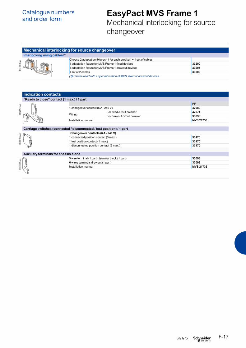
EasyPact MVS Frame 1Mechanical interlocking for source changeover
Catalogue numbersand order form
Mechanical interlocking for source changeoverInterlocking using cables (1)
DB4
1684
0.ep
s Choose 2 adaptation fixtures (1 for each breaker) + 1 set of cables1 adaptation fixture for MVS Frame 1 fixed devices 332001 adaptation fixture for MVS Frame 1 drawout devices 332011 set of 2 cables 33209(1) Can be used with any combination of MVS, fixed or drawout devices.
Indication contacts“Ready to close” contact (1 max.) / 1 part
DB40
2876
_new
.ai PF1 changeover contact (6 A - 240 V) 47080
WiringFor fixed circuit breaker 47074For drawout circuit breaker 33098
Installation manual MVS 21736
Carriage switches (connected / disconnected / test position) / 1 part
DB40
2916
_New
.ai Changeover contacts (6 A - 240 V)1 connected position contact (3 max.) 331701 test position contact (1 max.) 331701 disconnected position contact (2 max.) 33170
Auxiliary terminals for chassis alone
DB4
0439
9.ep
s 3 wire terminal (1 part), terminal block (1 part) 330986 wires terminals drawout (1 part) 33099Installation manual MVS 21736
F-17

EasyPact MVS Frame 2Remote operation
Catalogue numbersand order form
Remote operationGear motor
MCH (1 part)AC 50/60 Hz 100/130 V 47893
200/240 V 47894380/415 V 47896
DC 24/30 V 4788848/60 V 47889100/125 V 47890200/250 V 47891
Terminal block (1 part) For fixed circuit breaker 47074For draw-out circuit breaker 47849
Installation manual MVS21736Closing release (XF)
Standard coil (1 part)AC 50/60 HzDC
24/30 V DC, 24 V AC 3365948/60 V DC, 48 V AC 33660100/130 V AC/DC MVS15511200/250 V AC/DC MVS15512380/480 V AC MVS15513
Terminal block (1 part) For fixed circuit breaker 47074For draw-out circuit breaker 47849
Installation manual MVS21736Opening release (MX)
Standard coil (1 part)AC 50/60 HzDC
24/30 V DC, 24 V AC 3365948/60 V DC, 48 V AC 33660100/130 V AC/DC 33661200/250 V AC/DC 33662380/480 V AC 33664
Terminal block (1 part) For fixed circuit breaker 47074For draw-out circuit breaker 47849
Installation manual MVS21736
E951
72E9
5170
E951
70E9
5169
Fixed.
E951
71
Draw-out.
E951
69
Fixed.
E951
71
Draw-out.
E951
69
Fixed.
E951
71
Draw-out.
F-18

Remote operationUndervoltage release MN
Undervoltage release (1 part)AC 50/60 HzDC
24/30 V DC, 24 V AC 3366848/60 V DC, 48 V AC 33669100/130 V AC/DC 33670200/250 V AC/DC 33671380/480 V AC 33673
Terminal block (1 part) For fixed circuit breaker 47074For draw-out circuit breaker 47849
Installation manual MVS21736MN delay unit
MN delay unit (1 part)R (non-adjustable) Rr (adjustable)
AC 50/60 HzDC
48/60 V AC/DC 33680100/130 V AC/DC 33684 33681200/250 V AC/DC 33685 33682380/480 V AC/DC 33683
Installation manual MVS21736
E951
70E4
6694
E951
69
Fixed.
E951
71
Draw-out.
EasyPact MVS Frame 2Remote operation
Catalogue numbersand order form
F-19

EasyPact MVS Frame 2Chassis locking and accessories
Catalogue numbersand order form
Chassis locking“Disconnected” position locking / 1 part
By padlocksVCPO Standard
By Profalux keylocksProfalux 1 lock with 1 key + adaptation kit 64934
2 locks 1 key + adaptation kit 64935Profalux 1 lock+ 1 key (without adaptation kit) 42888Profalux 2 locks + 1 key (without adaptation kit) 42878Adaptation kit (without key locks) 48564
By Ronis keylocksRonis 1 lock with 1 key + adaptation kit 64937
2 locks 1 key + adaptation kit 64938Ronis 1 lock+ 1 key (without adaptation kit) 41940Ronis 2 locks + 1 key (without adaptation kit) 41950Adaptation kit (without key locks) 48564
Installation manual MVS21737Door interlock / 1 part
Right and left-hand side of chassis (VPECD or VPECG) 47914
Installation manual MVS21737
Chassis accessoriesAuxiliary terminal shield (CB) / 1 part
800/4000 A 3P 649424P 48596
Installation manual MVS21737Safety shutters + locking block / 1 part
800/4000 A 3P 487214P 48723
Installation manual MVS21737Shutter locking block (for replacement) / 1 part
2 parts for 800/4000 A 48591
Installation manual MVS21737
DB1
1745
8E4
6452
E464
58E4
6459
E464
60
Racking handleRacking handle 47944
E955
61
F-20

Circuit breaker lockingPushbutton locking device / 1 part
By padlocks 48536
Installation manual MVS21736OFF position locking / 1 part
By Profalux keylocksProfalux 1 lock with 1 key + adaptation kit 64928
2 locks 1 keys + adaptation kit 64929Profalux 1 lock+ 1 key (without adaptation kit) 42888Profalux 2 locks + 1 key (without adaptation kit) 42878Adaptation kit (without key locks) 64925
By Ronis keylocksRonis 1 lock with 1 key + adaptation kit 64931
2 locks 1 keys + adaptation kit 64932Ronis 1 lock+ 1 key (without adaptation kit) 41940Ronis 2 locks + 1 key (without adaptation kit) 41950Adaptation kit (without key locks) 64925
Installation manual MVS21736Mechanical operation counter / 1 part
Operation counter CDM 48535
Installation manual MVS21736Escutcheon and accessories / 1 part
E466
69
E466
70
Escutcheon Cover Blanking plate
Fixed Draw-outEscutcheon 48601 48603Transparent cover (IP 54) - 48604Escutcheon blanking plate 48605 48605
Installation manual MVS21736
E466
66E4
6735
DB1
2561
7C
DB5
0006
1
EasyPact MVS Frame 2Circuit breaker locking and accessories
Catalogue numbersand order form
F-21

Mechanical interlocking for source changeover
Mechanical interlocking for source changeoverInterlocking of 2 devices using cables (1)
Choose 2 adaptation sets (1 for each device + 1 set of cables)1 adaptation fixture for EasyPact MVS fixed devices 479261 adaptation fixture for EasyPact MVS draw-out devices 479261 set of 2 cables 33209(1) Can be used with any combination of EasyPact MVS, fixed or draw-out devices.
Installation manual MVS21738Interlocking of 3 devices using cables
Choose 3 adaptation (including 3 adaptation fixtures + cables)3 sources, only 1 device closed, fixed or draw-out devices 486102 sources + 1 coupling, fixed or draw-out devices 486092 normal + 1 replacement source, fixed or draw-out devices 48608Installation manual MVS21738
CD
B500
053
CD
B500
060
EasyPact MVS Frame 2Catalogue numbersand order form
F-22

Indication contactsON/OFF indication contacts (OF) / 12 parts
1 additional block of 4 contacts 47887Wiring For fixed circuit breaker 47074
For draw-out circuit breaker 47849
Installation manual MVS21736“Ready to close” contact (1 max.) / 1 part
1 changeover contact (5 A - 240 V) 47080Wiring For fixed circuit breaker 47074
For draw-out circuit breaker 47849
Installation manual MVS21736“Connected, disconnected, test position” indication contact (carriage switches) / 1 part
Changeover contacts 6 A - 240 V 33170
Installation manual MVS21736Auxiliary terminals for chassis alone
3 wire terminal (1 part) 478496 wire terminal (1 part) 47850Jumpers (10 parts) 47900
E466
89E4
6438
E466
61
EasyPact MVS Frame 2Indication contacts
Catalogue numbersand order form
F-23

Instructions
InstructionsEasyPact MVS User Manual (English) MVS21734Fixed & draw-out circuit breaker MVS21735Circuit breaker accessories MVS21736Chassis accessories MVS21737Interlocking of EasyPact MVS devices MVS21738MVS Communication user manual MVS21835
EasyPact MVS Catalogue numbersand order form
F-24

To indicate your choices, check the applicable square boxes
And enter the appropriate information in the rectangles
Circuit breaker or switch-disconnector Quantity
Rating A
Circuit breaker C/N/ H
Switch Disconnector CA/NA/HA
Number of poles 3 or 4
Optional Neutral on Right hand side YES
Type of equipment Fixed
Draw out with chassis
Draw out without chassis
(moving part only)
Chassis alone
Operating Mechanism Manual Operated
Electrical Operated
MCH - Gear motor V
XF - Closing coil V
MX - Shunt/Opening voltage release V
ET Trip System0- Without display 2I 5S 6G
A - Current Metering 2I 5S 6G
V - Energy Metering 2I 5S 6G
LR - Long-time rating plug Standard 0.4 to 1 Ir
CommunicationEco Com Module(only ETV Trip System)
Device(BCM ULP) Cradle management with
Modbus Interface(IFM) I/O application module (Chassis)
Breaker ULP Cord L=0.35m L=1.3m L=3m
Easy Communication Module
EasyCom Communication Module
Programmable contacts
2 M2C contacts(only with ETV Trip System)
ConnectionHorizontal Top Bottom √Vertical Top √ Bottom
Trip System functions:2I : Basic protection (long time + inst.)5S : Selective protection (long time + short time + inst.)6G : Selective + earth-fault protection (long time + short time + inst. + earth-fault)
EasyPact MVS
EasyPact MVSCircuit breaker and Switch-disconnectorsCustomer Order form
Indication contactsOF - ON/OFF indication contacts
Standard 1 block of 4 OF 10 A-240/380V AC
Additional(not incl MVS C/CA) 1 block of 4 OF 6 A-240/380V AC
SDE - “fault-trip” indication contact
Standard 1 SDE 5A -240/380V AC
OptionalCarriage switches 8 A-240/380V AC
CE - “Connected” position Max. 3 qty
CT - “Test” position Max. 3 qty
CD - “Disconnected” position Max. 3 qty
Remote tripping MN - Under voltage release V
R - Delay unit (fixed time delay) 0.25s
Rr - Adjustable delay unit 0.5s……3s
AD - External power-supply module V
TCE - MVS C- External sensor (NCT) for neutral of 3 Phase-4 Wire systems 400/1600A
TCE - MVS N/H- External sensor (NCT) for neutral of 3 Phase-4 Wire systems 400/2000A
TCE - MVS N/H- External sensor (NCT) for neutral of 3 Phase-4 Wire systems 1000/4000A
PF - “Ready to close” contact 5A-240/380V AC
LocksVBP - ON/OFF pushbutton locking (by transparent cover using padlock)
VSPO - Device locking in OFF position by key lock (Only one key lock per ACB possible)
Key lock kit (w/o key lock) Profalux Ronis
1 key lock Profalux Ronis
2 identical key locks, 1 key(non include MVS C/CA) Profalux Ronis
Chassis locking in “Disconnected” position:
VSPD - by key locks Key lock kit (w/o key lock) Profalux Ronis
1 key lock Profalux Ronis
2 identical key locks, 1 key Profalux Ronis
Door Interlock - VPEC On left-hand side of chassis (LH)
On right-hand side of chassis (RH)
Mechanical Interlocking of ACBs with Cable1 Normal source & 1 replacement source (2 devices)
2 normal + 1 replacement source, fixed or draw-out devices
2 sources with coupler on busbars (3 devices)
3 sources, only 1 device closed, fixed or draw-out devices
AccessoriesVO - Safety shutters on chassis Standard
CDP - Escutcheon Standard
Safety Shutter locking blocks
CP - Transparent cover for escutcheon
OP - Blanking plate for escutcheon
CDM - Mechanical operation counter for MVSl(not incl MVS C/CA)
CB - Auxiliary terminal shield fitted on chassis
EIP - Interphase barriers
HHTK - Hand held test kit
Notes:Customer can provide only the reference no. of the product for the listed references. Kindly refer to product catalogue for list of references. Customer to fill this order form for non-listed references.All breakers will be provided with 1 OF (4 c/o contacts), 1 SDE (trip contact), Escutcheon (Panel sealing frame) as standard.All draw-out breakers/switches will be supplied with Chassis & safety shutter.For Electrical operated breakers/ switches, indicate the voltage ratings of MCH,XF & MXRefer to product catalogue for available voltage ratings of MCH/XF/MX/MN & AD ModuleThe orientation of customer connecting terminals can be changed at site from Horizontal to vertical or vice-versa. EasyPact MVS order form V 2.1
Order ref no:
Date:
Product ref no:OA No. (to be filled by Order booking team)
Catalogue numbersand order form
F-25

Schneider Electric Industries SAS
35, rue Joseph MonierCS 3032392506 Rueil Malmaison Cedex France
RCS Nanterre 954 503 439Capital social 928 298 512 €www.se.com
May-2021 © 2021 - Schneider Electric. All Rights Reserved.All trademarks are owned by Schneider Electric Industries SAS or its affiliated companies.Document reference LVED211021EN
This document has beenprinted on recycled paper