EAST KERN WATER AGENCY CONTRACT DOCUMENTS
232
ANTELOPE VALLEY - EAST KERN WATER AGENCY CONTRACT DOCUMENTS FOR HIGH DESERT WATER BANK - MONITORING WELL, DUAL-COMPLETION PIEZOMETER NEST, AND PILOT RECOVERY WELLS PROJECT PROJECT NO. HDWB 20-01
-
Upload
khangminh22 -
Category
Documents
-
view
0 -
download
0
Transcript of EAST KERN WATER AGENCY CONTRACT DOCUMENTS

ANTELOPE VALLEY - EAST KERN WATER AGENCY
CONTRACT DOCUMENTS
FOR
HIGH DESERT WATER BANK - MONITORING WELL, DUAL-COMPLETION PIEZOMETER NEST, AND PILOT
RECOVERY WELLS PROJECT
PROJECT NO. HDWB 20-01

THIS PAGE INTENTIONALLY BLANK

TABLE OF CONTENTS
Page
HDWB – Monitoring Well, Dual-Completion Piezometer Nest, and Pilot Recovery Wells Project No.:HDWB 20-01
-i-
NOTICE INVITING BIDS ................................................................................................... NIB-1
INSTRUCTIONS TO BIDDERS ........................................................................................... IB-1
CHECKLIST FOR BIDDERS .................................................................................................... 1
BID ..................................................................................................................................B-1
CHECKLIST FOR EXECUTION OF CONTRACT .................................................................... 1
CONTRACT ......................................................................................................................... C-1
PAYMENT BOND (LABOR AND MATERIALS) ................................................................ LMB-1
PERFORMANCE BOND .................................................................................................... PB-1 INSURANCE CERTIFICATES AND ENDORSEMENTS ................................................... INS-1 GENERAL PROVISIONS ................................................................................................... GP-1
SPECIAL PROVISIONS ..................................................................................................... SP-1

TABLE OF CONTENTS
Page
HDWB – Monitoring Well, Dual-Completion Piezometer Nest, and Pilot Recovery Wells Project No.:HDWB 20-01
-ii-
THIS PAGE INTENTIONALLY BLANK

HDWB – Monitoring Well, Dual-Completion Piezometer Nest, and Pilot Recovery Wells Project No.:HDWB 20-01
NIB-1
NOTICE INVITING BIDS FOR
High Desert Water Bank – Monitoring Well, Dual-Completion Piezometer Nest, and Pilot Recovery Wells [the “Project”]
PROJECT NO. HDWB 20-01NOTICE IS HEREBY GIVEN that Antelope Valley - East Kern Water Agency (the “Agency”) invites sealed Bids for the Project. The Agency will receive such Bids at its Administrative Office, 6500 West Avenue N, Palmdale, CA 93551 up to 3:00 p.m. on DECEMBER 10, 2020, at which time they will be publicly opened and read aloud.
SCOPE OF WORK. The Project includes, without limitation, furnishing all necessary labor, materials, equipment, and other incidental and appurtenant Work necessary to satisfactorily complete the Project, as more specifically described in the Contract Documents. This Work will be performed in strict conformance with the Contract Documents, permits from regulatory agencies with jurisdiction, and applicable regulations. The quantity of Work to be performed and materials to be furnished are approximations only, being given as a basis for the comparison of Bids. Actual quantities of Work to be performed may vary at the discretion of the Agency Engineer.
Discrepancies in, and/or omissions from the Bid or Contract Documents or questions as to their meaning shall be immediately brought to the attention of AVEK by submission of a written request for an interpretation or clarification to AVEK. Such submission, if any, must be sent to Justin Livesay at [email protected]. Questions must be submitted by 5:00 p.m. on DECEMBER 3, 2020. Questions received after this date and time may not be answered.
Any interpretation of the Contract Documents will be made only by written addenda duly issued by AVEK. AVEK will not be responsible for any explanations or interpretations provided in any other manner. No person is authorized to make any oral interpretation of any provision in the Contract Documents to any bidder, and no bidder should rely on any such oral interpretation.
In general, the WORK shall consist of the drilling, construction, development and testing of four new Pilot Recovery Wells, one Monitoring Well and one Dual-Completion Piezometer Nest including but not limited to the following:
Pilot Recovery Wells Typical Four Locations:
A. Mobilize and demobilize all required equipment for the construction of four pilot recovery wells as described by these contract documents, specifications and plans.
B. Clearing and Grubbing to provide adequate unobstructed working space for the Pilot Wells at four locations.
C. Meet discharge and waste requirements.
D. Develop as required to accomplish the WORK all temporary facilities including but not limited to temporary water supply, water storage, disposal systems, temporary lighting, temporary power supply, required storage tankage, and safety measures requirements.

HDWB – Monitoring Well, Dual-Completion Piezometer Nest, and Pilot Recovery Wells Project No.:HDWB 20-01
NIB-2
E. Furnish, install and impervious-seal a 36-inch diameter by 0.50-inch thick steel conductor casing in a 42-inch diameter borehole to a depth of 50 feet below ground surface (bgs) required for the Pilot Recovery Wells at four locations.
F. Drill a nominal 17.5-inch diameter pilot hole from 50 to 1,200 feet bgs required for the Pilot Recovery Wells at four locations
G. Collect and preserve grab formation samples and submit for analysis at intervals prescribed by this Specification for the Pilot Recovery Wells at four locations.
H. Perform directional and deviation survey of the pilot hole for the Pilot Recovery Wells at four locations.
I. Perform a geophysical survey of the pilot hole for the Pilot Recovery Wells at four locations.
J. Perform isolated aquifer zone testing at up to six (6) discrete zones for each Pilot Recovery Well, typical at four locations.
K. Ream the pilot hole to 32-inches and 26-inches diameters to depth specified in the final well design from 50 feet up to 1,200 feet bgs
L. Perform a caliper survey of the reamed borehole for the Pilot Recovery Wells at four locations.
M. Furnish and install an 18-inch inside diameter, 3/8-inch wall thickness HSLA blank sump for the Pilot Recovery Wells at four locations.
N. Furnish and install an 18-inch inside diameter, HSLA Ful-Flo louvered well screen for the Pilot Recovery Wells at four locations.
O. Furnish and install an 18-inch inside diameter, 3/8-inch wall thickness HSLA blank casing for the Pilot Recovery Wells at four locations.
P. Furnish and install nominal 2.5-inch diameter mild steel filter pack fill feed tube for the Pilot Recovery Wells at four locations.
Q. Furnish and install 8 x 16 silica sand filter pack for the Pilot Recovery Wells at four locations.
R. Furnish and install No. 1C Silica Sand for the Pilot Recovery Wells at four locations.
S. Furnish and install cement seal from ground surface to 390 feet bgs for the Pilot Recovery Wells at four locations.
T. Perform two stages of well development for the Pilot Wells at four locations.
U. Install, operate and remove temporary pumping equipment and appurtenance for pumping development assuming up to 2,250 gpm with the pump intake at 420 feet bgs for the Pilot Wells at four locations.
V. Furnish and install pressure transducers and sounding tubes.

HDWB – Monitoring Well, Dual-Completion Piezometer Nest, and Pilot Recovery Wells Project No.:HDWB 20-01
NIB-3
W. Perform pump development by pumping and surging for the Pilot Wells at four locations.
X. Perform step-drawdown test by pumping for the Pilot Wells at four locations.
Y. Perform a seven (7)-day constant-rate discharge test by pumping for the Pilot Wells at four locations.
Z. Conduct a spinner-log survey with depth specific groundwater sampling for the Pilot Wells at four locations.
AA. Perform a color video survey for the Pilot Wells at four locations.
BB. Conduct a well alignment/deviation test by gyroscopic methods for the Pilot Wells at four locations
CC. Complete final disinfection and provide temporary lockable lid for the Pilot Wells at four locations.
DD. Construct a well completion pad with removable bollards for the Pilot Wells at four locations.
EE. Provide containment, transport and disposal of all Hazardous drill cuttings in a legal and proper manner for the Pilot Wells at four locations.
FF. Provide containment, transport and disposal of all Non-Hazardous drill cuttings in a legal and proper manner for the Pilot Wells at four locations.
GG. Provide containment and disposal of drilling fluid, solids settled and filtered from all waster related to the Pilot Wells construction in a legal and proper manner at four locations.
Monitoring Well
A. Mobilize and demobilize all required equipment for the construction of one monitoring well as described by these contract documents, specifications and plans.
B. Clearing and Grubbing to provide adequate unobstructed working space for the Monitoring Well.
C. Meet discharge and waste requirements for the construction, development and testing of one monitoring well.
D. Develop as required to accomplish the WORK all temporary facilities including but not limited to temporary water supply, water storage, disposal systems, temporary lighting, temporary power supply, required storage tankage, and safety measures requirements for the construction of one monitoring well.
E. Furnish, install and impervious-seal a 14-inch outside diameter by 0.25-inch thick steel surface casing in a 20-inch diameter borehole to a depth of 20 feet (bgs) required for the one monitoring well.

HDWB – Monitoring Well, Dual-Completion Piezometer Nest, and Pilot Recovery Wells Project No.:HDWB 20-01
NIB-4
F. Drill a 12-inch diameter borehole from 20 feet bgs to 1,000 feet bgs for one monitoring well.
G. Perform a geophysical survey, collect, preserve and preserve grab samples of the pilot hole for one monitoring well.
H. Furnish and install a 6-inch inside diameter by 0.25-inchwall thickness blank HSLA steel casing sump for one monitoring well.
I. Furnish and install a 6-inch inside diameter by 0.25-inch wall thickness Ful-Flo louvered well screen with centralizers at every 40 feet vertical distance for one monitoring well.
J. Furnish and install a 6-inch inside diameter by 0.25-inch wall thickness blank HSLA steel casing with centralizers at every 40 feet vertical distance with three pressure transducers strapped to the casing in the upper 350 feet for one monitoring well.
K. Furnish and Install filter pack sand (8 x 16 gradation) in the screened intervals, including three (3) feet of fine sand transition on top of the filter sand pack intervals.
L. Furnish and install hydrated bentonite intermediate seals between screened intervals for one monitoring well as described by these specifications and drawings.
M. Furnish and install a hydrated bentonite seal above the transition seal above the filter sand pack for the uppermost screened interval for one monitoring well.
N. Furnish and install cement-bentonite sanitary seal above the transition seal to ground surface for one monitoring well.
O. Perform well development by airlifting and swabbing for one monitoring well.
P. Install temporary pump with a minimum capacity of 200 gpm and all required temporary facilities to provide full functionality and perform additional development by pumping for one monitoring well.
Q. Perform two 12-hour constant-rate discharge test by pumping in each screened casing intervals inclusive of required packers to isolate each screened casing interval.
R. Conduct a well alignment/deviation test by gyroscopic methods for one monitoring well.
S. At the option of the AGENCY, install temporary pump with a minimum of 200 gpm and all required temporary facilities to provide full functionality and perform a third 12-hour constant-rate discharge test by pumping at a third screened interval inclusive of required packers to isolate each screened casing interval.
T. Provide containment, transport and disposal of all drill cuttings in a legal and proper manner for one monitoring well.
U. Provide containment and disposal of drilling fluid, solids settled and filtered from all waster related to one monitoring well construction in a legal and proper manner.
V. Construct a well completion pad with removable bollards for one monitoring well.

HDWB – Monitoring Well, Dual-Completion Piezometer Nest, and Pilot Recovery Wells Project No.:HDWB 20-01
NIB-5
Dual Completion Piezometer Nest.
A. Mobilize and demobilize all required equipment for the construction of a Dual Completion Well as described by these contract documents, specifications and plans.
B. Clearing and Grubbing to provide adequate unobstructed working space for the Dual Completion Piezometer Nest.
C. Drill by Air Rotary Casing Hammer (ARCH) or approved casing advancement drilling method a 12-inch nominal diameter borehole from ground surface to approximately 250 feet bgs for one Dual Completion Piezometer Nest.
D. Backfill bottom of borehole, if warranted, using cement or hydrated bentonite or approved equal material for one Dual Completion Piezometer Nest.
E. Furnish and install 2.5-inch diameter Schedule 80 polyvinyl chloride (PVC) blank casing for two completions for one Dual Completion Piezometer Nest.
F. Furnish and install 2.5-inch diameter Schedule 80 slotted PVC casing for two completions, with 0.020-inch wide slots for one Dual Completion Piezometer Nest.
G. Install all blank and slotted PVC casing for two completions in the same borehole with centralizers and spacers every 30 feet vertical for one Dual Completion Piezometer Nest.
H. Furnish and filter pack sand (8 x 16 gradation) in the two screened intervals, including 2 feet of fine sand on top of the filter sand pack for one Dual Completion Piezometer Nest.
I. Furnish and install hydrated bentonite transition seals above the filter sand pack for both screened intervals and below the filter sand pack for the upper screened interval for one Dual Completion Piezometer Nest.
J. Furnish and install a cement bentonite grout intermediate seal between screened intervals for one Dual Completion Piezometer Nest.
K. Furnish and install a cement bentonite grout sanitary seal above the uppermost transition seal to ground surface for one Dual Completion Piezometer Nest.
L. Provide field personnel for transportation and injection of water during hydraulic testing of the piezometer nest for one Dual Completion Piezometer Nest.
M. Construct a well completion pad with removable bollards for one Dual Completion Piezometer Nest.
N. Provide containment, transport and disposal of all Hazardous drill cuttings in a legal and proper manner for one Dual Completion Piezometer Nest.
O. Provide containment, transport and disposal of all Non-Hazardous drill cuttings in a legal and proper manner for one Dual Completion Piezometer Nest.
Project Location

HDWB – Monitoring Well, Dual-Completion Piezometer Nest, and Pilot Recovery Wells Project No.:HDWB 20-01
NIB-6
The project is located within the area bounded by the State Water Project East Branch to the south, 280th Street W to the east, 300th Street W to the west and West Avenue A to the north in the unincorporated portions of Los Angeles County, Antelope Valley California. The specific recovery wells, monitoring well and dual completion piezometer nest is within the area bounded as described above and is referenced on the plans and construction documents.
Schedule of Construction
Construction of one monitoring well, one dual completion piezometer nest, and four pilot recovery wells inclusive of providing all materials, labor, equipment, ancillary/temporary works, testing, mobilization/demobilization, site cleanup and project close out shall be accomplished within 120 working days. The Contractor shall construct the monitoring well and dual completions piezometer nest as the first order of work. The Contractor at his option may accomplish the remaining work in a parallel fashion using multiple drilling and project personnel to meet the objective schedule.
OBTAINING BID DOCUMENTS. Bidders may obtain copies of the Plans, Specifications and other Contract Documents online by visiting https://www.avek.org/invitation-for-bids-ifb. Potential Bidders may also purchase the Contract Documents for the Project at the Agency’s Administrative Office, 6500 West Avenue N, Palmdale, CA 93551for a non-refundable fee of $20.00 per set, or $50.00 per set if mailed. The Agency must receive payment before the Contract Documents will be provided.
MANDATORY PRE-BID MEETING AND SITE VISIT. A mandatory pre-bid meeting will be held on DECEMBER 1, 2020 at 10 a.m. at 6500 West Avenue N., Palmdale, CA, followed by a non-mandatory site visit. Every Bidder is required to attend the pre-bid meeting and Project site visit. Failure of a Bidder to attend will render that Bidder’s Bid non-responsive. No allowances for cost adjustments will be made if a Bidder fails to adequately examine the Project site before submitting a Bid. All Bidder’s shall comply with current COVID-19 local requirements and provide Personal Protective Equipment during the Pre-Bid Meeting and Site Visit.
REGISTRATION WITH THE DEPARTMENT OF INDUSTRIAL RELATIONS. In accordance with Labor Code Sections 1725.5 and 1771.1, no contractor or subcontractor shall be qualified to bid on, be listed in a bid proposal, subject to the requirements of Section 4104 of the Public Contract Code, or engage in the performance of any contract for public work, unless currently registered and qualified to perform public work pursuant to Section 1725.5 [with limited exceptions for bid purposes only under Labor Code Section 1771.1(a)].
PREVAILING WAGES. In accordance with Labor Code Section 1770 et seq., the Project is a “public work.” The selected Bidder (Contractor) and any Subcontractors shall pay wages in accordance with the determination of the Director of the Department of Industrial Relations (“DIR”) regarding the prevailing rate of per diem wages. Copies of those rates are on file with the Director of Public Works, and are available to any interested party upon request. The Contractor shall post a copy of the DIR’s determination of the prevailing rate of per diem wages at each job site. This Project is subject to compliance monitoring and enforcement by the DIR.
BONDS. Each Bid must be accompanied by a cash deposit, cashier’s check, certified check or Bidder’s Bond issued by a Surety insurer, made payable to the Agency and in an amount not less than ten percent (10%) of the total Bid submitted. Personal or company checks are not acceptable. Upon Contract award, the Contractor shall provide faithful performance and payment Bonds, each in a sum equal to the Contract Price. All Bonds must be issued by a California admitted Surety insurer using the forms set forth in the Contract Documents, or in any other form

approved by the Agency General Counsel. Failure to enter into the Contract with the Agency,including the submission of all required Bonds and insurance coverages, within fifteen (15) Daysafter the date of the mailing of written notice of contract award to the Bidder, shall subject the Bidsecurity to forfeiture to the extent provided by law.
LICENSES. Each Bidder shall possess a valid Class C-57 Contractor's license issued by theCalifornia State Contractors License Board at the time of the Bid submission, unless this Projecthas any federalfunding, in which case the successful Bidder must possess such a license at thetime of Contract award. The successful Contractor must also possess a current business licenseissued by the City of Palmdale.
RETENTION SUBSTITUTION. Five percent (5%) of any progress payment will be withheld asretention. ln accordance with Public Contract Code Section 22300, and at the request andexpense of the Contractor, securities equivalent to the amount withheld may be deposited withthe Agency or with a State or federally chartered bank as escrow agent, which shall then pay suchmoneys to the Contractor. Upon satisfactory completion of the Project, the securities shall bereturned to the Contractor. Alternatively, the Contractor may request that the Agency makepayments of earned retentions directly to an escrow agent at the Contractor's expense. No suchsubstitutions shall be accepted until all related documents are approved by the Agency GeneralCounsel.
BIDDING PROCESS. The Agency reserves the right to reject any Bid or all Bids, and to waiveany irregularities or informalities in any Bid or in the bidding, as deemed to be in its best interest.
By:
It-t6.-zozoDwayne Chisam, PERegistered Civil Engineer CA 43851General Manager/Chief EngineerAntelope Valley East Kern WaterAgency
Date
HDWB - Monitoring Well, Dual-CompletionPiezometer Nest, and Pilot Recovery Wells NIB-7Project No.:HDWB 20-01

HDWB – Monitoring Well, Dual-Completion Piezometer Nest, and Pilot Recovery Wells Project No.:HDWB 20-01
NIB-8
THIS PAGE INTENTIONALLY BLANK

HDWB – Monitoring Well, Dual-Completion Piezometer Nest, and Pilot Recovery Wells Project No.:HDWB 20-01
IB-1
INSTRUCTIONS TO BIDDERS
FORM OF BID. Bids shall be made on the Bid forms found herein. Bidders shall include all forms and fill in all blank spaces, including inserting “N/A” (for not applicable) where necessary. Each Bid must be submitted in a sealed envelope bearing the Bidder’s name and addressed to the Agency Clerk with the Project name and identification number (as described in the Notice Inviting Bids) typed or clearly printed on the lower left corner of the envelope.
DELIVERY OF BIDS. The Bid shall be delivered by the time and date, and to the place specified in the Notice Inviting Bids. No oral, faxed, emailed, or telephonic Bids or alternatives will be considered. The time of delivery shall be conclusively determined by the time-stamping clock located at the Agency Clerk’s office. Bidders are solely responsible for ensuring that their Bids are received in proper time, and Bidders assume all risks arising out of their chosen means of delivery. Any Bid received after the Bid submission deadline shall be returned unopened. Bidders are invited to be present for Bid opening. Accepted Bids shall become the property of the Agency.
AMENDED BIDS. Unauthorized conditions, limitations or provisos attached to a Bid may cause the Bid to be deemed incomplete and non-responsive.
WITHDRAWAL OF BID. A Bid may be withdrawn without prejudice upon written request by the Bidder filed with the Agency Clerk before the Bid submission deadline. Bids must remain valid and shall not be subject to withdrawal for sixty (60) Days after the Bid opening date.
BIDDER’S SECURITY. Each Bid shall be accompanied by cash, a certified or cashier’s check payable to the Agency, or a satisfactory Bid Bond in favor of the Agency executed by the Bidder as principal and an admitted surety insurer as Surety, in an amount not less than ten percent (10%) of the amount set forth in the Bid. The cash, check or Bid Bond shall be given as a guarantee that, if selected, the Bidder will execute the Contract in conformity with the Contract Documents, and will provide the evidence of insurance and furnish the specified Bonds, within fifteen (15) Days after the date of delivery of the Contract Documents to the Bidder. In case of the Bidder’s refusal or failure to do so, the Agency may award the Contract to the next lowest responsible bidder, and the cash, check, or Bond (as applicable) of the lowest Bidder shall be forfeited to the Agency to the extent permitted by law. No Bid Bond will be accepted unless it conforms substantially to the form provided in these Contract Documents.
QUANTITIES APPROXIMATE. Any quantities shown in the Bid form or elsewhere herein shall be considered as approximations listed to serve as a general indication of the amount of Work or materials to be performed or furnished, and as basis for the Bid comparison. The Agency does not guarantee that the actual amounts required will correspond with those shown. As deemed necessary or convenient, the Agency may increase or decrease the amount of any item or portion of Work or material to be performed or furnished or omit any such item or portion, in accordance with the Contract Documents.
ADDENDA. The Agency Engineer may, from time to time, issue Addenda to the Contract Documents. Bidders are responsible for ensuring that they have received any and all Addenda. Each Bidder is responsible for verifying that it has received all Addenda issued, if any. Bidders must acknowledge receipt of all Addenda, if any, in their bids. Failure to acknowledge receipt of all Addenda may cause a Bid to be deemed incomplete and non-responsive.
FACSIMILE NUMBER AND EMAIL ADDRESS. Bidders shall supply the Agency Engineer with a facsimile number and email address to facilitate transmission of Addenda and other information

HDWB – Monitoring Well, Dual-Completion Piezometer Nest, and Pilot Recovery Wells Project No.:HDWB 20-01
IB-2
related to these Contract Documents. If the Addenda and other information are emailed, the Agency shall also send all documents by facsimile or U.S. Mail. Failure to provide such a facsimile number and email address may result in late notification. The Agency does not guarantee that it will provide any information by facsimile, email, or both. A Bidder shall be responsible for all Addenda regardless of whether Bidder received any such fax or email, and a Bidder shall have no recourse due to not receiving such facsimile, email or both.
DISCREPANCIES IN BIDS. Each bidder shall set forth as to each item of Work, in clearly legible figures, a unit or line item Bid amount for the item in the respective spaces provided for this purpose.
In case of discrepancy between the unit price and the extended amount set forth for the item, the unit price shall prevail. However, if the amount set forth as a unit price is ambiguous, unintelligible or uncertain for any cause, or is omitted, or if the unit price is the same amount as the entry in the “extended amount” column, then the amount set forth in the “extended amount” column for the item shall prevail in accordance with the following:
(1) As to lump sum items, the amount set forth in the “extended amount” column shall bethe unit price.
(2) As to unit price items, the amount set forth in the “extended amount” column shall bedivided by the estimated quantity for the item set forth in the Bid documents, and theprice thus obtained shall be the unit price.
COMPETENCY OF BIDDERS. In evaluating Bidder responsibility, consideration will be given not only to the financial standing, but also to the general competency of the Bidder for the performance of the Project. Each Bidder shall set forth in the designated area of the Bid form a statement of its experience. No Contract will be executed with a Bidder that is not licensed and registered with the DIR in accordance with State law, and with any applicable specific licensing requirements specified in these Contract Documents. These licensing and registration requirements for Contractors shall also apply to all Subcontractors.
BIDDER’S EXAMINATION OF SITE AND CONTRACT DOCUMENTS. Each Bidder must carefully examine the Project site and the entirety of the Contract Documents. Upon submission of a Bid, it will be conclusively presumed that the Bidder has thoroughly investigated the Work and is satisfied as to the conditions to be encountered and the character, quality, and quantities of Work to be performed and materials to be furnished. Upon Bid submission, it also shall be conclusively presumed that the Bidder is familiar with and agrees to the requirements of the Contract Documents, including all Addenda. No information derived from an inspection of records or investigation will in any way relieve the Contractor from its obligations under the Contract Documents nor entitle the Contractor to any additional compensation. The Contractor shall not make any claim against the Agency based upon ignorance or misunderstanding of any condition of the Project site or of the requirements set forth in the Contract Documents. No claim for additional compensation will be allowed which is based on a lack of knowledge of the above items. Bidders assume all risks in connection with performance of the Work in accordance with the Contract Documents, regardless of actual conditions encountered, and waive and release the Agency with respect to any and all claims and liabilities in connection therewith, to the extent permitted by law.
TRADE NAMES OR EQUALS. Requests to substitute an equivalent item for a brand or trade name item must be made by written request submitted no later than the date specified in Section

HDWB – Monitoring Well, Dual-Completion Piezometer Nest, and Pilot Recovery Wells Project No.:HDWB 20-01
IB-3
4-6 of the General Provisions. Requests received after this time shall not be considered.Requests shall clearly describe the product for which approval is requested, including all datanecessary to demonstrate acceptability.
DISQUALIFICATION OF BIDDERS. No Person shall be allowed to make, file or be interested in more than one Bid for the Project, unless alternate Bids are specifically called for. A Person that has submitted a sub-bid to a Bidder, or that has quoted prices of materials to a Bidder, is not thereby disqualified from submitting a sub-proposal or quoting prices to other Bidders or from making a prime Bid. If there is a reason to believe that collusion exists among the Bidders, all affected Bids will be rejected.
RETURN OF BID SECURITY. The successful Bidder’s Bid security shall be held until the Contract is executed. Bid security shall be returned to the unsuccessful Bidders within a reasonable time, which in any case shall not exceed sixty (60) Days after the successful Bidder has signed the Contract.
AWARD OF CONTRACT. The Agency reserves the right to reject any or all Bids or any parts thereof or to waive any irregularities or informalities in any Bid or in the bidding. The Contract award, if made, will be to the lowest responsible, responsive Bidder and is anticipated to occur within sixty (60) Days after the Bid opening. The Contract award may be made after that period if the selected Bidder has not given the Agency written notice of the withdrawal of its Bid.
DETERMINATION OF LOWEST RESPONSIBLE BID. In accordance with Public Contract Code Section 20103.8.
TRENCHING. If the Project involves the construction of a pipeline, sewer, sewage disposal system, boring and jacking pits, or similar trenches or open excavations, which are five (5) feet deep or more, then each Bidder must submit, as a Bid item, adequate sheeting, shoring, and bracing, or an equivalent method, for the protection of life or limb, which shall conform to applicable safety orders. This final submission must be accepted by the Agency in advance of excavation and must include a detailed plan showing the design of shoring, bracing, sloping, or other provisions to be made for worker protection from caving ground during the excavation Work. If such plan varies from the shoring system standards, the plan shall be prepared by a registered civil or structural engineer.
LISTING SUBCONTRACTORS; SELF-PERFORMANCE. Each Bidder shall submit a list of the proposed Subcontractors on the Project, as required by the Subletting and Subcontracting Fair Practices Act (Public Contract Code Section 4100, et seq.). Contractor shall self-perform not less than 50% of the Work, in accordance with Section 3-2 of the Standard Specifications.
EXECUTION OF CONTRACT. The selected Bidder shall execute the Contract in the form included in these Contract Documents within fifteen (15) Days from the date of delivery of the Contract Documents to the Bidder. Additionally, the selected Bidder shall also secure all insurance and Bonds as herein specified, and provide copies to the Agency, within fifteen (15) Days from the date of delivery of the Contract Documents to the Bidder. Failure or refusal to execute the Contract or to conform to any of the stipulated requirements shall be just cause for the annulment of the award and forfeiture of the Bidder’s security. In such event, the Agency may declare the Bidder’s security forfeited to the extent permitted by law, and the Agency may award the Contract to the next lowest responsible Bidder or may reject all bids.

HDWB – Monitoring Well, Dual-Completion Piezometer Nest, and Pilot Recovery Wells Project No.:HDWB 20-01
IB-4
SIGNATURES. The Bidder shall execute all documents requiring signatures, and shall cause to be notarized all documents that indicate such a requirement. Bids submitted as joint ventures must so state and be signed by each joint venturer. The Bidder shall provide evidence satisfactory to the Agency, such as an authenticated resolution of its board of directors, a certified copy of a certificate of partnership acknowledging the signer to be a general partner, or a power of attorney, indicating the capacity of the person(s) signing the Bid to bind the Bidder to the Bid and any Contract arising therefrom. Alternatively, Bids submitted by corporations must be executed as specified in Corporations Code Section 313, and Bids submitted by partnerships must be executed by all partners comprising the partnership.
INSURANCE AND BONDS. The Contractor shall not begin Work until it has given the Agency evidence of all required insurance coverage (including all additional insured endorsements), a Bond guaranteeing the Contractor’s faithful performance of the Contract, and a Bond securing the payment of claims for labor and materials.
TELEPHONES. Bidders are hereby notified that the Agency will not provide telephones for their use at the time of Bid submission.
TAXES. Except as may be otherwise specifically provided herein, all sales and/or use taxes assessed by federal, State or local authorities on materials used or furnished by the Contractor in performing the Work shall be paid by the Contractor. The Bidder shall calculate payment for all sales, unemployment, pension and other taxes imposed by federal, State, and local law and shall include these payments in computing the Bid.

HDWB – Monitoring Well, Dual-Completion Piezometer Nest, and Pilot Recovery Wells Project No.:HDWB 20-01
Checklist-1
CHECKLIST FOR BIDDERS
The following information is required of all Bidders at the time of Bid submission:
____ Completed and Signed Bid Cover Form
____ Completed and Signed Bid Sheets
____ Completed, Signed and Notarized Questionnaire
____ Completed References Form
____ Resume of General Construction Superintendent/On-Site Construction Manager
____ Completed Subcontractor Designation Form
____ Completed and Signed Industrial Safety Record Form
____ Completed, Signed and Notarized Bid Bond or Other Security Form
____ Signed and Notarized Noncollusion Declaration Form
____ Evidence satisfactory to the Agency indicating the capacity of the person(s) signing the Bid to bind the Bidder
Failure of the Bidder to provide all required information in a complete and accurate manner may cause the Bid to be considered non-responsive.

HDWB – Monitoring Well, Dual-Completion Piezometer Nest, and Pilot Recovery Wells Project No.:HDWB 20-01
Checklist-2
THIS PAGE INTENTIONALLY BLANK

HDWB – Monitoring Well, Dual-Completion Piezometer Nest, and Pilot Recovery Wells Project No.:HDWB 20-01
B-1
BID
ANTELOPE VALLEY - EAST KERN WATER AGENCY High Desert Water Bank – Monitoring Well, Dual-Completion Piezometer Nest, and Pilot
Recovery Wells [PROJECT]
TO THE BOARD OF DIRECTORS OF ANTELOPE VALLEY - EAST KERN WATER AGENCY AND ANTELOPE VALLEY - EAST KERN WATER AGENCY:
The undersigned, as Bidder, declares that: (1) this Bid is made without collusion with any other person and that the only persons or parties interested as principals are those named herein; (2) the undersigned has carefully examined the Contract Documents (including all Addenda) andthe Project site; and (3) the undersigned has investigated and is satisfied as to the conditions tobe encountered, the character, quality and quantities of Work to be performed, and the materialsto be furnished. Furthermore, the undersigned agrees that submission of this Bid shall beconclusive evidence that such examination and investigation have been made and agrees, in theevent the Contract be awarded to it, to execute the Contract with Antelope Valley - East KernWater Agency to perform the Project in accordance with the Contract Documents in the time andmanner therein prescribed, and to furnish or provide all materials, labor, tools, equipment,apparatus and other means necessary so to do, except as may otherwise be furnished or providedunder the terms of the Contract Documents, for the following stated unit prices or lump-sum priceas submitted on the Bid herein.
Bidder acknowledges receipt of all addenda, as follows:
Addendum No. _______________ Date: ____________________
Addendum No. _______________ Date: ____________________
Addendum No. _______________ Date: ____________________
Addendum No. _______________ Date: ____________________
The undersigned submits as part of this Bid a completed copy of its Industrial Safety Record. This Safety Record includes all construction Work undertaken in California by the undersigned and any partnership, joint venture or corporation that any principal of the undersigned participated in as a principal or owner for the last five (5) calendar years and the current calendar year before the date of Bid submittal. Separate information is being submitted for each such partnership, joint venture, or corporate or individual Bidder. The undersigned may attach any additional information or explanation of data that it would like to be taken into consideration in evaluating the Safety Record. An explanation of the circumstances surrounding any and all fatalities is attached.
Accompanying this Bid is cash, a cashier’s check, a certified check or a Bid Bond in an amount equal to at least ten percent (10%) of the total aggregate Bid price based on the quantities shown and the unit prices quoted. The undersigned further agrees that, should it be awarded the Contract and thereafter fail or refuse to execute the Contract and provide the required evidence of insurance and Bonds within fifteen (15) Days after delivery of the Contract to the undersigned, then the cash, check or Bid Bond shall be forfeited to the Agency to the extent permitted by law.

HDWB – Monitoring Well, Dual-Completion Piezometer Nest, and Pilot Recovery Wells Project No.:HDWB 20-01
B-2
The undersigned certifies to have a minimum of three (3) consecutive years of current experience in the type of Work related to the Project and that this experience is in actual operation of the firm with permanent employees performing a part of the Work as distinct from a firm operating entirely by subcontracting all phases of the Work. The undersigned also certifies to be properly licensed by the State as a contractor to perform this type of Work. The undersigned possesses California Contractor’s License Number ____________, Class _____, which expires on _______________________.
Bidder’s Name: ___________________________________________________
Signature: __________________________________ Title: ___________ Date: ______
Signature: __________________________________ Title: ___________ Date: ______

HDWB – Monitoring Well, Dual-Completion Piezometer Nest, and Pilot Recovery Wells Project No.:HDWB 20-01
B-3
ANTELOPE VALLEY - EAST KERN WATER AGENCY
BID SHEETS FOR
High Desert Water Bank – Monitoring Well, Dual-Completion Piezometer Nest, and Pilot Recovery Wells [PROJECT]
Bidder’s Name: ____________________________________________________________
To Antelope Valley - East Kern Water Agency and its Board of Directors:
In compliance with the Notice Inviting Bids, the undersigned hereby agrees to execute the Contract to furnish all labor, materials, equipment and supplies for the Project in accordance with the Contract Documents to the satisfaction and under the direction of the Agency Engineer, at the following prices:
BASE AMOUNT:
ITEM NO.
ITEM DESCRIPTION QUANTITY UNIT UNIT PRICE NO. of
WELLS TOTAL PRICE
1
Mobilization and Demobilization (10% maximum of Total Bid Price)
1 LS $ N/A $
2 Technical Execution Plan and Discharge Management Plan
1 LS $ N/A $
3 Temporary Facilities 1 LS $ N/A $
4 Dust Control 1 LS $ N/A $
5
Treatment and Disposal of Construction Derived Wastes
1 LS $ N/A $
Pilot Recovery Wells
6 Pilot Recovery Well Site Setup and Tear down.
1 LS $ 4 $
7 Pilot Recovery Wells Conductor Casing 50 LF $ 4 $
8 Pilot Recovery Wells Pilot Borehole Drilling
1150 LF $ 4 $
9 Pilot Recovery Wells Downhole Geophysical Survey
1 LS $ 4 $
10 Pilot Recovery Wells Zonal Development and Testing
6 EA $ 4 $

HDWB – Monitoring Well, Dual-Completion Piezometer Nest, and Pilot Recovery Wells Project No.:HDWB 20-01
B-4
ITEM NO.
ITEM DESCRIPTION QUANTITY UNIT UNIT PRICE NO. of
WELLS TOTAL PRICE
11 Pilot Recovery Wells 32" Borehole 370 LF $ 4 $
12 Pilot Recovery Wells 26" Borehole 580 LF $ 4 $
13 Pilot Recovery Wells Caliper and Alignment Survey
1 LS $ 4 $
14 Pilot Recovery Wells Blank Sump Casing 10 LF $ 4 $
15 Pilot Recovery Wells Louvered Screen 550 LF $ 4 $
16 Pilot Recovery Wells Blank Casing 433 LF $ 4 $
17 Pilot Recovery Wells Gravel Feed Tube 413 LF $ 4 $
18 Pilot Recovery Wells Filter Pack 600 LF $ 4 $
19 Pilot Recovery Wells Annular Seal 390 LF $ 4 $
20
Pilot Recovery Wells Mechanical and Chemical Development
140 HR $ 4 $
21 Pilot Recovery Wells Color Video Camera Survey (1 of 2)
1 LS $ 4 $
22
Pilot Recovery Wells Dedicated Pressure Transducers Allotment
1 LS $ 5,000.00 4 $ 20,000.00
23 Pilot Recovery Wells Pump and Discharge Piping Assembly
1 LS $ 4 $
24 Pilot Recovery Wells Pumping Development
40 HR $ 4 $
25
Pilot Recovery Wells Pump Test Water Conveyance and Temporary Percolation Ponds
1 LS $ 4 $
26 Pilot Recovery Wells Variable Rate Pumping Test
12 HR $ 4 $
27
Pilot Recovery Wells Static Spinner Logs, Temperature, and Conductivity Logs
1 LS $ 4 $

HDWB – Monitoring Well, Dual-Completion Piezometer Nest, and Pilot Recovery Wells Project No.:HDWB 20-01
B-5
ITEM NO.
ITEM DESCRIPTION QUANTITY UNIT UNIT PRICE NO. of
WELLS TOTAL PRICE
28 Pilot Recovery Wells Constant Rate Pumping Test
168 HR $ 4 $
29
Pilot Recovery Wells Dynamic Spinner Logs, Temperature and Conductivity Logs, and Depth Specific Sampling
1 LS $ 4 $
30 Pilot Recovery Wells Color Video Camera Survey (2 of 2)
1 LS $ 4 $
31 Pilot Recovery Wells Alignment and Deviation Test
1 LS $ 4 $
32 Pilot Recovery Wells Disinfection 1 LS $ 4 $
33 Pilot Recovery Wells Surface Completion 1 LS $ 4 $
34 Pilot Recovery Wells Standby Time 1 HR $ N/A $
Monitoring Well
35 Monitoring Well Site Setup and Tear down.
1 LS $ 1 $
36 Monitoring Well Surface Casing and Sealing
20 LF $ 1 $
37 Monitoring Well Borehole Drilling 980 LF $ 1 $
38 Monitoring Well Downhole Geophysical Survey
1 LS $ 1 $
39
Monitoring Well Grouted-In Pressure Transducers Allotment
1 LS $ 4,500.00 1 $ 4,500.00
40 Monitoring Well Blank Sump Casing 20 LF $ 1 $
41 Monitoring Well Louvered Screen 400 LF $ 1 $
42
Furnish Additional Length of Monitoring Well Louvered Screen
40 LF $ 1 $
43 Monitoring Well Blank Casing 601.5 LF $ 1 $

HDWB – Monitoring Well, Dual-Completion Piezometer Nest, and Pilot Recovery Wells Project No.:HDWB 20-01
B-6
ITEM NO.
ITEM DESCRIPTION QUANTITY UNIT UNIT PRICE NO. of
WELLS TOTAL PRICE
44 Monitoring Well Sump Seal 30 LF $ 1 $
45 Monitoring Well Filter Pack 420 LF $ 1 $
46 Monitoring Wells Intermediate Annular Seals
160 LF $ 1 $
47 Monitoring Wells Transition Annular Seals
10 LF $ 1 $
48 Monitoring Well Mechanical Development
18 HR $ 1 $
49 Furnish Chemicals for Development 1 LS $ 1 1
50 Monitoring Well Discharge Piping Assembly
1 LS $ 1 $
51 Monitoring Well Pump Test Water Conveyance
500 LF $ 1 $
52 Monitoring Well Development and Pumping Tests
64 HR $ 1 $
53 Monitoring Well Alignment and Deviation Test
1 LS $ 1 $
54
Monitoring Well Dedicated Pressure Transducers Allotment
1 LS $ 12,600.00 1 $ 12,600.00
55 Monitoring Well Dedicated Inflatable Packers
2 EA $ 1 $
56
Monitoring Well Dedicated Pressure Transducers and Packers Installation
1 LS $ 1 $
57 Monitoring Well Surface Completion and Equipping
1 LS $ 1 $
58 Monitoring Well Standby Time 1 HR $ N/A $
Dual-Completion Piezometer Nest
59 Dual Completion Piezometer Nest Site Setup and Teardown
1 LS $ 1 $

HDWB – Monitoring Well, Dual-Completion Piezometer Nest, and Pilot Recovery Wells Project No.:HDWB 20-01
B-7
ITEM NO.
ITEM DESCRIPTION QUANTITY UNIT UNIT PRICE NO. of
WELLS TOTAL PRICE
60 Dual-Completion Piezometer Nest Borehole Drilling
251 LF $ 1 $
61 Dual-Completion Piezometer Nest Sieve Analysis
10 EA $ 1 $
62
Dual-Completion Piezometer Nest Pressure Transducers Allotment (2 Transducers)
1 LS $ 4,000.00 1 $ 4,000.00
63 Dual-Completion Piezometer Nest Screen
40 LF $ 1 $
64 Dual-Completion Piezometer Nest Blank Casing
362 LF $ 1 $
65 Dual-Completion Piezometer Nest Filter Pack
48 LF $ 1 $
66
Dual-Completion Piezometer Nest Hydrated Bentonite Intermediate Annular Seals
15 LF $ 1 $
67
Dual-Completion Piezometer Nest Cement – Bentonite Grout Intermediate Annular Seals
66 LF $ 1 $
68 Dual-Completion Piezometer Nest Sanitary Seal
122 LF $ 1 $
69
Dual-Completion Piezometer Nest Hydraulic Testing - Optional Item
1 LS $ 1 $
70 Dual-Completion Piezometer Nest Surface Completion
1 LS $ 1 $
71 Dual-Completion Piezometer Nest Standby Time
1 HR $ N/A $
HDWB – Monitoring Well, Dual-Completion Piezometer Nest, and Pilot Recovery Wells Project No.:HDWB 20-01
B-8
ADDITIVE ITEM:
Note: Items may be adjusted or deleted. Therefore, regardless of total actual volume (percentage) compared to estimated quantities, the unit prices provided above by the Bidder shall be applied to the final quantity when payment is calculated for these items. No adjustment in the unit prices will be allowed. The Agency reserves the right to not use any of the estimated quantities; and if this right is exercised, the Contractor will not be entitled to any additional compensation. Cost of all export of material shall be included in the above unit costs; no additional compensation will be granted for such expenses.
TOTAL BID PRICE = BASE AMOUNT PLUS (+) ALL ADDITIVE ITEMS
TOTAL BID PRICE IN DIGITS: $____________________
TOTAL BID PRICE IN WORDS: _________________________________________________
Signature: __________________________________ Title: ___________ Date: ______
Signature: __________________________________ Title: ___________ Date: ______

HDWB – Monitoring Well, Dual-Completion Piezometer Nest, and Pilot Recovery Wells Project No.:HDWB 20-01
B-9
QUESTIONNAIRE FORM
Fill out all of the following information. Attach additional sheets if necessary.
(1) Bidder’s Name:
(2) If the Bidder’s name is a fictitious name, who or what is the full name of the registeredowner? If the Bidder’s name is not a fictitious name, write “N/A” in the response to thisquestion. If you are doing business under a fictitious name, provide a copy of the filedvalid Fictitious Business Name Statement.
(3) Business Address:
(4) Telephone: Facsimile:
(5) Type of Firm – Individual, Partnership, LLC or Corporation:
(6) Corporation organized under the laws of the State of:
(7) California State Contractor’s License Number and Class:
Original Date Issued: Expiration Date:
(8) DIR Contractor Registration Number:
(9) List the name and title of the person(s) who inspected the Project site for your firm:
(10) List the name and title of the person(s) who attended the mandatory pre-Bid meeting foryour firm, including the mandatory site visit (if any): _____________________________
(11) Number of years’ experience the company has as a contractor in construction work:
(12) List the names, titles, addresses and telephone numbers of all individuals, firm members,partners, joint venturers, and company or corporate officers having a principal interest inthis Bid:
(13) List all current and prior D.B.A.’s, aliases, and fictitious business names for any principalhaving interest in this Bid:

HDWB – Monitoring Well, Dual-Completion Piezometer Nest, and Pilot Recovery Wells Project No.:HDWB 20-01
B-10
(14) List the dates of any voluntary or involuntary bankruptcy judgments against any principalhaving an interest in this Bid:
(15) For all arbitrations, lawsuits, settlements and the like (in or out of court) that the companyor any principal having an interest in this Bid has been involved with in the past five (5)years:
a. List the names, addresses and telephone numbers of contact persons for theparties:
b. Briefly summarize the parties’ claims and defenses:
c. State the tribunal (e.g., Superior Court, American Arbitration Association, etc.), thematter number, and the outcome:
(16) Has the company or any principal having an interest in this Bid ever had a contractterminated by agreement or otherwise by the owner or agency? If yes, explain.

HDWB – Monitoring Well, Dual-Completion Piezometer Nest, and Pilot Recovery Wells Project No.:HDWB 20-01
B-11
(17) Has the company or any principal having an interest in this Bid ever failed to complete a project? If yes, explain.
(18) Has the company or any principal having an interest in this Bid ever been terminated for cause by agreement or otherwise, even if it was converted to a “termination of convenience”? If yes, explain.
(19) For projects that the company or any principal having an interest in this Bid has been involved with in the last five (5) years, did you have any claims or actions:
a. By you against the owner? Circle one: Yes No
b. By the owner against you? Circle one: Yes No
c. By any outside agency or individual for labor compliance? Circle one: Yes No
d. By Subcontractors? Circle one: Yes No
e. Are any of these claims or actions unresolved or outstanding? Circle one: Yes No
If your answer is “yes” to any part or parts of this question, explain.
(20) List the last three (3) projects you have worked on or are currently working on for Antelope Valley - East Kern Water Agency:

HDWB – Monitoring Well, Dual-Completion Piezometer Nest, and Pilot Recovery Wells Project No.:HDWB 20-01
B-12
Upon request of the Agency, the Bidder shall furnish evidence showing a notarized financial statement, financial data, construction experience, or other additional information.
Failure to provide truthful answers to the questions above or in the following References Form may result in the Bid being deemed non-responsive.
The Bidder certifies under penalty of perjury under the laws of the State of California that the information provided above is true and correct.
Notary Public
Subscribed and sworn to me:
Signature: This ____ day of _____________, 20 Title: Signature:
(SEAL)
Company
Signature:
Title:
Date:
Signature:
Title:
Date:

HDWB – Monitoring Well, Dual-Completion Piezometer Nest, and Pilot Recovery Wells Project No.:HDWB 20-01
B-13
REFERENCES FORM
For all public agency projects in excess of $15,000 that you are currently working on or have worked on in the past two (2) years, provide the following information:
Project 1 Name/Number
Project Description ___________________________________________________________
Approximate Construction Dates From: ______________ To:
Agency Name:
Contact Person: Telephone:
Address:
Original Contract Amount: $ Final Contract Amount: $
If final amount is different from original amount, please explain (change orders, extra work, etc.).
Did you or any Subcontractor, file any claims against the Agency? Circle one: Yes No
Did the Agency file any claims against you? Circle one: Yes No
If you answered yes to either of the above two questions, please explain and indicate outcome of claims.
Project 2 Name/Number
Project Description ___________________________________________________________
Approximate Construction Date From: ______________ To:
Agency Name:
Contact Person: Telephone:
Address:
Original Contract Amount: $ Final Contract Amount: $

HDWB – Monitoring Well, Dual-Completion Piezometer Nest, and Pilot Recovery Wells Project No.:HDWB 20-01
B-14
If final amount is different from original amount, please explain (change orders, extra work, etc.).
Did you or any Subcontractor, file any claims against the Agency? Circle one: Yes No
Did the Agency file any claims against you? Circle one: Yes No
If you answered yes to either of the above two questions, please explain and indicate outcome of claims.
Project 3 Name/Number
Project Description ___________________________________________________________
Approximate Construction Dates From: ______________ To:
Agency Name:
Contact Person: Telephone:
Address:
Original Contract Amount: $ Final Contract Amount: $
If final amount is different from original amount, please explain (change orders, extra work, etc.).
Did you or any Subcontractor, file any claims against the Agency? Circle one: Yes No
Did the Agency file any claims against you? Circle one: Yes No
If you answered yes to either of the above two questions, please explain and indicate outcome of claims.

HDWB – Monitoring Well, Dual-Completion Piezometer Nest, and Pilot Recovery Wells Project No.:HDWB 20-01
B-15
Project 4 Name/Number
Project Description ___________________________________________________________
Approximate Construction Dates From: ______________ To:
Agency Name:
Contact Person: Telephone:
Address:
Original Contract Amount: $ Final Contract Amount: $
If final amount is different from original amount, please explain (change orders, extra work, etc.).
Did you or any Subcontractor, file any claims against the Agency? Circle one: Yes No
Did the Agency file any claims against you? Circle one: Yes No
If you answered yes to either of the above two questions, please explain and indicate outcome of claims.
Project 5 Name/Number
Project Description ___________________________________________________________
Approximate Construction Dates From: ______________ To:
Agency Name:
Contact Person: Telephone:
Address:
Original Contract Amount: $ Final Contract Amount: $
If final amount is different from original amount, please explain (change orders, extra work, etc.).

HDWB – Monitoring Well, Dual-Completion Piezometer Nest, and Pilot Recovery Wells Project No.:HDWB 20-01
B-16
Did you or any Subcontractor, file any claims against the Agency? Circle one: Yes No
Did the Agency file any claims against you? Circle one: Yes No
If you answered yes to either of the above two questions, please explain and indicate outcome of claims.
Project 6 Name/Number
Project Description ___________________________________________________________
Approximate Construction Dates From: ______________ To:
Agency Name:
Contact Person: Telephone:
Address:
Original Contract Amount: $ Final Contract Amount: $
If final amount is different from original amount, please explain (change orders, extra work, etc.).
Did you or any Subcontractor, file any claims against the Agency? Circle one: Yes No
Did the Agency file any claims against you? Circle one: Yes No
If you answered yes to either of the above two questions, please explain and indicate outcome of claims.

HDWB – Monitoring Well, Dual-Completion Piezometer Nest, and Pilot Recovery Wells Project No.:HDWB 20-01
B-17
RESUME
Attach to this Bid the experience resume of the person who will be designated as General Construction Superintendent or on-site Construction Manager for the Project.

HDWB – Monitoring Well, Dual-Completion Piezometer Nest, and Pilot Recovery Wells Project No.:HDWB 20-01
B-18
DESIGNATION OF SUBCONTRACTORS [Public Contract Code Section 4104]
List all Subcontractors who will perform Work or labor or render service to the Contractor in or about the construction of the Work or improvement, or a Subcontractor licensed by the State of California who, under subcontract to the Contractor, specially fabricates and installs a portion of the Work or improvement according to detailed drawings contained in the Plans and Specifications, in an amount in excess of one-half percent (0.5%) of the Contractor’s total Bid or, in the case of bids or offers for the construction of streets or highways, including bridges, in excess of one-half percent (0.5%) of the Contractor’s total Bid or $10,000, whichever is greater. If all Subcontractors do not fit on this page, attach another page listing all information for all other Subcontractors.
Name under which Subcontractor is
Licensed and Registered
CSLB License Number(s) and
Class(es)
DIR Contractor Registration
Number Address and Phone Number Type of Work
(e.g., Electrical) Percentage of Total
Bid (e.g., 10%)*
* The percentage of the total Bid shall represent the “portion of the work” for the purposes of Public Contract Code Section 4104(b).

HDWB – Monitoring Well, Dual-Completion Piezometer Nest, and Pilot Recovery Wells Project No.:HDWB 20-01
B-19
INDUSTRIAL SAFETY RECORD FORM
Bidder’s Name _______________________________________
Current Year of Record
2018 2017 2016 2015 2014 Total
Number of contracts
Total dollar amount of contracts (in thousands of dollars)
Number of fatalities
Number of lost workday cases
Number of lost workday cases involving permanent transfer to another job or termination of employment
The above information was compiled from the records that are available to me at this time and I declare under penalty of perjury under the laws of the State of California that the information is true and accurate within the limitations of those records.
Signature: Title: Date:
Signature: Title: Date:

HDWB – Monitoring Well, Dual-Completion Piezometer Nest, and Pilot Recovery Wells Project No.:HDWB 20-01
B-20
Bond No. _________ BID BOND
KNOW ALL PERSONS BY THESE PRESENTS that:
WHEREAS Antelope Valley - East Kern Water Agency (“Agency”), has issued an invitation for Bids for the Work described as follows: The drilling, construction, development, and testing of one 6-inch, 1,000 feet deep monitoring well. The drilling and construction of a dual-completion piezometer nest at a depth of approximately 251 ft below finished grade. The drilling, construction, development, and testing of four 18-inch, approximately 1,000 feet deep pilot recovery wells
WHEREAS (Name and address of Bidder)
(“Principal”), desires to submit a Bid to Agency for the Work.
WHEREAS, Bidders are required to furnish a form of Bidder’s security with their Bids.
NOW, THEREFORE, we, the undersigned Principal, and
(Name and address of Surety)
(“Surety”), a duly admitted surety insurer under the laws of the State of California, as Surety, are held and firmly bound unto the Agency in the penal sum of
Dollars ($ ), being not less than ten percent (10%) of the total Bid price, in lawful money of the United States of America, for the payment of which sum well and truly to be made, we bind ourselves, our heirs, executors, administrators, successors, and assigns, jointly and severally, firmly by these presents.
THE CONDITION OF THIS OBLIGATION IS SUCH THAT, if the hereby bounded Principal is awarded the Contract for the Work by the Agency and, within the time and in the manner required by the bidding specifications, enters into the written form of Contract included with the bidding specifications, furnishes the required Bonds (one to guarantee faithful performance and the other to guarantee payment for labor and materials), and furnishes the required insurance coverage, then this obligation shall become null and void; otherwise, it shall be and remain in full force and effect.
In case suit is brought upon this instrument, Surety further agrees to pay all court costs incurred by the Agency in the suit and reasonable attorneys’ fees in an amount fixed by the court. Surety hereby waives the provisions of Civil Code Section 2845.

HDWB – Monitoring Well, Dual-Completion Piezometer Nest, and Pilot Recovery Wells Project No.:HDWB 20-01
B-21
IN WITNESS WHEREOF, this instrument has been duly executed by Principal and Surety, on the date set forth below, the name of each corporate party being hereto affixed and these presents duly signed by its undersigned representative(s) pursuant to authority of its governing body.
Dated:
“Principal”
By: Its:
By: Its:
“Surety”
By: Its:
By: Its:
Note: This Bond must be dated, all signatures must be notarized, and evidence of the authority of any person signing as attorney-in-fact must be attached.

HDWB – Monitoring Well, Dual-Completion Piezometer Nest, and Pilot Recovery Wells Project No.:HDWB 20-01
B-22
NON-COLLUSION DECLARATION FORM TO BE EXECUTED BY BIDDER AND SUBMITTED WITH BID
[Public Contract Code Section 7106]
The undersigned declares:
I am the ______________________ of ____________________, the party making the foregoing Bid.
The Bid is not made in the interest of, or on behalf of, any undisclosed person, partnership, company, association, organization, or corporation. The Bid is genuine and not collusive or sham. The Bidder has not directly or indirectly induced or solicited any other Bidder to put in a false or sham Bid. The Bidder has not directly or indirectly colluded, conspired, connived, or agreed with any Bidder or anyone else to put in a sham Bid, or to refrain from bidding. The Bidder has not in any manner, directly or indirectly, sought by agreement, communication, or conference with anyone to fix the Bid price of the Bidder or any other Bidder, or to fix any overhead, profit, or cost element of the Bid price, or of that of any other Bidder. All statements contained in the Bid are true. The Bidder has not, directly or indirectly, submitted his or her Bid price or any breakdown thereof, or the contents thereof, or divulged information or data relative thereto, to any corporation, partnership, company, association, organization, Bid depository, or to any member or agent thereof, to effectuate a collusive or sham Bid, and has not paid, and will not pay, any Person or entity for such purpose.
Any person executing this declaration on behalf of a Bidder that is a corporation, partnership, joint venture, limited liability company, limited liability partnership, or any other entity, hereby represents that he or she has full power to execute, and does execute, this declaration on behalf of the Bidder.
I declare under penalty of perjury under the laws of the State of California that the foregoing is true and correct and that this declaration is executed on ___________ [date], at ___________________________________________ [city], ______________________ [state].
Signature:
Printed Name:
Date:
Signature:
Printed Name:
Date:
This form must be notarized.

HDWB – Monitoring Well, Dual-Completion Piezometer Nest, and Pilot Recovery Wells Project No.:HDWB 20-01
B-23
CHECKLIST FOR EXECUTION OF CONTRACT
TO BE SUBMITTED BY SUCCESSFUL BIDDER:
____ Two (2) executed and notarized copies of the Contract
____ Evidence satisfactory to the Agency indicating the capacity of the person(s) signing the Contract to bind the Contractor
_____ Payment Bond in amount of the Contract
____ Performance Bond in amount of the Contract
____ Workers’ Compensation Certificate
____ Liability insurance certificate in the amounts specified in Section 5-4.2 of the General Provisions, naming the Agency as a co-insured
____ Automobile insurance certificate in the amount specified in Section 5-4.4 of the General Provisions, naming the Agency as a co-insured
____ Copy of business license issued by City of Palmdale
____ Additional insured endorsement – comprehensive general liability
____ Additional insured endorsement – automobile liability
____ Additional insured endorsement – excess liability

HDWB – Monitoring Well, Dual-Completion Piezometer Nest, and Pilot Recovery Wells Project No.:HDWB 20-01
B-24
THIS PAGE INTENTIONALLY BLANK

HDWB – Monitoring Well, Dual-Completion Piezometer Nest, and Pilot Recovery Wells Project No.:HDWB 20-01
C-1
CONTRACT
HIGH DESERT WATER BANK – MONITORING WELL, DUAL-COMPLETION PIEZOMETER NEST, AND PILOT RECOVERY WELLS
THIS CONTRACT (“Contract”) is made and entered this ___________________, 20__ (“Effective Date”), by and between Antelope Valley - East Kern Water Agency, a public entity (“Agency”) and ________________________________________, a ______________________________ [Legal Form of Entity and state of formation, e.g., California corporation, limited partnership, limited liability company] (“Contractor”). Contractor’s California State Contractor’s license number is ______________; Class ____). Contractor’s DIR registration number is _______________.
In consideration of the mutual covenants hereinafter set forth, the parties hereto agree as follows:
1. Contract Documents. The Contract Documents consist of this Contract, the Notice InvitingBids, Instructions to Bidders, Bid (including documentation accompanying the Bid and any post-Bid documentation submitted before the Notice of Award), the Bonds, permits from regulatoryagencies with jurisdiction, General Provisions, Special Provisions, Technical Specifications,Plans, Standard Plans, Standard Specifications, Reference Specifications, Addenda, ChangeOrders, and Supplemental Agreements. The Contract Documents are attached hereto andincorporated herein by reference.
2. Scope of Services. Contractor shall perform the Work in a good and workmanlike mannerfor the project identified as High Desert Water Bank – Monitoring Well, Dual-CompletionPiezometer Nest, and Pilot Recovery Wells (“Project”), as described in this Contract and in theContract Documents.
3. Compensation. In consideration of the services rendered hereunder, Agency shall payContractor a not to exceed amount of ______________________ dollars ($____________) inaccordance with the prices as submitted in the Bid.
4. Incorporation by Reference. All of the following documents are attached hereto andincorporated herein by this reference: Workers’ Compensation Certificate of Insurance, AdditionalInsured Endorsement (Comprehensive General Liability), Additional Insured Endorsement(Automobile Liability), and Additional Insured Endorsement (Excess Liability).
5. Antitrust Claims. In entering into this Contract, Contractor offers and agrees to assign toAgency all rights, title, and interest in and to all causes of action it may have under Section 4 ofthe Clayton Act (15 U.S.C. Sec. § 15) or under the Cartwright Act (Business and ProfessionsCode Section 16700 et seq.) arising from purchases of goods, services, or materials pursuant tothe Contract. This assignment shall be made and become effective at the time Agency tendersfinal payment to Contractor without further acknowledgment by the parties.
6. Prevailing Wages. Agency and Contractor acknowledge that the Project is a public workto which prevailing wages apply.
7. Workers’ Compensation. Labor Code Sections 1860 and 3700 provide that everycontractor will be required to secure the payment of compensation to its employees. Inaccordance with the provisions of Labor Code Section 1861, by signing this Contract, theContractor certifies as follows:

HDWB – Monitoring Well, Dual-Completion Piezometer Nest, and Pilot Recovery Wells Project No.:HDWB 20-01
C-2
“I am aware of the provisions of Section 3700 of the Labor Code which require every employer to be insured against liability for workers’ compensation or to undertake self-insurance in accordance with the provisions of that Code, and I will comply with such provisions before commencing the performance of the Work of this Contract.”
8. Titles. The titles used in this Contract are for convenience only and shall in no way define, limit or describe the scope or intent of this Contract or any part of it.
9. Authority. Any person executing this Contract on behalf of Contractor warrants and represents that he or she has the authority to execute this Contract on behalf of Contractor and has the authority to bind Contractor to the performance of its obligations hereunder.
10. Entire Agreement. This Contract, including the Contract Documents and any other documents incorporated herein by specific reference, represents the entire and integrated agreement between Agency and Contractor. This Contract supersedes all prior oral or written negotiations, representations or agreements. This Contract may not be modified or amended, nor any provision or breach waived, except in a writing signed by both parties that expressly refers to this Contract.
11. Counterparts. This Contract may be executed in counterpart originals, duplicate originals, or both, each of which is deemed to be an original for all purposes.
IN WITNESS WHEREOF, the parties hereto have executed the Contract the day and year first above written.
Antelope Valley - East Kern Water Agency
By: President
APPROVED AS TO FORM:
By: General Counsel
Dated: (“CONTRACTOR”)
By: By:

HDWB – Monitoring Well, Dual-Completion Piezometer Nest, and Pilot Recovery Wells Project No.:HDWB 20-01
LMB-1
Bond No. __________
PAYMENT BOND (LABOR AND MATERIALS)
KNOW ALL PERSONS BY THESE PRESENTS that:
WHEREAS Antelope Valley - East Kern Water Agency (“Agency”), State of California, has awarded to
(“Principal”) (Name and address of Contractor)
a contract (the “Contract”) for the Work described as follows:
(Project name)
WHEREAS, under the terms of the Contract, the Principal is required before entering upon the performance of the Work, to file a good and sufficient payment Bond with the Agency to secure the claims to which reference is made in Title 3 (commencing with Section 9000) of Part 6 of Division 4 of the Civil Code.
NOW, THEREFORE, we, the undersigned Principal, and
(Name and address of Surety)
(“Surety”) a duly admitted surety insurer under the laws of the State of California, as Surety, are held and firmly bound unto the Agency and all contractors, subcontractors, laborers, material suppliers, and other persons employed in the performance of the Contract and referred to in Title 3 (commencing with Section 9000) of Part 6 of Division 4 of the Civil Code in the penal sum of
Dollars ($ ), for materials furnished or labor thereon of any kind, or for amounts due under the Unemployment Insurance Act with respect to this Work or labor, that the Surety will pay the same in an amount not exceeding the amount hereinabove set forth, and also in case suit is brought upon this Bond, will pay, in addition to the face amount thereof, costs and reasonable expenses and fees, including reasonable attorneys’ fees, incurred by Agency in successfully enforcing this obligation, to be awarded and fixed by the court, and to be taxed as costs and to be included in the judgment therein rendered.
It is hereby expressly stipulated and agreed that this Bond shall inure to the benefit of any and all persons, companies, and corporations entitled to file claims under Title 3 (commencing with Section 9000) of Part 6 of Division 4 of the Civil Code, so as to give a right of action to them or their assigns in any suit brought upon this Bond.
Upon expiration of the time within which the California Labor Commissioner may serve a civil wage and penalty assessment against the principal, any of its subcontractors, or both the principal and its subcontractors pursuant to Labor Code Section 1741, and upon expiration of the time within which a joint labor management committee may commence an action against the principal, any of its subcontractors, or both the principal and its subcontractors pursuant to Labor Code Section 1771.2, if the condition of this Bond be fully performed, then this obligation shall become null and void; otherwise, it shall be and remain in full force and effect.

HDWB – Monitoring Well, Dual-Completion Piezometer Nest, and Pilot Recovery Wells Project No.:HDWB 20-01
LMB-2
The Surety hereby stipulates and agrees that no change, extension of time, alteration, or addition to the terms of the Contract or the Specifications accompanying the same shall in any manner affect its obligations on this Bond, and it does hereby waive notice of any such change, extension, alteration, or addition.
IN WITNESS WHEREOF, two (2) identical counterparts of this instrument, each of which shall for all purposes be deemed an original hereof, have been duly executed by Principal and Surety, on the date set forth below, the name of each corporate party being hereto affixed and these presents duly signed by its undersigned representative(s) pursuant to authority of its governing body.
Dated:
“Principal”
By: Its
By: Its
(Seal)
“Surety”
By: Its
By: Its
(Seal)
Note: This Bond must be executed in duplicate and dated, all signatures must be notarized, and evidence of the authority of any person signing as attorney-in-fact must be attached. DATE OF BOND MUST NOT BE BEFORE DATE OF CONTRACT. Surety companies executing Bonds must appear on the Treasury Department’s most current list (Circular 570 as amended) and be authorized to transact business in the State where the project is located.

HDWB – Monitoring Well, Dual-Completion Piezometer Nest, and Pilot Recovery Wells Project No.:HDWB 20-01
PB-1
Bond No. __________
PERFORMANCE BOND
KNOW ALL PERSONS BY THESE PRESENTS that:
WHEREAS Antelope Valley - East Kern Water Agency (“Agency”), has awarded to
(“Principal”) (Name and address of Contractor)
a contract (the “Contract”) for the Work described as follows:
(Project name)
WHEREAS, Principal is required under the terms of the Contract to furnish a Bond for the faithful performance of the Contract.
NOW, THEREFORE, we, the undersigned Principal, and
, (Name and address of Surety)
(“Surety”) a duly admitted surety insurer under the laws of the State of California, as Surety, are held and firmly bound unto the Agency in the penal sum of
Dollars ($ ), this amount being not less than the total Contract Price, in lawful money of the United States of America, for the payment of which sum well and truly to be made, we bind ourselves, our heirs, successors executors and administrators, jointly and severally, firmly by these presents.
THE CONDITION OF THIS OBLIGATION IS SUCH THAT, if the hereby bounded Principal, his, her or its heirs, executors, administrators, successors or assigns, shall in all things stand to and abide by, and well and truly keep and perform the covenants, conditions and provisions in the Contract and any alteration thereof made as therein provided, on the Principal’s part, to be kept and performed at the time and in the manner therein specified, and in all respects according to their true intent and meaning, and shall indemnify and save harmless the Agency, its officers, agents and employees, as therein stipulated, then this obligation shall become null and void; otherwise, it shall be and remain in full force and effect.
As a part of the obligation secured hereby and in addition to the face amount specified therefor, there shall be included costs and reasonable expenses and fees, including reasonable attorneys’ fees, incurred by Agency in successfully enforcing such obligation, all to be taxed as costs and included in any judgment rendered. Surety hereby waives any statute of limitations as it applies to an action on this Bond.
The Surety hereby stipulates and agrees that no change, extension of time, alteration or addition to the terms of the Contract or of the Work to be performed thereunder or the specifications accompanying the same shall in anywise affect its obligations under this Bond, and it does hereby waive notice of any such change, extension of time, alteration or addition to the terms of the Contract or to the Work or to the specifications. Surety hereby waives the provisions of California

HDWB – Monitoring Well, Dual-Completion Piezometer Nest, and Pilot Recovery Wells Project No.:HDWB 20-01
PB-2
Civil Code Sections 2845 and 2849. The Agency is the principal beneficiary of this Bond and has all rights of a party hereto.
IN WITNESS WHEREOF, two (2) identical counterparts of this instrument, each of which shall for all purposes be deemed an original hereof, have been duly executed by Principal and Surety, on the date set forth below, the name of each corporate party being hereto affixed and these presents duly signed by its undersigned representative(s) pursuant to authority of its governing body.
Dated:
“Principal” By:
Its By:
Its (Seal)
“Surety” By:
Its By:
Its (Seal)
Note: This Bond must be executed in duplicate and dated, all signatures must be notarized, and evidence of the authority of any person signing as attorney-in-fact must be attached. DATE OF BOND MUST NOT BE BEFORE DATE OF CONTRACT. Surety companies executing Bonds must appear on the Treasury Department’s most current list (Circular 570 as amended) and be authorized to transact business in the State where the project is located.

HDWB – Monitoring Well, Dual-Completion Piezometer Nest, and Pilot Recovery Wells Project No.:HDWB 20-01
INS-1
WORKERS’ COMPENSATION CERTIFICATE OF INSURANCE
WHEREAS, Antelope Valley - East Kern Water Agency (“Agency”) has required certain insurance to be provided by:
NOW THEREFORE, the undersigned insurance company does hereby certify that it has issued the policy or policies described below to the following named insureds and that the same are in force at this time:
1. This certificate is issued to:
Antelope Valley - East Kern Water Agency 6500 West Avenue N, Palmdale, CA 93551 The insureds under such policy or policies are:
2. Workers’ Compensation Policy or Policies in a form approved by the Insurance Commissioner of California covering all operations of the named insureds as follows:
Policy Number Effective Date Expiration Date
By: Its Authorized Representative

HDWB – Monitoring Well, Dual-Completion Piezometer Nest, and Pilot Recovery Wells Project No.:HDWB 20-01
INS-2
ADDITIONAL INSURED ENDORSEMENT COMPREHENSIVE GENERAL LIABILITY
Name and address of named insured (“Named Insured”):
Name and address of insurance company (“Company”):
General description of agreement(s), permit(s), license(s), and/or activity(ies) insured:
Notwithstanding any inconsistent statement in the policy to which this endorsement is attached (the “Policy”) or in any endorsement now or hereafter attached thereto, it is agreed as follows:
1. Antelope Valley - East Kern Water Agency (“Agency”), its elected officials, officers,attorneys, agents, employees, and volunteers are additional insureds (the above named additional insureds are hereafter referred to as the “Additional Insureds”) under the Policy in relation to those activities described generally above with regard to operations performed by or on behalf of the Named Insured. The Additional Insureds have no liability for the payment of any premiums or assessments under the Policy.
2. The insurance coverages afforded the Additional Insureds under the Policy shall be primaryinsurance, and no other insurance maintained by the Additional Insureds shall be called upon to contribute with the insurance coverages provided by the Policy.
3. Each insurance coverage under the Policy shall apply separately to each AdditionalInsured against whom claim is made or suit is brought except with respect to the limits of the Company’s liability.
4. Nothing in this contract of insurance shall be construed to preclude coverage of a claim byone insured under the policy against another insured under the policy. All such claims shall be covered as third-party claims, i.e., in the same manner as if separate policies had been issued to each insured. Nothing contained in this provision shall operate to increase or replicate the Company’s limits of liability as provided under the policy.
5. The insurance afforded by the Policy for contractual liability insurance (subject to the terms,conditions and exclusions applicable to such insurance) includes liability assumed by the Named Insured under the indemnification and/or hold harmless provision(s) contained in or executed in conjunction with the written agreement(s) or permit(s) designated above, between the Named Insured and the Additional Insureds.
6. The policy to which this endorsement is attached shall not be subject to cancellation,change in coverage, reduction of limits (except as the result of the payment of claims), or non-renewal except after written notice to Agency, by certified mail, return receipt requested, not less than thirty (30) Days before the effective date thereof. In the event of Company’s failure to comply with this notice provision, the policy as initially drafted will continue in full force and effect until compliance with this notice requirement.
7. Company hereby waives all rights of subrogation and contribution against the AdditionalInsureds, while acting within the scope of their duties, from all claims, losses and liabilities arising out of or incident to the perils insured against in relation to those activities described generally above with regard to operations performed by or on behalf of the Named Insured regardless of any prior, concurrent, or subsequent active or passive negligence by the Additional Insureds.

HDWB – Monitoring Well, Dual-Completion Piezometer Nest, and Pilot Recovery Wells Project No.:HDWB 20-01
INS-3
8. It is hereby agreed that the laws of the State of California shall apply to and govern thevalidity, construction, interpretation, and enforcement of this contract of insurance.
9. This endorsement and all notices given hereunder shall be sent to Agency at:
General ManagerAntelope Valley - East Kern Water Agency6500 West Avenue N, Palmdale, CA 93551
10. Except as stated above and not in conflict with this endorsement, nothing contained hereinshall be held to waive, alter or extend any of the limits, agreements, or exclusions of the policy to which this endorsement is attached.
TYPE OF COVERAGES TO WHICH THIS ENDORSEMENT ATTACHES
POLICY PERIOD FROM/TO
LIMITS OF LIABILITY
11. Scheduled items or locations are to be identified on an attached sheet. The followinginclusions relate to the above coverages. Includes:
□ Contractual Liability □ Explosion Hazard□ Owners/Landlords/Tenants □ Collapse Hazard□ Manufacturers/Contractors □ Underground Property Damage□ Products/Completed Operations □ Pollution Liability□ Broad Form Property Damage □ Liquor Liability□ Extended Bodily Injury □□ Broad Form Comprehensive □ □ General Liability Endorsement □
12. A □ deductible or □ self-insured retention (check one) of $applies to all coverage(s) except: if none, so state). The deductible is applicable □ per claim or □ per occurrence (check one).
13. This is an □ occurrence or □ claims made policy (check one).
14. This endorsement is effective on at 12:01 a.m. and forms a part of Policy Number .
I, (print name), hereby declare under penalty of perjury under the laws of the State of California, that I have the authority to bind the Company to this endorsement and that by my execution hereof, I do so bind the Company.
Executed , 20
Signature of Authorized Representative (Original signature only; no facsimile signature
Telephone No.: ( ) or initialed signature accepted)

HDWB – Monitoring Well, Dual-Completion Piezometer Nest, and Pilot Recovery Wells Project No.:HDWB 20-01
INS-4
ADDITIONAL INSURED ENDORSEMENT AUTOMOBILE LIABILITY
Name and address of named insured (“Named Insured”):
Name and address of insurance company (“Company”):
General description of agreement(s), permit(s), license(s), and/or activity(ies) insured: Notwithstanding any inconsistent statement in the policy to which this endorsement is attached (the
“Policy”) or in any endorsement now or hereafter attached thereto, it is agreed as follows:
1. Antelope Valley - East Kern Water Agency (“Agency”), its elected officials, officers,attorneys, agents, employees, and volunteers are additional insureds (the above named additional insureds are hereafter referred to as the “Additional Insureds”) under the Policy in relation to those activities described generally above with regard to operations performed by or on behalf of the Named Insured. The Additional Insureds have no liability for the payment of any premiums or assessments under the Policy.
2. The insurance coverages afforded the Additional Insureds under the Policy shall be primaryinsurance, and no other insurance maintained by the Additional Insureds shall be called upon to contribute with the insurance coverages provided by the Policy.
3. Each insurance coverage under the Policy shall apply separately to each AdditionalInsured against whom claim is made or suit is brought except with respect to the limits of the Company’s liability.
4. Nothing in this contract of insurance shall be construed to preclude coverage of a claim byone insured under the policy against another insured under the policy. All such claims shall be covered as third-party claims, i.e., in the same manner as if separate policies had been issued to each insured. Nothing contained in this provision shall operate to increase or replicate the Company’s limits of liability as provided under the policy.
5. The insurance afforded by the Policy for contractual liability insurance (subject to the terms,conditions and exclusions applicable to such insurance) includes liability assumed by the Named Insured under the indemnification and/or hold harmless provision(s) contained or executed in conjunction with the written agreement(s) or permit(s) designated above, between the Named Insured and the Additional Insureds.
6. The policy to which this endorsement is attached shall not be subject to cancellation,change in coverage, reduction of limits (except as the result of the payment of claims), or non-renewal except after written notice to Agency, by certified mail, return receipt requested, not less than thirty (30) Days before the effective date thereto. In the event of Company’s failure to comply with this notice provision, the policy as initially drafted will continue in full force and effect until compliance with this notice requirement.
7. Company hereby waives all rights of subrogation and contribution against the AdditionalInsureds, while acting within the scope of their duties, from all claims, losses and liabilities arising out of or incident to the perils insured against in relation to those activities described generally above with regard to operations performed by or on behalf of the Named Insured regardless of any prior, concurrent, or subsequent active or passive negligence by the Additional Insureds.

HDWB – Monitoring Well, Dual-Completion Piezometer Nest, and Pilot Recovery Wells Project No.:HDWB 20-01
INS-5
8. It is hereby agreed that the laws of the State of California shall apply to and govern thevalidity, construction, interpretation, and enforcement of this contract of insurance.
9. This endorsement and all notices given hereunder shall be sent to the Agency at:
General ManagerAntelope Valley - East Kern Water Agency6500 West Avenue N, Palmdale, CA 93551
10. Except as stated above and not in conflict with this endorsement, nothing contained hereinshall be held to waive, alter or extend any of the limits, agreements, or exclusions of the policy to which this endorsement is attached.
TYPE OF COVERAGES TO WHICH THIS ENDORSEMENT ATTACHES
POLICY PERIOD FROM/TO
LIMITS OF LIABILITY
11. Scheduled items or locations are to be identified on an attached sheet. The followinginclusions relate to the above coverages. Includes:
□ Any Automobiles □ Truckers Coverage□ All Owned Automobiles □ Motor Carrier Act□ Non-owned Automobiles □ Bus Regulatory Reform Act□ Hired Automobiles □ Public Livery Coverage□ Scheduled Automobiles □□ Garage Coverage □
12. A □ deductible or □ self-insured retention (check one) of $ applies to all coverage(s) except: (if none, so state). The deductible is applicable □ per claim or □ per occurrence (check one).
13. This is an □ occurrence or □ claims made policy (check one).
14. This endorsement is effective on ______________ at 12:01 a.m. and forms a part of PolicyNumber _________.
I, (print name), hereby declare under penalty of perjury under the laws of the State of California, that I have the authority to bind the Company to this endorsement and that by my execution hereof, I do so bind the Company.
Executed , 20
Signature of Authorized Representative (Original signature only; no facsimile signature
Telephone No.: ( ) or initialed signature accepted)

HDWB – Monitoring Well, Dual-Completion Piezometer Nest, and Pilot Recovery Wells Project No.:HDWB 20-01
INS-6
ADDITIONAL INSURED ENDORSEMENT EXCESS LIABILITY
Name and address of named insured (“Named Insured”):
Name and address of insurance company (“Company”):
General description of agreement(s), permit(s), license(s), and/or activity(ies) insured:
Notwithstanding any inconsistent statement in the policy to which this endorsement is attached (the “Policy”) or in any endorsement now or hereafter attached thereto, it is agreed as follows:
1. Antelope Valley - East Kern Water Agency (“Agency”), its elected officials, officers,attorneys, agents, employees, and volunteers are additional insureds (the above named additional insureds are hereafter referred to as the “Additional Insureds”) under the Policy in relation to those activities described generally above with regard to operations performed by or on behalf of the Named Insured. The Additional Insureds have no liability for the payment of any premiums or assessments under the Policy.
2. The insurance coverages afforded the Additional Insureds under the Policy shall be primaryinsurance, and no other insurance maintained by the Additional Insureds shall be called upon to contribute with the insurance coverages provided by the Policy.
3. Each insurance coverage under the Policy shall apply separately to each AdditionalInsured against whom claim is made or suit is brought, except with respect to the limits of the Company’s liability.
4. Nothing in this contract of insurance shall be construed to preclude coverage of a claim byone insured under the policy against another insured under the policy. All such claims shall be covered as third-party claims, i.e., in the same manner as if separate policies had been issued to each insured. Nothing contained in this provision shall operate to increase or replicate the Company’s limits of liability as provided under the policy.
5. The insurance afforded by the Policy for contractual liability insurance (subject to the terms,conditions and exclusions applicable to such insurance) includes liability assumed by the Named Insured under the indemnification and/or hold harmless provision(s) contained in or executed in conjunction with the written agreement(s) or permit(s) designated above, between the Named Insured and the Additional Insureds.
6. The policy to which this endorsement is attached shall not be subject to cancellation,change in coverage, reduction of limits (except as the result of the payment of claims), or non-renewal except after written notice to Agency, by certified mail, return receipt requested, not less than thirty (30) Days before the effective date thereto. In the event of Company’s failure to comply with this notice provision, the policy as initially drafted will continue in full force and effect until compliance with this notice requirement.
7. Company hereby waives all rights of subrogation and contribution against the AdditionalInsureds, while acting within the scope of their duties, from all claims, losses and liabilities arising out of or incident to the perils insured against in relation to those activities described generally above with regard to

HDWB – Monitoring Well, Dual-Completion Piezometer Nest, and Pilot Recovery Wells Project No.:HDWB 20-01
INS-7
operations performed by or on behalf of the Named Insured regardless of any prior, concurrent, or subsequent active or passive negligence by the Additional Insureds.
8. It is hereby agreed that the laws of the State of California shall apply to and govern thevalidity, construction, interpretation, and enforcement of this contract of insurance.
9. This endorsement and all notices given hereunder shall be sent to the Agency at:
General ManagerAntelope Valley - East Kern Water Agency6500 West Avenue N, Palmdale, CA 93551
10. Except as stated above and not in conflict with this endorsement, nothing contained hereinshall be held to waive, alter or extend any of the limits, agreements, or exclusions of the policy to which this endorsement is attached.
TYPE OF COVERAGES TO WHICH THIS ENDORSEMENT ATTACHES
POLICY PERIOD FROM/TO
LIMITS OF LIABILITY
□ Following Form□ Umbrella Liability□
11. Applicable underlying coverages:
INSURANCE COMPANY POLICY NUMBER AMOUNT
12. The following inclusions, exclusions, extensions or specific provisions relate to the abovecoverages:
13. A □ deductible or □ self-insured retention (check one) of $applies to all coverage(s) except:
(if none, so state). The deductible is applicable □ per claim or □ per occurrence (check one).
14. This is an □ occurrence or □ claims made policy (check one).
15. This endorsement is effective on ________ at 12:01 a.m. and forms a part of PolicyNumber ________.

HDWB – Monitoring Well, Dual-Completion Piezometer Nest, and Pilot Recovery Wells Project No.:HDWB 20-01
INS-8
I, (print name), hereby declare under penalty of perjury under the laws of the State of California, that I have the authority to bind the Company to this endorsement and that by my execution hereof, I do so bind the Company.
Executed , 20
Signature of Authorized Representative (Original signature only; no facsimile signature
Telephone No.: ( ) or initialed signature accepted)

HDWB – Monitoring Well, Dual-Completion Piezometer Nest, and Pilot Recovery Wells Project No.: HDWB 20-01
GP-1
GENERAL PROVISIONS
SECTION 0. GENERAL PROVISIONS DEFINED
0-1 STANDARD SPECIFICATIONS
The 2018 edition of “Standard Specifications for Public Works Construction” (“Standard Specifications”), as amended by the Contract Documents, is incorporated into the Contract Documents by this reference. The Work described herein shall be done in accordance with the provisions of the Standard Specifications, as amended by the Contract Documents.
0-2 NUMBERING OF SECTIONS
The number of sections and subsections in these General Provisions are compatible with the numbering in the Standard Specifications.
0-3 SUPPLEMENTATION OF STANDARD SPECIFICATIONS
The Sections that follow supplement, but do not replace, the corresponding provisions in Part 1 (General Provisions) of the Standard Specifications, except as otherwise indicated herein. In the event of any conflict between the Standard Specifications and these General Provisions, these General Provisions shall control.
SECTION 1. GENERAL, TERMS, DEFINITIONS, ABBREVIATIONS, UNITS OF MEASURE, AND SYMBOLS
1-2 TERMS AND DEFINITIONS
Whenever in the Standard Specifications or in the Contract Documents the following terms are used, they shall be understood to mean the following:
Agency – Antelope Valley - East Kern Water Agency
Board – The Board of Directors of Antelope Valley - East Kern Water Agency
Contract Documents – As defined in Standard Specifications Section 1-2, but also including these General Provisions.
Engineer – The Agency Engineer, Geologist and Field Personnel acting either directly or through properly authorized agents or contracted for specific services on the behalf of the AGENCY. Such agents shall act within the scope of the particular duties entrusted to them.
Inspector – An authorized representative of the Agency, assigned by the Agency to make inspections of Work performed by or materials supplied by the Contractor.
Laboratory – A laboratory authorized by the Agency to test materials and Work involved in the Contract.
Notice of Completion – The notice authorized by Civil Code Section 9204.

HDWB – Monitoring Well, Dual-Completion Piezometer Nest, and Pilot Recovery Wells Project No.: HDWB 20-01
GP-2
Project – See Work.
Submittal – Any drawing, calculation, specification, product data, samples, manuals, requests for substitutes, spare parts, photographs, survey data, traffic control plans, record drawings, Bonds or similar items required to be submitted to the Agency under the terms of the Contract.
1-3.3 Institutions
The institutions listed in Section 1-3.3 of Part 1 of the Standard Specifications shall be supplemented by the list below:
Abbreviation Word or Words AAN ................................................................................... American Association of Nurserymen AGCA ....................................................................... Associated General Contractors of America APWA ................................................................................... American Public Works Association CRSI ..................................................................................... Concrete Reinforcing Steel Institute CSI ........................................................................................ Construction Specifications Institute NEC ........................................................................................................... National Electric Code NFPA .................................................................................... National Fire Protection Association SSS ........................................................................... State of California Standard Specifications,
Latest edition, Department of Transportation SSP ....................................................................................... State of California Standard Plans,
Latest edition, Department of Transportation
1-7.2 CONTRACT BONDS
Subsection 1-7.2 – Contract Bonds paragraph 4 last sentence “The Bond shall remain in effect until the end of all warranty periods set forth in the Contract Documents” must be replaced with the following:
The Faithful Performance Bond shall remain in force until the date of recordation of the Notice of Completion and the end of all warranty periods set forth in the Contract Documents. The Material and Labor Bond shall remain in force until expiration of the time within which the California Labor Commissioner may serve a civil wage and penalty assessment against the principal, any of its subcontractors, or both the principal and its subcontractors pursuant to Labor Code Section 1741, and until the expiration of the time within which a joint labor management committee may commence an action against the principal, any of its subcontractors, or both the principal and its subcontractors pursuant to Labor Code Section 1771.2.
All Bonds must be submitted using the required forms, which are in the Contract Documents, or on any other form approved by the Agency General Counsel.
SECTION 2. SCOPE OF THE WORK
2.2 PERMITS
Delete the following sentence: “The Agency will obtain, at no cost to the Contractor, all permits necessary to perform the Work in streets, highways, railways, or other rights-of-way.”

HDWB – Monitoring Well, Dual-Completion Piezometer Nest, and Pilot Recovery Wells Project No.: HDWB 20-01
GP-3
Before starting any construction work, the Contractor will be required to obtain all necessary permits from any and all necessary regulatory bodies, which may include obtaining a no fee encroachment permit for Work within the public right-of-way, as well as all other permits required from all other agencies. Should this Project require construction of trenches or excavations which are five (5) feet or deeper and into which a person is required to descend, the Contractor shall obtain a Cal/OSHA permit and furnish the Agency with a copy before Work can commence on this Project. Contractor shall bear all cost for fees for all agencies.
The following permits including but not limited to include the following:
A. Los Angeles County Department of Public Health –
The Contractor and its subcontractors, employees and support services shall complywith all of the requirements of the County of Los Angeles Public Health Drinking WaterProgram Work Plan Approval. The CONTRACTOR shall provide to the ENGINEERcopies of their current C-75 license, required insurance documentation for inclusionin the approved workplan. Copy of the approved work plan is included in Appendix A
County of Los Angeles Public Health Environmental Health Drinking Water Program
Application for Well / Exploration Hole PermitEnvironmental Health Drinking Water Program5050 Commerce Drive, Baldwin Park, CA 91706Telephone: 686-430-5420hppt://publichealth.lacounty.gov/eh/docs/ep_dw_well_app.pdf
B. NPDES Permit Requirements –
The Contractor and its subcontractors shall comply with all Laws and Regulations andobtain such permits, licenses and certificates required by all federal, state and localgovernmental authorities including but not limited to the national pollutant dischargeelimination system (NPDES) shall permit issued by the Regional Water QualityControl Board having jurisdiction within the area of the project site to whichContractor’s operations are subject. The Contractor shall conduct all aspects of itsoperation(s) so as to prevent all non-storm water discharges to enter existingwatercourses or allow sediment and erosion to enter existing watercourses to themaximum extent practicable. The Contractor shall implement the Best ManagementPractices (BMP) for water pollution control in conjunction with all its activities andconstruction practices related to this Work including, but not limited to, the BestManagement Practices procedures identified in these Specifications.
2.4 COOPERATION AND COLLATERAL WORK
The Contractor shall be responsible for coordinating all Work with any street sweeping, trash pick-up, and street maintenance contractors, emergency services departments, utility companies’ crews, and others when necessary. Payment for conforming to these requirements shall be included in other items of Work, and no additional payment shall be made thereof.
2-5.4 Haul Routes
Subsection 2-5.4 of Part 1 of the Standard Specifications shall be deleted and replaced as follows:

HDWB – Monitoring Well, Dual-Completion Piezometer Nest, and Pilot Recovery Wells Project No.: HDWB 20-01
GP-4
The Contractor must obtain the Agency Engineer’s approval before using any haul routes. The Contractor shall submit to the Agency a haul route plan identifying ingress/egress of the site and the surrounding areas unless deemed not required by the Agency.
2-7 CHANGES INITIATED BY THE AGENCY
2-7.1 General.
The Agency reserves the right, without notice to the Surety, to increase or decrease the quantity of any item or portion of the Work described in the Contract Documents or to alter or omit portions of the Work so described, as may be deemed necessary or expedient by the Agency Engineer, without in any way making the Contract void. Such increases, alterations or decreases of Work shall be considered and treated as though originally contracted for, and shall be subject to all the terms, conditions and provisions of the original Contract. The Contractor shall not claim or bring suit for damages, whether for loss of profits or otherwise, on account of any decrease, alteration or omission of any kind of Work to be done.
2-8 EXTRA WORK
New and unforeseen work will be classified as Extra Work only when the Work is not covered and cannot be paid for under any of the various items or combination of items for which a Bid price appears on the Bid. The Contractor shall not do any Extra Work except upon written order from the Agency Engineer.
SECTION 3. CONTROL OF THE WORK
3-1 ASSIGNMENT
Any purported assignment without written consent of the Agency shall be null, void, and of no effect, and the Contractor shall hold harmless, defend and indemnify the Agency and its officers, officials, employees, agents and representatives with respect to any claim, demand or action arising from or relating to any unauthorized assignment.
If the Agency opts to consent to assignment, the Agency’s consent shall be contingent upon: (1) a letter from the Surety agreeing to the assignment and assigning all of the Bonds to the assignee without any reduction, or the assignee supplying all new Bonds in the amounts originally required under the Contract Documents; and (2) the assignee supplying all of the required insurance in the amounts required in the Contract Documents. Until the Surety assigns all of the Bonds or the assignee supplies all of the new Bonds, and until the assignee supplies all of the required insurance, an assignment otherwise consented to in writing by the Agency shall not be effective. Even if the Agency consents to assignment, no assignment shall relieve the Contractor of liability under the Contract.
3-5 INSPECTION
The Contractor shall arrange and pay for all off-site inspection of the Work required by any ordinance or governing authorities. The Contractor shall also arrange and pay for other inspections, including tests in connection therewith, as may be assigned or required.
3.7 CONTRACT DOCUMENTS

HDWB – Monitoring Well, Dual-Completion Piezometer Nest, and Pilot Recovery Wells Project No.: HDWB 20-01
GP-5
3-7.1 General
In addition to the requirements under Section 3-7.1 in the Standard Specifications, the Contractor shall maintain a control set of Plans and Specifications on the Project site at all times. All final locations determined in the field, and any deviations from the Plans and Specifications, shall be marked in red on the control set to show the as-built conditions. This control set of Plans shall also be edited for all Addenda, Requests for Information, Change Orders, field changes not involving cost, and any other variation that occurred during construction. Upon completion of all Work, the Contractor shall return the control set to the Agency Engineer. Final payment will not be made until this requirement is met.
Where a work feature is shown on the drawings or identified in the Specifications but is not specifically indicated as an item in the Bid sheets, and there is no ambiguity regarding the requirement to construct, install, or construct and install that work feature, the Contractor is required to complete the work feature. All costs to the Contractor for constructing, installing, or both constructing and installing such a work feature shall be included in the Bid.
3-7.2 Precedence of the Contract Documents
With regard to Section 3-7.2 in the Standard Specifications, the General Provisions shall control over the Special Provisions, and the Notice Inviting Bids and Instructions to Bidders (in that order) shall control over the Bid, such that the order of precedence shall be as follows:
1. Permits issued by regulatory agencies with jurisdiction. 2. Change Orders and Supplemental Agreements, whichever occurs last. 3. Contract/Agreement. 4. Addenda. 5. Notice Inviting Bids. 6. Instructions to Bidders. 7. Bid/Proposal. 8. General Provisions. 9. Special Provisions. 10. Technical Specifications. 11. Plans. 12. Standard Plans. 13. Standard Specifications. 14. Reference Specifications.
3-9 SUBSURFACE DATA
If the Agency or its consultants have made investigations of subsurface conditions in areas where the Work is to be performed, such investigations shall be deemed made only for the purpose of study and design. If a geotechnical or other report has been prepared for the Project, the Contractor may inspect the records pertaining to such investigations subject to and upon the conditions hereinafter set forth. The inspection of the records shall be made in the office of the Agency Engineer. It is the Contractor’s sole responsibility to determine whether such investigations exist, and the Agency makes no affirmative or negative representation concerning the existence of such investigations.
The records of any such investigations are made available solely for the convenience of the Contractor. It is expressly understood and agreed that the Agency, the Agency Engineer, their

HDWB – Monitoring Well, Dual-Completion Piezometer Nest, and Pilot Recovery Wells Project No.: HDWB 20-01
GP-6
agents, consultants or employees assume no responsibility whatsoever with respect to the sufficiency or accuracy of any investigations, the records thereof, and the interpretations set forth therein. No warranty or guarantee is expressed or implied that the conditions indicated by any such investigations or records are representative of those existing in the Project area. The Contractor agrees to make such independent investigations and examination as necessary to be satisfied of the conditions to be encountered in the performance of the Work.
The Contractor represents that it has studied the Plans, Specifications and other Contract Documents, and all surveys and investigation reports of subsurface and latent physical conditions, has made such additional surveys and investigations as necessary for the performance of the Work at the Contract Price in accordance with the requirements of the Contract Documents, and that it has correlated the results of all such data with the requirements of the Contract Documents. No claim of any kind shall be made or allowed for any error, omission or claimed error or omission, in whole or in part, of any geotechnical exploration or any other report or data furnished or not furnished by the Agency.
3-10 SURVEYING
3-10.1 General
The Contractor shall verify all dimensions on the drawings and shall report to the Agency any discrepancies before proceeding with related Work. The Contractor shall perform all survey and layout Work per the benchmark information on the Project Plans. All surveying Work must conform to the Professional Land Surveyors’ Act (Business and Professions Code Section 8700 et seq). All Project surveying notes and “cut-sheets” are to be provided to the Agency after the completion of each surveying activity and all final surveying notes shall be provided before final payment to the Contractor.
Construction stakes shall be set and stationed by Contractor at its expense. Unless otherwise indicated in the Special Provisions, surveying costs shall be included in the price of items bid. No separate payment will be made. Re-staking and replacement of construction survey markers damaged as a result of the Work, vandalism, or accident shall be at the Contractor’s expense.
3-11 CONTRACT INFORMATION SIGNS
The names, addresses and specialties of the Contractor, Subcontractors, architects or engineers may not be displayed on any signage within the public right-of-way. This signage prohibition includes advertising banners hung from truck beds or other equipment.
3-12 WORKSITE MAINTENANCE
3-12.1 General.
Clean-up shall be done as Work progresses at the end of each day and thoroughly before weekends. The Contractor shall not allow the Work site to become littered with trash and waste material, but shall maintain the same in a neat and orderly condition throughout the construction operation. Materials which need to be disposed shall not be stored at the Project site, but shall be removed by the end of each Working Day. If the job site is not cleaned to the satisfaction of the Agency Engineer, the cleaning will be done or contracted by the Agency and shall be back-charged to the Contractor and deducted from the Contract Price.

HDWB – Monitoring Well, Dual-Completion Piezometer Nest, and Pilot Recovery Wells Project No.: HDWB 20-01
GP-7
The Contractor shall promptly remove from the vicinity of the completed Work, all rubbish, debris, unused materials, concrete forms, construction equipment, and temporary structures and facilities used during construction. Final acceptance of the Work by the Agency will be withheld until the Contractor has satisfactorily complied with the foregoing requirements for final clean-up of the Project site.
3.12.4 Storage of Equipment and Materials.
3-12.4.1 General
The Contractor shall make arrangements for storing its equipment and materials. The Contractor shall make its own arrangements for any necessary off-site storage or shop areas necessary for the proper execution of the Work. Approved areas within Work site may be used for temporary storage; however, the Contractor shall be responsible for obtaining any necessary permits and permissions from the Agency prior to use of Work site temporary storage. In any case, the Contractor’s equipment and personal vehicles of the Contractor’s employees shall not be parked on the traveled way or on any section where traffic is restricted at any time.
The Contractor shall deliver, handle, and store materials in accordance with the manufacturer’s written recommendations and by methods and means that will prevent damage, deterioration, and loss including theft. Delivery schedules shall be controlled to minimize long-term storage of products at the Project site and overcrowding of construction spaces. In particular, the Contractor shall provide delivery and installation coordination to ensure minimum holding or storage times for materials recognized to be flammable, hazardous, easily damaged, or sensitive to deterioration, theft, and other sources of loss.
Storage shall be arranged to provide access for inspection. The Contractor shall periodically inspect to assure materials are undamaged and are maintained under required conditions.
All costs associated with the clean-up and storage required to complete the Project shall be the sole responsibility of the Contractor.
3-12.4.2 Storage in Public Streets
The first sentence of Section 3-12.4.2 shall not be incorporated and shall instead be replaced with the following:
Construction materials and equipment shall not be stored in streets, roads, or highways unless otherwise specified in the Special Provisions or approved by the Agency Engineer.
3-13 COMPLETION, ACCEPTANCE, AND WARRANTY
3-13.1 Completion.
The Contractor shall complete all Work under the Contract within one-hundred and twenty (120) Working Days from the Notice to Proceed.
3-13.2 Acceptance
The Project will not be considered complete and ready for Agency’s Board of Directors’ direction to staff regarding recordation of the Notice of Completion until all required Work is completed, the

HDWB – Monitoring Well, Dual-Completion Piezometer Nest, and Pilot Recovery Wells Project No.: HDWB 20-01
GP-8
Work site is cleaned up in accordance with Section 3-12 of Part 1 of the Standard Specifications and the Special Provisions, and all of the following items have been received by the Agency Engineer:
1. A form of Notice of Completion, with all information required by the California Civil Code;
2. All written guarantees and warranties;
3. All “as-builts”;
4. Duplicate copies of all operating instructions and manufacturer’s operating catalogs anddata, together with such field instructions as necessary to fully instruct Agency personnelin correct operation and maintenance procedures for all equipment installed listed underthe electrical, air conditioning, heating, ventilating and other trades. This data andinstructions shall be furnished for all equipment requiring periodic adjustments,maintenance or other operation procedures.
The Contractor shall allow at least seven (7) Working Days’ notice for final inspection. Such notice shall be submitted to the Agency Engineer in writing.
3-13.3 Warranty
For the purposes of the calculation of the start of the warranty period, the Work shall be deemed to be completed upon the date of recordation of the Notice of Completion. If that direction is contingent on the completion of any items remaining on a punch list, the Work shall be deemed to be completed upon the date of the Agency Engineer’s acceptance of the final item(s) on that punch list.
The Contractor shall repair or replace defective materials and workmanship as required in this Section 3-13.3 at its own expense. Additionally, the Contractor agrees to defend, indemnify and hold the Agency harmless from claims of any kind arising from damage, injury or death due to such defects.
The parties agree that no certificate given shall be conclusive evidence of the faithful performance of the Contract, either in whole or in part, and that no payment shall be construed to be in acceptance of any defective Work or improper materials. Further, the certificate or final payment shall not terminate the Contractor’s obligations under the warranty herein. The Contractor agrees that payment of the amount due under the Contract and the adjustments and payments due for any Work done in accordance with any alterations of the same, shall release the Agency, the Agency’s Board of Directors and its officers and employees from any and all claims or liability on account of Work performed under the Contract or any alteration thereof.
SECTION 4. CONTROL OF MATERIALS
4-1 GENERAL
The Contractor and all Subcontractors, suppliers, and vendors shall guarantee that the Work will meet all requirements of this Contract as to the quality of materials, equipment, and workmanship.
4-4 TESTING

HDWB – Monitoring Well, Dual-Completion Piezometer Nest, and Pilot Recovery Wells Project No.: HDWB 20-01
GP-9
Except as elsewhere specified, the Agency shall bear the cost of testing materials and workmanship that meet or exceed the requirements indicated in the Standard Specifications and the Special Provisions. The cost of all other tests, including the retesting of material or workmanship that fails to pass the first test, shall be borne by the Contractor.
4-6 TRADE NAMES
If the Contractor requests to substitute an equivalent item for a brand or trade name item, the burden of proof as to the comparative quality and suitability of alternative equipment or articles or materials shall be upon the Contractor, and the Contractor shall furnish, at its own expense, all information necessary or related thereto as required by the Agency Engineer. All requests for substitution shall be submitted, together with all documentation necessary for the Agency Engineer to determine equivalence, no later than ten (10) Working Days after the award of Contract, unless a different deadline is listed in the Special Provisions.
SECTION 5. LEGAL RELATIONS AND RESPONSIBILITIES
5-3 LABOR
5-3.1 Public Work
The Contractor acknowledges that the Project is a “public work” as defined in Labor Code Section 1720 et seq. (“Chapter 1”), and that this Project is subject to (a) Chapter 1, including without limitation Labor Code Section 1771 and (b) the rules and regulations established by the Director of Industrial Relations (“DIR”) implementing such statutes. The Contractor shall perform all Work on the Project as a public work. The Contractor shall comply with and be bound by all the terms, rules and regulations described in (a) and (b) as though set forth in full herein.
5-3.2 Copies of Wage Rates
Pursuant to Labor Code Section 1773.2, copies of the prevailing rate of per diem wages for each craft, classification, or type of worker needed to perform the Project are on file at the Agency’s Administrative Offices and will be made available to any interested party on request. By initiating any Work, the Contractor acknowledges receipt of a copy of the DIR determination of such prevailing rate of per diem wages, and the Contractor shall post such rates at each job site covered by these Contract Documents.
The Contractor shall comply with and be bound by the provisions of Labor Code Sections 1774 and 1775 concerning the payment of prevailing rates of wages to workers and the penalties for failure to pay prevailing wages. The Contractor shall, as a penalty paid to the Agency, forfeit two hundred dollars ($200) for each calendar day, or portion thereof, for each worker paid less than the prevailing rates as determined by the DIR for the work or craft in which the worker is employed for any public work done pursuant to these Contract Documents by the Contractor or by any Subcontractor.
5-3.3 Payroll Records
The Contractor shall comply with and be bound by the provisions of Labor Code Section 1776, which requires the Contractor and each Subcontractor to (1) keep accurate payroll records and verify such records in writing under penalty of perjury, as specified in Section 1776, (2) certify and make such payroll records available for inspection as provided by Section 1776, and (3) inform

HDWB – Monitoring Well, Dual-Completion Piezometer Nest, and Pilot Recovery Wells Project No.: HDWB 20-01
GP-10
the Agency of the location of the records. The Contractor has ten (10) days in which to comply subsequent to receipt of a written notice requesting these records, or as a penalty to the Agency, the Contractor shall forfeit one hundred dollars ($100) for each Day, or portion thereof, for each worker, until strict compliance is effectuated. Upon the request of the Division of Labor Standards Enforcement, these penalties shall be withheld from progress payments then due.
The Contractor and each Subcontractor shall comply with and be bound by the provisions of Labor Code Section 1771.4(a)(3), which requires that each Contractor and each Subcontractor shall furnish the records specified in Section 1776 directly to the Labor Commissioner at least monthly, in a format prescribed by the Labor Commissioner.
5-3.4 Hours of Labor
The Contractor acknowledges that eight (8) hours labor constitutes a legal day’s work. The Contractor shall comply with and be bound by Labor Code Section 1810. The Contractor shall comply with and be bound by the provisions of Labor Code Section 1813 concerning penalties for workers who work excess hours. The Contractor shall, as a penalty paid to the Agency, forfeit twenty-five dollars ($25) for each worker employed in the performance of this Project by the Contractor or by any Subcontractor for each calendar day during which such worker is required or permitted to work more than eight (8) hours in any one (1) calendar day and forty (40) hours in any one calendar week in violation of the provisions of Division 2, Part 7, Chapter 1, Article 3 of the Labor Code. Pursuant to Labor Code Section 1815, work performed by employees of the Contractor in excess of eight (8) hours per day, and forty (40) hours during any one week shall be permitted upon public work upon compensation for all hours worked in excess of eight (8) hours per day at not less than one and one-half (1-1/2) times the basic rate of pay.
5-3.5 Apprentices
The Contractor shall comply with and be bound by the provisions of Labor Code Sections 1777.5, 1777.6 and 1777.7 and California Code of Regulations Title 8, Section 200 et seq. concerning the employment of apprentices on public works projects. The Contractor shall be responsible for compliance with these Sections for all apprenticeable occupations. Before commencing Work on this Project, the Contractor shall provide the Agency with a copy of the information submitted to any applicable apprenticeship program. Within sixty (60) Days after concluding Work, Contractor and each of its Subcontractors shall submit to the Agency a verified statement of the journeyman and apprentice hours performed under this Contract.
5-3.6 Debarment or Suspension
The Contractor shall not perform Work with any Subcontractor that has been debarred or suspended pursuant to California Labor Code Section 1777.1 or any other federal or State law providing for the debarment of contractors from public works. The Contractor and Subcontractors shall not be debarred or suspended throughout the duration of this Contract pursuant to Labor Code Section 1777.1 or any other federal or State law providing for the debarment of contractors from public works. If the Contractor or any Subcontractor becomes debarred or suspended during the duration of the Project, the Contractor shall immediately notify the Agency.
5-3.7 Registration with the DIR
In accordance with Labor Code Sections 1725.5 and 1771.1, no contractor or subcontractor shall be qualified to bid on, be listed in a bid proposal, subject to the requirements of Section 4104 of

HDWB – Monitoring Well, Dual-Completion Piezometer Nest, and Pilot Recovery Wells Project No.: HDWB 20-01
GP-11
the Public Contract Code, or engage in the performance of any contract for public work, unless currently registered and qualified to perform public work pursuant to Section 1725.5.
5-3.8 Compliance Monitoring and Posting Job Sites
This Project is subject to compliance monitoring and enforcement by the DIR. The Contractor shall post job site notices, as prescribed by regulation.
5-3.9 Subcontractors
For every Subcontractor who will perform Work on the Project, the Contractor shall be responsible for such Subcontractor’s compliance with Chapter 1 and Labor Code Sections 1860 and 3700, and the Contractor shall include in the written Contract between it and each Subcontractor a copy of the provisions in this Section 5-3 of the General Provisions and a requirement that each Subcontractor shall comply with those provisions. The Contractor shall be required to take all actions necessary to enforce such contractual provisions and ensure Subcontractor’s compliance, including without limitation, conducting a periodic review of the certified payroll records of the Subcontractor and upon becoming aware of the failure of the Subcontractor to pay its workers the specified prevailing rate of wages. The Contractor shall diligently take corrective action to halt or rectify any failure.
5-3.10 Prevailing Wage Indemnity
To the maximum extent permitted by law, the Contractor shall indemnify, hold harmless and defend (at the Contractor’s expense with counsel reasonably acceptable to the Agency) the Agency, its officials, officers, employees, agents and independent contractors serving in the role of Agency officials, and volunteers from and against any demand or claim for damages, compensation, fines, penalties or other amounts arising out of or incidental to any acts or omissions listed in Section 5-3 of the General Provisions by any Person (including the Contractor, its Subcontractors, and each of their officials, officers, employees and agents) in connection with any Work undertaken or in connection with the Contract Documents, including without limitation the payment of all consequential damages, attorneys’ fees, and other related costs and expenses. All duties of the Contractor under this Section 5-3.10 shall survive expiration or termination of the Contract.
5-4 INSURANCE
5-4.1 General
The first paragraph of Section 5-4.1 of Part 1 of the Standard Specifications shall not be incorporated and shall instead be replaced with the following:
The Contractor shall provide and maintain insurance naming the Agency, its elected and appointed officials, officers, employees, , agents, , and independent contractors in the role of Agency officials as insureds or additional insureds regardless of any inconsistent statement in the policy or any subsequent endorsement whether liability is attributable to the Contractor or the Agency. The insurance provisions shall not be construed to limit the Contractor’s indemnity obligations contained in the Contract. The Agency will not be liable for any accident, loss, or damage to the Work before completion, except as otherwise specified in Section 6-5.

HDWB – Monitoring Well, Dual-Completion Piezometer Nest, and Pilot Recovery Wells Project No.: HDWB 20-01
GP-12
5-4.2 General Liability Insurance
The Contractor shall at all times during the term of the Contract carry, maintain, and keep in full force and effect the insurance referenced in Section 5-4 of Part 1 of the Standard Specifications, as modified below.
5-4.2.1 Additional Insureds
The Agency, its elected and appointed officials, officers, employees, , agents, , and independent contractors in the role of Agency officials, shall be the insured or named as additional insureds covering the Work, regardless of any inconsistent statement in the policy or any subsequent endorsement, whether liability is attributable to the Contractor or the Agency.
5-4.2.2 No Limitation on Indemnity
The insurance provisions shall not be construed to limit the Contractor’s indemnity obligations contained in these Contract Documents.
5-4.2.3 Replacement Insurance
The Contractor agrees that it will not cancel, reduce or otherwise modify the insurance coverage. The Contractor agrees that if it does not keep the required insurance in full force and effect, and such insurance is available at a reasonable cost, the Agency may take out the necessary insurance and pay the premium thereon, and the repayment thereof shall be deemed an obligation of the Contractor and the cost of such insurance may be deducted, at the option of the Agency, from payments due the Contractor. This shall be in addition to all other legal options available to the Agency to enforce the insurance requirements.
5-4.2.4 Certificates of Insurance with Original Endorsements
The Contractor shall submit to the Agency certificates of insurance with the original endorsements, both of which reference the same policy number, for each of the insurance policies that meet the insurance requirements, not less than one (1) day before beginning of performance under the Contract. The endorsements are to be signed by a person authorized by that insurer to bind coverage on its behalf. Endorsements may be executed on the Agency’s standard forms titled “Additional Insured Endorsement,” copies of which are provided in the Contract Documents, or on any other form that contains substantially the same terms and is approved by the Agency’s Risk Manager or its equivalent staff person. In any case, the endorsements must specifically name Antelope Valley - East Kern Water Agency and its elected and appointed officials, officers, employees, attorneys, agents, designated volunteers, and independent contractors in the role of Agency officials as insureds or additional insureds. Current insurance certificates and endorsements shall be kept on file with the Agency at all times during the term of this Contract. The Agency reserves the right to require complete, certified copies of all required insurance policies at any time.
5-4.2.5 Subcontractors
The Contractor shall ensure all Subcontractors and their employees are listed as additional insureds on all of the Contractor’s insurance.
5-4.5 Insurance Requirements not Limiting

HDWB – Monitoring Well, Dual-Completion Piezometer Nest, and Pilot Recovery Wells Project No.: HDWB 20-01
GP-13
If the Contractor maintains broader coverage and/or higher limits than the minimums required in this Section 5-4, the Agency requires and shall be entitled to the broader coverage and/or the higher limits maintained by the Contractor. Any available insurance proceeds in excess of the specified minimum limits of insurance and coverage shall be available to the Agency.
5.7 SAFETY
5-7.8 Steel Plate Covers
5-7.8.1 General
The Contractor shall cover all openings, trenches, boreholes and excavations at the end of each Work Day with steel plate covers or other method of safety to prohibit access to open trenches, boreholes, and excavations as approved by the Agency Engineer. The Contractor shall provide to the Agency Engineer a Site/Project specific safety plan that identifies methods of prohibiting access to openings, trenches, boreholes, and excavations prior to the commencement of Work.
Section 5-8 is hereby added to Section 1 of Part 1 of the Standard Specifications, as follows:
5-8 INDEMNIFICATION
5-8.1 Contractor’s Duty
To the maximum extent permitted by law, the Contractor hereby agrees, at its sole cost and expense, to defend with competent defense counsel approved by the Agency’s General Counsel, protect, indemnify, and hold harmless the City, its elected and appointed officials, officers, employees, volunteers, attorneys, agents (including those Agency agents serving as independent contractors in the role of Agency representatives), successors, and assigns (collectively “Indemnitees”) from and against any and all claims (including, without limitation, claims for bodily injury, death or damage to property), demands, charges, obligations, damages, causes of action, proceedings, suits, losses, stop payment notices, judgments, fines, liens, penalties, liabilities, costs and expenses of every kind and nature whatsoever, in any manner arising out of, incident to, related to, in connection with or resulting from any act, failure to act, error or omission of the Contractor or any of its officers, agents, attorneys, servants, employees, Subcontractors, material suppliers or any of their officers, agents, servants or employees, and/or arising out of, incident to, related to, in connection with or resulting from any term, provision, image, plan, covenant, or condition in the Contract Documents; including, without limitation, the payment of all consequential damages, attorneys’ fees, experts’ fees, and other related costs and expenses (individually, a “Claim,” or collectively, “Claims”). The Contractor shall promptly pay and satisfy any judgment, award or decree that may be rendered against any of the Indemnitees as to any such Claim. The Contractor shall reimburse Indemnitees for any and all legal expenses and costs incurred by each of them in connection therewith or in enforcing the indemnity herein provided. The Contractor’s obligation to indemnify shall not be restricted to insurance proceeds, if any, received by the Contractor or Indemnitees. This indemnity shall apply to all Claims regardless of whether any insurance policies are applicable or whether the Claim was caused in part or contributed to by an Indemnitees.
5-8.2 Civil Code Exception
Nothing in this Section 5-8 shall be construed to encompass Indemnitees’ sole negligence or willful misconduct to the limited extent that the underlying Contract is subject to Civil Code Section

HDWB – Monitoring Well, Dual-Completion Piezometer Nest, and Pilot Recovery Wells Project No.: HDWB 20-01
GP-14
2782(a) or the Agency’s active negligence to the limited extent that the underlying Contract Documents are subject to Civil Code Section 2782(b), provided such sole negligence, willful misconduct or active negligence is determined by agreement between the parties or by the findings of a court of competent jurisdiction.
5-8.3 Nonwaiver of Rights
Indemnitees do not and shall not waive any rights that they may possess against the Contractor because the acceptance by the Agency, or the deposit with the Agency, of any insurance policy or certificate required pursuant to these Contract Documents. This indemnity provision is effective regardless of any prior, concurrent, or subsequent active or passive negligence by Indemnitees and shall operate to fully indemnify Indemnitees against any such negligence.
5-8.4 Waiver of Right of Subrogation
The Contractor, on behalf of itself and all parties claiming under or through it, hereby waives all rights of subrogation and contribution against the Indemnitees, while acting within the scope of their duties, from all Claims arising out of or incident to the activities or operations performed by or on behalf of the Contractor regardless of any prior, concurrent or subsequent active or passive negligence by Indemnitees.
5-8.5 Survival
The provisions of this Section 5-8 shall survive the term and termination of the Contract, are intended to be as broad and inclusive as is permitted by the law of the State, and are in addition to any other rights or remedies that Indemnitees may have under the law. Payment is not required as a condition precedent to an Indemnitee’s right to recover under this indemnity provision, and an entry of judgment against the Contractor shall be conclusive in favor of the Indemnitee’s right to recover under this indemnity provision.
SECTION 6. PROSECUTION AND PROGRESS OF THE WORK
6-1 CONSTRUCTION SCHEDULE AND COMMENCEMENT OF THE WORK
6-1.1 Construction Schedule
Ten working days before the scheduled pre-construction meeting, the Contractor must submit to the Agency Engineer for review and approval the construction schedule required by the first paragraph of Section 6-1.1. The Contractor shall make revisions as required by the Agency Engineer. The schedule must account for all subcontract work, as well as the work of the Contractor, submittals, coordination with the other contractors performing concurrent work and the Traffic Control Plan. The Contractor shall update this Construction Schedule when directed by the Agency Engineer, or when:
a. A Change Order significantly affects the Contract completion date or the sequence of construction approach or activities; or
b. The actual sequence of the Work, or the planned sequence of the Work, is changed and does not conform to the Contractor’s current accepted Project construction schedule.

HDWB – Monitoring Well, Dual-Completion Piezometer Nest, and Pilot Recovery Wells Project No.: HDWB 20-01
GP-15
The Contractor shall submit an updated construction schedule with its monthly invoice every month. Progress payments shall be contingent upon the receipt of monthly updated construction schedules.
6-1.1.1 Pre-Construction Conference
Approximately five (5) Working Days before the commencement of Work at the site, a pre-construction conference will be held at the Agency and shall be attended by the Contractor’s Project manager, its on-site field superintendent, and any Subcontractors that the Contractor deems appropriate. Attendance by the Contractor and any Subcontractors designated is mandatory.
Contractor shall submit its twenty-four (24) hour emergency telephone numbers to the Agency Engineer for approval a minimum of two (2) Working Days before the pre-construction conference. Unless previously submitted to the Agency Engineer, the Contractor shall bring to the pre-construction conference copies of each of the following:
1) Construction Schedule. 2) Procurement schedule of major equipment and materials and items requiring long
lead time. 3) Shop drawing/sample submittal schedule. 4) Preliminary schedule of values (lump sum price breakdown) for progress payment
purposes. 5) Written designation of the on-site field superintendent and the Project manager.
Both daytime and emergency telephone numbers shall be included in the written designation.
The purpose of the conference is to designate responsible personnel and establish a working relationship. The parties will discuss matters requiring coordination and establish procedures for handling such matters. The complete agenda will be furnished to the Contractor before the meeting date. The Contractor shall be prepared to discuss all of the items listed below.
1) The Contractor’s construction schedule. 2) Notification of local residents before starting any Work and keeping them informed
throughout the Project. 3) Procedures for transmittal, review, and distribution of the Contractor’s submittals. 4) Processing applications for payment. 5) Maintaining record documents. 6) Critical Work sequencing. 7) Maintaining sewage service during construction, including proposed by-passes. 8) NPDES requirements, if any. 9) Field decisions and Change Orders. 10) Use of Project site, office and storage areas, security, housekeeping, and the
Agency’s needs. 11) Major equipment deliveries and priorities. 12) Traffic control. 13) Any other item that the Agency representative states is relevant to the meeting.
6-1.1.2 Weekly Progress Meetings

HDWB – Monitoring Well, Dual-Completion Piezometer Nest, and Pilot Recovery Wells Project No.: HDWB 20-01
GP-16
Progress meetings will be held each week during the course of the Project. The meeting location, day of the week and time of day will be mutually agreed to by the Agency and the Contractor. The Contractor shall provide a two (2) week “look ahead” schedule for each meeting. The construction manager will preside at these meetings and will prepare the meeting agenda, meeting minutes and will distribute minutes to all persons in attendance. As the Work progresses, if it is determined by agreement of the attendees, that weekly meetings are not necessary, the weekly progress meetings may be changed to bi-weekly progress meetings.
6-1.2 Commencement of the Work
The Contractor shall not begin any construction activity at the site before the issuance of the Notice to Proceed. Any Work that is done by the Contractor in advance of the Notice to Proceed shall be considered as being done at the Contractor’s own risk and responsibility, and as a consequence will be subject to rejection.
Section 6-1.3 is hereby added to Section 6 of Part 1 of the Standard Specifications, as follows:
6-1.3 Working Days and Hours
The Contractor shall do all Work between the hours of 7 a.m. to 8 p.m., Monday through Friday. No Work will be allowed on Saturdays, Sundays, or nationally recognized holidays, during which construction activities do not require continuous workflow defined as a 24-hour daily work schedule. For activities requiring continuous workflow, the Contractor shall notify the Agency Engineer five working days in advance of when 24-hour construction operations will commence. Work designated to require 24-hour operation shall not cease until such time the specific activities are complete to the satisfaction of the Agency Engineer.
In addition, no Work will be allowed on any special election Day that may be declared. Should a special election Day be declared, a time extension of one (1) Working Day will be granted for each such Day.
A permit may have other hours or Days for the Contractor to do the Work, and those hours and Days shall supersede any hours and Days written in this Section.
Whenever the Contractor is permitted or directed to perform night Work or to vary the period during which Work is performed during the Working Day, the Contractor shall give twelve (12) hours’ notice to the Agency Engineer so that inspection may be provided. A charge may be made to the Contractor for approved overtime or weekend inspections requested by the Contractor.
6-4 DELAYS AND EXTENSIONS OF TIME
6-4.1 General.
Unless otherwise agreed in writing, an adjustment to the Contract time by reason of a Change Order shall be agreed to at the time the Change Order is issued and accepted by Contractor. If the Change Order does not reserve the right of the parties, or either of them, to seek an adjustment to the Contract time, then the parties forever relinquish and waive such right and there shall be no further adjustments to the Contract time.
6-4.2 Extensions of Time

HDWB – Monitoring Well, Dual-Completion Piezometer Nest, and Pilot Recovery Wells Project No.: HDWB 20-01
GP-17
In the event it is deemed appropriate by the Agency to extend the time for completion of the Work, any such extension shall not release any guarantee for the Work required by the Contract Documents, nor shall any such extension of time relieve or release the Sureties on the Bonds executed. In executing such Bonds, the Sureties shall be deemed to have expressly agreed to any such extensions of time. The amount of time allowed by an extension of time shall be limited to the period of the delay giving rise to the same as determined by the Agency. Notwithstanding any dispute which may arise in connection with a claim for adjustment of the Contract time, the Contractor shall promptly proceed with the Work.
6-4.3 Payment for Delays
Notwithstanding any other terms and conditions of the Contract Documents, the Agency shall have no obligation whatsoever to increase the Contract Price or extend the time for delays.
Unless compensation and/or markup is agreed upon by the Agency, the Contractor agrees that no payment of compensation of any kind shall be made to the Contractor for damages or increased overhead costs caused by any delays in the progress of the Contract, whether such delays are avoidable or unavoidable or caused by any act or omission of the Agency or its agents. Any accepted delay claim shall be fully compensated for by an extension of time to complete the performance of the Work.
This Section shall not apply to compensable delays caused solely by the Agency. If a compensable delay is caused solely by the Agency, the Contractor shall be entitled to a Change Order that: (1) extends the time for completion of the Contract by the amount of delay caused by the Agency; and (2) provides equitable adjustment, as determined by the Agency, to the Contractor.
6-8 TERMINATION OF THE CONTRACT FOR CONVENIENCE
The following sentence is added to Section 6-8:
In no event (including termination for impossibility or impracticability, due to conditions or events beyond the control of the Agency, for any other reason or for no reason) shall the total amount of money to Contractor exceed the amount which would have been paid to Contractor for the full performance of the services described in the Contract.
6-9 LIQUIDATED DAMAGES
For the purposes of the calculation of the start of the liquidated damages, the Work shall be deemed to be completed when the same has been completed in accordance with the Plans and Specifications therefor and to the satisfaction of the Agency Engineer, and the Agency Engineer has certified such completion. The liquidated damages value is $1,000 per calendar day.
SECTION 7. MEASUREMENT AND PAYMENT
7.3 PAYMENT
7.3.1 General
The unit and lump sum prices to be paid shall constitute full compensation for all labor, equipment, materials, tools and incidentals required to complete the Project as outlined in these Contract

HDWB – Monitoring Well, Dual-Completion Piezometer Nest, and Pilot Recovery Wells Project No.: HDWB 20-01
GP-18
Documents and as directed by the Agency Engineer. In accordance with Public Contract Code Section 7107, if no claims have been filed and are still pending, the amount deducted from the final estimate and retained by the Agency will be paid to the Contractor except such amounts as are required by law to be withheld by properly executed and filed notices to stop payment, or as may be withheld for any other lawful purposes.
7-3.2 Partial and Final Payment
7-3.2.1 Monthly Closure Date and Invoice Date
For purposes of Section 7-3.2, the monthly closure date shall be the last Day of each month. A measurement of Work performed and a progress estimate of the value thereof based on the Contract and of the monthly payment shall be prepared by the Contractor and submitted to the Agency Engineer before the tenth (10th) Day of the following month for verification and payment consideration.
7-3.2.2 Payments
The Agency shall make payments within thirty (30) Days after receipt of the Contractor’s undisputed and properly submitted payment request, including an updated construction schedule pursuant to Section 6-1.1 of the General Provisions. The Agency shall return to the Contractor any payment request determined not to be a proper payment request as soon as practicable, but not later than seven (7) Days after receipt, and shall explain in writing the reasons why the payment request is not proper.
7-3.2.3 Retention
The Agency shall withhold not less than five percent (5%) from each progress payment. However, at any time after fifty percent (50%) of the Work has been completed, if the Agency Council finds that satisfactory progress is being made, it may, at its discretion, make any of the remaining progress payments in full for actual Work completed. The Agency shall withhold not less than five percent (5%) of the Contract Price from the Final Payment Amount (defined in Section 7-3.2.4) until at least thirty-five (35) days after recordation of the Notice of Completion, or recordation of a notice of completion or cessation, but not later than the period permitted by Public Contract Code Section 7107.
7-3.2.4 Final Invoice and Payment
Whenever the Contractor shall have completely performed the Contract in the opinion of the Agency Engineer, the Agency Engineer shall notify the Agency’s Clerk or staff person equivalent that the Contract has been completed in its entirety. The Contractor shall then submit to the Agency Engineer a written statement of the final quantities of Contract items for inclusion in the final invoice. Upon receipt of such statement, the Agency Engineer shall check the quantities included therein and shall authorize a payment amount, which in the Agency Engineer’s opinion shall be just and fair, covering the value of the total amount of Work done by the Contractor, less all previous payments and all amounts to be retained under the provisions of the Contract Documents (“Final Payment Amount”). The Agency Engineer shall then request that the Agency accept the Work and that the Agency Clerk or staff person equivalent be authorized to file, on behalf of the Agency in the office of the County Recorder, a Notice of Completion of the Work herein agreed to be done by the Contractor. In addition, the final payment will not be released

HDWB – Monitoring Well, Dual-Completion Piezometer Nest, and Pilot Recovery Wells Project No.: HDWB 20-01
GP-19
until the Contractor returns the control set of Plans and Specifications showing the redlined as-built conditions.
7-3.2.5 Substitute Security
In accordance with Public Contract Code Section 22300, the Contractor may request that it be permitted to substitute securities in lieu of having retention withheld by the Agency from progress payments when such payments become due or, in the alternative, the Contractor may request that the Agency make payments of earned retentions directly to an agreed upon designated escrow agent at the Contractor’s expense. If the Contractor selects either one of these alternatives, the following shall control.
7.3.2.5.1 Substitution of Securities for Performance Retention
At some reasonable time before any progress payment would otherwise be due and payable to the Contractor in the performance of Work under these Contract Documents, the Contractor may submit a request to the Agency in writing to permit the substitution of retentions with securities equivalent to the amount estimated by the Agency (“estimated amount of retention”) to be withheld. The Contractor shall deposit such securities with the Agency or may, in the alternative, deposit such securities in escrow with a State or federally chartered bank in California, as the escrow agent, at the Contractor’s expense. Such securities will be the equivalent or greater in value of the estimated amount of retention. If the Contract is modified by written Modifications or Change Orders or the Contractor otherwise becomes entitled to receive an amount more than the Contract Price at the time the securities are deposited, the Contractor shall, at the request of the Agency, deposit with the Agency or escrow agent, whichever is applicable, additional securities within a reasonable time so that the amount of securities on deposit with the Agency or escrow agent is equivalent or greater in value than the amount of retention the Agency would otherwise be entitled to withhold from progress payments due or to become due to the Contractor as the Work progresses. The Agency shall withhold any retention amount that exceeds the security amount until the additional securities are deposited and, if the deposit is with an escrow agent, the Agency has confirmation from that escrow agent of the new total value of securities. Upon satisfactory completion of the Contract, which shall mean, among other things, that the Agency is not otherwise entitled to retain proceeds from progress payments as elsewhere provided in the Contract or under applicable law, the securities shall be returned to the Contractor. The Agency shall, within its sole discretion, determine whether the amount of the securities on deposit with the Agency or escrow agent is equal to or greater than the amount of estimated retention of progress payments that could otherwise be held by the Agency if the Contractor had not elected to substitute same with securities.
7-3.2.5.2 Deposit of Retention Proceeds with an Escrow Agent
As an alternative to the substitution of securities, as provided above, or the Agency otherwise retaining and holding retention proceeds from progress payments, the Contractor may request the Agency to make payments of retentions earned directly to an escrow agent with the same qualifications as required in Section 7-3.2.5.1 above and at the expense of the Contractor. At its sole expense, the Contractor may direct the investment of such retention payments into only such securities as mentioned in Section 7-3.2.5.4 below and shall be entitled to interest earned on such investments on the same terms provided for securities deposited by the Contractor. Upon satisfactory completion of the Contract, which shall mean when the Agency would not otherwise be entitled to withhold retention proceeds from progress payments had the Contractor not elected to have such proceeds deposited into escrow, the Contractor shall be allowed to receive from the

HDWB – Monitoring Well, Dual-Completion Piezometer Nest, and Pilot Recovery Wells Project No.: HDWB 20-01
GP-20
escrow agent all securities, interest and payments deposited into escrow pursuant to the terms of this Section. The Contractor shall pay to each Subcontractor, not later than ten (10) Days of receipt of payment, the respective amount of interest earned, net of costs attributed to retention withheld from each Subcontractor, on the amount withheld to ensure performance of the Contractor.
7-3.2.5.3 Subcontractor Entitlement to Interest
If the Contractor elects to receive interest on any moneys withheld in retention by the Agency, then the Subcontractor shall receive the identical rate of interest received by the Contractor on any retention moneys withheld from the Subcontractor by the Contractor, less any actual pro rata costs associated with administering and calculating that interest. In the event that the interest rate is a fluctuating rate, the rate for the Subcontractor shall be determined by calculating the interest rate paid during the time that retentions were withheld from the Subcontractor. If the Contractor elects to substitute securities in lieu of retention, then, by mutual consent of the Contractor and the Subcontractor, the Subcontractor may substitute securities in exchange for the release of moneys held in retention by the Contractor. The Contractor shall pay each Subcontractor, not later than ten (10) Days after receipt of escrow moneys, the amount owed to each Subcontractor from the moneys plus the respective amount of interest earned, net of costs attributed to the retention held from each Subcontractor, on the amount of retention withheld to ensure performance of the Subcontractor.
7-3.2.5.4 Securities Eligible for Investment
Securities eligible for investment shall include those listed in Government Code Section 16430, bank or savings and loan certificates of deposit, interest-bearing demand deposit accounts, standby letters of credit, or any other security mutually agreed upon between the Contractor and the Agency. The Contractor shall be the beneficial owner of any securities substituted for any monies withheld and shall receive any interest thereon.
7-3.2.5.5 Escrow Agreement for Security Deposits in Lieu of Retention
The escrow agreement that shall be used for the deposit of securities in lieu of retention shall substantially conform to the form prescribed in Public Contract Code Section 22300(f).
7-3.2.5.6 Inconsistencies with Prevailing Statutory Requirements
If there is any inconsistency between or differences in Public Contract Code Section 22300 and the terms of this provision, or any future amendments thereto, Section 22300 shall control.
Section 7-3.9 is hereby added to Section 7-3 of Part 1 of the Standard Specifications, as follows:
7-3.9 AUDIT
The Agency or its representative shall have the option of inspecting and/or auditing all records and other written materials used by the Contractor in preparing its billings to the Agency as a condition precedent to any payment to the Contractor or in response to a construction claim or a Public Records Act (Government Code Section 6250 et seq.) request. The Contractor will promptly furnish documents requested by the Agency at no cost. Additionally, the Contractor shall be subject to State Auditor examination and audit at the request of the Agency or as part of any audit of the Agency, for a period of three (3) years after final payment under the Contract.

HDWB – Monitoring Well, Dual-Completion Piezometer Nest, and Pilot Recovery Wells Project No.: HDWB 20-01
GP-21
The Contractor shall include a copy of this Section 7-3.9 in all contracts with its Subcontractors, and the Contractor shall be responsible for immediately obtaining those records or other written material from its Subcontractors upon a request by the State Auditor or the Agency. If the Project includes other auditing requirements, those additional requirements will be listed in the Special Provisions.
SECTION 8 FACILITIES FOR AGENCY PERSONNEL
8-1 General
Subsection 8-2.1 shall be deleted in its entirety.
Subsection 8-2.2 shall be deleted in its entirety and replaced with the following:
The Contractor shall provide a Class “B” Field Office conforming to 8-2.2 as amended and shall consist of an office with a minimum of 175 square feet, at least one door and window area not less than of 22 square feet. All doors and windows shall be provided with screens.
Furniture shall be provided as follows:
a) One (1) plan table,
b) One (1) standard five feet long double pedestal desk with a drawer suitable for holding files,
c) Two (2) chairs,
d) One (1) drafting stool, and
e) One (1) plan rack.
Electric power shall be provided to include a minimum of four (4) duplex convenience outlets. The office shall be illuminated at the tables and desk.
Heating and air conditioning shall be provided of sufficient capacity to maintain a minimum of 78 degrees Fahrenheit during cooling operations and 72 degrees Fahrenheit during heating operations.
Chemical toilet facilities shall be provided adjacent to the office and serviced a minimum of every 7 calendar days or more often to maintain a safe and sanitary environment for personnel use. Chemical toilet facilities shall have integrated hand washing system and be ADA-accessible.
The Class “B” Field Office shall be installed no later that five (5) working days after the notice to proceed for field mobilization.
Section 9 is hereby added to Part 1 of the Standard Specifications, as follows:
SECTION 9. ADDITIONAL TERMS
9-1 NONDISCRIMINATORY EMPLOYMENT
The Contractor shall not unlawfully discriminate against any individual based on race, religious

HDWB – Monitoring Well, Dual-Completion Piezometer Nest, and Pilot Recovery Wells Project No.: HDWB 20-01
GP-22
creed, color, national origin, ancestry, physical disability, mental disability, medical condition, genetic information, marital status, sex, gender, gender identity, gender expression, age, sexual orientation or military and veteran status. The Contractor understands and agrees that it is bound by and will comply with the nondiscrimination mandates of all statutes and local ordinances and regulations.
9-3 CONTRACTOR’S RESPONSIBILITY FOR WORK
Until the final acceptance of the Work by the Board of Directors of the Agency in accordance with Section 3-13.2 of the General Provisions, the Contractor shall have the charge and care thereof and shall bear the risk of injury or damage to any part of the Work by the action of the elements, criminal acts, or any other cause. The Contractor shall rebuild, repair, restore and make good all injuries or damages to any portion of the Work occasioned by any cause before its completion and acceptance and shall bear the expense thereof, except for such injuries or damages arising from the sole negligence or willful misconduct of the Agency, its officers, agents or employees. In the case of suspension of Work from any cause whatever, the Contractor shall be responsible for all materials and the protection of Work already completed, shall properly store and protect them if necessary, and shall provide suitable drainage and erect temporary structures where necessary.
9-4 PROCEDURE IN CASE OF DAMAGE TO PUBLIC PROPERTY
Any portions of curb, gutter, sidewalk or any other Agency improvement damaged by the Contractor during the course of construction shall be replaced by the Contractor at its own cost. The cost of additional replacement of curb, gutter or sidewalk in excess of the estimated quantities shown in the Bid form and Specifications, and found necessary during the process of construction (but not due to damage resulting from carelessness on the part of the Contractor during its operation), shall be paid to the Contractor at the unit prices submitted in his or her Bid.
9-5 REMOVAL OF INTERFERING OBSTRUCTIONS
The Contractor shall remove and dispose of all debris, abandoned structures, tree roots and obstructions of any character encountered during the process of excavation. It is understood that the cost of any such removals are made a part of the unit price bid by the Contractor under the item for excavation or removal of existing Work.
9-6 SOILS ENGINEERING AND TESTING
A certified materials testing firm may be retained by the Agency to perform materials tests during the Contractor’s entire operation to ascertain compliance with the Contract requirements. The Agency shall be responsible for the first series of tests. If the initial tests do not meet the Contract requirements, the Contractor shall bear the cost of all subsequent tests.
If the Agency requires other tests or more specific requirements for testing regarding this Project, those details will be included in the Special Provisions.
9-7 ACCESS TO PRIVATE PROPERTY
Unless otherwise stated in the Special Provisions, the Contractor shall be responsible for all fees and costs associated with securing permission to access private property for any portion of the Project.

HDWB – Monitoring Well, Dual-Completion Piezometer Nest, and Pilot Recovery Wells Project No.: HDWB 20-01
GP-23
9-9 CLAIM DISPUTE RESOLUTION
In the event of any dispute or controversy with the Agency over any matter whatsoever, the Contractor shall not cause any delay or cessation in or of Work, but shall proceed with the performance of the Work in dispute. The Contractor shall retain any and all rights provided that pertain to the resolution of disputes and protests between the parties. The Disputed Work will be categorized as an “unresolved dispute” and payment, if any, shall be as later determined by mutual agreement or a court of law. The Contractor shall keep accurate, detailed records of all Disputed Work, claims and other disputed matters.
All claims arising out of or related to the Contract Documents or this Project, and the consideration and payment of such claims, are subject to the Government Claims Act (Government Code Section 810 et seq.) with regard to filing claims. All such claims are also subject to Public Contract Code Section 9204 and Public Contract Code Section 20104 et seq. (Article 1.5), where applicable. This Contract hereby incorporates those provisions as through fully set forth herein. Thus, the Contractor or any Subcontractor must file a claim in accordance with the Government Claims Act as a prerequisite to filing a construction claim in compliance with Section 9204 and Article 1.5 (if applicable), and must then adhere to Section 9204 and Article 1.5 (as applicable), pursuant to the definition of “claim” as individually defined therein.
9-10 THIRD PARTY CLAIMS
The Agency shall have full authority to compromise or otherwise settle any claim relating to the Project at any time. The Agency shall timely notify the Contractor of the receipt of any third-party claim relating to the Project. The Agency shall be entitled to recover its reasonable costs incurred in providing this notice.
9-11 COMPLIANCE WITH LAWS
The Contractor shall comply with all applicable federal, State and local laws, ordinances, codes and regulations in force at the time the Contractor performs pursuant to the Contract Documents.
9-12 CONTRACTOR’S REPRESENTATIONS
By signing the Contract, the Contractor represents, covenants, agrees, and declares under penalty of perjury under the laws of the State of California that: (a) the Contractor is licensed, qualified, and capable of furnishing the labor, materials, and expertise necessary to perform the services in accordance with the terms and conditions set forth in the Contract Documents; (b) there are no obligations, commitments, or impediments of any kind that will limit or prevent itsfull performance under the Contract Documents; (c) there is no litigation pending against theContractor that could adversely affect its performance of the Contract, and the Contractor is notthe subject of any criminal investigation or proceeding; and (d) to the Contractor’s actualknowledge, neither the Contractor nor its personnel have been convicted of a felony.
9-13 CONFLICTS OF INTEREST
The Contractor agrees not to accept any employment or representation during the term of the Contract or within twelve (12) months after acceptance as defined in Section 3-13.2 of the General Provisions that is or may likely make the Contractor “financially interested,” as provided in Government Code Sections 1090 and 87100, in any decisions made by the Agency on any matter in connection with which the Contractor has been retained pursuant to the Contract Documents.

HDWB – Monitoring Well, Dual-Completion Piezometer Nest, and Pilot Recovery Wells Project No.: HDWB 20-01
GP-24
9-14 APPLICABLE LAW
The validity, interpretation, and performance of these Contract Documents shall be controlled by and construed under the laws of the State of California, excluding California’s choice of law rules. Venue for any such action relating to the Contract shall be in the Superior Court with geographic jurisdiction over the Agency.
9-15 TIME
Time is of the essence in these Contract Documents.
9-16 INDEPENDENT CONTRACTOR
The Contractor and Subcontractors shall at all times remain, as to the Agency, wholly independent contractors. Neither the Agency nor any of its officials, officers, employees or agents shall have control over the conduct of the Contractor, Subcontractors, or any of their officers, employees, or agents, except as herein set forth, and the Contractor and Subcontractors are free to dispose of all portions of their time and activities that they are not obligated to devote to the Agency in such a manner and to such Persons that the Contractor or Subcontractors wish except as expressly provided in these Contract Documents. The Contractor and Subcontractors shall have no power to incur any debt, obligation, or liability on behalf of the Agency, bind the Agency in any manner, or otherwise act on behalf of the Agency as agents. The Contractor and Subcontractors shall not, at any time or in any manner, represent that they or any of their agents, servants or employees, are in any manner agents, servants or employees of the Agency. The Contractor and Subcontractors agree to pay all required taxes on amounts paid to them under the Contract, and to indemnify and hold the Agency harmless from any and all taxes, assessments, penalties, and interest asserted against the Agency by reason of the independent contractor relationship created by the Contract Documents. The Contractor shall include this provision in all contracts with all Subcontractors.
9-17 CONSTRUCTION
In the event of any asserted ambiguity in, or dispute regarding the interpretation of any matter herein, the interpretation of these Contract Documents shall not be resolved by any rules of interpretation providing for interpretation against the party who causes the uncertainty to exist or against the party who drafted the Contract Documents or who drafted that portion of the Contract Documents.
9-18 NON-WAIVER OF TERMS, RIGHTS AND REMEDIES
Waiver by either party of any one (1) or more of the conditions of performance under these Contract Documents shall not be a waiver of any other condition of performance under these Contract Documents. In no event shall the making by the Agency of any payment to the Contractor constitute or be construed as a waiver by the Agency of any breach of covenant, or any default that may then exist on the part of the Contractor, and the making of any such payment by the Agency shall in no way impair or prejudice any right or remedy available to the Agency with regard to such breach or default.
9-19 TERM

HDWB – Monitoring Well, Dual-Completion Piezometer Nest, and Pilot Recovery Wells Project No.: HDWB 20-01
GP-25
The Contract is effective as of the Effective Date listed and shall remain in full force and effect until the Contractor has fully rendered the services required by the Contract Documents or the Contract has been otherwise terminated by the Agency. However, some provisions may survive the term listed within this Section, as stated in those provisions.
9-20 NOTICE
Except as otherwise required by law, any notice or other communication authorized or required by these Contract Documents shall be in writing and shall be deemed received on (a) the day of delivery if delivered by hand or overnight courier service during the Agency’s regular business hours or (b) on the third (3rd) business day following deposit in the United States mail, postage prepaid, to the addresses listed on the Contractor’s Bid and Agency Administrative Office, or at such other address as one party may notify the other.
9-21 SEVERABILITY
If any term or portion of these Contract Documents is held to be invalid, illegal, or otherwise unenforceable by a court of competent jurisdiction, the remaining provisions of these Contract Documents shall continue in full force and effect.

HDWB – Monitoring Well, Dual-Completion Piezometer Nest, and Pilot Recovery Wells Project No.: HDWB 20-01
GP-26
THIS PAGE INTENTIONALLY BLANK

HDWB – Monitoring Well, Dual-Completion Piezometer Nest, and Pilot Recovery Wells Project No.: HDWB 20-01
SP-1
SPECIAL PROVISIONS
The Sections that follow supplement, but do not replace, the corresponding provisions in Part 3 (Construction Methods) and Part 4 (Existing Improvements) of the Standard Specifications, except as otherwise indicated herein. In the event of any conflict between the Standard Specifications and these Special Provisions, these Special Provisions shall control.
SECTION 306 - OPEN TRENCH CONDUIT CONSTRUCTION
306-3.1 GENERAL
Pursuant to Public Contract Code Section 7104, if the project involves trenching more than four (4) feet deep, Contractor shall promptly and before the following conditions are disturbed notify the Agency in writing of any:
a. Material that Contractor believes may be material that is hazardous waste, as defined in California Health and Safety Code Section 25117, that is required to be removed to a Class I, Class II, or Class III disposal site in accordance with provisions of existing law; and/or
b. Subsurface or latent physical conditions at the site differing from those indicated; and/or
c. Unknown physical conditions at the site of any unusual nature, different materially from those ordinarily encountered and generally recognized as inherent in work of the character provided for in the Contract.
d. As required by Labor Code Section 6705 and in addition thereto, whenever work under the Contract that involves an estimated expenditure in excess of twenty-five thousand dollars ($25,000) for the excavation of any trench or trenches five (5) feet or more in depth, Contractor shall submit for acceptance by Agency in advance of excavation, a detailed plan showing the design of shoring, bracing, sloping, or other provisions to be made for worker protection from the hazard of caving ground during the excavation of such trench or trenches. If such plan varies from the shoring system standards established by the Construction Safety Orders of the Division of Industrial Safety, the plan shall be prepared by a registered civil or structural engineer employed by Contractor, and all costs therefor shall be included in the price of the Contract. Nothing in this provision shall be deemed to allow the use of a shoring, sloping, or other protective system less effective than that required by the Construction Safety Orders. Nothing in this provision shall be construed to impose tort liability on the Agency or on any Agency officer, agent, consultant, representative, or employee. All plans, processing and shoring costs are Contractor’s responsibility and must be included in Contractor’s bid.
SECTION 400 - PROTECTION AND RESTORATION
400-1 GENERAL
All costs to the Contractor for protecting, removing, restoring, relocating, repairing, replacing, or reestablishing existing improvements shall be included in the Bid. Temporary percolation ponds may be retained onsite upon completion of the proposed facilities at the approval of the ENGINEER.

HDWB – Monitoring Well, Dual-Completion Piezometer Nest, and Pilot Recovery Wells Project No.: HDWB 20-01
SP-2
SECTION 402 - UTILITIES
402-1 LOCATION
The location and existence of any underground Utility or substructure has not been obtained. The methods used and costs involved to locate existing elements, points of connection and all construction methods are the Contractor’s sole responsibility. Accuracy of information furnished, as to existing conditions, is not guaranteed by the Agency. The Contractor, at its sole expense, must make all investigations necessary to determine locations of existing elements, which may include contacting Underground Service Alert and other private underground locating firm(s), utilizing specialized locating equipment, hand trenching, or both. For every Dig Alert Identification Number issued by Underground Service Alert during the course of the Project, the Contractor must submit to the Agency the following form. The Contractor shall be responsible for preserving the integrity of the existing underground utilities at the site.

HDWB – Monitoring Well, Dual-Completion Piezometer Nest, and Pilot Recovery Wells Project No.: HDWB 20-01
SP-3
UNDERGROUND SERVICE ALERT IDENTIFICATION NUMBER FORM
No excavation will be permitted until this form is completed and returned to the Agency.
Government Code Section 4216 et seq. requires a Dig Alert Identification Number to be issued before a permit to excavate will be valid.
To obtain a Dig Alert Identification Number, call Underground Service Alert at 811 a minimum of three (3) Working Days before scheduled excavation. For best response, provide as much notice as possible up to ten (10) Working Days.
Dig Alert Identification Number: ________________________________________________
Dated: (“CONTRACTOR”)
By:
Printed Name:
Title:
By:
Printed Name:
Title:
Note: This form is required for every Dig Alert Identification Number issued by Underground Service during the course of the Work. Additional forms may be obtained from the Agency upon request.

HDWB – Monitoring Well, Dual-Completion Piezometer Nest, and Pilot Recovery Wells Project No.: HDWB 20-01
SP-4
402-1.3 Entry by Utility Owners
The right is reserved to the owners of public Utilities or franchises to enter the Project site for the purpose of making repairs or changes in their property that may be necessary as a result of the Work as well as any other reason authorized by the Agency. When the Contract Documents provide for the Utility owners to alter, relocate or reconstruct a Utility, or when the Contract Documents are silent in this regard and it is determined by the Agency Engineer that the Utility owners must alter, relocate or reconstruct a Utility, the Contractor shall schedule and allow adequate time for those alterations, relocations or reconstructions by the respective Utility owners. Agency employees and agents shall likewise have the right to enter upon the Project site at any time and for any reason or no reason at all.
402-2 PROTECTION
If Contractor damages or breaks the Utilities, it will be the Contractor’s responsibility to repair the Utility at no cost to the Utility or the Agency.
402-3 REMOVAL
Facilities encountered during the prosecution of the Work that are determined to be abandoned shall be removed by the Contractor as required for the Work, unless directed otherwise by the Agency Engineer. The remaining portion of the existing utility which is left in place shall be accurately recorded, in elevation and plan, on the control set of Contract Drawings.
402-4 RELOCATION
The Contractor shall cooperate fully with all Utility forces of the Agency or forces of other public or private agencies engaged in the relocation, altering, or otherwise rearranging of any facilities that interfere with the progress of the Work. The Contractor shall schedule the Work so as to minimize interference with the relocation, altering, or other rearranging of facilities.
402-6 COOPERATION
The Contractor’s attention is directed to the fact that Work may be conducted at or adjacent to the site by other contractors during the performance of the Work under this Contract. The Contractor shall conduct its operations so as to cause a minimum of interference with the work of such other contractors, and shall cooperate fully with such contractors to provide continued safe access to their respective portions of the site, as required to perform work under their respective contracts. Compensation for compliance shall be included in the various items of the Work, and no additional compensation shall be allowed therefor.
402-7 NOTIFICATION
The Contractor shall notify the Agency Engineer and the owners of all Utilities and substructures not less than forty-eight (48) hours before starting construction. The following list of names and telephone numbers is intended for the convenience of the Contractor and is not guaranteed to be complete or accurate:
Agency: Southern California Edison Phone Number: 811 Contact Person: DigAlert

PROJECT TECHNICAL SPECIFICATIONS
HDWB – Monitoring Well, Dual-Completion Piezometer Nest, and Pilot Recovery Wells
PROJECT NO. HDWB 20-01

THIS PAGE INTENTIONALLY BLANK

ANTELOPE VALLEY – EAST KERN WATER DISTRICT
HDWB – Monitoring Well, Dual-Completion Piezometer Nest, and Pilot Recovery Wells
PROJECT NO. HDWB 20-01
TABLE OF CONTENTS PROJECT TECHNICAL SPECIFICATIONS
SECTION DESCRIPTION
01000 ................................SUMMARY OF WORK 01001 ................................GENERAL REQUIREMENTS 01010 ................................COORDINATION OF WORK 01012 ................................TREATMENT AND DISPOSAL OF
CONSTRUCITON DERIVED WASTES 01014 ................................TECHNICAL EXECUTION AND DISCHARGE
MANAGEMENT PLANS 01150 ................................MEASUREMENT AND PAYMENT 01562 ................................DUST CONTROL 01701 ................................CONTRACT CLOSEOUT 02100 ................................MOBILIZATION AND DEMOBILIZATION 02201 ................................EARTHWORK AND GRADING 02210 ................................TEMPORARY PERCOLATION PONDS 02301 ................................PILOT RECOVERY WELLS 02302 ................................MONITORING WELL 02303 ................................DUAL-COMPLETION PIEZOMETER NEST 15051 ................................INSTALLATION OF TEMPORARY
PRESSURE PIPING 15100 ................................MANUAL VALVES 15150 ................................METERS

THIS PAGE INTENTIONALLY BLANK

HDWB – Monitoring Well, Dual-Completion SUMMARY OF WORK Piezometer Nest, and Pilot Recovery Wells Project No.: HDWB 20-01 SECTION 01000 - 1
SECTION 01000
SUMMARY OF WORK
PART 1 - GENERAL
1.1 LOCATION OF WORK A. The location of the Work to construct four (4) new pilot recovery well, one (1) new
monitoring well and one (1) new piezometer nest at various locations with anarea bounded by the State Water Project East Branch to the south, 280th StreetWest to the east, 300th Street West to the west and West Avenue A to the northin the unincorporated portions of Los Angeles County Antelope Valley, California.The specific locations of each specific facility are noted in the constructiondrawings by Northings and Eastings. All properties are legally accessed by AVEKand are considered under one ownership. The location is considered as highdesert with day temperatures reaching in excess of 100 degrees F and thereforeheat exposure precautions and personnel heat exposure protocols are required.
Ingress and egress to the site from Lancaster Road (SR-138) shall be along 300th
Street West only. All equipment and personnel shall use 300th Street West toaccess the site. No access except for emergency services shall be along 280th
Street West due to adjacent residential properties.
1.2 DESCRIPTION OF WORK A. Furnish all labor, materials, equipment, temporary facilities and incidentals
required to construction and install the facilities as shown on the Figures andDrawings and as specified herein.
B. The Drawings and Specifications provide information to delineate the extent ofconstruction and installation responsibilities to complete the bid items.
C. The list below DOES NOT include all the incidental work for each category but ismerely provided to give an overview of the project.
D. The general work required for the construction of four (4) pilot recovery wells,one (1) monitoring well and one (1) piezometer nest shall include but not limitedto the following:
1. Mobilization, demobilization and site clean-up
2. Obtain Los Angeles County Department of Health Drinking Water ProgramWell Permits. Draft permit applications are provided for the Contractor’s usein the Appendix A of these Specifications.
3. Obtain RWQCB approval for construction of the proposed pilot wells,monitoring well and piezometer nest along with ancillary equipment for thedisposal of development and testing waters through surface land applicationincluding required BMP’s for containment and erosion control. No

SUMMARY OF WORK HDWB – Monitoring Well, Dual-Completion Piezometer Nest, and Pilot Recovery Wells
SECTION 01000 - 2 Project No.: HDWB 20-01
development and testing water shall be allowed to enter into an existing drainage course during the construction of this project. Site BMP’s will be implemented to eliminate spill of stored chemicals and hydrocarbons including equipment fuels and oils. The Contractor shall obtain coverage for activities covered under the Construction General Permit.
4. Provide temporary storage tanks and filtration systems for the settlement ofsolids from and filtration of development and testing waters prior to dischargeto the land surface. Provide and install temporary conveyance piping asrequired from the new pilot well sites to the temporary storage tanks andfiltration systems. Discharge to land surface shall require provisions toeliminate surface ground erosion and transport of sediments downstream.Drilling Fluid laden waters shall not be allowed to touch the land surface andshall be removed from the project site(s) and disposed of in a legal manner.
5. Drill and complete four (4) 18-inch diameter finished pilot recovery wells toapproximately 1,000 feet in depth including ancillary equipment and surfacecompletion as described in the Construction Documents. Obtain and providegrab formation samples at intervals prescribed by this specification andconstruction documents. Perform all development and testing as prescribedby this specification.
6. Drill and complete one (1) 6-inch inside diameter monitoring well toapproximately 1,000 feet in depth including ancillary equipment and surfacecompletion as described in the Construction Documents. Perform alldevelopment and testing as prescribed by this specification.
7. Drill and compete one (1) dual completion piezometer nest 12-inch nominaldiameter to approximately 250 feet in depth inclusive of two completionsinstalling required ancillary equipment and surface completion as described inthe Construction Documents. Perform all development and testing asprescribed by this specification
8. Restore the site and remove all temporary facilities as required by theAgency.
E. Provide required facilities for Agency Personnel as described in thesespecifications.
F. Develop on-site water supply including all water storage and distribution facilities.The identified water supply is an existing irrigation well located on the siteeasterly of the existing building along West Avenue B. The CONTRACTOR shallcoordinate access to the existing irrigation well through the AGENCY and theENGINEER.

HDWB – Monitoring Well, Dual-Completion SUMMARY OF WORK Piezometer Nest, and Pilot Recovery Wells Project No.: HDWB 20-01 SECTION 01000 - 3
PART 2 - PRODUCTS (NOT USED)
PART 3 - EXECUTION (NOT USED)
PART 4 - PAYMENT (NOT USED)
END OF SECTION

SUMMARY OF WORK HDWB – Monitoring Well, Dual-Completion Piezometer Nest, and Pilot Recovery Wells
SECTION 01000 - 4 Project No.: HDWB 20-01
THIS PAGE INTENTIONALLY BLANK

HDWB – Monitoring Well, Dual-Completion GENERAL REQUIREMENTS Piezometer Nest, and Pilot Recovery Wells Project No.: HDWB 20-01 SECTION 01001 - 1
SECTION 01001
GENERAL REQUIREMENTS.
PART 1 - GENERAL
1.1 DESCRIPTION This Section contains general requirements and information for all aspects of the Work.
1.2 RELATED WORK DESCRIBED ELSEWHERE
A. Refer to the following Specifications Section(s) for additional requirements:
1. Contractor Submittals 01300
2. General Provisions
1.3 SUBMITTALS
A. Submit Shop Drawings in accordance with Section 1300 at the Contractor’s soleexpense.
1.4 REVIEW OF CONTRACT DOCUMENTS, DRAWINGS, SPECIFICATIONS AND FIELD VERIFICATION BY THE CONTRACTOR
A. General obligations of the CONTRACTOR shall be as set forth in the ContractDocuments. Unless special payment is specifically provided in the payment paragraphs ofthe specifications, all incidental work and expense in connection with the completion ofwork under the Contract will be considered a subsidiary obligation of the CONTRACTORand all such costs shall be included in the appropriate items in the Bid in connection withthe costs incurred.
B. Carefully study and compare the Contract Documents with each other and at oncereport to the AGENCY errors, inconsistencies or omissions discovered within one businessday of discovery. The AGENCY shall not be liable to the CONTRACTOR for damage ordelays resulting from errors, inconsistencies or omissions in the Contract Documents whichshould have been recognized by the CONTRACTOR and disclosed to the AGENCY. If theCONTRACTOR performs any construction activity knowing it involves a recognized error,in consistency or omission in the Contract Documents without such notice to the AGENCY,the CONTRACTOR shall assume responsibility for such performance and pay the costsfor corrections at CONTRACTOR’s sole expense.
C. Take field measurements and verify field conditions and carefully compare such fieldmeasurements and conditions and other information known to the CONTRACTOR with theContract Documents before commencing activities. Report errors, inconsistencies oromissions discovered to the AGENCY at once.
D. Inspect portions of Work, if any, already performed under this Contract or a previousContract to determine that such portions are in a proper condition to receive subsequentWork.

GENERAL REQUIREMENTS HDWB – Monitoring Well, Dual-Completion Piezometer Nest, and Pilot Recovery Wells SECTION 01001 - 2 PROJECT NO.: HDWB 20-01
1.5 LOCAL CONDITIONS
A. By submitting a bid, CONTRACTOR represents that it has carefully examined the Contract Documents and the site where the Work is to be performed and that it has familiarized itself with all local conditions and Federal, State and local laws, ordinances, rules, and regulations that may affect in any manner the performance of the Work, and further represents that it has studied physical conditions pertaining to the site, that it has performed such additional surveys and investigations as deemed necessary to complete the Work, and that it has correlated the results of all such data with the requirements of the Contract Documents. The submittal of a bid shall be conclusive evidence that the Contractor has investigated and is satisfied as to the conditions to be encountered, including locality, uncertainty of weather and all other contingencies, and as to the character, quality, quantities, and scope of the Work.
B. The CONTRACTOR shall satisfy itself as to the conditions existing within the project area, the type of equipment required to perform the work, the character, quality and quantity of the subsurface materials to be encountered insofar as this information is reasonably ascertainable from an inspection of the site, adjacent well logs, and geologic reports. Any failure of the CONTRACTOR to acquaint itself with the available information will not be relieved from the responsibility for estimating properly the difficulty or cost of successfully performing the work. AGENCY assumes no responsibility for any conclusions or interpretation made by the CONTRACTOR on the basis of the information made available by the AGENCY.
1.6 INTERPRETATION OF PLANS
A. The Contract Documents shall be interpreted as follows:
1. Discrepancies between Drawings and the figures written thereon shall be resolved by taking the figures as correct.
2. Figured dimensions shall govern over scaled dimensions.
3. Full scale Drawings shall govern over reduced size Drawings.
4. Where a dimension necessary for the prosecution of the Work can only be obtained by means of a scaled dimension, CONTRACTOR shall request a determination from the ENGINEER.
1.7 QUANTITIES OF WORK
A. The preliminary estimate of quantities of Work to be done and materials to be furnished, as shown in the bid tabulation is approximate and is given as a basis of comparison of bids only.
1.8 WORK SCHEDULE
A. Do not begin work until a Progress Schedule has been accepted by the AGENCY. File with the AGENCY a Work Schedule within 7 days after the award of the Contract. This schedule shall outline the various phases of Work and the estimated dates of commencement and completion for each. Said schedule shall be sufficiently detailed to permit ready comparisons with the actual construction as Work progresses. The schedule shall make allowances for delays and shall correlate to dates and times CONTRACTOR is allowed to Work. Under no circumstances will the work exceed 120 working days from the

HDWB – Monitoring Well, Dual-Completion GENERAL REQUIREMENTS Piezometer Nest, and Pilot Recovery Wells Project No.: HDWB 20-01 SECTION 01001 - 3
Notice to Proceed or liquidated damages will be invoked per Article 6-9 of General Provisions.
B. Review the progress schedule with the ENGINEER periodically. Such review shall be made on a monthly basis or more frequently as required by the ENGINEER. The progress schedule shall be updated as required by the ENGINEER.
C. The CONTRACTOR shall review progress on a daily basis with the ENGINEER for the purpose of tallying construction value to date.
D. Daily work hours shall be accordance with the General Provision Section 6-3.1 unless restricted by the ENGINEER.
E. CONTRACTOR shall advise ENGINEER of activities at the beginning of each week and shall give 48 hours advance notice of:
1. Start of mobilization
2. Start of pilot hole drilling for each facility
3. Geophysical and caliper logging for each applicable facility.
4. Well casing and screen installation for each applicable facility
5. Gravel pack/filter pack and cement/bentonite seal(s) installation for each applicable facility
6. Well development for each applicable facility
7. Step and constant rate pump testing for each applicable facility
8. Alignment and plumbness testing for each facility
9. Video logging for each applicable facility
1.9 PROVISIONS FOR CONTROL OF EROSION
A. Take sufficient precautions during construction to minimize the run off of polluting substances such as silt, clay, fuels, oils, bitumen and calcium chloride into the supplies and surface waters of the State. Special precautions shall be taken in the use of construction equipment to prevent operations which promote erosion.
B. Prevent the flow or seepage of drainage back into the construction drainage area. Drainage shall not be disposed of until silt and other sedimentary materials have been removed. Particular care shall be taken to prevent the discharge of unsuitable drainage to a water supply or surface water body or existing drainage path.
C. As a minimum, the following shall apply:
1. Staked bales of hay shall be provided at points where drainage from the work site leaves the site, to reduce the sediment content of the water. Sufficient bales of hay shall be provided such that all flow will filter through the hay. Other methods which reduce the sediment content to an equal or greater degree may be used as approved by the ENGINEER.

GENERAL REQUIREMENTS HDWB – Monitoring Well, Dual-Completion Piezometer Nest, and Pilot Recovery Wells SECTION 01001 - 4 PROJECT NO.: HDWB 20-01
2. Drainage leaving the site shall flow to water courses in such a manner to prevent erosion.
1.10 COORDINATION WITH SITE PROPERTY OWNER
A. Prior to the Notice to Proceed, an individual preconstruction conference must be held between the CONTRACTOR, ENGINEER, and AGENCY to review the CONTRACTOR's proposed methods of complying with the requirements of the contract documents. The purpose of this conference shall be to establish a working understanding between the parties and to discuss the construction schedule, shop drawing submittals, permits and authorizations, cost breakdown of major lump sum items, applications for payment and their processing, and such other subjects and submittals as may be pertinent to the project. A construction schedule will be presented and discussed. Access to the site, hours of operation, and other topics unique to the site shall be discussed.
B. The ENGINEER shall be responsible for organizing and notifying the CONTRACTOR, AGENCY and project stakeholders of the time, date, and place where the preconstruction conference will be held.
C. Within three (3) days after the preconstruction meeting date, the ENGINEER shall distribute copies of the minutes of the meeting to each entity present and to others who should have been present.
D. The ENGINEER shall arrange and conduct progress meetings, if deemed necessary. These meetings shall be attended by the ENGINEER, CONTRACTOR's superintendent, AGENCY, and representatives of pertinent SUBCONTRACTORS that are active on the project site. The purpose of this meeting shall be to expedite the work of any SUBCONTRACTOR or other organization that is not up to schedule, resolve conflicts, and in general, coordinate and expedite the operation of all organizations active at the project site.
E. The CONTRACTOR shall coordinate with the ENGINEER in the development of a construction schedule for all activities associated with the Work.
F. The CONTRACTOR shall be responsible for obtaining all necessary construction permits and payment of all associated fees unless specifically noted in these specifications.
G. Construction activities shall be coordinated with AGENCY and ENGINEER in writing, 48 hours prior to the planned activity. All construction activities shall be limited to the specified work area.
H. The CONTRACTOR shall protect all materials and equipment on site. The CONTRACTOR shall assume all responsibility for replacement of items damaged, destroyed, or stolen from the site(s).
I. The CONTRACTOR shall haul-off all construction materials ordered for the construction of the proposed facilities but not utilized during the course of construction. The CONTRACTOR shall credit the AGENCY for materials ordered for the construction of the proposed facilities but not utilized during the course of construction. The CONTRACTOR shall also haul-off construction derived wastes as required by these specifications, including but not limited to drilling fluids, drilling fluid laden waters, and waste waters retained in the turbidity reduction system and/or any other containment system upstream of the land application temporary percolation ponds.

HDWB – Monitoring Well, Dual-Completion GENERAL REQUIREMENTS Piezometer Nest, and Pilot Recovery Wells Project No.: HDWB 20-01 SECTION 01001 - 5
J. No on-site storage of equipment and materials shall be allowed unless specifically allowed by the AGENCY. All stored equipment shall be stored in such a manner as not allow fuels, oils, and greases to leak into the surface/subsurface soils. Protective barriers shall be placed under all stored equipment. The CONTRACTOR shall be allowed to store equipment, materials and supplies related to construction and testing of the facilities onsite adjacent to on-going construction related activities. Additional equipment required for moving of materials and supplies may be stored on-site by permission of the AGENCY. The CONTRACTOR shall coordinate with the ENGINEER regarding storage of equipment, materials, and supplies prior to mobilization and/or site setup activities.
K. At any time during the progress of the Work, AGENCY shall have the authority to require the CONTRACTOR to attend additional conferences along with any or all of the subcontractors engaged in the Work, and any notice of such conferences shall be duly observed and complied with by the CONTRACTOR.
L. Failure of the CONTRACTOR to attend conferences or meetings may result in issuance of a "stop work notice" by the ENGINEER. Delays resulting from the CONTRACTOR's non-compliance or non-responsiveness to attend conferences or meetings shall be the responsibility of the CONTRACTOR. Time extensions and monetary claims will not be granted or paid for any such delays.
1.11 RIGHT OF WAY
A. AGENCY will provide the right-of-way to the Project site outside designated public Rights of Way. It shall be the sole responsibility of the CONTRACTOR to acquire any additional right-of-way necessary to prosecute the Work. The CONTRACTOR will be permitted to occupy only that area that is reasonably needed to complete the Work.
1.12 PERMITS
A. Obtain all necessary permits for proper execution of certain phases of the project. Fill out all forms and furnish all drawings required to obtain the permits. A copy of the approved permits shall be submitted to the ENGINEER. All fees associated with these permits shall be paid by the CONTRACTOR as part of the project. Work shall not commence on any phase of the work requiring a permit until the permit is obtained. Permits include but may not be limited to:
1. A National Pollution Discharge Elimination System (NPDES) Discharge Permit for groundwater waste management associated with construction, development, and testing of the Work. All groundwater discharge, discharge monitoring, and discharge reporting associated with work at the NEW WELL shall be conducted by the CONTRACTOR in accordance with all requirements of the NPDES.
2. The CONTRACTOR shall obtain the required well permit from the County of Los Angeles Department of Health Services, Environmental Management Division. Upon completion of the NEW WELL(S), a since the ultimate designation of the Pilot Recovery Wells is considered as a Water Well, a Water Well CONTRACTOR's Report must be completed by the CONTRACTOR and filed with the State of California Department of Water Resources (DWR) for each well completed. A partially completed draft of the Los Angeles County permit is included in Appendix A. A copy of the completed DWR Water Well Report shall be provided to the ENGINEER.

GENERAL REQUIREMENTS HDWB – Monitoring Well, Dual-Completion Piezometer Nest, and Pilot Recovery Wells
SECTION 01001 - 6 PROJECT NO.: HDWB 20-01
1.13 CONTRACTOR’S JOBSITE DRAWINGS
A. Provide and maintain on the jobsite one complete set of prints of all Drawings that forma part of the contract. Immediately after each portion of the work is installed, indicate alldeviations from the original design shown in the Drawings either by additional sketches orink thereon. Upon completion of the job, deliver this record set to the ENGINEER.
1.14 OPERATING EXISTING WATER FACILITIES WITHIN THE PROJECT SITE
A. Coordinate all operations, adjustments and/or shutdown of existing utilities inclusive ofAGENCY water wells or other on-site equipment with the ENGINEER.
PART 2 - PRODUCTS
2.1 ALTERNATIVE EQUIPMENT AND MATERIALS
A. Submit data substantiating requests for substitution of "acceptable alternate" itemswithin 35 calendar days after award of Contract. This 35-calendar day period of time isincluded in the number of days allowed for the completion of the Work set forth in theGeneral Provisions and shall be strictly complied with.
2.2 AVAILABILITY OF MATERIALS
A. Ensure the availability of all material prior to the start of Work. Unavailability of materialwill not be sufficient reason to grant an extension of time or increase in project costs.
2.3 CORRECTION OF DEFECTS
A. Without limitation of any other rights or remedies of AGENCY, if any defect in the Workin violation of the warranties herein arises after the date of the Certificate of Completion,per 3-13 of the General Provisions the CONTRACTOR and its sureties shall, upon receiptof written notice of such defect and demand to correct any such defective Work, at no costto the AGENCY, promptly furnish and provide all design and engineering, labor, equipment,materials and other services at the site necessary to correct such defect and cause theWork to comply fully with the foregoing guarantees. The CONTRACTOR shall correct allsuch defects, whether these defects are discovered before or after the certification ofcompletion. The CONTRACTOR shall bear all costs of correcting such rejected anddefective Work, including access to the Work and removal and replacement of non-defective Work which is needed in order to correct defective Work, and also includingcompensation for additional services made necessary thereby.
2.4 CONTRACTOR’S FAILURE TO CORRECT
A. In the event the CONTRACTOR has been notified of any defect in the Work in violationof the CONTRACTOR's foregoing guarantees, and in the event the CONTRACTOR failsto promptly and adequately correct such defect, AGENCY shall have the right to correct orto have such defects corrected for the CONTRACTOR, and the CONTRACTOR shallpromptly pay AGENCY its costs incurred in correcting such defect.

HDWB – Monitoring Well, Dual-Completion GENERAL REQUIREMENTS Piezometer Nest, and Pilot Recovery Wells Project No.: HDWB 20-01 SECTION 01001 - 7
PART 3 - EXECUTION
3.1 SAFETY
A. The CONTRACTOR shall be solely and completely responsible for conditions on the Project Site, including safety of all persons and property during performance of the Work. Fully comply with all Laws and Regulations relating to safety of the public and workers.
B. The right of AGENCY and/or the ENGINEER to conduct construction review or observation of the CONTRACTOR's performance will not include review or observation of the adequacy of the CONTRACTOR's safety measures in, on, or near the site.
C. In the event the CONTRACTOR fails to take corrective action to ensure compliance with said safety regulations and/or removal of rubbish or debris resulting from its Work, AGENCY will have the right, but not the duty, to undertake these measures and charge the cost of same to the CONTRACTOR without further notice to the CONTRACTOR.
D. Notify AGENCY of all Work-related accidents which may occur to persons or property at or near the Project site and provide AGENCY with a copy of all accident reports. Sign all accident reports and submitted to AGENCY within twenty-four (24) hours after the accident's occurrence.
E. All construction tools, equipment, temporary facilities, and other items used in accomplishing the Work, whether purchased, rented, or otherwise provided by the CONTRACTOR or provided by others, shall be in a safe, sound, and good condition. All such items must be capable of performing the functions for which they are intended and maintained in conformity with applicable Laws and Regulations.
F. Guard all machinery and equipment and other physical hazards in accordance with the safety provisions of the Manual of Accident Prevention in Construction of the Associated General Contractors of America unless such provisions are incompatible with Laws or Regulations, in which event such Laws or Regulations shall control.
G. Maintain workable and harmonious relations among CONTRACTOR’s employees and between the CONTRACTOR’s employees and the employees of subcontractors, vendors and material suppliers and the employees of the AGENCY, and project stakeholders. Whenever the CONTRACTOR has knowledge that any actual or potential labor dispute is delaying or threatens to delay the timely performance of the Work, immediately give notice thereof to the ENGINEER, including all relevant information regarding such dispute.
H. Enforce strict discipline and good order among the CONTRACTOR’s employees and other persons carrying out the Work. Do not permit employment of unfit persons or persons not skilled in tasks assigned to them. Remove any employee of the CONTRACTOR deemed by the ENGINEER and/ AGENCY, in its sole judgment, to be objectionable from the site immediately upon AGENCY’s request and promptly replace that employee by the CONTRACTOR at no extra expense to AGENCY.
3.2 AGENCY SITE PROPERTY
A. Construction traffic barriers, directional and safety signs shall be provided for protection of vehicles and the construction site.

GENERAL REQUIREMENTS HDWB – Monitoring Well, Dual-Completion Piezometer Nest, and Pilot Recovery Wells
SECTION 01001 - 8 PROJECT NO.: HDWB 20-01
B. The CONTRACTOR shall protect all existing buildings, fences, signs, and preexistingstructures during drilling, construction and testing of the facilities being constructed as partof this contract.
3.3 EXCAVATION PLANS FOR WORKER PROTECTION REQUIRED BY LABOR CODE SECTION 6705
A. A. If excavation is required due to nature of Work, submit to the OWNER for acceptance, in advance of excavation, a detailed plan showing the design of shoring, bracing, sloping, or other provisions to be made for worker protection from the hazard of caving ground during the excavation of any trench or trenches 5 feet or more in depth. The plan shall be prepared by a registered civil or structural engineer. As a part of the plan, include a note stating that the registered civil or structural engineer certifies that the plan complies with the CAL-OSHA Construction Safety Orders, or that the registered civil or structural engineer certifies that the plan is not less effective than the shoring, bracing, sloping, or other provisions of the Safety Orders.
B. AGENCY or its consultants may have made investigations of the subsurface conditionsin areas where the Work is to be performed. If so, these investigations are identified inGeneral Provisions of the Specifications and the records of such investigations will beavailable for inspection at the office of AGENCY. The detailed plan showing the design ofshoring, etc., which the Contractor is required to submit to the ENGINEER for acceptancein advance of excavation will not be accepted by the ENGINEER if the plan is based onsubsurface conditions which are more favorable than those revealed by the investigationsmade by AGENCY or its consultants; nor will the plan be accepted if it is based on soilsrelated design criteria which is less restrictive than the criteria set forth in the report on theaforesaid investigations of subsurface conditions.
C. The detailed plan showing the design of shoring, etc., shall include surcharge loads fornearby embankments and structures, for spoil banks, and for construction equipment andother construction loadings. The plan shall indicate for all trench conditions the minimumhorizontal distances from the side of the trench at its top to the near side of the surchargeloads.
D. Nothing contained herein shall be construed as relieving the Contractor of the fullresponsibility for providing shoring, bracing, sloping, or other provisions which areadequate for worker protection.
3.4 ASSIGNMENT AND EXPERIENCE OF SUPERVISORS
A. Assign a responsible supervisor and an alternate who shall be identified at thebeginning of the Project as required by Article 6.3 of the General Conditions. TheCONTRACTOR's responsible supervisor shall remain in charge of theCONTRACTOR's duties through completion of the Work.
B. Provide in writing evidence of the responsible supervisor's experience prior tobeginning the Work. The supervisor and alternate shall each have a minimum of five (5)years' prior experience in direct construction supervision on the type of project describedherein.
C. If the CONTRACTOR's responsible supervisor should be unable to continue with theWork, then the CONTRACTOR's alternate responsible supervisor will become the primaryresponsible supervisor. Any other changes in the responsible supervisor must be approved

HDWB – Monitoring Well, Dual-Completion GENERAL REQUIREMENTS Piezometer Nest, and Pilot Recovery Wells Project No.: HDWB 20-01 SECTION 01001 - 9
by the ENGINEER in advance. The ENGINEER will have the right to reject proposed changes in responsible supervisor.
D. The CONTRACTOR's responsible supervisor shall have CONTRACTOR's completeauthority to act on behalf of, and to bind, CONTRACTOR in all matters pertaining to the
E. Work and the Contract Documents. The responsible supervisor shall be available toconsult with AGENCY and its authorized representatives at all times during the course ofthe Work.
3.5 PUBLIC UTILITIES
A. Notify USA Alert at 1 800 422 4133 at least 72 hours before cutting pavement, digging,trenching, blasting, demolishing, boring, backfilling, grading, landscaping, or other earthmoving operations.
B. Coordinate directly with utility companies as required. Provide the Utility Companieswith a schedule of the activities in areas where the utilities exist.
C. It shall be the CONTRACTOR's responsibility to find the exact location of undergroundutilities.
D. Hand-dig, or air-knife to a minimum depth of 5 feet bgs to full lateral limit of specifiedmechanical excavation prior to use of mechanical drilling or excavating equipment as asafety precaution and to prevent damage to possible subsurface utilities. If subsurfaceutilities are encountered during hand-digging or air-knifing stop excavation andimmediately notify the ENGINEER who will coordinate relocation of excavation/boring orcoordinate relocation of the utility with proper authorities.
E. Expose all utilities and services prior to any Work. If the utilities and serviceconnections differ from those shown on the Drawings, notify AGENCY immediately inwriting. Within one week, AGENCY may make changes with alignment and grade of Workto obviate the necessity to remove, relocate, protect or temporarily maintain such utilityfacilities or to reduce the costs of the Work involved in removing, relocating, protecting ortemporarily maintaining such utility facilities. All costs of potholing and exposing shall bepaid solely by the CONTRACTOR.
F. No payment will be made to the CONTRACTOR for the CONTRACTOR's work inconnection with aboveground or underground utilities, their relocation or negotiation forrelocation. Any cost shall be included in other bid items to which the relocation may pertain.
G. Notify utility companies of any damage to their utilities resulting from constructionoperations.
3.6 ADVANCED NOTIFICATION
A. Determine and notify those agencies requiring advance notification for inspection orother purposes before beginning construction in any area of concern to said agency. Givea minimum of 48 hours advance notice to various agencies before beginning constructionin the area unless specified advance times are stated in the Contract Documents.
B. Comply with Section 4216 of the California Government Code and notify UndergroundService Alert (USA), telephone number 811 not less than 48 hours before commencingexcavation, drilling, potholing, or soil sampling.

GENERAL REQUIREMENTS HDWB – Monitoring Well, Dual-Completion Piezometer Nest, and Pilot Recovery Wells SECTION 01001 - 10 PROJECT NO.: HDWB 20-01
3.7 EMERGENCY RESPONSE
A. Acknowledge and respond to emergency calls related to the Project within 15 minutes after receipt of call. Also, be at the site of the emergency work and begin action to mitigate damage and correct the emergency situation within 60 minutes after receipt of call. If the CONTRACTOR does not respond to call within 15 minutes or is not at the site commencing with the emergency work within 60 minutes, AGENCY will dispatch a crew to perform the Work and deduct the amount therefore from the next progress payment due to the CONTRACTOR.
B. Once AGENCY’s crew is dispatched, the CONTRACTOR will pay the costs related to dispatching the crew even if the emergency work is performed solely by the CONTRACTOR. The amount therefor will be deducted from the next progress payment due to the CONTRACTOR.
PART 4 - PAYMENT
A. Payment for the Work in this Section shall be included as part of the lump sum or unit price bid amount for which such Work is appurtenant thereto, and no additional payment will be made specifically for the Work in this Section.
END OF SECTION

HDWB – Monitoring Well, Dual-Completion COORDINATION OF WORK Piezometer Nest, and Pilot Recovery Wells Project No.: HDWB 20-01 01010 - 1
SECTION 01010
COORDINATION OF WORK
PART 1 - GENERAL
1.1 DESCRIPTION
A. This section provides general guidance on the sequencing of work. This section is notto be construed to dictate means and methods of the CONTRACTOR and is provided onlyas a clarification as to the preferred order of work.
1.2 WORK SEQUENCING
A. The CONTRACTOR shall install one temporary water connection to the existingagriculture well easterly of the existing residence on the site south of Avenue B West. TheCONTRACTOR shall coordinate with AVEK and the ENGINEER to arrange access to saidagriculture well, meter and connection point. The CONTRACTOR shall provide waterstorage facilities as needed to support the water supply needs and for the well drillingoperations and other required water supply demands.
B. Arrange and establish temporary electric power supply for Facilities for AgencyPersonnel.
C. Procure and set up Class “B” Office
D. Provide Sanitary Services for both the Class “B” Office and at a minimum of proposedWell Site.
E. The CONTRACTOR is directed to construct, test and develop the Monitoring Well priorto the construction of the four (4) pilot recovery wells. This work shall be inclusive of sitework required for mobilization of drilling equipment, construct discharge infiltration pondsand install settling tanks, temporary facilities for the construction of the Monitoring Well
F. The CONTRACTOR is directed to construct, test and develop the Dual CompletionPiezometer Nest after the construction of the Monitoring Well and prior to the constructionof the four (4) Pilot Recovery Wells. This work shall be inclusive of site work required formobilization of drilling equipment, construct discharge infiltration ponds and install settlingtanks, temporary facilities for the construction of the Dual Completion Piezometer Nest.
G. The CONTRACTOR is directed to construct, test and develop the Pilot Recovery Wellsin the following order: (1) the westerly most well (2) the northerly most well (3) the southerlymost well and (4) the easterly most well. This work shall be inclusive of site work requiredfor mobilization of drilling equipment, construct discharge infiltration ponds and installsettling tanks, temporary facilities for the construction of the four (4) Pilot Recovery Wellsand other works required by this specification and construction documents.
H. The CONTRACTOR shall complete all remaining work.
1.3 WORK BY OTHERS
A. The following work related to this Contract will be performed by others.

COORDINATION OF WORK HDWB – Monitoring Well, Dual-Completion Piezometer Nest, and Pilot Recovery Wells
01010 - 2 PROJECT NO.: HDWB 20-01
1. Wellhead facilities and permanent vertical pumping facilities installation will beconstructed by others under separate contracts.
2. The conveyance piping leading to the well collection system will be constructed byothers under separate contract.
END OF SECTION

HDWB – Monitoring Well, Dual-Completion TREATMENT AND DISPOSAL OF RUBBISH Piezometer Nest, and Pilot Recovery Wells AND CONSTRUCTION DERIVED WASTES Project No.: HDWB 20-01 01012 - 1
SECTION 01012
TREATMENT AND DISPOSAL OF RUBBISH AND CONSTRUCTION DERIVED WASTES
PART 1 - GENERAL
1.1 DESCRIPTION
A. This section describes the requirements for the disposal of rubbish and construction derived wastes.
1.2 SCOPE OF WORK
A. The CONTRACTOR shall provide trash services to the site or provide for an alternate means of removing rubbish from the site including but not limited to the Class “B” Office, multiple well drilling sites, and the site in general.
B. Drill cuttings, drill fluid, and other construction derived waste generated during all construction shall be properly disposed in accordance with all local, state and federal regulations.
1.3 RELATED WORK
A. Temporary Facilities 01500
B. Pilot Recovery Wells 02301
C. Monitoring Well 02302
D. Dual-Completion Piezometer Nest 02303
1.4 SUBMITTALS
A. List of disposal facilities for the drill cuttings, and drilling fluid for the AVEK’s approval.
B. Copies of signed manifests for disposal of drill cuttings and drill fluids shall be submitted to the ENGINEER within 10 days of waste disposal.
C. Copies of weight tickets for disposal of drill cuttings shall be submitted to the ENGINEER within 10 days of waste disposal.
PART 2 - PRODUCTS
2.1 The CONTRACTOR shall provide all tanks or bins as appropriate and as approved by the ENGINEER, to contain all drilling wastes at the drill site. Drill cuttings shall be stored in pre-cleaned, lined roll off bins with watertight covers. Drilling fluids shall be stored in pre-cleaned baker tanks or equivalent.

TREATMENT AND DISPOSAL OF RUBBISH HDWB – Monitoring Well, Dual-Completion AND CONSTRUCTION DERIVED WASTES Piezometer Nest, and Pilot Recovery Wells 01012 - 2 PROJECT NO.: HDWB 20-01
2.2 The CONTRACTOR shall provide settling tanks as required, and a filtration system for handling of development and testing waters on-site.
PART 3 - EXECUTION
3.1 Under no circumstances shall a container be unloaded onto a site without being inspected by the CONTRACTOR to ensure that the vessels are at a minimum visibly clean of contaminants from previous jobs. If a roll off bin or baker tank or equivalent arrives on site and is unacceptable according to the contractor, then it shall be returned immediately.
3.2 All drill cuttings shall be stored in pre-cleaned, lined roll off bins with hard covers. Cuttings shall be transferred directly from the mud tank to the roll off bins and shall not be allowed to touch the ground surface. Roll off bins shall be stored at the well site until representative analytical samples are obtained and tested to characterize the waste. Therefore, the CONTRACTOR shall supply an adequate number of bins to store cuttings while awaiting laboratory results.
3.3 Drilling fluid generated during borehole drilling and well development shall be stored in pre-cleaned Baker Tanks or equivalent. Drilling fluid shall be transferred directly into the tanks without touching the ground surface. An adequate number of tanks shall be onsite to contain fluids while awaiting analytical results.
3.4 Well development and testing water shall be conveyed to on-site settling tanks and any necessary filtration (bag filters or approved equivalent) provided by CONTRACTOR as necessary to meet discharge requirements. Well development and testing water shall be conveyed to on-site settling tanks and any necessary filtration provided by the contractor and then conveyed to temporary infiltration basins when the discharge is clear of any drilling and/or solids generated during the drilling operations. The CONTRACTOR will be required to install temporary conveyance piping and all ancillary equipment to deliver discharge water from the new well sites to the temporary percolation ponds. Waters not meeting the quality discharge requirements, solids, any necessary filters, and all other waste will be properly disposed offsite by the CONTRACTOR in accordance with all local, state, and federal laws and regulations. CONTRACTOR shall be responsible for the sizing, both flow and volume of tankage requirements based on maximum discharge rates required for development of each type of well.
PART 4 - PAYMENT (NOT USED)
END OF SECTION

HDWB – Monitoring Well, Dual-Completion TECHNICAL EXECUTION AND Piezometer Nest, and Pilot Recovery Wells DISCHARGE MANAGEMENT PLANS Project No.: HDWB 20-01 SECTION 01014 - 1
SECTION 01014
TECHNICAL EXECUTION AND DISCHARGE MANAGEMENT PLANS
PART 1 - GENERAL
1.1 DESCRIPTION
This Section contains the general descriptions and requirements for the preparation and submittal of the CONTRACTOR’s Technical Execution Plan, Discharge Management Plan, and Field Safety Plan. The CONTRACTOR shall be responsible for developing a construction process that meets safety and performance requirements and provides means to demonstrate that requirements are being achieved as part of the CONTRACTOR’s Technical Execution Plan. The CONTRACTOR shall develop a Discharge Management Plan that details the operations and handling of drilling/testing/development discharges related to the construction of the facilities specified as part of these specifications. The CONTRACTOR shall prepare a Field Safety Plan describing required safety measures, emergency protocols, responsible field personnel by title, and the identification of medical services to be used in the event of medical related situations.
A. The CONTRATOR’s Technical Execution Plan shall describe the detailed sequence ofwork, necessary equipment, number of crews, crew staffing, and the means and methodsintended to be used.
B. The CONTRACTOR’S Discharge Management Plan shall describe all equipment,tanks, storage containers.
C. The CONTRACTOR’s Field Safety Plan shall describe field safety protocols, identifyresponsible persons overseeing field safety, identify location of medical services, andprovide contact information for Fire, Police and Medical Personnel for field reference. TheCONTRACTOR is directed to fully review the site conditions and it is further noted that thesite is located in an area that is subject to extreme cold, extreme heat, contains plants thatmay be poisonous or cause allergic reactions and has identified insects/wildlife that maybe poisonous such as rattlesnakes.
1.2 RELATED WORK DESCRIBED ELSEWHERE
A. Summary of Work 01000
B. General Requirements 01001
C. Coordination of Work 01010
D. Treatment and Disposal of Construction Derived Wastes 01012
E. Contractor Submittals 01300
F. Temporary Facilities 01500
G. Pilot Recovery Wells 02301
H. Monitoring Well 02302

TECHNICAL EXECUTION AND HDWB – Monitoring Well, Dual-Completion DISCHARGE MANAGEMENT PLANS Piezometer Nest, and Pilot Recovery Wells SECTION 01014 - 2 PROJECT NO.: HDWB 20-01
I. Dual- Completion Piezometer Nest 02303
J. Installation of Temporary Pressure Piping 15051
K. Manual Valves 15100
L. Meters 15150
1.3 SUBMITTALS
A. Technical Execution Plan
B. Discharge Management Plan
C. Fire Safety Plan
1.4 TECHNICAL EXECUTION PLAN
A. The CONTRACTOR’s Technical Execution Plan shall describe in detail the sequenceof work, necessary equipment, number of crews, crew staffing, and the means andmethods intended to be used to accomplish the work. The CONTRACTOR shall reviewavailable geotechnical information and/or obtain by separate means geotechnicalinformation and develop an implementation plan that considers the site conditions andsafety protocols in conjunction with the required facilities installation work, including usingperformance requirements and design criteria indicated. The Technical Execution Planshall be submitted to the ENGINEER within 10 working days of the Notice to Proceed fromthe AGENCY. The Technical Execution Plan shall at a minimum include the followinginformation:
1. CONTRACTOR’s planned means and methods for performing installationactivities, ensuring the integrity and stability of the ground surface during the drillingand well pumping operations.
2. CONTRACTOR’s planned means and methods for completing facilitiesconstruction setup, drilling operations, well development and site area breakdown andclean up.
3. CONTRACTOR’s approach to addressing means and methods for flooded reverserotary drilling, particularly solids and liquid handling and well par area stability duringand after drilling.
4. CONTRACTOR’s shall indicate how and when access will be provided for theENGINEER to collect confirmation samples and include schedule allowance forresults.
1.5 DISCHARGE MANAGEMENT PLAN
A. The CONTRACTOR’S Discharge Management Plan shall describe all equipment,tanks, treatment/filter systems storage containers, piping, valves, temporary percolationponds, erosion control, BMPs, means and methods for treating, handling, containing,disposing of, and or discharging water from drilling operations, well development, and welltesting.

HDWB – Monitoring Well, Dual-Completion TECHNICAL EXECUTION AND Piezometer Nest, and Pilot Recovery Wells DISCHARGE MANAGEMENT PLANS Project No.: HDWB 20-01 SECTION 01014 - 3
B. The CONTRACTOR shall develop a grading plan that will provide containment of allwater being discharged during the construction, testing, and development of the proposedwells assuming an infiltration rate of 0.5 ft/day for uniformly distributed and a maximumstored water depth of one (1) foot within the temporary percolation ponds and determinethe appropriate areas and volumes required to contain all water applied to land. A minimumof one foot of freeboard shall be required. All land applied water shall contain less than 15parts per million (ppm) of sand as tested with a Rossum sand tester. All land applied waterused or produced during the drilling, development, or testing of any well shall not beallowed to flow into any drainage course on the site.
1.6 FIRE SAFETY PLAN
A. The CONTRACTOR shall prepare a field safety plan that identifies emergencyprotocols, locations of medical services, persons in responsible charge and site evacuationplans. The plan shall also address environmental concerns and protocols related to wind,weather, heat and cold. The field safety plan shall identify environmental needs such asshelter during rest periods, number of rest periods and minimum number of personsrequired to be on site during any and all field operations. The field safety plan shall identifymedical service locations, and transportation requirements during a medical event,whether and emergency or non-life threating incident. The CONTRACTOR is not requiredto provide medical transportation to persons other than the CONTRACTOR’s personnel.The field safety plan shall address safety requirements to be observed by visitingpersonnel, AGENCY personnel or the ENGINEER.
PART 2 - PRODUCTS (NOT USED)
PART 3 - EXECUTION
3.1 GENERAL
A. In the completion of the Work, the CONTRACTOR shall follow the approved TechnicalExecution Plan and Discharge Management Plan. Any changes or modifications to theCONTRACTOR’s Technical Execution Plan and/or the Discharge Management Plan shallbe submitted to the ENGINEER for approval in writing prior to the performance of the Workaffected by the changes or modifications.
PART 4 - PAYMENT (NOT USED)
END OF SECTION

TECHNICAL EXECUTION AND HDWB – Monitoring Well, Dual-Completion DISCHARGE MANAGEMENT PLANS Piezometer Nest, and Pilot Recovery Wells SECTION 01014 - 4 PROJECT NO.: HDWB 20-01
THIS PAGE INTENTIONALLY BLANK

HDWB – Monitoring Well, Dual-Completion MEASUREMENT & PAYMENT Piezometer Nest, and Pilot Recovery Wells Project No.: HDWB 20-01 01150-1
SECTION 01150
MEASUREMENT AND PAYMENT
PART 1 - GENERAL
1.1 DESCRIPTION
A. This section describes the quantities, units, and methods used for measurement of theBid Items as well as the determination of payment quantities, frequencies, and occurrencesfor the Bid Items
1.2 NOTES TO CONTRACTOR
A. Well designs are preliminary: casing depths, screen lengths, slot size and filter packspecifications are shown for bidding purposes only, final specifications will be provided bythe ENGINEER after receipt of geophysical logs, sieve analysis, and isolated zonal waterquality testing results.
B. The final well design for the pilot recovery well will be provided to the CONTRACTORwithin 5 (five) days of receipt of the aquifer zone testing water quality results performed bythe CONTRACTOR. This will allow the ENGINEER to review the isolation zone testingresults, formation sieve sample results, geophysical and lithologic logs and complete thefinal well design. No standby time will be allowed for this period.
C. The final well design for the monitoring well will be provided to the CONTRACTORwithin 48 hours of receipt of the geophysical logs from the CONTRACTOR. This will allowthe ENGINEER to review the formation sieve sample results, geophysical and lithologiclogs and complete the final well design. No standby time will be allowed for this period.
D. It is understood that the foregoing quantities are approximate only and are solely forthe purpose of comparing bids and that the CONTRACTOR’s compensation will becomputed upon the basis of the actual quantities in the completed work, whether they bemore or less than those shown. It is further understood that the Bidder has madeindependent examinations of the physical conditions of the site work and has carefullystudied the attached Contract Documents.
E. Each individual bid item shall be determined from visiting the work site, reviewing thePlans and Specifications, and all other portions of the Contract Documents, and shallinclude all items necessary to complete the Work, including the assumption of allobligations, duties, and responsibilities necessary to the successful completion of theContract, and the furnishing of all materials and equipment required to be incorporated inand form a permanent part of the Work; tools, equipment, supplies, transportation, facilities,labor, superintendence, and services required to perform and complete the Work; andbonds, insurance and submittals; all as per the requirements of the Contract Documents,whether or not expressly listed or designated.
1.3 SCHEDULE OF VALUES
A. Submit to the AGENCY within 10 days after execution of the Contract a breakdown ofeach bid item in a form that will assist the Owner in preparing the estimates for progresspayments.

MEASURMENT AND PAYMENT HDWB – Monitoring Well, Dual-Completion Piezometer Nest, and Pilot Recovery Wells
01150-2 PROJECT NO.: HDWB 20-01
B. Provide a breakdown of Lump Sum prices provided in the Bid for use in preparingestimates of completed Work on which to base claims for partial payments, under eachLump Sum item in the Bid prepare an itemized breakdown of the Contract Price indicatingquantities and unit prices for the various elements of the Work.
1. The breakdown shall be a true representation of the Contract Price for Workcovered by the specifications and drawings and shall be subject to acceptance by theAGENCY. An unbalanced breakdown will not be acceptable.
2. Values assigned to the price breakdown will be used only as a basis for partialpayments and not as a basis for additions to or deletions from the Contract Price.
1.4 WORK LISTED IN THE BID SHEETS
A. The unit prices and lump sum prices include full compensation for furnishing the labor,materials, tools, and equipment and doing all the work involved to complete the Work inthe Contract Documents, and no additional compensation will be allowed. Work describedherein is applicable to the Schedule of Work Items unless otherwise noted.
B. Mobilization & Demobilization (Bid Item No.1)
Work under this item includes mobilization and complete set-up, insurance, permits, bonds, financing, site security, project scheduling, documenting existing conditions, and movement of personnel, equipment, materials and incidentals to the project site in a safe and orderly manner, temporary surfaces, construction offices, demobilization from the site, general duty clean-up, restore site to conditions as good as or better than conditions prior to mobilization, removal of all temporary facilities, movement of personnel, equipment, materials and incidentals off the project site in a safe and orderly manner, document site conditions after demobilization as described in Section 02100 and Section 01701.
Payment shall be at the lump sum bid price.
C. Technical Execution Plan and Discharge Management Plan (Bid Item No. 2)
Work under this item includes the preparation and implementation of a Technical Execution Plan as described in Section 01014.
Work under this item also includes the design, preparation, and implementation of a Discharge Management Plan inclusive of all BMPs necessary to prevent the transport of sediment, construction waste, construction materials, or stored well pumping test water from being transported from the site to the floodway or neighboring properties as described in Section 01014.
Payment shall be at the lump sum bid price.
D. Temporary Facilities (Bid Item No. 3)
Work under this item includes furnishing, constructing, and or installing all temporary facilities as described in Section 01500, inclusive.
Payment shall be at the lump sum bid price.

HDWB – Monitoring Well, Dual-Completion MEASUREMENT & PAYMENT Piezometer Nest, and Pilot Recovery Wells Project No.: HDWB 20-01 01150-3
E. Dust Control (Bid Item No. 4)
Work under this item includes the application of water to access roads, paths, and all other sites cleared of natural vegetation to prevent nuisance dust generation from construction activities as described in Section 01562
Payment shall be at the lump sum bid price.
F. Treatment and Disposal of Construction Derived Wastes (Bid Item No. 5)
Work under this item includes furnishing and installing all materials and equipment necessary for the collection, storage, hauling, and proper disposal of all drilling mud, fluids and cuttings, and all water, solids, and development chemicals used or produced during drilling activities and mechanical, chemical, and pumped well development at a legal and appropriate disposal facility identified by the CONTRACTOR as described in Section 01012
Payment shall be at the lump sum bid price.
G. Pilot Recovery Well Site Setup and Teardown (Bid Item No. 6)
Work under this item includes the setup, operations, and teardown of all equipment, temporary power, temporary lighting, discharge water assemblies, tankage, safety equipment, transportation of equipment and personnel to and from the work site area required to construct, develop and test the Pilot Recovery Well.
Payment shall be at the lump sum bid price.
H. Pilot Recovery Wells Conductor Casing (Bid Item No. 7)
Work under this item includes furnishing, installing, and sealing 36-inch diameter by 1/2-inch thick ASTM A52 steel casing in 42-inch diameter borehole to a depth of 50 feet below ground surface (conductor casing shall have a total length of 51 linear feet and installed 50 bgs with one foot of vertical stick up; sealing @ 0 to 50 ft bgs) as described in Section 02301.
Payment shall be at the unit bid price per foot of actual drilling (unit bid price shall include the cost for the stickup and materials).
I. Pilot Recovery Wells Pilot Borehole Drilling (Bid Item No. 8)
Work under this item includes drilling by flooded reverse rotary method a nominal 17.5-inch diameter pilot hole from 50 to 1,200 feet below ground surface, performing and documenting directional surveys using a mechanical drift indicator at 100 foot intervals, and the collection and preservation of drill cutting samples at 10 foot intervals as described in Section 02301.
Payment shall be at the unit bid price per foot of actual drilling.

MEASURMENT AND PAYMENT HDWB – Monitoring Well, Dual-Completion Piezometer Nest, and Pilot Recovery Wells
01150-4 PROJECT NO.: HDWB 20-01
J. Pilot Recovery Wells Downhole Geophysical Survey (Bid Item No. 9)
Work under this item includes performing and delivering to the ENGINEER a geophysical survey of the pilot hole including: spontaneous potential, single point, 16-inch normal, 64-inch normal, focused guard, natural gamma, sonic velocity, caliper, and temperature as described in Section 02301.
Payment shall be at the lump sum bid price.
K. Pilot Recovery Wells Zonal Development and Testing (Bid Item No. 10)
Work under this item includes furnishing and installing all pea gravel fill materials, bentonite sealing materials, filter pack materials, the slotted sampling tool, plaster sand material, the development air line, the submersible pump, and the water level sounder access tube, and the development and zonal pump testing of up to six zones between 400 feet and 1,200 feet bgs of each pilot recovery well pilot borehole as described in Section 02301.
Upon receipt of copies of geophysical surveys and results of sieve analysis, the ENGINEER may require an evaluation period of up to one day (24 hours) to interpret the data and provide to the CONTRACTOR a written schedule of the intervals to perform the aquifer isolated zonal testing. No standby time will be paid during the evaluation period.
Payment shall be at the unit bid price per zonal test performed.
L. Pilot Recovery Wells 32” Borehole (Bid Item No. 11)
Work under this item includes reaming bore hole to 32-inch diameter by flooded reverse rotary method from 50 to 420 feet below ground surface as described in Section 02301.
The interval to be reamed will be provided to the CONTRACTOR within 5 (five) days of receipt of the aquifer zone testing water quality results, sieve analysis and geophysical logging performed by the CONTRACTOR. This will allow the ENGINEER to review the isolation zone testing results, formation sieve sample results, geophysical and lithologic logs and complete the final well design. No standby time will be allowed for this period.
Payment shall be at the unit bid price per foot of actual drilling.
M. Pilot Recovery Wells 26” Borehole (Bid Item No. 12)
Work under this item includes reaming bore hole to 26-inch diameter by flooded reverse rotary method from 420 to 1000 feet below ground surface as described in Section 02301.
The interval to be reamed will be provided to the CONTRACTOR within 5 (five) days of receipt of the aquifer zone testing water quality results, sieve analysis and geophysical logging performed by the CONTRACTOR. This will allow the ENGINEER to review the isolation zone testing results, formation sieve sample results, geophysical and lithologic logs and complete the final well design. No standby time will be allowed for this period.
Payment shall be at the unit bid price per foot of actual drilling.

HDWB – Monitoring Well, Dual-Completion MEASUREMENT & PAYMENT Piezometer Nest, and Pilot Recovery Wells Project No.: HDWB 20-01 01150-5
N. Pilot Recovery Wells Caliper and Alignment Survey (Bid Item No.13)
Work under this item includes furnishing professional logging services for a caliper survey of the reamed borehole as described in Section 02301.
Payment shall be at the lump sum bid price.
O. Pilot Recovery Wells Blank Sump Casing (Bid Item No.14)
Work under this item includes furnishing and installing an 18-inch I.D. 3/8-inch wall thickness HSLA steel blank casing with an end cap at the bottom from 990 feet below ground surface to 1000 feet below ground surface with the bottom plug as described in Section 02301.
Payment shall be at the unit bid price per foot of casing.
P. Pilot Recovery Wells Louvered Screen (Bid Item No.15)
Work under this item includes furnishing and installing an 18-inch I.D. 3/8-inch wall thickness HSLA Ful Flo louver type screen from 430 to 980 feet below ground surface as described in Section 02301. Actual screen depth intervals and slot width to be specified in final well design provided by ENGINEER (assume 0.060-inch aperture width for bidding purposes).
Payment shall be at the unit bid price per foot of screen.
Q. Pilot Recovery Wells Blank Casing (Bid Item No.16)
Work under this item includes furnishing and installing an 18-inch I.D. 3/8-inch wall thickness HSLA steel blank casing from 3 ft above ground surface to 430 feet below ground surface as described in Section 02301.
Payment shall be at the unit bid price per foot of casing.
R. Pilot Recovery Wells Gravel Feed Tube (Bid Item No.17)
Work under this item includes furnishing and installing 2.5-inch I.D. schedule 40 mild steel gravel feed tube from 3 feet above ground surface to 410 feet below ground surface as described in Section 02301.
Payment shall be at the unit bid price per foot of tube.
S. Pilot Recovery Wells Filter Pack (Bid Item No.18)
Work under this item includes furnishing and installing a silica sand filter pack from 400 feet below ground surface to 1,000 feet below ground surface while simultaneously adding one gallon of 12.5% sodium hypochlorite per cubic yard of filter pack and a fine silica transition sand from 390 feet below ground surface to 400 feet below ground surface as described in Section 02301. Filter pack gradation and depth intervals to be specified in final well design provided by ENGINEER (assume 8x16 filter pack gradation and a #1C fine silica transition sand for bidding purposes).
Payment shall be at the unit bid price per foot of silica sand.

MEASURMENT AND PAYMENT HDWB – Monitoring Well, Dual-Completion Piezometer Nest, and Pilot Recovery Wells
01150-6 PROJECT NO.: HDWB 20-01
T. Pilot Recovery Wells Annular Seal (Bid Item No. 19)
Work under this item includes furnishing and installing annular cement seal placed by tremie method from 390 feet below ground surface to ground surface as described in Section 02301.
Payment shall be at the unit bid price per foot of seal.
U. Pilot Recovery Wells Mechanical and Chemical Development (Bid Item No. 20)
Work under this item includes furnishing all materials and equipment necessary to mechanically and chemically develop the wells as described in Section 02301. Mechanical and chemical development consists of airlifting and swabbing the well in six passes across the screened interval: 1) from top to bottom without addition of chemicals (assume 1 hour per 20-foot interval), 2) from bottom to top while injecting NW-220 or equivalent (assume 0.5 hours per 20-foot interval, 3) from top to bottom without injection of chemicals (assume 1 hour per 20-foot interval), 4) from bottom to top while injecting a chlorine solution (assume 0.5 hours per 20-foot interval), 5) from top to bottom without addition of chemicals, and 6) from bottom to top without addition of chemicals. Assume a total of 140 hours of airlifting and swabbing.
Payment shall be at the unit bid price per hour of mechanical and chemical development.
V. Pilot Recovery Wells Color Video Camera Survey (1 of 2) (Bid Item No. 21)
Work under this item includes conducting a clear viewing down-well color video camera survey of well casing, camera tube, sounding tubes, and gravel feed tube as described in Section 02301.
Payment shall be at the lump sum bid price.
W. Pilot Recovery Wells Dedicated Pressure Transducers Allotment (Bid Item No. 22)
Work under this item includes furnishing one In-Situ Level Troll 400 with a pressure rating of 500 psia and a cable length of 990 feet.
Payment shall be at the lump sum allotment.
X. Pilot Recovery Wells Pump and Discharge Piping Assembly (Bid Item No. 23)
Work under this item shall include furnishing, installing, and (after successful completion of all well development and testing) the removal of the pump assembly and all necessary piping, valves, fittings, meters, sampling equipment, and instrumentation for the discharge piping assembly as shown in the Drawings, as described in Section 02301, and as described in Section 01500. Work under this item also includes the installation of all sounding tubes and pressure transducers for well development as described in Section 01500.
Payment shall be made at the lump sum bid price.

HDWB – Monitoring Well, Dual-Completion MEASUREMENT & PAYMENT Piezometer Nest, and Pilot Recovery Wells Project No.: HDWB 20-01 01150-7
Y. Pilot Recovery Wells Pumping Development (Bid Item No. 24)
Work under this item shall include furnishing all labor for developing the well by pumping as described in Section 02301 (for the purposes of bidding, assume 40 hours of pumping well development per well).
Payment shall be at the unit bid price per hour of pumping development.
Z. Pilot Recovery Wells Pump Test Water Conveyance and Temporary PercolationPonds (Bid Item No. 25)
Work under this item includes furnishing all labor and equipment necessary for the clearing and grading of temporary percolation ponds with pushup berms along with furnishing and installing all piping, valves, and fittings required to convey water between the discharge piping assembly and the temporary percolation ponds as shown in the Drawings, and as described in Section 02301, Section 02201, Section 15051, and Section 15100.
Payment shall be at the lump sum bid price per each Pilot Recovery Well site and additional compensation shall be allowed, therefore.
AA. Pilot Recovery Wells Variable Rate Pumping Test (Bid Item No. 26)
Work under this item shall include performing the variable rate test pumping of the wells at ½, ¾, 1, and 1¼ times the well design capacity of 1,800 gpm for 180 minute steps and documenting all measurements and data as described in Section 02301.
Payment shall be at the unit bid price per hour of variable rate pumping test performed.
BB. Pilot Recovery Wells Static Spinner Logs, Temperature and Conductivity Logs (Bid item No. 27)
Work under this item shall include procuring the services of a geophysical logging professional to perform continuous measurements of the fluid temperature and conductivity, spinner flow meter logs during a constant downward travel and up to 20 stationary depth, and depth specific water sampling for up to 10 2-liter, vacuum-actuated samples during non-pumping conditions as described in Section 02301.
Payment shall be at the lump sum bid price.
CC. Pilot Recovery Wells Constant Rate Pumping Test (Bid Item No. 28)
Work under this item shall include performing the constant rate test pumping at the rate to be specified by the ENGINEER for a period of not less than seven days and documenting all measurements and data as described in Section 02301. CONTRACTOR shall be responsible for sample collection, transport and cost of analysis at an approved laboratory.
Payment shall be at the unit bid price per hour of constant rate pumping test performed.

MEASURMENT AND PAYMENT HDWB – Monitoring Well, Dual-Completion Piezometer Nest, and Pilot Recovery Wells
01150-8 PROJECT NO.: HDWB 20-01
DD. Pilot Recovery Wells Dynamic Spinner Logs, Temperature and Conductivity Logs, andDepth Specific Sampling (Bid Item No. 29)
Work under this item shall include procuring the services of a geophysical logging professional to perform continuous measurements of the fluid temperature and conductivity, spinner flow meter logs during a constant downward travel and up to 20 stationary depth, and depth specific water sampling for up to 10 2-liter, vacuum-actuated samples during pumping conditions as described in Section 02301. ENGINEER shall be responsible for sample transport and cost of analysis.
Payment shall be at the lump sum bid price.
EE. Pilot Recovery Wells Color Video Camera Survey (2 of 2) (Bid Item No.30)
Work under this item includes conducting a clear viewing down-well color video camera survey of well casing, camera tube, sounding tubes, and gravel feed tube as described in Section 02301.
Payment shall be at the lump sum bid price.
FF. Pilot Recovery Wells Alignment and Deviation Test (Bid Item No. 31)
Work under this item shall include furnishing professional alignment and deviation survey services and all materials and providing all labor necessary to determine the plumbness and alignment of the well casing in compliance with AWWA A-100 standards and as described in Section 02301.
Payment shall be at the lump sum bid price.
GG. Pilot Recovery Wells Disinfection (Bid Item No. 32)
Work under this item includes well disinfection and well cap installation as described in Section 02301.
Payment shall be at the lump sum bid price.
HH. Pilot Recovery Wells Surface Completion (Bid Item No. 33)
Work under this item includes all labor, equipment, and materials required for the installation of all concrete pads, locking covers, bollards and other surface completion features shown on the Drawings and described in Section 02301.
Payment shall be at the lump sum bid price.
II. Pilot Recovery Wells Standby Time (Bid Item No. 34)
Work under this item is inclusive of standby time when pilot recovery well work is halted by the AGENCY and or ENGINEER outside of the prescribed design review/evaluation periods or as deemed necessary by the AGENCY and or ENGINEER. Standby time is not inclusive of delays caused by material delivery, and or CONTRACTOR furnished equipment failure.
Payment shall be at the unit bid price per hour of standby time.

HDWB – Monitoring Well, Dual-Completion MEASUREMENT & PAYMENT Piezometer Nest, and Pilot Recovery Wells Project No.: HDWB 20-01 01150-9
JJ. Monitoring Well Site Setup and Teardown (Bid Item No. 35)
Work under this item includes the setup, operations, and teardown of all equipment, temporary power, temporary lighting, discharge water assemblies, tankage, safety equipment, transportation of equipment and personnel to and from the work site area, and grading of the temporary percolation pond(s) required to construct, develop and test the Monitoring Well.
Payment shall be at the lump sum bid price.
KK. Monitoring Well Surface Casing and Sealing (Bid Item No. 36)
Work under this item includes furnishing, installing, and sealing 14-inch diameter by 1/4-inch thick ASTM A52 steel casing in 20-inch diameter borehole to a depth of 20 feet below ground surface (conductor casing @ +1 ft bgs to 20 ft bgs; sealing @ 0 to 20 ft bgs) as described in Section 02302.
Payment shall be at the unit bid price per foot of actual drilling (unit bid price shall include the cost for the stickup).
LL. Monitoring Well Borehole Drilling (Bid Item No. 37)
Work under this item includes drilling by standard mud rotary method a nominal 12-inch diameter borehole from 20 to 1,000 feet below ground surface, performing and documenting directional surveys using a mechanical drift indicator at 100 foot intervals, and the collection and preservation of drill cutting samples at 10 foot intervals as described in Section 02302.
Payment shall be at the unit bid price per foot of actual drilling.
MM. Monitoring Well Downhole Geophysical Survey (Bid Item No. 38)
Work under this item includes performing and delivering to the ENGINEER a geophysical survey of the pilot hole including: spontaneous potential, single point, 16-inch normal, 64-inch normal, focused guard, natural gamma, sonic velocity, caliper, and temperature as described in Section 02302.
Payment shall be at the lump sum bid price.
NN. Monitoring Well Grouted-In Pressure Transducers Allotment (Bid Item No. 39)
Work under this item includes furnishing all grouted-in pressure transducers and all materials necessary for affixing and grouting the pressure transducers in the upper 350 to 400 feet of the well as described in Section 02302.
Payment shall be at the lump sum allotment.
OO. Monitoring Well Blank Sump Casing (Bid Item No. 40)
Work under this item includes furnishing and installing 6-inch I.D. 1/4-inch wall thickness HSLA steel blank casing with an end cap at the bottom from 960 feet below ground surface to 980 feet below ground surface as described in Section 02302.
Payment shall be at the unit bid price per foot of casing.

MEASURMENT AND PAYMENT HDWB – Monitoring Well, Dual-Completion Piezometer Nest, and Pilot Recovery Wells 01150-10 PROJECT NO.: HDWB 20-01
PP. Monitoring Well Louvered Screen (Bid Item No. 41)
Work under this item includes furnishing and installing 6-inch I.D. 1/4-inch wall thickness HSLA Ful Flo louver type 0.045-inch aperture screen from 800 to 960 feet below ground surface, 600 to 700 feet below ground surface, and 400 to 500 feet below ground surface and extra screen intervals of various lengths as described in Section 02302. Actual screen depth intervals to be specified in final well design provided by ENGINEER.
Payment shall be at the unit bid price per foot of screen.
QQ. Furnish Additional Length of Monitoring Well Louvered Screen (Bid Item No. 42)
Work under this item includes furnishing 6-inch I.D. 1/4-inch wall thickness HSLA Ful Flo louver type 0.045-inch aperture screen. Extra screen of various lengths as described in Section 02302, shall be standby ready for the CONTRACTOR to install at the direction of the ENGINEER in-lieu of blank casing lengths. Actual screen depth intervals to be specified in final well design provided by ENGINEER.
Payment shall be at the unit bid price per foot of screen.
RR. Monitoring Well Blank Casing (Bid Item No. 43)
Work under this item includes furnishing and installing 6-inch I.D. 1/4-inch wall thickness HSLA steel blank casing from 700 feet to 800 feet below ground surface, 500 feet to 600 feet below ground surface, and 1.5 feet above ground surface to 400 feet below ground surface and installing the three grouted-in pressure transducers as described in Section 02302. Actual depth intervals to be specified in final well design provided by ENGINEER.
Payment shall be at the unit bid price per foot of casing.
SS. Monitoring Well Sump Seal (Bid Item No. 44)
Work under this item includes furnishing and installing bentonite in the bottom of the borehole below the well casing sump from 970 feet below ground surface to 1000 feet below ground surface as described in Section 02302.
Payment shall be at the unit price per foot of sump seal.
TT. Monitoring Well Filter Pack (Bid Item No. 45)
Work under this item includes furnishing and installing a silica sand filter pack from 790 feet below ground surface to 970 feet below ground surface, 590 feet below ground surface to 710 feet below ground surface, and 390 feet below ground surface to 510 feet below ground surface as described in Section 02302. Filter pack gradation and depth intervals to be specified in final well design provided by ENGINEER (assume 8x16 filter pack gradation for bidding purposes).
Payment shall be at the unit bid price per foot of silica sand.
UU. Monitoring Wells Intermediate Annular Seals (Bid Item No. 46)
Work under this item includes furnishing and installing hydrated bentonite intermediate annular seals placed by tremie method from 710 feet below ground surface to 790 feet below ground surface, and 510 feet below ground surface to 590 feet below ground surface

HDWB – Monitoring Well, Dual-Completion MEASUREMENT & PAYMENT Piezometer Nest, and Pilot Recovery Wells Project No.: HDWB 20-01 01150-11
as described in Section 02302. Intermediate seal intervals to be specified in final well design provided by ENGINEER.
Payment shall be at the unit bid price per foot of intermediate seal.
VV. Monitoring Wells Transition Annular Seals (Bid Item No. 47)
Work under this item includes furnishing and installing hydrated bentonite intermediate annular seals placed by tremie method from 380 feet below ground surface to 390 feet below ground surface as described in Section 02302. Transition seal interval to be specified in final well design provided by ENGINEER.
Payment shall be at the unit bid price per foot of transition seal.
WW. Monitoring Well Mechanical Development (Bid Item No. 48)
Work under this item includes furnishing all materials and equipment necessary to mechanically develop the wells as described in Section 02302. Mechanical development consists of airlifting and swabbing the well top to bottom on the first pass, and in 20-foot intervals of the screened portion on the second pass (for the purposes of bidding assume 18 hours of airlifting and swabbing for the entire length of screen).
Payment shall be at the unit bid price per hour of mechanical development.
XX. Furnish Chemicals for Mechanical Development (Bid Item No. 49)
Work under this item shall include furnishing all chemicals required during the mechanical development of the monitoring well as described in Section 02302.
Payment shall be at the lump sum bid price.
YY. Monitoring Well Discharge Piping Assembly (Bid Item No. 50)
Work under this item shall include furnishing and installing all necessary piping, valves, fittings, meters, sampling equipment, and instrumentation for the discharge piping assembly as described in Section 02302.
Payment shall be made at the lump sum bid price.
ZZ. Monitoring Well Pump Test Water Conveyance (Bid Item No. 51)
Work under this item includes furnishing and installing all piping, valves, fittings, standpipes, and perforated piping, required to convey water between the discharge piping assembly and infiltration basin as shown in the Drawings and described in Section 02302.
Payment shall be at the unit bid price per linear foot of conveyance piping.
AAA. Monitoring Well Development and Pumping Tests (Bid Item No. 52)
Work under this item shall include furnishing and installing the temporary pump and inflatable packer and providing all labor for isolated screen pumping development, two 12 hour constant rate isolated interval tests, and two 12 hour recovery tests and documenting all measurements and data as described in Section 02302 (for the purposes of bidding, assume 4 hours of pumping well development per zone).

MEASURMENT AND PAYMENT HDWB – Monitoring Well, Dual-Completion Piezometer Nest, and Pilot Recovery Wells 01150-12 PROJECT NO.: HDWB 20-01
Payment shall be at the unit bid price per hour of pumping development and testing.
BBB. Monitoring Well Alignment and Deviation Test (Bid Item No. 53)
Work under this item shall include furnishing professional alignment and deviation survey services and all materials and providing all labor necessary to determine the plumbness and alignment of the well casing as described in Section 02302.
Payment shall be at the lump sum bid price.
CCC. Monitoring Well Dedicated Pressure Transducers Allotment (Bid Item No. 54)
Work under this item includes furnishing three pressure transducers of the make and model described in Section 02302.
Payment shall be at the lump sum allotment.
DDD. Monitoring Well Dedicated Inflatable Packers (Bid Item No. 55)
Work under this item includes furnishing two inflatable packers with the necessary accommodations for passing pressure transducer cables as described in Section 02302.
Payment shall be at the unit bid price per packer furnished.
EEE. Monitoring Well Dedicated Pressure Transducers and Packers Installation (Bid Item No. 56)
Work under this item includes the installation of the three pressure transducers and two inflatable packers in the monitoring well as described in Section 02302 and at the depths to be provided by the ENGINEER.
Payment shall be at the lump sum bid price.
FFF. Monitoring Well Surface Completion and Equipping (Bid Item No. 57)
Work under this item includes furnishing and installing all materials necessary for bollards, a well pad, and locking lid well cover as described in Section 02302.
Payment shall be at the lump sum bid price.
GGG. Monitoring Well Standby Time (Bid Item No. 58)
Work under this item is inclusive of standby time when monitoring well work is halted by the AGENCY and or ENGINEER outside of the prescribed design review/evaluation periods or as deemed necessary by the AGENCY and or ENGINEER. Standby time is not inclusive of delays caused by material delivery, and or CONTRACTOR furnished equipment failure.
Payment shall be at the unit bid price per hour of standby time.
HHH. Dual Completion Piezometer Nest Site Setup and Teardown (Bid Item No. 59)
III. Work under this item includes the setup, operations, and teardown of all equipment, temporary power, temporary lighting, discharge water assemblies, tankage, safety

HDWB – Monitoring Well, Dual-Completion MEASUREMENT & PAYMENT Piezometer Nest, and Pilot Recovery Wells Project No.: HDWB 20-01 01150-13
equipment, transportation of equipment and personnel to and from the work site area, and test the Dual Completion Piezometer Nest.
Payment shall be at the lump sum bid price.
JJJ. Dual-Completion Piezometer Nest Borehole Drilling (Bid Item No. 60)
Work under this item includes drilling by ARCH method a nominal 12-inch diameter borehole to a maximum depth of 250 feet below ground surface and the collection and preservation of drill cutting samples at 5 foot intervals as described in Section 02303.
Payment shall be at the unit bid price per foot of actual drilling.
KKK. Dual-Completion Piezometer Nest Sieve Analysis (Bid Item No. 61)
Work under this item includes collecting of up to 10 grab samples at depths determined by the ENGINEER, submitting the samples for sieve analysis by ENGINEER approved laboratory as described in Section 02303.
Payment shall be at the unit bid price per sample collected and tested.
LLL. Dual-Completion Piezometer Nest Pressure Transducers Allotment (Bid Item No. 62)
Work under this item includes furnishing all materials necessary for two pressure transducers as described in Section 02303.
Payment shall be at the lump sum allotment.
MMM. Dual-Completion Piezometer Nest Screen (Bid Item No. 63)
Work under this item includes furnishing and installing 2.5-inch schedule 80 slotted PVC screen and centralizers for two casing strings as described in Section 02303.
Payment shall be at the unit bid price per foot of screen installed.
NNN. Dual-Completion Piezometer Nest Blank Casing (Bid Item No. 64)
Work under this item includes furnishing and installing 2.5-inch schedule 80 PVC casing for two casing strings as described in Section 02303.
Payment shall be at the unit bid price per foot of casing installed.
OOO. Dual-Completion Piezometer Nest Filter Pack (Bid Item No. 65)
Work under this item includes furnishing and installing a silica sand filter pack from 227 feet below ground surface to 251 feet below ground surface, and 127 feet below ground surface to 151 feet below ground surface, as described in Section 02303. Filter pack gradation and depth intervals to be specified in final well design provided by ENGINEER (assume 8x16 filter pack gradation for bidding purposes).
Payment shall be at the unit bid price per foot of silica sand.

MEASURMENT AND PAYMENT HDWB – Monitoring Well, Dual-Completion Piezometer Nest, and Pilot Recovery Wells 01150-14 PROJECT NO.: HDWB 20-01
PPP. Dual-Completion Piezometer Nest Hydrated Bentonite Intermediate Annular Seals (Bid Item No. 66)
Work under this item includes furnishing and installing hydrated bentonite intermediate annular seals placed by tremie method from 222 feet below ground surface to 227 feet below ground surface, 151 feet below ground surface to 156 feet below ground surface, and 122 feet below ground surface to 127 feet below ground surface as described in Section 02303. Intermediate seal intervals to be specified in final well design provided by ENGINEER.
Payment shall be at the unit bid price per foot of intermediate seal.
QQQ. Dual-Completion Piezometer Nest Cement – Bentonite Grout Intermediate Annular Seals (Bid Item No. 67)
Work under this item includes furnishing and installing cement - bentonite intermediate annular seals placed by tremie method from 156 feet below ground surface to 222 feet below ground surface as described in Section 02303. Intermediate seal intervals to be specified in final well design provided by ENGINEER.
Payment shall be at the unit bid price per foot of intermediate seal.
RRR. Dual-Completion Piezometer Nest Sanitary Seal (Bid Item No. 68)
Work under this item includes furnishing and installing of all materials necessary fill the annular space between the borehole and casing strings with cement – bentonite grout from ground surface to 122 feet below ground surface as described in Section 02303.
Payment shall be at the unit bid price per foot of sanitary seal.
SSS. Dual-Completion Piezometer Nest Surface Completion (Bid Item No.69)
Work under this item includes furnishing and installing all materials necessary for bollards, a well pad, and locking lid well cover as described in Section 02303.
Payment shall be at the lump sum bid price.
TTT. Dual-Completion Piezometer Nest Hydraulic Testing – Optional Item (Bid Item No. 70)
Work under this item includes furnishing all materials and labor necessary to perform the hydraulic testing of the dual-completion piezometer nest as described in Section 02303 (hydraulic testing is assumed to take two days for bidding purposes).
Payment shall be at the lump sum bid price.
UUU. Dual-Completion Piezometer Nest Standby Time (Bid Item No. 71)
Work under this item is inclusive of standby time when dual-completion piezometer nest work is halted by the AGENCY and or ENGINEER outside of the prescribed design review/evaluation periods or as deemed necessary by the AGENCY and or ENGINEER. Standby time is not inclusive of delays caused by material delivery, and or CONTRACTOR furnished equipment failure.

HDWB – Monitoring Well, Dual-Completion MEASUREMENT & PAYMENT Piezometer Nest, and Pilot Recovery Wells Project No.: HDWB 20-01 01150-15
Payment shall be at the unit bid price per hour of standby time.
1.5 WORK NOT LISTED IN THE BID ITEMS
A. The General Conditions, Supplementary General Conditions, Supplementary General Conditions (other) and items in the Standard Specifications and Technical Specifications which are not listed in the schedule of work items of the bid are, in general, applicable to more than one listed work item, and no separate work item is provided therefor. Include the cost of Work not listed but necessary to complete the Project designated in the Contract Documents in the various listed work items on the bid.
B. The bid for the Work is intended to establish a total cost for the Work in its entirety. Should the CONTRACTOR feel that the cost for the Work has not been established by specific items in the bid, include the cost for that Work in some related bid item so that the bid reflects the total cost for completing the Work in its entirety.
C. Provide and maintain sanitary facilities for employees and lower-tier Subcontractors' employees that will comply with the regulations of the local and state departments of health and safety. The cost of portable toilets and other appurtenances shall be included in Contractor's bid.
PART 2 - PRODUCTS (NOT USED)
PART 3 - EXECUTION (NOT USED)
PART 4 - PAYMENT
4.1 Payment for the Work in the Section shall be included as part of the lump sum or unit price bid amount for which such Work is appurtenant thereto, and no additional payment will be made specifically for the Work in this Section.
END OF SECTION

MEASURMENT AND PAYMENT HDWB – Monitoring Well, Dual-Completion Piezometer Nest, and Pilot Recovery Wells
01150-16 PROJECT NO.: HDWB 20-01
THIS PAGE INTENTIONALLY BLANK

HDWB – Monitoring Well, Dual-Completion CONTRACTOR SUBMITTALS Piezometer Nest, and Pilot Recovery Wells Project No.: HDWB 20-01 01300 - 1
SECTION 01300
CONTRACTOR SUBMITTALS
PART 1 - GENERAL
1.1 GENERAL
A. Where submittals are required by the Contract Documents, submit them to the ENGINEER.
B. For all submittals, material and non-material, Shop Drawings and samples, the CONTRACTOR shall include an electronic file, in PDF format, and two (2) paper copies, except three (3) paper copies shall be submitted for Shop Drawings related to electrical and instrumentation, unless otherwise specified in the Special Provisions.
C. Within twenty-one (21) calendar days after receipt of each submittal, material or non-material, Shop Drawing or sample submittal, DISTRICT will return an electronic file, in PDF format, to CONTRACTOR with a review action and remarks, as necessary.
D. At the time of each submission, CONTRACTOR shall give ENGINEER specific written notice of such variations, if any, that the Shop Drawing or sample submitted may have from the requirements of the Contract Documents. Such notice shall be in a written communication separate from the submittal. CONTRACTOR shall also cause a specific notation of each such variation to be made on each Shop Drawing and sample submitted to ENGINEER for review and approval.
E. ENGINEER will review and approve or disapprove or return as incomplete Shop Drawings and samples. ENGINEER’S review and approval or disapproval will be only to determine if the items covered by the submittals will, after installation or incorporation in the Work, conform to the information given in the Contract Documents and be compatible with the design concept of the completed project as a functioning whole as indicated by the Contract Documents. ENGINEER’S review and approval or disapproval will not extend to means, methods, techniques, sequences, or procedures of construction (except where a particular means, method, technique, sequence, or procedure of construction is specifically and expressly called for by the Contract Documents) or to safety precautions or programs incident thereto. The review and approval of a separate item as such will not indicate approval of the assembly in which the item functions. CONTRACTOR shall make corrections required by ENGINEER, and shall return the required number of corrected paper copies and corrected electronic files, in PDF format, of Shop Drawings and submit as required new samples for review and approval. Corrected Shop Drawings shall retain the number assigned to the Shop Drawing upon the first submittal and shall be given an R (for revision) and the number of revision of that Shop Drawing. Example: Submittal No. 15-R1 (Submittal No. 15, Revision 1). CONTRACTOR shall direct specific attention in writing to revisions other than the corrections called for by ENGINEER on previous submittals.
F. ENGINEER’S review and approval of Shop Drawings or samples shall not relieve CONTRACTOR from responsibility for any variation from the requirements of the Contract Documents unless CONTRACTOR has in writing called ENGINEER’S attention to each such variation at the time of submission and ENGINEER has given written approval of each such variation by a specific written notation incorporated in or accompanying the Shop Drawing or sample approval; nor will any approval by ENGINEER relieve CONTRACTOR from responsibility for complying with the requirements of these Specifications.

CONTRACTOR SUBMITTALS HDWB – Monitoring Well, Dual-Completion Piezometer Nest, and Pilot Recovery Wells 01300 - 2 PROJECT NO.: HDWB 20-01
G. No portion of the Work requiring submittals shall be started until the submittal has been reviewed by DISTRICT and returned to CONTRACTOR with a notation indicating that resubmittal is not required.
H. ENGINEER will review the initial submittal of Shop Drawings and sample submissions and one resubmittal without cost to CONTRACTOR. The cost of review of multiple resubmittals will be charged to CONTRACTOR.
END OF SECTION

HDWB – Monitoring Well, Dual-Completion TEMPORARY FACILITIES Piezometer Nest, and Pilot Recovery Wells Project No.: HDWB 20-01 01500 - 1
SECTION 01500
TEMPORARY FACILITIES
PART 1 - GENERAL
1.1 DESCRIPTION
A. This section describes the temporary facilities required to complete the work and to provide facilities for AGENCY and/or ENGINEER use during the course of construction. All temporary facilities identified in this section shall be paid as part of Mobilization / Demobilization based on the units provided in the Measurement and Payment section contained within these specifications.
1.2 SCOPE OF WORK
A. The CONTRACTOR shall as part of the project Mobilization and Demobilization install and remove the following (1) Class “B” Office as amended for AGENCY Personnel use, (2) all temporary supply adequate to provide power to the Class “B” Office and Temporary Security Lighting adjacent to the Class “B” office, No generators are to be used as a temporary power supply for the Class “B” office and security lighting. (3) provide temporary supply to the above referenced facilities through Southern California Edison, and (4) Temporary Water Supply to be used for all construction activities inclusive of drilling operations, well development and dust control activities during the course of all construction. The CONTRACTOR shall remove above referenced facilities and return the site to its original condition to the satisfaction of the ENGINEER prior to final close out of the contract.
1.3 RELATED WORK
A. General Provisions
B. Contractor Submittals 01300
C. Mobilization and Demobilization 02100
D. Treatment and Disposal of Construction Derived Wastes 01012
1.4 RELATED WORK SPECIFIED ELSE WHERE
A. 2018 APWA Greenbook Specifications
B. National Fire Protection Association (NFPA) 70 National Electrical Code (NEC) 2017
1.5 SUBMITTALS
A. CONTRACTOR shall prepare and submit a Field Office Complex layout plan.
B. CONTRACTOR shall prepare and submit a Temporary Water Supply Plan.
C. CONTRACTOR shall prepare and submit a Temporary Power Supply Plan including service plan to be provided by SCE inclusive of meter location and circuit breaker panel.

TEMPORARY FACILITIES HDWB – Monitoring Well, Dual-Completion Piezometer Nest, and Pilot Recovery Wells 01500 - 2 PROJECT NO.: HDWB 20-01
D. CONTRACTOR shall submit temporary lighting plan for the Field Office Complex including lighting type, and intensity to provide for a safe, well lighted work area.
E. CONTRACTOR shall submit specifications and cut sheets for the Class “B” Office and Furnishings.
F. CONTRACTOR shall submit single occupant temporary sanitary facilities inclusive of hand washing and eye washing provisions.
1.6 TEMPORARY LIGHT AND POWER
A. The CONTRACTOR shall coordinate and provide all electric power required for construction, testing, general and security lighting, and all other purposes through temporary utility services and or a temporary electrical generator. The CONTRACTOR shall provide adequate job site distribution facilities conforming to applicable codes and safety regulations.
B. The Contractor shall provide all electric power required for construction field offices and the ENGINEER’s field office though temporary utility services.
C. The CONTRACTOR shall provide temporary lighting in all work areas sufficient to maintain a lighting level during working hours not less than the lighting level required by California Occupational Safety and Health Administration (OSHA) standards. Lighting shall be shielded.
D. Install circuit and branch wiring, with area distribution boxes located so that power and lighting is available throughout the Site by use of construction type power cords. Facilities shall be installed to minimize potential tripping and electrocution hazards.
E. Provide properly configured National Electrical Manufacturers Association (NEMA) polarized outlets to prevent insertion of 110-120 volt plugs into higher voltage outlets. For connection of power tools and equipment, provide outlets equipped with ground-fault circuit interrupters, reset button and pilot light.
F. Provide grounded extension cords. Use "hard-service" cords where exposed to abrasion and traffic. Provide waterproof connectors to connect separate lengths of electric cords if more than one length is required.
G. Provide general service incandescent lamps or equal as required for adequate illumination. Provide guard cages or tempered glass enclosures, where exposed to breakage. Provide exterior fixtures.
H. The cost of power shall be included in the appropriate bid items to which it is appurtenant and shall include full compensation for furnishing all labor, materials, tools, and equipment required to obtain and distribute power for construction purposes.
1.7 TEMPORARY WATER
A. The CONTRACTOR shall provide and construct all facilities necessary to furnish water for use during drilling, construction, development, and testing activities at the sites. The water shall be kept free from contamination and shall conform to the requirements of the state and local authorities for potable water.

HDWB – Monitoring Well, Dual-Completion TEMPORARY FACILITIES Piezometer Nest, and Pilot Recovery Wells Project No.: HDWB 20-01 01500 - 3
B. Obtain water and pay all costs associated with obtaining a temporary water supply to conduct the Work at Contractor’s sole expense. All water requirements costs shall be included in the Contractor's bid.
C. Install temporary pipe, valves, meters, storage tanks and other appurtenances necessary to obtain water for use in completing the Work.
D. Furnish all equipment and labor necessary to haul, convey, or otherwise distribute water to the sites from the CONTRACTOR provided storage tank.
1.8 TEMPORARY SANITARY FACILITIES
A. Provide self-contained, single-occupant chemical toilet units properly vented and fully enclosed in a fiberglass or other approved non-absorbent shell. Cost of portable toilets and other appurtenances shall be included in CONTRACTOR’S bid. Temporary Sanitary Facilities shall be located at each location where field activities are present.
1.9 FIRE EXTINGUISHERS
A. Provide portable Underwriters Laboratories (UL)-rated, Class A fire extinguishers for temporary offices and similar spaces. In other locations, provide portable UL-rated Class ABC dry chemical extinguishers or a combination of National Fire Protection Association (NFPA) recommended Classes for the exposure. Comply with NFPA 10 and 241 for classification, extinguishing agent and size required by location and class of fire exposure. The CONTRACTOR’s attention is directed to the condition of the site and the nature of the existing conditions. The site is overlaid with dry brush and additional considerations as to fire fighting capabilities should be considered. The CONTRACTOR is responsible for any damages caused to private properties, public properties and/or lands in the event of a fire traced to the CONTRACTOR’s activities during the implementation of the WORK.
1.10 ENGINEER’S FIELD OFFICE
A. The CONTRACTOR shall furnish for the use of the AGENCY personnel and representatives of the AGENCY a field office as described in the General Provisions.
PART 2 - PRODUCTS (NOT USED)
PART 3 - EXECUTION
3.1 CLASS “B” OFFICE AMENDED
A. The CONTRACTOR shall furnish and maintain a Class “B” Field Office as amended in the General Provisions for the use of the ENGINEER and AGENCY. The chemical toilet facility provided by the CONTRACTOR shall be maintained in a clean, neat, and sanitary fashion at all times and shall be for the exclusive use of the ENGINEER and AGENCY. All sanitary paper products required for the sanitary facility shall be supplied by the CONTRACTOR and shall be considered as included in the CONTRACTOR bid price for Mobilization and Demobilization. The Field Office shall be equipped with a separate communication line or wireless device suitable to connect to the internet via computer and/or handheld wireless device.
1. If for any reason, Field Office is vandalized or contents become in disrepair, the CONTRACTOR shall, upon receipt of written notice by the ENGINEER, have 5 working days to repair, replace and correct the defect.

TEMPORARY FACILITIES HDWB – Monitoring Well, Dual-Completion Piezometer Nest, and Pilot Recovery Wells 01500 - 4 PROJECT NO.: HDWB 20-01
2. The CONTRACTOR shall coordinate with AGENCY to determine an appropriate location of the Class “B” Field Office.
B. The CONTRACTOR shall cause to have temporary utility power services provided to the Field Office Complex. The CONTRACTOR shall obtain all necessary permits, permissions and pay all fees associated with the procurement of temporary utility power. The CONTRACTOR shall coordinate, and obtain through Southern California Edison, necessary service plans and utility power drops as required to provide utility power services to the Field Office Complex. The CONTRACTOR shall furnish and install electrical distribution facilities as necessary to fully comply with applicable codes and regulations.
C. The CONTRACTOR shall coordinate with the appropriate communications utility provider to cause the Field Office Complex to have the ability to connect to the internet with via wireless and/or hard wire. All costs associated with communications shall be included in the costs of the Class “B” Field Office as part of Mobilization and Demobilization.
3.2 TEMPORARY WATER SUPPLY
A. The CONTRACTOR shall provide and construct all facilities necessary to furnish water for use during drilling, construction, development, and testing activities at the sites. The water shall be kept free from contamination and shall conform to the requirements of the state and local authorities for potable water.
B. The CONTRACTOR shall obtain water and pay all costs associated with obtaining a temporary water supply to conduct the Work at CONTRACTOR’s sole expense. All water requirements costs shall be included in the CONTRACTOR's bid.
C. The CONTRACTOR shall install temporary pipe, valves, meters, storage tanks and other appurtenances necessary to obtain water for use in completing the Work.
D. The CONTRACTOR shall furnish all equipment and labor necessary to haul, convey, or otherwise distribute water to the sites from the CONTRACTOR provided storage tank.
E. The identified water supply is an existing irrigation well located on the site easterly of the existing building along West Avenue B. The CONTRACTOR shall coordinate access to the existing irrigation well through the AGENCY and the ENGINEER.
PART 4 - PAYMENT
4.1 DESCRIPTION
Full compensation for conforming to the requirements of 01500 Temporary Facilities shall be included in Mobilization and Demobilization unit price and no additional compensation will be allowed.
END OF SECTION

HDWB – Monitoring Well, Dual-Completion DUST CONTROL Piezometer Nest, and Pilot Recovery Wells Project No.: HDWB 20-01 01562 - 1
SECTION 01562
DUST CONTROL
PART 1 - GENERAL
1.1 SCOPE OF WORK
A. The CONTRACTOR shall perform dust control operations, in an approved manner, whenever necessary or when directed by the ENGINEER, even though other work on the project may be suspended. Dust control shall be generally accomplished by the use of water.
B. The CONTRACTOR's methods of controlling dust shall meet all air pollutant standards as set forth by Federal and State regulatory agencies. Water shall also be sufficient to prevent dust in amounts damaging to property, cultivated vegetables, domestic animals, or as to cause a nuisance to persons living in or occupying buildings in the vicinity.
C. Dust nuisance during construction shall be abated by repeated wetting of exposed soils. During periods of high winds (30 mph or higher) earthmoving types of tasks shall be terminated.
D. Dirt hauled offsite in trucks shall be covered to reduce construction related dust.
1.2 RELATED WORK SPECIFIED ELSEWHERE
A. General Provisions
B. Technical Execution and Discharge Management Plan: 01014
PART 2 - PRODUCTS (NOT USED)
PART 3 - EXECUTION (NOT USED)
3.1 DUST CONTROL
A. The CONTRACTOR shall provide at a minimum of dust control measures throughout the working day. Dust Control shall also be applied prior to the start of equipment moving or movement of equipment and personnel. Dust Control shall also be applied at the direction of the ENGINEER.
PAYMENT (NOT USED)
END OF SECTION

DUST CONTROL HDWB – Monitoring Well, Dual-Completion Piezometer Nest, and Pilot Recovery Wells
01562 - 2 PROJECT NO.: HDWB 20-01
THIS PAGE INTENTIONALLY BLANK

HDWB – Monitoring Well, Dual-Completion CONTRACT CLOSEOUT Piezometer Nest, and Pilot Recovery Wells Project No.: HDWB 20-01 01701 - 1
SECTION 01701
CONTRACT CLOSEOUT
PART 1 - GENERAL
1.1 FINAL CLEANUP
A. The CONTRACTOR shall promptly remove from the vicinity of the completed WORK, all rubbish, unused materials, concrete forms, construction equipment, and temporary structures and facilities used during construction. Final acceptance of the WORK by the OWNER will be withheld until the CONTRACTOR has satisfactorily performed the final cleanup of the Site.
1.2 CLOSEOUT TIMETABLE
A. The CONTRACTOR shall establish dates for equipment testing, acceptance periods, and on-site instructional periods (as required under the Contract). Such dates shall be established not less than one week prior to beginning any of the foregoing items, to allow the OWNER, the ENGINEER, and their authorized representatives sufficient time to schedule attendance at such activities.
1.3 FINAL SUBMITTALS
A. The CONTRACTOR, prior to requesting final payment, shall obtain and submit the following items to the ENGINEER for transmittal to the OWNER:
1. Written guarantees, where required.
2. New permanent cylinders and key blanks for all locks.
3. Completed record drawings.
4. Certificates of inspection and acceptance by local governing agencies having jurisdiction.
5. Releases from all parties who are entitled to claims against the subject project, property, or improvement pursuant to the provisions of law.
1.4 MAINTENANCE AND GUARANTEE
A. The CONTRACTOR shall comply with the maintenance and guarantee requirements contained in the General Conditions.
B. Replacement of earth fill or backfill, where it has settled below the required finish elevations, shall be considered as a part of such required repair work, and any repair or resurfacing constructed by the CONTRACTOR which becomes necessary by reason of such settlement shall likewise be considered as a part of such required repair work unless the CONTRACTOR shall have obtained a statement in writing from the affected private owner or public agency releasing the OWNER from further responsibility in connection with such repair or resurfacing.
C. The CONTRACTOR shall make all repairs and replacements promptly upon receipt of written order from the OWNER. If the CONTRACTOR fails to make such repairs or

TREATMENT AND DISPOSAL OF RUBBISH HDWB – Monitoring Well, Dual-Completion AND CONSTRUCTION DERIVED WASTES Piezometer Nest, and Pilot Recovery Wells 01701 - 2 PROJECT NO.: HDWB 20-01
replacements promptly, the OWNER reserves the right to do the WORK and the CONTRACTOR and its surety shall be liable to the OWNER for the cost thereof.
1.5 BOND
A. The CONTRACTOR shall provide a bond to guarantee performance of the provisions contained in Paragraph "Maintenance and Guarantee" above, and the General Conditions.
PART 2 - PRODUCTS (NOT USED)
PART 3 - EXECUTION (NOT USED)
PART 4 - PAYMENT (NOT USED)
END OF SECTION

HDWB – Monitoring Well, Dual-Completion PILOT RECOVERY WELL Piezometer Nest, and Pilot Recovery Wells Project No.: HDWB 20-01 02301 - 1
SECTION 02301
PILOT RECOVERY WELLS
PART 1 - GENERAL
DESCRIPTION
A. This section describes general requirements, standards, and responsibilities for the CONTRACTOR; well materials and procedures for drilling, construction, development, and testing of four (4) pilot recovery wells with a design capacity of 1,800 gpm. Construction hereunder shall include payment for drilling, constructing, developing, and testing the recovery wells in accordance with the California Department of Water Resources (DWR) Bulletins 74-81 and 74-90, and Los Angeles County Department of Public Health (LACDPH) requirements.
SCOPE OF WORK
A. CONTRACTOR responsibilities for each of the four (4) pilot recovery well sites include:
1. Site setup and tear down including all equipment necessary including but not limited to sanitary facilities, temporary lighting, temporary power, temporary piping, safety provisions, tankage, conveyance piping, temporary percolation ponds, for drilling pilot recovery wells at each individual site, disposal of drill cuttings and drilling fluid additives in accordance with all applicable laws and regulations.
2. Drill minimum 42-inch diameter surface casing/sanitary seal borehole, install 36-inch outer diameter (O.D.) by 1/2-inch wall mild steel conductor casing, and install cement grout sanitary seal to a minimum depth of 50 feet bgs.
3. Drill by flooded reverse-rotary methods a maximum 17.5-inch nominal diameter pilot borehole from the bottom of the conductor to up to 1,200 feet bgs and conduct drift surveys during pilot hole drilling.
4. Perform Downhole Geophysical Surveys: Spontaneous Potential, Single-Point, 64-inch Long and 16-inch Short Normal Resistivity, Caliper, Temperature, Focused (Guard) Resistivity, Gamma-Ray, and Sonic Velocity.
5. Perform isolated aquifer zone testing at up to six depth discrete zones. Contractor will collect, transport, and pay for lab testing of zone test samples.
6. Ream pilot borehole to 32 inches and 26 inches diameter to depths specified in final well design using flooded reverse-rotary methods.
7. Conduct caliper and alignment survey.
8. Furnish and install 18-inch inside diameter (I.D.), 3/8-inch wall HSLA blank sump.
9. Furnish and install 18-inch I.D. 3/8-inch wall HSLA Ful Flo louvered well screen (assume 0.060-inch slot).
10. Furnish and install 18-inch I.D., 3/8-inch wall HSLA blank casing.

PILOT RECOVERY WELL HDWB – Monitoring Well, Dual-Completion Piezometer Nest, and Pilot Recovery Wells 02301 - 2 PROJECT NO.: HDWB 20-01
11. Furnish and install nominal 2.5-inch diameter mild steel fill feed tube.
12. Furnish and install silica sand filter pack (assume 8 by 16 gradation) supplied in super sacks, including 10-foot thick fine-grained transition sand on top of filter pack.
13. Furnish and install grout seal.
14. Perform well development by mechanical and chemical procedures, including swabbing and airlifting.
15. Perform a color video camera survey
16. Mobilize, install, and demobilize pump, equipment, and appurtenances for pumping development (assume up to 2,300 gallons per minute, assume pump intake at 420 feet bgs), including a transducer that will remain in the well and become the property of the AGENCY.
17. Perform pump development by pumping and surging as specified.
18. Perform step-drawdown test by pumping.
19. Conduct static flow velocity (spinner-log) and fluid temperature/conductivity surveys under non-pumping conditions.
20. Perform 7-day constant-rate discharge test by pumping.
21. Conduct dynamic flow velocity (spinner-log) and fluid temperature/conductivity surveys with depth-specific groundwater sampling during 7-day test.
22. Perform a color video camera survey.
23. Conduct well alignment/deviation tests by gyroscopic methods.
24. Conduct dummy alignment test
25. Complete final disinfection and surface completion.
RELATED WORK
A. Contractor Submittals 01300
B. Mobilization and Demobilization 02100
C. Treatment and Disposal of Construction Derived Wastes 01012
D. Installation of Temporary Pressure Pipe 015051
E. Manual Valves 15100
F. Meters 15150
G. Coordination of Work 01010

HDWB – Monitoring Well, Dual-Completion PILOT RECOVERY WELL Piezometer Nest, and Pilot Recovery Wells Project No.: HDWB 20-01 02301 - 3
RELATED WORK SPECIFIED ELSEWHERE
A. 2018 APWA Greenbook Specifications
B. National Fire Protection Association (NFPA) 70 National Electrical Code (NEC) 2017
C. California Water Well Standards – Department of Water Resources, Bulletin No. 74-81.
D. California Water Well Standards – Department of Water Resources, Bulletin No. 74-90
SUBMITTALS
A. All permits required by Los Angeles Department of Public Health (LACDPH)
B. Driller’s Daily logs
C. Drilling fluids system description
1. Name and qualifications of the Mud Engineer
2. Layout and arrangement
3. Fluid type and properties (weight, viscosity, sand and solids content, supplier name)
4. Water loss controls
D. Drilling fluids and makeup water logs
E. Formation samples and sieve analysis results
F. Name and qualifications of the firm completing the caliper and alignment/deviation surveys
G. Five field hardcopies of the caliper and alignment/deviation tests. The alignment/deviation results shall also be provided in a digital data format, both as PDF and LAS files. Alignment/deviation shall have a vertical scale of 50 feet per inch and horizontal scale appropriate to the log type and response values.
H. Name and qualifications of proposed water quality laboratory for isolated aquifer zone testing.
I. Laboratory test results for isolated aquifer zone testing
J. Development data field logs
K. Test pump assembly, driver, discharge head, flow control valve, and flow meter specifications
L. Surface casing mill materials certificate

PILOT RECOVERY WELL HDWB – Monitoring Well, Dual-Completion Piezometer Nest, and Pilot Recovery Wells 02301 - 4 PROJECT NO.: HDWB 20-01
M. Type and content of sealing materials
N. Name and qualifications of firm completing geophysical surveys
O. Five field hardcopies of the geophysical log. The geophysical log shall be also provided in a digital data format, both as PDF and LAS files. Geophysical logs shall have a vertical scale of 50 feet per inch and horizontal scale appropriate to the log type and response values.
P. Well casing and screen mill materials certificate
Q. Casing schedule for well casing, screens, end fitting, and centralizers
R. Volume calculations of the annular space
S. Filter pack gradation
T. Filter material delivery weight tickets
U. Measurement of filter media volume installed in well annulus
V. Cement delivery weight tickets and origin
W. Measurement of volume of sealing material placed in annular space
X. Turbidity reduction system source, design, and operator
Y. Name and qualifications of proposed water quality laboratory (zone testing)
Z. Laboratory test results (zone testing)
AA. Test pumping records
BB. Well development field logs
CC. The name and qualifications of the firm proposed for completing spinner/flow profile and electrical conductivity (EC)/temperature surveys
DD. Five field hardcopies of the spinner/flow profile EC/temperature logs. The log profiles shall be also provided in a digital data format, both as PDF and LAS files. Spinner/flow profile shall have a vertical scale of 50 feet per inch and horizontal scale appropriate to the log type and response values
EE. Well disinfection products and procedures
FF. Erosion control plan
PART 2 - PRODUCTS
CONDUCTOR CASING
A. Spiral welded mild steel well casing material shall be composed of new material conforming to ASTM A52 Grade B specifications. The conductor casing shall have a

HDWB – Monitoring Well, Dual-Completion PILOT RECOVERY WELL Piezometer Nest, and Pilot Recovery Wells Project No.: HDWB 20-01 02301 - 5
minimum outside diameter of 36 inches, wall thickness of not less than ½ inch and length of not less than 50 feet.
B. Unless approved otherwise by the ENGINEER and except for end pieces, all sections of casing shall be a minimum length of 20 feet.
C. The ends of each joint shall be machine beveled. Centralizers shall be of the same chemical and physical properties as the well conductor casing.
D. Casing joints shall be watertight and shall be appropriate for the material used so that the resulting joints possess the same structural integrity as the casing itself. Unless approved otherwise by the ENGINEER, all casing joints shall be welded by a certified welder in accordance with AWWA C206 and American Welding Society Standards.
E. All casing material shall be new.
SANITARY SEAL
A. CONTRACTOR shall fill the annular space between the borehole and the permanent conductor casing. The annular seal shall have a minimum thickness of 2 inches at all points circumferentially around the conductor casing.
B. Sealing material shall consist of batch plant mixed neat cement grout, sand cement grout, or concrete in conformance with permitting requirements. Accelerators, retardants, bentonite, and other additives shall not be used without prior approval by the ENGINEER.
C. Sealing material shall conform to California Department of Water Resources Bulletins 74-81 and 74-90 or updates thereof.
DRILLING FLUIDS
A. Potable water shall be used to mix either a polymer or bentonite-based drilling fluid designed to adequately maintain bore wall, minimize invasion of drilling fluid into the formation, and permit recovery of representative samples of cuttings. Soda ash may be used to increase pH of the water used to mix drilling fluids. The drilling fluid shall possess such characteristics that it can be readily removed from the borehole during development of the well. Drilling with clear water alone will not be permitted. Used drilling fluids shall not be reused at subsequent well sites. Flexible sleeve-type couplings shall be installed with all appurtenances necessary to provide a complete functional system.
B. In no case shall materials be added to the drilling fluid system or drill hole without prior approval of such materials by the ENGINEER. Addition of unapproved materials to the drill hole or fluid system may be cause for rejection of the well.
C. When flexible type couplings are used as expansion joints, the ends of the pipe shall be separated at least one inch to allow for expansion. The drilling fluid shall have the following properties in accordance with API Code RP 13B (or recent modification) "Recommended Standard Procedures for Testing Drilling Fluids.".
1. Weight – maximum of 9.2 pounds per gallon
2. Marsh Funnel Viscosity – minimum of 28 and maximum of 32 seconds

PILOT RECOVERY WELL HDWB – Monitoring Well, Dual-Completion Piezometer Nest, and Pilot Recovery Wells 02301 - 6 PROJECT NO.: HDWB 20-01
3. Sand Content – maximum of 1% by volume
4. Water Loss and Wall Cake – maximum thickness of 2/32 inches with maximum 30-minute water loss of 15 cubic centimeters (cc)
ISOLATED AQUIFER ZONE TESTING
A. Slotted Sampling Tool
1. Minimum 4-inch diameter mill-slotted steel pipe with 0.060-inch slot openings.
2. Length of 40 feet, as approved by the ENGINEER.
3. Approximate open area of 5.5 inches per linear foot of pipe.
B. Air Compressor: Minimum capacity to air lift not less than 300 gpm. Assume a static depth to water of 280 feet bgs.
C. Filter Pack: Coarse-grained sand or pea gravel materials washed clean of fine-grained sediment.
D. Plaster Sand: Uniform silica sand with 100% finer sieve size than No. 4 U.S. Standard
E. Annular Seals: Bentonite chips or ENGINEER approved equivalent.
F. Pump: NSF 61 certified submersible pump capable of producing a minimum capacity of 80 gpm at a total dynamic head of 360 feet, and 400 feet of column pipe. The pump and column pipe shall be clean and assembled using an NSF 61 threaded joint compound.
G. Water Level Sounder Access Tube: 1 inch inside diameter steel sounder access tube, with smooth beveled opening (top), perforated in the lower 10 feet with a minimum of 10 equally spaced ¼-inch diameter holes per foot, and capped on the bottom.
H. Discharge assembly including flow meter, pressure gage, flow control valve, and hose bib.
I. Discharge piping of sufficient length to convey water from well site to discharge location, to be specified by ENGINEER.
WELL CASING, SCREEN, AND ACCESSORY TUBING
A. Well casing shall be spiral welded (or ENGINEER approved equivalent) HSLA composed of new material manufactured in accordance with ASTM A242 (A606 Type 4). The well casing shall have an inside diameter of 18 inches and wall thickness of not less than 3/8 inch.
B. Well screen shall be HSLA composed of new material manufactured in accordance with ASTM A242 (A606 Type 4). The well screen shall have an inside diameter of 18 inches. The well screen shall be Ful Flo louvered well screen designed and manufactured by Roscoe Moss Company and designed and manufactured to withstand tensile and collapse pressures appropriate to the final well design. An aperture of 0.060 inches shall be assumed for bidding purposes.

HDWB – Monitoring Well, Dual-Completion PILOT RECOVERY WELL Piezometer Nest, and Pilot Recovery Wells Project No.: HDWB 20-01 02301 - 7
C. Well cellar shall be spiral welded (or ENGINEER approved equivalent) HSLA steel composed of new material manufactured in accordance with ASTM A242 (A606 Type 4). The well casing shall have an inside diameter of 18 inches and wall thickness of not less than 3/8 inch. The bottom of the well casing shall be a bullnose plug welded in place.
D. Permanent fill tube shall be Schedule 40 mild steel composed of new material manufactured in accordance with ASTM A53. The fill tube shall be nominal 2.5-inch diameter.
E. The CONTRACTOR shall ensure the inside diameter of the well screen is the same as the inside diameter of the blank well casing.
F. JOINTS
1. All field joints shall be properly lap or butt-welded during installation to assure complete penetration during welding with a minimum of two passes per circumference (including the 18-inch I.D. casing/screen). All joints shall be watertight. Special care shall be exercised to ensure that the casing is straight. Welders shall be certified in accordance with American Welding Society (AWS) Section IX for level AR-3 or equivalent for water well applications.
2. Welding electrodes shall be compatible for use with HSLA base materials.
3. All welding shall conform to AWS standards. Depending on the wall thickness, the following electrode sizes shall apply:
Wall Thickness Electrode Size
1/8-inch 1/8-inch
3/16- to 1/4-inch 5/32- to 3/16-inch
Over 1/4-inch 3/16- to 1/4-inch
FILTER PACK
A. Filter pack materials shall be hard, water-worn, at least 90% silica and washed clean of silt and foreign matter. A gradation of 8 by 16 shall be assumed for bidding purposes. Final gradation will be determined from pilot borehole data. The sand shall be delivered to and contained in 3,000-pound ‘super sacs’ and, if stockpiled at the well site, shall be protected and kept free of all foreign matter.
ANNULAR SEALS
A. Sealing material shall consist of batch plant mixed neat cement grout, sand cement grout, or concrete in conformance with permitting requirements. Accelerators, retardants, bentonite, and other additives shall not be used without prior approval by the ENGINEER.

PILOT RECOVERY WELL HDWB – Monitoring Well, Dual-Completion Piezometer Nest, and Pilot Recovery Wells 02301 - 8 PROJECT NO.: HDWB 20-01
SETTLING TANKS AND SECONDARY PUMP
A. The CONTRACTOR shall provide settling tanks with baffles installed, or approved equal to contain and settle out solids in the fluids generated during the development phases of the project. An additional tank is required for the retention of "heavy" fluids generated during the course of the work, prior to disposal. All disposal shall be through the settling system. The CONTRACTOR shall be required to maintain adequate staff to conduct drilling, development, and settling operations. Additional waste disposal specifications are described by these specifications.
B. The tanks shall be joined such that water flows between the tanks to maximize settling time and minimize disturbance of settled materials. Water shall enter the bottom of the first settling tank and shall be transferred to the bottom of the second tank by pumping via submersible (or other) pump or by gravity flow from the top of the first tank. Transfer of fluid between the second and any necessary subsequent tanks shall be performed in similar manner.
C. The settling system shall operate independently of the drilling fluids and displacement fluids storage tank. The “heavy” drilling and displacement fluids generated during drilling will be contained in separate tank(s) and shall be removed for disposal off-site in accordance with local, State and Federal requirements. Further waste disposal details are described by these specifications.
D. Well development and testing water shall be conveyed to on-site settling tanks and any necessary filtration (bag filters or approved equivalent) provided by CONTRACTOR as necessary to meet discharge requirements. Well development and testing water shall be conveyed to on-site settling tanks and any necessary filtration provided by the CONTRACTOR, and then conveyed to the approved land surface applications. The CONTRACTOR will be required to install temporary conveyance piping to deliver discharge water from the monitoring well site to the approved discharge point. If necessary a secondary pump with a minimum discharge capacity matching the development flow of the well will be provided by the CONTRACTOR to convey development and testing water from the settling tanks and any necessary filtration through the temporary discharge piping to the approved discharge point.
MECHANICAL AND CHEMICAL DEVELOPMENT
A. Double Surge Block and Swabs:
1. Two swabs separated by 10 feet of perforated drill pipe.
2. Outside diameter not more than 1 inch smaller than inside diameter of screen section of well.
B. Drill Pipe:
1. Fitted with air eductor pipe to allow air lift pumping.
2. Sufficient perforations in drill pipe and air compressor capacity to air lift 300 gpm. Assume a static depth to water of 280 feet bgs.
C. Discharge Piping:

HDWB – Monitoring Well, Dual-Completion PILOT RECOVERY WELL Piezometer Nest, and Pilot Recovery Wells Project No.: HDWB 20-01 02301 - 9
1. Size and length to convey not less than 300 gpm of water to discharge location and be approved by ENGINEER.
D. Well Development Discharge:
1. Tank: Provide of sufficient size and construction to accommodate development discharge.
2. Pump: Provide of sufficient size and horsepower to continuously pump stored discharge water as required from tank(s) to discharge point.
3. Discharge Piping: Provide of sufficient size and length to pump water to discharge point, including any necessary road crossings.
E. Provide an Imhoff Cone and Rossum Sand Tester during development to measure amount of sand produced from well.
F. Chemical Dispersant: Nu-Well 220 (NW-220, manufactured by Johnson Screens), or AquaClear PFD (manufactured by Baroid Industrial Drilling Products), or approved equal, shall be used in a concentration of one gallon per 500 gallons of water in the screen sections.
PUMPING DEVELOPMENT
A. Temporary Pump:
1. Capable of producing up to 2,250 gpm with anticipated depth to pumping water level of up to 400 feet; pump to be installed with intake at a maximum depth of 420 feet. Do not equip with a foot valve which would prevent backspin and interfere with surging.
B. Throttling Valve: Suitable to accurately regulate pumping rates throughout required range.
C. Provide an Imhoff Cone and Rossum Sand Tester during development to measure amount of sand produced from well.
D. Sounding Tubes:
1. Two 1-inch inside diameter steel, with smooth beveled opening (top), perforated in the lower 10 feet with a minimum of 10 equally spaced ¼-inch diameter holes per foot, and capped on the bottom.
2. Pressure Transducer(s) Level Troll Model 400, rated to 500 psia with 990 feet Rugged Twist-Lock Cable, and Troll Com Bundle. The CONTRACTOR shall make provisions on-site to neatly store the extra length cabling within the wellhead enclosure.
3. Securely fastened to pump column assembly, terminate approximately 5 feet above pump.
4. Allow free passage of pressure transducers that are 0.75-inch diameter and approximately 9 inches long.

PILOT RECOVERY WELL HDWB – Monitoring Well, Dual-Completion Piezometer Nest, and Pilot Recovery Wells 02301 - 10 PROJECT NO.: HDWB 20-01
5. Upon completion of well development testing the CONTRACTOR shall reinstall the pressure transducer deployed to 970 feet bgs along the centerline of the casing. The transducer will remain in the well and become the property of the AGENCY.
E. Steel Access Tube:
1. Provide 2.5-inch minimum inside diameter mild steel access tube, installed to approximately 5 feet below pump, allowing access for 1-11/16 inch outside diameter spinner logging tool and 2.135-inch outside diameter water quality sampler.
F. Discharge assembly (including discharge pipe, flowmeters, pressure gage, flow-control valves, bypass piping, Rossum sand tester, and sample port.
1. The discharge pipe assembly shall be horizontal and consist of a minimum 35-foot length of minimum 10-inch diameter steel pipe.
2. Two (2) accurate totalizing flowmeters
3. One Main flow control valve,
4. One Rossum sand tester.
5. One hose bib (sample port).
6. One pressure gage.
7. Discharge assembly description: A “gooseneck” shall be installed downstream of the flow meters to assure full pipe flow for proper operation of the flow meters. The minimum length of straight pipe upstream and downstream from each flow meter shall be 10 feet. One of the flow meters shall be a datalogging magnetic flow meter (Krohne or approved equivalent). Both flow meters shall be totalizing flow meters equipped with an instantaneous flow rate indicator capable of accurately measuring pumping rates from 200 to 3,000 gpm. Product information for the two flow meters and the main flow-control valve proposed for use shall be provided to ENGINEER for approval in advance of mobilization to the site. The main flow control valve shall be in sound working condition and be operable to the satisfaction of ENGINEER; the valve shall be replaced at CONTRACTOR's sole expense if found to be in poor operating condition.
G. Temporary lighting for the well site (“light tower”)
H. Electrical power source for ENGINEER’S computer and other equipment
I. Water level sounder graduated to the nearest 0.01 foot
J. Water quality meter(s) capable of reliably measuring pH, specific conductance, temperature, oxidation-reduction potential, and turbidity.
K. For safety and convenience, all access pipes shall not be located beneath the horizontal drive shaft that connects the drive head to the diesel engine. In addition, the horizontal section of drive shaft that connects the drive head to the engine shall be equipped with a heavy-duty steel shroud to protect personnel working in the vicinity of the well during pump operation.

HDWB – Monitoring Well, Dual-Completion PILOT RECOVERY WELL Piezometer Nest, and Pilot Recovery Wells Project No.: HDWB 20-01 02301 - 11
L. The main flow-control valve shall be installed at the end of the discharge pipe assembly. In addition to the main valve, the discharge assembly shall include a 2-inch valve that bypasses the main valve and allows small adjustments to be made to the flow rate. The Rossum sand tester shall be installed within 18 inches of the wellhead and shall be operated according to manufacturer's instructions. A hose bib and pressure gage shall be installed between the Rossum sand tester and the first flow meter. CONTRACTOR shall provide discharge pipe of sufficient length to convey fluids from the well to the point of disposal, to be determined by ENGINEER.
PRODUCTION TESTS
A. The temporary pump used for well development shall be used for the aquifer test unless other pumps and equipment are necessary to satisfy the requirements of this specification or as determined by the ENGINEER.
B. CONTRACTOR is responsible to ensure that no erosion or nuisance conditions result from test pump discharges. The discharge piping shall be installed to the satisfaction of the ENGINEER.
DISINFECTION
A. Liquid sodium hypochlorite solution in accordance with AWWA A100, Section 4.9.
PART 3 - EXECUTION
SITE SET UP AND TEAR DOWN
The CONTRACTOR shall set up at each individual well site with all equipment and materials (except those ordered as part of the final well design) needed for pilot recovery well drilling and isolated aquifer zone testing. This includes temporary lighting, sanitary facilities, temporary power, settling tanks, and discharge piping. After completion of the we construction and testing activities, the CONTRACTOR shall remove all equipment and debris. No work shall begin until such time as approved by the ENGINEER.
GENERAL
A. The pilot recovery wells shall be drilled by the flooded reverse-rotary method. CONTRACTOR shall provide all necessary equipment, tools, and appurtenances, for the timely completion of the work. CONTRACTOR shall provide all necessary power for completion of the work scope through temporary means, such as generators.
B. The CONTRACTOR shall use drilling equipment of sufficient capacity to drill the boreholes required by these Technical Specifications. Drilling equipment including, but not limited to, mast and draw works, air compressors, drilling fluid pumps, drill pipe, etc., must be of requisite size, sufficient capacity, and suitable condition to drill and set casing to the anticipated depths. The drill rig utilized must have the ability to fully lift and land the anticipated casing loads without the use of float plugs or other similar methods.
C. CONTRACTOR’s equipment shall be in complete and safe operating condition and shall be appropriately maintained and operated during the project. CONTRACTOR shall be solely responsible for the condition of their equipment and shall maintain an inventory of necessary spare parts for the timely repair of equipment in the event of a failure or breakdown. No payment shall be made for standby time or equipment rental caused by a breakdown or failure of the CONTRACTOR’s equipment.

PILOT RECOVERY WELL HDWB – Monitoring Well, Dual-Completion Piezometer Nest, and Pilot Recovery Wells 02301 - 12 PROJECT NO.: HDWB 20-01
D. The CONTRACTOR shall implement applicable measures, such as spraying water on the access road, for minimizing dust generation as described in Section 01562
E. The CONTRACTOR shall not cause the release of any hazardous or nuisance substances to the environment and shall use plastic sheeting or oil absorbent mats to protect the well site from spills of hydraulic oil, fuel, lubricants, or coolants from the drilling and support equipment. If a release occurs, the CONTRACTOR shall remove and properly dispose affected soil and shall place and maintain appropriate containment to prevent further impacts. Further, the CONTRACTOR shall be responsible for any and all costs associated with remedial or corrective actions to mitigate the release. In the event of a large leak or spill from equipment operated by the CONTRACTOR, the CONTRACTOR shall be responsible for the excavation and proper disposal of any contaminated soil, and the restoration of the site to original grade with clean topsoil, if applicable.
F. During drilling of the pilot recovery wells, the CONTRACTOR shall properly collect, label, and preserve samples of drill cuttings at 10-foot intervals, and at formation changes. The CONTRACTOR shall: (1) provide unwashed, quart-sized samples of drill cuttings; (2) place the samples in suitable, tightly sealed, transparent, waterproof containers (such as resealable plastic bags); (3) clearly label the containers with the well identifier and the accurate depth interval sampled; and (4) store the samples at the site in a location that prevents damage or loss of the samples and that is convenient and safe for the ENGINEER to conduct sample identification.
G. To avoid collapse or deformation of casing, all annular materials installed during well construction, including cement, bentonite, filter sands, and fluids, shall be installed in proper increments. Annular material levels and fluid levels shall be measured as required during installation. CONTRACTOR shall verify the proper increments to use to prevent casing damage and shall, at its own expense, be responsible for replacing any damaged casing and correcting associated problems in accordance with these Technical Specifications. If casing is deformed or otherwise damaged during well construction, CONTRACTOR shall bear all expenses to correct the casing failure and bring the well back to the condition before the failure. If the well cannot be properly rehabilitated to mitigate the failure, CONTRACTOR shall at its own expense, and at ENGINEER’S direction, properly abandon the failed well and drill a new well to the same specifications as the failed well, and shall construct the new well to the point of failure of the abandoned well. When the well is successfully constructed to this point, CONTRACTOR may resume invoicing further well construction costs to OWNER.
H. CONTRACTOR shall conduct an alignment/deviation test and shall comply with AWWA A-100 standards. Under these standards, the maximum allowable horizontal deviation (drift) of the well from the vertical shall not exceed 0.0067 times the smallest inside diameter of that part of the well being tested per 1 foot of depth. Failure to meet the requirements for plumbness and alignment shall be cause for rejection of the recovery well.
I. During drilling for the pilot recovery wells using the flooded reverse-rotary method, the CONTRACTOR shall contain drill cuttings and drilling fluids (drilling mud), and rinse water using portable bins and tanks, and shall not allow the drill cuttings and drilling fluids to be deposited/discharged off the well pad or into nearby drainage channels.
J. CONTRACTOR shall provide a discharge control plan for approval by ENGINEER that addresses the requirement to prevent discharge water from exiting the HDWB site and for erosion control.

HDWB – Monitoring Well, Dual-Completion PILOT RECOVERY WELL Piezometer Nest, and Pilot Recovery Wells Project No.: HDWB 20-01 02301 - 13
RECORDS
A. CONTRACTOR shall collect and submit to OWNER the measurements and records described in this Section, as well as any required measurements or records described elsewhere in these Technical Specifications. All work conducted by CONTRACTOR to execute these Technical Specifications shall be recorded in the driller daily log and/or on approved forms, as specified by ENGINEER. Some of these records will be included in the CONTRACTOR’S required submittals, as addressed in Section 1.5. Requirements for field measurements and records include those listed below.
B. Driller's Daily Log: International Association of Drilling Contractors (IADC) or American Petroleum Institute (API) standard daily logs, or similar form acceptable to ENGINEER, shall be maintained and used to record all site activities. Any hourly items shown in the Quotation Schedule shall be clearly identified so that the quantity can be verified. The daily logs shall indicate: personnel present; shifts worked; depths drilled, reamed, developed, or bailed; accurate depths, thicknesses, and nature of the strata penetrated; drilling rates; water levels; length of tremie pipe installed in well; volume and depth intervals cemented or sealed with bentonite, down time due to equipment issues; and results of any and all deviation surveys, borehole geophysical logs obtained, video survey, etc. The daily logs shall be signed by the CONTRACTOR shift supervisor and driller.
C. Drilling Fluids and Makeup Water: CONTRACTOR shall obtain regular measurements of drilling fluid properties. At a minimum, fluid properties shall be monitored at a frequency of every 4 hours, or every 50-foot drilled interval, whichever is more frequent. All drilling fluid samples shall be obtained at the flow line where fluid enters and re-circulates down the borehole.
D. Regular measurements of drilling fluid properties shall comprise the following:
1. Fluid weight,
2. Marsh funnel viscosity,
3. Sand content,
4. 30-minute water loss (as applicable), and
5. Filter cake thickness (as applicable).
E. In addition, CONTRACTOR shall keep an accurate record of the types and quantities of all drilling fluids additives, including the time used, mixture, Marsh funnel viscosity before and after use, and the rate, times, and duration of makeup water injection. Rate of makeup water injection shall also be recorded when drilling fluids are not being circulated so that an evaluation can be made of the ability of the borehole to accept water.
F. All drilling fluid measurements, additives, and makeup water usage shall be recorded on an approved specialized log form.
G. Drill Pipe Assembly: The measured length of each section of the drill pipe assembly shall be recorded and correlated with the depth drilled below ground surface. The outside diameter and type of each bit, reamer, hole opener, sub, drill pipe, etc., shall be recorded.

PILOT RECOVERY WELL HDWB – Monitoring Well, Dual-Completion Piezometer Nest, and Pilot Recovery Wells 02301 - 14 PROJECT NO.: HDWB 20-01
H. CONTRACTOR shall also provide a drill pipe tally for all operations involving installation of a drill pipe string in the borehole(s) or well, including filter-packing, cement installation, and airlift/swab development.
I. Penetration Rate Log: Drilling rate, accurate time and depth, drill string weight and rotational rate, and bit type and changes shall be recorded on an appropriate penetration rate log.
J. Depth-to-Water Measurements: All depth-to-water measurements shall be accurately recorded on the daily logs or specialized forms, as applicable. Where specified in these Technical Specifications or when requested by ENGINEER, the depth to water in the casing shall be measured and recorded with the time of measurement and measuring point. All measuring points shall be identified, and height of measuring point above land surface shall be provided.
K. Well Casing: The length of casing sections and access pipes installed in the pilot recovery wells shall be measured using a tape measure at the time of installation and shall be recorded and conveyed to ENGINEER. The specifications printed on all casing and pipes, as well as the inside and outside diameters of the pipe shall be recorded and conveyed to ENGINEER.
L. Annular Materials: The types and quantities of each annular material used shall be recorded, and the sequence of measurements of the depth to the top of the material in the annulus shall be recorded and conveyed to ENGINEER. All measuring points shall be identified, together with the distance above ground surface. Any specifications and brand information printed on the packaging for each type of material used, together with the source of the material, shall be recorded. Measurements of the density of the cement grout shall be recorded to verify compliance with the specifications.
M. Development and Pumping Tests: Times and results of development by airlifting/swabbing and pumping shall be recorded, including the number of surges per cycle, the time and flow rate of purge periods, and the water level prior to surging and at the end of the purge period, or as specified by ENGINEER. During pumping tests, the water level, and the duration, time, and rate of pumping shall be recorded at intervals specified by ENGINEER. During development and testing operations, sand production (via Rossum tester) and turbidity shall be measured and recorded not less than hourly.
N. During development and/or pumping operations, CONTRACTOR shall measure flow rate and the following parameters shall be measured and recorded at regular intervals, as specified herein (Section 3.17) or otherwise approved by ENGINEER:
1. pH,
2. Electrical conductance,
3. Water temperature,
4. Oxidation-reduction potential,
5. Water clarity (turbidity),
6. Discharge rate,
7. Duration of discharge,

HDWB – Monitoring Well, Dual-Completion PILOT RECOVERY WELL Piezometer Nest, and Pilot Recovery Wells Project No.: HDWB 20-01 02301 - 15
8. Sand production,
9. Other parameters specified by ENGINEER.
O. Pump Assembly: For the pumping tests conducted in the pilot recovery wells, CONTRACTOR shall record the pump model and specifications and shall provide a copy of the pump curve to ENGINEER. The length of pump column sections and access pipes installed in the wells shall be measured using a tape measure at the time of installation and shall be recorded and conveyed to ENGINEER. The depth of pump setting and bottom of access pipes shall be recorded.
P. Miscellaneous: Records shall include any notable event or activity, including but not limited to, accidents, violations, visitors, weather conditions
Q. CONTRACTOR shall maintain records, on a regular basis, and in a legible, professional format. All forms used to record field operations shall be approved by ENGINEER in advance of conducting the work. All records shall be submitted to ENGINEER on a daily basis.
R. The CONTRACTOR must keep records providing the following information for the well:
1. A log of drilling bit types and depths at which drill bit changes are made
2. A log of the cuttings, providing the depths and descriptions of the earth materials encountered during the pilot boring
3. Record of directional survey every 100 feet
S. All measurements for depths shall be referenced to existing ground surface at the well site. All drilling records shall be delivered to the ENGINEER upon completion of the well.
DRILLING FLUIDS
A. Excavation of pits on-site for drilling fluids will not be allowed, and surface containment (i.e., tanks and/or bins) of drilling fluids will be required. CONTRACTOR is advised that cuttings from shaker or those removed from tanks will need to be stored and contained on site for removal. CONTRACTOR may choose to utilize portable roll-off bins for cuttings storage. Upon completion of drilling operations and well construction, all fluids shall be removed from the site and legally disposed of by the CONTRACTOR.
B. It is the responsibility of the CONTRACTOR to ensure that the sizing and configuration of the fluid system, mechanical separator and/or settling tanks are adequate to meet the drilling fluid properties outlined below. In the event the CONTRACTOR cannot attain these properties, drilling shall be halted and the mud replaced at no additional cost to the OWNER.
C. Proper control of the drilling fluid must remain in compliance with these specifications, and the CONTRACTOR shall retain or employ an experienced, qualified Drilling Fluid (Mud) Engineer to supervise and maintain drilling fluid characteristics.
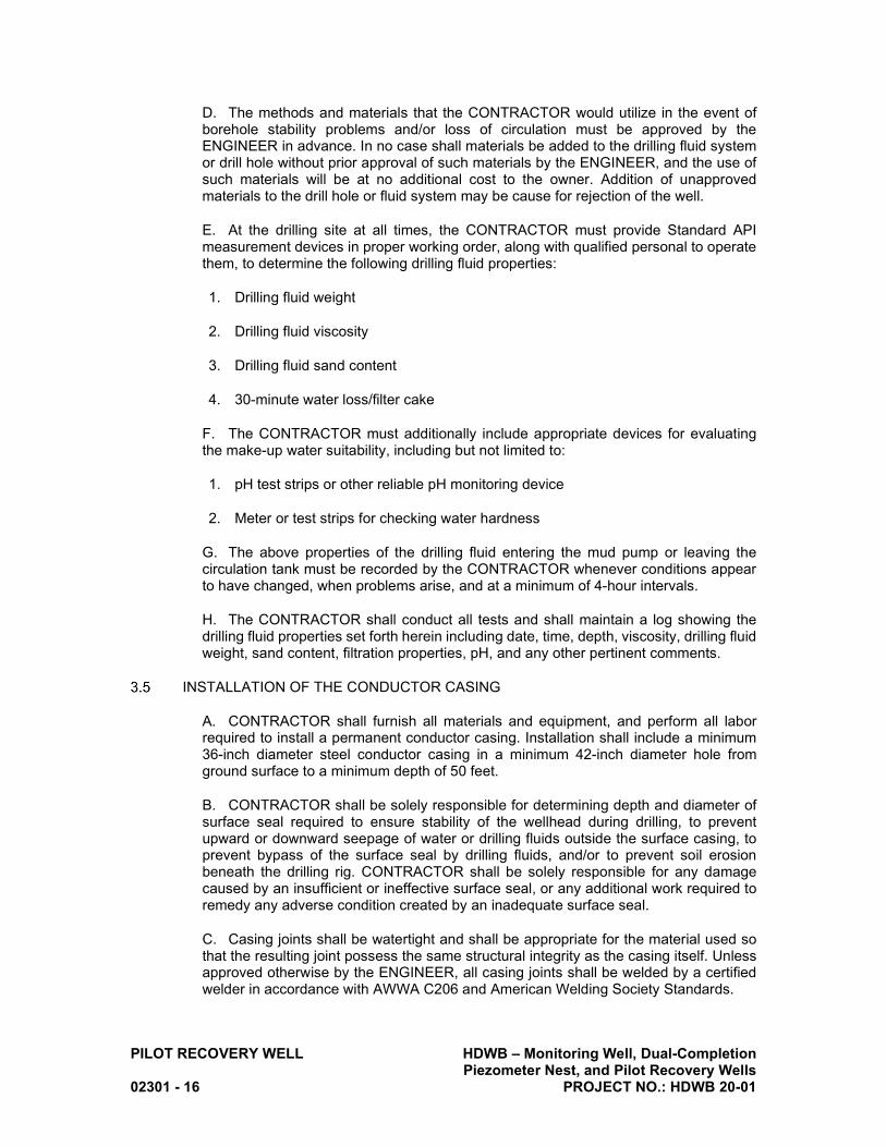
PILOT RECOVERY WELL HDWB – Monitoring Well, Dual-Completion Piezometer Nest, and Pilot Recovery Wells 02301 - 16 PROJECT NO.: HDWB 20-01
D. The methods and materials that the CONTRACTOR would utilize in the event of borehole stability problems and/or loss of circulation must be approved by the ENGINEER in advance. In no case shall materials be added to the drilling fluid system or drill hole without prior approval of such materials by the ENGINEER, and the use of such materials will be at no additional cost to the owner. Addition of unapproved materials to the drill hole or fluid system may be cause for rejection of the well.
E. At the drilling site at all times, the CONTRACTOR must provide Standard API measurement devices in proper working order, along with qualified personal to operate them, to determine the following drilling fluid properties:
1. Drilling fluid weight
2. Drilling fluid viscosity
3. Drilling fluid sand content
4. 30-minute water loss/filter cake
F. The CONTRACTOR must additionally include appropriate devices for evaluating the make-up water suitability, including but not limited to:
1. pH test strips or other reliable pH monitoring device
2. Meter or test strips for checking water hardness
G. The above properties of the drilling fluid entering the mud pump or leaving the circulation tank must be recorded by the CONTRACTOR whenever conditions appear to have changed, when problems arise, and at a minimum of 4-hour intervals.
H. The CONTRACTOR shall conduct all tests and shall maintain a log showing the drilling fluid properties set forth herein including date, time, depth, viscosity, drilling fluid weight, sand content, filtration properties, pH, and any other pertinent comments.
INSTALLATION OF THE CONDUCTOR CASING
A. CONTRACTOR shall furnish all materials and equipment, and perform all labor required to install a permanent conductor casing. Installation shall include a minimum 36-inch diameter steel conductor casing in a minimum 42-inch diameter hole from ground surface to a minimum depth of 50 feet.
B. CONTRACTOR shall be solely responsible for determining depth and diameter of surface seal required to ensure stability of the wellhead during drilling, to prevent upward or downward seepage of water or drilling fluids outside the surface casing, to prevent bypass of the surface seal by drilling fluids, and/or to prevent soil erosion beneath the drilling rig. CONTRACTOR shall be solely responsible for any damage caused by an insufficient or ineffective surface seal, or any additional work required to remedy any adverse condition created by an inadequate surface seal.
C. Casing joints shall be watertight and shall be appropriate for the material used so that the resulting joint possess the same structural integrity as the casing itself. Unless approved otherwise by the ENGINEER, all casing joints shall be welded by a certified welder in accordance with AWWA C206 and American Welding Society Standards.

HDWB – Monitoring Well, Dual-Completion PILOT RECOVERY WELL Piezometer Nest, and Pilot Recovery Wells Project No.: HDWB 20-01 02301 - 17
D. Centering guides shall be no less than 2 inches wide, welded to the conductor casing and include a minimum of two sets, each consisting of four guides equally spaced circumferentially around the casing. Guides shall be composed of the same material as the casing to which they are affixed and placed 5 feet from the top and bottom of the conductor casing.
E. CONTRACTOR shall furnish all material and equipment and perform all labor for grouting and sealing the conductor casing. The grouting consists of sealing by filling the annular space between the permanent conductor casing and conductor casing borehole with acceptable impervious material.
F. Sealing material shall be placed in the presence of the LACDPH inspector and the ENGINEER and shall be in compliance with permit requirements. CONTRACTOR shall notify the ENGINEER a minimum of 24 hours in advance of planned sealing material placement. CONTRACTOR shall be responsible for scheduling with the LACDPH inspector, who may require as much as 3 days advance notice.
G. Sealing material shall be placed using the tremie method from the bottom of the borehole and shall be completed in a manner that prevents freefall, bridging or separation. Placement shall be completed in one continuous operation from the bottom of the borehole to ground surface.
H. Upon installation of the sealing material and unless approved otherwise by the ENGINEER, CONTRACTOR shall not operate heavy equipment on the site for a minimum of 48 hours. The 48-hour curing period shall not be regarded as standby time.
DRILLING OF THE INITIAL PILOT HOLE
A. CONTRACTOR shall furnish all material and equipment and perform all labor to drill a maximum 17.5-inch-diameter pilot borehole from the bottom of the conductor casing to a depth of up to 1,200 feet bgs.
B. The pilot borehole shall be drilled using the flooded reverse-rotary method. Although a maximum diameter of 17.5 inches is specified, the CONTRACTOR shall drill the smallest diameter borehole of which they are capable while still allowing for conduct of isolated aquifer zone testing. A directional survey shall be made using a mechanical drift indicator every 100 feet while the pilot borehole is advanced. If the directional survey shows deviation from the plumb line, the CONTRACTOR shall make efforts to prevent ongoing deviation.
C. CONTRACTOR shall collect and preserve one set of drill cutting samples at 10-foot intervals during the drilling of the pilot borehole. Samples shall be placed in 1-gallon sized, heavy weight, re-sealable plastic bags and labeled with the well name, sample depth interval, and date. Collected samples shall be stored in a manner to prevent breakage or loss. The method of collection shall be approved by ENGINEER prior to collection (e.g., sluice box). Sample collection from a shaker screen or with a mesh strainer will not be acceptable unless approved by ENGINEER in writing.
D. The CONTRACTOR shall, at the discretion of the ENGINEER, conduct sieve analysis of samples of formation materials selected by the ENGINEER. A maximum of 5 samples per recovery well shall be tested. Sieve analyses shall be conducted by

PILOT RECOVERY WELL HDWB – Monitoring Well, Dual-Completion Piezometer Nest, and Pilot Recovery Wells 02301 - 18 PROJECT NO.: HDWB 20-01
Roscoe Moss Company, and results shall be provided to ENGINEER within 48 hours after completion of the pilot borehole.
GEOPHYSICAL SURVEY
A. CONTRACTOR shall furnish all material and equipment and provide all labor to perform a geophysical log of the pilot borehole. The geophysical log shall include measurements of:
1. Spontaneous potential
2. Electrical resistivity (single-point, 16-inch normal, 64-inch normal, and focused guard)
3. Natural gamma ray
4. Sonic velocity
5. Caliper
6. Temperature
B. CONTRACTOR shall ensure that the pilot borehole is properly conditioned by circulating drilling fluids in preparation for geophysical logging, and the pilot borehole is continually filled with fluid during logging operations.
C. Standby time will not be paid for additional cleaning and conditioning of the pilot borehole to enable logging operations to proceed.
D. If the logging probe fails to descend to within 10 feet of the total drilled depth of the pilot borehole, the CONTRACTOR, at their own expense, shall condition the pilot borehole to permit the logging probe to descend to within 10 feet of the drilled depth.
ISOLATED ZONE TESTING
A. CONTRACTOR shall furnish all material and equipment and provide all labor necessary to complete up to six isolated aquifer zone tests (zonal tests) described herein. CONTRACTOR will be responsible for all aspects of water quality sampling and laboratory analyses for the isolated zone aquifer testing, including sample collection, delivery of samples to the laboratory, and payment of laboratory fees. Analytes for laboratory testing are listed below. The zonal tests will be conducted within the depth interval of 400 to 1,200 feet bgs. Upon completion of the pilot borehole, the ENGINEER will provide a schedule of testing and sampling for specific zones, to include the number of zones, depth interval for the slotted tool, and depth intervals for gravel pack and seals. Duration of pumping for each zone shall be a minimum of 2 hours after discharge water clears and specific conductance, pH, oxidation-reduction potential, and temperature of the discharge water have stabilized to the satisfaction of the ENGINEER.
B. CONTRACTOR shall complete zonal sampling beginning with the deepest zone selected and proceeding progressively to the shallower zones until all zonal testing is completed. A schematic diagram of a typical isolated aquifer zone construction in the pilot borehole is shown on. The procedures for construction and testing of isolated aquifer zones include the following:

HDWB – Monitoring Well, Dual-Completion PILOT RECOVERY WELL Piezometer Nest, and Pilot Recovery Wells Project No.: HDWB 20-01 02301 - 19
1. Install slotted sampling tool to the specified depth and follow the design of each zone, to generally be as follows:
a. Fill the borehole below sampling tool with pea gravel to a depth approximately 20 feet below the lowest slot of the sampling tool.
b. Install a 10-foot thick lower bentonite seal above the pea gravel.
c. Install filter pack materials above the lower bentonite seal to a depth approximately 10-feet above the uppermost slot of the sampling tool.
d. Install a 5-foot thick layer of plaster sand.
e. Install a 10-foot thick upper bentonite seal in the annulus above the plaster sand.
2. The borehole fill materials listed above shall be installed using a tremie pipe and ENGINEER approved procedures.
3. Upon completion, allow a minimum of 12 hours for bentonite seals to hydrate before beginning airlift development.
4. Install air line inside the sampling tool to a depth of at least 100-ft below the static water level in the isolated zone. Adjust the depth of the airline as needed to accommodate encountered conditions.
5. Record static water level inside the sampling tool prior to beginning airlift development
6. Develop the zone as follows:
a. By airlift methods for a minimum of 6 hours, until discharge water is free of drilling mud and fine sediment and specific conductance stabilizes to the satisfaction of the ENGINEER, or as directed by the ENGINEER. Estimated maximum duration of airlift development is 12 hours. If ENGINEER requests additional development time, CONTRACTOR will be compensated for additional time in excess of 12 hours in accordance with the hourly rate in the bid schedule.
b. Collect and preserve water samples in containers acceptable to the ENGINEER at a frequency not less than every 30 minutes.
c. Record stabilized water level in the sampling tool after air lifting has stopped.
7. Install the submersible pump and water level sounder access tube inside the sampling tool to a depth specified by the ENGINEER, generally 100-feet below the static water level.
a. Record the static water level.
b. Pump the zone for a minimum of 2 hours after discharge water clears and specific conductance, pH temperature, and oxidation-reduction potential of the discharge water stabilized to the satisfaction of the ENGINEER.
c. Measure and record pumping rate and pumping water level.

PILOT RECOVERY WELL HDWB – Monitoring Well, Dual-Completion Piezometer Nest, and Pilot Recovery Wells 02301 - 20 PROJECT NO.: HDWB 20-01
8. As directed by the ENGINEER, collect and preserve water samples in containers provided by the CONTRACTOR’S laboratory and approved to the ENGINEER. CONTRACTOR shall submit the sample to an appropriate laboratory for analysis of constituents listed below. After the sample collection is completed, cease pumping and allow the water level in the zone to stabilize. Measure and record stabilized water level and remove the pump.
Common Constituents and Routine Parameters
Trace Metals
Calcium Aluminum
Magnesium Antimony
Sodium Arsenic
Potassium Barium
Chloride Beryllium
Carbonate Boron
Bicarbonate Cadmium
Sulfate Chromium (total)
Silicon Dioxide Chromium (hexavalent)
Bromide Cobalt
Fluoride Copper
Nitrate + Nitrate as Nitrogen Iron
Total Dissolved Solids Lead
Hardness Manganese
pH Molybdenum
Specific Electrical Conductance Nickel
Selenium
Other Silver
1,2,3-Trichloropropane Thallium
Gross Alpha Activity Zinc
9. Raise the sampling tool to the next interval, flush with potable water to clean the screens, and repeat the above procedure.

HDWB – Monitoring Well, Dual-Completion PILOT RECOVERY WELL Piezometer Nest, and Pilot Recovery Wells Project No.: HDWB 20-01 02301 - 21
REAMING OF THE PILOT HOLE
A. CONTRACTOR shall furnish all material and equipment and provide all labor necessary to ream the pilot borehole by flooded reverse-rotary methods to diameters shown in the drawings and as specified herein. Reaming shall not begin until: 1)all well casing, accessory tubing, filter pack and all other well materials and equipment necessary to construct a completed well are onsite and have been approved by the ENGINEER, excluding sanitary sealing material, and 2) ENGINEER has provided the final well design to CONTRACTOR. ENGINEER will provide final well design to CONTRACTOR within 120 hours after CONTRACTOR provides to ENGINEER results of all water quality analyses from isolated zone aquifer testing. Standby time shall not be charged while waiting on results of laboratory analyses or during the 120 -hour (five days, excluding weekends and holidays) period after results of laboratory analyses are provided to ENGINEER.
B. Drilling fluids shall be consistent with Paragraph 3.4 herein.
C. After completion of the drilling of the pilot borehole, ream by the flooded reverse-rotary methods to final diameters of 32 and 26 inches. Anticipated depths of each diameter are shown in the Drawings. The final reaming schedule will be provided by ENGINEER. Reaming shall continue on a continuous 24-hour per day, 7-day per week basis without interruption. Any significant delays in reaming may damage the formation and be cause for rejection of the well.
CALIPER AND ALIGNMENT SURVEY
A. CONTRACTOR shall furnish all material and equipment and provide all labor necessary to conduct caliper and alignment surveys of the final reamed borehole.
B. The CONTRACTOR shall furnish professional logging services for the caliper and alignment surveys of the final reamed borehole.
C. The caliper tool must be of sufficient arm capacity to have the ability to measure borehole diameters up to 48 inches for the entire length of the reamed borehole. The caliper survey shall include calculations of the theoretical volumes of filter pack and sand cement grout seal required for completion of the well.
D. If the caliper survey shows the reamed borehole to be less than the specified diameter(s) at any point or the final borehole or is less than the specified depth, the borehole shall be re-reamed or re-drilled and re-surveyed at the CONTRACTOR’s expense.
E. The alignment tool shall measure borehole inclination and azimuth (compass direction) at a maximum of 10-foot depth intervals to derive borehole deviations. A magnetic deviation tool will be acceptable for making these measurements
INSTALL WELL CASING AND GRAVEL FEED TUBE
A. The CONTRACTOR shall furnish all materials and work necessary to manufacture, deliver, and install well casing, screens, cellar pipes and caps, and fill tube as shown on the Drawings and in accordance with these Specifications.
B. The CONTRACTOR shall maintain circulation of drilling fluid until casing is set unless CONTRACTOR judges circulation to be unnecessary.

PILOT RECOVERY WELL HDWB – Monitoring Well, Dual-Completion Piezometer Nest, and Pilot Recovery Wells 02301 - 22 PROJECT NO.: HDWB 20-01
C. Well casing and tubes shall be installed such that a minimum 2-inch spacing is maintained between all casings/pipes, between casings/pipes and the bore wall, and between casing/pipes and the conductor casing. Compass orientation of all tubing shall comply with the final well design provided by ENGINEER.
D. Upon completion of reaming the pilot borehole, CONTRACTOR shall install the well screen and casing according to the final well design provided by the ENGINEER. The casing and screen shall be plumb and centered in the hole. All field joints shall be properly lap welded during installation with a minimum of two passes per circumference. Centering guides shall be welded to the casing, each consisting of three guides equally spaced circumferentially around the casing. Guides shall be no less than 2 inches wide, composed of the same material as the casing to which they are affixed and placed at intervals of not more than 50 feet within the screened casing and at intervals of not more than 80 feet within the blank casing. Guides shall be designed to have minimum bore wall contact of 12 inches and extend from the casing not less than 2.5 inches. For screened intervals, guides shall be affixed at joints, not in the screen.
E. Spacers shall be welded between the HSLA casing and the mild steel fill feed tube. Spacers shall be no less than 2 inches wide, composed of the same HSLA material as the casing to which they are affixed and placed at intervals not to exceed 50 feet.
F. The casing shall be suspended in tension from the surface by means of an appropriate hanger or clamp. The bottom of the casing shall be at a sufficient distance above the bottom of the reamed hole to ensure that the casing will not be supported from the bottom of the hole. The use of float plugs to land and set casing will not be permitted.
G. If, for any reason, the casing cannot be landed in the correct position or at a depth acceptable to the ENGINEER, or any of the casings or screens should collapse prior to well completion, the CONTRACTOR shall construct another well adjacent to the original location and complete this well in accordance with the specifications at no additional cost to the AGENCY. The first hole shall be destroyed by sealing in accordance with County requirements pertaining to proper well destruction. All work required to be repeated and all additional materials, labor, and equipment required, shall be furnished at the expense of the CONTRACTOR and no claim for additional compensation shall be made or be allowed, except as specifically provided herein.
H. To avoid collapse or deformation of casing, all annular materials, including cement, filter pack, fill materials, and fluids used during installation of annular materials, shall be installed in proper increments. CONTRACTOR shall document and verify the proper increments to use to prevent casing damage and shall, at its own expense, replace any damaged casing and repair, or remedy, any other associated damage to the well.
I. A clean construction tremie pipe shall be installed to place the annular materials. The fill tube shall not be used to place filter pack and shall remain empty. The CONTRACTOR shall ensure that the fill tube is maintained free and clear through cementing operations, to the satisfaction of the ENGINEER.
J. The top of the casing and accessory tubes shall be provided with a secure cap at all times when personnel are not on the site.
K. Field welding shall be performed by a certified welder in accordance with American Welding Society Standards. Welder shall be certified in accordance with AWS B2.1 for level AR 1 or AR 2, and in the 2G and 5G positions or the 6G position.

HDWB – Monitoring Well, Dual-Completion PILOT RECOVERY WELL Piezometer Nest, and Pilot Recovery Wells Project No.: HDWB 20-01 02301 - 23
L. The following field welding procedures shall apply:
1. A length shall be lowered into the well with the collar facing upward.
2. The plain end of the following length shall be inserted in the collar. True contact of the two joints must be verified by observation through the alignment holes.
3. Join by a continuous full fillet weld of thickness equal to thickness of coupling. Two passes shall be applied. Alignment holes shall be completely filled by welding.
4. Upon completion of welding, remove weld splatter, flux, slag, and burrs.
M. It is the CONTRACTOR’S responsibility to ensure that the appropriate electrodes are used for the various types of casing materials, and that the electrodes be of the appropriate size.
INSTALL FILTER PACK
A. CONTRACTOR shall furnish all material and equipment and provide all labor necessary to install filter media as described within these specifications.
B. Prior to placement of the filter pack in the borehole, the drilling fluid shall be thinned as appropriate with potable water to reduce weight and viscosity. The fill tube shall also be flushed with clean, potable water and cleared of any obstructions. Filter sands, as specified, shall be installed in the annular space between the reamed hole and the well screen through a construction tremie pipe. Place filter sands by hydraulically pumping through the tremie pipe from the bottom of the annulus upward to the depth specified by ENGINEER. The placement shall proceed without interruption until complete. During placement of the filter pack in the annulus, liquid sodium hypochlorite shall be added at a uniform rate of one gallon of 12.5% solution per cubic yard of filter pack. A circulating system with one or more positive displacement pumps utilizing fresh water shall be used for the purpose of introducing the filter pack into the annulus. Under no circumstances will the filter pack be allowed to “free-fall” down into the annular space. Fluids displaced from the well casing and annulus during filter packing (and sealing) operations shall be controlled and discharged to temporary storage tanks for off-site disposal.
C. An ENGINEER-approved device shall be used to measure the level of the filter pack during placement.
D. Following placement of the filter pack to the depth specified in the final well design, a surge block or jetting tool shall be used across the well screen to settle the filter pack. CONTRACTOR shall sound the level of the filter pack and continue surge activities until no measurable change in level is noted. Additional filter pack shall be added, as needed, to comply with the final well design.
E. CONTRACTOR shall contain and appropriately manage displaced fluids during the well installation process.
INSTALL ANNULAR SEAL
A. CONTRACTOR shall furnish all material and equipment and provide all labor necessary to install an annular cement seal in accordance with LACDPH permit conditions and DWR Bulletins No. 74-81 and 74-90. A 10-foot layer of plaster sand shall be installed immediately above the top of the filter pack to separate the cement seal

PILOT RECOVERY WELL HDWB – Monitoring Well, Dual-Completion Piezometer Nest, and Pilot Recovery Wells 02301 - 24 PROJECT NO.: HDWB 20-01
from the filter pack. The cement annular seal shall be installed from a depth immediately above the top of the plaster sand to ground surface.
B. Sealing material shall be placed in the presence of the LACDPH inspector and the ENGINEER and shall be in compliance with permit requirements. CONTRACTOR shall notify the ENGINEER a minimum of 24 hours in advance of planned sealing material placement. CONTRACTOR shall be responsible for scheduling with the LACDPH inspector, who may require as much as 3 days advance notice.
C. Sealing material shall be placed using the tremie method from the bottom of the borehole and shall be completed in a manner that prevents freefall, bridging or separation. Placement shall be completed in one continuous operation from the bottom of the borehole to ground surface.
D. Upon installation of the sealing material and unless approved otherwise by the ENGINEER, CONTRACTOR shall not operate heavy equipment on the site for a minimum of 24 hours. The 24-hour curing period shall not be regarded as standby time.
E. CONTRACTOR shall contain and appropriately manage displaced fluids during the well installation process.
MECHANICAL AND CHEMICAL WELL DEVELOPMENT
A. CONTRACTOR shall furnish all material and equipment and provide all labor necessary to develop the well by means of swabbing and airlifting.
B. CONTRACTOR shall commence development not less than 24 hours and no more than 48 hours after placing grout seal. If not commenced within 48 hours CONTRACTOR shall conduct, without additional cost to AGENCY, surge and air lift development for the length of time between 48 hours after placing grout seal and the time that development was initiated, in addition to normal development time.
C. Measurements of the fill tube shall be made and recorded no less than once daily during mechanical development. Addition of filter pack shall be added through the fill feed tube only at the direction of and under the supervision of ENGINEER.
D. Clean water shall be continuously added to the fill feed tube during mechanical development operation by use of a garden hose or similar.
E. Install an open-ended, single-swab surge block with airlifting. This will be done to remove heavy drilling muds and solids from the well and will be completed from the top of the well to the bottom.
F. The well will be developed by swabbing and airlifting from the top of the well to the bottom (first pass). The screen will be swabbed in 20-foot sections while simultaneously pumping. Each 20-foot screen section will be worked until successive swabbing produces little change in color and discharge is relatively clear. Development will continue for approximately one hour for each 20-foot interval of screen. This period may be extended or shortened by the ENGINEER based on condition of discharge water. Upon completion of a screen section, move to the next 20-foot interval and repeat until all screened intervals have been swabbed.
G. After reaching bottom, the development tools shall be utilized to inject NW-220, or approved equal, incrementally into the screen sections. The total amount of NW-220 introduced to the well shall be equal to the quantity necessary to achieve a NW-220

HDWB – Monitoring Well, Dual-Completion PILOT RECOVERY WELL Piezometer Nest, and Pilot Recovery Wells Project No.: HDWB 20-01 02301 - 25
concentration of one gallon per 500 gallons of water in the screened sections. The NW-220 solution shall be swabbed into each progressively shallower screen section as piping is removed. Each 20-foot screen section shall be swabbed for a period of up to 30 minutes to assure distribution. Upon reaching the uppermost screen section, the development tools shall be left in the well for a minimum period of 24 hours. After this period, the airlifting and swabbing development procedure described in the preceding paragraphs shall be repeated to bottom (second pass).
H. Once reaching the bottom of the well, a chlorine solution shall be swabbed into the screen sections from the bottom to the top as the double surge block is removed. Chlorine solution shall be sufficient to achieve a concentration of 500 parts per million (ppm) throughout the well screen. Upon reaching the uppermost screen section, the development tools shall be left in the well for a minimum period of 12 hours. Screen sections will then be developed in 20-foot intervals by swabbing and simultaneous airlifting. This process will be repeated throughout the entire length of all screened zones, beginning at the top and working down to the bottom, and then back to the top again.
I. ENGINEER shall make the determination of when mechanical and chemical development of the well is complete. Development will be considered complete once CONTRACTOR’s measurements of field water quality parameters (temperature, pH, specific electrical conductivity, and oxidation-reduction potential) have become relatively stable, and CONTRACTOR’s measurements of turbidity and sand content have decreased to acceptable levels (approximately 50 NTU and 5 ppm, respectively).
J. Following mechanical and chemical development, the well shall be bailed clean of accumulated material.
K. CONTRACTOR shall be compensated according to the hourly well development bid item for work performed in well screen sections only. The time required to move tooling through the unperforated well casing section(s) shall not be considered development and therefore will not be paid for by AGENCY.
COLOR VIDEO CAMERA SURVEY (INITIAL)
A. CONTRACTOR shall furnish all material and equipment and provide all labor necessary to complete a color video survey of the well after completion of mechanical and chemical development. The video survey shall be used to determine the efficacy of mechanical development in the screened intervals, and to verify the well is constructed per the final well design and is free of structural defects and clear of all debris throughout the entire depth of the well. If any defects or debris are found, the CONTRACTOR shall make repairs to, or remove debris from the well as necessary, prior to installation of the test pump.
B. Prior to conducting survey, bail well clean of debris and allow to remain idle for at least 24 hours. Prior to the survey, and if necessary, during survey, introduce a sufficient quantity of clear water into well to produce clear viewing conditions during survey. Run a dynamic vertical down-hole view video from top of well to the bottom of well at a speed not exceeding 30 feet per minute. Video shall be in color, with side-scan capabilities, and include an automatic depth indicator to the nearest 0.1 foot.
C. If survey fails to produce a clear picture of internal casing condition, introduce clear, potable water and conduct survey to ENGINEER’s satisfaction until a clear video is obtained.

PILOT RECOVERY WELL HDWB – Monitoring Well, Dual-Completion Piezometer Nest, and Pilot Recovery Wells 02301 - 26 PROJECT NO.: HDWB 20-01
WELL DEVELOPMENT BY PUMPING AND SURGING
A. CONTRACTOR shall furnish all material and equipment and provide all labor necessary to develop the well by means of pumping and surging.
B. CONTRACTOR shall install in the well a submersible or variable-speed turbine pump to complete pumping development including sounding tubes and transducers. Regardless of pump type the pumps shall not have backflow preventors. Pump intake shall be set at a depth of 420 feet bgs, unless otherwise directed by ENGINEER.
C. CONTRACTOR shall pump the well at an initial rate not to exceed 200 gpm. Alternate periods of surging (turning the pump on and off) followed by periods of continuous pumping. Increase the discharge rate when no significant improvements in specific capacity and sand content are achieved. Discharge rate shall be incrementally increased up to 2,300 gpm, or lower if directed by the ENGINEER.
D. The well shall be considered thoroughly developed when the following occur:
1. Specific capacity, gpm per foot of drawdown, is relatively constant plus or minus 5%, at design capacity of well.
2. There is no measurable settlement of filter pack.
3. Well does not produce sand in excess of sand production limitations. Sand production limitations shall be met when water produced contains less than 5 parts per million sand after 15 minutes of surging and pumping at design capacity of well.
E. CONTRACTOR shall not remove pump from well until well testing, including recovery monitoring, is complete
STEP TEST
A. CONTRACTOR shall furnish all material and equipment and provide all labor necessary to complete the well tests described herein. CONTRACTOR shall also keep records on the type of pumping equipment used including engines, drive components, bowls, lines, and shafts. The CONTRACTOR shall keep records of operation of equipment during the test including engine revolutions per minute and horsepower, fuel use, and other essential information that will be useful in designing a pump system.
B. CONTRACTOR shall perform a variable rate pumping test shall as follows:
1. A variable rate pumping (step drawdown) test shall be conducted following well development activities and shall be scheduled to begin when the water level has recovered to static water level as determined by the ENGINEER. No standby time will be paid for the water level recovery period.
2. The well shall be tested at rates of approximately ½, ¾, 1, and 1¼ times the design capacity of 1,800 gpm, or as directed by ENGINEER. The step test shall be performed for a total duration of 12 hours (180 minutes each step). CONTRACTOR shall operate the pump and change the discharge rate as directed by the ENGINEER. Pump discharge shall be measured with a totalizing meter and stop-watch, circular orifice meter, or Venturi meter as approved by the ENGINEER. An electric sounder shall be furnished by the CONTRACTOR. Sand content measurement shall be recorded at 15-minute intervals by the CONTRACTOR during the step-drawdown test using a Rossum

HDWB – Monitoring Well, Dual-Completion PILOT RECOVERY WELL Piezometer Nest, and Pilot Recovery Wells Project No.: HDWB 20-01 02301 - 27
sand tester. CONTRACTOR shall be responsible for maintaining the desired pump operation schedule.
3. CONTRACTOR shall measure depth to water in the well using an electric sounder at the following intervals, unless otherwise specified by ENGINEER:
a. 1 minute to 10 minutes: Measure at 1-minute interval.
b. 10 minutes to 20 minutes: Measure at 2-minute intervals.
c. 20 minutes to 30 minutes: Measure at 5-minute intervals.
d. 30 minutes to 60 minutes: Measure at 10-minute intervals.
e. 60 minutes to 90 minutes: Measure at 15-minute intervals
f. 90 minutes to end of test: Measure at 30-minute intervals
C. In addition, at discretion of ENGINEER, CONTRACTOR will monitor field water quality parameters at periodic intervals, including temperature, pH, specific electrical conductance, and oxidation-reduction potential. Parameters will be measured using a calibrated Myron L Ultrameter, or equivalent and will be provided to ENGINEER for review.
D. Toward the end of the test, ENGINEER will collect groundwater samples for laboratory analyses. The samples will be collected from a sampling port in the discharge line. ENGINEER will be responsible for submitting samples to the laboratory for analysis and paying the laboratory.
E. At no time shall test waters be applied to the land surface with a sand content exceeding 15ppm as measured at the temporary discharge assembly unless other approved by the ENGINEER.
STATIC FLOW VELOCITY SURVEY AND FLUID TEMPERATURE AND CONDUCTIVITY LOGGING
A. A static flow velocity survey and fluid temperature and conductivity logging shall be performed a minimum of 12 hours after cessation of pumping for the step test. The survey and logging operations shall be conducted by an approved geophysical logging SUBCONTRACTOR. No standby time will be paid for the 12-hour resting period.
B. The flow meter survey and temperature/conductivity logging shall be conducted from the top of the well screen to the bottom of the well. The static test shall consist of two-minute readings made at 10-foot increments across the screened interval. The meter used for the survey shall be calibrated within the blank sump portion of the completed well. The fluid temperature and conductivity measurements shall be continuous across the screened interval. Results of the conductivity log shall be compensated for temperature in the field.
CONSTANT-RATE DISCHARGE TEST, SPINNER FLOW MEASUREMENTS AND DEPTH-SPECIFIC WATER SAMPLING
A. Constant Rate Discharge Test

PILOT RECOVERY WELL HDWB – Monitoring Well, Dual-Completion Piezometer Nest, and Pilot Recovery Wells 02301 - 28 PROJECT NO.: HDWB 20-01
B. CONTRACTOR shall perform a constant-rate discharge test, spinner logging, and depth-specific sampling as follows:
1. A constant rate discharge test shall be conducted by pumping the well at a rate to be specified by the ENGINEER for a period of not less than seven days or until ENGINEER terminates the test. CONTRACTOR shall ensure the pumping rate remains within plus or minus 5% of the target rate.
2. CONTRACTOR shall test the final sand content. The final sand content shall be determined by averaging the results of samples collected at the following times during the constant rate discharge test: 1) 5 minutes after start of the test; 2) after ¼ of the total planned test time has elapsed; 3) after ½ of the time has elapsed; 4) after ¾ of the time has elapsed; and 5) near the end of the pumping test. If the average sand content exceeds 2 ppm, the CONTRACTOR, shall do the necessary redevelopment work of the well until the sand content is less than 2 ppm, as directed by the ENGINEER.
3. CONTRACTOR shall measure depth to water in the well at the following intervals during the seven-day pumping period, unless otherwise specified by ENGINEER:
a. 1 minute to 10 minutes: Measure at 1-minute interval.
b. 10 minutes to 20 minutes: Measure at 2-minute intervals.
c. 20 minutes to 30 minutes: Measure at 5-minute intervals.
d. 30 minutes to 60 minutes: Measure at 10-minute intervals.
e. 60 minutes to 90 minutes: Measure at 15-minute intervals.
f. 90 minutes to end of test: Measure at 30-minute intervals.
C. Fluid-movement and water quality investigations during pumping conditions will include:
1. Spinner flow meter and fluid temperature/conductivity logging during the seven-day pumping period
2. Depth-specific sampling during the seven-day pumping period
D. These downhole logging and sampling operations will be conducted by an approved geophysical logging SUBCONTRACTOR.
E. All logging and sampling equipment shall be cleaned and disinfected at an offsite location prior to installation into the wells using hot potable water applied with a high-pressure sprayer. Geophysical logging SUBCONTRACTOR shall conduct the following logging and groundwater sampling operations:
1. Fluid Temperature/Conductivity Probe – This combination probe shall be used to obtain continuous measurements of fluid temperature and conductivity during pumping conditions. Results of the conductivity log shall be compensated for temperature in the field.

HDWB – Monitoring Well, Dual-Completion PILOT RECOVERY WELL Piezometer Nest, and Pilot Recovery Wells Project No.: HDWB 20-01 02301 - 29
2. Spinner Flow Meter – The spinner flow meter shall be used to measure flow rates in the well during pumping conditions. The spinner flow meter shall be used in the following two modes: 1) during downward travel at a constant speed; and 2) at up to 20 stationary depths selected based on results of the geophysical logs obtained previously.
F. Depth-Specific Water Sampling (under pumping conditions only) – Depths for sampling will be selected by ENGINEER based on results of geophysical logs obtained previously; up to 10 samples shall be collected for each pilot recovery well. Depth-specific water samples will be obtained by geophysical logging subcontractor using 2-liter, vacuum-actuated sampling tools lowered into the well via a wire line. Geophysical logging SUBCONTRACTOR shall clean the sampling tool to the satisfaction of ENGINEER before each use. ENGINEER will record field measurements for pH, electrical conductivity, and temperature for the water samples obtained, will provide sample containers, and will be responsible for submitting samples to the laboratory for analysis and paying the laboratory costs. Following logging, the data shall be processed by the approved geophysical logging SUBCONTRACTOR to provide data and/or plots for volumetric flow rate and mass balance calculations using sample results. Summary plots of the logs shall be provided in tabloid size (11x17 inches) and shall include well construction information, stop counts, depth of sample locations and results, temperature, fluid resistivity, spinner run line speeds, spinner counts per speed, spinner flow velocity, and spinner volumetric flow rate. All geophysical logging information shall be provided in PDF, text, and Excel electronic files. For each investigation event: five field copies of survey results and 10 final copies shall be included (DVD copy of survey, digital summary report in approved format, and printed summary report).
G. After the pump is stopped, the temporary test pump shall remain in the well, undisturbed, for the full recovery period of seven days, or as specified by the ENGINEER. CONTRACTOR shall not be responsible for monitoring water levels during recovery period.
H. Whenever continuous pumping at a uniform rate has been specified, failure of pumping operation for a period greater than 1% of the elapsed pumping time shall require suspension of the steps until the water level in the pumped well has recovered to its original level. Recovery shall be considered "complete" after the well has been allowed to rest for a period at least equal to the elapsed pumping time of the aborted test, except that if any three successive water level measurements spaced at least 20 minutes apart show no further rise in the water level in the pumped well the test may be resumed immediately. The ENGINEER shall be the sole judge as to whether this latter condition exists. The CONTRACTOR will not be paid for any retesting done if the specified time or recovery requirements of the ENGINEER for the aborted test are not first met. These tests are invalid and will not be construed as a test.
I. At no time shall test waters be applied to the land surface with a sand content exceeding 15ppm as measured at the temporary discharge assembly unless other approved by the ENGINEER.
COLOR VIDEO CAMERA SURVEY (FINAL)
A. CONTRACTOR shall furnish all material and equipment and provide all labor necessary to complete a clear-viewing color video survey of the well prior to acceptance of the well by the ENGINEER. The color video survey shall verify well is constructed per the final well design and that the well is free of structural defects and clear of all debris throughout the entire depth of the well prior to acceptance of the well by the ENGINEER.

PILOT RECOVERY WELL HDWB – Monitoring Well, Dual-Completion Piezometer Nest, and Pilot Recovery Wells 02301 - 30 PROJECT NO.: HDWB 20-01
If any defects or debris are found, the CONTRACTOR shall make repairs to, or remove debris from, the well as necessary, prior to acceptance of the well by the ENGINEER.
B. Prior to conducting survey, remove test pump and bail well clean of debris; allow to remain idle for at least 24 hours. Prior to and, if necessary, during survey, introduce sufficient quantity of clear water into well to produce clear viewing conditions during survey. Run a dynamic vertical down-hole view video from top of well to the bottom of well at a speed not exceeding 30 feet per minute. Video shall be in color, with side-scan capabilities, and include an automatic depth indicator to the nearest 0.1 foot.
C. If survey fails to produce a clear picture of internal casing condition, introduce clear, potable water and conduct survey to ENGINEER’s satisfaction until a clear video is obtained.
WELL ALIGNMENT TEST
A. CONTRACTOR shall furnish all material and equipment and provide all labor necessary to complete the alignment and deviation tests to determine the plumbness and alignment of the well casing after the well has been completed and before its acceptance.
B. The CONTRACTOR shall furnish professional logging services for the alignment/deviation survey and shall comply with AWWA A-100 standards. Under these standards, the maximum allowable horizontal deviation (drift) of the well from the vertical shall not exceed 0.0067 times the smallest inside diameter of that part of the well being tested per 1 foot of depth. The ENGINEER may reject the well if the above tolerances are exceeded.
DUMMY ALIGNMENT TEST
A. Straightness of the well casing shall be tested by lowering a 40 feet long dummy into the well. The outer diameter of the dummy shall be 0.50-inch less than the inside diameter of the well casing. The dummy shall consist of a rigid spindle of at of at least 4-inch diameter extra heavy pipe with three rings rigidly fixed to the pipe so that they cannot move longitudinally along the pipe. The rings shall consist of suitable material which will not harm the interior of the casing while being lowered or raised.
B. The CONTRACTOR shall lower the dummy down the entire length of the casing. If the dummy fails to move freely throughout the entire length of the casing the CONTRACTOR shall undertake corrective measures at its own expense.
C. All dummy alignment tests shall be conducted in the presence of the ENGINEER.
WELL DISINFECTION
A. CONTRACTOR shall furnish all material and equipment and provide all labor necessary to cap and disinfect the well.
B. Disinfect well prior to final capping by adding sufficient sodium hypochlorite solution to achieve 100 ppm chlorine concentration in the well. The well shall be disinfected by swabbing the chlorine solution into the water column using an isolation development tool, surge block or nylon brush.

HDWB – Monitoring Well, Dual-Completion PILOT RECOVERY WELL Piezometer Nest, and Pilot Recovery Wells Project No.: HDWB 20-01 02301 - 31
C. No sooner than 24 hours after disinfection, the residual concentration in the well shall be measured and a sample collected by CONTRACTOR using a disposable bailer. CONTRACTOR shall submit the sample to an appropriate laboratory for analysis of total coliform (presence/absence), fecal coliform (presence/absence) and heterotrophic plate count.
SURFACE COMPLETION
A. After confirmation sampling results are approved by the ENGINEER, cap the well and fill tube by installing a locking steel cover with hinged lid of sufficient size so as to allow access to the well casing and fill tube. Set the cover into a concrete sealing block which extends at least 3 feet from well casing in all directions, with a minimum thickness of 6 inches and sloped to drain away at not less than 0.25 inch per foot. Install four concrete filled bollards equally spaced around the completed well.
QUALITY ASSURANCE
A. Measurement Devices
1. The CONTRACTOR shall use appropriate measuring devices to obtain and record periodic measurements of depths during operations, including depth to top of annular materials, such as filter pack, cement, or bentonite, borehole depth, and depth to water. Depth to water shall be measured using a calibrated electrical water level sounder, graduated to the nearest one-hundredth of 1 foot (i.e., 0.01 foot), and in good operating condition.
B. Casing Collapse or Deformation
1. To avoid collapse or deformation of casing, all annular materials installed during well construction, including cement, bentonite, filter sands, and fluids, shall be installed in proper increments. Annular material levels and fluid levels shall be measured as required during installation. CONTRACTOR shall verify the proper increments to use to prevent casing damage and shall, at its own expense, be responsible for replacing any damaged casing and correcting associated problems in accordance with these Technical Specifications. If casing is deformed or otherwise damaged during well construction, CONTRACTOR shall bear all expenses to correct the casing failure and bring the well back to the condition before the failure. If the well cannot be properly rehabilitated to mitigate the failure, CONTRACTOR shall at its own expense, and at ENGINEER’S direction, properly abandon the failed well and drill a new well to the same specifications as the failed well, and shall construct the new well to the point of failure of the abandoned well. When the well is successfully constructed to this point, CONTRACTOR may resume invoicing further well construction costs to ENGINEER.
C. Plumbness and Alignment
1. CONTRACTOR shall guarantee that the pilot recovery wells, when completed, shall be sufficiently straight and plumb to permit the free installation and normal operation of a future 14-inch O.D. line-shaft turbine pump.
2. CONTRACTOR shall conduct an alignment/deviation test and shall comply with AWWA A-100 standards. Under these standards, the maximum allowable horizontal deviation (drift) of the well from the vertical shall not exceed 0.0067 times the smallest inside diameter of that part of the C well being tested per 1 foot of depth. Failure to meet the requirements for plumbness and alignment shall be cause for rejection of the recovery well.

PILOT RECOVERY WELL HDWB – Monitoring Well, Dual-Completion Piezometer Nest, and Pilot Recovery Wells 02301 - 32 PROJECT NO.: HDWB 20-01
D. Contractor Qualifications
1. CONTRACTOR shall submit a list of at least ten (10) wells they have constructed in California in the past five (5) years that are of similar type, depth, and design as the recovery wells described herein. These lists shall include the construction dates of those wells, the client for whom the wells were constructed, and client contact information.
2. All members of the drill crew must have a minimum of two months drilling experience with the CONTRACTOR. CONTRACTOR will be responsible for assuring that drillers have documented training appropriate to their job descriptions. Training documentation will be assessed by ENGINEER during the process of procurement. All drill operators will have a minimum of five years drilling experience with production wells.
PERMITS
A. CONTRACTOR shall submit applications, pay requisite fees, obtain and comply with all appropriate permits required to complete the scope of work, which may include but are not limited to well installation permits. The CONTRACTOR shall maintain copies of all CONTRACTOR obtained project permits at the well site. A partially-completed application for a Los Angeles County well/exploration hole permit is included as an appendix to these specifications. The CONTRACTOR shall complete the application and submit to Los Angeles County with fees paid by the CONTRACTOR.
END OF SECTION

HDWB – Monitoring Well, Dual-Completion MONITORING WELL Piezometer Nest, and Pilot Recovery Wells Project No.: HDWB 20-01 02302 - 1
SECTION 02302
MONITORING WELL
PART 1 - GENERAL
1.1 DESCRIPTION
A. This section describes general requirements, standards, and responsibilities for the CONTRACTOR; well materials and procedures for drilling, construction, and testing of one monitoring well in accordance with the California Department of Water Resources (DWR) Bulletin 74-81 and 74-90 and Los Angeles County Department of Public Health (LACDPH) requirements.
1.2 SCOPE OF WORK
A. Site setup and tear down including all equipment necessary including but not limited to sanitary services, temporary lighting, temporary power, temporary piping, safety provisions, tankage, conveyance piping, temporary percolation ponds, for drilling monitoring well at one individual site, disposal of drill cuttings and drilling fluid additives in accordance with all applicable laws and regulations.
B. The CONTRACTOR shall drill a 20-inch diameter surface casing/sanitary seal borehole and install the required diameter surface casing and sanitary seal as further described in these specifications.
C. The CONTRACTOR shall drill a nominal 12-inch diameter bore hole and install required diameter high strength low alloy (HSLA) steel well casing, filter pack, sealing materials, and required appurtenances as further described in these specifications. The work shall be inclusive of performing a Caliper Survey on the 12-inch diameter bore hole. The CONTRACTOR shall retain the services of a firm/subcontractor to perform a caliper survey of the 12-inch diameter bore hole.
D. The CONTRACTOR shall retain a firm/subcontractor to perform Downhole Geophysical Surveys: Spontaneous Potential, Single-Point, 64-inch Long & 16-inch Short Normal Resistivity, Focused (Guard) Resistivity, Gamma-Ray, Sonic Velocity, and Temperature.
E. The CONTRACTOR shall provide a materials containment and discharge plan describing the required waste materials handling, drilling fluids control and temporary discharge percolation plan required for the development of the Monitoring Well and development water discharge.
F. The CONTRACTOR shall develop the Monitoring Well in accordance with these specifications.
G. The CONTRACTOR shall conduct two constant-rate discharge tests as further described by these specifications

MONITORING WELL HDWB – Monitoring Well, Dual-Completion Piezometer Nest, and Pilot Recovery Wells 02302 - 2 PROJECT NO.: HDWB 20-01
H. The CONTRACTOR shall cause to conduct a well alignment/deviation tests for plumbness and alignment further described by these specifications.
I. The CONTRACTOR shall install surface completion improvements as described in these Specifications and Contract Documents.
1.3 RELATED WORK
A. General Provisions
B. Contractor Submittals 01300
C. Mobilization and Demobilization 02100
D. Temporary Facilities 01500
E. Treatment and Disposal of Construction Derived Wastes 01012
F. Manual Valves 15100
G. Coordination of Work 01010
1.4 RELATED WORK SPECIFIED ELSEWHERE
A. 2018 APWA Greenbook Specifications
B. National Fire Protection Association (NFPA) 70 National Electrical Code (NEC) 2017
1.5 REFERENCES
A. California Water Well Standards – Department of Water Resources, Bulletin No. 74-81
B. California Water Well Standards – Department of Water Resources, Bulletin No. 74-90
1.6 SUBMITTALS The CONTRACTOR shall provide to the ENGINEER for review and approval prior to any site-specific field operations have commenced associated with the construction of the Monitoring Well regarding the following submittals:
A. A written Construction Progress Report shall be submitted to the ENGINEER every 24 hours after drilling begins. This report shall include a summary of activities performed during the previous 24 hours including the total depth drilled, lithology encountered, results of drilling fluids tests, type and quantity of drilling additives (no additives allowed except for premium bentonite and clean water unless otherwise pre-approved by the ENGINEER), locations of significant water loss, and document down time. The report will also describe the type, depth and duration of any sampling or other work activities conducted.

HDWB – Monitoring Well, Dual-Completion MONITORING WELL Piezometer Nest, and Pilot Recovery Wells Project No.: HDWB 20-01 02302 - 3
B. Site Layout and readiness to work plan.
C. The CONTRACTOR shall prepare and submit a Well Discharge Plan describing the flow process and methods being used to capture, maintain, test, convey, and store drilling based fluids including the following.
1. Temporary percolation basin grading plan, temporary piping, and control systems.
2. Erosion Control Plan.
3. Temporary solids and sediment containment, filtration systems, temporary piping, and control systems.
4. Turbidity reduction system source, design, and operator.
D. Qualifications of the Drilling Fluid Engineer.
E. Drilling Fluids materials type properties to include unit weight, viscosity, sand and solids content, and supplier name and address.
F. Drilling Fluid System Layout and Equipment.
G. Drilling Fluid and Water Loss Controls
H. Surface Casing Materials, configuration, manufacturer, and properties including the following:
1. Surface Casing and mill materials certificate.
I. Formation Samples and sieve analysis results.
J. Name and qualifications of firm completing the alignment/deviation surveys
K. Alignment/Deviation Survey Report including the following:
1. One copy digital data format PDF and LAS files.
2. Five copies of the alignment/deviation survey report
3. All alignment/deviation survey report shall have a vertical scale of 1-inch equals 50-feet and horizontal scale appropriate to the log type and response values.
L. Submit the name and qualifications of the firm proposed to conduct the caliper survey within 10 days of the Notice of Award.
M. Submit five (5) field copies of the caliper logs to the ENGINEER immediately after the logs are run. The CONTRACTOR shall submit ten (10) final copies of each log, one reproducible original and one compact disk of the log at no additional cost at the completion of the well.

MONITORING WELL HDWB – Monitoring Well, Dual-Completion Piezometer Nest, and Pilot Recovery Wells 02302 - 4 PROJECT NO.: HDWB 20-01
N. Based upon an examination of caliper results, the CONTRACTOR shall estimate and report to the ENGINEER the volumes of gravel pack and other annular fill materials required to complete the final well design.
O. Submit the name and qualifications of firm completing geophysical surveys within 10-days of the Notice of Award
P. Submit five (5) field copies of the geophysical logs to the ENGINEER immediately after the logs are run. The CONTRACTOR shall submit ten (10) final copies of each log, one reproducible original and one CD of the log at no additional cost at the completion of the well. Geophysical Survey Logs including the following:
1. One copy digital data format, PDF and LAS files.
2. Five copies of the field geophysical logs.
3. All geophysical logs shall have a vertical scale of 1-inch equals 50-feet and horizontal scale appropriate to the log type and response values.
Q. Type and content of sealing materials
R. Monitoring Well Casing and Screen
1. A. The CONTRACTOR shall submit certified test reports to show compliance with both physical and chemical properties of the casing materials. Included in the report shall be a schematic drawing of the blank casing and screen assembly including, but not limited to the following information: estimated screen weight, screen OD, clear ID, tensile strength, yield strength, safety factor used in all calculations and the basis for that figure, collapse strength and safe installation depth, and the square inches of open area per lineal foot of screen for all well screen used on the project, percent open area and all other information required to complete the design report. The final well design that the ENGINEER provides to the CONTRACTOR will include gravel gradation, casing perforation size, depth of the perforated intervals within the well, and final borehole depths and diameters. Installation of well casing and screen shall commence upon completion of an ENGINEER-approved caliper survey of the drilled borehole and after all well construction materials delivered on site have been examined and approved by the ENGINEER for compliance with the final well design.
2. Prior to, or at the time of delivery to the site, the CONTRACTOR shall submit to the ENGINEER a copy of the purchase order placed with the screen manufacturer for well screens to be supplied to the ENGINEER. The copy shall specify the type of screen ordered.
3. Prior to, or at the time of delivery to the site, a Bill of Lading (or invoice) shall be submitted to the ENGINEER certifying that the screen being delivered to the CONTRACTOR and hence to the well site, is the material ordered by the CONTRACTOR per the Specifications in this Section.

HDWB – Monitoring Well, Dual-Completion MONITORING WELL Piezometer Nest, and Pilot Recovery Wells Project No.: HDWB 20-01 02302 - 5
4. Certificate from the louvered screen, and blank casing supplier, certifying that the louvered screen and blank casing are structurally strong, have sufficient tensile strength during casing installation and have adequate collapse strength to the installation depth and can withstand the forces of well development.
5. Casing schedule for blank well casing, screened well casing, end fittings, and centralizers.
S. Filter pack gradations: A description and certified sieve analysis of filter pack to be used must be submitted at least three days prior to shipment from the supplier. The CONTRACTOR shall submit two (2) QA/QC sieve analyses provided by the gravel supplier for every 50 bags of filter pack ordered.
T. Filter material delivery weight tickets.
U. As installed measurement of filter media within the well annulus.
V. Cement and/or Concrete delivery weight tickets and origin.
W. As installed measurement of sealing material within the well annular space.
PART 2 - PRODUCTS
2.1 DRILLING FLUID
A. For the monitoring well, potable water shall be used to mix either a polymer or bentonite-based drilling fluid designed to adequately maintain bore wall, minimize invasion of drilling fluid into the formation, and permit recovery of representative samples of cuttings. Soda ash may be used to increase pH of the water used to mix drilling fluids. The drilling fluid shall possess such characteristics that it can be readily removed from the borehole during development of the well. Any drilling mud, additives, or fluids used by the CONTRACTOR shall be free of contaminants and approved by the ENGINEER. Drilling with clear water alone will not be permitted.
B. The drilling fluid shall have the following properties in accordance with API Code RP 13B (or recent modification) "Recommended Standard Procedures for Testing Drilling Fluids."
1. Weight - maximum of 9.2 pounds per gallon
2. Marsh Funnel Viscosity – minimum of 28 and maximum of 32 seconds
3. Sand Content - maximum of 1% by volume
4. Water Loss and Wall Cake – maximum thickness of 2/32 inches with maximum 30-minute water loss of 15 cubic centimeters (cc).

MONITORING WELL HDWB – Monitoring Well, Dual-Completion Piezometer Nest, and Pilot Recovery Wells 02302 - 6 PROJECT NO.: HDWB 20-01
2.2 DRILL RIG
A. The drill rig shall be a properly maintained direct mud rotary rig in good condition acceptable to the ENGINEER and capable of drilling and installing the MONITORING WELL in accordance with these project specifications. The drill rig discharge pipe shall be fabricated in such a way as to provide easy access for the collection of lithologic samples.
B. The drill pipe will be in good condition and will be connected by standard tool or flange-type joints. Only Teflon-based thread compound may be used to lubricate the threads; the use of any other thread compound is prohibited
2.3 DRILL CUTTINGS
A. The CONTRACTOR shall furnish and install a splitter-box or other acceptable method, pre-approved by the ENGINEER, for the collection of drill cuttings as the point where flow is returned to the surface. If samples cannot be adequately collected, drilling will cease until the problem can be corrected to the satisfaction of the ENGINEER.
2.4 SURFACE CASING
A. Surface casing shall be spiral welded mild steel well casing composed of new material conforming to ASTM A52 Grade B specifications. The surface casing shall have a minimum O.D. of 14 inches, wall thickness of not less than 1/4 inch and length of not less than 20 feet.
B. The surface casing shall not be fabricated in less than the 20-foot length. It shall be spiral welded or as otherwise approved by the ENGINEER. All spiral seams shall be butt-welded with shielded arc electrodes to assure full fusion with the parent metal and complete penetration.
C. Centering guides shall be no less than 2 inches wide, welded to the surface casing and include a minimum of two sets, each consisting of three guides equally spaced circumferentially around the casing. Guides shall be composed of the same material as the casing to which they are affixed and placed five feet from the top and bottom of the surface casing. Guides shall be composed of the same material as the casing to which they are affixed and placed five feet from the top and bottom of the surface casing.
D. All casing materials shall be new.
2.5 SURFACE CASING SEALING MATERIAL
Surface Casing Seal: Sealing shall meet the requirements of California Department of Water Resources (CDWR) Bulletins 74-81 and 74-90, and all requirements of the LACDPH. These requirements state that the surface casing seal must be placed to a minimum depth of 20 feet. The cement grout for the sanitary seal shall be mixed at a ratio of not more than one 94-pound sack of Portland cement and about 5.5 gallons of clean water. Accelerators, retardants,

HDWB – Monitoring Well, Dual-Completion MONITORING WELL Piezometer Nest, and Pilot Recovery Wells Project No.: HDWB 20-01 02302 - 7
bentonite, and other additives shall not be used without prior approval by the ENGINEER.
2.6 CALIPER SURVEY
A. The caliper used to perform the survey shall have a minimum of three arms and be capable of indicating a borehole diameter to 12 inches. The horizontal scale for the caliper plot shall be four inches diameter per inch and the vertical scale shall be 50 feet per inch. Caliper measurements should be run on digital equipment. The log should present total borehole volume (cubic feet) and annular borehole volume (cubic feet) for a given casing size, or multi-strings of casings, with capability to compensate for casing and borehole size changes.
2.7 HSLA BLANK MONITORING WELL CASING
A. HSLA Monitoring Well Casing shall be spiral welded (or ENGINEER approved equivalent) HSLA steel composed of new material manufactured in accordance with ASTM A242 (A606 Type 4). The well casing shall have an inside diameter of 6 inches and wall thickness of not less than 1/4 inch. The end fittings can be either welding collars or threaded. Casing shall not be fabricated in less than 20-foot lengths. It shall be spiral welded or as otherwise approved by the ENGINEER. No mid-welds will be permitted. All spiral seams shall be butt-welded with shielded arc electrodes to assure full fusion with the parent metal and complete penetration.
B. In all cases, the CONTRACTOR shall ensure that the blank casing used in conjunction with the screened (Ful Flo louvered) casing shall have the same inside diameter and thickness as the screened sections with no deviation allowed.
C. Well cellar shall be spiral welded (or ENGINEER approved equivalent) HSLA steel composed of new material manufactured in accordance with ASTM A242 (A606 Type 4). The well casing shall have an inside diameter of 6 inches and wall thickness of not less than 1/4 inch. The bottom of the well casing shall be a bullnose plug welded in place.
D. All welding shall be done with shielded arc electrodes and shall be performed by certified welders in accordance with American Welding Society Standards, and as provided herein.
E. The top of the casing shall be provided with a welded cap at all times when personnel are not on site.
2.8 HSLA SCREENED (FUL FLO) MONITORING WELL CASING
A. The well screen shall be of the Ful Flo Louver design as manufactured by Roscoe Moss Co. or pre-approved equal.
B. The screen shall be 6-inch I.D. and have a 1/4-inch wall thickness, in accordance with ASTM A242 (A606 Type 4) For bidding purposes, the HSLA Ful Flo louver screen shall be designed with a 0.045-inch opening. Actual screen lengths will be determined after examination of the lithologic log and sieve analyses of drill cuttings and the downhole geophysical surveys and will be

MONITORING WELL HDWB – Monitoring Well, Dual-Completion Piezometer Nest, and Pilot Recovery Wells 02302 - 8 PROJECT NO.: HDWB 20-01
specified in the final monitoring well design prepared by the ENGINEER within 48 hours of receipt of geophysical logs. No standby time will be paid to the CONTRACTOR during this design period.
C. Screen yield tensile strength must exceed at least twice the total weight of 6-inch I.D. pipe size screen and 6-inch I.D. pipe size standard well casing suspended below the top screen joint.
D. The Ful Flo louver screen shall not be fabricated in less than 20-foot lengths unless specified by the ENGINEER. The ends of each joint shall be machined perpendicular to the casing axis to ensure the straightness of each assembled section. CONTRACTOR shall propose the casing end fittings and method of joining for approval by AGENCY.
E. All Ful Flo louver screen designs shall be sufficient in collapse strength and tensile strength for typical installation to a depth of 1,000 feet beneath ground surface (consult manufacturer).
F. All screen material will be new and steam-cleaned prior to delivery on-site.
2.9 JOINTS
A. All field joints shall be properly lap or butt-welded during installation to assure complete penetration during welding with a minimum of two passes per circumference (including the 6-inch I.D. casing/screen). All joints shall be watertight. Special care shall be exercised to ensure that the casing is straight. Welders shall be certified in accordance with American Welding Society (AWS) Section IX for level AR-3 or equivalent for water well applications.
B. Welding electrodes shall be compatible for use with HSLA base materials.
C. All welding shall conform to AWS standards. Depending on the wall thickness, the following electrode sizes shall apply:
Wall Thickness Electrode Size
1/8-inch 1/8-inch
3/16- to 1/4-inch 5/32- to 3/16-inch
Over 1/4-inch 3/16- to 1/4-inch
2.10 MONITORING WELL FILTER PACK
A. Filter pack material consists of 8 x 16 gradation sand, and shall be hard, water-worn, at least 90% silica and washed clean of silt and foreign matter. The filter sand shall be delivered to and contained in 100-pound bags or 3,000-pound “super sacs” and, if stockpiled at the well site, shall be protected, and kept free of all foreign matter within the following gradation:

HDWB – Monitoring Well, Dual-Completion MONITORING WELL Piezometer Nest, and Pilot Recovery Wells Project No.: HDWB 20-01 02302 - 9
Mesh Size Percent Passing
#5 (0.157”) 100
#6 (0.132”) 99.9
#7 (0.111”) 97.3
#8 (0.093”) 70.1
#10 (0.078”) 42.8
#12 (0.066”) 13.4
#14 (0.055”) 2.9
#16 (0.046”) 0.06
B. A transition layer (5 feet or less) of #60 sand shall be emplaced above the filter sands for each filter pack interval
2.11 INTERMEDIATE ANNULAR SEAL
A. Hydrated bentonite in the form of bentonite chips or pellets (time release if warranted), cement-bentonite grout, or other material approved by ENGINEER shall be used. If grout is used, CONTRACTOR shall not allow the grout (and liquids) to rise to a level 5 feet below the targeted bottom of the overlying filter pack interval and shall add a layer of bentonite pellets or chips above the grout to provide a firm base for the filter pack interval.
2.12 SANITARY SEAL
A. Batch plant mixed cement-bentonite grout shall be used; sealing shall meet the requirements of CDWR Bulletins 74-81 and 74-90, and all requirements of the LACDPH. The grout shall be mixed at a bentonite to cement ratio of 0.3 by weight (e.g. one 94-pound sack of Portland cement and up to 25 pounds of bentonite in 30 gallons of clean water). No accelerators, retardants, and other additives shall be used without prior approval by the ENGINEER.
2.13 PRESSURE TRANSDUCERS AND INFLATABLE PACKERS
A. Pressure transducers for the monitoring well shall be the Manufacturers’ models specified below or approved equal.
1. Pressure transducer cable lengths shall be sufficient for installing the transducers at the desired depths plus 20 feet of extra cable for winding outside of the surface completion.
2. Manufacturers’ models and installation depths are as follows:

MONITORING WELL HDWB – Monitoring Well, Dual-Completion Piezometer Nest, and Pilot Recovery Wells 02302 - 10 PROJECT NO.: HDWB 20-01
a. Monitoring Well (grouted-in transducers): Three transducers, vibrating wire models VW2100-0.7, VW2100-1.0, and VW2100-2.0 (from R.S.T. Instruments, LTD) shall be installed at approximate depths of 150, 250, and 380 feet bgs, respectively.
b. Monitoring Well (dedicated transducers): Two transducers, Level TROLL 400 model rated for 300 psi (from In-Situ, Inc.), shall be installed at approximate depths of 500 and 700 feet bgs; and one Level TROLL 400 model rated for 500 psi shall be installed at an approximate depth of 960 feet bgs. These transducers will remain in the monitoring well and become the property of the AGENCY.
c. Barometer (for atmospheric pressure correction): One Level TROLL Barotroll model rated for 16.5 psi installed at the monitoring well site. This transducer will remain at the site and become the property of the AGENCY.
B. ENGINEER has determined the transducer models and cable lengths and has obtained vendor invoices, provided in Appendix. CONTRACTOR will procure and deliver equipment to the well site. ENGINEER has developed a cost estimate for the transducers and cables (and all appurtenances) based on venders’ invoices and added costs for sales tax and shipping; the total estimated cost is included in the bid sheet as a fixed line item cost.
C. CONTRACTOR shall furnish two inflatable pneumatic packers to be installed at approximate depths of 520 and 720 feet bgs. The packers shall be designed to be inflatable to pressures up to 250 psi, and to prevent leakage past the packer under a pressure differential up to 25 psi across the packer. In addition, the packers shall have a 1-inch diameter pass-through tube for passage of transducers/cables through the packers (two pass-through tubes for upper packer and one pass-through tube for lower packer). Packers shall be manufactured by Inflatable Packers International, TAM International, or ENGINEER approved equal. The packers shall remain in the monitoring well and become the property of the AGENCY.
2.14 WELL DEVELOPMENT
A. The CONTRACTOR shall provide a submittal addressing development and testing piping configuration within 10 days of the Notice of Award. The submittal shall include all piping, valving, tanks, and sampling taps documented on a site layout diagram.
B. The CONTRACTOR shall maintain a daily record of the static water level, pumping water level, discharge rate, time of development activities/cycles, and sand content to be submitted to the ENGINEER daily.
C. CONTRACTOR shall maintain a daily record of all water removed from the aquifer for the MONITORING WELL to be submitted by the ENGINEER monthly to the Watermaster.

HDWB – Monitoring Well, Dual-Completion MONITORING WELL Piezometer Nest, and Pilot Recovery Wells Project No.: HDWB 20-01 02302 - 11
D. Daily development reports recording time and procedures completed during each shift, as well as total chargeable hours on each day, shall be submitted to the ENGINEER daily.
E. Chemicals are not expected to be required during mechanical development. However, if chemicals are required during mechanical development, the CONTRACTOR shall provide a submittal addressing the types of chemicals that will be used, drilling fluids anticipated, and mixing and application techniques, for review and prior approval by the AGENCY and the ENGINEER.
F. The CONTRACTOR shall provide a submittal addressing the type of water quality multimeter being provided and its specifications prior to well development and testing. The multi-meter will have a flow through cell to monitor turbidity, dissolved oxygen, oxidation reduction potential, electrical conductivity values, acidity (pH), and temperature.
G. SWAB - Swabbing of the well shall be done with both close fitting double swabs whose outside diameter of the surge blocks shall not be more than 1 inch smaller than the inside diameter of the screen section. The surge blocks for the double swab shall be separated by 10 to 20 feet by a perforated piece of drill pipe.
H. DRILL PIPE: Drill pipe shall be fitted with air educator pipe to allow airlift pumping. There shall be sufficient perforations in the drill pipe, together with sufficient air compressor capacity to airlift 100 gallons per minute.
I. WELL DEVELOPMENT DISCHARGE: The CONTRACTOR shall provide storage tankage of sufficient size and construction to accommodate development water discharge flows / volumes. Inclusive on the storage tankage, the CONTRACTOR shall provide a pump of sufficient size and horsepower to continuously pump stored discharge water as required from the storage tankage to the discharge point at the time when solids volumes and turbidity have been reduced to a level to allow land application.
J. Discharge Piping:
1. Size and length to convey not less than 200 gpm water to the discharge location and be approved by ENGINEER; assume 500 feet of discharge pipe or hose will be needed.
2. In-line totalizing and instantaneous flow meter, or other flow meter approved by the ENGINEER, suitable to accurately record pumping rates throughout required range
K. Provide an Imhoff Cone and Rossum Sand Tester during development to measure amount of sand produced from the well.
2.15 TEST PUMP ASSEMBLY FOR MONITORING WELL TESTING
A. The test pump assembly shall be subject to ENGINEER approval and consist of the following:

MONITORING WELL HDWB – Monitoring Well, Dual-Completion Piezometer Nest, and Pilot Recovery Wells 02302 - 12 PROJECT NO.: HDWB 20-01
1. Submersible pump capable of producing up to 200 gpm from the well
2. Electric generator
3. Discharge piping manifold with a sampling port
4. Flow adjustment valve
5. In-line totalizing and instantaneous flow meter, or other flow meter approved by the ENGINEER, suitable to accurately record pumping rates throughout required range
6. Inflatable packer installed on pump column to isolate selected screened intervals in the well
B. CONTRACTOR shall provide a Rossum sand tester to measure sand production from the well.
C. CONTRACTOR shall provide sounding tubes. Sounding tubes shall consist of the following:
1. Two, 1-inch inside diameter with perforations along the bottom 20 feet and including an end cap, adequate for insertion of water level sensing devices into well before, during, and after test pumping.
2. Sounding tubes shall be securely fastened to pump column assembly and terminated approximately 5 feet above pump
3. Sounding tubes shall allow free passage of pressure transducers that are 0.75-inch diameter and approximately 8 inches long.
2.16 SETTLING TANKS AND SECONDARY PUMP
A. The CONTRACTOR shall provide settling tanks with baffles installed, or approved equal to contain and settle out solids in the fluids generated during the development phases of the project. An additional tank is required for the retention of "heavy" fluids generated during the course of the work, prior to disposal. All disposal shall be through the settling system. The CONTRACTOR shall be required to maintain adequate staff to conduct drilling, development, and settling operations. Additional waste disposal specifications are described by these specifications.
B. The tanks shall be joined such that water flows between the tanks to maximize settling time and minimize disturbance of settled materials. Water shall enter the bottom of the first settling tank and shall be transferred to the bottom of the second tank by pumping via submersible (or other) pump or by gravity flow from the top of the first tank. Transfer of fluid between the second and any necessary subsequent tanks shall be performed in similar manner.
C. The settling system shall operate independently of the drilling fluids and displacement fluids storage tank. The “heavy” drilling and displacement fluids

HDWB – Monitoring Well, Dual-Completion MONITORING WELL Piezometer Nest, and Pilot Recovery Wells Project No.: HDWB 20-01 02302 - 13
generated during drilling will be contained in separate tank(s) and shall be removed for disposal off-site in accordance to local, State and Federal requirements. Further waste disposal details are described by these specifications.
D. Well development and testing water shall be conveyed to on-site settling tanks and any necessary filtration (bag filters or approved equivalent) provided by CONTRACTOR as necessary to meet discharge requirements. Well development and testing water shall be conveyed to on-site settling tanks and any necessary filtration provided by the CONTRACTOR, and then conveyed to the approved land surface applications. The CONTRACTOR will be required to install temporary conveyance piping to deliver discharge water from the monitoring well site to the approved discharge point. If necessary a secondary pump with a minimum discharge capacity matching the development flow of the well will be provided by the CONTRACTOR to convey development and testing water from the settling tanks and any necessary filtration through the temporary discharge piping to the approved discharge point.
PART 3 - EXECUTION
3.1 SITE SET UP AND TEAR DOWN
A. The CONTRACTOR shall prepare a site layout of all equipment, including required tankage, temporary power and lighting, sanitary facilities, temporary piping, temporary water supply, site preparation, and temporary discharge percolation basins. The CONTRACTOR shall provide descriptions and specifications of all necessary equipment to accomplish the work associated with the construction of the Monitoring Well. No work shall begin until such time as approved by the ENGINEER.
3.2 INSTALLATION OF THE SURFACE CASING
A. The CONTRACTOR shall not start any drilling operations until approval regarding the location of the Monitoring Well is obtained from the ENGNEER.
B. CONTRACTOR shall furnish all materials and equipment, and perform all labor required to install a permanent conductor (surface) casing. Installation shall include a minimum 14-inch O.D. mild steel surface casing in a minimum 20-inch diameter hole from ground surface to a minimum depth of 20 feet. The CONTRACTOR shall seal the annular space between the surface casing and the borehole with approved sealing materials as described by these specifications.
C. CONTRACTOR shall be solely responsible for determining depth and diameter of surface seal required to ensure stability of the wellhead during drilling, to prevent upward or downward seepage of water or drilling fluids outside the surface casing, to prevent bypass of the surface seal by drilling fluids, and/or to prevent soil erosion beneath the drilling rig. CONTRACTOR shall be solely responsible for any damage caused by an insufficient or ineffective surface seal,

MONITORING WELL HDWB – Monitoring Well, Dual-Completion Piezometer Nest, and Pilot Recovery Wells 02302 - 14 PROJECT NO.: HDWB 20-01
or any additional work required to remedy any adverse condition created by an inadequate surface seal.
3.3 SURFACE SEAL
A. CONTRACTOR shall furnish all material and equipment and perform all labor for grouting and sealing the surface casing. The grouting consists of sealing by filling the annular space between the permanent surface casing and surface casing borehole with acceptable impervious material. The annular seal shall have a minimum thickness of 2 inches at all points circumferentially around the surface casing.
B. Sealing material shall be placed in the presence of the LACDPH inspector and ENGINEER and shall be in compliance with permit requirements. CONTRACTOR shall notify the ENGINEER a minimum of 72 hours in advance of planned sealing material placement. The CONTRACTOR shall notify the LACDPH 72 hours in advance of the placement of the Surface Seal requesting an inspector be present on-site. CONTRACTOR shall be responsible for scheduling with the LACDPH inspector. The Surface Seal will not be considered complete if not witnessed by the LACDPH inspector.
C. Sealing material shall be placed using the tremie method from the bottom of the borehole and shall be completed in a manner that prevents freefall, bridging or separation. Placement shall be completed in one continuous operation from the bottom of the borehole to ground surface.
D. Upon installation of the sealing material and unless approved otherwise by the ENGINEER, CONTRACTOR shall not operate heavy equipment on the site for a minimum of 24 hours. The 24-hour curing period shall not be regarded as standby time.
3.4 MONITORING WELL BOREHOLE DRILLING
A. CONTRACTOR shall furnish all material and equipment and perform all labor to drill a nominal 12-inch diameter borehole from the bottom of the surface casing to a depth of approximately 1,000 feet bgs unless otherwise directed by ENGINEER.
B. Drilling shall not begin until the CONTRACTOR has caused all ENGINEER approved well components and materials to be procured and ready for delivery to the site. The CONTRACTOR shall ensure timely delivery of all well components and materials to the site as required by the drilling operations. Delayed deliveries of well components and materials to the site does not provide the CONTRACTOR relief of any kind including claim for standby time.
C. The borehole shall be drilled using the direct mud-rotary method. Drilling shall continue on a continuous 24-hour per day, seven-day per week basis without interruption. Any significant delays in drilling may damage the formation and be cause for rejection of the well. A directional survey shall be made every 100 feet the borehole is advanced using a mechanical drift indicator. If the directional

HDWB – Monitoring Well, Dual-Completion MONITORING WELL Piezometer Nest, and Pilot Recovery Wells Project No.: HDWB 20-01 02302 - 15
survey shows deviation from the plumb line, the CONTRACTOR shall make efforts to prevent ongoing deviation.
D. CONTRACTOR shall collect and preserve one set of drill cutting samples at 10-foot intervals during the drilling of the borehole. Samples shall be placed in 1-gallon sized, heavy weight, resealable plastic bags and labeled with the well name, sample depth interval, and date. Collected samples shall be stored in a manner to prevent breakage or loss. The method of collection shall be approved by ENGINEER prior to collection. Sample collection from a shaker screen or by using a sieve will not be acceptable unless specifically approved by ENGINEER.
E. Excavation of pits on site for drilling fluids will not be allowed, and surface containment (i.e., tanks and/or bins) of drilling fluids will be required. CONTRACTOR is advised that cuttings from shaker or those removed from tanks will need to be stored and contained on site for removal. CONTRACTOR may choose to utilize portable roll-off bins for cuttings storage. As described in specifications and upon completion of drilling operations and well construction, all fluids shall be removed from the site and legally disposed of by the CONTRACTOR.
F. It is the responsibility of the CONTRACTOR to ensure that the sizing and configuration of the mud circulation or mud cleaner fluid system, desander/desilter cones and shaker system are adequate to meet the drilling fluid properties outlined below. In the event the CONTRACTOR cannot attain these properties, drilling shall be halted, and the mud replaced at no cost to the AGENCY.
G. Proper control of the drilling fluid must remain in compliance with these specifications, and the CONTRACTOR shall retain or employ an experienced, qualified Drilling Fluid (Mud) Engineer to supervise and maintain drilling fluid characteristics at no cost to the AGENCY.
H. The methods and materials that the CONTRACTOR would utilize in the event of borehole stability problems and/or loss of circulation must be approved by the ENGINEER. In no case shall materials be added to the drilling fluid system or drill hole without prior approval of such materials by the ENGINEER. Addition of unapproved materials to the drill hole or fluid system may be cause for rejection of the well.
I. The CONTRACTOR must provide at the drilling site at all times Standard API measurement devices in proper working order, along with qualified personal to operate them, to determine the following drilling fluid properties:
1. Drilling fluid weight
2. Drilling fluid viscosity
3. Drilling fluid sand content
4. 30-minute water loss/filter cake

MONITORING WELL HDWB – Monitoring Well, Dual-Completion Piezometer Nest, and Pilot Recovery Wells 02302 - 16 PROJECT NO.: HDWB 20-01
J. The above properties of the drilling fluid entering the mud pump or leaving the mud circulation or mud cleaner fluid system must be recorded by the CONTRACTOR whenever conditions appear to have changed, when problems arise, and at a minimum of 4-hour intervals.
K. The CONTRACTOR shall conduct all tests and shall maintain a log showing the drilling fluid properties set forth herein including date, time, depth, viscosity, drilling fluid weight, sand content, filtration properties, pH, and any other pertinent comments.
L. The CONTRACTOR must keep records providing the following information for the well:
1. A log of drilling bit types and depths at which drill bit changes are made
2. A log of the cuttings, providing the depths and descriptions of the earth materials encountered during the borehole drilling
3. Record of directional survey every 100 feet
M. All measurements for depths shall be referenced to existing ground surface at the well site. All drilling records shall be delivered to the ENGINEER upon completion of the well.
N. The CONTRACTOR shall, at the discretion of the ENGINEER, conduct sieve analysis of samples of formation materials selected by the ENGINEER. A maximum of 10 samples shall be tested by the Roscoe Moss Company of Los Angeles.
3.5 DRILL CUTTINGS, DRILLING FLUIDS AND OPERATIONAL GENERATED WASTES
A. Contain and haul drill cuttings and drilling fluids to a disposal facility in accordance with these Section 01012 Treatment and Disposal of Construction Derived Wastes.
3.6 CALIPER SURVEY / WELL LOGGING
A. Upon completion of the borehole drilling, a caliper survey shall be run. Before running the caliper survey, the CONTRACTOR shall cease drilling and circulate fluid for one hour.
B. All instruments shall be calibrated prior to and after the completion of the log.
C. The caliper survey shall become the property of the ENGINEER at the time the logging is completed. The log will be run in the presence of the ENGINEER. The CONTRACTOR shall provide five field copies of the log to the ENGINEER for interpretation immediately upon completion. The CONTRACTOR shall provide the ENGINEER with ten copies of the caliper survey, one reproducible original of the survey and a CD Rom disk at no additional cost.

HDWB – Monitoring Well, Dual-Completion MONITORING WELL Piezometer Nest, and Pilot Recovery Wells Project No.: HDWB 20-01 02302 - 17
D. The logging speed for all logs shall be 40 feet per minute, unless otherwise approved by the ENGINEER.
E. If the caliper survey shows the borehole to be less than the specified diameter at any point or the borehole depth is less than the specified depth, the borehole shall be re-reamed or re-drilled and resurveyed at the CONTRACTOR’s cost.
F. The CONTRACTOR shall be required to provide whatever assistance may be necessary to accomplish the caliper survey.
G. CONTRACTOR shall perform necessary measures during the 3-hour caliper survey interpretation period after the caliper survey is run to ensure the stability and preservation of the borehole.
H. After the caliper survey has been made, interpreted and approved by the ENGINEER, installation of the well casing shall commence immediately.
I. Loss of Tools
1. The CONTRACTOR shall take full responsibility for logging of the borehole.
2. The CONTRACTOR shall take full responsibility for the condition of the borehole during and after logging and shall hold harmless the AGENCY and ENGINEER for loss of tools and collapse.
3. The CONTRACTOR shall receive no payment for time and material for removal of lost tools and equipment and no compensation for replacement of equipment or loss of time.
4. The ENGINEER may withhold a portion of payment due in order to compensate the ENGINEER for the additional cost of inspection associated with loss of tools and subsequent borehole conditioning.
3.7 GEOPHYSICAL SURVEY / WELL LOGGING
A. Upon completion of drilling the borehole, the geophysical logs shall be run. Before running geophysical logs, the CONTRACTOR shall cease drilling and circulate fluid for not less than one hour.
B. CONTRACTOR shall ensure that the borehole is properly conditioned by circulating drilling fluids in preparation for geophysical logging, and the borehole is continually filled with fluid during logging operations.
C. Standby time will not be paid for additional cleaning and conditioning of the borehole to enable logging operations to proceed.
D. Geophysical logging instruments shall be calibrated prior to and after completion of the logs.
E. The geophysical logs shall become the property of the ENGINEER at the time the logging is completed. The logs will be run in the presence of the ENGINEER.

MONITORING WELL HDWB – Monitoring Well, Dual-Completion Piezometer Nest, and Pilot Recovery Wells 02302 - 18 PROJECT NO.: HDWB 20-01
The CONTRACTOR shall provide 5 field copies of the logs to the ENGINEER for interpretation immediately upon completion. The geophysical logging firm shall provide the ENGINEER with ten (10) final copies of each log at the completion of the well, one reproducible original, and one compact disk of each log at no additional cost.
F. The logging speed for all logs shall be 40 feet per minute, unless otherwise approved by the ENGINEER.
G. If the logging probe fails to descend to within 10 feet of the total drilled depth of the borehole, the CONTRACTOR, at their own expense, shall condition the borehole to permit the logging probe to descend to within 10 feet of the drilled depth.
H. If logging information indicates that the completion of the well is not warranted, the ENGINEER reserves the right to terminate further work on the well.
I. The CONTRACTOR shall be required to provide whatever assistance may be necessary to accomplish the geophysical logs. There will be no additional payment for rig time or idle time while the log is being evaluated.
J. The CONTRACTOR shall perform necessary measures during the period after the geophysical logs are run to ensure the stability and preservation of the borehole.
K. Any log that is not usable or is inaccurate because of equipment failure, reproduction quality, or individual error shall be relogged at no additional expense to the AGENCY.
L. LOSS OF TOOLS
1. The CONTRACTOR shall take full responsibility for logging of the wells.
2. The CONTRACTOR shall take full responsibility for the condition of the borehole during and after logging and shall hold harmless the AGENCY and ENGINEER for loss of tools and collapse.
3. The CONTRACTOR shall receive no payment for time and material for removal of lost tools and equipment and no compensation for replacement of equipment or loss of time.
4. The ENGINEER may withhold a portion of payment due in order to for the additional cost of inspection associated with loss of tools and subsequent hole conditioning.
3.8 MONITORING WELL CASING INSTALLATION
A. The CONTRACTOR shall furnish all materials and work necessary to manufacture, deliver, and install well casing, screens, cellar pipes and caps, and tremie pipes as shown in the Drawings and in accordance with these Specifications.

HDWB – Monitoring Well, Dual-Completion MONITORING WELL Piezometer Nest, and Pilot Recovery Wells Project No.: HDWB 20-01 02302 - 19
B. Prior to installation of well casing, CONTRACTOR may, at CONTRACTOR’S discretion, conduct a wiper pass of the borehole.
C. Maintain circulation of drilling fluid until casing is set unless CONTRACTOR determines circulation to be unnecessary.
D. Well casing shall be installed such that a minimum 2-inch spacing is maintained between the casing and the borehole wall, and between the well casing and the surface casing.
E. Upon completion of drilling the borehole, CONTRACTOR shall install the well casing according to the final well design to be provided by the ENGINEER. The final design shall be provided to CONTRACTOR within 48 hours of ENGINEER’s receipt of the caliper and borehole geophysical logs. Standby time shall not be charged for the 48-hour period; any time in excess of 48 hours shall be considered standby time. The casing string consists of three intervals of blank casing with a blank casing cellar and three intervals of screened casing. The blank and screened intervals shown in the drawings are approximate; the actual intervals will be determined following completion of drilling based on lithologic conditions encountered.
F. CONTRACTOR is advised the total footage of casing and screen on the bid sheets includes an additional 40 feet of screen than indicated by the well schematic to accommodate possible increases in the screened intervals based on the encountered lithology. These additional sections are required to be delivered as three 10-foot and two 5-foot lengths. Well casing and screen not used during the construction of the well will become the property of the AGENCY; CONTRACTOR will be required to transport this material to a location within 45 miles of the well site, as determined by the ENGINEER.
G. During installation of the well casing, CONTRACTOR shall affix three pressure transducers and associated data cables to the outside of the casing in approximately the upper 350 to 400 feet of the well. The actual transducer depths will be determined by ENGINEER during drilling operations. Transducers and data cables shall be affixed to the well casing by the CONTRACTOR using stainless steel straps or equivalent, as approved by the ENGINEER. Required pressure transducer models and cable lengths are specified in these specifications.
H. The casing and screen shall be plumb and centered in the hole. If welding collars are used, all field joints shall be properly lap welded during installation with a minimum of two passes per circumference. If threaded end fittings are used, CONTRACTOR must ensure that the threaded joints are evenly and fully screwed together. Pipe dope will be allowed but must be NSF/ANSI 60 certified. Centering guides shall be welded to the casing, each consisting of three guides equally spaced circumferentially around the casing. Guides shall be no less than 2 inches wide, composed of the same material as the casing to which they are affixed and placed at intervals of not more than 40 feet within the blank casing and screened sections. Guides shall be designed to have minimum borewall contact of 12 inches and extend from the casing not less than 2 inches. For screened intervals, guides shall be affixed at joints, not in the screen.

MONITORING WELL HDWB – Monitoring Well, Dual-Completion Piezometer Nest, and Pilot Recovery Wells 02302 - 20 PROJECT NO.: HDWB 20-01
I. The casing shall be suspended in tension from the surface by means of an appropriate hanger or clamp. The bottom of the casing shall be at a sufficient distance above the bottom of the drilled borehole to ensure that the casing will not be supported from the bottom of the hole. The use of float plugs to land and set casing will not be permitted.
J. If, for any reason, the casing cannot be landed in the correct position or at a depth acceptable to the ENGINEER, or any of the casings or screens should collapse prior to well completion, the CONTRACTOR shall construct another well adjacent to the original location and complete this well in accordance with the specifications at no additional cost to the AGENCY. The first hole shall be destroyed by sealing in accordance with LACDPH requirements pertaining to proper well destruction. All work required to be repeated and all additional materials, labor, and equipment required, shall be furnished at the expense of the CONTRACTOR and no claim for additional compensation shall be made or be allowed, except as specifically provided herein.
K. Plumbness and Alignment: CONTRACTOR shall guarantee that the monitoring well, when completed, shall be sufficiently straight and plumb to permit the free installation (to a maximum depth of 750 feet) and normal operation of a 5-inch diameter submersible pump designed for the installed 6-inch diameter HSLA casing. Failure to meet the requirements for plumbness and alignment shall be cause for rejection of the monitoring well. CONTRACTOR shall conduct a directional survey every 100 feet that the monitoring well borehole is advanced using a mechanical drift indicator. If the directional survey shows deviation from the plumb line, the CONTRACTOR shall make efforts to prevent ongoing deviation. Contractor may, at its own discretion, use other appropriate means during drilling and/or well construction to ensure sufficient well plumbness and alignment, if approved by and conducted under the oversight of ENGINEER.
L. Casing Collapse or Deformation: To avoid collapse or deformation of casing and/or screen, all annular materials, including cement, bentonite, filter sands, and fluids used during installation of annular materials, shall be installed in proper increments. Annular material levels and fluid levels shall be measured as required during installation. CONTRACTOR shall verify the proper increments to use to prevent casing damage and shall, at its own expense, be responsible for replacing any damaged casing and correcting associated damages in accordance with these Technical Specifications. CONTRACTOR shall document and verify the proper increments are used to prevent casing damage If casing is deformed or otherwise damaged during monitoring well construction, CONTRACTOR shall bear all expenses to correct the casing failure and bring the well back to the condition before the failure. If the monitoring well cannot be properly rehabilitated to mitigate the failure, CONTRACTOR shall at its own expense, and at ENGINEER’S direction, properly abandon the failed well and drill a new well to the same specifications as the failed well, and shall construct the new well. When the well is successfully constructed to this point, CONTRACTOR may resume invoicing further well construction costs to AGENCY.
M. A clean construction tremie pipe shall be installed to place the annular materials.

HDWB – Monitoring Well, Dual-Completion MONITORING WELL Piezometer Nest, and Pilot Recovery Wells Project No.: HDWB 20-01 02302 - 21
N. The top of the casing shall be provided with a secure cap at all times when personnel are not on the site.
O. If well casing end fittings and welding collars are used, field welding shall be performed by a certified welder in accordance AWS B2.1 for level AR 1 or AR 2, and in the 2G and 5G positions or the 6G position.
P. The following field welding procedures shall apply:
1. A length shall be lowered into the well with the collar facing upward.
2. The plain end of the following length shall be inserted in the collar. True contact of the two joints must be verified by observation through the alignment holes.
3. Join by a continuous full fillet weld of thickness equal to thickness of coupling. Alignment holes shall be completely filled by welding. Two passes shall be applied.
4. Upon completion of welding, remove weld splatter, flux, slag, and burrs.
Q. It is the CONTRACTOR’s responsibility to ensure that the appropriate electrodes are used for the various types of casing materials, and that the electrodes be of the appropriate size.
R. If for any reason the casing cannot be placed in the correct position or at a depth acceptable to the ENGINEER, the CONTRACTOR shall construct another well immediately adjacent to the original location and complete this well in accordance with the specifications and drawings at no additional cost to the ENGINEER. The abandoned hole shall be properly sealed at the CONTRACTOR’s expense.
S. If any of the casings or screens should separate or collapse prior to well completion, they shall be withdrawn and replaced at the CONTRACTOR’s expense.
T. All work required to be repeated, and all additional materials, labor, and equipment required, shall be furnished at the expense of the CONTRACTOR and no claim for additional compensation shall be made or be allowed therefore, except as specifically provided herein.
U. The casing shall be completed eighteen inches (18”) above ground surface (12 inches above the finished completion pad).
3.9 MONITORING WELL FILTER PACK
A. CONTRACTOR shall furnish all material and equipment and provide all labor necessary to install filter media as described within these Specifications.
B. Prior to placement of the three filter pack intervals in the well, the drilling fluid shall be thinned as appropriate with potable water to reduce weight and viscosity.

MONITORING WELL HDWB – Monitoring Well, Dual-Completion Piezometer Nest, and Pilot Recovery Wells 02302 - 22 PROJECT NO.: HDWB 20-01
The tremie pipe shall also be flushed with clean, potable water and cleared of any obstructions. Filter sands, as specified, shall be installed in the annular space between the borehole and the well screen through a construction tremie pipe. The filter sands shall be placed by hydraulically pumping through the tremie pipe from the bottom of the annulus upward to the depth specified by ENGINEER. Placement of the filter packs, together with placement of the annular seals, shall proceed without interruption until complete. A circulating system with one or more positive displacement pumps utilizing fresh water shall be used for the purpose of introducing the filter sands into the annulus. Under no circumstances will the filter sands be allowed to “free-fall” down into the annular space. Fluids displaced from the well casing and annulus during filter packing (and sealing) operations shall be controlled and discharged to temporary storage tanks for off-site disposal, as described in these specifications.
C. An ENGINEER-approved device shall be used to measure the level of the filter pack during placement, as described in these specifications.
D. Following placement of the filter pack to the depth specified in the final well design, a surge block shall be used across the well screen to settle the filter pack. CONTRACTOR shall sound the level of the filter pack and continue surge activities until no measurable change in filter pack level is noted. Additional filter sands shall be added, as needed, to comply with the final well design.
3.10 INTERMEDIATE ANNULAR SEAL AND SANITARY SEAL
A. CONTRACTOR shall furnish all material and equipment and provide all labor necessary to install annular seals in accordance with LACDPH permit conditions and DWR Bulletins No. 74-81 and 74-90, including any later supplements or revisions. Annular seals include an upper sanitary seal constructed with cement-bentonite grout, two intermediate seals (separating the filter pack intervals) constructed with hydrated bentonite, a transition seal above the uppermost filter pack interval constructed with hydrated bentonite, and a seal in the bottom of the borehole below the well casing (sump) constructed with bentonite or cement.
B. The depth interval of each intermediate annular seal shall be specified by the ENGINEER when the schedule of well casing, screen and filter pack is submitted to the CONTRACTOR. After placement of the casing and screen at intervals determined by the ENGINEER based on lithologic conditions encountered during drilling, the annular seals shall be installed in the depth intervals specified by the ENGINEER, below, between, and/or above the filter pack intervals.
C. Sealing material shall be placed in the presence of the LACDPH inspector and the ENGINEER and shall be in compliance with permit requirements. CONTRACTOR shall notify the ENGINEER a minimum of 72 hours in advance of planned sealing material placement. CONTRACTOR shall be responsible for scheduling with the LACDPH inspector, who may require as much as 3 days advance notice.
D. Sealing material shall be placed using the tremie method from the bottom of the borehole and shall be completed in a manner that prevents freefall, bridging or separation. Placement of the annular seals, together with placement of filter pack

HDWB – Monitoring Well, Dual-Completion MONITORING WELL Piezometer Nest, and Pilot Recovery Wells Project No.: HDWB 20-01 02302 - 23
intervals as specified by the ENGINEER, shall be completed in one continuous operation from the bottom of the borehole to ground surface. CONTRACTOR must exercise caution while emplacing the sanitary seal not to damage the pressure transducers and cabling strapped to the well casing.
E. The CONTRACTOR will sound the annular seal to verify the depth of the top of the seal after each load of sealing material has been placed. Upon completion of installation of each annular seal, or portion thereof, no additional work will be performed until the depth to the top of that seal has been accurately determined by sounding.
F. The CONTRACTOR shall calculate the amount of seal material necessary to backfill a specified interval. CONTRACTOR shall record all calculations and volumes of seal material used, and the sounding obtained after each annular seal placement. The CONTRACTOR shall verify those calculations with the ENGINEER.
G. Upon installation of the sealing material, CONTRACTOR shall not operate heavy equipment on the site for a minimum of 24 hours, unless otherwise approved by the ENGINEER. The 24-hour curing period shall not be regarded as standby time.
H. CONTRACTOR shall contain and appropriately manage displaced fluids during the annular seal installation process.
3.11 MONITORING WELL DEVELOPMENT
A. CONTRACTOR shall furnish all material and equipment and provide all labor necessary to develop the well by means of swabbing and airlifting.
B. CONTRACTOR shall commence development not less than 24 hours and no more than 48 hours after placing sanitary grout seal.
C. Install an open-ended single-swab surge block with airlifting. This will be done to remove heavy drilling muds and solids from the well and will be completed from the top of the well to the bottom.
D. CONTRACTOR shall develop the well by swabbing and airlifting from the top of the well to the bottom (first pass). Each screen interval will be swabbed in 20-foot sections while simultaneously airlifting. Each 20-foot screen section will be worked until successive swabbing produces little change in color and discharge is relatively clear as determined by ENGINEER. In addition, field measurements of temperature, pH, specific electrical conductance, and oxidation-reduction potential will be obtained on the development discharge; stabilization of these parameters will also be used to evaluate when development is complete for a given zone. Upon completion of a 20-foot screen section, the next 20-foot section will be swabbed; this procedure will be repeated until all screened intervals have been developed to the satisfaction of ENGINEER.

MONITORING WELL HDWB – Monitoring Well, Dual-Completion Piezometer Nest, and Pilot Recovery Wells 02302 - 24 PROJECT NO.: HDWB 20-01
E. Following mechanical development, the well shall be bailed clean of accumulated material. Additional well development by pumping may be required at the discretion of the ENGINEER, which would be conducted immediately before the two planned pumping tests. CONTRACTOR shall be compensated according to the hourly pumping development bid item.
F. CONTRACTOR shall be compensated according to the hourly well development bid item for work performed in well screen sections only. The time required to move tooling through the unscreened well casing section(s) shall not be considered development and therefore will not be paid for by AGENCY.
3.12 PUMPING TESTS IN THE MONITORING WELL
A. CONTRACTOR shall furnish all material and equipment and provide all labor necessary to complete two pumping tests in the monitoring well described herein to satisfy the requirements of these Specifications or as determined by ENGINEER. A temporary submersible pump shall be installed at separate depths for the two tests. The first pumping test will be conducted with the pump set at a depth just above the upper screened interval (approximately 350 feet bgs) and the second test will be conducted with the pump set near the bottom of the upper screened interval (approximately 500 feet bgs). For the second test, an inflatable packer will be installed in the section of blank casing below the pump in order to isolate the upper screened interval for testing. If requested by ENGINEER, CONTRACTOR shall conduct a third pumping test with the pump and packer assembly set near the bottom of the middle-screened interval in order to isolate the combined upper and middle screened intervals.
B. CONTRACTOR shall keep records on the type of pumping equipment used including motors, drive components, bowls, lines, and shafts.
C. Contractor shall develop the well by pumping as follows:
1. For each pumping test interval, the installed test pump will be operated for no more than 4 hours to provide additional well development. The development pumping will also serve as a pre-test to determine the pumping rate for the constant rate discharge test; the targeted pumping rate is 100 to 200 gpm. If at the end of the pumping development period the ENGINEER determines that additional development is required, CONTRACTOR shall extend the pumping period at CONTRACTOR’s hourly rate until ENGINEER determines that development is complete.
2. During the development pumping period, measurements of turbidity and sand content will be obtained by CONTRACTOR at approximately 15-minute intervals and will be recorded. If the discharged groundwater has no drilling fluids or fine aquifer materials the water can be discharged to the designated discharge area as described in as described in these Specifications. If the discharged groundwater would have unacceptable levels of solids or turbidity, CONTRACTOR shall direct the water to temporary on-site holding tanks or similar to allow settlement of all solids prior to discharge of decanted water, as described in these Specifications.

HDWB – Monitoring Well, Dual-Completion MONITORING WELL Piezometer Nest, and Pilot Recovery Wells Project No.: HDWB 20-01 02302 - 25
3. CONTRACTOR is responsible to ensure that no erosion or nuisance conditions result from test pump discharges. The discharge piping shall be installed to the satisfaction of the ENGINEER.
4. The development pumping will be terminated at the discretion of ENGINEER. Following recovery of groundwater levels in the well to near static conditions, the constant rate discharge tests can be initiated.
D. CONTRACTOR shall perform each constant rate discharge test as follows:
1. For each of the two test intervals in the well, a constant rate discharge test shall be conducted by pumping the well at the design rate for a period of not less than 12 hours or until ENGINEER terminates the test. CONTRACTOR shall operate the pump and adjust the flow valve to ensure the pumping rate remains within plus or minus 5% of the target rate, as directed by the ENGINEER. Pump discharge shall be measured with an instantaneous and totalizing flowmeter or other meter as approved by the ENGINEER. An electric sounder shall be furnished by the CONTRACTOR. Sand content measurements shall be recorded at 30-minute intervals by the CONTRACTOR using an Imhoff Cone or Rossum sand tester.
2. CONTRACTOR shall be responsible for maintaining the desired pump operation schedule.
3. Discharge considerations and constraints associated with potential drilling fluids and turbidity in the discharged groundwater described above for the pumping development period also apply to the constant rate pumping test.
4. During the constant rate discharge tests, CONTRACTOR shall measure depth to water at the following intervals using an electric sounder, unless otherwise specified by ENGINEER:
a. 1 minute to 10 minutes: Measure at 1-minute interval.
b. 10 minutes to 20 minutes: Measure at 2-minute intervals.
c. 20 minutes to 30 minutes: Measure at 5-minute intervals.
d. 30 minutes to 60 minutes: Measure at 10-minute intervals
e. 60 minutes to 90 minutes: Measure at 15-minute intervals
f. 90 minutes to end of test: Measure at 30-minute intervals
5. In addition, at discretion of ENGINEER, CONTRACTOR will monitor field water quality parameters at periodic intervals, including temperature, pH, specific electrical conductance, and oxidation-reduction potential. Parameters will be measured using a calibrated Myron L Ultrameter, or equivalent and will be provided to ENGINEER for review.

MONITORING WELL HDWB – Monitoring Well, Dual-Completion Piezometer Nest, and Pilot Recovery Wells 02302 - 26 PROJECT NO.: HDWB 20-01
6. Towards the end of the test, ENGINEER will collect groundwater samples for laboratory analyses. The samples will be collected from a sampling port in the discharge line. ENGINEER will be responsible for submitting samples to the laboratory and paying laboratory costs.
E. CONTRACTOR shall perform a recovery test as follows:
1. After the pump is stopped, the temporary test pump shall remain in the well, undisturbed, for the full recovery period of 12 hours, or as specified by the ENGINEER. CONTRACTOR shall not be responsible for monitoring water levels during recovery period.
2. Following completion of the recovery test period, CONTRACTOR shall remove the pump from the well and prepare to equip the well with pressure transducers and inflatable packers described in these specifications.
F. Whenever continuous pumping at a uniform rate has been specified, failure of pumping operation for a period greater than 1% of the elapsed pumping time shall require suspension of the steps until the water level in the pumped well has recovered to its original level and after the well has been allowed to rest for a period at least equal to the elapsed pumping time of the aborted test, except that if any three successive water level measurements spaced at least 20 minutes apart show no further rise in the water level in the pumped well the test may be resumed immediately. The ENGINEER shall be the sole judge as to whether this latter condition exists. The CONTRACTOR will not be paid for any retesting done if the specified time or recovery requirements of the ENGINEER for the aborted test are not first met. These tests are invalid and will not be construed as a test.
3.13 ALIGNMENT/DEVIATION TEST FOR THE MONITORING WELL
A. CONTRACTOR shall furnish all material and equipment and provide all labor necessary to complete the alignment and deviation tests in the monitoring well to determine the plumbness and alignment of the well casing after the well has been completed and before its acceptance.
B. The completed well shall be sufficiently plumb and straight so that there will be no interference with installation, alignment, operation, or future removal of the permanent well pump.
C. The CONTRACTOR shall furnish professional logging services for the alignment/deviation survey and shall provide results to ENGINEER and AGENCY.
3.14 MONITORING WELL SURFACE COMPLETION AND EQUIPPING
A. Following completion of the constant rate discharge tests, CONTRACTOR shall construct a surface completion around the monitoring well casing stickup. The monitoring well is located within an area where substantial grading may occur following well installation. The surface completion will consist of a steel enclosure as shown on Contract Drawings. The well identifier and registration number shall be marked on the well enclosure in accordance with regulatory requirements.

HDWB – Monitoring Well, Dual-Completion MONITORING WELL Piezometer Nest, and Pilot Recovery Wells Project No.: HDWB 20-01 02302 - 27
B. CONTRACTOR shall construct a concrete pad on which to install the well vault, as shown on Contract Drawings. The concrete pad shall have a minimum thickness of 4 inches and be sloped to drain away at not less than 0.25 inch per foot. CONTRACTOR shall install a minimum of four removable high-visibility steel bollards, filled with concrete (each with a stickup of approximately 4 feet) equally spaced around the well. CONTRACTOR to inscribe drilling date and contractor name into well pad.
C. For the monitoring well, CONTRACTOR shall install a pressure transducer at a depth near the bottom of each of the three screened intervals and will be sealed off from the other screened intervals using inflatable pneumatic packers. One packer would be installed between the lower and middle screened intervals and a second packer would be installed between the middle and upper screened intervals. The packers to be used must accommodate the transducer cables that will run through the packer interval and shall be approved by ENGINEER. CONTRACTOR shall install and inflate the packers and demonstrate that the packers maintain full pressure. In addition, CONTRACTOR shall provide a pressure gage and appropriate fitting for each packer to allow ENGINEER to monitor pressure and re-inflate the packers as needed.
END OF SECTION

MONITORING WELL HDWB – Monitoring Well, Dual-Completion Piezometer Nest, and Pilot Recovery Wells
02302 - 28 PROJECT NO.: HDWB 20-01
THIS PAGE INTENTIONALLY BLANK

HDWB – Monitoring Well, Dual-Completion DUAL COMPLETION Piezometer Nest, and Pilot Recovery Wells PIEZOMETER NEST Project No.: HDWB 20-01 02303 - 1
SECTION 02303
DUAL-COMPLETION PIEZOMETER NEST
PART 1 - GENERAL
1.1 DESCRIPTION
A. This section describes general requirements, standards, and responsibilities for the CONTRACTOR; well materials and procedures for drilling, construction, and testing of one dual-completion piezometer nest in accordance with the California Department of Water Resources (DWR) Bulletin 74-81 and 74-90 and Los Angeles County Department of Public Health (LACDPH) requirements.
1.2 SCOPE OF WORK
A. The CONTRACTOR shall prepare the site and readiness to work inclusive of providing all equipment, ancillary equipment, tools, and materials to perform the described work to completion of the one dual-completion piezometer nest and appurtenances.
B. The CONTRACTOR shall drill by air rotary casing hammer (ARCH) or other approved casing advancement drilling method a 12-inch nominal diameter borehole from ground surface to approximately 251 feet bgs.
C. The CONTRACTOR shall Contain and haul drill cuttings to a disposal facility in accordance with all applicable laws and regulations and described by these specifications
D. The CONTRACTOR shall furnish 2.5-inch diameter Schedule 80 polyvinyl chloride (PVC) blank casing for two completions (two casing strings) with centralizers and spacers every 30 feet.
E. The CONTRACTOR shall furnish 2.5-inch diameter Schedule 80 slotted PVC casing for two completions, slots are 0.020-inch wide.
F. The CONTRACTOR shall install all blank and slotted PVC casing for two completions (targeted depths of 150 and 250 feet bgs) in the same borehole, with centralizers and spacers every 30 feet.
G. The CONTRACTOR shall furnish and install filter pack sand (8 x 20 gradation) in the two screened intervals, including 2 feet of fine sand on top of filter sand pack
H. The CONTRACTOR shall furnish and install hydrated bentonite transition seals above the filter sand pack for both screened intervals and below the filter sand pack for the upper screened interval.
I. The CONTRACTOR shall furnish and install a cement-bentonite grout intermediate seal between screened intervals.
J. The CONTRACTOR shall furnish and install a cement-bentonite grout sanitary seal above the uppermost transition seal up to ground surface.
K. The CONTACTOR shall install surface completion (concrete pad, well cover, bollards).

DUAL COMPLETION HDWB – Monitoring Well, Dual-Completion PIEZOMETER NEST Piezometer Nest, and Pilot Recovery Wells 02303 - 2 PROJECT NO.: HDWB 20-01
L. The CONTRACTOR shall assist with the delivery of water for hydraulic testing in the piezometer nest.
M. CONTRACTOR stand-by time shall be credited only for inactive periods resulting from requirements of this contract or for actions of the AGENCY and ENGINEER. Idle time required for maintenance or failure of the CONTRACTOR’S equipment shall not be considered as CONTRACTOR stand by time.
1.3 RELATED WORK
A. General Provisions
B. Measurement and Payment 01150
C. Contractor Submittals 01300
D. Mobilization and Demobilization 02100
E. Temporary Facilities 01500
F. Treatment and Disposal of Construction Derived Wastes 01014
G. Installation of Temporary Pressure Pipe 15051
H. Manual Valves 15100
I. Coordination of Work 01010
1.4 RELATED WORK SPECIFIED ELSE WHERE
A. 2018 APWA Greenbook Specifications
B. National Fire Protection Association (NFPA) 70 National Electrical Code (NEC) 2017
C. ASTM D 1784
D. ASTM D 2467
E. ASTM D 2464
1.5 REFERENCES
A. California Water Well Standards – Department of Water Resources, Bulletin No. 74-81
B. California Water Well Standards – Department of Water Resources, Bulletin No. 74-90
1.6 SUBMITTALS
The CONTRACT shall provide to the ENGINEER for review and approval prior to any specific site field operations have commenced associated with the construction of the Dual Completion Piezometer Nest regarding the following submittals:

HDWB – Monitoring Well, Dual-Completion DUAL COMPLETION Piezometer Nest, and Pilot Recovery Wells PIEZOMETER NEST Project No.: HDWB 20-01 02303 - 3
A. All Permits required by LACDPH
B. A written Construction Progress Report shall be submitted to the ENGINEER every 24 hours after drilling begins. This report shall include a summary of activities performed during the previous 24 hours including the total depth drilled, lithology encountered results of drilling fluids tests, type and quantity of drilling additives (no additives allowed except for premium bentonite and clean water unless otherwise pre-approved by the ENGINEER), locations of significant water loss, and document down time. The report will also describe the type, depth and duration of any sampling or other work activities conducted.
C. Site Layout and readiness to work plan.
1. Temporary piping, and control systems.
2. Erosion Control Plan.
D. Development and Pumping Tests
E. Test pump assembly
PART 2 - PRODUCTS
2.1 CONTRACTOR’S EQUIPMENT
A. The CONTRACTOR shall use drilling equipment of sufficient capacity to drill the boreholes required by these Technical Specifications. Drilling equipment including, but not limited to, mast and draw works, air compressors, drilling fluid pumps, drill pipe, etc., must be of requisite size, sufficient capacity, and suitable condition to drill and set casing to the anticipated depths. The drill rig utilized must have the ability to fully lift and land the anticipated casing loads without the use of float plugs or other similar methods.
B. CONTRACTOR’s equipment shall be in complete and safe operating condition and shall be appropriately maintained and operated during the project. CONTRACTOR shall be solely responsible for the condition of their equipment and shall maintain an inventory of necessary spare parts for the timely repair of equipment in the event of a failure or breakdown. No payment shall be made for standby time or equipment rental caused by a breakdown or failure of the CONTRACTOR’s equipment.
2.2 PIEZOMETER CASING AND SCREEN
A. All piezometer casing shall be flush-threaded, 2.5-inch diameter Schedule 80 PVC composed of new material manufactured in accordance with ASTM F480. Casing shall be marked in accordance with these requirements, shall be new product, and shall be delivered as individually plastic-wrapped sections. Lengths of sections of blank and screened PVC casing shall be 10 or 20 feet. The PVC casing shall be flush threaded; the male threaded end shall have a rubber O-ring. The bottom caps shall be flush-threaded with perforations, either factory cut slots or manually drilled holes (approximately six 1/8-inch diameter holes).
B. The PVC screened casing shall have horizontal machine-cut slots, 0.020-inch wide, with a sufficient number of slots to have a total open area of approximately 4.6 square inches per foot of casing. Specifications of the slotted casing proposed by CONTRACTOR shall be submitted to ENGINEER for approval.

DUAL COMPLETION HDWB – Monitoring Well, Dual-Completion PIEZOMETER NEST Piezometer Nest, and Pilot Recovery Wells 02303 - 4 PROJECT NO.: HDWB 20-01
C. CONTRACTOR shall provide sufficient blank casing (360 feet) and screened casing (40 feet) to meet the piezometer nest design requirements shown on the Drawings, and shall provide 40 feet of additional blank casing to accommodate potential changes to the piezometer nest design based on lithologic conditions encountered.
D. CONTRACTOR shall inspect all piezometer casing for contamination by grease, oil, or other contaminants, and for compliance with specifications. If the casing is found to be contaminated or defective by either CONTRACTOR or ENGINEER, the casing shall be removed by CONTRACTOR and replaced at CONTRACTOR’S expense.
E. Manufactured casing centralizers and spacers shall be installed on the blank and screened casing. Centralizers and spacers must be approved by ENGINEER prior to construction of the piezometer nest.
2.3 PRESSURE TRANSDUCERS
A. Pressure transducers for the dual completion piezometer nest shall be the Manufacturers’ models specified below or approved equal.
1. Pressure transducer cable lengths shall be sufficient for installing the transducers at the desired depths plus 20 feet of extra cable for winding outside of the surface completion.
2. Manufacturers’ models and installation depths are as follows:
a. Dual-Completion Piezometer Nest: One transducer, Level TROLL 400 model rated for 100 psi (from In-Situ, Inc.), shall be installed in the shallower piezometer completion at an approximate depth of 150 feet bgs, and one transducer, Level TROLL 400 model rated for 300 psi, shall be installed in the deeper piezometer completion at an approximate depth of 250 feet bgs. After installation, the pressure transducers will remain in place and become property of the AGENCY.
2.4 PIEZOMETER FILTER PACK
A. Filter pack material consists of 8 x 20 gradation sand, washed clean of silt and foreign matter. The filter sand shall be delivered in and contained in 100-pound bags, and, if stockpiled at the piezometer site, shall be protected, and kept free of all foreign matter. CONTRACTOR shall also furnish six sacks of #60 sand.
2.5 PIEZOMETER SEALING MATERIALS
A. Upper Sanitary Seal and Intermediate Seal: cement-bentonite grout shall be used, either batch plant mixed or mixed on site; the bentonite content shall be approximately 5% by weight and accelerators, retardants, and other additives shall not be used without prior approval by the ENGINEER.
B. Transition Seals: hydrated bentonite shall be used, which could consist of hydrated bentonite chips or other material approved by ENGINEER.

HDWB – Monitoring Well, Dual-Completion DUAL COMPLETION Piezometer Nest, and Pilot Recovery Wells PIEZOMETER NEST Project No.: HDWB 20-01 02303 - 5
PART 3 - EXECUTION
3.1 SITE SET UP AND TEAR DOWN
A. The CONTRACTOR shall prepare a site layout of all equipment, including required tankage, temporary piping, temporary water supply, site preparation, and temporary lighting, power, and sanitary facilities. The CONRACTOR shall provide descriptions and specifications of all necessary equipment to accomplish the work associated with the construction of the Monitoring Well. No work shall begin until such time as approved by the ENGINEER.
3.2 GENERAL
A. The dual-completion piezometer nest shall be drilled and constructed to a depth of approximately 251 feet bgs by the air-rotary casing hammer (ARCH) drilling method or other approved casing advancement method. Conceptual design schematics for the dual-completion piezometer nest are shown in the Drawings. The conceptual designs are provided for bidding purposes only and are subject to change by AGENCY and ENGINEER.
B. The piezometer nest will be drilled and constructed in unconsolidated- to poorly-consolidated basin-fill alluvium; depth to bedrock is substantially greater than 1,000 feet.
C. The piezometer nest will be used to obtain groundwater level measurements during recharge and recovery operations at the HDWB. CONTRACTOR will assist as described herein in the conducting of short-duration hydraulic testing in the piezometer nest, which is provided for in the bid sheets.
D. .
3.3 PIEZOMETER BOREHOLE DRILLING
A. CONTRACTOR shall furnish all material and equipment and perform all labor to drill a 12-inch nominal diameter borehole from ground surface to a maximum depth of approximately 251 feet bgs unless otherwise directed by ENGINEER.
B. Drilling shall not begin until the CONTRACTOR has caused all ENGINEER approved well components and materials to be procured and ready for delivery to the site. The CONTRACTOR shall ensure timely delivery of all well components and materials to the site as required by the drilling operations. Delayed deliveries of well components and materials to the site does not provide the CONTRACTOR relief of any kind including claim for standby time.
C. The borehole shall be drilled using the ARCH method or other approved casing advancement method. For the ARCH method, the drill bit will not be permitted to advance more than 3 feet below the drive casing to prevent excessive sloughing of the borehole wall or loss of tools. Drilling fluids and additives shall not be added during drilling, although small amounts of potable water can be added during drilling through hard or clayey intervals if necessary. In no case shall materials be added to the borehole during drilling without prior approval of such materials by the ENGINEER. Addition of unapproved materials to the borehole may be cause for rejection of the well. Following completion of drilling, the drive casing shall remain in the borehole for installation of the piezometer casing.

DUAL COMPLETION HDWB – Monitoring Well, Dual-Completion PIEZOMETER NEST Piezometer Nest, and Pilot Recovery Wells 02303 - 6 PROJECT NO.: HDWB 20-01
D. CONTRACTOR shall collect and preserve one set of drill cutting samples at 5-foot intervals during the drilling of the borehole. Samples shall be placed in 1-gallon sized, heavy weight, re-sealable plastic bags and labeled with the well name, sample depth interval, time, and date. Collected samples shall be stored in a manner to prevent breakage or loss. The method of collection shall be approved by ENGINEER prior to collection.
E. The CONTRACTOR shall conduct sieve analysis of samples of formation materials selected by the ENGINEER. A maximum of 10 samples shall be tested. Results of sieve analysis will not impact the well design and are not required prior to ordering piezometer materials or completing piezometer installation.
F. The CONTRACTOR must keep records providing the following information for the well:
1. A summary log of the drill cuttings, providing the approximate depth intervals and general descriptions of the sediments encountered during the borehole drilling
2. All measurements for depths shall be referenced to existing ground surface at the well site. All drilling records shall be delivered to the ENGINEER upon completion of the well.
3.4 PIEZOMETER WELL CASING AND SCREEN
A. The CONTRACTOR shall furnish all materials and work necessary to manufacture, deliver, and install well casing, screens, caps, tremie pipes as shown in the Drawings and in accordance with these Specifications.
B. Upon completion of drilling, CONTRACTOR shall install the piezometer casing according to the final design provided by the ENGINEER. Two completions (two casing strings) shall be installed in the borehole. The casing strings shall be installed to targeted depths of approximately 150 and 250 feet bgs; each casing string consists of 20 feet of slotted casing at the bottom and blank casing up to ground surface. The actual depths of both casing strings will be determined at the completion of drilling based on lithologic conditions encountered.
C. The piezometer nest shall be constructed by lowering the casing strings inside the cased borehole to the specific depths determined by ENGINEER and adding annular materials through a tremie pipe as the drive casing is gradually removed from the borehole. The casing strings shall be suspended in tension from the surface by means of an appropriate hanger or clamp. The bottom of the casing shall be at a sufficient distance above the bottom of the drilled borehole to ensure that the casing will not be supported from the bottom of the hole. CONTRACTOR must ensure that the threaded joints are evenly and securely tightened, but not excessively tightened to damage the integrity of the casing connection. A perforated PVC cap shall be attached to the bottom of each casing string.
D. The casing strings shall be plumb with the casing pair centered in the borehole. The two piezometer casing strings shall be installed concurrently, with spacers and centralizers attached at maximum intervals of 30 feet (including a centralizer and spacer at or near ground surface) such that a minimum 2-inch spacing is maintained between the casing and the borehole wall, and between the two casing strings. For the screened intervals, the spacers and centralizers shall be affixed at joints, not in the screen.
E. If, for any reason, the casing cannot be landed in the correct position or at a depth acceptable to the ENGINEER, or any of the blank or screened casing should collapse prior to piezometer nest completion, the CONTRACTOR shall construct another piezometer

HDWB – Monitoring Well, Dual-Completion DUAL COMPLETION Piezometer Nest, and Pilot Recovery Wells PIEZOMETER NEST Project No.: HDWB 20-01 02303 - 7
nest adjacent to the original location and complete this piezometer nest in accordance with the Technical Specifications at no additional cost to the AGENCY. The first borehole shall be destroyed by sealing in accordance with LACDPH requirements pertaining to proper well destruction. All work required to be repeated and all additional materials, labor, and equipment required, shall be furnished at the expense of the CONTRACTOR and no claim for additional compensation shall be made or be allowed, except as specifically provided herein.
F. To avoid collapse or deformation of casing, all annular materials, including cement, bentonite, and filter sand pack, shall be installed in proper increments and shall consider the heat of hydration on the strength of PVC materials. CONTRACTOR shall document and verify the proper increments to use to prevent casing damage and shall, at its own expense, replace any damaged casing and repair, or remedy, any other associated damage to the piezometer nest.
G. The top of the casing strings shall be covered with a secure cap at all times when personnel are not on the site.
3.5 PIEZOMETER FILTER PACK
A. CONTRACTOR shall furnish all material and equipment and provide all labor necessary to install filter pack media as described within these Specifications.
B. Filter sands, as specified, shall be installed in the annular space between the borehole and the piezometer screen through a clean construction tremie pipe. The filter sands shall be placed by gravity feeding through the tremie pipe from the bottom of the annulus upward to the depths specified in the final piezometer nest design. Small quantities of potable water can be fed down the tremie pipe to facilitate emplacement of the filter packs. The drive casing shall be gradually removed from the borehole as filter pack is emplaced. The level of the added filter sand shall be frequently measured to ensure that the specified intervals of the filter pack is accurately installed. During placement of the filter pack, the filter sand shall be added so that the sand level remains approximately 5 feet up into the bottom of the drive casing so that the sand flows out and fills the borehole, preventing slumping of the borehole wall sediments.
C. An ENGINEER-approved device shall be used to measure the level of the filter sand pack during placement.
D. Following placement of the filter sand pack to the depth specified in the final piezometer nest design, ENGINEER may request that a thin transition layer (approximately 2 feet) of #60 sand be emplaced above each filter pack interval.
3.6 PIEZOMETER ANNULAR SEALS
A. CONTRACTOR shall furnish all material and equipment and provide all labor necessary to install annular seals in accordance with LACDPH permit conditions and DWR Bulletins No. 74-81 and 74-90, including any later supplements or revisions. Annular seals include an upper sanitary seal constructed with cement-bentonite grout; one intermediate seal (separating the filter sand pack intervals), constructed with cement-bentonite grout; and a transition seal above each of the two filter sand pack intervals and below the upper filter sand pack interval, constructed with hydrated bentonite.
B. Sealing materials, as specified, shall be installed in the annular space between the borehole and the piezometer casing strings through a clean construction tremie pipe. The

DUAL COMPLETION HDWB – Monitoring Well, Dual-Completion PIEZOMETER NEST Piezometer Nest, and Pilot Recovery Wells 02303 - 8 PROJECT NO.: HDWB 20-01
sealing material shall be placed by gravity feeding through the tremie pipe from the bottom of the lowermost annular seal upward to the depths specified in the final piezometer nest design, and in a manner that prevents bridging or separation. The annular seals shall have a minimum thickness of 2 inches at all points circumferentially around each piezometer casing string.
C. The drive casing shall be gradually removed from the borehole as each annular seal is emplaced. The level of the added sealing material shall be frequently measured to ensure that the specified intervals of the annular seals are accurately installed. During placement of the cement-bentonite grout seals, the grout shall be added so that the grout level remains approximately 5 feet up into the bottom of the drive casing so that the grout flows out and fills the borehole, preventing slumping of the borehole wall sediments. An ENGINEER-approved device, as described in Section 1.3.9, shall be used to measure the level of the sealing material during placement.
D. During placement of the cement-bentonite grout for the intermediate seal, CONTRACTOR shall not allow the grout (and associated liquids) to rise above a level 5 feet below the targeted bottom of the overlying filter pack interval. Following emplacement of the grout, CONTRACTOR shall halt annular material installation for a period of no less than 4 hours to allow the grout to settle and cure; this curing period shall not count as standby time for CONTRACTOR. CONTRACTOR shall then install a transition seal above the grout, consisting of bentonite chips, to ensure a firm base for the overlying filter pack interval.
E. The sanitary seal shall be placed in the presence of the LACDPH inspector and the ENGINEER and shall be in compliance with permit requirements. CONTRACTOR shall notify the ENGINEER a minimum of 24 hours in advance of planned sealing material placement. CONTRACTOR shall be responsible for scheduling with the LACDPH inspector, who may require as much as 3 days advance notice.
F. CONTRACTOR shall be very cautious in constructing the annular seals such that seal materials are emplaced in the correct depth intervals or to the correct thickness as specified in the final well design prepared by ENGINEER. If the annular seals are incorrectly constructed such that the sealing material would overlap a screened interval or be within 2 feet of a screened interval, or would be substantially thinner than specified in the final design, the ENGINEER may determine that the functionality of the well is compromised. In this event, CONTRACTOR will be required to re-drill and reconstruct the piezometer nest at no cost to AGENCY.
G. In order to reduce the potential risk of damage to the PVC casing from heat of hydration, CONTRACTOR can place the thick annular seals in stages or lifts if desired to assure that the integrity of the casing is maintained.
H. Following installation of the upper sanitary seal, and unless approved otherwise by the ENGINEER, CONTRACTOR shall not operate heavy equipment on the site for a minimum of 24 hours. The 24-hour curing period shall not be regarded as standby time.
3.7 PIEZOMETER SURFACE COMPLETION
A. Immediately following completion of the piezometer nest installation, CONTRACTOR shall construct a surface completion around the piezometer casing stickups. The surface completion will consist of a 12-inch diameter by 6-foot long cylindrical Monument-type steel well cover driven approximately 2 feet into the uncured top of the cement-bentonite grout sanitary seal. The well cover will have a locking lid and the well identifier will be marked on the well cover in a manner to be determined.

HDWB – Monitoring Well, Dual-Completion DUAL COMPLETION Piezometer Nest, and Pilot Recovery Wells PIEZOMETER NEST Project No.: HDWB 20-01 02303 - 9
B. CONTRACTOR shall construct a concrete pad around the well cover. The concretepad shall extend at least 3 feet from the well casing in all directions, with a minimumthickness of 6 inches and sloped to drain away at not less than 0.25 inch per foot.CONTRACTOR shall install four removable high-visibility steel bollards, filled with concrete(each with a stickup of approximately 4 feet) equally spaced around the piezometer nestat locations determined by ENGINEER. CONTRACTOR to inscribe drilling date andcontractor name into well pad.
3.8 PIEZOMETER HYDRAULIC TESTING (OPTIONAL)
A. Following installation of the surface completion for the piezometer nest, ENGINEERmay conduct hydraulic testing in each of the piezometer nest completions to measurehydraulic conductivity of the formation penetrated by the piezometer screens. Hydraulictesting will consist of adding water to each piezometer completion (casing string) whilemeasuring water levels in the piezometers and input flow rates. The testing is anticipatedto require two days, one day for each piezometer completion.
B. If requested by AGENCY or ENGINEER, CONTRACTOR shall assist ENGINEER withthe hydraulic testing by delivering water from the water source to the piezometer nest.
C. CONTRACTOR shall furnish all material and equipment and provide all labornecessary to transport the water and provide a means for pumping or gravity feeding thewater from the water truck or water trailer into the piezometer casing stickups.
D. CONTRACTOR shall furnish flush-threated 1-inch diameter Schedule 40 PVC casingto serve as a down-hole injection pipe.
PART 4 - PAYMENT (NOT USED)
END OF SECTION

DUAL COMPLETION HDWB – Monitoring Well, Dual-Completion PIEZOMETER NEST Piezometer Nest, and Pilot Recovery Wells 02303 - 10 PROJECT NO.: HDWB 20-01
THIS PAGE INTENTIONALLY BLANK

HDWB – Monitoring Well, Dual-Completion INSTALLATION OF TEMPORARY Piezometer Nest, and Pilot Recovery Wells PRESSURE PIPING Project No.: HDWB 20-01 15051 - 1
SECTION 15051
INSTALLATION OF TEMPORARY PRESSURE PIPELINES
PART 1 - GENERAL
1.1 DESCRIPTION
A. This section describes the installation of and materials requirement for temporary pressure pipelines.
1.2 RELATED WORK DESCRIBED ELSEWHERE
A. Section 15100 – Manual Valves
1.3 SUBMITTALS
A. Shop drawings shall be submitted in accordance with the General Provisions and as specified herein.
B. An installation schedule (tabulated layout) shall be submitted which includes:
1. Order of installation and closures.
2. Pipe centerline station and elevation at each change of grade and alignment.
3. Elements, curves, and bends, both in horizontal and vertical alignment including elements of the resultant true angular deflections in cases of combined curvature.
4. The location, length, size, design designation, and number designation of each pipe section and pipe special.
5. Locations of junction structures.
PART 2 - MATERIALS
2.1 INSTALLATION MATERIAL
A. Pipe material shall be steel or other standard pipe material subject to the approval of the AGENCY REPRESENTITVE.
B. Joints shall be flanged, threaded, or grooved end couplings, no push on joints will be allowed.
C. CONTRACTOR shall provide pipe and fittings as appropriate for each application’s pressure and flow rates. Selection of the pressure classes, cylinder thicknesses, and joint types shall be the sole responsibility of the CONTRACTOR. Verification of the dimensions and features of mating components shall be the sole responsibility of the CONTRACTOR.
D. All piping, valves, and fittings shown in the Drawings are diagrammatic in nature. The CONTRACTOR is responsible for determining the quantities, lengths, and diameters of temporary piping necessary for the Work.

INSTALLATION OF TEMPORARY HDWB – Monitoring Well, Dual-Completion PRESSURE PIPING Piezometer Nest, and Pilot Recovery Wells 15051 - 2 Project No.: HDWB 20-01
PART 3 - EXECUTION
3.1 PIPING INSTALLATION/SUPPORT
A. General: All piping, valves and fittings shall be installed in such a manner as to eliminate the leakage or spillage of any drilling fluids, well development water, and other waste materials conveyed in the pipeline.
B. Supports: All exposed pipe shall be adequately supported with devices of appropriate design. Where details are shown, the supports shall conform thereto and shall be placed as indicated; provided, that the support for all piping shall be complete and adequate as herein specified, whether or not supporting devices are specifically called for.
C. Grooved-End Pipe and Fittings: Grooved-end pipe and fittings shall be installed in accordance with the coupling manufacturer's recommendations and the following:
1. Loose scale, rust, oil, grease, and dirt shall be cleaned from the pipe or fitting groove. Lubricate the coupling gasket in accordance with the manufacturer's recommendations.
2. Coupling shall be tightened alternately and evenly until coupling halves are seated properly.
END OF SECTION

HDWB – Monitoring Well, Dual-Completion MANUAL VALVES Piezometer Nest, and Pilot Recovery Wells Project No.: HDWB 20-01 15100 - 1
SECTION 15100
MANUAL VALVES
PART 1 - GENERAL
1.1 DESCRIPTION
A. This section describes materials and installation of manually operated valves and check valves.
1.2 RELATED WORK SPECIFIED ELSEWHERE
A. Section 15051 – Installation of Pressure Piping
1.3 SUBMITTALS (FOR CONTRACTS BETWEEN DISTRICT AND CONTRACTOR)
A. Shop drawings shall be submitted in accordance with the General Provisions and as specified herein.
B. Submittals shall include the following information at a minimum. Factory signed and dated certification of compliance shall accompany all submittals. Signatures of agents or distributors of the factory will not be accepted.
1. Manufacturer's catalog data and detail construction sheets showing all valve parts and describing materials of construction by material and specification (such as AISI, ASTM, SAE, or CDA).
1.4 VALVE SELECTION CRITERIA
A. Selection of the type of valve for a given application shall follow the criteria defined below.
Selection Criteria
Nominal Valve
Diameter (inches)
Normal System Static Pressure
(0 to 100 psi)
Normal System Static Pressure
(100 to 150 psi)
Normal System Static Pressure
(150 to 250 psi)
3 and smaller Ball Ball Ball
4 Gate Butterfly CL 250 Butterfly 6 Gate Butterfly CL 250 Butterfly 8 Gate Butterfly CL 250 Butterfly 10 Gate Butterfly CL 250 Butterfly
12 and larger Butterfly Butterfly CL 250 Butterfly
PART 2 - MATERIALS
2.1 GENERAL
A. Valves shall be provided complete with operating hand-wheels, levers, and wrenches as required for operation.

MANUAL VALVES HDWB – Monitoring Well, Dual-Completion Piezometer Nest, and Pilot Recovery Wells 15100 - 2 Project No.: HDWB 20-01
2.2 RESILIENT SEATED GATE VALVES, 4-INCH THROUGH 10-INCH:
A. Resilient seated wedge-type, gate valves shall conform to AWWA C509 and the following requirements.
1. Valves shall have a wedge-type resilient seat.
2. Valves shall be designed for the minimum working pressure of the application as determined by the CONTRACTOR.
3. Each valve shall have a smooth unobstructed waterway free from any sediment pockets.
2.3 BUTTERFLY VALVES 4-INCH AND LARGER:
A. Butterfly valves shall be short body conforming to AWWA C504.
B. Valves shall be designed for the minimum working pressure of the application as determined by the CONTRACTOR.
2.4 OTHER VALVES
A. The following valves shall be used as specified in the Contract Documents.
1. Ball Valves 3-inch and Smaller:
a. Ball valves shall be used for non-buried valves 3-inch and smaller.
PART 3 - EXECUTION
3.1 JOINTS
A. Flanged Joints: Bolt holes of flanged valves shall straddle the horizontal and vertical centerlines of the pipe run to which the valves are attached. Flanges shall be cleaned by wire brushing before installing flanged valves. Flange bolts and nuts shall be cleaned by wire brushing, threads shall be lubricated with anti-seize compound, and nuts shall be tightened uniformly and progressively.
If flanges leak under pressure testing, nuts and bolts shall be loosened or removed, the gasket shall be reseated or replaced, the bolts and nuts shall be reinstalled or re-tightened, and the joint retested. Joints shall be watertight.
B. Threaded Joints: Threaded joints shall be cleaned by wire brushing or swabbing. Teflon joint compound or Teflon tape shall be applied to pipe threads before installing threaded valves. Joints shall be watertight.
END OF SECTION

HDWB – Monitoring Well, Dual-Completion METERS Piezometer Nest, and Pilot Recovery Wells Project No.: HDWB 20-01 15150 - 1
SECTION 15150 1
METERS 2
PART 1 - GENERAL 3
1.1 DESCRIPTION 4
A. This section describes the materials and installation of meter assemblies. 5
1.2 RELATED WORK SPECIFIED ELSEWHERE 6
A. Section 15051 - Installation of Temporary Pressure Pipelines 7
B. Section 15100 - Manual Valves 8
1.3 SUBMITTALS 9
A. Shop drawings shall be submitted in accordance with the General Provisions and as 10 specified herein. 11
PART 2 - MATERIALS 12
2.1 GENERAL 13
A. This specification covers Positive Displacement Meters, Single-Jet Meters, and 14 Turbine Meters. Compound Meters shall not be allowed for any applications. Positive 15 Displacement Meters shall be used for small diameter applications (5/8-inch through 16 2- inch) requiring very accurate low-flow ranges. For larger metered connections (2-17 inch through 10-inch), low-flow applications (non-irrigation) shall be metered with 18 Single-Jet Meters, high-flow and continuous average flow applications (such as 19 irrigation) shall be metered with Turbine Meters. 20
All meters shall be new and of current design, and all parts of the meters of the same 21 size and model shall be interchangeable. All meters shall be NSF 61 approved. 22
2.2 REGISTER 23
A. Reading Dials: Register shall have straight reading dial with 360° test circle(s), sweep 24 hand(s), and low flow (leak) detector. 25
B. Registration Units: Register shall be calibrated to read in cubic feet increments. 26 Meters shall measure at a minimum 10 cubic feet volume per sweep hand revolution. 27
C. Totalizer Display: Register shall be direct read and shall measure volume in cubic-feet 28 increments. Meters shall totalize in 100 cubic-feet increments. This may require the 29 stamping of a zero or zeroes on the register dial face. The last two digits including the 30 zero or zeroes stamped on the register dial face shall be easily distinguishable from 31 the balance of the digits either by contrast of white numbers on black, red numbers on 32 white, or silver numbers on black. 33
D. Registers: Registers for all meters shall be hermetically sealed and shall not have 34 replaceable change gears. 35

METERS HDWB – Monitoring Well, Dual-Completion Piezometer Nest, and Pilot Recovery Wells 15150 - 2 Project No.: HDWB 20-01
E. Gears: Register gears shall be self-lubricating molded plastic or brass unless stated 36 otherwise. 37
F. Drives: Registers shall be driven by magnetic coupling or directly shaft driven. 38
G. Lenses: All register lenses shall be tempered glass. 39
H. Serial Number: The serial number of each meter shall be imprinted on both the register 40 box cover and the main casing. 41
2.3 END CONNECTIONS 42
A. CONTRACTOR shall be responsible for coordinating the mating connections between 43 meters and piping, valves, and or fittings. 44
2.4 MAGNETIC METERS 45
A. General: Consists of stainless steel tube lined with a non-conductive material. 46 Energized detector coils around tube create a magnetic field across the diameter of 47 the pipe. As a conductive fluid flows through the magnetic field, a voltage is induced 48 across two electrodes; this voltage is proportional to the average flow velocity of the 49 fluid. 50
B. Certification: The manufacturer shall furnish certified results for each meter showing 51 that it has been tested for accuracy of registration according to the manufacturer 52 specifications. Meter shall be ± 1.0% for the normal flow range when tested in 53 accordance with AWWA Manual M6. 54
2.5 TOTALIZER - TRANSMITTER 55
A. General: Totalizer - transmitters shall be furnished with all necessary mounting 56 hardware for operation from the meter. 57
B. Operation: The transmitter shall have integrally mounted electronic circuitry to convert 58 to both a true 2-wire 4-20 mA DC output linear to flow rate and a true 2- wire scaled 59 pulse. 60
1. The 4-20 mA DC output shall operate from an external regulated 18-30 volt DC 61 power supply with load capacity of 575 ohms at 28 volts DC. The accuracy of the 62 4-20 mA output shall be better than ± 0.5% of scale. 63
2. The pulse output shall operate from an external regulated 10-30 volts DC power 64 supply which can be either the 4-20 mA DC power supply or a separate power 65 supply. The pulse circuit voltage drop across the transmitter shall be 3 volt DC or 66 less. Each pulse shall represent the volume of the least significant totalizer digit. 67
2.6 MANUAL VALVES 68
A. Valves shall conform with Section 15100, Manual Valves. Valves on by-pass shall be 69 lockable in the closed position. 70
71

HDWB – Monitoring Well, Dual-Completion METERS Piezometer Nest, and Pilot Recovery Wells Project No.: HDWB 20-01 15150 - 3
PART 3 - EXECUTION 72
3.1 METER INSTALLATIONS 73
A. Meters shall be installed as shown on the plans. 74
END OF SECTION 75
76

METERS HDWB – Monitoring Well, Dual-Completion Piezometer Nest, and Pilot Recovery Wells
15150 - 4 Project No.: HDWB 20-01
THIS PAGE INTENTIONALLY BLANK

APPENDIX A


ENVIRONMENTAL HEALTH Drinking Water Program
5050 Commerce Drive, Baldwin Park, CA 91706 Telephone: (626) 430-5420
http://publichealth.lacounty.gov/eh/docs/ep_dw_well_app.pdf
Revised: August 1, 2018 Cover Page
EFFECTIVE AUGUST 1, 2018
Application for Well/Exploration Hole Permit Submission Process:
Completed and signed Application for Well/Exploration Hole Permit, associated supporting documents, and corresponding fees may be mailed or hand-carried to:
Environmental Health Headquarters 5050 Commerce Drive
Baldwin Park, CA 91706 Attention: Drinking Water Program
Make checks or money orders payable to: LOS ANGELES COUNTY DEPARTMENT OF PUBLIC HEALTH. Do not send cash. Field personnel cannot accept payments.
If you wish to pay at one of our satellite offices listed below, please contact the Drinking Water Program at (626) 430-5420 to e-mail a copy of your application for processing prior to making a payment.
Santa Clarita Environmental Health Office 26415 Carl Boyer Drive Santa Clarita, Ca 91350
Lancaster Environmental Health Office 355-A East Avenue K-6 Lancaster, CA 93536
Please note: • Incomplete Application for Well/Exploration Hole Permits will not be accepted.• Application for Well/Exploration Hole Permits are nontransferable.• Cancellations of service requests are subject to a $75.00 processing fee plus additional plan review fees
(hourly rate as applicable).• No permit is required for Soil Vapor Probe/Soil Vapor Extraction installed in vadose zone. A permit will be
required if they reach saturated zone during the installation.• The EPA exempts permit requirements for well construction and destruction activities conducted at the
Comprehensive Environmental Response, Compensation, and Liability Act (CERCLA) sites, commonlyknown as Superfund.
• Additional fees (hourly rate of $167.00) will be applied due to following situations:o Field inspection is delayed in the field for more than one hour due to the driller not being
ready or unable to complete the processo Third plan review or second field visit is required
• For the projects located in Long Beach, Pasadena, or Vernon, please contact their Health Departments priorto submitting Application to Los Angeles County Department of Public Health - Environmental Health.


ENVIRONMENTAL HEALTH Drinking Water Program
5050 Commerce Drive, Baldwin Park, CA 91706 Telephone: (626) 430-5420
http://publichealth.lacounty.gov/eh/docs/ep_dw_well_app.pdf
Revised: August 1, 2018 Page 1 of 2
APPLICATION FOR WELL/EXPLORATION HOLE PERMIT
SERVICE FEE QTY TOTAL
PRODUCTION WELLS ☐ Residential ☐ Public / Municipal ☐ Irrigation
☐ Construction $ 970.00 x = $ ☐ Decommission ☐ Renovation $ 1,268.00 x = $
NON-PRODUCTION WELLS ☐ Monitoring ☐ Piezometer ☐ Water Extraction ☐ Injection ☐ Air Sparge ☐ Test Hole ☐ Soil Vapor Extraction (into saturated zone / groundwater) ☐ Geothermal Heat Exchange
☐ Construction ☐ Decommission $ 735.00
$ 825.00 ☐ 1-10 Wells ☐ 11-24 Wells ☐ 25+ Wells $ 1,666.00
EXPLORATION HOLES - CPT / HYDROPUNCH / SOIL BORING (Soil borings deeper than 10 feet or that extend into groundwater regardless of depth require a permit) ☐ Up to four (4) borings $ 126.00 ☐ 5+ Borings $ 406.00
Depth of boring (Min. to Max.): _________________________________________
Estimated groundwater depth: _________________________________________
CATHODIC WELLS ☐ Construction $ 970.00 x = $ ☐ Decommission $ 1,268.00 x = $
WATER SUPPLY YIELD ☐ Water Supply Yield Test - Commercial $ 1,038.00 x = $ ☐ Water Supply Yield Test - Residential $ 971.00 x = $
WELL SITE PLAN REVIEW (for Small Water Systems) $ 584.00 x = $
WATER TREATMENT SYSTEM EVALUATION $ 519.00 x = $
WATER SAMPLING (Commercial food service facility for USDA certification) $ 821.00 x = $
TOTAL COST $
Applications are nontransferable. Please allow ten (10) business days for work plan review and response.
PROJECT INFORMATION PROJECT NAME / NUMBER: ASSESSOR’S PARCEL NUMBER (APN): http://egisgcx.isd.lacounty.gov/slv/?Viewer=GISViewer#
MONITORING WELLS - Submit separate application(s) for each parcel.
WORK SITE ADDRESS: ADDRESS CITY ZIP CODE
CROSS STREET(S):
E-MAIL PERMIT TO: ☐ Driller ☐ Owner ☐ Consultant
FOR OFFICE USE ONLY ASSIGNED INSPECTOR:
DATE:
SUPERVISOR’S INITIAL:
SITE / PERMIT NO.: SR
INVOICE NO.: IN


ENVIRONMENTAL HEALTH Drinking Water Program
5050 Commerce Drive, Baldwin Park, CA 91706 Telephone: (626) 430-5420
http://publichealth.lacounty.gov/eh/docs/ep_dw_well_app.pdf
Revised: August 1, 2018 Page 2 of 2
APPLICATION FOR WELL/EXPLORATION HOLE PERMIT WORK SITE ADDRESS CITY ZIP CODE QUANTITY (QTY)
CALIFORNIA STATE REGISTERED DRILLER I C-57 LICENSE HOLDER NAME C-57 LICENSE NUMBER C-57 EXPIRATION DATE
TELEPHONE NO. MOBILE E-MAIL ADDRESS
CALIFORNIA STATE REGISTERED DRILLER II C-57 LICENSE HOLDER NAME C-57 LICENSE NUMBER C-57 EXPIRATION DATE
TELEPHONE NO. MOBILE E-MAIL ADDRESS
OWNER NAME TELEPHONE / MOBILE E-MAIL
CONSULTANT OFFICE NUMBER
PROJECT CONTACT TELEPHONE NO. Ext.
MOBILE E-MAIL ADDRESS
PROJECT MANAGER TELEPHONE NO. Ext.
MOBILE E-MAIL ADDRESS
REQUIRED SUPPORTING DOCUMENTS
Well Construction Well Decommission Borings
☐ Written narrative describing work plan details ☐ Written narrative describing work plan details ☐ Written narrative describing work plan details
☐ Well diagram detailing depth, size, thickness, and materials of:
(1) the casing (2) the annular (sanitary) seal (3) the screen / slotting (4) any pertinent geological features
☐ Well construction logs ☐ Scaled drawing of roads, property lines, private sewage disposal systems, surface water features, blue line streams, and other possible sources of contamination within 200 feet of the well site
☐ Type and amount of sealant
☐ Method of assessment
☐ Scaled drawing of roads, property lines, private sewage disposal systems, surface water features, blue line streams, and other possible sources of contamination within 200 feet of the well site
☐ Method of upper seal pressure application (including PSI and time applied)
☐ Scaled drawing of roads, property lines, private sewage disposal systems, surface water features, blue line streams, and other possible sources of contamination within 200 feet of the well site


ENVIRONMENTAL HEALTH Drinking Water Program
5050 Commerce Drive, Baldwin Park, CA 91706 Telephone: (626) 430-5420
http://publichealth.lacounty.gov/eh/docs/ep_dw_well_app.pdf
Revised: August 1, 2018 Cover Page
EFFECTIVE AUGUST 1, 2018
Application for Well/Exploration Hole Permit Submission Process:
Completed and signed Application for Well/Exploration Hole Permit, associated supporting documents, and corresponding fees may be mailed or hand-carried to:
Environmental Health Headquarters 5050 Commerce Drive
Baldwin Park, CA 91706 Attention: Drinking Water Program
Make checks or money orders payable to: LOS ANGELES COUNTY DEPARTMENT OF PUBLIC HEALTH. Do not send cash. Field personnel cannot accept payments.
If you wish to pay at one of our satellite offices listed below, please contact the Drinking Water Program at (626) 430-5420 to e-mail a copy of your application for processing prior to making a payment.
Santa Clarita Environmental Health Office 26415 Carl Boyer Drive Santa Clarita, Ca 91350
Lancaster Environmental Health Office 355-A East Avenue K-6 Lancaster, CA 93536
Please note: • Incomplete Application for Well/Exploration Hole Permits will not be accepted.• Application for Well/Exploration Hole Permits are nontransferable.• Cancellations of service requests are subject to a $75.00 processing fee plus additional plan review fees
(hourly rate as applicable).• No permit is required for Soil Vapor Probe/Soil Vapor Extraction installed in vadose zone. A permit will be
required if they reach saturated zone during the installation.• The EPA exempts permit requirements for well construction and destruction activities conducted at the
Comprehensive Environmental Response, Compensation, and Liability Act (CERCLA) sites, commonlyknown as Superfund.
• Additional fees (hourly rate of $167.00) will be applied due to following situations:o Field inspection is delayed in the field for more than one hour due to the driller not being
ready or unable to complete the processo Third plan review or second field visit is required
• For the projects located in Long Beach, Pasadena, or Vernon, please contact their Health Departments priorto submitting Application to Los Angeles County Department of Public Health - Environmental Health.


ENVIRONMENTAL HEALTH Drinking Water Program
5050 Commerce Drive, Baldwin Park, CA 91706 Telephone: (626) 430-5420
http://publichealth.lacounty.gov/eh/docs/ep_dw_well_app.pdf
Revised: August 1, 2018 Page 1 of 2
APPLICATION FOR WELL/EXPLORATION HOLE PERMIT
SERVICE FEE QTY TOTAL
PRODUCTION WELLS ☐ Residential ☐ Public / Municipal ☐ Irrigation
☐ Construction $ 970.00 x = $ ☐ Decommission ☐ Renovation $ 1,268.00 x = $
NON-PRODUCTION WELLS ☐ Monitoring ☐ Piezometer ☐ Water Extraction ☐ Injection ☐ Air Sparge ☐ Test Hole☐ Soil Vapor Extraction (into saturated zone / groundwater) ☐ Geothermal Heat Exchange
☐ Construction ☐ Decommission$ 735.00
$ 825.00 ☐ 1-10 Wells☐ 11-24 Wells☐ 25+ Wells $ 1,666.00
EXPLORATION HOLES - CPT / HYDROPUNCH / SOIL BORING (Soil borings deeper than 10 feet or that extend into groundwater regardless of depth require a permit) ☐ Up to four (4) borings $ 126.00 ☐ 5+ Borings $ 406.00
Depth of boring (Min. to Max.): _________________________________________
Estimated groundwater depth: _________________________________________
CATHODIC WELLS ☐ Construction $ 970.00 x = $ ☐ Decommission $ 1,268.00 x = $
WATER SUPPLY YIELD ☐ Water Supply Yield Test - Commercial $ 1,038.00 x = $ ☐ Water Supply Yield Test - Residential $ 971.00 x = $
WELL SITE PLAN REVIEW (for Small Water Systems) $ 584.00 x = $
WATER TREATMENT SYSTEM EVALUATION $ 519.00 x = $
WATER SAMPLING (Commercial food service facility for USDA certification) $ 821.00 x = $
TOTAL COST $
Applications are nontransferable. Please allow ten (10) business days for work plan review and response.
PROJECT INFORMATION PROJECT NAME / NUMBER: ASSESSOR’S PARCEL NUMBER (APN): http://egisgcx.isd.lacounty.gov/slv/?Viewer=GISViewer#
MONITORING WELLS - Submit separate application(s) for each parcel.
WORK SITE ADDRESS: ADDRESS CITY ZIP CODE
CROSS STREET(S):
E-MAIL PERMIT TO: ☐ Driller ☐ Owner ☐ Consultant
FOR OFFICE USE ONLY ASSIGNED INSPECTOR:
DATE:
SUPERVISOR’S INITIAL:
SITE / PERMIT NO.: SR
INVOICE NO.: IN


ENVIRONMENTAL HEALTH Drinking Water Program
5050 Commerce Drive, Baldwin Park, CA 91706 Telephone: (626) 430-5420
http://publichealth.lacounty.gov/eh/docs/ep_dw_well_app.pdf
Revised: August 1, 2018 Page 2 of 2
APPLICATION FOR WELL/EXPLORATION HOLE PERMIT WORK SITE ADDRESS CITY ZIP CODE QUANTITY (QTY)
CALIFORNIA STATE REGISTERED DRILLER I C-57 LICENSE HOLDER NAME C-57 LICENSE NUMBER C-57 EXPIRATION DATE
TELEPHONE NO. MOBILE E-MAIL ADDRESS
CALIFORNIA STATE REGISTERED DRILLER II C-57 LICENSE HOLDER NAME C-57 LICENSE NUMBER C-57 EXPIRATION DATE
TELEPHONE NO. MOBILE E-MAIL ADDRESS
OWNER NAME TELEPHONE / MOBILE E-MAIL
CONSULTANT OFFICE NUMBER
PROJECT CONTACT TELEPHONE NO. Ext.
MOBILE E-MAIL ADDRESS
PROJECT MANAGER TELEPHONE NO. Ext.
MOBILE E-MAIL ADDRESS
REQUIRED SUPPORTING DOCUMENTS
Well Construction Well Decommission Borings
☐ Written narrative describing work plan details ☐ Written narrative describing work plan details ☐ Written narrative describing work plan details
☐ Well diagram detailing depth, size, thickness, and materials of:
(1) the casing (2) the annular (sanitary) seal (3) the screen / slotting (4) any pertinent geological features
☐ Well construction logs ☐ Scaled drawing of roads, property lines, private sewage disposal systems, surface water features, blue line streams, and other possible sources of contamination within 200 feet of the well site
☐ Type and amount of sealant
☐ Method of assessment
☐ Scaled drawing of roads, property lines, private sewage disposal systems, surface water features, blue line streams, and other possible sources of contamination within 200 feet of the well site
☐ Method of upper seal pressure application (including PSI and time applied)
☐ Scaled drawing of roads, property lines, private sewage disposal systems, surface water features, blue line streams, and other possible sources of contamination within 200 feet of the well site