eagle tugs rtt-12 parts & service manual - Amazon S3
38
EAGLE TUGS RTT‐ 12 PARTS & SERVICE MANUAL Vehicle Type: RTT ‐ 12 Motor Type: AC ELECTRIC
-
Upload
khangminh22 -
Category
Documents
-
view
0 -
download
0
Transcript of eagle tugs rtt-12 parts & service manual - Amazon S3

EAGLE TUGS
RTT‐12 PARTS & SERVICE MANUAL
Vehicle Type: RTT‐12 Motor Type: AC ELECTRIC

2
INTRODUCTION
From everyone at Eagle Tugs, we would like to say Thank You for purchasing an Eagle RTT‐series tow tractor. We take a lot of pride in the quality of the products that we build, as well as our continued customer service. Our goal is to build a long term relationship with our customers. We want you, the customer, to be 100% satisfied with your Eagle experi‐ence. To us, this means that your Eagle RTT‐series tractor is functionally superior to any other products you have used. This also means that your Eagle product is continually supported in a professional, timely manner.
PURPOSE & USE OF THIS MANUAL This manual is designed as a reference guide to make the reader more familiar with the components of the Eagle RTT tow tractor model. This manual includes part numbers and descriptions to assist the reader in ordering component spare/service parts. The manual also outlines the Scheduled Maintenance Intervals recommended by Eagle in order to keep your vehicle running properly. In this manual you will also find the Eagle Standard Warranty on the RTT‐series tow tractor. However, for more detailed information on the Eagle Warranty and procedure, as well as information per‐taining to the safe operation of your Eagle product, please see the Eagle Operations Manual that was also included with your tow tractor.
TECHNICAL ASSISTANCE When addressing a repair procedure or operational problem, please remember that Eagle technical support is only a phone call away. Eagle technicians are available to assist you in vehicle diagnostics and recommended repair proce‐dures. We encourage you to use this service to reduce machine down‐time and to gain a better understanding of proper repair procedures.
ORDERING SPARE/SERVICE PARTS Eagle inventories the component parts found in its RTT‐series tow tractors, and most spare/service parts can be shipped the same day the order is received. Parts orders need to be received at Eagle by 12:00 pm (Noon) EST in order for the parts to be shipped that same day. Parts ordered after 12:00 pm EST will most likely be shipped the following day.
CONTACT INFORMATION
Eagle Corporate Office26111 Northline RdTaylor, MI 48180(800) 671‐0431www.eagletugs.com
Customer Service Parts & Service Technical [email protected] [email protected] [email protected](734) 442‐1000 ‐‐ (800) 671‐0431 (734) 442‐1000 ‐‐ (800) 671‐0431 (734) 442‐1000 ‐‐ (800) 671‐0431

3
TABLE OF CONTENTS
WARRANTY................................................................................................................................ 4 VEHICLE ID INFORMATION ..................................................................................................................................... 4 WARRANTY REGISTRATION..................................................................................................................................... 5 STANDARD WARRANTY........................................................................................................................................... 5
PERIODIC MAINTENANCE................................................................................................... 6 RTT PERIODIC MAINTINANCE INTERVALS............................................................................................................. 6
SERVICE PARTS ILLUSTRATIONS & DETAIL................................................................. 9 IDENTIFICATION KEY................................................................................................................................................ 9 GENERAL ASSEMBLY .............................................................................................................................................. 10 Beacon Pole Assembly..................................................................................................................................... 10 Beacon Pole Mounting Assembly .................................................................................................................. 11
BRAKES, WHEELS & TIRES ...................................................................................................................................... 12 Rim & Tire Assembly ...................................................................................................................................... 12 Parking Brake Bracket Assembly................................................................................................................... 13 Brake Line Tee Assembly................................................................................................................................ 14 Brake Assembly................................................................................................................................................ 15
DRIVE CABLES ........................................................................................................................................................ 16 Motor Drive Lead Cables................................................................................................................................ 16
AXLES & SPRINGS................................................................................................................................................... 17 Mounting Shaft Assembly .............................................................................................................................. 17 Newage Axle .................................................................................................................................................... 18 Newage Axle Breakdown ............................................................................................................................... 19 Springs Assembly ............................................................................................................................................ 21
BATTERY.................................................................................................................................................................. 22 Battery Plug Assembly & Jumper Cable for Contactor .............................................................................. 22
STEERED CASTER.................................................................................................................................................... 23 Caster Assembly............................................................................................................................................... 23 Accelerator Pedal Assembly........................................................................................................................... 24
STEERING SYSTEM & HORN................................................................................................................................... 25 Steering Column & Horn Assembly.............................................................................................................. 25 Steering Box Assembly.................................................................................................................................... 27
CYLINDER ASSEMBLY ............................................................................................................................................. 28 Master Cylinder Assembly ............................................................................................................................. 28
LIGHTS & ELECTRICAL ........................................................................................................................................... 30 Electrical Component Assembly.................................................................................................................... 30
OTHER ASSEMBLIES ................................................................................................................................................ 32 Instrument Panel Assembly ........................................................................................................................... 32 Seat Assembly .................................................................................................................................................. 33 Rear Hitch Assembly....................................................................................................................................... 34 Front Hitch Assembly ..................................................................................................................................... 35 Miscellaneous Components............................................................................................................................ 36 Wiring Diagram ............................................................................................................................................... 37 Wiring Diagram ............................................................................................................................................... 38

4
WARRANTY
VEHICLE ID INFORMATION This information can be found on the tractor’s I.D. Plate located on the fender left of the driver’s seat. Additionally, there is a permanent serial number located on the front chassis plate inside the steering compartment.
MODEL
SERIAL #
MFG DATE

5
STANDARD WARRANTY
Eagle Tugs (Eagle) warrants that EAGLE tow tractors will be free from defects in material and workmanship for a period of 12 months or 2,000 operating hours, (except for the electrical and cooling systems which are 3 months or 500 hours), from date of delivery to the first customer (or first use), whichever comes first. Written notice of any claimed defect must be given to EAGLE within the warranty period and within thirty (30) days after such defect is discovered. Liability under this warranty is limited to either replacing or repairing, at EAGLEʹs election, any part or parts deemed defective after examination by EAGLE or an Authorized Service Representative. EAGLE reserves the right to replace any part with an Eagle Tugs Certified Remanufactured part under warranty. Any EAGLE tow tractor or any of its parts returned by customer to EAGLE or an Authorized Service Representative via prepaid transportation, and which is found to be defective, will be repaired or replaced and returned to customer prepaid. On the other hand, should a part be found not defective, inspection and handling charges may be charged to the customer or Authorized Service Representative by EAGLE.
This warranty does not extend to the tires and batteries as these are warranted directly to the user by their respective manufacturer and not by EAGLE or the Authorized Service Representative.
This warranty does not apply to any EAGLE tow tractor, or component part(s) that have been subjected to misuse, acci‐dent or improper handling, lack of preventative maintenance or mis‐application; nor does it extend to the EAGLE tow tractor and/or parts which have been repaired or altered outside of EAGLEʹs plant or the facility of an Authorized Ser‐vice Representative.
This warranty does not apply to routine maintenance, ignition components, or wearable parts of the EAGLE tow tractor such as seals, hoses,, brake shoes, light bulbs, fuses or similar items. Moreover, this warranty does not extend beyond its original term for any EAGLE tow tractor or part replaced or repaired under warranty.
EXCEPT AS SET FORTH ABOVE, ALL WARRANTIES, CONDITIONS, REPRESENTATIONS, INDEMNITIES AND GUARANTEES, EXPRESS OR IMPLIED, WHETHER ARISING BY STATUTE, CUSTOM OF TRADE OR UNDER ORAL OR WRITTEN STATEMENTS MADE BY OR ON BEHALF OF EAGLE NEGOTIATIONS WITH CUSTOMER, DIS‐TRIBUTOR, DEALER OR ANY REPRESENTATIVE, ARE HEREBY OVERWRITTEN AND EXCLUDED, AND NO LI‐ABILITY SHALL ATTACH TO EAGLE, EITHER IN CONTRACT OR IN TORT, OR STRICT LIABILITY IN TORT, FOR ANY DAMAGE TO PROPERTY, LOSS OF PROFITS, DAMAGES, COSTS, CHARGES, LIABILITY OR EXPENSES, WHETHER DIRECT OR INDIRECT, CONSEQUENTIAL OR OTHERWISE, WHICH ARISE OUT OF OR IN CONNEC‐TION WITH THE SALE OR USE OF ANY EAGLE TOW TRACTOR OR THE SUPPLY OF SERVICES.
SUBJECT TO CHANGE WITHOUT NOTICE.

6
SERVICING PROCEDURES
PERIODIC MAINTENANCE
RTT‐12 ELECTRIC TRACTOR – 2000 HOUR PM SCHEDULE
1.Disconnect APC 350 battery plug and socket.
2.Remove the operator facing steering cover plate (Dash).
3.Unbolt battery covers and steering column cover as well as the battery APC 350 socket.
4.Remove battery and inspect for battery or compartment corrosion, clean and recoat as indicated.
5.Remove both front side inspection plates and properly pressure lubricate both U‐Joint bearing as well as the steering shaft flange bearing lubrication points with lithium grease.
6.Remove center console cover (access to motor, power electronics and hydraulic brake system).
7.Disconnect and remove RFI computer (if installed).
8.Safely jack tractor up and insert (3) safety stands spaced with (2) under frame (below batter).
9.Remove the (5) wheel hub bolts on each wheel and remove tire & wheel.
10.Remove the left fender assembly (as viewed from the drivers forward position).
11.Verify Steering column clamp u‐bolts are torqued at 15 ft. lbs.
12.Verify the steering gear box bolts are torqued at 45 ft. lbs.
13.Remove the front steered wheel assembly. Measure the diameter of the (single) red polyurethane or (dual) black rub‐ber front tire(s). If worn 1/4” (8” diameter down to 7 3/4” diameter), replace including bearings (see 14).
14.Remove front steered axle and visually inspect both tapered wheel bearings; replace wheel and bearings if bearing races are scored. Properly repack old or new bearings with Mobile SHC 32 grease or equal. Re‐assemble.
15.Block up axle torque arms; unbolt RH & LH pillow block bearings and remove cross shaft. Visually inspect plastic flange bearings in torque arms and replace if worn in appearance. Re‐assemble the shaft and pillow blocks to the torque arms and chassis, in reverse order of disassembly and torque pillow block bolts to 105 ft. lbs.
16.Change drive axle oil using Mobile HD80 or equivalent.
17.Remove RH & LH hub and brake drum assembly. Inspect parking brake cables for broken cable strands and replace as required. Inspect wheel cylinders for seepage, brake shoes for excess wear and axle seal for seepage. Replace as indicated. Re‐install in reverse order of removal.
18.Re‐install front side inspection plates, steering column cover and operator facing steering cover plate.
19.Visually inspect hydraulic brake master cylinder and brake line connections for leaking (to verify seepage you may need to use a flashlight). Tighten or replace as indicated. Fill brake fluid reservoir to between the Min/Max lines with Dot 3 (brake fluid) and bleed if necessary.
20.Check parking brake application and release, verify acceptable (20 pounds max to apply and release). Adjust lever knob and lock, as necessary.

7
21. Visually check the power controller wiring harness for deterioration due to routing or connection. Repair or replace as indicated.
22. Re‐install center console cover.
23. Re‐connect APC‐350 battery plug and socket.
24. Visually inspect that the battery green watering light is blinking and that the single point watering hose connections are tight. Continue inspection of battery leads (including 18 ga. Red and black wires) and terminal connectors (including ORC thermistor) for solid connection, arcing or corrosion. Repair or replace as indicated.
25. Visually inspect battery discharge display (BDI) & hour meter for operation. Replace if required.
26. Jack tractor up, remove the (3) safety stands and safely lower to floor.
27. Check accelerator operation to verify operation within specification (accelerate when depressed, re‐gen braking when released). Notify manufacturer local service rep if deviation is experienced.
28. Physically verify horn and turn operation key to on; the following observations should be—headlight‐on, taillight‐on and with directional control switch in F or R, parking brake‐on vehicle won’t move, parking brake‐off normal operation. Check brake light operation by stepping on safety switch pad with directional control in F or R and step slightly on accelerator. Brake light dims to taillight when movement occurs. Accept, repair or replace as indicated.
29. Physically verify floor mat safety switch by stepping on accelerator with foot on pad. Tractor should no move. If inoperative, diagnose wiring or mat replacement as indicated.
30. Check seat track for proper lubrication. Spray horizontal and vertical seat track with dry lubricant as needed.
PERIODIC MAINTENANCE—CONT.
RTT‐12 ELECTRIC TRACTOR – 2000 HOUR PM SCHEDULE
30 point PM inspection/adjustment/lubrication time allocation — 7.5 man hours plus additional time for any repair or replacement.

8
PM
Description2000 hours
3000 hours
4000 hours
5000 hours
6000 hours
7000 hours
8000 hours
9000 hours
10,000 hours
12,000 hours
Front Steered Wheel X X X X XFront wheel bearings X X XSteering shaft U-Joints X X X XPlastic thrust bearing X X X XAxial load flange bearing X X XSteering gear box X XSteering box input U-Joint X X XSteering column XSteering wheel horn button X X XBattery cable plug - SBC350 X X XAccelerator X X XAccelerator plastic roller X X XSuspension pillow blocks X X XSuspension flange bearings X X XRubber springs XDrive tires X XParking brake cable - assembly X X XParking brake handle X X XParking brake switch X X XDirection rocker switch X X XSpeed rocker switch X X XOn-off key switch X X XBeacon XHeadlight XTailight - LED XMaster cylinder - hydraulic switch X X XMaster cylinder - re-gen switch X X XBrake relay X X XSafety switch pad X X XBrake shoes- per wheel X X XBrake wheel cylinders - per wheel X X XSeat base cushion X X XSeat back cushion X X XSeat hip restraints X X X"E" hitch pin & spring X XDrive axle bearings-Replace XAC Motor bearings-Replace XFuses(Tube) X X XFuse-Drive control X X XAdj. Resistor X XHeadlight Bulb X
Eagle RTT Maintenance ScheduleScheduled Maintenance (possible replacement)
PM & SCHEDULED MAINTENANCE SCHEDULE

9
The following abbreviations are used throughout the parts lists in this section.
Abbreviation Meaning Purpose
NL Not Listed Part required but not shown on diagram
NPN No Part Number Parts shown and numbered, but not stocked and sold by Eagle. Typi‐cally used for bolts, clamps, etc…
AR As required
SERVICE PARTS ILLUSTRATIONS & DETAIL
IDENTIFICATION KEY

10
Beacon Pole Assembly
Item Part Number Qty Description1 A‐RTT12‐00294 1 BEACON 2 10 ‐ 32 X 1 3 HCS3 10 ‐ 32 LN 3 LOCK NUTS4 #10 FLAT WASHER 3 FLAT WASHER5 A‐RTT‐00292 1 BRAKE & TAIL LAMP6 5/16‐18X2 G5 HCS 1 HCS7 5/16‐18 1 LOCK NUTS8 5/16 2 FLAT WASHER9 WIRE: RED 143ʺ, BLK 143ʺ, YELLOW 143ʺ 1 WIRE10 1614 DM 250 NFI MALE END 3 MALE CONNECTORS11 A‐RTT12‐00293 1 BEACON POLE TAIL LIGHT BRACKET12 A‐RTT12‐00298 1 BEACON POLE TUBE 18ʺ LONG13 A‐RTT12‐00299 1 BEACON POLE TUBE 42ʺ LONG14 A‐RTT12‐00296 1 STROBE LIGHT BASE
Beacon Pole Assembly‐Detail
1
2,3,4
5
6,7,8
9
10
11
12
13
14
* Note: This is an optional breakaway light pole assembly

11
Item Part Number Qty Description1 A‐RTT12‐00297 2 BEACON POLE BOTTOM MOUNTING BRKTS2 1/4‐20X2 G5 HCS 4 HCS3 1/4‐20 4 LOCK NUTS4 1/4 8 FLAT WASHERS
Beacon Pole Mounting Plates Assembly
Beacon Pole Mounting Plates Assembly‐Detail
4
3
1
2

12
Rim and Tire Assembly
Rim and Tire Assembly‐Detail
Item Part Number Qty Description1 A‐RTT‐00122‐1 2 RIM2 A‐RTT‐00121‐1 2 TIRE
1
2

13
Parking Brake Bracket Assembly
Parking Brake Bracket Assembly‐Detail
Item Part Number Qty Description1 A‐RTT12‐00142 1 PARK BRAKE BRACKET2 1/4‐20X2.5 G5 HCS 4 HCS3 1/4 8 FLAT WASHER4 1/4‐20 4 LOCK NUT5 A‐RTT12‐00431 1 BRAKE CONTACT SWITCH6 A‐RTT‐00141 1 PARKING BRAKE HANDLE7 81008429 1 PARKING BRAKE CONTACT PIN8 90‐2511 1 PARKING BRAKE CABLE
1 2 3
4
5 7
6
7
8

14
Brake Line Tee Assembly
Brake Line Tee Assembly‐Detail
Item Part Number Qty Description1 A‐TT4‐00168 1 BRAKE LINE TEE2 A‐RTT12‐00171 1 RIGHT BRAKE LINE3 A‐RTT‐12‐00169 1 LEFT BRAKE LINE
1 2 3

15
Item Part Number Qty Description1 24868.01 2 BACKING PLATE2 D7980.002 4 SPRING WASHER DIN 79803 D912.033 4 SOCKET HD CAP SCREW4 44569.03 4 PIPE PLUG5 35161.01 2 BRAKE SHOE W/ LEVER6 D125.004 2 WASHER B10.57 45229 2 HEX BOLT8 45200 4 ADJUSTER BLOCK9 44826 2 READJUSTER BLOCK10 44015 2 WHEEL CYLINDER11 43351 2 TENSION SPRING12 43352.01 2 BRAKE TAPPET
43352.02 2 BRAKE TAPPET13 35162.01 2 BRAKE SHOE W/O LEVER14 42861.01 4 COMPRESSION SPRING15 45531 2 TENSION SPRING
1
2
3
4
5
6
7 8
9
10
11
12
13
14
15
Brake Assembly
Brake Assembly‐Detail

16
Motor & Motor Drive Lead Cable Set Assembly
Motor & Motor Drive Lead Cable Assembly‐Detail
Item Part Number Qty Description1 A‐RTT12‐00410‐B 3 MOTOR DRIVE LEAD CABLES2 A‐RTT‐00365 1 DRIVE MOTOR3 A‐RTT‐00365‐A (Not Shown) 1 BEARING
1
2

17
Axle Mounting Shaft Assembly
Axle Mounting Shaft Assembly‐Detail
Item Part Number Qty Description1 A‐RTT12‐00110 1 MOUNTING SHAFT2 A‐RTT12‐00100 2 PILLOW BLOCK3 A‐RTT12‐00329 2 SPACER4 A‐RTT12‐00151 2 FLANGE BUSHING
1 2 3 4

18
Newage Axle
Newage Axle‐Detail
Item Part Number Qty Description1 A‐RTT‐00361 1 NEWAGE AXLE
19
Newage Axle Breakdown

20
Newage Axle Breakdown—Detail
Item Part Number Qty Description1 008‐0070 1 VALVE2 90‐0011 1 GEARCASE3 90‐2730 1 SEAL HOUSING4 400543 4 OIL SEAL 45 X 60 X 75 513540 2 BALL BEARING6 90‐0100 1 AXLE SHAFT SHORT7 90‐2142 2 COLLAR8 90‐2141 2 SPACER9 90‐2500 2 BRAKE10 81320‐G10 22 CAP SCREW M6 X 20 LG11 0191004S 20 PLAIN WASHER M612 43021 2 Oʹ RING DOWTY13 191105 4 SPRING WASHER M814 0040823ZP 2 BOLT ZINC PASS M8 X 110 LG15 0040809ZP 1 BOLT ZINC PASS M8 X 30 LG16 90‐2680 1 PRIMARY WHEEL17 540253 2 TAPER BEARING18 CP1189 1 DRAIN PLUG 1/2ʺ BSP19 201714 1 BOND SEAL 1/2ʺ BSP20 0041013ZP 2 BOLT ZINC GD8 M10 X 50 LG21 90‐2830 1 SPACER WASHER M8 .5 X 2022 90‐2840 1 BRACKET23 0040803ZP 1 SCREW ZINK PASS M8 X 10 LG24 90‐2690 1 MOTOR GEAR25 191006 10 PLAINE WASHER M826 40823 1 CAP HEAD BOLT M8 X 110 LG27 90‐2130 2 DIFF SPIDER28 360‐2100 4 DIFF PINION29 250‐2120 4 THRUST WASHER30 250‐2110 2 THRUST WASHER31 360‐2090 2 DIFF WHEEL32 90‐2080 1 DIFF CASE RH33 055U049 2 BEARING CUP34 055C028 2 TAPER BEARING35 0041211ZP 6 BOLT ZINC GD10 M12 X 40 LG36 191107 6 SPRING WASHER M1237 GW1061 1 MAGNETIC PLUG38 CP1224 1 BONDED SEAL 1/8ʺ BSP39 0081460L 12 CAP SCREW M8 X 60 LG40 90‐2660 1 OUTPUT WHEEL41 210815 2 DOWEL 8 X 15 LG42 90‐2070 1 DIFF CASE LH43 90‐0541 2 BRAKE DRUM44 1207035 8 SCREW M12‐1.75 X 3545 90‐0170 10 M14 X 1.5 PITCH NUT46 90‐0450 10 WHEEL STUD M14 X 1.547 90‐2841 1 BRACKET48 CP1432 1 P‐CLIP49 0050506 1 NYLOC NUT M550 0040504 1 SCREW M5 X 12 LG51 0041011ZP 7 BOLT ZINC GD8 M10 X 40 LG52 90‐2511 1 HANDBRAKE CABLE

21
Springs Assembly
Springs Assembly‐Detail
Item Part Number Qty Description1 A‐RTT12‐00116 2 SPRINGS2 A‐TN4‐00115E 2 STEEL CUP3 A‐RTT12‐00117 2 WASHER4 A‐RTT12‐00328 2 SPRING SPACER5 A‐RTT12‐00101 2 1/2‐20X10 G8 HCS6 1/2 2 LOCK NUTS
1
2
3
4
5
6

22
Battery Plug Assembly
Battery Plug Assembly‐Detail
Item Part Number Qty Description1 A‐RTT12‐00410‐A 1 BATTERY CABLE PLUG2 A‐RTT12‐00410‐C 1 JUMPER CABLE FOR CONTACTOR3 AE‐RTT12‐0003 1 COMPUTER MOUNT BALL & ARM
1 2
*Note: A‐RTT12‐00410 is for the entire set which includes motor drive lead cables from page 14
3

23
Caster Assembly
Caster Assembly‐Detail
Item Part Number Qty Description1 A‐RTT12‐00050 1 COMPLETE CASTER ASSEMBLY2 A‐RTT12‐00105 1 BEARING3 MYLAR (COMES WITH CASTER) 1 MYLAR4 1/2‐13X2 FHCS 4 FHCS5 1/2‐13 4 LOCK NUTS6 1/2 4 FLAT WASHERS7 A‐RTT12‐00051 1 STEERED RED WHEEL FOR CASTER8 A‐RTT12‐00050‐A 1 CASTER SPACER (OUTSIDE)9 A‐RTT12‐00050‐B 3 CASTER SPRING
7
2 3 4 5 6
1
8
9

24
Accelerator Pedal Assembly
Accelerator Pedal Assembly‐Detail
Item Part Number Qty Description1 A‐RTT‐00281‐1 1 ACCELERATOR PEDAL ASSEMBLY (KIT)2 A‐RTT12‐00422 1 ACC PLUG3 A‐RTT12‐00424 4 ACC PLUG PINS4 5/16‐18X1.25 G8 HCS 1 HCS5 5/16‐18 1 LOCKNUT6 A‐RTT12‐00282 1 PLASTIC FOOT PEDAL WHEEL (INSERT)7 A‐RTT12‐00281‐1 1 METAL FOOT PEDAL
1
2
3
4 5 6
*Please note that when ordering part number A‐RTT‐00281‐1 it includes part # A‐RTT12‐00422 & A‐RTT12‐00424
7
25
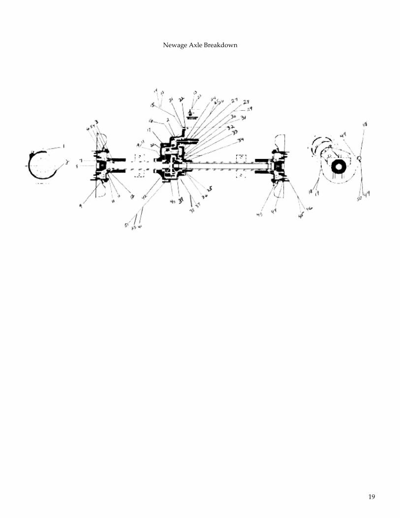
Steering Column & Horn Assembly (1 of 2)
Steering Column & Horn Assembly‐Detail (1 of 2)
Item Part Number Qty Description1 A‐RTT12‐00399‐1 1 STEERING COLUMN TILT2 A‐TN4‐00809E 1 STEERING WHEEL3 A‐TT10‐00811 1 HORN BUTTON4 A‐TT10‐00813 1 STEERING WHEEL NUT5 A‐RTT12‐00052 1 HORN
1
2
3
4
Wheel nut not seen
(Inside wheel)
5

26
Steering Column Assembly (2 of 2)
Steering Column Assembly‐Detail (2 of 2)
Item Part Number Qty Description1 1614DM250NFI 2 ELECTRIC MALE END FITTING2 A‐TT4‐00389 1 UNIVERSAL COUPLER3 5/16‐18X1.75 G8 HCS 1 HCS4 5/16 1 FLAT WASHER5 5/16‐18 1 LOCKNUT6 A‐RTT12‐00399‐A 2 WHITE HORN BRUSH ASSEMBLY
1 2
3
4
5
6
Note: Item # 6 includes item number 1 as part of the kit.

27
Steering Box Assembly
Steering Box Assembly‐Detail
Item Part Number Qty Description1 A‐RTT12‐00381 1 STEERING BOX2 A‐RTT12‐00383‐MACH 1 STEERING BOX YOKE3 A‐RTT12‐00387 1 CENTER YOKE4 A‐RTT12‐00386 1 TUBE YOKE5 A‐RTT12‐00385 1 LOCKING COLLAR6 A‐RTT12‐00388 1 YOKE ADAPTER 7 A‐RTT12‐00384 2 U‐JOINT8 A‐RTT12‐00330 3 SPACER9 7/16‐14X2.5 G8 HCS 3 HCS10 3/8 G8 3 FLAT WASHER
1
2
3
4
7
5
6
8 9 10

28
Master Cylinder Assembly (1 of 2)
Master Cylinder Assembly‐Detail (1 of 2)
Item Part Number Qty Description1 A‐RTT12‐00161 1 MASTER CYLINDER2 A‐RTT12‐00163 1 MASTER CYLINDER BRACKET3 A‐RTT12‐00181 1 BRAKE PEDAL4 C‐TT4‐10182 1 PEDAL PIVOT PIN5 C‐TT4‐10188 1 NYLINER BEARINGS6 A‐RTT12‐00389 1 CLEVIS7 7/16‐14 1 JAM NUT8 A‐RTT12‐00164 X 15 1 TUBING9 A‐RTT12‐00162 1 RESERVOIR10 A‐RTT12‐00170 1 BRAKE LINE CENTER11 A‐TT4‐00173 1 SWITCH12 A‐RTT12‐00165 2 FI HOSE CLAMPS 1/4
Note: Item # 12‐18 Continued on (2 of 2)
9
10
8
7 6 4
5
3
2
1
11
12

29
Master Cylinder Assembly (2 of 2)
Master Cylinder Assembly‐Detail (2 of 2)
Item Part Number Qty Description12 A‐TT4‐00163 1 SWITCH TEE13 A‐TT4‐00167 1 90 DEGREE BRAKE LINE14 A‐TT4‐00165 1 BRAKE HOSE CLIP15 A‐TT4‐00166 1 BRAKE HOSE16 NPN 1 HOSE BRACKET (EAGLE FAB PART)17 5/16‐18 2 LOCK NUT18 5/16‐18X1 G5 HCS 1 HCS
Note: Use 5/16‐18X1.5 on Master Cylinder for clamp space on assembly (rt side)
12 13 15 14
16
17
18

30
Electrical Component Assembly (1 of 2)
Electrical Component Assembly‐Detail (1 of 2)
Item Part Number Qty Description1 A‐TT4‐00299 1 FUSE BLOCK2 A‐TT4‐00300 2 BUS BAR3 A‐RTT‐00282 1 THROTTLE CONTACTOR4 A‐RTT‐00283 1 THROTTLE BRACKET5 A‐RTT‐00370 1 TRACTION DRIVE
7 A‐RTT12‐00408 1 LIGHT RELAY SOCKET8 A‐RTT12‐00409 1 LIGHT RELAY SOCKET (NOT SHOWN)
6 A‐RTT‐00411A‐RTT‐00410
11
VEHICLE CONTROLLER WITH BDIVEHICLE CONTROLLER WITH DISPLAY (OPTION)
2
6
3
1
5
4
7 8
9

31
Electrical Component Assembly (2 of 2)
Electrical Component Assembly‐Detail (2 of 2)
Item Part Number Qty Description1 A‐TT3‐0010 3 FUSE AGC 25 AMP2 A‐RTT12‐00417 1 FUSE
2 1

32
Instrument Panel Assembly
Instrument Panel Assembly‐Detail
Item Part Number Qty Description1 A‐RTT12‐00418‐1 1 F/N/R ROCKER SWITCH2 A‐RTT12‐00428 1 LO/HI SPEED SWITCH
4 A‐RTT12‐00490 1 LO/HI SPEEED & F/N/R DECAL SET5 A‐RTT12‐00426 1 BDI GAUGE
3 A‐RTT12‐00416A‐RTT12‐00416‐1
11
KEY SWITCH GM LDT ONLYKEY SWITCH ALL OTHER FACTORIES
2 1
3
4
5

33
Seat Assembly
Seat Assembly‐Detail
Item Part Number Qty Description1 A‐RTT12‐0048 1 SEAT FRAME2 A‐RTT12‐0047 KIT 4 SEAT CUSHIONS (ENTIRE SET)3 A‐RTT12‐00480 1 SEAT ADJUSTMENT SPRING4 A‐RTT12‐0047‐A 1 SEAT BACK CUSHION5 A‐RTT12‐0047‐B 1 SEAT BOTTOM CUSHION6 A‐RTT12‐0047‐C 1 SEAT RIGHT WING CUSHION7 A‐RTT12‐0047‐D 1 SEAT LEFT WING CUSHION8 A‐RTT12‐0048‐B 1 BOTTOM SEAT TORSION SPRING
1
2
3
4
5
6
7
8

34
Rear Hitch Assembly
Rear Hitch Assembly‐Detail
Item Part Number Qty Description1A AE‐OPT‐0036‐18 KIT REAR HITCH ASSEMBLY WITH LEVER
(ENTIRE SET)1 AE‐OPT‐0036 1 RTT REAR HITCH BODY2 A‐TT2‐0057 2 SHAFT COLLAR 3/4ʺ3 AE‐OPT‐0036A 2 FOAM GRIPS4 AE‐OPT‐0036‐18B 1 1/2‐13 X 7 HCS G8 BOLT5 A‐TT2‐0055 2 SHAFT COLLAR 1/2ʺ6 AE‐OPT‐0036‐18A 1 HITCH HEIGHT ADJUST ADAPTER (6ʺ)7 AE‐OPT‐0036‐20K 6 1/2‐13 X 1 3/4 HCS G8 BOLT8 AE‐OPT‐0036‐20L 2 1/2‐13 X 2 HCS G8 BOLT9 AE‐OPT‐0036‐20A 8 1/2‐13 HEX SERRATED FLANG NUT10 AE‐OPT‐0036B 2 3/8‐16 X 1 1/4 G8 HCS BOLT11 AE‐OPT‐0180‐2 4 3/8 FLAT WASHER12 AE‐OPT‐0036H 2 3/8‐16 LOCK NUT13 AE‐OPT‐0036‐18D 1 REAR LEVER RELEASE14 AE‐OPT‐0036‐20N 2 LEVER RELEASE SIDE TABS15 AE‐OPT‐0036‐18C 1 SADDLE BLOCK16 AE‐OPT‐0036C 2 1/2ʺ FLAT WASHER17 AE‐OPT‐0036D 1 1/2‐13 LOCK NUT
AE‐OPT‐0036‐18 (complete)
15
1
3 8 13
2
7
9
10
10
5
6
11
12
9
4
14
1A
16 17

35
1
17
Item Part Number Qty Description1 AE‐OPT‐0036‐20I 4ft COATED WIRE ROPE2 AE‐OPT‐0036‐20D 1 WIRE ROPE CLIP3 AE‐OPT‐0036‐20E 1 WIRE ROPE THIMBLE4 AE‐OPT‐0036‐20F 1 THREADED CONNECTOR5 AE‐OPT‐0036‐20G 1 SHELL BLOCK WITH SWIVEL EYE6 AE‐OPT‐0036‐20H 2 WIRE EYEBOLT WITH NUT7 AE‐OPT‐0036‐20B 1 PULL CORD STARTER HANDLE8 AE‐OPT‐0036‐20C 1 ALUMINUM STOP SLEEVE9 AE‐OPT‐0036‐20A 8 1/2‐13 HEX SERRATED FLANGE NUT10 AE‐OPT‐0036‐20K 8 1/2‐13 X 1 3/4 HCS G8 BOLT11 AE‐OPT‐0036B 2 3/8‐16 X 1 1/4 G8 HCS12 AE‐OPT‐0036‐20Q 1 1/4 X 1 1/4 ROLL PIN13 A‐TT2‐0057 2 SHAFT COLLAR 3/4ʺ14 AE‐OPT‐0180‐2 4 3/8 FLAT WASHER15 AE‐OPT‐0036H 2 3/8‐16 LOCK NUT16 A‐TT2‐0055 2 SHAFT COLLAR 1/2ʺ17 AE‐OPT‐0036‐20J 1 FRT HITCH HEIGHT ADJST. ADPTR (10ʺ)18 AE‐OPT‐0036 1 RTT F&R E‐HITCH19 AE‐OPT‐0036‐20M 1 FRONT LEVER RELEASE20 AE‐OPT‐0036‐20N 2 LEVER RELEASE SIDE TABS21 AE‐OPT‐0036‐18B 1 1/2‐13 X 7 HCS G8 BOLT22 AE‐OPT‐0036C 2 1/2ʺ FLAT WASHER23 AE‐OPT‐0036D 1 1/2‐13 LOCK NUT24 C‐TT4‐10188 (NOT SHOWN) 2 THOMPSON NYLINER BEARING
Front Hitch Assembly‐Detail
Front Hitch Assembly
12 11
9
16
18
7
8
13
10 20
21
2
3
4
5
10 10 14
20 15
19
6
AE‐OPT‐0036‐20 (complete)
22 23
1A

36
Miscellaneous Components
Miscellaneous Components‐Detail
Item Part Number Qty Description1 A‐RTT12‐00291‐1 1 HEADLIGHT2 A‐RTT12‐00491 2 EAGLE DECAL3 AE‐OPT‐0038 1 OPTIONAL HITCH FOR GM LDT4 A‐RTT‐00450 1 SWITCH MAT5 AE‐OPT‐0038A 1 TUGGER RELEASE HANDLE6 AE‐OPT‐0036‐21 1 TOW BAR RAMP
2
1
3
4
5
6

37

38