Operation and Control of Device-to-Device Communication in ...
Upload
khangminh22Category
view
2download
0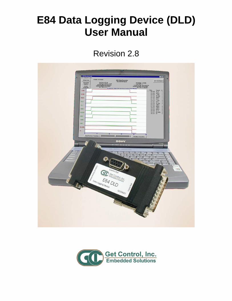
E84 Data Logging Device (DLD)User Manual
Revision 2.8

E84 Data Logging Device (DLD) User Manual Revision 2.8
E84_DLD_User_Manual.wpd
Table of Contents
Overview ..................................................................................................................................................... 1E84 Analysis Application ................................................................................................................ 1E84 DLD ......................................................................................................................................... 1
Getting Started ............................................................................................................................................ 2E84 DLD Package Contents .......................................................................................................... 2E84 DLD Power Requirements ...................................................................................................... 2Typographical Conventions ............................................................................................................ 2
E84 Data Logging Device (DLD) Description .............................................................................................. 2E84 DLD to Load Port Connection ................................................................................................. 2
E84 DLD Version Information ...................................................................................................................... 3
Configuring the E84 DLD ............................................................................................................................ 3Communicating with the E84 DLD ................................................................................................. 3
DLD Power Requirements ................................................................................................. 3E84 Analysis Application COM Settings ............................................................................ 3
E84 DLD Configuration Options ..................................................................................................... 4
Recording Data ........................................................................................................................................... 6Stored Data .................................................................................................................................... 6Live Data ........................................................................................................................................ 6Sampling Rate ................................................................................................................................ 7Timing Diagram Graph Update Rate .............................................................................................. 7E84 DLD Power On Graph Indicator .............................................................................................. 7E84 DLD Power Off Graph Indicator .............................................................................................. 7
Status LED’s ................................................................................................................................................ 8DLD Power Indicator ...................................................................................................................... 8DLD RAM Buffer Indicator .............................................................................................................. 8
Version History ............................................................................................................................................ 9
Technical Support ..................................................................................................................................... 10
E84 Data Logging Device (DLD) User Manual Revision 2.8
E84_DLD_User_Manual.wpd
List of Figures
Installed DLD ............................................................................................................................................... 2Help Menu ................................................................................................................................................... 3Record Using COM Menu ........................................................................................................................... 3Configure DLD Dialog Box .......................................................................................................................... 4Upload DLD Dialog Box .............................................................................................................................. 6DLD Power Up and Power Down Indicators ............................................................................................... 7
E84 Data Logging Device (DLD) User Manual Revision 2.8
E84_DLD_User_Manual.wpd 1
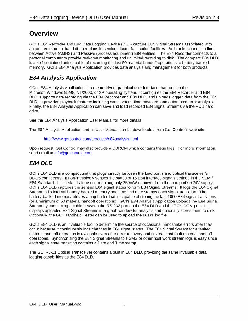
OverviewGCI’s E84 Recorder and E84 Data Logging Device (DLD) capture E84 Signal Streams associated withautomated material handoff operations in semiconductor fabrication facilities. Both units connect in-linebetween Active (AMHS) and Passive (process equipment) E84 entities. The E84 Recorder connects to apersonal computer to provide real-time monitoring and unlimited recording to disk. The compact E84 DLDis a self-contained unit capable of recording the last 50 material handoff operations to battery-backedmemory. GCI’s E84 Analysis Application provides data analysis and management for both products.
E84 Analysis ApplicationGCI’s E84 Analysis Application is a menu-driven graphical user interface that runs on theMicrosoft Windows 95/98, NT/2000, or XP operating system. It configures the E84 Recorder and E84DLD, supports data recording via the E84 Recorder and E84 DLD, and uploads logged data from the E84DLD. It provides playback features including scroll, zoom, time measure, and automated error analysis. Finally, the E84 Analysis Application can save and load recorded E84 Signal Streams via the PC’s harddrive.
See the E84 Analysis Application User Manual for more details.
The E84 Analysis Application and its User Manual can be downloaded from Get Control’s web site:
http://www.getcontrol.com/products/e84analysis.html
Upon request, Get Control may also provide a CDROM which contains these files. For more information,send email to [email protected].
E84 DLDGCI’s E84 DLD is a compact unit that plugs directly between the load port’s and optical transceiver’sDB-25 connectors. It non-intrusively senses the states of 15 E84 interface signals defined in the SEMI®
E84 Standard. It is a stand-alone unit requiring only 250mW of power from the load port’s +24V supply. GCI’s E84 DLD captures the sensed E84 signal states to form E84 Signal Streams. It logs the E84 SignalStream to its internal battery-backed memory and time and date stamps each signal transition. Thebattery-backed memory utilizes a ring buffer that is capable of storing the last 1000 E84 signal transitions(or a minimum of 50 material handoff operations). GCI’s E84 Analysis Application uploads the E84 SignalStream by connecting a cable between the RS-232 port on the E84 DLD and the PC’s COM port. Itdisplays uploaded E84 Signal Streams in a graph window for analysis and optionally stores them to disk. Optionally, the GCI Handheld Tester can be used to upload the DLD’s log file.
GCI’s E84 DLD is an invaluable tool to determine the source of occasional handshake errors after theyoccur because it continuously logs changes in E84 signal states. The E84 Signal Stream for a faultedmaterial handoff operation is available even after error recovery and several post-fault material handoffoperations. Synchronizing the E84 Signal Streams to HSMS or other host work stream logs is easy sinceeach signal state transition contains a Date and Time stamp.
The GCI RJ-11 Optical Transceiver contains a built in E84 DLD, providing the same invaluable datalogging capabilities as the E84 DLD.
E84 Data Logging Device (DLD) User Manual Revision 2.8
E84_DLD_User_Manual.wpd 2
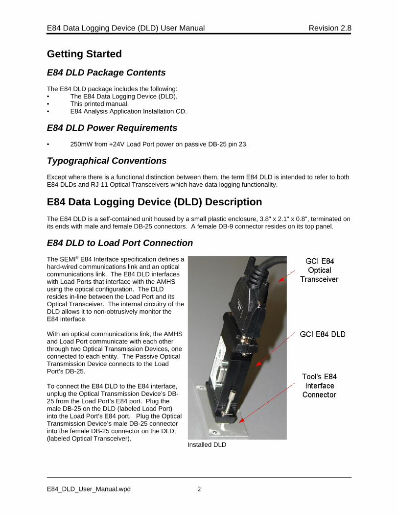
Installed DLD
Getting Started
E84 DLD Package ContentsThe E84 DLD package includes the following:• The E84 Data Logging Device (DLD).• This printed manual.• E84 Analysis Application Installation CD.
E84 DLD Power Requirements• 250mW from +24V Load Port power on passive DB-25 pin 23.
Typographical ConventionsExcept where there is a functional distinction between them, the term E84 DLD is intended to refer to bothE84 DLDs and RJ-11 Optical Transceivers which have data logging functionality.
E84 Data Logging Device (DLD) DescriptionThe E84 DLD is a self-contained unit housed by a small plastic enclosure, 3.8" x 2.1" x 0.8", terminated onits ends with male and female DB-25 connectors. A female DB-9 connector resides on its top panel.
E84 DLD to Load Port ConnectionThe SEMI® E84 Interface specification defines ahard-wired communications link and an opticalcommunications link. The E84 DLD interfaceswith Load Ports that interface with the AMHSusing the optical configuration. The DLDresides in-line between the Load Port and itsOptical Transceiver. The internal circuitry of theDLD allows it to non-obtrusively monitor theE84 interface.
With an optical communications link, the AMHSand Load Port communicate with each otherthrough two Optical Transmission Devices, oneconnected to each entity. The Passive OpticalTransmission Device connects to the LoadPort’s DB-25.
To connect the E84 DLD to the E84 interface,unplug the Optical Transmission Device’s DB-25 from the Load Port’s E84 port. Plug themale DB-25 on the DLD (labeled Load Port)into the Load Port’s E84 port. Plug the OpticalTransmission Device’s male DB-25 connectorinto the female DB-25 connector on the DLD,(labeled Optical Transceiver).
E84 Data Logging Device (DLD) User Manual Revision 2.8
E84_DLD_User_Manual.wpd 3
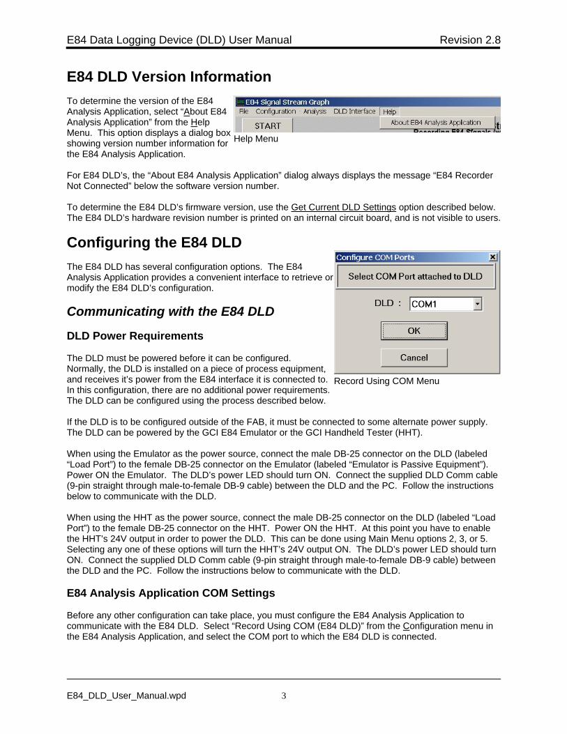
Help Menu
Record Using COM Menu
E84 DLD Version InformationTo determine the version of the E84Analysis Application, select “About E84Analysis Application” from the HelpMenu. This option displays a dialog boxshowing version number information forthe E84 Analysis Application.
For E84 DLD’s, the “About E84 Analysis Application” dialog always displays the message “E84 RecorderNot Connected” below the software version number.
To determine the E84 DLD’s firmware version, use the Get Current DLD Settings option described below. The E84 DLD’s hardware revision number is printed on an internal circuit board, and is not visible to users.
Configuring the E84 DLDThe E84 DLD has several configuration options. The E84Analysis Application provides a convenient interface to retrieve ormodify the E84 DLD’s configuration.
Communicating with the E84 DLD
DLD Power Requirements
The DLD must be powered before it can be configured. Normally, the DLD is installed on a piece of process equipment,and receives it’s power from the E84 interface it is connected to. In this configuration, there are no additional power requirements. The DLD can be configured using the process described below.
If the DLD is to be configured outside of the FAB, it must be connected to some alternate power supply. The DLD can be powered by the GCI E84 Emulator or the GCI Handheld Tester (HHT).
When using the Emulator as the power source, connect the male DB-25 connector on the DLD (labeled“Load Port”) to the female DB-25 connector on the Emulator (labeled “Emulator is Passive Equipment”). Power ON the Emulator. The DLD’s power LED should turn ON. Connect the supplied DLD Comm cable(9-pin straight through male-to-female DB-9 cable) between the DLD and the PC. Follow the instructionsbelow to communicate with the DLD.
When using the HHT as the power source, connect the male DB-25 connector on the DLD (labeled “LoadPort”) to the female DB-25 connector on the HHT. Power ON the HHT. At this point you have to enablethe HHT’s 24V output in order to power the DLD. This can be done using Main Menu options 2, 3, or 5. Selecting any one of these options will turn the HHT’s 24V output ON. The DLD’s power LED should turnON. Connect the supplied DLD Comm cable (9-pin straight through male-to-female DB-9 cable) betweenthe DLD and the PC. Follow the instructions below to communicate with the DLD.
E84 Analysis Application COM Settings
Before any other configuration can take place, you must configure the E84 Analysis Application tocommunicate with the E84 DLD. Select “Record Using COM (E84 DLD)” from the Configuration menu inthe E84 Analysis Application, and select the COM port to which the E84 DLD is connected.
E84 Data Logging Device (DLD) User Manual Revision 2.8
E84_DLD_User_Manual.wpd 4
Configure DLD Dialog Box
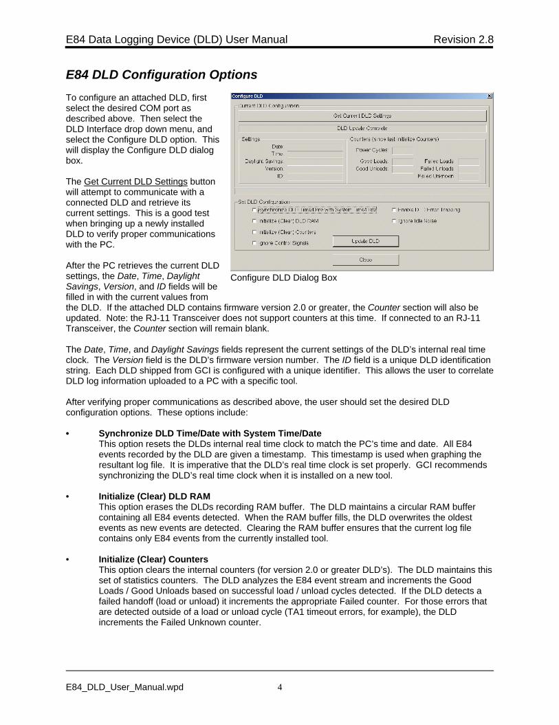
E84 DLD Configuration OptionsTo configure an attached DLD, firstselect the desired COM port asdescribed above. Then select theDLD Interface drop down menu, andselect the Configure DLD option. Thiswill display the Configure DLD dialogbox.
The Get Current DLD Settings buttonwill attempt to communicate with aconnected DLD and retrieve itscurrent settings. This is a good testwhen bringing up a newly installedDLD to verify proper communicationswith the PC.
After the PC retrieves the current DLDsettings, the Date, Time, DaylightSavings, Version, and ID fields will befilled in with the current values fromthe DLD. If the attached DLD contains firmware version 2.0 or greater, the Counter section will also beupdated. Note: the RJ-11 Transceiver does not support counters at this time. If connected to an RJ-11Transceiver, the Counter section will remain blank.
The Date, Time, and Daylight Savings fields represent the current settings of the DLD’s internal real timeclock. The Version field is the DLD’s firmware version number. The ID field is a unique DLD identificationstring. Each DLD shipped from GCI is configured with a unique identifier. This allows the user to correlateDLD log information uploaded to a PC with a specific tool.
After verifying proper communications as described above, the user should set the desired DLDconfiguration options. These options include:
• Synchronize DLD Time/Date with System Time/DateThis option resets the DLDs internal real time clock to match the PC’s time and date. All E84events recorded by the DLD are given a timestamp. This timestamp is used when graphing theresultant log file. It is imperative that the DLD’s real time clock is set properly. GCI recommendssynchronizing the DLD’s real time clock when it is installed on a new tool.
• Initialize (Clear) DLD RAMThis option erases the DLDs recording RAM buffer. The DLD maintains a circular RAM buffercontaining all E84 events detected. When the RAM buffer fills, the DLD overwrites the oldestevents as new events are detected. Clearing the RAM buffer ensures that the current log filecontains only E84 events from the currently installed tool.
• Initialize (Clear) CountersThis option clears the internal counters (for version 2.0 or greater DLD’s). The DLD maintains thisset of statistics counters. The DLD analyzes the E84 event stream and increments the GoodLoads / Good Unloads based on successful load / unload cycles detected. If the DLD detects afailed handoff (load or unload) it increments the appropriate Failed counter. For those errors thatare detected outside of a load or unload cycle (TA1 timeout errors, for example), the DLDincrements the Failed Unknown counter.
E84 Data Logging Device (DLD) User Manual Revision 2.8
E84_DLD_User_Manual.wpd 5
• Ignore Control SignalsThis option enables a masking function that treats changes in the three control signals as non-events. Changes to the control signals do not trigger a write into the battery backed RAM buffer. This option is useful when there is noise on one of the three control signals (pins 10, 11, and 12,which represent Select, Mode and GO respectively). If one of the control signals is changingfrequently, it can decrease the number of E84 handoffs that can be recorded.
When this option is disabled, changes on the three control signals do trigger events, and arewritten into the RAM buffer.
Note: Leave this option disabled unless the recorded data shows excessive control signal events. Having a recording of the true states of the control signals is very valuable when analyzing a dataset. This option will mask true changes to the control signals. This option requires version 2.52(or greater) of the E84 Analysis Application.
• Enable DLD Error TrappingThis option turns on the special Errors Only Recording mode (for version 2.0 or greater DLD’s). During normal recording, the DLD logs every E84 event detected. A typical handoff sequence(load or unload) is comprised of approximately 20 events. Based on this approximation, the DLDcan log the last 50 E84 handoffs (loads and unloads) before filling it’s internal RAM buffer.
When the Error Trapping option is enabled, the DLD only logs those E84 handoffs that fail tocomply with the published E84 sequence. In this mode, the DLD analyzes the E84 events in real-time, and discards any sequence of events that matches a valid load or unload cycle. If asequence of events does not match a valid load or unload, that sequence is added to the RAMbuffer. This allows the DLD to trap the(approximately) last 50 failed E84 handoffs.
• Ignore Idle NoiseThis option is used only when the Enable DLD Error Trapping option is selected. It instructs theDLD to ignore signal state changes that would normally trigger an error if those transitions occuroutside of a standard handoff (for version 2.0 or greater DLD’s).
The DLD treats a standard handoff as starting with CS_0 and / or CS_1 ON, followed by VALIDON. The DLD exits a standard handoff when the E84 bus returns to the IDLE state (all signalsOFF except HO_AVBL and ES).
If a signal changes state outside of this standard handoff period, a DLD in Error Trapping modewould log the event as an error. If the Ignore Idle Noise option is enabled, the DLD ignores allsignal state change events that fall outside a standard handoff.
When bringing up a newly installed DLD, the user should always select the Synchronize DLD Time/Dateand Initialize (Clear) DLD RAM options.
After desired options have been selected, press the Update DLD button. The PC will attempt tocommunicate with the connected DLD and configure it with the selected options. Options are stored innon-volatile RAM, and stay in affect until re-configured.
Note: when the Initialize (Clear) DLD RAM option is selected, the DLD erases it’s internal recording RAMbuffer. An attempt to upload the DLD log file just after clearing the RAM buffer will result in an errormessage saying that the DLD Log file contains no data points. After clearing the RAM buffer, make surethat the DLD has recorded new signal transitions so the RAM buffer will contain valid data points. TheDLD will log power on events, so an easy way to ensure the RAM contains at least one data point is topower cycle the DLD after clearing the RAM.
E84 Data Logging Device (DLD) User Manual Revision 2.8
E84_DLD_User_Manual.wpd 6
Upload DLD Dialog Box
Recording DataThe E84 DLD will automatically record E84 communications whenever it is inserted into an E84communication link. By default, the data is stored in the E84 DLD’s internal flash memory (however, seeLive Data below).
Stored DataTo retrieve stored data from an E84 DLD, first configure the E84 Analysis Application to communicate withthe E84 DLD (see Communicating with the E84 DLD above). Then, select “Upload DLD” from the DLDInterface menu.
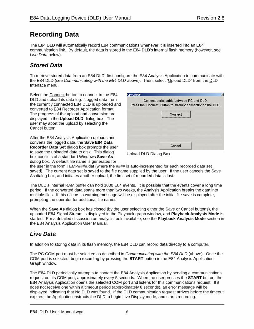
Select the Connect button to connect to the E84DLD and upload its data log. Logged data fromthe currently connected E84 DLD is uploaded andconverted to E84 Recorder Application format. The progress of the upload and conversion aredisplayed in the Upload DLD dialog box. Theuser may abort the upload by selecting theCancel button.
After the E84 Analysis Application uploads andconverts the logged data, the Save E84 DataRecorder Data Set dialog box prompts the userto save the uploaded data to disk. This dialogbox consists of a standard Windows Save Asdialog box. A default file name is generated forthe user in the form TEMP####.dat (where the #### is auto-incremented for each recorded data setsaved). The current data set is saved to the file name supplied by the user. If the user cancels the SaveAs dialog box, and initiates another upload, the first set of recorded data is lost.
The DLD’s internal RAM buffer can hold 1000 E84 events. It is possible that the events cover a long timeperiod. If the converted data spans more than two weeks, the Analysis Application breaks the data intomultiple files. If this occurs, a warning message will be displayed after the initial file save is complete,prompting the operator for additional file names.
When the Save As dialog box has closed (by the user selecting either the Save or Cancel buttons), theuploaded E84 Signal Stream is displayed in the Playback graph window, and Playback Analysis Mode isstarted. For a detailed discussion on analysis tools available, see the Playback Analysis Mode section inthe E84 Analysis Application User Manual.
Live DataIn addition to storing data in its flash memory, the E84 DLD can record data directly to a computer.
The PC COM port must be selected as described in Communicating with the E84 DLD (above). Once theCOM port is selected, begin recording by pressing the START button in the E84 Analysis ApplicationGraph window.
The E84 DLD periodically attempts to contact the E84 Analysis Application by sending a communicationsrequest out its COM port, approximately every 5 seconds. When the user presses the START button, theE84 Analysis Application opens the selected COM port and listens for this communications request. If itdoes not receive one within a timeout period (approximately 8 seconds), an error message will bedisplayed indicating that No DLD was found. If the DLD communication request arrives before the timeoutexpires, the Application instructs the DLD to begin Live Display mode, and starts recording.
E84 Data Logging Device (DLD) User Manual Revision 2.8
E84_DLD_User_Manual.wpd 7
DLD Power Up and Power Down Indicators
Recording can be terminated at any time by pressing the STOP button.
Note: By default, the E84 Analysis Application will chart the data on your computer screen as it is beingrecorded. To conserve computer resources while recording data, select the “Set Long Term RecordingMode” option from the Configuration menu. This will prevent the data from being charted onscreen.
For more details, see the E84 Analysis Application User Manual.
Sampling RateThe E84 DLD records E84 Signals using a transitional method. During recording, all E84 signals aresampled simultaneously. The current state of the signal is compared with the previously sampled signalstate. If one or more signals have changed from the previous sample, the data is time-stamped andrecorded. The E84 DLD samples at a 500 Hz rate (2mS resolution), and the RJ-11 Optical Transceiversamples at a 100 Hz rate (10mS resolution).
The E84 DLD and RJ-11 Optical Transceiver produce a 4Hz timing mark (250 mS period) that is read bythe E84 Analysis Application. The E84 Analysis Application buffers a minimum of four samples persecond. The timing mark produces a minimum 250 mSecond update for the timing diagram graph duringtime periods of static E84 signals.
Timing Diagram Graph Update RateThe real-time graph provides a maximum resolution of 100 data points per second (or 10 mS period). Thislimitation is imposed due to the overhead of updating the graphics screen. Signals which transition fasterthan 100 Hz may be transparent on the real-time graph. However, these signal transitions will berecorded, reported in the tabular reports, and available for graphing during Playback Analysis mode.
When displaying previously recorded data using the E84 Analysis Application’s Playback AnalysisMode, the graph update rate reverts to the 2 mSecond sample rate of the E84 DLD, or the 10 mSecondsample rate of the RJ-11 Optical Transceiver. This allows complete analysis of recorded data, includingthose signal state changes that occurred under the 10 mSecond update rate of the real-time graph.
E84 DLD Power On Graph IndicatorPower for the E84 DLD is provided by the Load Port. The E84 DLD can log transitory signal changesduring power up that the user may choose to ignore. At power up, the DLD writes a power up event intothe log file. To indicate a power cycle, a vertical black line is drawn at the time-stamp to indicate a powercycle on the E84 DLD.
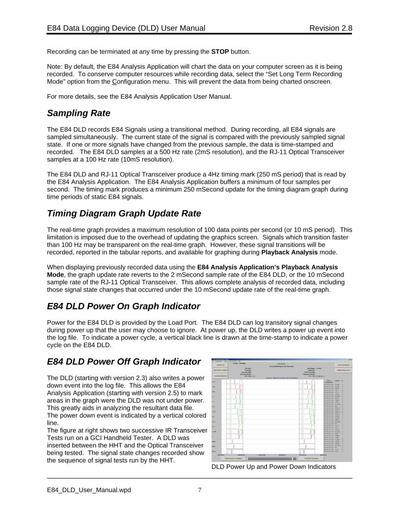
E84 DLD Power Off Graph IndicatorThe DLD (starting with version 2.3) also writes a powerdown event into the log file. This allows the E84Analysis Application (starting with version 2.5) to markareas in the graph were the DLD was not under power. This greatly aids in analyzing the resultant data file. The power down event is indicated by a vertical coloredline.The figure at right shows two successive IR TransceiverTests run on a GCI Handheld Tester. A DLD wasinserted between the HHT and the Optical Transceiverbeing tested. The signal state changes recorded showthe sequence of signal tests run by the HHT.
E84 Data Logging Device (DLD) User Manual Revision 2.8
E84_DLD_User_Manual.wpd 8
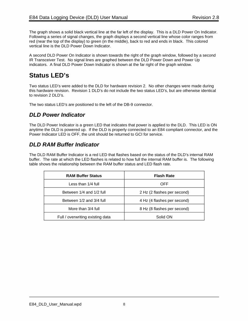
The graph shows a solid black vertical line at the far left of the display. This is a DLD Power On Indicator. Following a series of signal changes, the graph displays a second vertical line whose color ranges fromred (near the top of the display) to green (in the middle), back to red and ends in black. This coloredvertical line is the DLD Power Down Indicator.
A second DLD Power On Indicator is shown towards the right of the graph window, followed by a secondIR Transceiver Test. No signal lines are graphed between the DLD Power Down and Power Upindicators. A final DLD Power Down Indicator is shown at the far right of the graph window.
Status LED’sTwo status LED’s were added to the DLD for hardware revision 2. No other changes were made duringthis hardware revision. Revision 1 DLD’s do not include the two status LED’s, but are otherwise identicalto revision 2 DLD’s.
The two status LED’s are positioned to the left of the DB-9 connector.
DLD Power IndicatorThe DLD Power Indicator is a green LED that indicates that power is applied to the DLD. This LED is ONanytime the DLD is powered up. If the DLD is properly connected to an E84 compliant connector, and thePower Indicator LED is OFF, the unit should be returned to GCI for service.
DLD RAM Buffer IndicatorThe DLD RAM Buffer Indicator is a red LED that flashes based on the status of the DLD’s internal RAMbuffer. The rate at which the LED flashes is related to how full the internal RAM buffer is. The followingtable shows the relationship between the RAM buffer status and LED flash rate.
RAM Buffer Status Flash Rate
Less than 1/4 full OFF
Between 1/4 and 1/2 full 2 Hz (2 flashes per second)
Between 1/2 and 3/4 full 4 Hz (4 flashes per second)
More than 3/4 full 8 Hz (8 flashes per second)
Full / overwriting existing data Solid ON
E84 Data Logging Device (DLD) User Manual Revision 2.8
E84_DLD_User_Manual.wpd 9
Version History• Revision 2.72 changes the method for defining the COM port to use for DLD communications.
Added communications commands to support DLD firmware 2.6.
• Revision 2.6 corrects URL links to the E84 Analysis Application website. Additional commentswere also added to the DLD Upload operation.
• Revision 2.52 adds a description of power requirements when communicating with a DLD outsideof the FAB. It also adds the Ignore Control Signals option.
• Revision 2.5 divides this documentation into three individual documents: E84 Recorder UserManual, E84 Analysis Application User Manual, and E84 Data Logging Device (DLD) UserManual.
• Revision 2.3 adds support for the GCI RJ-11 Transceiver.
• Revision 2.0 adds support for the GCI E84 DLD.
• Revision 1.50 adds E84 Error Analysis. Recorded data sets can be analyzed against publishedE84 Specification timing requirements.
• Revision 1.42a corrects some typographical errors only. No other changes were made. CoversSoftware Version 1.42.
E84 Data Logging Device (DLD) User Manual Revision 2.8
E84_DLD_User_Manual.wpd 10
Technical SupportIf you encounter problems using your E84 Data Logging Device, Get Control technical support can bereached the following ways.
By email at [email protected].
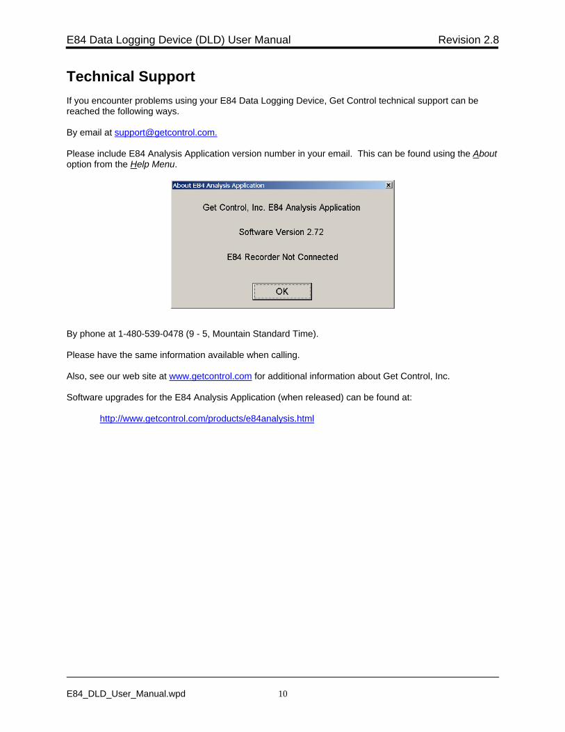
Please include E84 Analysis Application version number in your email. This can be found using the Aboutoption from the Help Menu.
By phone at 1-480-539-0478 (9 - 5, Mountain Standard Time).
Please have the same information available when calling.
Also, see our web site at www.getcontrol.com for additional information about Get Control, Inc.
Software upgrades for the E84 Analysis Application (when released) can be found at:
http://www.getcontrol.com/products/e84analysis.html

Copyright © 2022 FDOKUMEN