Dynamic process analyses of saline intrusion with over-exploitation by coupled flow and dispersive...
11
Introduction Saline intrusion is a dynamic movement of saline and fresh water under natural and man-made conditions. It is caused by advection, dispersion and diffusion of the saline solute into the fresh water body. Due to recharge of fresh water from precipitation and inland flow, salt can be pushed back to the sea. A dynamic balance and a mixing zone, or sharp interface if the thickness is much less than the aquifer thickness, will thus be formed be- tween saline and fresh water in the aquifer system. Abstraction can elevate the zone or interface, particu- larly in concentrated pumping well field, that is called up-cone; it can also extend the saline intrusion towards the inland. Sound understanding of saline intrusion into coastal aquifer is an important issue in management and protection of groundwater resource and hazard pre- vention. It is particularly useful for situations under over-exploitation in semi-arid regions. Groundwater modelling can play an important role in the under- standing and decision-making for management and prevention of such hazards. Plenty of researches on saline water intrusion have been carried out over the past hundred years. Ghyben and Herzberg found methods independently to calculate the fresh and saline interface, so-called Ghyben-Herzberg Fengshan Ma Y. S. Yang Z. Cai M. Chen R. Yuan Dynamic process analyses of saline intrusion with over-exploitation by coupled flow and dispersive modelling Received: 20 July 2004 Accepted: 18 May 2005 Published online: 30 July 2005 ȑ Springer-Verlag 2005 Abstract Understanding of saline intrusion into coastal aquifer is an important issue in management and protection of groundwater resource, which can be well achieved by groundwater modelling. To explain some phenomena of correlation be- tween groundwater level and salinity in observation wells in coastal area, the authors compare the migration velocity of saline particles and transmission velocity of water pres- sure and derive analytical equations of these two velocities for plane and radial flows. The driving force and resistance of saline intrusion were analysed based on the analytical modelling. The destruction and reconstruction of the equilibrium between fresh water seepage towards sea and saline dispersion to inland were considered as an essence of whole intrusion process. The dy- namic process of seepage and dis- persion at different stages of saline intrusion were analysed under groundwater over-exploitation. The basic equations of saline intrusion were derived and the mechanism of transitional zone movement was discussed. These constitute coupled seepage–dispersion theory of saline intrusion, which becomes an impor- tant supplement to existing theory of saline intrusion. As a case study on saline intrusion in Guangrao County in Eastern China, this theory was applied to predict the development of saline intrusion in the study area. Keywords Saline intrusion Coupled modelling Over-exploitation Dynamic process Eastern China Environ Geol (2005) 48: 818–828 DOI 10.1007/s00254-005-0024-0 ORIGINAL ARTICLE F. Ma Z. Cai R. Yuan Institute of Geology and Geophysics, Chinese Academy of Sciences, 9825, Beijing 100029, PR China Y. S. Yang (&) School of Earth Sciences, Cardiff University, Park Place, Cardiff CF10 3YE, UK E-mail: yangy6@cardiff.ac.uk Tel.: +44-29-2087-0232 Fax: +44-29-2087-4326 M. Chen Consulting and Research Centre, Ministry of Land and Resources, 37 West Quarter, Beijing 100035, PR China
-
Upload
independent -
Category
Documents
-
view
1 -
download
0
Transcript of Dynamic process analyses of saline intrusion with over-exploitation by coupled flow and dispersive...

Introduction
Saline intrusion is a dynamic movement of saline andfresh water under natural and man-made conditions. Itis caused by advection, dispersion and diffusion of thesaline solute into the fresh water body. Due to rechargeof fresh water from precipitation and inland flow, saltcan be pushed back to the sea. A dynamic balance and amixing zone, or sharp interface if the thickness is muchless than the aquifer thickness, will thus be formed be-tween saline and fresh water in the aquifer system.Abstraction can elevate the zone or interface, particu-larly in concentrated pumping well field, that is called
up-cone; it can also extend the saline intrusion towardsthe inland. Sound understanding of saline intrusion intocoastal aquifer is an important issue in management andprotection of groundwater resource and hazard pre-vention. It is particularly useful for situations underover-exploitation in semi-arid regions. Groundwatermodelling can play an important role in the under-standing and decision-making for management andprevention of such hazards.
Plenty of researches on saline water intrusion havebeen carried out over the past hundred years. Ghybenand Herzberg found methods independently to calculatethe fresh and saline interface, so-called Ghyben-Herzberg
Fengshan Ma
Y. S. Yang
Z. Cai
M. Chen
R. Yuan
Dynamic process analyses of saline intrusionwith over-exploitation by coupled flowand dispersive modelling
Received: 20 July 2004Accepted: 18 May 2005Published online: 30 July 2005� Springer-Verlag 2005
Abstract Understanding of salineintrusion into coastal aquifer is animportant issue in management andprotection of groundwater resource,which can be well achieved bygroundwater modelling. To explainsome phenomena of correlation be-tween groundwater level and salinityin observation wells in coastal area,the authors compare the migrationvelocity of saline particles andtransmission velocity of water pres-sure and derive analytical equationsof these two velocities for plane andradial flows. The driving force andresistance of saline intrusion wereanalysed based on the analyticalmodelling. The destruction andreconstruction of the equilibriumbetween fresh water seepage towardssea and saline dispersion to inlandwere considered as an essence of
whole intrusion process. The dy-namic process of seepage and dis-persion at different stages of salineintrusion were analysed undergroundwater over-exploitation. Thebasic equations of saline intrusionwere derived and the mechanism oftransitional zone movement wasdiscussed. These constitute coupledseepage–dispersion theory of salineintrusion, which becomes an impor-tant supplement to existing theory ofsaline intrusion. As a case study onsaline intrusion in Guangrao Countyin Eastern China, this theory wasapplied to predict the developmentof saline intrusion in the study area.
Keywords Saline intrusion ÆCoupled modelling ÆOver-exploitation Æ Dynamicprocess Æ Eastern China
Environ Geol (2005) 48: 818–828DOI 10.1007/s00254-005-0024-0 ORIGINAL ARTICLE
F. Ma Æ Z. Cai Æ R. YuanInstitute of Geology and Geophysics,Chinese Academy of Sciences, 9825,Beijing 100029, PR China
Y. S. Yang (&)School of Earth Sciences,Cardiff University,Park Place, Cardiff CF10 3YE, UKE-mail: [email protected].: +44-29-2087-0232Fax: +44-29-2087-4326
M. ChenConsulting and Research Centre,Ministry of Land and Resources,37 West Quarter, Beijing 100035,PR China

relation, which assumed the sharp interface between freshand saline water to calculate the pizometric surface of theinterface and neglected the dynamic hydraulic pressure(Freeze and Cherry 1979). Gupta and Yapa (1982)modelled salt-water intrusion in Bangkok using advec-tive-dispersive model by ignoring the influence of saltconcentration on the water flow velocity; the analyticalsolution of the saline intrusion has been studied exten-sively after these. Moor et al. (1992) studied fresh andsaline water relationship in the Yucatan Peninsula coastusing the sharp interface model.
Bear (1972) has studied the theory, mathematicaldescription and analytical approximations of the fresh-saline interface movement and the interface up-coningcaused by pumping above the interface. Custodio (1985)and Custodio and Bruggeman (1987) have also describedsaline intrusion quite well in their studies. The analyticalsolutions are always simple and able to reflect the factorsthat may control the interface/zone and movement.However, difficulty may exist with complicated geologyand non-linearity of the formula, which may be pursuedby numerical differential equations. The numericalmodels can describe more complex hydrogeology andobtain more accurate solutions for the interface/zonemovement under influence of human activity. They havethus been widely used for saline water intrusion. Collinsand Gelhar (1971) and Liu and others (1981) studied thesharp interface modelling in the phreatic, confine aqui-fers and up-coning of the boundary. The finite differencemethod was used by Mercer et al. (1980) to model theinterface and analyse the Hele-Shaw model, proposed byBear and Dagan; the boundary element method wasapplied to study the 2-D sea water intrusion location andup-coning issue (Liu et al. 1981). Wilson et al. (1982)employed finite element to simulate the sharp interfaceissue; Ledoux et al. (1990) and Rivera et al. (1990) alsoused finite difference to build a couple model for salinewater intrusion in Mexico City.
The sharp interface models are only suitable for thenarrow saline-fresh water boundary; research on thegeneral transitional zone with mixing of sea water andfresh water are more useful and practical. Such amodel, for example, the Henry model, was proposed in1960s (Pinder and Cooper 1970) to consider solutedispersion using the finite element numerical method.This was an application of the Henry’s analyticalsolution of solute concentration under confined andsteady flow condition on sea water study. The 2-Dfinite element model of cross section for the flowfunction and associated solute concentration was ini-tially put forward by Lee and Cheng (1974) in a casestudy of sea water intrusion in the Cutler area, Flor-ida. This study was continued by Segol et al. (1975)and Segol et al. (1976). Frind (1982) obtained a moreeffective 2-D finite element solution of saline waterintrusion in a leaky confined aquifer. Another 2-D
cross-sectional saline water intrusion model was solvedby the finite element method in a two-layer coastalaquifer, with discussion of dispersive tensor, itsexpression and effect on calculation result (Reilly andPage 1985). Huyakorn et al. (1987) established density-dependant flow and solute transport equations for thetransitional zone movement in a multi layer coastalaquifer. A 3-D finite element model was used to sim-ulate sea-water intrusion under steady-state flow con-dition in Naka and Kiki confined aquifers, Japan(Kakinuma et al. 1988); the dispersivity was assumedas constant. Galeati et al. (1992) proposed an implicitEulerian-Lagrangian finite element solution of salinewater intrusion in an unconfined aquifer and discussedthe impact of media heterogeneity and undergroundconstructions on saline intrusion. Xue et al. (1993,1995, 2000) and Wu et al. (1993) studied the distri-bution, monitoring, and hydrochemical characteristicsof sea water intrusion in the Laizhou Bay, China,constructed a 3D VOC finite element salt transportmodel to simulate the movement of the saline-freshwater interface. Gangopadhyay and Gupta (1995) useda quasi three dimensional flow and solute transportmodel for sea water intrusion in a regional multi-layergroundwater system in Bangkok; Huyakorn et al.(1996) proposed a multiphase numerical solution ofsharp interface simulation problem; and Yakirevichet al. (1998) modelled saline water intrusion into theGaza Strip coastal aquifer in the Khan Yunis area ofIsrael. More recently, Cartwright and Nielsen (2004)studied hydrodynamic and salinity of coastal ground-water and the mechanism of saline-fresh water inter-face movement responding to waves.
Therefore, the sharp interface model of sea waterintrusion was based on the presumption of immiscibilitybetween saline and fresh water, which did not representthe real mechanism of the most saline intrusion. Somemodels of transitional zone grounded on the misciblesaline transport were lack in reasonable selection anddiscussion on parameters (e.g. dispersivity). Researchshows that the dispersivity can be a great variation evenin similar porous media aquifer (e.g. scale effect). Theparameter selection and reliability are very importantissues in modelling and prediction of sea water intrusion.This paper characterises the transitional zone of salineintrusion using coupled advective flow and dispersivetransport modelling, based on the fact that the actualvelocity of the saline transport is much lower than thespeed of hydraulic head propagation and the minorsolute movement caused by density difference is ignoredin the coastal aquifer. The destruction and reconstruc-tion of the balance between fresh and saline water,seepage of either fresh water towards sea or saline to-wards inland, are regarded as a key process of sea waterintrusion; the interaction of advective seepage anddispersion are coupled in the modelling analyses. The
819

dynamics, process and geometry of the saline-freshtransitional zone under over-exploitation condition arediscussed and applied in a case study in the LaizhouBay, Eastern China.
Groundwater level, salinity and two velocities
Phenomena observation
Concentration of chloride (Cl)) in the coastal ground-water changes with groundwater level can be observed inthe bores of coastal aquifers. Observation data of bothgroundwater level and Cl) have been obtained in bore-holes near a water supply source in Daweijia, the Jinz-hou Bay of Eastern China. The 3-D Cl) observationswere made in 23 boreholes across the pumping field bymultiple-level measurements so that the 3-D concentra-tion gradient of Cl) could be obtained. With the datafrom these observations, a cross section of Cl) concen-tration in the bores with various distances from theshore can be drawn (Fig. 1).
The correlation between Cl) and groundwater levelof the bores at various distances from the sea can be alsodrawn from these time-dependent observations (seeFig. 2). This figure shows a time-dependent variation offour typical bores in the study area under different re-charge conditions. The observations were made in a fullcycle of groundwater level changes from rainy to dryseasons with impact of groundwater exploitation. It isknown from the dynamic process that groundwater be-comes saline rapidly (increase of Cl)) with drop-down ofwater level in the dry seasons in boreholes near the sea(borehole S207 in Figs. 1, 2), which is called salinization;whilst it reverses back to fresh (decrease of Cl)) in therainy seasons but not so fresh as the original that iscalled ‘remaining desalinization’; whenever water levelrecovers back to certain level, salinity will drop signifi-cantly but may be still greater than the original valuethat is called desalinization. Cl) variation is linearlycorrelated to groundwater level under such circum-stance.
The relationship between Cl) and water level is dif-ferent in boreholes farther from the sea (Figs. 1, 2), D5and D21, for example. The concentration of Cl) willremain increasing with the water level recovery in the‘remaining desalinization’ phase just at a lower speedthan that in the salinization phase. With further recov-ery, Cl) starts to decline but does not go back to originalvalue. The situation in the well S205 is similar to that ofD5 and D21, where sea water is well connected with thefresh groundwater via karst channels. However, thefluctuation of Cl) in S205 is much greater.
Theoretical analyses
These complicated processes in the phenomena are con-tributed to the ‘delay effect’ of a much slower transportof chloride than that of groundwater hydraulic head. Thevelocities of the saline particle transport and hydraulicpress transmission can be derived analytically. Thetransport of Cl) consists of three components: moleculardiffusion with the presence of a concentration gradient(described by diffusion coefficient Dm), dynamic disper-sion (dynamic dispersion coefficientDd) and advection ofCl) with its carrier flow. Generally, dispersion includesdiffusion and dynamic dispersion, D = Dm + Dd.
The dynamic dispersion coefficient is proportional toaverage seepage velocity v, Dd = a v, where a is a geo-metric coefficient of the dynamic dispersion, sometimecalled dispersivity (Fetter 1999, pp 52–54), with dimen-sion of length, related to size of element (scale effect).For sand, a is a few millimetre whilst for fissured rock afew to several dozen metre subject to fracture size. It is anoticeable value as regard to the scale of this study(Fig. 1). So, D= Dm + Dd = Dm + a v; plus advection,the velocity of the solute (Cl)) transport vs will be
vs ¼ vC � DdCdx¼ vC � ðDm þ avÞ dC
dx; ð1Þ
where C is Cl) concentration. The vs of Cl) can be cal-
culated based on the average seepage velocity. The aver-age seepage velocity v should be distinguished from the
Fig. 1 Diagrammatic cross-section showing the groundwater level and Cl) gradient, with location of some typical boreholes
820
Darcy velocity (v*, from theDarcy’s Law) that the latter isless by the factor of effective porosity (n) than v, v* = nv(Yang et al. 2001). Dm is caused by solute density (con-centration gradient), which is different from vC caused bythe average seepage velocity. Thus the issue can be solvedwith comparison between the average seepage velocity vand the hydraulic transmission velocity vc under the fol-lowing plane and radial flow conditions.
Plane flow
In a plane flow, groundwater is governed by @2s@2x ¼ S
T@s@t ;
with initial condition of s(x, 0)=0 for all x andboundary condition of lim
x!1sðx; tÞ ¼ 0 for all t and
limx!x0
@sðx; tÞ@x ¼ �
qT for t>0. Here s is drawdown, S and T
aquifer storativity and conductivity, x0 location ofpumping well and q specific well flow rate. T = KM,where K and M are the hydraulic conductivity andthickness of aquifer. Under such boundary and initialconditions, the solution to this differential equation willbe:
s ¼ s0 erfcx
2ffiffiffiffi
atp
� �
; ð2Þ
where s0 is the drawdown at the calculation point (thestarting point of the hydraulic transmission), erfc xð Þ ¼1� 2
ffiffi
ppR
x
0
expð�x2Þdx is the complementary error func-
tion, exp (y) = ey the exponential function, a hydraulicconductivity coefficient, a=T/S.
Whenever the hydraulic pressure is changed at thecalculation point, the drawdown will be spread out toform a depression. Therefore, along the edge ofdepression during the spreading the drawdown will be s
(x, t) = 0 when t>0, erfc x2ffiffiffi
atp
� �
¼ 0; x2ffiffiffi
atp ¼ 2:5; so,
x ¼ 5ffiffiffiffi
atp¼ 5
ffiffiffiffiffiffiffi
KMtS
q
ðt > 0Þ will be the equation govern-
ing the drawdown of groundwater pressure at the edgeof the spreading depression. The hydraulic transmissionvelocity, that is, the changing of the pressure, will be
vc ¼ dxdt¼ 2:5
ffiffiffiffiffiffi
KMSt
q
: From the Darcy’s Law, the average
seepage velocity is v = v*/n= KI/n, hence
vc
v¼ 2:5
nI
� �
ffiffiffiffiffiffiffiffi
MKSt
r
: ð3Þ
Radial flow
For the radial flow, the governing differential equation
of transient flow will be @2s@r2 þ 1
r@s@r ¼ S
T@s@t ; the initial and
boundary conditions are s(r, 0)=0 for all r,
limr!1
sðr; tÞ ¼ 0 for all t and limr!0
ðr; tÞ@x ¼ �
Q2pT for t>0,
where Q the constant well yield. The solution under suchconditions will be
s ¼ Q4pT
W ðlÞ; ð4Þ
where l=r2/4a is the variable of the well function W(l),which can be defined as exponent integral function
W ðlÞ ¼Z
1
u
1
lexpð�lÞdl
¼ �0:5772� ln l�X
1
n¼1ð�1Þ l
n � n!:
As long as t is large enough, l � 0:1; W ðlÞ ¼�0:5772� ln l ¼ ln 0:561
l ¼ ln 2:25atr2 ; Eq. 4 will become
Fig. 2 Correlation between Cl) and groundwater level of fourtypical boreholes at various distances from the sea
821

s ¼ Q4pT
ln2:25at
r2: ð5Þ
The drawdown at the starting point of the hydraulictransmission (i.e. the calculation point) will be spreadingradically to the edge of depression due to pumping in thewell. Similarly, taking the initial condition of s(r, 0)=0and boundary condition s(r, t)=0 (when t>0) from the
Eq. 5, ln 2:25atr2 ¼ 0; r ¼ 1:5
ffiffiffiffi
atp¼ 1:5
ffiffiffiffiffiffiffi
KMtS
q
ðt > 0Þ will bethe spreading equation of the depression edge. The
spreading speed is the hydraulic transmission velocity,
vc ¼ drdt¼ 0:75
ffiffiffiffiffiffi
KMSt
q
; and again the Darcy velocity v* =
nv = KI, so
vc
v¼ 0:75
nI
ffiffiffiffiffiffiffiffi
MKSt
r
: ð6Þ
Summary
The Eqs. 3 and 6 are the ratio of the hydraulic trans-mission velocity and the average seepage velocity underplane and radial flow conditions. The variables I and Salways take smaller values, K and M intermediate; therelation is associated n factor smaller again. Therefore,the hydraulic transmission velocity is much greater thanthe average seepage velocity under both plane and radialflows. The ratio is getting smaller with time, whichmeans the change of groundwater level is getting smallerduring the transmission from the stimulation point.
Because chloride is moving with the water particles,its particle velocity will hence be a much delay to thehydraulic transmission velocity of water table (i.e. v =v*/n). This is the reason of variation of the processes inFig. 2 (the left to right hand sides). Our other relatedinvestigations demonstrated that the hydraulic trans-mission velocity of groundwater level, obtained fromcorrelation analysis between spring flow and precipita-tion in recharge area several years before, is usuallygreater than the transport velocity (v*) of groundwaterparticles obtained from isotopic dating by 2–3 orders ofmagnitude (Cai and Ma 1993). Equations 3 and 6 pro-vide a theoretical foundation and quantitative expres-sion for such a relationship, which serves as afundamental basis for the coupled modelling of advec-tive flow and dispersive transport of saline intrusion inthe following sections.
Coupled modelling of advection and dispersion
From the physical mechanism of saline intrusion, thereare three types of driving force from saline to fresh
water: convective transport, dispersion and density-dri-ven seepage. The later two forces are relatively small andinsignificant sometimes. The difference of concentrationcauses dispersion of saline into inland, which also pro-duces the transitional zone between fresh and salinewater and makes the intruded saline water moving backto the sea under some circumstances.
For the density-driven flow, pressure in the water canbe expressed as p = q gh, where q and g is the densityand gravity; hence the hydraulic heads at two very closepoints in either sides of the fresh-saline interface can besimilar values, depending upon depth in the water;whilst their pressure p at these points are different be-cause of the different density of the saline and freshwater. The difference between these pressures drives themovement of the saline water, which will be much minorin the transitional zone.
Under natural condition, saline intrusion may not gotoo far because there is a resistance against it from thehorizontal fresh water flow by hydraulic gradient.Generally, the higher fresh water head than the sea levelcan resist saline intrusion from nearly vertical salt flowdensity; a moving boundary between the resistance andintrusion then will be established. For example, theGhyben–Herzberg formula was derived from suchequilibrium by neglecting the pressure contribution fromthe dynamic flow.
The coupled advection and dispersion modellinganalyses is proposed to study the saline intrusion in thecoastal aquifer. To simplify the analytical modelling, theminor driving force by density gradient was assumed tobe much small in the transitional zone and was ignored.The coupled modelling approach was then establishedwith such an assumption in the following section.
Fig. 3 The dip angle of the transitional zone in the coastal aquifer
822
Basic equations of saline intrusion
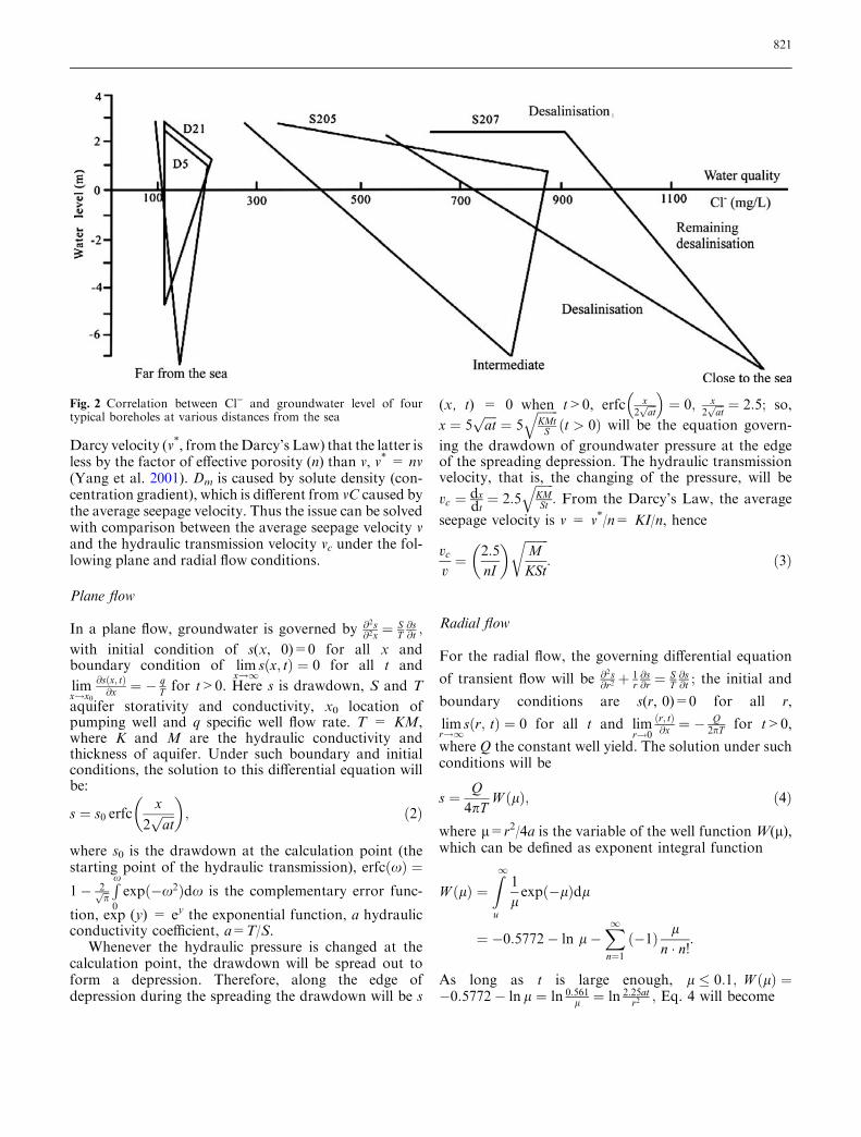
The transitional zone formed between saline and freshwater normally dips to inland in the coastal aquifer.The dip angle b can be calculated as illustrated inFig. 3. According to the Ghyben-Herzberg formula,z=(qf hf)/(qs ) qf), where qs and qf are densities ofsaline and fresh water respectively, z depth of thetransitional zone under the sea level and hf elevation offresh water table at the calculation point. The hydraulicgradient of groundwater is I ¼ hf
x ; and then x ¼ hf
I :Therefore,
tg b ¼ zx¼
qf I
qS � qf: ð7Þ
Let d=qf/(qS)qf), then tg b = d I.This is called the first basic equation of saline intru-
sion in our study. As described by this equation, theslope of the transitional zone becomes gentler with de-crease of I gradient caused by groundwater over-exploitation.
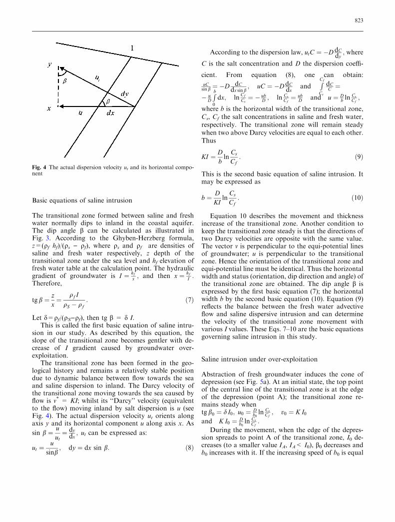
The transitional zone has been formed in the geo-logical history and remains a relatively stable positiondue to dynamic balance between flow towards the seaand saline dispersion to inland. The Darcy velocity ofthe transitional zone moving towards the sea caused byflow is v* = KI; whilst its ‘‘Darcy’’ velocity (equivalentto the flow) moving inland by salt dispersion is u (seeFig. 4). The actual dispersion velocity ut orients alongaxis y and its horizontal component u along axis x. As
sin b ¼ uut¼ dy
dx; ut can be expressed as:
ut ¼u
sinb; dy ¼ dx sin b: ð8Þ
According to the dispersion law, utC ¼ �D dCdy; where
C is the salt concentration and D the dispersion coeffi-
cient. From equation (8), one can obtain:
uCsin b ¼ �D dC
dx sin b; uC ¼ �D dC
dxand
R
Cf
Cs
dCC ¼
� uD
R
b
0
dx; lnCf
Cs¼ � ub
D ; ln CsCf¼ ub
D and u ¼ Db ln
CsCf;
where b is the horizontal width of the transitional zone,Cs, Cf the salt concentrations in saline and fresh water,respectively. The transitional zone will remain steadywhen two above Darcy velocities are equal to each other.Thus
KI ¼ Dbln
Cs
Cf: ð9Þ
This is the second basic equation of saline intrusion. Itmay be expressed as
b ¼ DKI
lnCs
Cf: ð10Þ
Equation 10 describes the movement and thicknessincrease of the transitional zone. Another condition tokeep the transitional zone steady is that the directions oftwo Darcy velocities are opposite with the same value.The vector v is perpendicular to the equi-potential linesof groundwater; u is perpendicular to the transitionalzone. Hence the orientation of the transitional zone andequi-potential line must be identical. Thus the horizontalwidth and status (orientation, dip direction and angle) ofthe transitional zone are obtained. The dip angle b isexpressed by the first basic equation (7); the horizontalwidth b by the second basic equation (10). Equation (9)reflects the balance between the fresh water advectiveflow and saline dispersive intrusion and can determinethe velocity of the transitional zone movement withvarious I values. These Eqs. 7–10 are the basic equationsgoverning saline intrusion in this study.
Saline intrusion under over-exploitation
Abstraction of fresh groundwater induces the cone ofdepression (see Fig. 5a). At an initial state, the top pointof the central line of the transitional zone is at the edgeof the depression (point A); the transitional zone re-mains steady whentg b0 ¼ d I0; u0 ¼ D
b0ln Cs
Cf; v0 ¼ K I0
and K I0 ¼ Db0ln Cs
Cf:
During the movement, when the edge of the depres-sion spreads to point A of the transitional zone, I0 de-creases (to a smaller value IA, IA< I0), b0 decreases andb0 increases with it. If the increasing speed of b0 is equal
Fig. 4 The actual dispersion velocity ut and its horizontal compo-nent
823

to the decreasing speed of I0, Eq. 9 remains tenable andthe transitional zone steady. However, both reality andtheory show that the migration velocity of salt ions is 2–3 orders of magnitude smaller than the transmissionvelocity of water pressure (cf. previous discussion).Therefore, decrease of b0 and increase of b0 are much
smaller than decrease of I0, and bA � b0 ¼ DK I0
ln CsCf
� �
:
Thus the Darcy velocity towards the sea is smaller, vA =KIA; whilst the Darcy velocity u to inland changes little,uA ¼ D
bAln Cs
Cf� KI0 > KIA; or uA > vA. Therefore, the
transitional zone moves towards inland and salineintrusion occurs; the moving speed is VA = uA ) vA �KI0 ) IA). The decreasing of dispersion has a delay todecreasing of hydraulic seepage, which is the drivingforce of saline intrusion at the beginning.
When the top point on the central line of the transi-tional zone moves towards inland over point B, thedown-gradient divide of the depression, the gradient isIB = 0; the Darcy velocity towards the sea then is vB =
KIB = 0. The Darcy velocity to inland is still uB � KI0,so the transitional zone moves to inland at speed of VB
= uB ) vB � KI0.From this point (B) towards the depression, flow
seepage of the transitional zone orients locally and ad-versely to the centre of the depression, or inland direc-tion instead of sea-bound. Both seepage and dispersionorient to inland, which makes the transitional zone moveinland. For example, at point C (Fig. 5a), VC = uC + vC� K (I0 + IC), the saline intrusion progresses. Undersuch a circumstance, the local seepage induced bypumping is the main driving force of saline intrusion;whilst the dispersion is relatively smaller but still thedriving force.
At point D, saline intrusion reaches the greatestvelocity, VD = uD + vD � K(I0+ ID). As the transi-tional zone moves towards depression centre, the ad-verse hydraulic gradient decreases gradually. Theseepage keeps same direction with dispersion but itsdriving force is getting smaller; saline intrusion slowsdown.
When the top point of the transitional zone reachesthe depression bottom point (point E in Fig. 5a), IE = 0,which is similar to point B, the transitional zone movesinland and VE = uE + vE � KI0. When it reaches theother side of the depression where the gradient is justsame as the initial one I0 at point F, vF = KI0, uF = KI0,and VF = uF ) vF � 0; the transitional zone stays stilland no intrusion occurs. The balance between intrusionand resistance is reconstructed. More exactly, thethickness of the transitional zone b is increased slightlybut the actual result is that the top of the depressioncentral-line will be located somewhere between points Eand F. This will be the intrusion limit when thedepression is relatively steady. As the natural gradient isgenerally small, point E and F is quite close. Hence thetop of the depression central line can be considered tostop at point E finally.
Therefore, saline intrusion from the beginning to theend has gone through three stages: initial, acceleratingand slowing-down development (Fig. 5b). The essenceof the whole process lies in the destruction and recon-struction of the balance between the fresh flow seepageand saline intrusive dispersion.
Case study
Regional setting
This coupled modelling approach was applied in a casestudy of the saline intrusion simulation and predictionunder over-exploitation condition in Guangrao County,Shandong Province, China. The study area is locatedat the coast of the Laizhou Bay, the Bohai Sea ofEastern China (Fig. 6a). Extensive hydrogeological
Fig. 5 a Geometry of the Groundwater cone of depression and thetransitional zone. b Three stages of saline intrusion and its break-through curve Vf(t)
824

investigations and long-term groundwater monitoringhave been carried out in this area, which provided asound basis for this study.
Since the Cenozoic era, thick drift deposits weredeveloped in this area, mainly alluvial and lacustrinematerials. Four layers of marine formations containingsaline water with a thickness of 50–70 m was depositedduring four transgressions in the geological history.Underlying continuous sandy clay with layers of clayeysilts of the alluvial and lacustrine origin with a thick-ness of about 20 m forms a regional aquitard (Q2 inFig. 6b). The saline layers extend an average of 25 kmfrom the shore-line to inland, forming a saline zonenarrow in the east and wider in the west. The salinelayers are connected with the layers of fresh water in ahorizontal direction with a transitional zone in be-
tween. The deep artesian layers of fresh water areseparated from these saline layers by the regional Q2
aquitard.In the study area, recharge of the groundwater system
is mainly from precipitation and some leakage fromrivers in rainy seasons only; discharge includes lateralflow to sea and abstraction. Under natural condition,saline and fresh groundwater in the shallow aquifer hasa hydraulic gradient of I=0.0015, saline densityqs=0.99956 g/l, fresh water density qf=0.998238 g/l.According to Eq. 7, the gradient of the saline-freshtransitional zone is tgb=1.13. A cross-section A-A’ inthe study area is conceptualized and shown in Fig. 6b.
Groundwater has been exploited in great amountsince 1977. A depression cone was formed years laterand enlarged gradually with over-exploitation; salineintrusion was discovered afterwards. Hydrogeologicalinvestigation has been carried out in the study area and aseries of groundwater observation was carried out. Thedepth underground at the depression centre was 31 m in1990. The average distance between the fresh-salineboundary and the depression centre is only 6.0 km. Theboundary of saline intrusion was determined by thethreshold concentration of Cl) = 0.3 g/l in the wells.The measured velocities of saline intrusion in this areaduring 1976–1992 are shown in Table 1.
Fig. 6 a The study area and relative location in China. b Theconceptualised geological cross-section of A-A¢ in a
Table 1 Measured values of the saline intrusion velocity
Fig. 7 The measured and corrected velocities of saline intrusion inthe case study
825

Analytical modelling and analyses
In this case study, the coupled modelling approach wasused to study the saline intrusion based on conditions ofmean precipitation, balanced groundwater abstractionand steady state depression in 1990. Therefore, themeasured values in Table 1 were corrected using corre-lation analysis method according to the correspondingprecipitations. In dry years the intrusion speed wasfaster than that in mean years, so measured values wereaccordingly corrected according to the degree ofdrought. The correction coefficients were calculatedfrom the precipitation in the observation period and thelong-term mean precipitation in the years 1956–1994.They are 0.677, 0.647, 0.876 and 0.945 for the first fourperiods. The measured and corrected values are shownin Fig. 7.
It is known from this curve that saline intrusion in thearea developed from the beginning and progressedgradually. By comparison to Fig. 5b, the velocity curve
in the development stages (initial, accelerating andslowing-down) of the intrusion can be described as threelinear equations (Fig. 8a). Based on these equations, it iscalculated that saline intrusion took shape in 1964 andaccelerated in 1984 with intrusion velocity of 52.3 m/a.In the down-gradient side of the depression, the maxi-mum adverse hydraulic gradient is at point D (Fig. 5b),the maximum invasion velocity VD will be worked out.The natural gradient prior to the depression in the areais I0=0.0015; if taking 1990 as the calculation startingyear of the modelling analysis, the gradient ID=0.033can be calculated from the equi-potential map in thisyear. From the pumping tests hydraulic conductivitywas obtained as K=20 m/d. Therefore, the velocity iscalculated as VD � KI0 + ID)=252 m/a and the timecorresponding to this point D is 1997.
Using this velocity data and the known location ofthe intrusion near the depression centre (6.0 km), thedefinite integral of the function of Vf(t) which consistedof three segments can be calculated in these segments.
Z
t2
t1
f ðtÞdt ¼ 6 ðkmÞ
The equations were calculated to represent these threesections and the stopping year of saline intrusion is 2,024under those conditions. So the intrusion velocity (V) andtime (t) in this study area follows the linear relationshipsat different periods:
V ¼2:6t � 5025 t 2 ð1964:27; 1984:72Þ16t � 31207 t 2 ð1984:72; 1997:39Þ�9t þ 19139 t 2 ð1997:39; 2024:04Þ .
8
<
:
ð11Þ
By integrating the linear equations (11), we obtain theequations representing the distance (D) of saline intru-sion of the area with time (t). They are:
D¼1:3t2�5025tþ4935232 t2 ð1964:27;1984:72Þ8t2�31207tþ30917158 t2 ð1984:72;1997:39Þ�5t2þ19139t�19363490 t2 ð1997:39;2024:04Þ:
8
<
:
ð12Þ
These equations are shown in Fig. 8a, b for V = f(t) andD = f(t) respectively.
Nevertheless, with such a coupled modelling ap-proach of advection and dispersion of solute transport,other situations of saline intrusion, for example, con-tinuous over-exploitation, depression expanding,depression recovery, can be modelled similarly (cf. Chenand Ma 2002). Using this proposed coupled modellingapproach one can easily show the process and ultimateposition of saline intrusion. While predicting variationof intrusion velocity using this approach, parameter Ican easily be measured.
Fig. 8 a The break-through curve of the saline intrusion velocity.b The break-through curve of the saline intrusion distance
826
Conclusions
Both reality phenomena and theory show that thetransport velocity of salt ions is much lower than thetransmission velocity of water pressure, which leads tothe movement of the transitional zone between saline andfresh water in the case of groundwater over-exploitationin coastal aquifer. This paper proposed a coupled mod-elling approach of the inland-bound advective seepageand sea toward dispersion with assumption of ignoringthe minor driving force by density gradient. The orien-tation, slope direction, dip angle and width of the tran-sitional zone were derived with analytical method. Basicequations describing the movement and status of thetransitional zone were obtained.
Saline intrusion was represented by movement of thetransitional zone. Based on the advective seepage anddispersion of saline solute, the driving force and resis-tance, intrusion process and limit location of the tran-sitional zone were explained theoretically and discussed
practically. The destruction and reconstruction of thedynamic balance involved advective seepage and dis-persion of the salt ions is the essence of the salineintrusion process, starting, accelerating and slowingdown. This coupled modelling approach was applied ina case study of saline water intrusion in a coastal aquiferunder over-pumping condition. The model not onlyprovided a satisfactory simulation to the intrusion his-tory but also made useful prediction for the futuredevelopment of the saline intrusion in Guangrao, theLaizhou Bay of Eastern China. The proposed analyticalmodel will be a useful supplement to existing analyticaland numerical models to understand the saline intrusionprocess, particularly, with impact of over-exploitation.
Acknowledgements The research presented in the paper was sup-ported by the Special Funds for Major State Basic Research Pro-jects under grant No. 2002CB412702. Preparation of themanuscript was also supported by the KC Wong Education Funds.We are grateful to the anonymous reviewers for their useful com-ments leading to this improved manuscript.
References
Bear J (1972) Dynamics of fluids in porousmedia. American Elsevier, New York
Cai Z, Ma F (1993) A discussion on sometheoretical problems connected withsaline intrusion. In: Resources, engi-neering, environmental system andeconomic development strategy incoastal areas of China. SeismologicalPress, Beijing
Cartwright N, Li L, Nielsen P (1994) Re-sponse of the salt-freshwater interface ina coastal aquifer to a wave-inducedgroundwater pulse: field observationsand modelling. Adv Wat Resour27(3):297–303
Chen M, Ma F (2002) Groundwater Re-sources and the Environment in China(in Chinese). Seismological Press, Beij-ing
Collins MA, Gelhar LW (1971) Seawaterintrusion in layered aquifer. Wat Re-sour Res 7(4):971–979
Custodio E (1985) Saline intrusion, inmemoires of the 18th Congress of IAH,Part1. Cambridge
Custodio E, Bruggeman GA(1987) Groundproblems in coastal areas. UNESCOPress, Belgium
Fetter CW (1999) Contaminant hydroge-ology, 2nd edn. Prentice Hall, NJ
Freeze RA, Cherry JA (1979) Groundwa-ter. Prentice Hall, New Jersey
Frind EO (1982) Seawater intrusion incontinuous coastal aquifer-aquitardsystems. Adv Water Resour 5(6):89–97
Galeati G, Gambolati G, Neuman S P(1992) Coupled and partially coupledEulerian-Lagrangian model of fresh-water-saltwater mixing. Wat ResourRes 28(1):149–165
Gangopadhyay S, Gupta AD (1995) Sim-ulation of salt-water encroachment in amulti-layer ground water system,Bangkok, Thailand. Hydrogeol J3(4):74–88
Gupta AD, Yapa PNDD (1982) Saltwaterencroachment in an aquifer: A casestudy. Wat Resour Res 8(3):546–556
Huyakorn PS, Anderson PF, Mercer JW(1987) Saltwater intrusion in aquifers:development and testing of a three-dimensional finite element model. WatResour Res 23(2):293–312
Huyakorn PS, Wu YS, Park NS (1996)Multiphase approach to the numericalsolution of a sharp interface saltwaterintrusion problem. Wat Resour Res32(1):93–102
Kakinuma T, Kishi Y, Inouchi K (1988)The behavior of groundwater with dis-persion in coastal aquifers. J Hydrol98:225–248
Ledoux E, Sauvagnac S, Rivera A (1990) Acompatible single-phase/two-phasenumerical model: 1. Modeling thetransient salt-water/Fresh-water inter-face motion. Ground Water 28(1):79–87
Lee GF, Cheng RTS (1974) On seawaterencroachment in coastal aquifers. WatResour Res 10(5):1039–1043
Liu PL, Cheng AH, Liggett JA (1981)Boundary integral equation solutions tomoving interface between two fluids inporous madia. Wat Resour Res17(5):1445–1452
Mercer JW, Larson SP, Faust CR (1980)Simulation of saltwater interface mo-tion. Ground Water 18(4):374–385
Moor YH, Stoessell RK, Easley DH (1992)Fresh-water/sea-water relationshipwithin a ground-water flow systemnortheastern coast of the Yucatan pen-insula. Ground Water 30(3):343–350
Pinder GF, Cooper HH (1970) A numericaltechnique for calculating the transientposition of the saltwater front. WatResour Res 6(4):875–883
Reilly TE, Page RH (1985) Quantitativeanalysis of saltwater-freshwater rela-tionships in groundwater system-a his-torical perspective. J Hydrol 80:125–160
Rivera A, Ledous E, Sauvagnac S(1990) Acompatible single-phase/two-phasenumerical model: 2. Application to acoastal aquifer in Mexico. GroundWater 28(2):215–223
Segol G, Pinnder GF (1976) Transientsimulation of saltwater in southeasternFlorida. Wat Resour Res 12(1):65–70
Segol G, Pinnder GF, Gray WG (1975) AGalerkin finite element technique forcalculating the transient position of thesaltwater front. Wat Resour Res11(2):343–347
827

Wilson JL, Sa DA, Costa A (1982) Finiteelement simulation of a saltwater/freshwater interface with indirect toetracking. Wat Resour Res 18(4):1069–1080
Wu J, Xue Y, Liu P, Wang J, Jiang Q, ShiH (1993) Sea water intrusion in thecoastal area of Laizhou Bay, China: 2.Sea water intrusion monitoring.Ground Water 31(5):740–745
Xue Y, Wu J, Liu P, Wang J, Jiang Q, ShiH (1993) Sea water intrusion in thecoastal area of Laizhou Bay, China: 1.Distribution of sea water and its hyd-rochemical characteristics. GroundWater 31(4):532–537
Xue Y, Xie C, Wu J, Liu P, Wang J, JiangQ (1995) A three dimensional miscibletransport model for sea water intrusionin China. Wat Resour Res 31(4):903–912
Xue, Y, Wu J, Ye S, Zhang Y (2000) Hy-drogeological and hydrogeochemicalstudies for salt water intrusion on thesouth of Laizhou Bay, China. GroundWater 38(1):38–45
Yakirevich A, Melloul A, Sorek S, ShaathS, Borisov V (1998) Simulation of sea-water intrusion into the Khan Yunisarea of the Gaza Strip coastal aquifer.Hydrogeol J 6(4):549–559
Yang YS, Lin X, Elliot T, Kalin RM(2001)A natural-gradient field tracertest for evaluation of pollutant-trans-port parameters in a porous-mediumaquifer. Hydrogeology J 9(3):313–320
828