Dynamic fault tolerance with misrouting in fat trees
10
Dynamic Fault Tolerance with Misrouting in Fat Trees Frank Olaf Sem-Jacobsen Tor Skeie, Olav Lysne Jos´ e Duato Department of Informatics Networks and Distributed Systems Dept. de Ingenieria de Sistemas, Computadores y Automatica University of Oslo Simula Research Laboratory Universidad Politecnica de Valencia Postboks 1080 Blindern P.O.Box 134 Pob 22012,46071 - Valencia 0316 Oslo, Norway 1325 Lysaker, Norway Spain frankose@ifi.uio.no {tskeie,olavly}@simula.no [email protected] Abstract Fault tolerance is critical for efficient utilisation of large computer systems. Dynamic fault tolerance allows the network to remain available through the occurance of faults as opposed to static fault tolerance which requires the network to be halted to reconfigure it. Although dy- namic fault tolerance may lead to less efficient solutions than static fault tolerance, it allows for a much higher availability of the system. In this paper we devise a dy- namic fault tolerant adaptive routing algorithm for the fat tree, a much used interconnect topology, which re- lies on misrouting around link faults. We show that we are guaranteed to tolerate any combination of less than num switch ports 2 link faults without the need for additional networkresources for deadlock freedom. There is also a high probability of tolerating an even larger number of link faults. Simulation results show that network perfor- mance degrades very little when faults are dynamically tolerated. 1. Introduction As the size and complexity of computer systems in- creases, efficient fault tolerance methods become of in- creasing importance. The key to high performance in today’s supercomputers and high-end servers is par- allelism, interconnecting a large number of processing units which work together. The interconnection net- work interconnecting the processing units among them- selves and/or these units with the storage subsystem becomes a critical component in the system, and it is essential that it is able to operate correctly despite in- termittent failure of network elements. To keep the network connected despite the failure of switches and links, several strategies have been pro- posed and/or implemented. The most frequently used technique in commercial systems is to implement the circuits required to switch off the faulty component (e.g. switching off several planes of the BlueGene/L 3D torus), possibly switching in some spare compo- nents (e.g. by implementing a few extra planes). This strategy has the benefit of simplifying routing by keep- ing the same topology, but it is quite expensive and often switches off too many healthy components. An- other approach followed in many academic papers con- sists of exploiting the existence of alternative paths in the network by defining a fault-tolerant routing algo- rithm. These algorithms provide alternative paths that can be followed in case of failure. They have become very popular among researchers because they do not require the use of spare components and usually dis- able very few (if any) healthy components. We will re- fer to this strategy as dynamic fault tolerance in this paper. Endpoint dynamic fault tolerance allows the source nodes to choose a different path through the network up on being informed of a network fault, the approach used in e.g. [15]. Local dynamic fault toler- ance, on the other hand, provides multiple paths from any single network element to avoid any faulty compo- nent it may be connected to. Unfortunately, most pro- posals introduce significant complexity (e.g. several ad- ditional virtual channels) to avoid deadlock in the pres- ence of failures. The third and most recent group of techniques con- sists of adding a network management layer that ex- plores the topology in case of failure and computes new routing tables. This is by far the most flexible ap- proach, supporting a large number of failures. This ap- proach, known as network reconfiguration, can be con- sidered as an extension of the network configuration software found in technologies like Myrinet and Infini- Band. However, flexibility comes at the expense of us- ing a generic routing algorithm that may not be op- timal for a given topology. Also, statically reconfigur-
-
Upload
independent -
Category
Documents
-
view
3 -
download
0
Transcript of Dynamic fault tolerance with misrouting in fat trees

Dynamic Fault Tolerance with Misrouting in Fat Trees
Frank Olaf Sem-Jacobsen Tor Skeie, Olav Lysne Jose DuatoDepartment of Informatics Networks and Distributed Systems Dept. de Ingenieria de Sistemas, Computadores y Automatica
University of Oslo Simula Research Laboratory Universidad Politecnica de Valencia
Postboks 1080 Blindern P.O.Box 134 Pob 22012,46071 - Valencia
0316 Oslo, Norway 1325 Lysaker, Norway Spain
[email protected] {tskeie,olavly}@simula.no [email protected]
Abstract
Fault tolerance is critical for efficient utilisation oflarge computer systems. Dynamic fault tolerance allowsthe network to remain available through the occurance offaults as opposed to static fault tolerance which requiresthe network to be halted to reconfigure it. Although dy-namic fault tolerance may lead to less efficient solutionsthan static fault tolerance, it allows for a much higheravailability of the system. In this paper we devise a dy-namic fault tolerant adaptive routing algorithm for thefat tree, a much used interconnect topology, which re-lies on misrouting around link faults. We show that weare guaranteed to tolerate any combination of less thannum switch ports
2 link faults without the need for additionalnetwork resources for deadlock freedom. There is also ahigh probability of tolerating an even larger number oflink faults. Simulation results show that network perfor-mance degrades very little when faults are dynamicallytolerated.
1. Introduction
As the size and complexity of computer systems in-creases, efficient fault tolerance methods become of in-creasing importance. The key to high performance intoday’s supercomputers and high-end servers is par-allelism, interconnecting a large number of processingunits which work together. The interconnection net-work interconnecting the processing units among them-selves and/or these units with the storage subsystembecomes a critical component in the system, and it isessential that it is able to operate correctly despite in-termittent failure of network elements.
To keep the network connected despite the failureof switches and links, several strategies have been pro-posed and/or implemented. The most frequently used
technique in commercial systems is to implement thecircuits required to switch off the faulty component(e.g. switching off several planes of the BlueGene/L3D torus), possibly switching in some spare compo-nents (e.g. by implementing a few extra planes). Thisstrategy has the benefit of simplifying routing by keep-ing the same topology, but it is quite expensive andoften switches off too many healthy components. An-other approach followed in many academic papers con-sists of exploiting the existence of alternative paths inthe network by defining a fault-tolerant routing algo-rithm. These algorithms provide alternative paths thatcan be followed in case of failure. They have becomevery popular among researchers because they do notrequire the use of spare components and usually dis-able very few (if any) healthy components. We will re-fer to this strategy as dynamic fault tolerance in thispaper. Endpoint dynamic fault tolerance allows thesource nodes to choose a different path through thenetwork up on being informed of a network fault, theapproach used in e.g. [15]. Local dynamic fault toler-ance, on the other hand, provides multiple paths fromany single network element to avoid any faulty compo-nent it may be connected to. Unfortunately, most pro-posals introduce significant complexity (e.g. several ad-ditional virtual channels) to avoid deadlock in the pres-ence of failures.
The third and most recent group of techniques con-sists of adding a network management layer that ex-plores the topology in case of failure and computesnew routing tables. This is by far the most flexible ap-proach, supporting a large number of failures. This ap-proach, known as network reconfiguration, can be con-sidered as an extension of the network configurationsoftware found in technologies like Myrinet and Infini-Band. However, flexibility comes at the expense of us-ing a generic routing algorithm that may not be op-timal for a given topology. Also, statically reconfigur-

ing the network is time-consuming since the networkapplications must be halted and the network drainedof all traffic to avoid dependencies between packetsrouted following the old and new routing algorithms.Dynamic fault tolerance is much more time efficient inthis respect, both the endpoint, but even more the lo-cal, approaches. However, the local solution of rout-ing around the faulty elements may lead to nonopti-mal paths. Despite this, local dynamic fault toleranceis overall much more efficient in large systems with fre-quent fault events, and it is the approach we will followin this paper.
Rerouting packets around network faults is mosteasily achieved by using an adaptive routing algorithm.An adaptive routing algorithm supplies several alter-native paths for a destination if available, allowing theswitch to choose the output queue with, for instance,the shortest length. Related to fault tolerance, whendiscovering a faulty network element, the switch is freeto adaptively choose a different path which is not af-fected by the fault. It is therefore relatively straight-forward to provide dynamic fault tolerance in networkswith multiple available paths such as meshes and toritopologies.
Interconnection networks are often interconnectedin regular topologies like the k-ary n-cube, mesh, andvarious Multistage Interconnection Networks (MIN).Multistage interconnection networks were first intro-duced in 1953 by C. Clos as a means of producing non-blocking switching networks consisting of few switchesorganised in switching stages [4]. The fat tree, a MINdeveloped by C. Leiserson in 1985 [12], is an ideal topol-ogy for use in supercomputer systems. It is an area uni-versal network, a network able to emulate any othernetwork topology built from the same amount of hard-ware with only a small decrease in computational ef-ficiency [12]. Because of this the fat tree is a muchused interconnection topology in parallel computer sys-tems. As many as seven of the top 20 supercomputersrely on the fat tree topology in some parts of their in-terconnection network (Q4, 2005). A classical exam-ple is CM5 [5], and a more recent example is SGI Al-tix 3700 [21] which is used in NASA’s Colombia, cur-rently ranked number three. Most of the commercialinterconnects for SANs and clusters also use fat treesor other similar bidirectional MINs, for instance Infini-Band [1], Myrinet 2000 [2], and Quadrics [17].
The fat tree (Figure 1) is usually a tree with multi-ple roots. The bottom stage of the network consists ofthe processing units connected as leaves to the switchesat the bottom of the tree. The switches are organised instages, and the number of stages depends on the num-ber of nodes connected to the network and the switch
Figure 1. A small fat tree with radix 4 switches.The black dots are switches, and the blacksquares are processing nodes connected to thebottom of the network. The outline describes aswitch group as it is defined in Section 3.
radix (the number of ports in the switch). The fat treeis distinct from an ordinary tree in that the aggregatelink capacity between two switch stages is maintainedat every stage to the top, i.e. the branches of the treeget fatter nearer the root. Fat-trees in which the capac-ity of the links themselves increases towards the rootare also feasible, but the common approach is to in-crease the number of links and switches at the upperstages. The fat tree we consider in this paper is thecommonly used K-ary N-tree as it is defined in [16].
Packet routing in the fat tree is performed as in anytree topology.The packet is forwarded from the sourceupwards to any least common ancestor of the sourceand destination, and then downwards following a de-terministic path determined by the least common an-cestor to the destination. We call this the upward phaseand the downward phase.
Previous approaches to dynamic fault tolerance infat trees [19, 18] have considered dynamic fault toler-ance combined with deterministic routing. Strict rout-ing rules, extra mechanisms in the switches, and addi-tional network resources have been required to routearound faults and guarantee deadlock freedom. In thispaper we will achieve local dynamic fault tolerance inconjunction with adaptive routing. However, since thefat tree is deterministic in the downward phase, theuse of an adaptive routing algorithm will not automat-ically lead to local dynamic fault tolerance. We there-fore develop an adaptive local dynamic fault tolerantrouting algorithm which misroutes packets one hop to-wards a different destination to reach an alternative de-terministic path, avoiding the fault.
The main contributions of this paper are: 1) A newand efficient routing algorithm for fat trees that is ableto tolerate at least up to an including radix
2 −1 link fail-ures without disconnecting the network; 2) a detailedtheoretical proof of the fault tolerant properties of theproposed routing algorithm; and 3) a performance eval-

uation showing that network performance experiencesa small degradation in the face of faults.
After an overview of past efforts in the field of faulttolerance in interconnection networks in Section 2, wepropose an adaptive routing algorithm designed to pro-vide dynamic fault tolerance in fat tree networks in Sec-tion 3. In Section 4 we present an evaluation of the pro-posed algorithm, and a conclusion is given in Section5.
2. Related work
Not all MIN topologies intrinsically provide mul-tiple paths that may be utilised for fault tolerance.For example, the Butterfly network [9] only providesa single path between each source/destination pair. Alarge amount of work concerning fault-tolerant MINs isbased on adding additional hardware in terms of addingextra links and switches to existing switching stages,or adding entirely new switching stages [23]. Anothermuch used approach is to route the packet through thenetwork in several passes. Routing through multiplepasses requires the MIN to possess a dynamic full ac-cess (DFA) property, i.e. the ability to route betweenany node pair using a limited number of passes [10].Hybrid approaches combining multiple paths and mul-tiple passes have also been suggested [22]. In [13]the authors give an overview of a number of fault-tolerant MIN topologies, describe their basis for fault-tolerance and evaluate their performance. J. Senguptaand P.K.Bansal [20] use several parallel MINs to cre-ate redundancy, with each MIN functioning as a dis-joint path between the sources and destinations. Thefault tolerance of Butterfly networks is studied in [3]and [11]. F.Cao and D. Du [3] discuss the fault toler-ance property of the Butterfly network and show howto construct paths through the faulty network. In [7]the authors analyse the fault tolerance properties ofMINs without additional redundancy. Most of his workis based on unidirectional MINs, there is little workdone on bidirectional MINs.
None of the above contributions consider dynamicfault tolerance. An exception to this statement is theapproaches in [19] and [18]. The first paper describesa method for achieving dynamic fault tolerance usingtwo parallel fat-trees with crossover paths between thecorresponding switches in both trees. The method isshown to yield almost as good performance as when us-ing static fault tolerance to route around failed links.The second paper presents a dynamic fault tolerantrouting algorithm which provides dynamic one faulttolerance in singleton fat-trees. A deterministic rout-ing algorithm is used combined with a dynamic fault
tolerance algorithm, so the use of additional virtuallayers is therefore required to guarantee deadlock free-dom.
Concerning fat-trees, some work has been done onfat-trees in general, and to some small extent on faulttolerance. Fat-trees are extended to generalised fattrees in [14], allowing them to have a varying num-ber of switches in switching stages and links betweenthe stages. Another variation of fat-trees are orthogo-nal fat-trees as presented in [24]. Orthogonal fat-treesare built using simple two level fat trees as the build-ing blocks to achieve a larger network and they pro-vide only a single path between any source/destinationpair. The authors extend this work in [23] by provid-ing several disjoint paths through the addition of net-work links.
3. Fault-Tolerant Routing in the FatTree
We consider a fat tree made up of virtual cut-through switches. In the virtual cut-through switch-ing scheme, packets are divided into small data units.During traversal of the network, the separate units of apacket may be spread over several switches, but on be-ing blocked the packet as a whole is buffered in a singleswitch, thus reducing contention and simplifying dead-lock avoidance.
Failures may be transient or permanent. Transientfailures can be easily handled by using a suitable com-munication protocol that re-transmits the informationin case of transmission errors. Therefore, we will fo-cus on permanent failures.
We consider only link faults in this paper. A linkis either present and operational, or faulty, in whichcase it may be viewed as non-existent. We assume thatthe network elements directly connected to the failedelement can detect the failure of that element, infor-mation about failed elements need not be propagatedfurther. Additionally, we do not allow the links con-necting processing nodes to the bottom of the tree tofail. Note that additional hardware is required to sup-port the failure of these links (e.g. using two NICs perprocessing node to connected to two different networkports, which also implies doubling the number of net-work ports).
In the first section below we will present a routing al-gorithm which is able to guarantee a connected networkfor one link fault without modifying the packet headeror network switches in any way, and for less than radix
2
link faults if we add a small field of length radix2 bits.
The non-minimal paths used to avoid the faulty linksmay lead to deadlocks, a state where every next hop

queue for a set of packets is full, forming a cyclic de-pendency. We will therefore present a proof that showsthat the proposed algorithm is deadlock free in Sec-tion 3.2.
3.1. The Routing Algorithm
The routing algorithm we present here relies on thenumerous paths between two neighbouring switches.When a link between two switches fails, the switch atthe top of the failed link will no longer have a path tothe destinations it used to reach through the failed link.However, the switch at the bottom end of the failed linkhas links to numerous switches next to the switch atthe top of the failed link. If a packet is routed to one ofthese switches it will have a valid path down to its des-tination. We construct a routing algorithm that mis-routes the packet, forcing it to traverse two extra hops,one hop down and one hop up, to reach a fault-free pathto the destination upon encountering a link fault. Thepath around a faulty link is shown in Figure 2, the de-tails of this will be discussed later.
Definition 1. Anadaptive routing function R* suppliesa set of output queues to be used by a packet in switch s toreach a destination d.
We construct an adaptive, dynamic fault-tolerantrouting algorithm by dividing packet routing into thefollowing two phases. In the following, a faulty queueis a queue associated with a faulty link.
1. In the upward phase, all upward queues are sup-plied by the routing function and one is selectedfor output. If any of the queues are faulty, they aresimply not chosen.
2. In the downward phase only one single queueis supplied by the routing algorithm, the short-est path from the current switch to the destina-tion. If this queue is faulty, all other downwardqueues are supplied, forcing the packet to be mis-routed through one of them. Once a packet hasbeen misrouted downwards, a new upward phasecommences, with the adaptive algorithm exclud-ing queues associated with the link on which thepacket arrived.
Definition 2. A U-turn switch is a switch in which atransition from a downward to upward phase takes place.
There will be U-turn switches in the network onlyin the case of faults.
Definition 3. A U-turn is a transition from downwardto upwardmovement involving a downward link, aU-turnswitch, and an upward link.
Thus the term U-turn does not apply to the up-ward to downward transition which separates the up-ward and downward paths in the routing algorithm. Ina fault-free network no U-turns will therefore ever beperformed.
This simple algorithm will be able to guarantee net-work connectivity when no more than one link fails [18],without having to modify the packet header in any way.For it to be able to tolerate a larger number of linkfaults, the algorithm must systematically test the set ofavailable paths once it has finished misrouting down-wards and is about to perform the U-turn and com-mence on a new upward phase. The reason is that sev-eral of the other switches reachable upwards from theU-turn switch might not have a fault-free downwardlink towards the destination. It might therefore be nec-essary to test several upward paths from the U-turnswitch to find one that leads one switch stage closer tothe destination. To preserve the adaptivity required bythe routing algorithm in the upward phase we must im-plement a systematic check such that all possible pathsare tested without forcing the packet on to any pathunless we know that it is deadlock free. We will showbelow that this may be achieved by having a field inthe packet header, a misroute vector, of length radix
2bits, one for each of the upward paths to test. Com-bined with the first algorithm the adaptive dynamicfault-tolerant algorithm which is guaranteed to toler-ate up to and including radix
2 − 1 link faults is as fol-lows:
1. In the upward phase, all upward queues are sup-plied by the routing function and one is selectedas the packet’s output. If any of the queues arefaulty, they are simply not chosen.
2. In the downward phase only one single queues issupplied by the routing algorithm, the shortestpath from the current switch to the destination.If this queue is faulty, all other downward queuesare supplied, forcing the packet to be misroutedthrough one of them.
3. A switch receiving a packet from a link connectedto an upper stage for which it has no downwardpath sets the bit in the misrouting bit-vector in thepacket header corresponding to the link on whichthe packet arrived (it is not necessary to try to usethis link for forwarding the packet since we knowthe path is broken). This switch is a U-turn switch.
4. The U-turn switch adaptively chooses one of itsupward queues which does not have its corre-sponding bit set in the packet header and subse-quently inserts the packet into this queue.

5. If the new switch that the packet arrived at fromthe U-turn switch has a valid downward path asthe next hop, the misrouting vector in the packetheader is reset and the packet is forwarded as nor-mal. Otherwise the packet is misrouted back to theU-turn switch down the same link on which it ar-rived at the current switch and step three is re-peated. If this link has just failed reset the mis-route vector and repeat from step 2.
6. A U-turn switch receiving a packet from an up-ward link in which all other bits in the misrout-ing vector are set discards the packet, Rm is dis-connected. The switch may inform the source thatthe path is no longer available. We know we havetested all upward links of the U-turn switch andthere is no available path to the destination fromthis switch.
This routing algorithm will be known as Rm
throughout the paper. We will now present a se-ries of arguments and proofs to show the validity, andexplore the properties and limits of Rm.
Definition 4. Two switches are neighbours if they areinterconnected through a single link.
Definition 5. Two sets of switches, a and b, are com-pletely interconnected if every switch in a is a neighbourof all switches in b (and implicitly vice versa).
Definition 6. A switch group g is the union of two com-pletely interconnected sets of switches, a and b, wherea contains only switches at stage l and b contains onlyswitches at stage l + 1. a contains all neighbours at stagel of all switches in b, and b contains all neighbours at stagel + 1 of all switches in a, g = a ∪ b.
Given the interconnection pattern of a fat tree, eachswitch group consists of radix
2 upper stage switches andradix
2 lower stage switches. Every switch in the fat treeis part of two switch groups, but the upper stage ofone switch group, and at the lower stage of another.The switches at the topmost and bottommost stagesof the tree are only members of one switch group. Fig-ure 1 shows a fat tree consisting of switches of radixfour. The switch group encompassed by the line there-fore consists of two upper stage and two lower stageswitches. For simplicity it is assumed that the top stageswitches of the fat tree have the same radix as the otherswitches in the network, but with radix
2 unused ports.Practical implementations may use switches withoutthe unused ports, or use the extra ports to halve thenumber of top stage switches.
Corollary 1. There are radix2 disjoint shortest paths
between any two switches at the same stage in a switchgroup.
Proof. It follows from Definition 6 that any switch sat the upper/lower stage of a switch group has radix
2neighbours at the lower/upper stage. Each of theseneighbours are neighbours to all switches in the groupat the same stage as s. Thus, there exists radix
2 pathsfrom s to each of the other switches in the group of thesame stage, one through each of its neighbours in thegroup. Since there are no links between switches at thesame stage these paths will be the shortest paths, eachof length two hops.
Lemma 1. Rm is connected when there are less thanradix
2 link faults.
Proof. In the upward phase Rm is obviously alwaysable to forward every packet one stage upwards withless than radix
2 link faults. As long as one link isavailable in the upward direction the packet may beforwarded. The downward phase is as follows: Withradix
2 − 1 link faults in the system at least one of theradix
2 upper stage switches in a group with link faultswill not be connected to any faulty link. We call thisswitch St. From corollary 1, there are radix
2 disjointpaths between any two switches at the same stage ina group. radix
2 − 1 link faults is not enough to discon-nect all these paths, and thus, any upper stage switchconnected to a faulty link is able to reach St, whichwe know has a healthy link moving the packet one hopcloser to its destination. Each lower stage switch in thegroup will be connected to St, so by misrouting to anarbitrary lower stage switch Sb there will be a path toSt. By checking all upward links from Sb exactly once,we are guaranteed to reach St without cycles. Once thepacket has reached a lower stage switch in the groupwith a valid downward path it enters a new group, sosubsequent link failures encountered will be toleratedin a different group, further down in the tree with atmost radix
2 − 2 link faults.
In addition to Lemma 1 which proves that the algo-rithm dynamically tolerates faults, we must show thatthe algorithm is livelock free. The key to this is the mis-route vector.
Lemma 2. Rm is livelock free when there are less thanradix
2 link faults in the network.
Proof. As the number of links is finite, a livelock re-quires that a packet is forwarded in a loop. There musttherefore exist a set of switches that the packet tra-verses an unlimited number of times. There are obvi-ously no such loops in the upward phase, the only pos-sible cause of a loop is the U-turn performed when mis-routing around a fault. However, the misrouting vectorguarantees in point 4 of the misrouting algorithm that

all the upper stage switches in the switch group con-taining the fault are visited at most once for each linkfault in the group, and hence none of these may be in-volved in a livelock. Since there are less than radix
2 linkfaults we are guaranteed a path which moves the packetout of the switch group and one stage lower downtowards the destination. Consequently, every time apacket is misrouted, it will find a path which brings itone stage closer to its destination, and the algorithm islivelock free.
(a)
Figure 2. Combinations of radix2 − 1 faults with
misrouting within a group in radix=8 network.The terms ingress and egress refer to theswitches where the packet enters and leaves theswitch group respectively. The bold lines are thelinks traversed by the packet, the dashed linksare a faulty, and the long dashed path with an ar-row is the path followed by a packet. The num-bered U-turns refer to the corresponding statesof the misroute vector (listed next to the U-turnswitch) as the U-turn is performed.
Figure 2 gives an example of a fault configurationwith radix
2 −1 faults and how it is tolerated by the rout-ing algorithm. The figure depicts a switch group in anetwork consisting of radix eight switches. The packethas to attempt to use several upward paths from thelower stage switch in order to reach an upper stageswitch with a fault-free path to the destination. It isclear from this figure that there exist combinations ofa large number of link faults that allow the routing al-gorithm to remain connected. Therefore, in addition tobe able to guarantee radix
2 − 1 fault tolerance, the al-gorithm will with some probability be able to toleratean even larger number of arbitrary link faults.
3.2. Deadlock Freedom
We have shown that Rm is connected and livelockfree for less than radix
2 link faults. Next we will provethat it is deadlock free as long as we can guarantee con-nectivity. The non-fault tolerant upward phase, down-ward phase routing algorithm relies on that there can-not be any downward to upward turns in the network tobe deadlock free. However, when we misroute around afault we introduce downward to upward turns and cre-ate dependency cycles that may cause deadlocks. Dead-lock freedom has previously been provided by utilisingvirtual channels to break the cycles [18]. In this sec-tion we will show that such a solution is unnecessarywhen we use adaptive routing since the cycles will notcause deadlocks. For this analysis, we assume the use ofvirtual cut-through switches and will focus on the de-pendencies between the switch queues where the pack-ets are buffered.
The following definition and theorem are taken from[6]:
Definition 7. A routing subfunction R1 of the routingfunction R* is a routing function connecting the same setof sources and destinations as R*, but provides a subsetof the queues provided by R*.
R1 may in other words be viewed as a limited ver-sion of R* where some of the network queues suppliedby R* for a destination are not supplied for that desti-nation by R1.
Theorem 1. A routing algorithm is deadlock free iffthere exists a connected routing subfunction R1 of therouting function R* which has no cycles in its extendedchannel dependency graph.
The theorem relies on the terms dependency, crossdependency, and extended channel dependency graphas they are defined in [6]. There is a dependency fromone queue to another if the first packet in the first queueis headed to the second queue following the routing al-gorithm. There exists a cross dependency when thereare packets in queues that are legal for R*, but not forR1, which have a queue that is legal for R1 as theirnext hop. The extended channel dependency graph isa graph whose vertices are queues, and the arcs are be-tween pairs of queues where the first queue is eitherdependent or cross-dependent on the other. The ex-tended channel dependency graph is similar to the or-dinary channel dependency graph except that the lat-ter only considers queues that are dependent, not cross-dependent.
Theorem 1 is primarily intended for direct networks,so in order to make use of Theorem 1 we must con-sider our indirect fat tree as a direct network. This im-

plies that every node in the network, both processorsand switches, must be viewed as packet producers, con-sumers, and packet forwarders. This creates a hugelycomplex routing algorithm since many of the paths inthe network will contain U-turns when packets are sentfrom one switch to another. We may however disregardmany of these U-turns when considering deadlock free-dom.
A configuration is an assignment of a set of pack-ets to the queues in the network, and a legal config-uration is such an assignment that is reachable froman empty network by injecting and forwarding packetsas the routing algorithm dictates. A deadlocked con-figuration is a nonempty legal configuration where sev-eral of the network queues are full, and all queues sup-plied by the routing function for the first packet inevery full queue are also full. Consequently, an ille-gal configuration which is deadlocked is not an issuesince it may never be reached. It is therefore only nec-essary to consider legal configurations when analysingthe dependencies of the routing algorithm. In an indi-rect network such as the fat tree a switch will never bea destination, and thus all configurations involving U-turns without the U-turn switch being due to a faultylink are illegal. This eliminates the numerous U-turnsthat would occur if packets should be transmitted be-tween two switches in the network. We are left withU-turns only occurring below faults. In fact, the onlything we must consider which is different from a directnetwork is that the routing subfunction must be con-nected with respect to any packet in any queue in thenetwork, i.e. we must view every switch as a “packetproducing” node, but not as a destination.
The deadlock freedom of Rm is not obvious sincemany of the downward to upward turns performedwhen attempting to misroute around a fault may closecycles in the channel dependency graph. To show thatRm is deadlock free we must show the existence ofa routing subfunction R′
m of Rm which is connectedand has no cycles in its extended channel dependencygraph as is required by Theorem 1. It is important tonote that the routing subfunction need not be imple-mented in any way, it is sufficient that we can provethe existence of such a function. The rest of this sec-tion is devoted to finding R′
m and proving that it iscycle free in its extended channel dependency graphand connected within the fault tolerance limits set bythe dynamic fault-tolerant routing function Rm. In or-der to achieve this we must create a basis upon whichto construct the routing algorithm. We will first iden-tify which U-turn switches may be part of a deadlock.
Definition 8. Assume we have a channel dependencycycle. A switch is part of a dependency cycle when
queues in that switch are part of the channel dependencychain forming the cycle in the extended channel depen-dency graph.
Lemma 3. A dependency cycle must always involve twoor more U-turn switches.
Proof. Suppose there is a dependency cycle involvingonly one U-turn switch, b, with the downward link ofthe U-turn from switch a to b and the upward link ofthe U-turn from b to switch c. In this case there is achain of dependencies from b, c to a, b which is closed bythe downward to upward U-turn a, b, c. In other words,it is possible to follow the chain of dependencies fromb, c and arrive at a, b. However, if we follow the chain ofdependencies from the upward link it will lead us someway upwards in the tree before it will turn downwards.a and c can not be part of the same subtree (other-wise switches at higher stages would have more thanone path downward to a destination, which is not thecase) so they have no common ancestors, and it is im-possible to reach a from c with only one upward anddownward phase. From here on the chain will there-fore only involve downward channels since there are noother U-turns and the chain will terminate in a process-ing node. Thus, there is no cycle.
As we shall see, not all combinations of U-turnswitches may form a dependency cycle, it depends onwhere in the fat tree the U-turn switches are located.
Definition 9. The subtree of a switch consists of allthe links and switches reachable in the downward direc-tion from that switch.
Every switch is member of a specific set of sub-trees, i.e. there is a certain set of tree roots that canbe reached in the upward direction from the switch. Atop rooted subtree is a subtree of a top stage switch.
Definition 10. Two switches are members of the sameset of top rooted subtrees when they have all top stagesubtree roots in common.
Lemma 4. Only U-turn switches that are members ofthe same set of top rooted subtrees may be part of a depen-dency cycle.
Proof. First, a dependency cycle must involve two ormore U-turn switches (Lemma 3). Next, consider theU-turn switches u and v1, v2, . . . , vn. Suppose that wehave a deadlocked configuration and that u is memberof a top rooted subtree st of which vi is not a mem-ber for every 0 < i ≤ n. Any packet forwarded up-wards through st from u will necessarily never reach vi
since vi is not in st. Consequently, there is a path outof the cyclic dependency between the U-turn switchesand thus no dependency cycle.

From Lemma 4 we may make the following observa-tion.
Observation 1. A dependency cycle may only occurbetween U-turn switches at the same switch stage in thenetwork since U-turn switches at different stages will bemembers of different sets of subtrees.
The basis for observation 1 is that with two switchesat different switch stages the switch at the upper stagewill necessarily be a member of fewer subtrees than theswitch at the lower stage, and they will therefore notbe members of the same set of top rooted subtrees.
We have established that any deadlock in the net-work must involve at least two U-turn switches at thesame switch stage. Therefore, if we can guarantee thata packet misrouted through a U-turn at stage l is for-warded in a subtree with no further failures in the linksof the same stage l, it will not be able to close any de-pendency cycles.
Definition 11. A subtree which is fault-free at stagel is a tree whose root is at the top stage of the fat-tree, andwhose leaves are at stage l. The fault-free subtree containsexcactly all nodes and links that are reachable throughdownward-links from the root, and that are at or abovelevel l.
Lemma 5. A U-turn switch at stage l will not be partof any dependency cycle in the extended channel depen-dency graph if it is connected to a subtree which is fault-free at stage l and forwards misrouted packets in this sub-tree.
Proof. For every link fault in the network both thefaulty link and the downward link of the associatedU-turn will be located in the same subtree. There areconsequently no downward links of U-turns at stagel in the subtree that is fault free at stage l. There-fore, if we follow the possible chain of dependenciesfrom the upward link of a U-turn through the sub-tree that is fault-free we will never encounter a down-ward link of a U-turn at stage l since we encounter nofaults. Since we may only have cyclic dependencies be-tween U-turns at the same stage and this is impossible,we are not able to create a cyclic dependency.
These are the foundations necessary to construct ourrouting subfunction. The steps of the routing subfunc-tion R′
m is listed below:
1. Adaptively forward the packet upwards towardsany least common ancestor.
2. Upon reaching the least common ancestor forwardthe packet downwards.
3. If a fault is encountered in the downward directionmisroute the packet one step downwards, to stagel.
4. Forward the packet back up the subtree that isfault-free at stage l.
R′m is obviously connected when considering every
switch as a packet producer. Any switch may forwardpackets upwards to a least common ancestor of anynode pair, or forward the packet downwards if thatis the shortest path to the destination, and any switchmay forward packets downwards one hop when encoun-tering a fault as long as there is less than radix
2 linkfaults. It is equally obvious that R′
m is a routing sub-function of Rm. The only limitation of R′
m is which up-ward path may be taken after a U-turn.
The deadlock freedom of R′m will be proven below,
but we must first determine the number of link faultsfor which we can guarantee that every possible U-turnswitch is connected to a fault-free subtree.
Every possible U-turn switch in the network, that is,all switches except the top stage switches, has radix
2 up-ward links, each connecting them to a set of subtrees.The size of this set will depend on at which stage theindividual switch is located. It is easy to see that ifevery one of the radix
2 upward links of a switch shouldfail there will be a link fault in all of the subtrees towhich the switch is connected. Similarly, if there areonly radix
2 − 1 link faults in the network it is impos-sible to place a link fault in each of the subtree setsto which a switch is connected. This is the basis forLemma 6.
Lemma 6. Every possible U-turn switch is connected toa fault-free subtree of the same stage when there are lessthan radix
2 link faults in the network.
Proof. Every U-turn switch in the network is connectedto radix
2 subtree sets. To put one fault in every sub-tree set requires at least radix
2 link faults. One of thesubtree sets will therefore consist of subtrees that arefault-free at the stage of the U-turn switch.
It is apparent that the U-turns performed in a U-turn switch will not cause cyclic dependencies if theupward link of the U-turn is part of a subtree that isfault-free at the same stage. Furthermore, we know thatwith less than radix
2 link faults every U-turn switch willbe connected to at least one subtree that is fault-free.We will now use this to prove that the routing sub-function R′
m is has no cycles in its extended channeldependency graph.
Theorem 2. R′m is connected and has no cycles in its
extended channel dependency graph with less than radix2
link faults in the network.
Proof. With less than radix2 link faults every U-turn
switch is connected to at least one fault-free subtree(Lemma 6). A packet performing a U-turn in a U-turn switch at any switch stage will not be part of anydependency cycle involving U-turn switches at otherstages (Lemma 4), or U-turn switches at the same stagewhen forwarded in the fault-free subtree from the U-turn switch (Lemma 5). Thus, none of the U-turns pos-sibly performed by a packet on its path from its sourceto its destination will create dependency cycles in theextended channel dependency graph.
Any switch can reach any processor in either theupward or downward direction. In the upward phaseR′
m follows the same algorithm as Rm and it is there-fore connected. In the downward phase, with less thanradix
2 link faults any packet encountering a fault at anystage will be able to reach a U-turn switch. From thisit can reach a fault-free subtree which brings it at leastone stage closer to the destination. The routing algo-rithm is therefore connected.
Therefore, using Theorem 1, we conclude that Rm
is deadlock free.
4. Performance Evaluation
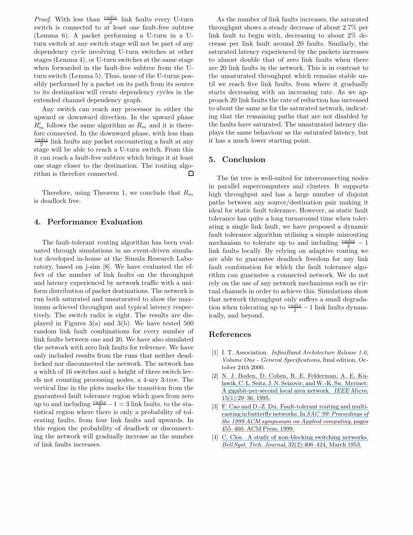
The fault-tolerant routing algorithm has been eval-uated through simulations in an event-driven simula-tor developed in-house at the Simula Research Labo-ratory, based on j-sim [8]. We have evaluated the ef-fect of the number of link faults on the throughputand latency experienced by network traffic with a uni-form distribution of packet destinations. The network isrun both saturated and unsaturated to show the max-imum achieved throughput and typical latency respec-tively. The switch radix is eight. The results are dis-played in Figures 3(a) and 3(b). We have tested 500random link fault combinations for every number oflink faults between one and 20. We have also simulatedthe network with zero link faults for reference. We haveonly included results from the runs that neither dead-locked nor disconnected the network. The network hasa width of 16 switches and a height of three switch lev-els not counting processing nodes, a 4-ary 3-tree. Thevertical line in the plots marks the transition from theguaranteed fault tolerance region which goes from zeroup to and including radix
2 −1 = 3 link faults, to the sta-tistical region where there is only a probability of tol-erating faults, from four link faults and upwards. Inthis region the probability of deadlock or disconnect-ing the network will gradually increase as the numberof link faults increases.
As the number of link faults increases, the saturatedthroughput shows a steady decrease of about 2.7% perlink fault to begin with, decreasing to about 2% de-crease per link fault around 20 faults. Similarly, thesaturated latency experienced by the packets increasesto almost double that of zero link faults when thereare 20 link faults in the network. This is in contrast tothe unsaturated throughput which remains stable un-til we reach five link faults, from where it graduallystarts decreasing with an increasing rate. As we ap-proach 20 link faults the rate of reduction has increasedto about the same as for the saturated network, indicat-ing that the remaining paths that are not disabled bythe faults have saturated. The unsaturated latency dis-plays the same behaviour as the saturated latency, butit has a much lower starting point.
5. Conclusion
The fat tree is well-suited for interconnecting nodesin parallel supercomputers and clusters. It supportshigh throughput and has a large number of disjointpaths between any source/destination pair making itideal for static fault tolerance. However, as static faulttolerance has quite a long turnaround time when toler-ating a single link fault, we have proposed a dynamicfault tolerance algorithm utilising a simple misroutingmechanism to tolerate up to and including radix
2 − 1link faults locally. By relying on adaptive routing weare able to guarantee deadlock freedom for any linkfault combination for which the fault tolerance algo-rithm can guarantee a connected network. We do notrely on the use of any network mechanisms such as vir-tual channels in order to achieve this. Simulations showthat network throughput only suffers a small degrada-tion when tolerating up to radix
2 −1 link faults dynam-ically, and beyond.
References
[1] I. T. Association. InfiniBand Architecture Release 1.0,Volume One - General Specifications, final edition, Oc-tober 24th 2000.
[2] N. J. Boden, D. Cohen, R. E. Felderman, A. E. Ku-lawik,C.L. Seitz, J.N. Seizovic, andW.-K. Su. Myrinet:A gigabit-per-second local area network. IEEE Micro,15(1):29–36, 1995.
[3] F. Cao and D.-Z. Du. Fault-tolerant routing and multi-casting in butterfly networks. InSAC ’99: Proceedings ofthe 1999 ACM symposium on Applied computing, pages455–460. ACM Press, 1999.
[4] C. Clos. A study of non-blocking switching networks.Bell Syst. Tech. Journal, 32(2):406–424, March 1953.

0 5 10 15 2010
12
14
16
18
20
22
Number of Faults
Acc
epte
d pa
cket
rate
(pa
cket
s/cy
cle)
Throughput
SaturatedUnsaturated
(a) Throughput
0 5 10 15 200
10
20
30
40
50
60
Number of Faults
Ave
rage
late
ncy
(sim
ulat
ion
cycl
es)
Latency for all packets
SaturatedUnsaturated
(b) Latency
Figure 3. Performance evaluation with link faults, both with a saturated (packet insertion rate is 32 pack-ets/cycle) and unsaturated network (packet insertion rate is 14 packets/cycle). The vertical line marks thetransition from guaranteed fault tolerance on the left side to probable fault tolerance on the right side.
[5] T. M. Corporation. Connection machine cm-5 technicalsummary. Technical report, 1993.
[6] J. Duato. A necessary and sufficient condition fordeadlock-free routing in cut-through and store-and-forward networks:. IEEE Transactions on Parallel andDistributed Systems, 7(8):841–854, 1996.
[7] I. Gazit and M. Malek. Fault tolerance capabilitiesin multistage network-based multicomputer systems.IEEE Trans. Comput., 37(7):788–798, 1988.
[8] J-sim. http://www.j-sim.org/, May 2006.
[9] A.R.Karlin,G.Nelson, andH.Tamaki. On the fault tol-erance of the butterfly. InProceedings of the 26th AnnualACM Symposium on the Theory of Computing, pages125–133, May 1994.
[10] T.-H.LeeandJ.-J.Chou. Somedirectedgraph theoremsfor testing thedynamic full accessproperty ofmultistageinterconnection networks. IEEE TENCON, 1993.
[11] T. Leighton, B. Maggs, and R. Sitaraman. On the faulttolerance of some popular bounded-degree networks.SIAM J. Comput., 27(5):1303–1333, 1998.
[12] C.E.Leiserson. Fat-trees:Universalnetworkshardware-efficient supercomputing. IEEE Transactions on Com-puters, c-34(10), 1985.
[13] Y. Mun and H. Y. Youn. On performance evaluation offault-tolerant multistage interconnection networks. InSAC ’92: Proceedings of the 1992 ACM/SIGAPP Sym-posium on Applied computing, pages 1–10. ACM Press,1992.
[14] S. R. Øhring, M. Ibel, S. K. Das, and M. J. Kumar. Ongeneralised fat-trees. In Proceedings of the 9th Interna-tional Symposium on Parallel Processing, page 39, April1995.
[15] F. Petrini, W. chun Feng, A. Hoisie, S. Coll, andE. Frachtenberg. The Quadrics network: High-performance clustering technology. IEEE Micro,22(1):46–57, /2002.
[16] F. Petrini and M. Vanneschi. K-ary N-trees: High per-formance networks for massively parallel architectures.Technical Report TR-95-18, 15, 1995.
[17] http://www.quadrics.com, September 2005.
[18] F. O. Sem-Jacobsen, T. Skeie, and O. Lysne. A dynamicfault-tolerant routing scheme for fat-trees. In Proceed-ings of the PDPTA conference, 2005.
[19] F. O. Sem-Jacobsen, T. Skeie, O. Lysne,O. Tørudbakken, E. Rongved, and B. Johnsen.Siamese-twin: A dynamically fault tolerant fat tree.Proceedings of the 19th IPDPS, 2005.
[20] J. Sengupta and P. Bansal. Fault-tolerant routing in ir-regular MINs. In TENCON ’98. 1998 IEEE Region 10International Conference on Global Connectivity in En-ergy, Computer, Communication andControl, volume2,pages 638–641, December 1998.
[21] SGI. http://www.sgi.com/products/servers/altix/,September 2005.
[22] N. Sharma. Fault-tolerance of a MIN using hybrid re-dundancy. In Proceedings of the 27th Annual SimulationSymposium, pages 142–149, April 1994.
[23] M. Valerio, L. Moser, and P. Melliar-Smith. Fault-tolerant orthogonal fat-trees as interconnection net-works. Proceedings 1st International Conference onAlgorithms and Architectures for Parallel Processing,2:749–754, 1995.
[24] M. Valerio, L. E. Moser, and P. M. Melliar-Smith. Re-cursively scalable fat-trees as interconnection networks.Proceeding of 13th IEEE Annual International PhoenixConference on Computers and Communications, 1994.