Dynamic analysis of reciprocating compressor with clearance ...
25
© JVE INTERNATIONAL LTD. JOURNAL OF VIBROENGINEERING. NOV 2017, VOL. 19, ISSUE 7. ISSN 1392-8716 5061 2656. Dynamic analysis of reciprocating compressor with clearance and subsidence Shungen Xiao 1 , Shulin Liu 2 , Shouguo Cheng 3 , Xiaogang Xue 4 , Mengmeng Song 5 , Xin Sun 6 1, 2, 3, 4, 6 School of Mechatronical Engineering and Automation, Shanghai University, Shanghai, People’s Republic of China 1, 5 College of Information, Mechanical and Electrical Engineering, Ningde Normal University, Ningde, People’s Republic of China 3 Department of Mechanical and Electrical Engineering, Jiangyin Polytechnic College, Jiangsu, People’s Republic of China 2 Corresponding author E-mail: 1 [email protected], 2 [email protected], 3 [email protected], 4 [email protected], 5 [email protected], 6 [email protected] Received 16 June 2017; received in revised form 13 August 2017; accepted 20 August 2017 DOI https://doi.org/10.21595/jve.2017.18771 Abstract. In this paper, the reciprocating compressor with clearance and subsidence of the crosshead is studied, considering the varying cylinder pressure. To investigate the nonlinear dynamical behaviors of the reciprocating compressor precisely, a novel dynamic model of the reciprocating compressor of single cylinder with clearance and subsidence for the varying cylinder pressure is established based on the Lagrangian approach. It is demonstrated that different clearance sizes, subsidence sizes and crankshaft angular velocities can affect the dynamic response of the crosshead in the horizontal direction, respectively. The analysis results of dynamic response illustrate that with the increase of clearance sizes and subsidence sizes, the influence of crosshead displacement, velocity and acceleration increase, but the effect of clearance is much stronger than subsidence. Fast Fourier transformation is also applied to analyze the frequency spectrum of the system response. Moreover, the stability of the motion is studied using phase trajectories, maximum Lyapunov exponents and Poincaré sections. Numerical solution results show that clearance sizes, subsidence sizes and crankshaft angular velocities change the dynamical behavior of the system. Through calculation of the maximum Lyapunov exponents and Poincaré portraits, the results reveal that the reciprocating compressor system is characterized by chaotic behavior with the faults of clearance and subsidence. Furthermore, with the increase of the clearance sizes and the crankshaft angular velocities, the shapes of chaotic phase trajectories have changed greatly, and varied inconspicuously with the increase of subsidence sizes in reciprocating compressor system. Keywords: reciprocating compressor, dynamics, clearance, subsidence, chaos. 1. Introduction Reciprocating compressors are one of the most popular machines used in petroleum and chemical production processes, such as gas compression, petroleum transportation and natural gas transportation [1, 2]. In practice, with reciprocating compressor working on a period of time, as the result of manufacture tolerance, material deformation, and wear, some clearances in its joints and subsidence of crosshead commonly exist, which are inevitable. In the case of oversized joint clearances and subsidence, contact forces generate impulsive effect, which causes increased vibration and noise, and reduces system reliability, stability, life and precision. So, clearance and subsidence play a significant role in the prediction of kinematic and dynamic behavior of reciprocating compressor [3]. In the past few decades, most studies have focused on the fault diagnosis method of reciprocating compressor with signal processing. For example, aiming at the bearing clearance fault of reciprocating compressor, a series of fault detection approaches have been used extensively in the literatures [4-6]. In addition, there are also many other studies on the fault diagnosis of reciprocating compressor valves [7-10]. However, few researchers studied the failure
-
Upload
khangminh22 -
Category
Documents
-
view
1 -
download
0
Transcript of Dynamic analysis of reciprocating compressor with clearance ...
© JVE INTERNATIONAL LTD. JOURNAL OF VIBROENGINEERING. NOV 2017, VOL. 19, ISSUE 7. ISSN 1392-8716 5061
2656. Dynamic analysis of reciprocating compressor with clearance and subsidence
Shungen Xiao1, Shulin Liu2, Shouguo Cheng3, Xiaogang Xue4, Mengmeng Song5, Xin Sun6 1, 2, 3, 4, 6School of Mechatronical Engineering and Automation, Shanghai University, Shanghai, People’s Republic of China 1, 5College of Information, Mechanical and Electrical Engineering, Ningde Normal University, Ningde, People’s Republic of China 3Department of Mechanical and Electrical Engineering, Jiangyin Polytechnic College, Jiangsu, People’s Republic of China 2Corresponding author E-mail: [email protected], [email protected], [email protected], [email protected], [email protected], [email protected] Received 16 June 2017; received in revised form 13 August 2017; accepted 20 August 2017 DOI https://doi.org/10.21595/jve.2017.18771
Abstract. In this paper, the reciprocating compressor with clearance and subsidence of the crosshead is studied, considering the varying cylinder pressure. To investigate the nonlinear dynamical behaviors of the reciprocating compressor precisely, a novel dynamic model of the reciprocating compressor of single cylinder with clearance and subsidence for the varying cylinder pressure is established based on the Lagrangian approach. It is demonstrated that different clearance sizes, subsidence sizes and crankshaft angular velocities can affect the dynamic response of the crosshead in the horizontal direction, respectively. The analysis results of dynamic response illustrate that with the increase of clearance sizes and subsidence sizes, the influence of crosshead displacement, velocity and acceleration increase, but the effect of clearance is much stronger than subsidence. Fast Fourier transformation is also applied to analyze the frequency spectrum of the system response. Moreover, the stability of the motion is studied using phase trajectories, maximum Lyapunov exponents and Poincaré sections. Numerical solution results show that clearance sizes, subsidence sizes and crankshaft angular velocities change the dynamical behavior of the system. Through calculation of the maximum Lyapunov exponents and Poincaré portraits, the results reveal that the reciprocating compressor system is characterized by chaotic behavior with the faults of clearance and subsidence. Furthermore, with the increase of the clearance sizes and the crankshaft angular velocities, the shapes of chaotic phase trajectories have changed greatly, and varied inconspicuously with the increase of subsidence sizes in reciprocating compressor system. Keywords: reciprocating compressor, dynamics, clearance, subsidence, chaos.
1. Introduction
Reciprocating compressors are one of the most popular machines used in petroleum and chemical production processes, such as gas compression, petroleum transportation and natural gas transportation [1, 2]. In practice, with reciprocating compressor working on a period of time, as the result of manufacture tolerance, material deformation, and wear, some clearances in its joints and subsidence of crosshead commonly exist, which are inevitable. In the case of oversized joint clearances and subsidence, contact forces generate impulsive effect, which causes increased vibration and noise, and reduces system reliability, stability, life and precision. So, clearance and subsidence play a significant role in the prediction of kinematic and dynamic behavior of reciprocating compressor [3].
In the past few decades, most studies have focused on the fault diagnosis method of reciprocating compressor with signal processing. For example, aiming at the bearing clearance fault of reciprocating compressor, a series of fault detection approaches have been used extensively in the literatures [4-6]. In addition, there are also many other studies on the fault diagnosis of reciprocating compressor valves [7-10]. However, few researchers studied the failure
2656. DYNAMIC ANALYSIS OF RECIPROCATING COMPRESSOR WITH CLEARANCE AND SUBSIDENCE. SHUNGEN XIAO, SHULIN LIU, SHOUGUO CHENG, XIAOGANG XUE, MENGMENG SONG, XIN SUN
5062 © JVE INTERNATIONAL LTD. JOURNAL OF VIBROENGINEERING. NOV 2017, VOL. 19, ISSUE 7. ISSN 1392-8716
mechanism of reciprocating compressor with joint clearances fault and subsidence fault of crosshead, and so on. Zhao et al. [11] studied the dynamic behavior of a reciprocating compressor transmission mechanism with joint clearance. In their study, taking cylinder pressure, amplitude of clearance, crank speed and flexibility of connecting rod as influence factors, the results showed that these factors play a significant role in dynamic behavior of mechanisms. Zhao et al. [12] also presented a parameter optimization approach for planar joint clearance model and its application for dynamics simulation of reciprocating compressor. The dynamics response experimental test verified the effectiveness of this application.
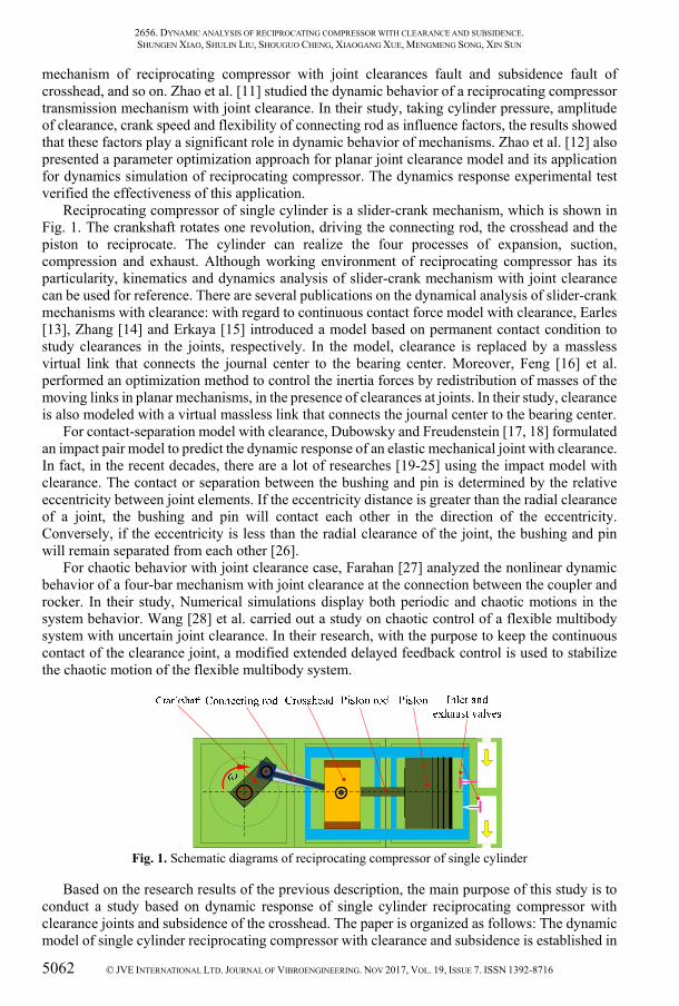
Reciprocating compressor of single cylinder is a slider-crank mechanism, which is shown in Fig. 1. The crankshaft rotates one revolution, driving the connecting rod, the crosshead and the piston to reciprocate. The cylinder can realize the four processes of expansion, suction, compression and exhaust. Although working environment of reciprocating compressor has its particularity, kinematics and dynamics analysis of slider-crank mechanism with joint clearance can be used for reference. There are several publications on the dynamical analysis of slider-crank mechanisms with clearance: with regard to continuous contact force model with clearance, Earles [13], Zhang [14] and Erkaya [15] introduced a model based on permanent contact condition to study clearances in the joints, respectively. In the model, clearance is replaced by a massless virtual link that connects the journal center to the bearing center. Moreover, Feng [16] et al. performed an optimization method to control the inertia forces by redistribution of masses of the moving links in planar mechanisms, in the presence of clearances at joints. In their study, clearance is also modeled with a virtual massless link that connects the journal center to the bearing center.
For contact-separation model with clearance, Dubowsky and Freudenstein [17, 18] formulated an impact pair model to predict the dynamic response of an elastic mechanical joint with clearance. In fact, in the recent decades, there are a lot of researches [19-25] using the impact model with clearance. The contact or separation between the bushing and pin is determined by the relative eccentricity between joint elements. If the eccentricity distance is greater than the radial clearance of a joint, the bushing and pin will contact each other in the direction of the eccentricity. Conversely, if the eccentricity is less than the radial clearance of the joint, the bushing and pin will remain separated from each other [26].
For chaotic behavior with joint clearance case, Farahan [27] analyzed the nonlinear dynamic behavior of a four-bar mechanism with joint clearance at the connection between the coupler and rocker. In their study, Numerical simulations display both periodic and chaotic motions in the system behavior. Wang [28] et al. carried out a study on chaotic control of a flexible multibody system with uncertain joint clearance. In their research, with the purpose to keep the continuous contact of the clearance joint, a modified extended delayed feedback control is used to stabilize the chaotic motion of the flexible multibody system.
Fig. 1. Schematic diagrams of reciprocating compressor of single cylinder
Based on the research results of the previous description, the main purpose of this study is to conduct a study based on dynamic response of single cylinder reciprocating compressor with clearance joints and subsidence of the crosshead. The paper is organized as follows: The dynamic model of single cylinder reciprocating compressor with clearance and subsidence is established in
2656. DYNAMIC ANALYSIS OF RECIPROCATING COMPRESSOR WITH CLEARANCE AND SUBSIDENCE. SHUNGEN XIAO, SHULIN LIU, SHOUGUO CHENG, XIAOGANG XUE, MENGMENG SONG, XIN SUN
© JVE INTERNATIONAL LTD. JOURNAL OF VIBROENGINEERING. NOV 2017, VOL. 19, ISSUE 7. ISSN 1392-8716 5063
Section 2. The effects of joint clearance size, subsidence size and angular velocity are discussed in Section 3, respectively. Phase trajectories of the reciprocating compressor crosshead are analyzed, and the chaotic behavior of the motion is studied using Lyapunov exponents and Poincaré sections with the change of clearance size, subsidence size and crankshaft angular velocity under varying cylinder pressure in Section 4. Dynamic response and chaotic behavior of the reciprocating compressor are summarized in Section 5. In addition, the conclusions of this paper are also given in Section 5.
2. System model of reciprocating compressor with clearance and subsidence
After the reciprocating compressor works for a period of time, the revolute joints clearance gradually increases and the crosshead may generate subsidence due to wear. In order to study the combined effects of clearance and subsidence on the motion of the crosshead, we build the dynamical mathematical model of the reciprocating compressor system.
2.1. Model of cylinder pressure
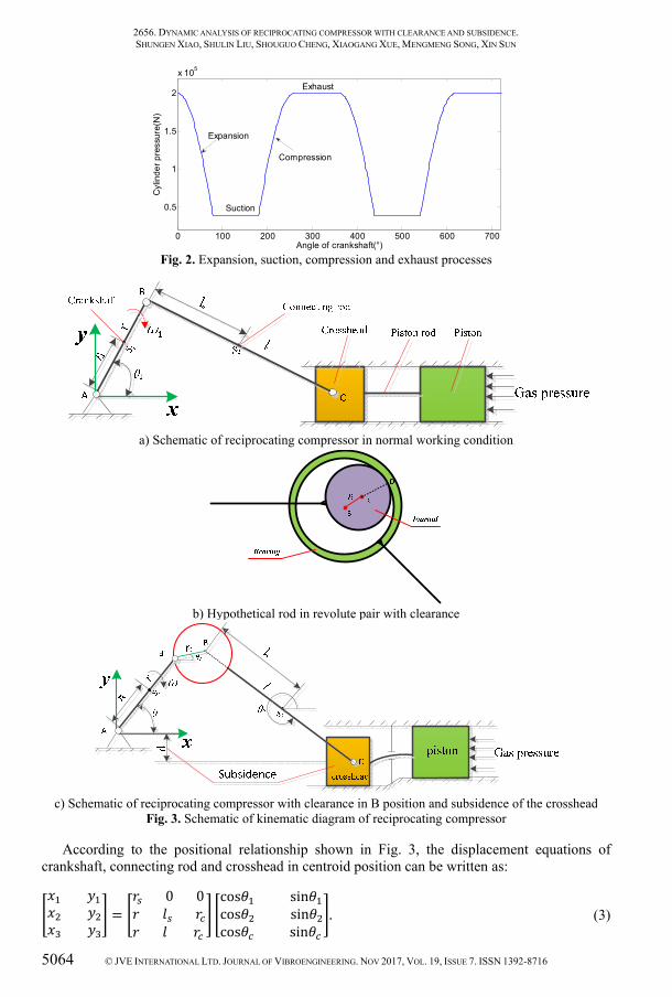
With the crankshaft of reciprocating compressor rotating a circle, the cylinder is accordingly carried out a working cycle, including expansion, suction, compression and exhaust processes, as shown in Fig. 2. In a circle, when the crankshaft is located at zero angle, the piston is located at right end with the inlet and exhaust vales closing at the same time. As the crankshaft turns clockwise, the crosshead and piston move from right to left, working volume that is located at the right side of the piston gradually increases, cavity gas gradually expands and cylinder pressure gradually decreases, which is expansion process. When the cylinder internal pressure decreases to slightly less than the external pressure of the cavity, the inlet valve is opened, until the crosshead and piston move to the far left, which is suction process. In the suction process, cylinder pressure is almost constant. The suction process is accomplished at the far left. The compression and exhaust processes are mostly the opposite of expansion and suction. Combining with the indicator diagram of reciprocating compressor, cylinder pressure can be expressed using the following equation: = 200000 , (1)
where is the cylinder pressure, is a cylinder pressure coefficient given by:
=sin 2 − , 0° + 2 ≤ ≤ 716 + 2 ( is integer) Expansion,sin 16, 716 + 2 ≤ ≤ + 2 ( is integer) Suction,−sin + 16 , + 2 ≤ ≤ 2316 + 2 ( is integer) Compression,1, 2316 + 2 ≤ ≤ 2 + 2 ( is integer) Exhaust.
(2)
2.2. Equations of motion
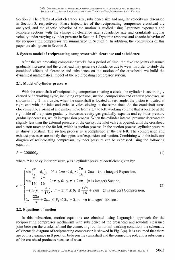
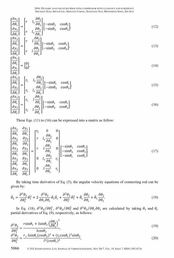
In this subsection, motion equations are obtained using Lagrangian approach for the reciprocating compressor mechanism with subsidence of the crosshead and revolute clearance joint between the crankshaft and the connecting rod. In normal working condition, the schematic of kinematic diagram of reciprocating compressor is showed in Fig. 3(a). It is assumed that there are both a clearance in B position between the crankshaft and the connecting rod, and a subsidence of the crosshead produces because of wear.
2656. DYNAMIC ANALYSIS OF RECIPROCATING COMPRESSOR WITH CLEARANCE AND SUBSIDENCE. SHUNGEN XIAO, SHULIN LIU, SHOUGUO CHENG, XIAOGANG XUE, MENGMENG SONG, XIN SUN
5064 © JVE INTERNATIONAL LTD. JOURNAL OF VIBROENGINEERING. NOV 2017, VOL. 19, ISSUE 7. ISSN 1392-8716
Fig. 2. Expansion, suction, compression and exhaust processes
a) Schematic of reciprocating compressor in normal working condition
b) Hypothetical rod in revolute pair with clearance
c) Schematic of reciprocating compressor with clearance in B position and subsidence of the crosshead
Fig. 3. Schematic of kinematic diagram of reciprocating compressor
According to the positional relationship shown in Fig. 3, the displacement equations of crankshaft, connecting rod and crosshead in centroid position can be written as: = 0 0 cos sincos sincos sin . (3)
0 100 200 300 400 500 600 700
0.5
1
1.5
2
x 105
Angle of crankshaft(°)
Cyl
inde
r pre
ssur
e(N
)
Suction
Compression
Expansion
Exhaust

2656. DYNAMIC ANALYSIS OF RECIPROCATING COMPRESSOR WITH CLEARANCE AND SUBSIDENCE. SHUNGEN XIAO, SHULIN LIU, SHOUGUO CHENG, XIAOGANG XUE, MENGMENG SONG, XIN SUN
© JVE INTERNATIONAL LTD. JOURNAL OF VIBROENGINEERING. NOV 2017, VOL. 19, ISSUE 7. ISSN 1392-8716 5065
In which and ( = 1,2,3) are the centroid position of crankshaft, connecting rod and crosshead, respectively. , and are the angle of the crankshaft, the clearance and connecting rod with the -axis, respectively. is the length of crankshaft, is the length of connecting rod and is clearance radius in B position. is the length of A joint to the centroid position of crankshaft and is the length of B joint to the centroid position of connecting rod.
According to the geometric relationship of the crank-slider mechanism, can be calculated using:
= −sin + sin + sin . (4)
In this expression, is the depth of crosshead subsidence, namely, = − . It is clear that is a function of and . Therefore, is given by:
= + . (5)
Obviously, the Eq. (4) can become: sin + sin + sin + = 0. (6)
In Eq. (5), ⁄ and ⁄ are calculated by taking and partial derivatives of Eq. (6), respectively, as follows:
cos + cos = 0, (7)cos + cos = 0. (8)⁄ and ⁄ are obtained in matrix form as:
= − 1cos coscos . (9)
By taking time derivatives of and ( = 1,2,3) , the velocity equations of crankshaft, connecting rod and crosshead in centroid position can be expressed as:
= + . (10)
In Eq. (10), ⁄ , ⁄ , ⁄ and ⁄ are calculated by taking and partial derivatives of Eq. (3) as follows, respectively:
= −sincos , (11)
2656. DYNAMIC ANALYSIS OF RECIPROCATING COMPRESSOR WITH CLEARANCE AND SUBSIDENCE. SHUNGEN XIAO, SHULIN LIU, SHOUGUO CHENG, XIAOGANG XUE, MENGMENG SONG, XIN SUN
5066 © JVE INTERNATIONAL LTD. JOURNAL OF VIBROENGINEERING. NOV 2017, VOL. 19, ISSUE 7. ISSN 1392-8716
= −sin cos−sin cos , (12)
= −sin cos−sin cos , (13)
= 00 , (14)
= −sin cos−sin cos , (15)
= −sin cos−sin cos . (16)
These Eqs. (11) to (16) can be expressed into a matrix as follow:
=0 00000
−sin cos−sin cos−sin cos . (17)
By taking time derivative of Eq. (5), the angular velocity equations of connecting rod can be given by:
= + 2 + + + . (18)
In Eq. (18), ⁄ , ⁄ and ⁄ are calculated by taking and partial derivatives of Eq. (9), respectively, as follows:
= sin + sincos , (19)
= sin (cos ) + ( cos ) sin(cos ) , (20)
2656. DYNAMIC ANALYSIS OF RECIPROCATING COMPRESSOR WITH CLEARANCE AND SUBSIDENCE. SHUNGEN XIAO, SHULIN LIU, SHOUGUO CHENG, XIAOGANG XUE, MENGMENG SONG, XIN SUN
© JVE INTERNATIONAL LTD. JOURNAL OF VIBROENGINEERING. NOV 2017, VOL. 19, ISSUE 7. ISSN 1392-8716 5067
= . . sin . cos . cos(cos ) . (21)
The acceleration equations of crankshaft, connecting rod and crosshead in centroid position can be solved by taking time derivative of Eq. (10) as follow:
= + 2 + + , ( = 1,2,3), (22)
where ⁄ , ⁄ , ⁄ , ⁄ , ⁄ and ⁄ can be determined using the following equations from Eqs. (23) to (31). ⁄ and ⁄ are calculated by taking derivative of Eq. (11) as follow:
= −cos−sin . (23)
⁄ and ⁄ are computed by taking derivative of Eq. (12) as follow:
= − − cos sinsin coscos sin . (24)
⁄ and ⁄ can be deduced by taking derivative of Eq. (13) as follow:
= − − cos sinsin coscos sin . (25)
⁄ and ⁄ are expressed by taking derivative of Eq. (11) as follow:
= 00 . (26)
⁄ and ⁄ are defined by taking derivative of Eq. (12) as follow:
= − − sin coscos sin . (27)

2656. DYNAMIC ANALYSIS OF RECIPROCATING COMPRESSOR WITH CLEARANCE AND SUBSIDENCE. SHUNGEN XIAO, SHULIN LIU, SHOUGUO CHENG, XIAOGANG XUE, MENGMENG SONG, XIN SUN
5068 © JVE INTERNATIONAL LTD. JOURNAL OF VIBROENGINEERING. NOV 2017, VOL. 19, ISSUE 7. ISSN 1392-8716
⁄ and ⁄ are computed by taking derivative of Eq. (13) as follow
= − − sin coscos sin . (28)
⁄ and ⁄ are calculated by taking derivative of Eq. (14) as follow:
= 00 . (29)
⁄ and ⁄ can be deduced by taking derivative of Eq. (15) as follow:
= − − sin coscos sincos sin . (30)
⁄ and ⁄ are calculated by taking derivative of Eq. (16) as follow:
= − − sin coscos sincos sin . (31)
These Eqs. (23) to (31) can be written into a matrix as follow:
=
0 0 0± 00 ± 00 ±
± 00 ± 00 ±
× cos sinsin coscos sincos sin . (32)
In Eq. (32), The meaning of the “±” is that “+” and “-” represent the symbol of the first column and the second column of the solved matrix, respectively.

2656. DYNAMIC ANALYSIS OF RECIPROCATING COMPRESSOR WITH CLEARANCE AND SUBSIDENCE. SHUNGEN XIAO, SHULIN LIU, SHOUGUO CHENG, XIAOGANG XUE, MENGMENG SONG, XIN SUN
© JVE INTERNATIONAL LTD. JOURNAL OF VIBROENGINEERING. NOV 2017, VOL. 19, ISSUE 7. ISSN 1392-8716 5069
In addition, it is easily obtained as follows:
= = = = = = = = = = = 0. (33)
2.3. Equations of dynamics
Lagrange motion equation for an unconstrained dynamical system is as follow:
− + = , ( = 1,2), (34)
where and are the system kinetic and potential energies, respectively. is the nonconservative generalized force corresponding to the generalized coordinate , and can be calculated as:
= ∗ . + ∗. . (35)
In Eq. (35), ∗ is the resultant of external force acting at the center of mass. ∗ is the external torque acting on body . and are the translational and rotational velocity for the mass center of body , respectively.
Taking the crankshaft, connecting rod and crosshead of the reciprocating compressor as a system, the kinetic energy and potential energy of the system are:
= = 12 + + 12 ,= . (36)
Substituting Eq. (36) into Eq. (34) leads to:
+ + + = . (37)
Substitute Eqs. (18) and (22) into Eq. (37). Because the crankshaft works for uniform rotation, the angular acceleration of crankshaft equals zero, Namely, = 0. Therefore, differential equation about can be written as: ⋅ = ⋅ + ⋅ + , (38)
where A, B, C and D are expressed as:
= + + , (39)

2656. DYNAMIC ANALYSIS OF RECIPROCATING COMPRESSOR WITH CLEARANCE AND SUBSIDENCE. SHUNGEN XIAO, SHULIN LIU, SHOUGUO CHENG, XIAOGANG XUE, MENGMENG SONG, XIN SUN
5070 © JVE INTERNATIONAL LTD. JOURNAL OF VIBROENGINEERING. NOV 2017, VOL. 19, ISSUE 7. ISSN 1392-8716
= −2 ⋅ + ⋅ + ⋅ , (40)
= − ⋅ + ⋅ + ⋅ , (41)
= − ⋅ + ⋅ + ⋅ − . (42)
Obviously, Eq. (38) is a nonlinear equation. It is supposed that the centroid of connecting rod is middle position, that is to say, = 2 .
Moreover, since the clearance size is very small, it can be considered the expression . + ≈ , where and are two expressions that are roughly the same order of magnitude. Substituting Eqs. (9), (17), (19)-(21) and (32) into Eqs. (39)-(42), respectively. The expressions of , , and can be expressed as follows:
= + 4 coscos + + cos (sin tan − cos ) + (tan cos − sin ) , (43)
where ( = 1, 2, 3) are constants, = ( ⁄ ) , = , = :
= cos cos sin cos + sin( + ) + ( + )sin( − ) . (44)
In which, ( = 1, 2, 3, 4) are constants, = −2 ⁄ , = − 4⁄ , = 3 , = −2 :
= 1 sin + 516 cos2 sin2 − 14 cos2 sin2 + sin2 − 8 sin2 . (45)
In which, ( = 1,2,3) are constants, = − 2⁄ + 3 16⁄ − , = , = − 2⁄ :
= (−sin + tan cos ) − cos ( cos sin + sin cos ) + sin( − ) ⋅ coscos + tan sin + coscos + (sin cos + sin( − )) , (46)
where:
= = ⋅ , = , = 2 + , = 4 + + 4 sin , = 4 . (47)
3. Numerical simulation and dynamic responses analysis
In this previous section, the numerical solution of the clearance angle is solved by the Runge-Kutta method according to the Eqs. (38) and (4). Subsequently, the displacement, velocity

2656. DYNAMIC ANALYSIS OF RECIPROCATING COMPRESSOR WITH CLEARANCE AND SUBSIDENCE. SHUNGEN XIAO, SHULIN LIU, SHOUGUO CHENG, XIAOGANG XUE, MENGMENG SONG, XIN SUN
© JVE INTERNATIONAL LTD. JOURNAL OF VIBROENGINEERING. NOV 2017, VOL. 19, ISSUE 7. ISSN 1392-8716 5071
and acceleration of the crosshead are also obtained accordingly in the horizontal direction. In this section, we discuss the influence of clearance, subsidence and rotation speed of the crankshaft. Taking the 2D12 model of reciprocating compressor as the research object, the simulation characteristics are presented in Table 1. In addition, the centroids of crankshaft and connecting rod are middle position.
Table 1. Dimension for the 2D12 model of reciprocating compressor Parts Length (m) Mass (kg) Moment of inertia (kg.m2)
Crankshaft 0.12 1 0.0012 Connecting rod 0.6 5 0.15
Crosshead – 1 –
3.1. Dynamic response of reciprocating compressor system with different clearance sizes
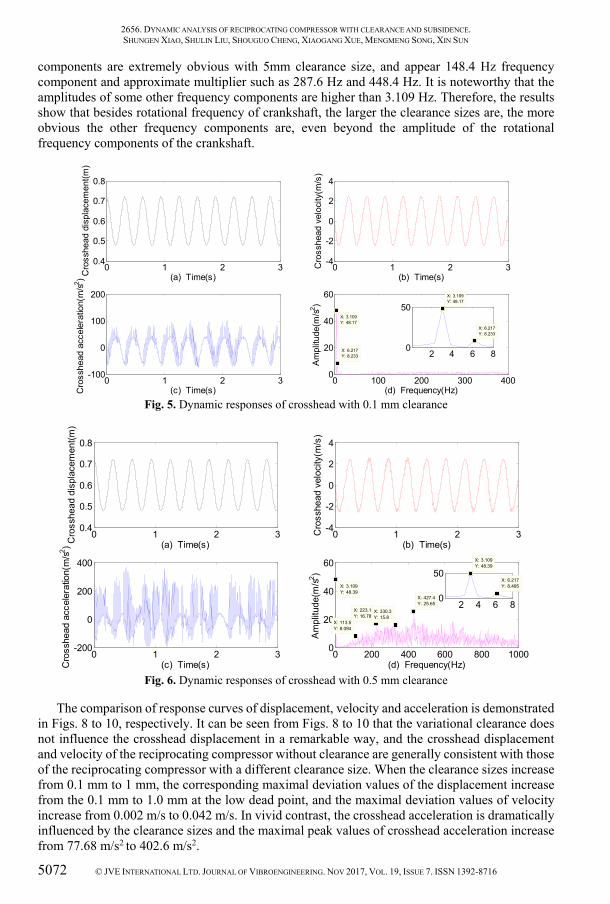
In this subsection, from the perspective of dynamic response, the effects of the reciprocating compressor with different clearance sizes are investigated under the conditions of without subsidence, crankshaft angular velocity 20 rad/s and variable cylinder load shown in Fig. 2. In this study, the revolute joint between the crankshaft and the linkage is used as the clearance for the research. The displacement, velocity, acceleration and acceleration spectrum of the crosshead without/with 0.1 mm, 0.5 mm and 5 mm clearance sizes are shown in Figs. 4 to 7, respectively. It is noteworthy that the clearance size is exaggerated to 5 mm so as to better investigate the dynamics response of the variational clearance sizes for the reciprocating compressor.
Fig. 4. Dynamic responses of crosshead without clearance
As can be seen from Figs. 4 to 7, with the increase of clearance sizes, the effects of displacement, velocity, and acceleration increase. It can be observed that the crosshead velocity and acceleration fluctuate more violently than the crosshead displacement. Furthermore, Fig. 4(d), 5(d), 6(d) and 7(d) show the acceleration spectrum using FFT transformation. In Fig. 4(d), it is clear that 3.109 Hz which is the rotational frequency of crankshaft and 6.217 Hz which is two times rotational frequency of crankshaft are displayed without clearance. In Fig. 5(d), In addition to 3.109 Hz and 6.217 Hz, there are very weak other frequency components with 0.1 mm clearance size, and it is distinct that the amplitudes of the other frequency components are lower than 6.217 Hz. In Fig. 6(d), except 3.109 Hz and 6.217 Hz, the other frequency components are obvious with 0.5 mm clearance size, and it is evident that the amplitudes of some other frequency components are higher than 6.217 Hz, but are lower than 3.109 Hz. It can be found that there are 113.5 Hz frequency component and approximate multiplier such as 223.1 Hz and 330.3 Hz in other frequency components. In Fig. 7(d), apart from 3.109 Hz and 6.217 Hz, the other frequency
0 1 2 30.4
0.5
0.6
0.7
0.8
Time(s)Cro
sshe
ad d
ispl
acem
ent(m
)
0 1 2 3-4
-2
0
2
4
Time(s)
Cro
sshe
ad v
eloc
ity(m
/s)
0 1 2 3-100
-50
0
50
Time(s)Cro
sshe
ad a
ccel
erat
ion(
m/s2 )
0 20 40 60 80 1000
20
40
60
X: 6.217Y: 8.248
Frequency(Hz)
Ampl
itude
(m/s2 )
X: 3.109Y: 48.19
2656. DYNAMIC ANALYSIS OF RECIPROCATING COMPRESSOR WITH CLEARANCE AND SUBSIDENCE. SHUNGEN XIAO, SHULIN LIU, SHOUGUO CHENG, XIAOGANG XUE, MENGMENG SONG, XIN SUN
5072 © JVE INTERNATIONAL LTD. JOURNAL OF VIBROENGINEERING. NOV 2017, VOL. 19, ISSUE 7. ISSN 1392-8716
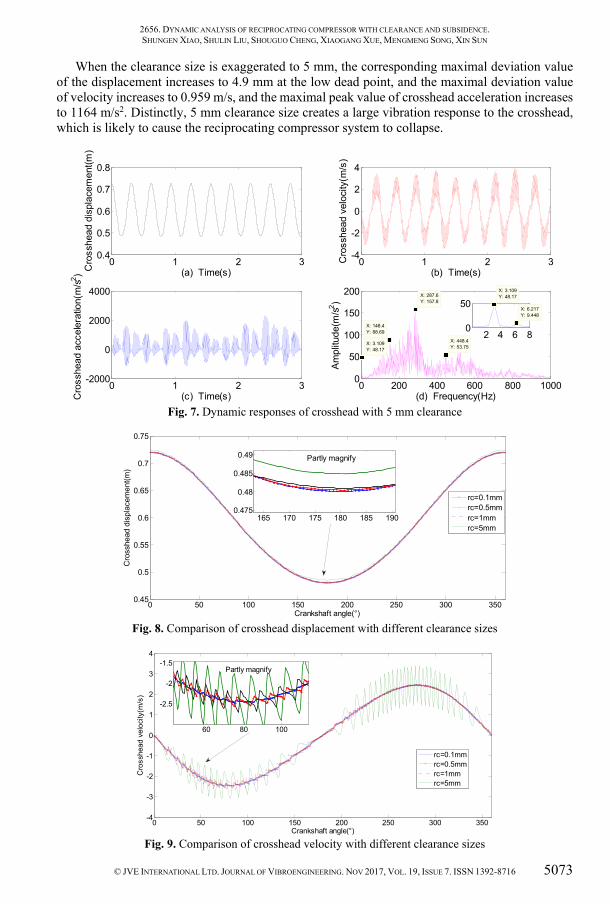
components are extremely obvious with 5mm clearance size, and appear 148.4 Hz frequency component and approximate multiplier such as 287.6 Hz and 448.4 Hz. It is noteworthy that the amplitudes of some other frequency components are higher than 3.109 Hz. Therefore, the results show that besides rotational frequency of crankshaft, the larger the clearance sizes are, the more obvious the other frequency components are, even beyond the amplitude of the rotational frequency components of the crankshaft.
Fig. 5. Dynamic responses of crosshead with 0.1 mm clearance
Fig. 6. Dynamic responses of crosshead with 0.5 mm clearance
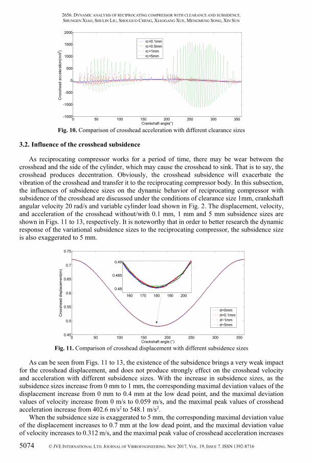
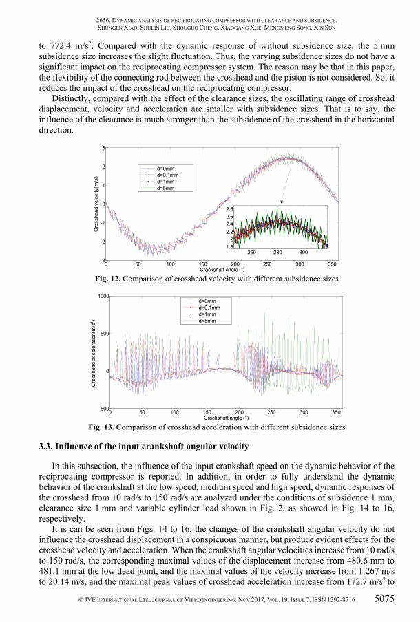
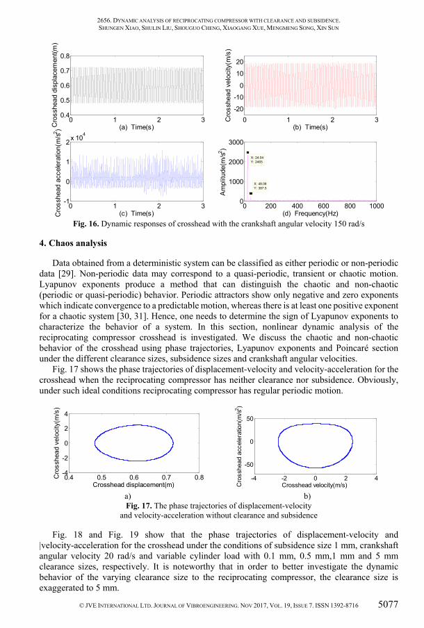
The comparison of response curves of displacement, velocity and acceleration is demonstrated in Figs. 8 to 10, respectively. It can be seen from Figs. 8 to 10 that the variational clearance does not influence the crosshead displacement in a remarkable way, and the crosshead displacement and velocity of the reciprocating compressor without clearance are generally consistent with those of the reciprocating compressor with a different clearance size. When the clearance sizes increase from 0.1 mm to 1 mm, the corresponding maximal deviation values of the displacement increase from the 0.1 mm to 1.0 mm at the low dead point, and the maximal deviation values of velocity increase from 0.002 m/s to 0.042 m/s. In vivid contrast, the crosshead acceleration is dramatically influenced by the clearance sizes and the maximal peak values of crosshead acceleration increase from 77.68 m/s2 to 402.6 m/s2.
0 1 2 30.4
0.5
0.6
0.7
0.8
(a) Time(s)Cro
sshe
ad d
ispl
acem
ent(m
)
0 1 2 3-4
-2
0
2
4
(b) Time(s)
Cro
sshe
ad v
eloc
ity(m
/s)
0 1 2 3-100
0
100
200
(c) Time(s)Cro
sshe
ad a
ccel
erat
ion(
m/s2 )
0 100 200 300 4000
20
40
60
X: 3.109Y: 48.17
(d) Frequency(Hz)
Ampl
itude
(m/s2 )
X: 6.217Y: 8.233 2 4 6 80
50
X: 6.217Y: 8.233
X: 3.109Y: 48.17
0 1 2 30.4
0.5
0.6
0.7
0.8
(a) Time(s)Cro
sshe
ad d
ispl
acem
ent(m
)
0 1 2 3-4
-2
0
2
4
(b) Time(s)
Cro
sshe
ad v
eloc
ity(m
/s)
0 1 2 3-200
0
200
400
(c) Time(s)Cro
sshe
ad a
ccel
erat
ion(
m/s2 )
0 200 400 600 800 10000
20
40
60
X: 223.1Y: 16.78
(d) Frequency(Hz)
Am
plitu
de(m
/s2 )
X: 330.3Y: 15.8
X: 113.5Y: 8.094
X: 427.4Y: 25.65
X: 3.109Y: 48.39
2 4 6 80
50X: 3.109Y: 48.39
X: 6.217Y: 8.495
2656. DYNAMIC ANALYSIS OF RECIPROCATING COMPRESSOR WITH CLEARANCE AND SUBSIDENCE. SHUNGEN XIAO, SHULIN LIU, SHOUGUO CHENG, XIAOGANG XUE, MENGMENG SONG, XIN SUN
© JVE INTERNATIONAL LTD. JOURNAL OF VIBROENGINEERING. NOV 2017, VOL. 19, ISSUE 7. ISSN 1392-8716 5073
When the clearance size is exaggerated to 5 mm, the corresponding maximal deviation value of the displacement increases to 4.9 mm at the low dead point, and the maximal deviation value of velocity increases to 0.959 m/s, and the maximal peak value of crosshead acceleration increases to 1164 m/s2. Distinctly, 5 mm clearance size creates a large vibration response to the crosshead, which is likely to cause the reciprocating compressor system to collapse.
Fig. 7. Dynamic responses of crosshead with 5 mm clearance
Fig. 8. Comparison of crosshead displacement with different clearance sizes
Fig. 9. Comparison of crosshead velocity with different clearance sizes
0 1 2 30.4
0.5
0.6
0.7
0.8
(a) Time(s)Cro
sshe
ad d
ispl
acem
ent(m
)
0 1 2 3-4
-2
0
2
4
(b) Time(s)
Cro
sshe
ad v
eloc
ity(m
/s)
0 1 2 3-2000
0
2000
4000
(c) Time(s)Cro
sshe
ad a
ccel
erat
ion(
m/s2 )
0 200 400 600 800 10000
50
100
150
200
X: 3.109Y: 48.17
(d) Frequency(Hz)
Ampl
itude
(m/s2 )
X: 148.4Y: 88.69
X: 287.6Y: 157.8
X: 448.4Y: 53.75
2 4 6 80
50X: 3.109Y: 48.17
X: 6.217Y: 9.448
0 50 100 150 200 250 300 3500.45
0.5
0.55
0.6
0.65
0.7
0.75
Crankshaft angle(°)
Cro
sshe
ad d
ispl
acem
ent(m
)
rc=0.1mmrc=0.5mmrc=1mmrc=5mm
165 170 175 180 185 1900.475
0.48
0.485
0.49
Partly magnify
0 50 100 150 200 250 300 350-4
-3
-2
-1
0
1
2
3
4
Crankshaft angle(°)
Cro
sshe
ad v
eloc
ity(m
/s)
rc=0.1mmrc=0.5mmrc=1mmrc=5mm
60 80 100
-2.5
-2
-1.5
Partly magnify
2656. DYNAMIC ANALYSIS OF RECIPROCATING COMPRESSOR WITH CLEARANCE AND SUBSIDENCE. SHUNGEN XIAO, SHULIN LIU, SHOUGUO CHENG, XIAOGANG XUE, MENGMENG SONG, XIN SUN
5074 © JVE INTERNATIONAL LTD. JOURNAL OF VIBROENGINEERING. NOV 2017, VOL. 19, ISSUE 7. ISSN 1392-8716
Fig. 10. Comparison of crosshead acceleration with different clearance sizes
3.2. Influence of the crosshead subsidence
As reciprocating compressor works for a period of time, there may be wear between the crosshead and the side of the cylinder, which may cause the crosshead to sink. That is to say, the crosshead produces decentration. Obviously, the crosshead subsidence will exacerbate the vibration of the crosshead and transfer it to the reciprocating compressor body. In this subsection, the influences of subsidence sizes on the dynamic behavior of reciprocating compressor with subsidence of the crosshead are discussed under the conditions of clearance size 1mm, crankshaft angular velocity 20 rad/s and variable cylinder load shown in Fig. 2. The displacement, velocity, and acceleration of the crosshead without/with 0.1 mm, 1 mm and 5 mm subsidence sizes are shown in Figs. 11 to 13, respectively. It is noteworthy that in order to better research the dynamic response of the variational subsidence sizes to the reciprocating compressor, the subsidence size is also exaggerated to 5 mm.
Fig. 11. Comparison of crosshead displacement with different subsidence sizes
As can be seen from Figs. 11 to 13, the existence of the subsidence brings a very weak impact for the crosshead displacement, and does not produce strongly effect on the crosshead velocity and acceleration with different subsidence sizes. With the increase in subsidence sizes, as the subsidence sizes increase from 0 mm to 1 mm, the corresponding maximal deviation values of the displacement increase from 0 mm to 0.4 mm at the low dead point, and the maximal deviation values of velocity increase from 0 m/s to 0.059 m/s, and the maximal peak values of crosshead acceleration increase from 402.6 m/s2 to 548.1 m/s2.
When the subsidence size is exaggerated to 5 mm, the corresponding maximal deviation value of the displacement increases to 0.7 mm at the low dead point, and the maximal deviation value of velocity increases to 0.312 m/s, and the maximal peak value of crosshead acceleration increases
0 50 100 150 200 250 300 350-1500
-1000
-500
0
500
1000
1500
2000
Crankshaft angle(°)
Cro
sshe
ad a
ccel
erat
ion(
m/s2 )
rc=0.1mmrc=0.5mmrc=1mmrc=5mm
0 50 100 150 200 250 300 3500.45
0.5
0.55
0.6
0.65
0.7
0.75
Crackshaft angle (°)
Cro
sshe
ad d
ispl
acem
ent(m
)
d=0mmd=0.1mmd=1mmd=5mm
160 170 180 190 200
0.48
0.485
0.49
2656. DYNAMIC ANALYSIS OF RECIPROCATING COMPRESSOR WITH CLEARANCE AND SUBSIDENCE. SHUNGEN XIAO, SHULIN LIU, SHOUGUO CHENG, XIAOGANG XUE, MENGMENG SONG, XIN SUN
© JVE INTERNATIONAL LTD. JOURNAL OF VIBROENGINEERING. NOV 2017, VOL. 19, ISSUE 7. ISSN 1392-8716 5075
to 772.4 m/s2. Compared with the dynamic response of without subsidence size, the 5 mm subsidence size increases the slight fluctuation. Thus, the varying subsidence sizes do not have a significant impact on the reciprocating compressor system. The reason may be that in this paper, the flexibility of the connecting rod between the crosshead and the piston is not considered. So, it reduces the impact of the crosshead on the reciprocating compressor.
Distinctly, compared with the effect of the clearance sizes, the oscillating range of crosshead displacement, velocity and acceleration are smaller with subsidence sizes. That is to say, the influence of the clearance is much stronger than the subsidence of the crosshead in the horizontal direction.
Fig. 12. Comparison of crosshead velocity with different subsidence sizes
Fig. 13. Comparison of crosshead acceleration with different subsidence sizes
3.3. Influence of the input crankshaft angular velocity
In this subsection, the influence of the input crankshaft speed on the dynamic behavior of the reciprocating compressor is reported. In addition, in order to fully understand the dynamic behavior of the crankshaft at the low speed, medium speed and high speed, dynamic responses of the crosshead from 10 rad/s to 150 rad/s are analyzed under the conditions of subsidence 1 mm, clearance size 1 mm and variable cylinder load shown in Fig. 2, as showed in Fig. 14 to 16, respectively.
It is can be seen from Figs. 14 to 16, the changes of the crankshaft angular velocity do not influence the crosshead displacement in a conspicuous manner, but produce evident effects for the crosshead velocity and acceleration. When the crankshaft angular velocities increase from 10 rad/s to 150 rad/s, the corresponding maximal values of the displacement increase from 480.6 mm to 481.1 mm at the low dead point, and the maximal values of the velocity increase from 1.267 m/s to 20.14 m/s, and the maximal peak values of crosshead acceleration increase from 172.7 m/s2 to
0 50 100 150 200 250 300 350-3
-2
-1
0
1
2
3
Crackshaft angle (°)
Cro
sshe
ad v
eloc
ity(m
/s)
d=0mmd=0.1mmd=1mmd=5mm
260 280 3001.8
22.22.42.62.8
0 50 100 150 200 250 300 350-500
0
500
1000
Crackshaft angle (°)
Cro
sshe
ad a
ccel
erat
ion(
m/s2 )
d=0mmd=0.1mmd=1mmd=5mm

2656. DYNAMIC ANALYSIS OF RECIPROCATING COMPRESSOR WITH CLEARANCE AND SUBSIDENCE. SHUNGEN XIAO, SHULIN LIU, SHOUGUO CHENG, XIAOGANG XUE, MENGMENG SONG, XIN SUN
5076 © JVE INTERNATIONAL LTD. JOURNAL OF VIBROENGINEERING. NOV 2017, VOL. 19, ISSUE 7. ISSN 1392-8716
16010 m/s2. In addition, as can be seen from Fig. 14(d), Fig. 15(d) and Fig. 16(d), with the increase in the crankshaft angular velocity, besides rotational frequency of crankshaft, the lower the crankshaft angular velocities are, the more obvious the other frequency components are, even beyond the amplitude of the rotational frequency components.
Fig. 14. Dynamic responses of crosshead with the crankshaft speed 10 rad/s
Fig. 15. Dynamic responses of crosshead with the crankshaft angular velocity 70 rad/s
When the crankshaft angular velocity is 10 rad/s, except 1.554 Hz which is the rotational frequency of crankshaft and 3.109 Hz which is the double rotational frequency, there are still some other remarkable frequency components that almost submerge the rotational frequency of crankshaft. One can observe 167.9 Hz frequency component and approximate multiplier such as 337.3 Hz in some other frequency components. When the crankshaft angular velocity is 70 rad/s, in addition to the rotational frequency 10.88 Hz and double rotational frequency 22.44 Hz, there are very weak other frequency components, and it is distinct that the amplitudes of the other frequency components are lower than 22.44 Hz. When the crankshaft angular velocity is 150 rad/s, the rotational frequency 24.04 Hz and double rotational frequency 48.04 Hz are more significant than the other frequency components which can be ignored.
0 1 2 30.4
0.5
0.6
0.7
0.8
(a) Time(s)Cro
sshe
ad d
ispl
acem
ent(m
)
0 1 2 3-2
-1
0
1
2
(b) Time(s)
Cro
sshe
ad v
eloc
ity(m
/s)
0 1 2 3-200
-100
0
100
200
(c) Time(s)Cro
sshe
ad a
ccel
erat
ion(
m/s2 )
0 200 400 600 800 10000
5
10
15
20
X: 167.9Y: 9.432
(d) Frequency(Hz)
Am
plitu
de(m
/s2 )
X: 337.3Y: 18.9
2 4 6 805
1015
X: 3.109Y: 2.213
X: 1.554Y: 12.19
0 1 2 30.4
0.5
0.6
0.7
0.8
(a) Time(s)Cro
sshe
ad d
ispl
acem
ent(m
)
0 1 2 3-10
-5
0
5
10
(b) Time(s)
Cro
sshe
ad v
eloc
ity(m
/s)
0 1 2 3-2000
0
2000
4000
6000
(c) Time(s)Cro
sshe
ad a
ccel
erat
ion(
m/s2 )
0 200 400 600 800 10000
200
400
600
X: 10.88Y: 451.5
(d) Frequency(Hz)
Am
plitu
de(m
/s2 )
X: 22.44Y: 115.7
2656. DYNAMIC ANALYSIS OF RECIPROCATING COMPRESSOR WITH CLEARANCE AND SUBSIDENCE. SHUNGEN XIAO, SHULIN LIU, SHOUGUO CHENG, XIAOGANG XUE, MENGMENG SONG, XIN SUN
© JVE INTERNATIONAL LTD. JOURNAL OF VIBROENGINEERING. NOV 2017, VOL. 19, ISSUE 7. ISSN 1392-8716 5077
Fig. 16. Dynamic responses of crosshead with the crankshaft angular velocity 150 rad/s
4. Chaos analysis
Data obtained from a deterministic system can be classified as either periodic or non-periodic data [29]. Non-periodic data may correspond to a quasi-periodic, transient or chaotic motion. Lyapunov exponents produce a method that can distinguish the chaotic and non-chaotic (periodic or quasi-periodic) behavior. Periodic attractors show only negative and zero exponents which indicate convergence to a predictable motion, whereas there is at least one positive exponent for a chaotic system [30, 31]. Hence, one needs to determine the sign of Lyapunov exponents to characterize the behavior of a system. In this section, nonlinear dynamic analysis of the reciprocating compressor crosshead is investigated. We discuss the chaotic and non-chaotic behavior of the crosshead using phase trajectories, Lyapunov exponents and Poincaré section under the different clearance sizes, subsidence sizes and crankshaft angular velocities.
Fig. 17 shows the phase trajectories of displacement-velocity and velocity-acceleration for the crosshead when the reciprocating compressor has neither clearance nor subsidence. Obviously, under such ideal conditions reciprocating compressor has regular periodic motion.
a)
b)
Fig. 17. The phase trajectories of displacement-velocity and velocity-acceleration without clearance and subsidence
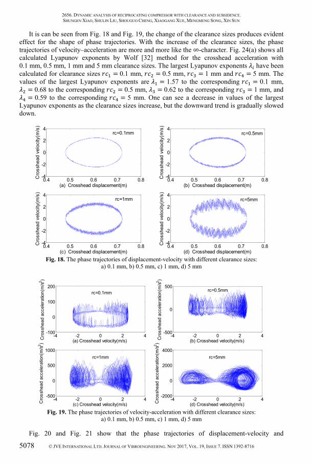
Fig. 18 and Fig. 19 show that the phase trajectories of displacement-velocity and |velocity-acceleration for the crosshead under the conditions of subsidence size 1 mm, crankshaft angular velocity 20 rad/s and variable cylinder load with 0.1 mm, 0.5 mm,1 mm and 5 mm clearance sizes, respectively. It is noteworthy that in order to better investigate the dynamic behavior of the varying clearance size to the reciprocating compressor, the clearance size is exaggerated to 5 mm.
0 1 2 30.4
0.5
0.6
0.7
0.8
(a) Time(s)Cro
sshe
ad d
ispl
acem
ent(m
)
0 1 2 3-20
-10
0
10
20
(b) Time(s)
Cro
sshe
ad v
eloc
ity(m
/s)
0 1 2 3-1
0
1
2x 10⁴
(c) Time(s)Cro
sshe
ad a
ccel
erat
ion(
m/s2 )
0 200 400 600 800 10000
1000
2000
3000
X: 24.04Y: 2465
(d) Frequency(Hz)A
mpl
itude
(m/s2 )
X: 48.08Y: 387.5
0.4 0.5 0.6 0.7 0.8-4
-2
0
2
4
Crosshead displacement(m)
Cro
sshe
ad v
eloc
ity(m
/s)
-4 -2 0 2 4
-50
0
50
Crosshead velocity(m/s)Cro
sshe
ad a
ccel
erat
ion(
m/s2 )
2656. DYNAMIC ANALYSIS OF RECIPROCATING COMPRESSOR WITH CLEARANCE AND SUBSIDENCE. SHUNGEN XIAO, SHULIN LIU, SHOUGUO CHENG, XIAOGANG XUE, MENGMENG SONG, XIN SUN
5078 © JVE INTERNATIONAL LTD. JOURNAL OF VIBROENGINEERING. NOV 2017, VOL. 19, ISSUE 7. ISSN 1392-8716
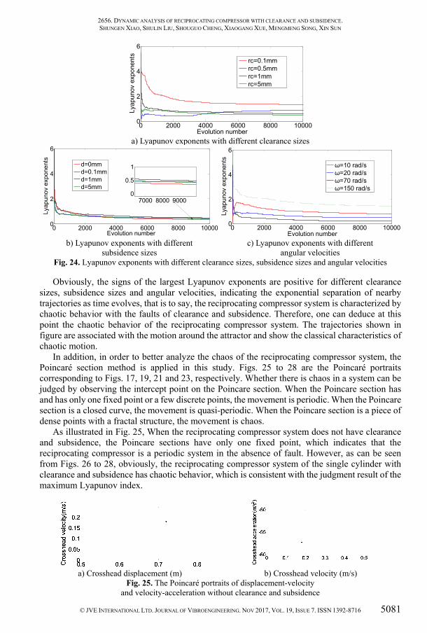
It is can be seen from Fig. 18 and Fig. 19, the change of the clearance sizes produces evident effect for the shape of phase trajectories. With the increase of the clearance sizes, the phase trajectories of velocity–acceleration are more and more like the ∞-character. Fig. 24(a) shows all calculated Lyapunov exponents by Wolf [32] method for the crosshead acceleration with 0.1 mm, 0.5 mm, 1 mm and 5 mm clearance sizes. The largest Lyapunov exponents have been calculated for clearance sizes = 0.1 mm, = 0.5 mm, = 1 mm and = 5 mm. The values of the largest Lyapunov exponents are = 1.57 to the corresponding = 0.1 mm, = 0.68 to the corresponding = 0.5 mm, = 0.62 to the corresponding = 1 mm, and = 0.59 to the corresponding = 5 mm. One can see a decrease in values of the largest Lyapunov exponents as the clearance sizes increase, but the downward trend is gradually slowed down.
Fig. 18. The phase trajectories of displacement-velocity with different clearance sizes:
a) 0.1 mm, b) 0.5 mm, c) 1 mm, d) 5 mm
Fig. 19. The phase trajectories of velocity-acceleration with different clearance sizes:
a) 0.1 mm, b) 0.5 mm, c) 1 mm, d) 5 mm
Fig. 20 and Fig. 21 show that the phase trajectories of displacement-velocity and
0.4 0.5 0.6 0.7 0.8-4
-2
0
2
4
(a) Crosshead displacement(m)
Cro
sshe
ad v
eloc
ity(m
/s)
0.4 0.5 0.6 0.7 0.8-4
-2
0
2
4
(b) Crosshead displacement(m)
Cro
sshe
ad v
eloc
ity(m
/s)
0.4 0.5 0.6 0.7 0.8-4
-2
0
2
4
(c) Crosshead displacement(m)
Cro
sshe
ad v
eloc
ity(m
/s)
0.4 0.5 0.6 0.7 0.8-4
-2
0
2
4
(d) Crosshead displacement(m)
Cro
sshe
ad v
eloc
ity(m
/s)
rc=0.5mm
rc=5mmrc=1mm
rc=0.1mm
-4 -2 0 2 4-100
0
100
200
(a) Crosshead velocity(m/s)Cro
sshe
ad a
ccel
erat
ion(
m/s2 )
-4 -2 0 2 4-500
0
500
(b) Crosshead velocity(m/s)Cro
sshe
ad a
ccel
erat
ion(
m/s2 )
-4 -2 0 2 4-500
0
500
1000
(c) Crosshead velocity(m/s)Cro
sshe
ad a
ccel
erat
ion(
m/s2 )
-4 -2 0 2 4-2000
0
2000
4000
(d) Crosshead velocity(m/s)Cro
sshe
ad a
ccel
erat
ion(
m/s2 )
rc=0.1mm
rc=5mmrc=1mm
rc=0.5mm

2656. DYNAMIC ANALYSIS OF RECIPROCATING COMPRESSOR WITH CLEARANCE AND SUBSIDENCE. SHUNGEN XIAO, SHULIN LIU, SHOUGUO CHENG, XIAOGANG XUE, MENGMENG SONG, XIN SUN
© JVE INTERNATIONAL LTD. JOURNAL OF VIBROENGINEERING. NOV 2017, VOL. 19, ISSUE 7. ISSN 1392-8716 5079
velocity-acceleration for the crosshead under the conditions of clearance size 1 mm, crankshaft angular velocity 20 rad/s and variable cylinder load with 0 mm, 0.1 mm, 1 mm and 5 mm subsidence sizes, respectively. It is noteworthy that in order to better study the dynamic behavior of the varying subsidence size to the reciprocating compressor, the subsidence size is also exaggerated to 5 mm.
As can be seen from Fig. 20 and Fig. 21, the changes of the subsidence sizes produce weak influence for the shape of phase trajectory. It is visible that the phase trajectory of the crosshead vibration does not close for each revolution. Fig. 24(b) shows all calculated Lyapunov exponents for the crosshead acceleration with 0 mm, 0.1mm, 1 mm and 5 mm subsidence sizes. The largest Lyapunov exponents have been computed for subsidence sizes = 0 mm, = 0.1 mm, = 1 mm and = 5 mm. The values of the largest Lyapunov exponents are = 0.51 to the corresponding = 0 mm, = 0.53 to the corresponding = 0.1 mm, = 0.62 to the corresponding = 1 mm, and = 0.52 to the corresponding = 5 mm.
Fig. 20. The phase trajectories of displacement-velocity with different subsidence sizes:
a) 0 mm, b) 0.1 mm, c) 1 mm, d) 5 mm
Fig. 21. The phase trajectories of velocity-acceleration with different subsidence sizes:
a) 0 mm, b) 0.1 mm, c) 1 mm, d) 5 mm
0.4 0.5 0.6 0.7 0.8-4
-2
0
2
4
(a) Crosshead displacement(m)
Cro
sshe
ad v
eloc
ity(m
/s)
0.4 0.5 0.6 0.7 0.8-4
-2
0
2
4
(b) Crosshead displacement(m)
Cro
sshe
ad v
eloc
ity(m
/s)
0.4 0.5 0.6 0.7 0.8-4
-2
0
2
4
(c) Crosshead displacement(m)
Cro
sshe
ad v
eloc
ity(m
/s)
0.4 0.5 0.6 0.7 0.8-4
-2
0
2
4
(d) Crosshead displacement(m)
Cro
sshe
ad v
eloc
ity(m
/s)
d=5mmd=1mm
d=0mm d=0.1mm
-4 -2 0 2 4-500
0
500
1000
(a) Crosshead velocity(m/s)Cro
sshe
ad a
ccel
erat
ion(
m/s2 )
-4 -2 0 2 4-500
0
500
1000
(b) Crosshead velocity(m/s)Cro
sshe
ad a
ccel
erat
ion(
m/s2 )
-4 -2 0 2 4-500
0
500
1000
(c) Crosshead velocity(m/s)Cro
sshe
ad a
ccel
erat
ion(
m/s2 )
-4 -2 0 2 4-500
0
500
1000
(d) Crosshead velocity(m/s)Cro
sshe
ad a
ccel
erat
ion(
m/s2 )
d=5mmd=1mm
d=0.1mmd=0mm

2656. DYNAMIC ANALYSIS OF RECIPROCATING COMPRESSOR WITH CLEARANCE AND SUBSIDENCE. SHUNGEN XIAO, SHULIN LIU, SHOUGUO CHENG, XIAOGANG XUE, MENGMENG SONG, XIN SUN
5080 © JVE INTERNATIONAL LTD. JOURNAL OF VIBROENGINEERING. NOV 2017, VOL. 19, ISSUE 7. ISSN 1392-8716
Fig. 22. The phase trajectories of displacement–velocity with different angular velocities:
a) 10 rad/s, b) 20 rad/s, c) 70 rad/s, d) 150 rad/s
Fig. 23. The phase trajectories of velocity-acceleration with different angular velocities:
a) 10 rad/s, b) 20 rad/s, c) 70 rad/s, d) 150 rad/s
Fig. 22 and Fig. 23 show that the phase trajectories of displacement-velocity and velocity-acceleration for the crosshead under the conditions of clearance size 5 mm, subsidence size 1 mm and variable cylinder load with 10 rad/s, 20 rad/s, 70 rad/s and 150 rad/s crankshaft angular velocities, respectively. It is can be seen from Fig. 22 and Fig. 23, the changes of the crankshaft angular velocity produce remarkable effects on the shape of phase trajectories,the higher the crankshaft angular velocity, the more regular the trajectory. In addition, with the decrease of the crankshaft angular velocities, the phase trajectories of velocity-acceleration are more and more like the ∞-character. Fig. 24(c) shows all calculated Lyapunov exponents for the crosshead acceleration with 10 rad/s, 20 rad/s, 70 rad/s and 150 rad/s crankshaft angular velocities. The largest Lyapunov exponents have been computed for crankshaft angular velocities = 10 rad/s, = 20 rad/s, = 70 rad/s and = 150 rad/s. The values of the largest Lyapunov exponents are = 0.97 to the corresponding = 10 rad/s, = 0.59 to the corresponding = 20 rad/s, = 0.23 to the corresponding = 70 rad/s, and = 1.5 to the corresponding = 150 rad/s.
0.4 0.5 0.6 0.7 0.8-2
-1
0
1
2
(a) Crosshead displacement(m)
Cro
sshe
ad v
eloc
ity(m
/s)
0.4 0.5 0.6 0.7 0.8-4
-2
0
2
4
(b) Crosshead displacement(m)
Cro
sshe
ad v
eloc
ity(m
/s)
0.4 0.5 0.6 0.7 0.8-20
-10
0
10
20
(c) Crosshead displacement(m)
Cro
sshe
ad v
eloc
ity(m
/s)
0.4 0.5 0.6 0.7 0.8-40
-20
0
20
40
(d) Crosshead displacement(m)
Cro
sshe
ad v
eloc
ity(m
/s)
ω1=20rad/s
ω1=70rad/s ω1=150rad/s
ω1=10rad/s
-2 -1 0 1 2-1000
-500
0
500
1000
(a) Crosshead velocity(m/s)Cro
sshe
ad a
ccel
erat
ion(
m/s2 )
-4 -2 0 2 4-2000
-1000
0
1000
2000
(b) Crosshead velocity(m/s)Cro
sshe
ad a
ccel
erat
ion(
m/s2 )
-20 -10 0 10 20-5000
0
5000
(c) Crosshead velocity(m/s)Cro
sshe
ad a
ccel
erat
ion(
m/s2 )
-40 -20 0 20 40-1
-0.5
0
0.5
1 x 10⁴
(d) Crosshead velocity(m/s)Cro
sshe
ad a
ccel
erat
ion(
m/s2 )
ω1=20rad/s
ω1=150rad/sω1=70rad/s
ω1=10rad/s
2656. DYNAMIC ANALYSIS OF RECIPROCATING COMPRESSOR WITH CLEARANCE AND SUBSIDENCE. SHUNGEN XIAO, SHULIN LIU, SHOUGUO CHENG, XIAOGANG XUE, MENGMENG SONG, XIN SUN
© JVE INTERNATIONAL LTD. JOURNAL OF VIBROENGINEERING. NOV 2017, VOL. 19, ISSUE 7. ISSN 1392-8716 5081
a) Lyapunov exponents with different clearance sizes
b) Lyapunov exponents with different
subsidence sizes
c) Lyapunov exponents with different
angular velocities Fig. 24. Lyapunov exponents with different clearance sizes, subsidence sizes and angular velocities
Obviously, the signs of the largest Lyapunov exponents are positive for different clearance sizes, subsidence sizes and angular velocities, indicating the exponential separation of nearby trajectories as time evolves, that is to say, the reciprocating compressor system is characterized by chaotic behavior with the faults of clearance and subsidence. Therefore, one can deduce at this point the chaotic behavior of the reciprocating compressor system. The trajectories shown in figure are associated with the motion around the attractor and show the classical characteristics of chaotic motion.
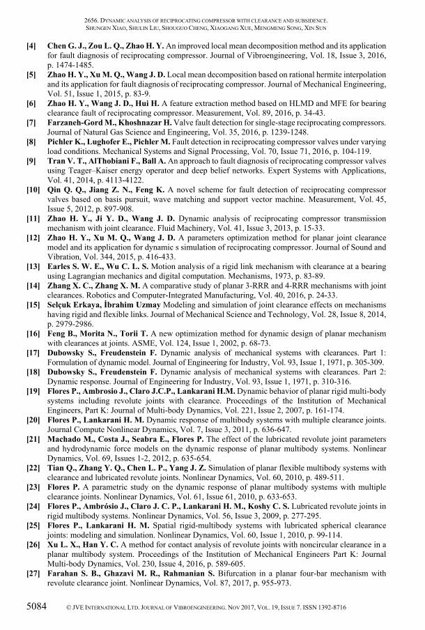
In addition, in order to better analyze the chaos of the reciprocating compressor system, the Poincaré section method is applied in this study. Figs. 25 to 28 are the Poincaré portraits corresponding to Figs. 17, 19, 21 and 23, respectively. Whether there is chaos in a system can be judged by observing the intercept point on the Poincare section. When the Poincare section has and has only one fixed point or a few discrete points, the movement is periodic. When the Poincare section is a closed curve, the movement is quasi-periodic. When the Poincare section is a piece of dense points with a fractal structure, the movement is chaos.
As illustrated in Fig. 25, When the reciprocating compressor system does not have clearance and subsidence, the Poincare sections have only one fixed point, which indicates that the reciprocating compressor is a periodic system in the absence of fault. However, as can be seen from Figs. 26 to 28, obviously, the reciprocating compressor system of the single cylinder with clearance and subsidence has chaotic behavior, which is consistent with the judgment result of the maximum Lyapunov index.
a) Crosshead displacement (m)
b) Crosshead velocity (m/s)
Fig. 25. The Poincaré portraits of displacement-velocity and velocity-acceleration without clearance and subsidence
0 2000 4000 6000 8000 100000
2
4
6
Evolution numberLy
apun
ov e
xpon
ents
rc=0.1mmrc=0.5mmrc=1mmrc=5mm
0 2000 4000 6000 8000 100000
2
4
6
Evolution number
Lyap
unov
exp
onen
ts
d=0mmd=0.1mmd=1mmd=5mm
7000 8000 90000
0.5
1
0 2000 4000 6000 8000 100000
2
4
6
Evolution numberLy
apun
ov e
xpon
ents
ω=10 rad/sω=20 rad/sω=70 rad/sω=150 rad/s

2656. DYNAMIC ANALYSIS OF RECIPROCATING COMPRESSOR WITH CLEARANCE AND SUBSIDENCE. SHUNGEN XIAO, SHULIN LIU, SHOUGUO CHENG, XIAOGANG XUE, MENGMENG SONG, XIN SUN
5082 © JVE INTERNATIONAL LTD. JOURNAL OF VIBROENGINEERING. NOV 2017, VOL. 19, ISSUE 7. ISSN 1392-8716
Fig. 26. The Poincaré portraits for (velocity, acceleration) with different clearance sizes:
a) 0.1 mm, b) 0.5 mm, c) 1 mm, d) 5 mm
Fig. 27. The Poincaré portraits for (velocity, acceleration) with different subsidence sizes:
a) 0 mm, b) 0.1 mm, c) 1 mm, d) 5 mm
Fig. 28. The Poincaré portraits for (velocity, acceleration) with different angular velocities:
a) 10 rad/s, b) 20 rad/s, c) 70 rad/s, d) 150 rad/s
0.1 0.2 0.3-100
-80
-60
-40
-20
(a) Crosshead velocity(m/s)Cro
sshe
ad a
ccel
erat
ion(
m/s2 )
0.1 0.15 0.2 0.25 0.3 0.35-150-100-50
050
100
(b) Crosshead velocity(m/s)Cro
sshe
ad a
ccel
erat
ion(
m/s2 )
0.1 0.2 0.3 0.4 0.5-200
-100
0
100
(c) Crosshead velocity(m/s)Cro
sshe
ad a
ccel
erat
ion(
m/s2 )
-0.5 0 0.5 1-500
0
500
(d) Crosshead velocity(m/s)Cro
sshe
ad a
ccel
erat
ion(
m/s2 )
rc=0.1mm rc=0.5mm
rc=1mm rc=5mm
0 0.1 0.2 0.3 0.4 0.5-200
-100
0
100
(a) Crosshead velocity(m/s)Cro
sshe
ad a
ccel
erat
ion(
m/s2 )
0 0.1 0.2 0.3 0.4 0.5-200
-100
0
100
(b) Crosshead velocity(m/s)Cro
sshe
ad a
ccel
erat
ion(
m/s2 )
0 0.1 0.2 0.3 0.4 0.5-200
-100
0
100
(c) Crosshead velocity(m/s)Cro
sshe
ad a
ccel
erat
ion(
m/s2 )
0 0.1 0.2 0.3 0.4 0.5-200
-100
0
100
(d) Crosshead velocity(m/s)Cro
sshe
ad a
ccel
erat
ion(
m/s2 )
d=0 mm d=0.1 mm
d=1 mm d=5 mm
-0.5 0 0.5-400
-200
0
200
400
(a) Crosshead velocity(m/s)Cro
sshe
ad a
ccel
erat
ion(
m/s2 )
-1 -0.5 0 0.5 1
-500
0
500
(b) Crosshead velocity(m/s)Cro
sshe
ad a
ccel
erat
ion(
m/s2 )
-3 -2 -1 0 1 2 3-5000
0
5000
(c) Crosshead velocity(m/s)Cro
sshe
ad a
ccel
erat
ion(
m/s2 )
-10 -5 0 5 10-2
0
2
4 x 10⁴
(d) Crosshead velocity(m/s)Cro
sshe
ad a
ccel
erat
ion(
m/s2 )
ω1=10rad/s ω1=20rad/s
ω1=70rad/s ω1=150rad/s

2656. DYNAMIC ANALYSIS OF RECIPROCATING COMPRESSOR WITH CLEARANCE AND SUBSIDENCE. SHUNGEN XIAO, SHULIN LIU, SHOUGUO CHENG, XIAOGANG XUE, MENGMENG SONG, XIN SUN
© JVE INTERNATIONAL LTD. JOURNAL OF VIBROENGINEERING. NOV 2017, VOL. 19, ISSUE 7. ISSN 1392-8716 5083
In this paper, Shungen Xiao is responsible for the writing of the entire paper, the realization of the core ideas and so on. Shulin Liu is the advocate of the core idea. Shouguo Cheng helps the first author to debug the programs of the dynamics equation. Xiaogan Xue assists the first author to establish a mathematical model of cylinder pressure. Mengmeng Song helps the first author to analyze the influence of the clearance size. Xin Sun helps the first author to debug the programs of the Lyapunov exponents.
5. Conclusions
In this work, the nonlinear dynamics of reciprocating compressor of single cylinder with subsidence of the crosshead and clearance between crankshaft and connecting rod are investigated. Dynamics differential equations are established based on the Lagrangian approach. Runge-Kutta method is used to solve the dynamics differential equations by MATLAB software.
Under the condition of the varying cylinder pressure in a cycle, the dynamics responses of reciprocating compressor cylinder are analyzed in the horizontal direction with the changes of clearance sizes, subsidence sizes and crankshaft angular velocities. The numerical simulation results show that the displacement, velocity and acceleration of the crosshead are slightly effected with the increase of the subsidence sizes, but the displacement, velocity and acceleration of the crosshead are significantly affected as the increase of the clearance sizes and crankshaft angular velocities. In addition, the response spectrums of the crosshead acceleration are drawn by using the fast Fourier transform. The results display that besides the rotation frequency of crankshaft, some other frequency components are more and more obvious and even submerge the rotation frequency components in the spectrum with the increase of the clearance sizes. The change in crankshaft angular velocities is just the opposite of the change in the clearance. That is to say, as the crankshaft angular velocities increase, some other frequency components are becoming weaker than the rotation frequency components.
Using Lyapunov exponents and Poincaré section, the stability of the reciprocating compressor system with clearance and subsidence is investigated. The signs of the largest Lyapunov exponents calculated by Wolf method are positive, and the Poincare section is a piece of dense points with a fractal structure for this nonlinear system with clearance and subsidence, indicating the existence of strange attractors and chaos phenomena. In addition, the mechanism exhibits different chaotic motion trajectories with the changes of clearance, subsidence and crankshaft angular velocity, in which the shapes of the phase trajectories significantly change with the variation of clearance and the crankshaft angular velocity, and inconspicuously vary as the change of subsidence.
Acknowledgements
This work is supported by the Natural Science Foundation of China (Grant No. 51575331 and Grant No. 51175316), Fujian Natural Science Foundation (Grant No. 2015J01643), and Talents Cultivation Program for Outstanding Young Scientists in Fujian Universities (Grant No. MIN Education (2015) 54). These supports are gratefully acknowledged.
References
[1] Elhaj M., Gub F., Ballb A. D. Numerical simulation and experimental study of a two-stage reciprocating compressor for condition monitoring. Mechanical Systems and Signal Processing, Vol. 22, 2008, p. 374-389.
[2] Almasi A. A new study and model for the mechanism of process reciprocating compressors and pumps. Proceedings of the Institution of Mechanical Engineers, Part E: Journal of Process Mechanical Engineering, Vol. 224, 2010, p. 143-148.
[3] Dupac M., Beale D. G. Dynamic analysis of a flexible linkage mechanism with cracks and clearance. Mechanism and Machine Theory, Vol. 45, 2010, p. 1909-1923.
2656. DYNAMIC ANALYSIS OF RECIPROCATING COMPRESSOR WITH CLEARANCE AND SUBSIDENCE. SHUNGEN XIAO, SHULIN LIU, SHOUGUO CHENG, XIAOGANG XUE, MENGMENG SONG, XIN SUN
5084 © JVE INTERNATIONAL LTD. JOURNAL OF VIBROENGINEERING. NOV 2017, VOL. 19, ISSUE 7. ISSN 1392-8716
[4] Chen G. J., Zou L. Q., Zhao H. Y. An improved local mean decomposition method and its application for fault diagnosis of reciprocating compressor. Journal of Vibroengineering, Vol. 18, Issue 3, 2016, p. 1474-1485.
[5] Zhao H. Y., Xu M. Q., Wang J. D. Local mean decomposition based on rational hermite interpolation and its application for fault diagnosis of reciprocating compressor. Journal of Mechanical Engineering, Vol. 51, Issue 1, 2015, p. 83-9.
[6] Zhao H. Y., Wang J. D., Hui H. A feature extraction method based on HLMD and MFE for bearing clearance fault of reciprocating compressor. Measurement, Vol. 89, 2016, p. 34-43.
[7] Farzaneh-Gord M., Khoshnazar H. Valve fault detection for single-stage reciprocating compressors. Journal of Natural Gas Science and Engineering, Vol. 35, 2016, p. 1239-1248.
[8] Pichler K., Lughofer E., Pichler M. Fault detection in reciprocating compressor valves under varying load conditions. Mechanical Systems and Signal Processing, Vol. 70, Issue 71, 2016, p. 104-119.
[9] Tran V. T., AlThobiani F., Ball A. An approach to fault diagnosis of reciprocating compressor valves using Teager–Kaiser energy operator and deep belief networks. Expert Systems with Applications, Vol. 41, 2014, p. 4113-4122.
[10] Qin Q. Q., Jiang Z. N., Feng K. A novel scheme for fault detection of reciprocating compressor valves based on basis pursuit, wave matching and support vector machine. Measurement, Vol. 45, Issue 5, 2012, p. 897-908.
[11] Zhao H. Y., Ji Y. D., Wang J. D. Dynamic analysis of reciprocating compressor transmission mechanism with joint clearance. Fluid Machinery, Vol. 41, Issue 3, 2013, p. 15-33.
[12] Zhao H. Y., Xu M. Q., Wang J. D. A parameters optimization method for planar joint clearance model and its application for dynamic s simulation of reciprocating compressor. Journal of Sound and Vibration, Vol. 344, 2015, p. 416-433.
[13] Earles S. W. E., Wu C. L. S. Motion analysis of a rigid link mechanism with clearance at a bearing using Lagrangian mechanics and digital computation. Mechanisms, 1973, p. 83-89.
[14] Zhang X. C., Zhang X. M. A comparative study of planar 3-RRR and 4-RRR mechanisms with joint clearances. Robotics and Computer-Integrated Manufacturing, Vol. 40, 2016, p. 24-33.
[15] Selçuk Erkaya, İbrahim Uzmay Modeling and simulation of joint clearance effects on mechanisms having rigid and flexible links. Journal of Mechanical Science and Technology, Vol. 28, Issue 8, 2014, p. 2979-2986.
[16] Feng B., Morita N., Torii T. A new optimization method for dynamic design of planar mechanism with clearances at joints. ASME, Vol. 124, Issue 1, 2002, p. 68-73.
[17] Dubowsky S., Freudenstein F. Dynamic analysis of mechanical systems with clearances. Part 1: Formulation of dynamic model. Journal of Engineering for Industry, Vol. 93, Issue 1, 1971, p. 305-309.
[18] Dubowsky S., Freudenstein F. Dynamic analysis of mechanical systems with clearances. Part 2: Dynamic response. Journal of Engineering for Industry, Vol. 93, Issue 1, 1971, p. 310-316.
[19] Flores P., Ambrosio J., Claro J.C.P., Lankarani H.M. Dynamic behavior of planar rigid multi-body systems including revolute joints with clearance. Proceedings of the Institution of Mechanical Engineers, Part K: Journal of Multi-body Dynamics, Vol. 221, Issue 2, 2007, p. 161-174.
[20] Flores P., Lankarani H. M. Dynamic response of multibody systems with multiple clearance joints. Journal Compute Nonlinear Dynamics, Vol. 7, Issue 3, 2011, p. 636-647.
[21] Machado M., Costa J., Seabra E., Flores P. The effect of the lubricated revolute joint parameters and hydrodynamic force models on the dynamic response of planar multibody systems. Nonlinear Dynamics, Vol. 69, Issues 1-2, 2012, p. 635-654.
[22] Tian Q., Zhang Y. Q., Chen L. P., Yang J. Z. Simulation of planar flexible multibody systems with clearance and lubricated revolute joints. Nonlinear Dynamics, Vol. 60, 2010, p. 489-511.
[23] Flores P. A parametric study on the dynamic response of planar multibody systems with multiple clearance joints. Nonlinear Dynamics, Vol. 61, Issue 61, 2010, p. 633-653.
[24] Flores P., Ambrósio J., Claro J. C. P., Lankarani H. M., Koshy C. S. Lubricated revolute joints in rigid multibody systems. Nonlinear Dynamics, Vol. 56, Issue 3, 2009, p. 277-295.
[25] Flores P., Lankarani H. M. Spatial rigid-multibody systems with lubricated spherical clearance joints: modeling and simulation. Nonlinear Dynamics, Vol. 60, Issue 1, 2010, p. 99-114.
[26] Xu L. X., Han Y. C. A method for contact analysis of revolute joints with noncircular clearance in a planar multibody system. Proceedings of the Institution of Mechanical Engineers Part K: Journal Multi-body Dynamics, Vol. 230, Issue 4, 2016, p. 589-605.
[27] Farahan S. B., Ghazavi M. R., Rahmanian S. Bifurcation in a planar four-bar mechanism with revolute clearance joint. Nonlinear Dynamics, Vol. 87, 2017, p. 955-973.

2656. DYNAMIC ANALYSIS OF RECIPROCATING COMPRESSOR WITH CLEARANCE AND SUBSIDENCE. SHUNGEN XIAO, SHULIN LIU, SHOUGUO CHENG, XIAOGANG XUE, MENGMENG SONG, XIN SUN
© JVE INTERNATIONAL LTD. JOURNAL OF VIBROENGINEERING. NOV 2017, VOL. 19, ISSUE 7. ISSN 1392-8716 5085
[28] Wang Z., Tian Q., Hu H. Nonlinear dynamics and chaotic control of a flexible multibody system w ith uncertain joint clearance. Nonlinear Dynamics, Vol. 86, Issue 3, 2016, p. 1571-1597.
[29] Nayfeh A. H., Balachandran B. Applied Nonlinear Dynamics. John Wiley and Sons, Inc., New York, 1995.
[30] Dupac M., Beale D. G. Dynamic analysis of a flexible linkage mechanism with cracks and clearance. Mechanism and Machine Theory, Vol. 45, Issue 12, 2010, p. 1909-1923.
[31] Dupac M., Marghitu D. B. Nonlinear dynamics of a flexible mechanism with impact. Journal of Sound and Vibration, Vol. 289, Issues 4-5, 2006, p. 952-966.
[32] Wolf A., Swift J. B., Swinney H. L., Vastano J. A. Determining Lyapunov exponents from a time series Physica D, Vol. 16, 1985, p. 285-317.
Shungen Xiao is currently a Ph.D. candidate at School of Mechatronic Engineering and Automation, Shanghai University, Shanghai, China. In addition, he is an Associate Professor at Ningde Normal University in Fujiang, China. His current research interests include nonlinear dynamics and fault diagnosis.
Shulin Liu is a Professor and Director of the institute for the Precision Mechanical Engineering at Shanghai University in Shanghai, China. He received the Ph.D. degree from Harbin Institute of Technology, Heilongjiang, China, in 2003. His current research interests include nonlinear dynamics, fault diagnosis of mechanical equipment and impact dynamics of reciprocating compressor crosshead. He has charged of about 30 important scientific research projects, and published 5 monographs and about 80 papers in journals and conferences.
Shouguo Cheng is currently a Ph.D. candidate at School of Mechatronic Engineering and Automation, Shanghai University, Shanghai, China. His current research interests include nonlinear dynamics and signal processing.
Xiaogang Xue is currently a Master candidate at School of Mechatronic Engineering and Automation, Shanghai University, Shanghai, China. His current research interests include mechanical system dynamics and simulation.
Mengmeng Song received Master in School of Mechanical Engineering from Jiangxi University of Science and Technology, Jiangxi, China, in 2012. Now she works at Ningde Normal University. Her current research interests include CAD/CAE and fault diagnosis. In this paper, she helps the first author to analyze the influence of the clearance size.
Xin Sun is currently a Ph.D. candidate at School of Mechatronic Engineering and Automation, Shanghai University, Shanghai, China. Her current research interests include multibody dynamics and impact dynamics of reciprocating compressor with clearance joints. In this paper, she helps the first author to debug the programs of the Lyapunov exponents.