Design and Experiment of a Reciprocating Intermittent ... - MDPI
23
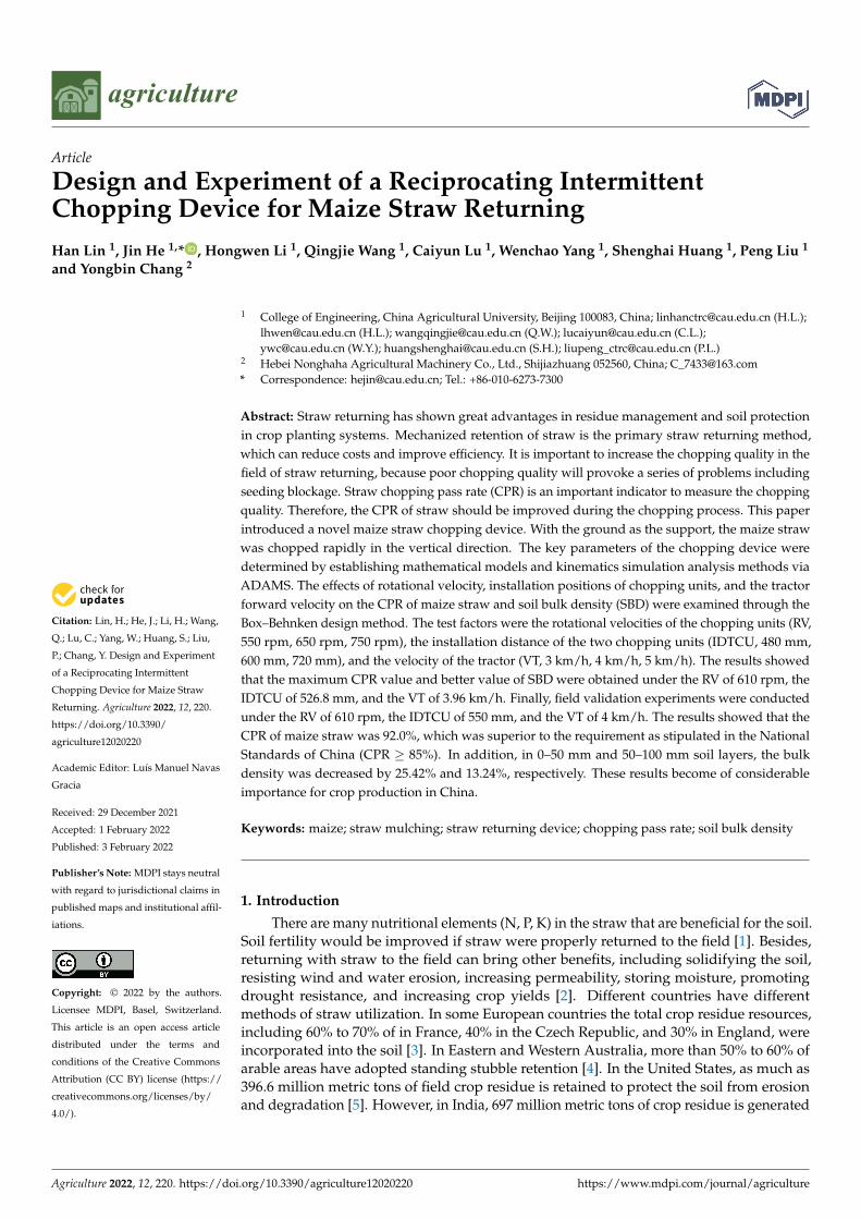
Citation: Lin, H.; He, J.; Li, H.; Wang, Q.; Lu, C.; Yang, W.; Huang, S.; Liu, P.; Chang, Y. Design and Experiment of a Reciprocating Intermittent Chopping Device for Maize Straw Returning. Agriculture 2022, 12, 220. https://doi.org/10.3390/ agriculture12020220 Academic Editor: Luís Manuel Navas Gracia Received: 29 December 2021 Accepted: 1 February 2022 Published: 3 February 2022 Publisher’s Note: MDPI stays neutral with regard to jurisdictional claims in published maps and institutional affil- iations. Copyright: © 2022 by the authors. Licensee MDPI, Basel, Switzerland. This article is an open access article distributed under the terms and conditions of the Creative Commons Attribution (CC BY) license (https:// creativecommons.org/licenses/by/ 4.0/). agriculture Article Design and Experiment of a Reciprocating Intermittent Chopping Device for Maize Straw Returning Han Lin 1 , Jin He 1, * , Hongwen Li 1 , Qingjie Wang 1 , Caiyun Lu 1 , Wenchao Yang 1 , Shenghai Huang 1 , Peng Liu 1 and Yongbin Chang 2 1 College of Engineering, China Agricultural University, Beijing 100083, China; [email protected] (H.L.); [email protected] (H.L.); [email protected] (Q.W.); [email protected] (C.L.); [email protected] (W.Y.); [email protected] (S.H.); [email protected] (P.L.) 2 Hebei Nonghaha Agricultural Machinery Co., Ltd., Shijiazhuang 052560, China; [email protected] * Correspondence: [email protected]; Tel.: +86-010-6273-7300 Abstract: Straw returning has shown great advantages in residue management and soil protection in crop planting systems. Mechanized retention of straw is the primary straw returning method, which can reduce costs and improve efficiency. It is important to increase the chopping quality in the field of straw returning, because poor chopping quality will provoke a series of problems including seeding blockage. Straw chopping pass rate (CPR) is an important indicator to measure the chopping quality. Therefore, the CPR of straw should be improved during the chopping process. This paper introduced a novel maize straw chopping device. With the ground as the support, the maize straw was chopped rapidly in the vertical direction. The key parameters of the chopping device were determined by establishing mathematical models and kinematics simulation analysis methods via ADAMS. The effects of rotational velocity, installation positions of chopping units, and the tractor forward velocity on the CPR of maize straw and soil bulk density (SBD) were examined through the Box–Behnken design method. The test factors were the rotational velocities of the chopping units (RV, 550 rpm, 650 rpm, 750 rpm), the installation distance of the two chopping units (IDTCU, 480 mm, 600 mm, 720 mm), and the velocity of the tractor (VT, 3 km/h, 4 km/h, 5 km/h). The results showed that the maximum CPR value and better value of SBD were obtained under the RV of 610 rpm, the IDTCU of 526.8 mm, and the VT of 3.96 km/h. Finally, field validation experiments were conducted under the RV of 610 rpm, the IDTCU of 550 mm, and the VT of 4 km/h. The results showed that the CPR of maize straw was 92.0%, which was superior to the requirement as stipulated in the National Standards of China (CPR ≥ 85%). In addition, in 0–50 mm and 50–100 mm soil layers, the bulk density was decreased by 25.42% and 13.24%, respectively. These results become of considerable importance for crop production in China. Keywords: maize; straw mulching; straw returning device; chopping pass rate; soil bulk density 1. Introduction There are many nutritional elements (N, P, K) in the straw that are beneficial for the soil. Soil fertility would be improved if straw were properly returned to the field [1]. Besides, returning with straw to the field can bring other benefits, including solidifying the soil, resisting wind and water erosion, increasing permeability, storing moisture, promoting drought resistance, and increasing crop yields [2]. Different countries have different methods of straw utilization. In some European countries the total crop residue resources, including 60% to 70% of in France, 40% in the Czech Republic, and 30% in England, were incorporated into the soil [3]. In Eastern and Western Australia, more than 50% to 60% of arable areas have adopted standing stubble retention [4]. In the United States, as much as 396.6 million metric tons of field crop residue is retained to protect the soil from erosion and degradation [5]. However, in India, 697 million metric tons of crop residue is generated Agriculture 2022, 12, 220. https://doi.org/10.3390/agriculture12020220 https://www.mdpi.com/journal/agriculture
-
Upload
khangminh22 -
Category
Documents
-
view
2 -
download
0
Transcript of Design and Experiment of a Reciprocating Intermittent ... - MDPI
�����������������
Citation: Lin, H.; He, J.; Li, H.; Wang,
Q.; Lu, C.; Yang, W.; Huang, S.; Liu,
P.; Chang, Y. Design and Experiment
of a Reciprocating Intermittent
Chopping Device for Maize Straw
Returning. Agriculture 2022, 12, 220.
https://doi.org/10.3390/
agriculture12020220
Academic Editor: Luís Manuel Navas
Gracia
Received: 29 December 2021
Accepted: 1 February 2022
Published: 3 February 2022
Publisher’s Note: MDPI stays neutral
with regard to jurisdictional claims in
published maps and institutional affil-
iations.
Copyright: © 2022 by the authors.
Licensee MDPI, Basel, Switzerland.
This article is an open access article
distributed under the terms and
conditions of the Creative Commons
Attribution (CC BY) license (https://
creativecommons.org/licenses/by/
4.0/).
agriculture
Article
Design and Experiment of a Reciprocating IntermittentChopping Device for Maize Straw ReturningHan Lin 1, Jin He 1,* , Hongwen Li 1, Qingjie Wang 1, Caiyun Lu 1, Wenchao Yang 1, Shenghai Huang 1, Peng Liu 1
and Yongbin Chang 2
1 College of Engineering, China Agricultural University, Beijing 100083, China; [email protected] (H.L.);[email protected] (H.L.); [email protected] (Q.W.); [email protected] (C.L.);[email protected] (W.Y.); [email protected] (S.H.); [email protected] (P.L.)
2 Hebei Nonghaha Agricultural Machinery Co., Ltd., Shijiazhuang 052560, China; [email protected]* Correspondence: [email protected]; Tel.: +86-010-6273-7300
Abstract: Straw returning has shown great advantages in residue management and soil protectionin crop planting systems. Mechanized retention of straw is the primary straw returning method,which can reduce costs and improve efficiency. It is important to increase the chopping quality in thefield of straw returning, because poor chopping quality will provoke a series of problems includingseeding blockage. Straw chopping pass rate (CPR) is an important indicator to measure the choppingquality. Therefore, the CPR of straw should be improved during the chopping process. This paperintroduced a novel maize straw chopping device. With the ground as the support, the maize strawwas chopped rapidly in the vertical direction. The key parameters of the chopping device weredetermined by establishing mathematical models and kinematics simulation analysis methods viaADAMS. The effects of rotational velocity, installation positions of chopping units, and the tractorforward velocity on the CPR of maize straw and soil bulk density (SBD) were examined through theBox–Behnken design method. The test factors were the rotational velocities of the chopping units (RV,550 rpm, 650 rpm, 750 rpm), the installation distance of the two chopping units (IDTCU, 480 mm,600 mm, 720 mm), and the velocity of the tractor (VT, 3 km/h, 4 km/h, 5 km/h). The results showedthat the maximum CPR value and better value of SBD were obtained under the RV of 610 rpm, theIDTCU of 526.8 mm, and the VT of 3.96 km/h. Finally, field validation experiments were conductedunder the RV of 610 rpm, the IDTCU of 550 mm, and the VT of 4 km/h. The results showed that theCPR of maize straw was 92.0%, which was superior to the requirement as stipulated in the NationalStandards of China (CPR ≥ 85%). In addition, in 0–50 mm and 50–100 mm soil layers, the bulkdensity was decreased by 25.42% and 13.24%, respectively. These results become of considerableimportance for crop production in China.
Keywords: maize; straw mulching; straw returning device; chopping pass rate; soil bulk density
1. Introduction
There are many nutritional elements (N, P, K) in the straw that are beneficial for the soil.Soil fertility would be improved if straw were properly returned to the field [1]. Besides,returning with straw to the field can bring other benefits, including solidifying the soil,resisting wind and water erosion, increasing permeability, storing moisture, promotingdrought resistance, and increasing crop yields [2]. Different countries have differentmethods of straw utilization. In some European countries the total crop residue resources,including 60% to 70% of in France, 40% in the Czech Republic, and 30% in England, wereincorporated into the soil [3]. In Eastern and Western Australia, more than 50% to 60% ofarable areas have adopted standing stubble retention [4]. In the United States, as much as396.6 million metric tons of field crop residue is retained to protect the soil from erosionand degradation [5]. However, in India, 697 million metric tons of crop residue is generated
Agriculture 2022, 12, 220. https://doi.org/10.3390/agriculture12020220 https://www.mdpi.com/journal/agriculture

Agriculture 2022, 12, 220 2 of 23
from 26 crops, where 60% to 70% of farmers prefer to burn the residue and less than 1% offarmers incorporate all rice straw [6]. In China, most of the straw is returned to the field.Straw burning and discarding has led to numerous problems including air pollution, wasteof resources, destroyed soil, and environmental damage. In recent years, the governmentsof the world have realized these issues. To solve the problem of openly straw burning andstraw discarding, the governments have developed a series of associated regulations.
Mechanized retention of straw is the common straw utilization method in the world [7].However, the quality of mechanized straw return operations needs to be further promoted.Specifically, the poor chopping quality and the high fuel consumption are the problemsof straw returning machinery. Good chopping quality is the key to enhancing seedinguniformity, promoting seed germination, and benefiting plant growth [8–10]. To improvethe chopping quality of straw and reduce the energy consumption of the machine, manystudies designed and optimized the structure of the machine.
The chopping pass rate (CPR), a significant indicator to measure the chopping quality,refers to the mass ratio between qualified straw and total straw after chopping operation.According to the requirement as stipulated in the National Standards of China, the lengthof the qualified straw is less than 100 mm [11]. In terms of improving the CPR of straw,many scholars focus on optimizing the blade and changing the chopping form. In terms ofoptimizing the blade, a V-L-type chopping blade was designed by Jia et al. [12], and thestraw CPR was increased to 93.43% when the rotational velocity of the V-L-type choppingblade was 1400 rpm. Zhang et al. optimized a Y-type chopping blade and installed fans inthe machines to improve the straw CPR [13]. A pick-up chopping machine with hammerblades for the harvester was designed by Abilzhanov et al. [14]. The CPR of straw wasobviously improved. An L-type chopping blade was improved by Liu et al. [15], andthe field test results demonstrated that the maize straw chopping pass rate was 92.58%.Liu et al. [16] designed a disc blade to promote the maize straw chopping quality. Accordingto Zastempowski’s and Bochat’s study [17], the CPR could be increased when the cuttingangle changed from 0◦ to 45◦. In terms of changing chopping form, a chopping methodbased on the principle of a four-bar linkage mechanism was put forward by Wang et al. [18],and the CPR of straw was increased to 94%. The double rollers type straw chopping methodwas proposed by Liu et al. [19], which can improve the CPR of straw. Zheng et al. [20]designed a straw crushing machine, which combined a cutting fixed knife with cuttingmovable knife (double spiral arranged). The CPR of straw increased to 91.5%. Sun et al.designed a straw chopper based on the principle of differential sawing, which couldincrease the CPR of straw to 93.23%. A straw chopping device with two stages of agitation,sliding cutting and tearing, was designed by Wang et al. [21], and the CPR of strawincreased to 95.49%.
The studies mentioned above aimed to improve chopping quality by optimizingchopping blades and changing chopping form. Through simulation and field experiments,they found the key parameters that affect work efficiency. However, the CPR of maizestraw could be further increased. Moreover, there are few studies on improving seedingconditions after straw chopping. In this paper, we proposed a novel chopping method,based on the chopping principle of reciprocating intermittent motion, and designed thechopping device to enhance the CPR of maize straw and improve seeding conditions. Thesoil bulk density (SBD) was selected as a test index to evaluate the quality of seedingconditions [22]. The research result will provide a theoretical reference and a novel methodfor the design and optimization of maize straw retention machines.
2. Design of the Chopping Device2.1. Overall Structure and Working Principle
The chopping device predominantly included a suspension unit, a transmission unit,four chopping units based on reciprocating intermittent motion principle, and a supportingframe. The arrangement of the four chopping units is shown in Figure 1. To ensure thesmooth operation of the device and improve the chopping efficiency, the phase difference
Agriculture 2022, 12, 220 3 of 23
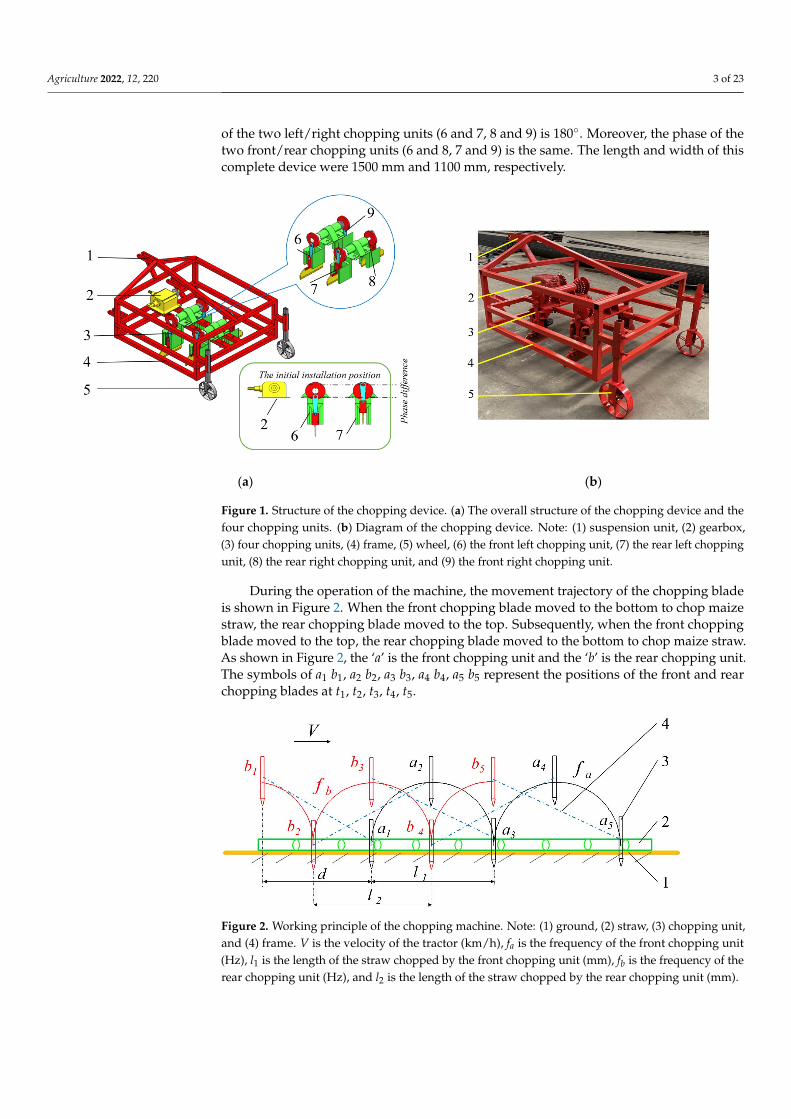
of the two left/right chopping units (6 and 7, 8 and 9) is 180◦. Moreover, the phase of thetwo front/rear chopping units (6 and 8, 7 and 9) is the same. The length and width of thiscomplete device were 1500 mm and 1100 mm, respectively.
Agriculture 2021, 11, x 3 of 24
The chopping device predominantly included a suspension unit, a transmission unit, four chopping units based on reciprocating intermittent motion principle, and a support-ing frame. The arrangement of the four chopping units is shown in Figure 1. To ensure the smooth operation of the device and improve the chopping efficiency, the phase differ-ence of the two left/right chopping units (6 and 7, 8 and 9) is 180°. Moreover, the phase of the two front/rear chopping units (6 and 8, 7 and 9) is the same. The length and width of this complete device were 1500 mm and 1100 mm, respectively.
Figure 1. Structure of the chopping device. (a) The overall structure of the chopping device and the four chopping units. (b) Diagram of the chopping device. Note: (1) suspension unit, (2) gearbox, (3) four chopping units, (4) frame, (5) wheel, (6) the front left chopping unit, (7) the rear left chopping unit, (8) the rear right chopping unit, and (9) the front right chopping unit.
During the operation of the machine, the movement trajectory of the chopping blade is shown in Figure 2. When the front chopping blade moved to the bottom to chop maize straw, the rear chopping blade moved to the top. Subsequently, when the front chopping blade moved to the top, the rear chopping blade moved to the bottom to chop maize straw. As shown in Figure 2, the ‘a’ is the front chopping unit and the ‘b’ is the rear chopping unit. The symbols of a1 b1, a2 b2, a3 b3, a4 b4, a5 b5 represent the positions of the front and rear chopping blades at t1, t2, t3, t4, t5.
Figure 2. Working principle of the chopping machine. Note: (1) ground, (2) straw, (3) chopping unit, and (4) frame. V is the velocity of the tractor (km/h), fa is the frequency of the front chopping unit
(a) (b)
Figure 1. Structure of the chopping device. (a) The overall structure of the chopping device and thefour chopping units. (b) Diagram of the chopping device. Note: (1) suspension unit, (2) gearbox,(3) four chopping units, (4) frame, (5) wheel, (6) the front left chopping unit, (7) the rear left choppingunit, (8) the rear right chopping unit, and (9) the front right chopping unit.
During the operation of the machine, the movement trajectory of the chopping bladeis shown in Figure 2. When the front chopping blade moved to the bottom to chop maizestraw, the rear chopping blade moved to the top. Subsequently, when the front choppingblade moved to the top, the rear chopping blade moved to the bottom to chop maize straw.As shown in Figure 2, the ‘a’ is the front chopping unit and the ‘b’ is the rear chopping unit.The symbols of a1 b1, a2 b2, a3 b3, a4 b4, a5 b5 represent the positions of the front and rearchopping blades at t1, t2, t3, t4, t5.
Agriculture 2021, 11, x 3 of 24
The chopping device predominantly included a suspension unit, a transmission unit, four chopping units based on reciprocating intermittent motion principle, and a support-ing frame. The arrangement of the four chopping units is shown in Figure 1. To ensure the smooth operation of the device and improve the chopping efficiency, the phase differ-ence of the two left/right chopping units (6 and 7, 8 and 9) is 180°. Moreover, the phase of the two front/rear chopping units (6 and 8, 7 and 9) is the same. The length and width of this complete device were 1500 mm and 1100 mm, respectively.
Figure 1. Structure of the chopping device. (a) The overall structure of the chopping device and the four chopping units. (b) Diagram of the chopping device. Note: (1) suspension unit, (2) gearbox, (3) four chopping units, (4) frame, (5) wheel, (6) the front left chopping unit, (7) the rear left chopping unit, (8) the rear right chopping unit, and (9) the front right chopping unit.
During the operation of the machine, the movement trajectory of the chopping blade is shown in Figure 2. When the front chopping blade moved to the bottom to chop maize straw, the rear chopping blade moved to the top. Subsequently, when the front chopping blade moved to the top, the rear chopping blade moved to the bottom to chop maize straw. As shown in Figure 2, the ‘a’ is the front chopping unit and the ‘b’ is the rear chopping unit. The symbols of a1 b1, a2 b2, a3 b3, a4 b4, a5 b5 represent the positions of the front and rear chopping blades at t1, t2, t3, t4, t5.
Figure 2. Working principle of the chopping machine. Note: (1) ground, (2) straw, (3) chopping unit, and (4) frame. V is the velocity of the tractor (km/h), fa is the frequency of the front chopping unit
(a) (b)
Figure 2. Working principle of the chopping machine. Note: (1) ground, (2) straw, (3) chopping unit,and (4) frame. V is the velocity of the tractor (km/h), fa is the frequency of the front chopping unit(Hz), l1 is the length of the straw chopped by the front chopping unit (mm), fb is the frequency of therear chopping unit (Hz), and l2 is the length of the straw chopped by the rear chopping unit (mm).

Agriculture 2022, 12, 220 4 of 23
2.2. Key Parameters of the Reciprocating Intermittent Mechanism2.2.1. Structure of Reciprocating Intermittent Mechanism
The per chopping unit includes five parts, which are the supporting sleeve, eccentricdisc (crank), link, slider, and chopping blade (Figure 3a). During the chopping process, theeccentric disc is rotating by the drive of the shaft. The crank is rocking with the force bythe eccentric disc, and it makes the slider reciprocate in a specific track. Simultaneously,the blade, installed at the bottom of the slider, could chop the straw on the surface of thefield in a vertical direction. In addition, two pulleys (bearings) were installed in the slider(Figure 3b) that ensure the slider can move smoothly in the orbit of the supporting sleeve(Figure 3c).
Agriculture 2021, 11, x 4 of 24
(Hz), l1 is the length of the straw chopped by the front chopping unit (mm), fb is the frequency of the rear chopping unit (Hz), and l2 is the length of the straw chopped by the rear chopping unit (mm).
2.2. Key Parameters of the Reciprocating Intermittent Mechanism 2.2.1. Structure of Reciprocating Intermittent Mechanism
The per chopping unit includes five parts, which are the supporting sleeve, eccentric disc (crank), link, slider, and chopping blade (Figure 3a). During the chopping process, the eccentric disc is rotating by the drive of the shaft. The crank is rocking with the force by the eccentric disc, and it makes the slider reciprocate in a specific track. Simultaneously, the blade, installed at the bottom of the slider, could chop the straw on the surface of the field in a vertical direction. In addition, two pulleys (bearings) were installed in the slider (Figure 3b) that ensure the slider can move smoothly in the orbit of the supporting sleeve (Figure 3c).
(a) (b) (c)
Figure 3. Structure of the reciprocating intermittent mechanism. (a) The overall reciprocating inter-mittent mechanism, (b) the structure of the slider, and (c) the structure of the supporting sleeve. Note: (1) eccentric disc (crank), (2) link, (3) slider, (4) chopping blade, (5) supporting sleeve, (6) pul-ley (bearing), and (7) orbit.
2.2.2. Determination of the Rotation Radius of the Eccentric Disc The rotation radius of the eccentric disc determined the maximum stroke of the chop-
ping blade. However, the maximum stroke of the chopping blade was calculated by the depth of the chopping blade into the soil and the maximum height of the chopping blade from the ground. Field measurement shows that about 85% of the straw was coved on the surface of the ground, and 25% of the straw was mixed with the soil. The deepest distance of mixed straw is no more than 60 mm, and the thickness of the cover straw on the ground surface is no more than 90 mm. Therefore, the value of the depth of chopping blade into the soil and the maximum height of chopping blade from the ground are 60 m and 90 mm, respectively. Therefore, the value of the rotation radius of the eccentric disc (a) is 75 mm. In addition, to obtain a better chopping effect, when the chopping blade starts to touch the soil, the value of the angle between a and b should be 90° (Figure 4). Therefore, the relationships between H, h 1, h 2, a, and b are shown as the following equation:
1 2
2 21
2H aH=h h
h a b a b
=+
= + − +
(1)
Figure 3. Structure of the reciprocating intermittent mechanism. (a) The overall reciprocatingintermittent mechanism, (b) the structure of the slider, and (c) the structure of the supporting sleeve.Note: (1) eccentric disc (crank), (2) link, (3) slider, (4) chopping blade, (5) supporting sleeve, (6) pulley(bearing), and (7) orbit.
2.2.2. Determination of the Rotation Radius of the Eccentric Disc
The rotation radius of the eccentric disc determined the maximum stroke of thechopping blade. However, the maximum stroke of the chopping blade was calculated bythe depth of the chopping blade into the soil and the maximum height of the choppingblade from the ground. Field measurement shows that about 85% of the straw was covedon the surface of the ground, and 25% of the straw was mixed with the soil. The deepestdistance of mixed straw is no more than 60 mm, and the thickness of the cover straw onthe ground surface is no more than 90 mm. Therefore, the value of the depth of choppingblade into the soil and the maximum height of chopping blade from the ground are 60 mand 90 mm, respectively. Therefore, the value of the rotation radius of the eccentric disc (a)is 75 mm. In addition, to obtain a better chopping effect, when the chopping blade starts totouch the soil, the value of the angle between a and b should be 90◦ (Figure 4). Therefore,the relationships between H, h1, h2, a, and b are shown as the following equation:
H = 2aH = h1 + h2
h1 = a + b−√
a2 + b2(1)
where H is the maximum stroke of chopping knife (mm), h1 is the maximum height ofchopping knife from the ground (mm), h2 is the depth of chopping knife into the soil (mm),a is the rotation radius of the eccentric disc (mm), and b is the length of the link (mm).

Agriculture 2022, 12, 220 5 of 23
Agriculture 2021, 11, x 5 of 24
where H is the maximum stroke of chopping knife (mm), h1 is the maximum height of chopping knife from the ground (mm), h2 is the depth of chopping knife into the soil (mm), a is the rotation radius of the eccentric disc (mm), and b is the length of the link (mm).
Figure 4. The position of the chopping blade. Note: (1) ground, (2) chopping blade, (3) slider, (4) link, and (5) eccentric disc (crank). ω is the angular velocity of the eccentric disc (rad/s).
2.2.3. Determination of the Minimum Transmission Angle (γmin) and the Link Rocking Angle (ψ)
The value of the minimum transmission angle (γmin) is the significant factor to deter-mine the performance of the reciprocating intermittent mechanisms. When the minimum transmission angle is larger, the transmission performance of the mechanism is better, and the mechanical efficiency is higher. According to the design criteria of reciprocating inter-mittent mechanism [23], the minimum transmission angle (γmin) appeared when the ec-centric disc was parallel to the ground in this model (Figure 5). The link rocking angle (ψ) affects the movement performance of reciprocating intermittent mechanisms in the verti-cal direction [24]. The smaller value of ψ, the better performance of the reciprocating in-termittent mechanism in the vertical direction.
Figure 5. The movement diagram of the reciprocating intermittent mechanism. ω is the angular velocity of the eccentric disc (rad/s). A1B1, A2B2, A3B3, A4B4, are the four different positions of crank and link.
According to the Cosine Theorem, the relationships between γmin, a, b, and ψ are de-termined as shown in the following formula:
Figure 4. The position of the chopping blade. Note: (1) ground, (2) chopping blade, (3) slider, (4) link,and (5) eccentric disc (crank). ω is the angular velocity of the eccentric disc (rad/s).
2.2.3. Determination of the Minimum Transmission Angle (γmin) and the Link RockingAngle (ψ)
The value of the minimum transmission angle (γmin) is the significant factor to deter-mine the performance of the reciprocating intermittent mechanisms. When the minimumtransmission angle is larger, the transmission performance of the mechanism is better,and the mechanical efficiency is higher. According to the design criteria of reciprocatingintermittent mechanism [23], the minimum transmission angle (γmin) appeared when theeccentric disc was parallel to the ground in this model (Figure 5). The link rocking angle(ψ) affects the movement performance of reciprocating intermittent mechanisms in thevertical direction [24]. The smaller value of ψ, the better performance of the reciprocatingintermittent mechanism in the vertical direction.
Agriculture 2021, 11, x 5 of 24
where H is the maximum stroke of chopping knife (mm), h1 is the maximum height of chopping knife from the ground (mm), h2 is the depth of chopping knife into the soil (mm), a is the rotation radius of the eccentric disc (mm), and b is the length of the link (mm).
Figure 4. The position of the chopping blade. Note: (1) ground, (2) chopping blade, (3) slider, (4) link, and (5) eccentric disc (crank). ω is the angular velocity of the eccentric disc (rad/s).
2.2.3. Determination of the Minimum Transmission Angle (γmin) and the Link Rocking Angle (ψ)
The value of the minimum transmission angle (γmin) is the significant factor to deter-mine the performance of the reciprocating intermittent mechanisms. When the minimum transmission angle is larger, the transmission performance of the mechanism is better, and the mechanical efficiency is higher. According to the design criteria of reciprocating inter-mittent mechanism [23], the minimum transmission angle (γmin) appeared when the ec-centric disc was parallel to the ground in this model (Figure 5). The link rocking angle (ψ) affects the movement performance of reciprocating intermittent mechanisms in the verti-cal direction [24]. The smaller value of ψ, the better performance of the reciprocating in-termittent mechanism in the vertical direction.
Figure 5. The movement diagram of the reciprocating intermittent mechanism. ω is the angular velocity of the eccentric disc (rad/s). A1B1, A2B2, A3B3, A4B4, are the four different positions of crank and link.
According to the Cosine Theorem, the relationships between γmin, a, b, and ψ are de-termined as shown in the following formula:
Figure 5. The movement diagram of the reciprocating intermittent mechanism. ω is the angularvelocity of the eccentric disc (rad/s). A1B1, A2B2, A3B3, A4B4, are the four different positions of crankand link.

Agriculture 2022, 12, 220 6 of 23
According to the Cosine Theorem, the relationships between γmin, a, b, and ψ aredetermined as shown in the following formula:
cos γmin = ab
ψ2 + γmin = 90◦
(2)
where γmin is the minimum transmission angle (◦), a is the rotation radius of the eccentricdisc (mm), b is the length of the link (mm), and ψ is the link rocking angle (◦).
When the value range of ψ is 20◦~35◦ and the value of γmin is larger than 50◦, thereciprocating intermittent mechanism can obtain a good performance [25]. Therefore, thevalue range of γmin is 72.5◦~80◦, which was calculated as Equation (2).
2.2.4. Determination of the Travel Velocity Ratio Coefficient and Size of the Mechanism(K, L, w, p)
According to the design criteria of reciprocating intermittent mechanism [26], thevalue of travel velocity ratio coefficient K affected the mechanical operating performance.When the value of K is 1, the mechanism would operate smoothly and avoid mechanicalvibration. Therefore, the value of K in the reciprocating intermittent mechanism is 1. Thedistance between O and B3 (L) (Figure 6) determined the height of the chopping device.The width of the track (w) and the length of the slider (p) determined the overall size of thereciprocating intermittent mechanism. They were calculated as the following equation:
a2 +(
L + H2
)2= b2(
H+p2
)tan ψ
2 ≤w2
(3)
where γmin is the minimum transmission angle (◦), a is the rotation radius of the eccentricdisc (mm), b is the length of the link (mm), L is the distance between O and B3 (mm), H isthe maximum stroke of chopping blade (mm), p is the length of the slider (mm), ψ is thelink rocking angle (◦), and w is the width of the track (mm).
Agriculture 2021, 11, x 6 of 24
cos
902
min
min
ab
γ
ψ γ
=
+ =
(2)
where γmin is the minimum transmission angle (°), a is the rotation radius of the eccentric disc (mm), b is the length of the link (mm), and ψ is the link rocking angle (°).
When the value range of ψ is 20°~35° and the value of γmin is larger than 50°, the reciprocating intermittent mechanism can obtain a good performance [25]. Therefore, the value range of γmin is 72.5°~80°, which was calculated as Equation (2).
2.2.4. Determination of the Travel Velocity Ratio Coefficient and Size of the Mechanism (K, L, w, p)
According to the design criteria of reciprocating intermittent mechanism [26], the value of travel velocity ratio coefficient K affected the mechanical operating performance. When the value of K is 1, the mechanism would operate smoothly and avoid mechanical vibration. Therefore, the value of K in the reciprocating intermittent mechanism is 1. The distance between O and B3 (L) (Figure 6) determined the height of the chopping device. The width of the track (w) and the length of the slider (p) determined the overall size of the reciprocating intermittent mechanism. They were calculated as the following equa-tion:
22 2
2
tan2 2 2
Ha L b
H p wψ
+ + =
+ ≤
(3)
where γmin is the minimum transmission angle (°), a is the rotation radius of the eccentric disc (mm), b is the length of the link (mm), L is the distance between O and B3 (mm), H is the maximum stroke of chopping blade (mm), p is the length of the slider (mm), ψ is the link rocking angle (°), and w is the width of the track (mm).
Figure 6. The schematic diagram of the key parameters. ω is the angular velocity of the eccentric disc (rad/s). A1B1, A2B2, A3B3, A4B4, are the four different positions of crank and link.
Figure 6. The schematic diagram of the key parameters. ω is the angular velocity of the eccentric disc(rad/s). A1B1, A2B2, A3B3, A4B4, are the four different positions of crank and link.
Agriculture 2022, 12, 220 7 of 23
The values of L, w, and p could be calculated through the values of a, b, and ψ. Inaddition, the value of w should be 15–20 mm larger than the calculated to ensure the stableoperation of the slider. The value of p is generally 50 mm.
2.2.5. Determination of the Best Combination of Key Parameters
Some specific values of γmin were selected, and the value of γmin, b, L, w, and h1 wasshown in Table 1 when the minimum transmission angle (γmin) takes different values.
Table 1. The value of γmin, b, L, w, and h1 when the minimum transmission angle (γmin) takesdifferent values.
Minimum TransmissionAngle γmin/(◦) b/mm L/mm w/mm h1/mm
73 256.52 170.31 37.36 64.2675 289.78 204.91 32.91 65.4577 333.41 249.86 28.48 66.6779 393.06 310.84 24.07 67.91
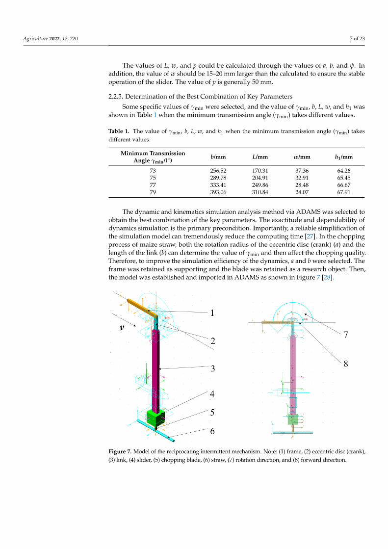
The dynamic and kinematics simulation analysis method via ADAMS was selected toobtain the best combination of the key parameters. The exactitude and dependability ofdynamics simulation is the primary precondition. Importantly, a reliable simplification ofthe simulation model can tremendously reduce the computing time [27]. In the choppingprocess of maize straw, both the rotation radius of the eccentric disc (crank) (a) and thelength of the link (b) can determine the value of γmin and then affect the chopping quality.Therefore, to improve the simulation efficiency of the dynamics, a and b were selected. Theframe was retained as supporting and the blade was retained as a research object. Then,the model was established and imported in ADAMS as shown in Figure 7 [28].
Agriculture 2021, 11, x 7 of 24
The values of L, w, and p could be calculated through the values of a, b, and ψ. In addition, the value of w should be 15–20 mm larger than the calculated to ensure the stable operation of the slider. The value of p is generally 50 mm.
2.2.5. Determination of the Best Combination of Key Parameters Some specific values of γmin were selected, and the value of γmin, b, L, w, and h1 was
shown in Table 1 when the minimum transmission angle (γmin) takes different values.
Table 1. The value of γmin, b, L, w, and h1 when the minimum transmission angle (γmin) takes different values.
Minimum Transmission Angle γmin/(°) b/mm L/mm w/mm h1/mm 73 256.52 170.31 37.36 64.26 75 289.78 204.91 32.91 65.45 77 333.41 249.86 28.48 66.67 79 393.06 310.84 24.07 67.91
The dynamic and kinematics simulation analysis method via ADAMS was selected to obtain the best combination of the key parameters. The exactitude and dependability of dynamics simulation is the primary precondition. Importantly, a reliable simplification of the simulation model can tremendously reduce the computing time [27]. In the chop-ping process of maize straw, both the rotation radius of the eccentric disc (crank) (a) and the length of the link (b) can determine the value of γmin and then affect the chopping qual-ity. Therefore, to improve the simulation efficiency of the dynamics, a and b were selected. The frame was retained as supporting and the blade was retained as a research object. Then, the model was established and imported in ADAMS as shown in Figure 7 [28].
Figure 7. Model of the reciprocating intermittent mechanism. Note: (1) frame, (2) eccentric disc (crank), (3) link, (4) slider, (5) chopping blade, (6) straw, (7) rotation direction, and (8) forward di-rection.
Selecting different values of γmin as shown in Table 1 to obtain the results via ADAMS. The chopping blade’s velocity and acceleration were calculated as Equations (4)–(7) (Fig-ure 8).The results of them are shown in Figures 9 and 10.
Figure 7. Model of the reciprocating intermittent mechanism. Note: (1) frame, (2) eccentric disc (crank),(3) link, (4) slider, (5) chopping blade, (6) straw, (7) rotation direction, and (8) forward direction.

Agriculture 2022, 12, 220 8 of 23
Selecting different values of γmin as shown in Table 1 to obtain the results via ADAMS.The chopping blade’s velocity and acceleration were calculated as Equations (4)–(7) (Figure 8).The results of them are shown in Figures 9 and 10.
−→a +−→b = −→c
|s|=|a|+|b|−|c|(4)
a cos α + b cos β = c
a sin α + b sin β = 0(5)
s = a(1− cos α) + b(1− cos β) (6)
vB = aω1sin(α−β)
b cos β
aB = aω12(
cos(α−β)cos β + a cos2 α
b cos3 β
) (7)
where a is the length of the crank (mm), b is the length of the link (mm), c is the distancebetween O and B (mm), s is the displacement of the slider (mm), α is the angular displace-ment of the eccentric disc (◦), β is the angular displacement of the link (◦), vB is the velocityof the slider (m/s), aB is the acceleration of the slider (m/s2), and ω is the angular velocityof the eccentric disc (rad/s).
Agriculture 2021, 11, x 8 of 24
(a) (b)
Figure 8. Schematic diagram of the reciprocating intermittent mechanism. (a) A random position of the reciprocating intermittent mechanism, and (b) the highest/lowest position of the reciprocating intermittent mechanism. Note: (1) eccentric disc (crank), (2) link, and (3) slider. xoy is coordinate system. vr is the velocity of the slider on random position. ar is the acceleration of the slider on ran-dom position. amax is the maximum value of the acceleration of the slider.
Figure 9. Effect of the value of γmin on velocity.
Figure 8. Schematic diagram of the reciprocating intermittent mechanism. (a) A random position ofthe reciprocating intermittent mechanism, and (b) the highest/lowest position of the reciprocatingintermittent mechanism. Note: (1) eccentric disc (crank), (2) link, and (3) slider. xoy is coordinatesystem. vr is the velocity of the slider on random position. ar is the acceleration of the slider onrandom position. amax is the maximum value of the acceleration of the slider.
Agriculture 2022, 12, 220 9 of 23
Agriculture 2021, 11, x 8 of 24
(a) (b)
Figure 8. Schematic diagram of the reciprocating intermittent mechanism. (a) A random position of the reciprocating intermittent mechanism, and (b) the highest/lowest position of the reciprocating intermittent mechanism. Note: (1) eccentric disc (crank), (2) link, and (3) slider. xoy is coordinatesystem. vr is the velocity of the slider on random position. ar is the acceleration of the slider on ran-dom position. amax is the maximum value of the acceleration of the slider.
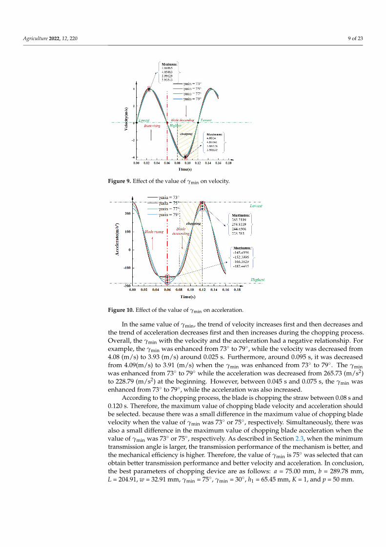
Figure 9. Effect of the value of γmin on velocity. Figure 9. Effect of the value of γmin on velocity.
Agriculture 2021, 11, x 9 of 24
Figure 10. Effect of the value of γmin on acceleration.
a b cs a b - c
+ = = +
(4)
cos cossin sin 0
a b ca b
α βα β
+ = + =
(4)
( ) ( )cos coss a bα β= +1- 1- (5)
( )
( )
1
22
1 3
sincos
cos coscos cos
B
B
v ab
aa ab
α βω
βα β αω
β β
−=
− = +
(6)
where a is the length of the crank (mm), b is the length of the link (mm), c is the distance between O and B (mm), s is the displacement of the slider (mm), α is the angular displace-ment of the eccentric disc (°), β is the angular displacement of the link (°), vB is the velocity of the slider (m/s), aB is the acceleration of the slider (m/s2), and ω is the angular velocity of the eccentric disc (rad/s).
In the same value of γmin, the trend of velocity increases first and then decreases and the trend of acceleration decreases first and then increases during the chopping process. Overall, the γmin with the velocity and the acceleration had a negative relationship. For example, the γmin was enhanced from 73° to 79°, while the velocity was decreased from 4.08 (m/s) to 3.93 (m/s) around 0.025 s. Furthermore, around 0.095 s, it was decreased from
Figure 10. Effect of the value of γmin on acceleration.
In the same value of γmin, the trend of velocity increases first and then decreases andthe trend of acceleration decreases first and then increases during the chopping process.Overall, the γmin with the velocity and the acceleration had a negative relationship. Forexample, the γmin was enhanced from 73◦ to 79◦, while the velocity was decreased from4.08 (m/s) to 3.93 (m/s) around 0.025 s. Furthermore, around 0.095 s, it was decreasedfrom 4.09(m/s) to 3.91 (m/s) when the γmin was enhanced from 73◦ to 79◦. The γminwas enhanced from 73◦ to 79◦ while the acceleration was decreased from 265.73 (m/s2)to 228.79 (m/s2) at the beginning. However, between 0.045 s and 0.075 s, the γmin wasenhanced from 73◦ to 79◦, while the acceleration was also increased.
According to the chopping process, the blade is chopping the straw between 0.08 s and0.120 s. Therefore, the maximum value of chopping blade velocity and acceleration shouldbe selected. because there was a small difference in the maximum value of chopping bladevelocity when the value of γmin was 73◦ or 75◦, respectively. Simultaneously, there wasalso a small difference in the maximum value of chopping blade acceleration when thevalue of γmin was 73◦ or 75◦, respectively. As described in Section 2.3, when the minimumtransmission angle is larger, the transmission performance of the mechanism is better, andthe mechanical efficiency is higher. Therefore, the value of γmin is 75◦ was selected that canobtain better transmission performance and better velocity and acceleration. In conclusion,the best parameters of chopping device are as follows: a = 75.00 mm, b = 289.78 mm,L = 204.91, w = 32.91 mm, γmin = 75◦, γmin = 30◦, h1 = 65.45 mm, K = 1, and p = 50 mm.

Agriculture 2022, 12, 220 10 of 23
2.3. The Rotational Velocity of the Eccentric Disc and the Velocity of the Tractor
The velocity of the eccentric disc determined the chopping force. During the choppingprocess, the ground was supporting the maize straw when it was chopped by blades.Because the machine was moving forward during chopping, the direction of the force wasgiven to the straw by the chopping blade was not perpendicular to the ground [29]. Therewas an angle (θ) between the chopping force (F) and the vertical direction. To ensure thechopping effect, the straw needs to keep still during the chopping process. The frictionbetween the ground and straw should be larger than the horizontal component of F. Thestraw could be regarded as a static state when the chopping blade was about to chop thestraw. The stress diagram of maize straw in the chopping process is shown in Figure 11.The relationship between F, θ, v′, v, and mg is shown in Equation (8).
F1 + mg− Fn = 0
f1 − F2 = 0
f1 = µ(mg + F1)
F1 = F cos θ
F2 = F sin θ
tan θ = v′v
(8)
where F is the chopping force from blade (N), m is mass of maize straw (kg), g is thegravitational acceleration (m/s2), µ is friction coefficient between ground and straw, θ isthe angle between F and the vertical direction (◦), v′ is the velocity of tractor (m/s), v is thevelocity of blade (m/s), and f 1 is the friction between ground and straw (N).
Agriculture 2021, 11, x 10 of 24
4.09(m/s) to 3.91 (m/s) when the γmin was enhanced from 73° to 79°. The γmin was enhanced from 73° to 79° while the acceleration was decreased from 265.73 (m/s2) to 228.79 (m/s2) at the beginning. However, between 0.045 s and 0.075 s, the γmin was enhanced from 73° to 79°, while the acceleration was also increased.
According to the chopping process, the blade is chopping the straw between 0.08 s and 0.120 s. Therefore, the maximum value of chopping blade velocity and acceleration should be selected. because there was a small difference in the maximum value of chop-ping blade velocity when the value of γmin was 73° or 75°, respectively. Simultaneously, there was also a small difference in the maximum value of chopping blade acceleration when the value of γmin was 73° or 75°, respectively. As described in Section 2.3, when the minimum transmission angle is larger, the transmission performance of the mechanism is better, and the mechanical efficiency is higher. Therefore, the value of γmin is 75° was se-lected that can obtain better transmission performance and better velocity and accelera-tion. In conclusion, the best parameters of chopping device are as follows: a = 75.00 mm, b = 289.78 mm, L = 204.91, w = 32.91 mm, γmin = 75°, γmin = 30°, h1 = 65.45 mm, K = 1, and p = 50 mm.
2.3. The Rotational Velocity of the Eccentric Disc and the Velocity of the Tractor The velocity of the eccentric disc determined the chopping force. During the chop-
ping process, the ground was supporting the maize straw when it was chopped by blades. Because the machine was moving forward during chopping, the direction of the force was given to the straw by the chopping blade was not perpendicular to the ground [29]. There was an angle (θ) between the chopping force (F) and the vertical direction. To ensure the chopping effect, the straw needs to keep still during the chopping process. The friction between the ground and straw should be larger than the horizontal component of F. The straw could be regarded as a static state when the chopping blade was about to chop the straw. The stress diagram of maize straw in the chopping process is shown in Figure 11. The relationship between F, θ, v’, v, and mg is shown in Equation (8).
Figure 11. Stress diagram of maize straw in the chopping process. Note: (1) ground, (2) straw, (3) chopping blade, and (4) movement trajectory of the chopping blade.
Figure 11. Stress diagram of maize straw in the chopping process. Note: (1) ground, (2) straw, (3)chopping blade, and (4) movement trajectory of the chopping blade.
The force of the chopping blade to the maize straw affects the chopping quality directly.As Equation (8) shows, F1, the direct force from chopping blade to straw, is related to F. Thevalue of F is related to the materials, edge angle, velocity, and acceleration of the choppingblade [30]. When the materials and shape of the blade are determined, the value of Fdepends on the velocity and acceleration of the chopping blade. When the rotation velocityof the machine is increased, the value of F will be increased, and the value of tan θ will bedecreased and the value of cos θ will be increased when the tractor’s velocity is determined.Besides, the value of sin θ will be decreased, causing the horizontal component of F to

Agriculture 2022, 12, 220 11 of 23
decrease. Therefore, the rotation velocity of the machine is larger, the chopping qualityis better.
According to the research of Gao et al., the force to chop maize straw was between919 N and 2233 N when the maize straw moisture content was 74% [31]. As the moisturecontent decreases, the chopping force also decreases. In addition, many researchers studiedthe physics of various straws’ (maize, longan, mulberry, and sugarcane) chopping, andthey found that the better chopping performance would be obtained when the value ofthe blade angle is between 10◦ and 20◦ [32–35]. The value of the blade angle is 25◦ dueto the working environment in the field. According to the theorem of momentum, therelationships between F and v are shown as Equation (9).
F∆t = mv (9)
where F is the chopping force from blade (N), m is mass of chopping blade (kg), ∆t ischopping time (s), and v is the velocity of chopping blade (m/s).
Generally, the value of ∆t is 0.01 s. The value of F is 1571 N according to the studyof Wang et al. [18]. The value of m is about 5 kg when the material of the chopping bladeis 65 Mn alloy steel. Therefore, the value of the velocity of the chopping blade should belarger than 3.142 m/s. According to the results of calculation by ADAMS, the rotationalvelocity of the eccentric disc should be larger than 550 rpm.
The rotational velocity of the eccentric disc and the velocity of the tractor determinedthe length of the straw chopped by the device. As shown in Figure 2, the relationshipsbetween n, l, and v were shown as the following equation:
1000vt3600 = 0.01l1n1t
1000vt3600 = 0.01l2n2t
(10)
where v is the velocity of the tractor (km/h), t is the operation time (s), n1 is the rotationalvelocity of the front chopping unit eccentric disc (rpm), l1 is the length of the straw choppedby the front chopping unit (mm), n2 is the rotational velocity of the rear chopping uniteccentric disc (rpm), and l2 is the length of the straw chopped by the rear choppingunit (mm).
To ensure the stability of the device operation and obtain higher chopping efficiency,the rotational velocity of the front/rear chopping units is the same. According to the ChinaNational Standards GB/T 24675.6-2009 [11], the length of maize straw after chopping is nomore than 100 mm. Generally, the velocity of the tractor is 3 km/h~5 km/h during most ofthe straw returning operation process [36]. Therefore, the rotational velocity of the eccentricdisc is 500 rpm~833 rpm as calculated. Simultaneously, the value of the transmission ratio(i) is between 0.93 and 0.6 (when the velocity of the tractor’s power take-off is 540 rpm [37]).It was calculated by the following equation:
i =n× 0.01× 3600l × t
60v× 1000t(11)
where v is the velocity of the tractor (km/h), t is the operation time (s), and l is the length ofthe straw chopped by the front chopping unit (mm).
3. Materials and Methods3.1. Site Description
The experiments were conducted in an experimental conservation tillage field of ChinaInstitute for Conservation Tillage in China Agricultural University in Shenze District, Hebeiprovince, China (38◦10′ N, 115◦15′ E) in March 2021 (Figure 12b). Maize was harvested man-ually in the previous year. Some maize straw remains upright in the field (Figure 12a). Theaverage annual temperature there is 12.4 ◦C with 188 frost-free days. Double cropping ofwinter wheat and summer maize is the main cropping system practiced in this region. Sum-
Agriculture 2022, 12, 220 12 of 23
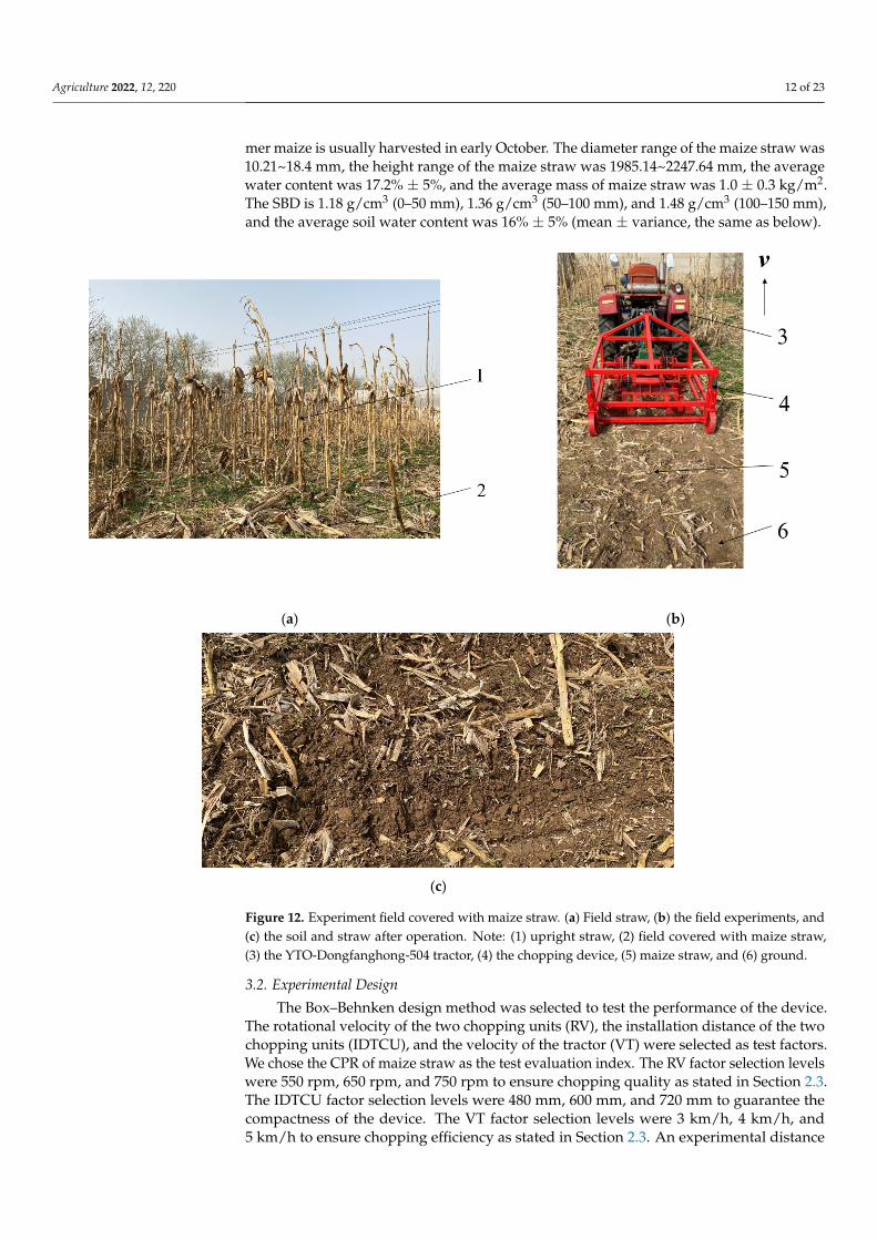
mer maize is usually harvested in early October. The diameter range of the maize straw was10.21~18.4 mm, the height range of the maize straw was 1985.14~2247.64 mm, the averagewater content was 17.2% ± 5%, and the average mass of maize straw was 1.0 ± 0.3 kg/m2.The SBD is 1.18 g/cm3 (0–50 mm), 1.36 g/cm3 (50–100 mm), and 1.48 g/cm3 (100–150 mm),and the average soil water content was 16% ± 5% (mean ± variance, the same as below).
Agriculture 2021, 11, x 12 of 24
unit eccentric disc (rpm), and l2 is the length of the straw chopped by the rear chopping unit (mm).
To ensure the stability of the device operation and obtain higher chopping efficiency, the rotational velocity of the front/rear chopping units is the same. According to the China National Standards GB/T 24675.6-2009 [11], the length of maize straw after chopping is no more than 100 mm. Generally, the velocity of the tractor is 3 km/h~5 km/h during most of the straw returning operation process [36]. Therefore, the rotational velocity of the eccen-tric disc is 500 rpm~833 rpm as calculated. Simultaneously, the value of the transmission ratio (i) is between 0.93 and 0.6 (when the velocity of the tractor’s power take-off is 540 rpm [37]). It was calculated by the following equation:
0 01 360060 1000
n . l tiv t
× × ×=×
(10)
where v is the velocity of the tractor (km/h), t is the operation time (s), and l is the length of the straw chopped by the front chopping unit (mm).
3. Materials and Methods 3.1. Site Description
The experiments were conducted in an experimental conservation tillage field of China Institute for Conservation Tillage in China Agricultural University in Shenze Dis-trict, Hebei province, China (38°10′ N, 115°15′ E) in March 2021 (Figure 12b). Maize was harvested manually in the previous year. Some maize straw remains upright in the field (Figure 12a). The average annual temperature there is 12.4 °C with 188 frost-free days. Double cropping of winter wheat and summer maize is the main cropping system prac-ticed in this region. Summer maize is usually harvested in early October. The diameter range of the maize straw was 10.21~18.4 mm, the height range of the maize straw was 1985.14~2247.64 mm, the average water content was 17.2% ± 5%, and the average mass of maize straw was 1.0 ± 0.3 kg/m2. The SBD is 1.18 g/cm3 (0–50 mm), 1.36 g/cm3 (50–100 mm), and 1.48 g/cm3 (100–150 mm), and the average soil water content was 16% ± 5% (mean ± variance, the same as below).
(a) (b)
Agriculture 2021, 11, x 13 of 24
(c)
Figure 12. Experiment field covered with maize straw. (a) Field straw, (b) the field experiments, and (c) the soil and straw after operation. Note: (1) upright straw, (2) field covered with maize straw, (3) the YTO-Dongfanghong-504 tractor, (4) the chopping device, (5) maize straw, and (6) ground.
3.2. Experimental Design The Box–Behnken design method was selected to test the performance of the device.
The rotational velocity of the two chopping units (RV), the installation distance of the two chopping units (IDTCU), and the velocity of the tractor (VT) were selected as test factors. We chose the CPR of maize straw as the test evaluation index. The RV factor selection levels were 550 rpm, 650 rpm, and 750 rpm to ensure chopping quality as stated in Section 2.3. The IDTCU factor selection levels were 480 mm, 600 mm, and 720 mm to guarantee the compactness of the device. The VT factor selection levels were 3 km/h, 4 km/h, and 5 km/h to ensure chopping efficiency as stated in Section 2.3. An experimental distance of 20 m was selected to measure the pass rate when the operating status of the chopping device was stable. The experiment factors and levels are shown in Table 2.
Table 2. The experiment factors and levels.
Code Number A: RV (rpm) B: IDTCU (mm) C: VT (km/h) −1 550 480 3 0 650 600 4 1 750 720 5
3.3. Data Collection and Analysis The CPR of maize straw was measured by the China National Standard “GB/T
24,675.6-2009 Conservation tillage equipment-smashed stalk machine.” The chopping ma-chine was equipped with the YTO-Dongfanghong-504 tractor. The main test equipment includes the Weiheng electronic scale with a hook (precision: 5 g), Vernier calipers, and a test frame with a 1 m2 square. Three test plots (1 m × 1 m) were selected randomly for measuring per test distance. The total straw in the test plots was collected and unqualified straw (length greater than 100 mm) was removed [38]. Then, we weighed the rest of the straw. The CPR was calculated as the following equation:
11
100
nu
i
mm
%n
= ∂
−
∂ = ×
(11)
where ∂ is the CPR of maize straw (%), mu is the weight of unqualified straw (kg), m∂ is the weight of qualified straw (kg), and n is the number of test plots.
Figure 12. Experiment field covered with maize straw. (a) Field straw, (b) the field experiments, and(c) the soil and straw after operation. Note: (1) upright straw, (2) field covered with maize straw,(3) the YTO-Dongfanghong-504 tractor, (4) the chopping device, (5) maize straw, and (6) ground.
3.2. Experimental Design
The Box–Behnken design method was selected to test the performance of the device.The rotational velocity of the two chopping units (RV), the installation distance of the twochopping units (IDTCU), and the velocity of the tractor (VT) were selected as test factors.We chose the CPR of maize straw as the test evaluation index. The RV factor selection levelswere 550 rpm, 650 rpm, and 750 rpm to ensure chopping quality as stated in Section 2.3.The IDTCU factor selection levels were 480 mm, 600 mm, and 720 mm to guarantee thecompactness of the device. The VT factor selection levels were 3 km/h, 4 km/h, and5 km/h to ensure chopping efficiency as stated in Section 2.3. An experimental distance

Agriculture 2022, 12, 220 13 of 23
of 20 m was selected to measure the pass rate when the operating status of the choppingdevice was stable. The experiment factors and levels are shown in Table 2.
Table 2. The experiment factors and levels.
Code Number A: RV (rpm) B: IDTCU (mm) C: VT (km/h)
−1 550 480 30 650 600 41 750 720 5
3.3. Data Collection and Analysis
The CPR of maize straw was measured by the China National Standard “GB/T 24675.6-2009 Conservation tillage equipment-smashed stalk machine.” The chopping machine wasequipped with the YTO-Dongfanghong-504 tractor. The main test equipment includes theWeiheng electronic scale with a hook (precision: 5 g), Vernier calipers, and a test framewith a 1 m2 square. Three test plots (1 m × 1 m) were selected randomly for measuring pertest distance. The total straw in the test plots was collected and unqualified straw (lengthgreater than 100 mm) was removed [38]. Then, we weighed the rest of the straw. The CPRwas calculated as the following equation:
∂ =
n∑
i=1
(1− mu
m∂
)n
× 100% (12)
where ∂ is the CPR of maize straw (%), mu is the weight of unqualified straw (kg), m∂ is theweight of qualified straw (kg), and n is the number of test plots.
SBD was used as a significant indicator of changes in soil structure and water retentioncapacity [39]. The quality of seeding will be improved when the value of SBD is small.In each plot, three random soil samples were taken using a 50.64 mm diameter steel coresampling tube, manually driven into a 150 mm depth. The soil cores were split into threesections: 0–5 mm, 5–10 mm, and 10–15 mm from the soil surface. These moisture sampleswere then weighed wet, dried at 105 ◦C for 8 h, and weighed again to determine bulkdensity [40]. The SBD was calculated as the following equation:
ρs =
k∑
i=1
maVs
k× 100% (13)
where ρs is SBD (g/cm3), ma is the weight of the dried soil (g), Vs is the volume of steel coresampling tube (cm3), and k is the number of test plots.
The Design-Expert 8.0.6 analytical software was used for the statistical analyses ofCPR and SBD. Mean values were calculated for each set of measurements, and ANOVAwas used to assess treatment effects on the measured variables. Means were declaredsignificantly different using a protected LSD (0.05) value.
4. Results and Discussion4.1. Experiment Results
The test results are shown in Table 3 according to the Box–Behnken design method.There were 17 experimental groups, including 12 groups for the factor analysis experimentsand 5 groups for the zero-level error estimation experiments. The approximate trend ofCPR can be obtained from the data in Table 3.

Agriculture 2022, 12, 220 14 of 23
Table 3. Experiment design and results.
NumberTest Factors
CPR (%) Y1A B C
1 650 720 5 84.62 550 720 4 79.43 750 600 5 90.94 650 600 4 92.65 750 600 3 91.96 650 720 3 92.17 750 480 4 93.58 650 600 4 91.79 650 600 4 92.910 650 720 5 89.211 750 600 4 90.112 650 600 4 93.113 550 480 3 81.414 650 600 4 92.915 550 720 5 78.116 550 600 4 83.717 650 480 3 92.7
The approximate trend of SBD can be obtained from the data in Table 4; factor A: RV,factor B: IDTCU, factor C: VT.
Table 4. Experiment design and results.
NumberTest Factors SBD (g/cm3)
A B C 0–50 mm Y2 50–100 mm Y3 100–150 mm Y4
1 650 720 5 1 1.29 1.462 550 720 4 1.11 1.4 1.463 750 600 5 0.94 1.3 1.494 650 600 4 0.93 1.19 1.465 750 600 3 0.86 1.19 1.476 650 720 3 1 1.26 1.527 750 480 4 0.89 1.23 1.448 650 600 4 0.9 1.22 1.449 650 600 4 0.91 1.2 1.45
10 650 720 5 0.99 1.33 1.4111 750 600 4 0.9 1.22 1.4512 650 600 4 0.95 1.23 1.4713 550 480 3 0.98 1.29 1.4714 650 600 4 0.94 1.24 1.4215 550 720 5 1.14 1.41 1.4316 550 600 4 1.05 1.33 1.417 650 480 3 0.91 1.24 1.44
factor A: RV, factor B: IDTCU, factor C: VT.
4.2. Variance Analysis
The quadratic polynomial regression model showing the effect of A (RV), B (IDTCU),and C (VT) on CPR was established based on the data in Table 3. The regression model isshown in Equation (14). The variance analysis of regression equation is shown in Table 4.
Y1 = 92.48 + 4.70A− 1.71B− 0.84C + 0.75AB + 1.35AC− 0.82BC− 5.35A2 − 1.18B2 − 2.43C2 (14)
According to the analysis results in Table 4, the significance levels of the regressionmodel for CPR were all less than 0.05, implying that the significance of the regressionanalysis model was excellent. The significance level of the lack of fit for the model was

Agriculture 2022, 12, 220 15 of 23
greater than 0.05, indicating that the model had good fitting degrees in the range of theexperimental parameters. In addition, the coefficient of determination R2 of the equationswas 0.9828, demonstrating that more than 98% of the response values could be explainedby the regression models. Therefore, the parameters of the chopping device could bepreliminarily predicted by using the regression model of CPR.
For the main effect, the rotational velocities of the two chopping units (factor A: RV)had highly significant effects on CPR, while the installation distance of the two choppingunits (factor B: IDTCU) and the velocity of the tractor (factor C: VT) had a significanteffect on CPR. For the interaction effects, the interactive factor AC had a significant effecton CPR. The interactive factor AB, BC had no significant effect on CPR (Figure 13a,b).For the quadratic factor effect, the quadratic factor A2 had a highly significant effect onCPR. The quadratic factors B2 and C2 had a significant effect on CPR. Consequently, theregression models were optimized so that the insignificant items were removed, whileensuring p < 0.01 for the model and p > 0.05 for the lack of fit, as shown in Equation (15).
Y1 = 92.48 + 4.70A− 1.71B− 0.84C + 1.35AC− 5.35A2 − 1.18B2 − 2.43C2 (15)
Agriculture 2021, 11, x 17 of 24
Total 387.30 16 / / / Note: ** was very significant (p < 0.01), * was significant (0.01 < p < 0.05), the others were insignificant.
As shown in Tables 3 and 4, when the values of factor B (IDTCU) and factor C (VT) are 600 mm (0) and 4 km/h (0), respectively, the CPR increased when the factor A (RV) increased from 550 (−1) rpm to 680 (0.3) rpm. The maximum value of the CPR could be obtained when factor A (RV) was around 680 rpm (0.3). The CPR decreased while factor A (RV) increased when the value of factor A (RV) was larger than 680 rpm (0.30). How-ever, the decrease rate was slow. When the values of factor A (RV) and factor C (VT) are 650 rpm (0) and 4 km/h (0), respectively, the CPR increased when factor B (IDTCU) in-creased from 480 mm (−1) to 600 (0) mm. The maximum value of CPR could be obtained when factor B (IDTCU) was around 540 mm (−0.5). The CPR decreased while factor A (RV) increased from 540 rpm (−0.5) to 720 (1) mm. When the values of factor A (RV) and factor B (IDTCU) are 650 rpm (0) and 600 mm (0), respectively, the CPR increased when factor C (VT) increased from 3 (−1) km/h to 4 km/h (0). The maximum value of the CPR could be obtained when factor C (VT) was around 4 km/h (0). The CPR decreased while factor C (VT) increased from 4 km/h (0) to 5 km/h (1).
In terms of the above significance analysis, the law of influence of the interactive fac-tors AC on the CPR was studied. The interaction of the rotational velocities of the two chopping units (factor A: RV) and the velocity of the tractor (factor C: VT) on the CPR are shown in Figure 13b. The effect of AC on CPR is the same regardless of the value of factor B. The CPR first increased and then decreased with an increase in the rotational velocities of the two chopping units at the same velocity as the tractor. The CPR will decrease when the rotational velocities of the two chopping units exceed a critical value. Besides, the CPR first increased and then decreased with an increase in the velocity of the tractor at the same rotational velocities of the two chopping units. The CPR will increase when the ve-locity of the tractor is increased within limits. When the velocity of the tractor exceeds the critical value, the CPR will decrease. Therefore, there was an optimal combination of the rotational velocities of the two chopping units and the velocity of the tractor that resulted in the maximum CPR. In summary, the maximum CPR can be obtained when the rota-tional velocities of the two chopping units are equal to 650 rpm, the installation distance of the two chopping units is equal to 600 mm, and the velocity of the tractor is equal to 4 km/h.
(a) (b) (c)
Figure 13. Analysis of double factors interaction on stalk chopping pass rate: (a) factor AB, (b) factor AC, and (c) factor BC.
The quadratic polynomial regression model showing the effect of A (RV), B (IDTCU), and A (VT) on SBD (0–50 mm), SBD (50–100 0 m), and SBD (100–150 mm) was established based on the data in Table 6. The regression model is shown in Equations (18)–(20). The variance analysis of regression equations is shown in Table 7.
2 2 22 0 93 0 086 0 021 0 040 0 013 0 020 0 020 0 033 0 028 0 021Y . . A . B . C . AB . AC . BC . A . B . C= − + + − − − + + + (17)
Figure 13. Analysis of double factors interaction on stalk chopping pass rate: (a) factor AB, (b) factorAC, and (c) factor BC.
The contribution value rate (K) reflects the influence degree of a single parameter onthe regression model such that a higher value of K indicates a greater influence degree. K iscalculated as follows:
δ =
0
1− 1F
F ≤ 1
F > 1(16)
KXj = δXj +12
3
∑i=1
δXj δXi + δX2j
j = 1, 2, 3 i 6= j (17)
where δ is the evaluation value of the regression term to F, F is each F value of the regressionterm in the regression equation in Table 4, and KXj is the contribution rate of each parameter.
From Table 4 and Equations (15)–(17), the order of the contribution rate of eachparameter on CPR was the rotational velocities of the two chopping units (factor A: RV) >the installation distance of the two chopping units (factor B: IDTCU) > the velocity of thetractor (factor C: VT). The calculation results are shown in Table 5.
Agriculture 2022, 12, 220 16 of 23
Table 5. Variance analysis for CPR.
Source Sum ofSquares
Degree ofFreedom
MeanSquare F Value p-Value
Model 380.65 9 42.29 44.52 <0.0001 **A-RV 176.72 1 176.72 186.01 <0.0001 **
B-IDTCU 23.46 1 23.46 24.69 0.0016 *C-VT 5.61 1 5.61 5.91 0.0454 *
AB 2.25 1 2.25 2.37 0.1677AC 7.29 1 7.29 7.67 0.0277 *BC 2.72 1 2.72 2.87 0.1343A2 120.63 1 120.63 126.97 <0.0001 **B2 5.84 1 5.84 6.14 0.0423 *C2 24.81 1 24.81 26.12 0.0014 *
Residual 6.65 7 0.95 / /Lack of fit 4.26 3 1.42 2.38 0.2105Pure error 2.39 4 0.60 / /
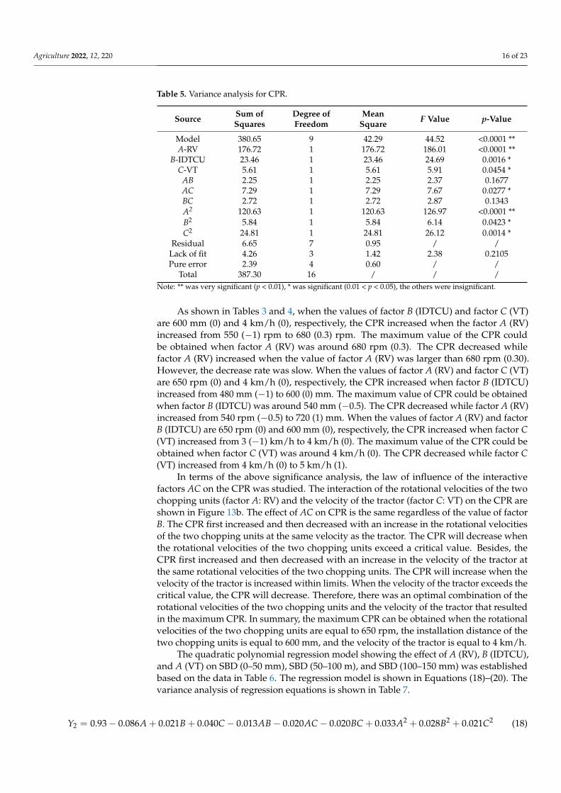
Total 387.30 16 / / /Note: ** was very significant (p < 0.01), * was significant (0.01 < p < 0.05), the others were insignificant.
As shown in Tables 3 and 4, when the values of factor B (IDTCU) and factor C (VT)are 600 mm (0) and 4 km/h (0), respectively, the CPR increased when the factor A (RV)increased from 550 (−1) rpm to 680 (0.3) rpm. The maximum value of the CPR couldbe obtained when factor A (RV) was around 680 rpm (0.3). The CPR decreased whilefactor A (RV) increased when the value of factor A (RV) was larger than 680 rpm (0.30).However, the decrease rate was slow. When the values of factor A (RV) and factor C (VT)are 650 rpm (0) and 4 km/h (0), respectively, the CPR increased when factor B (IDTCU)increased from 480 mm (−1) to 600 (0) mm. The maximum value of CPR could be obtainedwhen factor B (IDTCU) was around 540 mm (−0.5). The CPR decreased while factor A (RV)increased from 540 rpm (−0.5) to 720 (1) mm. When the values of factor A (RV) and factorB (IDTCU) are 650 rpm (0) and 600 mm (0), respectively, the CPR increased when factor C(VT) increased from 3 (−1) km/h to 4 km/h (0). The maximum value of the CPR could beobtained when factor C (VT) was around 4 km/h (0). The CPR decreased while factor C(VT) increased from 4 km/h (0) to 5 km/h (1).
In terms of the above significance analysis, the law of influence of the interactivefactors AC on the CPR was studied. The interaction of the rotational velocities of the twochopping units (factor A: RV) and the velocity of the tractor (factor C: VT) on the CPR areshown in Figure 13b. The effect of AC on CPR is the same regardless of the value of factorB. The CPR first increased and then decreased with an increase in the rotational velocitiesof the two chopping units at the same velocity as the tractor. The CPR will decrease whenthe rotational velocities of the two chopping units exceed a critical value. Besides, theCPR first increased and then decreased with an increase in the velocity of the tractor atthe same rotational velocities of the two chopping units. The CPR will increase when thevelocity of the tractor is increased within limits. When the velocity of the tractor exceeds thecritical value, the CPR will decrease. Therefore, there was an optimal combination of therotational velocities of the two chopping units and the velocity of the tractor that resultedin the maximum CPR. In summary, the maximum CPR can be obtained when the rotationalvelocities of the two chopping units are equal to 650 rpm, the installation distance of thetwo chopping units is equal to 600 mm, and the velocity of the tractor is equal to 4 km/h.
The quadratic polynomial regression model showing the effect of A (RV), B (IDTCU),and A (VT) on SBD (0–50 mm), SBD (50–100 m), and SBD (100–150 mm) was establishedbased on the data in Table 6. The regression model is shown in Equations (18)–(20). Thevariance analysis of regression equations is shown in Table 7.
Y2 = 0.93− 0.086A + 0.021B + 0.040C− 0.013AB− 0.020AC− 0.020BC + 0.033A2 + 0.028B2 + 0.021C2 (18)

Agriculture 2022, 12, 220 17 of 23
Y3 = 1.22− 0.061A− 0.005B + 0.044C− 0.020AB− 0.0025AC− 0.015BC + 0.048A2 + 0.031B2 + 0.033C2 (19)
Y4 = 1.45 + 0.011A + 0.025B− 0.014C− 0.013AB− 0.015AC− 0.0075BC + 0.0015A2 + 0.009B2 + 0.019C2 (20)
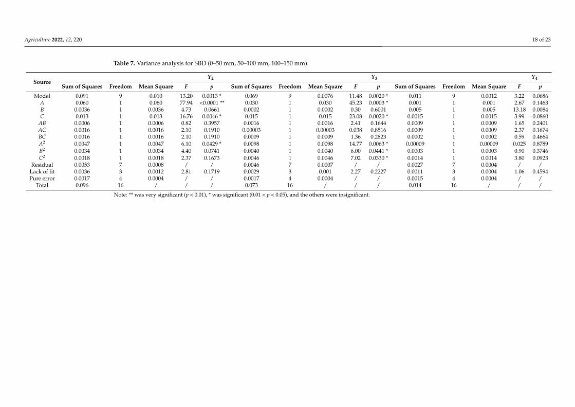
According to the analysis results in Table 7, the significance levels of the regressionmodel for SBD (0–50 mm, 50–100 mm) were all less than 0.05, and the lack of fit for the modelwas greater than 0.05. Therefore, there was a significant relationship between three factors(A: RV, B: IDTCU, and C: VT) and SBD (0–50 mm, 50–100 mm). In addition, the coefficientof determination R2 of the equations were 0.9443 (0–50 mm) and 0.9365 (50–100 mm),demonstrating that more than 94% and 93% of the response values could be explained bythe regression models. Therefore, the structural parameters and working parameters ofthe chopping device could be predicted and analyzed using the regression model of CPR.However, the significance levels of the regression model for SBD (100–150 mm) were allmore than 0.05, implying that there was an insignificant relationship between three factors(A: RV, B: IDTCU, and C: VT) and SBD (100–150 mm). For the main effect, the rotationalvelocities of the two chopping units (factor A: RV) and the velocity of the tractor (factor C:VT) had significant effects on SBD (0–50 mm, 50–100 mm). For the quadratic factor effect,the quadratic factor A2 had a significant effect on SBD (0–50 mm, 50–100 mm).
The values of SBD were 1.18 g/cm3 (0–50 mm), 1.36 g/cm3 (50–100 mm), and 1.48 g/cm3
(100–150 mm), respectively, before the field test. As shown in Tables 6 and 7, the valuesof SBD (0–50 mm and 50–100 mm) were obviously decreased after the device conductedchopping operations. However, the values of SBD (100–150 mm) did not change significantly.Furthermore, the minimum values of SBD (0–50 mm, 50–100 mm) were all obtained when therotational velocities of the two chopping units were 750 rpm, the installation distance of thetwo chopping units was 600 mm, and the velocity of the tractor was 3 km/h. There was apositive relationship between factor A: RV and SBD (0–50 mm, 50–100 mm). Meanwhile, therewas a negative relationship between factor C: VT and SBD (0–50 mm, 50–100 mm).
Table 6. Importance of effects of factors on response functions.
IndexFactors Contribution Rate (K)
Sort Contribution RateA: RV B: IDTCU C: VT
Y1 3.76 2.67 2.60 A > B > C
Agriculture 2022, 12, 220 18 of 23
Table 7. Variance analysis for SBD (0–50 mm, 50–100 mm, 100–150 mm).
SourceY2 Y3 Y4
Sum of Squares Freedom Mean Square F p Sum of Squares Freedom Mean Square F p Sum of Squares Freedom Mean Square F p
Model 0.091 9 0.010 13.20 0.0013 * 0.069 9 0.0076 11.48 0.0020 * 0.011 9 0.0012 3.22 0.0686A 0.060 1 0.060 77.94 <0.0001 ** 0.030 1 0.030 45.23 0.0003 * 0.001 1 0.001 2.67 0.1463B 0.0036 1 0.0036 4.73 0.0661 0.0002 1 0.0002 0.30 0.6001 0.005 1 0.005 13.18 0.0084C 0.013 1 0.013 16.76 0.0046 * 0.015 1 0.015 23.08 0.0020 * 0.0015 1 0.0015 3.99 0.0860
AB 0.0006 1 0.0006 0.82 0.3957 0.0016 1 0.0016 2.41 0.1644 0.0009 1 0.0009 1.65 0.2401AC 0.0016 1 0.0016 2.10 0.1910 0.00003 1 0.00003 0.038 0.8516 0.0009 1 0.0009 2.37 0.1674BC 0.0016 1 0.0016 2.10 0.1910 0.0009 1 0.0009 1.36 0.2823 0.0002 1 0.0002 0.59 0.4664A2 0.0047 1 0.0047 6.10 0.0429 * 0.0098 1 0.0098 14.77 0.0063 * 0.00009 1 0.00009 0.025 0.8789B2 0.0034 1 0.0034 4.40 0.0741 0.0040 1 0.0040 6.00 0.0441 * 0.0003 1 0.0003 0.90 0.3746C2 0.0018 1 0.0018 2.37 0.1673 0.0046 1 0.0046 7.02 0.0330 * 0.0014 1 0.0014 3.80 0.0923
Residual 0.0053 7 0.0008 / / 0.0046 7 0.0007 / / 0.0027 7 0.0004 / /Lack of fit 0.0036 3 0.0012 2.81 0.1719 0.0029 3 0.001 2.27 0.2227 0.0011 3 0.0004 1.06 0.4594Pure error 0.0017 4 0.0004 / / 0.0017 4 0.0004 / / 0.0015 4 0.0004 / /
Total 0.096 16 / / / 0.073 16 / / / 0.014 16 / / /
Note: ** was very significant (p < 0.01), * was significant (0.01 < p < 0.05), and the others were insignificant.
Agriculture 2022, 12, 220 19 of 23
4.3. Effects on CPR and SBD
In the chopping process, under the ground support and chopping by the blades, thepith and rind are compressed; then, the rind is broken. With the high chopping velocity ofthe blade in the chopping process, the pith and rind are simultaneously chopped under aforce, and the maize straw is finally cut off. When the velocity of the blade was increased,the chopping force on the straw from the chopping blade became larger. It makes the straweasier to be cut off, and then the CPR of maize straw is improved [41]. When the rotationalvelocities of the two chopping units are increased, the velocity and acceleration of thechopping blades are also increased. However, when the rotational velocities of the twochopping units are too fast, the chopping force will become so large that makes the strawmove irregularly. There will be a leakage chopping phenomenon. When the velocity of thetractor is increased, the fluidity of straw will be also increased, which makes the straw bechopped easier. However, when the velocity of the tractor is too high, the chopping bladewill drive the straw to move forward, and the straw will be piled up and then the devicewill be blocked.
In the chopping process, the soil is disturbed by chopping blades. With the highrotational velocity of the blades in the chopping process, the soil was loosed under force,and it finally became fined [18]. The depth of the chopping blade into the soil was 65.45 mm.Therefore, the soil was loose in the depth of 0 to 66 mm. The soil below 66 mm is not affectedby the chopping blades. Therefore, the values of SBD (0–50 mm, 50–100 mm) were decreasedsharply while the values of SBD (100–150 mm) did not change significantly. In this study,there was a positive correlation between factors A: RV and SBD (0–50 mm, 50–100 mm).The reason may be that in the maize straw chopping process when RV was increased, theforce and frequency from the chopping blade are also increased. Simultaneously, there wasa negative correlation between factors C: VT and SBD (0–50 mm, 50–100 mm). The reasonmay be that in the maize straw chopping process when VT was increased, the choppingtimes to soil is decreased per time.
4.4. Optimization and Verification
The analysis above indicates that the impact of various factors on the experimentalindex was inconsistent. To obtain the best value of CPR, and let the SBD (0–50 mm,50–100 mm) decrease over 20% and 10%, respectively, a multi-objective optimizationmethod combined with a restraint condition was used to optimize the regression equation.The restraint condition is given as:
maxY1(RSD, IDTCU, ST)
Y2 ≤ 0.94
Y3 ≤ 1.22
s.t.
550 rpm ≤ RSD ≤ 750 rpm
480 mm ≤ IDTCU ≤ 720 mm
3 km/h ≤ ST ≤ 5 km/h
(21)
Equation (21) was solved combined with restraint conditions, and the optimal param-eter combination was as follows: the rotational velocity of the two chopping units was610 rpm (−0.40), the installation distance of the two chopping units was 526.8 mm (−0.61),and the velocity of the tractor was 3.96 km/h (−0.04), while the CPR was 93.4%, the SBDvalues (0–50 mm, 50–100 mm, and 100–150 mm) were 0.90, 1.22, and 1.44, respectively.
The field validation experiments were conducted to verify the reliability of the op-timization results (Figure 14). The site selection and data collection were the same asdescribed in Section 3. The rotational velocities of the two chopping units were both610 rpm, the installation distance of the two chopping units was 550 mm, and the velocity

Agriculture 2022, 12, 220 20 of 23
of the tractor was 4 km/h; these were selected as test factors. The results showed that theCPR was 92.0% and the difference was less than 5%. The SBD values (0–50 mm, 50–100 mm,and 100–150 mm) were 0.88, 1.18, and 1.45, respectively. In 0–50 mm and 50–100 mm soillayers, the bulk density was decreased 25.42% and 13.24%, respectively (Figure 15). Thus,the results of the study are considered acceptable.
Agriculture 2021, 11, x 20 of 24
the installation distance of the two chopping units was 550 mm, and the velocity of the tractor was 4 km/h; these were selected as test factors. The results showed that the CPR was 92.0% and the difference was less than 5%. The SBD values (0–50 mm, 50–100 mm, and 100–150 mm) were 0.88, 1.18, and 1.45, respectively. In 0–50 mm and 50–100 mm soil layers, the bulk density was decreased 25.42% and 13.24%, respectively (Figure 15). Thus, the results of the study are considered acceptable.
Figure 14. The field validation experiments Note: (1) straw, (2) ground, (3) Vernier caliper, and (4) single straw.
Figure 14. The field validation experiments Note: (1) straw, (2) ground, (3) Vernier caliper, and (4)single straw.
Agriculture 2021, 11, x 21 of 24
Figure 15. Results of SBD.
5. Conclusions The novel chopping device, based on the reciprocating intermittent motion mecha-
nism, was developed to increase CPR for maize straw and decrease SBD after maize was harvested in China. In this study, the chopping principle of reciprocating intermittent mo-tion mechanism and the force of straw during the chopping operation were theoretically analyzed. Furthermore, the structure and key parameters of the devices were optimized through dynamic and kinematics simulation analysis methods by ADAMS software. In addition, field experiments were conducted to explore the effects of rotational velocities of the two chopping units, the installation distance of the two chopping units, and the velocity of the tractor on CPR and SBD, and then, response surface analysis was applied to optimize the chopping device. Finally, field validation experiments were conducted to verify the reliability of the optimization results. The main conclusions were as follows: a) Optimizing the structure and key parameters of the devices through dynamic and
kinematics simulation analysis method by ADAMS software, it was determined that the rotation radius of the eccentric disc (a), the minimum transmission angle (γmin), the length of the link (b), the distance between O and B 3 (L), the width of the track (w), and the depth of chopping blade into the soil (h1) were 75.00 mm, 75°, 289.78 mm, 204.91 mm, 32.91 mm, and 65.45 mm, respectively.
b) Via a response surface optimization experimental design and an analysis of CPR and SBD, the primary and secondary factors affecting the working performance of the chopping device were assessed. The optimal parameter combination was achieved: the rotational velocities of the two chopping units were both 610 rpm, the installation
Figure 15. Results of SBD.
5. Conclusions
The novel chopping device, based on the reciprocating intermittent motion mecha-nism, was developed to increase CPR for maize straw and decrease SBD after maize washarvested in China. In this study, the chopping principle of reciprocating intermittentmotion mechanism and the force of straw during the chopping operation were theoreticallyanalyzed. Furthermore, the structure and key parameters of the devices were optimizedthrough dynamic and kinematics simulation analysis methods by ADAMS software. Inaddition, field experiments were conducted to explore the effects of rotational velocitiesof the two chopping units, the installation distance of the two chopping units, and thevelocity of the tractor on CPR and SBD, and then, response surface analysis was appliedto optimize the chopping device. Finally, field validation experiments were conducted toverify the reliability of the optimization results. The main conclusions were as follows:
(a) Optimizing the structure and key parameters of the devices through dynamic andkinematics simulation analysis method by ADAMS software, it was determined thatthe rotation radius of the eccentric disc (a), the minimum transmission angle (γmin),the length of the link (b), the distance between O and B3 (L), the width of the track
Agriculture 2022, 12, 220 21 of 23
(w), and the depth of chopping blade into the soil (h1) were 75.00 mm, 75◦, 289.78 mm,204.91 mm, 32.91 mm, and 65.45 mm, respectively.
(b) Via a response surface optimization experimental design and an analysis of CPR andSBD, the primary and secondary factors affecting the working performance of thechopping device were assessed. The optimal parameter combination was achieved:the rotational velocities of the two chopping units were both 610 rpm, the installationdistance of the two chopping units was 526.8 mm, and the velocity of the tractor was3.96 km/h. These values were determined by the regression model.
(c) Finally, the working performances of the designed chopping device were verifiedthrough the field validation experiment. Under the velocity of 4 km/h, the CPR was92.0% and the SBD values (0–50 mm, 50–100 mm, and 100–150 mm) were 0.88, 1.18,and 1.45, respectively. In general, the CPR of the device was much more superior tothe relevant requirements as stipulated in the National Standards of China. Besides,the value of SBD (0–50 mm and 50–100 mm) decreased more than 20% and 10%,respectively, which can enhance seeding quality.
The designed chopping machine has the potential to make an important contributionto improving the chopping quality of maize straw in China. However, further research isneeded on several aspects, including long-term experiments, energy consumption research,and device vibration research. Furthermore, in the future straw chopping machine andsystems should be researched to further improve the CPR of maize straw.
Author Contributions: Conceptualization, H.L. (Han Lin) and J.H.; methodology, H.L. (Han Lin);P.L. and Y.C.; validation, H.L. (Han Lin) and Y.C.; software, W.Y.; writing—original draft preparation,H.L. (Han Lin); writing—review and editing, J.H.; H.L. (Hongwen Li), Q.W.; C.L. and S.H.; fundingacquisition, H.L. (Hongwen Li) and J.H. All authors have read and agreed to the published version ofthe manuscript.
Funding: This research was funded by National Natural Science Foundation of China (Grant No.31971803), the China Agriculture Research System of MOF and MARA (Grant No.CARS-03); Innova-tive Research Team in University of China (Grant No. IRT13039), and the 2115 Talent DevelopmentProgram of China Agricultural University and Chinese Universities Scientific Fund (Grant No.2021TC105).
Institutional Review Board Statement: Not applicable.
Informed Consent Statement: Not applicable.
Data Availability Statement: Not applicable.
Conflicts of Interest: The authors declare no conflict of interest.
References1. Liang, Y.; Al-Kaisi, M.; Yuan, J.; Liu, J.; Zhang, H.; Wang, L.; Cai, H.; Ren, J. Effect of chemical fertilizer and straw-derived organic
amendments on continuous maize yield, soil carbon sequestration and soil quality in a Chinese Mollisol. Agric. Ecosyst. Environ.2021, 314, 107403. [CrossRef]
2. Zhang, Z.; Qiang, H.; McHugh, A.D.; He, J.; Li, H.; Wang, Q.; Lu, Z. Effect of conservation farming practices on soil organicmatter and stratification in a mono-cropping system of Northern China. Soil Res. 2016, 156, 173–181. [CrossRef]
3. Kretschmer, B.; Allen, B.; Hart, K. Mobilising Cereal Straw in the EU to Feed Advanced Biofuel Production. Report Produced forNovozymes; Institute for European Environmental Policy: London, UK, 2012.
4. Scott, B.J.; Podmore, C.M.; Burns, H.M.; Bowden, P.I.; McMaster, C.L. Developments in Stubble Retention in Cropping Systems inSouthern Australia; Nicholls, C., Wolfe, E.C., Eds.; Report to GRDC on Project DAN 00170; NSW Department of Primary Industries:Orange, Australia, 2013.
5. Watts and Associates. Feasibility Research Report for Insuring Corn Stover, Straw and Other Crop Residues. Deliverable 2: FinalFeasibility Report. Risk Management Agency. Contract No: D11PX18877. 2011. Available online: https://www.rma.usda.gov/-/media/RMA/Publications/Risk-Management-Publications/cornstover_straw_other.ashx?la=en (accessed on 29 December 2021).
6. Hiloidhari, M.; Das, D.; Baruah, D.C. Bioenergy potential from crop residue biomass in India. Renew. Sustain. Energy Rev. 2014, 32,504–512. [CrossRef]
7. Sun, N.; Wang, X.; Li, H.; He, J.; Wang, Q.; Wang, J.; Liu, Z.; Wang, Y. Design and experiment of differential sawing rice strawchopper for turning to field. Trans. Chin. Soc. Agric. Eng. 2019, 35, 267–276. [CrossRef]
Agriculture 2022, 12, 220 22 of 23
8. Zhu, K.; Liu, Z.; Tan, X.; Lin, J.; Xu, D. Study on the ecological potential of Chinese straw resources available for bioenergyproducing based on soil protection functions. Biomass Bioenergy 2018, 116, 26–38. [CrossRef]
9. Li, Y.M.; Duan, Y.; Wang, G.L.; Wang, A.Q.; Shao, G.Z.; Meng, X.H.; Zhang, D.M. Straw alters the soil organic carbon compositionand microbial community under different tillage practices in a meadow soil in Northeast China. Soil Res. 2021, 208, 104879.[CrossRef]
10. Liu, P.; He, J.; Li, H.; Wang, Q.; Lu, C.; Zheng, K.; Liu, W.; Zhao, H.; Lou, S. Effect of straw retention on crop yield, soil properties,water use efficiency and greenhouse gas emission in China: A meta-analysis. Int. J. Plant Prod. 2019, 13, 347–367. [CrossRef]
11. General Administration of Quality Supervision, Inspection and Quarantine of the People’s Republic of China; StandardizationAdministration. GB/T 24675.6-2009 Conservation Tillage Equipment—Smashed Straw Machine; China Standards Press: Beijing,China, 2010.
12. Jia, H.; Jiang, X.; Guo, M.; Liu, X.; Wang, L. Design and experiment of V-L shaped smashed straw blade. Trans. Chin. Soc. Agric.Eng. 2015, 31, 28–33. [CrossRef]
13. Zhang, Z.; He, J.; Li, H.; Wang, Q.; Ju, J.; Yan, X. Design and experiment on straw chopper cum spreader with adjustable spreadingdevice. Trans. Chin. Soc. Agric. Mach. 2017, 48, 76–87. [CrossRef]
14. Abilzhanov, D.; Abilzhanuly, T.; Golikov, V.; Adilsheyev, A.; Alshurina, A. Development of universal pick-up chopper forharvesting of chopped hay and haylage. J. Eng. Appl. Sci. 2017, 12, 3309–3314. [CrossRef]
15. Liu, P.; He, J.; Li, Y.; Li, H.; Wang, Q.; Lu, C.; Zhang, Z.; Li, S. Design and experiment of double rollers maize stalk choppingdevice with different rotation speeds. Trans. Chin. Soc. Agric. Eng. 2020, 36, 69–79. [CrossRef]
16. Liu, P.; He, J.; Lou, S.; Wang, Y.; Zhang, Z.; Lin, H. Design and experiment for dynamic supporting type maize straw choppingretention device with different rotation speeds of disc blade. Trans. Chin. Soc. Agric. Mach. 2021, 52, 41–50. [CrossRef]
17. Zastempowski, M.; Bochat, A. Research issues in the process of cutting straw into pieces. Sustainability 2020, 12, 6167. [CrossRef]18. Wang, Q.; Liu, Z.; He, J.; Li, H.; Li, W.; He, J.; Yan, X. Design and experiment of chopping type maize straw returning machine.
Trans. Chin. Soc. Agric. Eng. 2018, 34, 10–17. [CrossRef]19. Liu, P.; He, J.; Li, H.; Wang, Q.; Lu, C.; Lou, S.; Wang, Y.; Lin, H.; Li, H.; Zhang, Z. Effects of various edge-curve types and
rotational speeds of disc blades on breaking force and energy consumption in the maize stalk chopping process. Am. Soc. Agric.Biol. Eng. 2021, 37, 951–965. [CrossRef]
20. Zheng, Z.; He, J.; Li, H.; Diao, P.; Wang, Q.; Zhang, X. Design and experiment of straw-chopping device with chopping and fixedknife supported slide cutting. Trans. Chin. Soc. Agric. Mach. 2016, 47, 108–116.
21. Wang, J.; Wang, X.; He, J.; Li, H.; Lu, C.; Liu, D. Design and experiment of rice straw chopping device for agitation sliding cuttingand tearing. Trans. Chin. Soc. Agric. Mach. 2021, 52, 28–40.
22. He, J. Study on the Soil Characteristics of Wheat Field under Various Tillage Practices and the Physiological Basis of Water Saving inWide-Range Sowing of Wheat; Shandong Agricultural University: Zibo, China, 2020.
23. Hernández, A.; Muñoyerro, A.; Urízar, M.; Amezua, E. Optimization based mathematical procedure for dimensional synthesis ofslider-crank linkage. Mathematics 2021, 9, 1581. [CrossRef]
24. Šarga, P.; Hroncová, D.; Rákay, R. The msc ADAMS/view and simulation of the crank rocker mechanism. Am. J. Mech. Eng. 2015,3, 161–164. [CrossRef]
25. Sun, H.; Chen, Z.; Ge, W. Theory of Machines and Mechanisms; Higher Education Press: Beijing, China, 2013; pp. 132–136.26. Sun, S.; Lv, N.; Xu, J.; Yan, Y.; Li, Z. A MATLAB realization method of connecting rod mechanism design according to the stroke
speed ratio coefficient. Electron. Test 2021, 09, 57–58. [CrossRef]27. Guo, J.; Zheng, R.; Lv, H. AUV Underwater docking collision analysis and guidance structure optimization based on ADAMS
simulation. Acta Armamentarii. 2019, 40, 1058–1067. [CrossRef]28. Li, H.; Wu, C.; Mu, S.; Guan, Z.; Jiang, T. Formation mechanism of laying angle of vertical rape windrower based on ANSYS-
ADAMS. Trans. Chin. Soc. Agric. Eng. 2020, 36, 96–105. [CrossRef]29. Li, P.; Cui, J.; Feng, W.; Zhang, X.; Zhang, T.; Li, Y. Design and test of real-time monitoring system for feeding quantity of small
combine. J. Agric. Mech. Res. 2022, 44, 240–246. [CrossRef]30. Wu, L.; Yang, Z.; Duan, J.; Wang, L.; Wang, W.; Liu, J.; Wang, L. Experiment on influencing factors of cutting force of blades of
trim tool for longan branch. Trans. Chin. Soc. Agric. Eng. 2012, 28, 8–14.31. Gao, X. Experimental Study of Mechanical Properties of Corn Stalks; Huazhong Agricultural University: Wuhan, China, 2013.
[CrossRef]32. Yuan, H.; Wang, D.; Wang, G.; Fu, Z.; Cai, S.; Liang, F. Design and experiment of straw cutting and rubbing process device. Trans.
Chin. Soc. Agric. Mach. 2012, 43 (Supp. 1), 153–157. [CrossRef]33. Wu, L.; Yang, Z.; Li, H.; Wu, W. Experiment of mechanical properties of longan branch for pruning machine design. J. Hunan
Agric. Univ. 2018, 044, 210–215. [CrossRef]34. Lai, R.; Sun, Y.; Jin, G. Experimental investigation of the cutting part for mini-type mulberry branch cutting machine. J. Agric.
Mech. Res. 2013, 35, 150–153. [CrossRef]35. Xiang, J.; Yang, L.; Li, S. Experimental investigation of the base cutter for mini type sugarcane harvester. Trans. Chin. Soc. Agric.
Eng. 2007, 23, 158–163.36. Chen, L.; Liang, X.; Cao, C. Virtual simulation and power test of straw counters-field based on multi-body dynamics. Trans. Chin.
Soc. Agric. Mach. 2016, 47, 106–111. [CrossRef]

Agriculture 2022, 12, 220 23 of 23
37. Yan, X.; Zhou, L.; Jia, F. Compilation and verification of dynamic torque load spectrum of tractor power take-off. Trans. Chin. Soc.Agric. Eng. 2019, 35, 74–81. [CrossRef]
38. Zheng, Z.; He, J.; Wang, Q.; Li, H.; Li, W.; Chen, W. Design and experiment on straw pickup-chopping and ditch-buryingintegrated machine. Trans. Chin. Soc. Agric. Mach. 2017, 48, 87–96. [CrossRef]
39. He, J.; Li, H.; Rasaily, R.; Wang, Q.; Cai, G.; Su, Y.; Qiao, X.; Liu, L. Soil properties and crop yields after 11 years of no tillagefarming in wheat–maize cropping system in North China Plain. Soil Res. 2011, 113, 48–54. [CrossRef]
40. Wang, Q.; Lu, C.; Li, H.; He, J.; Sarker, K.; Rasaily, R.; Liang, Z.; Qiao, X.; Li, H.; Mchugh, A. The effects of no-tillage withsubsoiling on soil properties and maize yield: 12-Year experiment on alkaline soils of Northeast China. Soil Res. 2014, 137, 43–49.[CrossRef]
41. Song, Z.; Song, H.; Geng, A.; Li, Y.; Yan, Y.; Li, F. Experiment on Cutting Characteristics of Cotton Stalk With Double Supports.Trans. Chin. Soc. Agric. Eng. 2019, 31, 37–45. [CrossRef]