dynamelt d15/d25/d45 series - adhesive supply unit - Societe ...
234
DYNAMELT D15/D25/D45 SERIES ADHESIVE SUPPLY UNIT with V6 DynaControl with LCD or Touch Screen Controller Rev.1.16 Technical Documentation, No.20-63, Rev.9.16 ITW Dynatec An Illinois Tool Works Company www.itwdynatec.com Adhesive Application Solutions | ISO 9001 certified
-
Upload
khangminh22 -
Category
Documents
-
view
0 -
download
0
Transcript of dynamelt d15/d25/d45 series - adhesive supply unit - Societe ...

DYNAMELT D15/D25/D45 SERIES ADHESIVE SUPPLY UNIT with V6 DynaControl with LCD or Touch Screen Controller Rev.1.16
Technical Documentation, No.20-63, Rev.9.16
ITW Dynatec An Illinois Tool Works Company
www.itwdynatec.com
Adhesive Application Solutions | ISO 9001 certified
Page ii ITW Dynatec D15/D25/D45 V6 DCL ASU Manual #20- 63
ITW Dynatec Service Parts and Technical Service: AMERICAS EUROPE, MIDDLE
EAST & AFRICA ASIA PACIFIC
ITW Dynatec 31 Volunteer Drive Hendersonville, TN 37075 USA Tel. +1.615.824.3634 [email protected] [email protected]
ITW Dynatec Industriestrasse 28 40822 Mettmann Germany Tel. +49.2104.915.0 [email protected] [email protected]
ITW Dynatec Unit2, B1 Building No.9 Weixin Road SIP, Suzhou, 215122 China Tel. +86.512.6289.0620 [email protected] [email protected]
ITW Dynatec Tsukimura Building 5th Floor 26-11, Nishikamata 7-chomeOta-ku, Tokyo 144-0051,JapanTel. [email protected]@itwdynatec.co.jp
Information about this manual Read all instructions before operating this equipment! It is the customer’s responsibility to have all operators and service personnel read and understand this information. Contact your ITW Dynatec customer service representative for additional copies.
NOTICE: Please be sure to include the serial number of your application system each time you order replacement parts and/or supplies. This will enable us to send you the correct items that you need.


ITW Dynatec D15/D25/D45 V6 DCL ASU Manual #20-63
Page iiiRevised 11/14
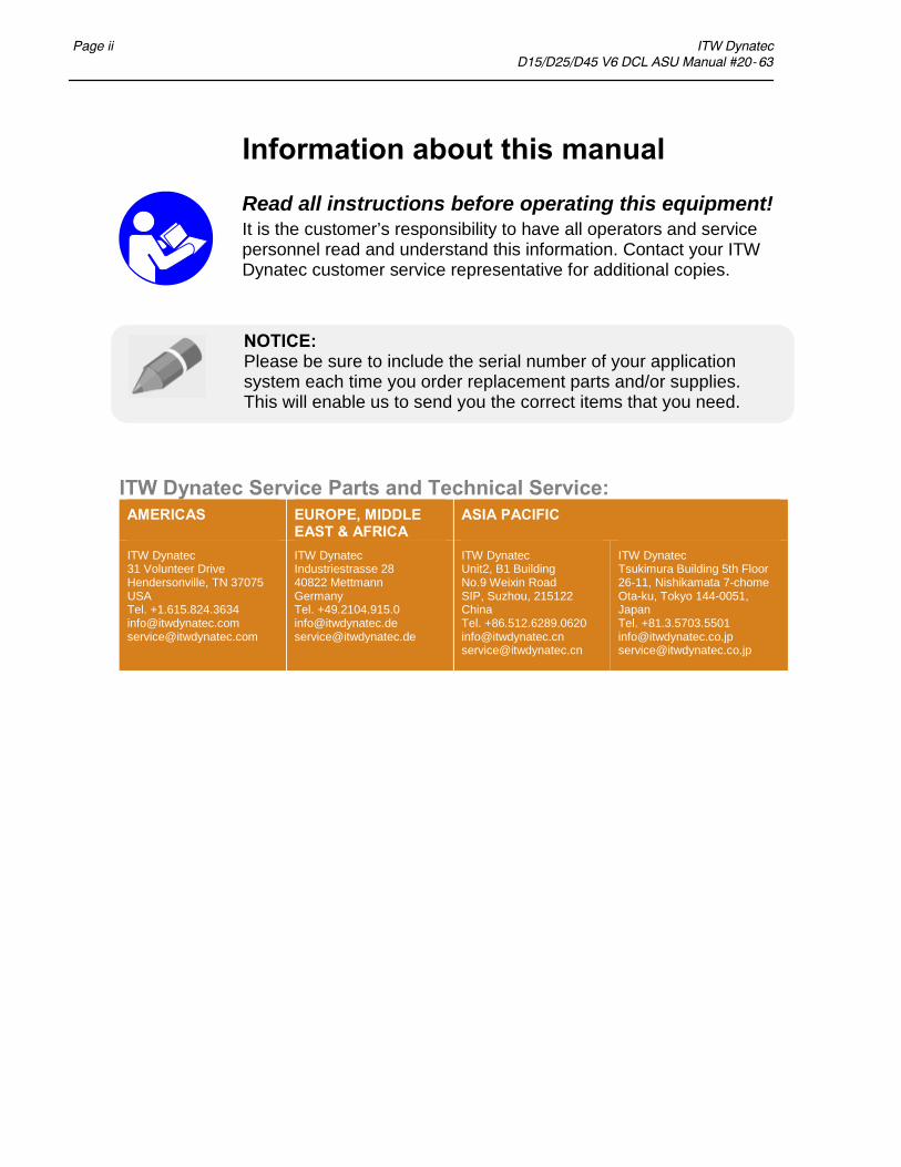
TABLE OF CONTENTS
Chapter 1 Safety Precautions Chapter - Page #
Safe Installation and Operation 1-1. . . . . . . . . . . . . . . . . . . . . . . . . . . . . . . . . . . . . . . . . . . . . . . . . . . . . . . . .Eye Protection & Protective Clothing 1-1. . . . . . . . . . . . . . . . . . . . . . . . . . . . . . . . . . . . . . . . . . . . . . . . . . . .Electrical 1-2. . . . . . . . . . . . . . . . . . . . . . . . . . . . . . . . . . . . . . . . . . . . . . . . . . . . . . . . . . . . . . . . . . . . . . . . . .High Temperatures 1-2. . . . . . . . . . . . . . . . . . . . . . . . . . . . . . . . . . . . . . . . . . . . . . . . . . . . . . . . . . . . . . . . . . .High Pressure 1-2. . . . . . . . . . . . . . . . . . . . . . . . . . . . . . . . . . . . . . . . . . . . . . . . . . . . . . . . . . . . . . . . . . . . . . .Protective Covers 1-2. . . . . . . . . . . . . . . . . . . . . . . . . . . . . . . . . . . . . . . . . . . . . . . . . . . . . . . . . . . . . . . . . . . .Service 1-2. . . . . . . . . . . . . . . . . . . . . . . . . . . . . . . . . . . . . . . . . . . . . . . . . . . . . . . . . . . . . . . . . . . . . . . . . . . .Treatment for Burns From Hot Melt Adhesives 1-3. . . . . . . . . . . . . . . . . . . . . . . . . . . . . . . . . . . . . . . . . . . .Explosion/ Fire Hazard 1-3. . . . . . . . . . . . . . . . . . . . . . . . . . . . . . . . . . . . . . . . . . . . . . . . . . . . . . . . . . . . . . .Lockout/ Tagout 1-3. . . . . . . . . . . . . . . . . . . . . . . . . . . . . . . . . . . . . . . . . . . . . . . . . . . . . . . . . . . . . . . . . . . . .Choice of Adhesives 1-3. . . . . . . . . . . . . . . . . . . . . . . . . . . . . . . . . . . . . . . . . . . . . . . . . . . . . . . . . . . . . . . . .Safety Symbols in this Manual 1-3. . . . . . . . . . . . . . . . . . . . . . . . . . . . . . . . . . . . . . . . . . . . . . . . . . . . . . . . .Special Safety Considerations When Using Reactive HMPUR Adhesives 1-4. . . . . . . . . . . . . . . . . . . . . . . .
Chapter 2 Description & Specifications
Description 2-1. . . . . . . . . . . . . . . . . . . . . . . . . . . . . . . . . . . . . . . . . . . . . . . . . . . . . . . . . . . . . . . . . . . . . . . . .Specifications 2-2. . . . . . . . . . . . . . . . . . . . . . . . . . . . . . . . . . . . . . . . . . . . . . . . . . . . . . . . . . . . . . . . . . . . . . .Installation Dimensions 2-4. . . . . . . . . . . . . . . . . . . . . . . . . . . . . . . . . . . . . . . . . . . . . . . . . . . . . . . . . . . . . . .Wattage Capacity 2-5. . . . . . . . . . . . . . . . . . . . . . . . . . . . . . . . . . . . . . . . . . . . . . . . . . . . . . . . . . . . . . . . . . . .Model Designation Matrix (SDS) 2-7. . . . . . . . . . . . . . . . . . . . . . . . . . . . . . . . . . . . . . . . . . . . . . . . . . . . . . .
Chapter 3 Installation & Start Up
Placing the ASU 3-1. . . . . . . . . . . . . . . . . . . . . . . . . . . . . . . . . . . . . . . . . . . . . . . . . . . . . . . . . . . . . . . . . . . . .Lifting the ASU 3-2. . . . . . . . . . . . . . . . . . . . . . . . . . . . . . . . . . . . . . . . . . . . . . . . . . . . . . . . . . . . . . . . . . . . .To Open/ Close Panel Box Door 3-2. . . . . . . . . . . . . . . . . . . . . . . . . . . . . . . . . . . . . . . . . . . . . . . . . . . . . . . .To Open Hopper Access Cover 3-2. . . . . . . . . . . . . . . . . . . . . . . . . . . . . . . . . . . . . . . . . . . . . . . . . . . . . . . . .Installation 3-3. . . . . . . . . . . . . . . . . . . . . . . . . . . . . . . . . . . . . . . . . . . . . . . . . . . . . . . . . . . . . . . . . . . . . . . . .Customer Connections Chart 3-6. . . . . . . . . . . . . . . . . . . . . . . . . . . . . . . . . . . . . . . . . . . . . . . . . . . . . . . . . . .Location of V6 Modules & Printed Circuit Boards (PCBs) 3-7. . . . . . . . . . . . . . . . . . . . . . . . . . . . . . . . . . .Adding Adhesive 3-8. . . . . . . . . . . . . . . . . . . . . . . . . . . . . . . . . . . . . . . . . . . . . . . . . . . . . . . . . . . . . . . . . . . .Changing the Adhesive Formula 3-8. . . . . . . . . . . . . . . . . . . . . . . . . . . . . . . . . . . . . . . . . . . . . . . . . . . . . . . .Rear Cover: Hose and Head Electrical and Adhesive Connections 3-9. . . . . . . . . . . . . . . . . . . . . . . . . . . . .Adjusting the Pressure Relief Valve 3-10. . . . . . . . . . . . . . . . . . . . . . . . . . . . . . . . . . . . . . . . . . . . . . . . . . . . .Field Installation of Controller Options 3-12. . . . . . . . . . . . . . . . . . . . . . . . . . . . . . . . . . . . . . . . . . . . . . . . . . .Adjustment of the Optional Level Control 3-12. . . . . . . . . . . . . . . . . . . . . . . . . . . . . . . . . . . . . . . . . . . . . . . .Typical Start Up and Shut Down Procedures 3-13. . . . . . . . . . . . . . . . . . . . . . . . . . . . . . . . . . . . . . . . . . . . . .Storage and Disposal of the Application System 3-16. . . . . . . . . . . . . . . . . . . . . . . . . . . . . . . . . . . . . . . . . . . .
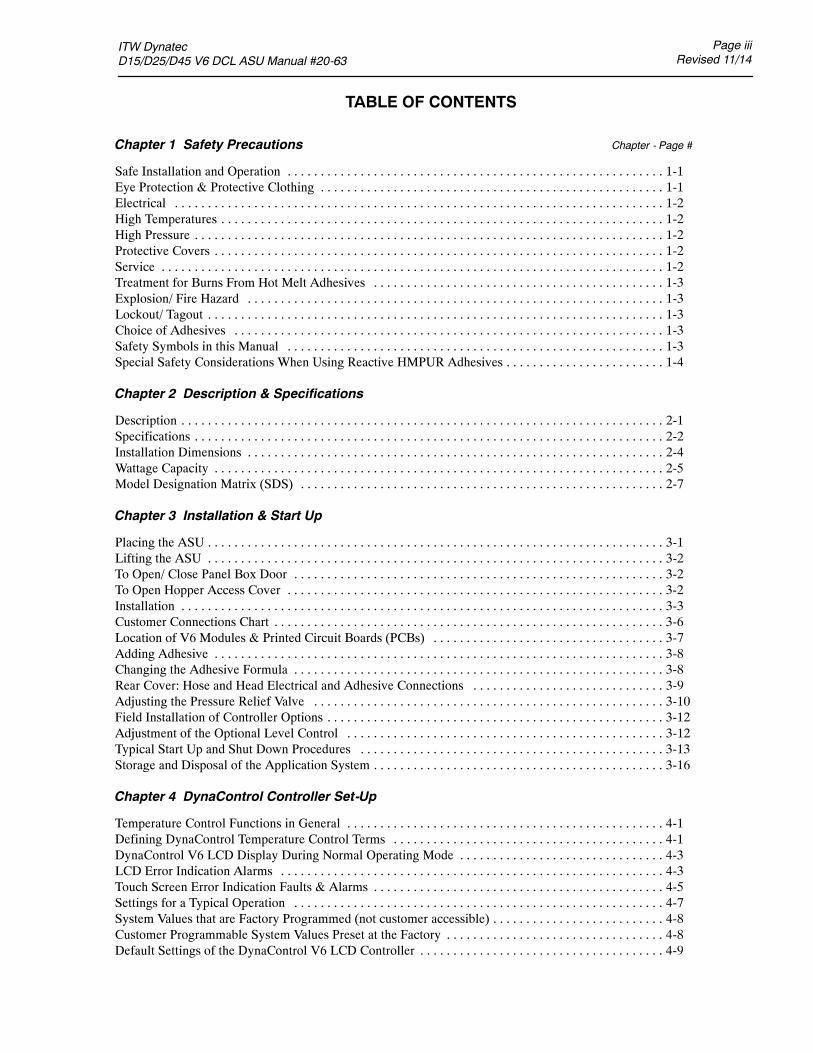
Chapter 4 DynaControl Controller Set-Up
Temperature Control Functions in General 4-1. . . . . . . . . . . . . . . . . . . . . . . . . . . . . . . . . . . . . . . . . . . . . . . .Defining DynaControl Temperature Control Terms 4-1. . . . . . . . . . . . . . . . . . . . . . . . . . . . . . . . . . . . . . . . .DynaControl V6 LCD Display During Normal Operating Mode 4-3. . . . . . . . . . . . . . . . . . . . . . . . . . . . . . .LCD Error Indication Alarms 4-3. . . . . . . . . . . . . . . . . . . . . . . . . . . . . . . . . . . . . . . . . . . . . . . . . . . . . . . . . .Touch Screen Error Indication Faults & Alarms 4-5. . . . . . . . . . . . . . . . . . . . . . . . . . . . . . . . . . . . . . . . . . . .Settings for a Typical Operation 4-7. . . . . . . . . . . . . . . . . . . . . . . . . . . . . . . . . . . . . . . . . . . . . . . . . . . . . . . .System Values that are Factory Programmed (not customer accessible) 4-8. . . . . . . . . . . . . . . . . . . . . . . . . .Customer Programmable System Values Preset at the Factory 4-8. . . . . . . . . . . . . . . . . . . . . . . . . . . . . . . . .Default Settings of the DynaControl V6 LCD Controller 4-9. . . . . . . . . . . . . . . . . . . . . . . . . . . . . . . . . . . . .

Page ivRevised 11/14
ITW Dynatec D15/D25/D45 V6 DCL ASU Manual #20-63
LCD Controller Features 4-10. . . . . . . . . . . . . . . . . . . . . . . . . . . . . . . . . . . . . . . . . . . . . . . . . . . . . . . . . . . . . .Helpful Tips for the User 4-10. . . . . . . . . . . . . . . . . . . . . . . . . . . . . . . . . . . . . . . . . . . . . . . . . . . . . . . . . . . . . .
Chapter 5 Programming of DynaControl Controllers
LCD HMI PROGRAMMING Section 1. . . . . . . . . . . . . . . . . . . . . . . . . . . . . . . . . . . . . . . . . . . . . . . . . . . . . . . . . . . . . . . . . .DynaControl V6 LCD Interface 5-1. . . . . . . . . . . . . . . . . . . . . . . . . . . . . . . . . . . . . . . . . . . . . . . . . . . . . . . .In General 5-1. . . . . . . . . . . . . . . . . . . . . . . . . . . . . . . . . . . . . . . . . . . . . . . . . . . . . . . . . . . . . . . . . . . . . . . . . .Overview Screen Reference 5-2. . . . . . . . . . . . . . . . . . . . . . . . . . . . . . . . . . . . . . . . . . . . . . . . . . . . . . . . . . . .Status Line 5-3. . . . . . . . . . . . . . . . . . . . . . . . . . . . . . . . . . . . . . . . . . . . . . . . . . . . . . . . . . . . . . . . . . . . . . . . .Temperature Zone Symbols 5-3. . . . . . . . . . . . . . . . . . . . . . . . . . . . . . . . . . . . . . . . . . . . . . . . . . . . . . . . . . . .Bar Graphs 5-4. . . . . . . . . . . . . . . . . . . . . . . . . . . . . . . . . . . . . . . . . . . . . . . . . . . . . . . . . . . . . . . . . . . . . . . . .Scan Mode 5-4. . . . . . . . . . . . . . . . . . . . . . . . . . . . . . . . . . . . . . . . . . . . . . . . . . . . . . . . . . . . . . . . . . . . . . . . .To Navigate Away from Overview Screen 5-5. . . . . . . . . . . . . . . . . . . . . . . . . . . . . . . . . . . . . . . . . . . . . . . .Setup Your System Parameters 5-6. . . . . . . . . . . . . . . . . . . . . . . . . . . . . . . . . . . . . . . . . . . . . . . . . . . . . . . . .Temperature Zones 5-6. . . . . . . . . . . . . . . . . . . . . . . . . . . . . . . . . . . . . . . . . . . . . . . . . . . . . . . . . . . . . . . . . . .Pump Settings 5-8. . . . . . . . . . . . . . . . . . . . . . . . . . . . . . . . . . . . . . . . . . . . . . . . . . . . . . . . . . . . . . . . . . . . . .Main Menu 5-10. . . . . . . . . . . . . . . . . . . . . . . . . . . . . . . . . . . . . . . . . . . . . . . . . . . . . . . . . . . . . . . . . . . . . . . . .
Recipe Management 5-10. . . . . . . . . . . . . . . . . . . . . . . . . . . . . . . . . . . . . . . . . . . . . . . . . . . . . . . . . . . . . .Standby/ Setback 5-11. . . . . . . . . . . . . . . . . . . . . . . . . . . . . . . . . . . . . . . . . . . . . . . . . . . . . . . . . . . . . . . .Setpoint Locking 5-12. . . . . . . . . . . . . . . . . . . . . . . . . . . . . . . . . . . . . . . . . . . . . . . . . . . . . . . . . . . . . . . . .7-Day Scheduler 5-12. . . . . . . . . . . . . . . . . . . . . . . . . . . . . . . . . . . . . . . . . . . . . . . . . . . . . . . . . . . . . . . . .Current Time-of-Day and Day-of-Week 5-14. . . . . . . . . . . . . . . . . . . . . . . . . . . . . . . . . . . . . . . . . . . . . . .Info Screen 5-15. . . . . . . . . . . . . . . . . . . . . . . . . . . . . . . . . . . . . . . . . . . . . . . . . . . . . . . . . . . . . . . . . . . . .
System Configuration Menu 5-16. . . . . . . . . . . . . . . . . . . . . . . . . . . . . . . . . . . . . . . . . . . . . . . . . . . . . . . . . . .Accessing the Parameters 5-16. . . . . . . . . . . . . . . . . . . . . . . . . . . . . . . . . . . . . . . . . . . . . . . . . . . . . . . . . .Temperature Unit (Celsius or Fahrenheit) 5-17. . . . . . . . . . . . . . . . . . . . . . . . . . . . . . . . . . . . . . . . . . . . .Language Selection 5-17. . . . . . . . . . . . . . . . . . . . . . . . . . . . . . . . . . . . . . . . . . . . . . . . . . . . . . . . . . . . . . .Zone Configuration 5-17. . . . . . . . . . . . . . . . . . . . . . . . . . . . . . . . . . . . . . . . . . . . . . . . . . . . . . . . . . . . . . .Pump Configuration 5-17. . . . . . . . . . . . . . . . . . . . . . . . . . . . . . . . . . . . . . . . . . . . . . . . . . . . . . . . . . . . . .Setpoint Limitation 5-18. . . . . . . . . . . . . . . . . . . . . . . . . . . . . . . . . . . . . . . . . . . . . . . . . . . . . . . . . . . . . . .Hi/Lo Alarm Tolerance 5-18. . . . . . . . . . . . . . . . . . . . . . . . . . . . . . . . . . . . . . . . . . . . . . . . . . . . . . . . . . . .Standby Configuration 5-18. . . . . . . . . . . . . . . . . . . . . . . . . . . . . . . . . . . . . . . . . . . . . . . . . . . . . . . . . . . .Level Detection 5-19. . . . . . . . . . . . . . . . . . . . . . . . . . . . . . . . . . . . . . . . . . . . . . . . . . . . . . . . . . . . . . . . . .Heatup Sequence (Priority) 5-20. . . . . . . . . . . . . . . . . . . . . . . . . . . . . . . . . . . . . . . . . . . . . . . . . . . . . . . .Access Code 5-21. . . . . . . . . . . . . . . . . . . . . . . . . . . . . . . . . . . . . . . . . . . . . . . . . . . . . . . . . . . . . . . . . . . .0.5 RPM Increment 5-21. . . . . . . . . . . . . . . . . . . . . . . . . . . . . . . . . . . . . . . . . . . . . . . . . . . . . . . . . . . . . . .Temperature Offset 5-21. . . . . . . . . . . . . . . . . . . . . . . . . . . . . . . . . . . . . . . . . . . . . . . . . . . . . . . . . . . . . . .Customer Zone Names 5-22. . . . . . . . . . . . . . . . . . . . . . . . . . . . . . . . . . . . . . . . . . . . . . . . . . . . . . . . . . . .Logbook/ Fault History 5-23. . . . . . . . . . . . . . . . . . . . . . . . . . . . . . . . . . . . . . . . . . . . . . . . . . . . . . . . . . .Power-On Configuration 5-24. . . . . . . . . . . . . . . . . . . . . . . . . . . . . . . . . . . . . . . . . . . . . . . . . . . . . . . . . .Global Setpoints 5-25. . . . . . . . . . . . . . . . . . . . . . . . . . . . . . . . . . . . . . . . . . . . . . . . . . . . . . . . . . . . . . . . .
Controller Messages Troubleshooting Guide 5-26. . . . . . . . . . . . . . . . . . . . . . . . . . . . . . . . . . . . . . . . . . . . . .
TOUCH SCREEN HMI PROGRAMMING Section 2. . . . . . . . . . . . . . . . . . . . . . . . . . . . . . . . . . . . . . . . . . . . . . . . . . . . . .Setup Your System’s Parameters 5-29. . . . . . . . . . . . . . . . . . . . . . . . . . . . . . . . . . . . . . . . . . . . . . . . . . . . . . . .Input Keyboard 5-29. . . . . . . . . . . . . . . . . . . . . . . . . . . . . . . . . . . . . . . . . . . . . . . . . . . . . . . . . . . . . . . . . . . . .Main Screen 5-30. . . . . . . . . . . . . . . . . . . . . . . . . . . . . . . . . . . . . . . . . . . . . . . . . . . . . . . . . . . . . . . . . . . . . . . .Temperature Zones Set Screen 5-34. . . . . . . . . . . . . . . . . . . . . . . . . . . . . . . . . . . . . . . . . . . . . . . . . . . . . . . . . .Pump Overview Screen 5-35. . . . . . . . . . . . . . . . . . . . . . . . . . . . . . . . . . . . . . . . . . . . . . . . . . . . . . . . . . . . . . .Pump Control, Linear Line Speed 5-36. . . . . . . . . . . . . . . . . . . . . . . . . . . . . . . . . . . . . . . . . . . . . . . . . . . . . . .Extended Pump Mode Settings, Linear Line Speed, Pressure Control 5-38. . . . . . . . . . . . . . . . . . . . . . . . . . .Pump Control, Pressure Control Screen 5-40. . . . . . . . . . . . . . . . . . . . . . . . . . . . . . . . . . . . . . . . . . . . . . . . . .Automatic Ramp Compensation (ARC) 5-42. . . . . . . . . . . . . . . . . . . . . . . . . . . . . . . . . . . . . . . . . . . . . . . . . .

ITW Dynatec D15/D25/D45 V6 DCL ASU Manual #20-63
Page vRevised 11/14
Control Switch On/Off and Standby Switch 5-44. . . . . . . . . . . . . . . . . . . . . . . . . . . . . . . . . . . . . . . . . . . . . . .Systems Screen 5-46. . . . . . . . . . . . . . . . . . . . . . . . . . . . . . . . . . . . . . . . . . . . . . . . . . . . . . . . . . . . . . . . . . . . .Settings Screen 5-48. . . . . . . . . . . . . . . . . . . . . . . . . . . . . . . . . . . . . . . . . . . . . . . . . . . . . . . . . . . . . . . . . . . . . .Heating Priority Screen 5-49. . . . . . . . . . . . . . . . . . . . . . . . . . . . . . . . . . . . . . . . . . . . . . . . . . . . . . . . . . . . . . .Temperature Offsets Screen 5-50. . . . . . . . . . . . . . . . . . . . . . . . . . . . . . . . . . . . . . . . . . . . . . . . . . . . . . . . . . . .Fieldbus Setup Screen 5-51. . . . . . . . . . . . . . . . . . . . . . . . . . . . . . . . . . . . . . . . . . . . . . . . . . . . . . . . . . . . . . . .General Settings Screen 5-52. . . . . . . . . . . . . . . . . . . . . . . . . . . . . . . . . . . . . . . . . . . . . . . . . . . . . . . . . . . . . . .Temperature Settings 5-52. . . . . . . . . . . . . . . . . . . . . . . . . . . . . . . . . . . . . . . . . . . . . . . . . . . . . . . . . . . . . . . . .Standby Settings 5-54. . . . . . . . . . . . . . . . . . . . . . . . . . . . . . . . . . . . . . . . . . . . . . . . . . . . . . . . . . . . . . . . . . . .Level Control Settings 5-56. . . . . . . . . . . . . . . . . . . . . . . . . . . . . . . . . . . . . . . . . . . . . . . . . . . . . . . . . . . . . . . .Pressure Zero Calibration 5-57. . . . . . . . . . . . . . . . . . . . . . . . . . . . . . . . . . . . . . . . . . . . . . . . . . . . . . . . . . . . .Calibrating Screen 5-58. . . . . . . . . . . . . . . . . . . . . . . . . . . . . . . . . . . . . . . . . . . . . . . . . . . . . . . . . . . . . . . . . . .Customer Zone Names Screen 5-59. . . . . . . . . . . . . . . . . . . . . . . . . . . . . . . . . . . . . . . . . . . . . . . . . . . . . . . . . .Recipes Screen 5-61. . . . . . . . . . . . . . . . . . . . . . . . . . . . . . . . . . . . . . . . . . . . . . . . . . . . . . . . . . . . . . . . . . . . . .Time & Scheduler Screen 5-62. . . . . . . . . . . . . . . . . . . . . . . . . . . . . . . . . . . . . . . . . . . . . . . . . . . . . . . . . . . . .Log Book Screen 5-65. . . . . . . . . . . . . . . . . . . . . . . . . . . . . . . . . . . . . . . . . . . . . . . . . . . . . . . . . . . . . . . . . . . .Security Screen 5-66. . . . . . . . . . . . . . . . . . . . . . . . . . . . . . . . . . . . . . . . . . . . . . . . . . . . . . . . . . . . . . . . . . . . .System Info Screen 5-68. . . . . . . . . . . . . . . . . . . . . . . . . . . . . . . . . . . . . . . . . . . . . . . . . . . . . . . . . . . . . . . . . .License Management Screen 5-69. . . . . . . . . . . . . . . . . . . . . . . . . . . . . . . . . . . . . . . . . . . . . . . . . . . . . . . . . . .Acknowledge Button 5-70. . . . . . . . . . . . . . . . . . . . . . . . . . . . . . . . . . . . . . . . . . . . . . . . . . . . . . . . . . . . . . . . .Faults, Alarms 5-71. . . . . . . . . . . . . . . . . . . . . . . . . . . . . . . . . . . . . . . . . . . . . . . . . . . . . . . . . . . . . . . . . . . . . .Operator Response to Error Indication Alarms 5-71. . . . . . . . . . . . . . . . . . . . . . . . . . . . . . . . . . . . . . . . . . . . .
Chapter 6 Preventive Maintenance
General Cleaning 6-1. . . . . . . . . . . . . . . . . . . . . . . . . . . . . . . . . . . . . . . . . . . . . . . . . . . . . . . . . . . . . . . . . . . .Preventive Maintenance Schedule 6-1. . . . . . . . . . . . . . . . . . . . . . . . . . . . . . . . . . . . . . . . . . . . . . . . . . . . . . .Output Filter 6-1. . . . . . . . . . . . . . . . . . . . . . . . . . . . . . . . . . . . . . . . . . . . . . . . . . . . . . . . . . . . . . . . . . . . . . . .Hose Fittings 6-2. . . . . . . . . . . . . . . . . . . . . . . . . . . . . . . . . . . . . . . . . . . . . . . . . . . . . . . . . . . . . . . . . . . . . . .Fasteners 6-2. . . . . . . . . . . . . . . . . . . . . . . . . . . . . . . . . . . . . . . . . . . . . . . . . . . . . . . . . . . . . . . . . . . . . . . . . .Primary Filter Cleaning 6-3. . . . . . . . . . . . . . . . . . . . . . . . . . . . . . . . . . . . . . . . . . . . . . . . . . . . . . . . . . . . . . .Pump Shaft Leak 6-4. . . . . . . . . . . . . . . . . . . . . . . . . . . . . . . . . . . . . . . . . . . . . . . . . . . . . . . . . . . . . . . . . . . .Summary of Preventive Maintenance Schedule 6-4. . . . . . . . . . . . . . . . . . . . . . . . . . . . . . . . . . . . . . . . . . . .Purging the Filter Manifold of Adhesive and Pressure 6-5. . . . . . . . . . . . . . . . . . . . . . . . . . . . . . . . . . . . . . .Flushing the System 6-5. . . . . . . . . . . . . . . . . . . . . . . . . . . . . . . . . . . . . . . . . . . . . . . . . . . . . . . . . . . . . . . . .
Chapter 7 Troubleshooting
General Troubleshooting Notes 7-1. . . . . . . . . . . . . . . . . . . . . . . . . . . . . . . . . . . . . . . . . . . . . . . . . . . . . . . . .Location of Components 7-2. . . . . . . . . . . . . . . . . . . . . . . . . . . . . . . . . . . . . . . . . . . . . . . . . . . . . . . . . . . . . .High-Temperature Redundant Overtemp Thermostat 7-3. . . . . . . . . . . . . . . . . . . . . . . . . . . . . . . . . . . . . . . .Lithium Battery 7-3. . . . . . . . . . . . . . . . . . . . . . . . . . . . . . . . . . . . . . . . . . . . . . . . . . . . . . . . . . . . . . . . . . . . .DynaControl V6 Modules 7-3. . . . . . . . . . . . . . . . . . . . . . . . . . . . . . . . . . . . . . . . . . . . . . . . . . . . . . . . . . . . .7-Day Scheduler Use with Pendant Controller 7-3. . . . . . . . . . . . . . . . . . . . . . . . . . . . . . . . . . . . . . . . . . . . .Handling Modules & Printed Circuit Boards 7-4. . . . . . . . . . . . . . . . . . . . . . . . . . . . . . . . . . . . . . . . . . . . . .V6 Base Module 7-5. . . . . . . . . . . . . . . . . . . . . . . . . . . . . . . . . . . . . . . . . . . . . . . . . . . . . . . . . . . . . . . . . . . .V6 Temperature Module 7-9. . . . . . . . . . . . . . . . . . . . . . . . . . . . . . . . . . . . . . . . . . . . . . . . . . . . . . . . . . . . . .V6 Power Module 7-10. . . . . . . . . . . . . . . . . . . . . . . . . . . . . . . . . . . . . . . . . . . . . . . . . . . . . . . . . . . . . . . . . . .V6 Aux Power Module 7-12. . . . . . . . . . . . . . . . . . . . . . . . . . . . . . . . . . . . . . . . . . . . . . . . . . . . . . . . . . . . . . .V6 Motor Module 7-13. . . . . . . . . . . . . . . . . . . . . . . . . . . . . . . . . . . . . . . . . . . . . . . . . . . . . . . . . . . . . . . . . . .Motor Speed Control Drive 7-14. . . . . . . . . . . . . . . . . . . . . . . . . . . . . . . . . . . . . . . . . . . . . . . . . . . . . . . . . . . .Optional Printed Circuit Boards 7-15. . . . . . . . . . . . . . . . . . . . . . . . . . . . . . . . . . . . . . . . . . . . . . . . . . . . . . . .Optional V6 Bus Communications Module 7-16. . . . . . . . . . . . . . . . . . . . . . . . . . . . . . . . . . . . . . . . . . . . . . . .Heater and Sensor Resistance Values 7-16. . . . . . . . . . . . . . . . . . . . . . . . . . . . . . . . . . . . . . . . . . . . . . . . . . . .Resistance Tables 7-17. . . . . . . . . . . . . . . . . . . . . . . . . . . . . . . . . . . . . . . . . . . . . . . . . . . . . . . . . . . . . . . . . . . .
Page viRevised 11/14
ITW Dynatec D15/D25/D45 V6 DCL ASU Manual #20-63
Error Indication Alarm Troubleshooting Guide 7-18. . . . . . . . . . . . . . . . . . . . . . . . . . . . . . . . . . . . . . . . . . . .Adjustable Adhesive Pressure Relief Valve 7-29. . . . . . . . . . . . . . . . . . . . . . . . . . . . . . . . . . . . . . . . . . . . . . . .Operation of the ASU’s Pump 7-30. . . . . . . . . . . . . . . . . . . . . . . . . . . . . . . . . . . . . . . . . . . . . . . . . . . . . . . . . .Pump Output Adjustments 7-30. . . . . . . . . . . . . . . . . . . . . . . . . . . . . . . . . . . . . . . . . . . . . . . . . . . . . . . . . . . . .Troubleshooting the ASU Pump 7-31. . . . . . . . . . . . . . . . . . . . . . . . . . . . . . . . . . . . . . . . . . . . . . . . . . . . . . . .Pump Troubleshooting Guide 7-32. . . . . . . . . . . . . . . . . . . . . . . . . . . . . . . . . . . . . . . . . . . . . . . . . . . . . . . . . .
Chapter 8 Disassembly & Re-assembly Procedures
Disassembly Procedures 8-1. . . . . . . . . . . . . . . . . . . . . . . . . . . . . . . . . . . . . . . . . . . . . . . . . . . . . . . . . . . . . .Remove Rear Cover 8-1. . . . . . . . . . . . . . . . . . . . . . . . . . . . . . . . . . . . . . . . . . . . . . . . . . . . . . . . . . . . . . . . . .Mechanical (Over-Temperature) Thermostat Replacement 8-1. . . . . . . . . . . . . . . . . . . . . . . . . . . . . . . . . . . .To Access the RTD Sensors 8-1. . . . . . . . . . . . . . . . . . . . . . . . . . . . . . . . . . . . . . . . . . . . . . . . . . . . . . . . . . . .RTD Replacement for ASU 8-1. . . . . . . . . . . . . . . . . . . . . . . . . . . . . . . . . . . . . . . . . . . . . . . . . . . . . . . . . . . .RTD Replacement for Drop-in Grid 8-1. . . . . . . . . . . . . . . . . . . . . . . . . . . . . . . . . . . . . . . . . . . . . . . . . . . . .To Access the Electrical Components 8-2. . . . . . . . . . . . . . . . . . . . . . . . . . . . . . . . . . . . . . . . . . . . . . . . . . . .To Remove Front Electrical Display 8-2. . . . . . . . . . . . . . . . . . . . . . . . . . . . . . . . . . . . . . . . . . . . . . . . . . . . .Main On/ Off Switch (Circuit Breaker) Replacement 8-2. . . . . . . . . . . . . . . . . . . . . . . . . . . . . . . . . . . . . . . .Fuse Replacement 8-2. . . . . . . . . . . . . . . . . . . . . . . . . . . . . . . . . . . . . . . . . . . . . . . . . . . . . . . . . . . . . . . . . . .Printed Circuit Board Replacement 8-2. . . . . . . . . . . . . . . . . . . . . . . . . . . . . . . . . . . . . . . . . . . . . . . . . . . . . .Module Replacement 8-2. . . . . . . . . . . . . . . . . . . . . . . . . . . . . . . . . . . . . . . . . . . . . . . . . . . . . . . . . . . . . . . . .Opening Modules 8-3. . . . . . . . . . . . . . . . . . . . . . . . . . . . . . . . . . . . . . . . . . . . . . . . . . . . . . . . . . . . . . . . . . . .To Access the Pump or Motor 8-3. . . . . . . . . . . . . . . . . . . . . . . . . . . . . . . . . . . . . . . . . . . . . . . . . . . . . . . . . .Gear Pump and Motor Removal 8-3. . . . . . . . . . . . . . . . . . . . . . . . . . . . . . . . . . . . . . . . . . . . . . . . . . . . . . . .Pump Seal (O-ring) Replacement 8-4. . . . . . . . . . . . . . . . . . . . . . . . . . . . . . . . . . . . . . . . . . . . . . . . . . . . . . .Re-assembly Procedures 8-4. . . . . . . . . . . . . . . . . . . . . . . . . . . . . . . . . . . . . . . . . . . . . . . . . . . . . . . . . . . . . .
Chapter 9 Available Options & Accessories
Pressure Gauge Kit 9-1. . . . . . . . . . . . . . . . . . . . . . . . . . . . . . . . . . . . . . . . . . . . . . . . . . . . . . . . . . . . . . . . . .Drop-in Grids 9-1. . . . . . . . . . . . . . . . . . . . . . . . . . . . . . . . . . . . . . . . . . . . . . . . . . . . . . . . . . . . . . . . . . . . . . .Filter Options 9-1. . . . . . . . . . . . . . . . . . . . . . . . . . . . . . . . . . . . . . . . . . . . . . . . . . . . . . . . . . . . . . . . . . . . . . .Pressure Transducer Assembly 9-1. . . . . . . . . . . . . . . . . . . . . . . . . . . . . . . . . . . . . . . . . . . . . . . . . . . . . . . . .Level Control Assembly 9-1. . . . . . . . . . . . . . . . . . . . . . . . . . . . . . . . . . . . . . . . . . . . . . . . . . . . . . . . . . . . . .Pneumatic Pressure Relief Valve (PPRV) 9-1. . . . . . . . . . . . . . . . . . . . . . . . . . . . . . . . . . . . . . . . . . . . . . . . .Pump Options 9-2. . . . . . . . . . . . . . . . . . . . . . . . . . . . . . . . . . . . . . . . . . . . . . . . . . . . . . . . . . . . . . . . . . . . . .DynaControl Options 9-3. . . . . . . . . . . . . . . . . . . . . . . . . . . . . . . . . . . . . . . . . . . . . . . . . . . . . . . . . . . . . . . . .Recommended Spare Parts List 9-4. . . . . . . . . . . . . . . . . . . . . . . . . . . . . . . . . . . . . . . . . . . . . . . . . . . . . . . . .
Chapter 10 Component Illustrations & Bills of Material
Cabinet Assembly 10-2. . . . . . . . . . . . . . . . . . . . . . . . . . . . . . . . . . . . . . . . . . . . . . . . . . . . . . . . . . . . . . . . . . .Electrical Panel Box Assembly 10-4. . . . . . . . . . . . . . . . . . . . . . . . . . . . . . . . . . . . . . . . . . . . . . . . . . . . . . . . .Front Panel Assembly 10-6. . . . . . . . . . . . . . . . . . . . . . . . . . . . . . . . . . . . . . . . . . . . . . . . . . . . . . . . . . . . . . . .Drive Assembly 10-8. . . . . . . . . . . . . . . . . . . . . . . . . . . . . . . . . . . . . . . . . . . . . . . . . . . . . . . . . . . . . . . . . . . . .Grid and Melt Section 10-10. . . . . . . . . . . . . . . . . . . . . . . . . . . . . . . . . . . . . . . . . . . . . . . . . . . . . . . . . . . . . . . .Filter Manifold Assemblies 10-12. . . . . . . . . . . . . . . . . . . . . . . . . . . . . . . . . . . . . . . . . . . . . . . . . . . . . . . . . . . .Gear Pumps 10-14. . . . . . . . . . . . . . . . . . . . . . . . . . . . . . . . . . . . . . . . . . . . . . . . . . . . . . . . . . . . . . . . . . . . . . . .Optional Pneumatic Pressure Relief Valve Kit 10-26. . . . . . . . . . . . . . . . . . . . . . . . . . . . . . . . . . . . . . . . . . . . .

ITW Dynatec D15/D25/D45 V6 DCL ASU Manual #20-63
Page viiRevised 11/14
Chapter 11 System Schematics & Engineering Drawings
Head Schematic: all models 11-1. . . . . . . . . . . . . . . . . . . . . . . . . . . . . . . . . . . . . . . . . . . . . . . . . . . . . . . . . . . .Hose Schematic: all models 11-2. . . . . . . . . . . . . . . . . . . . . . . . . . . . . . . . . . . . . . . . . . . . . . . . . . . . . . . . . . . .Typical Hydraulic Schematic 11-3. . . . . . . . . . . . . . . . . . . . . . . . . . . . . . . . . . . . . . . . . . . . . . . . . . . . . . . . . . .Level Control Schematic 11-4. . . . . . . . . . . . . . . . . . . . . . . . . . . . . . . . . . . . . . . . . . . . . . . . . . . . . . . . . . . . . .ASU Wiring Diagrams end of chapter. . . . . . . . . . . . . . . . . . . . . . . . . . . . . . . . . . . . . . . . . . . . . . . . . . . . . . . . . . . . . . . .
Appendix
Pressure Transducer . . . . . . . . . . . . . . . . . . . . . . . . . . . . . . . . . . . . . . . . . . . . . . . . . . . . . . . . . . . . . Appendix 3Signal Isolator . . . . . . . . . . . . . . . . . . . . . . . . . . . . . . . . . . . . . . . . . . . . . . . . . . . . . . . . . . . . . . . . . Appendix 2Gear Pumps . . . . . . . . . . . . . . . . . . . . . . . . . . . . . . . . . . . . . . . . . . . . . . . . . . . . . . . . . . . . . . . . . . . . Appendix 1

Page viiiRevised 11/14
ITW Dynatec D15/D25/D45 V6 DCL ASU Manual #20-63

ITW Dynatec ALL MODELS
Safety Precautions Page 1-1Revised 10/14
All operators and service personnel must read and understand this manual before operating or servi-cing equipment.
All maintenance and service on this equipment must be performed by trained technicians.
Safe Installation & Operation
Read this manual before applying electrical power to the equipment. Equipment may be damaged by incorrect electricalconnections.
To avoid possible failure of hoses, make sure all hoses are routed to avoid kinking, tight radius turns (8” or less) andabrasive contact. Hot-melt hoses should not have prolonged contact with heat-absorbing surfaces such as cold floors ormetal troughs. These heat-absorbing surfaces can alter adhesive flow and cause incorrect calibration. Hoses should neverbe covered with materials that prevent heat dissipation, such as insulation or sheathing. Hoses should be spaced apartfrom each other, not making direct contact.
Hoses and cables can present a trip hazard around the machinery. Provide hose/ cable management infrastructurewhenever possible.
Do not use adhesive that is dirty or that may be chemically contaminated. Doing so can cause system clogging andpump damage.
When adhesive hand-held applicators or other movable applicators are used, never point them at yourself or at anyother person. Never leave a hand-held applicator’s trigger unlocked when not actually in use.
Do not operate the hopper or other system components without adhesive for more than 15 minutes if the temper-ature is 150 degrees C (300 degrees F) or more. To do so will cause charring of the residual adhesive.
Never activate the heads, hand-held applicators and/ or other application devices until the adhesive’s temperature iswithin the operating range. Severe damage could result to internal parts and seals.
Always install the equipment on a flat surface. Never attempt to lift or move the unit when there is molten adhesive inthe system.
Promptly wipe up fluid spills to avoid potential slips or falls.
Eye Protection & Protective Clothing
Chapter 1SAFETY PRECAUTIONS
WARNING
PROTECTIVECLOTHINGREQUIRED
EYE PROTECTIONREQUIRED
It is very important that you PROTECT YOUR EYES whenworking around hot melt adhesive equipment!
Wear a face shield conforming to ANSI Z87.1 or safetyglasses with side shields which conform to ANSI Z87.1 orEN166.
Failure to wear a face shield or safety glasses could result insevere eye injury.
It is important to protect yourself from potential burnswhenworking around hotmelt adhesive equipment.Wear protectivegloves and long-sleeved, protective clothing to prevent burns that could result from contact with hot material or hot com-ponents and to protect against cuts due to potential sharp edges on access panels, doors or lids.
Always wear steel-reinforced safety shoes.
Page 1-2 Safety PrecautionsRevised 10/14
ITW Dynatec ALL MODELS
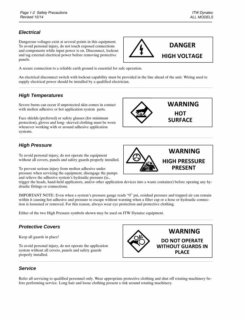
Electrical
Dangerous voltages exist at several points in this equipment.To avoid personal injury, do not touch exposed connectionsand components while input power is on. Disconnect, lockoutand tag external electrical power before removing protectivepanels.
A secure connection to a reliable earth ground is essential for safe operation.
An electrical disconnect switch with lockout capability must be provided in the line ahead of the unit. Wiring used tosupply electrical power should be installed by a qualified electrician.
High Temperatures
Severe burns can occur if unprotected skin comes in contactwith molten adhesive or hot application system parts.
Face shields (preferred) or safety glasses (for minimumprotection), gloves and long- sleeved clothing must be wornwhenever working with or around adhesive applicationsystems.
High Pressure
To avoid personal injury, do not operate the equipmentwithout all covers, panels and safety guards properly installed.
To prevent serious injury from molten adhesive underpressure when servicing the equipment, disengage the pumpsand relieve the adhesive system’s hydraulic pressure (ie.,trigger the heads, hand-held applicators, and/or other application devices into a waste container) before opening any hy-draulic fittings or connections.
IMPORTANT NOTE: Even when a system’s pressure gauge reads “0” psi, residual pressure and trapped air can remainwithin it causing hot adhesive and pressure to escape without warning when a filter cap or a hose or hydraulic connec-tion is loosened or removed. For this reason, always wear eye protection and protective clothing.
Either of the two High Pressure symbols shown may be used on ITW Dynatec equipment.
Protective Covers
Keep all guards in place!
To avoid personal injury, do not operate the applicationsystem without all covers, panels and safety guardsproperly installed.
Service
Refer all servicing to qualified personnel only. Wear appropriate protective clothing and shut off rotating machinery be-fore performing service. Long hair and loose clothing present a risk around rotating machinery.
DANGER
HIGH VOLTAGE
WARNINGHOT
SURFACE
WARNING
HIGH PRESSUREPRESENT
WARNINGDO NOT OPERATE
WITHOUT GUARDS INPLACE
ITW Dynatec ALL MODELS
Safety Precautions Page 1-3Revised 10/14
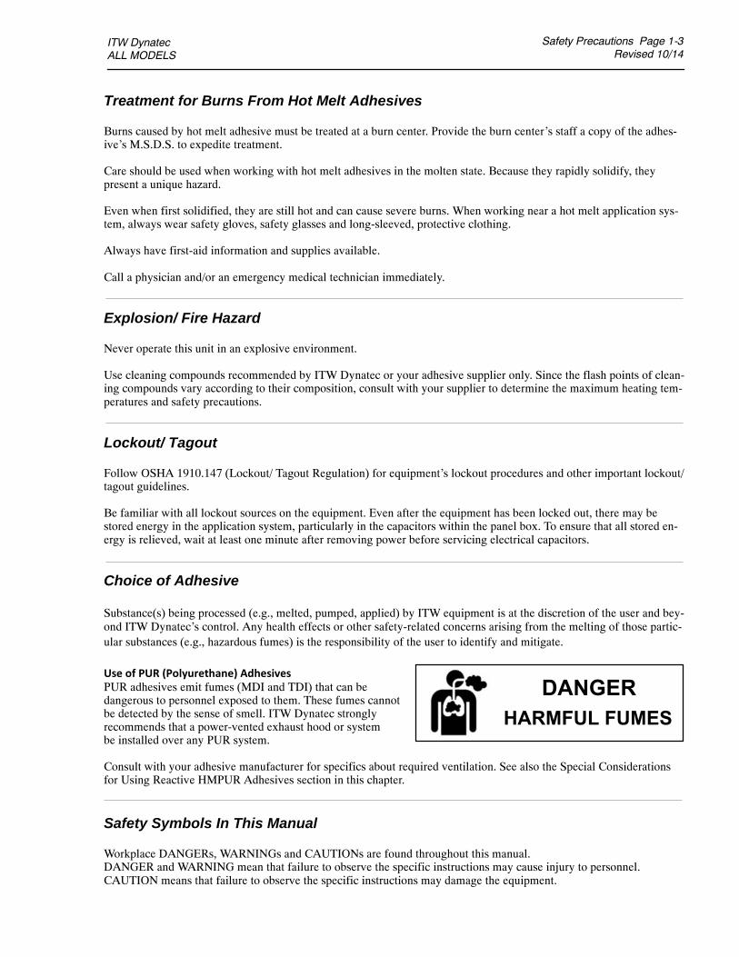
Treatment for Burns From Hot Melt Adhesives
Burns caused by hot melt adhesive must be treated at a burn center. Provide the burn center’s staff a copy of the adhes-ive’s M.S.D.S. to expedite treatment.
Care should be used when working with hot melt adhesives in the molten state. Because they rapidly solidify, theypresent a unique hazard.
Even when first solidified, they are still hot and can cause severe burns. When working near a hot melt application sys-tem, always wear safety gloves, safety glasses and long-sleeved, protective clothing.
Always have first-aid information and supplies available.
Call a physician and/or an emergency medical technician immediately.
Explosion/ Fire Hazard
Never operate this unit in an explosive environment.
Use cleaning compounds recommended by ITW Dynatec or your adhesive supplier only. Since the flash points of clean-ing compounds vary according to their composition, consult with your supplier to determine the maximum heating tem-peratures and safety precautions.
Lockout/ Tagout
Follow OSHA 1910.147 (Lockout/ Tagout Regulation) for equipment’s lockout procedures and other important lockout/tagout guidelines.
Be familiar with all lockout sources on the equipment. Even after the equipment has been locked out, there may bestored energy in the application system, particularly in the capacitors within the panel box. To ensure that all stored en-ergy is relieved, wait at least one minute after removing power before servicing electrical capacitors.
Choice of Adhesive
Substance(s) being processed (e.g., melted, pumped, applied) by ITW equipment is at the discretion of the user and bey-ond ITW Dynatec’s control. Any health effects or other safety-related concerns arising from the melting of those partic-ular substances (e.g., hazardous fumes) is the responsibility of the user to identify and mitigate.
Use of PUR (Polyurethane) AdhesivesPUR adhesives emit fumes (MDI and TDI) that can bedangerous to personnel exposed to them. These fumes cannotbe detected by the sense of smell. ITW Dynatec stronglyrecommends that a power-vented exhaust hood or systembe installed over any PUR system.
Consult with your adhesive manufacturer for specifics about required ventilation. See also the Special Considerationsfor Using Reactive HMPUR Adhesives section in this chapter.
Safety Symbols In This Manual
Workplace DANGERs, WARNINGs and CAUTIONs are found throughout this manual.DANGER and WARNING mean that failure to observe the specific instructions may cause injury to personnel.CAUTION means that failure to observe the specific instructions may damage the equipment.
DANGERHARMFUL FUMES

Page 1-4 Safety PrecautionsRevised 10/14
ITW Dynatec ALL MODELS
Special Safety Considerations When Using Reactive HMPUR Adhesives
Reactive hot melt PUR (HMPUR) adhesives are known for superior adhesion to numerous substrates and their exception-al heat, cold and moisture-resistance qualities. They are an excellent choice for the difficult-to-bond substrates used in awide range of environments. HMPUR adhesives chemically cross-link (i.e., cure or thermal-set) to reach maximum bondstrength, typically over a period of 24 to 48 hours after being exposed to moisture and/or high temperatures.
The advantages of using HMPURs, however, come with special handling requirements. The adhesive must remain sealedoff from the environment and maintained at low temperatures until it is dispensed, otherwise there is a risk that the adhes-ive will cross-link within the glue application equipment, rendering it impervious to melting when it is re-heated. Mostimportantly, when over-heated, many HMPURs release gases that can be hazardous to humans. Therefore, adequate vent-ilation must be available to prevent injury to personnel in the workspace. ITW Dynatec PN 114367 Vent Hood is re-quired.
The following is a list of general operational considerations for the use of HMPURs in ITW Dynatec equipment. In addi-tion, it is important to contact your adhesive manufacturer to discuss and verify precautions that must be implemented toprevent damage to equipment and injury to personnel who are working with their products.
Assure the workspace has adequate ventilation.
Assure the entire adhesive delivery system is sealed from the environment to the greatest extent possible toprevent moisture-related adhesive cross-linking.
Assure all air is evacuated from the adhesive delivery system as soon as possible after it has been introduced(i.e., when changing hoses, replacing filters, changing adhesive supplies, etc.) to prevent moisture-related cross-linking.
The ITW Dynatec equipment should not be left dormant (sealed at ambient temperature) with PUR inside forlonger than recommended by your adhesive manufacturer. The ITW Dynatec system, especially applicators and nozzles,should be thoroughly purged of adhesive using a PUR purge material if the system will be left dormant for extended timeperiods.
HMPUR viscosity increases the longer it remains molten within a system and can cross-link due to temperat-ure exposure. Assure the molten adhesive does not sit within the ITW Dynatec equipment at operating temperature formore than a cumulative total of 2 to 4 hours. Utilization of the Temperature Standby feature will ensure a temperaturedrop occurs automatically.
Turn off any gear pumps in the system if it will not be used for a period of five minutes or more. Doing so willreduce potential glue degradation.
When using spray applicators, the nozzles must be thoroughly cleaned on a regular basis to prevent the adhes-ive from cross-linking inside or on the surface of the air passageways.
The adhesive applicators must be either fully sealed or thoroughly cleaned with PUR purge material if the sys-tem is to be idle for more than two hours. Otherwise, HMPUR adhesive present in the exposed orifices of the applicatorcould potentially cross-link, clogging them.
Recommended adhesive application temperatures should never be exceeded. Higher application temperaturesmay result in higher adhesive viscosities and thermal-related cross-linking.
The use of air dryers such as ITW Dynatec PN 117944 or 117974 are recommended in humid environments.
There are many advantages to using HMPURs. However, the proper handling of these unique adhesives is imperative toassure success without damage to equipment or injury to personnel. ITW Dynatec equipment has been engineered to min-imize the effort required to assure safe and proper handling of HMPURs. ALLOWING PUR ADHESIVE TO CURE INA UNIT OR ITS COMPONENTS VOIDS ITW DYNATEC’S WARRANTY. Please consult with your ITW Dynatec rep-resentative to discuss these topics in further detail, if necessary.

ITW Dynatec D15/D25/D45 V6 DCL ASU Manual #20-63
Description Page 2-1Revised 10/14
Chapter 2DESCRIPTION AND SPECIFICATIONS
Description
The D15/D25/D45 Series adhesive supply units (ASUs) are computer-controlled hot-melt supplyunits designed on metric standards. Their “all-icon” control panels, with choice of display lan-guages, are internationally operator friendly.
Available in three hopper sizes and with a choice of dual or single gear pumps, the D15/D25/D45ASUs use a microprocessor temperature control to closely control the temperature of hot-melt adhe-sive for up to four hoses and four heads. Temperature setpoints are operator-selected for up to 15zones and the system automatically provides warnings and alarms for operator errors and systemmalfunctions.
The Dynamelt system provides accurate, proportionate temperature control for the hopper, hosesand applicators. Sequential heating delays may be programmed for turn-on of the hoses and heads.A “standby” temperature may be programmed so that the temperature zones can be maintained at alower temperature when the ASU is not in active use, enabling rapid return to normal operation. Aseven-day scheduler and adhesive level sensor are standard features.
With these flexible temperature programming features, the D15/D25/D45 system increases adhesivelife by eliminating prolonged high adhesive temperatures. It reduces energy consumption and bringsthe system up to normal operating temperatures in the shortest possible time.
The temperature control can interlock the parent machine with preselected adhesive temperatures sothat production automatically begins when adhesive temperatures are correct for the application. Allsystem temperature values can easily and quickly be programmed.
Digital readout of system conditions is provided. Optional external audible signals or lights whichalert the operator to alarm conditions may be wired in. A security code can restrict access to systemprogramming and parameters. The CPU monitors the electronic circuitry and provides alarms forerror conditions.
A choice of single or dual gear pumps, from 0.15 to 10 cc/ rev is available to assure a smooth andprecise adhesive flow. The pumps may be driven by a single or dual drive.
The D15/D25/D45’s teflon-coated hopper accepts adhesive in all popular forms, including pellets,slugs and blocks. The ASU can accommodate air-actuated automatic applicators (heads), electricapplicators, hand-held applicators and/or special applicators. Options available include a colortouch screen HMI, pressure gauge or transducer, drop-in grid, level control, digital RPM readout(on touch screen models only) and casters.

Page 2-2 DescriptionRevised 10/14
ITW Dynatec D15/D25/D45 V6 DCL ASU Manual #20-63
SpecificationsEnvironmentalStorage/ shipping temperature -40 C to 70C (-40 F to 158F). . . . . . . . . . . . . . . . . . . . . . . . . . . . .Ambient service temperature -7 C to 50C (20 F to 122F). . . . . . . . . . . . . . . . . . . . . . . . . . . . . . .Noise emission < 70 dbA (at 1 meter). . . . . . . . . . . . . . . . . . . . . . . . . . . . . . . . . . . . . . . . . . . . . . . . .
PhysicalDimensions see dimensional layouts on following pages. . . . . . . . . . . . . . . . . . . . . . . . . . . . . . . . . .Number of heads/ hoses 2, 4 heads/ hoses. . . . . . . . . . . . . . . . . . . . . . . . . . . . . . . . . . . . . . . . . . . . . .Number of hopper temperature zones 1 (add 1 or 2 for optional drop-in grids). . . . . . . . . . . . . . . . .Number of pumps 1 or 2, single or dual. . . . . . . . . . . . . . . . . . . . . . . . . . . . . . . . . . . . . . . . . . . . . . .Gear pumps (standard) 1.5cc/ rev, 3.2cc/ rev or 4.5cc/ rev. . . . . . . . . . . . . . . . . . . . . . . . . . . . . . . . . .Enclosure rectangular steel, dust and splatter resistant. . . . . . . . . . . . . . . . . . . . . . . . . . . . . . . . . . . .Hose connections universal 15-pin Amphenol connectors at ASU,. . . . . . . . . . . . . . . . . . . . . . . . . . .
wrench-secured fluid fittings (#6 JIC)Hopper (tank) capacity D15 = 15 kg/ 33 lb. . . . . . . . . . . . . . . . . . . . . . . . . . . . . . . . . . . . . . . . . . . . . .
D25 = 25 kg/ 55 lbD45 = 45 kg/ 100 lb
Hopper construction welded aluminum, cast-in heaters, TFE Teflon coated. . . . . . . . . . . . . . . . . . .Filtration hopper bottom screen and large pleated pump outlet filters. . . . . . . . . . . . . . . . . . . . . . . . .Weight, empty D15 = 155 kg/ 342 lb. . . . . . . . . . . . . . . . . . . . . . . . . . . . . . . . . . . . . . . . . . . . . . . . . .
D25 = 155 kg/ 342 lb.D45 = 182 kg/ 401 lb.
Fluid outputs 1 to 4 metered, 6 un-metered. . . . . . . . . . . . . . . . . . . . . . . . . . . . . . . . . . . . . . . . . . . . .Optional drop-in grids D25 = 1 available. . . . . . . . . . . . . . . . . . . . . . . . . . . . . . . . . . . . . . . . . . . . . . .
D45 = 1 or 2 availableAdhesive form accepts most forms. . . . . . . . . . . . . . . . . . . . . . . . . . . . . . . . . . . . . . . . . . . . . . . . . . .
ElectricalService Requirements . . . . . . . . . . . . . . . . . . . . . . . . 200-240 VAC/ 60 A*/ 3p/ 50-60 Hz (Delta)
380-400 VAC/ 30 A*/ 3p/ 50-60 Hz (Wye, Y)Power consumption, system maximum 26,700 watts. . . . . . . . . . . . . . . . . . . . . . . . . . . . . . . . . . . . . .Power consumption, hopper 2,500 watts. . . . . . . . . . . . . . . . . . . . . . . . . . . . . . . . . . . . . . . . . . . . . .Hopper heater type cast-in tubular. . . . . . . . . . . . . . . . . . . . . . . . . . . . . . . . . . . . . . . . . . . . . . . . . . . .Temperature control microprocessor-based proportional integral derivative (PID). . . . . . . . . . . . . . .Temperature sensors 100 Ohm Platinum RTD. . . . . . . . . . . . . . . . . . . . . . . . . . . . . . . . . . . . . . . . . . .Electrical connectors durable, latching connectors. . . . . . . . . . . . . . . . . . . . . . . . . . . . . . . . . . . . . . .Motor one or two 1/4 hp, alternating current motor, direct drive, horizontal orientation. . . . . . . . . .Maximum wattage available for each hose or head 2400 watts. . . . . . . . . . . . . . . . . . . . . . . . . . . . . .Maximum wattage available for each auxiliary 2400 watts. . . . . . . . . . . . . . . . . . . . . . . . . . . . . . . . .External electrical connectors 2 (4) hose, 2 (4) head, 2 (4) aux. . . . . . . . . . . . . . . . . . . . . . . . . . . . . .
* actual circuit breaker current depends on ASU configuration

ITW Dynatec D15/D25/D45 V6 DCL ASU Manual #20-63
Description Page 2-3Revised 10/14
PerformanceOperating temperature range 38C to 218C (100F to 425F). . . . . . . . . . . . . . . . . . . . . . . . . . . . . .Adhesive temperature control accuracy 1C ( 1F). . . . . . . . . . . . . . . . . . . . . . . . . . . . . . . . . . . .Standby adhesive temperature range up to 80C (150F) lower than setpoint. . . . . . . . . . . . . . . . . .Hopper ready adhesive temperature deviation (factory set/ field adjustable) 20C (36F) from setpointOver-temperature cutoff for hopper 218C (425F). . . . . . . . . . . . . . . . . . . . . . . . . . . . . . . . . . . . . . .Adhesive viscosity 1000 to 50,000 centipoise or. . . . . . . . . . . . . . . . . . . . . . . . . . . . . . . . . . . . . . . . .
50,000 to 100,000 cps at reduced melt rateWarm-up time, full hopper approximately 0.5 hour. . . . . . . . . . . . . . . . . . . . . . . . . . . . . . . . . . . . . . .Adhesive delivery rate, open line 0.38 kg/min (0.83 lb/min)(4.5cc gear pump). . . . . . . . . . . . . . . . .Typical adhesive melt rate (depends on adhesive used) all standard models = 23kg/hr (50 lb/hr). . .
D25 or D45 w. optional grid = 41kg/hr (90 lb/hr)D45 w. 2 optional grids = 59kg/hr (130 lb/hr)
Adhesive pressure up to 68 bar (1000 psi) maximum. . . . . . . . . . . . . . . . . . . . . . . . . . . . . . . . . . . . .Maximum recommended pump speed 90 revolutions per minute (gear pump). . . . . . . . . . . . . . . . . .
Fuses 5x20 mm, hose/ head: T6.3AL time delay. . . . . . . . . . . . . . . . . . . . . . . . . . . . . . . . . . . . . . . .
DynaControl V6 ControllerPower board 5 zones per board, modular construction. . . . . . . . . . . . . . . . . . . . . . . . . . . . . . . . . . . . .Auxiliary board 5 zones per board, modular construction. . . . . . . . . . . . . . . . . . . . . . . . . . . . . . . . . .Temperature control zones 5-15 triac-output. . . . . . . . . . . . . . . . . . . . . . . . . . . . . . . . . . . . . . . . . . . .Fuses 13 on main power board, 10 on each auxiliary power board: 10 Amp. . . . . . . . . . . . . . . . . . .Display languages English, German, Spanish, French, Japanese, Chinese. . . . . . . . . . . . . . . . . . . . .Operator interface (standard) LCD graphic display with rotary-knob controller and simple icons. . .Operator interface (option) color touch screen with expanded features. . . . . . . . . . . . . . . . . . . . . . .Temperature standby yes. . . . . . . . . . . . . . . . . . . . . . . . . . . . . . . . . . . . . . . . . . . . . . . . . . . . . . . . . . .High and low temp alarms yes. . . . . . . . . . . . . . . . . . . . . . . . . . . . . . . . . . . . . . . . . . . . . . . . . . . . . . .Ready interlock yes. . . . . . . . . . . . . . . . . . . . . . . . . . . . . . . . . . . . . . . . . . . . . . . . . . . . . . . . . . . . . . .Password protection yes. . . . . . . . . . . . . . . . . . . . . . . . . . . . . . . . . . . . . . . . . . . . . . . . . . . . . . . . . . . .Priority (sequential) heating yes (hopper, hose, head staged heating). . . . . . . . . . . . . . . . . . . . . . . . .Sensor open alarm yes. . . . . . . . . . . . . . . . . . . . . . . . . . . . . . . . . . . . . . . . . . . . . . . . . . . . . . . . . . . . .Remote communications capable yes. . . . . . . . . . . . . . . . . . . . . . . . . . . . . . . . . . . . . . . . . . . . . . . . .Seven-day scheduler yes. . . . . . . . . . . . . . . . . . . . . . . . . . . . . . . . . . . . . . . . . . . . . . . . . . . . . . . . . . .Adhesive level sensor yes. . . . . . . . . . . . . . . . . . . . . . . . . . . . . . . . . . . . . . . . . . . . . . . . . . . . . . . . . .CE approval yes. . . . . . . . . . . . . . . . . . . . . . . . . . . . . . . . . . . . . . . . . . . . . . . . . . . . . . . . . . . . . . . . . .

Page 2-4 DescriptionRevised 10/14
ITW Dynatec D15/D25/D45 V6 DCL ASU Manual #20-63
Installation Dimensions
* All mounting holes are 10mm diameter.
H
B
E
I
B
K
G
F
A
C
D
DIMENSION A B C D E F G H I K
120 525 985 1015 500 1225 520 435 790 13454.72 20.7 38.8 40 19.6 48.2 20.5 17.1 31.1 53
“ “ “ “ 870 “ “ “ “ ““ “ “ “ 34.3 “ “ “ “ “
D15/D25 mmD15/D25 inches
mounting holes*
D45 mmD45 inches

ITW Dynatec D15/D25/D45 V6 DCL ASU Manual #20-63
Description Page 2-5Revised 10/14
Total System Wattage Capacity
WATTAGE D15 D25 D45
Hopper 2500w 2500w 2500w
Up to 2 Optional Drop-in Grids not 2500w 5000w(2500 w each)
Hose + Applicator 1 & 2 3500w 3500w 3500w(maximum)
Hose + Applicator 3 & 4 3500w 3500w 3500w(maximum)
Up to 4 AUX Zones 9600w 9600w 9600w(2400 w each)
Total System Wattage: 19,100 w 21,600 w 24,100w
applicable

Page 2-6 DescriptionRevised 10/14
ITW Dynatec D15/D25/D45 V6 DCL ASU Manual #20-63
Wattage Chart D15/D25/D45
The ASUs are available in 12 electrically different versions. The following table shows the wattageand circuit breaker amps for each configuration:
30Amp 30Amp 30Amp 30Amp 30Amp
32Amp
30Amp
60Amp
30Amp 60Amp 60Amp 60Amp 60Amp
30Amp
12500W

ITW Dynatec D15/D25/D45 V6 DCL ASU Manual #20-63
Description Page 2-7Revised 11/14
HOPPER SIZE:15 = 15kg (33 lb)25 = 25kg (50 lb)45 = 45kg (90 lb)
CONTROLLER:V6L = LCD controls (standard)V6T = Touch screen controls
DROP-IN GRID = GNO DROP-IN GRID = N
NUMBER OF HOSES:2 or 4
PUMP(s):GAS = Gear pump 1.5cc snglGBS = Gear pump 3.2cc snglGCS = Gear pump 4.5cc snglGAD = Gear pump 1.5cc dualGBD = Gear pump 3.2cc dualGDD = Gear pump 0.55cc dualGGD = Gear pump 0.15cc dualGGS = Gear pump 0.15cc snglGDS = Gear pump 0.55cc snglGES = Gear pump 10cc sngl
VOLTAGE:2 = 200 - 240v/ 3 phase/ 50-60 HZ3 = 380 - 400v/ 3 phase/ 50-60 HZ with neutral
MOTOR/ DRIVE GROUP:D1 = 1 Drive (1 pump/ 2 or 4 hoses)D2 = 2 Drives (2 pumps/ 4 hoses)
FILTRATION:F1 = 150-mesh filterF2 = 100-mesh filter
OPTIONAL ACCESSORIES:C = Pendant controllerD = Digital pressure controlF = Profibus communicationG = Analog pressure gaugeH = Hi-temperature kitK = KBSI signal isolatorL = Adhesive level control sensorM = EtherCat communicationN = Nordson hose connectorO = EtherNet IP communication
EXAMPLE:D25V6LN2GBS2D1F2-GL = D25 ASU with 25 kg hopper, LCD controller, without drop-in grid, 2 hoses, a3.22cc single gear pump, 240 volts/ 3 phase, one drive, 100-mesh filters with optional analog pressuregauge and level control.
Model Designation Matrix (SDS)
Dynamelt D XX V6X X X X X X X X X X DX FX - X X X X X . . .
ZLS = Precision gear pump 0.160cc snglZES = Precision gear pump 0.584cc snglZFS = Precision gear pump 1.168cc snglZGS = Precision gear pump 2.92cc snglSHS = Precision gear pump 8.5cc snglZED = Precision gear pump 0.584cc dualZDD = Precision gear pump 0.297cc dualZFD = Precision gear pump 1.168cc dualZDS = Precision gear pump 0.297cc snglSGD = Precision gear pump 2.92cc dualZLD = Precision gear pump 0.160cc dual
P = Pneumatic pressure relief valveQ = Harting connectorR = Digital rpm readout (Touch screen models only)S = Multi-system HMI software license (Touch screen models only)T = Aux/ Temperature zones (2)U = Multi-system client (Touch screen models only)X = Extra drop-in grid (D45 only)Y = Rotary head connection

Page 2-8 DescriptionRevised 10/14
ITW Dynatec D15/D25/D45 V6 DCL ASU Manual #20-63

ITW Dynatec D15/D25/D45 V6 DCL ASU Manual #20-63
Installation Page 3-1Revised 10/14
Chapter 3INSTALLATION
Placing the ASU
The D15/D25/D45 SERIES ASUs can stand alone on flat surfaces. Access is needed for the mainelectrical power and the serial communication connections to come in from below the unit and toconnect to the V6 Base Module (which is inside the panel box). There is a cutout in the ASU’s baseplate, directly below the pump shaft, which allows adhesive to drain.
The ASU’s hinged hopper lid may be rotated 90 degrees in any direction, so that it can be set up toopen in the most convenient direction.
For installation dimensions, see illustration on page 2-4.
D15/D25 Adhesive Supply Unit (ASU)
DynaControl Controller
Main On/OffDisconnect Switch
Hopper Cover
Hopper Lid
Hopper Access Cover
Base Plate
Front Door Lock
Latch (1 of 4)
Key Lock
Panel Box Cabinet
DANGER INSTALL ON FLAT SURFACETypical equipment configuration includes wheels and brakes, which should beengaged whenever the equipment is not being transported. DO NOT installequipment on a sloped surface. Transportation of equipment over a sloped surfacepresents an increased risk of injury in the event of uncontrolled rolling.
Page 3-2 InstallationRevised 10/14
ITW Dynatec D15/D25/D45 V6 DCL ASU Manual #20-63
Front DoorKey
Hopper AccessSide Cover
Key
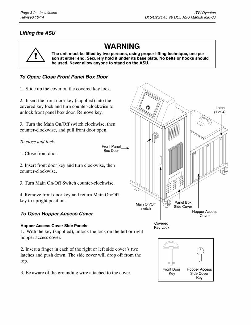
To Open/ Close Front Panel Box Door
1. Slide up the cover on the covered key lock.
2. Insert the front door key (supplied) into thecovered key lock and turn counter-clockwise tounlock front panel box door. Remove key.
3. Turn the Main On/Off switch clockwise, thencounter-clockwise, and pull front door open.
To close and lock:
1. Close front door.
2. Insert front door key and turn clockwise, thencounter-clockwise.
3. Turn Main On/Off Switch counter-clockwise.
4. Remove front door key and return Main On/Offkey to upright position.
To Open Hopper Access Cover
Hopper Access Cover Side Panels1. With the key (supplied), unlock the lock on the left or righthopper access cover.
2. Insert a finger in each of the right or left side cover’s twolatches and push down. The side cover will drop off from thetop.
3. Be aware of the grounding wire attached to the cover.
Main On/Offswitch
CoveredKey Lock
Latch(1 of 4)
Panel BoxSide Cover
Hopper AccessCover
Front PanelBox Door
Lifting the ASU
WARNINGThe unit must be lifted by two persons, using proper lifting technique, one per-son at either end. Securely hold it under its base plate. No belts or hooks shouldbe used. Never allow anyone to stand on the ASU.

ITW Dynatec D15/D25/D45 V6 DCL ASU Manual #20-63
Installation Page 3-3Revised 10/14
DANGER HIGH VOLTAGEDisconnect and lock out input power to the application system before start-ing any installation procedures. Make sure there is no electrical power on theleads you will be connecting.
CAUTION: Grounding conductors never carry electrical current. The use of a neutralconducting wire as earth ground is incorrect and may cause damage to the Dyna-Control controller.
Installation
Note: Re-read Chapter 1 “Safety Precautions” before performing any installation procedures. Allinstallation procedures must be performed by qualified, trained technicians.
After the D15/D25/D45 SERIES ASU has been properly mounted, the following general sequenceshould be followed for installation:
1. Make sure that incoming line power to the ASU and that the unit’s Main Power Switch areturned OFF.
2. Open the panel box door. Select correct plug for your ASU’s amperage (refer to instructions onthe following page). Run the power cord through the hole in the bottom of the base plate. In thepanel box, at the main circuit breaker, attach the power cord at the switch’s connectors. Attachground wire to ground lug provided in the base plate.
Filter Block Guard
HoseConnectors
D25 ASU: Rear View
AUXConnectors

Page 3-4 InstallationRevised 10/14
ITW Dynatec D15/D25/D45 V6 DCL ASU Manual #20-63
DynaControl V6 Power Module
Verify Voltage Configuration Connectoraccording to your voltage :
240V Three phase = Violet
400V Three phase = Yellow
Connect to Main Power ON/OFF Switchaccording to your voltage (see chart onnext page).‐
3. A voltage configuration connector (plug), appropriate for your order, has been installed in yourASU. Before proceeding, verify that this plug is correct for your operating voltage.
The voltage configuration connector is installed on the DynaControl V6 Power Module (see moduleillustration below). For location of the module, see illustration on page 3-7.
There are two different voltage configuration connectors available:240V Three phase = P/N 115725 (Violet)400V Three phase = P/N 115726 (Yellow)
For reference, the schematics of each voltage configuration connector is printed on the next page.
CAUTION: Using the incorrect power configuration connector may cause seriousdamage to the unit.

ITW Dynatec D15/D25/D45 V6 DCL ASU Manual #20-63
Installation Page 3-5Revised 10/14
Voltage Configuration Connector Schematics
Page 3-6 InstallationRevised 10/14
ITW Dynatec D15/D25/D45 V6 DCL ASU Manual #20-63
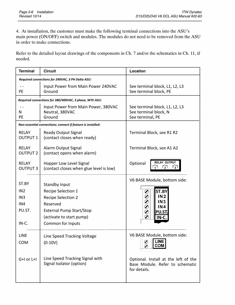
Terminal Circuit Location
‐ ‐ Input Power from Main Power 240VAC See terminal block, L1, L2, L3PE Ground See terminal block, PE
‐ ‐ Input Power from Main Power, 380VAC See terminal block, L1, L2, L3N Neutral, 380VAC See terminal block, NPE Ground See terminal, PE
RELAY Terminal Block, see R1 R2OUTPUT 1
RELAY Terminal Block, see A1 A2OUTPUT 2
RELAY OptionalOUTPUT 3
ST.BY
IN-C.
Ready Output Signal(contact closes when ready)
Alarm Output Signal(contact opens when alarm)
Hopper Low Level Signal(contact closes when glue level is low)
IN2
IN3
IN4
PU.ST.
Standby InputRecipe Selection 1Recipe Selection 2ReservedExternal Pump Start/Stop(activate to start pump)Common for Inputs
LINE COM
G+I or L+I
Line Speed Tracking Voltage (0‐10V)
Line Speed Tracking Signal with Signal Isolator (option)
Optional. Install at the left of the Base Module. Refer to schematic for details.
4. At installation, the customer must make the following terminal connections into the ASU’smain power (ON/OFF) switch and modules. The modules do not need to be removed from the ASUin order to make connections.
Refer to the detailed layout drawings of the components in Ch. 7 and/or the schematics in Ch. 11, ifneeded.
Required connections for 380/400VAC, 3 phase, WYE ASU:
Required connections for 240VAC, 3 PH Delta ASU:
Non‐essential connections; connect if feature is installed:
V6 BASE Module, bottom side:
V6 BASE Module, bottom side:

ITW Dynatec D15/D25/D45 V6 DCL ASU Manual #20-63
Installation Page 3-7Revised 10/14
Location of V6 Modules & Printed Circuit Boards (PCBs)
HMI Assembly(Operator’s Panel)
High Temp (OverTemp)Thermostat
#2 MotorSpeed Control
Signal IsolatorPCB #1 Motor
Speed Control
Fan
Main Circuit Breaker, On-Off, 30A (standard) Main Circuit Breaker, On-Off, 60A (option)
V6 MotorModule
V6 BaseModule
V6 AUXPower Board
V6 TempModule
PowerConnects:L1 L2 L3 N
V6 PowerModule
V6 AUXPower Board
(locatedwithincabinet)
Page 3-8 InstallationRevised 10/14
ITW Dynatec D15/D25/D45 V6 DCL ASU Manual #20-63
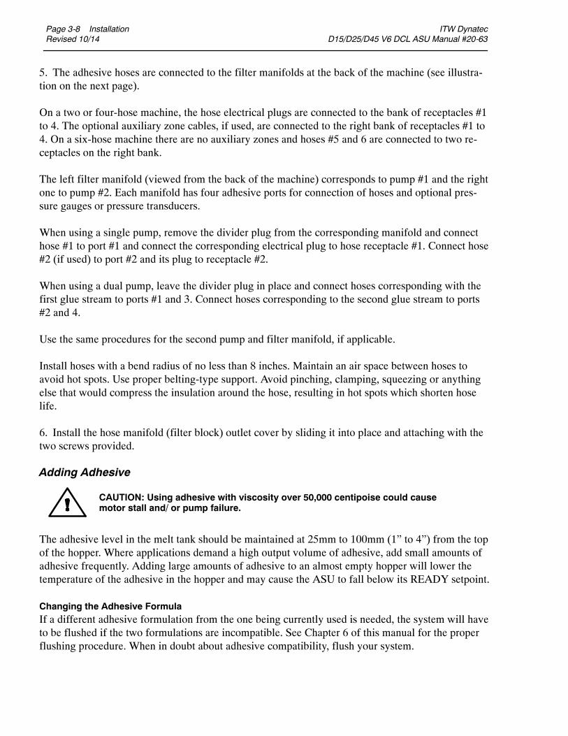
5. The adhesive hoses are connected to the filter manifolds at the back of the machine (see illustra-tion on the next page).
On a two or four-hose machine, the hose electrical plugs are connected to the bank of receptacles #1to 4. The optional auxiliary zone cables, if used, are connected to the right bank of receptacles #1 to4. On a six-hose machine there are no auxiliary zones and hoses #5 and 6 are connected to two re-ceptacles on the right bank.
The left filter manifold (viewed from the back of the machine) corresponds to pump #1 and the rightone to pump #2. Each manifold has four adhesive ports for connection of hoses and optional pres-sure gauges or pressure transducers.
When using a single pump, remove the divider plug from the corresponding manifold and connecthose #1 to port #1 and connect the corresponding electrical plug to hose receptacle #1. Connect hose#2 (if used) to port #2 and its plug to receptacle #2.
When using a dual pump, leave the divider plug in place and connect hoses corresponding with thefirst glue stream to ports #1 and 3. Connect hoses corresponding to the second glue stream to ports#2 and 4.
Use the same procedures for the second pump and filter manifold, if applicable.
Install hoses with a bend radius of no less than 8 inches. Maintain an air space between hoses toavoid hot spots. Use proper belting-type support. Avoid pinching, clamping, squeezing or anythingelse that would compress the insulation around the hose, resulting in hot spots which shorten hoselife.
6. Install the hose manifold (filter block) outlet cover by sliding it into place and attaching with thetwo screws provided.
Adding Adhesive
The adhesive level in the melt tank should be maintained at 25mm to 100mm (1” to 4”) from the topof the hopper. Where applications demand a high output volume of adhesive, add small amounts ofadhesive frequently. Adding large amounts of adhesive to an almost empty hopper will lower thetemperature of the adhesive in the hopper and may cause the ASU to fall below its READY setpoint.
Changing the Adhesive FormulaIf a different adhesive formulation from the one being currently used is needed, the system will haveto be flushed if the two formulations are incompatible. See Chapter 6 of this manual for the properflushing procedure. When in doubt about adhesive compatibility, flush your system.
CAUTION: Using adhesive with viscosity over 50,000 centipoise could causemotor stall and/ or pump failure.

ITW Dynatec D15/D25/D45 V6 DCL ASU Manual #20-63
Installation Page 3-9Revised 10/14
Rear Cover: Hose and Head Electrical and Adhesive Connections
Maintain adhesive level13mm to 100mm (1/2” to4”) from top of hopper
Filter Guard
Adjustable PressureRelief Valve
Pressure Gauge(optional)
Hose / HeadAdhesive Port
Adhesive SupplyHose
Hose/Head Electrical Connections are located on either sideof the Filter Outlet Manifold (8 hose/head model shown)
Adhesive Port ConnectionsHose/Head #1
Hose/Head #2
Hose/Head #4
Hose/Head #3
Auxiliary #4
Auxiliary #3
Auxiliary #2
Auxiliary #1
#1 #2
#4#3
#1 #2
#4#3
Page 3-10 InstallationRevised 10/14
ITW Dynatec D15/D25/D45 V6 DCL ASU Manual #20-63
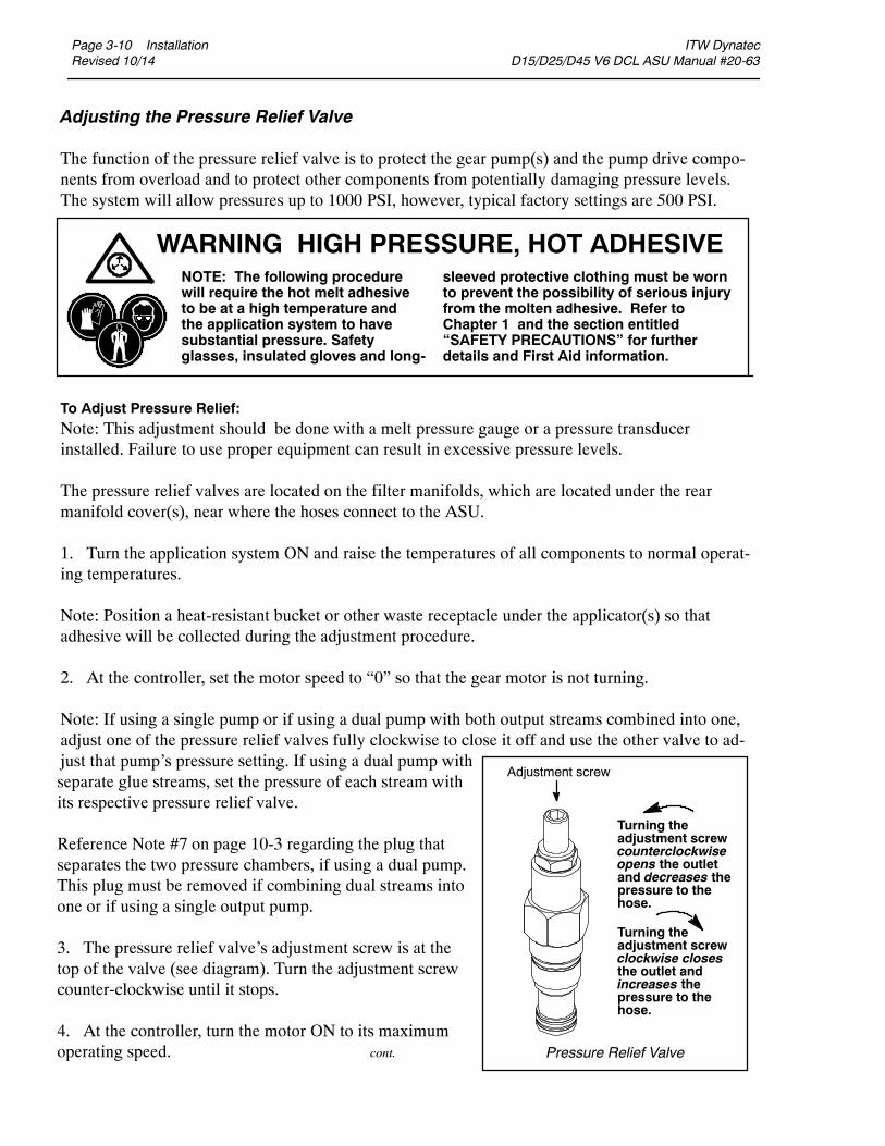
Adjusting the Pressure Relief Valve
The function of the pressure relief valve is to protect the gear pump(s) and the pump drive compo-nents from overload and to protect other components from potentially damaging pressure levels.The system will allow pressures up to 1000 PSI, however, typical factory settings are 500 PSI.
To Adjust Pressure Relief:Note: This adjustment should be done with a melt pressure gauge or a pressure transducerinstalled. Failure to use proper equipment can result in excessive pressure levels.
The pressure relief valves are located on the filter manifolds, which are located under the rearmanifold cover(s), near where the hoses connect to the ASU.
1. Turn the application system ON and raise the temperatures of all components to normal operat-ing temperatures.
Note: Position a heat-resistant bucket or other waste receptacle under the applicator(s) so thatadhesive will be collected during the adjustment procedure.
2. At the controller, set the motor speed to “0” so that the gear motor is not turning.
Note: If using a single pump or if using a dual pump with both output streams combined into one,adjust one of the pressure relief valves fully clockwise to close it off and use the other valve to ad-just that pump’s pressure setting. If using a dual pump with
WARNING HIGH PRESSURE, HOT ADHESIVEsleeved protective clothing must be wornto prevent the possibility of serious injuryfrom the molten adhesive. Refer toChapter 1 and the section entitled“SAFETY PRECAUTIONS” for furtherdetails and First Aid information.
NOTE: The following procedurewill require the hot melt adhesiveto be at a high temperature andthe application system to havesubstantial pressure. Safetyglasses, insulated gloves and long-
Adjustment screw
Turning theadjustment screwcounterclockwiseopens the outletand decreases thepressure to thehose.
Turning theadjustment screwclockwise closesthe outlet andincreases thepressure to thehose.
Pressure Relief Valve
separate glue streams, set the pressure of each stream withits respective pressure relief valve.
Reference Note #7 on page 10-3 regarding the plug thatseparates the two pressure chambers, if using a dual pump.This plug must be removed if combining dual streams intoone or if using a single output pump.
3. The pressure relief valve’s adjustment screw is at thetop of the valve (see diagram). Turn the adjustment screwcounter-clockwise until it stops.
4. At the controller, turn the motor ON to its maximumoperating speed. cont.
ITW Dynatec D15/D25/D45 V6 DCL ASU Manual #20-63
Installation Page 3-11Revised 10/14
5. Actuate (open) the valves on the applicator(s) in order to fill themwith adhesive and purge air fromthe system.
6. Close the valves (those opened in the last step) to stop the flow of adhesive.
7. Using a wrench, turn the adjustment screw clockwise to increase the pressure to the applicator(s).
8. After desired pressure is achieved, stop turning the adjustment screw.
9. While the motor is operating at maximum speed and the applicators are valved on, observe the ad-hesive flow from the applicator(s).
10. Reduce the motor speed, in increments of about 10%, until the adhesive flow begins to decrease.
Note: Though the speed of themotor is reduced, therewill be no change in the amount of adhesive flowcoming out of the applicator. This is because the pressure relief is designed to allow only a maximumadhesive pressure regardless of the motor speed past a certain point.
Then, increase motor speed in smaller increments (1 to 5%) until adhesive flow returns to the desiredamount.
Note: This is the optimumpoint of operation for themotor, pump and pressure relief. It will also facili-tate the best system performance and reduce wear on these components.
The application system is now adjusted for normal operation.
CAUTION: Approach desired pressure with caution. Be aware that the higher theadjusted pressure, the more sensitive the adjustment is (i.e., at higher pressures,smaller adjustments to the screw will make larger changes to actual pressure).

Page 3-12 InstallationRevised 10/14
ITW Dynatec D15/D25/D45 V6 DCL ASU Manual #20-63
Field Installation of Controller Options
Customerswhochoose tomodify their adhesive supply unitwith ITWDynatecmanufacturedoptionsshould assure that only qualified technicians perform such installations. The installation of optionsthat require specific procedures and/ or calibration are outlined in this chapter.
Before controller options are installed, always turn the controller’s main power switch OFF. In mostcases, turning the controllerOFFwill assure that the controllerwill retain its programmedparametersand configuration. Re-booting is not necessary.
Adjustment of the Optional Level Control
To adjust the adhesive level sensitivity: access the control’samplifier, located on the panel mount under the pump andelectronics cover. On the amplifier (diagrammed atright) is a sensitivity adjustment screw. Turn the screw clock-wise to increase sensitivity (or counter-clockwise to decrease).The yellow LED lights to indicate the presence of adhesive. Whenthe LED goes out, the audible and visible alarms will activate.
1 2 3 4 5 6
7 8 9 10 11 12
min max
SensitivityAdjustmentScrew
Yellow Light
SensorConnect S
ITW Dynatec D15/D25/D45 V6 DCL ASU Manual #20-63
Installation Page 3-13Revised 10/14
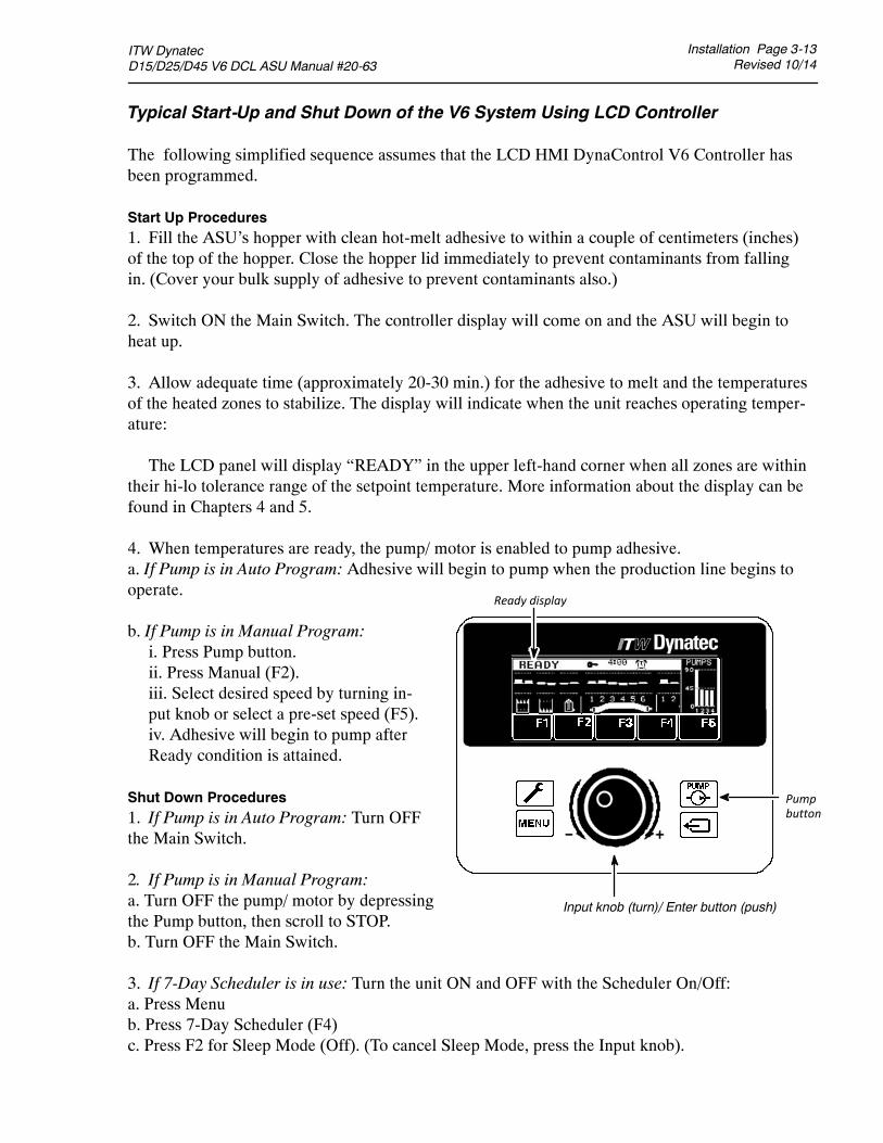
Typical Start-Up and Shut Down of the V6 System Using LCD Controller
The following simplified sequence assumes that the LCD HMI DynaControl V6 Controller hasbeen programmed.
Start Up Procedures1. Fill the ASU’s hopper with clean hot-melt adhesive to within a couple of centimeters (inches)of the top of the hopper. Close the hopper lid immediately to prevent contaminants from fallingin. (Cover your bulk supply of adhesive to prevent contaminants also.)
2. Switch ON the Main Switch. The controller display will come on and the ASU will begin toheat up.
3. Allow adequate time (approximately 20-30 min.) for the adhesive to melt and the temperaturesof the heated zones to stabilize. The display will indicate when the unit reaches operating temper-ature:
The LCD panel will display “READY” in the upper left-hand corner when all zones are withintheir hi-lo tolerance range of the setpoint temperature. More information about the display can befound in Chapters 4 and 5.
4. When temperatures are ready, the pump/ motor is enabled to pump adhesive.a. If Pump is in Auto Program: Adhesive will begin to pump when the production line begins tooperate.
b. If Pump is in Manual Program:i. Press Pump button.ii. Press Manual (F2).iii. Select desired speed by turning in-put knob or select a pre-set speed (F5).iv. Adhesive will begin to pump afterReady condition is attained.
Shut Down Procedures1. If Pump is in Auto Program: Turn OFFthe Main Switch.
2. If Pump is in Manual Program:a. Turn OFF the pump/ motor by depressingthe Pump button, then scroll to STOP.b. Turn OFF the Main Switch.
3. If 7-Day Scheduler is in use: Turn the unit ON and OFF with the Scheduler On/Off:a. Press Menub. Press 7-Day Scheduler (F4)c. Press F2 for Sleep Mode (Off). (To cancel Sleep Mode, press the Input knob).
Ready display
Input knob (turn)/ Enter button (push)
Pumpbutton
Page 3-14 InstallationRevised 10/14
ITW Dynatec D15/D25/D45 V6 DCL ASU Manual #20-63
Typical Start-Up and Shut Down of the Application System Using the Touch Screen
The following simplified sequence assumes that the DynaControl Controller has been pro-grammed.
Start Up Procedures1. Fill the ASU’s hopper with clean hot-melt adhesive to within a couple of centimeters (inches) ofthe top of the hopper. Close the hopper lid immediately to prevent contaminants from falling in.(Cover your bulk supply of adhesive to prevent contaminants also.)
2. Switch ON the Main Disconnect (the circuit breaker located on the panel box).
3. The Controller and the Touch Panel will start automatically. All system heaters go ON unlessthey have previously been de-activated (in which case they will be turned OFF) or if heating prior-ities have been set.
4. Allow adequate time (approximately 20- 30 min.) for the adhesive to melt and the temperaturesof the temperature zones to stabilize. Observe the Status Line display at the Main Screen to seewhen “Not Ready” changes to “Ready”.
5. When temperatures are ready, the pump and motor are enabled to pump adhesive.
6. At the Pump Overview Screen, select Auto or Manual Mode for each pump.
a. If Pump is in Auto Mode, select either Pump Control in Linear Line Speed or Pump Control,Pressure Control.
To select Pump Control in Linear Line Speed: Adhesive will begin to pump when the productionline begins to operate.i. Select the pump for programming under the Settings column on the Pump Overview Screen.ii. Select Linear Line Speed in the Current Pump Mode menu. Press BACK.iii. Set the minimum and maximum setpoint value (RPM). The pump speed is controlled via a
0-10VDC signal provided by an external device (pattern control equipment or parent machine in-put). The minimum speed is necessary to keep the pump turning in order to maintain a minimumamount of adhesive pressure through the hose and applicator head.iv. Select the next pump (if applicable) under the Settings column on the Pump Overview
Screen. Repeat steps i through iii until all pumps in the system are programmed.
To select Pump Control, Pressure Control: Adhesive will begin to pump when the pressure setpointis reached.i. Select the pump for programming under the Settings column on the Pump Overview Screen.ii. Select Pressure Control on the Current Pump Mode menu. Press BACK.iii. Set the minimum and maximum setpoint value (RPM), the pressure setpoint value and the
switch point value. The pump speed is controlled via the pressure signal provided by a pressuresensor.iv. Select the next pump (if applicable) under the Settings column on the Pump Overview
Screen. Repeat steps i thru iii until all pumps in the system are programmed.
ITW Dynatec D15/D25/D45 V6 DCL ASU Manual #20-63
Installation Page 3-15Revised 10/14
b. If Pump is in Manual Mode:i. Select the pump for programming under the Settings column on the Pump Overview Screen.ii. Set the manual setpoint value (RPM) under Manual Mode Settings.iii. Select the next pump (if applicable) under the Settings column on the Pump Overview
Screen. Repeat steps i thru iii until all pumps in the system are programmed.
Shut Down ProceduresAt the pump screen:1 .If Pump is in Auto Mode:a. Press STOP or ALL PUMPS STOP.b. Turn OFF the Main Disconnect Switch.
2. If Pump is in Manual Mode:a. Press STOP or ALL PUMPS STOP.b. Turn OFF the Main Disconnect Switch.
3. If the Scheduler is in use:Turn OFF the unit with the Control Switch On/Off (ie, on the Main Screen, press the Control but-ton. Then, at the Control Switch/ Standby Screen, press On/Off).
Note: If the Scheduler is not in operation, use the Main Disconnect Switch to turn the unit OFF toavoid unexpected ASU activation in the event of a power outage.

Page 3-16 InstallationRevised 10/14
ITW Dynatec D15/D25/D45 V6 DCL ASU Manual #20-63
Storage and Disposal of the Application System
Temporary Storage of the Unit1. Flush the adhesive application system with flushing fluid (PN L15653), following the instruc-tions detailed in chapter 6 of this manual.
2. Clean or replace both the outlet filter and the primary filter, following the instructionsdetailed in chapter 6.
3. Shut OFF all pressure and power sources.
4. Release residual air pressure.
5. Remove all residual adhesive and wipe components clean.
6. Remove all air lines and all power supply cables.
7. Pack the unit in a corrosion-proof manner.
8. Store the unit in such a way that it is protected from damage.
Disposal of the Unit1. Shut OFF all pressure and power sources.
2. Release residual air pressure.
3. Remove all residual adhesive.
4. Remove all air and adhesive supply hoses and all power supply cables.
5. Dismantle all components and sort into mechanical and electrical components.
6. Arrange for all components to be recycled.

ITW Dynatec D SERIES V6 DCL ASU Manuals
Controller Setup Page 4-1Revised 10/14
Chapter 4DynaControl V6 CONTROLLER SET-UP
Temperature Control Functions in General
The DynaControl microprocessor-based proportional temperature control in the ASU performs a number of functions that help to maintain adhesive setpoints in all temperature zones of the DY-NAMELT system. It maintains permanent system values such as the maximum temperature setpoint. It enables the user to program temperature settings and heater on/off sequencing that are appropriate to a specific application. It displays all programmed values, and it includes self-diagnostic malfunc-tion alerts and failure alarms. Note: Some DynaControl functions are direct temperature conversions between degrees Celsius and Fahrenheit. Other parameters are independently selected values.
Defining DynaControl Temperature Control Terms
Adhesive Temperature Control RangeThe temperature limits within which the ASU, hoses and applicators may be programmed and main-tained.
Default SettingsThe factory-set programmable system values that will be in effect if the user does not enter new val-ues.
Error Indication AlarmsController alarms which indicate that the programmed over-temperature values have been exceeded for one or more hopper, hose or head zones. Alarms may also indicate an open or short-circuited sensor.
Main Power & Aux Power PCBsThe V6 Power Module and V6 Aux Power Module provide power to all the temperature zones in the ASU’s system. The standard unit’s hopper, hoses and applicators are controlled by the Power Module. Additional hoses and applicators are controlled by the Aux Power Module.
Mechanical High-Temperature ProtectionA mechanical, redundant thermostat located on the hopper which turns OFF the system at 218C(425F) [or 232C (450F) for optional high temperature units].
Microprocessor-based Proportional Temperature ControlThe built-in control system that controls, monitors and displays all system temperatures.

Page 4-2 Controller SetupRevised 10/14
ITW Dynatec D SERIES V6 DCL ASU Manuals
Over-Temperature SetpointThe programmable temperatures that will cause alarms to occur when those temperaturesare exceeded. Power is not disconnected, the READY contact opens and the alarm contact opens. Ifan external alarm has been connected, it will activate. The over-temp setpoint is the upper limit ofthe ready temperature range of each zone.
RTD SensorsThe standard Dynamelt system uses 100-ohm platinum resistance temperature detector sensors forall temperature controls. Ni120 is available as an option.
Ready TemperatureThe programmable temperature which allows the ASU pump to turn ON. The default ready temper-ature range is a deviation of + 20C (+ 36F) from the setpoint. The setpoint minus the deviation isthe low limit of the range, and the setpoint plus the deviation is the high limit of the range.
Sequential HeatingThe heating sequence which allows the slower-heating hopper to reach operating temperaturewithout unnecessary use of electricity for faster-heating hoses and applicators. Sequential heating isthe time period during which the hoses and applicators remain OFF while the hopper (and optionaldrop-in grid) heats up. Hoses and applicators may be independently programmed. If hopper temper-ature is above ready temperature when the ASU is turned ON, the hose and applicator sequence isbypassed and they will be turned ON. Sequential heating is restored after Standby is turned fromON to OFF Sequential heating is not needed for most applications and can delay total systemwarm-up time.
SetpointsThe temperatures that you have selected and programmed for each of the temperature zones.
Setpoint LimitationThis is a universal maximum temperature for all zones. The programmer cannot program a temper-ature setpoint higher than the setpoint limitation. If the actual temperature of any zone climbs higherthan the setpoint limitation, all heaters will shut down.
Standby ConditionThe system condition where the ASU, hose and head temperatures are maintained at predeterminedreduced temperature values. Standby temperatures are set lower than setpoint temperatures in orderto reduce adhesive degradation and energy consumption when the system is temporarily inactive,and to permit rapid system warm-up when run condition is selected. When standby mode is activ-ated, the controller will display STANDBY.
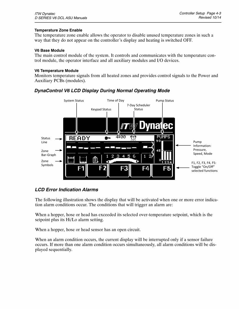
ITW Dynatec D SERIES V6 DCL ASU Manuals
Controller Setup Page 4-3Revised 10/14
LCD Error Indication Alarms
The following illustration shows the display that will be activated when one or more error indica-tion alarm conditions occur. The conditions that will trigger an alarm are:
When a hopper, hose or head has exceeded its selected over-temperature setpoint, which is the setpoint plus its Hi/Lo alarm setting.
When a hopper, hose or head sensor has an open circuit.
When an alarm condition occurs, the current display will be interrupted only if a sensor failure occurs. If more than one alarm condition occurs simultaneously, all alarm conditions will be dis-played sequentially.
Temperature Zone EnableThe temperature zone enable allows the operator to disable unused temperature zones in such away that they do not appear on the controller’s display and heating is switched OFF.
V6 Base ModuleThe main control module of the system. It controls and communicates with the temperature con-trol module, the operator interface and all auxiliary modules and I/O devices.
V6 Temperature ModuleMonitors temperature signals from all heated zones and provides control signals to the Power andAuxiliary PCBs (modules).
DynaControl V6 LCD Display During Normal Operating Mode
ZoneSymbols
ZoneBar‐Graph
StatusLine
Keypad Status7‐Day Scheduler
Status
Time of DaySystem Status Pump Status
PumpInformation:Pressure,Speed, Mode
F1, F2, F3, F4, F5:Toggle “On/Off”selected functions
320 PSI

Page 4-4 Controller SetupRevised 10/14
ITW Dynatec D SERIES V6 DCL ASU Manuals
LCD Error Indication Alarm Display Examples
Operator Response to LCD Error Indication AlarmsIf an alarm occurs during operation, the controller will switch off the internal power to the heatersand an appropriate error indication display will appear.
Pressing the RETURN button resets the error. If several zones display alarms, each must be ac-knowledged by pressing RETURN. The alarm display is switched off. The operator must eitherswitch OFF the indicated temperature zone(s) (via the DynaControl keypad) or troubleshoot to cor-rect the problem.
Low temperature alarms will not open the main contactor and are only indicated on the bar-graphdisplay and auxiliary alarm output contacts.
A sensor failure is displayed as a “?” on the bar-graph and power is switched off to the zone.
When the actual temperature exceeds the setpoint limitation plus a tolerance of a few degrees, a “!”is displayed on the bar-graph and heater power is switched off.
Zone is cold
Zone is at lower toleranceZone is just under setpointZone is exactly at setpointZone is slightly above setpoint
Zone has a sensor faultZone is over‐heating
Zone is coldZone is near setpoint
Zone hasno sensor
(”solid”bar‐graphs)
(”outlined”bar‐graphs)Active Zones
Non‐ActiveZones

ITW Dynatec D SERIES V6 DCL ASU Manuals
Controller Setup Page 4-5Revised 10/14
Acknowledge button in alarm state
Touch Screen Error Indication Faults & Alarms
If a fault/ alarm occurs, the Acknowledge button (on the Main Screen) and the temperature zonewill be highlighted in red. The controller will turn off the internal power to the heaters and an ap-propriate alarm indication will appear in the status line of the controller’s display.
The operator must either turn Off the indicated temperature zone(s) or troubleshoot to correct theproblem. Then press the Acknowledge button in order to turn on the main contactor and reset theerror. If more than one alarm condition occurs simultaneously, the alarms will be displayed se-quentially and each alarm must be acknowledged.
When an alarm occurs, the current display will be interrupted only if a sensor (or a motor drive)failure has occurred. When the actual temperature exceeds the setpoint limitation (plus a toler-ance) the over-temperature alarm is displayed and main power is switched Off.
statusline
2 temperature zones are in alarm state
FAIL FAIL
Page 4-6 Controller SetupRevised 10/14
ITW Dynatec D SERIES V6 DCL ASU Manuals
Error Alarms in Touch Screen Status LineAmong the Faults and Alarms that may be displayed on the controller’s status line are:
RTD Fault: a hopper, hose or applicator head RTD sensor has an open circuit.
Temperature Alarm:1. a temperature zone has exceeded its selected over-temperature setpoint, (which is the setpointplus the Temperature Alarm Window and Temperature Alarm Hysteresis), or2. a temperature zone is below its selected under-temperature setpoint (which is the setpoint minusthe Temperature Alarm Window and the Temperature Alarm Hysteresis).
Drive Failure: a motor drive (frequency converter) has a fault.
Minimum Level: the adhesive level has dropped below the level sensor and the hopper is empty.
Feedback Failure Motor #: (optional) speed monitor pump addressed.
Over temperature: hardware over-temperature indication.
Communication Error: there is a communication error between the touch panel and controller.
Parameter CRC Error: parameter memory has been lost. Call ITW Dynatec Technical Service.
Other Faults or Alarms: call ITW Dynatec Technical Service.
Touch Screen Controller’s Log BookThe controller’s Log Book Screen provides a list of the last 100 controller alarms, faults and events.
To go to the Log Book, press the Settings button on the Main Screen. Then press the Log Book but-ton on the Settings Screen.
WARNING USE OF SCHEDULER FEATUREThe controller’s Scheduler feature allows automatic start-up and shut-down of theunit’s heating and rotating components, which may present an unexpected hazardto those unfamiliar with it. Users, service technicians and others in the vicinity ofthe machine should be made aware of this possibility in order to mitigate the riskof injury.

ITW Dynatec D SERIES V6 DCL ASU Manuals
Controller Setup Page 4-7Revised 10/14
Settings for a Typical Operation
Note: The values given here are approximate settings for a typical packaging application. The val-ues you choose will be based on the type of equipment and adhesive you are using and the nature ofyour particular operation.
If Application Temperature is 177C (350F):
Hose and head temperature: 177C (350F).
Hopper setpoint temperature: 163C (325F).
Hi/ Lo limit deviation: 12C (20F).
ASU operating range: 149C to 177C (300F to 350F).
Standby condition temperature (deviation): 30C (50F).
Hopper over-temperature setpoint: 177C (350F)
Mechanical thermostat (for the hopper) over-temperature: 218C (425F)
For most operations, temperature fluctuations will be very small and of short duration. For thesereasons, the settings above are recommended.
Page 4-8 Controller SetupRevised 10/14
ITW Dynatec D SERIES V6 DCL ASU Manuals
System Values That Are Factory Programmed (not customer programmable)
Minimum setpoint value: 10C (50F).
Maximum setpoint value (setpoint limitation): 218C (425F).
Maximum alarm deviation: 50 (C or F).
Minimum alarm deviation: 5 (C or F).
Maximum standby temperature: 150 (C or F) less than setpoint.
Minimum standby temperature: 30 (C or F) less than setpoint.
“Actual” temperature indication range: 0C to 260C (32F to 500F).
Customer Programmable System Values Preset At The Factory
ITW Dynatec can set the controller’s system values to customer’s specs, if provided.
If customer’s specs are not provided, the following values will be entered into the DynaControl con-troller at the factory. They may be changed by reprogramming through the controller.(These are not the “default” settings, see following section).
Language: Chinese (when shipment is to a China destination).
Standby: 82C (180F) under setpoint.
All other system values: controller defaults.
ITW Dynatec D SERIES V6 DCL ASU Manuals
Controller Setup Page 4-9Revised 10/14
Default Settings of the DynaControl V6 LCD Controller
Language: English
Setting for Customer Access Code: “1111”.
Standby temperature for all zones: 66C (150F) lower than programmed setpoints.
Hi/ lo limit deviation for all temperature zones: + 20C (36F).
Temperature zone offset: 0C (0F).
Setpoint limitation: 218C (425F).
Automatic sleep mode: Off.
Sequential heat-up: Off.
Power-On motor Stop: No.
Power-On heater start: Yes.
Global setpoints: No.
Minimum pump speed: 0 RPM).
Maximum pump speed: 90 RPM.
The ITW Dynatec factory default settings may be re-loaded in the controller per the instructionsgiven in Chapter 5: Zone Configuration (P1 parameter).
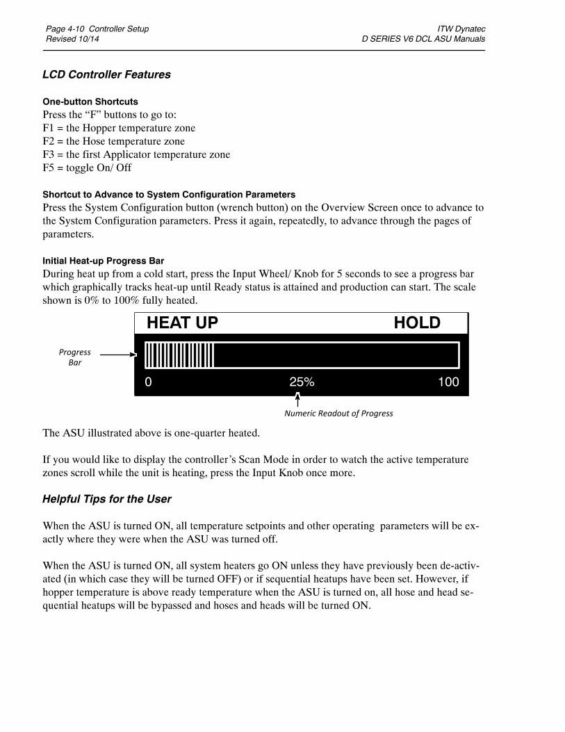
Page 4-10 Controller SetupRevised 10/14
ITW Dynatec D SERIES V6 DCL ASU Manuals
LCD Controller Features
One-button ShortcutsPress the “F” buttons to go to:F1 = the Hopper temperature zoneF2 = the Hose temperature zoneF3 = the first Applicator temperature zoneF5 = toggle On/ Off
Shortcut to Advance to System Configuration ParametersPress the System Configuration button (wrench button) on the Overview Screen once to advance tothe System Configuration parameters. Press it again, repeatedly, to advance through the pages ofparameters.
Initial Heat-up Progress BarDuring heat up from a cold start, press the Input Wheel/ Knob for 5 seconds to see a progress barwhich graphically tracks heat-up until Ready status is attained and production can start. The scaleshown is 0% to 100% fully heated.
The ASU illustrated above is one-quarter heated.
If you would like to display the controller’s Scan Mode in order to watch the active temperaturezones scroll while the unit is heating, press the Input Knob once more.
Helpful Tips for the User
When the ASU is turned ON, all temperature setpoints and other operating parameters will be ex-actly where they were when the ASU was turned off.
When the ASU is turned ON, all system heaters go ON unless they have previously been de-activ-ated (in which case they will be turned OFF) or if sequential heatups have been set. However, ifhopper temperature is above ready temperature when the ASU is turned on, all hose and head se-quential heatups will be bypassed and hoses and heads will be turned ON.
Numeric Readout of Progress
HEAT UP HOLD
0 10025%
ProgressBar

ITW Dynatec D SERIES V6 DCL ASU Manuals
LCD Programming Page 5-1Revised 10/14
DynaControl CONTROLLER, V.6.00 and Up
DynaControl (DCL) V6 LCD InterfaceDynaControl V6 controller technology is available as a liquid crystal display (LCD), which allows aninstant overview of temperature zone and pump status, and with a combination Input Wheel/Enter Knob to facilitate fast programming. The LCD HMI is the standard controller for the D SeriesASUs.
In General
Press the Return button to return to the Overview Screen (seen on next page).
This controller utilizes the graphics (indicating YES or ON or selected) and (indicating NOor OFF or not‐selected).
When there is no operator activity on a screen for approximately 30 seconds, the controller willautomatically return to the Overview Screen.
LCD
Input Wheel/ Press Knob to Enter
Chapter 5, Section 1PROGRAMMING INSTRUCTIONS, V6 LCD FOR D SERIES ASUs
Return
Adhesive Application SystemsV6Adhesive Application Systems DynaControl

Page 5-2 LCD ProgrammingRevised 10/14
ITW Dynatec D SERIES V6 DCL ASU Manuals
Overview Screen Reference
The Overview Screen gives a comprehensive view of the status of each of the temperaturezones and the system as a whole. It gives the status and speed of the pump.
Keypad Status7‐Day Scheduler
Status
ZoneSymbols
ZoneBar‐Graph
Pump /MotorSpeed
Go toMain Menu
Go toSystemConfigurationMenu
Go toPump (Motor)Screen
Return to Previous Screen
F1, F2, F3, F4, F5:Toggle “On/Off”selected functionsor “Go To” selectedscreens
StatusLine
Input Wheel/Press Knob to Enter
Time of DaySystem Status Pump Status

ITW Dynatec D SERIES V6 DCL ASU Manuals
LCD Programming Page 5-3Revised 10/14
Status Line
The status line is the top line of the display. It always lists the System Status, the Time‐of‐Dayand the Pump Status. It can also include the status of the Keypad (if locked) and the 7‐DayScheduler (if active). An example of an Overview Screen status line is seen below.
System Status
The status of the “system”, ie. the ASU (melter) and its hoses and applicators, is listed as one ofthe following:
Pump Status
The status of the adhesive pump is indicated as follows:
Time 7‐Day Scheduler is active Pump StatusSystem Status Keypad is locked
HEAT‐UP No faults present, zones are heating but haven't reached their setpoint windowREADY No faults present and all zones are within the setpoint windowALARM At least one zone is outside the setpoint window (over or under temp)STANDBY The system is in standby modeOVER‐TEMP The hopper is in over temperature condition, all power circuits are shut offFAULT A temperature zonehas a fault andall power circuits are shut off or themotordrivehas faultedHOPPER EMPTY Adhesive in the hopper is low and must be replenished
Temperature Zone Symbols
Each temperature zone is represented by a symbol on the display, as follows:
PUMPS Pump has start signal and is actually running (seen on Overview Screen, upper right corner)HOLD Pump is in Run mode (auto or manual) but a low temperature condition prevents it from
running (seen on Overview Screen, upper right corner)STOP Pump is in Stop mode (seen on Pump Screen)
ASU'sHopper(up to 3)
(not used in theD Series
configuration)
Hoses(up to 12)
Applicator Heads(up to 12)
ASU'sPremelt(Drop‐in)Grids
(up to 6)
Auxiliary Zones(up to 12)
AUX-ZONE
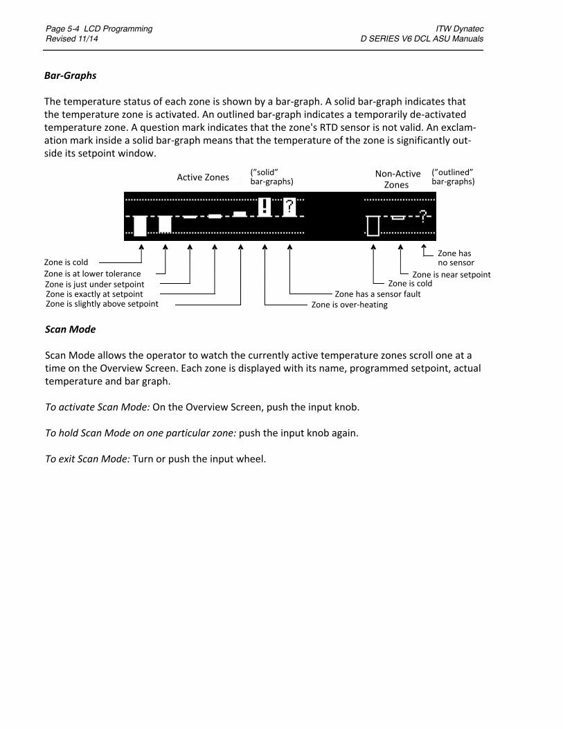
Page 5-4 LCD ProgrammingRevised 11/14
ITW Dynatec D SERIES V6 DCL ASU Manuals
Zone is cold
Zone is at lower toleranceZone is just under setpointZone is exactly at setpointZone is slightly above setpoint
Zone has a sensor faultZone is over‐heating
Zone is coldZone is near setpoint
Zone hasno sensor
(”solid”bar‐graphs)
(”outlined”bar‐graphs)
Bar‐Graphs
The temperature status of each zone is shown by a bar‐graph. A solid bar‐graph indicates thatthe temperature zone is activated. An outlined bar‐graph indicates a temporarily de‐activatedtemperature zone. A question mark indicates that the zone's RTD sensor is not valid. An exclam‐ation mark inside a solid bar‐graph means that the temperature of the zone is significantly out‐side its setpoint window.
Scan Mode
Scan Mode allows the operator to watch the currently active temperature zones scroll one at atime on the Overview Screen. Each zone is displayed with its name, programmed setpoint, actualtemperature and bar graph.
To activate Scan Mode: On the Overview Screen, push the input knob.
To hold Scan Mode on one particular zone: push the input knob again.
To exit Scan Mode: Turn or push the input wheel.
Active Zones Non‐ActiveZones

ITW Dynatec D SERIES V6 DCL ASU Manuals
LCD Programming Page 5-5Revised 10/14
To Navigate Away from the Overview Screen
Press This Button To:
System Configuration Go to the System Configuration Menu to program the temperatureunit, language, setpoint limitation, hi/ low tolerance, setbacktemperature, level control, heat‐up sequence, pump enabletemperature, access code, 0.5 RPM increments, temperature offset,zone names, power‐on configuration or view the logbook.
Menu Go to the Main Menu screen to program recipes, set‐back mode,keypad locking and the 7‐day scheduler or to go to the Help Screen
Pump Go to the Pump/ Motor screen to program pump parametersReturn Return to the previous screenF1, F2, F3, F4 Go to the temperature zones (use as shortcuts)F5 Go to the Pump/ Motor screen (alternative method)
Overview Screen Example
The Overview Screen illustrated below illustrates an example of a typical system. This melter hastwo premelt (drop‐in) grids and two hopper heaters for a total of four ASU temperature zones.
The screen also shows six hoses and four pump/ motors. There are additional temperature zonesin this system, not seen on this screen, as indicated by the flashing arrows.
Premelt symbol, showing two
temperature zonesHose symbol, showing six
temperature zones
Flashing arrows = turn Input Wheel to view more zones
(ie, Applicator and Aux zones),
Four pumps are run‐
ning. Their speeds (in
rpms) are shown
System Status Pump Status
or push to go back and forth to more zones.
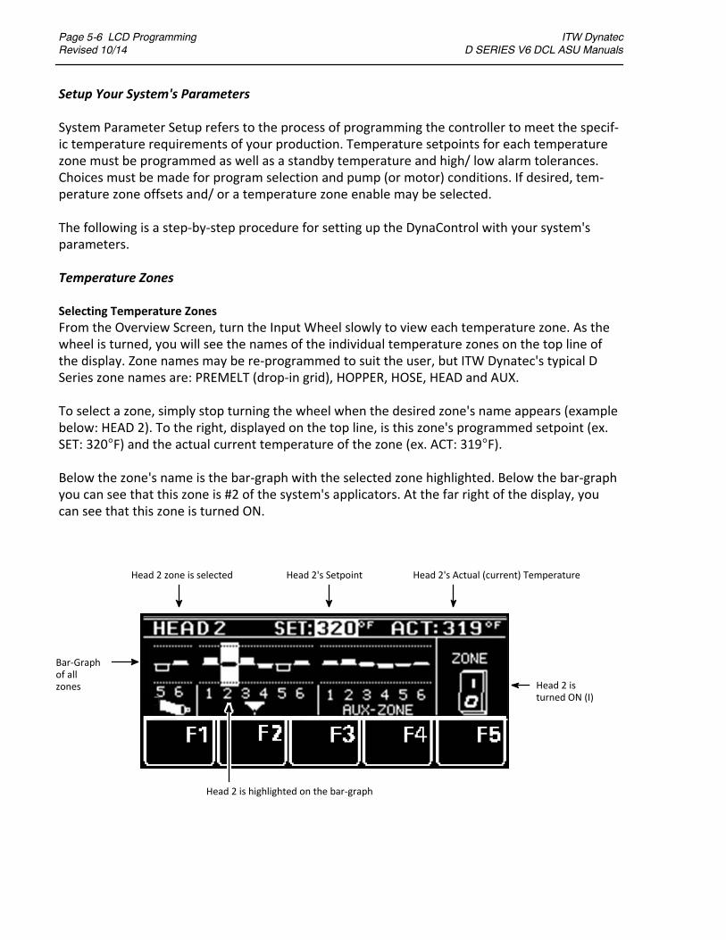
Page 5-6 LCD ProgrammingRevised 10/14
ITW Dynatec D SERIES V6 DCL ASU Manuals
Setup Your System's Parameters
System Parameter Setup refers to the process of programming the controller to meet the specif‐ic temperature requirements of your production. Temperature setpoints for each temperaturezone must be programmed as well as a standby temperature and high/ low alarm tolerances.Choices must be made for program selection and pump (or motor) conditions. If desired, tem‐perature zone offsets and/ or a temperature zone enable may be selected.
The following is a step‐by‐step procedure for setting up the DynaControl with your system'sparameters.
Temperature Zones
Selecting Temperature Zones
From the Overview Screen, turn the Input Wheel slowly to view each temperature zone. As thewheel is turned, you will see the names of the individual temperature zones on the top line ofthe display. Zone names may be re‐programmed to suit the user, but ITW Dynatec's typical DSeries zone names are: PREMELT (drop‐in grid), HOPPER, HOSE, HEAD and AUX.
To select a zone, simply stop turning the wheel when the desired zone's name appears (examplebelow: HEAD 2). To the right, displayed on the top line, is this zone's programmed setpoint (ex.SET: 320F) and the actual current temperature of the zone (ex. ACT: 319F).
Below the zone's name is the bar‐graph with the selected zone highlighted. Below the bar‐graphyou can see that this zone is #2 of the system's applicators. At the far right of the display, youcan see that this zone is turned ON.
Head 2 zone is selected Head 2's Setpoint Head 2's Actual (current) Temperature
Bar‐Graphof allzones Head 2 is
turned ON (I)
Head 2 is highlighted on the bar‐graph
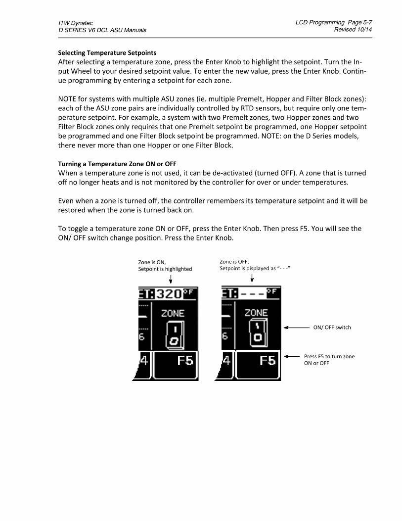
ITW Dynatec D SERIES V6 DCL ASU Manuals
LCD Programming Page 5-7Revised 10/14
Selecting Temperature Setpoints
After selecting a temperature zone, press the Enter Knob to highlight the setpoint. Turn the In‐put Wheel to your desired setpoint value. To enter the new value, press the Enter Knob. Contin‐ue programming by entering a setpoint for each zone.
NOTE for systems with multiple ASU zones (ie. multiple Premelt, Hopper and Filter Block zones):each of the ASU zone pairs are individually controlled by RTD sensors, but require only one tem‐perature setpoint. For example, a system with two Premelt zones, two Hopper zones and twoFilter Block zones only requires that one Premelt setpoint be programmed, one Hopper setpointbe programmed and one Filter Block setpoint be programmed. NOTE: on the D Series models,there never more than one Hopper or one Filter Block.
Turning a Temperature Zone ON or OFF
When a temperature zone is not used, it can be de‐activated (turned OFF). A zone that is turnedoff no longer heats and is not monitored by the controller for over or under temperatures.
Even when a zone is turned off, the controller remembers its temperature setpoint and it will berestored when the zone is turned back on.
To toggle a temperature zone ON or OFF, press the Enter Knob. Then press F5. You will see theON/ OFF switch change position. Press the Enter Knob.
Zone is ON,Setpoint is highlighted
Zone is OFF,Setpoint is displayed as “‐ ‐ ‐”
Press F5 to turn zoneON or OFF
ON/ OFF switch
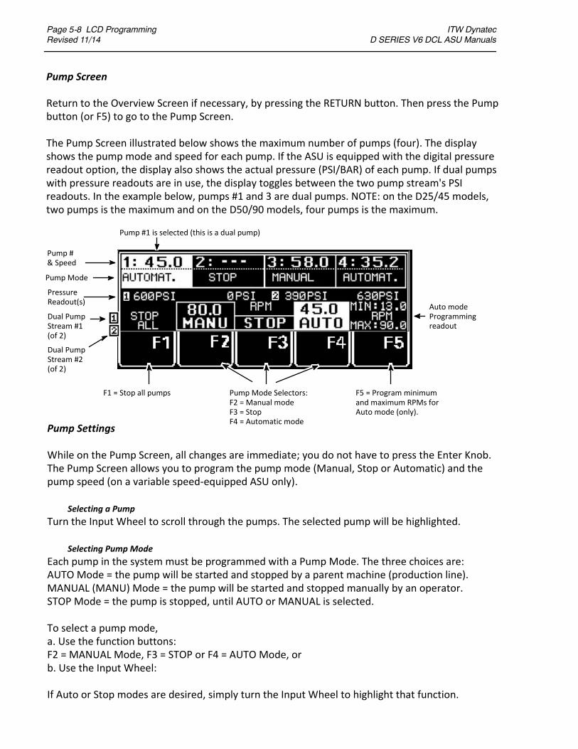
Page 5-8 LCD ProgrammingRevised 11/14
ITW Dynatec D SERIES V6 DCL ASU Manuals
Pump Settings
While on the Pump Screen, all changes are immediate; you do not have to press the Enter Knob.The Pump Screen allows you to program the pump mode (Manual, Stop or Automatic) and thepump speed (on a variable speed‐equipped ASU only).
Selecting a Pump
Turn the Input Wheel to scroll through the pumps. The selected pump will be highlighted.
Selecting Pump Mode
Each pump in the system must be programmed with a Pump Mode. The three choices are:AUTO Mode = the pump will be started and stopped by a parent machine (production line).MANUAL (MANU) Mode = the pump will be started and stopped manually by an operator.STOP Mode = the pump is stopped, until AUTO or MANUAL is selected.
To select a pump mode,a. Use the function buttons:F2 = MANUAL Mode, F3 = STOP or F4 = AUTO Mode, orb. Use the Input Wheel:
If Auto or Stop modes are desired, simply turn the Input Wheel to highlight that function.
Pump Screen
Return to the Overview Screen if necessary, by pressing the RETURN button. Then press the Pumpbutton (or F5) to go to the Pump Screen.
The Pump Screen illustrated below shows the maximum number of pumps (four). The displayshows the pump mode and speed for each pump. If the ASU is equipped with the digital pressurereadout option, the display also shows the actual pressure (PSI/BAR) of each pump. If dual pumpswith pressure readouts are in use, the display toggles between the two pump stream's PSIreadouts. In the example below, pumps #1 and 3 are dual pumps. NOTE: on the D25/45 models,two pumps is the maximum and on the D50/90 models, four pumps is the maximum.
F1 = Stop all pumps Pump Mode Selectors:F2 = Manual modeF3 = StopF4 = Automatic mode
F5 = Program minimumand maximum RPMs forAuto mode (only).
Pump #1 is selected (this is a dual pump)
Auto modeProgrammingreadout
Pump #& Speed
Pump Mode
PressureReadout(s)
Dual PumpStream #1(of 2)
Dual PumpStream #2(of 2)
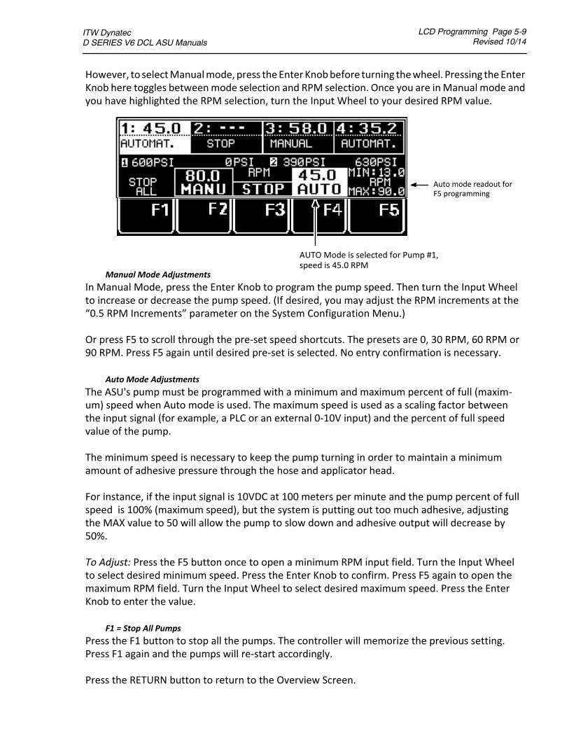
ITW Dynatec D SERIES V6 DCL ASU Manuals
LCD Programming Page 5-9Revised 10/14
Manual Mode Adjustments
In Manual Mode, press the Enter Knob to program the pump speed. Then turn the Input Wheelto increase or decrease the pump speed. (If desired, you may adjust the RPM increments at the“0.5 RPM Increments” parameter on the System Configuration Menu.)
Or press F5 to scroll through the pre‐set speed shortcuts. The presets are 0, 30 RPM, 60 RPM or90 RPM. Press F5 again until desired pre‐set is selected. No entry confirmation is necessary.
Auto Mode Adjustments
The ASU's pump must be programmed with a minimum and maximum percent of full (maxim‐um) speed when Auto mode is used. The maximum speed is used as a scaling factor betweenthe input signal (for example, a PLC or an external 0‐10V input) and the percent of full speedvalue of the pump.
The minimum speed is necessary to keep the pump turning in order to maintain a minimumamount of adhesive pressure through the hose and applicator head.
For instance, if the input signal is 10VDC at 100 meters per minute and the pump percent of fullspeed is 100% (maximum speed), but the system is putting out too much adhesive, adjustingthe MAX value to 50 will allow the pump to slow down and adhesive output will decrease by50%.
To Adjust: Press the F5 button once to open a minimum RPM input field. Turn the Input Wheelto select desired minimum speed. Press the Enter Knob to confirm. Press F5 again to open themaximum RPM field. Turn the Input Wheel to select desired maximum speed. Press the EnterKnob to enter the value.
F1 = Stop All Pumps
Press the F1 button to stop all the pumps. The controller will memorize the previous setting.Press F1 again and the pumps will re‐start accordingly.
Press the RETURN button to return to the Overview Screen.
However, to selectManualmode,press theEnterKnobbefore turning thewheel. Pressing theEnterKnob here toggles betweenmode selection and RPM selection. Once you are inManual mode andyou have highlighted the RPM selection, turn the Input Wheel to your desired RPM value.
AUTO Mode is selected for Pump #1,speed is 45.0 RPM
Auto mode readout forF5 programming

Page 5-10 LCD ProgrammingRevised 10/14
ITW Dynatec D SERIES V6 DCL ASU Manuals
Main Menu
Press the Main Menu button on the Overview Screen to go to the following functions:F1: Recipe ManagementF2: Standby ModeF3: Setpoint LockingF4: 7‐Day SchedulerF5: Info Menu
To select a function, press its “F” button (or turn the Input Wheel to highlight the desired func‐tion and then press the Enter Knob to select).
Recipe Management (F1)
A recipe (or “program”) is a set of temperature setpoints and parameters which the user hasprogrammed and stored in the controller for future use. Up to four recipes may be stored in theDynaControl controller.
F1 Recipes
F2 Standby/ Setback
F3 Setpoint Locking
F4 7‐Day Scheduler
F5 Info(selected)
F5 = ConfirmRecipe #
INFO

ITW Dynatec D SERIES V6 DCL ASU Manuals
LCD Programming Page 5-11Revised 10/14
To Save a Recipe (SAVE TO PROG):
1. Program the controller as you wish it to be setup for a recipe. Program the following paramet‐ers: temperature setpoints, zone On/Off settings and motor mode and speed.
2. Press the Main Menu button, then press F1: Recipe Management. Turn the Input Wheel toSAVE TO PROG. Press the Enter Knob to enter. Turn the Input Wheel to select a program number(up to four recipes may be created and stored). Press F5 to confirm.
To Load a Stored Recipe (LOAD FROM PROG):
1. Press the Main Menu button, then press F1: Recipe Management. Turn the Input Wheel toLOAD FROM PROG. Press the Enter Knob to enter.
2. Select the desired recipe by turning the Input Wheel until its recipe number is highlighted.Press F5 to confirm the selection.
NOTES:1. Recipes that contain temperature zones that do not show valid RTD sensors (ie, zones with“?” in their bar‐graphs) will be turned Off after re‐loading, because the controller assumes thosezones will not be used.
2. If you have loaded a recipe, any changes you make to the temperature or motor settings arenot automatically stored in that recipe. If your changes need to be stored, go to the Recipe Man‐agement Screen and follow the steps to SAVE TO PROG.
Standby (F2)
In Standby mode, the temperatures of all active temperature zones will decrease by apre‐defined amount and the pump will stop (Note: the pre‐defined amount is programmed onpage 2 of the System Configuration Menu).
System is inNormal Mode
System is inStandby Mode
Press the Main Menu button, then press F2 to toggle between Normal mode (setpoints and pumpare active) and Standbymode (setpoints are lowered andpump is stopped.) Confirm Standbymodeby pressing F2 again. After making a change, a screen message will indicate, “Standby ON” or“Standby Off”.
NOTES: Standby can also be activated via an external contact closure (E1, E2 on customer incomingconnector terminals) or via the 7‐Day Scheduler.
See also Standby Configuration in this chapter.
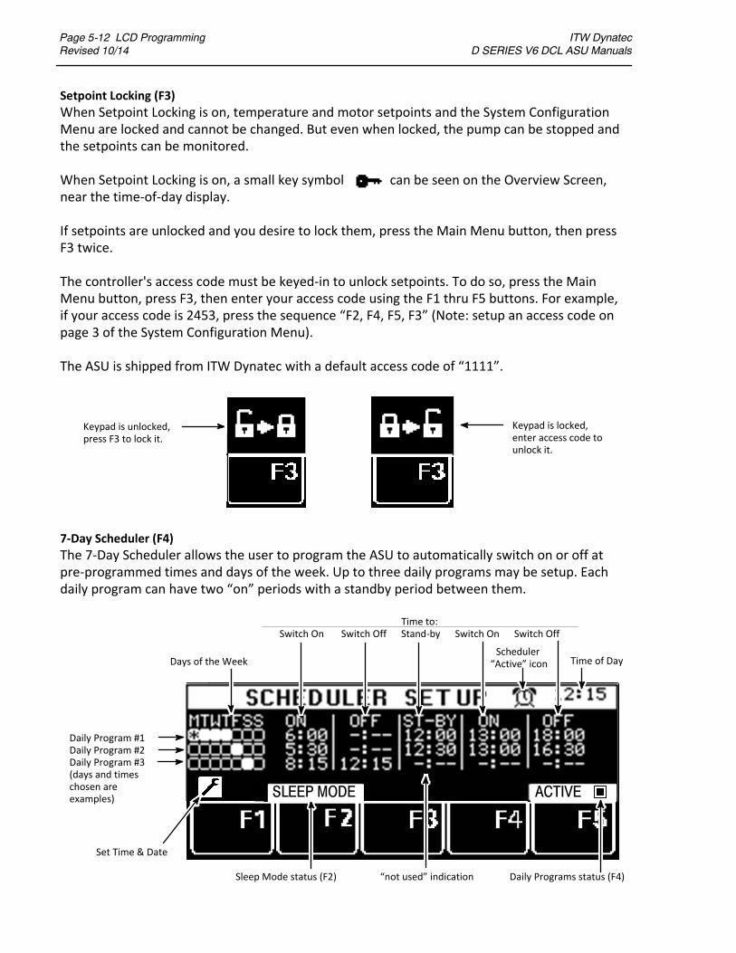
Page 5-12 LCD ProgrammingRevised 10/14
ITW Dynatec D SERIES V6 DCL ASU Manuals
Setpoint Locking (F3)
When Setpoint Locking is on, temperature and motor setpoints and the System ConfigurationMenu are locked and cannot be changed. But even when locked, the pump can be stopped andthe setpoints can be monitored.
When Setpoint Locking is on, a small key symbol can be seen on the Overview Screen,near the time‐of‐day display.
If setpoints are unlocked and you desire to lock them, press the Main Menu button, then pressF3 twice.
The controller's access code must be keyed‐in to unlock setpoints. To do so, press the MainMenu button, press F3, then enter your access code using the F1 thru F5 buttons. For example,if your access code is 2453, press the sequence “F2, F4, F5, F3” (Note: setup an access code onpage 3 of the System Configuration Menu).
The ASU is shipped from ITW Dynatec with a default access code of “1111”.
Keypad is unlocked,press F3 to lock it.
Keypad is locked,enter access code tounlock it.
7‐Day Scheduler (F4)
The 7‐Day Scheduler allows the user to program the ASU to automatically switch on or off atpre‐programmed times and days of the week. Up to three daily programs may be setup. Eachdaily program can have two “on” periods with a standby period between them.
Daily Program #1Daily Program #2Daily Program #3(days and timeschosen areexamples) Days of the Week
“not used” indicationSleep Mode status (F2) Daily Programs status (F4)
Set Time & Date
Time to:Switch On Switch Off Stand‐by Switch On Switch Off
Scheduler“Active” icon Time of DayDays of the Week
ACTIVESLEEP MODE

ITW Dynatec D SERIES V6 DCL ASU Manuals
LCD Programming Page 5-13Revised 10/14
Programming Sequence:
Set‐up each Daily Program entirely before moving on to the next Daily Program. Up to threeDaily Programs may be setup. All time selections are based on a 24‐hour clock.
To Program Active Days of the Week:
Turn the Input Wheel to the Days‐of‐the‐Week (Note: if you can no longer see the cursor whenturning the wheel, turn the wheel in the opposite direction). The Days‐of‐the‐Week may betoggled Active (registers as “selected” on the display) or Inactive by pressing the Enter Knob.
Each day of the week can only be assigned to one program.
To Program On/ Off Times:
Turn the Input Wheel to select the first Switch‐On time; press the Enter Knob to highlight thetime. Turn the Input Wheel to program your desired Switch‐On time (in hours and minutes) andpress the Enter Knob.
Turn the Input Wheel to select a Switch‐Off time or a Standby time, then press the Enter Knob tohighlight it. As above, turn the Input Wheel to program your desired time (in hours andminutes), then press the Enter Knob.
In the same manner, if desired, program another Switch‐On time and/or Switch‐Off time.
To Program Additional Daily Programs:
Turn the Input Wheel to the second or third set of Days‐of‐the‐Week to program Switch‐On andSwitch‐Off times for Daily Program #2 or #3. Program in the same manner as above.
To Choose Activate, Deactivate or Sleep Mode:
Once the 7‐Day Scheduler's Daily Programs are setup, press F5 to Activate. This is indicated bythe clock symbol in the status line. To deactivate the scheduler, press F5 again.
Press F2 to put the ASU into SLEEP MODE (indicated below). In this state, the ASU will be activ‐ated at the next programmed Switch‐On time of the scheduler or it can be manually started.
7‐Day Scheduler Examples (as shown on the illustration on the previous page):
Daily Program #1: On Mondays, Tuesdays, Wednesdays and Thursdays, the ASU will Switch‐Onat 6:00am. It will go into Standby at 12:00 noon. It will come out of Standby at 1:00pm andSwitch‐Off at 6:00pm.
cont.
Symbol for Push Enter Knob
System OFF

Page 5-14 LCD ProgrammingRevised 10/14
ITW Dynatec D SERIES V6 DCL ASU Manuals
Daily Program #2: On Fridays, the ASU will Switch‐On at 5:30am. It will go into Standby at12:30pm. It will come out of Standby at 1:00pm and will Switch‐Off at 4:30pm.
Daily Program #3: On Saturdays, the ASU will Switch‐On at 8:15am and Switch‐Off at 12:15pm.
Set Current Time‐of‐Day and Day‐of‐Week
While in the 7‐Day Scheduler Set Up screen, press the Configuration button ( ) or F1 to set thecurrent time and day.
Turn the Input Wheel to select the item to be changed. Press the Enter Knob. Turn the InputWheel to the desired time/ day and press F5 to confirm your entry.
Once all 7‐Day Scheduler programming is completed, press the return button twice to return tothe Overview Screen.
Press F5 to confirm your changes

ITW Dynatec D SERIES V6 DCL ASU Manuals
LCD Programming Page 5-15Revised 10/14
Info Menu (F5)
The info screens contain details about the hot melt system and can aid in troubleshooting.
Info Screen #1:
The first Info Screen lists temperature zone and pump configuration. It also provides the revisionlevel of the controller's modules and the elapsed time on the Dynamelt ASU's controller.
Press F5 to go to the next Info Screen.
Info Screen #2:
The second Info Screen lists each temperature zone individually. Scroll through the zones usingthe Input Wheel. The zone's description (ie, HOPPER) and zone # (ie, Z 2), actual temperature,heat‐up priority (Ie, PR 1) and location of its corresponding RTD sensor is given.
The screen also shows the physical location of the RTD connectors of the temperature module.This information can help in troubleshooting errors in wiring.
All zones are shown here, even those that are not in use on the ASU.
Press F5 to go to the next Info Screen
Info Screen #3:
The next Info Screen provides set‐up information for the unit's optional communication module.If that module is installed on your ASU, the set‐up info is provided on a supplemental CD. If themodule is not installed, the Info Screens end with Screen #2.
Press RETURN to exit the Info screens and press RETURN again to return to the Overview Screen.
PR1
Z 2

Page 5-16 LCD ProgrammingRevised 10/14
ITW Dynatec D SERIES V6 DCL ASU Manuals
System Configuration Menu
Press the System Configuration Menu button on the Overview Screen to program the followingparameters:Temperature/ Pressure Conversion ‐ Fahrenheit or Celsius/ PSI or BARLanguage Selection ‐ English, German, Spanish, French, Chinese or JapaneseZone Configuration ‐ typically configured by ITW DynatecPump Configuration ‐ typically configured by ITW DynatecSetpoint Limitation ‐ sets a limit on the maximum setpointHi/Low Tolerance ‐ the high and low temperature window which defines the Ready temperatureStandby Configuration ‐ amount of temperature difference, time delay, activation method andsleep mode for the standby functionLevel Detection ‐ activates or de‐activates the low adhesive level detectorHeat‐up Sequence (Priority) ‐ simultaneous or sequential heat‐up of temperature zonesAccess Code ‐ setup an access code to prevent un‐authorized programming0.5 RPM Increment ‐ allows faster manual mode programming of the pump speedTemperature Offset ‐ fine‐tuning allows compensation for temperature gradientsCustomer Zone Names ‐ allows personalization of the temperature zone's namesLogbook/ Fault History ‐ records the time and date of controller events and faultsPower‐On Configuration ‐ allows custom settings for pump/motor and heaters at startupGlobal Setpoints ‐ allows easy one‐temperature programming of setpoints
Accessing the Parameters
There are four pages of configuration parameters. Four parameters are on each page.
Turn the Input Wheel to select the parameter to be programmed. The slider graph (on the left)indicates the page # of the System Configuration Menu. Once you select (highlight) your desiredparameter, many parameters can be changed simply by pressing the Enter Knob.
Page 1 of 4 Pages of Parameters Selected parameter is unlockedand may be programmed.
Selected parameter is locked and cannotbe programmed without the access code.
Page #1indicator
Slider Graph
Reminder to pressEnter Knob.
ITW Dynatec D SERIES V6 DCL ASU Manuals
LCD Programming Page 5-17Revised 10/14
You may also progress through the pages by using the Configuration button ( ) or F1.
When in the System Configuration Menu pages, you may return to the Overview Screen at anytime by pressing the RETURN button twice.
Temperature/ Pressure Conversion (P1)
After turning the Input Wheel to select the Temperature/ Pressure parameter, toggle betweenFahrenheit with PSI or Celsius with BAR readouts by pressing the Enter Knob.
Language Selection (P1)
After turning the Input Wheel to select the Language parameter, press the Enter Knob. The cur‐rent language will flash. Turn the Input Wheel to select a language from the ones listed. Confirmyour choice by pressing the Enter Knob.
Zone Configuration (P1)
This menu configures the controller's temperature zones by listing the number of each type ofzone. Zone configuration is typically done at the ITW Dynatec factory and does not require pro‐gramming by the user.
The Zone Configuration screen may be used to reload the ITW Dynatec factory default controllerparameters. To do so: turn the Input Wheel to select the Zone Configuration parameter andpress the Enter Knob. Press and hold the F1 button for five seconds, then press F2 to restore de‐faults and wait for the controller to reboot.
Pump Configuration (P1)
This menu configures the ASU's pump by listing pump type. Most pump parameters are setup atthe ITW Dynatec factory. There are two user‐programmable pump parameters: Pump EnableTemperature and Individual Pump Control. NOTE: D15/25/45 models have a maximum of twopumps; D50/90 models have a maximum of four pumps.
Pump Enable Programming:
The Pump Enable Temperature serves as a low limit value. The controller will not allow thepump to come on until its enable temperature is achieved. By doing so, it protects the pump,pump shaft, motor and motor control module.
After pressing the Enter Knob to select the Pump Enable parameter, turn the Input Wheel to in‐crease or decrease the pump enable temperature. Confirm your choice by pressing the EnterKnob.
Individual Pump Control Programming:
When there are multiple pumps on a unit, they may be controlled individually since each pumphas its own external contact.
After pressing the Enter Knob to select the Individual Pump Control parameter, turn the InputWheel to select individual control, if desired, by choosing YES or NO. Confirm your choice bypressing the Enter Knob.

Page 5-18 LCD ProgrammingRevised 10/14
ITW Dynatec D SERIES V6 DCL ASU Manuals
Setpoint Limitation (P2)
This parameter sets the maximum temperature zone setpoint. The setpoint limitation is usefulfor an adhesive with a low melt temperature. In this case, the maximum selectable setpointcould be lowered in order to avoid over‐heating the adhesive.
After turning the Input Wheel to select the Setpoint Limitation parameter, press the Enter Knoband then turn the Input Wheel to select your desired setpoint limitation value. Confirm yourchoice by pressing the Enter Knob.
Hi/Lo Tolerance (P2)
A high and low temperature tolerance can be set for the temperature zones. During operation,these tolerances activate the error alarms which alert the operator to over‐temp and un‐der‐temp conditions.
The hi/ lo tolerance is a range (+ and ‐) from the setpoint. Thus a setpoint of 150C which hasbeen programmed with a 10 hi/ lo tolerance will activate an under‐temp alarm when the zone'stemperature falls below 140C and will activate an over‐temp alarm when the zone's temperat‐ure rises above 160. When this zone's temperature is within the tolerances (140 and 160), itis considered “Ready”.
When programming, only one value is chosen. This value applies to all temperature zones and isboth the high and low tolerance.
After turning the Input Wheel to select the Hi/Lo Tolerance parameter, press the Enter Knob andthen turn the Input Wheel to select your desired tolerance value. Confirm your choice by press‐ing the Enter Knob.
Standby Configuration (P2)
There are four ways to activate standby mode:1. Manually, at the Main Menu's F2,2. Automatically, via the 7‐Day Scheduler,3. Remotely, via an external contact (program as described below), or4. Automatically, after a pump stop (program as described below).
Standby Configuration allows you to select #3 or #4 and program other standby parameters.
Program a standby time delay Program a standby temperature difference
Toggle to choose After ExternalContact or After Pump Stop
Program a sleep mode after standby time delay

ITW Dynatec D SERIES V6 DCL ASU Manuals
LCD Programming Page 5-19Revised 10/14
Standby Temperature Difference
In Standby mode, the temperatures of all active temperature zones decrease by a programmedamount and the pump(s) stop pumping adhesive.
The programmed decrease in zone temperatures is the standby temperature difference. Thestandby temperature difference applies to all zones once standby is activated. For example, ifthe difference temperature is 80F, and setpoints are 300F, then all zones will reduce to 220F(300 ‐ 80 = 220) when standby is activated.
After turning the Input Wheel to select Standby Configuration, press the Enter Knob to advanceto the screen. Press the Enter Knob to select the first parameter, ie. temperature difference.Press the Enter Knob again to highlight the temperature difference value. Then turn the InputWheel to program your desired value. Confirm your choice by pressing the Enter Knob.
Standby Time Delay and Activation
The standby time delay is the programmed number of minutes until standby takes place afteractivation by either an external contact (for example: a PLC or an external switch) or by a pumpstoppage. The default time delay is 0 minutes (immediately!). The programmable range of thestandby time delay is 0‐150 minutes.
Turn the Input Wheel to select the time delay parameter (ie. Standby X min. After…). Press theEnter Knob. Turn the Input Wheel again to select your desired minutes value. Confirm yourchoice by pressing the Enter Knob.
Now turn the Input Wheel to select the After Ext Contact/ After Pump Stop field. Press the EnterKnob and then turn the Input Wheel to highlight your choice of activation. Confirm your choiceby pressing the Enter Knob.
Sleep Mode After Standby
Sleep mode shuts the ASU off after it has been in standby for a programmed length of time. Thislength of time can be from one hour to 99 hours. Or you can choose to program the unit to haveno sleep mode by programming “ ‐ ”. When the unit is in sleep mode, the Main Screen displays“System Off, Switch On with Enter Knob”.
Turn the Input Wheel to select the Sleep Mode After # Hrs In Standby field. Press the Enter Knobto highlight the hours value. Turn the Input Wheel to select your desired hours value. Confirmyour choice by pressing the Enter Knob.
Press the RETURN button to return to the System Configuration Menu.
Level Detection (P2)
The level detection sensor triggers an alarm when the liquid adhesive level in the hopper fallsbelow a certain level. Hopper Empty is the alarm message displayed on the controller's statusline. The level detection parameter allows the user to: turn the level sensor function On or Off,activate a Stop Pump After Hopper Empty and set a timed delay before the pump stops.
After turning the Input Wheel to select the level detection parameter, press the Enter Knob to
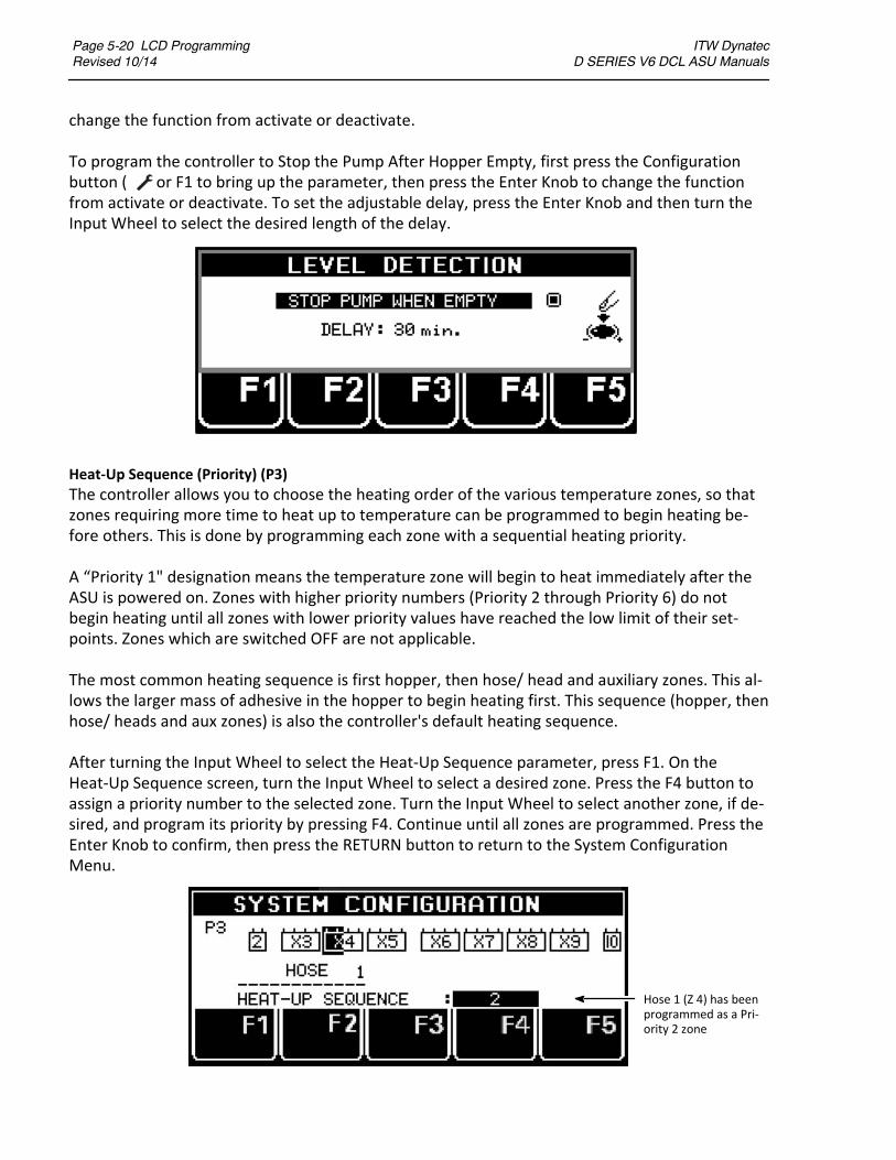
Page 5-20 LCD ProgrammingRevised 10/14
ITW Dynatec D SERIES V6 DCL ASU Manuals
change the function from activate or deactivate.
To program the controller to Stop the Pump After Hopper Empty, first press the Configurationbutton ( ) or F1 to bring up the parameter, then press the Enter Knob to change the functionfrom activate or deactivate. To set the adjustable delay, press the Enter Knob and then turn theInput Wheel to select the desired length of the delay.
Heat‐Up Sequence (Priority) (P3)
The controller allows you to choose the heating order of the various temperature zones, so thatzones requiring more time to heat up to temperature can be programmed to begin heating be‐fore others. This is done by programming each zone with a sequential heating priority.
A “Priority 1" designation means the temperature zone will begin to heat immediately after theASU is powered on. Zones with higher priority numbers (Priority 2 through Priority 6) do notbegin heating until all zones with lower priority values have reached the low limit of their set‐points. Zones which are switched OFF are not applicable.
The most common heating sequence is first hopper, then hose/ head and auxiliary zones. This al‐lows the larger mass of adhesive in the hopper to begin heating first. This sequence (hopper, thenhose/ heads and aux zones) is also the controller's default heating sequence.
After turning the Input Wheel to select the Heat‐Up Sequence parameter, press F1. On theHeat‐Up Sequence screen, turn the Input Wheel to select a desired zone. Press the F4 button toassign a priority number to the selected zone. Turn the Input Wheel to select another zone, if de‐sired, and program its priority by pressing F4. Continue until all zones are programmed. Press theEnter Knob to confirm, then press the RETURN button to return to the System ConfigurationMenu.
Hose 1 (Z 4) has beenprogrammed as a Pri‐ority 2 zone

ITW Dynatec D SERIES V6 DCL ASU Manuals
LCD Programming Page 5-21Revised 10/14
Access Code (P3)
An active access code prevents unauthorized programming of setpoints and other configurationparameters. To utilize the Setpoint Locking feature of the controller, your access code must bekeyed in at the Main Menu, F3.
The Dynamelt ASU is shipped from ITW Dynatec with a default code of 1111. To re‐program theaccess code, the current access code must be entered. All access codes must be 4‐digit numbersusing the digits 1, 2, 3, 4 and 5 only.
After turning the Input Wheel to select the Access Code parameter, enter the current accesscode using the F1 thru F5 numerals. Press the Enter Knob. Then enter your desired access codeusing the F1 thru F5 numerals. Confirm your choice by pressing the Enter Knob.
0.5 RPM Increment (P3)
When setting the pump RPM in Manual Mode on the Pump Screen, the default increment forRPM is 0.1. If a coarser adjustment is desired, it may be changed to 0.5 RPM at this parameter.
After turning the Input Wheel to select the 0.5 RPM Increment parameter, press the Enter Knobto toggle the parameter active or inactive.
Temperature Offset (P3)
Temperature Zone Offsets are mathematical factors which compensate for differences in tem‐perature within components. Each temperature zone may be programmed with an offset, if de‐sired. Standard equipment does not usually require temperature offsets.
Note: Entering a positive‐numbered offset will raise the temperature reading of that zone. Sincethe controller attempts to equate setpoint and actual temperature, this actually lowers the ac‐tual temperature by the amount of the offset.
For example: Setpoint and actual temperature both equal 300F. An offset of +10F is pro‐grammed. Initially the display will read 310F, but the controller will lower the output power un‐til the actual temperature value is back to 300F.
After turning the Input Wheel to select the Temperature Offset parameter, press the Enter Knobto display a list of all temperature zones. Turn the Input Wheel to select a zone for programmingand press the Enter Knob. Turn the Input Wheel to program the desired temperature offset forthat zone. Press the Enter Knob to confirm your selection.
If desired, turn the Input Wheel to select another zone for programming. Program this zone asoutlined above.
When all desired zones are programmed, press RETURN to go to the System Configuration Menu(page 1), then press RETURN again to go to the Overview Screen.

Page 5-22 LCD ProgrammingRevised 10/14
ITW Dynatec D SERIES V6 DCL ASU Manuals
Customer Zone Names (P4)
With this configuration parameter, the user may personalize the names of the temperaturezones with names that are more descriptive for his application. That is, instead of the factory‐setzone names of Z01, Z02, Z03, etc., the customer may prefer temperature zone names such as“TANK”, “HEAD 1”, “FILTER BLOCK”, “SUPPLY HOSE ‐ LEFT”, etc.
After turning the Input Wheel to select the Customer Zone Names parameter, press the EnterKnob to display YES. To enter programming mode, press F3 (Change Text).
Now, by turning the Input Wheel, you can scroll through the zones and see their current zonenames (or numbers). These names can be re‐programmed one at a time. Each new name mayconsist of two lines, with a maximum of 12 characters in each line. Note: the factory‐set numeric“names“ correspond to RTD inputs.
Customer Zone Name Programming Screen
Programming keys
Using F2, F3, F4 & F5 Programming Keys
F5 = press to Clear the entire zone name.F2 = press to select upper or lower case letters, to select numbers or to select special characters.F3 & F4 = press to Copy (F4) and Paste (F3) the name of one zone into another.
Programmed name
Zone indicators(see below)
Selected zone (Z6)Selected character (E)with cursor below (^) it
Z1 Z2 Z3 Z4 Z5 Z6 Z7 Z8 Z9 Z10 Z11 Z12 Z13 Z14 Z15 Z16
This line = 12 characters This line = 11 characters
“Supply Hose ‐ Left Side” = Zone #6 (highlighted zone indicator)
Zone indicators
Zone numbers

ITW Dynatec D SERIES V6 DCL ASU Manuals
LCD Programming Page 5-23Revised 10/14
Programming the Zone Names
NOTE: This feature cannot accommodate Chinese language characters.After selecting the Customer Zone Names parameter and pressing the Enter Knob to display YES,press F3 (Change Text) to begin programming.
1. Turn the Input Wheel to select desired temperature zone (refer to corresponding RTD). Theselected zone is highlighted.
2. Press the Input Knob to confirm zone.
3. Turn the Input Wheel to select the character to be re‐programmed.
4. Press the Input Knob to confirm selection. The cursor highlights the selected character.
5. Turn the Input Knob to select the new character.
6. Press the Input Knob to confirm the new character.
7. Repeat steps 3 through 6 to spell desired zone name.
8. Press the Return button to select another zone to program. Repeat steps 1 through 6for each zone desired.
9. Press Return again when all temperature zone name programming is completed.
Logbook/ Fault History (P4)
The Logbook provides a read‐only history of the last 65 (maximum) controller faults and events.Controller faults include sensor or temperature errors or motor faults. Examples of an event in‐clude switching the ASU on/off or System Ready. The most recent event is recorded at the topof the list (No. 1).
Day, Time and Event are listed for each item in the Logbook. This information can be valuablewhen troubleshooting controller problems.
After turning the Input Wheel to select the Logbook parameter, press the Enter Knob to displaythe Logbook. Turn the Input Wheel to scroll through the list.
#1 is most recent entry

Page 5-24 LCD ProgrammingRevised 10/14
ITW Dynatec D SERIES V6 DCL ASU Manuals
Power‐On Configuration (P4)
Two start‐up parameters are programmed at the Power‐On Configuration screen, and they areset by choosing YES or NO:
Power‐On Motor Stop
At the Power‐On Motor Stop parameter, you decide if you prefer that the motor to be stoppedwhen the ASU is turned on (if so, choose YES) or if you prefer that the motor remain in its previ‐ous mode when the ASU is turned on (choose NO).
Power‐On Heater Start
At the Power‐On Heater Start parameter, you decide if you prefer that the temperature zonesstart heating automatically when the ASU is turned on (if so, choose YES) or if the heaters shouldrequire a manual start when the ASU is turned on (choose NO). NOTE: If you choose NO, theheaters will not begin to heat until the Enter Knob is pressed at start‐up.
From the System Configuration Menu: after turning the Input Wheel to select Power‐On Config‐uration, press the Enter Knob. The first parameter (Power‐On Motor Stop) will be activated (seeillustration below). Press the Enter Knob to choose YES or NO.
Turn the Input Wheel to activate the second parameter (Power‐On Heater Start). Press the EnterKnob to choose YES or NO.
After programming, press RETURN twice to return to the Overview Screen.
POWER ON CONFIGURATION
POWER-ON MOTOR STOP
POWER-ON HEATER START NO
YES
Parameter is activated (programmable).Press Enter Knob to make selection.
This parameter may not be programmed until is isactivated. To activate, turn the Input Wheel.
POWER ON CONFIGURATION
POWER-ON MOTOR STOP
POWER-ON HEATER START

ITW Dynatec D SERIES V6 DCL ASU Manuals
LCD Programming Page 5-25Revised 10/14
Global Setpoints (P4)
Setpoint programming may be simplified by programming Global Setpoints. With this paramet‐er, the user programs a hopper setpoint and the controller configures all of the other zones.However, to do so, it must be appropriate for all your hoses to be programmed to one setpoint,and for all your applicator heads to be programmed to one setpoint.
After turning the Input Wheel to select the Global Setpoints parameter, press the Enter Knob toturn Global Setpoints On/Off.
Then press F3 to open the Global Setpoints menu.
On the Global Setpoints menu, you set up simple mathematical relationships (increases)between the hopper setpoint and the setpoints of the hoses and applicator heads. Pressing theInput Knob increases the temperature of the hose (or head) by 5 degrees, or, if you press again,by 10 degrees (press again for 15 degrees, and press again for 20 degrees). Once setup, all of thehoses will increase over the hopper setpoint by the same amount (0, 5, 10, 15 or 20 degrees)and likewise, all of the heads will increase over the hopper setpoint by the same amount as youprogram here.
Once Global Setpoints are set, you simply program the hopper (as described on page 5‐6) andyour hoses and heads will automatically be programmed to the increases you specified on theGlobal Setpoints menu.
For example: If you setup a Global Setpoint increase of 10 degrees for Hoses and 15 degrees forHeads, and you program your Hopper setpoint to 290 degrees, then the controller will automat‐ically program all of the hoses to 300 degrees and all of the heads to 305 degrees.
When Global Setpoints are turned On and a temperature setpoint is changed, the display willnot show the selected zone's name. Instead it will display GLOBAL SET:.
You can still turn individual zones Off and On while using Global Setpoints.

Page 5-26 LCD ProgrammingRevised 10/14
ITW Dynatec D SERIES V6 DCL ASU Manuals
Controller Messages Troubleshooting Guide
The following are examples of System Status or controller display error messages and solutions.
1.
The jumper connection from IN6 to COM (or IN6 to 24V) is not made on the Base Module.
2.
This fault could be caused by one of the following problems:a. there may be a motor short circuit (solution = replace the motor),b. there may be a faulty motor drive (solution = replace the motor drive),c. there may be a motor overload (contact ITW Dynatec, Technical Service).
3.
This fault, seenon the controller display,will result if the V6modules on theDIN rail are not connec‐tedproperly. Abus connector, near the rail, connects onemodule to the next.Modules canbecomedisconnected during transport or during repair procedures.
4.
A fault such as this indicates an over‐temperature or an RTD sensor fault. The solution is not simplytopress theRETURNbutton to confirm. The solution is to troubleshootandsolve theproblemwhichcaused the fault, and then confirm with the RETURN button.
5.
Thealarmshownabovecanoccuronany screen. Itsquestionmark indicatesaproblemwith theRTDsensor in the Head #1 zone. After about 20 seconds, the following display is shown:
SYSTEM FAULT !
MOTOR FAULT
FAULT CONFIRM WITH
ALARM HOLD
??Alarm
Press to returnto productionAFTER problemis solved.
MOTOR FAULT
MOTOR FAULTFAULT CONFIRM WITH
FAULT CONFIRM WITHTEMP ALARM PRESS
EXTCONHOLD

ITW Dynatec D SERIES V6 DCL ASU Manuals
LCD Programming Page 5-27Revised 10/14
?TEMP SENS FAULT PRESS
Advance to the temperature zonesdisplay to seewhich zone is affected. The two status lines shownabove will alternate in this mode. As seen above, the questionmark is placed on the zone with thefaulty sensor (ie, Head #1). After troubleshooting the fault (reference the Error Indication AlarmTroubleshooting Guide on the previous pages of this chapter) and solving the problem with thesensor, press the RETURN button.
Or, if Head #1 is not in use, press F5 to turn the zone Off.
?TEMP SENS FAULT PRESS
F5 = Zone Off
Status
Status

Page 5-28 LCD ProgrammingRevised 10/14
ITW Dynatec D SERIES V6 DCL ASU Manuals
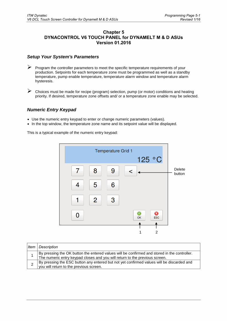
ITW Dynatec Programming Page 5-1 V6 DCL Touch Screen Controller for Dynamelt M & D ASUs Revised 1/16
Chapter 5 DYNACONTROL V6 TOUCH PANEL for DYNAMELT M & D ASUs
Version 01.2016 Setup Your System's Parameters Program the controller parameters to meet the specific temperature requirements of your
production. Setpoints for each temperature zone must be programmed as well as a standby temperature, pump enable temperature, temperature alarm window and temperature alarm hysteresis.
Choices must be made for recipe (program) selection, pump (or motor) conditions and heating
priority. If desired, temperature zone offsets and/ or a temperature zone enable may be selected. Numeric Entry Keypad • Use the numeric entry keypad to enter or change numeric parameters (values). • In the top window, the temperature zone name and its setpoint value will be displayed. This is a typical example of the numeric entry keypad:
Item Description
1 By pressing the OK button the entered values will be confirmed and stored in the controller. The numeric entry keypad closes and you will return to the previous screen.
2 By pressing the ESC button any entered but not yet confirmed values will be discarded and you will return to the previous screen.
Delete button
1 2

Page 5-2 ITW Dynatec Revised 1/16 V6 DCL Touch Screen Controller for Dynamelt M & D ASUs
Alphabetic Entry Keypad • Use the alphabetic keypad to enter or change text, e.g. temperature zone names. • In the top window, the temperature zone name will be displayed. This is a typical example of an alphabetic keypad:
Item Description
1 By pressing the OK button the entered text will be confirmed and stored in the controller. The alphabetic entry keypad closes and you will return to the previous screen.
2 By pressing the ESC button any entered but not yet confirmed text will be discarded and you will return to the previous screen.
1 2

ITW Dynatec Programming Page 5-3 V6 DCL Touch Screen Controller for Dynamelt M & D ASUs Revised 1/16
Main Screen The Main Screen is displayed automatically when the unit is switched ON. The Main Screen provides a comprehensive overview of the status of each of the temperature
zones and the system as a whole. It gives the status and speed of the pump, along with any adhesive pressures and level status.
Main Screen, if seven or more zones in any column are activated:
11
1
5
4
2
3
6 7 8 9 10
Selected System #
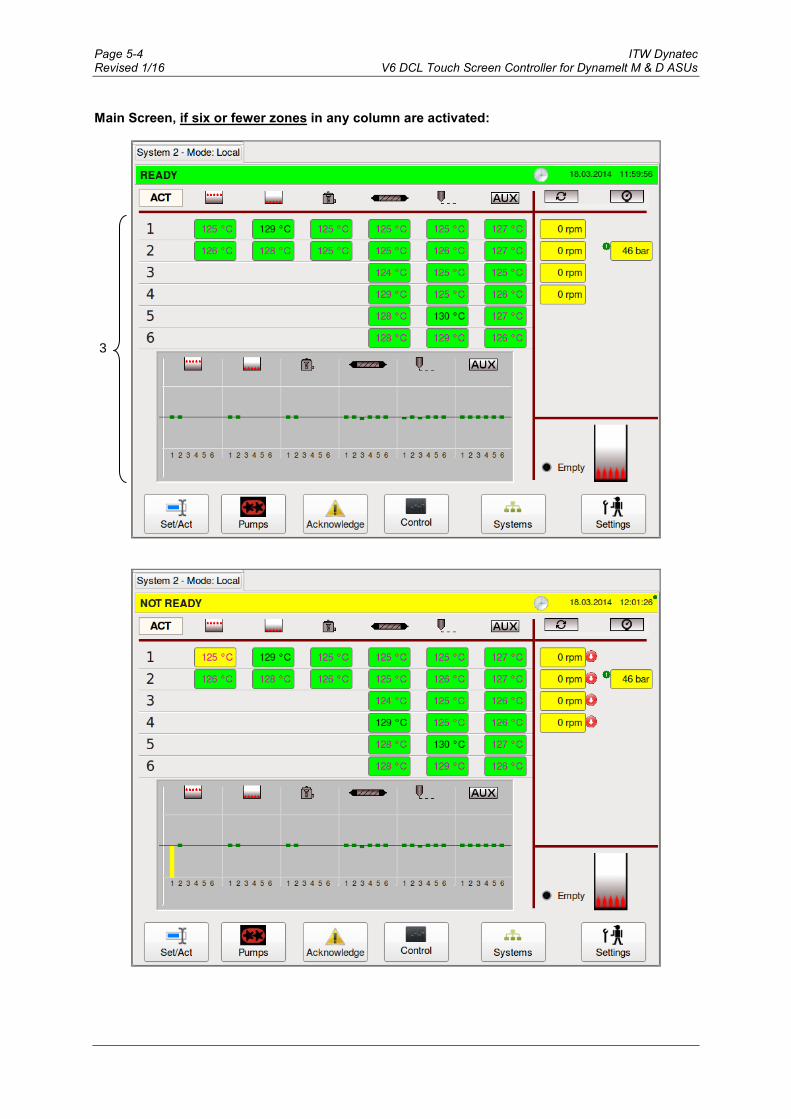
Page 5-4 ITW Dynatec Revised 1/16 V6 DCL Touch Screen Controller for Dynamelt M & D ASUs
Main Screen, if six or fewer zones in any column are activated:
3

ITW Dynatec Programming Page 5-5 V6 DCL Touch Screen Controller for Dynamelt M & D ASUs Revised 1/16
Item Description
1
Status Line Display of the actual status of the unit: • READY = All zones are within their setpoint temperatures and the unit is ready for
operation. • RUNNING = All zones are within their setpoint temperatures and the unit/pump is running. • NOT READY = At least one zone has not yet reached its setpoint temperature or has fallen
below its set point or it is lower than the set global release temperature. • STANDBY = Standby temperature is activated. • ALARM = Alarms or faults are active. The status line is highlighted green when the system is READY or RUNNING, yellow when NOT READY, grey when in STANDBY and red when in ALARM condition. The status line along with “Systems” button is in orange color if a non-visible system goes into Alarm condition (if f several systems are controlled by the HMI). The „clock“ icon appears if a timer is activated under „Time & Scheduler“ screen and disappears if the timer is deactivated. Display of the actual date and time are on the right side of the screen. Depending on the selection of the unit of temperature and pressure (°C and bar or °F and psi) made under Unit & Date Selection, the appearance of the date display is affected also. With the C/bar selection, the date is displayed as ‘day.month.year’ while in F/psi mode, the date is displayed as ‘month/day/year’. The time is displayed as hour.minutes.seconds (ie, 11:48:25 pm). By pressing the status line you go to the Log Book screen.
2
Icon Line ACT / SET: Indicates if the temperature values shown on the display are Actual or Setpoint
values. The Actual values will be displayed during production. By pressing the Set/Act button, the Set values can be displayed and edited. The display returns automatically to the Actual values after about 15 seconds if there is no activity.
The icons:
Pre Melt Grid
Hopper
Filter block
Hose
Applicator
Auxiliary components Pump RPM Pressures
Decentralized pumps (e.g. Applicator, Metering Station: A plausible limit value of Input Pressure (a minimum pressure of not less than 2 bar is recommended) has to be entered to avoid a dry run of the pumps; otherwise the pump can be damaged. See point “Extended Pump Mode Settings Screen, Linear Line Speed, Pressure Control”. The appropriate actual values (temperature, pump rpm, pressures) are displayed under the icons.

Page 5-6 ITW Dynatec Revised 1/16 V6 DCL Touch Screen Controller for Dynamelt M & D ASUs
Item Description
3
• The actual values of the temperature zones are displayed in columns under the icons. Zone status is indicated by color: the zone field is colored green when the zone reaches setpoint, yellow while the zone is heating up, grey it it has been temporarily switched off and red if in alarm.
• When all zones have reached their setpoint values, READY will be displayed in the status line. If zones are still heating up and have not yet reached their setpoint values, NOT READY will be displayed in the status line.
• If six or fewer zones in any column are activated, the temperature status of each zone is shown by a bar‐graph indicating if the temperature zone is inside its setpoint window (green) or outside (yellow). The bar-graph indication disappears if more than six zones are activated.
4
The appropriate actual values (pump rpm, pressures) are displayed under the icons.
Primary pressure: If the system is equipped with a (primary) pressure sensor, the
appropriate primary pressure transducer input will be displayed with number 1 . The primary pressure input can be controlled via the Pressure Set Point in Pump Control/ Pressure Control Screen.
Secondary pressure: If a second pressure sensor is equipped (usually in combination with dual pump outlets), the appropriate pressure transducer input will be
displayed with number 2 . The secondary pressure input is just a readout function. The display alternates between primary pressure 1 and secondary pressure 2.
5
If an optional digital level sensor is built-in, Hopper Empty status will be indicated when adhesive drops below the level sensor.
If an optional analog probe used the status bar will display the adhesive level along with a percentage of hopper volume.
6 Set/Act Button By pressing Set, values may be displayed and edited. The display will automatically return to actual values after about 15 seconds, if there is no display activity.
7 Pumps Button Press to go to the Pump Overview screen.
8 Acknowledge Button Press to acknowledge an error or alarm.
9 Control Button Press to go to the Control screen.
10 Systems Button Press to go to the Systems screen, if several systems are controlled by the HMI.
11 Settings Button Press to go to the Settings screen.

ITW Dynatec Programming Page 5-7 V6 DCL Touch Screen Controller for Dynamelt M & D ASUs Revised 1/16
Temperature Zones Set Screen To go to this screen, press the Set/Act button on the Main Screen. The Set screen allows you to program the setpoint temperature for each activated zone. Each
zone requires a temperature setpoint.
When a temperature zone is not used, it can be de‐activated (turned OFF) on the Heating Priority screen. A zone that is turned Off no longer heats and is not monitored by the controller for over or under temperatures.
Item Description
1
Set values • Display of the temperature setpoint values. • To edit values: Touch a zone input box and a numeric entry keypad will appear. Enter your
new setpoint value and confirm by pressing OK. NOTE: Must be below the maximum setpoint value listed below.
• The Set values are displayed for about 15 seconds and, if there is no display activity, the display returns automatically to the Actual values.
• The maximum setpoint value is 218°C (424°F).
See next page for Zone On/Off Switch on the Numeric Entry Keypad.
1
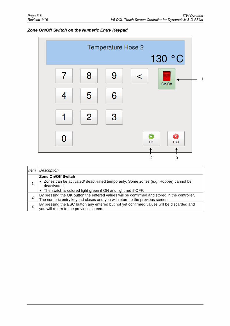
Page 5-8 ITW Dynatec Revised 1/16 V6 DCL Touch Screen Controller for Dynamelt M & D ASUs
Zone On/Off Switch on the Numeric Entry Keypad
Item Description
1
Zone On/Off Switch • Zones can be activated/ deactivated temporarily. Some zones (e.g. Hopper) cannot be
deactivated.• The switch is colored light green if ON and light red if OFF.
2 By pressing the OK button the entered values will be confirmed and stored in the controller. The numeric entry keypad closes and you will return to the previous screen.
3 By pressing the ESC button any entered but not yet confirmed values will be discarded and you will return to the previous screen.
1
2 3
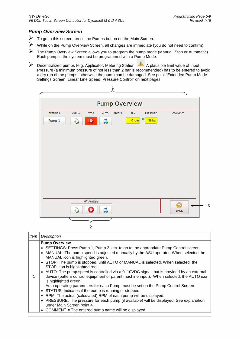
ITW Dynatec Programming Page 5-9 V6 DCL Touch Screen Controller for Dynamelt M & D ASUs Revised 1/16
Pump Overview Screen To go to this screen, press the Pumps button on the Main Screen. While on the Pump Overview Screen, all changes are immediate (you do not need to confirm). The Pump Overview Screen allows you to program the pump mode (Manual, Stop or Automatic).
Each pump in the system must be programmed with a Pump Mode.
Decentralized pumps (e.g. Applicator, Metering Station: A plausible limit value of Input Pressure (a minimum pressure of not less than 2 bar is recommended) has to be entered to avoid a dry run of the pumps; otherwise the pump can be damaged. See point “Extended Pump Mode Settings Screen, Linear Line Speed, Pressure Control” on next pages.
Item Description
1
Pump Overview • SETTINGS: Press Pump 1, Pump 2, etc. to go to the appropriate Pump Control screen. • MANUAL: The pump speed is adjusted manually by the ASU operator. When selected the
MANUAL icon is highlighted green. • STOP: The pump is stopped, until AUTO or MANUAL is selected. When selected, the
STOP icon is highlighted red. • AUTO: The pump speed is controlled via a 0–10VDC signal that is provided by an external
device (pattern control equipment or parent machine input). When selected, the AUTO icon is highlighted green. Auto operating parameters for each Pump must be set on the Pump Control Screen.
• STATUS: Indicates if the pump is running or stopped. • RPM: The actual (calculated) RPM of each pump will be displayed. • PRESSURE: The pressure for each pump (if available) will be displayed. See explanation
under Main Screen point 4. • COMMENT = The entered pump name will be displayed.
2
1
3

Page 5-10 ITW Dynatec Revised 1/16 V6 DCL Touch Screen Controller for Dynamelt M & D ASUs
Item Description
2 All Pumps Buttons Press one of the All Pumps buttons (either MANUAL, STOP or AUTO) to set all pumps to the desired function at one time.
3 BACK Button Press to return to the previous screen.

ITW Dynatec Programming Page 5-11 V6 DCL Touch Screen Controller for Dynamelt M & D ASUs Revised 1/16
Pump Control Screen/ Linear Line Speed To go to this screen, press the Pump 2 field on the Pump Overview screen (to go to the Pump 1,
etc. Control screen, press the corresponding field). Then press the Settings button, select Linear Line Speed in the Current Pump Mode menu on the Extended Pump Mode Settings screen and then press the BACK button.
The Pump Control Linear Line Speed screen allows you to program the Auto Mode Settings (Setpoint minimum/maximum RPM at 0–10VDC external signal control) and Manual Mode Settings (Manual Setpoint RPM).
Pump 2 Example:
Item Description
1 Pump #2 is the selected pump. All the settings and speeds displayed on this screen correspond to Pump #2.
2
Auto Mode Settings Setpoint The minimum and maximum setpoint values of the pump are displayed. The programmable range is 0 to 90 rpm. By pressing the input field you can edit the RPM values.
3
Manual Mode Settings Manual Setpoint The manual setpoint value of the pump is displayed. By pressing the input field you can edit the value.
4 Press the arrow icon to go to the previous pump screen (ie, Pump 1, etc.).
5
1
8
6
2
3
7
9
10
11
4

Page 5-12 ITW Dynatec Revised 1/16 V6 DCL Touch Screen Controller for Dynamelt M & D ASUs
Item Description
5
Set the pump to the desired mode by pressing MANUAL, OFF (STOP) or AUTO. • MANUAL: The pump speed is adjusted manually by the operator. If MANUAL is selected
the icon is highlighted green. • OFF (STOP): The pump is stopped, until AUTO or MANUAL is selected. If OFF is selected
the icon is highlighted red. • AUTO: The pump speed is controlled via a 0–10VDC signal that is provided by an external
device (pattern control equipment or parent machine input). If AUTO is selected the icon is highlighted green. A minimum speed is necessary to keep the pump turning in order to maintain a minimum amount of adhesive pressure through the hose and applicator head. For instance, if the input signal is 10VDC at 100 meters per minute and the pump percentage of full speed is 100% (maximum speed), but the system is putting out too much adhesive, adjusting the MAX pump percentage to 50 will cause the pump to slow down over the parent machine’s entire speed range and adhesive output will be decreased.
6
Settings Button Press this button to go to the Extended Pump Mode Settings screen where you can select the Current Pump Mode "Linear Line Speed" or "Pressure Control" and you can go to the "Automatic Ramp Compensation" screen.
7 Press the arrow icon to go to the next pump screen (ie, Pump 3, etc.).
8 BACK Button Press to return to the previous screen.
9 LINE SPEED: The actual (or calculated) line speed is displayed.
10 PRESSURE: The actual pressures are displayed. See explanation under Main Screen point 4.
11 SPEED: The actual (or calculated) pump speed is displayed.

ITW Dynatec Programming Page 5-13 V6 DCL Touch Screen Controller for Dynamelt M & D ASUs Revised 1/16
Extended Pump Mode Settings Screen, Linear Line Speed, Pressure Control To go to this screen, press the Settings button on the Pump Control screen. The Extended Pump Mode Settings screen allows you to select the Current Pump Mode and to
go to the Automatic Ramp Compensation (ARC) screen. System 1 Pump 1 Example:
3
1
6
2
3
4
5

Page 5-14 ITW Dynatec Revised 1/16 V6 DCL Touch Screen Controller for Dynamelt M & D ASUs
Item Description
1 System 1 Pump 1 is selected.
2
Pump Name Touch the input box and an Alphabetic Entry Keypad will appear. Enter your desired pump name and confirm by pressing OK. The entered pump name will be displayed on the Pump Overview Screen.
3 Current Pump Mode Press Current Pump Mode to select "Linear Line Speed" or "Pressure Control". Then press the BACK button to go to the appropriate screen.
4 Automatic Ramp Compensation (ARC) Button Press to go to the Automatic Ramp Compensation screen.
5
Optional: Minimum Input Pressure • This field appears only if the pump is configured for a minimum input pressure lock. • The Minimum Input Pressure is a customer parametrizable value which has to be reached
for the according pumps on decentralized pump (Applicator or Metering Station) to be released.
• A plausible limit value of Input Pressure (a minimum pressure of not less than 2 bar is recommended) has to be entered to avoid a dry run of the pumps; otherwise the pump can be damaged.
6 BACK Button Press to return to the previous screen.
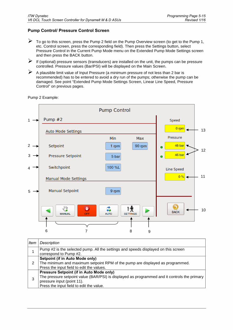
ITW Dynatec Programming Page 5-15 V6 DCL Touch Screen Controller for Dynamelt M & D ASUs Revised 1/16
Pump Control/ Pressure Control Screen To go to this screen, press the Pump 2 field on the Pump Overview screen (to get to the Pump 1,
etc. Control screen, press the corresponding field). Then press the Settings button, select Pressure Control in the Current Pump Mode menu on the Extended Pump Mode Settings screen and then press the BACK button.
If (optional) pressure sensors (transducers) are installed on the unit, the pumps can be pressure controlled. Pressure values (Bar/PSI) will be displayed on the Main Screen.
A plausible limit value of Input Pressure (a minimum pressure of not less than 2 bar is recommended) has to be entered to avoid a dry run of the pumps; otherwise the pump can be damaged. See point “Extended Pump Mode Settings Screen, Linear Line Speed, Pressure Control” on previous pages.
Pump 2 Example:
Item Description
1 Pump #2 is the selected pump. All the settings and speeds displayed on this screen correspond to Pump #2.
2 Setpoint (if in Auto Mode only) The minimum and maximum setpoint RPM of the pump are displayed as programmed. Press the input field to edit the values.
3
Pressure Setpoint (if in Auto Mode only) The pressure setpoint value (BAR/PSI) is displayed as programmed and it controls the primary pressure input (point 11). Press the input field to edit the value.
7
1
10
2
3
9
11
12
4
5
8
13
6

Page 5-16 ITW Dynatec Revised 1/16 V6 DCL Touch Screen Controller for Dynamelt M & D ASUs
Item Description
4
Switch Point (if in Auto Mode only) Switch Point is set at a percentage of line speed. In the example shown above, 10%L equals 10% of line speed. Below the Switch Point speed, the system runs in pressure control mode (PID control, in order to maintain the pressure set point). Above the Switch Point speed, the system runs in normal line speed following mode (utilizing the auto min and auto max parameters). The switch point value is displayed as programmed. Press the input field to edit the value.
5 Manual Setpoint (if in Manual Mode only) The manual setpoint RPM of the pump is displayed as programmed. Press the input field to edit the value.
6 Press the arrow icon to go to the previous pump screen (ie, Pump 1, etc.).
7
Set the pump to the desired mode by pressing either MANUAL, OFF (STOP) or AUTO. • MANUAL: The pump speed is adjusted manually by the operator. If MANUAL is selected
the icon is highlighted green. • OFF (STOP): The pump is stopped, until AUTO or MANUAL is selected. If OFF is selected
the icon is highlighted red. • AUTO: The pump speed is controlled via a 0–10VDC signal that is provided by an external
device (pattern control equipment or parent machine input). If AUTO is selected the icon is highlighted green. A minimum speed is necessary to keep the pump turning in order to maintain a minimum amount of adhesive pressure through the hose and applicator head. For instance, if the input signal is 10VDC at 100 meters per minute and the pump percentage of full speed is 100% (maximum speed), but the system is putting out too much adhesive, adjusting the MAX pump percentage to 50 will cause the pump to slow down over the parent machine’s entire speed range and adhesive output will be decreased.
8
Settings Button Press this button to go to the Extended Pump Mode Settings screen where you can select the Current Pump Mode "Linear Line Speed" or "Pressure Control" and you can go to the "Automatic Ramp Compensation" screen.
9 Press the arrow icon to go to the next pump screen (ie, Pump 3, etc.).
10 BACK Button Press to return to the previous screen.
11 LINE SPEED: The actual (or calculated) line speed is displayed.
12
PRESSURE: The actual pressures are displayed. The primary pressure input can be controlled via the Pressure Set Point (point 3) set on this screen. The secondary pressure input is just a readout function. See explanation under Main Screen point 4.
13 SPEED: The actual (or calculated) pump speed is displayed.
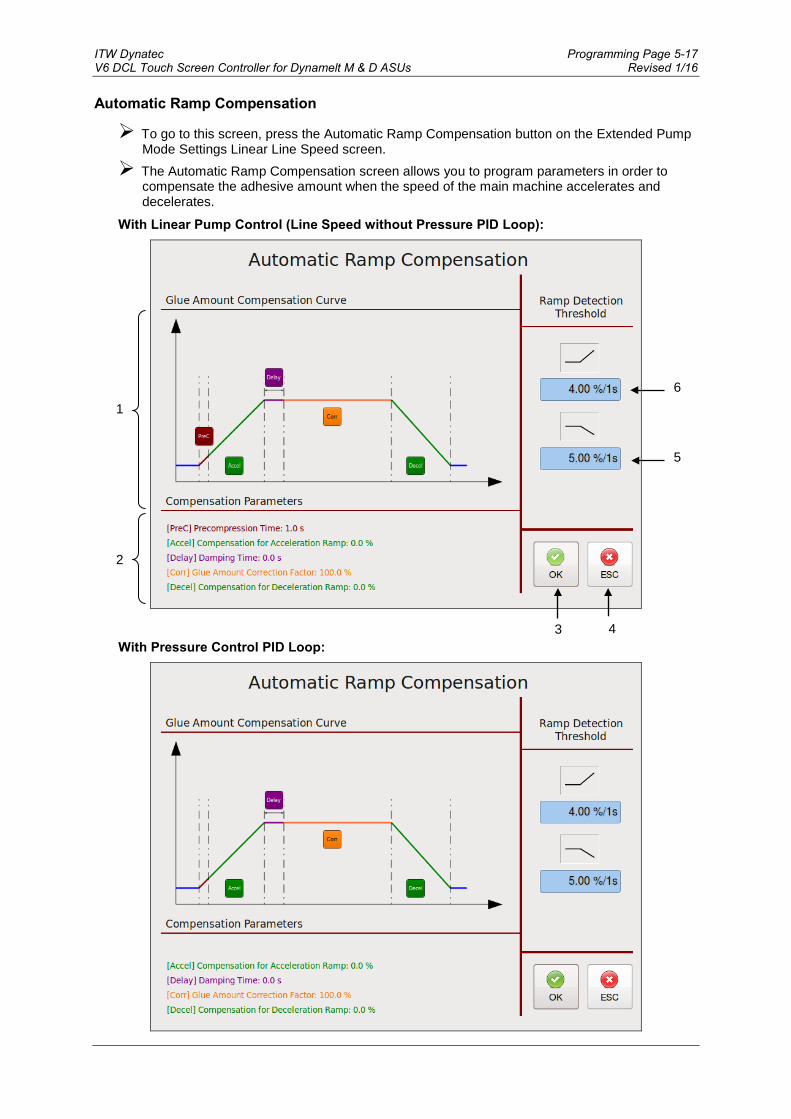
ITW Dynatec Programming Page 5-17 V6 DCL Touch Screen Controller for Dynamelt M & D ASUs Revised 1/16
Automatic Ramp Compensation
To go to this screen, press the Automatic Ramp Compensation button on the Extended Pump Mode Settings Linear Line Speed screen.
The Automatic Ramp Compensation screen allows you to program parameters in order to compensate the adhesive amount when the speed of the main machine accelerates and decelerates.
With Linear Pump Control (Line Speed without Pressure PID Loop):
With Pressure Control PID Loop:
1
4
2
3
5
6

Page 5-18 ITW Dynatec Revised 1/16 V6 DCL Touch Screen Controller for Dynamelt M & D ASUs
Ramp Compensation allows tuning of adhesive amounts during acceleration and deceleration of
main machine to reduce waste and increase machine efficiency by entering appropriate parameters.
The colored parameters are related to the different phases of the main machine (see colored graph). A higher value will result in a higher compensation (more glue amount during acceleration, less glue amount during deceleration).
After setting parameters by visibly checking the product result, further fine tuning might be necessary by checking products from the acceleration/deceleration ramp in a lab.
Item Description
1
Glue Amount Compensation Curve • (PreC) Precompression Time in seconds: When using ramp compensation without
pressure control loop, this defines the time the system will pre-compress at 75% pump speed before adhesive application.
• (Accel) Compensation for Acceleration Ramp in % or rpm: This is the added percentage or rpm of pump speed to compensate the main machine acceleration ramp.
• (Delay) Damping Time in seconds: within this time the compensation is reduced to the normal application rate in order to prevent an elastic impact.
• (Corr) Glue Amount Correction Factor in %: Allows an adjustment of pump speed if a speed correction is required due to measured deviations of the adhesive amount.
• (Decel) Compensation for Deceleration Ramp: This is the subtracted percentage or rpm of pump speed to compensate the main machine deceleration ramp.
By pressing the appropriate button you can edit the value by means of numeric entry keypad.
2 Compensation Parameters The compensation parameters values currently in use are displayed.
3 Press the OK button to confirm your entered values and return to the previous screen.
4 Press the ESC button to discard any non-confirmed values and return to the previous screen.
5
Ramp Detection Threshold for deceleration in %/1s A main machine deceleration phase is automatically detected when its speed change lies above the given value. By pressing the input field you can edit the value by means of numeric entry keypad.
6
Ramp Detection Threshold for acceleration in %/1s A main machine acceleration phase is automatically detected when its speed change lies above the given value. By pressing the input field you can edit the value by means of numeric entry keypad.

ITW Dynatec Programming Page 5-19 V6 DCL Touch Screen Controller for Dynamelt M & D ASUs Revised 1/16
Control Switch On/Off and Standby Switch
To go to this screen, press the Control button on the Main Screen. This screen allows you to turn the system On or Off and to activate/deactivate standby condition.
3 2 1

Page 5-20 ITW Dynatec Revised 1/16 V6 DCL Touch Screen Controller for Dynamelt M & D ASUs
Item Description
1
Standby Switch • Press the Standby switch to activate or deactivate the standby condition. When Standby is
activated, the button will be highlighted blue. • When Standby is activated, all zone temperatures will be set to the standby value
(programmed on the General Settings Screen) and all pumps will be disabled.
2 On/Off Switch Press the On/Off button to toggle the system On or Off. When the system is On, the button will be highlighted green. When the system is Off, the button will be highlighted red.
3 BACK Button Press to return to the previous screen.
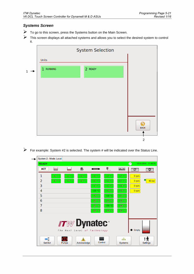
ITW Dynatec Programming Page 5-21 V6 DCL Touch Screen Controller for Dynamelt M & D ASUs Revised 1/16
Systems Screen
To go to this screen, press the Systems button on the Main Screen. This screen displays all attached systems and allows you to select the desired system to control
it.
For example: System #2 is selected. The system # will be indicated over the Status Line.
2
1

Page 5-22 ITW Dynatec Revised 1/16 V6 DCL Touch Screen Controller for Dynamelt M & D ASUs
Item Description
1
System # Button • Each system is assigned with a number. • Press the desired number to go to the appropriate system to control and to edit its
parameters. • The button is highlighted green when the system is RUNNING or READY, yellow when NOT
READY, grey when in STANDBY and red when in ALARM condition.
2 BACK Button Press to return to the previous screen.
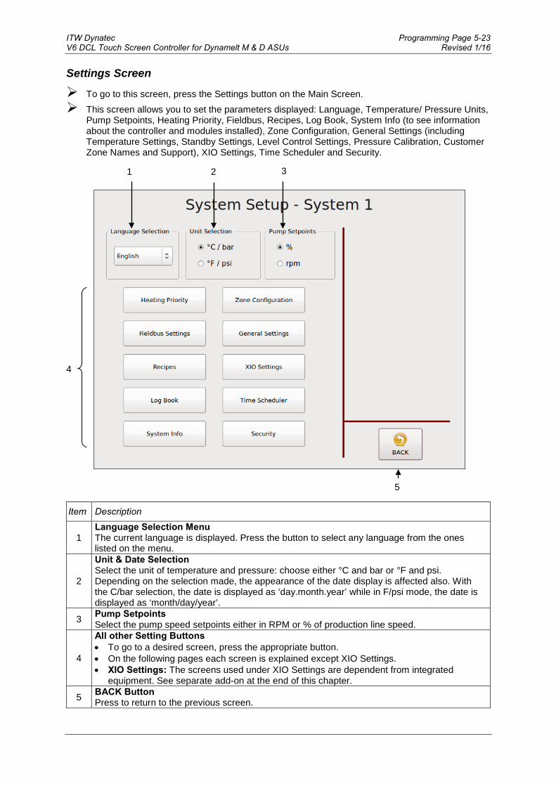
ITW Dynatec Programming Page 5-23 V6 DCL Touch Screen Controller for Dynamelt M & D ASUs Revised 1/16
Settings Screen
To go to this screen, press the Settings button on the Main Screen. This screen allows you to set the parameters displayed: Language, Temperature/ Pressure Units,
Pump Setpoints, Heating Priority, Fieldbus, Recipes, Log Book, System Info (to see information about the controller and modules installed), Zone Configuration, General Settings (including Temperature Settings, Standby Settings, Level Control Settings, Pressure Calibration, Customer Zone Names and Support), XIO Settings, Time Scheduler and Security.
Item Description
1 Language Selection Menu The current language is displayed. Press the button to select any language from the ones listed on the menu.
2
Unit & Date Selection Select the unit of temperature and pressure: choose either °C and bar or °F and psi. Depending on the selection made, the appearance of the date display is affected also. With the C/bar selection, the date is displayed as ‘day.month.year’ while in F/psi mode, the date is displayed as ‘month/day/year’.
3 Pump Setpoints Select the pump speed setpoints either in RPM or % of production line speed.
4
All other Setting Buttons • To go to a desired screen, press the appropriate button. • On the following pages each screen is explained except XIO Settings. • XIO Settings: The screens used under XIO Settings are dependent from integrated
equipment. See separate add-on at the end of this chapter.
5 BACK Button Press to return to the previous screen.
1 2 3
4
5

Page 5-24 ITW Dynatec Revised 1/16 V6 DCL Touch Screen Controller for Dynamelt M & D ASUs
Heating Priority Screen
To go to this screen, press the Heating Priority button on the Settings Screen. This screen allows you to set a Heating Priority for each zone. Heating Priority allows the hopper
zones to heat to their ready temperatures before the other zones begin heating. In this way, the larger mass of adhesive in the hopper zones (including the grid, hopper and filter block) gets a head start on the other zones (hoses, applicators and auxiliary zones).
Heating Priority Matrix Example:
Item Description
1
Touch each zone field to select one of the following three Heating Priorities, or to switch the zone OFF: • PRIO1 = the zone will heat first. • PRIO2 = the zone will begin to heat after the PRIO1 zones have reached their setpoints. • PRIO3 = the zone will begin to heat after the PRIO2 zones have reached their setpoints. • OFF = the zone is OFF. It will not heat and it will not be displayed on the Main screen.
2 Press the OK button to confirm your entered values and return to the previous screen.
3 Press the ESC button to discard any non-confirmed values and return to the previous screen.
4
Press the Standard Sequence button to accept the following standard Heating Priorities: • PRIO1 = grid, hopper and filter block • PRIO2 = hoses • PRIO3 = applicators and other auxiliary components Press the OK button to confirm.
5 Press the Without Sequence button to assign all zones to PRIO1. With this setting, all zones will begin to heat after turning on the unit. Press the OK button to confirm.
1
2 3
4
5

ITW Dynatec Programming Page 5-25 V6 DCL Touch Screen Controller for Dynamelt M & D ASUs Revised 1/16
Zone Configuration Screen To go to this screen, press the Zone Configuration button on the Settings Screen. This screen allows you to enter zone names and to set Offset Temperature and other Control
Settings for each zone.
Zone Configuration Screen Example:
Item Description
1
• Touch a zone input box to go to the Zone Settings.
• Zone is highlighted yellow if an Offset Temperature has been set for this zone.
• Square bracket is displayed if a custom zone name has been entered for this zone.
2 BACK Button Press to return to the previous screen.
1
2
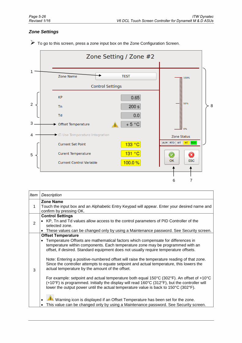
Page 5-26 ITW Dynatec Revised 1/16 V6 DCL Touch Screen Controller for Dynamelt M & D ASUs
Zone Settings To go to this screen, press a zone input box on the Zone Configuration Screen.
Item Description
1 Zone Name Touch the input box and an Alphabetic Entry Keypad will appear. Enter your desired name and confirm by pressing OK.
2
Control Settings • KP, Tn and Td values allow access to the control parameters of PID Controller of the
selected zone. • These values can be changed only by using a Maintenance password. See Security screen.
3
Offset Temperature • Temperature Offsets are mathematical factors which compensate for differences in
temperature within components. Each temperature zone may be programmed with an offset, if desired. Standard equipment does not usually require temperature offsets. Note: Entering a positive‐numbered offset will raise the temperature reading of that zone. Since the controller attempts to equate setpoint and actual temperature, this lowers the actual temperature by the amount of the offset. For example: setpoint and actual temperature both equal 150°C (302°F). An offset of +10°C (+10°F) is programmed. Initially the display will read 160°C (312°F), but the controller will lower the output power until the actual temperature value is back to 150°C (302°F).
• Warning icon is displayed if an Offset Temperature has been set for the zone. • This value can be changed only by using a Maintenance password. See Security screen.
7
8
1
2
3
4
6
5

ITW Dynatec Programming Page 5-27 V6 DCL Touch Screen Controller for Dynamelt M & D ASUs Revised 1/16
Item Description
4
Use Temperature Integration • Depending on your Temp Module this function can be activated/ deactivated. • If you experience strong variations in actual temperature read-out, an integration function
can be activated to eliminate EMC influence.
5 These values are read-only.
6 Press the OK button to confirm your entered values and return to the previous screen.
7 Press the ESC button to discard any non-confirmed values and return to the previous screen.
8
Zone Status Zone status is indicated. • ALM = is highlighted if zone has an alarm. • RTD = is highlighted if temperature sensor error occurs. • WT = is highlighted if zone is in wait status because of heating priority setting. • HT = is highlighted if zone is heating up. • RDY = is highlighted if zone ready (setpoint temperatures are reached). • Scale = Indication of Current Control Variable of the selected PID control zone.

Page 5-28 ITW Dynatec Revised 1/16 V6 DCL Touch Screen Controller for Dynamelt M & D ASUs
Fieldbus Setup Screen To go to this screen, press the Fieldbus Settings button on the Settings Screen.
When communicating to a parent machine which utilizes profibus or EtherNet IP, the unit must
have a Fieldbus Address to identify it. When there are additional units in a system, each unit must have its own unique Fieldbus Address.
Item Description
1
Fieldbus Address Touch the input box and a numeric entry keypad will appear. Enter the Fieldbus Address of the unit. Confirm by pressing OK. After programming the Fieldbus Address, the system must be re-started. To re-start the system with changed parameters: 1. Press OK to accept changes. 2. Wait at least one minute. 3. Switch unit Off via the main switch. 4. Switch unit On via the main switch.
2 Press the OK button to confirm your entered values and return to the previous screen.
3 Press the ESC button to discard any non-confirmed values and return to the previous screen.
1
2 3

ITW Dynatec Programming Page 5-29 V6 DCL Touch Screen Controller for Dynamelt M & D ASUs Revised 1/16
General Settings Screen To go to this screen, press the General Settings button on the Settings Screen. This screen allows you to set the parameters shown across the screen’s top line (Item #1, shown
below). Select a desired parameter (Temperature, Standby, Level Control, Pressure Calibration or
Customer Zone Names) by pressing its tab or by pressing the arrows at the bottom of the screen.
Temperature Settings
Item Description
1 Parameter Selection tabs The Temperature Settings tab has been selected.
2
Pump Enable Temperature • The Pump Enable Temperature is a low-limit value (e.g. 100°C / 212°F) which protects the
pump, pump shaft, motor and motor control module by preventing the pump from turning on until a minimum adhesive temperature is achieved. Caution should be taken to avoid setting this value too low because attempting to rotate the pump when the adhesive inside it is not molten will result in damage to the pump and, possibly, to the pump motor. The Pump Enable Temperature is independent from the temperature setpoints. The programmable range is 10-200 °C (50- 400°F).
• Touch the input box and a numeric entry keypad will appear. Enter your desired Pump Enable Temperature value and confirm by pressing OK.
8 9
1
2
3
4
6 7
5

Page 5-30 ITW Dynatec Revised 1/16 V6 DCL Touch Screen Controller for Dynamelt M & D ASUs
Item Description
3
Temperature Alarm Window • This is the programmable temperature range which allows the unit to go into Ready
condition. The Temperature Alarm Window is a deviation (e.g. ± 20°C / 36°F) from the setpoint. The setpoint minus the deviation is the low limit of the window, and the setpoint plus the deviation is the high limit of the window. The programmable range is 0-50 °C (0- 90°F).
• The Temperature Alarm Window (± the Temperature Alarm Hysteresis, if programmed) will trigger high and low temperature alarms when zone temperatures rise or fall outside of the window.
• Touch the input box and a numeric entry keypad will appear. Enter your desired Temperature Alarm Window value and confirm by pressing OK.
4
Temperature Alarm Hysteresis • This is a second, smaller, temperature range and alarm limit programmed in addition to the
Temperature Alarm Window which allows the unit to remain in Ready condition as temperatures stabilize. The Temperature Alarm Hysteresis is a deviation (e.g. ± 2°C / 3°F) from the Temperature Alarm Window. The Temperature Alarm Window minus the deviation is the low limit of the Temperature Alarm Hysteresis, and the Temperature Alarm Window plus the deviation is the high limit of the Temperature Alarm Hysteresis. The programmable range is 0-10 °C (0-30°F).
• The Temperature Alarm Hysteresis will trigger high and low temperature alarms when those temperatures are exceeded.
• Touch the input box and a numeric entry keypad will appear. Enter your desired Temperature Alarm Hysteresis value and confirm by pressing OK.
5 Temperature Set Point Limitation This is a by customer programmable maximum temperature set point limitation.
6 Press the left-pointing arrow to go to the previous General Settings screen.
7 Press the right-pointing arrow to go to the next General Settings screen.
8 Press the OK button to confirm your entered values and return to the previous screen.
9 Press the ESC button to discard any non-confirmed values and return to the previous screen.

ITW Dynatec Programming Page 5-31 V6 DCL Touch Screen Controller for Dynamelt M & D ASUs Revised 1/16
Standby Settings To go to this screen, press the General Settings button on the Settings Screen.
Item Description
1 Parameter Selection tabs The Standby Settings tab has been selected.
2
Standby Setback Temperature • This is the system condition where the hopper, hose and head temperatures are maintained
at predetermined reduced temperature values. Standby Setback Temperatures are set lower than setpoint temperatures (e.g. 83°C / 149°F) in order to reduce adhesive degradation and energy consumption when the system is temporarily inactive, and to permit rapid system warm‐up when run conditions are selected. When standby mode is activated, the controller will display STANDBY. The programmable range is 0-150 °C (0-270°F).
• Touch the input box and a numeric entry keypad will appear. Enter your desired Standby Setback Temperature value and confirm by pressing OK.
3
Standby Delay (External Contact) • The Standby Delay is the programmed number of minutes until the unit goes into standby
mode after activation by an external contact (for example: a PLC or an external switch). The programmable range is 0-150 minutes.
• Touch the input box and a numeric entry keypad will appear. Enter your desired Standby Delay value and confirm by pressing OK.
4
Automatic Standby Delay (0 = disabled) • The Automatic Standby Delay is the programmed number of minutes until the unit goes into
standby mode after the unit has heated-up and the pump is stopped (no adhesive feeding activity). The programmable range is 0-1440 minutes. Enter 0 to disable the feature.
• Touch the input box and a numeric entry keypad will appear. Enter your desired Automatic Standby Delay value and confirm by pressing OK.
7 8
1
2
3
4
5 6

Page 5-32 ITW Dynatec Revised 1/16 V6 DCL Touch Screen Controller for Dynamelt M & D ASUs
Item Description
5 Press the left-pointing arrow to go to the previous General Settings screen.
6 Press the right-pointing arrow to go to the next General Settings screen.
7 Press the OK button to confirm your entered values and return to the previous screen.
8 Press the ESC button to discard any non-confirmed values and return to the previous screen.
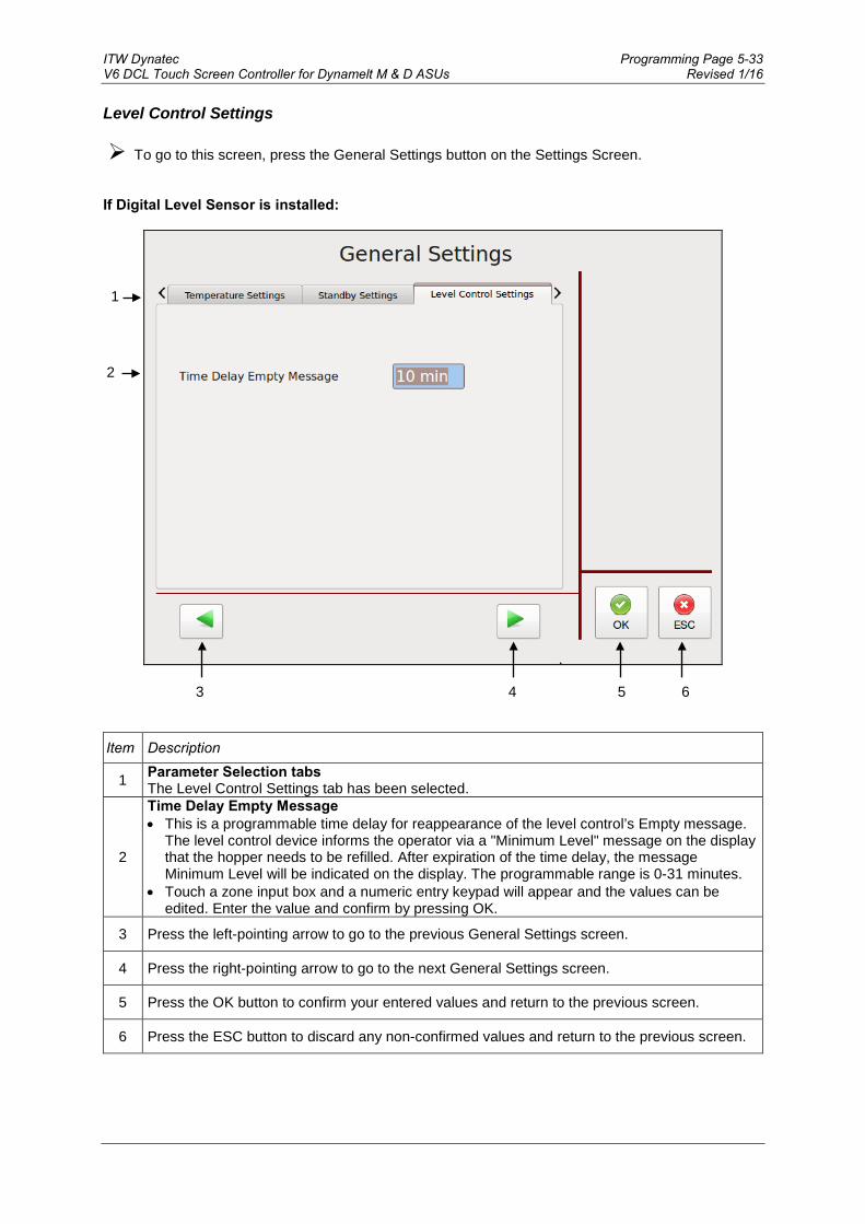
ITW Dynatec Programming Page 5-33 V6 DCL Touch Screen Controller for Dynamelt M & D ASUs Revised 1/16
Level Control Settings To go to this screen, press the General Settings button on the Settings Screen.
If Digital Level Sensor is installed:
Item Description
1 Parameter Selection tabs The Level Control Settings tab has been selected.
2
Time Delay Empty Message • This is a programmable time delay for reappearance of the level control’s Empty message.
The level control device informs the operator via a "Minimum Level" message on the display that the hopper needs to be refilled. After expiration of the time delay, the message Minimum Level will be indicated on the display. The programmable range is 0-31 minutes.
• Touch a zone input box and a numeric entry keypad will appear and the values can be edited. Enter the value and confirm by pressing OK.
3 Press the left-pointing arrow to go to the previous General Settings screen.
4 Press the right-pointing arrow to go to the next General Settings screen.
5 Press the OK button to confirm your entered values and return to the previous screen.
6 Press the ESC button to discard any non-confirmed values and return to the previous screen.
1
2
3 4 5 6
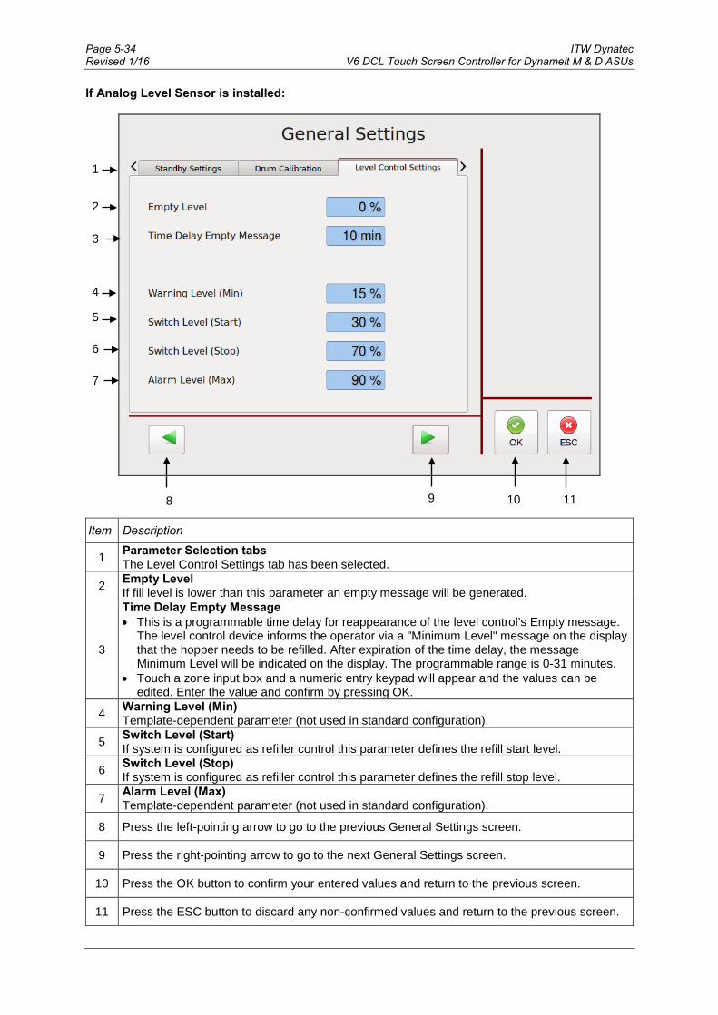
Page 5-34 ITW Dynatec Revised 1/16 V6 DCL Touch Screen Controller for Dynamelt M & D ASUs
If Analog Level Sensor is installed:
Item Description
1 Parameter Selection tabs The Level Control Settings tab has been selected.
2 Empty Level If fill level is lower than this parameter an empty message will be generated.
3
Time Delay Empty Message • This is a programmable time delay for reappearance of the level control’s Empty message.
The level control device informs the operator via a "Minimum Level" message on the display that the hopper needs to be refilled. After expiration of the time delay, the message Minimum Level will be indicated on the display. The programmable range is 0-31 minutes.
• Touch a zone input box and a numeric entry keypad will appear and the values can be edited. Enter the value and confirm by pressing OK.
4 Warning Level (Min) Template-dependent parameter (not used in standard configuration).
5 Switch Level (Start) If system is configured as refiller control this parameter defines the refill start level.
6 Switch Level (Stop) If system is configured as refiller control this parameter defines the refill stop level.
7 Alarm Level (Max) Template-dependent parameter (not used in standard configuration).
8 Press the left-pointing arrow to go to the previous General Settings screen.
9 Press the right-pointing arrow to go to the next General Settings screen.
10 Press the OK button to confirm your entered values and return to the previous screen.
11 Press the ESC button to discard any non-confirmed values and return to the previous screen.
4
3
5
6
7
10 11
1
2
8 9

ITW Dynatec Programming Page 5-35 V6 DCL Touch Screen Controller for Dynamelt M & D ASUs Revised 1/16
Pressure Zero Calibration To go to this screen, press the General Settings button on the Settings Screen.
Item Description
1 Parameter Selection tabs The Pressure Zero Calibration tab has been selected.
2
OK Button Before calibrating the (optional) pressure transducers, all pumps must be in STOP mode and the system must be fully depressurized. After taking the appropriate steps, confirm this by pressing the OK button. You will then go to the Calibrating Screen.
2
1
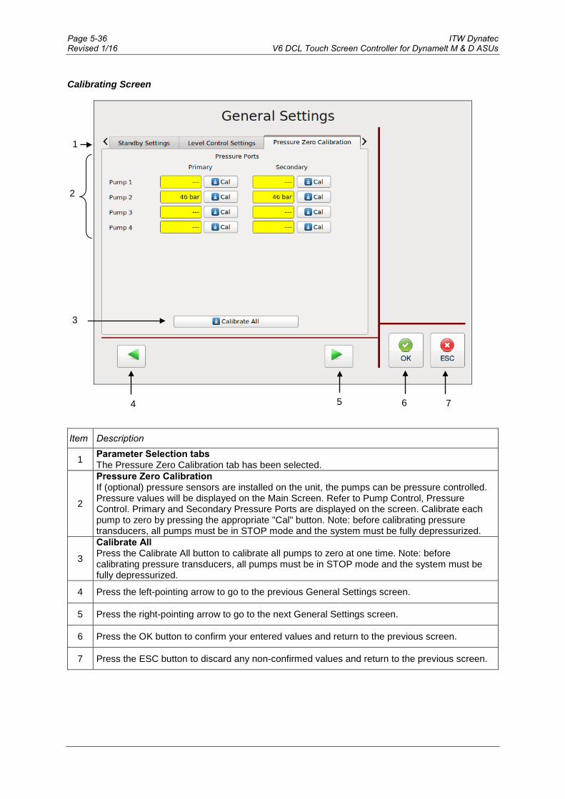
Page 5-36 ITW Dynatec Revised 1/16 V6 DCL Touch Screen Controller for Dynamelt M & D ASUs
Calibrating Screen
Item Description
1 Parameter Selection tabs The Pressure Zero Calibration tab has been selected.
2
Pressure Zero Calibration If (optional) pressure sensors are installed on the unit, the pumps can be pressure controlled. Pressure values will be displayed on the Main Screen. Refer to Pump Control, Pressure Control. Primary and Secondary Pressure Ports are displayed on the screen. Calibrate each pump to zero by pressing the appropriate "Cal" button. Note: before calibrating pressure transducers, all pumps must be in STOP mode and the system must be fully depressurized.
3
Calibrate All Press the Calibrate All button to calibrate all pumps to zero at one time. Note: before calibrating pressure transducers, all pumps must be in STOP mode and the system must be fully depressurized.
4 Press the left-pointing arrow to go to the previous General Settings screen.
5 Press the right-pointing arrow to go to the next General Settings screen.
6 Press the OK button to confirm your entered values and return to the previous screen.
7 Press the ESC button to discard any non-confirmed values and return to the previous screen.
6 7
1
2
4 5
3
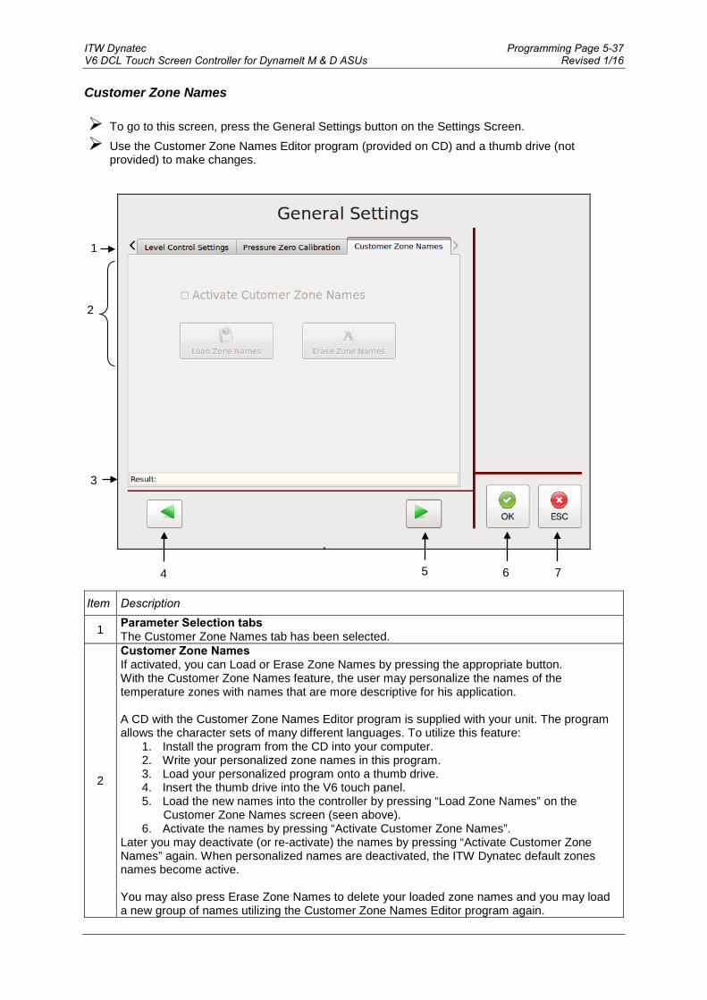
ITW Dynatec Programming Page 5-37 V6 DCL Touch Screen Controller for Dynamelt M & D ASUs Revised 1/16
Customer Zone Names To go to this screen, press the General Settings button on the Settings Screen. Use the Customer Zone Names Editor program (provided on CD) and a thumb drive (not
provided) to make changes.
Item Description
1 Parameter Selection tabs The Customer Zone Names tab has been selected.
2
Customer Zone Names If activated, you can Load or Erase Zone Names by pressing the appropriate button. With the Customer Zone Names feature, the user may personalize the names of the temperature zones with names that are more descriptive for his application. A CD with the Customer Zone Names Editor program is supplied with your unit. The program allows the character sets of many different languages. To utilize this feature:
1. Install the program from the CD into your computer. 2. Write your personalized zone names in this program. 3. Load your personalized program onto a thumb drive. 4. Insert the thumb drive into the V6 touch panel. 5. Load the new names into the controller by pressing “Load Zone Names” on the
Customer Zone Names screen (seen above). 6. Activate the names by pressing “Activate Customer Zone Names”.
Later you may deactivate (or re-activate) the names by pressing “Activate Customer Zone Names” again. When personalized names are deactivated, the ITW Dynatec default zones names become active. You may also press Erase Zone Names to delete your loaded zone names and you may load a new group of names utilizing the Customer Zone Names Editor program again.
6 7
1
2
4 5
3

Page 5-38 ITW Dynatec Revised 1/16 V6 DCL Touch Screen Controller for Dynamelt M & D ASUs
Item Description
3 Result A message will confirm if the names were successfully loaded, activated or deactivated, or if there was an error in loading the names.
4 Press the left-pointing arrow to go to the previous General Settings screen.
5 Press the right-pointing arrow to go to the next General Settings screen.
6 Press the OK button to confirm your entered values and return to the previous screen.
7 Press the ESC button to discard any non-confirmed values and return to the previous screen.
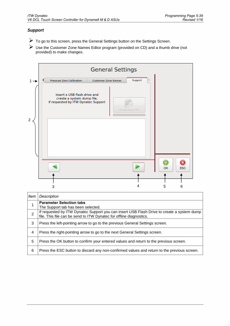
ITW Dynatec Programming Page 5-39 V6 DCL Touch Screen Controller for Dynamelt M & D ASUs Revised 1/16
Support To go to this screen, press the General Settings button on the Settings Screen. Use the Customer Zone Names Editor program (provided on CD) and a thumb drive (not
provided) to make changes.
Item Description
1 Parameter Selection tabs The Support tab has been selected.
2 If requested by ITW Dynatec Support you can insert USB Flash Drive to create a system dump file. This file can be send to ITW Dynatec for offline diagnostics.
3 Press the left-pointing arrow to go to the previous General Settings screen.
4 Press the right-pointing arrow to go to the next General Settings screen.
5 Press the OK button to confirm your entered values and return to the previous screen.
6 Press the ESC button to discard any non-confirmed values and return to the previous screen.
5 6
1
2
3 4
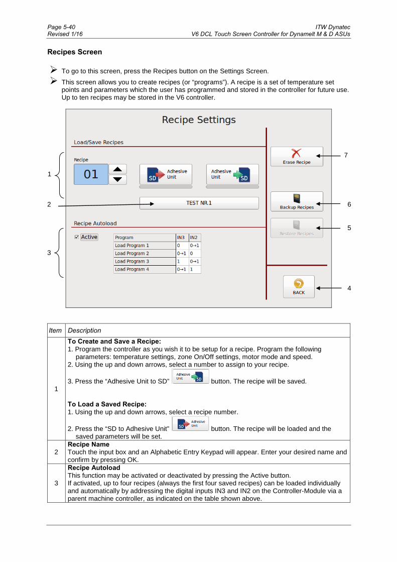
Page 5-40 ITW Dynatec Revised 1/16 V6 DCL Touch Screen Controller for Dynamelt M & D ASUs
Recipes Screen To go to this screen, press the Recipes button on the Settings Screen. This screen allows you to create recipes (or “programs”). A recipe is a set of temperature set
points and parameters which the user has programmed and stored in the controller for future use. Up to ten recipes may be stored in the V6 controller.
Item Description
1
To Create and Save a Recipe: 1. Program the controller as you wish it to be setup for a recipe. Program the following
parameters: temperature settings, zone On/Off settings, motor mode and speed. 2. Using the up and down arrows, select a number to assign to your recipe.
3. Press the “Adhesive Unit to SD” button. The recipe will be saved. To Load a Saved Recipe: 1. Using the up and down arrows, select a recipe number.
2. Press the “SD to Adhesive Unit” button. The recipe will be loaded and the saved parameters will be set.
2 Recipe Name Touch the input box and an Alphabetic Entry Keypad will appear. Enter your desired name and confirm by pressing OK.
3
Recipe Autoload This function may be activated or deactivated by pressing the Active button. If activated, up to four recipes (always the first four saved recipes) can be loaded individually and automatically by addressing the digital inputs IN3 and IN2 on the Controller-Module via a parent machine controller, as indicated on the table shown above.
1
3
4
7
2
5
6

ITW Dynatec Programming Page 5-41 V6 DCL Touch Screen Controller for Dynamelt M & D ASUs Revised 1/16
Item Description
4 BACK Button Press to return to the previous screen.
5 Restore Recipes This button is visible only if USB Flash Drive is inserted into the Touch Panel. Press this button to restore recipe collection from USB Flash Drive into the Touch Panel.
6 Backup Recipes This button is visible only if USB Flash Drive is inserted into the Touch Panel. Press this button to save recipe collection from Touch Panel to the USB Flash Drive.
7 Erase Recipe 1. Using the up and down arrows, select the number of the recipe you wish to erase. 2. Press Erase Recipe to delete the recipe from the controller/ Touch Panel.

Page 5-42 ITW Dynatec Revised 1/16 V6 DCL Touch Screen Controller for Dynamelt M & D ASUs
Time & Scheduler Screen To go to this screen, press the Time & Scheduler button on the Settings Screen. This screen allows you to set the current date and time, and program the scheduler.
Item Description
1
Time & Date Settings The Time and Date are set with the buttons across the top of the screen. Using the up and down arrows, choose the current Day, Month, Year, Hour and Minute. To confirm these values, press Set Time. Afterwards, the current date and time will be displayed at right (item #5).
2
Scheduler Settings The controller’s scheduler will automatically turn On the unit at the programmed start time and turn it Off at the programmed stop time on the programmed days (cycle).
Up to three scheduler timers may be programmed either for System On/Off or for Standby On/Off. Each scheduler timer is programmed with a start time, a stop time and a cycle. Three cycles are available: Monday thru Friday, Saturday & Sunday or Sunday thru Saturday (ie, every day).
For example: The display illustrated above shows Timer 1 programmed and activated. It is programmed for System On/Off with a Start time of 06:00, a Stop time of 16:00 and a Cycle of Mon-Fri.
5
2
1
3
4

ITW Dynatec Programming Page 5-43 V6 DCL Touch Screen Controller for Dynamelt M & D ASUs Revised 1/16
Item Description
2
Programming • Select a timer for programming by pressing Timer 1, Timer 2 or Timer 3. • Select either System On/Off or Standby On/Off. • Using the up and down arrows, set the start time hour and minute. The scheduler will
automatically turn On the unit at this time. • Using the up and down arrows, set the stop time hour and minute. The scheduler will
automatically turn Off the unit at this time. • Using the up and down arrows, set the cycle. The scheduler will automatically turn the unit
On and Off on these days. • By pressing the Enable Scheduler button, the programmed parameters will be confirmed
and the selected timer is activated.
To change a timer program, first select the desired timer. Then press the Disable Scheduler button. Now the selected timer can be re-programmed with new parameters as described above. The „clock“ icon appears in the status line on main screen if a timer is activated and disappears if the timer is deactivated.
3 BACK Button Press to return to the previous screen.
4 Turn System Off Press System Off to turn the system Off. Refer to "Control switch On/Off and Standby".
5 Current Date & Time Display of the current date and time as programmed into the controller.
Example: The display on the right shows Timer 2 programmed and activated for Standby On/Off with a Start time of 12:00, a Stop time of 13:00 and a Cycle of Mon-Fri.

Page 5-44 ITW Dynatec Revised 1/16 V6 DCL Touch Screen Controller for Dynamelt M & D ASUs
Example: The display on the right shows that Timer 3 is not programmed and not activated:
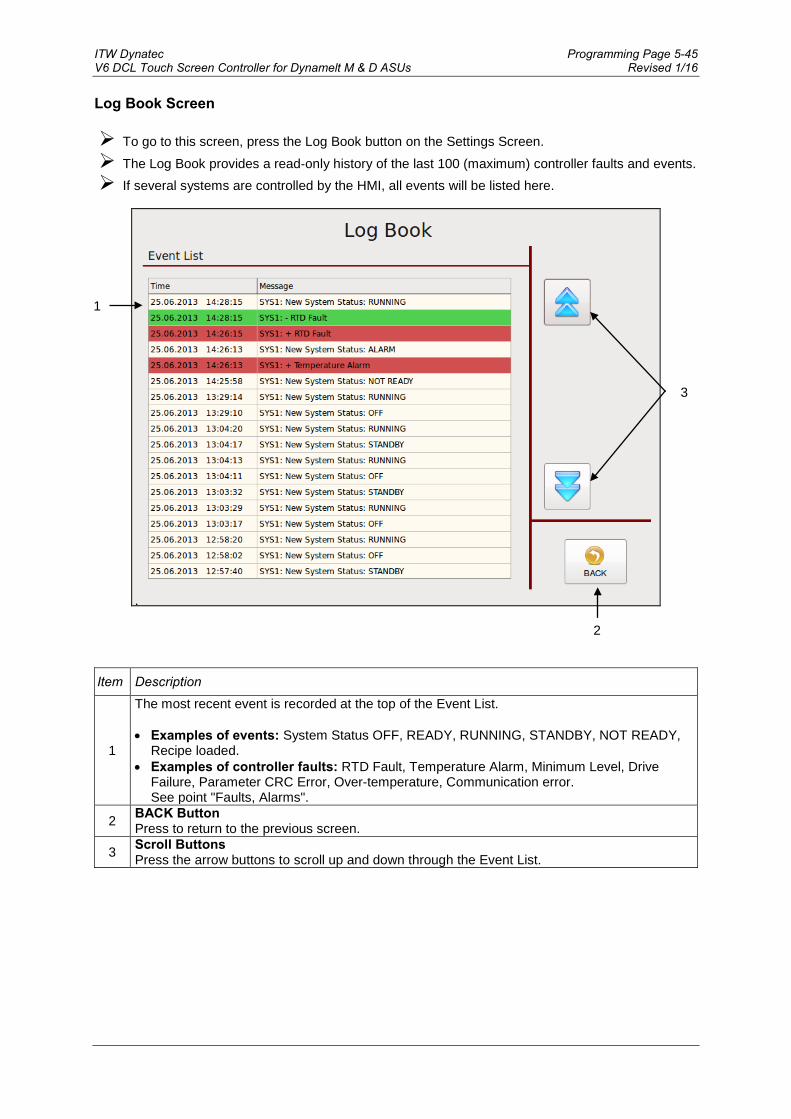
ITW Dynatec Programming Page 5-45 V6 DCL Touch Screen Controller for Dynamelt M & D ASUs Revised 1/16
Log Book Screen To go to this screen, press the Log Book button on the Settings Screen.
The Log Book provides a read‐only history of the last 100 (maximum) controller faults and events. If several systems are controlled by the HMI, all events will be listed here.
Item Description
1
The most recent event is recorded at the top of the Event List. • Examples of events: System Status OFF, READY, RUNNING, STANDBY, NOT READY,
Recipe loaded. • Examples of controller faults: RTD Fault, Temperature Alarm, Minimum Level, Drive
Failure, Parameter CRC Error, Over-temperature, Communication error. See point "Faults, Alarms".
2 BACK Button Press to return to the previous screen.
3 Scroll Buttons Press the arrow buttons to scroll up and down through the Event List.
1
2
3

Page 5-46 ITW Dynatec Revised 1/16 V6 DCL Touch Screen Controller for Dynamelt M & D ASUs
Security Screen To go to this screen, press the Security button on the Settings Screen. This screen allows you to set securities (with password) for access and for changing parameters.
Item Description
• Security unlocked = access to the Security Settings is unlocked and settings may be changed by all users. The crossed-out Key icon, shown above, means Security is unlocked. After pressing the Key button, it will disappear and the Security Settings will be locked.
• Security locked = access to the Security Settings is locked and settings may only be changed by entering a password.
Continued on next page.
Security is unlocked
Security is locked

ITW Dynatec Programming Page 5-47 V6 DCL Touch Screen Controller for Dynamelt M & D ASUs Revised 1/16
Item Description
1
Section Access Press the buttons to select access to each parameter as follows: • Unlock = the parameter may be changed by all users. • Operator = the parameter may be changed by Operator personnel only, by using an
Operator password. • Maintenance = the parameter may be changed by Maintenance personnel only, by using a
Maintenance password.
2 Press the OK button to confirm your entered values and return to the previous screen.
3 Press the ESC button to discard any non-confirmed values and return to the previous screen.
4 Change Maintenance Password Button Touch the Change Password button and a numeric entry keypad will appear. Enter desired numeric password (at least one digit). Press OK to confirm.
5 Change Operator Password Button Touch the Change Password button and a numeric entry keypad will appear. Enter desired numeric password (at least one digit). Press OK to confirm.
1
2 3
4
5

Page 5-48 ITW Dynatec Revised 1/16 V6 DCL Touch Screen Controller for Dynamelt M & D ASUs
System Info Screen To go to this screen, press the System Info button on the Settings Screen. This screen displays information about the V6 controller and its modules. The screen is read-only.
Item Description
1 Information about the controller and its modules is displayed. The illustration above shows an example only.
2 The real System Runtime respectively pump runtime is displayed. The runtime of each day will be added.
3 Licenses Button Press to go to the License Management screen.
4 BACK Button Press to return to the previous screen.
1
2 3 4

ITW Dynatec Programming Page 5-49 V6 DCL Touch Screen Controller for Dynamelt M & D ASUs Revised 1/16
License Management Screen To go to this screen, press the Licenses button on the System Info Screen. To purchase licenses with additional features, please contact ITW Dynatec Customer Service and
provide your unit’s serial number (provided on this screen). You will receive an USB Flash Drive with the license.
Item Description
1 Unit Serial No. The serial number of your unit is displayed.
2
Installed Licenses The licenses installed on this unit are displayed (e. g. HMI Professional License). Note: The HMI Basic License with basic functions is installed on all units. The following licenses are available: • HMI Advanced License: activates additional features. • HMI Professional License: activates all available features. • HMI Feature License ARC: activates the Automatic Ramp Compensation (ARC) feature.
HMI Feature License Multi-System: activates the Multi-System feature.
3 BACK Button Press to return to the previous screen.
4 Software Licenses Button Press to see the used Open Source Licenses.
5
Install License Button To install a new license: After connecting the USB Flash Drive to your controller/ touch panel, press the Install License button on this screen to install the new license. After installation, the new license will be displayed on the Installed Licenses list. Afterwards, remove the flash drive from the controller.
1
2
3
5
4
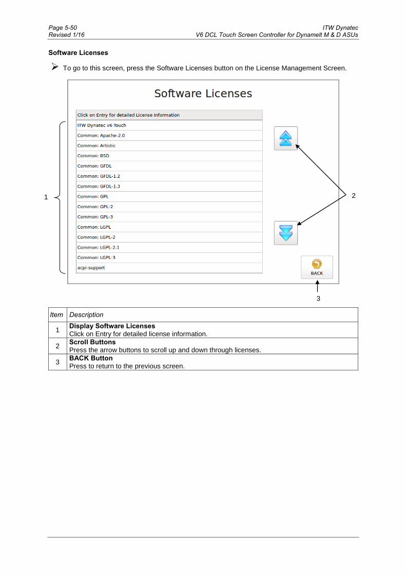
Page 5-50 ITW Dynatec Revised 1/16 V6 DCL Touch Screen Controller for Dynamelt M & D ASUs
Software Licenses
To go to this screen, press the Software Licenses button on the License Management Screen.
Item Description
1 Display Software Licenses Click on Entry for detailed license information.
2 Scroll Buttons Press the arrow buttons to scroll up and down through licenses.
3 BACK Button Press to return to the previous screen.
1 2
3

ITW Dynatec Programming Page 5-51 V6 DCL Touch Screen Controller for Dynamelt M & D ASUs Revised 1/16
Acknowledge Button The Acknowledge Button is on the Main Screen & Temperature Zones Set Screen.
1: no faults or alarms indicated
1: Fault indicated
Fault/ alarm Description in
Status Line

Page 5-52 ITW Dynatec Revised 1/16 V6 DCL Touch Screen Controller for Dynamelt M & D ASUs
Item Description
1
Acknowledge Button If a fault/ alarm is indicated, the affected temperature zone and the Acknowledge button will be highlighted red. When this occurs, follow these steps: • Correct and clear the faults/ alarms. • Press the Acknowledge button in order to switch On the main contactor.
Faults/ Alarms Among the Faults and Alarms that may be displayed are: • RTD Fault = a hopper, hose or head sensor has an open circuit. • Temperature Alarm = a temperature zone has exceeded its selected over‐temperature setpoint,
(which is the setpoint plus the Temperature Alarm Window and Temperature Alarm Hysteresis) or when it is below its selected under‐temperature setpoint (which is the setpoint minus the Temperature Alarm Window and the Temperature Alarm Hysteresis).
• Drive Failure = a motor drive (frequency converter) has a fault. • Minimum Level = adhesive level has dropped below the level sensor and the hopper is empty. • Feedback Failure Motor # = (optional) speed monitor pump addressed. • Overtemperature = hardware over-temperature indication. • Communication Error = Communication error between the touch panel and controller. • Parameter CRC Error = parameter memory is lost. Call ITW Dynatec Technical Service. • Other Faults or Alarms = Call ITW Dynatec Technical Service. When an alarm condition occurs, the current display will be interrupted only if a sensor (or motor drive) failure occurs. If more than one alarm condition occurs simultaneously, all alarm conditions will be displayed sequentially. Operator Response to Error Indication Alarms If an alarm occurs during operation, the controller will switch off the internal power to the heaters and an appropriate alarm indication will appear in the status line of the display. Pressing the Acknowledge button resets the error. If several zones display alarms, each must be acknowledged. The operator must either switch OFF the indicated temperature zone(s) or troubleshoot to correct the problem.

ITW Dynatec D15/D25/D45 V6 DCL ASU Manual #20-63
Maintenance Page 6-1Revised 10/14
Chapter 6PREVENTIVE MAINTENANCE
Note: Re-read Chapter 1 “Safety Precautions” before performing any maintenance procedures. Allmaintenance procedures must be performed by qualified, trained technicians.
General Cleaning
The D15/D25/D45 SERIES ASU enclosure is finished with an extremely durable polyurethanepaint. The enclosure may be cleaned with a variety of industrial cleaners following manufacturers’directions. To prevent discoloration or deterioration of the ASU’s finish, avoid prolonged contactwith strong solvents.
The molded plastic lid and control and hose panels may be cleaned with mineral spirits.
Preventive Maintenance Schedule
The ASU requires little maintenance. The hopper is fitted with a coarse screen to prevent large de-bris from entering the system. Normally this screen does not require cleaning. The ASU parts thatrequire regular, periodic maintenance are as follows:
Output FilterThe output (pump) filter should be replaced monthly during the first few months of operation. Afteryou gain experience with your system, you can determine how often you need to replace it. The out-put filter is located on the output filter manifold on the hose connection panel of the ASU. See il-lustration of the output filter on page 6-2.
Use the following procedure to replace the output filter. cont.
WARNINGPPE REQUIREDFailure to wear a face shield or safety glasses could result in severe eye injuryduring these procedures. Protect yourself from potential burns by wearinginsulated gloves and arm guards.
HIGH PRESSUREUse the output filter manifold’s bleed valve to relieve adhesive pressure beforeperforming any pump filter maintenance. See page 6-5 for detailed instructions.
HOT ADHESIVEAvoid splashing hot adhesive. The filter screen will be covered with hotadhesive and must be handled with proper tools. Position a heat-resistantcontainer under the manifold’s purge drain before proceeding.
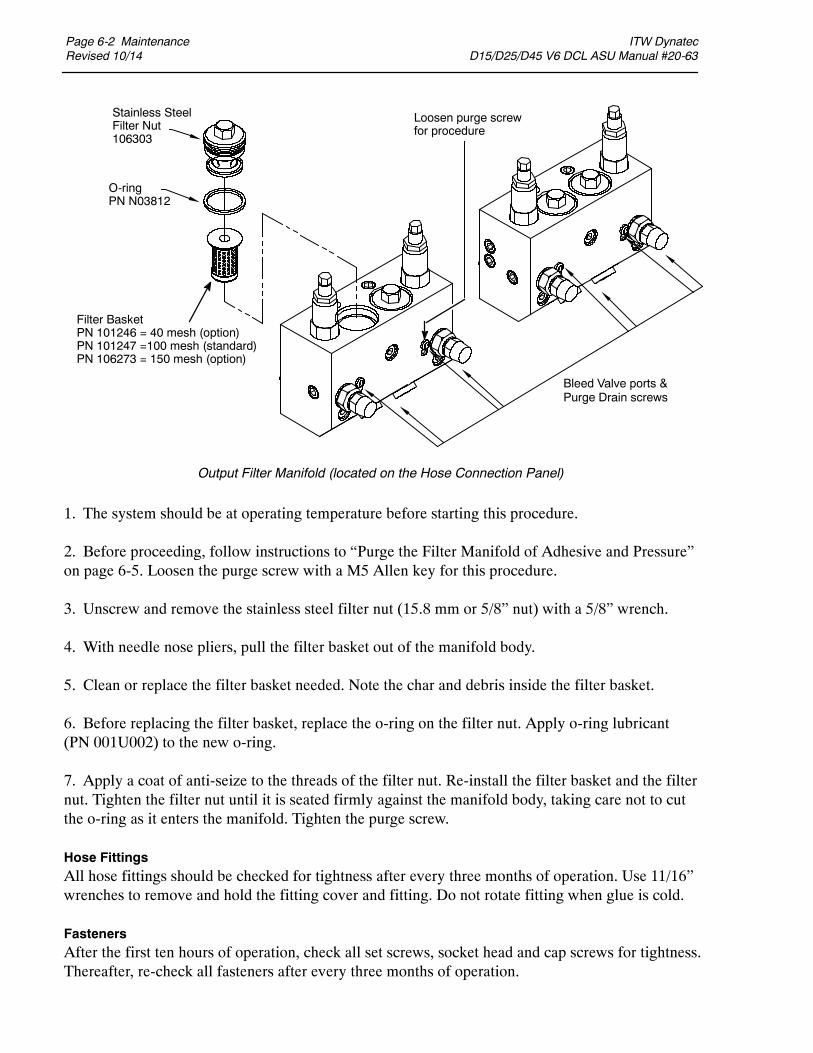
Page 6-2 MaintenanceRevised 10/14
ITW Dynatec D15/D25/D45 V6 DCL ASU Manual #20-63
1. The system should be at operating temperature before starting this procedure.
2. Before proceeding, follow instructions to “Purge the Filter Manifold of Adhesive and Pressure”on page 6-5. Loosen the purge screw with a M5 Allen key for this procedure.
3. Unscrew and remove the stainless steel filter nut (15.8 mm or 5/8” nut) with a 5/8” wrench.
4. With needle nose pliers, pull the filter basket out of the manifold body.
5. Clean or replace the filter basket needed. Note the char and debris inside the filter basket.
6. Before replacing the filter basket, replace the o-ring on the filter nut. Apply o-ring lubricant(PN 001U002) to the new o-ring.
7. Apply a coat of anti-seize to the threads of the filter nut. Re-install the filter basket and the filternut. Tighten the filter nut until it is seated firmly against the manifold body, taking care not to cutthe o-ring as it enters the manifold. Tighten the purge screw.
Hose FittingsAll hose fittings should be checked for tightness after every three months of operation. Use 11/16”wrenches to remove and hold the fitting cover and fitting. Do not rotate fitting when glue is cold.
FastenersAfter the first ten hours of operation, check all set screws, socket head and cap screws for tightness.Thereafter, re-check all fasteners after every three months of operation.
Output Filter Manifold (located on the Hose Connection Panel)
Stainless SteelFilter Nut106303
Filter BasketPN 101246 = 40 mesh (option)PN 101247 =100 mesh (standard)PN 106273 = 150 mesh (option)
O-ringPN N03812
Bleed Valve ports &Purge Drain screws
Loosen purge screwfor procedure
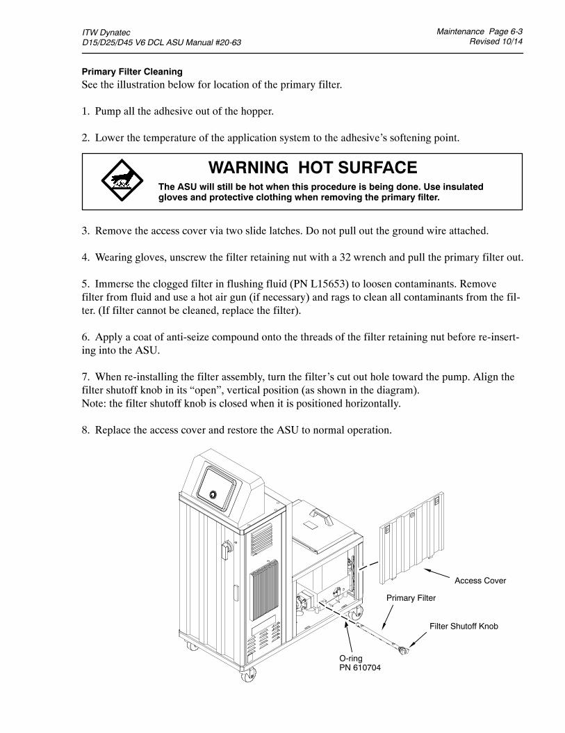
ITW Dynatec D15/D25/D45 V6 DCL ASU Manual #20-63
Maintenance Page 6-3Revised 10/14
Primary Filter CleaningSee the illustration below for location of the primary filter.
1. Pump all the adhesive out of the hopper.
2. Lower the temperature of the application system to the adhesive’s softening point.
3. Remove the access cover via two slide latches. Do not pull out the ground wire attached.
4. Wearing gloves, unscrew the filter retaining nut with a 32 wrench and pull the primary filter out.
5. Immerse the clogged filter in flushing fluid (PN L15653) to loosen contaminants. Removefilter from fluid and use a hot air gun (if necessary) and rags to clean all contaminants from the fil-ter. (If filter cannot be cleaned, replace the filter).
6. Apply a coat of anti-seize compound onto the threads of the filter retaining nut before re-insert-ing into the ASU.
7. When re-installing the filter assembly, turn the filter’s cut out hole toward the pump. Align thefilter shutoff knob in its “open”, vertical position (as shown in the diagram).Note: the filter shutoff knob is closed when it is positioned horizontally.
8. Replace the access cover and restore the ASU to normal operation.
WARNING HOT SURFACEThe ASU will still be hot when this procedure is being done. Use insulatedgloves and protective clothing when removing the primary filter.
Primary Filter
Access Cover
Filter Shutoff Knob
O-ringPN 610704

Page 6-4 MaintenanceRevised 10/14
ITW Dynatec D15/D25/D45 V6 DCL ASU Manual #20-63
Pump Shaft LeakThere is a cutout in the base plate, directly below the pumpshaft, which will allow adhesive from a leaking pump to exitthe ASU. Inspect the area under the base plate cutout everymonth for adhesive.
A leaking pump shaft indicates a worn pump seal. Seeinstructions in Chapter 8 for replacement of this seal.
Summary of Preventive Maintenance Schedule
Monthly (or as experience dictates)
Inspect output filter basket. Replace as required.
Check for leaking adhesive under the base plate, caused by a worn pump seal. Replace as required.
Every Three Months (or as experience dictates)
Check all hose fittings for tightness.
Check all fasteners for tightness.
Inspect primary filter. Clean or replace as required.
Gear Pump
Seal Assembly

ITW Dynatec D15/D25/D45 V6 DCL ASU Manual #20-63
Maintenance Page 6-5Revised 10/14
Purging the Filter Manifold (Output Filter) of Adhesive and Pressure
As a safety precaution, the ASU’s system should be purged of pressure and adhesive before at-tempting to change the output filter or before removing any of the hoses or applicators from theirmanifold port.
Refer to the illustration on page 6-2 while following these instructions.
The ASU should be at operating temperature. Turn the ASU’s pump/ motor OFF.
1. Locate the bleed valve (purge screw) on the output filter manifold.
2. With a hex key screwdriver (M5 Allen wrench), slowly loosen the purge screw (do not attempt toremove it) which is in the bleed valve’s port. Allow the adhesive and pressure to escape out of themanifold. The adhesive will flow into the heat-resistant container positioned below the manifold.
3. After all adhesive has run out, re-tighten the purge screw.
Flushing the System
Contaminated adhesive, accumulation of residue in the system and hopper, or changing the adhesiveformulation may require the system to be flushed. To flush the system, have at least 6 liters (1.5 gal-lons) of flushing fluid on hand (PN L15653).
1. Pump out as much of the molten adhesive from the hopper as possible.
WARNINGPPE REQUIREDFailure to wear a face shield or safety glasses could result in severe eye injuryduring these procedures. Protect yourself from potential burns by wearinginsulated gloves and arm guards.
HIGH PRESSUREUse the output filter manifold’s bleed valve to relieve adhesive pressure beforeperforming any pump filter maintenance. See page 6-5 for detailed instructions.
HOT ADHESIVEAvoid splashing hot adhesive. The filter screen will be covered with hotadhesive and must be handled with proper tools. Position a heat-resistantcontainer under the manifold’s purge drain before proceeding.
WARNING HOT ADHESIVEThe flushing fluid will splash easily. Wear protective clothing, gloves anda face shield to prevent severe burns.
Page 6-6 MaintenanceRevised 10/14
ITW Dynatec D15/D25/D45 V6 DCL ASU Manual #20-63
2. Reduce the ASU’s pump pressure to zero.
Note: the hose used in the following process is merely for the convenience of depositing flushingfluid. This procedure does not have to be repeated for each hose in the system.
3. Use a 11/16” wrench to disconnect one of the supply hose’s adhesive feeds from its applicatorhead, while holding the applicator’s fitting. Do not disconnect the electrical power to the head(since that would disable the pump). Put the hose in a secured position within a container which willcatch the used flushing fluid.
4. Add flushing fluid to the hopper and allow approximately fifteen minutes for it to reach hoppertemperature. Carefully stir the flushing fluid to mix with any adhesive remaining in the hopper.
5. Slowly increase the pump pressure. Pump about half of the fluid through the hopper, pump andadhesive supply hose into the flushing container.
6. Reduce the pump speed to zero.
7. Add new adhesive to the hopper and allow it to reach application temperature.
8. Slowly increase motor speed to the pump.
9. Actuate each of the heads until all the flushing fluid is removed and a steady stream of new ad-hesive flows.
10. Remove the output filter and replace the basket. Install a new o-ring on the filter nut (lubricatethe new o-ring with o-ring lubricant PN 001U002 prior to installation) and tighten the brass nut.
11. Re-adjust the pump speed for the desired flow.
12. Re-fill the hopper with adhesive. The system is now ready for production.
WARNING HOT ADHESIVEAvoid splashing the flushing fluid from the end of the hose.
WARNING HOT ADHESIVEDo not set hopper temperature too high or fluid could boil and splash.
ITW Dynatec D SERIES V6 DCL ASU Manuals
Troubleshooting Page 7-1Revised 10/14
General Troubleshooting Notes
The DynaControl controller includes malfunction self-diagnostics, alerts and error indicationalarms. The error indication alarms (the alarms displayed on the DynaControl readout) are triggeredwhenever there is a sensor failure and whenever there is an over-temperature condition. The opera-tion of the error indication alarms is described in Chapter 4 of this manual.
Preliminary Checks: Verify the following before proceeding:1. The ASU is switched on.2. The ASU is supplied with power.3. The ASU is supplied with pneumatic air (if applicable).4. Pneumatic and electrical connections are correct.5. Adhesive is in the hopper.
Error MessagesThe controller indicates an error by displaying the word FAULT or ALARM in either the SystemStatus or the Pump Status fields of the HMI.
Hose/ Applicator Troubleshooting TipHose or applicator problems can be isolated by electrically connecting the applicator and hose to analternate socket on the ASU. If the malfunction goes with the applicator and hose, the problem willusually be in the applicator or hose that was moved. If the malfunction does not move with the ap-plicator and hose, the problem is probably in the ASU.
Before disconnecting a hose or applicator, always turn its temperature zone OFF at the controller.This will avoid controller alarms and possible system shutdown.
DANGERHIGH VOLTAGE
WARNINGHOT SURFACE
ITW Dynatec systems use electrical power that can be life threatening and hot-melt adhesivesthat can cause serious burns. Re-read Chapter 1 “Safety Precautions” before performing anytroubleshooting or repair procedures. All troubleshooting and repair procedures must be per-formed by qualified, trained technicians.
CAUTION: Printed circuit boards (PCBs) are prone to damage from static electricalcharges during handling. Read the section on “Handling Printed CIrcuit Boards”before handling or attempting service on Dynamelt’s PCBs.
Chapter 7TROUBLESHOOTING
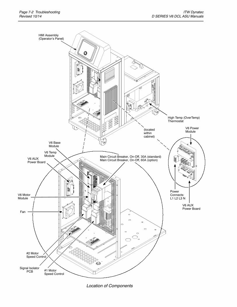
Page 7-2 TroubleshootingRevised 10/14
ITW Dynatec D SERIES V6 DCL ASU Manuals
Location of Components
HMI Assembly(Operator’s Panel)
High Temp (OverTemp)Thermostat
#2 MotorSpeed Control
Signal IsolatorPCB #1 Motor
Speed Control
Fan
Main Circuit Breaker, On-Off, 30A (standard) Main Circuit Breaker, On-Off, 60A (option)
V6 MotorModule
V6 BaseModule
V6 AUXPower Board
V6 TempModule
PowerConnects:L1 L2 L3 N
V6 PowerModule
V6 AUXPower Board
(locatedwithincabinet)
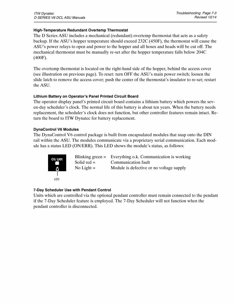
ITW Dynatec D SERIES V6 DCL ASU Manuals
Troubleshooting Page 7-3Revised 10/14
High-Temperature Redundant Overtemp ThermostatThe D Series ASU includes a mechanical (redundant) overtemp thermostat that acts as a safetybackup. If the ASU’s hopper temperature should exceed 232C (450F), the thermostat will cause theASU’s power relays to open and power to the hopper and all hoses and heads will be cut off. Themechanical thermostat must be manually re-set after the hopper temperature falls below 204C(400F).
The overtemp thermostat is located on the right-hand side of the hopper, behind the access cover(see illustration on previous page). To reset: turn OFF the ASU’s main power switch; loosen theslide latch to remove the access cover; push the center of the thermostat’s insulator to re-set; restartthe ASU.
Lithium Battery on Operator’s Panel Printed Circuit BoardThe operator display panel’s printed circuit board contains a lithium battery which powers the sev-en-day scheduler’s clock. The normal life of this battery is about ten years. When the battery needsreplacement, the scheduler’s clock does not function, but other controller features remain intact. Re-turn the board to ITW Dynatec for battery replacement.
DynaControl V6 ModulesThe DynaControl V6 control package is built from encapsulated modules that snap onto the DINrail within the ASU. The modules communicate via a proprietary serial communication. Each mod-ule has a status LED (ON/ERR). This LED shows the module’s status, as follows:
Blinking green = Everything o.k. Communication is workingSolid red = Communication faultNo Light = Module is defective or no voltage supply
7-Day Scheduler Use with Pendant ControlUnits which are controlled via the optional pendant controller must remain connected to the pendantif the 7-Day Scheduler feature is employed. The 7-Day Scheduler will not function when thependant controller is disconnected.
LED
Page 7-4 TroubleshootingRevised 10/14
ITW Dynatec D SERIES V6 DCL ASU Manuals
Handling Modules and Printed Circuit Boards (PCBs)
The Dynamelt ASU and DynaControl controller utilize several printed circuit boards (PCBs). Theseboards are extremely sensitive to electrostatic charges. When working near or with any PCBs, thefollowing procedures must be followed to avoid damage to them.
CAUTION: Printed circuit boards (PCBs) should be handled using the followingprocedures:
1. Wear a wrist grounding strap. If a grounding strap is not available, frequently touch abare metal part of the ASU (unpainted frame, mounting screw, etc.) to safely dischargeany electrostatic buildup on your body.
2. Handle a PCB by its edges only. Don’t grip a PCB across its surface.
3. When removed from the ASU, each PCB must be individually packaged inside ametallized, static drain envelope. Do not place the removed PCB on a table, counter,etc. until it has first been placed in or on a static drain envelope.
4. When handing a PCB to another person, touch the hand or wrist of that person toeliminate any electrostatic charge before you hand the PCB to him.
5. When unwrapping a PCB from its static drain envelope, place the envelope on agrounded, nonmetallic surface.
6. To cushion PCBs for shipment, use only static-drain bubble pack. Do not use foampeanuts or bubble pack not known to be static draining.
The following pages detail the Dynamelt D Series PCBs.
DANGER HIGH VOLTAGEBefore unplugging connectors from the I/O PCBs, ground yourself to theASU by touching any available unpainted cool metal surface, mounting
screws, etc. This will avoid electrical discharge to the PCB assembly when you are remov-ing and replacing connectors.

ITW Dynatec D SERIES V6 DCL ASU Manuals
Troubleshooting Page 7-5Revised 10/14
V6 Base Module PN 115734
The V6 Base Module is the main control module of the DynaControl V6 controller. Most of the in-ternal and external components are connected to the Base module. The Base module is always the top (first) module on the DIN-rail.ITW Dynatec recommends using dry contacts for connecting to DynaControl V6!
cont.
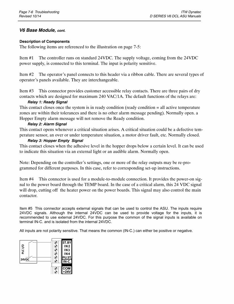
Page 7-6 TroubleshootingRevised 10/14
ITW Dynatec D SERIES V6 DCL ASU Manuals
V6 Base Module, cont.
Description of ComponentsThe following items are referenced to the illustration on page 7-5:
Item #1 The controller runs on standard 24VDC. The supply voltage, coming from the 24VDCpower supply, is connected to this terminal. The input is polarity sensitive.
Item #2 The operator’s panel connects to this header via a ribbon cable. There are several types ofoperator’s panels available. They are interchangeable.
Item #3 This connector provides customer accessible relay contacts. There are three pairs of drycontacts which are designed for maximum 240 VAC/1A. The default functions of the relays are:
Relay 1: Ready SignalThis contact closes once the system is in ready condition (ready condition = all active temperaturezones are within their tolerances and there is no other alarm message pending). Normally open. aHopper Empty alarm message will not remove the Ready condition.
Relay 2: Alarm SignalThis contact opens whenever a critical situation arises. A critical situation could be a defective tem-perature sensor, an over or under temperature situation, a motor driver fault, etc. Normally closed.
Relay 3: Hopper Empty SignalThis contact closes when the adhesive level in the hopper drops below a certain level. It can be usedto indicate this situation via an external light or an audible alarm. Normally open.
Note: Depending on the controller’s settings, one or more of the relay outputs may be re-pro-grammed for different purposes. In this case, refer to corresponding set-up instructions.
Item #4 This connector is used for a module-to-module connection. It provides the power-on sig-nal to the power board through the TEMP board. In the case of a critical alarm, this 24 VDC signalwill drop, cutting off the heater power on the power boards. This signal may also control the maincontactor.
Item #5 This connector accepts external signals that can be used to control the ASU. The inputs require 24VDC signals. Although the internal 24VDC can be used to provide voltage for the inputs, it is recommended to use external 24VDC. For this purpose the common of the signal inputs is available on terminal IN-C. and is isolated from the internal 24VDC.
All inputs are not polarity sensitive. That means the common (IN-C.) can either be positive or negative.

ITW Dynatec D SERIES V6 DCL ASU Manuals
Troubleshooting Page 7-7Revised 10/14
V6 Base Module, cont.
Input ST.BY: External Standby/ SetbackActivating this input sets the ASU in Standby Mode. In standby mode, all temperature zones will lower their temperatures by a programmed amount. Opening that contact will return to normal mode.
Input 2 & 3: External Program/ Recipe SelectionBy activating these inputs it is possible to load one of four programs (recipes) into the controller. The two inputs are coded in the following way:Activate input2 while input3 is not activated: Load Program 1Activate input3 while input2 is not activated: Load Program 2Activate input2 while input3 is activated: Load Program 3Activate input3 while input2 is activated: Load Program 4
Notes: the controller loads the new program when the corresponding input is activated. Deactivating an input does not affect the process.
It is possible to load a new program manually, independent from the input situation.
Item #6 This item is not applicable to the D Series ASUs.
Item #7 This input is connected to the over-temperature thermostat on the hopper. In the unlikely event that that hopper temperature exceeds 450F (232C), the thermostat will open and cause the power to all the heaters to be cut off. A corresponding alarm message will appear on the controller’s display. The thermostat must be manually re-set after the hopper temperature falls below 400F(204C).
cont.
Alternatively it is possible to use the external inputs via ‘dry’ contacts:
WARNING:The ASU’s internal 24VDC is grounded. It is not recommended to connect external 24VDC with the internal. If this cannot be avoided, it is important that the ground potential of the external and that of the ASU is equal. If this is not the case, damage to the V6 control modules is possible.
Inputs ST.BY, PU.ST. IN2 and IN3 are dedicated for default functions. Input 4 is for future use.

Page 7-8 TroubleshootingRevised 10/14
ITW Dynatec D SERIES V6 DCL ASU Manuals
V6 Base Module, cont.
Item #8 This connects to the motor driver.MB / MC: Alarm contact indicating driver fault (N.C.) SC / S1: Pump start signalA1 / AC: 0-10V pump speed signal
Item #9If the ASU is equipped with a digital pressure read-out, it connects to this terminal. The transducer type is two-wire 4-20mA.
In order to monitor the actual speed, a RPM reading device (gear pumps) or stroke counter (piston pumps) can be connected to this terminal.
In order for a gear pump to follow the line speed of a parent machine, a 0-10VDC voltage is required. This input voltage is connected to these terminals. The input is polarity sensitive. When an optional signal isolator is installed, the line speed input is located on the signal isolator.
Warning: The line speed input is grounded. If the line tracking voltage has a different ground potential, it is recommended to use a signal isolator. Otherwise, damage to the V6 modules is possible.

ITW Dynatec D SERIES V6 DCL ASU Manuals
Troubleshooting Page 7-9Revised 10/14
V6 Temperature Module PN 115735
The V6 TEMP module(s) is mounted next to the V6 Base Module on the Din-rail. It requires24VDC supply voltage. It is responsible for the temperature control of all heated temperaturezones. The RTD temperature sensors connect to this module and the TEMP module provides cor-responding output signals to the power boards. Depending on the configuration of the ASU, theRTDs may be PT100 (DynaControl) or NI120 (Nordson). Configuration is determined by a jumperlocated within the module (see below, to left of module illustration).
Each of the maximum 15 zones has a status LED which shows its heating status in the followingmanner:- if the zone is switched off, the LED is Off,- if the zone is heating, the LED is On,- if the zone is near or at the setpoint temperature, the LED blinks.
Approx. location of thejumper inside the module.
Dynacontrol RTD ASU: jump-er positioned horizontally, asabove.
Nordson RTD ASU: jumperpositioned vertically, as above.
TO POWERMODULE #3
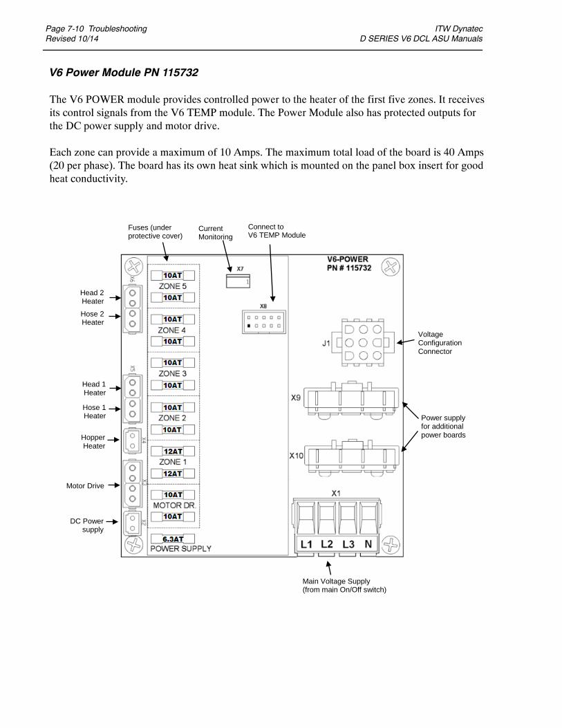
Page 7-10 TroubleshootingRevised 10/14
ITW Dynatec D SERIES V6 DCL ASU Manuals
V6 Power Module PN 115732
The V6 POWER module provides controlled power to the heater of the first five zones. It receivesits control signals from the V6 TEMP module. The Power Module also has protected outputs forthe DC power supply and motor drive.
Each zone can provide a maximum of 10 Amps. The maximum total load of the board is 40 Amps(20 per phase). The board has its own heat sink which is mounted on the panel box insert for goodheat conductivity.
Head 2 Heater
Hose 2 Heater
Head 1 Heater
Hose 1 Heater
Hopper Heater
Motor Drive
DC Power supply
Main Voltage Supply (from main On/Off switch)
Power supply for additional power boards
Voltage Configuration Connector
Fuses (under protective cover)
Connec t to V6 T EMP Module
Current Monitoring

ITW Dynatec D SERIES V6 DCL ASU Manuals
Troubleshooting Page 7-11Revised 10/14
V6 Power Module, cont.
FusesThe fuses of the POWER Module are located underneath a protective cover. The cover should only be removed after the ASU is switched Off and disconnected from the main power supply. After checking or replacing fuses, the cover must be re-installed.
Heater and motor driver circuits are fused on both legs with a 10A fuse.The output for the DC power supply has a 6.3A fuse.
Always replace fuses with the same type of fuse.
Voltage Configuration ConnectorThe appropriate voltage configuration plug must be installed for the machine to operate properly. Two different connectors (plugs) are available:PN 115725 - 240V three phase, Delta (violet)PN 115726 - 400V three phase, Wye (yellow)

Page 7-12 TroubleshootingRevised 10/14
ITW Dynatec D SERIES V6 DCL ASU Manuals
V6 Aux Power Module PN 115733
The V6 AUX module provides controlled power to the heater of the additional five zones. It re-ceives its control signals from the V6 TEMP module. There are two of these modules on a D Series ASU.
The fuses of the AUX Module are located underneath a protective cover. The cover should only be removed after the ASU is switched Off and disconnected from the main power supply. After check-ing or replacing fuses, the cover must be re-installed. All heater circuits are fused on both legs with a 10A fuse. Always replace fuses with the same type of fuse. The maximum total load current of the board is 40 Amps (20 per phase).
Connect to V6 TEMP Module
Fuses (under protective cover)
Head 4/6 Heater
Hose 4/6 Heater
Voltage Supply from
Main Power Board
Head 3/5 Heater
Hose 3/5 Heater
Heater Premelt Grid or
Filter Block
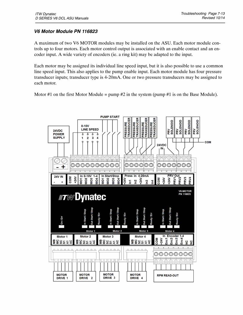
ITW Dynatec D SERIES V6 DCL ASU Manuals
Troubleshooting Page 7-13Revised 10/14
V6 Motor Module PN 116823
A maximum of two V6 MOTOR modules may be installed on the ASU. Each motor module con-trols up to four motors. Each motor control output is associated with an enable contact and an en-coder input. A wide variety of encoders (ie. a ring kit) may be adapted to the input.
Each motor may be assigned its individual line speed input, but it is also possible to use a commonline speed input. This also applies to the pump enable input. Each motor module has four pressuretransducer inputs; transducer type is 4-20mA. One or two pressure transducers may be assigned toeach motor.
Motor #1 on the first Motor Module = pump #2 in the system (pump #1 is on the Base Module).
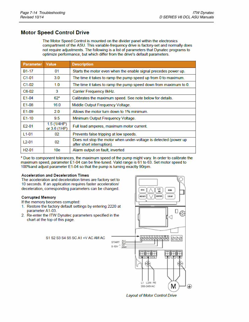
Page 7-14 TroubleshootingRevised 10/14
ITW Dynatec D SERIES V6 DCL ASU Manuals

ITW Dynatec D SERIES V6 DCL ASU Manuals
Troubleshooting Page 7-15Revised 10/14
Optional Printed Circuit Boards
Wiring diagrams and other details on the following optional PCBs can be found on the main ASU schematic in Chapter 11:
Adhesive Level Sensor (hopper low level detection)Signal Isolator (gear pump auto mode)Trigger Switch Pump Enable (hand-held applicators/ swirl kits)EtherNet/ IP, EtherCat or Profibus (communications protocols)

Page 7-16 TroubleshootingRevised 11/14
ITW Dynatec D SERIES V6 DCL ASU Manuals
Heater and Sensor Resistance Values
The resistance values given in the four tables on the following page will aid in troubleshooting if asensor or heater malfunction is suspected. The “Temperature Sensor Resistance” table gives valuesfor various temperatures. If you know the approximate temperature of the suspected sensor, you cancheck to see if the sensor resistance approximates the value given in the table by unplugging the af-fected head or hose connection and measuring resistance across the affected pins (see wiring dia-gram in Chapter 11 for pin numbers).
The “Nominal Hose Heater Resistance” table gives the heater resistance for hoses. A suspected hoseheater problem can be quickly isolated by measuring hose heater resistance and comparing it to thecorrect resistance for your hose length and voltage as shown.
The “Nominal Head Heater Resistance” table gives values for several different head wattages. Asuspected head heater problem can be isolated by measuring head heater resistance and comparingit to the resistance for the appropriate wattage of your system.
The “Nominal Hopper Heater Resistance” table gives heater resistance for the hopper heaters ofeach model and for the (optional) drop-in grids.
DANGER HIGH VOLTAGEBefore unplugging connectors from the PCBs, ground yourself to theASU by touching any available unpainted cool metal surface, mounting
screws, etc. This will avoid electrical discharge to the PCB assembly when you are remov-ing and replacing connectors.
TheV6BUSmodule is usedwith a communications protocol ad-apter to provide functionality so that the ASU may be operatedremotely. Several communication adapters are available, includ-ing EtherNet IP, EtherCat and Profibus.
Optional V6 BUS Communications Module PN 117382
Field Bus
communication adapter inserted

ITW Dynatec D SERIES V6 DCL ASU Manuals
Troubleshooting Page 7-17Revised 10/14
Temperature Sensor Resistance(0.00385 PT 100 RTD)
Nominal Hopper Heater Resistance
Temperature ResistanceF C in Ohms
32 0 10050 10 10468 20 10886 30 112104 40 116122 50 119140 60 123158 70 127176 80 131194 90 135212 100 139230 110 142248 120 146268 130 150284 140 154302 150 157320 160 161338 170 164356 180 168374 190 172392 200 176410 210 180428 220 183
Watts Resistance in Ohms
200 288270 213350 165500 115700 82
Nominal Head Heater Resistance
ASU Drop-in Grid
Qty. Heaters 2 1 or 2
Resistance in Ohms 22 ea.for each heater:200-240 v 19.4-24 ea.380-400 v 57.8-66.7 ea.
Note: Resistance is measured at ambient temperature (20C/ 68F).
Hose Length ResistanceMeters Feet in Ohms
1.2 4 466-5441.8 6 279-3262.4 8 236-2753 10 189-2213.7 12 155-1814.9 16 118-1377.3 24 77-90
Nominal Hose Heater Resistancefor #6 DynaFlex Hoses

Page 7-18 TroubleshootingRevised 10/14
ITW Dynatec D SERIES V6 DCL ASU Manuals
Error Indication Alarm Troubleshooting Guide
The operation of error indication alarms is described in Chapter 4. When checking for correctequipment operation in the following guide, be aware that all heaters will go off immediately afteran error indication alarm occurs if the operator takes no action. With the exception of the fuses,there are no user-replaceable parts on the printed circuit boards. If there is a non-fuse failure on anyof the PCBs, the PCB must be replaced.
DANGER HIGH VOLTAGESome of the procedures in the following Troubleshooting Guide require poten-tially dangerous electricity to be present. Only qualified service personnel shouldperform these procedures.
Problem Possible Cause
Hopper (tank) 1. Setpoints have beenOvertemp programmed without
enough deviation.
2. Hopper sensor inoperative.
3.Hopper control triacon V6 Power Module isinoperative.
Sensor
Solution
1. Re-program setpoints, allowing alarger deviation between the highand low limits.
2. Replace hopper sensor if resistancedoes not comply with the resistancetable in this manual.
3. If the hopper status LED on the Tem-perature Module is Off and the hoppertemperature continues to rise, thetriac on the power module has failed.The module must be replaced.

ITW Dynatec D SERIES V6 DCL ASU Manuals
Troubleshooting Page 7-19Revised 10/14
Problem Possible Cause
Hopper Sensor Open 1. Sensor cable has becomeunplugged from V6Temperature Module.
2.Hopper sensor inoperative.
Hopper Sensor Short 1. Short-circuit caused bydebris where sensor plugsinto the V6 TemperatureModule.
2. Pinched sensor lead wire.
3.Hopper sensor inoperative.
Sensor
Solution
1. Verify that hopper sensor cable isproperly connected at X3 on theTemperature Module.
2. Replace hopper sensor if resistancedoes not comply with resistance table.
1. Verify that sensor plug is clean andcorrectly connected at X3 on theTemperature Module.
2. Visually inspect sensor lead wire forbreak, kink, damage, etc. If no obviousdamage, use an ohmmeter to measurecontinuity from the sensor lead to theplug at the Temperature Module.Repair or replace any damaged wire.
3. Replace hopper sensor if resistancedoes not comply with resistance table.
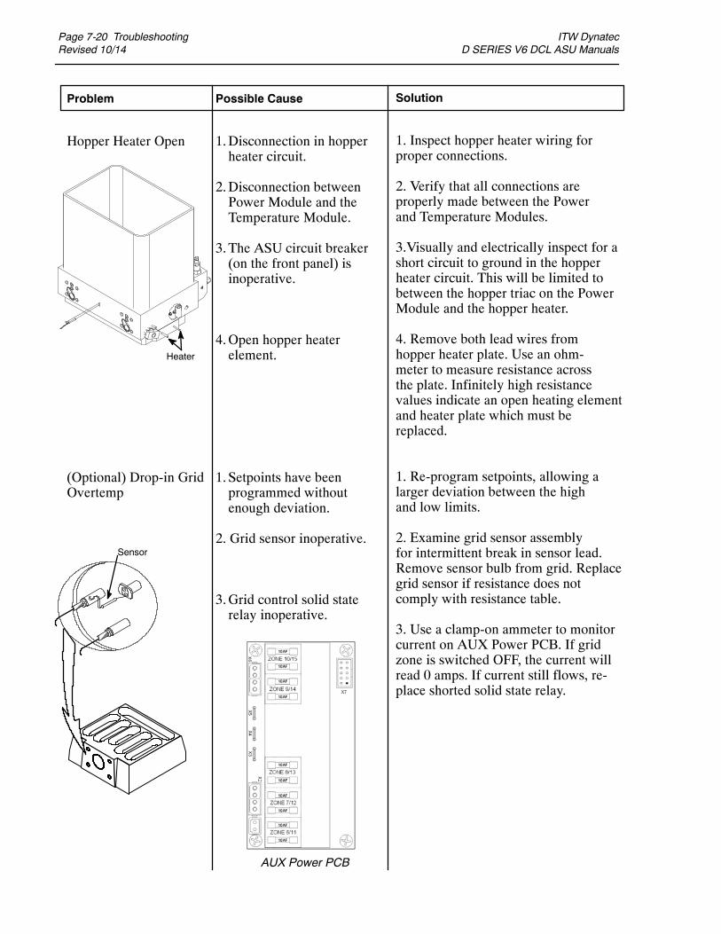
Page 7-20 TroubleshootingRevised 10/14
ITW Dynatec D SERIES V6 DCL ASU Manuals
Problem Possible Cause
Hopper Heater Open 1.Disconnection in hopperheater circuit.
2.Disconnection betweenPower Module and theTemperature Module.
3. The ASU circuit breaker(on the front panel) isinoperative.
4.Open hopper heaterelement.
(Optional) Drop-in Grid 1. Setpoints have beenOvertemp programmed without
enough deviation.
2. Grid sensor inoperative.
3.Grid control solid staterelay inoperative.
AUX Power PCB
Heater
Sensor
Solution
1. Inspect hopper heater wiring forproper connections.
2. Verify that all connections areproperly made between the Powerand Temperature Modules.
3.Visually and electrically inspect for ashort circuit to ground in the hopperheater circuit. This will be limited tobetween the hopper triac on the PowerModule and the hopper heater.
4. Remove both lead wires fromhopper heater plate. Use an ohm-meter to measure resistance acrossthe plate. Infinitely high resistancevalues indicate an open heating elementand heater plate which must bereplaced.
1. Re-program setpoints, allowing alarger deviation between the highand low limits.
2. Examine grid sensor assemblyfor intermittent break in sensor lead.Remove sensor bulb from grid. Replacegrid sensor if resistance does notcomply with resistance table.
3. Use a clamp-on ammeter to monitorcurrent on AUX Power PCB. If gridzone is switched OFF, the current willread 0 amps. If current still flows, re-place shorted solid state relay.

ITW Dynatec D SERIES V6 DCL ASU Manuals
Troubleshooting Page 7-21Revised 10/14
Problem Possible Cause
(Optional) Drop-In Grid 1. Sensor cable has becomeSensor Open unplugged from the Tem-
perature Module.
2.Drop-in Grid sensorinoperative.
(Optional) Drop-in Grid 1. Short-circuit caused bySensor Short debris where sensor plugs
into the TemperatureModule.
2. Pinched sensor lead wire.
3.Drop-in Grid sensorinoperative.
Solution
1. Verify that grid sensor cable isproperly connected at X3 (or X2) on theTemperature Module.
2. Replace grid sensor if resistancedoes not comply with resistance table.
1. Verify that sensor plug is clean andcorrectly connected at X3 (or X2) onthe Temperature Module.
2. Visually inspect sensor lead wire forbreak, kink, damage, etc. If no obviousdamage, use an ohmmeter to measurecontinuity from the sensor lead to theplug at X3 (or X2) on the TemperatureModule. Repair or replace any damagedwire.
3. Replace grid sensor if resistance doesnot comply with resistance table.
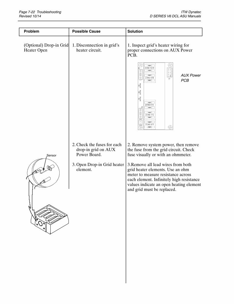
Page 7-22 TroubleshootingRevised 10/14
ITW Dynatec D SERIES V6 DCL ASU Manuals
Problem Possible Cause
(Optional) Drop-in Grid 1.Disconnection in grid’sHeater Open heater circuit.
2.Check the fuses for eachdrop-in grid on AUXPower Board.
3.Open Drop-in Grid heaterelement.
AUX PowerPCB
Sensor
Solution
1. Inspect grid’s heater wiring forproper connections on AUX PowerPCB.
2. Remove system power, then removethe fuse from the grid circuit. Checkfuse visually or with an ohmmeter.
3.Remove all lead wires from bothgrid heater elements. Use an ohmmeter to measure resistance acrosseach element. Infinitely high resistancevalues indicate an open heating elementand grid must be replaced.
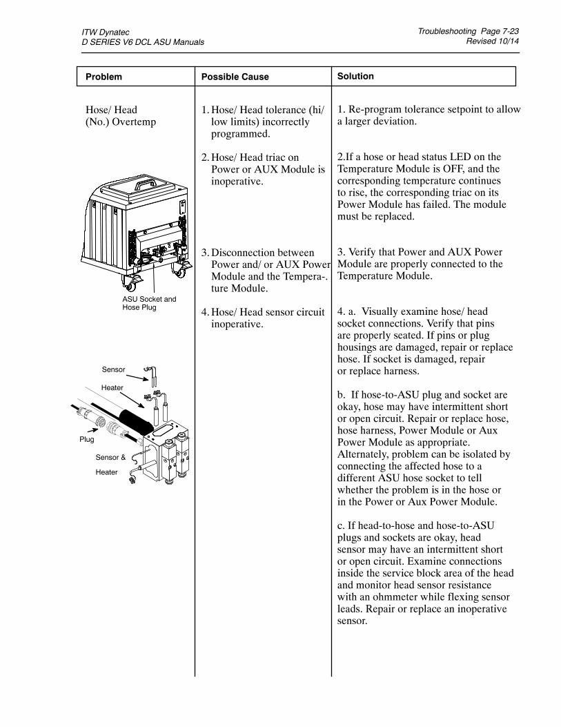
ITW Dynatec D SERIES V6 DCL ASU Manuals
Troubleshooting Page 7-23Revised 10/14
Problem Possible Cause
Hose/ Head 1.Hose/ Head tolerance (hi/(No.) Overtemp low limits) incorrectly
programmed.
2.Hose/ Head triac onPower or AUX Module isinoperative.
3.Disconnection betweenPower and/ or AUX PowerModule and the Tempera-.ture Module.
4.Hose/ Head sensor circuitinoperative.
Plug
Sensor
Heater
Sensor &
Heater
ASU Socket andHose Plug
Solution
1. Re-program tolerance setpoint to allowa larger deviation.
2.If a hose or head status LED on theTemperature Module is OFF, and thecorresponding temperature continuesto rise, the corresponding triac on itsPower Module has failed. The modulemust be replaced.
3. Verify that Power and AUX PowerModule are properly connected to theTemperature Module.
4. a. Visually examine hose/ headsocket connections. Verify that pinsare properly seated. If pins or plughousings are damaged, repair or replacehose. If socket is damaged, repairor replace harness.
b. If hose-to-ASU plug and socket areokay, hose may have intermittent shortor open circuit. Repair or replace hose,hose harness, Power Module or AuxPower Module as appropriate.Alternately, problem can be isolated byconnecting the affected hose to adifferent ASU hose socket to tellwhether the problem is in the hose orin the Power or Aux Power Module.
c. If head-to-hose and hose-to-ASUplugs and sockets are okay, headsensor may have an intermittent shortor open circuit. Examine connectionsinside the service block area of the headand monitor head sensor resistancewith an ohmmeter while flexing sensorleads. Repair or replace an inoperativesensor.

Page 7-24 TroubleshootingRevised 10/14
ITW Dynatec D SERIES V6 DCL ASU Manuals
Problem Possible Cause
Hose/ Head (No.)* Not 1.Disconnection betweenHeating hose and ASU.(Sensor Circuit Open)
2.Hose sensor harness un-plugged from Power orAUX Power Module.
3.Hose/ Head sensor circuitinoperative.
Hose/ Head (No.)* 1.Debris at connectionNot Heating between hose/ head and(Sensor Circuit Shorted) ASU.
2.Debris at connectionbetween hose/ headharness and Power or AUXPower Module.
3.Hose/ Head sensor circuitinoperative.
* Check each Hose/Head circuit on the system.
Solution
1.Visually examine connector for propercontact and seating. If pins or housingsare damaged, repair or replace hose orhose harness (in ASU).
2.Verify that affected hose is properlyconnected to Power or AUX Module.Replace or repair damaged hose harnessas necessary.
3.Replace head sensor if resistance doesnot comply with resistance table. Use hoseschematic to check hose sensor resistanceat ASU socket, repair or replace hose,hose harness, Power or AUX Power Mod-ule as appropriate.
1.Visually inspect hose plug and ASUsocket for cleanliness and proper contactand seating of pins.
2.Visually inspect that the affected hoseplug at Power or Aux Power Module isclean and properly installed.
3.Using the hose schematic, check hosesensor resistance at ASU socket. An ohm-meter can also be used to isolate a pinchedwire in the hose harness. When cause isisolated, repair or replace sensor, hose,hose harness, Power or AUX PowerModule as appropriate.
Plug
Sensor
Heater
Sensor &
Heater
ASU Socket andHose/ head Plug
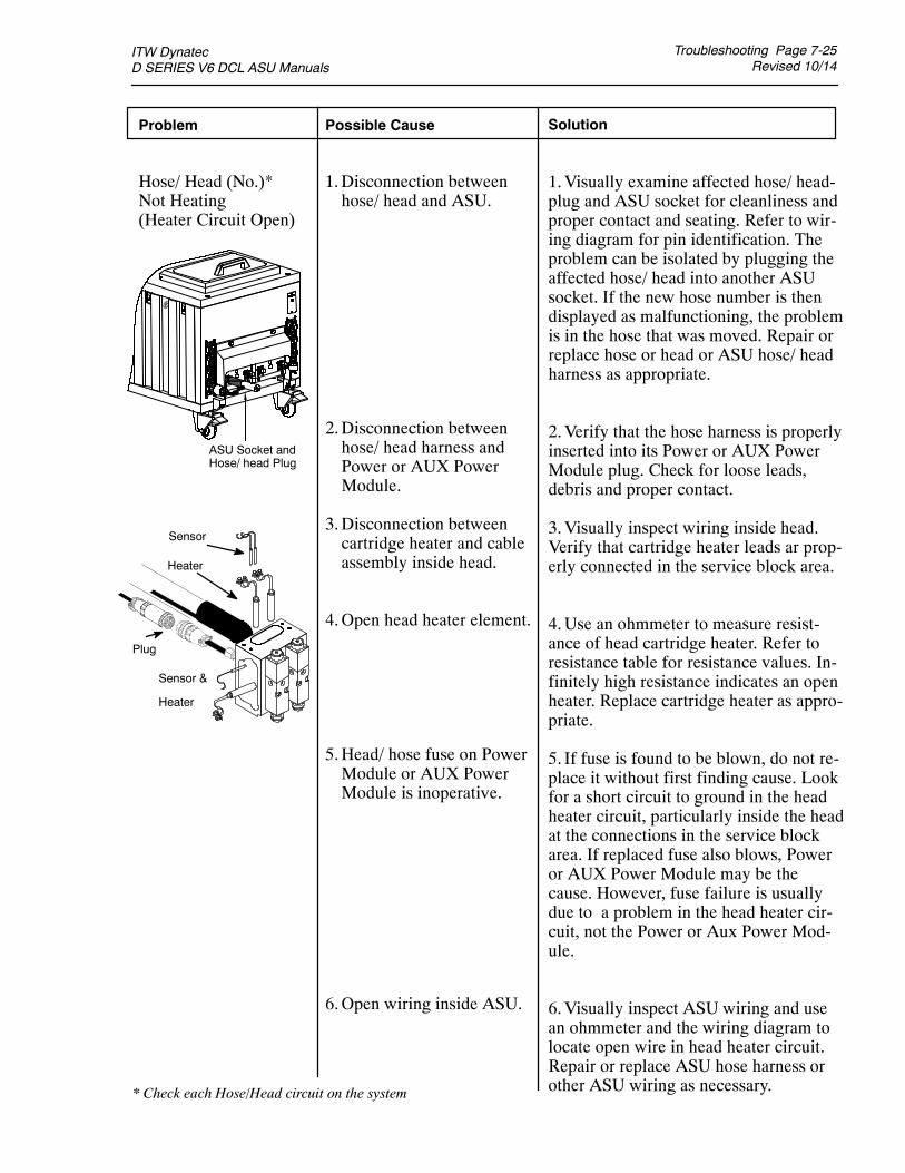
ITW Dynatec D SERIES V6 DCL ASU Manuals
Troubleshooting Page 7-25Revised 10/14
Solution
1.Visually examine affected hose/ head-plug and ASU socket for cleanliness andproper contact and seating. Refer to wir-ing diagram for pin identification. Theproblem can be isolated by plugging theaffected hose/ head into another ASUsocket. If the new hose number is thendisplayed as malfunctioning, the problemis in the hose that was moved. Repair orreplace hose or head or ASU hose/ headharness as appropriate.
2.Verify that the hose harness is properlyinserted into its Power or AUX PowerModule plug. Check for loose leads,debris and proper contact.
3.Visually inspect wiring inside head.Verify that cartridge heater leads ar prop-erly connected in the service block area.
4.Use an ohmmeter to measure resist-ance of head cartridge heater. Refer toresistance table for resistance values. In-finitely high resistance indicates an openheater. Replace cartridge heater as appro-priate.
5. If fuse is found to be blown, do not re-place it without first finding cause. Lookfor a short circuit to ground in the headheater circuit, particularly inside the headat the connections in the service blockarea. If replaced fuse also blows, Poweror AUX Power Module may be thecause. However, fuse failure is usuallydue to a problem in the head heater cir-cuit, not the Power or Aux Power Mod-ule.
6.Visually inspect ASU wiring and usean ohmmeter and the wiring diagram tolocate open wire in head heater circuit.Repair or replace ASU hose harness orother ASU wiring as necessary.
Problem Possible Cause
Hose/ Head (No.)* 1.Disconnection betweenNot Heating hose/ head and ASU.(Heater Circuit Open)
2.Disconnection betweenhose/ head harness andPower or AUX PowerModule.
3.Disconnection betweencartridge heater and cableassembly inside head.
4.Open head heater element.
5.Head/ hose fuse on PowerModule or AUX PowerModule is inoperative.
6.Open wiring inside ASU.
Plug
Sensor
Heater
Sensor &
Heater
ASU Socket andHose/ head Plug
* Check each Hose/Head circuit on the system

Page 7-26 TroubleshootingRevised 10/14
ITW Dynatec D SERIES V6 DCL ASU Manuals
Problem Possible Cause
Aux (No.) Overtemp 1.Aux tolerance (hi/ low)setpoints incorrectlyprogrammed.
2.Aux solid state relay isinoperative.
3.Aux sensor circuitinoperative.
AUX Power PCB
Solution
1. Re-program tolerance to allow alarger deviation.
2. Use a clamp-on ammeter to monitorAux current on AUX Power PCB. IfAux current does not cycle on and off,then relay is inoperative and must be re-placed.
3. a. Visually examine Aux socketconnections. Verify that pins areproperly seated. If pins or plug hous-ings are damaged, repair or replacehose. If socket is damaged, repair or re-place harness.
b. If Aux-to-ASU plug and socket areokay, Aux may have intermittent shortor open circuit. Repair or replace Aux,Aux harness or solid state relay asappropriate.
c. If Aux sockets and cables to ASUplugs and sockets are okay, Auxsensor may have an intermittent shortor open circuit. Examine connectionsat the Aux device and monitor Auxsensor resistance with an ohmmeterwhile flexing sensor leads. Repair orreplace an inoperative sensor.

ITW Dynatec D SERIES V6 DCL ASU Manuals
Troubleshooting Page 7-27Revised 10/14
Problem Possible Cause
Aux (No.) Sensor 1.Disconnection betweenOpen Aux connector and ASU.
2.Aux sensor harness un-plugged from the V6 Tem-perature Module.
3.Aux sensor circuitinoperative.
Aux (No.) Sensor 1.Debris at connectionShort between Aux and ASU.
2.Debris at V6 TemperatureModule.
3.Aux sensor circuitinoperative.
Solution
1.Visually examine connector for proper-contact and seating. If pins or housingsare damaged, repair or replace Aux har-ness (in ASU).
2.Verify that affected Aux is properlyconnected to Temp Module. Replace orrepair damaged Aux harness as neces-sary.
3. Replace Aux sensor if resistance doesnot comply with resistance table. Useschematic to check Aux sensor resistanceat ASU socket, repair or replace Aux,Aux harness or Temperature Module asappropriate.
1.Visually inspect Aux plug and ASUsocket for cleanliness and proper contactand seating of pins.
2.Visually inspect that the affected Auxplug at the Temperature Module is cleanand properly installed.
3.Using the schematic, check Aux sensorresistance at ASU socket. An ohmmetercan also be used to isolate a pinched wirein the Aux harness. When cause is isol-ated, repair or replace sensor, Aux, Auxharness or the Temperature Module asappropriate.

Page 7-28 TroubleshootingRevised 10/14
ITW Dynatec D SERIES V6 DCL ASU Manuals
Solution
1.Visually examine affected Aux plugand ASU socket for cleanliness and prop-er contact and seating. Refer to wiringdiagram for pin identification. The prob-lem can be isolated by plugging the af-fected Aux into another ASU socket. Ifthe new Aux number is then displayed asmalfunctioning, the problem is in the Auxthat was moved. Repair or replace Aux orASU Aux harness as appropriate.
2.Verify that the Aux harness is properly-inserted into its AUX Power PCB plug.Check for loose leads, debris and proper-contact.
3.Use an ohmmeter to measure resistanceof Aux cartridge heater. Refer to resist-ance table for resistance values. Infinitelyhigh resistance indicates an open heater.Replace cartridge heater as appropriate.
4. If fuse is found to be blown, do not re-place it without first finding cause. Lookfor a short circuit to ground in the Auxheater circuit, particularly at the Auxdevice.Fuse failure is usually due to a problem inthe Aux heater circuit, not the solid staterelays.
Problem Possible Cause
Aux (No.) Heater 1.Disconnection betweenOpen Aux and ASU.
2.Disconnection betweenAux harness and AUXPower PCB.
3.Open Aux heater element.
4.Aux fuse on AUX PowerPCB inoperative.

ITW Dynatec D SERIES V6 DCL ASU Manuals
Troubleshooting Page 7-29Revised 10/14
Adjustable Adhesive Pressure Relief Valve
D Series ASUs are outfitted with a high-pressure relief valve located on the outlet filter manifold.The valve is adjustable and it does not affect adhesive pressure under normal operating conditions.The adjustable pressure relief valve is factory set at 27 bar (400 psi).
When adhesive pressure exceeds the set limit, the pressure forces the valve to move away from itsseat, compressing the spring and allowing adhesive to flow back to the hopper. This adhesive flowreduces pressure. When the pressure falls below the set limit, the spring forces the valve against itsseat, cutting off adhesive flow.
Normally Closed (Unrelieved):
In the drawing below, the valve is closed.
Open (Relieved):
In this drawing, pressure has exceeded the settingof the valve, causing the valve to open and dis-charge adhesive to the hopper.
frompump
Adhesive flow throughfilter block to hose
return tohopper
tohose
frompump
tohose
Adhesive flow throughfilter block to hose
To Adjust Pressure Relief:Note: This adjustment should be done with a melt pressure gauge or a pressure transducer in-stalled. Failure to use proper equipment can result in excessive pressure levels.
1. Turn the application system ON and raise the temperatures of all components to normaloperating temperatures.
2. At the controller, set the motor speed to “0” so that the gearmotor is not turning.3. Locate the pressure relief assembly on the manifold (where the hoses attach).4. At the controller, turn the motor ON to desired operating speed.5. Hold the valve’s mounting nut with a 7/8” wrench to prevent it from rotating during procedure.6. Locate the valve’s adjustment screw and loosen its lock nut with a 3/4” wrench.7. Actuate (open) the valves on the applicator(s) in order to fill them with adhesive and purge air
from the system.8. Close the valves (those opened in the last step) to stop the flow of adhesive.9. Using a 7/16” wrench, turn the adjustment screw clockwise to increase the pressure to the
applicator(s) (or counter-clockwise to decrease pressure) until desired pressure is achieved.
10. After desired pressure is achieved, tighten the lock nut. The system is now adjusted.
CAUTION: DO NOT adjust the adjustment screw fully clockwise (closed).Maximum operating pressure should not exceed 1000 PSI.
Adjustment screwLock nut
Mounting nut
Page 7-30 TroubleshootingRevised 10/14
ITW Dynatec D SERIES V6 DCL ASU Manuals
Operation of the ASU’s Gear Pump
Manual or Automatic Pump OperationChoose MANUAL, STOP or AUTO gear pump operation via the PUMP button on the DynaCon-trol Overview screen. When the Dynamelt’s pump is to be operated manually (that is, without aline following signal), the manual mode is used to control pump speed (and adhesive output). Forthe gear pump to be operated in the automatic mode, a tach generator, or equivalent, (attached tothe parent conveyor line) must be provided and the following set-up procedure should be per-formed:
1. The tach generator or the signal isolator must be adjusted so that the voltage from the speedcontroller is 0 to10 VDC (but not more than +10 VDC when the conveyor is at maximum speed).This voltage is measured at the LINE and COMMON terminals on the V6 Base module.The 0-10VDC signal must be connected to the LINE terminal. See customer connector S1, S2.
2. The AUTO setting then changes pump speed for any given 0 to +10 VDC incomingtachometer signal. Voltage will vary given production speed.
The speed can be adjusted (trimmed) in automatic mode by setting maximum and minimum RPMvalues on the DynaControl keypad.
To make speed adjustments, follow the programming instructions on page 5-8.
Pump Output Adjustments
When the adhesive in the ASU’s hopper has reached a temperature high enough for the pump tooperate safely, the controller will place the hopper in “Ready” condition and power will be sup-plied to the pump. The pump is self-priming.
Pump output is adjusted by the motor speed control on the DynaControl keypad. However, if lesspressure is needed, maximum pressure of the pump can be decreased (or increased) by adjustingthe pressure relief valve installed on the pump output manifold. To change the setting of this valve,refer to instructions in Chapter 3. The relief valve is factory set at 27 bar (400 psi) for gear pumps.

ITW Dynatec D SERIES V6 DCL ASU Manuals
Troubleshooting Page 7-31Revised 10/14
Troubleshooting the ASU Pump
No special tools are needed for working on the ASU pump. See Chapter 8 of this manual for dis-assembly/ assembly procedures for the ASU pump, and Chapter 10 for locating pump parts on thecomponent illustrations (exploded-view drawings).
Gear Pump Priming/ Start-Up
The pump is self priming.
CAUTION: DO NOT continue to run the pump if no glue is coming out. This coulddamage the pump since it uses the glue as a lubricant. Stop and troubleshoot.

Page 7-32 TroubleshootingRevised 10/14
ITW Dynatec D SERIES V6 DCL ASU Manuals
Problem Possible Cause
Pump doesn’t operate 1.Pump RUN/STOP is setin “Manual” mode. to STOP at the controller
keypad.
2.Hopper temperature isbelow ready setpoint.
3.No incoming electricalpower.
Pump doesn’t operate 1. “Manual” pump is set atin “Manual” mode, zero RPM (at keypad).hopper is at Readycondition. 2. If pump RUN/STOP is
being controlled by aremote switch (i.e., ahand-held applicator), theswitch or switch circuitmay be open.
3. Faulty motor controller.
Solution
1.Check keypad setting.
2. Pump cannot operate until hopper hasreached ready condition. Verify thathopper has reached ready. Re-programhopper operating setpoint and readysetpoint if necessary.
3. Check to see if ASU temperaturecontrol is operating. If not, checkfor presence of incoming supplyvoltage.
1. Re-program pump.
2. Check condition of the remote switch(the hand-held applicator).
3. If the control is faulty, it must bereplaced.
WARNING HOT SURFACE & ADHESIVESome of the procedures in the following Troubleshooting Guide require workingnear hot adhesive. Be sure to wear protective gloves, safety glasses and clothingand use proper tools for handling hot melt components.
Gear Pump Troubleshooting Guide
Note: Each motor in the system can run independently (or dependently). Each motor may have itsown operating parameters. Therefore, each motor should be troubleshot independently.

ITW Dynatec D SERIES V6 DCL ASU Manuals
Troubleshooting Page 7-33Revised 10/14
Problem Possible Cause
Pump doesn’t operate 1. Parent machine is notin “Auto” mode, running.hopper is at Readycondition. 2. “Auto” motor is set at
zero (at controller keypad).
3.No incoming linefollowing signal.
Pump runs but there is 1.ASU is out of adhesive.no adhesive output.
2. If pump has been servicedand leads reversed, pumpwill run backwards withno output.
Low or inconsistent 1. Filter(s) clogged.adhesive output.
2.Adhesive used is tooviscous.
3.Clogged hose.
4.Clogged applicators.
5. The fixed pressure reliefvalve is opening.
Solution
1.Check parent machine.
2.Re-program pump.
3.Check for presence of 0 to 10 VDCcontrol signal at LINE and COMMONterminals on V6 Base module. If signalis not present, check connection attachometer drive connections. If controlsignal is present there, the problem iswithin the ASU.
1.Add adhesive to hopper.
2.Check pump wiring to schematic.
1.Remove and inspect filter basketand primary filter.
2.Verify that system components areat appropriate temperatures and thatthe selected adhesive is correct forthe application.
3. Inspect hose for kinks or internalplugs of debris or char. Clean orreplace hoses as necessary.
4. Inspect applicators for pluggednozzles or filters. Clean or repairapplicators as necessary.
5.When fully closed (clockwise) andall applicators are off, adhesivepressure should be around 68 bar(1000 psi). If it is significantly less,the pressure relief valve should bereplaced.
Filter Basket
Primary Filter
Pressurerelief valve

Page 7-34 TroubleshootingRevised 10/14
ITW Dynatec D SERIES V6 DCL ASU Manuals
Solution
1.Remove seal and bearing from pump.Verify that all components arecorrectly positioned.
2.Remove seal from pump, inspect itand replace it if worn or damaged.Be sure there are no burrs or othersharp edges on pump shaft or oninstallation tools that could damagea new seal.
1.Remove seal from pump, inspect itand replace it if worn or damaged. Besure there are no burrs or other sharpedges on the rear plate o-ring groovethat could damage a new o-ring.
2.Verify that all four pump retainingnuts are tightly assembled to thestuds.
3.Remove pump and inspect hopper.Repair or replace hopper as necessary.
Problem Possible Cause
Adhesive leak at pump 1. Pump seal is incorrectlyshaft seal. positioned inside the seal
and bearing assembly.
2. Pump seal inoperative.
Adhesive leak at pump- 1. O-ring in pump’s rearto-hopper interface. plate is inoperative.
2. Pump retaining nuts aremissing or loose.
3.Helicoil insert pulled outof hopper.
Seal assembly
Pump
Rear PlateO-ring

ITW Dynatec D15/D25/D45 V6 DCL ASU Manual #20-63
Disassembly Page 8-1Revised 10/14
Chapter 8DISASSEMBLY & RE-ASSEMBLY PROCEDURES
Note: Re-read Chapter 1 “Safety Precautions” before performing any disassembly procedures. Alldisassembly procedures must be performed by qualified, trained technicians.
Disassembly Procedures
Note: Use the exploded-view drawings referenced with each procedure in conjunction with the in-structions outlined in this chapter. Read the“cautions” on page 8-4 before re-assembling the ASU.
To Remove Rear Cover (Hopper)1. Loosen 8 button head screws, 2 screws along thebottom of the rear cover and the screw near the topcorner of the hopper side cover.2. Lift cover up and off.
Mechanical Thermostat (Over-temp) ReplacementUse the latches to remove the right-side hoppercover.Remove the 2 screws and slip the terminals and thehopper ground wire off of the thermostat before re-moving the thermostat from the base of the hopper.
To Access the RTD SensorsUse latches to remove the hopper access side cover.a. RTD for ASU: Each ASU has one RTD located
in the base of the hopper. This RTD slips into itsadapter and is easily plugged in electrically.b. RTD for Drop-in Grid: (see pg. 10-11 for dia-
gram) If the optional drop-in grid is installed, thereis a second RTD located in the grid. This RTD slipsinto its adapter and is easily plugged in electrically.
Over-tempThermostat
Hopper SideCover (1 of 2)
FrontDoor
ASU Sensor
FilterManifold
Hopper
HopperBase
Over-tempThermostat
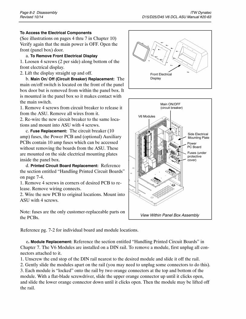
Page 8-2 DisassemblyRevised 10/14
ITW Dynatec D15/D25/D45 V6 DCL ASU Manual #20-63
PowerPC Board
Front ElectricalDisplay
Side ElectricalMounting Plate
Main ON/OFF(circuit breaker)
V6 Modules
Fuses (underprotectivecover)
To Access the Electrical Components(See illustrations on pages 4 thru 7 in Chapter 10)Verify again that the main power is OFF. Open thefront (panel box) door.a. To Remove Front Electrical Display
1. Loosen 4 screws (2 per side) along bottom of thefront electrical display.2. Lift the display straight up and off.b. Main On/ Off (Circuit Breaker) Replacement: The
main on/off switch is located on the front of the panelbox door but is removed from within the panel box. Itis mounted in the panel box so it makes contact withthe main switch.1. Remove 4 screws from circuit breaker to release itfrom the ASU. Remove all wires from it.2. Re-wire the new circuit breaker to the same loca-tions and mount into ASU with 4 screws.c. Fuse Replacement: The circuit breaker (10
amp) fuses, the Power PCB and (optional) AuxiliaryPCBs contain 10 amp fuses which can be accessedwithout removing the boards from the ASU. Theseare mounted on the side electrical mounting platesinside the panel box.d. Printed Circuit Board Replacement: Reference
the section entitled “Handling Printed Circuit Boards”on page 7-4.1. Remove 4 screws in corners of desired PCB to re-lease. Remove wiring connects.2. Wire the new PCB to original locations. Mount intoASU with 4 screws.
Note: fuses are the only customer-replaceable parts onthe PCBs. View Within Panel Box Assembly
Reference pg. 7-2 for individual board and module locations.
e. Module Replacement: Reference the section entitled “Handling Printed Circuit Boards” inChapter 7. The V6 Modules are installed on a DIN rail. To remove a module, first unplug all con-nectors attached to it.1. Unscrew the end stop of the DIN rail nearest to the desired module and slide it off the rail.2. Gently slide the modules apart on the rail (you may need to unplug some connectors to do this).3. Each module is “locked” onto the rail by two orange connectors at the top and bottom of themodule. With a flat-blade screwdriver, slide the upper orange connector up until it clicks open,and slide the lower orange connector down until it clicks open. Then the module may be lifted offthe rail.

ITW Dynatec D15/D25/D45 V6 DCL ASU Manual #20-63
Disassembly Page 8-3Revised 10/14
To Access the Pump or MotorOpen the ASU’s front door. Turn therotary handle switch OFF. Turn OFF thefilter shutoff valve.Gear Pump and Motor Removal:1. Loosen the two M5 screws and slideout the separator plate.2. Open the side doors.3. Loosen the two M8 screws and movethe L-shaped motor support frame out tothe maximum position.4. Remove the two hopper/ electronicsdividers by loosening their M6 screws.5. Remove the two plugs and loosen theM6 bolts. Remove the divider plate thathas the motor shaft cutouts.6. Pull out the desired motor/ pump(s).
DANGER HOT SURFACE/ HIGH VOLTAGEIf the pump is not operable but the heating system will function, raise thetemperature of the application system to the operating temperature to aid in thepump disassembly process. Otherwise, a heat gun or other controlled heatingmethod is recommended to melt hardened hot melt material. Never use a torchor an open flame on any of the components of the application system. Once thesystem is up to temperature, disconnect all incoming power before proceeding.
Front View
Back View
Front Door
Hopper Side Cover (1 of 2)
Hopper SideCover (1 of 2)
SeparatorPlate
SlideOut
M5Screws
HopperElectronicsDivider
HopperElectronicsDivider(1 of 2)
Divider w.MotorShaft Cutouts
Panel BoxSide Cover(1 of 2)
Motor/Pump
Pull Hinge Pin
HopperSideCover(1 of 2)
f. Opening ModulesThere are various electrical components located within the modules. To open a module, use two fin-gers to pull straight up on the top (lid) of the module. Position your fingers toward the outside edge(not the center) of the module. Do not use a tool as it could damage the module’s plastic casing.

Page 8-4 DisassemblyRevised 10/14
ITW Dynatec D15/D25/D45 V6 DCL ASU Manual #20-63
CAUTION: In general, all O-RINGS AND SEALS should be replaced wheneverhot-melt equipment is re-assembled. All new o-rings should be lubricated witho-ring lube (PN N07588).
CAUTION: TAPERED PIPE THREADS are found on air line fittings used with thepump air supply and on the outlet filter manifold. Apply thread sealant (PNN02892) whenever tapered pipe threaded parts are re-assembled.
CAUTION: SOME FITTINGS used for adhesive on the ASU have straight threadsand o-ring seals. Use of thread sealant is not necessary with these parts, but theo-ring seals should be clean and lubricated. Tighten straight-threaded parts andfittings until their shoulders are firmly seated against the pump body (or othersurface). Excessive torque may damage straight-threaded parts and the use ofpower wrenches is not recommended.
CAUTION: HOT-MELT RESIDUE should be cleaned from parts before they arere-assembled, particularly from threaded parts. As a precaution against adhesiveresidue preventing proper re-assembly, threaded parts should always bere-tightened at operating temperature.
Pump O-ring Replacement:1. Remove the pump from the ASU (see instructions onprevious page).2. Remove the external pump seal from its groove on theback of the pump.3. Reference the pump exploded-view illustration (in Chapter10) for your specific pump.4. Install the new seal.5. Re-assemble components.
Re-Assembly Procedures
Unless noted, the ASU’s re-assembly is simply the reverse sequence of the disassembly proce-dures. However, the following “cautions” should be followed (whenever they apply) for properre-assembly:
Pump Pump O-ring

ITW Dynatec D SERIES V6 DCL ASU Manuals
Options Page 9-1Revised 10/14
Chapter 9AVAILABLE OPTIONS & ACCESSORIES
Pressure Gauge Kit: PN 101175An optional analog pressure gauge can be mounted on the outlet filter manifold. Reading the adhe-sive pressure at the manifold, rather than in-line on a hose, allows for more precise monitoring ofsystem pressure. It is also useful for troubleshooting and maintenance.
The gauge is installed at one of the adhesive ports on the manifold (see illustration on page 3-7).Though there is no “dedicated” port for the gauge, ports #2 or #4 are preferred. Fittings are includedin the kit.
Drop-in Grids: PN 680089The drop-in grid is an extra heated grid which is installed near the bottom of the ASU’s hopper. Theadditional grid allows faster melting of adhesive for applications requiring higher melt rates andhigher volumes of adhesive.
Filter Options150 Mesh Outlet Filter: PN 106273Some situations call for a finer mesh outlet filter. A “dirty” adhesive or one with a short pot life areexamples. Systems utilizing very high temperatures or systems running in a dusty environment alsobenefit from a 150 mesh filter. Standard equipment is a 100 mesh filter (PN 101247).
Pressure Transducer Assembly: PN 680545A pressure transducer is an electronic probe that allows the melted adhesive’s pressure to be pro-cessed by the ASU’s control system and displayed on the HMI. They are used to monitor system op-erating pressures and their limits. They troubleshoot clogged nozzles and filters.
Level Control Assembly: PN 680614This device informs the operator, via a message on the DynaControl’s readout and an audible signal,that the hopper’s adhesive level is low. It may also be wired to stop production, turn on an alarmlight or signal a PLC at a low adhesive level.
Pneumatic Pressure Relief Valve (PPRV): PN 680424The pneumatic PRV provides gear pump units with a method to automatically relieve adhesive pres-sure (to zero) by turning off air supply to the ASU.

Page 9-2 OptionsRevised 10/14
ITW Dynatec D SERIES V6 DCL ASU Manuals
Pump Options
Gear PumpsFor higher tolerances and precision, several gear pumps are available for the ASU. Gear pumps givebetter service for continuous applications or applicationswhich requiremore control over the volumeofadhesive pumped. Gear pumps available are:
Single Pumps:PN 111253: 0.15 cc/rev single, standard accuracy, cast iron Gear PumpPN 109908: 0.55 cc/rev single, standard accuracy, cast iron Gear PumpPN 100860: 1.54 cc/rev single, standard accuracy Gear PumpPN 100861: 3.18 cc/rev single, standard accuracy Gear PumpPN 100862: 4.5 cc/rev single, standard accuracy Gear PumpPN 108875: 8.5 cc/rev single, high accuracy Gear PumpPN 084E374: 0.584 cc/rev single, high accuracy Gear PumpPN 084E428: .297 cc/rev single, high accuracy Gear PumpPN 084E430: 1.168 cc/rev single, high accuracy Gear PumpPN 084E434: 2.920 cc/rev single, high accuracy Gear Pump
Dual Pumps:PN 111254: 0.15 cc/rev dual, standard accuracy, cast iron Gear PumpPN 109909: 0.55 cc/rev dual, standard accuracy, cast iron Gear PumpPN 100863: 1.54 cc/rev dual, standard accuracy Gear PumpPN 100864: 3.18 cc/rev dual, standard accuracy Gear PumpPN 084E389: 0.584 cc/rev dual, high accuracy Gear PumpPN 084E432: 1.168 cc/rev dual, high accuracy Gear PumpPN 108874: 2.920 cc/rev dual, high accuracy Gear Pump
Gear Pump Repair Kit: PN 103151Contains the following itemsneeded to repair thePNs100860 thru 100864 and the 109908-109909gearpumps:
Pressure Relief Valve Repair Kit: PN 109982Contains the following three items needed to repair the PN101840 or PN115540PressureReliefValve:a PN N00179 O-ring 012, a N01601 O-ring 908 and a N05733 Backup Ring, 012.
PN Description Qty. PN Description Qty.
N00198 O-ring 2 069X064 O-ring 3018X031 Ball Bearing 5 078F017 Ring, Clip 4069X061 Seal 1 078I001 Key, Woodruff 1

ITW Dynatec D SERIES V6 DCL ASU Manuals
Options Page 9-3Revised 10/14
DynaControl V6 Options
HMI SelectionLCD Controller PN 115719
The LCD (liquid crystal display) controller is available with the complete line of DynaControl fea-tures. It features an intuitive, multi-line, graphic display and operates via an input wheel.
Touch Screen Controller PN 118135The V6 color touch screen controller is available with an expanded line of DynaControl features. Avariety of customer-selected devices may be integrated into the HMI utilizing VNC desktop shar-ing. An optional XIO module allows programmable I/O for custom applications. Up to ten unitsmay be controlled remotely by each touch panel.
LCD Pendant Control Assembly PN 680520The Pendant Control option gives the DynaControl keypad mobility via an up to 30 meter (100 ft)cable. The Pendant Control Panel Kit replaces the standard built-in keypad. An optional re-setswitch and on/off light can be mounted on the front panel.
V6 Communications AdaptersV6 EtherNet Assembly PN 680619V6 Profibus Kit PN 680618V6 EtherCAT Kit PN 680620
The V6 communications bus module adapts the ASU to full remote operation so that all system pa-rameters can be transmitted and received.
Signal Isolator PN 680617A signal isolator conditions a parent machine’s production line’s DC speed voltage or current refer-ence to allow the ASU’s gear pump to track the application’s line speed. It accepts 0-10V, 0-5V,4-20mA inputs and outputs a proportional 0-10V signal to DynaControl’s electronics.

Page 9-4 OptionsRevised 10/14
ITW Dynatec D SERIES V6 DCL ASU Manuals
Category Part No. Description Qty.
108689 2N02937 1L15653 1103151 1680132 1610201 1112568119975108566
2055
118430 1107183 2104166 1106519 1101840 1069X064 2-4807729 4069X064 1610714 1610712 4069X058 2N03812 4610704 1N00196 4108667 4806859 4610712 8N00192 1N00181 4106303 1680129 1115283 1115540
Dow 112 Silicone Lubricant, O-ring, 0.25Thread SealantKit, Flushing Fluid, 1 gallonGear Pump Repair KitMain Power Switch, 30 A (Circuit Breaker) (standard) Main Power Switch, 60 A (Circuit Breaker) (option) Fuse, 10A, 240VAC, 5x20mm (Power Boards) Fuse, 12A, 240VAC, 5x20mm (Power Boards) Fuse, 6.3A, 5x20mm (Power boards)Power Supply, 24VDC, 25WRTD Sensor, PT 100Over-Temp Thermostat & Insulator Assy.Hi Temp Over-Temp Thermostat Assy. (option) Pressure Relief ValveO-ring 041 Pump Shaft SealPump Shaft Seal (Zenith/ TSHA, high accuracy pumps)O-ring 041O-ring 21x2O-ring 9.5x1.8O-ring 028O-ring 125O-ring 24x3O-ring 5-005O-ring 5-005 Hi Temp (option)O-ring 125 Hi Temp (option)O-ring 9.5x1.8O-ring 032 (option)O-ring 014Filter NutCouplingMotor Speed Control Kit, YPneumatic Pressure Relief Valve 1
115719 HMI Assembly 1115733 Aux Power PCB, V6 1115732 Power PCB, V6 1115734 Base Module, V6 1115735 Temperature Module, V6 1116823 Motor Module, V6 1
101247 Filter Basket, 100 mesh/149 micron 4106273 Filter Basket, 150 mesh (optional) 4610702 Filter Shut-Off Assembly 1
Recommended Spare Parts List
Filter Replacements:
V6 Modules & Printed Circuit Boards:

ITW Dynatec D15/D25/D45 V6 DCL ASU Manual #20-63
Component Illustrations Page 10-1Revised 10/14
Chapter 10COMPONENT ILLUSTRATIONS & BILLS OF MATERIAL
Chapter Format
This chapter contains the component illustrations (exploded-view drawings) and bills of material(parts listings) for each assembly of the D15/D25/D45 SERIES of ASUs. These drawings are usefulfor finding part numbers as well as for use when maintaining or repairing the unit.
Note: most common nuts, bolts and fasteners can be obtained locally at your hardware store. Spe-cialty fasteners are available by contacting ITW Dynatec’s Customer Service.
WARNINGAll parts must be periodically inspected and replaced if worn or broken. Failureto do this can affect equipment’s operation and can result in personal injury.

Page 10-2 Component IllustrationsRevised 10/14
ITW Dynatec D15/D25/D45 V6 DCL ASU Manual #20-63
Cabinet AssemblyItem No. PN ITW PN Description Qty.
1 680161 Base Plate 12 680455 Side Cover (right) 13 106318 Washer, M5, External Tooth Lock 104 101626 Screw, SHC, M5x0.8 x 12mm 145 680174 Electrical Mounting Panel 16 680169 Front Door 17 610129 Front Door Lock 18 610202 Rotary Handle & Shaft (including circuit breaker) 19 L21483 Label, ITW/DYNATEC, 7.50 x 2.15 210 680430 FAN,120×120×38mm 211 102446 Screw, M4×0.7×10MM 812 680431 FILTER COVER,150×150MM,120×120 FAN 213 106531 Flat Head Cross Recess Screw, M3x0.5x8mm 1914 680456 Side Cover (left) 115 680216 Label, Electrical Cabinet, Top Side, D-Unit 216 see pages 10-6&7 HMI PCB Assemblies, V6 117 115792 Screw, PH, 4-20x3/8,TF,ZP 818 820488 Frame 119 106318 Washer, M5 1020 106110 Nut, M5 1021 see pages 10-6&7 Bezel, Display 122 680165 Top Cover 123 106319 Washer, M6, External Tooth Lock 1624 111906 Label-Front Panel 125 610186 Bracket, Support 126 610130 Bracket, CB Mount 127 680454 Front Electrical Divider Panel 128 680163 Middle Panel, D45 129 680164 Rear Electrical Divider Panel 129 680178 Rear Electrical Divider Panel 130 610132 Key Lock 231 610131 Plastic Slide Latches 432 680552 TOP COVER HOPPER D25 V6 132 680512 TOP COVER D15 V6 133 111345 M6, Split Lock Washer 2434 610141 Flat Washer M6 2435 104662 M6x1.0 x 16mm Socket Head Cap Screw 4036 610167 Hole Plugs 1237 106110 NUT, HEX, M5, BLK OX 638 680549 LID BASE D25/45 V6 238 680513 LID BASE D15 239 110734 Screw, PH FLTHD, M4X0.7X8,ZN 440 680646 Hinge, CL252, 304 stainless steel 441 106242 Screw, SHC, M5X16 442 600730 Handle,.Hopper Lid 143 048K769 HOT'WARNING STKR, 3X1.5 144 680551 LID, OUTER COVER D25/45 244 680514 LID, OUTER COVER D15 245 680550 HEAT SHIELD, LID D25/45 V6 145 680515 HEAT SHIELD, LID D15 146 106234 Washer, M4 147 106236 M4 External Tooth Lock 148 105113 Socket Head Screw, M4x0.7x8mm 149 104588 Data Tag 150 078E001 Rivet 251 106246 Label, HS 1-4, DMM 152 105113 Socket Head Cup Screw, M4x0.7 x 8mm 4053 102080 Label-Warning Nameplate DM (DANGER) 154 610185 Screw, BHSHC, M5x0.8x10 255 101074 Receptacle, Wiring Harness 656 610136 Cover, Connector Hole 257 610135 Cover Filter Manifold 158 106249 Label, AUX 1-4, DMM 159 680167 Rear Panel D25 159 680179 Rear Panel D45 160 610133 Bracket, Connector Bank, Amphenol 261 620120 Hopper Side Cover D25 261 620125 Hopper Side Cover D45 262 680399 Divider Panel Hopper Side D25 162 680400 Divider Panel Hopper Side D45 163 680223 Flash Panel 164 680198 Caster, 3” Diameter. 465 106237 M8 External Tooth Lock Washer 1666 610715 M8x1.25 x 20mm SHC Screw 1667 106336 Label-serve number 168 680473 Heat Sink 169 680133 Spring 4
680511 Tank Cover (lid gasket), D15 only (not shown) 1
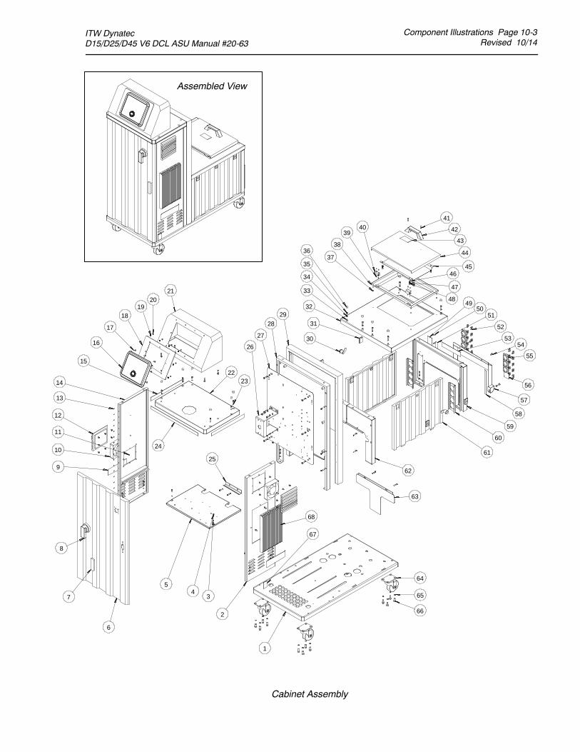
ITW Dynatec D15/D25/D45 V6 DCL ASU Manual #20-63
Component Illustrations Page 10-3Revised 10/14
Cabinet Assembly
Assembled View
1
2
34
5
6
7
8
13
9
10
11
12
14
15
16
17
1819
2021
24
2223
26
27
2928
30
31
33
34
35
36
4950
51
52
5354
55
56
57
58
59
60
61
62
63
25
68
64
65
66
67
32
37
38
3940
41
42
43
44
4546
47
48

Page 10-4 Component IllustrationsRevised 10/14
ITW Dynatec D15/D25/D45 V6 DCL ASU Manual #20-63
Electrical Panel Box Assembly

ITW Dynatec D15/D25/D45 V6 DCL ASU Manual #20-63
Component Illustrations Page 10-5Revised 10/14
Electrical Panel Box Assembly

Page 10-6 Component IllustrationsRevised 10/14
ITW Dynatec D15/D25/D45 V6 DCL ASU Manual #20-63
Front Panel Assembly
Item No. PN ITW PN Description Qty.
1 115893 PCB Assy. V6-LCD HMI 1
118135 Touch Panel Assy. V6 (option, not shown) 1
2 115792 SCR, PH, 4-20X3/8,TF,ZP 8
3 680453 Bezel, Display 1
820487 Bezel, HMI, Touch Panel (option, not shown) 1
4 106110 Hexagon Nut, M5x0.8 1
5 106318 External Tooth Lock Washer, 5mm 1

ITW Dynatec D15/D25/D45 V6 DCL ASU Manual #20-63
Component Illustrations Page 10-7Revised 10/14
D25/ D45 Front Panel Assembly
1 2 3
4 5

Page 10-8 Component IllustrationsRevised 10/14
ITW Dynatec D15/D25/D45 V6 DCL ASU Manual #20-63
Drive Assembly
Item No. PN ITW PN Description Qty.
1 610101 Base Plate 1
2 680137 Motor, Gear, 240V 3PH, 0.25HP 2
3 610715 M8x1.25 x 20mm Socket Head Cap Screw 8
4 107346 M8 Split Lock Washer 8 or 16
5 610109 Motor Nut Plate 2
6 610108 Motor Mounting Bracket 1 or 2
7 680129 Coupling 2
8 610209 Socket Set Screw Cup Point 4
9 104158 M10-1,Nut,5,FLG 8
10 104072 M10-1.5X100, Stud, GRD 8, 8
104073 M10-1.5X10⁵, Stud, GRD 8, 8 8
114890 M10-1.5X110, Stud, GRD 8, 8 8
11 100861 Pump (shown for reference only) 2
12 069X064 O-ring, #041 2
13 103518 Socket Head Cap Screw, M10x1.5 x 30mm 4
14 107538 M10 Split Lock Washer 10
15 610169 M10 Flat Washer 10
16 012G009 Block- off Plate 1
17 610701 Hopper D25 1
610722 Hopper D45 1
680510 Hopper D15 1
18 610204 Spacer L=40MM 6
19 104072 M10-1.5X85, Stud, GRD 8, 8 6
20 610122 Spacer L=8.5MM 6
21 610210 Hex Flange Nut Grade A 6
106244 M8x1.25 x 40mm Socket Head Cap Screw 4 or 8
N07429 M8x1.25 x 30mm Socket Head Cap Screw 10 or 16
106321 M8 Flat Washer 4 or 8
610146 Hexagon Flange Nut, M8x1.25 8 or 12
21 107538 Lock Washer, M10 Split, Hi Collar 8
1
2
3
4
5
6
7
8
9
10
10
10
11
12
13
14
15
16
17
17
17
18
19
20
21
22
23
24
25
26

ITW Dynatec D15/D25/D45 V6 DCL ASU Manual #20-63
Component Illustrations Page 10-9Revised 10/14
Drive Assembly
Assembled ViewDual Drive
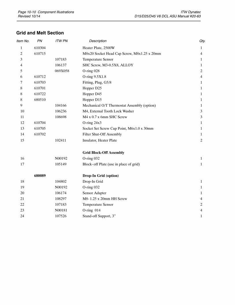
Page 10-10 Component IllustrationsRevised 10/14
ITW Dynatec D15/D25/D45 V6 DCL ASU Manual #20-63
Grid and Melt Section
Item No. PN ITW PN Description Qty.
1 610304 Heater Plate, 2500W 1
2 610715 M8x20 Socket Head Cap Screw, M8x1.25 x 20mm 4
3 107183 Temperature Sensor 1
4 106137 SHC Screw, M3-0.5X8, ALLOY 1
5 069X058 O-ring 028 2
6 610712 O-ring 9.5X1.8 4
7 610703 Fitting, Plug, G5/8 1
8 610701 Hopper D25 1
8 610722 Hopper D45 1
8 680510 Hopper D15 1
9 104166 Mechanical O/T Thermostat Assembly (option) 1
10 106236 M4, External Tooth Lock Washer 3
11 108698 M4 x 0.7 x 6mm SHC Screw 3
12 610704 O-ring 24x3 1
13 610705 Socket Set Screw Cup Point, M6x1.0 x 30mm 1
14 610702 Filter Shut-Off Assembly 1
15 102411 Insulator, Heater Plate 2
Grid Block-Off Assembly
16 N00192 O-ring 032 1
17 105149 Block- off Plate (use in place of grid) 1
680089 Drop-In Grid (option)
18 104802 Drop-In Grid 1
19 N00192 O-ring 032 1
20 106174 Sensor Adapter 1
21 108297 M8-1.25 x 20mm HH Screw 4
22 107183 Temperature Sensor 2
23 N00181 O-ring 014 4
24 107526 Stand-off Support, 3” 1

ITW Dynatec D15/D25/D45 V6 DCL ASU Manual #20-63
Component Illustrations Page 10-11Revised 10/14
Grid and Melt Section
Drop-In Grid (option)
Grid Block-Off Assembly
16
17
18
19
20
21
2223
24
23or
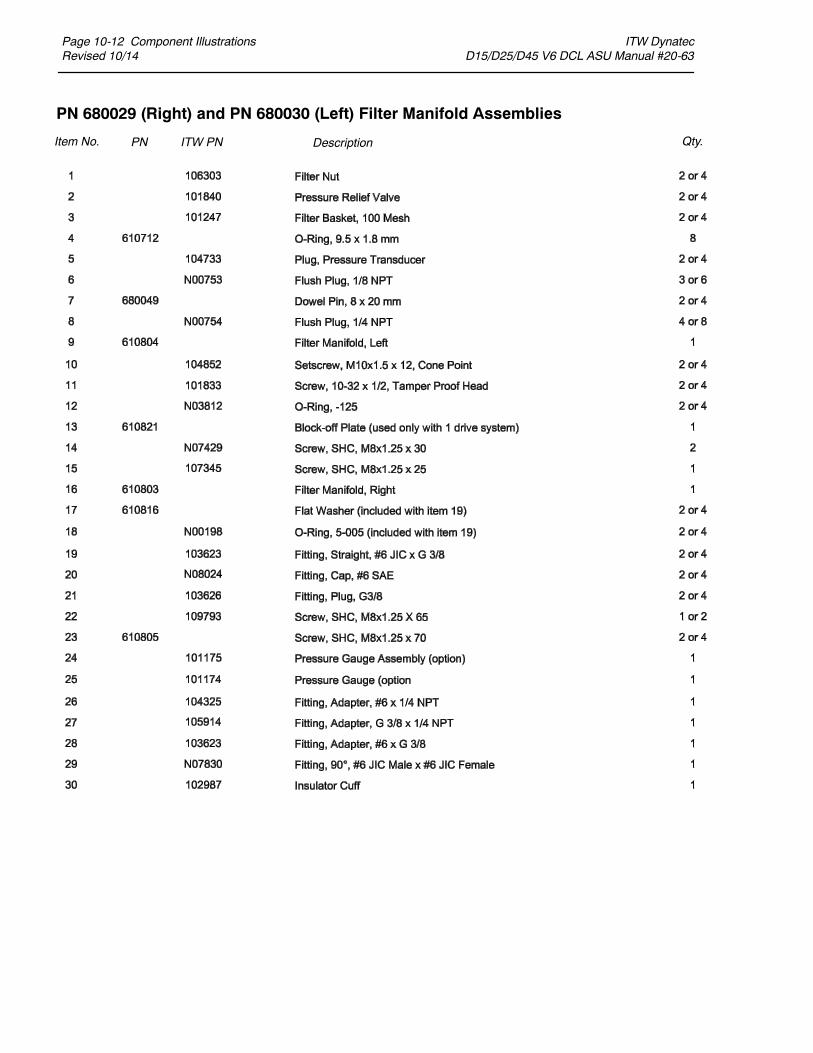
Page 10-12 Component IllustrationsRevised 10/14
ITW Dynatec D15/D25/D45 V6 DCL ASU Manual #20-63
PN 680029 (Right) and PN 680030 (Left) Filter Manifold Assemblies
Item No. PN ITW PN Description Qty.

ITW Dynatec D15/D25/D45 V6 DCL ASU Manual #20-63
Component Illustrations Page 10-13Revised 10/14
PN 680029 (Right) and PN 680030 (Left) Filter Manifold Assemblies
25
26
2728
29
30
26
28
or
Optional PressureGauge Assembly
or or
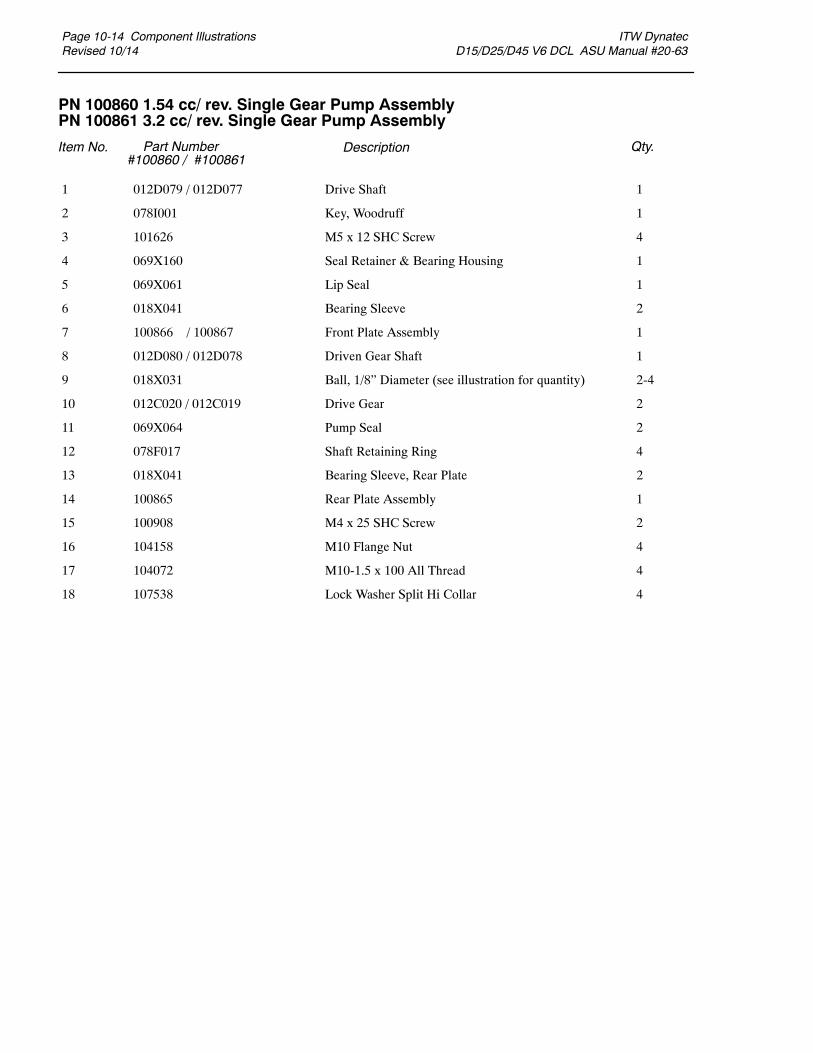
Page 10-14 Component IllustrationsRevised 10/14
ITW Dynatec D15/D25/D45 V6 DCL ASU Manual #20-63
PN 100860 1.54 cc/ rev. Single Gear Pump AssemblyPN 100861 3.2 cc/ rev. Single Gear Pump Assembly
Item No. Part Number#100860 / #100861
Description Qty.
012D079 / 012D077 Drive Shaft 1
078I001 Key, Woodruff 1
101626 M5 x 12 SHC Screw 4
069X160 Seal Retainer & Bearing Housing 1
069X061 Lip Seal 1
018X041 Bearing Sleeve 2
100866 / 100867 Front Plate Assembly 1
012D080 / 012D078 Driven Gear Shaft 1
018X031 Ball, 1/8” Diameter (see illustration for quantity) 2-4
012C020 / 012C019 Drive Gear 2
069X064 Pump Seal 2
078F017 Shaft Retaining Ring 4
018X041 Bearing Sleeve, Rear Plate 2
100865 Rear Plate Assembly 1
100908 M4 x 25 SHC Screw 2
104158 M10 Flange Nut 4
104072 M10-1.5 x 100 All Thread 4
107538 Lock Washer Split Hi Collar 4
1
2
3
4
5
6
7
8
9
10
11
12
13
14
15
16
17
18
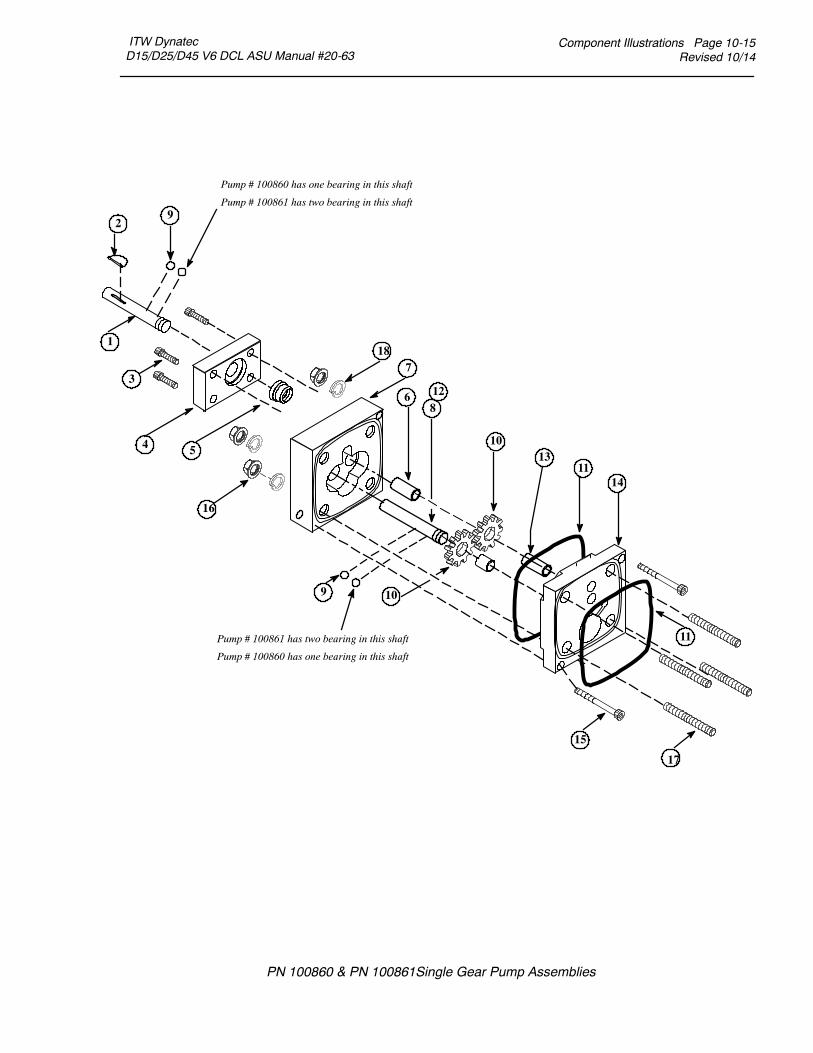
ITW Dynatec D15/D25/D45 V6 DCL ASU Manual #20-63
Component Illustrations Page 10-15Revised 10/14
PN 100860 & PN 100861Single Gear Pump Assemblies
1
2
3
4 5
6
7
8
9
10
11
12
13
14
15
10
11
16
9
17
Pump # 100860 has one bearing in this shaft
Pump # 100861 has two bearing in this shaft
Pump # 100861 has two bearing in this shaft
Pump # 100860 has one bearing in this shaft
18

Page 10-16 Component IllustrationsRevised 10/14
ITW Dynatec D15/D25/D45 V6 DCL ASU Manual #20-63
PN 109690 10 cc/ rev. Single Gear Pump Assembly
Item No. Part Number Description Qty.
018X031 Ball Bearing, 1/8 Dia. 6
078F017 Snap Ring, 1/2” 4
078I001 Key Woodruf, #404 1
069X061 Shaft Seal 1
069X064 O-ring, -041 2
108588 M4x25mm, Blk SHC Screw 2
101626 M5-0.8 x 12mm SHC Screw 4
109685 Pump Body 10cc/ rev 1
109686 Rear Bearing Plate 10cc/ rev 1
109689 Gear 10cc/ rev 2
109687 Drive Shaft 10cc/ 20cc 1
109688 Driven Shaft, 10cc/ 20cc 1
069X160 Shaft Seal Retainer 1
001U002 Dow Corning 112 Lubricant (not shown)
1
2
3
4
5
6
7
8
9
10
11
12
13
1
2
3
4
5
6
7
8
9
10
11
12
13
14
5
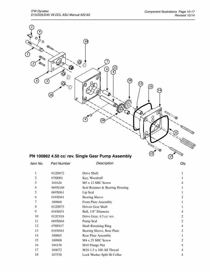
Component Illustrations Page 10-17Revised 10/14
ITW Dynatec D15/D25/D45 V6 DCL ASU Manual #20-63
1
2
3
4 5
6
7
8
9
10
11
12
13
14
15
10
11
16
9
17
18
123456789101112131415161718
PN 100862 4.50 cc/ rev. Single Gear Pump Assembly
Item No. Part Number Description Qty.
012D072 Drive Shaft 1078I001 Key, Woodruff 1101626 M5 x 12 SHC Screw 4069X160 Seal Retainer & Bearing Housing 1069X061 Lip Seal 1018X041 Bearing Sleeve 2100868 Front Plate Assembly 1012D073 Driven Gear Shaft 1018X031 Ball, 1/8” Diameter 4012C018 Drive Gear, 4.5 cc/ rev. 2069X064 Pump Seal 2078F017 Shaft Retaining Ring 4018X041 Bearing Sleeve, Rear Plate 2100865 Rear Plate Assembly 1100908 M4 x 25 SHC Screw 2104158 M10 Flange Nut 4104072 M10-1.5 x 100 All Thread 4107538 Lock Washer Split Hi Collar 4

Page 10-18 Component IllustrationsRevised 10/14
ITW Dynatec D15/D25/D45 V6 DCL ASU Manual #20-63
PN 100863 1.54 cc/ rev. Dual Gear Pump Assembly
Item No. Part Number Description Qty.
012D083 Drive Shaft 1
078I001 Key, Woodruff 1
101626 M5 x 12 SHC Screw 4
069X160 Seal retainer & Bearing Housing 1
069X061 Lip Seal 1
018X041 Bearing Sleeve 2
100866 Front Plate Assembly 1
012D082 Driven Gear Shaft 1
018X031 Ball, 1/8” Dia. 3
012C020 Pump Gear, 1.5 cc/ rev. 4
069X064 O-ring, -041 3
078F017 Shaft Retaining Ring 4
018X041 Bearing Sleeve, Rear Plate 2
100865 Rear Plate Assembly 1
101692 M4 x 35 SHC Screw 2
104158 M10-1.5 x 100 Flange Nut 4
100869 Middle Plate 1
N00198 O-ring, -113 2
104073 M10-1.5 x 10⁵ All Thread 4
107538 Lock Washer Split Hi Collar 4
1
2
3
4
5
6
7
8
9
10
11
12
13
14
15
16
17
18
19
20

Component Illustrations Page 10-19Revised 10/14
ITW Dynatec D15/D25/D45 V6 DCL ASU Manual #20-63
PN 100863 1.54 cc/ rev. Dual Gear Pump Assembly
1
2
3
4 5
6
7
8
9
10
11
12
13
14
15
10
11
16 10
10
11
18
17
9
19
20

Page 10-20 Component IllustrationsRevised 10/14
ITW Dynatec D15/D25/D45 V6 DCL ASU Manual #20-63
PN 100864 3.2 cc/ rev. Dual Gear Pump Assembly
Item No. Part Number Description Qty.
012D088 Drive Shaft 1
078I001 Key, Woodruff 1
101626 M5 x 12 SHC Screw 4
069X160 Seal Retainer & Bearing Housing 1
069X061 Lip Seal 1
018X041 Bearing Sleeve 2
100867 Front Plate Assembly 1
012D087 Driven Gear Shaft 1
018X031 Ball, 1/8” Diameter 5
012C019 Drive Gear 4
069X064 O-ring, -041 3
078F017 Shaft Retaining Ring 4
018X041 Bearing Sleeve, Rear Plate 2
100865 Rear Plate Assembly 1
101691 M4 x 40 SHC Screw 2
104158 M10 Flange Nut 4
100870 Middle Plate 1
N00198 O-ring, -113 2
114890 M10-1.5 x 110, Stud 4
107538 Lock Washer Split Hi Collar 4
1
2
3
4
5
6
7
8
9
10
11
12
13
14
15
16
17
18
19
20

Component Illustrations Page 10-21Revised 10/14
ITW Dynatec D15/D25/D45 V6 DCL ASU Manual #20-63
1
2
3
4 5
6
7
8
9
10
11
12
13
14
15
10
11
10
10
11
16
18
17
9
19
20
PN 100864 3.2 cc/ rev. Dual Gear Pump Assembly

Page 10-22 Component IllustrationsRevised 10/14
ITW Dynatec D15/D25/45 V6 DCL ASU Manual #20-63
PN 109908 0.55 cc/ rev. Single Gear Pump Assembly
Item No. Part Number Description Qty.
018X031 Ball Bearing, 1/8 Dia. 6
078F017 Snap Ring, 1/2” 4
078I001 Key Woodruff, #404 1
069X061 Shaft Seal 1
069X064 O-ring, -041 2
100908 M4-0.7 x 25mm SHC Screw 2
101626 M5-0.8 x 12mm SHC Screw 4
109906 Plate Front, .55 cc/ rev. 1
100865 Rear Bearing Plate .55 cc/ rev. 1
109907 Gear .55 cc/ rev. 2
012D079 Drive Shaft 1.5 cc/ rev. Dual 1
012D080 Driven shaft, 1.5 cc/ rev. Dual 1
069X160 Shaft Seal Retainer 1
001U002 Dow Corning 112 Lubricant (not shown)
1
2
3
4
5
6
7 8
9
10
11
12
13
1
2
3
4
5
6
7
8
9
10
11
12
13
14
5
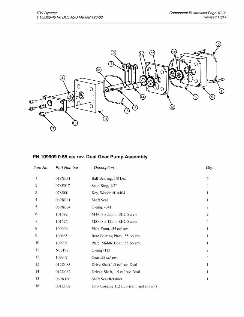
ITW Dynatec D15/D25/45 V6 DCL ASU Manual #20-63
Component Illustrations Page 10-23Revised 10/14
PN 109909 0.55 cc/ rev. Dual Gear Pump Assembly
Item No. Part Number Description Qty.
1
2
3
4
6
8
9
10
11 12
13
1
2
3
4
5
6
7
8
9
10
11
12
13
14
15
16
5
018X031 Ball Bearing, 1/8 Dia. 6
078F017 Snap Ring, 1/2” 4
078I001 Key, Woodruff #404 1
069X061 Shaft Seal 1
069X064 O-ring, -041 2
101692 M4-0.7 x 35mm SHC Screw 2
101626 M5-0.8 x 12mm SHC Screw 4
109906 Plate Front, .55 cc/ rev. 1
100865 Rear Bearing Plate, .55 cc/ rev. 1
109905 Plate, Middle Gear, .55 cc/ rev. 1
N00198 O-ring -113 2
109907 Gear .55 cc/ rev. 4
012D083 Drive Shaft 1.5 cc/ rev. Dual 1
012D082 Driven Shaft, 1.5 cc/ rev. Dual 1
069X160 Shaft Seal Retainer 1
001U002 Dow Corning 112 Lubricant (not shown)
15
5
14 5
12
7
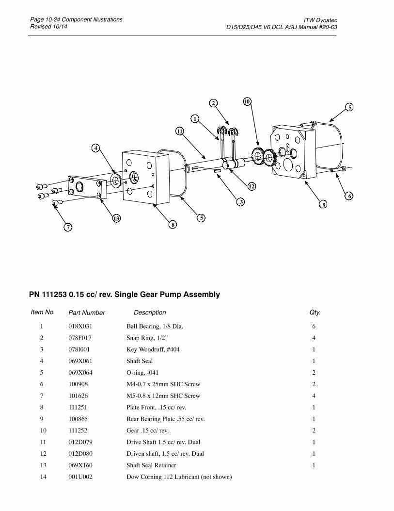
Page 10-24 Component IllustrationsRevised 10/14
ITW Dynatec D15/D25/D45 V6 DCL ASU Manual #20-63
PN 111253 0.15 cc/ rev. Single Gear Pump Assembly
Item No. Part Number Description Qty.
018X031 Ball Bearing, 1/8 Dia. 6
078F017 Snap Ring, 1/2” 4
078I001 Key Woodruff, #404 1
069X061 Shaft Seal 1
069X064 O-ring, -041 2
100908 M4-0.7 x 25mm SHC Screw 2
101626 M5-0.8 x 12mm SHC Screw 4
111251 Plate Front, .15 cc/ rev. 1
100865 Rear Bearing Plate .55 cc/ rev. 1
111252 Gear .15 cc/ rev. 2
012D079 Drive Shaft 1.5 cc/ rev. Dual 1
012D080 Driven shaft, 1.5 cc/ rev. Dual 1
069X160 Shaft Seal Retainer 1
001U002 Dow Corning 112 Lubricant (not shown)
1
2
3
4
5
6
7 8
9
10
11
12
13
1
2
3
4
5
6
7
8
9
10
11
12
13
14
5
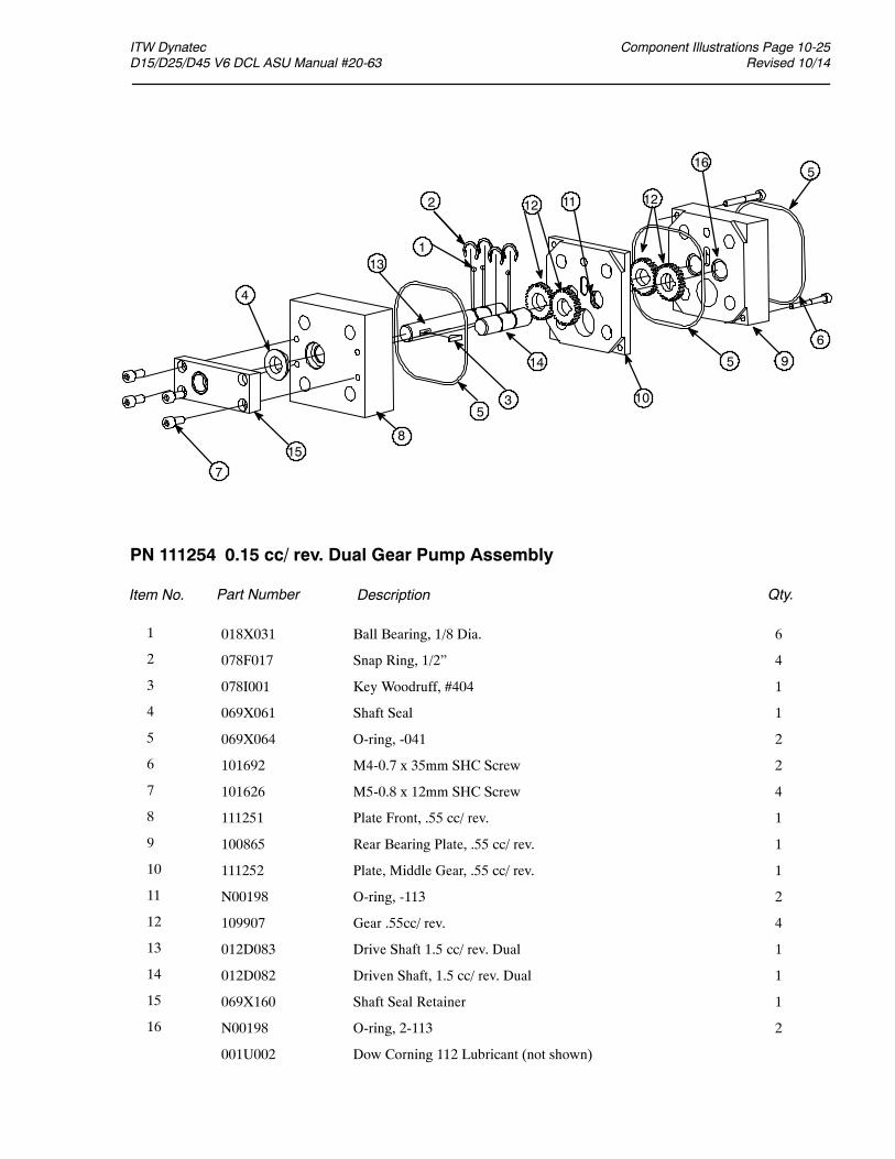
Component Illustrations Page 10-25Revised 10/14
ITW Dynatec D15/D25/D45 V6 DCL ASU Manual #20-63
PN 111254 0.15 cc/ rev. Dual Gear Pump Assembly
Item No. Part Number Description Qty.
1
2
3
4
6
7
8
9
10
11 12
13
1
2
3
4
5
6
7
8
9
10
11
12
13
14
15
16
5
018X031 Ball Bearing, 1/8 Dia. 6
078F017 Snap Ring, 1/2” 4
078I001 Key Woodruff, #404 1
069X061 Shaft Seal 1
069X064 O-ring, -041 2
101692 M4-0.7 x 35mm SHC Screw 2
101626 M5-0.8 x 12mm SHC Screw 4
111251 Plate Front, .55 cc/ rev. 1
100865 Rear Bearing Plate, .55 cc/ rev. 1
111252 Plate, Middle Gear, .55 cc/ rev. 1
N00198 O-ring, -113 2
109907 Gear .55cc/ rev. 4
012D083 Drive Shaft 1.5 cc/ rev. Dual 1
012D082 Driven Shaft, 1.5 cc/ rev. Dual 1
069X160 Shaft Seal Retainer 1
N00198 O-ring, 2-113 2
001U002 Dow Corning 112 Lubricant (not shown)
15
5
14 5
12
16
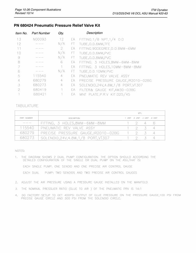
Page 10-26 Component IllustrationsRevised 10/14
ITW Dynatec D15/D25/D45 V6 DCL ASU Manual #20-63
PN 680424 Pneumatic Pressure Relief Valve Kit
Item No. Part Number DescriptionQty.
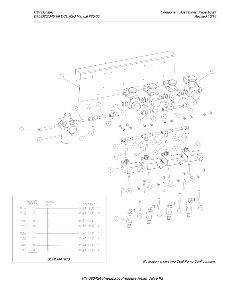
Component Illustrations Page 10-27Revised 10/14
ITW Dynatec D15/D25/D45 V6 DCL ASU Manual #20-63
PN 680424 Pneumatic Pressure Relief Valve Kit
Illustration shows two Dual Pump Configuration.SCHEMATICS

Page 10-28 Component Illustrations Revised 10/14
ITW Dynatec D15/D25/D45 V6 DCL ASU Manual #20-63

ITW Dynatec D SERIES V6 DCL ASU Manuals
Schematics Page 11-1Revised 10/14
Chapter 11SYSTEM SCHEMATICS
& ENGINEERING DRAWINGS
HEAD SCHEMATIC PN 103117 REV. B
Notes:1. ALL WIRE MIL-W-22759/10 OR 12, MINIMUM 600 VOLTS, 260 DEG. C2. SOLENOID(S) VOLTAGE AND TIMING METHOD DEPENDS ON APPLICATION.3. RTD WILL BE PLATINUM 100 OHM.
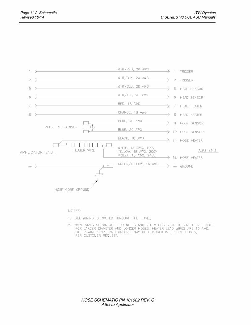
Page 11-2 SchematicsRevised 10/14
ITW Dynatec D SERIES V6 DCL ASU Manuals
HOSE SCHEMATIC PN 101082 REV. GASU to Applicator

ITW Dynatec D SERIES V6 DCL ASU Manuals
Schematics Page 11-3Revised 10/14
PumpBypass
Motor
FilterBasket
Gauge
Transducer
TYPICAL HYDRAULIC SCHEMATIC:Single Pump, Motor, Bypass, Filter, optional Transducer & optional Pressure Gauge

Page 11-4 SchematicsRevised 10/14
ITW Dynatec D SERIES V6 DCL ASU Manuals
LEVEL CONTROL SCHEMATIC PN 802972 REV. A

COVER SHEET AND INDEX
D15/25/45 V6
INDEX
SHEET PAGE REF. DESCRIPTION
1
2
3
4
5
6
9
8
7
20
1
30
40
50
COVER SHEET & INDEX
POWER HOOK-UP / DISTRIBUTION
POWER PCBs
CONTROL MODULES / RTD INPUTS
90
80
70
60
GROUNDING SCHEME
1 C
B
F
G
H
K
KN
M
Q
R
S
X
XS
Y
A
THERMOSTAT
FUSE, CIRCUIT BREAKER
POWER SUPPLY
INDICATOR, LAMP
CONTACTOR, RELAY
SAFETY RELAY, E-STOP
MAIN SWITCH
MOTOR
RESISTOR, RTD
SWITCH, PROXIMITY SWITCH
TERMINAL, TERMINAL STRIP
PLUG/SOCKET CONNECTION
SOLENOID
CONTROL GEAR, PLC, MODULE
COMPONENT DESIGNATORS
ADHESIVE SUPPLY UNIT D15/25/45 DynaControl V6
POWER SUPPLY: 3 PHASE, "4 WIRE-DELTA", PE, 50/60HZ
VOLTAGE:
MAX. WATTAGE:
240VAC / 50-60HZ
MAX. CURRENT:
EXAMPLE: -K20.5
CONTACTOR
ON PAGE 20 (SHEET 2)
COLUMN 5
SCHEM, D15/25/45, V6
MOTOR CIRCUITS
PANEL BOX LAYOUT
24.1KW
58A
3 PHASE, "5 WIRE-WYE", PE, 50/60HZ
400VAC / 50-60HZ
22.0KW
32A
HEATER CIRCUITS / HOSE- HEAD-AUX-ZONES
10 100
OPTIONS
BILL OF MATERIAL
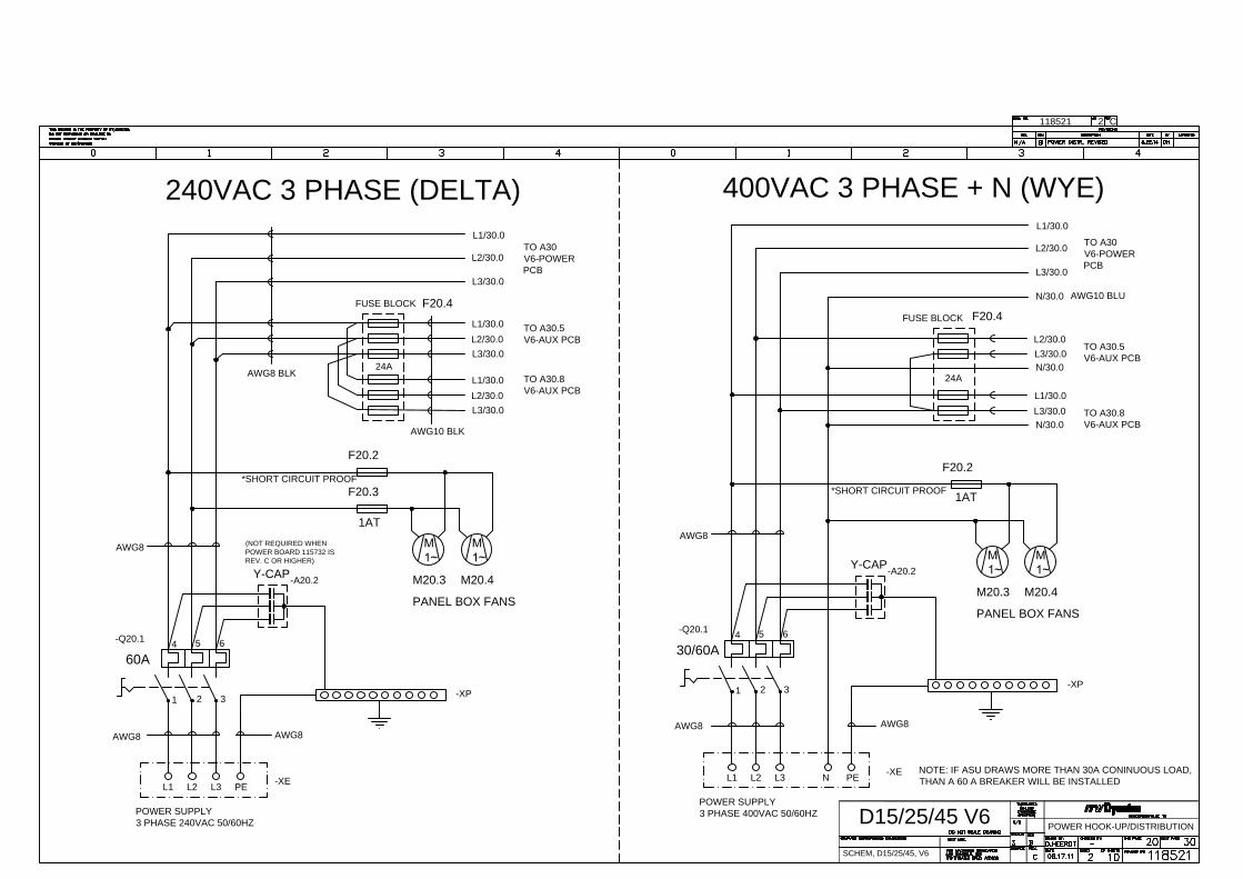
POWER HOOK-UP/DISTRIBUTION
D15/25/45 V6
118521 2 C
SCHEM, D15/25/45, V6
-Q20.1
AWG8
60A
6
32
5
1
4
TO A30
V6-POWER
PCB
L3/30.0
L2/30.0
L1/30.0
AWG8
POWER SUPPLY
3 PHASE 240VAC 50/60HZ
-XE
L3 PEL2L1
-XP
-XP
L1 L2 PEL3
-XE
POWER SUPPLY
3 PHASE 400VAC 50/60HZ
L1/30.0
L2/30.0
L3/30.0
TO A30
V6-POWER
PCB
4
1
5
2 3
6
30/60A
AWG8
-Q20.1
N
N/30.0
240VAC 3 PHASE (DELTA)400VAC 3 PHASE + N (WYE)
F20.2
F20.3
M20.3 M20.4
M20.4M20.3
F20.2
PANEL BOX FANS
PANEL BOX FANS
1AT
1AT
AWG8
AWG8
AWG8
AWG10 BLU
Y-CAP
-A20.2
-A20.2
Y-CAP
TO A30.8
V6-AUX PCB
TO A30.5
V6-AUX PCB
L1/30.0
L2/30.0
L3/30.0
L3/30.0
L2/30.0
L1/30.0
AWG10 BLK
*SHORT CIRCUIT PROOF
AWG8 BLK
L1/30.0
L3/30.0
L3/30.0
L2/30.0
TO A30.8
V6-AUX PCB
TO A30.5
V6-AUX PCB
N/30.0
N/30.0
FUSE BLOCKF20.4
24A
FUSE BLOCK
F20.4
24A
*SHORT CIRCUIT PROOF
NOTE: IF ASU DRAWS MORE THAN 30A CONINUOUS LOAD,
THAN A 60 A BREAKER WILL BE INSTALLED
(NOT REQUIRED WHEN
POWER BOARD 115732 IS
REV. C OR HIGHER)
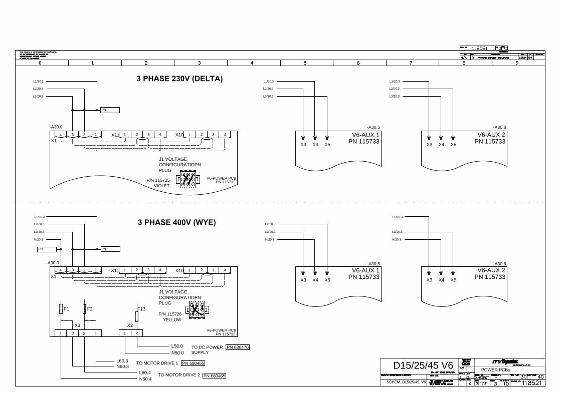
POWER PCBs
D15/25/45 V6
3 C
SCHEM, D15/25/45, V6
3 PHASE 400V (WYE)
3 PHASE 230V (DELTA)
34 2
1 12 43 3 4
21
X1
X11X10
L1/20.3
L2/20.3
L3/20.3
X3 X4 X5 X5X4X3
X3 X4 X5X5X4X3
X10X11
X1
12
433 4211
243
PN 115733
V6-AUX 1V6-AUX 2
PN 115733
L3/20.3
L2/20.3
L1/20.3
N/20.3
V6-AUX 1
PN 115733
V6-AUX 2
PN 115733
V6-POWER PCB
PN 115732
VIOLET
P/N 115725
YELLOW
P/N 115726
J1 VOLTAGE
CONFIGURATIOPN
PLUG
J1 VOLTAGE
CONFIGURATIOPN
PLUG
34 2
1 12
F2F1
X3
V6-POWER PCB
PN 115732
X2
F13
TO DC POWER
SUPPLY
TO MOTOR DRIVE 1
TO MOTOR DRIVE 2
-A30.0
-A30.0
-A30.5 -A30.8
-A30.5 -A30.8
L50.0
N50.0
N60.3
L60.3
L60.4
N60.4
PNPN
PN
PN 680470
PN 680465
PN 680465
L3/20.3
L2/20.3
L1/20.3 L1/20.3
L2/20.3
L3/20.3
N/20.3
L2/20.3
L3/20.3
N/20.3
L1/20.3
L3/20.3

HEATER CIRCUITS / HS-HD-AUX-Z.
D15/25/45 V6
118521 4 C
SCHEM, D15/25/45, V6
21
X4
AWG16
124
3
X6 X5
BR
N
BLK
BLU
RE
D
BR
N
BLK
BLU
RE
D
87
AUX 3
HEATER
-XS40.7
-XS40.2
121187
PE
HEAD 1
HEATER
HOSE 1
HEATER
34 2
1 124
3
HOSE 2
HEATER
HEAD 2
HEATER
PE
7 811 12
-XS40.0
-XS40.6
AUX 4
HEATER
7 8
RE
D
BLU
BLK
BR
N
RE
D
BLU
BLK
BR
N
X2
X6
34 2
1
AWG16
X1
1 2
AWG16
HOSE 4
HEATER
HEAD 4
HEATER
PE
7 811 12
BR
N
BLK
BLU
RE
D
BR
N
BLK
BLU
RE
D
F1 F2F3
F4F5
F6F7
F8F9
F10
V6-POWER PCB
PN 115732
V6-AUX PCB
PN 115733
45
1415
7 6 11 10
TO
V6-TEMP
X13
X7
TO
V6-TEMP
X12
TO
V6-TEMP
X11
-A30.0 -A30.5 -A30.8
-XS40.3
9 8
HOSE 3
HEATER
HEAD 3
HEATER
PE
7 811 12
-XS40.5
13
-XS40.8
87
AUX 2
HEATER
12
AUX 1
HEATER
7 8
-XS40.9
F1 F2 F4F3 F6F5 F7
F8
R
X5 X4 X3
F9 F10 F10F9
X3X4X5
R
F8
F7F5 F6F3F4
F2F1
X7
21
X1
124
3
X6
X2
34 2
1
V6-AUX PCB
PN 115733
X8
AWG12
1
2
BLK
BLK
GRID 2
HEATER
BLK
BLK
HOPPER
HEATER
BLK
BLK
GRID 1
HEATER
3
AWG14
AWG12AWG12
PN 680458
PN 680458
PN 680459
PN 680459
PN 680461
PN 680460
PN 680463
PN 680484
PN 680483
PN 680484

CPU & RTD-INPUTS
D15/25/45 V6
118521 5 C
SCHEM, D15/25/45, V6
+ -
OV.TEMP
T'STAT
COM +24V
X10X9
X6X7
X8
X11
OUT16
X13
X2
X5X4X3
3
PWR ON
OUTPUT
21
RELAY OUTPUT
V6-BASE4 PN 115734 REV. K & HIGHER
LIN
E
CO
M
EN
C
PR
E
SC
S1
MB
MC
AC
A1
MOT.DRIVER
+ -24V
LE
VE
L
P.P
U
+2
4V
IN
-C
CO
M
CO
M
INPUT
IN
2
IN
3
IN
4
ST
BY
PU
.S
T
AUX INPUTS
(CUSTOMER'S
CONNECTION)
V6-TEMP16 PN 115735
X12
POWER
SUPPLY
24VDC / 2A
21
+2
4V
+2
4V
RE
3
RE
1
RE
1
RE
2
RE
3
RE
2
1 2
+ -
1 2
24V+ -
21 1 2 43 3 421 1 2 43 3 4211 2 433 421 3 421 1 2
1 2 3 54 76 981110 1312 1514
2,4,5,6,7 3,8,9,10,11 1,12,13,14,15
L N PE + +--
TO A30.1
POWER
BOARD
TO A30.5
AUX
BOARD 1
TO A30.8
AUX
BOARD 2
PR
EM
EL
T
GR
ID
2
R
TD
HO
PP
ER
R
TD
PR
EM
EL
T
GR
ID
1
R
TD
HO
SE
1
R
TD
HO
SE
3
R
TD
HO
SE
4
R
TD
HO
SE
2
R
TD
HE
AD
4
R
TD
HE
AD
3
R
TD
HE
AD
2
R
TD
HE
AD
1
R
TD
AU
X 1
R
TD
AU
X 2
R
TD
AU
X 3
R
TD
AU
X 4
R
TD
OR
AN
GE
BL
UE
GR
AY
WH
/B
L
OR
AN
GE
BL
UE
GR
AY
WH
/B
L
OR
AN
GE
BL
UE
GR
AY
WH
/B
L
OR
AN
GE
BL
UE
GR
AY
WH
/B
L
GR
AY
WH
/B
L
GR
AY
WH
/B
L
GR
AY
WH
/B
L
GR
AY
WH
/B
L
X14
-A50.1-A50.0-A50.5
L30.2
N30.2
OR
A
GR
Y
BLK
RE
D
BLU
/W
HT
BLU
-+
0-10V
PUMP #1 (& PUMP #2 if
GLOBAL CONTROL)
CUSTOMER CONNECTION
READY EMPTYALARM
CUSTOMER CONNECTION
PN 680470
PN 680479
PN 680007
PN 680480
PN
6
80
45
8
PN
6
80
45
8
PN
6
80
45
9
PN
6
80
45
9
PN
6
80
46
0
PN
6
80
46
0
PN
6
80
46
1
PN
6
80
46
1
PN
6
80
46
3
PN 680484PN 680484
PN 680483
PN 680485
PN 680464
PN 680486
E1 TR1 IN-C +24
E1 = STAND BY
TR1 = PUMP START
PN 108050
-A50.2
OPERATOR PANEL
+2
4V
+2
4V
OV
ER
TE
MP
-+
0-10V
E1 TR1 IN-C +24
-
+
0-10V
E1 TR1 IN-C +24
TO A70.2
MOTOR
DRIVE 1
PN 680462
C
LOCAL MODE
REMOTE MODE
FULLY ISOLATED
APPLY 24VDC
FOR PUMP START
0-10V
LINE SPEED
SIGNAL
ISOLATOR
0-10V
LINE SPEED
CONTACT CLOSURE
FOR PUMP START
REMOTE MODE
ALTERNATIVE CUSTOMER CONNECTIONS
R1
R2
A1
A2
L1
L2
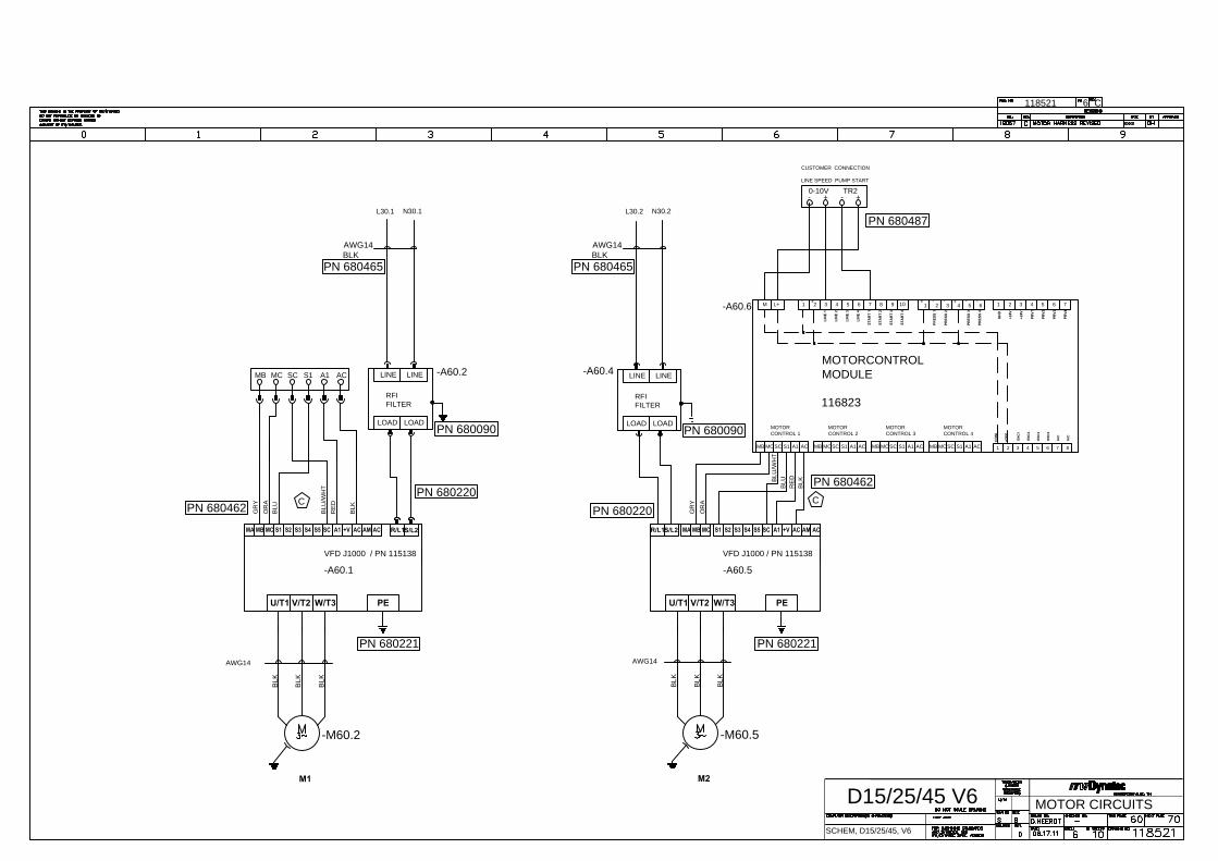
MOTOR CIRCUITS
D15/25/45 V6
118521 6 C
SCHEM, D15/25/45, V6
LINE LINE
LOADLOAD
-A60.4
-A60.5
VFD J1000 / PN 115138
S1 S2 S3 S4 SC A1 +V AC AM ACS5MB MC
LINE LINE
LOADLOAD
-A60.2
-A60.1
VFD J1000 / PN 115138
PEU/T1 V/T2 W/T3
AWG14
-M60.2
BL
K
BL
K
BL
K
R/L1S/L2S1 S2 S3 S4 SC A1 +V AC AM ACS5MB MC
AWG14
-M60.5
BL
K
BL
K
BL
K
PEU/T1 V/T2 W/T3
S1SCMC A1 ACMB
M1 M2
BL
U
BL
U/W
HT
RE
D
BL
K
L30.1 N30.1
AWG14
BLK
MOTORCONTROL
MODULE
116823
CUSTOMER CONNECTION
LINE SPEED PUMP START
876
ENC
4
N/C
N/C
5 6 7 8 109
AC MB MC ACS1 A1SC SC A1S1 ACMCMB
1 5432
MOTOR
CONTROL 3
MOTOR
CONTROL 4
ENC
1
ENC
2
ENC
3
LIN
E 4
LIN
E 3
STA
RT
4
STA
RT
3
STA
RT
2
STA
RT
1
M L+ 1 2 3 4
MB MC SC S1 A1 AC SC S1MCMB
MOTOR
CONTROL 1
LIN
E 1
LIN
E 2
A1
MOTOR
CONTROL 2
MA
BL
U
RE
D
BL
K
BL
U/W
HT
GR
Y
OR
A
S/L2R/L1
-A60.6
AWG14
BLK
N30.2L30.2
RFI
FILTER
RFI
FILTER
GR
Y
OR
A
MA
-
0-10V
+-
+
TR2
PRV4
PRV3
PRV2
7
+24V
PRV1
GN
D
+24V
-
65
PRES
S 4
PRES
S 3
PRES
S 1
PRES
S 2
54321
2 3 41
6
+
- -
+
-
CO
M
+24V
-
+
PN 680465 PN 680465
PN 680487
PN 680462
PN 680462
PN 680220
PN 680220
PN 680221 PN 680221
PN 680090
PN 680090
C
C

PANEL BOX LAYOUT
D15/25/45 V6
118521 7 C
SCHEM, D15/25/45, V6
A50.2
-A60.5 -A60.1
-Q20.1
-A
60.3
1 2
3 4
5 6
7 8
9 10
11
12
LE
VE
L
CO
NT
RO
L
(O
PT
IO
N)
PE
L3
L2
L1
-XE
-XP
-A
60.4
H1
H2
S1
S2
E1
E2
A1
A2
R1
R2
N
-M60.5
MOTOR 2
-M60.2
MOTOR 1
-XC
A30.8
A30.5
A30.0
-A50.1
-A50.5
-A60.6
-A50.0
V6-T
EM
P16
OU
T1
1-1
5
X9
OU
TP
UT
V6-B
AS
E4
GP+
X8
MO
T.-C
TR
L
+ -
24VIN2
IN1
+24V
P-P
UM
P
IN6
IN
PU
T
IN3
IN4
IN5
N P
COM
COM
T'S
TA
T
+24V
PP+
PP-
OV
-T
ERR
COM
1
+ -
X6
X2
X5
X4
X3
X8
X7
+ -
PR-
COM
0-10V
GP-
PR+
COM
ENC
LINE
+24V
OU
T1
6
23
PW
R O
N
OU
TP
UT
1
OU
T1
-5
1
OU
T6
-1
0
1
X10
V6-M
OT
OR
DynatecV
6-B
US
PN
117382 +
-
ON / ERR
IT
W D
ynatec 1
17
38
2 R
ev. x R
oH
S
S/N
: xxxxxxx J/O
:
IT
W
A60.1
A60.5
A70.6
OP
TIO
N
-A20.2
Y-CAP
F20.4 - L3
F20.4 - L3
F20.4 - L2
F20.4 - L1
-F20.4

D15/25/45 V6
C8118521
SCHEM, D15/25/45
D15/25/45 , GROUNDING SCHE.
-XE
AW
G1
0
PA
NE
L B
OX
IN
SE
RT
BA
SE
P
LA
TE
SID
E P
AN
EL
, R
IG
HT
SID
E P
AN
EL
, L
EF
T
DR
IV
ER
A
60
.1
DR
IV
ER
A
60
.5
HO
PP
ER
FR
ON
T D
OO
R
DIS
PL
AY
P
AN
EL
MO
TO
R D
RIV
E
A
70
.1
MO
TO
R D
RIV
E
A
70
.5
AWG10
AWG16
AWG10
CIR
CU
IT
B
RE
AK
ER
B
RA
CK
ET
XS
30
.1
P
E
XS
30
.2
P
E
XS
30
.3
P
E
XS
30
.4
P
E
AUX RECEPTACLES
MOTOR CABLES
NOTE:
IF MORE THAN ONE WIRE IS CONNECTED TO ONE TERMINAL OF THE
GROUND BAR, THOSE WIRES HAVE TO BE CRIMPED TOGETHER IN ONE
APPROPRIATE FERRULE.
ALL GROUND WIRE HAVE TO BE YELLOW/GREEN.
ALL GROUND TERMINALS HAVE TO BE APPROPRIATELY LABELED.
AWG16
HE
AT
S
IN
K, A
20
.6
AWG12
-XP
XS
40
.5
P
E
XS
40
.3
P
E
XS
40
.2
P
E
XS
40
.0
P
E
HOSE & HEAD
PN
6
80
02
3
HO
PP
ER
C
OV
ER
, L
EF
T
HO
PP
ER
C
OV
ER
,R
IG
HT
PN
6
80
01
8
PN
6
80
02
2
PN
6
80
18
7
PN
6
80
09
2
PN
6
80
09
3
PN
6
80
24
8
PN
6
80
25
6
PN
6
80
25
7
PN
6
80
22
6
PN
6
80
22
6
PN
6
80
48
1
PN
6
80
01
5
Y-C
AP
A
20
.2

OPTIONS
D15/25/45 V6
118521 9 C
SCHEM, D15/25/45, V6
N30.2
L30.2
-A60.5
-A60.0
-A60.1
-+PENL
+ -
24V
21
RE
2
RE
3
RE
2
RE
1
RE
1
RE
3
+24V
+24V
1 2
POWER
SUPPLY
24VDC / 2A
V6-TEMP16
24V
+ -
PR
E
EN
C
CO
M
LIN
E
V6-BASE4
RELAY OUTPUT
12
3
+24V
COM
+
-
+24V
CO
M
-
+
--
+
6
1 432
1 2 3 4 5
PRES
S 2
PRES
S 1
PRES
S 3
PRES
S 4
5 6
-
+24V
GN
D
PRV1
+24V
7
PRV2
PRV3
PRV4
-A70.6
A1
LIN
E 2
LIN
E 1
MB MC S1SCACA1S1SCMCMB
4321L+M
STA
RT
1
STA
RT
2
STA
RT
3
STA
RT
4
LIN
E 3
LIN
E 4
ENC
3
ENC
2
ENC
1
2 3 45
1
MB MC ACS1 A1SCSC A1S1 ACMCMBAC
9 108765
N/C
N/C
ENC
4
6 7 8
V6-MOTOR
R
Q
I L
G : V
L : mA
N
G
M
PUMP #2
LINE SPEED
R
Q
N M
G : V
L : mA
LGI
+-
+
LINE SPEED
-
PUMP #1
(& PUMP #2 if
GLOBAL
CONTROL)
+-
+-
+-
+-
L
N
PE
+
-
+24V
POWER
SUPPLY
24VDC / 2A
USB
ETHERNET
97 8NR
FIELD BUSCABLE
KIT - P/N 680619
1 2
24V
+ -
PE
KIT - P/N 680618
KIT - P/N 680620
LE
VE
L
P.P
U
+24V
IN
-C
CO
M
CO
M
INPUT
IN
2
IN
3
IN
4
ST
BY
PU
.S
T
+24V
+24V
OV
ER
TE
MP

D15/25/45 V6
C10118521
TERMINAL BLOCK, POWER ENTRY1-XE
REFERENCE QTY DESCRIPTION PN MANUFACTURER / PN MANUFACTURER / PNDESCRIPTIONQTYREFERENCE
-Q20.1 1 MAIN SWITCH / CIRCUIT BREAKER
-A30.0
-XS40.0
-XS40.2
-XS40.5
8 CONNECTOR, FEMALE SOCKET,
13+PE
-XS40.3
SCHEM, D15/25/45
-XS40.6
-XS40.7
-XS40.8
-XS40.9
-A60.3
-A60.4
-A60.5
-M60.2
-M60.5
D15/25/45 V6, BOM
32A / 63A 600V
POWER PCB115732
1
-A50.1 1 BASE MODULE
AUX PCB
2-A30.5
-A30.8
LINE FILTER, 1PH2
MOTOR DRIVE BOARD2-A60.1
MOTOR, AC, 3PH2
-A50.2 1 KEYPAD / DISPLAY PCB
-A50.0
-A50.9
2
SIGNAL ISOLATOR PCB (OPTION)
OV.TEMP 1 OVER TEMP. THERMOSTAT
-A50.0 DC POWER SUPPLY1
-A50.5 TEMP MODULE1
-A70.6 MOTOR MODULE1
115735
115734
680090
116823
-XP
-XC
1
1
GROUND BLOCK
CUSTOMER CONNECTION
115138
-A20.2 1 Y-CAP ASSEMBLY

ITW Dynatec Page 1 Appendix Pumps Rev.10.15
Gear Pumps, Safety and Operation
WARNING These instructions should be read thoroughly by all personnel involved with pump operation prior to pump installation, operation, or maintenance.
ATTENTION If operation of this pump is critical to your business, we strongly recommend you keep a spare pump in stock at all times. As a minimum, a seal kit (O-rings, gaskets, and shaft seal) should be kept in stock so pump refurbishment after internal inspection can be accomplished.
General Description
ITW Dynatec’s metering gear pumps are manufactured to precise tolerances. To retain their high performance, these pumps must be carefully installed and maintained. These pumps are CE (Declaration of Conformity) rated. The gear pumps are positive-displacement. A single, drive shaft transmits force / torque to one or more driving gears, which then engage and deliver force / torque to one or more driven gears. Fluid is directed into the pump through the inlet stream(s). The fluid fills the exposed spaces between the gear teeth, then is conveyed around the inside of the gear housing as the gears turn. Once the path is completed, the gear teeth mesh together and the fluid is displaced. The fluid flows out of the pump through the discharge port(s). There may be multiple, driven gears, each with its own, associated discharge port. There may be single or dual stream pump assemblies.
This manual will not cover all situations which might arise with regard to installation, operation, inspection and maintenance of the pump supplied. ITW Dynatec assumes the personnel assigned to install, operate and maintain the supplied equipment have sufficient technical knowledge to apply generally accepted safety and operational practices, which may not be otherwise covered.
Gear Pump types
Part Number Delivery rate/ revolution: cc/rev
Pump Type Shaft seal Part Number
111253 0.15 Single 807729 084E372 0.16 Single 807729 084E428 0.297 Single 807729 109908 0.55 Single 807729 084E374 0.584 Single 807729 084E430 1.168 Single 807729 100860 1.54 Single 807729 084E434 2.92 Single 807729 100861 3.18 Single 807729 100862 4.5 Single 807729 108875 8.5 Single 807729 109690 10.0 Single 807729 109694 20.0 Single 808680 110289 20.0 Single HF precision 806880 110290 30.0 Single HF precision 806880 110291 45.0 Single HF precision 806880 111254 0.15 Dual 807729 084E387 0.16 Dual 807729 084E388 0.297 Dual 807729 109909 0.55 Dual 807729 084E389 0.584 Dual 807729 084E432 1.168 Dual 807729 100863 1.55 Dual 807729 108874 2.92 Dual 807729 100864 3.18 Dual 807729
Page 2 ITW Dynatec Rev.10.15 Appendix Pumps
General Safety Instruction
WARNING • Installation, operation, and maintenance instructions must be correctly and strictly
followed, otherwise, injury to personnel or serious damage to the pump could result. • ITW Dynatec cannot accept responsibility for unsatisfactory performance or
damage resulting from failure to comply with instructions. • Only trained operators or trained, specialized personnel may handle or operate the
pump.
• Always wear proper personal protective equipment. (i.e. Safety glasses, steel-toed shoes, face shield, protective clothing, gloves, respirator, dust mask, etc., as required for safe practices).
• Do not run the pump dry, or with no inlet fluid flow. Make sure the pump is only
operated with, and never without, liquid filling the pump housing.
• Do not remove safety guards or other protective devices prior to installation or during operation.
• Be certain all safety devices, machine safety guards, protective electrical
connections, temperature monitoring devices, pressure monitoring devices and sealing apparatus are installed and operational prior to starting the pump.
• Pumps may not be used with foodstuffs.
• Do not allow the pump to change temperature rapidly. • Do not apply open flame to a pump. • Do not allow leaking fluid to combust. • Do not expose the pump to liquid nitrogen or other extremely cold substances. • Do not attempt to quench a hot pump by applying water or other cool liquid to the
surface.
If the pump is to be preheated or cooled prior to installation, heat or cool the pump to the operating temperature by use of an approved method, such as a band heater, bar heater, oven, cooling or environmental chamber, liquid bath or heating jacket, which can fully reach the operating temperature of the pumping system. Monitor the pump temperature and ensure the target temperature has been met and maintained. Allow ample time to heat-soak the pump thoroughly and evenly (including the seal arrangement).
• The manufacturer’s warranty will be void if any part is replaced, or the pump is
modified in any way, without permission from ITW Dynatec.
ITW Dynatec Page 3 Appendix Pumps Rev.10.15
Installation
WARNING • Follow all General Safety Instructions. • Ensure pump is free from protective packing materials and rotates freely. • Only use the pump as intended, while remaining aware of safety risks, and in
adherence to the instructions in this manual.
• Pump Drive: Drive alignment is very important. Ensure backlash is 0.1mm (0.004”) to avoid shock or radial load. In the event of drive shaft connection, two flexible components must be incorporated into each drive shaft to allow for misalignment. These flexible components must have the capacity to distort over the misalignment range while ensuring that any radial load is minimal. Do not allow shaft to put end thrust on the pump.
• Rotation:
Ensure drive rotates in correct direction. The pump must be checked for smooth operation by hand.
• Fixing and Lubrication:
The pump must be fixed securely to maintain position and alignment. When secured by lubricated bolts, torque them evenly to the suggested torque (see Maintenance). Start drive and bring up to speed slowly. Flush with process fluid. Note: motor base plate assemblies should be pre-checked in case the drive alignment has been disturbed.
• In order to ensure normal functioning of the pump and system, monitor the pressure
at the outlet of the pump. The monitoring locations should be in the outlet port connections.
• Monitor the pump temperature, after installation and during operation. Note sudden
changes in temperature which do not correlate with sudden changes in the temperature of the process liquid. If sudden temperature changes occur, shut down the pump operation and contact trained, specialized personnel for inspection and maintenance.
• Rotate the pump drive shaft by hand after mounting and fully tightening the
mounting bolts. The shaft should turn freely.

Page 4 ITW Dynatec Rev.10.15 Appendix Pumps
Operation
WARNING • Follow all General Safety Instructions.
• Measures must be taken to avoid skin contact. Wear protective clothing.
• Downstream pressure can change rapidly once the pump is started. If the
downstream flow passages are blocked or valves are closed, the pump will likely reach dead-head condition before valves can be opened or the blockage removed. Dead-head condition occurs when the pump reaches maximum pressure achievable at a given speed, with a given fluid viscosity. Reaching the dead-head condition may cause the pump to fail, or for piping limits to be exposed. Dead head occurs whenever the pump is operating but the applicators are not dispensing.
• Measure the pump temperature after installation, and monitor temperature during
operation. Rapid changes in temperature, while process temperatures and ambient temperatures are stable, signals a pending failure.
Safety Notes on Start-Up
• Check to insure that all process safety devices are in place and operational.
• Be certain the pump is fully lubricated and full of fluid prior to starting the motor.
• Be certain the pump temperature has fully reached the process temperature prior to starting the motor. Heat soak the pump sufficiently to ensure all recesses are at process temperature.
• Pump outlet pressure and speed limits are dependant on fluid viscosity and throughput. Pump inlet pressure is an important feature for lubrication and fluid stability. Materials for pump construction are important for corrosion and wear resistance. Consult ITW Dynatec for detailed applications. Normally the pumps are single or dual output. Typical speed ranges are 10-90 rev/ min.
• To avoid contamination of process fluid, the pump should be flushed out to remove test oil. Precaution must also be taken to flush out pumps at plant shutdown, since congealed fluid can cause seizure, when operating PUR.
• Unless fluid purity can be guaranteed (especially from metal fragments), filtration must be installed before pump inlet, to avoid damage to pump internals.
• During start-up, start the motor with a low speed set point, then gradually increase speed to the intended operating speed. An acceleration rate of 20 rpm / sec or less is recommended; 5 rpm / sec is a good starting point, allowing ample acceleration time for downstream apparatus to fill gradually with fluid, and for pressure to rise slowly.
• If at any time during operation the pump does not appear to be running smoothly, or unusual noise is heard, stop the pump immediately to limit internal damage and contact ITW Dynatec!

ITW Dynatec Page 5 Appendix Pumps Rev.10.15
Heating, Cooling During Operation
If the pump is to be operated outside of room temperature 10°C (50°F) – 45°C (113°F), care must be taken to ensure the process temperature is met and maintained prior to and during operation. Monitor the pump temperature and ensure the target temperature has been met and maintained. Allow ample time for the pump to adjust and stabilize. Ensure any temperature changes occur gently, thoroughly and evenly (including the seal arrangement). Protect the pump from thermal shocks of greater than 28°C (50°F). Rapid temperature changes must be avoided.
Shutdown
The pump will need to be purged of the process fluid during shutdown. Use of a purging liquid (an inert, lubricating liquid which is safe to the pump and personnel,) is recommended, rather than simply attempting to drain the process fluid from the pump. Run the pump slowly during the purging process in order to ensure no damage occurs. Separate the coupling components, connecting the pump shaft to the gearbox or motor, and turn the pump by hand, or with a wrench, when completing the purging and draining. If no purging liquid is available, and the pump will be run in order to facilitate draining, be cautious to complete the operation in less than 1 minute. If the pump is to be stored, or if it will sit for a long period without operation or protection, apply rust preventative oil to all internal and external surfaces.
Restarts
On restart, where the product fluid has hardened and solidified in the pump during the shutdown, the fluid must be softened and made completely liquid again prior to restarting the pump. If the product fluid can be softened by heating, preheat the pump and allow the product to completely melt. If the product fluid cannot be softened easily, or if the hardening of the product fluid is not reversible, the pump must be cleaned prior to restarting.
WARNING • Take care the product has not changed properties. • Ensure the fluid is still capable of providing lubrication to the pump internal
components. • Restart slowly and gradually. • During preheat; do not let polymer sit inside the pump more than 5 hours, due to the
risk of breakdown and conversion of the polymer. Breakdown or conversion would result in unsatisfactory lubrication of the pump bearings at start-up and cause pump failure.
Airborne Noise
• Under normal operating conditions, the airborne noise level will be less than or equal to 70 dB.
• If airborne noise levels above 70 dB are noted, the pump is not operating under normal conditions or component failure is imminent. Contact your ITW Dynatec representative for assistance.

Page 6 ITW Dynatec Rev.10.15 Appendix Pumps
Maintenance Tightening Torque for High Tensile ISO 12.9 Lubricated Bolts (572°F max. / 300°C max.)
Bolt Size & Qty. Bolt Location Torque Nm/ Ft.lbs.
M5 (4) Retainer cap 7.1/ 5.2
M10, 12 (4) Mounting bolts 41/ 30 at ambient temperature
M10, 12 (4) Mounting bolts 24/ 18 at production temperature
Notes: If mounting bolts are torqued at production temperature, they should be re-torqued (to 41 Nm/30 Ft lb.) when machine is at ambient temperature. 1 Nm = 8.85 in/lbs. Torques given above are for Metric and UNF threads. Multiply by 0.8 for UNC and BSF threads. Multiply by 0.8 for BSVV threads (multiply by 0.67 for stainless steel). ITW Dynatec frequently provides special features at their customer’s request. Please consult with ITW Dynatec, quoting job and pump references, if questions arise.
Maintenance Notes
WARNING • Seal failure will eventually occur. Develop a plan to deal with this situation. Take
appropriate safety measures if liquid is hazardous. • BEFORE starting any maintenance procedure, do the following:
Shut off all power switches and circuit breakers. Remove any electrical service fuses. Lock electrical service panel supplying power to system. Shut, wire or chain, and lock all valves in pump inlet/outlet hose. If applicable, shut off any pneumatic or other fluid supply lines to the pump.
• Visually check equipment frequently for signs of damage or leakage from shaft seals,
gaskets or O-rings. • Be sure all connections are tight. • If seal leakage is more than about 10 drops per hour per seal, shut down equipment
and repair or replace necessary parts. • Shaft seals have a limited, finite life which is affected by operating conditions and
environment. Expect them to wear and eventually fail. When leakage becomes unacceptable, replace the seal unit with the correct replacement unit, one compatible with pump’s operating conditions. Dirty liquids will reduce seal life.
• Cleaning fluids and methods are subject to strict Health and Safety regulations. Avoid contact with skin, do not inhale fumes and protect eyes.
• Packing seals should be replaced when all packing follower travel is exhausted or when packing is damaged and leakage cannot be controlled.
• Where pump out-of-service time is of vital concern and down-time must be minimized, kits of spare parts and seals should be acquired before needed and retained on-site.
• Only trained, specialized personnel, using the appropriate Original Installation, Care and Maintenance Instructions, can perform maintenance, which includes, but is not limited to, Inspection, Repair, Assembly and Disassembly.
• Contact ITW Dynatec for information on having personnel trained.

ITW Dynatec Page 7 Appendix Pumps Rev.10.15
Pump shaft Leakage
If shaft seal leakage is present the seal should be replaced. If the pump uses Packing seals:
WARNING • Slight leakage is necessary to lubricate the packing. • If not appropriately collected, packing leakage may make floor slippery and/or
expose personnel to hazardous fluids. Collect packing leakage properly and safely. • Tighten the packing follower screws in a crossing pattern, gradually, until the
packing is evenly compressed and the leakage diminishes to near zero, then loosen each of the screws, gradually, ¼ turn at a time, until slight leakage occurs. Slight leakage is necessary in order to lubricate the packing and the shaft.
• Be certain to adjust the packing follower properly. • Do not over-tighten the packing follower. Over-tightening will cause damage to the
packing and the shaft. • Other sealing options are available. • Re-adjust the packing follower several times through the running-in period, until the
seal is thoroughly seated and the rate of leakage is stable. Cleaning
Before removal from machine, the pump should be rotated for a short period (with inlet supply shut off) to discharge process fluid. Care should be taken, when removing and stripping the pump, to allow for any residual fluid. Pump components can be solvent or ultrasonically cleaned by immersion, using a compartmentalized wire basket. Dry in air. Stubborn residues may be removed with a brass wire brush. Avoid burnishing the sharp edges of gear and gear races. Fluid immersion in rust inhibitor is advised. If components are to be stored for some time, they should be lightly coated with oil.

Page 8 ITW Dynatec Rev.10.15 Appendix Pumps
Troubleshooting
Problem Possible Cause Solution Pump leaks Screws not tight. Re-torque screws to recommended
tightening torque. Seal scratched or worn. Replace seal.
Pump will not turn. 1. Low pump temperature. Check temperature sensor and control
loop for proper setting/ operation. Allow sufficient heat-up time.
2. Drive malfunction. Verify drive is powered. Check to assure all alarm circuits are clear. Check drive motor current and speed settings. Check all drive couplings.
3. Process conditions changed.
Check process conditions for proper melt temperature, pressures, viscosities and materials.
4. Foreign particle. Send pump for repair to ITW Dynatec.
5. Possible internal damages.
Send pump for repair to ITW Dynatec.
Excessive seal assembly leakage
1. Worn seal plate. Send pump for repair to ITW Dynatec.
2. Low temperature pump start.
Increase temperature. Allow heat soak time.
3. Worn lip seal. Replace lip seal.
Reduced pump efficiency / Error with pump delivery
1. Worn gears/ bearings/ plates.
Send pump for repair to ITW Dynatec.
2. Process conditions changed:
• Low inlet pressure (cavitation).
• High outlet pressure (slippage).
Check and adjust the recommended process conditions.
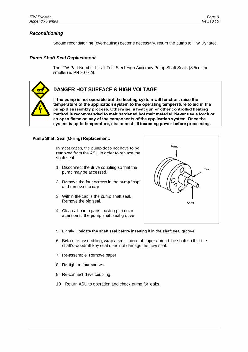
ITW Dynatec Page 9 Appendix Pumps Rev.10.15
Reconditioning
Should reconditioning (overhauling) become necessary, return the pump to ITW Dynatec. Pump Shaft Seal Replacement
The ITW Part Number for all Tool Steel High Accuracy Pump Shaft Seals (8.5cc and smaller) is PN 807729.
DANGER HOT SURFACE & HIGH VOLTAGE If the pump is not operable but the heating system will function, raise the temperature of the application system to the operating temperature to aid in the pump disassembly process. Otherwise, a heat gun or other controlled heating method is recommended to melt hardened hot melt material. Never use a torch or an open flame on any of the components of the application system. Once the system is up to temperature, disconnect all incoming power before proceeding.
Pump Shaft Seal (O-ring) Replacement: In most cases, the pump does not have to be removed from the ASU in order to replace the shaft seal. 1. Disconnect the drive coupling so that the
pump may be accessed. 2. Remove the four screws in the pump “cap”
and remove the cap 3. Within the cap is the pump shaft seal.
Remove the old seal. 4. Clean all pump parts, paying particular
attention to the pump shaft seal groove.
5. Lightly lubricate the shaft seal before inserting it in the shaft seal groove.
6. Before re-assembling, wrap a small piece of paper around the shaft so that the
shaft’s woodruff key seat does not damage the new seal. 7. Re-assemble. Remove paper 8. Re-tighten four screws. 9. Re-connect drive coupling. 10. Return ASU to operation and check pump for leaks.
Pump
Cap
Shaft

Page 10 ITW Dynatec Rev.10.15 Appendix Pumps
Transport / Storage
DANGER • Death or crushing of limbs caused by falling or overturning loads! • Bodily harm can occur if excessive weight is lifted or moved incorrectly! • Protection from hot surfaces and hot liquids must be provided by the operator!
Take care not to drop the pump. Read and consider the weight prior to attempting to lift or move the pump. Do not attempt to lift pumps heavier than 25 kg without the use of a crane or other type of lifting assist device. Only qualified personnel may transport pumps weighing more than 25 kg. When working with pumps that are hot, wear proper protective equipment and note that hot fluid may flow from the pump. Guard against skin contact with hot fluids, or with a hot pump. Follow all precautions of the fluid manufacturer in the handling of the fluid. In the event that a pump needs to be stored, always protect the pump against water and other contaminants. Store the pump in a clean, dry, and warm environment. Pumps are delivered filled with suitable lubricant and with protective covers in, or over, all openings. These covers should remain in place during the mounting and alignment procedures, as long as possible. Remove the covers just prior to attaching system hoses to the manifold. While storing spare parts, always protect the parts from water and contaminants. Store the parts in a clean, dry, and warm environment. Spare parts should be lightly coated with rust preventative oil and sealed in an air tight container.
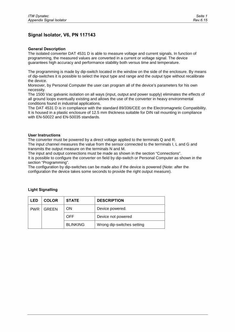
ITW Dynatec Seite 1 Appendix Signal Isolator Rev.6.15
Signal Isolator, V6, PN 117143 General Description The isolated converter DAT 4531 D is able to measure voltage and current signals. In function of programming, the measured values are converted in a current or voltage signal. The device guarantees high accuracy and performance stability both versus time and temperature. The programming is made by dip-switch located in the window on the side of the enclosure. By means of dip-switches it is possible to select the input type and range and the output type without recalibrate the device. Moreover, by Personal Computer the user can program all of the device’s parameters for his own necessity. The 1500 Vac galvanic isolation on all ways (input, output and power supply) eliminates the effects of all ground loops eventually existing and allows the use of the converter in heavy environmental conditions found in industrial applications. The DAT 4531 D is in compliance with the standard 89/336/CEE on the Electromagnetic Compatibility. It is housed in a plastic enclosure of 12.5 mm thickness suitable for DIN rail mounting in compliance with EN-50022 and EN-50035 standards. User Instructions The converter must be powered by a direct voltage applied to the terminals Q and R. The input channel measures the value from the sensor connected to the terminals I, L and G and transmits the output measure on the terminals N and M. The input and output connections must be made as shown in the section “Connections”. It is possible to configure the converter on field by dip-switch or Personal Computer as shown in the section “Programming”. The configuration by dip-switches can be made also if the device is powered (Note: after the configuration the device takes some seconds to provide the right output measure). Light Signalling
LED COLOR STATE DESCRIPTION
PWR
GREEN ON Device powered.
OFF Device not powered
BLINKING Wrong dip-switches setting

Seite 2 ITW Dynatec Rev.6.15 Appendix Signal Isolator
Programming Configuration by DIP-Switches
1) Open the suitable door on the side of the device. Refer to TAB.1.
2) Set the input type by the dip-switch SW1 [1..4]. 3) Set the output type by the dip-switch SW1
[6..8]. 4) Set the options type by the dip-switch SW1 [5].
NOTE: It is also possible to set the dip-switches using the wizard of the configuration software following the procedure described in the section “Configuration by PC” until the step 6 and slicking on “Switch”. DIP-Switch Configuration Tables TAB.1 - Settings
NOTES: * If the dip-switches SW1 [1..4] are all set in the position 0 (“Default”), the device will follow the
configuration programmed by PC (Input and output type and options). * Eventual wrong dip-switches settings will be signalled by the blinking of the LED “PWR”.
Example of configuration: ) Input 0 – 10 V - Options Direct - Output 4 - 20 mA

OIL FILLED MELT PRESSURE TRANSMITTERS
WE SERIES Output 4...20mA
The WE series of Gefran, are pressure transmitters for using in High temperature environment.The main characteristic of this series is the capability to read temperature of the media up to 315°C.The constructive principle is based on the hydraulic tra-smission of the pressure.The fluid-filled system assures the temperature stability.The phisical measure is transformed in a electrical mea-sure by means the strain-gauge technology.
TECHNICAL SPECIFICATIONSAccuracy (1)
ResolutionMeasurement range
Maximum overpressure(without degrading performances)Measurement principlePower supplyMaximum current absorptionInsulation resistance (at 50Vdc)Output signal Full Scale (FSO)Zero balance(tollerance ± 0.25% FSO)Zero signals adjustment(tollerance ± 0.25% FSO)Span adjustment within ± 5% FSOMaximum allowed loadResponse time (10...90% FSO)Output noise (RMS 10-400Hz)Calibration signalOutput short circuit ingress and reverse polarity protectionCompensed temperature rangeOperating temperature rangeStorage temperature rangeThermal drift in compesated range:Zero / Calibration / SensibilityDiaphragm maximum temperatureZero drift due to change in processtemperature (zero)Zero drift temperature for Autocompensated version (SP) within the temperature range 20°C-315°C inclusive the drift temperature of the housingStandard Material in contact with process medium
Thermocouple (model WE2)Protection degree(with 6-pole female connector)
H <±0.25%FSO (100...1000 bar) M <±0.5%FSO (35...1000 bar)
Infinite 0..35 to 0..1000bar
0..500 to 0..15000psi2 x FS
1.5 x FS above 500bar/7500psiExtensimetric
10...30Vdc32mA
>1000 MOhm20mA 4mA
“Autozero” function
See ManualSee diagram
~ 1ms< 0.025% FSO
80% FSOYES
0...+85°C-30...+105°C-40...+125°C
< 0.02% FSO/°C
315°C / 600°F< 0.04 bar/°C
< 0.005 bar/°C 100 ≤ p < 500 bar0.0022 %FS/°C p ≥ 500 bar
Diaphragm:• 17-7PH corrugated diaphragm
with GTPStem• 17-4 PH
STD: type “J” (isolated junction) IP65
FSO = Full scale output(1) BFSL method (Best Fit Straight Line): includes combined effects of Non-Linearity, Hysteresis and Repeatability.
MAIN FEATURES
• Pressure ranges from:0-35 to 0-1000 bar / 0-500 to 0-15000 psi
• Accuracy: < ±0.25% FSO (H); < ±0.5% FSO (M)• Fluid-filled system for temperature stability• Oil filling meets FDA requirements CFR 178.3620 and
CFR 172.878• Oil filling volume:
WE0 (30mm3); WE1, WE2, WE3 (40mm3)• 1/2-20UNF, M18x1.5 standard threads; other types avai-
lable on request• Other diaphragms available on request• Autozero function on board / external option• Drift Autocompensation function (SP version)• 17-7 PH corrugated diaphragm with GTP coating for ran-
ges below 100 bar-1500 psi
GTP (advanced protection)Coating with high resistance against corrosion, abrasion and high temperature
AUTOZERO FUNCTION
All signal variations in the absence of pressure can be eli-minated by using the Autozero function.This function is activated by closing a magnetic contact located on the transmitter housing.The procedure is permitted only with pressure at zero.
AUTOCOMPENSATES INFLUENCE OF MELT TEMPERATURE
Thanks to internal self-compensation, the WSP series transmitter cancels the effect of pressure signal variation caused by variation of Melt temperature.This reduces at the minimum the read error caused by heating of the filling fluid (typical of all sensors built with “filled” technology).
Pressure Transducer PN 812340
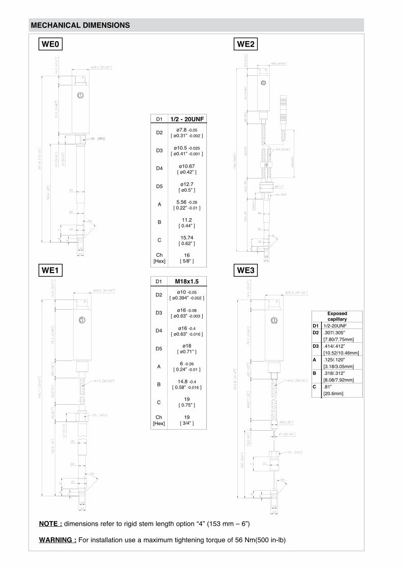
MECHANICAL DIMENSIONS
NOTE : dimensions refer to rigid stem length option “4” (153 mm – 6”)
WARNING : For installation use a maximum tightening torque of 56 Nm(500 in-lb)
1/2 - 20UNF
ø10 -0.05[ ø0.394” -0.002 ]
M18x1.5
D1
D2
D3
D4
D5
A
B
C
Ch [Hex]
D1
D2
D3
D4
D5
A
B
C
Ch [Hex]
ø16 -0.08[ ø0.63” -0.003 ]
ø18 [ ø0.71” ]
6 -0.26[ 0.24” -0.01 ]
14.8 -0.4 [ 0.58” -0.016 ]
19 [ 0.75” ]
19[ 3/4” ]
ø7.8 -0.05[ ø0.31” -0.002 ]
ø10.5 -0.025[ ø0.41” -0.001 ]
ø10.67 [ ø0.42” ]
ø12.7 [ ø0.5” ]
5.56 -0.26[ 0.22” -0.01 ]
11.2 [ 0.44” ]
15.74 [ 0.62” ]
16[ 5/8” ]
ø16 -0.4[ ø0.63” -0.016 ]
WE1 WE3
WE2WE0
Exposedcapillary
D1 1/2-20UNFD2 .307/.305” [7.80/7.75mm]D3 .414/.412” [10.52/10.46mm]A .125/.120” [3.18/3.05mm]B .318/.312” [8.08/7.92mm]C .81” [20.6mm]

ACCESSORIES
Connectors6-pin mating connector (IP65 protection degree) CON3008-pin mating connector CON307
AccessoriesMounting bracket SF18Dummy plug for 1/2-20UNF SC12Dummy plug for M18x1.5 SC18Drill kit for 1/2-20UNF KF12Drill kit for M18x1.5 KF18Cleaning kit for 1/2-20UNF CT12 Cleaning kit for M18x1.5 CT18Fixing pen clip PKIT309Autozero pen PKIT312
Thermocouple for WE2 modelType “J” (153mm - 6” stem) TTER 601
Extension cables6-pin connector with 8m (25ft) cable C08WLS6-pin connector with 15m (50ft) cable C15WLS6-pin connector with 25m (75ft) cable C25WLS6-pin connector with 30m (100ft) cable C30WLS
Other lengths consult factory
Conn. WireA RedB BlackC WhiteD GreenE BlueF Orange
Cable color code
42 [1.65"]The Autozero function is activated through a magnetic contact (exter-nal magnet supplied with the sensor).See the manual for a complete Autozero fun-ction explanation.
The diagram shows the optimum ratio between the load and supply voltage of the 4...20mA transmitter.For a correct use, choose any combination of load resistance and supply voltage, in the shaded area.
ELECTRICAL CONNECTIONS
AUTOZERO FUNCTIONLOAD DIAGRAM
CURRENT OUTPUT (4...20mA, two wires)
6-pin 8-pinACBD
E - F
BADC
E - F
G - H
n.c.
CONTROLLER
AMPL./CONV.n.c.
n.c.
Supply voltage(10...30Vdc)
+
-Signal(4...20mA)
Calibration shunt
Shield drain wire is tied to connector via cable clamp
6-pin 8-pinACBD
E - F
BADC
E - F
G - H
n.c.
n.c.
n.c.
-
Supply voltage(10...30Vdc)
Signal(4...20mA)
Autozero
+
MAGNETICAUTOZERO
EXTERNALAUTOZERO
6 pin connectorVPT07RA10-6PT2
(PT02A-10-6P)
8 pin connectorPC02E-12-8P Bendix
SUPPLY VOLTAGE
LOAD
RES
ISTA
NC
E R
l

GEFRAN reserves the right to make any kind of design or functional modification at any moment without prior notice.
ORDER CODE
Examples
WE2-6-M-B07C-1-4-D-000Melt pressure transmitter with type “J” thermocouple, 4...20mA output, 6-pin connector, 1/2-20UNF thread, 700 bar full scale, 0,5% accuracy class, 153 mm (6”) rigid stem, 457mm (18”) flexible capillary.
WSPM0-6-M-P03M-1-4-0-000Melt pressure transmitter autocompensated version, rigid stem, 4...20mA output, 6-pin connector, 1/2-20UNF thread, 3000 psi full scale, 0,5% accuracy class, 153 mm (6”) rigid stem.
000= Standard versionSpecial or customized versions available on request
CONNECTOR
6 pin 6
ACCURACY CLASS
0.5% FSO M
0.25% FSO (ranges ≥ 100 bar/1500 psi) H
CONFIGURATIONRigid stem 0
Rigid stem + flexible 1With thermocouple 2
Standard
THREAD
1/2 - 20 UNF1M18 x 1.54
Standard
RIGID STEM LENGTH (mm / inches) (*)
153mm4318mm5
Standard (WE0, WE1, WE2)
Available on request1 38mm2 50mm3 76mm6 350mm7 400mm8 456mm
6”12.5”
1.5”2”3”14”16”18”
FLEXIBLE LENGTH (mm / inches) (*)
457mmD610mmE
Standard (WE0)
Available on requestA 76mmB 152mmC 300mm
18”24”
3”6”12”
760mmF 30”
none0Standard (WE1, WE2)
100 B01C70 B07D
RANGE
3550
B35UB05D
200
bar psi
B02C
500 B05C350 B35D
700 B07C
1500 P15C1000 P01M
500750
P05CP75D
3000 P03M
7500 P75C5000 P05M
10000 P10M1000 B01M 15000 P15M
W 000
DTS_WE_04-2013_ENG
GEFRAN spavia Sebina, 7425050 PROVAGLIO D’ISEO (BS) - ITALIAtel. 0309888.1 - fax. 0309839063Internet: http://www.gefran.com
Exposed capillary 3
8 pin 8
711mmLStandard (WE3)
28”
none0Standard (WE3)
(*) max combined stem/flexible length is 914mm - 36”
External autozeroE Magnetic autozero-
OUTPUT SIGNAL4...20mA E
Autocompensation (*) SPStandard -
(*) available for ranges > to 100bar(*) not available for WE3 version
Sensors are manufactured in compliance with: - EMC 2004/108/CE compatibility directive - RoHS 2002/95/CE directive
Electrical installation requirements and Conformity certificate are available on our web site: www.gefran.com