
Dust resuspension by the flow around an impacting sphere
25
Journal of Fluid Mechanics http://journals.cambridge.org/FLM Additional services for Journal of Fluid Mechanics: Email alerts: Click here Subscriptions: Click here Commercial reprints: Click here Terms of use : Click here Dust resuspension by the flow around an impacting sphere I. EAMES and S. B. DALZIEL Journal of Fluid Mechanics / Volume 403 / January 2000, pp 305 328 DOI: 10.1017/S0022112099007120, Published online: 08 September 2000 Link to this article: http://journals.cambridge.org/abstract_S0022112099007120 How to cite this article: I. EAMES and S. B. DALZIEL (2000). Dust resuspension by the flow around an impacting sphere. Journal of Fluid Mechanics, 403, pp 305328 doi:10.1017/S0022112099007120 Request Permissions : Click here Downloaded from http://journals.cambridge.org/FLM, IP address: 144.82.107.50 on 31 Oct 2012
-
Upload
khangminh22 -
Category
Documents
-
view
1 -
download
0
Transcript of Dust resuspension by the flow around an impacting sphere

Journal of Fluid Mechanicshttp://journals.cambridge.org/FLM
Additional services for Journal of Fluid Mechanics:
Email alerts: Click hereSubscriptions: Click hereCommercial reprints: Click hereTerms of use : Click here
Dust resuspension by the flow around an impacting sphere
I. EAMES and S. B. DALZIEL
Journal of Fluid Mechanics / Volume 403 / January 2000, pp 305 328DOI: 10.1017/S0022112099007120, Published online: 08 September 2000
Link to this article: http://journals.cambridge.org/abstract_S0022112099007120
How to cite this article:I. EAMES and S. B. DALZIEL (2000). Dust resuspension by the flow around an impacting sphere. Journal of Fluid Mechanics, 403, pp 305328 doi:10.1017/S0022112099007120
Request Permissions : Click here
Downloaded from http://journals.cambridge.org/FLM, IP address: 144.82.107.50 on 31 Oct 2012

J. Fluid Mech. (2000), vol. 403, pp. 305–328. Printed in the United Kingdom
c© 2000 Cambridge University Press
305
Dust resuspension by the flow around animpacting sphere
By I. E A M E S† AND S. B. D A L Z I E L
Department of Applied Mathematics and Theoretical Physics, University of Cambridge,Silver Street, Cambridge CB3 9EW, UK
(Received 20 February 1999 and in revised form 11 August 1999)
A rigid body colliding with a layer of dust is capable of resuspending dust throughtwo distinct mechanisms: a ballistic mechanism, where kinetic energy is transferredfrom the impacting body to dust particles through direct contact, and a hydrodynamicmechanism, where dust particles are resuspended by the flow disturbance generatedby the body. In this paper, we study the hydrodynamic resuspension mechanism byconsidering the flow around a sphere moving either towards or away from a wall.Experiments were performed using a sphere translating at a constant velocity forReynolds number, Re, in the range 300 to 3500, and at varying angles of approachand departure from a wall. A wider range of Re was investigated by releasingdense rigid spheres above the wall. The high Reynolds number flow past a steadilytranslating sphere is characterized by a recirculating wake region behind the sphere.When the sphere approaches the wall and stops on making contact with it, the wakevortex which is initially behind the sphere threads over the sphere’s surface, generatinga secondary vortex ring. The coherent structure, composed of the wake and secondaryvortices, strikes the wall and pushes fluid or dust, initially adjacent to the wall, to oneside. The resuspension of dust particles of diameter b which are initally at rest onthe wall is governed by a particle Shields’ parameter, θp, based on the sphere’s impactvelocity, U: θp = ρfU
2/(ρp−ρf)bg, where ρp and ρf are respectively the density of thedust particles and fluid. The resuspension criterion is a function of particle Reynoldsnumber, Rep, based on the diameter and fall velocity of the dust particles and occurswhen θp > θp,c where θp,c ≈ 3.0 for Rep >∼ 1, and θp,c ≈ 5.0/Re
1/2p for Rep <∼ 1. The
geometry of the region of dust resuspended by the sphere was studied as a functionof the impact velocity, angle of impact and the properties of the dust particles. Whenthe sphere impacts a thick layer of dust, the volume concentration of resuspendeddust is sufficiently high to generate a particle-driven gravity current which transportsthe dust far from the point of impact. The dynamics of the gravity current weredetermined as a function of dust particle properties and size of the impacting sphere.
A sphere moving impulsively from rest away from a wall is found not to play asignificant role in the resuspension of dust; however trailing vorticity generated onthe surface of the sphere advects a large volume of fluid away from the wall, whichmay contain dust already in suspension.
† Present address: Department of Mechanical Engineering, University College London, Torring-ton Place, London WC1E 7JE, UK.

306 I. Eames and S. B. Dalziel
1. IntroductionFine airborne particulate such as dust occurs in great abundance in soils, sediments
and stockpiled materials such as mineral ores or agricultural grain. Such quantitiespose an important environmental problem, particularly because dust has the propen-sity to travel great distances in suspension and can also directly enter the bronchialtract of mammals, causing severe respiratory problems. Dust loss from soils is alsoresponsible for the reduction of soil fertility because the largest component of soilfertility is contained in the smallest particle size fraction. Central to assessing the en-vironmental risk posed by stockpiled sediments is an accurate estimate of the verticalmass flux of dust removed from the sediment surface. A large number of field andlaboratory studies have been performed to determine how the vertical mass flux ofdust varies with wind speed and soil properties (Gillette et al. 1974). Whilst progresshas been made in characterizing the vertical mass dust flux released from the groundin terms of soil type and moisture, relatively little is known about the processesresponsible for dust particles leaving the ground in the first place.
A great deal of research has been directed towards understanding the transport ofunimodal sediments by the wind (Bagnold 1941). The wind provides the mechanismof sediment removal from the ground through the action of aerodynamic lift andtransport, in the wind or along the ground, by the action of a drag force. Thestrength of the wind is characterized in terms of a friction velocity, u∗, which isoften related to the wind velocity in the boundary layer by a logarithmic profileU(z) = (u∗/κ) log(z/z0), where κ = 0.4 is von Karman’s constant and z0 the roughnessheight. When the friction velocity is low, the sediment is undisturbed, but as thefriction velocity increases, a critical value, u∗,c, is reached when sediment motion isinitiated. At this point the aerodynamic lift force on individual particles is sufficient toovercome the buoyancy or cohesive force (Absil & Beugeling 1984) which keeps themanchored to the ground. The critical condition for the removal of sediment particlesof diameter a from the ground is usually represented in terms of a Shields’ parameter,θ, defined as θ = ρfu
2∗/(ρp − ρf)ga, which may be interpreted as the ratio of theinertial lift force based on the critical friction velocity, O(ρfu
2∗a2), and the buoyancyforce O((ρp − ρf)ga3), where ρp, ρf are respectively the density of the particles andfluid. In general, small particles are difficult to remove from the ground by the windbecause they lie within the viscous sublayer and so the aerodynamic lift force actingon them is weak, and large particles are difficult to remove because they are heavy.Soil particles (density ρp = 2500 kg m−3) most susceptible to dislodgement by thewind have a typical diameter of 100 µm, corresponding to a minimum critical frictionvelocity of u∗,c = 0.15 m s−1. The mode of particle transport by the wind, followingsediment removal from the ground, depends on the ratio of the friction velocity, u∗,which is a measure of the turbulent velocity fluctuations in the wind, to the terminalfall speed of the particle, vT . The finest constituent of soil, which we hereafter referto as ‘dust’, has a typical diameter less than 50 µm and travels by suspension in thewind when vT <∼ u∗. ‘Sand’ particles of diameter 150–600 µm travel with parabolichops along the ground – this mode of transport is called saltation and occurs whenvT >∼ u∗. Particles with diameters greater than 600 µm are too large to enter the wind,except under extreme conditions, and instead roll or ‘creep’ along the ground.
Bagnold (1941) demonstrated experimentally that although a thin layer of dust isdifficult to resuspend from the ground because it lies within the viscous sublayer, it isreadily liberated when a small quantity of sand is introduced upstream of the layerof dust. As the sand particles saltate across the layer of dust, they disturb the dustparticles leading to dust release from the surface. We categorize the disturbance caused

Dust resuspension by an impacting sphere 307
by a particle colliding with a layer of dust as either ballistic, where saltating particlescollide with dust particles, break the cohesive inter-particle dust bonds and eject fineparticulate from the bed, or hydrodynamic, where the flow around saltating particlescolliding with or leaving the ground is responsible for resuspending particles. The aimof this paper is to examine in detail the hydrodynamic resuspension mechanism.
The ballistic mechanism describes when a particle colliding with a sediment breaksthe cohesive bonds which exist between particles, providing the kinetic energy ofthe impacting particle is sufficiently large, and ballistically ejecting particles bothlarger and smaller in size. Rice, Willetts & McEwan (1996) examined the microscopicprocess of dust ejection by sand particles (250–500 µm in diameter) colliding with anunaggregated bed of fine particles whose diameters were less than 53 µm. The collisionswere recorded on high-speed film and subsequent examination of the surface textureof the sediment by a scanning laser showed elliptical craters, where dust was removed.The mass of dust removed by the collision of a single saltating grain Sa could beaccurately measured, and was found to be proportional to the kinetic energy lost tothe sediment by the saltating particle colliding with the ground, in agreement withabrasion studies of Greeley & Iverson (1985). Shao, Raupach & Findlater (1993)studied the macroscopic process of dust release by measuring the horizontal mass fluxof dust generated by sand particles saltating across a layer of dust. They proposedthat the horizontal mass flux of dust, qd, is proportional to the collision rate perunit area, n, and the mass of dust ejected during each collision of a saltating particlewith the dust layer, Sa: qd = nSa. The predicted variation of qd with friction velocitywas found to be consistent with experimental measurements; we also note that thisvariation is consistent with the results of Rice et al. (1996). In the studies describedabove, the mass of dust released by a saltating particle colliding with a rich bed of dustwas quantified; however the processes which mediate the transport of suspended dustaway from the ground were not examined. In addition, the mechanisms or processesthrough which saltating particles resuspend thick dust deposits are not necessarilydominant when the dust is scattered across a sediment surface.
The hydrodynamic mechanism describes when the flow around a body moving near alayer of dust is responsible for dislodging and resuspending dust particles. Owen (1980)argued that the range of influence of an effective mechanism of dust resuspensionmust be larger than the contact area between a saltating particle and the groundbecause the probability that saltating particles strike and dislodge dust particlesthrough this mechanism is too low to account for the observed rates of dust release.Following this, Owen (1980) proposed the flow around the sand particle leaving theground as a candidate for the principal mechanism of dust resuspension. Owen (1980)originally examined the dynamics of dust particles in the flow around a body movingperpendicularly to a wall. More recently, Owen (1986) performed an experimentto illustrate the effect of a sphere colliding with a wall in resuspending dust. Owenobserved the intense wake vortex of the sphere threading over the surface of the sphere,subsequently striking the wall, removing and resuspending the dust, and concludedthat the impact of the sphere with the wall was the dominant mode of resuspension.
The main purpose of this paper is an examination of hydrodynamic resuspensionby a sphere moving near a wall. The study presented here has three new components:first, the high-Re flow around a body moving towards or away from a wall isexamined. Whilst the flow around a body moving near a wall has been examined forlow Re (Brenner 1961), the corresponding case of high Re has been restricted to adiscussion of space probes landing on Titan (Lorenz 1994). An examination of thehigh-Re flow past a rigid body moving near a wall has a bearing on other multiphase

308 I. Eames and S. B. Dalziel
Water level
40 cm
Driver cog
Solder collarRadius2 mm
Radius20 mm
Halogen lampα
Speed U
2a
Figure 1. Schematic illustration of the experimental apparatus used to study the flow around asphere moving towards or away from a rigid wall.
problems, such as the flow generated by ‘dirty’ bubbles rising to a free surface, whichplay an important role in interfacial gas transfer in the ocean. As we shall see, theresuspension process is dominated by the wake vortex colliding with the wall. Theflow generated by a ring vortex striking a wall has been studied in detail (see Walkeret al. 1985 and references therein), and recently the resuspension of dust by vorticesimpinging on a wall has been studied experimentally (Wells 1992). However, the roleplayed by the flow around a body in resuspending dust has not been studied in detail,and this remains the primary focus of this paper. Secondly, the critical condition forthis layer of particles to be disturbed and resuspended by the flow generated by asphere colliding with the ground is determined. The resuspension criterion has nothitherto been determined and is relevant to a wide range of problems such as theresuspension by containers dumped into the sea which impact the sea bed. Thirdly,the dust particle dynamics following resuspension is examined for the case when theconcentration of resuspended material is high and a particle-driven gravity currentis generated. The resuspension process controls the initial mass of dust resuspended,and the subsequent dynamics of the gravity current is characterized experimentally.
This paper is structured as follows: in § 2, the flow around a sphere moving towardsa wall is discussed. The role played by this flow in resuspending dust particles isstudied experimentally in § 3, where we treat the case of the sphere impacting a thinand thick layer separately. The flow around a sphere moving impulsively from restaway from a wall is presented in § 4. Finally our conclusions are drawn and put intothe broader context in § 5.
2. Flow around a sphere moving towards a wallThe flow around a polished Perspex sphere (radius a = 20 mm) moving near a wall
was studied in a 40 cm cubed Perspex tank which was filled with tap water (figure 1).The motion of the sphere was controlled by mounting it on the end of a 2 mm radiusrigid rod which was driven by a simple traverse consisting of two ‘v’ idler wheelson one side and a spring-loaded rubber driving wheel on the other. Two additionalguides were employed to maintain alignment and a guide rail to prevent rotation.
Dust resuspension by an impacting sphere 309
The Perspex sphere was impulsively started from rest at the top of the tank andtraversed with a constant velocity U towards the wall. As the sphere descends thewake vortex grows and the flow becomes well-established. This flow is characterizedby the Reynolds number, Re = 2Ua/ν, where a is the sphere’s radius and ν the fluidkinematic viscosity. This flow has been studied in detail by a number of researchers andthe main results are summarized by Clift, Grace & Weber (1978): when Re < 130, theflow past a sphere moving in an unbounded domain is steady but the wake becomesunsteady for 130 < Re < 400. At higher Reynolds number (Re > 400), the wake isunstable and liable to shed vortices, and the precise form of the shed vortices wasstudied by Magarvey & Maclarehy (1968). The vortex shedding frequency of the wakeis characterized by the Strouhal number, Sr = 2af/U, which is defined as the ratio ofadvective timescale of translation to shedding timescale (1/f). Consequently, a vortexis expected to shed from the wake as the sphere moves through a distance 2a/St.
We examined the flow for Reynolds numbers in the range Re = 300–3500, andimpact angles α = 64◦–90◦ relative to the wall. The Strouhal number increases from0.1 to 0.2 as Re increases from 300 to 3500, so we expect the wake to shed a vortex asthe sphere traverses a distance of 20a to 10a. Since the aim was to examine the roleplayed by the wake vortex behind the sphere in resuspending dust, we impulsivelystarted the sphere a vertical distance 15a from the wall. This distance was chosen asa compromise between having a well-established flow prior to the sphere impactingthe wall, and requiring that a vortex is not shed before the sphere strikes the wall.
2.1. Wake structure and vortex dynamics
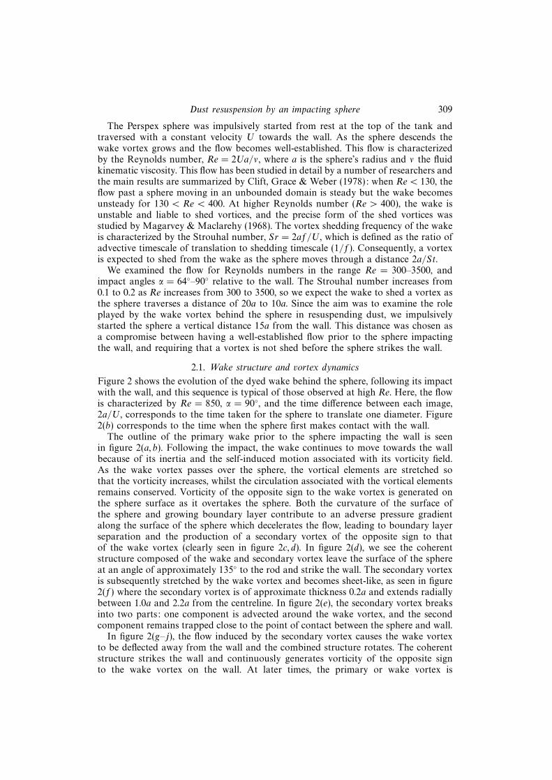
Figure 2 shows the evolution of the dyed wake behind the sphere, following its impactwith the wall, and this sequence is typical of those observed at high Re. Here, the flowis characterized by Re = 850, α = 90◦, and the time difference between each image,2a/U, corresponds to the time taken for the sphere to translate one diameter. Figure2(b) corresponds to the time when the sphere first makes contact with the wall.
The outline of the primary wake prior to the sphere impacting the wall is seenin figure 2(a, b). Following the impact, the wake continues to move towards the wallbecause of its inertia and the self-induced motion associated with its vorticity field.As the wake vortex passes over the sphere, the vortical elements are stretched sothat the vorticity increases, whilst the circulation associated with the vortical elementsremains conserved. Vorticity of the opposite sign to the wake vortex is generated onthe sphere surface as it overtakes the sphere. Both the curvature of the surface ofthe sphere and growing boundary layer contribute to an adverse pressure gradientalong the surface of the sphere which decelerates the flow, leading to boundary layerseparation and the production of a secondary vortex of the opposite sign to thatof the wake vortex (clearly seen in figure 2c, d). In figure 2(d), we see the coherentstructure composed of the wake and secondary vortex leave the surface of the sphereat an angle of approximately 135◦ to the rod and strike the wall. The secondary vortexis subsequently stretched by the wake vortex and becomes sheet-like, as seen in figure2(f) where the secondary vortex is of approximate thickness 0.2a and extends radiallybetween 1.0a and 2.2a from the centreline. In figure 2(e), the secondary vortex breaksinto two parts: one component is advected around the wake vortex, and the secondcomponent remains trapped close to the point of contact between the sphere and wall.
In figure 2(g–j), the flow induced by the secondary vortex causes the wake vortexto be deflected away from the wall and the combined structure rotates. The coherentstructure strikes the wall and continuously generates vorticity of the opposite signto the wake vortex on the wall. At later times, the primary or wake vortex is

310 I. Eames and S. B. Dalziel
(a) (b)
(c) (d)
(e) ( f )
(g) (h)
(i) ( j)
Figure 2. The sphere approaches the wall, and impulsively stops on making contact with the wall.The flow is characterized by Re = 850, α = 90◦, and the wake is dyed by electrolytic precipitationof tin chloride. The sequence of images illustrates the dynamics of the wake vortex following theimpact of the sphere, and the time difference between adjacent figures is 2a/U.
enveloped by vorticity of the opposite sign and shielded from the effect of the wall.Additional experiments indicated that even when the initial flow is three-dimensionaland turbulent, the final state appears to be one in which the wake vortex stopspropagating a finite distance from the centreline, and the strength of the wake vortexsubsequently decays due to viscous dissipation.
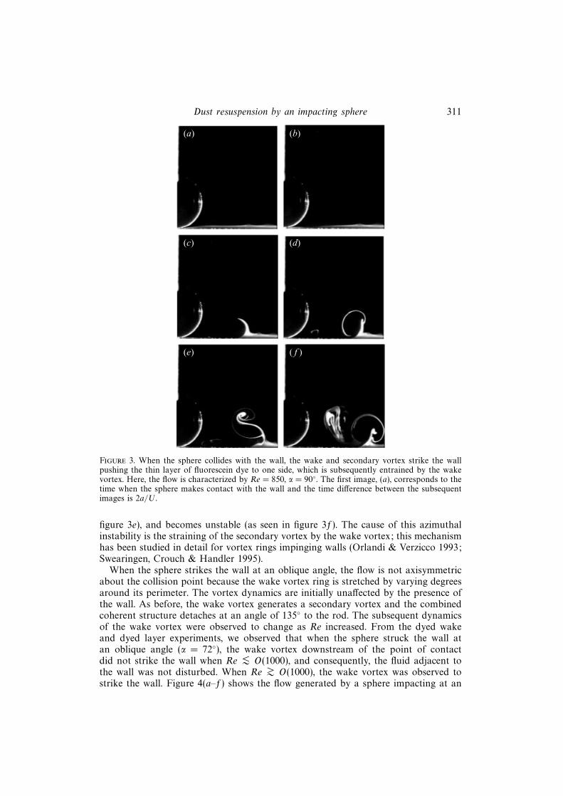
The flow adjacent to the wall was examined by introducing a thin layer of fluoresceindye adjacent to the wall. Figure 3(a–f) shows the motion of a thin dye layer dueto the impact of the sphere at Re = 850. The initial response is for the dye to bepushed to one side by the impact of the wake and secondary vortex. Subsequently,the secondary vortex is wrapped around the primary vortex, compressed (as seen in
Dust resuspension by an impacting sphere 311
(a) (b)
(c) (d)
(e) ( f )
Figure 3. When the sphere collides with the wall, the wake and secondary vortex strike the wallpushing the thin layer of fluorescein dye to one side, which is subsequently entrained by the wakevortex. Here, the flow is characterized by Re = 850, α = 90◦. The first image, (a), corresponds to thetime when the sphere makes contact with the wall and the time difference between the subsequentimages is 2a/U.
figure 3e), and becomes unstable (as seen in figure 3f). The cause of this azimuthalinstability is the straining of the secondary vortex by the wake vortex; this mechanismhas been studied in detail for vortex rings impinging walls (Orlandi & Verzicco 1993;Swearingen, Crouch & Handler 1995).
When the sphere strikes the wall at an oblique angle, the flow is not axisymmetricabout the collision point because the wake vortex ring is stretched by varying degreesaround its perimeter. The vortex dynamics are initially unaffected by the presence ofthe wall. As before, the wake vortex generates a secondary vortex and the combinedcoherent structure detaches at an angle of 135◦ to the rod. The subsequent dynamicsof the wake vortex were observed to change as Re increased. From the dyed wakeand dyed layer experiments, we observed that when the sphere struck the wall atan oblique angle (α = 72◦), the wake vortex downstream of the point of contactdid not strike the wall when Re <∼ O(1000), and consequently, the fluid adjacent tothe wall was not disturbed. When Re >∼ O(1000), the wake vortex was observed tostrike the wall. Figure 4(a–f) shows the flow generated by a sphere impacting at an

312 I. Eames and S. B. Dalziel
(a) (b)
(c) (d)
(e) ( f )
(g)
–2 –1 0 1
2.5
2.0
1.5
1.0
0.5
0
Figure 4. Series of images showing the collision of the sphere at an oblique angle (α = 72◦) with thewall. The flow is characterized by Re = 1470. The wake is visualized by precipitating tin chlorideat the neck of the rod. Image (a) corresponds to the time of contact between the wall and sphere.The time difference between subsequent images is 1.0a/U. (g) The positions of the primary (�),secondary (�) and separated primary vortices (+) are indicated (the time difference between thecentres of the vortices is a/4U).
oblique angle α = 72◦, Re = 1470; the time difference between each image is a/U.Figure 4(g) shows the positions of the wake vortex, secondary vortex, and part ofthe wake vortex which has been separated from the main wake. Although the flow isthree-dimensional, we shall discuss the flow on the left-hand and right-hand side ofthe sphere separately.
On the right of the sphere, the coherent structure composed of the wake andsecondary vortex travels a shorter distance prior to colliding with the wall at a steepangle 135◦ − α = 63◦ (compared to 45◦ when the sphere impacts the wall normally).As indicated in figure 4, the coherent structure is lifted up from the wall and rotates,prior to impacting the wall again. Similar observations were made by Walker et al.

Dust resuspension by an impacting sphere 313
d1 d2
Speed U
α
2d
+
–
–+
Figure 5. Schematic of a two-dimensional dipolar vortex impacting on a wall. This example is usedto gain some insight into the case when the sphere, and consequently the wake vortex, approachesthe wall at an oblique angle.
(1987) regarding the dynamics of secondary and primary vortices following the impactof a vortex ring on a wall.
On the left of the sphere, the primary and secondary vortices travel at a shallowerangle to the wall (α− 45◦ = 27◦), propagating further, prior to colliding with the wall.The coherent structure, composed of the wake and the secondary vortex, turns andas it continues to propagate is deflected away from the wall. The deflection of thewake vortex away from the wall is affected by the strength of the secondary vortex:as the strength of the secondary vortex decreases, the deflection of the wake vortexaway from the wall becomes more pronounced. The strength of the secondary vortexappears to increase as Re increases: when Re 6 O(1000), the secondary vortex isweak and the deflection of the wake vortex away from the wall is pronounced, andfor Re > O(1000) the wake vortex strikes the wall.
The flow generated by a sphere impacting a wall obliquely has an important bearingon the resuspension process. To facilitate our interpretation of figure 4 we examinedthe dynamics of a dipolar vortex striking a wall obliquely with an angle α (figure 5).The vortex dipole initially consists of line vortices of circulation ±κ and separationd, and therefore propagates with a velocity U = κ/2πd. Following the collision of thevortex dipole with the wall, the vortices separate and ultimately propagate parallelto the wall, but in opposite directions (figure 5). We may understand this behaviourby considering the impulse Ud2 associated with the translation of a vortex. Theconcept of fluid impulse is analogous to linear momentum and the component ofimpulse parallel to the wall is conserved during the collision. As a result of this, thedifference between the final separation of the line vortices and the wall must satisfyd1 − d2 = 2d cos α. Energy is conserved during the collision ensuring that d1d2 = d2
(Batchelor 1967). Therefore the separations between the line vortices and the wallultimately tend to d1/d = cos α +
√cos2 α+ 1, and d2/d =
√cos2 α+ 1− cos α. These
results indicate that a two-dimensional vortex striking a wall obliquely generates theline vortex propagating to the left in figure 5, which is at a distance d1 > d from thewall and travels more slowly than the initial vortex dipole. In contrast the line vortexon the right-hand side of figure 5, propagates with a velocity larger than U.
Although the above model of the flow is two-dimensional and inviscid, it demon-strates the immediate consequence of the component of fluid impulse parallel tothe wall and energy being conserved during the collision. Two-dimensional dynamics

314 I. Eames and S. B. Dalziel
104
103
102
101
100
10–4 10–3 10–2 10–1 100 101 102
Rep
h p,c
=q f
U2 c/[
(qp–
q f)
bg]
Figure 6. The variation of the critical particle Shields’ parameter, θp,c, with particle Reynoldsnumber, Rep = bvT /ν. The dashed lines represent the semi-empirical result (3.2).
provide a reasonable model since the separations d, d1 and d2 are typically much lessthan the vortex ring diameter, and hence the self-induced motion is relatively weak.This constraint also applies to the flow generated when a vortex ring strikes a wallobliquely, although the dynamics of a ring vortex are affected by the stretching ofvortical elements and curvature. Lim (1989) studied experimentally the flow generatedby a vortex ring impacting a wall, and observed that the section of vortex core up-stream of the point of impact was further from the wall and initially travelled moreslowly than the corresponding section downstream of the point of contact. Theseobservations have some implications for the flow generated by a sphere impactinga wall obliquely. As already indicated, when Re 6 O(1000) the component of thewake vortex downstream of the point of contact does not strike the wall because thesecondary vortex plays a negligible role in the dynamics of the wake vortex. However,at higher Reynolds number the secondary vortex plays a more significant role in thedynamics of the wake vortex, and the wake vortex is observed to strike the wall.
3. Resuspension of a layer of dust particles3.1. Resuspension criterion
The experiments described in the previous section gave insight into the flow generatedby an impacting sphere. The conditions required for this flow to resuspend a thinlayer of dust initially at rest on the wall, are now discussed.
The redistribution of a layer of dust, one or two particles thick, by a sphereimpacting the wall at α = 90◦, was examined for a range of impact velocity U andthe dust particle properties (e.g. diameter b and density ρp). For U < 10 cm s−1, thesphere was driven towards the wall by the motor and rod; higher impact velocitieswere obtained by releasing glass or steel spheres 20 cm above the wall, and allowingthem to reach their terminal velocity prior to impact. The free-falling spheres, whichwere either steel ball bearings or glass beads with diameters 0.6 cm to 1.6 cm, bouncedon the wall, but the subsequent collisions did not appear to contribute significantlyto the resuspension process. As the free-falling spheres descended they shed vorticeswhich travelled more slowly than the spheres and were observed to interact with

Dust resuspension by an impacting sphere 315
resuspended dust. The critical conditions for resuspension were determined by fixingthe properties of the dust particles (table 1) and systematically increasing the speed ofthe impacting sphere, either by increasing the speed of the motor driving the Perspexsphere or by increasing the size or density of the spheres in the free-fall experiments,until particle motion was initiated in order to determine the critical impact velocityUc. The experimental errors are associated with the incremental steps in the impactvelocity to determine Uc. The ability of an impacting sphere to resuspend dust wascharacterized in terms of a ‘particle’ Shields’ parameter, θp, defined as
θp =ρfU
2
(ρp − ρf)gb , (3.1)
and resuspension occurs when θp > θp,c, where θp,c is the critical Shields parameter.The threshold criterion for incipent sediment transport in channel flows is usuallydescribed by a Shields’ parameter defined in terms of the ratio of bed shear stress, ρfu
2∗,and (ρp − ρf)gb (Yalin 1977). The shear stress was not measured in our experiments;however the friction velocity scales with the impact velocity of the sphere and is thereason we have chosen to define a particle Shields’ parameter (3.1). Figure 6 showsthe variation of the critical particle Shields’ parameter θp,c with the particle Reynoldsnumber, Rep = vTb/ν, based on the terminal fall velocity vT and diameter of the dustparticles. When the dust particles are large (Rep >∼ 1), the critical Shields parameterwas found to be approximately constant, but θp,c increased significantly as the dustparticles became finer (Rep � 1).
The variation of θp,c with Rep may be understood by considering the conditions forincipient motion. The wake vortex passing over the layer of dust particles generatesa boundary layer of thickness a(ν/Uca)
1/2 on the wall, and an inner viscous sublayerof thickness O(ν/Uc). When the dust particles are larger than the viscous sublayer,the velocity of the fluid over the dust is O(Uc), and consequently the condition forthe inertial lift force, ρfπb
2U2c /4, to exceed the gravitational force πb3(ρp − ρf)g/6
reduces to θp,c ≈ O(1). When the dust particle is smaller than the viscous sublayer,the velocity of the fluid over the particle is O(U2
c b/ν) (Tennekes & Lumley 1992) sothat the inertial lift force due to the horizontal velocity in the viscous sublayer isO(U4
c b4ρf/ν
2) (see Krishnan & Leighton 1995). The fall velocity of the dust particlescharacterized by Rep � 1 is vT = gb2(ρp − ρf)/18νρf , so that the condition that
the inertial lift force exceeds the gravitational force reduces to θp,c ≈ O(1/Re1/2p ). A
semi-empirical condition for resuspension is
θp,c ≈ 5.0
Re1/2p
for Rep <∼ 1, θp,c ≈ 3.0 for Rep >∼ 1, (3.2)
where the multiplicative constants are determined from the experimental data. Acomparison between the relationship (3.2) and the experimental results is given infigure 6. Whilst there is scatter in the experimental data, which we attribute to thedifficulty of observing the exact conditions for the incipent motion, the general trendof the experimental results is captured by our prediction. We note, however, that thescatter is too great to confirm the exponent n = 1/2 in the θp,c ≈ Re−np scaling forRep � 1. Other factors may be important in characterizing the critical conditions forresuspension when the dust particles are of a size comparable to the impacting sphere.
An examination of the resuspension of a thin layer of dust by an obliquelyimpacting sphere showed that the critical impact velocity was insensitive to α in therange 64◦ to 90◦. The insensitivity of Uc to α may be anticipated on the grounds that

316 I. Eames and S. B. Dalziel
(a)
(d)
(b)
(e)
(c)
( f )
(g) (h) (i ) Azimuthal instabilityof secondary
vortex
Depositionof dust
Primaryvortex
Figure 7. Images showing the redistribution of a layer of Pliolite (100–150 µm in diameter), by asphere striking the wall at α = 90◦ with an impact velocity U/Uc = 3.3 (Re = 3100). Image (a)corresponds to the time of impact, and the time difference between adjacent images is a/U. Forcomparison see figure 2, but note that the time difference between each image in figure 2 is 2a/U.(i) A schematic illustration of the mechanism by which the radial pattern is generated (the doublearrows denote the direction of the vorticity).
the angle of impact sets a preferred direction for the wake vortex to leave the sphere,but does not significantly affect the speed of the fluid over the sediment, which is setby the speed of the impacting sphere. Consequently, the resuspension criterion (3.2)also applies to the case when the sphere strikes the wall obliquely, although the shapeof the eroded region is dependent on α.
3.2. Resuspension of a thin layer of dust
Figure 7 shows a series of images of the redistribution of a thin layer of Plioliteparticles (diameter 100–150 µm), due to the impact of sphere (Re = 3100, α = 90◦,U/Uc = 3.3). Following the sphere impact, the wake vortex detached, struck the walland pushed (or rolled) dust particles out radially. The time difference between eachimage is a/U, and should be compared with the corresponding images of the wakevortex in figure 2. Figure 7 shows that the erosion pattern quickly developed alternatelight and dark radial bands where the (white Pliolite) dust is respectively deposited anderoded. This pattern is generated because the secondary vortex develops an azimuthalinstability as it is strained by the wake vortex: the mechanism of this instability hasbeen studied in detail for vortex rings impinging walls (Orlandi & Verzicco 1993).The azimuthal wavenumber of the secondary vortex was estimated by counting thenumber of alternate light and dark bands and was observed to increase with Re; for

Dust resuspension by an impacting sphere 317
Material Rep b (µm) ρp (kg m−3) vT (cm s−1) Uc (cm s−1)
Silicon carbide 1.1× 10⁻⁴ 4.5 3200 0.0025 100∗Silicon carbide 6.0× 10⁻³ 17 3200 0.035 33.0∗Pliolite 0.056 100–150 1030 0.038 2.11Silicon carbide 0.23 54 3200 0.40 10.0Pliolite 0.45 300–350 1030 0.15 2.11Pliolite 1.8 450–500 1030 0.37 2.11Polystyrene 5.0 330 1250 1.5 8.15Polystyrene 16 950 1031 1.6 2.97Pliolite 29 1200–1400 1030 2.4 1.86Mustard seeds 72 2000 1060 3.6 2.36Glass beads 180 1200 2400 17 45.0∗
Table 1. Properties of ‘dust’ particles used to determine the resuspension criterion; ∗ denotesmeasurements using free-fall sphere experiments.
the particular experiment described in figure 7, the azimuthal wavenumber is 10, andis in the range calculated numerically by Orlandi & Verzicco (1993). When a vortexring, for instance a vortex shed from the sphere prior to the sphere striking the wall,collides with the wall, radial bands of Pliolite were not observed because the initialimpact of a vortex ring pushed the dust to one side before the instability developedon the secondary vortex.
Following the impact of the sphere, dust is either pushed out radially and accu-mulates in a roughly circular ring, or is entrained (resuspended) by the wake vortexand propelled several sphere diameters away from the wall. The azimuthal instabilityof the secondary vortex does appear to play a role in the resuspension process byaccumulating the dust into thick deposits which are then resuspended by the wakevortex. The timescale characterizing the resuspension process was set by the advectivetimescale associated with the flow past the sphere, a/U. Additional experiments wereperformed by illuminating the flow with a vertical light sheet passing through thecentre of the sphere, in order to examine in more detail the resuspension process.These experiments indicated that the trapped secondary vortex (figure 2a) pushes Pli-olite towards the sphere, resuspending a fraction and, following the sphere’s removal,Pliolite was found to have been accumulated as a ring, near to the point of contactwith the wall.
Figure 8(a) shows the variation of the diameter of the eroded region D with theimpact velocity, U/Uc, for α = 90◦. Following the impact of the sphere, the flowgenerated by the wake passing over the layer of the dust is maximum adjacent tothe vortex and decreases in magnitude with distance from the centreline. As U/Uc
increases, the wake vortex is able to resuspend dust further from the centreline andconsequently the diameter of the eroded region increases as shown in figure 9(a). Theincrease in the diameter of the eroded region was not brought about by the vortex ringbecoming larger, but due to flow generated by the vortex having a more distant effect.When the Perspex sphere moved with a low impact velocity perpendicular to the wall(U/Uc ≈ 1), the region of dust particles disturbed by the wake vortex was typically notaxisymmetric about the point of collision because the flow is not axisymmetric aboutthe rod. The eroded region was measured from video film of the experiments and Dwas taken to be the average of the width to the length of the eroded region. Includedin figure 8(a) are results from free-fall experiments. The eroded region became more

318 I. Eames and S. B. Dalziel
6
5
4
3
2
1
01 10 100
(a)
Da
D2a
4
3
2
1
0
–11.0 1.5 2.0 2.5 3.0 3.5 4.0
(b)
a l1
l3
l12a
l22a
l32a
U/Uc
l2
Figure 8. (a) The diameter of eroded region, D, generated by a sphere impacting at α = 90◦ as afunction of U/Uc, where Uc is the critical impact velocity, U is the impact velocity of the sphere.The symbols �, �, +, × and 4 denote respectively when the layer consists of 450–500 µm Plioliteparticles, a fluorescine layer, 17 µm silicon carbide, 0.95 mm polystyrene beads and 300–350 µmPliolite particles. For U < 10 cm s−1, a Perspex sphere was used, for U > 10 cm s−1 glass and steelballs of diameters 6–16 mm were used. (b) The geometry of the eroded region when a sphere collidesat angle α = 64◦ (300–350 µm Pliolite), which is specified in terms of three length scales, l1 (�), l2(+) and l3 (�), indicated in the inset. The full curve shows the general trend of the data from (a).

Dust resuspension by an impacting sphere 319
(a)
(d ) (e)
(c)
( f )
(g) (h)
(b)
Figure 9. Images showing the redistribution of a layer of Pliolite (100–150 µm in diameter), by asphere impacting at an oblique angle α = 72◦. The time difference between adjacent images is a/U.The sphere is moving from the right to the left, prior to colliding with the wall. The impact velocityis U/Uc = 3.3, and corresponds to that given in figure 7. In (h), the dashed elliptical curve showsthe erosion pattern predicted by the simple geometrical model.
axisymmetric for higher impact velocities (even though the flow is not axisymmetric),and the diameter of the eroded region, D, was well-defined. Even though the dustproperties were varied, the results in figure 9(a) collapsed onto a single curve, providedthat the impact velocity is scaled by Uc. Additional experiments were performed toexamine the resuspension of a thin mixed-layer of Pliolite and silicon carbide. In thiscase, two distinct regions of erosion were observed: one a large eroded area of purePliolite layer and the other corresponding to pure silicon carbide layer, suggestingthat thin dust layers do not affect the dynamics of the wake.
When the sphere impacts the wall at an oblique angle the erosion pattern is notaxisymmetric about the collision point. Figure 9 shows the resuspension of a layerof dust by a sphere impacting at an angle α = 70◦ and U/Uc = 2.0, where thesphere is moving from the right to the left in the figure, and the camera is orientedto look slightly down on the wall. Here the eroded region is characterized by threelengthscales: breadth l1, length, l2, and distance of the centre of the eroded regionfrom the collision point l3 (as indicated in the inset on figure 8b). These lengthscaleswere measured as a function of U/Uc for a number of impact angles; however wepresent results only for α = 64◦, which are plotted figure 8(b). For comparison, thediameter of the region corresponding to when the sphere struck the wall at α = 90◦ isindicated by the solid line. At low impact velocities U/Uc ≈ 1, l3 is negative, indicatingthat the eroded region does not extend around the sphere but is predominantly onone side giving a horseshoe shaped erosion pattern. As U/Uc increases, the erodedregion is extended around the sphere, initially becoming circular at U/Uc = 1.3,
320 I. Eames and S. B. Dalziel
but tending to an elliptical shape at higher impact velocities. The simple descriptionof the flow generated by a two-dimensional dipolar vortex impacting a wall atα = 64◦, indicates that the dust is eroded by both sides of an impacting vortexwhen U/Uc =
√1 + cos2 α + cos α ∼ 1.5; the experimental observations indicate that
resuspension occurs on both sides when U/Uc = 1.3. The general trend for obliqueimpacts is that the erosion pattern tends to oblate (where l2 > l1), and that thesize of the erosion pattern is larger than when the sphere strikes the wall normally(l1, l2 > D).
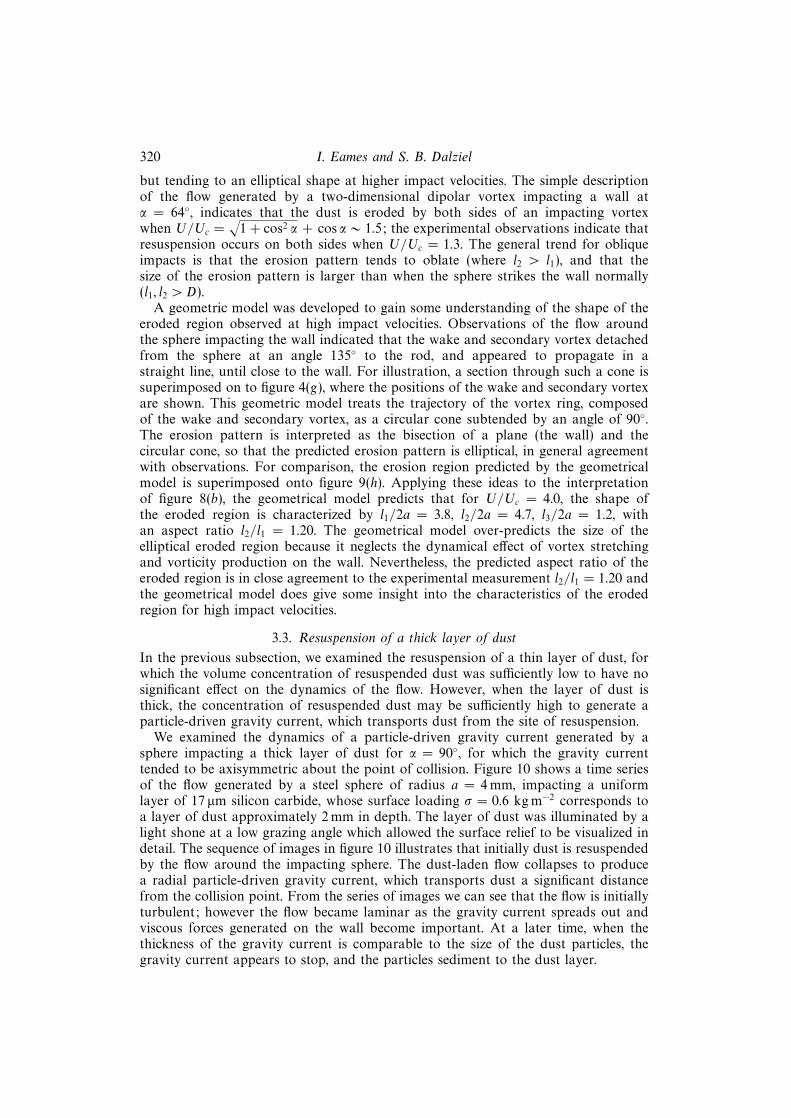
A geometric model was developed to gain some understanding of the shape of theeroded region observed at high impact velocities. Observations of the flow aroundthe sphere impacting the wall indicated that the wake and secondary vortex detachedfrom the sphere at an angle 135◦ to the rod, and appeared to propagate in astraight line, until close to the wall. For illustration, a section through such a cone issuperimposed on to figure 4(g), where the positions of the wake and secondary vortexare shown. This geometric model treats the trajectory of the vortex ring, composedof the wake and secondary vortex, as a circular cone subtended by an angle of 90◦.The erosion pattern is interpreted as the bisection of a plane (the wall) and thecircular cone, so that the predicted erosion pattern is elliptical, in general agreementwith observations. For comparison, the erosion region predicted by the geometricalmodel is superimposed onto figure 9(h). Applying these ideas to the interpretationof figure 8(b), the geometrical model predicts that for U/Uc = 4.0, the shape ofthe eroded region is characterized by l1/2a = 3.8, l2/2a = 4.7, l3/2a = 1.2, withan aspect ratio l2/l1 = 1.20. The geometrical model over-predicts the size of theelliptical eroded region because it neglects the dynamical effect of vortex stretchingand vorticity production on the wall. Nevertheless, the predicted aspect ratio of theeroded region is in close agreement to the experimental measurement l2/l1 = 1.20 andthe geometrical model does give some insight into the characteristics of the erodedregion for high impact velocities.
3.3. Resuspension of a thick layer of dust
In the previous subsection, we examined the resuspension of a thin layer of dust, forwhich the volume concentration of resuspended dust was sufficiently low to have nosignificant effect on the dynamics of the flow. However, when the layer of dust isthick, the concentration of resuspended dust may be sufficiently high to generate aparticle-driven gravity current, which transports dust from the site of resuspension.
We examined the dynamics of a particle-driven gravity current generated by asphere impacting a thick layer of dust for α = 90◦, for which the gravity currenttended to be axisymmetric about the point of collision. Figure 10 shows a time seriesof the flow generated by a steel sphere of radius a = 4 mm, impacting a uniformlayer of 17 µm silicon carbide, whose surface loading σ = 0.6 kg m−2 corresponds toa layer of dust approximately 2 mm in depth. The layer of dust was illuminated by alight shone at a low grazing angle which allowed the surface relief to be visualized indetail. The sequence of images in figure 10 illustrates that initially dust is resuspendedby the flow around the impacting sphere. The dust-laden flow collapses to producea radial particle-driven gravity current, which transports dust a significant distancefrom the collision point. From the series of images we can see that the flow is initiallyturbulent; however the flow became laminar as the gravity current spreads out andviscous forces generated on the wall become important. At a later time, when thethickness of the gravity current is comparable to the size of the dust particles, thegravity current appears to stop, and the particles sediment to the dust layer.

Dust resuspension by an impacting sphere 321
(a)
(d)
(b)
(e)
(c)
( f )
(g) (h)
Figure 10. This series of images shows the resuspension of a thick layer of dust (silicon carbide,17 µm in diameter), by a steel sphere of diameter 4 mm released above the layer. The areal densityof the silicon carbide is 0.6 kg m−2, which corresponds to a dust layer of 2 mm. The first imagecorresponds to the time 0.1 s after the sphere struck the wall, and time difference between subsequentimages is 0.5 s. The sphere impacted with a velocity U/Uc = 4.8, and bounced clear of the collisionpoint.
The radial extent of the gravity current, R(t), was measured as a function of thesize and velocity of the impacting sphere, and of the properties of the dust particles.Figure 11(a) shows the variation of R(t)/a with vT t/a, when the size of the impactingsteel sphere was fixed (a = 3 mm), but the size of the silicon carbide dust particleswas varied: b = 4.5, 17 and 54 µm. Figure 11(a) indicates that the time taken for theparticle-driven gravity current to stop, TM , after the sphere has impacted the groundis typically much less than a/vT , which is the time taken for a dust particle to fallthrough the height to which the dust particles are initially resuspended. In addition,the maximum radial extent of the particle-driven gravity current, RM , is much largerthan the size of the eroded region, demonstrating the important role gravity currentsplay in transporting dust from the point of resuspension.

322 I. Eames and S. B. Dalziel10
9
8
7
6
5
4
3
2
1
00.001 0.01 0.1 1
(a)
R(t)a
vTt/a
10
8
6
4
2
02 4 6 8 10
U/Uc
(b)
(RM
/a)(
bRe p
/a)1/
8
2 4 6 8 10
U/Uc
(c)3.0
2.5
2.0
1.5
1.0
0.5
0
[vT
(TM
–40
U/a
)/a]
/(a/
bRe p
)1/4
Figure 11. (a) The temporal variation of the radius of the gravity current, non-dimensionalized onthe radius of the impacting sphere, for three particles sizes of (silicon carbide) dust: �, 54 µm indiameter, Rep = 0.23;�, 17 µm in diameter, Rep = 6.0×10⁻³; +, 4.5 µm in diameter, Rep = 1.1×10⁻⁴.(b, c) The variation of the maximum radial extent of the gravity current, RM , and the time for thegravity current to stop, TM , versus U/Uc. The size a of the impacting sphere was varied: �, 3 mm;+, 4 mm; �, 5 mm. Equation (3.4) is also plotted for these a-values: ——, 3 mm; − − −−, 4 mm;- - - -, 5 mm.

Dust resuspension by an impacting sphere 323
The timescale associated with the hydrodynamic resuspension of the dust is set bythe advective time-scale, a/U, which corresponds to 0.0088 s for the results shownin figure 11(a). The advective time-scale is less than the time between video fields,0.02 s, and consequently the details of the resuspension process could not be followed.However, a field-by-field analysis of the video tape permitted an examination of thegrowth of the dust cloud following resuspension which showed that for the three dustparticle sizes considered, the size of the cloud of resuspended dust, R(t)/a, collapsedon to one curve when plotted against Ut/a for Ut/2a 6 20.0, where t = 0 correspondsto time of impact. From figure 11(a), we see that for large time the development ofthe gravity current may be treated as though a turbulent patch of dust-laden fluidwas released at time 40a/U after the sphere has impacted the ground.
The dynamics of a particle-driven gravity current generated by the collapse of avolume of turbulent particle-laden fluid have been studied in detail experimentallyand numerically by Dade & Huppert (1995), Bonnecaze et al. (1995) and Bonnecaze,Huppert & Lister (1996). Although the robust model of Bonnecaze et al. (1995,1996) is strictly not applicable for the later development of the gravity currentobserved in these experiments when the flow is not turbulent, we still proceed tocompare their predictions with our experimental measurements in order to gain insightinto the transport following resuspension. Bonnecaze et al. (1995, see Appendix)calculated an analytical expression for the radial extent using a ‘box model’, whichwas first developed by Dade & Huppert (1995) for two-dimensional particle-drivengravity currents. Bonnecaze et al. (1995) showed that the radial extend for a gravitycurrent released at time t = 0 is R(t)/RM = (tanh (t/τ))1/2, where τ is a timescaleassociated with the collapse of the gravity current and RM is the maximum radius.In fitting this expression to the experimental data, we estimate the timescale τ to beτ = 2(TM − 40a/U)/3, so that
R(t)
RM=
(tanh
(t− 40a/U
23(TM − 40U/a)
))1/2
. (3.3)
Expression (3.3) is plotted in figure 11(a), where RM and TM are experimentalmeasurements. We should note that the radial extent of the gravity current, RM , maybe measured more accurately than the TM because of the difficulty in determiningexactly when a thin gravity current has stopped.
Bonnecaze et al. (1995, 1996) parameterized the maximum radial extent, RM , andcharacteristic collapse time of a particle-driven gravity current released from theorigin at t = 0 in terms of the initial volume of dust-laden fluid, V, and the initialdust volume fraction, Φ, as
RM = 1.9V1/3
(vT√
gΦ(ρp/ρf − 1)V1/3
)−1/4
,
τ =
(4
πFr2
)1/4 V1/3
vT
(vT√
gΦ(ρp/ρf − 1)V1/3
)1/2
.
Analysis of the silicon carbide layer after the impact showed that the dust layerthickness changed abruptly between the resuspended region and the undisturbedlayer, indicating that dust within a distance D/2 from the point of impact wasresuspended, and not merely pushed to one side. In order to apply the scalings ofBonnecaze et al. (1995) an estimate of the initial volume V is required. We estimate

324 I. Eames and S. B. Dalziel
the volume of dust-laden fluid to be V = πD3/8, which is based on describing theinitial volume of resuspended fluid as a circular cylinder of radius D/2 and heightD/2. As a consequence of this assumption, the volume fraction of dust is estimatedto be Φ = (σD2/4)/(ρfD
3/8) = 2σ/(Dρf), where σ is the areal mass density of thedust. The maximum radial extent and collapse time vary according to
RM
a
(bRep
a
)1/8
= 1.9(36π3)1/2 D
2a
(σ
2aρf
)1/8
, (3.4a)
(TM − 40a/U)vTa
(a
bRep
)1/4
=
(1
9Fr2
)1/4D
2a
(σ
2aρf
)−1/4
, (3.4b)
where the fall velocity vT is estimated using the Stokes linear drag law consistent withthe approximation Rep � 1. It is important to note that RM and TM are functionsof the impact velocity through D/2a, whose variation with U/Uc is shown in figure8. Another important point is that the volume fraction of resuspended dust, Φ, isdependent on the size of the impacting body because the mass of dust resuspendedincreases with a as O(σa2), the volume of dust-laden fluid O(a3) increases more rapidly,and so the mass fraction, Φ ∼ O(σ/(ρfa)), decreases.
A series of experiments was undertaken using three sizes of impacting sphere andthree grades of silicon carbide to test the scalings (3.4), and the variation of RM and TMwith U/Uc is plotted in a dimensionless form in figure 11(b, c). Expressions (3.4 a, b)are plotted using data from figure 8(a) to determine a relationship between D/2a andU/Uc over the range 1 < U/Uc 6 10. A comparison between measurements and theprediction (3.4) indicates that the gravity current propagates a shorter distance thancan be accounted for by a turbulent particle-driven gravity current model. The robustmodel of Bonnecaze et al. is expected to describe the initial turbulent gravity currentdynamics but the viscously dominated motion observed at later time, which effectivelysets the run out distance, is not a feature of their model. While we anticipate thescalings (3.4) apply to gravity currents generated by large bodies resuspending dust,they appear to over-estimate the maximum radial extent, and the general trend of RMand TM with impact velocity is not predicted. The precise effect of viscous forces onparticle-driven gravity current dynamics still requires study and these experimentalresults may go some way to validating future mathematical models.
4. Flow around a sphere moving away from the wallIn this series of experiments, the sphere was initially in contact with the wall and
was set into motion impulsively at t = 0 by switching on the motor, which drove thesphere with a constant velocity away from the wall. When a sphere is impulsively setinto motion, the flow is inviscid outside the thin boundary layer on the surface ofthe sphere and wall. Since the fluid velocity close to the wall decreases with time, theinviscid flow has some bearing on whether dust, which is initially at rest on the wall,will be resuspended. The inviscid flow around the sphere may be calculated using themethod of images (Lamb 1932). From this solution we may calculate the variationof tangential fluid velocity, vx, on the wall with radial distance from the centrelinefor α = 90◦: the time difference between each curve is 0.2a/U. The results for thiscalculation are shown in figure 12(a). Viscous forces reduce the flow close to the walland consequently the lift force experience by the dust is less than that anticipated fromthe inviscid flow. Figure 12(a) indicates that the flow, and consequently the inertiallift force experienced by particles on the wall, decreases rapidly with time so that the

Dust resuspension by an impacting sphere 325
100
10
1
0.1
0.01
0.001
0.0001
Increasingtime
0.1 1 10
(a)
x/a
vx
U–
02 cm s–1
Vorticity: s–1
(b) (c)
02 cm s–1Vorticity: s–1
1
2
3
4
ya
1 2 30x/a
1
2
3
4
1 2 30x/a
–0.2 0.2 –0.2 0.2
ya
Figure 12. (a) The component of potential flow parallel to a wall generated by a sphere movingaway from a wall is plotted as a function of radial position. The curves represent the flow atdifferent times: the first curve corresponds to Ut/a = 0.01, and the time difference between thefollowing curves is 0.2a/U. (b, c) The velocity and vorticity field around a sphere moving away froma wall at times Ut/a = 2.5, 10 after the sphere has been impulsively started from rest. The flow ischaracterized by a Reynolds number, based on the sphere velocity, of Re = 450. The wake behindthe sphere is characterized by the dark region, which denotes negative vorticity (pointing into thepage). The flow near the wall persists for some time after the sphere has been removed, as indicatedby (c), and is consequently capable of driving a large volume of fluid away from the wall.
flow will have little effect on resuspension. In addition, the advective timescale (a/U),is typically much shorter than the response time for the dust particles, and the dustwill not respond to the flow generated by the sphere.
The velocity and vorticity field around the sphere are indicated in figure 12(b, c)for Re = 450, α = 90◦, and correspond respectively to the times Ut/a = 2.5 andUt/a = 10.0 after the motor was switched on. Figure 12(b) shows the wake behindthe sphere after the sphere has translated a distance 2.5a. Vorticity generated on the

326 I. Eames and S. B. Dalziel
surface of the sphere was either entrained by the wake vortex behind the sphere,causing it to grow with time, or deposited behind the sphere as trailing vorticity. Forlarge time, the flow near the wall was dominated by the trailing vorticity, as indicatedin figure 12(c), which shows the flow after the sphere has translated a distance 10.0a.The trailing vorticity advects a large (finite) volume of fluid, away from the wall, inthe direction in which the sphere translated. For large time, the flow generated by thetrailing vorticity decreased because of viscous dissipation, and was later disrupted byresidual convection in the tank. The volume flux, Q, generated by the trailing vorticitymay be estimated in an unbounded flow because it is related to the drag acting onthe body, FD , through FD = ρfQU (Batchelor 1967). At high Re, the form drag isproportional to the cross-sectional area of the body and the dynamic pressure at thefront stagnation point: FD = 1
2ρfπa
2CDU2, where the drag coefficient, CD , varies from
the value of 1.2 at Re = 100 to 0.4 at Re = 104. For the specific case of a sphere(V = 4πa3/3), the volume flux is related to the drag coefficient through
Q
VU/a= 3
8CD, (4.1)
which indicates that the trailing vorticity advects 3CD/8 or 25% of a sphere’s volumein the direction of motion. This estimation of the volume flux is only valid inunbounded flow where the flow is well-established. In the vicinity of the wall thevolume flux is decreased because the flow is not well-established and the kinematiceffect of the wall reduces the velocity normal to the wall, and consequently (4.1)remains an upper bound for Q.
The resuspension of dust was examined by introducing a thin layer of Pliolite par-ticles (100–150 µm in diameter) on the wall. Following the removal of the sphere, oneor two Pliolite particles which were initially in contact with the sphere, were observedto leave and remain trapped in its wake. In general, the Pliolite particles remainedundisturbed because the flow adjacent to the wall was localized and decreased rapidlywith time. These experiments were repeated using larger particles (mustard seeds,table 1), and we observed that slightly more particles were lifted from the wall. Thegeneral conclusion from these experiments was that a body moving away from a wallplays a negligible role in dust resuspension.
5. Concluding remarksIn this paper we examined experimentally the hydrodynamic mechanism of dust
resuspension. The main results from this study are the following.(a) The high-Re flow around a sphere moving towards and away from a rigid wall
has been examined. The study has shown that when a sphere collides with a wall,the wake vortex which is initially behind the body, threads over the sphere’s surfacegenerating a secondary vortex. The coherent structure, composed of the wake vortexand secondary vortex, collides with the wall, pushing fluid which is adjacent to thewall to one side, which is subsequently entrained by the wake vortex. The secondaryvortex was observed to develop an azimuthal instability, which was visualized by thedisruption of a layer of Pliolite particles. When the sphere moved away from a wall,trailing vorticity generated on the surface of the sphere was observed to advect alarge volume of fluid away from the wall.
(b) A criterion for resuspension by an impacting sphere was expressed in termsof a particle Shields’ parameter, θp = ρfU
2/(ρp − ρf)bg. When the dust-particle

Dust resuspension by an impacting sphere 327
Reynolds number Rep(= vTb/ν) <∼ 1, the dust is resuspended when θp > θp,c whereθp,c ≈ 5.0/Re
1/2p , and for Rep >∼ 1 the critical Shields’ parameter is θp,c ≈ 3.0. Above
the critical Shields’ parameter, the inertial lift force acting on the dust particles issufficient to overcome the gravitational force and the dust particles are removed fromthe wall. The dust is entrained by the wake vortex and propelled several spherediameters away from the wall. The geometry of the region eroded was determinedas a function of impact velocity, angle of impact and the characteristics of the dustparticles. The resuspension criterion indicates that the hydrodynamic mechanism ofresuspension by saltating particles does play an important role in dust resuspensionfrom soils.
(c) The dynamics of resuspensed dust were examined for the particular cases ofhigh and low volume concentrations. When the sphere impacts a thick layer of dust,the mass fraction of resuspended dust is sufficiently large to generate a particle-drivengravity current which transports the dust a considerable distance from the impactsite. The gravity current dynamics were studied and compared with the predictionsof Bonnecaze et al. (1996) for turbulent particle-driven gravity currents. The gravitycurrents propagated a shorter distance than predicted by turbulent particle-drivengravity current models indicating the important role viscous forces play in the laterdevelopment of these currents.
(d) A body moving away from a wall does not play a significant role in resuspendinga layer of dust because the flow it induces on the wall decreases rapidly with timeand distance from the sphere, and the advective timescale associated with the flowunsteadiness is much shorter than the response time of the dust particles. However,a body moving away from a wall transports a large volume of fluid away from thewall and consequently the flow around saltating particles leaving the ground play asignificant role in increasing the vertical mass flux of dust.
Within a more general context, the results in this paper give insight into a widerange of multiphase flow problems where bubbles or rigid particles leave or approachwalls or free surfaces. For instance, the sedimentation of large particles reduces theefficiency of sewage settling tanks, by resuspending fine particulate on the tank floor.The laying of oil pipes on the ocean floor or the dumping of containers will resuspendmaterial on the sea floor, because the flow they generate is similar to that observedwhen a sphere impacts a wall. The flow pattern generated by a bubble (with surfacecontamination) rising to a free surface is similar to that observed when a spherecollides with a wall, and consequently it will play a significant role in enhancinginterfacial gas transfer at the sea surface. A more detailed study of these flows iscurrently being undertaken.
I. E. acknowledges financial support from St. Catharine’s College, through theJeremy Howarth Fellowship. S. B. D. acknowledges the support of Yorkshire Waterand the Isaac Newton Trust. Both authors gratefully acknowledge Dr Ian McEwan forproviding a copy of Owen (1980) and Professor Dale Gillette for providing a copy ofOwen (1986). We thank Dr Anne Rice for kindly granting access to her experimentalresults. The constructive criticisms from anonymous referees is acknowledged.

328 I. Eames and S. B. Dalziel
REFERENCES
Absil, F. G. J. & Beugeling, G. L. H. 1984 The entrainment of small particles by a turbulent spot.In Atmospheric Dispersion of Heavy Gases and Small Particles – IUTAM Symp. Delft 1983,pp. 211–219. Springer.
Bagnold, R. A. 1941 The Physics of Blown Sand and Desert Dunes. Chapman & Hall.
Batchelor, G. K. 1967 Introduction to Fluid Dynamics. Cambridge University Press.
Bonnecaze, R. T., Hallworth, M. A., Huppert, H. E. & Lister, J. R. 1995 Axisymmetric particle-driven gravity currents. J. Fluid Mech. 294, 93–121.
Bonnecaze, R. T., Huppert, H. E. & Lister, J. R. 1996 Patterns of sedimentation from polydispersedturbidity currents. Proc. R. Soc. Lond. A 452, 2247–2261.
Brenner, H. 1961 The slow motion of a sphere through a viscous fluid towards a plane surface.Chem. Engng Sci. 16, 242–251.
Clift, R., Grace, J. R. & Weber, M. E. 1978 Bubbles, Drops and Particles. Academic.
Dade, W. B. & Huppert, H. E. 1995 A box model for non-entraining, suspension driven gravitysurges on horizontal surfaces. Sedimentology 42, 453–471.
Gillette, D. A., Blifford, I. H. & Fryrear, D. W. 1974 The influence of wind velocity on the sizedistribution of aerosols generated by the wind erosion of soils. J. Geophys. Res. 79, 4068–4075.
Greeley, R. & Iverson, J. D. 1985 Wind as a Geological Process on Earth, Mars, Venus & Titan.Cambridge University Press.
Krishnan, G. P. & Leighton, D. T. 1995 Inertial lift on a moving sphere in contact with a planewall in a shear flow. Physics Fluids 7, 2538–2545.
Lamb, H. 1932 Hydrodynamics. Cambridge University Press.
Lim, T. T. 1989 An experimental study of a vortex ring interacting with an inclined wall. Expts.Fluids 7, 453–463.
Lorenz, R. D. 1994 Huygens probe impact dynamics. ESA J. Eur. Space Agency 18, 93–117.
Magarvey, R. H. & Maclarehy, C. S. 1968 Mass transfer and wake phenomena. AIChE J. 14,260–265.
Orlandi, P. & Verzicco, R. 1993 Vortex rings impinging on walls: axisymmetric and three-dimensional simulations. J. Fluid Mech. 256, 615–646.
Owen, P. R. 1980 The physics of sand movement. Unpublished note.
Owen, P. R. 1986 The erosion of dust by a turbulent wind. Unpublished note.
Rice, M. A., Willetts, B. B. & McEwan, I. K. 1996 Wind erosion of crusted solid sediments. EarthSurface Processes & Landforms 21, 279–293.
Shao, Y., Raupach, M. R. & Findlater, P. A. 1993 Effect of saltation bombardment on theentrainment of dust by the wind. J. Geophys. Res. 98, 12719–12726.
Swearingen, J. D., Crouch, J. D. & Handler, R. A. 1995 Dynamics and stability of a vortex ringimpacting a solid wall. J. Fluid Mech. 297, 1–28.
Tennekes, H. & Lumley, J. L. 1992 A First Course in Turbulence. MIT Press.
Walker, J. D. A., Smith, C. R., Cerra, A. W. & Doligalski, T. L. 1987 The impact of a vortexring on a wall. J. Fluid Mech. 181, 99–140.
Wells, J. C. 1992 PhD Thesis, University of Grenoble.
Yalin, M. S. 1977 Mechanics of Sediment Transport. Pergamon.