Drainage Design and Construction Standards August 2020
439
DESIGN AND CONSTRUCTION STANDARDS VOLUME 3 DRAINAGE AUGUST 2020
-
Upload
khangminh22 -
Category
Documents
-
view
0 -
download
0
Transcript of Drainage Design and Construction Standards August 2020

DESIGN AND CONSTRUCTION STANDARDS
VOLUME 3
DRAINAGE
AUGUST 2020
Drainage Design Standards
i August 2020
TABLE OF CONTENTS
1.0 PLANNING ..................................................................................................................................... 1 2.0 PLANNING APPROVAL PROCESS - GENERAL ........................................................................... 1
2.1 Sewer and Drainage Planning in Relation to Land Use Planning ......................................... 1 2.2 Purpose of Reports ............................................................................................................. 1 2.3 Relationship between Land Use Planning and Sewer and Drainage Planning Process ........ 2
3.0 PLANNING AND DESIGN STUDIES ............................................................................................... 2 3.1 Regional Master Plan (RMP) ............................................................................................... 2 3.2 Watershed Plan (WP) ......................................................................................................... 3 3.3 Preliminary Drainage Report (PDR) ..................................................................................... 3 3.4 Area Master Plan (AMP) ..................................................................................................... 4 3.5 Neighbourhood Design Report (NDR) ................................................................................. 4
4.0 TYPICAL AREA MASTER PLAN REQUIREMENTS ....................................................................... 4 4.1 Scope of Study ................................................................................................................... 4 4.2 Requirements for Systems Analysis .................................................................................... 5 4.3 General Report Requirements ............................................................................................. 5 4.4 Identification of the Study Area and Existing Characteristics ................................................ 5 4.5 Preliminary Layout and Conceptual Design of the Selected Alternative ................................ 5 4.6 Documentation of Design Criteria ........................................................................................ 6 4.7 Declaration of Sufficiency of Standards and Professional Responsibility .............................. 6 4.8 Typical Requirements ......................................................................................................... 7 4.9 Site-Specific Requirements ................................................................................................. 8 4.10 Hydrogeotechnical Impact Assessment ............................................................................... 9 4.11 Environmental Impact Assessment (EIA) ............................................................................. 9
5.0 TYPICAL NEIGHBOURHOOD DESIGN REPORT REQUIREMENTS ............................................. 9 5.1 Scope of Study ................................................................................................................... 9 5.2 General Requirements ........................................................................................................ 9 5.3 Documentation of Design Criteria .......................................................................................10 5.4 Documentation of Methodology for Analyses and Design ...................................................10 5.5 Documentation of Input to Computer Model ........................................................................10 5.6 Documentation of Analyses of Drainage Systems ...............................................................10 5.7 Documentation of Costs .....................................................................................................11 5.8 Documentation of Implementation Plan ..............................................................................11 5.9 Detailed Requirements .......................................................................................................11
6.0 TYPICAL REQUIREMENTS FOR HYDROGEOTECHNICAL IMPACT ASSESSMENTS ................12 6.1 Intent .................................................................................................................................12 6.2 General Approach and Levels of Investigation ....................................................................13 6.3 Scope of Work - Preliminary Assessments .........................................................................13 6.4 Scope of Work - Detailed Assessments ..............................................................................14
7.0 SANITARY SEWER - POLICY, GOALS AND OBJECTIVES .........................................................15 7.1 Level of Service .................................................................................................................15 7.2 Provision for Future Extension of Development ..................................................................15 7.3 Separation of Storm and Sanitary Systems ........................................................................15 7.4 Economic Objectives ..........................................................................................................16
Drainage Design Standards
ii August 2020
7.5 Environmental Objectives ...................................................................................................16 8.0 SANITARY SEWER DESIGN CRITERIA .......................................................................................16
8.1 Estimating Sanitary Flows ..................................................................................................16 8.2 Average Flow Generation Estimates for Planning ...............................................................17 8.3 Determination of Peak Dry Weather Flow Rates .................................................................17 8.4 High-Water-Consumption Land Uses .................................................................................17 8.5 Residential Components of Commercial Developments ......................................................17 8.6 Extraneous Flow Allowance - All Land Uses .......................................................................17 8.7 Total Design Peak Flow Rates for Sanitary Sewers ............................................................18 8.8 Sizing of Sanitary Sewers ..................................................................................................18 8.9 Sanitary Sewer Slope Requirements ..................................................................................18 8.10 Required Depth for Sanitary Sewers ..................................................................................19 8.11 Pipe Elevation Considerations at Manholes, Junctions and Bends ......................................19 8.12 Sanitary Sewer Service Connections ..................................................................................20 8.13 Tables of Sanitary Design Factors ......................................................................................21
9.0 SANITARY WASTEWATER PUMPING SYSTEMS ........................................................................22 9.1 Initial Considerations ..........................................................................................................22 9.2 Basis for Detailed Design - Report Requirements ...............................................................22 9.3 Other Applicable Standards ................................................................................................23 9.4 Approval of Design by Other Authorities .............................................................................23
10.0 GENERAL DESIGN REQUIREMENTS FOR PUMP STATIONS .....................................................23 10.1 Location Considerations .....................................................................................................23 10.2 Pumping Station Configuration Considerations ...................................................................24 10.3 Building Requirements .......................................................................................................24 10.4 Pumping Capacity Requirements .......................................................................................25 10.5 Operational Reliability/Emergency Backup Provisions ........................................................25 10.6 Staging of Wastewater Pumping Facilities ..........................................................................26 10.7 Detailed Design Requirements for Wastewater Pumping Stations ......................................27 10.8 Wastewater Inlet Sewer .....................................................................................................27 10.9 Wet Well Size and Detail ....................................................................................................28 10.10 Pumps .............................................................................................................................29 10.11 Pump, Valve and Piping Arrangement ................................................................................29 10.12 Pump Control and Instrumentation Requirements ...............................................................31 10.13 Maintenance and Operational Provisions............................................................................31 10.14 Heating .............................................................................................................................33 10.15 Sump Pump .......................................................................................................................34 10.16 Site Requirements .............................................................................................................34 10.17 Operation and Maintenance Manual ...................................................................................35 10.18 Requirements for Activated Carbon Odour Control Units (OCU) in Pump Stations ..............36 10.19 EPCOR Chemical Dosing Requirements ............................................................................38
11.0 DESIGN OF SEWAGE FORCEMAINS ...........................................................................................39 11.1 Forcemain Size Considerations ..........................................................................................39 11.2 Flow Velocity Limits............................................................................................................39 11.3 Design Pressures ...............................................................................................................39 11.4 Surge Protection Devices ...................................................................................................39
Drainage Design Standards
iii August 2020
11.5 Slope .................................................................................................................................40 11.6 Alignment ...........................................................................................................................40 11.7 Air Release ........................................................................................................................40 11.8 Blowoff Valves ...................................................................................................................40 11.9 Vacuum Relief ...................................................................................................................40 11.10 Forcemain Outlet ...............................................................................................................40 11.11 Design Documentation on Engineering Drawings ...............................................................40 11.12 Requirements for Locating Forcemains ..............................................................................40 11.13 Requirements for Forcemain Inspection and Cleaning ........................................................40
12.0 STORM DRAINAGE SYSTEM - POLICY, GOALS AND OBJECTIVES..........................................40 12.1 Level of Service .................................................................................................................40 12.2 Major/Minor System Concept .............................................................................................41 12.3 Minor System .....................................................................................................................41 12.4 Sewers Servicing Areas Greater than 30 ha .......................................................................41 12.5 Major System .....................................................................................................................42 12.6 Provision for Areas beyond the Limits of Presently Proposed Development ........................43 12.7 Economic Objectives ..........................................................................................................43 12.8 Environmental Objectives ...................................................................................................44
13.0 STORMWATER RUNOFF ANALYSIS ...........................................................................................44 13.1 General Considerations......................................................................................................44 13.2 Commentary on Analytical Methods ...................................................................................44 13.3 Design Basis - Rainfall/Level of Service .............................................................................44 13.4 Rational Method .................................................................................................................45 13.5 Computer Simulation of Runoff...........................................................................................46 13.6 Table 13.3: Storm Runoff Coefficients and Imperviousness According to Zoning ................48 13.7 Table 13.4: Storm Runoff Coefficients and Imperviousness According to Land Use ............48 13.8 Table 13.5: Design Inlet Time (minutes) with Respect to Catchment Imperviousness and
Size ...................................................................................................................................48 13.9 Table 13.6: IDF Curves - Intensity Table ............................................................................49 13.10 Table 13.7: IDF Curves - Intensity Table-Summary ............................................................52 13.11 Table 13.9: Chicago Distribution (modified): 4-Hr Design Storm Data (mm/hr) ....................53 13.12 Table 13.10: Huff Distribution .............................................................................................55 13.13 Table 13.11: Recorded Storm of July 14, 1937 ...................................................................57 13.14 Table 13.12: Recorded Storm of July 10 - 11, 1978 ............................................................59 13.15 Table 13.13: Recorded Storm of July 2 & 3, 2004 (total of 135mm).....................................61 13.16 Table 13.14: Recorded Storm of July 12, 2012 ...................................................................63
14.0 MINOR CONVEYANCE SYSTEM DESIGN ....................................................................................63 14.1 Storm Sewers ....................................................................................................................63 14.2 Depth Requirements for Storm and Foundation Drainage Sewers ......................................65 14.3 Manholes, Junctions and Bends - Pipe Elevation Considerations .......................................65 14.4 Drainage of Roadways and Other Public Rights-of-Way - Minor System .............................66 14.5 Location of Drainage Inlets .................................................................................................66 14.6 Storm Sewer Service Connections .....................................................................................67
15.0 MAJOR CONVEYANCE SYSTEM DESIGN ...................................................................................68 15.1 Surface Drainage on Public Rights-of-Way - Major System.................................................68

Drainage Design Standards
iv August 2020
15.2 Swales ...............................................................................................................................68 15.3 Representation of the Major Conveyance System ..............................................................68
16.0 STORMWATER MANAGEMENT FACILITY DESIGN ....................................................................69 16.1 Basis for Detailed Design ...................................................................................................69 16.2 Design Requirements Common to Stormwater Management Facilities ...............................70 16.3 Emergency Overflow Provisions .........................................................................................71 16.4 Operation and Maintenance Manual ...................................................................................71 16.5 Signage for Safety and Public Information ..........................................................................72 16.6 Engineering Drawing Requirements ...................................................................................73 16.7 Design Details for Wet Ponds .............................................................................................73 16.8 Sediment Removal Provisions ............................................................................................75 16.9 Wet Pond Edge Treatment .................................................................................................75 16.10 Maintenance Access Requirements ...................................................................................76 16.11 Landscaping Requirements ................................................................................................76 16.12 Design Details for Constructed Wetlands............................................................................76 16.13 Design Standards for Dry Ponds ........................................................................................83
17.0 LID FACILITY DESIGN ..................................................................................................................84 17.1 Site Planning Considerations .............................................................................................85 17.2 Design Basis ......................................................................................................................86 17.3 Bioretention Garden Design ...............................................................................................87 17.4 Bioretention Basin Design ..................................................................................................89 17.5 Box Planter Design ............................................................................................................93 17.6 Soil Cell Design..................................................................................................................96 17.7 Piping and Infrastructure Considerations ............................................................................99 17.8 Cold Climate Design Considerations ................................................................................101 17.9 Vegetation Selection ........................................................................................................101 17.10 Drawing Requirements .....................................................................................................107 17.11 Construction Considerations ............................................................................................107 17.12 LID Growing Soil Media Specifications - Bioretention Gardens, Bioretention Basins, and Box
Planters ..........................................................................................................................108 17.13 Soil Specifications - Soil Cells ..........................................................................................110
18.0 LOT GRADING AND SURFACE DRAINAGE DESIGN ................................................................ 111 18.1 Lot Grading on Private Property .......................................................................................111 18.2 Lot Grading Design Requirements....................................................................................112 18.3 Use of Swales ..................................................................................................................115 18.4 Content of Lot Grading Plans ...........................................................................................116
19.0 SEWERS, APPURTENANCES AND STRUCTURES ................................................................... 118 19.1 Rights-of-Way for Sewer and Drainage Facilities ..............................................................118 19.2 Sewers ............................................................................................................................119 19.3 Sewer Service Connections .............................................................................................120 19.4 Sewer Service Connection Arrangement ..........................................................................120 19.5 Manholes, Junctions and Bends .......................................................................................121 19.6 Catch Basin Inlets ............................................................................................................124 19.7 Catch Basin Leads ...........................................................................................................125 19.8 Catch Basin Manholes .....................................................................................................125

Drainage Design Standards
v August 2020
19.9 Drop Manholes ................................................................................................................125 19.10 Design Criteria for Drop Manholes....................................................................................126 19.11 Storm Sewer Outfall Structures ........................................................................................126 19.12 Culverts ...........................................................................................................................127 19.13 Rural Runoff Inlets ...........................................................................................................128 19.14 Special Pipe Installation Methods .....................................................................................128
20.0 STRUCTURAL DESIGN FOR PIPE ............................................................................................. 128 20.1 Responsibility for Structural Design ..................................................................................128 20.2 General Design Basis ......................................................................................................128 20.3 Methods of Analysis .........................................................................................................128 20.4 Documentation and Submission of Design Calculations....................................................129
21.0 DETAILED ENGINEERING DRAWINGS ...................................................................................... 129 21.1 Prerequisites to Review of Engineering Drawings by the City ...........................................129 21.2 Engineering Drawing Requirements .................................................................................130 21.3 Statutory Requirements for Approvals by Other Authorities...............................................131 21.4 Post Approval Submission Requirements .........................................................................132 21.5 Design Revisions after Approval of Engineering Drawings ................................................132
22.0 AS-BUILT DRAWING REQUIREMENTS ..................................................................................... 132 22.1 Requirements for Submission of As-Built Drawings at CCC and FAC Stages....................132 22.2 Detail Requirements for As-Built Drawings .......................................................................133
23.0 PROJECT ACCEPTANCE ........................................................................................................... 135 23.1 Developer Requirements at Construction Completion and Final Acceptance ....................136 23.2 Inspection of Completed Systems by EPCOR ..................................................................137 23.3 Inspection and Testing of Sewers .....................................................................................137
APPENDICES
Appendix A: Design Guidelines for Electrical and Control Systems for Wastewater Pump Stations
Appendix B: Computer Model Transfer Requirement Check List
Appendix C: Catch Basin Inlet Capacity Curves
Appendix D: Standard Practice for the Design and Installation of Rigid Gravity Sewer Pipe in the City of Edmonton
Appendix E: Standard Practice for the Design and Construction of Flexible Thermoplastic Pipe in the City of Edmonton
Appendix F: Pumpwell Unit Confined Space Entry Fall Arrest and Rescue System
Appendix G: Pump Station Decision Model
Appendix H: Outfall Structure Monitoring
Drainage Design Standards
Page 1 of 139 August 2020
1.0 PLANNING Sections 1 to 6 summarize the procedure and framework developed by the City (the City may refer to, as appropriate to the context, the City of Edmonton, a Municipal Corporation, and includes all City Departments, as well as EPCOR Drainage Services, where applicable) to coordinate the resolution of urban sanitary sewerage and storm drainage serviceability issues in conjunction with and parallel to the evolution and implementation of general urban land development plans and other infrastructure components.
The various sanitary sewer and drainage design studies and reports which are required throughout the planning process are identified and their objectives and content described.
Specific requirements for the scope and content of the studies and reports to be prepared in support of development proposal applications on behalf of Developers are contained within Sections 4.0 to 6.0 of this Volume.
2.0 PLANNING APPROVAL PROCESS - GENERAL 2.1 Sewer and Drainage Planning in Relation to Land Use Planning
Levels of analysis and report requirements are identified to correspond with and precede the Area and Neighbourhood Structure Plan (NSP) and Subdivision levels included in the Land Use Planning and Development approval process. Section 2.3 illustrates the process and the precedence relationship between the reports required and the identified land use planning documents. Objectives for the sewer and drainage studies, plans and reports and the responsibility for their preparation are noted on the figure and further outlined in this section. The reports identified are to be prepared and approved as prerequisites to the subsequent stages of planning and development. Preliminary planning studies will usually be undertaken by the City. More detailed analysis and design studies are to be undertaken, normally by consulting engineers on behalf of private developers wishing to obtain approval of land development proposals.
2.2 Purpose of Reports 2.2.1 The reports required are intended to establish technical backup to demonstrate the viability of the
respective structure plans and development proposals. They will ultimately provide the basis for detailed system designs, which will be finalized in the form of detailed engineering drawings prepared by the Developer's engineers and to be approved by the City prior to the signing of Servicing Agreements between the Developer and the City. Specific sewer and drainage servicing concerns are to be addressed to an appropriate and increasing level of detail as the planning and development process proceeds and more detailed site-specific information becomes available.
2.2.2 The availability of recognized studies at each level of the planning process will determine whether the City will support applications to the City for approval of Area and NSPs, redevelopment proposals and subdivisions.

Drainage Design Standards
Page 2 of 139 August 2020
2.3 Relationship between Land Use Planning and Sewer and Drainage Planning Process Land Use Planning
Process Sewer and Drainage Planning Process Prime Responsibility
1. Regional Master Plan (RMP) A concept plan to define strategies and alternatives for storm and sanitary system extensions
the City
General Municipal Plan
2. Watershed Plan (WP) To determine existing constraints and best management alternatives for development within each storm drainage watershed in the City. - OR - 3. Preliminary Drainage Report (PDR) To review existing data, identify potential problems, formulate preliminary servicing plans and set the framework for the Area Master Plan in the context of storm drainage.
Private Developer Or the City
Area Structure Plan (ASP)
4. Area Master Plan (AMP) To develop servicing schemes respecting the long term user requirements, justify the selection of solutions proposed and define the characteristics of selected alternatives for sanitary and storm drainage servicing of the area.
Private Developer Or the City
4a) Area Hydrogeotechnical Impact Assessment
Private Developer
4b) Area Environmental Impact Assessment Private Developer Neighbourhood Structure Plan (NSP)
5. Neighbourhood Design Report (NDR) To define detailed design requirements for storm and sanitary sewer facilities required to service the development area.
Private Developer
5a) Neighbourhood Hydro-Geotechnical Impact Assessment
Private Developer
Detailed Subdivision Plan
5b) Neighbourhood Environmental Impact Assessment
Private Developer
6. Detailed Engineering Drawings Private Developer
Standard Servicing Agreement
3.0 PLANNING AND DESIGN STUDIES 3.1 Regional Master Plan (RMP) 3.1.1 The RMP is an overall drainage plan for the Edmonton Area that defines the short, medium and long-
term storm and sanitary servicing strategy. It is prepared and periodically updated by the City. This plan includes conceptual strategies for siting, sizing, preliminary layouts and designs of the storm, sanitary and combined sewer systems. This servicing plan provides a basis for orderly, economic growth by defining the optimal use of existing sewerage systems, extensions of these systems and possible alternatives. The creation and updating of the RMP is a prerequisite to the General Municipal Plan for the City prepared under the Municipal Government Act for Council approval.
3.1.2 Sanitary planning is required to identify, as part of the RMP, the practical conditions for sanitary serviceability, limiting factors in terms of capacities and elevations and the strategy for implementation of the necessary additions or extensions to the sewer network and sewage treatment systems. Capacity requirements must be defined that address inflow/infiltration contributions and provide a

Drainage Design Standards
Page 3 of 139 August 2020
reserve for future flexibility. Sanitary planning is formulated on the contributing basin concept. Basic considerations applying to individual sanitary basins are identified to establish the basis of the next level of analysis, undertaken as part of the AMP.
3.1.3 Stormwater drainage planning at this level is formulated on the watershed concept and will identify the conditions of drainage normally prevailing for runoff events including rainfall and snow melt runoff. Alternative means of stormwater management are defined. These planning efforts should include proposals for handling the storm drainage from undeveloped areas in the interim period until developments gradually substitute storm sewer networks in these areas. Particular attention should be paid to ensure that new developments are not adversely impacted by drainage from surrounding undeveloped areas due to changes or obstruction of existing drainage patterns in these areas. The RMP is to provide a basis for the more detailed evaluation of storm servicing alternatives to be undertaken as part of the WP.
3.1.4 The RMP is also required to address the environmental impact of stormwater and treated sewage effluents, to ensure the need for pollution abatement and protection of receiving waters is recognized. Appropriate control strategies are to be recommended.
3.2 Watershed Plan (WP) 3.2.1 A WP deals mainly with storm drainage issues and is required for any drainage basin either totally or
only partly within the city boundary, including both areas proposed for development and those expected to remain undeveloped. WP is normally prepared by the City and provides the conceptual framework for evolving the AMPs formulated in conjunction with AMPs.
3.2.2 Sanitary sewer system planning devolves from the RMP directly to the AMP level of analysis. Some considerations of the sanitary servicing alternatives must, however, be part of each WP to ensure compatibility of servicing schemes, alignments, staging and implementation strategies.
3.2.3 A WP identifies the existing drainage and environmental constraints and defines options for the management and development of alternatives, considering environmental and economic issues, developmental staging, the impact of hydrogeotechnical conditions, major utility corridors, Restricted Development Areas, power and pipeline rights-of-way.
3.2.4 The analysis of alternative drainage systems must be at a broad conceptual level since the details of the development are unlikely to be finalized at this stage. However, general proposed land use patterns must be evaluated in order to identify suitable trunk sewer and major system outfall points to receiving waterways. While the principal emphasis is on post-urbanization flow rates, quantities and quality, the analysis should include the use of stormwater management facilities (SWMFs) for urban conditions as well as servicing concepts to be implemented during the transition stage from rural and undeveloped to fully developed conditions, a process which may take a long period of time.
3.2.5 Watershed drainage planning is generally carried out by considering various alternatives for the major drainage system. The requirements for minor conveyance systems can then be defined in relation to the major system. The degree of protection provided by the major system can influence the level of conveyance required in the minor system.
3.2.6 The impact of the major and minor system components and their performance on the integrity of the sanitary sewage system should be evaluated and specific recommendations made to minimize potential overloading of the sanitary system due to stormwater related inflow and infiltration.
3.2.7 The finished plan and staging recommendations are incorporated in a preliminary engineering report for approval and implementation by the City. At later design stages, drainage services for individual developments must be considered in the frame of the WP.
3.3 Preliminary Drainage Report (PDR) 3.3.1 The City normally prepares a WP covering any potential development area of the City. However, for
those areas where WPs are not available, a Developer may have a PDR prepared by a Consultant to address the storm drainage planning requirements as necessary to establish the framework and terms of reference for an AMP Study and preliminary Environmental and Hydrogeotechnical Impact Assessments. These terms of reference must be approved by the City before an AMP is undertaken.

Drainage Design Standards
Page 4 of 139 August 2020
3.3.2 The PDR should review existing data, identify potential problems related to future drainage servicing and potential conflicts with other infrastructure plans and propose a conceptual plan for the orderly servicing of new developments.
3.4 Area Master Plan (AMP) 3.4.1 The AMP develops and proposes the optimum sewer and drainage servicing schemes that meet the
short- and long-term servicing needs of the development area. The selection of the proposed alternatives are to be justified by considering the cost of the sewer and drainage system components, financing and cost sharing relationships and assessing the economic viability of alternatives.
3.4.2 The approval of an AMP for both storm and sanitary servicing is a prerequisite for the support by the City of any related AMP proposals. The Developer concerned with the study area is responsible for having the AMP undertaken by a qualified engineering consultant. However, in some cases the City may initiate and conduct the study on the Developer's behalf when deemed necessary to accommodate area planning needs.
3.4.3 The sanitary sewer servicing component of this analysis must consider the planning and servicing objectives, resolve all concerns and address constraints, including any specific issues identified through the RMP with respect to the study area, which in this case relates to the contributing sanitary basin.
3.4.4 For storm drainage, the analysis considers the study area as defined in the WP or the PDR. The AMP must justify the selection of the proposed stormwater management alternative in terms of its suitability to address all constraints including those identified in the previous studies. If the WP or the PDR has identified any specific problems such as critical pollution loadings, sedimentation or erosion, the AMP would propose solutions to these problems. The AMP should also explore the potential of incorporating Low Impact Development (LID) as a best management practice (BMP) for stormwater management. LID should not be viewed as a redundant system, but as a necessary part of the integrated stormwater management system that helps to meet the environmental objectives.
3.4.5 The terms of reference for the AMP study for a development area must be approved by the City before the work is started.
3.5 Neighbourhood Design Report (NDR) 3.5.1 The NDR defines the basis for detailed design of servicing system components selected in the course
of the AMP study, the costs of the sewer and drainage system components, and the financing and cost sharing relationships and requirements necessary to implement the servicing systems.
3.5.2 The preparation and presentation of a NDR is the responsibility of the Developer, and the approval of the NDR is a prerequisite for support by the City of NSP proposals within the subject servicing area. Subdivision proposals and detailed engineering drawings related to the area are not accepted for review and approval in the absence of an approved NDR. Where subdivision proposals are different in substance from an approved NSP, or finalized servicing proposals vary from those defined in the NDR, then an amendment of the NDR needs to be approved before detailed engineering drawings are reviewed for approval.
4.0 TYPICAL AREA MASTER PLAN REQUIREMENTS 4.1 Scope of Study 4.1.1 The storm drainage component of the plan should be based on the concepts developed in the overall
RMP and the WP, should resolve any specific concerns raised in those studies and address any significant constraints. The RMP should identify basic considerations for sanitary sewer system planning, to be addressed on a similar basis
4.1.2 Area master planning is carried out by identifying and comparing alternative facility locations, sizes and type and includes the selection of the most suitable alternative. While the AMP need not include a rigorous comparison of alternatives considered, the selection of the proposed servicing schemes are to be adequately justified on the basis of relative merit, considering technical issues, short-term and long-term economic viability, and equity for those parties who eventually share in the costs of the facilities.
Drainage Design Standards
Page 5 of 139 August 2020
4.2 Requirements for Systems Analysis 4.2.1 The analysis of servicing systems for the AMP is necessarily at a broad and conceptual level. However,
proposed land use patterns and arterial roadway alignments must be evaluated in order to plan for location of suitable sewer trunks, outfalls, storage and stormwater quality enhancement facilities.
4.2.2 Hydraulic analysis of proposed servicing schemes is required only to the extent that is necessary to demonstrate the technical feasibility of servicing concepts for the specific area. Simple systems proposed to operate under free flow conditions may be analysed using hand calculation methods to determine post-development hydrographs. Systems anticipated to operate under surcharged conditions during the design event would typically require analysis using computer simulation techniques, as would systems with interconnected storage elements.
4.2.3 For systems proposed to use real time control of outflow from SWMFs, dynamic simulation of operation may be delayed until a later more detailed stage of the design process, provided that the system operating rules and control parameters are clearly set out in the AMP.
4.2.4 At the AMP level, the hydraulic analysis should be conducted using lumped modelling techniques, on simplified representations of the systems components comprising only the principal conveyance and storage elements and appropriate approximations of relative locations and elevations. The objective is to confirm the magnitude of flows and volumes which must be accommodated and the general adequacy of the proposed system to satisfy the level-of-service objectives (refer to Sections 7.0 and 12.0).
4.3 General Report Requirements 4.3.1 The AMP is to document, clearly describe and justify the selected sewer and drainage systems; identify
significant constraints and issues; describe assumptions and design criteria; provide simulation results; present recommendations and conclusions.
4.3.2 Scales for layout plans and mapping
Conceptual scale: For presentation of concept information, plans to a common scale of 1:20,000 are preferred.
Detail scale: More detailed information should be presented on plans to a scale of 1:5,000 on an orthophoto base. Larger scales may be utilized for specific details as is appropriate.
4.4 Identification of the Study Area and Existing Characteristics 4.4.1 The study area's topography, existing drainage patterns, existing land use and proposed land use, are
to be shown on plans to conceptual or detailed scales as appropriate.
4.4.2 The location and capacities of outfalls for the storm, sanitary and other major drainage systems are to be shown on plans. The City normally provides this information from the RMP and WP.
4.4.3 The report is to include a description of soils and groundwater conditions to the depth affecting drainage utilities, highlighting any constraints these conditions pose to drainage design and construction. See Hydrogeotechnical Impact Assessment requirement, Section 4.10.
4.5 Preliminary Layout and Conceptual Design of the Selected Alternative 4.5.1 The following plans are to be provided:
i. Plans showing preliminary alignments, pipe locations, subcatchment boundaries, pipe sizes, SWMFs, LID facilities, and other facilities for the selected alternative. Manhole or node locations and pipe numbers to correlate with a system analysis are to be included as necessary.
ii. Separate plans for storm and sanitary trunk systems, to conceptual or detailed scales as appropriate.
iii. A surface drainage plan showing drainage directions, collector routes, surface storage sites and subcatchment boundaries.
iv. Conceptual profiles showing pipe invert and crown, ground profile, pipe size, manhole or node

Drainage Design Standards Page 6 of 139 August 2020
locations and numbers as well as normal and high water levels and freeboard for SWMFs. Similar profiles are required for sanitary trunks and the major drainage system.
4.5.2 Tabulated data to describe the proposed systems are required, as follows:
i. Table of subcatchment properties showing inlet manhole, drainage area, land use, population andimperviousness or runoff coefficient.
ii. Table of pipe properties indicating:
pipe number or ID;
upstream and downstream manhole with number or ID;
"n" value;
diameter;
slope;
pipe-full capacity;
design flow;
design velocity.
iii. design calculation sheets (rational method and sanitary trunks) or computer model schematic andsummary output; and
iv. continuous modelling of a recorded series of storms may be required in specific circumstancessuch as where severe restrictions are imposed by downstream system capacities.
4.6 Documentation of Design Criteria The design basis for the selected alternative is to be documented, including identification of the following information:
design storm;
performance criteria: flow, pipe-full design, velocity restrictions, allowable street ponding depths, storage drawdown time, real time control operating rules and control parameters;
sewage generation factors;
population densities;
storm runoff factors, imperviousness and ground slopes;
weeping tile drainage methods proposed (not permitted to sanitary sewers);
stormwater handling and treatment facilities and contaminant removal capabilities;
pump station vs. gravity sewer option analysis (refer to Appendix G: Pump Stations Decision Model);
pollutant/contaminant possibilities; and
any proposed exception to the City standards. Such proposals are to be adequately justified and will require specific approval by the City.
4.7 Declaration of Sufficiency of Standards and Professional Responsibility The report is to include a statement that the proposed design standards provide an appropriate level of service and safety and adequately deal with any known special or unique conditions in the study area. The submission is to be sealed and signed with regard to professional responsibilities.

Drainage Design Standards
Page 7 of 139 August 2020
4.8 Typical Requirements The following checklists are provided to assist the Consultant in identifying the typical scope of issues to be addressed in the AMP.
4.8.1 Storm Portion Checklist
Watershed and development in relation to it;
Summary of PDR or Watershed Study;
Topography;
Details of watercourse crossings, for instance culverts, bridges and roads;
Details of watercourse and valley reaches including typical x-sections;
Natural storage and drainage;
Street layout, location of parks;
Present land ownership;
Present land use;
Identification of pre-development flows;
Proposed land use;
Subcatchment boundaries;
Develop and justify a servicing scheme respecting the long-term user requirements;
Description and discussion of storage requirements including storage volume and location, SWMF overflow alternatives, real time control operating rules and control parameters;
Proposed major drainage system;
Proposed minor drainage system;
Use of natural features, for example sloughs;
Identification of unusual factors affecting operation and maintenance costs;
Identification of potential surcharging;
Address Erosion and Sedimentation Controls (ESC) by presenting all ESC Information identified in Figure 4.1 – ESC Framework of the ESC Guidelines;
Simulated normal water level (NWL) and high water level (HWL) for SWMFs;
100 Year flood lines for ravines;
Identification of the need for water quality control;
Description of constructed wetlands; wet ponds or dry ponds;
Description or concept plan of BMPs including LID (if applicable);
Description of water quality impacts and its improvement;
Provide wetland; including existing natural wetlands; to watershed ratio;
Identification of requirements for pollutant control and determination of allowable pollutant loads;
Review of outlet operating constraints and sufficiency of depth;
Determine outlet arrangement and review hydraulics to ensure adequate rates of drawdown can be achieved at all levels of storage;
Hydraulic analysis by suitable methods is to be carried out to provide post-development hydrographs for the minor 5-year design storm event and appropriate major historical design
Drainage Design Standards
Page 8 of 139 August 2020
events; considering the following options:
o 100 year storm;
o 1937 storm;
o 1978 storm;
o 2004 storm; and
o 2012 storms.
Alternatively, for SWMFs sized to accommodate 120 mm of runoff over the basin, assuming zero discharge for the length of the storm event, system drawdown curve should be provided;
Outline the proposed staging and/or implementation plan.
4.8.2 Sanitary Portion Checklist
Study area/drainage basin;
Review of the RMP and the previous studies;
Identify points of servicing availability and downstream system capacity and depth constraints per information to be provided by the City;
Feasibility of gravity system extensions versus pumping;
Topography;
Existing developments;
Projected land development;
Populations;
Present land ownership;
Present land use;
Future land use;
Subcatchment boundaries;
Summary of design criteria;
Peak flows;
Average flows;
Conflicts with existing and proposed utilities;
Develop and justify a servicing scheme respecting the long-term user requirements;
Identify potential environmental impacts;
Identify unusual factors affecting operation and maintenance costs;
Identification of potential surcharge;
Identification of land requirements/easements;
Outline the proposed staging/implementation plan;
Outline any storage and real time outflow control requirements.
4.9 Site-Specific Requirements Depending on circumstances relevant to a specific ASP area, additional requirements may apply. These are determined on a case-by-case basis and may include: an environmental impact assessment, if discharging to natural watercourses or environmental reserve lands; a soils and groundwater investigation, and an analysis of downstream capacity constraints.

Drainage Design Standards
Page 9 of 139 August 2020
4.10 Hydrogeotechnical Impact Assessment 4.10.1 A Hydrogeotechnical Impact Assessment is required to define constraints, imposed by soil and
groundwater conditions, which will affect the choice of design philosophy and construction practices to be applied.
4.10.2 The undertaking of a preliminary Hydrogeotechnical Assessment study is a requirement of the AMP and terms of reference for this study are to be addressed when establishing the terms of reference for the AMP. In cases where this requirement is not fulfilled in conjunction with a previous AMP, it must be addressed in association with the NDR.
4.10.3 Where the preliminary assessment identifies constraints of concern, more specific hydrogeotechnical investigations to provide detailed site-specific recommendations may be required, either as part of the AMP or to be addressed at the NSP stage as part of the NDR. The determination of the scope and staging of such additional investigations is subject to the discretion of the Engineer and is to be based on the potential impact of the identified constraints on the viability of the development and the proposed servicing schemes.
4.11 Environmental Impact Assessment (EIA) A preliminary EIA is required for each development area in conjunction with the AMP. Where the preliminary assessment has identified environmental concerns which may have a bearing on the suitability of sewer and drainage servicing proposals, more detailed and specific investigations may be required, either as part of the AMP or in conjunction with the NDR. The determination of the requirements and staging of investigations with respect to the sewer and drainage systems planning reports are subject to the discretion of the Engineer. Usually, EIA reports describe the natural features, topography, special historic, archaeological and other aspects of the proposed development area, evaluate the impacts from development and define methods and action plans to minimize or mitigate such impacts. The Developer has the responsibility for conducting an EIA. The City will review EIA reports required pursuant to the River Valley Bylaw No. 7188 and other authorities and provide comment and/or support for approval from a drainage perspective. The City will undertake this review in conjunction with reviews by Alberta Environment and Parks (AEP) and others.
5.0 TYPICAL NEIGHBOURHOOD DESIGN REPORT REQUIREMENTS 5.1 Scope of Study 5.1.1 The NDR is to define the basis of detailed design of the principal components of the sanitary sewerage
and storm drainage infrastructure. The NDR will propose methods and procedures for overcoming all constraints identified in the AMP. The NDR will identify all constraints to implementation of the facilities, including financial, design, hydrogeotechnical and construction approvals.
5.1.2 The NDR presents the design of the permanent facilities. However, if large facilities are required, they are rarely constructed to their ultimate form in the first stages of development. In this situation, an addendum to the NDR is required to detail the design of interim stages for facilities and the impacts on the implementation plan. Addenda to the NDR may be required by the Engineer under the following circumstances:
significant changes to the AMP;
significant changes in design standards;
significant changes to the schedule of land development; and
significant changes to the implementation plan.
5.1.3 An ESC Strategy is an essential component of storm drainage in the NDR. The strategy shall build on the ESC Information presented in the AMP and address all items presented on Figure 4.1 – ESC Framework of the ESC Guidelines.
5.2 General Requirements 5.2.1 Plans showing topography, existing drainage patterns and facilities, existing land uses, land uses as
per the NSP, hydrogeotechnical information, constraints on implementation and land ownership.

Drainage Design Standards
Page 10 of 139 August 2020
5.2.2 Plans showing anticipated land development, with schedules and supporting documentation in tabular format.
5.2.3 Plans showing the layout of the proposed drainage facilities and conformance with the AMP, and if in regard to an addendum to a previously approved NDR, conformance and variations with that NDR.
All SWMFs, storm and sanitary pumping stations and forcemains, storm sewers and sanitary sewers;
layout of roads, private property limits, land use and other utilities, noting environmental and hydrogeotechnical constraints and differences from previously approved reports;
location of the systems in relation to adjacent systems and drainage basins; and
location of the systems and the study area showing the development relative to existing and future developments.
5.3 Documentation of Design Criteria 5.3.1 Plans and tables showing subcatchment boundaries, land use, imperviousness, runoff coefficients,
sewer pipe roughness, design performance criteria, sewage generation factors, population, service arrangement practices and wet-weather flow generation factors.
5.3.2 Studies to justify any use of design criteria different from those set out in these standards.
5.4 Documentation of Methodology for Analyses and Design 5.4.1 Design calculations in support of the proposals.
5.4.2 Description of computer models and their use;
5.4.3 Calibration and verification studies for models which have not been calibrated to conditions in the City of Edmonton;
5.4.4 Description of activities and procedures for undertaking design and analyses of the drainage systems.
5.5 Documentation of Input to Computer Model 5.5.1 Plans and tables relating input parameters to the layout of the drainage systems;
5.5.2 Subcatchment numbers, area, imperviousness, depression storage, grades, servicing arrangement, subcatchment width, infiltration parameters, node locations and numbers, gutter sizes/slopes/width, pipe sizes/slope/capacity/roughness coefficient/number/sub-catchment/gutter connections/node connections, outfalls, node inverts/ground elevations/ pipe connections, inlet numbers/capacity/ connection, road grades and major system grades/configuration/capacity/connections.
5.6 Documentation of Analyses of Drainage Systems 5.6.1 Plans and profiles of the sanitary sewer and storm drainage facilities.
5.6.2 Profiles showing pipe invert and crown, pipe size, ground profile, pipe slope, node locations and numbers, SWMFs.
5.6.3 Profiles of storm trunk sewers showing hydraulic grade lines under each design event and calculated flow rates.
5.6.4 Plans and profiles of the major systems showing flow rates, depth capture by the minor system, capacity, inlet hydrographs to SWMFs and existing sewers, drainage area and rating curves.
5.6.5 Pump and system curves showing staged performance of pumping systems.
5.6.6 Details of constructed wetlands and/or wet ponds.
5.6.7 Details of vegetation in constructed wetlands and/or wet ponds.
5.6.8 Comparison of flows and water quality under pre-development and post-development conditions and at all proposed stages of the implementation plan.
5.6.9 Consideration of using BMPs for stormwater runoff improvement.

Drainage Design Standards
Page 11 of 139 August 2020
5.6.10 Inspection of existing infrastructures (the tie-in points and one facility upstream and downstream of existing infrastructure which has passed 10 years after final acceptance certificate) that proposed work is to be connected to or that has potential to be affected by construction activity (refer to 21.1.2).
5.7 Documentation of Costs 5.7.1 Complete documentation of design, construction and long-term operation, maintenance and
replacement costs for each of the principal components of the systems in accordance with the implementation plan.
5.7.2 Costs for land purchase and/or easement acquisition.
5.8 Documentation of Implementation Plan 5.8.1 Definition of all constraints to implementation of the permanent facilities.
5.8.2 Discussion of alternative means of meeting constraints, methods of evaluating alternatives and decision criteria.
5.8.3 Report documenting the activities undertaken and the results in a clear, concise, logical format including conclusions and recommendations.
5.8.4 The report is to contain an assertion that the design standards criteria applied are suitable and appropriate, provide an adequate level of service and address any special or unique characteristics or conditions of the area.
5.8.5 Submissions are to be sealed and signed by the responsible professional.
5.9 Detailed Requirements The following checklists are provided to assist the Consultant in ensuring that typical requirements are met. Specific requirements are to be reviewed during preparation of the terms of reference for the study. Requirements may vary from area to area, depending of the constraints identified in the AMP and the complexity of the systems.
5.9.1 General Information Checklist:
Detailed description of the study area;
Proposed land use;
Present land ownership;
Summary of conclusions/recommendations of hydrogeotechnical assessments, including recommended means of foundation drainage and roof drainage.
5.9.2 Sanitary Portion Checklist:
Include technical summaries, for example details of pumping stations;
Financing considerations regarding cost shareable trunk sewers and facilities.
5.9.3 Storm Portion Checklist:
Outfall locations;
Overland flows;
Ponding depths;
Flood profiles for SWMFs and ravines for 5yr, 10yr, 25yr, 100yr and critical historical storm events for interim and ultimate development;
Details of minor drainage system;
Alignments;
Pipe sizes;
Pipe grades, profiles and invert elevations;

Drainage Design Standards
Page 12 of 139 August 2020
Pipe capacities;
25 Year and 5 Year peak flows for interim and ultimate development;
Manholes;
Catch basins;
Road grades;
Calculation of flows captured by minor system during 100-year storm and associated hydraulic grade lines, with particular attention to locations where there is increased potential for outflows from the system (manholes and inlets at relative low points);
Unusual factors affecting operation and maintenance costs;
Proposed flood control;
Land requirements - easements, public utility lots;
Controlled discharges from SWMFs;
Hydrographs at outfalls;
Pre-development versus controlled post-development flows at outfalls;
Determination of type of storage, e.g. constructed wetland, wet or dry ponds;
Details of storage facilities, including landscaping and vegetation in SWMFs;
Proposed SWMFs maintenance;
Details of constructed wetlands;
Earthwork balance assessment;
Vegetation plan for constructed wetlands;
Vegetation management plan for constructed wetlands;
Proposed water quality control;
LID site plan (refer to Section 17.10);
An ESC Strategy according to Figure 4.1 – ESC Framework of the ESC Guidelines;
Hydraulic aspects of pond inlets and outlets for example spillways;
Staging/implementation plan;
Details of any oversizing for adjacent areas;
Preliminary costs of trunk sewers and major system components;
Financing considerations regarding cost-shareable trunk sewers and facilities.
6.0 TYPICAL REQUIREMENTS FOR HYDROGEOTECHNICAL IMPACT ASSESSMENTS 6.1 Intent
The intent of a hydrogeotechnical impact assessment is to establish with respect to soil and groundwater conditions, the feasibility and viability of the implementation of the development proposals and associated utility infrastructure. The hydrogeotechnical assessment must, therefore, establish that conditions are suitable for the establishment of functional and maintainable sanitary sewer and storm drainage systems to serve the development area and also quantify potential problems that the hydrogeotechnical conditions may pose to the development. The Developer should engage the services of a qualified geotechnical engineer and the geotechnical engineer's recommendations shall be addressed by the Developer’s consultant in the design of the improvements, including the identification, development and implementation of any performance standards recommended by the geotechnical engineer.

Drainage Design Standards
Page 13 of 139 August 2020
6.2 General Approach and Levels of Investigation Hydrogeotechnical impact assessments should be conducted in two phases. The preliminary assessment generally associated with an AMP and conducted prior to the submission of an AMP, should compile readily available information and draw conclusions based on that data. Where indicated, due to the lack of existing data or to confirm questionable information, preliminary field investigations and office evaluations are to be conducted to provide a basis for conclusions. In the event that the preliminary assessment identifies significant cause for concern, a detailed assessment involving more in-depth field investigations and evaluations is to be undertaken. Depending on the specific nature of concerns, these detailed investigations may be required to be undertaken as part of either the AMP or the NDR.
6.3 Scope of Work - Preliminary Assessments 6.3.1 Acquisition of Existing Data
Two main sources of existing data should be reviewed to identify the hydrogeotechnical conditions of the study area. i. The first consists of all published reports in either the public domain or from private developers.
Areas which should be reviewed to gather existing published data include the City of Edmonton’s geotechnical library; the Alberta Research Council, AEP, Alberta Energy; hydrogeotechnical and geotechnical reports conducted by other consultants; construction records of previous developments; water well logs; environmental impact assessments.
ii. Another source of valuable information is personnel who have conducted work in the study area. This would include developers, owners, contractors, utility companies, hydrogeologists, geologists and other professional geotechnical engineers.
6.3.2 Field Investigations Where sufficient existing data is not available to support the preliminary assessment, an appropriate program of drilling of boreholes should be undertaken, subject to a geotechnical engineer's review and direction. Holes should be relatively deep, preferably to bedrock. Starting at investigations for the AMP level of planning, groundwater level monitoring should be included at all boreholes and should be continued for up to two years or as long as is possible, to accurately establish the seasonal variability of the groundwater table. Standpipes should be installed as permanent installations, so that they may be utilized as part of a long-term groundwater monitoring program.
6.3.3 Preliminary Assessment Reporting i. The results, conclusions and recommendations of the preliminary hydrogeotechnical assessment
should be consolidated into a report, which may be appended to the AMP or NDR as appropriate. The report should summarize the existing data collected under 6.3.1 above and present the results of any field investigation undertaken. The report is to summarize the magnitude and severity of any hydrogeotechnical or geotechnical problems identified and the need for additional data acquisition.
ii. In the event that additional data or further investigations are considered necessary, a recommended program for acquisition of additional data is to be presented within the preliminary review report.
iii. The preliminary report is to include consideration of the design aspects of future developments within the study area, inflow/infiltration concerns and the design of SWMFs.
iv. The Consultant should identify potential problem areas and recommend solutions to reflect specific areas of concern with construction standards and procedures such as pipe installation techniques, compaction in the pipe zone, trench backfill and the impact of groundwater table on foundation drainage/weeping tiles. Special consideration should be given to construction techniques, timing and equipment. Any requirements above and beyond the standard construction/engineering specifications should be identified.
v. The preliminary report should be reviewed with the City to establish if further investigation is to be required in advance of subsequent planning or design stages.

Drainage Design Standards
Page 14 of 139 August 2020
6.4 Scope of Work - Detailed Assessments 6.4.1 Where there are significant concerns regarding hydrogeotechnical conditions identified through a
preliminary assessment, more detailed assessments are to be undertaken, normally associated with the NSP level of planning and attached to the NDR. Field investigations associated with this level of review should involve a program of drilling at a minimum density of five boreholes per legal subdivision, subject to a geotechnical engineer’s review and discretion. The detailed assessment is to investigate any specific areas of concern that could affect the construction and/or long-term performance of subsurface utilities, drainage, cuts and fills. Detailed information on groundwater levels will also be required, to assess the potential impact of groundwater on the development. The responsibility for determining an adequate scope of work rests with the Developer and the engineering consultants.
6.4.2 Report Content
The following checklist identifies what issues should typically be addressed in detailed hydrogeotechnical impact assessments.
i. Construction of utilities:
trench construction and stability (especially for trunk sewers);
compaction and settlement;
feasibility of tunneling and boring techniques;
alignments and depths;
dewatering requirements and impacts;
special design and construction measures; and
frost penetration.
ii. Constructed wetlands, wet ponds and dry ponds:
construction methods;
stability of side slopes;
o under rapid drawdown conditions;
o during dewatering for maintenance;
use of spoil for fill;
groundwater levels, infiltration, exfiltration;
SWMF bottom lining requirements;
pre-draining requirements;
foundations for buildings;
bearing capacity;
potential settlement;
design constraints; and
seepage through walls (waterproofing requirements).
iii. Fill areas:
underlying soils;
compaction;
settlement potential; and
drainage.

Drainage Design Standards
Page 15 of 139 August 2020
iv. Roads and streets:
potential settlement;
potential frost heaving; and
typical design sections.
v. Drainage design:
weeping tile flow rates;
o dry weather;
o under storm conditions.
pipe infiltration;
soils and groundwater conditions relevant to roof leader discharge (spill on ground versus storm service connections ;
soil infiltration and runoff factors
lot grading; and
requirements for waterproofing of building basements.
vi. Effect on regional aquifers:
existing and potential groundwater users;
possibility of impact on quality or quantity due to interception or recharge; and
locations of artesian conditions in the study area.
vii. Operation and maintenance impacts on sewer and drainage facilities.
7.0 SANITARY SEWER - POLICY, GOALS AND OBJECTIVES 7.1 Level of Service 7.1.1 The goal of the City is to have 100% of the sanitary sewage generated in new development areas
collected and conveyed to wastewater treatment facilities for treatment. In order to accomplish this new systems must be designed and constructed with reliable conveyance capacity and minimal potential for rainfall and groundwater inflows, such that system backup is limited to cases of unforeseeable blockage. To achieve this objective, new system extensions will be sized to flow at less than full and with reasonable allowances for extraneous inflows. It is recognized that these criteria provide a safety factor compared to previously constructed systems, which will flow full at the design flow rate. Where at the point of a proposed connection to an existing sanitary sewer system and within the system immediately downstream, capacity was deemed to be adequate based on the Servicing Standards applicable prior to 1990, but does not satisfy the capacity requirement as projected using current design standards, the theoretical deficiency will not be a reason for disallowing upstream development or for requiring the upgrading of the immediate downstream system.
7.1.2 Where an actual capacity deficiency has been identified, the Developer and the City will jointly resolve the issue through the development approval process.
7.2 Provision for Future Extension of Development The design for each sanitary system extension shall include provision for further extensions to adjacent and future development areas in accordance with the RMP, AMP and/or NDR, as they apply to each development area.
7.3 Separation of Storm and Sanitary Systems 7.3.1 All new systems or extensions from existing systems are to be designed on a separated basis. Run-
off from roofs, lots, streets and other outside areas including yards and parking areas and infiltration water from foundation drains and other sources, is to be excluded from the sanitary sewer system.

Drainage Design Standards Page 16 of 139 August 2020
7.3.2 To protect the functional integrity of the sanitary sewer system, extraneous inflows must be prevented or controlled to match the design criteria and performance expectations.
7.4 Economic Objectives 7.4.1 A prime consideration in the selection of alternatives for the sanitary servicing of new development
areas must be minimization of the long-term cost to the public. Economic analysis must include evaluation and comparison of life cycle cost. Extension of sanitary servicing by means of gravity sewer systems to the maximum extent possible is preferred and the utilization of pumping systems is permitted only when insurmountable constraints cannot be resolved otherwise. Economics alone is not the only deciding factor in the City’s evaluation of the acceptability of servicing proposals. Detail evaluation of pump station versus gravity sewer proposals shall be undertaken as described in Appendix G.
7.4.2 The City wishes to promote an orderly process of development with the objective of achieving permanent sanitary sewer system extensions in the most cost-effective manner. For this reason, the City does not permit the proliferation of temporary servicing schemes in lieu of permanent system extensions. Further, extensions of systems and developments are discouraged when they involve the construction of downstream connections through undeveloped areas (leapfrogging) solely for the purpose of advancing service extensions to upstream areas.
7.5 Environmental Objectives The City wishes to promote environmental consciousness in the design of sanitary sewerage facilities. The objective is to prevent the escape or discharge of untreated sewage to receiving watercourses, public or private lands or to the environment in general, either directly or through overflow to storm drainage systems.
8.0 SANITARY SEWER DESIGN CRITERIA This section outlines the methodology and design criteria that apply to the preliminary and detailed design of sanitary sewage conveyance systems for new developments. The emphasis of this section is on those criteria that determine the size and profile of sanitary sewers. Refer to Section 19.0 for other design considerations such as alignments and the detailed design of appurtenances.
8.1 Estimating Sanitary Flows 8.1.1 Residential sanitary flow (population-generated)
The peak population-generated sanitary sewage flow for a residential population shall be determined by the following formula:
QPDW =G × P × PF
86400where: QPDW the peak dry weather flow rate (L/s)
and: G the per capita daily sewage flow generation
and: P
220 L/day/person
the design contributing population
and: PF
= =
a "peaking factor" determined as follows:
The peaking factor (PF) shall be the larger of 1.5 or :
PF = 2.6Ppf−0.1
where: Ppf = the design contributing population in 1,000’s
8.1.2 To assist designers, Table 8.2 at the end of this section can be used as a guide to establishment of population (P) on the basis of zoning. Population densities corresponding to the saturation density, i.e. the maximum permitted under the respective zoning, must be used for the design of sanitary sewers
=
=
Drainage Design Standards
Page 17 of 139 August 2020
to serve small numbers of properties, such as a single typical subdivision. For larger areas comprising several typical subdivisions or more, main collector and trunk sewers are to be sized to accommodate average population densities as proposed in preceding statutory plans (General Municipal Plan, Area and Neighbourhood Structure Plans).
8.1.3 Commercial, institutional and industrial sanitary flow generation
For detailed system design, the average sanitary sewage flow from commercial, institutional and industrial land use areas is to be estimated on the basis of, in order of preference:
Average daily flows computed using rates per unit floor area and/or unit flow generation factors for the specific land uses, as set out in Table 8.3 at the end of this section;
Average daily per area rates of flow generation in accordance with proposed ultimate zoning, as set out in Table 8.4 at the end of this section;
Projected flows justified by the designer with specific and reliable information relating the projected land uses to flow generation characteristics.
8.2 Average Flow Generation Estimates for Planning For system planning purposes, when specific land uses and zoning are unknown and the requirements of 8.1.1 cannot be defined, the recommended lower limits for estimation of average flow generation, to be used for preliminary planning unless the use of other values is justified with more specific or reliable information, are as follows:
Commercial and institutional land uses: The lower limit for average flow generation shall be 20 m³/day/ha;
Industrial land uses: The lower limit for average flow generation shall be 20 m³/day/ha.
8.3 Determination of Peak Dry Weather Flow Rates Peak dry weather flow rates for specific design for non-residential areas are to be determined by application of a peaking factor (PF), related to the average flow rate (QAVG in L/s) in accordance with the following expression to a maximum value of 25.0 and a minimum value of 2.5:
PF = 10QAVG−0.45
8.4 High-Water-Consumption Land Uses The foregoing guidelines do not apply to high-water-consumption land uses, for instance heavy industry, meat packing plants and breweries. Detailed analysis of the design requirements specific to each development proposal is required in such cases.
8.5 Residential Components of Commercial Developments Where proposed commercial developments include discretionary residential components, the sanitary flow generation from the residential component shall be determined in accordance with 8.1.1 and is to be included in the determination of the total generation for the development.
8.6 Extraneous Flow Allowance - All Land Uses In computing the total peak flow rates for design of sanitary sewers, the designer shall include allowances as specified below to account for flow from extraneous sources.
8.6.1 General Inflow/Infiltration Allowance
A general allowance of 0.28 L/s/ha shall be applied, irrespective of land use classification, to account for wet-weather inflow to manholes not located in street sags and for infiltration into pipes and manholes.
8.6.2 Inflow Allowance - Manholes in Sag Locations
A separate allowance for inflow to manholes located in street sags shall be added. Refer to 0 regarding location of manholes.

Drainage Design Standards
Page 18 of 139 August 2020
When sanitary sewer manholes are located within roadway sags or other low areas and are thus subject to inundation during major rainfall events, the sanitary design peak flow rate shall be increased by 0.4 L/s for each manhole.
For planning purposes and downstream system design, where specific requirements for an area are unknown, the designer must make a conservative estimate of the number of such manholes which may be installed in the contributing area based on the nature of the anticipated development and include an appropriate allowance in the design.
8.6.3 Foundation Drain (Weeping Tile) Allowances
Connection of foundation drains (weeping tile) to sanitary sewer systems is not permitted. Therefore, for new development areas a specific allowance for foundation drain flow to sanitary sewers is not required. However, the designer is required to account for foundation drain flow when computing sanitary design flows from areas developed prior to 1990 where such connections may be present.
8.7 Total Design Peak Flow Rates for Sanitary Sewers The total design peak flow rates for a sanitary sewer shall be the sum of the peak dry weather flow rates as generated by population and land use for the design contributing area plus all extraneous flow allowances.
8.8 Sizing of Sanitary Sewers 8.8.1 Capacity Requirement
All new sanitary sewers shall be designed to have hydraulic capacity such that the sewer is flowing at no more than 80% of the full depth when conveying the estimated total design peak flow rate as determined by methods specified in 8.7 above. The design peak flow rate shall be determined for the total planned contributing area based on the ultimate anticipated zoning and density of development.
8.8.2 Methodology for Sizing Sewers
i. All sanitary sewers in a straight alignment shall be sized using the Manning Equation and an "n" value of 0.013 for all smooth-wall pipe of approved materials.
ii. Where sanitary sewers are curved, the “n” value used in the calculation should be increased and shall be subject to the approval of the Engineer.
iii. Sanitary sewers are to be designed to carry the design flow at a flow depth of 80% of the sewer diameter. This results in a flow rate of approximately 86% of the sewers' full flow capacity. Therefore, the required flow capacity for sizing the sewer may be computed using the following relationship:
Required full flow sewer capacity = estimated total design peak flow rate
0.86
8.8.3 Minimum Size for Sanitary Sewers
Excluding service connections, sanitary sewers are to be 200 mm inside diameter or larger. Refer to Section 19.3.2 regarding minimum requirements for sewer service connections.
8.9 Sanitary Sewer Slope Requirements 8.9.1 Velocity Requirements
Sanitary sewers shall be designed to achieve a mean flow velocity when flowing at the depth corresponding to the design peak dry weather flow of not less than 0.6 m/s, to provide for self cleansing. For the upstream reaches of the sanitary system, where it is not feasible to obtain a 0.6 m/s flow velocity without resulting in excessive slopes, the pipe slope shall be maximized within the limits dictated by the system depth constraints. The designer is to optimize the use of the available elevation differences to provide extra slope in the reaches of the sewer system where design flows are minimal.
8.9.2 The maximum flow velocity shall be limited to 3.0 m/s. This is to prevent undue turbulence, minimize odours, and limit the erosive and momentum effects of the flow.

Drainage Design Standards
Page 19 of 139 August 2020
8.9.3 Slope Requirements
It is recommended that all sanitary sewers be designed with a slope of 0.4% or greater.
The maximum slope is based upon limiting to the maximum flow velocity of 3.0 m/s, as per Section 8.9.2.
No sanitary sewer shall have a slope of less than 0.1%.
The minimum slopes permitted for various sewer sizes are as in Table 8.1.
Table 8.1: The Minimum Slopes Permitted for Sanitary Sewers
Sewer Size (mm) Minimum Slope (%) for Straight Run
Minimum Slope (%) for Curved Sewer
200 0.40 0.40 250 0.28 0.31 300 0.22 0.25 375 0.15 0.18 450 0.12 0.15 525 0.10 0.13
600 and larger 0.10 0.10
8.10 Required Depth for Sanitary Sewers Sanitary sewers shall be installed with sufficient depth to meet the following requirements:
8.10.1 To permit all buildings to drain by gravity to the sewer main. Special consideration should be given when property elevations may be low with respect to the surface elevation at the road right-of-way. Typically, the obvert of the sewer should be at least 1.0 to 1.5 m lower than proposed basement elevations.
8.10.2 To allow sewer services to connect at the crown of the main. Where services tie in to a T-riser manhole, the service shall tie in within the manhole barrel, above the joint with the pipe or a tie-in to a T-riser may be reconsidered.
8.10.3 Sewer service pipes will pass beneath or over any adjacent water main while providing acceptable clearances as follows: Sewer services below the water main: a minimum of 300 mm separation between the top of the
sewer service pipe and the bottom of the water main; Sewer service over a water main: a minimum separation of 500 mm between the bottom of the
sewer service pipe and the top of the water main. 8.10.4 To permit sewer services to have a minimum of 2.6 m cover from the proposed ground surface to the
top elevation of the service pipe and a minimum of 2.75 m depth from the proposed ground surface elevation to the invert elevation of the service pipe at the property line.
8.10.5 Sufficient depth of cover is to be provided to give complete frost protection. 8.11 Pipe Elevation Considerations at Manholes, Junctions and Bends 8.11.1 Accounting for Energy Losses
The designer is to ensure that sufficient change in sewer invert elevation is provided across manholes and at junctions and bends to account for energy losses which will occur due to flow transitions, turbulence and impingement. Refer to 19.5.4 for specific requirements and methodology to be applied in this regard.
8.11.2 General Requirements - Sewer Profile at Manholes Minimum invert change at manholes and bends: i. The invert slope across manholes from inlet to outlet shall not be less than the greater of the slopes
of the downstream or upstream sewers.
Drainage Design Standards
Page 20 of 139 August 2020
ii. The obvert elevation of a sewer entering a manhole shall not be lower than the obvert elevation of the outlet sewer. In the case of a sewer entering a T-riser manhole, the connecting sewer must enter within the T-riser barrel, above the joint with the pipe.
iii. Where there is a bend (a deflection of the horizontal alignment between incoming and outgoing sewers) a drop in the sewer invert must be provided to account for energy losses. The amount of drop required is relative to the deflection in the sewer alignments and may be determined by the methods described in 19.5.4.
iv. Bends shall be 90° or less in deflection. Exceptions shall require provision of suitable justification by the designer and shall be subject to the approval of the Engineer.
8.11.3 Junctions
Laterally connecting sewers entering a manhole are to be vertically aligned so that the spring line of the laterally connecting sewer is at or above the 80% flow depth elevation of the outlet sewer. When the laterally connecting sewer is of a similar size to the outlet sewer, the requirements for energy loss provisions of 19.5.4 shall apply.
8.11.4 Drops at Sanitary Manholes
Extreme changes in elevation at sanitary manholes are to be avoided and a smooth transition is to be provided between the inverts of the incoming sewers and the outlet sewer. When this restriction is not feasible and where the elevation difference between incoming and outlet sewers is greater than 1.0 m a specifically designed drop manhole may be required (refer to Section 19.9).
8.12 Sanitary Sewer Service Connections 8.12.1 General requirements for sanitary service connections to properties
i. In accordance with the EPCOR Drainage Services Bylaw 18100, separate sanitary sewer connections shall be provided for each separately titled lot zoned for residential, commercial, industrial or institutional land use.
ii. Connections for all proposed separately titled detached and duplex residential lots shall be installed at the time of initial subdivision development.
8.12.2 For lots zoned duplex or multiplex residential land use, where construction of side by side units is anticipated, one sanitary sewer service shall be provided for each unit at the time of initial subdivision development and located so as to suit potential subdivision of the lot.
8.12.3 Where at the time of construction of the improvements the desirable point of service for multiple residential (excluding duplex), commercial, industrial or institutional zoned lots is unknown, the design and construction of sanitary sewer service connections for these lots may be deferred.
8.12.4 Refer to Section 19.3 for detail requirements for sanitary sewer service connections.

Drainage Design Standards
Page 21 of 139 August 2020
8.13 Tables of Sanitary Design Factors Table 8.2: Population Generation Factors (Residential Only)
Zoning Description (Net) Units/ha1 People/Unit2 (Net) People/ha RF1 Single Detached 27.8 3.463 96 RF2 Low Density Infill 30.6 2.81 86 RPL Planned Lot 42.0 3.46 145 RF3 Low Density Re- development 46.0 2.52 116 RF4 Semi-Detached 30.6 3.32 102 RF5 Row Housing 42.0 3.17 133 RF6 Medium Density Multiple 80.0 3.17 254 RA7 Low Rise Apartment 125.0 2.04 255 RA8 Medium Rise Apartment 225.0 2.17 488 RA9 High Rise Apartment 325.0 1.89 614
Table 8.3: Commercial/Institutional and Industrial Sanitary Flow Generation Factors on the Basis of Land Use
Type of Establishment Future Average Flow Generation L/day/m² of Floor Area
Office Buildings 8 Restaurants 20 Bars and Lounges 12 Hotels and Motels 14 Neighbourhood Stores 8 Department Stores 8 Shopping Centres 4 Laundries and Dry Cleaning 41 Banks & Financial Buildings 12 Medical Buildings & Clinics 12 Warehouses 4 Meat & Food Processing Plants 115 Car Washes 77 Service Stations 8 Auto Dealers, Repair & Service 6 Super Market 8 Trade Businesses – e.g. Plumbers, Exterminators. 8 Mobile Home Dealer, Lumber Co., Drive-In Movies, Flea Market 7
Places of Assembly - Churches, Schools, Libraries, Theatres 24 Factories - Manufacturing raw products into finished products 33 Hospitals 1700 L/bed/day
1 Units/Net Hectare derived from Bylaw 5996, June 1, 1987 (Maximum Permitted). 2 People/Unit as estimated by Planning and Building Department, PRISM Report on Residential
Densities in Edmonton, May 1983. 3 People/Unit generally confirmed by the Planning and Building Department Report, Suburban
Housing and Mix Density, June 1988.

Drainage Design Standards
Page 22 of 139 August 2020
Table 8.4: Commercial/Institutional and Industrial Sanitary Flow Generation Factors on the Basis of Zoning
Zone Average flow generation
m³/ha/day (Based on Gross Area)
Average flow generation m³/ha/day
(Based on Net Area)³ CNC¹,CHY¹ 68 85
CSC¹ 64 80 CB-1¹,CB-2¹,CO¹ 86 108
IB² 57 71 IM² 48 60 IH² 43 54
1 Where discretionary use for apartment housing and hotels is anticipated, flow generation is to be determined based on population and may be additive to other use generation.
2 For high water consumption industries, a special study is required. 3 Net Area assumed 80% of Gross Area.
9.0 SANITARY WASTEWATER PUMPING SYSTEMS 9.1 Initial Considerations
Extension of sanitary servicing by means other than gravity flow sewers shall be considered only in cases where physically or economically insurmountable constraints cannot be resolved, dictating a requirement for a wastewater pumping station. This must be justified through the AMP study for a development area. The evaluation process defined in the Appendix G shall be used when conducting pump station vs. gravity sewer option analysis.
9.2 Basis for Detailed Design - Report Requirements 9.2.1 The basis for detailed design of wastewater pumping stations should be defined in the NDR for the
respective development area. In support of the detailed design for a wastewater pumping station, a summary report should be prepared. This report is to address the following items.
A brief description of the project and purpose;
The justification for a wastewater pumping facility;
Design period;
Area serviced;
Population densities and ultimate total population;
Commercial and industrial contributing areas;
Projected average, peak and minimum daily dry weather flow, related to anticipated development staging;
Average and peak wet-weather flow;
Infiltration and extraneous flow allowances;
Design flow rates proposed;
Number, type, capacity and motor power of the proposed pumping units;
Forcemain design basis;
System head curves, including head computations for the pumping system;
System and pump curves illustrating power, efficiency, and family of curves;
A control philosophy for process pump operations and valves;

Drainage Design Standards
Page 23 of 139 August 2020
Process and instrumentation diagrams (P&ID) for lift stations and control gates; The information should include level start and stop, motor and pump description, all instrumentation;
Transient analysis for all complex pump stations; If the station is simple, a signed and stamped letter from a professional engineer stating that no transient issues will occur will be sufficient;
Sewage detention times in the wet well and forcemain under various operating conditions;
Cost estimates;
Projected present value of operating costs including those for power, operation and maintenance over the design life of the facility
Ventilation requirements;
Heating, ventilation, and air conditioning (HVAC) calculation details;
Odour control measures;
Emergency backup systems, including overflow provision and a standby power generator, to address mechanical, electrical or operator failures or catastrophic events;
Environmental considerations and impacts;
Station location considerations and accessibility;
Staging provisions;
Public consultation process undertaken or proposed;
Additional information as requested by the City.
9.3 Other Applicable Standards 9.3.1 In addition to meeting the requirements as laid out in this chapter, the design and construction of
wastewater pumping facilities must meet all the current requirements of other governmental authorities having jurisdiction, including:
Alberta Environment and Parks;
Alberta Occupational Health and Safety;
Electrical Protection Branch - Alberta Municipal Affairs and Housing ;
Plumbing and Gas Safety Branch - Alberta Municipal Affairs and Housing ; and
Building Standards Branch - Alberta Municipal Affairs and Housing as laid out in the Alberta Building Code.
9.3.2 Additional requirements for individual wastewater pumping stations may be imposed by the City as conditions warrant.
9.4 Approval of Design by Other Authorities Engineering drawings for wastewater pumping stations may have to be submitted to AEP for review as a condition of the Letter of Authorization for the project issued pursuant to the Alberta Environmental Protection and Enhancement Act. The issuance of a Letter of Acknowledgement by AEP, may be deemed necessary by AEP, before construction of the facility can begin. It shall be the responsibility of the Developer and engineering consultants to prepare and make all necessary submissions and applications to AEP and to satisfy any requirements as necessary to obtain that agency’s approval for the wastewater pumping station (refer to Section 21.3.4).
10.0 GENERAL DESIGN REQUIREMENTS FOR PUMP STATIONS 10.1 Location Considerations 10.1.1 Proximity to other Land Uses
Special consideration should be given to the location of wastewater pumping stations relative to
Drainage Design Standards
Page 24 of 139 August 2020
existing or proposed adjacent development, in order to minimize the facilities aesthetic impact in terms of visibility, odour and noise. The location of wastewater pumping stations in the immediate proximity of school sites and playgrounds should be avoided if possible. Safety and security measures are to be given special consideration in such cases.
10.1.2 Floodproofing
Pumping stations are to be located outside of the limits of any area subject to surface ponding or inundation by surface flow during major runoff events so that they are accessible in all weather conditions.
10.1.3 Vehicle Access
Wastewater pumping stations must be located to be readily accessible by road.
10.2 Pumping Station Configuration Considerations 10.2.1 Wet well/dry well configuration for pumping station is preferred. Wet well only option is acceptable
subject to the requirements stated in the following section. 10.2.2 The wet well (submersible pump only) configuration is acceptable for facilities with pumping
requirements of less than approximately 75 kW and if the pump is to be located 8.0 m or less below ground elevation in the wet well, facilitating maintenance. The Consultant shall meet with EPCOR Drainage Services to assure accessibility issues are discussed and addressed in design, and the required horizontal and vertical reach is available. The capacity for lifting equipment must be provided.
10.2.3 As pumping requirements increase, the designer should give more preference to provision of separate wet and dry wells, with pumps located in the dry well.
10.2.4 Where technically viable options exist in the choice of the type of pumps or in the station arrangement, a present value analysis should be undertaken to determine the most cost-effective equipment and arrangement, taking into account such factors as: cost of the facility and its life; energy cost over the life of the facility; life and replacement cost of the pumping equipment, including ancillary items such as switch gear,
lifting and ventilation equipment; the cost of operation and maintenance; reliability; safety; local availability of repair services and spare parts and equipment suppliers; flood proofing; nuisance to residents of adjacent homes, or users of parks, facilities and developments in the
area; the facility as a possible source of contamination to the environment.
10.2.5 The design is to address the required functional lifetime of the facility structure. This is deemed to be 50 years unless the Engineer specifically approves a different lifetime. The pumping equipment should be assumed to receive a major overhaul involving renewal of the wearing components at 7 to 10 year intervals, dependent on service conditions.
10.2.6 The analysis should bear in mind that the pumping units may have to be replaced every 15 years, as many manufacturers do not hold spare parts for pumps that have been out of production for longer than this period.
10.3 Building Requirements 10.3.1 A building is required at all pumping stations to house all electrical and control equipment and provide
tool storage space, office space and a washroom.

Drainage Design Standards
Page 25 of 139 August 2020
10.3.2 All heating and ventilating equipment and valves are to be housed in the building or a dry well. The building or dry well is to be completely isolated from the pumping station wet well and provision for access to the wet well shall only be from the outside, through doors or access hatches with suitable locking devices. Materials in dry well are to be fiberglass or 316 stainless steel.
10.3.3 Locking systems for pumping facilities shall be electronic and programmable, in accordance with the standards developed by EPCOR Drainage Services.
10.3.4 Anti-graffiti coating or easily cleaned material shall be applied on the outer surface of the building to allow for the removal of graffiti without damage to the building.
10.3.5 To prevent the contamination of potable water supplies at pump stations, a break tank, pressure pump, and pressure tank must be provided as required by the Alberta Government Standards and Guidelines for Municipal Waterworks, Wastewater, and Storm Drainage Systems. An air gap of at least 150 mm above the maximum flood line or the spill line of the tank is required. The Consultant shall provide written documentation that shows it meets provincial legislation.
10.4 Pumping Capacity Requirements 10.4.1 Design Capacity
Pumping equipment shall be selected with capacity in excess of the maximum expected flow as determined by established engineering practice. In all cases, the design capacity flow rate for a wastewater pumping station shall exceed the expected maximum flow rate determined in accordance with the requirements of Section 8.1 to 8.7.
10.4.2 Mechanical Redundancy
A minimum of two pumps are required for each pumping station and three is preferred. Generally these should be identical and interchangeable. Where only two pumping units are provided they shall each be of the same pumping capacity and each unit, operating independently, shall be capable of pumping at the design capacity flow rate for the station under the service conditions. Where three or more pumping units are provided they shall have pumping capacity such that with the largest unit out of service, the remaining units operating in parallel are capable of pumping at the design capacity flow rate for the station under the service conditions.
10.5 Operational Reliability/Emergency Backup Provisions 10.5.1 The design of wastewater pumping facilities must identify and anticipate all events that affect the
functioning of the facility. Provisions must be made to mitigate the consequences of failure of the facility by any mode, so as to prevent property damage, the endangerment of public health or environmental damage.
10.5.2 Power Supply Reliability Provisions
i. Independent power supply sources: Whenever it is feasible, the electric power supply to the facility is to be provided from two or more independent distribution sources.
ii. Emergency standby power: In cases where redundant electric power supply is not feasible, provision of on-site installed emergency standby power equipment is required.
Refer to the Design Guidelines for Electrical and Control Systems for Wastewater Pumping Stations, located in Appendix A, for details on the above.
10.5.3 Alarm Telemetry - General Requirements
Automated remote sensing and SCADA equipment shall be provided at each wastewater pumping station. This equipment shall provide for detection of the status of selected operating conditions and transmission of appropriate alarms to the monitoring facilities established and operated by EPCOR. Refer to the Design Guidelines for Electrical and Control Systems for Wastewater Pumping Stations in Appendix A.
Drainage Design Standards
Page 26 of 139 August 2020
10.5.4 Overflow Connections
In anticipation of the potential operational failure of a wastewater pumping facility and its backup provisions, the feasibility of providing a gravity overflow is to be evaluated. The elevation and hydraulic capacity of overflow connections are to be optimized to minimize the risk of basement flooding due to sanitary system backup.
10.5.5 Overflows to Storm Drainage Systems
Overflow connections to storm drainage sewers, storage facilities, natural water courses or surface outfall points require special justification and are subject to receipt of approval from AEP before acceptance by the City. Overflow connections to storm sewers are preferred rather than overflows to watercourses.
10.5.6 Overflows to Sanitary Sewer Systems.
Provision of an overflow connection to an adjacent or downstream sanitary sewer system is required whenever it is feasible. This connection should permit the overflow to bypass the pumping station. If this is not possible, then overflow from the pumping station wet well will be permitted.
10.5.7 Prevention of Backflow from Overflows.
Overflow connections shall be provided with suitable means to prevent backflow from the overflow into the pumping station.
10.5.8 Corrosion Considerations
Copper pipe shall not be used for water service connection due to the presence of H2S gas at pumping stations. Non-metallic approved alternatives or that confirm to applicable standards shall be used instead. The use of brass control valves shall be minimized where feasible. Stainless steel or corrosion resistant material shall be used for supporting pipe.
10.6 Staging of Wastewater Pumping Facilities 10.6.1 Where warranted, due to economic considerations or to accommodate extended periods of
development of the contributing area, the provision of pumping capacity and/or the construction of a wastewater pumping station may be staged appropriately. Where such staging is proposed, all stages are to be defined and related to the anticipated development scenario for the contributing area. A plan of action is to be established as part of the initial design to define the process for the implementation of future stages. The plan should consider continuity of service, the responsibility and financial arrangements for future stage implementation and the most cost-effective method for implementing the capacity changes.
10.6.2 Interim Wastewater Pumping Stations - Design Criteria
There is no relaxation of the criteria for design and construction for pumping stations that are anticipated to be required for a limited time period.

Drainage Design Standards
Page 27 of 139 August 2020
10.7 Detailed Design Requirements for Wastewater Pumping Stations Refer to Figure 10.1 for typical arrangement and components of wastewater pumping stations.
Figure 10.1: Typical Pumping Station Arrangement 10.8 Wastewater Inlet Sewer 10.8.1 Single Sewer Entry to Wet Wells
Only one sewer connection shall be provided into a wet well to convey sewage from the contributing collection system.
10.8.2 Collection Manhole
If more than one sewer enters the site or is required to be connected to the pumping station, a collection manhole shall be provided as a junction point for all incoming sewers. Appropriate stubs are to be provided for future connections. The access covers on collection manholes or manholes that are to be used for bypass pumping shall be 900 mm diameter vault covers or 900 mm square hatches.
10.8.3 Inlet Sewer Elevation
Excessive entrainment of air into the flow stream entering the wet well should be avoided to prevent entrained air from reducing pump performance or causing loss of prime. Provisions necessary to address this may include drop tubes inside wet wells of small facilities, or grade adjustments or a drop manhole upstream from the pumping station to lower the elevation of the inlet to the station. However, inlet sewers shall not enter the wet well at an elevation lower than the normal high liquid level for the design capacity flow rate.
10.8.4 Inflow Shutoff Provisions
An inflow shutoff stop log installation is to be provided on the inlet to the wet well so that inflow to the wet well can be stopped. Shutoff valves or slide gates should be installed in the first manhole upstream

Drainage Design Standards
Page 28 of 139 August 2020
from the pumping station. The shutoff equipment shall be of a type and materials suitable for raw sewage service. The installation of shutoff devices within the wet well is not recommended unless there is no alternative. Under these circumstances provisions must be made for operating them without entry to the wet well.
10.9 Wet Well Size and Detail 10.9.1 Size Considerations
i. Wet wells are to be of adequate size to suit equipment, operator access requirements and active volume considerations.
ii. Well access should be designed appropriately to accommodate and facilitate wet well cleaning. This requires either a very large hatch or two hatches to allow for hoses/equipment/ropes and worker rescue operations. This also requires a ladder and a small platform at an elevation to facilitate wand washing of the walls.
iii. Aluminum doors or hatches are recommended for access to wet wells. Installation of electrical equipment and wiring within the wet well is to be avoided.
iv. Lifting chains in wet wells shall be nickel plated or galvanized and have a molybdenum based corrosion protection coating.
v. To minimize dead storage volume, the depth from the "pump off" level to the floor of the wet well should be kept to an acceptable minimum. The required depth is to be dictated by suction pipe inlet conditions, pump manufacturer's requirements for submergence or cooling, net positive suction head, priming requirements and vortex control.
vi. Wet wells must be sized small enough to minimize total retention time, the time sewage is held in the wet well and any rising forcemain, and yet be large enough to control the frequency of pump starts. The maximum retention time in the wet well should not exceed 30 minutes for the design minimum flow rate anticipated when the contributing area is fully developed. Total retention time in the wet well and forcemain should be kept to a minimum (generally less than 4 h) to avoid anaerobic fermentation and the resultant production of odorous, hazardous and corrosive gases. Otherwise, provisions must be made to control anaerobic conditions. It is desirable to have a wet well with sufficient active volume so that all sewage within the discharge forcemain is replaced during one pumping cycle, especially if sags exist in the forcemain profile.
vii. Wet wells should be sized large enough to maximize pump life by decreasing the frequency of pump starts. Accordingly, sufficient storage between switching levels should be provided to limit the number of pump starts, normally to 6 per hour with pump alternation and 10 per hour with the standby pump inoperative. The manufacturers' recommendations with regard to the allowable frequency of pump starts for the specific size and type of motor are to be satisfied.
10.9.2 Wet Well Shape and Benching
i. Wet wells are to be arranged and benched to limit dead spaces where solids can accumulate and to provide smooth, uniform and unobstructed flow to the pump suction influence zones. Wet well floors should have a minimum slope of 1:1 to a hopper-type bottom. The horizontal area of the hopper bottom should be no larger than necessary for the proper installation of the pump or suction pipe.
ii. The cross-sectional area and shape of the wet well above the benching are to be constant or increasing from the bottom towards the top.
10.9.3 Vortex Prevention
Suction elbows, baffle plates, vortex breakers, or drop tubes are to be provided as required.
10.9.4 Corrosion Considerations - Wet Well
i. All bolts, nuts and other fasteners used in wet well areas shall be 316 stainless steel and all supports, brackets, gratings, ladders and other structures shall be of corrosion resistant materials. Gratings shall be either fiberglass or 316 stainless steel.

Drainage Design Standards
Page 29 of 139 August 2020
ii. Aluminium doors or hatches are recommended for access to wet wells. Installation of electrical equipment and wiring within the wet well is to be avoided whenever it not essential there. If wiring is within wet well, it shall be sealed to prevent H2S migration to junction boxes, electrical panel, etc.
iii. Lifting chains in wet wells shall be nickel plated or galvanized and have a molybdenum-based corrosion protection coating. Systems where the chain is not required to stay in the raw sewage are preferred (see also 10.13).
iv. Concrete surfaces in wet wells shall be coated to reduce sulphide corrosion (example of corrosion resistant materials are: Carboline Reactimine 760; Spectrashield; Sewergard Glaze No.210G Clayburn Refractories; 680 Ceilcote Primer, 664 Ceilcote; 610 Ceilcote ceilpatch;Valespar78 hi build epoxy).
10.9.5 Grease Control for Wet Wells
i. Wet wells are to have a non-stick coating or similarly functioning surface installed, to reduce the amount of grease building up on the walls and to facilitate wet well cleaning. The coating shall also provide corrosion protection for concrete. See 10.9.4 iv.
ii. A mixer/sprayer or similar system to limit grease built up shall be installed in the wet well.
10.9.6 Clogging Prevention
To deal with ragging (pump plugging) issues, provisions should be included in the design process for full installation of a comminutor/grinder device to reduce pump clogging.
10.10 Pumps 10.10.1 Pump Selection Considerations
i. Submersible pumps are preferred for all situations (wet or dry mounted). Where dry wells could become flooded, design of the cables, seals, and connectors and electronic controls (etc.) should allow dry mounted pumps to operate under water. Pumps are to be removable and replaceable without dewatering the wet well or requiring personnel to enter the wet well.
ii. Pump impellers shall be of a non-clog design and be capable of passing spherical solids of 75 mm diameter.
iii. Pumps are to be selected which to provide optimum efficiencies at actual operating points. The power rating of a motor should not be exceeded by the pump at any operating condition on the characteristic curve of the pump.
iv. Flush valves or recirculation pipes from the pump discharge to the wet well are to be provided for occasional aeration and suspension of grit and solids in wet well. Provision shall be made for automating the cleaning and agitation system, based on timing or other factors.
10.10.2 Pump Electrical Requirements
Main pump motors shall operate on 600 volt, 3 phase power. Refer to the Design Guidelines for Electrical and Control Systems for Wastewater Pumping stations, in Appendix A, for details of electric power, panels and connections.
10.11 Pump, Valve and Piping Arrangement 10.11.1 Pump and Discharge Header Arrangement
Two or more pumps shall be connected in a parallel arrangement to a common header, which must be located within a control building or dry well, such that all isolation and check valves are accessible for operation and maintenance.
10.11.2 Provision for Pump Removal
Pumps are to be connected such that when any pump is removed for servicing the remaining pump or pumps remain operational. Submersible pumps shall be removable and replaceable without the need for dewatering the wet well or for personnel to enter the wet well.

Drainage Design Standards
Page 30 of 139 August 2020
10.11.3 Pump Suction Arrangement
Each pump shall have its own individual intake and/or suction connection to the wet well.
10.11.4 Suction Crossover (Wet Well/Dry Well Pumping Stations)
In wet well/dry well stations, a full-sized valved crossover pipe shall be installed connecting the individual suction pipes, and shutoff valves shall be placed on the pump suction pipes between the crossover connections and the pumps. The piping and valve arrangement shall be suitable to permit isolation of any individual pump for maintenance or removal.
10.11.5 Provision for Back Flushing
Piping and valves shall be provided to back flush each pumping unit and its suction, using the discharge flow from another pump directed through the discharge of the unit being flushed.
10.11.6 Piping and Valve Requirements
i. Minimum size of piping: The minimum diameter for all pump suction and discharge piping shall be 100 mm nominal. Piping shall be sized such that flow velocity does not exceed 1.8 m/s in suction piping or 3.5 m/s in the discharge header within the pumping station. Flow velocities should not be less than 0.75 m/s, to maintain solids in suspension. Discharge piping should be as large as possible while maintaining this minimum velocity for scouring.
ii. Piping materials: All piping within wastewater pumping stations shall be corrosion resistant material. All pipes in wet well area must be stainless steel 316 and welded. If needed bolted flanges can be used but only as a final alternative and they must be accessible and approved by maintenance crews. Buried pipe under the facility and within the excavation shall be a minimum of standard wall welded steel, with yellow jacket exterior and cement or epoxy interior; or galvanized pipe with polyken tape wrapped exterior.
iii. Pressure rating for piping: The pressure rating for piping within the station shall suit the service requirement, however the minimum rating shall be 900 kPa.
10.11.7 Check Valves
i. Pump discharge: A check valve shall be installed on the discharge line between each pump and an isolation valve. These check valves should not be mounted in a vertical position. When vertical mounting of a check valve is necessary, it shall not be of the flapper type.
ii. Bypass T: A check valve shall be installed after the bypass T-connection shutoff valve to prevent backflow to any connected auxiliary pump. This valve may be mounted vertically if necessary.
iii. Check valve types: Check valves shall be supplied with external levers and spring and limit switches to indicate and prove valve opening.
10.11.8 Isolation Valves
i. Shutoff valves shall be included on the discharge lines from each pump between the pump check valve and the discharge header within the dry well. Shutoff valves shall also be included on the suction side of the pump. This will permit isolation of each pumping unit and check valve for removal or repair. Full port (ball valves, minimum 1” diameter) suitable for sewage application, shall be used instead of plug valves or gate valves.
ii. Bleed valves should be installed between the discharge valve and the pump header in the dry well in order to relieve pressure when servicing pumps and to allow pump priming.
iii. Station isolation valves are to be located outside of the carriageway. Avoid installation within access roads to the stations whenever possible. Isolation gates should be rising stem with acrylic so that operator can see if gate has reached open/closed or has failed.
10.11.9 A forcemain isolation valve shall be included on the main discharge pipe where it connects to the discharge forcemain leaving the facility, to isolate the forcemain from the pump station.

Drainage Design Standards
Page 31 of 139 August 2020
10.11.10 Bypass Provisions
A T-connection with a shutoff valve on the branch is to be provided on the main discharge pipe within each pumping station, upstream from the Forcemain Isolation Valve. The arrangement is to allow for either bypassing of the station using auxiliary pumping equipment, or bypassing the forcemain and pumping to an alternative outlet line. The unconnected end of the T-connection must be oriented to face toward an access hatch or entryway to facilitate the connection of the auxiliary pump discharge or outlet line. The emergency bypass connection shall be a 4” ball Bauer coupling.
10.11.11 Provisions for Removal of Valves and Equipment
Provisions shall be made in the piping for removal of all valves and equipment. Appropriately located vent and drain valves shall be provided to permit drainage of all piping to facilitate valve and equipment removal.
10.12 Pump Control and Instrumentation Requirements Refer to the Design Guidelines for Electrical and Control Systems for Wastewater Pumping Stations, in Appendix A.
10.12.1 Control Panel Location and Floodproofing.
The control panel must be located so that it cannot be flooded under any foreseeable circumstances. Control panels shall be mounted on a concrete base or plinth, or steel support posts founded in concrete bases that ensure stability of the control panel.
10.12.2 Pressure Gauges
Taps with shutoff valves suitable for portable quick-connect pressure gauges are to be provided on each suction and discharge pipe at suitable locations.
i. Gauge taps shall be installed on the suction and discharge side of all dry well mounted pumps, on the discharge pipe from all wet well mounted pumps and on the main discharge to the forcemain. Pump discharge gauge taps should be located between the pump discharge and the discharge check valve.
ii. Gauges should be a compound pressure/vacuum type, equipped with a diaphragm seal and isolation valves. Gauges provided for the discharge should be liquid-filled with a maximum range of approximately twice the working pressure.
iii. Pressure gauges shall be mounted on a nearby wall or floor mounted on a galvanized, steel stand, 1.2 m above the floor and connected to the gauge taps with suitably pressure-rated hose.
10.13 Maintenance and Operational Provisions 10.13.1 Pump and Equipment Removal
i. Permanent hoist equipment and access hatches are to be provided to permit removal and replacement of any piece of station equipment requiring routine maintenance or replacement. Hoists and beams should allow for placement of equipment onto service vehicles without double handling or use of mobile cranes. Hoists and beams must be robust, allowing for dynamic loads in case of hoist failure. Load rating for beam and hoist in wet well conditions must include provision for the additional load caused by ragging.
ii. As an alternative in specific cases, appropriate vehicle access and adequate access hatches may be provided to allow the use of exterior mobile cranes.
iii. For wet well pump installations, the provision and arrangement of lifting equipment is to be such that the necessity for personnel to enter the wet well for removal of equipment is minimized.
iv. Lifting equipment should have sufficient capacity to handle the heaviest load anticipated, including an allowance for dynamic forces due to load shifting and debris loads, safe working load on the beams of at least 1.5x expected pump size. The capacity of all lifting equipment is to be clearly posted and the safe working load marked on hoist beams. Eyebolts in the walls and/or ceilings should be provided for rigging chain hoists or come-alongs where hoists are heavier than 20 kg.

Drainage Design Standards
Page 32 of 139 August 2020
v. A load-rated swivel shall be installed between the load chain and the equipment attachment point. Systems to accomplish this that are compatible with the portable electric chain hoists (Kito) used by EPCOR Drainage Services. The hoist system should also not require chains residing in the sewage to pass through the lifting mechanism at any point during pump removal to prevent grit build-up within the hoist mechanism.
10.13.2 Access into Station Structures
i. Suitable and safe means of access shall be provided to all equipment requiring inspection or maintenance and to the wet well for inspection and cleaning.
ii. Stairways and ladders, including fall arrest hoops and rest platforms shall comply with the requirements of Occupational Health and Safety. All stairs shall be of a non-skid type. Areas that are designated as confined spaces shall have a system of rescue made available. This shall include standard davit bases to be installed at access openings in accordance with EPCOR Drainage Services’ standard portable lifting davits, as well as the provision for a straight line lifting rescue path out of confined spaces. Provision of fall protection for ladders exceeding 3.0 m is preferable to hoops. Details of alternative davit base configurations and dimensions and structural requirements of rescue davits are presented in Appendix F.
iii. Access into wet wells shall be from the outside and not through buildings or dry wells. All access points to wet wells and dry wells shall have straight drop point to bottom of the structure to facilitate rescue activities. Straight drop access point shall be equipped with fall protection davit base and railing. Anchor point is to be fall protection anchor. Anchor points need to be labelled as whether they are travel restriction or fall protection. Anchor points for safety ropes are to be provided above ladders, especially where the drop in height is greater than 2.5 m.
iv. Ladders are not acceptable for access into dry wells. The stairway width must be per building code. Fiberglass stairways are acceptable. Stairs are not required for prepackaged fiberglass lift stations.
v. The preferred hatch size is 1.0 m x 1.0 m. Any hatch on platforms shall be hinged and have locking mechanisms to prevent the grating/hatch from falling on workers. Any penetration through a platform requires fall protection guardrail/mangate, or travel restraint (not preferred).
vi. All external access hatches shall be protected by bollard to prevent vehicle passing over.
vii. Doors and access hatches shall have suitable locking devices in accordance with EPCOR Drainage Services electronic programmable locking standards. All external access hatches shall be pad-lockable and all padlocks supplied keyed to suit EPCOR Drainage Services security key system.
viii. For all entry hatches, non-protruding extension ladders are to be provided, which must be located far enough away from the walls to be able to be pulled up through the access opening and extended to a height of at least 1.0 m above the roof. Guard rails are a requirement around access openings. Chains are prohibited.
ix. Access hatches covers for all roof openings to wet or dry wells must be sealed or have sufficient overhang to prevent rainwater inflow. Odour tight aluminium hatch covers should be used.
x. Floors and platforms shall be provided to allow access to all components to facilitate maintenance, repair, removal and replacement tasks. Such floors and platforms shall not obstruct access to any other component.
10.13.3 Lighting
i. Adequate lighting shall be provided for the entire facility. The light fixtures shall be of the vapour-proof fluorescent type. Emergency backup lighting shall be provided.
ii. Wet well lighting should be arranged to be indirect (from outside of the well) and maintainable without entering the wet well whenever feasible.
iii. Exterior lights are to be provided to illuminate all building entrance areas, entrance hatches and outside equipment access locations.

Drainage Design Standards
Page 33 of 139 August 2020
10.13.4 Ventilation
i. Forced mechanical ventilation is required at all wastewater facilities. Suitable equipment shall be installed to provide for continuous ventilation at a rate of 6 air changes per hour (at low water level) in each of the wet well and dry well areas. Completely separate systems are required for each well and there must be no interconnection between the wet well and dry well ventilation systems.
ii. Fresh air, heated and thermostatically controlled, shall be forced into each area at a point 150 mm above the floor in dry wells and 150 mm above the high water level in wet wells and exhausted at higher levels. In pits over 4.5 m deep, multiple inlets and outlets are desirable.
iii. Subject to the approval of AEP, provisions for connection of portable ventilation equipment may be included as an alternative to continuous ventilation for the wet well only. The Engineer will supply details of the connection requirement on request.
iv. Consideration should be given to provision of an automatic control to increase ventilation rates to 20 to 30 air changes per hour, interlocked to turn on with light switches or door switches, in addition to the continuous ventilation requirements.
v. Provision shall be made to detect and actuate an alarm if the ventilation system should fail. A local alarm indicator, noticeable prior to station entry but not to be noticeable to the public, is required. A volume controllable buzzer and red beacon on the inside of a building, visible as soon as the doors open, is acceptable. Provision shall be made for transmission of the alarm through the SCADA system to the EPCOR Drainage Services’ dispatch office.
vi. Provision is to be made for ventilation of wet wells using portable ventilation equipment. This provision is to consist of a 200 mm diameter standpipe extending from inside the wet well to a flanged connection on the exterior of the facility. The end of the standpipe is to be located so as to permit discharge of air through the standpipe to a point 150 mm above the normal high operating level of the wet well.
10.13.5 Balancing Report
For stations with new or refitted ventilation systems, a balancing report is required, signed by a professional engineer, indicating measured ventilation flows and actual air change rates. This is to be forwarded by the Consultant to EPCOR Drainage Services and posted in the station.
10.14 Heating Use high-efficiency furnaces or boilers and provide heat recovery units to recover waste heat from exhausted air. Design the entire facility for energy conservation.
10.14.1 Water Supply
A potable water supply with sufficient length of hose is to be provided, to supply 0.4 L/s at 275 kPa for cleaning floors, equipment and pumps. There shall be no physical connection that might under any condition cause contamination of the potable water supply. Backflow prevention and cross-connection control must comply with current Provincial and the City of Edmonton plumbing regulations. Backflow preventers shall be the reduced pressure principal type installed 1.0 m above grade.
10.14.2 Provisions for Operating Personnel
i. Washroom Facilities: A partitioned washroom and lavatory are to be provided, including:
a toilet;
a large sink;
a washroom exhaust fan interlocked with the light switch;
floor drains with positive trapping;
mirror;
soap dispenser;
towel dispenser.

Drainage Design Standards
Page 34 of 139 August 2020
ii. Office Space: An office space and work area is to be provided, including the following items:
single pedestal desk and swivel-tilt arm chair;
floor mat;
waste receptacles;
fire extinguishers;
spare parts storage.
10.15 Sump Pump i. Dry wells must be equipped with a sump and sump pump to deal with leakage or seepage. Sump
pumps greater than 5 hp must be approved by EPCOR Drainage Services. The sump pump is to discharge to the wet well, at a point above the maximum high water level. A check valve and isolation valve downstream of the check valve shall be provided in the discharge pipe to preclude backflow of wastewater into the sump.
ii. Sump pumps should be of the appropriate size and capacity to handle common solids and must be capable of draining the well that it is designed for. The connection from sump to wet well must also be high enough to allow pump out of the dry well into the wet well for the condition where the dry well is flooded.
iii. A sump pump must either line up with the main dry well hoisting system for safe lifting or must include its own separate lifting system and trolley.
10.16 Site Requirements 10.16.1 Vehicle Access
A 4.5 m (minimum) wide paved road is to be provided into the site, with extensions as appropriate to provide maintenance vehicle access to electrical transformers and for removal or delivery of other station equipment. Space should also be provided for parking of maintenance staff and service vehicles and to allow turning of vehicles if necessary to exit the site without backing onto heavily trafficked roads. Dropped curbs are required where it is necessary to cross a curb line.
10.16.2 Fencing
All above ground pumping stations shall be fenced. The fence shall have an opening gate for entry of vehicles and equipment. The gate shall be pad-lockable to prevent unauthorized entry. Fences shall typically be zinc coated industrial grade steel chain link security type, of 1.83 m overall height complete with three-strand barbed wire overhang. Architectural fences providing a similar level of security may be considered where dictated by aesthetic considerations. Fencing must be durable and maintenance free. All padlocks shall be supplied, keyed to suit EPCOR Drainage Services security key system.
10.16.3 Site Grading
The pumping station site grading shall meet lot grading design requirements. The pumping station site shall be adequately graded so that it drains freely away from the facility and no ponding of water occurs adjacent to buildings, entrances or around electrical transformers. Site elevations shall be established such that the facility is not subject to flooding due to runoff flows or ponding under any conditions of rainfall or runoff from snowmelt.
10.16.4 Service Connection
A storm service connection is required for all pump station sites. Sanitary pump station building (lowest building opening) must be at or above the freeboard level adjacent to SWMF.
10.16.5 Landscaping and Aesthetic Considerations
At the minimum, pumping station sites shall be landscaped with grass or provided with a low maintenance ground cover material that effectively inhibits growth of weeds. Where the proximity to residential areas or other public land uses dictates a need for additional landscaping measures to conceal the facility, to make it blend into the surroundings or to enhance its appearance, these must
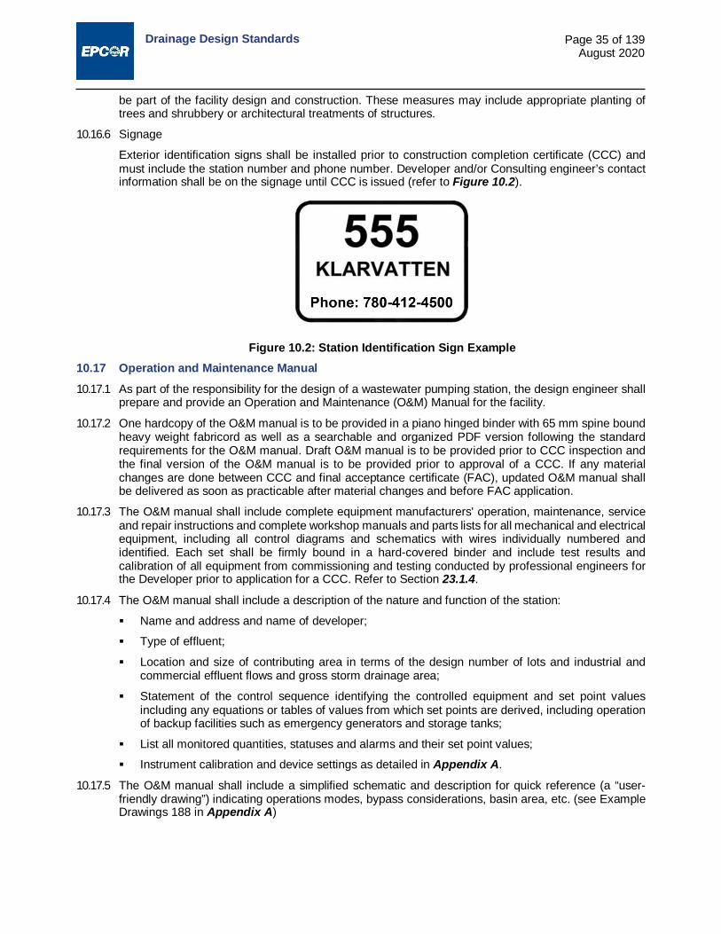
Drainage Design Standards
Page 35 of 139 August 2020
be part of the facility design and construction. These measures may include appropriate planting of trees and shrubbery or architectural treatments of structures.
10.16.6 Signage
Exterior identification signs shall be installed prior to construction completion certificate (CCC) and must include the station number and phone number. Developer and/or Consulting engineer’s contact information shall be on the signage until CCC is issued (refer to Figure 10.2).
10.17 Operation and Maintenance Manual 10.17.1 As part of the responsibility for the design of a wastewater pumping station, the design engineer shall
prepare and provide an Operation and Maintenance (O&M) Manual for the facility.
10.17.2 One hardcopy of the O&M manual is to be provided in a piano hinged binder with 65 mm spine bound heavy weight fabricord as well as a searchable and organized PDF version following the standard requirements for the O&M manual. Draft O&M manual is to be provided prior to CCC inspection and the final version of the O&M manual is to be provided prior to approval of a CCC. If any material changes are done between CCC and final acceptance certificate (FAC), updated O&M manual shall be delivered as soon as practicable after material changes and before FAC application.
10.17.3 The O&M manual shall include complete equipment manufacturers' operation, maintenance, service and repair instructions and complete workshop manuals and parts lists for all mechanical and electrical equipment, including all control diagrams and schematics with wires individually numbered and identified. Each set shall be firmly bound in a hard-covered binder and include test results and calibration of all equipment from commissioning and testing conducted by professional engineers for the Developer prior to application for a CCC. Refer to Section 23.1.4.
10.17.4 The O&M manual shall include a description of the nature and function of the station:
Name and address and name of developer;
Type of effluent;
Location and size of contributing area in terms of the design number of lots and industrial and commercial effluent flows and gross storm drainage area;
Statement of the control sequence identifying the controlled equipment and set point values including any equations or tables of values from which set points are derived, including operation of backup facilities such as emergency generators and storage tanks;
List all monitored quantities, statuses and alarms and their set point values;
Instrument calibration and device settings as detailed in Appendix A.
10.17.5 The O&M manual shall include a simplified schematic and description for quick reference (a “user-friendly drawing”) indicating operations modes, bypass considerations, basin area, etc. (see Example Drawings 188 in Appendix A)
Figure 10.2: Station Identification Sign Example

Drainage Design Standards
Page 36 of 139 August 2020
10.18 Requirements for Activated Carbon Odour Control Units (OCU) in Pump Stations 10.18.1 General
The activated carbon adsorption units should be capable of continuously treating odorous air at 100% relative humidity at air exchange rates for wet wells. The activated carbon adsorption system should be supplied complete with all supporting equipment and documentation required for system operation. The activated carbon media should also be supplied.
The activated carbon filter system should generally consist of an inlet isolation valve, pre-filter, heater, activated carbon housing and activated carbon media, extraction fan(s), discharge stack, control equipment panel, and monitoring equipment.
The minimum activated carbon design bed life should be approximately 24 months. The bed life is defined as the length of time between replacements of the activated carbon media based on breakthrough of gas. The Contractor should submit calculations verifying the amount of carbon to meet the carbon bed life specified. OCU’s should be built above ground to avoid potential complications associated with high levels
of hydrogen sulphide, utilities, space constraints, confined space entry and flooding: o Have enough room to inspect around the unit; o Be heated in a heated location; o Well-constructed.
Be safe to construct, operate, maintain and decommission; Provide reliable and effective odour removal; Have a minimum of 20 years’ service life; Comply with all relevant statutory and regulatory requirements, standards, code of practices and
municipal design standards; Not cause interruption to the normal operation of the pump station; Be capable of automatic operation via connection to EPCOR Supervisory Control and Data
Acquisition (SCADA) for Drainage Facilities; All electrical and mechanical systems should be above ground; Adequate access should be provided to allow all expected operational and maintenance activities
to be carried out in a safe and efficient manner; Allow easy installation and removal of equipment by lifting devices; Noise level should follow the City of Edmonton, Community Standards Bylaw 14600.
10.18.2 Pre-filter(s)
One easily removable and cleanable pre-filter assembly should be installed downstream of the inlet isolation valve and upstream of all other OCU equipment. The pre-filter should be designed to remove particulate matter and should have a removal efficiency of 96% based and of corrosion resistant construction materials. The pre-filter design should be sufficient to provide consistent flow to the unit for a period of approximately 6 weeks between cleaning events. The pre-filter(s) should be mounted in a frame and be constructed to prevent bypassing of the filter by inlet air. One spare set of filter(s) should be supplied. The design of the pre-filter should facilitate easy removal of the pre-filter for cleaning/replacement.
10.18.3 In-line Duct Heating
Should be provided on the inlet side of the carbon media adsorption unit. The capacity of the heater should be sufficient to reduce the relative humidity to less than 70% for the design inlet airflow with a relative humidity of 100% at 20°C. The in-line heater should not operate unless the fan is running and airflow through the inlet ducting is ensured. Temperature measurement and indicators should be provided on the inlet and outlet of the heater.

Drainage Design Standards
Page 37 of 139 August 2020
10.18.4 Adsorption Unit
The activated carbon vessel, internal components, and structural components should be corrosion resistant material .The minimum activated carbon bed life should be approximately 24 months. The carbon adsorption unit and associated ductwork should be designed to minimize pressure drop, prevent any by-pass of gas flow, and provide easy access for maintenance.
10.18.5 Monitoring
Permanent sampling ports should be provided on the carbon adsorption unit. Media Bed Monitor is required for all carbon beds only.
Sample ports for air sampling on the discharge side according to stack survey requirement
10.18.6 Control System
The activated carbon system should be designed for unmanned operation fully automated with allowance for manual operation. The activated carbon system unit should be installed with the following instrumentation and monitors as a minimum:
Differential pressure transmitters should be provided to measure the head loss across both the pre-filters and the OCU media bed connected to EPCOR SCADA;
Air flow monitoring (flow switch after fan) – interlocked to shut down the heater and connected to the EPCOR SCADA;
Temperature transmitters before and after the heater – connected to EPCOR SCADA;
Hydrogen Sulphide meters should be supplied to monitor the inlet and outlet OCU performance. Connected to EPCOR SCADA.
10.18.7 Adsorptive Media
The Contractor should include information including details and price of the activated carbon intended to be supplied in the concept design for review.
The adsorptive media should be either impregnated activated carbon or other similar media that is predominantly an activated carbon material, chemically treated to adsorb the constituent gases from the collected airstream.
The depth of media should be such that the minimum contact time for the airstream in the OCU is at least 2.0 seconds at maximum design airflow without exceeding the manufacturer recommended gas velocity through the activated carbon (typically maximum 25-33 cm/s). The adsorptive media should be evenly distributed in the bed so that no bypassing or short circuiting of foul air occurs within the OCU.
10.18.8 Media Chamber Access
Separate and easily accessible compartments/hatches for each type of media are required to facilitate monitoring and maintenance for crews, service trucks and vactor trucks. The chambers must be independent of one another for direct removal/replacement of media. The hatches should be lockable and of sufficient size to allow both removal of carbon by suction hose.
Outlet concentration as measured at the exit of the OCU or vent stack: Hydrogen Sulphide (H2S) ≤ 0.03 ppm
10.18.9 Inlet Isolation Valve
An easily operated positive shut off isolation valve should be provided on the extraction ductwork to the OCU. This valve is to provide a gas tight isolation of the OCU from the inlet gases for the purpose of carrying out maintenance activities. For treatment of wet wells, bypass ventilation ducting should be installed so that the treatment unit can be bypassed.

Drainage Design Standards
Page 38 of 139 August 2020
10.18.10 Drain
The OCU should have gravity drains to remove condensate from all parts of the unit. The material of construction should be sulphuric acid resistant. Drainage points must be supplied to prevent any condensate from collecting in the OCU.
10.18.11 Operating and Maintenance Manual
An O&M manual should be provided for the OCU. An acceptable O&M manual is considered a key requirement for successful handover. It should be provided in both paper form and electronic form
The manual should include, but not limited to:
Overview of the OCU conceptual design;
Detailed description of the unit and its components, process, and performance criteria;
Detailed P&IDs, complete list of all equipment items (including electrical items);
Detailed information for each supplied piece of equipment (Manufacturer, supplier, model number);
A list of suppliers and their current contact details;
Standard operating instructions covering all routine work requirements (system start up, shut down, routine monitoring, maintenance, inspections, changing of media);
Process optimization and troubleshooting guide;
The PLC functional description, Input / Output listings, electronic copies of PLC programs, details of the programming software used (including version details) and where it can be obtained;
Reference listing of all monitoring and alarm signals both locally and transmitted to EPCOR SCADA
Reference listing of all interlocks and system timers (their values, allowable ranges and where these are set);
List of any recommended spares to be held;
Instructions on storage, loading/unloading, and SDS of treatment media
Complete program settings for all programmable equipment (for example, Differential Pressure Transmitters);
Basic description of OCU system, including process flow description;
Drawings with the proposed layout complete with key dimensions, showing ductwork and access;
List of any special tools and lifting devices.
10.19 EPCOR Chemical Dosing Requirements Everything needs to comply with the relevant electrical/building/OH&S codes requirements. All stations with chemical treatment are required to have the following:
10.19.1 Pump Skid
1 duty and 1 spare diaphragm pump or peristaltic pump;
Pumps to be selected to allow varying the dosing rate;
Discharge hose for the pump is to deposit in wet well;
PLC controllable.
10.19.2 Tanks (located inside the building)
Must have enough room to inspect around and top of tanks;
Must provide 60 days of storage;

Drainage Design Standards
Page 39 of 139 August 2020
Provide high level overflow;
Have visual verification of level gauge;
Continuous level monitoring using SCADA with a local display;
o Include a high and low level alarm for liquid level in the tank
Temperature control building. The optimal temperature for most chemicals is 20°C. Include the low/high temperature alarm to SCADA;
External chemical fill location with tank level indicator and alarm.
10.19.3 Safety
Must have secondary spill containment. Ideally the tank and pump have separate containment area;
Chemical safety data sheets (MSDS);
Eye-wash station and safety shower designed and located according to ANSI Z358.1.
10.19.4 O&M manual for chemical dosing system and all the equipment
11.0 DESIGN OF SEWAGE FORCEMAINS 11.1 Forcemain Size Considerations
The design of a sewage forcemain is to include study of the comparative costs of construction and long-term operation for alternative sizes. There are, however, practical limitations to the size options which may be considered, as flow velocities are required to exceed certain minimum values to prevent slime growth within the forcemain and to ensure solids are not deposited within the forcemain. It is also necessary to minimize the residence time of sewage within pumping station wet wells and forcemains to avoid anaerobic fermentation and the resultant production of odorous, hazardous and corrosive gases such as hydrogen sulphide (H2S).
11.2 Flow Velocity Limits 11.2.1 To prevent slime growth on the pipe walls of the forcemain and to transport solids, the minimum
velocity of flow in the pipe should exceed the velocity determined by:
V = −0.3log 0.1D
where, V = velocity in m/s
D = pipe internal diameter in mm
11.2.2 Optimum design velocities, in the range of 0.9 to 1.5 m/s, are recommended, considering both operating costs and prevention of solids accumulation. When the forcemain grade profile includes steep slopes or vertical sections, the minimum design velocity should be increased by an order of 50%. Where design flow velocities in buried forcemains exceed 3.0 m/s, any special provisions required to ensure stability of the forcemain shall be identified and incorporated in the design. A maximum flow velocity of 3.5 m/s is recommended.
11.3 Design Pressures The pressure design for forcemains shall consider normal static and dynamic operating pressures, the potential conditions that may occur due to outlet surcharge or blockages and transient pressure (water hammer) effects. A transient pressure analysis is required to determine if protection is required and appropriate provisions are to be incorporated into the pumping system design.
11.4 Surge Protection Devices Where necessary, surge relief valves shall be designed with a suitable discharge location and be located with a suitable method of access. Surge relief valves that regulate with external springs or counterweights and dashpots are preferred to valves regulated with pilot pressure piping systems, for sanitary wastewater and liquids with substantial solids content. Rupture discs shall not be used.

Drainage Design Standards
Page 40 of 139 August 2020
11.5 Slope All forcemains shall be sloped sufficiently to promote the discharge of air during filling and to permit the forcemain to be drained. Forcemains shall not be installed at zero slope.
11.6 Alignment Forcemains should have a straight alignment wherever possible. The use of 90° bends in forcemains is to be avoided. A series of 45° or smaller deflection bends are to be used where extreme direction changes are required.
11.7 Air Release Automatic air release valves shall be provided at all relative high points along the forcemain. The need for air release valves should be minimized by establishing the grade profile to eliminate summits. Air release valves are to be installed in waterproof concrete access chambers, insulated to prevent freezing and with provisions for drainage.
11.8 Blowoff Valves A valve for blowoff and drainage of the forcemain is to be provided at each low point.
11.9 Vacuum Relief Provision for vacuum relief shall be made as necessary where forcemains are proposed to drain by gravity between pumping cycles.
11.10 Forcemain Outlet 11.10.1 The forcemain should enter the receiving manhole horizontally at an invert elevation no more than 300
mm above the flow line of the receiving sewer. A smooth flow transition to the gravity sewer is to be designed to minimize turbulence at the point of discharge.
11.10.2 Inert materials or protective coatings shall be used for areas subject to sulphide attack. 11.11 Design Documentation on Engineering Drawings
The Engineering Drawings shall include "system head" curves for each forcemain, considering the wet well water level at its lowest and highest points and for each different pump operation combinations possible. The plans shall include a notation of the design basis, which shall specify the design friction coefficients, equivalent hydraulic length and design operating conditions.
11.12 Requirements for Locating Forcemains To facilitate location, a tracing wire shall be placed along all forcemains at the time of construction. The wire shall be terminated in a labelled electrical box at the pump station (or appropriate secure location) and looped in any valve chambers and blow-off chambers to allow for connection of an electronic locator at intervals of not greater than every 300 m along the length of the forcemain. If a chamber is not available to provide this interval, the wire shall be looped into a cast iron valve box set at grade level. Locator wire shall be stranded 12-gauge copper with insulation for direct burial. Underground splice connections shall be minimized and shall be rated for direct burial service. Prior to acceptance of the forcemain, a continuity check shall be conducted to verify that the wire has not been broken during installation.
11.13 Requirements for Forcemain Inspection and Cleaning A pig launch port is to be provided at the pump station for cleaning and inspection of the forcemain. The intent of this provision is to allow cleaning using conventional pigs and inspection using smart pigs, televising or other equipment without significant pipe dis-assembly.
12.0 STORM DRAINAGE SYSTEM - POLICY, GOALS AND OBJECTIVES 12.1 Level of Service 12.1.1 The City stormwater management goal is to provide adequate drainage for urban areas that preserves
and promotes the general health welfare, security and economic wellbeing of the public and to protect and enhance the water quality of receiving watercourses.

Drainage Design Standards
Page 41 of 139 August 2020
12.1.2 To meet this goal the storm drainage system must include SWMFs that meet the following level-of-service objectives:
i. Avoid all property damage and flooding and to minimize inconvenience to the public due to runoff from 1:5 year and more frequent rainfall events;
ii. Avoid significant property damage from a 1:100 year return frequency rainfall event;
iii. Avoid loss of life and injuries and minimize damage to property, through control of runoff during unusual or infrequent storm events with high-intensity rainfall and large runoff volume;
iv. Avoid degradation of receiving watercourses, by implementing the requirements of the ESC Guidelines.
12.1.3 Where the capacity of existing downstream sewers was deemed to be adequate in accordance with the City of Edmonton Servicing Standards in effect prior to 1990, the theoretical design deficiency created downstream under later standards would not become a reason to stop the upstream development.
12.1.4 Where an actual capacity deficiency is identified, the Developer and the City will jointly resolve the issue through the development approval process.
12.2 Major/Minor System Concept 12.2.1 New development areas in Edmonton shall be designed using the major/minor system concept, with
each system planned and designed to achieve specific level-of-service objectives.
12.2.2 The term the "minor system" is applied to the network of local and trunk sewers, inlets and street gutters which are provided as a conveyance system to rapidly carry away storm runoff from road surfaces. Minor systems have generally been designed with capacity to remove runoff from minor rainfall events.
12.2.3 Runoff in excess of the capacity of the minor system ponds in depression areas or follow whatever overflow escape route is available. This network of planned or unplanned ponding areas and overland flow routes is the "major system". If a major system is adequately planned and designed and incorporated into the urban infrastructure, it should alleviate the potential inconvenience, property damage and loss of life, which could otherwise result from major rainfall events.
12.3 Minor System 12.3.1 General Requirements
Minor-system elements serving drainage areas of 30 ha or less shall be designed to accommodate the rate of runoff which would occur in a 5-year return period rainfall event;
i. without surcharge of storm sewers;
ii. with ponding of water to a depth no greater than 150 mm at depressions and at drainage inlets;
iii. with depths of flow and ponding on roadways limited such that no over-topping of curbs occurs on local roadways, a width equivalent to one traffic lane remains free from inundation on collector roads and one traffic lane in each travel direction remains free from inundation on arterial roads;
iv. with storm water quality BMPs prior to discharging into the piped system.
12.4 Sewers Servicing Areas Greater than 30 ha 12.4.1 Storm sewer trunks, for this purpose being those storm sewer pipes proposed to serve drainage areas
of greater than 30 uncontrolled ha, shall be designed with a reserve capacity to account for unanticipated changes in land use and runoff and to ensure downstream storm sewer trunks do not surcharge in advance of the upstream lateral storm sewers.
12.4.2 To achieve the objective the subject storm sewers are to be designed to accommodate, without surcharge, 1.25 times the rate of flow which would occur in a 5-year return period rainfall event.
12.4.3 In cases where the storm sewer trunk receives both uncontrolled flow from areas 30 ha or larger and controlled discharges from SWMFs, the sewer is to be designed so as to accommodate, without

Drainage Design Standards
Page 42 of 139 August 2020
surcharge, 1.25 times the 5 year design flow from the uncontrolled lands plus the maximum design SWMF outflow rate.
12.5 Major System 12.5.1 Conveyance Elements
Major-system conveyance elements shall be designed to accommodate runoff rates and volumes for a 100-year return period rainfall event such that:
i. The depth of peak flows and ponding in developed area streets, conveyance channels and swales, are to be limited so that major system flows do not constitute a significant hazard to the public, or result in significant erosion or other property damage. Where erosion is anticipated, an ESC Plan should be designed to suit site specific situations.
ii. The maximum water surface level of surface flows and ponding in streets is below the lowest anticipated landscape grade or opening at any adjacent buildings, with a freeboard provision generally in the order of 350 mm with a minimum of 150 mm.
iii. Depths of flow and ponding are less than 350 mm in roadways and other public rights-of-way. Roadway ponding should be minimized in a way that prevents encroachment on private property and ensure best practices to minimize flooding on private property.
iv. For arterial roadways, the water depth at the crown of the road shall not exceed 150 mm.
12.5.2 Storage Elements
i. Major-system storage elements shall be designed such that no over-topping of the storage facilities occurs due to storm events equal to or less severe than the critical storage event for the catchment served.
ii. The default requirement for the retention volume to be provided is to be the equivalent of 120 mm of water over the total catchment area draining to the facility. This requirement is based on the estimated volume of runoff from the recorded July 14 - 15, 1937 storm event, being 155 mm of rainfall with a runoff/rainfall ratio of 0.62 and including a 25% volume safety factor allowance. Where justified on the basis of a risk analysis, or in consideration of provision of a safe overflow, reduced storage volume requirements may be approved.
iii. Where a stormwater management storage facility is located such that minor and/or major system outlet capacity is guaranteed to be available for all design runoff events, due to proximity to a ravine or river, the outflow from the facility which occurs during any runoff events is considered in the determination of the required storage volume. i.e. if the outlet capacity cannot be guaranteed to be available, then the storage facility must be sized assuming zero discharge for the duration of the event.
iv. The performance of each storage facility design is to be verified by computer simulation of its response, considering the outflow rate as limited by control elements or downstream conditions, to the most critical of any of the design rainfall events from the following listing:
1:100 year, 24 h synthetic design event based on the Huff distribution;
The July 14 - 15, 1937 storm event;
The July 10 - 11, 1978 storm event;
The July 2 - 3, 2004 storm event; and
The July 12, 2012 storm event;
Refer to Section 13.5.8 for rainfall data references.
v. SWMF inlets and outlets should be physically separated around the perimeter of the facility. The inlet and outlet should be distanced as far from each other as possible to avoid hydraulic short-circuiting.

Drainage Design Standards
Page 43 of 139 August 2020
12.5.3 A high level emergency overflow is to be provided wherever feasible and each facility design is to include an evaluation of the impact of over-topping of the facility and the probability of exceeding the design high water level. The design of SWMFs which are provided with a high-level overflow to a safe outlet shall include a minimum freeboard provision of 300 mm from the design high water level to the lowest anticipated landscape grade or opening at any adjacent buildings.
12.5.4 In the absence of an emergency overflow, the freeboard provided is to be at least 0.5 m.
12.5.5 Except for constructed wetlands, sufficient outlet capacity is to be provided to permit post-event drawdown of water levels in storage facilities such that the availability of storage capacity is restored within the following time frames:
1:5 year runoff capacity to be available within 24 h;
1:25 year runoff capacity to be available within 48 h; and
90% of the facility full volume to be available within 96 h.
12.5.6 This is to be evaluated using the Huff distribution design storms for SWMF drawdown analysis provided as Table 13.10, in Section 13.12.
12.5.7 Where storage facilities are connected in series or where the provisions of post-event outlet capacity to satisfy the above drawdown requirements is not feasible, the satisfactory performance of the storage facilities to accommodate sequential rainfall events shall be verified by computer simulation using continuous rainfall records. Multiple Event Time Series’ and Long Duration Time Series’ are available from EPCOR Drainage Services.
12.6 Provision for Areas beyond the Limits of Presently Proposed Development 12.6.1 Provisions for Future Development
The design for each storm sewer system extension shall include provisions for further extensions to future developments in accordance with the WP and AMP for the development area. The design must also account for the interception, conveyance and storage requirements as necessary to accommodate runoff flows from undeveloped contributory areas for the indefinite future or for an interim period until development of those areas occurs.
12.6.2 Overland Drainage
i. The Developer shall make provisions for the interception of all overland drainage runoff which would enter the Developer's subdivision and may result in a nuisance, flooding, or maintenance problem.
ii. The Developer shall also ensure that the development does not adversely affect existing drainage in the vicinity of the development site resulting in a nuisance or maintenance problem.
12.6.3 Separation of the Storm and Sanitary Systems
Storm sewers shall be designed as a separate system to convey rainfall and snow melt runoff from roof drains, streets, parking lots and other areas and shall not receive effluent from any sources which may contain industrial, agricultural or domestic waste or sewage. Storm sewers shall not discharge into a sanitary system.
12.7 Economic Objectives 12.7.1 A prime consideration in the selection of alternatives for the storm servicing of new development areas
must be minimization of the long-term cost to the public. Economic analysis must include evaluation and comparison on the basis of operations and maintenance costs as well as capital cost differences.
12.7.2 The City desires to promote an orderly process of development with the objective of achieving permanent storm system extensions, in the most cost-effective manner, that meet the City’s environmental objectives. Extensions of systems and developments is discouraged when they involve the construction of downstream connection, through undeveloped areas (“leapfrogging”) solely for the purpose of advancing service extension to upstream areas.
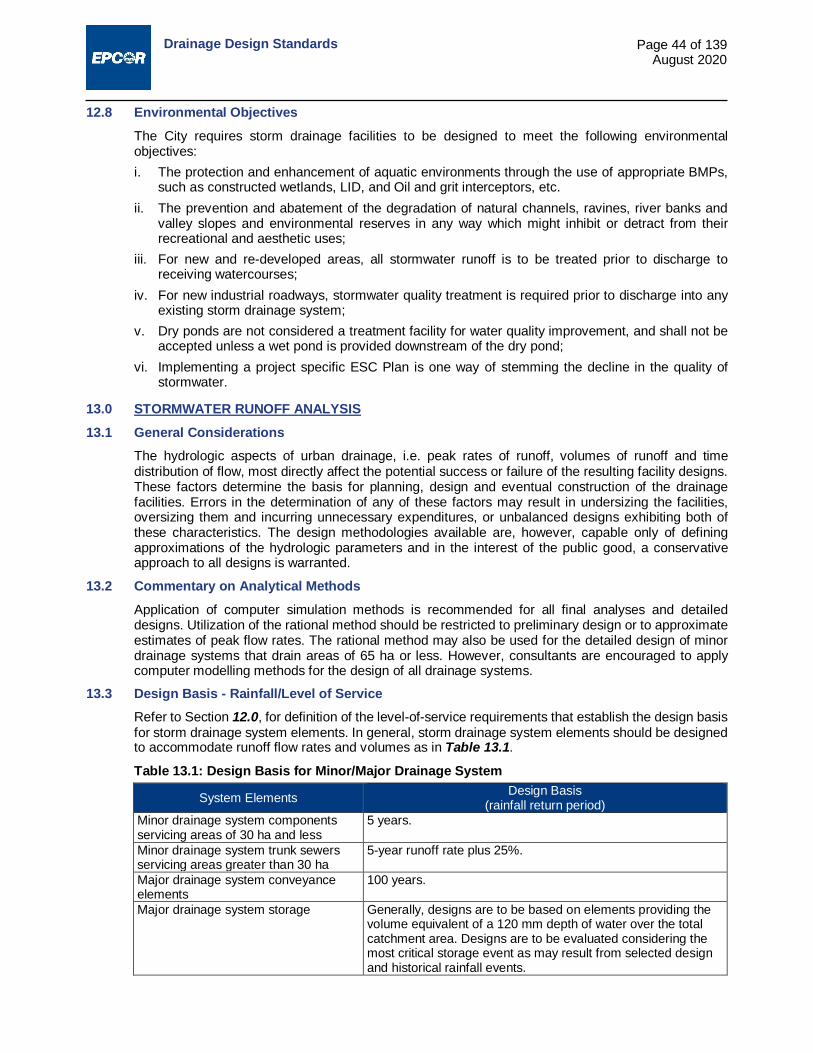
Drainage Design Standards
Page 44 of 139 August 2020
12.8 Environmental Objectives The City requires storm drainage facilities to be designed to meet the following environmental objectives: i. The protection and enhancement of aquatic environments through the use of appropriate BMPs,
such as constructed wetlands, LID, and Oil and grit interceptors, etc. ii. The prevention and abatement of the degradation of natural channels, ravines, river banks and
valley slopes and environmental reserves in any way which might inhibit or detract from their recreational and aesthetic uses;
iii. For new and re-developed areas, all stormwater runoff is to be treated prior to discharge to receiving watercourses;
iv. For new industrial roadways, stormwater quality treatment is required prior to discharge into any existing storm drainage system;
v. Dry ponds are not considered a treatment facility for water quality improvement, and shall not be accepted unless a wet pond is provided downstream of the dry pond;
vi. Implementing a project specific ESC Plan is one way of stemming the decline in the quality of stormwater.
13.0 STORMWATER RUNOFF ANALYSIS 13.1 General Considerations
The hydrologic aspects of urban drainage, i.e. peak rates of runoff, volumes of runoff and time distribution of flow, most directly affect the potential success or failure of the resulting facility designs. These factors determine the basis for planning, design and eventual construction of the drainage facilities. Errors in the determination of any of these factors may result in undersizing the facilities, oversizing them and incurring unnecessary expenditures, or unbalanced designs exhibiting both of these characteristics. The design methodologies available are, however, capable only of defining approximations of the hydrologic parameters and in the interest of the public good, a conservative approach to all designs is warranted.
13.2 Commentary on Analytical Methods Application of computer simulation methods is recommended for all final analyses and detailed designs. Utilization of the rational method should be restricted to preliminary design or to approximate estimates of peak flow rates. The rational method may also be used for the detailed design of minor drainage systems that drain areas of 65 ha or less. However, consultants are encouraged to apply computer modelling methods for the design of all drainage systems.
13.3 Design Basis - Rainfall/Level of Service Refer to Section 12.0, for definition of the level-of-service requirements that establish the design basis for storm drainage system elements. In general, storm drainage system elements should be designed to accommodate runoff flow rates and volumes as in Table 13.1.
Table 13.1: Design Basis for Minor/Major Drainage System
System Elements Design Basis (rainfall return period)
Minor drainage system components servicing areas of 30 ha and less
5 years.
Minor drainage system trunk sewers servicing areas greater than 30 ha
5-year runoff rate plus 25%.
Major drainage system conveyance elements
100 years.
Major drainage system storage Generally, designs are to be based on elements providing the volume equivalent of a 120 mm depth of water over the total catchment area. Designs are to be evaluated considering the most critical storage event as may result from selected design and historical rainfall events.

Drainage Design Standards
Page 45 of 139 August 2020
13.4 Rational Method 13.4.1 Application
The use of the rational method for final design calculations is to be limited to the design of minor storm drainage system components proposed to accommodate flows from catchments with an area of approximately 65 ha or smaller.
13.4.2 Estimating Runoff Flow Rates by the Rational Method The rational formula for storm runoff is expressed as:
Q =CIA360
where, Q = discharge in m³/s (design flow rate) C = a dimensionless runoff coefficient I = the average intensity of rainfall in mm/hr A = the drainage area in ha
13.4.3 Runoff Coefficients
The runoff coefficient, C, is to be consistent with the imperviousness for the respective land use. For the purposes of this standard, imperviousness (imp) shall be expressed as a fraction equivalent to the ratio of impervious area to the total area. The following formula relates C and imp and is applicable for the determination of runoff coefficients for storm events with return periods of 10 years or less.
C = 0.95 × imp + 0.1(1.0− imp)
13.4.4 Runoff coefficients may be calculated for site-specific conditions where details of ultimate site development are known. Otherwise, values of C are to be selected on the basis of zoning or general land uses from the respective tables, Table 13.3 or Table 13.4, provided at the end of this section. These values are to be applied only for determination of peak runoff rates for storms with return periods of 10 years or less.
13.4.5 For use of the rational method to determine peak rates of runoff due to storms with return periods greater than 10 years, the values of runoff coefficients are to be increased from those identified above, in accordance with Table 13.2, up to a maximum value of 0.95:
Table 13.2: Runoff Coefficient Modification Factor Design Return Period Runoff Coefficient Modification
Above 10 year up to 25 year multiply C by 1.1 Above 25 year up to 50 year multiply C by 1.2 Above 50 year multiply C by 1.25
13.4.6 Rainfall Design Intensity i. The value of the design rainfall intensity, I, for the rational formula is selected from the appropriate
intensity duration frequency (IDF) curve, with a duration chosen to coincide with the time of concentration, tc. The time of concentration for runoff flow is the time required for runoff flow to become established and reach the design location from the furthest point within the contributing catchment area.
ii. Determination of tc requires estimation of two components, the "inlet time" and "travel time". iii. The inlet time is the time for flow from the extreme limits of the catchment to reach the first point
of inflow into the defined conveyance system. It is dependent upon the imperviousness and the size of the catchment.
iv. The travel time is the length of time required for flow to travel within the conveyance system from the point of inflow to the design location.

Drainage Design Standards Page 46 of 139 August 2020
13.4.7 Inlet Time Determination
Appropriate values for inlet time may be selected from Table 13.5 at the end of this section. This specifies values with respect to imperviousness and size of the catchment.
13.4.8 Intensity Frequency Duration (IDF) Curves
Rainfall IDF curves for the City of Edmonton for selected return frequency events are presented in tabular form in Table 13.6 and Table 13.7 at the end of this section.
13.5 Computer Simulation of Runoff 13.5.1 Application
All storm drainage conveyance system elements proposed to accommodate flows for servicing areas larger than 65 ha and all stormwater management storage facilities shall be designed using computer modelling techniques.
13.5.2 Methodology for Computer Simulations, Selection of Computer Models i. Before commencing any computer modelling for purposes of AMP or neighbourhood design
studies, the Developer or the Consultant shall obtain approval from EPCOR Drainage Services onthe selection of the proposed computer models and version they plan to use. The selection andproper application of computer models is primarily the responsibility of developers and theirconsultants. It is necessary to use computer models which have the capability to generatehydrographs for a critical storm or series of storms and which can route these hydrographs througha network of conduits, surface channels and storage facilities.
ii. The DHI – Mike Urban (or Mouse) and Mike 21 models are recommended for use in the design ofdual (major and minor) drainage systems.
iii. Storage facilities should be designed using reservoir routing techniques when discharges arepermitted during an event. This is dependent on downstream conditions and constraints.
13.5.3 Modelling Procedures i. The basic approach involves a coarse discretization (lumped area) of the basin based upon the
latest available information, which may be a development proposal or area or neighbourhoodstructure plan.
ii. Runoff hydrographs are to be calculated from these lumped areas and used for pipe sizing,acknowledging the routing effects of the sewers. Post-development hydrographs are to bedetermined at key points of the trunk sewer and major systems for the 5, 10, 25, and 100-yeardesign storms and for the most critical rare runoff event for the sizing of stormwater managementstorage facilities.
iii. Drainage systems which involve a number of interconnected ponds in series, or which haverelatively restricted outlet flow capacity, require analysis for sequential storm events or modellingwith a continuous rainfall record. At the detailed levels of design (NDR and beyond) the systeminlets to the minor system must be designed to pass, without exceeding ponding depth allowances,runoff flows from the 1:5 year design runoff event. It must also be demonstrated that for eventsexceeding the 1:5 year design event, excess runoff volumes are accommodated by surfaceconveyance and ponding to depths not exceeding major event ponding depth allowances.
iv. The 4-h Chicago distribution hyetographs should be used for analysis of major and minorconveyance systems by computer simulation. When the design of stormwater management isinvolved, the 24-h Huff distribution design hydrographs should be used along with the “MultipleEvent Time Series’” as recommended by EPCOR Drainage Services i.e.: yr1991 and/or yr2004.
v. See Appendix B for the computer model transfer requirement.
13.5.4 Watershed Data Preparation
When modelling portions of the watershed that have been developed previously, data preparation shall be based upon existing conditions. Data preparation for new areas shall be based upon the best available planning information.

Drainage Design Standards
Page 47 of 139 August 2020
13.5.5 Rainfall Data
Tabulated rainfall data are provided at the end of this section. These data, as applicable, shall be used for all computer modelling studies along with “Multiple Event Time Series’” and Long Duration Time Series’ which are available from Drainage Planning.
13.5.6 Sensitivity Analysis
When using computer models, sensitivity work of the hydrological parameters shall be required to ensure proper calibration. Hydrological parameters should be discussed with “Drainage Planning” personnel to ensure the values utilized are within acceptable ranges.
13.5.7 Presentation of Modelling Results
To obtain standardization in presentation of model results, planning reports shall include an appropriate section that indicate the following:
type and version of computer model used;
all parameters and specific simulation assumptions used;
design storms used, to be clearly documented and plotted;
volumetric runoff coefficient or total runoff obtained;
peak flow versus area, plotted for each event studied; and
peak flow/area versus time, plotted for each event studied.
13.5.8 Index - Tables of Runoff and Rainfall Information
Table 13.3: Storm Runoff Coefficients and Imperviousness According to Zoning
Table 13.4: Storm Runoff Coefficients and Imperviousness According to Land UseTable 13.5: Design Inlet Time (minutes) with Respect to Catchment Imperviousness and Size
Table 13.6: IDF Curves - Intensity Table (Summary table for the 2-year, 5-year, 10-year, 25-year, 50-year, 100-year and 200-year curves.)
Table 13.7: IDF Curves - Intensity Table-Summary (Summary table for the 2-year, 5-year, 10-year, 25-year, 50-year, 100-year and 200-year curves.)
Table 13.8: IDF Parameters
Table 13.9: Chicago Distribution (modified): 4-Hr Design Storm Data (mm/hr) (The 2-year, 5-year, 25-year, 50-year, 100-year and 200-year design storm hyetographs.)
Table 13.10: Huff Distribution (24-h duration storm, first quartile 50% probability. Design Storm for SWMF Drawdown Analysis Only
Table 13.11: Recorded Storm of July 14, 1937
Table 13.12: Recorded Storm of July 10 - 11, 1978
Table 13.13: Recorded Storm of July 2 & 3, 2004 (total of 135mm)
Table 13.14: Recorded Storm of July 12, 2012

Drainage Design Standards
Page 48 of 139 August 2020
13.6 Table 13.3: Storm Runoff Coefficients and Imperviousness According to Zoning
Zoning or Classification Designation Per Bylaw # 128001
Runoff2 Coefficient " C "
Imperviousness3 " Imp " ( % )
A, RR, AC 0.2 10 - 50 AP, Schools 0.3 10 - 50 RF1, RF2, RF3, RF4, RMH, AGU 0.5 40 - 65 MA, IH 0.5 40 - 70 RF5, RF6, RSL, RA7 0.65 40 - 90 RA8, US, PU 0.75 40 - 90 CNC, CSC, IB, IM, RA9, CB1, CHY, AGI, CO 0.9 40 - 100
CB2 0.95 70 - 100 RMX, CMS, DC1, DC2, DC3, DC4 * 40 - 100
1 For zonings not shown in this table, the runoff coefficient “C” and the percentage of imperviousness “Imp%” shall be estimated by the designer.
2 Minimum design values to be used without specific area analysis. To be used only for calculation of peak runoff rates by the rational method.
3 Typical ranges based on land use bylaw site coverage limits and typical paving practice.
13.6.1 *Special districts
The storm runoff factor for special district zonings are to be the same as the factors for the land use designation which closest resembles the land use specified by the associated statutory plan overlay, or area structure plan, covering the parcel being assessed.
13.6.2 Zonings not shown above For zonings not shown in Table 13.3, the runoff coefficient "C" and the percentage of imperviousness Imp% shall be estimated by the designer.
13.7 Table 13.4: Storm Runoff Coefficients and Imperviousness According to Land Use Land Use Runoff Coefficient1 “C” Imperviousness “Imp”(%)
Asphalt, concrete, roof areas 0.95 90 - 100 Industrial, commercial 0.60 50 - 100 Single family residential 0.65 40 - 60 Predominant grassed areas, parkland 0.10 10 - 30
1 Minimum values to be used without specific area analysis. To be used only for calculation of peak flow rates by the Rational Method.
13.8 Table 13.5: Design Inlet Time (minutes) with Respect to Catchment Imperviousness and Size Imperviousness (%)
Catchment Area (A) 30 50 > 70
A = 8 ha or less 8 8 5 8 ha < A < 40 ha 9.2 9.2 6 A = 40 ha or more 10.4 10.4 7.25

Drainage Design Standards
Page 49 of 139 August 2020
13.9 Table 13.6: IDF Curves - Intensity Table Edmonton 11 Rain Gauges Upper Bound - IDF Period: 1984-2015
Maximum Years of Record = 32 IDF Intensity (mm/hr)
Time Return Frequency Minutes Hours 2-yr 5-yr 10-yr 25-yr 50-yr 100-yr 200-yr
5 66.0 89.0 108.6 138.0 162.2 188.4 217.8 6 61.3 83.2 101.9 129.9 152.9 178.1 206.8 7 57.2 78.3 96.1 122.9 144.7 169.0 197.1 8 53.8 73.9 91.1 116.7 137.5 160.9 188.4 9 50.8 70.1 86.6 111.1 131.1 153.7 180.6
10 48.2 66.7 82.6 106.2 125.3 147.2 173.5 11 45.8 63.7 79.0 101.7 120.1 141.3 167.0 12 43.8 61.0 75.7 97.7 115.4 136.0 161.1 13 41.9 58.6 72.7 93.9 111.1 131.1 155.6 14 40.2 56.3 70.0 90.6 107.1 126.6 150.5 15 0.25 38.7 54.3 67.6 87.4 103.5 122.4 145.9 16 37.2 52.4 65.3 84.6 100.2 118.6 141.5 17 36.0 50.7 63.2 81.9 97.0 115.0 137.5 18 34.8 49.1 61.2 79.4 94.1 111.7 133.7 19 33.7 47.6 59.4 77.1 91.4 108.6 130.1 20 32.6 46.2 57.7 74.9 88.9 105.7 126.8 21 31.7 44.9 56.1 72.9 86.6 102.9 123.6 22 30.8 43.7 54.6 71.0 84.3 100.4 120.7 23 30.0 42.6 53.2 69.2 82.2 97.9 117.9 24 29.2 41.5 51.9 67.5 80.3 95.6 115.2 25 28.5 40.5 50.7 65.9 78.4 93.5 112.7 26 27.8 39.5 49.5 64.4 76.6 91.4 110.3 27 27.1 38.6 48.4 63.0 74.9 89.5 108.0 28 26.5 37.8 47.3 61.6 73.4 87.6 105.9 29 25.9 37.0 46.3 60.3 71.8 85.8 103.8 30 0.5 25.4 36.2 45.3 59.1 70.4 84.2 101.8 31 24.8 35.5 44.4 57.9 69.0 82.5 100.0 32 24.3 34.8 43.6 56.8 67.7 81.0 98.1 33 23.9 34.1 42.7 55.7 66.4 79.5 96.4 34 23.4 33.5 41.9 54.7 65.2 78.1 94.8 35 23.0 32.9 41.2 53.7 64.1 76.8 93.2 36 22.5 32.3 40.4 52.7 63.0 75.5 91.6 37 22.1 31.7 39.7 51.8 61.9 74.2 90.2 38 21.8 31.2 39.1 50.9 60.9 73.0 88.7 39 21.4 30.7 38.4 50.1 59.9 71.9 87.4 40 21.0 30.2 37.8 49.3 58.9 70.8 86.0 41 20.7 29.7 37.2 48.5 58.0 69.7 84.8
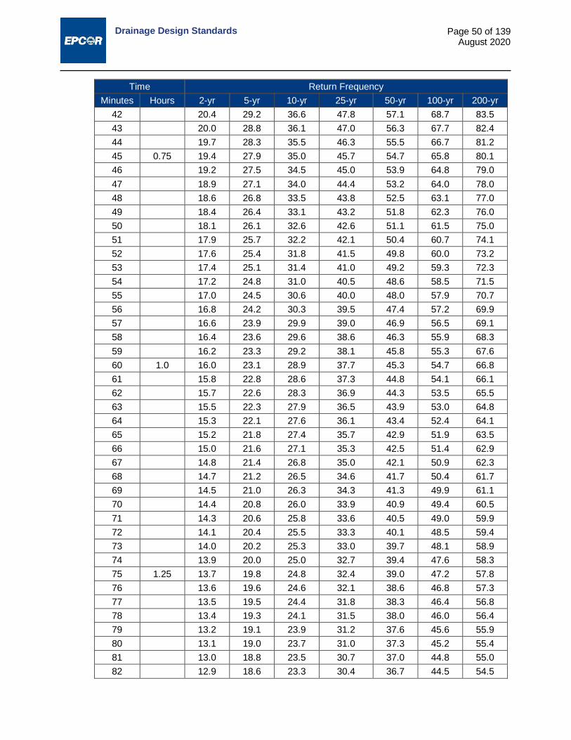
Drainage Design Standards
Page 50 of 139 August 2020
Time Return Frequency Minutes Hours 2-yr 5-yr 10-yr 25-yr 50-yr 100-yr 200-yr
42 20.4 29.2 36.6 47.8 57.1 68.7 83.5 43 20.0 28.8 36.1 47.0 56.3 67.7 82.4 44 19.7 28.3 35.5 46.3 55.5 66.7 81.2 45 0.75 19.4 27.9 35.0 45.7 54.7 65.8 80.1 46 19.2 27.5 34.5 45.0 53.9 64.8 79.0 47 18.9 27.1 34.0 44.4 53.2 64.0 78.0 48 18.6 26.8 33.5 43.8 52.5 63.1 77.0 49 18.4 26.4 33.1 43.2 51.8 62.3 76.0 50 18.1 26.1 32.6 42.6 51.1 61.5 75.0 51 17.9 25.7 32.2 42.1 50.4 60.7 74.1 52 17.6 25.4 31.8 41.5 49.8 60.0 73.2 53 17.4 25.1 31.4 41.0 49.2 59.3 72.3 54 17.2 24.8 31.0 40.5 48.6 58.5 71.5 55 17.0 24.5 30.6 40.0 48.0 57.9 70.7 56 16.8 24.2 30.3 39.5 47.4 57.2 69.9 57 16.6 23.9 29.9 39.0 46.9 56.5 69.1 58 16.4 23.6 29.6 38.6 46.3 55.9 68.3 59 16.2 23.3 29.2 38.1 45.8 55.3 67.6 60 1.0 16.0 23.1 28.9 37.7 45.3 54.7 66.8 61 15.8 22.8 28.6 37.3 44.8 54.1 66.1 62 15.7 22.6 28.3 36.9 44.3 53.5 65.5 63 15.5 22.3 27.9 36.5 43.9 53.0 64.8 64 15.3 22.1 27.6 36.1 43.4 52.4 64.1 65 15.2 21.8 27.4 35.7 42.9 51.9 63.5 66 15.0 21.6 27.1 35.3 42.5 51.4 62.9 67 14.8 21.4 26.8 35.0 42.1 50.9 62.3 68 14.7 21.2 26.5 34.6 41.7 50.4 61.7 69 14.5 21.0 26.3 34.3 41.3 49.9 61.1 70 14.4 20.8 26.0 33.9 40.9 49.4 60.5 71 14.3 20.6 25.8 33.6 40.5 49.0 59.9 72 14.1 20.4 25.5 33.3 40.1 48.5 59.4 73 14.0 20.2 25.3 33.0 39.7 48.1 58.9 74 13.9 20.0 25.0 32.7 39.4 47.6 58.3 75 1.25 13.7 19.8 24.8 32.4 39.0 47.2 57.8 76 13.6 19.6 24.6 32.1 38.6 46.8 57.3 77 13.5 19.5 24.4 31.8 38.3 46.4 56.8 78 13.4 19.3 24.1 31.5 38.0 46.0 56.4 79 13.2 19.1 23.9 31.2 37.6 45.6 55.9 80 13.1 19.0 23.7 31.0 37.3 45.2 55.4 81 13.0 18.8 23.5 30.7 37.0 44.8 55.0 82 12.9 18.6 23.3 30.4 36.7 44.5 54.5

Drainage Design Standards
Page 51 of 139 August 2020
Time Return Frequency Minutes Hours 2-yr 5-yr 10-yr 25-yr 50-yr 100-yr 200-yr
83 12.8 18.5 23.1 30.2 36.4 44.1 54.1 84 12.7 18.3 22.9 29.9 36.1 43.7 53.6 85 12.6 18.2 22.7 29.7 35.8 43.4 53.2 86 12.5 18.0 22.6 29.4 35.5 43.1 52.8 87 12.4 17.9 22.4 29.2 35.2 42.7 52.4 88 12.3 17.8 22.2 29.0 35.0 42.4 52.0 89 12.2 17.6 22.0 28.7 34.7 42.1 51.6 90 1.5 12.1 17.5 21.8 28.5 34.4 41.8 51.2
120 2 9.9 14.3 17.8 23.3 28.2 34.3 42.2 180 3 7.4 10.7 13.3 17.4 21.1 25.8 31.8 240 4 6.0 8.7 10.8 14.1 17.2 21.1 26.0 300 5 5.1 7.4 9.2 11.9 14.6 18.0 22.2 360 6 4.5 6.5 8.0 10.4 12.8 15.8 19.5 420 7 4.0 5.8 7.2 9.3 11.5 14.1 17.4 480 8 3.6 5.3 6.5 8.4 10.4 12.8 15.8 540 9 3.4 4.9 6.0 7.7 9.5 11.8 14.5 600 10 3.1 4.5 5.5 7.1 8.8 10.9 13.5 660 11 2.9 4.2 5.1 6.6 8.2 10.2 12.6 720 12 2.7 3.9 4.8 6.2 7.7 9.6 11.8 780 13 2.6 3.7 4.5 5.8 7.3 9.0 11.1 840 14 2.4 3.5 4.3 5.5 6.9 8.6 10.5 900 15 2.3 3.3 4.1 5.3 6.5 8.1 10.0 960 16 2.2 3.2 3.9 5.0 6.2 7.8 9.6 1020 17 2.1 3.1 3.7 4.8 6.0 7.4 9.2 1080 18 2.0 2.9 3.6 4.6 5.7 7.1 8.8 1140 19 1.9 2.8 3.4 4.4 5.5 6.8 8.4 1200 20 1.9 2.7 3.3 4.2 5.3 6.6 8.1 1260 21 1.8 2.6 3.2 4.1 5.1 6.4 7.8 1320 22 1.7 2.5 3.1 3.9 4.9 6.2 7.6 1380 23 1.7 2.4 3.0 3.8 4.8 6.0 7.3 1440 24 1.6 2.4 2.9 3.7 4.6 5.8 7.1

Drainage Design Standards
Page 52 of 139 August 2020
13.10 Table 13.7: IDF Curves - Intensity Table-Summary Edmonton 13 Rain Gauges Upper Bound - IDF Period: 1984-2015
Maximum Years of Record = 32 IDF Intensity (mm/hr)
Time Return Frequency Minutes Hours 2-yr 5-yr 10-yr 25-yr 50-yr 100-yr 200-yr
5 0.083 66.0 89.0 108.6 138.0 162.2 188.4 217.8 10 0.167 48.2 66.7 82.6 106.2 125.3 147.2 173.5 15 0.250 38.7 54.3 67.6 87.4 103.5 122.4 145.9 20 0.333 32.6 46.2 57.7 74.9 88.9 105.7 126.8 25 0.417 28.5 40.5 50.7 65.9 78.4 93.5 112.7 30 0.500 25.4 36.2 45.3 59.1 70.4 84.2 101.8 35 0.583 23.0 32.9 41.2 53.7 64.1 76.8 93.2 40 0.667 21.0 30.2 37.8 49.3 58.9 70.8 86.0 45 0.750 19.4 27.9 35.0 45.7 54.7 65.8 80.1 50 0.833 18.1 26.1 32.6 42.6 51.1 61.5 75.0 55 0.917 17.0 24.5 30.6 40.0 48.0 57.9 70.7 60 1 16.0 23.1 28.9 37.7 45.3 54.7 66.8
120 2 9.9 14.3 17.8 23.3 28.2 34.3 42.2 180 3 7.4 10.7 13.3 17.4 21.1 25.8 31.8 240 4 6.0 8.7 10.8 14.1 17.2 21.1 26.0 360 6 4.5 6.5 8.0 10.4 12.8 15.8 19.5 720 12 2.7 3.9 4.8 6.2 7.7 9.6 11.8 1440 24 1.6 2.4 2.9 3.7 4.6 5.8 7.1
Table 13.8: IDF Parameters
Rate=a(t+c)b Return Frequency Parameters 2-yr 5-yr 10-yr 25-yr 50-yr 100-yr 200-yr a (t in min) 337.0 498.1 665.2 909.9 1027.7 1200.5 1498.1
b -0.732 -0.735 -0.748 -0.757 -0.742 -0.733 -0.735 c (min) 4.3 5.4 6.3 7.1 7.0 7.5 8.8
R2 0.994 0.997 0.998 0.998 0.998 0.997 0.994

Drainage Design Standards
Page 53 of 139 August 2020
13.11 Table 13.9: Chicago Distribution (modified4): 4-Hr Design Storm Data (mm/hr) Edmonton 11 Rain Gauges Upper Bound, IDF-Period: 1984-2015
Maximum Years of Record = 32 Chicago Type Distribution - Design Storm (5-Minute Increment)
Time (min)
Return Frequency 2-yr 5-yr 10-yr 25-yr 50-yr 100-yr 200-yr
0 0.00 0.00 0.00 0.00 0.00 0.00 0.00 5 1.73 2.52 3.01 3.82 4.92 6.25 7.76 10 1.82 2.65 3.18 4.04 5.19 6.58 8.18 15 1.93 2.80 3.36 4.28 5.49 6.97 8.67 20 2.05 2.98 3.58 4.56 5.84 7.41 9.22 25 2.18 3.18 3.83 4.89 6.25 7.92 9.87 30 2.34 3.42 4.13 5.27 6.73 8.52 10.63 35 2.53 3.70 4.48 5.74 7.31 9.24 11.54 40 2.76 4.04 4.91 6.31 8.01 10.12 12.65 45 3.05 4.47 5.45 7.02 8.89 11.22 14.04 50 3.42 5.03 6.15 7.95 10.03 12.63 15.85 55 3.91 5.77 7.10 9.20 11.57 14.54 18.28 60 4.61 6.83 8.45 11.00 13.76 17.26 21.74 65 5.69 8.47 10.55 13.82 17.18 21.48 27.11 70 7.61 11.37 14.32 18.89 23.26 28.94 36.59 75 12.07 18.13 23.11 30.69 37.26 45.90 57.82 80 47.05 65.15 80.55 103.56 122.26 143.62 169.27 85 47.05 65.15 80.55 103.56 122.26 143.62 169.27 90 21.85 32.56 41.62 55.17 66.01 80.00 99.06 95 13.85 20.82 26.60 35.36 42.79 52.54 66.05 100 10.28 15.44 19.62 26.01 31.74 39.26 49.58 105 8.26 12.37 15.62 20.63 25.34 31.48 39.81 110 6.95 10.38 13.03 17.15 21.18 26.40 33.37 115 6.03 8.98 11.22 14.72 18.26 22.81 28.81 120 5.35 7.95 9.89 12.93 16.10 20.14 25.42 125 4.83 7.15 8.86 11.55 14.43 18.08 22.79 130 4.40 6.51 8.04 10.46 13.10 16.44 20.70 135 4.06 5.99 7.37 9.57 12.02 15.10 18.99 140 3.77 5.55 6.82 8.83 11.12 13.98 17.57 145 3.53 5.19 6.35 8.21 10.36 13.04 16.36 150 3.31 4.87 5.95 7.68 9.71 12.23 15.33 155 3.13 4.60 5.60 7.22 9.14 11.52 14.44 160 2.97 4.35 5.30 6.82 8.65 10.91 13.65 165 2.83 4.14 5.03 6.46 8.21 10.36 12.96 170 2.70 3.95 4.79 6.15 7.82 9.87 12.34
4 Instantaneous Peak Averaged out
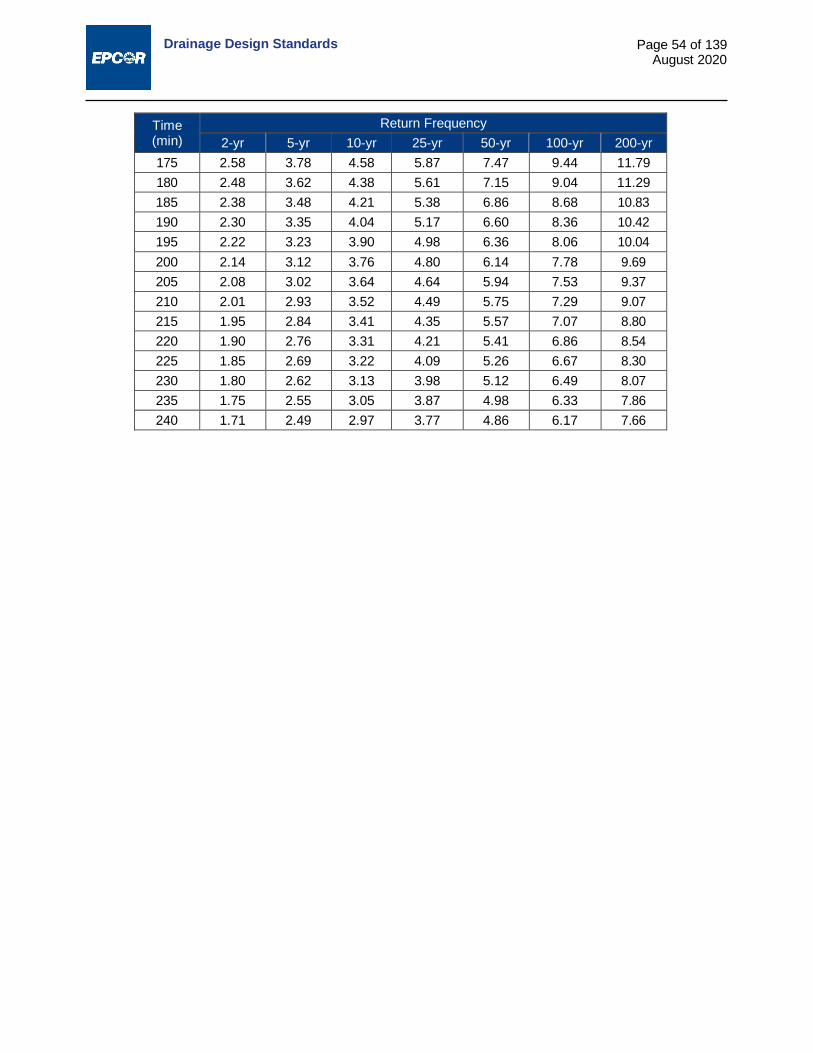
Drainage Design Standards
Page 54 of 139 August 2020
Time (min)
Return Frequency 2-yr 5-yr 10-yr 25-yr 50-yr 100-yr 200-yr
175 2.58 3.78 4.58 5.87 7.47 9.44 11.79 180 2.48 3.62 4.38 5.61 7.15 9.04 11.29 185 2.38 3.48 4.21 5.38 6.86 8.68 10.83 190 2.30 3.35 4.04 5.17 6.60 8.36 10.42 195 2.22 3.23 3.90 4.98 6.36 8.06 10.04 200 2.14 3.12 3.76 4.80 6.14 7.78 9.69 205 2.08 3.02 3.64 4.64 5.94 7.53 9.37 210 2.01 2.93 3.52 4.49 5.75 7.29 9.07 215 1.95 2.84 3.41 4.35 5.57 7.07 8.80 220 1.90 2.76 3.31 4.21 5.41 6.86 8.54 225 1.85 2.69 3.22 4.09 5.26 6.67 8.30 230 1.80 2.62 3.13 3.98 5.12 6.49 8.07 235 1.75 2.55 3.05 3.87 4.98 6.33 7.86 240 1.71 2.49 2.97 3.77 4.86 6.17 7.66
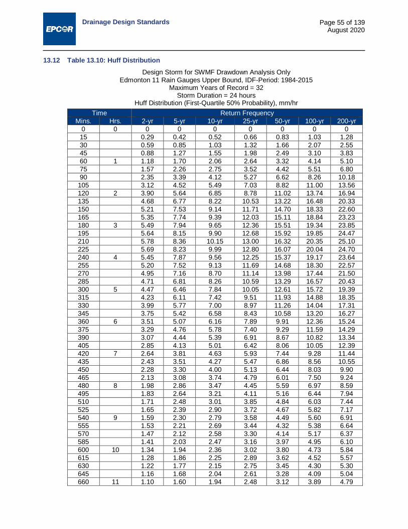
Drainage Design Standards
Page 55 of 139 August 2020
13.12 Table 13.10: Huff Distribution Design Storm for SWMF Drawdown Analysis Only
Edmonton 11 Rain Gauges Upper Bound, IDF-Period: 1984-2015 Maximum Years of Record = 32
Storm Duration = 24 hours Huff Distribution (First-Quartile 50% Probability), mm/hr
Time Return Frequency Mins. Hrs. 2-yr 5-yr 10-yr 25-yr 50-yr 100-yr 200-yr
0 0 0 0 0 0 0 0 0 15 0.29 0.42 0.52 0.66 0.83 1.03 1.28 30 0.59 0.85 1.03 1.32 1.66 2.07 2.55 45 0.88 1.27 1.55 1.98 2.49 3.10 3.83 60 1 1.18 1.70 2.06 2.64 3.32 4.14 5.10 75 1.57 2.26 2.75 3.52 4.42 5.51 6.80 90 2.35 3.39 4.12 5.27 6.62 8.26 10.18
105 3.12 4.52 5.49 7.03 8.82 11.00 13.56 120 2 3.90 5.64 6.85 8.78 11.02 13.74 16.94 135 4.68 6.77 8.22 10.53 13.22 16.48 20.33 150 5.21 7.53 9.14 11.71 14.70 18.33 22.60 165 5.35 7.74 9.39 12.03 15.11 18.84 23.23 180 3 5.49 7.94 9.65 12.36 15.51 19.34 23.85 195 5.64 8.15 9.90 12.68 15.92 19.85 24.47 210 5.78 8.36 10.15 13.00 16.32 20.35 25.10 225 5.69 8.23 9.99 12.80 16.07 20.04 24.70 240 4 5.45 7.87 9.56 12.25 15.37 19.17 23.64 255 5.20 7.52 9.13 11.69 14.68 18.30 22.57 270 4.95 7.16 8.70 11.14 13.98 17.44 21.50 285 4.71 6.81 8.26 10.59 13.29 16.57 20.43 300 5 4.47 6.46 7.84 10.05 12.61 15.72 19.39 315 4.23 6.11 7.42 9.51 11.93 14.88 18.35 330 3.99 5.77 7.00 8.97 11.26 14.04 17.31 345 3.75 5.42 6.58 8.43 10.58 13.20 16.27 360 6 3.51 5.07 6.16 7.89 9.91 12.36 15.24 375 3.29 4.76 5.78 7.40 9.29 11.59 14.29 390 3.07 4.44 5.39 6.91 8.67 10.82 13.34 405 2.85 4.13 5.01 6.42 8.06 10.05 12.39 420 7 2.64 3.81 4.63 5.93 7.44 9.28 11.44 435 2.43 3.51 4.27 5.47 6.86 8.56 10.55 450 2.28 3.30 4.00 5.13 6.44 8.03 9.90 465 2.13 3.08 3.74 4.79 6.01 7.50 9.24 480 8 1.98 2.86 3.47 4.45 5.59 6.97 8.59 495 1.83 2.64 3.21 4.11 5.16 6.44 7.94 510 1.71 2.48 3.01 3.85 4.84 6.03 7.44 525 1.65 2.39 2.90 3.72 4.67 5.82 7.17 540 9 1.59 2.30 2.79 3.58 4.49 5.60 6.91 555 1.53 2.21 2.69 3.44 4.32 5.38 6.64 570 1.47 2.12 2.58 3.30 4.14 5.17 6.37 585 1.41 2.03 2.47 3.16 3.97 4.95 6.10 600 10 1.34 1.94 2.36 3.02 3.80 4.73 5.84 615 1.28 1.86 2.25 2.89 3.62 4.52 5.57 630 1.22 1.77 2.15 2.75 3.45 4.30 5.30 645 1.16 1.68 2.04 2.61 3.28 4.09 5.04 660 11 1.10 1.60 1.94 2.48 3.12 3.89 4.79
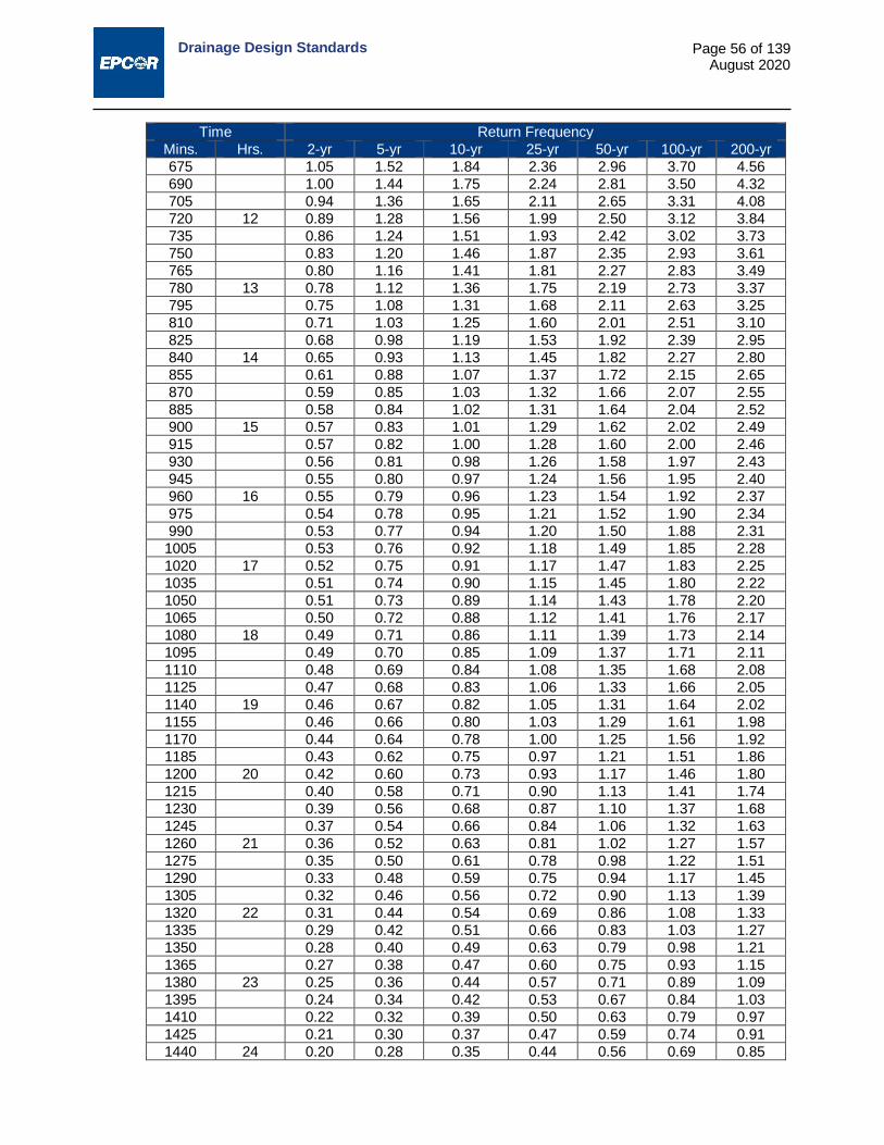
Drainage Design Standards
Page 56 of 139 August 2020
Time Return Frequency Mins. Hrs. 2-yr 5-yr 10-yr 25-yr 50-yr 100-yr 200-yr 675 1.05 1.52 1.84 2.36 2.96 3.70 4.56 690 1.00 1.44 1.75 2.24 2.81 3.50 4.32 705 0.94 1.36 1.65 2.11 2.65 3.31 4.08 720 12 0.89 1.28 1.56 1.99 2.50 3.12 3.84 735 0.86 1.24 1.51 1.93 2.42 3.02 3.73 750 0.83 1.20 1.46 1.87 2.35 2.93 3.61 765 0.80 1.16 1.41 1.81 2.27 2.83 3.49 780 13 0.78 1.12 1.36 1.75 2.19 2.73 3.37 795 0.75 1.08 1.31 1.68 2.11 2.63 3.25 810 0.71 1.03 1.25 1.60 2.01 2.51 3.10 825 0.68 0.98 1.19 1.53 1.92 2.39 2.95 840 14 0.65 0.93 1.13 1.45 1.82 2.27 2.80 855 0.61 0.88 1.07 1.37 1.72 2.15 2.65 870 0.59 0.85 1.03 1.32 1.66 2.07 2.55 885 0.58 0.84 1.02 1.31 1.64 2.04 2.52 900 15 0.57 0.83 1.01 1.29 1.62 2.02 2.49 915 0.57 0.82 1.00 1.28 1.60 2.00 2.46 930 0.56 0.81 0.98 1.26 1.58 1.97 2.43 945 0.55 0.80 0.97 1.24 1.56 1.95 2.40 960 16 0.55 0.79 0.96 1.23 1.54 1.92 2.37 975 0.54 0.78 0.95 1.21 1.52 1.90 2.34 990 0.53 0.77 0.94 1.20 1.50 1.88 2.31
1005 0.53 0.76 0.92 1.18 1.49 1.85 2.28 1020 17 0.52 0.75 0.91 1.17 1.47 1.83 2.25 1035 0.51 0.74 0.90 1.15 1.45 1.80 2.22 1050 0.51 0.73 0.89 1.14 1.43 1.78 2.20 1065 0.50 0.72 0.88 1.12 1.41 1.76 2.17 1080 18 0.49 0.71 0.86 1.11 1.39 1.73 2.14 1095 0.49 0.70 0.85 1.09 1.37 1.71 2.11 1110 0.48 0.69 0.84 1.08 1.35 1.68 2.08 1125 0.47 0.68 0.83 1.06 1.33 1.66 2.05 1140 19 0.46 0.67 0.82 1.05 1.31 1.64 2.02 1155 0.46 0.66 0.80 1.03 1.29 1.61 1.98 1170 0.44 0.64 0.78 1.00 1.25 1.56 1.92 1185 0.43 0.62 0.75 0.97 1.21 1.51 1.86 1200 20 0.42 0.60 0.73 0.93 1.17 1.46 1.80 1215 0.40 0.58 0.71 0.90 1.13 1.41 1.74 1230 0.39 0.56 0.68 0.87 1.10 1.37 1.68 1245 0.37 0.54 0.66 0.84 1.06 1.32 1.63 1260 21 0.36 0.52 0.63 0.81 1.02 1.27 1.57 1275 0.35 0.50 0.61 0.78 0.98 1.22 1.51 1290 0.33 0.48 0.59 0.75 0.94 1.17 1.45 1305 0.32 0.46 0.56 0.72 0.90 1.13 1.39 1320 22 0.31 0.44 0.54 0.69 0.86 1.08 1.33 1335 0.29 0.42 0.51 0.66 0.83 1.03 1.27 1350 0.28 0.40 0.49 0.63 0.79 0.98 1.21 1365 0.27 0.38 0.47 0.60 0.75 0.93 1.15 1380 23 0.25 0.36 0.44 0.57 0.71 0.89 1.09 1395 0.24 0.34 0.42 0.53 0.67 0.84 1.03 1410 0.22 0.32 0.39 0.50 0.63 0.79 0.97 1425 0.21 0.30 0.37 0.47 0.59 0.74 0.91 1440 24 0.20 0.28 0.35 0.44 0.56 0.69 0.85

Drainage Design Standards
Page 57 of 139 August 2020
13.13 Table 13.11: Recorded Storm of July 14, 1937 Municipal Airport Rain Gauge
Time Intensity Time Intensity Time Intensity Time Intensity Minutes mm/h Minutes mm/h Minutes mm/h Minutes mm/h July 14 12.00 2.50 July 15 12.15 1.80
0.00 0.50 12.15 2.50 0.00 4.30 12.30 1.80 0.15 0.50 12.30 2.50 0.15 4.30 12.45 1.80 0.30 0.50 12.45 2.50 0.30 4.30 13.00 0.50 0.45 0.50 13.00 1.50 0.45 4.30 13.15 0.50 1.00 0.00 13.15 1.50 1.00 2.80 13.30 0.50 1.15 0.00 13.30 1.50 1.15 2.80 13.45 0.50 1.30 0.00 13.45 1.50 1.30 2.80 14.00 0.00 1.45 0.00 14.00 0.50 1.45 2.80 14.15 0.00 2.00 0.00 14.15 0.50 2.00 2.80 14.30 0.00 2.15 0.00 14.30 0.50 2.15 2.80 14.45 0.00 2.30 0.00 14.45 0.50 2.30 2.80 15.00 0.50 2.45 0.00 15.00 0.50 2.45 2.80 15.15 0.50 3.00 4.00 15.15 0.50 3.00 2.80 15.30 0.50 3.15 4.00 15.30 0.50 3.15 2.80 15.45 0.50 3.30 4.00 15.45 0.50 3.30 2.80 16.00 2.80 3.45 4.00 16.00 1.00 3.45 2.80 16.15 2.80 4.00 4.10 16.15 1.00 4.00 5.30 16.30 2.80 4.15 4.10 16.30 1.00 4.15 5.30 16.45 2.80 4.30 4.10 16.45 1.00 4.30 5.30 17.00 1.50 4.45 4.10 17.00 0.50 4.45 5.30 17.15 1.50 5.00 1.00 17.15 0.50 5.00 6.10 17.30 1.50 5.15 1.00 17.30 0.50 5.15 6.10 17.45 1.50 5.30 1.00 17.45 0.50 5.30 6.10 18.00 1.00 5.45 1.00 18.00 0.50 5.45 6.10 18.15 1.00 6.00 4.60 18.15 0.50 6.00 6.40 18.30 1.00 6.15 4.60 18.30 0.50 6.15 6.40 18.45 1.00 6.30 4.60 18.45 0.50 6.30 6.40 19.00 0.50 6.45 4.60 19.00 0.50 6.45 6.40 19.15 0.50 7.00 15.50 19.15 0.50 7.00 5.10 19.30 0.50 7.15 15.50 19.30 0.50 7.15 5.10 19.45 0.50 7.30 15.50 19.45 0.50 7.30 5.10 20.00 0.00 7.45 15.00 20.00 0.50 7.45 5.10 20.15 0.00 8.00 18.50 20.15 0.50 8.00 3.30 20.30 0.00 8.15 18.50 20.30 0.50 8.15 3.30 20.45 0.00 8.30 18.50 20.45 0.50 8.30 3.30 21.00 1.00 8.45 18.50 21.00 1.30 8.45 3.30 21.15 1.00 9.00 15.50 21.15 1.30 9.00 6.40 21.30 1.00 9.15 15.50 21.30 1.30 9.15 6.40 21.45 1.00

Drainage Design Standards
Page 58 of 139 August 2020
Time Intensity Time Intensity Time Intensity Time Intensity Minutes mm/h Minutes mm/h Minutes mm/h Minutes mm/h
9.30 15.50 21.45 1.30 9.30 6.40 22.00 0.50 9.45 15.50 22.00 5.10 9.45 6.40 22.15 0.50
10.00 7.40 22.15 5.10 10.15 5.30 22.30 0.50 10.15 7.40 22.30 5.10 10.30 5.30 22.45 0.50 10.30 7.40 22.45 5.10 10.45 5.30 23.00 0.00 10.45 7.40 23.00 5.10 11.00 2.30 23.15 0.00 11.00 2.30 23.15 3.80 11.15 2.30 23.30 0.00 11.15 2.30 23.30 3.80 11.30 2.30 23.45 0.00 11.30 2.30 23.45 3.80 11.45 2.30 11.45 2.30 12.00 1.80
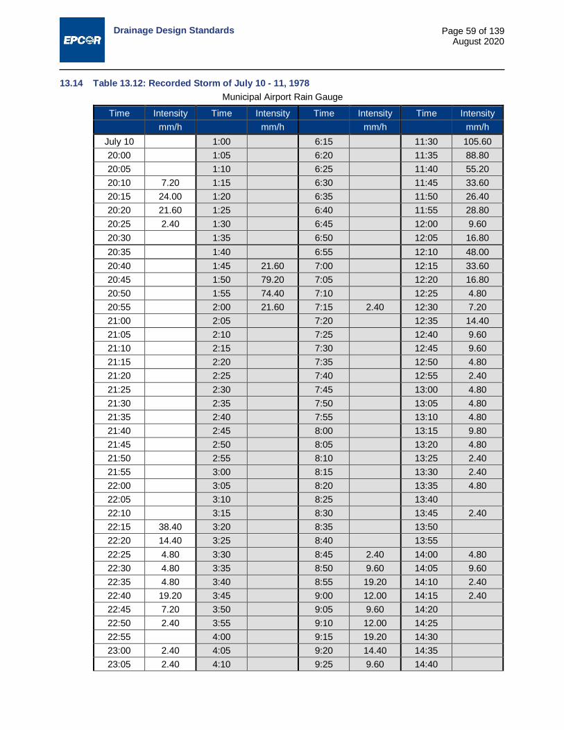
Drainage Design Standards
Page 59 of 139 August 2020
13.14 Table 13.12: Recorded Storm of July 10 - 11, 1978 Municipal Airport Rain Gauge
Time Intensity Time Intensity Time Intensity Time Intensity mm/h mm/h mm/h mm/h
July 10 1:00 6:15 11:30 105.60 20:00 1:05 6:20 11:35 88.80 20:05 1:10 6:25 11:40 55.20 20:10 7.20 1:15 6:30 11:45 33.60 20:15 24.00 1:20 6:35 11:50 26.40 20:20 21.60 1:25 6:40 11:55 28.80 20:25 2.40 1:30 6:45 12:00 9.60 20:30 1:35 6:50 12:05 16.80 20:35 1:40 6:55 12:10 48.00 20:40 1:45 21.60 7:00 12:15 33.60 20:45 1:50 79.20 7:05 12:20 16.80 20:50 1:55 74.40 7:10 12:25 4.80 20:55 2:00 21.60 7:15 2.40 12:30 7.20 21:00 2:05 7:20 12:35 14.40 21:05 2:10 7:25 12:40 9.60 21:10 2:15 7:30 12:45 9.60 21:15 2:20 7:35 12:50 4.80 21:20 2:25 7:40 12:55 2.40 21:25 2:30 7:45 13:00 4.80 21:30 2:35 7:50 13:05 4.80 21:35 2:40 7:55 13:10 4.80 21:40 2:45 8:00 13:15 9.80 21:45 2:50 8:05 13:20 4.80 21:50 2:55 8:10 13:25 2.40 21:55 3:00 8:15 13:30 2.40 22:00 3:05 8:20 13:35 4.80 22:05 3:10 8:25 13:40 22:10 3:15 8:30 13:45 2.40 22:15 38.40 3:20 8:35 13:50 22:20 14.40 3:25 8:40 13:55 22:25 4.80 3:30 8:45 2.40 14:00 4.80 22:30 4.80 3:35 8:50 9.60 14:05 9.60 22:35 4.80 3:40 8:55 19.20 14:10 2.40 22:40 19.20 3:45 9:00 12.00 14:15 2.40 22:45 7.20 3:50 9:05 9.60 14:20 22:50 2.40 3:55 9:10 12.00 14:25 22:55 4:00 9:15 19.20 14:30 23:00 2.40 4:05 9:20 14.40 14:35 23:05 2.40 4:10 9:25 9.60 14:40
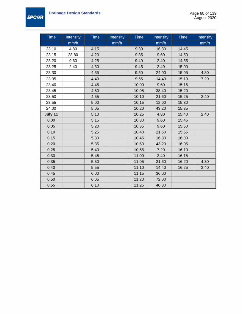
Drainage Design Standards
Page 60 of 139 August 2020
Time Intensity Time Intensity Time Intensity Time Intensity mm/h mm/h mm/h mm/h
23:10 4.80 4:15 9:30 16.80 14:45 23:15 28.80 4:20 9:35 9.60 14:50 23:20 9.60 4:25 9:40 2.40 14:55 23:25 2.40 4:30 9:45 2.40 15:00 23:30 4:35 9:50 24.00 15:05 4.80 23:35 4:40 9:55 14.40 15:10 7.20 23:40 4:45 10:00 9.60 15:15 23:45 4:50 10:05 38.40 15:20 23:50 4:55 10:10 21.60 15:25 2.40 23:55 5:00 10:15 12.00 15:30 24:00 5:05 10:20 43.20 15:35
July 11 5:10 10:25 4.80 15:40 2.40 0:00 5:15 10:30 9.60 15:45 0:05 5:20 10:35 9.60 15:50 0:10 5:25 10:40 21.60 15:55 0:15 5:30 10:45 16.80 16:00 0:20 5:35 10:50 43.20 16:05 0:25 5:40 10:55 7.20 16:10 0:30 5:45 11:00 2.40 16:15 0:35 5:50 11:05 21.60 16:20 4.80 0:40 5:55 11:10 14.40 16:25 2.40 0:45 6:00 11:15 36.00 0:50 6:05 11:20 72.00 0:55 6:10 11:25 40.80

Drainage Design Standards
Page 61 of 139 August 2020
13.15 Table 13.13: Recorded Storm of July 2 & 3, 2004 (total of 135mm) Time Intensity Time Intensity Time Intensity Time Intensity
Minutes mm/h Minutes mm/h Minutes mm/h Minutes mm/h 02-Jul-04 22:25 52.8 4:50 4.8 11:20 0
16:00 0 22:30 40.8 4:55 0 11:25 2.4 16:05 0 22:35 19.2 5:00 0 11:30 0 16:10 0 22:40 7.2 5:05 0 11:35 2.4 16:15 0 22:45 4.8 5:10 0 11:40 0 16:20 0 22:50 4.8 5:15 2.4 11:45 2.4 16:25 0 22:55 2.4 5:20 0 11:50 2.4 16:30 7.2 23:00 4.8 5:25 0 11:55 0 16:35 33.6 23:05 2.4 5:30 0 12:00 0 16:40 21.6 23:10 0 5:35 0 12:05 2.4 16:45 21.6 23:15 0 5:40 2.4 12:10 0 16:50 16.8 23:20 0 5:45 2.4 12:15 2.4 16:55 0 23:25 0 5:50 4.8 12:20 2.4 17:00 9.6 23:30 0 5:55 2.4 12:25 0 17:05 0 23:35 0 6:00 4.8 12:30 2.4 17:10 2.4 23:40 0 6:05 9.6 12:35 2.4 17:15 2.4 23:45 0 6:10 2.4 12:40 2.4 17:20 12 23:50 0 6:15 2.4 12:45 0 17:25 45.6 23:55 0 6:20 2.4 12:50 2.4 17:30 26.4 03-Jul-04 6:25 2.4 12:55 0 17:35 9.6 0:00 0 6:30 0 13:00 2.4 17:40 7.2 0:05 0 6:35 4.8 13:05 0 17:45 7.2 0:10 0 6:40 2.4 13:10 2.4 17:50 4.8 0:15 4.8 6:45 2.4 13:15 0 17:55 7.2 0:20 2.4 6:50 2.4 13:20 4.8 18:00 2.4 0:25 0 6:55 2.4 13:25 2.4 18:05 2.4 0:30 2.4 7:00 2.4 13:30 2.4 18:10 2.4 0:35 0 7:05 2.4 13:35 2.4 18:15 0 0:40 4.8 7:10 0 13:40 2.4 18:20 2.4 0:45 2.4 7:15 0 13:45 2.4 18:25 0 0:50 2.4 7:20 4.8 13:50 4.8 18:30 0 0:55 4.8 7:25 0 13:55 2.4 18:35 0 1:00 4.8 7:30 2.4 14:00 2.4 18:40 2.4 1:05 4.8 7:35 2.4 14:05 2.4 18:45 0 1:10 2.4 7:40 2.4 14:10 2.4 18:50 0 1:15 0 7:45 2.4 14:15 2.4 18:55 0 1:20 4.8 7:50 4.8 14:20 0 19:00 0 1:25 2.4 7:55 2.4 14:25 2.4 19:05 0 1:30 0 8:00 0 14:30 0 19:10 0 1:35 2.4 8:05 2.4 14:35 4.8

Drainage Design Standards
Page 62 of 139 August 2020
Time Intensity Time Intensity Time Intensity Time Intensity Minutes mm/h Minutes mm/h Minutes mm/h Minutes mm/h 19:15 0 1:40 2.4 8:10 4.8 14:40 4.8 19:20 0 1:45 0 8:15 4.8 14:45 4.8 19:25 0 1:50 2.4 8:20 2.4 14:50 2.4 19:30 0 1:55 0 8:25 0 14:55 2.4 19:35 0 2:00 4.8 8:30 2.4 15:00 4.8 19:40 0 2:05 2.4 8:35 2.4 15:05 2.4 19:45 0 2:10 2.4 8:40 2.4 15:10 2.4 19:50 0 2:15 2.4 8:45 0 15:15 2.4 19:55 0 2:20 4.8 8:50 2.4 15:20 2.4 20:00 0 2:25 2.4 8:55 0 15:25 2.4 20:05 0 2:30 0 9:00 2.4 15:30 2.4 20:10 0 2:35 2.4 9:05 2.4 15:35 0 20:15 0 2:40 2.4 9:10 0 15:40 2.4 20:20 0 2:45 7.2 9:15 2.4 15:45 0 20:25 0 2:50 4.8 9:20 2.4 15:50 2.4 20:30 0 2:55 4.8 9:25 2.4 15:55 0 20:35 0 3:00 4.8 9:30 2.4 16:00 0 20:40 0 3:05 2.4 9:35 4.8 16:05 0 20:45 0 3:10 7.2 9:40 2.4 16:10 2.4 20:50 0 3:15 4.8 9:45 2.4 16:15 0 20:55 0 3:20 2.4 9:50 7.2 16:20 0 21:00 0 3:25 9.6 9:55 4.8 16:25 0 21:05 0 3:30 2.4 10:00 4.8 16:30 0 21:10 0 3:35 7.2 10:05 2.4 16:35 0 21:15 0 3:40 4.8 10:10 2.4 16:40 0 21:20 0 3:45 2.4 10:15 4.8 16:45 0 21:25 0 3:50 4.8 10:20 0 16:50 0 21:30 0 3:55 2.4 10:25 2.4 16:55 0 21:35 0 4:00 2.4 10:30 2.4 17:00 0 21:40 4.8 4:05 0 10:35 0 17:05 0 21:45 33.6 4:10 2.4 10:40 2.4 17:10 0 21:50 72 4:15 0 10:45 0 17:15 0 21:55 129.6 4:20 4.8 10:50 0 17:20 0 22:00 103.2 4:25 2.4 10:55 2.4 17:25 0 22:05 127.2 4:30 2.4 11:00 0 17:30 0 22:10 158.4 4:35 2.4 11:05 2.4 17:35 0 22:15 100.8 4:40 0 11:10 2.4 17:40 0 22:20 64.8 4:45 0 11:15 0 17:45 0
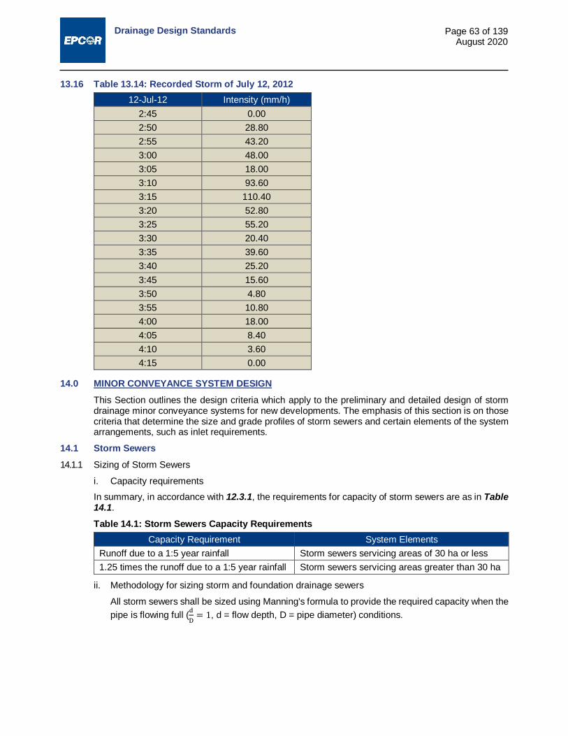
Drainage Design Standards
Page 63 of 139 August 2020
13.16 Table 13.14: Recorded Storm of July 12, 2012 12-Jul-12 Intensity (mm/h)
2:45 0.00 2:50 28.80 2:55 43.20 3:00 48.00 3:05 18.00 3:10 93.60 3:15 110.40 3:20 52.80 3:25 55.20 3:30 20.40 3:35 39.60 3:40 25.20 3:45 15.60 3:50 4.80 3:55 10.80 4:00 18.00 4:05 8.40 4:10 3.60 4:15 0.00
14.0 MINOR CONVEYANCE SYSTEM DESIGN This Section outlines the design criteria which apply to the preliminary and detailed design of storm drainage minor conveyance systems for new developments. The emphasis of this section is on those criteria that determine the size and grade profiles of storm sewers and certain elements of the system arrangements, such as inlet requirements.
14.1 Storm Sewers 14.1.1 Sizing of Storm Sewers
i. Capacity requirements In summary, in accordance with 12.3.1, the requirements for capacity of storm sewers are as in Table 14.1.
Table 14.1: Storm Sewers Capacity Requirements Capacity Requirement System Elements
Runoff due to a 1:5 year rainfall Storm sewers servicing areas of 30 ha or less 1.25 times the runoff due to a 1:5 year rainfall Storm sewers servicing areas greater than 30 ha
ii. Methodology for sizing storm and foundation drainage sewers
All storm sewers shall be sized using Manning's formula to provide the required capacity when the pipe is flowing full (d
D= 1, d = flow depth, D = pipe diameter) conditions.
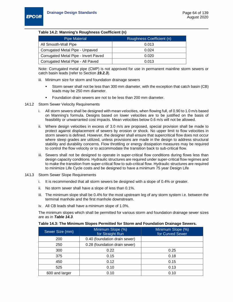
Drainage Design Standards
Page 64 of 139 August 2020
Table 14.2: Manning's Roughness Coefficient (n) Pipe Material Roughness Coefficient (n)
All Smooth-Wall Pipe 0.013 Corrugated Metal Pipe - Unpaved 0.024 Corrugated Metal Pipe - Invert Paved 0.020 Corrugated Metal Pipe - All Paved 0.013
Note: Corrugated metal pipe (CMP) is not approved for use in permanent mainline storm sewers or catch basin leads (refer to Section 19.2.3).
iii. Minimum size for storm and foundation drainage sewers
Storm sewer shall not be less than 300 mm diameter, with the exception that catch basin (CB) leads may be 250 mm diameter.
Foundation drain sewers are not to be less than 200 mm diameter.
14.1.2 Storm Sewer Velocity Requirements
i. All storm sewers shall be designed with mean velocities, when flowing full, of 0.90 to 1.0 m/s based on Manning's formula. Designs based on lower velocities are to be justified on the basis of feasibility or unwarranted cost impacts. Mean velocities below 0.6 m/s will not be allowed.
ii. Where design velocities in excess of 3.0 m/s are proposed, special provision shall be made to protect against displacement of sewers by erosion or shock. No upper limit to flow velocities in storm sewers is defined. However, the designer shall ensure that supercritical flow does not occur where steep grades are utilized, unless provisions are made in the design to address structural stability and durability concerns. Flow throttling or energy dissipation measures may be required to control the flow velocity or to accommodate the transition back to sub-critical flow.
iii. Sewers shall not be designed to operate in super-critical flow conditions during flows less than design capacity conditions. Hydraulic structures are required under super-critical flow regimes and to make the transition from super-critical flow to sub-critical flow. Hydraulic structures are required to minimize Life Cycle costs and be designed to have a minimum 75 year Design Life
14.1.3 Storm Sewer Slope Requirements
i. It is recommended that all storm sewers be designed with a slope of 0.4% or greater.
ii. No storm sewer shall have a slope of less than 0.1%.
iii. The minimum slope shall be 0.4% for the most upstream leg of any storm system i.e. between the terminal manhole and the first manhole downstream.
iv. All CB leads shall have a minimum slope of 1.0%.
The minimum slopes which shall be permitted for various storm and foundation drainage sewer sizes are as in Table 14.3.
Table 14.3: The Minimum Slopes Permitted for Storm and Foundation Drainage Sewers.
Sewer Size (mm) Minimum Slope (%) for Straight Run
Minimum Slope (%) for Curved Sewer
200 0.40 (foundation drain sewer) 250 0.28 (foundation drain sewer) 300 0.22 0.25 375 0.15 0.18 450 0.12 0.15 525 0.10 0.13
600 and larger 0.10 0.10

Drainage Design Standards
Page 65 of 139 August 2020
14.2 Depth Requirements for Storm and Foundation Drainage Sewers All sewers shall be installed with sufficient depth to meet the following requirements:
14.2.1 A minimum cover from finished grade to pipe obvert of 2.0 m for storm sewer and foundation drain sewer is to be provided for all pipes smaller than 600 mm diameter. If this cover cannot be achieved then provide adequate pipe insulation to prevent freezing in accordance with insulation manufacturer’s recommended installation procedures and as shown on the drawings. A minimum of 1.5 m of cover to obvert is required for storm sewers equal to or larger than 600 mm in diameter.
14.2.2 The depth of the storm service and foundation drain service should match the sanitary service at the property line. When this is not practical, provide a minimum cover from finished grade to pipe obvert of 2.0 m for the storm service and the foundation drain service at the property line. If this cover cannot be achieved, provide adequate pipe insulation to prevent freezing in accordance with insulation manufacturer’s recommended installation procedures and as shown on the drawings.
14.2.3 Adequate depth is to be provided to allow for drainage to the sewer main of the interior of sites where interior finished grades may be lower than the finished grade at the property line.
14.2.4 Provide adequate depth for CB leads to allow them to extend to proposed CB locations at the required slope of 1.0% or greater.
14.2.5 Provide adequate depth to allow sanitary sewer services to cross over the top of the storm sewer and have the required minimum depth at the property line for typical parallel storm and sanitary sewer alignments.
14.2.6 The Engineer may determine other depth requirements.
14.3 Manholes, Junctions and Bends - Pipe Elevation Considerations 14.3.1 Minimum Invert Change at Manholes
The invert slope across manholes from inlet to outlet shall not be less than the greater of the slopes of the downstream or upstream sewers;
The obvert elevation of a sewer entering a manhole shall not be lower than the obvert elevation of the outlet sewer;
Where there is a bend (a deflection of the horizontal alignment between incoming and outgoing sewers) a drop in the sewer invert must be provided to account for energy losses. The amount of the drop required is relative to the deflection in the sewer alignments and may be determined by the methods described in 19.5.4;
Bends shall be 90° or less. Exceptions shall require provision of suitable justification by the designer and shall be subject to the approval of the Engineer.
14.3.2 Junctions at Manholes
Where more than one inlet sewer enters a manhole, forming a junction, the laterally connecting sewers entering the manhole are to be vertically aligned so that the spring line of each laterally connecting sewer is at or above the 80% flow depth elevation of the outlet sewer. An exception is that when the laterally connecting sewer is of a similar size to the outlet sewer, the requirements for energy loss provisions of 19.5.4 shall apply.
14.3.3 Drops at Storm Manholes
Generally a smooth transition is to be provided between the inverts of incoming sewers and the outlet sewer and extreme changes in elevation at manholes should be avoided whenever feasible.
Where drops of 1.0 m or less occur at manholes, the designer is to ensure that free outflow and low backwater conditions will exist in the downstream sewer so that hydraulic jump formation and associated concentrated effects are avoided. For drops of greater than 1.0 m, a specifically designed drop structure may be required to address the hydraulic requirements of the change of elevation, refer to Section 19.9.

Drainage Design Standards
Page 66 of 139 August 2020
14.4 Drainage of Roadways and Other Public Rights-of-Way - Minor System 14.4.1 General Runoff Interception and Inlet Requirements
i. Storm sewers and inlets shall be provided to directly drain all streets, alleys, walkways and other public rights-of-way and to address the level of service requirements of Section 12.3.
ii. Sufficient inlet capacity is to be provided, in the form of CBs or specifically designed inlets, so that runoff from a 1:5 year rainfall event is conveyed into the minor storm drainage system without inhibiting the use of roadways.
iii. The following specific considerations and requirements are to be addressed with respect to the 1:5 year rainfall event:
14.4.2 Flow in Gutters
i. When storm sewers exist within the right-of-way, it is preferable to transport the drainage in the sewer rather than in the roadway gutters. Along sloped roadway sections, sufficient inlet capacity is to be provided to take runoff from the gutter before it reaches the next downstream sag location.
ii. The depth of flow in gutters should not exceed the top of curb at any point.
iii. The width of flow along curbsides of roadways should allow for a minimum of one lane width free of ponded water on collector roads and one free lane in each direction on two direction arterial roads.
14.4.3 Flow through Intersections
Drainage should not pass through intersections, but rather, sufficient inlet capacity is to be provided to intercept all flow at the uphill side and at the upstream of the curb ramps at sag locations.
14.4.4 Ponding at Sags
The depth of ponding at roadway sag locations and depressions is not to exceed 150 mm and should not reach the rim elevation of any sanitary manholes located within or near the sags. Inlet capacity provisions must consider the entire contributing area that may drain to the design location. At sag locations, the determination of required capacity must account for flow that may bypass inlets at upstream sloped gutter locations.
14.4.5 Maximum Spacing of Inlets
Where closer spacing of inlets is not dictated by the requirements of 14.4.2 above, the spacing of storm runoff inlets is to satisfy the following requirements:
i. Runoff shall not be required to flow a distance greater than 150 m along roadway gutters without reaching a CB or other inlet to the minor storm drainage system.
ii. In alleys and walkways, runoff shall not be required to flow on the surface a distance greater than 180 m to a point of interception.
iii. In the design of drainage inlets along walkways, alleys and utility rights-of-way, the designer must consider the total area that may drain to them and space CBs and inlets accordingly. Often residential lots drain onto the walkway, alley, or utility lot.
14.5 Location of Drainage Inlets 14.5.1 Locations for Drainage Inlets on Roadways
i. Inlets required at sags at intersections should be located at the end of curve (EC) or beginning of curve (BC) of the curb return.
ii. Where there is a continuous grade through the curb return at an intersection, stormwater CBs and CB manholes shall be located at the uphill side of the curb return (BC). Normal design locations for CBs and CB manholes are at sags at intersections, turning bays and centre medians as governed by roadway design.

Drainage Design Standards
Page 67 of 139 August 2020
iii. Location of drainage inlets must adhere to Volume 2: Complete Streets Design and Construction Standards (see Section 3). In situations where the design deviates from i or ii above to comply with Volume 2 Standards, it is the responsibility of the Consultant to prove that the location chosen does not result in conflicts with curb ramps or curb ramp flares, negative impacts to the drainage system, or safety concerns with ponding/icing at intersections.
iv. Design locations for CBs on residential or other roadways shall be chosen to avoid conflict with driveway crossings wherever possible. Subject to roadway design, drainage inlet locations at the projection of the property lines are preferred in these instances. It is the Consultant’s responsibility to ensure the locations of CBs and driveways and other crossings are chosen properly to avoid conflicts. If conflicts are present, the CB and CB leads may have to be relocated at the cost of the Developer.
14.5.2 Location of Drainage Inlets at Sidewalks and Walkways i. Minor runoff event flows from swales or other flow channels draining significant areas of residential
development, parks, school sites, municipal reserve, public utility lots, or walkway lots, shall not cross sidewalks or walkways (walks). To avoid excessive drainage of water across walks, or ponding of water where flow is obstructed by walks, drainage inlets shall be provided at strategic locations on the upstream side of walks to intercept concentrated drainage flows.
ii. CB inlets are to be installed for this purpose and shall be located a minimum of 600 mm from the edge of the walk.
iii. Subject to the approval of the Engineer, certain concentrated flows may be permitted to cross a sidewalk or walkway through a 1.0 m wide concrete gutter or a monolithic curb and gutter sidewalk section provided with such a flow channel.
14.5.3 Location of Drainage Inlets in Alleys CBs and CB manholes used to intercept drainage in alleys are to be located generally at the longitudinal centre line of the alley and so as not to be within the typical wheel track area.
14.5.4 Drainage of Private Property In residential subdivisions, no CBs or leads are to be placed or extended beyond the limits of the public rights-of-way. Low spots at the back or sides of lots must be filled and graded to ensure that all potential collection areas drain directly or indirectly to a public right-of-way. Design requirements for grading of private residential lots are addressed in Section 18.0.
14.5.5 Capacity of Catch Basin Inlets The designer is responsible for determination of the appropriate design capacity factors for the proposed CB inlets. Available information with regard to the capacity and capture efficiency of the current and non-current CBs in provided in Appendix C.
14.6 Storm Sewer Service Connections 14.6.1 General requirements for storm services to properties (detail requirements for storm sewer services,
refer to Sections 19.3 and 19.4.) i. Residential properties
Foundation drain service connections are to be provided to all new detached, semi-detached and duplex residential units. Storm service connections are also to be provided to the same residential units when roof leaders’ discharges from one lot drains to another lot. In addition, storm service connections are to be provided when dictated by geotechnical requirements as identified in the Hydrogeotechnical Impact Assessment or Slope Stability Evaluations for top-of- bank locations.
ii. Commercial/institutional, industrial and multiple residential properties Storm sewer service connections for the connection of onsite storm drainage systems and/or roof drains are to be provided to properties zoned or proposed to be zoned for commercial, institutional, industrial and multiple residential land uses. When required service locations are known, storm service connections should be installed concurrently with the general area servicing. Otherwise, installation of connections may be deferred until the specific property development is proposed.

Drainage Design Standards
Page 68 of 139 August 2020
15.0 MAJOR CONVEYANCE SYSTEM DESIGN Section 15.0 outlines the requirements and considerations which apply to the detailed design of the conveyance elements, surface flow routes and ponding locations, of major drainage systems, which carry flows not intercepted by or beyond the capacity of the minor drainage system.
15.1 Surface Drainage on Public Rights-of-Way - Major System Public rights-of-way, including roadways, alleys, utility lots and walkways, serve as components of the runoff conveyance system to collect runoff water from adjacent lands and convey it to the inlets of the minor drainage system. They also function as the surface flow conveyance elements of the major drainage system.
15.1.1 Level of Service
i. As stated in Section 12.0, rights-of-way for roadways, walkways and other public purposes shall be graded to provide a continuous surface drainage system to accommodate flows from rainfall events of greater intensity than the 1:5 year event and convey these flows to appropriate safe points of escape or storage.
ii. The level-of-service requirements for the major system include provision of a level of protection against surface flooding and property damage for the 1:100 year return frequency design storm. Through control of roadway and other surface elevations, designs should be such that maximum flow ponding surface elevations are generally 0.35 m or more below the lowest anticipated finished ground elevations at buildings on adjacent properties. An overflow must be provided from all sags or depressions such that there will be a freeboard of at least 150 mm above the overflow elevation to the proposed ground surface elevation at adjacent buildings and the maximum depth of ponding is limited to 350 mm.
15.1.2 Flow Capacity of Streets
The theoretical street carrying capacity can be calculated using modified Manning's formula with an "n" value applicable to the actual boundary conditions encountered. Recommended values are n = 0.013 for roadway and n = 0.05 for grassed boulevards.
15.2 Swales A swale is a shallow sloped linear depression for conveyance of surface runoff.
15.2.1 Use of swales on public rights-of-way
Swales may be used on public rights-of-way, including easements, for the collection and conveyance of major and minor runoff to appropriate points of interception or release. Swales on public rights-of- way, except easements, should not to be provided with concrete flow channels or hard surface treatments, except where such measures are required to address flow velocity or erosion concerns.
15.2.2 Use of swales on private property for drainage of other lands
The use of swales crossing private properties for collection of runoff and drainage control is not permitted unless proper justification is produced and documented indicating that no other alternative is feasible. If the Engineer approves use of such swales they are to be covered by easements in favour of EPCOR, to the satisfaction of the Engineer.
Refer to Section 18.0, Lot Grading and Surface Drainage Design, for details of the design and application of public use swales on private property.
15.3 Representation of the Major Conveyance System i. The nature and detail of the major conveyance system is to be shown on the overall storm drainage
basin schematic within the detailed engineering drawings for subdivision developments and on lot grading plans required for such developments or pursuant to other requirements or regulations.
ii. Information shown is to include the direction of surface flows on roadways, other rights-of-way and all surface flow routes, areas subject to ponding and depths of ponding, elevations of overflow points from local depressions and details of channel cross sections.
Drainage Design Standards
Page 69 of 139 August 2020
iii. Where significant major system flows are expected to discharge or overflow to a watercourse, ravine, environmental reserve area, etc., the rate and projected frequency of such flows is to be noted on the overall storm drainage basin schematic and the lot grading plan.
iv. For properties adjacent to SWMFs, requirements for appropriate control of elevations for buildings are to be noted on the associated lot grading plans.
16.0 STORMWATER MANAGEMENT FACILITY DESIGN This section identifies the general design parameters and specific requirements, including safety features that must be considered and addressed in the planning and design of SWMFs.
16.1 Basis for Detailed Design 16.1.1 Level of Service
SWMFs shall be designed to satisfy the level-of-service requirements for major system storage elements as stated in Section 12.0. The requirements for hydraulic performance for SWMFs including storage capacity, outlet restrictions, bypass and drawdown rates and other basic design parameters such as elevations and design water levels are required to be specifically defined and documented in the NDR for the respective development area.
16.1.2 Geotechnical Considerations
Special geotechnical investigations to address issues related to the design of all constructed wetlands, wet ponds and dry ponds are to be undertaken as part of the planning and design studies and are a prerequisite to the final design of such facilities.
16.1.3 Erosion and Sediment Control
A project specific ESC Plan shall be included with the engineering drawings. The Plan shall build on the ESC Strategy and be developed according to the checklist presented in the ESC Guidelines.
16.1.4 Staged Construction - Standards for Interim Facilities
When stormwater management storage facilities are to be implemented in stages, the standards applicable to the design and construction of the interim facilities are to be generally in accordance with the standards set out herein for permanent facilities of that type. For example, where an interim dry pond facility is proposed as a preliminary stage in the implementation of a wet pond, it shall be designed and constructed in accordance with the criteria and standards applicable to a permanent dry pond. Any proposal for application of alternative standards requires special approval. In all staged construction, erosion and sediment control shall be an important aspect to be adequately addressed in the design.
16.1.5 Storage Alternatives
The review of SWMF alternatives should include the storage methods described in this subsection. The optimum number and location of SWMFs must be determined bearing in mind the major/minor system concept. A combination of the various types of facilities should be considered to select a cost-effective drainage system that minimizes flooding and erosion and maximizes water quality improvement. Constructed wetlands or wet ponds should be used as the final treatment process prior to discharging to the receiving watercourse.
i. Retention storage
Retention storage collects and stores storm runoff for a significant period and releases it after the storm runoff has ended. Retention storage is often associated with "wet reservoirs," more commonly referred to as "wet ponds".
ii. Constructed wetlands
Constructed stormwater wetlands are human-made systems, designed, constructed and operated to emulate natural wetlands or many of their biological processes. They are generally shallow impoundments, planted with emergent rooted vegetation or colonized naturally by volunteer plant species. Water is the primary factor controlling the environment and associated plant and animal

Drainage Design Standards
Page 70 of 139 August 2020
life. The water storage, filtering capacity and biological processes in wetlands can improve the quality of stormwater discharge. They may be designed as single or multiple cell compartments to allow redistribution of flows, maintenance of plant communities and flexibility in operation. Multiple cell wetlands may be designed as a series of cells or as parallel cells.
iii. Detention storage
Detention storage or “dry ponds” have been commonly used for storage in urban drainage works but their use is actively discouraged by the City and AEP because of their shortcomings for stormwater quality enhancement. When the inflow is large enough, the proper functioning of flow controls on the outlet from the system restricts the outflow to a rate much less than the inflow and causes the excess to be temporarily detained in the storage element. Dry ponds should only be used at the discretion of the City when constructed wetlands and or wet ponds are not practical.
iv. Upstream storage
The storage of water close to the points of rainfall occurrence is referred to as upstream storage. This may be retention or detention storage and usually consists of rooftop ponding, parking lot ponding, property line swale ponding and small ponds in green areas. Although this method lends itself well to planned unit development, it may only be applicable when suitable and effective means are established to ensure that both implementation and long-term operating and maintenance responsibilities are met by property owners.
v. Downstream storage
Water stored downstream of the area where the rainfall occurs is downstream storage. It may be of either the retention or detention types.
vi. Offstream storage
A minor conveyance system may conduct low flows directly to an outlet, but have restricted outlet capacity or flow control elements that allow only peak flows to be routed to a SWMF for storage. This form of storage is usually termed "offstream" or "off-line" storage. The storage may incorporate depressed open areas, reservoirs and low lying recreation fields.
vii. Channel storage (blue-green storage)
Slow-flow channels with wide bottoms provide channel storage as an inherent part of their hydraulic characteristics. As the channel fills to transport water it is also storing water.
viii. Onstream storage
Onstream storage is achieved through the construction of an embankment across a channel so that a storage pond is formed. Spillway considerations are important to pass large floods exceeding the design runoff.
16.2 Design Requirements Common to Stormwater Management Facilities 16.2.1 Outflow Control Works
i. The outlet from a stormwater management storage system must incorporate appropriate means for control of outflow, to limit the rate of discharges as prescribed in the NDR. In addition the outlet works must include provisions for operational flexibility and to address unintentional blockage of the outlet and the possible need to either stop outflow or increase the rate of outflow.
ii. Outflow Control Gate
Each storage facility shall be provided with a slide gate or similar means to stop the discharge of impounded water from the facility. Gates and hardware used shall be constructed of corrosion resistant material such as stainless steel or marine grade aluminum or approved equivalent or better.
iii. Outlet Control Bypass and Rapid Drawdown Provisions
The outlet works of each storage facility are to include the means to permit bypassing of the control element and discharge at an increased rate, as may be required to drawdown water

Drainage Design Standards
Page 71 of 139 August 2020
levels at the facility more rapidly than the controlled rate would allow. Refer also to 16.7.8 in regard to provisions for draining wet storage facilities.
These provisions may require that outlet connecting sewers be sized with capacity in excess of that defined as the normal controlled outlet rate. An assessment of downstream system capacities, considering conditions during and subsequent to rainfall events, is necessary to define the constraints in this regard, including the impact of discharges from other stormwater management systems that may be operating in parallel.
In any case, the means should be provided to permit discharge from storage facilities at the maximum rate of flow that the downstream system can accommodate after storm runoff peak flows have passed and the flows from other contributing areas have decreased or ended. The rate of discharge to be provided for rapid drawdown purposes is to be sufficient to restore the availability of storage capacity above NWL to accommodate subsequent runoff events within a reasonable time frame. To achieve this purpose, drawdown rates should satisfy the relationship in Table 16.1.
Table 16.1: Drawdown Time and Available Volume of Wet Pond between NWL and HWL Time after commencing drawdown
from design full level Available volume between design HWL and NWL
24 h Volume equivalent to runoff from 1:5 year storm
48 h Volume equivalent to runoff from 1:25 year storm
96 h 90% of total storage volume above NWL
16.3 Emergency Overflow Provisions Where feasible an emergency overflow spillway is to be incorporated in the facility design. The designer is to identify the probable frequency of operation of the emergency spillway. Where provision of an emergency spillway or overflow route is found to be unfeasible, the design is to include an analysis of the impact of overtopping the storage facility and the probable frequency of occurrence of overtopping. Both analyses should consider the possible consequences of blockage of the system outlet or overloading due to consecutive runoff events, such that the storage capacity of the facility may be partially or completely unavailable at the beginning of a runoff event.
16.4 Operation and Maintenance Manual i. As part of the responsibility for design of a stormwater management storage facility the designer
shall prepare and provide an O&M Manual for the facility.
ii. One hardcopy of the O&M manual is to be provided in a piano hinged binder with 65 mm spine bound heavy weight fabricord as well as a searchable and organized PDF version following the standard requirements for the O&M manual. Draft O&M manual is to be provided to EPCOR Private Development Section and EPCOR Drainage Operations a minimum of two weeks prior to CCC inspection and the final version of the O&M manual is to be provided prior to approval of a CCC. If any material changes are done between CCC and FAC, updated O&M manual shall be delivered as soon as practicable after material changes and before FAC application. The manual shall include complete equipment manufacturer's operation, maintenance, service and repair instructions and complete parts lists for any mechanized and/or electrical equipment incorporated in the design.
iii. The O&M manual is to include, at minimum, the following information:
A copy of the approved engineering drawings relating to the SWMF and appurtenances, updated to "As-Built";
A completed SWMF Data Summary Form;
Schematic diagrams of the inlet and outlet arrangements, connections to and arrangement of upstream and downstream systems, including all controls, shutoff valves, bypasses, overflows and any other operation or control features;
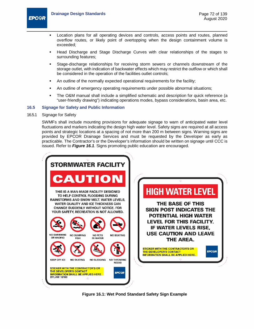
Drainage Design Standards
Page 72 of 139 August 2020
Location plans for all operating devices and controls, access points and routes, planned overflow routes, or likely point of overtopping when the design containment volume is exceeded;
Head Discharge and Stage Discharge Curves with clear relationships of the stages to surrounding features;
Stage-discharge relationships for receiving storm sewers or channels downstream of the storage outlet, with indication of backwater effects which may restrict the outflow or which shall be considered in the operation of the facilities outlet controls;
An outline of the normally expected operational requirements for the facility;
An outline of emergency operating requirements under possible abnormal situations;
The O&M manual shall include a simplified schematic and description for quick reference (a “user-friendly drawing”) indicating operations modes, bypass considerations, basin area, etc.
16.5 Signage for Safety and Public Information 16.5.1 Signage for Safety
SWMFs shall include mounting provisions for adequate signage to warn of anticipated water level fluctuations and markers indicating the design high water level. Safety signs are required at all access points and strategic locations at a spacing of not more than 200 m between signs. Warning signs are provided by EPCOR Drainage Services and must be requested by the Developer as early as practicable. The Contractor’s or the Developer’s information should be written on signage until CCC is issued. Refer to Figure 16.1. Signs promoting public education are encouraged.
Figure 16.1: Wet Pond Standard Safety Sign Example

Drainage Design Standards
Page 73 of 139 August 2020
16.5.2 Public Information
The Developer is required to inform the general public by means of signage and brochures that the facility is for stormwater management. It is the responsibility of the Developer to provide an educational brochure on SWMFs during the marketing of an area that includes a wet or dry pond. The purpose of the brochure is to educate residents about:
The specific function of wet ponds;
The water quality inherent with the function of the facility and the impact of water quality resulting from different land uses and landscaping practices (which directly feeds into the storm sewer system);
Design high water level;
Recreational use is not permitted.
The Developer is responsible for installation at least one interpretive signage showing schematic map of how storm flow gets in and out of a SWMF, high water level, its main function as a retention facility, water quality inherent with the function, naturalization and other relevant information as it fits to a specific facility.
16.6 Engineering Drawing Requirements The engineering drawings for any SWMF are to include the following information, in addition to the physical dimensions:
Stage-Storage Volume and Stage-Area Curves and tables of the values;
The High Water Level (HWL) design event basis;
Elevations at Pond Bottom, Normal Water Level (NWL), 5 Year, 25 Year, 100 Year Level and HWL;
Storage Volumes at NWL, 5 Year, 25 Year, 100 Year Level, HWL, and freeboard level;
Area at Pond Bottom, NWL, 5 Year, 25 Year, 100 Year, HWL, and freeboard level;
Freeboard elevation;
Notation indicating the lowest allowable building opening elevation for lots abutting the wet pond;
Pond and forebay depth at NWL, 5 Year Level, 25 Year, 100 Year Level and HWL;
Length of shoreline at NWL, 5 Year Level, 25 Year, 100 Year, and HWL;
Pond and forebay area in ha at NWL, 5 Year, 25 Year, 100 Year Level and HWL;
Contributing basin size in ha;
Measurements to locate submerged inlet(s), outlet(s) and sediment traps referenced to identifiable, permanent features which are not submerged at NWL.
16.7 Design Details for Wet Ponds 16.7.1 Land Dedication and Easement Requirements for Wet Ponds
i. The requirement for dedication of land on which a wet pond is to be situated should be in accordance with the City’s current policy.
ii. The area of land which would be covered by water when the wet pond level is at its HWL should be designated as a "Public Utility Lot." This designation should also apply to all rights-of-way for access to and protection of inlets, outlets and flow control facilities, and maintenance access routes to the wet pond.
iii. A restrictive covenant shall be placed upon lots abutting the wet pond to control lot development so as not to compromise design requirements of the wet pond and ensure that an adequate freeboard is maintained.

Drainage Design Standards
Page 74 of 139 August 2020
16.7.2 Minimum Wet Pond Size
When a choice is necessary between using one larger wet pond as an alternative to two or more smaller facilities, one of which would have a wet pond surface area of less than 2 ha at normal water level, then one wet pond is to be used. This is to discourage proliferation of large numbers of small wet ponds and higher maintenance costs.
16.7.3 Side Slopes
i. Side slopes requirements are to be generally as shown in Figure 16.2.
ii. Areas normally or infrequently covered by water, from the design high water level down to a point 1.0 m below the normal water level, shall have a maximum slope of 7 horizontal and 1 vertical (7H:1V). This is to include all overflow areas.
iii. A slope of 3H:1V shall be used from the 1.0 m depth point (below normal water level) to the pond bottom. This is to minimize the area of shallow water when the wet pond is at normal water level, to discourage the growth of unwanted vegetation.
iv. Where confined space or extremes of topography dictate, limited areas within overflow areas located on Public Utility and Walkway lots may be graded with a slope of 5H:1V. Proposals to amend the slope requirements are approved by the Engineer on a site specific basis.
16.7.4 Minimum Depth and Width
The minimum depth from NWL to wet pond bottom (beyond the side slope area) shall be 2.5 m. Refer to Figure 16.2. Provide a channel with a 3.0 m bottom width at a depth of no less than 1.0 m between the forebays, permanent pool and outlet pools.
16.7.5 Wet Pond Bottom Material
i. For areas where the ground water table is below the NWL, the wet pond bottom and side slopes are to be composed of impervious material with a suitably low permeability (e.g. with a permeability coefficient in the order of 1 x 10⁻⁶ cm/s).
ii. For areas where the ground water table is expected to be near or above the NWL, the wet pond bottom may be of a pervious material as dictated by geotechnical considerations.
Figure 16.2: Recommended Cross Section of a Wet Pond

Drainage Design Standards
Page 75 of 139 August 2020
16.7.6 Circulation Requirements Narrow and/or dead bay areas where floating debris may accumulate are to be avoided. Inlets and outlets should be located to maximize detention time and circulation within the wet pond water body.
16.7.7 Inlet and Outlet Requirements i. Submergence of inlets and outlets
Inlets and outlets are to be fully submerged, with the crown of the pipe at least 1.0 m below normal water level. Inlet and outlet pipe inverts are to be a minimum 100 mm above the wet pond bottom.
ii. Provision for free outfall from inlets to wet ponds The invert elevation of the inlet pipe(s) to the first manhole upstream from the wet pond shall be at or above the normal water level of the wet pond to avoid deposition of sediments in the inlet to the wet pond. To avoid backwater effects in the upstream sewers the obvert of the inlet sewer at the first manhole upstream from the wet pond shall be at or above the wet pond level for the 1:5 year storm. A drop structure upstream from the wet pond is generally be required to achieve this. Inlet and outlet control calculations are required to verify the mode of operation of the inlets.
iii. Separation of inlets and outlets The inlet and outlet shall be physically separated and be located at the perimeter of the facility. The inlet and outlet should be distanced as far as possible from each other to avoid hydraulic short-circuiting. Settlement time of particles shall be less than the travel time for water in a wet pond. Water quality improvement design calculations must be submitted as part of the engineering drawings.
iv. Provisions for water level measurement To permit direct measurement of water level in the wet pond, a manhole is to be provided and hydraulically connected to the wet pond.
v. Inlet and outlet foundation should be designed to provide adequate support to the structures (either through Class A bedding or piles)
16.7.8 Provisions for Lowering Wet Pond Level The provision of the means to drain the wet pond completely by gravity drainage is desirable. The incorporation of this provision with the outlet control bypass should be considered, whenever feasible, refer to 16.2.1 iii. Where a gravity drain is not feasible, provisions are to be made in association with the outlet works or otherwise, so that mobile pumping equipment may be used to lower the wet pond level.
16.8 Sediment Removal Provisions i. The wet pond design shall include an approved sedimentation removal process for control of heavy
solids that may be washed to the wet pond during the development of the contributing basin. ii. Sediment basins shall be provided at all inlet locations for use after completion of the subdivision
development.
16.9 Wet Pond Edge Treatment i. Edge treatment or shore protection is required and shall be compatible with the adjacent land use.
The treatment used shall meet criteria for low maintenance, safety and ease of access to the water’s edge.
ii. The edge treatment is to cover the ground surfaces exposed by a wet pond level decrease to 0.3 m below the NWL and covered by a wet pond level increase to 0.3 m above the NWL (refer to Figure 16.2) and shall be adequate to prevent erosion of the wet pond edge due to wave action. The typical edge treatment shall be a 250 mm deep layer of well graded washed rock, 75 mm minimum size, underlain with a woven polypropylene geotextile fabric.
iii. The designer is encouraged to propose alternate edge treatments that exceed this minimum standard. The final selection of edge treatment is subject to the approval of the Engineer.

Drainage Design Standards
Page 76 of 139 August 2020
16.10 Maintenance Access Requirements All-weather asphalted vehicle access must be provided to all wet pond outlet controls and works. An all-weather vehicle access route shall also be provided to the edge of all wet ponds suitable to carry maintenance vehicles and for use as a boat launch point. The access shall be a minimum of 3.0 m wide, extend into the wet pond to a point where the normal water depth is 1.0 m and be accessible from a public road right-of-way. It must also be designed to allow for proper drainage to avoid any ponding/icing issues. Sharp bends are to be avoided and it shall have a straight run of 12 m or more leading to the wet pond edge, to permit a straight run in for launching of boats and weed harvesting equipment. Boat launch ramp alignment shall be constructed to avoid conflict between inlet/outlet and boat. A curved transitional area between the maintenance pathway and boat ramp is required to allow for the entry and exit of maintenance equipment.
16.11 Landscaping Requirements Landscaping of areas bounding the wet pond is to be part of the wet pond construction requirement, and plans shall be submitted as part of the engineering drawings. This shall include all proposed public lands comprising the wet pond and all easement areas, including areas from the wet pond edge treatment to the limit of inundation when the wet pond is filled to the design high water level (refer to Figure 16.2). The minimum requirement for landscaping shall be as specified in the City of Edmonton Design and Construction Standards, Volume 5: Landscaping. The design intent for landscaping within a SWMF is to create a physical and a visual barrier discouraging direct access to the waterline. In order to mitigate public safety risks, a variety of design features and safety measures are required for site-specific landscape design around SWMFs:
Fencing is required along the property lines of residential, commercial, industrial or institutional lands where they border a wet pond.
Fencing is also required in instances where safety sensitive public and private facilities (schools, playgrounds, daycares, senior/nursing homes etc.) are directly adjacent to wet pond (no buffer i.e. road).
Proper railings are required on any vertical (retaining) walls or inlet outlet structures where fall hazards exist.
16.12 Design Details for Constructed Wetlands 16.12.1 For details refer to Figure 16.3 – Schematic Diagram of Constructed Wetland and to Table 16.3:
Summary Guide for the Design of Constructed Wetlands
16.12.2 Land dedication and easement requirements for constructed wetlands
i. The land required for the constructed wetland is to be dedicated to EPCOR Water Services Inc.
ii. It is not a part of the municipal reserve provided by the Developer to the City.
iii. It is not part of an environmental reserve.
iv. Generally, the area of land which would be covered by water when the water level is at the most critical design storm event level, high water level, is to be designated as a “Public Utility Lot.” This designation also applies to all rights-of-way for access to and protection of inlets, outlets and flow control facilities, and for maintenance access routes to the wetland.
v. Lots abutting the constructed wetland are allowed provided that there are areas around the wetland that are open for maintenance access routes to the wetland and secondary uses to the public (refer to Sections 16.12.20 and 16.12.21).
vi. A restrictive covenant is to be placed upon lots abutting the constructed wetland to control lot development so as not to compromise the design requirements of the SWMF and ensure that an adequate freeboard is maintained. Where overland overflow is available, a minimum of 0.3 m freeboard above HWL is acceptable. Otherwise, a minimum of 0.5 m is required.

Drainage Design Standards
Page 77 of 139 August 2020
16.12.3 Suspended Solids Removal
The minimum design requirement for total suspended solids removal is 85% of particle size 75 µm or greater, as recommended by AEP, April 2001. Constructed wetlands are considered to be the most effective treatment for sediment control and it is expected that this recommended criteria for reduction of total suspended solids is achieved. Refer to section 16.12.12 i .
16.12.4 Wetland Drainage Area
i. A minimum drainage area of 5 ha is required to generate constant or periodic flow to the constructed wetland.
ii. The smallest practical drainage area is considered to be 20 ha. For drainage areas between 5 and 20 ha in size, the City may approve the use of constructed wetlands on a site-specific basis.
iii. To determine that a permanent pool can be maintained in a constructed wetland, hydrological studies are to be conducted using the size and characteristic of the drainage area.
iv. The City prefers that fewer, larger wetlands be constructed rather than a series of smaller constructed wetlands.
v. The Developer is required to implement the ESC Plan during development in the drainage area to minimize sediment loading to the forebay and wetland during the construction phase of the project and during the staged construction of the SWMF.
16.12.5 Wetland Soil Characteristics
i. For wetland deep water areas, low soil permeability of 10-7 m/s is recommended to maintain a permanent pool of water and minimize exfiltration. Compacted sandy clays and silty clay loams may be suitable provided that documented geotechnical testing demonstrates low soil permeability.
ii. Wetland vegetative zones can be constructed using soils from recently displaced wetlands, sterilized topsoil, or peat from within the drainage basin or region. A layer of 10 cm to 30 cm of soil shall be spread over the vegetation zones of the constructed wetland. Planting should be done in this soil over the 2 years following construction.
16.12.6 Wetland Vegetation
i. After construction and placement of soil the entire vegetation area shall be planted with species that are tolerant to wide ranges of water elevations, salinity, temperature and pH as the pioneer colonizer to quickly establish a protective canopy and rigorous root development to stabilize the soil.
ii. In the spring of the year following construction the entire vegetation zone shall be overseeded with legumes and wild flowers. Also, at approximately the same time, the area above NWL shall be planted with 50% of the woody species agreed upon as noted in Section 16.12.7. Plants shall be selected for tolerance to flooding and oxygen-reduced environments.
iii. One year after completion of construction a stable mixture of water tolerant grasses shall be in place.
iv. In the spring of the second year following construction the non-surviving woody plants shall be replaced and the remaining 50% of the woody plants shall be planted.
v. Two years after completion of construction a diverse population of water tolerant grasses, native grasses, wild flowers, and water tolerant woody plants shall have taken root.
vi. Manipulation of water levels may be used to control plant species and maintain plant diversity.
vii. Harvesting emergent vegetation is not recommended.
16.12.7 Upland vegetation in the extended detention storage area around the wetland
i. Requirements for screening the constructed wetlands, between NWL and HWL, from adjacent land uses and for visual aesthetics shall be agreed by the Developer and the City.
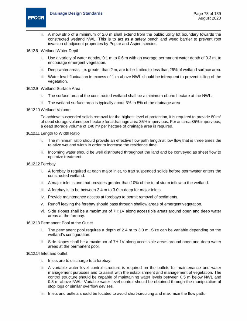
Drainage Design Standards
Page 78 of 139 August 2020
ii. A mow strip of a minimum of 2.0 m shall extend from the public utility lot boundary towards the constructed wetland NWL. This is to act as a safety bench and weed barrier to prevent root invasion of adjacent properties by Poplar and Aspen species.
16.12.8 Wetland Water Depth
i. Use a variety of water depths, 0.1 m to 0.6 m with an average permanent water depth of 0.3 m, to encourage emergent vegetation.
ii. Deep water areas, i.e. greater than 2 m, are to be limited to less than 25% of wetland surface area.
iii. Water level fluctuation in excess of 1 m above NWL should be infrequent to prevent killing of the vegetation.
16.12.9 Wetland Surface Area
i. The surface area of the constructed wetland shall be a minimum of one hectare at the NWL.
ii. The wetland surface area is typically about 3% to 5% of the drainage area.
16.12.10 Wetland Volume
To achieve suspended solids removal for the highest level of protection, it is required to provide 80 m³ of dead storage volume per hectare for a drainage area 35% impervious. For an area 85% impervious, a dead storage volume of 140 m³ per hectare of drainage area is required.
16.12.11 Length to Width Ratio
i. The minimum ratio should provide an effective flow path length at low flow that is three times the relative wetland width in order to increase the residence time.
ii. Incoming water should be well distributed throughout the land and be conveyed as sheet flow to optimize treatment.
16.12.12 Forebay
i. A forebay is required at each major inlet, to trap suspended solids before stormwater enters the constructed wetland.
ii. A major inlet is one that provides greater than 10% of the total storm inflow to the wetland.
iii. A forebay is to be between 2.4 m to 3.0 m deep for major inlets.
iv. Provide maintenance access at forebays to permit removal of sediments.
v. Runoff leaving the forebay should pass through shallow areas of emergent vegetation.
vi. Side slopes shall be a maximum of 7H:1V along accessible areas around open and deep water areas at the forebay.
16.12.13 Permanent Pool at the Outlet
i. The permanent pool requires a depth of 2.4 m to 3.0 m. Size can be variable depending on the wetland’s configuration.
ii. Side slopes shall be a maximum of 7H:1V along accessible areas around open and deep water areas at the permanent pool.
16.12.14 Inlet and outlet
i. Inlets are to discharge to a forebay.
ii. A variable water level control structure is required on the outlets for maintenance and water management purposes and to assist with the establishment and management of vegetation. The control structure should be capable of maintaining water levels between 0.5 m below NWL and 0.5 m above NWL. Variable water level control should be obtained through the manipulation of stop logs or similar overflow devises.
iii. Inlets and outlets should be located to avoid short-circuiting and maximize the flow path.

Drainage Design Standards
Page 79 of 139 August 2020
iv. The maximum depth in the inlet and outlet areas is restricted to 3.0 m.
v. Inlets and outlets are to be fully submerged, with the crown of the pipe at least 1.0 m below NWL. Inlet and outlet pipe inverts are to be a minimum of 100 mm above the bottom.
vi. Provide reinforced grassed maintenance access, with a minimum width of 3 m, to forebay and permanent pool to allow for sediment removal.
16.12.15 Grading
i. Slopes shall be 5H:1V or flatter to support larger areas of wetland vegetation. Terraced slopes are acceptable.
ii. A 2 m wide shallow marsh bench around the wetlands at NWL with a 10H:1V slope and the use of terraced grading is recommended to improve public safety.
iii. Side slopes around the accessible deep areas in sediment forebay and permanent pool areas shall be a maximum of 7H:1V.
iv. The 2 m wide mow strip shall have a side slope of either 7H:1V at accessible deep water areas or 5H:1V in other areas around the wetland.
16.12.16 Outflow Control
The quickest drawdown time shall be 24 hours for a 1:2 year storm to facilitate settling. For the most critical storm event, 90% of the total active storage volume shall have a drawdown time of 96 hours.
Table 16.2: Drawdown Time and Available Volume of Constructed Wetland between NWL and HWL
Time After Commencing Drawdown from Full Level at HWL Available Volume Between HWL and NWL
≥ 24 hours Volume equivalent to runoff from 1:2 year storm 48 hours Volume equivalent to runoff from 1:5 year storm
≤ 96 hours 90% of total storage volume above NWL
16.12.17 Floatables, Oil and Grease
To trap floatable materials, oil and grease, inlets and outlets are to be below normal water level.
16.12.18 Maintenance
i. The Developer is required to provide an O&M manual.
ii. Maintenance and warranty period shall be two years from CCC issuance.
iii. Removal of accumulated sediment during construction from forebays is required prior to issuance of the FAC.
iv. Sediment traps are to be cleaned during the maintenance period.
v. Sediment removal is required when forebay and permanent pool volumes are reduced by greater than 25%.
vi. Replace or adjust plantings and manage nuisance species during the maintenance period.
vii. During the maintenance period, the facility shall be inspected at least twice each year to determine vegetation distribution and the preservation of design depth. These inspection reports shall be submitted when applying for FAC.
viii. In future years, wetland vegetation regeneration should be possible by lowering the water level in the fall season using the control structure.

Drainage Design Standards
Page 80 of 139 August 2020
16.12.19 Monitoring
i. The Developer shall monitor stormwater quality. If required by EPCOR, effluent from the permanent pool shall be sampled and tested for the following parameters: TSS, TP, NH3, BOD and faecal coliforms each year during the maintenance period and the data provided to EPCOR.
ii. The Developer shall also monitor wetland and upland vegetation and take any corrective action required during the maintenance period.
iii. At the end of the maintenance period, before the issuance of the FAC, the Developer shall ensure that at least 75% of the grass cover and 30% of the non-grass emergent vegetation around the wetland’s edge has established given normal seasonal conditions. A vegetation survey by a qualified professional shall be submitted to the City.
16.12.20 Recreational Uses
Planting strategies should deter direct public access to the wetland so as to avoid disturbance of the wetland fauna and to protect the public from the hazards of the SWMF.
16.12.21 Access
Access is required to all inlets and outlets for maintenance, operation of water control structures, removal of debris and litter and vegetation management. Access from arterial roads and freeways should be avoided where possible due to safety concerns of maintenance staff.
16.12.22 Fencing
i. The Developer is required to use natural solutions such as grading and planting strategies to provide safety features for the wetland, inlets and outlets.
ii. The Developer shall provide a fence at the public utility lot boundary with openings for maintenance and public access to trails.
16.12.23 Wildlife
At the discretion of the City and the Developer the design may incorporate features that either encourage or discourage wildlife.
16.12.24 Mosquito Control
The Developer shall include design features that minimize mosquitoes in a constructed wetlands facility. Features can include system design and vegetation management that would preclude stagnant backwaters and shading of the water surface, providing habitat for purple martin, swallows, baitfish, dragon flies, bats and other predators.

Drainage Design Standards
Page 81 of 139 August 2020
Table 16.3: Summary Guide for the Design of Constructed Wetlands Design Element Design Objective Minimum Criteria Recommended
Criteria Level of Service/ Volumetric Sizing
To provide appropriate level of protection and adequate volume for quantity (retention) and quality (treatment).
Most critical storm event design and 85% TSS removal of particle size 75µm or greater for water quality. Provide 80 m3 of dead storage volume per hectare for a drainage area 35% impervious. For an area 85% impervious provide a dead storage volume of 140 m3 per hectare of drainage.
Land Dedication
To apply appropriate designation for specific areas within the wetlands facility
Public Utility Lot - area covered by water at the most critical design storm event; not part of municipal reserve, nor part of area's natural history, nor part of environmental reserve.
Drainage Area Maintain the sustainability of the wetlands, provide constant and or periodic flows and prevent stagnant and long periods of dry conditions.
Minimum of 5 hectares. 20 hectares;
Wetland Surface Area
Minimum of 1 hectare at NWL.
Number of Wetlands
To provide higher and consistent contaminant removal.
A series of small wetlands offering higher treatment capability can be provided.
Fewer, larger wetlands preferred.
Figure 16.3: Schematic Diagram of a Constructed Wetland
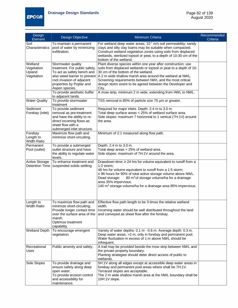
Drainage Design Standards
Page 82 of 139 August 2020
Design Element Design Objective Minimum Criteria Recommended
Criteria Soil Characteristics
To maintain a permanent pool of water by minimizing exfiltration.
For wetland deep water areas, 10-7 m/s soil permeability; sandy clays and silty clay loams may be suitable when compacted. Construct wetland vegetation zones using soils from displaced wetlands, sterilized topsoil or peat, to a depth of 10-30 cm of the bottom of the wetland.
Wetland Vegetation Upland Vegetation
Stormwater quality treatment. For public safety. To act as safety bench and also weed barrier to prevent root invasion of adjacent properties by Poplar and Aspen species.
Plant diverse species within one year after construction; use soils from displaced wetlands or topsoil or peat to a depth of 10-30 cm of the bottom of the wetland. A 2 m wide shallow marsh area around the wetland at NWL. Screening requirements between NWL and the most critical design storm event to be agreed between the Developer and City.
To provide aesthetic buffer to adjacent lands.
A mow strip, minimum 2 m wide, extending from HWL to NWL.
Water Quality To provide stormwater treatment
TSS removal is 85% of particle size 75 µm or greater.
Sediment Forebay (inlet)
To provide sediment removal as pre-treatment and have the ability to re-direct incoming flows as sheet flow with a submerged inlet structure.
Required for major inlets. Depth: 2.4 m to 3.0 m. Total deep surface areas < 25% of wetland surface area. Side slopes: maximum 7 horizontal to 1 vertical (7H:1V) around the area.
Forebay Length to Width Ratio
Maximize flow path and minimize short-circuiting.
Minimum of 2:1 measured along flow path.
Permanent Pool (outlet)
To provide a submerged outlet structure and have the ability to regulate water levels.
Depth: 2.4 m to 3.0 m. Total deep areas < 25% of wetland area. Side slopes: maximum of 7H:1V around the area.
Active Storage Detention Time
To enhance treatment and suspended solids settling.
Drawdown time: ≥ 24 hrs for volume equivalent to runoff from a 1:2 storm; 48 hrs for volume equivalent to runoff from a 1:5 storm; ≤ 96 hours for 90% of total active storage volume above NWL. Dead storage: 80 m3 of storage volume/ha for a drainage area 35% impervious. 140 m3 storage volume/ha for a drainage area 85% impervious.
Length to Width Ratio
To maximize flow path and minimize short-circuiting. Provide longer contact time over the surface area of the marsh. Optimize treatment capability.
Effective flow path length to be 3 times the relative wetland width. Incoming water should be well distributed throughout the land and conveyed as sheet flow after the forebay.
Wetland Depth To encourage emergent vegetation.
Variety of water depths: 0.1 m - 0.6 m. Average depth: 0.3 m. Deep water areas, >2 m, only in forebay and permanent pool. Water fluctuation in excess of 1 m above NWL should be infrequent.
Recreational Uses
Public amenity and safety. A trail may be provided beside the mow strip between NWL and the private property boundary. Planting strategies should deter direct access of public to wetlands.
Side Slopes To provide drainage and ensure safety along deep open water. To provide erosion control and accessibility for maintenance.
5H:1V along all edges except at accessible deep water areas in forebay and permanent pool areas where shall be 7H:1V. Terraced slopes are acceptable. The 2 m wide shallow marsh area at the NWL boundary shall be 10H:1V slope.

Drainage Design Standards
Page 83 of 139 August 2020
Design Element Design Objective Minimum Criteria Recommended
Criteria Access For maintenance and
operation of water control structures, litter and debris removal and vegetation management.
Required at all inlets and outlets.
Inlet Safety and maintenance. Maximum depth: 3 m. Distanced far away from outlet to avoid short-circuiting of flow. Fully submerged: crown 1.0 m below NWL; invert 100 mm above bottom.
Outlet Safety, maintenance and assistance in plant species management.
Use variable water level control structures to regulate water levels between 0.5 m below NWL and 0.5 m above NWL. Maximum depth: 3 m. Distanced far away from inlet to avoid short-circuiting of flow. Fully submerged: crown 1.0 m below normal water level; invert 100 mm above bottom.
Maintenance Vehicle Access
Access for equipment. Width: 4 m.
Fencing Safety. Use natural solutions such as grading and planting strategies. Developer should provide fencing around the PUL with openings for maintenance and public access to trails.
Signage Safety and public information.
Can use signage and brochures.
Erosion and Sediment Control
Implement appropriate erosion and sediment controls during development in the drainage area during the construction phase and during the staged-construction of wetland.
Wildlife At the discretion of the Developer and the City. Mosquitoes Incorporation of design features that minimize mosquitoes. Floatables, Oil and Grease
To trap floatables, oil and grease.
Inlets and outlets are to be below NWL.
Maintenance To properly operate and maintain constructed wetland; to optimize treatment.
Maintenance and warranty period shall be 2 years from the date of the CCC. Developer to provide an operations and maintenance manual. Replacing and or adjusting plantings, managing nuisance species and cleaning sediment traps are required. Inspect at least twice each year. Sediment removal required when sediment loading reduces forebay and permanent pool volumes by greater than 25%. Provide reinforced grassed maintenance access to forebay and permanent pool, 4 m minimum width.
Monitoring To monitor, make necessary corrective actions, and compile data on the use of constructed wetland as a SWMF.
Developer to monitor stormwater quality during the maintenance period. Developer to monitor wetland and upland vegetation and take corrective actions when necessary during the maintenance period. Before issuance of the FAC, the Developer shall ensure that at least 75% of the grass and 30% of the emergent vegetation around the wetland's edge has established. A vegetation survey by a qualified professional shall be submitted to the City.
16.13 Design Standards for Dry Ponds 16.13.1 Land Dedication for Dry Ponds
i. Dry ponds to be operated by EPCOR Drainage Services are to be located within public utility lots that encompass all lands subject to inundation at the 5 year design high water level.
ii. Lands subject to inundation for larger storm events, to the limit of inundation for the design maximum event, are to be either:

Drainage Design Standards
Page 84 of 139 August 2020
included within the Public Utility lots, or
privately owned land covered by an easement in favour of EPCOR Water Services Inc. to permit the encroachment of water onto the property and restrict development in areas subject to inundation.
iii. A restrictive covenant is to be registered on the titles of lots abutting the dry pond onto which ponded water will encroach in order to control lot development below HWL so as not to compromise the dry pond design requirements. This will also ensure that an adequate freeboard is maintained.
16.13.2 Frequency of Operation
i. All dry ponds shall be off-line storage areas designed to temporarily detain excess runoff and reduce the peak outflow rates to the downstream system.
ii. Designs that propose containment of runoff due to events more frequent than 1:2 years are to include special provisions to facilitate clean up, i.e. paved bottom areas or having a slope of 2% to the outlet to prevent ponding.
16.13.3 Depth of Ponding
The maximum live storage limit in a dry pond is 3.0 m measured from the invert elevation of the outlet pipe.
16.13.4 Dry Pond Bottom Grading and Drainage
The dry pond shall be graded to properly drain all areas after its operation. The pond bottom shall have a minimum slope of 0.7% and a slope of 1.0% or greater is recommended where feasible. Lateral slopes shall be 1.0% or greater. French drains or similar may be required where it is anticipated that these slopes may not properly drain the dry pond bottom, or where dictated by multiple use or other special considerations.
16.13.5 Side Slopes
Side slopes subject to inundation upon filling of the dry pond shall have a maximum slope of 7H:1V within private property and a maximum slope of 5H:1V within public property.
16.13.6 Landscaping
Landscaping of dry ponds is to be considered part of the construction and plans shall be submitted with the engineering drawings. The minimum requirement for landscaping of dry ponds shall be as specified in the City of Edmonton Design and Construction Standards, Volume 5: Landscaping
16.13.7 Inlets and Outlets
i. All inlet and outlet structures associated with dry ponds shall have grates provided over their openings to restrict access and prevent entry into sewers by children or other persons. A maximum clear bar spacing of 100 mm shall be used for gratings.
ii. Grated outlet structures are to be designed with a hydraulic capacity of at least twice the required capacity to allow for possible plugging. Further, the arrangement of the structures and the location of the grating shall be such that the velocity of the flow passing through the grating does not exceed 1.0 m/s. Appropriate fencing and guard-rails are to be provided to restrict access and reduce the hazard presented by headwalls and wing walls.
iii. The inlet and outlet should be physically separated around the perimeter of the dry pond. The inlet and outlet should be distanced as far as possible from each other to avoid hydraulic short-circuiting.
17.0 LID FACILITY DESIGN This Section outlines the design criteria that applies to the preliminary and detailed design of LID facilities including bioretention gardens, bioretention basins, box planters, and soil cells. For the design of other LID facilities, refer to the City of Edmonton Low Impact Development - Best Management

Drainage Design Standards
Page 85 of 139 August 2020
Practices Design Guide. Refer to Sections 17.12 and 17.13 for LID soil media requirements. Refer to Section 17.8 for cold climate design considerations. Refer to Section 17.9 for lists of vegetation recommended for LID features.
17.1 Site Planning Considerations Site integration is key to the use of LID features. This means strategically placing them to match soil conditions and satisfy various setbacks from buildings, utilities and road infrastructure. The following should be considered when siting an LID facility: Site drainage patterns and topography; Catchment area and size; System orientation and footprint; Underlying soil permeability and load-bearing capacity; Depth to water table; Buffers and setbacks; Utility conflicts; Future use of space; Cost implications of system configuration and size; Catchment land use, LID features should not be sited in areas with high contamination potential
such as gas stations. A background data review is important for both large and small development sites before selecting LID types. When considering LID facilities at large-scale developments, it has been assumed that at the ASP stage, an inventory of the physical attributes including hydrogeological, geological, and geomorphological setting of a watershed or large development area has been prepared and an understanding of the relationship between shallow groundwater and local surface water resources (recharge and discharge areas) has been established. For infill and redevelopment sites, it is assumed that some local geotechnical data is available from nearby sites or municipal projects (to assess suitable types of LID) or that site data can be collected during foundation excavations to confirm soil types. The following features should be identified for the development (large or small) including: The distribution of surficial geological materials and soil types within the development from
available resources; The topography and the hydrology (surface watercourses, wetlands, and marshes, if any)
including; o The probable depth, direction and rate of groundwater flow (estimated at the reconnaissance
or desktop level of planning); o Watercourses, wetlands, and marshes; o Recharge and discharge areas; and o Areas of potential groundwater and surface water interaction.
The geotechnical hazard areas including areas of geological hazards, abandoned coal mines or geotechnical instability of slopes including identifying preliminary setbacks.
For large developments, field investigations are required; the following are the objectives for assessing LID suitability and type. For smaller redevelopment sites, these issues may not be applicable, but they should be considered: Proximity to nearby building foundations and roadway infrastructure, and likelihood of a perched
water table. The investigation depth is dependent upon site conditions such as presence of sensitive receptors (e.g. surface water bodies) and slopes.
If applicable, interaction between groundwater and surface water near watercourses and in the

Drainage Design Standards
Page 86 of 139 August 2020
vicinity of wetlands and marshes to assess slope stability and aid in protecting habitats from loss of groundwater discharge/recharge or receipt of poor-quality surface drainage.
Potential slope stability issues.
The direction of groundwater flow (hydraulic gradient and hydraulic conductivity).
The potential vertical hydraulic conductivity of the soil above the water table (e.g., expected infiltration rates and percolation rates) and horizontal hydraulic conductivity of saturated soils if bioretention gardens are proposed.
17.2 Design Basis 17.2.1 LID facilities shall be designed to retain and store a minimum of 18 mm of rain from their contributing
impervious catchment area. The impervious catchment area includes paved surfaces, roofs, and surfaces that do not allow infiltration of water.
17.2.2 Design events for ponding and piping infrastructure are the 2 year – 4 hour event, and the 5 year – 4 hour event.
17.2.3 LID facilities must not be located on top of bank lands. LID features should be located at a minimum distance of 50 m from the top of bank or as specified in the geotechnical engineering assessment for the subject lands. If site restrictions for LID features are not specifically addressed in the geotechnical report for the subject lands, the location of LID features must follow the “Water Feature” setback requirements as identified in the neighbourhood ASP and associated geotechnical engineering assessment.
17.2.4 A minimum setback of 3.0 m from buildings is recommended with an impermeable membrane provided around the sides of the soil media if closer. Where this setback is not possible, site specific analysis is required; if lenses of non-cohesive soils such as silts and sand are encountered in subsoils, a mandatory liner should be considered for the LID feature side walls or excessive silting and clogging can occur. If possible LID features should be located down-gradient (minor surface drainage) from any building. As the LID invert level is likely to be higher than the closest building basement floor elevation, an impermeable barrier may be suitable to prevent lateral flow out of the facility towards buildings. Conversely, the setback could be increased by repositioning the LID and building footprint(s) within the development. Waterproofing membranes may also be applied to the building basement walls at sites with nearby LID features as well as use of impermeable membranes on the sides of the LID feature to prevent lateral outflows if sand lenses occur. Use of both can further reduce setback distances.
17.2.5 Depth to the seasonally high groundwater below the LID features invert should be generally no less than 1.0 m to prevent groundwater intrusion unless site details show the water table varies little throughout the year (0.6 m would be the minimum acceptable separation in that case). If the distance from the base of the proposed LID to the water table is less than 1.0 m, determining the fluctuations in groundwater should be completed by performing an actual borehole or test pit as directed by a qualified geotechnical professional when the area is near proposed grade. Groundwater levels will fluctuate seasonally and in response to climatic conditions so 1.0 m is a recommended guide where data from a detailed assessment is not available. Fluctuations are less pronounced in low permeability soils characteristic of the Edmonton area. Adjustments to these buffer distances may be considered if a signed and stamped geotechnical assessment and design has been completed. The design must consider potential lift of the underdrain system, and must use controls that limit/stop the movement of groundwater into the LID system.
17.2.6 For large developments a geotechnical assessment that includes soil type classification and groundwater evaluation is required across the developed site before selecting and implementing the LID features. In addition, hydraulic conductivity testing is required for features which lack an underdrain system, and which drain exclusively to groundwater. LID features with an underdrain system (Bioretention basins, Box planters and Soil cells) can be located over any soil type including high plastic clays (CH). The following is a guide to field work for large developments, but will vary based on the location, size, number and type of LID feature(s), and complexity of the development area.

Drainage Design Standards
Page 87 of 139 August 2020
Drilling a network of shallow boreholes placed at approximately 200 m centres to evaluate the potential variation in soil conditions within the development. For a development area of less than 1 ha, one borehole or excavation pit is required. The extent of this effort will largely depend on what information is already available.
Visual classification of soil types (textures) from soil samples collected during drilling using the Unified Soil Classification System (USCS). The first 3.0 m of depth for LID facility assessments is the most critical soils information to obtain.
Conducting standard penetration tests (SPTs) to identify zones of changing soil strength and consistency in terms of loose and consolidated soil. These tests aid in defining low permeability barriers that may inhibit infiltration capacity of native soil and suggest certain LID facilities over others.
Installing a borehole or excavation pit in the area of the LID for some local design information. Larger areas and areas of complex surficial geology may require additional investigation to better evaluate groundwater depth.
Depth to groundwater across the site must be calculated using borehole data. To undertake surface infiltration estimates, use of the following methods: the double ring, the Guelph Permeameter, or the Modified Phillips Dunne permeameter method, provided consideration is given to the specific site conditions and the suitability of each method’s application.
A design report supported by construction drawings (see Table 17.2 for requirements) must be submitted for large developments. A qualified professional must stamp reports and drawings.
If applicable, the construction details of the liner should include hydraulic conductivity and thickness (either as a hydraulic conductivity to achieve designed infiltration rates to support runoff targets, or the hydraulic conductivity required to minimize infiltration, depending upon the criteria that best satisfies the LID objective).
If a synthetic liner will be used to minimize infiltration, the specifications of the liner material must be provided and supported by the manufacturer’s detailed specifications. Recommendations on how to protect the liner from damage during construction and long-term maintenance requirements, if any, shall be provided.
An assessment of the designed infiltration rates of the infiltration areas and underdrains, and the methods for verifying that these infiltration rates will be achieved post-construction.
An analysis of the stability of the LID slopes based on soil type(s) found if applicable.
Analysis of the impact of percolation and underdrains on the water table, including the potential for impact on roadway infrastructure.
Recommendations on monitoring and maintenance requirements.
Test results to demonstrate that permeability between soil media/subgrade drains and the surrounding native soil will promote downward drainage.
17.3 Bioretention Garden Design 17.3.1 Definition
Bioretention gardens are SWMFs within a shallow depression. On the surface, bioretention gardens may appear similar to flower / shrub beds, however bioretention gardens utilize the specified LID Soil Media (Section 17.12) and vegetation to capture and treat rainwater and are located at the low point of a landscape. Bioretention gardens have no underdrain therefore they consist of pretreatment, a flow entrance, ponding area, plant materials, soil media, and structural storage layers. Structural storage layers are any man-made component that aids in the storage of water such as a concrete barrier, storage tank/pipe, storm chamber, or soil cell structure; this list is not exhaustive and other man-made components could be utilized. For an LID feature to be classified as a bioretention garden it must have a structural man-made storage layer/component.
Bioretention gardens are at much higher risk of freezing and should have natural underlying
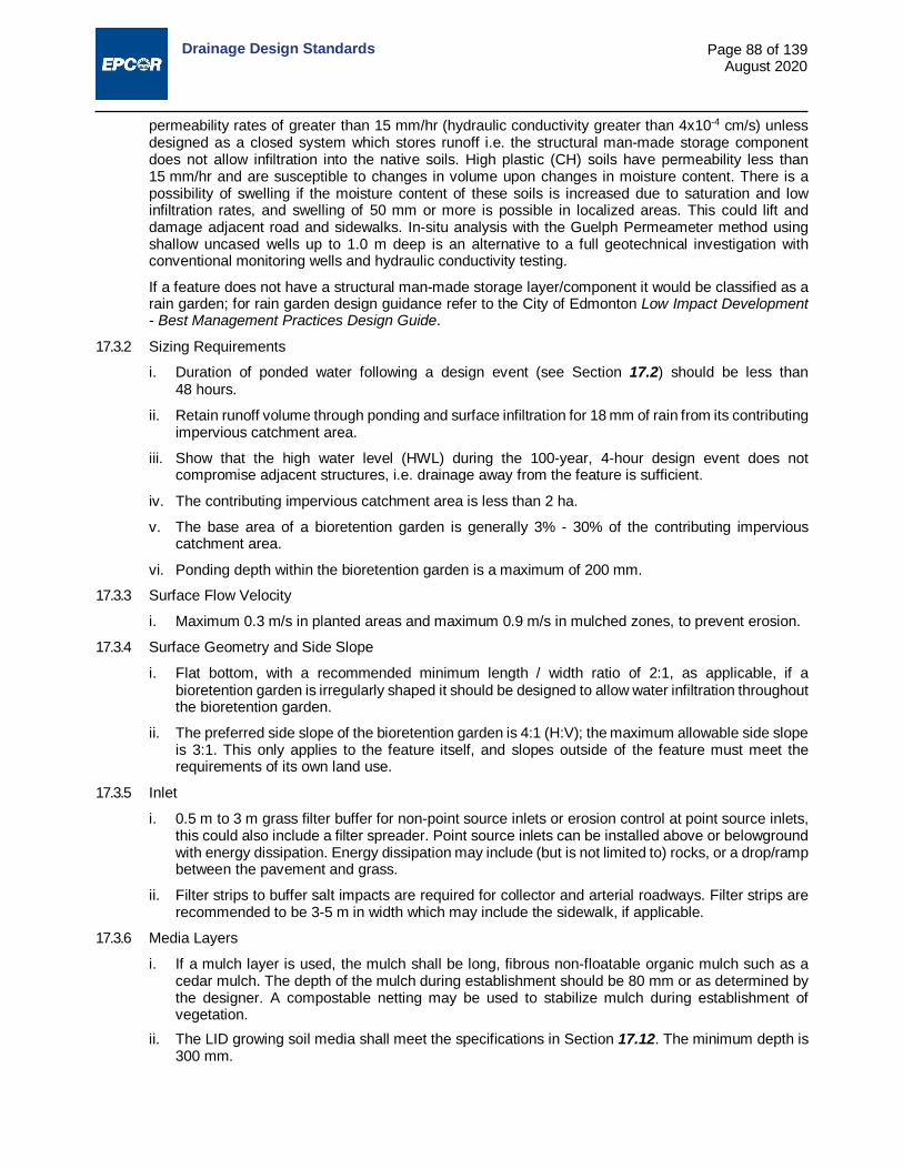
Drainage Design Standards
Page 88 of 139 August 2020
permeability rates of greater than 15 mm/hr (hydraulic conductivity greater than 4x10⁻⁴ cm/s) unless designed as a closed system which stores runoff i.e. the structural man-made storage component does not allow infiltration into the native soils. High plastic (CH) soils have permeability less than 15 mm/hr and are susceptible to changes in volume upon changes in moisture content. There is a possibility of swelling if the moisture content of these soils is increased due to saturation and low infiltration rates, and swelling of 50 mm or more is possible in localized areas. This could lift and damage adjacent road and sidewalks. In-situ analysis with the Guelph Permeameter method using shallow uncased wells up to 1.0 m deep is an alternative to a full geotechnical investigation with conventional monitoring wells and hydraulic conductivity testing.
If a feature does not have a structural man-made storage layer/component it would be classified as a rain garden; for rain garden design guidance refer to the City of Edmonton Low Impact Development - Best Management Practices Design Guide.
17.3.2 Sizing Requirements
i. Duration of ponded water following a design event (see Section 17.2) should be less than 48 hours.
ii. Retain runoff volume through ponding and surface infiltration for 18 mm of rain from its contributing impervious catchment area.
iii. Show that the high water level (HWL) during the 100-year, 4-hour design event does not compromise adjacent structures, i.e. drainage away from the feature is sufficient.
iv. The contributing impervious catchment area is less than 2 ha.
v. The base area of a bioretention garden is generally 3% - 30% of the contributing impervious catchment area.
vi. Ponding depth within the bioretention garden is a maximum of 200 mm.
17.3.3 Surface Flow Velocity
i. Maximum 0.3 m/s in planted areas and maximum 0.9 m/s in mulched zones, to prevent erosion.
17.3.4 Surface Geometry and Side Slope
i. Flat bottom, with a recommended minimum length / width ratio of 2:1, as applicable, if a bioretention garden is irregularly shaped it should be designed to allow water infiltration throughout the bioretention garden.
ii. The preferred side slope of the bioretention garden is 4:1 (H:V); the maximum allowable side slope is 3:1. This only applies to the feature itself, and slopes outside of the feature must meet the requirements of its own land use.
17.3.5 Inlet
i. 0.5 m to 3 m grass filter buffer for non-point source inlets or erosion control at point source inlets, this could also include a filter spreader. Point source inlets can be installed above or belowground with energy dissipation. Energy dissipation may include (but is not limited to) rocks, or a drop/ramp between the pavement and grass.
ii. Filter strips to buffer salt impacts are required for collector and arterial roadways. Filter strips are recommended to be 3-5 m in width which may include the sidewalk, if applicable.
17.3.6 Media Layers
i. If a mulch layer is used, the mulch shall be long, fibrous non-floatable organic mulch such as a cedar mulch. The depth of the mulch during establishment should be 80 mm or as determined by the designer. A compostable netting may be used to stabilize mulch during establishment of vegetation.
ii. The LID growing soil media shall meet the specifications in Section 17.12. The minimum depth is 300 mm.

Drainage Design Standards
Page 89 of 139 August 2020
iii. The filter layer is 100 mm depth with washed rock that is less than 13 mm and less than 0.1% silt. If used, the granular filter layer around the facility should have a minimum thickness of 100 mm with washed rock that is less than 13 mm diameter and less than 0.1% silt. Where situations permit, a greater depth may be applied.
iv. The storage layer must have a man-made structural layer/component that aids in the storage of water (see Section 17.3 for additional details).
17.3.7 Non-woven Geotextile i. Non-woven geotextiles are NOT recommended within LID features; if space and design allow,
using granular filter layers to limit sediment transport is preferred. ii. If geotextile is used for filtration or sidewall coverage, it should be woven monofilament or
non-woven needle punched fabrics. Woven slit film and non-woven heat bonded fabrics should not be used as they are prone to clogging. Geotextile fabric may be placed along the sides of the LID features to help direct the water flow downward and to reduce lateral flows if sand seams exist.
iii. If geotextile must be used within the LID to control transport of sediments, the permeability rate should be higher than that of the soil or 3 m³/min/m² (75 gal/min/ft²), whichever is greater.
17.3.8 Buffer i. The facility base must be 0.6 m to 1.0 m above the seasonally high groundwater table (see Section
17.2.5 for additional details). If required (i.e. if feature is not a closed system and relies on natural infiltration), groundwater mounding calculations must be conducted to ensure mounded groundwater will not affect nearby structures or features.
ii. Horizontal buffers are 3.0 m from building foundations, or closer with the use of engineering controls and as approved by a geotechnical professional (see Section 17.2.4 for additional details).
iii. Provide a buffer of at least 0.5 m from sidewalks and 0.6 m from Shared Use Pathways. Figure 17.1 shows an example of a typical bioretention garden layout, and is for illustrative purposes only, it does not depict every detail that may be required for successful construction, operations, and maintenance. These figures are one variation of the many scenarios that exist and any scenario that meets the requirements of the standards can be proposed. The man-made storage layer/component depicted in Figure 17.1 is simply a placeholder, and actual requirements of the layer are described in Section 17.3.
Figure 17.1: Bioretention Garden Cross Section 17.4 Bioretention Basin Design 17.4.1 Definition
A bioretention basin is a SWMF within a depression area relying on vegetation, specialized soil media and a storage layer to infiltrate, filter, detain, and retain stormwater runoff. Bioretention basins consist of pretreatment, flow entrance/inlet, ponding area, plant materials, LID soil media, filter layer, storage layer, underdrain, and overflow outlet.
17.4.2 Sizing Requirements

Drainage Design Standards
Page 90 of 139 August 2020
i. Duration of ponded water following a design event (see Section 17.2) should be less than 48 hours.
ii. Retain runoff volume through ponding and surface infiltration for a minimum of 18 mm from the contributing impervious catchment area.
iii. Show that the HWL during the 100-year, 4-hour design event does not compromise adjacent structures, i.e. drainage away from the feature is sufficient.
iv. The contributing impervious catchment area is less than 4 ha.
v. The base area of a bioretention basin is generally 3% - 30% of the contributing impervious catchment area.
vi. Ponding depth within the bioretention basin is a maximum of 350 mm.
17.4.3 Surface Flow Velocity
i. Maximum 0.3 m/s in planted areas and maximum 0.9 m/s in mulched zones, to prevent erosion.
17.4.4 Surface Geometry and Side Slope
i. Flat bottom, with a recommended minimum length / width ratio of 2:1 as applicable, if a bioretention basin is irregularly shaped it should be designed to allow water infiltration throughout the bioretention basin.
ii. The preferred side slope of the bioretention basin is 4:1 (H:V); the maximum allowable side slope is 3:1. This only applies to the feature itself, and slopes outside of the feature must meet the requirements of its own land use.
17.4.5 Inlet
i. Inlets may include (but are not limited to) curb cuts, CBs, filter strips, flow spreaders, curb cuts with grates or sidewalk grates. Sidewalk grates may only be used in certain applications after other options have been evaluated. If sidewalk grates are to be used they must have firm, stable, slip resistant, and heel-friendly covers; care must be taken to ensure the grates are level with the existing sidewalk.
ii. 0.5 m to 3 m grass filter buffers for non-point source inlets or erosion control at point source inlets are recommended. Erosion control and/or energy dissipation must be appropriate to the type of inlet and the location. Erosion control and energy dissipation methods chosen must be permanent and control erosion throughout the life of the bioretention basin.
iii. Point source inlets can be installed above or belowground with energy dissipation. Energy dissipation may include (but is not limited to) rocks, or a drop/ramp between the pavement and grass.
iv. Filter strips to buffer salt impacts are required as follows: 3-5 m width along collectors (may include sidewalk) and arterials (if necessary).
v. Pre-treatment is required to capture large particles and debris and prevent the spread of sediments on the surface of the bioretention basin.
vi. Inlets must be situated to allow for maintenance of both the inlet and the erosion control/energy dissipation (if applicable). Inlets should not be situated directly adjacent to overflows to encourage water movement throughout the LID. Proximity of inlets to potential obstructions should be minimized to reduce inlet blockage.
17.4.6 Media Layers
i. If a mulch layer is used, the mulch shall be long, fibrous, non-floatable organic mulch such as a cedar mulch. The depth of the mulch during establishment should be 80 mm or as determined by the designer. A compostable netting may be used to stabilize mulch during establishment of vegetation.
ii. The LID growing soil media shall meet the specification in Section 17.12. The minimum depth is
Drainage Design Standards
Page 91 of 139 August 2020
500 mm unless it is not feasible due to site constraints.
iii. The filter layer is 100 mm depth with washed rock that is less than 13 mm and less than 0.1% silt. If used, the granular filter layer around the facility should have a minimum thickness of 100 mm with washed rock that is less than 13 mm diameter and less than 0.1% silt. Where situations permit, a greater depth may be applied.
iv. The drainage layer is a minimum of 350 mm in depth with 25 mm - 40 mm angular crushed rock containing less than 0.1% silt.
17.4.7 Non-woven Geotextile
i. Non-woven geotextiles are NOT recommended within LID features; if space and design allow, using granular filter layers to limit sediment transport is preferred.
ii. If geotextile is used for filtration or sidewall coverage, it should be woven monofilament or non-woven needle punched fabrics. Woven slit film and non-woven heat bonded fabrics should not be used as they are prone to clogging. Geotextile fabric may be placed along the sides of the LID features to help direct the water flow downward and to reduce lateral flows if sand seams exist.
iii. If geotextile must be used within the LID to control transport of sediments, the permeability rate should be higher than that of the soil or 3 m³/min/m² (75 gal/min/ft²), whichever is greater.
17.4.8 Underdrain Perforated Pipe
i. All Piping and Infrastructure Considerations in Section 17.7 must be followed.
17.4.9 Buffer
i. The facility base must be 0.6 m to 1 m above the seasonally high groundwater table (see Section 17.2.5 for additional details).
ii. Horizontal buffers are 3.0 m from building foundations, or closer with the use of engineering controls and as approved by a geotechnical professional (see Section 17.2.4 for additional details).
Figure 17.2 shows plan and profile views of a typical bioretention basin layout, and are for illustrative purposes only, they do not depict every detail that may be required for successful construction, operations, and maintenance. These views show the inlet from a curb cut; however these figures are one variation of the many scenarios that exist and any scenario that meets the requirements of the standards can be proposed.

Drainage Design Standards
Page 92 of 139 August 2020
Figure 17.2: Bioretention Basin Plan View and Cross Sections
Drainage Design Standards
Page 93 of 139 August 2020
17.5 Box Planter Design 17.5.1 Definition
Similar to bioretention basins, box planters use vegetation and specialized soil media to filter and retain stormwater; however box planters are contained within a box-like structure (no bottom). Box planters are ideal for areas with small footprints such as downtown as they have smaller footprints (vertical sides) and can be located close to buildings. Box planters can be raised or located flush with/below ground. Box planters contain an underdrain pipe.
17.5.2 Sizing Requirements
i. Duration of ponded water following an 18 mm design event (see Section 17.2) should be less than 48 hours.
ii. Retain runoff volume through ponding and surface infiltration for 18 mm of rain from its contributing impervious catchment area.
iii. Show that the high water level (HWL) during the 100-year, 4-hour design event does not compromise adjacent structures, i.e. drainage away from the feature is sufficient.
iv. The contributing catchment area is less than 0.5 ha.
v. Ponding depth is a maximum of 350 mm.
17.5.3 Surface Flow Velocity
i. Maximum 0.3 m/s in planted areas and maximum 0.9 m/s in mulched zones, to prevent erosion.
17.5.4 Planter Material
i. Stone, concrete, brick, clay, or plastic are acceptable materials for the contained planters.
17.5.5 Surface Geometry and Surface Slopes
i. The width of the box planter must be greater than or equal to 450 mm.
ii. Surface slopes less than 0.5%.
17.5.6 Inlet
i. Erosion control and energy dissipation at inlets. Energy dissipation may include (but is not limited to) rocks, or a drop/ramp between the pavement and grass.
ii. Inlets may include (but are not limited to) curb cuts, curb cuts with grates, roof leaders, CBs, or concrete flow spreaders.
iii. Pre-treatment may be required to capture large particles and debris and prevent the spread of sediments on the surface of the box planter.
17.5.7 Media Layers
i. If a mulch layer is used, the mulch shall be long, fibrous non-floatable organic mulch such as a cedar mulch. The depth of the mulch during establishment should be 80 mm or as determined by the designer.
ii. The LID growing soil media shall meet the specification in Section 17.12. The minimum depth is 500 mm unless it is not feasible due to site constraints.
iii. The filter layer is 100 mm depth with washed rock that is less than 13 mm and less than 0.1% silt. If used, the granular filter layer around the facility should have a minimum thickness of 100 mm with washed rock that is less than 13 mm diameter and less than 0.1% silt. Where situations permit, a greater depth may be applied.
iv. The drainage layer is a minimum of 350 mm in depth with 25 mm - 40 mm angular crushed rock containing less than 0.1% silt.
Drainage Design Standards
Page 94 of 139 August 2020
17.5.8 Non-woven Geotextile
i. Non-woven geotextiles are NOT recommended within LID features; if space and design allow, using granular filter layers to limit sediment transport is preferred.
ii. If geotextile is used for filtration or sidewall coverage, it should be woven monofilament or non-woven needle punched fabrics. Woven slit film and non-woven heat bonded fabrics should not be used as they are prone to clogging. Geotextile fabric may be placed along the sides of the LID features to help direct the water flow downward and to reduce lateral flows if sand seams exist.
iii. If geotextile must be used within the LID to control transport of sediments, the permeability rate should be higher than that of the soil or 3 m³/min/m² (75 gal/min/ft²), whichever is greater.
17.5.9 Underdrain Pipe
i. All piping and infrastructure considerations in Section 17.7 must be followed.
17.5.10 Buffer
i. The facility base must be 0.6 m to 1 m above the seasonally high groundwater table (see Section 17.2.5 for additional details).
ii. Horizontal buffers are 3 m from building foundations, or closer with the use of engineering controls and as approved by a geotechnical professional (see Section 17.2.4 for additional details). Box planters may be placed adjacent to buildings with engineering controls e approved by a geotechnical professional.
Figure 17.3 shows plan and profile views of a typical box planter layout, and are for illustrative purposes only, they do not depict every detail that may be required for successful construction, operations, and maintenance. These views show the inlet from a curb cut; however these figures are one variation of the many scenarios that exist and any scenario that meets the requirements of the standards can be proposed.

Drainage Design Standards
Page 95 of 139 August 2020
Figure 17.3: Box Planter Plan View and Cross Sections

Drainage Design Standards
Page 96 of 139 August 2020
17.6 Soil Cell Design 17.6.1 Definition
Soil cells provide structural support for sidewalks and roadways while allowing space for specialized soil media to facilitate tree rooting and provide stormwater management by promoting absorption, evapotranspiration, and interception. Stormwater can be directed into the soil cell system through a CB with pre-treatment, sheet flow through a curb cut, or roof drain connection.
17.6.2 Sizing Requirements i. Duration of ponded water following an 18 mm design event (see Section 17.2) should be less than
48 hours, if applicable. ii. Retain runoff volume through ponding and surface infiltration for a minimum of 18 mm, soil cells
can also retain additional volume captured during large events. iii. Show that the HWL during the 5-year, 10-year and 100-year design events does not compromise
adjacent structures. iv. Meet minimum soil volumes required for trees by the City of Edmonton Volume 5 Landscape
Design and Construction Standard. 17.6.3 Geometry and Loading
i. Installed to the size and dimensions of the structural cell module chosen. ii. Structural cell modules and corresponding pavement (asphalt, concrete, etc.) must be able to
handle required loads (typically of the largest vehicle that would be driving over the soil cell), loading must be reviewed and approved by a structural engineer or following manufacturers’ specifications. Note: different products may have different load capacities and testing protocols, protocols should be checked for relevance in local jurisdictions.
17.6.4 Inlet i. Inlets may include (but are not limited to) CBs, roof leaders, trench drains, or pretreatment devices. ii. Energy dissipation should be provided if the water flows directly into the surface of the system.
Energy dissipation may include (but is not limited to) rocks, or a drop/ramp between the pavement and the soil cell.
17.6.5 Media Layer i. LID growing soil media shall meet the specifications in Section 17.13. ii. The structural cell module type selected will dictate the media layers required and their
corresponding depths and volumes; manufacturer’s specifications and recommendations must be followed. Note: soil and media specifications may differ depending on the purpose of the structural cell module. Soil and media must be designed for stormwater retention and detention and to allow tree root growth.
17.6.6 Distribution Pipe i. A minimum diameter 200 mm perforated PVC distribution pipe shall be installed as per one of the
following specifications: a) sloped at a minimum 0.5% to allow positive flow through the soil cells; b) a flat pipe set below the CB inlet; or c) as per manufacturer’s specifications.
ii. All Piping and Infrastructure Considerations in Section 17.7 must be followed. 17.6.7 Underdrain Pipe
i. A minimum diameter 200 m perforated PVC underdrain pipe shall be installed within an aggregate blanket that extends the length of the pipe or as per manufacturer’s specifications.
ii. The underdrain pipe must slope towards the catch basin/manhole.
Drainage Design Standards
Page 97 of 139 August 2020
iii. All Piping and Infrastructure Considerations in Section 17.7 must be followed.
17.6.8 Subbase and Subgrade
i. Subbase and subgrade must be prepared and/or installed as per manufacturer specifications and with consultation and approval of a geotechnical engineer.
ii. The native soil subbase must be compacted to a minimum of 95% Standard Proctor density to support the system load unless a geotechnical engineer has indicated another compaction level is acceptable.
iii. In certain situations manufacturers may require different soils, materials, or geotextiles immediately adjacent to or within the soil cell installation; all manufacturer’s specifications/ recommendations must be followed unless approved by a qualified engineering professional.
17.6.9 Buffer
i. The facility base must be 0.6 m to 1.0 m above the seasonally high groundwater table (see Section 17.2.5 for additional details) unless approved by a qualified engineering professional.
ii. Horizontal buffers are 3 m from building foundations, or closer with the use of engineering controls and as approved by a geotechnical professional (see Section 17.2.4 for additional details).
17.6.10 General Considerations
i. The structural systems must meet the requirements of the Complete Streets Design and Construction Standards for roadways, sidewalks, walkways, paths and/or trails.
ii. The soil cells must be designed and tested for the purpose of growing tree roots, and stormwater filtering, detention, and retention.
iii. Soil cells must be able to be installed to allow installation of utilities through the soil cells, if necessary. Installation of utilities through the spaces within the soil cell frames must be approved by the utility owner/operator. All utility lines installed through the soil cells must be secured and braced within the frames. Where utility lines require that the space between cells is larger than 150 mm, bridging must be designed.
iv. Geogrid shall be net-shaped woven polyester fabric with PVC coating; uniaxial or biaxial; inert to biological degradation; resistant to naturally occurring chemicals, alkalis, and acids; and used to provide a stabilizing force within the soil structure. Geogrid must meet the soil cell manufacturer’s specifications.
v. Geotextile shall be composed of high tenacity polypropylene yarns which are woven into a network such that the yarns retain their relative position; be inert to biological degradation; and resistant to naturally encountered chemicals, alkalis, and acids. Geotextiles must meet the soil cell manufacturer’s specifications.
vi. If a root barrier is required, the root barrier shall prevent root penetration. The root barrier shall be made of an impermeable and ribbed geotextile. The root barrier must be installed the full depth of the soil cells and as needed around utilities or other obstructions through the soil cells. Root barriers must be continuous or interlocking.
vii. Follow the manufacturer’s instructions for installation including locations of drainage lines, utilities, geogrid, geotextile, subgrade preparation, paving, and system layout.
viii. In areas of potential change or expansion, empty conduit should be installed to facilitate ease of future utility installation.
Figure 17.4 shows plan and profile views of a typical soil cell (with trees) layout, and are for illustrative purposes only, they do not depict every detail that may be required for successful construction, operations, and maintenance. These views show the inlet from a CB; however these figures are one variation of the many scenarios that exist and any scenario that meets the requirements of the standards can be proposed.

Drainage Design Standards
Page 98 of 139 August 2020
Figure 17.4: Soil Cell Plan View and Cross Section
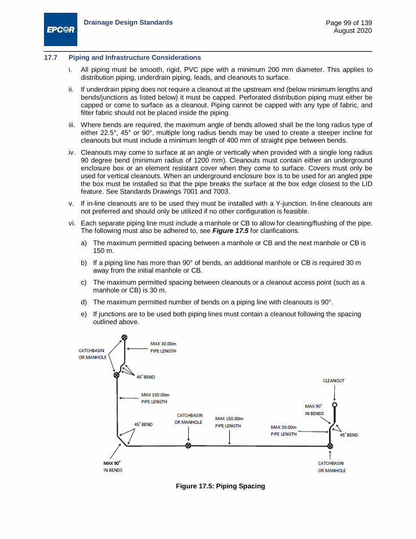
Drainage Design Standards
Page 99 of 139 August 2020
17.7 Piping and Infrastructure Considerations i. All piping must be smooth, rigid, PVC pipe with a minimum 200 mm diameter. This applies to
distribution piping, underdrain piping, leads, and cleanouts to surface.
ii. If underdrain piping does not require a cleanout at the upstream end (below minimum lengths and bends/junctions as listed below) it must be capped. Perforated distribution piping must either be capped or come to surface as a cleanout. Piping cannot be capped with any type of fabric, and filter fabric should not be placed inside the piping.
iii. Where bends are required, the maximum angle of bends allowed shall be the long radius type of either 22.5°, 45° or 90°, multiple long radius bends may be used to create a steeper incline for cleanouts but must include a minimum length of 400 mm of straight pipe between bends.
iv. Cleanouts may come to surface at an angle or vertically when provided with a single long radius 90 degree bend (minimum radius of 1200 mm). Cleanouts must contain either an underground enclosure box or an element resistant cover when they come to surface. Covers must only be used for vertical cleanouts. When an underground enclosure box is to be used for an angled pipe the box must be installed so that the pipe breaks the surface at the box edge closest to the LID feature. See Standards Drawings 7001 and 7003.
v. If in-line cleanouts are to be used they must be installed with a Y-junction. In-line cleanouts are not preferred and should only be utilized if no other configuration is feasible.
vi. Each separate piping line must include a manhole or CB to allow for cleaning/flushing of the pipe. The following must also be adhered to, see Figure 17.5 for clarifications.
a) The maximum permitted spacing between a manhole or CB and the next manhole or CB is 150 m.
b) If a piping line has more than 90° of bends, an additional manhole or CB is required 30 m away from the initial manhole or CB.
c) The maximum permitted spacing between cleanouts or a cleanout access point (such as a manhole or CB) is 30 m.
d) The maximum permitted number of bends on a piping line with cleanouts is 90°.
e) If junctions are to be used both piping lines must contain a cleanout following the spacing outlined above.
Figure 17.5: Piping Spacing
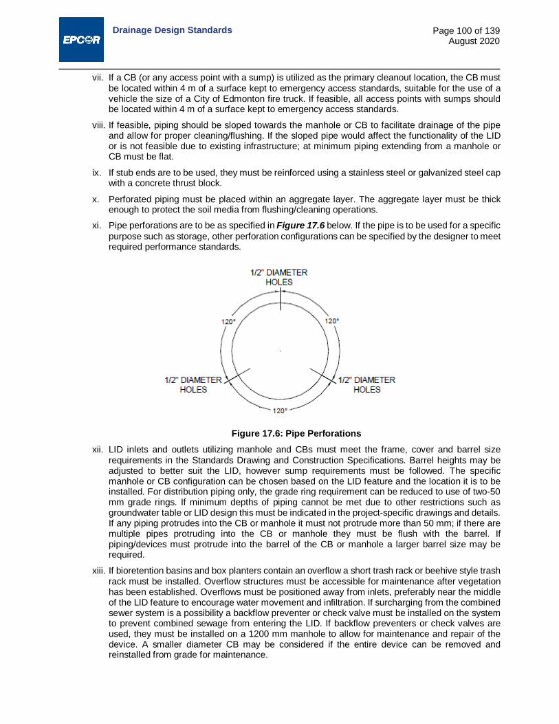
Drainage Design Standards
Page 100 of 139 August 2020
vii. If a CB (or any access point with a sump) is utilized as the primary cleanout location, the CB must be located within 4 m of a surface kept to emergency access standards, suitable for the use of a vehicle the size of a City of Edmonton fire truck. If feasible, all access points with sumps should be located within 4 m of a surface kept to emergency access standards.
viii. If feasible, piping should be sloped towards the manhole or CB to facilitate drainage of the pipe and allow for proper cleaning/flushing. If the sloped pipe would affect the functionality of the LID or is not feasible due to existing infrastructure; at minimum piping extending from a manhole or CB must be flat.
ix. If stub ends are to be used, they must be reinforced using a stainless steel or galvanized steel cap with a concrete thrust block.
x. Perforated piping must be placed within an aggregate layer. The aggregate layer must be thick enough to protect the soil media from flushing/cleaning operations.
xi. Pipe perforations are to be as specified in Figure 17.6 below. If the pipe is to be used for a specific purpose such as storage, other perforation configurations can be specified by the designer to meet required performance standards.
Figure 17.6: Pipe Perforations xii. LID inlets and outlets utilizing manhole and CBs must meet the frame, cover and barrel size
requirements in the Standards Drawing and Construction Specifications. Barrel heights may be adjusted to better suit the LID, however sump requirements must be followed. The specific manhole or CB configuration can be chosen based on the LID feature and the location it is to be installed. For distribution piping only, the grade ring requirement can be reduced to use of two-50 mm grade rings. If minimum depths of piping cannot be met due to other restrictions such as groundwater table or LID design this must be indicated in the project-specific drawings and details. If any piping protrudes into the CB or manhole it must not protrude more than 50 mm; if there are multiple pipes protruding into the CB or manhole they must be flush with the barrel. If piping/devices must protrude into the barrel of the CB or manhole a larger barrel size may be required.
xiii. If bioretention basins and box planters contain an overflow a short trash rack or beehive style trash rack must be installed. Overflow structures must be accessible for maintenance after vegetation has been established. Overflows must be positioned away from inlets, preferably near the middle of the LID feature to encourage water movement and infiltration. If surcharging from the combined sewer system is a possibility a backflow preventer or check valve must be installed on the system to prevent combined sewage from entering the LID. If backflow preventers or check valves are used, they must be installed on a 1200 mm manhole to allow for maintenance and repair of the device. A smaller diameter CB may be considered if the entire device can be removed and reinstalled from grade for maintenance.

Drainage Design Standards
Page 101 of 139 August 2020
xiv. Underground enclosure boxes (including junction boxes and valve boxes) and caps must be labelled appropriately. Underground enclosures boxes or caps should be installed to protect infrastructure coming to surface such as cleanouts. Underground enclosure boxes and caps must be designed and installed to meet any loadings relative to their location. Boxes and caps must be labelled indicating what they contain e.g. UNDERDRAIN CLEANOUT, DISTRIBUTION CLEANOUT, ELECTRICAL, etc. Cleanouts and underground enclosure boxes must be clear of trees, buildings, or permanent obstructions within 1 m of the cleanout location (small vegetation is acceptable). If due to site constraints a 1 m radius around the cleanout is not possible, a minimum of 180° is required.
17.8 Cold Climate Design Considerations 17.8.1 De-icing salt loadings to LID facilities should not exceed 1000 mg/L during winter months to avoid salt
induced injury to vegetation and soils. LID facilities that will receive higher loadings must be designed with salt tolerant species, highly permeable soils, and underdrains.
17.8.2 Locate snow storage areas away from LID facilities unless vegetation and soil structure is specifically designed to accommodate snow storage. Snow loading calculations must be completed for snow storage areas to ensure the weight of the snow will not affect the soil compaction or cause pipe deformations. Boulevards and other areas can sometimes be used for snow storage, these areas should be designed accordingly. Salt tolerant, non-woody vegetation are recommended for areas that may be used for snow storage. Loading calculations and corresponding design must be signed and stamped by a qualified professional. LID is not recommended for use at dedicated snow storage facilities (i.e. sites that store a large amount of snow from multiple sites).
17.8.3 Size curb cut inlets to prevent blockage by ice and snow during spring runoff. See Figure 17.7 below for a typical concrete curb opening approved by the City of Edmonton. Other curb openings may be accepted by the City of Edmonton.
Figure 17.7: Curb Cut Opening 17.9 Vegetation Selection 17.9.1 Select plant varieties that will thrive on the site conditions and that grow well together. Species
selection should consider:
Soil permeability and periodic inundation of the soil;
LID soil media type (as per Sections 17.12 and 17.13);
Tolerance of seasonal salt loadings depending on facility location;
Pollutant uptake capacity;
Maintenance needs, including mowing and pruning;
Sight lines for features on or near roadways;
Site use;
Drainage Design Standards
Page 102 of 139 August 2020
Reduction of water and fertilizer needs after establishment; and
Resistance to pests.
Recommended native species for LID are listed in Table 17.1 below. This table is limited to native material only, and it should be noted that this list is not fully comprehensive and there are many plants, both native and non-native, that will function in LID features that are not represented here. Table 17.1 is provided as a helpful guiding document that outlines some of the characteristics and principles of plant selection that we look for when designing LID features but, designers have the ability to provide exceptions and expansions to the list.
17.9.2 Native species are recommended to be used where possible as native species typically facilitate further ongoing infiltration through development of root structures and are more resistant to changing weather patterns and climate change. Recommended plant species have been included in Table 17.1, however, vegetation selected for specific LID features is still governed by the City of Edmonton Design and Construction Standards, Volume 5: Landscaping and must meet these requirements. Note all recommended plant species may not be suitable for every situation, for example LID features near roadways have size restrictions to maintain sight lines.
17.9.3 For soil cells ONLY, a drought tolerant, minimal maintenance blend of grasses can be used over top of the soil cells. This configuration can be used for mature neighbourhood retrofits. Trees and shrubs should be used where possible, to encourage stormwater uptake and ongoing infiltration through development of root structures. Table 17.1 lists very few trees suitable for soil cells as native species may not be ideal for soil cells in urban environments. A mix of ornamental and native tree species is encouraged for soil cells if possible. Trees selected are still governed by the City of Edmonton Design and Construction Standards, Volume 5: Landscaping and must meet these requirements.
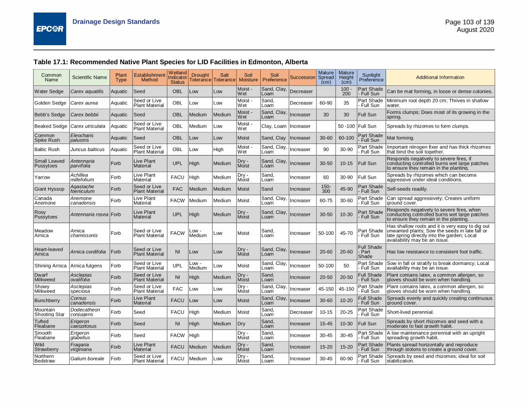
Drainage Design Standards
Page 103 of 139 August 2020
Table 17.1: Recommended Native Plant Species for LID Facilities in Edmonton, Alberta
Common Name Scientific Name Plant
Type Establishment
Method Wetland Indicator Status
Drought Tolerance
Salt Tolerance
Soil Moisture
Soil Preference Succession
Mature Spread
(cm)
Mature Height (cm)
Sunlight Preference Additional Information
Water Sedge Carex aquatilis Aquatic Seed OBL Low Low Moist - Wet
Sand, Clay, Loam Decreaser 100 -
200 Part Shade - Full Sun Can be mat forming, in loose or dense colonies.
Golden Sedge Carex aurea Aquatic Seed or Live Plant Material OBL Low Low Moist -
Wet Sand, Loam Decreaser 60-90 35 Part Shade
- Full Sun Minimum root depth 20 cm; Thrives in shallow water.
Bebb's Sedge Carex bebbii Aquatic Seed OBL Medium Medium Moist - Wet
Sand, Clay, Loam Increaser 30 30 Full Sun Forms clumps; Does most of its growing in the
spring.
Beaked Sedge Carex utriculata Aquatic Seed or Live Plant Material OBL Medium Low Moist -
Wet Clay, Loam Increaser 50 -100 Full Sun Spreads by rhizomes to form clumps.
Common Spike Rush
Eleocharis palustris Aquatic Seed OBL Low Low Moist Sand, Clay Increaser 30-60 60-100 Part Shade
- Full Sun Mat forming.
Baltic Rush Juncus balticus Aquatic Seed or Live Plant Material OBL Low High Moist -
Wet Sand, Clay, Loam Increaser 90 30-90 Part Shade
- Full Sun Important nitrogen fixer and has thick rhizomes that bind the soil together.
Small Leaved Pussytoes
Antennaria parvifolia Forb Live Plant
Material UPL High Medium Dry - Moist
Sand, Clay, Loam Increaser 30-50 10-15 Full Sun
Responds negatively to severe fires, if conducting controlled burns wet large patches to ensure they remain in the planting.
Yarrow Achillea millefolium Forb Live Plant
Material FACU High Medium Dry - Moist
Sand, Loam Increaser 60 30-90 Full Sun Spreads by rhizomes which can become
aggressive under ideal conditions.
Giant Hyssop Agastache foeniculum Forb Seed or Live
Plant Material FAC Medium Medium Moist Sand Increaser 150-300 45-90 Part Shade
- Full Sun Self-seeds readily.
Canada Anemone
Anemone canadensis Forb Live Plant
Material FACW Medium Medium Moist Sand, Clay, Loam Increaser 60-75 30-60 Part Shade
- Full Sun Can spread aggressively; Creates uniform ground cover.
Rosy Pussytoes Antennaria rosea Forb Live Plant
Material UPL High Medium Dry - Moist
Sand, Clay, Loam Increaser 30-50 10-30 Part Shade
- Full Sun Responds negatively to severe fires, when conducting controlled burns wet large patches to ensure they remain in the planting.
Meadow Arnica
Arnica chamissonis Forb Seed or Live
Plant Material FACW Low - Medium Low Moist Sand,
Loam Increaser 50-100 45-70 Part Shade - Full Sun
Has shallow roots and it is very easy to dig out unwanted plants; Sow the seeds in late fall or late spring directly into the garden; Local availability may be an issue.
Heart-leaved Arnica Arnica cordifolia Forb Seed or Live
Plant Material NI Low Low Dry - Moist
Sand, Clay, Loam Increaser 20-60 20-60
Full Shade - Part Shade
Has low resistance to consistent foot traffic.
Shining Arnica Arnica fulgens Forb Seed or Live Plant Material UPL Low -
Medium Low Moist Sand, Clay, Loam Increaser 50-100 50 Part Shade
- Full Sun Sow in fall or stratify to break dormancy; Local availability may be an issue.
Dwarf Milkweed
Asclepias ovalifolia Forb Seed or Live
Plant Material NI High Medium Dry - Moist
Sand, Loam Increaser 20-50 20-50 Full Shade
- Full Sun Plant contains latex, a common allergen, so gloves should be worn when handling.
Showy Milkweed
Asclepias speciosa Forb Seed or Live
Plant Material FAC Low Low Dry - Moist
Sand, Clay, Loam Increaser 45-150 45-150 Part Shade
- Full Sun Plant contains latex, a common allergen, so gloves should be worn when handling.
Bunchberry Cornus canadensis Forb Live Plant
Material FACU Low Low Moist Sand, Clay, Loam Increaser 30-60 10-20 Full Shade
- Full Sun Spreads evenly and quickly creating continuous ground cover.
Mountain Shooting Star
Dodecatheon conjugens Forb Seed FACU High Medium Moist Sand,
Loam Decreaser 10-15 20-25 Part Shade - Full Sun Short-lived perennial.
Tufted Fleabane
Erigeron caespitosus Forb Seed NI High Medium Dry Sand,
Loam Increaser 15-45 10-30 Full Sun Spreads by short rhizomes and seed with a moderate to fast growth habit.
Smooth Fleabane
Erigeron glabellus Forb Seed FACW High Dry -
Moist Sand, Loam Increaser 30-45 30-45 Part Shade
- Full Sun A low maintenance perennial with an upright spreading growth habit.
Wild Strawberry
Fragaria virginiana Forb Live Plant
Material FACU Medium Medium Dry - Moist
Sand, Loam Increaser 15-20 15-20 Part Shade
- Full Sun Plants spread horizontally and reproduce through stolons to create a ground cover.
Northern Bedstraw Galium boreale Forb Seed or Live
Plant Material FACU Medium Low Dry - Moist
Sand, Loam Increaser 30-45 60-90 Part Shade
- Full Sun Spreads by seed and rhizomes; ideal for soil stabilization.

Drainage Design Standards
Page 104 of 139 August 2020
Common Name Scientific Name Plant
Type Establishment
Method Wetland Indicator Status
Drought Tolerance
Salt Tolerance
Soil Moisture
Soil Preference Succession
Mature Spread
(cm)
Mature Height (cm)
Sunlight Preference Additional Information
Gumweed Grindelia squarrosa Forb Seed or Live
Plant Material UPL High High Dry Sand, Clay, Loam Increaser 30-60 20-60 Full Sun
Can be weedy; Plants may be pruned or mowed back to prevent excessive spreading; Plant is biennial and short-lived.
Beautiful Sunflower
Helianthus pauciflorus Forb Seed or Live
Plant Material NI High High Dry Sand Increaser 60 15-35 Part Shade - Full Sun
Plants exude allelopathic chemicals that inhibit the growth of young plants nearby.
Meadow Blazingstar Liatris ligulistylis Forb Seed or Live
Plant Material FAC High Medium Dry - Moist Sand Increaser 20-40 45-70 Full Sun
Seeds are large and wind dispersed; Collecting and reseeding into the desired area will increase establishment.
Blue Flax Linum lewisii Forb Seed NI High Low Dry - Moist
Sand, Loam Stable 50-90 30-90 Full Sun Short-lived perennial; Can become weedy if
there is little competition.
Ostrich Fern Matteuccia struthiopteris Forb Live Plant
Material FACW Low Low Moist Sand, Loam Increaser 100-
200 100-200 Full Shade - Part Shade
Clump forming and can become aggressive under ideal conditions.
Wild Mint Mentha arvensis Forb Live Plant Material FACW Low Low Moist -
Wet Clay, Loam Increaser 100 20-75 Full Shade - Full Sun
Can spread aggressively under ideal conditions; Resistant to browsing from deer; Can be mat forming.
Tall Bluebells Mertensia paniculata Forb Seed FAC Low Low Moist -
Wet Sand, Clay, Loam Increaser 45 20-80
Full Shade - Part Shade
Regenerates from thick rhizomes.
Wild Bergamot Monarda fistulosa Forb Seed or Live
Plant Material FACU High Medium - High
Dry - Moist
Sand, Clay, Loam Increaser 60-90 60-90 Full Sun Requires occasional maintenance, can spread
to form clumps and self seed. Yellow Coneflower
Ratibida columnifera Forb Seed NI High Low Dry -
Moist Sand, Loam Increaser 30-45 30-90 Full Sun Will readily self-seed.
Canada Goldenrod
Solidago canadensis Forb Seed or Live
Plant Material FACU Medium Low Dry - Moist
Sand, Clay, Loam Increaser 50-100 50-100 Part Shade
- Full Sun Can be aggressive under ideal conditions.
Prairie Goldenrod
Solidago missouriensis Forb Seed FACU Low Low Dry -
Moist Sand, Clay, Loam increaser 30-60 45-90 Part Shade
- Full Sun Spreads by rhizomes and seeds with a moderate to fast growth habit, can become aggressive.
Sticky Goldenrod Solidago simplex Forb Seed FACU Low Low Dry -
Moist Sand, Loam Increaser 30-45 20-45 Full Sun Could be used in smaller spaces; can be
controlled by deadheading.
Smooth Aster Symphyotrichum laeve Forb Seed or Live
Plant Material FACU Medium Medium Dry - Moist Clay, Loam Decreaser 30-90 30-90 Part Shade
- Full Sun Can directly seed into plantings, seeds do not require either scarification or stratification.
Purple Stemmed Aster
Symphyotrichum puniceum Forb Seed or Live
Plant Material OBL Medium Medium Moist - Wet Clay, Loam Increaser 60-90 60-150 Full Sun Can spread rapidly and form large colonies in
moist - wet areas.
Heart-leaved Alexanders Zizia aptera Forb Live Plant
Material FAC Medium Medium Dry - Moist
Sand, Clay, Loam Decreaser 45-60 45-90 Part Shade
- Full Sun Low maintenance perennial.
Indian Ricegrass
Achnatherum hymenoides (Oryzopsis hymenoides)
Grass Seed FACU High Medium Dry - Moist
Sand, Clay, Loam Stable 25-70 Full Sun Seeds must be pretreated to break dormancy.
Awned Wheatgrass
Agropyron subsecundum Grass Seed FACU Medium Low Dry -
Moist Loam Decreaser 50-100 Part Shade - Full Sun Self-seeds, some tillering.
Blue Grama Bouteloua gracilis Grass Seed UPL High Medium Dry Sand, Clay,
Loam Increaser 45-60 30-35 Full Sun Tolerates moderate to heavy foot traffic.
Marsh Reed Grass
Calamagrostis canadensis Grass Seed OBL Medium Medium Moist -
Wet Sand, Clay, Loam Decreaser 100-
150 100-200 Full Sun Rhizomes can be pruned in the spring to limit spread.
Tufted Hairgrass
Deschampsia caespitosa Grass Live Plant
Material FACW High Low Moist Sand, Clay, Loam Stable 30 40 Full sun A clump forming perennial that can provide
erosion control with its deep rhizomes. Canada Wildrye
Elymus canadensis Grass Seed FAC High High Dry -
Moist Sand, Clay, Loam Decreaser 60-90 100-150 Part Shade
- Full Sun Lives 4-5 years, reseeds easily on bare soil.

Drainage Design Standards
Page 105 of 139 August 2020
Common Name Scientific Name Plant
Type Establishment
Method Wetland Indicator Status
Drought Tolerance
Salt Tolerance
Soil Moisture
Soil Preference Succession
Mature Spread
(cm)
Mature Height (cm)
Sunlight Preference Additional Information
Rocky Mountain Fescue
Festuca saximontana Grass Seed or Live
Plant Material NI High High Dry - Moist
Sand, Loam Increaser 20-25 Part Shade
- Full Sun Does well in disturbed or polluted areas but does not tolerate heavy foot traffic.
Tall Manna Grass Glyceria grandis Grass Seed OBL Low Low Wet Clay, Loam Decreaser 25-60 Full Sun Spreads by thick rhizomes and stolons; suitable
for erosion control.
Sweetgrass Hierochloe odorata Grass Live Plant
Material FACW Low High Moist - Wet
Sand, Clay, Loam Increaser 60 30-60 Part Shade
- Full Sun
One of the four sacred plants to Metis and Indigenous people; It grows much better from rhizomes than from seed, and may triple in size within one year.
Junegrass Koeleria macrantha Grass Seed or Live
Plant Material FACU High Low Dry - Moist
Sand, Loam Increaser 30-60 30-60 Full Sun Seedlings are weak and do not survive
moderate to high foot traffic. Fowl Bluegrass Poa palustris Grass Seed FACW Low Low Moist Clay, Loam Decreaser 150 Part Shade Requires a minimum root depth of 30 cm.
False Melic Grass
Schizachne purpurascens Grass Seed FACU Medium Low Dry -
Moist Sand Decreaser 10-15 40-80 Full Shade - Part Shade
Prefers shadier spots than most grasses making it suitable for treed areas.
Little Bluestem Schizachyrium scoparium Grass Seed or Live
Plant Material FACU High Medium - High
Dry - Moist Sand Increaser 45-60 30-70 Full Sun Requires burning or mowing with thatch removal
every 3-5 years.
Needle and Thread Grass Stipa comata Grass Seed UPL High Low Dry Sand,
Loam Decreaser 30 40-60 Part Shade - Full Sun
Requires >254 mm of annual precipitation but grows in areas with less; Provides stabilization from erosion; Seed heads are potentially problematic for pet owners in residential areas.
Green Alder Alnus viridis Shrub Seed or Live Plant Material FAC Low Low Moist Sand,
Loam Increaser 300 Part Shade - Full Sun
Clearance from lowest branches to the ground can be up to 100 cm at maturity
Saskatoon Serviceberry
Amelanchier alnifolia Shrub Live Plant
Material FACU Low - Medium Low Dry -
Moist Sand, Loam Decreaser 200-
300 300-400 Full Sun No clearance under the lowest branches could impedes sightlines; Species is a decreaser without proper maintenance.
Bog Birch Betula pumila Shrub Live Plant Material OBL Low Low Moist -
Wet Sand, Loam Increaser 200-
300 100-300 Part Shade - Full Sun
Low maintenance, minimal suckering and has a fast growth rate.
Red Osier Dogwood Cornus sericea Shrub Live Plant
Material FACW Medium High Dry - Moist
Sand, Clay, Loam Increaser 300 300 Part Shade
- Full Sun Low maintenance, may require light pruning.
Beaked Hazelnut Corylus cornuta Shrub Live Plant
Material UPL Medium Low Dry - Moist
Sand, Loam Stable 100-
200 100-200 Part Shade - Full Sun
Controlled burn will kill the above ground portion of the shrub, but it readily resprouts.
Castlegar Hawthorn
Crataegus chrysocarpa Shrub Live Plant
Material FACU Medium Medium Moist - Wet Loam Decreaser 400 500 Part Shade
- Full Sun Does not require any significant pruning to maintain its shape; Can be planted to stabilize banks, preventing wind and water erosion.
American Silverberry
Elaeagnus commutata Shrub Live Plant
Material UPL High High Dry - Moist
Sand, Clay, Loam Increaser 300 200-400 Full Sun Recovers slowly from severe fire.
Wolf Willow Elaeagnus commutata Shrub Live Plant
Material UPL High Medium Dry - Moist Clay, Loam Increaser 200-
400 200-400 Full Sun Readily suckers, thicket forming.
Twinberry Honeysuckle
Lonicera involucrata Shrub Live Plant
Material FACU Medium Low Moist Clay, Loam Increaser 150 300 Part Shade - Full Sun
Naturalizes through self-seeding and can form colonies overtime.
Shrubby Cinquefoil
Potentilla fruticosa Shrub Live Plant
Material FACW High Medium Dry - Wet Sand, Clay, Loam Increaser 50-100 100-150 Part Shade
- Full Sun May require the removal of die back every spring.
Fire Cherry, Pin Cherry
Prunus pensylvanica Shrub Live Plant
Material FACU Medium - High Medium Dry -
Moist Sand, Clay, Loam Decreaser 200-
300 200-500 Full Sun Clearance from lowest branches to the ground can be up to 120 cm at maturity, without pruning.
Golden Currant Ribes aureum Shrub Live Plant
Material FACU High Low Dry - Moist
Sand, Clay, Loam Increaser 60-200 100-300 Part Shade
- Full Sun Plant may sucker under ideal conditions.
Wild Rose Rosa acicularis Shrub Live Plant Material FACU Low Low Dry -
Moist Clay, Loam Increaser 100 100 Part Shade - Full Sun
Requires occasional maintenance and upkeep, best pruned in late winter.

Drainage Design Standards
Page 106 of 139 August 2020
Common Name Scientific Name Plant
Type Establishment
Method Wetland Indicator Status
Drought Tolerance
Salt Tolerance
Soil Moisture
Soil Preference Succession
Mature Spread
(cm)
Mature Height (cm)
Sunlight Preference Additional Information
Beaked Willow Salix bebbiana Shrub Live Plant Material FACW Low Low Moist -
Wet Sand, Clay, Loam Increaser 100-
600 300-1000
Part Shade - Full Sun
Short-lived and fast-growing; Susceptible to insect, disease, and wind damage.
Hoary Willow Salix candida Shrub Live Plant Material OBL Low Low Moist -
Wet Sand, Clay, Loam Increaser 50-100 50-100 Part Shade
- Full Sun Short-lived and fast-growing; Susceptible to insect, disease, and wind damage.
Under-green Willow Salix commutata Shrub Live Plant
Material OBL Low Low Moist - Wet
Sand, Loam Increaser 50-150 300 Part Shade
- Full Sun Little maintenance required.
Pussy willow Salix discolor Shrub Live Plant Material FACW Medium Medium Wet Sand, Clay,
Loam Increaser 100-300 200-300 Part Shade
- Full Sun Branches will need maintenance annually.
Drrummond's Willow
Salix drummondiana Shrub Live Plant
Material FACW Low Low Moist - Wet
Sand, Clay, Loam Increaser 100-
300 200-400 Part Shade - Full Sun Plant can sucker profusely.
Sandbar Willow Salix exigua Shrub Live Plant
Material FACW Medium Low Moist - Wet
Sand, Loam Increaser 250-
400 400-700 Part Shade - Full Sun Plant can sucker profusely.
Gray leaf Willow Salix glauca Shrub Live Plant
Material FACW Low Low Moist - Wet Clay, Loam Increaser 200-
300 120-200 Part Shade - Full Sun Plant can sucker profusely.
Shining Willow Salix lucida Shrub Live Plant Material FACW Low Low Moist -
Wet Clay, Loam Increaser 500-600 500-600 Part Shade
- Full Sun Aggressive roots can exploit soil moisture; Fast-growing, short-lived, and prone to disease and insect damage.
Yellow Willow Salix lutea Shrub Live Plant Material FACW Low Low Moist Sand, Clay,
Loam Increaser 300 300-600 Full Sun Fast growing; Some maintenance required.
Meadow Willow Salix petiolaris Shrub Live Plant
Material OBL Medium Low Dry - Moist
Sand, Clay, Loam Increaser 300 300 Part Shade
- Full Sun Low maintenance; Forms dense spreading tidy clumps; Is good for erosion control.
Silver Buffaloberry
Shepherdia argentea Shrub Live Plant
Material UPL Medium High Dry - Moist
Sand, Loam Increaser 300 400 Full Sun
Tolerates the poor soils and does well in dry or alkaline situations; Low maintenance and extremely cold- and drought-tolerant.
Canada Buffaloberry
Shepherdia canadensis Shrub Live Plant
Material FACU High Medium Dry - Moist
Sand, Loam Increaser 200-
300 100-200 Full Shade - Full Sun
Low maintenance. Extremely cold- and drought-tolerant.
White Meadow Sweet Spiraea alba Shrub Live Plant
Material FACW Low Low Moist - Wet
Sand, Clay, Loam Increaser 50-150 100-200 Part Shade
- Full Sun Can sucker under ideal conditions. Remove spent flower clusters to promote additional bloom.
Snowberry Symphoricarpos albus Shrub Live Plant
Material UPL High Medium Dry - Moist
Sand, Clay, Loam Increaser 100-
200 100-200 Part Shade - Full Sun Plants can sucker, prune as needed.
High-bush Cranberry Viburnum edule Shrub Live Plant
Material FACW Low Low Moist Sand, Clay, Loam Decreaser 200-
400 200-300 Part Shade - Full Sun Thicket forming.
White Birch Betula papyrifera Tree Live Plant Material FACU Low Medium Moist Sand, Clay,
Loam Increaser 600 1200 Full Sun A short-lived tree and shade intolerant. Not suitable for a soil cell.
Tamarak Larch Larix laricina Tree Live Plant Material FACW Low Low Moist -
Wet Sand, Loam Increaser 300 1200 Full Sun Tree has a shallow root system. Not suitable for
a soil cell.
White Spruce Picea glauca Tree Live Plant Material FACU Medium Low Moist Clay, Loam Stable 300-
600 1000-2000 Full Sun
Clearance from lowest branches to the ground can be up 150 cm at maturity, without pruning. Not suitable for a soil cell.
Lodgepole Pine Pinus contorta Tree Live Plant
Material FACU High Medium Dry Sand, Loam Increaser 600 3000 Full Sun
Clearance from lowest branches to the ground can be up to 300 cm at maturity, without pruning. Not suitable for a soil cell.
Balsam Poplar Populus balsamifera Tree Live Plant
Material FACW Low Low Moist Sand, Clay, Loam Increaser 1000 2500 Full Sun A high maintenance tree that can become
invasive. Not suitable for a soil cell. Trembling Aspen
Populus tremuloides Tree Live Plant
Material FAC Low Medium Dry - Wet Sand, Clay, Loam Increaser 500 1500 Part Shade
- Full Sun Can be an aggressive invader under ideal conditions. Not suitable for a soil cell.
Bur Oak Quercus macrocarpa Tree Live Plant
Material FAC High Medium - High Dry - Wet Sand, Clay,
Loam Stable 1800-2500
1800-2500 Full Sun
Clearance from lowest branches to the ground can be up to 300 cm at maturity, without pruning.
*Thatch removal may be required every 3 - 5 years, determined by condition of planting*

Drainage Design and Construction Standards
Page 107 of 139 August 2020
17.10 Drawing Requirements Required plan view, detail, and profile view drawing details are listed in Table 17.2 below.
Table 17.2: Drawing Detail Requirements Parameter Plan Detail Profile Description
Location x Areal extent shown on plan view (bump-outs, municipal reserves, private lots, parks, road ROW, utilities)
Surface area x Outlined on plan view drawings, size of surface area of LID feature
Type x x The type of LID (using the definitions outlined above) or definitions as per the City of Edmonton Low Impact Development - Best Management Practices Design Guide.
Inlet x x x Shown on plan view and typical detail provided (curb cut, flow spreader, ribbon curb, pretreatment, CB, etc.)
Slopes (if applicable) x x Side slopes of the LID features as well as slope of ground adjacent to
LID feature.
Materials x x x
Material specifications including depths/thickness and volumes required (LID soil media, filter layer, drainage layer), depth/thickness, hydraulic conductivity, porosity and any other material such as geotextiles or soil cells that may be required. Piping size and specifications. There should be at least one profile view outlining all layers and materials within the LID feature, including pipe locations.
Vegetation x x Planting plan and vegetation details (species, mature density, succession plan)
Outlet x x x Underdrain specification & slope, spill elevation, CB type and grate, weir type and location, inlet control device and overflow details
Catchment x Delineated catchment area directed to LID facility, size of catchment area and impervious portion
Flow Arrows x From contributing area and overflow route(s)
Water Depth x x Ponding depth and water surface elevation during design storm(s) and maximum prior to spill. Water depths for all design storms identified in Section 17.2 must be shown.
Inundation x Extent of inundation during design storms Erosion Control/ Energy Dissipation
x x Outlined location on plan view (inlet, outlet if overland spill) and details, this should include both temporary and permanent measures
Cleanouts x x x Located on plan view, detailed with all piping details Location of surrounding sewer systems
x Location(s) shown on plan view. Sewer system type (i.e., sanitary, stormwater or combined) must be specified.
17.11 Construction Considerations Project specifications should consider the following regarding construction of the LID facility and placement of the soil mix:
i. Construction execution planning should give careful consideration to the sequencing and traffic flow of activities at and around the LID facility to minimize disturbance of the LID site.
ii. The LID feature(s) should be isolated from runoff and sedimentation from the impervious catchment area until vegetation is established and ready to provide treatment as per design. This can be achieved by physically blocking flow with a barrier, using sacrificial sod or geotextiles for ESC control, or installing the LID feature after construction around the site has been completed. This is especially important in highly saline areas such as snow storage areas or adjacent to arterial roadways. If the LID feature cannot be isolated from runoff and sedimentation ESC

Drainage Design and Construction Standards
Page 108 of 139 August 2020
measure for the catchment must be put into place and thought should be taken to using plantings instead of seed.
iii. The subsoil, LID growing soil media, filter layer, and granular drainage layer should be inspected by qualified personnel prior to backfill.
iv. Subgrade excavation should be performed by suitable equipment and construction practices that will minimize compaction to the infiltration area. The use of excavators reaching in from outside the infiltration footprint is preferred. If excavation must be carried out within the footprint, light weight, low ground-contact pressure equipment should be used. In this case, tests should be carried out to ensure the subgrade infiltrations rates meet that of the design prior to backfilling or installation of geotextiles. Tilling operations may be necessary should infiltration tests indicate excessive compaction of the area.
v. Surface of the subgrade and/or granular layers may require scarification to provide proper bonding and transition between materials.
vi. Gravel drain rocks should be placed uniformly in 300 mm lifts.
vii. Soil, compost, and/or other amendments should be uniformly mixed prior to placement. Care should be taken to avoid compacting the mixture during the mixing process. For further information on acceptable soil amendment see the City of Edmonton's Volume 5 - Topsoil Specification 02910.
viii. Soil mix should be placed uniformly in 200 mm to 300 mm lifts. Each lift should be water consolidated or compacted using a suitable method as per design specifications.
17.11.1 Safety Factor
When completing hydraulic simulations or calculations utilizing hydraulic conductivity, a minimum safety factor of 2 must be used for the hydraulic conductivity to account for variability in soil and clogging. For example for a soil with a hydraulic conductivity of 40 mm/hour, hydraulic simulations and calculations should be completed using a hydraulic conductivity of 20 mm/hour.
17.11.2 General Inlet and Outlet Considerations
LID feature design should consider the following regarding inlets and outlets:
i. The location of the inlets and outlets must be situated to allow water to fully flow through and percolate into the LID Soil Media.
ii. The overflow outlet must be situated near the center of the LID, between the inlet and the outlet to maximize water flow through the LID Soil Media. If the overflow outlet is located near the inlet flow may short circuit the system and flow directly into the overflow.
iii. Thought should be given to the type of erosion/flow control utilized at the inlets and outlets and the permanence of the installation.
iv. Inlets, outlets, and overflows must be accessible for operations and maintenance. Care should be taken during vegetation selection to ensure that all will still be accessible at peak vegetation size.
17.12 LID Growing Soil Media Specifications - Bioretention Gardens, Bioretention Basins, and Box Planters The LID soil media must meet the requirements in this Section or the performance-based standards outlined in Section 17.12.4. If performance-based standards are chosen, the designer must prove the standards can be met with their design.
17.12.1 Texture and Property
The LID soil media specification (Table 17.3) provides a range of values for each parameter. It is at the discretion of the engineer and the landscape architect to determine the exact value and whether any additional tolerances are allowed outside the standard ranges for a specific project. If ranges outside those listed below are chosen, the design basis must shift to the performance-based standards in Section 17.12.4.

Drainage Design and Construction Standards
Page 109 of 139 August 2020
Table 17.3: LID Soil Media Specification for Bioretention Gardens, Bioretention Basins, and Box Planters
Parameter Values Texture classification Loamy Sand; Sandy Loam Sand sized particles, larger than 0.05 mm diameter and smaller than 2 mm diameter 50% – 85%
Silt 10% – 15% Clay 5% - 15% Silt and clay combined Maximum 30% Compost (optional) 15% – 25 % Organic matter 5% – 15% pH value 6-8 Phosphorus 10 -50 ppm Cation Exchange Capacity >5 meq/100g Saturated Hydraulic conductivity, at soils specified compaction and moisture Minimum 40 mm/hr
Notes: All % are in dry weight.
Sand: Sand sized particles shall have a well-graded distribution with a coefficient of uniformity between 4 and 6. Sand shall be free from clay balls and other extraneous materials.
Compost: The use of compost is to enhance soil permeability and water holding capacity, and to provide the right amount of organics and nutrient for plant growth. Compost should be the City-certified for landscape use as per the City of Edmonton Landscape Standard Topsoil Section 02910.
Woodchips: A small amount of woodchips can be utilized to increase pore space within the LID soil mix to help plant establishment; however all other parameters listed must still be met. Woodchips must be smaller than 50 mm in length.
17.12.2 Sampling and Analysis
If the soil to be used as the LID soil mix is a purchased, premixed, and pretested soil one sample (regardless of volume to be used) prior to placement must be taken to confirm the supplier soil specifications. If the soil appears to change anytime during placement another sample must be taken.
Analyses conducted must include the following:
Texture classification by a qualified professional;
Grain size classification (sieve and/or hydrometer) (%);
Organic matter (%);
pH; and
In-situ Saturated Hydraulic Conductivity (mm/hr) - Guelph Permeameter testing must be conducted once per 100 m of LID feature or once per LID feature, in features smaller than 100 m in length. For each Guelph Permeameter test conducted, an additional test at an adjacent location should be completed for QA/QC purposes.
Sampling for LID soil mix that is not premixed and pretested must follow the Sampling Requirements as outlined in the City of Edmonton Volume 5 - Topsoil Specification 02910.
Additional analyses may be requested on a project-specific basis. In the case that written approval is given by the City/EPCOR to the Consultant or Contractor, as applicable, the City reserves the right to conduct in-situ testing after CCC and prior to FAC on the LID soil mix. If these test results show the soil does not meet the parameters in Table 17.3, and that there is no reasonable wear and tear or adjacent activity that could have altered the soil since it was placed such that is does not meet the
Drainage Design and Construction Standards
Page 110 of 139 August 2020
requirements set in Table 17.3, the City/EPCOR can, at its discretion, require the Developer, Consultant or Contractor, as applicable, to amend or replace the soil to meet the requirements.
Soil mix specifications, samples, and laboratory analysis results should be submitted to the Owner (or Owner Representative) prior to placement (with the exception of in-situ hydraulic conductivity) as per contract specification requirements. In-situ hydraulic conductivity using the Guelph permeameter must be tested at CCC and if possible at FAC as well.
17.12.3 Compaction and Infiltration
Compaction for the LID soil media is recommended to be specified at a minimum 75%-85% Standard Proctor density depending on the soil type to be used; unless further compaction is required for structural purposes. Soil shall be placed in 30 cm lifts; unless otherwise specified by the designer. Where substrate infiltration is slow (<15 mm/hr) an underdrain must be installed.
Soils with a high organic content, should still be lightly compacted to reduce settlement of the soil and LID feature.
When limiting compaction care must be taken to follow the Construction Considerations located in Section 0.
17.12.4 Performance-Based Standards
If a soil mix other than that specified in Table 17.3 is used the LID feature must be able to retain and store 18 mm of rain from the LID features impervious catchment area and drain the corresponding standing water within 48 hours. The HWL during the 100-year design event must not compromise adjacent structures. Surface storage, and soil mix shall not allow water from the 18 mm to drain directly into the stormwater system, as this will not provide storage or improvements in water quality.
Alternate soil mixes may be used for any of the layers (mulch layer, growing media, granular filter layer, or drainage infiltration layer) however layers must still meet their respective purposes and the overall performance-based standard. The drainage infiltration (storage) layer must be able to withstand flushing as per Section 17.7 Piping and Infrastructure Considerations and must provide adequate support for the specified piping.
Different soil mixes may be used for different areas of the LID feature (i.e. slopes vs. bottoms) if required to promote varied vegetation growth.
If LID features are constructed in series, the performance based standards will apply as one feature; that is the features working in tandem must be able to retain 18 mm and drain the corresponding standing water within 48 hours; each individual LID feature does not need to meet these requirements. If LID features are constructed in series, the space between LID features must be constructed to facilitate water flow. Spaces between LID features should be minimized to discourage use of space as access or crossing locations.
17.13 Soil Specifications - Soil Cells 17.13.1 Soil Media
The soil media for soil cells must meet the following requirements:
45% - 60% sand, 40% - 55% unscreened topsoil (native); screened topsoil must not be used as soil peds/ aggregates (naturally-occurring clumps of soil) must be retained, 5% - 10% organics (compost), 75%-85% compaction, placed in 20 - 30 cm lifts;
Or as per manufacturer’s specifications/recommendations.
The tree root package (that comes with the tree) may contain different soil, however soil media throughout the remainder of the soil cell system must be consistent. Figure 17.8 shows a profile view of a typical tree root package within a soil cell and is for illustrative purposes only, it does not depict every detail that may be required for successful construction, operations, and maintenance.

Drainage Design and Construction Standards
Page 111 of 139 August 2020
Figure 17.8: Tree Root Package
17.13.2 Backfill Material (Adjacent to Soil Cells)
The backfill material adjacent to the soil cell installation must be clean, compactable, coarse-grained (gravel) fill with less than 30% fines, or as per manufacturer’s specifications/ recommendations. Backfill material must be free of organic material, trash and other debris, and free of materials toxic to plant growth. Backfill material should be compacted and placed as per the manufacturer’s specifications.
Note, in certain situations manufacturers may require different soils, materials, or geotextiles immediately adjacent to or within the soil cell installation; all manufacturer’s specifications/ recommendations must be followed unless approved by a qualified engineering professional.
18.0 LOT GRADING AND SURFACE DRAINAGE DESIGN This section outlines the requirements and considerations that apply to the detailed design of lot grading plans. Note: City of Edmonton provides this service. Subdivision Engineering Plans which includes Lot Grading Plans submitted by Private Developers and Engineers are reviewed and approved by City of Edmonton, Development Services, Development Engineering and Review. Lot Grading Certificates and inspections on Private Property are submitted by Owners, Home Builders, Grading Contractors or Landscapers are reviewed, inspected and enforced by the City of Edmonton, Development Services, Lot Grading.
18.1 Lot Grading on Private Property 18.1.1 Level of Service
The level-of-service requirements for lot grading include provision of protection against surface flooding and property damage for the 1:100 year return frequency design storm. Through control of surface elevations, designs should be such that maximum flow or ponding surface elevations are 150 mm below the lowest anticipated finished ground elevations at buildings. An overflow route or sufficient ponding volume must be provided from or at all sags or depressions to provide for this 150 mm freeboard with the maximum depth of ponding is limited to 350 mm.
18.1.2 Intent and Application of Lot Grading Plans
i. The establishment of a lot grading plan is one of the principal means for establishing a critical component of the major drainage system. The lot grading plan is a specific requirement within the detailed Engineering Drawings for a subdivision under the terms of a standard servicing agreement. Lot grading plans are required for most property developments involving building
Drainage Design and Construction Standards
Page 112 of 139 August 2020
construction or surface improvements and may be a requirement of a development permit or pursuant to requirements of bylaws, regulations, other approvals or agreements.
ii. Site grading shall ensure proper drainage (lot grading) and control stormwater runoff of individual private properties or establish an effective surface runoff system for a whole development area. A lot grading plan establishes the drainage relationship between adjacent properties and its approval is an effective basis for the control of grading of the properties.
iii. The lot grading plan shall be suitable for use as a tool to control surface drainage and control stormwater runoff through the development process and thereafter. The lot grading plan is approved by the City of Edmonton, Development Services, Development Engineering Drawing Review Unit to establish the “Lot Grading Plan” pursuant to the Drainage Bylaw No. 18093. Lot Grading Plans specify design elevations, surface gradients, lot types, swale locations, and any other related drainage related information (e.g. Site Servicing, Easements, Restrictive Covenants) required for lot grading. The lot grading plan may be enforced by the City, initially to implement the approved grading and then to have the grading maintained by the property owner to prevent or correct obstruction of flow routes and excessive or recurrent ponding of water around buildings.
iv. Refer to the Lot Grading Guidelines, published by the City of Edmonton, Development Services, Lot Grading, for an outline of the mechanisms for establishment and control of lot grading and for drawings showing typical standard grading patterns for unit residential, multi-family residential and commercial / industrial properties. These guidelines are available from City of Edmonton, Development Services, Lot Grading web page www.edmonton.ca/lotgrading.
iv. General considerations in the establishment of Lot Grading Plans
In the design of lot grading plans, the designer must achieve a proper relationship and balance between the street elevation, building grade elevation, surrounding development and existing topography.
The implications of required noise attenuation berms and other elevation controlling features are to be fully addressed by the designer. It is also important to ensure that the lot grading design and the anticipated house or building designs are complementary. Reverse slope driveways and other features that would be likely to capture runoff or fail to drain during major rainfall events or snow melt should be discouraged.
The Developer must ensure that builders are informed of any potential problems or restrictions respecting building design, lot grading and site servicing. The lot grading plan is used as one of the principle means by which this information is communicated.
18.2 Lot Grading Design Requirements 18.2.1 Details of Grading Within Lots
Refer to Figure 18.1 and Figure 18.2 for typical lot grading details for various standard drainage arrangements for detached residential developments. Also refer to the Lot Grading Guidelines, published by the City of Edmonton, Development Services, Lot Grading, for drawings showing typical standard grading patterns for unit residential, multi-family residential and commercial/industrial properties. These guidelines are available from the City of Edmonton’s web page www.edmonton.ca/lotgrading.

Drainage Design and Construction Standards
Page 113 of 139 August 2020
Figure 18.1: Typical Lot Grading Details – Rear to Front Drainage
Figure 18.2: Typical Lot Grading Details – Split/Front to Back Drainage 18.2.2 Special Requirement for Multi-plex Development
For multi-plex developments comprised of three or more units with separate fee simple titles for each unit, specific lot grading requirements apply.
i. For multi-plex developments where cross lot surface drainage is required to provide a drainage path for the rear yards, a private to private easement and restrictive covenant document is required to be registered on all the lots. The easement and restrictive covenant document shall be registered to cover all the lots within a continuous block.
ii. Each individually titled lot must be provided with a separate storm service to accommodate roof leader connections and sump pump discharge connections.
iii. All roof leaders for each dwelling unit shall be connected to the storm sewer service for that lot. No roof leaders are permitted to discharge to the ground surface.
Drainage Design and Construction Standards
Page 114 of 139 August 2020
iv. Roof leader drainage from accessory buildings such as garages must also be connected to the storm sewer service of the individual lot or directed to discharge to the rear alley.
v. In situations where the rear yards of a titled lot cannot surface drain directly to a public Right-of- Way and cross lot surface drainage is required the following Lot Grading Plan requirements apply:
The Lot Grading Plan must clearly establish and define the drainage path on any downstream lot that is required to convey surface runoff from an upstream lot. This requires that an additional lot grade elevation be provided on the Lot Grading plan at the center of that lot along the defined flow path (see typical multi-plex lot grading detail in Figure 18.3).
The minimum slope along the cross-lot swale shall be 1.5%. The flow path shall be clearly illustrated using a flow arrow on the Lot Grading Plan.
Specific notes must be provided on the Lot Grading Plan to indicate the requirement for the private to private easement and restrictive covenant document to be registered on all the lots.
18.2.3 Establishment of Grade Elevations at Buildings
The finished grade elevations at buildings are basically established by following the Alberta Building Codes, Part 9 – Housing and Small Buildings https://www.alberta.ca/building-codes-and-standards.aspx. The Alberta Land Surveyor, Engineer, Architect, or other applicant for a building permit sets the elevation. The relative surface elevations must allow for the slope of the ground adjacent to the building to be at a minimum of 10% for a distance of 2.0 m or to the property line, on all sides of the house, with the slope directing drainage away from the building and then for reasonable slopes in the order of 1.5% to 2.0% from all points within the property to the property boundary at which the drainage may escape.
18.2.4 Overall Slopes for Property Grading
Property line elevations are to be established such that lots have a minimum overall slope of 2.0%, from the high point to the front or back property lines for split drainage situations, or between the higher and lower, front and rear property lines with through drainage. The minimum grade (2%) should normally be exceeded if topography allows.
18.2.5 Overall Drainage Arrangement
i. Lots abutting a public right-of-way at front and rear
ii. Split drainage or through drainage (front to rear or rear to front drainage) is allowed when a lot is located such that there is a road, alley, or public right-of-way at both the front and back of the lot.
iii. Alleyless subdivisions (properties with no alley)
iv. Rear to front drainage is preferred in alleyless subdivisions. Split drainage in alleyless subdivisions is permitted only if all of the following conditions are met:
it is not feasible to achieve rear-to-front drainage due to extreme natural topography;
the receiving downstream lot has an overall grade of 3.0% or more;
there is no concentration of flow from upstream lots to downstream lots;
only one lot drains to another lot;
runoff from the roof of the upstream lot is directed to a storm service or the upstream lot’s grading is designed with the ridge as close to the rear property line as possible.
In situations where split drainage may be problematic due to the above conditions not being met, the use of a swale for the interception of split drainage and its conveyance directly to a public right of way is permitted.

Drainage Design and Construction Standards
Page 115 of 139 August 2020
Figure 18.3: Typical Multiplex Lot Grading Details 18.3 Use of Swales 18.3.1 A swale is a shallow sloped linear depression for conveyance of surface runoff. The use of swales
crossing numerous properties for collection of runoff and drainage control is not permitted unless justification is produced and documented to the satisfaction of the Engineer, indicating that no other alternative is feasible.
18.3.2 If the Engineer approves a swale to drain numerous properties, it shall be covered by an easement in favour of EPCOR Water Services Inc., to the satisfaction of the Engineer.
18.3.3 For private development projects, the servicing agreement may identify swales as a separate improvement and therefore they would have their own construction completion certificates. Otherwise, the swales shall be completed as part of, and as a prerequisite to the issuance of the construction completion certificate for sewers.
18.3.4 Detail Requirements for Swales
When swales crossing several properties cannot reasonably be avoided, then the following requirements shall be satisfied:
i. Grass swales serving lots on one side only
Location: Rear of upstream lot in a 2.0 m easement
Cross Section: V-shape, 150 mm minimum depth and 4H:1V maximum side slope
Longitudinal slope: 1.5% minimum
ii. Grass swales serving lots on both sides
Location: Common rear property line as centre of a 4.0 m easement.
Cross-section: Trapezoidal with 1.0 m bottom, 150 mm minimum depth and 4H:1V maximum slope.
Longitudinal slope: 1.5% minimum
iii. Grass swales with concrete gutter (swale), serving lots on one or both sides
Location: Upstream lot with the gutter preferably centred on the 2.0 m easement.
Cross-section of gutter: V-shape, 75 mm to 150 mm deep, 500 mm to 610 mm wide with 4H:1V maximum slope. 100 mm minimum thickness with 3-10 M longitudinal bars and 3.0 m spaced control joints.

Drainage Design and Construction Standards
Page 116 of 139 August 2020
Longitudinal slope: 0.75% minimum.
Note: alternate design considerations with respect to minimum slope requirements for swales is considered when swales are located within existing developments or at locations where infill development is proposed.
iv. Other Parameters and Requirements
Capacity: Contain the 1:5 year storm flow within the concrete gutter and the 1:100 year storm major flow within the easement.
Interception: Provide a CB upstream of a walkway to intercept the 1:5 year storm flow. Limit the depth of ponding to 150 mm with 5H:1V maximum side slope all around the CB cover.
No. of lots draining to swale – Depending on the concrete gutter and swale capacities, and the CB’s 1:5 year storm flow inlet capacity.
Bends: Bends greater that 45° shall be avoided, and no bend greater than 90° shall be allowed. When 45° bend is exceeded, provide a 1.0 minimum centreline radius and adequate curbing to contain the design flows within the gutter and easement.
Conveyance: The grading of the boulevard and sidewalk shall be such that the major flow is not allowed to flow down the sidewalk.
Erosion and sediment control: Grass swales preferably shall be sodded, or at the least, shall be topsoiled and seeded, Interim measures shall be provided to protect exposed surfaces from erosion until the grass cover is established.
Swales that convey flows from more than two lots must not be routed along the side yard of a single family or duplex residential lot.
Future swale extensions shall be identified and evaluated to ensure that anticipated constraints and capacities are addressed.
Details: Show on the Lot Grading Plan, the cross-section, inverts, slopes and lot grades along the swale.
Calculations for the swale’s minor and major flow capacities shall be submitted with the engineering drawings.
18.4 Content of Lot Grading Plans Lot grading plans required as part of the detailed engineering drawings for development servicing agreements and as surface drainage plans necessary pursuant to other requirements or regulations are to include the following items of information:
18.4.1 Legal Descriptions
The general legal designation for all existing and proposed lots including lot and block numbers and plan numbers when established.
18.4.2 Predevelopment Topography
Existing contours within the subdivision and extending into the adjacent lands, at a maximum 0.5 m interval and flow patterns on adjacent lands.
18.4.3 Representation of the Major Conveyance System
i. The nature and detail of the major conveyance system is to be shown on the lot grading plan, including all major drainage flow directions, overland flow depth or profile on ROW for 1:5 year and 1:100 year design storm events, ponding areas and the extent and maximum depth of ponding anticipated for a 1:100 year return frequency rainfall event. The overall major drainage flow route is to be clearly defined and designated with prominent arrows (refer to Section 15.3).
ii. Information shown is generally to include the direction of surface flows on all surfaces, elevations of overflow points from local depressions and details of channel cross sections.

Drainage Design and Construction Standards
Page 117 of 139 August 2020
iii. Where significant major system flows are expected to discharge or overflow to a watercourse, ravine or environmental reserve area, the rate and projected frequency of such flows is to be noted on the lot grading plan.
18.4.4 Surface Slopes of Roadways and other Surfaces
Proposed roadway and other surface grades with arrows indicating the direction of flow.
18.4.5 Property Boundary Elevations
Proposed or existing elevations along the boundaries of the subdivision and design elevations at all lot corners and changes of surface slope along property boundaries.
18.4.6 Lot Drainage Pattern
The direction of surface drainage for each lot is to be identified, to indicate whether split drainage or through drainage is contemplated. Proposed surface drainage for abutting future development lands is to be shown to the extent that it will impact on the subject lands.
18.4.7 Lot Grading Details
Typical detail diagrams of the various types of lot grading arrangements, which normally conforms to the figures provided within the Lot Grading Guidelines, are to be used, identifying for each lot which typical detail applies. When more than one sheet is required for the lot grading plan, each sheet is to show the typical details which apply.
18.4.8 Roof Drain Provisions
i. Roof drain connections are proposed:
Where storm sewer service connections are provided to each lot and/or roof drain downspouts are intended or required to be connected to a storm sewer service, the proposed servicing and connection requirements are to be noted on the lot grading plan.
ii. Surface discharge of roof drains is proposed:
Only when supported by the conclusions of the geotechnical investigations applicable to the development site.
Where storm sewer service connections are not provided to each lot and/or roof drain downspouts are not to be connected to a storm service, and roof leaders’ discharge do not drain from one lot to another, provisions to carry and discharge roof drain flows away from the building foundation and to control erosion at the discharge point are required. A downspout extension or splash pad, provided by the house builder / owner, is recommended at each roof downspout location.
18.4.9 Foundation Drainage Details
Show in the lot grading plan the requirement of foundation drain service (for weeping tile flows only), and storm service, when required (for weeping tile and roof leader flows), for all new detached, semi- detached, duplex and multiplex residential units. The plan should also identify the need to use a sump pump discharging to a downpipe connected to the foundation drain service. Alternately, a gravity connection may be an option provided the grade allows it, and the consultant identifies no constraints or restrictions. For a gravity connection, a backwater valve and a cleanout should be installed downstream of the weeping tiles, in an accessible location. The legend indicating the different types of sewer service shall be as follows.
CL LOT ON PL Single / Dual Service
Existing Service
Water, Sanitary and Foundation Drain Service
Θ Water, Sanitary and Storm Service
(Foundation Drains and Roof Leaders)

Drainage Design and Construction Standards
Page 118 of 139 August 2020
18.4.10 Swale Details When the use of swales is included in the design, the lot grading plan is to show locations, easement requirements, slopes, cross sections and construction details for the swales.
18.4.11 Provisions for Properties Abutting SWMFs For lots backing onto SWMFs (owned and operated by EPCOR), the lowest permitted building opening elevations are to be above the ultimate design high water level for the facility by at least 300 mm if the facility has an emergency overflow provided at the high water level, or by at least 500 mm if such an overflow is not provided. Building footings shall also be at least 150 mm above the normal (permanent) water level of wet storage facilities. Lot Grading Plans are to include appropriate notation of the requirements to establish building elevations accordingly. This notation and the specific requirements for building elevations and the grading of the property are to be consistent with the requirements set out in easements and restrictive covenants to be registered against the affected properties (refer to Section 18.4.12).
18.4.12 Easements and Restrictive Covenants Requirements and locations for all easements and restrictive covenants related to drainage provisions and development restrictions associated with the drainage of the property are to be shown and identified on the lot grading plan. This is to include without limitation: i. Easements and restrictive covenants relating to SWMFs; ii. Restrictive covenants relating to top of bank lot development restrictions and servicing
requirements; iii. Other easements or restrictive covenants to contain requirements or limitations of development
with respect to drainage or sewer servicing as may apply to the subject lands.
19.0 SEWERS, APPURTENANCES AND STRUCTURES This section contains detailed design information applicable to sewers in general and appurtenances and structures ancillary to sanitary sewer and storm drainage systems. For general design criteria with respect to the various facilities, refer to Section 8.0 (sanitary) and 14.0 (storm and foundation drain).
19.1 Rights-of-Way for Sewer and Drainage Facilities 19.1.1 Use of Public Rights-of-Way
Whenever possible, sewer and drainage system facilities are to be located within road rights-of-way, walkway rights-of-way or public utility lots. All manholes and drainage inlets and outlets are to be located within and accessible through these rights-of-way.
19.1.2 Easements Public sewers and associated sewer and drainage facilities required to cross through, or to be located within, privately owned property or lands held or controlled by authorities other than EPCOR Water Services Inc., shall be protected by easements naming EPCOR Water Services Inc. as the grantee. Easements shall be suitably located to permit access to the sewer and drainage facilities within them and are to provide to EPCOR rights of surface access for maintenance and for excavation for repair or reconstruction by EPCOR. Sewer alignments and the easements protecting the sewer are to be on only one side of a property line, i.e. a property line shall not longitudinally bisect an easement. The width of easements for sewers shall be sufficient to provide a minimum clearance of 0.6 m on each side, measured from the limit of the easement to outside edge of the sewer closest to that boundary. The minimum total width of easements for sewers shall be 3.0 m. Wherever feasible, easements are to be located to provide a clearance of 6.0 m between the easement limit and any anticipated or existing structure. Manholes, drainage inlets and other sewer system appurtenances should not be located within easements. Refer to 16.7.1 in regard to easements and restrictive covenants for wet ponds. Refer to 18.4.12 in regard to easements for drainage swales.

Drainage Design and Construction Standards
Page 119 of 139 August 2020
19.1.3 Restrictions on Service Connections from Sewers in Easements
i. Service connections to properties zoned for single family or duplex residential land use shall not be permitted from sewer mains located in easements in favour of the City/EPCOR Water Services Inc.
ii. Service connections to public sewers within easements in favour of the City/EPCOR Water Services Inc. may be permitted by the Engineer subject to:
The premises being serviced and the easement are located on land zoned for multi-family residential, commercial, institutional or industrial land use and
Physical access to the service connections located in the easement and access across the adjoining property being unobstructed and suitable as determined by the Engineer.
19.2 Sewers 19.2.1 Location of Sewers within Rights-of-Way
Sewer alignment requirements
i. The alignment of sanitary and storm sewers within public road, walkway and utility rights-of-way are to conform to the standard drawings for the location of utilities. Refer to Volume 2: Complete Streets Standards Drawings, Cross Sections.
ii. Sewers are to be laid parallel with the centre line of the roadway or utility right-of-way within which they are located. Sewers should be laid straight wherever possible, however, curving of sewer alignments to parallel curved rights-of-way is acceptable.
iii. Sewers which are not laid parallel to a right of way centre line should be laid straight, and if crossing a right-of-way, should be aligned as near to perpendicular to the right-of-way as possible.
iv. The slope of sewers is to be uniform and continuous between manholes.
19.2.2 Horizontal Spacing of Sewers
Except where laid in the same trench, sewers running parallel and within the same right-of-way shall be horizontally separated by a minimum of 2.5 m, measured from centre line to centre line. When installed in a common trench, pipes shall be laid with a minimum separation of 250 mm, measured horizontally between vertical lines tangent to the adjacent outside faces of the pipes. For sewers in a common trench, refer to 20.3.1 for comments on the design basis and 23.3.3 for requirements for leakage testing of sanitary sewers.
19.2.3 General Sewer Materials Requirements
i. Concrete pipe
Non-reinforced concrete and reinforced concrete pipe are approved for storm and sanitary sewers, CB leads and permanent culverts. Refer to Section 20.0 for special considerations for using non-reinforced concrete pipe.
ii. PVC pipe
PVC pipe is approved for use in residential areas for sanitary and storm sewers and services.
PVC pipe is approved for use as storm sewers or CB leads serving arterial roadways and dangerous goods routes and any sewers conveying flows from these areas.
PVC pipe for sewers shall not be blue. Refer to 2.1.1 Volume 4: Water.
iii. Corrugated metal pipe (CMP)
CMP is only approved for culverts.
Drainage Design and Construction Standards
Page 120 of 139 August 2020
19.2.4 Corrosion Protection for Sanitary Sewers and Manholes
Sanitary pipes and manholes with potential for H2S exposure shall be corrosion resistant by either using corrosion resistant material such as plastic or using adequate corrosion resistant coating.
19.2.5 Prevention of Blockage of Sewers
Where siphons are designed to cross rivers or creeks, provisions must be included for a comminutor/grinder or some other means to prevent blockage of the pipe. Provision of cleanout shall not be accepted. All weather vehicular access must be provided for O&M of the facility.
19.3 Sewer Service Connections These requirements pertain only to the sewer service connections that are located between the sanitary, storm or foundation drain main and the edge of the public sewer right-of-way. EPCOR is not responsible for ownership or maintenance of extensions from the sewer service connections into private property.
19.3.1 Extension of Services across Gas Easements
In areas where natural gas distribution facilities are to be installed within an easement across the front or side of the property and the connection to sewer services cross the easement, then install these connections to the private property side of gas easements. This is to reduce the risk of damage to the gas main. Installation shall be as described in the Construction Specifications.
19.3.2 Sizes and Number of Service Connections Required
Table 19.1: Minimum requirements for sewer service connections
Class of Building Minimum Size of Sanitary Service (mm)
Minimum Size of Stormwater Service (mm)
Single-Family Dwelling 150 ** 100 Two-Family House Side by Side 2 - 150 ** 100 Two-Family House Up and Down 1 - 150 ** 100 Four-Family House 150 100 Commercial, Institutional and Industrial 150 150
The minimum size and grade of the foundation service for detached, semi-detached, and duplex residential units shall be 100 mm diameter and 1.0 % grade, respectively.
** Sanitary sewer services for single and duplex residential lots require a 150 mm to 100 mm reducer to be installed at either the property line or public right-of-way boundary on the private side, or at the property side limit of any natural gas system easement which must be crossed. Refer to the Construction Specifications.
19.3.3 Increased Service Connection Requirements
i. Services of size larger than those indicated in the above table may be required, where, in the opinion of the Engineer, the length of service pipe or other conditions warrant.
ii. Where more than one sanitary and one storm service is required, the sizes and locations of the services shall be subject to the approval of the Engineer.
19.4 Sewer Service Connection Arrangement 19.4.1 Orientation of Connections
The sanitary and stormwater services shall be oriented so that, when facing the lot being served, the sanitary service connection shall be on the right and the stormwater service connection shall be on the left. The alignment of the service connections shall intersect the property line at an angle as near to 90° as possible.

Drainage Design and Construction Standards
Page 121 of 139 August 2020
19.4.2 Location of Connections
i. Single sewer service connections shall be located towards the middle 4.5 m of the property frontage.
ii. Dual sewer service connections shall be centred about the projection of the common property line between the properties to be served.
iii. Not more than two service connections can be installed in a single standard sanitary manhole. Service connections must be a minimum of 150 mm from a manhole barrel joint to protect the gasket and structural integrity of the barrel. No new service connections can be connected to existing drill drop manholes (DDMH).
Refer to the Construction Specifications for the relative positions and construction details for service connections. Standards Drawings 2514-05, 2514-06, 2514-07, 2514-08, and 2514-09 in Volume 4: Water provide service location details.
19.4.3 Sewer Service Connection Depth
i. Sanitary service connections
The depth of the sanitary sewer service connection at the property line shall be 2.75 m from invert elevation to proposed finished grade. No variation shall be permitted without the written approval of the Engineer.
ii. Storm service connections
The depth of storm sewer service and/or foundation drainage service connections should match that of the sanitary sewer service connection. However, when this is not practical due to the depth of the storm or foundation drainage sewers available, provide a minimum cover of 2.0 m for the storm service and for the foundation drain service from the proposed finished grade to the pipe obvert of the service at the property line. If a minimum cover of 2.0 m is not achievable, then provide insulated pipe to prevent freezing.
19.5 Manholes, Junctions and Bends 19.5.1 General Manhole Requirements
All manholes shall be 1200 mm minimum inside diameter and constructed to the Construction Specifications. Manholes of 1200 mm diameter shall be installed at all changes in sewer size, grade or alignment and at all junctions. Manholes are required to be 1500 mm diameter or larger when connecting sewers 750 mm or larger, as shown on Standard Construction drawings, Location and design of manholes connecting 1200 mm or larger sewers shall be designed in accordance with hydraulic considerations contained within this section. Manholes for 1200 mm or greater diameter sewer lines shall be installed in accordance with the maximum spacing requirements located herein. Manholes are required at the intended permanent ends of all sewers, but are not required at the ends of sewers stubbed off for future extension. All sewers shall have sufficient access manholes for maintenance and to permit air venting. Access manholes shall have unrestrained direct access above sewer invert. For access manholes deeper than 40 feet and on sewers 1200 mm in diameter and larger, manhole frames and covers shall be a minimum of 900 mm in diameter to facilitate entry by inspectors’ breathing apparatus. For these access manholes, the top most rung of the manhole shall not be designed to be closer than 750 mm from the lid.
19.5.2 Maximum Spacing of Manholes for Access
i. The maximum permitted manhole spacing for all sewers less than 1200 mm in diameter is 150 m. For sewers 1200 to 1650 mm in diameter the access manholes may be spaced at a maximum of 500 m. For sewers 1800 mm in diameter or larger the access manholes may be spaced at a maximum of 800 m.
ii. Where sewers are to be used for storage, the maximum spacing of access manholes will be evaluated on a site specific basis.

Drainage Design and Construction Standards
Page 122 of 139 August 2020
19.5.3 Location of Manholes
i. Manholes for sewers located within roadway rights-of-way shall be located within the travel lanes or centre median as appropriate, between the outside curb lines.
ii. No standard manhole shall be located such that its centreline is closer than 1.5 m from a roadway curb face. Manhole frames and covers are not to be located within a sidewalk.
iii. Sanitary manholes are to be located away from roadway sags and low areas where surface runoff might pond. When this is unavoidable or the possibility of inundation by major drainage flows exists then provisions shall be made to waterproof the sanitary manhole.
19.5.4 Energy Loss Provisions at Manholes, Junction and Bends i. There is a loss of energy when flow passes through a bend in a sewer, a manhole on a sewer line,
or a point where sewers meet in a manhole or a specially designed junction chamber. These losses can be negligible as in the case of a small diameter sanitary sewer flowing partially full at minimum velocities, or substantial as in the case of a large diameter storm sewer flowing full and turning 90°. It is the designer's responsibility to allow for the losses incurred. In cases where the head available is limited, the designer has to provide a system that is hydraulically smoother.
ii. Major junctions and bends Analysis requirements
For bends and junctions in large sewers or where high flow velocities are anticipated, or for complex or unusual sewer junctions, detailed analysis may be required. The designer should consult appropriate references; for example: a) Sangster, Wood, Smerdon and Bossy at the University of Missouri, Bulletin No. 41
entitled "Pressure Changes at Storm Drain Junctions”; b) ASCE Journal of the Hydraulics Division entitled "Pressure Changes at Open Junctions
in Conduits"-HY6-#2057. Guidelines for large bends and junctions
It is recommended that sudden, extreme changes of direction be avoided where large flows and high velocities are involved. Changes of direction in the order of 90° are not recommended. Where necessary, they require the approval of the Engineer and the following guidelines are to be considered: a) The ratio of the radius of the bend R, measured to the pipe centre line, to the pipe's
inside diameter D, should be greater than 2. b) When R/D is less than 2, the maximum bend deflection at one point should be 45°, i.e.
use two – 45° bends to turn 90°. c) Benching on the outside of bends in manholes should be carried upwards to provide
super-elevation to contain the flow in the channel. d) Bends in large sewers should not be at the same location as junctions. Separate
structures should be provided to serve each function. Large inflows from opposing directions are not to be combined at one structure.
e) Manholes and structures where flows change direction must be designed with anchorage to resist thrust and impact forces generated by the flow.
f) Special consideration must be given to the provisions for safe access to these structures, including appropriate location of manholes.
iii. Minor junctions and bends Simplified methods for head loss calculation To facilitate the rapid determination of head losses in manholes, simplified methods, as
outlined below, are adequate for the majority of cases involving pipe sizes, 600 mm and smaller, and low flow velocities.

Drainage Design and Construction Standards
Page 123 of 139 August 2020
The head loss (HL) is computed by multiplication of the head loss coefficient (KL) for the particular bend or junction in the manhole by the velocity head of the flow through the outlet sewer.
i.e.: HL = KLV2
2g
iv. Bends in small sewers
Use of standard unit invert drops
For sewers of 600 mm diameter and smaller, with invert slopes less than 1.5 times the minimum slopes permitted by 8.9.3 and 14.1.2, for sanitary and storm sewers respectively, the following standard drop provisions may be used:
- deflections less than 45° require a 30 mm invert drop;
- deflections of 45° to 90° require a 60 mm invert drop.
Determination of head loss coefficients for bends - design aid
Head loss coefficients (KL) for bends may be determined in relation to the amount of deflection and channel characteristics as in Table 19.2:
Table 19.2: Head Loss Coefficients for Bends
Deflection Flow Channel Characteristics
90°
No benching or deflector, or provided only to the sewer spring line KL = 1.5 Benching or deflector provided to the sewer obvert level KL = 1.0
Less than 90°
To determine the head loss coefficient, multiply the head loss coefficient for a 90° bend and the appropriate flow channel type by a head loss ratio factor from Figure 19.1.
Figure 19.1: Head Loss Ratio Factor for Bends

Drainage Design and Construction Standards
Page 124 of 139 August 2020
19.5.5 Junctions with Side Inlets
For junctions with inlets at or near right angles to the outlet, the head loss coefficient applicable will vary depending on whether the incoming flow is deflected toward the inlet, or if incoming flows impinge. When a deflector with the full height and width of the incoming sewers is provided between the inlets the loss is, KL = 1.0, without a deflector between the inlets the loss is, KL = 1.5.
Figure 19.2: Head Loss Coefficient for Junctions with Side Inlets
19.5.6 Cross Junctions
For side and cross junctions, values of KL are obtained from Figure 19.3. Cross junctions where flows from opposite directions impinge at the junction are not recommended. Wherever possible, separate manholes should be used and inlet pipes should be aligned so as to maximize the velocity component to the outlet direction. Measures are to be taken to channel the flow toward the outlet by benching.
Figure 19.3: Head Loss Coefficients for Junctions 19.6 Catch Basin Inlets 19.6.1 General CB Requirements
Details of approved CB structures and components are provided in the Standard Drawings and Construction Specifications.
19.6.2 Catch Basin Frames and Covers
Table 19.3 lists the current frames and covers and their respective uses. Non-current frames and covers are not to be used for new development and renewal, but only for replacement or modifications associated with previously constructed curb types.

Drainage Design and Construction Standards
Page 125 of 139 August 2020
Table 19.3: Catch Basin Frame and Cover Application Summary
Frame and cover type* Curb type
Minimum barrel size
(mm, nominal) Allowable applications
2A Straight faced 600 For CBs only 4A Straight faced 1200 For CB manholes only
6 No curb 600 For off roadway locations or temporary inlets on roadways only
K7 80mm rolled faced 600 Current preferred inlet for residential areas
DK7 80mm rolled faced 900 Current preferred inlet for residential areas where increased capacity is needed
8 No curb 600 For alleys, swales, gutters and curb ramps F-51 without
side inlet No curb required 900 For situations requiring increased capacity over 2A, or where there is no curb
F-51 with side inlet Straight faced 900 For situations requiring increased capacity
over F-51
* Refer to the Drainage Standards Drawings for information on the various types.
19.7 Catch Basin Leads 19.7.1 CB Lead Size and Grade
The CB lead size and grade shall be based upon hydraulic capacity requirements, except that the minimum inside diameter for any CB lead shall be 250 mm and the minimum grade for CB leads shall be 1.0%.
19.7.2 CB Lead Arrangement
i. CB leads must enter a manhole or a CB manhole. CB leads must not connect directly to a sewer, or a downstream CB.
ii. Under no circumstances is the length of lead from a 600 mm CB to exceed 30 m.
iii. If a CB lead of over 30 m in length is required, a CB manhole must be used as the upstream inlet, rather than a CB.
iv. CB leads are to laid straight wherever possible.
19.8 Catch Basin Manholes CB manholes shall be 1200 mm inside diameter and constructed in accordance with the drawings.
19.9 Drop Manholes i. Drop manholes are to be used to carry flow from sewers at higher elevation to those at a lower
elevation. Generally, these shall be vertical drop shafts with inlet (upper) and outlet (lower) connection or chambers.
ii. Where the invert elevation of a sewer entering a manhole is more than 1.0 m above the invert of the outlet sewer, then that manhole is considered a drop manhole.
iii. Where inlet pipes entering a sanitary drop manhole are of 300mm diameter or less, the inlet pipe must protrude into the manhole 150 mm to provide for the attachment of flexible ducting.
iv. When the size of the inlet pipe is large in comparison to the drop shaft diameter and where it is anticipated that the impingement of flow on the drop shaft wall opposite the inlet may create unstable flow and impede smooth air passage, then the inlet shall provide a smooth transition of flow from the horizontal direction to the vertical (refer to 19.10.1).
v. When the rate of flow and the depth of the drop are of such a magnitude that there is potential for significant entrainment of air, then the drop shaft and lower connection shall be designed to provide for release of the entrained air and ventilation of the drop shaft (refer to 19.10.2 and 19.10.3).

Drainage Design and Construction Standards
Page 126 of 139 August 2020
19.10 Design Criteria for Drop Manholes 19.10.1 Inlet Connection
An inlet connection providing for a smooth transition of flow from horizontal to vertical is required, designed so that at the design flow rate the flow does not back-up in the inlet sewer. There is to be a free outfall of the flow into the drop shaft, with critical depth control at the entrance. To achieve this, the following conditions shall be met: The upstream flow in the inlet pipe shall be sub-critical and the pipe shall be of sufficient size so
that it does not surcharge. The pipe bottom profile, from the spring line down to the invert, shall form a smooth vertical curve
between the inlet pipe and the drop shaft, with no sharp breaks in grade, projections or edges. The radius of the vertical curve shall be such that the nappe of the flow maintains contact with the inlet invert. The actual vertical curve radius used shall incorporate a minimum safety factor of three, i.e. actual invert radius = three times theoretical radius when cavitation begins to occur.
19.10.2 Drop Shaft i. A drop shaft of a diameter equal to or larger than that of the largest inlet sewer pipe is
recommended. This will ensure that the drop shaft capacity exceeds the inlet sewer capacity with ample provision for air flow and unforeseen conditions. For multiple large inlet pipes connecting to a single drop manhole, an even larger drop shaft should be considered.
ii. Provision of air vents at intervals along the drop shaft is recommended. These vents should be connected by a vent to a manhole above the inlet and to the outlet. The vent connection may be a pipe placed outside of the drop shaft, or a divider wall within the drop shaft located no more than one-fourth of the shaft diameter from the wall opposite the inlet.
iii. A standard manhole with a restraining cover mechanism, designed to withstand the pressures resulting from air discharge and surcharging at the manhole, is to be provided directly over the drop shaft, extending from the inlet connection upward to the ground surface.
19.10.3 Outlet Connection i. The outlet connection shall provide a hydraulic jump basin to dissipate energy, to convert the flow
to sub critical velocity and to allow for the release of entrained air before the flow enters the downstream sewer.
ii. The hydraulic jump may be of the free or forced type depending on the available length of outlet pipe from the base of the shaft to the connection to the downstream sewer and the anticipated operating tail water conditions.
iii. An air vent or manhole is to be provided at the crown of the outlet pipe downstream of the drop structure to allow removal of air released at the lower connection. This vent or manhole is to be located upstream of the point where full flow in the outlet pipe is anticipated under design flow conditions. The air vent may be connected to the shaft vent system.
19.11 Storm Sewer Outfall Structures 19.11.1 Requirement for Outfall Structures
At the end of an outfall sewer, energy dissipaters are often necessary to avoid downstream erosion and damage of creeks, ravines or river banks from high exit flow velocities. Outfall structures are required at locations where it is necessary to convert supercritical flow to subcritical, dissipate flow energy and establish suitably tranquil flow conditions downstream.
19.11.2 Outfall Structure Hydraulic Requirements
i. When sewers discharge at subcritical flow, then smaller concrete structures with suitable baffles, aprons and rip-rap are acceptable. For all outfalls, it is required that a rigorous hydraulic analysis be completed, to ensure that the exit velocities do not damage natural watercourses. The final exit velocities, where the flow passes from an apron or erosion control medium to the natural channel, shall not exceed 1.0 m/s and may be further limited depending on site specific soil and flow conditions.

Drainage Design and Construction Standards
Page 127 of 139 August 2020
ii. Appropriate erosion control measures are to be provided at and downstream of the outfall to prevent erosion in the downstream channel.
iii. Where high outlet tail water conditions or other downstream conditions may result in formation of a forced hydraulic jump within the sewer pipe upstream of the outfall, special consideration shall be given to the bedding and structural requirements of that section of sewer.
19.11.3 Outfall Structure and SWMF Inlet/Outlet Safety Provisions
i. All sewer outlets shall be constructed with provisions to prevent the entrance of children or other unauthorized persons. A grate with vertical bars spaced at no more than 100 mm shall be installed with adequate means for locking in a closed position. Provide for opening or removal of the gate for cleaning or replacing the bars. Grates should be designed to break away under extreme hydraulic loads in the case of blockage. In the case of fully submerged outlets, grates shall not be installed.
ii. Guardrails or fences of corrosion resistant material shall be installed along concrete headwalls and wingwalls to provide protection against persons falling.
19.11.4 Outfall Safety and Aesthetics
Outfalls, which are often located in parks, ravines, or on river banks should be made as safe and attractive as is reasonably possible. All outfalls must be constructed with safety provisions to prevent the entrance of unauthorized persons. All outfalls shall be designed in such a way that it can be safely accessed for O&M by foot and by vehicle to the alleys standard that allows safe passage of O&M vehicle. The appearance of these structures is important and cosmetic treatment or concealment is to be considered as part of the design. Concrete surface treatment is recommended to present a pleasing appearance. Bush hammered or exposed aggregate concrete is recommended. Live stakes or bioengineering is encouraged wherever applicable.
19.11.5 Outfall Structure Monitoring
Conditions that would trigger needing an outfall monitoring station:
i. Outfall to North Saskatchewan River of pipe size greater than or equal to 1200 mm, or
ii. Outfall to Whitemud, Blackmud or Mill Creeks of pipe size greater than or equal to 900 mm, or
iii. Outfall to other creeks of pipe size greater than or equal to 500 mm, or
iv. Equivalent capacity for multiple outfalls servicing the complete development area, and
v. Any outfall upstream of the water treatment plant
(Refer to Appendix H)
19.12 Culverts 19.12.1 The Engineer may require submission of hydraulic design calculations to identify design flow
conditions and inlet head requirements for culverts. The need for energy dissipation and erosion control measures is to be considered for each design. When hydraulic considerations or minimal cover do not govern, the minimum culvert size shall be 400 mm, to allow for reliability and ease of maintenance.
19.12.2 Culverts are to be constructed with approved sewer material when they are to be permanent structures. End treatment and traffic protection are to be suitable for the location under consideration. All temporary crossings shall have culverts installed prior to road construction whenever feasible and are to be extended sufficiently to prevent end blockage.
19.12.3 Refer to the Construction Specifications for typical end treatment.
19.12.4 The discharge flow characteristics of culverts shall be analyzed and appropriate measures taken to avoid erosion. For outlets of large culverts, the requirements of 19.11, Storm Sewer Outfall Structures, shall apply, in respect of erosion control and safety.

Drainage Design and Construction Standards
Page 128 of 139 August 2020
19.13 Rural Runoff Inlets 19.13.1 The required inlet capacity to accept rural runoff is addressed in the hydraulic portions of the AMP and
NDR. Each inlet may be unique and appropriate consideration must be given to provisions for grates, safety, debris interception, sediment catchment and storage and maintenance. Normally a road right-of-way or a public utility lot is required to permit access to inlets for maintenance purposes. Rural runoff inlets may be located within public lands controlled by authorities other than the City of Edmonton/EPCOR Drainage Services. However, location of inlets in easements on privately owned property are to be permitted only where warranted by special circumstances.
19.13.2 Gratings installed over the ends of rural runoff inlets shall be sized with hydraulic capacity of 200% of the design flow rate to allow for the effects of blockage or fouling of the grate by debris carried by the flow.
19.13.3 In general, the considerations of safety and aesthetics identified for sewer outfalls in 19.11.3 and 19.11.4 shall also apply to the design of rural runoff inlets.
19.14 Special Pipe Installation Methods Where it is proposed to install sewers by special methods, for example tunnelling, jacking or boring, or where the pipe passes through fill sections or unstable ground then design loadings and details of the methods to be used for installing and supporting the pipe are to be submitted for the Engineer's approval.
Refer to the Construction Specifications for details relating to installations by these special methods.
20.0 STRUCTURAL DESIGN FOR PIPE This section outlines responsibilities for materials design, the design basis, parameters and performance criteria applicable to the selection of sewer pipe.
20.1 Responsibility for Structural Design The professional engineer responsible for preparation of engineering drawings is also responsible for the structural design of sewer installations.
20.2 General Design Basis 20.2.1 Rigid Pipe
Rigid pipe shall be designed in accordance with “Standard Practice for the Design and Installation of Rigid Gravity Sewer Pipe in the City of Edmonton” dated January 2008, located in Appendix D.
20.2.2 Flexible Pipe
Flexible thermoplastic pipe shall be designed in accordance with the “Standard Practice for the Design and Construction of Flexible Thermoplastic Pipe in the City of Edmonton” dated January 2008, located in Appendix E.
20.2.3 Tunnelled Sewer
Tunnel sewers or sewer installed by tunnelling methods shall have their project requirements reviewed with the City/EPCOR Drainage Services on a project specific basis.
20.3 Methods of Analysis 20.3.1 Common and/or Parallel Trench Pipe Installation
i. While the City does not prefer installation by common trench methods it acknowledges that common trench installations are required on certain installations.
ii. Where common and/or parallel trench is contemplated the Engineer shall carry out an appropriate assessment of any specialized loading cases that may arise. While the Engineer is permitted to utilize any recognized loading theory at their professional discretion to address specialized loading cases a thorough analytical approach that addresses parallel pipes and trenches is presented in “Buried Pipe Design”, 2nd edition, by A.P. Moser, pp 121-136.

Drainage Design and Construction Standards
Page 129 of 139 August 2020
20.4 Documentation and Submission of Design Calculations 20.4.1 In all cases, designers shall keep a record of structural design calculation associated with each project
in accordance with the appropriate Standard Practice. Design calculations for specific projects shall be provided to the City upon request.
20.4.2 For rigid pipe designs in accordance with the ASCE 15-98, “Standard Practice for Direct Design of Buried Precast Concrete Pipe Using Standard Installations (SIDD)”, the submission of pipe design calculations is mandatory.
21.0 DETAILED ENGINEERING DRAWINGS This section outlines the requirements for the submission of detailed engineering drawings for approval by the City pursuant to the terms of Servicing Agreements between the City and the Developer for new subdivision development.
21.1 Prerequisites to Review of Engineering Drawings by the City 21.1.1 Neighbourhood Design Report
A NDR for the development area, defining the basis for detailed design of the sewer and drainage system components may be required. The City may refuse to undertake review for approval of detailed engineering drawings in the absence of an approved NDR.
21.1.2 Inspection of Existing Infrastructure Prior to the submission of detailed engineering drawings, inspection of existing infrastructure (the tie-in points and one facility upstream and downstream of existing infrastructure which has passed 10 years after FAC) shall be conducted if the existing infrastructure is to be connected to or possibly affected by future construction activity. This aids in determining the condition of existing infrastructure and in identifying existing features that may not be recorded in order to minimize impacts on design. It also determines whether the existing infrastructure is suitable for connection (refer to Section 5.6.10). The Developers to contact the City to determine the specific requirements based on the scope of work, location, etc. during pre-engineering and NDR.
21.1.3 Detailed Submission Requirements In order for review for the approval of detailed engineering drawings to be undertaken by the City, the submission of the drawings shall be accompanied by support documents as described below. i. Hydraulic calculations
The Developer shall provide all storm and sanitary hydraulic calculations and documentation for justification of the pipe sizes and hydraulic structures presented in the engineering drawings. The calculations and support documentation shall be to the satisfaction of the Engineer and may include: a copy of the approved NDR including relevant computer simulation output for SWMF designs
and storm and sanitary sewer design computations; storm sewer rational method design computations; sanitary sewer design computations; when not provided within the NDR, calculations to support designs for hydraulic structures,
including but not limited to outfalls to watercourses or wet ponds, inlets to sewers or wet ponds, outlets from wet ponds, drop manholes and structures, junctions and pumping stations.
ii. Geotechnical reports The Developer shall provide copies of all soil and geotechnical reports prepared for the subdivision.
iii. Trench loading calculations The Developer shall provide all trench loading calculations for sewer mains with greater than 7.0 m of cover over the top of the pipe. Refer to Section 20.4.

Drainage Design and Construction Standards
Page 130 of 139 August 2020
iv. Crossing permit drawings
The Developer shall also submit approved drawings for permits for any oil or gas pipeline, power transmission main, or railway crossings. Refer to Volume 1: General, Chapter 1, Section 10.
v. Project cost information
The Developer shall submit with the drawings a detailed breakdown of the costs of the storm and sanitary system as shown on the plans, based on accepted bids or tenders, for use by the City in preparation of the development cost analysis for the Development Servicing Agreement.
This cost information shall be updated and resubmitted after initial review or approval of the drawings, if necessary, to account for revisions. A cost analysis is not prepared until after confirmation of the costs by the Consultant and until after an initial review of the development engineering drawings.
21.2 Engineering Drawing Requirements 21.2.1 Plan Standards
All construction plans shall conform to the plan standards outlined in Volume 1: General, Chapter 1.
21.2.2 Detail Content Requirements Further to the requirements of Volume 1: General, Chapter 1, Guidelines to Engineering Drawing Submissions, the engineering drawings shall include details to address the following specific requirements: i. Detail plans - plans and profiles shall be provided to show:
The location of streets and rights-of-way and sewers. The ground profile, proposed final road grade, size and type of pipe, length and grade of pipe
between adjacent manholes, invert and surface elevation at each manhole. All manholes shall be numbered on the plan and correspondingly numbered on the profile.
The numbering on extensions should be in accordance with the overall numbering system. This numbering system shall correspond to storm or sanitary calculation sheets.
ii. Special details - detail drawings, to a scale that clearly shows the nature of the design, shall be furnished to show the following particulars: All structures and storm sewer outlets. Details of all sewer appurtenances such as special manholes or junctions, inspection
chambers, inverted syphons, sampling devices and weirs. Details of special bedding for pipe where the design includes high flow velocities. Where poor
foundation conditions are identified in advance of construction, details and limits of special subgrade improvements are to be shown on the engineering drawings. When unsatisfactory conditions are encountered during the progress of construction, the Engineer shall be advised of the conditions and measures being taken in advance of their implementation. These measures shall be subject to approval. The details and scope of application of special subgrade improvements shall be shown on the as-built submission of engineering drawings.
Specific details of all proposed LID measures in accordance with the City of Edmonton Low Impact Development - Best Management Practices Design Guide and Section 17.0.
The details must also include specific information on the LID measures including size of the catchment area, size of the LID measure footprint, the depth and volume of amended soils and the amended soil mix parameters. The details must also include information on the under drain pipe size, length, slope, material as well as coordinates and invert elevations for the under drain pipe at key locations (i.e. at ends, connections, bends etc.) (See Section 17.10).
iii. Lot grading plans Refer to Section 18.4

Drainage Design and Construction Standards
Page 131 of 139 August 2020
iv. Project specific ESC Plan designed in accordance with the ESC Guidelines. Address ESC of LID features and reference checklists. For more information, refer to the Low Impact Development Construction, Inspection, and Maintenance Guide.
21.3 Statutory Requirements for Approvals by Other Authorities 21.3.1 It shall be a responsibility of the Consultant undertaking a development project to comply with the
statutory requirements governing the work. The Consultant shall obtain all approvals from the authorities having jurisdiction, including but not limited to those mentioned below.
21.3.2 Where these standards refer to bylaws, acts, regulations and standards, this shall mean the most recent edition or amendment of the referenced document.
21.3.3 Where due to amendment of statutory requirements, conflicts or inconsistencies with these standards arise, the Consultant is to be responsible for satisfying the more stringent requirement and shall refer the discrepancy to the Engineer.
21.3.4 Alberta Environmental Protection and Enhancement Act (AEPEA) i. Letter of Authorization requirement
Pursuant to the AEPEA, the City will apply on behalf of the City for Letters of Authorization from AEP to permit the construction of sewer and drainage infrastructure for the areas of subdivisions approved by the City of Edmonton Subdivision Authority. Construction of the sewer and drainage infrastructure for a specific development shall not commence prior to the issuance by AEP of a Letter of Authorization including the development area.
After approval by the Engineer, the City may require the engineering drawings to be submitted to AEP further to their requirements under the AEPEA and/or the Water Act and to other authorities whose approval must be obtained prior to commencement of any construction.
ii. Special features - Letter of Authorization When a development proposal includes the construction of any infrastructure classified as a
“special feature” by AEP a Letter of Authorization be obtained from them prior to the commencement of construction. Special features include SWMFs, storm system outlets to a natural watercourse, and sanitary system or storm drainage pumping stations.
It is the responsibility of the Developer, through the Consultant to do all that is necessary to obtain the Letter of Authorization on behalf of the City from AEP.
21.3.5 Water Act Pursuant to the Water Act, a license is required for drainage facilities involving the impoundment of water for the purpose of water management, or the diversion of water, or the discharge of water to a watercourse. The Consultant shall be responsible for applying to AEP for a drainage license when required and for obtaining the necessary approvals prior to the construction of those facilities.
21.3.6 Restricted Development Area Regulation Any surface disturbing activity or change in land use within areas governed by the Restricted Development Area Regulations further to The Department of the Environment Act requires the consent of the Minister of the Environment and Parks. Applications are to be made to the Land Use Branch, Environmental Assessment Division, AEP. They may refer proposals to other affected branches for review.
21.3.7 Public Lands Act Where a proposed facility may encroach on crown lands, a License of Occupation would be required under the Public Lands Act. Construction of an outfall discharging to a major watercourse is an example of this.
21.3.8 Navigable Waters Protection Act Should an improvement involve crossing over or under a "navigable water," such as the North Saskatchewan River, either a permit or an exemption from the requirement must be obtained from the appropriate federal department.

Drainage Design and Construction Standards
Page 132 of 139 August 2020
21.3.9 River Valley Bylaw No. 7188
Development or construction that would impact the designated areas within the North Saskatchewan River valley and ravine system within Edmonton requires assessment and review further to the requirements of and in accordance with Bylaw No. 7188. The River Valley bylaw approval should be obtained prior or concurrent to the review of the engineering drawings.
21.3.10 Edmonton Garrison Zoning Regulations
The Department of National Defence (DND) have regulations for height restrictions, bird hazard mitigation and noise attenuation that impact areas adjacent to and under the flight paths for the Edmonton Garrison. Contact Planning Services, Planning and Development for DND’s requirements.
21.4 Post Approval Submission Requirements After engineering drawing approval and prior to commencement of construction the following information shall be provided to the City:
E-plan of the approved engineering drawings;
Construction cost estimates that include separate costs for storm sewers, sanitary sewers, foundation drainage sewers, sanitary services and storm sewer services and/or foundation drainage services as applicable;
A schedule of the proposed construction including the starting date and the estimated duration of construction.
21.5 Design Revisions after Approval of Engineering Drawings Any changes to the sewer component of the engineering drawings are to be approved by the Engineer prior to construction of the affected portion. Refer to Volume 1: General, Chapter 1, Section 8.7 for the procedure to obtain approval of revisions to approved engineering drawings.
22.0 AS-BUILT DRAWING REQUIREMENTS This section outlines the requirements for submission of detailed "as- built Plan of Record (POR)” with regard to drainage sewer systems and facilities.
22.1 Requirements for Submission of As-Built Drawings at CCC and FAC Stages Refer to Chapter 1, Intent and Use of the Design and Construction Standards, Volume 1: General for general information in regard to the requirements for CCC and FAC as-built drawings for sewers.
22.1.1 CCC First Submission
Detailed engineering CCC information is to be provided to EPCOR Drainage Services by the Consultant. The CCC information is to be provided electronically in the form of one “.pdf” drawing file and a Consultant Data Loading (CDL) file both submitted to EPCOR Drainage Services via Citrix. If the Consultant is unable to access CDL program, the Consultant shall produce one “pdf” drawing file at CCC and FAC.
Any revisions and field changes approved by the Engineer in CCC drawings must be identified and shall be marked in red or highlighted in yellow.
22.1.2 FAC Final Submission
The detailed engineering “As-built Plan of Record (POR)” information must be received and approved by EPCOR Drainage Services before FAC is to be issued.
i. A complete set of as-built POR drawings shall be submitted 3 months prior to FAC approval.
ii. All changes to drawings from CCC to FAC are to be identified and submitted to EPCOR Drainage Services.
iii. All errors/deficiencies identified by EPCOR Drainage Services on CCC first submission must be addressed and corrected.

Drainage Design and Construction Standards
Page 133 of 139 August 2020
iv. As-built lot corner, swale and drainage route elevations are to be shown on the lot grading plan. The specific approval of the City is required for changes of design elevations from those shown on the lot grading plan as approved by the City. Refer the Lot Grading Guidelines.
v. All Department License of Occupation (DLO) approvals when required to be submitted to EPCOR Drainage Services with the package as mentioned in 22.1.2 i above.
22.1.3 Checking of Detailed Engineering “As-Built POR” Information
i. As part of the recording process, EPCOR Drainage Services reviews CCC and FAC information to ensure sufficient information is included for the establishment of permanent records. If deficiencies are found, and if necessary, files are returned to the Consultant for revision and resubmission.
ii. When the CCC first submission is received a letter of “Received” will be sent to the Consultant.
iii. When the FAC final submission is approved a letter of “Approval” is forwarded to the Consultant. 22.2 Detail Requirements for As-Built Drawings
The following minimum requirements are to be addressed in the preparation of as-built plans:
22.2.1 Location of drainage facilities, for example manholes, CBs and the end of pipe stubs.
Cadastral real world coordinates are to be provided based on the Alberta survey control system.
Note: Coordinates shall be given to the centreline of each manhole, CB or pipe stub, not to the centreline of any cover.
22.2.2 Manholes, Oversized Manholes, Drop Manholes and Tunnel Access Manholes:
size;
type - e.g. round, eye;
description - e.g. access;
directional offset from the centreline of sewer to the centreline of manhole - e.g. 4.5 m E. of centreline of sewer;
at the connection to tunnel give the size and invert elevation of the pipe section connecting the drop or access manhole to the tunnel;
elevation of bottom of manhole;
oversize manhole transition top slab elevation
location - give coordinates. See 22.2.1.
22.2.3 Rims and Inverts:
rim elevations only if in place;
elevations of all inverts including previously constructed manholes and pumping stations to which the new line is connected.
22.2.4 Alignments of Centreline of Trench or Tunnel:
perpendicular tie to property line;
azimuth where necessary.

Drainage Design and Construction Standards
Page 134 of 139 August 2020
22.2.5 Curves:
radius;
central angle;
sub-tangent;
length of curve;
BC and EC Cadastral coordinates.
22.2.6 Distances to be Checked Between:
manholes;
centrelines of chambers;
outfalls;
BCs and ECs of curves;
points where sewer changes grade;
underground drop structures, or similar.
points where size of pipe changes
22.2.7 Sewer Pipes and CB Leads:
size;
invert elevation at each end of pipe
type or shape – e.g. round, eye, monolithic;
material - e.g. concrete, tile;
pipe strength;
slope of pipe;
bedding type;
trench foundation improvements noting ballasting, subdrainage or geotextiles installed - provide detailed cross sections and limits;
locations (see 22.2.1) are to be given for all horizontal and vertical bends in sewer pipe and forcemains - accurate bend locations must be determined during construction before the trench is backfilled.
22.2.8 Structures such as Chambers, Pumpwells and Wing Walls.
location - see 22.2.1;
verification of construction as per plan, referring to drawing number.
Any changes are to be noted, with a description and a sketch if constructed without plan or major changes.
22.2.9 Special Construction
reconnecting of CBs - verification or a sketch;
cross connections - sketch, inverts and pipe size;
plugs – placement, e.g. E. side of manhole;
weirs - elevation of the top, placement and a sketch description of any similar construction.

Drainage Design and Construction Standards
Page 135 of 139 August 2020
22.2.10 Lot Grading Information:
all lot corner elevations are to be confirmed;
swales and drainage route locations (see 22.2.1) are to be provided at the beginning and end of the swale, as well as any horizontal or vertical bends.
swale and drainage route invert and channel edge elevations at property line crossings.
22.2.11 Stormwater Storage Facilities:
stage-storage volume and stage-area curves and tables of the values;
the high water level (HWL) design event basis;
elevations at pond bottom, normal water level (NWL), 5 year 25 year, 100 year level and HWL;
storage volumes at NWL, 5 year, 25 year, 100 year level, HWL and freeboard level;
area at pond bottom, NWL, 5 yr, 25 yr, 100 yr HWL and freeboard level
freeboard elevation;
notation indicating the elevation of the lowest allowable building opening for lots abutting the wet pond;
depth of pond and forebay at NWL, 5 year level, 25 year level 100 year level, and HWL;
length of shoreline at NWL, 5 year level 25 year, 100 year and HWL;
pond and forebay area in ha at NWL, 5 year, 25 year, 100 year level and HWL;
contributing basin size in ha;
measurements to locate submerged inlets, outlets and sediment traps referenced to identifiable, permanent features which are not submerged at NWL.
22.2.12 Culverts
location (see 22.2.1) at each end of culvert
material
diameter
invert at each end
slope
22.2.13 General Information:
name of the Contractor;
start date;
completion data;
unusual ground conditions.
23.0 PROJECT ACCEPTANCE This section describes the Developers responsibilities with regard to certification and documentation of quality control and system performance when applying to the City/EPCOR Drainage Services for acceptance of sewer and drainage improvements constructed under the terms of a Servicing Agreement.

Drainage Design and Construction Standards
Page 136 of 139 August 2020
23.1 Developer Requirements at Construction Completion and Final Acceptance Prior to or concurrent with an application for a CCC, and a FAC, the Developer is to address the following requirements:
23.1.1 Material Inspection and Testing Certification
Certifications for all materials used are to be submitted as detailed in General Provisions for Developers, Volume 1 General.
23.1.2 Leakage Testing Results
Leakage testing for CCC shall be conducted in accordance with the requirements of Section 02958 of the Construction Specifications and the results of testing shall be submitted. Leakage testing for FAC shall conform to the requirements of Section 23.3 herein.
23.1.3 Pre-Inspection by the Consultant
Prior to requesting inspection of sewer and drainage systems by EPCOR or application for a CCC or FAC, the Consultant shall inspect the improvements and verify that the works are complete and functional, in accordance with the approved engineering drawings and the requirements of these standards.
23.1.4 Commissioning of Special Structures/Facilities (Applicable for CCC)
i. Where the improvements include special structures or devices, the Consultant shall fully test the operation and function of these facilities to prove that they comply with the design specifications including fail safe response, fault and status monitoring. For all such structures, the Consultant shall submit a commissioning report to the Engineer in advance of or concurrently with a request for a construction completion inspection or application for a CCC. This report shall identify the scope of the testing performed and the specific measurement and parameter values recorded. The report is to bear the stamp of the professional engineer responsible for the project and include a statement that the facility meets all of criteria specified in the approved design reports and engineering drawings.
ii. Specific requirements for commissioning of particular special structures are outlined below. Similar requirements shall apply to other types of special structures as may be determined by the Engineer.
Pumping stations - the commissioning report for a pumping station is to include, but not necessarily be limited to, the following items: a) Test results and calibration of all major equipment including pumping pressures and
rates, power consumption of drivers, power supply voltage and amperage. b) A checklist and verification of operability of all valves, gates, air release and blowoff
valves, and lifting equipment. c) A ventilation system balancing report. See 10.13.5. d) A completed checklist of the testing of all auxiliary devices including the lighting, heating,
plumbing and electrical utility systems. e) A copy of the commissioning report for a pumping station is to be included in the O&M
manual to be provided. Refer to 10.17.1.
Stormwater management storage facilities - the commissioning report for a SWMF is to include, but not necessarily be limited to, the following items: a) A complete checklist of all operating features, including valves, flow gates and control
and measurement devices, with verification of the proper function of such features. b) Flow control mechanisms or devices are to be tested in the installed condition, calibrated
and verified to function in accordance with the design specifications.
23.1.5 A copy of the commissioning report shall be included within the O&M manual to be provided. Refer to 16.4.
Drainage Design and Construction Standards
Page 137 of 139 August 2020
23.1.6 Surface Grading Verification (Applicable for CCC)
i. The Consultant is to provide certification to verify that the surface grading requirements for the development have been established. “Established” means that all lot corner elevations and swale invert profiles and cross sections, are within a tolerance of -70 mm to -200 mm below the design elevation, measured on clay. Whenever site-specific constraints prevent the establishment of specific surface elevations prior to the proposed date for CCC application for surface grading and swales, deficiencies are to be noted on the certification. In these cases, the applications shall be accompanied by written confirmation of the intent to rectify the surface grading deficiencies prior to final acceptance for sewer and drainage improvements and a commitment to coordinate with all other parties so that the interim surface grading deficiencies do not result in misinterpretation by others of the final grading requirements.
ii. Refer to the Lot Grading Guidelines.
23.1.7 Erosion and Sediment Controls (ESC)
i. The consultant shall ensure the implementation of the ESC Plan during construction and post- construction stages in accordance with the ESC Guidelines and Field Manual until the FAC is signed off.
ii. Inspection of the ESC BMPs and installations shall be performed to ensure they are functioning adequately. Maintenance shall be carried out as required on failing ESC measures.
23.2 Inspection of Completed Systems by EPCOR 23.2.1 Cleaning of the System
When the works are completed and prior to requesting inspection of sewers by the EPCOR’s inspector, the Developer is to ensure that the system to be inspected is thoroughly clean and free from mud or any other obstructions. Unsatisfactory conditions shall be remedied to the satisfaction of the Engineer or the inspector at the Developer's expense.
23.2.2 Inspection by EPCOR upon CCC and FAC application
Upon application by the Developer for a CCC, and also for a FAC for an improvement, the EPCOR’s inspector conducts visual inspections of the improvement, provided that the Developer has reasonably complied with the requirements of 23.1.
23.2.3 Inspection Prior to Completion of Total Systems
In response to reasonable requests from the Developer, at the discretion of the Engineer, EPCOR’ inspector may inspect portions of the sewer and drainage improvements in advance of formal application for a CCC. This is to identify and correct deficiencies in underground works in advance of the construction of surface improvements or with regard to seasonal considerations. The Engineer shall not be obliged, however, to conduct piecemeal inspections for acceptance of work in progress, or to provide separate or advanced approval of a CCC or a FAC for any portion of the sewer and drainage improvements constructed under the terms of a single servicing agreement. The City will approve a CCC or an FAC only upon completion of all portions of each separate improvement itemized within the servicing agreement.
23.2.4 Wet Well Inspection Prior to Operation
A wet well inspection must be done by EPCOR Drainage Services before flooding with sewage in order to inspect proper seating/fastening of the pump and for any garbage left by the contractor in the well that could cause clogging in the future.
23.3 Inspection and Testing of Sewers 23.3.1 Manual Visual Inspection
All sewers greater than 1200 mm in diameter, and all manholes, CBs leads, CBs and appurtenances shall be subject to visual inspection by the Engineer or an authorized inspector at CCC and where feasible to do so, at FAC. Manual walk-through inspections shall conform to Section 02954 of the Construction Specifications. Where manual walk-through inspections are not feasible to be carried out

Drainage Design and Construction Standards
Page 138 of 139 August 2020
at FAC, sewer inspection shall be carried out by CCTV methods meeting the technical requirements of Section 02954.
Acceptance criteria for sewer pipe at both CCC and FAC shall conform to the requirements of Section 02535, Clause 3.12 – Visual Inspection and Acceptance Criteria.
Manholes, CBs and other appurtenances shall show no evidence of structural damage at CCC nor no evidence or premature material degradation at FAC
23.3.2 Sewer Inspection by CCTV Methods
i. CCTV inspection of the sanitary and storm sewer improvements shall be completed in accordance with Section 02954 of the Construction Specifications and the associated inspection results submitted to the Engineer prior to application for a CCC and a FAC.
ii. This shall include all sewers not subject to visual walk-through inspections. The Consultant shall review every CCTV inspection and provide to the Engineer a written summary indicating any deficiencies detected, including recommendations for repair. The interpretation of the CCTV inspection shall remain the responsibility of the Consultant.
iii. Any additional CCTV inspection of sewers to verify the Consultant's interpretation or to inspect deficiency repairs shall be done at the Developer's expense.
iv. If CCTV inspection reveals that any of the conditions noted in 23.3.1 Manual visual inspection exist, then these deficiencies shall be remedied to the satisfaction of the Engineer.
23.3.3 Leakage Testing
All leakage tests shall be conducted after the service connections to the main have been installed. Service connections include in-line tees, wyes and saddles.
No leakage testing other than visual interpretation of the CCTV inspections is required to comply with Leakage Testing Criteria at FAC.
i. Minimum requirement for leakage testing
Leakage tests shall be conducted on 10% of all sanitary sewers unless a further requirement for testing is defined below. The Engineer shall choose those sewers to be tested after construction is complete.
ii. Additional leakage testing in case of test failure
In the event that initial leakage tests described within the Construction Specifications reveal deficiencies in the 10% of the system tested, then in addition to retesting after repairs have been carried out, an additional 10% of the system shall be tested. Should this additional testing reveal further deficiencies, then the remainder of the system shall also be tested for leakage. All deficiencies detected shall be repaired and the system retested for leakage. The cycle of testing and repair shall be repeated until leakage from the system is within the allowances specified in the Construction Specifications.
iii. Sanitary sewers below the groundwater table
All sanitary sewers that are anticipated to be below the groundwater table at any time of year are to be tested for leakage.
iv. Sanitary sewers located near top of bank
All sanitary sewers situated within top of bank as defined in the subdivision plan shall be tested for leakage.
v. Storm sewers designed for surcharge
Storm sewers which are designed to operate under surcharged conditions for extended periods, for instance in the case of an outlet from a SWMF with flow controlled at the downstream end, may be required to be tested for leakage at the Engineer’s discretion.
Drainage Design and Construction Standards Page 139 of 139 August 2020
23.3.4 Methods for Leakage Testing
Leakage testing shall be conducted in accordance with Section 02958 of the Construction Specifications.
23.3.5 Leakage Testing Acceptance at FAC
As it is not feasible to conduct leakage tests at FAC, acceptance shall be based on visual acceptance criteria based on the results of the CCTV inspections. The CCTV inspections shall be reviewed for any infiltration type defect observations using the nomenclature noted in the EPCOR Closed-Circuit Television Inspection Manual and the National Association of Sewer Service Companies (NASSCO)’s Pipeline Assessment Certification Program (PACP) Reference Manual.
Any observed infiltration greater than the “seeper” level of infiltration shall be rectified at the Developer’s expense. Rectification of infiltration type deficiencies can be made utilizing approved grouting or trenchless point repair techniques. The Consultant shall make a recommendation to the City/EPCOR on an appropriate method of defect rectification in accordance with the methods outlined in Section 02535, Clause 3.12.4 (Flexible Pipe Defects) or 3.12.5 (Rigid Pipe Defects) for Infiltration through pipe defects or Clause 3.12.6 for infiltration through Joint Defects and an appropriate monitoring period to confirm that the defects were adequately rectified.
23.3.6 Easements and Restrictive Covenants
All easement, restrictive covenant and right-of-way documents indicated on the engineering drawings, shall be registered against the properties and on file at the Land Titles Office before CCC for the development is issued.

Appendix A:
Design Guidelines for Electrical and Control Systems for Wastewater
Pumping Stations

Appendix A: Design Guidelines for Electrical and Control Systems for Wastewater Pumping Stations
i August 2020
TABLE OF CONTENTS 1.0 ELECTRICAL DESIGN PHILOSOPHY ................................................................................................ 1
1.1 Basic Level-Of-Service Objectives ........................................................................................... 1 1.2 Supervisory Control and Data Acquisition (SCADA) System Overview ................................... 1 1.3 Control ...................................................................................................................................... 1 1.4 Monitoring ................................................................................................................................. 2 1.5 Maintenance and Operation ..................................................................................................... 4 1.6 Lock Out Standard .................................................................................................................... 4
2.0 DESIGN GUIDELINES .......................................................................................................................... 5 2.1 Electrical Power Supply System ............................................................................................... 5 2.2 Telephone Service .................................................................................................................... 6 2.3 Data Logger .............................................................................................................................. 6 2.4 SCADA System ........................................................................................................................ 7 2.5 Standby Systems ...................................................................................................................... 9 2.6 Lighting ................................................................................................................................... 11 2.7 General Construction and Wiring ........................................................................................... 12 2.8 Pump Station Control.............................................................................................................. 14 2.9 Level Controllers/Float Switches ............................................................................................ 20 2.10 Flow Meter .............................................................................................................................. 21 2.11 Heating and Ventilation .......................................................................................................... 22 2.12 Renovation of Existing Facilities ............................................................................................. 23 2.13 Miscellaneous Systems .......................................................................................................... 23
LIST OF STANDARD ELECTRICAL DRAWINGS .......................................................................................... 24 USER-FRIENDLY DRAWING .......................................................................................................................... 24

Appendix A: Design Guidelines for Electrical and Control Systems for Wastewater Pumping Stations
Page 1 of 24 August 2020
1.0 ELECTRICAL DESIGN PHILOSOPHY 1.1 Basic Level-Of-Service Objectives 1.1.1 The electrical design for control, monitoring and provision of backup systems at mechanical drainage
facilities shall be based on producing a high degree of reliability in the maintenance of:
Public safety from flooding of roadways.
Public health and property damage from flooding of property.
Public health and protection of the natural environment from release of pollutants to watercourses.
Safety of the public and operators from hazards at facilities.
1.2 Supervisory Control and Data Acquisition (SCADA) System Overview 1.2.1 A SCADA system is utilized to remotely monitor drainage sites such as pump stations, storage
facilities, monitoring facilities and gate controls located throughout the City. The SCADA runs on GE iFIX software to collect and display current status of all field devices, report and process alarms, and collect historical information. Status changes and alarms are reported to SCADA Servers as they occur rather than being polled on a fixed interval. This ‘report by exception’ method reduces network and server load by only transmitting changes.
1.2.2 All new facilities require status monitoring, data logging and alarming of all automated processes and devices to a level at which proper operation, in accordance with the stated intentions of their design, can be remotely confirmed.
1.2.3 At the present time the SCADA is not configured to remotely control (start and stop) field devices due to safety, security and technical support reasons. The requirement and priority for remote control points, if required, shall be reviewed with EPCOR Drainage Services prior to implementation.
1.2.4 Monitoring data is sent to and from the field sites to the SCADA servers using Rogers Communications wireless network. The iFIX SCADA server updates its database values, generates alarms, creates historical data, and accepts requests for the data from view nodes or SCADA clients located throughout the City.
1.3 Control 1.3.1 Automatic control of pumps shall be performed using a Programmable Logic Controller (PLC) and
level sensors/controllers. PLC types are described in Section 2.8.5. Level sensors/controllers are described in Section 2.9.
1.3.2 Network communication (Ethernet/IP or Modbus RTU) is preferred between the level controller and PLC. For pump station applications, the level controller shall provide pump control backup in the event of a PLC failure. A PLC fail output relay shall be used to provide the transfer of pump control from PLC to level controller upon PLC failure. Pump start/stop relays shall be provided and programming shall be provided in the level controller, as required.
1.3.3 Manual pump control shall be provided by a “hand/off/auto” selector. This selector shall directly energize and de-energize the motor starter relay circuit without relying on any additional controller.
1.3.4 Controller settings shall be made with consideration of the hydraulic effects and long- term reliability of the facility. Examples of such settings include:
If a pump controller is configured for lead and lag operation, the pump stop set points shall be different for the lead and lag pump, so that they do not switch off simultaneously, thereby reducing deleterious, hydraulic surge effects in the pipe work.
Sufficient capacity shall be provided in the wet well between the lead and lag pump stop elevations to allow the lag pump to stop before the water surface falls to the lead pump stop elevation.
Assignment of the lead or duty pump shall alternate automatically after each cycle so as to tend to equalize the running time of each pump.
Careful consideration shall be given to any fail-safe setting in the pump controller. Potential causes
Appendix A: Design Guidelines for Electrical and Control Systems for Wastewater Pumping Stations
Page 2 of 24 August 2020
of failsafe conditions shall be identified and the setting chosen to produce the least damaging effects consistent with the basic levels of service stated in Section 1.1 and damaging effects to equipment such as cavitating or overheating of pumps. The three fail-safe options available in the MultiRanger controller are:
1. Fail safe high: switch on all pumps and high alarms
2. Fail safe low: switch off all pumps and low alarms
3. Hold last known settings
1.3.5 Where pumps and other devices are controlled by signals transmitted over telecommunications systems from sensors at remote locations, the signals shall be transmitted as digital data with modems or other approved means of transmitting digital data. Communications via Roger’s cellular network is preferred when there is no radio line of sight between two locations. Hard links over short distances, leased lines or other wireless technology may be considered where cellular signal is not possible and upon approval of EPCOR Drainage Services.
1.3.6 Where the forcemain and pipe work is of sufficient strength to withstand the maximum hydraulic surge pressures, but may be susceptible to long-term deleterious effects from hydraulic surge pressures and slamming of check valves, the preferred method of minimizing such effects is by means of solid state, soft start or variable speed, motor controllers on pumps. Such motor controllers shall be specifically designed to steadily vary the driving torque produced by pump motors during starting and stopping. In cases where the pipe work and forcemain do not have sufficient strength to withstand hydraulic surge effects, the method of hydraulic surge protection shall be independent of the electricity supply.
1.3.7 Where pump motors are stopped by gradually reducing the speed over an extended period, control level settings shall allow sufficient capacity in the wet well to avoid drawing the water level below the pump suction after the stop sequence has been initiated.
1.3.8 Where it is desirable to vary the pump discharges by varying the speed of the pumps, the preferred method is to use pulse width modulated variable frequency drives. In such cases consideration shall be given to avoiding deleterious surges caused by rapid speed changes and collection of solids in pipe work caused by protracted operation at low speeds.
1.4 Monitoring 1.4.1 The critical aspects of the operation of the facility shall be identified and monitored by means of backup
circuits that work with the greatest degree of independence possible. Typical examples include the following sensors connected directly to the PLC so they will remain powered by the uninterruptible power supply (UPS) in the event of main electricity supply failure. These alarm circuits shall not be fitted with hardwired test switches or soft switches in the HMI that could disable the circuit:
Float switch level sensor to sense high and low water level (separate from the ultrasonic sensor high and low water signal), and to start one designated pump when water level is high, if no pump was running. Sanitary pump station with emergency overflow float switch level sensor to sense the onset of overflow. Storm pump station for draining a road, float switch level sensor to sense the onset of flooding of the road.
Door-mounted, limit switch to sense an intruder. Door switches shall be on the main entrance door of buildings, doors of pole-mounted or freestanding electrical cabinets, or access hatches for facilities with all construction below ground.
Smoke detector to sense fire. Smoke detector shall be near electrical panel to sense fire inside buildings, or inside freestanding electrical cabinets.
Main electricity supply sensor with delay programmed at one minute in the PLC.
All Hand/Off/Auto switches for the main pumps in the Off position (excludes dry well sump pumps and non-hazardous area ventilation fans).
Pump stations with a dry well: float switch to sense water depth 150 mm above the dry well floor.
Emergency generator set failed.

Appendix A: Design Guidelines for Electrical and Control Systems for Wastewater Pumping Stations
Page 3 of 24 August 2020
Applied torque from an electric actuator in terms of torque and percentage of capacity.
Carbon monoxide (CO) and LEL detector to sense high concentration of CO and hydrocarbon in the generator room.
All discrete inputs to the PLC should be filtered with de-bouncing logics in the PLC program.
1.4.2 Non-critical aspects of the operation of facilities are those for which a backup operation system is available or which are unlikely to lead to an immediate or imminent failure to meet the basic levels of service described in Section 1.1. Typical examples include the following sensors connected to the PLC, to reduce provision for relays:
When designated level settings for pump start are reached, the PLC relay outputs are energized. These outputs are utilized in each pump starter control circuit. A motor current signal from the pump starter overload module or current sensor, back to the PLC, shall initiate a time delay programmed into the PLC and alarm after 20 seconds, when a pump fails in the demand mode. This will transmit an alarm signal via the PLC.
Differential pressure - type switch to sense air flow failure in the dry well ventilator.
Pump winding temperature via Flygt Mini CAS II in the main control panel. This alarm signal shall disable the pump. Where more than one temperature sensor is provided in each pump, each sensor shall produce a separate signal.
Liquid ingress shall disable pump if the pump is over 20 hp.
For larger pumps use Flygt - MAS 711 monitoring system for monitoring winding temperature, liquid ingress, vibration, and pump bearing temperatures. Excessive temperature conditions shall disable the pump.
Pump failed:
o Overload for each pump motor.
o Phase loss for each pump motor.
o Phase imbalance for each pump motor.
o Under load for each pump motor.
o Ground fault for each pump motor.
o Jam for each pump motor.
o Stall for each pump motor.
o Pump failed to start
o Loss of communications between motor controller and programmable logic controller for each pump motor.
Pump motor stator leaking – for each pump
Pump lubricant chamber leaking – for each pump
Motor current for each pump motor.
Temperature Transducer to sense building or control panel temperature.
Pump stations with an emergency storage tank: ultrasonic or hydrostatic transducer to sense the onset of tank filling, storage utilized in terms of volume and percentage of capacity, and tank full.
Emergency generator set:
o engine battery charge low.
o running.
o failed - common trouble.

Appendix A: Design Guidelines for Electrical and Control Systems for Wastewater Pumping Stations
Page 4 of 24 August 2020
Valve or gate position and failure.
Transfer Switch position and trouble.
Discharge flow from the station, if EPCOR Drainage Services requires a flow meter.
For uninterruptible power supplies that provide power to mechanical equipment:
o UPS power supply battery charge low.
o UPS fault: unable to produce alternating current.
o UPS charge as percentage of capacity.
1.5 Maintenance and Operation 1.5.1 A written description of all modes of operation of the facility shall be included as the first section of the
operation and maintenance (O&M) manual, illustrating the control logic. The description shall include system behavior in all foreseeable circumstances, together with the governing criteria for each mode of operation. Criteria shall include control elevations and discharges, as applicable, at all sensors for pumps, and automatic valves and gates, and normal valve or gate positions and pump discharges under specified conditions. State also critical conditions and relevant values, such as liquid levels, that are monitored such as “storage full”, “overflow” etc. Include any governing, look-up tables, equations, and conditions applied by means of feed-back loops etc.
1.5.2 All failure conditions for which allowance has been made in the control system shall be listed together with the programmed response of the control system to each condition.
1.5.3 The manual shall include a table of all monitored conditions and their respective terminal number connections to the PLC.
1.5.4 The O&M manual shall include a table of the programmable settings and values programmed for each programmable device, such as controllers, motor drives, overload relays, adjustable speed drives and monitoring instruments. State the range and span settings of instruments. For instruments that measure position, such as water level, state the location of the position datum relative to the range. For signals used to transmit the values of physical effects, state the calibration or scaling factors used to produce the displayed values: this may be done by reference to specific lines in a printout of the programmable controller logic included in the O&M manual.
1.5.5 The manual shall include copies of all commissioning reports including results, dates of commissioning and names of witnesses.
1.5.6 The manual shall include a record of the manufacturer’s serial numbers of all equipment and control devices.
1.5.7 Electronic copies of all backup files shall be provided, such as:
HMI program files.
Complete PLC program files including comments, descriptors, add-on profile (AOP) and electronic data sheet (EDS) files for all equipment supplied with Ethernet/IP communication.
The non-contact ultrasonic or radar transducers shall have available software to backup parameter and view echo profiles.
Variable frequency drives (VFD) setup files.
1.6 Lock Out Standard 1.6.1 Mechanical and electrical equipment shall be capable of Lockout in accordance to applicable acts and
regulations.

Appendix A: Design Guidelines for Electrical and Control Systems for Wastewater Pumping Stations
Page 5 of 24 August 2020
2.0 DESIGN GUIDELINES 2.1 Electrical Power Supply System 2.1.1 General Electrical Requirements
All electrical systems and wiring shall be in accordance with the latest requirements of the Canadian Electrical Code, Electrical Protection Branch, Alberta Department of Municipal Affairs and Housing amendments, and the local inspection authority. A copy of the inspection acceptance report shall be provided to EPCOR Drainage Services.
All electrical systems shall be in accordance with the requirements and construction methods as outlined in these Design Guidelines and as directed by EPCOR Drainage Services.
Electrical equipment such as switchboards, panel boards, industrial control panels, meter socket enclosures, and motor control centers (MCC) that are likely to require examination, adjustment, servicing or maintenance while energized shall be field marked to warn persons of potential electric shock and arc flash hazards.
2.1.2 Power Supply
When required, provide underground primary duct with pull cord from the Utility Company switching cubicle to transformer pad primary. Maintain 3.0 m minimum clearance from all other underground services, pipes, manholes or buildings.
Provide for power service feeder from transformer secondary, underground to main power panel, unless specifically approved otherwise by EPCOR Drainage Services.
600 volt, 3-phase, 3-wire power service is preferred to all wastewater pumping facilities.
In order to accommodate for future capacity upgrade, the service entrance conduit(s) shall be sized to accommodate service conductors of double the required initial load or spare conduits of equal size
A coordinated main service, standby power transfer and motor control center is preferred to loose wall mounted equipment.
Phase rotation shall be clockwise, and shall be labelled accordingly.
Where a 600 volt, 3-phase mains electricity supply is not readily available and cannot be economically provided at the site of a pump station before it is commissioned, and approval is obtained from EPCOR Drainage Services, converting the available electricity supply to 600 volt 3-phase shall be achieved utilizing VFDs.
The preferred means of converting single phase to three-phase power and electrical control of motor speed is by a VFD from Allen-Bradley PowerFlex ranges of adjustable speed drives. Adequate cooling and ventilation shall be provided for such devices. Outdoor enclosures for such devices shall be designed to maintain them within the maximum and minimum operating temperatures specified by the manufacturer. Short circuit protection for drives shall be provided in the form of high speed fuses type HSJ unless protection is provided integral to the drive.
Install step-down transformer from 600 volt to 120/240 volt, 1-phase, 3-wire lighting panel for miscellaneous lighting and power requirements.
Power factor correction is required only where billing will be on the basis of KVA demand and electric motors 7½ hp and larger are used. The power factor of any pump motor shall not be less than 0.8 and in general shall be as close to 0.92 as economically possible.
The desirability of power factor correction shall be established by consultation with the Utility Company on the power supply conditions at the proposed site. The designer shall produce estimates of the cost of providing power factor correction capacitors and the associated saving on energy charges.
If power factor correction capacitors are used in conjunction with solid state soft start devices, the soft starter shall be supplied with a separate auxiliary contactor to be wired to the line side of the
Appendix A: Design Guidelines for Electrical and Control Systems for Wastewater Pumping Stations
Page 6 of 24 August 2020
soft starter to switch the power factor capacitors. The auxiliary contactor is to be energized when the soft starter signals motor is at full speed. At no time must the power factor capacitor be left connected to the supply bus without its motor running.
2.1.3 Main Panel Assembly
Where the main panel assembly is selected as a free standing modular unit such as a motor control center (MCC), it shall be mounted on a raised concrete plinth.
MCC shall have shipping splits in groups of two, when required, such that they can pass through doors when the MCC is turned on its side.
If large transformers are installed in MCCs and they require tipping, consideration should be made for removal of the transformer.
Where the main panel assembly consists of wall-mounted equipment, all components shall be mounted on a painted one-piece, good-one-side, fir plywood backboard, securely attached to building wall. If the wall does not contain thermal insulation, insulation shall be provided between the backboard and the wall.
The main panel assembly shall be fabricated of steel and sized as noted in details on the drawings.
On power services at 200 Amp and below, the meter socket shall be located on the building exterior, unless otherwise agreed with the utility company.
The main power disconnect shall be located on the interior of the building.
Exterior meter sockets shall be protected by a custom fabricated, heavy-gauge galvanized steel cage to reduce vandalism.
2.1.4 Grounding
Grounding system to consist of copper clad steel ground rods 20mm diameter by 3000 mm long as a minimum and interconnecting ground conductor. All ground terminations shall be compression type. Provide additional grounding to building structure, motor starter for each pump, major mechanical equipment, building water main ahead of shut-off valve, and gas line.
2.1.5 Power Meters
Main Power Supply Meters - Provision shall be made for a 3-phase voltmeter, either displaying or with means of selecting A-B-C phases on the main power supply line.
Pump Power Supply Meter - In each starter enclosure, an elapsed time meter and an ammeter on one phase shall be provided for each motor. The meters shall be installed on the covers of the respective motor’s combination magnetic starters.
2.2 Telephone Service 2.2.1 Telephone Service (if required)
Co-ordinate with EPCOR Drainage Services authorized representative, on an individual project basis, to determine if a telephone service is required.
2.3 Data Logger The requirement for a data logger will be specified by EPCOR Drainage Services.
The data logger shall be located adjacent to PLC panel.
The data logger shall be Campbell CR800 with 2 MB or larger non-volatile flash memory, and
12 VDC, 1A, AC adapter, and
External Sierra Wireless cellular modem specified by EPCOR Drainage Services
Model CR800 has data logger inputs for up to three pumps and 4-20 mA inputs for wet well level and discharge flow.
Appendix A: Design Guidelines for Electrical and Control Systems for Wastewater Pumping Stations
Page 7 of 24 August 2020
Data logger shall be programmed to obtain data on levels and flows
Data logger 4-20 mA analog signal for monitoring wet well level and discharge flow must be wired from each transmitter through splitter (Phoenix Contact MINI MCR-SL-UI-2I-NC) to both the PLC input and data logger input. Loss of either data logger or PLC shall not interrupt the signal.
For further information on data logger, contact Campbell Scientific, Edmonton.
2.4 SCADA System 2.4.1 General Requirements for PLC
Remote site PLC equipment shall communicate pumping station and other drainage facility system status, alarms and monitoring data to the SCADA host server. Where multiple remote sites have monitoring and control interlocks, control communications shall be directly between remote sites. Monitoring data and alarms shall be reported directly to the SCADA host from individual remote sites.
PLC and related control and communication equipment shall be installed within a dedicated SCADA/PLC cabinet or enclosure.
2.4.2 SCADA Status and Alarms
Equipment status and alarms shall be reported from all remote drainage mechanical and monitoring facilities via the PLCs.
The requirement and priority for the status and alarm points at any given site shall be reviewed with EPCOR Drainage Services during preparation of the design. A representative sample of points for SCADA is as follows:
Pump(s) Failure for each pump (incorporate a 20 second minimum time delay prior to alarm initiation)
Mains Power Failure (for plug-in-facilities it is indicated by a Power monitor relay de-energized, and for transfer facilities by an open contact of the transfer switch “source 1 connected and available”).
High Wet Well Level
Dry Well Flood
Door Entry (Intrusion)
Fire
Building And Dry Well Ventilator Air Flow (In Duct)
Pump #1 Running/Stopped
Pump #2 Running/Stopped
Pump #3 Running/Stopped
All Pump Hand/Off/Auto Switches in the Off Position.
Generator Failure
Generator Common Trouble Including Low Battery Charge
Generator Running
Storage Facility Filling (Where storage exists)
Overflow to Watercourse (for sanitary and combined flows)
Pump Overheating for each pump (indicated by pump Mini CAS II or MAS 711 monitoring relay)
Liquid in Pump Motor Stator for each pump (indicated by pump Mini CAS II or MAS 711 monitoring relay)
Bearing Temperature for each pump (indicated by pump MAS 711 monitoring relay)

Appendix A: Design Guidelines for Electrical and Control Systems for Wastewater Pumping Stations
Page 8 of 24 August 2020
Automatic Valve or Gate Failure
Over Current for each pump motor (indicated by motor overload module or soft starter)
Phase Loss for each pump motor (indicated by motor overload module or soft starter)
Phase imbalance for each pump motor (indicated by motor overload module or soft starter)
Ground Fault for each pump motor (indicated by motor overload module or soft starter)
Jam for each pump motor (indicated by motor overload module or soft starter)
Stall for each pump motor (indicated by motor overload module or soft starter)
Loss of communications between motor overload module or soft starter and PLC for each pump motor
For PLC and instrument uninterruptible power supply: UPS Low Battery
For PLC and instrument uninterruptible power supply: UPS Failed: unable to produce alternating current
Carbon Monoxide and Natural gas alarm for generator room
2.4.3 SCADA Analog Data
Analog data shall be reported from a remote station via the PLC. In cases where significant changes in values from an analog signal would not be reported on change of other values or statuses, report by exception control of transmission of the values shall be provided by reference to a dead band or significant values. The requirement and priority for analog data shall be reviewed with EPCOR Drainage Services during preparation of the design.
Typical points for analog data are as follows:
Pump #1 Motor Phase B Current
Pump #2 Motor Phase B Current
Pump #3 Motor Phase B Current
Pump #1 Running Hours
Pump #2 Running Hours
Pump #3 Running Hours
Wet Well Water Depth
Storage Tank Water Depth
Discharge Flow Rate
Discharge Volume per cycle
Discharge Volume per hour
Discharge Volume per day
Gate or Valve Position
Actuator torque for gate or valve actuators
Building or outdoor control panel temperature
2.4.4 SCADA Communication System
SCADA communication shall be via the Rogers cellular network. Hard links short distances, leased lines or other wireless technology may be considered where cellular signal is not possible and upon approval of EPCOR Drainage Services.
Appendix A: Design Guidelines for Electrical and Control Systems for Wastewater Pumping Stations
Page 9 of 24 August 2020
Cellular Communication – Where possible, all sites shall be provided with the same model of cellular modem. The preferred cellular modem is as follows:
Sierra Wireless AirLink RV50X
Class 1 Div 2 Certified
Minimum operating environment range: –30 to 65°C, 5 to 95 % humidity non-condensing
Mounting brackets and all hardware
2.4.5 Antennas
The preferred cellular antennas are as follows:
Multiband Vandal Resistant Low Profile Vertical Antenna (PCTEL MLPVMB/LTE or approved alternate):
Frequency range 700MHz to 2700 MHz
Low loss 50 Ohm coax cable, length as required
Provide low passive intermodulation Lightning Arrestor with minimum frequency range of 698MHz – 2.7GHz, and insert loss ≤ 0.1dB (PolyPhaser TSX-DFF-BF or approved alternate)
UV rated plastic antenna housing for outdoor installations
All mounting hardware
Higher gain antennas shall be considered if the cellular received signal strength at the modem is constantly below -89 dBm. Specifications of the antenna shall be reviewed with EPCOR Drainage Services during design.
Outdoor equipment enclosure sites shall be supplied with a vandal resistant, low profile antenna. High profile vertical antenna may be used within a secured area in order to improve signal reception. The antenna shall be mounted on top of the enclosure, preferably in the center of the panel. The antenna base shall be sealed to prevent water entry into the enclosure.
For underground pumping stations, an external antenna support structure shall be provided. The antenna support structure shall be a freestanding, metal pole as close as possible to the underground facility. The pole shall be a minimum of 4.0 m in height above ground level, and sufficiently strong to resist bending, breaking or other vandalism. The pole shall be mounted on a concrete pile and grounded for lightning protection. The antenna shall be mounted on a plate attached to the top of the pole and all wires and cables shall be routed inside the antenna support pole and mounting pad to the radio/modem in the underground facility. The antenna support pole shall be visually compatible with the surrounding area.
2.4.6 SCADA Commissioning and Testing
It is a requirement of all projects to:
Develop a list of SCADA logging and alarm points for the project with EPCOR Drainage Services,
Arrange for updating the SCADA databases,
Arrange for development of new or modified screens for the SCADA
Commission and verify in the presence of EPCOR Drainage Services staff the proper operation of the facility, data logging and alarming of all required SCADA points, including demonstration of alarms received by SCADA server.
2.5 Standby Systems 2.5.1 The requirement of not needing standby power or pumping at storm pump stations shall be considered
on a site by site basis. Standby power or pumping is generally not required when no significant flooding or property damage is expected to occur during a 1:100 year rainfall event as defined by the City of Edmonton Design and Construction Standards and during power failure.

Appendix A: Design Guidelines for Electrical and Control Systems for Wastewater Pumping Stations
Page 10 of 24 August 2020
2.5.2 Provision for bypass, emergency storage, standby power or standby pumping is required at all sanitary pump stations. Standby systems shall be capable of handling peak wet weather sanitary flows as determined by the City of Edmonton Design and Construction Standards.
2.5.3 Connection from at least two independent power sources such as substations is the preferred method of providing standby to pump stations. If two independent power sources are not available, a high level bypass or 4 hours of emergency storage is preferred.
2.5.4 Where connection from at least two independent power sources, high-level bypass or storage it is not feasible, natural gas or diesel fired standby power or pumping shall be provided.
2.5.5 Transfer Facility
Automatic transfer switch rating shall match the selected utility service entrance size.
Preferably located in a motor control center.
2.5.6 Circuit Breaker
A circuit breaker shall be provided to isolate the standby emergency power source.
Circuit breaker shall be rated to match the selected emergency power connection electric current capacity.
2.5.7 Emergency Power Generator
When an emergency power generator is provided, the following design concepts shall be established with EPCOR Drainage Services.
Diesel fuel establishes independence from utility source, but requires a fuel storage tank within a heated space, a double walled fuel tank, and must be within easy reach for filling. The size of a fuel storage tank shall be a function of engine fuel consumption rate and duration of running time between fills. A fuel tank low level alarm shall be specified with fuel tank. A fuel leak detection alarm shall be specified with the fuel tank. Black iron pipe is preferred for fuel lines. Galvanized pipe is not acceptable.
Natural gas fuelled engines will be cleaner and not subject to a limited fuel source and preferred over diesel fuel engine, but are dependent on availability of fuel during a natural disaster event, which may disrupt the natural gas supply. Generator sets with facilities for using propane as a switchable alternative fuel supply are most preferred.
Cummins Onan, spark-ignited types of generator sets, with natural gas main fuel supply and connection for a backup propane fuel supply mounted external to the building, are preferred.
The size of the generator is dependent on the loading. An agreement with the EPCOR Drainage Services will be made to determine if one (1) or multiple pumps need to be connected to the generator supply.
Generator voltage dip shall not exceed 20% during any load step.
Generator shall be de-rated when Variable Frequency Drives without harmonic correction are used
When a single pump is to be powered, a safety feature to disconnect any additional load such as a second pump shall be incorporated.
Consideration shall be given to generators with electronic governors, and permanent magnet exciters.
Generator source shall match the utility supply voltage with 347/600-Volt, 3- phase, and 4-wire as the standard source.
Generator ‘run,’ trouble’, ‘fail’ and “low battery charge” conditions shall be alarmed.
The automatic transfer switch shall generally be located in the motor control center and shall be supplied with voltage sensor, time delays and standard safety features for phase protection, and under voltage.

Appendix A: Design Guidelines for Electrical and Control Systems for Wastewater Pumping Stations
Page 11 of 24 August 2020
Automatic exercising control for the generator shall be included with the transfer switch.
Digital display and analog bar graph meters shall be included with the transfer switch for adjusting transfer switch parameters and monitoring load voltages, frequency, power factor and Kilowatts.
Provide relay output option for source 1 available, source 2 available, not in auto, and test active.
Provide a retransfer inhibit kit with the transfer switch interlocked to pumps running status to prevent the transfer switch from retransferring to normal source until all pumps running on the generator have completed their pump down cycle and have stopped.
Cummins OTPC Transfer switch with level 2 controls is preferred.
Automatic battery charger, 12 Amp at 12 Volt, for the generator shall be provided with the following minimum capabilities:
o Capable of returning a fully discharged battery to charged condition within 24 hours,
o 4-state charging algorithm type, trickle charge, bulk charge, adsorption state and float charge,
o Wall mounting,
o Complete with two line LCD display of DC ammeter, voltmeter, display alarm messages, and perform programming.
o AC input over current, over voltage and under voltage protection,
o DC output over current protection.
o AC input switch, LED lamps for normal charge, equalizing charge and fault condition.
o Alarm output relay.
Cummins Four-Stage battery charger is preferred.
Noise reduction measures such as critical class mufflers, water-cooled engines, or acoustic blocks shall be considered.
2.6 Lighting Adequate lighting shall be provided for the entire facility. The light fixtures in interior above or below-grade, clean areas shall be fluorescent fixture Type 1. Lighting in the dry well shall be LED Type 3. Exterior light fixtures shall be LED Type 2. Lights specifications shall meet the area classification.
For separate outdoor wet wells, lighting shall be arranged to be indirect (from outside of the well) and maintainable without entering the wet well whenever feasible. Corrosive effects make installation of lights inside sanitary wet wells undesirable. Install a receptacle nearby to permit the use of a portable trouble lamp.
For wet wells forming part of the lift station building with an upper equipment room and lower level wet well the upper equipment room lighting shall be Type 4 and the lower level wet well lighting shall be Type 5. All fixtures shall be located and installed to allow easy access for maintenance.
Unit Equipment emergency lighting units Type 6, shall be provided for plug-in facilities. Remote lamp heads to be provided at the lowest dry well levels as practical. Emergency lighting units shall be on same circuit as room lights, as required by C.E.C. 46-304(4)
Exterior lights shall be provided to illuminate all building entrance areas and outside equipment access locations.
Supply and install the following type of fixtures:
Type 1: Surface ceiling-mount LED light fixture, which is equivalent to 1200 mm long, fluorescent light fixture, 2-34 watt, cool white T-8.
Type 2: Exterior wall mount LED light which is equivalent to high-pressure sodium light fixture 35 Watt, 120VAC, vandal-resistant, polycarbonate lens, bronze housing, with photocell control.
Appendix A: Design Guidelines for Electrical and Control Systems for Wastewater Pumping Stations
Page 12 of 24 August 2020
Type 3: Dry well LED lighting, vapour tight, equivalent to 32-watt compact fluorescent, 120-volt, wall or ceiling mounting, polycarbonate clear globe.
Type 4: Wet well equipment room LED lighting, 600 mm long, Class I, Zone 2, Hazardous area, equivalent to 39-watt compact fluorescent, non-metallic FRP housing, clear acrylic lens, 120-volt.
Type 5: Wet well lower level LED lighting, Class I, Zone 2, Hazardous and Category 2area, equivalent to 32-watt compact fluorescent, non-metallic, 120-volt, wall or ceiling mounting, polycarbonate clear globe.
Type 6: Emergency Light, self-contained, Type 4X enclosure, sealed lead maintenance free battery, 6 Volt, 2 @ 8 Watt integral Halogen sealed beam heads, push to test switch, low battery disconnect, and provision for remote heads. Battery sized for a minimum time period of not less than 30 min.
2.7 General Construction and Wiring 2.7.1 Labelling
All electrical equipment, junction boxes, control panels, instruments and power equipment shall be clearly labelled with Equipment Tag number, Equipment name or function and power source and Breaker number by means of 2-layer, 2.5 mm thick, matte finish, lamicoid nameplates with black letters on a white background. Labels shall state the full name of the equipment. Use of abbreviations or references from the construction specifications and drawings alone is undesirable.
All breakers in MCCs or power distribution centers and low voltage distribution panels shall be labelled with a number and the equipment it supplies.
All motor starters in MCCs or individually mounted shall be labelled with a tag number and the equipment it supplies.
Each instrument and control device shall be labelled with a stamped or engraved tag number. Stamped tags shall be stainless steel. Tags to be affixed to instruments and control device with nylon tie wraps or adhesive. Do not use adhesive on curved surfaces.
Provide signage for operational instructions, overflow or flood levels, and pump start/stop set points.
Label all power, control, instrumentation and data cable/conduit with a unique tag number. Label where cable/conduit enters a device, panel or electrical equipment. Tag number is to identify where the opposite end of the cable/conduit terminates.
All conductors shall be identified and numbered in accordance with the control schematic. Labels shall be of the heat shrink type, appropriately sized for the size of wire. Adhesive tape style labels are not acceptable.
2.7.2 Wiring
All pump power cables in dry wells shall be continuous without splice or junction between the motor and the starters where possible.
All pump power cables in wet wells shall be wired to terminals injunction boxes installed outside of wet wells, and above any flood levels. Cables in the wet well shall be supported with stainless steel Kellem cable grips. Provide a reasonable amount of spare pump cable between Kellem support and junction box to facilitate pump removal and reinstallation. Power wiring from junction box to motor controller to be sealed as required by the CEC. Wet well is rated Class 1, Zone 2, and Category 2 corrosive.
All VFD motor feeders shall be shielded type, with flexible armour and PVC outer jacket where installed on cable try or run in RGS conduit.
Ultrasonic level sensor cables shall be shielded, run in RGS conduit and spaced 300 mm from any 600 volt motor feeders. (Note: VFD motor feeders have caused interference with ultrasonic level sensor signals.)

Appendix A: Design Guidelines for Electrical and Control Systems for Wastewater Pumping Stations
Page 13 of 24 August 2020
To alleviate corrosion in the wet well areas all wiring power, control or instrumentation to be tinned or coated with Penetrox A-13 prior to termination.
There shall be no disconnecting switch or junction box in a cable below ground level.
All cables for level sensor transducers and float switches in the dry wells shall be continuous without splice or junction between the device and control panel where possible and shall be supported from cable grips.
All cables for level sensor transducers and float switches in wet wells shall be continuous without splice, and wired to terminals in junction boxes, which are installed outside of wet wells, and above any flood levels. Cables in the wet well shall be supported with stainless steel Kellem cable grips. Wet well is rated Class 1, Zone 2 and Category 2 corrosive.
Equipment suitable for non-hazardous locations may be used in Class I, Zone 2 hazardous locations under the following conditions:
1. The equipment can be switched off at any time, without warning, without causing any hazards;
2. An audible and visual alarm is actuated when the combustible gas concentration reaches 20% of the LEL; and
3. The equipment is automatically disconnected from the electrical supply when the combustible gas concentration reaches 40% of LEL.
Verify that the cables supplied with motors are long enough for requirements. Excessive lengths of cable shall not be left in wet wells.
Verify that the pump motor amperage and leakage protection wiring is provided in the pump power feeder composite cable.
Level switches and other sensing devices, not rated for a Class 1, Zone 2 area will require an intrinsically safe barrier at the control panel.
2.7.3 Electrical Cables, Conduits and Pull Boxes
Use rigid PVC conduit and fittings for all work in the dry well.
Use only Teck cable with putty type sealing connectors approved for Class 1, Zone 2 and Category 2 for all work in the wet well. If Teck cable length is 10 m or longer no seals are required.
Install all pull boxes in the dry well at ceiling level.
Install all pull boxes for the wet well outside the well area, where possible.
Where electrical metal tube (EMT) is used in areas other than wet or dry wells, only water tight connections will be used. No set screw connectors shall be used.
EMT and rigid conduit system will use FS (standard) or FD (deep) cast aluminium boxes with matching cover for surface mounted outlets.
Conduits will be cast aluminium with threaded hubs solid gaskets and cast covers.
2.7.4 Location of Electrical Equipment
All electrical and control equipment shall be located such that it cannot be flooded under any foreseeable circumstances.
Local safety disconnect switches shall be located above potential flood level.
Any disconnect switches located away from the pump locations shall be lockable.
Switchgear and combination magnetic motor starters shall be lockable and located adjacent to the control panel.
Portable Start/Stop Station for Pumps: In a deep dry well pump application, provide a submersible push-button control receptacle mounted 1200 mm above the dry well floor, which shall be wired

Appendix A: Design Guidelines for Electrical and Control Systems for Wastewater Pumping Stations
Page 14 of 24 August 2020
to MCC and shall allow remote control of pumps using a portable start/stop station in the dry well. The MCC shall be equipped with a four-position selection switch (Hand/Off/Remote/Auto) to allow the required remote operational function. The intent is to allow operators to carry a portable start/stop station and remotely control pumps (start/stop) at the dry well floor level for the pump service/maintenance purposes. Refer to Drawing 03-E24 for details of the remote control receptacle and portable start/stop station for pumps.
2.7.5 Pump Station Electrical Protection Requirements
Facilities with an automatic transfer switch shall have the following Electrical protection features provided by the transfer switch: phase imbalance, phase loss, phase reversal and low voltage.
Surge Protection shall be provided for all facilities. Cutler-Hammer, Supervisor Series is the preferred product providing:
o 160 kA/phase surge rating,
o 3 phase wye connections,
o fault indicator lights/phase,
o form C alarm contact,
o audible alarm,
o transient counter,
o push to test,
o power quality meter, and
o A-B MCC mounting.
2.7.6 Receptacle Requirements
120-volt ground-fault-protected receptacles shall be provided, as necessary, for convenient power supplies throughout the facility (except the wet well).
Minimum receptacle requirements are as follows, on at least two separate circuits, each on their own circuits:
o One at the control panel.
o One within the dry well (where applicable).
o At least one outside of the building. External receptacles shall be under lockable weatherproof covers.
o An additional 120 volt circuit shall be provided solely for the dry well sump pump.
2.8 Pump Station Control 2.8.1 Control/SCADA Panel – General Requirement
A control/SCADA panel shall be provided for control and monitoring of pumps, gates, valves and other station equipment operation.
The panel must be located so that it cannot be flooded under any foreseeable circumstance.
Care must be taken when transmitting level changes over SCADA to limit the number of transmissions to a reasonable number to prevent communication system overload and excessive communication charges.
2.8.2 Pump Control Requirements
Provision shall be made to automatically alternate between at least two pumps in normal service. Controls shall also be provided such that if, with one pump operating, the sewage level in the wet well continues to rise, then the additional pump or pumps shall automatically start once the sewage level reaches a higher set point or points.

Appendix A: Design Guidelines for Electrical and Control Systems for Wastewater Pumping Stations
Page 15 of 24 August 2020
If in a two-pump station, one pump should fail to start for whatever reason or if the Hand-Off-Auto switch is in Off, the PLC logic shall generate only a single pump failed to start alarm and transfer all control to the remaining working pump.
This pump control shall not apply if the design philosophy specifically states that only one (1) pump shall be used, as in the case where downstream capacity is not available and/or storage is utilized for inflow rates in excess of pump capacity.
If an active pump fails in a station with a standby pump, the standby pump shall assume the failed pump operation. This pump sequencing shall remain constant until the fault has been rectified.
Tripping the high level float switch shall also start one or more designated pump(s) through PLC control, if no pump was running.
Where the electrical power service or standby power is not capable of supplying all pumps simultaneously, full operation shall be prevented by the use of electrical interlocks.
2.8.3 Gate and Valve Control
To avoid a high rate of wear, control delays or stepped motion increments shall be utilized to minimize gate or valve response frequency resulting from rapid and slight changes in monitoring levels.
2.8.4 Station Control/SCADA Enclosure
For new installations, all control and SCADA shall be located in one panel.
Indoor enclosures shall be CSA Type 12, casketed. Indoor enclosures shall be wall mounted using available space in the site equipment room. Indoor enclosures shall be un-insulated and ventilated.
All outdoor enclosures shall be CSA Type 4X stainless steel supplied with a hinged, pad-lockable door. Outdoor enclosures shall be heated and shall be supplied with air vents to prevent extreme heat. Enclosures for outdoor sites shall be frame-mounted. Frames shall be anchored to two concrete piles. Wherever possible, one frame size shall be used for all enclosure sizes to standardize on installation and mounting details.
To provide trouble free operation during extreme hot and cold temperatures, outdoor enclosures shall be insulated with 25 mm fire resistant, high R-value, foam insulation on all the inside surfaces of enclosure walls, floors, ceilings and doors. Insulation shall be specified for exposure to high temperatures that may be experienced during hot summer days. Equipment panels shall be mounted on studs to clear the insulation without compression.
The SCADA enclosure shall contain, but not be limited to, the following:
o Cellular radio modem (Section 2.4.4)
o Cellular antenna (Section 2.4.5)
o Allen Bradley PLC (Section 2.8.5)
o UPS (Section 2.8.6)
o 120 VAC to 24 VDC power supply (Section 2.8.7)
o 400 watt blower/heater with integral thermostat, quantity as required to suit size of enclosure (outdoor enclosures only). Preferred blower/heater is Hoffman model D-AH4001B
o Smoke detector (outdoor enclosures only)
o Terminal strips as required
o Door switch (outdoor enclosures only)
o Temperature transducer with minimum range -40oC to 100oC (outdoor enclosures only)
o Air vent
Control wiring shall be #16 AWG, TEW wire, with appropriate fuse protection. Auxiliary control relays, if required, shall be Omron, Potter-Brumfield, or Allen-Bradley of the octal-base type, 8-pin,
Appendix A: Design Guidelines for Electrical and Control Systems for Wastewater Pumping Stations
Page 16 of 24 August 2020
general-purpose relay, with a minimum contact rating of 10 amps. Time delay relays, if required, shall be Omron Type H3BA, or Allen Bradley, or an approved equivalent industrial grade. Indicating lights, pushbuttons, and selector switches, where required, shall be 800T style, 30.5 mm, Allen-Bradley.
Both indoor and outdoor assemblies shall be located as close to existing equipment as possible, to minimize lengthy cabling between enclosures. Coordinate exact location with EPCOR Drainage Services. All interconnecting wiring shall be run in conduit. Conduit between outdoor enclosures shall be trenched in as required.
For new installations the SCADA shall be integrated into the station control system PLC.
2.8.5 Programmable Logic Controller (PLC)
Primary process communications between the PLC and soft starters shall be via Ethernet/IP; and shall be Modbus, Ethernet/IP, between the PLC, Siemens (Miltronics) level monitor and power protection relay. Analogue and discrete communications shall be provided as backup.
Automatic pump control for typical lead and lag, and duty and standby types of operation shall be by means of the ultrasonic level controller c/w relays and analog output. Analog output shall be connected directly to the station PLC for Control of the pumps. Relays of the level controller are hard wired in pump motor starters for backup control in the event of PLC failure. Pump control must be independent of operation of local indication or annunciation equipment. In the eventuality of a level controller failure the pump control shall be provided through the PLC by using the high and low level alarm level switches.
For control of large and medium size pump stations and gate stations with large I/O counts, smart motor controllers and Real-Time control masters, supply and install an Allen Bradley CompactLogix PLC.
o 1769-L32E CompactLogix Processor with one serial port and one Ethernet port (or approved alternate) (Quantity 1)
o 1784-CF128 CompactFlash memory card
o 1769-PA4 120 VAC power supply (Quantity 1)
o 1769-IA16 PT. 120 VAC input module (Quantity as required by individual site requirements)
o 1769-OW8I 8PT. Isolated relay output module (Quantity as required by individual site requirements)
o 1769-IF4 4 channel analog input module (Quantity as required by individual site requirements)
o 1769-OF4 4 channel analog output module (Quantity as required by individual site requirements)
o 1769-ECL Left end cap
o 1769-ECR Right end cap
o Other modules as required to support facility equipment
For control of small pump stations, gate stations, level monitoring statins and other small sites, supply and install an Allen-Bradley MicroLogix 1400 Processor
o 1766-L32AWA MicroLogix 1400 processor with two RS-232 ports and one EtherNet port, 20 digital 120VAC inputs, 12 relay outputs
o 1766-MM1 Memory Module for MicroLogix 1400
o 1762 MicroLogix Expansion I/O modules as required to support facility equipment
o All required cables
For major pump stations and complex gate control stations, using A-B CompactLogix, provide Allen Bradley Panelview Plus 10” touch screen operator interface with multiple screens for:
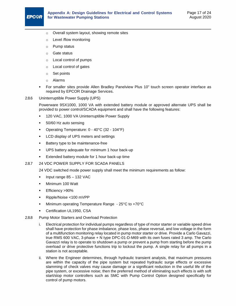
Appendix A: Design Guidelines for Electrical and Control Systems for Wastewater Pumping Stations
Page 17 of 24 August 2020
o Overall system layout, showing remote sites
o Level /flow monitoring
o Pump status
o Gate status
o Local control of pumps
o Local control of gates
o Set points
o Alarms
For smaller sites provide Allen Bradley Panelview Plus 10” touch screen operator interface as required by EPCOR Drainage Services.
2.8.6 Uninterruptible Power Supply (UPS)
Powerware 9SX1000, 1000 VA with extended battery module or approved alternate UPS shall be provided to power control/SCADA equipment and shall have the following features:
120 VAC, 1000 VA Uninterruptible Power Supply
50/60 Hz auto sensing
Operating Temperature: 0 - 40°C (32 - 104°F)
LCD display of UPS meters and settings
Battery type to be maintenance-free
UPS battery adequate for minimum 1 hour back-up
Extended battery module for 1 hour back-up time
2.8.7 24 VDC POWER SUPPLY FOR SCADA PANELS
24 VDC switched mode power supply shall meet the minimum requirements as follow:
Input range 85 – 132 VAC
Minimum 100 Watt
Efficiency >90%
Ripple/Noise <100 mVPP
Minimum operating Temperature Range - 25°C to +70°C
Certification UL1950, CSA
2.8.8 Pump Motor Starters and Overload Protection
i. Electrical protection for individual pumps regardless of type of motor starter or variable speed drive shall have protection for phase imbalance, phase loss, phase reversal, and low voltage in the form of a multifunction monitoring relay located in pump motor starter or drive. Provide a Carlo Gavazzi, true RMS 600 VAC, 3-phase + N type DPC-01-D-M69 with its own fuses rated 3 amp. The Carlo Gavazzi relay is to operate to shutdown a pump or prevent a pump from starting before the pump overload or drive protective functions trip to lockout the pump. A single relay for all pumps in a station is not acceptable.
ii. Where the Engineer determines, through hydraulic transient analysis, that maximum pressures are within the capacity of the pipe system but repeated hydraulic surge effects or excessive slamming of check valves may cause damage or a significant reduction in the useful life of the pipe system, or excessive noise; then the preferred method of eliminating such effects is with soft start/stop motor controllers such as SMC with Pump Control Option designed specifically for control of pump motors.

Appendix A: Design Guidelines for Electrical and Control Systems for Wastewater Pumping Stations
Page 18 of 24 August 2020
iii. Full-voltage, electric motor starters shall be Allen-Bradley combination circuit breaker and magnetic type starters, rated for the line voltage specified. Combination starters shall include a control transformer with primary and secondary fusing. Contactors for motor starters shall be selected in accordance with NEMA standard ICS2-321 for jogging and plugging duty and shall have replaceable contacts and coils. Short circuit protection devices shall be provided in accordance with the Canadian Electrical Code such that the contactor or starter shall cause no damage to persons or the installation, and shall be suitable for further use after reconditioning if necessary. Contactors rated in accordance with both NEMA and IEC standards shall be marked with the NEMA rating only. MCCs and combination motor starters manufactured by Allen-Bradley are preferred. The designer shall be required to provide justification for the selection of alternative equipment, and this selection shall be subject to the approval of EPCOR Drainage Services.
iv. Where soft start/stop type of motor starters are required, they shall be Allen-Bradley Smart Motor Controller SMC-50, or SMC Flex with pump control option, and appropriately sized for specified motor loads. Where a bypass contactor is provided once pump reaches full speed, each SMC-50 motor controller shall be fitted with an Allen-Bradley 150-SM2 current transformer expansion module, and an 825-MCM converter module to ensure current metering/protection is not lost. For SMC Flex motor controller, a separate overload must be provided when a bypass contactor is implemented. SMC motor starter configuration shall be specified by the Engineer in consultation with EPCOR Drainage Services. SMC motor starters shall be programmed by the Contractor with assistance from manufacturer’s service representative as required.
v. All pump motor starters, full voltage and SMC types, shall be complete with Allen Bradley Bulletin 800T, 30.5 mm Hand/Off/Auto selector switch, red “run” pilot light and “Mushroom” type emergency stop push button and Hobbs elapsed time meter (available at Gregg Distributors, Edmonton). Emergency stop buttons shall override the stop option of Smart Motor Controllers.
vi. Adjustment of trip settings of all overloads and circuit breakers shall be done to correctly co-ordinate tripping order. Overloads shall be adjusted to suit the full-load current without nuisance tripping. HMCP (motor circuit protectors) breakers shall have the magnetic trip settings adjusted to the appropriate setting.
vii. If full-voltage pump motor starters are used, they shall each include an Allen- Bradley, Bulletin 193/592, E300 overload relay for protection against overload, phase loss, phase imbalance, ground fault, jamming and stalling. The E300 shall be connected to the programmable logic controller by means of the standard Ethernet/IP communications system, to convey the following information:
Average electric current in the motor
Percentage of thermal capacity utilized
Full-load current settings
Manual Reset after trip
Trip cause and warning indications:
o Overload
o Phase loss
o Current imbalance (warning only)
o Ground fault (warning only)
o Jam
o Stall
o Loss of communication with programmable logic controller (warning only)
viii. If Allen-Bradley Smart Motor Controllers (SMC) are used, they must each be connected to the programmable logic controller by means of an Allen-Bradley 20-Comm-E Ethernet/IP adapter and shall convey the following information:

Appendix A: Design Guidelines for Electrical and Control Systems for Wastewater Pumping Stations
Page 19 of 24 August 2020
Average electric current in the motor
Percentage of thermal capacity utilized
Full-load current settings
Manual Reset after trip
Trip cause and warning indications:
o Overload
o Phase loss
o Current imbalance (warning only)
o Ground fault (warning only)
o Jam
o Stall
o Loss of communication with programmable logic controller (warning only)
ix. Where the engineer determines that variable speed pumps shall be used, the preferred VFD shall be from the Allen-Bradley PowerFlex ranges, appropriately sized for specified motor loads, with integrated silicon control rectifier fusing. VFD configuration shall be specified by the Engineer in consultation with EPCOR Drainage Services. VFDs shall be programmed by the Contractor with assistance from manufacturer’s service representative as required. If a PLC is used for station control the variable speed drive shall be connected to the PLC by means of a standard EtherNet/IP communication system, to convey the following information:
Average electric current in the motor
Percentage of thermal capacity utilized
Full-load current settings
Manual Reset after trip
Trip cause and warning indications:
o Over current
o Phase loss
o Phase imbalance (warning only)
o Ground fault (warning only)
o Jam
o Stall
o Loss of communication with programmable logic controller (warning only)
x. Starters and VFDs shall be preferably mounted in a Motor Control Center or alternately if approved by EPCOR Drainage Services CSA type 1, general- purpose enclosure with a disconnect device operating mechanism, interlocked with the enclosure door to prevent opening of the door with the device in the “ON” position. The operating handle shall be lockable in the “OFF” position with up to three padlocks. If VFDs are located in control panels, the control panel voltage shall be limited to 250 V maximum.
xi. Where Smart Motor Controllers and VFDs are mounted in motor control centers, install remote mount operator interface modules on the MCC doors. If remote mount operator interface modules are not available, provide windows in the MCC doors to allow viewing the liquid crystal displays on the drives without opening the doors.

Appendix A: Design Guidelines for Electrical and Control Systems for Wastewater Pumping Stations
Page 20 of 24 August 2020
2.8.9 Non-pump Motor Starters and Overload Protection
Full-voltage starters shall comply with Section 2.8.8 ii and have the following features.
Hand/off/auto selection
Red, run pilot light
Allen Bradley Type E2 overload relay, or approved alternate.
2.9 Level Controllers/Float Switches 2.9.1 Primary Level Controller
i. Ultrasonic level sensor from Siemens (Milltronics) range of ultrasonic level sensing and control devices shall be the primary level sensing device, where applicable. Acceptable models include:
MultiRanger 200
SITRANS LUT400
HydroRanger 200
Or a Drainage engineer approved equal. The proposed device should be vetted with EPCOR Drainage Services early in the design process.
The models with Ethernet/IP or Modbus communications interface to PLC a preferred for typical wastewater applications, unless other features are required.
The level controller shall be mounted in the control/SCADA panel or on a wall near the control panel at an easily viewable and accessible location. Configure the level controller with automatic control functions indicating pump cycle alternation and fail-safe mode appropriate to the design requirements of the station.
ii. Transducer Type
Siemens (Milltronics)
The XPS-15 ultrasonic transducer is preferred where feasible (0.3 to 15 m depth) and is compatible with all controllers above except the OCM III. Where deeper applications (0.6 to 30 m depth) are required the XPS 30 ultrasonic transducer is preferred. The XPS 30 is compatible with the LUT series controllers only. Other transducers may be considered where warranted and approved by EPCOR Drainage Services. Level controllers shall be installed in accordance with Standard Drawing E4.
iii. Transducer Installation - Wet Well, Tanks and Manholes
The ultrasonic level transducer shall be installed in accordance with the specifications in the ultrasonic manufactures manual, in a PVC rigid guide pipe extending to an elevation above potential flood level in the wet well. The transducer shall be fitted with a custom made plastic collar to insure that transducer remains central. The transducer face shall be flush with the bottom of the guide pipe. There shall be an unobstructed path for the cone shaped sound wave transmission from the transducer to the water surface and back.
The installation of the transducer and the range and span settings shall cover the full range of variation of the liquid level from the bottom of the well, tank or manhole as datum to the highest level of concern, such as overflow or flood level.
Prior to commissioning, the transducer installation shall be checked and adjusted as necessary to insure a stable, satisfactory signal confidence reading at the ultrasonic controller
2.9.2 Alternative Primary Level Controller
At locations where it is not feasible to measure accurately or reliably liquid level over the full range of level variation with an ultrasonic level sensor, a hydrostatic level sensor or radar level sensor may be used on approval of EPCOR Drainage Services instead of or in conjunction with an ultrasonic type level senor.

Appendix A: Design Guidelines for Electrical and Control Systems for Wastewater Pumping Stations
Page 21 of 24 August 2020
Preferred types of hydrostatic level sensor include: Model 311-M351 as manufactured by GP50 with a Tefzel cable for chemical resistance is EPCOR Drainage Services’ preferred pressure transducer.
The preferred type of radar level sensor is VEGAPULS.
Where multiple level sensors of different types are used, and normal operation may render a level sensor inoperative, such as exceeding the span of an ultrasonic transducer, transmission of a fault alarm should be inhibited while the liquid level exceeds the span.
2.9.3 Multiple Primary Level Controllers
At locations where the depth, operating conditions, or layout of the wet well make the reliability of a single type of level sensor questionable, three or more sensors of at least two different types shall be provided. The station programmable controller shall compare the readings from the different sensors to identify any sensor signal that may be erroneous but an acceptable amount of sensor drift shall be programmed into the controller. A reading found to be in error shall be rejected for control and identified in the SCADA system with an alarm. Consideration shall be given to the potential causes and consequences of level sensor failure when choosing the level sensing system.
2.9.4 Level Switch Installation for Wet Well and Dry Well
Float switches to be Flygt ENM-10, micro-switch design. Mercury type, float switches are not acceptable.
A float switch shall be provided in the dry well for a flooding alarm, set at an appropriate elevation near the bottom of the well. Where a sump pit is incorporated, a float switch shall be installed within the sump pit.
A float switch is to be provided in the wet well to serve as a backup to the ultrasonic
High Water Level sensor in the event of a failure. The high level switch alarm shall be programmed in the PLC to energize one designated pump, if no pump was running.
A float switch is to be provided in the wet well to serve as a backup to the ultrasonic Low Water Level sensor in the event of a failure.
Where applicable a separate float switch shall be provided in the wet well suspended at an appropriate elevation to detect an overflow condition, and activate an alarm.
Dry well float switches are to be directly connected to the PLC.
Wet well float switches shall be installed in accordance with Standard Drawing E4 and Section 2.7.2 Wiring.
2.9.5 All level sensor transducers and float switches shall be mounted so that they are easily removable and serviceable without entry into the wet well.
All cables for the devices shall be factory sealed and shall be of sufficient length to reach the control panel or above grade junction box and PLC without any intermediate splices. Junction boxes must be installed outside wet wells and above any flood level.
2.9.6 Wet wells and other chambers with flowing wastewater are rated as a Class 1 Zone 2 hazardous area and the Flygt level switches shall require a hazardous area isolating relay, MTL model 2213 in the control panel and field wiring isolated from all other panel wiring.
2.10 Flow Meter 2.10.1 Forcemain flow meters are required in all pump stations unless otherwise approved by EPCOR
Drainage Services. The flow meter shall be a magnetic flow meter with a remote secondary flow transmitter mounted in the control panel or on a wall near the control panel at an easily viewable and accessible location. Other types of flow meters may be considered if approved by EPCOR Drainage Services.

Appendix A: Design Guidelines for Electrical and Control Systems for Wastewater Pumping Stations
Page 22 of 24 August 2020
2.10.2 Primary Flow Element and Flow Transmitter
Endress + Hauser Promag W400 or approved alternate, including:
Hard rubber or neoprene liner, or Teflon liner where chemicals deleterious to rubber such as ferric chloride, are present in the wastewater.
Electrodes: 316 SST flush type.
Supply 316 SST ground rings or magmeter integral ground electrode when
Installed in lined pipes.
Minimum 5 pipe diameters upstream and 3 pipe diameters downstream straight pipe run or manufacturers recommendation if less. Magmeters are available with very short upstream/downstream pipe runs if necessary.
Installed ahead of control valves.
Installed in piping which shall maintain a full pipe at all times.
Ground with minimum #8 AWG copper to main station ground grid.
Installed in vertical pipes, where possible, to even out wear on the liner.
Install cables/conduits to provide watertight seal to guard against accidental submergence.
Wall or cabinet mount transmitter
Dual LCD readouts for instantaneous and total flow
The flow transmitter shall communicate with the PLC via Ethernet/IP
2.11 Heating and Ventilation 2.11.1 Specify power connections to all mechanical heating and ventilation equipment. Specify disconnect
switches where required and where not provided with the equipment. Verify all equipment sizes and power requirements with the mechanical designer.
2.11.2 Specify conduit for all low-voltage control wiring. Co-ordinate exact locations and routing with the mechanical designer.
2.11.3 Ensure that air supply fan is permanently energized to maintain continuous airflow in the dry well. 2.11.4 Specify a paddle type flow switch in the dry well air duct, Johnson Control Type F62AA, and connect
to the PLC system. Mechanical designer shall select a location in duct that is free of air turbulence. 2.11.5 Provide interlock control circuitry between air exhaust fan and make-up-air unit where applicable. 2.11.6 Where electric heaters are required, units shall be sized to required BTU output and specified with
internal thermostatic control, connected to the main power supply. Unit rating shall be adjusted to permit ‘off-the-shelf’ purchase.
2.11.7 For pump stations requiring wet well ventilation, there shall be an interlock between fans and motorized dampers to prevent the escape of odours when the fan is not running.
2.11.8 Ventilation and damper controls for generators and the building shall operate from a common, compatible voltage and signal.
2.11.9 The design of wet well ventilation systems shall be such that the fan motor and electrical wiring shall be external to the ventilation conduit/duct.
2.11.10 In accordance with Alberta Environment Standards and Guidelines for Municipal Waterworks, Wastewater and Storm Drainage Systems, wet well ventilation shall be designed to provide continuous 6 air changes an hour or 30 air changes an hour during occupation. Provisions for portable ventilators in lieu of permanent ventilation may only be considered on approval from EPCOR Drainage Services. Intermittent ventilation of 30 air changes an hour is a generally preferred operating mode depending upon the size and type of the pump station. Coordinate with EPCOR Drainage Services for the preferred/required ventilation mode on each project.

Appendix A: Design Guidelines for Electrical and Control Systems for Wastewater Pumping Stations
Page 23 of 24 August 2020
2.12 Renovation of Existing Facilities Where appropriate, include in the contract price, the removal of electrical equipment and conduit
and wiring from the existing lift station subject to modification or upgrading.
Prior to disposal of equipment, invite EPCOR Drainage Services staff to salvage any items that may be of use at other locations.
Prior to construction of new work, arrange for temporary power connection to pumping facilities and as described in the general contract documents.
2.13 Miscellaneous Systems 2.13.1 Building Low Temperature
Specify a Johnston Controls Model A19BAC-1C, SPDT, -1 to 43°C range, mounted on a wall in the pump house, set at 5 degrees Celsius, and connect to the main control panel alarm circuit and the PLC.
Contact to PLC to open on low temperature alarm.
Specify a plywood mounting back plate behind thermostat if wall is of concrete block construction.
2.13.2 Intrusion Alarm
Specify heavy-duty lever-operated switches (Allen-Bradley 802 T-D or equal) on exterior access hatches or exterior doors, connected to the alarm system and operated at 120 VAC, from the PLC.
2.13.3 Fire Alarm
Specify an American Sensors model ESA5011 ULC certified smoke detection device, operated at 120 V AC, from the UPS.
Auxiliary relay output contact, connected to the PLC.
Smoke detection devices are required inside outdoor-mounted enclosures. Smoke detection device(s) are required in main equipment and generator set rooms of pump houses.
2.13.4 Electric Hoist
When required show power to the hoist drive, complete with a disconnect switch. Verify the exact location and load requirement with the process engineer.
For hoists of 1 tonne or less, portable hoists shall be provided with Class 1, Zone 1 rated plugs and receptacles.
2.13.5 Storage Pond Gate Control and Level Monitoring Sites
The standard PLC preferred by EPCOR Drainage Services is the A-B CompactLogix L32E or equivalent model. However for gate control and level monitoring sites which require very few I/O the A-B PLC may be a MicroLogix 1400. See Section 2.8.5 for details.
Level monitoring shall utilize a Siemens (Milltronics) MultiRanger 200. Refer to Section 2.9.1 for additional details.
2.13.6 Storage Tank Facilities Level Monitoring
Level monitoring shall utilize an approved listed ultrasonic device
2.13.7 Portable Start/Stop Station for Pumps
For stations with deep dry well pump installation, provide a submersible remote control receptacle 1200 mm above the dry well floor complete with a portable start/stop station. Refer to Section 2.7.4, and Standard Drawing E24 for further details.

Appendix A: Design Guidelines for Electrical and Control Systems for Wastewater Pumping Stations
Page 24 of 24 August 2020
LIST OF STANDARD ELECTRICAL DRAWINGS 03-E1 Electrical Symbol Legend
03-E2 Typical Electrical Building Plan
03-E3 Typical Dry Well Section
03-E4 Typical Wet Well Section
03-E5 Typical Wet Well Plan View
03-E6 Wet Well with Interior Electrical Boxes – Section
03-E7 Wet Well with Interior Electrical Boxes - Plan View
03-E8 Typical Level Transducer Leads Mounting Detail
03-E9A Typical Single Line Power Diagram without GenSet
03-E9B Typical Single Line Power Diagram with GenSet and MCC
03-E10 Typical Main Panel Assembly and Panel System Schedule
03-E11 Outdoor Main Panel Assembly
03-E12 Exterior Panel Enclosure
03-E13 Typical Panel Schedules
03-E14 Control Panel Detail (With PLC)
03-E15 Typical PLC Layouts
03-E16 Typical FVNR Pump Motor Control
03-E17 Pump Motor Control Schematic (Soft Start)
03-E18 Typical AC Power Distribution
03-E19 Typical Pump Protection Relays Control Schematic
03-E20 Pump Control Typical PLC Inputs Slot 1
03-E21 Pump Control Typical PLC Inputs Slot 2
03-E22 Pump Control Typical PLC Outputs Slot 5
03-E23 Pump Control Typical PLC Analog Inputs
03-E24 Portable Start/Stop Station for Pumps
Note: Standard Electrical Drawings will be provided on request.
USER-FRIENDLY DRAWING 188 North Edmonton Sanitary Trunk Stage NC1

1883 9 1 6 3 3
SEPTEMBER 2019
BY-PASSBY-PASS MANHOLE
PUMPING HEADSWET WELL TO
FORCEMAIN OUTLET
EMERGENCY BYPASSPUMP CONNECTION
PUMPING HEADSWET WELL
TO SURFACE
• It is a 2.92 meters storage tunnel extended from 127 Street to Castledowns Road on 153 Avenue.
• The pump station is connected to the storage tunnel at Castledowns Road north of 153 Avenue.
Definition
• The storage tunnel is here to store any excessive sewage entering the city’s drainage system during rainstorms period, and collect sewage from the newly built residential areas.
• The pump station is here to drain the storage tunnel.Purpose
• The sewer trunk currently carries inflows from Oxford and the Palisades Neighborhood.
• The tunnel is also designed to collect inflow from Dunluce Neighborhood in the future.
• In a dry day, the pump will start pumping when the wet well level reaches elevation 662.50m.
• During extreme rainstorms, the tunnel can be surcharged to the overflowing elevation at 674.305m.
Function
• Slide gates• Debris and solid settlements
Check &Maintain
• Nearest manhole not draining to the same pump station:Castledowns Road and south of 153 Avenue (manhole #288984)
• Emergency bypass pumping connection does not exist.• Pumping heads: Wet well to surface: 18.21m (at pump station) Wet well to forcemain outlet: 14.23m
EmergencyNotes
288984 14.23mNONE 18.21m
PUMP WELL
North Edmonton Sanitary Trunk Stage NC1
SANITARY LIFT STATION11410 153 AVENUE
Page 1

5053 34 AVENUE
SEPTEMBER 2019SANITARY PUMP STATION 188PUMP WELL3 9 1 6 3 3
North Edmonton Sanitary TrunkOverall Site Plans
North Edmonton Sanitary Trank Stage NC111410 153 AVENUE
Page 2

5053 34 AVENUE
SEPTEMBER 2019SANITARY PUMP STATION 188PUMP WELL3 9 1 6 3 3
North Edmonton Sanitary TrunkOverall Site Plans
North Edmonton Sanitary Trank Stage NC111410 153 AVENUE
Page 3

5053 34 AVENUE
SEPTEMBER 2019SANITARY PUMP STATION 188PUMP WELL3 9 1 6 3 3
Pump Sequence:• Dry Weather Conditions (High Level Alarm 5795mm, Elevation 666.035m)
Duty Pump Stops:• Upstream Working Level < = 1200mm or Downstream Level > 425mm
North Edmonton Sanitary Trank Stage NC111410 153 AVENUE
Page 4

Wet Weather Operation
5053 34 AVENUE
SEPTEMBER 2019SANITARY PUMP STATION 188PUMP WELL3 9 1 6 3 3
Pump sequence:• Wet Weather Conditions (High Level Alarm 5795mm, Elevation 666.035m)
Duty Pump Start:• Upstream Working Level > 2460mm or Downstream Level < 325mm.
North Edmonton Sanitary Trank Stage NC111410 153 AVENUE
Page 5

1883 9 1 6 3 3
Page 6SEPTEMBER 2019
2019 2019
PUMP WELL
North Edmonton Sanitary Trunk Stage NC1
SANITARY LIFT STATION11410 153 AVENUE

Appendix B:
Computer Model Transfer Checklist
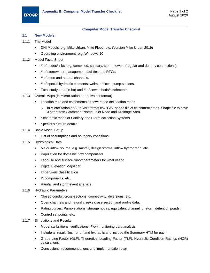
Appendix B: Computer Model Transfer Checklist
Page 1 of 2 August 2020
Computer Model Transfer Checklist
1.1 New Models 1.1.1 The Model
DHI Models, e.g. Mike Urban, Mike Flood, etc. (Version Mike Urban 2019)
Operating environment- e.g. Windows 10
1.1.2 Model Facts Sheet
# of nodes/links, e.g. combined, sanitary, storm sewers (regular and dummy connections)
# of stormwater management facilities and RTCs.
# of open and natural channels.
# of special hydraulic elements: weirs, orifices, pump stations.
Total study area (in ha) and # of sewersheds/catchments
1.1.3 Overall Maps (in MicroStation or equivalent format)
Location map and catchments or sewershed delineation maps
o In MicroStation or AutoCAD format c/w “GIS” shape file of catchment areas. Shape file to have 3 attributes: Catchment Name, Inlet Node and Drainage Area.
Schematic maps of Sanitary and Storm collection Systems
Special structure details
1.1.4 Basic Model Setup
List of assumptions and boundary conditions
1.1.5 Hydrological Data
Major inflow source, e.g. rainfall, design storms, inflow hydrograph, etc.
Population for domestic flow components
Landuse and surface runoff parameters for what year?
Digital Elevation Map/lidar
Impervious classification
I/I components, etc.
Rainfall and storm event analysis
1.1.6 Hydraulic Parameters
Closed conduit cross-sections, connectivity, diversions, etc.
Open channels and natural creeks cross-section and profile data.
Rating curves: Pump stations, storage nodes, equivalent channel for storm detention ponds.
Control set points, etc.
1.1.7 Simulations and Results
Model calibrations, verifications: Flow monitoring data analysis
Include all result files, runoff and hydraulic and include the Summary HTM for each.
Grade Line Factor (GLF), Theoretical Loading Factor (TLF), Hydraulic Condition Ratings (HCR) calculations
Conclusions, recommendations and implementation plan

Appendix B: Computer Model Transfer Checklist
Page 2 of 2 August 2020
1.1.8 Files
Final report, presentation and all supporting files such as tables, charts and maps. Format: Searchable PDF format, MicroStation, Microsoft Office, etc.
Model input and output files (organized index list with descriptions)
Where coupled models are used, the database submission should include the separated minor and major system models as well as the final model, e.g. 1D-1D and 2D-1D coupled models
Include all result files
Detailed scenario descriptions. What is included in each and why?
Other items
1.2 Models supplied by EPCOR to the Consultants for projects (and returned to EPCOR after project completion)
1.2.1 The Model DHI Models, e.g. Mike Urban, Mike Flood, etc. (Mike Urban 2019) Operating environment- e.g. Windows 10
1.2.2 Model Facts Sheet Details of any changes to the model elements such as pipes, manholes and other structures.
1.2.3 Overall Maps (in MicroStation or equivalent format) Sketches of any upgrades and/or changes to the model elements
1.2.4 Basic Model Setup List of assumptions and boundary conditions and details of any changes to the boundary
conditions or assumptions
1.2.5 Hydrological Data Details of any changes to the hydrological data such as rainfall, design storms, inflow hydrograph,
population for domestic flow components, landuse and surface runoff parameters and/or I/I components, etc.
1.2.6 Hydraulic Parameters Details of any changes to closed conduit cross-sections, connectivity, diversions, open channels
and natural creeks cross-section and profile data; Rating curves: Pump stations, storage nodes, equivalent channel for storm detention ponds and/or Control set points, etc.
1.2.7 Simulations and Results Model calibrations, verifications: Flow monitoring data analysis Grade Line Factor (GLF), Theoretical Loading Factor (TLF), Hydraulic Condition Ratings (HCR)
calculations. Conclusions, recommendations and implementation plan
1.2.8 Files Final report, presentation and all supporting files such as tables, charts and maps. Format:
Searchable PDF format, MicroStation, Microsoft Office, etc. Where coupled models are used, the database submission should include the separated minor
and major system models as well as the final model, e.g. 1D-1D and 2D-1D coupled models Model input and output files (organized index list with descriptions) Include all result files Detailed scenario descriptions. What is included in each and why? Other items

Appendix C:
Catch Basin Inlet Capacity Curves

Appendix C: Catch Basin Inlet Capacity Curves
Page 1 of 8 August 2020

Appendix C: Catch Basin Inlet Capacity Curves
Page 2 of 8 August 2020

Appendix C: Catch Basin Inlet Capacity Curves
Page 3 of 8 August 2020

Appendix C: Catch Basin Inlet Capacity Curves
Page 4 of 8 August 2020

Appendix C: Catch Basin Inlet Capacity Curves
Page 5 of 8 August 2020

Appendix C: Catch Basin Inlet Capacity Curves
Page 6 of 8 August 2020

Appendix C: Catch Basin Inlet Capacity Curves
Page 7 of 8 August 2020
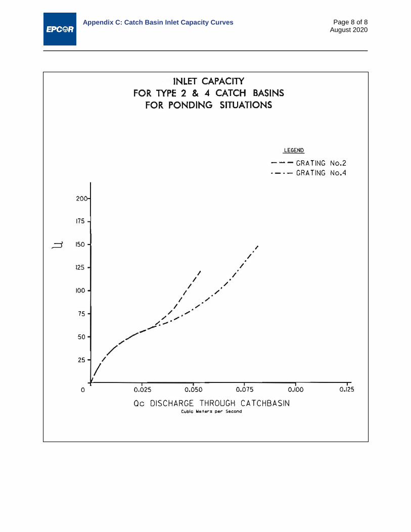
Appendix C: Catch Basin Inlet Capacity Curves
Page 8 of 8 August 2020

Appendix D:
Standard Practice for the Design and Installation of Rigid Gravity Sewer Pipe
in the City of Edmonton

Appendix D: Standard Practice for the Design and Installation of Rigid Gravity Sewer Pipe in the City of Edmonton
i January 2008
TABLE OF CONTENTS
1.0 INTRODUCTION ...................................................................................................................................... 1
1.1 Direct and Indirect Design Process Overview ............................................................................... 1 1.1.1 Establish Basic Design Criteria ........................................................................................... 1 1.1.2 Determine Design Loads and Earth Pressure Distribution ................................................. 2 1.1.3 Select Design Factors ......................................................................................................... 2 1.1.4 Perform Structural Analysis ................................................................................................. 2 1.1.5 Design the Pipe ................................................................................................................... 2
2.0 EXTERNAL LOADS AND PRESSURE DISTRIBUTION ........................................................................ 2
2.1 Pipe Weight .................................................................................................................................... 3 2.2 Earth Loads .................................................................................................................................... 3
2.2.1 Earth Loads – Heger Pressure Distributions ....................................................................... 4 2.2.2 Marston-Spangler Soil Structure Analysis ........................................................................... 7 2.2.3 Fluid Loads and Internal Pressure .................................................................................... 15
2.3 Live Loads .................................................................................................................................... 16 2.3.1 Boussinesq Load Theory ................................................................................................... 16 2.3.2 Impact Factors ................................................................................................................... 20 2.3.3 Truck and Traffic Loads – AASHTO Method ..................................................................... 21 2.3.4 Cooper Series Railway Loads ........................................................................................... 23
3.0 PIPE DESIGN ........................................................................................................................................ 26
3.1 Direct Design – Overview of Limit States Design Factors and Structural Design Process ......... 26 3.1.1 Direct Design – Reasonable Assumptions for Initial Design Parameters ......................... 28 3.1.2 Direct Design - Designing the Pipe ................................................................................... 31
3.2 Indirect Design ............................................................................................................................. 31 3.2.1 Indirect Design – Design Factors ...................................................................................... 31 3.2.2 Indirect Design – Structural Analysis and Design of the Pipe ........................................... 32
4.0 NOTATIONS FOR INDIRECT AND DIRECT DESIGN ......................................................................... 34
5.0 INDIRECT DESIGN – SAMPLE PIPE SELECTION PROBLEMS ........................................................ 36

Appendix D: Standard Practice for the Design and Installation of Rigid Gravity Sewer Pipe in the City of Edmonton
Page 1 of 41 January 2008
1.0 INTRODUCTION This Standard Practice covers the design and construction of rigid pipe for use in gravity flow applications within the City of Edmonton. While the Standard Practice is primarily focused on the use of concrete pipe, it is applicable to other rigid pipe products intended for use in gravity applications.
The Standard Practice provides an overview of both indirect and direct design methods. As direct design methods are applicable to the standard installations developed for reinforced pre-cast concrete pipe, they are generally not applicable to be applied to other rigid pipe products with the possible exception of the load theory associated with direct design.
The overview provided in the Standard Practice presents a balance of theoretical and historical context for design practices and recommendations specific to the manner in which indirect and direct design is desired to be carried out in the City of Edmonton as well as general guidance as to what situations are most applicable for each design method.
The Standard Practice is intended to be used as a reference by the owner or owner’s engineer in preparing project specifications within the City of Edmonton based on the standard design and installation practices specified herein.
The design procedures given in this standard are intended for use by engineers who are familiar with the concept of soil-pipe interaction and of the factors that may impact both the performance of the pipe and of the soil envelope. Before using the design procedures, the engineer should review the guidance and requirements given in the primary design manuals that cover indirect and direct design more fully including a detailed accounting of the theory behind each design method. Both design methods are described fully in the Concrete Pipe Technology Handbook1 while the Standard Practice of Direct Design is detailed in ASCE Standard Practice 15-982.
For ease in use versus other references, the notations utilized are consistent with the Concrete Pipe Technology Handbook and the primary values of dimensions and quantities are expressed in inch-pound (English) units with conversions expressed in SI unit values. For convenience notational standards are re-produced in Section 4.0 of this Standard Practice.
1.1 Direct and Indirect Design Process Overview While the direct and indirect design methods are markedly different they are essentially geared towards reaching the same overall objective, the selection of an appropriate balance of pipe structure and soil supporting structure for a given design condition.
Direct design as a process is well suited to larger diameter pipe both due to the thoroughness of design checks and the ability to achieve a more cost effective design that conventional indirect design with ASTM C76 pipe cannot achieve due to the restrictive nature of Class pipe standard design sections. Due to the most common governing modes of structural failure, it would be prudent to carry out all direct design checks in pipe diameters of 900 mm or larger irrespective of whether the practitioner is utilizing direct or indirect design concepts to ensure that all critical failure modes are reviewed in instances where the capital investment in the product are high as typically are the consequences of failure.
At the highest level each of the design processes involves the following necessary steps:
1.1.1 Establish Basic Design Criteria
Inside diameter of pipe
Height of cover and unit weight of earth
Surface design loads
1 American Concrete Pipe Association, “Concrete Pipe Technology Handbook – A Presentation of
Historical and Current State-of- the-art Design and Installation Methodology”, ACPA, 1993 2 ASCE, “ASCE 15-98, Standard Practice for Direct Design of Buried Precast Concrete Pipe Using
Standard Installations (SIDD)”, American Society of Civil Engineers, 1998

Appendix D: Standard Practice for the Design and Installation of Rigid Gravity Sewer Pipe in the City of Edmonton
Page 2 of 41 January 2008
Design internal pressure (not possible to use indirect design if required and limited to 15 m of head in direct design applications)
Type of Standard Installation Pipe initial design parameters such as wall thickness, concrete strength, thickness of cover over
reinforcement, steel arrangement, type and strength of reinforcement (all required for direct design only)
1.1.2 Determine Design Loads and Earth Pressure Distribution In direct design applications earth loads and soil response is facilitated through the use of the
Standard Installations and the Heger pressure distribution model In indirect design this is accomplished through either the Marston-Spangler pressure distribution
approach or the Heger pressure distribution assessment for vertical loads and the use of bedding factors
Live load determination is carried out in an identical manner for direct and indirect design. 1.1.3 Select Design Factors
In direct design various load and resistance factors and crack control factors are applicable based on a limit states design approach and minimum values permitted by the ASCE Standard Practice
In indirect design, a single safety factor is selected based on the recommendations of this Standard Practice and whether the designer is working with reinforced or non-reinforced pipe. Non-reinforced pipe is not permitted in direct design applications.
1.1.4 Perform Structural Analysis In direct design structural analysis involves a comprehensive determination of all moments, thrust,
and shears produced by the applied design loads. In indirect design, structural analysis is limited to applying the appropriate bedding factors to the
applied design loads. 1.1.5 Design the Pipe
In direct design the pipe wall is designed selecting the appropriate balance between pipe structure and selected soil structure.
In indirect design a pipe class strength is specified in terms of an appropriate three edge bearing strength to be supplied in conjunction with a specified installation type.
2.0 EXTERNAL LOADS AND PRESSURE DISTRIBUTION The designer shall evaluate the various loads that affect the pipe structurally. The effects of loads and the resulting pressures that act on the pipe are complicated by the effects of pipe-soil interaction that occur as a result of subtle deformations of the pipe and the surrounding soil. The significance of pipe-soil interaction and the role it plays in pipe design is discussed more fully in Section 3.0. While it is necessary to understand different components of loads in different manners dependent of whether the practitioner is utilizing indirect or direct design methods, the same basic range of external loads must be understood in order assess pipe design requirements. Typical loads that must be considered when analysing or designing a buried pipe installation
include: Weight of the pipe Earth loads Weight of the fluid and internal pressure, if any Live loads
o Surface concentrated loads o Surface surcharge loads

Appendix D: Standard Practice for the Design and Installation of Rigid Gravity Sewer Pipe in the City of Edmonton
Page 3 of 41 January 2008
2.1 Pipe Weight Pipe weight may or not be a significant component of load relative to other loads in buried pipe analysis.
In indirect design, the structural design of the pipe is based upon the strength of the pipe in a three edge bearing test. As the pipe self-weight is already accounted for in a three-edge bearing test it can be ignored in accounting for overall loads in analysis. In direct design, however, pipe weight is a true component of overall loads and should be considered in design, particularly in larger diameter structures.
Approximate weights of pipe may be calculated as follows: Circular 𝑊𝑊𝑝𝑝 = 3.3ℎ(𝐷𝐷𝑖𝑖 + ℎ) (2-1)
The wall thickness for circular pipes is often referred to in standard nomenclature of “A”, “B”, or “C” wall thicknesses. The relationship between wall thickness, wall thickness type and inside diameter is governed by the following expressions (Note: dimensions are in inches):
Wall A ℎ =𝐷𝐷𝑖𝑖12
(2-2)
Wall B ℎ =𝐷𝐷𝑖𝑖12
+ 1 (2-3)
Wall C ℎ =𝐷𝐷𝑖𝑖12
+ 1.75 (2-4)
2.2 Earth Loads The earth load that acts on a buried pipe is significantly affected by the relative deformation of the pipe and the adjacent soil. Two common methods are used for estimating earth loads and the resultant pressure distribution around the pipe:
Heger Pressure Distribution Loads
Marston-Spangler soil-structure interaction analysis
Earth loads and pressure distributions determined via the finite element model (FEM) and model studies used in SPIDA (Soil Pipe Interaction Design and Analysis) are the most current and modern assessment of earth loads and the resultant pressure distributions around rigid pipe. This method of earth load assessment and the soil response is commonly referred to as the Heger Pressure Distributions. This is the method of earth load determination that is used for direct design and is incorporated into the Direct Design Standard Practice ASCE 15-98. In terms of earth load predictions, however, it can be used for both direct and indirect design methods.
Marston-Spangler soil-structure analysis has been utilized for decades to compute earth loads on rigid buried pipes and a form a soil-pipe interaction through the use of bedding factors. In this Standard Practice it is still an acceptable means of determining earth loads for indirect design.

Appendix D: Standard Practice for the Design and Installation of Rigid Gravity Sewer Pipe in the City of Edmonton
Page 4 of 41 January 2008
2.2.1 Earth Loads – Heger Pressure Distributions
The major feature of the Heger pressure distributions are the use of nomenclature that relate vertical and horizontal loads to the prism load at the top of the pipe and the use of non-dimensional “Arching Factors” and “Pressure Distribution Ratios” (the pressure bulbs A1, A2, A4, A5, and A6 in Figure 2.1 below) to define the distribution of loads within the embedment zone in response to the applied vertical and horizontal loads.
The vertical and horizontal components of earth and horizontal loads on the pipe are defined in terms of arching factors with the following definitions:
𝑉𝑉𝑉𝑉𝑉𝑉 =𝑊𝑊𝑒𝑒
𝑃𝑃𝑃𝑃 (2-5)
where,
VAF = vertical arching factor
We = total vertical earth load
PL = prism load
𝐻𝐻𝑉𝑉𝑉𝑉 =𝑊𝑊ℎ
𝑃𝑃𝑃𝑃 (2-6)
where,
HAF = horizontal arching factor
Wh = total horizontal load on the side of pipe
PL = prism load
The HAF should not be confused with the ratio of lateral to vertical earth load that is used in other design methods. In terms of Heger pressure distributions the ratio of lateral to vertical earth load can be determined by the expression:
𝑅𝑅𝑅𝑅𝑅𝑅𝑅𝑅𝑅𝑅 𝑅𝑅𝑜𝑜 𝑃𝑃𝑅𝑅𝑅𝑅𝐿𝐿𝐿𝐿𝑅𝑅𝐿𝐿 𝑅𝑅𝑅𝑅 𝑉𝑉𝐿𝐿𝐿𝐿𝑅𝑅𝑅𝑅𝑉𝑉𝑅𝑅𝐿𝐿 𝑃𝑃𝑅𝑅𝑅𝑅𝐿𝐿 =𝐻𝐻𝑉𝑉𝑉𝑉𝑉𝑉𝑉𝑉𝑉𝑉
The datum for both vertical and horizontal loads on pipes in Heger distributions is the prism load, PL, in the form:
𝑃𝑃𝑃𝑃 = 𝑤𝑤 �𝐻𝐻 +𝐷𝐷0(4 − 𝜋𝜋)
8� 𝐷𝐷0 (2-7)
Figure 2.1: Heger Pressure Distribution

Appendix D: Standard Practice for the Design and Installation of Rigid Gravity Sewer Pipe in the City of Edmonton
Page 5 of 41 January 2008
where,
w = unit weight of soil (lbs/ft³)
H = height of fill (ft)
Do = outside pipe diameter (ft)
The prism load, PL, is defined as the unit weight of backfill soil over the pipe times the volume of a one foot thick prism over the outside diameter of the pipe.
For any of the Standard pipe-soil installations in the City of Edmonton, the VAF and HAF may be established by relating it to soil-structure analysis that has been previously carried out (the SPIDA parametric studies) and, therefore, the resultant earth load and horizontal load on the side of the pipe can be computed through expressions (2-5), (2-6), and (2-7), respectively. The Standard Installation Types for use in the City of Edmonton are depicted in Figure 2.2. While the selection of specific Standard Installation Types is a function of economics (e.g. in terms of the balance invested in pipe structure versus soil structure) and end use considerations (e.g. a Type 4 installation may not be appropriate for use under a pavement due to the amount of consolidation that may be anticipated) each installation Type can be appropriate in the appropriate circumstances.
VAF ratios typically range between 1.2 and 1.5 for positive projecting embankment loads. Higher ratios can develop with soft soils on firm foundations (e.g. without the middle third of the bedding placed loose as noted). VAF ratios for trench installations are generally significantly less than these values and can be significantly less than 1.0 in very narrow trenches with firm natural soil walls.
HAF ratios typically range from 0.5 to 0.3 for positive projecting embankment loads and may drop to less than 0.1 in very narrow trench installations. The optimum balance in pipe design is achieved by ensuring adequate trench widths to facilitate proper placement of embedment material in the haunch area as noted in Figure 2.2. While Class A bedding is still permitted for use in Edmonton under special design cases it is not a recognized Standard Installation Type nor is it recommended for widespread use.
Based on the use of the minimum trench widths and the materials noted in the City of Edmonton Standard specifications, the VAF and HAF values noted in Table 2.1 shall be used for design for each installation type.
Table 2.1: VAF and HAF for Standard Installations Standard Installation Type VAF HAF Type 1 1.35 0.45 Type 2 1.40 0.40 Type 3 1.40 0.37 Type 4 1.45 0.30
The principle of the Heger Pressure distributions has been verified in numerous field trials including trials carried out in the City of Edmonton3. The embedment soil response to applied loads is largely reflected in pressure bulbs A1, A2, A4, and A5 in Figure 2.1, with pressure bulbs A2 and A4 increasing in value with improved placement of material in the haunch area (i.e. picking up and transferring more of the load) and pressure bulbs A1 and A5 decreasing in value with improved placement of material in the haunch area (i.e. picking up and transferring less of the load).
It is important to understand the principle that increasing the quality of embedment (i.e. higher quality material placed at higher densities) minimizes load transfer directly to the invert pressure bulb and maximizes load transference to the haunch area, which results in a more balanced distribution of pressure around the pipe. This phenomenon is depicted in Figure 2.3 for each of the ASCE Standard Practice Installations.
3 Simpson, Gumpertz, & Heger, Inc., “Instrumented Concrete Pipe test, Cranston Development,
Edmonton, Alberta”, February 1999.
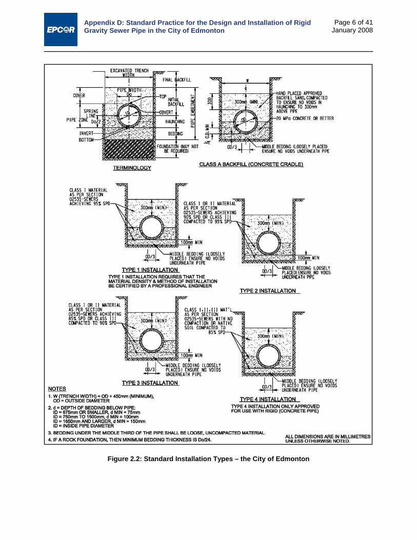
Appendix D: Standard Practice for the Design and Installation of Rigid Gravity Sewer Pipe in the City of Edmonton
Page 6 of 41 January 2008
Figure 2.2: Standard Installation Types – the City of Edmonton

Appendix D: Standard Practice for the Design and Installation of Rigid Gravity Sewer Pipe in the City of Edmonton
Page 7 of 41 January 2008
2.2.2 Marston-Spangler Soil Structure Analysis
Marston-Spangler soil-structure analysis determined loads on buried pipes for various installation types, the essential features of which are detailed in Figure 2.4 below.
This Standard Practice will deal with the computational procedure of determining trench and positive projecting embankment loads only. Tunnelled or jacked loads are beyond the scope of this Standard Practice and while usually considerably lower in magnitude than conventional loads, they are influenced by considerably more complex phenomena. From a practical perspective, trench loads and positive projecting embankment loads are the most quantifiable of loading conditions related to open cut installations and typically represent an extreme range of the minimum and maximum earth loads that can occur over buried rigid pipe in conventional construction.
Figure 2.3: Pressure Distributions Associated with Standard Installations
Figure 2.4: Marston-Spangler Installation Types – Essential Features

Appendix D: Standard Practice for the Design and Installation of Rigid Gravity Sewer Pipe in the City of Edmonton
Page 8 of 41 January 2008
In Marston’s research it was determined that earth loads on rigid pipe installed in a trench could be estimated by the following expression:
𝑊𝑊𝑒𝑒 = 𝐶𝐶𝑑𝑑𝑤𝑤𝐵𝐵𝑑𝑑2 (2-8)
where,
Cd = load coefficient as defined below
w = unit weight of soil (lb/ft³)
Bd = trench width at top of pipe (ft)
And, Cd can be determined by the following expression
𝐶𝐶𝑑𝑑 =1 − 𝐿𝐿−2𝐾𝐾𝐾𝐾′
𝐻𝐻𝐵𝐵𝑑𝑑
2𝐾𝐾𝐾𝐾′ (2-9)
where,
K = Rankine lateral soil pressure coefficient
μ’ = coefficient of sliding friction between fill material and sides of trench
The product of the Rankine’s lateral soil pressure coefficient and the coefficient of sliding friction between fill material and sides of trench angle is summarized for various soil types in Table 2.2 below.
Table 2.2: Product of Rankine Coefficient and Coefficient of Sliding Friction between Fill Material and Sides of Trench
Soil Type Kµ’ Max for Granular materials without cohesion 0.1924
Maximum for Sand and Gravel 0.165 Topsoil 0.150 Maximum for Saturated Clay 0.110

Appendix D: Standard Practice for the Design and Installation of Rigid Gravity Sewer Pipe in the City of Edmonton
Page 9 of 41 January 2008
Earth loads are normally calculated for either the greater of utilizing sand and gravel backfill with a density of 135 lb/ft³ (2165 kg/m³) or saturated clay backfill with a density of 120 lb/ft³ (1920 kg/m³). Standard Practice in the City of Edmonton is to utilize an assumption of sand and gravel backfill for all installations.
Figure 2.5: Trench Load Coefficient, Cd

Appendix D: Standard Practice for the Design and Installation of Rigid Gravity Sewer Pipe in the City of Edmonton
Page 10 of 41 January 2008
Values of Cd may be calculated directly from expression (2-9) above or estimated based on graphical solutions such as Figure 2.5. Having determined the load coefficient the earth load, We, may be computed directly from expression (2-8) above.
Similar to earth loads due to trench conditions, Marston developed the following expression for estimating earth loads on rigid pipe exposed to pure embankment conditions:
𝑊𝑊𝑒𝑒 = 𝐶𝐶𝑐𝑐𝑤𝑤𝐵𝐵𝑐𝑐2 (2-10) where,
Cc = positive projecting embankment load coefficient as defined below
Bc = outside diameter of pipe (ft)
The positive projecting embankment load coefficient, Cc, is a function of the ratio of the height of backfill to the outside pipe diameter as well as the following soil and installation parameters:
Rankine lateral soil pressure coefficient times the internal soil friction angle;
Projection ratio, p, for positive projecting pipe, where p is the ratio of the vertical height of the top of the pipe above the embankment subgrade to the pipe outside diameter;
Settlement ratio, rsd, where rsd is the ratio of the difference between the settlement of the soil adjacent to the pipe and the top of the pipe.
While considerable work has been undertaken to quantify the parameters impacting positive projection load coefficients, they are complex and do not lend themselves to uniform application by a wide range of practitioners. The most current Concrete Pipe Design Manual and this Standard Practice, therefore, recommend the use of Heger VAF’s to determine embankment loading for indirect design applications. As noted in Section 2.2.1, the VAF’s for use in Edmonton are based on the prism load, PL, and vary according to Standard installation type with:
Prism Load equal to: 𝑃𝑃𝑃𝑃 = 𝑤𝑤 �𝐻𝐻 + 𝐷𝐷0(4−𝜋𝜋)8
� 𝐷𝐷0
And the embankment condition earth load determined by: 𝑊𝑊𝑒𝑒 = 𝑉𝑉𝑉𝑉𝑉𝑉 × 𝑃𝑃𝑃𝑃 (2-11)
The values for VAF vary in accordance with the Standard Installation Type as detailed in Table 2.1 in Section 2.2.1.
In embankment loading the earth load is independent of the trench width and, therefore, no contractual controls are necessary to ensure that anticipated earth loading is not in excess of contemplated loading based on a contractor’s proposed construction method. In this Standard Practice it is recommended to use embankment loading values to calculate anticipated earth loading unless specific contractual controls are in place to limit trench widths to specific or narrow trench values.
The point at which embankment loading and trench loading are computationally equal is commonly called the transition width. The point at which the transition occurs is complex and is a function of the height of fill, the pipe diameter as well the settlement (rsd) and projection (p) ratios. Figure 2.6 provides a graphical solution to estimate transition widths for Marston-Spangler analysis for a range of rsdp values in granular backfill. From a practical perspective rsdp values that are less than 0 approach true trench conditions, while rsdp values greater than 2 approach true embankment conditions.
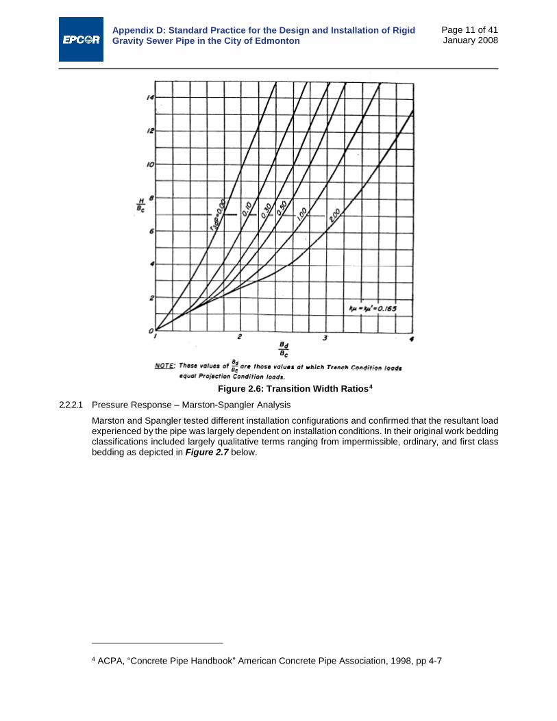
Appendix D: Standard Practice for the Design and Installation of Rigid Gravity Sewer Pipe in the City of Edmonton
Page 11 of 41 January 2008
Figure 2.6: Transition Width Ratios4 2.2.2.1 Pressure Response – Marston-Spangler Analysis
Marston and Spangler tested different installation configurations and confirmed that the resultant load experienced by the pipe was largely dependent on installation conditions. In their original work bedding classifications included largely qualitative terms ranging from impermissible, ordinary, and first class bedding as depicted in Figure 2.7 below.
4 ACPA, “Concrete Pipe Handbook” American Concrete Pipe Association, 1998, pp 4-7

Appendix D: Standard Practice for the Design and Installation of Rigid Gravity Sewer Pipe in the City of Edmonton
Page 12 of 41 January 2008
The load response requirements of the pipe in Marston-Spangler analysis is carried out by means of a bedding factor, Bf, which, in theory is the ratio of the strength of the pipe under the installed condition of loading and bedding to the strength of the pipe in a controlled three edge bearing test. This same ratio was originally defined by Spangler as the load factor. This latter term, however, was subsequently defined in the ultimate strength method of reinforced concrete design with an entirely different meaning. To avoid confusion, therefore, Spangler’s term was renamed the bedding factor.
The three-edge bearing test as shown in Figure 2.8 is the normally accepted plant test that is used as a datum prior to evaluating the in-field strength of an installation. Proper procedures for the test are detailed in Section 4 of CSA Standard A257.0-03 Methods for Determining Physical Properties of Circular Concrete Pipe, Manhole Sections, Catch Basins, and Fittings.
Spangler’s research is documented in a 1933 paper entitled, The Supporting Strength of Rigid Pipe Culverts. Spangler presented the three bedding configurations depicted in Figure 2.7 and the concept of a bedding factor to relate the supporting strength of the buried pipe to the strength obtained in a three-edge bearing test.
Figure 2.7: Marston-Spangler Load Distribution Assumptions for Embankment Conditions
Figure 2.8: Three-Edge Bearing Load Test

Appendix D: Standard Practice for the Design and Installation of Rigid Gravity Sewer Pipe in the City of Edmonton
Page 13 of 41 January 2008
Spangler’s theory postulated that the bedding factor for a particular pipeline and, consequently, the supporting strength of the buried pipe, was dependent on two installation characteristics:
Width and quality of contact between the pipe and bedding.
Magnitude of lateral pressure and the portion of the vertical height of the pipe over which it acts.
For the embankment condition, Spangler developed a general equation for the bedding factor, which partially included the effects of lateral pressure. For the trench condition, he established conservative fixed bedding factors, which neglected the effects of lateral pressure, for each of the three embedment conditions noted.
In theory, Spangler’s elastic analysis of the pipe ring resulted in the following equation for bedding factor, Bf.
𝐵𝐵𝑓𝑓 =1.431𝑁𝑁 − 𝑥𝑥𝑥𝑥
where,
N varies with the type of bedding
x varies with the projection ratio, p
q varies with the Rankine pressure coefficient K
Parametric studies carried out since Spangler’s original work in conjunction with the ASCE Standard Installations have modified the values of recommended bedding factors somewhat, but analytically they remain reasonably true to the original derivation.
The development of bedding factors for Standard Installations follows the same concept utilized in Direct design reinforced concrete design theory. The basic definition of bedding factor is the ratio of maximum moment in the three-edge bearing test to the maximum moment in the buried condition, when the vertical loads under each condition are equal, therefore:
𝐵𝐵𝑓𝑓 =𝑀𝑀𝑇𝑇𝑒𝑒𝑇𝑇𝑇𝑇
𝑀𝑀𝐹𝐹𝑖𝑖𝑒𝑒𝐹𝐹𝑑𝑑 (2-12)
where,
Bf = bedding factor
MTest = maximum moment in pipe wall under three-edge bearing test load (inch-pounds).
MField = maximum moment in pipe wall under field loads (inch-pounds).
To evaluate the proper bedding factor relationship, the vertical load on the pipe for each condition must be equal, which occurs when the springline axial thrusts for both conditions are equal. In accordance with the laws of statics and equilibrium, MTest and MField are:
𝑀𝑀𝑇𝑇𝑒𝑒𝑇𝑇𝑇𝑇 = (0.318𝑁𝑁𝑓𝑓𝑇𝑇) × (𝐷𝐷𝑖𝑖 + ℎ) (2-13)
𝑀𝑀𝐹𝐹𝑖𝑖𝑒𝑒𝐹𝐹𝑑𝑑 = (𝑀𝑀𝑓𝑓𝑖𝑖) − (0.38 × ℎ × 𝑁𝑁𝑓𝑓𝑖𝑖) − (0.125 × 𝑁𝑁𝑓𝑓𝑖𝑖 × 𝑉𝑉) (2-14)
Nfs = axial thrust at the springline under a three-edge bearing test load (lb/ft)
Di = internal pipe diameter (inches)
h = pipe wall thickness (inches)
Mfi = moment at the invert under field loading (inch-pounds/ft)
Nfi = axial thrust at the invert under field loads (lb/ft)
c = thickness of concrete cover over the inner reinforcement, inches

Appendix D: Standard Practice for the Design and Installation of Rigid Gravity Sewer Pipe in the City of Edmonton
Page 14 of 41 January 2008
Combining the above equations yields the following expression:
𝐵𝐵𝑓𝑓 =(0.318𝑁𝑁𝑓𝑓𝑇𝑇) × (𝐷𝐷𝑖𝑖 + ℎ)
(𝑀𝑀𝑓𝑓𝑖𝑖) − (0.38 × ℎ × 𝑁𝑁𝑓𝑓𝑖𝑖) − (0.125 × 𝑁𝑁𝑓𝑓𝑖𝑖 × 𝑉𝑉) (2-15)
Using the Standard Installations software design package provided by American Concrete Pipe Association to calculate moments and thrusts, bedding factors were determined for a range of pipe diameters and depths of burial. These calculations were based on one inch cover over the reinforcement, a moment arm of 0.875d between the resultant tensile and compressive forces, and a reinforcement diameter of 0.075t. Evaluations indicated that for A, B and C pipe wall thicknesses, there was negligible variation in the bedding factor due to pipe wall thickness or the concrete cover, c, over the reinforcement.
Actual bedding factors vary with the size of pipe, the quality of the installation, and the width of the trench, therefore, are truly variable between the minimum values associated with a pure narrow trench installation and the maximum values associated with embankment installations. While a valid analytical approach to determine bedding factors between these two extremes is presented in the Concrete Pipe Technology Handbook5, it is not very practical to utilize variable bedding factors in day-to-day practice.
This Standard Practice recommends to consider the method used to estimate earth load when determining which bedding factor is appropriate in indirect design. The use of variable bedding factors as indicated above should be restricted to analytical cases in instances where indirect design methods are being utilized to gain a better appreciation of actual pipe-soil interaction under unique circumstances.
In instances where the designer uses traditional Marston-Spangler Trench Loading theory to estimate earth loads, trench bedding factors should be utilized as the actual trench width is very difficult to regulate or control in the field. If Heger VAF’s are utlized, however, full embankment bedding factors can be utilized as the design case of full embankment loading with embankment bedding factors will always govern over any proportional reduction in earth loading and horizontal side support. This approach is summarized in Table 2.3 with the recommended bedding factors for use in indirect design noted in Table 2.4.
Table 2.3: Type of Bedding Factor to Use versus Design Approach
Method Used to Estimate Earth Load Bedding Factor Selection
Heger VAF’s as per Table 2.1 Use Bfe for Embankment Installation and appropriate Installation Type and Diameter from Table 2.4
Marston-Spangler Trench Loading as per Equation (2-8)
Use Bft for Trench Installation and appropriate Installation Type from Table 2.4
5 American Concrete Pipe Association, “Concrete Pipe Technology Handbook – A Presentation of
Historical and Current State-of- the-art Design and Installation Methodology”, ACPA, 1993, pp. 3-11

Appendix D: Standard Practice for the Design and Installation of Rigid Gravity Sewer Pipe in the City of Edmonton
Page 15 of 41 January 2008
Table 2.4: Bedding Factors (Bf) for Standard Trench and Embankment Installations Pipe Diameter Type 1 Type 2 Type 3 Type 4
Bft - Trench Installation All 2.3 1.9 1.7 1.5
Bfe - Embankment Installation 12 in (300mm) 4.40 3.20 2.50 1.70 15 in (375mm) 4.35 3.15 2.48 1.70 18 in (450mm) 4.30 3.10 2.45 1.70 21 in (525mm) 4.25 3.05 2.43 1.70 24 in (600mm) 4.20 3.00 2.40 1.70 30 in (750mm) 4.10 2.95 2.35 1.70 36 in (900mm) 4.00 2.90 2.30 1.70 42 in (1050mm) 3.97 2.88 2.28 1.70 48 in (1200mm) 3.93 2.87 2.27 1.70 54 in (1350mm) 3.90 2.85 2.25 1.70 60 in (1500mm) 3.87 2.83 2.23 1.70 66 in (1650mm) 3.83 2.82 2.22 1.70 72 in (1800mm) 3.80 2.80 2.20 1.70 144 in (3600mm) 3.60 2.80 2.20 1.70
Where embankment bedding factors are utilized on pipes larger the 1800 mm in diameter, the designer may interpolate between pipe diameters for the correct Bf. In instances where Class A bedding has been provided the designer should consult the Concrete Pipe Technology Handbook for guidance on bedding factor selection.
2.2.3 Fluid Loads and Internal Pressure
The weight of fluid in a rigid pipe, Wf, generally produces bending effects that are about the same in magnitude as those caused by pipe weight (except for thrust which is tensile). Unlike pipe weight, however, fluid weight must be considered in both indirect and direct design. While the effects are small in small diameter pipe (~450 mm and smaller), they become increasing significant with increasing diameter and should be considered in design.
Fluid loads can be computed by simply calculating the weight of the fluid per unit length as per the expression:
𝑊𝑊𝑓𝑓 =𝜋𝜋𝐷𝐷𝑖𝑖2
4× 𝛾𝛾𝑤𝑤 (2-16)
where,
𝛾𝛾𝑤𝑤 = unit weight of water (lb/ft3)
Di = inside diameter of the pipe
If Di is expressed in inches and Wf is desired in units of lbs/ft, the expression becomes:
𝑊𝑊𝑓𝑓 = 0.5454 × 10² × 𝛾𝛾𝑤𝑤 × 𝐷𝐷𝑖𝑖2 (2-17)
Gravity pipes are often designed for full flow conditions with little to no anticipated surcharge conditions. However, under conditions where significant surcharge conditions are anticipated (i.e. the hydraulic grade line is anticipated to rise above the obvert of the pipe), the pipe will be subjected to combined loading and these pressures should be considered in design.
Where internal pressure conditions are anticipated the pipe should only be designed by direct design methods as indirect design methods do not consider internal pressure as a design condition.

Appendix D: Standard Practice for the Design and Installation of Rigid Gravity Sewer Pipe in the City of Edmonton
Page 16 of 41 January 2008
2.3 Live Loads Live loads or surface loads on pipe can introduce significant loads on buried pipe and should be considered in both direct and indirect design. Surface loads can be static loads such as those due to structures or transient loads such as those introduced by concentrated wheel loads (e.g. vehicular or airplanes), the distributed loads due to train traffic, or concentrated or distributed construction traffic loads.
Surface loads are normally classified as either concentrated loads, such as wheel loads, or as uniformly distributed loads, such as those produced by tracked vehicles, rail traffic, and building foundations. While several analytical methods exist for addressing surcharge loading effects, some of which are presented below, the most predominant methods to estimate surface loads are based on a solution by Boussinesq that was developed in 1885.
2.3.1 Boussinesq Load Theory
The Boussinesq equation was developed with the assumption that a point load is applied to a working surface and is transferred through an ideally elastic, isotropic mass of material to act on a small area at depth. The distribution of stress at depth produces a bell-shaped stress distribution for any given depth z. As a rule, the effect of vertical stress will decrease with depth and horizontal distance from the origin. The general expression for the Boussinesq Equation is depicted in Figure 2.9.
where, σz is the vertical stress acting on a plane at depth P is the concentrated load acting at the surface r is the radial distance (horizontal) from the point of origin to the plane at depth z is the vertical distance from the plane of the origin to the plane at depth
Figure 2.9: Boussinesq Equation Stress Distribution with Depth
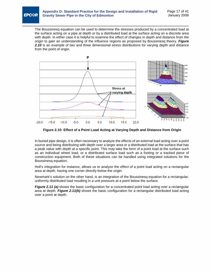
Appendix D: Standard Practice for the Design and Installation of Rigid Gravity Sewer Pipe in the City of Edmonton
Page 17 of 41 January 2008
The Boussinesq equation can be used to determine the stresses produced by a concentrated load at the surface acting on a pipe at depth or by a distributed load at the surface acting on a discrete area with depth. In either case it is helpful to examine the effect of changes in depth and distance from the origin to gain an understanding of the influence regions as proposed by Boussinesq theory. Figure 2.10 is an example of two and three dimensional stress distributions for varying depth and distance from the point of origin.
In buried pipe design, it is often necessary to analyze the effects of an external load acting over a point source and being distributing with depth over a larger area or a distributed load at the surface that has a peak value with depth at a specific point. This may take the form of a point load at the surface such as an individual wheel load, or a distributed surface load such as a footing or a tracked piece of construction equipment. Both of these situations can be handled using integrated solutions for the Boussinesq equation.
Holl’s integration for instance, allows us to analyze the effect of a point load acting on a rectangular area at depth, having one corner directly below the origin.
Newmark’s solution on the other hand, is an integration of the Boussinesq equation for a rectangular, uniformly distributed load resulting in a unit pressure at a point below the surface.
Figure 2.11 (a) shows the basic configuration for a concentrated point load acting over a rectangular area at depth. Figure 2.11(b) shows the basic configuration for a rectangular distributed load acting over a point at depth.
Figure 2.10: Effect of a Point Load Acting at Varying Depth and Distance from Origin

Appendix D: Standard Practice for the Design and Installation of Rigid Gravity Sewer Pipe in the City of Edmonton
Page 18 of 41 January 2008
Figure 2.11: Basic Geometry and Theory for Boussinesq Integrations
The result for Holl’s Integration for a concentrated point load at the surface is:
𝜎𝜎𝑝𝑝
=14−
12𝜋𝜋
��𝑠𝑠𝑅𝑅𝑠𝑠−1𝐻𝐻�𝑉𝑉2 + 𝐵𝐵2 + 𝐻𝐻2
(𝑉𝑉2 + 𝐻𝐻2)(𝐵𝐵2 + 𝐻𝐻2)� −𝑉𝑉𝐵𝐵𝐻𝐻
√𝑉𝑉2 + 𝐵𝐵2 + 𝐻𝐻2�
1𝑉𝑉2 + 𝐻𝐻2 +
1𝐵𝐵2 + 𝐻𝐻2��
The result for Newmark’s Integration for a rectangular distributed surface load is:
𝜎𝜎𝑝𝑝
=1
4𝜋𝜋�
2𝑉𝑉𝐵𝐵𝐻𝐻√𝑉𝑉2 + 𝐵𝐵2 + 𝐻𝐻2
𝐻𝐻2(𝑉𝑉2 + 𝐵𝐵2 + 𝐻𝐻2) + 𝑉𝑉2𝐵𝐵2𝑉𝑉2 + 𝐵𝐵2 + 2𝐻𝐻2
𝑉𝑉2 + 𝐵𝐵2 + 𝐻𝐻2 + �𝑠𝑠𝑅𝑅𝑠𝑠−12𝑉𝑉𝐵𝐵𝐻𝐻√𝑉𝑉2 + 𝐵𝐵2 + 𝐻𝐻2
𝐻𝐻2(𝑉𝑉2 + 𝐵𝐵2 + 𝐻𝐻2) + 𝑉𝑉2𝐵𝐵2��
Where in each case:
H is the vertical distance from surface to pipe crown
A and B are dimensions of the rectangle as seen in Figure 2.11.
As the equations are considered cumbersome by most to use, the solutions are often reduced to the form of WAB for concentrated loads and σAB for distributed loads as follows:
𝑊𝑊𝐴𝐴𝐵𝐵 = 𝐶𝐶𝑇𝑇𝑝𝑝 (2-18) 𝜎𝜎𝐴𝐴𝐵𝐵 = 𝐶𝐶𝑇𝑇𝑝𝑝 (2-19)
where,
Ct = load coefficient dependent on the magnitude of A, B, and H
p = unit surface load, either in the form of a concentrated load for Holl’s solution or in terms of and average load per unit area in the case of Newmark’s solution.
Values of the load coefficient, Ct, are presented in Table 2.5
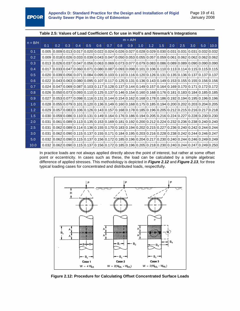
Appendix D: Standard Practice for the Design and Installation of Rigid Gravity Sewer Pipe in the City of Edmonton
Page 19 of 41 January 2008
Table 2.5: Values of Load Coefficient Ct for use in Holl’s and Newmark’s Integrations
n = B/H m = A/H
0.1 0.2 0.3 0.4 0.5 0.6 0.7 0.8 0.9 1.0 1.2 1.5 2.0 2.5 3.0 5.0 10.0 0.1 0.005 0.009 0.013 0.017 0.020 0.022 0.024 0.026 0.027 0.028 0.029 0.030 0.031 0.031 0.031 0.032 0.032 0.2 0.009 0.018 0.026 0.033 0.039 0.043 0.047 0.050 0.053 0.055 0.057 0.059 0.061 0.062 0.062 0.062 0.062 0.3 0.013 0.026 0.037 0.047 0.056 0.063 0.069 0.073 0.077 0.079 0.083 0.086 0.089 0.089 0.090 0.090 0.090 0.4 0.017 0.033 0.047 0.060 0.071 0.080 0.087 0.093 0.098 0.101 0.106 0.110 0.113 0.114 0.115 0.115 0.115 0.5 0.020 0.039 0.056 0.071 0.084 0.095 0.103 0.110 0.116 0.120 0.126 0.131 0.135 0.136 0.137 0.137 0.137 0.6 0.022 0.043 0.063 0.080 0.095 0.107 0.117 0.125 0.131 0.136 0.143 0.149 0.153 0.155 0.155 0.156 0.156 0.7 0.024 0.047 0.069 0.087 0.103 0.117 0.128 0.137 0.144 0.149 0.157 0.164 0.169 0.170 0.171 0.172 0.172 0.8 0.026 0.050 0.073 0.093 0.110 0.125 0.137 0.146 0.154 0.160 0.168 0.176 0.181 0.183 0.184 0.185 0.185 0.9 0.027 0.053 0.077 0.098 0.116 0.131 0.144 0.154 0.162 0.168 0.178 0.186 0.192 0.194 0.195 0.196 0.196 1.0 0.028 0.055 0.079 0.101 0.120 0.136 0.149 0.160 0.168 0.175 0.185 0.194 0.200 0.202 0.203 0.204 0.205 1.2 0.029 0.057 0.083 0.106 0.126 0.143 0.157 0.168 0.178 0.185 0.196 0.205 0.212 0.215 0.216 0.217 0.218 1.5 0.030 0.059 0.086 0.110 0.131 0.149 0.164 0.176 0.186 0.194 0.205 0.216 0.224 0.227 0.228 0.230 0.230 2.0 0.031 0.061 0.089 0.113 0.135 0.153 0.169 0.181 0.192 0.200 0.212 0.224 0.232 0.236 0.238 0.240 0.240 2.5 0.031 0.062 0.089 0.114 0.136 0.155 0.170 0.183 0.194 0.202 0.215 0.227 0.236 0.240 0.242 0.244 0.244 3.0 0.031 0.062 0.090 0.115 0.137 0.155 0.171 0.184 0.195 0.203 0.216 0.228 0.238 0.242 0.244 0.246 0.247 5.0 0.032 0.062 0.090 0.115 0.137 0.156 0.172 0.185 0.196 0.204 0.217 0.230 0.240 0.244 0.246 0.249 0.249
10.0 0.032 0.062 0.090 0.115 0.137 0.156 0.172 0.185 0.196 0.205 0.218 0.230 0.240 0.244 0.247 0.249 0.250
In practice loads are not always applied directly above the point of interest, but rather at some offset point or eccentricity. In cases such as these, the load can be calculated by a simple algebraic difference of applied stresses. This methodology is depicted in Figure 2.12 and Figure 2.13, for three typical loading cases for concentrated and distributed loads, respectfully.
Figure 2.12: Procedure for Calculating Offset Concentrated Surface Loads

Appendix D: Standard Practice for the Design and Installation of Rigid Gravity Sewer Pipe in the City of Edmonton
Page 20 of 41 January 2008
To express live loads in the same units as those calculated in the preceding sections for earth and fluid loads, they must be expressed in the form of load/linear length along the pipe. For concentrated live loads this would take the form of:
𝑊𝑊𝑆𝑆 =𝑊𝑊𝐴𝐴𝐵𝐵
𝐵𝐵𝐶𝐶 (2-20)
And the following form for distributed loads:
𝑊𝑊𝑆𝑆 = 𝜎𝜎 × 𝐵𝐵𝐶𝐶 (2-21)
2.3.2 Impact Factors
Transient surface loads at shallow covers produce dynamic effects which amplify the magnitude of live loads. Shallow transient loads, therefore, should be modified by an Impact Factor, If, such that live loads are calculated as follows:
𝑊𝑊𝐿𝐿 = 𝑊𝑊𝑆𝑆(1 + 𝐼𝐼𝑓𝑓) (2-22)
This Standard Practice recommends ignoring the impacts of pavement bridging for standard vehicular loads and to decrease impact factors with increasing depth. AASHTO has prepared guidelines for impact factors for unpaved surfaces and these are recommended for use in this Standard Practice. Table 2.6 outlines recommended impact factors at varying depths of cover.
Figure 2.13: Procedure for Calculating Offset Distributed Surface Loads

Appendix D: Standard Practice for the Design and Installation of Rigid Gravity Sewer Pipe in the City of Edmonton
Page 21 of 41 January 2008
Table 2.6: Recommended Impact Factors for Vehicular Loads Impact Factor
Cover (ft) Cover (m) If 1’-0” 0.30 0.50 2’-0” 0.61 0.50 2’-6” 0.76 0.43 3’-0” 0.91 0.38 3’-6” 1.07 0.30 4’-0” 1.22 0.23 4’-6” 1.37 0.17 5’-0” 1.52 0.10 5’-6” 1.68 0.04
5’-9”+ 1.75 0.00
For railway loading, the American Railway Engineering and Maintenance-of-Way Association (AREMA) recommend the use of an impact factor of 40% at minimum covers of 300 mm decreasing to zero at 3 m of cover.
2.3.3 Truck and Traffic Loads – AASHTO Method
The simplified AASHTO Method can be used to estimate concentrated wheel loads for either AASHTO series vehicles or standard vehicle configurations conforming to the CL series trucks as set out in the CAN/CSA-S6-00 Canadian Highway Bridge Design Code (CHBDC).
The CL-W series truck, for example, is a simplified five-axle vehicle for which the W indicates the total gross vehicle load in kN as set out in the CAN/CSA-S6-00 Canadian Highway Bridge Design Code (CHBDC). A CL-625 design vehicle would therefore have a gross vehicle weight of 625 kN. The load is distributed over both sets of dual tires (each 0.60 m x 0.25 m), at approximately 1.80 m centre on centre. The per-axle load distribution for CL-W series trucks is shown in Figure 2.14 from the CHBDC.
Figure 2.14: CL-W Truck load distribution6
6 Figure 2.5: CAN/CSA-S6-00 Canadian Highway Bridge Design Code
Typical Vehicles CL-625 CL-750 CL-800 CL-850

Appendix D: Standard Practice for the Design and Installation of Rigid Gravity Sewer Pipe in the City of Edmonton
Page 22 of 41 January 2008
The AASHTO HS series design vehicle also represents a simplified or idealized five-axle truck. In this case however, the associated load is given for the single axle carrying the largest load. The following table lists some typical AASHTO design vehicles and their associated loads.
Table 2.7: Typical AASHTO Design Vehicles
Design Vehicle Single Axle (lb)
Single Axle (kg)
Single Axle Load (kN)
HS 20 (MS 18.15) 32,000 14,520 142 HS 25 (MS 22.69) 40,000 18,150 178 HS 30 (MS 27.23) 48,000 21,780 214 HSS 25 (MSS 22.95) 40,500 18,360 180 HS 20 (LRFD) 32,600 14,790 145
Under the AASHTO simplified live load method the load for a single axle is considered to be distributed over dual tires with a total contact area of 0.25 m x 0.51 m (10”x20”) spaced at approximately 1.83 m (6.0 ft). The load is assumed to increase with depth in a pyramidal fashion as depicted in Figure 2.15.
Figure 2.15: Zones of Influence and Impact Factors at Depth7 At a depth of 0.75 m (2.5 ft) the influence areas overlap and the total load from both sets of tires is assumed to be evenly distributed over the entire area. Thus, for depths less than 0.75 m, the single axle load can be divided by two. For depths greater than 0.75 m, the pressure can be calculated as noted in Figure 2.16.
7 Figure 2.7: Ameron Concrete Cylinder Pipe Design Manual 1988
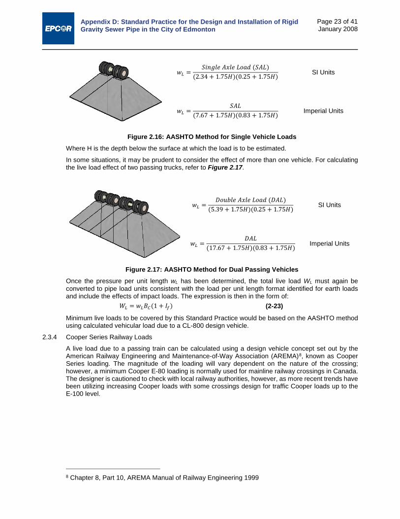
Appendix D: Standard Practice for the Design and Installation of Rigid Gravity Sewer Pipe in the City of Edmonton
Page 23 of 41 January 2008
𝑤𝑤𝐿𝐿 =𝑆𝑆𝑅𝑅𝑠𝑠𝑆𝑆𝐿𝐿𝐿𝐿 𝑉𝑉𝑥𝑥𝐿𝐿𝐿𝐿 𝑃𝑃𝑅𝑅𝑅𝑅𝐿𝐿 (𝑆𝑆𝑉𝑉𝑃𝑃)
(2.34 + 1.75𝐻𝐻)(0.25 + 1.75𝐻𝐻) SI Units
𝑤𝑤𝐿𝐿 =𝑆𝑆𝑉𝑉𝑃𝑃
(7.67 + 1.75𝐻𝐻)(0.83 + 1.75𝐻𝐻) Imperial Units
Figure 2.16: AASHTO Method for Single Vehicle Loads Where H is the depth below the surface at which the load is to be estimated.
In some situations, it may be prudent to consider the effect of more than one vehicle. For calculating the live load effect of two passing trucks, refer to Figure 2.17.
𝑤𝑤𝐿𝐿 =𝐷𝐷𝑅𝑅𝐷𝐷𝐷𝐷𝐿𝐿𝐿𝐿 𝑉𝑉𝑥𝑥𝐿𝐿𝐿𝐿 𝑃𝑃𝑅𝑅𝑅𝑅𝐿𝐿 (𝐷𝐷𝑉𝑉𝑃𝑃)
(5.39 + 1.75𝐻𝐻)(0.25 + 1.75𝐻𝐻) SI Units
𝑤𝑤𝐿𝐿 =𝐷𝐷𝑉𝑉𝑃𝑃
(17.67 + 1.75𝐻𝐻)(0.83 + 1.75𝐻𝐻) Imperial Units
Figure 2.17: AASHTO Method for Dual Passing Vehicles Once the pressure per unit length wL has been determined, the total live load WL must again be converted to pipe load units consistent with the load per unit length format identified for earth loads and include the effects of impact loads. The expression is then in the form of:
𝑊𝑊𝐿𝐿 = 𝑤𝑤𝐿𝐿𝐵𝐵𝐶𝐶(1 + 𝐼𝐼𝑓𝑓) (2-23)
Minimum live loads to be covered by this Standard Practice would be based on the AASHTO method using calculated vehicular load due to a CL-800 design vehicle.
2.3.4 Cooper Series Railway Loads
A live load due to a passing train can be calculated using a design vehicle concept set out by the American Railway Engineering and Maintenance-of-Way Association (AREMA)8, known as Cooper Series loading. The magnitude of the loading will vary dependent on the nature of the crossing; however, a minimum Cooper E-80 loading is normally used for mainline railway crossings in Canada. The designer is cautioned to check with local railway authorities, however, as more recent trends have been utilizing increasing Cooper loads with some crossings design for traffic Cooper loads up to the E-100 level.
8 Chapter 8, Part 10, AREMA Manual of Railway Engineering 1999

Appendix D: Standard Practice for the Design and Installation of Rigid Gravity Sewer Pipe in the City of Edmonton
Page 24 of 41 January 2008
With design vehicles or locomotives designated as Cooper E-Series vehicles, the E designation corresponds to the axle weight of the train in kips. A Cooper E-80 load, for example, would have a design axle weight of 80 kips, with 4 axles in total. The axle load is assumed to be uniformly distributed by the railway ties over an area of 20 ft long by 8 ft wide (6 m long by 2.4 m wide). Figure 2.18 shows the suggested axle configuration and corresponding load.
In addition to the axle load the tracks are assumed an applied load of 200 lb/lin ft. Total Cooper series loading, therefore, in terms of a distributed load at ground surface would be:
𝑝𝑝 =𝐸𝐸 × 1000
20 × 8+
200 × 2020 × 8
= 25(𝐸𝐸 + 1)
Where
p = distributed surface load in lb/ft²
E = Cooper series load
The load WS acting on the pipe at depth H can then be calculated using Newmark’s integration of the Boussinesq solution as described in Section 2.3.1 of this report and the Impact Factors for railway loading described in Section 2.3.2.
Figure 2.18: Cooper E-Series Axle Spacing and Load Configuration

Appendix D: Standard Practice for the Design and Installation of Rigid Gravity Sewer Pipe in the City of Edmonton
Page 25 of 41 January 2008
The total contribution of the locomotive and the dead load can be seen graphically for an E80 Cooper load in the example shown in Figure 2.19.
Figure 2.19: Typical Live and Dead Load Components with a Cooper E80 Live Load

Appendix D: Standard Practice for the Design and Installation of Rigid Gravity Sewer Pipe in the City of Edmonton
Page 26 of 41 January 2008
3.0 PIPE DESIGN After determining the basic design criteria and the design loads and resultant pressure distribution, the remainder of the design process in terms of pipe selection can be carried out.
As indicated in Section 1.1, structural design of the pipe is completed in the following final three steps in the overall design process:
i. Select design factors
ii. Perform structural analysis
iii. Design the pipe
While there are numerous similarities in terms of determining relevant basic design requirements and assessing design loads and pressure distributions, the structural design procedures employed using direct and indirect methods are markedly different.
Even from a process perspective, indirect design usually has a designer ultimately selecting an appropriate pipe strength based on a specified installation condition, while in direct design the designer of record typically specifies a range of design criteria to be utilized and a range of acceptable installation types, and reviews the Shop Drawing design submission of a contractor or subcontractor (usually a pipe manufacturer) to check for conformance to the specified requirements and the requirements of a prescriptive Standard Practice.
The primary purpose of the conventional designer in becoming well versed in direct design is typically to facilitate an educated review in the Shop Drawing process as well as increasing one’s understanding of the true economies that can be achieved in design by gaining a more thorough understanding of all of the factors that impact structural requirements for reinforced concrete pipe design.
3.1 Direct Design – Overview of Limit States Design Factors and Structural Design Process Direct design was developed as a Standard Practice under ASCE Standard Practice 15. The most current version of the Standard Practice at the time of this Standard Practice development was ASCE 15- 989.
The ASCE Standard Installation Direct Design (SIDD) Standard Practice was developed to ensure that all possible modes of failure were evaluated for concrete pipe and to assure that appropriate factors of safety were attached to each aspect of the design process in proportion to the level of uncertainty associated with that aspect of the design process. This is known as the limit states design method. SIDD designs use limit states design methods to evaluate reinforcing steel requirements for:
i. Service cracking based on the degree of crack control desired;
ii. Ultimate flexural load;
iii. Limiting conditions for concrete radial tension strength;
iv. Limiting conditions for shear (diagonal tension).
The latter two checks are not carried out in indirect design yet are common governing conditions in the intermediate to larger diameter range when direct design is carried out. Further, as bedding and load distribution around the pipe is better distributed to minimize overall steel requirements they also become more critical limiting conditions to assess.
The overall SIDD design procedure involves structural design to provide:
Minimum ultimate strength equal to the strength required for expected service loading multiplied by a load factor;
Control of crack width at the expected service load to maintain suitable protection of reinforcement from corrosion, and to limit infiltration or exfiltration of fluids.
9 ASCE, “ASCE 15-98, Standard Practice for Direct Design of Buried Precast Concrete Pipe Using
Standard Installations (SIDD)”, American Society of Civil Engineers, 1998

Appendix D: Standard Practice for the Design and Installation of Rigid Gravity Sewer Pipe in the City of Edmonton
Page 27 of 41 January 2008
In addition, provisions are incorporated to account for the potential reduction of nominal strength and crack control because of variations from nominal design dimensions and strength properties.
As opposed to the single factor of safety utilized in indirect design, direct design uses individual load factors for strength design that are multipliers of the governing moments, thrusts, and shears to account for variations in load and their effects in actual installation from those calculated using the design assumptions and to provide a margin of safety against structural failure. The following load factors are required to be used based on the ASCE Standard Manual of Practice and minimum required load factors recommended for use in the City of Edmonton:
Dead and earth load - shear and moment 1.3
Dead and earth load - compressive thrust
o Tension reinforcement 1.0
o Concrete compression 1.3
Live load - shear and moment - single truck 2.17
o thrust - single truck 1.3
o shear and moment - multiple trucks 1.3
o thrusts - multiple trucks 1.0
Internal pressure - tensile thrust 1.5
Strength reduction factors are applied to account for variations in material properties that occur as a result of their manufacture or due to the fabrication of the pipe. These are applied as multipliers of the parameters that define the strength of the pipe. The ASCE Standard Manual of Practice recommends the following strength reduction factors:
Reinforcement: tensile yield strength 0.95
Concrete: shear and radial tension 0.90
Crack control factors can be applied if specific application requirements are more stringent than 0.01”. For normal gravity applications, a service crack width factor of Fcr = 1.0 is adequate.
Where non-circular steel arrangements are selected, a minimum cage misorientation factor of θ =10° should be utilized. Similarly there are provisions to increase or decrease process factors based on a manufacturer’s substantiated ability to deliver increased performance in radial or diagonal tension. Under this Standard Practice, process factors for both radial and diagonal tension shall be 1.0.
Structural design of the pipe using the ASCE Standard Practice is then carried out in the following manner:
1. The amount of reinforcement required near the inner and outer pipe faces of the pipe wall is determined, based on the tensile yield strength limit state. For most circular pipe the inner reinforcement area is usually governed by the combined factored moment and thrust that act at the invert. The outer reinforcement is usually governed by the combined factored moment and thrust near the springline.
2. A check is carried out to determine if the maximum factored moments that cause tension at the inside face (at the invert and crown), combined with the associated thrusts at those locations, cause radial tension stresses that exceed the radial tension strength limit.
3. A check is carried out to determine if the maximum factored moments at the crown, invert, or springline, combined with the associated thrust at those locations, cause compressive strains that exceed the appropriate limits.
4. A check is carried out at critical wall sections to determine if the critical shear force exceeds the shear (diagonal tension) strength limit. This is a critical check in larger diameter pipelines.
5. If any of the strength limits are exceeded the design is modified accordingly.
Appendix D: Standard Practice for the Design and Installation of Rigid Gravity Sewer Pipe in the City of Edmonton
Page 28 of 41 January 2008
6. A check is then carried out to determine if the service load moments at the crown, invert, or springline, combined with the associated thrusts, cause reinforcement stresses that exceed the service load limit for crack width control. The reinforcement area that is required for flexural tension strength (or the increased area when required for shear) must be sufficient to provide the desired degree of crack control.
While the designer can use hand computations based on the formulae developed and prepared for the ASCE Standard Practice, it is assumed that direct design is typically carried out using the software design package to evaluate Standard Installations.
3.1.1 Direct Design – Reasonable Assumptions for Initial Design Parameters
The direct design process requires the designer to make a series of assumptions relative to initial pipe design parameters such as wall thickness, concrete strength, thickness of cover over reinforcement, steel arrangement, type and strength of reinforcement. While all of these parameters can have significant variance dependent on the manufacturer of the pipe, there are both practical and reasonable considerations that should be accepted and understood by the local design community. A brief discussion follows for each of the initial pipe design parameters.
3.1.1.1 Wall Thickness
As noted in Section 2.1 reinforced concrete pipe is typically manufactured in one of three standard wall thickness configurations, Wall A, B, or C. Of the manufacturers that most commonly supply the Edmonton market most diameter ranges are normally supplied with only a single standard Wall thickness configuration in each diameter range and typically in either a “B” Wall or “C” Wall configuration. The exact configuration carried can be ascertained by applying the standard dimensional formulae noted in Section 2.1 and reviewing each manufacturer’s catalogue.
The designer is encouraged to examine the impact of varying wall thickness configurations on design (not to actually modify them but to understand the sensitivity of design to the different manufacturers standard wall thickness sections), particularly for designs based on “A” or “B” Wall thicknesses, as these design’s more commonly encounter limiting conditions where the wall thickness is inadequate to overcome compression and the use of a thicker wall will be required to meet some design conditions in lower classes of Standard Installations (i.e. higher Installation Type numbers).
3.1.1.2 Concrete Strength
Concrete strengths is usually specified as the standard 28-day compressive strength as defined in ASTM C39/C39M-05e1 Standard Test Method for Compressive Strength of Cylindrical Concrete Specimens.
Typical design practice locally is to use strengths between fc’ = 4,000 psi (28 MPa) and fc’ = 5,000 psi (35 MPa). Higher strengths can be readily be obtained but the designer is cautioned to pursue evidence of the manufacturer to consistently deliver the required design strength in accordance with Appendix A, Clause A.7.2.3 of the ASCE Standard Practice and the time period that the pipes are actually being installed in. While modern precast manufacturing processed can readily achieve much higher 28 day strengths than the above typical design values, larger diameter pipe often has a much tighter time frame between manufacture and installation and the designer should be cognizant of this in their selection of an appropriate design value.
The maximum strength that can be used in the ASCE Standard practice is limited to fc’ = 7000 psi (48 MPa). This is because the experimental basis for some of the semi-empirical design procedures has never been verified on pipes with strengths in excess of this value.
3.1.1.3 Thickness of Cover over Reinforcing Steel
Most designs are based on a minimum of 25 mm of cover over the reinforcing steel for corrosion protection and are not that sensitive to reinforcement cover beyond that.
The designer should be cognizant of steel placement in designs where service cracking governs in design, as the baseline for service cracking control, Fcr = 1.0, is 0.01 inch cracking measured at a point 1 inch (25 mm) beyond the inner or outer reinforcement. In pipe designed to have 1 inch (25 mm) of cover, this corresponds to the inner or outer surface, however, if the pipe is designed (or built) with

Appendix D: Standard Practice for the Design and Installation of Rigid Gravity Sewer Pipe in the City of Edmonton
Page 29 of 41 January 2008
greater cover, the crack at the surface would be greater than the 0.01 inch criterion.
3.1.1.4 Steel Arrangement and Reinforcing Type
Most precast reinforced concrete pipe products are manufactured using closely spaced wire reinforcement in the form of welded wire fabric (either supplied as a product or wrapped on a cage making machine in the pipe fabricating plant). Local manufacturers in Edmonton have cage making machines and currently use closely spaced welded wire fabric either smooth or in a deformed form (Type 2 or 3 below).
As a designer previewing designs with software design package, consult your local manufacturer to determine what standard practice is for them, in terms of steel selection for inventory and what practical limitations they have in their manufacturing processes.
Reinforcement types are classified in the design procedure for crack width control in ascending order in terms of their bonding qualities as follows:
Type 1 – smooth wire or bars, or smooth welded wire fabric with cross wire spacing in excess of 8 inches (200 mm).
Type 2 – welded smooth wire fabric with cross wire spacing of 8 inches (200 mm) or less.
Type 3 – cold drawn deformed wire, or welded deformed wire fabric, or deformed steel mild steel bars
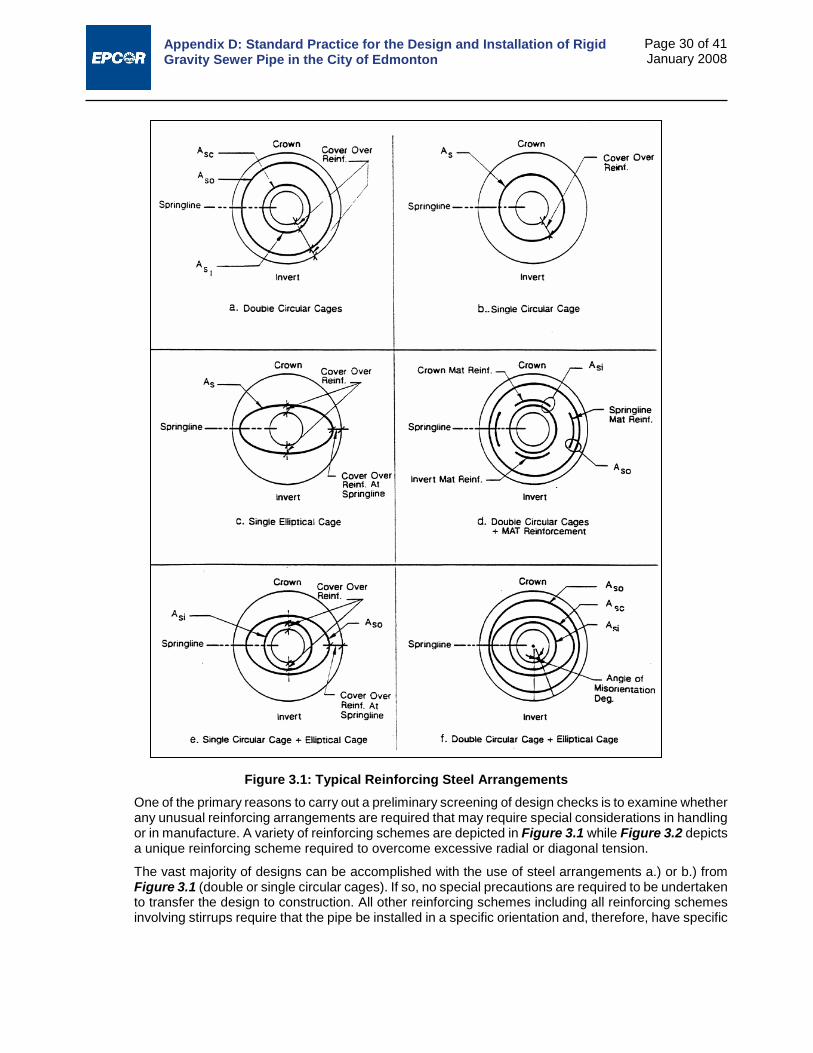
Appendix D: Standard Practice for the Design and Installation of Rigid Gravity Sewer Pipe in the City of Edmonton
Page 30 of 41 January 2008
One of the primary reasons to carry out a preliminary screening of design checks is to examine whether any unusual reinforcing arrangements are required that may require special considerations in handling or in manufacture. A variety of reinforcing schemes are depicted in Figure 3.1 while Figure 3.2 depicts a unique reinforcing scheme required to overcome excessive radial or diagonal tension.
The vast majority of designs can be accomplished with the use of steel arrangements a.) or b.) from Figure 3.1 (double or single circular cages). If so, no special precautions are required to be undertaken to transfer the design to construction. All other reinforcing schemes including all reinforcing schemes involving stirrups require that the pipe be installed in a specific orientation and, therefore, have specific
Figure 3.1: Typical Reinforcing Steel Arrangements
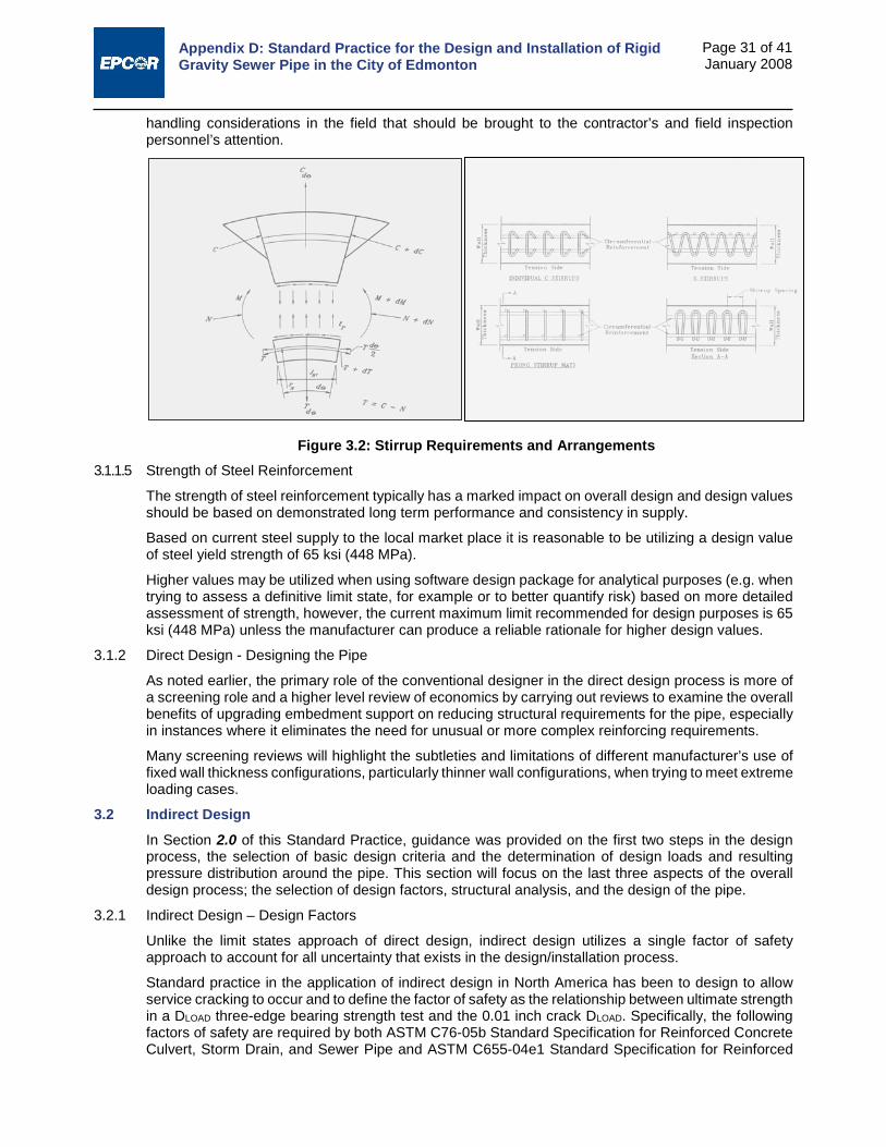
Appendix D: Standard Practice for the Design and Installation of Rigid Gravity Sewer Pipe in the City of Edmonton
Page 31 of 41 January 2008
handling considerations in the field that should be brought to the contractor’s and field inspection personnel’s attention.
3.1.1.5 Strength of Steel Reinforcement
The strength of steel reinforcement typically has a marked impact on overall design and design values should be based on demonstrated long term performance and consistency in supply.
Based on current steel supply to the local market place it is reasonable to be utilizing a design value of steel yield strength of 65 ksi (448 MPa).
Higher values may be utilized when using software design package for analytical purposes (e.g. when trying to assess a definitive limit state, for example or to better quantify risk) based on more detailed assessment of strength, however, the current maximum limit recommended for design purposes is 65 ksi (448 MPa) unless the manufacturer can produce a reliable rationale for higher design values.
3.1.2 Direct Design - Designing the Pipe
As noted earlier, the primary role of the conventional designer in the direct design process is more of a screening role and a higher level review of economics by carrying out reviews to examine the overall benefits of upgrading embedment support on reducing structural requirements for the pipe, especially in instances where it eliminates the need for unusual or more complex reinforcing requirements.
Many screening reviews will highlight the subtleties and limitations of different manufacturer’s use of fixed wall thickness configurations, particularly thinner wall configurations, when trying to meet extreme loading cases.
3.2 Indirect Design In Section 2.0 of this Standard Practice, guidance was provided on the first two steps in the design process, the selection of basic design criteria and the determination of design loads and resulting pressure distribution around the pipe. This section will focus on the last three aspects of the overall design process; the selection of design factors, structural analysis, and the design of the pipe.
3.2.1 Indirect Design – Design Factors
Unlike the limit states approach of direct design, indirect design utilizes a single factor of safety approach to account for all uncertainty that exists in the design/installation process.
Standard practice in the application of indirect design in North America has been to design to allow service cracking to occur and to define the factor of safety as the relationship between ultimate strength in a DLOAD three-edge bearing strength test and the 0.01 inch crack DLOAD. Specifically, the following factors of safety are required by both ASTM C76-05b Standard Specification for Reinforced Concrete Culvert, Storm Drain, and Sewer Pipe and ASTM C655-04e1 Standard Specification for Reinforced
Figure 3.2: Stirrup Requirements and Arrangements

Appendix D: Standard Practice for the Design and Installation of Rigid Gravity Sewer Pipe in the City of Edmonton
Page 32 of 41 January 2008
Concrete D - Load Culvert, Storm Drain, and Sewer Pipe:
For D0.01 loads of 2000 lb/ft/ft of diameter or less FS = 1.5
For D0.01 loads > 2000 lb/ft/ft of diameter and < 3000 lb/ft/ft of diameter FS = a linear reduction from 1.5 to 1.25
For D0.01 loads of 3000 lb/ft/ft of diameter or more FS = 1.25
For ASTM C76 pipe, this reasonably assures the designer of the following relationships:
1. Class I Pipe
D0.01 = 800 lbf/lin ft/ft diameter
DU = 1200 lbf/lin ft/ft diameter
2. Class II Pipe
D0.01 = 1000 lbf/lin ft/ft diameter
DU = 1500 lbf/lin ft/ft diameter
3. Class III Pipe
D0.01 = 1350 lbf/lin ft/ft diameter
DU = 2000 lbf/lin ft/ft diameter
4. Class IV Pipe
D0.01 = 2000 lbf/lin ft/ft diameter
DU = 3000 lbf/lin ft/ft diameter
5. Class V Pipe
D0.01 = 3000 lbf/lin ft/ft diameter
DU = 3750 lbf/lin ft/ft diameter
The designer is cautioned to understand these relationships, evaluate them on a case by case basis dependent on the degree of contractual controls in place to ensure that loading and pipe support objectives will be met, the consequences of failure, and acceptability of the service cracking criterion for the intended application (e.g. some higher risk wastewater applications, may warrant more stringent crack control) and adjust factors of safety accordingly. The above factors of safety are the minimum permitted under this Standard Practice.
Where non-reinforced concrete pipe conforming to ASTM C14-05a Standard Specification for Non- reinforced Concrete Sewer, Storm Drain, and Culvert Pipe is utilized there is obviously no protection between service cracking and ultimate load even though the pipe will continue to function in typical pipe soil interaction applications. In using non-reinforced concrete pipe a minimum FS of 1.5 is recommended on the load required to produce 0.01 cracking.
3.2.2 Indirect Design – Structural Analysis and Design of the Pipe
In indirect design the process of structural analysis and design of the pipe is a seamless and simple one. Design is based on:
1. Acquisition of basic design criteria (in terms of pipe size, etc.)
2. Calculation of design loads and pressure response in terms of We, WL, Wf, and Bf.
3. Rationalizing an appropriate Factor of Safety
Structural analysis and pipe selection then consist of determining the required strength of the pipe in a three-edge bearing test (TEB) as per the following expression:
𝑇𝑇𝐸𝐸𝐵𝐵 =(𝑊𝑊𝑒𝑒 + 𝑊𝑊𝐿𝐿 + 𝑊𝑊𝑓𝑓)
𝐵𝐵𝑓𝑓× 𝑉𝑉𝑆𝑆 (3-1)

Appendix D: Standard Practice for the Design and Installation of Rigid Gravity Sewer Pipe in the City of Edmonton
Page 33 of 41 January 2008
If service cracking can be tolerated (and 0.01 inch cracking is acceptable performance in most applications) then the FS = 1.0 in the above formula for reinforced pipe and 1.5 for non-reinforced pipe applies. Where more stringent criteria need to be applied to the service cracking criterion based on the designer’s assessment of risk, uncertainty or the intended application; an increased FS should be applied.
Applied in the above manner the above pipe selection method yields factors between service cracking and ultimate failure varying from 1.5 to 1.25 dependent on the strength class selected as noted in Section 3.2.1. Again based on the designer’s assessment of risk, uncertainty or the intended application; an increased FS could be applied.
In any event designers would be encouraged to evaluate pipe performance utilizing direct design methods to ascertain the governing modes of failure under the intended application. A limiting feature of indirect design as previously noted is its focus entirely on service cracking and its relationship to ultimate flexural load. While these are typically valid governing failure modes for smaller diameter pipe (typically 450 mm and smaller), they are often not the governing failure mode on intermediate to larger diameter pipe. In these instances the designer would be well advised to utilize direct design methods to reasonably ensure that design life objectives are truly achieved.
Sample problems applying the indirect design method are contained in Section 5.0 of this Standard Practice for the practitioner’s convenience.
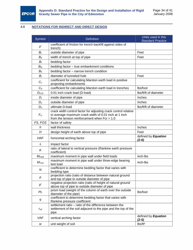
Appendix D: Standard Practice for the Design and Installation of Rigid Gravity Sewer Pipe in the City of Edmonton
Page 34 of 41 January 2008
4.0 NOTATIONS FOR INDIRECT AND DIRECT DESIGN
Symbol Definition Units used in this Standard Practice
µ' coefficient of friction for trench backfill against sides of trench)
Bc outside diameter of pipe Feet Bd width of trench at top of pipe Feet Bf bedding factor Bfe bedding factor – true embankment conditions Bft bedding factor – narrow trench condition Bt diameter of tunneled hole Feet
Cc coefficient for calculating Marston earth load in positive projecting embankments
Cd coefficient for calculating Marston earth load in trenches lbs/foot D0.01 0.01 inch crack load (D-load) lbs/ft/ft of diameter
Di inside diameter of pipe Inches Do outside diameter of pipe Inches Du ultimate D-load lbs/ft/ft of diameter
Fcr crack width control factor for adjusting crack control relative to average maximum crack width of 0.01 inch at 1 inch from the tension reinforcement when Fcr = 1.0
FS, FOS factor of safety h wall thickness Inches H design height of earth above top of pipe Feet
HAF horizontal arching factor defined by Equation (2-6)
If impact factor
K ratio of lateral to vertical pressure (Rankine earth pressure coefficient)
MField maximum moment in pipe wall under field loads inch-lbs
MTest maximum moment in pipe wall under three-edge bearing test load inch-lbs
N coefficient to determine bedding factor that varies with bedding type
p projection ratio (ratio of distance between natural ground and top of pipe to outside diameter of pipe
p' negative projection ratio (ratio of height of natural ground above top of pipe to outside diameter of pipe
PL prism load (weight of the column of earth over the outside diameter of the pipe) lbs/foot
q coefficient to determine bedding factor that varies with Rankine pressure coefficient
rsd settlement ratio – ratio of the difference between the settlement of the soil adjacent to the pipe and the top of the pipe
VAF vertical arching factor defined by Equation (2-5)
w unit weight of soil lbs/ft³

Appendix D: Standard Practice for the Design and Installation of Rigid Gravity Sewer Pipe in the City of Edmonton
Page 35 of 41 January 2008
Symbol Definition Units used in this Standard Practice
WAB live load due to a concentrated surface load per unit area (no impact) lbs/ft²
We vertical earth load on pipe lbs/foot Wf weight of fluid in the pipe lbs/foot Wh horizontal (lateral load on pipe) lbs/foot WL live load with impact lbs/foot
wL live load per unit area due to a concentrated surface load - AASHTO method lbs/ft²
Wp weight of the pipe lbs/foot WS live load without impact lbs/foot
x coefficient to determine bedding factor that varies with the projection ratio
σ live load due to a distributed surface load per unit area (no impact) lbs/ft²
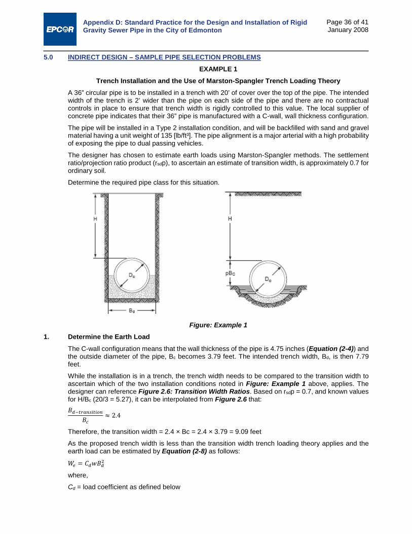
Appendix D: Standard Practice for the Design and Installation of Rigid Gravity Sewer Pipe in the City of Edmonton
Page 36 of 41 January 2008
5.0 INDIRECT DESIGN – SAMPLE PIPE SELECTION PROBLEMS EXAMPLE 1
Trench Installation and the Use of Marston-Spangler Trench Loading Theory A 36” circular pipe is to be installed in a trench with 20’ of cover over the top of the pipe. The intended width of the trench is 2’ wider than the pipe on each side of the pipe and there are no contractual controls in place to ensure that trench width is rigidly controlled to this value. The local supplier of concrete pipe indicates that their 36” pipe is manufactured with a C-wall, wall thickness configuration.
The pipe will be installed in a Type 2 installation condition, and will be backfilled with sand and gravel material having a unit weight of 135 [lb/ft³]. The pipe alignment is a major arterial with a high probability of exposing the pipe to dual passing vehicles.
The designer has chosen to estimate earth loads using Marston-Spangler methods. The settlement ratio/projection ratio product (rsdp), to ascertain an estimate of transition width, is approximately 0.7 for ordinary soil.
Determine the required pipe class for this situation.
Figure: Example 1
1. Determine the Earth Load The C-wall configuration means that the wall thickness of the pipe is 4.75 inches (Equation (2-4)) and the outside diameter of the pipe, Bc becomes 3.79 feet. The intended trench width, Bd, is then 7.79 feet.
While the installation is in a trench, the trench width needs to be compared to the transition width to ascertain which of the two installation conditions noted in Figure: Example 1 above, applies. The designer can reference Figure 2.6: Transition Width Ratios. Based on rsdp = 0.7, and known values for H/Bc (20/3 = 5.27), it can be interpolated from Figure 2.6 that: 𝐵𝐵𝑑𝑑−𝑇𝑇𝑡𝑡𝑡𝑡𝑡𝑡𝑇𝑇𝑖𝑖𝑇𝑇𝑖𝑖𝑡𝑡𝑡𝑡
𝐵𝐵𝑐𝑐≈ 2.4
Therefore, the transition width = 2.4 × Bc = 2.4 × 3.79 = 9.09 feet
As the proposed trench width is less than the transition width trench loading theory applies and the earth load can be estimated by Equation (2-8) as follows:
𝑊𝑊𝑒𝑒 = 𝐶𝐶𝑑𝑑𝑤𝑤𝐵𝐵𝑑𝑑2
where,
Cd = load coefficient as defined below
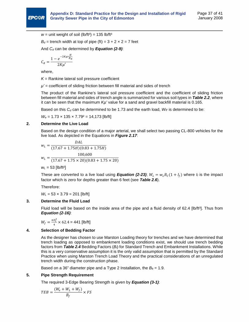
Appendix D: Standard Practice for the Design and Installation of Rigid Gravity Sewer Pipe in the City of Edmonton
Page 37 of 41 January 2008
w = unit weight of soil (lb/ft³) = 135 lb/ft³
Bd = trench width at top of pipe (ft) = 3 + 2 × 2 = 7 feet
And Cd can be determined by Equation (2-9):
𝐶𝐶𝑑𝑑 =1 − 𝐿𝐿−2𝐾𝐾𝐾𝐾′
𝐻𝐻𝐵𝐵𝑑𝑑
2𝐾𝐾𝐾𝐾′
where,
K = Rankine lateral soil pressure coefficient
μ’ = coefficient of sliding friction between fill material and sides of trench
The product of the Rankine’s lateral soil pressure coefficient and the coefficient of sliding friction between fill material and sides of trench angle is summarized for various soil types in Table 2.2, where it can be seen that the maximum Kµ’ value for a sand and gravel backfill material is 0.165.
Based on this Cd can be determined to be 1.73 and the earth load, W𝐿𝐿 is determined to be:
We = 1.73 × 135 × 7.79² = 14,173 [lb/ft]
2. Determine the Live Load Based on the design condition of a major arterial, we shall select two passing CL-800 vehicles for the live load. As depicted in the Equations in Figure 2.17:
𝑤𝑤𝐿𝐿 =𝐷𝐷𝑉𝑉𝑃𝑃
(17.67 + 1.75𝐻𝐻)(0.83 + 1.75𝐻𝐻)
𝑤𝑤𝐿𝐿 =100,600
(17.67 + 1.75 × 20)(0.83 + 1.75 × 20)
wL = 53 [lb/ft²]
These are converted to a live load using Equation (2-23); 𝑊𝑊𝐿𝐿 = 𝑤𝑤𝐿𝐿𝐵𝐵𝐶𝐶(1 + 𝐼𝐼𝑓𝑓) where If is the impact factor which is zero for depths greater than 6 feet (see Table 2.6).
Therefore:
WL = 53 × 3.79 = 201 [lb/ft]
3. Determine the Fluid Load Fluid load will be based on the inside area of the pipe and a fluid density of 62.4 [lb/ft³]. Thus from Equation (2-16):
𝑊𝑊𝑓𝑓 = 𝜋𝜋𝐷𝐷𝑖𝑖2
4× 62.4 = 441 [lb/ft]
4. Selection of Bedding Factor As the designer has chosen to use Marston Loading theory for trenches and we have determined that trench loading as opposed to embankment loading conditions exist, we should use trench bedding factors from Table 2.4 Bedding Factors (Bf) for Standard Trench and Embankment Installations. While this is a very conservative assumption it is the only valid assumption that is permitted by the Standard Practice when using Marston Trench Load Theory and the practical considerations of an unregulated trench width during the construction phase.
Based on a 36” diameter pipe and a Type 2 Installation, the Bft = 1.9.
5. Pipe Strength Requirement The required 3-Edge Bearing Strength is given by Equation (3-1):
𝑇𝑇𝐸𝐸𝐵𝐵 =(𝑊𝑊𝑒𝑒 + 𝑊𝑊𝐿𝐿 + 𝑊𝑊𝑓𝑓)
𝐵𝐵𝑓𝑓× 𝑉𝑉𝑆𝑆

Appendix D: Standard Practice for the Design and Installation of Rigid Gravity Sewer Pipe in the City of Edmonton
Page 38 of 41 January 2008
Based on the use of reinforced concrete pipe, conservative loading and bedding support assumptions, and the acceptability of 0.01” service cracking as a design condition, a TEB factor of safety of 1.0 is appropriate:
𝑇𝑇𝐸𝐸𝐵𝐵 = (14,173+201+441)1.9
× 1 = 7797 [lb/ft]
The required D-Load in units of lbs/ft/ft of diameter is given by:
𝐷𝐷0.01 = 𝑇𝑇𝐸𝐸𝐵𝐵𝐷𝐷𝑖𝑖
Therefore:
𝐷𝐷0.01 = 77973
= 2599 [lb/ft/ft]
As per ASTM C76 and Section 3.2.1, D0.01 = 2599 [lb/ft/ft] correlates to a CL-V pipe. The completed design has actual FOS against service cracking and ultimate failure as follows:
Service cracking 𝑉𝑉𝐹𝐹𝑆𝑆 = 𝐷𝐷0.01 𝐶𝐶𝐶𝐶𝐶𝐶𝐶𝐶𝐶𝐶𝐶𝐶𝐷𝐷𝐴𝐴𝐴𝐴𝐴𝐴𝐶𝐶𝑖𝑖𝐴𝐴𝑑𝑑 𝑇𝑇𝑇𝑇𝑇𝑇
= 30002599
= 1.15
Ultimate 𝑉𝑉𝐹𝐹𝑆𝑆 = 𝐷𝐷𝑢𝑢 𝐶𝐶𝐶𝐶𝐶𝐶𝐶𝐶𝐶𝐶𝐶𝐶𝐷𝐷𝐴𝐴𝐴𝐴𝐴𝐴𝐶𝐶𝑖𝑖𝐴𝐴𝑑𝑑 𝑇𝑇𝑇𝑇𝑇𝑇
= 37502599
= 1.44
As these are both greater than our design objectives (FOS of 1.0 for service cracking and 1.25 for ultimate for TEB capacity greater than or equal to 3000 lb/ft/ft diameter) the design is adequate.
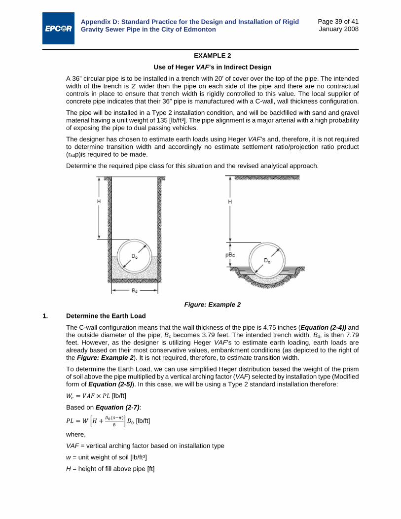
Appendix D: Standard Practice for the Design and Installation of Rigid Gravity Sewer Pipe in the City of Edmonton
Page 39 of 41 January 2008
EXAMPLE 2 Use of Heger VAF’s in Indirect Design
A 36” circular pipe is to be installed in a trench with 20’ of cover over the top of the pipe. The intended width of the trench is 2’ wider than the pipe on each side of the pipe and there are no contractual controls in place to ensure that trench width is rigidly controlled to this value. The local supplier of concrete pipe indicates that their 36” pipe is manufactured with a C-wall, wall thickness configuration.
The pipe will be installed in a Type 2 installation condition, and will be backfilled with sand and gravel material having a unit weight of 135 [lb/ft³]. The pipe alignment is a major arterial with a high probability of exposing the pipe to dual passing vehicles.
The designer has chosen to estimate earth loads using Heger VAF’s and, therefore, it is not required to determine transition width and accordingly no estimate settlement ratio/projection ratio product (rsdp)is required to be made.
Determine the required pipe class for this situation and the revised analytical approach.
Figure: Example 2 1. Determine the Earth Load
The C-wall configuration means that the wall thickness of the pipe is 4.75 inches (Equation (2-4)) and the outside diameter of the pipe, Bc becomes 3.79 feet. The intended trench width, Bd, is then 7.79 feet. However, as the designer is utilizing Heger VAF’s to estimate earth loading, earth loads are already based on their most conservative values, embankment conditions (as depicted to the right of the Figure: Example 2). It is not required, therefore, to estimate transition width.
To determine the Earth Load, we can use simplified Heger distribution based the weight of the prism of soil above the pipe multiplied by a vertical arching factor (VAF) selected by installation type (Modified form of Equation (2-5)). In this case, we will be using a Type 2 standard installation therefore:
𝑊𝑊𝑒𝑒 = 𝑉𝑉𝑉𝑉𝑉𝑉 × 𝑃𝑃𝑃𝑃 [lb/ft]
Based on Equation (2-7):
𝑃𝑃𝑃𝑃 = 𝑊𝑊 �𝐻𝐻 + 𝐷𝐷0(4−𝜋𝜋)8
� 𝐷𝐷0 [lb/ft]
where,
VAF = vertical arching factor based on installation type
w = unit weight of soil [lb/ft³]
H = height of fill above pipe [ft]

Appendix D: Standard Practice for the Design and Installation of Rigid Gravity Sewer Pipe in the City of Edmonton
Page 40 of 41 January 2008
D0 = outside diameter of pipe [ft]
Based on Table 2.1 - VAF and HAF for Standard Installations, VAF for a Type 2 Installation would be 1.40. Therefore:
𝑃𝑃𝑃𝑃 = 135 �20 + 3.79(4−𝜋𝜋)8
� × 3.79 = 10,441 [lb/ft]
For a Type 2 installation, VAF = 1.40, therefore We = 1.40 × 10,104 = 14,617 [lb/ft]
2. Determine the Live Load Based on the design condition of a major arterial, we shall select two passing CL-800 vehicles for the live load. As depicted in the Equations in Figure 2.17:
𝑤𝑤𝐿𝐿 =𝐷𝐷𝑉𝑉𝑃𝑃
(17.67 + 1.75𝐻𝐻)(0.83 + 1.75𝐻𝐻)
𝑤𝑤𝐿𝐿 =100,600
(17.67 + 1.75 × 20)(0.83 + 1.75 × 20)
wL = 53 [lb/ft²]
These are converted to a live load using Equation (2-23); 𝑊𝑊𝐿𝐿 = 𝑤𝑤𝐿𝐿𝐵𝐵𝐶𝐶(1 + 𝐼𝐼𝑓𝑓), where If is the impact factor which is zero for depths greater than 6 feet (see Table 2.6).
Therefore:
WL = 53 × 3.79 = 201 [lb/ft]
3. Determine the Fluid Load Fluid load will be based on the inside area of the pipe and a fluid density of 62.4 [lb/ft³]. Thus from Equation (2-16):
𝑊𝑊𝑓𝑓 = 𝜋𝜋𝐷𝐷𝑖𝑖2
4× 62.4= 441 [lb/ft]
4. Selection of Bedding Factor As we are using Heger VAF’s to estimate earth loads which are based on embankment loading conditions (the most conservative earth loading condition), we can safely use embankment bedding factors from Table 2.4- Bedding Factors (Bf) for Standard Trench and Embankment Installations. This is because any reduction in horizontal support that may result from a narrower trench in the construction phase will also be accompanied by a proportional reduction in real earth loading.
Based on a 36” diameter pipe and a Type 2 Installation an embankment loading factor can be determined from Table 2.4 as Bfe = 2.9.
5. Pipe Strength Requirement The required 3-Edge Bearing Strength is given by Equation (3-1):
𝑇𝑇𝐸𝐸𝐵𝐵 =�𝑊𝑊𝑒𝑒 + 𝑊𝑊𝐿𝐿 + 𝑊𝑊𝑓𝑓�
𝐵𝐵𝑓𝑓× 𝑉𝑉𝑆𝑆
Based on the use of reinforced concrete pipe, conservative loading and bedding support assumptions, and the acceptability of 0.01” service cracking as a design condition, a TEB factor of safety of 1.0 is appropriate:
𝑇𝑇𝐸𝐸𝐵𝐵 = (14,617+201+441)2.9
× 1 = 5262 [lb/ft]
The required D-Load in units of lbs/ft/ft of diameter is given by:
𝐷𝐷0.01 = 𝑇𝑇𝐸𝐸𝐵𝐵𝐷𝐷𝑖𝑖

Appendix D: Standard Practice for the Design and Installation of Rigid Gravity Sewer Pipe in the City of Edmonton
Page 41 of 41 January 2008
Therefore:
𝐷𝐷0.01 = 52623
= 1754 [lb/ft/ft]
As per ASTM C76 and Section 3.2.1, D0.01 = 1754 [lb/ft/ft] correlates to a CL-IV pipe. The completed design has actual FOS against service cracking and ultimate failure as follows:
Service cracking 𝑉𝑉𝐹𝐹𝑆𝑆 = 𝐷𝐷0.01 𝐶𝐶𝐶𝐶𝐶𝐶𝐶𝐶𝐶𝐶𝐶𝐶𝐶𝐶𝐷𝐷𝐴𝐴𝐴𝐴𝐴𝐴𝐶𝐶𝑖𝑖𝐴𝐴𝑑𝑑 𝑇𝑇𝑇𝑇𝑇𝑇
= 20001754
= 1.14
Ultimate 𝑉𝑉𝐹𝐹𝑆𝑆 = 𝐷𝐷𝑢𝑢 𝐶𝐶𝐶𝐶𝐶𝐶𝐶𝐶𝐶𝐶𝐶𝐶𝐶𝐶𝐷𝐷𝐴𝐴𝐴𝐴𝐴𝐴𝐶𝐶𝑖𝑖𝐴𝐴𝑑𝑑 𝑇𝑇𝑇𝑇𝑇𝑇
= 30001754
= 1.71
As these are both greater than our design objectives (FOS of 1.0 for service cracking and 1.5 for ultimate for TEB capacity greater less 2000 lb/ft/ft diameter) the design is adequate.

Appendix E:
Standard Practice for the Design and Construction of Flexible Thermoplastic
Pipe in the City of Edmonton

Appendix E: Standard Practice for the Design and Construction of Flexible Thermoplastic Pipe in the City of Edmonton
i
January 2008
TABLE OF CONTENTS
PART I: GENERAL .................................................................................................................................. 1
PART II: DESIGN METHOD FOR FLEXIBLE PIPE DESIGN USING CITY OF EDMONTON SPECIFIED INSTALLATION CONDITIONS............................................................................. 6
PART III: CONSTRUCTION OF SOIL/FLEXIBLE PIPE SYSTEMS ..................................................... 25
PART IV: MANDREL REQUIREMENTS FOR DEFLECTION TESTING .............................................. 32
PART V: COMMENTARY ...................................................................................................................... 35
PART VI: DESIGN EXAMPLES ............................................................................................................. 38

Appendix E: Standard Practice for the Design and Construction of Flexible Thermoplastic Pipe in the City of Edmonton
1
January 2008
PART I: GENERAL 1.0 Scope 1.1 This Standard Practice covers the design and construction of flexible thermoplastic pipe for use
in installations within the City of Edmonton. While the Standard Practice is primarily focused on the use of PVC pipe, it does address HDPE pipe products to illustrate some of the subtle differences between the two thermoplastics that must be addressed in design.
1.2 When buried, it must be recognized that thermoplastic pipes are a composite structure made up of the plastic ring of the pipe and the soil envelope around them, and that both materials play a vital part in the structural design requirements for the pipe. It also essential that the designer and installer recognize that the soil envelope in typical trench installations is composed of two components – the embedment zone soil and the native soil and that the interaction of these materials can play a significant role in pipe performance.
1.3 Part II of this Standard Practice presents the proposed design method for flexible pipe design using the standard installation configurations that are specified herein. This design method is predicated on the principle that controlling deflection to within acceptable limits will be sufficient to meet both structural requirements of the pipe based on the materials specifically covered in this standard and the standard installations detailed herein, and the functional requirements of pipe performance such as joint integrity, connections to other structures, etc. in the majority of design situations. This does not preclude the fact that the designer should carry out the appropriate structural design checks as detailed in Part II of the Standard Practice to ensure that performance limiting factors other than deflection do not control in any site specific design.
1.4 Part III of this Standard Practice presents the construction requirements for thermoplastic pipe designed and installed in accordance with this Standard Practice.
1.5 This Standard Practice shall be used as a reference by the owner or owner’s engineer in preparing project specifications within the City of Edmonton based on the standard design and installation practices specified herein.
1.6 The design procedures given in this standard are intended for use by engineers who are familiar with the concept of soil-pipe interaction and of the factors that may impact both the performance of the pipe and of the soil envelope. Before using the design procedures given in Part II, the engineer should review the guidance and requirements given in other sections of this Standard Practice and its accompanying commentary.
1.7 The values of dimensions and quantities are expressed in SI unit values with conversions expressed in inch-pound (English) units for convenience.
2.0 Applicable Documents 2.1 ASTM (American Society for Testing and Materials) 2.1.1 D420-98 Guide to Site Characterization for Engineering, Design, and Construction Purposes
2.1.2 D2321-00 Standard Practice for Underground Installation of Thermoplastic Pipe for Sewers and Other Gravity-Flow Applications
2.1.3 D2487-00 Standard Classification of Soils for Engineering Purposes (Unified Soil Classification System)
2.1.4 D2488-00 Standard Practice for Description and Identification of Soils (Visual-Manual Procedure)
2.1.5 D3034-00 Standard Specification for Type PSM Poly(Vinyl Chloride) (PVC) Sewer Pipe and Fittings
2.1.6 D3212-96a Standard Specification for Joints for Drain and Sewer Plastic Pipes Using Flexible Elastomeric Seals
2.1.7 D3350-02a Standard Specification for Polyethylene Plastics Pipe and Fittings Materials

Appendix E: Standard Practice for the Design and Construction of Flexible Thermoplastic Pipe in the City of Edmonton
2
January 2008
2.1.8 F679-01 Standard Specification for Poly(Vinyl Chloride) (PVC) Large-Diameter Plastic Gravity Sewer Pipe and Fittings
2.1.9 F794-99 Standard Specification for Poly(Vinyl Chloride) (PVC) Profile Gravity Sewer Pipe and Fittings Based on Controlled Inside Diameter
2.1.10 F894-98a Standard Specification for Polyethylene (PE) Large Diameter Profile Wall Sewer and Drain Pipe
2.2 CSA (Canadian Standards Association) 2.2.1 B182.2, PVC Sewer Pipe and Fittings (PSM Type)
2.2.2 B182.4, Profile PVC Sewer Pipe and Fittings
2.2.3 B182.6, Profile Polyethylene Sewer Pipe and Fittings for Leak-Proof Sewer Applications
2.2.4 B182.8, Profile Polyethylene Storm Sewer and Drainage Pipe and Fittings
2.2.5 B182.11, Standard Practice for the Installation of Thermoplastic Drain, Storm, and Sewer Pipe and Fittings
2.3 AWWA (American Water Works Association) 2.3.1 AWWA M45, Fiberglass Pipe Design Manual
3.0 Definitions 3.1 Figure 1 illustrates the definitions and limits of the terms, foundation, subgrade, bedding, haunch,
lower side, initial backfill, pipe zone, embedment zone, backfill or overfill, invert, crown, springline, top of pipe, and bottom of pipe as used in this Standard Practice.
Figure 1: Standard Terminology

Appendix E: Standard Practice for the Design and Construction of Flexible Thermoplastic Pipe in the City of Edmonton
3
January 2008
4.0 Notations A = cross sectional area (m²)
Bc = width of pipe (m)
Bd = width of trench (m)
Cc = coefficient of curvature (unitless)
Cu = coefficient of uniformity (unitless)
D, d = pipe diameter (m)
Δx = horizontal deflection (m)
Δy = vertical deflection (m)
DL = deflection lag factor (unitless)
E = flexural modulus of elasticity (kPa)
E' = modulus of soil reaction (kPa)
E'b = modulus of soil reaction - embedment soils (kPa)
E'design = modulus of soil reaction - composite design value (kPa)
E'native = modulus of soil reaction - native soils (kPa)
Є = bending strain (mm/mm)
Γ = soil density
H = height of cover (m)
I = moment of inertia
If = impact factor (unitless)
J = Masada's bedding angle/bedding factor constant
K = bedding factor (unitless)
LL = liquid limit
M = bending moment
ν = Poisson’s Ratio
P = external load expressed as a pressure (kPa)
Pcr = critical buckling pressure (kPa)
PI = plasticity index
PS = pipe stiffness (kPa)
qu = unconfined compressive strength
R = radius
Sc = composite soil support factor (unitless)
σy = yield point stress
SPD = standard Proctor dry density
SPT = standard penetration test blow count
t = wall thickness

Appendix E: Standard Practice for the Design and Construction of Flexible Thermoplastic Pipe in the City of Edmonton
4
January 2008
W = total load (kN/m)
WD = earth load (kN/m)
WL = live load (kN/m)
wL = live load pressure (kN/m²)
5.0 Summary of Standard Practice Approach 5.1 The design approach of this Standard Practice is based upon the assumptions inherent in the
original Spangler load distribution1 for flexible pipe. In this approach, the vertical reaction on the bottom of the pipe is equal to the vertical load on the top of the pipe and is equally distributed over the bedding. Passive horizontal pressures on the sides of the pipe have a parabolic distribution over the middle 100° of the pipe (see Figure 2).
Figure 2: Load Distribution Based on Spangler2
5.2 Earth load effects are computed based upon the pressure distributions presented herein. While both embankment loading and trench loading nomenclature are presented for clarity, all design is based upon developing full prism loads as opposed to Marston load theory.
5.3 Soil stiffness values (modulus of soil reaction, E’) for material in the embedment zone are based upon the research of Duncan and Hartley3 and McGrath4. The soil stiffness values to be utilized in design are based upon a direct substitution of the one-dimensional constrained modulus, Ms, for E’. In the absence of direct measurement of constrained modulus values, the design values determined by McGrath’s research are recommended for use herein.
5.4 The soil stiffness values should be further modified, if required, based on the trench width and the nature and properties of native soils encountered in accordance with the procedure articulated in AWWA Manual of Practice M455.
1 Watkins, R.K. and M.G. Spangler, “Some Characteristics of the Modulus of Passive Resistance of Soil – A
Study in Similitude”, Highway Research Board Proceedings, 1958. 2 Uni-Bell PVC Pipe Association, “Handbook of PVC Pipe – Design and Construction”, 3rd Edition
September 1991, pp. 204 3 Hartley, J.D. and J.M. Duncan, “E’ and Its Variation with Depth”, Journal of Transportation Engineering,
September 1987. 4 McGrath, T.J., “Replacing E’ with the Constrained Modulus in Flexible Pipe Design”, Proceedings of the
Pipeline Division Conference, San Diego, ASCE, 1998. 5 American Water Works Association, “Manual of Water Supply Practices – M45; Fiberglass Pipe Design”,
1st Edition, 1996.
Appendix E: Standard Practice for the Design and Construction of Flexible Thermoplastic Pipe in the City of Edmonton
5
January 2008
5.5 Lastly, the Modified Iowa formula, as developed by Spangler-Watkins, should be corrected to solve for vertical as opposed to horizontal deflection in accordance with the procedure proposed by Masada 6 and reproduced herein and the recommendations presented in Part II of the Standard Practice.
6 Masada, T., “Modified Iowa Formula for Vertical Deflection of Buried Pipe”, Journal of Transportation
Engineering, September/October 2000.

Appendix E: Standard Practice for the Design and Construction of Flexible Thermoplastic Pipe in the City of Edmonton
6
January 2008
PART II: DESIGN METHOD FOR FLEXIBLE PIPE DESIGN USING CITY OF EDMONTON SPECIFIED INSTALLATION CONDITIONS
6.0 General 6.1 Design criteria and methodology shall conform to the applicable sections of this Standard
Practice.
6.2 The designer shall carry out design checks in accordance with this Standard Practice to ensure that the maximum localized distortion and net tension strain of the installed thermoplastic pipe shall not exceed the specified limits based upon the pipe selected for use, the embedment material properties specified, the native soil conditions that are anticipated to be encountered, and the installation configuration specified.
6.3 As the native soil component can significantly impact both short and long-term pipe performance, and its impact may vary with both trench configuration and embedment material selection, the designer shall clearly indicate the combination of native soils, embedment soils, and installation configuration assumed in design and articulate this information to the installer in the manner prescribed by Section 7.2.
7.0 Design Requirements 7.1 General Design Approach
The performance limits for thermoplastic pipe can include wall crushing (stress), localized wall buckling, reversal of curvature (over-deflection), excessive deflection (i.e. deflection that compromises functional performance), strain limits, longitudinal stresses, shear loadings, and fatigue (see typical examples of most common modes in Figure 3).
In practice, limiting deflection to within tolerable limits is satisfactory to meet all performance requirements for PVC thermoplastic pipe products in the vast majority of non-pressure applications. The designer is encouraged to determine the conditions under which other performance limits will govern in design to facilitate streamlining the design process. However, the designer should understand that he alone is responsible for carrying out all necessary performance limit checks for each specific design situation.
Both low DR and solid-wall and HDPE thermoplastic pipe products should be reviewed by the designer for the full range of design checks before applying the design principles articulated in this Standard Practice so that the designer is fully cognizant of the performance limiting factors that will govern in design.
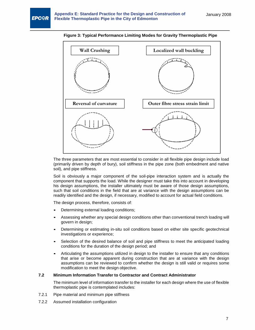
Appendix E: Standard Practice for the Design and Construction of Flexible Thermoplastic Pipe in the City of Edmonton
7
January 2008
Figure 3: Typical Performance Limiting Modes for Gravity Thermoplastic Pipe
The three parameters that are most essential to consider in all flexible pipe design include load (primarily driven by depth of bury), soil stiffness in the pipe zone (both embedment and native soil), and pipe stiffness.
Soil is obviously a major component of the soil-pipe interaction system and is actually the component that supports the load. While the designer must take this into account in developing his design assumptions, the installer ultimately must be aware of those design assumptions, such that soil conditions in the field that are at variance with the design assumptions can be readily identified and the design, if necessary, modified to account for actual field conditions.
The design process, therefore, consists of:
Determining external loading conditions;
Assessing whether any special design conditions other than conventional trench loading will govern in design;
Determining or estimating in-situ soil conditions based on either site specific geotechnical investigations or experience;
Selection of the desired balance of soil and pipe stiffness to meet the anticipated loading conditions for the duration of the design period; and
Articulating the assumptions utilized in design to the installer to ensure that any conditions that arise or become apparent during construction that are at variance with the design assumptions can be reviewed to confirm whether the design is still valid or requires some modification to meet the design objective.
7.2 Minimum Information Transfer to Contractor and Contract Administrator The minimum level of information transfer to the installer for each design where the use of flexible thermoplastic pipe is contemplated includes:
7.2.1 Pipe material and minimum pipe stiffness
7.2.2 Assumed installation configuration
Outer fibre stress strain limit Reversal of curvature
Localized wall buckling Wall Crushing

Appendix E: Standard Practice for the Design and Construction of Flexible Thermoplastic Pipe in the City of Edmonton
8
January 2008
7.2.3 Embedment material and required placement density
7.2.4 Assumed trench width and assumed native soil characteristics (qualitative description and E’native value)
8.0 Pipe Material Requirements Pipe material requirements are general pipe material requirements to conform to this Standard Practice. They are not to be construed as general approval for the use of these products within the City of Edmonton. Specific products approvals are addressed by the City on a product-by-product basis outside of this Standard Practice.
8.1 Smooth-wall PVC Products 8.1.1 Smooth wall PVC pipe products and fittings shall conform to Sections 4 and 5 of CSA Standard
B182.2 for all basic material requirements and manufactured quality and dimensional tolerance.
8.1.2 Materials used for pipe shall come from a single compound manufacturer and shall have a cell classification of 12454-B, 12454-C, or 12364-C as defined in ASTM Standard D1784. Materials used for moulded fittings shall come from a single compound manufacturer and shall have a cell classification of 12454-B, 12454-C, or 13343-C as defined in ASTM Standard D1784.
8.1.3 Notwithstanding the requirements of Section 4 of CSA Standard B182.2, compounds with different cell classifications than that noted above shall not be used without the prior approval of the City of Edmonton.
8.2 Profile PVC Products 8.2.1 Closed profile, dual-wall corrugated, and open profile PVC pipe products and fittings shall
conform to Sections 4 and 5 of CSA Standard B182.4 for all basic material requirements and manufactured quality and dimensional tolerance.
8.2.2 Materials used for pipe and fittings shall come from a single compound manufacturer and shall have a cell classification of 12454-B, 12454-C, or 12364-C as defined in ASTM Standard D1784.
8.2.3 Notwithstanding the requirements of Section 4 of CSA Standard B182.4, compounds with different cell classifications than that noted above shall not be used without the prior approval of the City of Edmonton.
8.3 Polyethylene (PE) Profile Wall Products 8.3.1 Closed profile and open profile PE pipe products and fittings shall conform to Sections 4 and 5
of CSA Standards B182.6 and B182.8 for all basic material requirements and manufactured quality and dimensional tolerance for sanitary and storm sewer applications, respectively.
8.3.2 Materials used for pipe and fabricated fittings shall come from a single compound manufacturer and shall be made from virgin polyethylene compounds having the following minimum cell classifications as defined in ASTM Standard D3350:
Product Outside Profile, Corrugations Inside Lining, Waterway Wall Storm Sewer and Fabricated
Fittings Sanitary Sewer and Fabricated
Fittings
324420 C or 324420 E
324430 C or 324430 E
321120C or 321120E
324430 C or 324430 E
8.3.3 Resin compounds shall be tested for slow crack growth resistance in accordance with Appendix SP-NCTL in ASTM Standard D5397 as modified in Clause 8.8 of CSA B182.8.
9.0 Bedding and Foundation Material Requirements 9.1 Classification of Materials
Materials for use as foundation, embedment, and backfill are classified in Table 1. They include natural, manufactured, and processed aggregates and the soil types classified according to ASTM Test Method D 2487.
Appendix E: Standard Practice for the Design and Construction of Flexible Thermoplastic Pipe in the City of Edmonton
9
January 2008
9.2 Installation and Intended Use of Materials Table 2 provides recommendations on installation and use based on class of soil or aggregates and their location in the trench.
Class I, Class II, and Class III materials are suitable for use as foundation material and in the embedment zone subject to the limitations noted herein and in Table 2.
Class IV-A materials should only be used in the embedment zone in special design cases, as they would not normally be construed as a desirable embedment material for flexible pipe.
Class IV-B, Class V Soils, and Frozen Materials are not recommended for embedment, and should be excluded from the final backfill except where specifically allowed by project specifications.
9.3 Description of Embedment Material Sections 9.3.1 through 9.3.7 describe characteristics of materials recommended for use in the embedment zone.

Appendix E: Standard Practice for the Design and Construction of Flexible Thermoplastic Pipe in the City of Edmonton
10
January 2008
Table 1: Classes of Embedment and Backfill Materials7
Class Type Soil Group
Symbol D2487
Description Percentage Passing Sieve Sizes Atterberg Limits Coefficients
20 mm (3/4 in)
4.75 mm (No. 4)
0.075 mm (No. 200) LL PI Uniformity
CU Curvature
CC IA Manufactured
Aggregates: open- graded, clean. None
Angular, crushed stone or rock, crushed gravel, broken coral, crushed slag, cinders or shells; large void content, contain little or no fines.
100% <10% <5% Non Plastic
IB Manufactured, Processed Aggregates; dense- graded, clean.
None
Angular, crushed stone (or other Class 1A materials) and stone/sand mixtures with gradations selected to minimize migration of adjacent soils; contain little or no fines (see commentary in Part V).
100% <50% <5% Non Plastic
II Coarse-Grained Soils, clean GW Well-graded gravels and gravel-sand
mixtures; little or no fines.
100%
<50% of “Coarse Fraction”
<5% Non Plastic
>4 1 to 3
GP Poorly-graded gravels and gravel-sand mixtures; little or no fines. <4 <1 or >3
SW Well-graded sands and gravelly sands; little or no fines. >50% of
“Coarse Fraction”
>6 1 to 3
SP Poorly-graded sands and gravelly sands; little or no fines. <6 <1 or >3
Coarse-Grained Soils, borderline clean to w/fines
e.g. GW- GC, SP-
SM
Sands and gravels which are borderline between clean and with fines.
100% Varies 5% to 12% Non Plastic Same as for GW, GP, SW and SP
III Coarse-Grained Soils With Fines GM Silty gravels, gravel-sand-silt
mixtures.
100%
<50% of “Coarse Fraction” 12% to
50%
<4 or <”A” Line
GC Clayey gravels, gravel-sand-clay
mixtures. <7 and >”A”
Line
SM Silty sands, sand-silt mixtures. >50% of “Coarse Fraction”
>4 or <”A” Line
SC Clayey sands, sand-clay mixtures. >7 and >”A” Line
7 Table excerpt from D2321-00 Standard Practice for Underground Installation of Thermoplastic Pipe for Sewers and Other Gravity-Flow Applications. Maximum
aggregate size modified.

Appendix E: Standard Practice for the Design and Construction of Flexible Thermoplastic Pipe in the City of Edmonton
11
January 2008
Class Type Soil Group
Symbol D2487
Description Percentage Passing Sieve Sizes Atterberg Limits Coefficients
20 mm (3/4 in)
4.75 mm (No. 4)
0.075 mm (No. 200) LL PI Uniformity
CU Curvature
CC IVAA Fine-Grained Soils
(inorganic) ML Inorganic silts and very fine sands, rock flour, silty or clayey fine sands, silts with slight plasticity. 100% 100% >50% <50
<4 or <”A” Line
CL Inorganic clays of low to medium plasticity, gravely clays, sandy clays, silty clays, lean clays.
>7 and >”A” Line
IVB Fine-Grained Soils (inorganic) MH
Inorganic silts, micaceous or diatomaceous fine sandy or silty soils, elastic silts. 100% 100% >50% >50
<”A” Line
CH Inorganic clays of high plasticity, fat clays >”A” Line
V Organic Soils Highly Organic
OL Organic silts and organic silty clays of low plasticity.
100% 100% >50%
<50 <4 or <”A” Line
OH Organic clays of medium to high plasticity, organic silts. >50 <”A” Line
PT Peat and other high organic soils.
A Includes Test Method D2487 borderline classifications and dual symbols depending on plasticity index and liquid limits. NOTE – “Coarse Fraction” as used in this table is defined as material retained on a 0.075 mm (No. 200) sieve.

Appendix E: Standard Practice for the Design and Construction of Flexible Thermoplastic Pipe in the City of Edmonton
12
January 2008
Table 2: Recommendations for Installation and Use of Soils and Aggregates for Foundation, Embedment and Backfill8
Soil Classes (see Table 1)A Class IA Class IB Class II Class III Class IV-A
General Recommendations and Restrictions
Do not use where Conditions may cause migration of fines from adjacent soil and loss of pipe support. Suitable for use as a drainage blanket and underdrain in rock cuts where adjacent material is suitably graded (see Commentary in Part V)
Process materials As required to obtain gradation which will minimize migration of adjacent materials (see Commentary in Part V). Suitable for use as drainage blanket and underdrain.
Where hydraulic gradient exists, check gradation to minimize migration. “Clean” groups suitable for use as drainage blanket and underdrain
Do not use where water conditions in trench may cause instability.
Obtain geotechnical evaluation of proposed material. May not be suitable under high earth fills, surface applied wheel loads, and under heavy vibratory compactors and tampers. Do not use where water conditions in trench may cause instability.
Foundation Suitable as foundation and for replacing over-excavated and unstable trench bottom as restricted above. Install and compact in 150 mm maximum layers.
Suitable as foundation and for replacing over-excavated and unstable trench bottom. Install and compact in 150 mm maximum layers.
Suitable as a foundation and for replacing over- excavated and unstable trench bottom as restricted above. Install and compact in 150 mm maximum layers.
Suitable as foundation and for replacing over- excavated trench bottom as restricted above. Do not use in thicknesses greater than 300 mm total. Install and compact in 150 mm maximum layers.
Suitable only in undisturbed condition and where trench is dry. Remove all loose material and provide firm, uniform trench bottom before bedding is placed.
Bedding Suitable as restricted above. Install in 150 mm maximum layers. Level final grade by hand. Minimum depth 100 mm (150 mm in rock cuts).
Install and compact in 150 mm maximum layers. Level final grade by hand. Minimum depth 100 mm (150 mm in rock cuts).
Suitable as restricted above. Install and compact in 150 mm maximum layers. Level final grade by hand. Minimum depth 100 mm (150 mm in rock cuts).
Suitable only in dry trench conditions. Install and compact in 150 mm maximum layers. Level final grade by hand. Minimum depth 100 mm (150 mm in rock cuts).
Suitable only in dry trench conditions and when optimum placement and compaction control is maintained. Install and compact In 150 mm maximum layers. Level final grade by hand. Minimum depth 100 mm (150 mm in rock cuts).
8 Table excerpt from D2321-00 Standard Practice for Underground Installation of Thermoplastic Pipe for
Sewers and Other Gravity- Flow Applications. Minimum initial backfill and embedment compaction values modified.
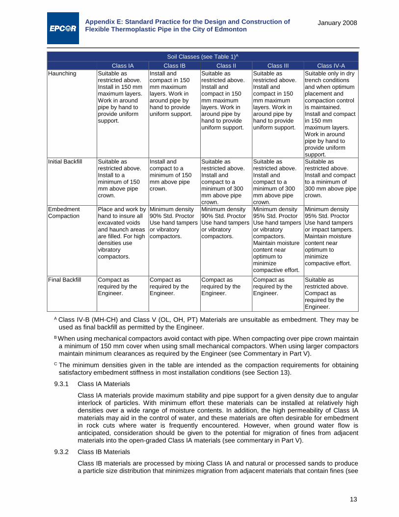
Appendix E: Standard Practice for the Design and Construction of Flexible Thermoplastic Pipe in the City of Edmonton
13
January 2008
Soil Classes (see Table 1)A Class IA Class IB Class II Class III Class IV-A
Haunching Suitable as restricted above. Install in 150 mm maximum layers. Work in around pipe by hand to provide uniform support.
Install and compact in 150 mm maximum layers. Work in around pipe by hand to provide uniform support.
Suitable as restricted above. Install and compact in 150 mm maximum layers. Work in around pipe by hand to provide uniform support.
Suitable as restricted above. Install and compact in 150 mm maximum layers. Work in around pipe by hand to provide uniform support.
Suitable only in dry trench conditions and when optimum placement and compaction control is maintained. Install and compact in 150 mm maximum layers. Work in around pipe by hand to provide uniform support.
Initial Backfill Suitable as restricted above. Install to a minimum of 150 mm above pipe crown.
Install and compact to a minimum of 150 mm above pipe crown.
Suitable as restricted above. Install and compact to a minimum of 300 mm above pipe crown.
Suitable as restricted above. Install and compact to a minimum of 300 mm above pipe crown.
Suitable as restricted above. Install and compact to a minimum of 300 mm above pipe crown.
Embedment Compaction
Place and work by hand to insure all excavated voids and haunch areas are filled. For high densities use vibratory compactors.
Minimum density 90% Std. Proctor Use hand tampers or vibratory compactors.
Minimum density 90% Std. Proctor Use hand tampers or vibratory compactors.
Minimum density 95% Std. Proctor Use hand tampers or vibratory compactors. Maintain moisture content near optimum to minimize compactive effort.
Minimum density 95% Std. Proctor Use hand tampers or impact tampers. Maintain moisture content near optimum to minimize compactive effort.
Final Backfill Compact as required by the Engineer.
Compact as required by the Engineer.
Compact as required by the Engineer.
Compact as required by the Engineer.
Suitable as restricted above. Compact as required by the Engineer.
A Class IV-B (MH-CH) and Class V (OL, OH, PT) Materials are unsuitable as embedment. They may be used as final backfill as permitted by the Engineer.
B When using mechanical compactors avoid contact with pipe. When compacting over pipe crown maintain a minimum of 150 mm cover when using small mechanical compactors. When using larger compactors maintain minimum clearances as required by the Engineer (see Commentary in Part V).
C The minimum densities given in the table are intended as the compaction requirements for obtaining satisfactory embedment stiffness in most installation conditions (see Section 13).
9.3.1 Class IA Materials
Class IA materials provide maximum stability and pipe support for a given density due to angular interlock of particles. With minimum effort these materials can be installed at relatively high densities over a wide range of moisture contents. In addition, the high permeability of Class IA materials may aid in the control of water, and these materials are often desirable for embedment in rock cuts where water is frequently encountered. However, when ground water flow is anticipated, consideration should be given to the potential for migration of fines from adjacent materials into the open-graded Class IA materials (see commentary in Part V).
9.3.2 Class IB Materials
Class IB materials are processed by mixing Class IA and natural or processed sands to produce a particle size distribution that minimizes migration from adjacent materials that contain fines (see
Appendix E: Standard Practice for the Design and Construction of Flexible Thermoplastic Pipe in the City of Edmonton
14
January 2008
commentary in Part V). They are more densely graded than Class IA materials and thus require more compactive effort to achieve the minimum density specified. When properly compacted, Class IB materials offer high stiffness and strength and, depending on the amount of fines, may be relatively free draining.
9.3.3 Class II Materials
Class II materials, when compacted, provide a relatively high level of pipe support. In most respects, they have all the desirable characteristics of Class IB materials when densely graded. However, open graded groups may allow migration and the sizes should be checked for compatibility with adjacent material (see commentary in Part V). Typically, Class II materials consist of rounded particles and are less stable than angular materials unless they are confined and compacted.
9.3.4 Class III Materials
Class III materials provide less support for a given density than Class I or Class II materials. High levels of compactive effort may be required unless moisture content is controlled. These materials provide reasonable levels of pipe support once proper density is achieved.
9.3.5 Class IV-A Materials
Class IV-A materials require a geotechnical evaluation prior to use and are only permitted to be used in special design applications such as in cut-off walls or in areas where a short section of low permeability soil is required by design.
Moisture content must be near optimum to minimize compactive effort and achieve the required density. Properly placed and compacted, Class IV-A materials can provide reasonable levels of pipe support; however, these materials may not be suitable under high fills, surface applied wheel loads, or under heavy vibratory compactors and tampers. Do not use where water conditions in the trench may cause instability and result in uncontrolled water content.
9.3.6 Moisture Content of Embedment Material
The moisture content of embedment materials must be within suitable limits to permit placement and compaction to required levels with reasonable effort. For non-free draining soils (that is, Class III, Class IVA, and some borderline Class II soils), moisture content is normally required to be held to +3% of optimum (see ASTM Test Methods D 698). The practicality of obtaining and maintaining the required limits on moisture content is an important criterion for selecting materials, since failure to achieve required density, especially in the pipe zone, may result in excessive deflection. Where a chance for water in the trench exists, embedment materials should be selected for their ability to be readily densified while saturated (that is, free-draining, cohesionless granular materials).
9.3.7 Maximum Particle Size
Maximum particle size for embedment is limited to material passing a 20 mm (3/4 in.) sieve (see Table 1). To enhance placement around small diameter pipe and to prevent damage to the pipe wall, a smaller maximum size may be required (see commentary in Part V). When final backfill contains rocks, cobbles, etc., the Engineer may require greater initial backfill cover levels (see Figure 1).
10.0 Characterization of Native Soil Conditions 10.1 Characterization of Native Soils
Native soils must be characterized to determine their potential impact on both short and long-term pipe performance.
Soil characterization to evaluate short-term implications shall be geared towards assessing the impact of native soils on the modulus of soil reaction, E’.
Soil characterization to evaluate potential long-term implications shall be geared towards assessing the potential for migration of native soils into the embedment material or other conditions that may cause degradation of the embedment material’s performance with time.

Appendix E: Standard Practice for the Design and Construction of Flexible Thermoplastic Pipe in the City of Edmonton
15
January 2008
10.2 Implication of Native Soils versus Embedment Material Selection Short-term performance shall be evaluated to determine whether the modulus of soil reaction in design, E’design, needs to be adjusted based on native soil conditions in accordance with Section 13.2.1.6. Potential native soil impact on long-term pipe performance shall be assessed in accordance with the recommendations for matching various embedment classes to native soil conditions in Table 2.
11.0 Standard Installation Configurations Standard installation configurations are presented on Figure 10, Figure 11, and Figure 12 in Part III of this Standard Practice for narrow, sub-ditch, and wide trenches.
12.0 External Loads The designer shall evaluate external loads in response to both dead and live loads. Based upon the specifics of the installation, the designer may be required to assess specialized loading conditions such as those noted in Section 12.3.
12.1 Dead Load Design Requirements The earth load from fill over the pipe shall be calculated based on the prism load as determined by:
WD = γ x H x BC (1)
where, γ = ρ x g
The minimum density (ρ) used in design shall be 2165 kg/m³ (135 lb/ft³), and the acceleration of gravity (g) used shall be 9.8064 m/s². Should an engineered backfill be utilized with densities markedly higher or lower than this value, the designer shall review the specifics of the material’s long-term performance characteristics with the Approving Authority to seek approval for use of alternate design values.
12.2 Minimum Live Load Requirements 12.2.1 Minimum live load requirements shall be the live load generated by a CL-800 truck as defined by
Canadian Highway Bridge Design Code (CAN/CSA-S6-00). Where warranted based on traffic volumes, sewer alignment, and the nature of the traffic route, the designer shall review the possible impact of dual or passing CL-800 trucks.
12.2.2 Where pipes cross or could be impacted by railway loads, live loads shall be estimated based on the AREA designated Cooper E-series loads. The minimum live load for consideration in design shall be a Cooper E-80 live load unless the Approving Authority indicates that a greater live load needs to be accommodated.
12.2.3 Requirements for aircraft or other live loads shall be as required by Approving Authority in each specific design.
12.3 Special Design Considerations The designer shall note that the primary design checks articulated in this Standard Practice relate to dead and live loads acting on a single conduit in a variety of conventional trench configurations. There can exist, in design, a number of conditions that warrant special consideration as unique design conditions that are beyond the scope of the design checks suggested by Section 13.0. This could include: i. Shallow Parallel pipes subjected to heavy surface loads ii. Parallel trenches iii. Sloped trench walls iv. Situations involving longitudinal bending, support spacing, and thermal contraction and
expansion.

Appendix E: Standard Practice for the Design and Construction of Flexible Thermoplastic Pipe in the City of Edmonton
16
January 2008
A brief discussion on each of these situations follows complete with references to additional resources to evaluate these unique design situations.
12.3.1 Shallow Parallel Pipes subjected to Heavy Surface Loads Where buried pipes are installed in parallel as illustrated in Figure 4 below, the principles of analysis for single pipes still apply. The design of parallel pipes, however, subjected to heavy surface loads requires additional analysis to determine minimum cover requirements. The designer should consult a suitable reference to conduct this analysis such as the analytical technique proposed by Moser9.
Figure 4: Shallow Parallel Pipes, Heavy Surface Loads
12.3.2 Parallel trenches to Existing Flexible Pipes Where a parallel trench is cut adjacent an in-place flexible pipe, the width of sidefill soil beside the flexible pipe should be reviewed to ensure that it is sufficiently thick to maintain adequate side support for the pipe (see Figure 5). A suitable analytical technique for this analysis is presented in Moser10.
9 A.P. Moser, “Buried Pipe Design – 2nd Edition”, published by McGraw-Hill, 2001, pp. 121. 10 A.P. Moser, “Buried Pipe Design – 2nd Edition”, published by McGraw-Hill, 2001, pp. 130.

Appendix E: Standard Practice for the Design and Construction of Flexible Thermoplastic Pipe in the City of Edmonton
17
January 2008
Figure 5: Vertical Trench Parallel to Flexible Pipe Initiating Active Soil Wedge
12.3.3 Sloped trench walls Where sloped trench walls are cut adjacent to flexible pipes at deeper heights of cover (see Figure 6), the pipe ring stiffness should be reviewed to determine that it is sufficient to withstand the resulting pressure distribution that is imposed upon the pipe. A suitable analytical technique is presented in Moser11.
Figure 6: Slope Adjacent Trench Wall – Pressure Distribution
12.3.4 Longitudinal Bending, Support Spacing, and Thermal Contraction and Expansion 12.3.4.1 Longitudinal Bending
Where flexible pipe is required by design to be subjected to horizontal alignment modifications without the use of bends, deflection typically occurs as a result of longitudinal pipe bending as opposed to individual joint offsets. Where the designer or installer intends to accomplish horizontal offsets in this manner they should review the analytical method and performance limitations of the specific products in use. Analytical procedures and performance limitations for PVC pipe are presented in the PVC pipe Handbook12.
11 A.P. Moser, “Buried Pipe Design – 2nd Edition”, published by McGraw-Hill, 2001, pp. 132. 12 Uni-Bell PVC Pipe Association, “Handbook of PVC Pipe – Design & Construction”, 4th edition, August 2001.

Appendix E: Standard Practice for the Design and Construction of Flexible Thermoplastic Pipe in the City of Edmonton
18
January 2008
12.3.4.2 Support Spacing In buried applications, a flexible pipe’s strength in longitudinal bending is rarely, if ever, a performance limiting design feature. Where flexible pipe is required to be supported either temporarily or in permanent free span installations such as pipe installed within encasement pipes, its strength in longitudinal bending must be reviewed in greater detail. This is particularly true for some profile wall configurations that provide equivalent strength in terms of equivalent ring stiffness to solid wall products but markedly lower strength in longitudinal bending. Support spacing requirements for both solid wall and profile wall PVC products are presented in the PVC pipe Handbook13.
12.3.4.3 Thermal Contraction and Expansion Flexible thermoplastic materials have markedly higher coefficients of thermal contraction and expansion than most rigid pipe materials. This is particularly true for thermoplastics such as HDPE. Where flexible thermoplastic pipes, however, are installed in buried applications, even with shallow cover, there is typically enough skin friction to overcome axial contraction and expansion (e.g. about 600 mm of cover is generally sufficient to overcome axial movement in smooth wall HDPE pipe). Where thermoplastics are installed in special design situations without the benefit of skin friction, such as in encasement pipes, the effects of thermal contraction and expansion should be reviewed closely.
13.0 Specific Design Approach 13.1 Design Objective
While deflection is required in flexible pipe installations to transfer overburden load to the adjacent soils, deflection must be controlled within tolerable limits to meet both structural and functional requirements for the pipe installation. Controlling deflection to acceptable levels will:
Avoid reversal of curvature
Limit bending and strain
Avoid pipe flattening
Maintain hydraulics
Maintain hydrostatic integrity at joints
Controlling deflection will be a function of the load, pipe stiffness, and soil stiffness. In practice, deflection can readily be controlled to within acceptable limits with:
Proper material selection (both pipe and embedment material)
Proper construction techniques
While the designer has limited control over the use of proper construction techniques, he can have a greater assurance that his design will be successfully implemented in practice by ensuring that the design is practical and achievable with adherence to normal good pipe installation practices. Any design that requires the use of specialized materials or an unusual level of installer effort to assure success should have those additional requirements clearly articulated to the installer as an output of the design process, to ensure that the installer can make the appropriate adjustments to their normal construction method(s).
13.2 Deflection and Deflection Limits For PVC pipe materials specified in Sections 8.1 and 8.2, short and long-term deflection shall meet the requirements of Table 3. HDPE deflection limits will vary with DR and will be identified at a later date.
13 Uni-Bell PVC Pipe Association, “Handbook of PVC Pipe – Design & Construction”, 4th edition, August
2001.

Appendix E: Standard Practice for the Design and Construction of Flexible Thermoplastic Pipe in the City of Edmonton
19
January 2008
Table 3: Short and Long-Term Deflection Requirements Maximum Allowable Deflection
Short-term Long-term 5.00% 7.50%
Short-term deflection shall be deemed to be any deflection measured not sooner than 30 days after backfilling an installation up to 1 year after backfilling an installation.
Long-term deflection shall be deemed to be any deflection measured after 1 year of backfilling.
Allowable deflection limits for specific pipe materials shall be measured as indicated in Part IV, which incorporates the appropriate allowances for out-of-roundness and other manufacturing tolerances permitted by this Standard Practice.
13.2.1 Modified Iowa Formula The modified Iowa formula in the following form shall be used to estimate horizontal deflection (expressed as a percent change in original diameter):
∆𝑥𝑥𝑑𝑑
(%) =100𝐷𝐷𝐿𝐿𝐾𝐾𝐾𝐾
0.149(𝐾𝐾𝑃𝑃) + 0.061𝐸𝐸𝑑𝑑𝑑𝑑𝑑𝑑𝑑𝑑𝑑𝑑𝑑𝑑′ (2)
13.2.1.1 Deflection Lag Factor, DL
A deflection lag factor, DL, of 1.0 shall be used in all analysis where long-term loading has been estimated based on prism load theory.
13.2.1.2 Bedding Factor, K
A bedding factor, K, of 0.10 shall be utilized in design, for all standard installation configurations specified herein. This is based on the assumption that bedding angles of 60-75 degrees are readily achievable in practice with adherence to good pipe installation practices (see Figure 7 for an illustration of bedding angle).
Figure 7: Bedding Angle θ, a Measure of the Pipe’s Interface with the Bedding Material
13.2.1.3 External Load, P External loads shall be estimated as detailed in Section 12.0 for the appropriate dead and live loading condition. For use in the modified Iowa formula, dead and live loads shall be converted to the equivalent overburden pressure acting over the pipe as follows:
𝐾𝐾 =𝑊𝑊𝐷𝐷 + 𝑊𝑊𝐿𝐿
𝐵𝐵𝐶𝐶 (3)

Appendix E: Standard Practice for the Design and Construction of Flexible Thermoplastic Pipe in the City of Edmonton
20
January 2008
13.2.1.4 Pipe Stiffness, PS Pipe stiffness, PS, shall be the load required to deflect the pipe to 5% deflection as measured in an ASTM D2412 parallel-plate loading test. The pipe stiffness value is calculated by dividing the force per unit length by the deflection. While these values are commonly reported in units of kilopascals (kPa) in SI and pounds per inch² (psi) in the inch-pound system, the values do not represent an equivalent resisting force and should not be construed as such.
The minimum PS recommended by this Standard Practice is 320 kPa (46 psi).
If lower pipe stiffness materials are used the designer should exercise considerable caution, carry out all necessary design checks, and carefully consider all contributing factors that may impact pipe-soil interaction. It would be prudent if using pipe materials with less than 320 kPa (46 psi) PS, to employ only Class I embedment material.
In carrying out analytical checks for pipes with PS values less than 320 kPa (46 psi), the designer should note that the analytical model proposed herein may no longer be valid as experimental load cell tests have shown markedly greater observed vertical deflection for pipe products with PS values less than 260 kPa (37 psi). This fact is illustrated in Figure 8 based on research carried out at the Utah State.
Figure 8: Observed Vertical Ring Deflection in Buried Plastic Pipe as a Function of Pipe Stiffness14
Note that Figure 8 represents medium embedment compaction conditions (approximately 85% Standard Proctor Density). Under similar loading conditions, denser embedment conditions have a significant impact on the observed vertical deflection for pipe with PS values less than 260 kPa (37 psi). This is evident from Figure 9, representing compaction density of approximately 90-94% Standard Proctor Density.
14 Uni-Bell PVC Pipe Association, “Handbook of PVC Pipe – Design & Construction”, 4th edition, August
2001.

Appendix E: Standard Practice for the Design and Construction of Flexible Thermoplastic Pipe in the City of Edmonton
21
January 2008
Figure 9: Observed Vertical Ring Deflection in Buried Plastic Pipe as a Function of Pipe Stiffness, Denser Embedment Compaction (Note Loading and Embedment Conditions as per Figure 8)15
13.2.1.5 Modulus of Soil Reaction, E’b – Embedment Soils The values for modulus of soil reaction for embedment soils may be estimated based upon a direct substitution of the one-dimensional constrained modulus, Ms, for E’. The values published by McGrath have been related to embedment materials permitted for use in the City of Edmonton by this Standard Practice and are reproduced in Table 4 below. These values may be utilized in design subject to the cautionary notes below.
Table 4: E’b Values for Embedment Soil based on McGrath
Height of Cover
Class I, II Embedment Class III Embedment Class IVA Embedment 95% SPD
90% SPD
85% SPD
95% SPD
90% SPD
85% SPD
95% SPD
90% SPD
85% SPD
0-2 m (3-6 ft)
13.8 (2000)
8.8 (1300)
3.2 (500)
9.8 (1400)
4.6 (700)
2.5 (400)
3.7 (500)
1.8 (300)
0.9 (100)
2-4 m (6-13 ft)
17.9 (2600)
10.3 (1500)
3.6 (500)
11.5 (1700)
5.1 (700)
2.7 (400)
4.3 (600)
2.2 (300)
1.2 (200)
4-8 m (13-26 ft)
20.7 (3000)
11.2 (1600)
3.9 (600)
12.2 (1800)
5.2 (800)
2.8 (400)
4.8 (700)
2.4 (300)
1.4 (200)
Note 1: E’ in MPa (psi rounded to nearest 100 in brackets)
Note 2: Use E’ values for 4-8 m of cover and for all heights of cover greater than 8 m.
15 A.P. Moser, R.K. Watkins, and R.R. Bishop, “The Structural Response of Buried PVC Pipe” , Utah State
University, 1972

Appendix E: Standard Practice for the Design and Construction of Flexible Thermoplastic Pipe in the City of Edmonton
22
January 2008
The following commentary is provided to the designer in terms of selection of appropriate design values from the above table:
Class IV-A materials (fine grained soils, CL and ML) are only permitted as embedment materials in specialized design situations (such as cut-off walls, for example). In practice, obtaining uniform densities greater than 85% with fine- grained materials is very difficult to attain unless considerable quality control efforts are exercised and moisture is tightly controlled during construction.
In practice, consistently obtaining densities higher than 90% is very difficult to achieve with the use of Class III materials (standard bedding sand with greater than 12% fines). Where greater values are required to facilitate design, the designer is encouraged to review the feasibility of utilizing a higher standard of embedment material to achieve a more practical, readily achievable design for the installer.
In practice, densities of 90% or more are readily achieved with moderate compactive effort with Class II materials. The practitioner is encouraged to review the Commentary in Part V, Section B7 to determine the appropriate methods of compaction for each embedment class.
In practice, it is requires considerable compactive effort to consistently achieve densities of 95% or higher in the embedment zone unless Class I materials are utilized. In situations where site conditions and design requirements truly require the consistent development of densities as high 95% SPD, the designer would be wise to require the use of Class I embedment materials.
The designer is encouraged not to arbitrarily specify an unreasonably high level of compactive effort unless that level of effort is required by design. As illustrated in Part V and the design examples of Part VI, consistently achieving composite E’design values in excess of 1000 MPa is what is truly required for adequate long-term performance in the vast majority of design situations.
The designer is further advised to exercise caution for any construction to be carried out under winter conditions, as the use of frozen embedment materials can preclude achieving any of the density values noted irrespective of the level of compactive effort exercised due to the difficulties in generating free moisture in the embedment material under winter construction conditions.
13.2.1.6 Influence of Native Soils (Determining Composite E’ Values) The E’ value to be utilized in design shall be a composite E’design value, based upon the E’b, of the embedment material as indicated in Section 13.2.1.5 and the designer’s understanding of both native soil conditions, E’native and specified trench width.
E’native values can be estimated based upon Table 5 below.
Table 5: E’native for Various Native Soil Conditions In-situ Soils
Granular Cohesive E’native
SPT (Blows/0.3 m) Description
Unconfined Compressive
Strength qu(kPa) Description kPa (psi)
>0-1 very, very loose >0-12 very, very soft 345 (50) 1-2 very loose 12-24 very soft 1380 (200) 2-4 24-48 soft 4825 (700) 4-8 loose 48-96 medium 10,340 (1,500)
8-15 slightly loose 96-192 stiff 20,680 (3,000) 15-30 compact 192-383 very stiff 34,470 (5,000) 30-50 dense 383-575 hard 68,940 (10,000) >50 very dense >575 very hard 137,880 (20,000)

Appendix E: Standard Practice for the Design and Construction of Flexible Thermoplastic Pipe in the City of Edmonton
23
January 2008
The designer shall determine an E’design based upon combined interaction of the embedment soils specified, the native soils anticipated, and the specified trench width. The value for E’design shall be determined from the expression:
E’design = Sc x E’b (4)
where, Sc is determined interpolation of the values provided in Table 6 below. Table 6: Values of Sc, Versus E’b and E’native
E'native/E'b Bd/Bc Bd/Bc Bd/Bc Bd/Bc Bd/Bc Bd/Bc 1.5 2 2.5 3 4 5
0.1 0.15 0.30 0.60 0.80 0.90 1.00 0.2 0.30 0.45 0.70 0.85 0.92 1.00 0.4 0.50 0.60 0.80 0.90 0.95 1.00 0.6 0.70 0.80 0.90 0.95 1.00 1.00 0.8 0.85 0.90 0.95 0.98 1.00 1.00 1.0 1.00 1.00 1.00 1.00 1.00 1.00
13.2.1.7 Calculation of Vertical Deflection Computed values for horizontal deflection shall be converted to vertical deflection based on Masada’s16 simplified integration of the modified Iowa formula:
�∆𝑦𝑦∆𝑥𝑥�
= 1 +0.0094𝐸𝐸𝑑𝑑𝑑𝑑𝑑𝑑𝑑𝑑𝑑𝑑𝑑𝑑′
(𝐾𝐾𝑃𝑃) (5)
13.3 Strain Limits Strain is more commonly a performance limiting factor in thermosetting (e.g. fiberglass, CIPP, GRP) as opposed to thermoplastic (e.g. PVC, HDPE) materials. Strain as described herein is total circumferential strain, which is comprised of bending strain, ring compression strain, hoop strain due to internal pressure, and strain due to Poisson’s effect. In gravity sewer applications, bending strain is by far the largest and other components are typical small in comparison. Therefore, if bending strains approach the materials strain limit, a more comprehensive review would be warranted.
13.3.1 Bending Strain Bending strain in the hoop direction may be reasonably approximated by the following expression:
𝜖𝜖 ≈𝑡𝑡𝐷𝐷
×3∆𝑦𝑦𝐷𝐷
1 − 2∆𝑦𝑦𝐷𝐷 (6)
13.3.2 Wall Crushing Wall crushing describes the condition of localized yielding for a ductile material or cracking failure for brittle materials. The performance limit is reached when the in-wall stress reaches the yield stress or ultimate stress of the pipe material. Ring compression stress is the primary contributor to this performance limit, where:
𝑅𝑅𝑅𝑅𝑅𝑅𝑅𝑅 𝐶𝐶𝐶𝐶𝐶𝐶𝐶𝐶𝐶𝐶𝐶𝐶𝐶𝐶𝐶𝐶𝑅𝑅𝐶𝐶𝑅𝑅 =𝐾𝐾𝐷𝐷2𝐴𝐴
(7)
16 Masada, T., “Modified Iowa Formula for Vertical Deflection of Buried Pipe”, Journal of Transportation
Engineering, September/October 2000.

Appendix E: Standard Practice for the Design and Construction of Flexible Thermoplastic Pipe in the City of Edmonton
24
January 2008
However, wall crushing can also be influenced by circumferential bending stresses, where:
𝐵𝐵𝐶𝐶𝑅𝑅𝑑𝑑𝑅𝑅𝑅𝑅𝑅𝑅 𝑃𝑃𝑡𝑡𝐶𝐶𝐶𝐶𝐶𝐶 =𝑀𝑀𝑡𝑡2𝐼𝐼
(8)
Wall crushing is typically performance limiting in only rigid or brittle pipe products. In flexible thermoplastic pipes, it is not usually performance limiting unless stiffer pipes are subjected to very deep cover, in highly compacted backfill.
13.3.3 Localized Wall Buckling Localized wall buckling is not normally performance limiting in conventionally buried gravity sewer pipes. Localized buckling may govern in the design of flexible pipes subjected to internal vacuum, high external hydrostatic pressure, or in instances where pipe is subjected to high soil pressures in very highly compacted soil. Localized buckling typically governs in flexible pipes installed as close-fitting liners and should be reviewed more closely in profile wall applications, dependent on the design of the profile section, and particularly in instances when HDPE profile pipe is utilized to its lower flexural modulus.
For long circular tubes subjected to plain strain, the critical buckling pressure is determined by:
𝐾𝐾𝑐𝑐𝑐𝑐 =𝐸𝐸𝑡𝑡3
4(1 − 𝑣𝑣2)𝑅𝑅3 (9)
For buckling in the inelastic range (materials with a pronounced yield point), the critical buckling point in terms of the materials yield point is:
𝐾𝐾𝑐𝑐𝑐𝑐 =𝑡𝑡𝑅𝑅
×𝜎𝜎𝑦𝑦
1 + 𝜎𝜎𝑦𝑦𝑅𝑅2𝐸𝐸𝑡𝑡2
(10)
However, critical buckling pressures can be significantly impacted by the geometry of the deflected conduit and the nature of the medium that the pipe is buried in. Calculated critical buckling pressure should be modified to account for geometric effects and should be reviewed to assess the impact, if any, of the surrounding medium17.
In restrained buckling situations, such as in close-fitting liner pipe installations, the flexural modulus is also impacted by phenomenon of creep and the use of the apparent long-term flexural modulus as determined by ASTM D299018
is more appropriate than use of the short-term modulus.
For a thorough review of localized buckling in soil situations the designer should review Moser19
and for the use of thermoplastics as close-fitting liners the designer should review the recommended design procedure in Appendix X1 of ASTM Standard F121620.
17 F1216-07b Standard Practice for Rehabilitation of Existing Pipelines and Conduits by the Inversion and
Curing of a Resin- Impregnated Tube, pp 5 18 D2990-01 Standard Test Methods for Tensile, Compressive, and Flexural Creep and Creep-Rupture of
Plastics 19 A.P. Moser, Buried Pipe Design – 2nd Edition”, published by McGraw-Hill, 2001, pp. 110, pp 470 20 F1216-07b Standard Practice for Rehabilitation of Existing Pipelines and Conduits by the Inversion and
Curing of a Resin- Impregnated Tube

Appendix E: Standard Practice for the Design and Construction of Flexible Thermoplastic Pipe in the City of Edmonton
25
January 2008
PART III: CONSTRUCTION OF SOIL/FLEXIBLE PIPE SYSTEMS 14.0 General 14.1 The soil-flexible thermoplastic pipe system shall be in configurations that conform to the
requirements of Figure 10, Figure 11, and Figure 12, the criteria and design concepts presented in Parts I and II, and to the line and grade designated on the plans and the City of Edmonton Standard Specifications. Owners are advised to provide for or require adequate inspection of the pipe installation at the construction site.
15.0 Safety 15.1 Safety requirements for construction shall be in accordance with the applicable federal,
provincial, and local standard regulations.
16.0 Excavation 16.1 The maximum earth load on flexible pipes results from the consolidated prism of soil directly over
the pipe, which has been considered in design by this Standard Practice. The load on the pipe will not increase beyond these values with increasing trench width. The installer, therefore, shall construct the trench as wide as is dictated by practical and economic considerations but in all cases wide enough to permit proper placement of the material in the embedment zone.
17.0 Trench Construction 17.1 General
Standard construction practices may necessitate the construction of supported or unsupported trenches in variations of narrow or wide trench configurations.
17.1.1 Unsupported trenches include
Narrow, unsupported vertical-walled trenches;
Sub-ditch trenches; and
Wide trenches
17.1.2 Supported trenches may involve the construction of either narrow vertical-walled trenches or sub-ditch trenches but as supported trenches with the appropriate movable sheeting, trench boxes, shields, or other protective apparatus in place to facilitate construction.

Appendix E: Standard Practice for the Design and Construction of Flexible Thermoplastic Pipe in the City of Edmonton
26
January 2008
Figure 10: Narrow Unsupported Trench – Typical
Figure 11: Sub-ditch Trench Configurations - Typical
Note 1: Do not over densify middle-third of bedding under pipe. Note 2: Technical transition to wide trench at Bd/Do > 5. Practical transition at Bd/Do > 3.

Appendix E: Standard Practice for the Design and Construction of Flexible Thermoplastic Pipe in the City of Edmonton
27
January 2008
Figure 12: Wide Trench –Typical
17.1.3 A wide trench is defined as any trench whose width at the top of the pipe measures wider than 5 pipe diameters. By inference, all trenches less than 5 pipe diameters are narrow trenches.
From a practical perspective, the influence of native soils on embedment soils diminishes rapidly at trench widths beyond 3 pipe diameters. Installers should review the values reprinted in Table 6 of Part II of this Standard Practice to gain an appreciation for conditions under which native soils may impact embedment soils in a deleterious manner.
17.2 Narrow, Unsupported Vertical-Walled Trenches 17.2.1 Where site conditions and safety regulations permit, the trench may be constructed as a narrow,
unsupported vertical-walled trench. The width of trench under these conditions shall be the minimum required for a worker to safely place and compact material within the embedment zone in accordance with the specified installation requirements and the compaction equipment and methods required to achieve the specified embedment densities.
17.2.2 The installer should note that the embedment soil support in all narrow trench installations is impacted by native soil characteristics. At trench widths less than 3 pipe diameters, native soil characteristics have an increasingly significant impact on embedment soil support (see Table 6 of Part II). The installer, therefore, should pay particular attention to the designer of record’s design assumption for native soils in all narrow trench installations and report soils at variance with the design assumptions to the Engineer in a prompt manner to determine what design modifications, if any, are required to be implemented.
17.3 Unsupported Sub-ditch Trenches 17.3.1 Sub-ditch trenches are variations of the narrow vertical wall trenches, where the vertical- walled
portion above the pipe has been backcut or sloped. The minimum width of the lower trench for sub-ditch trenches shall conform to the requirements of 17.2.1.
17.3.2 The installer should note that sub-ditch trenches, by design, have the narrowest of trench widths within the embedment zone and, therefore, pipe performance will be significantly impacted by native soil characteristics in all sub-ditch trench applications. As noted in 17.2.2, the installer shall promptly notify the Engineer in all cases where the conditions encountered are at variance with the stated design assumptions.
17.4 Wide Trenches – See Figure 6 17.4.1 Where design or field conditions dictate that a wide trench configuration be utilized the minimum
Note 1: Do not over densify middle-third of bedding under pipe. Note 2: Technical transition to wide trench at Bd/Do > 5. Practical transition at Bd/Do > 3.

Appendix E: Standard Practice for the Design and Construction of Flexible Thermoplastic Pipe in the City of Edmonton
28
January 2008
width of embedment zone densification shall extend for a distance of 2.5 pipe diameters on either side of the pipe. The designer may permit a narrower width of embedment zone densification if it can be demonstrated that the composite embedment zone structure will produce acceptable pipe functional and structural behavior. In these cases the requirements for material type and density outside the embedment zone shall be clearly articulated to the installer.
17.4.2 In instances where wide trench construction is employed, the installer is not required to inform the Engineer of native soil condition characteristics that are at variance with the design assumptions.
17.5 Supported trenches 17.5.1 Support of Trench Walls
Where required based on safety regulations, field conditions, or design, the pipe shall be installed in a supported trench.
Where unstable or flowing soil conditions are encountered in the trench wall, such as may be encountered in excavations below the water table and/or in weak non-cohesive soils, the unstable soils shall be stabilized prior to proceeding with pipe installation.
When supports such as trench sheeting, trench jacks, trench shields, or boxes are used, ensure that support of the pipe and its embedment is maintained throughout installation. Ensure that sheeting, where required, is sufficiently tight to prevent washing out of the trench wall from behind the sheeting. Provide tight support of trench walls below existing utilities or other obstructions that restrict driving of sheeting.
17.5.2 Supports Left in Place Unless otherwise directed by the Engineer, sheeting driven into or below the pipe zone should be left in place to preclude loss of support of foundation or embedment zone material. When top of sheeting is to be cut off, make cut 500 mm or more above the crown of the pipe. Leave rangers, whalers, and braces in place as required to support cutoff sheeting and the trench wall in the vicinity of the pipe zone. Timber sheeting to be left in place is considered a permanent structural member and shall be treated against biological degradation as necessary, and against decay if above the groundwater table. Certain preservative and protective compounds react adversely with thermoplastics, and their use should be avoided in proximity to the pipe material.
17.5.3 Movable Trench Wall Support Do not disturb the installed pipe and its embedment when using movable trench boxes and shields. Movable supports shall not be used below the top of the pipe zone unless an approved method is used to maintain the integrity of the embedment material. Before moving supports, place and compact embedment to sufficient depths to ensure protection of the pipe. As supports are moved, finish placing and compaction of embedment material.
17.5.4 Removable Trench Wall Support Where sheeting or other trench wall supports are used within or below the pipe zone, ensure the foundation and embedment materials are not disturbed by support removal. Fill any voids left on removal of supports and compact all material to required densities.
18.0 Foundation 18.1 The foundation soil shall be moderately firm to hard in situ soil, stabilized soil, or compacted fill
material.
18.2 When unsuitable or unstable material is encountered, the foundation shall be stabilized.
18.3 Where groundwater and soil characteristics may contribute to the migration of soil fines into or out of the foundation, embedment soils, sidefill, and/or backfill materials, methods to prevent migration shall be provided. Commentary on the potential and means to preclude migration of soil fines are presented in Part V of this Standard Practice.
Appendix E: Standard Practice for the Design and Construction of Flexible Thermoplastic Pipe in the City of Edmonton
29
January 2008
19.0 Bedding and Initial Backfill Requirements 19.1 Verification that Proposed Construction Method is Consistent with Design Intent
Project specific design requirements for the in-place density of outside bedding material, haunch material, and initial backfill shall be noted on the plans or in the project specifications. As the precise measurement of these densities in-place during construction is often not technically feasible, the installer shall demonstrate to the Engineer for the project that their proposed method of placement of these materials is sufficient to achieve the specified results, through a trial compaction demonstration.
Should the materials proposed for use in the embedment zone change during the course of the works the installer shall notify the Engineer and carry out additional compaction trials, sufficient to demonstrate that their proposed method of placement is consistent with achieving the specified requirements.
The trial compaction demonstration shall in no way relieve the installer from their contractual requirement of meeting the minimum performance criteria for completed installations as specified herein.
19.2 Placement of Bedding Materials 19.2.1 The bedding shall be constructed as required by the project specifications and in accordance with
the installer’s proposed construction method as verified in the compaction trial demonstration. Bedding shall be placed in such a manner to maximize the bedding angle achieved, to provide uniform load-bearing reaction, and to maintain the specified pipe grade.
19.2.2 The bedding layer shall be placed as uniformly as possible to the required density, except that loose, un-compacted material shall be placed under the middle third of the pipe, prior to placement of the pipe.
19.2.3 Bell holes shall be excavated in the bedding when installing pipe with expanded bells such that the barrel and not the pipe bells support the pipe.
19.3 Placement of Haunch and Initial Backfill Materials 19.3.1 Placement of haunching and initial backfill embedment materials shall be carried out by methods
that will not disturb or damage the pipe.
19.3.2 Work in and tamp the haunching material in the area between the bedding and the underside of the pipe before placement and compaction of the remainder of the material in the embedment zone.
19.3.3 Use compaction equipment and methods that are compatible with the materials used, the location in the trench, and the in-place densities required. In addition to the requirements of the compaction trial demonstration, review commentary in Part V of this Standard Practice.
19.3.4 The primary purpose of initial backfill is to protect the pipe from any impact damage that may arise from the placement of overfill materials. Minimum thickness of the initial backfill layer shall be as indicated on the standard installation drawings. In instances where overfill material contains large objects or is required to be deposited from very high heights, initial backfill shall be extended to such additional height above the pipe as is necessary to prevent damage from occurring to the pipe during backfilling operations.
19.3.5 Before using heavy compaction or construction equipment directly over the pipe, ensure that sufficient backfill has been placed over the pipe to prevent damaging either the pipe or the embedment zone materials as indicated in Section 22.0.
20.0 Change in Native Soil Conditions 20.1 The designer will apprise the installer of the assumed in-situ soil conditions that the design was
based on. As noted in Part II of this Standard Practice, in-situ soil properties can significantly impact both short and long-term pipe performance in narrow trench and sub- ditch type trench configurations. Should a change in site conditions be observed that would result in impacting either

Appendix E: Standard Practice for the Design and Construction of Flexible Thermoplastic Pipe in the City of Edmonton
30
January 2008
short or long-term pipe and/or embedment soil performance, the installer shall notify the Engineer, such that the validity of the original design concept can be reviewed by the designer of record. If necessary, the design will be modified to suit the actual conditions encountered in the field.
20.2 Where such modifications are required, they shall be addressed as a change in site conditions and valued for payment in accordance with the requirements of the specific contract provisions for changed site conditions. Where no adjustments are required, there shall be no adjustments in contract price.
20.3 In all instances where the designer of record’s input is sought, it shall be provided in as expeditious a manner as possible so as to minimize the impact on construction progress.
21.0 Backfill (Overfill) Materials 21.1 Construction of the backfill zone shall be as specified in the specific project requirements.
21.2 The soil shall be approved material containing no debris, organic matter, frozen material, or large stones or other object that may be detrimental to the pipe or the embedment materials. The presence of such material in the embedment may preclude uniform compaction and result in excessive localized deflections.
21.3 The installer shall ensure that there is sufficient cover over the pipe and embedment zone materials to facilitate all construction operations associated with the placement and compaction of overfill material.
22.0 Minimum Cover Requirements for Construction Loads 22.1 To preclude damage to the pipe and disturbance to the embedment zone, a minimum depth of
backfill should be maintained before allowing vehicles or heavy construction equipment traverse the pipe trench.
22.2 The minimum depth of cover should be established by the project engineer based on the specific project requirements.
22.3 In the absence of such a detailed investigation, the installer shall meet the following minimum cover requirements before allowing vehicles or construction equipment to traffic the trench surface, assuming that the minimum embedment zone densities as noted in Table 2:
Provide minimum cover of at least 600 mm or one pipe diameter (whichever is larger) where Class I embedment materials have been utilized, or
Provide minimum cover of at least 900 mm or one pipe diameter (whichever is larger) where Class II or lower embedment materials have been utilized, and
Allow at least 1200 mm of cover before using a hydrohammer for compaction directly over the pipe, and
Where construction loads may be excessive (e.g. cranes, earth moving equipment, etc.) consult with the project engineer to determine minimum operating cover requirements.
23.0 Connection of Flexible Pipe to Manholes 23.1 The installer shall use flexible water stops, resilient connectors, or other flexible systems approved
by the project engineer to make watertight connections to manholes and other structures.
23.2 The designer should review the structural requirements associated with installing flexible pipes within manholes and should ensure that sufficient manhole structure is provided to accommodate the installation of a flexible pipe.
24.0 Completion of Construction Criteria and Acceptance Testing 24.1 Vertical and Horizontal Alignment Tolerances
The pipe shall be installed to the line and grade noted on the construction drawings. Acceptance variance shall be:
6 mm plus 20 mm per m of diameter for vertical grade, and

Appendix E: Standard Practice for the Design and Construction of Flexible Thermoplastic Pipe in the City of Edmonton
31
January 2008
within 150 mm of the designated alignment for horizontal grade of pipes up to 900 mm in diameter or 50 mm per 300 mm of diameter of the designated alignment for pipes greater than 900 mm in diameter, and
No variance from grade shall be permitted that results in individual joint deflections in excess of the manufacturer’s recommended value to maintain hydrostatic integrity to the limits specified herein.
24.2 Infiltration/Exfiltration Limits Elastomeric gasket joints for pipe and fittings shall meet the requirements of ASTM D3212, except that the internal hydrostatic pressure shall be 100 kPa (15 psi).
24.3 CCTV Inspection All pipe up to and including 1200 mm NPS shall be inspected by CCTV Inspection methods as per Section 02954 – Inspection of Sewers of the City of Edmonton Construction Specifications. Pipes larger than 1200 mm NPS shall be inspected by man-entry methods as per Section 02954 – Inspection of Sewers of the City of Edmonton Construction Specifications.
24.4 Deflection Testing Where closed circuit television (CCTV) or visual walk-through inspections show evidence of excessive or non-symmetrical deflection (e.g. a non-elliptical deformation pattern), formal deflection tests shall be conducted. Where formal deflection testing is required it shall be carried out in accordance with the procedures of Part IV of this Standard Practice to confirm that the installed pipe meets the requirements for either short or long-term deflection limits as per Section 13.2 and Part IV. Deflection tests shall not be carried out sooner than 30 days after installation and backfilling complete to assess short-term deflection and not sooner than 1 year to assess long-term deflection.

Appendix E: Standard Practice for the Design and Construction of Flexible Thermoplastic Pipe in the City of Edmonton
32
January 2008
PART IV: MANDREL REQUIREMENTS FOR DEFLECTION TESTING A1.0 Scope
Part IV covers the technical requirements for deflection testing of flexible thermoplastic pipe installations within the City of Edmonton designed and constructed in accordance with this Standard Practice.
A2.0 Inspection Method Where closed circuit television (CCTV) or visual walk-through inspections show evidence of excessive or non-symmetrical deflection (e.g. a non-elliptical deformation pattern), formal deflection tests shall be conducted.
Where formal deflection tests are required:
Pipe up to and including 900 mm NPS diameter shall be inspected with “go/no-go” mandrel device as described herein.
Pipe larger than 900 mm NPS diameter shall be inspected with a suitable proving device to confirm that vertical deflection does not exceed either the maximum allowable short or long-term deflection limits stipulated by Section 13.2.
The mandrel or proving device shall be pulled through the pipe in such a manner so as to ensure that excessive force is not used to advance the device through any deflected portion of the pipe.
Deflection testing shall be performed in conjunction with a closed circuit television inspection. The mandrel shall be located in front of, and in clear view of, the television camera. An appropriate distance is typically from 1.5 to 2.5 pipe diameters in front of the television camera.
The mandrel shall be cylindrical in shape, constructed with 9 evenly spaced arms and shall generally conform to Figure A1.
Figure A1: General Mandrel Configuration
Mandrels larger than 450 mm in diameter shall be constructed of special breakdown devices to facilitate entry through access manholes.
A2.0 Mandrel Dimensional Requirements The minimum diameter of the circle scribed around the outside of the mandrel arms shall be equal to the values indicated in Section A3 for each specific pipe material, within a tolerance of ± 0.25 millimetres. The contact length of the mandrel shall be measured between the points of contact on the mandrel arm as indicated in Figure A1. The outside radius of the mandrel arms shall be

Appendix E: Standard Practice for the Design and Construction of Flexible Thermoplastic Pipe in the City of Edmonton
33
January 2008
checked for conformance with these specifications with a proving ring.
An oversized proving ring may be used, which shall be manufactured to a diameter equal to the outside diameter of the mandrel plus 1 millimetre, to facilitate undertaking measurements to confirm that the size of the mandrel conforms the dimensions and dimensional tolerances specified herein. The proving ring shall be manufactured to within 0.25 millimetres of the specified size. The proving ring shall be fabricated from 6 millimetre minimum thick steel.
As an alternative, a “go/no-go” proving ring device shall be permitted in which case the proving ring shall be sized up to 0.30 millimetres less than the circle that would be scribed by the specified mandrel size. If a “go/no-go” proving ring is utilized, an acceptable mandrel will not be able to pass through the proving ring. “Go/no-go” proving rings shall not be less than 0.1 millimetres of the specified dimension.
The radius of mandrel arm required to assess short and long-term deflection limits is noted in Section A3 for all pipe materials contemplated by this Standard Practice.
The barrel section of the mandrel shall have a contact length of at least 75% of the base inside diameter of the pipe.
A3.0 Acceptance Test Limits Mandrel or visual walk-through proving devices shall be sized to confirm that either short or long-term vertical deflection limits are not in excess of the appropriate allowance as dictated by Section 13.2. Deflection shall be measured versus the appropriate base inside diameter for each specific pipe material as indicated in the following sections.
Base inside diameter for the purposes of this Standard Practice is the base inside diameter as defined by the appropriate CSA Standard than governs manufacture of the specific pipe being tested.
The base inside diameter is the minimum inside pipe diameter prior to calculating allowable deflection and is derived by subtracting a statistical tolerance package from the pipe’s average inside diameter. The tolerance package includes allowances for variation in outside diameter, over-thickened walls, and initial out-of-roundness.
A3.1 Solid Wall DR35 and DR 41 PVC Pipe Spec CSA B182.2, Solid Wall PVC, DR 35
NPS
Average Inside
Diameter
Base Inside Diameter
(BID)
Allowable Vertical Deflection (mm) Radius of Mandrel Arm (r)
(mm) Short Term Long Term (mm) (mm) 5.00% 7.50% Short Term Long Term
100 100.57 98.40 93.5 91.0 47.0 45.9 150 149.73 146.50 139.2 135.5 70.0 68.3 200 200.42 196.11 186.3 181.4 93.7 91.4 250 250.55 245.16 232.9 226.8 117.1 114.3 300 298.27 291.86 277.3 270.0 139.4 136.0 375 365.09 357.25 339.4 330.5 170.6 166.5 450 446.23 436.64 414.8 403.9 208.5 203.5 525 526.08 514.77 489.0 476.2 245.8 239.9 600 591.84 579.11 550.2 535.7 276.6 269.9 675 666.99 652.64 620.0 603.7 311.7 304.2 750 763.57 747.68 710.3 691.6 357.1 348.5 900 913.89 894.77 850.0 827.7 427.3 417.0 1050 1061.84 1039.51 987.5 961.5 496.4 484.5 1200 1212.14 1186.60 1127.3 1097.6 566.7 553.0
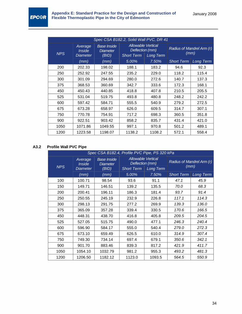
Appendix E: Standard Practice for the Design and Construction of Flexible Thermoplastic Pipe in the City of Edmonton
34
January 2008
Spec CSA B182.2, Solid Wall PVC, DR 41
NPS
Average Inside
Diameter
Base Inside Diameter
(BID)
Allowable Vertical Deflection (mm) Radius of Mandrel Arm (r)
(mm) Short Term Long Term (mm) (mm) 5.00% 7.50% Short Term Long Term
200 202.33 198.02 188.1 183.2 94.6 92.3 250 252.92 247.55 235.2 229.0 118.2 115.4 300 301.09 294.69 280.0 272.6 140.7 137.3 375 368.53 360.69 342.7 333.6 172.3 168.1 450 450.43 440.85 418.8 407.8 210.5 205.5 525 531.04 519.75 493.8 480.8 248.2 242.2 600 597.42 584.71 555.5 540.9 279.2 272.5 675 673.28 658.97 626.0 609.5 314.7 307.1 750 770.78 754.91 717.2 698.3 360.5 351.8 900 922.51 903.42 858.2 835.7 431.4 421.0 1050 1071.86 1049.55 997.1 970.8 501.2 489.1 1200 1223.58 1198.07 1138.2 1108.2 572.1 558.4
A3.2 Profile Wall PVC Pipe
Spec CSA B182.4, Profile PVC Pipe, PS 320 kPa
NPS
Average Inside
Diameter
Base Inside Diameter
(BID)
Allowable Vertical Deflection (mm) Radius of Mandrel Arm (r)
(mm) Short Term Long Term (mm) (mm) 5.00% 7.50% Short Term Long Term
100 100.71 98.54 93.6 91.1 47.1 45.9 150 149.71 146.51 139.2 135.5 70.0 68.3 200 200.41 196.11 186.3 181.4 93.7 91.4 250 250.55 245.19 232.9 226.8 117.1 114.3 300 298.13 291.75 277.2 269.9 139.3 136.0 375 365.09 357.28 339.4 330.5 170.6 166.5 450 448.31 438.70 416.8 405.8 209.5 204.5 525 527.05 515.75 490.0 477.1 246.3 240.4 600 596.90 584.17 555.0 540.4 279.0 272.3 675 673.10 659.49 626.5 610.0 314.9 307.4 750 749.30 734.14 697.4 679.1 350.6 342.1 900 901.70 883.46 839.3 817.2 421.9 411.7 1050 1054.10 1032.79 981.2 955.3 493.2 481.3 1200 1206.50 1182.12 1123.0 1093.5 564.5 550.9

Appendix E: Standard Practice for the Design and Construction of Flexible Thermoplastic Pipe in the City of Edmonton
35
January 2008
PART V: COMMENTARY21 B.1 Those concerned with the service performance of a buried flexible pipe should understand factors
that can affect this performance. Accordingly, key considerations in the design and execution of a satisfactory installation of buried flexible thermoplastic pipe that provided a basis for the development of this practice are given in this Part.
B.2 General – Sub-surface conditions should be adequately investigated prior to construction, in accordance with Practice D 420, as a basis for establishing requirements for foundation, embedment and backfill materials and construction methods. The type of pipe selected should be suited for the job conditions.
B.3 Load/Deflection Performance – The thermoplastic pipes considered in this practice are classified as flexible conduits since in carrying load they deform (deflect) to develop support from the surrounding embedment. This interaction of pipe and soil provides a pipe-soil structure capable of supporting earth fills and surface live loads of considerable magnitude. The design, specification and construction of the buried flexible pipe system should recognize that embedment materials must be selected, placed and compacted so that pipe and soil act in concert to carry the applied loads without excessive strains from deflections or localized pipe wall distortions.
B.4 Pipe Deflection – Pipe deflection is the diametral change in the pipe-soil system resulting from the process of installing the pipe (construction deflection), static and live loads applied to the pipe (load-induced deflection), and time dependent soil response (deflection lag). Construction and load induced deflections together constitute initial pipe deflection. Additional time dependent deflections are attributed primarily to changes in embedment and in-situ soils, and trench settlement. The sum of initial and time dependent deflections constitutes total deflection. The analytical methods proposed in this Standard Practice are intended to limit total deflection to within acceptable limits.
B.4.1 Construction Deflection – Construction deflections are induced during the process of installing and embedding flexible pipe, even before significant earth and surface loads are applied. The magnitude of construction deflections depends on such factors as the method and extent of compaction of the embedment materials, type of embedment, water conditions in the trench, pipe stiffness, uniformity of embedment support, pipe out-of-roundness, and installation workmanship in general. These deflections may exceed the subsequent load- induced deflections. Compaction of the side fill may result in negative vertical deflections (that is, increases in pipe vertical diameter and decreases in horizontal diameter).
B.4.2 Load-Inducted Deflection – Load-induced deflections result from backfill loads and other superimposed loads that are applied after the pipe is embedded.
B.4.3 Short-term Deflection – Short-term deflection is the deflection in the installed and backfilled pipe. It is the total of construction deflections and load-induced deflections determined after a sufficient portion of the long-term load has developed on the pipe. For the purposes of this Standard Practice the short-term deflection shall be total deflection as measured after a time period not shorter than 30 days after backfilling.
B.4.4 Time Dependent Factors – Time dependent factors include changes in soil stiffness in the pipe embedment zone and native trench soils, as well as loading changes due to trench settlement over time. These changes typically add to the short-term deflection; the time involved varies from a few days to several years depending on soil types, their placement, and initial compaction. Time dependent factors are accounted for in this Standard Practice by adjusting acceptable short-term deflection limits by a factor of 1.5.
B.4.5 Long-term Deflection – Long-term deflection is the total long-term deflection of the pipe. It consists of initial deflection adjusted for time dependent factors as noted. While acknowledged the time-dependent deflection can occur for many years, the experience has shown that the vast majority of long-term deflection (typically 90% or more) has occurred after the first year of installation. For the purposes of this Standard Practice, therefore, the long-term deflection shall be considered to
21 Modified from ASTM 2321-00, Standard Practice for Underground Installation of Thermoplastic Pipe for
Sewers and Other Gravity Applications

Appendix E: Standard Practice for the Design and Construction of Flexible Thermoplastic Pipe in the City of Edmonton
36
January 2008
be any deflection measured one year or later after backfilling.
B.5 Deflection Criteria – Deflection criteria are the limits set for the design and acceptance of buried flexible pipe installation. Deflection limits for specific pipe systems may be derived from both structural and practical considerations. Structural considerations include pipe cracking, yielding, strength, strain, and local distortion. Practical considerations include such factors as flow requirements, clearance for inspection and cleaning, and maintenance of joint seals. Acceptable short and long-term deflection limits are presented for all pipes addressed by this Standard Practice in Part IV.
B.6 Deflection Control – Embedment materials should be selected, placed, and compacted so as to minimize total deflections and, in any event, to maintain installed deflections within specific limits. Methods of placement, compaction, and moisture control should be selected based on soil types given in Table 1 of Part II of this Standard Practice and on recommendations given in Table 2 of Part II of this Standard Practice. The amount of load-induced deflection is primarily a function of the stiffness of the pipe and soil embedment system. Other factors that are important in obtaining deflection control are outlined below.
B.6.1 Embedment at Pipe Haunches – Lack of adequate compaction of embedment material in the haunch zone can result in excessive deflection, since it is this material that supports the vertical loads applied to the pipe. A key objective during installation of flexible thermoplastic pipe (or any pipe) is to work in and compact embedment material under pipe haunches, to ensure complete contact with the pipe bottom, and to fill voids below the pipe.
B.6.2 Embedment Density – Embedment density requirements should be determined by the engineer based on deflection limits established for the pipe, pipe stiffness, and installation quality control, as well as the characteristics of the in-situ soil and compatibility characteristics of the embedment materials used. The minimum densities given in Table 2 are based on attaining an average modulus of soil reaction (E’) of greater than 6.9 MPa (1000 psi) except under special circumstances where Class IVA embedment material is used. Where higher modulus of soil reaction values are required the designer should refer to Table 4 as well as making the appropriate adjustments if necessary to account for the impact of native soils that may have modulus values lower than the proposed embedment soils.
B.7 Compaction Methods – Achieving desired densities for specific types of materials depends on the methods used to impart compactive energy. Coarse-grained, clean materials such as crushed stone, gravels, and sand are more readily compacted using vibratory equipment, whereas fine materials with high plasticity require kneading and impact force along with controlled water content to achieve acceptable densities. In pipe trenches, small, hand-held or walk-behind compactors are required, not only to preclude damage to the pipe, but to ensure thorough compaction in the confined areas around the pipe and along the trench wall. As examples, vibratory plate tampers work well for coarse grained materials of Class I and Class II, whereas hand tampers or air driven hand-held impact rammers are suitable for the fine-grained, plastic groups of Class III and IV A. Gas or diesel powered jumping jacks or small, walk-behind vibratory rollers impart both vibratory and kneading or impact force, and hence are suitable for most classes of embedment and backfill material.
B.8 Migration – When coarse and open-graded material is placed adjacent to a finer material, fines may migrate into the coarser material under the action of hydraulic gradient from ground water flow. Significant hydraulic gradients may arise in the pipeline trench during construction when water levels are being controlled by various pumping or well-pointing methods, or after construction when permeable under drain or embedment materials act as a “French” drain under high ground water levels. Field experience shows that migration can result in significant loss of pipe support and continuing deflections that may exceed design limits. The gradation and relative size of the embedment and adjacent materials must be compatible in order to minimize migration (see B.8.1 below). In general, where significant ground water flow is anticipated, avoid placing coarse, open-graded materials, such as Class IA, above, below, or adjacent to finer materials, unless methods are employed to impede migration such as the use of an appropriate stone filter or filter fabric along the boundary of the incompatible materials. To guard against loss of pipe support from lateral

Appendix E: Standard Practice for the Design and Construction of Flexible Thermoplastic Pipe in the City of Edmonton
37
January 2008
migration of fines from the trench wall into open-graded embedment materials, it is sufficient to follow the minimum embedment width guidelines in B.10.
B.8.1 The following filter gradation criteria may be used to restrict migration of fines into the voids of coarser material under a hydraulic gradient:
B.8.1.1 D15/d85 < 5 where D15 is the sieve opening size passing 15% by weight of the coarser material and d85 is the sieve opening six passing 85% by weight of the finer material.
B.8.1.2 D50/d50 < 25 where D50 is the sieve opening size passing 50% by weight of the coarser material and d50 is the sieve opening size passing 50% by weight of the finer material. This criterion need not apply of the coarser material is well-graded (see Test Method D 2487).
B.8.1.3 If the finer material is a medium to highly plastic clay without sand or silt partings (CL or CH), then the following criterion may be used in lieu of B.8.1.1: D15 < 15% by weight of the coarser material.
Note – Materials selected for use based on filter gradation criteria, such as in B.8.1, should be handled and placed in a manner that will minimize segregation.
B.9 Maximum Particle Size – Limiting particle size to 20 mm (¾ in.) or less enhances placement of embedment material for nominal pipe sizes 200 mm (8 in.) through 375 mm (15 in.). For smaller pipe, a particle size of about 10% of the nominal pipe diameter is recommended.
B.10 Embedment Width for Adequate Support – In certain conditions, a minimum width of embedment material is required to ensure that adequate embedment stiffness is developed to support the pipe. These conditions arise where in-situ lateral soil resistance is negligible, such as in very poor native soils (for example, peat, muck, or highly expansive soils) or along highway embankments. Under these conditions, for small diameter pipe (12 in (300mm) or less), embedment should be placed and compacted to a point at least 2.5 pipe diameters on either side of the pipe. For pipe larger than 12 in. (300mm), the engineer should establish the minimum embedment width based on an evaluation of parameters such as pipe stiffness, embedment stiffness, nature of in-situ soil, and magnitude of construction and service loads.
B.11 Other Design and Construction Criteria – The design and construction of the pipe system should recognize conditions that may induce excessive shear, longitudinal bending, or compression loading in the pipe. Live loads applied by construction and service traffic may result in large, cumulative pipe deflections if the pipe is installed with a low density embedment and shallow cover. Other sources of loads on buried pipes are: freezing and thawing of the ground in the vicinity of the pipe, rising and falling of the ground water table, hydrostatic pressure due to ground water, and localized differential settlement loads occurring next to structures such as manholes and foundations. Where external loads are deemed to be excessive, the pipe should be installed in casing pipe or other load limiting structures.

Appendix E: Standard Practice for the Design and Construction of Flexible Thermoplastic Pipe in the City of Edmonton
38
January 2008
PART VI: DESIGN EXAMPLES This Standard Practice provides a couple of design examples to compute deflection based on the application of the analytical model recommended by this Standard Practice.
The design method recommended by this Standard Practice is comprised of the following basic steps:
1. Determine external loading (both Dead and Live Loading). Dead loading is directly related to the height of cover, while live loading will be a function of the height of cover and the anticipated live loading vehicle (e.g. standard truck loads, railway loads, and/or airport loading).
2. Evaluate whether any special design conditions need to be evaluated and evaluate them independently.
3. Determine a representative Modulus of Soil Reaction, E’. The effective or composite Modulus of Soil Reaction will be a function of the embedment soil we select, native soil conditions, and trench width.
4. Select the remaining Modified Iowa Formula parameters including the deflection lag factor (DL), bedding factor (K), and pipe stiffness (PS).
5. Calculate horizontal deflection utilizing the Modified Iowa Formula.
6. Calculate the vertical deflection using Masada’s simplified integration of the Modified Iowa Formula. Review the answer versus our performance limits for deflection to determine whether we need to carry out additional iterations with modified bedding conditions, increased trench width, etc.
This is intended to be a relatively simple set of examples, and purposely has omitted reviews of any evaluation of specialized design conditions.
EXAMPLE NO. 1 A 300 mm PVC pipe is to be installed with a maximum of 7.3 m of cover. Proposed material for use as bedding and initial backfill is standard City of Edmonton bedding sand. This material has been confirmed to have a fines content in the 5-12% range.
The trench configuration is anticipated to be a wyed sub-ditch type of trench with a trench width of O.D. plus 0.6 m at pipe depth (0.9 m).
The installation location is within the right-of-way of a typical residential subdivision within the City of Edmonton.
Based on geotechnical investigations carried out in the area, native soils in the pipe zone are predominately comprised of cohesive soils with visual descriptions varying from soft to very soft. Grain size approaches silt or varved silts in clay. Based on the borehole investigations these soils are reported to have unconfined compressive strengths on the order of 15-20 kPa at anticipated pipe depth.
Design computations would include:
1. Dead and Live Load a. Dead Load (as per Clause 12.1 of the Standard Practice)
WD = ρ × g × H × BC
0.3 7.3 m
0.3 0.3

Appendix E: Standard Practice for the Design and Construction of Flexible Thermoplastic Pipe in the City of Edmonton
39
January 2008
WD = (2100kg/m³) × (9.8064 m/s²) × 7.3 m × 0.3 m x (1 kN/1000 N)
= 45.10 kN/m
b. Live Load We will use the AASHTO Live Load calculation method for simplicity. As this is a residential street we will assume only 1 large truck as opposed multiple passing trucks. Using this method average pressure is calculated (in SI units) by:
wL =Axle Load
(2.34 m + 1.75H )(0.25 m + 1.75H )
Total live load per unit length of pipe is then calculated by:
WL = wLBC (1 + If),
where, If = Impact factor
Typical Impact factors (If) range from 0.5 at 0.3 m of cover to 0 at 1.8 m of cover or greater.
The AASHTO method is calculating an average stress at pipe depth based on the load distribution assumptions noted in the Figure below.
We will use an AASHTO HS 20 vehicle (depicted above in Imperial units), which has a total axle load of 142.34 kN (32,000 lbf).
Using SI units, live load pressure is then:
wL = 142.34 kN(2.34m+ 1.75×7.3m )(0.25m+ 1.75×7.3m )
= 0.72 𝑘𝑘𝑘𝑘𝑚𝑚2 =0.72 kPA
Total live load is therefore,
WL = 0.72 kN/m² × 0.3 m (1+ 0) = 0.22 kN/m
c. Total Dead + Live Load as a Pressure As per Clause 13.2.1.3 of our Standard Practice:
𝐾𝐾 =𝑊𝑊𝐷𝐷 + 𝑊𝑊𝐿𝐿
𝐵𝐵𝐶𝐶
Therefore, our total live + dead load is:

Appendix E: Standard Practice for the Design and Construction of Flexible Thermoplastic Pipe in the City of Edmonton
40
January 2008
𝐾𝐾 =45.0 𝑘𝑘𝑘𝑘𝐶𝐶 + 0.22 𝑘𝑘𝑘𝑘𝐶𝐶
0.30 m= 151.06
𝑘𝑘𝑘𝑘𝐶𝐶²
= 151.06 𝑘𝑘𝐾𝐾𝑘𝑘
We now move on to the Iowa Formula.
2. Evaluate Special Design Conditions Based on a review of Section 12.3 of the Standard Practice, none present.
3. Determine Modulus of Soil Reaction E’design
E’design will be a function of our embedment material, E’b, native soil conditions, E’native, and our selected trench width, BD.
Standard the City of Edmonton bedding sand with less than 12% fines, is a Class II embedment material (Table 1 of the Standard Practice). We will assume a minimum of 90% of the maximum standard Proctor dry density (SPD) will be achieved. Based on Table 4 of the Standard Practice, E’b at all heights of cover greater than 4 m is 11.2 MPa or 11,200 kPa. The native soil conditions, E’native, can be estimated based on the geotechnical data. Based on Table 5 of the Standard Practice, unconfined compressive strengths of 15-20 kPa for the native soils do indeed correspond to the visual descriptor very soft. The native E’native, can read from Table 5 as 1380 kPa. The composite value for E’design can be estimated by determining the modifying factor, Sc, from Table 6 of the Standard Practice by knowing:
𝐸𝐸𝑑𝑑𝑛𝑛𝑛𝑛𝑑𝑑𝑛𝑛𝑑𝑑′
𝐸𝐸𝑏𝑏′=
1380 𝑘𝑘𝐾𝐾𝑘𝑘11,200 𝑘𝑘𝐾𝐾𝑘𝑘
= 0.12, and
𝐵𝐵𝐷𝐷𝐵𝐵𝐶𝐶
=0.9 𝐶𝐶0.3 𝐶𝐶
= 3
Interpolating from the table, Sc, = 0.81, E’design can be calculated by:
E’design = Sc x E’b = 0.81 x 11,200 kPa = 9090 kPa
4. Select remaining parameters for the Modified Iowa Formula We will need values for:
Deflection Lag = DL = 1.0,
(Clause 13.2.1.1 of the Standard Practice) where a Prism Load is used in design, and
Bedding Factor = K = 0.10
as per Clause 13.2.1.2 of the Standard Practice for 60°-75° bedding angle, and
Pipe Stiffness = PS = 320 kPa
for a DR 35 PVC pipe as per Clause 13.2.1.4 of the Standard Practice.
5. Calculate Horizontal Deflection Using the Modified Iowa formula calculate maximum anticipated long-term horizontal deflection (Clause 13.2.1 of the Standard Practice):
∆𝑥𝑥𝑑𝑑
(%) =100𝐷𝐷𝐿𝐿𝐾𝐾𝐾𝐾
0.149(𝐾𝐾𝑃𝑃) + 0.061𝐸𝐸𝑑𝑑𝑑𝑑𝑑𝑑𝑑𝑑𝑑𝑑𝑑𝑑′ =100 × 1.0 × 0.10 × 151.06 𝑘𝑘𝐾𝐾𝑘𝑘
0.149 × 320 𝑘𝑘𝐾𝐾𝑘𝑘 + 0.061 × 9090 𝑘𝑘𝐾𝐾𝑘𝑘= 2.51%
6. Calculate Vertical Deflection Calculate the deflection ratio with Masada’s simplified formula as follows (Clause 13.2.1.7 of the Standard Practice):

Appendix E: Standard Practice for the Design and Construction of Flexible Thermoplastic Pipe in the City of Edmonton
41
January 2008
�∆𝑦𝑦∆𝑥𝑥� = 1 +
0.0094𝐸𝐸𝑑𝑑𝑑𝑑𝑑𝑑𝑑𝑑𝑑𝑑𝑑𝑑′
(𝐾𝐾𝑃𝑃)
�∆𝑦𝑦∆𝑥𝑥� = 1 +
0.0094 × 9090 𝑘𝑘𝐾𝐾𝑘𝑘320 𝑘𝑘𝐾𝐾𝑘𝑘
=1.27
Therefore, anticipated long-term vertical deflection equals:
∆𝑦𝑦𝑑𝑑
=∆𝑥𝑥𝑑𝑑
× 1.27 = 2.51% × 1.27 = 3.18%
Which is less than our long-term acceptable limit of 7.50% as per Table 3 of the Standard Practice, and is O.K.
EXAMPLE NO. 2 A 900 mm PVC pipe is to be installed with a maximum of 7.3 m of cover. Proposed material for use as bedding and initial backfill is standard the City of Edmonton bedding sand. This material has been confirmed to have a fines content in the 5-12% range.
The trench configuration is anticipated to be a wyed sub-ditch type of trench with a trench width of O.D. plus 0.6 m at pipe depth (1.5 m).
7.3 m
The installation location is within the busier right-of-way that may encounter multiple passing trucks.
Based on geotechnical investigations carried out in the area, native soils in the pipe zone are predominately comprised of cohesive soils as per Example No. 1 with visual descriptions varying from soft to very soft. Grain size approaches silt or varved silts in clay. Based on the borehole investigations these soils are reported to have unconfined compressive strengths on the order of 15- 20 kPa at anticipated pipe depth.
Design should determine:
1. Dead and Live Load a. Dead Load (as per Clause 12.1 of the Standard Practice)
WD = ρ × g × H × BC
WD = (2100kg/m3) × (9.8064 m/s2) × 7.3 m × 0.9 m × (1 kN/1000 N)
= 135.30 kN/m
b. Live Load We will use the AASHTO Live Load calculation method for multiple passing trucks. Using this method average pressure is calculated (in SI units) by:
wL =Axle Load
(5.39 m + 1.75H )(0.25 m + 1.75H )
Total live load per unit length of pipe is then calculated by:
WL = wLBc (1+ If),
where, If = Impact factor
0.9
0.3 0.3

Appendix E: Standard Practice for the Design and Construction of Flexible Thermoplastic Pipe in the City of Edmonton
42
January 2008
Typical Impact factors (If) range from 0.5 at 0.3 m of cover to 0 at 1.8 m of cover or greater. The AASHTO method for multiple trucks is calculating an average stress at pipe depth based on the load distribution assumptions noted in the Figure below.
We will continue to use an AASHTO HS 20 vehicle (depicted above in Imperial units), which has a total axle load of 142.34 kN (32,000 lbf) per truck for a total load of 284.69 kN (64,000 lbf).
Using SI units, live load pressure is then:
wL =284.69 kN
(5.39 m + 1.75 × 7.3 m )(0.25 m + 1.75 × 7.3 m )= 1.20
𝑘𝑘𝑘𝑘𝐶𝐶2 = 1.2 𝑘𝑘𝐾𝐾𝑘𝑘
WL = 1.20kNm2 × 0.9 m × (1 + 0) = 1.08
𝑘𝑘𝑘𝑘𝐶𝐶
Total live load is therefore,
c. Total Dead + Live Load as a Pressure As per Clause 13.2.1.3 of our Standard Practice:
𝐾𝐾 =𝑊𝑊𝐷𝐷 + 𝑊𝑊𝐿𝐿
𝐵𝐵𝐶𝐶
Therefore, our total live + dead load is:
𝐾𝐾 =135.3 𝑘𝑘𝑘𝑘𝐶𝐶 + 1.08 𝑘𝑘𝑘𝑘𝐶𝐶
0.9 m= 151.54
𝑘𝑘𝑘𝑘𝐶𝐶²
= 151.54 𝑘𝑘𝐾𝐾𝑘𝑘
We now move on to the Iowa Formula.
2. Evaluate Special Design Conditions Based on a review of Section 12.3 of the Standard Practice, none present.
3. Determine Modulus of Soil Reaction E’design E’design will be a function of our embedment material, E’b, native soil conditions, E’native, and our selected trench width, BD.
Standard the City of Edmonton bedding sand with less than 12% fines, is a Class II

Appendix E: Standard Practice for the Design and Construction of Flexible Thermoplastic Pipe in the City of Edmonton
43
January 2008
embedment material (Table 1 of the Standard Practice). We will assume a minimum of 90% of the maximum standard Proctor dry density (SPD) will be achieved. Based on Table 4 of the Standard Practice, E’b at all heights of cover greater than 4 m is 11.2 MPa or 11,200 kPa. The native soil conditions, E’native, can be estimated based on the geotechnical data. Based on Table 5 of the Standard Practice, unconfined compressive strengths of 15-20 kPa for the native soils do indeed correspond to the visual descriptor very soft. The native E’native, can read from Table 5 as 1380 kPa. The composite value for E’design can be estimated by determining the modifying factor, Sc, from Table 6 of the Standard Practice by knowing:
𝐸𝐸𝑑𝑑𝑛𝑛𝑛𝑛𝑑𝑑𝑛𝑛𝑑𝑑′
𝐸𝐸𝑏𝑏′=
1380 𝑘𝑘𝐾𝐾𝑘𝑘11,200 𝑘𝑘𝐾𝐾𝑘𝑘
= 0.12, and
𝐵𝐵𝐷𝐷𝐵𝐵𝐶𝐶
=1.5 𝐶𝐶0.9 𝐶𝐶
= 1.67
Interpolating from the table, Sc, = 0.23, E’design can be calculated by:
E’design = SC× E’b = 0.23 × 11,200 kPa = 2630 kPa
4. Select remaining parameters for the Modified Iowa Formula We will need values for:
Deflection Lag = DL = 1.0 ,
(Clause 13.2.1.1 of the Standard Practice) where a Prism Load is used in design, and
Bedding Factor = K = 0.10
as per Clause 13.2.1.2 of the Standard Practice for 60°-75° bedding angle, and
Pipe Stiffness = PS = 320kPa
for a DR 35 PVC pipe as per Clause 13.2.1.4 of the Standard Practice.
5. Calculate Horizontal Deflection Using the Modified Iowa formula, calculate the maximum anticipated long-term horizontal deflection (Clause 13.2.1 of the Standard Practice):
∆𝑥𝑥𝑑𝑑
(%) =100𝐷𝐷𝐿𝐿𝐾𝐾𝐾𝐾
0.149(𝐾𝐾𝑃𝑃) + 0.061𝐸𝐸𝑑𝑑𝑑𝑑𝑑𝑑𝑑𝑑𝑑𝑑𝑑𝑑′ =100 × 1.0 × 0.10 × 151.54 𝑘𝑘𝐾𝐾𝑘𝑘
0.149 × 320 𝑘𝑘𝐾𝐾𝑘𝑘 + 0.061 × 2630 𝑘𝑘𝐾𝐾𝑘𝑘= 7.28% < 7.5%
6. Calculate Vertical Deflection Calculate the deflection ratio with Masada’s simplified formula as follows (Clause 13.2.1.7 of the Standard Practice):
�∆𝑦𝑦∆𝑥𝑥� = 1 +
0.0094𝐸𝐸𝑑𝑑𝑑𝑑𝑑𝑑𝑑𝑑𝑑𝑑𝑑𝑑′
(𝐾𝐾𝑃𝑃)
�∆𝑦𝑦∆𝑥𝑥� = 1 +
0.0094 × 2630 𝑘𝑘𝐾𝐾𝑘𝑘320 𝑘𝑘𝐾𝐾𝑘𝑘
=1.08
Therefore, anticipated long-term vertical deflection equals:
∆𝑦𝑦𝑑𝑑
=∆𝑥𝑥𝑑𝑑
× 1.08 = 7.28% × 1.08 = 7.84% > 7.5% ◄ Exceeds long-term deflection limit
This is greater than our long-term acceptable limit of 7.50% (see Table 3 of the Standard Practice) and is not O.K. We could either increase minimum trench width or upgrade the
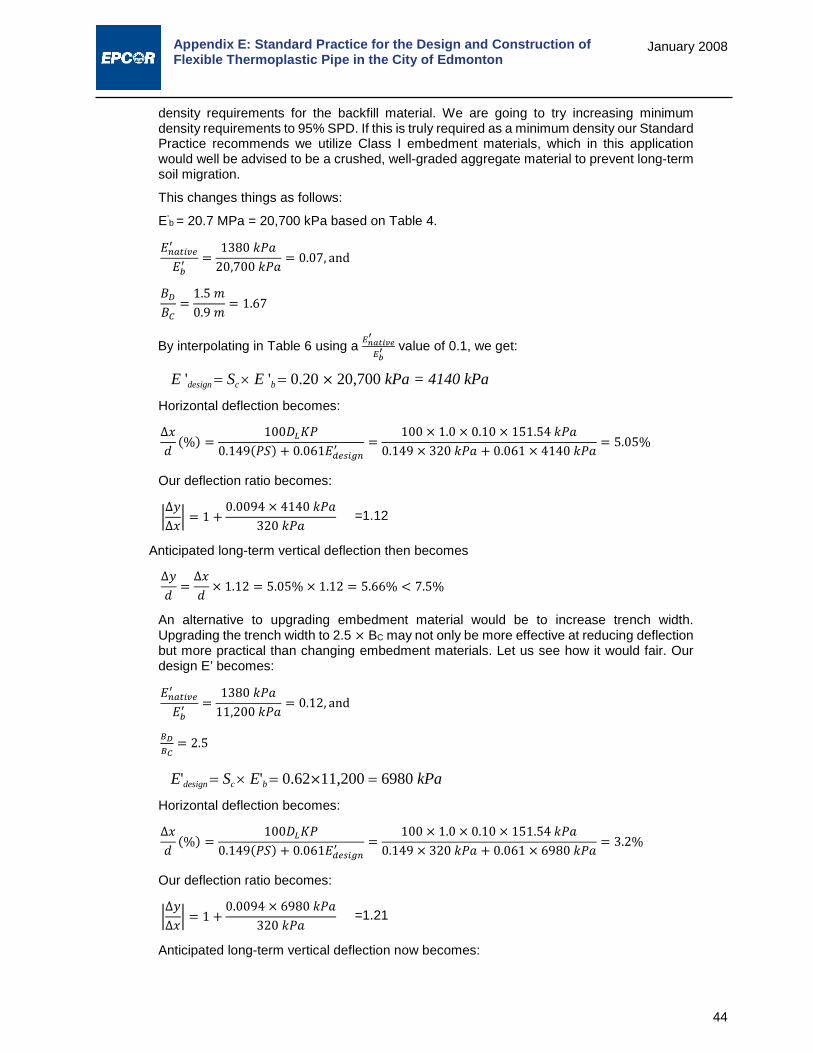
Appendix E: Standard Practice for the Design and Construction of Flexible Thermoplastic Pipe in the City of Edmonton
44
January 2008
density requirements for the backfill material. We are going to try increasing minimum density requirements to 95% SPD. If this is truly required as a minimum density our Standard Practice recommends we utilize Class I embedment materials, which in this application would well be advised to be a crushed, well-graded aggregate material to prevent long-term soil migration.
This changes things as follows:
E’b = 20.7 MPa = 20,700 kPa based on Table 4.
𝐸𝐸𝑑𝑑𝑛𝑛𝑛𝑛𝑑𝑑𝑛𝑛𝑑𝑑′
𝐸𝐸𝑏𝑏′=
1380 𝑘𝑘𝐾𝐾𝑘𝑘20,700 𝑘𝑘𝐾𝐾𝑘𝑘
= 0.07, and
𝐵𝐵𝐷𝐷𝐵𝐵𝐶𝐶
=1.5 𝐶𝐶0.9 𝐶𝐶
= 1.67
By interpolating in Table 6 using a 𝐸𝐸𝑛𝑛𝑛𝑛𝑛𝑛𝑛𝑛𝑛𝑛𝑛𝑛′
𝐸𝐸𝑏𝑏′ value of 0.1, we get:
E 'design = Sc × E 'b = 0.20 × 20,700 kPa = 4140 kPa Horizontal deflection becomes:
∆𝑥𝑥𝑑𝑑
(%) =100𝐷𝐷𝐿𝐿𝐾𝐾𝐾𝐾
0.149(𝐾𝐾𝑃𝑃) + 0.061𝐸𝐸𝑑𝑑𝑑𝑑𝑑𝑑𝑑𝑑𝑑𝑑𝑑𝑑′ =100 × 1.0 × 0.10 × 151.54 𝑘𝑘𝐾𝐾𝑘𝑘
0.149 × 320 𝑘𝑘𝐾𝐾𝑘𝑘 + 0.061 × 4140 𝑘𝑘𝐾𝐾𝑘𝑘= 5.05%
Our deflection ratio becomes:
�∆𝑦𝑦∆𝑥𝑥� = 1 +
0.0094 × 4140 𝑘𝑘𝐾𝐾𝑘𝑘320 𝑘𝑘𝐾𝐾𝑘𝑘
=1.12
Anticipated long-term vertical deflection then becomes
∆𝑦𝑦𝑑𝑑
=∆𝑥𝑥𝑑𝑑
× 1.12 = 5.05% × 1.12 = 5.66% < 7.5%
An alternative to upgrading embedment material would be to increase trench width. Upgrading the trench width to 2.5 × BC may not only be more effective at reducing deflection but more practical than changing embedment materials. Let us see how it would fair. Our design E’ becomes:
𝐸𝐸𝑑𝑑𝑛𝑛𝑛𝑛𝑑𝑑𝑛𝑛𝑑𝑑′
𝐸𝐸𝑏𝑏′=
1380 𝑘𝑘𝐾𝐾𝑘𝑘11,200 𝑘𝑘𝐾𝐾𝑘𝑘
= 0.12, and
𝐵𝐵𝐷𝐷𝐵𝐵𝐶𝐶
= 2.5
E'design = Sc × E'b = 0.62×11,200 = 6980 kPa Horizontal deflection becomes:
∆𝑥𝑥𝑑𝑑
(%) =100𝐷𝐷𝐿𝐿𝐾𝐾𝐾𝐾
0.149(𝐾𝐾𝑃𝑃) + 0.061𝐸𝐸𝑑𝑑𝑑𝑑𝑑𝑑𝑑𝑑𝑑𝑑𝑑𝑑′ =100 × 1.0 × 0.10 × 151.54 𝑘𝑘𝐾𝐾𝑘𝑘
0.149 × 320 𝑘𝑘𝐾𝐾𝑘𝑘 + 0.061 × 6980 𝑘𝑘𝐾𝐾𝑘𝑘= 3.2%
Our deflection ratio becomes:
�∆𝑦𝑦∆𝑥𝑥� = 1 +
0.0094 × 6980 𝑘𝑘𝐾𝐾𝑘𝑘320 𝑘𝑘𝐾𝐾𝑘𝑘
=1.21
Anticipated long-term vertical deflection now becomes:

Appendix E: Standard Practice for the Design and Construction of Flexible Thermoplastic Pipe in the City of Edmonton
45
January 2008
∆𝑦𝑦𝑑𝑑
=∆𝑥𝑥𝑑𝑑
× 1.21 = 3.2% × 1.21 = 3.86%
This level of anticipated long-term deflection is O.K.
From this analysis, it is evident that increasing trench width is more effective at reducing deflection than increasing densities in the embedment zone. It also doesn’t require acquiring a brand new bedding material or force a contractor to achieve densities that are, from a practical perspective, much harder to achieve.

Appendix F:
Pumpwell Unit Confined Space Entry Fall-Arrest and Rescue System

Appendix F: Pumpwell Unit Confined Space Entry Fall Arrest and Rescue System
Page 1 of 10 August 2020
INFORMATION ON EQUIPMENT IN THIS APPENDIX IS PROVIDED FOR GUIDANCE IN THE DETAILED DESIGN OF MECHANICAL DRAINAGE FACILITIES WHERE PROVISION FOR FALL ARREST AND RESCUE IS REQUIRED. THE INFORMATION WAS CURRENT AT THE TIME IT WAS OBTAINED FROM THE MANUFACTURERS. THE MANUFACTURERS SHOULD BE CONSULTED TO CHECK ON ANY REVISION TO THEIR PRODUCT SPECIFICATIONS.
Provision of emergency rescue facilities – The code of practice for entry of confined spaces at drainage mechanical facilities includes is a requirement for provision of a means of emergency rescue of a person from each confined space. The rescue system adopted comprises a portable davit and winch system for use with ropes. It is necessary to provide a mounting device for the davit that allows it to be set up at each confined space. In general each location chosen for the support base should facilitate rapid setting up of the davit and lifting an injured person.
Consideration should be given to the geometry of the davit, space to operate the system, including accommodation of the injured person and his rescuers, and the structural support required for the lifting system.
The davit, mounting base is a fabricated steel socket that is bolted into place. Diagrams below show the dimensions of the davit and base. The manufacturer’s documents from which the diagrams were produce are controlled. Copies that are to be used for design of the required installation should be obtained directly from the manufacturer of the davits, North Safety Products of Toronto.
SKYHOOK RESCUE WINCH 10-AMP MOTOR DRIVE

Appendix F: Pumpwell Unit Confined Space Entry Fall Arrest and Rescue System
Page 2 of 10 August 2020
The SkyHook Hoist/System was designed to simplify confined space and remote rescues requiring a device with lifting and lowering capability. The heart of the system is a two-speed, self-tailing manual winch with a removable handle for compact storage. The SkyHook Hoist utilizes any length of standard 1/2" (12 mm) static kernmantle rope used. The winch requires minimum maintenance providing a gear ratio of 2.2 to 1 and 6 to 1, and a power ratio of 13.5 to 1 and 40 to 1.
The winch is mounted to a versatile base plate which also features a Guide Roller Assembly (GRA) which allows for easy placement or removal of the specified static kernmantle rope. The GRA is designed with attachment holes which will accept single and/or tandem Prusik or tandem device. When the Prusik safety is attached and the rope is loaded, the unit provides the user with the ability to remove or replace the load rope and change to a second rope, minimizing the time and equipment needed to duplicate the raising and lowering system.
The base plate can connect quickly to the Sure-Strong or Lynx Tripod legs, but has the flexibility to be attached to a variety of structures via tie-down holes. The SkyHook would be attached to the winch mounting brackets shown on the davit mast below.
Look up: http://www.westernsafety.com/msaroseproducts/msafallprotec9.html
Contact: SkyHook Rescue Systems, Inc. 7074 Estepa Drive Tujunga, CA 91042, USA
Office: 818 293-0320 Fax: 818 353-1749 Telephone Orders: 714 270-2730

Appendix F: Pumpwell Unit Confined Space Entry Fall Arrest and Rescue System
Page 3 of 10 August 2020
RESCUE DAVIT FLOOR-MOUNT SUPPORT BASE NORTH SAFETY PRODUCTS DAVIT BASE MODEL FP6660/00
Look up: http://www.northsafety.com/ (information on the davit is limited at this site)
20
202
255
125
SIDE
END
12.5 mm thick galvanized steel
• Not to scale All dimensions in are in millimetres
DESCRIPTION: Davit base mounts to concrete or structural steel. PVC inner sleeve allows for easy rotation of the davit
GENERAL SPECIFICATION: Rated capacity 450 lbs (200 kg) – 1 person Safety factor 11:1 Ultimate load 5000 lbs (22.2 kN) Mast rotation 3600
Weight 25 lbs
MATERIAL CONSTRUCTION: Steel A36 or better Welding CWB-47.1 Finish Hot dip galvanized Bearing Polyvinyl chloride Thrust bearing High density polyethylene
MOUNTING REQUIREMENTS:
Mounting surface must be horizontal and capable of withstanding a moment of 11 kipf (15 kNm) in all directions. Davit base installations must be certified by a professional engineer to local regulations.
5/8” (16 mm) bolts A325 (grade 5) minimum for steel mounting 5/8” (16 mm) chemical anchors for concrete mounting, or bolt through with backup plate.
90 mm bore, 6 mm galvanized steel cylinder
70
305
PLAN
45 77.5 mm bore, 6 mm thick PVC cylinder
30
34.5 128
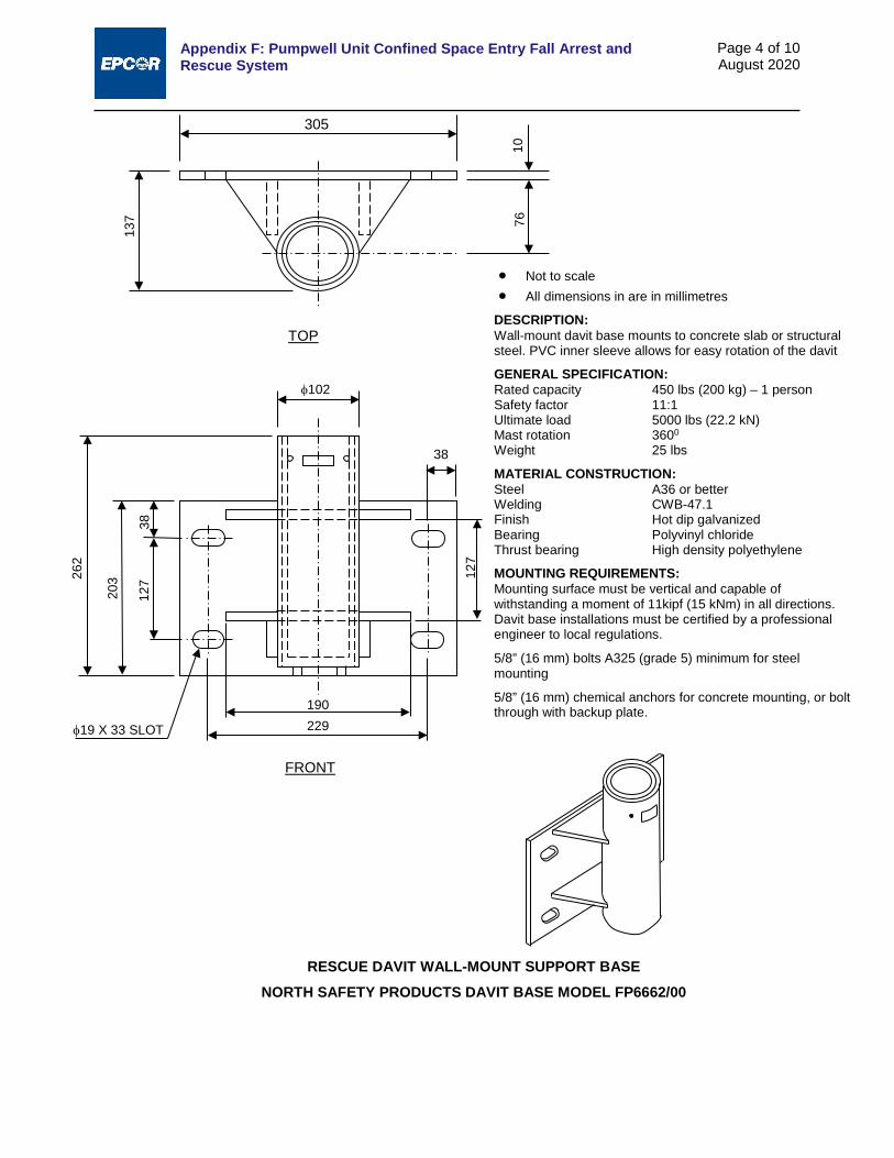
Appendix F: Pumpwell Unit Confined Space Entry Fall Arrest and Rescue System
Page 4 of 10 August 2020
RESCUE DAVIT WALL-MOUNT SUPPORT BASE NORTH SAFETY PRODUCTS DAVIT BASE MODEL FP6662/00
305
10
76
137
TOP
• Not to scale • All dimensions in are in millimetres
DESCRIPTION: Wall-mount davit base mounts to concrete slab or structural steel. PVC inner sleeve allows for easy rotation of the davit
GENERAL SPECIFICATION: Rated capacity 450 lbs (200 kg) – 1 person Safety factor 11:1 Ultimate load 5000 lbs (22.2 kN) Mast rotation 3600
Weight 25 lbs
MATERIAL CONSTRUCTION: Steel A36 or better Welding CWB-47.1 Finish Hot dip galvanized Bearing Polyvinyl chloride Thrust bearing High density polyethylene
MOUNTING REQUIREMENTS: Mounting surface must be vertical and capable of withstanding a moment of 11kipf (15 kNm) in all directions. Davit base installations must be certified by a professional engineer to local regulations.
5/8” (16 mm) bolts A325 (grade 5) minimum for steel mounting
5/8” (16 mm) chemical anchors for concrete mounting, or bolt through with backup plate.
FRONT
38
127
203 26
2
φ102
38 12
7
190 229 φ19 X 33 SLOT
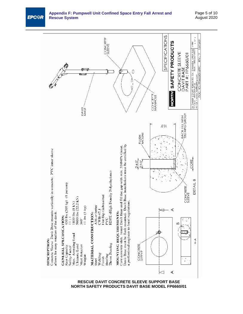
Appendix F: Pumpwell Unit Confined Space Entry Fall Arrest and Rescue System
Page 5 of 10 August 2020
RESCUE DAVIT CONCRETE SLEEVE SUPPORT BASE NORTH SAFETY PRODUCTS DAVIT BASE MODEL FP6660/01
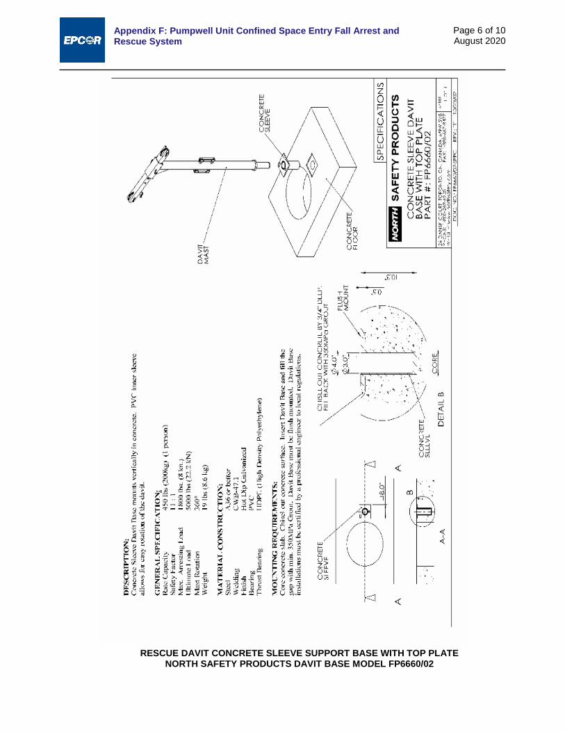
Appendix F: Pumpwell Unit Confined Space Entry Fall Arrest and Rescue System
Page 6 of 10 August 2020
RESCUE DAVIT CONCRETE SLEEVE SUPPORT BASE WITH TOP PLATE NORTH SAFETY PRODUCTS DAVIT BASE MODEL FP6660/02

Appendix F: Pumpwell Unit Confined Space Entry Fall Arrest and Rescue System
Page 7 of 10 August 2020
RESCUE DAVIT CATWALK SLEEVE SUPPORT BASE WITH TOP PLATE NORTH SAFETY PRODUCTS DAVIT BASE MODEL FP6660/03
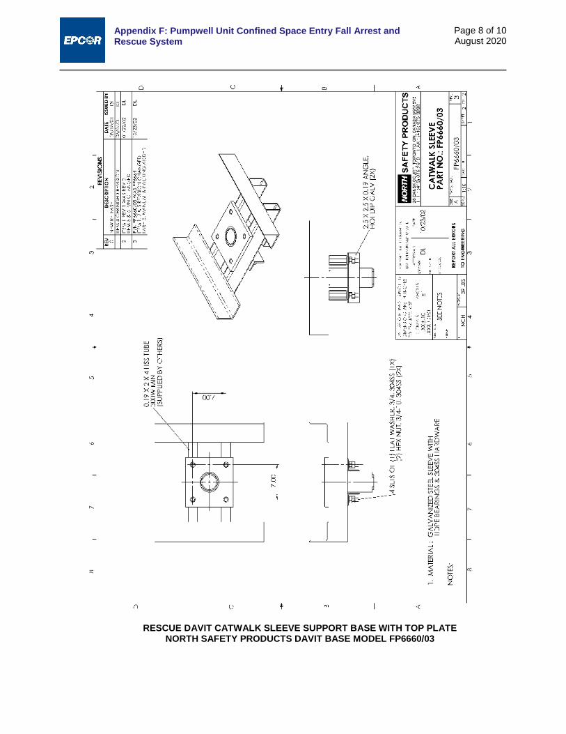
Appendix F: Pumpwell Unit Confined Space Entry Fall Arrest and Rescue System
Page 8 of 10 August 2020
RESCUE DAVIT CATWALK SLEEVE SUPPORT BASE WITH TOP PLATE NORTH SAFETY PRODUCTS DAVIT BASE MODEL FP6660/03

Appendix F: Pumpwell Unit Confined Space Entry Fall Arrest and Rescue System
Page 9 of 10 August 2020
POSITION L1 Inch (mm)
L2 Inch (mm)
L3 Inch (mm)
X1 Inch (mm)
X2 Inch (mm)
X3 Inch (mm)
A 82.3 (2090) 89.1 (2263) 76.2 (1935) 19.3 (490) 24.4 (620) 6.1 (155) B 81.5 (2070) 88.3 (2243) 75.4 (1915) 16.4 (417) 21.5 (546) 9.0 (229) C 80.7 (2050) 87.5 (2223) 74.6 (1895) 13.5 (343) 18.6 (472) 11.9 (302) D 79.9 (2029) 86.7 (2202) 73.8 (1875) 10.6 (269) 15.7 (399) 14.8 (376) E 79.2 (2012) 86.0 (2184) 73.1 (1857) 7.8 (198) 12.8 (325) 17.7 (450)
NORTH SAFETY PRODUCTS DAVIT ASSEMBLY (12” – 24” OFFSET)
X1
X2
X3
L3
1295
1694
27
3
L1
L2

Appendix F: Pumpwell Unit Confined Space Entry Fall Arrest and Rescue System
Page 10 of 10 August 2020
RECOMMENDATIONS: Each installation must be approved by a professional engineer or a qualified person as per OHSA requirements.
Item Number Description Part Number Weight 1 Adjustable Offset Boom FP6680 12 lb (5kg) 2 Davit Mast FP6670 34 lb (15kg) 3 Davit Base FP6660 25 lb (12kg)
DESCRIPTION: The davit is made of these parts: 1) Adjustable Offset Boom, 2) Davit Mast, 3) Davit Base. The boom & mast are constructed of lightweight aluminum tubing. The mast comes with tow mounting brackets for a winch and/or self-retracting lifeline (SRL) mounting. The boom includes a single pulley in the front and back and a universal anchor point at the boom front.
GENERAL SPECIFICATIONS:
Adjustable Offset Boom Position
A B C D E
Mast offset 24 in 21 in 18 in 15 in 12 in
600 mm 530 mm 450 mm 380 mm 300 mm Safety factor 8:1 9:1 11:1 11:1 11:1
Ultimate load 3600 lb 4000 lb 5000 lb 5000 lb 5000 lb 16 kN 18 kN 22 kN 22 kN 22 kN
Maximum arresting load 1800 lb (8kN) Rated capacity 450 lb (200 kg) Number of workers 1 Mast rotation 360° Weight (Boom and mast) 46 lb (26 kg)
FABRICATION DETAIL: Aluminum 6061 T6 Steel A36 or better Welding CWB 47.1, CWB 47.2 Finish Blue powder coated Hardware Grade S steel zinc plated, 306
stainless steel
NOTES: 1. Only one worker is allowed to be suspended from the
davit at a time. 2. Winches and self-retracting lifelines (SRL) to be
mounted from the front or rear mounting bracket. 3. Winches cannot be suspended from the universal
anchor point. Only an SRL can be hung from the front universal anchor point.
4. Davit cannot be used for material handling. 5. Davit must be use with North Davit Base Model
FP6660. 6. All winches, SRL, blocks shock absorbers must meet
CSA, ANSI and/or OHSA requirements and must be used in accordance with manufacturer’s instructions.
7. Workers must use a full, body harness.
1
2
3
A B
C
Universal anchor point
Winch/SRL mounting brackets
Pulleys
NORTH SAFETY PRODUCTS DAVIT ASSEMBLY (12” – 24” OFFSET)

Appendix G:
Pumping Stations Decision Model

Appendix G: Pumping Stations Decision Model i August 2020
TABLE OF CONTENTS
1.0 INITIATION .............................................................................................................................................. 1 2.0 OPTIONS DESCRIPTION ....................................................................................................................... 2 3.0 OPTIONS LIFE CYCLE COST ANALYSIS ............................................................................................ 2 4.0 OPTIONS RISK ANALYSIS .................................................................................................................... 3 5.0 OPTIONS EVALUATION CRITERIA AND FUNCTIONS: ...................................................................... 4

Appendix G: Pumping Stations Decision Model
Page 1 of 6 August 2020
The following decision model will be used when a pump station is proposed. The model can be used at any stage of the development process. It is intended to assist both the owner’s design consultant and the City Engineer to conduct value/risk-based analysis in order to recommend the best value option for sanitary servicing.
The process includes the following steps:
1. Initiation
a. Opportunity/need for a pump station
b. Motivation/reasoning
2. Option description
3. Options life cycle cost analysis
4. Options risk analysis
5. Options evaluation criteria
6. Options value
7. Recommendation
1.0 INITIATION
1.1 Timeline: Any point in the development process.
1.2 Motivation: The Design Consultant defines an opportunity/need to propose a pump station instead of a gravity system due to one or more of the following:
The expected value of the pump station is higher than the gravity system due to lower life cycle cost and equal functionality.
There is a physical barrier (e.g., ravine, river) for servicing the area that makes a gravity system unfeasible due to the vertical alignment requirement and unavailability of a discharge location.
Environmental constraints deem a gravity system unfeasible (e.g., wetlands, environmental reserve).
Geotechnical conditions (e.g., gravity profile goes through silt/unsuitable material)
Economic reasons deem a gravity system unfeasible (e.g., tunneling vs. shallow forcemain).
o The return on investment is higher for the developer (cash flow – ROI is a function of time).
Downstream constraints deem a gravity system unfeasible (i.e., need storage on the system).
o Implementation must occur in a built-up area.
Staging and development requirements (for either temporary or permanent) deem a gravity system unfeasible.
The service should be scheduled to facilitate development; if servicing is required within a short time frame during construction, the gravity option is not feasible.
1.3 Output: Proposal to change gravity option to pump station option. This proposal shall include the following information:
i. Options description
ii. Options life cycle cost analysis
iii. Options risk analysis
iv. Option evaluation

Appendix G: Pumping Stations Decision Model
Page 2 of 6 August 2020
2.0 OPTIONS DESCRIPTION A pump station is a deviation from the preferred gravity system therefore as part of the process for approval the design consultant proposing the pump station must provide a complete description of a gravity option and the pump station option. The level of detail will be of an acceptable level associated with the design stage.
For the gravity option, the following details are required:
1. Horizontal alignment
2. Vertical alignment or the proposed depth of installation
3. Pipe diameter and proposed construction method
4. Connections and any other typical components, including utility crossings
5. Geotechnical information
6. The option’s level of service
For the pump station option, the following details are required:
1. Pump station structure and storage requirements
2. Pump station equipment
3. Location and land requirements
4. Forcemain (size, number, staging)
5. Discharge location
6. Level of service
7. Future upgrade plan, if any exists
The two options should have the same level of service; if the level of service is different, then the applicant should indicate that in the description of the options.
3.0 OPTIONS LIFE CYCLE COST ANALYSIS Life cycle cost analysis is a well-established and well-defined financial analysis to evaluate the net present value (cost) of options, which can then be used in evaluations that include all future expenditure in the analysis.
For the gravity option, the following are the cost items:
1. Estimated Project Capital Cost: This cost includes the cost estimate, inclusive of engineering and construction, for all work to provide the required conveyance and storage.
2. Operation and maintenance cost/year: This cost needs to be updated based on Drainage Operation’s cost per km of pipe
For the pump station option, the following are the cost items:
1. Estimated Project Capital Cost: This cost includes the construction of the new pump station and forcemain, the land cost, and any other component required to provide service, including the engineering cost.
2. Pump Station Rehabilitation: This includes mechanical, electrical, and process components that require replacement after 15 years due to deterioration and change of technology.
3. Pump Station Upgrade: This includes any planned future upgrades for the pump station.
4. Pump Station Operation and Maintenance: This includes regular maintenance costs, electricity costs, and any other maintenance and operation activities.
The items mentioned above should be adjusted based on the project requirements. The other inputs required to conduct life cycle cost analysis are the financial parameters and analysis duration.
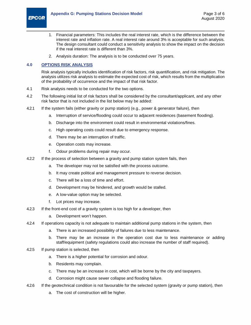
Appendix G: Pumping Stations Decision Model
Page 3 of 6 August 2020
1. Financial parameters: This includes the real interest rate, which is the difference between the interest rate and inflation rate. A real interest rate around 3% is acceptable for such analysis. The design consultant could conduct a sensitivity analysis to show the impact on the decision if the real interest rate is different than 3%.
2. Analysis duration: The analysis is to be conducted over 75 years.
4.0 OPTIONS RISK ANALYSIS Risk analysis typically includes identification of risk factors, risk quantification, and risk mitigation. The analysis utilizes risk analysis to estimate the expected cost of risk, which results from the multiplication of the probability of occurrence and the impact of that risk factor.
4.1 Risk analysis needs to be conducted for the two options.
4.2 The following initial list of risk factors shall be considered by the consultant/applicant, and any other risk factor that is not included in the list below may be added:
4.2.1 If the system fails (either gravity or pump station) (e.g., power & generator failure), then
a. Interruption of service/flooding could occur to adjacent residences (basement flooding).
b. Discharge into the environment could result in environmental violations/fines.
c. High operating costs could result due to emergency response.
d. There may be an interruption of traffic.
e. Operation costs may increase.
f. Odour problems during repair may occur.
4.2.2 If the process of selection between a gravity and pump station system fails, then
a. The developer may not be satisfied with the process outcome.
b. It may create political and management pressure to reverse decision.
c. There will be a loss of time and effort.
d. Development may be hindered, and growth would be stalled.
e. A low-value option may be selected.
f. Lot prices may increase.
4.2.3 If the front-end cost of a gravity system is too high for a developer, then
a. Development won’t happen.
4.2.4 If operations capacity is not adequate to maintain additional pump stations in the system, then
a. There is an increased possibility of failures due to less maintenance.
b. There may be an increase in the operation cost due to less maintenance or adding staff/equipment (safety regulations could also increase the number of staff required).
4.2.5 If pump station is selected, then
a. There is a higher potential for corrosion and odour.
b. Residents may complain.
c. There may be an increase in cost, which will be borne by the city and taxpayers.
d. Corrosion might cause sewer collapse and flooding failure.
4.2.6 If the geotechnical condition is not favourable for the selected system (gravity or pump station), then
a. The cost of construction will be higher.

Appendix G: Pumping Stations Decision Model
Page 4 of 6 August 2020
b. There may be a longer schedule of implementation.
4.2.7 If there are long forcemains, then
a. The condition assessment of the forcemain is difficult to attain.
b. The odour and corrosion in downstream areas will increase.
4.2.8 If pump station is selected and development is slow, then
a. Retention times will increase and cause odour and corrosion, impacting the downstream system.
4.2.9 If a gravity system is selected and debris/grease/corrosion/collapse gets into the system and plugs it, then
a. Flooding could occur.
4.2.10 If land can’t be secured for the pump station, then
a. The cost of the pump station will be higher.
4.2.11 If, for the gravity option, right-of-way/working easement is not available, then
a. The gravity option will be too expensive or not possible.
b. We may be forced to attain strata easement through court, which would add time/cost; or expropriate land.
4.2.12 If the selected option does not promote stageability, then
a. Upfront costs will be high, and building the ultimate system will occur earlier than it is required.
b. We might build less than what is needed.
4.2.13 If the design of a long forcemain does not account for transience and water hammer, then
a. Failure and leaking could occur.
4.2.14 If dangerous chemicals for odour control are used, then
a. Mishandling of chemicals may cause safety issues.
5.0 OPTIONS EVALUATION CRITERIA AND FUNCTIONS: Once the expected cost of risk and life cycle cost analysis are completed, the City and the Consultant/Applicant participate in the project-specific identification and weighting of evaluation criteria. The following initial list of evaluation criteria could be used in the analysis, and can be adjusted depending on the project constraints and limitations.
1. Constructability: the ease of construction and suitability from a geotechnical point of view and topographic impact; e.g., open cut vs. tunneling, etc.
2. Operation: operability: ease of operation leads to certain well-defined costs reliability: frequency and consequences of failure (e.g., flooding)
3. Impact on public: short-term and long-term impact (odour impact on residents; impact on commuters during construction)
4. Stageability/flexibility: providing service when needed and deferring unneeded costs until later (e.g., non-participating landowners)
5. Impact on existing infrastructure: impact on infrastructure due to corrosion, H2S
After identifying and defining the evaluation criteria, the team needs to conduct a pairwise comparison to establish the criteria’s relative weights, and then each of the criteria needs to be scored for each option. The tally of the weight multiplication with the criteria score for each option represents the option functionality. Then, the division of the function over the total cost, which includes life cycle cost and the expected cost of risk, represents the option’s value. The highest value option shall be accepted
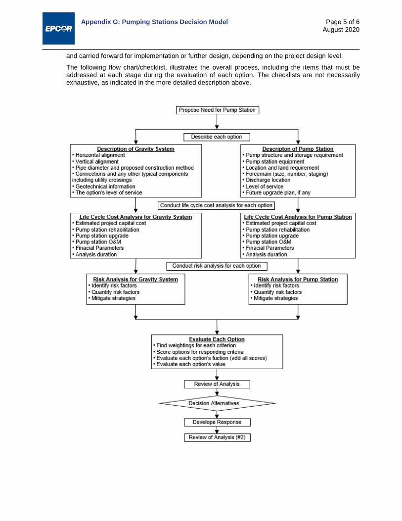
Appendix G: Pumping Stations Decision Model
Page 5 of 6 August 2020
and carried forward for implementation or further design, depending on the project design level.
The following flow chart/checklist, illustrates the overall process, including the items that must be addressed at each stage during the evaluation of each option. The checklists are not necessarily exhaustive, as indicated in the more detailed description above.
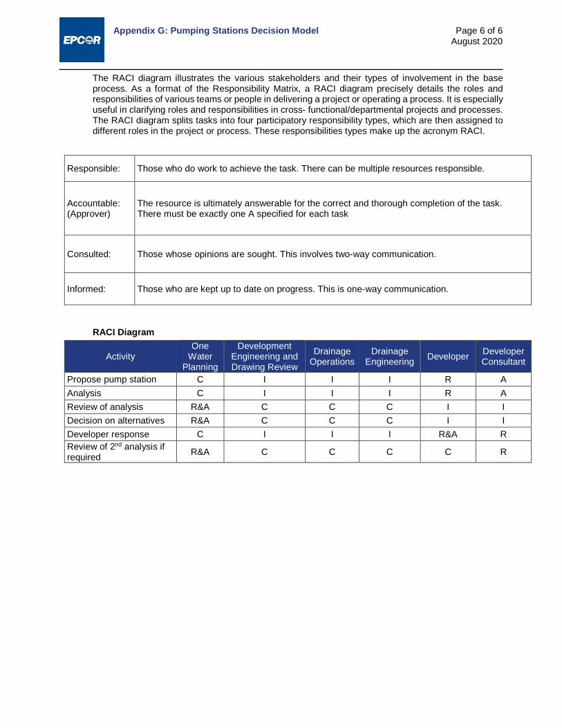
Appendix G: Pumping Stations Decision Model
Page 6 of 6 August 2020
The RACI diagram illustrates the various stakeholders and their types of involvement in the base process. As a format of the Responsibility Matrix, a RACI diagram precisely details the roles and responsibilities of various teams or people in delivering a project or operating a process. It is especially useful in clarifying roles and responsibilities in cross- functional/departmental projects and processes. The RACI diagram splits tasks into four participatory responsibility types, which are then assigned to different roles in the project or process. These responsibilities types make up the acronym RACI.
Responsible: Those who do work to achieve the task. There can be multiple resources responsible.
Accountable: (Approver)
The resource is ultimately answerable for the correct and thorough completion of the task. There must be exactly one A specified for each task
Consulted: Those whose opinions are sought. This involves two-way communication.
Informed: Those who are kept up to date on progress. This is one-way communication.
RACI Diagram
Activity One
Water Planning
Development Engineering and Drawing Review
Drainage Operations
Drainage Engineering Developer Developer
Consultant
Propose pump station C I I I R A Analysis C I I I R A Review of analysis R&A C C C I I Decision on alternatives R&A C C C I I Developer response C I I I R&A R Review of 2nd analysis if required R&A C C C C R

Appendix H:
Outfall Structure Monitoring

Appendix H: Outfall Structure Monitoring
Page 1 of 2 August 2020
1. Pursuant to 19.11.5 Outfall Structure Monitoring and subject to EPCOR Drainage Services review, sewer system design would incorporate: Access manhole(s), less than 30 m deep, and connected to an upstream pipe(s) that carries the
full flow at the eventual discharge point(s) - i.e. - can use further upstream pipe(s) if the outfall pipe itself is inaccessible under these criteria or outfall pipe is too steep or inappropriate for monitoring (see below).
This upstream pipe(s) must have a length of at least ten diameters without slope change, turns, drops, connections or any other flow disturbances, or greater length as necessary to avoid disturbances such as hydraulic jumps near the manhole. If surcharge is expected from the 1:100 year design storm, for this and lesser storms the pipe(s) must always carry flow at less than 6.0 m/s based on Manning's Formula. If surcharge is not expected the velocity may be higher if shown to be necessary.
This pipe must not be subject to or hydraulically affected by backwater from the discharge point or downstream structures.
2. General monitoring station construction criteria: Easy and safe access to site by land.
Instrumentation cabinet as per Figure H.1. Area in front of the cabinet must be adequate for safe access while doing work in the cabinet.
The cabinet must be located so that it cannot be flooded under any foreseeable circumstances. Cabinets shall be mounted on a concrete base or plinth, or steel support posts founded in concrete bases that ensure stability of the cabinet.
Ground surrounding manhole must be open and graded to allow tripod-enabled entry.
4" conduit from cabinet underground through wall of manhole near ladder rungs, with pull string. Run must not exceed 140 m from cabinet, including depth down manhole to measuring pipe.
Installation of electrical components in cabinet (as specified in cabinet drawing).
Arrange access and hookup from a single phase power source (EPCOR Distribution and Transmission) to the cabinet via 4" underground conduit or other method as per electrical code.
All work to be done to electrical code, including electrical inspection and approval of power source and power conduit before burial.
Power and instrumentation conduit locations and sizes to be included in as-built drawings for site.
Provision of monitoring instrumentation. EPCOR Drainage Services, System and Industrial Monitoring team will specify and install flow measurement instrumentation. Typically, this will include: Campbell CR800 datalogger, Raven RV50 Sierra Wireless cellular modem, Greyline AVFM 6.1 velocity meter with sensor, and Keller Acculevel pressure sensor; may vary depending on site requirements.
Depending on the site and EPCOR Drainage Services review, provision may be needed for an automatic sampler installation. If surcharge of the monitoring manhole for the 1:100 design storm is less than 2.0 m below the top of manhole, the manhole itself may suffice. Else a larger slab or equivalent, sampler cabinet and a conduit from it into the manhole will be needed. The requirement for a sampling site and details will be specified by EPCOR Drainage Services, System and Industrial Monitoring team.

Appendix H: Outfall Structure Monitoring
Page 2 of 2 August 2020
Figure H.1: Typical AC Powered Instrumentation Cabinet

DESIGN AND CONSTRUCTION STANDARDS
VOLUME 3
DRAINAGE
CONSTRUCTION SPECIFICATIONS

Drainage Construction Specifications Index
i August 2020
Section Title Issued
02412 Tunnel Excavation Using Sequential Excavation Method August 2020
02415 Soft Ground Shield Driven Tunnelling August 2020
02422 Steel Ribs and Lagging August 2020
02423 Shotcrete Tunnel Lining August 2020
02426 Pipe Jacking August 2020
02427 Precast Concrete Tunnel Lining August 2020
02435 Tunnel Liner Grouting August 2020
02441 Microtunelling August 2020
02444 Shaft Construction August 2020
02445 Bored Undercrossings August 2020
02446 Horizontal Directional Drilling August 2020
02531 Sewage Force Mains August 2020
02535 Sewers August 2020
02538 Sewer Services August 2020
02559 Factory Applied Pipe Insulation August 2020
02620 Subdrains August 2020
02631 Manholes and Catch Basins August 2020
02632 Drainage Manholes Frames and Covers August 2020
02640 Corrugated Steel Pipe Culvert August 2020
02645 Precast Concrete Box Sewers August 2020
02952 Temporary Flow Control August 2020
02953 Cleaning Sewers August 2020
02954 Inspection of Sewers August 2020
02955 Pipe Bursting August 2020
02956 Joint Grouting Concrete Sewers August 2020
02957 Relining Sewers August 2020
02958 Leakage Testing of Sewers August 2020
02959 Deflection Testing of Flexible Pipe August 2020
03310 Concrete for Water and Drainage Structures August 2020

Drainage Construction Specifications Section 02412 – Tunnel Excavation using Sequential Excavation Method
Page 1 of 3 August 2020
1. GENERAL 1.1 SCOPE
This section specifies the requirements for excavation of tunnels by sequential heading and bench method or methods used to excavate and support a tunnel in a specific sequence, often by dividing the tunnel face into sections, normally referred to as Sequential Excavation Method (SEM).
1.2 RELATED SECTIONS Steel Ribs and Lagging Section 02422
Shotcrete Tunnel Lining Section 02423
Tunnel Liner Grouting Section 02435
1.3 DEFINITIONS 1.3.1 "Heading" shall be used to describe the excavation in the upper portion of tunnel.
1.3.2 "Bench" shall be used to describe the excavation in the lower portion of tunnel.
1.3.3 "Initial support" shall be used to describe shotcrete, steel ribs, lagging, blocking and other related ground support installed after excavation.
1.3.4 "Minimum excavation" shall be used to describe the minimum excavation required to install the specified initial support shown on the drawings.
1.4 MONITORING 1.4.1 Instruments may be installed at ground surface or as designated by the instrumentation specialist, to
monitor tunnel excavation and related ground movement, if required by the Engineer.
1.4.2 Instruments will be monitored both on a routine basis and as reasonably requested by the Contractor and the Engineer.
1.4.3 Monitoring results will be provided to the City by the instrumentation specialist and passed onto the Contractor immediately upon receipt.
1.4.4 Use monitoring results to adjust the excavation and support system installation to achieve minimum loss of ground and an economic, safe excavation.
1.4.5 Install and monitor any extra instrumentation necessary for the safe conduct of the work at no additional cost to the City. Such instrumentation results shall be copied to the Engineer on timely basis after readings are taken.
1.5 SUBMITTALS Provide the following within 15 calendar days of the award of the contract:
List of construction equipment. Method and equipment used for spoil disposal from tunnel area. Drawings and descriptions of excavation, sequencing and ground support installation, complete
with shop drawings of initial tunnel lining stamped by a professional Engineer. Details of a ground monitoring program if required.
2. PRODUCTS Not Applicable.
3. EXECUTION 3.1 PREPARATION 3.1.1 Before the ground is disturbed or existing concrete is removed at a worksite, the Contractor must
contact the utility owner, advise on proposed work, request the location of the utility and not begin any work until utility location is identified and marked.

Drainage Construction Specifications Section 02412 – Tunnel Excavation using Sequential Excavation Method
Page 2 of 3 August 2020
3.1.2 All required permits must be obtained and current.
3.2 EXCAVATION 3.2.1 Excavate to elevations, alignment and dimensions shown on the drawings.
3.2.2 Adhere to excavation and initial support sequences and restraints set out in shop drawings and as approved by the Engineer in writing.
3.2.3 Use underground excavation methods, techniques and procedures that will result in minimum voids behind the tunnel liner. Remove soil to the minimum excavation lines shown on the drawings. The choice of excavation machinery or tools shall be the responsibility of the Contractor, based on the anticipated soil conditions derived from the geotechnical report or what could be reasonably expected. The Contractor shall have contingency plans for removal of boulders or minor changes in ground and these changes will be accounted for in the Contractor’s methodology and cost.
3.2.4 If the ground conditions vary considerably from what the geotechnical report indicates, the Contractor shall inform the Engineer immediately.
3.2.5 Excavate tunnel by SEM, in accordance with designed procedures, sequences and support systems.
3.2.6 The height of the heading excavation shall be as indicated on shop drawings prepared by a professional engineer. Straight faced or full faced excavation in excess of 1.5 m will not be permitted unless approved by the Engineer and by Alberta Occupational Health and Safety.
3.2.7 In unstable ground, adjust the height of the heading, sequentially excavate and support the face and roof in small exposed areas as necessary to minimize loss of ground.
3.2.8 In unstable ground, pre-support of the tunnel roof may be required. The use of forepoling, spiling or other pre-support techniques may be employed as necessary to minimize ground loss and ensure worker safety.
3.2.9 If necessary, determine the nature of the ground before the excavation cycle by probing a minimum of 3 m in advance of the face with suitable drilling equipment. Drill two holes, one horizontal hole at mid- height of the face, the second located near the crown and angling upwards at approximately 20º.
3.2.10 The excavation may be accomplished by hand operated tools or by mechanical means. The appropriate safety authorities and the Engineer must approve any machines that affect air quality.
3.3 ALIGNMENT AND GRADE TOLERANCES 3.3.1 The centre line of the tunnel shall not be more than 100 mm from the design alignment.
3.3.2 The invert of the tunnel shall not deviate from the given grade by an amount greater than 40 mm plus 10 mm for each metre of diameter �≯ 40 mm + 10 mm
1.0 m of diameter× m diameter�. If this tolerance is
exceeded, make corrections at no cost to the City. The Engineer shall approve the method of correction.
3.4 ADVANCE LIMITS 3.4.1 Excavate the tunnels to the minimum excavation lines of whatever size and shape fits the external
dimensions for the type of support system being used at the time.
3.4.2 Should the excavation deviate beyond the required minimum excavation lines, for whatever reason, thereby reducing the effectiveness of the designed initial support system, remedial action shall be taken immediately to ensure that the possibility of ground settlement is reduced to a minimum. Such remedial action will include, but not be limited to, the following:
Blocking of ribs. Adding ribs. Immediate application of shotcrete. Immediate installation of lagging and blocking. Immediate installation of spilings. Prompt backfill grouting of fallout voids and cavities.

Drainage Construction Specifications Section 02412 – Tunnel Excavation using Sequential Excavation Method
Page 3 of 3 August 2020
3.5 SEQUENCING AND SCHEDULING 3.5.1 All shotcrete, steel ribs, spiling, mesh, lagging and all other related support materials for at least 100
m length of tunnel shall be on site before commencement of tunnel excavation.
3.5.2 Organise the tunnel driving operations to be as continuous as practical. No part of the tunnel circumference will be allowed to remain unsupported for longer than the minimum time required to install initial support. If the tunnel excavation and initial support installation cycle is discontinued, stabilise the face before leaving the tunnel.
3.5.3 Follow up closely behind the placement of support on the tunnel floor with a firm surface for tunnel traffic to prevent deterioration of the tunnel floor.
3.5.4 Provide adequate drainage.
3.6 PROTECTION AND DISPOSAL 3.6.1 The equipment and method of disposal of excavated material from the tunnel must be approved by
the City prior to starting work.
3.6.2 Protect and maintain tunnel support system from damage.
3.6.3 Maintain tunnel free of waste, debris at all times. Control water infiltration so that is does not interfere with the excavation procedure and so it does not cause deterioration of the tunnel invert.
3.7 SAFETY 3.7.1 Conduct operations to the standards set down in EPCOR - Tunnel Safety Regulations and the
applicable provisions of all relevant regulatory and inspecting authorities.
3.7.2 Continuously monitor and inspect the tunnel excavation at the face and at all times install adequate support to the walls of the tunnel to ensure a safe and stable condition.
3.7.3 Perform remedial action directly to ensure that soil surrounding the excavated tunnel is maintained in a stable condition.
3.7.4 The Engineer may work with the Contractor to address any safety concerns with the excavations.
3.7.5 Nothing in these specifications shall be construed to relieve the Contractor from sole responsibility for safety.
END OF SECTION
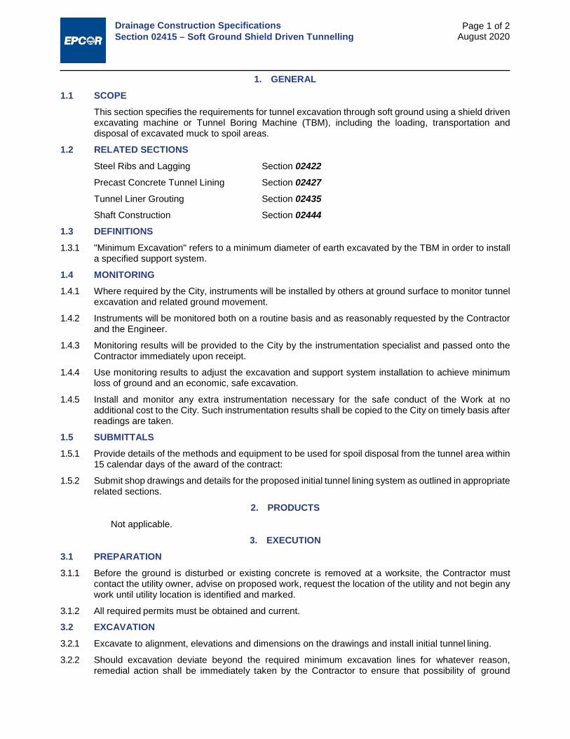
Drainage Construction Specifications Section 02415 – Soft Ground Shield Driven Tunnelling
Page 1 of 2 August 2020
1. GENERAL 1.1 SCOPE
This section specifies the requirements for tunnel excavation through soft ground using a shield driven excavating machine or Tunnel Boring Machine (TBM), including the loading, transportation and disposal of excavated muck to spoil areas.
1.2 RELATED SECTIONS Steel Ribs and Lagging Section 02422
Precast Concrete Tunnel Lining Section 02427
Tunnel Liner Grouting Section 02435
Shaft Construction Section 02444
1.3 DEFINITIONS 1.3.1 "Minimum Excavation" refers to a minimum diameter of earth excavated by the TBM in order to install
a specified support system.
1.4 MONITORING 1.4.1 Where required by the City, instruments will be installed by others at ground surface to monitor tunnel
excavation and related ground movement.
1.4.2 Instruments will be monitored both on a routine basis and as reasonably requested by the Contractor and the Engineer.
1.4.3 Monitoring results will be provided to the City by the instrumentation specialist and passed onto the Contractor immediately upon receipt.
1.4.4 Use monitoring results to adjust the excavation and support system installation to achieve minimum loss of ground and an economic, safe excavation.
1.4.5 Install and monitor any extra instrumentation necessary for the safe conduct of the Work at no additional cost to the City. Such instrumentation results shall be copied to the City on timely basis after readings are taken.
1.5 SUBMITTALS 1.5.1 Provide details of the methods and equipment to be used for spoil disposal from the tunnel area within
15 calendar days of the award of the contract:
1.5.2 Submit shop drawings and details for the proposed initial tunnel lining system as outlined in appropriate related sections.
2. PRODUCTS Not applicable.
3. EXECUTION 3.1 PREPARATION 3.1.1 Before the ground is disturbed or existing concrete is removed at a worksite, the Contractor must
contact the utility owner, advise on proposed work, request the location of the utility and not begin any work until utility location is identified and marked.
3.1.2 All required permits must be obtained and current.
3.2 EXCAVATION 3.2.1 Excavate to alignment, elevations and dimensions on the drawings and install initial tunnel lining.
3.2.2 Should excavation deviate beyond the required minimum excavation lines for whatever reason, remedial action shall be immediately taken by the Contractor to ensure that possibility of ground

Drainage Construction Specifications Section 02415 – Soft Ground Shield Driven Tunnelling
Page 2 of 2 August 2020
settlement is reduced to a minimum. Such remedial action will include, but not be limited to the following:
Blocking of ribs. Adding ribs. Immediate installation of lagging and blocking. Prompt backfill of fallout voids and cavities with grout. Soil stabilisation in advance of the excavation.
3.3 ALIGNMENT AND GRADE TOLERANCES 3.3.1 Centreline of the tunnel shall not be more than 150 mm off the given line.
3.3.2 The invert of the tunnel shall not deviate from the given grade by an amount greater than 40 mm plus 20 mm for each metre of diameter �≯ 40 mm + 20 mm
1.0 m of diameter× m diameter�. If this tolerance is
exceeded, make corrections at no cost to the City. The City shall approve the method of correction.
3.4 EXCAVATING EQUIPMENT 3.4.1 The choice of equipment for the tunnel excavation is the responsibility of the Contractor and shall be
made on the basis of expected soil conditions outlined in the geotechnical report and soils logs. The Contractor shall make allowances in the choice of equipment to account for reasonable and minor deviations in ground conditions and shall have contingency plans for removal of boulders or other minor changes in ground conditions. The City must approve the method of disposal of excavated material from the tunnel, prior to any work on the project.
3.4.2 If, in the opinion of the Contractor, a change in ground conditions occurs, the Engineer shall be notified immediately.
3.4.3 Protect and maintain the tunnel support system from damage from the muck disposal system or from any other equipment.
3.4.4 Maintain tunnel free of waste, debris at all times. Manage any water infiltration so that the excavation process and the soil stability are not adversely affected.
3.5 SAFETY 3.5.1 Conduct operations to the standards set down in EPCOR - Tunnel Safety Regulations and the
applicable provisions of all relevant regulatory and inspecting authorities
3.5.2 Continuously monitor and inspect the tunnel excavation at the face and at all times install adequate support to the walls of the tunnel to ensure a safe and stable condition.
3.5.3 Perform remedial action directly to ensure that the ground surrounding the excavated tunnel is maintained in a stable condition.
3.5.4 The Engineer may work with the Contractor to address any safety concerns with the excavations.
3.5.5 Nothing in these specifications shall be construed to relieve the Contractor from sole responsibility for safety.
END OF SECTION
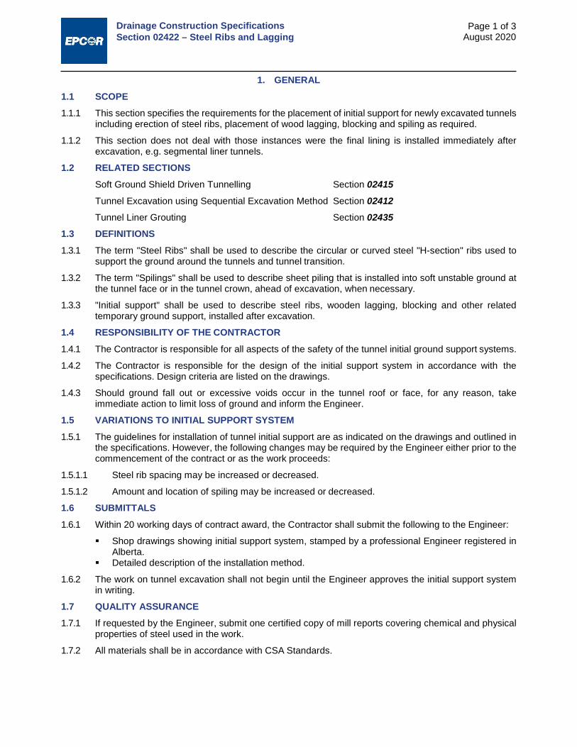
Drainage Construction Specifications Section 02422 – Steel Ribs and Lagging
Page 1 of 3 August 2020
1. GENERAL 1.1 SCOPE 1.1.1 This section specifies the requirements for the placement of initial support for newly excavated tunnels
including erection of steel ribs, placement of wood lagging, blocking and spiling as required.
1.1.2 This section does not deal with those instances were the final lining is installed immediately after excavation, e.g. segmental liner tunnels.
1.2 RELATED SECTIONS Soft Ground Shield Driven Tunnelling Section 02415
Tunnel Excavation using Sequential Excavation Method Section 02412
Tunnel Liner Grouting Section 02435
1.3 DEFINITIONS 1.3.1 The term "Steel Ribs" shall be used to describe the circular or curved steel "H-section" ribs used to
support the ground around the tunnels and tunnel transition.
1.3.2 The term "Spilings" shall be used to describe sheet piling that is installed into soft unstable ground at the tunnel face or in the tunnel crown, ahead of excavation, when necessary.
1.3.3 "Initial support" shall be used to describe steel ribs, wooden lagging, blocking and other related temporary ground support, installed after excavation.
1.4 RESPONSIBILITY OF THE CONTRACTOR 1.4.1 The Contractor is responsible for all aspects of the safety of the tunnel initial ground support systems.
1.4.2 The Contractor is responsible for the design of the initial support system in accordance with the specifications. Design criteria are listed on the drawings.
1.4.3 Should ground fall out or excessive voids occur in the tunnel roof or face, for any reason, take immediate action to limit loss of ground and inform the Engineer.
1.5 VARIATIONS TO INITIAL SUPPORT SYSTEM 1.5.1 The guidelines for installation of tunnel initial support are as indicated on the drawings and outlined in
the specifications. However, the following changes may be required by the Engineer either prior to the commencement of the contract or as the work proceeds:
1.5.1.1 Steel rib spacing may be increased or decreased.
1.5.1.2 Amount and location of spiling may be increased or decreased.
1.6 SUBMITTALS 1.6.1 Within 20 working days of contract award, the Contractor shall submit the following to the Engineer:
Shop drawings showing initial support system, stamped by a professional Engineer registered in Alberta.
Detailed description of the installation method.
1.6.2 The work on tunnel excavation shall not begin until the Engineer approves the initial support system in writing.
1.7 QUALITY ASSURANCE 1.7.1 If requested by the Engineer, submit one certified copy of mill reports covering chemical and physical
properties of steel used in the work.
1.7.2 All materials shall be in accordance with CSA Standards.
Drainage Construction Specifications Section 02422 – Steel Ribs and Lagging
Page 2 of 3 August 2020
2. PRODUCTS 2.1 STEEL RIBS, DUTCHMEN, AND BLOCKING
All material used for steel ribs shall conform to CSA-G40.21 Grade 300W. Fabrication of the ribs shall conform to CAN/CSA-S16.1. The ribs shall be supplied complete with bolts, nuts, plates, spikes, drift pins, dowels, wedges, tie rods, steel Dutchmen, shims and other accessories required for assembling and erecting the supports.
2.2 SPILINGS 2.2.1 Select appropriate spiling for ground to be encountered. If material used for spiling is steel, it shall
conform to CSA-G40.21 Grade 300W. Fabrication of spilings shall conform to CAN/CSA-S16.1.
2.2.2 Design and supply a suitable mechanical device for installing the spilings into the ground at the tunnel face without causing excessive shock or vibration to the surrounding ground.
2.3 DRAINS In wet areas of ground, drains shall be devised to duct water away from the working face and may consist of slotted plastic pipes or tubes, dimpled plastic sheets, geotextile cloth, geotextile wicks or other material as approved by the Engineer.
2.4 TIMBER LAGGING AND BLOCKING Rough cut construction material, as per design requirements.
3. EXECUTION 3.1 INSTALLATION SEQUENCING 3.1.1 The installation of the tunnel initial support shall be carried out as an integral part of the tunnel
excavation.
3.1.2 The routine sequence of excavation and initial support for sequential excavation method is shown on the drawings and shall be adhered to unless the Engineer approves modifications in writing. For shield driven tunnel excavation, initial support shall be installed within the tail shield and expanded when the TBM shield advances forward past the rib section.
3.1.3 Initial support will routinely consist of rib and lagging installed as follows:
Install rib section immediately after the excavation has advanced the required distance. Install timber lagging and blocking. Expand rib section, if required, to required dimension as soon as possible.
3.2 STEEL RIBS 3.2.1 Install in the manner indicated on the shop drawings approved by the Engineer.
3.2.2 Ribs installed in the bench shall be expanded until tight against the excavated wall. Dutchmen and shims shall be installed to maintain the expanded rib shape.
3.3 SPILINGS 3.3.1 Install spilings as necessary to support unstable ground in the excavation.
3.3.2 The actual number of spilings over any rib, at any location in the crown heading, will vary dependent on the ground condition encountered.
3.3.3 Spilings shall be smoothly installed into the heading face over the rib at the crown.
3.3.4 In the event of being unable to install any spiling fully into it's planned location, for any reason, no attempt shall be made to withdraw the spiling.
3.3.5 Spilings not fully installed shall have the part behind the steel rib at the heading-face cut off and removed so that it does not interfere with placement of the final concrete lining.
3.3.6 Installation forces on spilings shall be controlled so that no buckling or sagging occurs in the spilings.

Drainage Construction Specifications Section 02422 – Steel Ribs and Lagging
Page 3 of 3 August 2020
3.4 LAGGING AND BLOCKING 3.4.1 Lagging and blocking, if and when used as part of the tunnel initial support system, will be suitably cut
and sized to fit into ground fallout area, excavation overbreak and the like, as part of the support system.
3.4.2 When tunnel face excavation is halted for more than 36 hours or where ground conditions are unfavorable, the tunnel face shall be boarded and blocked to prevent excessive soil loss from the tunnel face. Excavation shall proceed in a sequential, controlled method through partial face blocking so that loss of ground and settlement is minimized.
3.5 EXCAVATION AND GROUND SUPPORT RECORDS Provide daily, on a form approved by the Engineer, the following information:
3.5.1 For Sequential Excavation Method
Station of the partial rib at the heading face and station of the full-circle-rib at the bench face and rib spacing.
Ground type being excavated. Details of spilings, lagging and face blocking installed.
3.5.2 For Tunnel Boring Machine Excavation
Station of the last rib installed. Ground type being excavated. Rib Spacing.
END OF SECTION

Drainage Construction Specifications Section 02423 – Shotcrete Tunnel Lining
Page 1 of 3 August 2020
1. GENERAL 1.1 SCOPE
This section specifies the requirement for the supply and application of early set primary and secondary shotcrete for initial tunnel support and normal set shotcrete for final liner.
1.2 RELATED SECTIONS Tunnel Excavation using Sequential Excavation Method Section 02412
Soft Ground Shield Driven Tunnelling Section 02415
1.3 QUALITY CONTROL 1.3.1 Comply with American Concrete Institute recommended practice for shotcreting.
1.3.2 Cement to be High sulphate‐resistant hydraulic to CSA-A3000.
1.3.3 Concrete and concrete testing to comply with CSA-A23.1 and CSA-A23.2 respectively.
1.3.4 Conform to ASTM C1140.
1.3.5 The Contractor in accordance with CSA-A23.1 will carry out inspection and testing of concrete and concrete materials for the purposes of quality control. The City may also perform testing at its discretion for the purposes of quality assurance.
1.3.6 The minimum tests required for quality control shall be:
Air content and slump shall be tested every batch until specifications are met and then once every third batch thereafter.
Concrete strength shall be tested by taking three cylinders for every 50 m3 placed, with a minimum of one set per project. They shall be field cured. One cylinder to be broken at 7 days and the remaining two at 28 days.
1.3.7 For the purpose of quality control, the Engineer will, from time to time, require the Contractor to shoot test panels of fibre reinforced shotcrete for flexural and toughness testing.
1.3.8 Inform the Engineer, at least three days in advance of start up of all shotcrete operations.
1.3.9 The Engineer will take additional test samples during cold weather concreting. Cure samples on job site under same conditions as the concrete that they represent.
1.3.10 Non-destructive methods for testing concrete shall be in accordance with CSA-A23.2.
1.3.11 If the tests performed by the Contractor or the Engineer indicate that shotcrete fails to meet the specified requirements, then adopt such remedial measures as the Engineer may require, at no expense to the City.
1.3.12 Toughness strength requirements will be considered satisfactory or unsatisfactory on the same basis as compressive strength requirements in CSA-A23.1.
1.4 DEFINITIONS 1.4.1 Primary Shotcrete: early set unreinforced shotcrete applied to excavated ground in tunnels.
1.4.2 Secondary Shotcrete: early set reinforced shotcrete applied to shotcrete. Reinforcement shall be either steel fibre, polypropylene fibre or steel wire mesh, as shown on the drawings.
1.5 SUBMITTALS 1.5.1 A minimum of 20 working days before commencing work, the Contractor shall supply the following:
1.5.2 Information on all equipment to be used.
1.5.2.1 Proposed mix-designs and test results for shotcrete, including brand-names of admixtures.
1.5.2.2 Names and resumes of foremen and nozzle operators.
Drainage Construction Specifications Section 02423 – Shotcrete Tunnel Lining
Page 2 of 3 August 2020
1.6 TRIAL MIX TESTING PROGRAM 1.6.1 Retain a qualified laboratory to independently take samples and test shotcrete during the development
of the mix design.
1.6.2 Ten working days before start of shotcreting perform full-scale shotcrete test using intended equipment. In the Engineer's presence, shoot on plywood panels to minimum 100 mm thickness, both horizontally and vertically upwards. Use trial specimens of all proposed shotcrete mixes to be used in the Work.
1.6.3 Take samples of and test the above trial specimens of shotcrete.
1.6.4 The City may do simultaneous testing during the development of this mix design.
2. PRODUCTS 2.1 CEMENT
Cement in shotcrete shall be Type HS High sulphate-resistant hydraulic cement, conforming to the requirements of CSA-A3000.
3. EXECUTION 3.1 PREPARATION 3.1.1 For processing of aggregates, refer to CSA-A23.1, Clause 5.
3.1.2 Primary shotcrete, placed directly on freshly excavated ground, requires no surface preparation other than removal of loose material, rebound etc. and the control of water.
3.1.3 Any water that is running or seeping into the surface to be covered with primary shotcrete will be suitable drained and ducted into the tunnel or grouted before shotcrete is placed.
3.1.4 Other surfaces that require shotcrete such as shotcrete to steel ribs and steel spilings, lagging or mesh, shall have all loose material, rebound and deleterious material removed and the surface dampened before shotcrete is placed.
3.2 PROFICIENCY OF WORKERS Nozzlemen shall have previous experience on at least one comparable project in the past five years or shall work under the immediate supervision of a foreman with such experience. Each crew shall demonstrate to the Engineer acceptable proficiency in the application of shotcrete to vertical and overhead test panels before beginning production work.
3.3 PLACING 3.3.1 Primary shotcrete for initial tunnel support shall always be placed immediately after each tunnel
sequence has been excavated.
3.3.2 The Contractor may choose to use either a wet or a dry mix shotcrete process. If the dry mix process is used, demonstrate to the satisfaction of the Engineer, that excessive dust problems can be minimised and that Alberta Occupational Health and Safety Act, Regulations, and Codeare complied with.
3.3.3 Pre-dampened mix shall be used 60 minutes after initial contact with water.
3.3.4 Thoroughly mix shotcrete used in wet mix equipment for a period of at least 1-½ minutes prior to use. Any shotcrete that is not used within 60 minutes after initial mixing shall be wasted and the mixer washed out with clean water. The slump for wet mix shotcrete shall be limited 60 mm to 100 mm.
3.3.5 Apply shotcrete to provide a dense, smooth, firmly adhering coating at no point less than the thickness required by the design drawings. Each layer shall be applied before the shotcrete in the preceding layer has set completely. Rebound shall be kept clear of the shotcrete being placed. The re-use of rebound materials will not be permitted.

Drainage Construction Specifications Section 02423 – Shotcrete Tunnel Lining
Page 3 of 3 August 2020
3.4 COLD WEATHER REQUIREMENTS 3.4.1 No shotcrete shall be placed when the temperature inside the tunnel or shaft chamber is below 10ºC.
3.4.2 During cold weather, all materials stored outside shall be pre-heated throughout their bulk to 10ºC or above, before delivery to the shotcrete equipment.
3.4.3 Any chemical additives that may be effected by cold shall be stored in an above freezing environment throughout its life until used in the shotcrete.
3.5 CURING 3.5.1 All permanent finished shotcrete surfaces shall be cured using a water spray, curing compound or any
other suitable method approved by the Engineer. Curing shall extend for a period of at least seven days following the data on which curing commences. No curing compound shall remain on surfaces that will be subsequently covered with concrete or with additional layers of shotcrete.
3.5.2 Shotcrete, used to support the ground during tunnel driving operations, shall be kept damp for two days after applications.
3.5.3 Normal set shotcrete shall trowelled to obtain smooth surface.
3.6 CLEAN UP 3.6.1 Rebound and waste shall be disposed of off-site.
3.6.2 Water contaminated with toxic chemicals or any toxic or potentially toxic chemicals shall not be allowed to enter EPCOR Drainage Services’ sewers or be removed with the tunnel spoil. Make suitable arrangements for separate disposal of this material as and when it becomes necessary.
3.7 REPAIR Damage to the primary shotcrete liner shall immediately be repaired to the satisfaction of the Engineer.
3.8 SAFETY MEASURES 3.8.1 Alkali hydroxides and other chemicals contained in shotcrete admixtures and moderately toxic and can
cause skin and respiratory irritation unless adequate safety measures are undertaken. In applying shotcrete containing toxic admixtures the nozzlemen and helpers shall wear appropriate protective clothing and equipment such as eye, respiratory and hand protection as per the Safety Data Sheet (SDS). Ability to flush skin or eyes shall be readily available in the immediate vicinity of shotcrete application in case of contact.
3.8.2 The Contractor is totally responsible for implementation of a project safety program for the project. Nothing in this specification relieves the Contractor of that responsibility.
END OF SECTION

Drainage Construction Specifications Section 02426 – Pipe Jacking
Page 1 of 4 August 2020
1. GENERAL 1.1 SCOPE
This section specifies the requirements for the supply and installation of sewer pipes by pipe jacking methods.
1.2 RELATED SECTIONS
Trench Backfill Section 3.1 Volume 2: Complete Streets Tunnel Excavation using Sequential Excavation Method Section 02412
Microtunnelling Section 02441
Sewers Section 02535
Inspection of Sewers Section 02954
Leakage Testing of Sewers Section 02958
1.3 DEFINITIONS 1.3.1 Tunnel Boring Machine (TBM) is a mechanical excavating machine used to create an underground
void through which a pipe or conduit is installed.
1.3.2 Pipe Jacking is the installation of sewer pipe by pushing a series of pipe lengths through an excavated tunnel from a jacking pit to a receiving pit. It may be used to propel a TBM
2. PRODUCTS 2.1 PIPE 2.1.1 Pipe Design Approval
2.1.1.1 Submit for approval the type and design of pipe proposed for use in the pipe jacking operation.
2.1.1.2 Submit detailed information to show that the proposal will meet the requirements of the installation process, as well as the expected service loads and conditions.
2.1.1.3 The submission should include calculations showing the axial loading capacity of the pipe, the expected jacking loads during the installation and the safety factor to be applied.
2.1.1.4 Show how the design of the pipe and the joint take into account and allow for the eccentric loadings that arise from uneven distribution of the jacking loads and deviations of the line during installation. Calculations will be required to show that the proposed pipe is capable of meeting all the source loading.
2.1.1.5 Provide confirmation that the proposed pipe is manufactured to close dimensional tolerances on length, diameter, at the joints and for perpendicular surfaces.
2.1.1.6 Provide confirmation that the joint is designed for the following conditions:
To be formed within the pipe wall thickness. No internal or external projections shall be allowed. To transfer the longitudinal jacking loads, including eccentric loads from line deviations without
over stressing or spalling of the joint faces. To meet the service watertightness requirements (internal and external).
2.1.1.7 For jointed pipe, the Contractor will provide a 360° packing ring at every joint to provide even distribution of the axial load across the joint. This ring shall be made from homogeneous material that will compress in a mechanically stable manner over the expected level of deformation. The packing ring shall be manufactured and fixed to the pipe so that no part projects beyond the pipe wall thickness, and shall not interfere with the performance of the joint.
2.1.1.8 The Contractor shall submit guarantees or warranty conditions and a statement of any restrictions of installation requirements imposed by the manufacturer.

Drainage Construction Specifications Section 02426 – Pipe Jacking
Page 2 of 4 August 2020
2.2 PRECAST CONCRETE PIPE 2.2.1 Precast concrete jacking pipe shall conform to CSA/CAN-A257.2, rubber gasket, straight-wall. Pipe
shall be true to design dimensions and shall have bell and spigot mating surfaces perpendicular to the pipe axis within a variation of 6 mm.
2.2.2 Bell and spigot design shall be such that no axial thrust loads are borne by the spigot. Pipe shall be supplied with metal bands if required for axial loading. Deflections at joints shall not exceed manufacturer's recommendations.
2.2.3 Concrete shall be made with Type HS High sulphate‐resistant hydraulic cement and shall have a minimum compressive strength of 41 MPa.
2.2.4 Reinforcement shall consist of inner and outer cages. Elliptical reinforcement shall not be used. Reinforcement shall be supplemented by an additional cage at the inside of the bell of the pipe joint.
2.2.5 Cushion material consisting of rubber, plywood or other suitable material shall be supplied and used to carry axial thrust across all joints. The dimensional details, cushion material, and method of attachment shall be submitted for the City's approval.
2.2.6 All joints shall be rubber gasketed to conform to CAN/CSA-A-257.3 or ASTM C443M and shall be capable of providing a watertight seal.
2.3 FIBREGLASS REINFORCED RESIN PIPE 2.3.1 Fibreglass reinforced resin pipe shall be centrifugally cast polyester resin, sand filled and fibreglass
reinforced, conforming to ASTM D3262.
2.3.2 "Hobas" pipe conforming to this standard with straight-wall joints or type WKH couplings will be accepted.
2.3.3 Pipe shall be designed to withstand earth pressure, live loads, and axial thrust loads with a minimum safety factor of 1.5.
2.4 STEEL PIPE 2.4.1 Steel pipe: to AWWA C200, minimum wall thickness schedule 40 or standard wall, unless otherwise
shown on the drawings. Steel sheet to ASTM A570/A570M Grade 36. Pipe shall have not more than one longitudinal seam and not more than two girth seams for single random length. Supply pipe in single and double random lengths.
2.4.2 Exterior finish: to AWWA C210, two-part epoxy.
2.4.3 Interior finish: to AWWA C210, two-part epoxy.
2.4.4 Pipe joints: to be butt welded joints with bevelled ends. Interior and exterior finishes on the pipe to be touched up with epoxy paint after welding.
2.5 GROUT Cement grout where required for backfill (non-structural) purposes, shall meet the following minimum specifications:
Type HS High Sulphate-Resistant Hydraulic Cement 1 part
Sharp, Clean Sand (Submit gradation for approval) 2 parts
Water For a 28-day strength of 1.4 MPa

Drainage Construction Specifications Section 02426 – Pipe Jacking
Page 3 of 4 August 2020
3. EXECUTION 3.1 EQUIPMENT 3.1.1 Pipe jacking methods shall be integrated with the tunnel excavation to maintain a continuously and
completely supported excavation throughout.
3.1.2 All power machinery and tools within the tunnel headings and shaft shall be operated by electricity, compressed air, or other approved power. The use of gasoline power or of internal combustion engines in the tunnels or shafts is prohibited.
3.1.3 Pipe jacking equipment shall distribute jacking forces uniformly around the periphery of the pipe and a thrust ring shall be used to transmit pressures to the end of the pipe uniformly. As a minimum, the main jacks shall have a capacity of 1.2 times the maximum allowable jacking force of the pipe. Intermediate jacking stations shall be installed when the Contractor deems necessary to ensure that allowable jacking forces are not exceeded.
3.1.4 If a pipe lubrication system is used, the Contractor shall obtain approval of the proposed lubricant, which shall be non-toxic and environmentally safe. The Contractor shall arrange for and pay for the necessary water for lubrication.
3.1.5 Continuously monitor line and grade utilizing a laser capable of monitoring the entire length of each tunnelling operation and having a beam deviation over this length of 6 mm or less.
3.2 TUNNELLING AND JACKING 3.2.1 The methods of tunnelling and jacking shall be as selected by the Contractor and appropriate to the
equipment used and soil conditions anticipated.
3.2.2 The tunnelling and jacking operation shall provide for continuous hole protection by tunnelling shield or pipe.
3.2.3 Tolerance for pipe alignment shall be as follows:
3.2.3.1 For pipes 900 mm and smaller, maximum deviation from line is 150 mm.
3.2.3.2 For pipes 1050 mm and larger, maximum deviation from line is 50 mm per 300 mm of pipe diameter.
3.2.3.3 The pipe invert elevation shall not deviate from the design elevation by more than 12 mm plus 6 mm per 300 mm of pipe diameter �≯ 12 mm + 6 mm
300 mm of diameter× mm diameter�, nor have any
measurable sags between manholes.
3.2.3.4 If this tolerance is exceeded, the Contractor is required to make corrections at the Contractor's own cost, subject to the approval of the Engineer.
3.2.4 Where the annular space between the pipe wall and tunnel excavation exceeds 25 mm, the annular space shall be completely filled by pressure grouting. Where the pipe supplier requires or recommends grouting of annular space, this shall be done regardless of dimensions. The placing of pipe shall be in accordance with the manufacturer's directions and recommendations.
3.3 TESTING AND INSPECTION 3.3.1 Laboratory Testing
3.3.1.1 Test pipe in accordance with CAN/CSA-A257.0. The manufacturer shall furnish 0.5% of order but not less than 2 specimens of each size and type for every 300 m of sewer for test purposes. Load testing and hydrostatic testing shall be performed and witnessed by the City's representative.
3.3.1.2 The Contractor shall bear the cost of testing.
3.3.1.3 The City shall be notified in advance at all testing.
Drainage Construction Specifications Section 02426 – Pipe Jacking
Page 4 of 4 August 2020
3.3.2 Leakage Testing
Leakage tests shall be conducted on all sanitary sewers to the requirements outlined in Section 02958 - Leakage Testing of Sewers.
3.3.3 Visual Inspection
3.3.3.1 Television and/or visual inspection of the completed sewer to be as directed in Section 02954 - Inspection of Sewers.
3.3.3.2 The inspection shall be performed after all mains, manholes and service connections have been installed.
3.3.4 Flush all mains and locate all manholes for inspection.
END OF SECTION
Drainage Construction Specifications Section 02427 – Precast Concrete Tunnel Lining
Page 1 of 2 August 2020
1. GENERAL 1.1 SCOPE
This section specifies the requirements for construction of a tunnel using precast concrete segmental liner.
1.2 RELATED SECTIONS Soft Ground Shield Driven Tunnelling Section 02415
Tunnel Liner Grouting Section 02435
Sewers Section 02535
Leakage Testing of Sewers Section 02958
1.3 PRE-QUALIFICATION OF MANUFACTURER 1.3.1 All precast elements within the scope of this specification and drawings shall be fabricated by a
manufacturing plant certified in the appropriate category according to CSA-A251.
1.3.2 The Canadian Welding Bureau under CSA-W47.1 shall approve all fabricators of steel components.
1.4 SUBMITTALS 1.4.1 Submit the following data to the City for review at least ten days in advance of fabrication and not later
than 30 working days from contract award:
Shop drawings showing fabrication details. Detailed description of installation method.
1.4.2 Do not proceed with manufacture of units prior to receiving the approval of the City in writing.
1.5 PRODUCT DELIVERY, STORAGE AND HANDLING 1.5.1 Support units at points that will not cause stresses to the concrete for which it was not designed.
1.5.2 Take care to prevent cracking or other damage.
1.5.3 Identify all miscellaneous items clearly.
1.6 RESPONSIBILITY OF THE CONTRACTOR 1.6.1 The Contractor is responsible for the manufacture of segmental liner sections.
1.6.2 The Contractor is responsible for all aspects of the safety of the tunnel ground support systems.
1.6.3 Install the tunnel segments as recommended by manufacturer.
1.6.4 Should ground fall out or excessive voids occur in the tunnel roof, for any reason, take immediate remedial action and inform the Engineer.
2. PRODUCTS 2.1 PRECAST CONCRETE SEGMENTS 2.1.1 Precast concrete segments shall conform to CSA-A23.4 and shall be as shown on the drawings.
2.1.2 Welded wire fabric shall conform to requirements of CSA-G30.5.
2.2 JOINT SEALANT Joint sealant compound shall be as recommended by the segmental liner manufacturer and approved by the Engineer.
2.3 GROUT Expanding grout for grouting the joints and lifting bar ports shall be non-shrink, non-metallic aggregate developing minimum compressive strength of 35 MPa at 28 days.
Drainage Construction Specifications Section 02427 – Precast Concrete Tunnel Lining
Page 2 of 2 August 2020
3. EXECUTION 3.1 PREPARATION
All material required to line a 100 m length of the tunnel shall be on site before commencement of tunnel excavation.
3.2 ALIGNMENT AND GRADE TOLERANCES 3.2.1 Centreline of the tunnel shall not be more than 150 mm off the given line.
3.2.2 The invert of the tunnel shall not deviate from the given grade by an amount greater than 40 mm plus 20 mm for each metre of diameter �≯ 40 mm + 20 mm
1.0 m of diameter× m diameter�. If this tolerance is
exceeded, make corrections at no cost to the City. The Engineer shall approve the method of correction.
3.3 INSTALLATION OF SEGMENTS 3.3.1 Install segments as recommended by the manufacturer.
3.3.2 Apply sealing compound to all joints.
3.3.3 Use concrete and steel blocking to support segments in place after expansion.
3.3.4 Alternate location of expansion joint.
3.3.5 Grout all lifting bar recesses. Grout all circumferential joints and those transverse joints, which, in the opinion of the Engineer, are open or misaligned enough to adversely, affect hydraulics or cause potential future infiltration problems.
3.4 TUNNEL LINER GROUTING At locations where the liner could not be fully expanded to its design diameter or where ground loss occurred during excavation and prior to lining, voids behind the precast lining will be pressure grouted in accordance with Section 02435 - Tunnel Liner Grouting.
3.5 CLEAN UP When tunnel is completed, remove all equipment from the tunnel area, clean and remove all debris and mud from within the tunnel.
3.6 INSPECTION AND TESTING 3.6.1 Maintain a high level of quality control in the manufacture of the precast segments. Submit to the City
a complete set of test results necessary to assure adherence to specifications. A minimum of one test per day of production shall be taken on the concrete.
3.6.2 The City shall periodically perform additional tests as required and the manufacturer shall provide reasonable access to the City’s quality assurance laboratory for inspection of the manufacturing and testing processes.
3.6.3 General quality control and quality assurance requirements are specified in Chapter 8 – Quality Assurance and Chapter 9 – Quality Control, both in Volume 1: General.
3.6.4 Conduct infiltration testing in accordance with the requirements of Section 02958 - Leakage Testing of Sewers.
3.7 EXCAVATION AND GROUND RECORDS The following information shall be provided daily on a form approved by the Engineer:
Station of the last set of fully expanded segmental liner sections. Type of ground encountered during the day. Location and volume of any ground loss.
END OF SECTION
Drainage Construction Specifications Section 02435 – Tunnel Liner Grouting
Page 1 of 3 August 2020
1. GENERAL 1.1 SCOPE
This section specifies the requirements for the supply, mixing and injection of sand-cement or cement grout mixes, to be used for filling behind tunnel liners.
1.2 RELATED SECTIONS Tunnel Excavation using Sequential Excavation Method Section 02412
Soft Ground Shield Driven Tunnelling Section 02415
Steel Ribs and Lagging Section 02422
Precast Concrete Tunnel Lining Section 02427
1.3 QUALITY ASSURANCE 1.3.1 Grouting to conform to CSA-A23.1 and ASTM C404.
1.3.2 Cement to conform to CSA-A3000.
1.4 DEFINITIONS 1.4.1 Void grouting means the injection of cement grout or mortar grout comprised of cement, fine sand and
water to fill voids in the top of the tunnel liner due to incomplete pouring of concrete in concrete lined sections.
1.4.2 Backfill grouting shall mean drilling and grouting of holes to fill voids between the soil formation and the initial support system.
1.4.3 Washing is the process of cleaning drill cuttings and sludge from a drill hole by injecting water or water and air into the hole and returning the fluid and suspended matter toward the surface.
1.4.4 Grouting pressure shall mean the pressure of grout as measured at the header while grout is being pumped into the hole.
1.4.5 Effective pressure shall mean the pressure of grout, while being pumped at the point of absorption in the hole, as calculated from the measured grouting pressure at the header and allowing for the pressure head of grout in the hole.
1.4.6 Grout take is the quantity of materials injected in a hole expressed in units of bags of cement and m3 of sand.
1.4.7 Grout holes refer to holes drilled through concrete, shotcrete, spiling or any other initial support component for the purpose of injecting grout.
1.5 TESTING 1.5.1 Test trial batches of all grout mixes.
1.5.2 Routinely test production grout as the Engineer directs at no additional cost to the City.
1.5.3 Record all grouting operations on approved forms.
1.6 MEASUREMENT AND PAYMENT 1.6.1 Backfill grouting is incidental to tunnel initial support and ground control and no extra payment shall
be made.
1.6.2 Void grouting is incidental to the installation of tunnel liner and no extra measurement nor payment shall be made.
1.6.3 No payment for tunnel liner grouting shall be made unless it is specifically required and specified as a control for infiltration and is itemised as such in the bill of quantities.
2. PRODUCTS

Drainage Construction Specifications Section 02435 – Tunnel Liner Grouting
Page 2 of 3 August 2020
2.1 GROUT MATERIALS 2.1.1 Water: fresh, clean and free from deleterious amount of silt organic matter, alkali, acids, salts and other
impurities in conformity with CSA-A23.1. Temperature of water used in grout shall be less than 27ºC and greater than 5ºC.
2.1.2 Cement: Type HS High sulphate‐resistant hydraulic cement to CSA-A3000.
2.1.2.1 Cement that is found to contain lumps or foreign matter that the Engineer considers detrimental to the results of grouting will be rejected and shall immediately be removed from the site by the Contractor.
2.1.2.2 Cement shall be above 0ºC when added to the grout mixture.
2.1.3 Sand: clean, durable stone particles, free from lumps of clay and objectionable foreign matter, having a moisture content of less the 3% of dry weight and conforming to ASTM C404 with the following modified requirements:
Sieve Size (µm) % Passing by Mass 2.36 100 1.18 95 - 100 600 60 - 85 300 30 - 50 150 10 - 30 5 0 - 5
2.1.4 Admixtures: Retarding and expanding admixtures for cement and sand/cement grouts shall be subject to the Engineer's approval.
2.2 GROUT MIXES 2.2.1 Submit a grout mix design to the Engineer for review. Grout shall normally consist of a mixture of Type
HS High sulphate‐resistant hydraulic cement, water, approved additives and sand as required. Fly ash may be utilized with the prior approval of the Engineer.
2.2.2 The mixture shall be designed to suit particular conditions encountered. Proportions of materials used in the grout mixture and any adjustments thereto during grouting operations shall be only as approved by the Engineer. All grout shall contain an expansion agent of a type and amount approved by the Engineer to eliminate shrinkage.
2.2.3 The Engineer may require the addition of material other than those specified above.
2.2.4 Use chemical additives in grout mixes only with prior written approval of the Engineer.
2.2.5 Handle, store and protect all cement and additives in such manner that they will not deteriorate or become contaminated. Deteriorated or contaminated materials shall not be used in the work.
2.2.6 Grout mixes shall be both with and without sand, non-bleeding and attain the following compressive strengths:
Grout Application Minimum Compressive Strength at days (MPa) Tunnel Liner Design Condition
Fill the annular space between host pipe and sliplining pipe or native ground and tunnel liner
2 the new liner is designed to take the full load as a stand alone liner
35 the existing tunnel shares the load with the new liner
Fill voids 35 or equal to the design of the concrete liner
2.2.7 Minimum cement content of the grout mix to be 160 kg/m3.

Drainage Construction Specifications Section 02435 – Tunnel Liner Grouting
Page 3 of 3 August 2020
3. EXECUTION 3.1 DRILLING 3.1.1 For backfill grouting, drill nominal 25 mm diameter holes through the tunnel initial support system.
Where spilings and lagging are encountered, tape and thread as required to install grout nipples. 3.1.2 For void grouting core nominal 50 mm diameter grout holes through the concrete liner.
3.2 LAYOUT AND PREPARATION 3.2.1 Grout holes through initial support for backfill grouting to be located at lowest points of known voids
and voids suspected by the Engineer to exist. Vent-pipes or tubes to be located to vent highest points of voids, where applicable.
3.2.2 Grout holes through permanent concrete liner for void grouting to be located at the crown. Hole spacing along the line of the tunnel to be located between steel ribs and at not more than 3 m centres or at locations of known voids or both.
3.2.3 Packers or threaded connectors with valves attached to be all in the pace before grouting is to commence.
3.3 BATCHING, MIXING AND AGITATING 3.3.1 Measure or weigh all grout materials into the mixer in complete "Batch-Units" compatible with mix used
and mixer size. 3.3.2 Mix complete batches of grout for minimum 3 minutes or until thoroughly mixed and then transfer whole
batch to agitator and clean out mixer, if necessary. 3.3.3 Keep grout batches agitated in the agitator tank until they are completely used. Any grout batches kept
in the agitator for over one hour are to be dumped and the agitator cleaned out.
3.4 PUMPING AND GROUT PRESSURE CONTROL 3.4.1 Pumping to be at a controllable rate without significant fluctuations of pressure. 3.4.2 Nozzle operator to continuously monitor and adjust pressure at header-unit during pumping.
3.5 BACKFILL GROUTING 3.5.1 Fill voids with grout until a pressure of 0.05 MPa applied to the liner is reached unless directed
otherwise by the Engineer. 3.5.2 Grouting to continue until totally undiluted grout comes out of the vent-pipes or tubes or adjacent grout-
holes or until refusal.
3.6 VOID GROUTING 3.6.1 Grouting to commence at lowest point of tunnel being grouted and to proceed to highest point. 3.6.2 Grouting of small voids or voids of unknown extent to commence using mix without sand. Should grout
takes exceed 0.5 m3 in 5 minutes, change to a grout mix with sand. 3.6.3 Grouting of each connection shall continue until refusal, at a pressure of 0.05 MPa. 3.6.4 The Engineer may require additional grouting behind concrete tunnel liner, if there is reason to believe
the grouting was incomplete.
3.7 GROUTING RECORDS 3.7.1 Accurately measure and record all aspects of the grouting operations as they are performed and
submit results to the Engineer. 3.7.2 Records shall be kept on approved forms and submitted to the Engineer in a timely manner.
3.8 CLEAN UP 3.8.1 Fill void grouting holes flush with the interior surface of the tunnel. 3.8.2 Clean all interior surfaces of the tunnel of excess grout.
END OF SECTION

Drainage Construction Specifications Section 02441 – Microtunnelling
Page 1 of 3 August 2020
1. GENERAL 1.1 SCOPE
This section specifies the requirements for the excavation of earth utilizing a TBM that is too small for man entry, for the purpose of installing sewer pipe.
1.2 RELATED SECTIONS Trench Backfill Section 3.1 Volume 2: Complete Streets
Pipe Jacking Section 02426
Shaft Construction Section 02444
Sewers Section 02535
1.3 DEFINITION Microtunnelling: A method of ground excavation using a tunnelling machine which is too small for person entry and which generally has a propelled, mobile, cutting mechanism. The machine is distinguished from augers or boring machines, which excavate by stationary engines and use flights and extensions to excavate and remove spoil.
1.4 REGULATIONS 1.4.1 The Alberta Occupational Health and Safety Act, Regulation, and Code.
1.4.2 EPCOR Tunnel Safety Regulations.
1.5 SUBMITTALS Provide the following within 15 working days of the award of the Contract:
Method and equipment used for spoil disposal from tunnel area. Drawings and descriptions of excavation and ground support operations. Details for monitoring of ground settlements. Shoring design for access shaft or pit excavations. Construction procedures.
2. PRODUCTS Not applicable
3. EXECUTION 3.1 EQUIPMENT 3.1.1 The Contractor shall be responsible for selecting the micro-tunnelling method and equipment.
Tunnelling machines shall be remotely controlled and have monitoring systems, built-in or external, that can adequately maintain the tunnel excavation to the required tolerances.
3.1.2 The Contractor shall confirm that the system proposed will deal with all ground and groundwater conditions that were indicated by boreholes, geotechnical reports or elsewhere and that could be reasonably foreseen.
3.1.3 The equipment shall conform to the following criteria:
3.1.3.1 Face support shall be provided, either by full earth pressure balance, slurry or other system that will control ground settlement and is approved by the Engineer.
3.1.3.2 The overall diameter of the shield shall not be greater than that of the pipe by more than 25 mm.
3.1.3.3 The system shall have a continuous monitoring system for detecting and recording deviations from the required line and level of 5 mm. The monitoring system located at a surface control station should be equipped to record jacking loads and face pressures. The monitoring system should be checked periodically to ensure that it is performing properly.
Drainage Construction Specifications Section 02441 – Microtunnelling
Page 2 of 3 August 2020
3.1.3.4 The system shall be equipped with remote steering control with line, level and gradient prediction capability.
3.2 SHAFT OR PIT CONSTRUCTION 3.2.1 Pits shall be excavated to minimum dimensions required for TBM insertion and jacking unit.
3.2.2 Temporary shoring and bracing shall be designed by a professional engineer competent in this field. Submit stamped shoring and bracing design to the Engineer prior to excavation of pits.
3.2.3 Wherever practical, pits shall be at locations on the line where manholes are required. The Engineer shall approve pits in other locations.
3.2.4 Pits shall be fenced to provide safety to the public.
3.2.5 Dewater pits as required to maintain a suitable floor for operations.
3.2.6 The pits shall be designed to provide a thrust wall reaction in excess of the anticipated maximum jacking load.
3.2.7 The thrust wall of the pit shall be designed to be capable of resisting the jacking load without movement in excess of 50 mm.
3.2.8 The Contractor may submit proposals for provision of jacking and reception shafts, constructed from concrete precast sections, which can be converted into permanent manholes.
3.3 PIPE INSTALLATION BY MICROTUNNELLING 3.3.1 The Contractor shall be responsible for:
3.3.1.1 Selecting and operating all the equipment required to undertake the work in a timely and efficient manner.
3.3.1.2 Providing an experienced and expert operator for controlling and operating the equipment. The operator shall be present at all times when the microtunnelling equipment is in use.
3.3.2 The tolerance for grade and alignment shall be:
For pipes 900 mm and smaller, maximum deviation from line is 150 mm For pipes 1050 mm and larger, maximum deviation from line is 50 mm per 300 mm in pipe diameter. The pipe invert elevation shall not deviate from the design elevation by more than 6 mm plus 6
mm per 300 mm in pipe diameter �≯ 6 mm + 6 mm300 mm of diameter
× mm diameter�, nor have any measurable sag between manholes.
3.3.3 If this tolerance is exceeded, the Contractor is required to make corrections at the Contractor's own cost, subject to the approval of the Engineer.
3.3.4 Records of deviations from the specified line and level will be continuously recorded together with records of jacking loads and pressure balance loads.
3.3.5 The work shall be organized at the surface so that the storage of pipes, disposal of soil and location of plant shall be kept as compact as possible so as to minimize disruption to traffic and the public.
3.3.6 The level of noise arising from the operation and equipment employed shall adhere to the City's Community Standards Bylaw 14600. For workers exposed to noise, the Contractor shall adhere to Alberta Occupation Health and Safety Act, Regulation, and Code.
3.3.7 Where a slurry system is proposed, adequate arrangements should be employed to reduce the volume of material arising and recover the slurry where possible. Disposal of residual spoil should be to an approved site at the Contractor's expense.
3.3.8 Provide and pay for all power and water supplies needed to undertake the Work.
3.3.9 Notwithstanding the provisions of the specification, the Engineer may require the Contractor to take action to assure the safety of the excavations. Promptly comply with such requirements. Nothing in these specifications shall be construed to relieve the Contractor from sole responsibility for safety.
Drainage Construction Specifications Section 02441 – Microtunnelling
Page 3 of 3 August 2020
3.4 REMOVAL OF BOULDERS 3.4.1 In the event that boulders are encountered and such boulders cannot be crushed or removed by the
TBM or removed through the pipe, the Contractor shall excavate down from the surface and remove such boulders.
3.4.2 Alternate methods, such as blasting, may be submitted for approval, but no work shall be undertaken without prior written authority.
3.4.3 Excavations to remove boulders shall be protected and backfilled as specified in Clauses 3.2 and 3.5.
3.5 BACKFILL OF PITS 3.5.1 Remove and dispose of all saturated soil in the pit before backfilling.
3.5.2 Pipe bedding material shall be approved granular material, class as shown on drawings and specified in Section 02535 - Sewers.
3.5.3 The pit shall then be backfilled in lifts not exceeding 300 mm. Backfilling shall be in accordance with Section 3.1 - Trench Backfill, Volume 2: Complete Streets.
3.5.4 Sheeting, shoring and bracing shall be removed as backfilling proceeds in a manner that provides continuous soil support and safety for workers in and about the pit.
3.5.5 The surface shall be restored to conditions that existed prior to disturbance or as indicated by drawings.
END OF SECTION

Drainage Construction Specifications Section 02444 – Shaft Construction
Page 1 of 2 August 2020
1. GENERAL 1.1 SCOPE
This section specifies the requirements for the supply and installation of vertical access shafts and associated structures for sewers.
1.2 RELATED SECTIONS Manholes and Catch Basins Section 02631
Concrete Forms and Accessories Section 7.10 Volume 2: Complete Streets
Reinforcing Steel Section 7.12 Volume 2: Complete Streets
Concrete for Water and Drainage Structures Section 03310
1.3 MATERIAL TESTING Tests for concrete are specified in Section 03310 - Concrete for Water and Drainage Structures.
1.4 STANDARDS Materials supplied for work covered by this section shall be in accordance with ASTM, CGSB and Canadian Standards.
1.5 SHOP DRAWINGS 1.5.1 Submit shop drawings for all cast in place reinforced concrete structures at least 15 calendar days
prior to installation.
1.5.2 Provide details of excavation procedure, and submit shop drawings for initial support system to the Engineer for review 10 calendar days prior to excavation.
2. PRODUCTS 2.1 CONCRETE 2.1.1 Concrete shall be made with Type HS High sulphate‐resistant hydraulic cement.
2.1.2 Refer to Section 03310 - Concrete for Water and Drainage Structures, for mix design requirements and standards for concrete production.
2.2 MORTAR 2.2.1 Mortar shall conform to the following mix:
1 part Type HS High sulphate‐resistant hydraulic cement 1½ parts clean sharp sand Water to provide workability
2.2.2 Grout to be non-shrink type Master Builders Embeco or approved equal.
2.3 SHAFT BASES Poured-in-place concrete as detailed on the drawings.
2.4 SHAFT MANHOLE BARRELS AND TOPS 2.4.1 Barrels - circular precast sections and joints as specified in Section 02631 - Manholes and Catch
Basins.
2.4.2 Cast-in-Place Walls - as detailed on the drawings.
2.4.3 Top Sections - top section shall be precast conical, eccentric in accordance with Section 02631 and as shown on drawings.
2.4.4 Covers, Frames - as shown on the drawings, and specified in Section 02631.
2.4.5 Safety Steps - cast into precast section or drilled into cast concrete, with maximum spacing 410 mm, as specified in Section 02631.

Drainage Construction Specifications Section 02444 – Shaft Construction
Page 2 of 2 August 2020
2.4.6 All precast units to conform to CAN/CSA-A257.3.
2.5 MISCELLANEOUS METAL 2.5.1 All miscellaneous metal used inside shaft manholes, or buried as part of shaft sewer manholes shall
be steel, hot dipped galvanised after fabrications.
2.5.2 All inserts and insert bolts shall be stainless steel to the grade specified on the drawings.
2.6 SHAFT BACKFILL Backfill for the annular space between temporary shaft liner and precast access manhole structure to be fillcrete as specified in Section 3.1 - Trench Backfill, Volume 2: Complete Streets or approved equal.
3. EXECUTION 3.1 EXCAVATION AND INITIAL SHAFT LINING 3.1.1 The Contractor is responsible for selecting the excavation method, designing and installing the shaft
initial support based on borehole information or geotechnical reports. The Contractor shall monitor the ground conditions during excavation to ensure the proposed procedure can be accomplished without ground loss, settlement, and within legislated safety guidelines. If the ground conditions differ significantly from what was assumed in the Contractor’s design, inform the Engineer immediately.
3.1.2 The Contractor shall install the initial shaft lining and secure it in the excavation. Any pre-drilled hole and subsequent insertion of pre-built liner will be secured by backfilling with Fillcrete around the annulus.
3.1.3 Remove water from excavations prior to placing structural concrete. Where water is present, provide a continuous dewatering system to prevent the flow of water affecting the setting of the concrete.
3.1.4 Over excavate at the base to remove unsuitable ground as required for structure installation, and place a mud slab as required.
3.2 STRUCTURAL SHAFT LINING Construct access shaft and structures in accordance with details on the drawings.
3.3 PRECAST STRUCTURES 3.3.1 Set bottom sections plumb on poured bases prior to concrete setting completely and seal base joint
with mortar.
3.3.2 Install gaskets and set manhole sections in place, in accordance with the directions of the manufacture.
3.3.3 Manhole steps shall be aligned with a maximum spacing of 410 mm.
3.3.4 Seal all interior joints with mortar.
3.3.5 Place backfill around manholes for the full depth.
3.3.6 Set the conical tops, frame and cover and adjust to finished grades.
3.3.7 Clean manhole rungs and remove dirt, mortar, debris and other material from access shaft manholes.
3.4 CAST IN PLACE STRUCTURAL LINING Set formwork, install steel reinforcement, and place concrete in accordance with the drawings and Section 7.10 – Concrete Forms and Accessories, Section 7.12 – Reinforcing Steel, both in Volume 2: Complete Streets and Section 03310 – Concrete for Water and Sewer Structures.
3.5 INFILTRATION TESTING Infiltration into the completed shaft to be a maximum of 5 litres/minute
END OF SECTION
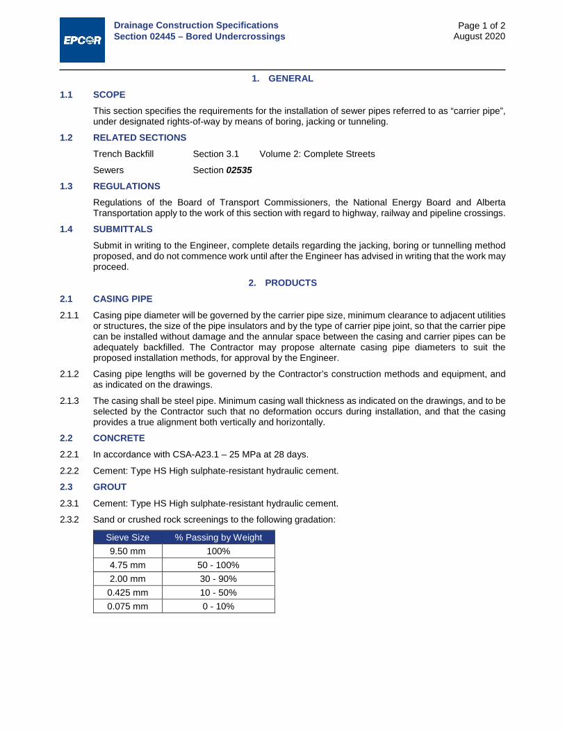
Drainage Construction Specifications Section 02445 – Bored Undercrossings
Page 1 of 2 August 2020
1. GENERAL 1.1 SCOPE
This section specifies the requirements for the installation of sewer pipes referred to as “carrier pipe”, under designated rights-of-way by means of boring, jacking or tunneling.
1.2 RELATED SECTIONS Trench Backfill Section 3.1 Volume 2: Complete Streets
Sewers Section 02535
1.3 REGULATIONS Regulations of the Board of Transport Commissioners, the National Energy Board and Alberta Transportation apply to the work of this section with regard to highway, railway and pipeline crossings.
1.4 SUBMITTALS Submit in writing to the Engineer, complete details regarding the jacking, boring or tunnelling method proposed, and do not commence work until after the Engineer has advised in writing that the work may proceed.
2. PRODUCTS 2.1 CASING PIPE 2.1.1 Casing pipe diameter will be governed by the carrier pipe size, minimum clearance to adjacent utilities
or structures, the size of the pipe insulators and by the type of carrier pipe joint, so that the carrier pipe can be installed without damage and the annular space between the casing and carrier pipes can be adequately backfilled. The Contractor may propose alternate casing pipe diameters to suit the proposed installation methods, for approval by the Engineer.
2.1.2 Casing pipe lengths will be governed by the Contractor’s construction methods and equipment, and as indicated on the drawings.
2.1.3 The casing shall be steel pipe. Minimum casing wall thickness as indicated on the drawings, and to be selected by the Contractor such that no deformation occurs during installation, and that the casing provides a true alignment both vertically and horizontally.
2.2 CONCRETE 2.2.1 In accordance with CSA-A23.1 – 25 MPa at 28 days.
2.2.2 Cement: Type HS High sulphate‐resistant hydraulic cement.
2.3 GROUT
2.3.1 Cement: Type HS High sulphate‐resistant hydraulic cement.
2.3.2 Sand or crushed rock screenings to the following gradation:
Sieve Size % Passing by Weight 9.50 mm 100% 4.75 mm 50 - 100% 2.00 mm 30 - 90% 0.425 mm 10 - 50% 0.075 mm 0 - 10%

Drainage Construction Specifications Section 02445 – Bored Undercrossings
Page 2 of 2 August 2020
2.4 PIPE INSULATORS AND SPACERS
Two-part epoxy painted steel band with plastic runners as supplied by Plainsman Manufacturing Ltd. or approved equal.
3. EXECUTION 3.1 EXCAVATION 3.1.1 Excavate trenches, working shafts or pits as necessary to install the casing pipe, in accordance with
Section 3.1 - Trench Backfill.
3.1.2 De-water the trench as necessary.
3.2 CASING 3.2.1 Undercrossings may be cased with pipe, or be uncased if the ground conditions permit and if permitted
on drawings.
3.2.2 Install the casing pipe by jacking, boring or tunnelling. Monitor line and grade of the casing pipe with appropriate instruments. Monitor loss of ground, over-excavation or settlement of the structures, pipes or surface above the undercrossing. Halt all operations, take immediate remedial action and inform the Engineer if loss of ground or over-excavation is detected.
3.2.3 Install the casing pipe so that the carrier pipe can be laid to the line and grade as shown on the drawings, with tolerances as required for the carrier pipe as specified in related sections.
3.2.4 Backfill any detectable voids around the outside of the casing pipe with sand or grout.
3.3 CARRIER PIPE 3.3.1 Refer to related sections for the specification for carrier pipe.
3.3.2 Attach plastic or other approved pipe insulators at predetermined intervals to ensure that the pipe is correctly located in the casing pipe and to prevent flotation and sags. The use of wooden spacers will not be allowed.
3.3.3 Fill the annular space between the carrier pipe and casing pipe with pneumatically blown sand or pressure grout, unless indicated otherwise on the drawing.
3.3.4 Fill each end of the casing around the carrier pipe with a waterproof concrete plug, unless the casing is under railroad tracks, or otherwise shown on the drawings.
3.4 BACKFILL 3.4.1 Backfill trenches or pits in accordance with Section 3.1 - Trench Backfill, Volume 2: Complete Streets.
3.4.2 Where working shafts, pits or trenches have been excavated below normal trench depth and wider than a normally excavated trench to accommodate boring, jacking or other equipment, the Contractor shall provide an engineered design for the backfill of the subgrade. Unless otherwise approved by the Engineer, the over-excavated depth shall be backfilled with Class A bedding or fillcrete.
3.4.3 If the excavation for working shafts, pits, or trenches is such that trench conditions assumed for the design of the pipe are affected by the Contractor’s methods, the Contractor shall provide an engineered design for a higher class of bedding for the pipe or a stronger class of pipe, or both, on the affected side(s) of the cased section, and install the pipe and bedding at no extra cost to the City, and as directed by the Engineer.
3.4.4 Do not backfill pits until the Engineer has inspected the installation.
END OF SECTION
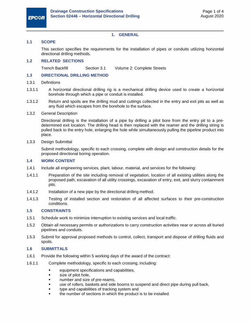
Drainage Construction Specifications Section 02446 – Horizontal Directional Drilling
Page 1 of 4 August 2020
1. GENERAL 1.1 SCOPE
This section specifies the requirements for the installation of pipes or conduits utilizing horizontal directional drilling methods.
1.2 RELATED SECTIONS Trench Backfill Section 3.1 Volume 2: Complete Streets
1.3 DIRECTIONAL DRILLING METHOD 1.3.1 Definitions
1.3.1.1 A horizontal directional drilling rig is a mechanical drilling device used to create a horizontal borehole through which a pipe or conduit is installed.
1.3.1.2 Return and spoils are the drilling mud and cuttings collected in the entry and exit pits as well as any fluid which escapes from the borehole to the surface.
1.3.2 General Description
Directional drilling is the installation of a pipe by drilling a pilot bore from the entry pit to a pre- determined exit location. The drilling head is then replaced with the reamer and the drilling string is pulled back to the entry hole, enlarging the hole while simultaneously pulling the pipeline product into place.
1.3.3 Design Submittal
Submit methodology, specific to each crossing, complete with design and construction details for the proposed directional boring operation.
1.4 WORK CONTENT 1.4.1 Include all engineering services, plant, labour, material, and services for the following:
1.4.1.1 Preparation of the site including removal of vegetation, location of all existing utilities along the proposed path, excavation of all utility crossings, excavation of entry, exit, and slurry containment pits.
1.4.1.2 Installation of a new pipe by the directional drilling method.
1.4.1.3 Testing of installed section and restoration of all affected surfaces to their pre-construction conditions.
1.5 CONSTRAINTS 1.5.1 Schedule work to minimize interruption to existing services and local traffic.
1.5.2 Obtain all necessary permits or authorizations to carry construction activities near or across all buried pipelines and conduits.
1.5.3 Submit for approval proposed methods to control, collect, transport and dispose of drilling fluids and spoils.
1.6 SUBMITTALS 1.6.1 Provide the following within 5 working days of the award of the contract:
1.6.1.1 Complete methodology, specific to each crossing, including:
equipment specifications and capabilities, size of pilot hole, number and size of pre-reams, use of rollers, baskets and side booms to suspend and direct pipe during pull back, type and capabilities of tracking system and the number of sections in which the product is to be installed.

Drainage Construction Specifications Section 02446 – Horizontal Directional Drilling
Page 2 of 4 August 2020
1.6.1.2 Schedule of work.
1.6.1.3 Drawing of work site, including location and footprints of equipment, and the locations of the entry, exit and slurry containment pits.
1.6.1.4 Drawing of pullback installation showing partial or full closure of roadways and their approximate duration.
1.6.1.5 Drilling fluid management plan, including drilling fluid containment, recycling/transport and approve disposal site.
1.6.1.6 Emergency procedures for inadvertently boring into a live power line, natural gas line, water line, sewer line, or fibre-optic cables. Procedures must comply with regulations.
1.6.1.7 Method of dealing with inadvertent returns of surface seepage of drilling fluids and spoils.
1.6.2 At least two weeks prior to commencing work submit data from the manufacturer regarding the tensile strength and recommended minimum bending radius of the pipe.
2. PRODUCTS Not applicable. Refer to the Section that specifies the pipe or conduit.
3. EXECUTION 3.1 EQUIPMENT 3.1.1 The Contractor shall be responsible for the directional drilling method and equipment. The Contractor
shall confirm that the drilling rig and mud mixing system have the capacity required to successfully complete the installation knowing the length of the crossing and product type and diameter, and considering ground and groundwater conditions that can be reasonably foreseen.
3.1.2 Operating range and degree of accuracy of proposed tracking system shall be adequate to meet project conditions. Tracking/steering equipment shall allow for continuous monitoring of the drilling head along the entire proposed alignment. If a poor contact with sound is expected to occur at any section, this should be communicated to the Engineer prior to commencement of construction.
3.1.3 The drilling unit must be equipped with an electrical strike safety package. The package should include warning sound alarm, grounding mats and protective gear.
3.2 PRE-COMMENCEMENT 3.2.1 Notify owners of subsurface utilities and on either side of the proposed drill path of the impending work
through the one-call program. All utilities along and on either side of the proposed drill path are to be located.
3.2.2 All utility crossings shall be exposed using hydro-excavation, hand excavation or another approved method to confirm depth.
3.2.3 The proposed drill path shall be determined and documented, including its horizontal and vertical alignments and the location of buried utilities and substructures along the path.
3.2.4 Excavation for entrance and exit pits is to be of sufficient size to avoid a sudden radius change of the pipe and resultant excessive deformation.
3.3 INSTALLATION PROCEDURES 3.3.1 General
3.3.1.1 Only trained operators should be permitted to operate the drilling equipment, and manufacturer’s operating instructions and safety practice shall always be followed.
3.3.1.2 Drilling mud pressure in the borehole should not exceed that which can be supported by the overburden to prevent heaving or hydraulic fracturing of the soil (“Frac-out”).
3.3.1.3 Entrance and exit angles of the drill string should range between 8º and 20º and 5º and 10º respectively. Any deviation from these values shall first be approved by the Engineer.

Drainage Construction Specifications Section 02446 – Horizontal Directional Drilling
Page 3 of 4 August 2020
3.3.1.4 If a drilled hole beneath an artificial surface must be abandoned the hole shall be filled with grout or bentonite to prevent future subsidence.
3.3.1.5 Pipe installation should be performed in a manner that minimizes the over-stressing and straining of the pipe.
3.3.2 Drilling and back-reaming
3.3.2.1 Drilling mud may be used during drilling and back-reaming operations, pending the approval of a fluids management plan.
3.3.2.2 A sufficient number of pre-reams shall be utilized as to avoid heaving while enlarging the hole to the desired diameter.
3.3.2.3 During back-reaming the conduit must be sealed at either end with a cap or lug to prevent water, drilling fluids and other foreign materials from entering the pipe.
3.3.2.4 Pipe rollers, skates or other protective devices should be used in the installation of products 150 mm outside diameter or larger.
3.3.2.5 Where possible and unless otherwise approved by the Engineer, the product pipeline will be fused, welded or connected into one string prior to commencement of the pull-back operation.
3.3.2.6 The pilot hole shall be back-reamed to accommodate and permit free sliding of the product inside the borehole according to the following specifications:
Nominal Pipe Diameter Back-Reamed Hole 50 75 to 100 75 100 to 150 100 150 to 200 150 250 to 300 200 300 to 350 250 350 to 400
>300 Minimum of 1.5 times product pipe outside
diameter
3.4 SERVICE CONNECTIONS 3.4.1 Trenching shall be used to make connections (if required) or join ends of conduits installed by the
directional boring method.
3.4.2 Sufficient pipe length for joining adjacent sections of pipe shall be pulled into the entrance pit. This additional pipe shall not be damaged or interfere with the subsequent drilling of the next section of pipe.
3.4.3 Connections and tie-ins to HDPE pipe shall only be made after a suitable time period in order to allow the pipe to recover and rebound from the insertion forces. Recovery period shall be equal to at least twice the pull-back time.
3.5 DRILLING FLUIDS - COLLECTION AND DISPOSAL PRACTICES 3.5.1 Excess drilling mud slurry shall be contained in a lined pit or containment pond at exit and entry points
until recycled or removed from the site. Entrance and exit pits shall be of sufficient size to contain the expected return of drilling mud and spoils.
3.5.2 When working in an area of contaminated ground, the slurry shall be tested for contamination and disposed of in a manner that meets government requirements.
3.5.3 Precautions shall be taken to keep drilling fluids out of the streets, manholes, sanitary and storm sewers, and other drainage systems including streams and rivers.
3.5.4 Recycling drilling fluids is an acceptable alternative to disposal.

Drainage Construction Specifications Section 02446 – Horizontal Directional Drilling
Page 4 of 4 August 2020
3.5.5 The Contractor shall make a diligent effort to minimize the amount of drilling fluids and cuttings spilled during the drilling operation and shall clean-up all drilling mud overflows or spills.
3.6 ACCEPTANCE 3.6.1 The Contractor shall provide a set of as-built drawings including both alignment and profile. Drawings
should be constructed from actual field readings. Raw data should be submitted at any time upon the City’s request.
3.6.2 Pipeline product shall be installed within the pre-specified alignment and grade tolerance as shown on the drawings and provided in the project specifications.
END OF SECTION

Drainage Construction Specifications Section 02531 – Sewage Forcemains
Page 1 of 3 August 2020
1. GENERAL 1.1 SCOPE
The supply, installation, testing and inspection of pressure pipe for use as sewage force mains.
1.2 RELATED SECTIONS Trench Backfill Section 3.1 Volume 2: Complete Streets
Aggregates Section 2.1 Volume 2: Complete Streets
Concrete for Water and Drainage Structures Section 03310
1.3 AS-BUILT DRAWINGS Provide as-built drawings on project completion. Give directions and list equipment required for opening and closing valves, details of pipe material, location of cleanouts, locations of air and vacuum release valves, maintenance and operating instructions.
2. PRODUCTS 2.1 STEEL PIPE 2.1.1 Steel pipe shall be ASTM A53 Grade B, minimum standard wall thickness, unless otherwise shown on
drawings.
2.1.2 All underground steel piping shall be exterior coated with Polyethylene Tape wrapping to AWWA C214 or Yellow Jacket No: 1, total minimum thickness 1.27 mm.
2.1.3 All interior lining shall be cement mortar lined to AWWA C205 or epoxy lined to AWWA C210.
2.1.4 Flanges: to AWWA C207
2.1.5 Pipe fittings: to AWWA C208 and exterior protected to AWWA C203.
2.2 POLYVINYL CHLORIDE (PVC) PIPE: 2.2.1 Pipe, fittings and joints conform to CSA-B137.3.
2.2.2 Pressure class and Standard Dimensional Ratio as indicated on the drawings.
2.2.3 Pipe joints: bell and spigot with rubber gaskets or mechanical joints to AWWA C111/A21.11, with transition gaskets to pipe manufacturers specifications.
2.2.4 Rubber gaskets: to AWWA C111/A21.11.
2.3 POLYETHYLENE PIPE 2.3.1 Conform to CSA-B.137.1 and CGSB 41-GP-25M, PE 3408.
2.3.2 Joint pipe using thermal butt fusion to AWWA C207.
2.3.3 Fittings
2.3.3.1 To be flanged to AWWA C207.
2.3.3.2 Fittings shall match the pipe supplied and shall be supplied by the manufacturer of the pipe or by suppliers approved by the pipe manufacturer.
2.3.3.3 All fittings to be compatible in materials and dimensions with the pipe.
2.4 PIPE BEDDING MATERIALS 2.4.1 Class I, Class II, and Class III materials as defined in Section 02535 – Sewers are suitable for use as
foundation material and in the embedment zone. For ease of compactability and to facilitate proper placement of material in the haunch area of the pipe, a suggested gradation for sand within the pipe embedment zone are the following limits:

Drainage Construction Specifications Section 02531 – Sewage Forcemains
Page 2 of 3 August 2020
Sieve Size (mm) Percent Passing by Mass 10 100 5 70 - 100
0.16 5 - 20 0.08 0 -12
2.4.2 Washed gravel: Where specifically specified for use, washed gravel shall consist of washed, crushed or screened stone or gravel consisting of hard and durable particles meeting the following gradation limits and free from sand, clay, cementitious, organic and other deleterious material.
Sieve Size (mm) Percent Passing by Mass 5 maximum 10
0.08 maximum 2
2.5 TRACER WIRE Tracer wire to be an electric #14 AWG Solid SBC (1/64”) polyethylene insulated wire or metal tape detectable to 3 m bury.
3. EXECUTION 3.1 PREPARATION
Pipes and fittings to be clean and dry. Carefully inspect materials for defects before installing. Remove any defective materials from site.
3.2 TRENCHING AND BACKFILLING 3.2.1 Trench and backfill in accordance with Section 3.1 – Trench Backfill, Volume 2: Complete Streets.
3.2.2 Place and compact pipe bedding in accordance with Drawing 7980, Type 2 Installation, unless shown otherwise on the construction drawings.
3.3 INSTALLATION 3.3.1 Steel Pipe
Lay and join steel pipe in accordance with AWWA Manual M11.
3.3.2 Polyvinyl Chloride (PVC) Pipe
3.3.2.1 Lay and join PVC pipe in accordance with AWWA Manual M23 with specified bedding.
3.3.2.2 All pipes shall be thoroughly inspected for damage just prior to installation. Evidence of gouges or cuts exceeding 10% of the wall thickness shall be cause for rejection.
3.3.2.3 All joints shall be clean and smooth at all times during the jointing operation.
3.3.2.4 Avoid bumping gasket and knocking it out of position or contaminating with dirt or other foreign material. Gaskets so disturbed to be removed, cleaned, lubricated and replaced before jointing is attempted.
3.3.2.5 Deflections, where possible, shall be made by long radius curves keeping pipe deflections within the manufacturer’s recommended limits.
3.3.2.6 Short lengths of pipe not exceeding 1 m shall be installed on both sides of all fittings and valves.
3.3.2.7 When laying operations are not in progress, the open ends of the pipe shall be kept water tight to prevent trench water from entering.
3.3.2.8 Any pipe that has floated shall be re-laid.
3.3.3 Polyethylene Pipe
3.3.3.1 Install polyethylene pipe in strict conformance with the manufacturer’s recommendations for the specific pipe being installed.

Drainage Construction Specifications Section 02531 – Sewage Forcemains
Page 3 of 3 August 2020
3.3.3.2 Just prior to placement in the trench, check the pipe to ensure the surface is free of debris, stones, nails, loose concrete or other material that may ultimately damage the pipe. Any gouges or cuts that are deeper than 10% of the wall thickness shall result in rejection of that section of pipe. Other defects such as kinking and ovality shall not be cause for rejection providing the sections involved are satisfactorily repaired and meet the limits outlined by the pipe manufacturer.
3.3.3.3 Any spillage of petroleum products on any polyethylene pipe material shall result in rejection of that section.
3.3.3.4 Stainless steel bolts for fittings, to the class shown on the drawings shall be used in conjunction with insulating bolt sleeves and washers to install all fittings.
3.3.3.5 The pipe shall be lifted and placed into the trench, not rolled.
3.3.3.6 Make all allowances for expansion and contraction of pipe due to temperature changes, especially when tying into rigid structures and existing lines.
3.3.3.7 Backfilling shall follow a minimum of 20 m behind the point where the pipe passes over the top of the trench. Backfilling equipment shall maintain a minimum of 1 m vertical separation above the pipe.
3.4 TRACER WIRE Install tracer wire along the entire length of all plastic pipe installations. The tracer wire shall be brought to the ground surface in an accessible location, marked, and located on as-built drawings. Number of test locations shall be as shown on plans, and spacing shall not exceed 300 m.
3.5 THRUST BLOCKS 3.5.1 Place concrete thrust blocks at bends, tees and fittings and on undisturbed ground.
3.5.2 Keep pipe couplings free of concrete.
3.5.3 Bearing area of thrust blocks to be as shown on the drawings.
3.6 FIELD TESTING OF FORCE MAIN 3.6.1 Test Parameters
3.6.1.1 Force main to be flushed before commencing testing.
3.6.1.2 Carry out field testing in accordance with Clause 3.4 of Section 02958 – Leakage Testing of Sewers.
3.6.1.3 Prior to acceptance of the forcemain, a continuity check shall be conducted on the tracer wire to verify that the wire has not been broken during installation.
END OF SECTION

Drainage Construction Specifications Section 02535 – Sewers
Page 1 of 9 August 2020
1. GENERAL 1.1 SCOPE
This section specifies requirements for supplying and installing sewers and for the abandonment of existing sewers.
1.2 RELATED SECTIONS Quality Assurance Chapter 8 Volume 1: General
Trench Backfill Section 3.1 Volume 2: Complete Streets
Sewer Services Section 02538
Manholes and Catch Basins Section 02631
Inspection of Sewers Section 02954
Leakage Testing of Sewers Section 02958
Deflection Testing of Flexible Pipe Section 02959
1.3 SUBMITTALS 1.3.1 At least 15 working days prior to commencing work inform the City of the proposed source of bedding
material and provide access for sampling.
1.4 AS-BUILT DRAWINGS 1.4.1 Provide as-built drawings on completion of contract. Give details of pipe material, strength and/or wall
thickness designation, invert elevations at manholes and connections, location of tees, bends, clean-outs, manholes, service connections, laterals and caps. Refer to Section 21 of the Design Standards.
1.4.2 Provide as-built information on the Service Report Form for all drainage services affected by the work. Refer to Section 02538 – Sewer Services for details.
1.4.3 Record abandonments on the as-built drawings.
1.5 QUALITY CONTROL 1.5.1 Pipe Zone Material
1.5.1.1 For pipe installed by trenching methods, the Contractor shall supply a sample of pipe zone material and associated moisture density curves to ASTM D698 and sieve analysis to ASTM C136.
1.5.1.2 Contractor to perform field density tests to ASTM D2167 or to ASTM D2922.
1.5.1.3 The Contractor shall perform as many tests as are necessary to ensure that the work conforms to the requirements of the contract. Under no circumstances shall the frequency of testing be less than 1 density test per MH-to-MH section.
2. PRODUCTS 2.1 CONCRETE PIPE 2.1.1 Markings
2.1.1.1 Markings for indirect design projects shall be according to CAN/CSA A257.2.
2.1.1.2 Markings for direct design projects shall conform to ASCE Standard Practice 15 – Standard Practice for Direct Design of Buried Precast Concrete Pipe Using Standard Installations.
2.1.2 Product
2.1.2.1 Non-reinforced circular concrete pipe and fittings: to CAN/CSA-A257.1 Class 3, designed for flexible rubber gasket joints to CAN/CSA-A257.3 made with Type HS High sulphate‐resistant hydraulic cement to CSA-A3000.

Drainage Construction Specifications Section 02535 – Sewers
Page 2 of 9 August 2020
2.1.2.2 Reinforced circular concrete pipe and fittings: to CAN/CSA-A257.2 with flexible rubber gasket joints to CAN/CSA-A257.3, made with Type HS High sulphate‐resistant hydraulic cement to CSA-A3000. Elliptical reinforcement is acceptable upon specific approval given by EPCOR Drainage Services prior to the manufacture of the pipe. Pipes with elliptical reinforcement must be clearly marked with the following labels:
“Elliptical reinforcing” “Pipe must be installed with swift lift at the crown of the pipe”
2.1.3 Lifting systems
2.1.3.1 Pipe lifting systems shall be provided. However, the following rules shall be observed:
Pipe 900 mm and less in diameter, no lift holes. Pipe greater than 900 mm diameter; designed lifting systems with cast-in anchors that are
compatible with a “Swift Lift” system shall be provided. When elliptical reinforcement steel is used the cast in anchor must be orientated to ensure
the elliptical reinforcing is in the proper orientation during installation and prior to backfill.
2.1.3.2 Seal lift holes watertight after installation of pipe.
2.2 PLASTIC PIPE 2.2.1 PVC (PSM Type) Pipe:
2.2.1.1 Smooth wall PVC pipe products and fittings shall conform to Sections 4 and 5 of CSA Standard B182.2 for all basic material requirements and manufactured quality and dimensional tolerance.
2.2.1.2 Materials used for pipe shall come from a single compound manufacturer and shall have a cell classification of 12454-B, 12454-C, or 12364-C as defined in ASTM Standard D1784. Materials used for moulded fittings shall come from a single compound manufacturer and shall have a cell classification of 12454-B, 12454-C, or 13343-C as defined in ASTM Standard D1784.
2.2.1.2.1 Notwithstanding the requirements of Section 4 of CSA Standard B182.2, compounds with different cell classifications than that noted above shall not be used without the prior approval of EPCOR Drainage Services.
2.2.1.2.2 Minimum wall thickness shall be as required for SDR 35 unless otherwise approved by EPCOR Drainage Services.
2.2.1.2.3 Pipe shall be installed within two years from the production date indicated on the pipe.
2.2.2 Open Profile Wall PVC Pipe:
2.2.2.1 Closed profile and dual-wall corrugated pipe, (if specifically approved by EPCOR for a project) and open profile PVC pipe products and fittings shall conform to Sections 4 and 5 of CSA Standard B182.4 for all basic material requirements and manufactured quality and dimensional tolerance.
2.2.2.2 Materials used for pipe and fittings shall come from a single compound manufacturer and shall have a cell classification of 12454-B, 12454-C, or 12364-C as defined in ASTM Standard D1784.
2.2.2.3 Notwithstanding the requirements of Section 4 of CSA Standard B182.4, compounds with different cell classifications than that noted above shall not be used without the prior approval of EPCOR Drainage Services.
2.2.2.4 Minimum waterway wall thickness shall conform to CSA-B182.4 Table 3 for pipe stiffness of 320 kPa .
2.2.2.5 Pipe shall be installed within two years from the production date indicated on the pipe
2.3 PIPE EMBEDMENT ZONE MATERIALS 2.3.1 Materials for use as foundation, embedment, and backfill are classified in Table 1 of the Standard
Practice for the Design and Construction of Flexible Thermoplastic Pipe in the City of Edmonton. They include natural, manufactured, and processed aggregates and the soil types classified according to ASTM Test Method D2487.

Drainage Construction Specifications Section 02535 – Sewers
Page 3 of 9 August 2020
2.3.2 Class I, Class II, and Class III materials are suitable for use as foundation material and in the embedment zone subject to the limitations noted herein and in Table 2 of the Standard Practice for the Design and Construction of Flexible Thermoplastic Pipe in the City of Edmonton.
2.3.3 Class IV-A materials should only be used in the embedment zone in special design cases, as they would not normally be construed as a desirable embedment material for flexible pipe.
2.3.4 Class IV-B, Class V Soils, and Frozen Materials are not recommended for embedment, and should be excluded from the final backfill except where specifically allowed by project specifications.
For ease of compactability and to facilitate proper placement of material in the haunch area of the pipe, a suggested gradation for sand within the pipe embedment zone are the following limits:
Sieve Size (mm) Percent Passing by Mass 10 100 5 70 – 100
0.16 5 – 20 0.08 0 –12
The above material is an example of a Class II embedment material.
2.3.5 Washed gravel: Where specifically specified for use, washed gravel shall consist of washed, crushed or screened stone or gravel consisting of hard and durable particles meeting the following gradation limits and free from sand, clay, cementitious, organic and other deleterious material:
Sieve Size (mm) Percent Passing by Mass 25 100 5 Maximum 10
0.08 Maximum 2
Washed gravel meets the technical requirements for classification as a Class I embedment material.
2.4 CONCRETE Concrete mixes and materials for bedding, cradles, encasement and supports to be in accordance with Section 03310 - Concrete for Water and Drainage Structures.
2.5 QUALITY CONTROL FOR PIPE, FITTINGS, AND APPUTENANCES MATERIAL 2.5.1 Concrete Pipe
2.5.1.1 For indirect design projects the manufacturer of concrete pipe shall perform quality control and quality assurance testing in accordance with CAN/CSA-A257.0, CAN/CSA-A257.1, CAN/CSA-A257.2 and CAN/CSA-A257.3.
2.5.1.2 For direct design projects the manufacturer of concrete pipe shall perform quality control and quality assurance testing in accordance with ASCE Standard Practice 15 – Standard Practice for Direct Design of Buried Precast Concrete Pipe Using Standard Installations. Hydrostatic joint integrity shall also be demonstrated in accordance with Section 7 of CSA A257.0.
2.5.2 PVC (PSM Type) Pipe
The manufacturer of PVC (PSM Type) pipe shall perform quality control and quality assurance testing in accordance with CSA-B182.2.
2.5.3 Profile Wall PVC Pipe
The manufacturer of Profile Wall PVC pipe shall perform quality control and quality assurance testing in accordance with CAN/CSA-B182.4 in conjunction with ASTM F794 with minimum waterway wall thickness as per Table 3.

Drainage Construction Specifications Section 02535 – Sewers
Page 4 of 9 August 2020
3. EXECUTION 3.1 PREPARATION OF PIPE 3.1.1 Clean pipes and fittings of debris, dirt, mud, ice and snow before installation. Inspect materials for
defects before installing. Remove defective materials from site.
3.1.2 Inspect every pipe for damage in shipment. Reject any damaged pipe and have it removed from the site.
3.2 PIPE EMBEDMENT ZONE CLASSIFICATION AND CONSTRUCTION 3.2.1 The pipe embedment zone is detailed on Standard Drawing 7980. The pipe embedment zone consists
of the foundation (where required), bedding and haunch, and initial backfill as detailed on the standard drawing.
3.2.2 Construction requirements within the pipe embedment zone for both concrete pipe and flexible pipes (PVC pipes) shall be based on the following modified ASCE 15 Standard Installation Types as depicted on Standard drawing 7980 as detailed in the project specific specifications or construction drawings. Where no Type of installation is specified or noted, a Type II Installation shall be inferred. Each Standard Installation Type can be described as follows:
3.2.2.1 Type 1 Installation – Embedment installation shall be compacted to a minimum of 95% Standard Proctor utilizing Class 1A or 1B material. Type 1 installation requires that the material, density and method of installation be CERTIFIED by Professional Engineer. The use of Type 1 installation requires City pre-approval on a case by case basis.
3.2.2.2 Type 2 Installation – Embedment installation shall be compacted to a minimum of 90% Standard Proctor utilizing Class 1A, 1B, or II embedment materials, or 95% Standard Proctor when utilizing Class III embedment materials.
3.2.2.3 Type 3 Installation – Embedment installation shall be compacted to a minimum of 85% Standard Proctor utilizing Class 1A, 1B, II, III material.
3.2.2.4 Type 4 Installation – Embedment installation with no compaction utilizing Class 1A, 1B, II or III material, or compacted to 85% Standard Proctor utilizing Native Materials. Type 4 installations are approved only for appropriately design concrete pipe applications.
3.2.2.5 Class A Bedding (Concrete Cradle Construction) – Class A bedding is generally the construction of a pipe with a concrete cradle in the bedding and lower haunch zone. Class A bedding shall only be used where identified in the project specific specification and under no circumstances shall it be used in conjunction with flexible pipe.
3.3 FOUNDATION ZONE REQUIREMENTS AND CONSTRUCTION 3.3.1 The foundation soil shall be moderately firm to hard in situ soil, stabilized soil, or compacted fill
material.
3.3.2 When unsuitable or unstable material is encountered, the foundation shall be stabilized.
3.3.3 Where groundwater and soil characteristics may contribute to the migration of soil fines into or out of the foundation, embedment soils, sidefill, and/or backfill materials, methods to prevent migration shall be provided.
3.4 VERIFICATION THAT PROPOSED CONSTRUCTION METHOD IS CONSISTENT WITH DESIGN INTENT
3.4.1 Project specific design requirements for the in-place density of outside bedding material, haunch material, and initial backfill shall be noted on the plans or in the project specifications or as detailed herein. As the precise measurement of these densities in the bedding and haunch zones during construction is often not technically feasible, the Contractor shall demonstrate to the Engineer for the project that their proposed method of placement of these materials is sufficient to achieve the specified results, through a trial compaction demonstration.
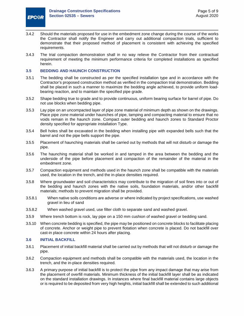
Drainage Construction Specifications Section 02535 – Sewers
Page 5 of 9 August 2020
3.4.2 Should the materials proposed for use in the embedment zone change during the course of the works the Contractor shall notify the Engineer and carry out additional compaction trials, sufficient to demonstrate that their proposed method of placement is consistent with achieving the specified requirements.
3.4.3 The trial compaction demonstration shall in no way relieve the Contractor from their contractual requirement of meeting the minimum performance criteria for completed installations as specified herein.
3.5 BEDDING AND HAUNCH CONSTRUCTION 3.5.1 The bedding shall be constructed as per the specified installation type and in accordance with the
Contractor’s proposed construction method as verified in the compaction trial demonstration. Bedding shall be placed in such a manner to maximize the bedding angle achieved, to provide uniform load-bearing reaction, and to maintain the specified pipe grade.
3.5.2 Shape bedding true to grade and to provide continuous, uniform bearing surface for barrel of pipe. Do not use blocks when bedding pipe.
3.5.3 Lay pipe on an uncompacted layer of pipe zone material of minimum depth as shown on the drawings. Place pipe zone material under haunches of pipe, tamping and compacting material to ensure that no voids remain in the haunch zone. Compact outer bedding and haunch zones to Standard Proctor density specified for appropriate installation Type.
3.5.4 Bell holes shall be excavated in the bedding when installing pipe with expanded bells such that the barrel and not the pipe bells support the pipe.
3.5.5 Placement of haunching materials shall be carried out by methods that will not disturb or damage the pipe.
3.5.6 The haunching material shall be worked in and tamped in the area between the bedding and the underside of the pipe before placement and compaction of the remainder of the material in the embedment zone.
3.5.7 Compaction equipment and methods used in the haunch zone shall be compatible with the materials used, the location in the trench, and the in-place densities required.
3.5.8 Where groundwater and soil characteristics may contribute to the migration of soil fines into or out of the bedding and haunch zones with the native soils, foundation materials, and/or other backfill materials; methods to prevent migration shall be provided.
3.5.8.1 When native soils conditions are adverse or where indicated by project specifications, use washed gravel in lieu of sand
3.5.8.2 When washed gravel used, use filter cloth to separate sand and washed gravel.
3.5.9 Where trench bottom is rock, lay pipe on a 150 mm cushion of washed gravel or bedding sand.
3.5.10 When concrete bedding is specified, the pipe may be positioned on concrete blocks to facilitate placing of concrete. Anchor or weight pipe to prevent flotation when concrete is placed. Do not backfill over cast-in place concrete within 24 hours after placing.
3.6 INITIAL BACKFILL 3.6.1 Placement of initial backfill material shall be carried out by methods that will not disturb or damage the
pipe.
3.6.2 Compaction equipment and methods shall be compatible with the materials used, the location in the trench, and the in-place densities required.
3.6.3 A primary purpose of initial backfill is to protect the pipe from any impact damage that may arise from the placement of overfill materials. Minimum thickness of the initial backfill layer shall be as indicated on the standard installation drawings. In instances where final backfill material contains large objects or is required to be deposited from very high heights, initial backfill shall be extended to such additional

Drainage Construction Specifications Section 02535 – Sewers
Page 6 of 9 August 2020
height above the pipe as is necessary to prevent damage from occurring to the pipe during backfilling operations.
3.6.4 Before using heavy compaction or construction equipment directly over the pipe, ensure that sufficient backfill has been placed over the pipe to prevent damaging either the pipe or the embedment zone materials.
3.7 INSTALLATION OF PIPE 3.7.1 Lay and join pipes in accordance with manufacturer's recommendations.
3.7.2 Installation of PVC pipe and fittings shall conform to CSA-B182.11 and the construction requirements identified in the Standard Practice for the Design and Construction of Flexible Thermoplastic Pipe in the City of Edmonton.
3.7.3 Installation requirements for Direct Design concrete pipe shall conform to the supplemental construction requirements identified in with ASCE Standard Practice 15 – Standard Practice for Direct Design of Buried Precast Concrete Pipe Using Standard Installations
3.7.4 Handle pipe with approved equipment. Do not use chains or cables passed through pipe bore so that weight of pipe bears upon pipe ends.
3.7.5 Lay pipes on prepared bedding, true to line and grade, with pipe invert smooth and free of sags or high points. Ensure barrel of each pipe is in contact with shaped bed throughout its full length.
3.7.6 Commence laying at outlet and proceed in upstream direction with socket ends of pipe facing upgrade.
3.7.7 Do not exceed maximum joint deflection recommended by pipe manufacturer.
3.7.8 Do not allow water to flow through pipe during construction, except as may be permitted by Engineer.
3.7.9 Whenever work is suspended, install a removable watertight bulkhead at open end of last pipe laid to prevent entry of foreign materials.
3.7.10 Position and join pipes by approved methods. Do not use excavating equipment to force pipe sections together.
3.7.11 Block pipes as required when any stoppage of work occurs to prevent creep during down time.
3.7.12 Plug lifting holes, swift lift cups and lift pin divots with non-shrink grout.
3.7.13 Cut pipes as required for special inserts, fittings or closure pieces in a neat manner, as recommended by pipe manufacturer, without damaging pipe and to leave a smooth end at right angles to axis of pipe.
3.7.14 Connect pipe to manholes in accordance with Construction Specification Section 02631.
3.7.15 Use approved field connections for connecting pipes to existing sewer pipes. For connections of service to the main pipe refer to Section 02538 - Sewer Services.
3.7.16 When complete, the sewer must be thoroughly cleaned out of all dirt, stones and rubbish.
3.8 PIPE JOINTING 3.8.1 Install gaskets in accordance with manufacturer's recommendations.
3.8.2 Support pipes with hand slings or crane as required to minimise lateral pressure on gasket and maintain concentricity until gasket is properly positioned.
3.8.3 Align pipes carefully before jointing.
3.8.4 Maintain pipe joints free from mud, silt, gravel and other foreign material.
3.8.5 Avoid displacing gasket or contaminating with dirt or other foreign material. Gaskets so disturbed shall be removed, cleaned and lubricated and replaced before joining is attempted.
3.8.6 Complete each joint before laying next length of pipe.
3.8.7 Minimize joint deflection after joint has been made to avoid joint damage.

Drainage Construction Specifications Section 02535 – Sewers
Page 7 of 9 August 2020
3.8.8 At rigid structures, install the first pipe joints not more than 1.2 m from the side of the structure.
3.8.9 Apply sufficient pressure in making joints to ensure that joint is complete as outlined in manufacturer's recommendations.
3.8.10 Poured concrete pipe joints will require the City approval prior to construction. Refer to Standard Drawings.
3.9 TRENCH AND FINAL BACKFILL 3.9.1 Trench and final backfill in accordance with Section 3.1 – Trench Backfill, Volume 2: Complete Streets.
3.9.2 Do not allow contents of existing sewer or sewer connection to flow into trench.
3.9.3 Trench line, depth and bottom of trench excavation require approval by the Engineer prior to placing bedding material and pipe.
3.9.4 Do not use heavy vibratory equipment for compaction until at least 1 m of backfill has been placed above the elevation of the top of the pipe.
3.10 TOLERANCE OF SANITARY SEWERS 3.10.1 Alignment
The centre line of 900 mm and smaller diameter pipes shall not be more than 150 mm off the designated alignment. The centre line of pipe greater than 900 mm shall not be more than 50 mm per 300 mm of diameter off the designated alignment. Where the pipeline alignment is supposed to be straight between manholes a line of sight through the pipe shall exist from manhole to manhole.
3.10.2 Grade
The invert of the sewer main shall not deviate from the designated grade by an amount greater than the total of 6 mm plus 20 mm per metre of diameter of sewer pipe �≯ 6 mm + 20 mm
1.0 m of diameter×
m diameter�.
3.10.3 Joints
Deflections at joints of concrete pipe shall not exceed those as permitted in the specifications for concrete pipe CAN/CSA-A257. Deflections at the joints of other pipe material shall not exceed those recommended by the manufacturer.
3.11 FIELD LEAKAGE TESTING 3.11.1 Perform testing identified in the Contract or as specified by the City.
3.11.2 For identified testing, follow Section 02958 - Leakage Testing of Sewers.
3.12 VISUAL INSPECTION AND ACCEPTANCE CRITERIA 3.12.1 Carry out CCTV and/or visual walk-through inspection of the completed sewer as described in the
Section 02954 - Inspection of Sewers.
3.12.2 Perform inspection after all mains, manholes and service connections have been installed.
3.12.3 Repair all defects which will impair the structural integrity or the performance of the sewer system including, but not limited to improper joints, cracked, sheared or excessively deflected pipe, sags and rises which pond water in excess of twice the allowable deviation from grade, protruding service connections and visible infiltration or exfiltration.
3.12.4 Flexible Pipe Defects
3.12.4.1 Where there is visual evidence of excessive or non-symmetrical deflection (e.g. a non-elliptical deformation pattern), formal deflection tests shall be conducted in accordance with Section 02959 – Deflection Testing of Flexible Pipe.

Drainage Construction Specifications Section 02535 – Sewers
Page 8 of 9 August 2020
3.12.4.2 For DR35 PVC pipe or profile pipe with equivalent pipe stiffness, the maximum allowable deflection shall be 5% of the CSA base inside diameter (BID) for short term observations (i.e. more than 30 days and less than 1 year) and 7.5% of CSA BID for long term observations (1 year or greater).
3.12.4.3 Excessive or non-symmetrical deflection shall be reviewed by the Engineer and a determination shall be made as to whether the deformation is in excess of the strain limits for the pipe. Deformation less than the allowable strain limits can be re-excavated and have the embedment zone re-built to resolve the deficiency. Deformation in excess of the strain limit of the pipe material shall have the corresponding section of pipe removed and replaced.
3.12.4.4 Under circumstances where the excavation of a pipe to resolve an excessive deformation deficiency is not technically feasible due to its depth or its location relative to other utilities and the amount of deformation is determined by the Engineer to be within the strain limits of the pipe, the Contractor may make special application to the Engineer to achieve resolution of the deficiency through the use of an approved re-rounding device specially designed for use in the re-round of flexible pipes. Approval for the use of re-rounding devices will only be made in special circumstances on a case-by-case basis and will always be subject to an increased monitoring period for acceptance at the Contractor’s expense. The length of the monitoring period shall be determined by the City on a case-by-case basis. Only re-rounding devices that work on the principle of imparting vibration to the surrounding embedment zone as a means of stabilizing the pipe-soil structure will be considered for use.
3.12.4.5 Defects in flexible pipe that involve cracks and fractures to the pipe structure shall be cut out and replaced. Minor scratches from handling or inspection activities that are less than 10% of the wall thickness of the pipe are not defective, while pronounced scratches and scratches deeper than 10% of the wall thickness shall be deemed to be defective and shall be cut out and replaced.
3.12.5 Rigid Pipe Defects
3.12.5.1 Cracks in concrete pipe shall be reviewed by the Engineer to make a determination as to whether they are in excess of the design crack width for service cracking. While project specific requirements may vary, acceptable service cracking is generally deemed to be cracks that measure 0.25 mm (0.01”) in width at a distance of the lesser of 25 mm away from the inner pipe surface or at the interface with the reinforcing steel. This may result in cracks at the surface that are slightly in excess of the service crack width limit. A crack comparator or other suitable means shall be used to aid in the determination.
3.12.5.2 Cracks in excess of the service crack limit shall be deemed to be defective and shall be repaired while cracks within service crack limit tolerances shall be deemed to be acceptable. In making their determination, the Engineer shall also consider the time-history of loading on the pipe. Full long term loading conditions shall not be deemed to have occurred until after 1 year after completion of backfilling. Therefore, very minor cracks can be determined to be acceptable but cracks near the limit of service crack tolerance shall be re-inspected to confirm whether they are acceptable or not after full loading is deemed to have developed on the pipe.
3.12.5.3 For cracks deemed to be defective, the Engineer shall also make a determination as to whether the nature of the cracks compromises the structural integrity of the pipe. Cracks that are deemed to compromise the structural integrity of the pipe shall be taken out and replaced while non-structural cracks may be reviewed for alternate repair methods. Where alternate repair methods are proposed, the Contractor shall make a specific proposal for the Engineer and City’s review and approval.
3.12.5.4 Under circumstances where the excavation of a pipe to resolve a structural performance deficiency is not technically feasible due to its depth or its location relative to other utilities and the nature of the deficiency is determined by the Engineer to be feasible for repair by trenchless methods, the Contractor may make special application to the Engineer to achieve resolution of the deficiency by effecting an appropriately designed trenchless point repair. Approval for the rectification of structural deficiencies will only be made in special circumstances on a case-by-case basis and will always be subject to an increased monitoring period for acceptance at the Contractor’s expense. The length of the monitoring period shall be determined by the City on a case-by-case basis.

Drainage Construction Specifications Section 02535 – Sewers
Page 9 of 9 August 2020
3.12.6 Joint Defects
3.12.6.1 Significant joint defects, cracked or offset joints shall be cut out and replaced in a manner acceptable to the City.
3.12.6.2 Joint defects such as hanging or improperly installed or improperly functioning gaskets shall be reviewed on a case-by-case basis to establish the most feasible means of repair. In all cases the joint may be cut out and replaced as a suitable means of repair. For minor joint deficiencies alternate repair methods may be considered. Where alternate repair methods are considered the Contractor shall seek the approval of the Engineer and the City.
3.12.6.3 Under circumstances where the excavation of a pipe to resolve a joint deficiency is not technically feasible due to its depth or its location relative to other utilities and the nature of the joint deficiency is determined by the Engineer to be feasible for repair by trenchless methods, the Contractor may make special application to the Engineer to achieve resolution of the deficiency by effecting an appropriately designed trenchless point repair and by the use of an appropriately selected grouting technology. Approval for the rectification of joint deficiencies by trenchless point repair or by the use of grouting technologies will only be made in special circumstances on a case-by-case basis and will always be subject to an increased monitoring period for acceptance at the Contractor’s expense. The length of the monitoring period shall be determined by the City on a case-by-case basis.
3.13 ABANDONMENT OF SEWERS 3.13.1 Abandon existing sewers and sewer services by plugging one end with as noted herein and completely
filling the sewer or sewer service with cement-stabilized flowable fill and then sealing it as noted herein. Confirm all active sewer services have been disconnected from sewer being abandoned and have been reconnected to new sewer before filling the sewer.
3.13.2 Plug each end of the sewer section identified on the drawings for abandonment, as follows:
3.13.2.1 For concrete pipe 375 mm to 675 mm diameter, place sandbags or other firm backing 300 mm inside the abandoned sewer and seal with concrete. Break out section of the pipe invert in front of the sandbags to allow concrete to key into the pipe to prevent shifting.
3.13.2.2 For PVC pipe 375 mm to 675 mm diameter, place sandbags or other firm backing 300 mm inside the abandoned sewer and seal using manufactured compression type plug.
3.13.2.3 The method for plugging each end of sewer pipes larger than 675 mm shall be detailed on the drawings or specified elsewhere.
END OF SECTION

Drainage Construction Specifications Section 02538 – Sewer Services
Page 1 of 3 August 2020
1. GENERAL 1.1 SCOPE
This section specifies requirements for construction of new storm and sanitary sewer services and for abandonment of existing services.
1.2 RELATED SECTIONS
Quality Assurance Chapter 8 Volume 1: General Trench Backfill Section 3.1 Volume 2: Complete Streets Sewers Section 02535 Inspection of Sewers Section 02954 Single Service Drawing 2514-05 Volume 4: Water Typical Dual Service (One Trench) Drawing 2514-06 Volume 4: Water Typical Dual Service for Duplex/Semi-Detached Lots Drawing 2514-07 Volume 4: Water
Typical Single Services Drawing 2514-08 Volume 4: Water Service Extension into Private Property (Beyond Gas Easement) Drawing 2514-09 Volume 4: Water
1.3 SUBMITTALS 1.3.1 At least 15 working days prior to commencing work inform the City of the proposed source of bedding
material and provide access for sampling.
1.4 AS-BUILT REPORT Obtain service report forms from Public Services, Drainage Services. Complete these forms strictly in accordance with Public Services’ instructions including the following information:
Invert elevation and location at sewer main. Invert elevation and location at property line. Alignment of the service. Length and type of material used. Location of a plug in abandoned service connection.
2. PRODUCTS 2.1 SEWER PIPE 2.1.1 PVC (PSM Type) Pipe:
2.1.1.1 PVC pipe products and fittings shall conform to Sections 4 and 5 of CSA Standard B182.2 for all basic material requirements and manufactured quality and dimensional tolerance.
2.1.1.2 Materials used for pipe shall come from a single compound manufacturer and shall have a cell classification of 12454-B, 12454-C, or 12364-C as defined in ASTM Standard D1784. Materials used for moulded fittings shall come from a single compound manufacturer and shall have a cell classification of 12454- B, 12454-C, or 13343-C as defined in ASTM Standard D1784.
2.1.2 Notwithstanding the requirements of Section 4 of CSA Standard B182.2, compounds with different cell classifications than that noted above shall not be used without the prior approval of EPCOR Drainage Services.
2.1.3 Standard Dimensional Ratio (SDR) 35 unless indicated otherwise on the drawing.
2.1.4 Minimum wall thickness for pipe diameter up to 375 mm shall be SDR 35.
2.1.5 Pipe shall be installed within 2 years from the production date indicated on the pipe.
2.2 SEWER CONNECTIONS 2.2.1 Connections to main line sewers shall be made with full tees, “strap-on” tee or wye saddles, or “insert-

Drainage Construction Specifications Section 02538 – Sewer Services
Page 2 of 3 August 2020
a- tee” type connectors. All clamps, straps, bands, nuts and bolts to be stainless steel in accordance with ASTM A320, ANSI Type 316. The following connectors are approved for use:
2.2.1.1 IPEX, Multi-Fittings, or Fernco gasketted “strap-on” Tee (or Wye) saddle with two stainless steel clamps for PVC mains.
2.2.1.2 “Insert-A-Tee” or Core-Bell insert type with rubber gasket sleeve and stainless steel clamp for concrete, PVC, vitrified clay tile and asbestos cement mains.
2.2.1.3 HKT Connectors for 300 mm to 750 mm diameter concrete pipe only.
2.3 SEWER ADAPTER Sewer adapters for connecting to existing building service connections shall conform to ASTM D5926 Standard Specification for Poly (Vinyl Chloride) (PVC) Gaskets for Drain, Waste, and Vent (DWV), Sewer, Sanitary, and Storm Plumbing Systems, ASTM C1173 Standard Specification for Flexible Transition Couplings for Underground Piping Systems, and CSA Standard B602 Mechanical Couplings for Drain, Waste, and Vent Pipe and Sewer Pipe. Acceptable products include Fernco Connectors Ltd., Plumb Qwik, (HKT for concrete) or equal.
2.4 PIPE EMBEDMENT ZONE MATERIALS 2.4.1 Pipe embedment zone materials shall conform to Clause 2.3 of Section 02535 for sand and washed
gravel materials.
2.5 CONCRETE Concrete mixes and materials for bedding, cradles, encasements and supports to be in accordance with Section 03310 - Concrete for Water and Drainage Structures.
2.6 QUALITY CONTROL FOR PIPE MATERIAL 2.6.1 PVC (PSM) Pipe
2.6.1.1 The manufacturer of PVC (PSM Type) pipe shall perform quality control and quality assurance testing in accordance with CSA-B182.2.
2.6.1.2 At the City’s discretion, PVC pipes shall be tested for joint leakage in accordance with CSA-B182.2, Clause 6.2.3
3. EXECUTION 3.1 PREPARATION
Clean pipes and fittings of debris, dirt, mud, ice and snow before installation. Inspect materials for defects before installing. Remove defective materials from site.
3.2 TRENCH AND FINAL BACKFILL 3.2.1 Trenching and backfill work to Section 3.1 – Trench Backfill, Volume 2: Complete Streets.
3.2.2 Do not allow the contents of any sewer or sewer connection to flow into the trench.
3.3 PIPE EMBEDMENT ZONE CLASSIFICATION AND CONSTRUCTION 3.3.1 Pipe embedment classification and construction shall conform to Clause 3.2 (Pipe Embedment Zone
and Construction) of Section 02535 Sewers.
3.3.2 Minimum Installation type for the construction of sewer services shall be a Type 2 Installation.
3.3.3 Foundation Zone requirements, Bedding and Haunch construction and Initial Backfill shall conform to Clauses 3.3, 3.5, and 3.6 of Section 02535, respectively.
3.4 INSTALLATION 3.4.1 Install service lines as shown on the drawings, in accordance with the standard drawings as follows:
3.4.1.1 If sanitary and stormwater services are laid in common trench, there will be a minimum clearance of 150 mm between the outside walls of the lines.

Drainage Construction Specifications Section 02538 – Sewer Services
Page 3 of 3 August 2020
3.4.1.2 Install services at right angle to main, unless otherwise shown on the drawings.
3.4.1.3 Bench trench when one service pipe is lower than the other pipe. If benching is not possible, support higher service pipe(s) with compacted granular backfill or washed gravel to prevent settlement or dislocation.
3.4.1.4 Where bends are required, the maximum angle of bend allowed shall be the long radius type or a combination of 22.5° bends and straight pipe.
3.4.1.5 The grade of a sanitary service pipe shall be minimum of 2.0% from the property line to the main sewer line. For storm services the minimum grade shall be 1.0%.
3.4.1.6 Where services are required to connect to mains more than 4.25 m deep, risers shall be installed at the time of construction of the sewer mains and in accordance with the standard drawings. Risers shall be firmly supported and anchored to the trench wall in a manner that will minimize the possibility of damage to the riser by the backfilling operations. Supports and anchors to be to the satisfaction of the Engineer.
3.4.1.7 The depth of a sanitary service pipe at the property line shall be 2.75 m from invert elevation to finished curb top grade. The depth of a storm service pipe at the property line shall be 2.0 m from invert elevation to finished curb top grade. No variation shall be permitted without the written approval of the Engineer.
3.4.1.8 Connect to building service line if existing. If there is no existing service, temporary PVC caps, with rubber gaskets, shall be placed on end of service connection pipes.
3.4.1.9 Provide 150 mm to 100 mm diameter reducer for sanitary service to a single residential and duplex residential lot. The reducer is to be located at the property line or at the edge of the gas easement.
3.4.1.10 The bell ends of the service pipes on the City side nearest to the property line and the caps or plugs shall be painted red for sanitary services and green for stormwater services.
3.4.1.11 Mark the sanitary service location by placing a 50 mm by 100 mm red painted stake, 750 mm long, extending 450 mm above ground, immediately adjacent to the curb stop.
3.4.1.12 When sewer services are not installed in a common trench with water service, place a marker at the centerline of the trench at the property line. The marker for the storm service shall be a 50 mm by 100 mm green painted stake, 750 mm long, extending 450 mm above ground.
3.4.1.13 Do not backfill trenches until the Engineer has approved the installation.
3.5 CONNECTION TO SEWER LINE 3.5.1 Connections to the main sewer line shall be made using integral fittings that incorporate an in-line
service tee, or other acceptable method of connection to the main line. For new construction of PVC mains and services, it is expected that service connection locations shall be known and located, and that in line tees shall be used. Only in cases where services are added to a sewer main shall cutting or tapping be considered, as outlined below.
3.5.2 Machine tap or core hole in sewer main within 45° of the pipe crown. Remove cuttings from sewer.
3.5.3 Connect service lines to main using approved saddle or tee. Do not project spigot into main. Make joint watertight.
3.5.4 Adequately support the main, saddle and service, as shown on the standard drawings.
3.6 ABANDONMENT OF SERVICES 3.6.1 All services shall be abandoned at the property line unless the City has approved another location.
3.6.2 Plug the service pipe by placing sandbags or other firm backing 300 mm inside the abandoned sewer and seal the pipe using a manufactured compression type plug.
3.6.3 Document the location of the plug on the service report form.
END OF SECTION

Drainage Construction Specifications Section 02559 – Factory Applied Pipe Insulation
Page 1 of 3 August 2020
1. GENERAL 1.1 SCOPE
This section specifies the requirements for the application of insulation to pipes and piping systems to be used in the construction of drainage projects. Insulation specified under this section shall be applied at the factory, before delivery to site, except for Section 2.9, which covers the repair of damage that has occurred during delivery or installation.
1.2 RELATED SECTIONS Sewage Force Mains Section 02531
Sewers Section 02535
Sewer Services Section 02538
2. PRODUCTS 2.1 FACTORY APPLIED INSULATION 2.1.1 Pipes to be cleaned of surface dust or dirt and treated to assure positive bond of foam to entire pipe
surface.
2.1.2 Insulation thickness to be 50 mm or as shown on drawings.
2.1.3 Material to be rigid polyurethane foam factory applied.
Density to ASTM D1622, 35 to 46 kg/m³ (2.2 to 3.0 lbs/ft³). Closed cell content: to ASTM D2856, 90% minimum. Water absorption to ASTM D2842, 4% by volume. Compressive strength to ASTM D1621, up to 206 kPa (30 lbs/in²) Thermal conductivity to ASTM C518, 0.020 to 0.026 W/m°C (0.14 to 0.17 Btu•in/ft²•Hr•°F) Service temperature to be from -45°C to +120°C Centering +6.35 mm to -0.0 mm (+250/ - 0.0 mils)
2.2 PROTECTION AT ENDS Protect insulation on both ends of pipe from moisture and sunlight by 0.25 mm thick (10 mils) continuous concentration of black asphalt mastic compound. Leave all mill and heat numbers accessible for audit.
2.3 OUTER JACKET FOR BURIED APPLICATIONS Jacket Material; polyethylene UV inhibited.
Minimum density, 940 kg/m³ (58 lbs/ft³). Sealant to be Butyl Rubber. Jacket thickness 1.27 mm (50 mils). Maximum elongation to ASTM D638, 400% 6 month test. Service temperature range -34°C to +82°C. Water vapour transmission rate to ASTM D570, 3 gm/m²/24 hrs (002g/100in²/24 hours). Tensile strength to ASTM G14, 9.8 kg/cm (55 lbs/in). Impact resistance 1.36 N*m (12 in*lbs).
2.4 OUTER JACKET FOR ABOVE GROUND APPLICATIONS 2.4.1 Shall be one of the following:
2.4.1.1 Factory applied galvanized lock seam, spiral steel outer jacket; U.I.P. Spiwrap®, 18 - 26 ga., or equivalent
2.4.1.2 U.I.P. Spiwrap®, Locked seam aluminum O-Pipe jacket 18 ga., or equivalent.
2.4.1.3 Corrugated steel pipe (CSP) jacket 1.6 mm or 2.0 mm (63 mils or 79 mils).
2.4.2 "U.I.P." casing system shall consist of black HDPE 3.17 - 6.35 mm (125 - 250 mil) wall casing pipe, UV inhibited factory applied.
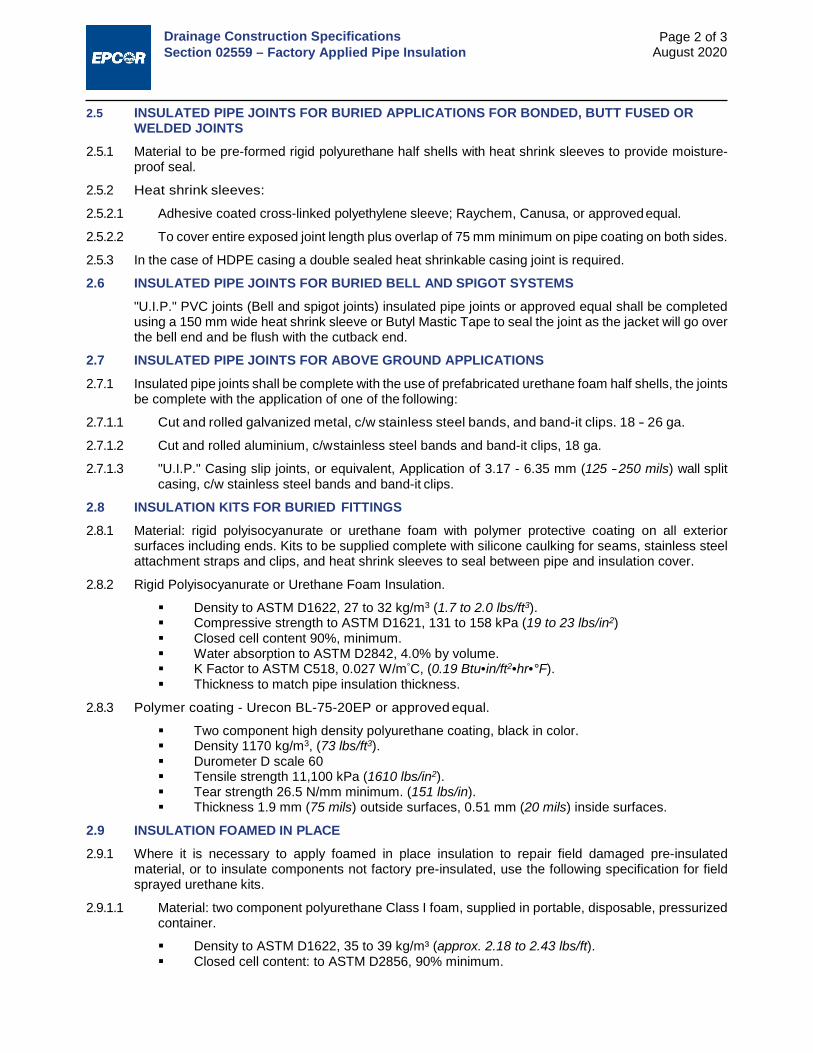
Drainage Construction Specifications Section 02559 – Factory Applied Pipe Insulation
Page 2 of 3 August 2020
2.5 INSULATED PIPE JOINTS FOR BURIED APPLICATIONS FOR BONDED, BUTT FUSED OR WELDED JOINTS
2.5.1 Material to be pre-formed rigid polyurethane half shells with heat shrink sleeves to provide moisture- proof seal.
2.5.2 Heat shrink sleeves:
2.5.2.1 Adhesive coated cross-linked polyethylene sleeve; Raychem, Canusa, or approved equal.
2.5.2.2 To cover entire exposed joint length plus overlap of 75 mm minimum on pipe coating on both sides.
2.5.3 In the case of HDPE casing a double sealed heat shrinkable casing joint is required.
2.6 INSULATED PIPE JOINTS FOR BURIED BELL AND SPIGOT SYSTEMS "U.I.P." PVC joints (Bell and spigot joints) insulated pipe joints or approved equal shall be completed using a 150 mm wide heat shrink sleeve or Butyl Mastic Tape to seal the joint as the jacket will go over the bell end and be flush with the cutback end.
2.7 INSULATED PIPE JOINTS FOR ABOVE GROUND APPLICATIONS 2.7.1 Insulated pipe joints shall be complete with the use of prefabricated urethane foam half shells, the joints
be complete with the application of one of the following:
2.7.1.1 Cut and rolled galvanized metal, c/w stainless steel bands, and band-it clips. 18 - 26 ga.
2.7.1.2 Cut and rolled aluminium, c/w stainless steel bands and band-it clips, 18 ga.
2.7.1.3 "U.I.P." Casing slip joints, or equivalent, Application of 3.17 - 6.35 mm (125 - 250 mils) wall split casing, c/w stainless steel bands and band-it clips.
2.8 INSULATION KITS FOR BURIED FITTINGS 2.8.1 Material: rigid polyisocyanurate or urethane foam with polymer protective coating on all exterior
surfaces including ends. Kits to be supplied complete with silicone caulking for seams, stainless steel attachment straps and clips, and heat shrink sleeves to seal between pipe and insulation cover.
2.8.2 Rigid Polyisocyanurate or Urethane Foam Insulation.
Density to ASTM D1622, 27 to 32 kg/m3 (1.7 to 2.0 lbs/ft3). Compressive strength to ASTM D1621, 131 to 158 kPa (19 to 23 lbs/in2) Closed cell content 90%, minimum. Water absorption to ASTM D2842, 4.0% by volume. K Factor to ASTM C518, 0.027 W/m°C, (0.19 Btu•in/ft2•hr•°F). Thickness to match pipe insulation thickness.
2.8.3 Polymer coating - Urecon BL-75-20EP or approved equal.
Two component high density polyurethane coating, black in color. Density 1170 kg/m3, (73 lbs/ft3). Durometer D scale 60 Tensile strength 11,100 kPa (1610 lbs/in2). Tear strength 26.5 N/mm minimum. (151 lbs/in). Thickness 1.9 mm (75 mils) outside surfaces, 0.51 mm (20 mils) inside surfaces.
2.9 INSULATION FOAMED IN PLACE 2.9.1 Where it is necessary to apply foamed in place insulation to repair field damaged pre-insulated
material, or to insulate components not factory pre-insulated, use the following specification for field sprayed urethane kits.
2.9.1.1 Material: two component polyurethane Class I foam, supplied in portable, disposable, pressurized container.
Density to ASTM D1622, 35 to 39 kg/m³ (approx. 2.18 to 2.43 lbs/ft). Closed cell content: to ASTM D2856, 90% minimum.

Drainage Construction Specifications Section 02559 – Factory Applied Pipe Insulation
Page 3 of 3 August 2020
Thermal conductivity: to ASTM C518, 0.020 to 0.028 W/m0 (0.14 to 0.20 Btu•in/ft²•hr•°F) Compressive strength to ASTM D1621, 103 to 172 kPa at 10% defection minimum (15 to
25 lbs/in2). Water absorption to ASTM D2842, 4.0% maximum by volume. Portafoam® or approved equivalent.
2.10 INSULATION ACCESSORIES 2.10.1 Heat-shrink tape for sealing insulation half shells against moisture adaptable to flexible installations as
manufactured by Raychem, Canusa, or approved equal.
2.10.2 Asphalt mastic vapor barrier coating to waterproof exterior surfaces of half shells or sprayed in place foam, as manufactured by Bakor #110 - 14, Insul Mastic #7505, or approved equal.
2.11 ELECTRIC HEAT TRACING 2.11.1 Active electric heat tracing to prevent the liquid in the pipe from freezing requires a heat tracing conduit,
electric tracing cable, power connection kits, terminal end seal kits and specified thermostatic controllers.
2.11.2 Heat tracing conduits.
2.11.2.1 To consist of extruded plastic moulding and to be applied to pipe to application of insulation.
2.11.2.2 To be securely fastened to pipe and sealed to prevent ingress of foam during insulation.
2.11.2.3 Each conduit to be checked after insulating to ensure they are not plugged.
2.11.2.4 Ends to be sealed prior to shipping to prevent foreign material from entering conduit while in transit or during installation.
2.11.3 Electric tracing cable.
2.11.3.1 Resistive parallel circuit type: to CSA-C22.2 No. 130.2, constant watt Thermocable.
2.11.3.2 Fluoropolymer polyolefin inner and outer insulation jackets and suitable for cutting to length in field.
2.11.3.3 If pipe being traced is plastic, heat trace cable to have metallic grounding overbraid and secondary Fluoropolymer extruded overjacket.
2.11.3.4 Manufacturer to ensure that specified electric tracing cable and heat tracing conduit size are compatible, so that cable may be pulled in with relative ease.
2.11.4 Thermostatic controller
2.11.4.1 Low temperature sensor control to be factory preset at 0.5°C.
2.11.4.2 High temperature sensor control to be attached to active zone of heat tracing cable and to serve as high temperature cut-out, factory preset at 29°C, for plastic pipe only.
2.11.5 Accessories
Thermocable accessories such as termination kits, splice kits and power feed kits shall be compatible with the cable being connected and be CSA approved.
2.11.6 Electric Tracing System
The electric tracing system and associated controls shall be as per the manufacturer's recommendations with particular attention being paid to the watt densities applied through conduits on plastic pipes. All tracing cables and related accessories to be CSA approved and comply with CSA heat-tracing standard CSA-C22.2 No. 130.2. Standard of acceptance is Urecon's Thermocable or approved equal.
3. EXECUTION Not Applicable
END OF SECTION

Drainage Construction Specifications Section 02620 – Subdrains
Page 1 of 1 August 2020
1. GENERAL 1.1 SCOPE
Supply and installation of subdrain pipe and filter materials.
1.2 RELATED SECTIONS Trench Backfill Section 3.1 Volume 2: Complete Streets
Aggregates Section 2.1 Volume 2: Complete Streets
2. PRODUCTS 2.1 PIPE
Pipe shall be perforated, asphalt coated, corrugated steel pipe conforming to CSA-G401; or other pipe as indicated on the drawings or as directed by the Engineer. Submit manufacturer's product data to the Engineer, 7 days prior to use.
2.2 FILTER AGGREGATE Filter aggregate shall conform to Section 2.1 - Aggregates, Volume 2: Complete Streets, designation 6, class 20.
2.3 GEOTEXTILE FABRIC 2.3.1 To be nonwoven plastic, non-biodegradable type, designed for separation of fill materials while
permitting movement of ground water.
2.3.2 Submit manufacturer's product data to the Engineer for approval, 7 days prior to use.
3. EXECUTION 3.1 TRENCHING 3.1.1 Excavate trench according to Section 3.1 – Trench Backfill, Volume 2: Complete Streets.
3.1.2 Trim and compact trench bottom to provide firm uniform support throughout length of pipe.
3.1.3 Allow 100 mm clearance on both sides of pipe for filter aggregate.
3.2 INSTALLATION 3.2.1 Install pipe materials according to manufacturer's recommended practice.
3.2.2 Place at trench bottom the geotextile fabric of sufficient width to completely wrap around filter aggregate and pipe with minimum 300 mm overlap. Lay pipe on fabric with perforations 2/3 down.
3.2.3 Alternatively, a sock of approved geotextile fabric may be slipped over the pipe.
3.2.4 Place filter aggregate around pipe to a minimum depth of 150 mm above top of pipe. Level aggregate surface and overlap the fabric.
3.2.5 Install connections to catch basin, manhole, or sewer pipe as required. Seal joints with approved sealant.
3.3 TOLERANCE Invert grade to be ±12 mm maximum variation from designated invert grade elevations, provided positive flow is maintained.
3.4 BACKFILL 3.4.1 Do not cover work until it has passed inspection by Engineer. Correct deficiencies as directed.
3.4.2 Backfill according to Section 3.1 – Trench Backfill, Volume 2: Complete Streets.
END OF SECTION

Drainage Construction Specifications Section 02631 – Manholes and Catch Basins
Page 1 of 4 August 2020
1. GENERAL 1.1 SCOPE
This section specifies requirements for constructing new manholes and catch basins, adjusting existing manholes and abandonments of manholes and catch basins.
1.2 RELATED SECTIONS Quality Assurance Chapter 8 Volume 1: General
Trench Backfill Section 3.1 Volume 2: Complete Streets
Sewers Section 02535
Drainage Manhole Frames and Covers Section 02632
Inspection of Sewers Section 02954
Leakage Testing of Sewers Section 02958
Concrete for Water and Drainage Structures Section 03310
1.3 PRODUCT QUALITY ASSURANCE AND QUALITY CONTROL 1.3.1 Pre-Cast Concrete
1.3.1.1 The manufacturer of pre-cast concrete items shall perform quality testing and control in accordance with CAN/CSA-A257.0.
1.3.1.2 The City representative may review the manufacturer’s quality control during production of pre-cast units for the City projects.
1.3.2 Frames and Covers
Refer to Section 02632 – Drainage Manhole Frames and Covers for Specifications for manholes frames, covers, grates and associates cast metal products for usage in the drainage system.
2. PRODUCTS 2.1 CONCRETE 2.1.1 Cast-in-place concrete: to Sections 03310 - Concrete for Water and Drainage Structures.
2.2 PRE-CAST MANHOLE AND CATCH BASIN SECTIONS 2.2.1 Pre-cast manhole sections, catch basins, adjusting neck rings and manhole steps shall conform to
CAN/CSA-A257.4 and be manufactured using Type HS High sulphate‐resistant hydraulic cement. All manhole sections shall have flexible watertight joints using flexible joint sealants. All preformed flexible joint sealants shall meet ASTM C990, Section 6.2.1, Butyl rubber sealants and contain 50% min Butyl rubber (hydrocarbon blends), % by weight.
2.2.2 Manhole joints shall meet requirements of CAN/CSA-A257.3.
2.2.3 All pre-cast units shall be marked with manufacturer’s identification, date of casting, type of cement and CSA Standard.
2.2.4 All pipe-to-structure connections shall meet the physical property and performance requirements of ASTM C923. In addition, all mechanical devices, including castings, bolt assemblies and take up clamps shall be constructed of 300 series stainless and use no plastic or plastic parts.
2.3 SAFETY STEPS 2.3.1 Safety steps shall be of the shape and size as shown on standard drawings and material shall be either
of the following:
2.3.1.1 A 25 mm diameter mild steel and deformed bar conforming to ASTM A615, hot bent at temperature of at least 870°C and galvanized in accordance with ASTM A123/A123M.

Drainage Construction Specifications Section 02631 – Manholes and Catch Basins
Page 2 of 4 August 2020
2.3.1.2 Minimum 20 mm diameter aluminium forged from 6061-T6, 6351-T6 or equal alloy having minimum tensile strength of 260 MPa.
2.4 FRAMES, GRATINGS, COVERS Refer to Section 2632 Drainage Manhole Frames and Covers
2.5 OTHER MATERIAL
2.5.1 Mortar: to requirements of CSA-A179, type S using Type HS High sulphate‐resistant hydraulic cement.
2.5.2 Washed gravel: Washed, crushed or screened stone or gravel consisting of hard and durable particles meeting the following gradation limits and free from sand, clay, cementitious, organic and other deleterious material:
Sieve Size (mm) Percent Passing by Mass 25 100 5 maximum 10
0.08 maximum 2
2.5.3 Granular material: Sand, free of organic matter and graded within the following limits:
Sieve Size (mm) Percent Passing by Mass 10 100 5 70 – 100
0.16 5 – 20 0.08 0 -12
3. EXECUTION 3.1 EXCAVATION AND BACKFILL 3.1.1 Excavate and backfill in accordance with Section 3.1 - Trench Backfill, Volume 2: Complete Streets.
3.1.2 Install manholes and catch basins in accordance with the design.
3.2 CONCRETE WORK 3.2.1 Do cast-in place concrete work in accordance with Section 03310 - Concrete for Water and Drainage
Structures.
3.2.2 Place concrete reinforcement in accordance with Section 7.12 - Reinforcing Steel, Volume 2: Complete Streets.
3.3 INSTALLATION 3.3.1 Construct units plumb and true to alignments and grade.
3.3.2 Complete units as pipe laying progresses.
3.3.3 Pump excavation free of standing water and remove soft, frozen, and foreign material.
3.3.4 Check all pre-cast units for required stamps. Any pre-cast unit without stamp is to be rejected.
3.3.5 Inspect all pre-cast units for damage in shipment. Reject all damaged units and advise the supplier.
3.3.6 Manholes shall be installed without field cutting.
3.3.7 Standard manholes
3.3.7.1 Standard manholes shall be constructed as shown on the construction drawings and in accordance with the standard drawings. As noted in the Design Standards, access manholes deeper than 40 feet on sewers 1200 mm diameter and larger shall have manhole frames and covers with a minimum of 900 mm in diameter installed.

Drainage Construction Specifications Section 02631 – Manholes and Catch Basins
Page 3 of 4 August 2020
3.3.7.2 Set pre-cast, pre-benched base on minimum 100 mm to maximum 300 mm depth of washed gravel material with a minimum of 150 mm offset around the pre-cast, pre-benched base. The washed gravel shall extend under incoming connection pipes to the extent of over-excavation that occurs around manholes.
3.3.7.3 As an exception, and subject to the City’s approval, cast -in place manhole base can be used. Place concrete directly on undisturbed ground and embed the first manhole section in the concrete. A layer of reinforcement shall be placed above the midpoint and shall have a minimum cross sectional area of 250 mm² per linear metre of concrete, in both directions. Form the channel and benching by casting the sloping manhole floor around the pipe to the spring line, cutting and trimming the pipe evenly with the concrete surface after the concrete has set sufficiently. Place additional concrete to form the upper channel sides and benching as shown on the standard drawings. Steel trowel finish required for benching. “Perched” manholes are not permitted on new construction.
3.3.7.4 Install T-riser pre-cast base with Class A bedding to the elevation of spring line. Connections to T-riser manholes must be within the barrel of the manhole, above the joint with the pipe.
3.3.7.5 Assemble manhole out of pre-cast sections. Make each joint watertight by using gaskets.
3.3.7.6 Manholes are to be oriented to allow for safe and easy egress and frame and cover must be aligned in the center of the travelled lane to the extend possible for arterial road and freeway/express way. The safety steps shall be installed in all pre - cast manhole sections, including the neck and in the cast -in place section to form a continuous ladder, with rungs equally spaced at a maximum of 410 mm, from within 300 mm below the cover, to within 600 mm of the base or benching. The steps shall be cast firmly in place or secured with a suitable mechanical anchorage to prevent pullout and maintain water tightness. The steps must be aligned vertically and cannot be installed in manhole barrel joints. The steps cannot be impeded by catch basin leads or service connections.
3.3.7.7 The neck section shall be within the height limits shown on the standard drawings. A manhole step is required in the appropriate joints within the neck section. As noted in the Design Standards, for access manholes greater than 40 feet deep on sewers of 1200 mm diameter and larger, the top-most rung shall be no closer than 750 mm from the manhole frame. The joint with a manhole rung shall be mortared. All other joints between pre-cast rings within the neck section shall have a removable gasket installed. Grout and/or bricks, concrete block, steel, wood, or any type of wedge shall not be used for height adjustment.
3.3.7.8 The manholes shall be fitted with frame and cover specified on the drawings.
3.3.7.9 The Contractor shall follow the manufacturer’s instructions for installation of the floating frame and covers (Type 80), ensuring that the frame is supported by the paving material and not by the manhole.
3.3.8 Catch Basins
3.3.8.1 Catch basins shall be constructed as shown on the drawings and in accordance with the standard drawings.
3.3.8.2 Set the pre-cast catch basin on 100 mm of compacted granular course.
3.3.8.3 All joints between pre-cast components shall be sealed with Kent seal or equivalent.
3.3.8.4 The neck section shall be within the height limits show on the Standards Drawings.
3.3.8.5 The catch basins shall be fitted with frame and cover specified on the drawings.
3.3.9 Connecting pipe to manholes and catch basins
3.3.9.1 SDR PVC and Open-profile PVC pipes shall be connected to the new or existing pre-cast, pre-benched manhole/catch basin or manhole/catch basin wall through a cored or formed opening, and a resilient connector installed into the manhole/catch basin wall in a manner that meets the performance requirements of ASTM C923.

Drainage Construction Specifications Section 02631 – Manholes and Catch Basins
Page 4 of 4 August 2020
A concrete pipe shall be installed through a cored or rough cut opening. The pipe shall be centered within the opening before grout is applied. To insure grout is not displaced after placement and during backfill, a short concrete collar shall be poured around the outside of the grouted joint. The maximum size of all rough cut openings shall not extend more than 50 mm greater than the OD. of the pipe. No gasket is required on the exterior of rigid pipe to MH’s at connections, but as an option, a cored hole with an approved gasket which meets ASTM C923 may be used. Connections to tee-riser manholes shall be within the manhole barrel. Not more than two service connections are permitted to a standard sanitary manhole. Service connections must be a minimum of 150 mm from a manhole barrel joint to protect the gasket and structural integrity of the barrel. No new service connections can be connected to existing drill drop manholes (DDMHs).
3.3.9.2 Plug lifting holes with low-shrink grout set in cement mortar. Insure all mortar is set prior to backfilling.
3.3.10 Place and compact backfill in accordance with Section 3.1 - Trench Backfill, Volume 2: Complete Streets.
3.4 INSTALLING UNITS IN EXISTING SYSTEMS 3.4.1 Where a new manhole is to be installed in an existing run of pipe, ensure full support of existing pipe
during installation and install new unit as specified and in accordance with standard drawings. Carefully saw cut and break out the portion of the existing pipe within the new manhole and remove all pieces.
3.4.2 Make joints watertight between new unit and existing pipe.
3.4.3 Where deemed expedient to maintain service through existing pipes and when systems constructed under this project are ready to be put in operation, complete installation with appropriate break-outs, removals, redirection of flows, blocking unused pipes or other necessary work.
3.5 ADJUSTING TOPS OF EXISTING MANHOLES 3.5.1 Remove existing grating, frames, covers, without breaking, and store for re-use at locations designated
by Engineer.
3.5.2 Raise or lower by adjusting the number of concrete neck rings. Refer to the standard drawings for neck section height limits.
3.5.3 Where raising or lowering with neck rings exceeds the neck height limits, rebuild the top section of the manhole by adding or removing pre-cast sections as required, in accordance with the Standard Drawings.
3.5.4 Install additional safety steps in adjusted portion of units as required.
3.6 ABANDONING OF EXISTING UNITS 3.6.1 Abandonment of manholes
3.6.1.1 Plug all pipes leading to the manhole as per Section 02535 - Sewers, Section 3.11, Abandonment of Sewers.
3.6.1.2 Remove and dispose of manhole portion to elevation of 1.0 m below finished grade and fill with low slump cast-in-place concrete, fillcrete or sand as directed by the Engineer.
3.6.2 Abandonment of catch basins
3.6.2.1 Completely remove all catch basins of diameter smaller than 900 mm diameter, plug the catch basin leads and backfill the area.
3.6.2.2 For 900 mm diameter units, follow the abandonment of manholes method.
END OF SECTION
Drainage Construction Specifications Section 02632 – Drainage Manholes Frames and Covers
Page 1 of 5 August 2020
1. GENERAL 1.1 SCOPE
This section specifies requirements for the manufacture and installation of gray iron and ductile iron castings. Castings are intended for use as frames, covers, and grates for Drainage manholes, catch basins and associated structures.
1.2 RELATED SECTIONS Quality Assurance Chapter 8 Volume 1 General
Sewers Section 02535
Manholes and Catch Basins Section 02631
Inspection of Sewers Section 02954
1.3 REFERENCED DOCUMENTS ASTM A48/A48M - Standard Specification for Gray Iron Castings.
ASTM A536 - Standard Specifications for Ductile Iron Castings.
AASHTO Designation M306 – 10 - Standard Specification for Drainage Sewer Utility and Related Castings.
Where the requirements of this Specification vary from the requirements of the referenced standards, the requirements of this Specification shall govern.
1.4 GENERAL REQUIREMENTS 1.4.1 Product supplied shall be in new and serviceable condition.
1.4.2 Gray Iron Castings shall conform to ASTM A48/A48 M; latest edition and revision. Class is shown on individual Drawings.
1.4.3 Ductile Iron Castings shall conform to ASTM A536, latest edition and revision. Class is shown on individual Drawings.
1.4.4 Requirements for Manufacturing, Testing, Inspection, Certification, Marking and Records shall conform to AASHTO M306-10, (or latest edition and revision in effect), with the following exceptions or additions to the AASHTO numbered Sections below:
1.4.4.1 Section 2.3 – Referenced Documents - Federal Specifications, is deleted
1.4.4.2 Section 5 – Manufacture – Section 5.2 - Permissible Variations, shall be superseded by requirements noted as Manufacturing Tolerances elsewhere. Tolerances noted on the drawings shall govern. If not on drawings, then Section 1.7 of this specification shall govern, and only if otherwise not noted elsewhere, AASHTO M306 Section 5.2 shall lastly apply.
1.4.4.3 Section 6 – Proof-Load Testing - Section 6.1 - First article inspection and proof-load testing is defined as a single representative test of a design being required in any of the following cases: a) any product that EPCOR Drainage Services specifies that is subject to loads, (b) any revision to an original design including any those where material changes are proposed, (c) any new manufacturer who has not supplied to EPCOR Drainage Services previously and (d) any manufacturer who has had their products rejected due to failures and wish to re- enter the supply market.
1.4.4.4 Section 6 – Proof- Load Testing – Section 6.1 - Proof-load third party testing may also occur in Canada with certified and calibrated equipment.
1.4.4.5 Section 6 – Proof-Load Testing – EPCOR Drainage Services will require the load test referred to in AASHTO M306 as “HS- 20” loading (178 kN) as its test load.

Drainage Construction Specifications Section 02632 – Drainage Manholes Frames and Covers
Page 2 of 5 August 2020
1.4.4.6 Section 8 - Inspection – Section 8.1 – where AASHTO M306 refers to differing basis of acceptance based on whether or not the foundry is located in the United States of America, EPCOR shall include “or Canada” after “….America” in this section.
1.4.4.7 Section 8 - Inspection – as an alternative to Section 8.1.3 – Acceptance on the Basis of Cast-on Test Bars, the manufacturer may gain acceptance on the basis of the following:
1.4.4.8 The manufacturer shall pour separately cast test bars as outlined in Section 8.1.2 and in accordance with ASTM standards for initial samples. The pouring of these samples and corresponding test bars shall be witnessed by a professional engineer licensed to practice in Canada or the United States, and certified by the engineer’s stamp that the same iron was used in the samples and test bars. Three separately cast ASTM test bars with the same serial number will be poured with each heat of the samples. One sample will be tested by the manufacturing foundry, one will be provided to EPCOR Drainage Services, and the third will be tested by the supplier using third party, certified Canadian or American metallurgical labs. Reports of the manufacturer’s and supplier’s test results shall be supplied to EPCOR Drainage Services, as well as in a Material Test Certificate in a form that is acceptable to EPCOR Drainage Services. In addition to this, the manufacturer shall supply a casting of load bearing units for destructive testing. These test casting units will have proof-load test results provided, test bars with matching serial numbers provided, and the complete metallurgical records provided as well. Correlations between material properties, test results, and load capacity for specific designs shall be derived from this.
1.4.4.9 Section 9 - Certification – The second sentence, “The certification shall state… …or local unit of government.” shall be deleted.
1.4.4.10 Section 10 - Markings - Section 10.1.1 – The AASHTO standard shall be superseded by Section 1.9 of this standard. “Made in …” is not required.
1.4.4.11 Section 10 – Markings – Section 10.1.6 shall be deleted.
1.4.5 Use of alternate classes or grades requires express written approval of EPCOR Drainage Services.
1.5 SUBMISSIONS 1.5.1 Shop Drawings - The supplier shall provide detailed dimensional shop drawings for review for all
products. The drawings shall be stamped by a professional engineer licensed to practice in Canada or the United States of America and show compliance to the standards.
1.5.2 Proof-Load Test Results - The supplier shall provide certified third party testing results for products that are subject to loads, to show compliance with AASHTO M306.
1.5.3 Markings - The supplier shall provide information and examples of the system used to identify the products, and the tracing system as per Section 1.9 of this standard.
1.6 DRAWINGS 1.6.1 The City Drainage Standards Drawings form an integral part of this Specification. The Drawings are
shown elsewhere on the City’s Standards.
1.6.2 Drawings referenced represent dimensional information for products that have historically been produced for the City. It is the intent that new products be dimensionally and functionally interchangeable with these existing products. Manufacturers may propose alternate materials, including grades of metal, structural variations or functional enhancements for review and approval.
1.6.3 For items not identified on the Standards Drawings, the Supplier shall provide six (6) copies of Shop Drawings for review and approval by EPCOR Drainage Services prior to production of item.
1.7 DIMENSIONS AND TOLERANCES 1.7.1 Product supplied shall conform to dimensions and tolerances as shown on Drawings.
1.7.2 Except as otherwise noted on Drawings, tolerances shall be:
Casting Pattern Dimension Allowable Tolerance
Mating Parts: Less than 50 mm ±0.8 mm

Drainage Construction Specifications Section 02632 – Drainage Manholes Frames and Covers
Page 3 of 5 August 2020
Mating Parts: 300 mm to 50 mm ±1.5 mm
Mating Parts: Greater than 300 mm ±3.0 mm
Other Dimensions to 900 mm ±3.0 mm
1.8 WORKMANSHIP AND FINISH 1.8.1 Castings shall be free of defects, cracks, porosity, flaws and excessive shrinkage.
1.8.2 Castings shall be true to pattern.
1.8.3 Castings shall be sandblasted or cleaned and ground to eliminate surface imperfections.
1.8.4 Coated or painted castings will not be accepted.
1.8.5 Manhole cover castings shall not perceptibly rock when mated with corresponding frame. Surfaces shall be machined or ground as noted on Drawings.
1.9 MARKINGS 1.9.1 Castings shall be marked with identification markings which include:
1.9.1.1 Series designation (City of Edmonton standard).
1.9.1.2 Foundry identification marking including month and year of production, as well as the Standard and class of material (ASTM for example), as well as an identifier such as a heat code and/or serial number that traces the product to test bar data and metallurgical composition records.
1.9.2 Markings shall be located in such a manner that they are easily identifiable. The markings shall be located on a “non-wear” location of the product.
1.10 QUALITY CONTROL AND QUALITY ASSURANCE 1.10.1 The Manufacturer shall co-operate with EPCOR Drainage Services and facilitate inspection and testing
activities.
1.10.2 Plant Inspection
1.10.2.1 Prior to the acceptance of a Manufacturer’s product, EPCOR Drainage Services will conduct a plant inspection to examine manufacturing facilities and quality control procedures. Manufacturer shall provide the following data, as requested:
Flow chart showing inspection and quality control functions Applicable standard Specifications Applicable production casting tolerances Foundry material analysis quality control reports for verification of chemical composition and
material strength properties.
1.10.3 Manufacturer shall provide a minimum of six (6) cast test bars prepared in accordance with ASTM A48/A48M or ASTM A536, as applicable. Test bars shall be provided on a minimum frequency of once per year. EPCOR Drainage Services may request additional test bars, at its sole discretion.
1.10.4 Supplier shall arrange for the initial plant inspection by contacting EPCOR Drainage Services. Plant inspection shall be conducted at a time and date mutually acceptable to the Manufacturer and EPCOR Drainage Services.
1.10.5 EPCOR Drainage Services may request the use of an approved third party for the purposes of conducting facility inspection. EPCOR Drainage Services shall have the sole right of approving the third party.
1.10.6 Initial plant inspections shall be performed at each plant facility manufacturing product governed by this Specification. Product manufactured in a plant not inspected and approved by EPCOR Drainage Services will not be accepted.
1.10.7 Initial plant inspection shall be valid for a period not to exceed three (3) years.

Drainage Construction Specifications Section 02632 – Drainage Manholes Frames and Covers
Page 4 of 5 August 2020
1.10.8 Costs for the initial plant inspections shall be borne by the Supplier. Costs incurred for subsequent plant re-inspections due to significant non-conformances found during the initial inspection shall be borne by the Supplier.
1.10.9 Additional plant inspections and testing may be conducted by EPCOR Drainage Services, at its sole discretion. Costs for additional discretionary inspections will be borne by EPCOR Drainage Services.
1.11 PRODUCT QUALITY CONTROL 1.11.1 Manufacturer shall perform quality control and testing for all product supplied. Testing shall be done in
accordance with this Specification and referenced documents.
1.11.2 Manufacturer shall retain quality control and testing documentation. Manufacturer shall make documentation available to EPCOR Drainage Services upon request.
1.11.3 Castings shall be inspected by EPCOR Drainage Services at Supplier’s premises in the greater Edmonton area. In the event the supplier does not have facilities in the greater Edmonton area, the supplier may request the inspection to occur at EPCOR Drainage Services’s delivery location (delivery yard).
1.11.4 Inspection shall be done in the presence of the Supplier’s representative. The Supplier shall be responsible for all inspection related costs including cost of labour and equipment required for the lifting and handling of the castings during the inspection.
1.11.5 EPCOR Drainage Services’ inspector shall stamp each casting that conforms to Specifications. Castings delivered without an EPCOR Drainage Services inspection stamp will not be accepted and shall be promptly removed at no cost to EPCOR Drainage Services.
1.11.6 EPCOR Drainage Services inspection shall consist of:
1.11.6.1 Visual inspection.
1.11.6.2 Measurement of dimensions for conformance to Drawings.
1.11.6.3 Trial fitting of frames and covers to “Standard” or “Proof” castings having machined bearing edges.
1.11.7 “Proof” castings referenced in Specification Clause 1.11.6.3 shall be manufactured by the Manufacturer. Costs incurred shall be borne by the Manufacturer.
1.11.8 “Proof” castings referenced in Specification Clause 1.11.6.3 shall be stored at the Manufacturer’s premises.
1.11.9 Costs incurred by EPCOR Drainage Services for additional testing due to rejected product will be borne by the Supplier.
1.11.10 Quality assurance testing performed by EPCOR Drainage Services shall not relieve the Manufacturer of responsibility for producing material in accordance with Specification requirements.
1.11.11 Repeated failure to comply with the requirements of this Specification may result in removal of the Manufacturer’s name from the approved supplier list.
2. PRODUCTS 2.1 FRAMES, GRATINGS, COVERS
Frames, gratings, and covers as shown on the standard drawings shall be guaranteed not to rock when installed in corresponding mating frame.
3. INSTALLATION 3.1 Construct units plumb and true to alignments and grade.
3.2 Check all units for required stamps. Any pre-cast unit without stamp is to be rejected.
3.3 Inspect all units for damage in shipment. Reject all damaged units and advise the supplier.

Drainage Construction Specifications Section 02632 – Drainage Manholes Frames and Covers
Page 5 of 5 August 2020
3.4 STANDARD MANHOLES 3.4.1 As required, install concrete neck rings for a final elevation adjustment of the manhole frame and cover.
3.4.2 The manholes shall be fitted with frame and cover specified on the drawings.
3.4.3 The Contractor shall follow the manufacturer’s instructions for installation of the floating frame and covers (Type 80), ensuring that the frame is supported by the paving material and not by the manhole.
3.5 CATCH BASINS 3.5.1 Catch basins shall be constructed as shown on the drawings and in accordance with the standard
drawings.
3.5.2 The catch basins shall be fitted with frame and cover specified on the drawings.
3.6 ADJUSTING TOPS OF EXISTING MANHOLES 3.6.1 Remove existing grating, frames, covers, without breaking, and store for re-use at locations designated
by Engineer.
END OF SECTION
Drainage Construction Specifications Section 02640 – Corrugated Steel Pipe Culvert
Page 1 of 2 August 2020
1. GENERAL 1.1 SCOPE
Supply and installation of corrugated steel pipe culvert. Removal of existing culvert.
1.2 RELATED SECTIONS Trench Backfill. Section 3.1 Volume 2: Complete Streets
Aggregates Section 2.1 Volume 2: Complete Streets
2. PRODUCTS 2.1.1 Corrugated steel pipe: to CSA-G401, plain galvanized; with helical lock seam corrugations having a
profile of 68 mm by 13 mm; round, diameters 300 mm to 2000 mm; 1.6 mm thick or as shown on drawings with ends cut square or bevelled as indicated. Include all necessary couplers and fasteners. Submit manufacturer's product data to the Engineer, 7 days prior to use.
2.1.2 Granular bedding: to Section 2.1 - Aggregates, Volume 2: Complete Streets designation 5, class 80.
2.1.3 Granular backfill: to Section 2.1 - Aggregates, Volume 2: Complete Streets designation 7, class 80.
2.1.4 Riprap
2.1.4.1 Rock: hard, durable stones that will not deteriorate with water or freeze and thaw cycles, with a minimum nominal size of 150 mm and a maximum nominal size of 400 mm.
2.1.5 Trash rack: made of steel as detailed on the drawings.
2.1.6 Geotextile Fabric: woven polypropylene monofilament which forms a dimensionally stable construction fabric. Minimum percent open area of 10%.
3. EXECUTION 3.1 EXCAVATION AND BASE PREPARATION 3.1.1 Excavate down to 300 mm below intended pipe invert in accordance with Section 3.1 – Trench Backfill,
Volume 2: Complete Streets. Excavate to a minimum width of three times the pipe diameter to permit pipe assembly and accommodate bedding placement and compaction equipment on both sides of the pipe.
3.1.2 Carefully trim bottom of excavation to provide uniform support along the profile and throughout the length of pipe. Compact base to a minimum 95% Standard Proctor density. If base is too soft to compact, continue excavation to firm base and backfill with granular or other material approved by the Engineer compacted in 150 mm lifts to a minimum 95% of Standard Proctor density.
3.1.3 Place granular bedding to a width at least 3 times the diameter of pipe in lifts of 150 mm when compacted. Compact each lift to a minimum 95% of maximum density according to ASTM D698 Method A. Loosen the top 50 mm of bedding in contact with the pipe to permit the corrugations to seat snugly.
3.2 LAYING PIPE 3.2.1 Roll or lift and lower pipe into position on prepared bedding. Do not drop or drag pipe.
3.2.2 Join pipe sections with appropriate couplers and fasteners according to manufacturer's instructions.
3.2.3 Repair damage to protective coating with two coats of galvacon, zinc oxide or bituminous paint.
3.2.4 Ensure that pipe is laid true to line and grade with the proper camber. If necessary, shore pipe to required position. Remove shoring when backfill has progressed to adequately support the pipe without displacement.
3.3 TOLERANCES 3.3.1 Alignment: Centreline of culvert shall not vary from the designated alignment by more than 75 mm.

Drainage Construction Specifications Section 02640 – Corrugated Steel Pipe Culvert
Page 2 of 2 August 2020
3.3.2 Invert Grade: ±12 mm maximum variation from designated invert grade elevations, provided positive flow is maintained.
3.4 PIPE ZONE BACKFILLING 3.4.1 Do not cover work until it has passed inspection by the Engineer. Correct deficiencies as directed.
3.4.2 Backfill according to Section 3.1 – Trench Backfill, Volume 2: Complete Streets as modified below.
3.4.3 Place granular backfill under pipe haunches on both sides of pipe in 150 mm lifts. Compact each lift thoroughly with hand tampers or hand-held power tampers.
3.4.4 Continue placing backfill simultaneously on both sides of pipe in 150 mm lifts. Compact each lift to a minimum 95% of maximum density according to ASTM D698 Method A. Do not allow the levels of fill on the two sides to differ by more than one lift at any time.
3.4.5 Build up backfill until reaching a minimum cover of 300 mm over pipe. After compaction, the remainder of the embankment or roadwork may proceed.
3.4.6 Do not allow construction and other traffic over the pipe unless adequate protective fill is placed in addition to the minimum cover. Remove such protective cover before proceeding with the rest of embankment fill.
3.5 RIPRAP 3.5.1 Install riprap at both ends of culvert as detailed.
3.5.2 Grade and level the slopes to receive the riprap. Lay geotextile fabric on the slopes anchored at the top.
3.5.3 Place rock in a staggered manner to form a running bond pattern on each layer and between layers. Remove foreign matter from rock surfaces during placement. Riprap face shall appear closely packed and uniform.
3.5.4 Where required, install trash rack as detailed on the drawings.
3.6 REMOVAL OF EXISTING CULVERT 3.6.1 Where indicated or required, carefully excavate and remove existing culvert. Deliver to designated
location or dispose of as directed by the Engineer.
3.6.2 Backfill the void as directed by the Engineer.
END OF SECTION

Drainage Construction Specifications Section 02645 – Precast Concrete Box Sewers
Page 1 of 4 August 2020
1. GENERAL 1.1 SCOPE
This section specifies requirements for constructing new gravity concrete box sewer lines for storm, sanitary and combined sewers.
1.2 RELATED SECTIONS Quality Assurance Chapter 8 Volume 1: General
Protection of the Urban Environment Chapter 13 Volume 1: General
Trench Backfill Section 3.1 Volume 2: Complete Streets
Inspection of Sewers Section 02954
Leakage Testing of Sewers Section 02958
Concrete for Water and Drainage Structures Section 03310
1.3 SUBMITTALS The Contractor shall submit shop drawings, not later than 10 working days prior to installation.
1.4 QUALITY ASSURANCE 1.4.1 The Engineer may at any time require the Contractor to produce certification by an independent testing
agency that materials used conform to the specified standards.
1.4.2 All concrete box sections shall be marked with the date of manufacture.
1.4.3 The Contractor and supplier shall provide reasonable access to the City's Quality Assurance Laboratory during and after manufacture for all testing required by the City.
1.5 HANDLING OF BOX SECTIONS 1.5.1 Handle box sections and appurtenances with approved equipment to prevent damage.
1.5.2 Store box sections in accordance with the manufacturer's recommendations.
2. PRODUCTS 2.1 CONCRETE BOX SECTIONS 2.1.1 Precast reinforced concrete box sections conforming to C1433M Standard Specification for Precast
Reinforced Concrete Monolithic Box Sections for Culverts, Storm Drains, and Sewers (Metric), made with Type HS High sulphate‐resistant hydraulic cement, as indicated on the drawings.
2.1.2 The box sections shall have male and female joints.
2.2 CEMENT MORTAR 2.2.1 Cement mortar for concrete box sections joints, shall conform to the following mix.
1 part Type HS High sulphate‐resistant hydraulic cement 1½ parts clean sharp sand Water to provide workability
2.2.2 In freezing weather heat sand, cement and apply mortar hot. Protect joints from freezing until mortar has set.

Drainage Construction Specifications Section 02645 – Precast Concrete Box Sewers
Page 2 of 4 August 2020
2.3 BEDDING AND BACKFILL AROUND THE BOX SECTION 2.3.1 Bedding: gravel complying with the following gradation:
Sieve Size % Passing by Mass 50 mm 100 25 mm 50 - 90
4.75 mm 20 - 60 425 µm 5 - 35 75 µm 0 - 5
2.3.2 Backfill: approved native material or gravel complying with the gradation in 2.3.1.
2.4 SEWER INSULATION Rigid Styrofoam HI-40 sheets, 50 mm thick of minimum size 600 mm by 2400 mm, if shown on drawings.
2.5 CONCRETE Concrete for forming additional concrete box fillets if required, to be as specified in Section 03310 - Concrete for Water and Drainage Structures.
3. EXECUTION 3.1 TRENCH AND BACKFILL 3.1.1 Do trench and backfill work in accordance with Section 3.1 - Trench Backfill, Volume 2: Complete
Streets.
3.1.2 Trench line, depth and bottom of excavation require approval by the Engineer prior to placing bedding material.
3.1.3 Remove and replace unsuitable material from trench bottom as directed by the Engineer.
3.1.4 Keep the excavation free of water. Dispose of water in accordance with Chapter 13 - Protection of the Urban Environment, Volume 1: General.
3.2 BEDDING 3.2.1 Prepare the box sewer bedding in accordance with the drawings.
3.2.2 Place gravel bedding specified in Clause 2.3.1 as shown on the drawings and compact to 95% of Standard Proctor density across the full width of the trench.
3.3 INSPECTION OF BOX SECTIONS 3.3.1 Inspect box sections for defects, immediately before lowering into the trench.
3.3.2 Do not install any box sections earlier than 7 days after the date of manufacture.
3.4 ALIGNMENT AND GRADE 3.4.1 Lay box sections to the alignment and grade shown on the drawings.
3.4.2 Laser equipment used to maintain alignment and grade shall be operated by a qualified technician.
3.4.3 The centreline of the box sewer shall not be more than 100 mm off the given line.
3.4.4 The invert of the sewer main shall not deviate from the grade given by an amount greater than 15 mm. Any deviations in excess of this shall be corrected by the Contractor, in a manner approved by the Engineer, at no cost to the City.
3.4.5 All box sections shall be laid sloping in the desired directions, with no reversed grades on any box section.
3.4.6 Box sections shall be level across their width.

Drainage Construction Specifications Section 02645 – Precast Concrete Box Sewers
Page 3 of 4 August 2020
3.5 LAYING AND JOINTING 3.5.1 Lower box sections carefully into trench so as to prevent damage. Do not drop box sections or
materials into the trench.
3.5.2 Lay box sections in accordance with manufacturer's recommendations and proceed upgrade.
3.5.3 Produce a smooth, uniform invert.
3.5.4 Forming gasket joints:
3.5.4.1 Place Kent Seal or equal sealing compound gasket inside the female end of the box.
3.5.4.2 Gasket diameter shall be not less than 19 mm and shall be lapped at the top.
3.5.4.3 Insert the male end of box and drive in.
3.5.4.4 Ram the gasket solidly and tightly into the annular space using suitable caulking tools and fill the joint with cement mortar.
3.5.4.5 Overfill the joint with mortar and level off to a 45° angle to the outside of the box.
3.5.4.6 Set two box sections ahead of the joint, before mortaring the joint.
3.6 BACKFILLING 3.6.1 Backfill around the box sections with selected native material or imported granular backfill deposited
uniformly in the trench at both sides of the box sewer, for the full width of the excavation. Compact in layers of 150 mm maximum depth to 95% of Standard Proctor density until the compacted backfill is to the top of the box section.
3.6.2 Frozen material shall not be used for backfill or bedding. When conditions are such that unfrozen native material is not obtainable, provide unfrozen imported granular material at no additional cost.
3.7 INSTALLATION OF INSULATION 3.7.1 Where shown on drawings, place the rigid Styrofoam sheets on top of the box sewer, butting ends
together for a uniform fit.
3.7.2 To secure insulation to the top of the box sewer, use a light application of mastic as recommended by the Styrofoam manufacturer, or a mechanical fastening system as approved by the Engineer.
3.7.3 Backfill carefully over the insulation using suitable equipment, selected backfill, and appropriate backfill thickness so that the insulation is not damaged.
3.7.4 Backfill to the original ground surface as shown in the drawings.
3.8 CLEANING 3.8.1 Cover open ends of box sewer using timber and plywood before leaving the unfinished work at any
time.
3.8.2 Remove all foreign material from the box sewer and take precautions to prevent debris from new sewers from entering existing systems.
3.8.3 Flush box sewer clean by a method approved by the Engineer and dispose of all contaminated water away from existing sewers in accordance with Chapter 13 - Protection of the Urban Environment, Volume 1: General.
3.9 FIELD LEAKAGE TESTING 3.9.1 Perform testing identified in the Contract or as specified by the City.
3.9.2 For identified testing follow Section 02958 - Leakage Testing of Sewers.
3.10 INSPECTION 3.10.1 Carry out television or visual inspection of the completed sewer as described in the Section 02954 -
Inspection of Sewers.

Drainage Construction Specifications Section 02645 – Precast Concrete Box Sewers
Page 4 of 4 August 2020
3.10.2 Perform inspection after all mains, manholes and service connections have been installed.
3.10.3 Repair all defects which will impair the structural integrity and the performance of the sewer system including, but not limited to improper joints, cracked, sheared or excessively deflected pipe, sags and rises which pond water in excess of 35 mm, protruding service connections and visible leaks.
3.10.4 Precast box sections shall be rejected if cracks 0.6 mm or wider are found.
END OF SECTION

Drainage Construction Specifications Section 02952 – Temporary Flow Control
Page 1 of 2 August 2020
1. GENERAL 1.1 SCOPE
This section specifies the requirements for the provision of temporary sanitary sewer service and the control of sanitary or storm sewer flows using by-pass pumping.
1.2 RELATED SECTIONS Cleaning Sewers Section 02953
Inspection of Sewers Section 02954
Relining Sewers Section 02957
1.3 WORK CONTENT The work includes supplying all equipment, labour, material, and services for the following:
1.3.1 Engineering services for the proposed temporary by-pass scheme.
1.3.2 Mobilization and demobilization.
1.3.3 Traffic control and maintenance of access to properties.
1.3.4 Providing alternate sanitary servicing to residents.
1.3.5 By-passing flow.
1.3.6 Reinstatement of permanent sanitary services and normal flows.
1.4 CONSTRAINTS 1.4.1 Existing sewer services shall not be shut off for more than 48 consecutive hours.
1.4.2 A maximum of 25 services shall be out of service at one time, unless specifically authorized by EPCOR Drainage Services.
2. PRODUCTS None Applicable
3. EXECUTION 3.1 FLOW CONTROL
When sewer flows are too high to effectively conduct inspection or relining, one or more of the following methods of flow control or isolation shall be used.
3.1.1 Plugging and Blocking
A sewer line plug shall be inserted into the line at a manhole upstream from the section to be isolated. The plug shall be so designed that all or a portion of the sewage flows can be released. During the isolation portion of the operation, flows shall be shut off or substantially reduced in order to execute required work. After work is completed flows shall be returned to normal.
3.1.2 By-passing Flow in Sewer Lines
3.1.2.1 When adequate flow control cannot be obtained by the plugging method, pumps or siphons shall be used to divert all or a portion of the sewage flows, as may be necessary to perform the specified inspection or relining. Excess sewage flows shall be transported through a closed pipeline or using tank trucks provided by the Contractor. Trucks shall go to the nearest or most economical approved disposal site.
Drainage Construction Specifications Section 02952 – Temporary Flow Control
Page 2 of 2 August 2020
3.1.2.2 The Contractor shall provide a detailed scheme to deal with mainline flows for EPCOR Drainage Services' approval, taking into account the following:
i. Pumps and bypass lines shall be of adequate capacity to handle the peak flows, and ensure that no upstream flooding occurs during isolation period.
ii. Equipment shall conform to the applicable noise bylaws.
3.2 MONITORING 3.2.1 Provide continuous monitoring of water levels in upstream and downstream manholes. Ensure that
there is no contamination of basements, ditches, roadways or sidewalks with raw sewage. In the event of such contamination, immediate action shall be taken to eliminate the source of contamination. Proper clean up of the affected area shall be followed and no work shall recommence until a reevaluation of the complete process has been carried out by EPCOR Drainage Services. No rehabilitation work shall be undertaken unless authorized by EPCOR Drainage Services.
3.2.2 Where the Contractor has used a flow control procedure to limit flows during an inspection, the Contractor shall note on the inspection report the depth of normal flow and the duration the flow control was in affect.
3.3 SAFETY 3.3.1 The Contractor shall pay strict attention to the Alberta Occupational Health and Safety Act, Regulation,
Code, and other construction safety measures as outlined in Chapter 4 - Occupational Health and Safety Requirements, Volume 1: General.
3.3.2 Contractors shall provide a copy of their confined space entry code of practice and applicable procedures prior to commencing work.
3.4 TEMPORARY SANITARY SERVICE 3.4.1 The Contractor shall provide temporary facilities as required to divert sewage from the sanitary service
connections for commercial and apartment buildings affected by the work. Temporary facilities, for example portable toilet units, are not acceptable unless the residents signs a release.
3.4.2 The Contractor shall supply residents of single family houses or duplexes affected by the work with temporary sanitary facilities inside the house for the entire duration of the work and shall ensure that they are properly maintained during operation and removed when work is completed.
3.4.3 Inform affected residents in writing of the length of disruption to service, details of alternate services that will be provided, any traffic-related constraints, noise levels to be expected, hours of work and safety concerns.
3.4.4 Attend meetings with residents as required.
3.5 CLEAN-UP 3.5.1 Upon completion of the work clean up and restore the affected surface areas to the condition that
existed prior to commencement.
3.5.2 Remove and haul debris to an approved disposal site.
END OF SECTION
Drainage Construction Specifications Section 02953 – Cleaning Sewers
Page 1 of 2 August 2020
1. GENERAL 1.1 SCOPE 1.1.1 This section specifies the requirements for cleaning of sewer mains and removing foreign materials
from lines.
1.1.2 Contractors that are cleaning sewers are required to provide information which includes detailed specifications, methodology, design and cleaning details.
1.2 RELATED SECTIONS Temporary Flow Control Section 02952
Inspection of Sewers Section 02954
1.3 CONSTRAINTS 1.3.1 The Contractor's cleaning methods shall not shut off the existing services for more than 12 hours. The
Contractor shall provide acceptable alternatives to services that are temporarily disrupted.
1.3.2 The cleaning shall be undertaken without any excavation unless approved in writing by EPCOR Drainage Services.
2. PRODUCTS 2.1 MATERIALS 2.1.1 Chemicals such as those used for root control shall be selected in accordance with current
environmental protection regulations to minimise negative impacts on the environment.
2.1.2 Contractors shall submit a material safety data sheet (SDS) for each chemical used prior to starting work.
2.2 EQUIPMENT The equipment required for this work may include one or more of the following:
Rotating Chain Cutter Tool Rotating Cutter Head Tool Service Hub Cutter Tool High-Velocity Jet Nozzles. CCTV Cameras
3. EXECUTION 3.1 SAFETY PROCEDURES 3.1.1 The Contractor shall pay strict attention to the Alberta Occupational Health and Safety Act, Regulation,
Code and other construction safety measures as outlined in Chapter 4 - Occupational Health and Safety Requirements, Volume 1: General.
3.1.2 Contractors shall provide a copy of their confined space entry code of practice and applicable procedures prior to commencing work.
3.1.3 Supply material safety data sheets for all chemicals to be used to EPCOR Drainage Services for approval.
3.2 PRELIMINARY INSPECTION 3.2.1 Obtain all information necessary for the planning and execution of the sewer cleaning.
3.2.2 Review all available closed circuit TV (CCTV) videos and record drawings.
3.2.3 If required, inspect sewer by CCTV and by other means prior to starting work. Inspect the interior of the sewer carefully to determine the existence of any conditions that may prevent proper cleaning. (e.g. if roots or solid debris is suspected)

Drainage Construction Specifications Section 02953 – Cleaning Sewers
Page 2 of 2 August 2020
3.2.4 Employ personnel trained in viewing CCTV in accordance with EPCOR Closed-Circuit Television Inspection Manual and the National Association of Sewer Service Companies (NASSCO)’s Pipeline Assessment Certification Program (PACP) Reference Manual for locating breaks, obstacles, and service connections.
3.2.5 Provide a detailed record of all breaks, severe pipe deformations, significant changes in cross sections between manholes, obstacles and service connections.
3.3 BYPASSING FLOW IN SEWER LINES: Where high sewer flows prevent adequate cleaning or post cleaning inspection, flows shall be controlled as defined in Section 02952 – Temporary Flow Control.
3.4 LINE CLEANING 3.4.1 Clean the line of obstruction such as solids, roots, sediments, protruding service connections or
encrustation to at least 98% of the original capacity so that any subsequent rehabilitation scheme, such as joint grouting or relining, can proceed.
3.4.2 If sewer clearing or obstacle removal methods can not remove an obstruction, a point repair excavation shall be made to uncover and remove or repair the obstruction. EPCOR Drainage Services’ prior approval must be obtained.
3.4.3 The Contractor shall make every effort to identify such locations during the tender period after reviewing the available CCTV inspection videos and reports and record plans. No extra payment shall be made for removal of obstructions that in the opinion of EPCOR Drainage Services were adequately identified at the time of tender.
3.5 INSPECTION ON COMPLETION 3.5.1 The Contractor will carry out inspection of the cleaned sewers by television camera or other related
means, in accordance with Section 02954 – Inspection of Sewers.
3.5.2 The inspection shall be performed after all mains, manholes and service connections have been cleaned along a section.
3.6 CLEAN UP 3.6.1 Upon completion of the sewer cleaning, clean up and restore externally affected areas to the condition
that existed prior to commencement of the work.
3.6.2 Remove and haul debris to an approved disposal site. Debris and water shall be disposed of in accordance with applicable bylaws and legislation. Where necessary, debris may need to be tested for compliance with environmental law. Contractor shall retain invoices of disposal and such testing, and provide them for payment, if payment terms of the contract allow.
END OF SECTION

Drainage Construction Specifications Section 02954 – Inspection of Sewers
Page 1 of 5 August 2020
1. GENERAL 1.1 SCOPE 1.1.1 This section specifies requirements for the inspection of gravity sewer lines, including:
Closed circuit television (CCTV) Sonar Visual (walk-through) Manhole Inspection
1.1.2 The purpose of the sewer inspection may be for the requirements of a construction completion certificate (CCC), a final acceptance certificate (FAC), or for other reasons that the City/EPCOR Drainage Services has specified elsewhere. (a condition assessment of older sewers, for example). The Inspection Service Levels are defined herein, and the requirements for a specific project shall be indicated in the project requirements.
1.1.3 The work of this section includes:
Supply of all materials, equipment, labour and supervision. Cleaning of sewers immediately before inspection. Inspection of manholes, where specified.
1.2 DEFINITIONS Inspection Service Levels: The description of the various levels of service required for complete CCTV inspection of sewer pipes. Levels are further defined below:
1.2.1 Level 1: Refers to performing CCTV inspection with sewers in existing condition, with no cleaning or flushing.
1.2.2 Level 2: Refers to performing CCTV inspection with sewers being cleaned with one pass by flushing and cleaning equipment prior to televising. Unless otherwise specified, this is the level normally associated with CCC or FAC acceptance inspection.
1.2.3 Level 3: Refers to performing CCTV inspection with sewers cleaned to Level 2, plus removal of sediments, solids, roots, encrustations and protruding services to allow passage of CCTV equipment.
1.2.4 Level 4: Refers to performing CCTV inspection with sewers cleaned as specified in Section 02953. This is a level associated with preparations of sewers prior to cured-in-place pipe (CIPP) relining. It includes a Level 3 cleaning plus any requirement of the lining design and installation, including close fit of the lining, removal of grease, removal of water, etc.
1.3 RELATED SECTIONS Temporary Flow Control Section 02952
Cleaning Sewers Section 02953
1.4 SAFETY PROCEDURES 1.4.1 The Contractor shall pay strict attention to the Alberta Occupational Health and Safety Act, Regulation,
Code and other construction safety measures as outlined in Chapter 4 – Occupational Health and Safety Requirements, Volume 1: General.
1.4.2 Contractors shall provide a copy of their confined space entry code of practice and applicable procedures prior to commencing work.
1.4.3 All documents and safety equipment required shall be available for inspection on demand.
1.4.4 Violation of any aspect of Chapter 4, Volume 1: General will be grounds for terminating the Contract.

Drainage Construction Specifications Section 02954 – Inspection of Sewers
Page 2 of 5 August 2020
2. PRODUCTS 2.1 CLOSED CIRCUIT TELEVISION INSPECTION EQUIPMENT 2.1.1 Television equipment shall consist of a self-contained camera and a monitoring unit connected by a
coaxial cable. This equipment shall be specifically designed and constructed for such inspection purposes. The camera shall be mounted on adjustable skids, or wheels, or have a height adjustment to facilitate the inspection of different sizes of pipe and to allow for visual judgement of ovality, by centring the camera within the pipe. The camera shall be waterproof and shall have a remote controlled self-contained lighting system capable of producing effective illumination for all sizes of pipe. The lighting system shall be capable of lighting the entire periphery of the pipe.
2.1.2 For inspection of existing sewers and new sewers the camera shall have pan and tilt capabilities or sidescan technology.
2.1.3 Recorded picture quality and definition shall be to the satisfaction of EPCOR Drainage Services.
2.1.4 Location measurement of defects shall be made by devices having a proven accuracy of ±1.5% or 2 m, whichever is greater. Cable markings, if used, shall not be spaced greater than 600 mm along the length of the cable. Distance measurement system used shall be regularly calibrated by the Contractor, with records to be made available to EPCOR Drainage Services. EPCOR Drainage Services may reject equipment that cannot meet the accuracy requirements. The Contractor shall promptly inform EPCOR Drainage Services of significant discrepancies between EPCOR Drainage Services record drawings and actual field observations.
2.1.5 Equipment shall be mounted in appropriate vehicle. Electrical power for the system shall be self-contained and shall not require removal for each set-up. External power sources from public or private residences shall not be permitted. Sound dampening shall be applied to the vehicle and equipment.
2.1.6 Stub lines and other locations where access is limited to one manhole shall be televised using a crawler equipped camera.
2.1.7 EPCOR Drainage Services shall not be responsible for any loss or damage to the Contractor's equipment. The Contractor shall carry all necessary insurance to cover loss, damage, and/or retrieval during inspection. The Contractor shall be responsible for any damages due to sewer back-up or flooding that are caused by his cleaning or inspection operations. The Contractor shall promptly inform EPCOR Drainage Services if any such damages occur.
2.2 CCTV INSPECTION REPORTS 2.2.1 A digital video shall be provided accompanied by an inspection report. This report shall be in
accordance with EPCOR Closed-Circuit Television Inspection Manual and the National Association of Sewer Service Companies (NASSCO)’s Pipeline Assessment Certification Program (PACP) Reference Manual. It shall be a record of the exact location of each leak or fault discovered by the television - e.g. open joints, broken, cracked, deformed or collapsed pipe, presence of grease, roots, debris, accumulation, obstruction, infiltration, water depth variations and other points of significance. The reference location for distance measurements shall be the wall of the launch manhole (chainage 0+00). If the inspection includes an intermediate manhole, chainage shall be reset to 0+00 in the centre of the intermediate manhole.
2.2.2 All videos shall be in digital mp4 (H.264 compression) format at a minimum resolution of 640 x 480 and a data rate of 6000 kbps. For inspections reports that are provided to EPCOR Drainage Services under a direct contract, the report shall be created in a current CCTV software. The latest version of the NASSCO template for the report shall be provided by CCTV software provider. CCTV reports shall be submitted in digital media as individual reports also containing the “NASSCO standard data exchange format” and shall not contain any Player software or other embedded programs
2.2.3 The report shall include the location of all service connections together with a statement of opinion as to whether or not the service connections are subject to joint infiltration. Protrusions of service connections into the main line shall be noted with reference to the degree of protrusion.

Drainage Construction Specifications Section 02954 – Inspection of Sewers
Page 3 of 5 August 2020
2.2.4 Photographs of sewer defects shall be provided in the CCTV software report. The photographs shall be co-ordinated within the written report by defect and location. A minimum of one photograph per line shall be taken to show a representative view of the workmanship.
2.2.5 The reports shall be submitted on external hard drives. Media submitted shall become the property of EPCOR Drainage Services.
2.3 CCTV MANHOLE INSPECTION REPORTS 2.3.1 Manholes shall be inspected and reports prepared in conformance with EPCOR Closed-Circuit
Television Inspection Manual and the National Association of Sewer Service Companies (NASSCO)’s Pipeline Assessment Certification Program (PACP) Reference Manual, MACP Section and shall indicate structural conditions of the cover, frame, barrel, benching, flow channel and steps of each manhole. The report shall also show video of both sides of the cover. The report shall also identify cross-connections between sanitary and storm systems, high water marks and degree of sedimentation.
3. EXECUTION 3.1 GENERAL
EPCOR Drainage Services will supply all maps and drawings required for locating the mainlines and manholes to be inspected. The Contractor will be responsible for locating and identifying the manholes and lines in the field. The Contractor shall advise EPCOR Drainage Services of buried or non-locatable manholes immediately through phone and email. Any discrepancies found should be noted and reported to EPCOR Drainage Services.
3.2 CLEANING (FOR SONAR OR CCTV INSPECTION) 3.2.1 Refer also to Section 02953 Cleaning Sewers. Prior to inspection, other than for level 1 service, sewer
lines are to be cleaned utilising low pressure flushing.
3.2.2 If the amount of debris, roots or encrustation makes it impossible to determine the structural condition of the sewer, Contractor shall undertake high pressure flushing, as directed. Sludge, dirt, sand and other debris resulting from the cleaning operations shall be removed from the downstream manhole of the section being cleaned. Passing material from the section being cleaned to the downstream sewer section shall not be permitted.
3.2.3 Where the initial CCTV inspection indicates the presence of sags greater than 25% of the internal diameter of the sewer, the Contractor shall high-pressure flush that section of line. The section shall then be re-televised twice, firstly with a flusher a short distance ahead of the camera and then without a flusher active. All three records shall be forwarded to EPCOR Drainage Services.
3.2.4 All debris flushed from the lines shall be removed and the Contractor shall be responsible for the proper disposal of the material.
3.2.5 Water for flushing is generally available from fire hydrants located near the job site. The Contractor shall make arrangement with EPCOR Water Services for the use and payment of water consumed. A hydrant use report shall be filled out and submitted to EPCOR Water Services.
3.3 TRAFFIC CONTROL 3.3.1 Interference to the normal flow of traffic shall be kept to a minimum.
3.3.2 Traffic control, barricades, guards, and other safety precautions to be as directed in Chapter 14, Volume 1: General – Vehicular Access and Parking.
3.4 FLOW CONTROL When sewer flows are too high, generally more than 1/3 of the pipe diameter, to effectively conduct the inspection, flows shall be controlled as defined in Section 02952 – Temporary Flow Control.
3.5 WORK DURING NON-PEAK HOURS Should the area being inspected be anticipated to have peak flow periods during normal working hours, the option to convert to night shifts for inspection procedures may be exercised by mutual agreement

Drainage Construction Specifications Section 02954 – Inspection of Sewers
Page 4 of 5 August 2020
between the Contractor and EPCOR Drainage Services. The Contractor shall comply with the requirements of the City of Edmonton Community Standards Bylaw 14600.
3.6 CLOSED CIRCUIT TELEVISION INSPECTION 3.6.1 The CCTV inspection shall provide a full record of the condition of the pipes, manholes, and
appurtenances along the designated section of sewer.
3.6.2 The Contractor shall not attempt a CCTV inspection if water levels in the pipe obstruct the camera’s view unless instructed by EPCOR Drainage Services.
3.6.3 When required, a small diameter polyethylene rope or similar line shall be installed in the sewer in advance of the inspection in order that the camera traction cable may be drawn through the sewer. This line shall be installed on a manhole to manhole basis with the line being tied off at each individual manhole to facilitate the quick removal of the equipment should the need arise due to mainline sewer blockages or other emergency situations.
3.6.4 Direct communication shall be established between the monitoring station and the camera towing device operator. No loudspeaker devices shall be allowed.
3.6.5 The camera advance rate shall not exceed 9 m/min to allow adequate time for operator interpretation. A uniform rate of speed shall prevail.
3.6.6 If, during the inspection procedures the television camera will not pass through the entire pipe section between manholes, the Contractor will reset the equipment in such a manner so that the inspection can be performed from the opposite manhole.
3.6.7 The camera operator shall, during the inspection, pan the camera to focus on observable deficiencies in the pipe that may be located off-center to the direction of camera travel. This shall include all services, joints to the top, left or right, cracks and fractures or surface deterioration of the pipe walls.
3.6.8 On completion the Contractor shall provide television reports and digital media as detailed in Section 2.2 above.
3.7 SONAR INSPECTION 3.7.1 The sonar inspection shall identify all the major defects along the wetted perimeter of the pipe.
3.7.2 Sonar imaging equipment shall consist of a self-contained monitoring unit. The unit will be specifically adapted for the sewer main inspection purposes. The float or skid used to facilitate the movement of the equipment along the sewer main must be designed to accommodate various pipe sizes.
3.7.3 If the sewer contains debris, roots or encrustations that could impede the accuracy of the results from the sonar inspection then the sewer shall be cleaned by high pressure flushing equipment prior to undertaking the inspection.
3.7.4 The Contractor shall not attempt inspection, if the water depth in the sewer is not sufficient to fully submerge the sonar equipment. There shall be a minimum of 75 mm of water above the equipment.
3.7.5 The sonar equipment shall be equipped with a zoom-in feature to produce a full screen image on the computer or TV monitor.
3.7.6 If turbulent flow conditions are expected in the sewer line due to bends, incoming flow from another sewer, or near drop manholes, the Contractor shall carry out inspection during off-peak hours (i.e., night time or weekends), to minimise distortion to the sonar image due to air bubbles and suspended particles.
3.7.7 The Contractor shall maintain the sonar equipment at the centre of the sewer line to obtain the best image of the wetted perimeter of pipe.
3.7.8 The following information shall be submitted to EPCOR Drainage Services:
3.7.8.1 Reports shall be supplied on external hard drives. Each report must be per individual asset, each report must contain a produced CCTV software report containing a photo for each defect, and one photo for the overall line condition, and must also contain an export file in the NASSCO standard data exchange format.
Drainage Construction Specifications Section 02954 – Inspection of Sewers
Page 5 of 5 August 2020
3.7.9 EPCOR Drainage Services may accept alternative inspection method to sonar. Contractor shall submit all details of the methodology, design of supplementary equipment required for inspection and history of using the equipment for sewer inspection to EPCOR Drainage Services for approval.
3.8 VISUAL WALK-THROUGH INSPECTION OF LARGE DIAMETER SEWERS 3.8.1 Visual and video inspections will be required in lines where conditions will allow the Contractor's
inspection crew to safely walk through the sewer. Visual inspections shall not be carried out for sewers less than 1200 mm diameter.
3.8.2 Special industrial grade colour inspection cameras, either hand-held or contained in waterproof housings shall be carried manually through the sewer during inspection work. The cameras shall be operable in conditions of 100% humidity. Camera lighting shall be sufficient for use with colour inspection cameras to clearly see details of the sewer interior. The complete video system (camera, lens, lighting, cables, monitors and recorders) shall be capable of providing a picture quality acceptable to EPCOR Drainage Services. If the equipment does not produce an acceptable picture quality then it shall be removed. No payment will be made for unsatisfactory inspections.
3.8.3 Safety of the inspection crew is a prime concern. There shall be a minimum of two personnel in the sewer at any time. All crew members, whether assigned to the sewer or to assist at the surface, must receive confined space entry and rescue training.
3.8.4 The Contractor is responsible for obtaining all information concerning depths of flow, manhole depths, air quality in the sewers, accessibility of manholes, traffic flows and any other considerations that might affect the manner in which the inspection is undertaken. The Contractor’s tender price shall allow for completing the required inspections under existing conditions.
3.8.5 Whenever practical the video camera shall be used to look up sewer lines and services connected to the main line being inspected. Conditions in these sewer lines and services shall be noted on the inspection reports. Accurate and continuous distance readings, the date of inspection and EPCOR Drainage Services’ manhole number designation for each manhole shall be superimposed on the video recording for each line inspected
3.8.6 No maximum flow depth has been established in this specification for manual walk-through inspections. However, Contractors shall use their own judgement before attempting any inspections. Special attention shall be paid to the current weather conditions when inspecting the combined sewers or storm sewers, as there may be a sudden increase in flow depth due to rain in the service area of the sewer.
3.8.7 The following information shall also be submitted:
Reports shall be submitted on an external hard drive with each inspection documented by the technician during the actual inspection work describing the parameters of the line being inspected, i.e. location, depth, diameter and pipe type, as well as describing direction of inspection, connections, defects and unusual conditions observed during the inspection.
3.9 CLOSED CIRCUIT TELEVISION MANHOLE INSPECTION 3.9.1 When specifically required for conditions assessments of existing manholes (not normally required for
CCC and FAC), the CCTV inspection shall provide a full record of the designated manholes.
3.9.2 The Contractor shall not attempt a CCTV inspection if water levels in the manhole obstruct the camera’s view unless instructed by EPCOR Drainage Services.
3.9.3 The camera descent rate shall not exceed 20 m/min to allow adequate time for operator interpretation. A uniform rate of speed shall prevail.
3.9.4 The camera operator shall, during an inspection with a normal video camera, pan the camera to focus on observable deficiencies in the manhole, sidescan technology only requires a single pass.
3.9.5 On completion the Contractor shall provide reports as detailed in Section 2.3 above.
END OF SECTION
Drainage Construction Specifications Section 02955 – Pipe Bursting
Page 1 of 4 August 2020
1. GENERAL 1.1 SCOPE
This section specifies the requirements for the supply and installation of sewers utilising pipe bursting.
1.2 RELATED SECTIONS Trench Backfill Section 3.1 Volume 2: Complete Streets
Sewer Services Section 02538
Manholes and Catch Basins Section 02631
Inspection of Sewers Section 02954
Leakage Testing for Sewers Section 02958
1.3 PIPE BURSTING METHOD 1.3.1 Design
Submit methodology specific to each sewer section, design and construction details for the proposed pipe bursting operation.
1.3.2 General Description
1.3.2.1 A tool whose outside diameter is greater than the maximum inside diameter of the existing sewer pipe is drawn through the existing sewer pipe, breaking it into small fragments and driving the broken pieces into the surrounding soil.
1.3.2.2 The tool makes a void along the path formerly occupied by the existing sewer pipeline and simultaneously pulls the new pipe into place.
1.3.2.3 The tool shall be of dimensions such that the design maximum diameter of the space created shall not exceed the maximum outside diameter of the new pipe by more than 15%.
1.3.2.4 The installation procedure shall make the invert of the new pipe lower than the original invert by half the difference between the inside diameters of the old pipe and the replacement pipe.
1.4 WORK CONTENT 1.4.1 Includes all engineering services, plant, labour, material, and services for the following:
1.4.1.1 Preparation of the sewers for accepting the bursting tool and new pipe. This includes CCTV inspection, flushing and cleaning sewer lines, and may include review of existing CCTV videos, service records and plans.
1.4.1.2 Installation of a new sewer by the pipe bursting process.
1.4.1.3 Isolation of sewer during rehabilitation and maintaining servicing to users by an approved method.
1.4.1.4 CCTV inspection of the rehabilitated sewer.
1.5 CONSTRAINTS 1.5.1 Maintain existing flow during construction.
1.5.2 Schedule work to minimize interruptions to existing services.
1.6 SUBMITTALS 1.6.1 The Contractor is required to submit the following within 10 working days of award of contract:
Detailed specifications of proposed pipe bursting methods. Complete methodology specific to each sewer section requiring rehabilitation. Complete details about component materials, their properties and installation procedures. Schedule of work. Drawings and description of excavation locations.

Drainage Construction Specifications Section 02955 – Pipe Bursting
Page 2 of 4 August 2020
Access shaft or pit excavation shoring design stamped by a professional engineer registered in Alberta.
Method of dealing with existing pipe sections which may be partially/fully encased in concrete bedding.
Manufacturer's test data and certification that pipe materials meet requirements of this section. The proposed method of maintaining services or providing alternate facilities, for approval by
EPCOR Drainage Services.
1.6.2 The Contractor shall not change any material, thickness, design values or procedural matters stated or approved in the submittals without the Engineer's prior knowledge and approval.
2. PRODUCTS 2.1 HIGH DENSITY POLYETHYLENE PIPE (HDPE) 2.1.1 The pipe shall be made from polyethylene resin compound which conforms to ASTM D1248 and
qualified as Type III, Class C, Category 5, Grade P34 material and with ASTM D3350 as a 345434C cell class material. This material shall be listed with the Plastic Pipe Institute (PPI) as a PE 3408 material.
2.1.2 A Certificate of Compliance with the specifications shall be furnished by the supplier.
2.1.3 The pipe dimension specified on the drawings is the inside diameter (ID) required for the sewer hydraulics. If the Contractor proposes alternative pipe materials or pipe diameters (ID or OD.), then the Contractor must submit details to the Engineer for approval.
2.1.4 The pipe shall be free from visual defects such as foreign inclusions, concentrated ridges, pitting, discoloration, varying wall thickness and other deformities.
2.2 CLAMPS 2.2.1 Where excavations for the insertion of the replacement pipe are made between two manholes, the
ends of the new pipe will be cut smooth and square to the axis so that both ends meet and touch uniformly and continuously with the existing pipe. A stainless steel full circle universal clamp coupling with a 6 mm minimum thickness grid type gasket shall be used to join the new pipe to the existing pipe.
2.2.2 Select clamps to fit the outside diameter of the replacement pipe. Minimum clamp widths shall be 750 mm for pipe outside diameters greater than 300 mm.
2.2.3 Any alternate coupling system must be submitted to the Engineer for approval.
2.3 OTHER PIPE MATERIALS Where the Contractor proposes to use other pipe materials in a pipe bursting application, the Contractor shall submit details for approval.
3. EXECUTION 3.1 INSTALLATION PROCEDURE 3.1.1 Inspection and Cleaning of Sewer Lines
3.1.1.1 Review all available CCTV videos and record plans.
3.1.1.2 Inspect the interior of the sewer carefully using CCTV or other means to determine the existence of any conditions that may prevent completion of the pipe bursting process.
3.1.1.3 Obtain adequate information for designing and execution of the rehabilitation scheme.
3.1.1.4 Clean the sewer to a degree that is required for the proper completion of the pipe bursting process.
3.1.1.5 Dispose of debris removed from the sewer by an approved method.
3.2 BYPASS FLOW IN SEWER LINES AND SERVICE CONNECTIONS 3.2.1 Provide a detailed scheme to deal with mainline flows for EPCOR Drainage Services' approval, taking
into account the following:

Drainage Construction Specifications Section 02955 – Pipe Bursting
Page 3 of 4 August 2020
3.2.1.1 Pumps and bypass lines shall be of adequate capacity to handle the peak flows, and ensure that no upstream flooding occurs during construction.
3.2.1.2 Equipment shall conform to the applicable noise bylaws.
3.2.1.3 Allow for continuous monitoring of water levels in upstream and downstream manholes. Ensure that there is no contamination of basements, ditches, roadways, sidewalks, etc. with raw sewage. In the event of such contamination, immediate action shall be taken to close the source of contamination. Proper clean up of the affected area shall be followed and no work shall commence until a re-evaluation of the complete process has been carried out by the Engineer. No rehabilitation work shall commence unless authorized by EPCOR Drainage Services. No extra payment will be made for decontamination, clean up, or down time.
3.2.2 All service connections attached to the existing sewer shall be completely disconnected and isolated from the existing sewer before pipe bursting operations commence.
3.2.3 Provide detailed proposals for dealing with flows in existing service connections.
3.3 LINE OBSTRUCTIONS 3.3.1 Clean the line of obstructions such as solids, roots, sediments, protruding service connection,
encrustation, or collapsed pipe that will prevent the completion of the pipe bursting process.
3.3.2 If sewer cleaning or obstacle removal methods cannot remove an obstruction, a point repair excavation shall be made to uncover and remove or repair the obstruction. Written approval from EPCOR Drainage Services is required prior to undertaking this work.
3.3.3 Make every effort to identify such locations during tender time after reviewing available CCTV videos and record plans. No extra payment will be made for removal of obstructions that in the opinion of the Engineer were adequately identified at tender time.
3.4 SAGS IN LINE 3.4.1 If the CCTV inspection reveals a sag in the existing sewer, the Contractor shall define the degree to
which the sag may or may not be reduced by the pipe bursting process.
3.4.2 Undertake the necessary measures to reduce existing sags by the pipe bursting process or locate the insertion/access pits such that the sag location is exposed and the bottom of the pipe trench is raised to provide a uniform grade in line with the new pipe invert.
3.4.3 No new sags or accentuation of existing sags outside of the limits defined under Section 3.9 Acceptance will be accepted.
3.4.4 Take all measures required to repair new sags deemed as unacceptable, including, if necessary, excavating a pit and bringing the bottom of the trench up to a uniform grade in line with the invert of the adjacent pipe.
3.5 INSERTION OR ACCESS PITS 3.5.1 The location and number of insertion or access pits shall be outlined by the Contractor and submitted
in writing for approval by the Engineer prior to commencement of work.
3.5.2 Unless otherwise stipulated, the pits shall be located such that their total number shall be minimized and the length of replacement pipe installed in a single pull is maximized.
3.5.3 Locations of damaged pipe or sags shall be used for insertion/access pits if directed by the Engineer.
3.6 INSTALLATION OF REPLACEMENT PIPE 3.6.1 As the pipe bursting is advanced through the existing sewer pipe, the replacement pipe shall be
advanced directly behind the tool to fill the void left by the shattered sewer pipe.
3.6.2 The installation of the replacement pipe shall not damage other underground utilities in the vicinity. The Contractor shall be responsible or making good any damage incurred.

Drainage Construction Specifications Section 02955 – Pipe Bursting
Page 4 of 4 August 2020
3.6.3 Replacement pipe with gashes, nicks, abrasions, or any such physical damage which are larger/deeper than 10% of the wall thickness shall not be used and shall be removed from the construction site.
3.6.4 The installed replacement pipe shall be continuous over the entire length, from manhole to manhole.
3.7 PIPE JOINING 3.7.1 Sections of HDPE replacement pipe shall be assembled and joined on the job site above the ground.
Jointing shall be accomplished by the heating and butt-fusion method in strict conformance with the manufacturer's printed instructions. Joint: to AWWA C207.
3.7.2 The butt-fusion method for pipe joining shall be carried out in the field by operators with prior experience in fusing polyethylene pipe with similar equipment using proper jigs and tools per standard procedures outlined by the pipe manufacturer. These joints shall have a smooth, uniform double rolled back bead made while supplying the proper melt, pressure, and alignment. It shall be the sole responsibility of the Contractor to provide an acceptable butt-fusion joint.
3.7.3 All joints shall be made available for inspection by the Engineer before insertion.
3.8 SERVICE CONNECTIONS 3.8.1 After the replacement pipe has been completely installed and tested, all services shall be reconnected
to the replacement pipe.
3.8.2 The utmost care shall be exercised in the tapping of the sewer main for the connection, in order to ensure that no damage is caused to the sewer main.
3.8.3 The connection to the sewer main shall be by means of an approved field connection. The connection and any joints between the service and the sewer main shall be structurally sound and watertight.
3.8.4 The service connection pipe shall not protrude into the sewer main.
3.9 ACCEPTANCE 3.9.1 On completion of the replacement pipe installation, arrange for CCTV camera inspection and provide:
3.9.2 Digital videos for the entire sewer installation.
3.9.3 Inspection report and log sheet between each manhole.
3.9.4 The installed pipe invert in areas where sags were not previously identified shall not deviate from the given grade by an amount greater than the total of 25 mm plus 20 mm per metre of diameter of new sewer pipe �≯ 25 mm + 20 mm
1.0 m of diameter× m diameter�.
3.9.5 The installed pipe shall meet the leakage requirements as specified in Section 02958 - Leakage Testing of Sewers.
3.10 BENCHING AT MANHOLES 3.10.1 If the replacement pipe fails to make a tight seal at the manhole, apply a compatible sealant material
between the manhole barrel and pipe.
3.10.2 The channel in the manhole shall be a smooth continuation of the pipe(s) and shall be merged with other channels, if any exist.
END OF SECTION

Drainage Construction Specifications Section 02956 – Joint Grouting Concrete Sewers
Page 1 of 4 August 2020
1. GENERAL 1.1 SCOPE
This section specifies the requirements for rehabilitation of sewer lines by the injection of chemical grouting material into and/or through structurally sound joints from within the pipe.
1.2 RELATED SECTIONS Cleaning Sewers Section 02953
Inspection of Sewers Section 02954
1.3 DESIGN Contractors proposing joint chemical grouting systems are required to submit detailed specifications, methodology, design, construction details and data complying with ASTM Standards.
1.4 CONSTRAINTS 1.4.1 The Contractor's rehabilitation scheme shall not shut off the existing services for more than 12 hours.
The Contractor shall provide acceptable alternatives to any services that are temporarily interrupted.
1.4.2 The rehabilitation scheme shall be executed without any excavation.
2. PRODUCTS 2.1 CHEMICAL GROUT - GENERAL 2.1.1 All chemical sealing materials used in the performance of the work specified must have the following
characteristics:
2.1.1.1 While being injected, the chemical sealant must be able to react and perform in the presence of groundwater.
2.1.1.2 The cured material must withstand submergence in water without degradation.
2.1.1.3 The resultant sealant formation must prevent the passage of water through the sewer pipe joint.
2.1.1.4 The sealant material, after curing, must be flexible as opposed to brittle.
2.1.1.5 In place, the sealant formation should be able to withstand freeze - thaw, and wet/dry cycles without adversely affecting the seal.
2.1.1.6 The sealant formation must not be biodegradable.
2.1.1.7 The cured sealant should be chemically stable and resistant to the mild concentrations of acids, alkalis, and organic material found in normal sewage.
2.1.1.8 Packaging of component materials must be compatible with field storage and handling requirements. Packaging must provide for worker safety and minimize spillage during handling.
2.1.1.9 Mixing of the component materials must be compatible with field operations and not require precise measurements of the ingredients by field personnel.
2.1.1.10 Clean up must be done without inordinate use of flammable or hazardous chemicals.
2.1.1.11 Residual sealing materials must be easily removable from the sewer line to prevent reduction or blockage of the sewage flow.
2.1.1.12 Grout materials shall comply with ASTM C309 Type 1 and AASHO M198 Type 1 specifications.
2.1.1.13 Prior to construction, provide all relevant chemical and physical properties and impacts on sewage treatment process to the City for approval.

Drainage Construction Specifications Section 02956 – Joint Grouting Concrete Sewers
Page 2 of 4 August 2020
2.2 ACRYLIC BASE GEL CHEMICAL SEALING MATERIAL The sealant material shall have:
A minimum of 10% acrylic base material by volume in the total sealant mix. A higher concentration of acrylic base material may be used to increase strength or offset dilution during injection.
The ability to tolerate some dilution and react in moving water during injection. A viscosity of approximately 2 centipoise which can be increased with additives. A constant viscosity during the reaction period. A controllable reaction time from 5 seconds to 6 hours. A reaction (curing) which produces a homogeneous, chemically stable, non-biodegradable,
flexible gel. The ability to increase mix viscosity, density and gel strength by the use of additives.
2.3 SUBMITTALS Contractor shall submit data supporting the non-shrink characteristics of the grout material and data that illustrates the ability of the grout to resist chemical attack.
3. EXECUTION 3.1 SAFETY 3.1.1 Strictly observe the Occupational Health and Safety Guidelines with special emphasis on its
requirements for entering confined spaces.
3.1.2 Contractors shall provide a copy of their confined space entry code of practice and applicable procedures prior to commencing work.
3.1.3 Prior to entering access areas such as manholes and performing inspection or cleaning operations, evaluate the atmosphere to determine the presence of toxic or flammable vapours or lack of oxygen.
3.1.4 Provide material safety data sheets (SDS) for all chemicals to be used to the Engineer for approval before usage.
3.1.5 Workers shall wear appropriate protective clothing and equipment such as eye, respiratory and hand protection as per the Safety Data Sheet (SDS).
3.2 INSPECTION AND CLEANING OF SEWER LINES The inspection and cleaning of the lines, including all bypass pumping required, shall be as detailed in Sections 02953 – Cleaning of Sewers and 02954 – Inspection of Sewers.
3.3 JOINT TESTING Each sewer pipe joint which is not visibly leaking or, as indicated on drawings, shall be individually pressure tested using a test pressure of 70 kPa for liquid and 20 kPa for air, in accordance with one of the following procedures:
3.4 LIQUID TEST PROCEDURE 3.4.1 The testing device shall be positioned within the pipe in such a manner as to straddle the pipe joint to
be tested.
3.4.2 The testing device end elements (sleeves) shall be expanded so as to isolate the joint from the remainder of the line and create a void between the testing device and the pipe joint. The ends of the testing device shall be expanded against the pipe with sufficient inflation pressure to contain the test liquid within the void without leakage past the expanded ends.
3.4.3 Water or an equivalent liquid shall then be introduced into the void until a pressure equal to or greater than the required test pressure is observed with the void pressure monitoring equipment. If the required test pressure cannot be developed (due to joint leakage), the joint will have failed the test and shall be sealed as specified.
3.4.4 The flow rate of the test liquid shall then be regulated to a rate at which the void pressure is observed to be the required test pressure. A reading of the test liquid flow meter shall then be taken. If the flow

Drainage Construction Specifications Section 02956 – Joint Grouting Concrete Sewers
Page 3 of 4 August 2020
rate exceeds 1.13 litres per minute (due to joint leakage), the joint will have failed the test and shall be sealed as specified.
3.5 AIR TEST PROCEDURE 3.5.1 The testing device shall be positioned within the line in such a manner as to straddle the pipe joint to
be tested.
3.5.2 The testing device end elements (sleeves) shall be expanded so as to isolate the joint from the remainder of the line and create a void between the testing device and the pipe joint. The ends of the testing device shall be expanded against the pipe with sufficient inflation pressure to contain the test liquid within the void without leakage past the expanded ends.
3.5.3 Air shall then be introduced into the void until a pressure equal to or greater than the required test pressure is observed with the void pressure monitoring equipment. If the required test pressure cannot be developed (due to joint leakage), the joint will have failed the test and shall be sealed as specified.
3.5.4 After the void pressure is observed to be equal to or greater than the required test pressure, the air flow shall be stopped. If the void pressure decays by more than 15 kPa within 15 seconds (due to joint leakage), the joint will have failed the test has shall be sealed as specified.
3.6 CONTROL TEST 3.6.1 Prior to starting the pipe joint testing phase of the work, a two-part control test shall be performed as
follows:
3.6.2 To ensure the accuracy, integrity, and performance capabilities of the testing equipment, a demonstration test will be performed in a test cylinder constructed in such a manner that a minimum of two known leak sizes can be simulated. This technique will establish the test equipment performance capability in relationship to the test criteria and insure that there is no leakage of the test medium from the system or other equipment defects that could affect the joint testing results. If this test cannot be performed successfully, the Contractor shall be instructed to repair or otherwise modify the equipment and perform the test until the results are satisfactory. This test may be required at any other time during the joint testing work if the Engineer suspects the testing equipment is not functioning properly.
3.6.3 After entering each manhole section with the test equipment, but prior to the commencement of joint testing, the test equipment shall be positioned on a section of sound sewer pipe between pipe joints, and a test performed as specified. This procedure will demonstrate the reality of the test requirement, as no joint will test in excess of the pipe capability. Should it be found that the barrel of the sewer pipe will not meet the joint test requirements, the requirements will be modified as necessary.
3.7 JOINT GROUTING PROCEDURES 3.7.1 Joints showing visible leakage or joints that have failed the joint test specified shall be sealed as
specified.
3.7.2 Joint sealing shall be accomplished by forcing chemical sealing materials into or through faulty joints by a system of pumps, hoses, and sealing packers.
3.7.3 The packer shall be positioned over the faulty joint by means of a measuring device and the closed-circuit television camera in the line.
3.7.4 The packer ends (end elements, sleeves) shall be expanded using controlled pressure and shall seal against the inside periphery of the pipe to form a void area at the faulty joint, now completely isolated from the remainder of the pipe line.
3.7.5 Sealant materials shall be pumped through the hose system at controlled pressures that are in excess of groundwater pressures.
3.7.6 The pumping unit, metering equipment, and the packer device shall be designed so that proportions and quantities of materials can be regulated in accordance with the type and size of the leak being sealed.

Drainage Construction Specifications Section 02956 – Joint Grouting Concrete Sewers
Page 4 of 4 August 2020
3.8 RESIDUAL SEALING MATERIAL 3.8.1 Residual sealing materials that extend into the pipe, shall be removed from the joint.
3.8.2 The sealed joints shall be left "flush" with the existing pipe surface.
3.8.3 If excessive residual sealing materials accumulate in the line (and/or if directed by the Engineer) the section shall be cleaned to remove the residual materials.
3.8.4 No service connection shall be obstructed by residual grout material.
3.9 JOINT SEALING VERIFICATION 3.9.1 Upon completing the sealing of each individual joint, the packer shall be deflated until the void pressure
meter reads zero pressure, then re-inflated and the joint re-tested as specified.
3.9.2 Should the void pressure meter not read zero, the Contractor shall clean the equipment of residual grout material or make the necessary equipment repairs or adjustments to produce accurate void pressure readings.
3.9.3 Joints that fail to meet the specified test criteria shall be resealed and re-tested.
3.9.4 Joint sealing verification shall be completed after the removal of residual sealing material.
3.10 RECORDS 3.10.1 Complete records shall be kept of joint sealing performed in each section of sewer.
3.10.2 The records shall identify the manholes between which the sealing was done, the location of each joint sealed, and the joint sealing verification results.
3.10.3 Provide a colour CCTV video of the rehabilitated sewer main in accordance with Section 02954 – Inspection of Sewers.
3.11 CLEAN UP 3.11.1 Upon acceptance of the liner, clean up and restore the affected surface areas to the condition that
existed prior to commencement of the work.
3.11.2 Remove and haul debris to an approved disposal site.
END OF SECTION

Drainage Construction Specifications Section 02957 – Relining Sewers
Page 1 of 6 August 2020
1. GENERAL 1.1 SCOPE
This section specifies the requirements for lining of existing sanitary or storm sewers using a cured-in-place pipe (CIPP) lining system.
1.2 RELATED SECTIONS Sewers Section 02535
Temporary Flow Control Section 02952
Cleaning Sewers Section 02953
Inspection of Sewers Section 02954
Leakage Testing for Sewers Section 02958
1.3 WORK CONTENT The work includes for the supply of all equipment, labour, material, and services for the following:
1.3.1 Engineering services for the design of the proposed liner system.
1.3.2 Mobilization and demobilization.
1.3.3 Traffic control and maintenance of access to properties.
1.3.4 Preparation of sewers for accepting the liner system. This includes preliminary inspection, line cleaning and final inspection as outlined in Section 02954 – Inspection of Sewers.
1.3.5 Isolation of sewer during rehabilitation; providing alternate sanitary servicing to users and bypassing flow as provide for in Section 02952 – Temporary Flow Control.
1.3.6 Reconnecting all existing services to provide integral, structurally sound joints with the relined sewer.
1.3.7 Providing CCTV inspection of the rehabilitated sewer, including service connections, in accordance with Section 02954 – Inspection of Sewers
1.3.8 Quality control during manufacture and installation.
1.4 CONSTRAINTS 1.4.1 Prior to commencing work the proposed method of reconnecting services is to be reviewed and
approved by EPCOR Drainage Services.
1.4.2 Existing sewer services shall not be shut off for more than 48 consecutive hours.
1.4.3 The Contractor shall adhere to the work schedule.
1.4.4 The rehabilitation scheme shall be executed with no excavation, except as specified. Any excavation required shall be as identified in the tender documents.
1.5 ALTERNATIVE PIPE RELINING SYSTEMS 1.5.1 Alternatives proposed by Contractors shall meet the performance requirements specified in this
section.
1.5.2 Contractors shall submit with their tender; detailed specifications, details of proposed design and construction methodology and test data, all complying with ASTM Standards.
1.5.3 Contractors shall submit independently verified material testing data to EPCOR Drainage Services for approval.
1.5.4 Contractors shall submit a design, stamped by a professional engineer licensed to practice in the Province of Alberta.
1.5.5 Alternative proposed shall have a quality of materials and workmanship warranted for a period of two years from the date of construction completion.

Drainage Construction Specifications Section 02957 – Relining Sewers
Page 2 of 6 August 2020
1.5.6 Where relining is specified, rehabilitation methods requiring the destruction of the host pipe, for example pipe bursting, are not permitted unless otherwise indicated.
2. PRODUCTS 2.1 CURED-IN-PLACE PIPE LINER 2.1.1 Sewer rehabilitation products submitted for approval must provide independent test results supporting
the long-term performance and structural strength of the product. Specifically, independent testing information that follows ASTM D2990 testing protocols or the Trenchless Technology Center (TTC) Technical Report #302, Long-Term Structural Behavior of Pipeline Rehabilitation Systems, shall be considered acceptable in determining the long-term performance and structural strength of the product. Test samples shall be prepared so as to simulate installation methods and trauma of the product. No product will be approved without independent testing verification.
2.1.2 Contractors shall submit with their tender; detailed specifications, methodology, design and construction details, and data complying with ASTM Standards.
2.1.3 Contractors are to supply all material to fabricate a CIPP liner to a size, which when installed, will provide a close-fit with the host pipe with an annulus no greater than the maximum allowable diametric shrinkage due to curing permitted in ASTM D5813.
2.1.4 The cured-in-place liner shall have sufficient strength to bridge missing pipe and be sized correctly to allow for circumferential stretching, fitting irregular pipe section and insuring that the existing pipe is completely filled during installation.
2.1.5 The cured-in-place liner shall consist of one or more layers of absorbent flexible needled non-woven or woven felt meeting requirements of ASTM F1216 or ASTM F1743. It shall be capable of carrying resin, withstanding installation pressures and curing temperature, be compatible with the resin system used and be able to cure in the presence or absence of water.
2.1.6 The wet-out tube shall have a uniform thickness that, when compressed at installation pressures, will meet or exceed the design thickness.
2.1.7 The tube shall be sewn to a size that when installed will tightly fit the internal circumference and length of the original pipe. Allowance shall be made for circumferential stretching during installation. Overlapped layers of felt in longitudinal seams that cause lumps in the final product shall not be used.
2.1.8 The outside layer of the tube, before wet-out, shall be coated with an impermeable, flexible membrane that will contain the resin and facilitate monitoring of resin saturation during the resin impregnation, (wet-out) procedure.
2.1.9 The tube shall be homogeneous across the entire wall thickness, containing no intermediate or encapsulated elastomeric layers. No material shall be included in the tube that may cause delamination in the cured CIPP liner. No dry or unsaturated layers shall be evident.
2.1.10 The wall colour of the interior pipe surface of the CIPP liner after installation shall be a light reflective colour to facilitate a clear, detailed examination with CCTV inspection equipment.
2.1.11 Seams in the tube shall be stronger than the unseamed felt.
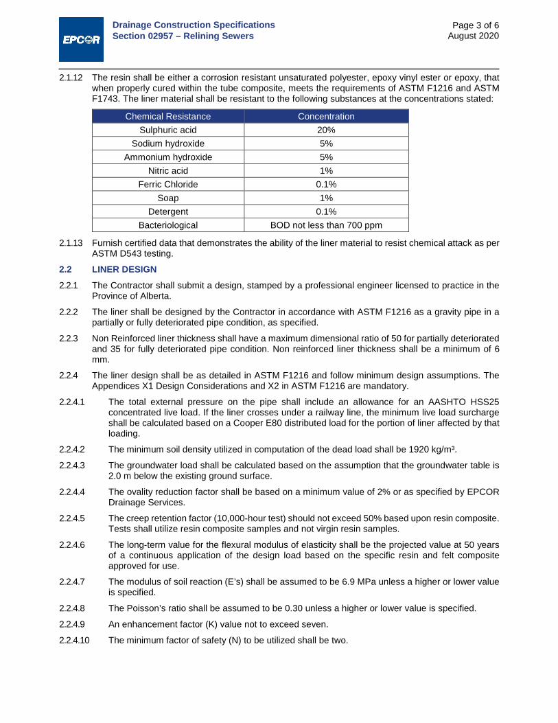
Drainage Construction Specifications Section 02957 – Relining Sewers
Page 3 of 6 August 2020
2.1.12 The resin shall be either a corrosion resistant unsaturated polyester, epoxy vinyl ester or epoxy, that when properly cured within the tube composite, meets the requirements of ASTM F1216 and ASTM F1743. The liner material shall be resistant to the following substances at the concentrations stated:
Chemical Resistance Concentration Sulphuric acid 20%
Sodium hydroxide 5% Ammonium hydroxide 5%
Nitric acid 1% Ferric Chloride 0.1%
Soap 1% Detergent 0.1%
Bacteriological BOD not less than 700 ppm
2.1.13 Furnish certified data that demonstrates the ability of the liner material to resist chemical attack as per ASTM D543 testing.
2.2 LINER DESIGN 2.2.1 The Contractor shall submit a design, stamped by a professional engineer licensed to practice in the
Province of Alberta.
2.2.2 The liner shall be designed by the Contractor in accordance with ASTM F1216 as a gravity pipe in a partially or fully deteriorated pipe condition, as specified.
2.2.3 Non Reinforced liner thickness shall have a maximum dimensional ratio of 50 for partially deteriorated and 35 for fully deteriorated pipe condition. Non reinforced liner thickness shall be a minimum of 6 mm.
2.2.4 The liner design shall be as detailed in ASTM F1216 and follow minimum design assumptions. The Appendices X1 Design Considerations and X2 in ASTM F1216 are mandatory.
2.2.4.1 The total external pressure on the pipe shall include an allowance for an AASHTO HSS25 concentrated live load. If the liner crosses under a railway line, the minimum live load surcharge shall be calculated based on a Cooper E80 distributed load for the portion of liner affected by that loading.
2.2.4.2 The minimum soil density utilized in computation of the dead load shall be 1920 kg/m³.
2.2.4.3 The groundwater load shall be calculated based on the assumption that the groundwater table is 2.0 m below the existing ground surface.
2.2.4.4 The ovality reduction factor shall be based on a minimum value of 2% or as specified by EPCOR Drainage Services.
2.2.4.5 The creep retention factor (10,000-hour test) should not exceed 50% based upon resin composite. Tests shall utilize resin composite samples and not virgin resin samples.
2.2.4.6 The long-term value for the flexural modulus of elasticity shall be the projected value at 50 years of a continuous application of the design load based on the specific resin and felt composite approved for use.
2.2.4.7 The modulus of soil reaction (E’s) shall be assumed to be 6.9 MPa unless a higher or lower value is specified.
2.2.4.8 The Poisson’s ratio shall be assumed to be 0.30 unless a higher or lower value is specified.
2.2.4.9 An enhancement factor (K) value not to exceed seven.
2.2.4.10 The minimum factor of safety (N) to be utilized shall be two.
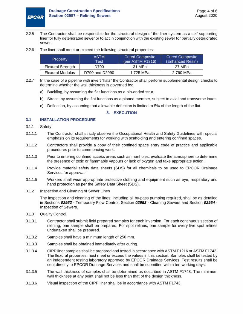
Drainage Construction Specifications Section 02957 – Relining Sewers
Page 4 of 6 August 2020
2.2.5 The Contractor shall be responsible for the structural design of the liner system as a self supporting liner for fully deteriorated sewer or to act in conjunction with the existing sewer for partially deteriorated sewer.
2.2.6 The liner shall meet or exceed the following structural properties:
Property ASTM Test
Cured Composite (per ASTM F1216)
Cured Composite (Enhanced Resin)
Flexural Strength D790 31 MPa 27 MPa Flexural Modulus D790 and D2990 1 725 MPa 2 760 MPa
2.2.7 In the case of a pipeline with invert “flats” the Contractor shall perform supplemental design checks to determine whether the wall thickness is governed by:
a) Buckling, by assuming the flat functions as a pin-ended strut.
b) Stress, by assuming the flat functions as a pinned member, subject to axial and transverse loads.
c) Deflection, by assuming that allowable defection is limited to 5% of the length of the flat.
3. EXECUTION 3.1 INSTALLATION PROCEDURE 3.1.1 Safety
3.1.1.1 The Contractor shall strictly observe the Occupational Health and Safety Guidelines with special emphasis on its requirements for working with scaffolding and entering confined spaces.
3.1.1.2 Contractors shall provide a copy of their confined space entry code of practice and applicable procedures prior to commencing work.
3.1.1.3 Prior to entering confined access areas such as manholes; evaluate the atmosphere to determine the presence of toxic or flammable vapours or lack of oxygen and take appropriate action.
3.1.1.4 Provide material safety data sheets (SDS) for all chemicals to be used to EPCOR Drainage Services for approval.
3.1.1.5 Workers shall wear appropriate protective clothing and equipment such as eye, respiratory and hand protection as per the Safety Data Sheet (SDS).
3.1.2 Inspection and Cleaning of Sewer Lines
The inspection and cleaning of the lines, including all by-pass pumping required, shall be as detailed in Sections 02952 - Temporary Flow Control, Section 02953 - Cleaning Sewers and Section 02954 - Inspection of Sewers.
3.1.3 Quality Control
3.1.3.1 Contractor shall submit field prepared samples for each inversion. For each continuous section of relining, one sample shall be prepared. For spot relines, one sample for every five spot relines undertaken shall be prepared.
3.1.3.2 Samples shall have a minimum length of 250 mm.
3.1.3.3 Samples shall be obtained immediately after curing.
3.1.3.4 CIPP liner samples shall be prepared and tested in accordance with ASTM F1216 or ASTM F1743. The flexural properties must meet or exceed the values in this section. Samples shall be tested by an independent testing laboratory approved by EPCOR Drainage Services. Test results shall be sent directly to EPCOR Drainage Services and shall be submitted within ten working days.
3.1.3.5 The wall thickness of samples shall be determined as described in ASTM F1743. The minimum wall thickness at any point shall not be less than that of the design thickness.
3.1.3.6 Visual inspection of the CIPP liner shall be in accordance with ASTM F1743.

Drainage Construction Specifications Section 02957 – Relining Sewers
Page 5 of 6 August 2020
3.2 INSTALLATION OF CIPP LINER 3.2.1 Job Commencement
Prior to commencing work, the Contractor shall submit, for EPCOR Drainage Services’ approval, proposals for the preparation of liners, transportation, handling, installing and curing.
3.2.2 Processing
3.2.2.1 Prior to resin impregnation, each liner material shall be inspected for defects.
3.2.2.2 The Contractor shall allow EPCOR Drainage Services to inspect the materials and resin impregnation process.
3.2.2.3 Use a resin and catalyst compatible with the CIPP method.
3.2.3 Installation
3.2.3.1 Prior to installation inform affected residents in writing of the anticipated length of disruption to service, details of alternate service provided, any traffic-related constraints, noise levels to be expected, hours of work and safety concerns.
3.2.3.2 The Contractor is required to attend any meetings organised with residents to discuss the work.
3.2.3.3 The Contractor shall arrange for supply and pay for usage of water required. The use of fire hydrants will require a permit from EPCOR Water Services.
3.2.3.4 The liner length shall be adequate to effectively span the distance to be lined. Verify lengths in the field prior to installation.
3.2.3.5 Individual installations may run over one or more manhole sections if shown on the shop drawings or determined in the field and approved by EPCOR Drainage Services.
3.2.3.6 The saturated lining material shall be inserted through an existing manhole or other approved access point by means of an inversion process, or other approved method. Sufficient force shall be applied to fully extend the lining material to the next designated manhole or termination point. The procedure shall produce an identifiable mark at the service connections.
3.2.3.7 Lubricants may be used to reduce friction during inversion or insertion. Lubricants shall be approved by EPCOR Drainage Services.
3.2.4 Curing and Cool Down
3.2.4.1 After the liner placement is completed, supply all equipment to cure the resin.
3.2.4.2 The equipment shall be capable of uniformly raising the liner temperature above that required to effectively cure the resin. Temperature shall be maintained during the curing period recommended by the resin manufacturer.
3.2.4.3 Supply a temperature gauge to monitor the incoming and outgoing temperatures of the water, air, or steam.
3.2.4.4 Install another temperature gauge between the impregnated CIPP liner and the pipe invert at the remote manhole to determine the temperature during curing.
3.2.4.5 Maintain curing temperature until the CIPP liner becomes hard and sound.
3.2.4.6 After the curing, a cool down period shall be provided prior to opening the downstream pipe system, reconnection of services, and returning normal flow back to the system.
3.2.4.7 The CIPP liner shall be cooled to a suitable temperature before relieving the pressure on the liner.
3.2.4.8 Release the pressure gradually to prevent development of a vacuum in the newly installed CIPP liner.

Drainage Construction Specifications Section 02957 – Relining Sewers
Page 6 of 6 August 2020
3.3 SEALING CIPP LINER AT MANHOLES 3.3.1 At manhole entrances and exits, the interface between the exterior surface of the liner and the manhole
shall be made watertight. The ends of the liner shall be neatly trimmed so the liner fits flush with the manhole interior surface.
3.3.2 If the CIPP liner fails to make a tight seal at the manhole, the Contractor shall apply a compatible resin mixture seal in accordance with ASTM F1216.
3.4 REINSTATEMENT OF SERVICE CONNECTIONS 3.4.1 After the pipe system is in position, the existing services shall be re-established in accordance with
ASTM F1216.
3.4.2 Unless otherwise approved by EPCOR Drainage Services, reconnection of services shall be done without excavation by means of a remote control cutting device or directly where entry is possible.
3.4.3 A CCTV camera shall be attached to the cutting device for precise location of the service connections.
3.4.4 Prior to any sewer leads being completely opened to the newly lined sewer, a small diameter relief hole shall be cut through the liner into each lead opening to relieve any water that has accumulated in the leads during the lining process. After the relief holes have been cut for each service, the process of completely opening each lead shall commence.
3.4.5 All service leads existing prior to CIPP liner installation shall be opened immediately following the lining installation process. The cost of any damages occurring from services that are not re-opened shall be borne by the Contractor.
3.4.6 The service connections shall be re-established to the same condition as existed prior to the installation of the liner. Sewer connection reinstatement, including catchbasin leads, shall be restored to a minimum of 95% of the original cross sectional area of the connection.
3.4.7 Voids between the liner and the existing sewer wall after connection reinstatement shall be filled with either a non-shrinking, watertight cement grout, an approved polyurethane grout; a resin mixture compatible with the liner system; or other approved grouting product.
3.5 LINER FINISH AND PROJECT COMPLETION 3.5.1 Ensure that the CIPP liner is continuous over the entire length of installation and is free from visual
defects such as foreign inclusions, dry spots, pinholes, lifts, wrinkles and delamination. If any of these conditions are present, remove and replace the CIPP liner in these areas.
3.5.2 Provide a digital video accompanied by an inspection report showing the relined sewer with a clear view of each lateral service. Equipment used for this CCTV record shall be capable of viewing the service from the main to show at least 2 m into the service lead. The format of the report shall be in accordance with Section 02954 - Inspection of Sewers.
3.5.3 During the warranty period, repair at no cost to EPCOR Drainage Services any defects that will affect the integrity or strength of the CIPP liner to the satisfaction of EPCOR Drainage Services.
3.6 CLEAN-UP 3.6.1 Upon acceptance of the liner, clean up and restore the affected surface areas to the condition that
existed prior to commencement of the work.
3.6.2 Remove and haul debris to an approved disposal site.
END OF SECTION

Drainage Construction Specifications Section 02958 – Leakage Testing of Sewers
Page 1 of 3 August 2020
1. GENERAL 1.1 SCOPE
This section specifies requirements for leakage testing of gravity sewers and sewer forcemains.
1.2 RELATED SECTIONS Quality Assurance Chapter 8 Volume 1: General
Trench Backfill Section 3.1 Volume 2: Complete Streets
Sewage Force Mains Section 02531
Sewers Section 02535
Sewer Services Section 02538
Manholes and Catch Basins Section 02631
Precast Concrete Box Sewers Section 02645
Inspection of Sewers Section 02954
1.3 SUBMITTALS 1.3.1 Submit reports of testing at the completion of the project. The report shall contain test forms signed by
the recorder and the supervisor.
1.3.2 In the report, each instrument used for testing shall be identified and the date of latest calibration noted.
1.4 GRAVITY MAINS TESTING - GENERAL 1.4.1 All leakage tests shall be conducted after the service connections to the main have been installed.
Service connections include in-line tees, wyes, saddles, etc.
1.4.2 The testing scope is identified in the Contract. As a minimum, the leakage tests shall be conducted on 10% of all sanitary sewers.
1.4.3 The Engineer will select the sewer sections to be tested after the construction is complete.
1.4.4 The Engineer will select the type of leakage test to be performed for the gravity mains, and it will be either the exfiltration test or the Infiltration test. For the forcemains, it shall be the hydrostatic pressure test.
1.4.5 Perform tests in presence of the Engineer. Notify the Engineer 48 hours in advance of proposed tests. The Contractor shall perform and record testing.
1.4.6 If the event that the initial leakage test conducted by methods described within this section fails, then in addition to re-testing of the repaired initial 10% of the system, an additional 10% of the system shall be tested. Should this additional section fail too, the remainder of the sewer in the project shall be also tested for leakage. The Contractor shall replace or repair the section(s) of sewer and the testing and remedial work shall be repeated until leakage is within the allowance specified in this section.
1.4.6.1 In the event that an exfiltration test fails, the line must be left drained and left for a period of 4 calendar days before attempting any further tests.
1.4.7 Damage resulting from testing shall be repaired by the Contractor at the Contractor’s expense.

Drainage Construction Specifications Section 02958 – Leakage Testing of Sewers
Page 2 of 3 August 2020
2. PRODUCTS
Not applicable
3. EXECUTION 3.1 PREPARATION FOR TESTING OF GRAVITY MAINS 3.1.1 Remove foreign material from sewers and related appurtenances by flushing with water. Do not allow
debris to enter the downstream sewer system but remove in accordance with Chapter 13 - Protection of the Urban Environment, Volume 1: General.
3.1.2 Perform inspections in accordance with Section 02954 - Inspection of Sewers, as soon as practicable after construction is complete and service connections have been installed.
3.1.3 Install watertight bulkheads in suitable manner to isolate test section from the rest of the pipeline.
3.2 EXFILTRATION TEST 3.2.1 Fill test section with water in such a manner as to allow displacement of air in line. Maintain pressure
under nominal head for 24 hours to ensure absorption in pipe wall and manhole barrels is complete before test measurements are commenced.
3.2.2 Immediately prior to the test period add water to pipeline until there is adequate head of water. The Engineer will determine the height, and it will be between minimum of 1 m and maximum of 3 m over the interior crown of the pipe measured at highest point of the test section.
3.2.3 The duration of the exfiltration test shall be 2 hours.
3.2.4 Water loss at the end of the test period is not to exceed the maximum allowable leakage of 10.0 litres per day per mm of pipe diameter per 1 km of sewer line.
3.3 INFILTRATION TEST 3.3.1 Discontinue trench dewatering operations for at least three days prior to testing.
3.3.2 Prevent damage to pipe and bedding material due to flotation and erosion.
3.3.3 Place 90o V-notch weir, or other measuring device approved by the Engineer in the invert of the sewer at each manhole.
3.3.4 Measure rate of flow over a minimum of 1 hour, with recorded flows for each 5 minute interval.
3.3.5 The maximum allowable leakage is not to exceed 10.0 litres per day per mm of pipe diameter per 1 km of sewer line.
3.3.6 The above leakage limit shall constitute the overall leakage allowance for the test section, inclusive of leakage from manholes and other appurtenances.
3.3.7 Where service connections exist along the test section, the allowable leakage from the service connections can be included in addition to the main sewer leakage allowance to arrive at a total allowable leakage. Service connection allowance shall be calculated by use of the above formula.
3.4 HYDROSTATIC TEST - FORCEMAINS 3.4.1 After flushing, the main shall be subjected to a hydrostatic pressure test. The test pressure shall be
one and a half times the operating pressure and not less than 350 kPa.
3.4.2 Immediately prior to testing any section, all appurtenances shall be checked to ensure that they are prepared for the test. Air valves shall be checked to ensure that they are prepared for the test. Air valves shall be opened while the mains are filled. If all the air from the test section cannot be expelled from existing fittings and appurtenances, the Contractor shall tap the section in a manner acceptable to the Engineer to expel the air.
3.4.3 Strut and brace caps, bends and tees to prevent movement when test pressure is applied.

Drainage Construction Specifications Section 02958 – Leakage Testing of Sewers
Page 3 of 3 August 2020
3.4.4 The main shall be filled with the test water and brought to a pressure of 10% of test pressure at the testing point. Any air valves in the test section shall than be closed so that test pressure will not cause damage. The main shall remain under the above pressure for a period of at least 24 hours before applying test pressure.
3.4.5 Test Requirements – Steel and PVC Pipe
3.4.5.1 Testing shall be conducted in accordance with AWWA C605 for PVC pipe and AWWA C604 for steel pipe, except as amended herein.
3.4.5.2 The pipeline shall than be brought up to the test pressure, and it shall be maintained for a period of not less than 1 hour. Accurate means shall be provided for measuring the quantity of water required to maintain full pressure on the line for the test period
3.4.5.3 No pipe installation will be accepted until the apparent leakage is less than the number of litres per hour as determined by the formula:
𝑄𝑄 =𝐿𝐿𝐿𝐿√𝑃𝑃
795,000
where, Q = the allowable apparent leakage (or quantity of make-up water) in litres per hour.
L = the length of pipe in the test section in m.
D = the nominal pipe diameter of pipe in mm, and
P = the average test pressure during the leakage test in kPa.
3.4.6 Test Requirements – Polyethylene (PE) Pipe
3.4.6.1 Testing for PE pipe shall be generally completed in accordance to AWWA F 2164 except as amended herein.
3.4.6.2 Confirm test pressure is less than 1.5 times the design pressure rating for the pipe. Do not exceed maximum test pressure.
3.4.6.3 The entire test procedure, including expansion phase and test phase, shall not exceed 8 hours. If test exceeds 8 hours, depressurize and allow pipe to relax for a minimum of 8 hours.
3.4.6.4 Initial expansion phase -Slowly pressurize the main to test pressure and add makeup water to maintain test pressure for a period of 4 hours.
3.4.6.5 Test Phase – Reduce test pressure by 70 kPa and monitor pressure for 1 hour. Do not increase pressure or add makeup water.
3.4.6.6 If there is no visible leakage, and the test pressure during the test phase remains constant, within 5 percent of the test pressure, a passing test is indicated. There is no allowable makeup water for this test.
3.4.6.7 If retesting is necessary, depressurize main and allow pipe to relax for a minimum period of 8 hours. Repeat expansion phase and test phase as specified herein.
3.4.7 Leakage test allowance in all tests is for “apparent” leakage due to entrapped air and pipe expansion. No visible leakage is permitted as acceptance criteria irrespective of the apparent leakage determine by this acceptance test.
3.4.8 Should the test section fail to meet the maximum allowable apparent leakage specifications or has any signs of visible leakage whatsoever, the Contractor shall take whatever steps are necessary to locate the leaks and correct them. The test procedure shall be repeated after repairs are made until satisfactory results are obtained.
END OF SECTION

Drainage Construction Specifications Section 02959 – Deflection Testing of Flexible Pipe
Page 1 of 3 August 2020
1. GENERAL 1.1 SCOPE
This section specifies requirements for the deflection testing of sewers with a “go/no-go” mandrel and/or other suitable measuring devices. Other suitable devices may include laser profiling equipment, or other methods as approved by EPCOR Drainage Services. The onus shall be on the Contractor to demonstrate that the accuracy of the alternate measuring device meets the technical requirements of the specification.
1.2 RELATED SECTIONS Trench Backfill Section 3.1 Volume 2: Complete Streets
Sewers Section 02535
Inspection of Sewers Section 02954
1.3 SUBMITTALS Submit reports of testing at the completion of the project. The report shall contain test forms signed by the recorder and the supervisor.
1.4 DEFLECTION TESTING FOR FLEXIBLE PIPES - GENERAL 1.4.1 The scope of work of the deflection testing includes cleaning, traffic control and CCTV inspection.
1.4.2 Where closed circuit television (CCTV) or visual walk-through inspections show evidence of excessive or non-symmetrical deflection (e.g. a non-elliptical deformation pattern), formal deflection tests shall be conducted. The location and number of deflection tests shall be at the sole discretion of EPCOR Drainage Services.
1.4.3 Where formal inspection tests are required, inspect pipes up to and including 900 mm diameter with a “go/no - go” mandrel device as described in this section. Other suitable measurement devices shall be approved by EPCOR Drainage Services. Where required, pipes larger than 1050 mm diameter shall be inspected with a suitable measurement device such as a telescoping rod in conjunction with a walk-through inspection. These tests are to confirm that the vertical deflection does not exceed the allowable deflection limit stipulated below and that the nature of deflection observed is illustrative of natural anticipated flexible-pipe soil interaction.
1.4.4 Deflection tests for acceptance purposes shall be conducted not sooner than 30 days after all backfill has been completed.
1.4.5 Short term deflection shall be deemed to be any deflection measured not sooner than 30 days after backfilling.
1.4.6 Long term deflection shall be deemed to be any deflection measured after one year of backfilling

Drainage Construction Specifications Section 02959 – Deflection Testing of Flexible Pipe
Page 2 of 3 August 2020
2. PRODUCTS 2.1 MANDREL 2.1.1 The mandrel shall be cylindrical in shape, constructed with nine evenly spaced arms and shall conform
to the following schematic:
2.1.2 Mandrels larger than 450 mm in diameter shall be constructed with special breakdown devices to facilitate entry through standard access manholes.
2.1.3 The minimum diameter of the circle scribed around the outside of the mandrel arms shall be equal to the values indicated below for each specific pipe material, within a tolerance of +/- 0.25 mm. The contact length of the mandrel shall be at least 75% of the inside diameter of the pipe. The outside diameter of the mandrel arms shall be checked for conformance with proving rings.
2.1.4 Either an oversize or undersize proving ring shall be used to confirm the acceptability of mandrel dimensions. An oversize proving ring shall be of a diameter equal to the required outside mandrel size plus 1 mm. An undersize proving ring shall be of a diameter equal to the required outside mandrel size minus 0.30 mm. Both proving rings shall be manufactured to within 0.25 mm of the specified size. The proving rings shall be fabricated from 6 mm minimum thickness stainless steel.

Drainage Construction Specifications Section 02959 – Deflection Testing of Flexible Pipe
Page 3 of 3 August 2020
2.1.5 Dimensions for mandrels for acceptance purposes shall conform to the table below.
Nominal Pipe Size
(mm)
Radius of Test Mandrel (mm) Solid Wall PVC Pipe SDR 35 Open Profile Wall PVC Pipe Short Term Long Term Short Term Long Term
100 47 45.9 47.1 45.9 150 70 68.3 70 68.3 200 93.7 91.4 93.7 91.4 250 117.1 114.3 117.1 114.3 300 139.4 136 139.3 136 375 170.6 166.5 170.6 166.5 450 208.5 203.5 209.5 204.5 525 245.8 239.9 246.3 240.4 600 276.6 269.9 279 272.3 675 311.7 304.2 314.9 307.4 750 357.1 348.5 350.6 342.1 900 427.3 417 421.9 411.7
1,050 496.4 484.5 493.2 481.3 1,200 566.7 553 564.5 550.9
2.1.6 An acceptable mandrel will pass through the oversize ring, but not through the undersize ring.
2.1.7 The allowed vertical deflection shall be as follows:
2.1.7.1 For testing done after 30 days, short term deflection, maximum allowable deflection is 5% of the CSA Base Inside Diameter (BID).
2.1.7.2 For testing done after one year, long term deflection, maximum allowable deflection is 7.5% of the CSA BID.
END OF SECTION

Drainage Construction Specifications Section 3310 – Concrete for Water and Drainage Structures
Page 1 of 6 August 2020
1. GENERAL 1.1 SCOPE
Supply and installation of cement concrete for water and drainage structures, excluding precast concrete.
1.2 RELATED SECTIONS Concrete Forms and Accessories Section 7.10 Volume 2: Complete Streets
Reinforcing Steel Section 7.12 Volume 2: Complete Streets
1.3 QUALITY CONTROL 1.3.1 The Contractor shall retain and pay for the services of a testing laboratory to perform field tests on the
concrete produced and installed. The minimum test requirements shall be:
1.3.1.1 Air content: Every batch delivered until air content is established to within specifications, minimum once per day. Every third batch thereafter, unless specifications are not met.
1.3.1.2 Slump: Every batch delivered until specifications are met, minimum once per day. Every third batch thereafter.
1.3.1.3 Strength: In accordance with CSA-A23.2, standard tests for strength will be conducted at a frequency of not less than one strength test for each 50 m3 poured, or portion thereof, with minimum of one test per project. The standard strength test shall consist of three cylinders, laboratory moist cured, except when temperature is below 5o C, when cylinders shall be field cured. Slump and air content taken with cylinders. One cylinder shall be broken at 7 days, and two cylinders at 28 days.
1.3.1.4 Field cured cylinders: Two additional cylinders shall be cast when the ambient temperature is 5o C, or lower. Field cured cylinders shall be cured on the job site under the same conditions as the concrete they represent. One cylinder shall be broken at 7 days, and one cylinder at 28 days.
1.3.2 Failure to meet specifications shall result in the Engineer requesting, at the Contractor's cost:
a change in mix design or supplier. additional testing (coring, etc.) remedial work or replacement. other work as deemed necessary.
2. PRODUCTS 2.1 MATERIALS 2.1.1 Cement: to CSA-A3000, Type HS High sulphate-resistant hydraulic
2.1.2 Aggregates: to CSA-A23.1
2.1.3 Water: to CSA-A23.1
2.1.4 Air Entraining Admixture: to ASTM C260
2.1.5 Chemical Admixture: to ASTM C494. Engineer to approve accelerating or set retarding admixtures during cold and hot weather placing.
2.2 NON-SHRINK GROUT Premixed compound consisting of non-ferrous aggregate, cement, water reducing and plasticizing agents, capable of developing minimum compressive strength of 16.5 MPa at 2 days and 48 MPa at 28 days.
2.3 CURING COMPOUND Non-membrane, colourless, non-yellowing chemical liquid curing compound conforming to CSA-A23.1 and to ASTM C309.

Drainage Construction Specifications Section 3310 – Concrete for Water and Drainage Structures
Page 2 of 6 August 2020
2.4 FLOOR HARDENER Non-metallic, natural aggregate surface hardener.
2.5 BONDING AGENT Two component, epoxy resin.
2.6 WATERSTOPS PVC Waterstop: Extruded PVC of sizes as indicated in the drawings, to conform to CGSB 41-GP--35M. Waterstop type and profile to be pre-approved by the Engineer.
2.7 DAMPPROOFING FOR DRAINAGE STRUCTURES Emulsified asphalt, mineral colloid type, unfilled to CAN/CGSB-37.2.
2.8 WATERPROOFING FOR DRAINAGE STRUCTURES Cementitious waterproofing such as Xypex, Vandex, or approved equal.
2.9 JOINT SEALANT Control and expansion joints, on the interior and exterior of concrete walls as shown on drawings. Sealant to CAN/CGSB-19.13 - one component, elastomeric, chemical curing sealing compound. Refer to drawings for joint details and sealants for other joint types.
2.10 OTHER MATERIALS All other materials, not specifically described but required for a complete and proper installation of all cast-in-place concrete, shall be as selected by the Contractor subject to the approval of the Engineer.
2.11 MIX DESIGN 2.11.1 Submittals: In accordance with CSA-A23.1, Table 5, it is the intent that the City follows Alternative 1
method of specifying concrete. The concrete supplier assumes responsibility for the concrete mix proportions, and in conjunction with the Contractor, shall submit a design to the Engineer for review that will comply with the requirements of the City.
2.11.2 As a minimum, and unless specified by the Engineer elsewhere, for concrete used in water and sewage facilities, the properties of the concrete shall be:
2.11.2.1 The minimum 28-day compressive strength requirement is 30 MPa.
2.11.2.2 The maximum water/cementing material ratio is 0.50.
2.11.2.3 Air content to be 5 % to 7%.
2.11.2.4 The slump for concrete shall be 80 mm, ± 30 mm, unless specified elsewhere by the Engineer. The specified slump for pumping of concrete may be increased with the use of superplasticizing admixtures, upon approval of the mix design by the Engineer.
2.11.2.5 Maximum aggregate size of 20 mm, unless specified otherwise elsewhere. Concrete density shall be normal.
2.11.3 Accelerating admixtures may be used in cold weather subject to approval of the Engineer. If approved, the use of admixture will not relax the cold weather placement requirements. Use of calcium chloride shall not be permitted.
2.11.4 Set retarding admixtures may be used during hot weather to allow for proper finishing of concrete, subject to approval of the Engineer.
2.11.5 The ratio of supplementary cementitious materials to total cementitious materials shall not exceed 0.20.
3. EXECUTION 3.1 DELIVERY OF CONCRETE 3.1.1 Concrete shall be delivered to the job site according to CSA-23.1 as supplemented or modified below.
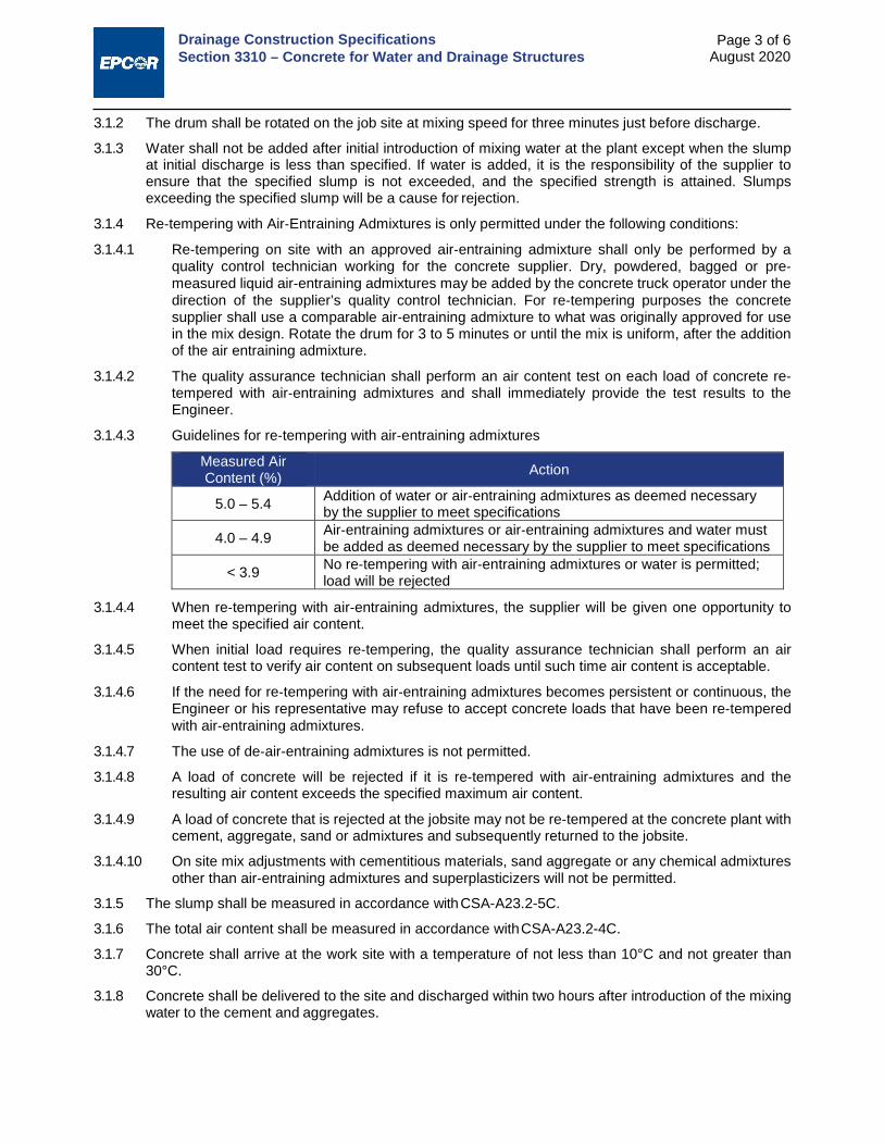
Drainage Construction Specifications Section 3310 – Concrete for Water and Drainage Structures
Page 3 of 6 August 2020
3.1.2 The drum shall be rotated on the job site at mixing speed for three minutes just before discharge.
3.1.3 Water shall not be added after initial introduction of mixing water at the plant except when the slump at initial discharge is less than specified. If water is added, it is the responsibility of the supplier to ensure that the specified slump is not exceeded, and the specified strength is attained. Slumps exceeding the specified slump will be a cause for rejection.
3.1.4 Re‐tempering with Air‐Entraining Admixtures is only permitted under the following conditions:
3.1.4.1 Re‐tempering on site with an approved air‐entraining admixture shall only be performed by a quality control technician working for the concrete supplier. Dry, powdered, bagged or pre‐measured liquid air‐entraining admixtures may be added by the concrete truck operator under the direction of the supplier’s quality control technician. For re‐tempering purposes the concrete supplier shall use a comparable air‐entraining admixture to what was originally approved for use in the mix design. Rotate the drum for 3 to 5 minutes or until the mix is uniform, after the addition of the air entraining admixture.
3.1.4.2 The quality assurance technician shall perform an air content test on each load of concrete re‐tempered with air‐entraining admixtures and shall immediately provide the test results to the Engineer.
3.1.4.3 Guidelines for re‐tempering with air‐entraining admixtures
Measured Air Content (%) Action
5.0 – 5.4 Addition of water or air‐entraining admixtures as deemed necessary by the supplier to meet specifications
4.0 – 4.9 Air‐entraining admixtures or air‐entraining admixtures and water must be added as deemed necessary by the supplier to meet specifications
< 3.9 No re‐tempering with air‐entraining admixtures or water is permitted; load will be rejected
3.1.4.4 When re‐tempering with air‐entraining admixtures, the supplier will be given one opportunity to meet the specified air content.
3.1.4.5 When initial load requires re‐tempering, the quality assurance technician shall perform an air content test to verify air content on subsequent loads until such time air content is acceptable.
3.1.4.6 If the need for re‐tempering with air‐entraining admixtures becomes persistent or continuous, the Engineer or his representative may refuse to accept concrete loads that have been re‐tempered with air‐entraining admixtures.
3.1.4.7 The use of de‐air-entraining admixtures is not permitted.
3.1.4.8 A load of concrete will be rejected if it is re‐tempered with air‐entraining admixtures and the resulting air content exceeds the specified maximum air content.
3.1.4.9 A load of concrete that is rejected at the jobsite may not be re‐tempered at the concrete plant with cement, aggregate, sand or admixtures and subsequently returned to the jobsite.
3.1.4.10 On site mix adjustments with cementitious materials, sand aggregate or any chemical admixtures other than air‐entraining admixtures and superplasticizers will not be permitted.
3.1.5 The slump shall be measured in accordance with CSA-A23.2-5C.
3.1.6 The total air content shall be measured in accordance with CSA-A23.2-4C.
3.1.7 Concrete shall arrive at the work site with a temperature of not less than 10°C and not greater than 30°C.
3.1.8 Concrete shall be delivered to the site and discharged within two hours after introduction of the mixing water to the cement and aggregates.

Drainage Construction Specifications Section 3310 – Concrete for Water and Drainage Structures
Page 4 of 6 August 2020
3.1.9 The delivery ticket shall show batch plant location, supplier's name, ticket and truck numbers, mechanically punched date and time of initial plant mixing, mix design designation, water added, volume of concrete, site arrival and discharge time and any other information requested by the Engineer. Non compliance of any of the requirements above shall be reasons for rejection of concrete by the Engineer.
3.2 PREPARATION 3.2.1 Obtain the Engineer's approval before placing concrete. Provide 24 hours notice prior to placing
concrete.
3.2.2 Pumping of concrete is permitted only after approval of equipment and mix.
3.2.3 Ensure reinforcement and inserts are not disturbed during concrete placement.
3.2.4 Prior to placing of concrete obtain Engineer's approval of proposed method for protection of concrete during placing and curing.
3.2.5 Maintain accurate records of poured concrete items to indicate date, location of pour, quality, air temperature and test samples taken.
3.2.6 Do not place load upon new concrete until authorized by the Engineer.
3.3 CONSTRUCTION 3.3.1 Do cast-in-place concrete work in accordance with CSA-A23.1.
3.3.2 Sleeves and Inserts
3.3.2.1 No sleeves, ducts, pipes or other openings shall pass through joists, beams, column capitals or columns, except where indicated or approved by the Engineer.
3.3.2.2 Where approved by the Engineer, set sleeves, ties, pipe hangers and other inserts and openings as indicated or specified elsewhere. Sleeves and openings greater than 100 mm x 100 mm not indicated shall be approved by the Engineer.
3.3.2.3 Do not eliminate or displace reinforcement to accommodate hardware. If inserts cannot be located as specified, obtain approval of modifications from the Engineer before placing of concrete.
3.3.2.4 Check locations and sizes of sleeves and openings shown on drawings.
3.3.2.5 Set special inserts for strength testing as indicated and if required by non-destructive method of testing concrete. Refer to 1.3 - Quality Control above.
3.3.3 Anchor Bolts
3.3.3.1 Set anchor bolts to templates under supervision of appropriate trade prior to placing concrete.
3.3.3.2 With approval of the Engineer grout anchor bolts in pre-formed holes or holes drilled after concrete has set.
3.3.3.3 Protect anchor bolt holes from water accumulations, snow and ice build-ups.
3.3.3.4 Set bolts and fill holes with shrinkage compensating grout.
3.3.3.5 Grout under base plates and machinery using procedures in accordance with manufacturer's recommendations which result in 100% contact over grouted area.
3.3.4 Waterstops
3.3.4.1 Install waterstops in all construction joints as shown on detailed drawings, or located below finished grade. Install them to provide a continuous water seal. Do not distort or pierce waterstop in such a way as to hamper performance. Do not displace reinforcement when installing waterstops.
3.3.4.2 Use only straight heat sealed butt joints in field. Use factory welded corners and intersections unless otherwise approved by the Engineer.

Drainage Construction Specifications Section 3310 – Concrete for Water and Drainage Structures
Page 5 of 6 August 2020
3.3.4.3 All field splices to be inspected by the Engineer.
3.3.5 Joints
3.3.5.1 Locate and form all isolation or expansion joints as indicated on the Drawings. Install joint filler, sealer and primer to manufacturer's instructions.
3.3.5.2 Install a polyethylene strip over joint filler to prevent bonding to joint sealer.
3.3.5.3 The Contractor shall submit a plan that shows the proposed location of joints and pour breaks to the Engineer for approval.
3.3.5.4 Do not allow reinforcing steel to run through expansion joints or isolation joints unless otherwise indicated.
3.3.6 Finishing
3.3.6.1 Finish concrete in accordance with CSA-A23.1.
3.3.6.2 Use procedures acceptable to the Engineer or those noted in CSA-A23.1 to remove excess bleed water. Ensure surface is not damaged.
3.3.7 Floor Finishes
Finish and protect the top surface of all concrete as indicated on the Drawings or as specified below:
3.3.7.1 Plain Floor Finish (all covered floors and roof)
i. Finish concrete floors to CSA-A23.1 as specified below.
ii. Use two passes of steel trowelling to produce smooth burnished surface to within 5 mm tolerance when measured in any direction using 3 m. straight edge.
iii. At areas with floor drains, maintain floors level at walls, pitch floor uniformly to drains at a minimum rate of one half of one percent (5 mm per m) or as shown on the Drawings.
3.3.7.2 Hardened Floor Finish (all exposed floors)
Finish concrete floors as per 3.3.7.1 above, and apply hardener at a rate specified by the manufacturer.
3.3.7.3 Textured Non-Slip Finish (all exterior flatwork)
Immediately after first trowelling of the "Plain Floor Finish", swirl-trowel, brush or broom the surface to a uniformly textured non-slip finish, as described in CSA-A23.1.
3.3.8 Wall Finishes
3.3.8.1 In accordance with CSA-A23.1, leave concrete with a rough form finish for use on surfaces not exposed to view in the structure. Chip off fins and irregular projections, and patch form tie holes.
3.3.8.2 For walls and surfaces exposed to view, the Contractor shall provide a sack rubbed finish as described in CSA-A23.1
3.3.9 Protection and Curing
3.3.9.1 Cure all concrete in accordance with CSA-A23.1, Section 7.
3.3.9.2 Loosen wall forms within 24 hours as outlined in Section 7.10 - Concrete Forms and Accessories, Volume 2: Complete Streets.
3.3.9.3 Initial curing: ensure the concrete surface is kept continuously moist until the temperature produced by the heat of hydration of the cement has peaked and dropped at least 8°C.
3.3.9.4 Final Curing: immediately after initial curing, additional curing shall be applied and maintained for a period of 7 days, to ensure that the specified concrete strength and quality has been obtained.
3.3.10 Damp-proofing and Waterproofing of Drainage Structures

Drainage Construction Specifications Section 3310 – Concrete for Water and Drainage Structures
Page 6 of 6 August 2020
3.3.10.1 Apply damp-proofing compound to exterior of structural wall below grade where shown on drawings, according to manufacturer's recommendations.
3.3.10.2 Apply waterproofing material onto interior surfaces of structural base and wall as indicated on drawings, within 72 hours of stripping forms, and as recommended by the manufacture of the waterproofing materials. Cure the waterproofing compound as recommended by the manufacturer.
3.3.11 Repairing Concrete
3.3.11.1 Cut back metal form ties and voids not less than 20 mm from surface and fill with non-shrink grout.
3.3.11.2 Cut back honeycombed or defective areas perpendicular to the surface to a depth of 20 mm. Brush on 1:1 cement sand grout over a saturated surface then patch with a 1:2 cement sand mortar with 10% hydrated lime.
3.3.11.3 Where honeycombing or defective areas require cut backs deeper than 50 mm, use non-shrink grout.
3.3.12 Bonding New Concrete to Old
3.3.12.1 Clean old concrete surface and protruding reinforcing steel concrete for a distance shown on detailed drawings.
3.3.12.2 Roughen cleaned surfaces to expose the coarse aggregate of the existing concrete.
3.3.12.3 Immediately prior to placing new concrete, apply a coating of bonding agent to the existing surface, in strict accordance with the manufacturer's recommendation.
3.3.12.4 In locations where new concrete is doweled to existing work, drill holes in existing concrete and insert steel dowels and pack solidly with non-shrink grout to positively position and anchor dowels, or as indicated on the drawings.
END OF SECTION

DESIGN AND CONSTRUCTION STANDARDS
VOLUME 3
DRAINAGE
STANDARDS DRAWINGS

Standards Drawings Index
i August 2020
Drawing No. Description Date
Section 17.0 – LID Facility Design 7001 Bioretention Cleanouts June 2020 7003 Soil Cell Cleanouts June 2020
Sections 02631 – Manholes and Catch Basins and 02632 – Drainage Manholes Frames and Covers 7005 Standard 600 Catch Basin with Type 2A Grating and Frame June 2020 7006 Standard 600 Catch Basin with Type K-7 Grating and Frame June 2020 7007 Neck Section Details for Type 4A, 6B and 8 Grating and Frame June 2020 7008 Neck Section Details for Type F-51 and K-7 Grating and Frame June 2020 7009 Standard 900 Catch Basin with Type DK-7 Grating and Frame June 2020 7010 Standard 900 Catch Basin with Type F-51 Grating and Frame with Side Inlet June 2020 7011 Standard 1200 CB Manhole with Type 6B or 8 Grating and Frame June 2020 7012 Standard 1200 CB Manhole with Type F-51 Grating and Frame with Side Inlet June 2020 7013 Standard 1200 Manhole for Piping up to 600mm Diameter with Type 6A Cover
and Frame June 2020
7014 Neck Section Details for Standard 1200 Manhole June 2020 7020 Benching Detail for Standard 1200 Manhole June 2020 7021 Safety Steps for Manholes June 2020 7030 Grade Rings June 2020 7031 Rings/Tops June 2020 7032 Slab Tops for Standard 900 Catch Basin June 2020 7033 Slab Top for Standard 900 Catch Basin June 2020 7034 Slab Tops for Standard 1200mm Manhole June 2020 7040 Type 2A Two Piece Side Inlet Catch Basin Grating and Frame June 2020 7041 Type 4A Two Piece Side Inlet Catch Basin Manhole Grating and Frame June 2020 7042 Type 8 Catch Basin Manhole Grating and Frame June 2020
7043A/B Type 6 Standard Manhole Frame, Cover and Round Catch Basin Cover June 2020 7043C Type 6S Manhole Frame and Cover June 2020 7044 Type 80 Cover and Floating Type Manhole Frame June 2020 7045 Type K-7 and DK-7 Catch Basin Frame and Grating June 2020 7047 Type F-51 Three Piece Catch Basin Frame and Grating with Side Inlet June 2020 7048 Type F-51 Two Piece Curb Component Frame and Grating June 2020 7050 Type 41 Manhole Frame and Cover June 2020 7051 Type 6C Slotted Flat Cover to be used on Type 6 Frame for Air Release June 2020
Section 02640 – Corrugated Steel Pipe Culvert 7062 Culvert End Riprap June 2020
Section 02538 – Sewer Services 7063 Standard Riser Connections to Storm and Sanitary Sewers in Common Trench June 2020
Sections 02535 – Sewers and 02538 – Sewer Services 7980 Trench Bedding Types June 2020 7981 Concrete Pipe Butt-Joint Detail June 2020