DRAFT FOR PUBLIC REVIEW
13
DRAFT FOR PUBLIC REVIEW DRAFT UGANDA STANDARD DUS 1844 First Edition 2017-mm-dd This Draft Uganda Standard, FDUS 1844:2017, is based on ASTM C666/C666M-15, Standard Test Method for Resistance of Concrete to Rapid Freezing and Thawing, Copyright ASTM International, 100 Barr Harbor Drive, West Conshohocken, PA 19428, USA, pursuant to license with ASTM International. Reference number DUS 1844: 2017 © UNBS 2017 Standard Test Method for Resistance of Concrete to Rapid Freezing and Thawing
-
Upload
khangminh22 -
Category
Documents
-
view
0 -
download
0
Transcript of DRAFT FOR PUBLIC REVIEW
DRAFT FOR PUBLIC R
EVIEW
DRAFT UGANDA STANDARD
DUS 1844
First Edition 2017-mm-dd
This Draft Uganda Standard, FDUS 1844:2017, is based on ASTM C666/C666M-15, Standard Test Method for Resistance of Concrete to Rapid Freezing and Thawing, Copyright ASTM International, 100 Barr Harbor Drive, West Conshohocken, PA 19428, USA, pursuant to license with ASTM International.
Reference number DUS 1844: 2017
© UNBS 2017
Standard Test Method for Resistance of Concrete to Rapid Freezing and Thawing
DRAFT FOR PUBLIC R
EVIEW
C666/C666M-15 DUS 1844: 2017
© UNBS 2017 – All rights reserved ii
Compliance with this standard does not, of itself confer immunity from legal obligations
A Uganda Standard does not purport to include all necessary provisions of a contract. Users are responsible for its correct application
© UNBS 2017
All rights reserved. Unless otherwise specified, no part of this publication may be reproduced or utilised in any form or by any means, electronic or mechanical, including photocopying and microfilm, without prior written permission from UNBS.
Requests for permission to reproduce this document should be addressed to
The Executive Director Uganda National Bureau of Standards P.O. Box 6329 Kampala Uganda Tel: +256 417 333 250/1/2/3 Fax:+ 256 414 286 123 E-mail: [email protected] Web: www.unbs.go.ug
DRAFT FOR PUBLIC R
EVIEW
C666/C666M-15 DUS 1844: 2017
© UNBS 2017 – All rights reserved iii
Foreword
Uganda National Bureau of Standards (UNBS) is a parastatal under the Ministry of Trade, Industry and Cooperatives established under Cap 327, of the Laws of Uganda, as amended. UNBS is mandated to co-ordinate the elaboration of standards and is
(a) a member of International Organisation for Standardisation (ISO) and
(b) a contact point for the WHO/FAO Codex Alimentarius Commission on Food Standards, and
(c) the National Enquiry Point on TBT Agreement of the World Trade Organisation (WTO).
The work of preparing Uganda Standards is carried out through Technical Committees. A Technical Committee is established to deliberate on standards in a given field or area and consists of key stakeholders including government, academia, consumer groups, private sector and other interested parties.
Draft Uganda Standards adopted by the Technical Committee are widely circulated to stakeholders and the general public for comments. The committee reviews the comments before recommending the draft standards for approval and declaration as Uganda Standards by the National Standards Council.
This standard was developed by the Building and Construction Standards Technical Committee (UNBS/TC 3).
Wherever the words, “ASTM Standard" appear, they should be replaced by "Uganda Standard."
DRAFT FOR PUBLIC R
EVIEW
DRAFT UGANDA STANDARD DUS 1844: 2017
Designation: C666/C666M-15 This Draft Uganda Standard, DUS 1844:2017, is based on ASTM C666/C666M-16, Standard Test Method for Time of Setting of Concrete Mixtures by Penetration Resistance, Copyright ASTM International, 100 Barr Harbor Drive, West Conshohocken, PA 19428, USA, pursuant to license with ASTM International.
© UNBS 2017 – All rights reserved 1
Standard Test Methods for
Resistance of Concrete to Rapid Freezing and Thawing1 This standard is issued under the fixed designation C666/C666M; the number immediately following the designation indicates the year of original adoption or, in the case of revision, the year of last revision. A number in parentheses indicates the year of last reapproval. A superscript epsilon (ε) indicates an
editorial change since the last revision or reapproval.
This standard has been approved for use by agencies of the U.S. Department of Defense.
1. Scope *
1.1 This test method covers the determination of the resistance of concrete specimens to rapidly repeated cycles of freezing
and thawing in the laboratory by two different procedures: Procedure A, Rapid Freezing and Thawing in Water, and
Procedure B, Rapid Freezing in Air and Thawing in Water. Both procedures are intended for use in determining the effects of
variations in the properties of concrete on the resistance of the concrete to the freezing-and-thawing cycles specified in the
particular procedure. Neither procedure is intended to provide a quantitative measure of the length of service that may be
expected from a specific type of concrete.
1.2 The values stated in either inch-pound units or SI units shall be regarded separately as standard. The SI units are shown
in brackets. The values stated may not be exact equivalents; therefore each system must be used independently of the other.
Combining values from the two units may result in nonconformance.
1.3 All material in this test method not specifically designated as belonging to Procedure A or Procedure B applies to either
procedure.
1.4 This standard does not purport to address all of the safety concerns, if any, associated with its use. It is the
responsibility of the user of this standard to establish appropriate safety and health practices and determine the applicability
of regulatory limitations prior to use.
2. Referenced Documents
2.1 ASTM Standards:2
C157/C157M Test Method for Length Change of Hardened Hydraulic-Cement Mortar and Concrete
C192/C192M Practice for Making and Curing Concrete Test Specimens in the Laboratory
C215 Test Method for Fundamental Transverse, Longitudinal, and Torsional Resonant Frequencies of Concrete
Specimens
C233 Test Method for Air-Entraining Admixtures for Concrete
C295 Guide for Petrographic Examination of Aggregates for Concrete
C341/C341M Practice for Preparation and Conditioning of Cast, Drilled, or Sawed Specimens of Hydraulic-Cement
Mortar and Concrete Used for Length Change Measurements
1 This test method is under the jurisdiction of ASTM Committee C09 on Concrete and Concrete Aggregates and is the direct responsibility of Subcommittee
C09.67 on Resistance to the Environment.
Current edition approved Feb. 1, 2015. Published March 2015. Originally approved in 1971. Last previous edition approved in 2008 as C666/C666M – 03 (2008). DOI: 10.1520/C0666_C0666M-15.
*A Summary of Changes section appears at the end of this standard.
2 For referenced ASTM standards and Special Technical Publications (STPs), visit the ASTM website, www.astm.org, or contact ASTM Customer Service at [email protected]. For Annual Book of ASTM Standards volume information, refer to the standard's Document Summary page on the ASTM website.
DRAFT FOR PUBLIC R
EVIEW
C666/C666M-15 FDUS 1844: 2017
© UNBS 2017 – All rights reserved 2
C490 Practice for Use of Apparatus for the Determination of Length Change of Hardened Cement Paste, Mortar, and
Concrete
C494/C494M Specification for Chemical Admixtures for Concrete
C670 Practice for Preparing Precision and Bias Statements for Test Methods for Construction Materials
C823 Practice for Examination and Sampling of Hardened Concrete in Constructions
2.2 ASTM STP:2
ASTM STP 169C and D[1, 2] Significance of Tests and Properties of Concrete and Concrete-Making Materials
3. Significance and Use
3.1 As noted in the scope, the two procedures described in this test method are intended to determine the effects of
variations in both properties and conditioning of concrete in the resistance to freezing and thawing cycles specified in the
particular procedure. Specific applications include specified use in Specification C494/C494M, Test Method C233, and
ranking of coarse aggregates as to their effect on concrete freeze-thaw durability, especially where soundness of the aggregate
is questionable.
3.2 It is assumed that the procedures will have no significantly damaging effects on frost-resistant concrete which may be
defined as (1) any concrete not critically saturated with water (that is, not sufficiently saturated to be damaged by freezing)
and (2) concrete made with frost-resistant aggregates and having an adequate air-void system that has achieved appropriate
maturity and thus will prevent critical saturation by water under common conditions.
3.3 If as a result of performance tests as described in this test method concrete is found to be relatively unaffected, it can be
assumed that it was either not critically saturated, or was made with “sound” aggregates, a proper air-void system, and
allowed to mature properly.
3.4 No relationship has been established between the resistance to cycles of freezing and thawing of specimens cut from
hardened concrete and specimens prepared in the laboratory.
3.5 There is no specific guidance on choosing between Procedure A and Procedure B for a given application, except when
contained in a specification. Specifications C233 and C494/C494M both stipulate Procedure A. In many instances the choice
is based on the user’s determination of suitability to a specific application. Procedure A is generally considered to be the more
aggressive of the two and to better reveal defective materials, although some consider the constant saturation of the test
specimens to be unrealistic. Some users prefer Procedure B as being more representative of the saturation patterns in some
field applications. The history of this standard and a more complete discussion of significance and use can be found in ASTM
STP 169C and D[1, 2].
4. Apparatus
4.1 Freezing-and-Thawing Apparatus:
4.1.1 The freezing-and-thawing apparatus shall consist of a suitable chamber or chambers in which the specimens may be
subjected to the specified freezing-and-thawing cycle, together with the necessary refrigerating and heating equipment and
controls to produce continuously, and automatically, reproducible cycles within the specified temperature requirements. In the
event that the equipment does not operate automatically, provision shall be made for either its continuous manual operation on
a 24-h a day basis or for the storage of all specimens in a frozen condition when the equipment is not in operation.
4.1.2 The apparatus shall be so arranged that, except for necessary supports, each specimen is: (1) for Procedure A,
completely surrounded by not less than 1/32 in. [1 mm] nor more than 1/8 in. [3 mm] of water at all times while it is being
subjected to freezing-and-thawing cycles, or ( 2) for Procedure B, completely surrounded by air during the freezing phase of
the cycle and by water during the thawing phase. Rigid containers, which have the potential to damage specimens, are not
permitted. Length change specimens in vertical containers shall be supported in a manner to avoid damage to the gage studs.
NOTE 1—Experience has indicated that ice or water pressure, during freezing tests, particularly in equipment that uses air rather than a
liquid as the heat transfer medium, can cause excessive damage to rigid metal containers, and possibly to the specimens therein. Results of
tests during which bulging or other distortion of containers occurs should be interpreted with caution.
4.1.3 The temperature of the heat-exchanging medium shall be uniform within 6 °F [3 °C] throughout the specimen cabinet
when measured at any given time, at any point on the surface of any specimen container for Procedure A or on the surface of
any specimen for Procedure B, except during the transition between freezing and thawing and vice versa.
4.1.3.1 Support each specimen at the bottom of its container in such a way that the temperature of the heat-exchanging
medium will not be transmitted directly through the bottom of the container to the full area of the bottom of the specimen,
thereby subjecting it to conditions substantially different from the remainder of the specimen.
DRAFT FOR PUBLIC R
EVIEW
C666/C666M-15 FDUS 1844: 2017
© UNBS 2017 – All rights reserved 3
NOTE 2—A flat spiral of 1/8-in. [3-mm] wire placed in the bottom of the container has been found adequate for supporting specimens.
4.1.4 For Procedure B, it is not contemplated that the specimens will be kept in containers. The supports on which the
specimens rest shall be such that they are not in contact with the full area of the supported side or end of the specimen, thereby
subjecting this area to conditions substantially different from those imposed on the remainder of the specimen.
NOTE 3—The use of relatively open gratings, metal rods, or the edges of metal angles has been found adequate for supporting specimens,
provided the heat-exchanging medium can circulate in the direction of the long axis of the rods or angles.
4.2 Temperature-Measuring Equipment, consisting of thermometers, resistance thermometers, or thermocouples, capable
of measuring the temperature at various points within the specimen chamber and at the centers of control specimens to within
2 °F [1 °C].
4.3 Dynamic Testing Apparatus, conforming to the requirements of Test Method C215.
4.4 Optional Length Change Test Length Change Comparator, conforming to the requirements of Specification C490.
When specimens longer than the nominal 111/4 in. [285 mm] length provided for in Specification C490 are used for freeze-
thaw tests, use an appropriate length reference bar, which otherwise meets the Specification C490 requirements. Dial gage
micrometers for use on these longer length change comparators shall meet the gradation interval and accuracy requirements
for Specification C490 for either the inch or millimetre calibration requirements. Prior to the start of measurements on any
specimens, fix the comparator at an appropriate length to accommodate all of the specimens to be monitored for length
change.
4.5 Scales, with a capacity approximately 50 % greater than the mass of the specimens and accurate to at least 0.01 lb [0.5
g] within the range of ±10 % of the specimen mass will be satisfactory.
4.6 Tempering Tank, with suitable provisions for maintaining the temperature of the test specimens in water, such that
when removed from the tank and tested for fundamental transverse frequency and length change, the specimens will be
maintained within -2 °F and +4 °F (-1 °C and +2 °C) of the target thaw temperature for specimens in the actual freezing-and-
thawing cycle and equipment being used. The use of the specimen chamber in the freezing-and-thawing apparatus by stopping
the apparatus at the end of the thawing cycle and holding the specimens in it shall be considered as meeting this requirement,
provided the specimens are tested for fundamental transverse frequency within the above temperature range. It is required that
the same target specimen thaw temperature be used throughout the testing of an individual specimen since a change in
specimen temperature at the time of length measurement can affect the length of the specimen significantly.
5. Freezing-and-Thawing Cycle
5.1 Base conformity with the requirements for the freezing-and-thawing cycle on temperature measurements of control
specimens of similar concrete to the specimens under test in which suitable temperature-measuring devices have been
imbedded. Change the position of these control specimens frequently in such a way as to indicate the extremes of temperature
variation at different locations in the specimen cabinet.
5.2 The nominal freezing-and-thawing cycle for both procedures of this test method shall consist of alternately lowering
the temperature of the specimens from 40 to 0 °F [4 to -18 °C] and raising it from 0 to 40 °F [-18 to 4 °C] in not less than 2
nor more than 5 h. For Procedure A, not less than 25 % of the time shall be used for thawing, and for Procedure B, not less
than 20 % of the time shall be used for thawing (Note 4). At the end of the cooling period the temperature at the centers of the
specimens shall be 0 ± 3 °F [-18 ± 2 °C], and at the end of the heating period the temperature shall be 40 ± 3 °F [4 ± 2 °C],
with no specimen at any time reaching a temperature lower than -3 °F [-19 °C] nor higher than 43 °F [6 °C]. The time required
for the temperature at the center of any single specimen to be reduced from 37 to 3 °F [3 to -16 °C] shall be not less than one
half of the length of the cooling period, and the time required for the temperature at the center of any single specimen to be
raised from 3 to 37 °F [-16 to 3 °C] shall be not less than one half of the length of the heating period. For specimens to be
compared with each other, the time required to change the temperature at the centers of any specimens from 35 to 10 °F [2 to -
12 °C] shall not differ by more than one sixth of the length of the cooling period from the time required for any specimen and
the time required to change the temperature at the centers of any specimens from 10 to 35 °F [-12 to 2 °C] shall not differ by
more than one third of the length of the heating period from the time required for any specimen.
NOTE 4—In most cases, uniform temperature and time conditions can be controlled most conveniently by maintaining a capacity load of
specimens in the equipment at all times. In the event that a capacity load of test specimens is not available, dummy specimens can be used to
fill empty spaces. This procedure also assists greatly in maintaining uniform fluid level conditions in the specimen and solution tanks.
The testing of concrete specimens composed of widely varying materials or with widely varying thermal properties, in the same
equipment at the same time, may not permit adherence to the time-temperature requirements for all specimens. It is advisable that such
specimens be tested at different times and that appropriate adjustments be made to the equipment.
5.3 The difference between the temperature at the center of a specimen and the temperature at its surface shall at no time
exceed 50 °F [28 °C].
5.4 The period of transition between the freezing-and-thawing phases of the cycle shall not exceed 10 min, except when
DRAFT FOR PUBLIC R
EVIEW
C666/C666M-15 FDUS 1844: 2017
© UNBS 2017 – All rights reserved 4
specimens are being tested in accordance with 8.3.
6. Sampling
6.1 Constituent materials for concrete specimens made in the laboratory shall be sampled using applicable standard
methods.
6.2 Samples cut from hardened concrete are to be obtained in accordance with Practice C823.
7. Test Specimens
7.1 The specimens for use in this test method shall be prisms or cylinders made and cured in accordance with the
applicable requirements of Practice C192/C192M and Specification C490.
7.2 Specimens used shall not be less than 3 in. [75 mm] nor more than 5 in. [125 mm] in width, depth, or diameter, and not
less than 11 in. [275 mm] nor more than 16 in. [405 mm] in length.
7.3 Test specimens may also be cores or prisms cut from hardened concrete. If so, the specimens should not be allowed to
dry to a moisture condition below that of the structure from which taken. This may be accomplished by wrapping in plastic or
by other suitable means. The specimens so obtained shall be furnished with gage studs in accordance with Test Method
C341/C341M.
7.4 For this test the specimens shall be stored in saturated lime water from the time of their removal from the molds until
the time freezing-and-thawing tests are started. All specimens to be compared with each other initially shall be of the same
nominal dimensions.
8. Procedure
8.1 Molded beam specimens shall be cured for 14 days prior to testing unless otherwise specified. Beam specimens sawed
from hardened concrete shall be moisture-conditioned by immersing in saturated lime water at 73.4 ± 3 °F [23.0 ± 2.0 °C] for
48 h prior to testing unless otherwise specified.
8.2 Immediately after the specified curing or conditioning period, bring the specimen to a temperature within -2 °F and +4
°F [-1 °C and +2 °C] of the target thaw temperature that will be used in the freeze-thaw cycle and test for fundamental
transverse frequency, determine the mass and average length and cross section dimensions of the concrete specimen within the
tolerance required in Test Method C215, and determine the initial length comparator reading (optional) for the specimen with
the length change comparator. Protect the specimens against loss of moisture between the time of removal from curing and the
start of the freezing-and-thawing cycles.
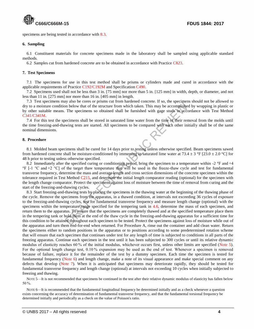
8.3 Start freezing-and-thawing tests by placing the specimens in the thawing water at the beginning of the thawing phase of
the cycle. Remove the specimens from the apparatus, in a thawed condition, at intervals not exceeding 36 cycles of exposure
to the freezing-and-thawing cycles, test for fundamental transverse frequency and measure length change (optional) with the
specimens within the temperature range specified for the tempering tank in 4.6, determine the mass of each specimen, and
return them to the apparatus. To ensure that the specimens are completely thawed and at the specified temperature place them
in the tempering tank or hold them at the end of the thaw cycle in the freezing-and-thawing apparatus for a sufficient time for
this condition to be attained throughout each specimen to be tested. Protect the specimens against loss of moisture while out of
the apparatus and turn them end-for-end when returned. For Procedure A, rinse out the container and add clean water. Return
the specimens either to random positions in the apparatus or to positions according to some predetermined rotation scheme
that will ensure that each specimen that continues under test for any length of time is subjected to conditions in all parts of the
freezing apparatus. Continue each specimen in the test until it has been subjected to 300 cycles or until its relative dynamic
modulus of elasticity reaches 60 % of the initial modulus, whichever occurs first, unless other limits are specified (Note 5).
For the optional length change test, 0.10 % expansion may be used as the end of test. Whenever a specimen is removed
because of failure, replace it for the remainder of the test by a dummy specimen. Each time the specimen is tested for
fundamental frequency (Note 6) and length change, make a note of its visual appearance and make special comment on any
defects that develop (Note 7). When it is anticipated that specimens may deteriorate rapidly, they should be tested for
fundamental transverse frequency and length change (optional) at intervals not exceeding 10 cycles when initially subjected to
freezing and thawing.
NOTE 5—It is not recommended that specimens be continued in the test after their relative dynamic modulus of elasticity has fallen below
50 %.
NOTE 6—It is recommended that the fundamental longitudinal frequency be determined initially and as a check whenever a question
exists concerning the accuracy of determination of fundamental transverse frequency, and that the fundamental torsional frequency be
determined initially and periodically as a check on the value of Poisson's ratio.
DRAFT FOR PUBLIC R
EVIEW
C666/C666M-15 FDUS 1844: 2017
© UNBS 2017 – All rights reserved 5
NOTE 7—In some applications, such as airfield pavements and other slabs, popouts may be defects that are a concern. A popout is
characterized by the breaking away of a small portion of the concrete surface due to internal pressure, thereby leaving a shallow and
typically conical spall in the surface of the concrete through the aggregate particle. Popouts may be observed as defects in the test
specimens. Where popouts are a concern, the number and general description should be reported as a special comment. The aggregates
causing the popout may be identified by petrographic examination as in Practice C295.
8.4 When the sequence of freezing-and-thawing cycles must be interrupted store the specimens in a frozen condition.
NOTE 8—If, due to equipment breakdown or for other reasons, it becomes necessary to interrupt the cycles for a protracted period, store
the specimens in a frozen condition in such a way as to prevent loss of moisture. For Procedure A, maintain the specimens in the containers
and surround them by ice, if possible. If it is not possible to store the specimens in their containers, wrap and seal them, in as wet a condition
as possible, in moisture-proof material to prevent dehydration and store in a refrigerator or cold room maintained at 0 ± 3 °F [-18 ± 2 °C].
Follow the latter procedure when Procedure B is being used. In general, for specimens to remain in a thawed condition for more than two
cycles is undesirable, but a longer period may be permissible if this occurs only once or twice during a complete test.
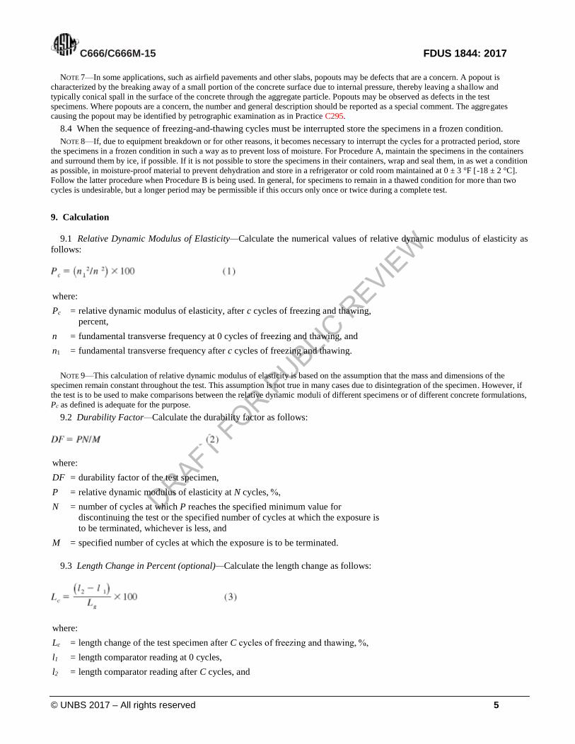
9. Calculation
9.1 Relative Dynamic Modulus of Elasticity—Calculate the numerical values of relative dynamic modulus of elasticity as
follows:
where:
Pc = relative dynamic modulus of elasticity, after c cycles of freezing and thawing,
percent,
n = fundamental transverse frequency at 0 cycles of freezing and thawing, and
n1 = fundamental transverse frequency after c cycles of freezing and thawing.
NOTE 9—This calculation of relative dynamic modulus of elasticity is based on the assumption that the mass and dimensions of the
specimen remain constant throughout the test. This assumption is not true in many cases due to disintegration of the specimen. However, if
the test is to be used to make comparisons between the relative dynamic moduli of different specimens or of different concrete formulations,
Pc as defined is adequate for the purpose.
9.2 Durability Factor—Calculate the durability factor as follows:
where:
DF = durability factor of the test specimen,
P = relative dynamic modulus of elasticity at N cycles, %,
N = number of cycles at which P reaches the specified minimum value for
discontinuing the test or the specified number of cycles at which the exposure is
to be terminated, whichever is less, and
M = specified number of cycles at which the exposure is to be terminated.
9.3 Length Change in Percent (optional)—Calculate the length change as follows:
where:
Lc = length change of the test specimen after C cycles of freezing and thawing, %,
l1 = length comparator reading at 0 cycles,
l2 = length comparator reading after C cycles, and
DRAFT FOR PUBLIC R
EVIEW
C666/C666M-15 FDUS 1844: 2017
© UNBS 2017 – All rights reserved 6
Lg = the effective gage length between the innermost ends of the gage studs as shown
in the mold diagram in Specification C490.
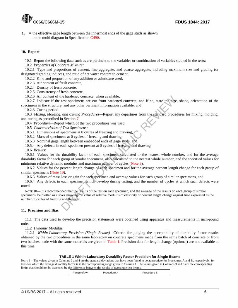
10. Report
10.1 Report the following data such as are pertinent to the variables or combination of variables studied in the tests:
10.2 Properties of Concrete Mixture:
10.2.1 Type and proportions of cement, fine aggregate, and coarse aggregate, including maximum size and grading (or
designated grading indices), and ratio of net water content to cement,
10.2.2 Kind and proportion of any addition or admixture used,
10.2.3 Air content of fresh concrete,
10.2.4 Density of fresh concrete,
10.2.5 Consistency of fresh concrete,
10.2.6 Air content of the hardened concrete, when available,
10.2.7 Indicate if the test specimens are cut from hardened concrete, and if so, state the size, shape, orientation of the
specimens in the structure, and any other pertinent information available, and
10.2.8 Curing period.
10.3 Mixing, Molding, and Curing Procedures—Report any departures from the standard procedures for mixing, molding,
and curing as prescribed in Section 7.
10.4 Procedure—Report which of the two procedures was used.
10.5 Characteristics of Test Specimens:
10.5.1 Dimensions of specimens at 0 cycles of freezing and thawing,
10.5.2 Mass of specimens at 0 cycles of freezing and thawing,
10.5.3 Nominal gage length between embedded ends of gage studs, and
10.5.4 Any defects in each specimen present at 0 cycles of freezing and thawing.
10.6 Results:
10.6.1 Values for the durability factor of each specimen, calculated to the nearest whole number, and for the average
durability factor for each group of similar specimens, also calculated to the nearest whole number, and the specified values for
minimum relative dynamic modulus and maximum number of cycles (Note 9),
10.6.2 Values for the percent length change of each specimen and for the average percent length change for each group of
similar specimens (Note 10),
10.6.3 Values of mass loss or gain for each specimen and average values for each group of similar specimens, and
10.6.4 Any defects in each specimen which develop during testing, and the number of cycles at which such defects were
noted.
NOTE 10—It is recommended that the results of the test on each specimen, and the average of the results on each group of similar
specimens, be plotted as curves showing the value of relative modulus of elasticity or percent length change against time expressed as the
number of cycles of freezing and thawing.
11. Precision and Bias
11.1 The data used to develop the precision statements were obtained using apparatus and measurements in inch-pound
units.
11.2 Dynamic Modulus:
11.2.1 Within-Laboratory Precision (Single Beams)—Criteria for judging the acceptability of durability factor results
obtained by the two procedures in the same laboratory on concrete specimens made from the same batch of concrete or from
two batches made with the same materials are given in Table 1. Precision data for length change (optional) are not available at
this time.
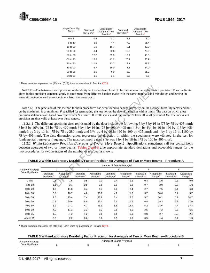
TABLE 1 Within-Laboratory Durability Factor Precision for Single Beams NOTE 1—The values given in Columns 2 and 4 are the standard deviations that have been found to be appropriate for Procedures A and B, respectively, for
tests for which the average durability factor is in the corresponding range given in Column 1. The values given in Columns 3 and 5 are the corresponding limits that should not be exceeded by the difference between the results of two single test beams.
Range of Av- Procedure A Procedure B
DRAFT FOR PUBLIC R
EVIEW
C666/C666M-15 FDUS 1844: 2017
© UNBS 2017 – All rights reserved 7
erage Durability Factor Standard
DeviationA
Acceptable Range of Two
ResultsA
Standard DeviationA
Acceptable Range of Two
ResultsA
0 to 5 0.8 2.2 1.1 3.0
5 to 10 1.5 4.4 4.0 11.4
10 to 20 5.9 16.7 8.1 22.9
20 to 30 8.4 23.6 10.5 29.8
30 to 50 12.7 35.9 15.4 43.5
50 to 70 15.3 43.2 20.1 56.9
70 to 80 11.6 32.7 17.1 48.3
80 to 90 5.7 16.0 8.8 24.9
90 to 95 2.1 6.0 3.9 11.0
Over 95 1.1 3.1 2.0 5.7
A These numbers represent the (1S) and (D2S) limits as described in Practice C670.
NOTE 11—The between-batch precision of durability factors has been found to be the same as the within-batch precision. Thus the limits
given in this precision statement apply to specimens from different batches made with the same materials and mix design and having the
same air content as well as to specimens from the same batch.
NOTE 12—The precision of this method for both procedures has been found to depend primarily on the average durability factor and not
on the maximum N or minimum P specified for terminating the test nor on the size of the beams within limits. The data on which these
precision statements are based cover maximum N's from 100 to 300 cycles, and minimum P's from 50 to 70 percent of E 0. The indexes of
precision are thus valid at least over these ranges.
11.2.1.1 The different specimen sizes represented by the data include the following: 3 by 3 by 16-in [75 by 75 by 405-mm];
3 by 3 by 161/4-in. [75 by 75 by 420-mm]; 3 by 4 by 16-in. [75 by 100 by 405-mm]; 31/2 by 41/2 by 16-in. [90 by 115 by 405-
mm]; 3 by 3 by 11-in. [75 by 75 by 280-mm]; and 31/2 by 4 by 16-in. [90 by 100 by 405-mm]; and 4 by 3 by 16-in. [100 by
75 by 405-mm]. The first dimension given represents the direction in which the specimens were vibrated in the test for
fundamental transverse frequency. The most commonly used size was 3 by 4 by 16-in. [75 by 100 by 405-mm].
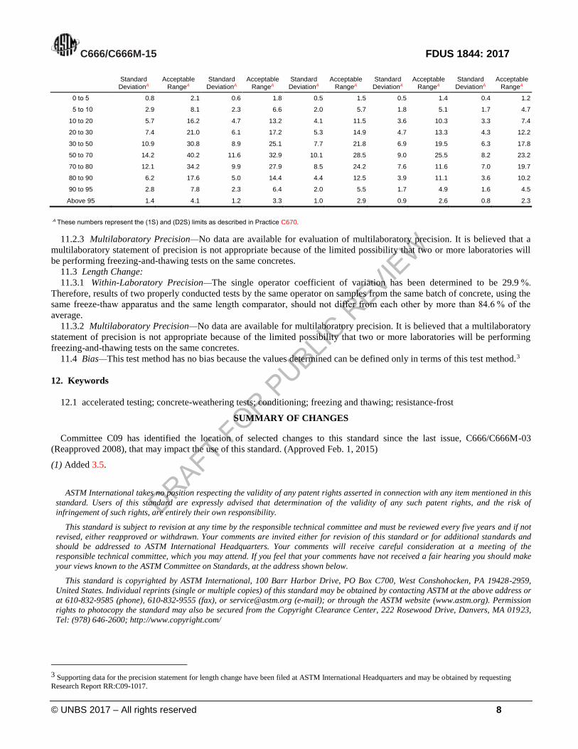
11.2.2 Within-Laboratory Precision (Averages of Two or More Beams)—Specifications sometimes call for comparisons
between averages of two or more beams. Tables 2 and 3 give appropriate standard deviations and acceptable ranges for the
two procedures for two averages of the number of test beams shown.
TABLE 2 Within-Laboratory Durability Factor Precision for Averages of Two or More Beams—Procedure A
Range of Average Durability Factor
Number of Beams Averaged
2 3 4 5 6
Standard DeviationA
Acceptable RangeA
Standard DeviationA
Acceptable RangeA
Standard DeviationA
Acceptable RangeA
Standard DeviationA
Acceptable RangeA
Standard DeviationA
Acceptable RangeA
0 to 5 0.6 1.6 0.5 1.3 0.4 1.1 0.4 1.0 0.3 0.9
5 to 10 1.1 3.1 0.9 2.5 0.8 2.2 0.7 2.0 0.6 1.8
10 to 20 4.2 11.8 3.4 9.7 3.0 8.4 2.7 7.5 2.4 6.8
20 to 30 5.9 16.7 4.8 13.7 4.2 11.8 3.7 10.6 3.4 9.7
30 to 50 9.0 25.4 7.4 20.8 6.4 18.0 5.7 16.1 5.2 14.7
50 to 70 10.8 30.6 8.8 25.0 7.6 21.6 6.8 19.3 6.2 17.6
70 to 80 8.2 23.1 6.7 18.9 5.8 16.4 5.2 14.6 4.7 13.4
80 to 90 4.0 11.3 3.3 9.2 2.8 8.0 2.5 7.2 2.3 6.5
90 to 95 1.5 4.2 1.2 3.5 1.1 3.0 0.9 2.7 0.9 2.4
Above 95 0.8 2.2 0.6 1.8 0.5 1.5 0.5 1.4 0.4 1.3
A These numbers represent the (1S) and (D2S) limits as described in Practice C670.
TABLE 3 Within-Laboratory Durability Factor Precision for Averages of Two or More Beams—Procedure B
Range of Average Durability Factor
Number of Beams Averaged
2 3 4 5 6
DRAFT FOR PUBLIC R
EVIEW
C666/C666M-15 FDUS 1844: 2017
© UNBS 2017 – All rights reserved 8
Standard DeviationA
Acceptable RangeA
Standard DeviationA
Acceptable RangeA
Standard DeviationA
Acceptable RangeA
Standard DeviationA
Acceptable RangeA
Standard DeviationA
Acceptable RangeA
0 to 5 0.8 2.1 0.6 1.8 0.5 1.5 0.5 1.4 0.4 1.2
5 to 10 2.9 8.1 2.3 6.6 2.0 5.7 1.8 5.1 1.7 4.7
10 to 20 5.7 16.2 4.7 13.2 4.1 11.5 3.6 10.3 3.3 7.4
20 to 30 7.4 21.0 6.1 17.2 5.3 14.9 4.7 13.3 4.3 12.2
30 to 50 10.9 30.8 8.9 25.1 7.7 21.8 6.9 19.5 6.3 17.8
50 to 70 14.2 40.2 11.6 32.9 10.1 28.5 9.0 25.5 8.2 23.2
70 to 80 12.1 34.2 9.9 27.9 8.5 24.2 7.6 11.6 7.0 19.7
80 to 90 6.2 17.6 5.0 14.4 4.4 12.5 3.9 11.1 3.6 10.2
90 to 95 2.8 7.8 2.3 6.4 2.0 5.5 1.7 4.9 1.6 4.5
Above 95 1.4 4.1 1.2 3.3 1.0 2.9 0.9 2.6 0.8 2.3
A These numbers represent the (1S) and (D2S) limits as described in Practice C670.
11.2.3 Multilaboratory Precision—No data are available for evaluation of multilaboratory precision. It is believed that a
multilaboratory statement of precision is not appropriate because of the limited possibility that two or more laboratories will
be performing freezing-and-thawing tests on the same concretes.
11.3 Length Change:
11.3.1 Within-Laboratory Precision—The single operator coefficient of variation has been determined to be 29.9 %.
Therefore, results of two properly conducted tests by the same operator on samples from the same batch of concrete, using the
same freeze-thaw apparatus and the same length comparator, should not differ from each other by more than 84.6 % of the
average.
11.3.2 Multilaboratory Precision—No data are available for multilaboratory precision. It is believed that a multilaboratory
statement of precision is not appropriate because of the limited possibility that two or more laboratories will be performing
freezing-and-thawing tests on the same concretes.
11.4 Bias—This test method has no bias because the values determined can be defined only in terms of this test method.3
12. Keywords
12.1 accelerated testing; concrete-weathering tests; conditioning; freezing and thawing; resistance-frost
SUMMARY OF CHANGES
Committee C09 has identified the location of selected changes to this standard since the last issue, C666/C666M-03
(Reapproved 2008), that may impact the use of this standard. (Approved Feb. 1, 2015)
(1) Added 3.5.
ASTM International takes no position respecting the validity of any patent rights asserted in connection with any item mentioned in this
standard. Users of this standard are expressly advised that determination of the validity of any such patent rights, and the risk of
infringement of such rights, are entirely their own responsibility.
This standard is subject to revision at any time by the responsible technical committee and must be reviewed every five years and if not
revised, either reapproved or withdrawn. Your comments are invited either for revision of this standard or for additional standards and
should be addressed to ASTM International Headquarters. Your comments will receive careful consideration at a meeting of the
responsible technical committee, which you may attend. If you feel that your comments have not received a fair hearing you should make
your views known to the ASTM Committee on Standards, at the address shown below.
This standard is copyrighted by ASTM International, 100 Barr Harbor Drive, PO Box C700, West Conshohocken, PA 19428-2959,
United States. Individual reprints (single or multiple copies) of this standard may be obtained by contacting ASTM at the above address or
at 610-832-9585 (phone), 610-832-9555 (fax), or [email protected] (e-mail); or through the ASTM website (www.astm.org). Permission
rights to photocopy the standard may also be secured from the Copyright Clearance Center, 222 Rosewood Drive, Danvers, MA 01923,
Tel: (978) 646-2600; http://www.copyright.com/
3 Supporting data for the precision statement for length change have been filed at ASTM International Headquarters and may be obtained by requesting
Research Report RR:C09-1017.
DRAFT FOR PUBLIC R
EVIEW
C666/C666M-15 FDUS 1844: 2017
© UNBS 2017 – All rights reserved 9
Certification marking
Products that conform to Uganda standards may be marked with Uganda National Bureau of Standards (UNBS) Certification Mark shown in the figure below.
The use of the UNBS Certification Mark is governed by the Standards Act, and the Regulations made thereunder. This mark can be used only by those licensed under the certification mark scheme operated by the Uganda National Bureau of Standards and in conjunction with the relevant Uganda Standard. The presence of this mark on a product or in relation to a product is an assurance that the goods comply with the requirements of that standard under a system of supervision, control and testing in accordance with the certification mark scheme of the Uganda National Bureau of Standards. UNBS marked products are continually checked by UNBS for conformity to that standard.
Further particulars of the terms and conditions of licensing may be obtained from the Director, Uganda National Bureau of Standards.

DRAFT FOR PUBLIC R
EVIEW
C403/C403M-16 FDUS 1843: 2017
ICS nn.nnn.nn
Price based on nn pages
© UNBS 2017 – All rights reserved