
Download PDF - MDPI
16
applied sciences Article Systematization of the Simulation Process of Transformer Inrush Current Using EMTP Hun-Chul Seo 1 and Gi-Hyeon Gwon 2, * 1 School of Electronic & Electrical Engineering, Yonam Institute of Technology, Jinju-si 52821, Gyeongsangnam-do, Korea; [email protected] or [email protected] 2 Department of Smart Electrical & Electronic Engineering, Yonam Institute of Technology, Jinju-si 52821, Gyeongsangnam-do, Korea * Correspondence: [email protected]; Tel.: +82-55-751-2045 Received: 2 May 2019; Accepted: 6 June 2019; Published: 12 June 2019 Abstract: An inrush current is generated when a transformer is energized. This current has a large magnitude and rich harmonics, thereby causing mal-operation of the protection relay. Therefore, the development of countermeasures against inrush current is necessary, and this study has been performed by computer simulations. However, it is difficult for a power system operator to perform a computer simulation as it is difficult to determine what data should be selected and entered. Therefore, this paper establishes the simulation process of transformer inrush current using the Electromagnetic Transients Program (EMTP). Two methods to simulate the transformer inrush current are described in detail. Based on the actual 154 kV transformer test report in Korea, the simulation results of the inrush current using the two methods are discussed. Keywords: current-flux value; EMTP; leakage impedance, saturation point; test report; transformer inrush current 1. Introduction Transformers are essential components of power systems. However, energization of the transformer is necessary for the operation of power systems. When the transformer is energized, an inrush current of large magnitude and rich harmonics is generated. This current adversely affects the power system causing a reduction in the lifetime of the transformer, damage, and mal-operation of the protective relay. Therefore, several studies have been carried out on the inrush current of a transformer to counteract these adverse effects. References [1–5] studied the discrimination strategies between transformer faults and inrush current. References [6–13] studied the reduction techniques of inrush current. Moreover, [6–9] studied the controlled energization of transformers, while [10,11] studied the utilization of uninterrupted power supply and photovoltaic systems. In addition, [12–17] studied the power quality and protection of power systems by inrush current. The studies above were performed using a power system simulation program. [1,3,4,9] used Power Systems Computer Aided Design Electromagnetic Transients including DC (PSCAD/EMTDC). References [2,5] used MATLAB. References [6,7,10,14,15] used Electromagnetic Transients Program (EMTP). Reference [16] used Electromagnetic Transients Program—Restructured Version (EMTP-RV). Reference [17] used DigSILENT software, and [11] performed laboratory experiments. References [8,12,13] did not provide any simulation software information. References [1–17] did not provide detailed information for the simulation of the transformer inrush current. Appl. Sci. 2019, 9, 2398; doi:10.3390/app9122398 www.mdpi.com/journal/applsci
-
Upload
khangminh22 -
Category
Documents
-
view
1 -
download
0
Transcript of Download PDF - MDPI

applied sciences
Article
Systematization of the Simulation Process ofTransformer Inrush Current Using EMTP
Hun-Chul Seo 1 and Gi-Hyeon Gwon 2,*1 School of Electronic & Electrical Engineering, Yonam Institute of Technology, Jinju-si 52821,
Gyeongsangnam-do, Korea; [email protected] or [email protected] Department of Smart Electrical & Electronic Engineering, Yonam Institute of Technology, Jinju-si 52821,
Gyeongsangnam-do, Korea* Correspondence: [email protected]; Tel.: +82-55-751-2045
Received: 2 May 2019; Accepted: 6 June 2019; Published: 12 June 2019�����������������
Abstract: An inrush current is generated when a transformer is energized. This current has a largemagnitude and rich harmonics, thereby causing mal-operation of the protection relay. Therefore,the development of countermeasures against inrush current is necessary, and this study has beenperformed by computer simulations. However, it is difficult for a power system operator to perform acomputer simulation as it is difficult to determine what data should be selected and entered. Therefore,this paper establishes the simulation process of transformer inrush current using the ElectromagneticTransients Program (EMTP). Two methods to simulate the transformer inrush current are describedin detail. Based on the actual 154 kV transformer test report in Korea, the simulation results of theinrush current using the two methods are discussed.
Keywords: current-flux value; EMTP; leakage impedance, saturation point; test report; transformerinrush current
1. Introduction
Transformers are essential components of power systems. However, energization of thetransformer is necessary for the operation of power systems. When the transformer is energized,an inrush current of large magnitude and rich harmonics is generated. This current adversely affectsthe power system causing a reduction in the lifetime of the transformer, damage, and mal-operationof the protective relay. Therefore, several studies have been carried out on the inrush current of atransformer to counteract these adverse effects. References [1–5] studied the discrimination strategiesbetween transformer faults and inrush current. References [6–13] studied the reduction techniquesof inrush current. Moreover, [6–9] studied the controlled energization of transformers, while [10,11]studied the utilization of uninterrupted power supply and photovoltaic systems. In addition, [12–17]studied the power quality and protection of power systems by inrush current. The studies abovewere performed using a power system simulation program. [1,3,4,9] used Power Systems ComputerAided Design Electromagnetic Transients including DC (PSCAD/EMTDC). References [2,5] usedMATLAB. References [6,7,10,14,15] used Electromagnetic Transients Program (EMTP). Reference [16]used Electromagnetic Transients Program—Restructured Version (EMTP-RV). Reference [17] usedDigSILENT software, and [11] performed laboratory experiments. References [8,12,13] did not provideany simulation software information. References [1–17] did not provide detailed information for thesimulation of the transformer inrush current.
Appl. Sci. 2019, 9, 2398; doi:10.3390/app9122398 www.mdpi.com/journal/applsci

Appl. Sci. 2019, 9, 2398 2 of 16
For a transient simulation program, it is necessary to derive the data based on the current–fluxcurve necessary for simulating the transformer inrush current. In addition, data such as impedanceratio, impedance voltage, no-load losses, and winding resistance in transformer test reports arerequired. However, it is often difficult to determine what data should be used and how they shouldbe processed when the power system operator performs transformer inrush current simulations.Therefore, this paper provides detailed information on the simulation of transformer inrush current topower system operators. The novel contribution of this paper is as follows:
(1) The simulation process of transformer inrush current using EMTP has been systematized.(2) The necessary data for the simulation are derived from the test report.(3) The method for simulating transformer inrush current using these data is described in detail.(4) Based on the method proposed in this paper, the power system operator can easily perform the
inrush current simulation.
Therefore, this paper establishes the simulation process of transformer inrush current using EMTP,which simulates transient electromagnetic phenomena and is one of the most widely used electricutilities programs. Alternative Transients Program Draw (ATPDraw) is a graphical, mouse-drivenpre-processor to the ATP version of EMTP [18–20]. Based on the established simulation process,the simulation example of transformer inrush current is presented using 154 kV transformer test datain Korea.
The remainder of this paper is organized as follows: Section 2 discusses the inrush current.In Section 3, two methods of the simulation process of transformer inrush current using EMTP areintroduced. Section 4 discusses the simulation results using 154 kV transformer test data in Korea.Finally, the conclusions derived from the study are presented in Section 5.
2. Transformer Inrush Current
At the initial energization of the transformer, there is an injection of current to create the magneticfield of the transformer, which is called magnetizing inrush current. When the transformer is initiallyenergized, the magnetic flux and winding current become repeatedly larger and smaller. This currentcan be several times larger than the rated current of the transformer, which can lead to mal-operationof the protective relay. Its duration varies from a few cycles to several seconds [1–4].
The magnitude of the inrush current is based on the closing point on the voltage waveform andresidual flux. The greater the residual magnetic flux, the higher the possibility that the magnetic fluxexceeds the saturation magnetic flux, such that the possibility of inrush current generation increases.When the transformer is energized, at the instant when the voltage becomes zero, the magnetic fluxbecomes larger than the saturation flux and a large inrush current is generated. However, when thetransformer is energized, at the instant when the voltage becomes peak value (90 degree) on thewaveform, the possibility that the magnetic flux becomes smaller than the saturation flux is low. Hence,the possibility of inrush current generation is also low. However, if the residual magnetic flux is large,the inrush current may exceed the saturation flux.
3. Simulation Process of Transformer Inrush Current Using EMTP
There are two methods for simulating the nonlinear characteristics of the transformer as shown inFigure 1. The methods are different for Step 1 and 2, and the same for Step 3.

Appl. Sci. 2019, 9, 2398 3 of 16
Figure 1. The simulation methods of transformer inrush current.
3.1. Method 1
3.1.1. Step 1: Estimation of Current–Flux
To simulate the inrush current, hysteresis (current–flux) curves are required to express thenonlinear characteristics of the transformer. These curves can be obtained using voltage and excitationcurrent. Meanwhile, the auxiliary routine SATURA program provided by EMTP is used to convertthe root mean square (RMS) (V–i) curve in the test report into the current–flux curve required fortransient simulation [21]. However, the auxiliary routine SATURA is not supported by EMTP/ATPDraw.Therefore, the value must be entered in a text format and run in DOS mode after inputting all theSATURA values. The user can see the result by opening the punch file after execution. The current–fluxdata generated by the SATURA is symmetrical in the first and third quadrants. Therefore, the SATURAmethod has a disadvantage in that it cannot model the residual magnetic flux. The result of this methodcan be entered into the current–flux data of the Type 98 device or the current–flux data in the saturationtransformer model of EMTP.
3.1.2. Step 2: Input of Current–Flux Values
(1) Input of current–flux values using Type 98 deviceType 98 device in the Branch/Nonlinear library of EMTP can be used to enter the current–flux
value. The results obtained by running SATURA in Step 1 are inputted in this device. The current valuein steady state is inputted in the CURR section of the Type 98 device, while the flux value in steadystate is inputted in FLUX section. However, for this value, the first value among the current–flux valuesextracted in Step 1 is inputted. Meanwhile, the current–flux values are inputted in the Characteristictab. The current–magnetic flux curve is then generated by clicking the View button at the bottom ofthe screen.
Meanwhile, this Type 98 device corresponds only to the magnetizing current in the actualtransformer equivalent circuit. The leakage resistance and leakage reactance in the primary side canbe represented by introducing resistor and inductor model in the Branch/Linear library of EMTP.In addition, the transformer in the equivalent circuit can be represented by the transformer model.It should be noted that a single Type 98 device supports only a single-phase transformer model.

Appl. Sci. 2019, 9, 2398 4 of 16
Moreover, a three-phase transformer model can be developed using three Type 98 devices. The methodwill be described in detail in Step 3.
(2) Input of current–flux values in the transformer modelThe next step is to input the current–flux value in the transformer model. The saturable
three-phase transformer model in the Transformers library is selected among the models providedby EMTP. On the Attributes dialog box that appears, the primary and secondary voltages, leakageresistance, and leakage reactance can be inputted. Meanwhile, the Characteristic tab allows the usersto input current–flux values.
3.1.3. Step 3: Power System Modeling
(1) Using a Type 98 deviceSince Type 98 devices do not support three-phase modeling, three Type 98 devices should be used.
Figure 2 shows an example of the entire modeling. The primary-side leakage resistance and leakagereactance should be located on the left side of the Type 98 device, represented by R–L elements in thered portion of Figure 2. The transformer model should select either a saturable single-phase model ora saturable three-phase model in the Transformers library. When selecting a saturable single-phasemodel, the transformer winding must be connected directly as the 4 or y winding. Figure 2 shows anexample of y–y winding.
Figure 2. System configuration using Type 98 device.
Meanwhile, BCTRAN model in Transformers library of EMTP can also be used to input thetransformer internal parameters. It converts the transformer into mutually coupled [R]–[L]−1
elements [21]. However, nonlinear devices such as Type 98 or Type 96 must be connected externallyas the saturation characteristics are not included. In the Input section, the number of phases and ofwindings, iron core type, and frequency are inputted; while the rated voltage and capacity in theprimary, secondary, and tertiary windings are inputted in the Rating section. In the Connection section,winding method is selected. Herein, ‘A’ is selected for the case of an autotransformer, while ‘Y’ and ‘D’are selected for y and delta connections, respectively. In the Factory Test section, open circuit test andshort circuit test data are inputted. For the open test, the voltage (%), excitation current (%), and ironloss (kW) are inputted; while the test results of % impedance, capacity (MVA), and load loss (kW) areinputted for short circuit tests.
(2) Input of the current–flux value inside the transformer modelWhen inputting the current–flux value inside the transformer model described in Step 2 (2),
the saturable three-phase model in the Transformers library should be selected. However, the primaryleakage resistance and the leakage reactance must be inputted into the transformer model since noseparate current–flux input device exists in the library.

Appl. Sci. 2019, 9, 2398 5 of 16
3.1.4. Discussion
For Method 1, the current–flux value is derived using the SATURA auxiliary routine in Step 1.The users can then simulate the inrush current by inputting the current–flux values in a Type 98 deviceor transformer model and modeling the entire system. If the voltage–current values are inputteddirectly in the transformer model, the process of deriving and inputting the current–magnetic fluxvalue obtained by the SATURA auxiliary routine in Step 1 and 2 can be omitted. However, it hasa disadvantage that the users cannot determine the actual current–flux value. In addition, it doesconsider the residual magnetic flux that greatly affects the inrush current of the transformer.
3.2. Method 2
3.2.1. Step 1: Estimation of Current–Flux
The HYSDAT auxiliary routine provided by EMTP can be used to estimate the current–flux valuesof the hysteresis curve and the characteristics of the residual magnetic flux [21]. When inputting thevalues in HYSDAT, the current–flux of the saturation point should be inputted. As this method doesnot exist in EMTP/ATPDraw, it must be configured in a text format. After simulation, the current–fluxvalues are included in the punch file.
This method has an advantage in that the modeling of the hysteresis curve and the residualmagnetic flux can be performed. However, users need to first estimate the current–flux at the saturationpoint, which can be done using SATURA discussed in Method 1. The saturation point can be roughlyestimated from the simulation results using SATURA. Alternatively, the saturation point can beestimated from the open test results. The saturation point estimated should then be inputted inHYSDAT, and the results should be inputted as the current–flux values in the Type 96 device in Step 2.
3.2.2. Step 2: Input of Current–Flux Values
The current–flux values derived using the HYSDAT auxiliary routine must be inputted usingType 96 device located in the Branch/Nonlinear library. The current value in steady state is inputted inthe CURR section in the Attributes screen of Type 96, while the flux value in steady state is inputtedin the FLUX section. For this value, the first value in the first quadrant of the extracted current–fluxvalues can be inputted. Residual flux can be inputted in RESID. In the Characteristic tab of the Type 96device, current–flux values are inputted and the current–flux curve is generated by clicking the Viewbutton at the bottom of the screen.
3.2.3. Step 3: Power System Modeling
When using a Type 96 device, the method for the entire system configuration is the same asshown in Figure 2 except that the Type 98 device is replaced with the Type 96 device. The primary-sideleakage resistance and the leakage reactance are located on the left side of the Type 96 device, while atransformer model exists on the right side of the Type 96 device.
The transformer model can be selected from among saturable single-phase, saturable three-phase,and BCTRAN models. For a double winding transformer, saturable single-phase and three-phasemodels are suitable. Meanwhile, saturable three-phase and BCTRAN models can be used for athree-winding transformer. However, since the equivalent circuit of a three-winding transformer isderived based on the star connection, the leakage inductance may become negative based on thetransformer test result, thereby resulting in numerical instability. In this case, the BCTRAN model canbe used.
3.2.4. Discussion
For Method 2, the SATURA auxiliary routine may be used to obtain the saturation point using theType 96 device. The current–flux values should be derived through the HYSDAT auxiliary routine

Appl. Sci. 2019, 9, 2398 6 of 16
using only the saturation point, and the derived values should be inputted in the Type 96 device.Finally, the inrush current simulation can be performed by modeling the entire system. In this method,the process is more complicated than in the previous method. However, the advantage is that theresidual flux value, which has a large effect on the transformer inrush current, can be considered.
4. Simulation of Transformer Inrush Current Using 154 kV Transformer Test Report
4.1. Transformer Test Report
In this section, an example of transformer inrush current simulation based on Methods 1 and 2will be described. Table 1 shows the test list in the transformer test report.
Table 1. Test list in transformer test report.
1. Structure and Exterior test 12. Insulation strength test of operation and control circuit1.1. Structure test 13. Noise level1.2. Exterior test 14. Short circuit test of transformer
2. Turns ratio measurement, polarity test, and angledisplacement test 14.1. Short circuit test (Primary -Secondary winding)
2.1. Turns ratio measuremnt 14.2. Short circuit test (Primary -Tertiary winding)2.1.1. Primary - Secondary winding 14.3. Winding temperature during short circuit test2.1.2. Primary –Tertiary winding 14.4. Confirmation test after short circuit test
2.1.3. Secondary - Tertiary winding 14.4.1. Turns ration measurement, polarity test andangle displacement test
2.2. Polarity test and angle displacement test 14.4.2. Impedance voltage and full load loss test3. Impedance voltage and full load loss test 14.4.3. No load loss and excitation current test4. No load loss and excitation current test 14.4.4. Winding resistance measurement5. Winding resistance measurement 14.4.5. Power frequency withstand voltage test
6. Power frequency withstand voltage test 14.4.6. Induced withstand voltage test and partialdischarge test
7. Induced withstand voltage test and partialdischarge test 14.4.7. Insulation power factor test
8. Insulation power factor test 14.4.8. Motor test
8.1. Phase A 14.4.9. Insulation strength test of operation and controlcircuit
8.2. Phase B 14.4.10. Variation ratio of reactance8.3. Phase C 14.4.11. Visual inspection after short circuit test
9. Temperature rise test 15. Poly Chlorniated Biphenyls (PCB) analysis test ininsulation oil
9.1. Temperature rise test 16. Winding insulation resistance measurement9.1.1. Primary and Secondary winding 16.1. Before short circuit test9.1.2. Tertiary winding 16.2. After short circuit test
9.2. Dissolved gas test 17. Frame and core insulation test10. Lightning impulse withstand voltage test 17.1. Before short circuit test11. Motor test 17.2. After short circuit test
11.1. Fan power consumption measurement androtating direction test 18. Conclusion
11.2. On Load Tap Changer (OLTC) operation test
The necessary data from the transformer report should be extracted as follows:
(1) Turns ratio measurement, polarity test, and angle displacement test(2) Impedance voltage and full-load loss test(3) No-load loss and excitation current test(4) Winding resistance measurement.
4.2. Calculation of Leakage Impedance Using the Results in Test Report
To select the appropriate transformer model, the leakage impedance of the transformer mustbe calculated. Since this transformer is a three-winding transformer, the leakage impedance can becalculated using Equations (1)–(3).
Appl. Sci. 2019, 9, 2398 7 of 16
Z1 =12(Z12 + Z13 −Z23), (1)
Z2 =12(Z12 + Z23 −Z13), (2)
Z3 =12(Z13 + Z23 −Z12), (3)
where
Z1: Leakage impedance of primary side;Z2: Leakage impedance of secondary side;Z3: Leakage impedance of tertiary side;Z12: Per-unit leakage impedance measured from winding 1, with wind 2 shorted and winding 3 open;Z13: Per-unit leakage impedance measured from winding 1, with wind 3 shorted and winding 2
open; andZ23: Per-unit leakage impedance measured from winding 2, with wind 3 shorted and winding 1 open.
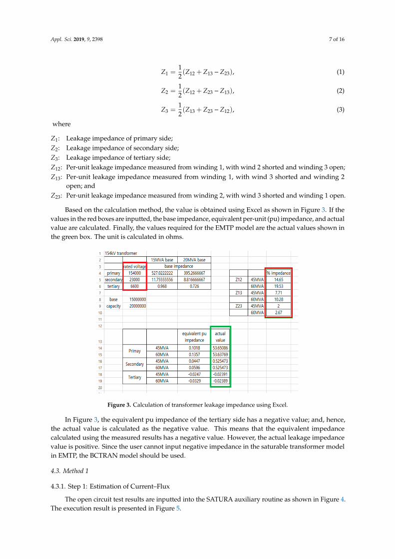
Based on the calculation method, the value is obtained using Excel as shown in Figure 3. If thevalues in the red boxes are inputted, the base impedance, equivalent per-unit (pu) impedance, and actualvalue are calculated. Finally, the values required for the EMTP model are the actual values shown inthe green box. The unit is calculated in ohms.
Figure 3. Calculation of transformer leakage impedance using Excel.
In Figure 3, the equivalent pu impedance of the tertiary side has a negative value; and, hence,the actual value is calculated as the negative value. This means that the equivalent impedancecalculated using the measured results has a negative value. However, the actual leakage impedancevalue is positive. Since the user cannot input negative impedance in the saturable transformer modelin EMTP, the BCTRAN model should be used.
4.3. Method 1
4.3.1. Step 1: Estimation of Current–Flux
The open circuit test results are inputted into the SATURA auxiliary routine as shown in Figure 4.The execution result is presented in Figure 5.
Appl. Sci. 2019, 9, 2398 8 of 16
Figure 4. SATURA input.
Figure 5. Simulation result of SATURA.
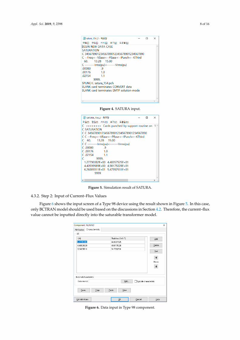
4.3.2. Step 2: Input of Current–Flux Values
Figure 6 shows the input screen of a Type 98 device using the result shown in Figure 5. In this case,only BCTRAN model should be used based on the discussions in Section 4.2. Therefore, the current–fluxvalue cannot be inputted directly into the saturable transformer model.
Figure 6. Data input in Type 98 component.

Appl. Sci. 2019, 9, 2398 9 of 16
4.3.3. Step 3: Power System Modeling
If the negative leakage impedance on the tertiary side calculated in Figure 3 is inputted intosaturable three-phase model, the execution is stopped due to numerical instability. Therefore,it is not appropriate to enter the transformer leakage resistance and leakage reactance using thesaturable three-phase model. The test data in transformer test report should be inputted using theBCTRAN model.
The system modeling using BCTRAN model is shown in Figure 7, where the red part is theBCTRAN transformer model. Since the excitation characteristics are not represented in this model,the corresponding part is added using the Type 98 device as shown in the green part.
Figure 7. Power system modeling using BCTRAN.
Moreover, the data input screen of BCTRAN is shown in Figure 8. The results of the open circuittest and the short circuit test are inputted. The winding on which the open circuit test had beenperformed can be set at “Performed at” and “Connect at” in BCTRAN model. Therefore, the Type 98device should be connected in the same manner as set here. Since the transformer test data used inthis paper was performed on the secondary side, the LV winding is selected and the Type 98 device isconnected to the secondary side.
Figure 8. BCTRAN input.
4.3.4. Simulation Results
Figure 9 shows the simulation result of the inrush current. Figure 9a shows the current flowing inthe primary side of the transformer. After energizing the transformer at 0.1 s, a DC offset waveform isgenerated. As the time passes, the current magnitude decays and becomes closer to the rated current.Figure 9b shows the magnetizing current. The typical inrush current waveform larger than the rated

Appl. Sci. 2019, 9, 2398 10 of 16
current with DC offset and harmonics is observed. Figure 9c shows the frequency analysis of thecurrent flowing in the primary side of the transformer. It shows a typical form of inrush current withsecond harmonics.
Figure 9. Simulation results. (a) Current flowing in the primary side of the transformer; (b) magnetizingcurrent; and (c) frequency analysis.
Figure 9 shows the typical characteristics of inrush current with DC offsets having a magnitudelarger than the rated current and a rich second harmonic. Therefore, the simulation process usingMethod 1 is appropriate.
Appl. Sci. 2019, 9, 2398 11 of 16
4.4. Method 2
4.4.1. Step 1: Estimation of Current–Flux
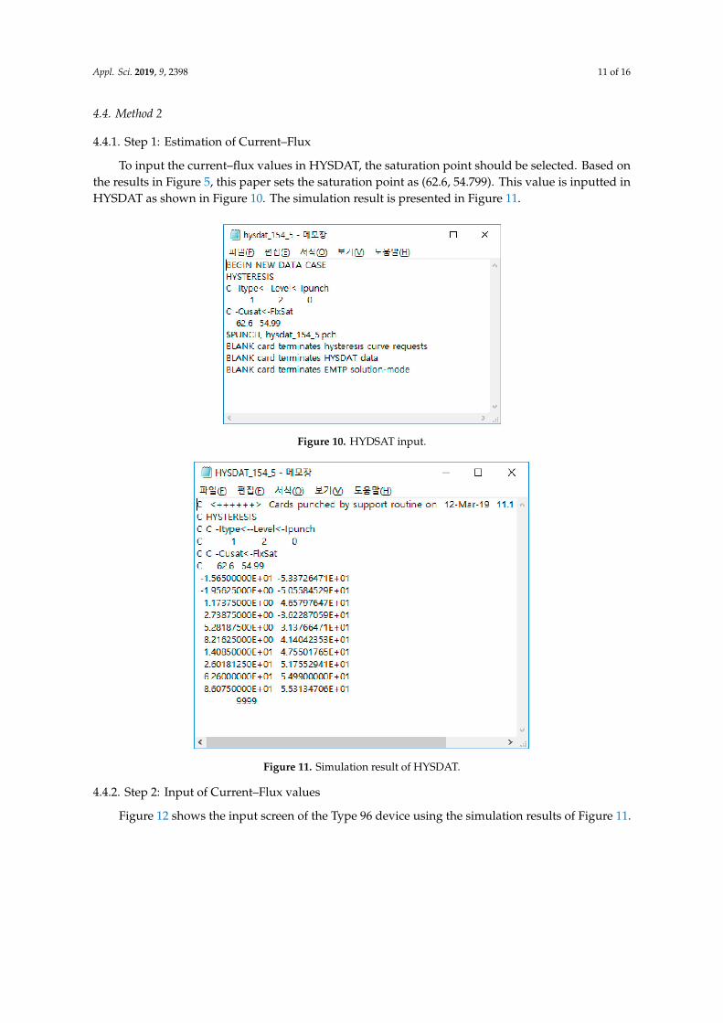
To input the current–flux values in HYSDAT, the saturation point should be selected. Based onthe results in Figure 5, this paper sets the saturation point as (62.6, 54.799). This value is inputted inHYSDAT as shown in Figure 10. The simulation result is presented in Figure 11.
Figure 10. HYDSAT input.
Figure 11. Simulation result of HYSDAT.
4.4.2. Step 2: Input of Current–Flux values
Figure 12 shows the input screen of the Type 96 device using the simulation results of Figure 11.

Appl. Sci. 2019, 9, 2398 12 of 16
Figure 12. Data input in Type 96 component.
4.4.3. Step 3: Power System Modeling
Based on the same reason in Method 1, only the BCTRAN model should be used. The modelingmethod using BCTRAN is similar to the method shown in Figure 7. However, it is necessary to changethe Type 98 device to a Type 96 device.
4.4.4. Simulation Results
The simulation results of inrush current by Method 2 are shown in Figure 13. Figure 13a showsthe current flowing in the primary side of the transformer. It has a DC offset after energizing thetransformer at 0.1 s. However, this DC offset decreases with time and the rated current eventually flows.Figure 13b shows the magnetization current waveform with DC offset and harmonics. Figure 13c isthe frequency analysis result of Figure 13a, which contains a large second harmonic. On the otherhand, Figures 9 and 13 show the typical characteristics of inrush current with DC offsets having alarger magnitude and second harmonic than the rated current. Therefore, the simulation process usingMethod 2 is appropriate.
In Figures 9 and 13, the maximum value of the current flowing in the primary side of thetransformer is slightly different. The results in Figure 9 do not consider the residual magnetic flux sincethe current–flux curve passes through (0, 0). However, the results in Figure 13 consider the residualflux. Therefore, the magnitude of the inrush current is larger because the hysteresis curve that passesthrough (0, −47) is inputted.
In this paper, the simulations of inrush current are performed for a simple power system.The Methods 1 and 2 presented in this paper can be applied to complex power systems such as anInstitute of Electrical and Electronics Engineers (IEEE) test system [22–24].

Appl. Sci. 2019, 9, 2398 13 of 16
Figure 13. Simulation results. (a) Current flowing in the primary side of the transformer; (b) magnetizingcurrent; and (c) frequency analysis.
4.5. Discussion
The test result of the inrush current cannot be obtained in the test report. Therefore, the simulationresults cannot be compared with field test results. Meanwhile, the absolute value of residual fluxcan be quite different from one transformer to another. Its true nature has not been experimentallyclarified because the flux values in the transformer core cannot be measured directly and field testscannot be easily conducted [25–27]. However, [28,29] conducted the field test of inrush current. In [28],

Appl. Sci. 2019, 9, 2398 14 of 16
the Subestacao Eunapolis in Brazil was selected to be the site test due to an experienced undesiredtrip of the transformer of a neutral overcurrent protection during the energizing of one of the threeparallel transformers. In [29], Korea Electric Power Corporation conducted the field test of inrushcurrent at 765 kV transmission lines because they did not conduct the long-term field test for thesubstation equipment. References [28,29] performed field tests in actual transmission lines based onthe requirements of the electric power corporation such as undesired operation and deterioration ofelectric facilities.
Thus, the studies on inrush current have been performed using simulations. In this paper, data from‘2. Turns ratio measurement, polarity test, and angle displacement test’, ‘3. Impedance voltage andfull-load loss test’, ‘4. No-load loss and excitation current test’, and ‘5. Winding resistance measurement’in Table 1 were used for simulations. Therefore, the actual characteristic of the transformer inrushcurrent was considered in our simulations. In addition, although the simulation results cannot becompared with the field test results, the simulations using actual parameters are well performed basedon the analysis of the simulation results presented in Sections 4.2 and 4.3.
5. Conclusion
Since EMTP provides several transformer models and a large amount of information exists in thetransformer test data, it is difficult for the power system operator to simulate the transformer inrushcurrent directly. Therefore, this paper establishes the simulation process of the transformer inrushcurrent using EMTP so that any power system operator can easily perform it. The method presentedin this paper consists of three steps: (1) Estimation of current–flux values, (2) input of current–fluxvalues, and (3) power system modeling. In this paper, the methods of inputting current–flux values areexplained in detail in each step. An example of transformer inrush current simulation using actual154 kV transformer test report data is described by applying these methods. Thus, both Method 1 and 2in this paper can be utilized to simulate the transformer inrush current. However, it is recommended toapply Method 2 if the actual transformer contains a large amount of residual magnetic flux; otherwise,either Method 1 or Method 2 may be applied.
When the mal-operation of the protection relay occurs in actual power systems due to a very largeinrush current, the power system operator will attempt to identify this problem and provide solutions.Since the inrush current of the transformer cannot be actually tested, the problem can be solved usingcomputer simulation. If the power system operator has no experience with inrush current simulationsand does not understand the well-organized simulation method, it will take a long time to provide asolution. Therefore, the simulation process described in this paper can aid the power system operatorin analyzing the problem using inrush current simulation in a short time and developing a solution toachieve stable power system operation.
Author Contributions: H.-C.S. conceived, designed, and performed the experiments. H.-C.S. and G.-H.G.analyzed the data and wrote the paper.
Funding: This work was supported by a 2019 Yonam Institute of Technology grant.
Conflicts of Interest: The authors declare no conflict of interest.
References
1. Wencong, W.; Tianyao, J.; Mengshi, L.; Qinghua, W. Using mathematical morphology to discriminate betweeninternal fault and inrush current of transformers. IET Gen. Trans. Distrib. 2016, 10, 73–80.
2. Bagheri, S.; Moravej, Z.; Gharehpetian, G.B. Classification and Discrimination Among Winding MechanicalDefects, Internal and External Electrical Faults, and Inrush Current of Transformer. IEEE Trans. Ind. Inform.2018, 14, 484–493. [CrossRef]
3. Sahebi, A.; Samet, H.; Ghanbari, T. Evaluation of power transformer inrush currents and internal faultsdiscrimination methods in presence of fault current limiter. Renew. Sustain. Energy Rev. 2017, 68, 102–112.[CrossRef]

Appl. Sci. 2019, 9, 2398 15 of 16
4. Dashti, H.; Davarpanah, M.; Sanaye-Pasand, M.; Lesani, H. Discriminating transformer large inrush currentsfrom fault currents. Int. J. Electr. Power Energy Syst. 2017, 75, 74–82. [CrossRef]
5. Ibrahim, O.M.S.O.; Zheng, T.; Zheng, X. Power transformer inrush current identification using relative waveletenergy. In Proceedings of the International Conference on Computer, Control, Electrical, and ElectronicsEngineering, Khartoum, Sudan, 12–14 August 2018.
6. Cui, Y.; Abdulsalam, S.G.; Chen, S.; Xu, W. A sequential phase energization technique for transformer inrushcurrent —Part I: Simulation and experimental results. IEEE Trans. Power Deliv. 2005, 20, 943–949. [CrossRef]
7. Cano-González, R.; Bachiller-Soler, A.; Rosendo-Macías, J.A.; Álvarez-Cordero, G.. Controlled switchingstrategies for transformer inrush current reduction: A comparative study. Electr. Power Syst. Res. 2017, 145,12–18. [CrossRef]
8. Sahoo, S.K.; Modi, A.; Balamurugan, M.; Sultana, R.; Chhawchharia, S. Reduction of inrush current usingpoint on wave switching in power transformers. In Proceedings of the Innovations in Power and AdvancedComputing Technologies, Vellore, India, 21–22 April 2017.
9. Parikh, U.; Bhavesh, R.B. Mitigation of magnetic inrush current during controlled energization of coupledun-loaded power transformers in presence of residual flux without load side voltage measurements. Int. J.Electr. Power Energy Syst. 2016, 76, 156–164. [CrossRef]
10. Fang, S.; Ni, H.; Lin, H.; Ho, S.L. A novel strategy for reducing inrush current of three-phase transformerconsidering residual flux. IEEE Trans. Ind. Electr. 2016, 63, 4442–4451. [CrossRef]
11. Bukhari, S.S.H.; Lipo, T.A.; Kwon, B. An online UPS system that eliminates the inrush current phenomenonwhile feeding multiple load transformers. IEEE Trans. Ind. Appl. 2017, 53, 1149–1156. [CrossRef]
12. Abdelsalam, A.A.; Hany, A.A. Mitigation of transformer-energizing inrush current using grid-connectedphotovoltaic system. Int. J. Electr. Power Energy Syst. 2016, 79, 312–321.
13. Burkard, J.; Biela, J. Transformer inrush current mitigation concept for hybrid transformers. In Proceedingsof the European Conference on Power Electronics and Applications, Warsaw, Poland, 11–14 September 2017.
14. Chiesak, N.; Mork, B.A.; Høidalen, H.K. Transformer model for inrush current calculations: Simulations,measurements and sensitivity analysis. IEEE Trans. Power Deliv. 2010, 25, 2599–2608. [CrossRef]
15. Nagpal, M.; Martinich, T.G.; Moshref, A.; Morison, K.; Kundur, P. Assessing and limiting impact oftransformer inrush current on power quality. IEEE Trans. Power Deliv. 2006, 21, 890–896. [CrossRef]
16. Seo, H.-C.; Kim, C.-H. The analysis of power quality effects from the transformer inrush current: A case studyof the Jeju power system, Korea. In Proceedings of the IEEE Power and Energy Society General Meeting,Pittsburgh, PA, USA, 20–24 July 2008.
17. Sadeghi, M.H.; Damchi, Y.; Shirani, H. Improvement of operation of power transformer protection systemduring sympathetic inrush current phenomena using fault current limiter. IET Gen. Trans. Distrib. 2018, 12,5968–5974. [CrossRef]
18. Seo, H.-C. New configuration and novel reclosing procedure of distribution system for utilization of BESS asUPS in smart grid. Sustainability 2017, 9, 507. [CrossRef]
19. Seo, H.-C. Development of reclosing method in a distribution system with distributed generation and batteryenergy storage system. Energies 2018, 11, 1407. [CrossRef]
20. Seo, H.-C. Novel adaptive reclosing scheme using wavelet transform in distribution system with batteryenergy storage system. Int. J. Electr. Power Energy Syst. 2018, 97, 186–200. [CrossRef]
21. Meyer, W.S.; Liu, T.H. Alternative Transients Program ATP Rule Book EEUG; Canadian/American EMTP UserGroup: Portland, OR, USA, 1987.
22. Mohammadi, F.; Zheng, C.; Su, R. Fault diagnosis in smart grid based on data-driven computationalmethods. In Proceedings of the 5th International Conference on Applied Research in Electrical, Mechanical& Mechatronics Engineering, Tehran, Iran, 28 February 2019.
23. Mohammadi, F.; Zheng, C. A Precise SVM Classification Model for Predictions with Missing Data.In Proceedings of the 4th National Conference on Applied Research in Electrical, Mechanical, Computer,and IT Engineering, Shiraz, Iran, 4 October 2018.
24. Mohammadi, F.; Zheng, C. Stability analysis of electric power system. In Proceedings of the 4th NationalConference on technology in Electrical and Computer Engineering, Tehran, Iran, 19 February 2018.
25. Hase, Y.; Kamesawa, T.; Inoue, S.; Yamamura, S. Experimental study of transformer residual flux and themethod of restraining inrush current. Electr. Eng. Jap. 2014, 188, 54–67. [CrossRef]

Appl. Sci. 2019, 9, 2398 16 of 16
26. Ge, W.; Wang, Y.; Zhao, Z.; Yiang, X.; Li, Y. Residual flux in the closed magnetic core of a power transformer.IEEE Trans. Appl. Supercond. 2014, 24, 1–4.
27. Ekwue, A.O.; Rawn, B. Investigations into the transformer inrush current problem. Nig. J. Technol. 2018, 37,1058–1065. [CrossRef]
28. Herivelto, S.B.; Servulo, O.P.; Jonsson, P.; de Olivera, J.C.; Chaves, M.L.R. Transformer inrush mitigation—PartII: Field test on a 100MVA three-phase transformer. In Proceedings of the IEEE/PES Transmission &Distribution Conference and Exposition, Caracas, Venezuela, 15–18 August 2006.
29. Shim, E.B.; Woo, J.W.; Jung, G.J. The field test and computer simulation on the inrush current and circulatingcurrent of KEPCO’s 765 kV transformer. In Proceedings of the CIGRE, Paris, France, 30 August 2004.
© 2019 by the authors. Licensee MDPI, Basel, Switzerland. This article is an open accessarticle distributed under the terms and conditions of the Creative Commons Attribution(CC BY) license (http://creativecommons.org/licenses/by/4.0/).