
Document Image Decoding Approach to Character Template ...
34
Document Image Decoding Approach to Character Template Estimation Gary E. Kopec Xerox Palo Alto Research Center Mauricio Lomelin Microsoft Corp. November 29, 1995 Abstract This paper develops an approach to supervised training of character templates from page images and unaligned transcriptions. The template estimation problem is formulated as one of constrained max- imum likelihood parameter estimation within the document image decoding framework. This leads to a two-phase iterative training algorithm consisting of transcription alignment and aligned tem- plate estimation (ATE) steps. The maximum likelihood ATE problem is shown to be NP-complete and thus a number of simple suboptimal solutions are developed. The training procedure is illus- trated by its use in creating a document-specific decoder for high-accuracy transcription of a large (400 page) text document. Depending on the language model used, the decoder character error rate is a factor of 7–20 less than that of a commercial omni-font OCR program; the best case error rate is 0.036%. Index Terms: document image decoding, Markov models, template estimation, character recognition Submitted Nov. 1995 to IEEE Trans. Pattern Analysis and Machine Intelligence. Correspondence: Information Sciences and Technologies Laboratory, Xerox Palo Alto Research Center, 3333 Coyote Hill Rd., Palo Alto, CA 94304; e-mail: [email protected]; phone: (415)-812-4454;fax: (415)-812-4374. Work performed while author was a student at the Massachusetts Institute of Technology.
-
Upload
khangminh22 -
Category
Documents
-
view
1 -
download
0
Transcript of Document Image Decoding Approach to Character Template ...
Document Image Decoding Approach to CharacterTemplate Estimation 1
Gary E. Kopec2Xerox Palo Alto Research Center
Mauricio Lomelin 3Microsoft Corp.
November 29, 1995
Abstract
This paper develops an approach to supervised training of character templates from page images and
unaligned transcriptions. The template estimation problem is formulated as one of constrained max-
imum likelihood parameter estimation within the document image decoding framework. This leads
to a two-phase iterative training algorithm consisting of transcription alignment and aligned tem-
plate estimation (ATE) steps. The maximum likelihood ATE problem is shown to be NP-complete
and thus a number of simple suboptimal solutions are developed. The training procedure is illus-
trated by its use in creating a document-specific decoder for high-accuracy transcription of a large
(400 page) text document. Depending on the language model used, the decoder character error rate
is a factor of 7–20 less than that of a commercial omni-font OCR program; the best case error rate
is 0.036%.
Index Terms: document image decoding, Markov models, template estimation, character
recognition1Submitted Nov. 1995 to IEEE Trans. Pattern Analysis and Machine Intelligence.2Correspondence: Information Sciences and Technologies Laboratory, Xerox Palo Alto Research Center, 3333Coyote Hill Rd., Palo Alto, CA 94304; e-mail: [email protected]; phone: (415)-812-4454; fax: (415)-812-4374.3Work performed while author was a student at the Massachusetts Institute of Technology.

*** Kopec and Lomelin; CTE... (DRAFT, do not distibute) *** 1
1 Introduction
Document image decoding (DID) is an approach to document recognition that is based on a commu-
nication theory view of the processes of document creation, transmission and recognition [11]. A
major issue in applying DID to a particular recognition problem is developing explicit models of the
character shapes and positioning in the documents to be recognized [10]. Unlike most approaches
to character recognition, DID emphasizes the use of document-specific bitmap templates as charac-
ter models, rather than “omni-font” feature-based models. The focus on document-specific models
is motivated by the observation that the error rate of a font-specific recognizer can be significantly
less than that of a multi-font system [1]. Thus, in many cases the cost of constructing specialized
templates will be more than offset by a reduced need for post-recognition proofreading and error
correction.
The traditional approach to creating character templates is to average and threshold a set
of aligned sample images for each character. The sample images are typically obtained by inter-
actively segmenting and labeling a set of training pages. Manual segmentation and labeling is a
simple and reliable approach to data preparation that is applicable to a wide variety of document
types. However, it can be very expensive, even with powerful interactive tools such as those de-
scribed in [7].
The success of automatic speech recognition systems based on hidden Markov models (HMMs)
has motivated recent attempts to develop HMM-based methods for printed text recognition [12, 4].
One of the main advantages of the HMM approach is that optimal estimation of character model
parameters can be carried out using whole word or text line images with unaligned transcriptions.
This eliminates the need for segmentation of the training data into individual glyph images prior
to training. However, existing HMM training algorithms are applicable to only a limited range of
character shape and positioning models. HMM text recognizers typically are based on a simple 1-
dimensional typsetting model in which a line of text can be partitioned into individual glyphs by ver-
tical cuts. Thus, although HMM training procedures such as the Baum-Welch (forward-backward)
algorithm [14] do not require segmented input, they do assume that the input is segmentable into
disjoint rectangular regions representing individual glyphs.

*** Kopec and Lomelin; CTE... (DRAFT, do not distibute) *** 2
Complex graphical notations such as music and equations are not well described in terms of
non-overlapping rectangular components. Moreover, even for simple text, bounding box overlap
can occur in the case of italics or pairwise kerning. Thus, current HMM training methods are not
suitable for the full range of typesetting models found in contemporary documents.
This paper presents an approach to supervised maximum likelihood template estimation,
similar in spirit to current HMM methods, that is applicable to the general sidebearing model of
character shape and positioning that is widely used in digital typography [15]. The inputs to the
training procedure are images of whole pages or text lines plus the corresponding unaligned tran-
scriptions. The method does not assume that the training data can be segmented into individual
glyphs by rectangular subdivision. Rather, glyph segmentation and template estimation are per-
formed contemporaneously on a pixel-by-pixel basis.
The proposed algorithm is a two-phase iterative procedure. The first phase is transcription
alignment, in which the glyph origins are located and labeled using a current set of templates. The
second phase is aligned template estimation (ATE) in which templates are estimated using the cur-
rent labeled glyph origins. The iteration can be started in either phase, i.e., by providing either a set
of initial glyph positions or a set of initial templates.
The training procedure is applicable to a class of multilevel character shape models that gen-
eralizes the bilevel models defined in [11]. The principles underlying the method apply to a general
class of layout models based on stochastic context-free attribute grammars [5, 6]. For simplicity,
however, we will develop the method for the important specific case of Markov image sources [11].
The rest of this paper is organized as follows. Section 2 briefly reviews Markov image
sources and formulates the supervised maximum likelihood template estimation problem. Section 3
defines the multilevel source and channel models. Section 4 discusses aligned template estimation
for multilevel models. Section 5 discusses transcription alignment and the related problem of ini-
tial conditions for the iteration. Section 6 illustrates various aspects of the proposed algorithms and
demonstrates their use in high-accuracy document-specific decoding. Finally, section 7 contains a
brief summary.

*** Kopec and Lomelin; CTE... (DRAFT, do not distibute) *** 3
2 Background and Problem Formulation
DID is based on a classical communications theory view of document-based information transmis-
sion. A stochastic message source selects a finite string M from a set of candidate strings accord-
ing to a prior probability distribution. An imager converts the message into an ideal image Q. The
message source and imager are typically modelled as a single subsystem called the image source. A
channel maps the ideal image into an observed image Z by introducing distortions due to printing
and scanning, such as skew, blur and salt-and-pepper noise. Finally, a decoder receives image Zand produces an estimate M̂ of the original message according to a maximum a posteriori (MAP)
decision criterion.
Most of the work in DID has focussed on a class of image sources called Markov sources.
A Markov image source is a directed graph consisting of a finite set of states (nodes, vertices) Nand a set of directed transitions (branches, edges) B. Two distinguished members ofN are the ini-
tial state nI and the final state nF . Each transition t connects a pair of states, Lt and Rt, that are
called, respectively, the predecessor (left) state and the successor (right) state of t. Each transition
is labeled with a 4-tuple of attributes, (Qt;mt; at; ~�t), where Qt is a bitmap template, mt is a mes-
sage string, at is the transition probability and ~�t is the vector displacement of t. The template or
message string may be null, i.e. effectively omitted.
A complete path � through a Markov source is a sequence of transitions t0; : : : ; tP�1 whereLt0 = nI , RtP�1 = nF and Rti�1 = Lti for i = 1; : : : ; P � 1.4 In general, a given transition will
occur multiple times in a complete path; we will let Nt be the number of occurances of transition t.A complete path defines a composite message, or transcription, M� = mt0 � � �mtP�1 ,
formed by concatenating the message strings of the transitions of the path. Also associated with
each path is a sequence of positions in the image plane, ~x0; : : : ; ~xP , recursively defined by ~xi+1 =~xi + ~�ti , where ~x0 is an initial position, normally ~0.5 The pairs f(~xi; ti); i = 0; : : : ; P � 1g are
called the labeled glyph positions defined by � and we will let ~x(t)1 ; : : : ; ~x(t)Nt denote the coordinates
of the glyph positions labeled with a particular transition t. By virtue of the labeled glyph positions4All complete paths through a source do not necessarily have the same length. However, for notational simplicitythe dependence of P on � will not be indicated.5We use an image coordinate system in which x increases to the right, y increases downward, and the upper leftcorner of the page is at x = y = 0.

*** Kopec and Lomelin; CTE... (DRAFT, do not distibute) *** 4
canvas
templateorigin
x
y
W
H
(−χ, ψ)
Figure 1: Canvas parameters and template coordinate system. The lower left corner of the canvasis at (��; ) in the template coordinate system.
a path defines an alignment between the transcription and the image plane.
A complete path or a set of labeled glyph positions defines a composite ideal image Q� byQ� = P�1]i=0 Qti[~xi] (1)
whereQti[~xi] denotesQti shifted so that the origin of its local coordinate system is located at ~xi andUrepresents a template composition rule that defines how the individual templates are merged to
form Q�. In [11] the ideal and observed images are taken to be bilevel bitmaps, with pixel values
of 0 and 1 corresponding to background (normally white) and foreground (normally black), respec-
tively, andU
is the bitwise inclusive or operator.
We denote by qt(~x) the pixel value (color) ofQt at position ~x relative to the local origin of the
template.6 In principle, each template extends over the entire image plane. However, the support
of Qt (the set of locations where qt(~x) differs from the background color) is typically localized to a
small region in the vicinity of the origin. In particular, we assume that the support of each template
lies within a rectangle C of height H and width W . We call this rectangular region the canvas of
the template, illustrated in fig. 1. The template origin is assumed to lie within the canvas, so that0 � � < W and 0 � < H . The canvas parameters H , W , � and may depend on the template,6The color of a template pixel is simply it value and does not necessarily have a physical interpretationas an intensityor color in the ordinary sense (e.g. RGB coordinates).

*** Kopec and Lomelin; CTE... (DRAFT, do not distibute) *** 5
although we will suppress this dependence. A typical choice forW is 3–5 times the character width.
A complete set of pixel values fqt(~x) j t 2 B; ~x 2 Cg defines a template parameter vector� whose elements are indexed by (t; ~x). The supervised template estimation problem is to find �given an image Z and its transcriptionM . A valid � is required to satisfy the template disjointness
constraint, which can be informally stated as the requirement that the shifted templates Qti[~xi] on
the right hand side of (1) have disjoint support [11]. The disjointness constraint is motivated by the
observation that typefaces are normally designed so that adjacent characters in a line of printed text
do not overlap.
The template disjointness constraint is formalized as follows. Given a set of labeled glyph
positions, each template pixel (t; ~x) defines a set of image locationsI(t; ~x) = n~x+ ~x(t)i ; i = 1; : : : ; Ntothat can be loosely described as the pixels ofQ� or Z that are covered by (t; ~x). Two template pix-
els (t1; ~x1) and (t2; ~x2) are said to conflict if I(t1; ~x1) \ I(t2; ~x2) 6= ;. The set of template pixels
that conflict with (t; ~x) will be denotedK(t; ~x). The template disjointness constraint prohibits pairs
of distinct foreground template pixels from conflicting.
Maximum likelihood template estimation is the problem of finding �̂ such that�̂ = arg max� Pr fZ j �;Mg (2)
and �̂ satisfies the template disjointness constraint. By expanding in terms of paths that are consis-
tent with the transcription, (2) can be written�̂ = argmax� X�jM�=M Pr fZ;� j �;Mg (3)= argmax� X�jM�=M Pr fZ j �;�;MgPr f� j �;Mg : (4)
Since � consists only of pixel color values, it clear that Pr f� j �;Mg = Pr f� jMg. Further-
more, since M is fixed it is easily shown that Pr f� jMg can be replaced by Pr f�g. Moreover,Pr fZ j �;�;Mg = Pr fZ j Q�;�g, where the subscripts on Q�;� reflect dependence on both the

*** Kopec and Lomelin; CTE... (DRAFT, do not distibute) *** 6
path and the template parameters, and thus (4) becomes�̂ = argmax� X�jM�=M Pr fZ j Q�;�gPr f�g : (5)
As discussed in [11], it is usual to approximate the sum in (5) by its largest term, in which case�̂ = argmax� max�jM�=M Pr fZ j Q�;�gPr f�g : (6)
Finally, following [11] we note that (6) remains valid if the right hand side is divided byPr fZ j Q0g,where Q0 is the all-background image, and the logarithm is taken. If this is done we obtain�̂ = argmax� max�jM�=M [L(Z j Q�;�) + log Pr f�g] (7)
where L(Z j Q�;�) = log Pr fZ j Q�;�gPr fZ j Q0g : (8)
A straightforward approach to the joint maximization over � and � implied by (7) is to
iteratively maximize over � and � in separate parameter update steps,
step 1. �0 arg max�jM�=M [L(Z j Q�;�) + log Pr f�g] (9)
step 2. �0 argmax� L(Z j Q�;�) (10)
starting with some initial templates or glyph positions and continuing until a stopping criterion is
reached. Step 1 of the iteration finds an alignment between the transcription and the image, using
the current set of templates. Step 2 finds a set of templates given the current alignment and is called
aligned template estimation (ATE). Fig. 2 summarizes the overall structure of a supervised template
estimation algorithm based on (9) and (10).
The transcription alignment and ATE operations depend on the exact form of the likelihood
function L(Z j Q). The likelihood function, in turn, is determined by the assumed image source

*** Kopec and Lomelin; CTE... (DRAFT, do not distibute) *** 7
Templates
Image
Labeled
Glyph Positions
Image
Transcription
Templates
AlignedTemplate
EstimationAlignment
Transcription
Figure 2: Iterative transcription alignment and aligned template estimation.
and channel models. The next section defines the multilevel source and channel models and derives
the corresponding likelihood function.
3 Multilevel Image Source and Channel Models
Previous published work in DID was based on bilevel image models in which Q and Z are binary
images and pixel values of 0 and 1 correspond to background (white) and foreground (black), re-
spectively [11]. The standard bilevel channel is the memoryless asymmetric bit-flip channel char-
acterized by two parameters, �0 = Pr fz(~x) = 0 j q(~x) = 0g and �1 = Pr fz(~x) = 1 j q(~x) = 1g.The likelihood function for the bilevel source and channel is given byL(Z j Q) = kQ ^ Zk + � kQk (11)
where kXk denotes the number of 1’s in X , ^ is the bitwise and operator and = log �0�1(1 � �0)(1 � �1) (12)� = log 1 � �1�0 : (13)
The multilevel source model generalizes the bilevel model by allowing a finite set of colors
for the pixels of Q, i.e. q(~x) 2 f0; : : : ; L� 1g. Level 0 denotes the background color and levels1; : : : ; L � 1 are foreground colors. The observed image Z is bilevel, as before. The multilevel

*** Kopec and Lomelin; CTE... (DRAFT, do not distibute) *** 8
1
0
0
1
L−1
1α
0α1− 0α1− 1α
αL−1
1−αL−1
Figure 3: L-input symbol, 2-output symbol discrete memoryless channel model.
channel is the L-input symbol, 2-output symbol discrete memoryless channel shown in fig. 3. The
multilevel channel parameters are defined so that the case L = 2 corresponds exactly to the bilevel
model.
One motivation for the multilevel channel is the common observation that pixels in a char-
acter image are more or less “reliable”, depending on their distance from an edge. Intuitively, dif-
ferent levels might correspond to “black pixel near edge”, “black pixel away from edge”, “white
pixel near edge”, etc. While this intuition is helpful, it should be noted that our approach to pixel
color assignment is based solely on statistical criteria.
Depending on the relationship between �l and �0 one of two physical interpretations can be
attached to a foreground level. If �l > 1 � �0 then a foreground pixel is more likely than a back-
ground pixel to be observed as black. This corresponds to the common situation of black-on-white,
or “write-black”, printing. Conversely, if �l < 1 � �0 then a foreground pixel is less likely than
a background pixel to be oberved black. This corresponds, loosely, to “reverse video”, or “write-
white” printing.
A given template (or set of templates) may include both write-black and write-white levels.
In particular, we have found it useful to include a write-white level even when decoding printed
text that was physically produced by depositing black ink on white paper. In that situation, a write-
white template can be used to model “space” characters. Modeling space characters as templates
allows their parameters to be estimated in the same way as those of “printing” characters.
A related use for write-white is to explicitly model the whitespace that typically occurs in
the immediate vicinity of a black glyph (e.g. interior of ‘o’, cup of ‘u’ etc.). Templates with both

*** Kopec and Lomelin; CTE... (DRAFT, do not distibute) *** 9
write-black and write-white levels are similar to the hit-miss transforms used for morphological
shape recognition [2]. Fig. 19 shows a set of multilevel templates for 212 characters in four fonts
of the Times family, created as described in section 6. The level parameters are �0 = :95, �1 = :999and �2 = :001. The background level is rendered as middle gray. For the “printing” characters, the
write-black (�1) and write-white (�2) levels are rendered in black and white, respectively. The four
space templates (e.g. upper left corner) have a single foreground level (�2) that is rendered in black.
The derivation of (11) presented in [11] can be generalized to multilevel models by treating
each foreground level as a separate bilevel template. If Q is a multilevel template, let ~Q(l) be the
bilevel bitmap representing the lth level set of Q, defined by~q(l)(~x) � 8><>: 1 if q(~x) = l0 otherwise.(14)
Then, it is not difficult to show thatL(Z j Q) = L�1Xl=1 h l k ~Q(l) ^ Zk + �l k ~Q(l)ki (15)= L�1Xl=1 L(Z j ~Q(l)) (16)
where l and �l are given by (12) and (13) for each level. For a write-white level, l < 0 and �l > 0.
As a result, L(Z j ~Q(l)) will be maximally positive when ~Q(l) is positioned over pure whitespace
and will decrease as more black pixels fall under ~Q(l).The significance of (16) is that the problem of multilevel ATE effectively reduces to the
bilevel case. To show this, we begin by observing that if Q1 and Q2 are multilevel templates with
disjoint support then L(Z j Q1 +Q2) = L(Z j Q1) + L(Z j Q2), where + denotes elementwise
addition. This follows from (16) and the analogous result for bilevel templates. As a result, if the
template composition operatorU
in (1) is taken to be addition we haveL(Z j Q�;�) = P�1Xi=0 L(Z j Qti;�[~xi]) (17)
which again generalizes a bilevel result. By expanding the right hand side of (15) in terms of indi-

*** Kopec and Lomelin; CTE... (DRAFT, do not distibute) *** 10
vidual pixels, L(Z j Qti;�[~xi]) in (17) can be writtenL(Z j Qti;�[~xi]) = X~x2C L�1Xl=1 h l~q(l)ti (~x)z(~x+ ~xi) + �l~q(l)ti (~x)i : (18)
Substituting this into (17) givesL(Z j Q�;�) = P�1Xi=0 X~x2C L�1Xl=1 h l~q(l)ti (~x)z(~x+ ~xi) + �l~q(l)ti (~x)i : (19)
If the outer summation over path transitions is replaced by a summation over source model transi-
tions, (19) becomesL(Z j Q�;�) = Xt2B NtXi=1X~x2C L�1Xl=1 h l~q(l)t (~x)z(~x+ ~x(t)i ) + �l~q(l)t (~x)i (20)= Xt2BX~x2C L�1Xl=1 ~q(l)t (~x) " l NtXi=1 z(~x+ ~x(t)i ) + �lNt# : (21)
In the L = 2 case of bilevel templates, (21) reduces toL(Z j Q�;�) = Xt2BX~x2C qt(~x) " NtXi=1 z(~x+ ~x(t)i ) + �Nt# : (22)
Multilevel ATE is the problem of choosing� to maximizeL(Z j Q�;�)while satisfying the
template disjointness constraint. Comparison of (21) and (22) suggests that multilevel estimation is
equivalent to bilevel estimation of the level set bitmaps, with two minor differences. First, the level
set bitmaps must satisfy the constraint that only one value of ~q(l)t (~x) may be non-zero for a given tand ~x. However, this will happen automatically as a consequence of the template disjointness con-
straint. Second, in (22) the same values of and � are used for all templates, whereas in (21) they
depend on the level. However, this is simply a bookeeping issue that introduces no real difficulty.
Thus, the following sections focus primarily on algorithms for bilevel estimation. Except where
noted, the corresponding multilevel versions are obvious.

*** Kopec and Lomelin; CTE... (DRAFT, do not distibute) *** 11
Figure 4: Glyph image regions for Times Roman “a”. The canvas origin is indicated by a cross.
4 Aligned Template Estimation (ATE)
Traditional character template estimation is concerned with deriving a character template from a set
of isolated images of the character. The character images are typically extracted from a page image
during a segmentation operation that preceeds template estimation. The inputs to an ATE algorithm,
by contrast, are a page image and a path in the page image (equivalently, the set of labeled glyph
positions defined by a path).
Although our ATE algorithms are not based on character image segmentation, it is instruc-
tive to consider the analog of the isolated character image in ATE. If (~xi; ti) is a labeled glyph po-
sition, the corresponding glyph image region is defined to be that portion of Z within the canvas ofQti , when the canvas origin is positioned at ~xi. Fig. 4 shows a collection of glyph image regions for
the Times-Roman character “a” drawn from a set of scanned pages [3]. As the figure illustrates, a
glyph image region typically contains glyphs and/or parts of glyphs in addition to the glyph located
at the canvas origin. Similarly, it is clear that there can be significant overlap between the glyph im-
age regions at adjacent glyph positions. As part of the estimation process, an ATE algorithm will
effectively decide which of the pixels in each glyph image region belong to the labeled glyph, and
*** Kopec and Lomelin; CTE... (DRAFT, do not distibute) *** 12
which belong to adjacent glyphs.
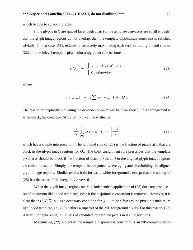
If the glyphs in Z are spaced far enough apart (or the template canvasses are small enough)
that the glyph image regions do not overlap, then the template disjointness constraint is satisfied
trivially. In that case, ATE reduces to separately maximizing each term of the right hand side of
(22) and the bilevel template pixel color assignment rule becomesqt(~x) = 8><>: 1 if S(t; ~x;Z) > 00 otherwise(23)
where S(t; ~x;Z) � NtXi=1 z(~x+ ~x(t)i ) + �Nt: (24)
The reason for explicitly indicating the dependence on Z will be clear shortly. If the foreground is
write-black, the condition S(t; ~x;Z) > 0 can be written as1Nt NtXi=1 z(~x+ ~x(t)i ) > ������� ����� (25)
which has a simple interpretation. The left hand side of (25) is the fraction of pixels at ~x that are
black in the glyph image regions for Qt. The color assignment rule prescribes that the template
pixel at ~x should be black if the fraction of black pixels at ~x in the aligned glyph image regions
exceeds a threshold. Simply, the template is computed by averaging and thresholding the aligned
glyph image regions. Similar results hold for write-white foregrounds, except that the analog of
(25) has the sense of the inequality reversed.
When the glyph image regions overlap, independent application of (23) does not produce a
set of maximum likelihood templates, even if the disjointness constraint is removed. However, it is
clear that S(t; ~x;Z) > 0 is a necessary condition for (t; ~x) to be a foreground pixel in a maximum
likelihood template, i.e., (23) defines a superset of the ML foreground pixels. For this reason, (23)
is useful for generating initial sets of candidate foreground pixels in ATE algorithms.
Maximizing (22) subject to the template disjointness constraint is an NP-complete prob-

*** Kopec and Lomelin; CTE... (DRAFT, do not distibute) *** 13
procedure (B; C; Z) do beginqt(~x) := 0 8t 2 B; ~x 2 CQ := f(t; ~x) j S(t; ~x;Z) > 0gwhile Q 6= ; do begin(s; ~w) := arg max(t;~x)2QS(t; ~x;Z)qs(~w) := 1Q := Q�K(s; ~w)� f(s; ~w)gend
end
Figure 5: A simple greedy template pixel color assignment algorithm.
lem, as shown in appendix A. Indeed, the problem remains NP-complete even if the constraint is
removed. The implied worst-case exponential complexity would not necessarily be troublesome if
ATE problems qualified as “small”. However, as an example, the foreground pixels in the templates
shown in fig. 19 were selected from a candidate set containing about 125,000 pixels. For compari-
son, we have found that exhaustive evaluation of alternative pixel assignments is feasible for up to
about 20 pixels.
The NP-completeness of ATE implies that a practical estimation algorithm cannot guarantee
that (22) will be maximized. Nevertheless, for image decoding applications it does appear possible
to construct effective templates without this guarantee. The following two simple algorithms have
been useful in practice and illustrate the main issues in template estimation. The first enforces the
disjointness constraint strictly, while the second allows templates to overlap slightly. We note that
the space of possible ATE strategies has not been extensively explored. Thus, these algorithms may
be subject to significant improvement.
A simple greedy pixel coloring algorithm is shown in fig. 5. The algorithm begins by assign-
ing all pixels to the background and constructing a set of candidate foreground pixels Q using (23).
The algorithm then iteratively selects the most promising single pixel (s; ~w) fromQ and assigns it
to the foreground. In case of a tie, one of the maximum score alternatives is selected randomly. The
selected pixel and all of its conflicts K(s; ~w) are removed from Q. The iteration continues untilQis empty.

*** Kopec and Lomelin; CTE... (DRAFT, do not distibute) *** 14
procedure (B; C; Z) do beginQ := f(t; ~x) j S(t; ~x;Z) > 0gwhile Q 6= ; do begin(s; ~w) := arg max(t;~x)2QS(t; ~x;Z)
if qs(~w) = 1 do beginW := K(s; ~w)F := f(t; ~x) j qt(~x) = 1gV := [(t;~x)2WK(t; ~x) \ Fmake assignments to W [ V
endQ := Q� f(s; ~w)gend
end
Figure 6: A pixel color assignment refinement procedure.
The algorithm in fig. 5 produces relatively good templates, as we will see. However, it ex-
hibits a failure mode that is typical of greedy labeling algorithms that only consider one candidate
at a time. Suppose template pixel (t̂; ~̂x) maximizes S(t; ~x;Z) and that (t̂; ~̂x) conflicts with both(t1; ~x1) and (t2; ~x2). Then the algorithm will make (t̂; ~̂x) a foreground pixel and assign (t1; ~x1) and(t2; ~x2) to the background. But suppose further that (t1; ~x1) and (t2; ~x2) do not conflict with each
other and that S(t1; ~x1;Z) + S(t2; ~x2;Z) > S(t̂; ~̂x;Z). In that case, a better assignment might
be to put (t1; ~x1) and (t2; ~x2) in the foreground and move (t̂; ~̂x) to the background. However, this
possibility is not considered by the greedy algorithm.
A simple approach to eliminating the above problem is to follow the greedy algorithm with a
refinement procedure that examines perturbations to the set of identified foreground pixels. Fig. 6
shows an example of such a refinement procedure. The inputs to the algorithm include an initial
assignment that is assumed to satisfy the disjointness constraint. The algorithm attempts to improve
on the initial assignment while preserving disjointness. The basic strategy during each iteration is to
identify a small set of pixels whose assignments can be modified, as a group, without considering
pixels outside the set. The set is constructed by considering two levels of conflicts from a single
“root” pixel (s; ~w) that is in the foreground in the current assignment. The root pixels are selected

*** Kopec and Lomelin; CTE... (DRAFT, do not distibute) *** 15
by considering the members of a candidate set Q in order of decreasing score. The set W consists
of all the pixels that conflict with the root. Since the disjointness constraint is assumed to hold,
each of the pixels inW is 0. The set V contains all of the conflicts withW that are currently in the
foreground (including the root pixel).
It is not hard to see that no set of assigments to the pixels inW[V can introduce a foreground
conflict with any pixel outside the set. Thus, the assignments toW[V may be optimized, subject to
the disjointness constraint, without regard for any other pixels. IfW[V contains fewer than about
20 members exhaustive optimization is feasible. For larger sets a useful approach is to compare
the current assignment with just one alternative, created by applying the greedy algorithm first toW and then to the pixels of V that do not conflict with the resulting foreground pixels inW . The
refinement procedure can be applied repeatedly; we have found that after three or four iterations
the change in likelihood becomes insignificant.
The greedy algorithm and refinement procedure enforce the template disjointness constraint
rigorously. If the transcription and glyph positions are accurate, doing so leads to good templates.
However, if the transcription or alignment is errorful, the disjointness constraint can cause prob-
lems. As a simple example, suppose the input consists of a very large number of glyph positions,
all of which are correct except for a single pair of adjacent glyphs whose estimated locations are
too close together. In particular, suppose that the correct templates would overlap if placed at the
two incorrect locations, but would not overlap at any of the other glyph positions. If the estimated
templates are forced to be disjoint, one or both will have missing pixels, compared with the correct
templates. This will happen regardless of the number of correct glyph positions.
Fig. 7 shows an algorithm that softens the disjointness constraint and avoids this problem.
This algorithm is structurally very similar to the greedy algorithm but is more easily explained as
a variation of independent pixel asignment. In differs from independent assignment in that (23) is
not applied independently (i.e., simultaneously) to each pixel, but rather a value of 1 is assigned
sequentially to each pixel for which S(s; ~w;Z) > 0. After each such assignment, the image Z is
modified by setting to 0 all pixels in Z that are covered by the newly-assigned template pixel, i.e.
the pixels in I(s; ~w). The effect of clearing Z is to reduce the value of S(s; ~w;Z) for conflicting
template pixels that have not yet been considered, thereby decreasing the likelihood that they will

*** Kopec and Lomelin; CTE... (DRAFT, do not distibute) *** 16
procedure (B; C; Z) do beginqt(~x) := 0 8t 2 B; ~x 2 CQ := f(t; ~x) j S(t; ~x;Z) > 0gwhile Q 6= ; do begin(s; ~w) := arg max(t;~x)2QS(t; ~x;Z)qs(~w) := 1
for i = 1; : : : ; Ns do z(~w + ~x(s)i ) := 0Q := f(t; ~x) j S(t; ~x;Z) > 0gend
end
Figure 7: A pixel color assignment algorithm that softens the template disjointness constraint.
be set to 1.
The algorithm in fig. 7 is applicable when all foreground levels are write-black but is easily
modified for other cases. If all foreground levels are write-white, the modification simply consists
of setting the pixels of Z to 1 rather than to 0. For templates with both types of levels, separate
copies of Z are maintained for the write-black and write-white levels.
5 Transcription Alignment and Initial Conditions
Transcription alignment (9) involves finding a complete path � that maximizes L(Z j Q�;�) +log Pr f�g, subject to the constraint that M� = M , where M is the given transcription. This is a
constrained decoding problem that is analogous to the speech recognition problem of training hid-
den Markov models using sentence-level transcriptions [14]. By analogy with the speech case, con-
strained decoding can be carried out in two steps. First, the image source model and transcription
are combined into a transcription image source model. The transcription image source is defined
as a source that generates the subset of the original source images consisting of just those whose
message is M . Second, image Z is decoded using the transcription image model. The resulting
complete path defines an alignment between M and Z .
The transcription image source can be constructed using a straightforward extension to the

*** Kopec and Lomelin; CTE... (DRAFT, do not distibute) *** 17
(1, 0)(1, 0) (1, 0)(1, 0)
Q d
"d"
d∆( , 0)
Q i
"i"
i∆( , 0)
Q d
"d"
d∆( , 0)n I n F
Figure 8: Transcription image source for simple text line and transcription string “did”.
standard algorithm for intersecting two finite-state automata [8]. This construction is applicable to
any Markov image source and transcription that can be described using regular grammars. Thus,
for example, templates for the yellow page model discussed in [11] could be trained using the two-
dimensional source models and LaTeX-like transcriptions presented therein. In practice, however,
we anticipate that applications of template estimation will primarily involve one-dimensional hor-
izontal source models, such as those described in [9], applied to images of individual text lines.
The reason is that full two-dimensional decoding is significantly more expensive computationally
than line decoding and is unnecessary if the lines can be extracted reliably through simpler means.
Moreover, for most text decoding applications it is sufficient to train using a simple text line model
in which any character may follow any other and the messages include no logical or formatting tags.
The transcription image models for such sources have the simple form illustrated in fig. 8, which
shows a line source for images of the string “did”. The model consists of a chain of transitions for
the characters of the string plus unit displacement self-transitions for horizontal spacing adjustment.
Image decoding using Markov source models with bilevel templates is described in [11].
The only change introduced by multilevel templates is in the computation of the template match
scores L(Z j Qt[~x]). However, by (16), if a multilevel template is represented by its level set
bitmaps then algorithms for the bilevel template matching operation (11) can be used to compute
the multilevel likelihood.
The iterative alignment and ATE algorithm in fig. 2 can be started with either a set of initial
templates or a set of initial glyph positions. A simple way to obtain initial templates is to excise a
sample of each required character from the training images using an interactive tool [7]. Alterna-

*** Kopec and Lomelin; CTE... (DRAFT, do not distibute) *** 18
Figure 9: Templates for word boundary location. Baseline indicated by dash line. Left: Support ofwrite-white space character template. Right: Support of write-black printing character template.
tively, initial templates can be derived from an existing bitmap or outline font. We have found that
the training procedure is not very sensitive to the exact shapes or sizes of the initial templates. In
particular, if the templates are extracted from images it is usually sufficient to excise a single sample
of each character.
If the transcription is plain text, a set of initial glyph positions can be found by first locating
the start and end point of each transcription word in the image and then dividing the horizontal
word interval into the proper number of glyph positions. The glyph origins can be either spaced
uniformly or at intervals proportional to character set widths obtained from an existing font. We
have found that proportional spacing usually leads to better initial templates than uniform spacing
and is insensitive to the choice of font for the set widths.
The word endpoints can be found using the normal transcription alignment procedure and
templates such as those shown in fig. 9. The space template is a solid rectangle, in this case 15
pixels wide by 60 pixels high. The template for each printing character is a 15 by 15 square. The
set width of each template is taken to be 6 pixels. These dimensions and set widths are appropriate
for 12 pt fonts, although the exact values do not appear to be critical. The important dimension is
the width of the space template, which should be larger than the intercharacter gaps within a word
but smaller than the minimum interword space. When this condition is satisfied we have found that
the space templates will be reliably positioned between the words.

*** Kopec and Lomelin; CTE... (DRAFT, do not distibute) *** 19
6 Experimental Results
We have applied the above template estimation algorithm to a variety of English documents, includ-
ing newspaper columns, 15th century books, degraded microfilm images of 19th century newspa-
pers, connected text in script-like fonts, and mathematical notation. The most extensive application
has been to create document-specific templates for decoding scanned reports in the Environmen-
tal Digital Library at the Univ. of California at Berkeley [16]. Many of these documents are rel-
atively long (100-600 pages) and contain statistical information that is useful only if accuractely
transcribed. We will use one of the Berkeley documents to illustrate the training algorithms and the
use of document-specific templates in image decoding.
Bulletin 155 (B155) [3] is a report by the California Department of Water Resources (DWR)
that summarizes the provisions of 157 state water district acts. The information about each act is
presented as a two column table that spans one to five pages. Fig. 10 shows a portion of one ta-
ble. B155 contains 375 pages of such tables (about 540,000 glyphs). B155 also contains about 20
pages of single column background material comprising a table of contents, explanations of terms,
summaries of related legislative acts, etc. The text of the tables and background pages is typeset
in 12 pt Times family fonts. The dominant style is Roman, with small amounts of Italic, Bold and
BoldItalic.
The basic scenario in document-specific decoding is to train a set of templates using a small
subset of the document pages plus their transcriptions and then use the templates to decode the re-
maining pages. In the case of B155 we trained using the 20 single column pages and then decoded
the 375 table pages. B155 was selected because of the availablility of a WordPerfect source file to
serve as ground truth in the recognition experiments and as a source of training transcriptions.7Table 1 summarizes the composition of the training data in terms of the numbers of charac-
ters and glyphs in each of the four fonts. In counting glyphs, an interword space is treated as one
instance of a space character. The training data contains a total of 212 characters, where charac-
ters in different fonts are considered to be distinct. The mean number of samples of each character
varies widely over the four fonts, from about 500 for Roman to 2 for Bold. The Bold text consists7Access to the WordPerfect source makes B155 ideal for performance evaluation but of course lessens the value ofthe resulting transcription.

*** Kopec and Lomelin; CTE... (DRAFT, do not distibute) *** 20
Figure 10: Portion of page from DWR Bulletin 155.
Style Characters GlyphsRoman 83 42004
BoldItalic 63 1468Italic 43 316Bold 23 46
Table 1: Character and glyph counts for the training pages of Bulletin 155. Fonts are 12 pt Timesfamily.

*** Kopec and Lomelin; CTE... (DRAFT, do not distibute) *** 21
solely of the string “District Securities Investigation Law of 1965” in which 13 characters appear
just once. As we will see, this leads to considerable difficulty in estimating the Bold templates.
The 212 training characters can be seen in fig. 19, which shows the final templates used to
decode the B155 tables, grouped by font in the order Roman, BoldItalic, Italic and Bold (i.e. in
order of decreasing training glyph count). Within each font the space character is first, followed
by the normal “printing” characters. Each row of templates is aligned with the template origins on
a horizontal baseline. Similarly, the templates in each column are aligned with their origins on a
vertical line. This template order and alignment are used in all of the figures in this section.
The templates in fig. 19 were created by 25 iterations of the algorithm in fig. 2 using the soft
constraint ATE procedure of fig. 7. Initial glyph positions were found using the word alignment
approach described in the previous section with proportional spacing of glyphs within each word.
The channel parameters were set manually to �0 = :95, �1 = :999 and �2 = :001.
Before discussing the performance of the final templates in decoding, we will illustrate var-
ious aspects of the ATE and alignment algorithms using the B155 training data. The labeled glyph
positions required by the ATE algorithms were taken from the final iteration for the templates of
fig. 19. Visual inspection revealed these positions to be relatively accurate.
6.1 Aligned Template Estimation
Fig. 11 shows a set of bilevel templates estimated by independent application of (23) to each can-
vas pixel, using the (assumed) known glyph positions. Each of the templates clearly shows the
“correct” character shape, aligned at the origin of the canvas, plus “extra” foreground pixels due
to neighboring glyphs in the glyph image regions. The number of extra pixels is relatively small
for the most common characters of the Roman font and increases as the amount of training data
decreases. Overall, the Roman templates are remarkably clean, suggesting that with a sufficiently
large and diverse training set most of the extra foreground would be eliminated as a consequence
of the averaging process in (25).
As noted previously, the supports of the independent templates are supersets of the supports
of the maximum likelihood templates. Table 2 shows the total number of template foreground pix-
els,Pt2B kQt;�k, and the training data likelihood, L(Z j Q�;�), for the various ATE algorithms.

*** Kopec and Lomelin; CTE... (DRAFT, do not distibute) *** 22
Figure 11: Templates estimated by independent application of (23) to each canvas pixel.
AlgorithmXt2B kQt;�k L(Z j Q�;�)
independent 126833 45070greedy 79777 54943refined 80762 54967
soft 80126 55075
Table 2: Bulletin 155 foreground template pixel counts and training data likelihoods for variousATE algorithms.
Fig. 12 shows a set of templates produced using the greedy algorithm of fig. 5. Compared
with the independent templates, the greedy templates have significantly fewer extra foregound pix-
els. Table 2 confirms this and also shows that the training data likelihood is significantly greater for
the greedy templates.
The greedy algorithm selects randomly from the set of maximum score candidates during
each iteration, as discussed previously. This random selection is evident in the Italic “E” and “x”
templates in fig. 12. The training data contains one sample of each of these characters, in the word
“Explanatory”. Every allowable distribution of the foreground pixels of “Ex” between the two tem-

*** Kopec and Lomelin; CTE... (DRAFT, do not distibute) *** 23
Figure 12: Templates estimated using the greedy algorithm.
plates has the same score and thus the maximum likelihood templates are inherently ambiguous. A
similar situation arises with BoldItalic “-K” and Bold “1965.” A partial solution to the ambiguity
problem is described below.
Several of the templates in fig. 12, most notably the BoldItalic numerals, have “holes” in
them. The BoldItalic parentheses, conversely, have extra pixels that exactly match these holes.
Each of the BoldItalic numerals except zero occurs adjacent to a parenthesis at least once in the
training data. The holes arise because the foreground pixels of the parentheses are assigned before
those of the numerals— both left and right parentheses occur more frequently than any single nu-
meral (but less frequently than all numerals combined). To satisfy the disjointness constraint, the
conflicting pixels in the numerals are then assigned to the background. This is an example of the
greedy failure mode that motivated the refinement procedure of fig. 6.
Fig. 13 shows the result of four iterations of the refinement procedure on the templates of
fig. 12. The holes are filled and all of the templates, except the Bold ones and those with inherent
ambiguities, are of fairly high visual quality. As table 2 indicates, the refinement procedure slightly
increases both the number of foreground pixels and the training data likelihood.
Fig. 14 shows results from the soft constraint algorithm of fig. 7. Visually, the soft con-

*** Kopec and Lomelin; CTE... (DRAFT, do not distibute) *** 24
Figure 13: Templates derived from fig. 12 after four iterations of the refinement procedure.
Figure 14: Templates estimated using the soft constraint algorithm of fig. 7.

*** Kopec and Lomelin; CTE... (DRAFT, do not distibute) *** 25
Figure 15: Templates derived from fig. 12 using the refinement procedure with a distance-based tiebreaking criterion.
straint templates are slighly better than those from the greedy algorithm, but not quite as good as the
refined greedy templates. The BoldItalic numerals have holes, but the holes in a number of other
templates are missing. Indeed, from table 2 we see that the number of foreground pixels is inter-
mediate between the greedy and refined templates. Interestingly, the soft algorithm provides the
greatest likelihood of any of the ATE procedures.
Finally, fig. 15 shows the result of a simple modification to the refinement procedure in-
tended to resolve some of the cases of template ambiguity. Rather than randomly select among
equal likelihood assignments toW [ V , an assignment was chosen with minimum total absolute
horizontal distance of the foreground pixels from the canvas origin. This has the effect of prefering
templates whose supports are localized near the origin. Comparing fig. 15 with fig. 13 shows that
the result can be a significant improvement in visual template quality.
6.2 Iterative Transcription Alignment and Template Estimation
Transcription alignment was performed on a line-by-line basis during estimation of the B155 tem-
plates, using transcription image models of the type shown in fig. 8. The line baselines were ex-

*** Kopec and Lomelin; CTE... (DRAFT, do not distibute) *** 26
Figure 16: Templates estimated by the soft constraint algorithm from glyph positions obtained byword alignment and proportional glyph spacing within each word.
tracted by decoding the training images using a simple text page model with 12 pt Times Roman
templates generated by a PostScript font program. While the decoded text was extremely errorful,
the baseline locations were reasonably accurate.
Initial templates were created by applying the soft constraint ATE algorithm to the glyph po-
sitions estimated by the word alignment procedure described in section 5. The resulting templates,
shown in fig. 16, are inferior to those obtained using accurate glyph positions, as expected.
Fig. 17 shows the estimated templates after 20 iterations of alignment and ATE. The Roman
and BoldItalic templates are similar to those obtained using accurate glyph positions. Many of the
Italic templates are also correct but most of the Bold ones are wrong. As might be expected, many
of the individual glyph positions in all four fonts are incorrect. The relatively high quality of the
Roman and BoldItalic templates reflects the fact that there were enough accurate positions for the
averaging process to produce acceptable estimates.
Lack of tolerance to glyph position errors was cited previously as a problem with the greedy
algorithm. This is illustrated in fig. 18, which shows the templates produced after 20 iterations of
the greedy algorithm. Overall, these templates are inferior to those in fig. 17. One source of error
is illustrated clearly by the BoldItalic “D” template, which appears to have an “i” cut out of it. The

*** Kopec and Lomelin; CTE... (DRAFT, do not distibute) *** 27
Figure 17: Templates estimates after 20 iterations using soft constraint algorithm with distance-based tie breaking criterion. Initial templates as in fig. 16.
Figure 18: Templates estimates after 20 iterations using greedy algorithm with distance-based tiebreaking criterion. Initial templates as in fig. 16.

*** Kopec and Lomelin; CTE... (DRAFT, do not distibute) *** 28
Figure 19: Multilevel template estimates after 5 iterations of soft constraint algorithm with distance-based tie breaking criterion. Initial templates from fig. 17 with manual adjustment of canvas param-eters.
most common context for BoldItalic “D” in the training data is the word “District”. In at least one
instance, the template for the “i” was incorrectly positioned on a “D”. Because “i” is more common
than “D” in the training data, the foregound pixels of “i” were assigned before those of “D”. The
template disjointness constraint then forced the conflicting “D” pixels into the background.
Finally, fig. 19 shows the result of five iterations starting with the templates of fig. 17 after
manual adjustment of the canvas parameters. The origins and set widths of the 212 templates were
inspected and adjusted using a bitmap font editor. In addition, each template canvas was manually
trimmed to be about 10 pixels wider than the expected template support. The editing was intended
to correct gross alignment errors and thus was performed quickly and with only moderate care. Dur-
ing the final iteration, a write-white level was estimated for the printing characters, leading to the
multilevel templates shown.

*** Kopec and Lomelin; CTE... (DRAFT, do not distibute) *** 29
Decoder Language Character ErrorsModel Substitutions Deletions Insertions Total (%)
ScanWorX word lexicon 2149 1069 1061 4279 (0.79%)DID char. unigram 430 73 80 583 (0.11%)DID char. uni+bigram� 289 72 68 429 (0.079%)DID char. bigramy 87 57 53 197 (0.036%)� bigrams for table headings, unigrams elsewherey bigrams collected from entire document
Table 3: Character recognition results on Bulletin 155 tables.
6.3 Recognition Results
The templates of fig. 19 were used to decode the 375 table pages of B155, using several simple
language models. For comparison, the pages were also transcribed using the commercial omni-
font recognition system ScanWorX.8 Results of the experiments are summarized in table 3. The
errors rates were computed in the standard way by dividing the total number of insertions, deletions
and substitutions (computed by minimum edit distance alignment of the decoded and ground truth
transcriptions) by the number of ground truth characters (543,779). The error calculation included
space characters and ignored differences in font.
The character unigram language model allows any of the 212 characters to follow any other
and exactly corresponds to the simple text column model described in [11, 9]. The unigram model
imposes no constraints on character sequencing and thus places the entire recognition burden on the
templates. As table 3 shows, the unigram error rate of 0.11% is about a factor of seven less than that
of the omni-font system. This is particular noteworthy since ScanWorX employs a large lexicon of
English words and the text of B155 is largely ordinary text.
Examination of the unigram errors revealed that a large fraction occurred in the uppercase
table headings, e.g. “COMMUNITY FACILITIES DISTRICTS” at the top of fig. 10 and many
involved uppercase to lowercase substitutions, such as “I” into “ l”. The table headings were rere-
cognized using a bigram model in which the characters allowed to follow a given character were
restricted to just those that were observed to follow the character in the training data. Thus, for ex-8Xerox Desktop Document Systems, Peabody, MA.

*** Kopec and Lomelin; CTE... (DRAFT, do not distibute) *** 30
ample, the bigram model allowed the sequence “ IT” but not “ lT” or “ iT”. The bigram model was
derived from the entire training set and consisted of 1670 bigrams. Use of the bigram model on the
table headings reduced the overall error rate to 0.079%, a factor of ten below ScanWorX.
Finally, the tables were decoded using a bigram model derived from the ground truth for all
395 pages. This is the smallest bigram model that is capable of recognizing the data perfectly and
is included to provide an upper bound on the performance of any bigram model for this data. The
observed error rate was 0.036%, a factor of twenty below ScanWorX.
The bigram model trained on all of B155 contained 2232 bigrams, which is 652 more than
the bigram model derived from the 20 training pages alone. By considering the relative frequency
of the bigrams, it can be predicted that a decoder using the training page bigram model will mis-
recognize at least 4744 (0.87%) of the characters in the tables. Since this error rate exceeds that of
the unigram model, decoding with a pure training bigram model was not carried out.
7 Summary
A maximum likelihood approach to character template estimation using unaligned transcriptions
has been developed. The kernel of the approach is a method of aligned template estimation (ATE)
that allows the bounding boxes of adjacent glyphs to overlap. While the method was developed
specifically to support the creation of document-specific decoders in the DID framework, it is ap-
plicable to any situation in which character templates are to be derived from sample images.
8 Acknowledgements
The authors wish to thank Phil Chou for many stimulating discussions throughout the course of
this work. The B155 data was provided by the Univ. of California Environmental Digital Library
Project, headed by Robert Wilensky and supported by National Science Foundation grant IRI-9411334
as part of the NSF/NASA/ARPA Digital Library Initiative.

*** Kopec and Lomelin; CTE... (DRAFT, do not distibute) *** 31
(1, 0) (1, 0)
Q vl1 1
rQ v Q v
l Er
Q vE
n I nF
Figure 20: Image source for independent set problem.
A NP-Completeness of Aligned Template Estimation
Aligned template estimation (ATE) is the problem of choosing � to maximizeL(Z j Q�;�) in (22)
subject to the template disjointness constraint. The theory of NP-completeness applies to decision
problems, i.e. problems whose solution is either “yes” or “no”. ATE can be transformed into a
decision problem by the standard technique of introducing a numerical parameter B and asking
whether there is a � for which L(Z j Q�;�) � B. We establish the NP-completeness of ATE
by showing that any algorithm that solves ATE exactly can be used to solve the independent set
problem, which is known to be NP-complete [13].
Let G be an undirected graph consisting of a finite set of vertices V = fv1 : : : vV g and a
finite set of edges E = f(vli; vri); i = 1 : : : Eg. An independent set of vertices is a subset V 0 � Vwith the property that no pair of vertices in V 0 are joined by an edge in E . Given a positive integerK , the independent set (IS) problem is to decide whether or not G contains an independent set of
size at least K .
Given a graph G and positive integer K , we construct an ATE decision problem whose so-
lution is equivalent to IS for G and K . This involves specifying a source model, a complete path�, an image Z and a likelihood bound B. Fig. 20 shows the source model, a simple chain of 3Ebranches that has exactly one complete path �. Each graph vertex v 2 V corresponds to a templateQv whose canvas consists of the single point at the template origin. We will view the template pix-
els as being indexed by the vertices in V . The branches of the source model occur in groups of
three, where each triple corresponds to one edge in E . The first two of the three branches represent-
ing edge (vli; vri) are labeled with templates Qvli and Qvri and have zero displacement. The third
branch has unit horizontal displacement, (1; 0).

*** Kopec and Lomelin; CTE... (DRAFT, do not distibute) *** 32
It is not hard to see that kQ�k = E and that template pixels u and v conflict if and only if(u; v) 2 E . Thus, each independent subset V 0 � V corresponds to a set of template pixels that do
not conflict, i.e. a candidate pixel assignment � that satisfies the template disjointness constraint.
If Nv denotes the number of edges attached to vertex v it is clear that kI(v)k = Nv . Let
each templateQv be associated with a separate write-black level and let the channel parameters be
given by �0 = e1 + e (26)�v = e 1Nv1 + e: (27)
Then, ifZ is taken to be the ideal imageQ� it is easy to show from (12), (13) and (24) thatS(v;Z) =1 for each pixel v. As a result, kV 0k = L(Z j Q�;�), where � is the pixel assignment that corre-
sponds to V 0. It should be clear that the ATE decision problem with B = K is equivalent to the
given IS problem.
If the template disjointness constraint is removed, a similar construction can be used to show
that a solution to the (uncontrained) ATE problem implies a solution to the NP-complete minimum
cover [13] problem.
References
[1] H. Baird and G. Nagy, “A self-correcting 100-font classifier”, in Document Recognition, L.
Vincent and T. Pavlidis, editors, Proc. SPIE vol. 2181, pp. 106–115, 1994.
[2] D. Bloomberg and L. Vincent, “Blur hit-miss transform and its use in document image pat-
tern detection”, in Document Recognition II, L. Vincent and H. Baird, editors, Proc. SPIE vol.
2422, pp. 84–97, 1995.
[3] California Dept. of Water Resources, General Comparison of Water District Acts, Bulletin
155-94, March, 1994.
[4] F. Chen, D. Bloomberg and L. Wilcox, “Spotting phrases in lines of imaged text”, Document
Recognition II, L. Vincent and H. Baird, editors, Proc. SPIE vol. 2422, pp. 256–269, 1995.

*** Kopec and Lomelin; CTE... (DRAFT, do not distibute) *** 33
[5] P. Chou, “Recognition of equations using a two-dimensional stochastic context-free gram-
mar”, SPIE Conf. on Visual Communications and Image Processing, Philadelphia, PA, Nov.
1989.
[6] P. Chou and G. Kopec, “A stochastic attribute grammar model of document production and its
use in document image decoding”, Document Recognition II, L. Vincent and H. Baird, editors,
Proc. SPIE vol. 2422, pp. 66–73, 1995.
[7] T. Fruchterman, “DAFS: a standard for document and image understanding”, Proc. 1995 Sym-
posium on Document Image Understanding Technology, Bowie, MD, Oct. 24–25, 1995, pp.
94–100.
[8] J. Hopcroft and J. Ullman, Introduction to Automata Theory, Languages and Computation,
1979, Reading: Addison-Wesley.
[9] A. Kam and G. Kopec, “Separable source models for document image decoding”, Document
Recognition II, L. Vincent and H. Baird, editors, Proc. SPIE vol. 2422, pp. 84–97, 1995.
[10] G. Kopec and P. Chou, “Automatic generation of custom document image decoders”, Proc.
Second Intl. Conf. on Document Analysis and Recognition, Tsukuba Science City, Japan, Oct.
20–22, 1993.
[11] G. Kopec and P. Chou, “Document image decoding using Markov source models”, IEEE
Trans. Pattern Analysis and Machine Intelligence, vol. 16, no. 6, June, 1994, pp. 602–617.
[12] S. Kuo and O. Agazzi, “Keyword spotting in poorly printed documents using pseudo 2-d hid-
den Markov models”, IEEE Trans. Pattern Analysis and Machine Intelligence, vol. 16, no. 8,
Aug., 1994, pp. 842–848.
[13] C. Papadimitriou and K. Steiglitz, Combinatorial Optimization, 1982, Englewood Cliffs:
Prentice-Hall.
[14] L. Rabiner and B.-H. Juang, Fundamentals of Speech Recognition, 1993, Englewood Cliffs:
Prentice-Hall.
[15] R. Rubenstein, Digital Typography, 1988, Reading: Addison-Wesley.
[16] R. Wilensky, “Toward work-centered digital information services”, to appear in IEEE Com-
puter, special issue on “Building Large-scale Digital Libraries”, May, 1996.