docketed - California Energy Commission
387
DOCKETED Docket Number: 21-BSTD-01 Project Title: 2022 Energy Code Update Rulemaking TN #: 238404 Document Title: Statewide Utility Codes and Standards Enhancement Team Comments on 45-Day Express Terms_Part 1 Description: N/A Filer: System Organization: Statewide Utility Codes and Standards Enhancement Team Submitter Role: Public Submission Date: 6/21/2021 5:16:23 PM Docketed Date: 6/21/2021
-
Upload
khangminh22 -
Category
Documents
-
view
0 -
download
0
Transcript of docketed - California Energy Commission

DOCKETED Docket Number: 21-BSTD-01
Project Title: 2022 Energy Code Update Rulemaking
TN #: 238404
Document Title: Statewide Utility Codes and Standards Enhancement Team
Comments on 45-Day Express Terms_Part 1
Description: N/A
Filer: System
Organization: Statewide Utility Codes and Standards Enhancement Team
Submitter Role: Public
Submission Date: 6/21/2021 5:16:23 PM
Docketed Date: 6/21/2021

Comment Received From: Statewide Utility Codes and Standards Enhancement Team Submitted On: 6/21/2021
Docket Number: 21-BSTD-01
Comments on 45-Day Express Terms_Part 1
Additional submitted attachment is included below.

Comments on 45-Day Express Terms
CALIFORNIA STATEWIDE UTILITY CODES AND STANDARDS TEAM
June 21, 2021
1. Introduction
The California Statewide Utility Codes and Standards Enhancement Team (Statewide
CASE Team) appreciates the opportunity to participate in the review of the May 6, 2021
Express Terms 2022 Energy Code, Title 24 Parts 1 and 6 (45-Day Express Terms).1
The Statewide CASE Team actively supports code-setting bodies in developing and
revising building energy codes and standards. The program's objective is to achieve
significant energy savings and assist in meeting other energy-related state policy goals
through the development of reasonable, responsible, and cost-effective code changes.
Three California Investor Owned Utilities – Pacific Gas and Electric Company, San
Diego Gas and Electric, and Southern California Edison – and two Publicly Owned
Utilities – Los Angeles Department of Water and Power and Sacramento Municipal
Utility District (herein referred to as the Statewide CASE Team when including the
CASE Author) – sponsored this effort. The Statewide CASE Team is actively supporting
the California Energy Commission (Energy Commission) in updating the California
Energy Code (Title 24, Part 6) for the 2022 code update cycle. Through CASE Reports,
the Statewide CASE Team has provided the Energy Commission with the technical and
cost-effectiveness information required to make informed judgments on proposed
standards for promising energy efficiency design practices and technologies. CASE
Reports are posted within each measure topic page on title24stakeholders.com.
2. Comments on 45-Day Express Terms
The Statewide CASE Team has reviewed the 45-Day Express Terms and appreciates
that many of the code changes that we have worked with the Energy Commission and
other stakeholders to develop since early 2019 are incorporated into the language. In
our review we identified a number of areas where the language could be clearer, more
precise, and ambiguity could be removed. Many of the changes are non-substantive,
1 CEC Docket #21-BSTD-01, Document #237717
https://efiling.energy.ca.gov/GetDocument.aspx?tn=237717&DocumentContentId=70942

Statewide CASE Team Comments on 45-Day Express Terms | June 18, 2021 | 2
meaning the revisions to not change the stringency of the requirements or where the
requirements would apply. There are a few proposed changes that would modify the
stringency of the code. The Statewide CASE Team has been in communication with
Energy Commission staff on substantive changes and have provided additional
documentation in the docket for changes related to integrated pump refrigerant
economizers,2, 3 dedicated outdoor air systems,4 nonresidential lighting,5 outdoor
lighting controls,6 indoor lighting7, and multifamily common use areas8.
The Statewide Utility Compliance Improvement Team has also reviewed the language
and provided recommendations in table format, which are included in this document in
Table 1. We will also provide Energy Commission staff with an Excel file with the same
information to support review and revisions.
In the remainder of this comment, we have provided a marked ups version of the 45-
Day Express Terms with our suggested revisions. Our recommended language
insertions are underlined in red and recommended language deletions are struck in red.
The comments in the document provides an indication as to which CASE measure each
mark-up pertains. We sent a Word version of the mark-up language to Energy
Commission staff directly to facilitate reviews if staff prefer to review in Word instead of
this PDF version.
We welcome the opportunity to continue working with the Energy Commission to
discuss our recommendations and to make improvements that would make language
less complex throughout, including addressing the issues identified in the remainder of
this letter.
2 CEC Docket #21-BSTD-01, Document # 238288
https://efiling.energy.ca.gov/GetDocument.aspx?tn=238288&DocumentContentId=71583
3 CEC Docket #21-BSTD-01, Document # 238233
https://efiling.energy.ca.gov/GetDocument.aspx?tn=238233&DocumentContentId=71509
4 CEC Docket #21-BSTD-01, Document # 238158
https://efiling.energy.ca.gov/GetDocument.aspx?tn=238158&DocumentContentId=71425
5 CEC Docket #21-BSTD-01, Document # 238197
https://efiling.energy.ca.gov/GetDocument.aspx?tn=238197&DocumentContentId=71469
6 CEC Docket #21-BSTD-01, Document # 238087
https://efiling.energy.ca.gov/GetDocument.aspx?tn=238087&DocumentContentId=71361
7 CEC Docket #21-BSTD-01, Document # 238296
https://efiling.energy.ca.gov/GetDocument.aspx?tn=238296&DocumentContentId=71591 8 CEC Docket #21-BSTD-01, Document # 238377
https://efiling.energy.ca.gov/GetDocument.aspx?tn=238377&DocumentContentId=71679

Table 1: Compliance Improvement Team’s Recommended Revisions to 45-Day Express Terms
# Parent Section
of change
Precise section with Recommended
Revisions Description of change Justification of change
Who made recommended change
Priority
1 100.1 Include definitions of conditioned greenhouse from CASE Report detailing the thresholds of 10 Btu/hr/sf for heating energy and 5 Btu/hr/sf cooling energy in the definitions. This was included in the CASE team proposal but not included in the 45 Day Language
The "Greenhouse, Conditioned" definition makes it clear that the envelope requirements only apply to fully conditioned greenhouses as opposed to seasonal or tempered greenhouses used for other horticulture types.
Ted M. Tiffany
High
2 120.1 Table 120.1-A Table 120.1-A refers to footnotes G and H but the footnotes stop at F.
Incorrect reference Ben Lalor High
3 140.2 140.2 prescriptive requirements include 140.10 Ben Lalor High
4 150 Exception to Section 150.1(a)1
Change EXCEPTION to Section 150.0(a)1 to something like "No roof deck insulation is required when no duct work is located in the attic."
The language in Exception to Section 150.1(a)1 only indicates that no roof deck insulation is required when the ducts and air handler are located in conditioned space. This is not consistent with information provided during 45-day express terms hearings. Based on CEC staff (hearing on 5/27/2021), the intent of this exception applies whenever ducts are NOT located in an attic, or when a ductless system is used.
Brian Selby High
5 150 150.0(m)1Bii a & b I suggest adding language to identify the intended material for ducting for a & b.
Using an emissivity value to trigger meeting a or b is problematic for compliance. Based on 45-day express terms hearings, ducts with a surface emissivity greater than or equal to 0.8 were referred to as sheet metal ducting. Unfortunately, emissivity ratings for this type of material is uncommon and may cause confusion for installers and inspectors.
Brian Selby High
6 150 Section 150.0(s)2 Change the term “collocated” to something that’s more commonly used to describe how the circuits are intended to be placed to avoid confusion
Section 150.0(s)2 uses the term “collocated” as it pertains to the four ESS branch circuits being identified at a single panel board. Based on the definition of “collocate”, I assume this is referring to the branch circuits being “place side by side or in a particular relation” (definition). If so, I think the use of this term is confusing. I would suggest using language that’s more commonly used to describe how the circuits are intended to be placed. Possibly use something like “terminate” as in “…shall be identified and have their source of supply terminate at a single panelboard”
Brian Selby High
7 150.1 150.1(c)1Aii Consider providing an exception for JADUs to the high-performance attic prescriptive requirement and instead require reasonable ceiling-only insulation.
JADUs with smaller footprints, attics have much less vertical clearance than a typical single-family dwelling. This makes high-performance attic measures more difficult to install correctly, including below-roof-deck batt insulation and low
Brian Selby High

Statewide CASE Team Comments on 45-Day Express Terms | June 18, 2021 | 4
# Parent Section
of change
Precise section with Recommended
Revisions Description of change Justification of change
Who made recommended change
Priority
and high attic vents and baffles. I recommend providing an exception for JADUs to the high-performance attic prescriptive requirement and instead require reasonable ceiling-only insulation.
8 150.1 150.1(c)3 consider allowing a higher glazing percentage for JADUs and ADUs
Since other concessions for JADUs have been introduced into Section 150.1, consider allowing a higher glazing percentage for JADUs which could allow a 30% glazing for JADUs (≤ 500 ft²) and possibly a 25% glazing for ADUs >500 ft² and ≤ 700 ft².
Brian Selby High
9 150.2 150.2(b)1G I suggest changing the language in Section 150.2(b)1G to be consistent with information provided during the CEC hearing, something similar to what's in the 2019 Energy Code: "Replacement space-heating systems shall be limited to natural gas, liquefied petroleum gas, or the existing fuel type." "EXCEPTION to Section 150.2(b)1G: When the fuel type of the replaced heating system was natural gas or liquefied petroleum gas, the replacement space-conditioning system may be a heat pump"
Section 150.2(b)1G indicates Altered space-heating systems shall comply with Section 150.1(c)6, which refers to Table 150.1-A and requires a gas furnace to be replaced with a heat pump in CZ 3, 4, 10, 13 and 14. Based on the CEC hearing, this is not the CECs intention for altered space-heating systems.
Brian Selby High
10 100.1, 160, 170, 180
100.1 COMMON ... Definitions, use of new terms throughout 160, 170, 180 need to be revised to "dwelling unit" and "common use area" only, and these 2 new definitions removed
The addition of the new definitions to describe dwelling units spaces "common living area" in which habitable spaces are included, but then the new definition for common areas "common service areas" which includes the word nonhabitable, will cause confusion throughout the industry in understanding the intent of these new definitions to their application of code to particular spaces. Please keep to "dwelling unit" and "common use area" as is supported consistently throughout the Energy Code, and all other parts of the Building Code
Prevent confusion of application of code requirements
Gina Rodda High
11 100 Table 100.0-A new multifamily lines
Missing references to any 110 sections as supported in nonresidential and single family lines above need to be added
It may be construed that these subchapter section do not apply to multifamily occupancies
Gina Rodda High
12 160 Will new fan requirements of 120.10 apply to multifamily buildings? If so, this needs to be added to 160
Missing new proposed fan requirements if intention is for them to also apply to multifamily
support multifamily unification Gina Rodda High

Statewide CASE Team Comments on 45-Day Express Terms | June 18, 2021 | 5
# Parent Section
of change
Precise section with Recommended
Revisions Description of change Justification of change
Who made recommended change
Priority
13 160 45 day updates made to subchapters outside of 160 not fully captured here, is that on purpose?
160.1(a) versus 150.0(a); 160.2(c)3 versus 120.1(c)3; 160.2©5E versus 120.1©5; 160.2©7 versus 120.1(f); 160.2©8 versus 120.1(g); Table 160.2-B versus Table 120.1-A; 160.3(a)2Diii versus 120.2(e)3; 160.3(a)Aii versus 150.0(m)1B; 160.3©2Ciid versus 120.4(b)2D; 160.3(c)2Hic versus 140.4(g)1D; 160.3(c)3 versus 120.5(a)3; 160.4(a) versus 150.0(n); 160.4(e)3 versus 120.9(c); 160.5(b)4Cie versus 130.1(c)1E; 160.5(b)4Cv versus 130.1(c)5 which I find very confusing; 160.5(b)C4Cvi versus 160.1(c)6; 160.5(b)4D exception 8 versus 130.1(d) exception 8; 160.5(e)1 versus 130.4(a); 160.5(e)2 versus 130.4(b)
support multifamily unification Gina Rodda High
14 170 45 day updates made to subchapters outside of 170 not fully captured here, is that on purpose?
170.2©3Biii versus 150.1©10C; Table 170.2-B versus Table 140.4-A; 170.2©4ci versus 140.4(e)1 exceptions 6 (7 not needed); missing 140.4(k)8 high capacity space heating gas boiler systems; 170.2©4Nii differs from 140.4(p)2; Table 170.2-I and J missing notes from Table 140.4-I and H; 170.2(d)1C versus 150.1(c)8; 170.2(e)2Bix versus 140.6(a)2I; 170.2(e)2D versus 140.6(a)4B; 170.2(e)4Avg versus 140.6(c)2Gvii; Table 170.2-L versus Table 140.60A; Table 170.2-M versus Table 140.6-C including footnotes; Table 170.2-N versus Table 140.6-D
support multifamily unification Gina Rodda Medium
15 180 45 day updates made to subchapters outside of 180 not fully captured here, is that on purpose?
180.1 versus 141.0(a) new exceptions 5 and 6; 180.2(a) versus new 141.0(b)1D; 180.2(b)1Bii versus 141.0(b)2Bii; 180.2(b)1Ai versus 141.0(b)2Bii (recoat clean up); 180.2(a) versus 141.0(b)D(new); 180.2(b)2Ai versus 141.0(b)2C; 180.2(b)2Aii versus 141.0(b)2D; 180.2(b)2AiiaI versus 150.2(b)1Diia; 180.2(b)2AiiaII versus 150.2(b)aDiib; 180.2(b)2Aiii versus 150.2(b)1E; 180.2(b)2BiicIII versus 141.0(b)2Dii; 180.2(b)2Bii versus 141.0(c)2Diii; 180.2(b)2Biii versus 141.0(b)2E; 180.2(b)4Biv versus 141.0(b)2I; 180.2(b)4Bvb and c versus 141.0(b)2Lii and iii; 180.2(b)4Bviid versus 141.0(b)2PiV
support multifamily unification Gina Rodda Medium
16 All of JA New multifamily subchapter references not included
RA3.1.4.7(c); RA3.1.4.8(c) and (d); RA3.2.2; RA3.2.2.3; RA3.2.3; RA3.3.4/.1/.2; RA3.4.4.3 including (c); RA3.5.1; RA3.5.3; RA3.5.4; RA3.5.5; RA3.6.2; RA3.6.6(f); RA3.6.7(h); RA4.4.1; RA4.4.4; RA4.4.5; RA4.4.7.1; RA4.5.1;RA4.5.3; NA1.1; NA2.1.1; NA7.5.3.1(g); NA7.5.3.2; NA7.5.4.1(a) and
support multifamily unification Gina Rodda High
Statewide CASE Team Comments on 45-Day Express Terms | June 18, 2021 | 6
# Parent Section
of change
Precise section with Recommended
Revisions Description of change Justification of change
Who made recommended change
Priority
(h) and (l); NA7.5.5.1(a) and (c); NA7.5.5.2; (NA7.5.6.1(b); NA7.5.9.1(a); NA7.5.15.1(a); NA7.5.17.1(a); NA7.5.17.2; NA7.6.1.4(c); NA7.6.1.6(c); NA7.6.2.6; NA7.7.2.1; NA7.7.4.1; NA7.7.5.1; NA7.7.6.1(c);
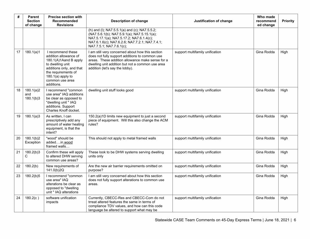
17 180.1(a)1 I recommend these addition allowance of 180.1(A)1Aand B apply to dwelling unit additions only, and that the requirements of 180.1(a) apply to common use area additions.
I am still very concerned about how this section does not fully support additions to common use areas. These addition allowance make sense for a dwelling unit addition but not a common use area addition (let's say the lobby).
support multifamily unification Gina Rodda High
18 180.1(a)2 and 180.1(b)3
I recommend "common use area" IAQ additions be clear as opposed to "dwelling unit " IAQ additions. Support Charles Knoff docket.
dwelling unit stuff looks good support multifamily unification Gina Rodda High
19 180.1(a)3 As written, I can prescriptively add any amount of water heating equipment, is that the intent?
150.2(a)1D limits new equipment to just a second piece of equipment. Will this also change the ACM rules?
support multifamily unification Gina Rodda High
20 180.1(b)2 Exception
"wood" should be added….in wood framed walls…
This should not apply to metal framed walls support multifamily unification Gina Rodda High
21 180.2(b)3C
Confirm these will apply to altered DHW serving common use areas?
These look to be DHW systems serving dwelling units only
support multifamily unification Gina Rodda High
22 180.2(b) New requirements of 141.0(b)2Q
Are the new air barrier requirements omitted on purpose?
support multifamily unification Gina Rodda High
23 180.2(b)5 I recommend "common use area" IAQ alterations be clear as opposed to "dwelling unit " IAQ alterations
I am still very concerned about how this section does not fully support alterations to common use areas.
support multifamily unification Gina Rodda High
24 180.2(c ) software unification impacts
Currently, CBECC-Res and CBECC-Com do not trreat altered features the same in terms of compliance TDV values, and how can this code language be altered to support what may be
support multifamily unification Gina Rodda High

Statewide CASE Team Comments on 45-Day Express Terms | June 18, 2021 | 7
# Parent Section
of change
Precise section with Recommended
Revisions Description of change Justification of change
Who made recommended change
Priority
happening? Curretnly this only supports how CBECC-Res deals with dwelling unit features.
25 110, 129, 130, 140, 150, 160
Support Charles Knuffke Lighting and IAQ proposed language in docketed comment. https://efiling.energy.ca.gov/GetDocument.aspx?tn=238269&DocumentContentId=71562
Lighting language clarifications Gina Rodda High
26 100.1 100.1 "Nonresidential Compliance Manual" needs to include low-rise residential.
Definition needs to include new low-rise residential building type since being moved from Residential Manual
support multifamily unification Gina Rodda Medium
27 100.1 "Nonresidential Building: needs to remove "high-rise residential buildings"
No longer in those sections support multifamily unification Gina Rodda Medium
28 120.8 NOTE: Nonresidential buildings include nonresidential spaces occupancies such as nonresidential function areas within hotel/motel and high-rise residential buildings. The requirements of Section 120.8 apply based on the square footage of the nonresidential spaces occupancies.
Make it clear we are talking about missed-use residential buildings that include nonresidential occupancies, not space types.
This causes a lot of confusion in how the Cx requirements apply to hotel/motel/multifamily buildings with or without nonresidential occupancies (mixed-use).
Gina Rodda Medium
29 150 Exception to 150.0(o)1Giva needs to be removed "Exception to 150.0(o)1Giva: For multifamily dwelling units, the manual ON-OFF control shall not be required to be accessible to the dwelling unit occupant. "
Remove reference to multifamily in single family subchapter
support multifamily unification Gina Rodda Medium
30 130.1(c)5 If intentions is to remove vacancy/partial-on requirements for spaces that trigger multilevel, just get rid of all this language. If not, I have no idea what is
Not understanding how to read the changes to 130.1(c)5: I have the choice to use partial-on or vacancy in addition to occupancy sensor, in spaces where multi-level is not required in any room with 1 luminaire and restrooms? So occupancy sensors that turn off all the lights are allowed everywhere and not linked to multi-level? Why not just get rid of
Very confusing Gina Rodda Medium

Statewide CASE Team Comments on 45-Day Express Terms | June 18, 2021 | 8
# Parent Section
of change
Precise section with Recommended
Revisions Description of change Justification of change
Who made recommended change
Priority
being said here and how to apply it.
anything that speaks to occupancy sensor type as it may be dictated by multilevel?
31 160.5(b)4Fix
UpdateTable 120.1-A and Section 120.2(e)3 references to 160
Think it was missed support multifamily unification Gina Rodda Medium
32 160.2 Equation 160.2-A missing
Think it was missed support multifamily unification Gina Rodda Medium
33 170 45 day updates made to subchapters outside of 170 not fully captured here, is that on purpose?
New air barrier requirements of 140.3(a)9 are not included in 170.2, is this on purpose?
support multifamily unification Gina Rodda Medium
34 170.2(e )3E
This should not be it's own subtext, but in line with 170.2(e )3D above
Not lined up correctly support multifamily unification Gina Rodda Medium
35 170.2(e )3F
becomes 170.2(e )3E Not lined up correctly support multifamily unification Gina Rodda Medium
36 170.2(e ) missing 140.6(b)4 Needed to support when additional power allowances of Table 170.2-M and 170.2-N
support multifamily unification Gina Rodda Medium
37 Table 170.2-N
Missing column number 4 which in turn is causing confusion in 170.2(e )4Bviii
looks like a typo support multifamily unification Gina Rodda Medium
38 170.2(e )4Bix
Reference to Column 5 should be included to line up with 170.2(e )4Bviii and vii above
Would make things flow better support multifamily unification Gina Rodda Low
39 Table 170.2-P
Equations missing looks like a typo support multifamily unification Gina Rodda Medium
40 150.1(c )14
Include low-rise multifamily
since 170.2(f) points to 150.1(c )14, multifamily should be included in the 150.1 language
support multifamily unification Gina Rodda Medium
41 180.2(b)1B
It is not clear if these requirements apply to common use areas AND dwelling unit roofs since there is "dwelling unit" language included. Not sure how the 3rd party verification will work with 4-stories or greater. This needs to be clarified or cleaned up.
Not clear how to apply to dwelling unit AND common use area altered roofs. How will the 3rd party inspection happen for highrise multifamily buildings?
support multifamily unification Gina Rodda Medium
42 180.1 exception
wrong section # used, change to 180.1
Looks like a typo, 150.2(a) used support multifamily unification Gina Rodda Medium

Statewide CASE Team Comments on 45-Day Express Terms | June 18, 2021 | 9
# Parent Section
of change
Precise section with Recommended
Revisions Description of change Justification of change
Who made recommended change
Priority
6
43 180.2(b)2Aii
missing language on ducts in garage spaces of 150.2(b)1Diic
This happens when systems are in parking garage, are you sure you don't want to include this language?
support multifamily unification Gina Rodda Medium
44 180.2(b)2Biic
indent issue looks like a typo support multifamily unification Gina Rodda Medium
45 120.1 Table 120.1-A Occupancy types should be sorted by alphabetical order within each category (eg alphabetical within "Educational Facilites" and alphabetical within "Food and Beverage Service"
Difficult to find what you are looking for. Table 120.1-B is alphabetical
Ben Lalor Medium
46 JA11.3 Documentation procedures needed to support Exception 1 to 150.1(c)14 provided via the Certified SOlar Assessment tools
Building departments are struggling with how to confirm the exception has been used appropriately.
Gina Rodda Low
47 150 EXCEPTION 1 to Section 150.0(m)1B
clarify who is intended to provide visual inspection Condition “i” and “iii” indicate “as confirmed by visual inspection”, but does not identify who’s responsible for verifying whether the condition has been met. If this is intended to be verified by the authority having jurisdiction (AHJ), I suggest indicating this here. Otherwise, I suggest removing “as confirmed by visual inspection” to avoid confusion of this having to be HERS verified.
Brian Selby Medium
48 150 Section 150.0(o)1Gvb clarify who is intended to provide visual inspection Section 150.0(o)1Gvb. indicates “Visual inspection shall verify the installed system conforms to the requirements”, but does not identify who’s responsible for verifying whether the condition has been met. If this is intended to be verified by the authority having jurisdiction (AHJ), I suggest indicating this here. Otherwise, I suggest removing “Visual inspection shall verify the installed system conforms to the requirements” to avoid confusion of this having to be HERS verified.
Brian Selby Medium
49 150 Section 150.0(o)1Gvi include the sound rating requirement in the Energy Code to avoid confusion
Section 150.0(o)1Gvi indicates “…rated for sound in accordance with Section 7.2 of ASHRAE 62.2” but does not include what the sound rating requirement is. Referencing codes outside of what’s adopted by the BSC is problematic for installers and building department staff and recommend including the sound rating in the Energy Code to avoid
Brian Selby Medium
Statewide CASE Team Comments on 45-Day Express Terms | June 18, 2021 | 10
# Parent Section
of change
Precise section with Recommended
Revisions Description of change Justification of change
Who made recommended change
Priority
confusion. FYI, the sound rating requirement is also referred to in Section 150.0(o)2Bii and implies the rating can be found in Section 150.0(o)1Gvi.
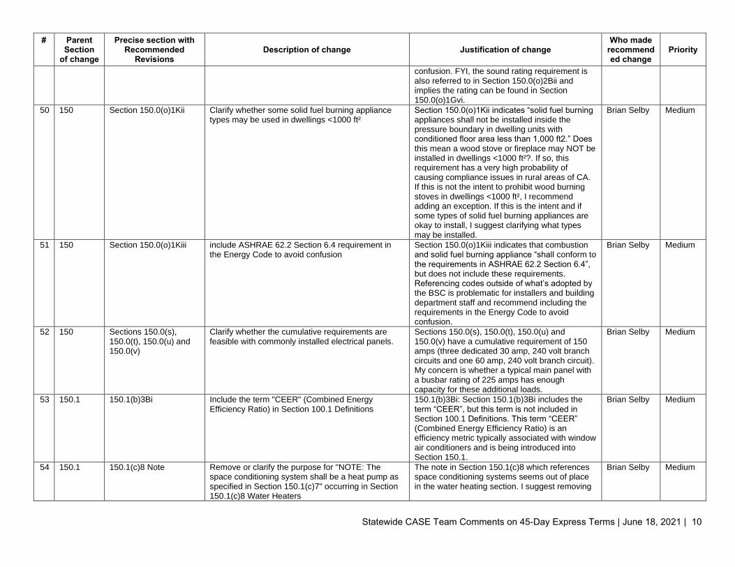
50 150 Section 150.0(o)1Kii Clarify whether some solid fuel burning appliance types may be used in dwellings <1000 ft²
Section 150.0(o)1Kii indicates “solid fuel burning appliances shall not be installed inside the pressure boundary in dwelling units with conditioned floor area less than 1,000 ft2.” Does this mean a wood stove or fireplace may NOT be installed in dwellings <1000 ft²?. If so, this requirement has a very high probability of causing compliance issues in rural areas of CA. If this is not the intent to prohibit wood burning stoves in dwellings <1000 ft², I recommend adding an exception. If this is the intent and if some types of solid fuel burning appliances are okay to install, I suggest clarifying what types may be installed.
Brian Selby Medium
51 150 Section 150.0(o)1Kiii include ASHRAE 62.2 Section 6.4 requirement in the Energy Code to avoid confusion
Section 150.0(o)1Kiii indicates that combustion and solid fuel burning appliance “shall conform to the requirements in ASHRAE 62.2 Section 6.4”, but does not include these requirements. Referencing codes outside of what’s adopted by the BSC is problematic for installers and building department staff and recommend including the requirements in the Energy Code to avoid confusion.
Brian Selby Medium
52 150 Sections 150.0(s), 150.0(t), 150.0(u) and 150.0(v)
Clarify whether the cumulative requirements are feasible with commonly installed electrical panels.
Sections 150.0(s), 150.0(t), 150.0(u) and 150.0(v) have a cumulative requirement of 150 amps (three dedicated 30 amp, 240 volt branch circuits and one 60 amp, 240 volt branch circuit). My concern is whether a typical main panel with a busbar rating of 225 amps has enough capacity for these additional loads.
Brian Selby Medium
53 150.1 150.1(b)3Bi Include the term "CEER" (Combined Energy Efficiency Ratio) in Section 100.1 Definitions
150.1(b)3Bi: Section 150.1(b)3Bi includes the term “CEER”, but this term is not included in Section 100.1 Definitions. This term “CEER” (Combined Energy Efficiency Ratio) is an efficiency metric typically associated with window air conditioners and is being introduced into Section 150.1.
Brian Selby Medium
54 150.1 150.1(c)8 Note Remove or clarify the purpose for "NOTE: The space conditioning system shall be a heat pump as specified in Section 150.1(c)7" occurring in Section 150.1(c)8 Water Heaters
The note in Section 150.1(c)8 which references space conditioning systems seems out of place in the water heating section. I suggest removing
Brian Selby Medium

Statewide CASE Team Comments on 45-Day Express Terms | June 18, 2021 | 11
# Parent Section
of change
Precise section with Recommended
Revisions Description of change Justification of change
Who made recommended change
Priority
it, or clarifying the purpose for it in Section 150.1(c)8
55 140.3 140.3(a)5 Conditioned greenhouses are exempt from 140.3(a)5 all together. No need to list the exemption under every requirement, 140.3(a)5A, 140.3(a)5b..... just list it once at the end.
Clarity Ben Lalor Low
56 140.3 140.3(a)6 Conditioned greenhouses are exempt from 140.3(a)6 all together. No need to list the exemption under every requirement, 140.3(a)6A, 140.3(a)6b..... just list it once at the end.
Clarity Ben Lalor Low
57 140.3 140.3(a)9A Remove the first word "Design" Clarity Ben Lalor Medium
58 140.4 140.4(a)2 consider formatting 140.4(a)2 into a table. This will greatly improve the readability of this new requirement
Clarity Ben Lalor Medium
59 140.6 140.6(b) Formatting issue at 140.6(b) Calculation of Allowed Indoor Lighting Power: General Rules
Clarity Ben Lalor Medium

DOCKETED Docket Number: 21-BSTD-01
Project Title: 2022 Energy Code Update Rulemaking TN #: 237717
Document Title: Express Terms 2022 Energy Code, Title 24 Parts 1 and 6
Description: California Energy Commission proposed changes to the California Code of Regulations, Title 24, Part 1, Chapter 10 and Part 6 (2022 California Energy Code).
Filer: Adrian Ownby Organization: California Energy Commission
Submitter Role: Commission Staff Submission Date: 5/6/2021 11:58:57 AM
Docketed Date: 5/6/2021

2022 Building Energy Efficiency Standards Page 1
ADMINISTRATIVE REGULATIONS
CALIFORNIA CODE OF REGULATIONS TITLE 24, PART 1

Page 2 2022 Building Energy Efficiency Standards
(This page intentionally left blank.)

2022 Building Energy Efficiency Standards Page 3
10-101 – SCOPE
ARTICLE 1 – ENERGY BUILDING REGULATIONS
10-101 – SCOPE (a) This article contains administrative regulations relating to the energy building regulations in Title 24, Part 6. This
article applies to all residential and nonresidential buildings.
(b) Nothing in this article lessens any necessary qualifications or responsibilities of licensed or registered building professionals or other designers or builders, or the duties of enforcement agencies that exist under state or local law.
(c) If any provision of the regulations in this article or the Building Energy Efficiency Standards, Title 24, Part 6, of the California Code of Regulations is found invalid by a court of competent jurisdiction, the remainder of these regulations shall remain in effect.
NOTE: Authority: Sections 25402 and 25402.1, Public Resources Code. Reference: Sections 25402 and 25402.1, Public Resources Code.
10-102 – DEFINITIONS In this article the following definitions apply:
ACCEPTANCE REQUIREMENTS are "acceptance requirements for code compliance" as defined in Section 100.1(b) of Part 6.
ACCEPTANCE TEST TECHNICIAN (ATT) is a Field Technician as defined in Section 10-102 who is certified by an authorized Acceptance Test Technician Certification Provider to perform acceptance testing of either lighting controls or mechanical systems pursuant to the requirements of Sections 10-103.1 or 10-103.2, respectively. ATTs are authorized to perform only those acceptance tests for which they are certified by an ATTCP; ATTs certified to perform acceptance testing of lighting controls are sometimes referred to as “lighting control ATTs”, and ATTs certified to perform acceptance testing of mechanical systems are sometimes referred to as “mechanical ATTs”. (See “Field Technician” and “Acceptance Test Technician Certification Provider”.)
ACCEPTANCE TEST EMPLOYER (ATE) is a person or entity who employs an Acceptance Test Technician and is certified by an authorized Acceptance Test Technician Certification Provider pursuant to the requirements of Sections 10-103.1 or 10-103.2. ATEs are authorized to employ only those ATTs for which they are certified by an ATTCP; ATEs certified to employ ATTs that perform acceptance testing of lighting controls are sometimes referred to as “lighting control ATEs”, and ATEs certified to employ ATTs that perform acceptance testing of mechanical systems are sometimes referred to as “mechanical ATEs”. (See “Acceptance Test Technician” and “Acceptance Test Technician Certification Provider”.)
ACCEPTANCE TEST TECHNICIAN CERTIFICATION PROVIDER (ATTCP) is an agency, organization or entity approved by the Energy Commission to train, certify and oversee ATTs and ATEs relating to either lighting controls or mechanical systems according to the requirements of Sections 10-103.1 or 10-103.2, respectively. ATTCPs are authorized to certify only those ATTs and ATEs for which they are approved by the Energy Commission; ATTCPs approved to certify ATTs and ATEs relating to the acceptance testing of lighting controls are sometimes referred to as “lighting control ATTCPs”, and ATTCPs approved to certify ATTs and ATEs relating to the acceptance testing of mechanical systems are sometimes referred to as “mechanical ATTCPs”. (See “Acceptance Test Technician” and “Acceptance Test Employer”.)
ACM means ALTERNATIVE CALCULATION METHOD are compliance software, or alternative component packages, or exceptional methods approved by the Commission under Section 10-109. ACMs are also referred to as Compliance Software.
Page 4 2022 Building Energy Efficiency Standards
10-102 – DEFINITIONS
ACM APPROVAL MANUALS are the documents establishing the requirements for Energy Commission approval of Compliance Software used to demonstrate compliance with the Building Energy Efficiency Standards for Residential and Nonresidential Buildings currently adopted by the Energy Commission.
ACM REFERENCE MANUAL is the document establishing the procedures required to implement Sections 140.1 and 150.1 of Title 24, Part 6 of the California Code of Regulations in Compliance Software.
ADDITIONALITY is a property of solar offsets whereby the offset causes additional benefits beyond what would occur as a result of all other actions, and which would exclusively benefit the building or property for which the offset substitutes for compliance obligations that would otherwise be required for that building or property, and those benefits would not ever be transferred to other buildings or property.
ALTERNATIVE COMPONENT PACKAGE is a set of building measures whose aggregate calculated energy use is less than or equal to the maximum allowed Energy Budget.
APPLIANCE EFFICIENCY REGULATIONS are the regulations in Title 20, Section 1601 et. seq. of the California Code of Regulations.
APPROVED CALCULATION METHOD is compliance software, or alternative component packages, or exceptional methods approved under Section 10-109.
BUILDING ENERGY EFFICIENCY STANDARDS are those regulations contained in Title 24, Part 6 of the California Code of Regulations.
BUILDING PERMIT is an electrical, plumbing, mechanical, building, or other permit or approval, that is issued by an enforcement agency, and that authorizes any construction that is subject to Part 6.
CALIFORNIA ENERGY COMMISSION is the California State Energy Resources Conservation and Development Commission.
COMMISSION is the California State Energy Resources Conservation and Development Commission.
COMPLEX MECHANICAL SYSTEM is defined here for the purposes of complying with the Design Phase Review component of Section 10-103(a)1. Complex Mechanical Systems are systems that include 1) fan systems each serving multiple thermostatically controlled zones, or 2) built-up air handler systems (non-unitary or nonpackaged HVAC equipment), or 3) hydronic or steam heating systems, or 4) hydronic cooling systems. Complex systems are NOT the following: unitary or packaged equipment listed in Tables 110.2-A, 110.2-B, 110.2- C, and 110.2-E, that each serve one zone, or two-pipe, heating only systems serving one or more zones.
COMPLIANCE APPROACH is any one of the allowable methods by which the design and construction of a building may be demonstrated to be in compliance with Part 6. The compliance approaches are the performance compliance approach and the prescriptive compliance approach. The requirements for each compliance approach are set forth in Section 100.0(e)2 of Part 6.
COMPLIANCE DOCUMENT is any of the documents specified in Section 10-103(a) utilized to demonstrate compliance with Part 6 (i.e., Certificate of Compliance, Certificate of Installation, Certificate of Acceptance, and Certificate of Verification).
COMPLIANCE SOFTWARE is software that has been approved pursuant to Section 10-109 of Part 1.
CONDITIONED FLOOR AREA is the “conditioned floor area” as defined in Section 100.1(b) of Part 6.
CRRC-1 is the Cool Roof Rating Council document titled “Product Rating Program”.
DATA REGISTRY is a web service with a user interface and database maintained by a Registration Provider that complies with the applicable requirements in Reference Joint Appendix JA7, with guidance from the Data Registry Requirements Manual, and provides for registration of residential or nonresidential compliance documentation used for demonstrating compliance with Part 6.
RESIDENTIAL DATA REGISTRY is a data registry that is maintained by a HERS Provider that provides for registration, when required by Part 6 of all residential compliance documentation and the nonresidential Certificate of Verification.

2022 Building Energy Efficiency Standards Page 5
10-102 – DEFINITIONS
NONRESIDENTIAL DATA REGISTRY is a data registry that is maintained by a Registration Provider approved by the Commission that provides for registration, when required by Part 6 of all nonresidential compliance documentation, excluding all Certificates of Acceptance recorded by an acceptance test technician certification provider (10-103.1 and 10-103.2). However, nonresidential data registries may not provide for registration of nonresidential Certificates of Verification.
DATA REGISTRY REQUIREMENTS MANUAL is a document that provides additional detailed guidance regarding the functional and technical aspects of the data registry requirements given in Joint Appendix JA7.
DOCUMENTATION AUTHOR is a person who prepares a Title 24 Part 6 compliance document that must subsequently be reviewed and signed by a responsible person in order to certify compliance with Part 6.
ENERGY BUDGET is the “energy budget” as defined in Section 100.1(b) of Part 6.
ENERGY COMMISSION is the California State Energy Resources Conservation and Development Commission.
ENFORCEMENT AGENCY is the city, county, or state agency responsible for issuing a building permit.
EXCEPTIONAL METHOD is a method for estimating the energy performance of building features that cannot be adequately modeled using existing Compliance Software and that is approved by the Executive Director.
EXECUTIVE DIRECTOR is the executive director of the Commission.
FIELD TECHNICIAN is a person who performs acceptance tests in accordance with the specifications in Reference Nonresidential Appendix NA7, and reports the results of the acceptance tests on the Certificate of Acceptance in accordance with the requirements of Section 10-103(a)4.
HERS is the California Home Energy Rating System as described in Title 20, Chapter 4, Article 8, Section 1670.
HERS PROVIDER is an organization that administers a home energy rating system as described in Title 20, Chapter 4, Article 8, Section 1670.
HERS PROVIDER DATA REGISTRY is a data registry maintained by a HERS provider.
HERS RATER is a person who has been trained, tested, and certified by a HERS Provider to perform the field verification and diagnostic testing required for demonstrating compliance with the Part 6 as described in Title 20, Chapter 4, Article 8, Section 1670(i).
HVAC SYSTEM is the “HVAC system” as defined in Section 100.1(b) of Part 6.
MANUFACTURED DEVICE is the “manufactured device” as defined in Section 100.1(b) of Part 6.
NFRC 100 is the National Fenestration Rating Council document titled “NFRC 100: Procedure for Determining Fenestration Product U-factors.” (2017) NFRC 100 includes procedures for the Component Modeling Approach (CMA) and site-built fenestration formerly included in a separate document, NFRC 100-SB.
NFRC 200 is the National Fenestration Rating Council document titled “NFRC 200: Procedure for Determining Fenestration Product Solar Heat Gain Coefficients and Visible Transmittance at Normal Incidence.” (2017),
NFRC 202 is the National Fenestration Rating Council document titled “NFRC 202: Procedures for Determining Translucent Fenestration Product Visible Transmittance at Normal Incidence.” (2017).
NFRC 203 is the National Fenestration Rating Council document titled “NFRC 203: Procedure for Determining Visible Transmittance of Tubular Daylighting Devices.” (2017),
NFRC 400 is the National Fenestration Rating Council document titled “NFRC 400: Procedure for Determining Fenestration Product Air Leakage.” (2017).
PART 6 is Title 24, Part 6 of the California Code of Regulations.
PUBLIC ADVISER is the Public Adviser of the Commission.
R-VALUE is the measure of the thermal resistance of insulation or any material or building component expressed in ft²-hr-°F/Btu.
Commented [AT1]: Compliance related, same for below

Page 6 2022 Building Energy Efficiency Standards
10-102 – DEFINITIONS
RECORD DRAWINGS are drawings that document the as installed location and performance data on all lighting and space conditioning system components, devices, appliances and equipment, including but not limited to wiring sequences, control sequences, duct and pipe distribution system layout and sizes, space conditioning system terminal device layout and airflow rates, hydronic system and flow rates, and connections for the space conditioning system. Record drawings are sometimes referred to as “as built” drawings.
REFERENCE APPENDICES are the support document for the Building Energy Efficiency Standards and the ACM Approval Manuals. The document consists of three sections: the Reference Joint Appendices (JA), the Reference Residential Appendices (RA), and the Reference Nonresidential Appendices (NA) currently adopted by the Energy Commission.
REFERENCE JOINT APPENDICES are the Reference Joint Appendices currently adopted by the Energy Commission.
REFERENCE NONRESIDENTIAL APPENDICES are the Reference Nonresidential Appendices currently adopted by the Energy Commission.
REFERENCE RESIDENTIAL APPENDICES are the Reference Residential Appendices currently adopted by the Energy Commission.
REGISTERED DOCUMENT is a document that has been submitted to a residential or nonresidential data registry for retention, and the data registry has assigned a unique registration number to the document.
REGISTRATION PROVIDER is an organization that administers a data registry service that conforms to the requirements in Reference Joint Appendix JA7.
STANDARD DESIGN BUILDING is a “Standard Design Building” as defined in Section 100.1(b) of Part 6.
NOTE: Authority: Sections 25402 and 25402.1, and 25213, Public Resources Code. Reference: Sections 25007, 25008, 25218.5, 25310, 25402 and 25402.1, 25402.4, 25402.5, 25402.8 and 25943, Public Resources Code.

2022 Building Energy Efficiency Standards Page 7
10-103 – PERMIT, CERTIFICATE, INFORMATIONAL, AND ENFORCEMENT REQUIREMENTS FOR DESIGNERS, INSTALLERS, BUILDERS, MANUFACTURERS, AND SUPPLIERS
10-103 – PERMIT, CERTIFICATE, INFORMATIONAL, AND ENFORCEMENT REQUIREMENTS FOR DESIGNERS, INSTALLERS, BUILDERS, MANUFACTURERS, AND SUPPLIERS (a) Documentation. For all buildings other than healthcare facilities, the following documentation is required to
demonstrate compliance with Part 6. This documentation shall meet the requirements of Section 10-103(a) or alternatives approved by the Executive Director. Healthcare facilities shall instead comply with the applicable provisions of Chapter 7.
1. Certificate of Compliance. For all buildings, the Certificate of Compliance described in Section 10-103 shall be signed by the person who is eligible under Division 3 of the Business and Professions Code to accept responsibility for the building design (responsible person); and submitted in accordance with Sections 10- 103(a)1 and 10-103(a)2 to certify conformance with Part 6. If more than one person has responsibility for the building design, each person shall sign the Certificate of Compliance document(s) applicable to that portion of the design for which the person is responsible. Alternatively, the person with chief responsibility for the building design shall prepare and sign the Certificate of Compliance document(s) for the entire building design. Subject to the requirements of Sections 10-103(a)1 and 10-103(a)2, persons who prepare Certificate of Compliance documents (documentation authors) shall sign a declaration statement on the documents they prepare to certify the information provided on the documentation is accurate and complete. In accordance with applicable requirements of 10-103(a)1, the signatures provided by responsible persons and documentation authors shall be original signatures on paper documents or electronic signatures on electronic documents conforming to the electronic signature specifications in Reference Joint Appendix JA7.
For all Nonresidential buildings, the Design Review Kickoff Certificate(s) of Compliance and the Construction Document Design Review Checklist Certificate(s) of Compliance shall be reviewed and signed by a licensed professional engineer or licensed architect, or a licensed contractor representing services performed by or under the direct supervision of a licensed engineer or architect, as specified in the provisions of Division 3 of the Business and Professions Code. For buildings less than 10,000 square feet, this signer may be the engineer or architect of record. For buildings greater than 10,000 square feet but less than 50,000 square feet, this signer shall be a qualified in-house engineer or architect with no other project involvement or a third-party engineer, architect, or contractor. For buildings greater than 50,000 square feet and all buildings with complex mechanical systems serving more than 10,000 square feet, this signer shall be a third-party engineer, architect, or contractor.
A. All Certificate of Compliance documentation shall conform to a format and informational order and content approved by the Energy Commission.
These documents shall:
i. Identify the energy features, performance specifications, materials, components, and manufactured devices required for compliance with Part 6.
ii. Identify the building project name and location. The building project name and location identification on the Certificate of Compliance shall be consistent with the building project name and location identification given on the other applicable building design plans and specifications submitted to the enforcement agency for approval with the building permit application.
iii. Display the unique registration number assigned by the data registry if Section 10-103(a)1 requires the document to be registered.
iv. Include a declaration statement to the effect that the building energy features, performance specifications, materials, components, and manufactured devices for the building design identified on the Certificate of Compliance indicate the building is in compliance with the requirements of Title 24, Parts 1 and 6, and the building design features identified on the

Page 8 2022 Building Energy Efficiency Standards
10-103 – PERMIT, CERTIFICATE, INFORMATIONAL, AND ENFORCEMENT REQUIREMENTS FOR DESIGNERS, INSTALLERS, BUILDERS, MANUFACTURERS, AND SUPPLIERS
Certificate of Compliance are consistent with the building design features identified on the other applicable compliance documents, worksheets, calculations, plans, and specifications submitted to the enforcement agency for approval with the building permit application.
v. Be signed by the documentation author to certify the documentation is accurate and complete. When document registration is required by Section 10-103(a)1, the signature shall be an electronic signature on an electronic document in accordance with the electronic signature specifications in Reference Joint Appendix JA7.
vi. Be signed by the responsible person eligible under Division 3 of the Business and Professions Code to accept responsibility for the design to certify conformance with Part 6. When document registration is required by Section 10-103(a)1, the signature shall be an electronic signature on an electronic document in accordance with the electronic signature specifications in Reference Joint Appendix JA7.
B. For all low-rise residential buildings for which compliance requires HERS field verification, the person(s) responsible for the Certificate(s) of Compliance shall submit the Certificate(s) for registration and retention to a HERS provider data registry. The submittals to the HERS provider data registry shall be made electronically in accordance with the specifications in Reference Joint Appendix JA7.
Contingent upon availability and approval of an electronic document repository by the Executive Director, Certificate of Compliance documents that are registered and retained by a HERS provider data registry shall also be automatically transmitted by the data registry, to an electronic document repository for retention in accordance with the specifications in Reference Joint Appendix JA7.
C. For alterations to existing residential buildings for which HERS field verification is not required, including but not limited to water heater and window replacements, and for additions to existing residential buildings that are less than 300 square feet for which HERS field verification is not required, the enforcement agencies may at their discretion not require any Certificate of Compliance documentation, or may develop simplified Certificate of Compliance documentation for demonstrating compliance with the Standards.
Exemptions from submitting compliance documentation shall not be deemed to grant authorization for any work to be done in any manner in violation of this code or other provisions of law.
D. Contingent upon approval of data registry(s) by the Commission, all nonresidential buildings, high-rise residential buildings, and hotels and motels, when designated to allow use of an occupancy group or type regulated by Part 6 the person(s) responsible for the Certificate(s) of Compliance shall submit the Certificate(s) for registration and retention to a data registry approved by the Commission. The submittals to the approved data registry shall be made electronically in accordance with the specifications in Reference Joint Appendix JA7.
Contingent upon availability and approval of an electronic document repository by the Executive Director, Certificate of Compliance documents that are registered and retained by an approved data registry shall also be automatically transmitted by the data registry to an electronic document repository for retention in accordance with the specifications in Reference Joint Appendix JA7.
2. Application for a building permit. Each application for a building permit subject to Part 6 shall contain at least one copy of the documents specified in Sections 10-103(a)2A, 10-103(a)2B, and 10-103(a)2C.
A. For all newly constructed buildings, additions, alterations, or repairs regulated by Part 6 the applicant shall submit the applicable Certificate(s) of Compliance to the enforcement agency for approval. The certificate(s) shall conform to the requirements of Section 10-103(a)1, and shall be approved by the local enforcement agency, in accordance with all applicable requirements of Section 10-103(d), by stamp or authorized signature prior to issuance of a building permit. A copy of the Certificate(s) of Compliance shall be included with the documentation the builder provides to the building owner at occupancy as specified in Section 10-103(b).

2022 Building Energy Efficiency Standards Page 9
10-103 – PERMIT, CERTIFICATE, INFORMATIONAL, AND ENFORCEMENT REQUIREMENTS FOR DESIGNERS, INSTALLERS, BUILDERS, MANUFACTURERS, AND SUPPLIERS
For alterations to existing residential buildings for which HERS field verification is required, and when the enforcement agency does not require building design plans to be submitted with the application for a building permit, the applicable Certificate of Compliance documentation specified in Section 10- 103(a)1 is not required to be approved by the enforcement agency prior to issuance of a building permit, but shall be approved by the enforcement agency prior to final inspection of the dwelling unit, and shall be made available to the enforcement agency for all applicable inspections, or made available for viewing on an approved data registry.
When the enforcement agency requires building design plans to be submitted with the application for a building permit, the applicable Certificate of Compliance documents shall be incorporated into the building design plans. When Section 10-103(a)1 requires document registration, the certificate(s) that are incorporated into the building design plans shall be copies of the registered Certificate of Compliance documents from a HERS provider data registry, or a data registry approved by the Commission.
B. When the enforcement agency requires building design plans and specifications to be submitted with the application for a building permit, the plans shall conform to the specifications for the features, materials, components, and manufactured devices identified on the Certificate(s) of Compliance, and shall conform to all other applicable requirements of Part 6. Plans and specifications shall be submitted to the enforcement agency for any other feature, material, component, or manufactured device that Part 6 requires be indicated on the building design plans and specifications. Plans and specifications submitted with each application for a building permit for Nonresidential buildings, High- rise Residential buildings and Hotels and Motels shall provide acceptance requirements for code compliance of each feature, material, component or manufactured device when acceptance requirements are required under Part 6. Plans and specifications for Nonresidential buildings, High- rise Residential buildings and Hotels and Motels shall require, and indicate with a prominent note on the plans, that within 90 days after the Enforcement Agency issues a permanent final occupancy permit, record drawings be provided to the building owner.
For all buildings, if the specification for a building design feature, material, component, or manufactured device is changed before final construction or installation, such that the building may no longer comply with Part 6 the building must be brought back into compliance, and so indicated on amended plans, specifications, and Certificate(s) of Compliance that shall be submitted to the enforcement agency for approval. Such characteristics shall include the efficiency (or other characteristic regulated by Part 6) of each building design feature, material, component, or device.
C. The enforcement agency shall have the authority to require submittal of any supportive documentation that was used to generate the Certificate(s) of Compliance, including but not limited to the electronic input file for the compliance software tool that was used to generate performance method Certificate(s) of Compliance; or any other supportive documentation that is necessary to demonstrate that the building design conforms to the requirements of Part 6.
3. Certificate of Installation. For all buildings, the person in charge of the construction or installation, who is eligible under Division 3 of the Business and Professions Code to accept responsibility for the construction or installation of features, materials, components, or manufactured devices regulated by Part 6 or the Appliance Efficiency Regulations (responsible person) shall sign and submit Certificate of Installation documentation as specified in Section 10-103(a)3 to certify conformance with Part 6. If more than one person has responsibility for the construction or installation, each person shall sign and submit the Certificate of Installation documentation applicable to the portion of the construction or installation for which they are responsible; alternatively, the person with chief responsibility for the construction or installation shall sign and submit the Certificate of Installation documentation for the entire construction or installation scope of work for the project. Subject to the requirements of Section 10-103(a)3, persons who prepare Certificate of Installation documentation (documentation authors) shall sign a declaration statement on the documents they prepare to certify the information provided on the documentation is accurate and complete. In accordance with applicable requirements of 10-103(a)3, the signatures provided by responsible persons and documentation authors shall be original signatures on paper

Page 10 2022 Building Energy Efficiency Standards
10-103 – PERMIT, CERTIFICATE, INFORMATIONAL, AND ENFORCEMENT REQUIREMENTS FOR DESIGNERS, INSTALLERS, BUILDERS, MANUFACTURERS, AND SUPPLIERS
documents or electronic signatures on electronic documents conforming to the electronic signature specifications in Reference Joint Appendix JA7.
A. Delegation of Signature Authority. Except where prohibited by law, including but not limited to any requirements under Division 3 of the Business and Professions Code, the Responsible Person may delegate signature authority to third parties (Authorized Representatives) provided that there is a written agreement:
i. Between the Responsible Person and the person to be designated as the Authorized Representative.
ii. Specifying that the Authorized Representative may sign Certificates of Installation on behalf of the Responsible Person.
iii. Specifying that the legal responsibility for construction or installation in the applicable classification for the scope of work specified on the Certificate of Installation document(s) remains with the Responsible Person.
iv. That is signed by both the Responsible Person and the Authorized Representative.
v. That is retained by the HERS Provider to which all compliance documents are submitted for the building to which the Certificate of Installation documentation pertains.
vi. That is maintained in the HERS Provider Data Registry such that it is accessible for verification by, included but not limited to, the Energy Commission and enforcement agencies.
B. Format. All Certificate of Installation documentation shall conform to a format and informational order and content approved by the Energy Commission.
These documents shall:
i. Identify the features, materials, components, manufactured devices, and system performance diagnostic results required to demonstrate compliance with Part 6 and the Appliance Efficiency Regulations.
ii. State the number of the building permit under which the construction or installation was performed.
iii. Display the unique registration number assigned by the data registry if Section 10-103(a)3 requires the document to be registered.
iv. Include a declaration statement indicating that the constructed or installed features, materials, components or manufactured devices (the installation) identified on the Certificate of Installation conforms to all applicable codes and regulations, and the installation conforms to the requirements given on the plans and specifications approved by the enforcement agency.
v. Be signed by the documentation author to certify the documentation is accurate and complete. When document registration is required by Section 10-103(a)3, the signature shall be an electronic signature on an electronic document in accordance with the electronic signature specifications in Reference Joint Appendix JA7.
vi. Be signed by the Responsible Person eligible under Division 3 of the Business and Professions Code to accept responsibility for construction or installation in the applicable classification for the scope of work specified on the Certificate of Installation document(s), or shall be signed by their Authorized Representative. When document registration is required by Section 10-103(a)3, the signature shall be an electronic signature on an electronic document in accordance with the electronic signature specifications in Reference Joint Appendix JA7.
C. For all low-rise residential buildings, the person(s) responsible for the Certificate(s) of Installation, or their Authorized Representative(s), shall submit the following Certificate of Installation documentation that is applicable to the building to a HERS provider data registry for registration and retention in accordance with procedures specified in Reference Residential Appendix RA2:

2022 Building Energy Efficiency Standards Page 11
10-103 – PERMIT, CERTIFICATE, INFORMATIONAL, AND ENFORCEMENT REQUIREMENTS FOR DESIGNERS, INSTALLERS, BUILDERS, MANUFACTURERS, AND SUPPLIERS
i. All Certificates of Installation for which compliance requires HERS field verification.
ii. All other Certificates of Installation, except those exempted by the Energy Commission.
The submittals to the HERS provider data registry shall be made electronically in accordance with the specifications in Reference Joint Appendix JA7.
Contingent upon availability and approval of an electronic document repository by the Executive Director, Certificate of Installation documents that are registered and retained by a HERS provider data registry shall also be automatically transmitted by the data registry to an electronic document repository for retention in accordance with the specifications in Reference Joint Appendix JA7.
D. For alterations to existing residential buildings for which HERS field verification is not required, including but not limited to water heater and window replacements, and for additions to existing residential buildings that are less than 300 square feet for which HERS field verification is not required, the enforcement agencies may, at their discretion, not require any Certificate of Installation documentation, or may develop simplified Certificate of Installation documentation for demonstrating compliance with the Standards.
Exemptions from submitting compliance documentation shall not be deemed to grant authorization for any work to be done in any manner in violation of this code or other provisions of law.
E. Contingent upon approval of data registry(s) by the Commission, all nonresidential buildings, high-rise residential buildings, and hotels and motels, when designated to allow use of an occupancy group or type regulated by Part 6 the person(s) responsible for the Certificate(s) of Installation, except those documents exempted by the Energy Commission, shall submit the Certificate(s) for registration and retention to a data registry approved by the Commission. The submittals to the approved data registry shall be made electronically in accordance with the specifications in Reference Joint Appendix JA7.
Contingent upon availability and approval of an electronic document repository by the Executive Director, Certificate of Installation documents that are registered and retained by an approved data registry shall also be automatically transmitted by the data registry to an electronic document repository for retention in accordance with the specifications in Reference Joint Appendix JA7.
F. Availability. For all buildings, a copy of the Certificate(s) of Installation shall be posted, or made available with the building permit(s) issued for the building, or made available for viewing on an approved data registry, and shall be made available to the enforcement agency for all applicable inspections. When document registration is required by Section 10-103(a)3, registered copies of the Certificate(s) of Installation from a HERS provider data registry or a data registry approved by the Commission shall be posted or made available with the building permit(s) issued for the building, and shall be made available to the enforcement agency for all applicable inspections. If construction on any portion of the building subject to Part 6 will be impossible to inspect because of subsequent construction, the enforcement agency may require the Certificate(s) of Installation to be posted upon completion of that portion. A copy of the Certificate(s) of Installation shall be included with the documentation the builder provides to the building owner at occupancy as specified in Section 10- 103(b).
4. Certificate of Acceptance. For all nonresidential buildings, high-rise residential buildings, and hotels and motels, when designated to allow use of an occupancy group or type regulated by Part 6 the person in charge of the acceptance testing, who is eligible under Division 3 of the Business and Professions Code to accept responsibility for the applicable scope of system design, or construction, or installation of features, materials, components, or manufactured devices regulated by Part 6 or the Appliance Efficiency Regulations (responsible person), shall sign and submit all applicable Certificate of Acceptance documentation in accordance with Section 10-103(a)4 and Reference Nonresidential Appendix NA7 to certify conformance with Part 6. If more than one person has responsibility for the acceptance testing, each person shall sign and submit the Certificate of Acceptance documentation applicable to the portion of the construction or installation, for which they are responsible; alternatively, the person with chief responsibility for the system design, construction or installation, shall sign and submit the Certificate of Acceptance documentation for the entire construction or installation scope of work for the project.

Page 12 2022 Building Energy Efficiency Standards
10-103 – PERMIT, CERTIFICATE, INFORMATIONAL, AND ENFORCEMENT REQUIREMENTS FOR DESIGNERS, INSTALLERS, BUILDERS, MANUFACTURERS, AND SUPPLIERS
Subject to the requirements of Section 10-103(a)4, persons who prepare Certificate of Acceptance documentation (documentation authors) shall sign a declaration statement on the documents they prepare to certify the information provided on the documentation is accurate and complete. Persons who perform acceptance test procedures in accordance with the specifications in Reference Nonresidential Appendix NA7, and report the results of the acceptance tests on the Certificate of Acceptance (field technicians) shall sign a declaration statement on the documents they submit to certify the information provided on the documentation is true and correct. In accordance with applicable requirements of Section 10-103(a)4, the signatures provided by responsible persons, field technicians, and documentation authors shall be original signatures on paper documents or electronic signatures on electronic documents conforming to the electronic signature specifications in Reference Joint Appendix JA7.
A. All Certificate of Acceptance documentation shall conform to a format and informational order and content approved by the Energy Commission.
These documents shall:
i. Identify the features, materials, components, manufactured devices, and system performance diagnostic results required to demonstrate compliance with the acceptance requirements to which the applicant must conform as indicated in the plans and specifications submitted under Section 10-103(a)2, and as specified in Reference Nonresidential Appendix NA7.
ii. State the number of the building permit under which the construction or installation was performed.
iii. Display the unique registration number assigned by the data registry if Section 10-103(a)4 requires the document to be registered.
iv. Include a declaration statement indicating that the features, materials, components or manufactured devices identified on the Certificate of Acceptance conform to the applicable acceptance requirements as indicated in the plans and specifications submitted under Section 10- 103(a), and with applicable acceptance requirements and procedures specified in the Reference Nonresidential Appendix NA7, and confirms that Certificate(s) of Installation described in Section 10-103(a)3 has been completed and is posted or made available with the building permit(s) issued for the building, or made available for viewing on an approved data registry.
v. Be signed by the documentation author to certify the documentation is accurate and complete. When document registration is required by Section 10-103(a)4, the signature shall be an electronic signature on an electronic document in accordance with the electronic signature specifications in Reference Joint Appendix JA7.
vi. Be signed by the field technician who performed the acceptance test procedures and reported the results on the Certificate of Acceptance. When document registration is required by Section 10-103(a)4, the signature shall be an electronic signature on an electronic document in accordance with the electronic signature specifications in Reference Joint Appendix JA7.
vii. Be signed by the responsible person in charge of the acceptance testing who is eligible under Division 3 of the Business and Professions Code to accept responsibility for the system design, construction or installation in the applicable classification for the scope of work identified on the Certificate of Acceptance, or shall be signed by their authorized representative. When document registration is required by Section 10-103(a)4, the signature shall be an electronic signature on an electronic document in accordance with the electronic signature specifications in Reference Joint Appendix JA7.
B. Contingent upon approval of data registry(s) by the Commission, for all nonresidential buildings, high- rise residential buildings, and hotels and motels, when designated to allow use of an occupancy group or type regulated by Part 6 the person(s) responsible for the Certificate(s) of Acceptance shall submit the Certificate(s) for registration and retention to a data registry approved by the Commission, excluding all Certificates of Acceptance recorded by an acceptance test technician certification Commented [AT2]: same

2022 Building Energy Efficiency Standards Page 13
10-103 – PERMIT, CERTIFICATE, INFORMATIONAL, AND ENFORCEMENT REQUIREMENTS FOR DESIGNERS, INSTALLERS, BUILDERS, MANUFACTURERS, AND SUPPLIERS
provider (10-103.1 and 10-103.2). The submittals to the approved data registry shall be made electronically in accordance with the specifications in Reference Joint Appendix JA7.
Contingent upon availability and approval of an electronic document repository by the Executive Director, Certificate of Acceptance documents that are registered and retained by an approved data registry shall also be automatically transmitted by the data registry, to an electronic document repository for retention in accordance with the specifications in Reference Joint Appendix JA7.
C. A copy of the registered Certificate(s) of Acceptance shall be posted, or made available with the building permit(s) issued for the building, or made available for viewing on an approved data registry, and shall be made available to the enforcement agency for all applicable inspections. If construction on any portion of the building subject to Part 6 will be impossible to inspect because of subsequent construction, the enforcement agency may require the Certificate(s) of Acceptance to be posted upon completion of that portion. A copy of the Certificate(s) of Acceptance shall be included with the documentation the builder provides to the building owner at occupancy as specified in Section 10- 103(b).
5. Certificate of Field Verification and Diagnostic Testing (Certificate of Verification). For all buildings for which compliance requires HERS field verification, a certified HERS Rater shall conduct all required HERS field verification and diagnostic testing in accordance with applicable procedures specified in Reference Appendices RA2, RA3, NA1, and NA2. All applicable Certificate of Verification documentation shall be completed, signed, and submitted by the certified HERS Rater who performed the field verification and diagnostic testing services (responsible person) in accordance with the requirements of Section 10-103(a)5, and Reference Appendices RA2, and NA1, to certify conformance with Part 6. If more than one rater has responsibility for the HERS verification for the building, each rater shall sign and submit the Certificate of Verification documentation applicable to the portion of the building for which they are responsible. Subject to the requirements of Section 10-103(a)5, persons who prepare Certificate of Verification documentation (documentation authors) shall sign a declaration statement on the documents they prepare to certify the information provided on the documentation is accurate and complete. The signatures provided by responsible persons and documentation authors shall be electronic signatures on electronic documents.
A. Format. All Certificate of Verification documentation shall conform to a format and informational order and content approved by the Energy Commission.
These documents shall:
i. Identify the installed features, materials, components, manufactured devices, or system performance diagnostic results that require HERS verification for compliance with Part 6 as specified on the Certificate(s) of Compliance for the building.
ii. State the number of the building permit under which the construction or installation was performed,
iii. Display the unique registration number assigned by the HERS provider data registry, and provide any additional information required by Reference Appendices RA2, RA3, NA1, and NA2.
iv. Include a declaration statement indicating that the installed features, materials, components or manufactured devices requiring HERS verification conform to the applicable requirements in Reference Appendices RA2, RA3, NA1, NA2, and the requirements specified on the Certificate(s) of Compliance approved by the local enforcement agency, and confirms the same features, materials, components or manufactured devices are identified on the applicable Certificate(s) of Installation signed and submitted by the person(s) responsible for the construction or installation as described in Section 10-103(a)3.
v. Be signed by the documentation author to certify the documentation is accurate and complete. The signatures shall be electronic signatures on electronic documents in accordance with the electronic signature specifications in Reference Joint Appendix JA7.

Page 14 2022 Building Energy Efficiency Standards
10-103 – PERMIT, CERTIFICATE, INFORMATIONAL, AND ENFORCEMENT REQUIREMENTS FOR DESIGNERS, INSTALLERS, BUILDERS, MANUFACTURERS, AND SUPPLIERS
vi. Be signed by the HERS Rater who performed the field verification and diagnostic testing services (responsible person). The signatures shall be electronic signatures on electronic documents in accordance with the electronic signature specifications in Reference Joint Appendix JA7.
B. For all buildings for which compliance requires HERS field verification, the certified HERS Rater responsible for the Certificate(s) of Verification shall submit the Certificates for registration and retention to a HERS provider data registry in accordance with the applicable procedures in Reference Appendices RA2 and NA1.
The submittals to the HERS provider data registry shall be made electronically in accordance with the specifications in Reference Joint Appendix JA7.
Contingent upon availability and approval of an electronic document repository by the Executive Director, Certificate of Verification documents that are registered and retained by a HERS provider data registry shall also be automatically transmitted by the data registry, to an electronic document repository for retention in accordance with the specifications in Reference Joint Appendix JA7.
C. Availability. For all buildings, a copy of the registered Certificate(s) of Verification shall be posted, or made available with the building permit(s) issued for the building, or made available for viewing on an approved data registry, and shall be made available to the enforcement agency for all applicable inspections. If construction on any portion of the building subject to Part 6 will be impossible to inspect because of subsequent construction, the enforcement agency may require the Certificate(s) of Verification to be posted upon completion of that portion. A copy of the registered Certificate(s) of Verification shall be included with the documentation the builder provides to the building owner at occupancy as specified in Section 10-103(b).
EXCEPTION to Section 10-103(a): Enforcing agencies may exempt nonresidential buildings that have no more than 1,000 square feet of conditioned floor area in the entire building and an occupant load of 49 persons or less from the documentation requirements of Section 10-103(a), provided a statement of compliance with Part 6 is submitted and signed by a licensed engineer or the licensed architect with chief responsibility for the design.
(b) Compliance, Operating, Maintenance, and Ventilation Information to be provided by Builder.
1. Compliance information.
A. For low-rise residential buildings, at final inspection, the enforcement agency shall require the builder to leave in the building, copies of the completed, signed, and submitted compliance documents for the building owner at occupancy. For low-rise residential buildings, such information shall, at a minimum, include copies of all Certificate of Compliance, Certificate of Installation, and Certificate of Verification documentation submitted. These documents shall be in paper or electronic format and shall conform to the applicable requirements of Section 10-103(a).
B. For nonresidential buildings, high-rise residential buildings and hotels and motels, at final inspection, the enforcement agency shall require the builder to leave in the building, copies of the completed, signed, and submitted compliance documents for the building owner at occupancy. For nonresidential buildings, high-rise residential buildings and hotels and motels, such information shall include copies of all Certificate of Compliance, Certificate of Installation, Certificate of Acceptance and Certificate of Verification documentation submitted. These documents shall be in paper or electronic format and shall conform to the applicable requirements of Section 10-103(a).
2. Operating information. At final inspection, the enforcement agency shall require the builder to leave in the building, for the building owner at occupancy, operating information for all applicable features, materials, components, and mechanical devices installed in the building. Operating information shall include instructions on how to operate the features, materials, components, and mechanical devices correctly and efficiently. The instructions shall be consistent with specifications set forth by the Executive Director. For low-rise residential buildings, such information shall be contained in a folder or manual which provides all information specified in Section 10-103(b). This operating information shall be in paper or electronic format.

2022 Building Energy Efficiency Standards Page 15
10-103 – PERMIT, CERTIFICATE, INFORMATIONAL, AND ENFORCEMENT REQUIREMENTS FOR DESIGNERS, INSTALLERS, BUILDERS, MANUFACTURERS, AND SUPPLIERS
For dwelling units, buildings or tenant spaces that are not individually owned and operated, or are centrally operated, such information shall be provided to the person(s) responsible for operating the feature, material, component or mechanical device installed in the building. This operating information shall be in paper or electronic format.
3. Maintenance information. At final inspection, the enforcement agency shall require the builder to leave in the building, for the building owner at occupancy, maintenance information for all features, materials, components, and manufactured devices that require routine maintenance for efficient operation. Required routine maintenance actions shall be clearly stated and incorporated on a readily accessible label. The label may be limited to identifying, by title and/or publication number, the operation and maintenance manual for that particular model and type of feature, material, component or manufactured device. For low-rise residential buildings, this information shall include a schedule of all interior luminaires and lamps installed to comply with Section 150.0(k).
For dwelling units, buildings or tenant spaces that are not individually owned and operated, or are centrally operated, such information shall be provided to the person(s) responsible for maintaining the feature, material, component or mechanical device installed in the building. This information shall be in paper or electronic format.
4. Ventilation information.
A. For low-rise low-rise and high-rise residential buildings, the enforcement agency shall require the builder to leave the following information in the building, for the building owner at occupancy:
i. , a A description of the quantities of outdoor air that the whole-dwelling unit ventilation system(s) are designed to provide to the building’s conditioned space, and instructions for proper operation and maintenance of the ventilation system.
ii. Instructions for proper operation and maintenance of local exhaust systems, including instructions for conditions for which any occupant-controlled systems such as kitchen range hoods and bathroom exhaust fans should be used.
iii. For systems in buildings or tenant spaces that are not individually owned and operated by the dwelling unit occupants, the building’s owner or their representative shall provide a copy of the ventilation system information to dwelling occupants at the beginning of their occupancy. For systems in buildings or tenant spaces thator are centrally operated, such all applicable ventilation system information shall be provided to the person(s) responsible for operating and maintaining the feature, material, component or mechanical ventilation device installed in the building. This information shall be in paper or electronic format.
B. For nonresidential buildings, high-rise residential buildings and hotels, and motels, the enforcement agency shall require the builder to provide the building owner at occupancy a description of the quantities of outdoor and recirculated air that the ventilation systems are designed to provide to each area. For buildings or tenant spaces that are not individually owned and operated, or are centrally operated, such information shall be provided to the person(s) responsible for operating and maintaining the feature, material, component or mechanical device installed in the building. This information shall be in paper or electronic format.
(c) Equipment Information to be Provided by Manufacturer or Supplier. The manufacturer or supplier of any manufactured device shall, upon request, provide to building designers and installers information about the device. The information shall include the efficiency (and other characteristics regulated by Part 6). This information shall be in paper or electronic format.
(d) Enforcement Agency Requirements.
1. Permits. An enforcement agency shall not issue a building permit for any construction unless the enforcement agency determines in writing that the construction is designed to comply with the requirements of Part 6 that are in effect on the date the building permit was applied for. The enforcement agency determination shall confirm that the documentation requirements of Sections 10-103(a)1 and 10- 103(a)2 have been met.

Page 16 2022 Building Energy Efficiency Standards
10-103 – PERMIT, CERTIFICATE, INFORMATIONAL, AND ENFORCEMENT REQUIREMENTS FOR DESIGNERS, INSTALLERS, BUILDERS, MANUFACTURERS, AND SUPPLIERS
If a building permit has been previously issued, there has been no construction under the permit, and the permit has expired, the enforcement agency shall not issue a new permit unless the enforcement agency determines in writing that the construction is designed to comply with the requirements of Part 6 in effect on the date the new permit is applied for. The enforcement agency determination shall confirm that the documentation requirements of Sections 10-103(a)1 and 10-103(a)2 have been met.
“Determines in writing” includes, but is not limited to, approval of a building permit with a stamp normally used by the enforcement agency.
2. Inspection. The enforcement agency shall inspect newly constructed buildings and additions, and alterations to existing buildings to determine whether the construction or installation is consistent with the agency's approved plans and specifications, and complies with Part 6. Final certificate of occupancy shall not be issued until such consistency and compliance is verified. For Occupancy Group R-3, final inspection shall not be complete until such consistency and compliance is verified.
Such verification shall include determination that:
A. All installed features, materials, components or manufactured devices, regulated by the Appliance Efficiency Regulations or Part 6 are indicated, when applicable, on the Certificate(s) of Installation, Certificate(s) of Acceptance and Certificate(s) of Verification, and are consistent with such features, materials, components or manufactured devices given in the plans and specifications and the Certificate(s) of Compliance approved by the local enforcement agency.
B. All required Certificates of Installation are posted, or made available with the building permit(s) issued for the building, or made available for viewing on an approved data registry, and are made available to the enforcement agency for all applicable inspections, and that all required Certificates of Installation conform to the specifications of Section 10-103(a)3.
C. All required Certificates of Acceptance are posted, or made available with the building permit(s) issued for the building, or made available for viewing on an approved data registry, and are made available to the enforcement agency for all applicable inspections, and that all required Certificates of Acceptance conform to the specifications of Section 10-103(a)4.
D. All required Certificates of Verification are posted, or made available with the building permit(s) issued for the building, or made available for viewing on an approved data registry, and are made available to the enforcement agency for all applicable inspections, and that all required Certificates of Verification conform to the specifications of Section 10-103(a)5.
NOTE: Authority: Section 25402, 25402.1, Public Resources Code. Reference: Section 25402, Public Resources Code.

2022 Building Energy Efficiency Standards Page 17
10-103.1 – NONRESIDENTIAL LIGHTING CONTROLS ACCEPTANCE TEST TRAINING AND CERTIFICATION
10-103.1 – NONRESIDENTIAL LIGHTING CONTROLS ACCEPTANCE TEST TRAINING AND CERTIFICATION (a) Scope. The requirements of this section apply to Acceptance Test Technicians (ATTs), Acceptance Test
Employers (ATEs), and Acceptance Test Technician Certification Providers (ATTCPs) that perform work relating to the acceptance testing of nonresidential lighting systems and controls.
(b) Industry Certification Threshold. ATT and ATE certification requirements shall take effect when the Energy Commission finds that each of the following conditions are met. Until such time that Sections 10-103.1(b)1 and 10-103.1(b)2 are met, or if, subsequent to being met, they cease to be maintained, Field Technicians may complete acceptance testing as specified in Part 6, Section 130.4 without meeting the certification requirements specified in Part 1, Section 10-103.1.
1. Number of Certified ATTs. There shall be no less than 300 ATTs certified to perform the lighting acceptance tests in Building Energy Efficiency Standards, Section 130.4. The number of certified ATTs shall be submitted to the Energy Commission in the annual reports prepared by ATTCPs, as specified in Section 10-103.1(d)1.
2. Industry Coverage by ATTCPs. ATTCPs approved by the Energy Commission, in their entirety, shall provide reasonable access to certification to the following industry groups: electrical contractors, certified general electricians, licensed architects, professional engineers, controls installation and startup contractors and certified commissioning professionals who have verifiable training, experience and expertise in lighting controls and electrical systems. The Energy Commission will determine whether reasonable access to certification is provided by considering factors such as certification costs commensurate with the complexity of the training being provided, certification marketing materials, prequalification criteria, class location and availability, and curriculum.
(c) Qualifications and Approval of ATTCPs. ATTCPs shall submit a written application to the Energy Commission with a summary and the related background documents to explain how the following criteria and procedures have been met:
1. Organizational Structure. ATTCPs shall provide written explanations of the organization type, by-laws, and ownership structure. ATTCPs shall explain in writing how their certification program meets the qualification requirements of Title 24, Part 1, Section 10-103.1(c). ATTCPs shall explain in their application to the Energy Commission their organizational structure and their procedures for independent oversight, quality assurance, supervision and support of the acceptance test training and certification processes.
2. Certification of ATEs. The ATTCPs shall provide written explanations of their certification and oversight of ATEs. This explanation shall document how the ATTCP ensures that ATEs are providing quality control and appropriate supervision and support for their ATTs.
A. Recertification. The ATTCP shall recertify all ATEs prior to the implementation of each adopted update to the Building Energy Efficiency Standards as these updates affect the acceptance test requirements. Recertification requirements and procedures shall only apply to those specific elements that are new or modified in future updates to Building Energy Efficiency Standards.
3. Training and Certification Procedures. ATTCPs shall include with their application a complete copy of all training and testing procedures, manuals, handbooks and materials. ATTCPs shall explain in writing how their training and certification procedures include, but are not limited to, the following:
A. Training Scope. The scope of the training shall include both hands-on experience and theoretical training to certify competency in the technologies and skills necessary to perform the acceptance tests.
B. ATT Training.

Page 18 2022 Building Energy Efficiency Standards
10-103.1 – NONRESIDENTIAL LIGHTING CONTROLS ACCEPTANCE TEST TRAINING AND CERTIFICATION
i. Curricula. ATTCP training curricula for ATTs shall include, but not be limited to, the analysis, theory, and practical application of the following:
a. Lamp and ballast systems;
b. Line voltage switching controls;
c. Low voltage switching controls;
d. Dimming controls;
e. Occupancy sensors;
f. Photosensors;
g. Demand responsive signal inputs to lighting control systems;
h. Building Energy Efficiency Standards required lighting control systems;
i. Building Energy Efficiency Standards required lighting control system-specific analytical/problem solving skills;
j. Integration of mechanical and electrical systems for Building Energy Efficiency Standards required lighting control installation and commissioning;
k. Safety procedures for low-voltage retrofits (<50 volts) to control line voltage systems (120 to 480 volts);
l. Accurate and effective tuning, calibration, and programming of Building Energy Efficiency Standards required lighting control systems;
m. Measurement of illuminance according to the Illuminating Engineering Society’s measurement procedures as provided in the IES Lighting Handbook, 10th Edition, 2011;
n. Building Energy Efficiency Standards lighting controls acceptance testing procedures; and
o. Building Energy Efficiency Standards acceptance testing compliance documentation for lighting controls.
ii. Hands-on training. The ATTCP shall describe in its application the design and technical specifications of the laboratory boards, equipment and other elements that will be used to meet the hands-on requirements of the training and certification.
iii. Prequalification. Participation in the certification program shall be limited to persons who have at least three years of professional experience and expertise in lighting controls and electrical systems as determined by the Lighting Controls ATTCPs.
NOTE: ATTCPs may specify additional qualifications for participation in their programs, such as limiting participation to persons that are not currently listed as “decertified” by another ATTCP.
iv. Instructor to Trainee Ratio. The ATTCP shall document in its application to the Energy Commission why its instructor to trainee ratio is sufficient to ensure the integrity and efficacy of the curriculum and program based on industry standards and other relevant information.
v. Tests. The ATTCP shall describe the written and practical tests used to demonstrate each certification applicant’s competence in all specified subjects. The ATTCPs shall retain all results of these tests for five years from the date of the test.
vi. Recertification. The ATTCP shall recertify all ATTs prior to the implementation of each adopted update to the Building Energy Efficiency Standards when these updates affect the acceptance test requirements. Recertification requirements and procedures shall

2022 Building Energy Efficiency Standards Page 19
10-103.1 – NONRESIDENTIAL LIGHTING CONTROLS ACCEPTANCE TEST TRAINING AND CERTIFICATION
only apply to those specific elements that are new or modified in future updates to Building Energy Efficiency Standards. The ATTCP shall develop recertification training curricula for ATTs consistent with training requirements in Sections 10-103.1(c)3A and 10-103.1(c)3B, and shall submit the proposed recertification training curricula to the Energy Commission for review and approval in the update report required under Section 10-103.1(d)2.
C. ATE Training. Training for ATEs shall consist of a single class or webinar consisting of at least four hours of instruction that covers the scope and process of the acceptance tests in Building Energy Efficiency Standards, Section 130.4.
D. Complaint Procedures. The ATTCP shall describe in its applications to the Energy Commission procedures for accepting and addressing complaints regarding the performance of any ATT or ATE certified by the ATTCP, and explain how building departments and the public will be notified of these proceedings.
E. Decertification Procedures. The ATTCP shall describe in its applications to the Energy Commission procedures for revoking their certification of ATTs and ATEs based upon poor quality or ineffective work, failure to perform acceptance tests, falsification of documents, failure to comply with the documentation requirements of these regulations or other specified actions that justify decertification. The ATTCP shall also describe its general procedures for decertified ATTs or ATEs seeking to regain their certification status, including eligibility requirements for recertification (if any).
F. Quality Assurance and Accountability. The ATTCP shall describe in its application to the Energy Commission its procedures for conducting quality assurance and accountability activities, including but not limited to the following:
i. The ATTCP shall include quality assurance and accountability measures, including but not limited to independent oversight of the certification materials, processes and procedures, visits to building sites where certified technicians are completing acceptance tests, certification process evaluations, building department surveys to determine acceptance testing effectiveness, and expert review of the training curricula developed for Building Energy Efficiency Standards, Section 130.4.
ii. The ATTCP shall review a random sample of no less than 1 percent of each ATT’s completed compliance forms, and shall perform randomly selected on-site audits of no less than 1 percent of each ATT’s completed acceptance tests. Independent oversight may be demonstrated by accreditation under the ISO/IEC 17024 standard.
G. Certification Identification Number and Verification of ATT and ATE Certification Status. The ATTCP shall describe in its application to the Energy Commission its procedures for recording, tracking, and communicating certification status, including but not limited to the following:
i. Upon certification of an ATT or ATE, the ATTCP shall issue a unique certification identification number to the ATT or ATE.
ii. The ATTCP shall maintain an accurate public record of the certification status for all ATTs and ATEs that the ATTCP has certified, including any ATTs or ATEs who have been decertified as specified in Section 10-103.1(c)3E.
iii. The ATTCP shall provide verification of current ATT certification status upon request to authorized document Registration Provider personnel or enforcement agency personnel to determine the ATT's eligibility to sign Certificate of Acceptance documentation according to all applicable requirements in Sections 10-103.1, 10-102, 10-103(a)4, and the Reference Joint Appendix JA7.
H. Electronic Database System. The ATTCP shall maintain, or by suitable contractual requirements cause to be maintained, an electronic database system approved by the Energy Commission. The electronic database system shall be capable of all the following:

Page 20 2022 Building Energy Efficiency Standards
10-103.1 – NONRESIDENTIAL LIGHTING CONTROLS ACCEPTANCE TEST TRAINING AND CERTIFICATION
i. Support all activities for the ATTCP to comply with its quality assurance program as required by Section 10-103.1(c)3F.
ii. For no less than five years, record and preserve all certificates of acceptance offered for certification by the ATTCP and as performed by its own certified ATTs.
iii. Allow the transmission of electronic copies of each completed certificate of acceptance to the ATT that performed the test, the ATE associated with that ATT, or both.
a. Each page of each certificate of acceptance shall bear the logo of the ATTCP or other identifying insignia as approved by the Energy Commission.
b. The electronic copy shall be capable of being printed.
c. The ATTCP may apply to the Energy Commission for approval to use alternative compliance documents that differ from those approved for use by the Energy Commission but must demonstrate that these alternative compliance documents do not differ in format, informational order, or content from approved compliance documents.
iv. Provide a means of verifying any certificate of acceptance to the enforcement agency having jurisdiction as identified on the certificate of acceptance.
v. Provide the Energy Commission with any of the following project data or documents upon request: project address, permit numbers, acceptance test technician and acceptance test employee certification numbers, certificates of acceptance, compliance forms, installation forms, and record of quality assurance review. The Energy Commission may adopt an Application Programming Interface (API) for providing data electronically. Within one year of development of an API, the ATTCP’s electronic database system shall have the ability to transfer project data to the Energy Commission through the API upon completion of the project or at established intervals no longer than monthly.
I. Compliance Document Recording and Repository Reporting Requirement:
i. The ATTCP shall record all certificates of compliance (Section 10-103(a)1), certificates of installation (Section 10-103(a)3), and certificates of acceptance (Section 10-103(a)4) associated with any acceptance test specified in Part 6, Section 130.4.
ii. Contingent upon Energy Commission approval of the threshold (Section 10-103.1(b) or 10- 103.2(b)) and upon availability and approval of an electronic document repository by the Executive Director, the ATTCP shall submit monthly data transfer packets to the Energy Commission to an electronic document repository for retention consistent with Energy Commission instructions.
(d) Requirements for ATTCPs to Provide Regular Reports. The ATTCP shall provide the following regular reports to the Energy Commission:
1. Annual Report. The ATTCP shall provide an annual report to the Energy Commission that includes the following:
A. A summary of the certification services provided over the reporting period, including the total number of Acceptance Test Technicians and Employers certified by the ATTCP during the reporting period and to date.
B. A summary of all actions taken against any ATT or ATE as a result of the complaint or quality assurance procedures described by the ATTCP as required under Section 10-103.1(c)(3)(D) and 10-103.1(c)(3)(F).
C. A summary of the quality assurance and accountability activities conducted over the reporting period, including the compliance forms reviewed and the on-site audits performed as required under Section 10-103.1(c)3F(ii) during the reporting period and to date.

2022 Building Energy Efficiency Standards Page 21
10-103.1 – NONRESIDENTIAL LIGHTING CONTROLS ACCEPTANCE TEST TRAINING AND CERTIFICATION
D. A summary of the number and type of acceptance tests performed in each local jurisdiction over the reporting period and to date.
E. A signed certification to the Energy Commission that the ATTCP continues to meet the requirements of Section 10-103.1.
2. Update Report. The ATTCP shall have no less than six months following the adoption of an update to the Building Energy Efficiency Standards to prepare an Update Report. The ATTCP shall submit an Update Report to the Energy Commission no less than six months prior to the effective date of any newly adopted update to the Building Energy Efficiency Standards. The ATTCP shall report to the Energy Commission what application amendments are proposed, to address changes to the Building Energy Efficiency Standards or to ensure training is reflective of the variety of lighting controls that are currently encountered in the field. All required update reports shall contain a signed certification that the ATTCP continues to meet the requirements of Section 10-103.1. Update reports shall be approved through the Amendment Process provided under Section 10-103.1(f).
All required reports shall contain a signed certification that the ATTCP has met all requirements for this program.
(e) Application Review and Determination. The Energy Commission shall review ATTCP applications according to the criteria and procedures in Section 10-103.1(c) to determine if such providers meet the specified requirements for providing acceptance testing certification services.
1. Energy Commission staff will review and validate all information received on ATTCP applications, and determine whether the application is complete and contains sufficient information to be evaluated by staff. Complete applications shall be evaluated by staff based on their contents.
2. The Executive Director may require that the applicant provide additional information as required by staff to fully evaluate the ATTCP application.
3. The Executive Director shall provide a copy of the staff evaluation to interested persons and provide a reasonable opportunity for public comment.
4. The Executive Director shall issue a written recommendation that the Energy Commission designate the applicant as an authorized ATTCP or deny the application.
5. The Energy Commission shall make a final decision on the application at a publicly noticed hearing.
(f) Amendment Process.
The ATTCP may amend a submitted or approved application, as follows:
1. Amendment Scope.
A. Nonsubstantive Changes. A nonsubstantive change is a change that does not substantively alter the requirements of the application materials for the ATTCP, ATT, or ATE. For amendments making only nonsubstantive changes, the ATTCP shall submit the following:
i. A letter describing the change to the Energy Commission as an addendum to the application;
ii. A replacement copy of the affected sections of the ATTCP application with the changes incorporated; and
iii. A copy of the affected sections of the ATTCP application showing the changes in underline and strikeout format.
B. Substantive Changes. A substantive change is a change that substantively alters the requirements of the application materials for the ATTCP, ATT, or ATE. For amendments making any substantive changes, the ATTCP shall submit the following:
i. A document describing the scope of the change to the application, the reason for the change and the potential impact to the ATTCP, ATT, and ATE as an addendum to the application;

Page 22 2022 Building Energy Efficiency Standards
10-103.1 – NONRESIDENTIAL LIGHTING CONTROLS ACCEPTANCE TEST TRAINING AND CERTIFICATION
ii. A replacement copy of the affected sections of the ATTCP application with the changes incorporated; and
iii. A copy of the affected sections of the ATTCP application showing the changes in underline and strikeout format.
2. Amendment Review. Amendments submitted prior to approval of an ATTCP application shall be included in the application’s Application Review and Determination process specified in Section 10-103.1(e).
Amendments submitted after approval of an ATTCP’s application that contain only nonsubstantive changes shall be reviewed by the Executive Director for consistency with Section 10-103.1. Amendments determined to be consistent with this Section shall be incorporated into the approval as errata.
Amendments submitted after approval of an ATTCP’s application that contain any substantive changes shall be subject to the Application Review and Determination process specified in Section 10-103.1(e). If the Energy Commission finds that the amended application does not meet the requirements of Section 10- 103.1, then the ATTCP shall either abide by the terms of their previously approved application or have their approval suspended.
(g) Review by the Energy Commission.
If the Energy Commission determines there is a violation of these regulations or that an ATTCP is no longer providing adequate certification services, the Energy Commission may revoke the authorization of the ATTCP pursuant to Section 1230 et seq. of Title 20 of the California Code of Regulations.
NOTE: Authority: Sections 25402, 25402.1, 25213, Public Resources Code. Reference: Sections 25007, 25008, 25218.5, 25310, 25402, 25402.1, 25402.4, 25402.5, 25402.8 and 25943, Public Resources Code.

2022 Building Energy Efficiency Standards Page 23
10-103.2 – NONRESIDENTIAL MECHANICAL ACCEPTANCE TEST TRAINING AND CERTIFICATION
10-103.2 – NONRESIDENTIAL MECHANICAL ACCEPTANCE TEST TRAINING AND CERTIFICATION (a) Scope. The requirements of this section apply to Acceptance Test Technicians (ATTs), Acceptance Test
Employers (ATEs), and Acceptance Test Technician Certification Providers (ATTCPs) that perform work relating to the acceptance testing of nonresidential mechanical systems and controls.
(b) Industry Certification Threshold. ATT and ATE certification requirements shall take effect when the Energy Commission finds that each of the following conditions are met. Until such time that Sections 10-103.2(b)1 and 10-103.2(b)2 are met, or if, subsequent to being met, they cease to be maintained, Field Technicians may complete acceptance testing as specified in Section 120.5 without completing certification requirements specified in Part 1, Section 10-103.2.
1. Number of Certified ATTs.
A. There shall be no less than 300 ATTs certified to perform the complete set of mechanical acceptance tests in Building Energy Efficiency Standards, Section 120.5, except as provided in Subsection 10- 103.2(b)1.B. The number of certified ATTs shall be submitted to the Energy Commission in the annual reports prepared by ATTCPs, as specified in Section 10-103.2(d)1.
B. If there are less than 300 ATTs certified to perform all of the acceptance tests in Building Energy Efficiency Standards, Section 120.5, then there shall be at least 300 ATTs certified to complete the following tests:
i. NA7.5.1 Outdoor Air Ventilation Systems ii. NA7.5.2 Constant Volume, Single Zone Unitary Air Conditioners and Heat Pumps iii. NA7.5.4 Air Economizer Controls iv. NA7.5.5 Demand Control Ventilation Systems v. NA 7.5.6 Supply Fan Variable Flow Controls vi. NA7.5.7, NA7.5.9 Hydronic System Variable Flow Controls vii. NA7.5.10 Automatic Demand Shed Controls
2. Industry Coverage by ATTCPs. ATTCPs approved by the Energy Commission, in their entirety, provide reasonable access to certification to the following industry groups: Professional engineers, licensed architects, HVAC installers, mechanical contractors, Testing and Balancing (TAB) certified technicians, controls installation and startup contractors and certified commissioning professionals who have verifiable training, experience and expertise in HVAC systems. The Energy Commission will determine reasonable access by considering factors such as certification costs commensurate with the complexity of the training being provided, certification marketing materials, prequalification criteria, class availability and curriculum.
(c) Qualifications and Approval of ATTCPs. ATTCPs shall submit a written application to the Energy Commission with a summary and the necessary background documents to explain how the following criteria and procedures have been met:
1. Organizational Structure. ATTCPs shall provide written explanations of the organization type, by-laws, and ownership structure. ATTCPs shall explain in writing how their certification program meets the qualifications of Building Energy Efficiency Standards, Section 10-103.2(c). ATTCPs shall explain in their application to the Energy Commission their organizational structure and their procedures for independent oversight, quality assurance, supervision and support of the acceptance test training and certification processes.
2. Certification of ATEs. The ATTCPs shall provide written explanations of their certification and oversight of ATEs. This explanation shall document how the ATTCP ensures that ATEs are providing quality control and appropriate supervision and support for their ATTs.
A. Recertification. The ATTCP shall recertify all ATEs prior to the implementation of each adopted update to the Building Energy Efficiency Standards as these updates affect the acceptance test

Page 24 2022 Building Energy Efficiency Standards
10-103.2 – NONRESIDENTIAL MECHANICAL ACCEPTANCE TEST TRAINING AND CERTIFICATION
requirements. Recertification requirements and procedures shall only apply to those specific elements that are new or modified in future updates to Building Energy Efficiency Standards.
3. Requirements for Applicant ATTCPs to Document Training and Certification Procedures. ATTCPs shall include with their application a complete copy of all training and testing procedures, manuals, handbooks and materials. ATTCPs shall explain in writing how their training and certification procedures include, but are not limited to, the following:
A. Training Scope. The scope of the training shall include both hands-on experience and theoretical training to certify competency in the technologies and skills necessary to perform the acceptance tests.
B. ATT Training.
i. Curricula. ATTCP training curricula for ATTs shall include, but not be limited to, the analysis, theory, and practical application of the following:
a. Constant volume system controls;
b. Variable volume system controls;
c. Air-side economizers;
d. Air distribution system leakage;
e. Demand controlled ventilation with CO2 sensors;
f. Demand controlled ventilation with occupancy sensors;
g. Automatic demand shed controls;
h. Hydronic valve leakage;
i. Hydronic system variable flow controls;
j. Supply air temperature reset controls;
k. Condenser water temperature reset controls;
l. Outdoor air ventilation systems;
m. Supply fan variable flow controls;
n. Boiler and chiller isolation controls;
o. Fault detection and diagnostics for packaged direct-expansion units;
p. Automatic fault detection and diagnostics for air handling units and zone terminal units;
q. Distributed energy storage direct-expansion air conditioning systems;
r. Thermal energy storage systems;
s. Building Energy Efficiency Standards mechanical acceptance testing procedures; and
t. Building Energy Efficiency Standards acceptance testing compliance documentation for mechanical systems.
ii. Hands-on training. The ATTCP shall describe in its application the design and technical specifications of the laboratory boards, equipment and other elements that will be used to meet the hands-on requirements of the training and certification.
iii. Prequalification. Participation in the certification program shall be limited to persons who have at least three years of professional experience and expertise in mechanical controls and systems as determined by the Mechanical ATTCPs.

2022 Building Energy Efficiency Standards Page 25
10-103.2 – NONRESIDENTIAL MECHANICAL ACCEPTANCE TEST TRAINING AND CERTIFICATION
NOTE: ATTCPs may specify additional qualifications for participation in their programs, such as limiting participation to persons that are not currently listed as “decertified” by another ATTCP.
iv. Instructor to Trainee Ratio. The ATTCP shall document in its application to the Energy Commission why its instructor to trainee ratio is sufficient to ensure the integrity and efficacy of the curriculum and program based on industry standards and other relevant information.
v. Tests. The ATTCP shall describe the written and practical tests used to demonstrate each certification applicant’s competence in all specified subjects. The ATTCPs shall retain all results of these tests for five years from the date of the test.
vi. Recertification. The ATTCP shall recertify all ATTs prior to the implementation of each adopted update to the Building Energy Efficiency Standards as these updates affect the acceptance test requirements. Recertification requirements and procedures shall only apply to those specific elements that are new or modified in future updates to Building Energy Efficiency Standards.
C. ATE Training. Training for ATEs shall consist of a single class or webinar consisting of at least four hours of instruction that covers the scope and process of the acceptance tests in Building Energy Efficiency Standards, Section 120.5.
D. Complaint Procedures. Procedures described in writing for notifying building departments and the public that the ATTCP will accept complaints regarding the performance of any certified ATT or ATE, and procedures for how the ATTCP will address these complaints.
E. Decertification Procedures. The ATTCP shall describe in its application to the Energy Commission procedures for revoking their certification of ATTs and ATEs based upon poor quality or ineffective work, failure to perform acceptance tests, falsification of documents, failure to comply with the documentation requirements of these regulations or other specified actions that justify decertification. The ATTCP shall also describe its general procedures for decertified ATTs or ATEs seeking to regain their certification status, including eligibility requirements for recertification (if any).
F. Quality Assurance and Accountability. The ATTCP shall describe in its applications to the Energy Commission procedures for conducting quality assurance and accountability activities, including but not limited to the following:
i. The ATTCPs shall include quality assurance and accountability measures, including but not limited to independent oversight of the certification materials, processes and procedures, visits to building sites where certified technicians are completing acceptance tests, certification process evaluations, building department surveys to determine acceptance testing effectiveness, and expert review of the training curricula developed for Building Energy Efficiency Standards, Section 120.5.
ii. The ATTCP shall review a random sample of no less than 1 percent of each ATT’s completed compliance forms. The ATTCP shall also randomly select and shadow audit no less than 1 percent of each ATE’s overseen projects, following the assigned ATT and observing their performance on the job site. Independent oversight may be demonstrated by accreditation under the ISO/IEC 17024 standard.
G. Certification Identification Number and Verification of ATT and ATE Certification Status. The ATTCP shall describe in its applications to the Energy Commission procedures for recording, tracking, and communicating certification status, including but not limited to the following:
i. Upon certification of an ATT or ATE, the ATTCP shall issue a unique certification identification number to the ATT or ATE.

Page 26 2022 Building Energy Efficiency Standards
10-103.2 – NONRESIDENTIAL MECHANICAL ACCEPTANCE TEST TRAINING AND CERTIFICATION
ii. The ATTCP shall maintain an accurate public record of the certification status for all ATTs and ATEs that the ATTCP has certified, including any ATTs or ATEs who have been decertified as specified in 10-103.2(c)3E.
iii. The ATTCP shall provide verification of current ATT certification status upon request to authorized document Registration Provider personnel or enforcement agency personnel to determine the ATT's eligibility to sign Certificate of Acceptance documentation according to all applicable requirements in Sections 10-103.2, 10-102, 10-103(a)4, and Reference Joint Appendix JA7.
H. Electronic Database System. The ATTCP shall maintain, or by suitable contractual requirements cause to be maintained, an electronic database system approved by the Energy Commission. The electronic database system shall be capable of all the following:
i. Support all activities for the ATTCP to comply with its quality assurance program as required by Section 10-103.2(c)3F.
ii. For no less than five years, record and preserve all certificates of acceptance offered for certification by the ATTCP and as performed by its own certified ATTs.
iii. Allow the transmission of electronic copies of each completed certificate of acceptance to the ATT that performed the test, the ATE associated with that ATT, or both.
a. Each page of each certificate of acceptance shall bear the logo of the ATTCP or other identifying insignia as approved by the Energy Commission.
b. The electronic copy shall be capable of being printed.
c. The ATTCP may apply to the Energy Commission for approval to use alternative compliance documents that differ from those approved for use by the Energy Commission but must demonstrate that these alternative compliance documents do not differ in format, informational order, or content from approved compliance documents.
iv. Provide a means of verifying any certificate of acceptance to the enforcement agency having jurisdiction as identified on the certificate of acceptance.
v. Provide the Energy Commission with any of the following project data or documents upon request: project address, permit numbers, acceptance test technician and acceptance test employee certification numbers, certificates of acceptance, compliance forms, installation forms, and record of quality assurance review. The Energy Commission may adopt an Application Programming Interface (API) for providing data electronically. Within one year of development of an API, the ATTCP’s electronic database system shall have the ability to transfer project data to the Energy Commission through the API upon completion of the project or at established intervals no longer than monthly.
I. Compliance Document Recording and Repository Reporting Requirement:
i. The ATTCP shall record all certificates of compliance (Section 10-103(a)1), certificates of installation (Section 10-103(a)3), and certificates of acceptance (Section 10-103(a)4) associated with any acceptance test specified in Part 6, Section 120.5.
ii. Contingent upon Energy Commission approval of the threshold (Section 10-103.1(b) or 10- 103.2(b)) and upon availability and approval of an electronic document repository by the Executive Director, the ATTCP shall submit monthly data transfer packets to the Energy Commission to an electronic document repository for retention consistent with Energy Commission instructions.
(d) Requirements for ATTCPs to Provide Regular Reports. The ATTCP shall provide the following regular reports to the Energy Commission:
1. Annual Report. The ATTCP shall provide an annual report to the Energy Commission that includes the following:

2022 Building Energy Efficiency Standards Page 27
10-103.2 – NONRESIDENTIAL MECHANICAL ACCEPTANCE TEST TRAINING AND CERTIFICATION
A. A summary of the certification services provided over the reporting period, including the total number of Acceptance Test Technicians and Employers certified by the agency during the reporting period and to date.
B. A summary of all actions taken against any ATT or ATE as a result of the complaint or quality assurance procedures described by the ATTCP as required under Section 10-103.2(c)(3)(D) and 10-103.2(c)(3)(F).
C. A summary of the quality assurance and accountability activities conducted over the reporting period, including the compliance forms reviewed and the on-site audits performed as required under Section 10-103.2(c)3F(ii) during the reporting period and to date.
D. A summary of the number and type of acceptance tests performed in each local jurisdiction over the reporting period and to date.
E. A signed certification to the Energy Commission that the ATTCP continues to meet the requirements of Section 10-103.2.
2. Update Report. The ATTCP shall have no less than six months following the adoption of an update to the Building Energy Efficiency Standards to prepare an Update Report. The ATTCP shall submit an Update Report to the Energy Commission no less than six months prior to the effective date of any newly adopted update to the Building Energy Efficiency Standards, The ATTCP shall report to the Energy Commission what application amendments are proposed to address changes to the Building Energy Efficiency Standards or to ensure training is reflective of the variety of mechanical equipment and systems currently encountered in the field. All required update reports shall contain a signed certification that the ATTCP continues to meet all the requirements of Section 10-103.2(c). Update reports shall be approved through the Amendment Process provided under Section 10-103.2(f).
All required reports shall contain a signed certification that the ATTCP has met all requirements for this program.
(e) Application Review and Determination. The Energy Commission shall review ATTCP applications according to the criteria and procedures in Section 10-103.2(c) to determine if such providers meet the specified requirements for providing acceptance testing certification services.
1. Energy Commission staff will review and validate all information received on ATTCP applications, and determine whether the application is complete and contains sufficient information to be evaluated by staff. Complete applications shall be evaluated by staff based on their contents.
2. The Executive Director may require that the applicant provide additional information as required by staff to fully evaluate the ATTCP application.
3. The Executive Director shall provide a copy of the staff evaluation to interested persons and provide an opportunity for public comment.
4. The Executive Director shall issue a written recommendation that the Energy Commission designate the applicant as an authorized ATTCP or deny the Provider application.
5. The Energy Commission shall make a final decision on the application at a publicly noticed hearing.
(f) Amendment Process.
The ATTCP may amend a submitted or approved application, as follows:
1. Amendment Scope.
A. Nonsubstantive Changes. A nonsubstantive change is a change that does not substantively alter the requirements of the application materials for the ATTCP, ATT, or ATE. For amendments making only nonsubstantive changes, the ATTCP shall submit the following:
i. a letter describing the change to the Energy Commission as an addendum to the application;
ii. A replacement copy of the affected sections of the ATTCP application with the changes incorporated; and
Page 28 2022 Building Energy Efficiency Standards
10-103.2 – NONRESIDENTIAL MECHANICAL ACCEPTANCE TEST TRAINING AND CERTIFICATION
iii. A copy of the affected sections of the ATTCP application showing the changes in underline and strikeout format.
B. Substantive Changes. A substantive change is a change that substantively alters the requirements of the application materials for the ATTCP, ATT, or ATE. For amendments making any substantive changes, the ATTCP shall submit the following:
i. A document describing the scope of the change to the application, the reason for the change and the potential impact to the ATTCP, ATT, and ATE as an addendum to the application;
ii. A replacement copy of the affected sections of the ATTCP application with the changes incorporated; and
iii. A copy of the affected sections of the ATTCP application showing the changes in underline and strikeout format.
2. Amendment Review. Amendments submitted prior to approval of an ATTCP application shall be included in the application’s Application Review and Determination process specified in Section 10-103.2(e).
Amendments submitted after approval of an ATTCP’s application that contain only nonsubstantive changes shall be reviewed by the Executive Director for consistency with Section 10-103.2. Amendments determined to be consistent with this Section shall be incorporated into the approval as errata.
Amendments submitted after approval of an ATTCP’s application that contain any substantive changes shall be subject to the Application Review and Determination process specified in Section 10-103.2(e). If the Energy Commission finds that the amended application does not meet the requirements of Section 10- 103.2, then the ATTCP shall either abide by the terms of their previously approved application or have their approval suspended.
(g) Review by the Energy Commission.
If the Energy Commission determines there is a violation of these regulations or that an ATTCP is no longer providing adequate certification services, the Energy Commission may revoke the authorization of the ATTCP pursuant to Section 1230 et. seq. of Title 20 of the California Code of Regulations.
NOTE: Authority: Sections 25402, 25402.1, 25213, Public Resources Code. Reference: Sections 25007, 25008, 25218.5, 25310, 25402, 25402.1, 25402.4, 25402.5, 25402.8 and 25943, Public Resources Code.

2022 Building Energy Efficiency Standards Page 29
10-104 – EXCEPTIONAL DESIGNS
10-104 – EXCEPTIONAL DESIGNS NOTE: See Section 10-109 for approval of calculation methods and Alternative Component Packages.
(a) Requirements. If a building permit applicant proposes to use a performance compliance approach, and the building designs cannot be adequately modeled by an approved calculation method, an applicant shall be granted a building permit if the Commission finds:
1. That the design cannot be adequately modeled with an approved calculation method;
2. Using an alternative evaluation technique, that the design complies with Part 6; and
3. That the enforcement agency has determined that the design complies with all other legal requirements.
(b) Applications. The applicant shall submit four copies of a signed application with the following materials to the Executive Director:
1. A copy of the plans and documentation required by Section 10-103(a)2;
2. A statement explaining why meeting the energy budget cannot be demonstrated using an approved calculation method;
3. Documentation from the enforcement agency stating that:
A. Meeting the energy budget requirements cannot be demonstrated using an approved calculation method; and
B. The design complies with all other legal requirements; and
4. A detailed evaluation of the energy consumption of the proposed building and the building's materials, components, and manufactured devices proposed to be installed to meet the requirements of Part 6 using an alternative evaluation technique. The evaluation shall include a copy of the technique, instructions for its use, a list of all input data, and all other information required to replicate the results.
NOTE: Authority: Sections 25402 and 25402.1, Public Resources Code. Reference: Sections 25007, 25008, 25218.5, 25310, 25402, 25402.1, 25402.4, 25402.5, 25402.8 and 25943, Public Resources Code.

Page 30 2022 Building Energy Efficiency Standards
10-105 – ENFORCEMENT BY THE COMMISSION
10-105 – ENFORCEMENT BY THE COMMISSION (a) Where there is No Local Enforcement Agency. Before new construction may begin in an area where there is
no local enforcement agency, the Executive Director shall determine in writing that the building design conforms to the requirements of Part 6. The person proposing to construct the building shall submit the information described in Sections 10-103(a)1 and 10-103(a)2 to the Executive Director when such a determination is sought.
(b) Where building construction is under the jurisdiction of a State agency. Pursuant to Public Resources Code Section 25402.1(g)(5), no construction of any State building shall commence until the Department of General Services or the State agency that otherwise has jurisdiction over the property determines that the construction is designed to comply with the requirements of Part 6, and confirms that the documentation requirements of Sections 10-103(a)1 and 10-103(a)2 have been met and that the plans indicate the features and performance specifications needed to comply with Part 6. The responsible state agency shall notify the Commission’s Executive Director of its determination.
(c) Where the Enforcement Agency Fails to Enforce. If an enforcement agency fails to enforce the requirements of this article or of Part 6 the Commission, after furnishing 10 days written notice, may condition building permit issuance on submission of the information described in Sections 10-103(a)1 and 10-103(a)2 to the Executive Director and on his or her written determination that proposed construction conforms to the requirements of Part 6.
NOTE: Authority: Code Section 25402.1, Public Resources Code. Reference: Section 25402.1, Public Resources Code.

2022 Building Energy Efficiency Standards Page 31
10-106 – LOCALLY ADOPTED ENERGY STANDARDS
10-106 – LOCALLY ADOPTED ENERGY STANDARDS (a) Requirements. Local governmental agencies may adopt and enforce energy standards for newly constructed
buildings, additions, alterations, and repairs to existing buildings provided the following two requirements are met prior to any enforcement of the standards:
1. A determination that the standards are cost effective is adopted by the local agency at a public meeting and subsequently filed with the Energy Commission; and
2. The Energy Commission finds that the standards will require buildings to be designed to consume less energy than permitted by Title 24, Part 6.
(b) Documentation Application. Local governmental agencies wishing to enforce energy standards subject to Section10-106(a) shall submit an application with the following materials to the Executive Director:
1. The proposed energy standards;
2. The local governmental agency's findings and supporting analyses on the energy savings and cost effectiveness of the proposed energy standards;
3. A statement or finding by the local governmental agency that the proposed energy standards will require buildings to be designed to consume less energy than permitted by Part 6; and
4. Any findings, determinations, declarations or reports, including any negative declaration or environmental impact report, required pursuant to the California Environmental Quality Act, Pub. Resources Code Section 21000 et seq.
NOTE: Authority: Section 25402.1, Public Resources Code. Reference: Sections 25402.1, 21080.4, 21153, Public Resources Code.

Page 32 2022 Building Energy Efficiency Standards
10-107 – INTERPRETATIONS
10-107 – INTERPRETATIONS (a) The Commission may make a written determination as to the applicability or interpretation of any provision of
this article or of Part 6 upon written application, if a dispute concerning a provision arises between an applicant for a building permit and the enforcement agency, and the dispute has been heard by the local board of permit appeals or other highest local review body. Notice of any such appeal, including a summary of the dispute and the section of the regulations involved, shall if possible be sent to the Commission by the enforcing agency 15 days before the appeal is heard, and the result of the appeal shall be sent to the Commission within 15 days after the decision is made. Either party to the dispute may apply for a determination but shall concurrently deliver a copy of the application to the other party. The determinations are binding on the parties.
(b) The Executive Director may, upon request, give written advice concerning the meaning of any provision of this article or of Part 6. Such advice is not binding on any person.
NOTE: Authority: Section 25402.1, Public Resources Code. Reference: Section 25218.5 and 25402.1, Public Resources Code.

2022 Building Energy Efficiency Standards Page 33
10-108 – EXEMPTION
10-108 – EXEMPTION (a) Requirements. The Commission may exempt any building from any provision of Part 6 if it finds that:
1. Substantial funds had been expended in good faith on planning, designing, architecture, or engineering of the building before the adoption date of the provision; and
2. Compliance with the requirements of the provision would be impossible without both substantial delays and substantial increases in costs of construction above the reasonable costs of the measures required to comply with the provision.
(b) Application. The applicant shall submit four copies of a signed application with the following materials to the Executive Director:
1. A summary of the claimant's contracts for the project;
2. A summary of internal financial reports on the project;
3. Dated schedules of design activities; and
4. A progress report on project completion.
NOTE: Authority: Section 25402.1, Public Resources Code. Reference: Section 25402.1, Public Resources Code.

Page 34 2022 Building Energy Efficiency Standards
10-109 – COMPLIANCE SOFTWARE, ALTERNATIVE COMPONENT PACKAGES, EXCEPTIONAL METHODS, DATA REGISTRIES AND RELATED EXTERNAL DIGITAL DATA SOURCES, ALTERNATIVE RESIDENTIAL FIELD VERIFICATION PROTOCOLS, ELECTRONIC DOCUMENT REPOSITORIES, AND PHOTOVOLTAIC SYSTEM RE
10-109 – COMPLIANCE SOFTWARE, ALTERNATIVE COMPONENT PACKAGES, EXCEPTIONAL METHODS, DATA REGISTRIES AND RELATED EXTERNAL DIGITAL DATA SOURCES, ALTERNATIVE RESIDENTIAL FIELD VERIFICATION PROTOCOLS, ELECTRONIC DOCUMENT REPOSITORIES, AND PHOTOVOLTAIC SYSTEM REQUIREMENT DETERMINATIONS
(a) Compliance software, alternative component packages, exceptional methods, data registries and related
data input software, alternative residential field verification protocols or electronic document repositories must be approved by the Commission in order to be used to demonstrate compliance with Part 6.
(b) Application. Applications for approval of compliance software, alternative component packages, exceptional methods, data registries and related data input software, and alternative field verification protocols must be made as follows:
1. An applicant shall submit four copies of a signed application form specified by the Executive Director.
2. The application shall include the following materials:
A. A description of the functional or analytical capabilities of the compliance software, alternative component package, calculation method, exceptional method, data registry or related data input software, and alternative field verification protocol; and
B. A demonstration that the criteria in Section 10-109 are met; and
C. An initial fee of one thousand dollars ($1,000). The total fee shall cover the Commission's cost of reviewing and analyzing the application. Within 75 days of receipt of an application, the Commission will provide an estimate of the total maximum cost to review and analyze the application and make a determination as to the completeness of the application. Consideration of the application will be delayed until the applicant submits requested additional information. After the Commission determines the total cost, if the cost exceeds the initial fee, the Commission shall assess an additional fee to cover the total cost. If the actual cost is less than the initial, or any estimated maximum, fee the Commission shall refund the difference to the applicant.
(c) Compliance Software.
1. Public Domain Computer Programs. In addition to the public domain computer programs that are approved pursuant to Public Resources Code Section 25402.1, the Commission may, upon written application or its own motion, approve additional public domain computer programs that may be used to demonstrate that proposed building designs meet energy budgets.
A. The Commission shall ensure that users' manuals or guides for each approved program are available.
B. The Commission shall approve a program only if it predicts energy consumption substantially equivalent to that predicted by the above-referenced public domain computer program, when it models building designs or features.
2. Alternative Calculation Methods (All Occupancies). The Commission may approve non-public domain computer programs as an alternative calculation method that building permit applicants may then use to demonstrate compliance with the performance standards (energy budgets) in Part 6. In addition to the application requirements of subdivision (b) above, an application for approval of compliance software must include documentation demonstrating that the compliance software meets the requirements, specifications, and criteria set forth in the Residential or Nonresidential ACM Approval Manual, as appropriate.

2022 Building Energy Efficiency Standards Page 35
FIELD VERIFICATION PROTOCOLS, ELECTRONIC DOCUMENT REPOSITORIES, AND PHOTOVOLTAIC SYSTEM RE
NOTE: Copies of the ACM Approval Manuals may be obtained from the Commission's website at: www.energy.ca.gov/title24.
(d) Alternative Component Packages. In addition to the application requirements of subdivision (b) above, an application for approval of an alternative component package must include documentation that demonstrates that the package:
1. Will meet the applicable energy budgets; and
2. Is likely to apply to a significant percentage of newly constructed buildings or to a significant segment of the building construction and design community.
(e) Exceptional Methods. The Commission may approve an exceptional method that analyzes a design, material, or device that cannot be adequately modeled using the public domain computer programs. Applications for approval of exceptional methods shall include all information needed to verify the method's accuracy.
(f) Commission Action. The Commission may take the following actions on an application submitted pursuant to this section:
1. Approve the application unconditionally;
2. Restrict approval to specified occupancies, designs, materials, or devices; or
3. Reject the application.
(g) Resubmittal. An applicant may resubmit a rejected application or may request modification of a restricted approval. Such application shall include the information required pursuant to this section, and, if applicable, shall indicate how the proposed compliance software, alternative component package, exceptional method, data registry or related data input software has been changed to enhance its accuracy or capabilities.
1. Modification. Whenever an approved compliance software, alternative component package, exceptional method, data registry or related data input software is changed in any way, it must be resubmitted under this section for approval.
2. The Commission may modify or withdraw approval of compliance software, an alternative component package, an exceptional method, or a data registry or related data input software based on its approval of other programs, methods, registries or data input software that are more suitable.
(h) In addition to the procedures and protocols identified in the Alternative Calculation Method Approval Manuals and the Reference Appendices, the Commission may authorize alternative procedures or protocols that demonstrate compliance with Part 6.
(i) Data Registries And Related External Digital Data Sources, And Electronic Document Repositories.
1. Data Registries and Related External Digital Data Sources.
Data registries and related external digital data sources shall conform to the requirements specified in Reference Joint Appendix JA7.
A. The Commission may approve residential data registries that provide for registration, when required by Part 6 of all residential compliance documentation and the nonresidential Certificates of Verification.
B. Nonresidential Data Registry Approval Thresholds.
i. The Commission may approve nonresidential data registries that provide for registration, when required by Part 6 of all nonresidential compliance documentation. However, nonresidential data registries may not provide for registration of nonresidential Certificates of Verification.
ii. As a prerequisite to reviewing and/or approving nonresidential data registries for use on or after January 1, 2023, the Commission shall first make all of the following findings:
10-109 – COMPLIANCE SOFTWARE, ALTERNATIVE COMPONENT PACKAGES, EXCEPTIONAL METHODS,

Page 36 2022 Building Energy Efficiency Standards
10-109 – COMPLIANCE SOFTWARE, ALTERNATIVE COMPONENT PACKAGES, EXCEPTIONAL METHODS, DATA REGISTRIES AND RELATED EXTERNAL DIGITAL DATA SOURCES, ALTERNATIVE RESIDENTIAL FIELD VERIFICATION PROTOCOLS, ELECTRONIC DOCUMENT REPOSITORIES, AND PHOTOVOLTAIC SYSTEM RE
DATA REGISTRIES AND RELATED EXTERNAL DIGITAL DATA SOURCES, ALTERNATIVE RESIDENTIAL

2022 Building Energy Efficiency Standards Page 37
FIELD VERIFICATION PROTOCOLS, ELECTRONIC DOCUMENT REPOSITORIES, AND PHOTOVOLTAIC SYSTEM RE
a. The Commission has approved data schema capable of utilization in the development of any nonresidential data registry.
b. The Commission will not lose access to information necessary to support the enforcement and development of current and future building code cycles.
iii. The procedures for consideration and approval of applications enumerated in 10-110 shall not apply to applications for nonresidential data registries until the Commission makes the findings specified in 10-109(i)1Bii.
iv. Nothing in this or any other section, including 10-110, shall be construed as requiring the Commission to make the findings specified in 10-109(i)1Biia by any set date, regardless of pending applications.
v. The Registration Provider shall only use data schema approved by the Commission in a nonresidential data registry.
C. The Commission may approve external digital data sources used for data input to various data registries for registering, when required by Part 6 residential or nonresidential compliance documentation.
2. Electronic Document Repositories.
A. The Commission may approve electronic document repositories that retain for the Commission electronic compliance documentation generated by residential and nonresidential data registries when registration is required by Part 6.
(j) Alternative Residential Field Verification Protocols.
Alternative residential field verification protocols shall comply with the application requirements of Section 10- 109(b) and any applicable requirements of Reference Residential Appendices RA1.
(k) Photovoltaic System Requirement Determinations.
The Commission may, upon written application or its own motion, determine that the photovoltaic requirements in Section 150.1(c)14 and Section 140.10 shall not apply, if the Commission finds that the implementation of public agency rules regarding utility system costs and revenue requirements, compensation for customer-owned generation, or interconnection fees, or other factors, causes the Commission’s cost effectiveness conclusions, made pursuant to Public Resources Code 25402(b)(3), to not hold for particular buildings.
Applications shall include full information regarding the differences between public agency rules and Energy Commission cost effectiveness determinations, including all information requested by the Commission to enable full review of the application. Applications shall also include specific recommended limitations to the scope of the determination that is requested, and specific eligibility criteria to determine what buildings would qualify for the determination. Applications from public agencies shall be submitted to the Energy Commission only after public review within the jurisdiction of the public entity or service area of the utility.
NOTE: Authority: Sections 25402 and 25402.1, Public Resources Code. Reference: Sections 25007, 25008, 25218.5, 25310, 25402, 25402.1, 25402.4, 25402.5, 25402.8,25605, 25910, and 25943, Public Resources Code.


2022 Building Energy Efficiency Standards Page 37
10-110 – PROCEDURES FOR CONSIDERATION OF APPLICATIONS UNDER SECTIONS 10-104, 10-106, 10- 108, AND 10-109
10-110 – PROCEDURES FOR CONSIDERATION OF APPLICATIONS UNDER SECTIONS 10-104, 10-106, 10-108, AND 10-109 (a) Within 75 days of receipt of an application, the Executive Director shall determine if the application is
complete with all the supporting information required pursuant to Sections 10-104, 10-106, 10-108, or 10-109 (the complete application package).
(b) Once the application is determined to be complete, the Executive Director shall make the complete application package available to interested parties for review and comment. Comments from interested parties must be submitted within a time period set by the Executive Director, which shall be no less than 15 and no greater than 60 days after the complete application package is made available.
(c) Within 75 days of the date the application is determined to be complete, the Executive Director may request any additional information needed to evaluate the application. Consideration of the application will be delayed until the applicant submits the requested additional information.
(d) Within 75 days of the date the application is determined to be complete, the Executive Director may convene a workshop to gather additional information from the applicant and other interested parties. Interested parties will have 15 days after the workshop to submit additional comments or information regarding the application.
(e) Within 90 days of the date the application is determined to be complete, or within 30 days after receipt of complete additional information requested under Section 10-110(c), or within 60 days after the receipt of additional information submitted by interested parties under Section 10-110(d), whichever is later, the Executive Director shall submit to the Commission a written recommendation on the application.
(f) The complete application package, any additional information considered by the Executive Director, and the Executive Director's recommendation shall be placed on the consent calendar and considered at the next business meeting after submission of the recommendation. The matter may be removed from the consent calendar at the request of any person.
(g) The Executive Director may charge a fee to recover the costs of processing and reviewing applications, with the exception of Section 10-106 applications.
(h) All applicants have the burden of proof to establish that their applications should be granted.
NOTE: Authority: Section 25402.1, Public Resources Code. Reference: Section 25402.1, Public Resources Code.

Page 38 2022 Building Energy Efficiency Standards
10-111 – CERTIFICATION AND LABELING OF FENESTRATION PRODUCT AND EXTERIOR DOOR U- FACTORS, SOLAR HEAT GAIN COEFFICIENTS, VISIBLE TRANSMITTANCE AND AIR LEAKAGE
10-111 – CERTIFICATION AND LABELING OF FENESTRATION PRODUCT AND EXTERIOR DOOR U-FACTORS, SOLAR HEAT GAIN COEFFICIENTS, VISIBLE TRANSMITTANCE AND AIR LEAKAGE This section establishes rules for implementing labeling and certification requirements relating to U-factors, solar heat gain coefficients (SHGCs), visible transmittance (VT) and air leakage for fenestration products and exterior doors under Section 110.6(a) of Part 6. This section also provides for designation of the National Fenestration Rating Council (NFRC) as the supervisory entity responsible for administering the state's certification program for fenestration products and exterior doors, provided NFRC meets specified criteria.
(a) Labeling Requirements.
1. Temporary labels.
A. Every manufactured fenestration product and exterior door shall have attached to it a clearly visible temporary label that lists the U-factor, the solar heat gain coefficient (SHGC) and Visible Transmittance (VT) and that certifies compliance with the air leakage requirements of Section 110.6(a)1. Temporary labels for manufactured fenestration products and exterior doors are to incorporate the values determined by Section 10-111(a)1B and shall comply with the labeling requirements of NFRC 700. No other values for U-factor, SHGC, VT and Air Leakage are allowed on the temporary label attached to the manufactured fenestration product or exterior door. Component Modeling Approach (CMA) and site-built fenestration products shall have an NFRC label certificate that lists the U-factor, the Solar Heat Gain Coefficient (SHGC), and the Visible Transmittance (VT) and shall comply with the labeling requirements of NFRC 705 for the Computer Modeling Approach or NFRC 700 for site-built fenestration products.
B. U-factor, SHGC, VT and Air Leakage shall be determined by either:
i. Fenestration products and exterior doors rated and certified using NFRC 100, NFRC 200, NFRC 202 NFRC 203 or NFRC 400 Rating Procedures. The manufacturer shall stipulate that the ratings were determined in accordance with applicable NFRC procedures. For manufactured fenestration products and exterior doors, a temporary label certificate approved by the supervisory entity (NFRC) meets the requirements of this section. For component modeling and site-built fenestration products, a label certificate approved by the supervisory entity (NFRC) meets the requirements of this section.
ii. For manufactured or site-built fenestration products and exterior doors not rated by NFRC, a temporary label with the words “CEC Default U-factor,” followed by the appropriate default U- factor specified in Section 110.6(a)2 and with the words “CEC Default SHGC,” followed by the appropriate default SHGC specified in Section 110.6(a)3 and with the words "CEC Default VT," followed by the appropriate VT as specified in Section 110.6(a)4, meets the requirements of this Subsection B.
C. Temporary labels shall also certify that the manufactured fenestration product or exterior door complies with the air leakage requirements of Section 110.6(a)1 of the Standards.
2. Permanent labels. Rated products shall have a permanent label consistent with their rating and certification that is either a stand-alone label, an extension or tab of an existing permanent certification label being used by the manufacturer/responsible party, or a series of marks or etchings on the product. The permanent label coupled with observable product characteristics, shall be usable to trace the product to certification information on file with the supervisory entity or to a directory of certified products, published by the supervisory entity. For CMA and site-built fenestration products, a label certificate approved by the supervisory entity meets the requirements of this section.
EXCEPTION to Section 10-111(a): Field-fabricated fenestration products.

2022 Building Energy Efficiency Standards Page 39
10-111 – CERTIFICATION AND LABELING OF FENESTRATION PRODUCT AND EXTERIOR DOOR U- FACTORS, SOLAR HEAT GAIN COEFFICIENTS, VISIBLE TRANSMITTANCE AND AIR LEAKAGE
(b) Certification Requirements.
1. Certification to default ratings. The manufacturer shall certify on the Default Label that the product's U- factor, SHGC and VT meets the default criteria in Sections 110.6(a)2, 110.6(a)3 and 110.6(a)4; and
A. A temporary label, affixed to the product, that meets the requirements of Section 10-111(a)1B meets this requirement.
B. If the product claims the default U-factor for a thermal break product, the manufacturer shall also certify on the label that the product meets the thermal break product criteria, specified on the default table, on which the default value is based. Placing the terms “Meets Thermal Break Default Criteria” on the default temporary label or default label certificate meets this requirement.
2. Certification to NFRC rating procedure. If a product's U-factor, SHGC or VT is based on the NFRC Rating Procedure, the U-factor, SHGC or VT shall be certified by the manufacturer according to the procedures of an independent certifying organization approved by the Commission.
A. A temporary label, affixed to the product or label certificate for CMA and site-built fenestration, meeting the requirements of Section 10-111(a) certified by the independent certifying organization complies with this requirement.
B. An “independent certifying organization approved by the Commission” means any organization authorized by the supervisory entity to certify U-factor ratings, Solar Heat Gain Coefficient and Visible Transmittance ratings in accordance with the NFRC Rating Procedure. If the Commission designates the NFRC as the supervisory entity, any independent certification and inspection agency (IA) licensed by NFRC shall be deemed to be an “independent certifying organization approved by the Commission.”
C. The “supervisory entity” means the NFRC, except as provided in Section 10-111(c)1.
EXCEPTION to Section 10-111(b): Field-fabricated fenestration products.
(c) Designation of Supervisory Entity. The NFRC shall be the supervisory entity to administer the certification program relating to U-factors, SHGC, and VT ratings for fenestration products and exterior doors, provided the Commission determines that the NFRC meets the criteria in Section 10-111(d).
1. The Commission may consider designating a supervisory entity other than NFRC only if the Commission determines that the NFRC cannot meet the criteria in Section 10-111(d). Such other supervisory entity shall meet the criteria in Section 10-111(d) prior to being designated.
2. The Commission shall periodically review, at least annually, the structure and operations of the supervisory entity to ensure continuing compliance with the criteria in Section 10-111(d).
(d) Criteria for Supervisory Entity.
1. Membership in the entity shall be open on a nondiscriminatory basis to any person or organization that has an interest in uniform thermal performance ratings for fenestration products and exterior doors, including, but not limited to, members of the fenestration industry, glazing infill industry, building industry, design professionals, specifiers, utilities, government agencies, and public interest organizations. The membership shall be composed of a broad cross section of those interested in uniform thermal performance ratings for fenestration products.
2. The governing body of the entity shall reflect a reasonable cross section of the interests represented by the membership.
3. The entity shall maintain a program of oversight of product manufacturers, laboratories, and independent certifying organizations that ensures uniform application of the NFRC Rating Procedures, labeling and certification, and such other rating procedures for other factors affecting energy performance as the NFRC and the Commission may adopt.
4. The entity shall require manufacturers and independent certifying organizations within its program to use laboratories accredited by the supervisory entity to perform simulations and tests under the NFRC Rating

Page 40 2022 Building Energy Efficiency Standards
10-111 – CERTIFICATION AND LABELING OF FENESTRATION PRODUCT AND EXTERIOR DOOR U- FACTORS, SOLAR HEAT GAIN COEFFICIENTS, VISIBLE TRANSMITTANCE AND AIR LEAKAGE
Procedure or by an NFRC Approved Calculation Entity (ACE) under the Component Modeling Approach (CMA) Product Certification Program (PCP).
5. The entity shall maintain appropriate guidelines for testing and simulation laboratories, manufacturers, and certifying agencies, including requirements for adequate:
A. Possession and calibration of equipment;
B. Education, competence, and training of personnel;
C. Quality control;
D. Record keeping and reporting;
E. Periodic review (including, but not limited to, blind testing by laboratories; inspections of products; and inspections of laboratories, manufacturing facilities, and certifying agencies);
F. Challenges to certified ratings; and
G. Guidelines to maintain the integrity of the program, including, but not limited to, provisions to avoid conflicts of interest within the rating and certification process.
6. The entity shall be a nonprofit organization and shall maintain reasonable, nondiscriminatory fee schedules for the services it provides and shall make its fee schedules, the financial information on which fees are based, and financial statements available to its members for inspection.
7. The entity shall provide hearing processes that give laboratories, manufacturers, and certifying agencies a fair review of decisions that adversely affect them.
8. The entity shall maintain a certification policy committee whose procedures are designed to avoid conflicts of interest in deciding appeals, resolving disputes, and setting policy for the certifying organizations within its program.
9. The entity shall publish at least annually a directory of products certified and decertified within its program.
10. The entity itself shall be free from conflict-of-interest ties or to undue influence from any particular manufacturing interest(s), testing or simulation lab(s), or independent certifying organization(s).
11. The entity shall provide or authorize the use of labels and label certificates for Component Modeling Approach and site-built fenestration products that can be used to meet the requirements of Sections 110.6(a)2, 110.6(a)3 and 110.6(a)4, and this section.
12. The entity's certification program shall allow for multiple participants in each aspect of the program to provide for competition between manufacturers, testing labs, simulation labs, and independent certifying organizations.
(e) Certification for Other Factors. Nothing in this section shall preclude any entity, whether associated with a U- factor, SHGC or VT certification program or not, from providing certification services relating to factors other than U-factors, SHGCs and VTs for fenestration products and exterior doors.
NOTE: Authority: Section 25402 and 25402.1, Public Resources Code. Reference: Sections 25007, 25008, 25218.5, 25310, 25402, 25402.1, 25402.4, 25402.8, and 25943, Public Resources Code.

2022 Building Energy Efficiency Standards Page 41
10-112 – CRITERIA FOR DEFAULT TABLES
10-112 – CRITERIA FOR DEFAULT TABLES (a) The Commission shall maintain tables of default U-factors and SHGCs for use as an alternative to U-factors and
SHGCs derived based on the NFRC Rating Procedure. The default values shall meet the following criteria:
1. The values shall be derived from simulations of products using the same computer simulation program(s) used in the NFRC Rating Procedure.
2. The default values shall be set so that they do not provide to any significant number of products a lower U-factor or SHGC than those products would obtain if they were rated using the full NFRC Rating Procedure.
(b) The Commission shall periodically review and revise the default tables as necessary to ensure that the criteria are met.
NOTE: Authority: Sections 25402 and 25402.1, Public Resources Code. Reference: Sections 25007, 25008, 25218.5, 25310, 25402, 25402.1, 25402.4, 25402.8, 25910 and 25943, Public Resources Code.

Page 42 2022 Building Energy Efficiency Standards
10-113 – RATING AND LABELING OF ROOFING PRODUCT REFLECTANCE AND EMITTANCE
10-113 – RATING AND LABELING OF ROOFING PRODUCT REFLECTANCE AND EMITTANCE This section establishes rules for implementing labeling and rating requirements relating to reflectance and emittance for roofing products for showing compliance with Sections 140.1, 140.2, 140.3(a)1, 141.0(b)2B, 150.1(c)11, 150.2(b)1H, and 150.2(b)2 of Title 24, California Code of Regulations, Part 6. This section also provides for designation of the Cool Roof Rating Council (CRRC) as the supervisory entity responsible for administering the state's rating program for roofing products, provided CRRC meets specified criteria.
(a) Labeling Requirements.
Every roofing product installed in construction to take compliance credit or meet the prescriptive requirements for reflectance and emittance under Sections 140.1, 140.2, 140.3(a)1, 141.0(b)2B, 150.1(c)11, 150.2(b)1H or 150.2(b)2 shall have a clearly visible packaging label that lists the emittance and the initial and aged solar reflectance, or a CRRC Rapid Rating for solar reflectance, tested in accordance with CRRC-1.
Packaging for liquid-applied roof coatings shall state the product meets the requirements specified in Section 110.8(i)4.
(b) Certification Requirements.
Every roofing product installed in construction to take compliance credit or meet the prescriptive requirements for reflectance and emittance under Sections 140.1, 140.2, 140.3(a)1, 141.0(b)2B, 150.1(c)11, 150.2(b)1H or 150.2(b)2 shall be rated by CRRC or another supervisory entity approved by the Commission pursuant to Section 10-113(c).
(c) Designation of Supervisory Entity. The CRRC shall be the supervisory entity to administer the rating program relating to reflectance and emittance ratings for roofing products, provided the Commission determines that the CRRC meets the criteria in Section 10-113(d).
1. The Commission may consider designating a supervisory entity other than CRRC if the Commission determines that the CRRC is not meeting the criteria in Section 10-113(d). Such other supervisory entity shall meet the criteria in Section 10-113(d) prior to being designated.
2. The Commission shall periodically review, at least annually, the structure and operations of the supervisory entity to ensure continuing compliance with the criteria in Section 10-113(d). The supervisory entity shall provide an annual report to the Commission explaining all of the measures it has taken to comply with the criteria in Section 10-113(d).
(d) Criteria for Supervisory Entity.
1. Membership in the entity shall be open on a nondiscriminatory basis to any person or organization that has an interest in uniform performance ratings for roofing products, including, but not limited to, members of the roofing industry, building industry, design professionals, specifiers, utilities, government agencies, and public interest organizations. The membership shall be composed of a broad cross section of those interested in uniform thermal performance ratings for roofing products.
2. The governing body of the entity shall reflect a reasonable cross-section of the interests represented by the membership.
3. The entity shall maintain a program of oversight of product manufacturers, laboratories, and independent certifying organizations that ensures uniform application of the CRRC testing and rating procedures, labeling and rating, and such other rating procedures for other factors that improves the accuracy of properties of roofing products affecting energy performance as the CRRC and the Commission may adopt.
4. The entity shall require manufacturers and independent certifying organizations within its program to use only laboratories accredited by the supervisory entity to perform tests in accordance with CRRC-1.

2022 Building Energy Efficiency Standards Page 43
10-113 – RATING AND LABELING OF ROOFING PRODUCT REFLECTANCE AND EMITTANCE
5. The entity shall maintain appropriate guidelines for testing laboratories and manufacturers, including requirements for adequate:
A. Possession and calibration of equipment;
B. Education, competence, and training of personnel;
C. Quality control;
D. Record keeping and reporting;
E. Periodic review including but not limited to, blind testing by laboratories; inspections of products; and inspections of laboratories and manufacturing facilities;
F. Challenges to ratings; and
G. Guidelines to maintain the integrity of the program, including, but not limited to, provisions to avoid conflicts of interest within the rating process.
6. The entity shall be a nonprofit organization and shall maintain reasonable, nondiscriminatory fee schedules for the services it provides, and shall make its fee schedules, the financial information on which fees are based, and financial statements available to its members for inspection.
7. The entity shall provide hearing processes that give laboratories, manufacturers and certifying agencies a fair review of decisions that adversely affect them.
8. The entity shall maintain a policy committee or similar body whose procedures are designed to avoid conflicts of interest in deciding appeals, resolving disputes and setting policy for the certifying organizations in its program.
9. The entity shall publish at least annually a directory of rated products and products that are no longer rated by the CRRC.
10. The entity itself shall be free from conflict-of-interest ties or to undue influence from any particular roofing product manufacturing interest(s), testing or independent certifying organization(s).
11. The entity shall provide or authorize the use of labels that can be used to meet the requirements for showing compliance with the requirements of Sections 140.1, 140.2, 140.3(a)1, 141.0(b)2B, 150.1(c)11, 150.2(b)1H and 150.2(b)2, and this section.
12. The entity's rating program shall allow for multiple participants in each aspect of the program to provide for competition between manufacturers and between testing labs.
NOTE: Authority: Sections 25402 and 25402.1, Public Resources Code. Reference: Sections 25007, 25008, 25218.5, 25310, 25402, 25402.1, 25402.4, 25402.8, 25910 and 25943, Public Resources Code.

2019 Building Energy Efficiency Standards Page 44
10-114 – DETERMINATION OF OUTDOOR LIGHTING ZONES AND ADMINISTRATIVE RULES FOR USE
10-114 – DETERMINATION OF OUTDOOR LIGHTING ZONES AND ADMINISTRATIVE RULES FOR USE This section establishes rules for implementing outdoor lighting zones to show compliance with Section 140.7 of Title 24, California Code of Regulations, Part 6.
(a) Lighting Zones. Exterior lighting allowances in California vary by Lighting Zones (LZ).
(b) Lighting Zone Characteristics. TABLE 10-114-A specifies the relative ambient illumination level and the statewide default location for each lighting zone.
(c) Amending the Lighting Zone Designation. A local jurisdiction may officially adopt changes to the lighting zone designation of an area by following a public process that allows for formal public notification, review, and comment about the proposed change. The local jurisdiction may determine areas where Lighting Zone 4 is applicable and may increase or decrease the lighting zones for areas that are in State Default Lighting Zones 1, 2 and 3, as specified in TABLE 10-114-A.
(d) Commission Notification, Amended Outdoor Lighting Zone Designation. Local jurisdictions who adopt changes to the State Default Lighting Zones shall notify the Commission by providing the following materials to the Executive Director:
1. A detailed specification of the boundaries of the adopted Lighting Zones, consisting of the county name, the city name if any, the zip code(s) of the redesignated areas, and a description of the physical boundaries within each zip code;
2. A description of the public process that was conducted in adopting the Lighting Zone changes; and
3. An explanation of how the adopted Lighting Zone changes are consistent with the specifications of Section 10-114.
(e) The Commission shall have the authority to not allow Lighting Zone changes which the Commission finds to be inconsistent with the specifications of Section 10-114.

2022 Building Energy Efficiency Standards Page 45
10-114 – DETERMINATION OF OUTDOOR LIGHTING ZONES AND ADMINISTRATIVE RULES FOR USE
TABLE 10-114-A LIGHTING ZONE CHARACTERISTICS AND RULES FOR AMENDMENTS BY LOCAL JURISDICTIONS Zone Ambient
Illumination State wide Default Location Moving Up to Higher Zones Moving Down to Lower
Zones
LZ0
Very Low
Undeveloped areas of government designated parks, recreation areas, and wildlife
preserves.
Undeveloped areas of government designated parks, recreation areas,
and wildlife preserves can be designated as LZ1 or LZ2 if they are
contained within such a zone.
Not applicable
LZ1
Low
Rural areas, as defined by the 2010 U.S. Census. These areas include: single or dual family residential areas, parks, and
agricultural zone districts, Developed developed portion of government designated parks, recreation areas, and wildlife
preserves. Those that are wholly contained within a higher
lighting zone may be considered by the local government as part
of that lighting zone.
Developed portion of a government designated park,
recreation area, or wildlife preserve, can be designated as LZ2 or LZ3 if they are contained within
such a zone. Retail stores, located in a
residential neighborhood, and rural town centers, as defined by
the 2010 U.S. Census, can be designated as LZ2 if the business
operates during hours of darkness.
Not applicable.
LZ2
Moderate
Rural areasUrban clusters, as defined by the 2010 U.S. Census.
The following building types may occur here: multifamily
housing, mixed use residential neighborhoods, religious
facilities, schools, and light commercial business districts or
industrial zoning districts.
Special districts within a default
LZ2 zone may be designated as LZ3 or LZ4 by a local jurisdiction.
Examples include special commercial districts or areas with
special security considerations located within a rural mixed-use
residential area or city center.
Special districts and government designated parks within a default
LZ2 zone may be designated as LZ1 by the local jurisdiction, for lower illumination
standards, without any size limits.
LZ3
Moderately High
Urban areas, as defined by the 2010 U.S. Census.
The following building types may occur here: high intensity
commercial corridors, entertainment centers, and
heavy industrial or manufacturing zone districts.
Special districts within a default LZ3 may be designated as a LZ4 by local jurisdiction for high intensity
nighttime use, such as entertainment or commercial districts or areas with special
security considerations requiring very high light levels.
Special districts and government designated parks within a default
LZ3 zone may be designated as LZ1 or
LZ2 by the local jurisdiction, without
any size limits.
LZ4 High None. Not applicable. Not applicable.
NOTE: Authority: Sections 25402 and 25402.1, Public Resources Code. Reference: Sections 25007, 25008, 25218.5, 25310, 25402, 25402.1, 25402.4, 25402.5, 25402.8, and 25943, Public Resources Code.

Page 46 2022 Building Energy Efficiency Standards
10-115 – COMMUNITY SHARED SOLAR ELECTRIC GENERATION SYSTEM OR COMMUNITY SHARED BATTERY STORAGE SYSTEM COMPLIANCE OPTION FOR ON-SITE SOLAR ELECTRIC GENERATION OR BATTERY STORAGE REQUIREMENTS
10-115 – COMMUNITY SHARED SOLAR ELECTRIC GENERATION SYSTEM OR COMMUNITY SHARED BATTERY STORAGE SYSTEM COMPLIANCE OPTION FOR ON-SITE SOLAR ELECTRIC GENERATION OR BATTERY STORAGE REQUIREMENTS (a) Community Shared Solar Electric Generation System or Battery Storage System Offset. If approved by the
commission, Aa community shared solar system, other community shared renewable system, community shared battery storage system, or combination of the aforementioned systems (hereinafter referred to as a community shared solar or battery storage system) may be approved by the Commission used as a compliance option to partially or totally meet the on-site solar electric generation system and/or battery storage system that is otherwise required by Section 140.1(b), 150.1(b)1, or 170.1(b) of Title 24, California Code of Regulations, Part 6. To be approved, the community shared solar electric generation or community shared battery storage system shall must meet demonstrate, to the Commission’s satisfaction, that all the following requirements will be met:.
1. Enforcement Agency. The community shared solar electric generation system and/or community shared battery storage system shall be installed and available for enforcement agency site inspection, no later than the point in time the enforcement agency must physically verify compliance of the building, which would otherwise be required to have an on-site solar electric generation and/or battery storage system, and shall not cause delay in the process of enforcement agency review and approval of that building. The enforcement agency shall have jurisdiction and facilitated access to make site inspections. All documentation for the community solar electric generation system and/or community solar battery storage system that is required to demonstrate compliance for the building shall be completed prior to building permit application.
2. Energy Performance. The community shared solar electric generation system and/or community shared battery storage system shall be demonstrated to provide the same or better energy performance equal to the partial or total compliance with the energy performance of the on-site solar electric generation and/or battery storage system that would otherwise have been required for the building, computed by compliance software certified for use by the Commission.
3. Dedicated Participating Building Energy Savings Benefits. The community shared solar electric generation system and/or community shared battery storage system shall provide energy saving benefits directly to the building that would otherwise have been required to have an on-site solar electric generation system and/or battery storage system. The energy savings benefits shall be allocated from the total resource of the community shared solar electric generation system and/or community shared battery storage system in a manner demonstrated to be equivalent to the reductions in energy consumption that would have resulted from the on-site solar electric generation system and/or battery storage system that is otherwise required by Section 150.1 of Title 24. The energy savings benefits allocated to the building shall be in the form of:
A. actual reductions in the energy consumption of the dedicated participating building;
B. utility energy reduction credits that will result in virtual reductions in the building’s energy consumption that is subject to energy bill payments; or
C. payments to the building that will have an equivalent effect as energy bill reductions.
The reduction in the building’s energy bill resulting from A, B, or C above shall be greater than the added cost to the building resulting from the building’s share in the community shared solar and/or battery storage system.
4. Durability and Building Opt-out. The community shared solar electric generation system and/or community shared battery storage system shall be designed and installed to provide the energy savings benefits to the dedicated participating building specified in Section 10-115(a)3 for a period of no less than twenty (20) years. At any time during this period, the building owner shall have the option to discontinue the participation of the building in the community shared solar and/or battery storage system if and only if the building owner causes an on-site solar electric generation system to be installed, which meets the

2022 Building Energy Efficiency Standards Page 47
BATTERY STORAGE REQUIREMENTS
requirements of Section 150.1(b)(1) or successor requirements, which were in effect at the time the building was permitted. At the time of interconnection of that on-site solar electric generation system, all costs associated with participation in the community shared solar and/or battery storage system shall cease.
5. Additionality. The community shared solar electric generation system and/or community shared battery storage system shall provide the energy savings benefits specified in Section 10-115(a)3 exclusively to the dedicated participating building(s). Those energy savings benefits shall in no way be attributed to other purposes or transferred to other buildings or property.
A. The participating building(s) shall be served primarily by renewable resources developed specifically for the community solar electric generation system.
B. Other renewable resources may be used when participating buildings are permitted before the renewable resources developed for the program start operating or after they cease operating. During these times, other renewable resources may be used to meet the requirements of Section 10-115(a)4 for each participating building.
C. The renewable resources, including those developed primarily to serve participating buildings and those utilized to fill before and after time gaps for the purpose of meeting the requirements of Section 10-115(a)4, shall meet the following requirement:
i. For each renewable resource used to serve participating buildings, bundled (Product Content Category 1) Renewable Energy Credits (RECs) shall be retired and tracked in the Western Renewable Energy Generation Information System (WREGIS) on the behalf of program participants, to ensure that they will not be allocated to or used for any other purpose, including Renewable Performance Standard (RPS) compliance, resale of RECs or renewable generation to any other person or entity, or any other mandatory or voluntary renewable electricity program requirement or claim.
6. Location. The community shared solar electric generation system and/or community shared battery storage system shall be located on a distribution system of the load serving entity providing service to the participating buildings.
7. Size. The community shared solar electric generation system and/or community shared battery storage system shall not be served by any individual source larger than 20 MW.
8. Original Building Purchaser Choice. Whenever a newly constructed building is offered for sale as being eligible to be a participating building in a community shared solar electric generation system and/or community shared battery storage system, the potential original building-purchaser shall also be offered the option instead to comply with the requirements of Section 150.1(b)1 through installation of an on-site solar electric generation system.
96. Accountability and Recordkeeping. Applicants for Commission approval of community shared solar electric generation systems and/or community shared battery storage systems shall be accountable to all parties who relied on these systems for partial or total compliance with the on-site solar electric generation and/or battery storage system that would otherwise be required, including but not limited to builders of the buildings, owners of the buildings, enforcement agencies, and the Commission. Annual reports demonstrating compliance with the requirements of each Section within 10-115 shall be provided to the Commission. Recordkeeping regarding compliance with the requirements in Sections 10-115(a)1-6 shall be maintained over the period of time specified in Section 10-115(a)4 for each building for which the community shared solar electric generation or battery storage system is used to demonstrate partial or total compliance. Access to these records shall be provided to any entity approved by the Commission for auditing compliance with these requirements.
(b) Application for Commission Approval. Any entity may apply to the Commission for approval to administer a community shared solar electric generation or community shared battery storage system to provide partial or total compliance with the on-site solar electric generation system and/or battery storage system required by Section 150.1 of Title 24, California Code of Regulations, Part 6.
10-115 – COMMUNITY SHARED SOLAR ELECTRIC GENERATION SYSTEM OR COMMUNITY SHARED

Page 48 2022 Building Energy Efficiency Standards
10-115 – COMMUNITY SHARED SOLAR ELECTRIC GENERATION SYSTEM OR COMMUNITY SHARED BATTERY STORAGE SYSTEM COMPLIANCE OPTION FOR ON-SITE SOLAR ELECTRIC GENERATION OR BATTERY STORAGE REQUIREMENTS
BATTERY STORAGE SYSTEM COMPLIANCE OPTION FOR ON-SITE SOLAR ELECTRIC GENERATION OR

Page 548 2022 Building Energy Efficiency Standards
APPENDIX 1-B ENERGY COMMISSION DOCUMENTS INCORPORATED BY REFERENCE IN THEIR ENTIRETY
1. The application shall demonstrate to the Commission’s satisfaction that each of the requirements specified in Section 10-115(a)1-96 will be met and shall include detailed explanation of the actions that will be taken by the applicant to ensure that each requirement is met over the period of time specified in Section 10-115(a)4 for each building for which a partial or total offset is used to demonstrate compliance.
2. All applicants have the burden of proof to establish that their application should be granted.
3. Applications from public agencies shall be submitted to the Energy Commission only after public review through at least one public meeting within the jurisdiction of the public entity or service area of the load- serving entity and adoption by the public agency. The Commission shall have the authority to not approve any application that the Commission determines to be inconsistent with the requirements of Section 10- 115.
(c) Commission Approval. Community shared solar electric generation systems and/or community shared battery storage systems, which demonstrate to the Commission’s satisfaction that all of the requirements specified in Section 10-115 will be met, shall be approved.(c)Executive Director Approval of Revised Applications. The administrator of an approved community shared solar electric generation system and/or community shared battery storage system shall submit a revised application demonstrating compliance with the Section 10-115 requirements to the Executive Director for approval, when:
1. A new renewable resource is proposed to be added to a community shared solar electric generation system and/or community shared battery storage system, and/or
2. The Commission modifies the requirements of Section 10-115 in a building standards rulemaking.
The Executive Director may either: approve the revised application by letter if the Executive Director concludes that the requirements of Section 10-115 will be met, request the administrator resubmit their revised application with changes, or refer the revised application to the Commission.
NOTE: Authority: Sections 25213, 25218, 25218.5, 25402, 25402.1, and 25605, Public Resources Code. Reference: Sections 25007, 25008, 25218.5, 25310, 25402, 25402.1, 25402.4, 25402.8, 25605, and 25943, Public Resources Code.
Page 50 2022 Building Energy Efficiency Standards
SECTION 100.0 - SCOPE
SUBCHAPTER 1 ALL OCCUPANCIES—GENERAL PROVISIONS
SECTION 100.0 – SCOPE (a) Buildings Covered. The provisions of Part 6 apply to all buildings:
1. That are of Occupancy Group A, B, E, F, H, I, M, R, S, or U; and
2. For which an application for a building permit or renewal of an existing permit is filed (or is required by law to be filed) on or after the effective date of the provisions, or which are constructed by a governmental agency; and
3. That are:
A. Unconditioned; or
B. Indirectly or directly conditioned, or process spaces.
EXCEPTION 1 to Section 100.0(a): Qualified historic buildings, as regulated by the California Historic Building Code (Title 24, Part 8). Lighting in qualified historic buildings shall comply with the applicable requirements in Section 140.6(a)3Q.
EXCEPTION 2 to Section 100.0(a): Building departments, at their discretion, may exempt temporary buildings, temporary outdoor lighting or temporary lighting in an unconditioned building, or structures erected in response to a natural disaster. Temporary buildings or structures shall be completely removed upon the expiration of the time limit stated in the permit.
EXCEPTION 3 to Section 100.0(a): Buildings in Occupancy Group I-3 and I-4.
(b) Parts of Buildings Regulated. The provisions of Part 6 apply to the building envelope, space-conditioning systems, water-heating systems, pool and spas, solar ready buildings, indoor lighting systems of buildings, outdoor lighting systems, electrical power distribution systems, and signs located either indoors or outdoors, in buildings that are:
1. Covered by Section 100.0(a); and
2. Set forth in TABLE 100.0-A.
(c) Habitable Stories.
1. All conditioned space in a story shall comply with Part 6 whether or not the story is a habitable space.
2. All unconditioned space in a story shall comply with the lighting requirements of Part 6 whether or not the story is a habitable space.
(d) Outdoor Lighting and Indoor and Outdoor Signs. The provisions of Part 6 apply to outdoor lighting systems and to signs located either indoors or outdoors as set forth in TABLE 100.0-A.
(e) Sections Applicable to Particular Buildings. TABLE 100.0-A and this subsection list the provisions of Part 6 that are applicable to different types of buildings covered by Section 100.0(a).
1. All buildings. Sections 100.0 through 110.12 apply to all buildings.
EXCEPTION to Section 100.0(e)1: Spaces or requirements not listed in TABLE 100.0-A.
2. Newly constructed buildings.
A. All newly constructed buildings. Sections 110.0 through 110.12 apply to all newly constructed buildings within the scope of Section 100.0(a). In addition, newly constructed buildings shall meet the requirements of Subsections B, C, D or E, as applicable.

2022 Building Energy Efficiency Standards Page 51
SECTION 100.0 - SCOPE
B. Nonresidential, high-rise residential, and hotel/motel buildings that are mechanically heated or mechanically cooled.
i. Sections applicable. Sections 120.0 through 140.8 apply to newly constructed nonresidential buildings, high-rise residential buildings, and hotels/motels that are mechanically heated or mechanically cooled.
ii. Compliance approaches. In order to comply with Part 6, newly constructed nonresidential buildings, high-rise residential buildings, and hotels/motels that are mechanically heated or mechanically cooled must meet the requirements of:
a. Mandatory measures: The applicable provisions of Sections 120.0 through 130.5; and
b. Either:
(i) Performance approach: Section 140.1; or
(ii) Prescriptive approach: Sections 140.2 through 140.9.
C. Unconditioned nonresidential buildings and process space. Sections 110.9, 110.10, 120.6, 130.0 through 130.5, 140.3(c), 140.6, 140.7, and 140.8 apply to all newly constructed unconditioned buildings and 140.1, and 140.3(c), for process spaces within the scope of Section 100.0(a).
D. Low-rise residentialSingle-family buildings.
i. Sections applicable. Sections 150.0 through 150.1 apply to newly constructed low-rise residentialsingle-family buildings.
ii. Compliance approaches. In order to comply with Part 6 newly constructed single-familylow-rise residential buildings must meet the requirements of:
a. Mandatory measures: The applicable provisions of Sections 110.0 through 110.10, and 150.0; and
b. Either:
(i) Performance approach: Sections 150.1(a) and (b); or
(ii) Prescriptive approach: Sections 150.1(a) and (c).
EXCEPTION to Section 100.0(e)2Diib: Seasonally occupied agricultural housing limited by state or federal agency contract to occupancy not more than 180 days in any calendar year.
E. Multifamily Buildings.
i. Sections applicable. Sections 160.0 through 170.2 apply to newly constructed multifamily buildings.
ii. Compliance approaches. In order to comply with Part 6 newly constructed multifamily buildings must meet the requirements of:
a. Mandatory measures: The applicable provisions of Sections 110.0 through 110.10, and 160.0; and
b. Either:
(i) Performance approach: Section 170.1; or
(ii) Prescriptive approach: Section 170.2(a) through (f).
FE. Covered Processes.
i. Sections applicable. Sections 110.2, 120.6 and 140.9 apply to covered processes.

Page 52 2022 Building Energy Efficiency Standards
SECTION 100.0 - SCOPE
ii. Compliance approaches. In order to comply with Part 6, covered processes must meet the requirements of:
a. The applicable mandatory measures in Section 120.6; and
b. Either:
(i) The Performance approach requirements of Section 140.1; or
(ii) The Prescriptive approach requirements of Section 140.9.
Note: If covered processes do not have prescriptive requirements, then only the applicable mandatory measures in Section 120.6 must be met.
3. New construction in existing buildings (additions, alterations and repairs).
A. Nonresidential , high-rise residential, and hotel/motel buildings. Section 141.0 applies to new construction in existing nonresidential, high-rise residential, and hotel/motel buildings. New construction in existing buildings includes additions, alterations and repairs. Section 141.0 specifies requirements that uniquely apply to additions, alterations or repairs to existing buildings, and specify which requirements in other sections also apply. For alterations that change the occupancy classification of the building, the requirements specified in Section 141.0 apply to the occupancy after the alterations.
B. Low-rise residentialSingle-family buildings. Section 150.2 applies to new construction in existing low- rise residentialsingle-family buildings. New construction in existing buildings includes additions, alterations and repairs. Section 150.2 specifies requirements that uniquely apply to additions, alterations or repairs to existing buildings, and specify which requirements in other sections also apply. For alterations that change the occupancy classification of the building, the requirements specified in Section 150.2 apply to the occupancy after the alterations.
C. Multifamily buildings. Section 180.0 applies to new construction in existing multifamily buildings. New construction in existing buildings includes additions, alterations and repairs. Section 180.0 specifies requirements that uniquely apply to additions, alterations or repairs to existing buildings, and specify which requirements in other sections also apply. For alterations that change the occupancy classification of the building, the requirements specified in Section 180.0 apply to the occupancy after the alterations.
4. Installation of insulation in existing buildings. Section 110.8(d) applies to buildings in which insulation is being installed in existing attics, or on existing water heaters, or existing space conditioning ducts.
5. Outdoor Lighting. Sections 110.9, 130.0, 130.2, 130.4, 140.7, and 150.0 apply to newly constructed outdoor lighting systems, and Section 141.0 applies to outdoor lighting that is either added or altered.
6. Signs. Sections 130.0, 130.3 and 140.8 apply to newly constructed signs located either indoors or outdoors and Section 141.0 applies to sign alterations located either indoors or outdoors.
(f) Mixed Occupancy. When a building is designed and constructed for more than one type of occupancy (residential and nonresidential), the space for each occupancy shall meet the provisions of Part 6 applicable to that occupancy.
EXCEPTION 1 to Section 100.0(f): If one occupancy constitutes at least 80 percent of the conditioned floor area of the building, the entire building envelope, HVAC, and water heating may be designed to comply with the provisions of Part 6 applicable to that occupancy, provided that the applicable lighting requirements in Sections 140.6 through 140.8, or 150.0(k), or 160.5 and 170.2(e) are met for each occupancy and space, and mandatory measures in Sections 110.0 through 130.5, and 150.0, and 160.0 through 160.9 are met for each occupancy and space.

2022 Building Energy Efficiency Standards Page 53
SECTION 100.0 - SCOPE
EXCEPTION 2 to Section 100.0(f): If one occupancy constitutes at least 90 percent of the combined conditioned plus unconditioned floor area of the building, the entire building indoor lighting may be designed to comply with only the lighting provisions of Part 6 applicable to that occupancy.
(g) Administrative Requirements. Administrative requirements relating to permit requirements, enforcement by the Commission, locally adopted energy standards, interpretations, claims of exemption, approved calculation methods, rights of appeal, and certification and labeling requirements of fenestration products and roofing products are specified in California Code of Regulations, Title 24, Part 1, Sections 10-101 to 10-114.
(h) Certification Requirements for Manufactured Equipment, Products, and Devices. Part 6 limits the installation of manufactured equipment, products, and devices to those that have been certified as specified by sections 110.0 and 110.1. Requirements for manufactured equipment, products, and devices, when not specified in Title 24 Part 6, are specified in California Code of Regulations, Title 20, Sections 1601-1609.

Page 54 2022 Building Energy Efficiency Standards
SECTION 100.0 - SCOPE
TABLE 100.0-A APPLICATION OF STANDARDS (This TABLE will be updated for the 15-Day language)

2022 Building Energy Efficiency Standards Page 55
SECTION 100.0 - SCOPE
Occupancies Application Mandatory Prescriptive Performance Additions/Alterations
General Provisions for All Buildings 100.0, 100.1, 100.2, 110.0
Nonresidential, High-Rise
Residential, And Hotels/Motels
General 120.0 140.0, 140.2
140.0, 140.1
141.0
Envelope (conditioned)
110.6, 110.7, 110.8,120.7
140.3
Envelope (unconditioned process spaces)
N.A.
140.3(c)
HVAC
(conditioned)
110.2, 110.5, 120.1, 120.2, 120.3, 120.4, 120.5, 120.8
140.4
Water Heating 110.3, 120.3, 120.8, 120.9 140.5
Indoor Lighting (conditioned,
process spaces)
110.9, 120.8, 130.0, 130.1, 130.4
140.3(c), 140.6
Indoor Lighting (unconditioned
and parking garages)
110.9, 120.8,
130.0, 130.1, 130.4
140.3(c), 140.6
N.A.
Outdoor Lighting 110.9, 130.0, 130.2, 130.4
140.7
Electrical Power Distribution 110.11, 130.5 N.A.
Pool and Spa Systems
110.4, 110.5, 150.0(p) N. A. 141.0
Solar Ready Buildings 110.10 N.A. 141.0(a)
Solar PV and Battery Storage
Systems
N.A.
141.10
140.0, 140.1
N.A.
Covered Processes1
Envelope, Ventilation,
Process Loads
110.2, 120.6
140.9
140.1
120.6, 140.9, 141.1
Signs Indoor and Outdoor 110.9, 130.0, 130.3 140.8 N.A. 141.0, 141.0(b)2H
Low-Rise ResidentialSingle-
Family
General 150.0
150.1(a, c)
150.1(a), 150.1(b)
150.2(a), 150.2(b)
Envelope (conditioned)
110.6, 110.7, 110.8, 150(a),
150.0(b), 150.0(c), 150.0(d), 150.0(e), 150.0(g), 150.0(q)
HVAC
(conditioned)
110.2, 110.5, 150.0(h), 150.0(i), 150.0(j), 150.0(m),
150.0(o)
Water Heating 110.3, 150.0(j, n)
Indoor Lighting (conditioned,
unconditioned and parking garages)
110.9, 130.0,
150.0(k)
Outdoor Lighting 110.9, 130.0,150.0(k)
Pool and Spa Systems 110.4, 150.0(p) N. A. N.A. 150.2(a), 150.2(b)

Page 56 2022 Building Energy Efficiency Standards
SECTION 100.0 - SCOPE
Solar Ready Buildings 110.10 N. A. N.A. N.A.
Solar PV Systems N.A. 150.1(c)14 150.1(a), 150.1(b) N.A.
Multifamily
General 160.0 170.2
170.1
180.0
Envelope (conditioned) 160.1 170.1(a)
Ventilation and Indoor Air Quality 160.2 N.A.
HVAC (conditioned)
160.3 170.2(c)
Water Heating 160.4 170.2(d)
Indoor Lighting 160.5 170.2(e)
Outdoor Lighting 160.5 170.2(e)
Electrical Power Distribution 160.6 N.A. N.A.
Pool and Spa Systems 110.4 N.A. N.A.
Solar Ready Buildings 110.10 N.A. N.A.
Solar PV and Battery Storage
Systems
N.A.
170.2(f), (g), (h)
170.1
N.A.
1 Nonresidential, high-rise and hotel/motel buildings that contain covered processes may conform to the applicable requirements of both occupancy types listed in this table.
NOTE: Authority: Sections 25213, 25218, 25218.5, 25402 and 25402.1, Public Resources Code. Reference: Sections 25007, 25008, 25218.5, 25310, 25402, 25402.1, 25402.4, 25402.5, 25402.8, and 25943, Public Resources Code.

2022 Building Energy Efficiency Standards Page 57
SECTION 100.1 – DEFINITIONS AND RULES OF CONSTRUCTION
SECTION 100.1 – DEFINITIONS AND RULES OF CONSTRUCTION (a) Rules of Construction.
1. Where the context requires, the singular includes the plural and the plural includes the singular.
2. The use of "and" in a conjunctive provision means that all elements in the provision must be complied with, or must exist to make the provision applicable. Where compliance with one or more elements suffices, or where existence of one or more elements makes the provision applicable, "or" (rather than "and/or") is used.
3. "Shall" is mandatory and "may" is permissive.
(b) Definitions. Terms, phrases, words and their derivatives in Part 6 shall be defined as specified in Section 100.1. Terms, phrases, words and their derivatives not found in Section 100.1 shall be defined as specified in the “Definitions” chapters of Title 24, Parts 1 through 5 of the California Code of Regulations. Where terms, phrases, words and their derivatives are not defined in any of the references above, they shall be defined as specified in Webster's Third New International Dictionary of the English Language, Unabridged (1961 edition, through the 2002 addenda), unless the context requires otherwise.
AAMA/WDMA/CSA 101/ I.S.2/A440-1117 are the American Architectural Manufacturers Association/ Window and Door Manufacturers Association/ Canadian Standards Association document titled “North American Fenestration Standard/Specification for windows, doors, and skylights” (20112017)
ACCA is the Air Conditioning Contractors of America.
ACCA MANUAL J is the Air Conditioning Contractors of America document titled “Manual J - Residential Load Calculation” (ANSI/ACCA 2 Manual J – 2016).
ACCEPTANCE REQUIREMENTS FOR CODE COMPLIANCE is a description of test procedures in the Reference Nonresidential Appendices that includes equipment and systems to be tested, functions to be tested, conditions under which the test shall be performed, the scope of the tests, results to be obtained, and measurable criteria for acceptable performance.
ACCESSIBLE is having access thereto, but which first may require removal or opening of access panels, doors, or similar obstructions.
ADDITION is any change to a building that increases conditioned floor area and conditioned volume. See also “newly conditioned space.” Addition is also any change that increases the floor area and volume of an unconditioned building of an occupancy group or type regulated by Part 6. Addition is also any change that increases the illuminated area of an outdoor lighting application regulated by Part 6.
ADIABATIC PAD is a material located before the heat transfer surface of an adiabatic condenser, which precools the ambient air by becoming fully wetted during precool mode operation.
AGRICULTURAL BUILDING is a structure designed and constructed to house farm implements, hay, grain, poultry, livestock or other horticultural products. It is not a structure that is a place of human habitation, a place of employment where agricultural products are processed, treated or packaged, or a place used by the public.
AIR BARRIER is a combination of interconnected materials and assemblies joined and sealed together to provide a continuous barrier to air leakage through the building envelope that separates conditioned from unconditioned space, or that separates adjoining conditioned spaces of different occupancies or uses.
AIR CONDITIONER is an appliance that supplies cooled and dehumidified air to a space for the purpose of cooling objects within the space.
AIR-COOLED AIR CONDITIONER is an air conditioner using an air-cooled condenser.
AIR CURTAIN UNIT means equipment providing a directionally-controlled stream of air moving across the entire height and width of an opening that reduces the infiltration or transfer of air from one side of the opening.
AIR-HANDLING UNIT or AIR HANDLER is a blower or fan that distributes supply air to a room, space, or area.

Page 58 2022 Building Energy Efficiency Standards
SECTION 100.1 – DEFINITIONS AND RULES OF CONSTRUCTION
AIR FILTER, AIR FILTER EQUIPMENT, or AIR FILTER DEVICE is air-cleaning equipment used for removing particulate matter from the air.
AIR FILTER MEDIA is the part of the air filter equipment which is the actual particulate removing agent.
AIR-TO-AIR HEAT EXCHANGER is a device which will reduce the heat losses or gains that occur when a building is mechanically ventilated, by transferring heat between the conditioned air being exhausted and outside air being supplied.
AIR-SOURCE HEAT PUMP is an appliance that consists of one or more factory-made assemblies, that includes an indoor conditioning coil, a compressor, and a refrigerant-to-air heat exchanger, and that provides heating and cooling functions.
ALTERATION is any change to a building's water-heating system, space-conditioning system, lighting system, electrical power distribution system, or envelope that is not an addition. Alteration is also any change that is regulated by Part 6 to an outdoor lighting system that is not an addition. Alteration is also any change that is regulated by Part 6 to signs located either indoors or outdoors. Alteration is also any change that is regulated by Part 6 to a covered process that is not an addition. (See also “fenestration alteration”.)
ALTERED COMPONENT is a component that has undergone an alteration.
ALTERNATIVE CALCULATION METHODS (ACM) are compliance softwares, or alternative component packages, or exceptional methods approved by the Commission under Section 10-109. ACMs are also referred to as Compliance Software.
ALTERNATIVE CALCULATION METHODS (ACM) APPROVAL MANUAL are the documents establishing the requirements for Energy Commission approval of Compliance Software used to demonstrate compliance with the Building Energy Efficiency Standards for Residential and Nonresidential Buildings currently adopted by the Energy Commission.
ALTERNATING CURRENT-OUTPUT UNINTERRUPTIBLE POWER SUPPLY (AC-OUTPUT UPS) is a combination of convertors, switches, and energy storage devices, such as batteries, constituting a power system for maintaining continuity of load power in case of input power failure. Input power failure occurs when voltage and frequency are outside rated steady- state and transient tolerance bands or when distortion or interruptions are outside the limits specified for the uninterruptible power supply. An AC-output UPS is an uninterruptible power supply that supplies power with a continuous flow of electric charge that periodically reverses direction.
AMCA Is the Air Movement and Control Association.
ANNUAL FUEL UTILIZATION EFFICIENCY (AFUE) is a measure of the percentage of heat from the combustion of gas or oil which is transferred to the space being heated during a year, as determined using the applicable test method in the Appliance Efficiency Regulations or Section 110.2.
ANNUNCIATED is a type of visual signaling device that indicates the on, off, or other status of a load ANSI is the American National Standards Institute.
ANSI C82.6-2015 is the American National Standards Institute document titled “Ballasts for High-Intensity Discharge Lamps – Methods of Measurement.” (ANSI C82.6-2015)
ANSI/AMCA STANDARD 500-D is the American National Standards Institute / Air Movement and Control Association document titled “Laboratory Methods of Testing Dampers For Rating”.2018 (ANSI/AMCA 500-D-201218)
ANSI/ASABE S640 is the American National Standards Institute/American Society of Agricultural and Biological Engineers document titled “Quantities and Units of Electromagnetic Radiation for Plants (Photosynthetic Organisms)” 2017 (ANSI/ASABE S640 JUL2017).
ANSI/IES RP-16-17 is the document coauthored by the American National Standards Institute and the Illuminating Engineering Society of North America, Recommended Practice titled "Nomenclature and Definitions for Illuminating Engineering". ANSI Z9.5 is the American National Standards Institute document titled “Laboratory Ventilation,” 2012 (ANSI/ASSE Z9.5-2012).
ANSI/NEMA WD 6 is the National Electrical Manufacturers Association Document titled, “Wiring Devices – Dimensional Specification,” 2016 (ANSI/NEMA WD 6-2016).
Commented [HW1]: Computer rooms

2022 Building Energy Efficiency Standards Page 59
SECTION 100.1 – DEFINITIONS AND RULES OF CONSTRUCTION
ANSI C82.6- Is The American National Standards Institute Document Titled “Ballasts For High-Intensity Discharge Lamps – Methods Of Measurement.” 2020 (ANSI C82.6-2020).
ANSI/CTA-2045-A is the American National Standards Institute document titled "Modular Communications Interface for Energy Management" 2018 (ANSI/CTA-2045-A-2018).
ANSI Z21.10.3 is the American National Standards Institute document titled “Gas Water Heaters - Volume III, Storage Water Heaters With Input Ratings Above 75,000 Btu Per Hour,” 20112019 (ANSI Z21.10.3-20172019/CSA 4.3-20172019).
ANSI Z21.13 is the American National Standards Institute document titled “Gas-Fired Low Pressure Steam and Hot Water Boilers,” 2017 (ANSI Z21.13-2017/CSA 4.9-2017).
ANSI Z21.40.4aA is the American National Standards Institute document titled “Addenda 1 to ANSI Z21.40.4-1996/CGA 2.94-M96, Performance Testing and Rating of Gas-Fired, Air Conditioning and Heat Pump Appliances,” 20171998 (ANSI Z21.40.4a-1998 (R2017)/CGA 2.94aA-M98(R2017)).
ANSI Z21.47 is the American National Standards Institute document titled “Gas-Fired Central Furnaces,” 2016 (ANSI Z21.47-2016/CSA 2.3-2016).
ANSI Z83.8 is the American National Standards Institute document titled “American National Standard/CSA Standard For Gas Unit Heaters, Gas Packaged Heaters, Gas Utility Heaters and Gas-Fired Duct Furnaces,” 2016 (ANSI Z83.8 -2016/CSA 2.6-2016).
ANSI Z9.5 is the American National Standards Institute document titled “Laboratory Ventilation,” 2012 (ANSI/ASSE Z9.5- 2012).
APPLIANCE EFFICIENCY REGULATIONS are the regulations in Title 20, Sections 1601 et seq. of the California Code of Regulations.
APPROVED CALCULATION METHOD (See “alternative calculation methods”)
AHRI is the Air-Conditioning, Heating, and Refrigeration Institute.
AHRI 210/240 is the Air-Conditioning, Heating, and Refrigeration Institute document titled “Performance Rating of Unitary Air-Conditioning and Air-Source Heat Pump Equipment,” 20082017 (ANSI/AHRI Standard 210/240-20082017 with Addenda 1 and 2).
ANSI/ASHRAE 84 is the American National Standards Institute / American Society of Heating, Refrigeration, and Air- conditioning Engineers document titled “Method of Testing Air-to-Air Heat/Energy Exchanger”. 2020 (ANSI/ASHRAE 84- 2020)
ANSI/AMCA 208 is the Air Movement and Control Association document titled “Calculation of the Fan Energy Index”. 2018 (ANSI/AMCA 208-18)
ANSI/AMCA 210 is the Air Movement and Control Association document titled “Laboratory Methods of Testing Fans for Certified Aerodynamic Performance Rating”. 2016 (ANSI/AMCA 210-16)
ANSI/AHRI/CSA 310/380 is the Air-Conditioning, Heating, and Refrigeration Institute document titled “Standard for Packaged Terminal Air-Conditioners and Heat Pumps (CSA-C744-17),” 2004 (ANSI/AHRI/CSA Standard 310/380-2017).
AHRI 320 is the Air-Conditioning, Heating, and Refrigeration Institute document titled “Water-Source Heat Pumps,” 1998 (AHRI Standard 320-1998).
AHRI 325 is the Air-Conditioning, Heating, and Refrigeration Institute document titled “Ground Water-Source Heat Pumps,” 1998 (ARI Standard 325-1998).
ANSI/AHRI 340/360 is the Air-Conditioning, Heating, and Refrigeration Institute document titled “Performance Rating of Commercial and Industrial Unitary Air-Conditioning and Heat Pump Equipment,” 20152019 (ANSI/AHRI Standard 340/360-(I-P)-20152019).
ANSI/AHRI 365 is the Air-Conditioning, Heating, and Refrigeration Institute document titled " Performance Rating of Commercial and Industrial Unitary Air-Conditioning Condensing Units," 2009 (ANSI/AHRI Standard 365 (I-P)-2009).
Page 60 2022 Building Energy Efficiency Standards
SECTION 100.1 – DEFINITIONS AND RULES OF CONSTRUCTION
ANSI/AHRI 390 is the Air-Conditioning, Heating, and Refrigeration Institute document titled "Performance Rating of Single Package Vertical Air-Conditioners and Heat Pumps," 2003 (ANSI/AHRI Standard 390 (I-P)-2003).
ANSI/AHRI 400 is the Air-Conditioning, Heating, and Refrigeration Institute document titled " Performance Rating of Liquid to Liquid Heat Exchangers," 2015 (ANSI/AHRI Standard 400 (I-P)-2015).
AHAM is the Association of Home Appliance Manufacturers.
AHAM HRH-2 is the Association of Home Appliance Manufacturers document titled "Residential Kitchen Range Hood Performance Test Procedures," 2020 (AHAM HRH-2).
AHAM RKRH-CPPG is the Association of Home Appliance Manufacturers document titled "Residential Kitchen Range Hood Certification Program Procedural Guide" 2020 (version 3).
AHRI 430 is the Air-conditioning, Heating and Refrigeration Institute document titled “Performance Rating of Central Station Air-handling Unit Supply Fans”. 2020 (AHRI Standard 430 (I-P)-2020)
AHRI 440 is the Air-conditioning, Heating and Refrigeration Institute document titled “Performance Rating of Fan-coil Units”. 2019 (AHRI Standard 440 (I-P)-2019)
ANSI/AHRI 460 is the Air-Conditioning, Heating, and Refrigeration Institute document titled “Performance Rating of Remote Mechanical-Draft Air-Cooled Refrigerant Condensers,” 2005 (ANSI/AHRI Standard 460-2005).
AHRI 550/590 is the Air-Conditioning, Heating, and Refrigeration Institute document titled “Performance Rating of Water Chilling and Heat Pump Water-heating Packages Using the Vapor Compression Cycle,” 202015 (AHRI Standard 550/590 -(I- P)-202015) with Addendum 1.
ANSI/AHRI 560 is the Air-Conditioning, Heating, and Refrigeration Institute document titled “Absorption Water Chilling and Water Heating Packages,” 2000 (ANSI/AHRI Standard 560-2000).
AHRI 680 is the Air-Conditioning, Heating, and Refrigeration Institute document titled “Performance Rating of Residential Air Filter Equipment,” 2017 (ANSI/AHRI Standard 680-2017).
AHRI 920 is the Air-Conditioning, Heating, and Refrigeration Institute document titled “Performance Rating of DX- Dedicated Outdoor Air System Units” 2020 (ANSI/AHRI Standard 920 (I-P)-2020).
AHRI 1060 is the Air-Conditioning, Heating, and Refrigeration Institute document titled “Performance Rating of Air-to-Air Exchangers for Energy Recovery Ventilation Equipment,” 2018 (AHRI Standard 1060 (I-P)-2018).
AHRI 1230 is the Air-Conditioning, Heating, and Refrigeration Institute document titled “Performance Rating of Variable Refrigerant Flow (VRF) Multi-Split Air-Conditioning and Heat Pump Equipment,” 2014 (AHRI Standard 1230-2014) with Addendum 1.
AHRI 1360 is the Air-Conditioning, Heating, and Refrigeration Institute document titled “Performance Rating of Computer and Data Processing Room Air Conditioners,” 2017 (AHRI Standard 1360 (I-P)-2017).
AIR, AVAILABLE TRANSFER is that portion of total outdoor ventilation air that is not required to satisfy other exhaust needs or to maintain pressurization of other spaces and that is transferable according to Section 120.1(g).
AIR, INFILTRATION is outdoor air that enters a building or space through openings in the building or space envelope due to negative pressure in the space or building relative to the exterior of the building envelope.
AIR, MAKEUP, or Compensating Outdoor Air is outdoor air that is intentionally conveyed by openings or ducts into the building from the outside; is supplied to the vicinity of an exhaust hood; and replaces air, vapor and contaminants being exhausted by the exhaust hood. Makeup air is generally filtered and fan-forced, and it may be heated or cooled. Makeup air may be delivered through openings or ducts integral to the exhaust hood.
AIR, REPLACEMENT is air that is used to replace air removed from a building through an exhaust system. Replacement air may be derived from one or more of the following: makeup air, portions of supply air, transfer air, or infiltration air.
AIR, SUPPLY is air entering a space from an air-conditioning, heating, or ventilating system for the purpose of comfort conditioning. Supply air is generally filtered, fan-forced, and heated, cooled, humidified or dehumidified as necessary to maintain specified temperature and humidity conditions.
Commented [SS2]: MF IAQ
Commented [SS3]: MF IAQ

2022 Building Energy Efficiency Standards Page 61
SECTION 100.1 – DEFINITIONS AND RULES OF CONSTRUCTION
AIR, TRANSFER is air transferred, whether actively by fans or passively by pressure differentials, from one room to another within a building through openings in the room envelope.
ASCE 7-16 Is the American Society of Civil Engineers Standard 7-16,
ASHRAE is the American Society of Heating, Refrigerating, and Air-conditioning Engineers.
ASHRAE CLIMATIC DATA FOR REGION × is the American Society of Heating, Refrigerating and Air-Conditioning Engineers document titled "ASHRAE Climatic Data for Region X, Arizona, California, Hawaii and Nevada,” Publication SPCDX, 1982 and “Supplement,” 1994.
ASHRAE HANDBOOK, APPLICATIONS VOLUME is the American Society of Heating, Refrigerating and Air-Conditioning Engineers document titled "ASHRAE Handbook: Heating, Ventilating, and Air-Conditioning Applications" (20152019).
ASHRAE HANDBOOK, SYSTEMS AND EQUIPMENT VOLUME is the American Society of Heating, Refrigerating and Air- Conditioning Engineers document titled "ASHRAE Handbook: Heating, Ventilating, and Air-Conditioning Systems and Equipment" (20162020).
ASHRAE HANDBOOK, FUNDAMENTALS VOLUME is the American Society of Heating, Refrigerating and Air-Conditioning Engineers document titled "ASHRAE Handbook: Fundamentals" (2017).
ASHRAE STANDARD 52.2 is the American Society of Heating, Refrigerating and Air-Conditioning Engineers document titled "Method of Testing General Ventilation Air-Cleaning Devices for Removal Efficiency by Particle Size,” 2017 (ANSI/ASHRAE Standard 52.2-2017).
ASHRAE STANDARD 55 is the American Society of Heating, Refrigerating and Air-Conditioning Engineers document titled " Thermal Environmental Conditions for Human Occupancy,” 20172020 (ANSI/ASHRAE Standard 55-20172020).
ASHRAE STANDARD 62.1 is the American Society of Heating, Refrigerating and Air-Conditioning Engineers document titled “Ventilation for Acceptable Indoor Air Quality”, 20162019 (ANSI/ASHRAE Standard 62.1-20162019, including Addenda ky, ao, P, B).
ASHRAE STANDARD 62.2 is the American Society of Heating, Refrigerating and Air-Conditioning Engineers document titled "Ventilation and Acceptable Indoor Air Quality in Residential Buildings,” 2016 2019 (ANSI/ASHRAE Standard 62.2- 2016 2019 including ANSI/ASHRAE Addenda b, d, l, q, and sAddendum v to ANSI/ASHRAE 62.2-2016 2019.published in the 2017 supplement).
ANSI/ASHRAE STANDARD 154 is the American Society of Heating, Refrigerating and Air-Conditioning Engineers document titled “Ventilation For Commercial Cooking Operations,” 2016 (ANSI/ASHRAE Standard 154-2016)
ASHRAE STANDARD 193 is the American Society of Heating, Refrigerating and Air-Conditioning Engineers document titled "Method of Test for Determining the Airtightness of HVAC Equipment," RA2014 (ANSI/ASHRAE Standard 193- RA2014).
ASME is the American Society of Mechanical Engineers.
ASME A17.1/CSA B44 is the American Society of Mechanical Engineers document titled “Handbook on Safety Code for Elevators and Escalators” 20162019 (ASME Standard A17.1/CSAB44-20162019).
ASME A112.18.1/CSA B125.1 is the American Society of Mechanical Engineers document titled “Plumbing Fixture Fittings” 20122018 (ASME Standard A112.18.1-20122018/CSA B125.1-1218).
ASTM is the American Society for Testing and Materials International.
ASTM C55 is the American Society for Testing and Materials document titled “Standard Specification for Concrete Brick,” 2017 (ASTM C55-17).
ASTM C177 is the American Society for Testing and Materials document titled “Standard Test Method for Steady-State Heat Flux Measurements and Thermal Transmission Properties by Means of the Guarded-Hot-Plate Apparatus,” 20132019 (ASTM C177-1319).
ASTM C272 is the American Society for Testing and Materials document titled “Standard Test Method for Water Absorption of Core Materials for Structural Sandwich Constructions,” 20162018 (ASTM C272/C272M-1618).

Page 62 2022 Building Energy Efficiency Standards
SECTION 100.1 – DEFINITIONS AND RULES OF CONSTRUCTION
ASTM C335/C335M is the American Society for Testing and Materials document titled “Standard Test Method for Steady- State Heat Transfer Properties of Pipe Insulation,” 2017 (ASTM C335/C335M-17).
ASTM C518 is the American Society for Testing and Materials document titled “Standard Test Method for Steady-State Thermal Transmission Properties by Means of the Heat Flow Meter Apparatus,” 2017 (ASTM C518-17).
ASTM C731 is the American Society for Testing and Materials document titled “Standard Test Method for Extrudability, After Package Aging of Latex Sealants,” 2015 (ASTM C731-15).
ASTM C732 is the American Society for Testing and Materials document titled “Standard Test Method for Aging Effects of Artificial Weathering on Latex Sealants,” 2017 (ASTM C732-17) (2017).
ASTM C836 is the American Society of Testing and Materials document titled, “Standard Specification for High Solids Content, Cold Liquid-Applied Elastomeric Waterproofing Membrane for Use with Separate Wearing Course,” 20152018 (ASTM C836/C836M-1518).
ASTM C1167 is the American Society for Testing and Materials document titled “Standard Specification for Clay Roof Tiles,” 20112017 (ASTM C1167-11(2017)).
ASTM C1371 is the American Society for Testing and Materials document titled “Standard Test Method for Determination of Emittance of Materials Near Room Temperature Using Portable Emissometers,” 2015 (ASTM C1371- 15(2015).
ASTM C1492 is the American Society for Testing and Materials document entitled “Standard Specification for Concrete Roof Tile,” 2016 (ASTM C1492-03(2016)).
ASTM C1549 is the American Society for Testing and Materials document entitled, "Standard Test Method for Determination of Solar Reflectance Near Ambient Temperature Using a Portable Solar Reflectometer,"2016 (ASTM C1549- 16. (2016).
ASTM C1583 is the American Society of Testing and Materials document titled, “Standard Test Method for Tensile Strength of Concrete Surfaces and the Bond Strength or Tensile Strength of Concrete Repair and Overlay Materials by Direct Tension (Pull-off Method),” 20132020 (ASTM C1583/c1583M-1320).
ASTM D448 is the American Society for Testing and Materials document titled, "Standard Classification for Sizes of Aggregate for Road and Bridge Construction,"2017 (ASTM D448-12(2017)).
ASTM D522 is the American Society of Testing and Materials document titled, “Standard Test Methods for Mandrel Bend Test of Attached Organic Coatings,” 2017 (ASTM D522/D522M-17).
ASTM D822 is the American Society of Testing and Materials document titled, “Standard Practice for Filtered Open-Flame Carbon-Arc Exposures of Paint and Related Coatings,” 20132018 (ASTM D822/D822M-1313(2018)).
ASTM D1003 is the American Society for Testing and Materials document titled “Standard Test Method for Haze and Luminous Transmittance of Transparent Plastics,” 2013 (ANSI/ASTM D1003-13).
ASTM D1653 is the American Society of Testing and Materials document titled, “Standard Test Methods for Water Vapor Transmission of Organic Coating Films,” 2013 (ASTM D1653-13).
ASTM D1863 is the American Society for Testing and Materials document titled, "Standard Specification for Mineral Aggregate Used on Built-Up Roofs,"20112018 (ASTM D1863/D1863M-05 (20112018)).
ASTM D2202 is the American Society of Testing and Materials document titled, “Standard Test Method for Slump of Sealants,” 2019 (ASTM D2202 - 00(2019))
ASTM D2370 is the American Society of Testing and Materials document titled, “Standard Test Method for Tensile Properties of Organic Coatings,” 2016 (ASTM D2370-98 (2016)).
ASTM D2824 is the American Society of Testing and Materials document titled “Standard Specification for Aluminum- Pigmented Asphalt Roof Coatings, Nonfibered, Asbestos Fibered, and Fibered without Asbestos,” 20132018 (ASTM D2824/D2824M-1318).

2022 Building Energy Efficiency Standards Page 63
SECTION 100.1 – DEFINITIONS AND RULES OF CONSTRUCTION
ASTM D3468 is the American Society of Testing and Materials document titled, “Standard Specification for Liquid-Applied Neoprene and Chlorosulfonated Polyethylene Used in Roofing and Waterproofing,” 20132020 (ASTM D3468/D3468M-99 (20132020)).
ASTM D3805 is the American Society of Testing and Materials document titled “Standard Guide for Application of Aluminum-Pigmented Asphalt Roof Coatings,” 2016 (ASTM D3805/D3805M-16 (2016)).
ASTM D4798 is the American Society for Testing and Materials document titled “Standard Test Method for Accelerated Weathering Test Conditions and Procedures for Bituminous Materials (Xenon-Arc Method),” 20162021 (ASTM D4798/D4798M-1611(2021)).
ASTM D5870 is the American Society of Testing and Materials document titled, “Standard Practice for Calculating Property Retention Index of Plastics,” 2016 (ASTM D5870-16).
ASTM D6083 is the American Society of Testing and Materials document title, “Standard Specification for Liquid Applied Acrylic Coatings Used in Roofing,” 2021 (ASTM D6083/D6083M-21).
ASTM D6694 is the American Society of Testing and Materials document titled, “Standard Specification for Liquid-Applied Silicone Coating Used in Spray Polyurethane Foam Roofing,” 2015 (ASTM D6694/D6694M-15 (2015).
ASTM E96 is the American Society for Testing and Materials document titled “Standard Test Methods for Water Vapor Transmission of Materials,” 2016 (ASTM E96/E96M-16).
ASTM E283 is the American Society for Testing and Materials document titled “Standard Test Method for Determining the Rate of Air Leakage Through Exterior Windows, Skylight, Curtain Walls, and Doors Under Specified Pressure Differences Across the Specimen,” 20122019 (ASTM E283/E238-04(2012)-19).
ASTM E408 is the American Society for Testing and Materials document titled, “Standard Test Methods for Total Normal Emittance of Surfaces Using Inspection-Meter Techniques,” 20132019 (ASTM E408-1313(2019)).
ASTM E779 is the American Society for Testing and Materials document titled, “Standard Test Method for Determining Air Leakage Rate by Fan Pressurization,” 20102019 (ASTM E779-1019).
ASTM E903 is the American Society for Testing and Materials document titled, "Standard Test Method for Solar Absorptance, Reflectance, and Transmittance of Materials Using Integrating Spheres,"20122020 (ASTM E903- 12(2012)20).
ASTM E972 is the American Society for Testing and Materials document titled, "Standard Test Method for Solar Photometric Transmittance of Sheet Materials Using Sunlight,"19962021 (ASTM E972-96(20132021)).
ASTM E1175 is the American Society for Testing and Materials document titled, "Standard Test Method for Determining Solar or Photopic Reflectance, Transmittance, and Absorptance of Materials Using a Large Diameter Integrating Sphere," 2015 (ASTM E1175-87(2015)).
ASTM E1186 is the American Society for Testing and Materials document titled, “Air Leakage Site Detection in Building Envelopes and Air Barrier Systems,” 2017 (ASTM E1186-17).
ASTM E1677 is the American Society for Testing and Materials document titled, “Standard Specification for an Air Retarder (AR) Barrier (AB) Material or System Assemblies for Low-Rise Framed Building Walls,” 20112019 (ASTM E1677- 1119).
ASTM E1680 is the American Society for Testing and Materials document titled, ” Standard Test Method for Rate of Air Leakage through Exterior Metal Roof Panel Systems,” 2016 (ASTM E1680-16).
ASTM E1918 is the American Society for Testing and Materials document entitled, "Standard Test Method for Measuring Solar reflectance of Horizontal and Low-Sloped Surfaces in the Field,"2016 (ASTM E1918-16(2016)).
ASTM E1980 is the American Society for Testing and Materials document titled, “Standard Practice for Calculating Solar Reflectance Index of Horizontal and Low-Sloped Opaque Surface,” 20112019 (ASTM E1980-1111(2019)).
ASTM E2178 is the American Society for Testing and Materials document titled, "Standard Test Method for Determining Air Leakage Rate and Calculation of Air Permeance of Building Materials," 20132021 (ASTM E21778-1321).
ASTM E2357 is the American Society for Testing and Materials document titled, "Standard Test Method for determining
Commented [BZ4]: Reduced Infiltration
Commented [BZ5]: Reduced Infiltration

Page 64 2022 Building Energy Efficiency Standards
SECTION 100.1 – DEFINITIONS AND RULES OF CONSTRUCTION
air leakage of air barrier assemblies" 20172018 (ASTM E2357-1718).

2022 Building Energy Efficiency Standards Page 65
SECTION 100.1 – DEFINITIONS AND RULES OF CONSTRUCTION
ASTM E3087 is the American Society of Testing and Materials document titled “Standard Test Method for Measuring Capture Efficiency of Domestic Range Hoods”, 2018 (ASTM E3087-18)
ASTM E3158 is the American Society for Testing and Materials document titled, “Standard Test Method for Measuring the Air Leakage Rate of a Large or Multizone Building,” 2018 (ASTM E3158-18).
ATTIC is an enclosed space directly below the roof deck and above the ceiling beams.
AUTOMATIC is capable of operating without human intervention.
AUTOMATED TELLER MACHINE (ATM) is any electronic information processing device which accepts or dispenses currency in connection with a credit, deposit, or convenience account without involvement by a clerk.
AZIMUTH is the degrees of clockwise rotation from true north.
BACK-UP COMPRESSORS are those compressors not used to meet peak compressed air loads. Back-up compressors are physically connected to the compressed air piping system and can be automatically controlled to turn on if one of the online compressors fails. Back-up compressors do not normally operate.
BATTERY SYSTEM, STATIONARY STORAGE. A rechargeable energy storage system consisting of electrochemical storage batteries, battery chargers, controls, and associated electrical equipment designed to provide electrical power to a building. The system is typically used to provide standby or emergency power, and uninterruptable power supply, load shedding, load sharing or similar capabilities.
BELOW-GRADE WALL is the portion of a wall, enclosing conditioned space that is below the grade line.
BOILER SYSTEM is one or more boilers and their piping and controls that work together to supply steam or hot water to heat output devices remote from the boiler.
BUBBLE POINT is the liquid saturation temperature of a refrigerant at a specified pressure.
BUILDING is any structure or space covered by Section 100.0 of the Building Energy Efficiency Standards.
BUILDING COMMISSIONING is a systematic quality assurance process that spans the entire design and construction process, including verifying and documenting that building systems and components are planned, designed, installed, tested, operated and maintained to meet the owner’s project requirements.
BUILDING ENVELOPE is the ensemble of exterior and demising partitions of a building that enclose conditioned space.
CALL CENTER is a phone center that handles large number of phone calls including but not limited to help desk, customer and sales support, technical support, emergency response, telephone answering service, and inbound and outbound telemarketing.
CARBON DIOXIDE ENRICHMENT is injection of additional carbon dioxide into the CEH spaces for the purpose of stimulating plant growth.
CASCADE REFRIGERATION SYSTEM is a type of refrigeration system that uses a low-stage refrigeration system where the heat rejected from condensing the low-stage refrigerant is absorbed using a heat-exchanger by a separate high-stage refrigeration system, and the ultimate heat rejection to ambient air is accomplished by the high-stage refrigeration system.
CEILING FAN means a nonportable device that is suspended from a ceiling or overhead structure for circulating air via the rotation of fan blades as defined in 10 cfr 430.2.
Central Fan Ventilation Cooling System, or CFVCS is a ducting arrangement including outside air ducts, motorized dampers, and an automatic control system that allows a residential space conditioning system central fan and ducts to distribute outside air throughout a residential dwelling unit, intending to reduce or eliminate the need for mechanical cooling.
CERTIFIED TO THE ENERGY COMMISSION means, when used in association with appliances, certified under Section 1606 of Title 20 of the California Code of Regulations; and otherwise means certified by the manufacturer in a declaration, executed under penalty of perjury under the laws of the State of California, that all the information provided pursuant to the certification is true, complete, accurate and in compliance with all applicable provisions of Part 6; and if applicable that the equipment, product, or device was tested under the applicable test method specified in Part 6.
CERTIFYING ORGANIZATION is an independent organization recognized by the Commission to certify manufactured
Commented [BZ6]: Reduced Infiltration

Page 66 2022 Building Energy Efficiency Standards
SECTION 100.1 – DEFINITIONS AND RULES OF CONSTRUCTION
devices for performance values in accordance with procedures adopted by the Commission.

2022 Building Energy Efficiency Standards Page 67
SECTION 100.1 – DEFINITIONS AND RULES OF CONSTRUCTION
CIE 13.3 is the International Commission on Illumination (Commission Internationale de l’Eclairage) document titled “Method of Measuring and Specifying Colour Rendering Properties of Light Sources,” 1995 (CIE 13.3-1995).
CIE 15 is the International Commission on Illumination (Commission Internationale de l’Eclairage) document titled “Technical Report: Colorimetry,” 20042018 (CIE 15:20042018).
CIRCULATING FAN means a fan that is not a ceiling fan, but that is used to move air within a space that has no provision for connection to ducting or separation of the fan inlet from its outlet, and designed to be used for the general circulation of air.
CLIMATE ZONES are the 16 geographic areas of California for which the Commission has established typical weather data, prescriptive packages and energy budgets. Climate zones are defined by ZIP code and listed in Reference Joint Appendix JA2. FIGURE 100.1-A is an approximate map of the 16 Climate Zones.
CLOSED-CIRCUIT COOLING TOWER is a cooling tower that utilizes indirect contact between a heated fluid, typically water or glycol, and the cooling atmosphere to transfer the source heat load through sensible heat, latent heat, and mass transfer indirectly to the air, essentially combining a heat exchanger and cooling tower into an integrated and relatively compact device.
CODES, CALIFORNIA HISTORICAL BUILDING CODE is the California Historical Building Code, California Code of Regulations, Title 24, Part 8 and Part 2 (Chapter 34).
CODES, CBC is the 2016 2022 California Building Code.
CODES, CEC is the 2016 2022 California Electrical Code.
CODES, CMC is the 202216 California Mechanical Code.
CODES, CPC is the 2016 2022California Plumbing Code.
COEFFICIENT OF PERFORMANCE (COP), COOLING is the ratio of the rate of net heat removal to the rate of total energy input, calculated under designated operating conditions and expressed in consistent units, as determined using the applicable test method in the Appliance Efficiency Regulations or Section 110.2.
COEFFICIENT OF PERFORMANCE (COP), HEATING is the ratio of the rate of net heat output to the rate of total energy input, calculated under designated operating conditions and expressed in consistent units, as determined using the applicable test method in the Appliance Efficiency Regulations or Section 110.2.
COEFFICIENT OF PERFORMANCE (COP), HEAT PUMP is the ratio of the rate of useful heat output delivered by the complete heat pump unit (exclusive of supplementary heating) to the corresponding rate of energy input, in consistent units and as determined using the applicable test method in Appliance Efficiency Regulations or Section 110.2.
COMBUSTION AIR POSITIVE SHUT-OFF is a means of restricting airflow through a boiler combustion chamber during standby periods, used to reduce standby heat loss. A flue damper and a vent damper are two examples of combustion air positive shut-off devices.
COMBUSTION EFFICIENCY is a measure of the percentage of heat from the combustion of gas or oil that is transferred to the medium being heated or lost as jacket loss.
COMMERCIAL BOILER is a type of boiler with a capacity (rated maximum input) of 300,000 Btus per hour (Btu/h) or more and serving a space heating or water heating load in a commercial building.
COMMISSION is the California State Energy Resources Conservation and Development Commission, which is also referred to as the California Energy Commission.
COMMON LIVING AREAS are habitable common use areas in multifamily buildings intended for use by residents in the same manner as dwelling spaces. Common living areas do not include nonhabitable common use areas; see common service areas within multifamily residential facilities intended to be occupied for living purposes.
COMMON SERVICE AREAS are nonhabitable common use areas in multifamily buildings used to provide amenities or services to residents and their guests, including but not limited to shared laundry facilities, gyms and workout areas, guest services areas, pool or spa areas, recreational areas, and office areas or conference rooms available for use by
Commented [SS7]: MF Restructuring

Page 68 2022 Building Energy Efficiency Standards
SECTION 100.1 – DEFINITIONS AND RULES OF CONSTRUCTION
residents. Common service areas also include office and maintenance spaces necessary for the operation of the multifamily building. Common service areas do not include habitable common use areas; see common living areas.
COMMON USE AREAS are private use areas within multifamily residential facilities where the use of these areas is limited exclusively to owners, residents, and their guests. The areas may be defined as rooms or spaces or elements inside or outside of a building.
COMPLEX MECHANICAL SYSTEMS are systems that include 1) fan systems each serving multiple thermostatically controlled zones; or 2) built-up air handler systems (nonunitary or nonpackaged HVAC equipment); or 3) hydronic or steam heating systems; or 4) hydronic cooling systems. Complex mechanical systems are NOT the following: 1) unitary or packaged equipment listed in Table 110.2-A, 110.2-B, 110.2-C, or 110.2-E that each serves one zone, or 2) two-pipe, heating only systems serving one or more zones.
COMPLIANCE SOFTWARE is software that has been approved pursuant to Section 10-109 of Part 1 of Title 24 of the California Code of Regulations, to demonstrate compliance with the performance approach of Part 6.
COMPRESSED AIR SYSTEM is a system of at least one compressor providing compressed air at 40 psig or higher.
COMPUTER ROOM is a room within a building whose primary function is to house electronic equipment and that has a design information technology equipment (ITE) equipment power density exceeding 20 watts/ft2 (215 watts/m2) of conditioned floor area.
CONDENSER is a refrigeration component that condenses refrigerant vapor by rejecting heat to air mechanically circulated over its heat transfer surface.
CONDENSER, ADIABATIC is a condenser that has the ability to use two heat transfer processes in series as accomplished by a single factory-made unit. The first heat transfer process is the precooling of the entering air by lowering the entering air drybulb temperature. The second heat transfer process is forced-air circulation cooling over the heat transfer surface of the condenser.
DRY MODE is an operating condition of an adiabatic condenser wherein the only means of heat transfer is accomplished through forced-air circulation over the heat transfer surface of the condenser without any precooling of the entering air.
PRECOOL MODE is an operating condition of an adiabatic condenser wherein the entering air is precooled.
CONDENSER SPECIFIC EFFICIENCY is the full load condenser Total Heat of Rejection (THR) capacity at standardized conditions divided by the fan input electric power (including but not limited to spray pump electric input power for evaporative condensers) at 100 percent rated fan speed.
CONDENSING UNIT is a mechanical refrigeration system consisting of a compressor, condenser, liquid receiver, and controls that are packaged as a single product.
CONDITIONED FLOOR AREA (CFA) is the floor area (in square feet) of enclosed conditioned space on all floors of a building, as measured at the floor level of the exterior surfaces of exterior walls enclosing the conditioned space.
CONDITIONED SPACE is an enclosed space within a building that is directly conditioned or indirectly conditioned.
CONDITIONED SPACE, DIRECTLY is an enclosed space that is provided with wood heating, mechanical heating that has a capacity exceeding 10 Btu/hr-ft², or mechanical cooling that has a capacity exceeding 5 Btu/hr-ft², . Directly conditioned space does not include process space. (See “process space.”)
CONDITIONED SPACE, INDIRECTLY is enclosed space that (1) is not directly conditioned space; and (2) either (a) has a thermal transmittance area product (UA) to directly conditioned space exceeding that to the outdoors or to unconditioned space and does not have fixed vents or openings to the outdoors or to unconditioned space, or (b) is a space through which air from directly conditioned spaces is transferred at a rate exceeding three air changes per hour.
CONDITIONED VOLUME is the total volume (in cubic feet) of the conditioned space within a building.
CONTINUOUS INSULATION (c.i.) is insulation that is continuous across all assemblies that separate conditioned from unconditioned space. It is installed on the exterior or interior or is integral to any opaque surface of the building envelope and has no thermal bridges other than fasteners and necessary service openings.
CONTROLLED ATMOSPHERE is an airtight space maintained at reduced oxygen levels for the purpose of reducing respiration of perishable product in long term storage.
Commented [KL8]: Refrigeration System Opportunities

2022 Building Energy Efficiency Standards Page 69
SECTION 100.1 – DEFINITIONS AND RULES OF CONSTRUCTION
CONTROLLED ENVIRONMENT HORTICULTURE (CEH) SPACE is a building space dedicated to plant production by manipulating indoor environmental conditions, such as through electric lighting, irrigation, mechanical heating, mechanical cooling, or dehumidification. CEH space does not include building space where plants are grown solely to decorate that same space. Greenhouse and indoor growing are types of CEH spaces (see “greenhouse” and “indoor growing”).
COOLER is a space to be capable of operation at a temperature greater than or equal to 28°F but less than 55°F.
COOL ROOF is a roofing material with high thermal emittance and high solar reflectance, or low thermal emittance and exceptionally high solar reflectance as specified in Part 6 that reduces heat gain through the roof.
COOLING EQUIPMENT is equipment used to provide mechanical cooling for a room or rooms in a building.
CRAWL SPACE is a space immediately under the first floor of a building adjacent to grade.
CRRC-1 is the Cool Roof Rating Council document titled “Product Rating Program Manual.”(2021)
CTI is the Cooling Technology Institute.
CTI ATC-105 is the Cooling Technology Institute document titled “Acceptance Test Code for Water Cooling Towers,” 20002019 (CTI ATC-105-0019).
CTI ATC-105S(11) is the Cooling Technology Institute document titled “Acceptance Test Code for Closed-Circuit Cooling Towers,” 2011 (CTI ATC-105-(11)).
CTI ATC-105DS is the Cooling Technology Institute document titled “Acceptance Test Code for Dry Fluid Coolers,” 2018(CTI ATC 105DS (18)).
CTI ATC-106 is the Cooling Technology Institute document titled “Acceptance Test Code for Mechanical Draft Evaporative Vapor Condensers”, 2011 (CTI ATC-106 (11)).
CTI STD-201 is the Cooling Technology Institute document titled “Standard for Thermal Performance the Certification of Water Cooling Thermal Performance Evaporative Heat Rejection Equipment,” 20152017 (CTI STD-201-15RS(17)).
CURRENT AIR DEMAND is the actual cubic feet per minute (acfm) of total airflow necessary for end uses in a compressed air system.
C-VALUE (also known as C-factor) is the time rate of heat flow through unit area of a body induced by a unit temperature difference between the body surfaces, in Btu (hr × ft² × °F). It is not the same as K-value or K-factor.
CYCLES OF CONCENTRATION is the number of times the concentration of total dissolved solids (TDS) in cooling tower water is multiplied relative to the TDS in the makeup water. Because evaporation of pure water leaves dissolved solids behind in the system water, TDS increases over time as the tower operates. The number of times the dissolved minerals are concentrated is relative to the TDS in the makeup water. For example, five cycles of concentration represents five times the concentration of solids in the cooling tower system water relative to the TDS in the makeup water entering the tower.
DATA CENTER is a building whose primary function is to house computer room(s).
DAYLIT ZONE is the floor area under skylights or next to windows. Types of Daylit Zones include Primary Sidelit Daylit Zone, Secondary Sidelit Daylit Zone, and Skylit Daylit Zone.
DEADBAND is the temperature range within which the HVAC system is neither calling for heating or cooling.
DECORATIVE GAS APPLIANCE is a gas appliance that is designed or installed for visual effect only, cannot burn solid wood, and simulates a fire in a fireplace.
DEDICATED OUTDOOR AIR SYSTEM (DOAS) – A ventilation system which delivers 100 percent outdoor air and delivers ventilation supply air to each space, either directly or in conjunction with local or central space-conditioning systems serving those same spaces such as a DX-DOAS, HRV, ERV, or custom ventilation only unit./s
DEGREE DAY, HEATING, is a unit, based upon temperature difference and time, used in estimating fuel consumption and specifying nominal annual heating load of a building. For any one day, when the mean temperature is less than 65°F, there exist as many degree days as there are Fahrenheit degrees difference in temperature between the mean temperature for the day and 65°F. The number of degree days for specific geographical locations are those listed in the
Commented [TM9]: - Related to Frank T Morrison
Comments, 21-BSTD-01 (#238257)

Page 70 2022 Building Energy Efficiency Standards
SECTION 100.1 – DEFINITIONS AND RULES OF CONSTRUCTION
Reference Joint Appendix JA2. For those localities not listed in the Reference Joint Appendix JA2, the number of degree days is as determined by the applicable enforcing agency.
DEMAND FLEXIBILITY MEASURE is a measure that reduces TDV energy consumption using communication and control technology to shift electricity use across hours of the day to decrease energy use onpeak or increase energy use offpeak, including but not limited to battery storage, or HVAC or water heating load shifting.
DEMAND RESPONSE is short-term changes in electricity usage by end-use customers from their normal consumption patterns. Demand response may be in response to:
a. changes in the price of electricity; or
b. participation in programs or services designed to modify electricity use:
i. in response to wholesale market prices; or
ii. when system reliability is jeopardized.
DEMAND RESPONSE PERIOD is a period of time during which electricity loads are modified in response to a demand response signal.
DEMAND RESPONSE SIGNAL is a signal that indicates a price or a request to modify electricity consumption for a limited time period.
DEMAND RESPONSIVE CONTROL is an automatic control that is capable of receiving and automatically responding to a demand response signal.
DEMISING PARTITION is a wall, fenestration, floor, or ceiling that separates conditioned space from enclosed unconditioned space or a controlled environment horticulture space.
DESIGN CONDITIONS are the parameters and conditions used to determine the performance requirements of space- conditioning systems. Design conditions for determining design heating and cooling loads are specified in Section 140.4(b) for nonresidential, high-rise residential, and hotel/motel buildings, and in Section 150.0(h) for low-rise single- family residential buildings, and in Sections 160.3(b) and 170.2(c) for multifamily buildings.
DESIGN HEAT GAIN RATE is the total calculated heat gain through the building envelope under design conditions.
DESIGN HEAT LOSS RATE is the total calculated heat loss through the building envelope under design conditions.
DESIGN REVIEW is an additional review of the construction documents (drawings and specifications) that seeks to improve compliance with existing Title 24 regulations, to encourage adoption of best practices in design, and to encourage designs that are constructible and maintainable. It is an opportunity for an experienced design engineer or architect to look at a project with a fresh perspective in an effort to catch missing or unclear design information and to suggest design enhancements.
DESICCANT DEHUMIDIFICATION SYSTEM is a mechanical dehumidification technology that uses a solid or liquid desiccant to remove moisture from the air.
DEW POINT TEMPERATURE is the vapor saturation temperature at a specified pressure for a substance undergoing phase change from vapor to liquid.
DIRECT DIGITAL CONTROL (DDC) is a type of control where controlled and monitored analog or binary data, such as temperature and contact closures, are converted to digital format for manipulation and calculations by a digital computer or microprocessor, then converted back to analog or binary form to control mechanical devices.
DIRECT-VENT APPLIANCE or “sealed combustion” appliance is an appliance that is constructed and installed so that air from combustion is derived directly from the outdoors and flue gases are discharged to the outdoors.
DISPLAY PERIMETER is the length of an exterior wall in a Group B; Group F, Division 1; or Group M, Occupancy that immediately abuts a public sidewalk, measured at the sidewalk level for each story that abuts a public sidewalk.
DOMESTIC WATER HEATING SYSTEMS (see “service water heating”)

2022 Building Energy Efficiency Standards Page 71
SECTION 100.1 – DEFINITIONS AND RULES OF CONSTRUCTION
DOOR is an operable opening in the building envelope, including swinging and roll-up doors, fire doors, pet doors and access hatches with less than 25 percent glazed area. When that operable opening has 25 percent or more glazed area it is a glazed door. See Fenestration: Glazed Door.
DOOR AREA is the total rough opening area which includes the door, and when present, the fenestration, and the fenestration frame components in the door frame assembly.
DRAIN WATER HEAT RECOVERY (DWHR) is a system that recovers heat from effluent in waste piping and uses it to preheat water in a domestic or service water heating system in order to reduce water heating energy usage.
DUAL-GLAZED GREENHOUSE WINDOWS are a type of dual-glazed fenestration product which adds conditioned volume but not conditioned floor area to a building.
DUCT SEALING is a procedure for installing a space-conditioning distribution system that minimizes leakage of air from or to the distribution system. Minimum specifications for installation procedures, materials, diagnostic testing and field verification are contained in the Reference Residential Appendix RA3 and Reference Nonresidential Appendix NA1.
DUCT SYSTEM is all the ducts, duct fittings, plenums and fans when assembled to form a continuous passageway for the distribution of air.
DUCT WALL PENETRATIONS are openings to the duct wall made by pipes, holes, conduit, tie rods, or wires.
DUCTED SYSTEM is an air conditioner or heat pump, either a split system or single-packaged unit, that is designed to be permanently installed equipment and delivers conditioned air to an indoor space through a duct.
DWELLING is a building that contains one or two dwelling units used, intended or designed to be used, rented, leased, let or hired out to be occupied for living purposes.
DWELLING UNIT is a single unit providing complete, independent living facilities for one or more persons including access, permanent provisions for living, sleeping, eating, cooking and sanitation.
DWELLING UNIT, ATTACHED is a dwelling unit that shares a common wall or common floor/ceiling with another dwelling unit.
DWELLING UNIT, JUNIOR ACCESSORY, or JADU is a dwelling unit that is no more than 500 square feet in size and contained entirely within an existing single family building. A JADU includes a kitchen, a separate entrance from the main entrance to the building, and an interior entry to the main living area. A JADU may include separate sanitation facilities, or may share sanitation facilities with the existing single family building.
DX-DEDICATED OUTDOOR AIR SYSTEM UNITS (DX-DOAS)- a type of air-cooled, water-cooled, or water-source DOAS unit that dehumidifies 100 percent outdoor air and includes reheat that is capable of controlling the supply dry-bulb temperature of the dehumidified air to the designed supply air temperature. This conditioned outdoor air is then delivered directly or indirectly to the conditioned spaces. It may precondition outdoor air by containing an enthalpy wheel, sensible wheel, desiccant wheel, plate heat exchanger, heat pipes, or other heat or mass transfer apparatus.
EAST-FACING (See “orientation.”)
ECONOMIZER, AIR, is a ducting arrangement, including dampers, linkages, and an automatic control system that allows a cooling supply fan system to supply outside air to reduce or eliminate the need for mechanical cooling.
ECONOMIZER, PUMPED REFRIGERANT, is a system by which the supply air of a cooling system is cooled directly by refrigerant pumped between indoor and outdoor units during cooler ambient temperatures in order to reduce or eliminate the need for mechanical cooling.
ECONOMIZER, WATER, is a system by which the supply air of a cooling system is cooled directly or indirectly by evaporation of water, or other appropriate fluid, in order to reduce or eliminate the need for mechanical cooling.
ELECTRICAL POWER DISTRIBUTION SYSTEMS. The following definitions are intended to apply to Section 130.5 only:
EQUIPMENT. A general term, including devices, luminaires, apparatus, machinery, and the like used as a part of, or in connection with, an electrical installation.
PLUG LOAD is the energy consumed by any appliances or electronic device that is plugged into a receptacle or receptacle outlet. Plug loads are not related to general lighting, heating, ventilation, cooling, and water heating,
Commented [TM10]: - Related to incorporation of Dry
Cooler Minimum Efficiency into the efficiency tables of
110.2
- Related to Frank T Morrison Comments, 21-BSTD-01
(#238257)

Page 72 2022 Building Energy Efficiency Standards
SECTION 100.1 – DEFINITIONS AND RULES OF CONSTRUCTION
domestic and service water system, renewable power, information technology equipment, computer room electronic equipment, and electric vehicle charging.
ELECTRICAL METERING is a device or system for measuring the electrical power and energy supplied to a customer or premise(s).
LOW VOLTAGE DRY-TYPE DISTRIBUTION TRANSFORMER is a distribution transformer that has an input voltage of 600 volts or less, that is air-cooled, and that does not use oil as a coolant.
SERVICE is the conductors and equipment for delivering electric energy from the serving utility to the wiring system of the premise served.
SERVICE EQUIPMENT is the necessary equipment, usually consisting of a circuit breaker(s) or switch(es) and fuse(s) and their accessories, connected to the load end of service conductors to a building or other structure, or an otherwise designated area, and intended to constitute the main control and cutoff of the supply.
ELECTRONICALLY-COMMUTATED MOTOR is a brushless DC motor with a permanent magnet rotor that is surrounded by stationary motor windings, and an electronic controller that varies rotor speed and direction by sequentially supplying DC current to the windings.
EMITTANCE, THERMAL is the ratio of the radiant heat flux emitted by a sample to that emitted by a blackbody radiator at the same temperature.
ENCLOSED SPACE is space that is substantially surrounded by solid surfaces, including walls, ceilings or roofs, doors, fenestration areas, and floors or ground.
ENERGY BUDGET is the maximum energy consumption, based on Time Dependent Valuation (TDV) energy, that a proposed building, or portion of a building, can be designed to consume, calculated using Commission-approved compliance software as specified by the Alternative Calculation Method Approval Manual. The Energy Budget for newly constructed, low-rise residential buildings is expressed in terms of the Energy Design Rating.
ENERGY COMMISSION (CEC) is the California State Energy Resources Conservation and Development Commission.
ENERGY DESIGN RATING (EDR) is a way to express the energy consumption of a building as a rating score index where a score of 100 represents the energy consumption of the building built to the specifications of the Residential Energy Services (RESNET) reference home characterization of the 2006 International Energy Conservation Code (IECC) with Title 24, Part 6 modeling assumptions, and a score of 0 (zero) represents a building that has zero net energy consumption. The EDR is calculated using Commission-approved compliance software as specified by the Alternative Calculation Method Approval Manual.
ENERGY DESIGN RATING, ENERGY EFFICIENCY is an Energy Design Rating based on the TDV energy consumption of a building that results from the building’s energy efficiency characteristics, calculated using Commission-approved compliance software as specified by the Alternative Calculation Methods Approval Manual.
ENERGY DESIGN RATING, SOLAR ELECTRIC GENERATION AND DEMAND FLEXIBILITY is the reduction in TDV energy consumption of a building expressed in terms of an Energy Design Rating reduction that results from the combination of the building’s solar electric generation system and demand flexibility measures.
ENERGY DESIGN RATING, TOTAL is the total Energy Design Rating for the building that is determined by subtracting the Solar Electric Generation System and Demand Flexibility Energy Design Rating from the Energy Efficiency Energy Design Rating.
ENERGY EFFICIENCY RATIO (EER) is the ratio of net cooling capacity (in Btu/hr) to total rate of electrical energy input (in watts), of a cooling system under designated operating conditions, as determined using the applicable test method in the Appliance Efficiency Regulations or Section 110.2.
ENERGY FACTOR (EF) of a water heater is a measure of overall water heater efficiency, as determined using the applicable test method in the Appliance Efficiency Regulations.

2022 Building Energy Efficiency Standards Page 73
SECTION 100.1 – DEFINITIONS AND RULES OF CONSTRUCTION
ENERGY MANAGEMENT CONTROL SYSTEM (EMCS) is an automated control system that regulates the energy consumption of a building by controlling the operation of energy consuming systems, and is capable of monitoring loads and adjusting operations in order to optimize energy usage and respond to demand response signals.
ENERGY OBTAINED FROM DEPLETABLE SOURCES is electricity purchased from a public utility, or any energy obtained from coal, oil, natural gas, or liquefied petroleum gases.
ENERGY OBTAINED FROM NONDEPLETABLE SOURCES is energy that is not energy obtained from depletable sources.
ENERGY STORAGE SYSTEM (ESS) is one or more devices, assembled together, that are capable of storing energy used for safely supplying electrical energy to selected loads at a future time.
ESS READY INTERCONNECTION EQUIPMENT is equipment, including but not limited to an ESS ready panelboard, that can accommodate the connection of a distributed energy resource or an ESS capable of either automatic or manual isolation from the utility power source.
ESS READY PANELBOARD is a panelboard that can accommodate either automatic or manual switching between a utility power source to a distributed energy resource or an energy storage system, such as a split bus panelboard.
ENFORCEMENT AGENCY is the city, county, or state agency responsible for issuing a building permit.
ENTHALPY RECOVERY RATIO (ERR) is a ratio of the change in enthalpy of the outdoor air supply to the difference in enthalpy between the entering supply airflow and the entering exhaust airflow, with no adjustment to account for that portion of the psychometric change in the leaving supply airflow that is the result of leakage of entering exhaust airflow rather than exchange of heat or moisture between the airstreams.
ENTIRE BUILDING is the ensemble of all enclosed space in a building, including the space for which a permit is sought, plus all existing conditioned and unconditioned space within the structure.
ENVELOPE (See “building envelope”.)
EXFILTRATION is uncontrolled outward air leakage from inside a building, including leakage through cracks and interstices, around windows and doors, and through any other exterior partition or duct penetration.
EXTERIOR FLOOR/SOFFIT is a horizontal exterior partition, or a horizontal demising partition, under conditioned space. For low-rise residential occupancies, exterior floors also include those on grade.
EXTERIOR PARTITION is an opaque, translucent, or transparent solid barrier that separates conditioned space from ambient air or space. For low-rise residential occupancies, exterior partitions also include barriers that separate conditioned space from unconditioned space, or the ground.
EXTERIOR ROOF/CEILING is an exterior partition, or a demising partition, that has a slope less than 60° from horizontal, that has conditioned space below, and that is not an exterior door or skylight.
EXTERIOR ROOF/CEILING AREA is the area of the exterior surface of exterior roof/ceilings.
EXTERIOR WALL is any wall or element of a wall, or any member or group of members, which defines the exterior boundaries or courts of a building and which has a slope of 60° or greater with the horizontal plane. An exterior wall or partition is not an exterior floor/soffit, exterior door, exterior roof/ceiling, window, skylight, or demising wall.
EXTERIOR WALL AREA is the area of the opaque exterior surface of exterior walls.
FAÇADE is the contiguous exterior of a building surface, but not limited to fenestration products.
FACTORY is build, structure or space designated as Factory Group F that is used for assembling, disassembling, fabricating, finishing, manufacturing, packaging, repair or processing operations.
FACTORY ASSEMBLED COOLING TOWERS are cooling towers constructed from factory-assembled modules either shipped to the site in one piece or put together in the field.
FAN ARRAYS are multiple fans in parallel and in a single enclosure between two plenum sections in an air distribution system, where plenum means a compartment or chamber that forms a part of the air distribution system, and that is not used for occupancy or storage.

Page 74 2022 Building Energy Efficiency Standards
SECTION 100.1 – DEFINITIONS AND RULES OF CONSTRUCTION
FAN, EMBEDDED is a fan that is part of a manufactured assembly where the assembly includes functions other than air movement.
FAN ENERGY INDEX (FEI) is the ratio of the electric input power of a reference fan to the electric input power of the actual fan as calculated per ANSI/AMCA 208-18 at fan system design conditions.
FAN ELECTRICAL INPUT POWER (FAN kWdesign) is the electrical input power in kilowatts required to operate an individual fan or fan array at design conditions. It includes the power consumption of motor controllers, if present.
FAN NAMEPLATE ELECTRICAL INPUT POWER (kW) is the nominal electrical input power rating stamped on a fan assembly nameplate.
FAN SYSTEM includes all the fans that contribute to the movement of air through a point of a common duct, plenum, or cabinet.
FAN SYSTEM, COMPLEX means a fan system that combines a single-cabinet fan system with other supply fans, exhaust fans, or both.
FAN SYSTEM, EXHAUST is a fan system dedicated to the removal of air from interior spaces to the outdoors that may operate at times other than economizer operation.
FAN SYSTEM, MULTI-ZONE VARIABLE AIR VOLUME (VAV) is a fan system that serves three or more space-conditioning zones where airflow to each zone is individually controlled based on heating, cooling and/or ventilation requirements, indoor fan airflow varies as a function of load, and the sum of the minimum airflows for each zone is 40% or less of the fan system design conditions.
FAN SYSTEM, RELIEF is a fan system dedicated to the removal of air from interior spaces to the outdoors that operates only during economizer operation.
FAN SYSTEM, RETURN is a fan system dedicated to removing air from interior where some or all the air is to be recirculated except during economizer operation.
FAN SYSTEM, SUPPLY-ONLY is a fan system that provides supply air to interior spaces and does not recirculate the air.
FAN SYSTEM, SINGLE-CABINET is a fan system where a single fan, single fan array, a single set of fans operating in parallel, or fans or fan arrays in series and embedded in the same cabinet, that both supplies air to a space and recirculates the air.
FAN SYSTEM, TRANSFER is a fan system that exclusively moves air from one occupied space to another.
FAN SYSTEM AIRFLOW (cfm) is the sum of the airflow of all fans with fan electrical input power greater than 1 kW at fan system design conditions, excluding the airflow that passes through downstream fans with fan input power less than 1 kW.
FAN SYSTEM DESIGN CONDITIONS are operating conditions that can be expected to occur during normal system operation that result in the highest supply airflow rate to or from the conditioned spaces served by the fan system.
FAN SYSTEM ELECTRICAL INPUT POWER (Fan kWdesign, system) the sum of the fan electrical input power (Fan kWdesign) in kilowatts of all fans that are required to operate at fan system design conditions to supply air from the heating or cooling source to the conditioned spaces, return it to the source, exhaust it to the outdoors, or transfer it to another space.
FENESTRATION: Includes the following:
ACE is an NFRC-Approved Calculation Entity that conducts calculations of fenestration product ratings for certification authorization using the NFRC Component Modeling approach and issues label certificates to Specifying Authorities for product certification authorization in accordance with NFRC requirements.
ALTERED COMPONENT is a new fenestration component that has undergone an alteration other than a repair and is subject to all applicable Standards requirements.
BAY WINDOW is a combination assembly which is composed of three or more individual windows either joined side by side or installed within opaque assemblies and which projects away from the wall on which it is installed. Center

2022 Building Energy Efficiency Standards Page 75
SECTION 100.1 – DEFINITIONS AND RULES OF CONSTRUCTION
windows, if used are parallel to the wall on which the bay is installed, the end panels or two side windows are angled with respect to the center window. Common angles are 30° and 45°, although other angles may be employed.
CLERESTORY FENESTRATION is fenestration installed above a roofline greater than or equal to 60° from the horizontal, or any portion of exterior vertical glazing greater than eight feet per floor above the finished floor of a space.
CMA (component modeling approach) is a fenestration product certification program from the National Fenestration Rating Council (NFRC) that enables energy-related performance ratings for nonresidential fenestration products, including the thermal performance U-factor, Solar Heat Gain Coefficient, and Visible Transmittance.
CMAST (Component Modeling Approach Software Tool) is an NFRC approved software that allows a user to create a fenestration product “virtually,” and generate its energy-related performance ratings, including the thermal performance U-factor, Solar Heat Gain Coefficient, and Visible Transmittance.
CURTAIN WALL/STOREFRONT is an external non-bearing wall intended to separate the exterior nonconditioned and interior conditioned spaces. It also consists of any combination of framing materials, fixed glazing, opaque glazing, operable windows, or other in-fill materials. Note: Window wall is also included as part of the curtain wall/storefront fenestration category.
DUAL-GLAZED GREENHOUSE WINDOWS is a double glass pane separated by an air or other gas space that adds conditioned volume but not conditioned floor area to a building.
DYNAMIC GLAZING SYSTEMS are glazing systems that have the ability to reversibly change their performance properties, including U-factor, Solar Heat Gain Coefficient (SHGC), and/or Visible Transmittance (VT) between well- defined end points. These may include, but are not limited to chromogenic glazing systems and integrated shading systems (defined below). Dynamic Glazing systems do not include internally mounted or externally mounted shading devices that attach to the window framing/glazing that may or may not be removable.
CHROMOGENIC GLAZING is a class of switchable glazing that includes active materials (e.g. electrochromic) and passive materials (e.g. photochromic and thermochromic) permanently integrated into the glazing assembly. Their primary function is to switch reversibly from a high transmission state to a low transmission state with associated changes in VT and SHGC.
INTEGRATED SHADING SYSTEM is a class of fenestration products including an active layer: e.g. shades, louvers, blinds or other materials permanently integrated between two or more glazing layers. The U-factor and/or SHGC and VT of the insulating glass assembly can be altered by reversibly changing the enclosed active layer.
FENESTRATION ALTERATION is any change to an existing building's exterior fenestration product that is not a repair (see “fenestration repair”) that:
i. Replaces existing fenestration in an existing wall or roof with no net area added; or
ii. Replaces existing fenestration and adds new net area in the existing wall or roof; or
iii. Adds a new window that increases the net fenestration area to an existing wall or roof.
FENESTRATION AREA is the rough opening area of any fenestration product.
FENESTRATION PRODUCT is any transparent or translucent material plus any sash, frame, mullions and dividers, in the facade of a building, including, but not limited to, windows, glazed doors, skylights, curtain walls, dynamic glazing, garden windows and, glass block, and glazing used in greenhouses.
FENESTRATION REPAIR is the reconstruction or renewal for the purpose of maintenance of any fenestration product, component or system and shall not increase the preexisting energy consumption of the repaired fenestration product, component, system, or equipment. Replacement of any component, system, or equipment for which there are requirements in the Standards are considered an alteration (see “fenestration”, “alteration”) and not a repair and is subject to the requirements of Part 6 of the Standards.
FIELD-FABRICATED is a fenestration product whose frame is made at the construction site of standard dimensional lumber or other materials that were not previously cut, or otherwise formed with the specific intention of being used to fabricate a fenestration product. Field fabricated does not include site-built fenestration.
Page 76 2022 Building Energy Efficiency Standards
SECTION 100.1 – DEFINITIONS AND RULES OF CONSTRUCTION
FIN is an opaque surface, oriented vertically and projecting outward horizontally from an exterior vertical surface.
FIN OFFSET is the horizontal distance from the edge of exposed exterior glazing at the jamb of a window to the fin.
FIN PROJECTION is the horizontal distance, measured outward horizontally, from the surface of exposed exterior glazing at the jamb of a window to the outward edge of a fin.
FIXED is fenestration that is not designed to be opened or closed.
GLAZED DOOR is an exterior door having a glazed area of 25 percent or greater of the area of the door. Glazed doors shall meet fenestration product requirements. See “door”.
GREENHOUSE or GARDEN WINDOW is a window unit that consists of a three-dimensional, five-sided structure generally protruding from the wall in which it is installed. Operating sash may or may not be included.
HORIZONTAL SLATS, when referring to a daylighting device, is a set of adjacent surfaces located directly adjacent to vertical fenestration, oriented horizontally and projecting horizontally from its interior or exterior vertical surface.
LIGHT SHELF is an adjacent, opaque surfaced daylighting device located at the sill of clerestory glazing, oriented horizontally and projecting horizontally from an interior or exterior vertical surface.
MANUFACTURED or KNOCKED DOWN PRODUCT is a fenestration product constructed of materials which are factory cut or otherwise factory formed with the specific intention of being used to fabricate a fenestration product. Knocked down or partially assembled products may be sold as a fenestration product when provided with temporary and permanent labels as described in Section 10-111; or as a site-built fenestration product when not provided with temporary and permanent labels as described in Section 10-111.
NFRC 100 is the National Fenestration Rating Council document titled “NFRC 100: Procedure for Determining Fenestration Product U-factors.” (20172020) (ANSI/NFRC 100-2020).
NFRC 200 is the National Fenestration Rating Council document titled “NFRC 200: Procedure for Determining Fenestration Product Solar Heat Gain Coefficients and Visible Transmittance at Normal Incidence.” (20172020). (ANSI/NFRC 200-2020).
NFRC 202 is the National Fenestration Rating Council document titled “NFRC 202: Procedures for Determining Translucent Fenestration Product Visible Transmittance at Normal Incidence.” (20172020).(ANSI/NFRC 202-2020).
NFRC 203 is the National Fenestration Rating Council document titled “NFRC 203: Procedure for Determining Visible Transmittance of Tubular Daylighting Devices.” (20172020).(ANSI/NFRC 203-2020).
NFRC 400 is the National Fenestration Rating Council document titled “NFRC 400: Procedure for Determining Fenestration Product Air Leakage.” (20172020).(ANSI/NFRC 400-2020).
OPERABLE SHADING DEVICE is a device at the interior or exterior of a building or integral with a fenestration product, which is capable of being operated, either manually or automatically, to adjust the amount of solar radiation admitted to the interior of the building.
RELATIVE SOLAR HEAT GAIN COEFFICIENT (RSHGC) is the ratio of solar heat gain through a fenestration product (corrected for external shading) to the incident solar radiation. Solar heat gain includes directly transmitted solar heat and absorbed solar radiation, which is then reradiated, conducted, or convected into the space.
SITE-BUILT is fenestration designed to be field-glazed or field assembled units using specific factory cut or otherwise factory formed framing and glazing units, that are manufactured with the intention of being assembled at the construction site. These include storefront systems, curtain walls, and atrium roof systems.
SKYLIGHT ROOF RATIO (SRR) is the ratio of the skylight area to the gross exterior roof area.
SOLAR HEAT GAIN COEFFICIENT (SHGC) is the ratio of the solar heat gain entering the space through the fenestration area to the incident solar radiation. Solar heat gain includes directly transmitted solar heat and absorbed solar radiation, which is then reradiated, conducted, or convected into the space.
SPANDRAL is opaque glazing material most often used to conceal building elements between floors of a building so they cannot be seen from the exterior, also known as “opaque in-fill systems”.

2022 Building Energy Efficiency Standards Page 77
SECTION 100.1 – DEFINITIONS AND RULES OF CONSTRUCTION
TINTED GLASS is colored glass by incorporation of a mineral admixture resulting in a degree of tinting. Any tinting reduces both visible and radiant transmittance.
VERTICAL FENESTRATION is all fenestration other than skylights and doors.
VISIBLE REFLECTANCE is the reflectance of light at wavelengths from 410 to 722 namometers.
VISIBLE TRANSMITTANCE (VT) is the ratio (expressed as a decimal) of visible light that is transmitted through a glazing fenestration. The higher the VT rating, the more light is allowed through a window.
WINDOW is fenestration that is not a skylight and that is an assembled unit consisting of a frame and sash component holding one or more pieces of glazing.
WINDOW AREA is the area of the surface of a window, plus the area of the frame, sash, and mullions.
WINDOW HEAD HEIGHT is the height from the floor to the top of the vertical fenestration.
WINDOW WALL RATIO (WWR) is the ratio of the window area to the gross exterior wall area.
FIELD ERECTED COOLING TOWERS are cooling towers which are custom designed for a specific application and which cannot be delivered to a project site in the form of factory assembled modules due to their size, configuration, or materials of construction.
FIREPLACE is a hearth and fire chamber, or similar prepared place, in which a fire may be made and which is built in conjunction with a flue or chimney, including but not limited to factory-built fireplaces, masonry fireplaces, and masonry heaters as further clarified in the CBC.
FLOOR/SOFFIT TYPE is a type of floor/soffit assembly having a specific heat capacity, framing type, and U-factor.
FLUID COOLER is a fan-powered heat rejection device that includes a water or glycol circuit connected by a closed circulation loop to a liquid-cooled refrigerant condenser, and may be either evaporative-cooled, air-cooled, or a combination of the two.
FLUX is the rate of energy flow per unit area.
FOOD PREPARATION EQUIPMENT is cooking equipment intended for commercial use, including coffee machines, espresso coffee makers, conductive cookers, food warmers including heated food servers, fryers, griddles, nut warmers, ovens, popcorn makers, steam kettles, ranges, and cooking appliances for use in commercial kitchens, restaurants, or other business establishments where food is dispensed.
FREEZER is a space designed to be capable of operation at less than 28°F.
GAS COOLER is a refrigeration component that reduces the temperature of a refrigerant vapor by rejecting heat to air mechanically circulated over its heat transfer surface. Used by a CO2 refrigeration system in transcitical mode, and normally also capable of operating in subcritical mode.
GAS COOLING EQUIPMENT is cooling equipment that produces chilled water or cold air using natural gas or liquefied petroleum gas as the primary energy source.
GAS HEATING SYSTEM is a system that uses natural gas or liquefied petroleum gas as a fuel to heat a conditioned space.
GAS LOG is a self-contained, free-standing, open-flame, gas-burning appliance consisting of a metal frame or base supporting simulated logs, and designed for installation only in a vented fireplace.
GLAZING (See “fenestration product”)
GLOBAL WARMING POTENTIAL (GWP) is the radiative forcing impact of one mass-based unit of a given greenhouse gas relative to an equivalent unit of carbon dioxide over a given period of time.
GLOBAL WARMING POTENTIAL VALUE (GWP Value) is the 100-year GWP value published by the Intergovernmental Panel on Climate Change (IPCC) in either its Second Assessment Report (SAR) (IPCC, 1995), or its Fourth Assessment A-3 Report (AR4) (IPCC, 2007). Both the 1995 IPCC SAR values and the 2007 IPCC AR4 values are published in table 2.14 of the 2007 IPCC AR4. The SAR GWP values are found in column “SAR (100-yr)” of Table 2.14.; the AR4 GWP values are found in column “100 yr” of Table 2.14.”

Page 78 2022 Building Energy Efficiency Standards
SECTION 100.1 – DEFINITIONS AND RULES OF CONSTRUCTION
GOVERNMENTAL AGENCY is any public agency or subdivision thereof, including, but not limited to, any agency of the state, a county, a city, a district, an association of governments, or a joint power agency.
GREENHOUSE, CONDITIONED is a greenhouse with heating that has a capacity exceeding 10 Btu/hr-ft2 or mechanical cooling that has a capacity exceeding 5 Btu/hr-ft2.
GROSS EXTERIOR ROOF AREA is the sum of the skylight area and the exterior roof/ceiling area.
GROSS EXTERIOR WALL AREA is the sum of the window area, door area, and exterior wall area.
HABITABLE SPACE is space in a building for living, sleeping, eating or cooking, excluding bathrooms, toilets, hallways, storage areas, closets, utility rooms and similar areas. (See also “occupiable space”.)
HABITABLE STORY is a story that contains habitable space and that has at least 50 percent of its volume above grade.
HEALTHCARE FACILITY is any building or portion thereof licensed pursuant to California Health and Safety Code Division 2, Chapter 1, §1204 or Chapter 2, §1250.
HEAT CAPACITY (HC) is the measurable physical quantity that characterizes the amount of heat required to change a substance's temperature by a given amount.
HEAT PUMP is an appliance, that consists of one or more assemblies; that uses an indoor conditioning coil, a compressor, and a refrigerant-to-outdoor air heat exchanger to provide air heating; and that may also provide air cooling, dehumidifying, humidifying, circulating, or air cleaning.
HEAT PUMP WATER HEATER (HPWH) is a water heater that transfer thermal energy from one temperature level to a higher temperature level for the purpose of heating water, including all ancillary equipment such as fans, storage tanks, pumps, or controls necessary for the device to perform its function.
SINGLE-PASS HEAT PUMP WATER HEATER is a HPWH which the cold water passes through the heat pump(s) once and is heated to the intended storage temperature.
MULTI-PASS HEAT PUMP WATER HEATER is a HPWH which the cold water passes through the heat pump(s) multiple times, each time gaining a temperature increase, until the tank reaches the intended storage temperature.
HEATED SLAB FLOOR is a concrete floor either, on-grade, raised, or a lightweight concrete slab topping. Heating is provided by a system placed within or under the slab, and is sometimes referred to as a radiant slab floor.
HEATING EQUIPMENT is equipment used to provide mechanical heating for a room or rooms in a building.
HEATING SEASONAL PERFORMANCE FACTOR (HSPF) is the total heating output of a central air-conditioning heat pump (in Btu) during its normal use period for heating divided by the total electrical energy input (in watt-hours) during the same period, as determined using the applicable test method in the Appliance Efficiency Regulations.
HIGH-RISE RESIDENTIAL BUILDING is a building, other than a hotel/motel, of Occupancy Group R-2 or R-4 with four or more habitable stories.
HORTICULTURAL LIGHTING consists of luminaires used for plant growth and maintenance. Horticultural luminaires may have either plug-in or hard-wired connections for electric power.
HOTEL/MOTEL is a building or buildings that has six or more guest rooms or a lobby serving six or more guest rooms, where the guest rooms are intended or designed to be used, or which are used, rented, or hired out to be occupied, or which are occupied for sleeping purposes by guests, and all conditioned spaces within the same building envelope. Hotel/motel also includes all conditioned spaces which are (1) on the same property as the hotel/motel, (2) served by the same central heating, ventilation, and air-conditioning system as the hotel/motel, and (3) integrally related to the functioning of the hotel/motel as such, including, but not limited to, exhibition facilities, meeting and conference facilities, food service facilities, lobbies, and laundries. Hotel/motel also includes the following:
A building of Occupancy Group R-1,
Vacation timeshare properties and hotel or motel buildings of Occupancy Group R-2, and
The following types of Occupancy Group R-3:
Congregate residences for transient use,
Commented [SS11]: CEH

2022 Building Energy Efficiency Standards Page 79
SECTION 100.1 – DEFINITIONS AND RULES OF CONSTRUCTION
Boarding houses of more than 6 guests, and

Page 80 2022 Building Energy Efficiency Standards
SECTION 100.1 – DEFINITIONS AND RULES OF CONSTRUCTION
Alcohol or drug abuse recovery homes of more than 6 guests.
HVAC SYSTEM is a space-conditioning system or a ventilation system.
HVI 915 is the Home Ventilating Institute document titled “Home Ventilating Institute HVI Loudness Testing and Rating Procedure,” 20152020 (HVI Publication 915-20152020).
HVI 916 is the Home Ventilating Institute document titled “Home Ventilating Institute HVI Airflow Test Procedure,” 20152020 (HVI Publication 916-20152020).
HVI 920 is the Home Ventilating Institute document titled “Home Ventilating InstituteHVI Product Performance Certification Procedure Including Verification And Challenge,” 20152020 (HVI Publication 920-20152020).
IES HB (See IES Lighting HandbookLibrary)
IES LIGHTING HANDBOOK LIBRARY Formerly called the “IES Lighting Handbook (IES HB)” is the Illuminating Engineering Society document titled “The IES Lighting Handbook: Reference and Applications, Tenth Edition” (2011)LibraryTM..”
INTEGRATED SEASONAL COEFFICIENT OF PERFORMANCE (ISCOP) A seasonal efficiency number that is a combined value based on the formula listed in AHRI Standard 920 of the two COP values for the heating season of a DX-DOAS unit water or air source heat pump, expressed in W/W.
INTEGRATED SEASONAL MOISTURE REMOVAL EFFICIENCY (ISMRE) A seasonal efficiency number that is a combined value based on the formula listed in AHRI Standard 920 of the four dehumidification moisture removal efficiency (MRE) ratings required for DX-DOAS units, expressed in lb. of moisture/kWh.
IES LM-79-08 is thean American National Standards authored by the Illuminating Engineering Society documentand titled, “Approved Method: Optical and Electrical Measurements of Solid State Lighting ProductsIES Approved Method for the Electrical and Photometric Measurements of Solid-State Lighting Products” (200198) (ANSI/IES LM-79-19).
IES LS-1-20 is the American National Standard authored by the Illuminating Engineering Society and titled "Lighting Science: Nomenclature and Definitions for Illuminating Engineering" 2020 (ANSI/IES LS-1-20)
IES RP-8 is the Illuminating Engineering Society document titled, “American National Standard Practice for Design and Maintenance of Roadway and Parking Facility Lighting”.
IES TM-15-11 is an American National Standards authored by the Illuminating Engineering Society document and titled, “Technical Memorandum: Luminaire Classification Systems for Outdoor Luminaires” (20112020) (ANSI/IES TM-15-20).
INDOOR GROWING is a type of CEH space in a building with a Skylight Roof Ratio less than 50 percent. Growing plants in a warehouse with or without skylights is an example of indoor growing.
INFILTRATION is uncontrolled inward air leakage from outside a building or unconditioned space, including leakage through cracks and interstices, around windows and doors, and through any other exterior or demising partition or pipe or duct penetration. See AIR BARRIER.
INFORMATION TECHNOLOGY EQUIPMENT (ITE) includes computers, data storage, servers, and network/communication equipment located in a computer room.
INTEGRATED ENERGY EFFICIENCY RATIO (IEER) is a single-number cooling part load efficiency figure of merit calculated as specified by the method described in ANSI/AHRI Standard 340/360/1230 . This metric replaces the IPLV for ducted and non-ducted units.
INTEGRATED HVAC SYSTEM is an HVAC system designed to handle both sensible and latent heat removal. Integrated HVAC systems may include, but are not limited to: HVAC systems with a sensible heat ratio of 0.65 or less and the capability of providing cooling, dedicated outdoor air systems, single package air conditioners with at least one refrigerant circuit providing hot gas reheat, and stand-alone dehumidifiers modified to allow external heat rejection.
INTEGRATED PART LOAD VALUE (IPLV) is a single-number cooling part-load efficiency figure of merit calculated as specified by the method described in ANSI/AHRI Standard 550/590 for use with chillers.
ISO 5801 is the International Standards Organization document titled “Fans- Performance testing using standardized airways”. 2017 (ISO 5801:2017)

2022 Building Energy Efficiency Standards Page 81
SECTION 100.1 – DEFINITIONS AND RULES OF CONSTRUCTION
ISO STANDARD 17025 is the International Organization for Standardization document titled "General Criteria for the Competence of Testing and Calibration Laboratories", 2005 (ANSI/ISO/IEC Standard 17025:2005).
ISO 13256-1 is the International Organization for Standardization document titled "Water-source heat pumps -- Testing and rating for performance -- Part 1: Water-to-air and brine-to-air heat pumps," 20121998 (ASHRAE 13256-1:1998 (RA 2012).
ISO 13256-2 is the International Organization for Standardization document titled "Water-source heat pumps -- Testing and rating for performance -- Part 1: Water-to-water and brine-to-water heat pumps," 20201998 (CAN/CSA C13256-2-01 (R2020)).
ITE DESIGN LOAD is the combined power of all the ITE loads for which the ITE cooling system is designed.
LANGELIER SATURATION INDEX (LSI) is expressed as the difference between the actual system pH and the saturation pH. LSI indicates whether water will precipitate, dissolve, or be in equilibrium with calcium carbonate, and is a function of hardness, alkalinity, conductivity, pH and temperature.
LARGEST NET CAPACITY INCREMENT is the largest increase in capacity when switching between combinations of base compressors that is expected to occur under the compressed air system control scheme.
LIGHTING definitions:
Accent Lighting is directional lighting designed to emphasize highlight or spotlight objectsa particular object or surface feature, or to draw attention to a part of the field of view. It can be recessed, surface mounted, or mounted to a pendant, stem, or track, and can be display lighting. It shall not provide general lighting.
Astronomical Time-Switch Control is a lighting control that controls lighting based on the time of day and astronomical events such as sunset and sunrise, accounting for geographic location and calendar date.
Automatic Daylight Control adjusts the luminous flux of the electric lighting system in either a series of steps or by continuous dimming in response to available daylight. This kind of control uses one or more photosensors to detect changes in daylight illumination and then automatically adjusts the electric lighting levels in response.
Automatic Scheduling Control is a time-based lighting control that is capable of being programmed to reduce or turn off lighting power for a portion of the night and to turn off lighting power for the day.
Automatic Time Switch Control controls lighting based on the time of day.
Captive-Key Override is a type of lighting control in which the key that activates the override cannot be released when the lights are in the on position.
Chandelier is a ceiling-mounted, close-to-ceiling, or suspended decorative luminaire that uses glass, crystal, ornamental metals, or other decorative material.
Color Rendering Index (CRI) is a measure of the degree of color shift that objects undergo when illuminated by the lighting source as compared with the color of the same objects when illuminated by a reference source of comparable color temperature.the ability of a light source to reflect the color of illuminated objects with fidelity relative to ideal or natural light sources of the same color temperature. CRI is calculated according to CIE 13.3.
Correlated Color Temperature (CCT) is the absolute temperature of a blackbody whose chromaticity most nearly resembles that of the light source. a description of color of light relative to the chromaticity of the radiative emission of heated black body and reported in temperature units of Kelvin according to CIE 15
Colored light source is a light source designed and marketed as a colored light source and not designed or marketed for general lighting applications with either of the following characteristics maintained throughout all modes of operation including color changing operation:
(1) A Color Rendering Index (CRI) less than 40, as determined according to the method set forth in CIE Publication 13.3; or
(2) A Correlated Color Temperature less than 2,200 K or greater than 7,000 K as determined according to the method set forth inas measured with ANSI/IES LM-66-20 or ANSI/IES LM-79-19, (as appropriate) and calculated with CIE 15, which does not have a corresponding nominal CCT designation in ANSI C78.377-2017.

Page 82 2022 Building Energy Efficiency Standards
SECTION 100.1 – DEFINITIONS AND RULES OF CONSTRUCTION
Compact Fluorescent Lamp is a fluorescent lamp with a small diameter glass tube (T5 or smaller) that isa single- ended fluorescent lamp with a T5 or smaller diameter glass tube that is folded, bent, or bridged to create a long discharge path in a small volume. The lamp designs generally include an amalgam and a cold chamber, or a cold spot, to control the mercury vapor pressure and light output.
Countdown Timer Switch turns lighting or other loads ON when activated using one or more selectable countdown time periods and then automatically turns lighting or other loads OFF when the selected time period had elapsed.
Daylight Continuous Dimming Controls is a continuous dimming controls that vary the luminous flux in response to available daylight.
Decorative (Lighting/Luminaires) is lighting or luminaires installed only for aesthetic purposes and that does not serve as display lighting or general lighting. Decorative luminaires are chandeliers, sconces, lanterns, neon or cold cathode, light emitting diodes, theatrical projectors, moving lights, and light color panels, not providing general lighting or task lighting.
Dimmer is a device used to control the intensity of light emitted by a luminaire by controlling the voltage or current available to it.
Dimmer, Continuous means a dimmer that varies the luminous flux of the electric lighting system over a continuous range from the device's maximum light output to the device's minimum light output without visually apparent abrupt changes in light level between the various steps.
Dimmer, Forward Phase Cut, varies the luminous flux of the electric lighting system in which a portion of the alternating current voltage waveform supplying to the light source is removed.
Dimmer, Stepped varies the luminous flux of the electric lighting system in one or more predetermined discrete steps between maximum light output and OFF with changes in light level between adjacent steps being visually apparent.
Display Lighting is lighting that provides a higher level of illuminance to a specific area than the level of surrounding ambient illuminance. Types of display lighting include:
Display Lighting, Floor: is supplementary lighting that provides a higher level of illuminance to a specific area than the level of surrounding ambient illuminance required to highlight features, such as merchandise on a clothing rack or sculpture or free standing of artwork, which is not displayed against a wall.
Display Lighting, Wall: is supplementary lighting that provides a higher level of illuminance to a specific area than the level of surrounding ambient illuminance required to highlight features, such as merchandise on a shelf or wall-mounted artwork, which is displayed on perimeter walls.
Display Lighting, Window: is lighting that provides a higher level of illuminance to a specific area than the level of surrounding ambient illuminance of objects such as merchandise, goods, and artifacts, in a show window, to be viewed from the outside of a space through a window.
Display Lighting, Case: is lighting that provides a higher level of illuminance to a specific area than the level of surrounding ambient illuminance of small art objects, artifacts, or valuable collections which involves customer inspection of very fine detail from outside of a glass enclosed display case.
Enclosed Luminaires are luminaires which contain enclosed lamp compartments where ventilation openings are less than 3 square inches per lamp in the lamp compartment as defined by UL 1598.
General Lighting is installed electric lighting that provides a uniform level of illumination throughout an area, exclusive of any provision for special visual tasks or decorative effect, exclusive of daylighting, and also known as ambient lighting.
GU-24 is the designation of a lamp holder and socket configuration, based on a coding system by the International Energy Consortium, where “G” indicates the broad type of two or more projecting contacts, such as pins or posts, “U” distinguishes between lamp and holder designs of similar type but that are not interchangeable due to electrical or mechanical requirements, and “24” indicates 24 millimeters center to center spacing of the electrical contact posts.
Illuminance is the area density of the luminous flux incident at a point on a surface.
2022 Building Energy Efficiency Standards Page 83
SECTION 100.1 – DEFINITIONS AND RULES OF CONSTRUCTION
Illumination is commonly used in a qualitative sense to designate the act of illuminating or the state of being illuminated.light incident on a surface of body, or the general condition of being illuminated.
Inseparable Solid State Lighting (SSL) Luminaire is a luminaire featuring solid state lighting components such as LEDs, light engines, and/or driver components which cannot be easily removed or replaced by the end user, thus requiring replacement of the entire luminaire. Removal of solid state lighting components may require the cutting of wires, use of a soldering iron, or damage to or destruction of the luminaire. If solid state lighting components are not removable without destruction to the luminaire, the luminaire is deemed inseparable.
Institutional Tuning is the process of adjusting the maximum light output of lighting systems to support visual needs or save energy. Institutional tuning differs from personal tuning in that the control strategy is implemented at the institutional rather than the individual user level, and maximum light level adjustments are available only to authorized personnel.
Lamp is an electrical appliance that produces optical radiation for the purpose of visual illumination, designed with a base to provide an electrical connection between the lamp and a luminaire, and designed to be installed into a luminaire. A lamp is not a luminaire and is not an LED retrofit kit.
Landscape Lighting is a type of outdoor lighting that is recessed into or mounted on the ground, paving, or raised deck, which is mounted less than 42 inches above grade or mounted onto trees or trellises, and that is intended to be aimed only at landscape features.
Lantern is an outdoor luminaire that uses an electric lamp to replicate the appearance of a pre-electric lantern, which used a flame to generate light.
Light is the luminous equivalent of power and is properly called luminous flux.a form of radiant energy that is capable of exciting the retina and producing a visual sensation. The visible portion of the electromagnetic spectrum extends from about 380 to about 770 nanometers.
Lighting, or illumination, is the application of light to achieve some practical or aesthetic effectcommonly used in a qualitative or general sense to designate the act of illuminating or the state of being illuminated.
Lighting Control, Self-Contained is a unitary lighting control module that requires no additional components to be a fully functional lighting control.
Lighting Control System requires two or more components to be installed in the building to provide all of the functionality required to make up a fully functional and compliant lighting control.
Light Emitting Diode (LED) is a p-n junction semiconductor device that emits incoherent optical radiation when forward-biased. The optical emission may be in the ultraviolet, visible, or infrared wavelength regions.
LED Driver is a device composed of a power source and light emitting diode (LED) control circuitry designed to operate an LED package (component), an LED array (module), or an LED lamp.solid state diode whose radiated output is a function of its physical construction, material used and exciting current. The output may be in the near ultraviolet, the visible or in the infrared regions of the spectrum.LED Driver is a power source that adjusts the voltage or current to LEDs, ranging in complexity from a resistor to a constant voltage or constant current power supply. LED Driver is also known and referred to as Lamp Control Gear.
LED Light Engine is an integrated assembly composedcomprised of light emitting diode (LED) packages , LED (components), or LED arrays, LED (modules), oras well as an LED driver, and other optical, thermal, mechanical and electrical components. The device is intended to connect directly to the branch circuit through a custom connector compatible with the LED luminaire for which it was designed. andIt does not use an ANSI standard base. (IES RP-16- 17).
LED Retrofit Kit is a solid state lighting product intended to replace existing light sources and systems, including incandescent and fluorescent light sources, in previously installed luminaires that already comply with safety standards. These kits replace the existing light source and related electrical components, and are classified or certified to UL 1598C. They may employ an ANSI standard lamp base, either integral or connected to the retrofit by wire leads. LED retrofit kit does not include self-ballasted lamps.

Page 84 2022 Building Energy Efficiency Standards
SECTION 100.1 – DEFINITIONS AND RULES OF CONSTRUCTION
Non-integrated LED lamp is an assembly composed of a light emitting diode (LED) array (module) or LED packages (components), and an ANSI standard base. The device is intended to connect to the LED driver of an LED luminaire through an ANSI standard lamp-holder (socket). The device cannot be connected directly to the branch circuit. (ANSI/IES LS-1-20RP-16-17).
Integrated LED lamp is an integrated assembly composed of light emitting diode (LED) packages (components) or LED arrays (modules), as well as an LED driver, an ANSI standard base, and other optical, thermal, mechanical and electrical components. The device is intended to connect directly to the branch circuit through a corresponding ANSI standard lamp-holder (socket). (ANSI/IES RP-16LS-1-20-17).
Low Voltage is less than 90 volts.
Lumen Luminous Maintenance (often referred to as “lumen flux maintenance” or “lumen maintenance”) is the remaining luminous flux output, typically expressed as a percentage of initial luminous flux output, at any selected elapsed operating time. Luminous maintenance is the converse of luminous flux depreciation (or “lumen depreciation”).is a strategy used to provide a precise, constant level of lighting from a lighting system regardless of the age of the lamps or the maintenance of the luminaires.
Luminaire is a complete lighting unit consisting of a light source such as a lamp or lamps, together with the parts that distribute the light, to position and protect the light source, and to connect itthe light source to the power supply.
Luminance is the luminous intensity of the source or surface divided by the area of the source or surface seen by the observer.
Luminous Efficacy is a measure of the luminous efficiency of a light source. It is the quotient of the total luminous flux emitted by the total light source power input, expressed in lm/W.
Luminous Flux is visually evaluated radiant flux and defines “light” for purposes of lighting design and illuminating engineeringthe time rate of flow of radiant energy, evaluated in terms of a standardized visual response..
Marquee Lighting is a permanent lighting system consisting of one or more rows of many small lamps, including light emitting diodes (LEDs) lamps, tungsten lamps, low pressure discharge lamps or fiber optic lighting, attached to a canopy.
Multilevel Astronomical Time Switch is an Astronomical Time Switch Control that reduces lighting power in multiple steps.
Multilevel Lighting Control reduces power going to a lighting system in multiple steps.
Multiscene Programmable Control allows for two or more predefined lighting settings, in addition to all-OFF, for two or more groups of luminaires to suit multiple activities in the space.
Narrow Band Spectrum is a limited range of wavelengths (nm) concentric to a dominant peak wavelength in the visible spectrum. The limited range of wavelength shall be within 20 nm on either side of the peak wavelength at 50 percent of the peak wavelength’s relative spectral power, and within 75 nm on either side of the peak wavelength at 10 percent of the peak wavelength’s relative spectral power.
NEMA LSD 57 is the National Electrical Manufacturers Association document titled “Polyurethane Foam Application: Lighting Equipment,” 2018 (NEMA LSD 57-2018).
NEMA SSL 7A is the National Electrical Manufacturers Association document titled “Phase Cut Dimming for Solid State Lighting: Basic Compatibility,” 2015 (NEMA SSL 7A-2015).
Occupant Sensing Controls automatically control levels of illumination, allow for manual operation, and consist of the following types:
Motion Sensing Control is used outdoors, automatically reduces lighting power or turns lights OFF after an area is vacated of occupants, and automatically turns the lights ON when the area is occupied.
Occupant Sensing Control is used indoors, automatically reduces lighting power or turns lights OFF after an area is vacated of occupants and is capable of automatically turning the lighting load ON when an area is occupied.

2022 Building Energy Efficiency Standards Page 85
SECTION 100.1 – DEFINITIONS AND RULES OF CONSTRUCTION
Partial-ON Occupant or Motion Sensing Control automatically turns lights OFF after an area is vacated of occupants and is capable of automatically or manually turning ON part of the lighting load when an area is occupied.
Partial-OFF Occupant or Motion Sensing Control automatically dims the lighting or turns OFF part of the lighting load after an area is vacated of occupants, and is capable of automatically turning ON the lighting load or restoring it to full when an area is occupied.
Vacancy Sensing Control automatically turns lights OFF after an area is vacated of occupants but requires lights to be turned ON manually.
Ornamental Lighting for compliance with Part 6 is the following:
Ornamental (Lighting/Luminaires) is lighting or luminaires installed outdoor which are rated for 50 watts or less which are rated for 30 watts or less ththat at are post-top luminaires, lanterns, pendant luminaires, chandeliers, and marquee lighting, not providing general lighting or task lighting.
Decorative Luminaires installed indoor that are chandeliers, sconces, lanterns, neon and cold cathode, light emitting diodes, theatrical projectors, moving lights, and light color panels, not providing general lighting or task lighting.
Pendant Luminaire (Suspended Luminaire) is a luminaire that is hung from a ceiling by supports.
Permanently Installed lighting consists of luminaires that are affixed to land, within the meaning of Civil Code Sections 658 and 660, except as provided below. Permanently installed luminaires may be mounted inside or outside of a building or site. Permanently installed luminaires may have either plug-in or hardwired connections for electric power. Examples include track and flexible lighting systems; lighting attached to walls, ceilings, columns, inside or outside of permanently installed cabinets, internally illuminated cabinets, mounted on poles, in trees, or in the ground; attached to ceiling fans and integral to exhaust fans. Permanently installed lighting does not include portable lighting or lighting that is installed by the manufacturer in exhaust hoods for cooking equipment, refrigerated cases, food preparation equipment, and scientific and industrial equipment.
Photo Control automatically turns lights ON and OFF, or automatically adjusts lighting levels, in response to the amount of daylight that is available. A Photo Control may also be one component of a field assembled lighting system, the component having the capability to provide a signal proportional to the amount of daylight to a Lighting Control System to dim or brighten the electric lights in response.
Portable Lighting is lighting equipment designed for manual portability, with plug-in connections for electric power, that is: table and freestanding floor lamps; attached to modular furniture; workstation task luminaires; luminaires attached to workstation panels; attached to movable displays; or attached to other personal property.
Post Top Luminaire is an outdoor luminaire that is mounted directly on top of a lamp-post.
Precision Lighting is task lighting for commercial or industrial work that illuminates low contrast, finely detailed, or fast moving objects.
Radiant Power is the time- rate- of flow of radiant energy. It is expressed preferably in watts.
Radiant Energy is energy travelling in the form of electromagnetic waves. It is measured in units of energy such as joules or kilowatt hours.
Recessed Luminaire is a luminaire that is mounted in the ceiling or behind a wall or other surface with the opening of the luminaire flush with the surface.
Sconce is a wall mounted decorative accent luminaire.
Security Cameras are any operational camera used to enhance the safety and security within a general hardscape area.
Shut-off Controls is any lighting control capable of automatically shutting OFF the lighting in a space when the space is typically unoccupied.

Page 86 2022 Building Energy Efficiency Standards
SECTION 100.1 – DEFINITIONS AND RULES OF CONSTRUCTION
Solid State Lighting (SSL) is a family of light sources that includes: semiconductor light emitting diodes (LEDs); and organic light emitting diodes (OLEDs).
Driver, when used in relation to solid state lighting, is a device that uses semiconductors to control and supply dc power for LED starting and operation.
Source (light) is the general term used to reference a source of light. It can refer variously to an electric lamp, a light emitting diode (LED), an entire luminaire with lamp and optical control, or fenestration for daylighting.
Special Effects Lighting is lighting installed to give off luminance instead of providing illuminance, which does not serve as general, task, or display lighting.
Task Lighting is lighting directed to a specific surface or area, providing illumination for visual tasks. Task lighting is not general lighting.that is not general lighting and that specifically illuminates a location where a task is performed.
Temporary Lighting is a lighting installation, with plug-in connections, that does not persist beyond 60 consecutive days or more than 120 days per year.
Track Lighting is a lighting equipment system consisting of an electrified power channel (track) and removable luminaires (lamp holders; track heads) that can be mechanically attached anywhere along the power channel. The luminaires can be repositioned and re-aimed as desired.that includes luminaires and a track, rails, or cables that both mount the system, and deliver electric power. Track lighting includes the following types:
Line-Voltage Track Lighting is equipped with luminaires that, use line-voltage lamps or that are equipped with integral transformers at each luminaire.
Low-Voltage Track Lighting is equipped with remote transformers for use with low-voltage equipment along the entire length of track.
Track Lighting Integral Current Limiter consists of a current limiter integral to the end-feed housing of a manufactured line-voltage track lighting system.
Track Lighting Supplementary Overcurrent Protection Panel is a panelboard containing Supplementary Overcurrent Protection Devices as defined in Article 100 of the California Electrical Code, and used only with line voltage track lighting.
Track Mounted Luminaires are luminaires designed to be attached at any point along a track lighting system. Track mounted luminaires may be line-voltage or low-voltage.
Tunable Lighting are light sources with the ability to alter their luminous flux and/or spectral power distribution. Tunable lighting includes the following types:
Dim-to-warm (also known as warm dim) light source is capable of simultaneously decreasing its correlated color temperature as its light output decreases, typically resembling the change in color temperature of an incandescent lamp as it dims.
Tunable white light source is capable of adjusting its correlated color temperature while maintaining its relative light output and capable of adjusting its light output while maintaining its correlated color temperature.
Color tunable light source is capable of emitting highly saturated light of varying hues, as well as white light, for example by varying the relative intensity of individual emitters within the light source.
Tuning is the ability to set maximum light levels at a lower level than full lighting power.
LIGHTING CONTROLS consist of the following:
Astronomical Time-Switch Control is a lighting control that controls lighting based on the time of day and astronomical events such as sunset and sunrise, accounting for geographic location and calendar date.
Automatic Daylight Control uses one or more photosensors to detect changes in daylight illumination and then automatically adjusts the luminous flux of the electric lighting system in response.

2022 Building Energy Efficiency Standards Page 87
SECTION 100.1 – DEFINITIONS AND RULES OF CONSTRUCTION
Automatic Multilevel Daylight Control adjusts the luminous flux of the electric lighting system in either a series of steps or by continuous dimming in response to available daylight. This kind of control uses one or more photosensors to detect changes in daylight illumination and then automatically adjusts the electric lighting levels in response.
Automatic Scheduling Control is a time-based lighting control that is capable of being programmed to reduce or turn off lighting power for a portion of the night and to turn off lighting power for the day.
Automatic Time Switch Control controls lighting based on the time of day.
Captive-Key Override is a type of lighting control in which the key that activates the override cannot be released when the lights are in the on position.
Countdown Timer Switch turns lighting or other loads ON when activated using one or more selectable countdown time periods and then automatically turns lighting or other loads OFF when the selected time period had elapsed.
Dimmer is a lighting control that varies the luminous flux of the electric lighting system by changing the power used by or delivered to that lighting system.
Dimmer, Full-Range, or Continuous Dimmer, means a dimmer that varies the luminous flux of the electric lighting system over a continuous range from the device's maximum light output to the device's minimum light output without visually apparent abrupt changes in light level between the various steps.
Dimmer, Stepped varies the luminous flux of the electric lighting system in one or more predetermined discrete steps between maximum light output and OFF with changes in light level between adjacent steps being visually apparent.
Dimmer, Forward Phase Cut, varies the luminous flux of the electric lighting system in which a portion of the alternating current voltage waveform supplying to the light source is removed.
Lighting Control, Self-Contained is a unitary lighting control module that requires no additional components to be a fully functional lighting control.
Lighting Control System requires two or more components to be installed in the building to provide all of the functionality required to make up a fully functional and compliant lighting control.
Multilevel Astronomical Time Switch is an Astronomical Time Switch Control that reduces lighting power in multiple steps.
Multilevel Lighting Control reduces power going to a lighting system in multiple steps.
Multiscene Programmable Control allows for two or more predefined lighting settings, in addition to all-OFF, for two or more groups of luminaires to suit multiple activities in the space.
NEMA SSL 7A is the National Electrical Manufacturers Association document titled “Phase Cut Dimming for Solid State Lighting: Basic Compatibility,” 2015 (NEMA SSL 7A-2015).
Occupant Sensing Controls automatically control levels of illumination, allow for manual operation, and consist of the following types:
Motion Sensor is used outdoors, automatically reduces lighting power or turns lights OFF after an area is vacated of occupants, and automatically turns the lights ON when the area is occupied.
Occupant Sensor is used indoors, automatically reduces lighting power or turns lights OFF after an area is vacated of occupants and is capable of automatically turning the lighting load ON when an area is occupied.
Partial-ON Occupant or Motion Sensor automatically turns lights OFF after an area is vacated of occupants and is capable of automatically or manually turning ON part of the lighting load when an area is occupied.
Partial-OFF Occupant or Motion Sensor automatically dims the lighting or turns OFF part of the lighting load after an area is vacated of occupants, and is capable of automatically turning ON the lighting load or restoring it to full when an area is occupied.

Page 88 2022 Building Energy Efficiency Standards
SECTION 100.1 – DEFINITIONS AND RULES OF CONSTRUCTION
Vacancy Sensor automatically turns lights OFF after an area is vacated of occupants but requires lights to be turned ON manually.
Part-Night Outdoor Lighting Control is a light sensing and time-based lighting control device or system that is programmed to reduce or turn off the lighting power to an outdoor luminaire for a portion of the night.
Photo Control automatically turns lights ON and OFF, or automatically adjusts lighting levels, in response to the amount of daylight that is available. A Photo Control may also be one component of a field assembled lighting system, the component having the capability to provide a signal proportional to the amount of daylight to a Lighting Control System to dim or brighten the electric lights in response.
Shut-off Controls is any lighting control capable of automatically shutting OFF the lighting in a space when the space is typically unoccupied.
LISTED is in accordance with Article 100 of the California Electrical Code.
LOW-GWP REFRIGERANT is a compound used as a heat transfer fluid or gas that is: (A) any compound or blend of compounds, with a GWP Value less than 150; and (B) U.S. EPA Significant New Alternatives Policy (SNAP)-approved; and (C) not an ozone depleting substance as defined in Title 40 of the Code of Federal Regulations, Part 82, §82.3 (as amended March 10, 2017).
LOW-RISE RESIDENTIAL BUILDING is a building, other than a hotel/motel, that is Occupancy Group:
R-2, multifamily, with three habitable stories or less; or
R-3, single- family; or
U-building, located on a residential site.
LPG is liquefied petroleum gas.
MANUAL is capable of being operated by personal intervention.
MANUFACTURED DEVICE is any heating, cooling, ventilation, lighting, water heating, refrigeration, cooking, plumbing fitting, insulation, door, fenestration product, or any other appliance, device, equipment, or system subject to Sections 110.0 through 110.9 of Part 6.
MECHANICAL COOLING is lowering the temperature within a space using refrigerant compressors or absorbers, desiccant dehumidifiers, or other systems that require energy to directly condition the space. Systems that are solely energy recovery ventilation (ERV) or heat recovery ventilation (HRV) are not considered mechanical cooling. In nonresidential, high-rise residentialmultifamily buildings, and hotel/motel buildings, cooling of a space by direct or indirect evaporation of water alone is not considered mechanical cooling.
MECHANICAL HEATING is raising the temperature within a space using electric resistance heaters, fossil fuel burners, heat pumps, or other systems that require energy to directly condition the space. Systems that only use solar energy or heat recovery as the heat source are not mechanical heating systems.
MERV is the minimum efficiency reporting value as determined by ASHRAE Standard 52.2 Method of Testing General Ventilation Air-Cleaning Devices for Removal Efficiency by Particle Size.
METAL BUILDING is a complete integrated set of mutually dependent components and assemblies that form a building, which consists of a steel-framed superstructure and metal skin. This does not include structural glass or metal panels such as in a curtainwall system.
MICROCHANNEL CONDENSER is an air-cooled condenser for refrigeration systems which utilizes multiple small parallel gas flow passages in a flat configuration with fin surfaces bonded between the parallel gas passages.
MINISPLIT AIR CONDITIONERS AND HEAT PUMPS are air conditioner or heat pump systems that have a single outdoor section and one or more indoor sections. The indoor sections cycle on and off in unison in response to a single indoor thermostat.
MODELING ASSUMPTIONS are the conditions (such as weather conditions, thermostat settings and schedules, internal gain schedules, etc.) that are used for calculating a building's annual energy consumption as specified in the Alternative Calculation Methods (ACM) Approval Manuals.

2022 Building Energy Efficiency Standards Page 89
SECTION 100.1 – DEFINITIONS AND RULES OF CONSTRUCTION
Multifamily Building is any of the following:
A building of Occupancy Group R-2, other than a hotel/motel building or timeshare property,
A building of Occupancy Group R-3 that is a nontransient congregate residence, other than boarding houses of more than 6 guests and alcohol or drug abuse recovery homes of more than 6 guests, or
A building of Occupancy Group R-4.
MULTIPLE-SPLIT AIR CONDITIONERS AND HEAT PUMPS are air conditioner or heat pump systems that have two or more indoor sections. The indoor sections operate independently and can be used to condition multiple zones in response to multiple indoor thermostats.
MULTIPLE ZONE SYSTEM is an air distribution system that supplies air to more than one Space Conditioning Zone, each of which has one or more devices (such as dampers, cooling coils, and heating coils) that regulate airflow, cooling, or heating capacity to the zone.
NATURAL GAS AVAILABILITY. For newly constructed buildings, natural gas is available if a gas service line can be connected to the site without a gas main extension. For addition and alteration, natural gas is available if a gas service line is connected to the existing building.
NEEA is the Northwest Energy Efficiency Alliance.
NEEA ADVANCED WATER HEATER SPECIFICATION is the Northwest Energy Efficiency Alliance (NEEA) specification version 6.07.0 for heat pump water heaters.
NET EXHAUST FLOW RATE is the exhaust flow rate for a hood, minus any internal discharge makeup airflow rate.
NEWLY CONDITIONED SPACE is any space being converted from unconditioned to directly conditioned or indirectly conditioned space. Newly conditioned space must comply with the requirements for an addition. See Section 141.0 for nonresidential occupancies and Section 150.2 for residential occupancies.
NEWLY CONSTRUCTED BUILDING is a building that has never been used or occupied for any purpose.
NONDUCTED SYSTEM is an air conditioner or heat pump that is permanently installed; directly heats or cools air within the conditioned space; and uses one or more indoor coils that are mounted on walls or ceilings within the conditioned space. The system may be of a modular design that allows for combining multiple outdoor coils and compressors to create one unified system.
NONRESIDENTIAL BUILDING is any building which is identified in the California Building Code Table; Description of Occupancy as Group A, B, E, F, H, I, M, or S, and is a U; as defined by Part 2 of Title 24 of the California Code or Regulation. NOTE: Requirements for high-rise residential buildings and hotels/motels are included in the nonresidential sections of Part 6.
NONRESIDENTIAL BUILDING OCCUPANCY TYPES are building types in which a minimum of 90 percent of the building floor area functions as one of the following, which do not qualify as any other Building Occupancy Types more specifically defined in Section 100.1, and which do not have a combined total of more than 10 percent of the area functioning of any Nonresidential Function Areas specifically defined in Section 100.1:
Assembly Building is a building with meeting halls in which people gather for civic, social, or recreational activities. These include civic centers, convention centers and auditoriums.
Commercial and Industrial Storage Building is a building with building floor areas used for storing items.
Financial Institution Building is a building with floor areas used by an institution which collects funds from the public and places them in financial assets, such as deposits, loans, and bonds.
Industrial/Manufacturing Facility Building is a building with building floor areas used for performing a craft, assembly or manufacturing operation.
Grocery Store Building is a building with building floor areas used for the display and sale of food.
Page 90 2022 Building Energy Efficiency Standards
SECTION 100.1 – DEFINITIONS AND RULES OF CONSTRUCTION
Gymnasium Building is a building with building floor areas used for physical exercises and recreational sport events and activities.
Library Building is a building with building floor area used for repository of literary materials, and for reading reference such as books, periodicals, newspapers, pamphlets and prints.
Museum Building is a building with building floor areas in which objects of historical, scientific, artistic or cultural interests are curated, treated, preserved, exhibited and stored.
Office Building is a building of CBC Group B Occupancy with building floor areas in which business, clerical or professional activities are conducted.
Parking Garage Building is a building with building floor areas used for parking vehicles, and consists of at least a roof over the parking area enclosed with walls on all sides. The building includes areas for vehicle maneuvering to reach designated parking spaces. If the roof of a parking structure is also used for parking, the section without an overhead roof is considered an outdoor parking lot instead of a parking garage.
Religious Facility Building is a building with building floor areas used for assembly of people to worship.
Restaurant Building is a building with building floor areas in which food and drink are prepared and served to customers in return for money.
Retail Store Building is a building with building floor areas used for the display and sale of merchandise except food.
School Building is a building used by an educational institution. The building floor area can include classrooms or educational laboratories, and may include an auditorium, gymnasium, kitchen, library, multipurpose room, cafeteria, student union, or workroom. A maintenance or storage building is not a school building.
Sports Arena Building is a building with building floor areas used for public viewing of sporting events and activities. Sports arenas are classified according to the number of spectators they are able to accommodate, as follows:
Class I Facility is used for competition play for 5000 or more spectators.
Class II Facility is used for competition play for up to 5000 spectators.
Class III Facility is used for competition play for up to 2000 spectators.
Class IV Facility is normally used for recreational play and there is limited or no provision for spectators.
Motion Picture Theater Building is a building with building floor areas used for showing motion pictures to audiences.
Performance Arts Theater Building is a building with building floor areas used for showing performing arts that include plays, music or dance to audiences.
NONRESIDENTIAL COMPLIANCE MANUAL is the manual developed by the Commission, under Section 25402.1(e) of the Public Resources Code, to aid designers, builders, and contractors in meeting the energy efficiency requirements for nonresidential, high-rise residential, and hotel/motel buildings.
NONRESIDENTIAL FUNCTION AREAS are those areas, rooms, and spaces within Nonresidential Buildings that fall within the following particular definitions, and are defined according to the most specific definition:
Aisle Way is the passage or walkway between storage racks permanently anchored to the floor in a Commercial or Industrial Storage Building, where the racks are used to store materials such as goods and merchandise.
Atrium is a large-volume indoor space created by openings between two or more stories but is not used for an enclosed stairway, elevator hoistway, escalator opening, or utility shaft for plumbing, electrical, air-conditioning or other equipment.
Audience Seating Area is a room or area with fixed seats for public meetings or gatherings.
Auditorium Area is a room or area with a stage and fixed seats used for public meetings or gatherings.
Auto Repair / Maintenance Area is an area used to repair or maintain automotive equipment and/or vehicles.

2022 Building Energy Efficiency Standards Page 91
SECTION 100.1 – DEFINITIONS AND RULES OF CONSTRUCTION
Barber, Beauty Salon, Spa Area is a room or area in which the primary activity is manicures, pedicures, facials, or the cutting or styling of hair.
Civic Meeting Place Area is a space in a government building designed or used for public debate, discussion, or public meetings of governmental bodies.
Classroom, Lecture, Training, Vocational Area is a room or area where an audience or class receives instruction.
Commercial and Industrial Storage, Commercial and Industrial Area includes the following:
Warehouse is a room or areas used for storing of items such as goods, merchandise and materials.
Shipping & Handling is a room or areas used for packing, wrapping, labeling and shipping out goods, merchandise and materials.
Commercial and Industrial Storage Area (refrigerated) is a room or area used for storing items where mechanical refrigeration is used to maintain the space temperature at 55° F or less.
Convention, Conference, Multipurpose and Meeting Area are rooms or areas that are designed or used for meetings, conventions or events, and that have neither fixed seating nor fixed staging.
Copy Room is a room or area used for copying, scanning, or binding documents.
Corridor Area is a passageway or route into which compartments or rooms open.
Dining Areas include the following:
Bar/Lounge is a room or area where wait staff serve patrons with liquor, cocktails, wine and beer in a relaxed atmosphere, usually with tables and chairs.
Fine Dining is a room or area where wait staff serve patrons with meals in an elegant and formal atmosphere.
Cafeteria/Fast Food is a room or area where customers pick up their food at a counter and there is little or no wait staff or table service.
Family Dining is a room or area where wait staff serve patrons with meals in a causal atmosphere.
Electrical/Mechanical/Telephone Room is a room in which the building's electrical switchbox or control panels, telephone switchbox, and/or HVAC controls or equipment is located.
Exercise/Fitness Center and Gymnasium Area is a room or area equipped for gymnastics, exercise equipment, or indoor athletic activities.
Financial Transaction Area is a room or area used by an institution that collects funds from the public and places them in financial assets such as deposits, loans and bonds, and includes tellers, work stations, and customers' waiting areas; to complete financial transactions. Financial transaction areas do not include private offices, hallways, restrooms, or other support areas.
General Manufacturing, Commercial and Industrial Work Area is a room or area in which an art, craft, assembly or manufacturing operation is performed. Lighting installed in these areas is classified as follows:
High bay: Where the luminaires are 25 feet or more above the floor.
Low bay: Where the luminaires are less than 25 feet above the floor.
Precision: Where visual tasks of small size or fine detail such as electronics assembly, fine woodworking, metal lathe operation, fine hand painting and finishing, egg processing operations, or tasks of similar visual difficulty are performed.
Healthcare Facilities may have a room or area as follows:
Exam/Treatment Room is a room or area that does not provide overnight patient care and that is used to provide physical and mental care through medical, dental, or psychological examination and treatment, including laboratories and treatment spaces.

Page 92 2022 Building Energy Efficiency Standards
SECTION 100.1 – DEFINITIONS AND RULES OF CONSTRUCTION
Imaging Room is a diagnostic room and area for application and review of results from imaging technologies including x-ray, ultrasound, computerized tomography (CT), and magnetic resonance imaging (MRI).
Medical Supply Room is a room or area used for storing medical supplies.
Nursery is a room or area for providing medical care for newly born infants.
Nurse’s Station is a room or area where health care staff work when not directly interacting with patients.
Operating Room is a room or area where surgical operations are carried out in a sterile environment. This category also applies to veterinary operating rooms.
Patient Room is a room or area that is occupied by one or more patients during a stay in a healthcare facility or hospital.
Physical Therapy Room is a room or area for providing physical therapy treatment.
Recovery Room is a room or area that is equipped with apparatus for meeting postoperative emergencies and in which surgical patients are kept during the immediate postoperative period for care and recovery from anesthesia.
Hotel Function Area is a hotel room or area such as a hotel ballroom, meeting room, exhibit hall or conference room, together with prefunction areas and other spaces ancillary to its function.
Kitchen/Food Preparation Area is a room or area with cooking facilities or where food is prepared.
Laundry Area is a room or area primarily designed or used for laundering activities.
Library Area is a room or area primarily designed or used as a repository for literary materials, such as books, periodicals, newspapers, pamphlets and prints, kept for reading or reference.
Reading Area is a room or area in a library containing tables, chairs, or desks for patrons to use for the purpose of reading books and other reference documents. Library reading areas include reading, circulation, and checkout areas. Reading areas do not include private offices, meeting, photocopy, or other rooms not used specifically for reading by library patrons.
Stack Area is a room or area in a library with grouping of shelving sections. Stack aisles include pedestrian paths located in stack areas.
Lobby, Main Entry Lobby is the contiguous area in buildings including hotel/motel that is directly located by the main entrance of the building through which persons must pass, including any ancillary reception, waiting and seating areas.
Locker Room is a room or area for changing clothing, sometimes equipped with lockers.
Lounge/Breakroom or Waiting Area is a room or area in which people sit, wait and relax.
Mall is a roofed or covered common pedestrian area within a mall building that serves as access for two or more tenants.
Multipurpose Room is a room that can be used for multipurpose activities such as meetings, instructional activities and social gatherings. Multipurpose rooms are typically found in offices, schools, convention centers, and assisted living facilities.
Museum Areas include the following:
Exhibit/Display is a room or area in a museum that has for its primary purpose exhibitions, having neither fixed seating nor fixed staging. An exhibit does not include a gallery or other place where art is for sale. An exhibit does not include a lobby, conference room, or other occupancies where the primary function is not exhibitions.
Restoration Room is a room or area in which the primary function is the care of works of artistic, historical, or scientific value. A restoration does not include a gallery or other place where art is for sale. A restoration does not include a lobby, conference room, or other occupancies where the primary function is not the care or exhibit of works of artistic, historical, or scientific value.

2022 Building Energy Efficiency Standards Page 93
SECTION 100.1 – DEFINITIONS AND RULES OF CONSTRUCTION
Office Area is a room or area in a building of CBC Group B Occupancy in which business, clerical or professional activities are conducted.
Parking Garage Areas include the following:
Parking Zone and Ramps in a Parking Garage is used for the purpose of parking and maneuvering of vehicles on a single floor. Parking areas include sloping floors of a parking garage. Ramps and driveways specifically for the purpose of moving vehicles between floors of a parking garage. Parking areas and ramps do not include Daylight Transition Adaptation Zones, Dedicated Ramps, or the roof of a Parking Garage, which may be present in a Parking Garage.
Daylight Adaptation Zone in a Parking Garage is the interior path of travel for vehicles to enteradjacent to the entrance or exit of a parking garage as needed for visual adaptation to transition from exterior daylight levels to interior light levels. Daylight Transition Adaptation Zones only include the path of vehicular travel and do not include adjacent Parking Areas.
Dedicated Ramps in Parking Garages are driveways specifically for the purpose of moving vehicles between floors of a parking garage and which have no adjacent parking. Dedicated ramps do not include sloping floors of a parking structure, which are considered Parking Areas.
Pharmacy Area is a room or area where medicinal drugs are dispensed and sold, usually in a retail store.
Religious Worship Area is a room or area in which the primary function is for an assembly of people to worship. Religious worship does not include classrooms, offices, or other areas in which the primary function is not for an assembly of people to worship.
Restroom is a room providing personal facilities such as toilets and washbasins.
Retail Sales Areas include the following:
Grocery Sales is a room or area that has as its primary purpose the sale of foodstuffs requiring additional preparation prior to consumption.
Retail Merchandise Sales is a room or area in which the primary activity is the sale of merchandise.
Fitting Room is a room or area where the retail customers try out clothing before purchasing.
Server Room is a room smaller than 500 square feet, within a larger building, in which networking equipment and Information Technology (IT) server equipment is housed, and a minimum of five IT servers are installed in frame racks.
Server Aisle is an aisle of racks of Information Technology (IT) server equipment in a Server Room. While networking equipment may also be housed on these racks, it is largely a room to manage server equipment.
Playing Area for Sports Arena is an area where sports are played in front an audience.
Scientific Laboratory, Scientific Area is a room or area where research, experiments, and measurement in medical and physical sciences are performed requiring examination of fine details. The area may include workbenches, countertops, scientific instruments, and associated floor spaces. Scientific laboratory does not refer to film, computer, and other laboratories where scientific experiments are not performed.
Stairs is a series of steps providing passage for persons from one level of a building to another, including escalators.
Stairwell is a vertical shaft in which stairs are located.
Support Area is a room or area used as a passageway, utility room, storage space, or other type of space associated with or secondary to the function of an occupancy that is listed in these regulations.
Tenant Lease Area is a room or area in a building intended for lease for which a specific tenant is not identified at the time of building permit application.
Theater Areas include the following:
Motion Picture Theater is an assembly room or area with rows of seats for the showing of motion pictures.

Page 94 2022 Building Energy Efficiency Standards
SECTION 100.1 – DEFINITIONS AND RULES OF CONSTRUCTION
Performance Theater is an assembly room or area with rows of seats for the viewing of dramatic performances, lectures, musical events and similar live performances.
Transportation Function Areas include the following:
Baggage Area is a room or area in a transportation facility such as an airport where the travelers reclaim their baggage.
Ticketing Area is a room or area in a transportation facility such as an airport or a train station where travelers purchase tickets, check in baggage, or inquire about travel information.
Videoconferencing Studio is a room or area with permanently installed videoconferencing cameras, audio equipment, and playback equipment for both audio-based and video-based two-way communication between local and remote sites.
NONSTANDARD PART LOAD VALUE (NPLV) is a single- number part-load efficiency figure of merit for chillers referenced to conditions other than IPLV conditions. (See "integrated part load value.")
NORTH-FACING (See "orientation.")
OCCUPANCY is the purpose for which a building or part thereof is used or intended to be used.
OCCUPANCY, HUMAN is any occupancy that is intended primarily for human activities.
OCCUPANCY GROUP is a classification of occupancy defined in Chapter 3 of the CBC (Title 24, Part 2).
OCCUPANCY TYPE is a description of occupancy that is more specific than occupancy group and that relates to determining the amount of lighting, ventilation, or other services needed for that portion of the building.
OCCUPIABLE SPACE is any enclosed space that is intended for human occupancy, including all habitable spaces as well as bathrooms, toilets, closets, halls, storage and utility areas, laundry areas, and similar areas. (See also “habitable space”.)
OCCUPIED STANDBY MODE is when a zone is scheduled to be occupied and an occupant sensor indicates zero population within the zone.
ONLINE CAPACITY is the total combined capacity in actual cubic feet per minute of compressed air at a given pressure from all online compressors.
ONLINE COMPRESSORS are all the compressors that are physically connected to compressed air piping and are available to serve peak load. Online compressors do not include back up compressors whose only purpose is to be available when an online compressor fails.
OPEN COOLING TOWER is an open, or direct contact, cooling tower which exposes water directly to the cooling atmosphere, thereby transferring the source heat load from the water directly to the air by a combination of heat and mass transfer.
OPENADR 2.0a is the OpenADR Alliance document titled, “OpenADR 2.0 Profile Specification A Profile,” 2011.
OPENADR 2.0b is the OpenADR Alliance document titled, “OpenADR 2.0 Profile Specification B Profile,” 2015.
OPERABLE FENESTRATION is designed to be opened or closed.
OPTIMUM START CONTROLS are controls that are designed to automatically adjust the start time of a space conditioning system each day with the intent of bringing the space to desired occupied temperature levels at the beginning of scheduled occupancy.
OPTIMUM STOP CONROLS are controls that are designed to setup or setback thermostat setpoints before scheduled unoccupied periods based upon the thermal lag and acceptable drift in space temperature that is within comfort limits.
OSHPD is the California Office of Statewide Health Planning and Development
ORIENTATION, CARDINAL is one of the four principal directional indicators, north, east, south, and west, which are marked on a compass, also called cardinal directions.
ORIENTATION, EAST-FACING is oriented to within 45° of true east, including 45°00'00" south of east (SE), but excluding 45°00'00" north of east (NE).

2022 Building Energy Efficiency Standards Page 95
SECTION 100.1 – DEFINITIONS AND RULES OF CONSTRUCTION
ORIENTATION, NORTH-FACING is oriented to within 45° of true north, including 45°00'00" east of north (NE), but excluding 45°00'00" west of north (NW).
ORIENTATION, SOUTH-FACING is oriented to within 45° of true south including 45°00'00" west of south (SW), but excluding 45°00'00" east of south (SE).
ORIENTATION, WEST-FACING is oriented to within 45° of true west, including 45°00'00" north of due west (NW), but excluding 45°00'00" south of west (SW).
OUTDOOR AIR (Outside air) is air taken from outdoors and not previously circulated in the building.
OUTDOOR LIGHTING is electrical lighting used to illuminate outdoor areas.
OUTDOOR AREAS are areas external to a building. These include but are not limited to the following areas:
Building entrance way is the external area of any operable doorway in or out of a building, including overhead doors. These areas serve any doorway, set of doors (including elevator doors such as in parking garages), turnstile, vestibule, or other form of portal that is ordinarily used to gain access to the building by its users and occupants. Where buildings have separate one-way doors to enter and to leave, this also includes any area serving any doors ordinarily used to leave the building.
Building façade is the exterior surfaces of a building, not including horizontal roofing, signs, and surfaces not visible from any public accessible viewing location.
Canopy is a permanent structure, other than a parking garage area, consisting of a roof and supporting building elements, with the area beneath at least partially open to the elements. A canopy may be freestanding or attached to surrounding structures. A canopy roof may serve as the floor of a structure above.
Carport is a covered, open-sided structure designed or used primarily for the purpose of parking vehicles, having a roof over the parking area. Typically, carports are free-standing or projected from the side of the building and are only two or fewer car lengths deep. A Carport is not a Garage.
Hardscape is the area of an improvement to a site that is paved or has other structural features such as curbs, plazas, entries, parking lots, site roadways, driveways, walkways, sidewalks, bikeways, water features and pools, storage or service yards, loading docks, amphitheaters, outdoor sales lots, and private monuments and statuary.
Outdoor sales frontage is the portion of the perimeter of an outdoor sales area immediately adjacent to a public street, road, or sidewalk.
Outdoor sales lot is an uncovered paved area used exclusively for the display of vehicles, equipment or other merchandise for sale. All internal and adjacent access drives, walkway areas, employee and customer parking areas, vehicle service or storage areas are not outdoor sales lot areas, but are considered hardscape.
Parking lot is an uncovered area for the purpose of parking vehicles. Parking lot is a type of hardscape.
Paved area is an area that is paved with concrete, asphalt, stone, brick, gravel, or other improved wearing surface, including the curb.
Principal viewing location is anywhere along the adjacent highway, street, road or sidewalk running parallel to an outdoor sales frontage.
Public monuments are statuary, buildings, structures, and/or hardscape on public land.
Outdoor Sales canopy is a canopy specifically to cover and protect an outdoor sales area.
Stairways and Ramps. Stairways are one or more flights of stairs with the necessary landings and platforms connecting them to form a continuous and uninterrupted passage from one level to another. An exterior stairway is open on at least one side, except for required structural columns, beams, handrails and guards. The adjoining open areas shall be either yards, courts or public ways. The other sides of the exterior stairway need not be open. Ramps are walking surfaces with a slope steeper than 5 percent.
Vehicle service station is a gasoline, natural gas, diesel, or other fuel dispensing station.
Page 96 2022 Building Energy Efficiency Standards
SECTION 100.1 – DEFINITIONS AND RULES OF CONSTRUCTION
OUTDOOR LIGHTING ZONE is a geographic area designated by the California Energy Commission in accordance with Part 1, Section 10-114, that determines requirements for outdoor lighting, including lighting power densities and specific control, equipment or performance requirements. Lighting zones are numbered LZ0, LZ1, LZ2, LZ3 and LZ4.
OVERHANG is a contiguous opaque surface, oriented horizontally and projecting outward horizontally from an exterior vertical surface.
OVERHANG PROJECTION is the horizontal distance, measured outward horizontally from the surface of exposed exterior glazing at the head of a window to the outward edge of an overhang.
OVERHANG RISE is the vertical distance between the projected edge of an overhang and the sill of the vertical fenestration below it.
PACKAGED REFRIGERATION SYSTEMS are mechanical refrigeration systems consisting of compressors, condensers, evaporators and vessels used to provide direct or indirect cooling for refrigerated spaces that have been integrated into a single packaged unit designed to be installed on the roof of a refrigerated warehouse or on grade. Applies to systems with evaporators integrated into the package or with evaporators pre-engineered as a split system.
PART 1 means Part 1 of Title 24 of the California Code of Regulations.
PART 6 means Part 6 of Title 24 of the California Code of Regulations.
PART-LOAD OPERATION occurs when a system or device is operating below its maximum rated capacity.
PARTICLE SIZE EFFICIENCY is the fraction (percentage) of particles that are captured on air filter equipment as determined during rating tests conducted in accordance with ASHRAE Standard 52.2 or AHRI Standard 680. Particle Size Efficiency is measured in three particle size ranges: 0.3-1.0, 1.0-3.0, 3.0-10 microns.
Photosynthetic photon efficacy (PPE) is photosynthetic photon flux divided by input electric power in units of micromoles per second per watt, or micromoles per joule as defined by ANSI/ASABE S640.
Photosynthetic photon flux (PPF) is the rate of flow of photons between 400 to 700 nanometers in wavelength from a radiation source as defined by ANSI/ASABE S640.
POOLS, ANSI/NSPI-5 ANSI/APSP/ICC-5 is the American National Standards Institute and National Spa and Pool Institute document titled “American National Standard for Residential Inground Swimming Pools” 20162012 (ANSI/NSPI- APSP/ICC 5a 20162012) with Addenda A.
POOLS, AUXILIARY POOL LOADS are features or devices that circulate pool water in addition to that required for pool filtration, including, but not limited to, solar pool heating systems, filter backwashing, pool cleaners, waterfalls, fountains, and spas.
POOLS, BACKWASH VALVE is a diverter valve designed to backwash filters located between the circulation pump and the filter, including, but not limited to, slide, push-pull, multiport, and full-flow valves.
POOLS, MULTISPEED PUMP is a pump capable of operating at two or more speeds and includes two-speed and variable- speed pumps.
POOLS, NSF/ANSI/CAN 50 is the NSF International (formerly National Sanitation Foundation) Standard and American National Standards Institute document titled “Circulation System Components and Related Materials for Swimming Pools, Spas/Hot Tubs Equipment and Chemicals for Swimming Pools, Spas, Hot Tubs, and Other Recreational Water Facilities” 20162019 (NSF/ANSI/CAN 50 – 20162019).
POOLS, RESIDENTIAL are permanently installed residential in-ground swimming pools intended for use by a single-family home for noncommercial purposes and with dimensions as defined in ANSI/NSPI-5.
PRESSURE BOUNDARY is the primary air enclosure boundary separating indoor and outdoor air. For example, a volume that has more leakage to the outside than to the conditioned space would be considered outside the pressure boundary. Exposed earth in a crawl space or basement shall not be considered part of the pressure boundary.
PRIMARY AIRFLOW is the airflow (cfm cfm or L/s) supplied to the zone from the air-handling unit at which the outdoor air intake is located. It includes outdoor intake air and recirculated air from that air-handling unit but does not include air transferred or air recirculated to the zone by other means.
PRIMARY STORAGE is compressed air storage located upstream of the distribution system and any pressure flow regulators.
Commented [KL12]: Refrigeration System Opportunities
2022 Building Energy Efficiency Standards Page 97
SECTION 100.1 – DEFINITIONS AND RULES OF CONSTRUCTION
PROCESS is an activity or treatment that is not related to the space conditioning, lighting, service water heating, or ventilating of a building as it relates to human occupancy.
PROCESS BOILER is a type of boiler with a capacity (rated maximum input) of 300,000 Btus per hour (Btu/h) or more that serves a process.
PROCESS, COVERED is a process that is regulated under Part 6, Sections 120.6 and 140.9, which includes computer rooms, data centers, elevators, escalators and moving walkways, laboratories, enclosed parking garages, commercial kitchens, refrigerated warehouses, commercial refrigeration, compressed air systems, and process boilers, and controlled environment horticultural spaces.
PROCESS, EXEMPT is a process that is not a covered process regulated under Part 6.
PROCESS LOAD is an energy load resulting from a process.
PROCESS SPACE is a nonresidential space that is designed to be thermostatically controlled to maintain a process environment temperature less than 55º F or to maintain a process environment temperature greater than 90º F for the whole space that the system serves, or that is a space with a space-conditioning system designed and controlled to be incapable of operating at temperatures above 55º F or incapable of operating at temperatures below 90º F at design conditions.
PROPOSED DESIGN BUILDING is a building that is simulated by Commission-approved compliance software to determine the energy consumption resulting from all of the characteristics and energy consuming features that are actually proposed for a building, as specified by the Alternative Calculation Method (ACM) Approval Manual.
PUBLIC AREAS are spaces generally open to the public at large, customers or congregation members, or similar spaces where occupants need to be prevented from controlling lights for safety, security, or business reasons.
R-VALUE is the measure of the thermal resistance of insulation or any material or building component expressed in ft2- hr-°F/Btu.
RADIANT BARRIER is a highly reflective, low emitting material installed at the underside surface of the roof deck and the inside surface of gable ends or other exterior vertical surfaces in attics to reduce solar heat gain.
RAISED FLOOR is a floor (partition) over a crawl space, or an unconditioned space, or ambient air.
READILY ACCESSIBLE is capable of being reached quickly for operation, repair or inspection, without requiring climbing or removing obstacles, or resorting to access equipment.
RECOOL is the cooling of air that has been previously heated by space-conditioning equipment or systems serving the same building.
RECOVERED ENERGY is energy used in a building that (1) is recovered from space conditioning, service water heating, lighting, or process equipment after the energy has performed its original function; (2) provides space conditioning, service water heating, or lighting; and (3) would otherwise be wasted.
REFERENCE APPENDICES is the support document for the Building Energy Efficiency Standards and the ACM Approval Manuals. The document consists of three sections: the Reference Joint Appendices (JA), the Reference Residential Appendices (RA), and the Reference Nonresidential Appendices (NA).
REFLECTANCE, SOLAR is the ratio of the reflected solar flux to the incident solar flux.
REFRIGERATED CASE is a manufactured commercial refrigerator or freezer, including but not limited to display cases, reach-in cabinets, meat cases, and frozen food and soda fountain units.
REFRIGERATED SPACE is a space constructed for storage or handling of products, where mechanical refrigeration is used to maintain the space temperature at 55° F or less.
REFRIGERATED WAREHOUSE is a building or a space greater than or equal to 3,000 square feet constructed for storage or handling of products, where mechanical refrigeration is used to maintain the space temperature at 55° F or less.
REHEAT is the heating of air that has been previously cooled by cooling equipment or supplied by an economizer.
Page 98 2022 Building Energy Efficiency Standards
SECTION 100.1 – DEFINITIONS AND RULES OF CONSTRUCTION
RELOCATABLE PUBLIC SCHOOL BUILDING is a relocatable building as defined by Title 24, Part 1, Section 4-314, which is subject to Title 24, Part 1, Chapter 4, Group 1.
REPAIR is the reconstruction or renewal for the purpose of maintenance of any component, system, or equipment of an existing building. Repairs shall not increase the preexisting energy consumption of the repaired component, system, or equipment. Replacement of any component, system, or equipment for which there are requirements in the Standards is considered an alteration and not a repair.
RESIDENTIAL BUILDING (See “high-rise residential building” and “low-rise residential building.”)
RESIDENTIAL COMPLIANCE MANUAL is the manual developed by the Commission, under Section 25402.1 of the Public Resources Code, to aid designers, builders, and contractors in meeting Energy Efficiency Standards for low-rise residential buildings.
RESIDENTIAL SPACE TYPE is one of the following:
Bathroom is a room or area containing a sink used for personal hygiene, toilet, shower, or a tub.
Closet is a nonhabitable room used for the storage of linens, household supplies, clothing, nonperishable food, or similar uses, and which is not a hallway or passageway.
Garage is a nonhabitable building or portion of building, attached to or detached from a residential dwelling unit, in which motor vehicles are parked.
Kitchen is a room or area used for cooking, food storage and preparation and washing dishes, including associated counter tops and cabinets, refrigerator, stove, ovens, and floor area.
Laundry is a nonhabitable room or space which contains plumbing and electrical connections for a washing machine or clothes dryer.
Storage building is a nonhabitable detached building used for the storage of tools, garden equipment, or miscellaneous items.
Utility room is a nonhabitable room or building which contains only HVAC, plumbing, or electrical controls or equipment; and which is not a bathroom, closet, garage, or laundry room.
RESNET 380 is the Residential Energy Services Network document titled “Standard for Testing Airtightness of Building Enclosures, Dwelling Unit, and Sleeping Unit Enclosures, Airtightness of Heating and Cooling Air Distribution Systems, and Airflow of Mechanical Ventilation Systems” 20162019 (ANSI/RESNET/ICC 380-20162019).
ROOF is the outside cover of a building or structure including the structural supports, decking, and top layer that is exposed to the outside with a slope less than 60° from the horizontal.
ROOF, LOW-SLOPED is a roof that has a ratio of rise to run of less than 2:12 (9.5° from the horizontal).
ROOF, STEEP-SLOPED is a roof that has a ratio of rise to run of greater than or equal to 2:12 (9.5° from the horizontal).
ROOFING PRODUCT is the top layer of the roof that is exposed to the outside, which has properties including but not limited to solar reflectance, thermal emittance, and mass.
ROOF RECOVER is the process of installing an additional roof covering over a prepared existing roof covering without removing the existing roof covering.
ROOF RECOVER BOARD is a rigid type board, installed directly below a low-sloped roof membrane, with or without above deck thermal insulation, to: (a) improve a roof system's compressive strength, (b) physically separate the roof membrane from the thermal insulation, or (c) physically separate a new roof covering from an underlying roof membrane as part of a roof overlay project.
ROOF REPLACEMENT is the process of removing the existing roof covering, repairing any damaged substrate and installing a new roof covering.
RUNOUT is piping that is no more than 12 feet long and that connects to a fixture or an individual terminal unit.
SAE J1772 is the SAE International document titled “SAE Electric Vehicle and Plug in Hybrid Electric Vehicle Conductive Charge Coupler” (SAE J1772_201710).
2022 Building Energy Efficiency Standards Page 99
SECTION 100.1 – DEFINITIONS AND RULES OF CONSTRUCTION
SATURATED CONDENSING TEMPERATURE (also known as CONDENSING TEMPERATURE) is: (a) for single component and azeotropic refrigerants, the saturation temperature corresponding to the refrigerant pressure at the condenser entrance, or (b) for zeotropic refrigerants, the arithmetic average of the Dew Point and Bubble Point temperatures corresponding to the refrigerant pressure at the condenser entrance.
SCIENTIFIC EQUIPMENT is measurement, testing or metering equipment used for scientific research or investigation, including but not limited to manufactured cabinets, carts and racks.
SEASONAL ENERGY EFFICIENCY RATIO (SEER) is the total cooling output of an air conditioner in Btu during its normal usage period for cooling divided by the total electrical energy input in watt-hours during the same period, as determined using the applicable test method in the Appliance Efficiency Regulations.
SEAL CLASS A is a ductwork sealing category that requires sealing all transverse joints, longitudinal seams, and duct wall penetrations. Duct wall penetrations are openings made by pipes, conduit, tie rods, or wires. Longitudinal seams are joints oriented in the direction of airflow. Transverse joints are connections of two duct sections oriented perpendicular to airflow. Openings for rotating shafts shall be sealed with bushings or other devices that seal off air leakage. All connections shall be sealed, including but not limited to spin-ins, taps, other branch connections, access doors, access panels, and duct connections to equipment. Sealing that would void product listings is not required. All duct pressure class ratings shall be designated in the design documents.
SERVICE WATER HEATING is heating of water for sanitary purposes for human occupancy, other than for comfort heating.
SENSIBLE ENERGY RECOVERY RATIO is a ratio of the change in the dry-bulb temperature of the outdoor air supply to the difference in dry-bulb temperature between the outdoor air and entering exhaust airflow, with no adjustment to account for that portion of the dry-bulb temperature change in the leaving supply airflow that is the result of leakage of entering exhaust airflow rather than heat exchange between the airstreams.
SHADING is the protection from heat gains because of direct solar radiation by permanently attached exterior devices or building elements, interior shading devices, glazing material, or adherent materials.
SHADING COEFFICIENT (SC) is the ratio of the solar heat gain through a fenestration product to the solar heat gain through an unshaded 1/8-inch-thick clear double strength glass under the same set of conditions. For nonresidential, high-rise residential, and hotel/motel buildings, this shall exclude the effects of mullions, frames, sashes, and interior and exterior shading devices.
SIDELIT DAYLIT ZONE, PRIMARY is the area in plan view directly adjacent to each vertical glazing, one window head height deep into the area, and window width plus 0.5 times window head height wide on each side of the rough opening of the window, minus any area on a plan beyond a permanent obstruction that is 6 feet or taller as measured from the floor.
SIDELIT DAYLIT ZONE, SECONDARY is the area in plan view directly adjacent to each vertical glazing, two window head heights deep into the area, and window width plus 0.5 times window head height wide on each side of the rough opening of the window, minus any area on a plan beyond a permanent obstruction that is 6 feet or taller as measured from the floor.
SIGN definitions include the following:
Electronic Message Center (EMC) is a pixilated image producing electronically controlled sign formed by any light source. Bare lamps used to create linear lighting animation sequences through the use of chaser circuits, also known as “chaser lights” are not considered an EMC.
Illuminated face is a side of a sign that has the message on it. For an exit sign it is the side that has the word “EXIT” on it.
Sign, cabinet is an internally illuminated sign consisting of frame and face, with a continuous translucent message panel, also referred to as a panel sign.
Sign, channel letter is an internally illuminated sign with multiple components, each built in the shape of an individual three dimensional letter or symbol that are each independently illuminated, with a separate translucent panel over the light source for each element.

Page 100 2022 Building Energy Efficiency Standards
SECTION 100.1 – DEFINITIONS AND RULES OF CONSTRUCTION
Sign, double-faced is a sign with two parallel opposing faces.
Sign, externally illuminated is any sign or a billboard that is lit by a light source that is external to the sign directed towards and shining on the face of the sign.
Sign, internally illuminated is a sign that is illuminated by a light source that is contained inside the sign where the message area is luminous, including cabinet signs and channel letter signs.
Sign, traffic is a sign for traffic direction, warning, and roadway identification.
Sign, unfiltered is a sign where the viewer perceives the light source directly as the message, without any colored filter between the viewer and the light source, including neon, cold cathode, and LED signs.
SINGLE- FAMILY RESIDENCE BUILDING is any of the following:
A residential building of Occupancy Group R-3 with two or less dwelling units,
A building that is of Occupancy Group R-3, other than a multifamily building or hotel/motel building,
A townhouse,
A building of Occupancy Group R-3.1, or
A building of Occupancy Group U when located on a residential site.
SINGLE PACKAGE VERTICAL AIR CONDITIONER (SPVAC): Is a type of air-cooled small or large commercial package air- conditioning and heating equipment; factory assembled as a single package having its major components arranged vertically, which is an encased combination of cooling and optional heating components; is intended for exterior mounting on, adjacent interior to, or through an outside wall; and is powered by single or three-phase current. It may contain separate indoor grille, outdoor louvers, various ventilation options, indoor free air discharge, ductwork, wall plenum, or sleeve. Heating components may include electrical resistance, steam, hot water, gas, or no heat but may not include reverse cycle refrigeration as a heating means.
SINGLE PACKAGE VERTICAL HEAT PUMP (SPVHP): Is an SPVAC that utilizes reverse cycle refrigeration as its primary heat source, with secondary supplemental heating by means of electrical resistance, steam, hot water, or gas.
SINGLE ZONE SYSTEM is an air distribution system that supplies air to one thermal zone controlled by a single thermostat.
SITE-BUILT is fenestration designed to be field-glazed or field assembled units using specific factory cut or otherwise factory formed framing and glazing units that are manufactured with the intention of being assembled at the construction site. These include storefront systems, curtain walls and atrium roof systems.
SITE SOLAR ENERGY is thermal, chemical, or electrical energy derived from direct conversion of incident solar radiation at the building site.
SKYLIGHT is fenestration installed on a roof less than 60° from the horizontal.
SKYLIGHT AREA is the area of the rough opening for the skylight.
SKYLIGHT TYPE is one of the following three types of skylights: glass mounted on a curb, glass not mounted on a curb or plastic (assumed to be mounted on a curb).
SKYLIT DAYLIT ZONE is the rough area in plan view under each skylight, plus 0.7 times the average ceiling height in each direction from the edge of the rough opening of the skylight, minus any area on a plan beyond a permanent obstruction that is taller than one-half of the distance from the floor to the bottom of the skylight. The bottom of the skylight is measured from the bottom of the skylight well for skylights having wells, or the bottom of the skylight if no skylight well exists. For the purpose of determining the skylit daylit zone, the geometric shape of the skylit daylit zone shall be identical to the plan view geometric shape of the rough opening of the skylight; for example, for a rectangular skylight the skylit daylit zone plan area shall be rectangular, and for a circular skylight the skylit daylit zone plan area shall be circular. For skylight located in an atrium, the skylit daylit zone shall include the floor area directly under the atrium, and the area of the top floor that is directly under the skylight, plus 0.7 times the average ceiling height of the top floor, in

2022 Building Energy Efficiency Standards Page 101
SECTION 100.1 – DEFINITIONS AND RULES OF CONSTRUCTION
each direction from the edge of the rough opening of the skylight, minus any area on a plan beyond a permanent obstruction that is taller than one-half of the distance from the top floor to the bottom of the skylight.
SMACNA is the Sheet Metal and Air-Conditioning Contractors National Association.
SMACNA HVAC DUCT CONSTRUCTION STANDARDS is the Sheet Metal Contractors’ National Association document "HVAC Duct Construction Standards Metal and Flexible - 3rd Edition," 2006 (2006 ANSI/SMACNA-006-2006 HVAC Duct Construction Standards Metal and Flexible 3rd Edition).
SMACNA RESIDENTIAL COMFORT SYSTEM INSTALLATION STANDARDS is the Sheet Metal Contractors’ National Association document titled “Residential Comfort System Installation Standards, Eighth Edition.” (2016).
SOCIAL SERVICES BUILDING is a space where public assistance and social services are provided to individuals or families.
SOLAR ELECTRIC GENERATION SYSTEM or PHOTOVOLTAIC SYSTEM is the complete set of all components for converting sunlight into electricity through the photovoltaic process, including the array of panels, inverter(s) and the balance of system components required to enable the system to effectively deliver power to reduce a building’s consumption of electricity from the utility grid.
SOLAR REFLECTANCE INDEX (SRI) is a measure of the roof's ability to reject solar heat which includes both reflectance and emittance.
SOLAR SAVINGS FRACTION (SSF) is the fraction of domestic hot water demand provided by a solar water-heating system.
SOLAR ZONE is a section of the roof designated and reserved for the future installation of a solar electric or solar thermal system.
SOUTH-FACING (See “orientation.”)
SPA is a vessel that contains heated water in which humans can immerse themselves, is not a pool, and is not a bathtub.
SPACE-CONDITIONING SYSTEM is a system that provides mechanical heating, or mechanical cooling within or associated with conditioned spaces in a building, and may incorporate use of components such as chillers/compressors, fluid distribution systems (e.g., air ducts, water piping, refrigerant piping), pumps, air handlers, cooling and heating coils, air or water cooled condensers, economizers, terminal units, and associated controls.
Stand-Alone Dehumidifier is a product with the sole purpose of dehumidifying the space and does not include a portable air conditioner, room air conditioner, or packaged terminal air conditioner. Stand-alone dehumidifier is a self-contained, electrically operated, and mechanically encased assembly consisting of 1) a refrigerated surface (evaporator) that condenses moisture from the atmosphere, 2) a refrigerating system, including an electric motor, 3) an air-circulating fan, and 4) a means for collecting or disposing of the condensate.
STANDARD DESIGN BUILDING is a building that is automatically simulated by Commission-approved compliance software to establish the Energy Budget that is the maximum energy consumption allowed by a Proposed Design Building to comply with the Title 24 Building Energy Efficiency Standards. The Standard Design building is simulated using the same location and having the same characteristics of the Proposed Design building, but assuming minimal compliance with the mandatory and prescriptive requirements that are applicable to the proposed building, as specified by the Alternative Calculation Methods Approval Manual.
STEAM TRAP OPERATING PRESSURE is the steam pressure entering the steam trap during normal design operating conditions.
STORAGE, COLD, is a storage area within a refrigerated warehouse where space temperatures are maintained at or above 32° F.
STORAGE, FROZEN is a storage area within a refrigerated warehouse where the space temperatures are maintained below 32° F.
TENANT SPACE is a portion of a building occupied by a tenant.
THERMAL MASS is solid or liquid material with a high overall heat capacity to store energy for heating or cooling requirements.
THERMAL RESISTANCE (R) is a measurement of the resistance over time of a material or building component to the
Commented [AT13]: steam traps

Page 102 2022 Building Energy Efficiency Standards
SECTION 100.1 – DEFINITIONS AND RULES OF CONSTRUCTION
passage of heat in (hr × ft² × ºF)/Btu.

2022 Building Energy Efficiency Standards Page 103
SECTION 100.1 – DEFINITIONS AND RULES OF CONSTRUCTION
THERMOSTAT is an automatic control device or system used to maintain temperature at a fixed or adjustable setpoint.
THERMOSTATIC EXPANSION VALVE (TXV) is a refrigerant metering valve, installed in an air conditioner or heat pump, which controls the flow of liquid refrigerant entering the evaporator in response to the superheat of the gas leaving it.
TIME DEPENDENT VALUATION (TDV) ENERGY is the time varying energy caused to be used by the building to provide space conditioning and water heating and for specified buildings lighting. TDV energy accounts for the energy used at the building site and consumed in producing and in delivering energy to a site, including, but not limited to, power generation, transmission and distribution losses.
TINTED GLASS is colored glass by incorporation of a mineral admixture resulting in a degree of tinting. Any tinting reduces both visible and radiant transmittance.
TOTAL HEAT OF REJECTION (THR) is the heat rejected by refrigeration system compressors at design conditions, consisting of the design cooling capacity plus the heat of compression added by the compressors.
TOWNHOUSE is a single--family dwelling unit constructed in a group of three or more attached units in which each unit extends from the foundation to roof and with open space on at least two sides.
TRANSCRITICAL CO2 REFRIGERATION SYSTEM is a type of refrigeration system that uses CO2 as the refrigerant where the ultimate heat rejection to ambient air can take place above the critical point.
TRANSCRITICAL MODE is a system operating condition for a refrigeration system wherein the refrigerant pressure and temperature leaving the compressor is such that the refrigerant is at or above the critical point. Typically used in reference to CO2 refrigeration systems.
SUBCRITICAL MODE is a system operating condition for a refrigeration system wherein the refrigerant pressure and temperature leaving the compressor is such that the refrigerant is below the critical point. Typically used in reference to CO2 refrigeration systems.
Transient is the occupancy for not more than 30 days of a dwelling unit or sleeping unit.
TRIM COMPRESSOR is a compressor that is designated for part-load operation, handling the short term variable trim load of end uses, in addition to the fully loaded base compressors.
U-FACTOR is the overall coefficient of thermal transmittance of a fenestration, wall, floor, or roof/ceiling component, in Btu/(hr × ft² × ºF), including air film resistance at both surfaces.
UL is the Underwriters Laboratories.
UL 181 is the Underwriters Laboratories document titled “Standard for Safety for Factory-Made Air Ducts and Air Connectors,” 2017 (UL 181).
UL 181A is the Underwriters Laboratories document titled “Standard for Safety for Closure Systems for Use With Rigid Air Ducts,” 2017 (UL 181A).
UL 181B is the Underwriters Laboratories document titled “Standard for Safety for Closure Systems for Use With Flexible Air Ducts and Air Connectors,” 2017 (UL 181B).
UL 723 is the Underwriters Laboratories document titled “Standard for Safety for Test for Surface Burning Characteristics,” 20172018 (UL 723).
UL 727 is the Underwriters Laboratories document titled “Standard for Safety for Oil-Fired Central Furnaces,” 20062018 (UL727).
UL 731 is the Underwriters Laboratories document titled “Standard for Safety for Oil-Fired Unit Heaters,” 20122018 (UL 731).
UL 1077 is the Underwriters Laboratories document titled “Standard for Safety for Supplementary Protectors for Use in Electrical Equipment”, 2015 (UL 1077).
UL 1574 is the Underwriters Laboratories document entitled " Standard for Safety for Track Lighting Systems," 20162020 (UL 1574).
UL 1598 is the Underwriters Laboratories document titled “Standard for Safety for Luminaires,” 20122020 ( UL 1598).

Page 104 2022 Building Energy Efficiency Standards
SECTION 100.1 – DEFINITIONS AND RULES OF CONSTRUCTION
UL 1741 is the Underwriter Laboratories documents titled “Standard for Safety for Inverters, Converters, Controllers and Interconnection System Equipment for Use With Distributed Energy Resources,” 2020 (UL 1741).
UL 1973 is the Underwriter Laboratories documents titled “Standard for Safety for Batteries for Use in Stationary, Vehicle Auxiliary Power and Light Electric Rail (LER) Applications),” 2018 (ANSI/CAN/UL-1973:2018).
UL 2108 is the Underwriters Laboratories document titled “Standard for Safety for Low Voltage Lighting Systems,” 20172019 (UL 2108).
UL 8750 is the Underwriters Laboratories document titled “Standards for Safety for Light Emitting Diode (LED) Equipment for Use in Lighting Products,” 20182021 (UL 2108).
UL 9540 is the Underwriter Laboratories documents titled “Standard for Safety for Energy Storage Systems and Equipment” 2020 (ANSI/CAN/UL 9540:2020)
UNCONDITIONED SPACE is enclosed space within a building that is not directly conditioned, or indirectly conditioned.
UNIFORM ENERGY FACTOR (UEF) of a water heater is a measure of overall water heater efficiency, as determined using the applicable test method in the Appliance Efficiency Regulations.
USDOE 10 CFR 430 is the regulation issued by Department of Energy and available in the Code of Federal Regulation - Title 10, Chapter II, Subchapter D, Part 430 – Energy Conservation Program for Consumer Products. Relevant testing methodologies are specified in applicable appendices.“Appendix N to subpart B of Part 430 – Uniform test method for measuring the energy consumption of furnaces and boilers.”USDOE 10 CFR 431 is the regulation issued by Department of Energy and available in the Code of Federal Regulation - Title 10, Chapter II, Subchapter D, Part 431 - Energy Conservation Program for Certain Commercial and Industrial equipment. Relevant testing methodologies are specified in “Subpart E to Part 431 – Uniform test method for the measurement of energy efficiency of commercial packaged boilers.”
VAPOR RETARDER CLASS is a measure of the ability of a material or assembly to limit the amount of moisture that passes through the material or assembly meeting Section 202 of the California Building Code.
VARIABLE AIR VOLUME (VAV) SYSTEM is a space-conditioning system that maintains comfort levels by varying the volume of supply air to the zones served.
VENDING MACHINE is a machine for vending and dispensing refrigerated or nonrefrigerated food and beverages or general merchandise.
VENTILATION SYSTEM, BALANCED is a mechanical device intended to remove air from buildings, and simultaneously replace it with outdoor air.
VENTILATION SYSTEM, CENTRAL FAN INTEGRATED, or CFI is a ventilation system configuration in which the ventilation ductwork is connected to the duct system of a dwelling unit’s primary space conditioning system to and enable the space conditioning system air handling unit distributiones of ventilation air to the dwelling unit while the space conditioning system air handling unit is operating. a central fan forced air space conditioning system that also intends to bring outdoor air into buildings, causing indoor air to flow out of the building through ventilation relief outlets or normal leakage paths through the building envelope.
VENTILATION SYSTEM, ENERGY RECOVERY, or ERV is a mechanical device intended to remove air from buildings, simultaneously replace it with outdoor air, and in the process transfer heat from the warmer to the colder of the simultaneous airflows and transfer moisture from the most humid to least humid of the simultaneous airflows.
VENTILATION SYSTEM, EXHAUST is a mechanical device intended to remove air from buildings, causing outdoor air to enter by ventilation inlets or normal leakage paths through the building envelope.
VENTILATION SYSTEM, HEAT RECOVERY, or HRV is a mechanical device intended to remove air from buildings, simultaneously replace it with outdoor air, and in the process transfer heat from the warmer to the colder of the simultaneous airflows.
VENTILATION SYSTEM, SUPPLY is a mechanical device intended to bring outdoor air into buildings, causing indoor air to flow out of the building through ventilation relief outlets or normal leakage paths through the building envelope.
Commented [SS14]: MF IAQ
2022 Building Energy Efficiency Standards Page 105
SECTION 100.1 – DEFINITIONS AND RULES OF CONSTRUCTION
VERY VALUABLE MERCHANDISE is rare or precious objects, including, but not limited to, jewelry, coins, small art objects, crystal, ceramics, or silver, the selling of which involves customer inspection of very fine detail from outside of a locked case.
VIRTUAL END NODE (VEN) is an interface with a demand responsive control system that accepts signals transmitted through OpenADR, consistent with the specifications in OpenADR 2.0a or 2.0b.
WALL TYPE is a type of wall assembly having a specific heat capacity, framing type, and U-factor.
WATER BALANCE IN EVAPORATIVE COOLING TOWERS The water balance of a cooling tower is:
M = E + B, where:
M = makeup water (from the mains water supply)
E = losses due to evaporation
B = losses due to blowdown
WEST-FACING (See “orientation”)
WINDOW FILM is fenestration attachment products that consists of a flexible adhesive-backed polymer film which may be applied to the interior or exterior surface of an existing glazing system.
WOOD HEATER is an enclosed wood-burning appliance used for space heating and/or domestic water heating.
WOOD STOVE (See “wood heater.”)
ZONAL describes characterized by or relating to a zone or zones.
ZONE, CRITICAL is a zone serving a process where reset of the zone temperature setpoint during a demand shed event might disrupt the process, including but not limited to computer rooms, data centers, telecom and private branch exchange (PBX) rooms, and laboratories.
ZONE, NONCRITICAL is a zone that is not a critical zone.
ZONE, SPACE-CONDITIONING, is a space or group of spaces within a building with sufficiently similar comfort conditioning requirements so that comfort conditions, as specified in Section 140.4(b)3 or 150.0(h), as applicable, can be maintained throughout the zone by a single controlling device.
NOTE: Authority: Sections 25213, 25218, 25218.5, 25402 and 25402.1, Public Resources Code. Reference: Sections 25007, 25008, 25218.5, 25310, 25402, 25402.1, 25402.4, 25402.5, 25402.8, and 25943, Public Resources Code.

Page 106 2022 Building Energy Efficiency Standards
SECTION 100.1 – DEFINITIONS AND RULES OF CONSTRUCTION
T:\Projects\CEC\Mexico\MX Border.apr VIEW: CZ Building B&W 8.5X11 LAYOUT:CZ Building B&W 8.5X11
FIGURE 100.1-A—CALIFORNIA CLIMATE ZONES
Climate Zones for Residential and Nonresidential Occupancies
CALIFORNIA BUILDING CLIMATE ZONES
S
S#
S#
S# SONOMA
#S
S
S
S
S
San Diego S#

2022 Building Energy Efficiency Standards Page 103
SECTION 100.2 – CALCULATION OF TIME DEPENDENT VALUATION (TDV) ENERGY
SECTION 100.2 – CALCULATION OF TIME DEPENDENT VALUATION (TDV) ENERGY Time Dependent Valuation (TDV) energy shall be used to compare proposed designs to their energy budget when using the performance compliance approach. TDV energy is calculated by multiplying the site energy use (electricity kWh, natural gas therms, or fuel oil or LPG gallons) for each energy type times the applicable TDV multiplier. TDV multipliers vary for each hour of the year and by energy type (electricity, natural gas or propane), by Climate Zone and by building type (low-rise residential or nonresidential, high-rise residential or hotel/motel). TDV multipliers are summarized in Reference Joint Appendix JA3. TDV multipliers for propane shall be used for all energy obtained from depletable sources other than electricity and natural gas.
NOTE: Authority: Sections 25213, 25218, 25218.5, 25402 and 25402.1, Public Resources Code. Reference: Sections 25007, 25008, 25218.5, 25310, 25402, 25402.1, 25402.4, 25402.5, 25402.8, and 25943, Public Resources Code.

Page 104 2022 Building Energy Efficiency Standards
APPENDIX 1-B ENERGY COMMISSION DOCUMENTS INCORPORATED BY REFERENCE IN THEIR ENTIRETY

2022 Building Energy Efficiency Standards Page 1
SECTION 100.2 – CALCULATION OF TIME DEPENDENT VALUATION (TDV) ENERGY
SUBCHAPTER 2 ALL OCCUPANCIES—MANDATORY REQUIREMENTS FOR THE
MANUFACTURE, CONSTRUCTION AND INSTALLATION OF SYSTEMS, EQUIPMENT AND BUILDING COMPONENTS
SECTION 110.0 – SYSTEMS AND EQUIPMENT—GENERAL Sections 110.1 through 110.12 specify requirements for manufacturing, construction, and installation of certain systems, equipment, appliances and building components that are installed in buildings within the scope of Section 100.0(a).
NOTE: The requirements of Sections 110.0 through 110.12 apply to newly constructed buildings. Sections 141.0 and 150.2 specify which requirements of Sections 110.1 through 110.12 also apply to additions and alterations to existing buildings.
(a) General Requirements. Systems, equipment, appliances and building components shall only be installed in a building within the scope of Section 100.0(a) if:
1. The manufacturer has certified that the system, equipment, appliances or building component complies with the applicable manufacturing provisions of Sections 110.1 through 110.12, and
2. The system, equipment, appliance or building component complies with all applicable installation provisions of Sections 110.1 through 110.12.
(b) Certification Requirements for Manufactured Systems, Equipment, Appliances and Building Components.
1. Appliances that are within the scope of Section 1601 of the Appliance Efficiency Regulations shall only be installed if they have been certified to the Energy Commission by the manufacturer, pursuant to the provisions of Title 20 California Code of Regulations, Section 1606; or
2. Systems, equipment, appliances and building components that are required by Part 6 or the Reference Appendices to be certified to the Energy Commission, which are not appliances that are within the scope of Section 1601 of the Appliance Efficiency Regulations, shall only be installed if they are certified by the manufacturer in a declaration, executed under penalty of perjury under the laws of the State of California, that:
A. all the information provided pursuant to the certification is true, complete, accurate and in compliance with all applicable requirements of Part 6; and
B. the equipment, product, or device was tested using the test procedure specified in Part 6 if applicable.
3. The certification status of any system, equipment, appliance or building component shall be confirmed only by reference to:
A. A directory published or approved by the Commission; or
B. A copy of the application for certification from the manufacturer and the letter of acceptance from the Commission staff; or
C. Written confirmation from the publisher of a Commission-approved directory that a device has been certified; or
D. A Commission-approved label on the device.
NOTE: Part 6 does not require a builder, designer, owner, operator, or enforcing agency to test any certified device to determine its compliance with minimum specifications or efficiencies adopted by the Commission.

2022 Building Energy Efficiency Standards Page 105
SECTION 110.0 – SYSTEMS AND EQUIPMENT—GENERAL
NOTE: Authority: Sections 25213, 25218, 25218.5, 25402 and 25402.1, Public Resources Code. Reference: Sections 25007, 25008, 25218.5, 25310, 25402, 25402.1, 25402.4, 25402.5, 25402.8, and 25943, Public Resources Code
Page 106 2022 Building Energy Efficiency Standards
SECTION 110.1 – MANDATORY REQUIREMENTS FOR APPLIANCES
SECTION 110.1 – MANDATORY REQUIREMENTS FOR APPLIANCES (a) Any appliance regulated by the Appliance Efficiency Regulations, Title 20 California Code of Regulations,
Section 1601 et seq., may be installed only if the appliance fully complies with Section 1608(a) of those regulations.
(b) Except for those circumstances described in Section 110.1(c), conformance with efficiency levels required to comply with Part 6 mandatory, prescriptive and performance standards shall be verified utilizing data from either:
1. The Energy Commission's database of certified appliances maintained pursuant to Title 20 California Code of Regulations, Section 1606, and which is available at: www.energy.ca.gov/appliances/database/; or
2. An equivalent directory published by a federal agency; or
3. An approved trade association directory as defined in Title 20 California Code of Regulations, Section 1606(h).
(c) Conformance with efficiency levels required to comply with Part 6 mandatory, prescriptive and performance standards shall be demonstrated either by default to the mandatory efficiency levels specified in Part 6 or by following procedures approved by the Commission pursuant to Section 10-109 of Title 24, Part 1, when:
1. Data to verify conformance with efficiency levels required to comply with Part 6 mandatory, prescriptive and performance standards is not available pursuant to subdivision (b); or
2. Field verification and diagnostic testing is required for compliance with Part 6 and the Energy Commission has not approved a field verification and diagnostic test protocol that is applicable to the appliance; or
3. The appliance meets the requirements of Section 110.1(a) but has been site-modified in a way that affects its performance; or
4. The U.S. Department of Energy has approved a waiver from federal test procedures, pursuant to 10 CFR Section 430.27 or Section 431.401 and that waiver fails to specify how the efficiency of the system shall be determined.
NOTE: Authority: Sections 25213, 25218, 25218.5, 25402 and 25402.1, Public Resources Code. Reference: Sections 25007, 25008, 25218.5, 25310, 25402, 25402.1, 25402.4, 25402.5, 25402.8, and 25943, Public Resources Code
2022 Building Energy Efficiency Standards Page 107
SECTION 110.2 – MANDATORY REQUIREMENTS FOR SPACE-CONDITIONING EQUIPMENT
SECTION 110.2 – MANDATORY REQUIREMENTS FOR SPACE-CONDITIONING EQUIPMENT Certification by Manufacturers. Any space-conditioning equipment listed in this section may be installed only if the manufacturer has certified to the Commission
that the equipment complies with all the applicable requirements of this section.
(a) Efficiency. Equipment shall meet the applicable efficiency requirements in TABLE 110.2-A through TABLE 110.2-K subject to the following:
1. If more than one efficiency standard is listed for any equipment in TABLE 110.2-A through TABLE 110.2-K, the equipment shall meet all the applicable
standards that are listed; and
2. If more than one test method is listed in TABLE 110.2-A through TABLE 110.2-K, the equipment shall comply with the applicable efficiency standard when
tested with each listed test method; and
3. Where equipment serves more than one function, it shall comply with the efficiency standards applicable to each function; and
4. Where a requirement is for equipment rated at its "maximum rated capacity" or "minimum rated capacity," the capacity shall be as provided for and
allowed by the controls, during steady-state operation.
EXCEPTION 1 to Section 110.2(a): Water-cooled centrifugal water-chilling packages that are not designed for operation at ANSI/AHRI Standard 550/590 test
conditions of 44°F leaving chilled water temperature and 85°F entering condenser water temperature with 3 gallons per minute per ton condenser water flow
shall have a maximum full load kW/ton and NPLV ratings adjusted using the following equation:
Adjusted maximum full-load kW/ton rating = (full-load kW/ton from TABLE 110.2-D) / Kadj
Adjusted maximum NPLV rating = (IPLV from TABLE 110.2-D) / Kadj
Where:
Kadj = (A) × (B)
A = 0.00000014592 × (LIFT)4 – 0.0000346496 × (LIFT)
3+0.00314196 × (LIFT)
2 – 0.147199 × (LIFT) + 3.9302
LIFT = LvgCond – LvgEvap (°F)
LvgCond = Full-load leaving condenser fluid temperature (°F)
LvgEvap = Full-load leaving evaporator fluid temperature (°F)
B = (0.0015 × LvgEvap) + 0.934
The adjusted full-load and NPLV values are only applicable for centrifugal chillers meeting all of the following full-load design ranges:
• Minimum Leaving Evaporator Fluid Temperature: 36°F
Page 108 2022 Building Energy Efficiency Standards
SECTION 110.2 – MANDATORY REQUIREMENTS FOR SPACE-CONDITIONING EQUIPMENT
• Maximum Leaving Condenser Fluid Temperature: 115°F
• LIFT ≥ 20°F and ≤ 80°F
Centrifugal chillers designed to operate outside of these ranges are not covered by this exception.
EXCEPTION 2 to Section 110.2(a): Positive displacement (air-cooled and water-cooled) chillers with a leaving evaporator fluid temperature higher than 32°F
shall show compliance with TABLE 110.2-D when tested or certified with water at standard rating conditions, per the referenced test procedure.
EXCEPTION 3 to Section 110.2(a): Equipment primarily serving refrigerated warehouses or commercial refrigeration.
(b) Controls for Heat Pumps with Supplementary Electric Resistance Heaters. Heat pumps with supplementary electric resistance heaters shall have controls:
1. That prevent supplementary heater operation when the heating load can be met by the heat pump alone; and
2. In which the cut-on temperature for compression heating is higher than the cut-on temperature for supplementary heating, and the cut-off temperature
for compression heating is higher than the cut-off temperature for supplementary heating.
EXCEPTION 1 to Section 110.2(b): The controls may allow supplementary heater operation during:
A. Defrost; and
B. Transient periods such as start-ups and following room thermostat setpoint advance, if the controls provide preferential rate control, intelligent
recovery, staging, ramping or another control mechanism designed to preclude the unnecessary operation of supplementary heating.
EXCEPTION 2 to Section 110.2(b): Room air-conditioner heat pumps.
(c) Thermostats. All heating or cooling systems not controlled by a central energy management control system (EMCS) shall have a setback thermostat.
1. Setback Capabilities. All thermostats shall have a clock mechanism that allows the building occupant to program the temperature setpoints for at least
four periods within 24 hours. Thermostats for heat pumps shall meet the requirements of Section 110.2(b).
EXCEPTION to Section 110.2(c): Gravity gas wall heaters, gravity floor heaters, gravity room heaters, non-central electric heaters, fireplaces or decorative gas
appliances, wood stoves, room air conditioners, and room air-conditioner heat pumps.
(d) Gas-Fired and Oil-Fired Furnace Standby Loss Controls. Gas-fired and oil-fired forced air furnaces with input ratings ≥225,000 Btu/hr shall also have an
intermittent ignition or interrupted device (IID), and have either power venting or a flue damper. A vent damper is an acceptable alternative to a flue damper
for furnaces where combustion air is drawn from the conditioned space. All furnaces with input ratings ≥225,000 Btu/h, including electric furnaces, that are not
located within the conditioned space shall have jacket losses not exceeding 0.75 percent of the input rating.
(e) Open and Closed Circuit Cooling Towers. All open and closed circuit cooling tower installations shall comply with the following:
1. Be equipped with Conductivity or Flow-based Controls that maximize cycles of concentration based on local water quality conditions. Controls shall
automate system bleed and chemical feed based on conductivity, or in proportion to metered makeup volume, metered bleed volume, recirculating pump
run time, or bleed time. Conductivity controllers shall be installed in accordance with manufacturer’s specifications in order to maximize accuracy.

2022 Building Energy Efficiency Standards Page 109
SECTION 110.2 – MANDATORY REQUIREMENTS FOR SPACE-CONDITIONING EQUIPMENT
2. Documentation of Maximum Achievable Cycles of Concentration. Building owners shall document the maximum cycles of concentration based on local
water supply as reported annually by the local water supplier, and using the calculator approved by the Energy Commission. The calculator is intended to
determine maximum cycles based on a Langelier Saturation Index (LSI) of 2.5 or less. Building owner shall document maximum cycles of concentration on
the mechanical compliance form which shall be reviewed and signed by the Professional Engineer (P.E.) of Record.
3. Be equipped with a Flow Meter with an analog output for flow either hardwired or available through a gateway on the makeup water line.
4. Be equipped with an Overflow Alarm to prevent overflow of the sump in case of makeup water valve failure. Overflow alarm shall send an audible signal or
provide an alert via the Energy Management Control System to the tower operator in case of sump overflow.
5. Be equipped with Efficient Drift Eliminators that achieve drift reduction to 0.002 percent of the circulated water volume for counter-flow towers and 0.005
percent for cross-flow towers.
EXCEPTION to Section 110.2(e): Open and closed cooling Ttowers with rated capacity < 150 tons.
(f) Low Leakage Air-Handling Units. To qualify as a low leakage air-handling unit for use for meeting the requirements for applicable low leakage air-handling unit
compliance credit(s) available in the performance standards set forth in Sections 150.1(b) and 140.1, the manufacturer shall certify to the Energy Commission
that the air-handling unit meets the specifications in Reference Joint Appendix JA9.

Page 110 2022 Building Energy Efficiency Standards
SECTION 110.2 – MANDATORY REQUIREMENTS FOR SPACE-CONDITIONING EQUIPMENT
TABLE 110.2-A AIR CONDITIONERS AND CONDENSING UNITS – MINIMUM EFFICIENCY REQUIREMENTS

2022 Building Energy Efficiency Standards Page 111
SECTION 110.2 – MANDATORY REQUIREMENTS FOR SPACE-CONDITIONING EQUIPMENT
Equipment Type
Size Category
Efficiency a, b
Test Procedurec
Air conditioners, air cooled
both split system and single package
≥ 65,000 Btu/h and < 135,000 Btu/h
11.2 EERb
14.812.9 IEERb
ANSI/AHRI 340/360
≥ 135,000 Btu/h and < 240,000 Btu/h
11.0 EERb
14.212.4 IEERb
ANSI/AHRI 340/360 ≥ 240,000 Btu/h and
< 760,000 Btu/h 10.0 EERb
13.211.6 IEERb
≥ 760,000 Btu/h
9.7 EERb
12.511.2 IEERb
Air conditioners,
water cooled
≥ 65,000 Btu/h and < 135,000 Btu/h
12.1 EERb
13.9 IEERb
ANSI/AHRI 340/360
≥135,000 Btu/h and < 240,000 Btu/h
12.5 EERb
13.9 IEERb
ANSI/AHRI 340/360
≥240,000 Btu/h and < 760,000 Btu/h
12.4 EERb
13.6 IEERb
ANSI/AHRI 340/360
≥ 760,000 Btu/h
12.2EERb
13.5 IEERb
ANSI/AHRI 340/360
Air conditioners, evaporatively cooled
≥65,000 Btu/h and < 135,000 Btu/h
12.1 EERb
12.3 IEERb
ANSI/AHRI 340/360
≥ 135,000 Btu/h and
< 240,000 Btu/h 12.0 EERb
12.2 IEERb
ANSI/AHRI 340/360
≥240,000 Btu/h and < 760,000 Btu/h
11.9 EERb
12.1 IEERb
ANSI/AHRI 340/360
≥ 760,000 Btu/h
11.7 EERb
11.9 IEERb
ANSI/AHRI 340/360
Condensing units, air cooled
≥ 135,000 Btu/h
10.5 EER 11.8 IEER
ANSI/AHRI 365

Page 112 2022 Building Energy Efficiency Standards
SECTION 110.2 – MANDATORY REQUIREMENTS FOR SPACE-CONDITIONING EQUIPMENT
Condensing units, water cooled
≥ 135,000 Btu/h
13.5 EER 14.0 IEER
Condensing units, evaporatively cooled
≥ 135,000 Btu/h
13.5 EER 14.0 IEER
a IEERs are only applicable to equipment with capacity control as specified by ANSI/AHRI 340/360 test procedures
b Deduct 0.2 from the required EERs and IEERs for units with a heating section other than electric resistance heat.
c Applicable test procedure and reference year are provided under the definitions.

2022 Building Energy Efficiency Standards Page 113
SECTION 110.2 – MANDATORY REQUIREMENTS FOR SPACE-CONDITIONING EQUIPMENT
TABLE 110.2-B HEAT PUMPS, MINIMUM EFFICIENCY REQUIREMENTS

Page 114 2022 Building Energy Efficiency Standards
SECTION 110.2 – MANDATORY REQUIREMENTS FOR SPACE-CONDITIONING EQUIPMENT
Equipment Type
Size Category
Rating ConditionEfficiency a ,b Efficiency a ,b
Test Procedurec
≥ 65,000 Btu/h and 11.0 EER
< 135,000 Btu/h 14.112.2 IEER
Air Cooled (Cooling Mode), both split
≥ 135,000 Btu/h and < 240,000 Btu/h
10.6 EER 13.511.6 IEER
ANSI/AHRI 340/360
system and single package
≥ 240,000 Btu/h 9.5 EER
12.510.6 IEER
Water source (cooling mode)
≥ 65,000 Btu/h and
< 135,000 Btu/h
86ºF entering water
13.0 EER
ISO-13256-1
Groundwater source (cooling
mode)
< 135,000 Btu/h
59ºF entering water
18.0 EER
ISO-13256-1
Ground source (cooling mode)
< 135,000 Btu/h
77ºF entering water
14.1 EER
ISO-13256-1
Water source water-to-water
(cooling mode)
< 135,000 Btu/h
86ºF entering water
10.6 EER
ISO-13256-2
Groundwater source water-to-
water (cooling mode)
< 135,000 Btu/h
59ºF entering water
16.3 EER
ISO-13256-21
Ground source brine-to-water
(cooling mode)
< 135,000 Btu/h
77ºF entering water
12.1 EER
ISO-13256-2

2022 Building Energy Efficiency Standards Page 115
SECTION 110.2 – MANDATORY REQUIREMENTS FOR SPACE-CONDITIONING EQUIPMENT
Air Cooled (Heating Mode) Split system and single package
≥ 65,000 Btu/h and < 135,000 Btu/h
(cooling capacity)
47° F db/43° F wb
outdoor air
3.43.3 COP
ANSI/AHRI 340/360
17° F db/15° F wb
outdoor air
2.25 COP
≥ 135,000 Btu/h
(cooling capacity)
47° F db/43° F wb
outdoor air
3.33.2 COP
17° F db/15° F wb outdoor air
2.05 COP

Page 116 2022 Building Energy Efficiency Standards
SECTION 110.2 – MANDATORY REQUIREMENTS FOR SPACE-CONDITIONING EQUIPMENT
CONTINUED: TABLE 110.2-B HEAT PUMPS, MINIMUM EFFICIENCY REQUIREMENTS
Equipment Type
Size Category
Subcategory or Rating Condition
Efficiency a
Test Procedurec
Water source (heating mode)
< 135,000 Btu/h
(cooling capacity)
68ºF entering water
4.3 COP
ISO-13256-1
≥ 135,000 Btu/h and < 240,000 Btu/h
68ºF entering water
2.90 COP
Groundwater source (heating
mode)
< 135,000 Btu/h (cooling capacity)
50ºF entering water
3.7 COP
ISO-13256-1
Ground source (heating mode)
< 135,000 Btu/h (cooling capacity)
32ºF entering water
3.2 COP
ISO-13256-1
Water source water-to-water
(heating mode)
< 135,000 Btu/h (cooling capacity)
68ºF entering water
3.7 COP
ISO-13256-2
Groundwater source water-to- water
(heating mode)
< 135,000 Btu/h (cooling capacity)
50ºF entering water
3.1 COP
ISO-13256-2
Ground source brine-to-water
(heating mode)
< 135,000 Btu/h (cooling capacity)
32ºF entering water
2.5 COP
ISO-13256-2
a IEERs are only applicable to equipment with capacity control as specified by ANSI/AHRI 340/360 test procedures.
b Deduct 0.2 from the required EERs and IEERs for units with a heating section other than electric resistance heat.
c Applicable test procedure and reference year are provided under the definitions.

2022 Building Energy Efficiency Standards Page 117
SECTION 110.2 – MANDATORY REQUIREMENTS FOR SPACE-CONDITIONING EQUIPMENT
TABLE 110.2-C AIR-COOLED GAS-ENGINE HEAT PUMPS
Equipment Type Size Category Subcategory or Rating Condition Efficiency Test Procedurea
Air-Cooled Gas-Engine Heat Pump (Cooling Mode)
All Capacities
95° F db
Outdoor Air
0.60 COP
ANSI Z21.40.4A
Air-Cooled Gas-Engine Heat Pump (Heating Mode)
All Capacities
47° F db/43° F wb
Outdoor Air
0.72 COP
ANSI Z21.40.4A
a Applicable test procedure and reference year are provided under the definitions.

Page 118 2022 Building Energy Efficiency Standards
SECTION 110.2 – MANDATORY REQUIREMENTS FOR SPACE-CONDITIONING EQUIPMENT
TABLE 110.2-D WATER CHILLING PACKAGES – MINIMUM EFFICIENCY REQUIREMENTS a,b
Equipment Type Size Category Path A Efficiency a,b Path B Efficiency a,b Test Procedure c
Air Cooled, With Condenser
Electrically Operated
< 150 Tons
≥ 10.100 EER ≥ 13.700 IPLV
≥ 9.700 EER ≥15.800 IPLV
AHRI 550/590 ≥ 150 Tons
≥ 10.100 EER ≥ 14.000 IPLV
≥ 9.700 EER ≥16.100 IPLV
Air Cooled,
Without Condenser Electrically Operated
All Capacities
Air-cooled chillers without condensers must be rated with matching
condensers and comply with the air-cooled chiller efficiency requirements.
Water Cooled, Electrically Operated, Reciprocating
All Capacities
Reciprocating units must comply with the water-cooled positive displacement efficiency requirements.
AHRI 550/590
Water Cooled, Electrically Operated Positive
Displacement
< 75 Tons ≤0.750kW/ton
≤ 0.600 IPLV ≤ 0.780 kW/ton
≤ 0.500 IPLV
AHRI 550/590
≥ 75 tons and < 150 tons ≤ 0.720 kW/ton
≤ 0.560 IPLV ≤ 0.750 kW/ton
≤ 0.490 IPLV
≥ 150 tons and < 300 tons ≤ 0.660 kW/ton
≤ 0.540 IPLV ≤ 0.680 kW/ton
≤ 0.440 IPLV
≥ 300 Tons and < 600 tons ≤ 0.610kW/ton
≤ 0.520 IPLV ≤ 0.625 kW/ton
≤ 0.410 IPLV
≥ 600 tons ≤ 0.560 kW/ton
≤ 0.500 IPLV ≤ 0.585 kW/ton
≤ 0.380 IPLV
Water Cooled, Electrically Operated, Centrifugal
< 150 Tons ≤ 0.610 kW/ton
≤ 0.550IPLV ≤ 0.695 kW/ton
≤ 0.440 IPLV
≥ 150 tons and < 300 tons ≤ 0.610 kW/ton
≤ 0.550 IPLV ≤ 0.635 kW/ton
≤ 0.400 IPLV
≥ 300 tons and < 400 tons ≤ 0.560 kW/ton
≤ 0.520 IPLV ≤ 0.595 kW/ton
≤ 0.390 IPLV
≥ 400 tons and < 600 tons ≤ 0.560 kW/ton
≤ 0.500 IPLV ≤ 0.585 kW/ton
≤ 0.380 IPLV
≥ 600 tons ≤ 0.560 kW/ton
≤ 0.500 IPLV ≤ 0.585 kW/ton
≤ 0.380 IPLV

2022 Building Energy Efficiency Standards Page 119
SECTION 110.2 – MANDATORY REQUIREMENTS FOR SPACE-CONDITIONING EQUIPMENT
CONTINUED: TABLE 110.2-D WATER CHILLING PACKAGES – MINIMUM
EFFICIENCY REQUIREMENTS a,b
Equipment Type
Size Category
Path A Efficiency a,b
Path B Efficiency a,b
Test Procedure c
Air Cooled Absorption, Single Effect
All Capacities
≥0.600 COP
N.A. d
ANSI/AHRI 560
Water Cooled Absorption, Single
Effect
All Capacities
≥ 0.700 COP
N.A. d
Absorption Double Effect, Indirect- Fired
All Capacities ≥ 1.000 COP ≥ 1.050 IPLV
N.A. d
Absorption Double Effect, Direct- Fired
All Capacities ≥ 1.000 COP ≥1.000 IPLV
N.A. d
Water Cooled Gas Engine Driven Chiller
All Capacities ≥ 1.2 COP ≥ 2.0 IPLV N.A. d ANSI Z21.40.4A
a No requirements for:
• Centrifugal chillers with design leaving evaporator temperature < 36°F; or
• Positive displacement chillers with design leaving fluid temperature ≤ 32°F; or
• Absorption chillers with design leaving fluid temperature < 40°F. b Must meet the minimum requirements of Path A or Path B. However, both the full load (COP) and IPLV must be met to fulfill the requirements of the applicable Path.
c See Section 100.1 for definitions. d NA means not applicable.

Page 120 2022 Building Energy Efficiency Standards
SECTION 110.2 – MANDATORY REQUIREMENTS FOR SPACE-CONDITIONING EQUIPMENT
TABLE 110.2-E PACKAGED TERMINAL AIR CONDITIONERS AND PACKAGED TERMINAL HEAT PUMPS – MINIMUM EFFICIENCY REQUIREMENTS
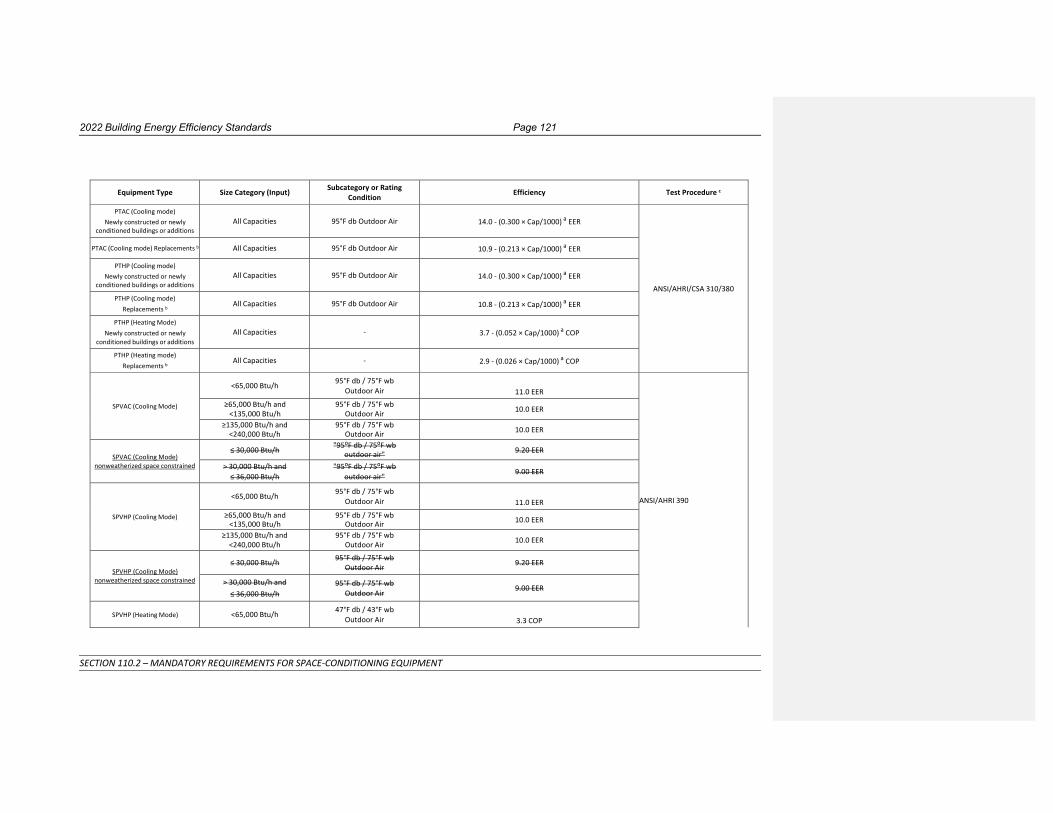
2022 Building Energy Efficiency Standards Page 121
SECTION 110.2 – MANDATORY REQUIREMENTS FOR SPACE-CONDITIONING EQUIPMENT
Equipment Type Size Category (Input) Subcategory or Rating Condition Efficiency Test Procedure c
PTAC (Cooling mode) Newly constructed or newly
conditioned buildings or additions
All Capacities
95°F db Outdoor Air
14.0 - (0.300 × Cap/1000) a EER
ANSI/AHRI/CSA 310/380
PTAC (Cooling mode) Replacements b All Capacities 95°F db Outdoor Air 10.9 - (0.213 × Cap/1000) a EER
PTHP (Cooling mode) Newly constructed or newly
conditioned buildings or additions
All Capacities
95°F db Outdoor Air
14.0 - (0.300 × Cap/1000) a EER
PTHP (Cooling mode) Replacements b
All Capacities 95°F db Outdoor Air 10.8 - (0.213 × Cap/1000) a EER
PTHP (Heating Mode) Newly constructed or newly
conditioned buildings or additions
All Capacities
-
3.7 - (0.052 × Cap/1000) a COP
PTHP (Heating mode) Replacements b
All Capacities - 2.9 - (0.026 × Cap/1000) a COP
SPVAC (Cooling Mode)
<65,000 Btu/h 95°F db / 75°F wb
Outdoor Air
11.0 EER
ANSI/AHRI 390
≥65,000 Btu/h and <135,000 Btu/h
95°F db / 75°F wb Outdoor Air 10.0 EER
≥135,000 Btu/h and <240,000 Btu/h
95°F db / 75°F wb Outdoor Air 10.0 EER
SPVAC (Cooling Mode)
nonweatherized space constrained
≤ 30,000 Btu/h "95⁰F db / 75⁰F wb outdoor air" 9.20 EER
> 30,000 Btu/h and ≤ 36,000 Btu/h
"95⁰F db / 75⁰F wb outdoor air" 9.00 EER
SPVHP (Cooling Mode)
<65,000 Btu/h 95°F db / 75°F wb
Outdoor Air
11.0 EER ≥65,000 Btu/h and
<135,000 Btu/h 95°F db / 75°F wb
Outdoor Air 10.0 EER
≥135,000 Btu/h and <240,000 Btu/h
95°F db / 75°F wb Outdoor Air 10.0 EER
SPVHP (Cooling Mode) nonweatherized space constrained
≤ 30,000 Btu/h 95°F db / 75°F wb Outdoor Air 9.20 EER
> 30,000 Btu/h and ≤ 36,000 Btu/h
95°F db / 75°F wb Outdoor Air
9.00 EER
SPVHP (Heating Mode)
<65,000 Btu/h 47°F db / 43°F wb
Outdoor Air
3.3 COP

Page 122 2022 Building Energy Efficiency Standards
SECTION 110.2 – MANDATORY REQUIREMENTS FOR SPACE-CONDITIONING EQUIPMENT
≥65,000 Btu/h and <135,000 Btu/h
47°F db / 43°F wb Outdoor Air 3.0 COP
≥135,000 Btu/h and <240,000 Btu/h
47°F db / 43°F wb Outdoor Air 3.0 COP
SPVHP (Heating Mode) nonweatherized space constrained ≤ 30,000 Btu/h 47°F db / 43°F wb
Outdoor Air 3.00 COP
> 30,000 Btu/h and ≤ 36,000 Btu/h
47°F db / 43°F wb Outdoor Air
3.00 COP
a Cap means the rated cooling capacity of the product in Btu/h. If the unit’s capacity is less than 7000 Btu/h, use 7000 Btu/h in the calculation. If the unit’s capacity is greater than 15,000 Btu/h, use 15,000 Btu/h in the calculation. b Replacement units must be factory labeled as follows: "MANUFACTURED FOR REPLACEMENT APPLICATIONS ONLY; NOT TO BE INSTALLED IN NEWLY CONSTRUCTED BUILDINGS." Replacement efficiencies apply only to units with existing sleeves less than 16 inches high or less than 42 inch wide and having a cross-sectional area less than 670 square inches. c Applicable test procedure and reference year are provided under the definitions.

2022 Building Energy Efficiency Standards Page 123
SECTION 110.2 – MANDATORY REQUIREMENTS FOR SPACE-CONDITIONING EQUIPMENT
TABLE 110.2-F HEAT TRANSFER EQUIPMENT
Equipment Type Subcategory Minimum Efficiencya Test Procedure b
Liquid-to-liquid heat exchangers Plate type NR ANSI/AHRI 400 a NR means no requirement. b Applicable test procedure and reference year are provided under the definitions.
TABLE 110.2-G PERFORMANCE REQUIREMENTS FOR HEAT REJECTION EQUIPMENT

Page 124 2022 Building Energy Efficiency Standards
SECTION 110.2 – MANDATORY REQUIREMENTS FOR SPACE-CONDITIONING EQUIPMENT
Equipment Type Total System Heat Rejection Capacity at
Rated Conditions
Subcategory or Rating Condition
Performance Required ,a ,b, c, d
Test Procedure e,f
Propeller or axial fan
Open-circuit cooling towers
All
95°F entering water 85°F leaving water 75°F entering air wb
≥ 42.1 gpm/hp
CTI ATC-105 and
CTI STD-201 RS
Centrifugal fan Open-circuit cooling towers
All
95°F entering water 85°F leaving water
75°F entering air wb
≥ 20.0 gpm/hp
Propeller or axial fan closed-circuit cooling towers
All
102°F entering water 90°F leaving water
75°F entering air wb
≥ 16.1 gpm/hp
CTI ATC-105S and
CTI STD-201 RS Centrifugal fan
closed-circuit cooling towers
All
102°F entering water 90°F leaving water
75°F entering air wb
≥ 7.0 gpm/hp
Propeller or axial fan dry coolers
(air-cooled fluid coolers) All
115°F entering water 105°F leaving water
95°F entering db ≥ 4.5 gpm/hp CTI ATC-105DS
Propeller or axial fan evaporative condensers
All
R-507A test fluid 165⁰F entering gas temp 105⁰F condensing temp
75⁰F entering air wb
≥ 157,000 Btu/h • hp
CTI ATC-106
All
Ammonia test fluid 140⁰F entering gas temp 96.3⁰F condensing temp
75⁰F entering air wb
≥ 134,000 Btu/h • hp
Centrifugal fan evaporative condensers
All
R-507A test fluid 165⁰F entering gas temp 105⁰F condensing temp
75⁰F entering air wb
≥ 135,000 Btu/h • hp
All
Ammonia test fluid 140⁰F entering gas temp 96.3⁰F condensing temp
75⁰F entering air wb
≥ 110,000 Btu/h • hp
Air cooled condensers
All
125°F condensing temperature R22 test fluid
190°F entering gas temperature 15°F subcooling
95°F entering drybulb
≥ 176,000 Btu/h·hp
ANSI/AHRI 460
Commented [TM1]: - Related to Frank T Morrison Comments, 21-BSTD-01 (#238257)

2022 Building Energy Efficiency Standards Page 125
SECTION 110.2 – MANDATORY REQUIREMENTS FOR SPACE-CONDITIONING EQUIPMENT
f For the purposes of this table, dry cooler performance is defined as the process water flow rating of the unit at the thermal rating condition divided by the total
fan motor nameplate power of the unit.
a b
c
d
e
For purposes of this table, open-circuit cooling tower performance is defined as the water flow rating of the tower at the given rated conditions divided by the fan motor nameplate power. For purposes of this table, closed-circuit cooling tower performance is defined as the process water flow rating of the tower at the given rated conditions divided by the sum of the fan motor nameplate rated power and the integral spray pump motor nameplate power. For purposes of this table air-cooled condenser performance is defined as the heat rejected from the refrigerant divided by the fan motor nameplate power. Open cooling towers shall be tested using the test procedures in CTI ATC-105. Performance of factory assembled open cooling towers shall be either certified as base models as specified in CTI STD-201 or verified by testing in the field by a CTI approved testing agency. Open factory assembled cooling towers with custom options added to a CTI certified base model for the purpose of safe maintenance or to reduce environmental or noise impact shall be rated at 90 percent of the CTI certified performance of the associated base model or at the manufacturer’s stated performance, whichever is less. Base models of open factory assembled cooling towers are open cooling towers configured in exact accordance with the Data of Record submitted to CTI as specified by CTI STD-201. There are no certification requirements for field erected cooling towers. Applicable test procedure and reference year are provided under the definitions.
For refrigerated warehouses or commercial refrigeration applications, condensers shall comply with requirements specified by Section 120.6(a) or Section 120.6(b).

Page 126 2022 Building Energy Efficiency Standards
SECTION 110.2 – MANDATORY REQUIREMENTS FOR SPACE-CONDITIONING EQUIPMENT
TABLE 110.2-H Electrically Operated Variable Refrigerant Flow (VRF) Air Conditioners
Minimum Efficiency Requirements
Equipment Type
Size Category
Heating Section Type
Sub-Category or Rating Condition
Minimum Efficiency
Test Procedurea
VRF Air Conditioners, Air Cooled
<65,000 Btu/h All VRF Multi-split System 13.0 SEER
ANSI/AHRI 1230
≥65,000 Btu/h and <135,000 Btu/h
Electric Resistance (or none)
VRF Multi-split System
11.2 EER
15.5 IEER b
≥135,000 Btu/h and <240,000 Btu/h
Electric Resistance (or none)
VRF Multi-split System
11.0 EER
14.9 IEER b
≥240,000 Btu/h
Electric Resistance (or none)
VRF Multi-split System
10.0 EER
13.9 IEER b
a Applicable test procedure and reference year are provided under the definitions.
b IEERs are only applicable to equipment with capacity control as specified by ANSI/AHRI 1230 test procedures.

2022 Building Energy Efficiency Standards Page 127
SECTION 110.2 – MANDATORY REQUIREMENTS FOR SPACE-CONDITIONING EQUIPMENT
TABLE 110.2-I Electrically Operated Variable Refrigerant Flow Air-to-Air and Applied Heat Pumps - Minimum Efficiency Requirements
Equipment Type
Size Category
Heating Section Type
Sub-Category or Rating Condition
Minimum Efficiency
Test Procedure b
VRF Air Cooled, (cooling mode)
<65,000 Btu/h All VRF Multi-split System 13.0 SEER
AHRI 1230
≥65,000 Btu/h and <135,000 Btu/h
Electric Resistance (or none)
VRF Multi-split System a
11.0 EER
14.6 IEER c
≥135,000 Btu/h and <240,000 Btu/h
Electric Resistance (or none)
VRF Multi-split System a
10.6 EER
13.9 IEER c
≥240,000 Btu/h
Electric Resistance (or none)
VRF Multi-split System a
9.5 EER
12.7 IEER c
VRF Water source (cooling mode)
<65,000 Btu/h All VRF Multi-split systems a
86ºF entering water
12.0 EER
16.015.8 IEER c
AHRI 1230
≥65,000 Btu/h and
<135,000 Btu/h
All VRF Multi-split System a
86ºF entering water
12.0 EER
16.015.8 IEER c
≥135,000 Btu/h and < 240,000
All VRF Multi-split System a
86ºF entering water
10.0 EER
14.013.8 IEER c
≥ 240,000 Btu/h All VRF Multi-split Systema 86oF entering water
10.0 EER
12.0 IEER
VRF Groundwater source
(cooling mode) <135,000 Btu/h All VRF Multi-split System a
59ºF entering water
16.2 EER AHRI 1230
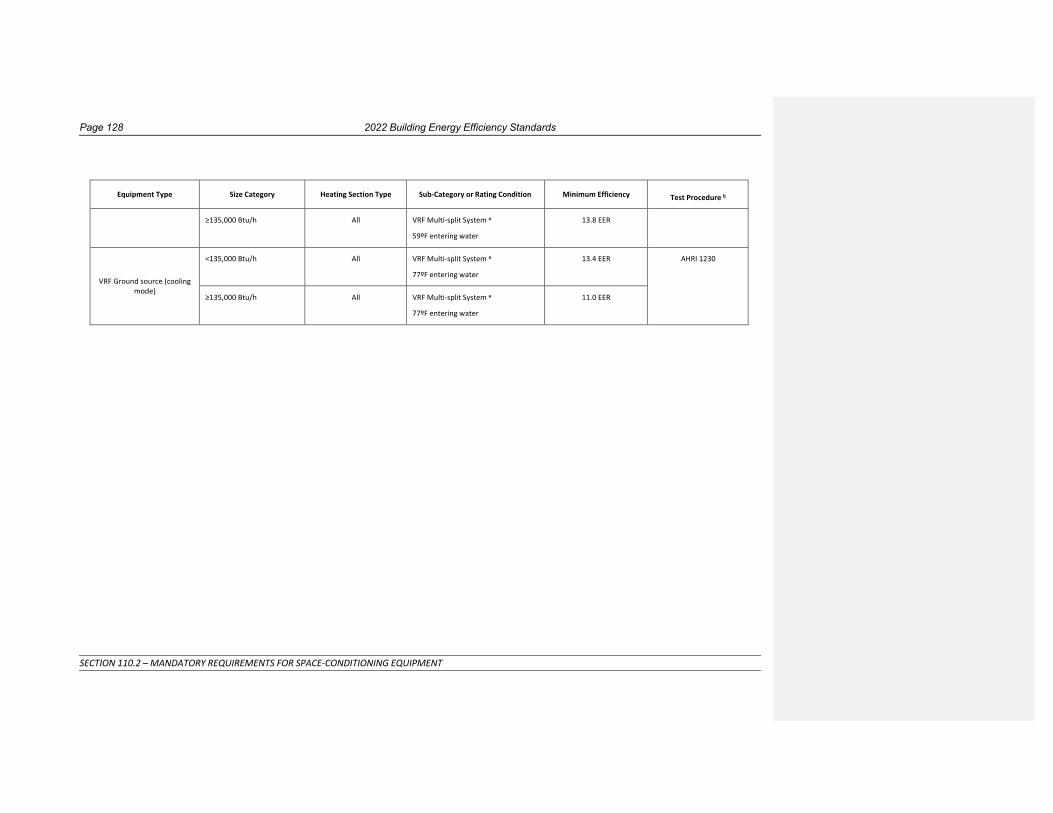
Page 128 2022 Building Energy Efficiency Standards
SECTION 110.2 – MANDATORY REQUIREMENTS FOR SPACE-CONDITIONING EQUIPMENT
Equipment Type
Size Category
Heating Section Type
Sub-Category or Rating Condition
Minimum Efficiency
Test Procedure b
≥135,000 Btu/h All VRF Multi-split System a
59ºF entering water
13.8 EER
VRF Ground source (cooling mode)
<135,000 Btu/h All VRF Multi-split System a
77ºF entering water
13.4 EER AHRI 1230
≥135,000 Btu/h All VRF Multi-split System a
77ºF entering water
11.0 EER
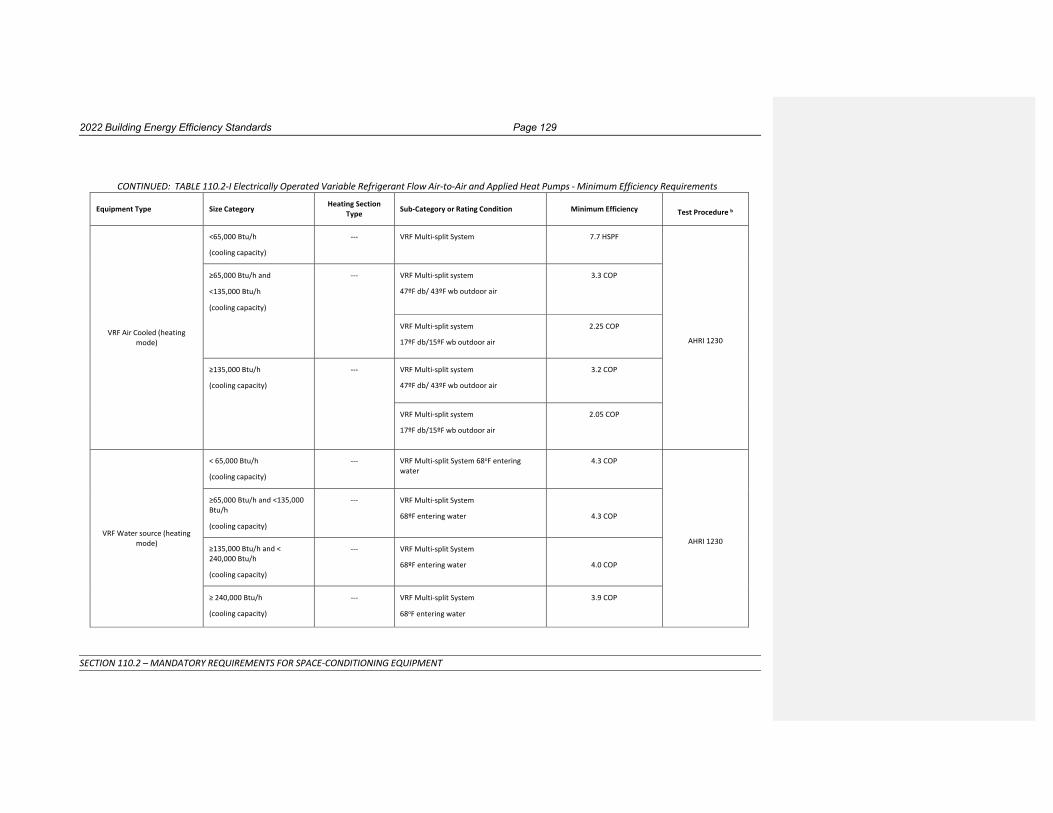
2022 Building Energy Efficiency Standards Page 129
SECTION 110.2 – MANDATORY REQUIREMENTS FOR SPACE-CONDITIONING EQUIPMENT
CONTINUED: TABLE 110.2-I Electrically Operated Variable Refrigerant Flow Air-to-Air and Applied Heat Pumps - Minimum Efficiency Requirements
Equipment Type
Size Category Heating Section Type
Sub-Category or Rating Condition
Minimum Efficiency
Test Procedure b
VRF Air Cooled (heating mode)
<65,000 Btu/h
(cooling capacity)
--- VRF Multi-split System 7.7 HSPF
AHRI 1230
≥65,000 Btu/h and
<135,000 Btu/h
(cooling capacity)
--- VRF Multi-split system
47ºF db/ 43ºF wb outdoor air
3.3 COP
VRF Multi-split system
17ºF db/15ºF wb outdoor air
2.25 COP
≥135,000 Btu/h
(cooling capacity)
--- VRF Multi-split system
47ºF db/ 43ºF wb outdoor air
3.2 COP
VRF Multi-split system
17ºF db/15ºF wb outdoor air
2.05 COP
VRF Water source (heating mode)
< 65,000 Btu/h
(cooling capacity)
--- VRF Multi-split System 68oF entering water
4.3 COP
AHRI 1230
≥65,000 Btu/h and <135,000 Btu/h
(cooling capacity)
--- VRF Multi-split System
68ºF entering water
4.3 COP
≥135,000 Btu/h and < 240,000 Btu/h
(cooling capacity)
--- VRF Multi-split System
68ºF entering water
4.0 COP
≥ 240,000 Btu/h
(cooling capacity)
--- VRF Multi-split System
68oF entering water
3.9 COP

Page 130 2022 Building Energy Efficiency Standards
SECTION 110.2 – MANDATORY REQUIREMENTS FOR SPACE-CONDITIONING EQUIPMENT
VRF Groundwater source (heating mode)
<135,000 Btu/h
(cooling capacity)
--- VRF Multi-split System
50ºF entering water
3.6 COP
AHRI 1230 ≥135,000 Btu/h
(cooling capacity)
--- VRF Multi-split System
50ºF entering water
3.3 COP
VRF Ground source (heating mode)
<135,000 Btu/h
(cooling capacity)
--- VRF Multi-split System
32ºF entering water
3.1 COP
AHRI 1230 ≥135,000 Btu/h
(cooling capacity)
--- VRF Multi-split System
32ºF entering water
2.8 COP
a Deduct 0.2 from the required EERs and IEERs for Variable Refrigerant Flow (VRF) Multi-split system units with a heating recovery section.
b Applicable test procedure and reference year are provided under the definitions.
c IEERs are only applicable to equipment with capacity control as specified by ANSI/AHRI 1230 test procedures.

2022 Building Energy Efficiency Standards Page 131
SECTION 110.2 – MANDATORY REQUIREMENTS FOR SPACE-CONDITIONING EQUIPMENT
TABLE 110.2-J Warm-Air Furnaces and Combination Warm-Air Furnaces/Air-Conditioning Units, Warm-Air Duct Furnaces, and Unit Heaters
Equipment Type
Size Category (Input)
Subcategory or Rating
Conditionb
Minimum Efficiencyd,e
Test Procedurea
Warm-Air Furnace, Gas-Fired
≥ 225,000 Btu/h
Maximum Capacityb
8180% Et
Section 2.39, Thermal Efficiency, ANSI Z21.47
Warm-Air Furnace, oil-Fired
≥ 225,000 Btu/h
Maximum Capacityb
8281% Et
Section 42, Combustion, UL 727
Warm-Air Duct Furnaces, Gas-
Fired
All Capacities
Maximum Capacityb
80% Ec
Section 2.10, Efficiency, ANSI Z83.8
Warm-Air Unit Heaters, Gas-
Fired
All Capacities
Maximum Capacityb
80% Ec
Section 2.10, Efficiency, ANSI Z83.8
Warm-Air Unit Heaters, Oil-
Fired
All Capacities
Maximum Capacityb
81% Ec
Section 40, Combustion, UL 731
a Applicable test procedure and reference year are provided under the definitions. b Compliance of multiple firing rate units shall be at maximum firing rate.
c Combustion units not covered by the U.S. Department of Energy Code of Federal Regulations 10 CFR 430 (3-phase power or cooling capacity greater than or equal to 19 kW) may comply with either rating.
d Et= thermal efficiency. Units must also include an interrupted or intermittent ignition device (IID), have jacket losses not exceeding 0.75% of the input rating, and have either power venting or a flue damper. A vent damper is an acceptable alternative to a flue damper for those furnaces where combustion air is drawn from the conditioned space.
e Ec= combustion efficiency (100% less flue losses). See test procedure for detailed discussion. f As of August 8, 2008, according to the Energy Policy Act of 2005, units must also include interrupted or intermittent ignition device (IID) and have either power venting or an automatic flue damper.

Page 132 2022 Building Energy Efficiency Standards
SECTION 110.2 – MANDATORY REQUIREMENTS FOR SPACE-CONDITIONING EQUIPMENT
TABLE 110.2-K Gas- and Oil-Fired Boilers, Minimum Efficiency requirements

2022 Building Energy Efficiency Standards Page 133
SECTION 110.2 – MANDATORY REQUIREMENTS FOR SPACE-CONDITIONING EQUIPMENT
Equipment Type
Sub Category
Size Category (Input)
Minimum Efficiency b,c
Test Procedure a
Before 1/10/20233/2/2020 On or After
1/10/20233/2/2020
Boiler, hot water
Gas-Fired
< 300,000 Btu/h 82% AFUE 82% AFUE DOE 10 CFR Part 430
≥ 300,000 Btu/h and ≤ 2,500,000 Btu/h d
80% Et
8480% Et
DOE 10 CFR Part 431 > 2,500,000 Btu/h and <10,000,000 Btu/h e
82% Ec 8582% Ec
>10,000,000 Btu/h 82% Ec 82% Ec DOE 10 CFR Part 431
Oil-Fired e
< 300,000 Btu/h 84% AFUE 84% AFUE DOE 10 CFR Part 430
≥ 300,000 Btu/h and ≤ 2,500,000 Btu/h d
82% Et
8782% Et
DOE 10 CFR Part 431 > 2,500,000 Btu/h and <10,000,000 Btu/h e
84% Ec 8884% Ec
>10,000,000 Btu/h 84% Ec 84% Ec DOE 10 CFR Part 431
Boiler, steam
Gas-Fired
< 300,000 Btu/h 80% AFUE 80% AFUE DOE 10 CFR Part 430
>300,000 Btu/h and <2,500,000 Btu/h
81% Et DOE 10 CFR Part 431
>2,500,000 Btu/h and <10,000,000 Btu/h
82% Et DOE 10 CFR Part 431
>10,000,000 Btu/h 79% Et DOE 10 CFR Part 431
Gas-Fired all, except natural draft f
≥ 300,000 Btu/h and ≤ 2,500,000 Btu/h d
79% Et
8179% Et
DOE 10 CFR Part 431
> 2,500,000 Btu/h and <10,000,000 Btu/h e
79% Et 8279% Et DOE 10 CFR Part 431
>10,000,000 Btu/h 79% Et 79% Et DOE 10 CFR Part 431
Gas-Fired, natural draft f
≥ 300,000 Btu/h and ≤ 2,500,000 Btu/h d
77% Et
8179% Et
DOE 10 CFR Part 431

Page 134 2022 Building Energy Efficiency Standards
SECTION 110.2 – MANDATORY REQUIREMENTS FOR SPACE-CONDITIONING EQUIPMENT
> 2,500,000 Btu/h and <10,000,000 Btu/he
77% Et 8279% Et DOE 10 CFR Part 431
>10,000,000 Btu/h 77% Et 79% Et DOE 10 CFR Part 431
Oil-Fired e
< 300,000 Btu/h 82% AFUE 82% AFUE DOE 10 CFR Part 430
≥ 300,000 Btu/h and ≤ 2,500,000 Btu/h d
81% Et
8481% Et
DOE 10 CFR Part 431
> 2,500,000 Btu/h and <10,000,000 Btu/h e
81% Et 8581% Et DOE 10 CFR Part 431
10,000,000 Btu/h 81% Et 81% Et DOE 10 CFR Part 431
a Applicable test procedure and reference year are provided under the definitions. b Ec = combustion efficiency (100% less flue losses).See test procedure for detailed informationreference document for detailed information. c Et= thermal efficiency. See test procedure for detailed information. d Maximum capacity - minimum and maximum rating per the certified unit capacitys as provided for and allowed by the unit’s controls. e Included oil-fired (residual). f Federal efficiency standards do not distinguish between natural draft gas-fired steam boilers and other gas-fired steam boilers on or after January 10, 2023.
NOTE: Authority: Sections 25213, 25218, 25218.5, 25402 and 25402.1, Public Resources Code. Reference: Sections 25007, 25008, 25218.5, 25310, 25402, 25402.1,
25402.4, 25402.8, and 25943, Public Resources Code

2022 Building Energy Efficiency Standards Page 135
SECTION 110.2 – MANDATORY REQUIREMENTS FOR SPACE-CONDITIONING EQUIPMENT

Page 136 2022 Building Energy Efficiency Standards
SECTION 110.3 – MANDATORY REQUIREMENTS FOR SERVICE WATER-HEATING SYSTEMS AND EQUIPMENT
SECTION 110.3 – MANDATORY REQUIREMENTS FOR SERVICE WATER-HEATING SYSTEMS AND EQUIPMENT (a) Certification by Manufacturers. Any service water-heating system or equipment may be installed only if the
manufacturer has certified that the system or equipment complies with all of the requirements of this
subsection for that system or equipment.
1. Temperature controls for service water heating systems. Service water-heating systems shall be equipped
with automatic temperature controls capable of adjustment from the lowest to the highest acceptable
temperature settings for the intended use as listed in Table 3, Chapter 50 of the ASHRAE Handbook, HVAC
Applications Volume or Table 613.1 of the California Plumbing Code for healthcare facilities.
EXCEPTION to Section 110.3(a)1: Residential occupancies.
(b) Efficiency. Equipment shall meet the applicable requirements of the Appliance Efficiency Regulations as
required by Section 110.1, subject to the following:
1. If more than one standard is listed in the Appliance Efficiency Regulations, the equipment shall meet all
the standards listed; and
2. If more than one test method is listed in the Appliance Efficiency Regulations, the equipment shall comply
with the applicable standard when tested with each test method; and
3. Where equipment can serve more than one function, such as both heating and cooling, or both space
heating and water heating, it shall comply with all the requirements applicable to each function; and
4. Where a requirement is for equipment rated at its "maximum rated capacity" or "minimum rated
capacity," the capacity shall be as provided for and allowed by the controls, during steady-state operation.
(c) Installation. Any service water-heating system or equipment may be installed only if the system or equipment
complies with all of the applicable requirements of this subsection for the system or equipment.
1. Outlet temperature controls. On systems that have a total capacity greater than 167,000 Btu/hr, outlets
that require higher than service water temperatures as listed in the ASHRAE Handbook, Applications
Volume, shall have separate remote heaters, heat exchangers, or boosters to supply the outlet with the
higher temperature.
EXCEPTION to section 110.3(c)1: Systems covered by California Plumbing Code Section 613.0 shall instead
follow the requirements of that section.
2. Controls for hot water distribution systems. Service hot water systems with circulating pumps or with
electrical heat trace systems shall be capable of automatically turning off the system.
EXCEPTION to Section 110.3(c)2: Systems serving healthcare facilities.
3. Insulation. Unfired service water heater storage tanks and backup tanks for solar water-heating systems
shall have:
A. External insulation with an installed R-value of at least R-12; or
B. Internal and external insulation with a combined R-value of at least R-16; or
C. The heat loss of the tank surface based on an 80°F water-air temperature difference shall be less than
6.5 Btu per hour per square foot.
4. Water Heating Recirculation Loops Serving Multiple Dwelling Units, High-Rise Residential, Hotel/Motel, and Nonresidential Occupancies. A water heating recirculation loop is a type of hot water distribution
system that reduces the time needed to deliver hot water to fixtures that are distant from the water
heater, boiler or other water heating equipment. The recirculation loop is comprised of a supply portion,
connected to branches that serve multiple dwelling units, guest rooms, or fixtures and a return portion
that completes the loop back to the water heating equipment. A water heating recirculation loop shall
meet the following requirements:

2022 Building Energy Efficiency Standards Page 137
SECTION 110.3 – MANDATORY REQUIREMENTS FOR SERVICE WATER-HEATING SYSTEMS AND EQUIPMENT
A. Air release valve or vertical pump installation. An automatic air release valve shall be installed on the
recirculation loop piping on the inlet side of the recirculation pump and no more than 4 feet from the
pump. This valve shall be mounted on top of a vertical riser at least 12” in length and shall be
accessible for replacement and repair. Alternatively, the pump shall be installed on a vertical section
of the return line.
B. Recirculation loop backflow prevention. A check valve or similar device shall be located between the
recirculation pump and the water heating equipment to prevent water from flowing backwards
though the recirculation loop.
C. Equipment for pump priming. A hose bibb shall be installed between the pump and the water heating
equipment. An isolation valve shall be installed between the hose bibb and the water heating
equipment. This hose bibb is used for bleeding air out of the pump after pump replacement.
D. Pump isolation valves. Isolation valves shall be installed on both sides of the pump. These valves may
be part of the flange that attaches the pump to the pipe. One of the isolation valves may be the same
isolation valve as in Item C.
E. Cold water supply and recirculation loop connection to hot water storage tank. Storage water
heaters and boilers shall be plumbed in accordance with the manufacturer’s specifications. The cold
water piping and the recirculation loop piping shall not be connected to the hot water storage tank
drain port.
F. Cold water supply backflow prevention. A check valve shall be installed on the cold water supply line
between the hot water system and the next closest tee on the cold water supply line. The system shall
comply with the expansion tank requirements as described in the California Plumbing Code Section
608.3.
5. Service water heaters in state buildings. Any newly constructed building constructed by the State shall
derive its service water heating from a system that provides at least 60 percent of the energy needed for
service water heating from site solar energy or recovered energy, per the statutory requirement of
California Public Resources Code Section 25498.
EXCEPTION to Section 110.3(c)5: Buildings for which the state architect determines that service water
heating from site solar energy or recovered energy is economically or physically infeasible.
6. Isolation valves. Instantaneous water heaters with an input rating greater than 6.8 kBTU/hr (2 kW) shall
have isolation valves on both the cold water supply and the hot water pipe leaving the water heater, and
hose bibbs or other fittings on each valve for flushing the water heater when the valves are closed.
NOTE: Authority: Sections 25213, 25218, 25218.5, 25402 and 25402.1, Public Resources Code. Reference: Sections
25007, 25008, 25218.5, 25310, 25402, 25402.1, 25402.4, 25402.8, and 25943, Public Resources Code

Page 138 2022 Building Energy Efficiency Standards
SECTION 110.4 – MANDATORY REQUIREMENTS FOR POOL AND SPA SYSTEMS AND EQUIPMENT
SECTION 110.4 – MANDATORY REQUIREMENTS FOR POOL AND SPA SYSTEMS AND EQUIPMENT (a) Certification by Manufacturers. Any pool or spa heating system or equipment may be installed only if the
manufacturer has certified that the system or equipment has all of the following:
1. Efficiency. A thermal efficiency that complies with the Appliance Efficiency Regulations; and
2. On-off switch. A readily accessible on-off switch, mounted on the outside of the heater that allows
shutting off the heater without adjusting the thermostat setting; and
3. Instructions. A permanent, easily readable, and weatherproof plate or card that gives instruction for the
energy efficient operation of the pool or spa heater and for the proper care of pool or spa water when a
cover is used; and
4. Electric resistance heating. No electric resistance heating.
EXCEPTION 1 to Section 110.4(a)4: Listed package units with fully insulated enclosures, and with tight-
fitting covers that are insulated to at least R-6.
EXCEPTION 2 to Section 110.4(a)4: Pools or spas deriving at least 60 percent of the annual heating energy
from site solar energy or recovered energy.
(b) Installation. Any pool or spa system or equipment shall be installed with all of the following:
1. Piping. At least 36 inches of pipe shall be installed between the filter and the heater or dedicated suction
and return lines, or built-in or built-up connections shall be installed to allow for the future addition of
solar heating equipment;
2. Covers. A cover for outdoor pools or outdoor spas that have a heat pump or gas heater; and
3. Directional inlets and time switches for pools. If the system or equipment is for a pool:
i. The pool shall have directional inlets that adequately mix the pool water; and
ii. A time switch or similar control mechanism shall be installed as part of a pool water circulation
control system that will allow all pumps to be set or programmed to run only during the off-peak
electric demand period and for the minimum time necessary to maintain the water in the condition
required by applicable public health standards.

2022 Building Energy Efficiency Standards Page 139
FIREPLACES: PILOT LIGHTS PROHIBITED
SECTION 110.5 – NATURAL GAS CENTRAL FURNACES, COOKING EQUIPMENT, POOL AND SPA HEATERS, AND FIREPLACES: PILOT LIGHTS PROHIBITED Any natural gas system or equipment listed below may be installed only if it does not have a continuously burning
pilot light:
(a) Fan-type central furnaces.
(b) Household cooking appliances.
EXCEPTION to Section 110.5(b): Household cooking appliances without an electrical supply voltage connection
and in which each pilot consumes less than 150 Btu/hr.
(c) Pool heaters.
(d) Spa heaters.
(e) Indoor and outdoor fireplaces.
NOTE: Authority: Sections 25213, 25218, 25218.5, 25402 and 25402.1, Public Resources Code. Reference: Sections
25007, 25008, 25218.5, 25310, 25402, 25402.1, 25402.4, 25402.8, and 25943, Public Resources Code
SECTION 110.5 – NATURAL GAS CENTRAL FURNACES, COOKING EQUIPMENT, POOL AND SPA HEATERS, AND
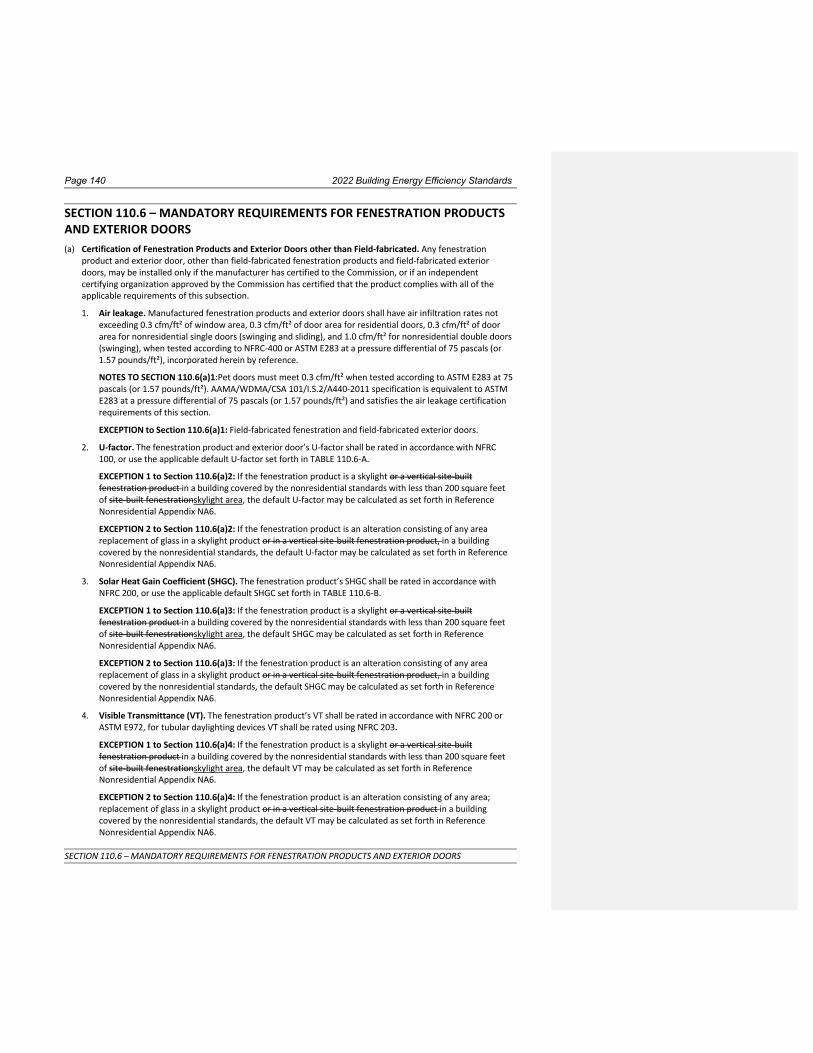
Page 140 2022 Building Energy Efficiency Standards
SECTION 110.6 – MANDATORY REQUIREMENTS FOR FENESTRATION PRODUCTS AND EXTERIOR DOORS
SECTION 110.6 – MANDATORY REQUIREMENTS FOR FENESTRATION PRODUCTS AND EXTERIOR DOORS (a) Certification of Fenestration Products and Exterior Doors other than Field-fabricated. Any fenestration
product and exterior door, other than field-fabricated fenestration products and field-fabricated exterior
doors, may be installed only if the manufacturer has certified to the Commission, or if an independent
certifying organization approved by the Commission has certified that the product complies with all of the
applicable requirements of this subsection.
1. Air leakage. Manufactured fenestration products and exterior doors shall have air infiltration rates not
exceeding 0.3 cfm/ft² of window area, 0.3 cfm/ft² of door area for residential doors, 0.3 cfm/ft² of door
area for nonresidential single doors (swinging and sliding), and 1.0 cfm/ft² for nonresidential double doors
(swinging), when tested according to NFRC-400 or ASTM E283 at a pressure differential of 75 pascals (or
1.57 pounds/ft²), incorporated herein by reference.
NOTES TO SECTION 110.6(a)1:Pet doors must meet 0.3 cfm/ft² when tested according to ASTM E283 at 75
pascals (or 1.57 pounds/ft²). AAMA/WDMA/CSA 101/I.S.2/A440-2011 specification is equivalent to ASTM
E283 at a pressure differential of 75 pascals (or 1.57 pounds/ft²) and satisfies the air leakage certification
requirements of this section.
EXCEPTION to Section 110.6(a)1: Field-fabricated fenestration and field-fabricated exterior doors.
2. U-factor. The fenestration product and exterior door’s U-factor shall be rated in accordance with NFRC
100, or use the applicable default U-factor set forth in TABLE 110.6-A.
EXCEPTION 1 to Section 110.6(a)2: If the fenestration product is a skylight or a vertical site-built
fenestration product in a building covered by the nonresidential standards with less than 200 square feet
of site-built fenestrationskylight area, the default U-factor may be calculated as set forth in Reference
Nonresidential Appendix NA6.
EXCEPTION 2 to Section 110.6(a)2: If the fenestration product is an alteration consisting of any area
replacement of glass in a skylight product or in a vertical site-built fenestration product, in a building
covered by the nonresidential standards, the default U-factor may be calculated as set forth in Reference
Nonresidential Appendix NA6.
3. Solar Heat Gain Coefficient (SHGC). The fenestration product’s SHGC shall be rated in accordance with
NFRC 200, or use the applicable default SHGC set forth in TABLE 110.6-B.
EXCEPTION 1 to Section 110.6(a)3: If the fenestration product is a skylight or a vertical site-built
fenestration product in a building covered by the nonresidential standards with less than 200 square feet
of site-built fenestrationskylight area, the default SHGC may be calculated as set forth in Reference
Nonresidential Appendix NA6.
EXCEPTION 2 to Section 110.6(a)3: If the fenestration product is an alteration consisting of any area
replacement of glass in a skylight product or in a vertical site-built fenestration product, in a building
covered by the nonresidential standards, the default SHGC may be calculated as set forth in Reference
Nonresidential Appendix NA6.
4. Visible Transmittance (VT). The fenestration product’s VT shall be rated in accordance with NFRC 200 or
ASTM E972, for tubular daylighting devices VT shall be rated using NFRC 203.
EXCEPTION 1 to Section 110.6(a)4: If the fenestration product is a skylight or a vertical site-built
fenestration product in a building covered by the nonresidential standards with less than 200 square feet
of site-built fenestrationskylight area, the default VT may be calculated as set forth in Reference
Nonresidential Appendix NA6.
EXCEPTION 2 to Section 110.6(a)4: If the fenestration product is an alteration consisting of any area;
replacement of glass in a skylight product or in a vertical site-built fenestration product in a building
covered by the nonresidential standards, the default VT may be calculated as set forth in Reference
Nonresidential Appendix NA6.
2022 Building Energy Efficiency Standards Page 141
SECTION 110.6 – MANDATORY REQUIREMENTS FOR FENESTRATION PRODUCTS AND EXTERIOR DOORS
5. Labeling. Fenestration products and exterior doors shall:
A. Have a temporary label for manufactured fenestration products and exterior doors or a label
certificate when the Component Modeling Approach (CMA) is used and for site-built fenestration
meeting the requirements of Section 10-111(a)1. The temporary label shall not be removed before
inspection by the enforcement agency; and
B. Have a permanent label or a label certificate when the Component Modeling Approach (CMA) is used
and for site-built fenestration meeting the requirements of Section 10-111(a)2 if the product is rated
using NFRC procedures.
6. Fenestration Acceptance Requirements. Before an occupancy permit is granted, site-built fenestration
products in other than low-rise residentialsingle-family buildings shall be certified as meeting the
Acceptance Requirements for Code Compliance, as specified in the Reference Nonresidential Appendix
NA7 to ensure that site-built fenestration meets Standards requirements, including a matching label
certificate for product(s) installed and be readily accessible at the project location. A Certificate of
Acceptance certifying that the fenestration product meets the acceptance requirements shall be
completed, signed and submitted to the enforcement agency.
EXCEPTION to Section 110.6(a): Fenestration products removed and reinstalled as part of a building
alteration or addition.
(b) Installation of Field-Fabricated Fenestration and Exterior Doors. Field-fabricated fenestration and field-
fabricated exterior doors may be installed only if the compliance documentation has demonstrated compliance
for the installation using U-factors from Table 110.6-A and SHGC values from Table 110.6-B. Field-fabricated
fenestration and field-fabricated exterior doors shall be caulked between the fenestration products or exterior
door and the building, and shall be weatherstripped.
EXCEPTION to Section 110.6(b): Unframed glass doors and fire doors need not be weatherstripped or caulked.
NOTE: Authority: Sections 25213, 25218, 25218.5, 25402 and 25402.1, Public Resources Code. Reference: Sections
25007, 25008, 25218.5, 25310, 25402, 25402.1, 25402.4, 25402.5, 25402.8, and 25943, Public Resources Code

Page 142 2022 Building Energy Efficiency Standards
SECTION 110.6 – MANDATORY REQUIREMENTS FOR FENESTRATION PRODUCTS AND EXTERIOR DOORS
TABLE 110.6-A DEFAULT FENESTRATION PRODUCT U-FACTORS
Frame Product Type Single Pane 3, 4 U-Factor
Double Pane 1, 3, 4 U-Factor
Glass Block 2,3 U-Factor
Metal
Operable 1.28 0.79 0.87
Fixed 1.19 0.71 0.72
Greenhouse/Garden
Window
2.26
1.40
N.A.
Glazed Doors 1.25 0.77 N.A.
Skylight 1.98 1.30 N.A.
Metal, Thermal
Break
Operable N.A. 0.66 N.A.
Fixed N.A. 0.55 N.A.
Greenhouse/Garden
Window
N.A.
1.12
N.A.
Glazed Doors N.A. 0.59 N.A.
Skylight N.A. 1.11 N.A.
Nonmetal
Operable 0.99 0.58 0.60
Fixed 1.04 0.55 0.57
Glazed Doors 0.99 0.53 N.A.
Greenhouse/Garden
Windows
1.94
1.06
N.A.
Skylight 1.47 0.84 N.A.
1. For all dual-glazed fenestration products, adjust the listed U-factors as follows:
a. Add 0.05 for products with dividers between panes if spacer is less than 7/16 inch wide.
b. Add 0.05 to any product with true divided lite (dividers through the panes).
2. Translucent or transparent panels shall use glass block values when not rated by NFRC 100.
3. Visible Transmittance (VT) shall be calculated by using Reference Nonresidential Appendix NA6.
4. Windows with window film applied that is not rated by NFRC 100 shall use the default values from this
table.

2022 Building Energy Efficiency Standards Page 143
SECTION 110.6 – MANDATORY REQUIREMENTS FOR FENESTRATION PRODUCTS AND EXTERIOR DOORS
TABLE 110.6-B DEFAULT SOLAR HEAT GAIN COEFFICIENT (SHGC)
FRAME TYPE
PRODUCT
GLAZING
FENESTRATION PRODUCT SHGC
Single Pane2,3
SHGC
Double Pane2,3
SHGC
Glass Block1,2
SHGC
Metal
Operable Clear 0.80 0.70 0.70
Fixed Clear 0.83 0.73 0.73
Operable Tinted 0.67 0.59 N.A.
Fixed Tinted 0.68 0.60 N.A.
Metal, Thermal
Break
Operable Clear N.A. 0.63 N.A.
Fixed Clear N.A. 0.69 N.A.
Operable Tinted N.A. 0.53 N.A.
Fixed Tinted N.A. 0.57 N.A.
Nonmetal
Operable Clear 0.74 0.65 0.70
Fixed Clear 0.76 0.67 0.67
Operable Tinted 0.60 0.53 N.A.
Fixed Tinted 0.63 0.55 N.A.
1 Translucent or transparent panels shall use glass block values when not rated by NFRC 200.
2. Visible Transmittance (VT) shall be calculated by using Reference Nonresidential Appendix NA6.
3. Windows with window film applied that is not rated by NFRC 200 shall use the default values from this
table.

Page 144 2022 Building Energy Efficiency Standards
SECTION 110.7 – MANDATORY REQUIREMENTS TO LIMIT AIR LEAKAGE
SECTION 110.7 – MANDATORY REQUIREMENTS TO LIMIT AIR LEAKAGE All joints, penetrations and other openings in the building envelope that are potential sources of air leakage shall
be caulked, gasketed, weather stripped, or otherwise sealed to limit infiltration and exfiltration.
NOTE: Authority: Sections 25213, 25218, 25218.5, 25402 and 25402.1, Public Resources Code. Reference: Sections
25007, 25008, 25218.5, 25310, 25402, 25402.1, 25402.4, 25402.8, and 25943, Public Resources Code

2022 Building Energy Efficiency Standards Page 145
SECTION 110.8 – MANDATORY REQUIREMENTS FOR INSULATION, ROOFING PRODUCTS AND RADIANT BARRIERS
SECTION 110.8 – MANDATORY REQUIREMENTS FOR INSULATION, ROOFING PRODUCTS AND RADIANT BARRIERS (a) Insulation Certification by Manufacturers. All insulation shall be certified by Department of Consumer Affairs,
Bureau of Electronic and Appliance Repair, Home Furnishings and Thermal Insulation that the insulation
conductive thermal performance is approved pursuant to the California Code of Regulations, Title 24, Part 12,
Chapters 12-13, Article 3, “Standards for Insulating Material.”
(b) Installation of Urea Formaldehyde Foam Insulation. Urea formaldehyde foam insulation may be applied or
installed only if:
1. It is installed in exterior side walls; and
2. A four-mil-thick plastic polyethylene vapor retarder or equivalent plastic sheathing vapor retarder is
installed between the urea formaldehyde foam insulation and the interior space in all applications.
(c) Flame Spread Rating of Insulation. All insulating material shall be installed in compliance with the flame
spread rating and smoke density requirements of the CBC.
(d) Installation of Insulation in Existing Buildings. Insulation installed in an existing attic, or on an existing duct or
water heater, shall comply with the applicable requirements of Subsections 1, 2, and 3 below. If a contractor
installs the insulation, the contractor shall certify to the customer, in writing, that the insulation meets the
applicable requirements of Subsections 1, 2, and 3 below.
1. Attics. If insulation is installed in the existing attic of a low-rise residentialsingle-family building, the R-
value of the total amount of insulation (after addition of insulation to the amount, if any, already in the
attic) shall meet the requirements of Section 150.0(a).
EXCEPTION to Section 110.8(d)1: Where the accessible space in the attic is not large enough to
accommodate the required R-value, the entire accessible space shall be filled with insulation provided
such installation does not violate Section 1203.21202.2 of Title 24, Part 2 or Section 806 of Title 24, Part
2.5.
2. Water heaters. If external insulation is installed on an existing unfired water storage tank or on an existing
back-up tank for a solar water-heating system, it shall have an R-value of at least R-12, or the heat loss of
the tank surface based on an 80°F water-air temperature difference shall be less than 6.5 Btu per hour per
square foot.
3. Ducts. If insulation is installed on an existing space-conditioning duct, it shall comply with Section 604.0 of
the CMC.
(e) RESERVED
(f) RESERVED
(g) Insulation Requirements for Heated Slab Floors. Heated slab floors shall be insulated according to the
requirements in TABLE 110.8-A.
1. Insulation materials in ground contact must:
A. Comply with the certification requirements of Section 110.8(a); and
B. Have a water absorption rate for the insulation material alone without facings that are no greater
than 0.3 percent when tested in accordance with Test Method A – 24 Hour-Immersion of ASTM C272.
C. Water vapor permeance no greater than 2.0 perm/inch when tested in accordance with ASTM E96.
2. Insulation installation must:
A. Be covered with a solid guard that protects against damage from ultraviolet radiation, moisture,
landscaping operation, equipment maintenance, and wind; and
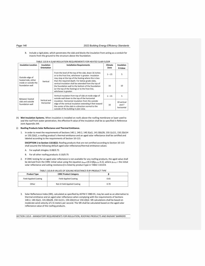
Page 146 2022 Building Energy Efficiency Standards
SECTION 110.8 – MANDATORY REQUIREMENTS FOR INSULATION, ROOFING PRODUCTS AND RADIANT BARRIERS
B. Include a rigid plate, which penetrates the slab and blocks the insulation from acting as a conduit for
insects from the ground to the structure above the foundation.
TABLE 110.8-A SLAB INSULATION REQUIREMENTS FOR HEATED SLAB FLOOR
Insulation Location Insulation Orientation
Installation Requirements Climate Zone
Insulation
R-Value
Outside edge of heated slab, either inside or outside the foundation wall
Vertical
From the level of the top of the slab, down 16 inches or to the frost line, whichever is greater. Insulation may stop at the top of the footing where this is less than the required depth. For below grade slabs, vertical insulation shall be extended from the top of the foundation wall to the bottom of the foundation (or the top of the footing) or to the frost line, whichever is greater.
1 – 15
5
16
10
Between heated slab and outside foundation wall
Vertical and Horizontal
Vertical insulation from top of slab at inside edge of outside wall down to the top of the horizontal insulation. Horizontal insulation from the outside edge of the vertical insulation extending 4 feet toward the center of the slab in a direction normal to the outside of the building in plan view.
1 – 15 5
16 10 vertical
and 7 horizontal
(h) Wet Insulation Systems. When insulation is installed on roofs above the roofing membrane or layer used to
seal the roof from water penetration, the effective R-value of the insulation shall be as specified in Reference
Joint Appendix JA4.
(i) Roofing Products Solar Reflectance and Thermal Emittance.
1. In order to meet the requirements of Sections 140.1, 140.2, 140.3(a)1, 141.0(b)2B, 150.1(c)11, 150.2(b)1H
or 150.2(b)2, a roofing product’s thermal emittance and an aged solar reflectance shall be certified and
labeled according to the requirements of Section 10-113.
EXCEPTION 1 to Section 110.8(i)1: Roofing products that are not certified according to Section 10-113
shall assume the following default aged solar reflectance/thermal emittance values:
A. For asphalt shingles: 0.08/0.75
B. For all other roofing products: 0.10/0.75
2. If CRRC testing for an aged solar reflectance is not available for any roofing products, the aged value shall
be derived from the CRRC initial value using the equation ρaged=[0.2+β[ρinitial-0.2], where ρinitial = the initial
solar reflectance and soiling resistance β is listed by product type in TABLE 110.8-B.
TABLE 110.8-B VALUES OF SOILING RESISTANCE β BY PRODUCT TYPE
Product Type CRRC Product Category β
Field-Applied Coating Field-Applied Coating 0.65
Other Not A Field-Applied Coating 0.70
3. Solar Reflectance Index (SRI), calculated as specified by ASTM E 1980-01, may be used as an alternative to
thermal emittance and an aged solar reflectance when complying with the requirements of Sections
140.2, 140.3(a)1, 141.0(b)2B, 150.1(c)11, 150.2(b)1H,or 150.2(b)2. SRI calculations shall be based on
moderate wind velocity of 2-6 meters per second. The SRI shall be calculated based on the aged solar
reflectance value of the roofing products.

2022 Building Energy Efficiency Standards Page 147
SECTION 110.8 – MANDATORY REQUIREMENTS FOR INSULATION, ROOFING PRODUCTS AND RADIANT BARRIERS
4. Liquid applied roof coatings applied to low-sloped roofs in the field as the top surface of a roof covering
shall:
A. Be applied across the entire roof surface to meet the dry mil thickness or coverage recommended by
the coating manufacturer, taking into consideration the substrate on which the coating is applied; and
B. Meet the minimum performance requirements listed in TABLE 110.8-C or the minimum performance
requirements of ASTM C836, D3468, D6083 or D6694, whichever are appropriate to the coating
material.
EXCEPTION 1 to Section 110.8(i)4B: Aluminum-pigmented asphalt roof coatings shall meet the
requirements of ASTM D2824 and be installed as specified by ASTM D3805.
EXCEPTION 2 to Section 110.8(i)4B: Cement-based roof coatings shall contain a minimum of 20
percent cement and shall meet the requirements of ASTM C1583, ASTM D822, and ASTM D5870.
TABLE 110.8-C MINIMUM PERFORMANCE REQUIREMENTS FOR LIQUID APPLIED ROOF COATINGS
Physical Property ASTM Test Procedure Requirement
Initial percent elongation (break) D 2370 Minimum 200% @ 73° F (23° C)
Initial percent elongation (break)
OR
Initial Flexibility
D 2370
D522, Test B
Minimum 60% @ 0° F (-18° C)
Minimum pass 1” mandrel @ 0° F (-18° C)
Initial tensile strength (maximum stress) D 2370 Minimum 100 psi (1.38 Mpa) @ 73° F (23° C)
Initial tensile strength (maximum stress)
OR
Initial Flexibility
D 2370
D522, Test B
Minimum 200 psi (2.76 Mpa) @ 0° F (-18° C)
Minimum pass 1” mandrel @ 0° F (-18° C)
Final percent elongation (break) after accelerated weathering 1000 h
D2370 Minimum 100% @ 73° F (23° C)
Final percent elongation (break) after accelerated weathering 1000 h
OR
Flexibility after accelerated weathering 1000 h
D2370
D522, Test B
Minimum 40% @ 0° F (-18° C)
Minimum pass 1” mandrel @ 0° F (-18° C)
Permeance D 1653 Maximum 50 perms
Accelerated weathering 1000 h D 4798 No cracking or checking1
1. Any cracking or checking visible to the eye fails the test procedure.
(j) Radiant Barrier. A radiant barrier shall have an emittance of 0.05 or less, tested in accordance with ASTM C1371
or ASTM E408, and shall be certified to the Department of Consumer Affairs as required by Title 24, Part12, Chapter
12-13, Standards for Insulating Material.
NOTE: Authority: Sections 25213, 25218, 25218.5, 25402 and 25402.1, Public Resources Code. Reference: Sections
25007, 25008, 25218.5, 25310, 25402, 25402.1, 25402.4, 25402.8, and 25943, Public Resources Code

Page 148 2022 Building Energy Efficiency Standards
SECTION 110.9 – MANDATORY REQUIREMENTS FOR LIGHTING CONTROLS
SECTION 110.9 – MANDATORY REQUIREMENTS FOR LIGHTING CONTROLS
(a) All lighting control devices and systems and all light sources subject to the requirements of Section 110.9 shall
meet the following requirements:
1. Shall be installed only if the lighting control or light source complies with all of the applicable requirements
of Section 110.9.
2. Lighting controls may be individual devices or systems consisting of two or more components.
(b) All Lighting Controls. Lighting controls listed in Section 110.9(b) shall comply with the requirements listed
below; and all components of the system considered together as installed shall meet all applicable
requirements for the application for which they are installed as required in Sections 130.0 through 130.5,
Sections 140.6 through 140.8, Section 141.0, and Section 150.0(k).
1. Time-Switch Lighting Controls. All controls that provide time-switch functionality, including all automatic
and astronomical time-switch controls, shall have program backup capabilities that prevent the loss of the
device’s schedule for at least 7 days, and the device’s date and time for at least 72 hours if power is
interrupted. In addition:
A. Time-Switch Controls installed in nonresidential buildings shall
i. For each connected load, bBe capable of providing manual override to each connected load and
of resuming normally scheduled operation after a manual override is initiated within 2 hours; and
ii. Provide an automatic holiday shutoff feature that turns off all connected loads for at least 24
hours and then resumes normally scheduled operation.
B. Astronomical Time-Switch Controls shall:
i. Have sunrise and sunset prediction accuracy within plus-or-minus 15 minutes and timekeeping
accuracy within 5 minutes per year;
ii. Be capable of displaying date, current time, sunrise time, sunset time, and switching times for
each step during programming;
iii. Be capable of automatically adjusting for daylight savings time; and
iv. Have the ability to independently offset the on and off for each channel by at least 90 minutes
before and after sunrise or sunset.
C. Multilevel Time-Switch Controls shall include at least two separately programmable steps per zone.
D. Time-Switch Controls installed outdoors shall have setback functions that allow the lighting on each
controlled channel to be switched or dimmed to lower levels. The set back functions shall be capable
of being programmed by the user for at least one specific time of day.
2. Daylighting Controls. Controls that provide automatic daylighting functionality shall:
A. Automatically return to its most recent time delay settings within 60 minutes of the last received
input when left in calibration mode;
B. Have a set point control that easily distinguishes settings to within 10 percent of full scale adjustment;
C. Provide a linear response within 5 percent accuracy over the range of illuminance measured by the
light sensor; and
D. Be capable of being calibrated in a manner that the person initiating the calibration is remote from
the sensor during calibration to avoid influencing calibration accuracy, for example by having a light
sensor that is physically separated from where the calibration adjustments are made.
3. Dimmers. Controls that provide dimming functionality shall:
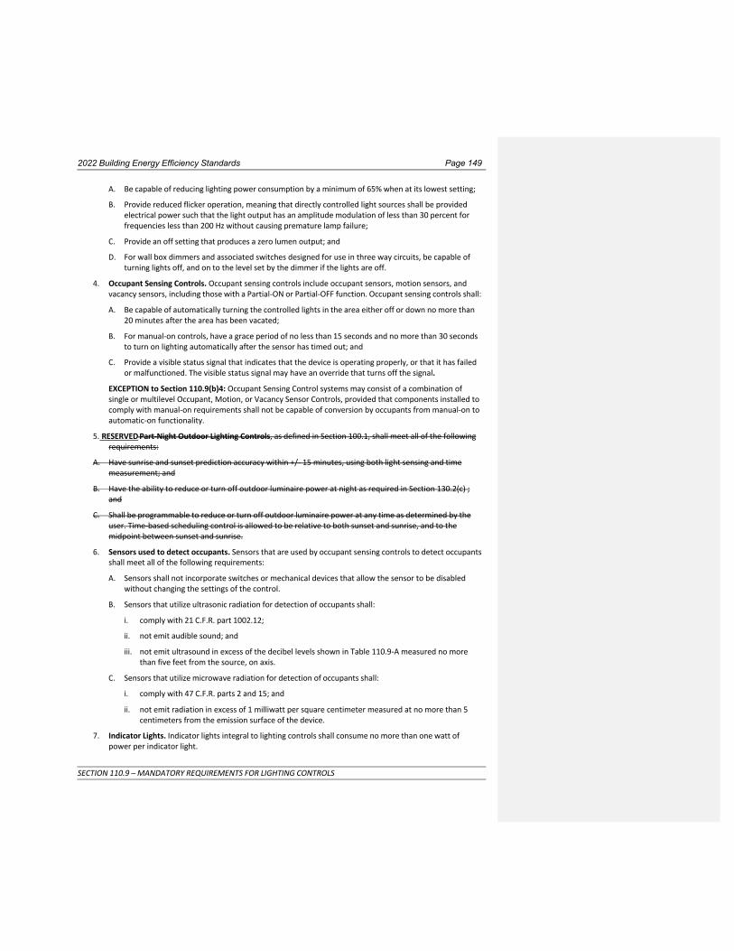
2022 Building Energy Efficiency Standards Page 149
SECTION 110.9 – MANDATORY REQUIREMENTS FOR LIGHTING CONTROLS
A. Be capable of reducing lighting power consumption by a minimum of 65% when at its lowest setting;
B. Provide reduced flicker operation, meaning that directly controlled light sources shall be provided
electrical power such that the light output has an amplitude modulation of less than 30 percent for
frequencies less than 200 Hz without causing premature lamp failure;
C. Provide an off setting that produces a zero lumen output; and
D. For wall box dimmers and associated switches designed for use in three way circuits, be capable of
turning lights off, and on to the level set by the dimmer if the lights are off.
4. Occupant Sensing Controls. Occupant sensing controls include occupant sensors, motion sensors, and
vacancy sensors, including those with a Partial-ON or Partial-OFF function. Occupant sensing controls shall:
A. Be capable of automatically turning the controlled lights in the area either off or down no more than
20 minutes after the area has been vacated;
B. For manual-on controls, have a grace period of no less than 15 seconds and no more than 30 seconds
to turn on lighting automatically after the sensor has timed out; and
C. Provide a visible status signal that indicates that the device is operating properly, or that it has failed
or malfunctioned. The visible status signal may have an override that turns off the signal.
EXCEPTION to Section 110.9(b)4: Occupant Sensing Control systems may consist of a combination of
single or multilevel Occupant, Motion, or Vacancy Sensor Controls, provided that components installed to
comply with manual-on requirements shall not be capable of conversion by occupants from manual-on to
automatic-on functionality.
5. RESERVED Part-Night Outdoor Lighting Controls, as defined in Section 100.1, shall meet all of the following
requirements:
A. Have sunrise and sunset prediction accuracy within +/- 15 minutes, using both light sensing and time
measurement; and
B. Have the ability to reduce or turn off outdoor luminaire power at night as required in Section 130.2(c) ;
and
C. Shall be programmable to reduce or turn off outdoor luminaire power at any time as determined by the
user. Time-based scheduling control is allowed to be relative to both sunset and sunrise, and to the
midpoint between sunset and sunrise.
6. Sensors used to detect occupants. Sensors that are used by occupant sensing controls to detect occupants
shall meet all of the following requirements:
A. Sensors shall not incorporate switches or mechanical devices that allow the sensor to be disabled
without changing the settings of the control.
B. Sensors that utilize ultrasonic radiation for detection of occupants shall:
i. comply with 21 C.F.R. part 1002.12;
ii. not emit audible sound; and
iii. not emit ultrasound in excess of the decibel levels shown in Table 110.9-A measured no more
than five feet from the source, on axis.
C. Sensors that utilize microwave radiation for detection of occupants shall:
i. comply with 47 C.F.R. parts 2 and 15; and
ii. not emit radiation in excess of 1 milliwatt per square centimeter measured at no more than 5
centimeters from the emission surface of the device.
7. Indicator Lights. Indicator lights integral to lighting controls shall consume no more than one watt of
power per indicator light.
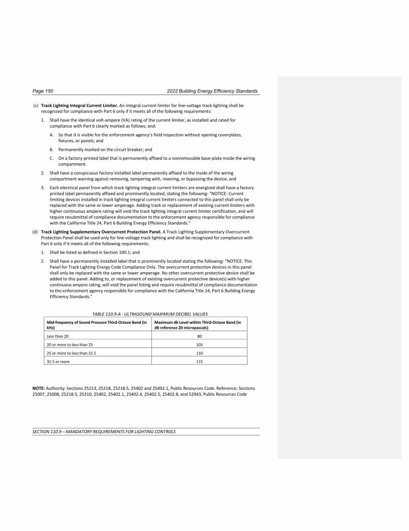
Page 150 2022 Building Energy Efficiency Standards
SECTION 110.9 – MANDATORY REQUIREMENTS FOR LIGHTING CONTROLS
(c) Track Lighting Integral Current Limiter. An integral current limiter for line-voltage track lighting shall be
recognized for compliance with Part 6 only if it meets all of the following requirements:
1. Shall have the identical volt-ampere (VA) rating of the current limiter, as installed and rated for
compliance with Part 6 clearly marked as follows; and:
A. So that it is visible for the enforcement agency’s field inspection without opening coverplates,
fixtures, or panels; and
B. Permanently marked on the circuit breaker; and
C. On a factory-printed label that is permanently affixed to a nonremovable base-plate inside the wiring
compartment.
2. Shall have a conspicuous factory installed label permanently affixed to the inside of the wiring
compartment warning against removing, tampering with, rewiring, or bypassing the device; and
3. Each electrical panel from which track lighting integral current limiters are energized shall have a factory
printed label permanently affixed and prominently located, stating the following: "NOTICE: Current
limiting devices installed in track lighting integral current limiters connected to this panel shall only be
replaced with the same or lower amperage. Adding track or replacement of existing current limiters with
higher continuous ampere rating will void the track lighting integral current limiter certification, and will
require resubmittal of compliance documentation to the enforcement agency responsible for compliance
with the California Title 24, Part 6 Building Energy Efficiency Standards.”
(d) Track Lighting Supplementary Overcurrent Protection Panel. A Track Lighting Supplementary Overcurrent
Protection Panel shall be used only for line-voltage track lighting and shall be recognized for compliance with
Part 6 only if it meets all of the following requirements:
1. Shall be listed as defined in Section 100.1; and
2. Shall have a permanently installed label that is prominently located stating the following: "NOTICE: This
Panel for Track Lighting Energy Code Compliance Only. The overcurrent protection devices in this panel
shall only be replaced with the same or lower amperage. No other overcurrent protective device shall be
added to this panel. Adding to, or replacement of existing overcurrent protective device(s) with higher
continuous ampere rating, will void the panel listing and require resubmittal of compliance documentation
to the enforcement agency responsible for compliance with the California Title 24, Part 6 Building Energy
Efficiency Standards.”
TABLE 110.9-A - ULTRASOUND MAXIMUM DECIBEL VALUES
Mid-frequency of Sound Pressure Third-Octave Band (in kHz)
Maximum db Level within Third-Octave Band (in dB reference 20 micropascals)
Less than 20 80
20 or more to less than 25 105
25 or more to less than 31.5 110
31.5 or more 115
NOTE: Authority: Sections 25213, 25218, 25218.5, 25402 and 25402.1, Public Resources Code. Reference: Sections
25007, 25008, 25218.5, 25310, 25402, 25402.1, 25402.4, 25402.5, 25402.8, and 52943, Public Resources Code

2022 Building Energy Efficiency Standards Page 151
SECTION 110.10 – MANDATORY REQUIREMENTS FOR SOLAR READY BUILDINGSREADINESS
SECTION 110.10 – MANDATORY REQUIREMENTS FOR SOLAR READY BUILDINGSREADINESS (a) Covered Occupancies.
1. Single- Family Residences. Single- family residences located in subdivisions with ten or more single- family
residences and where the application for a tentative subdivision map for the residences has been deemed
complete approved by the enforcement agency, which do not have a photovoltaic system installed, shall
comply with the requirements of Sections 110.10(b) through 110.10(e).
2. Low-rise Multifamily Buildings. Low-rise multi-family buildings that do not have a photovoltaic system
installed shall comply with the requirements of Sections 110.10(b) through 110.10(d).
3. Hotel/Motel Occupancies and High-rise Multifamily Buildings. Hotel/motel occupancies and high-rise
multifamily buildings with ten habitable stories or fewer, which do not have a photovoltaic system
installed, shall comply with the requirements of Sections 110.10(b) through 110.10(d).
4. Nonresidential Buildings. Nonresidential buildings with three habitable stories or fewer, other than
healthcare facilitiesI-2 and I-2.1 buildings, which do not have a photovoltaic system installed, shall comply
with the requirements of Sections 110.10(b) through 110.10(d).
(b) Solar Zone.
1. Minimum Solar Zone Area. The solar zone shall have a minimum total area as described below. The solar
zone shall comply with access, pathway, smoke ventilation, and spacing requirements as specified in Title
24, Part 9 or other Parts of Title 24 or in any requirements adopted by a local jurisdiction. The solar zone
total area shall be comprised of areas that have no dimension less than five feet and are no less than 80
square feet each for buildings with roof areas less than or equal to 10,000 square feet or no less than 160
square feet each for buildings with roof areas greater than 10,000 square feet.
A. Single- Family Residences. The solar zone shall be located on the roof or overhang of the building and
have a total area no less than 250 square feet.
EXCEPTION 1 to Section 110.10(b)1A: Single- family residences with a permanently installed domestic
solar water-heating system meeting the installation criteria specified in the Reference Residential
Appendix RA4 and with a minimum solar savings fraction of 0.50.
EXCEPTION 2 to Section 110.10(b)1A: Single- family residences with three habitable stories or more
and with a total floor area less than or equal to 2000 square feet and having a solar zone total area no
less than 150 square feet.
EXCEPTION 3 to Section 110.10(b)1A: Single- family residences located in the Wildland-Urban
Interface Fire Area as defined in Title 24, Part 2 and having a whole-house fan and having a solar zone
total area no less than 150 square feet.
EXCEPTION 4 to Section 110.10(b)1A: Buildings with a designated solar zone area that is no less than
50 percent of the potential solar zone area. The potential solar zone area is the total area of any low-
sloped roofs where the annual solar access is 70 percent or greater and any steep-sloped roofs
oriented between 90° and 300° of true north where the annual solar access is 70 percent or greater.
Solar access is the ratio of solar insolation including shade to the solar insolation without shade.
Shading from obstructions located on the roof or any other part of the building shall not be included
in the determination of annual solar access.
EXCEPTION 5 to Section 110.10(b)1A: Single- family residences having a solar zone total area no less
than 150 square feet and where all thermostats are demand responsive controls and comply with
Section 110.12(a), and are capable of receiving and responding to Demand Response Signals prior to
granting of an occupancy permit by the enforcing agency.
EXCEPTION 6 to Section 110.10(b)1A: Single- family residences meeting the following conditions:

Page 152 2022 Building Energy Efficiency Standards
SECTION 110.10 – MANDATORY REQUIREMENTS FOR SOLAR READY BUILDINGSREADINESS
A. All thermostats are demand responsive controls that comply with Section 110.12(a), and are
capable of receiving and responding to Demand Response Signals prior to granting of an
occupancy permit by the enforcing agency.
B. Comply with one of the following measures:
i. Install a dishwasher that meets or exceeds the ENERGY STAR Program requirements with a
refrigerator that meets or exceeds the ENERGY STAR Program requirements, a whole-house
fan driven by an electronically commutated motor, or an SAE J1772 Level 2 Electric Vehicle
Supply Equipment (EVSE or EV Charger) with a minimum of 40 amperes; or
ii. Install a home automation system capable of, at a minimum, controlling the appliances and
lighting of the dwelling and responding to demand response signals; or
iii. Install alternative plumbing piping to permit the discharge from the clothes washer and all
showers and bathtubs to be used for an irrigation system in compliance with the California
Plumbing Code and any applicable local ordinances; or
iv. Install a rainwater catchment system designed to comply with the California Plumbing Code
and any applicable local ordinances, and that uses rainwater flowing from at least 65 percent
of the available roof area.
B. Low-rise and High-rise Multifamily Buildings, Hotel/Motel Occupancies, and Nonresidential Buildings. The solar zone shall be located on the roof or overhang of the building or on the roof or
overhang of another structure located within 250 feet of the building or on covered parking installed
with the building project, and shall have a total area no less than 15 percent of the total roof area of
the building excluding any skylight area. The solar zone requirement is applicable to the entire
building, including mixed occupancy.
EXCEPTION 1 to Section 110.10(b)1B: High-rise Multifamily Buildings, Hotel/Motel Occupancies, and
Nonresidential Buildings with a permanently installed solar electric system having a nameplate DC
power rating, measured under Standard Test Conditions, of no less than one watt per square foot of
roof area.
EXCEPTION 2 to Section 110.10(b)1B: High-rise Multifamily Buildings, Hotel/Motel Occupancies with a
permanently installed domestic solar water-heating system complying with Section 150.1(c)8Biii.
EXCEPTION 3 to Section 110.10(b)1B: Buildings with a designated solar zone area that is no less than
50 percent of the potential solar zone area. The potential solar zone area is the total area of any low-
sloped roofs where the annual solar access is 70 percent or greater and any steep-sloped roofs
oriented between 90° and 300° of true north where the annual solar access is 70 percent or greater.
Solar access is the ratio of solar insolation including shade to the solar insolation without shade.
Shading from obstructions located on the roof or any other part of the building shall not be included
in the determination of annual solar access.
EXCEPTION 4 to Section 110.10(b)1B: Low-rise and high-rise multifamily buildings with all thermostats
in each dwelling unit are demand response controls that comply with Section 110.12(a), and are
capable of receiving and responding to Demand Response Signals prior to granting of an occupancy
permit by the enforcing agency. In addition, either A or B below:
A. In each dwelling unit, comply with one of the following measures:
i. Install a dishwasher that meets or exceeds the ENERGY STAR Program requirements with
either a refrigerator that meets or exceeds the ENERGY STAR Program requirements or a
whole-house fan driven by an electronically commutated motor; or
ii. Install a home automation system that complies with Section 110.12(a) and is capable of, at a
minimum, controlling the appliances and lighting of the dwelling and responding to demand
response signals; or

2022 Building Energy Efficiency Standards Page 153
SECTION 110.10 – MANDATORY REQUIREMENTS FOR SOLAR READY BUILDINGSREADINESS
iii. Install alternative plumbing piping to permit the discharge from the clothes washer and all
showers and bathtubs to be used for an irrigation system in compliance with the California
Plumbing Code and any applicable local ordinances; or
iv. Install a rainwater catchment system designed to comply with the California Plumbing Code
and any applicable local ordinances, and that uses rainwater flowing from at least 65 percent
of the available roof area.
B. Meet the Title 24, Part 11, Section A4.106.8.2 requirements for electric vehicle charging spaces.
EXCEPTION 5 to Section 110.10(b)1B: Buildings where the roof is designed and approved to be used for
vehicular traffic or parking or for a heliport.
2. Azimuth Range. All sections of the solar zone located on steep-sloped roofs shall be orientedhave an
azimuth range between 90° and 300° of true north.
3. Shading.
A. No obstructions, including but not limited to, vents, chimneys, architectural features, and roof
mounted equipment, shall be located in the solar zone.
B. Any obstruction, located on the roof or any other part of the building that projects above a solar zone
shall be located at least twice the distance, measured in the horizontal plane, of the height difference
between the highest point of the obstruction and the horizontal projection of the nearest point of the
solar zone, measured in the vertical plane.
EXCEPTION to Section 110.10(b)3: Any roof obstruction, located on the roof or any other part of the
building, that is oriented north of all points on the solar zone.
4. Structural Design Loads on Construction Documents. For areas of the roof designated as solar zone, the
structural design loads for roof dead load and roof live load shall be clearly indicated on the construction
documents.
NOTE: Section 110.10(b)4 does not require the inclusion of any collateral loads for future solar energy
systems.
(c) Interconnection Pathways.
1. The construction documents shall indicate a location reserved for inverters and metering equipment and a
pathway reserved for routing of conduit from the solar zone to the point of interconnection with the
electrical service.
2. For single- family residences and central water-heating systems, the construction documents shall indicate
a pathway for routing of plumbing from the solar zone to the water-heating system.
(d) Documentation. A copy of the construction documents or a comparable document indicating the information
from Sections 110.10(b) through 110.10(c) shall be provided to the occupant.
(e) Main Electrical Service Panel for Single Family Homes.
1. The main electrical service panel shall have a minimum busbar rating of 200 amps.
2. The main electrical service panel shall have a reserved space to allow for the installation of a double pole
circuit breaker for a future solar electric installation. The reserved space shall be permanently marked as
“For Future Solar Electric”.
NOTE: Authority: Sections 25213, 25218, 25218.5, 25402, 25402.1, and 25605, Public Resources Code. Reference:
Sections 25007, 25008, 25218.5, 25310, 25402, 25402.1, 25402.4, 25402.8, 25605, and 25943, Public Resources
Code
Commented [GA2]: 110.10(e) should specify that it applies to single family residences only.
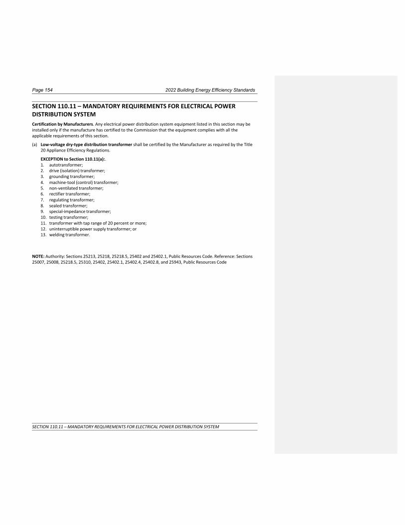
Page 154 2022 Building Energy Efficiency Standards
SECTION 110.11 – MANDATORY REQUIREMENTS FOR ELECTRICAL POWER DISTRIBUTION SYSTEM
SECTION 110.11 – MANDATORY REQUIREMENTS FOR ELECTRICAL POWER DISTRIBUTION SYSTEM Certification by Manufacturers. Any electrical power distribution system equipment listed in this section may be
installed only if the manufacture has certified to the Commission that the equipment complies with all the
applicable requirements of this section.
(a) Low-voltage dry-type distribution transformer shall be certified by the Manufacturer as required by the Title
20 Appliance Efficiency Regulations.
EXCEPTION to Section 110.11(a):. 1. autotransformer;
2. drive (isolation) transformer;
3. grounding transformer;
4. machine-tool (control) transformer;
5. non-ventilated transformer;
6. rectifier transformer;
7. regulating transformer;
8. sealed transformer;
9. special-impedance transformer;
10. testing transformer;
11. transformer with tap range of 20 percent or more;
12. uninterruptible power supply transformer; or
13. welding transformer.
NOTE: Authority: Sections 25213, 25218, 25218.5, 25402 and 25402.1, Public Resources Code. Reference: Sections
25007, 25008, 25218.5, 25310, 25402, 25402.1, 25402.4, 25402.8, and 25943, Public Resources Code

2022 Building Energy Efficiency Standards Page 155
SECTION 110.12 – MANDATORY REQUIREMENTS FOR DEMAND MANAGEMENT
SECTION 110.12 – MANDATORY REQUIREMENTS FOR DEMAND MANAGEMENT Buildings, other than healthcare facilities, that install or are required to install demand responsive controls
shall comply with the applicable demand responsive control requirements of Sections 110.12(a) through
110.12(de).
(a) Demand responsive controls.
1. All demand responsive controls shall be either:
A. A certified OpenADR 2.0a or OpenADR 2.0b Virtual End Node (VEN), as specified under Clause 11,
Conformance, in the applicable OpenADR 2.0 Specification; or
B. Certified by the manufacturer as being capable of responding to a demand response signal from a
certified OpenADR 2.0b Virtual End Node by automatically implementing the control functions
requested by the Virtual End Node for the equipment it controls.
2. All demand responsive controls shall be capable of communicating with the VEN using one or more of
the following: Wi-Fi, ZigBee, BACnet, Ethernet, or hard-wiringa wired or wireless bi-directional
communication pathway.
3. Demand responsive controls may incorporate and use additional protocols beyond those specified in
Sections 110.12(a)1 and 2.
4. When communications are disabled or unavailable, all demand responsive controls shall continue to
perform all other control functions provided by the control.
5. Demand responsive control thermostats shall comply with Reference Joint Appendix 5 (JA5), Technical
Specifications For Occupant Controlled Smart Thermostats.
(b) Demand Responsive Zonal HVAC Controls. Nonresidential HVAC systems with DDC to the Zone level shall
be programmed to allow centralized demand shed for noncritical zones as follows:
1. The controls shall have a capability to remotely increase the operating cooling temperature set points
by 4° or more in all noncritical zones on signal from a centralized contact or software point within an
Energy Management Control System (EMCS).
2. The controls shall have a capability to remotely decrease the operating heating temperature set
points by 4° or more in all noncritical zones on signal from a centralized contact or software point
within an EMCS.
3. The controls shall have capabilities to remotely reset the temperatures in all noncritical zones to
original operating levels on signal from a centralized contact or software point within an EMCS.
4. The controls shall be programmed to provide an adjustable rate of change for the temperature
increase, decrease, and reset.
5. The controls shall have the following features:
A. Disabled. Disabled by authorized facility operators; and
B. Manual control. Manual control by authorized facility operators to allow adjustment of heating
and cooling set points globally from a single point in the EMCS; and
C. Automatic Demand Shed Control. Upon receipt of a demand response signal, the space-
conditioning systems shall conduct a centralized demand shed, as specified in Sections 110.12(b)1
and 110.12(b)2, for noncritical zones during the demand response period.
(c) Demand Responsive Lighting Controls. Nonresidential general lighting systems subject to the
requirements of Section 130.1(b) with a general lighting power of 4,000 watts or greater, shall have
controls that areLighting controls in nonresidential buildings larger than 10,000 square feet shall be
capable of automatically reducing lighting power in response to a Demand Response Signal. General

Page 156 2022 Building Energy Efficiency Standards
SECTION 110.12 – MANDATORY REQUIREMENTS FOR DEMAND MANAGEMENT
lighting shall be reduced in a manner consistent with the uniform level of illumination requirements in
TABLE 130.1-A.
1. For compliance testing, the lighting controls shall demonstrate a lighting power reduction in
controlled spaces of a minimum of 15 percent below the total installed lighting power (general +
additional) as described in NA7.6.3. The controls may provide additional demand responsive
functions or abilities.
EXCEPTION 1 to 110.12(c): Spaces with a lighting power density of 0.5 watts per square foot or less are
not required to install demand responsive controls and do not count toward the 10,000 square foot
threshold.
EXCEPTION 2 to 110.12(c): Spaces where a health or life safety statute, ordinance, or regulation does not
permit the general lighting to be reduced are not required to install demand responsive controls and do
not count toward the 10,000 square foot4,000 watt threshold.
(d) Demand Responsive Electronic Message Center Control. Controls for electronic message centers greater
than 15 kW shall be capable of reducing the lighting power by a minimum of 30 percent when receiving a
demand response signal.
EXCEPTION to Section 110.12(d): Electronic message centers that are not permitted by a health or life
safety statute, ordinance, or regulation to be reduced.
(e) Demand Responsive Controlled Receptacles. Controlled receptacles in buildings shall be capable of
automatically turning off all loads connected to the receptacle in response to a demand response signal.
Exception 1 to 110.12(e): Buildings not required to have demand responsive lighting controls.
Exception 2 to 110.12(e): Spaces where a health or life safety statute, ordinance, or regulation does not
permit the receptacles to be automatically controlled.
NOTE: Authority: Sections 25213, 25218, 25218.5, 25402 and 25402.1, Public Resources Code. Reference: Sections
25007, 25008, 25218.5, 25310, 25402, 25402.1, 25402.4, 25402.5, 25402.8, and 25943, Public Resources Code.
Commented [SS3]: NR Grid Integration


Page 548 2022 Building Energy Efficiency Standards
APPENDIX 1-B
ENERGY COMMISSION DOCUMENTS INCORPORATED BY REFERENCE IN THEIR ENTIRETY

2022BuildingEnergyEfficiencyStandards Page1
SECTION 120.0̶ GENERAL
SUBCHAPTER 3 NONRESIDENTIAL, HIGH-RISE RESIDENTIAL, HOTEL/MOTEL OCCUPANCIES, AND COVERED PROCESSES—MANDATORY
REQUIREMENTS SECTION 120.0— GENERAL Sections 120.1 through 120.9 establish requirements for the design and installation of building envelopes, ventilation, space-conditioning and service water-heating systems and equipment in nonresidential, high-rise residential, and hotel/motel buildings, as well as covered processes that are within the scope of Section 100.0(a).
NOTE: The requirements of Sections 120.1 through 120.9 apply to newly constructed buildings. Section 141.0 specifies which requirements of Sections 120.1 through 120.9 also apply to additions or alterations to existing buildings.
NOTE: Authority: Sections 25213, 25218, 25218.5, 25402 and 25402.1, Public Resources Code. Reference: Sections 25007, 25008, 25218.5, 25310, 25402, 25402.1, 25402.4, 25402.5, 25402.8, and 25943, Public Resources Code.

Page158 2022BuildingEnergyEfficiencyStandards
SECTION 120.1 ‒ REQUIREMENTS FOR VENTILATION AND INDOOR AIR QUALITY
SECTION 120.1 – REQUIREMENTS FOR VENTILATION AND INDOOR AIR QUALITY (a) General Requirements.
1. All occupiable spaces in high-rise residential buildings, hotel/motel buildings, and nonresidential buildings other than healthcare facilities shall comply with the applicable requirements of Section 120.1(a) through 120.1(g). Healthcare facilities shall be ventilated in accordance with Chapter 4 of the California Mechanical Code.
2. The required outdoor air-ventilation rate and the air-distribution system design shall be clearly identified on the plans in accordance with Section 10-103 of Title 24, Part 1.
(b) ReservedHigh-rise Residential Buildings.
Attached dwellings units shall comply with the requirements of subsections 1 and 2 below. Occupiable spaces other than attached dwelling units shall comply with the requirements of section 120.1(c).
1. Air Filtration.
A. System types specified in subsections i, ii, and iii shall be provided with air filters in accordance with Sections 120.1(b)1B through 1D. System types specified in subsection i shall also comply with Section 120.1(b)1E.
i. Mechanical space conditioning systems that supply air to an occupiable space through ductwork exceeding 10 ft (3 m) in length.
ii. Mechanical supply-only ventilation systems that provide outside air to an occupiable space.
iii. The supply side of mechanical balanced ventilation systems, including heat recovery ventilation systems and energy recovery ventilation systems that provide outside air to an occupiable space.
B. System Design and Installation.
i. The system shall be designed to ensure that all recirculated air or outdoor air supplied to the occupiable space is filtered before passing through any system thermal conditioning components.
EXCEPTION to Section 120.1(b)1Bi: For heat recovery ventilators and energy recovery ventilators the location of the filters required by Section 120.1(b) may be downstream of a system thermal conditioning component, provided the system is equipped with ancillary filtration upstream of the system’s thermal conditioning component.
ii. All systems shall be designed to accommodate the clean-filter pressure drop imposed by the system air filter(s). The design airflow rate, and maximum allowable clean-filter pressure drop at the design airflow rate applicable to each air filter shall be determined and reported on labels according to subsection iv below.
Systems specified in Section 120.1(b)1Ai shall be equipped with air filters that meet either subsection a or b below:
a. Nominal two-inch minimum depth filter(s) shall be sized by the system designer; or
b. Nominal one-inch minimum depth filters(s) shall be allowed if the filter(s) are sized according to Equation 120.1-A, based on a maximum face velocity of 150 ft per minute and according to the maximum allowable clean filter pressure drop specified in Section 120.1(b)1Dii
Aface = Qfilter / Vface (Equation 120.1-A)
Where,
Aface = air filter face area, the product of air filter nominal length × nominal width, ft2

2022BuildingEnergyEfficiencyStandards Page159
SECTION 120.1 ‒ REQUIREMENTS FOR VENTILATION AND INDOOR AIR QUALITY
Qfilter = design airflow rate for the air filter, ft3/min
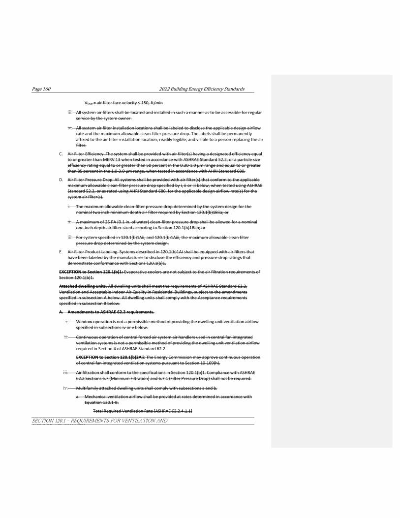
Page160 2022BuildingEnergyEfficiencyStandards
SECTION 120.1 ‒ REQUIREMENTS FOR VENTILATION AND INDOOR AIR QUALITY
Vface = air filter face velocity ≤ 150, ft/min
iii. All system air filters shall be located and installed in such a manner as to be accessible for regular service by the system owner.
iv. All system air filter installation locations shall be labeled to disclose the applicable design airflow rate and the maximum allowable clean-filter pressure drop. The labels shall be permanently affixed to the air filter installation location, readily legible, and visible to a person replacing the air filter.
C. Air Filter Efficiency. The system shall be provided with air filter(s) having a designated efficiency equal to or greater than MERV 13 when tested in accordance with ASHRAE Standard 52.2, or a particle size efficiency rating equal to or greater than 50 percent in the 0.30-1.0 μm range and equal to or greater than 85 percent in the 1.0-3.0 μm range, when tested in accordance with AHRI Standard 680.
D. Air Filter Pressure Drop. All systems shall be provided with air filter(s) that conform to the applicable maximum allowable clean-filter pressure drop specified by i, ii or iii below, when tested using ASHRAE Standard 52.2, or as rated using AHRI Standard 680, for the applicable design airflow rate(s) for the system air filter(s).
i. The maximum allowable clean-filter pressure drop determined by the system design for the nominal two inch minimum depth air filter required by Section 120.1(b)1Biia; or
ii. A maximum of 25 PA (0.1 in. of water) clean-filter pressure drop shall be allowed for a nominal one-inch depth air filter sized according to Section 120.1(b)1Biib; or
iii. For system specified in 120.1(b)1Aii, and 120.1(b)1Aiii, the maximum allowable clean filter pressure drop determined by the system design.
E. Air Filter Product Labeling. Systems described in 120.1(b)1Ai shall be equipped with air filters that have been labeled by the manufacturer to disclose the efficiency and pressure drop ratings that demonstrate conformance with Sections 120.1(b)1.
EXCEPTION to Section 120.1(b)1: Evaporative coolers are not subject to the air filtration requirements of Section 120.1(b)1.
Attached dwelling units. All dwelling units shall meet the requirements of ASHRAE Standard 62.2, Ventilation and Acceptable Indoor Air Quality in Residential Buildings, subject to the amendments specified in subsection A below. All dwelling units shall comply with the Acceptance requirements specified in subsection B below.
A. Amendments to ASHRAE 62.2 requirements.
i. Window operation is not a permissible method of providing the dwelling unit ventilation airflow specified in subsections iv or v below.
ii. Continuous operation of central forced air system air handlers used in central fan integrated ventilation systems is not a permissible method of providing the dwelling unit ventilation airflow required in Section 4 of ASHRAE Standard 62.2.
EXCEPTION to Section 120.1(b)2Aii: The Energy Commission may approve continuous operation of central fan integrated ventilation systems pursuant to Section 10-109(h).
iii. Air filtration shall conform to the specifications in Section 120.1(b)1. Compliance with ASHRAE 62.2 Sections 6.7 (Minimum Filtration) and 6.7.1 (Filter Pressure Drop) shall not be required.
iv. Multifamily attached dwelling units shall comply with subsections a and b.
a. Mechanical ventilation airflow shall be provided at rates determined in accordance with Equation 120.1-B.
Total Required Ventilation Rate [ASHRAE 62.2.4.1.1]

2022BuildingEnergyEfficiencyStandards Page161
SECTION 120.1 ‒ REQUIREMENTS FOR VENTILATION AND INDOOR AIR QUALITY
Qtot = 0.03Afloor + 7.5(Nbr + 1) (Equation 120.1-B)

Page162 2022BuildingEnergyEfficiencyStandards
SECTION 120.1 ‒ REQUIREMENTS FOR VENTILATION AND INDOOR AIR QUALITY
Where,
Qtot = total required ventilation rate, cfm
Afloor = dwelling-unit floor area, ft2
Nbr = number of bedrooms (not to be less than 1)
b. The mechanical ventilation system shall comply with one of the following subsections 1 or 2 below. When subsection 2 is utilized for compliance, all dwelling units in the multifamily building shall use the same ventilation system type.
1. A balanced mechanical ventilation system shall provide the required dwelling-unit ventilation airflow.
2. Continuously operating supply ventilation systems or continuous operating exhaust ventilation systems shall be allowed to be used to provide the required dwelling unit ventilation airflow if the dwelling-unit envelope leakage is less than or equal to 0.3 cubic feet per minute at 50 Pa (0.2 in. of water) per ft2 of dwelling unit envelope surface area as confirmed by field verification and diagnostic testing in accordance with Reference Nonresidential Appendix NA7.18.2.
v. Multifamily building central ventilation systems that serve multiple dwelling-units shall be balanced to provide ventilation airflow to each dwelling-unit served at a rate equal to or greater than the rate specified by Equation 120.1-B, but not more than twenty percent greater than the specified rate. These systems shall utilize balancing means to ensure the dwelling unit airflows can be adjusted to meet this balancing requirement. These system balancing means may include but not be limited to constant air regulation devices, orifice plates, and variable speed central fans.
vi. Kitchen range hoods shall be rated for sound in accordance with Section 7.2 of ASHRAE 62.2.
EXCEPTION to Section 120.1(b)2Avi: Kitchen range hoods may be rated for sound at a static pressure determined at working speed as specified in HVI 916 Section 7.2.
vii. Compliance with ASHRAE 62.2 Section 6.5.2 (Space Conditioning System Ducts) shall not be required.
viii. Compliance with ASHRAE 62.2 Section 4.4 (Control and Operation) shall require manual switches associated with dwelling unit ventilation systems to have a label clearly displaying the following text, or equivalent text: “This switch controls the indoor air quality ventilation for the home. Leave it on unless the outdoor air quality is very poor.”
B. High-Rise Residential Dwelling Unit Acceptance.
i. Airflow Performance. The dwelling-unit ventilation airflow required by Section 120.1(b)2Aiv or 120.1(b)2Av shall be confirmed through field verification and diagnostic testing in accordance with Reference Nonresidential Appendix NA7.18.1.
ii. Kitchen Range Hoods. The installed kitchen range hood shall be field verified in accordance with Reference Nonresidential Appendix NA7.18.1 to confirm the model is rated by HVI to comply with the following requirements:
a. The minimum ventilation airflow rate as specified in Section 5 of ASHRAE 62.2.
b. The maximum sound rating as specified in Section 120.1(b)2Avi.
(c) Nonresidential and Hotel/Motel Buildings. All occupiable spaces shall meet the requirements of subsection 1Section 120.1(c)1, and shall also comply with either 2Section 120.1(c)2 or 3Section 120.1(c)3.:
1. Air Filtration.

2022BuildingEnergyEfficiencyStandards Page163
SECTION 120.1 ‒ REQUIREMENTS FOR VENTILATION AND INDOOR AIR QUALITY
A. Mechanical system types specified in subsections i, ii, and iii below described in Section 120.1(b)1A shall be designed to ensure that all recirculated air and all outdoor air supplied to the occupiable

Page164 2022BuildingEnergyEfficiencyStandards
SECTION 120.1 ‒ REQUIREMENTS FOR VENTILATION AND INDOOR AIR QUALITY
space is filtered before passing through any system thermal conditioning components. Air Filters shall conform to the requirements of Sections 120.1(c)1B, 120.1(c)1C and 120.1(c)1D.provided with air filters to clean the outside and return air prior to its introduction into occupied spaces.
i. Mechanical space conditioning systems that supply air to an occupiable space through ductwork exceeding 10 ft (3 m) in length.
ii. Mechanical supply-only ventilation systems and makeup air systems that provide outside air to an occupiable space.
iii. The supply side of mechanical balanced ventilation systems, including heat recovery ventilation systems and energy recovery ventilation systems that provide outside air to an occupiable space.
EXCEPTION to Section 120.1(c)1A: For heat recovery ventilators and energy recovery ventilators the location of the filters required by Section 120.1(c)1A may be downstream of a system thermal conditioning component, provided the system is equipped with ancillary filtration upstream of the system’s thermal conditioning component
B. Air Filter Efficiency. The filters shall have a designated efficiency equal to or greater than MERV 13 when tested in accordance with ASHRAE Standard 52.2, or a particle size efficiency rating equal to or greater than 50 percent in the 0.30-1.0 μm range, and equal to or greater than 85 percent in the 1.0- 3.0 μm range when tested in accordance with AHRI Standard 680; and
C. Systems shall be equipped with air filters that meet either subsection i or ii below.
i. Nominal two inch minimum depth filter(s); or
ii. Nominal one inch minimum depth filter(s) shall be allowed if the filter(s) are sized according to Equation 120.1-A, based on a maximum face velocity of 150 ft per minute.
Aface = Qfilter / Vface (Equation 120.1-A)
Where,
Aface = air filter face area, the product of air filter nominal length × nominal width, ft2
Qfilter = design airflow rate for the air filter, ft3/min
Vface = air filter face velocity ≤ 150, ft/min
D. Filter racks or grilles shall be gasketed or sealed to eliminate any gaps around the filter to prevent air from bypassing the filter.
2. Natural Ventilation. Naturally ventilated spaces shall be designed in accordance with 120.1(c)2A through 120.1(c)2C and include a mechanical ventilation system designed in accordance with 120.1(c)3:
A. Floor area to be ventilated. Spaces or portions of spaces to be naturally ventilated shall be located within a distance based on the ceiling height, as specified in i, ii and iii. The ceiling height (H) to be used in i, ii or iii shall be the minimum ceiling height in the space, or for ceilings that are increasing in height as distance from the operable openings is increased, the ceiling height shall be determined as the average height of the ceiling within 20 ft from the operable opening. [ASHRAE 62.1:6.4.1]
i. Single Side Opening. For spaces with operable opening on one side of the space, the maximum distance from the operable opening shall be not more than 2H. [ASHRAE 62.1:6.4.1.1]
ii. Double Side Opening. For spaces with operable openings on two opposite sides of the space, the maximum distance from the operable opening shall be not more than 5H. [ASHRAE 62.1:6.4.1.2]
iii. Corner Opening. For spaces with operable openings on two adjacent sides of a space, the maximum distance from the operable openings shall be not more than 5H along a line drawn between the two openings that are the farthest apart. Floor area outside that line shall comply with i or ii. [ASHRAE 62.1:6.4.1.3]

2022BuildingEnergyEfficiencyStandards Page165
SECTION 120.1 ‒ REQUIREMENTS FOR VENTILATION AND INDOOR AIR QUALITY
iv. Ceiling Height. The ceiling height (hH) to be used in Section 120.1(c)2Ai through 120.1(c)2Aiii shall be the minimum ceiling height in the space.
EXCEPTION to Section 120.1(c)2Aiv: For ceilings that are increasing in height as distance from the opening is increased, the ceiling height shall be determined as the average height of the ceiling within 20 feet from the operable openings. [ASHRAE 62.1:6.4.1.4]
B. Location and Size of Openings. Spaces or portions of spaces to be naturally ventilated shall be permanently open to operable wall openings directly to the outdoors. The openable area shall be not less than 4 percent of the net occupiable floor area. Where openings are covered with louvers or otherwise obstructed, the openable area shall be based on the net free unobstructed area through the opening. Where interior rooms, or portions of rooms, without direct openings to the outdoors are ventilated through adjoining rooms, the opening between rooms shall be permanently unobstructed and have a free area of not less than 8 percent of the area of the interior room or less than 25 square feet. [ASHRAE 62.1:6.4.2]
C. Control and Accessibility. The means to open the required operable opening shall be readily accessible to building occupants whenever the space is occupied. Controls shall be designed to coordinate operation of the natural and mechanical ventilation systems. [ASHRAE 62.1:6.4.3]
EXCEPTION 1 to Section 120.1(c)2: The mechanical ventilation system shall not be required where natural ventilation openings complying with 120.1(c)2 are either permanently open or have controls that prevent the openings from being closed during periods of expected occupancy.
EXCEPTION 2 to Section 120.1(c)2: The mechanical ventilation system shall not be required where the zone is not served by a space conditioning system.
3. Mechanical Ventilation. Occupiable spaces shall be ventilated with a mechanical ventilation system capable of providing an outdoor airflow rate to the zone (Vz) to the zone no less than Equation 120.1-F the larger of A or B as described below:
A. The outdoor airflow rate to the zone (Vz) shall be determined in accordance with Equation 120.1-F; or
Vz = Rat × Az (Equation 120.1-F)
Where:
Rat = Total outdoor airflow rate required per unit area as determined from Table 120.1-A.
Az = Zone floor area, is meaning the net occupiable floor area of the ventilation zone in square feet.
B. EXCEPTION 1 to Section 120.1(c)3: Designed Occupancy. For spaces designed for an expected number of occupants per the Exception to Section 1004.5 of the CBC, or spaces with fixed seating per Section 1004.6 of the CBC, the outdoor airflow rate to the zone (Vz) shall be determined in accordance with Equation 120.1-G;
Vz = The larger of Rp × Pz or Ra × Az (Equation 120.1-G)
Where:
Rp = 15 cubic feet per minute of outdoor airflow per person
Pz = The expected number of occupants. The expected number of occupants shall be the expected number specified by the building designer. For spaces with fixed seating, the expected number of occupants shall be determined in accordance with the California Building Code.
Ra = The minimum ventilation airflow rate allowed for DCV in Table 120.1-A. If Ra is not defined for an occupancy category, Ra = 0.
Az = Zone floor area, meaning the net occupiable floor area of the ventilation zone in square feet.
EXCEPTION 2 to Section 120.1(c)3: Transfer air. The rate of outdoor air required by Section 120.1(c)3 may be provided with air transferred from other ventilated space if:

Page166 2022BuildingEnergyEfficiencyStandards
SECTION 120.1 ‒ REQUIREMENTS FOR VENTILATION AND INDOOR AIR QUALITY
A. Use of transfer air is in accordance with Section 120.1(g); and
B. The outdoor air that is supplied to all spaces combined, is sufficient to meet the requirements of Section 120.1(c)3 for each space individually.
4. Exhaust Ventilation. The design exhaust airflow shall be determined in accordance with the requirements in Table 120.1-B. Exhaust makeup air shall be permitted to be any combination of outdoor air, recirculated air, or transfer air. [ASHRAE 62.1:6.5.1]
(d) Operation and Control Requirements for Minimum Quantities of Outdoor Air.
1. Times of occupancy. The minimum rate of outdoor air required by Section 120.1(c) shall be supplied to each space at all times when the space is usually occupied.
EXCEPTION 1 to Section 120.1(d)1: Demand control ventilation. In intermittently occupied spaces that do not have processes or operations that generate dusts, fumes, mists, vapors or gasses and are not provided with local exhaust ventilation (such as indoor operation of internal combustion engines or areas designated for unvented food service preparation), the rate of outdoor air may be reduced if the ventilation system serving the space is controlled by a demand control ventilation device complying with Section 120.1(d)4 or by an occupant sensor ventilation control device complying with Section 120.1(d)5.
EXCEPTION 2 to Section 120.1(d)1: Temporary reduction. The rate of outdoor air provided to a space may be reduced below the level required by Section 120.1(c) for up to 30 minutes at a time if the average rate for each hour is equal to or greater than the required ventilation rate.
2. Pre-occupancy. The lesser of the minimum rate of outdoor air required by Section 120.1(c) or three complete air changes shall be supplied to the entire building during the 1-hour period immediately before the building is normally occupied.
3. Required Demand Control Ventilation. Demand ventilation controls complying with Section 120.1(d)4 are required for a space with a design occupant density, or a maximum occupant load factor for egress purposes in the CBC, greater than or equal to 25 people per 1000 square feet (40 square feet or less per person) if the ventilation system serving the space has one or more of the following:
A. an air economizer; or
B. modulating outside air control; or
C. design outdoor airflow rate > 3,000 cfm.
EXCEPTION 1 to Section 120.1(d)3: Where space exhaust is greater than the design ventilation rate specified in Section 120.1(c)3 minus 0.2 cfm per ft² of conditioned area.
EXCEPTION 2 to Section 120.1(d)3: Spaces that have processes or operations that generate dusts, fumes, mists, vapors, or gases and are not provided with local exhaust ventilation, such as indoor operation of internal combustion engines or areas designated for unvented food service preparation, daycare sickrooms, science labs, barber shops or beauty and nail salons shall not install demand control ventilation.
EXCEPTION 3 to Section 120.1(d)3: Spaces with an area of less than 150 square feet, or a design occupancy of less than 10 people as specified by Section 120.1(c)3.
4. Demand Control Ventilation Devices.
A. For each system with demand control ventilation (DCV), CO2 sensors shall be installed in each room that meets the criteria of Section 120.1(d)3 with no less than one sensor per 10,000 ft² of floor space. When a zone or a space is served by more than one sensor, a signal from any sensor indicating that CO2 is near or at the setpoint within the zone or space shall trigger an increase in ventilation.
B. CO2 sensors shall be located in the room between 3 ft and 6 ft above the floor or at the anticipated height of the occupants’ heads.

2022BuildingEnergyEfficiencyStandards Page167
SECTION 120.1 ‒ REQUIREMENTS FOR VENTILATION AND INDOOR AIR QUALITY
C. Demand ventilation controls shall maintain CO2 concentrations less than or equal to 600 ppm plus the outdoor air CO2 concentration in all rooms with CO2 sensors.
EXCEPTION to Section 120.1(d)4C: The outdoor air ventilation rate is not required to be larger than the design outdoor air ventilation rate required by Section 120.1(c)3 regardless of CO2 concentration.
D. Outdoor air CO2 concentration shall be determined by one of the following:
i. CO2 concentration shall be assumed to be 400 ppm without any direct measurement; or
ii. CO2 concentration shall be dynamically measured using a CO2 sensor located within 4 ft of the outdoor air intake.
E. When the system is operating during hours of expected occupancy, the controls shall maintain system outdoor air ventilation rates no less than the rate listed in Table 120.1-A for DCV, times the conditioned floor area for spaces with CO2 sensors, plus the rate required by Section 120.1(c)3 for other spaces served by the system, or the exhaust air rate whichever is greater.
F. CO2 sensors shall be certified by the manufacturer to be accurate within plus or minus 75 ppm at a 600 and 1000 ppm concentration when measured at sea level and 25°C, factory calibrated, and certified by the manufacturer to require calibration no more frequently than once every 5 years. Upon detection of sensor failure, the system shall provide a signal which resets to supply the minimum quantity of outside air to levels required by Section 120.1(c)3 to the zone serviced by the sensor at all times that the zone is occupied.
G. The CO2 sensor(s) reading for each zone shall be displayed continuously, and shall be recorded on systems with DDC to the zone level.
5. Occupant Sensor Ventilation Control Devices. When occupancy sensor ventilation devices are required by Section 120.2(e)3, Occupancy sensor Occupant sensing ventilation controls are required for airspace conditioning zones that are both permitted to have their ventilation air reduced to zero while in occupied standby mode per Table 120.1-A and required to install occupant sensors to comply with Section 130.1. Occupant sensorsOccupant sensing ventilation control devices shall be used to reduce the rate of outdoor airflow when occupants are not present in accordanceshall comply with the following:
A. Occupant sensors shall meet the requirements in Section 110.9(b)4 and shall have suitable coverage and placement to detect occupants in the entire space ventilated. Within 20 minutes of no occupancy being detected by any sensors covering the room, occupant sensing controls shall indicate a room is vacant.
B. If When occupant sensors controlling lighting are also used for ventilation, the ventilation signal shall be independent of daylighting, manual lighting overrides or manual control of lighting.
C. When a single zone damper or a single zone system serves multiple rooms, there shall be an occupancy sensor in each room and the zone is shall not be considered vacant until all rooms in the zone are vacant.
BD. One hour prior to normal scheduled occupancy, the occupancy sensor ventilation control shall allow pre-occupancy purge as described in Section 120.1(d)2.
E. When the zone is scheduled to be occupied and occupancy sensing controls in all rooms and areas served by the zone indicate the spaces are unoccupied, the zone shall be placed in occupied standby mode.
F. Within 5 minutes of entering occupied-standby mode, mechanical ventilation to the zone shall be shut off until the space becomes occupied or until ventilation is needed to provide space heating or conditioning.
G. Where the system providing space conditioning also provides ventilation to the zone, within 5 minutes of entering occupied-standby mode, space conditioning zone setpoints shall be reset in accordance with Section 120.2(e)3.
Commented [YJW1]: Indoor Lighting. Suggest making the change to be consistent of the use of "occupant sensing controls" below and in 130.1(c).
Commented [YJW2]: Indoor Lighting. Suggest to use a consistent term, either "air conditioning" or "space conditioning". "Space condition" is used in F and G below and 120.2(e)3.

Page168 2022BuildingEnergyEfficiencyStandards
SECTION 120.1 ‒ REQUIREMENTS FOR VENTILATION AND INDOOR AIR QUALITY
(e) Ducting for Zonal Heating and Cooling Units. Where a return plenum is used to distribute outdoor air to a zonal heating or cooling unit which then supplies the air to a space in order to meet the requirements of Section 120.1(c)3, the outdoor air shall be ducted to discharge either:
1. Within 5 feet of the unit; or
2. Within 15 feet of the unit, substantially toward the unit, and at a velocity not less than 500 feet per minute.
(f) Design and Control Requirements for Quantities of Outdoor Air.
1. All mechanical ventilation and space-conditioning systems shall be designed with and have installed ductwork, dampers, and controls to that allow design minimum outside air rates to be operated at no less than the larger of (1) the minimum levels specified in Section 120.1(c)3 or (2) the rate required for make- up of exhaust systems that are required for an exempt or covered process, for control of odors, or for the removal of contaminants within the space.
2. All variable air volume mechanical ventilation and space-conditioning systems shall include dynamic controls that are capable of maintaining measured outside air ventilation rates within 10 percent of the requireddesign minimum outside air ventilation rate at both full and reduced supply airflow conditions. Fixed minimum damper position is not considered to be dynamic and is not an allowed control strategy.
3. Measured outdoor air rates of constant volumeAll mechanical ventilation and space-conditioning systems shall be tested to confirm their ability to operate within 10 percent of the requireddesign minimum outside air rate.
(g) Air Classification and Recirculation Limitations. Air classification and recirculation limitations of air shall be based on the air classification as listed in Table 120.1-A or Table 120.1-C, and in accordance with the requirements of 120.1(g)1 through 4.
NOTE: Air class definitions are taken directly from ASHRAE 62.1 and are duplicated here for convenience.
1. Class 1 Air is air with low contaminant concentration, low sensory-irritation intensity, or inoffensive odor. Recirculation or transfer of Class 1 air to any space shall be permitted; [ASHRAE 62.1:5.16.3.1]
2. Class 2 Air is air with moderate contaminant concentration, mild sensory-irritation intensity, or mildly offensive odors (Class 2 air also includes air that is not necessarily harmful or objectionable but that is inappropriate for transfer or recirculation to spaces used for different purposes). Recirculation or transfer of Class 2 air shall be permitted in accordance with 120.1(g)2A through 120.1(g)2E:
A. Recirculation of Class 2 air within the space of origin shall be permitted [ASHRAE 62.1:5.16.3.2.1]:
B. Recirculation or transfer of Class 2 to other Class 2 or Class 3 spaces shall be permitted, provided that the other spaces are used for the same or similar purpose or task and involve the same or similar pollutant sources as the Class 2 space [ASHRAE 62.1:5.16.3.2.2]; or
C. Transfer of Class 2 air to toilet rooms [ASHRAE 62.1:5.16.3.2.3]; or
D. Recirculation or transfer of Class 2 air to Class 4 spaces [ASHRAE 62.1:5.16.3.2.4]; or
E. Class 2 air shall not be recirculated or transferred to Class 1 spaces. [ASHRAE 62.1:5.16.3.2.5]
EXCEPTION to Section 120.1(g)2E: When using any energy recovery device, recirculation from leakage, carryover, or transfer from the exhaust side of the energy recovery device is permitted. Recirculated Class 2 air shall not exceed 10% of the outdoor air intake flow.
3. Class 3 Air is air with significant contaminant concentration, significant sensory-irritation intensity, or offensive odor. Recirculation or transfer of Class 3 air shall be permitted in accordance with 120.1(g)3A and B:
A. Recirculation of Class 3 air within the space of origin shall be permitted. [ASHRAE 62.1:5.16.3.3.1]

2022BuildingEnergyEfficiencyStandards Page169
SECTION 120.1 ‒ REQUIREMENTS FOR VENTILATION AND INDOOR AIR QUALITY
B. Class 3 air shall not be recirculated or transferred to any other space. [ASHRAE 62.1:5.16.3.3.2].
EXCEPTION to Section 120.1(g)3B: When using any energy recovery device, recirculation from leakage, carryover, or transfer from the exhaust side of the energy recovery device is permitted. Recirculated Class 3 air shall not exceed 5% of the outdoor air intake flow.
4. Class 4 Air is air with highly objectionable fumes or gases or with potentially dangerous particles, bioaerosols, or gases at concentrations high enough to be considered as harmful. Class 4 air shall not be recirculated or transferred to any space or recirculated within the space of origin. [ASHRAE 62.1:5.16.3.4]
5. Ancillary spaces. Redesignation of Class 1 air to Class 2 air shall be permitted for Class 1 spaces that are ancillary to Class 2 spaces. [ASHRAE 62.1:5.16.2.3]
6. Transfer. A mixture of air that has been transferred through or returned form spaces or locations with different air classes shall be redesignated with the highest classification among the air classes mixed. [ASHRAE 62.1:5.16.2.2]
7. Classification. Air leaving each space or location shall be designated at an expected air-quality classification not less than that shown in Tables 120.1-A, 120.1-B or 120.1-C. Air leaving spaces or locations that are not listed in Tables 120.1-A, 120.1-B or 120.1-C shall be designated with the same classification as air from the most similar space or location listed in terms of occupant activities and building construction.
(h) Ventilation Only Mechanical Systems. HVAC Systems without mechanical cooling or mechanical heating shall meet the requirements of Section 120.2(f).
Table 120.1-A – Minimum Ventilation Rates
Occupancy Category
Area Outdoor AirTotal
Outdoor Air Rate1 Rta (cfm/ft2)
Min Ventilation
Air Rate for DCV2
Ra (cfm/ft2)
Air
Class
Notes
Educational Facilities
Daycare (through age 4) 0.21
0.15 2
Daycare sickroom 0.15
3
Classrooms (ages 5-8) 0.38
0.15 1
Classrooms (age 9 -18) 0.38
0.15 1
Lecture/postsecondary classroom 0.38
0.15 1 F
Lecture hall (fixed seats) -
0.15 1 F
Art classroom 0.15 2
Science laboratories 0.15
2
University/college laboratories 0.15
2
Wood/metal shop 0.15 2
Computer lab 0.15
1
Media center 0.15
1 A
Music/theater/dance 1.07
0.15 1 F
Multiuse assembly 0.5
0.15 1 F
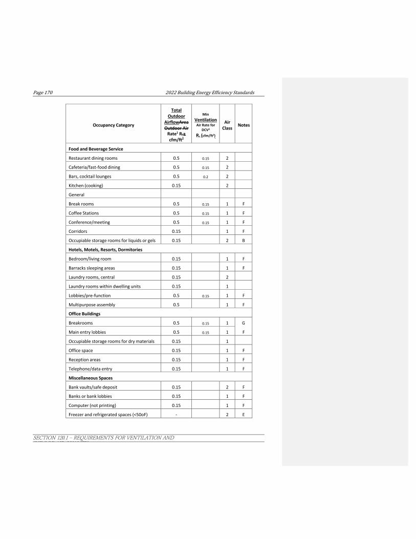
Page170 2022BuildingEnergyEfficiencyStandards
SECTION 120.1 ‒ REQUIREMENTS FOR VENTILATION AND INDOOR AIR QUALITY
Occupancy Category
Total Outdoor
AirflowArea Outdoor Air
Rate1 Rta cfm/ft2
Min Ventilation
Air Rate for DCV2
Ra (cfm/ft2)
Air
Class
Notes
Food and Beverage Service
Restaurant dining rooms 0.5
0.15 2
Cafeteria/fast-food dining 0.5
0.15 2
Bars, cocktail lounges 0.5
0.2 2
Kitchen (cooking) 0.15
2
General
Break rooms 0.5
0.15 1 F
Coffee Stations 0.5
0.15 1 F
Conference/meeting 0.5
0.15 1 F
Corridors 0.15 1 F
Occupiable storage rooms for liquids or gels 0.15
2 B
Hotels, Motels, Resorts, Dormitories
Bedroom/living room 0.15
1 F
Barracks sleeping areas 0.15
1 F
Laundry rooms, central 0.15
2
Laundry rooms within dwelling units 0.15
1
Lobbies/pre-function 0.5
0.15 1 F
Multipurpose assembly 0.5
1 F
Office Buildings
Breakrooms 0.5
0.15 1 G
Main entry lobbies 0.5
0.15 1 F
Occupiable storage rooms for dry materials 0.15
1
Office space 0.15
1 F
Reception areas 0.15
1 F
Telephone/data entry 0.15
1 F
Miscellaneous Spaces
Bank vaults/safe deposit 0.15
2 F
Banks or bank lobbies 0.15 1 F
Computer (not printing) 0.15
1 F
Freezer and refrigerated spaces (<50oF) -
2 E

2022BuildingEnergyEfficiencyStandards Page171
SECTION 120.1 ‒ REQUIREMENTS FOR VENTILATION AND INDOOR AIR QUALITY
Occupancy Category
Total Outdoor
AirflowArea Outdoor Air
Rate1 Rta cfm/ft2
Min Ventilation
Air Rate for DCV2
Ra (cfm/ft2)
Air
Class
Notes
General manufacturing (excludes heavy industrial and process using chemicals)
0.15
3
Pharmacy (prep. Area) 0.15
2
Photo studios 0.15
1
Shipping/receiving 0.15 2 B
Sorting, packing, light assembly 0.15
2
Telephone closets 0.15
1
Transportation waiting 0.5
0.15 1 F
Warehouses 0.15
2 B
All others 0.15
2
Public Assembly Spaces
Auditorium seating area 1.07
0.15 1 F
Places of religious worship 1.07
0.15 1 F
Courtrooms 0.19
0.15 1 F
Legislative chambers 0.19
0.15 1 F
Libraries (reading rooms and stack areas) 0.15
1
Lobbies 0.5
0.15 1 F
Museums (children’s) 0.25
0.15 1
Museums/galleries 0.25
0.15 1 F
Residential
Common corridors 0.15
1 F
Retail
Sales (except as below) 0.25
0.2 2 H
Mall common areas 0.25
0.15 1 F
Barbershop 0.4
2
Beauty and nail salons 0.4
2
Pet shops (animal areas) 0.25
0.15 2
Supermarket 0.25
0.2 1 F
Coin-operated laundries 0.3
2
Sports and Entertainment
Gym, sports arena (play area) 0.5
0.15 2 E

Page172 2022BuildingEnergyEfficiencyStandards
SECTION 120.1 ‒ REQUIREMENTS FOR VENTILATION AND INDOOR AIR QUALITY
Occupancy Category
Total Outdoor
AirflowArea Outdoor Air
Rate1 Rta cfm/ft2
Min Ventilation
Air Rate for DCV2
Ra (cfm/ft2)
Air
Class
Notes
Spectator areas 0.5
0.15 1 F
Swimming (pool) 0.15
2 C
Swimming (deck) 0.5
0.15 2 C
Disco/dance floors 1.5
0.15 2 F
Health club/aerobics room 0.15
2
Health club/weight rooms 0.15
2
Bowling alley (seating) 1.07
0.15 1
Gambling casinos 0.68
0.15 1
Game arcades 0.68
0.15 1
Stages, studios 0.5
0.15 1 D, F
General footnotes for Table 120.1-A: 1 Rta was is determined as being the larger of the area method and the default per person method. The occupant density used in the default per person method was assumed to beis one half of the maximum occupant load assumed for egress purposes in the CBC. 2 If this column specifies a minimum cfm/ft2 then it shall be used to comply with Section 120.1(d)4E.
Specific Notes:
A – For high-school and college libraries, the values shown for “Public Assembly Spaces – Libraries” shall be used.
B – Rate may not be sufficient where stored materials include those having potentially harmful emissions.
C – Rate does not allow for humidity control. “Deck area” refers to the area surrounding the pool that is capable of being wetted during pool use or when the pool is occupied. Deck area that is not expected to be wetted shall be designated as an occupancy category.
D – Rate does not include special exhaust for stage effects such as dry ice vapors and smoke.
E – Where combustion equipment is intended to be used on the playing surface or in the space, additional dilution ventilation, source control, or both shall be provided.
F – Ventilation air for this occupancy category shall be permitted to be reduced to zero when the space is in occupied-standby mode.

2022BuildingEnergyEfficiencyStandards Page173
SECTION 120.1 ‒ REQUIREMENTS FOR VENTILATION AND INDOOR AIR QUALITY
Table 120.1-B – Minimum Exhaust Rates [ASHRAE 62.1: Table 6.5]
Occupancy Category
Exhaust Raete,
cfm/unit
Exhaust Rate,
cfm/ft2
Air Class
Notes
Arenas - 0.50 1 B
Art classrooms - 0.70 2
Auto repair rooms - 1.5 2 A
Barber shops - 0.50 2
Beauty and nail salons - 0.60 2
Cells with toilet - 1.00 2
Copy, printing rooms - 0.50 2
Darkrooms - 1.00 2
Educational science laboratories - 1.00 2
Janitor closets, trash rooms, recycling - 1.00 3
Kitchenettes - 0.30 2
Kitchens – commercial - 0.70 2
Locker rooms for athletic or industrial facilities - 0.50 2
All other locker rooms - 0.25 2
Shower rooms 20/50 - 2 G,H
Paint spray booths - - 4 F
Parking garages - 0.75 2 C
Pet shops (animal areas) - 0.90 2
Refrigerating machinery rooms - - 3 F
Soiled laundry storage rooms - 1.00 3 F
Storage rooms, chemical - 1.50 4 F
Toilets – private 25/50 - 2 E
Toilets – public 50/70 - 2 D
Woodwork shop/classrooms - 0.50 2
Notes: A – Stands where engines are run shall have exhaust systems that directly connect to the engine exhaust and prevent escape of fumes. B – Where combustion equipment is intended to be used on the playing surface, additional dilution ventilation, source control, or both shall be provided. C – Exhaust shall not be required where two or more sides comprise walls that are at least 50% open to the outside. D – Rate is per water closet, urinal, or both. Provide the higher rate where periods of heavy use are expected to occur. The lower rate shall be permitted to be used otherwise. E – Rate is for a toilet room intended to be occupied by one person at a time. For continuous systems operation during hours of use, the lower rate shall be permitted to be used. Otherwise the higher rate shall be used. F – See other applicable standards for exhaust rate. G – For continuous system operation, the lower rate shall be permitted to be used. Otherwise the higher rate shall be used. H – Rate is per showerhead

Page174 2022BuildingEnergyEfficiencyStandards
SECTION 120.1 ‒ REQUIREMENTS FOR VENTILATION AND INDOOR AIR QUALITY
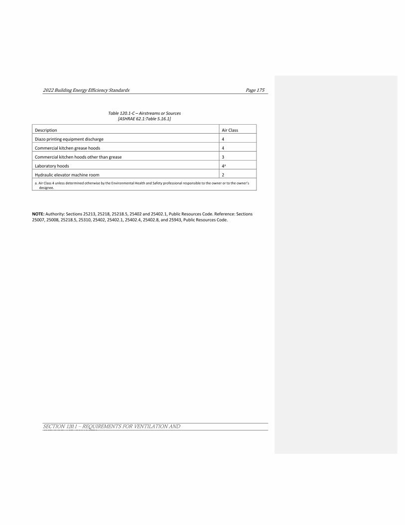
2022BuildingEnergyEfficiencyStandards Page175
SECTION 120.1 ‒ REQUIREMENTS FOR VENTILATION AND INDOOR AIR QUALITY
Table 120.1-C – Airstreams or Sources [ASHRAE 62.1:Table 5.16.1]
Description Air Class
Diazo printing equipment discharge 4
Commercial kitchen grease hoods 4
Commercial kitchen hoods other than grease 3
Laboratory hoods 4a
Hydraulic elevator machine room 2
a. Air Class 4 unless determined otherwise by the Environmental Health and Safety professional responsible to the owner or to the owner’s designee.
NOTE: Authority: Sections 25213, 25218, 25218.5, 25402 and 25402.1, Public Resources Code. Reference: Sections 25007, 25008, 25218.5, 25310, 25402, 25402.1, 25402.4, 25402.8, and 25943, Public Resources Code.


2022BuildingEnergyEfficiencyStandards Page173
SECTION 120.2 ‒ REQUIRED CONTROLS FOR SPACE-CONDITIONING SYSTEMS
SECTION 120.2 – REQUIRED CONTROLS FOR SPACE-CONDITIONING SYSTEMS Nonresidential, high-rise residential, and hotel/motel buildings shall comply with the applicable requirements of Sections 120.2(a) through 120.2(k).
(a) Thermostatic Controls for Each Zone. The supply of heating and cooling energy to each space-conditioning zone or dwelling unit shall be controlled by an individual thermostatic control that responds to temperature within the zone and that meets the applicable requirements of Section 120.2(b). An Energy Management Control System (EMCS) may be installed to comply with the requirements of one or more thermostatic controls if it complies with all applicable requirements for each thermostatic control.
EXCEPTION to Section 120.2(a): An independent perimeter heating or cooling system may serve more than one zone without individual thermostatic controls if:
1. All zones are also served by an interior cooling system; and
2. The perimeter system is designed solely to offset envelope heat losses or gains; and
3. The perimeter system has at least one thermostatic control for each building orientation of 50 feet or more; and
4. The perimeter system is controlled by at least one thermostat located in one of the zones served by the system.
(b) Criteria for Zonal Thermostatic Controls. The individual thermostatic controls required by Section 120.2(a) shall meet the following requirements as applicable:
1. Where used to control comfort heating, the thermostatic controls shall be capable of being set, locally or remotely, down to 55°F or lower.
2. Where used to control comfort cooling, the thermostatic controls shall be capable of being set, locally or remotely, up to 85°F or higher.
3. Where used to control both comfort heating and comfort cooling, the thermostatic controls shall meet Items 1 and 2 and shall be capable of providing a temperature range or deadband of at least 5°F within which the supply of heating and cooling energy to the zone is shut off or reduced to a minimum.
EXCEPTION 1 to Section 120.2(b)3: Systems with thermostats that require manual changeover between heating and cooling modes.
EXCEPTION 2 to Section 120.2(b)3: Systems serving healthcare facilities.
4. Thermostatic controls for all single zone air conditioners and heat pumps, shall comply with the requirements of Sections 110.2(c) and 110.12(a) and, if equipped with DDC to the Zone level, with the Automatic Demand Shed Controls of Section 110.12(b).
EXCEPTION 1 to Section 120.2(b)4: Systems serving exempt process loads that must have constant temperatures to prevent degradation of materials, a process, plants or animals.
EXCEPTION 2 to Section 120.2(b)4:Package terminal air conditioners, package terminal heat pumps, room air conditioners, and room air-conditioner heat pumps.
EXCEPTION 3 to Section 120.2(b)4: Systems serving healthcare facilities.
(c) Hotel/Motel Guest Room and High-rise Residential Dwelling Unit Thermostats.
1. Hotel/motel guest room thermostats shall:
A. Have numeric temperature setpoints in °F and °C; and
B. Have setpoint stops, which are accessible only to authorized personnel, such that guest room occupants cannot adjust the setpoint more than ±5°F (±3°C); and

Page174 2022BuildingEnergyEfficiencyStandards
SECTION 120.2 ‒ REQUIRED CONTROLS FOR SPACE-CONDITIONING SYSTEMS
C. Meet the requirements of Section 110.2(c).
EXCEPTION to Section 120.2(c)1: Thermostats that are integrated into the room heating and cooling equipment.
2. High-rise residential dwelling unit thermostats shall meet the requirements of Section 110.2(c).
(d) Heat Pump Controls. All heat pumps with supplementary electric resistance heaters shall be installed with controls that comply with Section 110.2(b).
(e) Shut-off and Reset Controls for Space-conditioning Systems. Each space-conditioning system shall be installed with controls that comply with the following:
1. The control shall be capable of automatically shutting off the system during periods of nonuse and shall have:
A. An automatic time switch control device complying with Section 110.9, with an accessible manual override that allows operation of the system for up to 4 hours; or
B. An occupancy sensor; or
C. A 4-hour timer that can be manually operated.
EXCEPTION to Section 120.2(e)1: Mechanical systems serving retail stores and associated malls, restaurants, grocery stores, churches, and theaters equipped with 7-day programmable timers.
2. The control shall automatically restart and temporarily operate the system as required to maintain:
A. A setback heating thermostat setpoint if the system provides mechanical heating; and
EXCEPTION to Section 120.2(e)2A: Thermostat setback controls are not required in nonresidential buildings in areas where the Winter Median of Extremes outdoor air temperature determined in accordance with Section 140.4(b)3 is greater than 32°F.
B. A setup cooling thermostat setpoint if the system provides mechanical cooling.
EXCEPTION to Section 120.2(e)2B: Thermostat setup controls are not required in nonresidential buildings in areas where the Summer Design Dry Bulb 0.5 percent temperature determined in accordance with Section 140.4(b)3 is less than 100°F.
3. OccupancyOccupant Sensing Zone Controls. Space conditioning systems serving room(s) that are required to have occupant sensing controls in accordance with Section 130.1(c), and where the Table 120.1-A occupancy category permits ventilation air to be reduced to zero when the space is in occupied-standby mode, shall meet the following:Where the system providing space conditioning also provides the ventilation required by Section 120.1 and includes occupant sensor ventilation control as specified in Section 120.1(d)5, the occupant sensing zone controls shall additionally comply with the following:
A. The zone shall be placed in occupied standby mode when all room(s) served by the zone are unoccupied for more than 5 minutes; and
BA. During Within 5 minutes of entering occupied- standby mode as described in Section 120.1(d).
i. Automatically set up the operating cooling temperature set point by 2°F or more and set back the operating heating temperature set point by 2°F or more; or
ii. For multiple zone systems with Direct Digital Controls (DDC) to the zone level, set up the operating cooling temperature setpoint by 0.5°F or more and set back the operating heating temperature setpoint by 0.5°F or more.
CB. During Within 5 minutes of entering occupied-standby mode, all airflowmechanical ventilation to the zone shall be shutremain off whenever the space temperature is between the active heating and cooling setpoints.
EXCEPTION 1 to Sections 120.2(e)1, 2, and 3: Where it can be demonstrated to the satisfaction of the enforcing agency that the system serves an area that must operate continuously.
Commented [YJW3]: Indoor Lighting. Suggest using "occupant sensing", instead of "occupancy sensing", for consistency as it has been used through out, including 120.1(d)5 and 130.1(c).
2022BuildingEnergyEfficiencyStandards Page175
SECTION 120.2 ‒ REQUIRED CONTROLS FOR SPACE-CONDITIONING SYSTEMS
EXCEPTION 2 to Sections 120.2(e)1, 2, and 3: Systems with full load demands of 2 kW or less, if they have a readily accessible manual shut-off switch.
EXCEPTION 3 to Sections 120.2(e)1 and 2: Systems serving hotel/motel guest rooms, if they have a readily accessible manual shut-off switch.
4. Hotel and motel guest rooms shall have captive card key controls, occupancy sensing controls, or automatic controls such that, no longer than 30 minutes after the guest room has been vacated, setpoints are set up at least +5°F (+3°C) in cooling mode and set down at least -5°F (-3°C) in heating mode.
EXCEPTION to Section 120.2(e): Systems serving healthcare facilities.
(f) Dampers for Air Supply and Exhaust Equipment. Outdoor air supply and exhaust equipment shall be installed with dampers that automatically close upon fan shutdown.
EXCEPTION 1 to Section 120.2(f): Equipment that serves an area that must operate continuously.
EXCEPTION 2 to Section 120.2(f): Gravity and other nonelectrical equipment that has readily accessible manual damper controls.
EXCEPTION 3 to Section 120.2(f): At combustion air intakes and shaft vents.
EXCEPTION 4 to Section 120.2(f): Where prohibited by other provisions of law.
(g) Isolation Area Devices. Each space-conditioning system serving multiple zones with a combined conditioned floor area of more than 25,000 square feet shall be designed, installed, and controlled to serve isolation areas.
1. Each zone, or any combination of zones not exceeding 25,000 square feet, shall be a separate isolation area.
2. Each isolation area shall be provided with isolation devices, such as valves or dampers that allow the supply of heating or cooling to be reduced or shut-off independently of other isolation areas.
3. Each isolation area shall be controlled by a device meeting the requirements of Section 120.2(e)1.
EXCEPTION to Section 120.2(g): Zones designed to be conditioned continuously.
(h) Automatic Demand Shed Controls. See Section 110.12 for requirements for Automatic Demand Shed Controls.
(i) Economizer Fault Detection and Diagnostics (FDD). All newly installed air handlers with a mechanical cooling capacity greater than 54,000 Btu/hrover 33,000 Btu/hr and an installed air economizer shall include a stand- alone or integrated Fault Detection and Diagnostics (FDD) system in accordance with Subsections 120.2(i)1 through 120.2(i)8.
1. The following temperature sensors shall be permanently installed to monitor system operation: outside air, supply air, and when required for differential economizer operation, a return air sensor; and
2. Temperature sensors shall have an accuracy of ±2°F over the range of 40°F to 80°F; and
3. The controller shall have the capability of displaying the value of each sensor; and
4. The controller shall provide system status by indicating the following conditions:
A. Free cooling available;
B. Economizer enabled;
C. Compressor enabled;
D. Heating enabled, if the system is capable of heating; and
E. Mixed air low limit cycle active.
5. The unit controller shall allow manual initiation of each operating mode so that the operation of cooling systems, economizers, fans, and heating systems can be independently tested and verified; and
6. Faults shall be reported in one of the following ways:

Page176 2022BuildingEnergyEfficiencyStandards
SECTION 120.2 ‒ REQUIRED CONTROLS FOR SPACE-CONDITIONING SYSTEMS
A. Reported to an Energy Management Control System regularly monitored by facility personnel.
B. Annunciated locally on one or more zone thermostats, or a device within five (5) feet of zone thermostat(s), clearly visible, at eye level, and meeting the following requirements:
i. On the thermostat, device, or an adjacent written sign, display instructions to contact appropriate building personnel or an HVAC technician; and
ii. In buildings with multiple tenants, the annunciation shall either be within property management offices or in a common space accessible by the property or building manager.
C. Reported to a fault management application which automatically provides notification of the fault to remote HVAC service provider.
7. The FDD system shall detect the following faults:
A. Air temperature sensor failure/fault;
B. Not economizing when it should;
C. Economizing when it should not;
D. Damper not modulating; and
E. Excess outdoor air.
8. The FDD System shall be certified by the Energy Commission as meeting requirements of Sections 120.2(i)1 through 120.2(i)7 in accordance with Section 110.0 and JA6.3.
EXCEPTION to 120.2(i)8: FDD algorithms based in Direct Digital Control systems are not required to be certified to the Energy Commission.
(j) Direct Digital Controls (DDC). Direct Digital Controls to the zone shall be provided as specified by Table 120.2-A.
The provided DDC system shall meet the control logic requirements of Sections 120.1(d), 110.12(a) and 110.12(b)120.2(h), and be capable of the following:
1. Monitoring zone and system demand for fan pressure, pump pressure, heating and cooling;
2. Transferring zone and system demand information from zones to air distribution system controllers and from air distribution systems to heating and cooling plant controllers;
3. Automatically detecting the zones and systems that may be excessively driving the reset logic and generate an alarm or other indication to the system operator;
4. Readily allow operator removal of zones(s) from the reset algorithm;
5. For new buildings, trending and graphically displaying input and output points; and
6. Resetting heating and cooling setpoints in all noncritical zones upon receipt of a signal from a centralized contact or software point as described in Section 120.2(h)110.12(b).
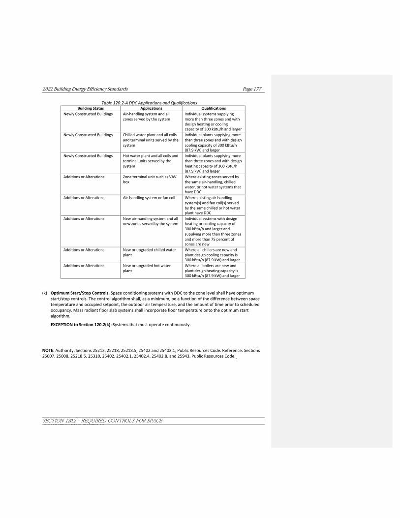
2022BuildingEnergyEfficiencyStandards Page177
SECTION 120.2 ‒ REQUIRED CONTROLS FOR SPACE-CONDITIONING SYSTEMS
Table 120.2-A DDC Applications and Qualifications Building Status Applications Qualifications
Newly Constructed Buildings Air-handling system and all zones served by the system
Individual systems supplying more than three zones and with design heating or cooling capacity of 300 kBtu/h and larger
Newly Constructed Buildings Chilled water plant and all coils and terminal units served by the system
Individual plants supplying more than three zones and with design cooling capacity of 300 kBtu/h (87.9 kW) and larger
Newly Constructed Buildings Hot water plant and all coils and terminal units served by the system
Individual plants supplying more than three zones and with design heating capacity of 300 kBtu/h (87.9 kW) and larger
Additions or Alterations Zone terminal unit such as VAV box
Where existing zones served by the same air-handling, chilled water, or hot water systems that have DDC
Additions or Alterations Air-handling system or fan coil Where existing air-handling system(s) and fan coil(s) served by the same chilled or hot water plant have DDC
Additions or Alterations New air-handling system and all new zones served by the system
Individual systems with design heating or cooling capacity of 300 kBtu/h and larger and supplying more than three zones and more than 75 percent of zones are new
Additions or Alterations New or upgraded chilled water plant
Where all chillers are new and plant design cooling capacity is 300 kBtu/h (87.9 kW) and larger
Additions or Alterations New or upgraded hot water plant
Where all boilers are new and plant design heating capacity is 300 kBtu/h (87.9 kW) and larger
(k) Optimum Start/Stop Controls. Space conditioning systems with DDC to the zone level shall have optimum start/stop controls. The control algorithm shall, as a minimum, be a function of the difference between space temperature and occupied setpoint, the outdoor air temperature, and the amount of time prior to scheduled occupancy. Mass radiant floor slab systems shall incorporate floor temperature onto the optimum start algorithm.
EXCEPTION to Section 120.2(k): Systems that must operate continuously.
NOTE: Authority: Sections 25213, 25218, 25218.5, 25402 and 25402.1, Public Resources Code. Reference: Sections 25007, 25008, 25218.5, 25310, 25402, 25402.1, 25402.4, 25402.8, and 25943, Public Resources Code.

Page178 2022BuildingEnergyEfficiencyStandards
SECTION 120.3 – REQUIREMENTS FOR PIPE INSULATION
SECTION 120.3 – REQUIREMENTS FOR PIPE INSULATION Nonresidential, high-rise residential, and hotel/motel buildings shall comply with the applicable requirements of Sections 120.3(a) through 120.3(c).
(a) General Requirements. The piping conditions listed below for space-conditioning and service water-heating systems with fluid normal operating temperatures listed in Table 120.3-A, shall have at least the amount of insulation specified in Subsection (c):
1. Space Cooling Systems. All refrigerant suction, chilled water, and brine fluid distribution systems.
2. Space Heating Systems. All refrigerant, steam, steam condensate and hot water fluid distribution systems.
3. Service wWater-heating sSystems., including hotel/motel domestic hot water systems.
A. Recirculating system piping, including the supply and return piping to the water heater.
B. The first 8 feet of hot and cold outlet piping, including piping between a storage tank and a heat trap, for a nonrecirculating storage system.
C. Pipes that are externally heated.
Insulation conductivity shall be determined in accordance with ASTM C335 at the mean temperature listed in Table 120.3-A, and shall be rounded to the nearest 1/100 Btu-inch per hour per square foot per °F. Fluid distribution systems include all elements that are in series with the fluid flow, such as pipes, pumps, valves, strainers, coil u- bends, and air separators, but not including elements that are not in series with the fluid flow, such as expansion tanks, fill lines, chemical feeders, and drains.
(b) Insulation Protection. Pipe Insulation shall be protected from damage due to sunlight, moisture, equipment maintenance, and wind. Protection shall, at minimum, include the following:
1. Pipe insulation exposed to weather shall be protected by a cover suitable for outdoor service. The cover shall be water retardant and provide shielding from solar radiation that can cause degradation of the material. Adhesive tape shall not be used to provide this protection.
2. Pipe insulation covering chilled water piping and refrigerant suction piping located outside the conditioned space shall include, or be protected by, a Class I or Class II vapor retarder. All penetrations and joints shall be sealed.
3. Pipe insulation buried below grade must be installed in a water proof and non-crushable casing or sleeve.
(c) Insulation Thickness
1. For insulation with a conductivity in the range shown in Table 120.3-A for the applicable fluid temperature range, the insulation shall have the applicable minimum thickness or R-value shown in Table 120.3-A.
2. For insulation with a conductivity outside the range shown in Table 120.3-A for the applicable fluid temperature range, the insulation shall have a minimum R-value shown in Table 120.3-A or thickness as calculated with:

2022BuildingEnergyEfficiencyStandards Page179
SECTION 120.3 ‒ REQUIREMENTS FOR PIPE INSULATION
��
MINIMUM INSULATION THICKNESS EQUATION
� T � PR
��1 �
K
t � k �
� � 1�
� PR � � � �
WHERE:
T = Minimum insulation thickness for material with conductivity K, inches.
PR = Pipe actual outside radius, inches.
t = Insulation thickness from Table 120.3-A, inches.
K = Conductivity of alternate material at the mean rating temperature indicated in Table 120.3-A for the applicable fluid temperature range, in Btu-inch per hour per square foot per °F.
k = The lower value of the conductivity range listed in Table 120.3-A for the applicable fluid temperature
range, Btu-inch per hour per square foot per °F.

Page180 2022BuildingEnergyEfficiencyStandards
SECTION 120.3 – REQUIREMENTS FOR PIPE INSULATION
Table 120.3-A PIPE INSULATION THICKNESS
Fluid Operating
Temperature Range
(°F)
Insulation Conductivity Nominal Pipe Diameter (in inches)
Conductivity
(in Btu·in/h·ft2· °F)
Mean Rating Temperature
(°F)
< 1
1 to <1.5
1.5 to < 4
4 to < 8 8 and larger
Space heating and Service Water Heating Systems (Steam, Steam Condensate, Refrigerant, Space Heating,
Service Hot Water)
Minimum Pipe Insulation Required (Thickness in inches or R-value)
Above 350
0.32-0.34
250
Inches 4.5 5.0 5.0 5.0 5.0
R-value R 37 R 41 R 37 R 27 R 23
251-350
0.29-0.32
200 Inches 3.0 4.0 4.5 4.5 4.5
R-value R 24 R 34 R 35 R 26 R 22
201-250
0.27-0.30
150 Inches 2.5 2.5 2.5 3.0 3.0
R-value R 21 R 20 R 17.5 R 17 R 14.5
141-200
0.25-0.29
125
Inches 1.5 1.5 2.0 2.0 2.0
R-value R 11.5 R 11 R 14 R 11 R 10
105-140
0.22-0.28
100
Inches 1.0 1.5 1.5 1.5 1.5
R-value R 7.7 R 12.5 R 11 R 9 R 8 Nominal Pipe Diameter (in inches)
< 1 1 to <1.5 1.5 to < 4 4 to < 8 8 and larger
Space cooling systems (chilled water, refrigerant and brine)
Minimum Pipe Insulation Required (Thickness in inches or R-value)1
40-60 0.21-0.27 75 Inches Nonres 0.5
Res 0.75
Nonres 0.5
Res 0.75
1.0 1.0 1.0
R-value Nonres R 3
Res R 6
Nonres R 3
Res R 5
R 7 R 6 R 5
Below 40 0.20-0.26 50 Inches 1.0 1.5 1.5 1.5 1.5
R-value R 8.5 R 14 R 12 R 10 R 9
Nominal Pipe Diameter (in inches)
< 1 1 to <1.5
1.5 to < 4
4 to < 8 8 and larger
Hotel/Motel Domestic Hot Water Systems (recirculating system piping) 2
Minimum Pipe Insulation Required (Thickness in inches or R-value)
105-140 0.22-0.28 100 Inches 1.0 1.5 2.0 2.0 2.0
R-value R 7.7 R 12.5 R 16 R 12.5 R 11
Footnote to Table 120.3-A:
1. These thickness are based on energy efficiency considerations only. Issues such as water vapor permeability or surface condensation sometimes require vapor retarders or additional insulation.
2. For hotel/motel buildings, domestic hot water systems piping with water temperature 105 – 140 °F should use the specified insulation requirement. For temperature ranges above 141°F, insulation requirements under Space heating and Service Water Heating Systems in Table 120.3-A shall be used.
EXCEPTION 1 to Section 120.3: Factory-installed piping within space-conditioning equipment certified under Section 110.1 or 110.2.
EXCEPTION 2 to Section 120.3: Piping that conveys fluids with a design operating temperature range between 60°F
Commented [SS4]: MF DHW

2022BuildingEnergyEfficiencyStandards Page181
SECTION 120.3 ‒ REQUIREMENTS FOR PIPE INSULATION
and 105°F.
EXCEPTION 3 to Section 120.3: Where the heat gain or heat loss to or from piping without insulation will not increase building source energy use.
EXCEPTION 4 to Section 120.3: Piping that penetrates framing members shall not be required to have pipe insulation for the distance of the framing penetration. Metal piping that penetrates metal framing shall use grommets, plugs, wrapping or other insulating material to assure that no contact is made with the metal framing.
NOTE: Authority: Sections 25213, 25218, 25218.5, 25402 and 25402.1, Public Resources Code. Reference: Sections 25007, 25008, 25218.5, 25310, 25402, 25402.1, 25402.4, 25402.5, 25402.8, and 25943, Public Resources Code.


2022BuildingEnergyEfficiencyStandards Page181
SECTION 120.4 ‒ REQUIREMENTS FOR AIR DISTRIBUTION SYSTEM DUCTS AND PLENUMS
SECTION 120.4 – REQUIREMENTS FOR AIR DISTRIBUTION SYSTEM DUCTS AND PLENUMS Nonresidential, high-rise residential, and hotel/motel buildings shall comply with the applicable requirements of Sections 120.4(a) through 120.4(fg).
EXCEPTION to Section 120.4: Systems serving healthcare facilities shall comply with the applicable requirements of the California Mechanical Code.
(a) CMC Compliance. All air distribution system ducts and plenums, including, but not limited to, building cavities, mechanical closets, air-handler boxes and support platforms used as ducts or plenums, shall meet the requirements of the CMC Sections 601.0, 602.0, 603.0, 604.0, 605.0, and ANSI/SMACNA-006-2006 HVAC Duct Construction Standards Metal and Flexible 3rd Edition, incorporated herein by reference. Connections of metal ducts and the inner core of flexible ducts shall be mechanically fastened. Openings shall be sealed with mastic, tape, aerosol sealant, or other duct-closure system that meets the applicable requirements of UL 181, UL 181A, or UL 181B. If mastic or tape is used to seal openings greater than 1/4 inch, the combination of mastic and either mesh or tape shall be used.
Portions of supply-air and return-air ducts conveying heated or cooled air located in one or more of the following spaces shall be insulated to a minimum installed level of R-8:
1. Outdoors; or
2. In a space between the roof and an insulated ceiling; or
3. In a space directly under a roof with fixed vents or openings to the outside or unconditioned spaces; or
4. In an unconditioned crawl space; or
5. In other unconditioned spaces.
Portions of supply-air ducts that are not in one of these spaces, including ducts buried in concrete slab, shall be insulated to a minimum installed level of R-4.2 or be enclosed in directly conditioned space.
(b) Duct and Plenum Materials.
1. Factory-fabricated duct systems.
A. All factory-fabricated duct systems shall comply with UL 181 for ducts and closure systems, including collars, connections, and splices, and be labeled as complying with UL 181. UL 181 testing may be performed by UL laboratories or a laboratory approved by the Executive Director.
B. All pressure-sensitive tapes, heat-activated tapes, and mastics used in the manufacture of rigid fiberglass ducts shall comply with UL 181 and UL 181A.
C. All pressure-sensitive tapes and mastics used with flexible ducts shall comply with UL 181 and UL 181B.
D. All ductwork and plenums with pressure class ratings shall be constructed to Seal Class A, as specified by ASHRAE 90.1. Joints and seams of duct systems and their components shall not be sealed with cloth-back rubber adhesive duct tapes unless such tape is used in combination with mastic and drawbands.
EXCEPTION to Section 120.4(b)1D: Ductwork located in occupied space and exposed to view is not required to meet Seal Class A.
2. Field-fabricated duct systems.
A. Factory-made rigid fiberglass and flexible ducts for field-fabricated duct systems shall comply with UL 181. All pressure-sensitive tapes, mastics, aerosol sealants, or other closure systems used for installing
Commented [BZ5]: Duct Leakage

Page182 2022BuildingEnergyEfficiencyStandards
SECTION 120.4 ‒ REQUIREMENTS FOR AIR DISTRIBUTION SYSTEM DUCTS AND PLENUMS
field-fabricated duct systems shall meet the applicable requirements of UL 181, UL 181A, and UL 181B.
B. Mastic sealants and mesh.
i. Sealants shall comply with the applicable requirements of UL 181, UL 181A, and UL 181B, and be nontoxic and water resistant.
ii. Sealants for interior applications shall pass ASTM C731 (extrudability after aging) and D2202 (slump test on vertical surfaces), incorporated herein by reference.
iii. Sealants for exterior applications shall pass ASTM tests C731, C732 (artificial weathering test), and D2202, incorporated herein by reference.
iv. Sealants and meshes shall be rated for exterior use.
C. Pressure-sensitive tape. Pressure-sensitive tapes shall comply with the applicable requirements of UL 181, UL 181A, and UL 181B.
D. All ductwork and plenums with pressure class ratings shall be constructed to Seal Class A, as specified by ASHRAE 90.1. Joints and seams of duct systems and their components shall not be sealed with cloth-back rubber adhesive duct tapes unless such tape is used in combination with mastic and drawbands.
EXCEPTION to Section 120.4(b)2D: Ductwork located in occupied space and exposed to view is not required to meet Seal Class A.
E. Drawbands used with flexible duct.
i. Drawbands shall be either stainless-steel worm-drive hose clamps or UV-resistant nylon duct ties.
ii. Drawbands shall have a minimum tensile strength rating of 150 pounds.
iii. Drawbands shall be tightened as recommended by the manufacturer with an adjustable tensioning tool.
F. Aerosol-sealant closures.
i. Aerosol sealants shall meet the requirements of UL 723 and be applied according to manufacturer specifications.
ii. Tapes or mastics used in combination with aerosol sealing shall meet the requirements of this section.
(c) All duct insulation product R-values shall be based on insulation only (excluding air films, vapor retarders, or other duct components) and tested C-values at 75°F mean temperature at the installed thickness, in accordance with ASTM C518 or ASTM C177, incorporated herein by reference, and certified pursuant to Section 110.8.
(d) The installed thickness of duct insulation used to determine its R-value shall be determined as follows:
1. For duct board, duct liner, and factory-made rigid ducts not normally subjected to compression, the nominal insulation thickness shall be used.
2. For duct wrap, installed thickness shall be assumed to be 75 percent (25 percent compression) of nominal thickness.
3. For factory-made flexible air ducts, the installed thickness shall be determined by dividing the difference between the actual outside diameter and nominal inside diameter by two.
(e) Insulated flexible duct products installed to meet this requirement must include labels, in maximum intervals of 3 feet, showing the thermal performance R-value for the duct insulation itself (excluding air films, vapor retarder, or other duct components), based on the tests in Section 120.4(c) and the installed thickness determined by Section 120.4(d)3.

2022BuildingEnergyEfficiencyStandards Page183
SECTION 120.4 ‒ REQUIREMENTS FOR AIR DISTRIBUTION SYSTEM DUCTS AND PLENUMS
(f) Protection of Insulation. Insulation shall be protected from damage, including that due to sunlight, moisture, equipment maintenance, and wind but not limited to the following: insulation exposed to weather shall be suitable for outdoor service, e.g., protected by aluminum, sheet metal, painted canvas, or plastic cover. Cellular foam insulation shall be protected as above or painted with a coating that is water retardant and provides shielding from solar radiation that can cause degradation of the material.
(g) Duct Sealing. Duct systems shall comply with subsections 1 or 2 below:
1. New duct systems that meet the criteria in Subsections A, B, C, and D below shall be sealed to a leakage rate not to exceed 6 percent of the nominal air handler airflow rate as confirmed through HERS field verification and diagnostic testing, in accordance with the applicable procedures in Reference Nonresidential Appendix NA7.5.3 ces NA1 and NA2;
A. The duct system does not serve a healthcare facility; and
B. The duct system provides conditioned air to an occupiable space for a constant volume, single zone, space-conditioning system; and
C. The space conditioning system serves less than 5,000 square feet of conditioned floor area; and
D. The combined surface area of the ducts located outdoors or in unconditioned space is more than 25 percent of the total surface area of the entire duct system.
2. New duct systems that are not subject to testing under Section 120.4(g)1 shall instead meet the duct leakage testing requirements of CMC Section 603.10.1.
NOTE: Authority: Sections 25213, 25218, 25218.5, 25402 and 25402.1, Public Resources Code. Reference: Sections 25007, 25008, 25218.5, 25310, 25402, 25402.1, 25402.4, 25402.8, and 25943, Public Resources Code.

Page184 2022BuildingEnergyEfficiencyStandards
SECTION 120.5 ‒ REQUIRED NONRESIDENTIAL MECHANICAL SYSTEM ACCEPTANCE
SECTION 120.5 – REQUIRED NONRESIDENTIAL MECHANICAL SYSTEM ACCEPTANCE Nonresidential, high-rise residential, and hotel/motel buildings shall comply with the applicable requirements of Sections 120.5(a) through 120.5(b).
EXCEPTION to Section 120.5: Systems serving healthcare facilities.
(a) Before an occupancy permit is granted the following equipment and systems shall be certified as meeting the Acceptance Requirements for Code Compliance, as specified by the Reference Nonresidential Appendix NA7. A Certificate of Acceptance shall be submitted to the enforcement agency that certifies that the equipment and systems meet the acceptance requirements:
1. Outdoor air ventilation systems shall be tested in accordance with NA7.5.1
2. Constant volume, single zone air conditioning and heat pump unit controls shall be tested in accordance with NA7.5.2.
3. Duct systems that are subject to testing under Section 120.4(g)1, Section 141.0(b)2Di, or Section 141.0(b)2Dii shall be tested in accordance with NA7.5.3. where either:
A. They are new duct systems that meet the criteria of Sections 140.4(l)1a, 140.4(l)1b, and 140.4(l)1c; or
B. They are part of a system that meets the criteria of Section 141.0(b)2D.
4. Air economizers shall be tested in accordance with NA7.5.4.
EXCEPTION to Section 120.5(a)4: Air economizers installed by the HVAC system manufacturer and certified to the Commission as being factory calibrated and tested are exempt from the Functional Testing section of the Air Economizer Controls acceptance test as described in NA7.5.4.2.
5. Demand control ventilation systems required by Section 120.1(c)3 shall be tested in accordance with NA7.5.5
6. Supply fan variable flow controls shall be tested in accordance with NA7.5.6
7. Hydronic system variable flow controls shall be tested in accordance with NA7.5.7 and NA7.5.9
8. Boiler or chillers that require isolation controls as specified by Section 140.4(k)2 or 140.4(k)3 shall be tested in accordance with NA7.5.7
9. Hydronic systems with supply water temperature reset controls shall be tested in accordance with NA7.5.8
10. Automatic demand shed controls shall be tested in accordance with NA7.5.10.
11. Fault Detection and Diagnostics (FDD) for Packaged Direct-Expansion Units shall be tested in accordance with NA7.5.11.
12. Automatic Fault Detection and Diagnostics (FDD) for air-handling units and zone terminal units shall be tested in accordance with NA7.5.12.
13. Distributed Energy Storage DX AC Systems shall be tested in accordance with NA7.5.13.
14. Thermal Energy Storage (TES) Systems shall be tested in accordance with NA7.5.14.
15. Supply air temperature reset controls shall be tested in accordance with NA7.5.15.
16. Water-cooled chillers served by cooling towers with condenser water reset controls shall be tested in accordance with NA7.5.16.
17. When an Energy Management Control System is installed, it shall functionally meet all of the applicable requirements of Part 6.
Commented [SS6]: Duct Leakage

2022BuildingEnergyEfficiencyStandards Page185
SECTION 120.5 ‒ REQUIRED NONRESIDENTIAL MECHANICAL SYSTEM ACCEPTANCE
18. Occupant Sensing Zone Controls shall be tested in accordance with NA7.5.17.
(b) When certification is required by Title 24, Part 1, Section 10-103.2, the acceptance testing specified by Section 120.5(a) shall be performed by a Certified Mechanical Acceptance Test Technician (CMATT). If the CMATT is operating as an employee, the CMATT shall be employed by a Certified Mechanical Acceptance Test Employer. The CMATT shall disclose on the Certificate of Acceptance a valid CMATT certification identification number issued by an approved Acceptance Test Technician Certification Provider. The CMATT shall complete all Certificate of Acceptance documentation in accordance with the applicable requirements in Section 10- 103(a)4.
NOTE: Authority: Sections 25213, 25218, 25218.5, 25402, and 25402.1, and 25213, Public Resources Code. Reference: Sections 25007, 25008, 25218.5, 25310, 25402, 25402.1, 25402.4, , 25402.8, 25943, Public Resources Code.

Page186 2022BuildingEnergyEfficiencyStandards
SECTION 120.6 ‒ MANDATORY REQUIREMENTS FOR COVERED PROCESSES
SECTION 120.6 – MANDATORY REQUIREMENTS FOR COVERED PROCESSES Nonresidential, high-rise residential, and hotel/motel buildings shall comply with the applicable requirements of Sections 120.6(a) through 120.6(g).
(a) Mandatory Requirements for Refrigerated Warehouses
Refrigerated warehouses that are greater than or equal to 3,000 square feet and refrigerated spaces with a sum total of 3,000 square feet or more that are served by the same refrigeration system shall meet the requirements of Section 120.6(a).
Refrigerated spaces that are less than 3,000 square feet shall meet the requirements of the Appliance Efficiency Regulations for walk-in coolers or freezers contained in the Appliance Efficiency Regulations (California Code of Regulations, Title 20, Sections 1601 through 1608).
1. Insulation Requirements. Exterior surfaces of refrigerated warehouses shall be insulated at least to the R- values in Table 120.6-A.
Table 120.6-A REFRIGERATED WAREHOUSE INSULATION
SPACE SURFACE MINIMUM R-VALUE (°F·hr·sf/Btu)
Freezers
Roof/Ceiling R-40
Wall R-36
Floor R-35
Floor with all heating from productive refrigeration capacity1
R-20
Coolers
Roof/Ceiling R-28
Wall R-28
1All underslab heating is provided by a heat exchanger that provides refrigerant subcooling or other means that result in productive refrigeration capacity on the associated refrigerated system.
2. Underslab heating. Electric resistance heat shall not be used for the purposes of underslab heating.
EXCEPTION to Section 120.6(a)2: Underslab heating systems controlled such that the electric resistance heat is thermostatically controlled and disabled during the summer on-peak period defined by the local electric utility.
3. Evaporators. New fan-powered evaporators used in coolers and freezers shall conform to the following:
A. Single phase fan motors less than 1 hp and less than 460 Volts in newly installed evaporators shall be electronically commutated motors or shall have a minimum motor efficiency of 70 percent when rated in accordance with NEMA Standard MG 1-2006 at full load rating conditions.
B. Evaporator fans served either by a suction group with multiple compressors, or by a single compressor with variable capacity capability shall be variable speed and the speed shall be controlled in response to space temperature or humidity.
EXCEPTION 1 to Section 120.6(a)3B: Addition, alteration or replacement of less than all of the evaporators in an existing refrigerated space that does not have speed-controlled evaporators.
EXCEPTION 2 to Section 120.6(a)3B: Coolers within refrigerated warehouses that maintain a Controlled Atmosphere for which a licensed engineer has certified that the types of products stored will require constant operation at 100 percent of the design airflow.
EXCEPTION 3 to Section 120.6(a)3B: Areas within refrigerated warehouses that are designed solely for the purpose of quick chilling/freezing of products, including but not limited to spaces with design cooling capacities of greater than 240 Btu/hr-ft² (2 tons per 100 ft²).
2022BuildingEnergyEfficiencyStandards Page187
SECTION 120.6 ‒ MANDATORY REQUIREMENTS FOR COVERED PROCESSES
C. Evaporator fans served by a single compressor that does not have variable capacity shall utilize controls to reduce airflow by at least 40 percent for at least 75 percent of the time when the compressor is not running.
EXCEPTION to Section 120.6(a)3C: Areas within refrigerated warehouses that are designed solely for the purpose of quick chilling/freezing of products (space with design cooling capacities of greater than 240 Btu/hr-ft² (2 tons per 100 ft²)).
4. Condensers. New fan-powered condensers on new refrigeration systems shall conform to the following:
A. Design saturated condensing temperatures for evaporative-cooled condensers and water-cooled condensers served by fluid coolers or cooling towers shall be less than or equal to:
i. The design wetbulb temperature plus 20°F in locations where the design wetbulb temperature is less than or equal to 76°F;
ii. The design wetbulb temperature plus 19°F in locations where the design wetbulb temperature is between 76°F and 78°F; or
iii. The design wetbulb temperature plus 18°F in locations were the design wetbulb temperature is greater than or equal to 78°F.
EXCEPTION 1 to Section 120.6(a)4A: Compressors and condensers on a refrigeration system for which more than 20 percent of the total design refrigeration cooling load is for quick chilling/ or freezing of products (space with design cooling capacities of greater than 240 Btu/hr-ft2), or process refrigeration cooling for other than a refrigerated space.
B. Design saturated condensing temperatures for air-cooled condensers shall be less than or equal to:
i. The design drybulb temperature plus 10°F for systems serving freezers;
ii. The design drybulb temperature plus 15°F for systems serving coolers.
EXCEPTION 1 to Section 120.6(a)4B: Condensing units with a total compressor horsepower less than 100 HP.
EXCEPTION 2 to Section 120.6(a)4B: Compressors and condensers on a refrigeration system for which more than 20 percent of the total design refrigeration cooling load is for quick chilling/ or freezing of products (space with design cooling capacities of greater than 240 Btu/hr-ft2), or process refrigeration cooling for other than a refrigerated space.
C. The saturated condensing temperature necessary for adiabatic condensers to reject the design total heat of rejection of a refrigeration system assuming dry mode performance shall be less than or equal to:
i. The design drybulb temperature plus 20°F for systems serving freezers;
ii. The design drybulb temperature plus 30°F for systems serving coolers.
EXCEPTION 1 to Section 120.6(a)4C: Compressors and condensers on a refrigeration system for which more than 20 percent of the total design refrigeration cooling load is for quick chilling/ or freezing of products (space with design cooling capacities of greater than 240 Btu/hr-ft2 (2 tons per 100 ft2)), or process refrigeration cooling for other than a refrigerated space.
D. All condenser fans for air-cooled condensers, evaporative-cooled condensers, adiabatic condensers, gas coolers, air or water fluid coolers or cooling towers shall be continuously variable speed, with the speed of all fans serving a common condenser high side controlled in unison.
E. The minimum condensing temperature setpoint shall be less than or equal to 70°F for systems utilizing air-cooled condensers, evaporative-cooled condensers, adiabatic condensers, gas coolers, air or water-cooled fluid coolers or cooling towers for heat rejection.
F. Condensing temperature reset. The condensing temperature set point of systems served by air-cooled condensers shall be reset in response to ambient drybulb temperature. The condensing temperature

Page188 2022BuildingEnergyEfficiencyStandards
SECTION 120.6 ‒ MANDATORY REQUIREMENTS FOR COVERED PROCESSES
set point of systems served by evaporative-cooled condensers or water-cooled condensers (via cooling towers or fluid coolers) shall be reset in response to ambient wetbulb temperatures. The condensing temperature set point for systems served by adiabatic condensers shall be reset in response to ambient drybulb temperature while operating in dry mode.
EXCEPTION 1 to Section 120.6(a)4F: Condensing temperature control strategies approved by the Executive Director that have been demonstrated to provide at least equal energy savings.
EXCEPTION 2 to Section 120.6(a)4F: Systems served by adiabatic condensers in Climate Zones 1, 3, 5, 12, 14 and 16.
G. Fan-powered condensers shall meet the condenser efficiency requirements listed in Table 120.6-B. Condenser efficiency is defined as the Total Heat of Rejection (THR) capacity divided by all electrical input power including fan power at 100 percent fan speed, and power of spray pumps for evaporative condensers.
EXCEPTION to Section 120.6(a)4G: Adiabatic condensers with ammonia as refrigerant.
H. Air-cooled condensers shall have a fin density no greater than 10 fins per inch.
EXCEPTION to Section 120.6(a)4H: Micro-channel condensers.
EXCEPTION to Section 120.6(a)4A, 4B, 4C, 4E, 4F and 4G: Transcritical CO2 refrigeration systems.
Table 120.6-B FAN-POWERED CONDENSERS – MINIMUM EFFICIENCY REQUIREMENTS
CONDENSER TYPE REFRIGERANT TYPE MINIMUM EFFICIENCY RATING CONDITION
Outdoor Evaporative- Cooled with THR Capacity > 8,000 MBH
All
350 Btuh/watt
100°F Saturated Condensing Temperature
(SCT), 70°F Outdoor Wetbulb Temperature
Outdoor Evaporative- Cooled with THR Capacity < 8,000 MBH and Indoor Evaporative-Cooled
All
160 Btuh/watt
Outdoor Air-Cooled
Ammonia 75 Btuh/watt 105°F Saturated Condensing Temperature
(SCT), 95°F Outdoor Drybulb Temperature
Halocarbon
65 Btuh/watt
Adiabatic Dry Mode
Halocarbon
45 Btuh/watt
105°F Saturated Condensing Temperature
(SCT), 95°F Outdoor Drybulb Temperature
Indoor Air-Cooled All Exempt
5. Compressors. Compressor systems utilized in refrigerated warehouses shall conform to the following:
A. Compressors serving refrigeration systems that are not transcritical CO2, shall be designed to operate at a minimum condensing temperature of 70°F or less.
B. Compressors for transcritical CO2 refrigeration systems shall be designed to operate at a minimum condensing temperature of 60°F or less.
EXCEPTION to Section 120.6(a)5B: Compressors with a design saturated suction temperature greater than or equal to 30°F shall be designed to operate at a minimum condensing temperature of 70°F or less.

2022BuildingEnergyEfficiencyStandards Page189
SECTION 120.6 ‒ MANDATORY REQUIREMENTS FOR COVERED PROCESSES
C.B. New open-drive screw compressors in new refrigeration systems with a design saturated suction temperature (SST) of 28°F or lower that discharges to the system condenser pressure shall control compressor speed in response to the refrigeration load.
EXCEPTION 1 to Section 120.6(a)5CB: Refrigeration plants with more than one dedicated compressor per suction group.
EXCEPTION 2 to Section 120.6(a)5CB: Compressors and condensers on a refrigeration system for which more than 20 percent of the total design refrigeration cooling load is for quick chilling/ or freezing of products (space with design cooling capacities of greater than 240 Btu/hr-ft2 (2 tons per 100 ft2)), or process refrigeration cooling for other than a refrigerated space.
DC. New screw compressors with nominal electric motor power greater than 150 HP shall include the ability to automatically vary the compressor volume ratio (Vi) in response to operating pressures.
6. Infiltration Barriers. Passageways between freezers and higher-temperature spaces, and passageways between coolers and nonrefrigerated spaces, shall have an infiltration barrier consisting of strip curtains, an automatically-closing door, or an air curtain designed by the manufacturer for use in the passageway and temperature for which it is applied.
EXCEPTION 1 to Section 120.6(a)6: Openings with less than 16 square feet of opening area.
EXCEPTION 2 to Section 120.6(a)6: Dock doorways for trailers.
77. Refrigeratedion System Warehouse Acceptance. Before an occupancy permit is granted for a new refrigerated warehouse, or before a new refrigeration system serving a refrigerated warehouse is operated for normal use, the following equipment and systems shall be certified as meeting the Acceptance Requirements for Code Compliance, as specified by the Reference Nonresidential Appendix NA7. A Certificate of Acceptance shall be submitted to the enforcement agency that certifies that the equipment and systems meet the acceptance requirements:
A. Electric resistance underslab heating systems shall be tested in accordance with NA7.10.1.
B. Evaporators fan motor controls shall be tested in accordance with NA7.10.2.
C. Evaporative condensers shall be tested in accordance with NA7.10.3.1.
D. Air-cooled condensers shall be tested in accordance with NA7.10.3.2.
E. Adiabatic condensers shall be tested in accordance with NA7.10.3.3.
F. Variable speed compressors shall be tested in accordance with NA7.10.4.
G. Transcritical CO2 refrigeration systems shall be tested in accordance with NA7.20.1
8. Transcritical CO2 Gas Coolers. New fan-powered gas coolers on all new transcritical CO2 refrigeration systems shall conform to the following:
A. Air-cooled gas coolers are prohibited in Climate Zones 9 through 15.
B. Design leaving gas temperature for air-cooled gas coolers shall be less than or equal to the design dry bulb temperature plus 6°F.
EXCEPTION to Section 120.6(a)8B: Design leaving gas temperature for air-cooled gas coolers in Climate Zone 2, 4, and 8 shall be less than or equal to the design dry bulb temperature plus 8°F.
C. Design leaving gas temperature for adiabatic gas coolers necessary to reject the design total heat of rejection of a refrigeration system assuming dry mode performance shall be less than or equal to the design dry bulb temperature plus 15°F.
D. All gas cooler fans shall be continuously variable speed, with the speed of all fans serving a common condenser high side controlled in unison.
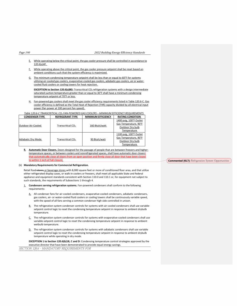
Page190 2022BuildingEnergyEfficiencyStandards
SECTION 120.6 ‒ MANDATORY REQUIREMENTS FOR COVERED PROCESSES
E. While operating below the critical point, the gas cooler pressure shall be controlled in accordance to 120.6(a)4F.
F. While operating above the critical point, the gas cooler pressure setpoint shall be reset based on ambient conditions such that the system efficiency is maximized.
G. The minimum condensing temperature setpoint shall be less than or equal to 60°F for systems utilizing air-cooled gas coolers, evaporative-cooled gas coolers, adiabatic gas coolers, air or water- cooled fluid coolers or cooling towers for heat rejection.
EXCEPTION to Section 120.6(a)8G: Transcritical CO2 refrigeration systems with a design intermediate saturated suction temperature greater than or equal to 30°F shall have a minimum condensing temperature setpoint of 70°F or less.
H. Fan-powered gas coolers shall meet the gas cooler efficiency requirements listed in Table 120.6-C. Gas cooler efficiency is defined as the Total Heat of Rejection (THR) capacity divided by all electrical input power (fan power at 100 percent fan speed).
Table 120.6-C TRANSCRITICAL CO2 FAN-POWERED GAS COOLERS – MINIMUM EFFICIENCY REQUIREMENTS CONDENSER TYPE REFRIGERANT TYPE MINIMUM EFFICIENCY RATING CONDITION
Outdoor Air-Cooled
Transcritical CO2
160 Btuh/watt
1400 psig, 100°F Outlet Gas Temperature, 90°F
Outdoor Dry bulb Temperature
Adiabatic Dry Mode
Transcritical CO2
90 Btuh/watt
1100 psig, 100°F Outlet Gas Temperature, 90°F
Outdoor Dry bulb Temperature
9. Automatic Door Closers. Doors designed for the passage of people that are between freezers and higher- temperature spaces, or between coolers and nonrefrigerated spaces, shall have automatic door closers that automatically close all doors from an open position and firmly close all door that have been closed to within 1 inch of full closure.
(b) Mandatory Requirements for Commercial Refrigeration.
Retail food stores or beverage stores with 8,000 square feet or more of conditioned floor area, and that utilize either refrigerated display cases, or walk-in coolers or freezers, shall meet all applicable State and federal appliance and equipment standards consistent with Section 110.0 and 110.1 or, for equipment not subject to such standards, the requirements of Subsections 1 through 4.
1. Condensers serving refrigeration systems. Fan-powered condensers shall conform to the following requirements:
A. All condenser fans for air-cooled condensers, evaporative-cooled condensers, adiabatic condensers, gas coolers, air- or water-cooled fluid coolers or cooling towers shall be continuously variable speed, with the speed of all fans serving a common condenser high side controlled in unison.
B. The refrigeration system condenser controls for systems with air-cooled condensers shall use variable- setpoint control logic to reset the condensing temperature setpoint in response to ambient drybulb temperature.
C. The refrigeration system condenser controls for systems with evaporative-cooled condensers shall use variable-setpoint control logic to reset the condensing temperature setpoint in response to ambient wetbulb temperature.
D. The refrigeration system condenser controls for systems with adiabatic condensers shall use variable setpoint control logic to reset the condensing temperature setpoint in response to ambient drybulb temperature while operating in dry mode.
EXCEPTION 1 to Section 120.6(b)1B, C and D: Condensing temperature control strategies approved by the executive director that have been demonstrated to provide equal energy savings.
Commented [KL7]: Refrigeration System Opportunities

2022BuildingEnergyEfficiencyStandards Page191
SECTION 120.6 ‒ MANDATORY REQUIREMENTS FOR COVERED PROCESSES
EXCEPTION 2 to Section 120.6(b)1D: Systems served by adiabatic condensers in Climate Zone 16.
E. The saturated condensing temperature necessary for adiabatic condensers to reject the design total heat of rejection of a refrigeration system assuming dry mode performance shall be less than or equal to:
i. The design drybulb temperature plus 20°F for systems serving freezers;
ii. The design drybulb temperature plus 30°F for systems serving coolers.
F. The minimum condensing temperature setpoint shall be less than or equal to 70°F.
G. Fan-powered condensers shall meet the specific efficiency requirements listed in Table 120.6-DC.

Page192 2022BuildingEnergyEfficiencyStandards
SECTION 120.6 ‒ MANDATORY REQUIREMENTS FOR COVERED PROCESSES
Table 120.6-DC FAN-POWERED CONDENSERS –SPECIFIC EFFICIENCY REQUIREMENTS CONDENSER TYPE MINIMUM SPECIFIC EFFICIENCYa RATING CONDITION
Evaporative-Cooled
160 Btuh/watt 100°F Saturated Condensing Temperature (SCT), 70°F
Entering Wetbulb Temperature
Air-Cooled
65 Btuh/watt 105°F Saturated Condensing Temperature (SCT), 95°F Entering Drybulb Temperature
Adiabatic Dry Mode
45 Btu/watt (halocarbon) 105°F Saturated Condensing Temperature (SCT), 95°F Entering Drybulb Temperature
aSee Section 100.1 for definition of condenser specific efficiency.
EXCEPTION 1 to Section 120.6(b)1G: Condensers with a Total Heat Rejection capacity of less than 150,000 Btuh at the specific efficiency rating condition.
EXCEPTION 2 to Section 120.6(b)1G: Stores located in Climate Zone 1.
EXCEPTION 3 to Section 120.6(b)1G: Existing condensers that are reused for an addition or alteration.
H. Air-cooled condensers shall have a fin density no greater than 10 fins per inch.
EXCEPTION 1 to Section 120.6(b)1H: Microchannel condensers.
EXCEPTION 2 to Section 120.6(b)1H: Existing condensers that are reused for an addition or alteration.
EXCEPTION to Section 120.6(b)1B, 1C, 1D, 1E, 1F, 1G: Transcritical CO2 refrigeration systems.
EXCEPTION to Section 120.6(b)1: New condensers replacing existing condensers when the attached compressor system Total Heat of Rejection does not increase and less than 25 percent of both the attached compressors and the attached display cases are new.
2. Compressor Systems. Refrigeration compressor systems and condensing units shall conform to the following requirements:
A. Compressors and multiple-compressor suction groups shall include control systems that use floating suction pressure logic to reset the target saturated suction temperature based on the temperature requirements of the attached refrigeration display cases or walk-ins.
EXCEPTION 1 to Section 120.6(b)2A: Single compressor systems that do not have continuously variable capacity capability.
EXCEPTION 2 to Section 120.6(b)2A: Suction groups that have a design saturated suction temperature of 30°F or higher, or suction groups that comprise the high stage of a two-stage or cascade system or that primarily serve chillers for secondary cooling fluids.
B. Liquid subcooling shall be provided for all low temperature compressor systems with a design cooling capacity equal or greater than 100,000 Btu/hr with a design saturated suction temperature of -10°F or lower, with the subcooled liquid temperature maintained continuously at 50°F or less at the exit of the subcooler, using compressor economizer port(s) or a separate medium or high temperature suction group operating at a saturated suction temperature of 18°F or higher.
EXCEPTION 1 to Section 120.6(b)2B: Low temperature cascade systems that condense into another refrigeration system rather than condensing to ambient temperature.
EXCEPTION 2 to Section 120.6(b)2B: Transcritical CO2 refrigeration systems.
C. Compressors for transcritical CO2 refrigeration systems shall be designed to operate at a minimum condensing temperature of 60°F or less.

2022BuildingEnergyEfficiencyStandards Page193
SECTION 120.6 ‒ MANDATORY REQUIREMENTS FOR COVERED PROCESSES
EXCEPTION to Section 120.6(b)2C: Compressors with a design saturated suction temperature greater than or equal to 30°F shall be designed to operate at a minimum condensing temperature of 70°F or less.
EXCEPTION to Section 120.6(b)2: Existing compressor systems that are reused for an addition or alteration.
3. Refrigerated Display Cases. Lighting in refrigerated display cases, and lights on glass doors installed on walk-in coolers and freezers shall be controlled by one of the following:
A. Automatic time switch controls to turn off lights during nonbusiness hours. Timed overrides for any line-up or walk-in case may only be used to turn the lights on for up to one hour. Manual overrides shall time-out automatically to turn the lights off after one hour.
B. Motion sensor controls on each case that reduce display case lighting power by at least 50 percent within 30 minutes after the area near the case is vacated.
4. Refrigeration Heat Recovery.
A. HVAC systems shall utilize heat recovery from refrigeration system(s) for space heating, using no less than 25 percent of the sum of the design Total Heat of Rejection of all refrigeration systems that have individual Total Heat of Rejection values of 150,000 Btu/h or greater at design conditions.
EXCEPTION 1 to Section 120.6(b)4A: Stores located in Climate Zone 15.
EXCEPTION 2 to Section 120.6(b)4A: HVAC systems or refrigeration systems that are reused for an addition or alteration.
EXCEPTION 3 to Section 120.6(b)4A: Stores where the design Total Heat of Rejection of all refrigeration systems is less than or equal to 500,000 Btu/h.
B. The increase in hydrofluorocarbon refrigerant charge associated with refrigeration heat recovery equipment and piping shall be no greater than 0.35 lbs per 1,000 Btu/h of heat recovery heating capacity.
5. Transcritical CO2 Gas Coolers. New fan-powered gas coolers on all new transcritical CO2 refrigeration systems shall conform to the following:
A. Air-cooled gas coolers are prohibited in Climate Zones 10 through 15.
B. Design leaving gas temperature for air-cooled gas coolers shall be less than or equal to the design dry bulb temperature plus 6°F.
C. Design leaving gas temperature for adiabatic gas coolers necessary to reject the design total heat of rejection of a refrigeration system assuming dry mode performance shall be less than or equal to the design dry bulb temperature plus 15°F.
D. All gas cooler fans shall be continuously variable speed, with the speed of all fans serving a common condenser high side controlled in unison.
E. While operating below the critical point, the gas cooler pressure shall be controlled in accordance to 120.6(b)1A.
F. While operating above the critical point, the gas cooler pressure setpoint shall be reset based on ambient conditions such that the system efficiency is maximized.
G. The minimum condensing temperature setpoint shall be less than or equal to 60°F for air-cooled gas coolers, evaporative-cooled gas coolers, adiabatic gas coolers, air or water-cooled fluid coolers or cooling towers.
EXCEPTION to Section 120.6(b)5G: Transcritical CO2 refrigeration systems with a design intermediate saturated suction temperature greater than or equal to 30°F shall have a minimum condensing temperature setpoint of 70°F or less.

Page194 2022BuildingEnergyEfficiencyStandards
SECTION 120.6 ‒ MANDATORY REQUIREMENTS FOR COVERED PROCESSES
H. Fan-powered gas coolers shall meet the condenser efficiency requirements listed in Table 120.6- E. Gas cooler efficiency is defined as the Total Heat of Rejection (THR) capacity divided by all electrical input power (fan power at 100 percent fan speed).
Table 120.6-E TRANSCRITICAL CO2 FAN-POWERED GAS COOLERS – MINIMUM EFFICIENCY REQUIREMENTS CONDENSER TYPE REFRIGERANT TYPE MINIMUM EFFICIENCY RATING CONDITION
Outdoor Air-Cooled
Transcritical CO2
160 Btuh/watt
1400 psig, 100°F Outlet Gas Temperature, 90°F
Outdoor Dry bulb Temperature
Adiabatic Dry Mode
Transcritical CO2
90 Btuh/watt
1100 psig, 100°F Outlet Gas Temperature, 90°F
Outdoor Dry bulb Temperature
6. Commercial Refrigeration Acceptance. Before an occupancy permit is granted for a new retail food or beverage store, or before a new refrigeration system serving a retail food or beverage store is operated for normal use, the following equipment and systems shall be certified as meeting the Acceptance Requirements for Code Compliance, as specified by the Reference Nonresidential Appendix NA7. A Certificate of Acceptance shall be submitted to the enforcement agency that certifies that the equipment and systems meet the acceptance requirements:
A. Evaporative condenser controls shall be tested in accordance with NA7.21.1.1.
B. Air-cooled condenser controls shall be tested in accordance with NA7.21.1.2.
C. Adiabatic condenser controls shall be tested in accordance with NA7.21.1.3.
D. Compressor floating suction controls shall be tested in accordance with NA7.21.2.
E. Liquid Subcooling controls shall be tested in accordance with NA7.21.3.
F. Refrigerated display case lighting control shall be tested in accordance with NA7.21.4.
G. Refrigeration heat recovery control shall be tested in accordance with NA7.21.5.
H. Transcritical CO2 refrigeration systems shall be tested in accordance with NA7.20.1.
(c) Mandatory Requirements for Enclosed Parking Garages. Mechanical ventilation systems for enclosed parking garages where the total design exhaust rate for the garage is greater than or equal to 10,000 cfm shall conform to all of the following:
1. Automatically detect contaminant levels and stage fans or modulate fan airflow rates to 50 percent or less of design capacity provided acceptable contaminant levels are maintained.
2. Have controls and/or devices that will result in fan motor demand of no more than 30 percent of design wattage at 50 percent of design airflow.
3. CO shall be monitored with at least one sensor per 5,000 square feet, with the sensor located in the highest expected concentration locations, with at least two sensors per proximity zone. A proximity zone is defined as an area that is isolated from other areas either by floor or other impenetrable obstruction.
4. CO concentration at all sensors is maintained at 25 ppm or less at all times.
5. The ventilation rate shall be at least 0.15 cfm/ft2 when the garage is scheduled to be occupied.
6. The system shall maintain the garage at negative or neutral pressure relative to other occupiable spaces when the garage is scheduled to be occupied.
7. CO sensors shall be:
Commented [KL8]: Refrigeration System Opportunities. Added missing acceptance tests. Missing back to the 2013, believed by error since refrigerated warehouses share similar tests.

2022BuildingEnergyEfficiencyStandards Page195
SECTION 120.6 ‒ MANDATORY REQUIREMENTS FOR COVERED PROCESSES
A. Certified by the manufacturer to be accurate within plus or minus 5 percent of measurement.
B. Factory calibrated.
C. Certified by the manufacturer to drift no more than 5 percent per year.
D. Certified by the manufacturer to require calibration no more frequently than once a year.
E. Monitored by a control system. The system shall have logic that automatically checks for sensor failure by the following means. Upon detection of a failure, the system shall reset to design ventilation rates and transmit an alarm to the facility operators.

Page196 2022BuildingEnergyEfficiencyStandards
SECTION 120.6 ‒ MANDATORY REQUIREMENTS FOR COVERED PROCESSES
i. If any sensor has not been calibrated according to the manufacturer’s recommendations within the specified calibration period, the sensor has failed.
ii. During unoccupied periods the system compares the readings of all sensors, e.g., if any sensor is more than 15 ppm above or below the average of all sensors for longer than four hours, the sensor has failed.
iii. During occupied periods the system compares the readings of sensors in the same proximity zone, e.g., if the 30 minute rolling average for any sensor in a proximity zone is more than 15 ppm above or below the 30 minute rolling average for other sensor(s) in that proximity zone, the sensor has failed.
8. Parking Garage Ventilation System Acceptance. Before an occupancy permit is granted for a parking garage system subject to Section 120.6(c), the following equipment and systems shall be certified as meeting the Acceptance Requirements for Code Compliance, as specified by the Reference Nonresidential Appendix NA7. A Certificate of Acceptance shall be submitted to the enforcement agency that certifies that the equipment and systems meet the acceptance requirements specified in NA7.12.
EXCEPTION 1 to Section 120.6(c): Any garage, or portion of a garage, where more than 20 percent of the vehicles expected to be stored have non-gasoline combustion engines.
EXCEPTION 2 to Section 120.6(c): Additions and alterations to existing garages where less than 10,000 cfm of new exhaust capacity is being added.
(d) Mandatory Requirements for Process Boilers
1. Combustion air positive shut-off shall be provided on all newly installed process boilers as follows:
A. All process boilers with an input capacity of 2.5 MMBtu/h (2,500,000 Btu/h) and above, in which the boiler is designed to operate with a non-positive vent static pressure.
B. All process boilers where one stack serves two or more boilers with a total combined input capacity per stack of 2.5 MMBtu/h (2,500,000 Btu/h).
2. Process boiler combustion air fans with motors 10 horsepower or larger shall meet one of the following for newly installed boilers:
A. The fan motor shall be driven by a variable speed drive; or
B. The fan motor shall include controls that limit the fan motor demand to no more than 30 percent of the total design wattage at 50 percent of design air volume.
3. Newly installed process boilers with an input capacity of 5 MMBtu/h (5,000,000 Btu/h) to 10 MMBtu/h (10,000,000 Btu/h) shall maintain excess (stack-gas) oxygen concentrations at less than or equal to 5.0 percent by volume on a dry basis over firing rates of 20 percent to 100 percent. Combustion air volume shall be controlled with respect to firing rate or measured flue gas oxygen concentration. Use of a common gas and combustion air control linkage or jack shaft is prohibited.
43. Newly installed process boilers with an input capacity greater than 10 5 MMBtu/h (105,000,000 Btu/h) shall maintain excess (stack-gas) oxygen concentrations at less than or equal to 3.0 percent by volume on a dry basis over firing rates of 20 to 100 percent. Combustion air volume shall be controlled with respect to measured flue gas oxygen concentration. Use of a common gas and combustion air control linkage or jack shaft is prohibited.
EXCEPTION to Section 120.6(d)3: Boilers with steady state full-load combustion efficiency 90 percent or higher.
(e) Mandatory Requirements for Compressed Air Systems. All new compressed air systems, and all additions or alterations of compressed air systems where the total combined online horsepower (hp) of the compressor(s) is 25 horsepower hp or more shall meet the requirements of Subsections 1 through 53. These requirements apply to the compressors, related piping systems, and related controls that provide compressed air and do not apply to any equipment or controls that use or process the compressed air.

2022BuildingEnergyEfficiencyStandards Page197
SECTION 120.6 ‒ MANDATORY REQUIREMENTS FOR COVERED PROCESSES
EXCEPTION 1 to Section 120.6(e): Alterations of existing compressed air systems that include one or more centrifugal compressors.
EXCEPTION 21 to Section 120.6(e): Compressed Air Systems, including Medical gas compressed air systems, serving healthcare facilities.
1. Trim Compressor and Storage. The compressed air system shall be equipped with an appropriately sized trim compressor and primary storage to provide acceptable performance across the range of the system and to avoid control gaps. The compressed air system shall comply with Subsection A or B below:
A. The compressed air system shall include one or more variable speed drive (VSD) compressors. For systems with more than one compressor, the total combined capacity of the VSD compressor(s) acting as trim compressors must be at least 1.25 times the largest net capacity increment between combinations of compressors. The compressed air system shall include primary storage of at least one gallon per actual cubic feet per minute (acfm) of the largest trim compressor; or,
B. The compressed air system shall include a compressor or set of compressors with total effective trim capacity at least the size of the largest net capacity increment between combinations of compressors, or the size of the smallest compressor, whichever is larger. The total effective trim capacity of single compressor systems shall cover at least the range from 70 percent to 100 percent of rated capacity. The effective trim capacity of a compressor is the size of the continuous operational range where the specific power of the compressor (kW/100 acfm) is within 15 percent of the specific power at its most efficient operating point. The total effective trim capacity of the system is the sum of the effective trim capacity of the trim compressors. The system shall include primary storage of at least 2 gallons per acfm of the largest trim compressor.
EXCEPTION 1 to Section 120.6(e)1: Compressed air systems in existing facilities that are adding or replacing less than 50 percent of the online capacity of the systemAlterations where the total combined added or replaced compressor horsepower is less than the average per-compressor horsepower of all compressors in the system.
EXCEPTION 2 to Section 120.6(e)1: Alterations where all added or replaced compressors are variable speed drive (VSD) compressors and compressed air system includes primary storage of at least one gallon per actual cubic feet per minute (acfm) of the largest trim compressor.
EXCEPTION 32 to Section 120.6(e)1: Compressed air systems that have been approved by the Energy Commission Executive Director as having demonstrated that the system serves loads for which typical air demand fluctuates less than 10 percent.
EXCEPTION 4 to Section 120.6(e)1: Alterations of existing compressed air systems that include one or more centrifugal compressors.
2. Controls. Compressed air systems with three or more than one compressors online, havingand a combined horsepower rating of more than 100 hp, mustshall operate with a controller that iscontrols that are able to choose the most energy efficient combination and loading of compressors within the system based on the current compressed air demand as measured by a sensor.
3. Monitoring. Compressed air systems having a combined horsepower rating equal to or greater than 100 hp shall have an energy and air demand monitoring system with the following minimum requirements:
A. Measurement of system pressure.
B. Measurement of amps or power of each compressor.
C. Measurement or determination of total airflow from compressors in cfm.
D. Data logging of pressure, power in kW, airflow in cfm, and compressed air system specific efficiency in kW/100 cfm at intervals of 5 minutes or less.
E. Maintained data storage of at least the most recent 24 months.
F. Visual trending display of each recorded point, load, and specific energy.

Page198 2022BuildingEnergyEfficiencyStandards
SECTION 120.6 ‒ MANDATORY REQUIREMENTS FOR COVERED PROCESSES
4. Leak Testing of Compressed Air Piping. Compressed air system piping greater than 50 adjoining feet in length shall be pressure tested after being isolated from the compressed air supply and end uses. The piping shall be pressurized to the design pressure and test pressures shall be held for a length of time at the discretion of the authority having jurisdiction, but in no case for less than 30 minutes, with no perceptible drop in pressure.
If dial gauges are used for conducting this test, these gauges must conform with California Plumbing Code section 318.3, 318.4, and 318.5.
Piping less than or equal to 50 adjoining feet in length shall be pressurized and inspected. Connections shall be tested with a noncorrosive leak-detecting fluid or other leak detecting methods at the discretion of the Authority Having Jurisdiction.
5. Pipe Sizing. Compressed air piping greater than 50 adjoining feet in length shall be designed and installed to minimize frictional losses in the distribution network. These piping installations shall meet the requirements of Section 120.6(e)5A and either Section 120.6(e)5B or 120.6(e)5C:
A. Service line piping shall have inner diameters greater than or equal to ¾ inch. Service line piping are pipes that deliver compressed air from distribution piping to end uses.
B. Piping section average velocity. Compressor room interconnection and main header piping shall be sized so that at coincident peak flow conditions, the average velocity in the segment of pipe is no greater than 20 ft/sec. Compressor room interconnection and main header piping are the pipes that deliver compressed air from the compressor outlets to the inlet to the distribution piping. Each segment of distribution and service piping shall be sized so that at coincident peak flow conditions, the average velocity in the segment of pipe is no greater than 30 ft/sec. Distribution piping are pipes that deliver compressed air from the compressor room interconnection piping or main header piping to the service line piping.
C. Piping total pressure drop. Piping shall be designed such that piping frictional pressure loss at coincident peak loads are less than 5 percent of operating pressure between the compressor and end use or end use regulator.
63. Compressed Air System Acceptance. Before an occupancy permit is granted for a compressed air system subject to Section 120.6(e), the following equipment and systems shall be certified as meeting the Acceptance Requirements for Code Compliance, as specified by the Reference Nonresidential Appendix NA7. A Certificate of Acceptance shall be submitted to the enforcement agency that certifies that the equipment and systems meet the acceptance requirements specified in NA 7.13.
(f) Mandatory Requirements for Elevators. Elevators shall meet the following requirements:
1. The light power density for the luminaires inside the elevator cab shall be no greater than 0.6 watts per square foot.
EXCEPTION to Section 120.6(f)1: Interior signal lighting and interior display lighting are not included in the calculation of lighting power density.
2. Elevator cab ventilation fans for cabs without space conditioning shall not exceed 0.33 watts per cfm as measured at maximum speed.
3. When the elevator cab is stopped and unoccupied with doors closed for over 15 minutes, the cab interior lighting and ventilation fans shall be switched off until elevator cab operation resumes.
4. Lighting and ventilation shall remain operational in the event that the elevator cabin gets stuck when passengers are in the cabin.
5. Elevator Lighting and Ventilation Control Acceptance. Before an occupancy permit is granted for elevators subject to 120.6(f), the following equipment and systems shall be certified as meeting the Acceptance Requirement for Code Compliance, as specified by the Reference Nonresidential Appendix NA7. A Certificate of Acceptance shall be submitted to the enforcement agency that certifies that the equipment and systems meet the acceptance requirements specified in NA7.14.

2022BuildingEnergyEfficiencyStandards Page199
SECTION 120.6 ‒ MANDATORY REQUIREMENTS FOR COVERED PROCESSES
EXCEPTION to Section 120.6(f): Elevators located in healthcare facilities.
(g) Mandatory Requirements for Escalators and Moving Walkways
1. Escalators and moving walkways located in airports, hotels, and transportation function areas shall automatically slow to the minimum permitted speed in accordance with ASME A17.1/CSA B44 when not conveying passengers.
2. Escalators and Moving Walkways Acceptance. Before an occupancy permit is granted for escalators and moving walkways subject to 120.6(g), the following equipment and systems shall be certified as meeting the Acceptance Requirement for Code Compliance, as specified by the Reference Nonresidential Appendix NA7. A Certificate of Acceptance shall be submitted to the enforcement agency that certifies that the equipment and systems meet the acceptance requirements specified in NA7.15.
(h) Mandatory Requirements for Controlled Environment Horticulture (CEH) Spaces
1. Indoor Growing, Dehumidification. Dehumidification equipment shall be one of the following:
A. Stand-alone dehumidifiers that meet the following minimum integrated energy factors as measured by the test conditions in Appendix X1 to Subpart B of 10 CFR Part 430:
i. Minimum integrated energy factor of 1.77 L/kWh for product case volumes of 8.0 cubic feet or less;
ii. Minimum integrated energy factor of 2.41 L/kWh for product case volumes greater than 8.0 cubic feet;
B. Integrated HVAC system with on-site heat recovery designed to fulfill at least 75 percent of the annual energy for dehumidification reheat;
C. Chilled water system with on-site heat recovery designed to fulfill at least 75 percent of the annual energy for dehumidification reheat; or
D. Solid or liquid desiccant dehumidification system for system designs that require dewpoint of 50°F or less.
2. Indoor Growing, Horticultural Lighting. In a building with CEH spaces and with more than 40 kW of aggregate horticultural lighting load, the electric lighting systems used for plant growth and plant maintenance shall meet the all of the following requirements:
A. The horticultural lighting systems shall have a photosynthetic photon efficacy (PPE) rated in accordance with ANSI/ASABE S640 for wavelengths from 400 to 700 nanometers and meet one of the following requirements:
i. Integrated, non-serviceable luminaires shall have a rated PPE of at least 1.9 micromoles per joule; or
ii. Luminaires with removable or serviceable lamps shall have lamps with a rated PPE of at least 1.9 micromoles per joule.
B. Time-switch lighting controls shall be installed and comply with Section 110.9(b)1, Section 130.4(a)4, and applicable sections of NA7.6.2.
C. Multilevel lighting controls shall be installed and comply with Section 130.1(b).
3. Indoor Growing, Electrical Power Distribution Systems. Electrical power distribution system serving CEH spaces shall be designed so that a measurement device is capable of monitoring the electrical energy usage of aggregate horticultural lighting load.
4. Conditioned Greenhouses, Building Envelope. Conditioned greenhouses shall meet the following requirements:
A. Opaque wall and opaque roof assembly shall meet the requirements of Section 120.7; and
B. Non-opaque envelope assemblies shall have two or more glazing layers separated by air
Page200 2022BuildingEnergyEfficiencyStandards
SECTION 120.6 ‒ MANDATORY REQUIREMENTS FOR COVERED PROCESSES
or gas. Fenestration products used for greenhouse glazing shall have

2022BuildingEnergyEfficiencyStandards Page201
SECTION 120.6 ‒ MANDATORY REQUIREMENTS FOR COVERED PROCESSES
5. Conditioned Greenhouses, Space-Conditioning Systems. Space-conditioning systems used for plant production shall comply with all applicable requirements.
6. Greenhouses, Horticultural Lighting. In a greenhouse with more than 40 kW of aggregate horticultural lighting load, the electric lighting system used for plant growth and plant maintenance shall meet the following requirements:
A. The horticultural lighting systems shall have a photosynthetic photon efficacy (PPE) rated in accordance with ANSI/ASABE S640 for wavelengths from 400 to 700 nanometers and meet one of the following requirements:
i. Integrated, non-serviceable luminaires shall have a rated PPE of at least 1.7 micromoles per joule; or
ii. Luminaires with removable or serviceable lamps shall have lamps with a rated PPE of at least 1.7 micromoles per joule.
B. Time-switch lighting controls shall be installed and comply with Section 110.9(b)1, Section 130.4(a)4, applicable sections of Reference Nonresidential Appendix NA7.6.2.
C. Multilevel lighting controls shall be installed and comply with Section 130.1(b).
(i) Mandatory Requirements for Steam Traps. Steam traps in new industrial facilities and new steam traps added to support new, non-replacement, process equipment in existing industrial facilities where the installed steam trap operating pressure, which is the steam pressure entering the steam trap during normal design operating conditions, is greater than 15 psig and the total combined connected boiler input rating is greater than 5 Million Btu/hr, shall meet the following requirements:
1. Central Steam Trap Fault Detection and Diagnostics Monitoring. Steam trap systems shall be equipped with a central steam trap monitoring system that:
A. Provides a status update of all steam trap fault detection sensors at no greater than 8 hour intervals.
B. Automatically display an alarm that identifies which steam trap has fault once the system has detected a fault.
2. Steam Trap Fault Detection. Steam traps shall be equipped with automatic fault detection sensors that shall communicate their operational state to the central steam trap monitoring system as described in Section 120.6(i)1.
3. Steam Trap Strainer Installation. Steam traps shall either:
A. Be equipped with an integral strainer and blow-off valve; or
B. Be installed downstream with 3 feet of a strainer and blow-off valve.
4. Steam Trap System Acceptance. Before an occupancy permit is granted for steam trap systems subject to Section 120.6(i), the equipment and systems shall be certified as meeting the Acceptance Requirement for Code Compliance, as specified by the Reference Nonresidential Appendix NA7.19. A Certificate of Acceptance shall be submitted to the enforcement agency that certifies that the equipment and systems meet the acceptance requirements specified in NA7.19.
EXCEPTION 1 to Section 120.6(i): Steam traps where steam is diverted to a steam system of lower pressure for use when the steam trap fails open.
(j) Mandatory Requirements for Computer Rooms. Space conditioning systems serving a computer room shall meet the following requirements:
1. Reheat. Each computer room zone shall have controls that prevent reheating, recooling and simultaneous provisions of heating and cooling to the same zone, such as mixing or simultaneous supply of air that has been previously mechanically heated and air that has been previously cooled, either by cooling equipment or by economizer systems.
Commented [AT9]: Computer Rooms

Page202 2022BuildingEnergyEfficiencyStandards
SECTION 120.6 ‒ MANDATORY REQUIREMENTS FOR COVERED PROCESSES
2. Humidification. Humidification shall be adiabatic. Nonadiabatic humidification, including but not limited to steam and infrared, is prohibited.
3. Fan Control. Each unitary air conditioner with mechanical cooling capacity exceeding 60,000 Btu/hr and each chilled water fan system shall be designed to vary the airflow rate as a function of actual load. Fan motor demand shall not exceed 50 percent of design wattage at 66 percent of design fan speed airflow.
NOTE: Authority: Sections 25213, 25218, 25218.5, 25402 and 25402.1, Public Resources Code. Reference: Sections 25007, 25008, 25218.5, 25310, 25402, 25402.1, 25402.4, 25402.8, and 25943, Public Resources Code.
Commented [HW10]: Computer rooms

2022BuildingEnergyEfficiencyStandards Page201
SECTION 120.7 ‒ MANDATORY INSULATION REQUIREMENTS
SECTION 120.7 – MANDATORY INSULATION REQUIREMENTS Nonresidential, high-rise residential, and hotel/motel buildings shall comply with the applicable requirements in Sections 120.7(a) through 120.7(c).
(a) Roof/Ceiling Insulation. The opaque portions of the roof/ceiling that separates conditioned spaces from unconditioned spaces or ambient air shall meet the applicable requirements of Items 1 through 3 below:
1. Metal Building- The weighted average U-factor of the roof assembly shall not exceed 0.098.
2. Wood Framed and Others- The weighted average U-factor of the roof assembly shall not exceed 0.075.
3. Insulation Placement- Insulation installed to limit heat loss and gain from conditioned spaces to unconditioned spaces shall comply with all of the following:
A. Insulation shall be installed in direct contact with a continuous roof or ceiling that is sealed to limit infiltration and exfiltration as specified in Section 110.7. This may include, but is not limited to, placing insulation either above or below the roof deck or on top of the finished ceiling.
B. When insulation is installed at the roof in nonresidential buildings, fixed vents or openings to the outdoors or to unconditioned spaces shall not be installed. When the space between the ceiling and the roof is either directly or indirectly conditioned space, it shall not be considered an attic for the purposes of complying with CBC attic ventilation requirements.
C. Insulation placed on top of a suspended ceiling with removable ceiling panels shall not be used to meet the Roof/Ceiling requirement of Sections 140.3 and 141.0.
EXCEPTION to Section 120.7(a)3: When there are conditioned spaces with a combined floor area no greater than 2,000 square feet in an otherwise unconditioned building, and when the average height of the space between the ceiling and the roof over these spaces is greater than 12 feet, insulation placed in direct contact with a suspended ceiling with removable ceiling panels shall be an acceptable method of reducing heat loss from a conditioned space and shall be accounted for in heat loss calculations.
NOTE: Vents that do not penetrate the roof deck and are instead designed for wind resistance for roof membranes are not within the scope of Section 120.7(a)3B.
(b) Wall Insulation. The opaque portions of walls that separate conditioned spaces from unconditioned spaces or ambient air shall meet the applicable requirements of Items 1 through 7 below:
1. Metal Building. The weighted average U-factor of the wall assembly shall not exceed 0.113.
2. Metal Framed. The weighted average U-factor of the wall assembly shall not exceed 0.151.
3. Light Mass Walls. A 6 inch or greater Hollow Core Concrete Masonry Unit shall have a U-factor not to exceed 0.440.
4. Heavy Mass Walls. An 8 inch or greater Hollow Core Concrete Masonry Unit shall have a U-factor not to exceed 0.690.
5. Wood Framed and Others. The weighted average U-factor of the wall assembly shall not exceed 0.110.
6. Spandrel Panels and Curtain Wall. The weighted average U-factor of the spandrel panels and curtain wall assembly shall not exceed 0.280.
7. Demising Walls. The opaque portions of framed demising walls shall meet the requirements of Item A or B below:
A. Wood framed walls shall be insulated to meet a U-factor not greater than 0.099.
B. Metal Framed walls shall be insulated to meet a U-factor not greater than 0.151.
(c) Floor and Soffit Insulation. The opaque portions of floors and soffits that separate conditioned spaces from unconditioned spaces or ambient air shall meet the applicable requirements of Items 1 and 2 below:

Page202 2022BuildingEnergyEfficiencyStandards
SECTION 120.7 ‒ MANDATORY INSULATION REQUIREMENTS
1. Raised Mass Floors. Shall have a minimum of 3 inches of lightweight concrete over a metal deck or the weighted average U-factor of the floor assembly shall not exceed 0.269.
2. Other Floors. The weighted average U-factor of the floor assembly shall not exceed 0.071.
3. Heated Slab On Grade Floor. A heated slab on grade floor shall be insulated to meet the requirements of Section 110.8(g)
EXCEPTION to Section 120.7: A dedicated building used solely as a data center that has a total covered process load exceeding 750 kW.
NOTE: Authority: Sections 25213, 25218, 25218.5, 25402 and 25402.1, Public Resources Code. Reference: Sections 25007, 25008, 25218.5, 25310, 25402, 25402.1, 25402.4, 25402.8, and 25943, Public Resources Code.
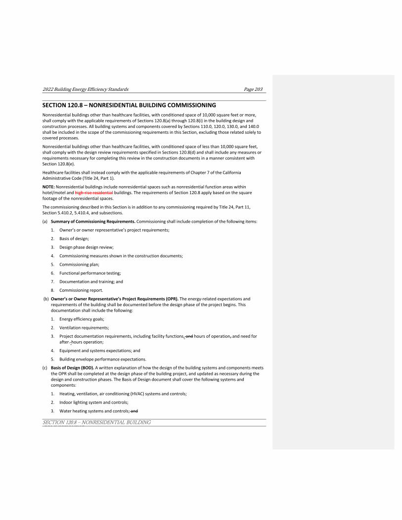
2022BuildingEnergyEfficiencyStandards Page203
SECTION 120.8 ‒ NONRESIDENTIAL BUILDING COMMISSIONING
SECTION 120.8 – NONRESIDENTIAL BUILDING COMMISSIONING Nonresidential buildings other than healthcare facilities, with conditioned space of 10,000 square feet or more, shall comply with the applicable requirements of Sections 120.8(a) through 120.8(i) in the building design and construction processes. All building systems and components covered by Sections 110.0, 120.0, 130.0, and 140.0 shall be included in the scope of the commissioning requirements in this Section, excluding those related solely to covered processes.
Nonresidential buildings other than healthcare facilities, with conditioned space of less than 10,000 square feet, shall comply with the design review requirements specified in Sections 120.8(d) and shall include any measures or requirements necessary for completing this review in the construction documents in a manner consistent with Section 120.8(e).
Healthcare facilities shall instead comply with the applicable requirements of Chapter 7 of the California Administrative Code (Title 24, Part 1).
NOTE: Nonresidential buildings include nonresidential spaces such as nonresidential function areas within hotel/motel and high-rise residential buildings. The requirements of Section 120.8 apply based on the square footage of the nonresidential spaces.
The commissioning described in this Section is in addition to any commissioning required by Title 24, Part 11, Section 5.410.2, 5.410.4, and subsections.
(a) Summary of Commissioning Requirements. Commissioning shall include completion of the following items:
1. Owner’s or owner representative’s project requirements;
2. Basis of design;
3. Design phase design review;
4. Commissioning measures shown in the construction documents;
5. Commissioning plan;
6. Functional performance testing;
7. Documentation and training; and
8. Commissioning report.
(b) Owner’s or Owner Representative’s Project Requirements (OPR). The energy-related expectations and requirements of the building shall be documented before the design phase of the project begins. This documentation shall include the following:
1. Energy efficiency goals;
2. Ventilation requirements;
3. Project documentation requirements, including facility functions, and hours of operation, and need for after -hours operation;
4. Equipment and systems expectations; and
5. Building envelope performance expectations.
(c) Basis of Design (BOD). A written explanation of how the design of the building systems and components meets the OPR shall be completed at the design phase of the building project, and updated as necessary during the design and construction phases. The Basis of Design document shall cover the following systems and components:
1. Heating, ventilation, air conditioning (HVAC) systems and controls;
2. Indoor lighting system and controls;
3. Water heating systems and controls; and

Page204 2022BuildingEnergyEfficiencyStandards
SECTION 120.8 ‒ NONRESIDENTIAL BUILDING COMMISSIONING
4. Any other building equipment or system listed in the OPR; and
5. Any building envelope component considered in the OPR.
(d) Design Phase Design Review.
1. Design Reviewer Requirements. The design reviewer shall be the signer of the Design Review Kickoff Certificate(s) of Compliance and Construction Document Design Review Checklist Certificate(s) of Compliance as specified in Part 1 Section 10-103(a)1.
2. Design Review Kickoff. During the schematic design phase of the building project, the owner or owner’s representative, design team and design reviewer must meet to discuss the project scope, schedule and how the design reviewer will coordinate with the project team. The building owner or owner's representative shall include the Design Review Kickoff Certificate of Compliance form in the Certificate of Compliance documentation as specified in Part 1 Section 10-103.
3. Construction Documents Design Review. The Construction Document Design Review Checklist Certificate of Compliance shall list the items checked by the design reviewer during the construction document review. The completed form shall be returned to the owner and design team for review and sign-off. The building owner or owner's representative shall include this form in the Certificate of Compliance documentation as specified in Part 1 Section 10-103.
(e) Commissioning measures shown in the construction documents. Complete descriptions of all measures or requirements necessary for commissioning shall be included in the construction documents (plans and specifications). Commissioning measures or requirements shall be clear, detailed and complete to clarify the commissioning process.
(f) Commissioning Plan. Prior to permit issuance a commissioning plan shall be completed to document how the project will be commissioned and shall be started during the design phase of the building project. The Commissioning Plan shall include the following:
1. General project information; and
2. Commissioning goals; and
3 Systems to be commissioned; and
4. Plans to test systems and components, which shall include:
A. An explanation of the original design intent; and
B. Equipment and systems to be tested, including the extent of tests; and
C. Functions to be tested; and
D. Conditions under which the test shall be performed; and
E. Measurable criteria for acceptable performance; and
F. Commissioning team information; and
G. Commissioning process activities, schedules and responsibilities. Plans for the completion of commissioning requirements listed in Sections 120.8(g) through 120.8(i) shall be included.
(g) Functional performance testing. Functional performance tests shall demonstrate the correct installation and operation of each component, system and system-to-system interface in accordance with the acceptance test requirements in Sections 120.5, 130.4 and 140.9. Functional performance testing reports shall contain information addressing each of the building components tested, the testing methods utilized, and include any readings and adjustments made.
EXCEPTION to Section 120.8(g): Healthcare facilities.
(h) Documentation and training. A Systems Manual and Systems Operations Training shall be completed.
2022BuildingEnergyEfficiencyStandards Page205
SECTION 120.8 ‒ NONRESIDENTIAL BUILDING COMMISSIONING
1. Systems manual. Documentation of the operational aspects of the building shall be completed within the Systems Manual and delivered to the building owner or representative and facilities operator. The Systems Manual shall include the following:
A. Site information, including facility description, history and current requirements; and
B. Site contact information; and
C. Instructions for basic operations and maintenance, including general site operating procedures, basic troubleshooting, recommended maintenance requirements, and a site events log; and
D. Description of major systems; and
E. Site equipment inventory and maintenance notes; and
F. A copy of all special inspection verifications required by the enforcing agency or the Standards.
2. Systems operations training. The training of the appropriate maintenance staff for each equipment type or system shall be documented in the commissioning report. Training materials shall include the following:
A. System and equipment overview (i.e., what the equipment is, what it does and with what other systems or equipment it interfaces);
B. Review and demonstration of operation, servicing and preventive maintenance procedures;
C. Review of the information in the Systems Manual; and
D. Review of the record drawings on the systems and equipment
(i) Commissioning report. A complete report of commissioning process activities undertaken through the design, construction and reporting recommendations for post-construction phases of the building project shall be completed and provided to the owner or owner’s representative.
NOTE: Authority: Sections 25213, 25218, 25218.5, 25402 and 25402.1, Public Resources Code. Reference: Sections 25007, 25008, 25218.5, 25310, 25402, 25402.1, 25402.4, 25402.5, 25402.8, and 25943, Public Resources Code.

Page206 2022BuildingEnergyEfficiencyStandards
SECTION 120.9 ‒ MANDATORY REQUIREMENTS FOR COMMERCIAL BOILERS.
SECTION 120.9 – MANDATORY REQUIREMENTS FOR COMMERCIAL BOILERS. (a) Combustion air positive shut-off shall be provided on all newly installed boilers as follows:
1. All boilers with an input capacity of 2.5 MMBtu/h (2,500,000 Btu/h) and above, in which the boiler is designed to operate with a nonpositive vent static pressure.
2. All boilers where one stack serves two or more boilers with a total combined input capacity per stack of 2.5 MMBtu/h (2,500,000 Btu/h).
(b) Boiler combustion air fans with motors 10 horsepower or larger shall meet one of the following for newly installed boilers:
1. The fan motor shall be driven by a variable speed drive, or
2. The fan motor shall include controls that limit the fan motor demand to no more than 30 percent of the total design wattage at 50 percent of design air volume.
(c) Newly installed boilers with an input capacity 5 MMBtu/h (5,000,000 Btu/h) and greater shall maintain excess (stack-gas) oxygen concentrations at less than or equal to 5.0 percent by volume on a dry basis over firing rates of 20 to 100 percent. Combustion air volume shall be controlled with respect to firing rate or flue gas oxygen concentration. Use of a common gas and combustion air control linkage or jack shaft is prohibited.
EXCEPTION to Section 120.9(c): Boilers with steady state full-load thermal efficiency 85 90 percent or higher.
NOTE: Authority: Sections 25213, 25218, 25218.5, 25402 and 25402.1, Public Resources Code. Reference: Sections 25007, 25008, 25218.5, 25310, 25402, 25402.1, 25402.4, 25402.8, and 25943, Public Resources Code.
2022BuildingEnergyEfficiencyStandards Page207
SECTION 120.10 ‒ MANDATORY REQUIREMENTS FOR FANS
SECTION 120.10 – MANDATORY REQUIREMENTS FOR FANS
a) Each fan or fan array with a combined motor nameplate horsepower greater than 1.00 hp or with a combined fan nameplate electrical input power greater than 0.89 kW shall have a fan energy index (FEI) of 1.00 or higher at fan system design conditions. Each fan and fan array used for a variable-air-volume system that meets the requirements of Section 140.4(c)(2) shall have an FEI of 0.95 or higher at fan system design conditions.
1. The FEI for fan arrays shall be calculated in accordance with ANSI/AMCA 208-18 Annex C.
2. All FEI values shall be provided by a manufacturer, where fan selection software and/or fan catalogs display third party verified FEI values in accordance with ANSI/AMCA 208-18.
EXCEPTION to Section 120.10(a)2: FEI values for embedded fans do not need to be third party verified.
EXCEPTION 1 to Section 120.10(a): Embedded fans that are part of equipment listed under Section 110.2, Section 110.1, or equipment that has an energy conservation standard under 10 CFR 431, including any equipment with new energy conservation standards with effective dates prior to January 1, 2026.
EXCEPTION 2 to Section 120.10(a): Embedded fans and fan arrays with a combined motor nameplate horsepower of 5 hp or less or with a fan system electrical input power of 4.1 kW or less.
EXCEPTION 3 to Section 120.10(a): Circulation fans, ceiling fans and air curtains.
EXCEPTION 4 to Section 120.10(a): Fans that are intended to only operate during emergency conditions.
8, 25218.5, 25402 and 25402.1, Public Resources Code. Reference: Sections 25007, 25008, 25218.5, 25310, 25402, 25402.1, 25402.4, 25402.8, and 25943, Public Resources Code.
NOTE: Authority: Sections 25213, 25218, 25218.5, 25402 and 25402.1, Public Resources Code. Reference: Sections 25007, 25008, 25218.5, 25310, 25402, 25402.1, 25402.4, 25402.8, and 25943, Public Resources Code.

Page450 2022BuildingEnergyEfficiencyStandards

Page 208 2022 Building Energy Efficiency Standards
SECTION 130.0 – LIGHTING SYSTEMS AND EQUIPMENT, AND ELECTRICAL POWER DISTRIBUTION SYSTEMS — GENERAL
SUBCHAPTER 4 NONRESIDENTIAL, HIGH-RISE RESIDENTIAL, AND
HOTEL/MOTEL OCCUPANCIES—MANDATORY REQUIREMENTS FOR LIGHTING SYSTEMS AND EQUIPMENT, AND ELECTRICAL
POWER DISTRIBUTION SYSTEMS SECTION 130.0 – LIGHTING SYSTEMS AND EQUIPMENT, AND ELECTRICAL POWER DISTRIBUTION SYSTEMS —GENERAL
(a) The design and installation of all lighting systems and equipment in nonresidential and, high-rise residential, hotel/motel buildings, outdoor lighting, and electrical power distribution systems within the scope of Section 100.0(a) shall comply with the applicable provisions of Sections 130.0 through 130.5.
NOTE: The requirements of Sections 130.0 through 130.5 apply to newly constructed buildings. Section 141.0 specifies which requirements of Sections 130.0 through 130.5 also apply to additions and alterations to existing buildings.
(b) Functional areas where compliance with the residential lighting standards is required. The design and installation of all lighting systems, lighting controls, and equipment in the following functional areas shall comply with the applicable residential lighting requirements of Section 150.0(k). In buildings containing these functional areas, all other functional areas, such as common areas, shall comply with the applicable nonresidential lighting and controlled receptacle requirements.
1. RESERVEDHigh-rise residential dwelling units.
2. Outdoor lighting attached to a high-rise residential or hotel/motel building and separately controlled from the inside of a dwelling unit or guest room.
3. Fire station dwelling accommodations.
4. Hotel and motel guest rooms. Additionally, hotel and motel guest rooms shall meet the requirements of Section 130.1(c)8 and Section 130.5(d)4.
5. RESERVED
Dormitory and Senior housing dwelling accommodations.
NOTE: The requirements of Section 130.0(b) also apply to additions and alterations to functional areas of existing buildings as specified in Section 130.0(b).
(c) Luminaire classification and power. Luminaires shall be classified and their wattage shall be determined as follows:
1. Luminaire wattage shall be labeled as follows:
A. The maximum rated wattage or relamping rated wattage of a luminaire shall be listed on a permanent, preprinted, factory-installed label, as specified by UL 1574, 1598, 2108, or 8750, as applicable; and
B. The factory-installed maximum rated wattage or relamping rated wattage label shall not consist of peel-off or peel-down layers or other methods that allow the rated wattage to be changed after the luminaire has been shipped from the manufacturer.

2022 Building Energy Efficiency Standards Page 209
GENERAL
EXCEPTION to Section 130.0(c)1B: Peel-down labels may be used only for the following luminaires when they can accommodate a range of lamp wattages without changing the luminaire housing, ballast, transformer or wiring. Qualifying luminaires shall have a single lamp, and shall have integrated ballasts or transformers. Peel-down labels must be layered such that the rated wattage reduces as successive layers are removed.
i. High intensity discharge luminaires, having an integral electronic ballast, with a maximum relamping rated wattage of 150 watts.
ii. Low-voltage luminaires (except low voltage track systems), ≤ 24 volts, with a maximum relamping rated wattage of 50 watts.
iii. Compact fluorescent luminaires, having an integral electronic ballast, with a maximum relamping rated wattage of 42 watts.
2. For luminaires with line voltage lamp holders not containing permanently installedserved by drivers, ballasts, or transformers, the wattage of such luminaires shall be determined as follows:
A. Thethe maximum rated wattage of the luminaire; and
B. For recessed luminaires with line-voltage medium screw base sockets, wattage shall not be less than 50 watts per socket, or the rated wattage of the installed JA8 compliant lampsas labeled in accordance with Section 130.0(c)1.
3. For luminaires with permanently installed or remotely installed ballasts, the wattage of such luminaires shall be the operating input wattage of the rated lamp/ballast combination published in the ballast manufacturer’s catalogs based on independent testing lab reports as specified by UL 1598.
4. For inseparable SSL luminaires and SSL luminaires with remotely mounted drivers, the maximum rated wattage shall be the maximum rated input wattage of the SSL luminaire as specified in Section 130.0(c)1 when tested in accordance with UL 1598, 2108, 8750, or IES LM-79.
5. For LED tape lighting and LED linear lighting with LED tape lighting components, the maximum rated wattage shall be the sum of the installed length of the tape lighting times its rated linear power density in watts per linear feet, or the maximum rated input wattage of the driver or power supply providing power to the lighting system, with tape lighting tested in accordance with UL 2108, 8750, or IES LM-79.
6. For modular lighting systems that allow the addition or relocation of luminaires without altering the wiring of the system, shall be determined as follows:
A. The wattage shall be the greater of:
i. 30 watts per linear foot of track or plug-in busway; or
ii. the rated wattage of all of the luminaires included in the system, where the luminaire wattage is determined as specified in Section 130.0(c)1.; or
B. For line-voltage lighting track and plug-in busway served by a track lighting integral current limiter or a dedicated track lighting supplementary overcurrent protection panel, the wattage shall be determined as follows:
i. The volt-ampere rating of the current limiter as specified by UL 1077; or
ii. The sum of the ampere (A) rating of all of the current protection devices times the branch circuit voltages for track lighting supplementary overcurrent protection panel. ; or
C. For other modular lighting systems with power supplied by a driver, power supply or transformer, including but not limited to low-voltage lighting systems, the wattage of the system shall be the maximum rated input wattage of the driver, power supply or transformer published in the manufacturer’s catalogs, as specified by UL 2108 or 8750.
Page 210 2022 Building Energy Efficiency Standards
SECTION 130.0 – LIGHTING SYSTEMS AND EQUIPMENT, AND ELECTRICAL POWER DISTRIBUTION SYSTEMS — GENERAL
SECTION 130.0 – LIGHTING SYSTEMS AND EQUIPMENT, AND ELECTRICAL POWER DISTRIBUTION SYSTEMS —

2022 Building Energy Efficiency Standards Page 211
GENERAL
EXCEPTION to Section 130.0(c)6: For power-over-Ethernet lighting systems, power provided to installed non-lighting devices may be subtracted from the total power rating of the power-over-Ethernet system.
7. For all other lighting equipment not addressed by Sections 130.0(c)2 through 6, the wattage of the lighting equipment shall be the maximum rated wattage of the lighting equipment, or operating input wattage of the system, labeled in accordance with Section 130.0(c)1, or published in manufacturer’s catalogs, based on independent testing lab reports as specified by UL 1574, 1598, 2108, 8750, or IES LM-79.
(d) Lighting Controls. All lighting controls and equipment shall comply with the applicable requirements in Sections 110.9, 130.1 and 130.2, and shall be installed in accordance with any applicable manufacturer instructions.
(e) Energy Management Control System (EMCS). An EMCS may be installed to comply with the requirements of one or more lighting controls if it meets the following minimum requirements:
1. Provides all applicable functionality for each specific lighting control or system for which it is installed in accordance with Sections 110.9, 130.1 and 130.2; and
2. Complies with all applicable Lighting Control Installation Requirements in accordance with Section 130.4 for each specific lighting control or system for which it is installed; and
3. Complies with all applicable application requirements for each specific lighting control or system for which it is installed, in accordance with Part 6.
NOTE: Authority: Sections 25213, 25218, 25218.5, 25402 and 25402.1, Public Resources Code. Reference: Sections 25007, 25008, 25218.5, 25310, 25402, 25402.1, 25402.4, 25402.5, 25402.8, and 25943, Public Resources Code.


2022 Building Energy Efficiency Standards Page 211
SECTION 130.1 – MANDATORY INDOOR LIGHTING CONTROLS
SECTION 130.1 – MANDATORY INDOOR LIGHTING CONTROLS Nonresidential, high-rise residential, and hotel/motel buildings shall comply with the applicable requirements of Sections 130.1(a) through 130.1(f), in addition to the applicable requirements of Sections 110.9 and 130.0.
(a) Manual Area Controls. Each area enclosed by ceiling-height partitions shall provide lighting controls that allow the lighting in that area to be manually turned on and off. The manual control shall:
1. Be readily accessible; and
EXCEPTION to Section 130.1(a)1: Public rRestrooms having two or more stalls, parking areas, stairwells, and corridors, and areas of the building intended for access or use by the public may use a manual control not accessible to unauthorized personnel.
2. Be located in the same enclosed area with the lighting it controls; and
EXCEPTION 1 to Section 130.1(a)2: For malls and atria, main entry lobbies, auditorium areas, dining areas, retail merchandise sales areas, wholesale showroom areas, commercial and industrial storage areas, general commercial and industrial work areas, convention centers, arenas, psychiatric and secure areas in healthcare facilities, and other areas where placement of a manual area control poses a health and safety hazard, the manual area control may instead be located so that a person using the control can see the lights or area controlled by that control, or visually signal or display showing the current state of the controlled lighting.
EXCEPTION 2 to Section 130.1(a)2: In healthcare facilities, for restrooms and bathing rooms intended for a single occupant, the lighting control may be located outside the enclosed area but directly adjacent to the door.
3. Provide separate control of general, floor display, wall display, window display, case display, ornamental, and special effects lighting, such that each type of lighting can be turned on or off without turning on or off other types of lighting., and without turning on or off any other equipment.Scene controllers may comply with this requirement provided that at least one scene turns on general lighting only, and the control provides a means to manually turn off all lighting.
EXCEPTION to Section 130.1(a): Up to 0.20.1 watts per square foot of indoor lighting may be continuously illuminated to allow for means of egress illumination consistent with California Building Code Section 1008. Egress lighting complying with this wattage limitation is not required to comply with manual area control requirements if:
1. The area is designated for means of egress on the plans and specifications submitted to the enforcement agency under Section 10-103(a)2 of Part 1; and
2. The controls for the egress lighting are not accessible to unauthorized personnel.
(b) Multilevel Lighting Controls. The general lighting of any enclosed area 100 square feet or larger with a connected lighting load that exceeds 0.5 watts per square foot shall provide multilevel lighting controls that allow the level of lighting to be adjusted up and down. The multilevel controls shall:
1. Pprovide the number of control steps specified in TABLE 130.1-A; and
meet the uniformity requirements specified in TABLE 130.1-A.
EXCEPTION 1 to Section 130.1(b): An area enclosed by ceiling height partitions that has only one luminaire with no more than two lamps.
EXCEPTION 2 to Section 130.1(b): Restrooms.

Page 212 2022 Building Energy Efficiency Standards
SECTION 130.1 – MANDATORY INDOOR LIGHTING CONTROLS
EXCEPTION 3 to Section 130.1(b): Healthcare facilities.EXCEPTION 1 to Section 130.1(b)1: Classrooms with a connected general lighting load of 0.6 watts per square feet or less shall have a minimum of one control step between 30-70 percent of full rated power, regardless of luminaire type.
2. Meet the uniformity requirements specified in TABLE 130.1-A.
EXCEPTION 1 to Section 130.1(b): An area enclosed by ceiling height partitions that has only one luminaire with no more than two lamps or has only one inseparable SSL luminaire.
EXCEPTION 2 to Section 130.1(b): Restrooms.
EXCEPTION 3 to Section 130.1(b): Healthcare facilities.
(c) Shut-OFF Controls. All installed indoor lighting shall be equipped with controls able to automatically reduce
lighting power when the space is typically unoccupied.
EXCEPTION 1 to Section 130.1(c): Healthcare facilities.
EXCEPTION 2 to Section 130.1(c): Lighting providing means of egress illumination, as the term is used in the California Building Code, shall be configured to provide no less than the amount of light required by California Building Code Section 1008 while in the partial-off mode.
1. In addition to lighting controls installed to comply with Sections 130.1(a) and (b), all installed indoor lighting shall be equipped with controls that meet the following requirements:
A. Shall be controlled with an occupant sensing control, automatic time-switch control, or other control capable of automatically shutting OFF all of the lighting when the space is typically unoccupied; and
B. Separate controls for the lighting on each floor, other than lighting in stairwells; and
C. Separate controls for a space enclosed by ceiling height partitions not exceeding 5,000 square feet; and
EXCEPTION to Section 130.1(c)1C: In the following function areas Tthe area controlled may not exceed 20,000 square feet in the following function areas : Malls, auditoriums, single tenant retail, industrial, convention centers, and arenas;
D. Separate controls for general, display, ornamental, and display case lighting; and.
E. For automatic time-switch controls, may include a manual-on mode.
EXCEPTION 1 to Section 130.1(c)1: Where the lighting is serving an area that is in continuous use, 24 hours per day/365 days per year.
EXCEPTION 2 to Section 130.1(c)1: Lighting complying with Section 130.1(c)5 or 7.
EXCEPTION 3 to Section 130.1(c)1: Up to 0.1 watts per square foot of lighting in any area within a building may be continuously illuminated, provided that the area is designated for means of egress on the plans and specifications submitted to the enforcement agency under Section 10-103(a)2 of Part 1.
EXCEPTION 4 to Section 130.1(c)1: Electrical equipment rooms subject to Article 110.26(D) of the California Electrical Code.
EXCEPTION 5 to Section 130.1(c)1: Illumination provided by lighting equipment that is designated for emergency lighting, connected to an emergency power source or battery supply, and is intended to function in emergency mode only when normal power is absent.
EXCEPTION 6 to Section 130.1(c)1: Lighting in stairways provided that the stairway is designated for means of egress on the plans and specifications submitted to the enforcement agency under Section 10- 103(a)2 of Part 1.
Commented [CU1]: Indoor lighting LPD

2022 Building Energy Efficiency Standards Page 213
SECTION 130.1 – MANDATORY INDOOR LIGHTING CONTROLS
2. Countdown timer switches may be used to comply with the automatic shut-OFF control requirements in Section 130.1(c)1 only in closets less than 70 square feet, and server aisles in server rooms. The maximum timer setting shall be 10 minutes for closets, and 30 minutes for server aisles.
3. If an automatic time-switch control, other than an occupant sensing control, is installed to comply with Section 130.1(c)1, it shall incorporate a manual override lighting control that:
A. Complies with Section 130.1(a); and
B. Allows the lighting to remain ON for no more than 2 hours when an override is initiated.
EXCEPTION to Section 130.1(c)3B: In the following function areas, the override time may exceed 2 hours: Malls, auditoriums, single tenant retail, industrial, and arenas where captive-key override is utilized.
4. If an automatic time-switch control, other than an occupant sensing control, is installed to comply with Section 130.1(c)1, it shall incorporate an automatic holiday "shut-OFF" feature that turns OFF all loads for at least 24 hours, and then resumes the normally scheduled operation.
EXCEPTION to Section 130.1(c)4: In retail stores and associated malls, restaurants, grocery stores, churches, controlled environment horticulture spaces, and theaters, the automatic time-switch control is not required to incorporate an automatic holiday shut-OFF feature.
5. Areas where Occupant Sensing Controls are required to shut OFF All Lightingfor specified offices, multipurpose rooms, classrooms, conference rooms and restrooms. In offices 250 square feet or smaller, multipurpose rooms of less than 1,000 square feet, classrooms of any size, conference rooms of any size, and restrooms of any size, lighting shall be controlled with occupant sensing controls to automatically shut OFF all of the lighting when the room is unoccupiedwithin 20 minutes of the control zone being unoccupied. The controls shall meet the following requirements:
A. General lighting subject to section 130.1(b) to use occupant controls that shall function as either a Vacancy sensing or as a Partial-ON occupant control. All other lighting to be controlled with either Occupant sensing, Vacancy sensing, or Partial-On occupant control. Partial-on occupant sensing controls shall automatically activate between 50-70 percent of controlled lighting power when the control zone is occupied.
B. Controls shall be configured to allow the lights to be manually shut-OFF in accordance with Section 130.1(a) regardless of the sensor status.
EXCEPTION 1 to Section 130.1(c)5A: Lighting in restrooms controlled by an occupant sensor.
In areas required by Section 130.1(b) to have multilevel lighting controls, the occupant sensing controls shall function either as a:
Partial-ON Occupant Sensor capable of automatically activating between 50-70 percent of controlled lighting power, or
Vacancy Sensor, where all lighting responds to a manual ON input only.
In areas not required by Section 130.1(b) to have multilevel lighting controls, the occupant sensing controls shall function either as a:
The general lighting in the following areas are required to be controlled by Occupant Sensing Controls or partial-on occupant sensing controls or vacancy sensing controls: (the areas are not required to have multilevel lighting controls)
A. An area enclosed by ceiling height partitions that has only one luminaire with no more than two lampsOccupant Sensor; or
B. RestroomsPartial-ON Occupant Sensor, or
C. Vacancy Sensor, where all lighting responds to a manual ON input only.
The general lighting in the following areas are required to be controlled by partial-on occupant sensing controls capable of automatically activating between 50-70 percent of controlled lighting power:
Commented [CU2]: CEH
Commented [CU3]: Indoor lighting LPDs

Page 214 2022 Building Energy Efficiency Standards
SECTION 130.1 – MANDATORY INDOOR LIGHTING CONTROLS
Classrooms with a connected lighting load of 0.6 watts per square feet or less.
In addition, controls shall be provided that allow the lights to be manually shut-OFF in accordance with Section 130.1(a) regardless of the sensor status.
6. Areas where full or partial Partial OFF occupant sensing controls are required for aisle ways and open area in warehouses, library book stack aisles, corridors and stairwells, and offices greater than 300

2022 Building Energy Efficiency Standards Page 215
SECTION 130.1 – MANDATORY INDOOR LIGHTING CONTROLS
square feet. General Lighting lighting installed in the following areas shall meet the following requirements below in addition to complying with Section 130.1(c)1.
A. In aisle ways and open areas in warehouses, lighting shall be controlled with occupant sensing controls that automatically reduce lighting power by at least 50 percent when the areas are unoccupied. The occupant sensing controls shall independently control lighting in each aisle way, and shall not control lighting beyond the aisle way being controlled by the sensor.
EXCEPTION 1 to Section 130.1(c)6A: In aisle ways and open areas in warehouses in which the installed lighting power is 80 percent or less of the value allowed under the Area Category Method, occupant sensing controls shall reduce lighting power by at least 40 percent.
EXCEPTION 2 to Section 130.1(c)6A: When metal halide lighting or high pressure sodium lighting is installed in warehouses, occupant sensing controls shall reduce lighting power by at least 40 percent.
B. In library book stack aisles 10 feet or longer that are accessible from only one end, and library book stack aisles 20 feet or longer that are accessible from both ends, lighting shall be controlled with occupant sensing controls that automatically reduce lighting power by at least 50 percent when the areas are unoccupied. The occupant sensing controls shall independently control lighting in each aisle way, and shall not control lighting beyond the aisle way being controlled by the sensor.
C. Lighting installed Iin corridors and stairwells, lighting shall be controlled by occupant sensing controls that separately reduce the lighting power in each space by at least 50 percent when the space is unoccupied. The occupant sensing controls shall be capable of automatically turning the lighting fully ON only in the separately controlled space, and shall be automatically activated from all designed paths of egress.
D. In office spaces greater than 250 square feet, general lighting shall be controlled with occupant sensing controls that meet all of the following:
i. The occupant sensing controls shall be configured so that lighting shall be controlled separately in control zones not greater than 600 square feet. For luminaires with an embedded occupant sensor that are capable of reducing power independently from other luminaires, each luminaire can be considered its own control zone; and
ii. Within 20 minutes of the control zone being unoccupied, the occupant sensing controls shall uniformly reduce lighting power in the control zone to by at least 80 percent of full power. Control functions that switch control zone lights completely off when the zone is vacant meet this requirement; and
iii. Within 20 minutes of the entire office space being unoccupied, the occupant sensing controls shall automatically turn off lighting in all control zones in the space; and
iv. In each control zone, lighting shall be allowed to automatically turn on to full power upon occupancy within the control zone. When occupancy is detected in any control zone in the space, the lighting in other control zones that are unoccupied shall operate at no more than 20 percent of full power.
EXCEPTION to Section 130.1(c)6D: Under-shelf or furniture-mounted task lighting controlled by a local switch and either a time switch or an occupancy sensor.
7. Areas where pPartial OFF occupant sensing controls. Partial OFF occupant sensing controls are required for specified stairwells and common area corridors, parking garages, parking areas and loading and unloading areas. LGeneral lighting installed in the following areas shall meet the following requirements below instead of complying with Section 130.1(c)1.
A. Lighting in stairwells and common area corridors that provide access to guest rooms and dwelling units of high-rise residential buildings and hotel/motels shall be controlled with occupant sensing controls that automatically reduce lighting power by at least 50 percent when the areas are unoccupied. The occupant sensing controls shall be capable of automatically turning the lighting fully
Page 216 2022 Building Energy Efficiency Standards
SECTION 130.1 – MANDATORY INDOOR LIGHTING CONTROLS
ON only in the separately controlled space, and shall be automatically activated from all designed paths of egress.
EXCEPTION to Section 130.1(c)7A: In corridors and stairwells in which the installed lighting power is 80 percent or less of the value allowed under the Area Category Method, occupant sensing controls shall reduce power by at least 40 percent.
B. In parking garages, parking areas and loading and unloading areas, general lighting shall be controlled by occupant sensing controls having at least one control step between 20 percent and 50 percent of design lighting power. No more than 500 watts of rated lighting power shall be controlled together as a single zone. A reasonably uniform level of illuminance shall be achieved in accordance with the applicable requirements in TABLE 130.1-A. The occupant sensing controls shall be capable of automatically turning the lighting fully ON only in the separately controlled space, and shall be automatically activated from all designed paths of egress.
Interior areas of parking garages are classified as indoor lighting for compliance with Section 130.1(c)7B. Parking areas on the roof of a parking structure are classified as outdoor hardscape and shall comply with the applicable provisions in Section 130.2.
EXCEPTION to Section 130.1(c)7B: Metal halide luminaires with a lamp plus ballast mean system efficacy of greater than 75 lumens per watt, used for general lighting in parking garages, parking areas and loading and unloading areas, shall be controlled by occupant sensing controls having at least one control step between 20 percent and 60 percent of design lighting power.
8. Hotel motel guest rooms shall be controlled with one of the following have captive card key controls, occupancy sensing controls, or automatic controls such that, no longer than 20 minutes after the guest room has been vacated, lighting power is switched off
i. captive card key controls; or
ii. occupant sensing controls; or
iii. automatic controls.
EXCEPTION to Section 130.1(c)8: One high efficacy luminaire as defined in TABLE 150.0-A that is switched separately and where the switch is located within 6 feet of the entry door.
EXCEPTION 2 to Section 130.1(c): Lighting providing means of egress illumination, as the term is used in the California Building Code, shall be configured to provide no less than the amount of light required by California Building Code Section 1008 while in the partial-off mode.
(d) Automatic Daylighting Controls. The general lighting in skylit daylit zones, and primary sidelit daylit zones, and secondary sidelit daylit zones, as well as the general lighting in the combined primary and secondary sidelit daylit zones in parking garages, shall be provided with controls that automatically adjust the power of the installed lighting up and down to keep the total light level stable as the amount of incoming daylight changes. For skylights located in an atrium, the skylit daylit zone definition shall apply to the floor area directly under the atrium and the top floor area directly adjacent to the atrium.
1. All skylit daylit zones, and primary sidelit daylit zones, secondary sidelit daylit zones, and the combined primary and secondary sidelit daylit zones in parking garages shall be shown on the plans.
NOTE: Parking areas on the roof of a parking structure are outdoor hardscape, not skylit daylit areas.
2. The automatic daylighting controls shall provide separate control for luminaires general lighting in each type of daylit zone. Luminaires General lighting that fall in both overlapping a skylit daylit zone and sidelit daylit zone shall be controlled as part of the skylit daylit zone. General lighting in overlapping primary and secondary sidelit daylit zones shall be controlled as part of the primary sidelit daylit zone. Linear LED and other solid state lighting (SSL) light sources in linear form may be treated as linear lamps in increments of 4 feet segments or smaller, and each segment is separately controlled based on the type of the daylit zone the segment is primarily located.
3. The automatic daylighting controls shall:

2022 Building Energy Efficiency Standards Page 217
SECTION 130.1 – MANDATORY INDOOR LIGHTING CONTROLS
A. For spaces required to install multilevel controls under Section 130.1(b), adjust lighting via continuous dimming or the number of control steps provided by the multilevel controls;
B. For each space, ensure the combined illuminance from the controlled lighting and daylight is not less than the illuminance from controlled lighting when no daylight is available;
C. For areas other than parking garages, ensure that when the daylight illuminance is greater than 150 percent of the design illuminance received fromprovided by the generalcontrolled lighting system at full powerwhen no daylight is available, the generalcontrolled lighting power in that daylight zone shall be reduced by a minimum of 65 90 percent; and
D. For parking garages, ensure that when daylight illuminance levels measured at the farthest edge of the secondary sidelit zone away from the glazing or opening are greater than 150 percent of the illuminance provided by the controlled lighting when no daylight is available, the controlled lighting power in the combined primary and secondary sidelit daylit zones shall be reduced by 100 percentconsumption is zero.
4. When photosensors are located within the daylit zone, at least one pPhotosensor shall be located so that they are not readily accessible to unauthorized personnel.
5. The location where calibration adjustments are made to the automatic daylighting controls shall be readily accessible to authorized personnel but may be inside a locked case or under a cover which requires a tool for access.
EXCEPTION 1 to Section 130.1(d): Areas under skylights where it is documented that existing adjacent structures or natural objects block direct sunlight for more than 1,500 daytime hours per year between 8 a.m. and 4 p.m.
EXCEPTION 2 to Section 130.1(d): Areas adjacent to vertical glazing below an overhang, where the overhang covers the entire width of the vertical glazing, no vertical glazing is above the overhang, and the ratio of the overhang projection to the overhang rise is greater than 1.5 for South, East and West orientations or greater than 1 for North orientations.
EXCEPTION 3 to Section 130.1(d): Rooms in which the combined total installed general lighting power in the Skylit Daylit Zone and Primary Sidelit Daylit Zone is less than 120 Watts, or parking garage areas where the total combined general lighting power in the sidelit daylight zones is less than 60 watts.Rooms in which the total installed general lighting power in the Skylit Daylit Zone and Primary Sidelit Daylit Zone is less than 120 watts do not require automatic daylighting controls in the daylit zones.
EXCEPTION 4 to Section 130.1(d): Rooms in which the total installed general lighting power in the Secondary Sidelit Daylit Zone is less than 120 watts do not require automatic daylighting controls in the secondary daylit zones.
EXCEPTION 5 to Section 130.1(d): Rooms in which the total installed wattage of the general lighting in the primary and the secondary sidelit daylit zones is less than 240 watts do not require automatic daylighting controls in the secondary sidelit daylit zones.
EXCEPTION 6 to Section 130.1(d): Parking garage areas where the total installed wattage of the general lighting in the primary and the secondary sidelit daylit zones is less than 60 watts do not require automatic daylighting controls in the daylit zones.
EXCEPTION 4 7 to Section 130.1(d): Rooms that have a total glazing area of less than 24 square feet, or parking garage areas with a combined total of less than 36 square feet of glazing or opening.
EXCEPTION 5 8 to Section 130.1(d): For parking garages, luminaires located in the daylight adaptation zone and luminaires for only dedicated ramps. Daylight adaptation zone and dedicated ramps are defined in Section 100.1.
Commented [CU4]: Daylighting
Commented [CU5]: Daylighting

Page 218 2022 Building Energy Efficiency Standards
SECTION 130.1 – MANDATORY INDOOR LIGHTING CONTROLS
EXCEPTION 6 9 to Section 130.1(d): Luminaires in sidelit daylit zones in retail merchandise sales and wholesale showroom areas.
(e) Demand Responsive Controls. See Section 110.12 for requirements for demand responsive lighting controls.
(f) Control Interactions. Each lighting control installed to comply with Section 130.1(a) through(e) shall permit or incorporate the functions of the other lighting controls required by this Section..
1. For general lighting, the manual area control shall permit the level or amount of light provided while the lighting is on to be set or adjusted by the controls specified in Section 130.1(b), (c), (d), and (e).
2. The manual area control shall permit the shutoff control to turn the lighting down or off.
3. The multilevel lighting control shall permit the automatic daylighting control to adjust the electric lighting level in response to changes in the amount of daylight in the daylit zone.
4. The multilevel lighting control shall permit the demand responsive control to adjust the lighting during a demand response event and to return it to the level set by the multilevel control after the event.
5. The shutoff control shall permit the manual area control to turn the lighting on. If the on request occurs while an automatic time switch control would turn the lighting off, then the on request shall be treated as an override request consistent with Section 130.1(c)3.
6. The automatic daylighting control shall permit the multilevel lighting control to adjust the level of lighting.
7. For lighting controlled by multilevel lighting controls and by occupant sensing controls that provide an automatic-on function, the controls shall provide a partial-on function that is capable of automatically activating between 50-70 percent of controlled lighting power.
8. (RESERVED)
9. For space conditioning system zones serving only spaces that are required to have occupant sensing controls as specified in Section 130.1(c), and where Table 120.1-A allows the ventilation air to be reduced to zero when the space is in occupied-standby mode, the space conditioning system shall be controlled by occupancy sensing controls as specified in Section 120.2(e)3.
NOTE: Authority: Sections 25213, 25218, 25218.5, 25402 and 25402.1, Public Resources Code. Reference: Sections 25007, 25008, 25218.5, 25310, 25402, 25402.1, 25402.4, 25402.5, 25402.8, and 25943, Public Resources Code.
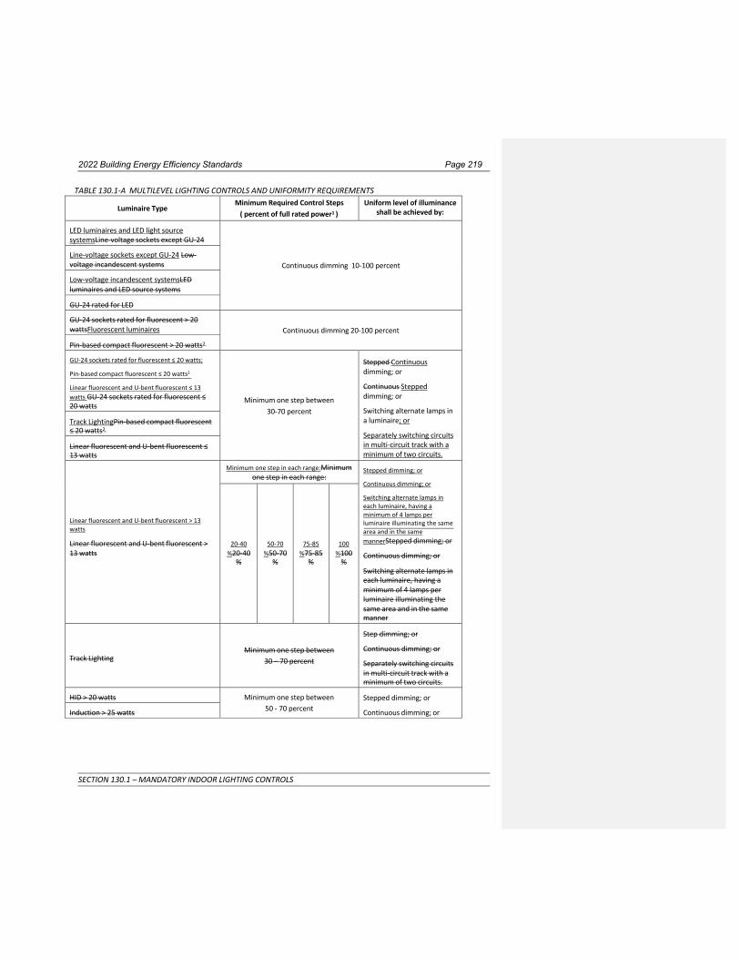
2022 Building Energy Efficiency Standards Page 219
SECTION 130.1 – MANDATORY INDOOR LIGHTING CONTROLS
TABLE 130.1-A MULTILEVEL LIGHTING CONTROLS AND UNIFORMITY REQUIREMENTS
Luminaire Type Minimum Required Control Steps
( percent of full rated power1 ) Uniform level of illuminance
shall be achieved by:
LED luminaires and LED light source systemsLine-voltage sockets except GU-24
Continuous dimming 10-100 percent Line-voltage sockets except GU-24 Low- voltage incandescent systems
Low-voltage incandescent systemsLED luminaires and LED source systems
GU-24 rated for LED
GU-24 sockets rated for fluorescent > 20 wattsFluorescent luminaires
Continuous dimming 20-100 percent
Pin-based compact fluorescent > 20 watts2
GU-24 sockets rated for fluorescent ≤ 20 watts;
Stepped Continuous dimming; or
Continuous Stepped dimming; or
Switching alternate lamps in a luminaire; or
Separately switching circuits in multi-circuit track with a minimum of two circuits.
Pin-based compact fluorescent ≤ 20 watts2
Linear fluorescent and U-bent fluorescent ≤ 13 watts GU-24 sockets rated for fluorescent ≤ 20 watts
Minimum one step between
30-70 percent Track LightingPin-based compact fluorescent ≤ 20 watts2
Linear fluorescent and U-bent fluorescent ≤ 13 watts
Minimum one step in each range:Minimum one step in each range:
Stepped dimming; or
Continuous dimming; or
Linear fluorescent and U-bent fluorescent > 13 watts
Linear fluorescent and U-bent fluorescent > 13 watts
20-40 %20-40
%
50-70 %50-70
%
75-85 %75-85
%
100 %100
%
Switching alternate lamps in each luminaire, having a minimum of 4 lamps per luminaire illuminating the same area and in the same mannerStepped dimming; or
Continuous dimming; or
Switching alternate lamps in each luminaire, having a minimum of 4 lamps per luminaire illuminating the same area and in the same manner
Track Lighting
Minimum one step between 30 – 70 percent
Step dimming; or
Continuous dimming; or
Separately switching circuits in multi-circuit track with a minimum of two circuits.
HID > 20 watts Minimum one step between 50 - 70 percent
Stepped dimming; or
Continuous dimming; or Induction > 25 watts
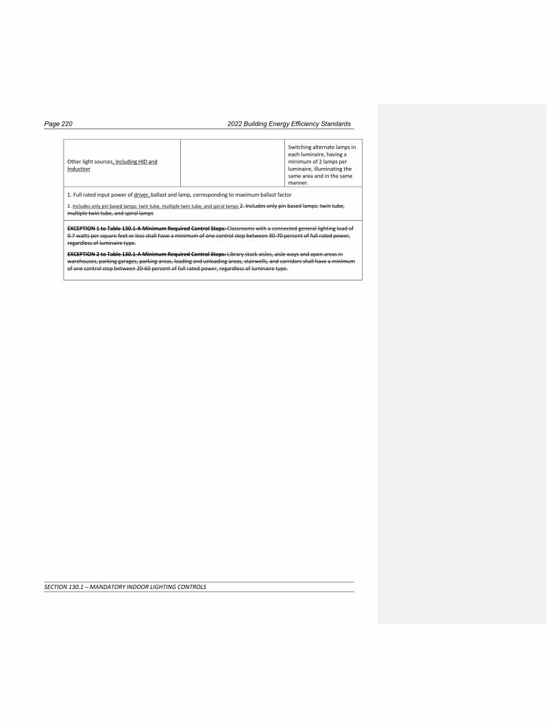
Page 220 2022 Building Energy Efficiency Standards
SECTION 130.1 – MANDATORY INDOOR LIGHTING CONTROLS
Other light sources, including HID and Induction
Switching alternate lamps in each luminaire, having a minimum of 2 lamps per luminaire, illuminating the same area and in the same manner.
1. Full rated input power of driver, ballast and lamp, corresponding to maximum ballast factor
2. Includes only pin based lamps: twin tube, multiple twin tube, and spiral lamps 2. Includes only pin based lamps: twin tube, multiple twin tube, and spiral lamps
EXCEPTION 1 to Table 130.1-A Minimum Required Control Steps: Classrooms with a connected general lighting load of 0.7 watts per square feet or less shall have a minimum of one control step between 30-70 percent of full rated power, regardless of luminaire type.
EXCEPTION 2 to Table 130.1-A Minimum Required Control Steps: Library stack aisles, aisle ways and open areas in warehouses, parking garages, parking areas, loading and unloading areas, stairwells, and corridors shall have a minimum of one control step between 20-60 percent of full rated power, regardless of luminaire type.


Page 220 2022 Building Energy Efficiency Standards
SECTION 130.2 – OUTDOOR LIGHTING CONTROLS AND EQUIPMENT
SECTION 130.2 – OUTDOOR LIGHTING CONTROLS AND EQUIPMENT Nonresidential, high-rise residential and hotel/motel buildings shall comply with the applicable requirements of Sections 130.2(a) through 130.2(c).
(a) RESERVED
(b) Luminaire Cutoff Shielding Requirements. All outdoor luminaires of 6,200 initial luminaire lumens or greater, shall comply with Backlight, Uplight, and Glare (BUG) (collectively referred to as "BUG" in accordance with ANSI/IES TM-15-1120, Addendum Annex A) requirements as follows:
1. Maximum zonal lumens for Backlight, Uplight, and Glare shall be in accordance with Title 24, Part 11, Section 5.106.8.
EXCEPTION 1 to Section 130.2(b): Signs.
EXCEPTION 2 to Section 130.2(b): Lighting for building facades, public monuments, public art, statues, and vertical surfaces of bridges.
EXCEPTION 3 to Section 130.2(b): Lighting not permitted by a health or life safety statute, ordinance, or regulation to be a cutoff luminaire.
EXCEPTION 4 to Section 130.2(b): Temporary outdoor lighting.
EXCEPTION 5 to Section 130.2(b): Replacement of existing pole mounted luminaires in hardscape areas meeting all of the following conditions:
A. Where the existing luminaire does not meet the luminaire BUG requirements in Section 130.2(b); and
B. Spacing between existing poles is greater than six times the mounting height of the existing luminaires; and
C. Where no additional poles are being added to the site; and
D. Where new wiring to the luminaires is not being installed; and
E. Provided that the connected lighting power wattage is not increased.
EXCEPTION 6 to Section 130.2(b): Luminaires that illuminate the public right of way on including publicly- maintained or utility-maintained roadways, sidewalks, and bikeways.
EXCEPTION 7 to Section 130.2(b): Outdoor lighting attached to a high-rise residential or hotel/motel building and separately controlled from the inside of a dwelling unit or guest room.
(c) Controls for Outdoor Lighting. Outdoor lighting shall be independently controlled from other electrical loads, and the controls for outdoor lighting shall meet the following functional requirements:
EXCEPTION 1 to Section 130.2(c): Outdoor lighting not permitted by a health or life safety statute, ordinance, or regulation to be turned OFF or reduced.
EXCEPTION 2 to Section 130.2(c): Lighting in tunnels required to be illuminated 24 hours per day and 365 days per year.
1. Daylight Availability. All installed outdoor lighting shall be controlled by a photo control, astronomical time-switch control, or other control capable of automatically shutting OFF the outdoor lighting when daylight is available.
2. Automatic Scheduling Controls.
A. Automatic scheduling controls shall be installed for all outdoor lighting. Automatic Scheduling Controls may be installed in combination with motion sensing controls or other outdoor lighting controls.
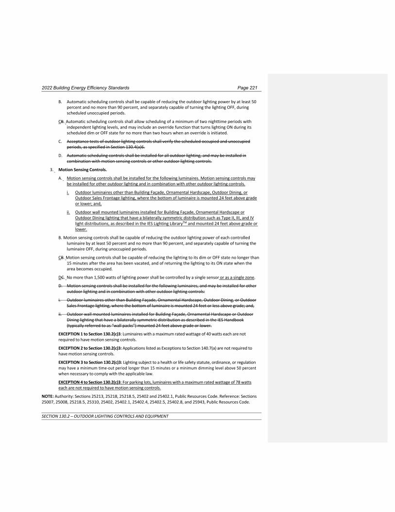
2022 Building Energy Efficiency Standards Page 221
SECTION 130.2 – OUTDOOR LIGHTING CONTROLS AND EQUIPMENT
B. Automatic scheduling controls shall be capable of reducing the outdoor lighting power by at least 50 percent and no more than 90 percent, and separately capable of turning the lighting OFF, during scheduled unoccupied periods.
CB. Automatic scheduling controls shall allow scheduling of a minimum of two nighttime periods with independent lighting levels, and may include an override function that turns lighting ON during its scheduled dim or OFF state for no more than two hours when an override is initiated.
C. Acceptance tests of outdoor lighting controls shall verify the scheduled occupied and unoccupied periods, as specified in Section 130.4(a)6.
D. Automatic scheduling controls shall be installed for all outdoor lighting, and may be installed in combination with motion sensing controls or other outdoor lighting controls.
3. Motion Sensing Controls.
A. Motion sensing controls shall be installed for the following luminaires. Motion sensing controls may be installed for other outdoor lighting and in combination with other outdoor lighting controls.
i. Outdoor luminaires other than Building Façade, Ornamental Hardscape, Outdoor Dining, or Outdoor Sales Frontage lighting, where the bottom of luminaire is mounted 24 feet above grade or lower; and,
ii. Outdoor wall mounted luminaires installed for Building Façade, Ornamental Hardscape or Outdoor Dining lighting that have a bilaterally symmetric distribution such as Type II, III, and IV light distributions, as described in the IES Lighting LibraryTM and mounted 24 feet above grade or lower.
B. Motion sensing controls shall be capable of reducing the outdoor lighting power of each controlled luminaire by at least 50 percent and no more than 90 percent, and separately capable of turning the luminaire OFF, during unoccupied periods.
CB. Motion sensing controls shall be capable of reducing the lighting to its dim or OFF state no longer than 15 minutes after the area has been vacated, and of returning the lighting to its ON state when the area becomes occupied.
DC. No more than 1,500 watts of lighting power shall be controlled by a single sensor or as a single zone.
D. Motion sensing controls shall be installed for the following luminaires, and may be installed for other outdoor lighting and in combination with other outdoor lighting controls:
i. Outdoor luminaires other than Building Façade, Ornamental Hardscape, Outdoor Dining, or Outdoor Sales Frontage lighting, where the bottom of luminaire is mounted 24 feet or less above grade; and,
ii. Outdoor wall mounted luminaires installed for Building Façade, Ornamental Hardscape or Outdoor Dining lighting that have a bilaterally symmetric distribution as described in the IES Handbook (typically referred to as “wall packs”) mounted 24 feet above grade or lower.
EXCEPTION 1 to Section 130.2(c)3: Luminaires with a maximum rated wattage of 40 watts each are not required to have motion sensing controls.
EXCEPTION 2 to Section 130.2(c)3: Applications listed as Exceptions to Section 140.7(a) are not required to have motion sensing controls.
EXCEPTION 3 to Section 130.2(c)3: Lighting subject to a health or life safety statute, ordinance, or regulation may have a minimum time-out period longer than 15 minutes or a minimum dimming level above 50 percent when necessary to comply with the applicable law.
EXCEPTION 4 to Section 130.2(c)3: For parking lots, luminaires with a maximum rated wattage of 78 watts each are not required to have motion sensing controls.
NOTE: Authority: Sections 25213, 25218, 25218.5, 25402 and 25402.1, Public Resources Code. Reference: Sections 25007, 25008, 25218.5, 25310, 25402, 25402.1, 25402.4, 25402.5, 25402.8, and 25943, Public Resources Code.

Page 222 2022 Building Energy Efficiency Standards
SECTION 130.3 – SIGN LIGHTING CONTROLS
SECTION 130.3 – SIGN LIGHTING CONTROLS Nonresidential buildings other than healthcare facilities, high-rise residential buildings, and hotel/motel buildings shall comply with the applicable requirements of Sections 130.3(a)1 through 130.3(a)3.
(a) Controls for Sign Lighting. All sign lighting shall meet the requirements below as applicable:
1. Indoor Signs. All indoor sign lighting other than exit sign lighting shall be controlled with an automatic time-switch control or astronomical time-switch control.
2. Outdoor Signs. Outdoor sign lighting shall meet the following requirements as applicable:
A. All outdoor sign lighting shall be controlled with a photocontrol in addition to an automatic time- switch control, or an astronomical time-switch control.
EXCEPTION to Section 130.3(a)2A: Outdoor signs in tunnels, and signs in large permanently covered outdoor areas that are intended to be continuously lit, 24 hours per day and 365 days per year.
B. All outdoor sign lighting that is ON both day and night shall be controlled with a dimmer that provides the ability to automatically reduce sign lighting power by a minimum of 65 percent during nighttime hours. Signs that are illuminated at night and for more than 1 hour during daylight hours shall be considered ON both day and night.
EXCEPTION to Section 130.3(a)2B: Outdoor signs in tunnels and large covered areas that are intended to be illuminated both day and night.
3. Demand Responsive Electronic Message Center (EMC) Control. See Section 110.12 for requirements for demand responsive EMC controls.
NOTE: Authority: Sections 25213, 25218, 25218.5, 25402 and 25402.1, Public Resources Code. Reference: Sections 25007, 25008, 25218.5, 25310, 25402, 25402.1, 25402.4, 25402.5, 25402.8, and 25943, Public Resources Code.

2022 Building Energy Efficiency Standards Page 223
SECTION 130.4 –LIGHTING CONTROL ACCEPTANCE AND INSTALLATION CERTIFICATE REQUIREMENTS
SECTION 130.4 –LIGHTING CONTROL ACCEPTANCE AND INSTALLATION CERTIFICATE REQUIREMENTS Nonresidential buildings other than healthcare facilities, high-rise residential buildings, and hotel/motel buildings shall comply with the applicable requirements of Sections 130.4(a) through 130.4(c). Healthcare facilities shall comply with the applicable acceptance and installation documentation requirements of OSHPD.
(a) Lighting and Receptacle Control Acceptance Requirements. Before an occupancy permit is granted, indoor and outdoor lighting and receptacle controls serving the building, area, or site and installed to comply with Sections 110.12, 130.1, 130.2, 130.5 or 140.6 shall be certified as meeting the Acceptance Requirements for Code Compliance, in accordance with Section 130.4(a).as specified by the Reference Nonresidential Appendix NA7.6 and NA7.8. A Certificate of Acceptance shall be submitted to the enforcement agency under Section 10- 103(a) of Part 1, that the equipment and systems meet the acceptance requirements:
1. Certifies that all of the lighting acceptance testing necessary to meet the requirements of Part 6 is completedRESERVED
2. Certifies that the applicable procedures in Reference Nonresidential Appendix NA7.6 and NA7.8 have been followedRESERVED
3. Certifies that aAutomatic daylight controls comply with Section 130.1(d) and shall be tested in accordance with Reference Reference Nonresidential Appendix NA7.6.1;
4. Certifies that lLighting shut-OFF controls comply with Section 130.1(c) and shall be tested in accordance with Reference Reference Nonresidential Appendix NA7.6.2;
5. DCertifies that demand responsive lighting controls comply with Section 130.1(e) and shall be tested in accordance with Reference Reference Nonresidential Appendix NA7.6.3; and
6. Certifies that oOutdoor lighting controls comply with the applicable requirements of Section 130.2(c) shall be tested in accordance with Reference and Reference Nonresidential Appendix NA7.8; and
7. Certifies that lLighting systems receiving the Institutional Tuning Power Adjustment Factor comply with Section 140.6(a)2J shall be tested in accordance with Reference and Reference Nonresidential Appendix NA7.6.47.6.2.
8. Demand responsive controls required to control controlled receptacles shall be tested in accordance with Reference Nonresidential Appendix NA7.6.5.
(b) Lighting Control Installation Certificate Requirements. To be recognized for compliance with Part 6, an Installation Certificate shall be submitted in accordance with Section 10-103(a) for any lighting control system, Energy Management Control System, track lighting integral current limiter, track lighting supplementary overcurrent protection panel, interlocked lighting system, lighting Power Adjustment Factor, or additional wattage available for a videoconference studio, in accordance with the following requirements, as applicable:
1. Certification that when a lighting control system is installed to comply with lighting control requirements in Part 6 it complies with the applicable requirements of Section 110.9; and complies with Reference Nonresidential Appendix NA7.7.1.
2. Certification that when an Energy Management Control System is installed to function as a lighting control required by Part 6 it functionally meets all applicable requirements for each application for which it is installed, in accordance with Sections 110.9, 130.0 through 130.5, 140.6 through 150.0, and 150.2; and complies with Reference Nonresidential Appendix NA7.7.2.
3. RESERVED
4. RESERVED
5. Certification that interlocked lighting systems used to serve an approved area comply with Section 140.6(a)1; and comply with Reference Nonresidential Appendix NA7.7.4.

Page 224 2022 Building Energy Efficiency Standards
SECTION 130.4 –LIGHTING CONTROL ACCEPTANCE AND INSTALLATION CERTIFICATE REQUIREMENTS
6. Certification that lighting controls installed to earn a lighting Power Adjustment Factor (PAF) comply with Section 140.6(a)2; and comply with Reference Nonresidential Appendix NA7.7.5.
7. Certification that additional lighting wattage installed for a videoconference studio complies with Section 140.6(c)2Gvii; and complies with Reference Nonresidential Appendix NA7.7.6.
(c) When certification is required by Title 24, Part 1, Section 10-103.1, the acceptance testing specified by Section
130.4 shall be performed by a Certified Lighting Controls Acceptance Test Technician (CLCATT). If the CLCATT is operating as an employee, the CLCATT shall be employed by a Certified Lighting Controls Acceptance Test Employer. The CLCATT shall disclose on the Certificate of Acceptance a valid CLCATT certification identification number issued by an approved Acceptance Test Technician Certification Provider. The CLCATT shall complete all Certificate of Acceptance documentation in accordance with the applicable requirements in Section 10- 103(a)4.
NOTE: Authority: Sections 25402, 25402.1, 25213, Public Resources Code. Reference: Sections 25007, 25008, 25218.5, 25310, 25402, 25402.1, 25402.4, 25402.5, 25402.8, and 25943, Public Resources Code.

2022 Building Energy Efficiency Standards Page 225
SECTION 130.5 –ELECTRICAL POWER DISTRIBUTION SYSTEMS
SECTION 130.5 –ELECTRICAL POWER DISTRIBUTION SYSTEMS Nonresidential, high-rise residential and hotel/motel buildings shall comply with the applicable requirements of Sections 130.5(a) through 130.5(e).
(a) Service Electrical Metering. Each electrical service or feeder shall have a permanently installed metering system which measures electrical energy use in accordance with TABLE 130.5-A.
EXCEPTION 1 to Section 130.5(a): Service or feeder for which the utility company provides a metering system that indicates instantaneous kW demand and kWh for a utility-defined period.
EXCEPTION 2 to Section 130.5(a): Electrical power distribution systems subject to California Electrical Code Article 517.
(b) Separation of Electrical Circuits for Electrical Energy Monitoring. Electrical power distribution systems shall be designed so that measurement devices can monitor the electrical energy usage of load types according to TABLE 130.5-B.
EXCEPTION 1 to Section 130.5(b): For each separate load type, up to 10 percent of the connected load may be of any type.
EXCEPTION 2 to Section 130.5(b): Electrical power distribution systems subject to California Electrical Code Article 517.
(c) Voltage Drop. The maximum combined voltage drop on both installed feeder conductors and branch circuit conductors to the farthest connected load or outlet shall not exceed 5 percent.
EXCEPTION to Section 130.5(c): Voltage drop permitted by California Electrical Code Sections 647.4, 695.6 and 695.7.
(d) Circuit Controls for 120-Volt Receptacles and Controlled Receptacles. In all buildings, both controlled and uncontrolled 120 volt receptacles shall be provided in office areas, lobbies, conference rooms, kitchen areas in office spaces, and copy rooms. Additionally, hotel/motel guest rooms shall comply with Section 130.5(d)4. Controlled receptacles shall meet the following requirements, as applicable:
1. Install a control capable of automatically shutting OFF the controlled receptacles when the space is typically unoccupied, either at the receptacle or circuit level. When an automatic time switch control is installed it shall incorporate an override control that allows the controlled receptacle to remain ON for no more than 2 hours when an override is initiated and an automatic holiday “shut-OFF” feature that turns OFF all loads for at least 24 hours and then resumes the normally scheduled operation. Countdown timer switches shall not be used to comply with the automatic time switch control requirements; and
2. Install at least one controlled receptacle within 6 feet from each uncontrolled receptacle or install a splitwired receptacle with at least one controlled and one uncontrolled receptacle. Where receptacles are installed in modular furniture in open office areas, at least one controlled receptacle shall be installed at each workstation; and
3. Provide a permanent and durable marking for controlled receptacles or circuits to differentiate them from uncontrolled receptacles or circuits; and
4. For hotel and motel guest rooms, install controlled receptacles for at least one-half of the 120-volt receptacles in each guest room. Electric circuits serving controlled receptacles in guest rooms shall have captive card key controls, occupancy occupant sensing controls, or automatic controls so the power is switched off no longer than 30 minutes after the guest room has been vacated.
NOTE: A hardwired power strip controlled by an occupant sensing control may be used to comply with Section 130.5(d). Plug-in strips and other plug-in devices shall not be used to comply with the requirements of this SectionSection 130.5(d).
EXCEPTION 1 to Section 130.5(d): Receptacles that are only for the following purposes:

Page 226 2022 Building Energy Efficiency Standards
SECTION 130.5 –ELECTRICAL POWER DISTRIBUTION SYSTEMS
i. Receptacles specifically for refrigerators and water dispensers in kitchen areas. Receptacles specifically for refrigerators and water dispensers in kitchen areas.
ii. Receptacles located a minimum of six feet above the floor that are specifically for clocks.
iii. Receptacles for network copiers, fax machines, A/V and data equipment other than personal computers in copy rooms.
iv. Receptacles on circuits rated more than 20 amperes.
v. Receptacles connected to an uninterruptible power supply (UPS) that are intended to be in continuous use, 24 hours per day/365 days per year, and are marked to differentiate them from other uncontrolled receptacles or circuits.
EXCEPTION 2 to Section 130.5(d): Receptacles in healthcare facilities.
(e) Demand responsive controls and equipment. See Section 110.12 for requirements for demand responsive controls and equipment including demand responsive controls for controlled receptacles.
NOTE: Definitions of terms and phrases in Section 130.5 are determined as specified in Section 100.1(b). Terms and phrases not found in Section 100.1(b) shall be defined as specified in Title 24, Part 3, Article 100 of the California Electrical Code.
TABLE 130.5-A MINIMUM REQUIREMENTS FOR METERING OF ELECTRICAL LOAD
Metering Functionality
Electrical Services
rated 50 kVA or less
Electrical Services rated more than
50kVA and less than or equal to 250 kVA
Electrical Services rated more than 250 kVA and less than or
equal to 1000kVA
Electrical Services rated more than
1000kVA
Instantaneous (at the time) kW demand Required Required Required Required
Historical peak demand (kW) Not required Not required Required Required
Tracking kWh for a user- definable period. Required Required Required Required
kWh per rate period Not required Not required Not required Required

2022 Building Energy Efficiency Standards Page 227
SECTION 130.5 –ELECTRICAL POWER DISTRIBUTION SYSTEMS
TABLE 130.5-B MINIMUM REQUIREMENTS FOR SEPARATION OF ELECTRICAL LOAD
Electrical Load Type
Electrical
Services rated 50 kVA or less
Electrical Services rated more than 50kVA and less than or equal
to 250 kVA
Electrical Services rated more than 250 kVA and
less than or equal to 1000kVA
Electrical Services rated more than 1000kVA
Lighting including exit and egress lighting and exterior lighting
Not required
All lighting in aggregate
All lighting disaggregated by floor,
type or area
All lighting disaggregated by floor,
type or area
HVAC systems and components including chillers, fans, heaters, furnaces, package units, cooling towers, and circulation pumps associated with HVAC
Not required
All HVAC in aggregate
All HVAC in aggregate and each HVAC load rated at least 50 kVA
All HVAC in aggregate and each HVAC load rated at least 50kVA
Domestic and service water system pumps and related systems and components
Not required
All loads in aggregate
All loads in aggregate
All loads in aggregate
Plug load including appliances rated less than 25 kVA
Not required
All plug load in aggregate
Groups of plug loads exceeding 25 kVA
connected load in an area less than 5000 sf
All plug load separated by floor, type or area Groups of plug loads
exceeding 25 kVA connected load in an area less than 5000 sf
All plug load separated by floor, type or area
All groups of plug loads exceeding 25 kVA
connected load in an area less than 5000 sf
Elevators, escalators, moving walks, and transit systems
Not required
All loads in aggregate
All loads in aggregate
All loads in aggregate
Other individual non- HVAC loads or appliances rated 25kVA or greater
Not required
All loads in aggregate
All loads in aggregate
All loads in aggregate
Industrial and commercial load centers 25 kVA or greater including theatrical lighting installations and commercial kitchens
Not required
All loads in aggregate
All loads in aggregate
All loads in aggregate
Renewable power source (net or total) Each group Each group Each group Each group
Loads associated with renewable power source
Not required
All loads in aggregate
All loads in aggregate
All loads in aggregate
Charging stations for electric vehicles
All loads in aggregate All loads in aggregate All loads in aggregate All loads in aggregate
NOTE: Authority: Sections 25213, 25218, 25218.5, 25402 and 25402.1, Public Resources Code. Reference: Sections 25007, 25008, 25218.5, 25310, 25402, 25402.1, 25402.4, 25402.5, 25402.8, and 25943, Public Resources Code.

Page 548 2022 Building Energy Efficiency Standards

2022 Building Energy Efficiency Standards Page 228
SECTION 140.1 – PERFORMANCE APPROACH: ENERGY BUDGETS
SUBCHAPTER 5 NONRESIDENTIAL, HIGH-RISE RESIDENTIAL, AND
HOTEL/MOTEL OCCUPANCIES—PERFORMANCE AND PRESCRIPTIVE COMPLIANCE APPROACHES FOR ACHIEVING
ENERGY EFFICIENCY
SECTION 140.0 – PERFORMANCE AND PRESCRIPTIVE COMPLIANCE APPROACHES Nonresidential, high-rise residential and hotel/motel buildings shall comply with all of the following:
(a) The requirements of Sections 100.0 through 110.12 applicable to the building project (mandatory measures for all buildings).
(b) The requirements of Sections 120.0 through 130.5 (mandatory measures for nonresidential, high-rise residential and hotel/motel buildings).
(c) Either the performance compliance approach (energy budgets) specified in Section 140.1 or the prescriptive compliance approach specified in Section 140.2 for the Climate Zone in which the building will be located. Climate zones are shown in FIGURE 100.1-A.
NOTE to Section 140.0(c): The Commission periodically updates, publishes, and makes available to interested persons and local enforcement agencies precise descriptions of the Climate Zones, which is available by zip code boundaries depicted in the Reference Joint Appendices along with a list of the communities in each zone.
NOTE to Section 140.0: The requirements of Sections 140.1 through 140.9 apply to newly constructed buildings. Section 141.0 specifies which requirements of Sections 140.1 through 140.9 also apply to additions or alterations to existing buildings.
NOTE: Authority: Sections 25213, 25218, 25218.5, 25402 and 25402.1, Public Resources Code. Reference: Sections 25007, 25008, 25218.5, 25310, 25402, 25402.1, 25402.4, 25402.5, 25402.8, and 25943, Public Resources Code.

2022 Building Energy Efficiency Standards Page 229
SECTION 140.1 – PERFORMANCE APPROACH: ENERGY BUDGETS
SECTION 140.1 – PERFORMANCE APPROACH: ENERGY BUDGETS A building complies with the performance approach if the energy budget calculated for the Proposed Design Building under Subsection (b) is no greater than the energy budget calculated for the Standard Design Building under Subsection (a).
(a) Energy Budget for the Standard Design Building. The energy budget for the Standard Design Building is determined by applying the mandatory and prescriptive requirements to the Proposed Design Building. The energy budget is the sum of the TDV energy for space-conditioning, indoor lighting, mechanical ventilation, photovoltaic (PV) and battery storage systems, service water heating, and covered process loads.
(b) Energy Budget for the Proposed Design Building. The energy budget for a Proposed Design Building is determined by calculating the TDV energy for the Proposed Design Building. The energy budget is the sum of the TDV energy for space-conditioning, indoor lighting, mechanical ventilation, photovoltaic (PV) and battery storage systems, and service water heating and covered process loads.
EXCEPTION to Section 140.1(b). A community shared solar electric generation system, or other renewable electric generation system, and/or community shared battery storage system, which provides dedicated power, utility energy reduction credits, or payments for energy bill reductions, to the permitted building and is approved by the Energy Commission as specified in Title 24, Part 1, Section 10-115, may offset part or all of the solar electric generation system TDV energy required to comply with the Standards, as calculated according to methods established by the Commission in the Nonresidential ACM Reference Manual.
(c) Calculation of Energy Budget. The TDV energy for both the Standard Design Building and the Proposed Design Building shall be computed by Compliance Software certified for this use by the Commission. The processes for Compliance Software approval by the Commission are documented in the ACM Approval Manual.
NOTE: Authority: Sections 25213, 25218, 25218.5, 25402 and 25402.1, Public Resources Code. Reference: Sections 25007, 25008, 25218.5, 25310, 25402, 25402.1, 25402.4, 25402.5, 25402.8, and 25943, Public Resources Code.
2022 Building Energy Efficiency Standards Page 230
SECTION 140.3 – PRESCRIPTIVE REQUIREMENTS FOR BUILDING ENVELOPES
SECTION 140.2 – PRESCRIPTIVE APPROACH To comply using the prescriptive approach, a building shall be designed with and shall have constructed and installed systems and components meeting the applicable requirements of Sections 140.3 through 140.9.
NOTE: Authority: Sections 25213, 25218, 25218.5, 25402 and 25402.1, Public Resources Code. Reference: Sections 25007, 25008, 25218.5, 25310, 25402, 25402.1, 25402.4, 25402.5, 25402.8, and 25943, Public Resources Code.

2022 Building Energy Efficiency Standards Page 231
SECTION 140.3 – PRESCRIPTIVE REQUIREMENTS FOR BUILDING ENVELOPES
SECTION 140.3 – PRESCRIPTIVE REQUIREMENTS FOR BUILDING ENVELOPES A building complies with this section by being designed with and having constructed to meet all prescriptive requirements in Subsection (a) and the requirements of Subsection (c) and (d) where they apply.
(a) Envelope Component Requirements.
1. Exterior roofs and ceilings. Exterior roofs and ceilings shall comply with each of the applicable requirements in this subsection:
A. Roofing Products. Shall meet the requirements of Section 110.8 and the applicable requirements of Subsections i through ii:
i. Nonresidential buildings:
a. Low-sloped roofs in Climate Zones 1 through 16 shall have:
1. A minimum aged solar reflectance of 0.63 and a minimum thermal emittance of 0.75; or
2. A minimum Solar Reflectance Index (SRI) of 75.
EXCEPTION 1 to Section 140.3(a)1Aia: Wood-framed roofs in Climate Zones 3 and 5 are exempt from the requirements of Section 140.3(a)1Aia if the roof assembly has a U-factor of 0.034 or lower.
EXCEPTION 2 to Section 140.3(a)1Aia: Roof constructions with a weight of at least 25 lb/ft² over the roof membrane are exempt from the requirements of Section 140.3(a)1Aia.
EXCEPTION 3 to SECTION 140.3(a)1Aia: An aged solar reflectance less than 0.63 is allowed provided the maximum roof/ceiling U-factor in TABLE 140.3 is not exceeded.
b. Steep-sloped roofs
1. iIn Climate Zones 1 through 16and 3 shall have a minimum aged solar reflectance of 0.20 and a minimum thermal emittance of 0.75, or a minimum SRI of 16.
2. In Climate Zones 2 and 4 through 16 shall have a minimum aged solar reflectance of 0.25 and a minimum thermal emittance of 0.80, or a minimum SRI of 23.
ii. High-rise residential buildings and hotels and motels:
a. Low-sloped roofs in Climate Zones 9, 10, 11, 13, 14 and 15 shall have a minimum aged solar reflectance of 0.55 and a minimum thermal emittance of 0.75, or a minimum SRI of 64.
EXCEPTION to Section 140.3(a)1Aiia: Roof constructions with a weight of at least 25 lb/ft² over the roof membrane.
b. Steep-sloped roofs in Climate Zones 2 through 15 shall have a minimum aged solar reflectance of 0.20 and a minimum thermal emittance of 0.75, or a minimum SRI of 16.

2022 Building Energy Efficiency Standards Page 232
SECTION 140.3 – PRESCRIPTIVE REQUIREMENTS FOR BUILDING ENVELOPES
TABLE 140.3 ROOF/CEILING INSULATION TRADEOFF FOR AGED SOLAR REFLECTANCE – NONRESIDENTIAL BUILDINGS
Nonresidential
Aged Solar Reflectance
Metal Building
Climate Zone 1-16
U-factor
Wood framed and Other
Climate Zone 6 & 7 8
U-factor
Wood Framed and Other
All Other Climate Zones
U-factor
0.62-0.56 0.038 0.045 0.032
0.55-0.46 0.035 0.042 0.030
0.45-0.36 0.033 0.039 0.029
0.35-0.25 0.031 0.037 0.028
EXCEPTION to Section 140.3(a)1A: Roof area covered by building integrated photovoltaic panels and building integrated solar thermal panels are not required to meet the minimum requirements for solar reflectance, thermal emittance, or SRI.
B. Roof Insulation. Roofs shall have an overall assembly U-factor no greater than the applicable value in Table 140.3- B, C or D, and where required by Section 110.8 and 120.7(a)3, insulation shall be placed in direct contact with a continuous roof or drywall ceiling.
2. Exterior Walls. Exterior walls shall have an overall assembly U-factor no greater than the applicable value in TABLE 140.3-B, C or D.
3. Demising Walls. Demising walls shall meet the requirements of Section 120.7(b)7. Vertical windows in demising walls between conditioned and unconditioned spaces shall have an area-weighted average U- factor no greater than the applicable value in TABLE140.3-B, C or D.
4. Exterior Floors and Soffits. Exterior floors and soffits shall have an overall assembly U-factor no greater than the applicable value in TABLE 140.3-B, C or D.
5. Exterior Windows. Vertical windows in exterior walls shall:
A. Percent window area shall be limited in accordance with the applicable requirements of i and ii below:
i. a west-facing area no greater than 40 percent of the gross west-facing exterior wall area, or 6 feet times the west-facing display perimeter, whichever is greater; and
ii. a total area no greater than 40 percent of the gross exterior wall area, or 6 feet times the display perimeter, whichever is greater; and
NOTE: Demising walls are not exterior walls, and therefore demising wall area is not part of the gross exterior wall area or display perimeter, and windows in demising walls are not part of the window area.
EXCEPTION to Section 140.3(a)5A: Conditioned greenhouses. The requirements of Section 120.6(h)4 apply.
B. Have an area-weighted average U-factor no greater than the applicable value in TABLE 140.3-B, C or D.
EXCEPTION 1 to Section 140.3(a)5B: For school buildings less than 25,000 square feet and 3 stories or less in climate zones 1 and 16 shall have a U-factor of 0.26 or less.
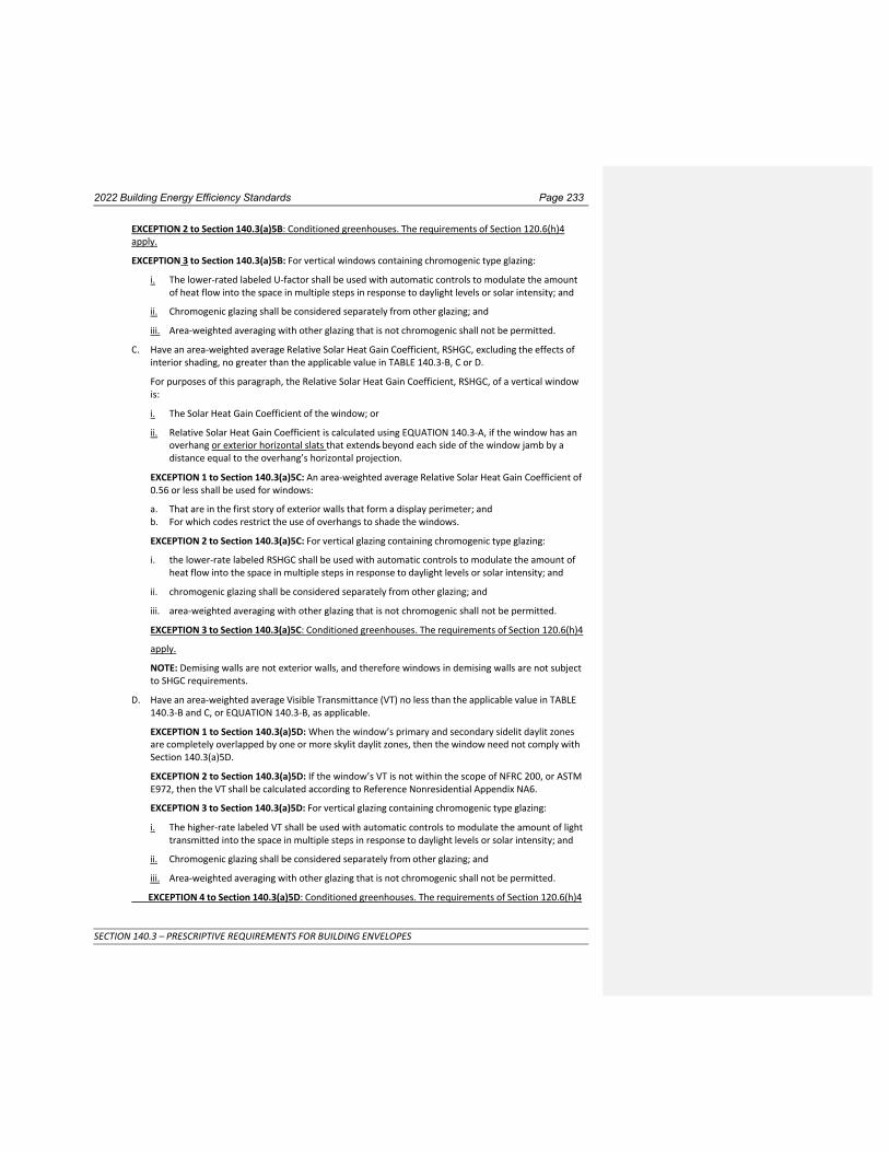
2022 Building Energy Efficiency Standards Page 233
SECTION 140.3 – PRESCRIPTIVE REQUIREMENTS FOR BUILDING ENVELOPES
EXCEPTION 2 to Section 140.3(a)5B: Conditioned greenhouses. The requirements of Section 120.6(h)4 apply.
EXCEPTION 3 to Section 140.3(a)5B: For vertical windows containing chromogenic type glazing:
i. The lower-rated labeled U-factor shall be used with automatic controls to modulate the amount of heat flow into the space in multiple steps in response to daylight levels or solar intensity; and
ii. Chromogenic glazing shall be considered separately from other glazing; and
iii. Area-weighted averaging with other glazing that is not chromogenic shall not be permitted.
C. Have an area-weighted average Relative Solar Heat Gain Coefficient, RSHGC, excluding the effects of interior shading, no greater than the applicable value in TABLE 140.3-B, C or D.
For purposes of this paragraph, the Relative Solar Heat Gain Coefficient, RSHGC, of a vertical window is:
i. The Solar Heat Gain Coefficient of the window; or
ii. Relative Solar Heat Gain Coefficient is calculated using EQUATION 140.3-A, if the window has an overhang or exterior horizontal slats that extends beyond each side of the window jamb by a distance equal to the overhang’s horizontal projection.
EXCEPTION 1 to Section 140.3(a)5C: An area-weighted average Relative Solar Heat Gain Coefficient of 0.56 or less shall be used for windows:
a. That are in the first story of exterior walls that form a display perimeter; and b. For which codes restrict the use of overhangs to shade the windows.
EXCEPTION 2 to Section 140.3(a)5C: For vertical glazing containing chromogenic type glazing:
i. the lower-rate labeled RSHGC shall be used with automatic controls to modulate the amount of heat flow into the space in multiple steps in response to daylight levels or solar intensity; and
ii. chromogenic glazing shall be considered separately from other glazing; and
iii. area-weighted averaging with other glazing that is not chromogenic shall not be permitted.
EXCEPTION 3 to Section 140.3(a)5C: Conditioned greenhouses. The requirements of Section 120.6(h)4
apply.
NOTE: Demising walls are not exterior walls, and therefore windows in demising walls are not subject to SHGC requirements.
D. Have an area-weighted average Visible Transmittance (VT) no less than the applicable value in TABLE 140.3-B and C, or EQUATION 140.3-B, as applicable.
EXCEPTION 1 to Section 140.3(a)5D: When the window’s primary and secondary sidelit daylit zones are completely overlapped by one or more skylit daylit zones, then the window need not comply with Section 140.3(a)5D.
EXCEPTION 2 to Section 140.3(a)5D: If the window’s VT is not within the scope of NFRC 200, or ASTM E972, then the VT shall be calculated according to Reference Nonresidential Appendix NA6.
EXCEPTION 3 to Section 140.3(a)5D: For vertical glazing containing chromogenic type glazing:
i. The higher-rate labeled VT shall be used with automatic controls to modulate the amount of light transmitted into the space in multiple steps in response to daylight levels or solar intensity; and
ii. Chromogenic glazing shall be considered separately from other glazing; and
iii. Area-weighted averaging with other glazing that is not chromogenic shall not be permitted.
EXCEPTION 4 to Section 140.3(a)5D: Conditioned greenhouses. The requirements of Section 120.6(h)4

2022 Building Energy Efficiency Standards Page 234
SECTION 140.3 – PRESCRIPTIVE REQUIREMENTS FOR BUILDING ENVELOPES
apply.
NOTE: Demising walls are not exterior walls, and therefore windows in demising walls are not subject to VT requirements.
EQUATION 140.3-A RELATIVE SOLAR HEAT GAIN COEFFICIENT, RSHGC
é aH æ H ö2 ù RSHGC = SHGCwin ´ ê1 +
V + bç ÷ ú V
êë è ø ûú
RSHGC = SHGC × [1 + a × (2.72-PF – 1) × (sin(b × Az) – c]
WHERE:
a
b
c
Overhang
0.150
0.130
5.67
Exterior Horizontal Slat
0.144
0.133
5.13
RSHGC = Relative Solar Heat Gain Coefficient.
SHGCwin = Solar Heat Gain Coefficient of the windowvertical fenestration.
H = Horizontal projection of the overhang from the surface of the window in feet, but no greater than V.
V = Vertical distance from the window sill to the bottom of the overhang in feet.
a = -0.41 for north-facing windows, -1.22 for south-facing windows, and -0.92 for east and west-facing windows.
b = 0.20 for north-facing windows, 0.66 for south-facing windows, and 0.35 for east and west-facing windows.
Az = Azimuth of the vertical fenestration in degrees.
PF = Projection factor as calculated by Equation 140.3-C.
EQUATION 140.3-B VERTICAL FENESTRATION MINIMUM VT
VT ≥ 0.11/ WWR
WHERE:
WWR = Window Wall Ratio, the ratio of (i) the total window area of the entire building to (ii) the total gross exterior wall area of the entire building. If the WWR is greater than 0.40, then 0.40 shall be used as the value for WWR in EQUATION 140.3-B.
VT = Visible Transmittance of framed window.
6. Skylights. Skylights shall:
A. Have an area no greater than 5 percent of the gross exterior roof area Skylight Roof Ratio (SRR); and
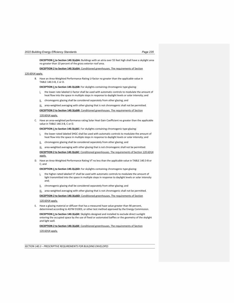
2022 Building Energy Efficiency Standards Page 235
SECTION 140.3 – PRESCRIPTIVE REQUIREMENTS FOR BUILDING ENVELOPES
EXCEPTION 1 to Section 140.3(a)6A: Buildings with an atria over 55 feet high shall have a skylight area no greater than 10 percent of the gross exterior roof area.
EXCEPTION 2 to Section 140.3(a)6A: Conditioned greenhouses. The requirements of Section
120.6(h)4 apply.
B. Have an Area-Weighted Performance Rating U-factor no greater than the applicable value in TABLE 140.3-B, C or D.
EXCEPTION 1 to Section 140.3(a)6B: For skylights containing chromogenic type glazing:
i. the lower-rate labeled U-factor shall be used with automatic controls to modulate the amount of heat flow into the space in multiple steps in response to daylight levels or solar intensity; and
ii. chromogenic glazing shall be considered separately from other glazing; and
iii. area-weighted averaging with other glazing that is not chromogenic shall not be permitted.
EXCEPTION 2 to Section 140.3(a)6B: Conditioned greenhouses. The requirements of Section
120.6(h)4 apply.
C. Have an area-weighted performance rating Solar Heat Gain Coefficient no greater than the applicable value in TABLE 140.3-B, C or D.
EXCEPTION 1 to Section 140.3(a)6C: For skylights containing chromogenic type glazing:
i. the lower-rated labeled SHGC shall be used with automatic controls to modulate the amount of heat flow into the space in multiple steps in response to daylight levels or solar intensity; and
ii. chromogenic glazing shall be considered separately from other glazing; and
iii. area-weighted averaging with other glazing that is not chromogenic shall not be permitted.
EXCEPTION 2 to Section 140.3(a)6C: Conditioned greenhouses. The requirements of Section 120.6(h)4 apply.
D. Have an Area-Weighted Performance Rating VT no less than the applicable value in TABLE 140.3-B or C; and
EXCEPTION 1 to Section 140.3(a)6D: For skylights containing chromogenic type glazing:
i. the higher-rated labeled VT shall be used with automatic controls to modulate the amount of light transmitted into the space in multiple steps in response to daylight levels or solar intensity and;
ii. chromogenic glazing shall be considered separately from other glazing; and
iii. area-weighted averaging with other glazing that is not chromogenic shall not be permitted.
EXCEPTION 2 to Section 140.3(a)6D: Conditioned greenhouses. The requirements of Section
120.6(h)4 apply.
E. Have a glazing material or diffuser that has a measured haze value greater than 90 percent, determined according to ASTM D1003, or other test method approved by the Energy Commission.
EXCEPTION 1 to Section 140.3(a)6E: Skylights designed and installed to exclude direct sunlight entering the occupied space by the use of fixed or automated baffles or the geometry of the skylight and light well.
EXCEPTION 2 to Section 140.3(a)6E: Conditioned greenhouses. The requirements of Section
120.6(h)4 apply.

2022 Building Energy Efficiency Standards Page 236
SECTION 140.3 – PRESCRIPTIVE REQUIREMENTS FOR BUILDING ENVELOPES
7. Exterior doors. All exterior doors that separate conditioned space from unconditioned space or from ambient air shall have a U-factor not greater than the applicable value in TABLE 140.3-B, C or D. Doors that are more than one-half quarter glass in area are considered Glazed Doors.
8. Relocatable Public School Buildings. In complying with Sections 140.3(a)1 to 7 shall meet the following:
A. Relocatable public school buildings shall comply with TABLE 140.3-B for a specific Climate Zone when the manufacturer or builder of the relocatable public school building certifies that the building is intended for use only in a specific Climate Zone; or
B. Relocatable public school buildings shall comply with TABLE 140.3-D for any Climate Zone when the manufacturer or builder of the relocatable public school building certifies that the building is intended for use in any Climate Zone; and
C. The manufacturer or builder of a relocatable public school building shall certify that components of the building comply with requirements of this section by:
i. The placement of two (2) metal identification labels on the building, one mechanically fastened and visible from the exterior and the other mechanically fastened to the interior frame above the ceiling at the end of the module, both labels stating (in addition to any other information by the Division of the State Architect or other law) "Complies with Title 24, Part 6 for all Climate Zones”; and
ii. Identification of the location of the 2 labels on the plans submitted to the enforcing agency.
9. Air Barrier. To meet the requirement of TABLE 140.3-B, all buildings shall have a continuous air barrier that is designed and constructed to control air leakage into, and out of, the building’s conditioned space.
EXCEPTION to Section 140.3(a)9: Relocatable Public School Buildings.
A. Design. Construction documents shall include air barrier boundaries, interconnections and penetrations, and associated square foot calculations for all sides of the air barrier.
B. Acceptable Materials and Assemblies, The air barrier shall be sealed at all joints for its entire length and shall be composed of:
Ai .Materials that have an air permeance not exceeding 0.004 cfm/ft2, under a pressure differential of 0.3 in. of water (1.57 psf) (0.02 L/(sec-m2) at 75 pa), when tested in accordance with ASTM E2178; or
EXCEPTION to Section 140.3(a)9A: Materials in TABLE 140.3-A shall be deemed to comply with Section 140.3(a)9A provided if all joints are sealed and all of the materials are installed as air barriers in accordance with the manufacturer's instructions.
Commented [BZ1]: Reduced Infiltration
Commented [AT2R1]: changes in this section are related to reduce infiltration

2022 Building Energy Efficiency Standards Page 237
SECTION 140.3 – PRESCRIPTIVE REQUIREMENTS FOR BUILDING ENVELOPES
TABLE 140.3-A MATERIALS DEEMED TO COMPLY WITH SECTION 140.3(a)9A
MATERIALS AND THICKNESS
MATERIALS AND THICKNESS
1 Plywood – min. 3/8 inches thickness 9 Built up roofing membrane
2 Oriented strand board – min. 3/8 inches
thickness
10
Modified bituminous roof membrane
3 Extruded polystyrene insulation board – min.
½ inches thickness
11
Fully adhered single-ply roof membrane
4
Foil-back polyisocyanurate insulation board –
min. ½ inches thickness
12
A Portland cement or Portland sand parge, or a gypsum plaster, each with min. 5/8 inches
thickness
5
Closed cell spray foam with a minimum density of 2.0 pcf and a min. 2.0 inches
thickness
13
Cast-in-place concrete, or precast concrete
6
Open cell spray foam with a density no less than 0.4 pcf and no greater than 1.5 pcf, and a
min. 5½ inches thickness
14
Fully grouted concrete block masonry
7 Exterior or interior gypsum board min. 1/2
inches thickness
15
Sheet steel or sheet aluminum
8 Cement board – min. 1/2 inches thickness --- ---------------------------------
Bii . Assemblies of materials and components that have an average air leakage not exceeding 0.04 cfm/ft2, under a pressure differential of 0.3 in. of water (1.57 psf) (0.2 L/m2 at 75 pa), when tested in accordance with ASTM E2357, ASTM E1677, ASTM E1680, or ASTM E283; or
EXCEPTION to Section 140.3(a)9 Bi: Materials in TABLE 140.3-B shall be deemed to comply with Section 140.3(a)9B provided if all joints are sealed and all of the materials are installed as air barriers in accordance with the manufacturer's instructions.
EXCEPTION to Section 140.3(a)9Bii: The following materials shall be deemed to comply with Section 140.3(a)9B if all joints are sealed and all of the materials are installed as air barriers in accordance with the manufacturer's instructions:
a. i. Concrete masonry walls that have at least two coatings of paint or at least two coatings of sealer coating.
b. ii. Concrete masonry walls with integral rigid board insulation.
c. iii. Structurally Insulated Panels.
d. iv. Portland cement or Portland sand parge, or stucco, or a gypsum plaster, each with minimum 1/2 inch thickness
C. Verification. If verification is conducted In Climate Zones 1-6 and 8-16, the entire building shall meet one either of the following requirements:
i. The entire building has a A pressurization test of the entire building is performed after completion of construction in accordance with NA 2.4, or another test method approved by the Commission. If the An air leakage rate does not exceeding 0.40 cfm/ft2 at a pressure differential of 0.3 in of water (1.57 psf) (2.0 L/ m2 at 75 pa) the building complies., when the entire building is

2022 Building Energy Efficiency Standards Page 238
SECTION 140.3 – PRESCRIPTIVE REQUIREMENTS FOR BUILDING ENVELOPES
tested, after completion of construction, in accordance with ASTM E779 NA 2.4, or another test method approved by the Commission; or.
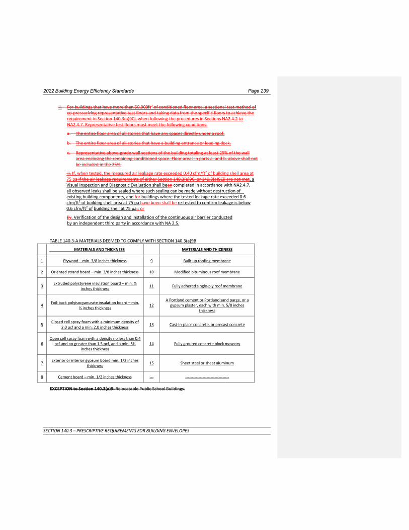
2022 Building Energy Efficiency Standards Page 239
SECTION 140.3 – PRESCRIPTIVE REQUIREMENTS FOR BUILDING ENVELOPES
ii. For buildings that have more than 50,000ft2 of conditioned floor area, a sectional test method of co-pressurizing representative test floors and taking data from the specific floors to achieve the requirement in Section 140.3(a)9Ci. when following the procedures in Sections NA2.4.2 to NA2.4.7. Representative test floors must meet the following conditions:
a. The entire floor area of all stories that have any spaces directly under a roof.
b. The entire floor area of all stories that have a building entrance or loading dock.
c. Representative above-grade wall sections of the building totaling at least 25% of the wall area enclosing the remaining conditioned space. Floor areas in parts a. and b. above shall not be included in the 25%.
iii. If, when tested, the measured air leakage rate exceeded 0.40 cfm/ft2 of building shell area at 75 pa If the air leakage requirements of either Section 140.3(a)9Ci or 140.3(a)9Cii are not met, a Visual Inspection and Diagnostic Evaluation shall been completed in accordance with NA2.4.7, all observed leaks shall be sealed where such sealing can be made without destruction of existing building components, and for buildings where the tested leakage rate exceeded 0.6 cfm/ft2 of building shell area at 75 pa have been shall be re-tested to confirm leakage is below 0.6 cfm/ft2 of building shell at 75 pa.; or
iiv. Verification of the design and installation of the continuous air barrier conducted by an independent third party in accordance with NA 2.5.
TABLE 140.3-A MATERIALS DEEMED TO COMPLY WITH SECTION 140.3(a)9B
MATERIALS AND THICKNESS
MATERIALS AND THICKNESS
1 Plywood – min. 3/8 inches thickness 9 Built up roofing membrane
2 Oriented strand board – min. 3/8 inches thickness 10 Modified bituminous roof membrane
3 Extruded polystyrene insulation board – min. ½
inches thickness
11
Fully adhered single-ply roof membrane
4
Foil-back polyisocyanurate insulation board – min.
½ inches thickness
12 A Portland cement or Portland sand parge, or a
gypsum plaster, each with min. 5/8 inches thickness
5 Closed cell spray foam with a minimum density of
2.0 pcf and a min. 2.0 inches thickness
13
Cast-in-place concrete, or precast concrete
6 Open cell spray foam with a density no less than 0.4
pcf and no greater than 1.5 pcf, and a min. 5½ inches thickness
14
Fully grouted concrete block masonry
7 Exterior or interior gypsum board min. 1/2 inches
thickness
15
Sheet steel or sheet aluminum
8 Cement board – min. 1/2 inches thickness --- ---------------------------------
EXCEPTION to Section 140.3(a)9: Relocatable Public School Buildings.

2022 Building Energy Efficiency Standards Page 239
SECTION 140.3 – PRESCRIPTIVE REQUIREMENTS FOR BUILDING ENVELOPES
TABLE 140.3-B – PRESCRIPTIVE ENVELOPE CRITERIA FOR NONRESIDENTIAL BUILDINGS (INCLUDING RELOCATABLE PUBLIC SCHOOL BUILDINGS (WHERE MANUFACTURER CERTIFIES USE ONLY IN SPECIFIC CLIMATE ZONE; NOT INCLUDING HIGH-RISE RESIDENTIAL BUILDINGS AND GUEST ROOMS OF HOTEL/MOTEL
BUILDINGS) Climate Zone
1 2 3 4 5 6 7 8 9 10 11 12 13 14 15 16
En
velo
pe
M
axim
um U
-fact
or
Roof
s/
Ceili
ngs Metal Building 0.041 0.041 0.041 0.041 0.041 0.041 0.041 0.041 0.041 0.041 0.041 0.041 0.041 0.041 0.041 0.041
Wood Framed and Other
0.034 0.034 0.034 0.034 0.034 0.049 0.049 0.049 0.034 0.034 0.034 0.034 0.034 0.034 0.034 0.034
W
alls
Metal Building 0.113 0.061 0.113 0.061 0.061 0.113 0.113 0.061 0.061 0.061 0.061 0.061 0.061 0.061 0.057 0.061
Metal-framed
0.069 0.060
0.062 0.055
0.082 0.071
0.062
0.055 0.062 0.055
0.069 0.060
0.069 0.060
0.062
0.055
0.062
0.055
0.062
0.055 0.062 0.055
0.062 0.055
0.062 0.055
0.062 0.055
0.062 0.055
0.062 0.055
Mass Light1 0.196 0.170 0.278 0.227 0.440 0.440 0.440 0.440 0.440 0.170 0.170 0.170 0.170 0.170 0.170 0.170
Mass Heavy1 0.253 0.650 0.650 0.650 0.650 0.690 0.690 0.690 0.690 0.650 0.184 0.253 0.211 0.184 0.184 0.160
Wood-framed and Other
0.095 0.059 0.110 0.059 0.102 0.110 0.110 0.102 0.059 0.059 0.045 0.059 0.059 0.059 0.042 0.059
Floo
rs/
Soffi
ts
Raised Mass 0.092 0.092 0.269 0.269 0.269 0.269 0.269 0.269 0.269 0.269 0.092 0.092 0.092 0.092 0.092 0.058
Other 0.048 0.039 0.071 0.071 0.071 0.071 0.071 0.071 0.071 0.071 0.039 0.071 0.071 0.039 0.039 0.039
Roof
ing
Prod
ucts
Low
- slo
ped Aged Solar Reflectance 0.63 0.63 0.63 0.63 0.63 0.63 0.63 0.63 0.63 0.63 0.63 0.63 0.63 0.63 0.63 0.63
Thermal Emittance 0.75 0.75 0.75 0.75 0.75 0.75 0.75 0.75 0.75 0.75 0.75 0.75 0.75 0.75 0.75 0.75
Stee
p- S
lope
d
Aged Solar Reflectance 0.20 0.20 0.25
0.20 0.20 0.25
0.20 0.25
0.20 0.25
0.20 0.25
0.20 0.25
0.20 0.25
0.20 0.25
0.20 0.25
0.20 0.25
0.20 0.25
0.20 0.25
0.20 0.25
0.20 0.25
Thermal Emittance 0.75 0.75 0.80
0.75 0.75 0.80
0.75 0.80
0.75 0.80
0.75 0.80
0.75 0.80
0.75 0.80
0. 75 0.80
0.75 0.80
0.75 0.80
0.75 0.80
0.75 0.80
0.75 0.80
0.75 0.80
Air Barrier
REQNR
REQNR
REQNR
REQNR
REQ NR
REQ NR
NR
NR
REQ
NR REQ
REQ NR
REQ
REQ
REQ
REQ
REQ
REQ
REQ
Exterior Doors, Maximum U-factor
Non-Swinging 0.50 1.45 1.45 1.45 1.45 1.45 1.45 1.45 1.45 1.45 1.45 1.45 1.45 1.45 1.45 0.50
Swinging 0.70 0.70 0.70 0.70 0.70 0.70 0.70 0.70 0.70 0.70 0.70 0.70 0.70 0.70 0.70 0.70
Commented [SS3]: NR HPE
Commented [BZ4]: Reduced Infiltration
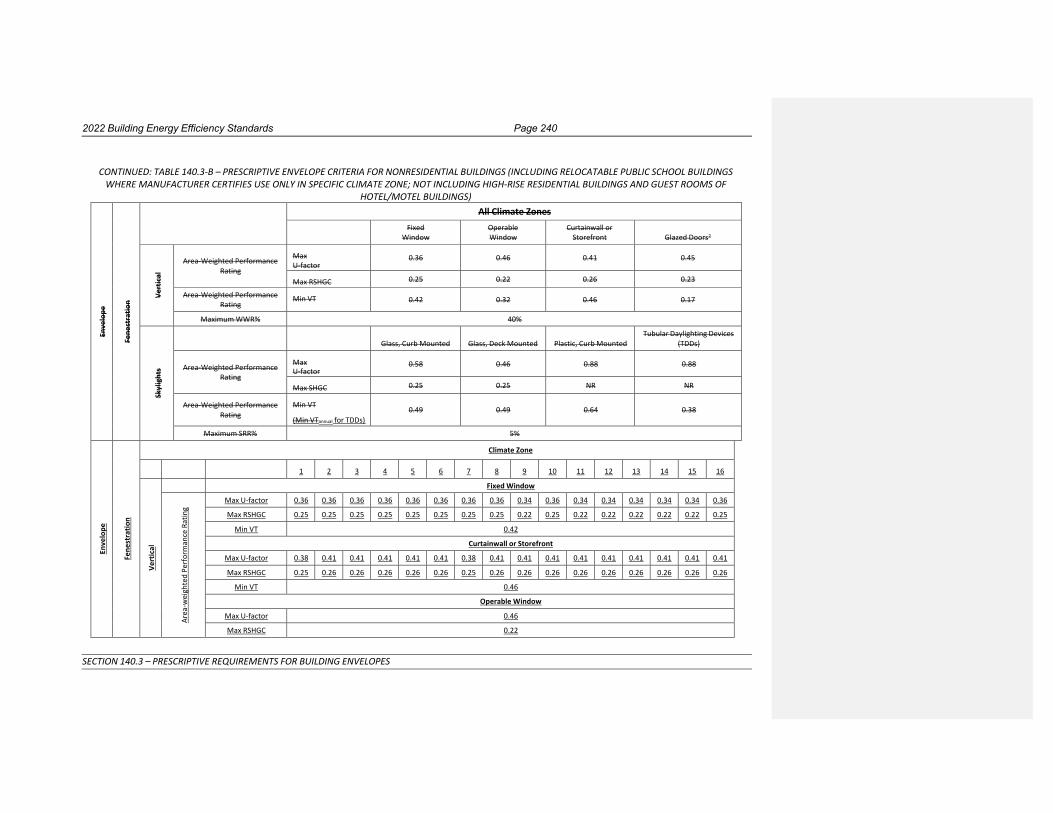
2022 Building Energy Efficiency Standards Page 240
SECTION 140.3 – PRESCRIPTIVE REQUIREMENTS FOR BUILDING ENVELOPES
CONTINUED: TABLE 140.3-B – PRESCRIPTIVE ENVELOPE CRITERIA FOR NONRESIDENTIAL BUILDINGS (INCLUDING RELOCATABLE PUBLIC SCHOOL BUILDINGS WHERE MANUFACTURER CERTIFIES USE ONLY IN SPECIFIC CLIMATE ZONE; NOT INCLUDING HIGH-RISE RESIDENTIAL BUILDINGS AND GUEST ROOMS OF
HOTEL/MOTEL BUILDINGS)
Enve
lope
Fe
nest
ratio
n
All Climate Zones Fixed
Window Operable Window
Curtainwall or Storefront
Glazed Doors2
Ve
rtic
al
Area-Weighted Performance
Rating
Max U-factor
0.36
0.46
0.41
0.45
Max RSHGC 0.25 0.22 0.26 0.23
Area-Weighted Performance Rating
Min VT 0.42 0.32 0.46 0.17
Maximum WWR% 40%
Sk
ylig
hts
Glass, Curb Mounted
Glass, Deck Mounted
Plastic, Curb Mounted
Tubular Daylighting Devices (TDDs)
Area-Weighted Performance
Rating
Max U-factor
0.58
0.46
0.88
0.88
Max SHGC 0.25 0.25 NR NR
Area-Weighted Performance Rating
Min VT
(Min VTannual for TDDs)
0.49
0.49
0.64
0.38
Maximum SRR% 5%
Enve
lope
Fe
nest
ratio
n
Climate Zone
1 2 3 4 5 6 7 8 9 10 11 12 13 14 15 16
Vert
ica l
Fixed Window
Are
a -w
eigh
ted
Perf
orm
ance
Rat
ing
Max U-factor 0.36 0.36 0.36 0.36 0.36 0.36 0.36 0.36 0.34 0.36 0.34 0.34 0.34 0.34 0.34 0.36
Max RSHGC 0.25 0.25 0.25 0.25 0.25 0.25 0.25 0.25 0.22 0.25 0.22 0.22 0.22 0.22 0.22 0.25
Min VT 0.42
Curtainwall or Storefront
Max U-factor 0.38 0.41 0.41 0.41 0.41 0.41 0.38 0.41 0.41 0.41 0.41 0.41 0.41 0.41 0.41 0.41
Max RSHGC 0.25 0.26 0.26 0.26 0.26 0.26 0.25 0.26 0.26 0.26 0.26 0.26 0.26 0.26 0.26 0.26
Min VT 0.46
Operable Window
Max U-factor 0.46
Max RSHGC 0.22

2022 Building Energy Efficiency Standards Page 241
SECTION 140.3 – PRESCRIPTIVE REQUIREMENTS FOR BUILDING ENVELOPES
Min VT 0.32
Glazed Doors
Max U-factor 0.45
Max RSHGC 0.23
Min VT 0.17
Max WWR%
40%
All Climate Zones
Skyl
ight
s
Glass, Curb Mounted
Glass, Deck Mounted
Plastic, Curb Mounted
Tubular Daylighting Devices (TDDs)
A
rea-
Wei
ghte
d Pe
rfor
man
ce
Rati
ng
Max U-factor 0.58 0.46 0.88 0.88
Max SHGC 0.25 0.25 NR NR
Min VT
(Min VTannual for TDDs)
0.49
0.49
0.64
0.38
Maximu m
SRR%
5%

2022 Building Energy Efficiency Standards Page 242
SECTION 140.3 – PRESCRIPTIVE REQUIREMENTS FOR BUILDING ENVELOPES
TABLE 140.3-C – PRESCRIPTIVE ENVELOPE CRITERIA FOR HIGH-RISE RESIDENTIAL BUILDINGS AND GUEST ROOMS OF HOTEL/MOTEL BUILDINGS Climate Zone
1 2 3 4 5 6 7 8 9 10 11 12 13 14 15 16
En
velo
pe
M
axim
um U
-fact
or
Ro
ofs /
Ce
iling
s Metal Building 0.041 0.041 0.041 0.041 0.041 0.041 0.041 0.041 0.041 0.041 0.041 0.041 0.041 0.041 0.041 0.041
Wood Framed and Other
0.028 0.028 0.034 0.028 0.034 0.034 0.039 0.028 0.028 0.028 0.028 0.028 0.028 0.028 0.028 0.028
W
alls
Metal Building 0.061 0.061 0.061 0.061 0.061 0.061 0.061 0.061 0.061 0.061 0.057 0.057 0.057 0.057 0.057 0.057
Metal-framed 0.069 0.069 0.069 0.069 0.069 0.069 0.105 0.069 0.069 0.069 0.069 0.069 0.069 0.069 0.048 0.069
Mass, Light1 0.170 0.170 0.170 0.170 0.170 0.227 0.227 0.227 0.196 0.170 0.170 0.170 0.170 0.170 0.170 0.170
Mass, Heavy1 0.160 0.160 0.160 0.184 0.211 0.690 0.690 0.690 0.690 0.690 0.184 0.253 0.211 0.184 0.184 0.160
Wood-framed and Other
0.059 0.059 0.059 0.059 0.059 0.059 0.059 0.059 0.059 0.059 0.042 0.059 0.059 0.042 0.042 0.042
Floo
rs /
So
ffits
Raised Mass1 0.045 0.045 0.058 0.058 0.058 0.069 0.092 0.092 0.092 0.069 0.058 0.058 0.058 0.045 0.058 0.037
Other 0.034 0.034 0.039 0.039 0.039 0.039 0.071 0.039 0.039 0.039 0.039 0.039 0.039 0.034 0.039 0.034
Roof
ing
Prod
ucts
Lo
w-s
lope
d Aged Solar Reflectance
NR NR NR NR NR NR NR NR 0.55 0.55 0.55 NR 0.55 0.55 0.55 NR
Thermal Emittance NR NR NR NR NR NR NR NR 0.75 0.75 0.75 NR 0.75 0.75 0.75 NR
St
eep-
Sl
oped
Aged Solar Reflectance
NR 0.20 0.20 0.20 0.20 0.20 0.20 0.20 0.20 0.20 0.20 0.20 0.20 0.20 0.20 NR
Thermal Emittance NR 0.75 0.75 0.75 0.75 0.75 0.75 0.75 0.75 0. 75 0.75 0.75 0.75 0.75 0.75 NR
Air Barrier REQ REQ REQ REQ REQ REQ NR REQ REQ REQ REQ REQ REQ REQ REQ REQ
Exterior Doors, Maximum U-
factor
Non-Swinging 0.50 1.45 1.45 1.45 1.45 1.45 1.45 1.45 1.45 1.45 1.45 1.45 1.45 1.45 1.45 0.50
Swinging 0.70 0.70 0.70 0.70 0.70 0.70 0.70 0.70 0.70 0.70 0.70 0.70 0.70 0.70 0.70 0.70
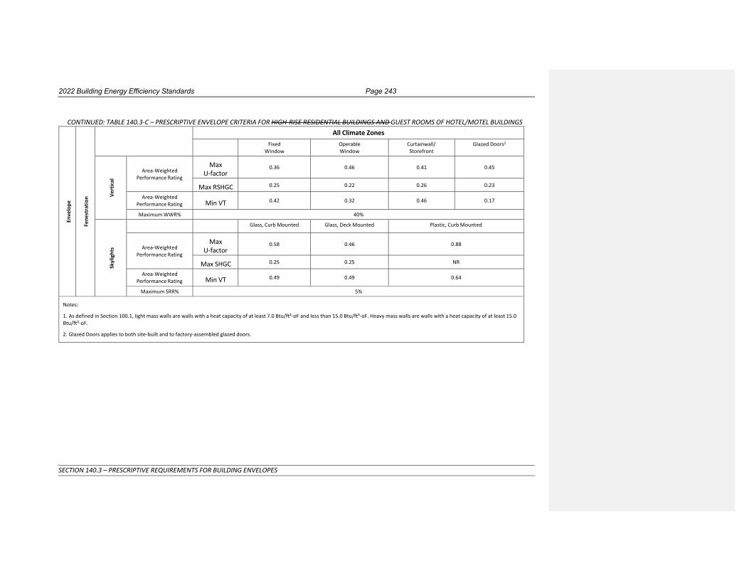
2022 Building Energy Efficiency Standards Page 243
SECTION 140.3 – PRESCRIPTIVE REQUIREMENTS FOR BUILDING ENVELOPES
CONTINUED: TABLE 140.3-C – PRESCRIPTIVE ENVELOPE CRITERIA FOR HIGH-RISE RESIDENTIAL BUILDINGS AND GUEST ROOMS OF HOTEL/MOTEL BUILDINGS
En
velo
pe
Fe
nest
ratio
n
All Climate Zones Fixed
Window Operable Window
Curtainwall/ Storefront
Glazed Doors2
Ve
rtic
al
Area-Weighted Performance Rating
Max U-factor
0.36
0.46
0.41
0.45
Max RSHGC 0.25 0.22 0.26 0.23
Area-Weighted Performance Rating Min VT 0.42 0.32 0.46 0.17
Maximum WWR% 40%
Sk
ylig
hts
Glass, Curb Mounted Glass, Deck Mounted Plastic, Curb Mounted
Area-Weighted Performance Rating
Max U-factor
0.58
0.46
0.88
Max SHGC 0.25 0.25 NR
Area-Weighted Performance Rating Min VT 0.49 0.49 0.64
Maximum SRR% 5%
Notes:
1. As defined in Section 100.1, light mass walls are walls with a heat capacity of at least 7.0 Btu/ft²-oF and less than 15.0 Btu/ft²-oF. Heavy mass walls are walls with a heat capacity of at least 15.0 Btu/ft²-oF.
2. Glazed Doors applies to both site-built and to factory-assembled glazed doors.
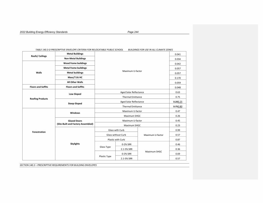
2022 Building Energy Efficiency Standards Page 244
SECTION 140.3 – PRESCRIPTIVE REQUIREMENTS FOR BUILDING ENVELOPES
TABLE 140.3-D PRESCRIPTIVE ENVELOPE CRITERIA FOR RELOCATABLE PUBLIC SCHOOL BUILDINGS FOR USE IN ALL CLIMATE ZONES
Roofs/ Ceilings
Metal Buildings
Maximum U-factor
0.041
Non-Metal Buildings 0.034
Walls
Wood frame buildings 0.042
Metal frame buildings 0.057
Metal buildings 0.057
Mass/7.0≤ HC 0.170
All Other Walls 0.059
Floors and Soffits Floors and Soffits 0.048
Roofing Products
Low-Sloped
Aged Solar Reflectance 0.63
Thermal Emittance 0.75
Steep-Sloped Aged Solar Reflectance 0.200.25
Thermal Emittance 0.750.80
Fenestration
Windows
Maximum U-factor 0.47
Maximum SHGC 0.26
Glazed Doors (Site-Built and Factory Assembled)
Maximum U-factor 0.45
Maximum SHGC 0.23
Skylights
Glass with Curb
Maximum U-factor
0.99
Glass without Curb 0.57
Plastic with Curb 0.87
Glass Type
0-2% SRR
Maximum SHGC
0.46
2.1-5% SRR 0.36
Plastic Type
0-2% SRR 0.69
2.1-5% SRR 0.57

2022 Building Energy Efficiency Standards Page 245
SECTION 140.3 – PRESCRIPTIVE REQUIREMENTS FOR BUILDING ENVELOPES
Exterior Doors
Non-Swinging doors Maximum U-factor
0.50
Swinging doors 0.70

2022 Building Energy Efficiency Standards Page 246
SECTION 140.3 – PRESCRIPTIVE REQUIREMENTS FOR BUILDING ENVELOPES
(b) RESERVED
(c) Minimum Daylighting Requirement for Large Enclosed Spaces. In Climate Zones 2 through 15, conditioned enclosed spaces, and unconditioned enclosed spaces, that are greater than 5,000 ft² and that are directly under a roof with ceiling heights greater than 15 feet, shall meet the following requirements:
1. A combined total of at least 75 percent of the floor area, as determined in building floor plan (drawings) view, shall be within one or more of the following:
A. Primary Sidelight Daylight Zone in accordance with Section 130.1(d), or
B. The total floor area in the space within a horizontal distance of 0.7 times the average ceiling height from the edge of rough opening of skylights.
2. All Skylit Daylit Zones and Primary Sidelit Daylit Zones shall be shown on building plans.
3. General lighting in daylit zones shall be controlled in accordance with Section 130.1(d).
4. The total skylight area is at least 3 percent of the total floor area in the space within a horizontal distance of 0.7 times the average ceiling height from the edge of rough opening of skylights; or the product of the total skylight area and the average skylight visible transmittance is no less than 1.5 percent of the total floor area in the space within a horizontal distance of 0.7 times the average ceiling height from the edge of rough opening of skylights.
5. All skylights shall have a glazing material or diffuser that has a measured haze value greater than 90 percent, tested according to ASTM D1003 (notwithstanding its scope) or an\other test method approved by the Commission.
6. Skylights for conditioned and unconditioned spaces shall have an area-weighted average Visible Transmittance (VT) no less than the applicable value required by Section 140.3(a)6D.
EXCEPTION 1 to Section 140.3(c): Auditoriums, churches, movie theaters, museums, and refrigerated warehouses.
EXCEPTION 2 to Section 140.3(c): In buildings with unfinished interiors, future enclosed spaces for which there are plans to have:
A. A floor area of less than or equal to 5,000 square feet; or
B. Ceiling heights of less than or equal to 15 feet. This exception shall not be used for S-1 or S-2 (storage), or for F-1 or F-2 (factory) occupancies.
EXCEPTION 3 to Section 140.3(c): Enclosed spaces having a designed general lighting system with a lighting power density less than 0.5 watts per square foot.
EXCEPTION 4 to Section 140.3(c): Enclosed spaces where it is documented that permanent architectural features of the building, existing structures or natural objects block direct beam sunlight on at least half of the roof over the enclosed space for more than 1500 daytime hours per year between 8 a.m. and 4 p.m.
(d) Daylighting Design Power Adjustment Factors (PAFs). To qualify for a Power Adjustment Factor (PAF) as specified in Section 140.6(a)2L, daylighting devices shall meet the following requirements:
1. Clerestory Fenestration. To qualify for a PAF, clerestory fenestration shall meet the following requirements:
A. Shall be installed on east-, west-, or south-facing facades.
B. Shall have a head height that is at least 10 feet above the finished floor.

2022 Building Energy Efficiency Standards Page 247
SECTION 140.3 – PRESCRIPTIVE REQUIREMENTS FOR BUILDING ENVELOPES
C. Shall have a glazing height that is greater than or equal to 10 percent of the head height.
D. If operable shading is installed on the clerestory fenestration, then the clerestory fenestration shading shall be controlled separately from shading serving other vertical fenestration.
2. Interior and Exterior Horizontal Slats. To qualify for a PAF, horizontal slats shall meet the following requirements:
A. Shall be installed adjacent to vertical fenestration on east- or west-facing facades with Window Wall Ratios between 20 and 30 percent, and extend to the entire height of the vertical fenestration.
B. Exterior horizontal slats shall be level or sloped downwards from fenestration. Interior horizontal slats shall be level or sloped upwards from fenestration.
C. Shall have a projection factor as specified in Table 140.3-E. The projection factor is calculated using EQUATION 140.3-CE.
D. Shall have a minimum Distance Factor of 0.3. The distance factor is calculated using EQUATION 140.3-EC.
EXCEPTION to Section 140.3(d)2D: Where it is documented that existing adjacent structures or natural objects within view of the vertical fenestration block direct sunlight onto the vertical fenestration between 8 a.m. and 5 p.m. for less than 500 daytime hours per year.
E. Shall have a minimum Visible Reflectance of 0.50 when tested as specified in ASTM E903.
F. Shall be opaque.
EXCEPTION to Section 140.3(d)2F: Horizontal slats with a Visible Transmittance of 0.03 or less when tested as specified in ASTM E1175.
G. Shall be permanently mounted and not adjustable.
H. Shall extend the entire height of the vertical fenestration and beyond each side of the window jamb by a distance equal to or greater than their horizontal projection.
EXCEPTION to Section 140.3(d)2H: Where the slats are located entirely within the vertical fenestration’s rough opening or a fin is located at the window jambs and extends vertically the entire height of the window jamb and extends horizontally the entire depth of the projection.
I. Shall be shown on the plans with the dimensions for the slat projection and slat spacing as specified in EQUATION 140.3-E.C
J. Shall have a conspicuous factory installed label permanently affixed and prominently located on an attachment point of the device to the building envelope, stating the following: “NOTICE: Removal of this device will require re-submittal of compliance documentation to the enforcement agency responsible for compliance with California Title 24, Part 6”.
3. Interior and Exterior Light Shelves. To qualify for a PAF, light shelves shall meet the following requirements:
A. Where there is vertical fenestration area below the light shelf, both interior and exterior light shelves shall be installed.
B. Shall be installed adjacent to clerestory fenestration on south-facing facades with Window Wall Ratios greater than 30 percent. The head height of the light shelves shall be no more than one foot below the finished ceiling. The clerestory fenestration shall meet the requirements of Section 140.3(d)1.

2022 Building Energy Efficiency Standards Page 248
SECTION 140.3 – PRESCRIPTIVE REQUIREMENTS FOR BUILDING ENVELOPES
C. Shall be level or sloped based on their installation. Exterior light shelves shall be level or sloped downwards from fenestration. Interior light shelves shall be level or sloped upwards from fenestration.
D. Shall have a projection factor of the applicable value as specified in Table 140.3-E. The light shelf projection factor is calculated using EQUATION 140.3-EC.
E. Shall have a minimum Distance Factor of 0.3. The distance factor is calculated using EQUATION 140.3-EC.
EXCEPTION to Section 140.3(d)3E: Where it is documented that existing adjacent structures or natural objects within view of the vertical fenestration block direct sunlight onto the vertical fenestration between 8 a.m. and 5 p.m. for less than 750 daytime hours per year.
F. Shall have a top surface with a minimum Visible Reflectance of 0.50 when tested as specified in ASTM E903.
EXCEPTION to Section 140.3(d)3F: Where an exterior light shelf is installed greater than two feet below the clerestory sill.
G. Shall extend beyond each side of the window jamb by a distance equal to or greater than their horizontal projection.
H. Shall be shown on the plans with the dimensions for the light shelf projection and light shelf spacing as specified in EQUATION 140.3-EC.
TABLE 140.3-E Daylighting Devices
Daylighting Device
Orientation of the Vertical Fenestration
Projection Factor
Horizontal Slats East or West 2.0 to 3.0
Interior Light Shelf South 1.0 to 2.0
Exterior Light Shelf South 0.25 to 1.25
EQUATION 140.3-E C PROJECTION AND DISTANCE FACTOR CALCULATION
Projection Factor = Projection / Spacing
Distance Factor = D / (HAS × Projection Factor)
WHERE:
Projection = The horizontal distance between the base edge and the projected edge of the overhang, slat, or light shelf.
Spacing = For overhangs, the vertical distance between the projected edge of the overhang and sill of the vertical fenestration below it.

2022 Building Energy Efficiency Standards Page 249
SECTION 140.3 – PRESCRIPTIVE REQUIREMENTS FOR BUILDING ENVELOPES
For horizontal slats, the vertical distance between the projected edge of
a slat to the base edge of the slat below it.
For interior light shelves, the vertical distance between the projected edge of the light shelf and head of the clerestory fenestration above it.
For exterior light shelves, the vertical distance between the projected edge of the light shelf and sill of the vertical fenestration below it.
D = Distance between the existing structure or nature object and the fenestration
HAS = Height difference between the top of the existing structure or nature object and the bottom of the fenestration
NOTE: The base edge is the edge of an overhang, slat, or light shelf that is adjacent to the vertical fenestration. The projected edge is the opposite edge from the base edge.
NOTE: Authority: Sections 25213, 25218, 25218.5, 25402 and 25402.1, Public Resources Code. Reference: Sections 25007, 25008, 25218.5, 25310, 25402, 25402.1, 25402.4, 25402.5, 25402.8, and 25943, Public Resources Code.
2022 Building Energy Efficiency Standards Page 250
SECTION 140.4 – PRESCRIPTIVE REQUIREMENTS FOR SPACE CONDITIONING SYSTEMS
SECTION 140.4 – PRESCRIPTIVE REQUIREMENTS FOR SPACE CONDITIONING SYSTEMS A building complies with this section by being designed with and having constructed and installed a space-conditioning system that meets the applicable prescriptive requirements of Subsections (a) through (oq).
(a) Sizing, and Equipment Selection, and Type.
1. Sizing and Equipment Selection. Mechanical heating and mechanical cooling equipment serving healthcare facilities shall be sized to meet the design heating and cooling loads as calculated according to the subsection (b). Mechanical heating and mechanical cooling equipment serving high-rise residential buildings, hotel/motel buildings and nonresidential buildings other than healthcare facilities, shall be the smallest size, within the available options of the desired equipment line, necessary to meet the design heating and cooling loads of the building, as calculated according to Subsection (b).
EXCEPTION 1 to Section 140.4(a)1: Where it can be demonstrated to the satisfaction of the enforcing agency that oversizing will not increase building TDV energy use.
EXCEPTION 2 to Section 140.4(a)1: Standby equipment with controls that allow the standby equipment to operate only when the primary equipment is not operating.
EXCEPTION 3 to Section 140.4(a)1: Multiple units of the same equipment type, such as multiple chillers and boilers, having combined capacities exceeding the design load, if they have controls that sequence or otherwise optimally control the operation of each unit based on load.
2. Single Zone Space Conditioning System Type. Single zone space conditioning systems with direct expansion cooling with rated cooling capacity 240,000 Btu/hr or less serving the following spaces shall meet the applicable requirements in A-H, or shall meet the performance compliance requirements of Section 140.1. All other system types, including systems with rated cooling capacity greater than 240,000 Btu/hr, multi-zone systems, and systems using central boilers or chillers, shall comply with the applicable requirements of Section 140.
A. Retail and Grocery Building Spaces in climate zones 2 through 15. The space conditioning system shall be a heat pump.
B. Retail and Grocery Building Spaces in climate zones 1 and 16 with cooling capacity less than 65,000 Btu/hr. The space conditioning system shall be an air conditioner with furnace.
C. Retail and Grocery Building Spaces in climate zones 1 and 16 with cooling capacity 65,000 Btu/hr or greater. The space conditioning system shall be a dual-fuel heat pump.
D. School Building Spaces. For climate zones 2 through 15 , the space conditioning system shall be a heat pump. For climate zones 1 and 16, the space conditioning system shall be a dual-fuel heat pump.
E. Office, Financial Institution, and Library Building Spaces in climate zones 1 through 15. The space conditioning system shall be a heat pump.
F. Office, Financial Institution, and Library Building Spaces in climate zones 16 with cooling capacity less than 65,000 Btu/hr. The space conditioning system shall be an air conditioner with furnace, a dual-fuel heat pump.
G. Office, Financial Institution, and Library Building Spaces in climate zones 16 with cooling capacity 65,000 Btu/hr or greater. The space conditioning system shall be a dual-fuel heat pump.
2022 Building Energy Efficiency Standards Page 251
SECTION 140.4 – PRESCRIPTIVE REQUIREMENTS FOR SPACE CONDITIONING SYSTEMS
H. Office Spaces in Warehouses. The space conditioning system shall be a heat pump in all climate zones.
EXCEPTION to Section 140.4(a)2: Systems utilizing recovered heat for space heating.
(b) Calculations. In making equipment sizing calculations under Subsection (a), all of the following rules shall apply:
1. Heating and cooling loads. Heating and cooling system design loads shall be determined in accordance with the procedures described in subsection A or B below:
A. For systems serving high-rise residential buildings, hotel/motel buildings, and nonresidential buildings other than healthcare facilities, the method in the 2017 ASHRAE Handbook, Fundamentals shall be used, or as specified in a method approved by the Commission.
B. For system serving healthcare facilities the method in the California Mechanical Code shall be used.
2. Indoor design conditions. Indoor design temperature and humidity conditions for comfort applications shall be determined in accordance with subsection A or B below:
A. For systems serving high-rise residential buildings, hotel/motel buildings, and nonresidential buildings other than healthcare facilities, ASHRAE Standard 55 or the 2017 ASHRAE Handbook, Fundamentals Volume, except that winter humidification and summer dehumidification shall not be required.
B. For system serving healthcare facilities the method in Section 320.0 of the California Mechanical Code shall be used.
3. Outdoor design conditions. Outdoor design conditions shall be selected in accordance with subsection A or B below:
A. For systems serving high-rise residential buildings, hotel/motel buildings, and nonresidential buildings other than healthcare facilities the design conditions from Reference Joint Appendix JA2 shall be used, which is based on data from the ASHRAE Climatic Data for Region X. Heating design temperatures shall be no lower than the Heating Winter Median of Extremes values. Cooling design temperatures shall be no greater than the 0.5 percent Cooling Dry Bulb and Mean Coincident Wet Bulb values.
B. For system serving healthcare facilities the method in Section 320.0 of the California Mechanical Code shall be used.
EXCEPTION to Section 140.4(b)3: Cooling design temperatures for cooling towers shall be no greater than the 0.5 percent Cooling Design Wet bulb values.
4. Ventilation. Outdoor air ventilation loads shall be calculated using the ventilation rates required in Section 120.1(c)3.
5. Envelope. Envelope heating and cooling loads shall be calculated using envelope characteristics, including square footage, thermal conductance, Solar Heat Gain Coefficient or shading coefficient, and air leakage, consistent with the proposed design.
6. Lighting. Lighting heating and cooling loads shall be based on actual design lighting levels or power densities as specified in Section 140.6.
7. People. Occupant density shall be based on the expected occupancy of the building and shall be the same as determined under Section 120.1(c)3A, if used. Sensible and latent heat gains shall be as listed in the 2017 ASHRAE Handbook- Fundamentals, Chapter 18.

2022 Building Energy Efficiency Standards Page 252
SECTION 140.4 – PRESCRIPTIVE REQUIREMENTS FOR SPACE CONDITIONING SYSTEMS
8. Process loads. Loads caused by a process shall be based upon actual information on the intended use of the building.
9. Miscellaneous equipment. Equipment loads other than process loads shall be calculated using design data compiled from one or more of the following sources:
A. Actual information based on the intended use of the building; or
B. Published data from manufacturer's technical publications or from technical societies, such as the ASHRAE Handbook, Applications Volume; or
C. Other data based on the designer's experience of expected loads and occupancy patterns.
10. Internal heat gains. Internal heat gains may be ignored for heating load calculations.
11. Safety factor. Calculated design loads based on 140.4(b)1 through 10 may be increased by up to 10 percent to account for unexpected loads or changes in space usage.
12. Other loads. Loads such as warm-up or cool-down shall be calculated from principles based on the thermal capacity of the building and its contents, the degree of setback, and desired recovery time; or may be assumed to be no more than 30 percent for heating and 10 percent for cooling of the steady-state design loads. In addition, the steady-state load may include a safety factor in accordance with Section 140.4(b)11.
(c) Fan Systems. Each fan system moving air into, out of, or between conditioned having a total fan system motor nameplate horsepower exceeding 5 hp used for spaces conditioning or circulating air for the purpose of conditioning air within a space shall meet the requirements of Items 1, 2, and 3 below. Total fan system power demand equals the sum of the power demand of all fans in the system that are required to operate at design conditions in order to supply air from the heating or cooling source to the conditioned space, and to return it back to the source or to exhaust it to the outdoors.
1. 1. Fan Power LimitationBudget. At design conditions each fan system shall not exceed the allowable fan system power of option 1 or 2 as specified in Table
140.4-A For each fan system that includes at least one fan or fan array with fan electrical input power ≥ 1 kW, fan system electrical input power (Fan kWdesign,system) determined per Section 140.4(c)1(B) at the fan system design airflow shall not exceed Fan kWbudget as calculated per section 140.4(c)1(A).
A. Calculation of Fan Power Budget (Fan kWbudget). For each fan system:
i. Determine the fan system airflow and choose the appropriate table(s) for fan power allowance.
a. For single-cabinet fan systems, use the fan system airflow and the power allowances in both Table 140.4-A and Table 140.4-B.
b. For supply-only fan systems, use the fan system airflow and power allowances in Table 140.4-A.
c. For relief fan systems, use the design relief airflow and the power allowances in Table 140.4-B.
d. For exhaust, return and transfer fan systems, use the fan system airflow and the power allowances in Table 140.4-B.
e. For complex fan systems, separately calculate the fan power allowance for the supply and return/exhaust systems and sum them. For the supply airflow, use supply airflow at the fan system design conditions, and the power allowances in Table 140.4-A. For the return exhaust airflow, use

2022 Building Energy Efficiency Standards Page 253
SECTION 140.4 – PRESCRIPTIVE REQUIREMENTS FOR SPACE CONDITIONING SYSTEMS
return /exhaust airflow at the fan system design conditions, and the power allowances in Table 140.4-B.
ii. For each fan system determine the components included in the fan system and sum the Fan Power Allowances of those components. All fan systems shall include the System Base Allowance. If, for a given component, only a portion of the fan system airflow passes through the component, calculate the Fan Power Allowance for that component per equation 140.4-A:
EQUATION 140.4-A FAN POWER ALLOWANCE Qcomp
FPAadj=
Where
Qsys XFPAcomp
FPAadj = The corrected fan power allowance for the component in Ww/cfm
Qcomp = The airflow through component in cfm
Qsys = The fan system airflow in cfm
FPAcomp = The fan power allowance of the component from Table 140.4A or Table 140.4B
iii. Multiply the fan system airflow by the sum of the fan power allowances for the fan system.
iv. Divide by 1000 to convert to Fan kWbudget.
v. For building sites at elevations greater than 3,000 feet, multiply Fan kWbudget by Correction Factor in Table 140.4-C.
B. Determining Fan System Electrical Input Power (Fan kWdesign,system). Fan kWdesign,system is the sum of Fan kWdesign for each fan or fan array included in the fan system with Fan kWdesign ≥ 1 kW. If variable speed drives are used, their efficiency losses shall be included. Fan input power shall be calculated with mid-life2x clean filter pressure drop, which is the mean of the clean filter pressure drop and design final filter pressure drop. The Fan kWdesign for each fan or fan array shall be determined using one of the following methods. There is no requirement to use the same method for all fans in a fan system:
i. Use the default Fan kWdesign in Table 140.4-D for one or more of the fans. This method cannot be used for complex fan systems.
ii. Use the Fan kWdesign at fan system design conditions provided by the manufacturer of the fan, fan array, or equipment that includes the fan or fan array calculated per a test procedure included in USDOE 10 CFR Part 430, USDOE 10 CFR Part 431, ANSI/AMCA Standard 208-2018, ANSI/AMCA Standard 210-2016, AHRI Standard 430-2020, AHRI Standard 440-2019, or ISO 5801-2017.
iii Use the Fan kWdesign provided by the manufacturer, calculated at fan system design conditions per one of the methods listed in section 5.3 of ANSI/AMCA 208-2018.
Commented [BB5]: Air Distribution

2022 Building Energy Efficiency Standards Page 254
SECTION 140.4 – PRESCRIPTIVE REQUIREMENTS FOR SPACE CONDITIONING SYSTEMS
iv. Determine the Fan kWdesign by using the maximum electrical input power provided on the motor nameplate.

2022 Building Energy Efficiency Standards Page 255
SECTION 140.4 – PRESCRIPTIVE REQUIREMENTS FOR SPACE CONDITIONING SYSTEMS
TABLE 140.4 - A Fan Power Limitation
Limit Constant Volume Variable Volume
Option 1: Fan system motor nameplate hp
Allowable motor nameplate hp
hp ≤ cfms × 0.0011 hp ≤ cfms × 0.0015
Option 2: Fan system bhp
Allowable fan system bhp
bhp ≤ cfms × 0.00094 + A bhp ≤ cfms × 0.0013 + A
1cfms = maximum design supply airflow rate to conditioned spaces served by the system in cubic feet per minute
hp = maximum combined motor nameplate horsepower for all fans in the system
bhp = maximum combined fan-brake horsepower for all fans in the system
A = sum of (PD × cfmD/4131)
PD = each applicable pressure drop adjustment from Table 140.4 – B, in inches of water
cfmD = the design airflow through each applicable device from Table 140.4 – B, in cubic feet per minute

2022 Building Energy Efficiency Standards Page 256
SECTION 140.4 – PRESCRIPTIVE REQUIREMENTS FOR SPACE CONDITIONING SYSTEMS
TABLE 140.4-B – Fan Power Limitation Pressure Drop Adjustment
Device Adjustment Credits
Return or exhaust systems required by code or accreditation standards to be fully ducted, or systems required to maintain air pressure differentials between adjacent rooms
0.5 in. of water
Return and/or exhaust airflow control devices 0.5 in. of water
Exhaust filters, scrubbers, or other exhaust treatment
The pressure drop of device calculated at fan system design condition
Particulate Filtration Credit: MERV 16 and greater and electronically enhanced filters
Pressure drop calculated at 2 × clean filter pressure drop at fan system design condition
Carbon and other gas-phase air cleaners Clean filter pressure drop at fan system design condition
Biosafety cabinet Pressure drop of device at fan system design condition
Energy recovery device, other than coil runaround loop
For each airstream [(2.2 × Energy Recovery Effectiveness) – 0.5] in. of water
Coil runaround loop 0.6 in. of water for each airstream
Exhaust systems serving fume hoods 0.35 in. of water
Table 140.4-A: Supply Fan Power Allowances (watts/ cfm)

2022 Building Energy Efficiency Standards Page 257
SECTION 140.4 – PRESCRIPTIVE REQUIREMENTS FOR SPACE CONDITIONING SYSTEMS
Airflow
Multi-Zone
VAV Systems ≤5,000
cfm1
Multi-Zone
VAV Systems >5,000 and
≤10,000 cfm1
Multi-Zone VAV Systems >10,000 cfm1
All Other Fan Systems ≤5,000
cfm
All Other Fan
Systems >5,000 and
≤10,000 cfm
All Other Fan Systems
>10,000 cfm1
Supply System Base Allowance for AHU serving spaces ≤ 6 floors away).
0.395 0.453 0.413 0.232 0.256 0.236
Supply system base allowance for AHU serving spaces > 6 floors away
0.508 0.548 0.501 0.349 0.356 0.325
MERV 13 to MERV 16 Filter upstream of thermal conditioning equipment (mid-life2x clean)2
0.136 0.114 0.105 0.139 0.120 0.107
MERV 13 to MERV 16 Final filter downstream of thermal conditioning equipment. (mid-life2x clean)2
0.225 0.188 0.176 0.231 0.197 0.177
Filtration allowance for > MERV 16 or HEPA Filter (mid-life2x clean) 2
0.335 0.280 0.265 0.342 0.292 0.264
Central Hydronic heating coil allowance
0.046 0.048 0.052 0.046 0.050 0.054
Electric heat allowance 0.046 0.038 0.035 0.046 0.040 0.036
Gas heat allowance 0.069 0.057 0.070 0.058 0.060 0.072
Hydronic/DX cooling coil or heat pump coil (wet) allowance3
0.135 0.114 0.105 0.139 0.120 0.107
Solid or liquid Desiccant system allowance
0.157 0.132 0.123 0.163 0.139 0.124
Allowance for reheat coil for dehumidification
0.045 0.038 0.035 0.046 0.040 0.036
Commented [BB6]: Air Distribution

2022 Building Energy Efficiency Standards Page 258
SECTION 140.4 – PRESCRIPTIVE REQUIREMENTS FOR SPACE CONDITIONING SYSTEMS
Allowance for Evaporative humidifier/cooler in series with a cooling coil. Value shown is allowed watts/cfm per 1.0 Inches of water gauge (in.w.g.) Determine pressure loss (in.w.g.) at 400 fpm or maximum velocity allowed by the manufacturer, whichever is less. [Calculation required, see note 4]
0.224 0.188 0.176 0.231 0.197 0.177
Allowance for 100% Outdoor air system5.
0.000
0.000
0.000
0.070
0.100
0.107
Energy recovery allowance for 0.50 ≤ ERR <0.55 6
0.135
0.114
0.105
0.139
0.120
0.107
Energy recovery allowance for 0.55 ≤ ERR <0.60 6
0.160
0.134
0.124
0.165
0.141
0.126
Energy recovery allowance for 0.60 ≤ ERR <0.65 6
0.184
0.155
0.144
0.190
0.163
0.146
Energy recovery allowance for 0.65 ≤ ERR <0.70 6
0.208
0.175
0.163
0.215
0.184
0.165
Energy recovery allowance for 0.70 ≤ ERR <0.75 6
0.232
0.196
0.183
0.240
0.205
0.184
Energy recovery allowance for 0.75 ≤ ERR <0.80 6
0.257
0.216
0.202
0.264
0.226
0.203
Energy recovery allowance for ERR ≥ 0.80 6
0.281
0.236
0.222
0.289
0.247
0.222
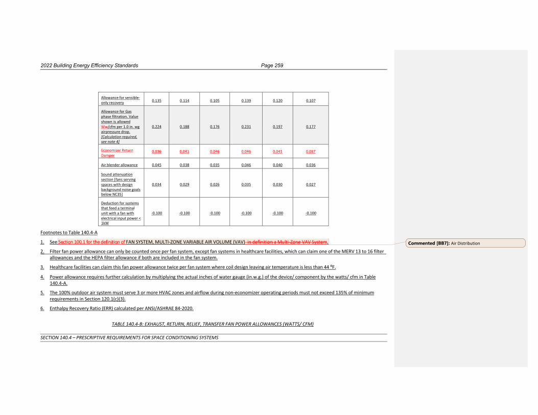
2022 Building Energy Efficiency Standards Page 259
SECTION 140.4 – PRESCRIPTIVE REQUIREMENTS FOR SPACE CONDITIONING SYSTEMS
Allowance for sensible- only recovery
0.135
0.114
0.105
0.139
0.120
0.107
Allowance for Gas phase filtration. Value shown is allowed Ww/cfm per 1.0 in. wg air pressure drop. [Calculation required, see note 4]
0.224
0.188
0.176
0.231
0.197
0.177
Economizer Return Damper
0.036 0.041 0.046 0.046 0.041 0.037
Air blender allowance
0.045
0.038
0.035
0.046
0.040
0.036
Sound attenuation section [fans serving spaces with design background noise goals below NC35]
0.034
0.029
0.026
0.035
0.030
0.027
Deduction for systems that feed a terminal unit with a fan with electrical input power < 1kW
-0.100
-0.100
-0.100
-0.100
-0.100
-0.100
Footnotes to Table 140.4-A
1. See Section 100.1 for the definition of FAN SYSTEM, MULTI-ZONE VARIABLE AIR VOLUME (VAV) in definition a Multi-Zone VAV System.
2. Filter fan power allowance can only be counted once per fan system, except fan systems in healthcare facilities, which can claim one of the MERV 13 to 16 filter allowances and the HEPA filter allowance if both are included in the fan system.
3. Healthcare facilities can claim this fan power allowance twice per fan system where coil design leaving air temperature is less than 44 ⁰F.
4. Power allowance requires further calculation by multiplying the actual inches of water gauge (in.w.g.) of the device/ component by the watts/ cfm in Table 140.4-A.
5. The 100% outdoor air system must serve 3 or more HVAC zones and airflow during non-economizer operating periods must not exceed 135% of minimum requirements in Section 120.1(c)(3).
6. Enthalpy Recovery Ratio (ERR) calculated per ANSI/ASHRAE 84-2020.
TABLE 140.4-B: EXHAUST, RETURN, RELIEF, TRANSFER FAN POWER ALLOWANCES (WATTS/ CFM)
Commented [BB7]: Air Distribution

2022 Building Energy Efficiency Standards Page 260
SECTION 140.4 – PRESCRIPTIVE REQUIREMENTS FOR SPACE CONDITIONING SYSTEMS
Airflow Multi-Zone VAV
Systems1 >10,000 cfm
Multi-Zone VAV Systems1
>5,000 and ≤10,000 cfm
Multi-Zone VAV
Systems1 ≤5,000 cfm
All Other Fan Systems
≤5,000 cfm
All Other Fan Systems >5,000 and
≤10,000 cfm
All Other Fan Systems
>10,000 cfm
All Other Fan Systems
>5,000 and ≤10,000 cfm
All Other Fan Systems
≤5,000 cfm
Exhaust System Base Allowance
0.236
0.246
0.221
0.186
0.184
0.190
0.184
0.186 Filter (any MERV value)2
0.036
0.041
0.046
0.046
0.041
0.035
0.041
0.046
Energy Recovery Allowance For 0.50 ≤ ERR <0.55 3
0.107
0.120
0.139
0.139
0.123
0.109
0.123
0.139
Energy Recovery Allowance For 0.55 ≤ ERR <0.60 3
0.126
0.142
0.165
0.165
0.144
0.128
0.144
0.165
Energy Recovery Allowance For 0.60 ≤ ERR <0.65 3
0.146
0.163
0.190
0.191
0.166
0.148
0.166
0.191
Energy Recovery Allowance For 0.65 ≤ ERR <0.70 3
0.165
0.184
0.215
0.216
0.188
0.167
0.188
0.216
Energy Recovery Allowance For 0.70 ≤ ERR <0.75 3
0.184
0.206
0.240
0.241
0.209
0.186
0.209
0.241
Energy Recovery Allowance For 0.75 ≤ ERR <0.80 3
0.203
0.227
0.265
0.266
0.231
0.205
0.231
0.266
Energy Recovery Allowance For ERR ≥ 0.80 3
0.222
0.248
0.289
0.291
0.252
0.225
0.252
0.291
Allowance For Sensible-only recovery
0.107
0.120
0.139
0.139
0.123
0.109
0.123
0.139
Economizer Return Damper 0.036 0.041 0.046 0.046 0.041 0.037 0.041 0.046
Return or exhaust systems required by code or accreditation standards to be fully ducted, or systems required to maintain air pressure differentials between adjacent rooms
0.089
0.100
0.116
0.116
0.102
0.091
0.102
0.116 Return and/or exhaust airflow control devices
0.089
0.100
0.116
0.116
0.102
0.091
0.102
0.116
Commented [BB8]: Air Distribution

2022 Building Energy Efficiency Standards Page 261
SECTION 140.4 – PRESCRIPTIVE REQUIREMENTS FOR SPACE CONDITIONING SYSTEMS
Laboratory and vivarium exhaust systems in high-rise buildings for vertical duct exceeding 75 ft. Value shown is allowed Ww/cfm per 0.25 in. wg for each 100 feet exceeding 75 feet. [Calculation required, see note 4]
0.045
0.051
0.058
0.058
0.052
0.046
0.052
0.058
Biosafety cabinet. Value shown is allowed Ww/cfm per 1.0 in. wg air pressure drop. [Calculation required, see note 4]
0.177
0.198
0.231
0.232
0.202
0.179
0.202
0.232
Exhaust filters, scrubbers, or other exhaust treatment required by code or standard. Value shown is allowed Ww/cfm per 1.0 in. wg air pressure drop. [Calculation required, see note 4]
0.177
0.198
0.231
0.232
0.202
0.179
0.202
0.232 Healthcare facility allowance5
0.177 0.198 0.231 0.232 0.202 0.179 0.202 0.232 Sound attenuation section [Fans serving spaces with design background noise goals below NC35.]
0.027
0.030
0.035
0.035
0.031
0.028
0.031
0.035
Footnotes to Table 140.4-B 1. See FAN SYSTEM, MULTI-ZONE VARIABLE AIR VOLUME (VAV) in definitions for Multizone to be classified as a Multi-Zone VAV System. 2. Filter pressure loss can only be counted once per fan system. 3. Enthalpy Recovery Ratio (ERR) calculated per ANSI/ASHRAE 84-2020. 4. Power allowance requires further calculation, multiplying the actual pressure drop (in. wg.) of the device/ component by the watts/cfm in the Table
140.4-B. 5. This allowance can only be taken for healthcare facilities.
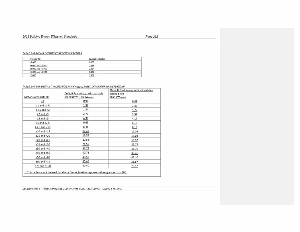
2022 Building Energy Efficiency Standards Page 262
SECTION 140.4 – PRESCRIPTIVE REQUIREMENTS FOR SPACE CONDITIONING SYSTEMS
TABLE 140.4-C AIR DENSITY CORRECTION FACTORS
Altitude (ft) Correction factor
<3,000 1.000
≥3,000 and <4,000 0.896
≥4,000 and <5,000 0.864
≥5,000 and <6,000 0.832
≥6,000 0.801
TABLE 140.4-D: DEFAULT VALUES FOR FAN KWDESIGN BASED ON MOTOR NAMEPLATE HP
Motor Nameplate HP
Default Fan kWdesign with variable speed drive (Fan kWdesign)
Default Fan kWdesign without variable speed drive (Fan kWdesign)
<1 0.96 0.89 ≥1 and <1.5 1.38 1.29 ≥1.5 and <2 1.84 1.72 ≥2 and <3 2.73 2.57 ≥3 and <5 4.38 4.17
≥5 and <7.5 6.43 6.15 ≥7.5 and <10 8.46 8.13 ≥10 and <15 12.47 12.03 ≥15 and <20 16.55 16.04 ≥20 and <25 20.58 19.92 ≥25 and <30 24.59 23.77 ≥30 and <40 32.74 31.70 ≥40 and <50 40.71 39.46 ≥50 and <60 48.50 47.10 ≥60 and <75 60.45 58.87
≥75 and ≤100 80.40 78.17
1. This table cannot be used for Motor Nameplate Horsepower values greater than 100.
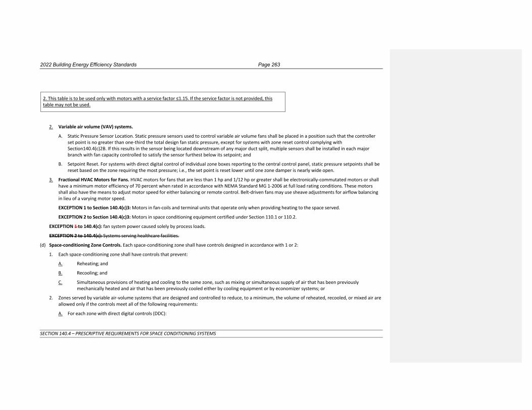
2022 Building Energy Efficiency Standards Page 263
SECTION 140.4 – PRESCRIPTIVE REQUIREMENTS FOR SPACE CONDITIONING SYSTEMS
2. Variable air volume (VAV) systems.
A. Static Pressure Sensor Location. Static pressure sensors used to control variable air volume fans shall be placed in a position such that the controller set point is no greater than one-third the total design fan static pressure, except for systems with zone reset control complying with Section140.4(c)2B. If this results in the sensor being located downstream of any major duct split, multiple sensors shall be installed in each major branch with fan capacity controlled to satisfy the sensor furthest below its setpoint; and
B. Setpoint Reset. For systems with direct digital control of individual zone boxes reporting to the central control panel, static pressure setpoints shall be reset based on the zone requiring the most pressure; i.e., the set point is reset lower until one zone damper is nearly wide open.
3. Fractional HVAC Motors for Fans. HVAC motors for fans that are less than 1 hp and 1/12 hp or greater shall be electronically-commutated motors or shall have a minimum motor efficiency of 70 percent when rated in accordance with NEMA Standard MG 1-2006 at full load rating conditions. These motors shall also have the means to adjust motor speed for either balancing or remote control. Belt-driven fans may use sheave adjustments for airflow balancing in lieu of a varying motor speed.
EXCEPTION 1 to Section 140.4(c)3: Motors in fan-coils and terminal units that operate only when providing heating to the space served.
EXCEPTION 2 to Section 140.4(c)3: Motors in space conditioning equipment certified under Section 110.1 or 110.2.
EXCEPTION 1 to 140.4(c): fan system power caused solely by process loads.
EXCEPTION 2 to 140.4(c): Systems serving healthcare facilities.
(d) Space-conditioning Zone Controls. Each space-conditioning zone shall have controls designed in accordance with 1 or 2:
1. Each space-conditioning zone shall have controls that prevent:
A. Reheating; and
B. Recooling; and
C. Simultaneous provisions of heating and cooling to the same zone, such as mixing or simultaneous supply of air that has been previously mechanically heated and air that has been previously cooled either by cooling equipment or by economizer systems; or
2. Zones served by variable air-volume systems that are designed and controlled to reduce, to a minimum, the volume of reheated, recooled, or mixed air are allowed only if the controls meet all of the following requirements:
A. For each zone with direct digital controls (DDC):
2. This table is to be used only with motors with a service factor ≤1.15. If the service factor is not provided, this table may not be used.

2022 Building Energy Efficiency Standards Page 264
SECTION 140.4 – PRESCRIPTIVE REQUIREMENTS FOR SPACE CONDITIONING SYSTEMS
i. The volume of primary air that is reheated, recooled or mixed air supply shall not exceed the larger of:
a. 50 percent of the peak primary airflow; or
b. The design zone outdoor airflow rate as specified by Section 120.1(c)3.
ii. The volume of primary air in the deadband shall not exceed the larger of:
a. 20 percent of the peak primary airflow; or
b. The design zone outdoor airflow rate as specified by Section 120.1(c)3.
iii. The first stage of heating consists of modulating the zone supply air temperature setpoint up to a maximum setpoint no higher than 95ºF while the airflow is maintained at the deadband flow rate.
iv. The second stage of heating consists of modulating the airflow rate from the deadband flow rate up to the heating maximum flow rate.
B. For each zone without DDC, the volume of primary air that is reheated, re-cooled, or mixed air supply shall not exceed the larger of the following:
i. 30 percent of the peak primary airflow; or
ii. The design zone outdoor airflow rate as specified by Section 120.1(c)3.
EXCEPTION 1 to Section 140.4(d): Zones with special pressurization relationships or cross-contamination control needs.
EXCEPTION 2 to Section 140.4(d): Zones served by space-conditioning systems in which at least 75 percent of the energy for reheating, or providing warm air in mixing systems, is provided from a site-recovered or site-solar energy source.
EXCEPTION 3 to Section 140.4(d): Zones in which specific humidity levels are required to satisfy exempt process loads. Computer rooms or other spaces where the only process load is from IT equipment may not use this exception.
EXCEPTION 4 to Section 140.4(d): Zones with a peak supply-air quantity of 300 cfm or less.
EXCEPTION 5 to Section 140.4(d): Systems serving healthcare facilities.
(e) Economizers.
1. Each cooling air handler that has a design total mechanical cooling capacity over 54,00033,000 Btu/hr, or chilled-water cooling systems without a fan or that use induced airflow that has a cooling capacity greater than the systems listed in Table 140.4-C, shall include either:
A. An air economizer capable of modulating outside-air and return-air dampers to supply 100 percent of the design supply air quantity as outside-air; or
B. A water economizer capable of providing 100 percent of the expected system cooling load, at outside air temperatures of 50°F dry-bulb and 45°F wet- bulb and below.
EXCEPTION 1 to Section 140.4(e)1: Where special outside air filtration and treatment, for the reduction and treatment of unusual outdoor contaminants, makes compliance infeasible.

2022 Building Energy Efficiency Standards Page 265
SECTION 140.4 – PRESCRIPTIVE REQUIREMENTS FOR SPACE CONDITIONING SYSTEMS
EXCEPTION 2 to Section 140.4(e)1: Where the use of outdoor air for cooling will affect other systems, such as humidification, dehumidification, or supermarket refrigeration systems, so as to increase overall building TDV energy use.
EXCEPTION 3 to Section 140.4(e)1: Systems serving high-rise residential living quarters and hotel/motel guest rooms.
EXCEPTION 4 to Section 140.4(e)1: Where comfort cooling systems have the cooling efficiency that meets or exceeds the cooling efficiency improvement requirements in TABLE 140.4-D.
EXCEPTION 5 to Section 140.4(e)1: Fan systems primarily serving computer rooms. See Section 140.9(a) for computer room economizer requirements.
EXCEPTION 6 to Section 140.4(e)1: Systems design to operate at 100 percent outside air at all times.EXCEPTION 6 to Section 140.4(e)1 In all climate zones, e Each air handler that has a design total mechanical cooling capacity less than 54,000 Btu/hr that utilizes where ventilation is provided by a dedicated outdoor air system (DOAS), (such as a DX-DOAS, HRV, or ERV unit) for ventilation with exhaust air heat recovery in accordance with 140.4(p)1B and 140.4(p)2 through 140.4(p)6. and the following:
A. The DOAS unit shall meet the exhaust air heat recovery ratio as specified in 140.4(q)1 and includes bypass or control to disable energy recovery as specified in 140.4(q)2.
B. The DOAS unit shall provide at least the minimum ventilation airflow rate as specified in Section 120.1(c)3 and provide no less than 0.3 cfm/ft² during economizer conditions.
EXCEPTION 7 to Section 140.4(e)1: Where the use of an air economizer in controlled environment horticulture spaces will affect carbon dioxide enrichment systems.
TABLE 140.4-C CHILLED WATER SYSTEM COOLING CAPACITY
Climate Zones
Total Building Chilled Water System Capacity, Minus Capacity of the Cooling units with Air Economizers
Building Water-Cooled Chilled Water System
Air-Cooled Chilled Water Systems or District Chilled Water Systems
15 ≥ 960,000 Btu/h (280 kW) ≥ 1,250,000 Btu/h (365 kW)
1-14 ≥720,000 Btu/h (210 kW) ≥940,000 Btu/h (275 kW)
16 ≥1,320,000 Btu/h (385 kW) ≥1,720,000 Bu/h (505 kW)
Commented [TM9]: HVAC Controls (DOAS Revisions)

2022 Building Energy Efficiency Standards Page 266
SECTION 140.4 – PRESCRIPTIVE REQUIREMENTS FOR SPACE CONDITIONING SYSTEMS
TABLE 140.4-D ECONOMIZER TRADE-OFF TABLE FOR COOLING SYSTEMS Climate Zone Efficiency Improvement a a If a unit is rated with an annualized or part-load metric, IPLV,
IEER or SEER, then to eliminate the required air or water economizer, only the applicable minimum cooling efficiency of the HVAC unit must be increased by the percentage shown. If the HVAC unit is only rated with a full load metric, such as like EER or COP cooling, then that metric must be increased by the percentage shown. To determine the efficiency required to eliminate the economizer, when the unit equipment efficiency is rated with an energy-input divided by work-output metric, the metric shall first be converted to COP prior to multiplying by the efficiency improvement percentage and then converted back to the rated metric.
1 70%
2 65%
3 65%
4 65%
5 70%
6 30%
7 30%
8 30%
9 30%
10 30%
11 30%
12 30%
13 30%
14 30%
15 30%
16 70%
2. If an economizer is required by Section 140.4(e)1, and an air economizer is used to meet the requirement, then it shall be:
A. Designed and equipped with controls so that economizer operation does not increase the building heating energy use during normal operation; and
EXCEPTION to Section 140.4(e)2A: Systems that provide 75 percent of the annual energy used for mechanical heating from site-recovered energy or a site-solar energy source.
B. Capable of providing partial cooling even when additional mechanical cooling is required to meet the remainder of the cooling load.
C. Designed and equipped with a device type and high limit shut off complying with TABLE 140.4-E.

2022 Building Energy Efficiency Standards Page 267
SECTION 140.4 – PRESCRIPTIVE REQUIREMENTS FOR SPACE CONDITIONING SYSTEMS
TABLE 140.4-E AIR ECONOMIZER HIGH LIMIT SHUT OFF CONTROL REQUIREMENTS
Device Typea
Climate Zones Required High Limit (Economizer Off When):
Equationb Description
Fixed Dry Bulb
1, 3, 5, 11-16 TOA > 75°F Outdoor air temperature exceeds 75°F
2, 4, 10 TOA > 73°F Outdoor air temperature exceeds 73°F
6, 8, 9 TOA > 71°F Outdoor air temperature exceeds 71°F
7 TOA > 69°F Outdoor air temperature exceeds 69°F
Differential Dry Bulb
1, 3, 5, 11-16 TOA > TRA°F Outdoor air temperature exceeds return air temperature
2, 4, 10 TOA > TRA-2°F Outdoor air temperature exceeds return air temperature minus 2°F
6, 8, 9 TOA > TRA-4°F Outdoor air temperature exceeds return air temperature minus 4°F
7 TOA > TRA-6°F Outdoor air temperature exceeds return air temperature minus 6°F
Fixed Enthalpyc + Fixed Drybulb
All
hOA > 28 Btu/lbc or TOA > 75°F Outdoor air enthalpy exceeds 28 Btu/lb of dry airc or
Outdoor air temperature exceeds 75°F
a Only the high limit control devices listed are allowed to be used and at the setpoints listed. Others such as Dew Point, Fixed Enthalpy, Electronic Enthalpy, and Differential Enthalpy Controls, may not be used in any Climate Zone for compliance with Section 140.4(e)1 unless approval for use is provided by the Energy Commission Executive Director.
b Devices with selectable (rather than adjustable) setpoints shall be capable of being set to within 2°F and 2 Btu/lb of the setpoint listed. c At altitudes substantially different than sea level, the Fixed Enthalpy limit value shall be set to the enthalpy value at 75°F and 50% relative humidity. As an example, at approximately 6,000 foot elevation, the fixed enthalpy limit is approximately 30.7 Btu/lb.
D. The air economizer and all air dampers shall have the following features:
i. Warranty. 5-year Manufacturer warranty of economizer assembly.
ii. Damper reliability testing. Suppliers of economizers shall certify that the economizer assembly, including but not limited to outdoor air damper, return air damper, drive linkage, and actuator, have been tested and are able to open and close against the rated airflow and pressure of the system for 60,000 damper opening and closing cycles.
iii. Damper leakage. Economizer outdoor air and return air dampers shall have a maximum leakage rate of 10 cfm/sf at 250 Pascals (1.0 in. of water) when tested in accordance with AMCA Standard 500-D. The economizer outside air and return air damper leakage rates shall be certified to the Energy Commission in accordance with Section 110.0.
iv. Adjustable setpoint. If the high-limit control is fixed dry-bulb or fixed enthalpy + fixed dry-bulb then the control shall have an adjustable setpoint.

2022 Building Energy Efficiency Standards Page 268
SECTION 140.4 – PRESCRIPTIVE REQUIREMENTS FOR SPACE CONDITIONING SYSTEMS
v. Sensor accuracy. Outdoor air, return air, mixed air, and supply air sensors shall be calibrated within the following accuracies.
1. Drybulb and wetbulb temperatures accurate to ±2°F over the range of 40°F to 80°F;
2. Enthalpy accurate to ±3 Btu/lb over the range of 20 Btu/lb to 36 Btu/lb;
3. Relative humidity (RH) accurate to ±5 percent over the range of 20 percent to 80 percent RH;
vi. Sensor calibration data. Data used for control of the economizer shall be plotted on a sensor performance curve.
vii. Sensor high limit control. Sensors used for the high limit control shall be located to prevent false readings, including but not limited to being properly shielded from direct sunlight.
viii. Relief air system. Relief air systems shall be capable of providing 100 percent outside air without over-pressurizing the building.
E. The space conditioning system shall include the following:
Ai. Unit controls shall have mechanical capacity controls interlocked with economizer controls such that the economizer is at 100 percent open position when mechanical cooling is on and does not begin to close until the leaving air temperature is less than 45oF.
Bii. Direct Expansion (DX) units greater than 65,000 Btu/hr that control the capacity of the mechanical cooling directly based on occupied space temperature shall have a minimum of two stages of mechanical cooling capacity.
Ciii. DX units not within the scope of Section 140.4(e)2E,B shall (i) comply with the requirements in TABLE 140.4-F, and (ii) shall have controls that do not false load the mechanical cooling system by limiting or disabling the economizer or by any other means except at the lowest stage of mechanical cooling capacity.
TABLE 140.4-F DIRECT EXPANSION (DX) UNIT REQUIREMENTS FOR COOLING STAGES AND COMPRESSOR DISPLACEMENT
Cooling Capacity Minimum Number of
Mechanical Cooling Stages Minimum Compressor
Displacement
≥ 65,000 Btu/h and
< 240,000 Btu/h
3 stages
≤ 35% full load
≥ 240,000 Btu/h 4 stages ≤ 25% full load
3. Systems that include a water economizer to meet Section 140.4(e)1 shall include the following:
A. Maximum pressure drop. Precooling coils and water-to-water heat exchangers used as part of a water economizer shall either have a waterside pressure drop of less than 15 feet of water, or a secondary loop shall be installed so that the coil or heat exchanger pressure drop is not contributing to pressure drop when the system is in the normal cooling (non-economizer) mode.

2022 Building Energy Efficiency Standards Page 269
SECTION 140.4 – PRESCRIPTIVE REQUIREMENTS FOR SPACE CONDITIONING SYSTEMS
B. Economizer systems shall be integrated with the mechanical cooling system so that they are capable of providing partial cooling even when additional mechanical cooling is required to meet the remainder of the cooling load. Controls shall not false load the mechanical cooling system by limiting or disabling the economizer or by any other means, such as hot gas bypass, except at the lowest stage of mechanical cooling.
(f) Supply Air Temperature Reset Controls. Space-conditioning systems supplying heated or cooled air to multiple zones shall include controls that automatically reset supply-air temperatures. Air distribution systems serving zones that are likely to have constant loads shall be designed for the airflows resulting from the fully reset supply air temperature. Supply air temperature reset controls shall be:
1. In response to representative building loads or to outdoor air temperature; and
2. At least 25 percent of the difference between the design supply-air temperature and the design room air temperature.
EXCEPTION 1 to Section 140.4(f): Systems that meet the requirements of Section 140.4(d)1, without using Exception 1 to that section.
EXCEPTION 2 to Section 140.4(f): Where supply-air temperature reset would increase overall building energy use.
EXCEPTION 3 to Section 140.4(f): Systems supplying zones in which specific humidity levels are required to satisfy process loads. Computer Rooms or other spaces with only IT equipment may not use this exception.
EXCEPTION 4 to Section 140.4(f): Systems serving healthcare facilities.
(g) Electric Resistance Heating. Electric resistance heating systems shall not be used for space heating.
EXCEPTION 1 to Section 140.4(g): Where an electric-resistance heating system supplements a heating system in which at least 60 percent of the annual energy requirement is supplied by site-solar or recovered energy.
EXCEPTION 2 to Section 140.4(g): Where an electric-resistance heating system supplements a heat pump heating system, and the heating capacity of the heat pump is more than 75 percent of the design heating load calculated in accordance with Section 140.4(a) at the design outdoor temperature specified in Section 140.4(b)4.
EXCEPTION 3 to Section 140.4(g): Where the total capacity of all electric-resistance heating systems serving the entire building is less than 10 percent of the total design output capacity of all heating equipment serving the entire building.
EXCEPTION 4 to Section 140.4(g): Where the total capacity of all electric-resistance heating systems serving the entire building, excluding those allowed under Exception 2, is no more than 3 kW.
EXCEPTION 5 to Section 140.4(g): Where an electric resistance heating system serves an entire building that is not a high-rise residential or hotel/motel building; and has a conditioned floor area no greater than 5,000 square feet; and has no mechanical cooling; and is in an area where natural gas is not currently available.
EXCEPTION 6 to Section 140.4(g): heating systems serving as emergency backup to gas heating equipment.
(h) Heat Rejection Systems. Heat rejection equipment used in comfort cooling systems such as air-cooled condensers, open cooling towers, closed-circuit cooling towers, and evaporative condensers shall include the following:

2022 Building Energy Efficiency Standards Page 270
SECTION 140.4 – PRESCRIPTIVE REQUIREMENTS FOR SPACE CONDITIONING SYSTEMS
1. Fan Speed Control. Each fan powered by a motor of 7.5 hp (5.6 kW) or larger shall have the capability to operate that fan at 2/3 of full speed or less, and shall have controls that automatically change the fan speed to control the leaving fluid temperature or condensing temperature or pressure of the heat rejection device.
EXCEPTION 1 to Section 140.4(h)1: Heat rejection devices included as an integral part of the equipment listed in TABLE 110.2-A through TABLE 110.2-I.
EXCEPTION 2 to Section 140.4(h)1: Condenser fans serving multiple refrigerant circuits.
EXCEPTION 3 to Section 140.4(h)1: Condenser fans serving flooded condensers.
EXCEPTION 4 to Section 140.4(h)1: Up to one third of the fans on a condenser or tower with multiple fans where the lead fans comply with the speed control requirement.
2. Tower Flow Turndown. Open cooling towers configured with multiple condenser water pumps shall be designed so that all cells can be run in parallel with the larger of:
A. The flow that is produced by the smallest pump; or
B. 50 percent of the design flow for the cell.
3. Limitation on Centrifugal Fan Cooling Towers. Open cooling towers with a combined rated capacity of 900 gpm and greater at 95°F condenser water return, 85°F condenser water supply, and 75°F outdoor wet-bulb temperature, shall use propeller fans and shall not use centrifugal fans.
EXCEPTION 1 to Section 140.4(h)3: Cooling towers that are ducted (inlet or discharge) or have an external sound trap that requires external static pressure capability.
EXCEPTION 2 to Section 140.4(h)3: Cooling towers that meet the energy efficiency requirement for propeller fan towers in Section 110.2, TABLE 110.2-G.
4. Multiple Cell Heat Rejection Equipment. Multiple cell heat rejection equipment with variable speed fan drives shall:
A. Operate the maximum number of fans allowed that comply with the manufacturer’s requirements for all system components, and
B. Control all operating fans to the same speed. Minimum fan speed shall comply with the minimum allowable speed of the fan drive as specified by the manufactures recommendation. Staging of fans is allowed once the fans are at their minimum operating speed.
5. Cooling tower efficiency. Axial fan, open-circuit cooling towers serving condenser water loops for chilled water plants with a total of 900 gpm or greater, shall have a rated efficiency of no less than 60 gpm/hp when rated in accordance with the conditions as listed in Table 110.2-G.
EXCEPTION 1 to Section 140.4(h)5: Replacement of existing cooling towers that are inside an existing building or on an existing roof.
EXCEPTION 2 to Section 140.4(h)5: Cooling towers serving buildings in Climate Zone 1 or 16.
(i) Minimum Chiller Efficiency. Chillers shall meet or exceed Path B from TABLE 110.2-D
EXCEPTION 1 to Section 140.4(i): Chillers with electrical service > 600V.

2022 Building Energy Efficiency Standards Page 271
SECTION 140.4 – PRESCRIPTIVE REQUIREMENTS FOR SPACE CONDITIONING SYSTEMS
EXCEPTION 2 to Section 140.4(i): Chillers attached to a heat recovery system with a design heat recovery capacity > 40 percent of the design chiller cooling capacity.
EXCEPTION 3 to Section 140.4(i): Chillers used to charge thermal energy storage systems where the charging temperature is < 40 °F.
EXCEPTION 4 to Section 140.4(i): In buildings with more than three chillers, only three chillers are required to meet the Path B efficiencies.
(j) Limitation of Air-Cooled Chillers. Chilled water plants shall not have more than 300 tons provided by air-cooled chillers.
EXCEPTION 1 to Section 140.4(j): Where the water quality at the building site fails to meet manufacturer’s specifications for the use of water-cooled chillers.
EXCEPTION 2 to Section 140.4(j): Chillers that are used to charge a thermal energy storage system with a design temperature of less than 40° F (4° C).
EXCEPTION 3 to Section 140.4(j): Systems serving healthcare facilities.
(k) Hydronic System Measures
1. Hydronic Variable Flow Systems. HVAC chilled and hot water pumping shall be designed for variable fluid flow and shall be capable of reducing pump flow rates to no more than the larger of: a) 50 percent or less of the design flow rate; or b) the minimum flow required by the equipment manufacturer for the proper operation of equipment served by the system.
EXCEPTION 1 to Section 140.4(k)1: Systems that include no more than three control valves.
EXCEPTION 2 to Section 140.4(k)1: Systems having a total pump system power less than or equal to 1.5 hp.
2. Chiller Isolation. When a chilled water system includes more than one chiller, provisions shall be made so that flow through any chiller is automatically shut off when that chiller is shut off while still maintaining flow through other operating chiller(s). Chillers that are piped in series for the purpose of increased temperature differential shall be considered as one chiller.
3. Boiler Isolation. When a hot water plant includes more than one boiler, provisions shall be made so that flow through any boiler is automatically shut off when that boiler is shut off while still maintaining flow through other operating boiler(s).
4. Chilled and Hot Water Temperature Reset Controls. Systems with a design capacity exceeding 500,000 Btu/hr supplying chilled or heated water shall include controls that automatically reset supply water temperatures as a function of representative building loads or outside air temperature.
EXCEPTION 1 to Section 140.4(k)4: Hydronic systems that use variable flow to reduce pumping energy in accordance with Section 140.4(k)1.
EXCEPTION 2 to Section 140.4(k)4: Systems serving healthcare facilities.
5. Water-Cooled Air Conditioner and Hydronic Heat Pump Systems. Water circulation systems serving water-cooled air conditioners, hydronic heat pumps, or both, that have total pump system power exceeding 5 hp shall have flow controls that meet the requirements of Section 140.4(k)6. Each such air conditioner or heat pump shall have a two-position automatic valve interlocked to shut off water flow when the compressor is off.
6. Variable Flow Controls.

2022 Building Energy Efficiency Standards Page 272
SECTION 140.4 – PRESCRIPTIVE REQUIREMENTS FOR SPACE CONDITIONING SYSTEMS
A. Variable Speed Drives. Individual pumps serving variable flow systems and having a motor horsepower exceeding 5 hp shall have controls or devices (such as variable speed control) that will result in pump motor demand of no more than 30 percent of design wattage at 50 percent of design water flow. The pumps shall be controlled as a function of required differential pressure.
B. Pressure Sensor Location and Setpoint.
i. For systems without direct digital control of individual coils reporting to the central control panel, differential pressure shall be measured at the most remote heat exchanger or the heat exchanger requiring the greatest differential pressure.
ii. For systems with direct digital control of individual coils with a central control panel, the static pressure set point shall be reset based on the valve requiring the most pressure, and the setpoint shall be no less than 80 percent open. Pressure sensors may be mounted anywhere.
EXCEPTION 1 to Section 140.4(k)6: Heating hot water systems.
EXCEPTION 2 to Section 140.4(k)6: Condenser water systems serving only water-cooled chillers.
7. Hydronic Heat Pump (WLHP) Controls. Hydronic heat pumps connected to a common heat pump water loop with central devices for heat rejection and heat addition shall have controls that are capable of providing a heat pump water supply temperature deadband of at least 20°F between initiation of heat rejection and heat addition by the central devices.
EXCEPTION to Section 140.4(k)7: Where a system loop temperature optimization controller is used to determine the most efficient operating temperature based on real-time conditions of demand and capacity, deadbands of less than 20°F shall be allowed.
8. High Capacity Space Heating Gas Boiler Systems. In Climate Zones 1 through 6, 9 through 14, and 16 with gas hot water boiler systems for space heating with a total system input of at least 1 MMBtu/h but no more than 10 MMBtu/h shall meet all of the following requirements.
A. Boiler System Efficiency. Gas hot water boilers shall have a minimum thermal efficiency of 90 percent. Systems with multiple boilers can meet this requirement if the space-heating input provided by equipment with thermal efficiencies above and below 90 percent has an input capacity-weighted average thermal efficiency of at least 90 percent. For boilers federally regulated by combustion efficiency, the calculation for the input capacity- weighted average thermal efficiency shall use the combustion efficiency value.
B. Hot water distribution design. The hot water distribution system shall be designed to comply with items i and ii.
i. Coils and other heat exchangers shall be selected so that at design conditions the hot water return temperature entering the boilers is 120°F or less.
ii Under all operating conditions, the water temperature entering the boiler is 120°F or less or the flow rate of supply hot water that recirculates directly into the return system, such as by 3-way valves or minimum flow bypass controls, shall be no greater than 20 percent of the design flow of the operating boilers.
Exception 1 to 140.4(k)8: Where 25 percent of the annual space heating requirement is provided by on-site renewable energy, site-recovered energy, or heat recovery chillers.
Exception 2 to 140.4(k)8: Space heating boilers installed in individual dwelling units.

2022 Building Energy Efficiency Standards Page 273
SECTION 140.4 – PRESCRIPTIVE REQUIREMENTS FOR SPACE CONDITIONING SYSTEMS
Exception 3 to 140.4(k)8: Where 50 percent or more of the design heating load is served using perimeter convective heating, radiant ceiling panels or both.
Exception 4 to 140.4(k)8: Individual gas boilers with input capacity less than 300,000 Btu/h shall not be included in the calculations of the total system input or total system efficiency.
(l) RESERVED
(l) Air Distribution System Duct Leakage Sealing. Duct systems shall be sealed in accordance with 1 or 2 below:
1. Systems serving high-rise residential buildings, hotel/motel buildings and nonresidential buildings other than healthcare facilities, the duct system shall be sealed to a leakage rate not to exceed 6 percent of the nominal air handler airflow rate as confirmed through field verification and diagnostic testing, in accordance with the applicable procedures in Reference Nonresidential Appendices NA1 and NA2 if the criteria in Subsections A, B and C below are met:
A. The duct system provides conditioned air to an occupiable space for a constant volume, single zone, space-conditioning system; and
B. The space conditioning system serves less than 5,000 square feet of conditioned floor area; and
C. The combined surface area of the ducts located in the following spaces is more than 25 percent of the total surface area of the entire duct system:
i. Outdoors; or
i. In a space directly under a roof that
a. Has a U-factor greater than the U-factor of the ceiling, or if the roof does not meet the requirements of Section 140.3(a)1B, or
b. Has fixed vents or openings to the outside or unconditioned spaces; or
ii. In an unconditioned crawl space; or
iv. In other unconditioned spaces.
2. Duct systems serving healthcare facilities shall be sealed in accordance with the California Mechanical Code.
(m) Fan Control. Each cooling system listed in TABLE 140.4-G shall be designed to vary the indoor fan airflow as a function of load and shall comply with the following requirements:
1. DX and chilled water cooling systems that control the capacity of the mechanical cooling directly based on occupied space temperature shall (i) have a minimum of 2 stages of fan control with no more than 66 percent speed when operating on stage 1; and (ii) draw no more than 40 percent of the fan power at full fan speed, when operating at 66 percent speed.
2. All other systems, including but not limited to DX cooling systems and chilled water systems that control the space temperature by modulating the airflow to the space, shall have proportional fan control such that at 50 percent airflow the power draw is no more than 30 percent of the fan power at full fan speed.

2022 Building Energy Efficiency Standards Page 274
SECTION 140.4 – PRESCRIPTIVE REQUIREMENTS FOR SPACE CONDITIONING SYSTEMS
3. Systems that include an air side economizer to meet 140.4(e)1 shall have a minimum of two speeds of fan control during economizer operation.
EXCEPTION 1 to Section 140.4(m): Modulating fan control is not required for chilled water systems with all fan motors <1 HP, or for evaporative systems with all fan motors < 1 HP, if the systems are not used to provide ventilation air and all indoor fans cycle with the load.
EXCEPTION 2 to Section 140.0(m): Systems serving healthcare facilities.
TABLE 140.4-G FAN CONTROL SYSTEMS
Cooling System Type Fan Motor Size Cooling Capacity
DX Cooling any ≥ 65,000 Btu/hr
Chilled Water and Evaporative ≥ 1/4 HP any
(nn) Mechanical System Shut-off. Any directly conditioned space with operable wall or roof openings to the outdoors shall be provided with interlock controls that disable or reset the temperature setpoint to 55°F for mechanical heating and disable or reset the temperature setpoint to 90°F for mechanical cooling to that space when any such opening is open for more than 5 minutes.
EXCEPTION 1 to Section 140.4(n): Interlocks are not required on doors with automatic closing devices.
EXCEPTION 2 to Section 140.4(n): Any space without a thermostatic control (thermostat or a space temperature sensor used to control heating or cooling to the space).
EXCEPTION 3 to Section 140.4(n): Healthcare facilities.
EXCEPTION 4 to Section 140.4(n): High-rise residential dwelling units.
(oo) Exhaust System Transfer Air. Conditioned supply air delivered to any space with mechanical exhaust shall not exceed the greater of:
1. The supply flow required to meet the space heating or cooling load; or
2. The ventilation rate required by the authority having jurisdiction, the facility Environmental Health and Safety Department, or by Section 120.1(c)3; or
3. The mechanical exhaust flow minus the available transfer air. Available transfer air shall be from another conditioned space or return air plenums on the same floor and same smoke or fire compartment, and that at their closest point are within 15 feet of each other.
EXCEPTION 1 to Section 140.4(o): Biosafety level classified laboratories 3 or higher.
EXCEPTION 2 to Section 140.4(o): Vivarium spaces.
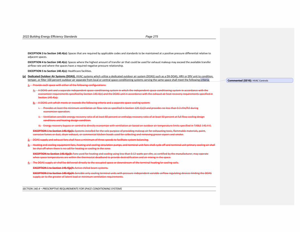
2022 Building Energy Efficiency Standards Page 275
SECTION 140.4 – PRESCRIPTIVE REQUIREMENTS FOR SPACE CONDITIONING SYSTEMS
EXCEPTION 3 to Section 140.4(o): Spaces that are required by applicable codes and standards to be maintained at a positive pressure differential relative to adjacent spaces.
EXCEPTION 4 to Section 140.4(o): Spaces where the highest amount of transfer air that could be used for exhaust makeup may exceed the available transfer airflow rate and where the spaces have a required negative pressure relationship.
EXCEPTION 5 to Section 140.4(o): Healthcare facilities.
(p) Dedicated Outdoor Air Systems (DOAS). HVAC systems which utilize a dedicated outdoor air system (DOAS) such as a DX-DOAS, HRV or ERV unit to condition, temper, or filter 100 percent outdoor air separate from local or central space-conditioning systems serving the same space shall meet the following criteria:
1. Provide each space with either of the following configurations:
A. A DOAS unit and a separate independent space-conditioning system in which the independent space-conditioning system in accordance with the economizer requirements specified by Section 140.4(e) and the DOAS unit in accordance with the exhaust air heat recovery requirements specified in Section 140.4(q).
B. A DOAS unit which meets or exceeds the following criteria and a separate space cooling system:
i. Provides at least the minimum ventilation air flow rate as specified in Section 120.1(c)3 and provides no less than 0.3 cfm/ft2 during economizer operation.
ii. Ventilation sensible energy recovery ratio of at least 60 percent or enthalpy recovery ratio of at least 50 percent at full flow cooling design conditions and heating design condition.
iii. Energy recovery bypass or control to directly economize with ventilation air based on outdoor air temperature limits specified in TABLE 140.4-E.
EXCEPTION 1 to Section 140.4(p)1: Systems installed for the sole purpose of providing makeup air for exhausting toxic, flammable materials, paint, corrosive fumes or dust, dryer exhaust, or commercial kitchen hoods used for collecting and removing grease vapors and smoke.
2. DOAS supply and exhaust fans shall have a minimum of three speeds to facilitate system balancing.
3. Heating and cooling equipment fans, heating and cooling circulation pumps, and terminal unit fans shall cycle off and terminal unit primary cooling air shall be shut off when there is no call for heating or cooling in the zone.
EXCEPTION to Section 140.4(p)3: Fans used for heating and cooling using less than 0.12 watts per cfm, as certified by the manufacturer, may operate when space temperatures are within the thermostat deadband to provide destratification and air mixing in the space.
4. The DOAS supply air shall be delivered directly to the occupied space or downstream of the terminal heating/or cooling coils.
EXCEPTION 1 to Section 140.4(p)4: Active chilled beam systems.
EXCEPTION 2 to Section 140.4(p)4: Sensible only cooling terminal units with pressure-independent variable-airflow regulating devices limiting the DOAS supply air to the greater of latent load or minimum ventilation requirements.
Commented [SS10]: HVAC Controls
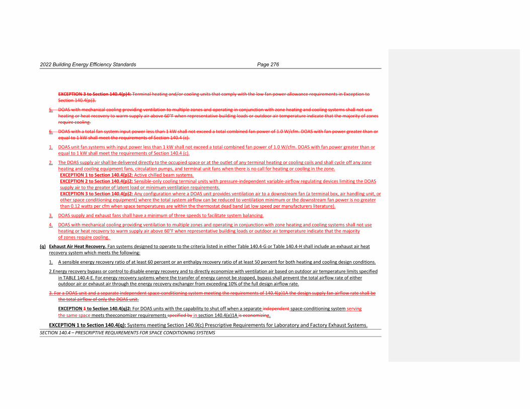
2022 Building Energy Efficiency Standards Page 276
SECTION 140.4 – PRESCRIPTIVE REQUIREMENTS FOR SPACE CONDITIONING SYSTEMS
EXCEPTION 3 to Section 140.4(p)4: Terminal heating and/or cooling units that comply with the low fan power allowance requirements in Exception to Section 140.4(p)3.
5. DOAS with mechanical cooling providing ventilation to multiple zones and operating in conjunction with zone heating and cooling systems shall not use heating or heat recovery to warm supply air above 60°F when representative building loads or outdoor air temperature indicate that the majority of zones require cooling.
6. DOAS with a total fan system input power less than 1 kW shall not exceed a total combined fan power of 1.0 W/cfm. DOAS with fan power greater than or equal to 1 kW shall meet the requirements of Section 140.4 (c).
1. DOAS unit fan systems with input power less than 1 kW shall not exceed a total combined fan power of 1.0 W/cfm. DOAS with fan power greater than or equal to 1 kW shall meet the requirements of Section 140.4 (c).
2. The DOAS supply air shall be delivered directly to the occupied space or at the outlet of any terminal heating or cooling coils and shall cycle off any zone heating and cooling equipment fans, circulation pumps, and terminal unit fans when there is no call for heating or cooling in the zone. EXCEPTION 1 to Section 140.4(p)2: Active chilled beam systems. EXCEPTION 2 to Section 140.4(p)2: Sensible-only cooling terminal units with pressure-independent variable-airflow regulating devices limiting the DOAS supply air to the greater of latent load or minimum ventilation requirements. EXCEPTION 3 to Section 140.4(p)2: Any configuration where a DOAS unit provides ventilation air to a downstream fan (a terminal box, air handling unit, or other space conditioning equipment) where the total system airflow can be reduced to ventilation minimum or the downstream fan power is no greater than 0.12 watts per cfm when space temperatures are within the thermostat dead band (at low speed per manufacturers literature).
3. DOAS supply and exhaust fans shall have a minimum of three speeds to facilitate system balancing.
4. DOAS with mechanical cooling providing ventilation to multiple zones and operating in conjunction with zone heating and cooling systems shall not use heating or heat recovery to warm supply air above 60°F when representative building loads or outdoor air temperature indicate that the majority of zones require cooling.
(q) Exhaust Air Heat Recovery. Fan systems designed to operate to the criteria listed in either Table 140.4-G or Table 140.4-H shall include an exhaust air heat recovery system which meets the following:
1. A sensible energy recovery ratio of at least 60 percent or an enthalpy recovery ratio of at least 50 percent for both heating and cooling design conditions.
2.Energy recovery bypass or control to disable energy recovery and to directly economize with ventilation air based on outdoor air temperature limits specified in TABLE 140.4-E. For energy recovery systems where the transfer of energy cannot be stopped, bypass shall prevent the total airflow rate of either outdoor air or exhaust air through the energy recovery exchanger from exceeding 10% of the full design airflow rate.
3. For a DOAS unit and a separate independent space-conditioning system meeting the requirements of 140.4(p)1A the design supply fan airflow rate shall be the total airflow of only the DOAS unit.
EXCEPTION 1 to Section 140.4(q)2: For DOAS units with the capability to shut off when a separate independent space-conditioning system serving the same space meets the economizer requirements specified by in section 140.4(e)1A is economizing.
EXCEPTION 1 to Section 140.4(q): Systems meeting Section 140.9(c) Prescriptive Requirements for Laboratory and Factory Exhaust Systems.

2022 Building Energy Efficiency Standards Page 277
SECTION 140.4 – PRESCRIPTIVE REQUIREMENTS FOR SPACE CONDITIONING SYSTEMS
EXCEPTION 2 to Section 140.4(q): Systems serving spaces that are not cooled and that are heated to less than 60°F.
EXCEPTION 3 to Section 140.4(q): Where more than 60 percent of the outdoor air heating energy is provided from site-recovered energy in
Climate Zone 16.
EXCEPTION 4 to Section 140.4(q): Sensible recovery ratio requirements at heating design conditions are exempted for Climate Zone 15.
EXCEPTION 5 to Section 140.4(q): Sensible recovery ratio requirements at cooling design conditions are exempted for Climate Zone 01.
EXCEPTION 6 to Section 140.4(q): Where the sum of the airflow rates exhausted and relieved within 20 feet of each other is less than 75 percent
of the design outdoor airflow rate, excluding exhaust air that is either:
1. used for another energy recovery system,
2. not allowed by California Mechanical Code (Title 24, Part 4) (CMC)for use in energy recovery systems with leakage potential, or
3. of Class 4 as specified in Section 120.1(g).
EXCEPTION 7 to Section 140.4(q): Systems expected to operate less than 20 hours per week.

2022 Building Energy Efficiency Standards Page 278
SECTION 140.4 – PRESCRIPTIVE REQUIREMENTS FOR SPACE CONDITIONING SYSTEMS
TABLE 140.4-G: ENERGY RECOVERY REQUIREMENTS BY CLIMATE ZONE AND PERCENT OUTDOOR AIR AT FULL DESIGN AIRFLOW (<8,000 HOURS / YEAR)
% Outdoor Air at Full Design Airflow
1 2 3 4 5 6 7 8 9 10 11 12 13 14 15 16
≥10% and <20% NR NR NR NR NR NR NR NR NR NR NR NR NR NR NR NR
≥20% and <30% ≥15,000 ≥20,000 NR NR NR NR NR NR NR NR ≥18,500 ≥18,500 ≥18,500 ≥18,500 ≥18,500 ≥18,500
≥30% and <40% ≥13,000 ≥15,000 NR NR NR NR NR NR NR NR ≥15,000 ≥15,000 ≥15,000 ≥15,000 ≥15,000 ≥15,000
≥40% and <50% ≥10,000 ≥12,000 NR NR NR NR NR NR NR ≥22,000 ≥10,000 ≥10,000 ≥10,000 ≥10,000 ≥10,000 ≥10,000
≥50% and <60% ≥9,000 ≥10,000 NR ≥18,500 NR NR NR NR NR ≥17,000 ≥8,000 ≥8,000 ≥8,000 ≥8,000 ≥8,000 ≥8,000
≥60% and <70% ≥7,000 ≥7,500 NR ≥16,500 NR NR NR NR ≥20,000 ≥15,000 ≥7,000 ≥7,000 ≥7,000 ≥7,000 ≥7,000 ≥7,000
≥70% and <80% ≥6,500 ≥7,000 NR ≥15,000 NR NR NR NR ≥17,000 ≥14,000 ≥5,000 ≥5,000 ≥5,000 ≥5,000 ≥5,000 ≥5,000
≥80% ≥4,500 ≥6,500 NR ≥14,000 NR NR NR NR ≥15,000 ≥13,000 ≥2,000 ≥2,000 ≥2,000 ≥2,000 ≥2,000 ≥2,000
1. Flow rates in Table 140.4-G represent the design supply fan airflow rate in CFM.
2. For a DOAS unit providing outdoor air to another space-conditioning system, and a separate independent space-conditioning system meeting the requirements of 140.4(p)1A, the full design supply fan airflow rate shall be the total airflow of only the DOAS unit.
TABLE 140.4-H: ENERGY RECOVERY REQUIREMENTS BY CLIMATE ZONE AND PERCENT OUTDOOR AIR AT FULL DESIGN AIRFLOW (≥8,000 HOURS / YEAR)
% Outdoor Air at Full Design Airflow
1 2 3 4 5 6 7 8 9 10 11 12 13 14 15 16
≥10% and <20% ≥10,000 ≥10,000 NR NR NR NR NR NR NR ≥40,000 ≥40,000 ≥20,000 ≥10,000 ≥10,000 ≥10,000 ≥10,000
≥20% and <30% ≥2,000 ≥5,000 ≥13,000 ≥9,000 ≥9,000 NR NR NR NR ≥15,000 ≥15,000 ≥5,000 ≥5,000 ≥5,000 ≥5,000 ≥5,000
≥30% and <40% ≥2,000 ≥3,000 ≥10,000 ≥6,500 ≥6,500 NR NR NR ≥15,000 ≥7,500 ≥7,500 ≥3,000 ≥3,000 ≥3,000 ≥3,000 ≥3,000
≥40% and <50% ≥2,000 ≥2,000 ≥8,000 ≥6,000 ≥6,000 NR NR NR ≥12,000 ≥6,000 ≥6,000 ≥2,000 ≥2,000 ≥2,000 ≥2,000 ≥2,000
≥50% and <60% ≥2,000 ≥2,000 ≥7,000 ≥6,000 ≥6,000 NR NR ≥20,000 ≥10,000 ≥5,000 ≥5,000 ≥2,000 ≥2,000 ≥2,000 ≥2,000 ≥2,000
≥60% and <70% ≥2,000 ≥2,000 ≥6,000 ≥6,000 ≥6,000 NR NR ≥18,000 ≥9,000 ≥4,000 ≥4,000 ≥2,000 ≥2,000 ≥2,000 ≥2,000 ≥2,000
≥70% and <80% ≥2,000 ≥2,000 ≥6,000 ≥5,000 ≥5,000 NR NR ≥15,000 ≥8,000 ≥3,000 ≥3,000 ≥2,000 ≥2,000 ≥2,000 ≥2,000 ≥2,000
≥80% ≥2,000 ≥2,000 ≥6,000 ≥5,000 ≥5,000 NR NR ≥12,000 ≥7,000 ≥3,000 ≥3,000 ≥2,000 ≥2,000 ≥2,000 ≥2,000 ≥2,000
1. Flow rates in Table 140.4-G represent the design supply fan airflow rate in CFM.
2. For a DOAS unit providing outdoor air to another space-conditioning system, and a separate independent space-conditioning system meeting the requirements of 140.4(p)1A, the full design supply fan airflow rate shall be the total airflow of only the DOAS unit.

2022 Building Energy Efficiency Standards Page 279
SECTION 140.4 – PRESCRIPTIVE REQUIREMENTS FOR SPACE CONDITIONING SYSTEMS
NOTE: Authority: Sections 25213, 25218, 25218.5, 25402 and 25402.1, Public Resources Code. Reference: Sections 25007, 25008, 25218.5, 25310, 25402, 25402.1,
1. 25402.4, 25402.8, and 25943, Public Resources Code.

2022 Building Energy Efficiency Standards Page 278
SECTION 140.6 – PRESCRIPTIVE REQUIREMENTS FOR INDOOR LIGHTING
SECTION 140.5 – PRESCRIPTIVE REQUIREMENTS FOR SERVICE WATER HEATING SYSTEMS (a) Nonresidential Occupancies. Service water heating systems in nonresidential buildings shall meet the
requirements of 1, 2 below, or meet the performance compliance requirements of Section 140.1:
1. School buildings less than 25,000 square feet and less than 4 stories in climate zones 2 through 15. A heat pump water heating system that meets the applicable requirements of Sections 110.1, 110.3 and 120.3.
2. All other occupancies. A service water heating system installed in a nonresidential building complies with this section if it complies withthat meets the applicable requirements of Sections 110.1, 110.3, and 120.3, and 140.5(c).
EXCEPTION to 140.5(a)1: Water heating system serving an individual bathroom space may be an instantaneous electric water heater.
(b) High-Rise Residential and Hotel/Motel Occupancies. A service water heating system installed in a high-rise residential or hotel/motel building complies with this section if itshall meets the requirements of Section 150.1(c)8170.2(d).
(c) High Capacity Service Water Heating Systems. Gas service water-heating systems with a total installed gas water-heating input capacity of 1 MMBtu/h or greater shall have gas service water-heating equipment with a minimum thermal efficiency of 90 percent. Multiple units can meet this requirement if the water-heating input provided by equipment with thermal efficiencies above and below 90 percent averages out to an input capacity-weighted average of at least 90 percent.
Exception 1 to 140.5(c): If 25 percent of the annual service water-heating requirement is provided by site-solar energy or site-recovered energy.
Exception 2 to 140.5(c): Water heaters installed in individual dwelling units.
Exception 3 to 140.5(c): Individual gas water heaters with input capacity at or below 100,000 Btu/h shall not be included in the calculations of the total system input or total system efficiency
NOTE: Authority: Sections 25213, 25218, 25218.5, 25402 and 25402.1, Public Resources Code. Reference: Sections 25007, 25008, 25218.5, 25310, 25402, 25402.1, 25402.4, 25402.8, and 25943, Public Resources Code.
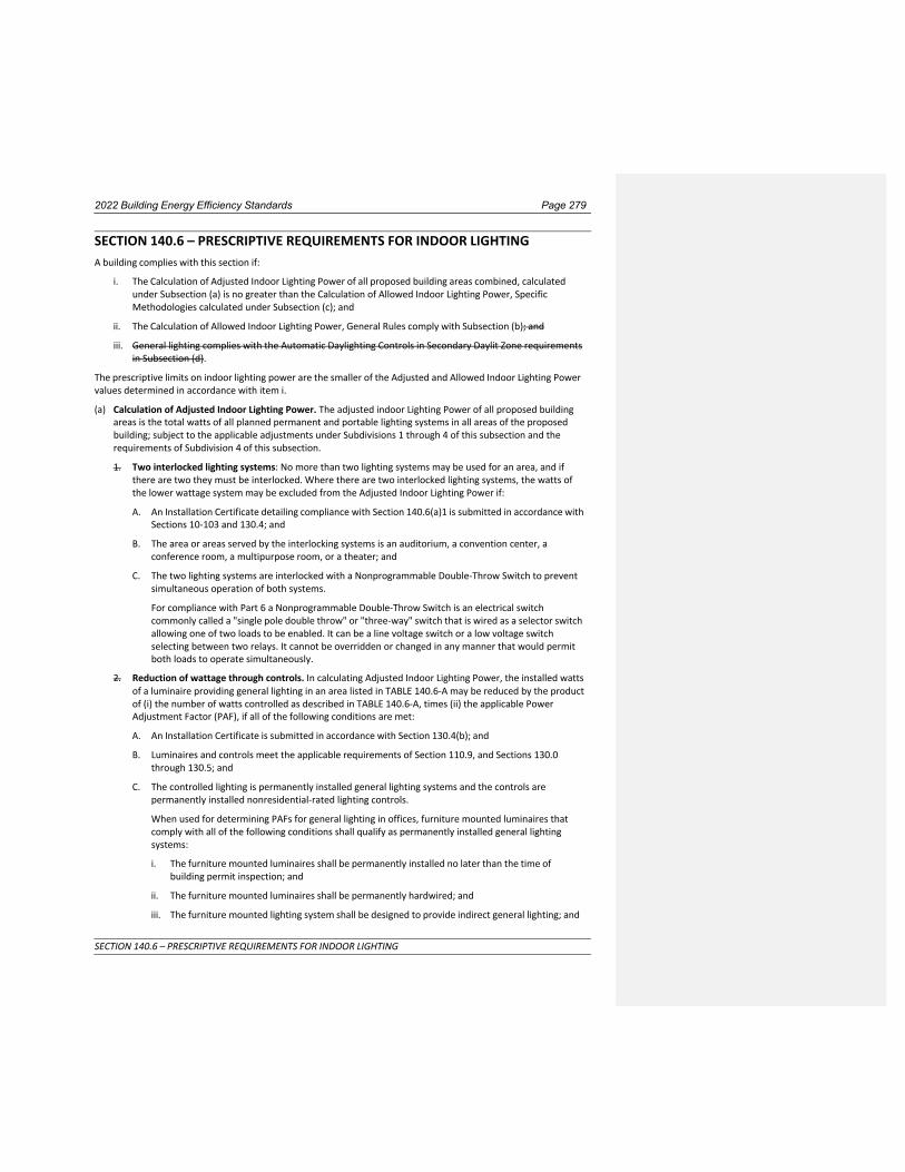
2022 Building Energy Efficiency Standards Page 279
SECTION 140.6 – PRESCRIPTIVE REQUIREMENTS FOR INDOOR LIGHTING
SECTION 140.6 – PRESCRIPTIVE REQUIREMENTS FOR INDOOR LIGHTING A building complies with this section if:
i. The Calculation of Adjusted Indoor Lighting Power of all proposed building areas combined, calculated under Subsection (a) is no greater than the Calculation of Allowed Indoor Lighting Power, Specific Methodologies calculated under Subsection (c); and
ii. The Calculation of Allowed Indoor Lighting Power, General Rules comply with Subsection (b); and
iii. General lighting complies with the Automatic Daylighting Controls in Secondary Daylit Zone requirements in Subsection (d).
The prescriptive limits on indoor lighting power are the smaller of the Adjusted and Allowed Indoor Lighting Power values determined in accordance with item i.
(a) Calculation of Adjusted Indoor Lighting Power. The adjusted indoor Lighting Power of all proposed building areas is the total watts of all planned permanent and portable lighting systems in all areas of the proposed building; subject to the applicable adjustments under Subdivisions 1 through 4 of this subsection and the requirements of Subdivision 4 of this subsection.
1. Two interlocked lighting systems: No more than two lighting systems may be used for an area, and if there are two they must be interlocked. Where there are two interlocked lighting systems, the watts of the lower wattage system may be excluded from the Adjusted Indoor Lighting Power if:
A. An Installation Certificate detailing compliance with Section 140.6(a)1 is submitted in accordance with Sections 10-103 and 130.4; and
B. The area or areas served by the interlocking systems is an auditorium, a convention center, a conference room, a multipurpose room, or a theater; and
C. The two lighting systems are interlocked with a Nonprogrammable Double-Throw Switch to prevent simultaneous operation of both systems.
For compliance with Part 6 a Nonprogrammable Double-Throw Switch is an electrical switch commonly called a "single pole double throw" or "three-way" switch that is wired as a selector switch allowing one of two loads to be enabled. It can be a line voltage switch or a low voltage switch selecting between two relays. It cannot be overridden or changed in any manner that would permit both loads to operate simultaneously.
2. Reduction of wattage through controls. In calculating Adjusted Indoor Lighting Power, the installed watts of a luminaire providing general lighting in an area listed in TABLE 140.6-A may be reduced by the product of (i) the number of watts controlled as described in TABLE 140.6-A, times (ii) the applicable Power Adjustment Factor (PAF), if all of the following conditions are met:
A. An Installation Certificate is submitted in accordance with Section 130.4(b); and
B. Luminaires and controls meet the applicable requirements of Section 110.9, and Sections 130.0 through 130.5; and
C. The controlled lighting is permanently installed general lighting systems and the controls are permanently installed nonresidential-rated lighting controls.
When used for determining PAFs for general lighting in offices, furniture mounted luminaires that comply with all of the following conditions shall qualify as permanently installed general lighting systems:
i. The furniture mounted luminaires shall be permanently installed no later than the time of building permit inspection; and
ii. The furniture mounted luminaires shall be permanently hardwired; and
iii. The furniture mounted lighting system shall be designed to provide indirect general lighting; and
2022 Building Energy Efficiency Standards Page 280
SECTION 140.6 – PRESCRIPTIVE REQUIREMENTS FOR INDOOR LIGHTING
iv. Before multiplying the installed watts of the furniture mounted luminaire by the applicable PAF, 0.3 2 watts per square foot of the area illuminated by the furniture mounted luminaires shall be subtracted from installed watts of the furniture mounted luminaires; and
v. The lighting control for the furniture mounted luminaire complies with all other applicable requirements in Section 140.6(a)2.
D. At least 50 percent of the light output of the controlled luminaire is within the applicable area listed in TABLE 140.6-A. Luminaires on lighting tracks shall be within the applicable area in order to qualify for a PAF.
E. Only one PAF from TABLE 140.6-A may be used for each qualifying luminaire. PAFs shall not be added together unless allowed in TABLE 140.6-A.
F. Only lighting wattage directly controlled in accordance with Section 140.6(a)2 shall be used to reduce the installed watts as allowed by Section 140.6(a)2 for calculating the Adjusted Indoor Lighting Power. If only a portion of the wattage in a luminaire is controlled in accordance with Section 140.6(a)2, then only that portion of controlled wattage may be reduced in calculating Adjusted Indoor Lighting Power.
G. Lighting controls used to qualify for a PAF shall be designed and installed in addition to manual, multilevel, and automatic lighting controls required in Section 130.1, and in addition to any other lighting controls required by any provision of Part 6. PAFs shall not be available for lighting controls required by Part 6.
H. To qualify for the PAF for daylight continuous dimming plus OFF control, the daylight control and controlled luminaires shall comply with Section 130.1(d), 130.4(a)3 and 130.4(a)7, and the daylight control shall be continuous dimming and shall additionally turn lights completely OFF when the daylight available in the daylit zone is greater than 150 percent of the illuminance received from the general lighting system at full power. The PAF shall apply only to the luminaires in the primary sidelit daylit zone, secondary sidelit daylit zone and the skylit daylit zone.
I. To qualify for the PAF for an occupant sensing control controlling the general lighting in large open plan office areas above workstations, in accordance with TABLE 140.6-A, the following requirements shall be met:
i. The open plan office area shall be greater than 250 square feet; and
ii. This PAF shall be available only in office areas which contain workstations; and
iii. Controlled luminaires shall only be those that provide general lighting directly above the controlled area, or furniture mounted luminaires that comply with Section 140.6(a)2 and provide general lighting directly above the controlled area; and
iv. Qualifying luminaires shall be controlled by occupant sensing controls that meet all of the following requirements, as applicable:
a. Infrared sensors shall be equipped by the manufacturer, of fitted in the field by the installer, with lenses or shrouds to prevent them from being triggered by movement outside of the controlled area.
b. Ultrasonic sensors shall be tuned to reduce their sensitivity to prevent them from being triggered by movements outside of the controlled area.
c. All other sensors shall be installed and adjusted as necessary to prevent them from being triggered by movements outside of the controlled area.
J. To qualify for the PAF for an Institutional Tuning in TABLE 140.6-A, the tuned lighting system shall comply with all of the following requirements:
i. The lighting controls shall limit the maximum output or maximum power draw of the controlled lighting to 85 percent or less of full light output or full power draw; and
ii. The means of setting the limit is accessible only to authorized personnel; and

2022 Building Energy Efficiency Standards Page 281
SECTION 140.6 – PRESCRIPTIVE REQUIREMENTS FOR INDOOR LIGHTING
iii. The setting of the limit is verified by the acceptance test required by Section 130.4(a)7; and
iv. The construction documents specify which lighting systems shall have their maximum light output or maximum power draw set to no greater than 85% of full light output or full power draw.
K. To qualify for the PAF for a Demand Responsive Control in TABLE 140.6-A, the general lighting wattage receiving the PAF shall not be within the scope of Section 110.12(c) and a Demand Responsive Control shall meet all of the following requirements:
i. The building shall be 10,000 square feet or smaller; and
ii. The controlled lighting shall be capable of being automatically reduced in response to a demand response signal; and
iii. LGeneral lighting shall be reduced in a manner consistent with uniform level of illumination requirements in TABLE 130.1-A; and.
iv. Spaces that are nonhabitable shall not be used to comply with this requirement, and spaces with a lighting power density of less than 0.5 watts per square foot shall not be counted toward the building’s total lighting power.
L. To qualify for the PAFs for clerestory fenestration, horizontal slats, or light shelves in TABLE 140.6-A, the daylighting design shall meet the requirements in Section 140.3(d). The PAFs shall only apply to lighting in a primary or secondary sidelit daylit zone where continuous dimming daylighting controls meeting the requirements of Section 130.1(d) are installed.
3. Lighting wattage excluded. The watts of the following indoor lighting applications may be excluded from Adjusted Indoor Lighting Power. (Indoor lighting not listed below shall comply with all applicable nonresidential indoor lighting requirements in Part 6.):
A. In theme parks: Lighting for themes and special effects.
B. Studio lighting for film or photography provided that these lighting systems are in addition to and separately switched from a general lighting system.
C. Lighting for dance floors, lighting for theatrical and other live performances, and theatrical lighting used for religious worship, provided that these lighting systems are additions to a general lighting system and are separately controlled by a multiscene or theatrical cross-fade control station accessible only to authorized operators.
Lighting intended for makeup, hair, and costume preparation in performing arts facility dressing rooms, provided that the lighting is separately switched from the general lighting system, switched independently at each dressing station, and is controlled with a Vacancy Sensor.
D. In civic facilities, transportation facilities, convention centers, and hotel function areas: Lighting for temporary exhibits, if the lighting is in addition to a general lighting system and is separately controlled from a panel accessible only to authorized operators.
E. Lighting installed by the manufacturer in walk-in coolers or freezers, vending machines, food preparation equipment, and scientific and industrial equipment.
F. In office buildings with medical and clinical areas and healthcare facilities: Examination and surgical lights, low-ambient night-lights, and lighting integral to medical equipment, provided that these lighting systems are additions to and separately switched from a general lighting system.
G. Lighting for plant growth or maintenance in non-CEH spaces, if it is controlled by a multilevel astronomical time-switch control that complies with the applicable provisions of Section 110.9.
H. Lighting equipment that is for sale.
I. Lighting demonstration equipment in lighting education facilities.
J. Lighting that is required for exit signs subject to the CBC. Exit signs shall meet the requirements of the Appliance Efficiency Regulations.

2022 Building Energy Efficiency Standards Page 282
SECTION 140.6 – PRESCRIPTIVE REQUIREMENTS FOR INDOOR LIGHTING
K. Exitway or egress illumination that is normally off and that is subject to the CBC.
L. In hotel/motel buildings: Lighting in guest rooms (lighting in hotel/motel guest rooms shall comply with Section 130.0(b). (Indoor lighting not in guest rooms shall comply with all applicable nonresidential lighting requirements in Part 6.)
M. In high-rise residential buildings: Lighting in dwelling units (Lighting in high-rise residential dwelling units shall comply with Section 130.0(b).) (Indoor lighting not in dwelling units shall comply with all applicable nonresidential lighting requirements in Part 6.)
N. Temporary lighting systems. (As defined in Section 100.1.)
O. Lighting in occupancy group U buildings less than 1,000 square feet.
P. Lighting in unconditioned agricultural buildings less than 2,500 square feet.
Q. Lighting systems in qualified historic buildings, as defined in the California Historical Building Code (Title 24, Part 8), are exempt from the Lighting Power Density allowances, if they consist solely of historic lighting components or replicas of historic lighting components. If lighting systems in qualified buildings contain some historic lighting components or replicas of historic components, combined with other lighting components, only those historic or historic replica components are exempt. All other lighting systems in qualified historic buildings shall comply with the Lighting Power Density allowances.
R. Lighting in nonresidential parking garages for seven or less vehicles: Lighting in nonresidential parking garages for seven or less vehicles shall comply with the applicable residential parking garage provisions of Section 150.0(k).
S. Lighting for signs: Lighting for signs shall comply with Section 140.8.
T. Lighting in refrigerated cases less than 3,000 square feet. (Lighting in refrigerated cases less than 3,000 square feet shall comply with the Title 20 Appliance Efficiency Regulations).
U. Lighting in elevators where the lighting meets the requirements in Section 120.6(f).
V. Lighting connected to a Life Safety Branch or Critical Branch, as specified in Section 517 of the California Electrical Code.
W. Horticultural lighting in CEH spaces (indoor growing and greenhouses) complying with Section 120.6(h).
4. Luminaire Classification and Power Adjustment.
A. Luminaire Classification and Power shall be determined in accordance with Section 130.0(c).
B. Small Aperture Tunable-White and Dim-to-Warm Luminaires Lighting Power Adjustment. For qualifying small aperture tunable-white and dim-to-warm LED luminaires, the adjusted indoor lighting power of these luminaires shall be calculated by multiplying their maximum rated wattage by 0.750.80. Qualifying luminaires shall meet all of the following:
i. Small Aperture. Qualifying luminaires with a luminaire aperture length longer than 18 inches shall be have a luminaire aperture no wider than four inches. Qualifying luminaires with a luminaire aperture length of 18 inches or less shall be have a luminaire aperture no wider than eight inches.
ii. Color Changing. Qualifying tunable-white luminaires shall be capable of a color change greater than or equal to 2000 Kelvin correlated color temperature (CCT). Qualifying dim-to-warm luminaires shall be capable of color change greater than or equal to 500 Kelvin CCT.
iii. Controls. Qualifying luminaires shall be connected to controls that allows color changing of the luminaires.
C. Tailored Method Display Lighting Mounting Height Lighting Power Adjustment. For wall display luminaires or floor display luminaires meeting Tailored Method Section 140.6(c)3G and H and where the bottom of luminaires are 10 feet 7 inches and greater above the finished floor, the adjusted

2022 Building Energy Efficiency Standards Page 283
SECTION 140.6 – PRESCRIPTIVE REQUIREMENTS FOR INDOOR LIGHTING
indoor lighting power of these luminaires shall be calculated by multiplying their maximum rated wattage and the appropriated mounting height adjustment factor from TABLE 140.6-E. Luminaire mounting height is the distance from the finished floor to the bottom of the luminaire. General lighting shall not qualify for a mounting height multiplier.

2022 Building Energy Efficiency Standards Page 284
SECTION 140.6 – PRESCRIPTIVE REQUIREMENTS FOR INDOOR LIGHTING
(b) Calculation of Allowed Indoor Lighting Power: General Rules
1. The allowed indoor lighting power allotment for conditioned areas shall be calculated separately from the allowed Lighting Power allotment for unconditioned areas. Each allotment is applicable solely to the area to which it applies, and there shall be no trade-offs between conditioned and unconditioned area allotments.
2. allowed indoor lighting power allotment shall be calculated separately from the allowed Outdoor Lighting Power allotment. Each allotment is applicable solely to the area to which it applies, and there shall be no trade-offs between the separate Indoor and Outdoor allotments.
3. The allowed indoor lighting power allotment for general lighting shall be calculated as follows:
A. The Complete Building Method, as described in Section 140.6(c)1, shall be used only for an entire building, except as permitted by Section 140.6(c)1. As described more fully in Section 140.6(c)1, and subject to the adjustments listed there, the Allowed Indoor Lighting Power allotment for general lighting for the entire building shall be calculated as follows:
i. For a conditioned building, the product of the square feet of conditioned space of the building times the applicable allotment of watts per square foot described in TABLE 140.6-B.
ii. For an unconditioned building, the product of the square foot of unconditioned space of the building times the applicable allotment of watts per square feet described in TABLE 140.6-B.
B. The Area Category Method, as described in Section 140.6(c)2, shall be used either by itself for all areas in the building, or when some areas in the building use the Tailored Method described in Section 140.6(c)3. Under the Area Category Method (either by itself or in conjunction with the Tailored Method), as described more fully in Section 140.6(c)2, and subject to the adjustments listed there, the allowed Indoor Lighting Power allotment for general lighting shall be calculated for each area in the building as follows:
i. For conditioned areas, by multiplying the conditioned square feet of the area times the applicable allotment of watts per square foot for the area shown in TABLE 140.6-C (or TABLE 140.6-D if the Tailored Method is used for that area).
ii. For unconditioned areas, by multiplying the unconditioned square feet of the area times the applicable allotment of watts per square foot for the area shown in TABLE 140.6-C (or TABLE 140.6-D if the Tailored Method is used for that area).
The allowed indoor lighting power allotment for general lighting for one area for which the Area Category Method was used may be increased up to the amount that the allowed indoor lighting power allotment for general lighting for another area using the Area Category Method or Tailored Method is decreased, except that such increases and decreases shall not be made between conditioned and unconditioned space.
C. The Tailored Method, as described in Section 140.6(c)3, shall be used either by itself for all areas in the building, or when some areas in the building use the Area Category Method described in Section 140.6(c)2. Under the Tailored Method (either by itself or in conjunction with the Area Category Method) as described more fully in Section 140.6(c)3, and subject to the adjustments listed there, allowed Indoor Lighting Power allotment for general lighting shall be calculated for each area in the building as follows:
i. For conditioned areas, by multiplying the conditioned square feet of the area times the applicable allotment of watts per square foot for the area shown in TABLE 140.6-D (or TABLE 140.6-C if the Area Category Method is used for that area);
ii For unconditioned areas, by multiplying the unconditioned square feet of the area times the applicable allotment of watts per square foot for the area shown in TABLE 140.6-D (or TABLE 140.6-C if the Area Category Method is used for that area);
2022 Building Energy Efficiency Standards Page 285
SECTION 140.6 – PRESCRIPTIVE REQUIREMENTS FOR INDOOR LIGHTING
The allowed indoor lighting power allotment for general lighting for one area for which the Tailored Method was used may be increased up to the amount that the allowed indoor power lighting for general lighting for another area is decreased, but only if the Tailored Method or Area Category Method was used for the other area, except that such increases and decreases shall not be made between conditioned and unconditioned space.
D. If the Area Category Method is used for an area, the Tailored Method may not be used for that area. If the Tailored Method is used for an area, the Area Category Method may not be used for that area.
4. Allowed Indoor Lighting Power allotments for all lighting power allotments other than general lighting shall be restricted as follows:
A. When using the Area Category Method, allowed Indoor Lighting Power allotments for specialized task work; ornamental; precision commercial and industrial work; white board or chalk board; accent, display and feature; decorative; or Videoconferencing Studio; may not be increased as a result of, or otherwise traded off against, decreasing any other allotment; and
B. When using the Tailored Method, allowed indoor lighting power allotments for wall display; floor display and task; ornamentaldecorative/special effect; or very valuable display case; may not be increased, or otherwise traded between any of the separate allotments.
(c) Calculation of Allowed Indoor Lighting Power: Specific Methodologies. The allowed indoor lighting power for each building type, or each primary function area shall be calculated using only one of the methods in Subsection 1, 2 or 3 below as applicable.
1. Complete Building Method. Requirements for using the Complete Building Method include all of the following:
A. The Complete Building Method shall be used only for building types, as defined in Section 100.1, that are specifically listed in TABLE 140.6-B. (For example, retail and wholesale stores, hotel/motel, and high-rise residential buildings shall not use this method.)
B. The Complete Building Method shall be used only on projects involving:
i. Entire buildings with one type of use occupancy; or
ii. Mixed occupancy buildings where one type of use makes up at least 90 percent of the entire building (in which case, when applying the Complete Building Method, it shall be assumed that the primary use is 100 percent of the building); or
iii. A tenant space where one type of use makes up at least 90 percent of the entire tenant space (in which case, when applying the Complete Building Method, it shall be assumed that the primary use is 100 percent of the tenant space).
C. The Complete Building Method shall be used only when the applicant is applying for a lighting permit and submits plans and specifications for the entire building or the entire tenant space.
D. Under the Complete Building Method, the allowed indoor lighting power allotment is the Lighting Power Density value times the floor area of the entire building.
E. For buildings including a parking garage plus another type of use listed in TABLE 140.6-B, the parking garage portion of the building and other type of use portion of the building shall each separately use the Complete Building Method.
2. Area Category Method. Requirements for using the Area Category Method include all of the following:
A. The Area Category Method shall be used only for primary function areas, as defined in Section 100.1, that are listed in TABLE 140.6-C. For primary function areas not listed, selection of a reasonably equivalent type shall be permitted.
B. Primary function areas in TABLE 140.6-C shall not apply to a complete building. Each primary function area shall be determined as a separate area.

2022 Building Energy Efficiency Standards Page 286
SECTION 140.6 – PRESCRIPTIVE REQUIREMENTS FOR INDOOR LIGHTING
C. For purposes of compliance with Section 140.6(c)2, an "area" shall be defined as all contiguous areas that accommodate or are associated with a single primary function area listed in TABLE 140.6-C.
D. Where areas are bounded or separated by interior partitions, the floor area occupied by those interior partitions may be included in a primary function area.
E. If at the time of permitting for a newly constructed building, a tenant is not identified for a multitenant area, a maximum of 0.4 watts per square foot shall be allowed for the lighting in each area in which a tenant has not been identified. The area shall be classified as unleased tenant area.
F. Under the Area Category Method, the allowed indoor lighting power for each primary function area is the Lighting Power Density value in TABLE 140.6-C times the square feet of the primary function area. The total allowed indoor lighting power density for the building is the sum of all allowed indoor lighting power densities for all areas in the building.
G. In addition to the allowed indoor lighting power calculated according to Sections 140.6(c)2A through F, the building may add additional lighting power allowances for qualifying lighting systems as specified in the Qualifying Lighting Systems column in TABLE 140.6-C under the following conditions:
i. Only primary function areas having a lighting system as specified in the Qualifying Lighting Systems column in TABLE 140.6-C and in accordance with the corresponding footnote of the TABLE shall qualify for the additional lighting power allowances; and
ii. The additional lighting power allowances shall be used only if the plans clearly identify all applicable task areas and the lighting equipment designed to illuminate these tasks; and
iii. Tasks that are performed less than two hours per day or poor quality tasks that can be improved are not eligible for the additional lighting power allowances; and
iv. The additional lighting power allowances shall not utilize any type of luminaires that are used for general lighting in the building; and
v. The additional lighting power allowances shall not be used when using the Complete Building Method, or when the Tailored Method is used for any area in the building; and
vi. The additional lighting power allowed is the smaller of:
a. the lighting power density listed in the “Allowed Additional Lighting LPD” column in TABLE 140.6-C, times the square feet of the primary function, or
b. the Adjusted Indoor Lighting Power of the applicable lighting; and
vii. In addition to all other additional lighting power allowed undermeeting Sections 140.6(c)2Gi through vi, up to 1.0 watts per square foot of additional lighting power for videoconferencing as specified in TABLE 140.6-C shall be allowed in a videoconferencing studio, as defined in Section 100.1, provided the following conditions are met:
a. A completed and signed Installation Certificate is prepared and submitted in accordance with Section 130.4(b), specifically detailing compliance with the applicable requirements of Section 140.6(c)2Gvii; and
b. The Videoconferencing Studio is a room with permanently installed videoconferencing cameras, audio equipment, and playback equipment for both audio-based and video-based two-way communication between local and remote sites; and
c. General lighting is switched in accordance with TABLE 130.1-A; and
d. Wall wash lighting is separately switched from the general lighting system; and
e. All of the lighting in the studio, including general lighting and additional lighting power allowed by Section 140.6(c)2Gvii is controlled by a multiscene programmable control system (also known as a scene preset control system).
3. Tailored Method. Requirements for using the Tailored Method include all of the following:

2022 Building Energy Efficiency Standards Page 287
SECTION 140.6 – PRESCRIPTIVE REQUIREMENTS FOR INDOOR LIGHTING
A. The Tailored Method shall be used only for primary function areas listed in TABLE 140.6-D, as defined in Section 100.1.
B. Allowed Indoor Lighting Power allotments for general lighting shall be determined according to Section 140.6(c)3F, as applicable.
C. For compliance with Section 140.6(c)3, an "area" shall be defined as all contiguous areas that accommodate or are associated with a single primary function area listed in TABLE 140.6-D.
D. Where areas are bounded or separated by interior partitions, the floor area occupied by those interior partitions may be included in a Primary Function Area.
E. In addition to the allowed indoor lighting power allotments for general lighting calculated according to Sections 140.6(c)3F, as applicable, the building may add additional lighting power allowances for wall display lighting, floor display lighting and task lighting, ornamentaldecorative/special effects lighting, and very valuable display cases lighting according to Sections 140.6(c)3G through J.
F. Determine allowed indoor lighting power allotments for general lighting for primary function areas listed in TABLE 140.6-D as follows:
i. Use the General Illumination Level (Lux) listed in Column 2 of Table 140.6-D to determine the Allowed General Lighting Power Density allotments for the area.
ii. Determine the room cavity ratio (RCR) for the area. The RCR shall be calculated according to the applicable equation in TABLE 140.6-F.
iii. Find the allowed General Lighting Power Density allotments in TABLE 140.6-G that is applicable to the General Illuminance Level (Lux) from Column 2 of Table 140.6-D (as described in Item i.) and the RCR determined in accordance with TABLE 140.6-F (as described in Item ii).
iv. Determine the square feet of the area in accordance with Section 140.6(c)3C and D.
v. Multiply the allowed Lighting Power Density allotment, as determined in accordance with Item iii by the square feet of each primary function area, as determined in accordance with Item iv. The product is the allowed indoor lighting power allotment for general lighting for the area.
G. Determine additional allowed power for wall display lighting according to column 3 of Table 140.6-D for each primary function area as follows:
i. Floor displays shall not qualify for wall display allowances.
ii. Qualifying wall lighting shall:
a. Be mounted within 10 feet of the wall having the wall display. When track lighting is used for wall display, and where portions of that lighting track are more than 10 feet from the wall and other portions are within 10 feet of the wall, portions of track more than 10 feet from the wall shall not be used for the wall display allowance.
b. Be a lighting system type appropriate for wall lighting. Lighting systems appropriate for wall lighting are lighting track adjacent to the wall, wall-washer luminaires, luminaires behind a wall valance or wall cove, or accent light. (Accent luminaires are adjustable or fixed luminaires with PAR, R, MR, AR, or luminaires providing directional display light.)
iii. Additional allowed power for wall display lighting is available only for lighting that illuminates walls having wall displays. The length of display walls shall include the length of the perimeter walls, including but not limited to closable openings and permanent full height interior partitions. Permanent full height interior partitions are those that (I) extend from the floor to within two feet of the ceiling or are taller than ten feet and (II) are permanently anchored to the floor.
iv. For wall display lighting where the bottom of the luminaire is greater than 10 feet 6 inches above the finished floor, the mounting height adjustment factor from Table 140.6-E can be used to adjust the installed luminaire wattage as specified in Section 140.6(a)4C.

2022 Building Energy Efficiency Standards Page 288
SECTION 140.6 – PRESCRIPTIVE REQUIREMENTS FOR INDOOR LIGHTING
v. The allowed power for wall display lighting shall be the smaller of:
a. the “wall display lighting power density” determined in accordance with TABLE 140.6-D, multiplied by the wall display lengths determined in accordance with Item iii; and
b. The Adjusted Indoor Lighting Power used for the wall display lighting systems.
vi. Lighting internal to display cases that are attached to a wall or directly adjacent to a wall are counted as wall display lighting as specified in Section 140.6(c)3G. All other lighting internal to display cases are counted as floor display lighting as specified in Section 140.6(c)3H, or as very valuable display case lighting as specified in Section 140.6(c)3J.
H. Determine additional allowed power for floor display lighting and task lighting as follows:
i. Displays that are installed against a wall shall not qualify for the floor display lighting power allowances.
ii. Lighting internal to display cases that are not attached to a wall and not directly adjacent to a wall shall be counted as floor display lighting in accordance with Section 140.6(c)3H; or very valuable display case lighting in accordance with Section 140.6(c)3J.
iii. Additional allowed power for floor display lighting, and additional allowed power for task lighting, may be used by qualifying floor display lighting systems, qualifying task lighting systems, or a combination of both. For floor areas qualifying for both floor display and task lighting power allowances, the additional allowed power shall be used only once for the same floor area, so that the allowance shall not be additive.
iv. Qualifying floor display lighting shall:
a. Be mounted no closer than 2 feet to a wall.
b. Consist of only (I) directional lamp types, such as PAR, R, MR, AR; or (II) luminaires providing directional display light.
c. If track lighting is used, shall be only track heads that are classified as direction lighting types.
v. Qualifying task lighting shall:
a. Be located immediately adjacent to and capable of illuminating the task for which it is installed.
b. Be of a type different from the general lighting system.
c. Be separately switched from the general lighting system.
vi. If there are illuminated floor displays, floor display lighting power shall be used only if allowed by column 4 of TABLE 140.6-D.
vii. The square footage of floor displays or the square footage of task areas shall be determined in accordance with Section 140.6(c)3C and D, except that any floor area designed to not have floor displays or tasks, such as floor areas designated as a path of egress, shall not be included for the floor display allowance.
viii. For floor display lighting where the bottom of the luminaire is greater than 10.6 feet above the finished floor, multiply the floor display installed watts by the appropriate mounting height adjustment factor from Table 140.6-E to calculate the Adjusted Indoor Lighting Power as specified in Section 140.6(a)4C.
ix. The allowed power for floor display lighting for each applicable area shall be the smaller of:
a. The allowed floor display and task lighting power determined in accordance with Section 140.6(c)3Hvi multiplied by the floor square footage determined in accordance with Section 140.6(c)3Hvii; and
b. The Adjusted Indoor Lighting Power used for the floor display lighting systems.
2022 Building Energy Efficiency Standards Page 289
SECTION 140.6 – PRESCRIPTIVE REQUIREMENTS FOR INDOOR LIGHTING
I. Determine additional allowed power for ornamentaldecorative/special effects lighting as follows:
i. Qualifying ornamental decorative lighting includes luminaires such as chandeliers, sconces, lanterns, neon and cold cathode, light emitting diodes, theatrical projectors, moving lights and light color panels, when any of those lights are used in a decorative manner that does not serve as display lighting or general lighting.
ii. Additional lighting power for ornamentaldecorative/special effects lighting shall be used only if allowed by Column 5 of TABLE 140.6-D.
iii. Additional lighting power for ornamentaldecorative/special effects lighting shall be used only in areas having ornamentaldecorative/special effects lighting. The square footage of the floor area shall be determined in accordance with Section 140.6(c)3C and D, and it shall not include floor areas not having ornamentaldecorative/special effects lighting.
iv. The additional allowed power for ornamentaldecorative/special effects lighting for each applicable area shall be the smaller of:
a. The product of the “allowed ornamentaldecorative/special effects lighting power” determined in accordance with Section 140.6(c)3Kii3Iii, multiplied by the floor square footage determined in accordance with Section 140.6(c)3Kiii3Iiii; and
b. The Adjusted Indoor Lighting Power of allowed ornamentaldecorative/special effects lighting.
J. Determine additional allowed power for very valuable display case lighting as follows:
i. Additional allowed power for very valuable display case lighting shall be available only for display cases in appropriate function areas in retail merchandise sales, museum and religious worship.
ii. To qualify for additional allowed power for very valuable display case lighting, a case shall contain jewelry, coins, fine china, fine crystal, precious stones, silver, small art objects and artifacts, and/or valuable collections the display of which involves customer inspection of very fine detail from outside of a locked case.
iii. Qualifying lighting includes internal display case lighting or external lighting employing highly directional luminaires specifically designed to illuminate the case or inspection area without spill light, and shall not be fluorescent lighting unless installed inside of a display case.
iv. If there is qualifying very valuable display case lighting, in accordance with Section 140.6(c)3Jii, the smallest of the following separate lighting power for display cases presenting very valuable display items is permitted:
a. The product of the area of the primary function and 0.55 50 watt per square foot; or
b. The product of the area of the display case and 8 7 watts per square foot; or
c. The Adjusted Indoor Lighting Power of lighting for very valuable displays.
(d) Automatic Daylighting Controls in Secondary Daylit Zones. All luminaires providing general lighting that is in, or partially in a Secondary Sidelit Daylit Zone, and that is not in a Primary Sidelit Daylit Zone shall:
1. Be controlled independently from all other luminaires by automatic daylighting controls that meet the applicable requirements of Section 110.9; and
2. Be controlled in accordance with the applicable requirements in Section 130.1(d); and
3. All Secondary Sidelit Daylit Zones shall be shown on the plans submitted to the enforcing agency.
EXCEPTION 1 to Section 140.6(d): Luminaires in Secondary Sidelit Daylit Zone(s) in an enclosed space in which the combined total general lighting power in Secondary Daylit Zone(s) is less than 120 watts, or where the combined total general lighting power in Primary and Secondary Daylit Zone(s) is less than 240 watts.
EXCEPTION 2 to Section 140.6(d): Luminaires in parking garages complying with Section 130.1(d)3.

2022 Building Energy Efficiency Standards Page 290
SECTION 140.6 – PRESCRIPTIVE REQUIREMENTS FOR INDOOR LIGHTING
EXCEPTION 3 to Section 140.6(d): Areas adjacent to vertical glazing below an overhang, where there is no vertical glazing above the overhang and where the ratio of the overhang projection to the overhang rise is greater than 1.5 for South, East and West orientations, or where the ratio of the overhang projection to the overhang rise is greater than 1 for North orientations.
EXCEPTION 4 to Section 140.6(d): Rooms that have a total glazing area of less than 24 square feet, or parking garage areas with a combined total of less than 36 square feet of glazing or opening.
EXCEPTION 5 to Section 140.6(d): Luminaires in sidelit daylit zones in retail merchandise sales and wholesale showroom areas.
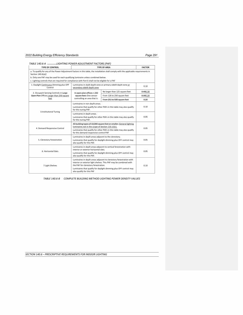
2022 Building Energy Efficiency Standards Page 291
SECTION 140.6 – PRESCRIPTIVE REQUIREMENTS FOR INDOOR LIGHTING
TABLE 140.6-A LIGHTING POWER ADJUSTMENT FACTORS (PAF) TYPE OF CONTROL TYPE OF AREA FACTOR
a. To qualify for any of the Power Adjustment Factors in this table, the installation shall comply with the applicable requirements in Section 140.6(a)2
b. Only one PAF may be used for each qualifying luminaire unless combined below.
c. Lighting controls that are required for compliance with Part 6 shall not be eligible for a PAF
1. Daylight Continuous Dimming plus OFF Control
Luminaires in skylit daylit zone or primary sidelit daylit zone or secondary sidelit daylit zone
0.10
2. Occupant Sensing Controls in Large Open Plan Offices Larger than 250 square
feet
In open plan offices > 250 square feet: One sensor
controlling an area that is:
No larger than 125 square feet 0.400.30
From 126 to 250 square feet 0.300.20
From 251 to 500 square feet 0.20
3.Institutional Tuning
Luminaires in non-daylit areas.
Luminaires that qualify for other PAFs in this table may also qualify for this tuning PAF.
0.10
Luminaires in daylit areas.
Luminaires that qualify for other PAFs in this table may also qualify for this tuning PAF.
0.05
4. Demand Responsive Control
All building types of 10,000 square feet or smaller. General lighting luminaires not in the scope of Section 110.12(c).
Luminaires that qualify for other PAFs in this table may also qualify for this demand responsive control PAF
0.05
5. Clerestory Fenestration
Luminaires in daylit areas adjacent to the clerestory.
Luminaires that qualify for daylight dimming plus OFF control may also qualify for this PAF.
0.05
6. Horizontal Slats
Luminaires in daylit areas adjacent to vertical fenestration with interior or exterior horizontal slats.
Luminaires that qualify for daylight dimming plus OFF control may also qualify for this PAF.
0.05
7.Light Shelves
Luminaires in daylit areas adjacent to clerestory fenestration with interior or exterior light shelves. This PAF may be combined with the PAF for clerestory fenestration.
Luminaires that qualify for daylight dimming plus OFF control may also qualify for this PAF
0.10
TABLE 140.6-B COMPLETE BUILDING METHOD LIGHTING POWER DENSITY VALUES
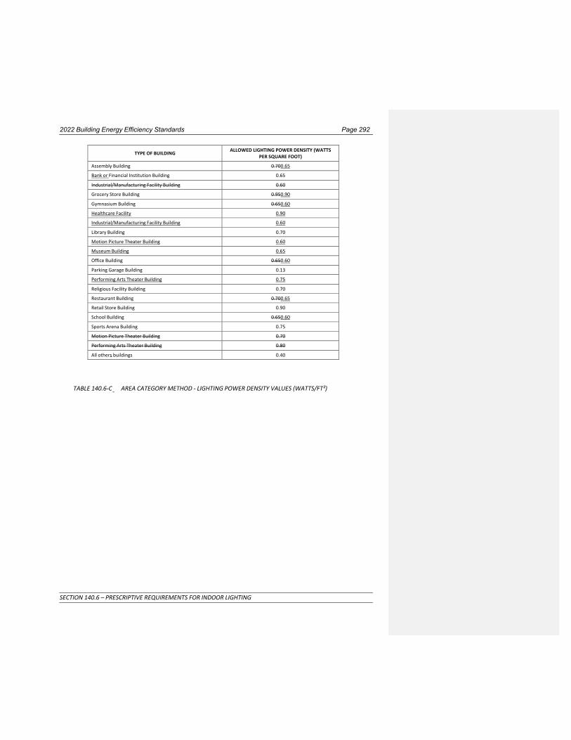
2022 Building Energy Efficiency Standards Page 292
SECTION 140.6 – PRESCRIPTIVE REQUIREMENTS FOR INDOOR LIGHTING
TYPE OF BUILDING ALLOWED LIGHTING POWER DENSITY (WATTS PER SQUARE FOOT)
Assembly Building 0.700.65
Bank or Financial Institution Building 0.65
Industrial/Manufacturing Facility Building 0.60
Grocery Store Building 0.950.90
Gymnasium Building 0.650.60
Healthcare Facility 0.90
Industrial/Manufacturing Facility Building 0.60
Library Building 0.70
Motion Picture Theater Building 0.60
Museum Building 0.65
Office Building 0.650.60
Parking Garage Building 0.13
Performing Arts Theater Building 0.75
Religious Facility Building 0.70
Restaurant Building 0.700.65
Retail Store Building 0.90
School Building 0.650.60
Sports Arena Building 0.75
Motion Picture Theater Building 0.70
Performing Arts Theater Building 0.80
All others buildings 0.40
TABLE 140.6-C AREA CATEGORY METHOD - LIGHTING POWER DENSITY VALUES (WATTS/FT²)

2022 Building Energy Efficiency Standards Page 293
SECTION 140.6 – PRESCRIPTIVE REQUIREMENTS FOR INDOOR LIGHTING
Primary Function Area
Allowed Lighting
Power Density for General Lighting
(W/ft2)
Additional Lighting Power1
Qualified Lighting Systems
Additional Allowance
(W/ft², unless noted otherwise)
Auditorium Area 0.70
Ornamental 0.30
Accent, display and feature3 0.20
Auto Repair / Maintenance Area 0.55 Detailed Task Work7 0.20
Audience Seating Area 0.60 Ornamental 0.30
Beauty Salon Area 0.80
Detailed Task Work7 0.20
Ornamental 0.30
Civic Meeting Place Area 1.00 Ornamental 0.30
Classroom, Lecture, Training, Vocational Area 0.70 White or Chalk Board1 4.50 W/ft
Aging Eye/Low-vision11 Corridor Area 0.70 Decorative/Display 0.30
Dining
0.80
Decorative/Display 0.30
Tunable white or dim-to- warm10
0.10
Lobby, Main Entry
0.85
Decorative/Display 0.30
Transition Lighting OFF at night12
0.95
Tunable white or dim-to- warm10
0.10
Lounge/Waiting Area
0.80
Decorative/Display 0.30
Tunable white or dim-to- warm10
0.10
Multipurpose Room
0.85
Decorative/Display 0.30
Tunable white or dim-to- warm10
0.10
Religious Worship
Area
1.00
Decorative/Display 0.30
Tunable white or dim-to- warm10
0.10
Restroom 1.00 Decorative/Display 0.20
Stairwell 0.80 Decorative/Display 0.30
Audience Seating Area 0.50 Decorative/Display 0.25
Auditorium Area 0.70 Decorative/Display 0.45
Auto Repair / Maintenance Area 0.55 Detailed Task Work7 0.20
Barber, Beauty Salon, Spa Area 0.65 0.70
Detailed Task Work7 0.20 0.30
Decorative/Display 0.25
Civic Meeting Place Area 0.90 Decorative/Display 0.25
Classroom, Lecture, Training, Vocational Area 0.60 White or Chalk Board1 7 W/ft
Concourse and Atria Area 0.60 Decorative/Display 0.25
Convention, Conference, Multipurpose and Meeting Area
Shipping & Handling
0.750.60
Decorative/Display-
0.25-
Convention, Conference, Multipurpose and Meeting Area
0.85 Ornamental 0.30
Copy Room 0.50 - -
Corridor Area 0.600.40 Decorative/Display- 0.25-
Dining Area Bar/Lounge and Fine Dining
0.550.45 Decorative/Display
Ornamental 0.300.35
Commented [AT11]: Indoor lighting LPDs
Commented [CU12]: Indoor Lighting LPDs
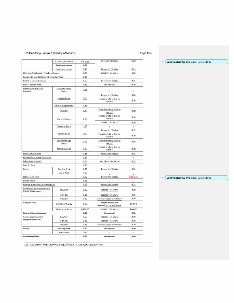
2022 Building Energy Efficiency Standards Page 294
SECTION 140.6 – PRESCRIPTIVE REQUIREMENTS FOR INDOOR LIGHTING
Cafeteria/Fast Food 0.400.45 Decorative/Display 0.25
Family and Leisure 0.50
Family and Leisure 0.40 Decorative/Display 0.25
Electrical, Mechanical, Telephone Rooms 0.40 Detailed Task Work7 0.20
Exercise/Fitness Center and Gymnasium Area 0.50 - -
Financial Transaction Area 0.70 Decorative/Display 0.25
Hotel Function Area 0.85 Ornamental 0.30
Healthcare Facility and Hospitals
Exam/Treatment Room
1.15 - -
Imaging Room
0.60
Decorative/Display 0.20
Tunable white or dim-to- warm10
0.10
Medical Supply Room 0.55 - -
Nursery 0.80 Tunable white or dim-to-
warm10 0.10
Nurse’s Station
0.85
Tunable white or dim-to- warm10
0.10
Detailed Task Work7 0.20
Operating Room 1.90 - -
Patient Room
0.70
Decorative/Display 0.15
Tunable white or dim-to- warm10
0.10
Physical Therapy Room
0.75 Tunable white or dim-to-
warm10 0.10
Recovery Room 0.90 Tunable white or dim-to-
warm10 0.10
Hotel Function Area 0.85 Decorative/Display 0.25
Kitchen/Food Preparation Area 0.95 - -
Laboratory, Scientific 0.90 Specialized Task Work8 0.35
Laundry Area 0.45 - -
Library Reading Area 0.80 Decorative/Display 0.25
Stacks Area 1.00 - -
Lobby, Main Entry 0.70 Decorative/Display 0.35 0.25
Locker Room 0.45 - -
Lounge, Breakroom, or Waiting Area 0.55 Decorative/Display 0.25
Manufacturing, Commercial & Industrial Work Area
Low Bay 0.60 Detailed Task Work7 0.20
High Bay 0.65 Detailed Task Work7 0.20
Precision 0.85 Precision Specialized Work9 0.70
Museum Area Exhibition/Display 0.60
Accent, display and feature3Decorative/Display
0.500.45
Restoration Room 0.750.70 Detailed Task Work7 0.200.35
Financial Transaction Area 0.80 Ornamental 0.30
General/Commercial & Industrial Work Area
Low Bay 0.60 Detailed Task Work7 0.20
High Bay 0.65 Detailed Task Work7 0.20
Precision 0.85 Precision Specialized Work9 0.70
Library Reading Area 0.80 Ornamental 0.30
Stacks Area 1.10 - -
Main Entry Lobby 0.85 Ornamental 0.30
Commented [CU13]: Indoor Lighting LPDs
Commented [CU14]: Indoor Lighting LPDs

2022 Building Energy Efficiency Standards Page 295
SECTION 140.6 – PRESCRIPTIVE REQUIREMENTS FOR INDOOR LIGHTING
Locker Room 0.45 - -
Lounge, Breakroom, or Waiting Area 0.65 Ornamental 0.30
Concourse and Atria Area 0.90 Ornamental 0.30
Office Area > 250 square feet 0.650.60 Decorative/Display and Portable lighting for office
areas6
0.20 ≤ 250 square feet 0.700.65
Open plan office 0.60
Parking Garage Area Parking Zone and
Ramps
0.10
First ATM or Ticket Machine 100 W
Additional ATM or Ticket Machine
50 W each
Dedicated Ramps 0.25 - -
Daylight Adaptation Zones2
0.501.00 - -

2022 Building Energy Efficiency Standards Page 296
SECTION 140.6 – PRESCRIPTIVE REQUIREMENTS FOR INDOOR LIGHTING
Pharmacy Area 1.101.00 Specialized Task Work8 0.35
Retail Sales Area Grocery Sales
1.051.00
Accent, display and feature3 0.20
Decorative/Display 0.150.35
Retail Merchandise Sales
1.000.95
Accent, display and feature3 0.20
Decorative/DisplayDecorative 0.150.35
Fitting Room
0.60
External Illuminated Mirror5 40 W/ea
Internal Illuminated Mirror5 120 W/ea
Religious Worship Area 0.95 Decorative/Display 0.25
Restrooms 0.65 Decorative/Display 0.35
Theater Area Motion picture 0.60 Ornamental
0.30
Performance 1.00
Kitchen/Food Preparation Area 0.95 - -
Scientific Laboratory Area 1.00 Specialized Task Work8 0.35
Healthcare Facility and Hospitals Exam/Treatment Room
1.15 - -
Imaging Room 1.00 - -
Medical Supply Room 0.55 - -
Nursery 0.95 Tunable white or dim-to-
warm10 0.10
Nurse’s Station 0.75 Tunable white or dim-to-
warm10 0.10
Operating Room 1.90 - -
Patient Room
0.55
Decorative 0.15
Tunable white or dim-to- warm10
0.10
Physical Therapy Room 0.85 Tunable white or dim-to-
warm10 0.10
Recovery Room 0.90 Tunable white or dim-to-
warm10 0.10
Laundry Area 0.45 - -
Religious Worship Area 0.95 Ornamental 0.30
Restrooms 0.65
Accent, display and feature3 0.20
Decorative4 0.15
Stairwell 0.60 Decorative/Display 0.35
Storage, Commercial/Industrial Warehouse 0.40 - -
Shipping & Handling 0.60 - -
Transportation Function Baggage Area 0.40 - -
Ticketing Area 0.45 Accent, display and feature3 0.20
Sports Arena – Playing Area Class I Facility13 2.25 - -
Class II Facility13 1.45 - -
Class III Facility13 1.10 - -
Class IV Facility13 0.75 - -
Theater Area Motion picture 0.50 Decorative/Display
0.25
Performance 0.80
Transportation Function Baggage Area 0.40 - -
Ticketing Area 0.45 Decorative/Display 0.20
Stairwell 0.50
Accent, display and feature3 0.20
Decorative4 0.15

2022 Building Energy Efficiency Standards Page 297
SECTION 140.6 – PRESCRIPTIVE REQUIREMENTS FOR INDOOR LIGHTING
Videoconferencing Studio 0.90 Videoconferencing14 1.00
All other 0.40 - -

2022 Building Energy Efficiency Standards Page 298
SECTION 140.6 – PRESCRIPTIVE REQUIREMENTS FOR INDOOR LIGHTING
Aging Eye/Low-vision11 Main Entry Lobby
0.85
Ornamental 0.30
Transition Lighting OFF at night12
0.95
Stairwell 0.80 - -
Corridor Area 0.80 Decorative4 0.15
Lounge/Waiting Area 0.75 Ornamental 0.30
Multipurpose Room 0.95 Ornamental 0.30
Religious Worship Area 1.00 Ornamental 0.30
Dining 0.80 Ornamental 0.30
Restroom 0.80 Accent, display and
feature3 0.20
Footnotes for this table are listed below.
1. White board or chalk board. – Directional lighting dedicated to a white board or chalk board.
2. Daylight Adaptation Zones shall be no longer than 66 feet from the entrance to the parking garage.
3. Accent, display and feature lighting – luminaires shall be adjustable or directionalReserved
4. Decorative lighting – primary function shall be decorative and not to provide general lightingReserved.
5. Illuminated mirrors. Lighting shall be dedicated to the mirror.
6. Portable lighting in office areas includes under shelf or furniture-mounted supplemental task lighting qualifies when controlled by a time clock or an occupancy sensor.
7. Detailed task work – Lighting provides high level of visual acuity required for activities with close attention to small elements and/or extreme close up work.
8. Specialized task work – Lighting provides for small-scale, cognitive or fast performance visual tasks; lighting required for operating specialized equipment associated with pharmaceutical/laboratorial activities.
9. Precision specialized work – Lighting for work performed within a commercial or industrial environment that entails working with low contrast, finely detailed, or fast moving objects.
10. Tunable white luminaires capable of color change greater than or equal to 2000K CCT, or dim-to-warm luminaires capable of color change greater than or equal to 500K CCT, connected to controls that allows color changing of the luminaires.
11. Aging Eye/Low-vision areas can be documented as being designed to comply with the light levels in ANSI/IES RP-28 and are or will be licensed by local or state authorities for either senior long-term care, adult day care, senior support, and/or people with special visual needs.
12. Transition lighting OFF at night. Lighting power controlled by astronomical time clock or other control to shut off lighting at night. Additional LPD only applies to area within 30 feet of an exit. Not applicable to lighting in daylit zones.
13. Class I Facility is used for competition play for 5000 or more spectators. Class II Facility is used for competition play for up to 5000 spectators. Class III Facility is used for competition play for up to 2000 spectators. Class IV Facility is normally used for recreational play and there is limited or no provision for spectators.
14. The additional videoconferencing lighting power shall be allowed provided the videoconferencing studio meets all the requirements of Section 140.6(c)2Gvii.

2022 Building Energy Efficiency Standards Page 299
SECTION 140.6 – PRESCRIPTIVE REQUIREMENTS FOR INDOOR LIGHTING
TABLE 140.6-D TAILORED METHOD LIGHTING POWER ALLOWANCES 1 2 3 4 5
Primary Function Area
General Illumination Level (Lux)
Wall Display
Lighting Power
Density (W/ft)
Allowed Combined
Floor Display Power and
Task Lighting Power Density
(W/ft²)
Allowed OrnamentalDecorative/
Special Effect Lighting Power Density (W/ft²)
Auditorium Area 300 3.00 0.20 0.400.35
Convention, Conference, Multipurpose, and Meeting Center Areas
300 2.00 0.350.30 0.400.35
Dining Areas 200 1.25 0.500.45 0.400.35
Exhibit, Museum Areas 150 11.5011.20 0.800.70 0.400.35
Hotel Area:
Ballroom/Events 400 1.80 0.12 0.400.35
Lobby 200 3.503.40 0.20 0.400.35
Lobby, Main entry lobby 200 3.503.40 0.20 0.400.35
Religious Worship Area 300 1.30 0.40 0.400.35
Retail Sales
Grocery 600 6.806.60 0.700.60 0.400.35
Merchandise Sales, and Showroom Areas
500 11.8011.50 0.800.70 0.400.35
Theater Area:
Motion picture 200 2.00 0.20 0.400.35
Performance Arts 200 7.507.30 0.20 0.400..35
TABLE 140.6-E TAILORED WALL AND FLOOR DISPLAY MOUNTING HEIGHT ADJUSTMENT FACTORS
Height in feet above finished floor and bottom of luminaire(s) Floor Display or Wall Display Mounting Height Adjustment Factor
≤ 10’-6” 1.00
> 10’-6” to 14’-0” 0.85
>14’-0” to 18’-0” 0.75
> 18’-0” 0.70

2022 Building Energy Efficiency Standards Page 300
SECTION 140.6 – PRESCRIPTIVE REQUIREMENTS FOR INDOOR LIGHTING
TABLE 140.6-F ROOM CAVITY RATIO (RCR) EQUATIONS Determine the Room Cavity Ratio for TABLE 140.6-G using one of the following equations.
Room cavity ratio for rectangular rooms
RCR = 5 ́ H ´ (L + W ) L ́ W
Room cavity ratio for irregular-shaped rooms
RCR = 2.5´ H ´ P A
Where: L =Length of room; W = Width of room; H =Vertical distance from the work plane to the centerline of the lighting fixture; P = Perimeter of room, and A = Area of room
TABLE 140.6-G TAILORED METHOD GENERAL LIGHTING POWER ALLOWED – BY ILLUMINANCE AND ROOM
CAVITY RATIO General Lighting Power Density (W/ft²) for the following RCR valuesbvaluesb
General Illuminance Level (lux)a
RCR ≤ 2.0
RCR > 2.0 and ≤ 3.5
RCR > 3.5 and ≤ 7.0
RCR > 7.0
150 0.400.35 0.450.40 0.600.50 00.750.65
200 0.450.40 0.550.50 0.750.65 1.000.85
300 0.650.55 0.800.70 1.000.85 1.401.20
400 0.750.65 0.950.80 1.251.05 1.501.25
500 0.900.80 1.050.90 1.451.25 1.851.55
600 1.080.90 1.241.05 1.641.40 2.382.00
a Illuminance values from Column 2 of TABLE 140.6-D. b RCR values are calculated using applicable equations in TABLE 140.6-F.
NOTE: Authority: Sections 25213, 25218, 25218.5, 25402 and 25402.1, Public Resources Code. Reference: Sections 25007, 25008, 25218.5, 25310, 25402, 25402.1, 25402.4, 25402.5, 25402.8, and 25943, Public Resources Code.

2022 Building Energy Efficiency Standards Page 301
SECTION 140.7 – PRESCRIPTIVE REQUIREMENTS FOR OUTDOOR LIGHTING
SECTION 140.7 – PRESCRIPTIVE REQUIREMENTS FOR OUTDOOR LIGHTING
(a) An outdoor lighting installation complies with this section if it meets the requirements in Subsections (b) and (c), and the actual outdoor lighting power installed is no greater than the allowed outdoor lighting power calculated under Subsection (d). The allowed outdoor lighting shall be calculated according to Outdoor Lighting Zone in Title 24, Part 1, Section 10-114.
EXCEPTIONS to Section 140.7(a): When more than 50 percent of the light from a luminaire falls within one or more of the following applications, the lighting power for that luminaire shall be exempt from Section 140.7:
1. Temporary outdoor lighting.
2. Lighting required and regulated by the Federal Aviation Administration, and the Coast Guard.
3. Lighting for public streets, roadways, highways and traffic signage lighting, including lighting for driveway entrances occurring in the public right-of-way.
4. Lighting for sports and athletic fields, and children’s playgrounds.
5. Lighting for industrial sites, including but not limited to, rail yards, maritime shipyards and docks, piers and marinas, chemical and petroleum processing plants, and aviation facilities.
6. Lighting of public monuments.
7. Lighting of signs complying with the requirements of Sections 130.3 and 140.8.
8. Lighting of tunnels, bridges, stairs, wheelchair elevator lifts for American with Disabilities Act (ADA) compliance, and ramps that are other than parking garage ramps.
9. Landscape lighting.
10. In theme parks: outdoor lighting only for themes and special effects.
11. Lighting for outdoor theatrical and other outdoor live performances, provided that these lighting systems are additions to area lighting systems and are controlled by a multiscene or theatrical cross-fade control station accessible only to authorized operators.
12. Outdoor lighting systems for qualified historic buildings, as defined in the California Historic Building Code (Title 24, Part 8), if they consist solely of historic lighting components or replicas of historic lighting components. If lighting systems for qualified historic buildings contain some historic lighting components or replicas of historic components, combined with other lighting components, only those historic or historic replica components are exempt. All other outdoor lighting systems for qualified historic buildings shall comply with Section 140.7.
(b) Outdoor Lighting Power Trade-offs. Outdoor lighting power trade-offs shall be determined as follows:
1. Allowed lighting power determined according to Section 140.7(d)1 for general hardscape lighting allowance may be traded to specific applications in Section 140.7(d)2, provided the hardscape area from which the lighting power is traded continues to be illuminated in accordance with Section 140.7(d)1A.
2. Allowed lighting power determined according to Section 140.7(d)2 for additional lighting power allowances for specific applications shall not be traded between specific applications, or to hardscape lighting in Section 140.7(d)1.
3. Trading of lighting power allowances between outdoor and indoor areas shall not be permitted.
(c) Calculation of Actual Lighting Power. The wattage of outdoor luminaires shall be determined in accordance with Section 130.0(c).
(d) Calculation of Allowed Lighting Power. The allowed lighting power shall be the combined total of the sum of the general hardscape lighting allowance determined in accordance with Section 140.7(d)1, and the sum of the additional lighting power allowance for specific applications determined in accordance with Section 140.7(d)2.

2022 Building Energy Efficiency Standards Page 302
SECTION 140.7 – PRESCRIPTIVE REQUIREMENTS FOR OUTDOOR LIGHTING
1. General Hardscape Lighting Allowance. Determine the general hardscape lighting power allowances as follows:
A. The general hardscape area of a site shall include parking lot(s), roadway(s), driveway(s), sidewalk(s), walkway(s), bikeway(s), plaza(s), bridge(s), tunnel(s), and other improved area(s) that are illuminated. In plan view of the site, determine the illuminated hardscape area, which is defined as any hardscape area that is within a square pattern around each luminaire or pole that is ten times the luminaire mounting height with the luminaire in the middle of the pattern, less any areas that are within a building, beyond the hardscape area, beyond property lines or obstructed by a structure. The illuminated hardscape area shall include portions of planters and landscaped areas that are within the lighting application and are less than or equal to 10 feet wide in the short dimensions and are enclosed by hardscape or other improvement on at least three sides. Multiply the illuminated hardscape area by the Area Wattage Allowance (AWA) from Table 140.7-A for the appropriate Lighting Zone.
B. Determine the perimeter length of the general hardscape area. The total perimeter shall not include portions of hardscape that are not illuminated according to Section 140.7(d)1A. Multiply the hardscape perimeter by the Linear Wattage Allowance (LWA) for hardscape from Table 140.7-A for the appropriate lighting zone. The perimeter length for hardscape around landscaped areas and permanent planters shall be determined as follows:
i. Landscaped areas completely enclosed within the hardscape area, and which have a width or length less than 10 feet wide, shall not be added to the hardscape perimeter length.
ii. Landscaped areas completely enclosed within the hardscape area, and which width or length is a minimum of 10 feet wide, the perimeter of the landscaped areas or permanent planter shall be added to the hardscape perimeter length.
iii. Landscaped edges that are not abutting the hardscape shall not be added to the hardscape perimeter length.
C. Determine the Initial Wattage Allowance (IWA) for general hardscape lighting from Table 140.7-A for the appropriate lighting zone. The hardscape area shall be permitted one IWA per site.
D. The general hardscape lighting allowance shall be the sum of the allowed watts determined from (A), (B) and (C) above.
2. Additional Lighting Power Allowance for Specific Applications. Additional lighting power for specific applications shall be the smaller of the additional lighting allowances for specific applications determined in accordance with TABLE 140.7-B for the appropriate lighting zone, or the actual installed lighting power meeting the requirements for the allowance.
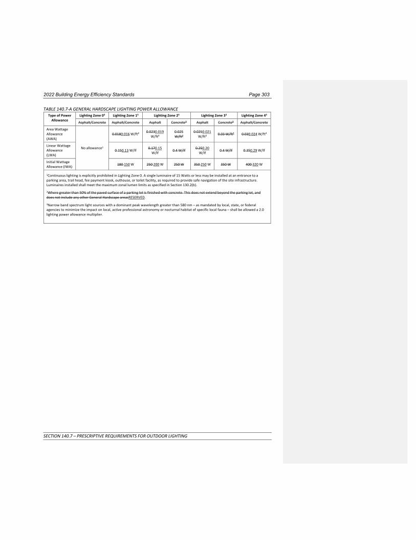
2022 Building Energy Efficiency Standards Page 303
SECTION 140.7 – PRESCRIPTIVE REQUIREMENTS FOR OUTDOOR LIGHTING
TABLE 140.7-A GENERAL HARDSCAPE LIGHTING POWER ALLOWANCE Type of Power
Allowance Lighting Zone 03 Lighting Zone 13 Lighting Zone 23 Lighting Zone 33 Lighting Zone 43
Asphalt/Concrete Asphalt/Concrete Asphalt Concrete2 Asphalt Concrete2 Asphalt/Concrete
Area Wattage Allowance (AWA)
No allowance1
0.0180.016 W/ft²
0.0230.019 W/ft²
0.025 W/ft²
0.0250.021 W/ft²
0.03 W/ft²
0.030.024 W/ft²
Linear Wattage Allowance (LWA)
0.150.13 W/lf
0.170.15 W/lf
0.4 W/lf
0.250.20 W/lf
0.4 W/lf
0.350.29 W/lf
Initial Wattage Allowance (IWA)
180 150 W 250 200 W 250 W 350 250 W 350 W 400 320 W
1Continuous lighting is explicitly prohibited in Lighting Zone 0. A single luminaire of 15 Watts or less may be installed at an entrance to a parking area, trail head, fee payment kiosk, outhouse, or toilet facility, as required to provide safe navigation of the site infrastructure. Luminaires installed shall meet the maximum zonal lumen limits as specified in Section 130.2(b).
2Where greater than 50% of the paved surface of a parking lot is finished with concrete. This does not extend beyond the parking lot, and does not include any other General Hardscape areasRESERVED.
3Narrow band spectrum light sources with a dominant peak wavelength greater than 580 nm – as mandated by local, state, or federal agencies to minimize the impact on local, active professional astronomy or nocturnal habitat of specific local fauna – shall be allowed a 2.0 lighting power allowance multiplier.

2022 Building Energy Efficiency Standards Page 304
SECTION 140.7 – PRESCRIPTIVE REQUIREMENTS FOR OUTDOOR LIGHTING
TABLE 140.7-B ADDITIONAL LIGHTING POWER ALLOWANCE FOR SPECIFIC APPLICATIONS All area and distance measurements in plan view unless otherwise noted.
Lighting Application Lighting Zone 0
Lighting Zone 1
Lighting Zone 2
Lighting Zone 3
Lighting Zone 4
WATTAGE ALLOWANCE PER APPLICATION. Use all that apply as appropriate.
Building Entrances or Exits. Allowance per door. Luminaires qualifying for this allowance shall be within 20 feet of the door.
Not applicable
9 watts
15 watts
19 watts
21 watts
Primary Entrances to Senior Care Facilities, Police Stations, Healthcare Facilities, Fire Stations, and Emergency Vehicle Facilities. Allowance per primary entrance(s) only. Primary entrances shall provide access for the general public and shall not be used exclusively for staff or service personnel. This allowance shall be in addition to the building entrance or exit allowance above. Luminaires qualifying for this allowance shall be within 100 feet of the primary entrance.
Not applicable
20 watts
40 watts
57 watts
60 watts
Drive Up Windows. Allowance per customer service location. Luminaires qualifying for this allowance shall be within 2 mounting heights of the sill of the window.
Not applicable
16 watts
30 watts
50 watts
75 watts
Vehicle Service Station Uncovered Fuel Dispenser. Allowance per fueling dispenser. Luminaires qualifying for this allowance shall be within 2 mounting heights of the dispenser.
Not applicable
55 watts
77 watts
81 watts
135 watts
ATM Machine Lighting. Allowance per ATM machine. Luminaires qualifying for this allowance shall be within 50 feet of the dispenser.
Not applicable
100 watts for first ATM machine, 35 watts for each additional ATM machine.
WATTAGE ALLOWANCE PER UNIT LENGTH (w/linear ft). May be used for one or two frontage side(s) per site.
Outdoor Sales Frontage. Allowance for frontage immediately adjacent to the principal viewing location(s) and unobstructed for its viewing length. A corner sales lot may include two adjacent sides provided that a different principal viewing location exists for each side. Luminaires qualifying for this allowance shall be located between the principal viewing location and the frontage outdoor sales area.
Not applicable
No Allowance
11 W/linear ft
19 W/linear ft
25 W/linear ft
WATTAGE ALLOWANCE PER HARDSCAPE AREA (W/ft²). May be used for any illuminated hardscape area on the site.
Hardscape Ornamental Lighting. Allowance for the total site illuminated hardscape area. Luminaires qualifying for this allowance shall be rated for 100 50 watts or less as determined in accordance with Section 130.0(dc), and shall be post-top luminaires, lanterns, pendant luminaires, or chandeliers.
Not applicable
No Allowance
0.007 W/ft²
0.013 W/ft²
0.019 W/ft²
WATTAGE ALLOWANCE PER SPECIFIC AREA (W/ft²). Use as appropriate provided that none of the following specific applications shall be used for the same area.
Building Facades. Only areas of building façade that are illuminated shall qualify for this allowance. Luminaires qualifying for this allowance shall be aimed at the façade and shall be capable of illuminating it without obstruction or interference by permanent building features or other objects.
Not applicable
No Allowance
0.100 W/ft²
0.170 W/ft²
0.225 W/ft²
Outdoor Sales Lots. Allowance for uncovered sales lots used exclusively for the display of vehicles or other merchandise for sale. Driveways, parking lots or other non sales areas shall be considered hardscape areas even if these areas are completely surrounded by sales lot on all sides. Luminaires qualifying for this allowance shall be within 5 mounting heights of the sales lot area.
Not applicable
0.060 W/ft²
0.210 W/ft²
0.280 W/ft²
0.485 W/ft²
Vehicle Service Station Hardscape. Allowance for the total illuminated hardscape area less area of buildings, under canopies, off property, or obstructed by signs or structures. Luminaires qualifying for this allowance shall be illuminating the hardscape area and shall not be within a building, below a canopy, beyond property lines, or obstructed by a sign or other structure.
Not applicable
0.006 W/ft²
0.068 W/ft²
0.138 W/ft²
0.200 W/ft²
Vehicle Service Station Canopies. Allowance for the total area within the drip line of the canopy. Luminaires qualifying for this allowance shall be located under the canopy.
Not applicable
0.220 W/ft²
0.430 W/ft²
0.580 W/ft²
1.010 W/ft²

2022 Building Energy Efficiency Standards Page 305
SECTION 140.7 – PRESCRIPTIVE REQUIREMENTS FOR OUTDOOR LIGHTING
Sales Canopies. Allowance for the total area within the drip line of the canopy. Luminaires qualifying for this allowance shall be located under the canopy.
Not applicable
No Allowance
0.470 W/ft²
0.622 W/ft²
0.740 W/ft²
Non-sales Canopies and Tunnels. Allowance for the total area within the drip line of the canopy or inside the tunnel. Luminaires qualifying for this allowance shall be located under the canopy or tunnel.
Not applicable
0.057 W/ft²
0.137 W/ft²
0.270 W/ft²
0.370 W/ft²
Guard Stations. Allowance up to 1,000 square feet per vehicle lane. Guard stations provide access to secure areas controlled by security personnel who stop and may inspect vehicles and vehicle occupants, including identification, documentation, vehicle license plates, and vehicle contents. Qualifying luminaires shall be within 2 mounting heights of a vehicle lane or the guardhouse.
Not applicable
0.081 W/ft²
0.176 W/ft²
0.325 W/ft²
0.425 W/ft²
Student Pick-up/Drop-off zone. Allowance for the area of the student pick-up/drop-off zone, with or without canopy, for preschool through 12th grade school campuses. A student pick-up/drop off zone is a curbside, controlled traffic area on a school campus where students are picked-up and dropped off from vehicles. The allowed area shall be the smaller of the actual width or 25 feet, times the smaller of the actual length or 250 feet. Qualifying luminaires shall be within 2 mounting heights of the student pick-up/drop-off zone.
Not applicable
No Allowance
0.056 W/ft²
0.200 W/ft²
No Allowance
Outdoor Dining. Allowance for the total illuminated hardscape of outdoor dining. Outdoor dining areas are hardscape areas used to serve and consume food and beverages. Qualifying luminaires shall be within 2 mounting heights of the hardscape area of outdoor dining.
Not applicable
0.004 W/ft²
0.030 W/ft²
0.050 W/ft²
0.075 W/ft²
Special Security Lighting for Retail Parking and Pedestrian Hardscape. This additional allowance is for illuminated retail parking and pedestrian hardscape identified as having special security needs. This allowance shall be in addition to the building entrance or exit allowance.
Not applicable
0.004 W/ft²
0.005 W/ft²
0.010 W/ft²
No Allowance
Security Cameras. This additional allowance is for illuminated general hardscape area. This allowance shall apply when a security camera is installed within 2 mounting heights of the general hardscape area and mounted more than 10 feet away from a building.
Not
applicable
No
Allowance
0.018 W/ft²
0.018 W/ft²
0.018 W/ft²
NOTE: Authority: Sections 25213, 25218, 25218.5, 25402 and 25402.1, Public Resources Code. Reference: Sections 25007, 25008, 25218.5, 25310, 25402, 25402.1, 25402.4, 25402.5, 25402.8, and 25943, Public Resources Code.
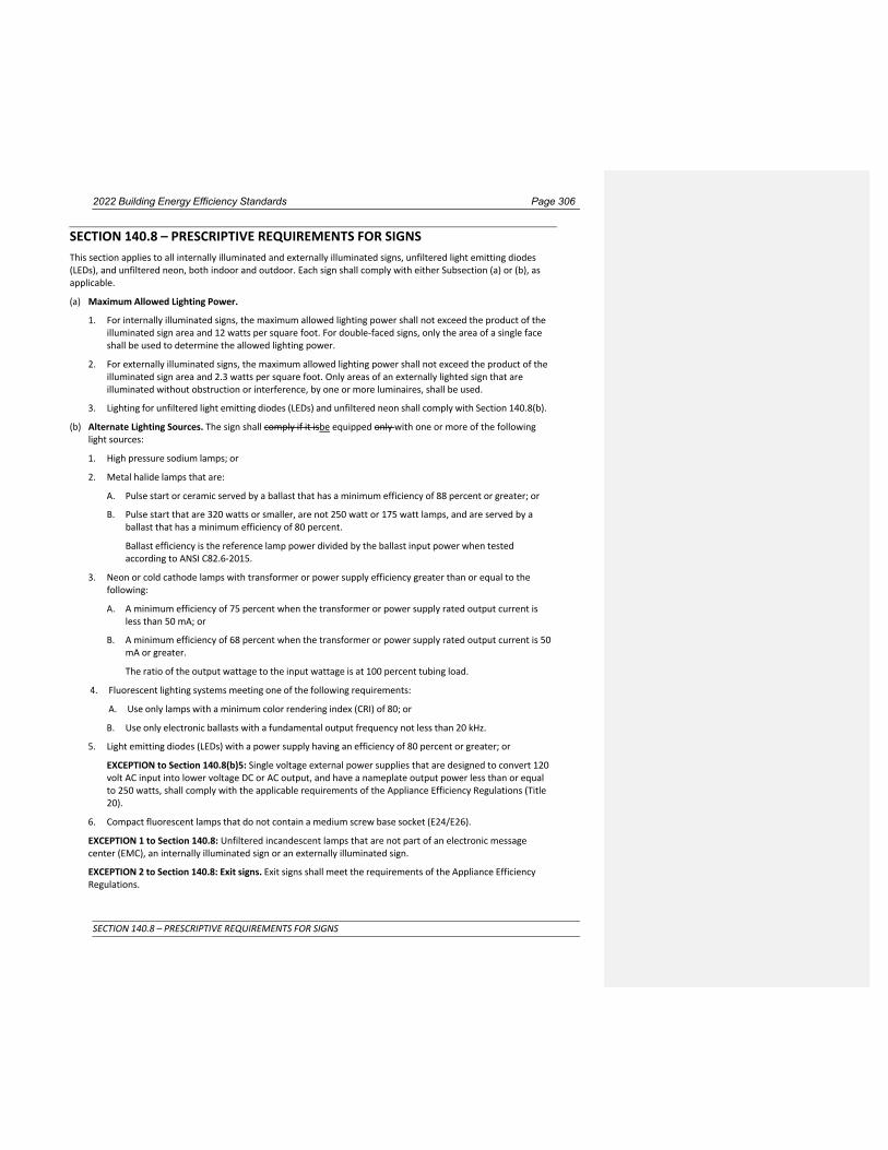
2022 Building Energy Efficiency Standards Page 306
SECTION 140.8 – PRESCRIPTIVE REQUIREMENTS FOR SIGNS
SECTION 140.8 – PRESCRIPTIVE REQUIREMENTS FOR SIGNS This section applies to all internally illuminated and externally illuminated signs, unfiltered light emitting diodes (LEDs), and unfiltered neon, both indoor and outdoor. Each sign shall comply with either Subsection (a) or (b), as applicable.
(a) Maximum Allowed Lighting Power.
1. For internally illuminated signs, the maximum allowed lighting power shall not exceed the product of the illuminated sign area and 12 watts per square foot. For double-faced signs, only the area of a single face shall be used to determine the allowed lighting power.
2. For externally illuminated signs, the maximum allowed lighting power shall not exceed the product of the illuminated sign area and 2.3 watts per square foot. Only areas of an externally lighted sign that are illuminated without obstruction or interference, by one or more luminaires, shall be used.
3. Lighting for unfiltered light emitting diodes (LEDs) and unfiltered neon shall comply with Section 140.8(b).
(b) Alternate Lighting Sources. The sign shall comply if it isbe equipped only with one or more of the following light sources:
1. High pressure sodium lamps; or
2. Metal halide lamps that are:
A. Pulse start or ceramic served by a ballast that has a minimum efficiency of 88 percent or greater; or
B. Pulse start that are 320 watts or smaller, are not 250 watt or 175 watt lamps, and are served by a ballast that has a minimum efficiency of 80 percent.
Ballast efficiency is the reference lamp power divided by the ballast input power when tested according to ANSI C82.6-2015.
3. Neon or cold cathode lamps with transformer or power supply efficiency greater than or equal to the following:
A. A minimum efficiency of 75 percent when the transformer or power supply rated output current is less than 50 mA; or
B. A minimum efficiency of 68 percent when the transformer or power supply rated output current is 50 mA or greater.
The ratio of the output wattage to the input wattage is at 100 percent tubing load.
4. Fluorescent lighting systems meeting one of the following requirements:
A. Use only lamps with a minimum color rendering index (CRI) of 80; or
B. Use only electronic ballasts with a fundamental output frequency not less than 20 kHz.
5. Light emitting diodes (LEDs) with a power supply having an efficiency of 80 percent or greater; or
EXCEPTION to Section 140.8(b)5: Single voltage external power supplies that are designed to convert 120 volt AC input into lower voltage DC or AC output, and have a nameplate output power less than or equal to 250 watts, shall comply with the applicable requirements of the Appliance Efficiency Regulations (Title 20).
6. Compact fluorescent lamps that do not contain a medium screw base socket (E24/E26).
EXCEPTION 1 to Section 140.8: Unfiltered incandescent lamps that are not part of an electronic message center (EMC), an internally illuminated sign or an externally illuminated sign.
EXCEPTION 2 to Section 140.8: Exit signs. Exit signs shall meet the requirements of the Appliance Efficiency Regulations.

2022 Building Energy Efficiency Standards Page 307
SECTION 140.8 – PRESCRIPTIVE REQUIREMENTS FOR SIGNS
EXCEPTION 3 to Section 140.8: Traffic Signs. Traffic signs shall meet the requirements of the Appliance Efficiency Regulations.
NOTE: Authority: Sections 25213, 25218, 25218.5, 25402 and 25402.1, Public Resources Code. Reference: Sections 25007, 25008, 25218.5, 25310, 25402, 25402.1, 25402.4, 25402.5, 25402.8, and 25943, Public Resources Code.

2022 Building Energy Efficiency Standards Page 308
SECTION 140.9 – PRESCRIPTIVE REQUIREMENTS FOR COVERED PROCESSES
SECTION 140.9 – PRESCRIPTIVE REQUIREMENTS FOR COVERED PROCESSES (a) Prescriptive Requirements for Computer Rooms. Space conditioning systems serving a cComputer rooms
with a power density greater than 20 W/ft2 shall comply with this section by being designed with and having constructed and installed a cooling system that meets the requirements of Subsections 1 through 6.
1. Economizers. Each individual cooling system primarily serving computer rooms shall include either:
A. An integrated air economizer capable of providing 100 percent of the expected system cooling load as calculated in accordance with a method approved by the Commission, at 65°F to 80.6°F supply air temperature at outside air temperatures of 5565°F dry-bulb and below or /50°F wet-bulb and below, and be equipped with a fault detection and diagnostic system as specified by that complies with Section 120.2(i); or
B. An integrated water economizer capable of providing 100 percent of the expected system cooling load as calculated in accordance with a method approved by the Commission,at 65°F to 80.6°F supply air temperature at outside air temperatures of 4050°F dry-bulb and below or /345°F wet-bulb and below.; or
C. An integrated pumped refrigerant economizer capable of providing 100 percent of the expected system cooling load at 65°F to 80.6°F supply air temperature at outside air temperatures of 50°F dry- bulb and below.
EXCEPTION 1 to Section 140.9(a)1: Individual computer rooms with an ITE design load under 5 tons (18 kW) in a building that does not have any economizers.
EXCEPTION 2 to Section 140.9(a)1: New cooling systems serving an existing computer room in an existing building up to a total of 50 tons of new cooling equipment per building.
EXCEPTION 3 to Section 140.9(a)1: New cooling systems serving a new computer room in an existing building up to a total of 20 tons of new cooling equipment per building.
EXCEPTION 42 to Section 140.9(a)1: A computer room with an ITE design load less than 20 tons (70 kW) may be served by a second fan system without an economizer if it is also served by a fan system with an economizer that also serves other spaces within the building, provided that all of the following are met:
i. The economizer system is sized to meet the design cooling load of the computer room when the other spaces within the building are at 50 percent of their design load The economizer system is sized to meet the design cooling load of the computer room when the other spaces within the building are at 50 percent of their design load at outside air temperatures of 65°F dry-bulb and below or 50°F wet-bulb and below; and
ii. The economizer system has the ability to serve only the computer rooms connected to it, e.g., shut off flow to other spaces within the building when unoccupied; and.
ii. The economizer system has the ability to deliver either the computer room ITE design load or the maximum of 5 tons and at least 25 percent of the economizer system capacity at design conditions.
iii. The noneconomizer system does not operate when the outside air drybulb temperatures is below 60°F and, the cooling load of other spaces within the building served by the economizer system is less than 50 percent of design load.
EXCEPTION 3 to Section 140.9(a)1: If the local water authority does not allow cooling towers the cooling system shall include either:
i. An integrated air economizer capable of providing 100 percent of the expected system cooling load at 65°F to 80.6°F supply air temperature at outside air temperatures of 55°F dry-bulb and below or 50°F wet-bulb and below, and be equipped with a fault detection and diagnostic system as specified by section 120.2(ji); or
ii. An integrated water economizer capable of providing 100 percent of the expected system cooling load at 65°F to 80.6°F supply air temperature at outside air temperatures of 40°F dry-bulb and
Commented [AT15]: Computer Rooms

2022 Building Energy Efficiency Standards Page 309
SECTION 140.9 – PRESCRIPTIVE REQUIREMENTS FOR COVERED PROCESSES
below or 35°F wet-bulb and below.; or

2022 Building Energy Efficiency Standards Page 310
SECTION 140.9 – PRESCRIPTIVE REQUIREMENTS FOR COVERED PROCESSES
iii. An integrated refrigerant economizer capable of providing 100 percent of the expected system cooling load at 65°F to 80.6°F supply air temperature supply air temperature at outside air temperatures of 40°F dry-bulb and below or 35°F wet-bulb and below.
2. Reheat. Each computer room zone shall have controls that prevent reheating, recooling and simultaneous provisions of heating and cooling to the same zone, such as mixing or simultaneous supply of air that has been previously mechanically heated and air that has been previously cooled, either by cooling equipment or by economizer systems.
3. Humidification. Nonadiabatic humidification (e.g. steam, infrared) is prohibited. Only adiabatic humidification (e.g. direct evaporative, ultrasonic) is permitted.
42. Power Consumption of Fans. The total fan power at design conditions of each fan system shall not exceed 27 W/kBtu·h of net sensible cooling capacity.
5. Fan Control. Each unitary air conditioner with mechanical cooling capacity exceeding 60,000 Btu/hr and each chilled water fan system shall be designed to vary the airflow rate as a function of actual load and shall have controls and/or devices (such as two-speed or variable speed control) that will result in fan motor demand of no more than 50 percent of design wattage at 66 percent of design fan speed.
36. Air Containment. Computer rooms with air-cooled computers in racks and with a ITE design load exceeding 17510 kW/ (2.8 tons) per room shall include air barriers such that there is no significant air path for computer discharge air to recirculate back to computer inlets without passing through a cooling system.
EXCEPTION 1 to Section 140.9(a)36: Expansions of existing computer rooms.
EXCEPTION 2 to Section 140.9(a)36: Computer racks with a design load less than 1 kW (0.28 tons) per /rack.
EXCEPTION 3 to Section 140.9(a)36: Equivalent energy performance based on computational fluid dynamics or other analysis.
4. Alternating Current-Output Uninterruptible Power Supplies (UPS). Alternating current-output UPS systems serving a computer room shall meet or exceed minimum average efficiencies in Table 140.9-A. Minimum average efficiency for alternating current-output UPS shall meet or exceed calculation and testing requirements identified in ENERGY STAR Program Requirements for Uninterruptible Power Supplies (UPSs) – Eligibility Criteria Version 2.0.
Where:
P is the rated output power in watts (W).
EMOD is an allowance of 0.004 for modular UPSs applicable in commercial 1,500-10,000 W range.
ln is the natural logarithm.
The requirement shall be rounded to the third decimal place for certification and reporting.
EXCEPTION to 140.9(a)4: Alternating current-output UPS that utilizes standardized NEMA 1-15P or NEMA 5-15P input plug, as specified in ANSI/NEMA WD-6-2016.
Table 140.9-A Alternating Current-Output Uninterruptible Power Supply Minimum Average Efficiency
Voltage and Frequency Dependent
Voltage Independent Voltage and Frequency Independent
P<≤350 W 5.71 x 10⁻⁵ x P + 0.962 5.71 x 10⁻⁵ x P + 0.964 0.011 x ln(P) + 0.824
350 W<P<≤1,500 W 0.982 0.984
1,500 W<P<≤10,000 W 0.981 – EMOD 0.980 – EMOD 0.0145 x ln(P) +0.800 – EMOD
P>10,000 W 0.970 0.940 0.0058 x ln(P) + 0.886

2022 Building Energy Efficiency Standards Page 311
SECTION 140.9 – PRESCRIPTIVE REQUIREMENTS FOR COVERED PROCESSES
EXCEPTION to Section 140.9(a): Computer rooms located in healthcare facilities.
(b) Prescriptive Requirements for Commercial Kitchens.
1. Kitchen exhaust systems.
A. Replacement air introduced directly into the hood cavity of kitchen exhaust hoods shall not exceed 10 percent of the hood exhaust airflow rate.
B. For kitchen/dining facilities having total Type I and Type II kitchen hood exhaust airflow rates greater than 5,000 cfm, each Type I hood shall have an exhaust rate that complies with TABLE 140.9-AB. If a single hood or hood section is installed over appliances with different duty ratings, then the maximum allowable flow rate for the hood or hood section shall not exceed the TABLE 140.9-A values for the highest appliance duty rating under the hood or hood section. Refer to ASHRAE Standard 154-2011 for definitions of hood type, appliance duty and next exhaust flow rate.
EXCEPTION 1 to Section 140.9(b)1B: 75 percent of the total Type I and Type II exhaust replacement air is transfer air that would otherwise be exhausted.
EXCEPTION 2 to Section 140.9(b)1B: Existing hoods not being replaced as part of an addition or alteration.
TABLE 140.9-A B MAXIMUM NET EXHAUST FLOW RATE, CFM PER LINEAR FOOT OF HOOD LENGTH
Type of Hood Light Duty Equipment
Medium Duty Equipment
Heavy Duty Equipment
Extra Heavy Duty Equipment
Wall-mounted
Canopy
140
210
280
385
Single Island 280 350 420 490
Double Island 175 210 280 385
Eyebrow 175 175 Not Allowed Not Allowed
Backshelf / Passover 210 210 280 Not Allowed
2. Kitchen ventilation.
A. Mechanically cooled or heated makeup air delivered to any space with a kitchen hood shall not exceed the greater of:
i. The supply flow required to meet the space heating and cooling load; or
ii. The hood exhaust flow minus the available transfer air from adjacent spaces. Available transfer air is that portion of outdoor ventilation air serving adjacent spaces not required to satisfy other exhaust needs, such as restrooms, not required to maintain pressurization of adjacent spaces, and that would otherwise be relieved from the building.
EXCEPTION to Section 140.9(b)2A: Existing kitchen makeup air units not being replaced as part of an addition or alteration.
B. A kitchen/dining facility having a total Type I and Type II kitchen hood exhaust airflow rate greater than 5,000 cfm shall have one of the following:
i. At least 50 percent of all replacement air is transfer air that would otherwise be exhausted; or
ii. Demand ventilation system(s) on at least 75 percent of the exhaust air. Such systems shall:
a. Include controls necessary to modulate airflow in response to appliance operation and to maintain full capture and containment of smoke, effluent and combustion products during cooking and idle; and
b. Include failsafe controls that result in full flow upon cooking sensor failure; and
c. Include an adjustable timed override to allow occupants the ability to temporarily override the system to full flow; and

2022 Building Energy Efficiency Standards Page 312
SECTION 140.9 – PRESCRIPTIVE REQUIREMENTS FOR COVERED PROCESSES
d. Be capable of reducing exhaust and replacement air system airflow rates to the larger of:
(i) 50 percent of the total design exhaust and replacement air system airflow rates; or
(ii) The ventilation rate required as specified by Section 120.1(c)3.
iii. Listed energy recovery devices with a sensible heat recovery effectiveness of not less than 40 percent on at least 50 percent of the total exhaust airflow; or
iv. A minimum of 75 percent of makeup air volume that is:
a. Unheated or heated to no more than 60°F; and
b. Uncooled or cooled without the use of mechanical cooling.
EXCEPTION to Section 140.9(b)2B: Existing hoods not being replaced as part of an addition or alteration.
3. Kitchen Exhaust System Acceptance. Before an occupancy permit is granted for a commercial kitchen subject to Section 140.9(b), the following equipment and systems shall be certified as meeting the Acceptance Requirements for Code Compliance, as specified by the Reference Nonresidential Appendix NA7. A Certificate of Acceptance shall be submitted to the enforcement agency that certifies that the equipment and systems meet the acceptance requirements specified in NA7.11.
EXCEPTION to Section 140.9(b): healthcare facilities.
(c) Prescriptive Requirements for Laboratory and Factory Exhaust Systems.
1. Airflow Reduction Requirements. For buildings with laboratory exhaust systems where the minimum circulation rate to comply with code or accreditation standards is 10 ACH or less, the design exhaust airflow shall be capable of reducing zone exhaust and makeup airflow rates to the regulated minimum circulation rate, or the minimum required to maintain pressurization requirements, whichever is larger. Variable exhaust and makeup airflow shall be coordinated to achieve the required space pressurization at varied levels of demand and fan system capacity.
EXCEPTION 1 to Section 140.9(c)1: Laboratory exhaust systems serving zones where constant volume is required by the Authority Having Jurisdiction, facility Environmental Health & Safety department or other applicable code.
EXCEPTION 2 to Section 140.9(c)1: New zones on an existing constant volume exhaust system.
2. Exhaust System Transfer Air. Conditioned supply air delivered to any space with mechanical exhaust shall comply with the requirements of Section 140.4(o).
3. Fan System Power Consumption. All newly installed fan exhaust systems serving a laboratory or factory greater than 10,000 CFMcfm, shall meet subsection A and either B, C, or D:
A. System shall meet all discharge requirements in ANSI Z9.5-2012.
B. The exhaust fan system power shall not exceed 0.85 watts per cfm of exhaust air for systems with air filtration, scrubbers, or other air treatment devices. For all other exhaust fan systems the system power shall not exceed 0.65 watts per cfm of exhaust air. Exhaust fan system power equals the sum of the power of all fans in the exhaust system that are required to operate at normal occupied design conditions in order to exhaust air from the conditioned space to the outdoors. Exhaust air does not include entrained air, but does include all exhaust air from fume hoods, hazardous exhaust flows, or other manifolded exhaust streams.
EXCEPTION to Section 140.9(c)3B: Laboratory exhaust systems where applicable local, state, or federal exhaust treatment requirements specify installation of air treatment devices that cause more than 1 in. of water pressure drop.
C. The volume flow rate at the stack shall vary based on the measured 5-minute averaged wind speed and wind direction obtained from a calibrated local anemometer.

2022 Building Energy Efficiency Standards Page 313
SECTION 140.9 – PRESCRIPTIVE REQUIREMENTS FOR COVERED PROCESSES
i. At least one sonic anemometer or at least two anemometers of other types shall be installed in a location that experiences similar wind conditions to the free stream environment above the exhaust stacks and be at a height that is outside the wake region of nearby structures.
ii. Look-up tables shall be used to define the required exhaust volume flow rate, as a function of at least eight wind speeds and eight wind directions, to maintain downwind concentrations below health and odor limits, as defined by the 2018 American Conference of Governmental Industrial Hygienists Threshold Limit Values and Biological Exposure Indices, for all detectable contaminants, or as defined by applicable local, state, or federal jurisdictions, if more stringent.
iii. Wind speed/direction sensors shall be certified by the manufacturer to be accurate within plus or minus 40 fpm (0.2 m/s) and 5.0° when measured at sea level and 25°C, factory calibrated, and certified by the manufacturer to require calibration no more frequently than once every 5 years.
iv. Upon detection of anemometer and/or signal failure, the system shall reset the exhaust volume flow rate to the value needed to maintain downwind concentrations below health and odor limits for all detectable contaminants at worst-case wind conditions and shall report the fault to an Energy Management Control System or fault management application which automatically provides notification of the fault to a remote system provider. The ECMS or fault management system shall log the error and the time when it occurred. The system shall have logic that automatically checks for anemometer failure by the following means.
a. If any anemometer has not been calibrated within the manufacturer’s recommended calibration period, the sensor anemometer has failed.
b. During unoccupied periods the system compares the readings of all anemometers. If any anemometer is more than 30% above or below the average reading for a period of 4 hours, the anemometer has failed.
c. Wind speed and wind direction readings shall be sampled at least 10 times per minute. If the difference between the maximum and minimum readings from the average of either the wind direction or the wind speed over a one minute period is less than 10% of the average value, the measurements shall be considered a signal failure.
d. Other error signals sent by the anemometer
v. Before an occupancy permit is granted for a laboratory or process facility subject to Section 140.9(c)3C, the applicable equipment and systems shall be certified as meeting the Acceptance Requirements for Code Compliance, as specified by the Reference Nonresidential Appendix NA7.16. A Certificate of Acceptance shall be submitted to the enforcement agency that certifies that the equipment and systems meet the acceptance requirements specified in NA7.16.
D. The volume flow rate at the stack shall vary based on the measured contaminant concentration in the exhaust plenum from a calibrated contaminant sensor installed within each exhaust plenum.
i. A contaminant-event threshold shall be established based on maintaining downwind concentrations below health and odor limits for all detectable chemicals at worst-case wind conditions, as defined by the 2018 American Conference of Governmental Industrial Hygienists Threshold Limit Values and Biological Exposure Indices, or as defined by applicable local, state, or federal jurisdictions, if more stringent.
ii. At least two contaminant concentration sensors shall be Photo Ionization Detectors (PID) certified by the manufacturer to be accurate within plus or minus 5% when measured at sea level and 25°C, factory calibrated, and certified by the manufacturer to require calibration no more frequently than once every 6 months.
iii. Upon detection of sensor and/or signal failure, the system shall reset the exhaust volume flow rate to the value needed to maintain downwind concentrations below health and odor limits for all detectable contaminants at worst-case wind conditions and shall report the fault to an Energy Management Control System or fault management application which automatically provides

2022 Building Energy Efficiency Standards Page 314
SECTION 140.9 – PRESCRIPTIVE REQUIREMENTS FOR COVERED PROCESSES
notification of the fault to a remote system provider. The system shall have logic that automatically checks for sensor failure by the following means.
a. If any sensor has not been calibrated within the manufacturer’s recommended calibration period, the sensor has failed.
b. During unoccupied periods the system compares the readings of all sensors. If any sensor is more than 30% above or below the average reading for a period of 4 hours, the sensor has failed.
iv. Before an occupancy permit is granted for a laboratory or process facility subject to Section 140.9(c)3D, the applicable equipment and systems shall be certified as meeting the Acceptance Requirements for Code Compliance, as specified by the Reference Nonresidential Appendix NA7.16. A Certificate of Acceptance shall be submitted to the enforcement agency that certifies that the equipment and systems meet the acceptance requirements specified in NA7.16.
4. Fume Hood Automatic Sash Closure. Variable air volume laboratory fume hoods with vertical only sashes located in fume hood intensive laboratories, as described in Table 140.9-BC, shall have an automatic sash closure system that complies with the following:
A. The automatic sash closure system shall be capable of the following:
i. The automatic sash closure system shall have a dedicated zone presence sensor that detects people in the area near the fume hood sash and automatically closes the sash within 5 minutes of no detection.
ii. The automatic sash closure system shall have controls to prevent the sash from automatic closing when a force of no more than 10 lbs is detected.
iii. The automatic sash closure system shall be equipped with an obstruction sensor that prevents the sash from automatic closing with obstructions in the sash opening. Obstruction sensor shall be capable of sensing transparent materials such as laboratory glassware.
iv. The automatic sash closure system shall be capable of being configured in a manual open mode where once the sash is closed, detection of people in the area near the fume hood by the zone presence sensor does not open the fume hood sash.
B. Fume Hood Automatic Sash Closure Acceptance. Before an occupancy permit is granted for the fume hoods subject to 140.9(c)4, the equipment and systems shall be certified as meeting the Acceptance Requirement for Code Compliance as specified by the Reference Nonresidential Appendix NA7. A Certificate of Acceptance shall be submitted to the enforcement agency that certifies that the equipment and systems meet the acceptance requirements specified in NA7.17.
Table 140.9-B C Fume Hood Intensive Laboratories
Occupied Minimum Ventilation ACH
≤ 4
> 4 and ≤ 6
> 6 and ≤ 8
> 8 and ≤ 10
> 10 and ≤ 12
> 12 and ≤ 14
Hood Density (linear feet per 10,000 ft3 of laboratory space
≥ 6
≥ 8
≥ 10
≥ 12
≥ 14
≥ 16
EXCEPTION to Section 140.9(c): healthcare facilities.
NOTE: Authority: Sections 25213, 25218, 25218.5, 25402 and 25402.1, Public Resources Code. Reference: Sections 25007, 25008, 25218.5, 25310, 25402, 25402.1, 25402.4, 25402.8, and 25943, Public Resources Code.

2022 Building Energy Efficiency Standards Page 314
SECTION 140.10 – PRESCRIPTIVE REQUIREMENTS FOR PHOTOVOLTAIC AND BATTERY STORAGE SYSTEMS
SECTION 140.10 – PRESCRIPTIVE REQUIREMENTS FOR PHOTOVOLTAIC AND BATTERY STORAGE SYSTEMS
(a) Photovoltaic Requirements. All newly constructed building types specified in Table 140.10-A, or mixed
occupancy buildings where one or more of these building types constitute at least 80 percent of the floor area of the building, shall have a photovoltaic (PV) system meeting the minimum qualification requirements of Reference Joint Appendix JA11. The PV size in kWdc shall be not less than the smaller of the PV system size determined by Equation 140.10-A, or the total of all available Solar Access Roof Areas (SARA) multiplied by 14 W/ft².
1. SARA include the area of the building’s roof space capable of structurally supporting a PV system, and the
area of all roof space on covered parking areas, carports, and all other newly constructed structures on the site that are compatible with supporting a PV system per Title 24, Part 2, Section 1511.2.
2. SARA does NOT include:
A. Any area that has less than 70 percent annual solar access. Annual solar access is determined by dividing the total annual solar insolation (accounting for shading obstructions) by the total annual solar insolation if the same areas were unshaded by those obstructions. For all roofs, all obstructions including those that are external to the building, and obstructions that are part of the building design and elevation features may be considered for the annual solar access calculations.
B. Occupied roofs as specified by CBC Section 503.1.4.
C. Roof space that is otherwise not available due to compliance with other building code requirements if confirmed by the Executive Director.
EQUATION 140.10-A PHOTOVOLTAIC DIRECT CURRENT SIZE
kWPVdc = (CFA x A)/1000
WHERE:
kWPVdc = Size of the PV system in kW
CFA = Conditioned floor area in square feet
A = PV capacity factor specified in Table 140.10-A for the building type
Where the building includes more than one of the space types listed in Table 140.10-A, the total PV system capacity for the building shall be determined by applying Equation 140.10-A to each of the listed space types and summing the capacities determined for each.
EXCEPTION 1 to Section 140.10(a). No PV system is required where the total of all available SARA is less than three percent of the conditioned floor area.
EXCEPTION 2 to Section 140.10(a). No PV system is required where the required PV system size is less than 4 kWdc.
EXCEPTION 3 to Section 140.10(a). No PV system is required if the SARA contains less than 80 contiguous square feet.

2022 Building Energy Efficiency Standards Page 315
SECTION 140.10 – PRESCRIPTIVE REQUIREMENTS FOR PHOTOVOLTAIC AND BATTERY STORAGE SYSTEMS
EXCEPTION 4 to Section 140.10(a). Buildings with enforcement-authority-approved roof designs, where the enforcement authority determines it is not possible for the PV system, including panels, modules, components, supports, and attachments to the roof structure, to meet ASCE 7-16, Chapter 7, Snow Loads.
EXCEPTION 5 to Section 140.10(a). Multi-tenant buildings in areas where a load serving entity does not provide either a Virtual Net Metering (VNEM) or community solar program.
(b) Battery Storage System Requirements. All buildings that are required by Section 140.10(a) to have a PV system shall also have a battery storage system meeting the minimum qualification requirements of Reference Joint Appendix JA12. The rated energy capacity and the rated power capacity shall be not less than the values determined by Equation 140.10-B and Equation 140.10-C. Where the building includes more than one of the space types listed in Table 140.10-B, the total battery system capacity for the building shall be determined by applying Equations 140.10-B and 140.10-C to each of the listed space types and summing the capacities determined for each space type and equation.
EXCEPTION 1 to Section 140.10(b). No battery storage system is required if the installed PV system size is less than 15 percent of the size determined by Equation 140.10-A.
EXCEPTION 2 to Section 140.10(b). No battery storage system is required in buildings with battery storage system requirements with less than 10 kWh rated useable capacity.
EXCEPTION 3 to Section 140.10(b). For multi-tenant buildings, the energy capacity and power capacity of the battery storage system shall be based on the tenant spaces, not including common area spaces, with more than 5,000 square feet of conditioned floor area. For single-tenant buildings with less than 5,000 square feet of conditioned floor area, no battery storage system is required.
EXCEPTION 4 to Section 140.10(b). In climate zone 1, no battery storage system is required for offices, schools, and warehouses.
EQUATION 140.10-B - BATTERY STORAGE RATED ENERGY CAPACITY
kWhbatt = kWPVdc x B / D0.5
WHERE:
kWhbatt = Rated Useable Energy Capacity of the battery storage system in kWh
kWPVdc = PV system capacity required by section 140.10(a) in kWdc
B = Battery energy capacity factor specified in Table 140.10-B for the building type
D = Rated single charge-discharge cycle AC to AC (round-trip) efficiency of the battery storage system
EQUATION 140.10-C - BATTERY STORAGE RATED POWER CAPACITY
kWbatt = kWPVdc x C
WHERE:
kWbatt = Power capacity of the battery storage system in kWdc
kWPVdc = PV system capacity required by section 140.10(a) in kWdc
C = Battery power capacity factor specified in Table 140.10-B for the building type
Commented [GA16]: Clarify that the exception pertains to “useable” capacity instead of “nameplate” capacity

2022 Building Energy Efficiency Standards Page 316
SECTION 140.10 – PRESCRIPTIVE REQUIREMENTS FOR PHOTOVOLTAIC AND BATTERY STORAGE SYSTEMS
Table 140.10-A – PV Capacity Factors
Factor A – Minimum PV Capacity (W/ft² of conditioned floor area)
Climate Zone 1, 3, 5, 16 2, 4, 6-14 15
Grocery 2.62 2.91 3.53
Highrise Multifamily 1.82 2.21 2.77
Office, Financial Institutions, Unleased Tenant Space 2.59 3.13 3.80
Retail 2.62 2.91 3.53
School 1.27 1.63 2.46
Warehouse 0.39 0.44 0.58
Auditorium, Convention Center, Hotel/Motel, Library, Medical Office Building/Clinic, Restaurant, Theater
0.39
0.44
0.58
Table 140.10-B – Battery Storage Capacity Factors Factor B – Energy
Capacity Factor C – Power Capacity
Storage to PV Ratio Wh/W W/W
Grocery 1.03 0.26
Highrise Multifamily 1.03 0.26
Office, Financial Institutions, Unleased Tenant Space 1.68 0.42
Retail 1.03 0.26
School 1.87 0.46
Warehouse 0.93 0.23
Auditorium, Convention Center, Hotel/Motel, Library, Medical Office Building/Clinic, Restaurant, Theater
0.93
0.23
NOTE1: Authority: Sections 25213, 25218, 25218.5, 25402 and 25402.1, Public Resources Code. Reference: Sections 25007, 25008, 25218.5, 25310, 25402, 25402.1, 25402.4, 25402.8, and 25943, Public Resources Code.

2022 Building Energy Efficiency Standards Page 333
SECTION 150.0 – MANDATORY FEATURES AND DEVICES
SUBCHAPTER 7 LOW-RISESINGLE-FAMILY RESIDENTIAL BUILDINGS –
MANDATORY FEATURES AND DEVICES
SECTION 150.0 – MANDATORY FEATURES AND DEVICES Low-riseSingle-family residential buildings shall comply with the applicable requirements of Sections 150(a)
through 150.0(rv).
NOTE: The requirements of Sections 150.0(a) through 150.0(r) apply to newly constructed buildings. Sections 150.2(a) and 150.2(b) specify which requirements of Sections 150.0(a) through 150.0(r) also apply to additions or alterations.
(a) Roof Deck, Ceiling and Rafter Roof Insulation. The opaque portions of ceilings and roofs separating conditioned spaces from unconditioned spaces or ambient air shall meet the requirements of Items 1 through 3 4 below:
1. In climate zones 4 and 8 through 16 Roof decks in newly constructed attic systems shall be insulated to achieve an area-weighted average U-factor not exceeding U-0.184.
EXCEPTION to Section 150.0(a)1: No roof deck insulation is required when ducts and air handler are located in conditioned space.
2. Ceilings and rafter roofs Shall shall be insulated to achieve an area-weighted average U-factor not exceeding U-0.043 or shall be insulated between wood-framing members with insulation resulting in an installed thermal resistance of R-22 or greater for the insulation alone. For vented attics, the mandatory insulation shall be installed at the ceiling level; for unvented attics, the mandatory insulation shall be placed at either ceiling or roof level; and
EXCEPTION to Section 150.0(a)21: Ceilings and rafter roofs in an alteration shall be insulated to achieve an area-weighted average U-factor not exceeding 0.054 or shall be insulated between wood-framing members with insulation resulting in an installed thermal resistance of R-19 or greater.
23. Attic access doors shall have permanently attached insulation using adhesive or mechanical fasteners. The attic access shall be gasketed to prevent air leakage; and
34. Insulation shall be installed in direct contact with a continuous roof or ceiling which is sealed to limit infiltration and exfiltration as specified in Section 110.7, including but not limited to placing insulation either above or below the roof deck or on top of a drywall ceiling.
(b) Loose-fill Insulation. When loose-fill insulation is installed, the minimum installed weight per square foot shall conform with the insulation manufacturer's installed design weight per square foot at the manufacturer's labeled R-value.
(c) Wall Insulation. Opaque portions of above grade walls separating conditioned spaces from unconditioned spaces or ambient air shall meet the following requirements:
1. 2×4 inch framing shall have an overall assembly U-factor not exceeding U-0.102.
EXCEPTION to Section 150.0(c)1: Existing walls already insulated to a U-factor not exceeding U-0.110 or already insulated between framing members with insulation having an installed thermal resistance of R-11 or greater.
2. 2×6 inch or greater framing shall have an overall assembly U-factor not exceeding U-0.071.
3. Opaque nonframed assemblies shall have an overall assembly U-factor not exceeding U-0.102.

2022 Building Energy Efficiency Standards Page 334
SECTION 150.0 – MANDATORY FEATURES AND DEVICES
4. Bay or Bow Window roofs and floors shall be insulated to meet the wall insulation requirements of TABLE 150.1-A or B.
5. Masonry walls shall be insulated to meet the wall insulation requirements of TABLE 150.1-A or B.
6. In wood framed assemblies, compliance with U-factors may be demonstrated by installing wall insulation with an R-value of 13 in 2x4 assemblies, and 20 in 2x6 assemblies.
(d) Raised-floor Insulation. Raised floors separating conditioned space from unconditioned space or ambient air shall have an overall assembly U-factor not exceeding U-0.037. In a wood framed assembly, compliance with the U-factor may be demonstrated by installing insulation with an R-value of 19 or greater.
EXCEPTION to Section 150.0(d): A building with a controlled ventilation or unvented crawl space may omit raised floor insulation if all of the following are met:
A. The foundation walls are insulated to meet the wall insulation minimums as shown in TABLE 150.1-A or B; and
B. A Class I or Class II vapor retarder is placed over the entire floor of the crawl space; and
C. Vents between the crawl space and outside air are fitted with automatically operated louvers that are temperature actuated; and
D. The requirements in Reference Residential Appendix RA4.5.1.
(e) Installation of Fireplaces, Decorative Gas Appliances and Gas Logs. If a masonry or factory-built fireplace is installed, it shall comply with Section 110.5, Section 4.503 of Part 11, and shall have the following:
1. Closable metal or glass doors covering the entire opening of the firebox; and
2. A combustion air intake to draw air from the outside of the building, which is at least 6 square inches in area and is equipped with a readily accessible, operable, and tight-fitting damper or combustion-air control device; and
EXCEPTION to Section 150.0(e)2: An outside combustion-air intake is not required if the fireplace will be installed over concrete slab flooring and the fireplace will not be located on an exterior wall.
3. A flue damper with a readily accessible control.
EXCEPTION to Section 150.0(e)3: When a gas log, log lighter, or decorative gas appliance is installed in a fireplace, the flue damper shall be blocked open if required by the CMC or the manufacturer's installation instructions.
(f) Slab Edge Insulation. Material used for slab edge insulation shall meet the following minimum specifications:
1. Water absorption rate for the insulation material alone without facings no greater than 0.3 percent when tested in accordance with Test Method A – 24-Hour-Immersion of ASTM C272.
2. Water vapor permeance no greater than 2.0 perm/inch when tested in accordance with ASTM E96.
3. Concrete slab perimeter insulation shall be protected from physical damage and ultraviolet light deterioration.
4. Insulation for a heated slab floor shall meet the requirements of Section 110.8(g).
(g) Vapor Retarder.
1. In Climate Zones 1-16, the earth floor of unvented crawl space shall be covered with a Class I or Class II vapor retarder. This requirement shall also apply to controlled ventilation crawl space for buildings complying with the Exception to Section 150.0(d).
2. In Climate Zones 14 and 16, a Class I or Class II vapor retarder shall be installed on the conditioned space side of all insulation in all exterior walls, vented attics and unvented attics with air-permeable insulation.
(h) Space-Conditioning Equipment.

2022 Building Energy Efficiency Standards Page 335
SECTION 150.0 – MANDATORY FEATURES AND DEVICES
1. Building Cooling and Heating Loads. Building heating and cooling loads shall be determined using a method based on any one of the following:
A. The ASHRAE Handbook, Equipment Volume, Applications Volume, and Fundamentals Volume; or
B. The SMACNA Residential Comfort System Installation Standards Manual; or
C. The ACCA Manual J.
The cooling and heating loads are two of the criteria that shall be used for equipment sizing and selection.
NOTE: Heating systems are required to have a minimum heating capacity adequate to meet the minimum requirements of the CBC. The furnace output capacity and other specifications are published in the Commission's directory of certified equipment or other directories approved by the Commission.
2. Design conditions. For the purpose of sizing the space-conditioning (HVAC) system, the indoor design temperatures shall be 68°F for heating and 75°F for cooling. Outdoor design conditions shall be selected from Reference Joint Appendix JA2, which is based on data from the ASHRAE Climatic Data for Region X. The outdoor design temperatures for heating shall be no lower than the Heating Winter Median of Extremes values. The outdoor design temperatures for cooling shall be no greater than the 1.0 percent Cooling Dry Bulb and Mean Coincident Wet Bulb values.
3. Outdoor Condensing Units.
A. Clearances. Installed air conditioner and heat pump outdoor condensing units shall have a clearance of at least five (5) feet (1.5 meters) from the outlet of any dryer vent.
B. Liquid Line Drier. Installed air conditioner and heat pump systems shall be equipped with liquid line filter driers if required, as specified by manufacturer’s instructions.
4. Central Forced-Air Heating Furnaces.
A. Temperature Rise. Central forced-air heating furnace installations shall be configured to operate in conformance with the furnace manufacturer's maximum inlet-to-outlet temperature rise specifications.
(i) Thermostats. All heating or cooling systems, including heat pumps, not controlled by a central energy management control system (EMCS) shall have a setback thermostat, as specified in Section 110.2(c).
(j) Insulation for Piping and Tanks.
1. Storage tank insulation. Unfired hot water tanks, such as storage tanks and backup storage tanks for solar water-heating systems, shall be externally wrapped with insulation having an installed thermal resistance of R-12 4 or greater.
EXCEPTION to Section 150.0(j)1 or Unfired storage tank withhave internal insulation of at least R-16 and a label on the exterior of the tank showing the insulation R-value.
2. Water piping, solar water-heating system piping, and space conditioning system line insulation thickness and conductivity. Piping shall be insulated as follows:
A. All domestic hot water piping shall be insulated as specified in Section 609.11 of the California Plumbing Code. In addition, the following piping conditions shall have a minimum insulation wall thickness of 1 inch or a minimum insulation R-value of 7.7:
i. The first 5 feet (1.5 meters) of cold water pipes from the storage tank.
ii. All hot water piping with a nominal diameter equal to or greater than 3/4 inch (19 millimeter) and less than 1 inch.
iii. All hot water piping with a nominal diameter less than 3/4 inch that is:
a. Associated with a domestic hot water recirculation system;
b. From the heating source to the kitchen fixtures;

2022 Building Energy Efficiency Standards Page 336
SECTION 150.0 – MANDATORY FEATURES AND DEVICES
c. From the heating source to a storage tank or between storage tanks; or
d. Buried below grade.
B. Piping for space conditioning systems, solar water-heating system collector loop, and distribution piping for steam and hydronic heating system, shall meet the requirements of Section 120.3(c).
EXCEPTION 1 to Section 150.0(j)2: Factory-installed piping within space-conditioning equipment certified under Section 110.1 or 110.2.
EXCEPTION 2 to Section 150.0(j)2: Piping that penetrates framing members shall not be required to have pipe insulation for the distance of the framing penetration. Piping that penetrates metal framing shall use grommets, plugs, wrapping or other insulating material to assure that no contact is made with the metal framing. Insulation shall butt securely against all framing members.
EXCEPTION 3 to Section 150.0(j)2: Piping installed in interior or exterior walls shall not be required to have pipe insulation if all of the requirements are met for compliance with Quality Insulation Installation (QII) as specified in the Reference Residential Appendix RA3.5.
EXCEPTION 4 to Section 150.0(j)2: Piping surrounded with a minimum of 1 inch of wall insulation, 2 inches of crawl space insulation, or 4 inches of attic insulation, shall not be required to have pipe insulation.
3. Insulation Protection. Pipe insulation shall meet the insulation protection requirements of Section 120.3(b).
(k) Residential Lighting.
1. Luminaire Requirements.
A. Luminaire Efficacy. All installed luminaires shall meet the requirements in TABLE 150.0-A.
EXCEPTION 1 to Section 150.0(k)1A: Integrated device lighting. Lighting integral to exhaust fans, kitchen range hoods, bath vanity mirrors, and garage door openers.
EXCEPTION 2 to Section 150.0(k)1A: Navigation lighting such as night lights, step lights, and path lights less than 5 watts.
EXCEPTION 3 to Section 150.0(k)1A: Cabinet Lighting. Lighting internal to drawers, cabinetry, and linen closets with an efficacy of 45 lumens per watt or greater.
B. Screw based luminairesBlank Electrical Boxes. Screw based luminaires shall contain lamps that comply with Reference Joint Appendix JA8 or contain lamps as specified in Table 150.0-A including qualified colored lamps, dim-to-warm lamps, tunable-white lamps, color-tunable lamps, and Title 20- compliant LED lampsThe number of electrical boxes that are more than 5 feet above the finished floor and do not contain a luminaire or other device shall be no greater than the number of bedrooms. These electrical boxes must be served by a dimmer, vacancy sensor control, or fan speed control.
C. Recessed Downlight Luminaires in Ceilings. In addition to complying with 150.0(k)1A, luminaires recessed into ceilings shall meet all all of the following requirements requirements:
i. Shall not contain screw base lamp socketsBe listed, as defined in Section 100.1, for zero clearance insulation contact (IC) by Underwriters Laboratories or other nationally recognized testing/rating laboratory; and
ii. Have a label that certifies the luminaire is airtight with air leakage less than 2.0 CFM cfm at 75 Pascals when tested in accordance with ASTM E283. An exhaust fan housing with integral light shall not be required to be certified airtight; and
iii. Be sealed with a gasket or caulk between the luminaire housing and ceiling, and have all air leak paths between conditioned and unconditioned spaces sealed with a gasket or caulk, or be installed per manufacturer’s instructions to maintain airtightness between the luminaire housing and ceiling; and

2022 Building Energy Efficiency Standards Page 337
SECTION 150.0 – MANDATORY FEATURES AND DEVICES
iv. Meet the clearance and installation requirements of California Electrical Code Section 410.116For luminaires with hardwired ballasts or drivers, allow ballast or driver maintenance and replacement to be readily accessible to building occupants from below the ceiling without requiring the cutting of holes in the ceiling; and
v. Shall not contain screw base sockets.
EXCEPTION to Section 150.0(k)1Cii and iii: Recessed luminaires marked for use in fire-rated installations extruded into ceiling spac,e and recessed luminaires installed in non-insulated ceilings.
D. Light Sources in Enclosed or Recessed LuminairesElectronic Ballasts for Fluorescent Lamps. Lamps and other separable light sources that are not compliant with the JA8 elevated temperature requirements, including marking requirements, shall not be installed in enclosed or recessed luminairesBallasts for fluorescent lamps rated 13 watts or greater shall be electronic and shall have an output frequency no less than 20 kHz.
E. Night Lights, Step Lights and Path Lights. Night lights, step lights and path lights shall not be required to comply with Table 150.0-A or be controlled by vacancy sensors provided they are rated to consume no more than 5 watts of power and emit no more than 150 lumens.
F. Lighting Integral to Exhaust Fans. Lighting integral to exhaust fans shall meet the applicable requirements of Section 150.0(k).
EXCEPTION to Section 150.0(k)1F: Lighting installed by the manufacturer in kitchen exhaust hoods.
G. Screw based luminaires. Screw based luminaires shall contain lamps that comply with Reference Joint Appendix JA8.
EXCEPTION to Section 150.0(k)1G: Luminaires with hard-wired ballasts for high intensity discharge lamps.
H. Light Sources in Enclosed or Recessed Luminaires. Lamps and other separable light sources that are not compliant with the JA8 elevated temperature requirements, including marking requirements, shall not be installed in enclosed or recessed luminaires.
I. Light Sources in Drawers, Cabinets, and Linen Closets. Light sources internal to drawers, cabinetry or linen closets shall not be required to comply with Table 150.0-A or be controlled by vacancy sensors provided that they are rated to consume no more than 5 watts of power and emit no more than 150 lumens, and are equipped with controls that automatically turn the lighting off when the drawer, cabinet or linen closet is closed.Blank Electrical Boxes. The number of electrical boxes that are more than 5 feet above the finished floor and do not contain a luminaire or other device shall be no greater than the number of bedrooms. These electrical boxes must be served by a dimmer, vacancy sensor control, low voltage wiring or fan speed control.
2. Interior Indoor Lighting Switching Devices and Controls.
A. All forward phase cut dimmers used with LED light sources shall comply with NEMA SSL 7A.
B. Exhaust fans shall be controlled separately from lighting systems.
EXCEPTION to Section 150.0(k)2B: Lighting integral to an exhaust fan may be on the same control as the fan provided the lighting can be turned OFF in accordance with the applicable provisions in Section 150.0(k)2 while allowing the fan to continue to operate.
CA. Lighting shall have readily accessible wall-mounted controls that allow the lighting to be manually turned ON and OFF.
EXCEPTION to Section 150.0(k)2C2A: Ceiling fans may provide control of integrated lighting via a remote control.
D. Lighting controls and equipment shall be installed in accordance with the manufacturer's instructions.

2022 Building Energy Efficiency Standards Page 338
SECTION 150.0 – MANDATORY FEATURES AND DEVICES
EB. No controls shall bypass a dimmer, occupant sensor or vacancy sensor function where that dimmer or sensor has been installed to comply with Section 150.0(k).
FC. Lighting controls shall comply with the applicable requirements of Section 110.9.
GD. An Energy Management Control System (EMCS) or a multiscene programmable control may be used to comply with dimming, occupancy, and lighting control requirements in Section 150.0(k)2 if at a minimum it provides the functionality of the specified controls in accordance with Section 110.9, and the physical controls specified in 150.0(k)2A, meets the installation certificate requirements in Section 130.4, meets the EMCS requirements in Section 130.0(e), and complies with all other applicable requirements in Section 150.0(k)2.
H. A multiscene programmable controller may be used to comply with dimmer requirements in Section 150.0(k) if at a minimum it provides the functionality of a dimmer in accordance with Section 110.9, and complies with all other applicable requirements in Section 150.0(k)2.
IE. Automatic Off Controls.
i. In bathrooms, garages, laundry rooms, and utility rooms, and walk-in closets, at least one installed luminaire in each of these spaces shall be controlled by an occupant occupancy or vacancy sensor providing automatic-off functionality. If an occupant sensor is installed, it shall be initially configured to manual-on operation using the manual control required under Section 150.0(k)2AC.
ii. For lighting internal to drawers and cabinetry with opaque fronts or doors, controls that turn light off when the drawer or door is closed shall be provided.
JF. Dimming Controls. Luminaires that are or contain light sources that meet Reference Joint Appendix JA8 requirements for dimming, and that are not controlled by occupancy or vacancy sensors, shall have dimming controlsLighting in habitable spaces, including but not limited to living rooms, dining rooms, kitchens, and bedrooms, shall have readily accessible wall-mounted dimming controls that allow the lighting to be manually adjusted up and down. Forward phase cut dimmers controlling LED light sources in these spaces shall comply with NEMA SSL 7A.
EXCEPTION 1 to Section 150.0(k)2J2F: Luminaires in closets less than 70 square feet. Ceiling fans may provide control of integrated lighting via a remote control.
EXCEPTION 2 to Section 150.0(k)2J: Luminaires in hallways.
EXCEPTION 2 to Section 150.0(k)2F: Luminaires connected to a circuit with controlled lighting power less than 20 watts or controlled by an occupancy or vacancy sensor providing automatic-off functionality.
EXCEPTION 3 to Section 150.0(k)2F: Navigation lighting such as night lights, step lights, and path lights less than 5 watts, and lighting internal to drawers and cabinetry with opaque fronts or doors.
KG. Independent controls. Integrated lighting of exhaust fans shall be controlled independently from the fans. Undercabinet lightingThe following shall be controlled separately from ceiling-installed lighting such that one can be turned on without turning on the other:
i. Undercabinet lighting
ii. Undershelf lighting
iii. Interior lighting of display cabinets
iv. Switched outlets.
3. Residential Outdoor Lighting. In addition to meeting the requirements of Section 150.0(k)1A, luminaires providing residential outdoor lighting shall meet the following requirements, as applicable:
2022 Building Energy Efficiency Standards Page 339
SECTION 150.0 – MANDATORY FEATURES AND DEVICES
A. For single-family residential buildings, outdoor lighting permanently mounted to a residential building or to other buildings on the same lot shall meet the requirement in item i and the requirements in either item ii or item iii:
i. Controlled by a manual ON and OFF control switch that permits the automatic actions of items ii or iii below; and
ii. Controlled by a photocell and either a motion sensor or an automatic time switch control; or
iii. Controlled by an astronomical time clock control or an automatic time switch control. Time switch or time clock controls that override to ON shall not be allowed unless the override automatically returns the automatic control to its normal operation within 6 hours.
Controls that override to ON shall not be allowed unless the override automatically returns the automatic control to its normal operation within 6 hours. An energy management control system that provides the specified lighting control functionality and complies with all requirements applicable to the specified controls may be used to meet these requirements.
B. For low-rise residential buildings with four or more dwelling units, outdoor lighting for private patios, entrances, balconies, porches; and residential parking lots and carports with less than eight vehicles per site shall comply with either:
i. Section 150.0(k)3A; or
ii. The applicable requirements in Sections 110.9, 130.0, 130.2, 130.4, 140.7 and 141.0.
C. For low-rise residential buildings with four or more dwelling units, any outdoor lighting for residential parking lots or carports with a total of eight or more vehicles per site and any outdoor lighting not regulated by Section 150.0(k)3B shall comply with the applicable requirements in Sections 110.9, 130.0, 130.2, 130.4, 140.7 and 141.0.
4. Internally illuminated address signs. Internally illuminated address signs shall either:
A. Comply with Section 140.8; or
B. Consume no more than 5 watts of power.
5. Residential Garages for Eight or More Vehicles. Lighting for residential parking garages for eight or more vehicles shall comply with the applicable requirements for nonresidential garages in Sections 110.9, 130.0, 130.1, 130.4, 140.6, and 141.0.
6. Interior Common Areas of Low-rise Multifamily Residential Buildings.
A. In a low-rise multifamily residential building where the total interior common area in a single building equals 20 percent or less of the floor area, permanently installed lighting for the interior common areas in that building shall comply with Table 150.0-A and be controlled by an occupant sensor.
B. In a low-rise multifamily residential building where the total interior common area in a single building equals more than 20 percent of the floor area, permanently installed lighting for the interior common areas in that building shall:
i. Comply with the applicable requirements in Sections 110.9, 130.0, 130.1, 140.6 and 141.0; and
ii. Lighting installed in corridors and stairwells shall be controlled by occupant sensors that reduce the lighting power in each space by at least 50 percent. The occupant sensors shall be capable of turning the light fully on and off from all designed paths of ingress and egress.
(l) RESERVED
(m) Air-Distribution and Ventilation System Ducts, Plenums, and Fans.
1. CMC Compliance.
A. All air-distribution system ducts and plenums, including, but not limited to, mechanical closets and air- handler boxes, shall meet the requirements of the CMC Sections 601.0, 602.0, 603.0, 604.0, 605.0 and

2022 Building Energy Efficiency Standards Page 340
SECTION 150.0 – MANDATORY FEATURES AND DEVICES
ANSI/SMACNA-006-2006 HVAC Duct Construction Standards Metal and Flexible 3rd Edition, incorporated herein by reference.
B. Portions of supply-air and return-air ducts and plenums of a space heating or cooling system shall either be insulated to:
i. a minimum installed level of R-6.0, or
ii. a minimum installed level of R-4.2as specified in subsections a or b below when the duct system is located entirely in conditioned space as confirmed through field verification and diagnostic testing in accordance with the requirements of Reference Residential Appendix RA3.1.4.3.8.
a. R-1 for ducts with a surface emissivity greater than or equal to 0.8.
b. R-3 for ducts with a surface emissivity less than 0.8.
EXCEPTION 1 to Section 150.0(m)1B: Portions of the duct system located in wall cavities are not required to be insulated if all of the following conditions are met:
i. The cavity, duct or plenumcavity containing the non-insulated portion of the duct system is located entirely inside the building’s thermal envelope as confirmed by visual inspection.
ii. The non-insulated portion of the duct system has outer cross-sectional dimensions that are within 0.25 inch of the inner cross-sectional dimensions of the cavity.
iii. At all locations where non-insulated portions of non-insulated cavities,the duct system, or plenums make a transition into unconditioned space, the transition shall beis air-sealed to prevent air infiltration into the cavity and be insulated to a minimum of R-6 as confirmed by visual inspection.
EXCEPTION 2 to Section 150.0(m)1B: Portions of the duct system completely exposed and surrounded by directly conditioned space are not required to be insulated.
C. Connections of metal ducts and the inner core of flexible ducts shall be mechanically fastened.
D. Openings shall be sealed with mastic, tape, or other duct-closure system that meets the applicable requirements of UL 181, UL 181A or UL 181B or aerosol sealant that meets the requirements of UL 723. If mastic or tape is used to seal openings greater than 1/4 inch, the combination of mastic and either mesh or tape shall be used.
E. Building cavities, support platforms for air handlers, and plenums designed or constructed with materials other than sealed sheet metal, duct board or flexible duct shall not be used for conveying conditioned air. Building cavities and support platforms may contain ducts. Ducts installed in cavities and support platforms shall not be compressed to cause reductions in the cross-sectional area of the ducts.
EXCEPTION to Section 150.0(m)1: Ducts and fans integral to a wood heater or fireplace.
2. Factory-Fabricated Duct Systems.
A. All factory-fabricated duct systems shall comply with UL 181 for ducts and closure systems, including collars, connections, and splices, and be labeled as complying with UL 181. UL 181 testing may be performed by UL laboratories or a laboratory approved by the Executive Director.
B. All pressure-sensitive tapes, heat-activated tapes, and mastics used in the manufacture of rigid fiberglass ducts shall comply with UL 181 and UL 181A.
C. All pressure-sensitive tapes and mastics used with flexible ducts shall comply with UL 181 and UL 181B.
D. Joints and seams of duct systems and their components shall not be sealed with cloth-back rubber adhesive duct tapes unless such tape is used in combination with mastic and drawbands.
3. Field-Fabricated Duct Systems.

2022 Building Energy Efficiency Standards Page 341
SECTION 150.0 – MANDATORY FEATURES AND DEVICES
A. Factory-made rigid fiberglass and flexible ducts for field-fabricated duct systems shall comply with UL 181. All pressure-sensitive tapes, mastics, aerosol sealants, or other closure systems used for installing field-fabricated duct systems shall meet the applicable requirements of UL 181, UL 181A, and UL 181B.
B. Mastic sealants and mesh.
i. Sealants shall comply with the applicable requirements of UL 181, UL 181A, and UL 181B, and be nontoxic and water resistant.
ii. Sealants for interior applications shall be tested in accordance with ASTM C731 and D2202, incorporated herein by reference.
iii. Sealants for exterior applications shall be tested in accordance with ASTM C731, C732, and D2202, incorporated herein by reference.
iv. Sealants and meshes shall be rated for exterior use.
C. Pressure-sensitive tape. Pressure-sensitive tapes shall comply with the applicable requirements of UL 181, UL 181A, and UL 181B.
D. Joints and seams of duct systems and their components shall not be sealed with cloth-back rubber adhesive duct tapes unless such tape is used in combination with mastic and drawbands.
E. Drawbands used with flexible duct.
i. Drawbands shall be either stainless-steel worm-drive hose clamps or UV-resistant nylon duct ties.
ii. Drawbands shall have a minimum tensile strength rating of 150 pounds.
iii. Drawbands shall be tightened as recommended by the manufacturer with an adjustable tensioning tool.
F. Aerosol-sealant closures.
i. Aerosol sealants shall meet the requirements of UL 723 and be applied according to manufacturer specifications.
ii. Tapes or mastics used in combination with aerosol sealing shall meet the requirements of this section.
4. Duct Insulation R-value Ratings. All duct insulation product R-values shall be based on insulation only (excluding air films, vapor retarder, or other duct components) and tested C-values at 75°F mean temperature at the installed thickness, in accordance with ASTM C518 or ASTM C177, incorporated herein by reference, and certified pursuant to Section 110.8.
5. Duct Insulation Thickness. The installed thickness of duct insulation used to determine its R-value shall be determined as follows:
A. For duct board, duct liner, and factory-made rigid ducts not normally subjected to compression, the nominal insulation thickness shall be used.
B. For duct wrap, installed thickness shall be assumed to be 75 percent (25 percent compression) of nominal thickness.
C. For factory-made flexible air ducts, the installed thickness shall be determined by dividing the difference between the actual outside diameter and nominal inside diameter by two.
6. Duct Labeling. Insulated flexible duct products installed to meet this requirement shall include labels, in maximum intervals of 3 feet, showing the thermal performance R-value for the duct insulation itself (excluding air films, vapor retarders or other duct components), based on the tests in Section 150.0(m)4 and the installed thickness determined by Section 150.0(m)5C.
2022 Building Energy Efficiency Standards Page 342
SECTION 150.0 – MANDATORY FEATURES AND DEVICES
7. Backdraft Dampers. All fan systems, regardless of volumetric capacity, that exchange air between the building conditioned space and the outside of the building shall be provided with backdraft or automatic dampers to prevent unintended air leakage through the fan system when the fan system is not operating.
8. Gravity Ventilation Dampers. All gravity ventilating systems that serve conditioned space shall be provided with either automatic or readily accessible, manually operated dampers in all openings to the outside except combustion inlet and outlet air openings and elevator shaft vents.
9. Protection of Insulation. Insulation shall be protected from damage, including that due to sunlight, moisture, equipment maintenance, and wind but not limited to the following: Insulation exposed to weather shall be suitable for outdoor service, e.g., protected by aluminum, sheet metal, painted canvas, or plastic cover. Cellular foam insulation shall be protected as above or painted with a coating that is water retardant and provides shielding from solar radiation that can cause degradation of the material.
10. Porous Inner Core Flex Duct. Flexible ducts having porous inner cores shall have a non-porous layer or air barrier between the inner core and the outer vapor barrier.
11. Duct System Sealing and Leakage Testing. When space conditioning systems utilize forced air duct systems to supply conditioned air to an occupiable space, the ducts shall be sealed, as confirmed through field verification and diagnostic testing, in accordance with all applicable procedures specified in Reference Residential Appendix RA3.1, and the leakage compliance criteria specified in Reference Residential Appendix TABLE RA3.1-2, and conforming to one of the following Subsections A, B, or C as applicable.: Air handler airflow for calculation of duct leakage rate compliance targets shall be determined according to methods specified in Reference Residential Appendix RA3.1.4.2.
A. For single- family dwellings and townhouses with the air-handling unit installed and the ducts connected directly to the air handler, the total leakage of the duct system shall not exceed 5 percent of the nominal system air handler airflow as determined utilizing the procedures in Reference Residential Appendix Section RA3.1.4.3.1.
B. For single- family dwellings and townhouses at the rough-in stage of construction prior to installation of the dwelling's interior finishing:
i. Air-handling unit installed. If the air-handling unit is installed and the ducts are connected directly to the air handler, the total leakage of the duct system shall not exceed 5 percent of the nominal system air handler airflow as determined utilizing the procedures in Reference Residential Appendix Sections RA3.1.4.3.2, RA3.1.4.3.2.1 and RA3.1.4.3.3.
ii. Air-handling unit not yet installed. If the air-handling unit is not yet installed, the total leakage of the duct system shall not exceed 4 percent of the nominal system air handler airflow as determined utilizing the procedures in Reference Residential Appendix Sections RA3.1.4.3.2, RA3.1.4.3.2.2 and RA3.1.4.3.3.
C. For multifamily dwellings with the air-handling unit installed and the ducts connected directly to the air handler, regardless of duct system location:
i. The total leakage of the duct system shall not exceed 12 percent of the nominal system air handler airflow as determined utilizing the procedures in Reference Residential Appendix Section RA3.1.4.3.1; or
ii. The duct system leakage to outside shall not exceed 6 percent of the nominal system air handler airflow as determined utilizing the procedures in Reference Residential Appendix Section RA3.1.4.3.4.
12. Air Filtration.
A. System types specified in subsections i, ii, and iii shall be provided with air filters in accordance with Sections 150.0(m)12B, 150.0(m)12C, and 150.0(m)12D. System types specified in subsection i shall also comply with Section 150.0(m)12E.

2022 Building Energy Efficiency Standards Page 343
SECTION 150.0 – MANDATORY FEATURES AND DEVICES
i. Mechanical space conditioning systems that supply air to an occupiable space through ductwork exceeding 10 ft (3 m) in length.
ii. Mechanical supply-only ventilation systems and makeup air systems that provide outside air to an occupiable space.
iii. The supply side of mechanical balanced ventilation systems, including heat recovery ventilation systems, and energy recovery ventilation systems that provide outside air to an occupiable space.
EXCEPTION 1 to Section 150.0(m)12A: Evaporative coolers are exempt from the air filtration requirements in Section 150.0(m)12.
B. System Design and Installation.
i. The system shall be designed to ensure that all recirculated air and all outdoor air supplied to the occupiable space is filtered before passing through any system’s thermal conditioning components.
EXCEPTION 1 to Section 150.0(m)12Bi: For heat recovery ventilators and energy recovery ventilators the location of the filters required by Section 150.0(m)12 may be downstream of a system thermal conditioning component, provided the system is equipped with ancillary filtration upstream of the system’s thermal conditioning component.
ii. All systems shall be designed to accommodate the clean-filter pressure drop imposed by the system air filter(s). The design airflow rate, and maximum allowable clean-filter pressure drop at the design airflow rate applicable to each air filter shall be determined and reported on labels according to subsection iv below.
Systems specified in Section 150.0(m)12Ai shall be equipped with air filters that meet either subsection a or b below.
a. Nominal two-inch minimum depth filter(s) shall be sized by the system designer, or
b. Nominal one-inch minimum depth filter(s) shall be allowed if the filter(s) are sized according to Equation 150.0-A, based on a maximum face velocity of 150 ft per minute, and according to the maximum allowable clean-filter pressure drop specified in Section 150.0(m)12Dii.
Aface = Qfilter / Vface (Equation 150.0-A)
where
Aface = air filter face area, the product of air filter nominal length × nominal width, ft2
Qfilter = design airflow rate for the air filter, ft3/min
Vface = air filter face velocity ≤ 150, ft/min
iii. All system air filters shall be located and installed in such a manner as to be accessible for regular service by the system owner.
iv. All system air filter installation locations shall be labeled to disclose the applicable design airflow rate and the maximum allowable clean-filter pressure drop. The labels shall be permanently affixed to the air filter installation location, readily legible, and visible to a person replacing the air filter.
v. Filter racks or grilles shall be gasketed or sealed to eliminate any gaps around the filter to prevent air from bypassing the filter.
C. Air Filter Efficiency. The system shall be provided with air filters having a designated efficiency equal to or greater than MERV 13 when tested in accordance with ASHRAE Standard 52.2, or a particle size efficiency rating equal to or greater than 50 percent in the 0.30-1.0 μm range, and equal to or greater than 85 percent in the 1.0-3.0 μm range when tested in accordance with AHRI Standard 680.
Commented [AT1]: Updated related to multifamily content
2022 Building Energy Efficiency Standards Page 344
SECTION 150.0 – MANDATORY FEATURES AND DEVICES
D. Air Filter Pressure Drop. All systems shall be provided with air filters that conform to the applicable maximum allowable clean-filter pressure drop specified in subsections i, ii, iii, or iv below, when tested using ASHRAE Standard 52.2, or as rated using AHRI Standard 680, for the applicable design airflow rates for the system air filters.
i. The maximum allowable clean-filter pressure drop shall be determined by the system design for the nominal two-inch minimum depth air filter required by Section 150.0(m)12Biia, or
ii. A maximum of 25 PA (0.1 inches water) clean-filter pressure drop shall be allowed for a nominal one-inch depth air filter sized according to Section 150.0(m)12Biib, or
iii. For systems specified in 150.0(m)12Aii, and 150.0(m)12Aiii, the maximum allowable clean filter pressure drop shall be determined by the system design.
iv. If EXCEPTION 1 to Section 150.0(m)13B or D is utilized for compliance with cooling system airflow rate and fan efficacy requirements, the clean-filter pressure drop for the system air filter shall conform to the requirements given in TABLE 150.0-B or 150.0-C.
E. Air Filter Product Labeling. Systems described in 150.0(m)12)Ai shall be equipped with air filters that have been labeled by the manufacturer to disclose the efficiency and pressure drop ratings that demonstrate conformance with Sections 150.0(m)12C and 150.0(m)12D.
13. Space Conditioning System Airflow Rate and Fan Efficacy. Space conditioning systems that utilize forced air ducts to supply cooling to an occupiable space shall:
A. Static Pressure Probe. Have a hole for the placement of a static pressure probe (HSPP), or a permanently installed static pressure probe (PSPP) in the supply plenum downstream of the air conditioning evaporator coil. The size, location, and labeling of the HSPP or PSPP shall conform to the requirements specified in Reference Residential Appendix RA3.3.1.1 as confirmed by field verification and diagnostic testing; and
EXCEPTION to 150.0(m)13A: Systems that cannot conform to the specifications for hole location in Reference Residential Appendix Figure RA3.3-1 shall not be required to provide holes as described in Figure RA3.3-1.
B. Single Zone Central Forced Air Systems. Demonstrate, in every control mode, airflow greater than or equal to 350 cfm per ton of nominal cooling capacity through the return grilles, and an air-handling unit fan efficacy less than or equal to the maximum W/cfm specified in subsections i or ii below. The airflow rate and fan efficacy requirements in this section shall be confirmed by field verification and diagnostic testing in accordance with the procedures given in Reference Residential Appendix RA3.3.
i. 0.45 W/cfm for gas furnace air-handling units.
ii. 0.58 W/cfm for air-handling units that are not gas furnaces.
C. Zonally Controlled Central Forced Air Systems. Zonally controlled central forced air cooling systems shall be capable of simultaneously delivering, in every zonal control mode, an airflow from the dwelling, through the air handler fan and delivered to the dwelling, of greater than or equal to 350 cfm per ton of nominal cooling capacity, and operating at an air-handling unit fan efficacy of less than or equal to the maximum W/cfm specified in subsections i or ii below. The airflow rate and fan efficacy requirements in this section shall be confirmed by field verification and diagnostic testing in accordance with the applicable procedures specified in Reference Residential Appendix RA3.3.
i. 0.45 W/cfm for gas furnace air-handling units.
ii. 0.58 W/cfm for air-handling units that are not gas furnaces.
D. Small Duct High Velocity Forced Air Systems. Demonstrate, in every control mode, airflow greater than or equal to 250 cfm per ton of nominal cooling capacity through the return grilles, and an air- handling unit fan efficacy less than or equal to 0.62 W/cfm as confirmed by field verification and diagnostic testing in accordance with the procedures given in Reference Residential Appendix RA3.3

2022 Building Energy Efficiency Standards Page 345
SECTION 150.0 – MANDATORY FEATURES AND DEVICES
EXCEPTION 1 to Section 150.0(m)13B and D: Standard ducted systems without zoning dampers may comply by meeting the applicable requirements in TABLE 150.0-B or 150.0-C as confirmed by field verification and diagnostic testing in accordance with the procedures in Reference Residential Appendix Sections RA3.1.4.4 and RA3.1.4.5. The design clean-filter pressure drop requirements specified by Section 150.0(m)12Div for the system air filter(s) shall conform to the requirements given in TABLES 150.0-B and 150.0-C.
EXCEPTION 2 to Section 150.0(m)13B and D: Multispeed compressor systems or variable speed compressor systems shall verify airflow (cfm/ton) and fan efficacy (Watt/cfm) for system operation at the maximum compressor speed and the maximum air handler fan speed.
EXCEPTION 3 to Section 150.0(m)13B: Gas furnace air-handling units manufactured prior to July 3, 2019 shall comply with a fan efficacy value less than or equal to 0.58 w/cfm as confirmed by field verification and diagnostic testing in accordance with the procedures given in Reference Residential Appendix RA3.3.
EXCEPTION 1 to Section 150.0(m)13C: Multispeed or variable speed compressor systems, or single speed compressor systems that utilize the performance compliance approach, shall demonstrate compliance with the airflow (cfm/ton) and fan efficacy (Watt/cfm) requirements of Section 150.0(m)13C by operating the system at maximum compressor capacity and system fan speed with all zones calling for conditioning, rather than in every zonal control mode.
EXCEPTION 2 to Section 150.0(m)13C: Gas furnace air-handling units manufactured prior to July 3, 2019 shall comply with a fan efficacy value less than or equal to 0.58 w/cfm as confirmed by field verification and diagnostic testing in accordance with the procedures given in Reference Residential Appendix RA3.3.
(n) Water Heating System.
1. Systems using gas or propane water heaters to serve individual dwelling units shall include the following components: designate a space at least 2.5 feet by 2.5 feet wide and 7 feet tall suitable for the future installation of a heat pump water heater (HPWH) by meeting either A or B below. All electrical components shall be installed in accordance with the California Electrical Code:
A. If the designated space is within 3 feet from the water heater, then this space shall include the following:
i. A dedicated 125 volt, 20 amp electrical receptacle that is connected to the electric panel with a 120/240 volt 3 conductor, 10 AWG copper branch circuit, within 3 feet from the water heater and accessible to the water heater with no obstructions; and. In addition, all of the following:
ii. Both ends of the unused conductor shall be labeled with the word “spare” and be electrically isolated; and
iii. A reserved single pole circuit breaker space in the electrical panel adjacent to the circuit breaker for the branch circuit in A above and labeled with the words “Future 240V Use”; and
B. A Category III or IV vent, or a Type B vent with straight pipe between the outside termination and the space where the water heater is installed; and
iv. C. A condensate drain that is no more than 2 inches higher than the base of the installed water heater, and allows natural draining without pump assistance.; and
D. A gas supply line with a capacity of at least 200,000 Btu/hr.
B. If the designated space is more than 3 feet from the water heater, then this space shall include the following:
i. A dedicated 240 volt branch circuit shall be installed within 3 feet from the designated space. The branch circuit shall be rated at 30 amps minimum. The blank cover shall be identified as “240V ready”; and

2022 Building Energy Efficiency Standards Page 346
SECTION 150.0 – MANDATORY FEATURES AND DEVICES
ii. The main electrical service panel shall have a reserved space to allow for the installation of a double pole circuit breaker for a future HPWH installation. The reserved space shall be permanently marked as “For Future 240V use”; and
iii. Either a dedicated cold water supply, or the cold water supply shall pass through the designated HPWH location just before reaching the gas or propane water heater; and
iv. The hot water supply pipe coming out of the gas or propane water heater shall be routed first through the designated HPWH location before serving any fixtures; and
v. The hot and cold water piping at the designated HPWH location shall be exposed and readily accessible for future installation of a HPWH; and
vi. A condensate drain that is no more than 2 inches higher than the base of the installed water heater, and allows natural draining without pump assistance.
2. Water heating recirculation loops serving multiple dwelling units shall meet the requirements of Section 110.3(c)4.
3. Solar water-heating systems and collectors shall be certified and rated by the Solar Rating and Certification Corporation (SRCC), the International Association of Plumbing and Mechanical Officials, Research and Testing (IAPMO R&T), or by a listing agency that is approved by the Executive Director.
4. Instantaneous water heaters with an input rating greater than 6.8 kBTU/hr (2kW) shall meet the requirements of Section 110.3(c)6.
(o) Requirements for Ventilation and Indoor Air Quality. All dwelling units shall meet the requirements of ASHRAE Standard 62.2, Ventilation and Acceptable Indoor Air Quality in Residential Buildings subject to the amendments specified in Section 150.0(o)1 below. All dwelling units shall comply with Section 150.0(o)2 below.
Exception to Section 150.0(o): The following sections of ASHRAE 62.2 shall not be required for compliance: Section 4.1.1, Section 4.1.2; Section 4.1.4; Section 4.3; Section 4.6, Section 5, Section 6.1.1, Section 6.5.2, and Normative Appendix A.
1. Amendments to ASHRAE 62.2 requirements.
A. Window Operation. Window operation is not a permissible method of providing the dwelling unit ventilation airflow specified in subsections Section 150.0(o)1C, E, or F below.
B. Central Fan Integrated (CFI) Ventilation Systems. CFI ventilation systems shall meet the following requirements.
i. Continuous Operation Prohibition. Continuous operation of a dwelling unit's central forced air system air handlers used in central fan integratedCFI ventilation systems is not a permissible method of providing the whole-dwelling unit ventilation airflow required in Section 150.0(o)1C Section 4 of ASHRAE Standard 62.2.
ii. Outdoor Air Damper(s). A motorized damper(s) shall be installed on the connected ventilation duct(s) of CFI systems that prevents all airflow into or out of the space conditioning duct system when the damper(s) is closed.
iii. Damper Control. The required motorized damper(s) shall be controlled to be in an opened position when outdoor air ventilation is required for compliance, and shall be in the closed position when ventilation air is not required. The damper(s) shall be closed whenever the space conditioning system air handling unit is not operating. If the outdoor airflow for the CFI ventilation system is fan-powered, then the outdoor air fan shall not operate when the required motorized damper(s) on the outdoor air ventilation duct(s) is closed.
iv. Variable Ventilation. CFI ventilation systems shall incorporate controls that track outdoor air ventilation run time, and either open or close the required motorized damper(s) depending on whether or not outdoor air ventilation is required for compliance with section 150.0(o)1C. During

2022 Building Energy Efficiency Standards Page 347
SECTION 150.0 – MANDATORY FEATURES AND DEVICES
periods when comfort conditioning is not called for by the space conditioning thermostat, the CFI ventilation system controls shall operate the space conditioning system central fan and outdoor air damper(s) when necessary to ensure compliance with the minimum outdoor air ventilation required by sections 150.0(o) in accordance with applicable variable mechanical ventilation methods specified in ASHRAE 62.2 section 4.5.
C. Whole-Dwelling Unit Mechanical Ventilation for Single-Family Detached and Townhouses. Single- family detached dwelling units, and attached dwelling units not sharing ceilings or floors with other dwelling units, occupiable spaces, public garages, or commercial spaces shall have mechanical ventilation airflow provided at rates determined in accordance with ASHRAE 62.2 Sections 4.1.1 and 4.1.2 as specified in subsections i, ii, and iii below.
i. Total Required Ventilation Rate [ASHRAE 62.2:4.1.1].
The total required ventilation rate shall be calculated using Equation 150.0-B
Qtot = 0.03Afloor + 7.5(Nbr + 1) (Equation 150.0-B)
where Qtot = total required ventilation rate, cfm
Afloor = dwelling-unit floor area, ft2 Nbr = number of bedrooms (not to be less than 1)
ii. Effective Annual Average Infiltration Rate. The effective annual average infiltration rate shall be determined in accordance with subsections a and b:
a. An enclosure leakage rate in cubic feet per minute at 50 Pa (0.2 inch water) (Q50) shall be determined by either subsection 1, or subsection 2 below.
1. Q50 shall be calculated based on the conditioned volume of the dwelling unit and a default value for dwelling unit envelope leakage of 2 air changes per hour at 50 PA (0.2 inch water) (2 ACH50) as specified by equation 150.0-C below.
Q50 = Vdu × 2 ACH50 / 60 min (Equation 150.0-C)
where
Q50 = leakage rate at 50 Pa
Vdu = dwelling unit conditioned volume, ft3
ACH50 = air changes per hour at 50 Pa (0.2 inch water)
2. If dwelling unit envelope leakage less than 2 ACH50 is confirmed by field verification and diagnostic testing, Q50 shall be calculated according to Equation 150.0-D below, using the value for dwelling unit envelope leakage less than 2 ACH50 verified by the procedures specified in Reference Residential Appendix RA3.8.
Q50 = Vdu × Verified ACH50 / 60 min (Equation 150.0-D)
where
Q50 = leakage rate at 50 Pa
Vdu = dwelling unit conditioned volume, ft3
ACH50 = air changes per hour at 50 Pa (0.2 inch water)

2022 Building Energy Efficiency Standards Page 348
SECTION 150.0 – MANDATORY FEATURES AND DEVICES
b. The Effective Annual Average Infiltration Rate (Qinf) shall be calculated using Equation 150.0-E [ASHRAE 62.2:4.1.2.1].
Qinf = 0.052 × Q50 × wsf × [H/Hr]z (Equation 150.0-E)
where
Qinf = effective annual infiltration rate, cfm (L/s)
Q50 = leakage rate at 50 Pa from equation 150.0-C, or equation 150.0-D
wsf = weather and shielding factor from Table 150.0-D
H = vertical distance between the lowest and highest above-grade points within the pressure boundary, ft (m)
Hr = reference height, 8.2 ft (2.5 m)
z = 0.4 for the purpose of calculating the Effective Annual Average Infiltration Rate
iii. Required Mechanical Ventilation Rate [ASHRAE 62.2:4.1.2].
The Required Mechanical Ventilation Rate (Qfan) shall be calculated using Equation 150.0-F
Qfan = Qtot – Φ (Qinf × Aext) (Equation 150.0-F)
where
Qfan = required mechanical ventilation rate, cfm (L/s)
Qtot = total required ventilation rate, cfm (L/s) from Equation 150.0-B
Qinf = effective annual average infiltration rate, cfm (L/s) from Equation 150.0-E
Aext = 1 for single-family detached homes, or the ratio of exterior envelope surface area that is not attached to garages or other dwelling units to total envelope surface area for attached dwelling units not sharing ceilings or floors with other dwelling units, occupiable spaces, public garages, or commercial spaces.
Φ=1 for balanced ventilation systems and Qinf/Qtot otherwise
D. Air Filtration. Air filtration shall conform to the specifications in Section 150.0(m)12. Compliance with ASHRAE 62.2 Sections 6.7 (Minimum Filtration) and 6.7.1 (Filter Pressure Drop) shall not be required.
E. RESERVED.Multifamily attached dwelling units shall have mechanical ventilation airflow provided at rates in accordance with Equation 150.0-B [ASHRAE 62.2:4.1.1], and comply with one of the following subsections i or ii below. When subsection ii below is utilized for compliance, all dwelling units in the multifamily building shall use the same ventilation system type.
i. A balanced ventilation system shall provide the required dwelling-unit ventilation airflow, or
ii. Continuously operating supply ventilation systems, or continuously operating exhaust ventilation systems shall be allowed to be used to provide the required dwelling unit ventilation airflow if the dwelling-unit envelope leakage is less than or equal to 0.3 cubic feet per minute at 50 Pa (0.2 inch water) per ft2 of dwelling unit envelope surface area as confirmed by field verification and diagnostic testing in accordance with the procedures specified in Reference Residential Appendix RA3.8.
F. RESERVED.Multifamily building central ventilation systems that serve multiple dwelling units shall be balanced to provide ventilation airflow for each dwelling unit served at a rate equal to or greater than the rate specified by Equation 150.0-B [ASHRAE 62.2:4.1.1], but no more than twenty percent greater than the specified rate. These systems shall utilize balancing means to ensure the dwelling-unit airflows can be adjusted to meet this balancing requirement. These system balancing means may

2022 Building Energy Efficiency Standards Page 349
SECTION 150.0 – MANDATORY FEATURES AND DEVICES
include but not be limited to constant air regulation devices, orifice plates, and variable speed central fans.
G. Local Mechanical Exhaust. A local mechanical exhaust system shall be installed in each kitchen and bathroom. Systems shall be rated for airflow in accordance with ASHRAE 62.2 section 7.1.
i. Nonenclosed kitchens shall have a demand-controlled mechanical exhaust system meeting the requirements of Section 150.0(o)1Giii.
ii Enclosed kitchens and all bathrooms shall have either one of the following alternatives a or b:
a. A demand-controlled mechanical exhaust system meeting the requirements of Section 150.0(o)1Giii
a. A continuous mechanical exhaust system meeting the requirements of Section 150.0(o)1Giv.
iii Demand-Controlled Mechanical Exhaust. A local mechanical exhaust system shall be designed to be operated as needed.
a. Control and Operation. Demand-controlled mechanical exhaust systems shall be provided with at least one of the following controls:
1. A readily accessible occupant-controlled ON-OFF control
2. An automatic control that does not impede occupant ON control
b. Ventilation Rate and Capture Efficiency. The system shall meet or exceed either the minimum airflow in accordance with Table 150.0-E or the minimum capture efficiency in accordance with Table 150.0-E, and Table 150.0-G. Capture efficiency ratings shall be determined in accordance with ASTM E3087 and listed in a product directory approved by the Energy Commission.
iv. Continuous Mechanical Exhaust. A mechanical exhaust system shall be installed to operate continuously. The system may be part of a balanced mechanical ventilation system.
a. Control and Operation. A manual ON-OFF control shall be provided for each continuous mechanical exhaust system. The system shall be designed to operate during all occupiable hours. The ON-OFF control shall be accessible to the dwelling unit occupant.
Exception to 150.0(o)1Giva: For multifamily dwelling units, the manual ON-OFF control shall not be required to be accessible to the dwelling unit occupant.
b. Ventilation Rate. The minimum delivered ventilation shall be at least the amount indicated in Table 150.0-F during each hour of operation.
v. Airflow Measurement of Local Mechanical Exhaust by The System Installer. The airflow required by section 150.0(o)1G is the quantity of indoor air exhausted by the ventilation system as installed in the dwelling unit. When a vented range hood utilizes a capture efficiency rating to demonstrate compliance with 150.0(o)1Giiib, the airflow listed in the approved directory corresponding to the compliant capture efficiency rating point shall be met by the installed system. The as-installed airflow shall be verified by the system installer to ensure compliance by use of either subsection a or b below:
a. The system installer shall measure the airflow by using a flow hood, flow grid, or other airflow measuring device at the mechanical ventilation fan’s inlet terminals/grilles, or outlet terminals/grilles, or at another location between the inlet and outlet terminal grills as specified by the manufacturer in accordance with the procedures in Reference Residential Appendix RA3.7.
b. As an alternative to performing an airflow measurement of the system as installed in the dwelling unit, compliance may be demonstrated by installing an exhaust fan and duct system that conforms to the specifications of Table 150.0-H. Visual inspection shall verify the installed system conforms to the requirements of Table 150.0-H.
2022 Building Energy Efficiency Standards Page 350
SECTION 150.0 – MANDATORY FEATURES AND DEVICES
When using Table 150.0-H for demonstrating compliance, the airflow rating shall be greater than or equal to the value required by Section 150.0(o)1G at a static pressure greater than or equal to 0.25 in. of water (62.5 Pa). When a vented range hood utilizes a capture efficiency rating to demonstrate compliance with 150.0(o)1Giiib, a static pressure greater than or equal to 0.25 in. of water at the rating point shall not be required, and the airflow listed in the approved directory corresponding to the compliant capture efficiency rating point shall be applied to Table 150.0-H for determining compliance.
Use of Table 150.0-H is limited to ventilation systems that conform to all of the following three specifications:
1. total duct length is less than or equal to 25 ft (8 m),
2. duct system has no more than three (3) elbows, and
3. duct system has exterior termination fitting with a hydraulic diameter greater than or equal to the minimum duct diameter and not less than the hydraulic diameter of the fan outlet.
vi. Sound Ratings for Local Mechanical Exhaust. Local mechanical exhaust systems Kitchen range hoods shall be rated for sound in accordance with Section 7.2 of ASHRAE 62.2 at no less than the minimum airflow rate required by Section 150.0(o)1G.
EXCEPTION to Section 150.0(o)1Gvi: Kitchen range hoods may be rated for sound at 100 cfm at a static pressure determined at no less than the working speed as specified in HVI 916 section 7.2.
H. Airflow Measurement of Whole-Dwelling Unit Ventilation. The airflow required by sections 150.0(o)1C is the quantity of outdoor ventilation air supplied or indoor air exhausted by the mechanical ventilation system as installed and shall be measured by using a flow hood, flow grid, or other airflow measuring device at the mechanical ventilation fan’s inlet terminals/grilles, or outlet terminals/grilles, or at another location between the inlet and outlet terminal grills as specified by the manufacturer in accordance with the procedures in Reference Residential Appendix RA3.7. Balanced mechanical ventilation system airflow shall be the average of the supply fan and exhaust fan flows.Compliance with ASHRAE 62.2 Section 6.5.2 (Space Conditioning System Ducts) shall not be required.
I. Sound Ratings for Whole-Dwelling Unit Ventilation Systems. Whole-dDwelling unit ventilation systems shall be rated for sound in accordance with Section 7.2 of ASHRAE 62.2 at no less than the minimum airflow rate required by Sections 150.0(o)1C or 150.0(o)1E as applicable.
IJ. Label for Whole-Dwelling Unit Ventilation System On-Off Control. Compliance with ASHRAE 62.2 Section 4.4 (Control and Operation) shall require manual ON-OFF control switches associated with whole-dwelling unit ventilation systems to have a label clearly displaying the following text, or equivalent text: "This switch controls the indoor air quality ventilation for the home. Leave itit switch in the "on" position at all times unless the outdoor air quality is very poor."
K. Combustion Air and Compensating Outdoor Air or Makeup Air
i. All dwelling units shall conform to the applicable requirements specified in California Mechanical Code Chapter 7, Combustion Air.
ii. Atmospherically vented or solid fuel burning appliances shall not be installed inside the pressure boundary in dwelling units with conditioned floor area less than 1,000 ft2.
iii. All dwelling units shall conform to the requirements in ASHRAE 62.2 Section 6.4, Combustion and Solid-Fuel-Burning Appliances.
2. Field Verification and Diagnostic Testing.
A. Whole-Dwelling Unit Ventilation Airflow Performance. The whole-dwelling unit ventilation airflow required by Sections 150.0(o)1C, 150.0(o)1E, and 150.0(o)1F shall be confirmed through field verification and diagnostic testing in accordance with the applicable procedures specified in Reference Residential Appendix RA3.7. Balanced mechanical ventilation system airflow shall be the average of

2022 Building Energy Efficiency Standards Page 351
SECTION 150.0 – MANDATORY FEATURES AND DEVICES
the supply fan and exhaust fan flows. Ventilation airflow of systems with multiple operating modes shall be tested in all modes designed to comply with the required ventilation airflows.
B. Kitchen Local Mechanical Exhaust - Vented Range Hoods. Kitchen Range Hoods. The installed kitchen Vented range hoods installed to comply with local mechanical exhaust requirements specified in 150.0(o)1G shall be field verified in accordance with the procedures in Reference Residential Appendix RA3.7.4.3 to confirm the model is rated by HVI or AHAM to comply with the following requirements:
i. The minimum ventilation airflow rate as specified in by Section 150.0(o)1G, or alternatively the minimum capture efficiency as specified by Section 150.0(o)1G.5 of ASHRAE 62.2.
ii The maximum sound rating as specified in Section 150.0(o)1Gvi.
C. Heat Recovery Ventilation (HRV) and Energy Recovery Ventilation (ERV) System Fan Efficacy. Systems with heat or energy recovery serving a single dwelling unit shall have a fan efficacy of ≤1.0 W/cfm as confirmed by HERS field verification in accordance with Reference Appendix RA3.7.4.4.
(p) Pool Systems and Equipment Installation. Any residential pool system or equipment installed shall comply with the applicable requirements of Section 110.4, as well as the requirements listed in this section.
1. Pump sizing and flow rate.
A. All pumps and pump motors installed shall be listed in the Commission’s directory of certified equipment and shall comply with the Appliance Efficiency Regulations.
B. All pump flow rates shall be calculated using the following system equation:
H = C × F2 WHERE:
H is the total system head in feet of water.
F is the flow rate in gallons per minute (gpm).
C is a coefficient based on the volume of the pool:
0.0167 for pools less than or equal to 17,000 gallons.
0.0082 for pools greater than 17,000 gallons.
C. Filtration pumps shall be sized, or if programmable, shall be programmed, so that the filtration flow rate is not greater than the rate needed to turn over the pool water volume in 6 hours or 36 gpm, whichever is greater; and
D. Pump motors used for filtration with a capacity of 1 hp or more shall be multispeed; and
E. Each auxiliary pool load shall be served by either separate pumps or the system shall be served by a multispeed pump; and
EXCEPTION to Section 150.0(p)1E: Pumps less than 1 hp may be single speed.
F. Multispeed pumps shall have controls which default to the filtration flow rate when no auxiliary pool loads are operating; and
G. For multispeed pumps, the controls shall default to the filtration flow rate setting within 24 hours and shall have an override capability for servicing.
2. System piping.
A. A length of straight pipe that is greater than or equal to at least 4 pipe diameters shall be installed before the pump; and
B. Pool piping shall be sized so that the velocity of the water at maximum flow for auxiliary pool loads does not exceed 8 feet per second in the return line and 6 feet per second in the suction line; and

2022 Building Energy Efficiency Standards Page 352
SECTION 150.0 – MANDATORY FEATURES AND DEVICES
C. All elbows shall be sweep elbows or of an elbow-type that has a pressure drop of less than the pressure drop of straight pipe with a length of 30 pipe diameters.
3. Filters. Filters shall be at least the size specified in NSF/ANSI 50 for public pool intended applications.
4. Valves. Minimum diameter of backwash valves shall be 2 inches or the diameter of the return pipe, whichever is greater.
(q) Fenestration Products. Fenestration separating conditioned space from unconditioned space or outdoors shall meet the requirements of either Item 1 or 2 below:
1. Fenestration, including skylight products, must have a maximum U-factor of 0.5845.
EXCEPTION 1 to Section 150.0(q)1: Up to 10 square feet of fenestration area or 0.5 percent of the Conditioned Floor Area, whichever is greater, is exempt from the maximum U-factor requirement.
EXCEPTION 2 to Section 150.0(q)1: For dual-glazed greenhouse or garden windows, up to 30 square feet of fenestration area is exempt from the maximum U-factor requirement.
2. The area-weighted average U-factor of all fenestration, including skylight products, shall not exceed 0.5845.
(r) Solar Ready Buildings. Shall meet the requirements of Section 110.10 applicable to the building project.
(s) Energy Storage Systems (ESS) Ready. All single-family residences, that include one or two dwelling units shall meet the following. All electrical components shall be installed in accordance with the California Electrical Code:
1. At least one of the following shall be provided:
A. ESS ready interconnection equipment with a minimum backed up capacity of 60 amps and a minimum of four ESS supplied branch circuits, or
B. A dedicated raceway from the main service to a panelboard (subpanel) that supplies the branch circuits in 150.0(s)(2). All branch circuits are permitted to be supplied by the main service panel prior to the installation of an ESS. The trade size of the raceway shall be not less than one inch. The panelboard that supplies the branch circuits (subpanel) must be labeled “Subpanel shall include all backed-up load circuits.”
2. A minimum of four branch circuits shall be identified and have their source of supply collocated at a single panelboard suitable to be supplied by the ESS. At least one circuit shall supply the refrigerator, one lighting circuit near the primary egress, and at least one circuit shall supply a sleeping room receptacle outlet.
3. The main panelboard shall have a minimum busbar rating of 225 amps.
4. Sufficient space shall be reserved to allow future installation of a system isolation equipment/transfer switch within 3 feet of the main panelboard. Raceways shall be installed between the panelboard and the system isolation equipment/transfer switch location to allow the connection of backup power source.
(t) Heat Pump Space Heater Ready. Systems using gas or propane furnace to serve individual dwelling units shall include the following:
1. A dedicated 240 volt branch circuit shall be installed within 3 feet from the furnace and accessible to the furnace with no obstructions. The branch circuit shall be rated at 30 amps minimum. The blank cover shall be identified as “240V ready”. All electrical components shall be installed in accordance with the California Electrical Code.
2. The main electrical service panel shall have a reserved space to allow for the installation of a double pole circuit breaker for a future heat pump space heater installation. The reserved space shall be permanently marked as “For Future 240V use”.
(u) Electric Cooktop Ready. Systems using gas or propane cooktop to serve individual dwelling units shall include the following:

2022 Building Energy Efficiency Standards Page 353
SECTION 150.0 – MANDATORY FEATURES AND DEVICES
1. A dedicated 240 volt branch circuit shall be installed within 3 feet from the cooktop and accessible to the cooktop with no obstructions . The branch circuit shall be rated at 50 amps minimum. The blank cover shall be identified as “240V ready”. All electrical components shall be installed in accordance with the California Electrical Code.
2. The main electrical service panel shall have a reserved space to allow for the installation of a double pole circuit breaker for a future electric cooktop installation. The reserved space shall be permanently marked as “For Future 240V use”.
(v) Electric Clothes Dryer Ready. Systems using Clothes dryer locations with gas or propane plumbing clothes dryer to serve individual dwelling units shall include the following:
1. A dedicated 240 volt branch circuit shall be installed within 3 feet from the clothes dryer and accessible to the clothes dryer location with no obstructions . The branch circuit shall be rated at 30 amps minimum. The blank cover shall be identified as “240V ready”. All electrical components shall be installed in accordance with the California Electrical Code.
2. The main electrical service panel shall have a reserved space to allow for the installation of a double pole circuit breaker for a future electric clothes dryer installation. The reserved space shall be permanently marked as “For Future 240V use”.
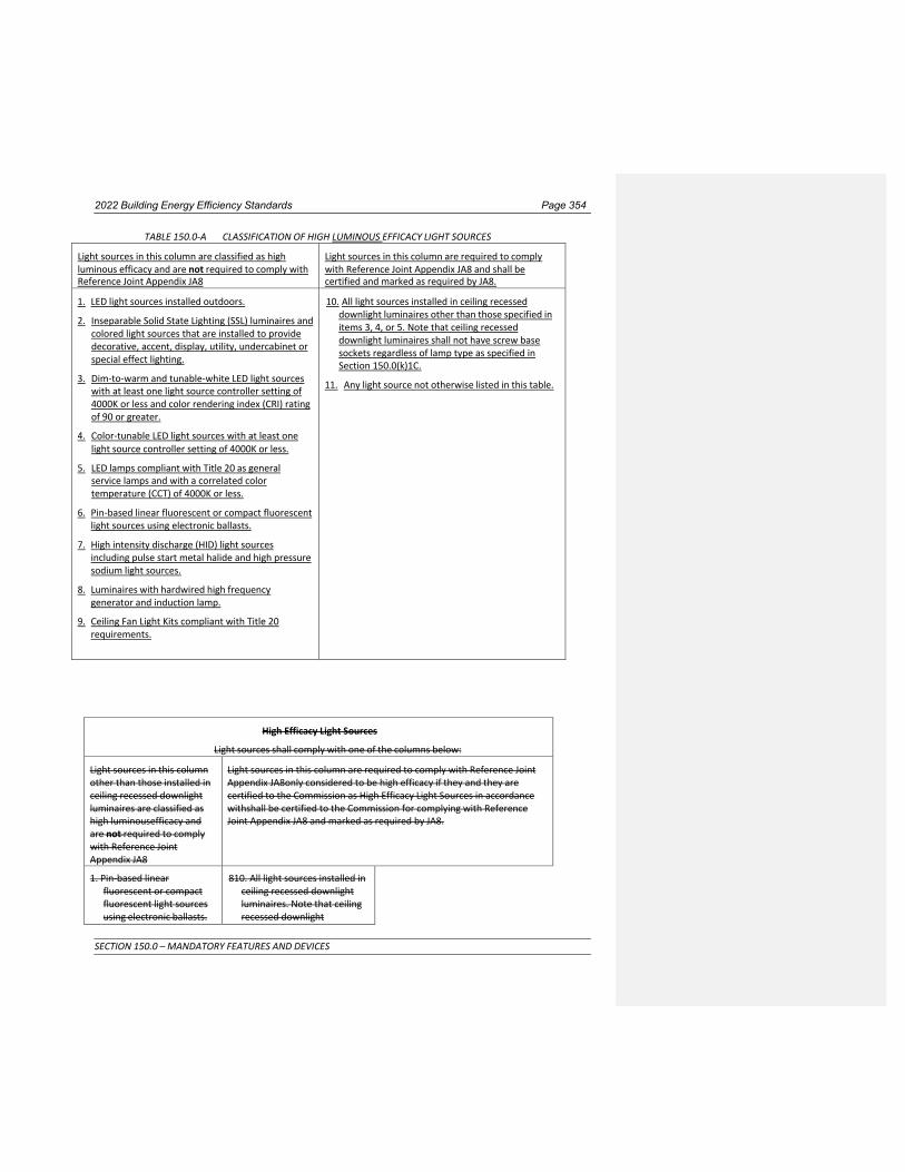
2022 Building Energy Efficiency Standards Page 354
SECTION 150.0 – MANDATORY FEATURES AND DEVICES
TABLE 150.0-A CLASSIFICATION OF HIGH LUMINOUS EFFICACY LIGHT SOURCES
Light sources in this column are classified as high luminous efficacy and are not required to comply with Reference Joint Appendix JA8
Light sources in this column are required to comply with Reference Joint Appendix JA8 and shall be certified and marked as required by JA8.
1. LED light sources installed outdoors.
2. Inseparable Solid State Lighting (SSL) luminaires and colored light sources that are installed to provide decorative, accent, display, utility, undercabinet or special effect lighting.
3. Dim-to-warm and tunable-white LED light sources with at least one light source controller setting of 4000K or less and color rendering index (CRI) rating of 90 or greater.
4. Color-tunable LED light sources with at least one light source controller setting of 4000K or less.
5. LED lamps compliant with Title 20 as general service lamps and with a correlated color temperature (CCT) of 4000K or less.
6. Pin-based linear fluorescent or compact fluorescent light sources using electronic ballasts.
7. High intensity discharge (HID) light sources including pulse start metal halide and high pressure sodium light sources.
8. Luminaires with hardwired high frequency generator and induction lamp.
9. Ceiling Fan Light Kits compliant with Title 20 requirements.
10. All light sources installed in ceiling recessed downlight luminaires other than those specified in items 3, 4, or 5. Note that ceiling recessed downlight luminaires shall not have screw base sockets regardless of lamp type as specified in Section 150.0(k)1C.
11. Any light source not otherwise listed in this table.
High Efficacy Light Sources
Light sources shall comply with one of the columns below:
Light sources in this column other than those installed in ceiling recessed downlight luminaires are classified as high luminousefficacy and are not required to comply with Reference Joint Appendix JA8
Light sources in this column are required to comply with Reference Joint Appendix JA8only considered to be high efficacy if they and they are certified to the Commission as High Efficacy Light Sources in accordance withshall be certified to the Commission for complying with Reference Joint Appendix JA8 and marked as required by JA8.
1. Pin-based linear fluorescent or compact fluorescent light sources using electronic ballasts.
810. All light sources installed in ceiling recessed downlight luminaires. Note that ceiling recessed downlight

2022 Building Energy Efficiency Standards Page 355
SECTION 150.0 – MANDATORY FEATURES AND DEVICES
2. Pulse-start metal halide light sources.
3. High pressure sodium light sources.
4. Luminaires with hardwired high frequency generator and induction lamp.
5. LED light sources installed outdoors.
6. Inseparable Solid State Lighting (SSL) luminaires containing and colored light sources that are installed to provide decorative, accent, display, or special effect lighting.
3. Dim-to-warm and tunable- white LED light sources with at least one light source controller setting of 4000K or less and color rendering index (CRI) rating of 0 or greater.
4. Color-tunable LED light sources.
5. LED lamps compliant with Title 20 as general service lamps and with a correlated color temperature (CCT) of 4000K or less.
6. Pin-based linear fluorescent or compact fluorescent light sources using electronic ballasts.
7. High intensity discharge (HID) light sources including pulse start metal halide and high pressure sodium light sources.
8. Luminaires with hardwired high frequency generator and induction lamp.
luminaires shall not have screw bases regardless of lamp type as described in Section 150.0(k)1C.
911. Any light source not otherwise listed in this table.

2022 Building Energy Efficiency Standards Page 356
SECTION 150.0 – MANDATORY FEATURES AND DEVICES
TABLE 150.0-B: Return Duct Sizing for Single Return Duct Systems
Return duct length shall not exceed 30 feet and shall contain no more than 180° of bend. If the total bending exceeds 90°, one bend shall be a metal elbow.
Return grille devices shall be labeled in accordance with the requirements in Section 150.0(m)12Biv to disclose the grille's design airflow rate and a maximum allowable clean-filter pressure drop of 25 Pa (0.1 inches water) for the air filter when tested using ASHRAE Standard 52.2, or as rated in accordance with AHRI Standard 680 for the design airflow rate for the return grille.
System Nominal Cooling
Capacity (Ton)*
Return Duct Minimum Nominal
Diameter (inch)
Minimum Total Return Filter Grille Nominal Area
(inch2)
1.5 16 500
2.0 18 600
2.5 20 800
*Not applicable to systems with nominal cooling capacity greater than 2.5 tons or less than 1.5 ton
TABLE 150.0-C: Return Duct Sizing for Multiple Return Duct Systems Each return duct length shall not exceed 30 feet and shall contain no more than 180° of bend. If the total bending exceeds 90°, one bend shall be a metal elbow. Return grille devices shall be labeled in accordance with the requirements in Section 150.0(m)12Biv to disclose the grille's design airflow rate and a maximum allowable clean-filter pressure drop of 25 Pa (0.1 inches water) for the air filter when tested using ASHRAE Standard 52.2, or as rated in accordance with AHRI Standard 680 for the design airflow rate for the return grille.
System Nominal Cooling Capacity
(Ton)*
Return Duct 1 Minimum Nominal
Diameter (inch)
Return Duct 2 Minimum Nominal
Diameter (inch)
Minimum Total Return Filter Grille Nominal Area
(inch2)
1.5 12 10 500
2.0 14 12 600
2.5 14 14 800
3.0 16 14 900
3.5 16 16 1000
4.0 18 18 1200
5.0 20 20 1500
*Not applicable to systems with nominal cooling capacity greater than 5.0 tons or less than 1.5 tons.

2022 Building Energy Efficiency Standards Page 357
SECTION 150.0 – MANDATORY FEATURES AND DEVICES
TABLE 150.0-D: Infiltration Effectiveness Weather and Shielding Factors [ASHRAE 62.2:Table B1] TMY3 wsf Weather Station Latitude Longitude State 690150 0.50 Twentynine Palms 34.30 –116.17 California
722860 0.43 March AFB 33.90 –117.25 California
722868 0.45 Palm Springs Intl 33.83 –116.50 California
722869 0.42 Riverside Muni 33.95 –117.45 California
722880 0.39 Burbank–Glendale–Pasadena AP 34.20 –118.35 California
722885 0.39 Santa Monica Muni 34.02 –118.45 California
722886 0.39 Van Nuys Airport 34.22 –118.48 California
722895 0.55 Lompoc (AWOS) 34.67 –120.47 California
722897 0.51 San Luis Co Rgnl 35.23 –120.63 California
722899 0.45 Chino Airport 33.97 –117.63 California
722900 0.38 San Diego Lindbergh Field 32.73 –117.17 California
722903 0.39 San Diego/Montgomery 32.82 –117.13 California
722904 0.40 Chula Vista Brown Field NAAS 32.58 –116.98 California
722906 0.39 San Diego North Island NAS 32.70 –117.20 California
722926 0.40 Camp Pendleton MCAS 33.30 –117.35 California
722927 0.38 Carlsbad/Palomar 33.13 –117.28 California
722930 0.39 San Diego Miramar NAS 32.87 –117.13 California
722950 0.42 Los Angeles Intl Arpt 33.93 –118.40 California
722956 0.38 Jack Northrop Fld H 33.92 –118.33 California
722970 0.38 Long Beach Daugherty Fld 33.83 –118.17 California
722976 0.34 Fullerton Municipal 33.87 –117.98 California
722977 0.36 Santa Ana John Wayne AP 33.68 –117.87 California
723805 0.51 Needles Airport 34.77 –114.62 California
723810 0.59 Edwards AFB 34.90 –117.87 California
723815 0.58 Daggett Barstow–Daggett AP 34.85 –116.80 California
723816 0.62 Lancaster Gen Wm Fox Field 34.73 –118.22 California
723820 0.57 Palmdale Airport 34.63 –118.08 California
723830 0.68 Sandberg 34.75 –118.72 California
723840 0.43 Bakersfield Meadows Field 35.43 –119.05 California
723890 0.45 Fresno Yosemite Intl AP 36.78 –119.72 California
723895 0.42 Porterville (AWOS) 36.03 –119.07 California
723896 0.43 Visalia Muni (AWOS) 36.32 –119.40 California
723910 0.45 Point Mugu Nf 34.12 –119.12 California
723925 0.44 Santa Barbara Municipal AP 34.43 –119.85 California
723926 0.43 Camarillo (AWOS) 34.22 –119.08 California
723927 0.45 Oxnard Airport 34.20 –119.20 California
723940 0.52 Santa Maria Public Arpt 34.92 –120.47 California

2022 Building Energy Efficiency Standards Page 358
SECTION 150.0 – MANDATORY FEATURES AND DEVICES
TABLE 150.0-D: Infiltration Effectiveness Weather and Shielding Factors [ASHRAE 62.2:Table B1] (continued) TMY3 wsf Weather Station Latitude Longitude State 723965 0.53 Paso Robles Municipal Arpt 35.67 –120.63 California
724800 0.55 Bishop Airport 37.37 –118.35 California
724815 0.46 Merced/Macready Fld 37.28 –120.52 California
724830 0.51 Sacramento Executive Arpt 38.50 –121.50 California
724837 0.45 Beale AFB 39.13 –121.43 California
724838 0.50 Yuba Co 39.10 –121.57 California
724839 0.51 Sacramento Metropolitan AP 38.70 –121.58 California
724915 0.49 Monterey Naf 36.60 –121.87 California
724917 0.54 Salinas Municipal AP 36.67 –121.60 California
724920 0.50 Stockton Metropolitan Arpt 37.90 –121.23 California
724926 0.47 Modesto City–County AP 37.63 –120.95 California
724927 0.53 Livermore Municipal 37.70 –121.82 California
724930 0.54 Oakland Metropolitan Arpt 37.72 –122.22 California
724935 0.47 Hayward Air Term 37.67 –122.12 California
724936 0.53 Concord–Buchanan Field 38.00 –122.05 California
724940 0.60 San Francisco Intl AP 37.62 –122.40 California
724945 0.48 San Jose Intl AP 37.37 –121.93 California
724955 0.55 Napa Co. Airport 38.22 –122.28 California
724957 0.49 Santa Rosa (AWOS) 38.52 –122.82 California
725845 0.44 Blue Canyon AP 39.30 –120.72 California
725846 0.66 Truckee–Tahoe 39.32 –120.13 California
725847 0.64 South Lake Tahoe 38.90 –120.00 California
725905 0.47 Ukiah Municipal AP 39.13 –123.20 California
725910 0.50 Red Bluff Municipal Arpt 40.15 –122.25 California
725920 0.47 Redding Municipal Arpt 40.52 –122.32 California
725945 0.56 Arcata Airport 40.98 –124.10 California
725946 0.60 Crescent City Faa Ai 41.78 –124.23 California
725955 0.55 Montague Siskiyou County AP 41.78 –122.47 California
725958 0.59 Alturas 41.50 –120.53 California
745090 0.45 Mountain View Moffett Fld NAS 37.40 –122.05 California
745160 0.67 Travis Field AFB 38.27 –121.93 California
746120 0.52 China Lake Naf 35.68 –117.68 California
747020 0.50 Lemoore Reeves NAS 36.33 –119.95 California
747185 0.46 Imperial 32.83 –115.58 California
747187 0.46 Palm Springs Thermal AP 33.63 –116.17 California
747188 0.48 Blythe Riverside Co Arpt 33.62 –114.72 California

2022 Building Energy Efficiency Standards Page 359
SECTION 150.0 – MANDATORY FEATURES AND DEVICES
Table 150.0-E Demand-Controlled Local Ventilation Exhaust Airflow Rates and Capture Efficiency Application Compliance Criteria
Enclosed Kitchen or Nonenclosed Kitchen
Vented range hood, including appliance-range hood combinations shall meet either the capture efficiency (CE) or the airflow rate specified in Table 150.0-G as applicable.
Enclosed Kitchen Other kitchen exhaust fans, including downdraft: 300 cfm (150 L/s) or a capacity of 5 ACH
Nonenclosed Kitchen Other kitchen exhaust fans, including downdraft: 300 cfm (150 L/s)
Bathroom 50 cfm (25 L/s)
Table 150.0-F Continuous Local Ventilation Exhaust Airflow Rates Application Airflow
Enclosed kitchen 5 ach, based on kitchen volume
Bathroom 20 cfm (10 L/s)
Table 150.0-G Kitchen Range Hood Airflow Rates (cfm) and ASTM E3087 Capture Efficiency (CE) Ratings According to Dwelling Unit Floor Area and Kitchen Range Fuel Type
Dwelling Unit Floor Area (ft2) Hood Over Electric Range Hood Over Natural Gas Range
>1500 50% CE or 110 cfm 70% CE or 180 cfm
>1000 - 1500 50% CE or 110 cfm 80% CE or 250 cfm
750 - 1000 55% CE or 130 cfm 85% CE or 280 cfm
<750 65% CE or 160 cfm 85% CE or 280 cfm
Table 150.0-H Prescriptive Ventilation System Duct Sizing [ASHRAE 62.2:Table 5-3] Fan Airflow Rating,
cfm at minimum static pressuref 0.25 in. water
(L/s at minimum 62.5 Pa)
≤50 (25)
≤80 (40)
≤100 (50)
≤125 (60)
≤150 (70)
≤175 (85)
≤200 (95)
≤250 (120)
≤350 (165)
≤400 (190)
≤450 (210)
≤700 (330)
≤800 (380)
Minimum Duct Diameter, in. (mm) a,b For Rigid duct
4 e
(100) 5
(125) 5
(125) 6
(150) 6
(150) 7
(180) 7
(180) 8
(205) 9
(230) 10
(255) 10
(255) 12
(305) 12 d
(305) Minimum Duct Diameter,
in. (mm) a,b For Flex duct c 4
(100) 5
(125) 6
(150) 6
(150) 7
(150) 7
(180) 8
(205) 8
(205) 9
(230) 10
(255)
NP
NP
NP
Footnotes for Table 150.0-H: a. For noncircular ducts, calculate the diameter as four times the cross-sectional area divided by the perimeter. b. NP = application of the prescriptive table is not permitted for this scenario. c. Use of this table for verification of flex duct systems requires flex duct to be fully extended and any flex duct
elbows to have a minimum bend radius to duct diameter ratio of 1.0. d. For this scenario, use of elbows is not permitted. e. For this scenario, 4 in. (100 mm) oval duct shall be permitted, provided the minor axis of the oval is greater
than or equal to 3 in. (75 mm) f. When a vented range hood utilizes a capture efficiency rating to demonstrate compliance with 150.0(o)1Giiib,
a static pressure greater than or equal to 0.25 in. of water at the rating point shall not be required, and the

2022 Building Energy Efficiency Standards Page 360
SECTION 150.0 – MANDATORY FEATURES AND DEVICES
airflow listed in the approved directory corresponding to the compliant capture efficiency rating point shall be applied to Table 150.0-H for determining compliance.
NOTE: Authority: Sections 25213, 25218, 25218.5, 25402 and 25402.1, Public Resources Code. Reference: Sections 25007, 25008, 25218.5, 25310, 25402, 25402.1, 25402.4, 25402.5, 25402.8, and 25943, Public Resources Code.