DOCKET - California Energy Commission : e-filing
429
DATE REC'D DOCKET 07-AFC-5 DEC 07 2009 DEC 30 2009 PROOF OF SERVICE ( REVISED 11/23/09 ) FILED WITH ORIGINAL MAILED FROM SACRAMENTO ON 12/30/09 AA
-
Upload
khangminh22 -
Category
Documents
-
view
0 -
download
0
Transcript of DOCKET - California Energy Commission : e-filing

DATE REC'D
DOCKET 07-AFC-5
DEC 07 2009
DEC 30 2009
PROOF OF SERVICE ( REVISED 11/23/09 ) FILED WITH
ORIGINAL MAILED FROM SACRAMENTO ON 12/30/09
AA

1
Biological Assessment for the Ivanpah Solar Electric
Generating System (Ivanpah SEGS) Project
Prepared for
Bureau of Land Management
Prepared on behalf of
Solar Partners I, LLC; Solar Partners II, LLC; Solar Partners IV, LLC; and Solar Partners VIII,
LLC Prepared by
2485 Natomas Park Drive, Suite 600
Sacramento, CA 95833
December 2009

III
Contents
Section ..................................................................................................................................... Page
Contents ........................................................................................................................................ iii Figures ................................................................................................................. iv Attachments ........................................................................................................ v
Background ............................................................................................................................... 1-1 1.1 Introduction ............................................................................................................. 1-1
Description of Proposed Action ........................................................................................... 2-1 2.1 Introduction ............................................................................................................. 2-1 2.2 Project Features ....................................................................................................... 2-7
2.2.1 Solar Fields .............................................................................................. 2-7 2.2.2 Power Block ............................................................................................. 2-9 2.2.3 Stormwater Management .................................................................... 2-12 2.2.4 Power Lines and Substation ................................................................ 2-13 2.2.5 Telecommunications ............................................................................ 2-14 2.2.6 Gas Line ................................................................................................. 2-14 2.2.7 Water Line ............................................................................................. 2-15
2.3 Construction .......................................................................................................... 2-15 2.3.1 Colosseum Road and Rerouted Trails ............................................... 2-18 2.3.2 Security and Desert Tortoise Fencing ................................................ 2-18 2.3.3 Vegetation Clearing and Cutting ....................................................... 2-19 2.3.4 Gas Pipeline ........................................................................................... 2-19 2.3.5 Water Line ............................................................................................. 2-20 2.3.6 Gen-tie Lines and Substation .............................................................. 2-20 2.3.7 Telecommunications Line ................................................................... 2-21
2.4 Operation ............................................................................................................... 2-23 2.4.1 Solar Fields ............................................................................................ 2-23 2.4.2 Water System ........................................................................................ 2-23 2.4.3 Concrete Holding Basins ..................................................................... 2-24 2.4.4 Waste Management .............................................................................. 2-24
2.5 Project Maintenance Activities ........................................................................... 2-24 2.5.1 Class I ..................................................................................................... 2-25 2.5.2 Class II .................................................................................................... 2-25 2.5.3 Class III .................................................................................................. 2-26 2.5.4 Class IV .................................................................................................. 2-26 2.5.5 Class V .................................................................................................... 2-26
2.6 Site Rehabilitation Plan ........................................................................................ 2-26 2.7 Facility Closure ..................................................................................................... 2-28
2.7.1 Temporary Closure .............................................................................. 2-28 2.7.2 Permanent Closure ............................................................................... 2-29
2.8 Minimization Measures ....................................................................................... 2-29

CONTENTS
IV
2.8.1 Construction Minimization Measures ............................................... 2-30 2.8.2 Operation Minimization Measures .................................................... 2-36
2.9 Progress and Compliance Report ....................................................................... 2-39
Environmental Baseline .......................................................................................................... 3-1 3.1 Biological Setting ..................................................................................................... 3-1
3.1.1 Regional Overview ................................................................................. 3-1 3.1.2 Habitat and Vegetation .......................................................................... 3-1 3.1.3 Threatened and Endangered Plant Species ......................................... 3-3 3.1.4 Noxious Weeds ....................................................................................... 3-4 3.1.5 Wildlife Species ....................................................................................... 3-6
3.2 Environmental Baseline ......................................................................................... 3-7 3.2.1 Projects That Are Reasonably Foreseeable .......................................... 3-7 3.2.2 Projects That Are Not Reasonably Foreseeable ................................ 3-10
Status of Species and Habitat ................................................................................................ 4-1 4.1 Mojave Desert Tortoise (Gopherus agassizii) ......................................................... 4-1
4.1.1 Status ......................................................................................................... 4-1 4.1.2 Natural History, Distribution, Abundance, and Habitat .................. 4-1 4.1.3 Survey Methodology .............................................................................. 4-4 4.1.4 Survey Results ......................................................................................... 4-4
Effects of Proposed Action ..................................................................................................... 5-1 5.1 Introduction ............................................................................................................. 5-1 5.2 Direct Effects ............................................................................................................ 5-1 5.3 Indirect Effects ......................................................................................................... 5-2 5.4 Cumulative Effects .................................................................................................. 5-3
References.................................................................................................................................. 6-5
Figures 1-1 Vicinity Map 2-1 Site Plan and Linear Facilities 2-2 Construction Logistics Area 2-3 Fiber Optic Route 2-4 Trails 2-5 Appearance of Site After Construction 2-6 Proposed Gas Line Route 2-7 Eldorado Ivanpah Transmission Project Access Roads 3-1 Project Area 3-2 Vegetation Map and Sensitive Geomorphic Features 4-1 2007 Desert Tortoise Survey Area 4-2 Desert Tortoise Survey Results 4-3 Translocation areas

CONTENTS
V
Attachments A Draft Closure, Revegetation and Rehabilitation Plan B Tortoise Fencing and Tortoise Guard Specifications C No attachment D Desert Tortoise Translocation/Relocation Plan E Raven Management Plan F No attachment G Survey of translocation sites 2009 H 2008 Desert Tortoise Survey Report for Additional Ivanpah SEGS Action Area I List of Observed Desert Tortoise Sign at Ivanpah SEGS in 2007

1-1
Background
1.1 Introduction Solar Partners I, LLC; Solar Partners II, LLC; Solar Partners VIII, LLC, the owners of the three separate solar plant sites, and Solar Partners IV, LLC, the owner of shared facilities required by the three solar plant sites, propose to develop a solar facility (together referred to as the Ivanpah Solar Electric Generating System, or Ivanpah SEGS) in the Ivanpah Valley about 4.5 miles southwest of Primm, Nevada. This Biological Assessment has been prepared in accordance with legal requirements set forth under Section 7 of the Endangered Species Act [ESA] (16 U.S.C. 1536(c)). The Mojave population of the desert tortoise (Gopherus agassizii) is a federally threatened species under the ESA.
Solar Partners I, LLC; Solar Partners II, LLC; Solar Partners VIII, LLC, the owners of the three separate solar plant sites, and Solar Partners IV, LLC, the owner of shared facilities required by the three solar plant sites, are the proponent for the project. These four companies are Delaware limited liability companies. BrightSource Energy Inc. (BrightSource), a Delaware corporation, is a technology and development company, and the parent company of the Solar Partners entities.
The Proposed Action is to develop three solar energy plant sites in the Ivanpah Valley located in San Bernardino County, California, 4.5 miles southwest of Primm, Nevada (Figure 1-1, all figures are located at the end of the section). The site is located in Township 17N, Range 14E, and Township 16N, Range 14E on land administered by the U.S. Bureau of Land Management (Bureau). Access to the site is via the Yates Well Road interchange on I-15 and Colosseum Road. The site is located 0.5 mile to the west of the Primm Valley Golf Club.
BrightSource is seeking a separate right-of-way (ROW) grant from the Bureau for each of the three solar plant sites and for the shared infrastructure.

Proposed Ivanpah Project Site
!Primm
!Jean
Mojave National Preserve
Toiyabe National Forest
Mojave National Preserve
Las VegasPahrumpPahrump
¬«160
¬«159
¬«164
¬«161
¬«160
15
95
Cima Rd
Kelbaker Rd
515
Las
Vega
s B
lvd
King
ston
Rd
Nipton Rd
Craig Rd
Excelsior Mine Rd
In dustri al Rd
Lesl
ie S
t
Old Sp anish Trail Hwy
Kel
so C
ima
Rd
Sandy Valley Rd
Old Spanish T
rl
Smith Talc Rd
Baker B
lvd
Lone Mountain Rd
Kingston Rd
Soda Lake
Ivanpah Lake
Silver Lake
Mesquite Lake
Roach Lake
1:506,880
FIGURE 1-1VICINITY MAPIVANPAH SOLAR ELECTRIC GENERATING SYSTEM
!
!
!
!
!
San Jose
San Diego
Sacramento
Los Angeles
San Francisco
_̂§̈¦40
§̈¦15§̈¦5
AÎ
LEGEND
STATE BOUNDARIES
COUNTY BOUNDARIES
PROPOSED PROJECT SITE
NevadaCalifornia
0 84Miles
Project Site
SAC\\GLACIER\352897_IVANPAH\MAPFILES\REPORT\VICINITY_MAP.MXD 8/17/2007

2-1
Description of Proposed Action
2.1 Introduction The companies have filed SF 299 Right-Of-Way (ROW) grant applications for use of the land with the Bureau’s Needles Field Office. The Ivanpah SEGS will consist of three independent solar thermal electric generating facilities (or plants) that will be co-located approximately 1.6 miles west of the Ivanpah Dry Lake and 4.5 miles southwest of Primm, Nevada, in San Bernardino County, California (Figure 1-1). The project site will be located on federal property managed by BLM. The three Ivanpah SEGS facilities (see Figure 2-1) will have a combined net rating of approximately 400 megawatt (MW). The total Ivanpah SEGS project area consists of approximately 4,062 acres. Ivanpah 1 will require approximately 914 acres (1.4 square miles); Ivanpah 2 will require approximately 921 acres (1.4 square miles); and Ivanpah 3 is larger and will require approximately 1,834 acres (2.9 square miles). The developed areas for Ivanpah 1, 2, and 3 will cover a total of 3,671 acres (5.7 square miles).
Following completion of low-impact design (LID) and issuance of permits, the proposed project will be constructed in three phases, and completed within 48 months (target completion by December 2013). Construction is planned in the following order: (1) Ivanpah 1 (the southernmost site; nominal 100 MW) and shared facilities; (2) Ivanpah 2 (the middle site; nominal 100 MW); and (3) Ivanpah 3 (the northern site, nominal 200 MW). Alternative sequencing of the facilities is a possibility, but in each case the shared facilities (administration/storage building, groundwater production wells, and portions of linear facilities) will be constructed in connection with the first plant’s construction. For purposes of this biological assessment, impacts have been placed into three categories.
1. Permanently disturbed areas: This includes those features that would remain after the project’s 50-year span1. They would include the Southern California Edison (SCE) substation and the paved portion of Colosseum Road from the Golf Club to the substation; the rerouted trails (i.e., the gravel road from the end of the paved portion of the rerouted Colosseum Road to where it connects with the Colosseum dirt road, the rerouted access tracks around the top of Ivanpah 3; and stabilized channel crossings.
2. Long-term disturbance areas: This includes facilities that will remain in place for the duration of the project. Examples include the solar plants, administration/warehouse building, water supply wells, monitoring well, and utility lines. Areas affected by these facilities will be revegetated following closure, which would be the same order as construction, with the exception that the shared facilities would be handled as part of the last phase that is closed.
3. Temporary disturbance areas: This includes areas that will be revegetated within 5 years from the time of disturbance. Facilities that fall into this category include the
1 The BLM right-of-way grant will be for 50 years, which includes construction and decommissioning/restoration. Therefore, the plant’s operating life will be between 40 and 45 years.

2. DESCRIPTION OF PROPOSED ACTION
2-2
utility and roadway construction corridors and lightly graded areas within Ivanpah 2 and Ivanpah 3 (which will be revegetated within 1 year of completion of construction) and those areas within the Construction Logistics Area (CLA) that are used for construction (which will be revegetated once construction of all three solar plants is completed).
A breakdown of the project’s permanent and long-term disturbance areas is presented in Tables 2.1-1 and 2.1-2. Most of the temporary disturbance will occur in the CLA between Ivanpah 1 and 2 (approximately 377 acres in size, see Figure 2-2) and the graded areas within Ivanpah 2 and Ivanpah 3. However, it will include the SCE substation (permanent disturbance), the administration/ warehouse building, and shared utilities (long-term disturbances). Portions of the CLA will be used during construction for staging, laydown, heliostat fabrication, and temporary offices. Once construction has been completed, only the shared facilities will remain in this area. In addition to the CLA, temporary impacts would occur to approximately 8.6 acres that will be used for construction of the gas line tap station at the existing Kern River Gas Transmission (KRGT) pipeline, construction of the approximately 2,000-foot-long gas pipeline north of Ivanpah 3, and construction of the gas metering set for Ivanpah 1 and 2. A breakdown of the temporary disturbance areas is provided in Table 2.1-3. In addition, within the proposed site boundaries are about 7 miles of existing trails. Hence, the total impact area for the project site is about 4,055 acres (see Table 2.1-4).
TABLE 2.1-1 Areas of Permanent Disturbance
Components Linear Feet Acres
Ivanpah 3
12' dirt road from gas line to trail 699226 (east side of Ivanpah 3) 6,752 1.86
12' dirt road from trail 699198 to asphalt road between Units 2 & 3 1,572 0.43
12' rerouted trail 699226 from gas line west side 6,906 1.90
30' asphalt road between Ivanpah Units 2 & 3 4,751 3.93
12' dirt trail to mining claim 1,492 0.41
Ivanpah 2
12’ rerouted trail 699198 (along west side of Ivanpah 2) 3,115 0.86
CLA including improvements to Colosseum Road
30' asphalt improved Colosseum Rd. 8,442 6.98
30' asphalt re-routed Colosseum Road 4,343 3.59
12' gravel road re-routed Colosseum Road to where it exits the CLA 2,452 0.68
24' access road to substation 1,761 1.21
Substation 16.10
Diversion berms & channel around Substation 8.30
TOTAL AREAS OF PERMANENT DISTURBANCE 46.25
2. DESCRIPTION OF PROPOSED ACTION
2-3
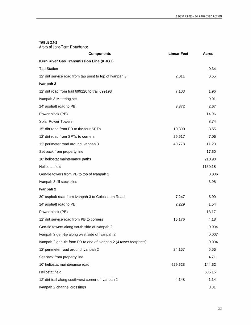
TABLE 2.1-2 Areas of Long-Term Disturbance
Components Linear Feet Acres
Kern River Gas Transmission Line (KRGT)
Tap Station 0.34
12' dirt service road from tap point to top of Ivanpah 3 2,011 0.55
Ivanpah 3
12' dirt road from trail 699226 to trail 699198 7,103 1.96
Ivanpah 3 Metering set 0.01
24' asphalt road to PB 3,872 2.67
Power block (PB) 14.96
Solar Power Towers 3.74
15' dirt road from PB to the four SPTs 10,300 3.55
12' dirt road from SPTs to corners 25,617 7.06
12' perimeter road around Ivanpah 3 40,778 11.23
Set back from property line 17.50
10' heliostat maintenance paths 210.98
Heliostat field 1150.18
Gen-tie towers from PB to top of Ivanpah 2 0.006
Ivanpah 3 fill stockpiles 3.98
Ivanpah 2
30' asphalt road from Ivanpah 3 to Colosseum Road 7,247 5.99
24' asphalt road to PB 2,229 1.54
Power block (PB) 13.17
12' dirt service road from PB to corners 15,176 4.18
Gen-tie towers along south side of Ivanpah 2 0.004
Ivanpah 3 gen-tie along west side of Ivanpah 2 0.007
Ivanpah 2 gen-tie from PB to end of Ivanpah 2 (4 tower footprints) 0.004
12' perimeter road around Ivanpah 2 24,167 6.66
Set back from property line 4.71
10' heliostat maintenance road 629,528 144.52
Heliostat field 606.16
12' dirt trail along southwest corner of Ivanpah 2 4,148 1.14
Ivanpah 2 channel crossings 0.31

2. DESCRIPTION OF PROPOSED ACTION
2-4
TABLE 2.1-2 (CONT.) Areas of Long-Term Disturbance
Components Linear Feet Acres
Ivanpah 2 fill stockpiles 2.03
CLA including Improvements to Colosseum Road
12' dirt service road for double-circuit gen-tie line 1,898 0.52
Double-circuit gen-tie towers (area of 4 tower footprints) 0.004
Gas meter set for Ivanpah 1 & 2 0.02
24' asphalt road from re-routed Colosseum to Ivanpah 1 2,153 1.48
Admin Building (incl. entrance road) 8.90
12' dirt service road for monitoring well 866 0.24
Monitoring well 0.002
12' dirt service road for production wells 1,075 0.30
Production wells 0.005
12' dirt service road from Ivanpah 1 to Substation 2,867 0.79
Gen-tie towers from Ivanpah 1 to Substation 0.005
40-acre succulent storage & stockpile area 40.00
CLA fill stockpile 0.91
Ivanpah 1
24' asphalt road from edge of Ivanpah 1 to PB 3,361 2.31
Gas & water line corridor to PB 3,361 0.00
Power block (PB) 13.17
Gen-tie towers from PB to Ivanpah 1 (area of 6 tower footprints) 0.005
12' dirt service road from PB to corners 12,020 3.31
12' perimeter road around Ivanpah 1 23,857 6.57
Set back from property line 8.79
10' heliostat maintenance road 636,325 146.08
Heliostat field 730.30
Ivanpah 1 fill stockpiles 1.57
TOTAL AREAS OF LONG-TERM DISTURBANCE 3,184.43

2. DESCRIPTION OF PROPOSED ACTION
2-5
TABLE 2.1-3 Areas of Temporary Disturbance
Components Linear Feet Acres
Kern River Gas Transmission Line (KRGT)
Tap Station Construction Area 0.92
Gas Line from tap point to top of I-3 2,011 1.75
Ivanpah 3
Gas Line Corridor 50' construction area (east side) 15,427 13.46
Construction corridor for 30' asphalt road between Units 2 & 3 4,751 1.53
Construction corridor for 24' asphalt road to PB 3,872 1.24
Gas line from metering set to PB 5,823 0.00b
Water line from metering set to PB 5,785 0.00b
Construction corridor for gas & water line 5,823 3.74
Gen-tie corridor from PB to top of Unit 2 4,065 0.36
Ivanpah 3 graded areas 380.00
Ivanpah 2
Construction corridor for 30' asphalt road from Ivanpah 3 to Colosseum 7,247 2.33
Gas & water line corridor to PB 3,972 2.55
Construction corridor for 24' asphalt road to PB 2,229 0.72
Ivanpah 3 gen-tie along south side of Ivanpah 2 3,296 0.25
Ivanpah 3 gen-tie along west side of Ivanpah 2 5,371 0.38
Ivanpah 2 gen-tie from PB to end of Unit 2 2,322 0.20
Graded areas 123.00
CLA Including improvements to Colosseum Road
Construction corridor for 30' asphalt improved Colosseum Rd. 8,442 2.71
Tire wash/concrete washout off Colosseum Road 1.04
Construction corridor for 30' asphalt re-routed Colosseum Road 4,343 1.40
Construction corridor for 24' access road to substation 1,761 0.57
Ivanpah 2 & 3 gen-tie to substation construction corridor 1,898 0.35
Construction of double-circuit gen-tie towers 0.20
Construction area for gas meter set for Ivanpah 1 & 2 0.92
Construction corridor for 24' asphalt road from re-routed Colosseum to Ivanpah 1 2,153 0.69
Construction corridor from wells to main line 1,075 0.69
Gen-tie line from Ivanpah 1 to Substation 2,867 0.53
Construction of gen-tie towers from Ivanpah 1 to Sub 0.32

2. DESCRIPTION OF PROPOSED ACTION
2-6
TABLE 2.1-3 Areas of Temporary Disturbance
Components Linear Feet Acres
Construction parking 1.53
Contractor Trailer area 18.57
Equipment Laydown 20.46
CLA area available for construction use 247.19
Ivanpah 1
Construction corridor for 24' asphalt road from edge to PB 3,361 1.08
Construction of gen-tie towers from PB to end of Ivanpah 1 0.29
TOTAL AREAS OF TEMPORARY DISTURBANCE 830.97 b Located within the dirt access road. No additional impact.
TABLE 2 TABLE 2.1-4 Net Disturbed Area Acres
Total Disturbed Area of the Solar Plant 4,061.65
Less existing trails - 6.96
Net Disturbed Area of the Solar Plant 4,054.69
In addition to the project site, the action area includes the installation of a fiber optic line. This fiber optic route consists of two segments. The first segment is from Ivanpah substation to Mountain Pass substation using existing poles shown in Figure 2-3. The second segment is from Mountain Pass substation to an interface point to be designated by the local telecommunication carrier. In both segments the fiber optic cable would be installed on the existing distribution line poles. Therefore, the action area includes the project site plus the route for the fiber optic line.
Concurrent with the Bureau’s ROW filing process, BrightSource also filed an Application For Certification (AFC) with the California Energy Commission (CEC). BrightSource has been informed by both the CEC and the Bureau of their intention to conduct a joint environmental review of the proposed project. The CEC has issued its Final Staff Assessment and the Bureau has issued a draft Environmental Impact Statement. The two agencies will coordinate their analysis but will issue separate decisions.
2. DESCRIPTION OF PROPOSED ACTION
2-7
2.2 Project Features 2.2.1 Solar Fields The approximate size of the area for Ivanpah 1 (Phase 1) is 914 acres; for Ivanpah 2 (Phase 2) the area is 921 acres; and for Ivanpah 3 (Phase 3) the area is 1,834 acres (Figure 2-1). The following sections describe the major components of the solar fields.
2.2.1.1 Security and Desert Tortoise Fence Prior to clearing vegetation and site grading, for the construction logistics area and each project site, the boundary would be permanently fenced with an 8-foot-high chain-link for security purposes and permanent desert tortoise exclusionary fencing would either be attached to the base of the security fence or installed outside the security fence to allow construction of linear facilities. A permanent I-beam design desert tortoise guard would be installed to allow equipment access to the fenced sites and exclude desert tortoises. The specifications for the proposed desert tortoise guard are included in Attachment B.
All tortoise exclusion fencing, tortoise guards and combined tortoise/security fence will be inspected on a regular basis (at least twice per year and after each storm event) sufficient to maintain an effective barrier to tortoise movements. Inspections would be documented in writing and include any observations of damaged fencing. All fence damage will be repaired in a timely manner to ensure that tortoises do not travel through damaged sections. Similarly, tortoise guards will be cleaned out of deposited material underneath them in a timely manner to ensure that any tortoise that falls underneath has a path of escape without crossing the intended barrier. Debris will be removed that accumulates along the fence line or under the tortoise guards.
2.2.1.2 Colosseum Road and Rerouted Trails Construction and permanent access would be from Colosseum Road to the project entrance road (Figure 2-1). Colosseum Road is an existing dirt road, which will be paved (30-feet-wide, 3-foot-wide dirt shoulders on each side, 2 lanes) for a 1.6-mile length from the Primm Valley Golf Club to the project site2. The project would re-route a portion of Colosseum Road around the southern end of the Ivanpah 2 plant site for a distance of 0.8 miles, which will also be a 30-foot paved 2-lane road, then continue as an 8-foot-wide dirt road another 0.5 mile to connect to the point where the existing Colosseum dirt road would exit the Ivanpah 2 site boundary. In addition, paved access roads would be created to access the power blocks of the three Ivanpah plant sites within the fenced solar sites.
Existing dirt trails that traverse the site will be re-routed either around the project site or to a proposed paved access road. Each re-routed dirt trail will be 8 to 12 feet wide (to match the existing trail) and will be reconnected to the original dirt trail on the other side of the project site (see Figure 2-4). Tortoise gates will be installed to prevent tortoise from entering internal roads. A list of trails in the area and the project’s impact upon them is presented in the following table.
2 A portion of this road has been recently paved from the golf club to their wells, but may lack sufficient road base to support construction vehicles.

2. DESCRIPTION OF PROPOSED ACTION
2-8
TABLE 2.2-1 Modification Status for Bureau Trails in Proximity of Ivanpah Site Bureau Trail # Proximity to Ivanpah SEGS Component Status
699135 North of Project Site Remains Open – no impact
699194 South of Project Site, runs between Trails 699238, 699244, and Power Line
Remains Open – no impact
699195 Southwest of Project Site, runs between Power Line and Colosseum Trails
Remains Open – no impact
699197 Southwest of Project Site Remains Open – no impact
699198 Runs through southern portion of Ivanpah 3 and northern portion of Ivanpah 2
Modification required - on east side of Ivanpah 3, close trail and connect with dirt road to be constructed that connects to a road between Ivanpah 2 and 3. Follow new road to reconnection with 699198 on the west side of Ivanpah 2 as shown on Figure 2-4.
699199 South of Project Site Remains Open – no impact
699221 South of Project Site, runs between Trails 699194 and 699199
Remains Open – no impact
699223 South of Ivanpah 2, runs between the Wash and Colosseum Road Trails.
Remains Open – no impact
699226 Runs through northern portion of Ivanpah 3 Modification required - relocate trail around the north side of Ivanpah 3, as shown on Figure 2-4.
699227 West of Project Site Remains Open – no impact
699232 West of Project Site Remains Open – no impact
699238 East of Project Site and goes around Primm Valley Golf Club and continues south
Remains Open – no impact
699239 East of Project Site Remains Open – no impact
699244 Southeast of Project Site Remains Open – no impact
699617 Goes around metamorphic hill and connects to Trail 699238.
Remains Open – no impact
Colosseum Road
Runs through the southern portion of Ivanpah 2
Modification required - realign and improve road as shown on Figure 2-4 to follow the existing power line corridor and then follow the southern boundary of Ivanpah 2 to the original Colosseum Road Trail southwest of Ivanpah 2.
2.2.1.3 Heliostats and Solar Receivers The solar fields would consist of one heliostat (mirror) array constructed within each 100-MW plant site and five heliostat arrays constructed within the 200-MW plant site. Each heliostat array would be arranged around a single centralized solar power tower (SPT). An

2. DESCRIPTION OF PROPOSED ACTION
2-9
artist rendering is provided as Figure 2-5. The heliostats would automatically track the sun throughout the day and reflect the solar energy to the SPT. It is estimated that the 100 and 200 MW plant sites would contain approximately 55,000 and 104,000 heliostats, respectively. Each heliostat consists of two mirrors. Each mirror is 7.22 feet wide by 10.5 feet high (2.20 meters by 3.20 meters) yielding a reflecting surface of 75.8 square feet (7.04 square meters).
2.2.1.4 Solar Power Tower Height The SPT height for all three solar plant sites would be 459 feet (140 meters). In addition, FAA-required lighting and a lightning pole would extend above the top of the towers approximately 5 to 10 feet (1.5 to 3 meters).
2.2.2 Power Block All three units (Ivanpah 1, 2, and 3) will have their own individual power block. The size of both Ivanpah 1 and 2 power blocks (including the diversion berms and stormwater channel) will be approximately 13.17 acres; whereas, Ivanpah 3 power block will be approximate 14.96 acres. Each power block will contain, but is not limited to, the following equipment:
TABLE 2.2-2 Power Block Equipment List
Steam Turbine Power Tower
Generator Generator Step-up Transformer
Auxiliary Boiler Unit Auxiliary Transformer
Air Cooled Condenser SUS Transformer
Feed Water Heaters Raw Water/Fire Water Tank
Boiler Feed Pumps Demineralized Water Tank
Plant Services Building Raw Water Forwarding Pumps
Water Treatment Equipment Area Demineralized Water Forwarding Pumps
Underground Gas Pipeline Electrical Substation
Emergency Evaporation Ponds 115 kV Generation Tie Line
Condensate Tank/Pump Waste Water Tank
Emergency Generator Domestic Water System
Local Control Building Concrete Holding Basins
Solar Superheater/Reheater Receiver Access Roadway
2.2.2.1 Power Cycle The solar plant’s power cycle is based on a Rankine cycle turbine with three pressure stage casings. Primary thermal input is via solar receiver boilers, superheater and reheaters at the top of four distributed power towers. Live superheated steam enters a high pressure turbine

2. DESCRIPTION OF PROPOSED ACTION
2-10
casing at 140 bar and 1,004°F (540°C). It leaves the high pressure casing via two extractions to high pressure preheaters, and is exhausted to a reheat circuit.
In Ivanpah 3, the reheat steam is heated in a solar reheater (similar to the solar boiler), at the top of a power tower located in the power block adjacent to the turbogenerator. The reheated steam enters an intermediate pressure turbine casing at 3.5 bar and 896°F (480°C). It leaves the intermediate pressure casing via two extractions – one to a de-aerator and one to a preheater.
The IP exhaust then enters the low pressure casing at 4.5 bar and 432°F (222°C). Exhaust steam at 0.1265 bar is condensed in an air-cooled condenser. Condensate is sent from the condenser well through three LP preheaters, to the de-aerator, which also serves for feedwater reserve storage and is the point of feedwater make-up injection. From the de-aerator, high pressure feedwater pumps send feedwater through two high pressure preheaters out to the solar field boilers.
The major components of the combined-cycle power block are described below.
2.2.2.2 Steam Generation Subsystems The steam generation subsystems consist of the receiver boiler and blowdown systems. The receiver boilers collect solar energy from the heliostat mirrors and transfer it to feedwater for steam production. This heat transfer produces steam at the pressures and temperatures required by the steam turbine. The blowdown system maintains feedwater quality. The system includes safety and auto relief valves and processing of continuous and intermittent blowdown streams.
2.2.2.3 Steam Turbine Generator Subsystems The steam turbine system consists of a condensing steam turbine generator with reheat, gland steam system, lubricating oil system, hydraulic control system, and steam admission/induction valving. High pressure and intermediate pressure steam from the superheater receiver enters the associated steam turbine sections through the inlet steam system. The steam expands through multiple stages of the turbine, driving the generator. On exiting the low pressure turbine, the steam is directed into the surface condenser.
2.2.2.4 Distributed Control System The Distributed Control System will be a redundant microprocessor-based system that will provide the following functions:
• Control the heliostat mirrors, steam turbine generator, and other systems in response to unit load demands (coordinated control)
• Provide control room operator interface
• Monitor plant equipment and process parameters and provide this information to the plant operators in a meaningful format
• Provide visual and audible alarms for abnormal events based on field signals or software-generated signals from plant systems, processes, or equipment

2. DESCRIPTION OF PROPOSED ACTION
2-11
The Distributed Control System will have functionally distributed architecture comprising a group of similar redundant processing units linked to a group of operator consoles and an engineer workstation by redundant data highways. Each processor will be programmed to perform specific dedicated tasks for control information, data acquisition, annunciation, and historical purposes.
Plant operation will be controlled from the operator panel located in the control room. The operator panel will consist of two individual video/keyboard consoles and one engineering workstation. Each video/keyboard console will be an independent electronic package so that failure of a single package does not disable more than one video/keyboard. The engineering workstation will allow the control system operator interface to be revised by authorized personnel.
2.2.2.5 Boiler Feedwater System The boiler feedwater system transfers feedwater from the low pressure steam turbine to the solar receiver boilers. The system will consist of two pumps, each pump sized for 100 percent capacity for supplying all boilers. The pump will be multistage, horizontal, motor-driven with intermediate bleed-off, and will include regulating control valves, minimum flow recirculation control, and other associated piping and valves. One 100 percent capacity spare pump will be available for all boilers.
2.2.2.6 Condensate System The condensate system will provide a flow path from the condenser hotwell to the boiler feed pumps. The condensate system will include three, 50-percent capacity multistage, vertical, motor-driven condensate pumps.
2.2.2.7 Demineralized Water System The demineralized water system will consist of a filter and demineralizer train from an onsite water treatment system consisting of activated carbon filters, de-ionization columns, and a mixed bed polisher. The unit will be a self-contained trailer-mounted unit. Demineralized water will be stored in a 25,000-gallon demineralized water storage tank; boiler feedwater make-up water will be stored in another 25,000-gallon tank.
2.2.2.8 Power Cycle Makeup and Storage The power cycle makeup and storage subsystem provides demineralized water storage and pumping capabilities to supply high-purity water for system cycle makeup and chemical cleaning operations. Major components of the system are the demineralized water storage tank, providing for more than a 14-hour supply of demineralized water at peak load, and two, 100-percent capacity, horizontal, centrifugal, cycle makeup water pumps.
2.2.2.9 Compressed Air The compressed air system provides instrument air and service air to points of use throughout the facility. The compressed air system will include two, 100-percent capacity motor-driven air compressors, two air dryers with prefilters and after filters, an air receiver, instrument air header, and service air header. All instrument air will be dried. A control

2. DESCRIPTION OF PROPOSED ACTION
2-12
valve will be provided in the service air header to prevent high consumption of service air from reducing the instrument air header pressure below critical levels.
2.2.2.10 Fuel Availability Natural gas will be delivered to the power block via pipeline as described below. Each solar plant will have a single 100 percent capacity fuel gas booster compressor to ensure that natural gas is delivered at the proper pressure.
2.2.2.11 Steam Boiler
Each solar plant includes a partial-load steam boiler, which will be used for thermal input to the turbine during the morning start-up cycle to assist the plant in coming up to operating temperature more quickly. The boiler will also be operated during transient cloudy conditions, to maintain the turbine on-line and ready to resume production from solar thermal input, after the clouds pass. After the clouds pass and solar thermal input resumes, the turbine will be returned to full solar production and the boilers will be shut down.
2.2.2.12 Domestic Water Use and Wastewater Management A small filtration and purification system at the administration/warehouse building will be used to provide potable water for domestic, including sanitary, uses (sinks, showers, and toilets). Drinking water may also be trucked to the site. The power block sites will have porta-potties (i.e., portable toilets with self-contained hand wash stations), and use bottled water. Portable toilets will be serviced by a waste management firm on a regular basis, depending on the number of toilets and staff at each facility. A septic system and leach lines will be used at the administration and maintenance complex to treat domestic wastewater.
2.2.2.13 Concrete Holding Basins Two concrete-lined holding basins about 40 feet wide by 60 feet long by 6 feet deep would be included in the power block for each project site. They would be used during boiler commissioning and emergency outfalls from any of the processes.
2.2.3 Stormwater Management Stormwater runoff at the site is predominantly sheet flow from west to east, eventually discharging into Ivanpah Dry Lake. In support of a low-impact design (LID), with exception of the power block areas, solar field development will maintain sheet flow where possible, with water exiting the site in existing natural contours and flows. In addition, the majority of the project site will maintain the original grades and natural drainage features and, therefore, requires no added storm drainage control.
Existing small to moderate ephemeral washes will remain intact at locations capable of being traversed by installation equipment. Large ephemeral washes will be graded to the extent necessary to provide equipment access. In limited areas such as the power blocks and administrative areas, a storm drainage system will be designed using diversion channels, by-pass channels, or swales to direct run-on flow from up-slope areas, and run-off flow through and around each facility. The design will be developed for sheet flow for all storm events less than or equal to a 100-year, 24-hour storm event. Diversion channels will be designed so that a minimum ground surface slope of 0.5 percent shall be provided to

2. DESCRIPTION OF PROPOSED ACTION
2-13
provide positive, puddle-free drainage. Storm drainage channels will be sized to convey floods at relatively low velocities that will not result in significant scour or particle transport, and may be lined with a non-erodible material such as compacted rip-rap, geo-synthetic matting, or engineered vegetation.
Stormwater will be allowed to sheet flow across roads. An “Irish Bridge” style crossing will be constructed where permanent asphalt paved access roads cross major ephemeral washes on the site. The Irish Bridges will be constructed of reinforced concrete or gabion baskets and are being designed to prevent the scour and washout of major asphalt access roads during storm events.
Grading within the power block, switch yard and administrative building area are to be designed to provide positive drainage of rainfall runoff away from each structure. In general, grade shall be sloped away from the building walls and equipment at a minimum pitch of two percent to provide surface drainage. Slopes of excavated areas shall be protected from rutting and scouring by means of armoring with local stone. Surface water will not be permitted to flow uncontrolled down any embankment slope. Where grade surfaces are flat or rise from the edge of an excavation, the top of the excavated slope will be protected by a low berm that is to be continuous and extend to a point at each end where the grade has a positive slope away from the excavation. The discharge from such protective system will be led to the edge of the excavation in order to prevent edge and slope scour. All surface runoff during and after construction will be controlled in accordance with the requirements of the Construction Stormwater Pollution Prevention Plan (CH2M HILL, 2009b), National Pollutant Discharge Elimination System (NPDES) Construction Runoff Permit, the requirements of the San Bernardino Water Quality Management Plan manual, and all other applicable laws, ordinances, regulations and standards.
2.2.4 Power Lines and Substation Ivanpah 1, 2, and 3 would be interconnected to an existing Southern California Edison (SCE) grid through an upgraded El Dorado– Baker–Coolwater-Dunn Siding-Mountain Pass 115-kV line passing between Ivanpah 1 and 2 on a northeast-southwest utility corridor. A substation would be constructed between Ivanpah 1 and 2 that would be used to connect Ivanpah SEGS to the electrical grid. The approximate location of the substation is shown in Figure 2-1. The substation dimensions would be about 835 feet wide by 850 feet long—approximately 16.2 acres in size with another 8.3 acres being used for a stormwater diversion berm and channel. In addition, a 24 foot wide asphalt road (shown in Figure 2-2) about 1,760 feet long will be needed to connect the substation to the re-routed Colosseum Road (on the south side of Ivanpah 2).
The 115-kV transmission generation tie line (gen-tie line) from the edge of the Ivanpah 1 solar field to the substation would be approximately 2,870 feet long. The Ivanpah 2 and 3 gen-tie lines extend approximately 2,320 feet and 9,440 feet, respectively, before coming together. The combined gen-tie line then extends approximately 1,900 feet to the substation. There would be a 12 foot wide dirt service road running alongside the gen-tie lines.
Each circuit would be supported by single-pole structures at appropriate intervals (generally about 750 feet apart) with final heights as determined during detailed design. The shared gen-tie line for Ivanpah 2 and 3 would be carried on a double-circuit pole line. The

2. DESCRIPTION OF PROPOSED ACTION
2-14
lines would be insulated from the poles using porcelain insulators. The gen-tie lines would be constructed to be raptor safe, in conformance with Suggested Practices for Raptor Protection on Power Lines: the State of the Art in 1996 (APLIC 1996).
2.2.5 Telecommunications The proposed Ivanpah substation would also require new telecommunication infrastructure to be installed to provide protective relay circuit, Supervisory Control and Data Acquisition (SCADA) circuit, data, and telephone services. The telecommunication path from Ivanpah substation to a local carrier facility interface in the Mountain Pass area consists of approximately 8 miles of fiber optic cable to be installed overhead on existing poles and new underground conduits to be constructed in the substation and telecom carrier interface point. This fiber optic route consists of two segments. The first segment would be from Ivanpah substation to Mountain Pass substation using the existing Nipton 33-kV distribution line poles built along the transmission line corridor that crosses between Ivanpah 1 and 2. The second segment would be from Mountain Pass substation to the telecommunications facility approximately 1.5 miles away at an interface point to be designated by the local telecommunication carrier. The fiber optic cable along this portion of the route would be installed on the existing Earth 12 kV distribution line poles.
2.2.6 Gas Line Natural gas would be used as a supplementary fuel for project operation. Each phase of the project includes a small package natural gas-fired start-up boiler to provide heat for solar plant start-up and during temporary cloud cover. Natural gas would be obtained by the construction of a new 6 mile long, 4 to 6 inch distribution pipeline from the existing Kern River Gas Transmission (KRGT) pipeline located approximately 0.5 mile north of the Ivanpah 3 site (see Figure 2-6). A permanent gas metering station (100 feet x 150 feet) and a temporary construction area (200 feet x 200 feet) would be located at the point of connection. From the tap station, the natural gas line would head south along the western edge of Ivanpah 3 to a metering station (10 feet x 40 feet) near its southeast corner. Although the gas line and metering station would be within the area that was surveyed, they would be located outside the project’s fenced heliostat fields and a dirt access road would follow the pipeline so that the gas company has access to it for maintenance.
From the metering station at Ivanpah 3, the gas line (and 12-foot-wide dirt access road) would continue along the eastern edge of Ivanpah 2 to another metering station (20 feet x 40 feet) on the southeast corner, below Colosseum Road that would service Ivanpah 1 and 2. Again, the gas line and metering station would be located within the project area, but outside the fenced heliostat field. From that metering station, the gas line to Ivanpah 1 would be located alongside or under the 30-foot-wide paved access road that goes from Colosseum Road past the Administration Building to the Ivanpah 1’s power block (see Figure 2-6).
A gas-metering station would be required at the KRGT tap point to measure and record gas volumes. In addition, facilities would be installed to regulate the gas pressure and to remove any liquids or solid particles. Construction activities related to the metering station and metering sets would include grading a pad and installing aboveground- and underground gas piping, metering equipment, gas conditioning, pressure regulation, and pigging facilities. Either a distribution line or photovoltaic cells and batteries would be used

2. DESCRIPTION OF PROPOSED ACTION
2-15
for metering station operation lighting and, communication equipment. Perimeter chain link fencing for security would also be installed.
Gas line pigging facilities would be located at strategic locations along the gas pipe line. Periodic gas line pigging is required to remove liquids and debris within the pipeline, which improves gas flow. Also, inspection pigs would be used to monitor the pipeline integrity to ensure the pipeline is in proper working order. With routine maintenance, the gas lines will run more efficiently and will minimize product losses during launch and capture.
2.2.7 Water Line Two new groundwater production wells would be drilled and developed to provide raw water for the Ivanpah SEGS project. The water would be drawn from one of the two wells that would be located near the northwest corner of Ivanpah 1 (see Figure 2-1), with the other well serving as 100 percent redundant backup. To reduce impacts on the land and provide operating efficiencies, the wells would provide water to all three plant sites. The 400-MW capacity of the 3 plant sites would require up to 46 gallons per minute (gpm) of raw water make-up, which would be drawn from the wells and distributed to the plant sites via underground high density polyethylene (HDPE) or polyvinyl chloride (PVC) pipe. Each plant site would have a raw water tank with a capacity of 250,000 gallons. A portion of the raw water (100,000 gallons) is for plant site use while the majority would be reserved for fire water.
There would be a 12-foot-wide dirt access road to the wells. The water supply line would go from the wells along the dirt access road to the paved road on the northwest corner of Ivanpah 1 and run north to Administration Building, Ivanpah 2 and Ivanpah 3 along the same corridor as the gas line; and south to Ivanpah 1 along the paved access road leading to the power block. This new water distribution line would be approximately 1,075 feet long from the wells to the main line going to each of the plant sites.
In addition, a monitoring well would be installed southeast of the Administration Building near the northwest corner of Ivanpah 1 (see Figure 2-1). The permanent area required for the installation of the monitoring well and the approximately 870-foot-long, 12-foot-wide dirt access road to it is 0.24 acres.
2.3 Construction After the California Energy Commission (CEC) license and BLM right-of-way (ROW) grant have been issued, the proposed project will be constructed in three phases. Construction is anticipated to be performed in the following order: (1) the Construction Logistics Area; (2) Ivanpah 1 (the southernmost site) and other shared facilities; (3) Ivanpah 2 (the middle site); and (4) Ivanpah 3 (the 200-MW plant on the north). However, given that the three plants will receive separate, independent licensing approvals, it is possible that the order of construction may change. The shared facilities will be constructed in connection with the first plant construction, whether it is Ivanpah 1, 2, or 3.Construction is planned to take place over approximately 48 months, from the first quarter of 2010 to the fourth quarter 2013. Commercial operations are expected to commence in 2011 at Ivanpah 1, in 2012 at Ivanpah 2, and in 2013 at Ivanpah 3. Major milestones are listed in Table 2.3-1.

2. DESCRIPTION OF PROPOSED ACTION
2-16
TABLE 2.3-1 Project Schedule Major Milestones
Activity Date
Begin Construction First Quarter 2010
Ivanpah 1 Commercial Operation Fourth Quarter 2011
Ivanpah 2 Commercial Operation Fourth Quarter 2012
Ivanpah 3 Commercial Operation Fourth Quarter 2013
There would be an average workforce of approximately 474 construction craft people, supervisory, support, and construction management personnel onsite during construction. The peak construction site workforce level (959 workers) is expected to occur in Month 32.
Typically, construction would be scheduled to occur between 5 a.m. and 7 p.m. on weekdays and Saturdays. Additional hours may be necessary to make up schedule deficiencies, or to complete critical construction activities (e.g., pouring concrete at night during hot weather and working around time-critical shutdowns and constraints). During some construction periods and during the startup phase of the project, some activities would continue 24 hours per day, 7 days per week. During summer, construction may start substantially earlier to avoid the heat of the day.
Construction laydown and parking would occupy areas of the solar plant sites within the heliostat fields as well as the Construction Logistics Area between Ivanpah 1 and Ivanpah 2 (see Figure 2-2). For example, while constructing the power block, materials for the construction of the power block as well as vehicles for those workers would be parked near the power block. Similarly, steel pipes to be used for the heliostats would be laid out in the heliostat field near where they are to be placed. The Construction Logistics Area would also contain additional equipment laydown and worker parking and trailer areas. Temporary construction support facilities within the construction logistics area (primarily located in Area E on Figure 2-2) are expected to include:
• 10 single-wide full-length trailer offices or equivalent • Chemical toilets/porta-potties • Parking for 200 vehicles • 5 tool sheds/containers • Equipment parking for 20 pieces of construction equipment • Construction material laydown area • Solar field equipment laydown area • Fabrication sheds
A construction equipment noxious weed wash station would be constructed within the project site (currently planned in Area E) or within an alternate area approved by the Bureau. Table 2.3-2 provides a construction sequence for the project.

2. DESCRIPTION OF PROPOSED ACTION
2-17
TABLE 2.3-2 Ivanpah SEGS Construction Sequence
Preliminary Stage
Site and construction logistic area (CLA) fence lines are staked by land surveyors
Improved Colosseum Road location staked by land surveyors
Approved biologists survey staked borders of internal perimeter road and area of Colosseum Road and translocate/relocate all desert tortoises found
10-foot-wide perimeter road (within the staked fence line) is cleared of all vegetation and graded
Fencing company installs combined tortoise/security fence along staked fence line and installs tortoise gates at entrances
Fencing company installs tortoise exclusion fence along Colosseum Road.
Area within fenced perimeters is surveyed by biologists and desert tortoises translocated/relocated.
Area is opened for public salvage of succulent plants, if required by the Bureau
Site Development Stage
Vegetation mowed to within 12 to 18 inches of ground surface
Locations of roads, buildings and structures staked by land surveyors
Pads, parking areas and construction laydown areas graded if needed, and construction trailers moved to locations within the CLA
Rough Grading of site
Grading of power block, building pads, internal roads and solar field (as necessary)
Construction Stage
Wells installed to provide construction water
Wheel-washing stations established
Power block excavated and foundations poured
Colosseum Road graded and paved from golf course to plant
Internal roads graded, graveled, or paved
Fabrication shops erected
Power equipment and materials brought onsite
Installation of underground piping and wiring
Heliostat materials brought onsite
Construction of power block
Construction of Administration/warehouse building
Construction of heliostat field
Ivanpah 2 and 3
Repeat process described above for Ivanpah 1 for Ivanpah 2 and Ivanpah 3
Removal/Restoration Phase
Once construction has been completed, all construction equipment and temporary buildings will be removed.
Areas used for construction that are no longer required for operation will be restored per the Closure, Revegetation and Rehabilitation Plan.

2. DESCRIPTION OF PROPOSED ACTION
2-18
2.3.1 Colosseum Road and Rerouted Trails Construction access would be from Colosseum Road to the plant site entrance road (Figure 2-1). Colosseum Road is an existing dirt road, which will be paved from the Primm Valley Golf Club to the project site as part of the project. This 30-foot wide (2-lane) section of roadway would be about 1.6 miles long. The project would also re-route a 0.95-mile-long segment of the existing Colosseum Road that passes through Ivanpah 2, around the southern end of the Ivanpah 2 plant site. That new section of asphalt road will be 0.8 miles long with an additional 10.5 mile of dirt road that will connect to the existing Colosseum dirt road where it exits the south end of Ivanpah 2 (see also Figure 2-2). In addition, paved access roads would be created to access the power blocks of the three Ivanpah plant sites. Trails passing through the project site would be re-routed, as described in Section 2.2.1.2, when that section of the project is built (see Figure 2-4).
2.3.2 Security and Desert Tortoise Fencing Prior to clearing vegetation and site grading at the start of the development of each solar plant, the boundary of the site being developed would be permanently fenced with an 8-foot-high chain-link for security purposes and permanent desert tortoise exclusion fencing would either be attached to the base of the security fence or installed outside the security fence to allow construction of linear facilities. Desert tortoise guards would be installed at the gates to allow equipment access to the fenced sites and exclude desert tortoises. The first step would include clearing an approximately 10-foot-wide linear swath along the entire outer edge of each facility boundary to create an internal perimeter road and install the fencing. The perimeter road would be within the fence line of the site boundary. Once the fence is installed and prior to vegetation clearing and site grading, a desert tortoise clearance survey according to USFWS protocol and the project-specific translocation plan3 would be performed. If required by the Bureau, upon completion of the desert tortoise clearance survey and translocation, and prior to mowing, the barrel cactus and Mojave yucca that would otherwise be mowed or impacted during construction would be offered up for public salvage. Otherwise, the succulent plants will be salvaged according to the Closure, Revegetation and Rehabilitation Plan.
The combined security and tortoise exclusion fence would be constructed with durable materials (i.e., 11 gauge or heavier) suitable to resist desert environments, alkaline and acidic soils, wind, and erosion. Fence material will consist of 1-inch horizontal by 2-inch vertical, galvanized welded wire, 36 inches in width. A trench will be dug to allow 12 inches of fence to be buried below the natural level of the ground, leaving 22 to 24 inches aboveground. The top end of the tortoise fence is to be secured to the security fence with hog rings at 12- to 18-inch intervals. Distance between posts is not to exceed 10 feet. The fence will be perpendicular to the ground surface, or slightly angled away from the road toward the side encountered by tortoises. After the tortoise fence has been installed and secured to the security fence and posts, excavated soil will be replaced and compacted to minimize soil erosion.
3 See Desert Tortoise Translocation/Relocation Plan for the Ivanpah Solar Electric Generating System, Attachment D.

2. DESCRIPTION OF PROPOSED ACTION
2-19
As part of its mitigation, the Applicant (or Caltrans, if required as part of Caltrans’ mitigation requirements for construction of the Joint Point of Entry) will fence the north side of I-15 with desert tortoise exclusion fencing from Nipton Road exit to the Yates Well Road exit. If fencing is to be performed by the Applicant, it will work with Caltrans regarding the appropriate location for this fencing along I-15. The Applicant will also consider the location of the proposed Joint Port of Entry in locating this fencing.
2.3.3 Vegetation Clearing and Cutting To construct the heliostat array fields located within these sites, some vegetation clearing will occur but only where necessary to allow for equipment access and stormwater management. In areas where general site grading is not required, vegetation clearing will not occur. Although vegetation removal will be minimized, the entire area covered by the solar plant sites and related facilities would no longer be available to desert tortoises.
The related facilities such as the substation and administration building outside the fenced solar sites would be permanently fenced and desert tortoises excluded during construction and operation. Inclusive of these solar plant sites and the area used for access roads, transmission poles, and the substation and administration building, the total area that would be permanently disturbed by development activities consists of approximately 4,062 acres or approximately 6.35 square miles.
As practicable, existing root systems would remain in place to anchor the soil. Occasional cutting of the vegetation may be required to control plant re-growth that could affect mirror movement. All cut vegetation would be handled as described in the Draft Closure, Revegetation and Rehabilitation Plan (Attachment A of this document; CH2M HILL, 2009c).
Regarding stormwater runoff and hydrologic connectivity, the solar field development would maintain unobstructed sheet flow, to the degree possible. The power block footprint will be graded to create level pad elevations with approximately balanced cut and fill earthwork for each power block. The size of both Ivanpah 1 and 2 power blocks will be about 13.2 acres; the Ivanpah 3 power block will be approximately 15 acres. Acreage estimates include the power block perimeter road, stormwater diversion channel and berm, and concrete holding basins.
2.3.4 Gas Pipeline The construction contractor will determine which method to use to install the natural gas pipeline—a trench or trenchless method. The most common method of pipeline construction includes excavation of an open trench approximately 36 inches wide and 3 to 10 feet deep, depending on the site-specific soil type. With loose soil, a trench up to 8 feet wide at the top and 3 feet wide at the bottom may be required. The pipeline would be buried to provide a minimum cover of 36 inches. During construction, a 50-foot-wide construction corridor may be disturbed. This temporary construction corridor would be used to store the excavated soil, provide access for equipment and vehicles, and space for fitting the pipeline prior to installation and backfill via backhoe. If metal piping is used, a cathodic protection system would be designed to control the electrochemical corrosion of metal piping buried in the soil. Depending upon the corrosion potential and the site soils, either passive or impressed

2. DESCRIPTION OF PROPOSED ACTION
2-20
current cathodic protection would be provided. Once completed, a 12-foot-wide dirt service road or paved road access will be maintained.
Construction would require temporary disturbance of the ROW (e.g., vegetation clearing, trench excavation, soil compaction, dust generation, and restoration). The temporary construction disturbance area for the natural gas pipeline tap point would be a 200-foot by 200-foot area required by KRGT. Construction of the Ivanpah 3 metering set would use a temporary laydown area within the Ivanpah 3 site; whereas, construction of the Ivanpah 1 and 2 metering set would use a portion of the Construction Logistics Area just south of the metering set (Area F on Figure 2-2).
2.3.5 Water Line The construction contractor will determine which method to use to install the water supply pipeline—a trench or trenchless method. The most common method of construction of the water supply line includes excavation of an open trench approximately 3 feet wide and 5 to 10 feet deep, depending on the site-specific soil type. With loose soil, a trench up to 8 feet wide at the top and 3 feet wide at the bottom may be required. The pipeline would be buried to provide a minimum cover of 36 inches. During construction, a 50-foot wide construction corridor may be disturbed. This temporary construction corridor would be used to store the excavated soil, provide access for equipment and vehicles, and space for fitting the pipeline prior to installation and backfill via backhoe.
Construction would require temporary disturbance to the approximate 11,075-foot-long corridor (e.g., vegetation clearing, trench excavation, soil compaction, dust generation, and restoration). The temporary construction disturbance area for the water supply line located just north of Ivanpah 1 encompasses 0.99 acres, with permanent disturbance of 0.3 acres (assuming a 12-foot wide dirt access road).
2.3.6 Gen-tie Lines and Substation 2.3.6.1 Construction of Proposed Ivanpah Substation Substation construction would be performed by SCE (or its contractor) and would consist of grading and site preparation, foundation excavation and pouring, equipment delivery and installation, and wiring and testing. In addition, a permanent berm and stormwater diversion channel (about 8.3 acres in size) will be constructed around the substation to protect it from stormwater runoff.
Grading of the approximate 16.1-acre site and construction of the stormwater berm/diversion channel would require an estimated 3 to 5 weeks. In addition, a 5-foot-wide graded apron will extend outside the boundary fence around the substation’s perimeter. Once graded, the area will be graveled and dunnage will be used for equipment and material storage during construction of the substation. The substation site is large enough to provide for laydown of substation construction materials and equipment as well as construction parking within it. Temporary berms may be placed around the construction site to prevent stormwater from flowing across the site during construction.
Equipment and materials for substation construction would be delivered and stored in the 16.1-acre site. Hazardous materials such as paints, epoxies, grease, and compounds would be

2. DESCRIPTION OF PROPOSED ACTION
2-21
stored in lockers or covered containers within these areas. Transformer oil and caustic electrolyte (battery fluid) would be delivered after the electrical equipment is in place.
2.3.6.2 Construction of Proposed Generation Tie Lines The 115-kV generation tie line (gen-tie) structures, insulators, conductors, and other equipment will be delivered to a construction laydown area or marshalling yard located either within the Construction Logistics Area, near the switchyard at the power block of the unit under construction, or within the laydown area adjacent to the Ivanpah Substation. Construction crews would deliver the poles and other equipment from the laydown area to the individual pole locations. In most locations, the poles could be placed on the side of the 8- to 12-foot-wide dirt access roads. Construction vehicles would follow a route between the substation and the heliostat field. At most, 4 or 5 vehicles would need to use this access route to erect the poles. Construction activity is usually confined within the electrical easement with little or no disturbance to the adjacent lands. An area approximately 100 feet by 20 feet may be temporarily disturbed at each pole site during pole setting activities. Where poles with concrete foundations are located (angle locations), the maximum area of temporary construction disturbance would be approximately 100 feet by 30 feet.
For each embedded pole location, the crews would auger a hole approximately 10 feet deep. The soil would be backfilled and compacted around the pole. Setting the poles would require 1 or 2 days at each pole location. Augering, the noisiest activity, would last 15 to 30 minutes at each location. Soil that is excavated and is determined to be surplus would be used as fill elsewhere on the Ivanpah SEGS site. Poles with a concrete foundation would require an excavation 20 to 30 feet deep and less than 7 feet in diameter. Where the soils are sandy, approved soil stabilizers may be needed to prevent the soil from sloughing back into the pits. A circular cage of rebar, up to 6 feet in diameter, would be assembled and lowered into the pit, and a concrete foundation would be poured and allowed to cure for 7 days or longer. The steel pole would then be mounted and bolted to the foundation.
To string the conductors onto the poles, the construction crew would first pull a rope through travelers or pulleys, which would be attached to the insulators on the structures. Three ropes would be used—one for each conductor phase. Each rope will then be attached to its respective conductor. Reel trucks and tensioners would be used to pull the conductors and set the proper sag. Temporary disturbance at each pulling location will be approximately 100 feet by 40 feet for tensioner and reel truck positioning.
2.3.7 Telecommunications Line 2.3.7.1 Poles Accessible by Service Road The overhead cable would be installed by attaching cross arms on existing distribution poles. This would require the use of a bucket truck. Four people and two trucks would be used. A crew can install up to 2,000 feet of cable in one day. A crew can complete three splices in one day.
Overhead fiber optic cable stringing includes all activities associated with the installation of cables onto cross-arms on existing wood pole structures. This includes the installation of vibration dampeners and suspension and dead-end hardware assemblies. Stringing sheaves (rollers or travelers) are attached during the framing process. A standard wire stringing plan

2. DESCRIPTION OF PROPOSED ACTION
2-22
includes a sequenced program of events starting with determination of cable pulls and cable pulling equipment set-up positions. Advanced planning determines pulling locations, times, and safety protocols needed for ensuring that safe and quick installation of cable is accomplished.
Fiber optic cable pulls typically occur every 10,000 to 20,000 feet over flat or mountainous terrain. Fiber optic cable splices are required at the ends of each cable pull. “Fiber optic cable pulls” are the lengths of any given continuous cable installation process between two selected points along the existing overhead or underground structure line. Fiber optic cable pulls are selected, where possible, based on availability of pulling equipment and designated dead-end structures at the ends of each pull, geometry of the line as affected by points of inflection, terrain, and suitability of fiber optic cable stringing and splicing equipment set ups. The dimensions of the area needed for stringing set ups varies depending upon the terrain; however, a typical stringing set up is 40 feet by 60 feet. Where necessary due to space limitations, crews can work from within a substantially smaller area.
For the installation of the fiber optic cable in existing and new underground conduit, a high density polyethylene smoothwall innerduct would be used. Innerduct facilitates the installation of the fiber optic cable, provides protection, and helps identify the cable. The innerduct is installed first inside the conduit. The fiber optic cable is then installed inside the innerduct.
2.3.7.2 Poles to be Constructed on Foot SCE estimates that approximately 20 poles are not accessible from the existing dirt service roads. Poles with potential access issues are located between Pole 4045066E/67E (the last H-frame structure accessible from the dirt service road east of Mountain Pass Substation) and Pole 4045099E—the single corner pole before the end of the existing access road southwest of the proposed Ivanpah Substation site (see Figure 2-7). Construction of the fiber optic line on these poles would be done by workers on foot. A summary of the poles with potential access issues are provided below:
2.3.7.2.1 Poles 4045068E/69E to Pole 4045078E/79E (corner structure) Six H-frame structures in canyon east of the last structures accessible from the Mountain Pass access roads. These poles are located on a steep east-facing slope and along the wash in the canyon. No access roads are visible in aerial photos.
2.3.7.2.2 Poles 4045080E to 4045083E (single wood poles) Approximately 2 or 3 poles between H-frame corner pole and access road to the east may not have access roads to the poles. Due to the presence of small washes in the area it is not clear whether there are access roads based on aerial photos; however, there appears to be a two-track road to these poles or near these poles.
2.3.7.2.3 Poles 4045084E to 4045099E (single wood poles) Approximately 10 poles located in the area between the two existing access roads do not appear to have access roads to the poles.

2. DESCRIPTION OF PROPOSED ACTION
2-23
2.4 Operation Ivanpah SEGS would be designed for an operating life of up to 45 years4.
2.4.1 Solar Fields Management, engineering, administrative staff, skilled workers, and operators would serve the three Ivanpah SEGS plant sites. Ivanpah SEGS is expected to employ up to 90 full-time employees. The plant sites are expected to operate 7 days a week, up to 14 hours per day. Ivanpah SEGS is expected to have an annual power plant performance availability of 92 to 98 percent.
2.4.2 Water System Water consumption is considered minimal (estimated at less than 100 acre-feet/year for all three solar plant sites) and would mainly be used to provide water for washing heliostats and to replace boiler feedwater blowdown. Operation requirements necessitate the washing of some portion of the project’s solar heliostats on a nightly basis. Individual heliostats are washed about once every 2 weeks. The application rate per heliostat would be 2.5 gallons once every 2 weeks. Heliostat wash water requirements for Ivanpah 1 and 2 will be 3,575,000 gallons per year or 10.97 acre-feet per year (afy) and 6,760,000 gallons or about 20.75 afy for Ivanpah 3, for total deionized water consumption of 42.7 afy after project build-out.
Because of dust created during site grading, it is possible that this washing cycle may need to be more frequent during the first 5 months of construction of Ivanpah 3, when Ivanpah 1 is operating. The amount of additional water needed for mirror washing during this 5-month period depends on several factors such as the frequency, speed, and direction of wind and the amount of dust created by the grading activities. Additionally, during construction of Ivanpah 3 (as with the other units), dust suppression (water or soil binders) will be used to minimize wind erosion. Also considering that the closest points between Ivanpah 1 and Ivanpah 3 exceed 1.5 miles, it is not likely that any additional mirror washing will be needed. However, it was conservatively estimated that the frequency of mirror washing would, at most, double (i.e., weekly washing). If washing frequency is doubled, the amount of water required would be: 55,000 heliostats x 2.5 gallons per heliostat x 22 weeks or 3,025,000 gallons (or about 9.3 acre-feet). Therefore, the amount of additional water required is estimated not to exceed 4.65 acre-feet.
High quality deionized water containing only minimal iron and copper from the water piping will be used for heliostat mirror washing. Assuming uniform dispersion of the 1.25 gallons of water across the mirror surface and no evaporation, runoff onto the ground will be about 0.17 gal, or about 22 fluid ounces per linear foot per washing episode. Given such small amounts, no water will run offsite as a result of heliostat washing. Due to the high evaporation rates in the area, and the minimal amount of runoff water used, it is likely that wash water will evaporate at or just below the ground surface in most seasons.5 The 4 The BLM right-of-way lease will be for 50 years, which includes construction and decommissioning/restoration. Therefore, the plant’s operating life will be between 40 and 45 years. 5 At an estimated 1.8 oz of water per inch every other week, the potential for the wash water to stimulate weed growth is minimal.

2. DESCRIPTION OF PROPOSED ACTION
2-24
area underneath the mirrors will be inspected for weeds and addressed per the requirements of the Weed Management Plan (Attachment DR13-1A, Data Response Set 1F; CH2M HILL, 2008b).
Stormwater discharge during operations would adhere to the Industrial Stormwater Pollution Prevention Plan (CH2M HILL, 2009d ) and the Preliminary Draft Drainage, Erosion, and Sediment Control Plan (CH2M HILL, 2009a) and state water quality standards.
Make-up water for the steam system will be treated by means of a mixed-bed ion-exchange system to produce feedwater-quality water for use in the boiler system. The ion exchange resigns will be sent offsite for regeneration. Drinking water will either be brought onsite or a small filter/purification system would be used to provide potable water for sanitary uses (sinks, showers, and toilets) within the plants.
2.4.3 Concrete Holding Basins Two concrete-lined holding basins of about 40 feet by 60 feet by 6 feet deep are included in the power block area. They can serve for boiler commissioning and emergency outfalls from any of the processes. No waste streams will be discharged to the concrete holding basins.
2.4.4 Waste Management Waste management is the process whereby all operational wastes produced at Ivanpah SEGS are properly collected, treated (if necessary), and disposed of. Wastes may include process waste, nonhazardous waste, and hazardous waste, both liquid and solid. The primary wastewater collection system would collect process wastewater from all equipment, including the boilers and water treatment equipment. Each power block would include portable facilities that will be serviced regularly by an outside vendor. All wastewater would be recycled in the system. Drinking water will either be brought onsite or a small filter/purification system would be used to provide potable water at the administration/warehouse building.
2.5 Project Maintenance Activities Project components that are expected to require routine or infrequent maintenance are the natural gas pipeline, monitoring well, water supply wells, water pipeline, access roads, and the general project perimeter fence. Since the security fences around each of the three solar plant sites and the shared facilities area would be designed to exclude desert tortoises, the potential for direct effects to desert tortoises from maintenance activities would only be expected to occur outside the fenced areas.
Structures and machinery may be repaired, upgraded or retrofitted to ensure peak performance. The anticipated maintenance activities that could occur outside the fenced solar plant sites are grouped into the following five categories:
• Class I: Maintenance activities that do not result in new surface disturbance;
• Class II: Maintenance activities that result in minimal surface disturbance;
• Class III: Maintenance activities that result in major surface disturbance;

2. DESCRIPTION OF PROPOSED ACTION
2-25
• Class IV: Maintenance activities that may extend outside the project ROW; and
• Class V: Emergency repairs.
The activities associated with the maintenance classes are further discussed as follows.
2.5.1 Class I Class I are those maintenance activities outside the fenced area that do not result in new surface disturbance. These activities include tasks that would be performed by hand or with the use of tools, equipment, and/or vehicles. Class I activities would take place on existing structures or would be staged from existing roads or likewise disturbed areas (excluding those areas subjected to restoration). They would not include off-road travel. Vehicles used for such tasks would likely include those primarily used for transportation or lifting purposes. Low-boy tractor and trailer, flat bed, utility trucks, forklifts, scissor lifts, cherry pickers, and mechanical hoists may be used to transport equipment and materials and to lift heavy objects. Labor may involve several workers confined to the area in need of maintenance. These activities may need to be performed on a routine daily, or as needed, basis.
2.5.2 Class II Class II activities would result in minimal surface disturbance. These activities would likely be performed with heavy earth moving equipment including motor grader, bulldozer, front-end loader, backhoe, water truck, asphalt paver, and/or dump truck. Labor may involve several workers confined to the area in need of maintenance. Class II activities may involve the following:
a) Underground utility (e.g.; water, gas, sewage, electrical, communication, etc.) repairs, upgrades and tie-ins to structures;
b) Motor grading and repairs of existing dirt roads, shoulders, and berms;
c) Cut or fill of soil surface to re-establish appropriate cover due to soil erosion after rainfall events;
d) Maintenance of drainages, fords and culverts for proper flow of water runoff, including the removal of debris along the outside of the security fences and remedy for areas of undercut fence;
e) Re-surfacing and other maintenance of the asphalt roads, shoulders and parking lots;
f) Major security and desert tortoise exclusion fence repairs;
g) Pipeline segment replacement should a below grade inspection reveal severe damage, then excavation and replacement of a portion of the pipeline would be necessary;
h) Installation of anodes should routine cathodic protection surveys reveal an isolated gas pipeline segment with low pipe-to-soil electrical potentials;

2. DESCRIPTION OF PROPOSED ACTION
2-26
i) Below grade gas pipe and coating inspections indicating low pipe-to-soil electrical potentials where a portion of the pipe would be excavated for visual inspection; and
j) Installation of anode flex for cathodic protection should a below grade inspection reveal failed gas pipeline coating where excavation and recoating of the pipeline segment could be necessary.
2.5.3 Class III Class III includes maintenance activities that result in major surface disturbance. Class III activities may involve the following:
a) Installation of a new underground pipeline a distance of 1,000 feet or more; and
b) Disturbance of 1 acre or more for construction of any new stormwater drainage features.
2.5.4 Class IV Class IV includes maintenance activities that would extend outside the action area described in this BA. This class of activities may include any of the previously mentioned actions that would extend beyond these limits including the creation of staging or laydown areas and equipment stockpile and spoil pile deposition areas. The extent of disturbance may vary with the project and depend upon the ROW width, topography, layout, and other factors. Class IV activities may require additional consultation with the USFWS prior to implementation.
2.5.5 Class V Class V includes emergency situations to ensure public safety, service reliability, and to protect the environment. Emergency repairs may include temporary closure and bringing the solar plant site back online, utility outages, pipeline leaks or breaks, fire control, human medical emergency, and reestablishment of access roads severely damaged by storms. These activities may involve a backhoe and/or cat-loader, motor grader, and possibly other heavy earth moving equipment. It is anticipated that most emergency situations would affect less than 0.5 acre, although the amount of habitat disturbance would vary depending upon the nature of the emergency. BrightSource may need to consult with the USFWS following the emergency action if those activities extend beyond the action area described in this BA.
2.6 Site Rehabilitation Plan The Draft Closure, Revegetation and Rehabilitation Plan (Rehabilitation Plan) is included as Attachment A. The Rehabilitation Plan follows the Technical Basis Document (CH2M HILL, 2008a), the Weed Management Plan (CH2M HILL, 2008b), and other component plans approved by the Bureau, CDFG and other appropriate resource agencies. The plan will be implemented to rehabilitate habitat including accelerating revegetation following construction and closure of the facility. One of the objectives is the acceleration of secondary succession and consequent improvement of desert tortoise habitat characteristics over time following last disturbance. A brief description of the rehabilitation and revegetation plan is provided below. The Rehabilitation Plan for construction impacts would be incorporated

2. DESCRIPTION OF PROPOSED ACTION
2-27
into the BRMIMP and submitted to the Bureau and CEC for review and approval at least 30 days prior to the start of construction. Temporarily disturbed areas such as the pipeline corridors would be treated within one year following completion of the construction activities. The Draft Closure, Revegetation and Rehabilitation Plan includes the following sections and details:
1) Goals and objectives of rehabilitation and revegetation
2) A description of methods employed to achieve them
3) Criteria to determine the progress of revegetation
4) Operations phase procedures and guidelines for addressing occasional disturbance such as may be caused by flood waters
5) Integration of measures provided in the accepted weed control plan
6) Reporting procedures and schedule objectives
The scope of the plan would be proportionate to the magnitude of the expected impact from construction, and to the size of the area to be rehabilitated at the end of Ivanpah SEGS operational life.
As noted in the Rehabilitation Plan, arid region soils can have accumulated substantial amounts of nutrients as well as a dormant seed bank, despite having little organic matter compared to humid zone soils. Soil mycorrhizal fungi are also usually present, and all these characteristics can aid in rehabilitation and revegetation. Therefore, the top 2 to 3 inches of topsoil in trenched areas for pipeline installation would be salvaged and stockpiled until it can be re-spread following construction. Decompacting surface areas compressed by passing vehicles, and compacting areas where the density of the soil has been affected by excavation is planned, followed by re-spreading the stockpiled topsoil area prior to seeding. The disturbed construction corridor would then be seeded with native species identified in the plan, emphasizing those species adapted to disturbed habitat such as cheesebush (Hymenoclea salsola), saltbush (Atriplex canescens), and black-banded rabbitbrush (Chysothamnus paniculatus). The Rehabilitation Plan and, in particular, the Technical Basis Document prepared as part of that effort, detail the ecological basis for this project’s approach to revegetation. Of particular importance is the conclusion based on ecological studies as well as revegetation monitoring that successful revegetation occurs in stages beginning with those species best adapted to disturbed soils. Achieving vegetation comparable in density and composition to the surrounding landscape is not a near-term goal of revegetation, since it would be physically impossible in the absence of mature soil conditions, as well as other microenvironmental factors achieved through vegetation succession. Seeding and other revegetation measures are specifically intended to accelerate that successional process. Because rainfall is not only sparse but also intermittent, seeding would be timed as far as practicable to avoid drought periods. Volunteers, weedy species that would naturally disperse to the area and become established, are also anticipated and would be used to accelerate revegetation, provided they are not noxious weeds identified for eradication if encountered.
Over the long-term, once the Ivanpah SEGS facilities are decommissioned (anticipated to be approximately 40 to 45 years after commencement of commercial operation of the unit) the

2. DESCRIPTION OF PROPOSED ACTION
2-28
structures would be removed and the project area would be rehabilitated to approximate preconstruction surface conditions in terms of slope and surface roughness. Because rehabilitation and revegetation of the site would not occur for at least 40 years, the Rehabilitation Plan has provisions to allow for updating to accommodate changing environmental conditions as well as provide increased specificity when needed. Because the conditions that would affect the decommissioning decision and overall goals for rehabilitation are uncertain, the Rehabilitation Plan will be reviewed at least 5 years prior to planned permanent closure and a Final Closure Plan will be prepared. Completed no later than 1 year prior to closure, these updates would also reflect the current technology and regulatory requirements at the time of facility closure, and document any deviations from the original plan. The Final Closure Plan would be submitted to the agencies involved (assumed to be CEC and BLM) prior to facility closure.
2.7 Facility Closure Facility closure can be temporary or permanent. Temporary closure is a shutdown for a period exceeding the time required for normal maintenance, including closure for overhaul or replacement of the steam turbine. Causes for temporary closure include a disruption in the supply of natural gas or damage to an integral component from natural events such as earthquake or flood, or a radical change in the market for electrical energy. Permanent closure is defined as a cessation in operations with no intent to restart operations owing to facility age, damage to the plant beyond repair, economic conditions, or other reasons.
2.7.1 Temporary Closure For a temporary facility closure, where there is no release of hazardous materials, security would be maintained on a 24-hour basis. The CEC, Bureau and other responsible agencies would be notified of a temporary closure as necessary and appropriate. Depending on the length of the shutdown, a contingency plan for the temporary cessation of operations would be implemented. The contingency plan would be conducted to ensure conformance with all applicable LORS and the protection of public health, safety, and the environment. The plan, depending on the expected duration of the shutdown, may include the draining of all chemicals from storage tanks and other equipment and the safe shutdown of all equipment. All wastes would be properly disposed of according to applicable LORS.
Where the temporary closure includes damage to the facility, and there is a release or threatened release of regulated substances or other hazardous materials into the environment, procedures would be followed as set forth in a Risk Management Plan (RMP) and a Hazardous Materials Business Plan (HMBP). (The RMP and HMBP are available on request.) Procedures would include methods to control releases, notification of applicable authorities and public, emergency response, and training for facility personnel in responding to and controlling releases of hazardous materials. Once the immediate problem is solved, and the regulated substance/hazardous material release is contained and cleaned up, temporary closure would proceed as described above for a closure where there is no release of hazardous materials.
It is possible for a temporary closure to become a permanent closure. Although there may be every intention of resuming operations, if a temporary closure continues for longer than

2. DESCRIPTION OF PROPOSED ACTION
2-29
3 years, then unless the project owner can present reasonable evidence of its plan to resume operations, the Bureau can assume permanent closure and ask the project owner to begin the decommissioning and restoration process, or access the performance bond funds and begin the process itself.
2.7.2 Permanent Closure Because the conditions that would affect the planned decommissioning decision are largely unknown at this time, these conditions would be presented to the CEC and Bureau when more information is available and the timing for decommissioning is imminent (at least 5 years prior to the planned start of decommissioning activities). It is also assumed that decommissioning would take place in the same sequence as project construction, with Ivanpah 1 being the first to be decommissioned, followed by Ivanpah 2, then the Ivanpah 3 along with the shared facilities being part of the final phase. Because the BLM ROW grant is anticipated to be for a 50-year duration, decommissioning of each phase would begin sometime after 40 years of operation so that construction, operation, decommissioning and restoration do not exceed the term of the 50-year grant.
To ensure that public health, safety and the environment are protected during this period, a decommissioning plan would be submitted to the CEC and Bureau for approval prior to decommissioning. The plan would include the following:
• Proposed decommissioning activities
• Conformance of the proposed decommissioning activities to all applicable LORS and local/regional plans
• Activities necessary to restore the site if the plan requires removal of all equipment and appurtenant facilities
• Decommissioning alternatives
• Associated costs of the decommissioning activities
In general, the decommissioning plan for the facility would attempt to maximize the recycling of all facility components. Unused chemicals would be sold back to the suppliers or other purchasers or users. Equipment containing chemicals would be drained and shut down to ensure public health, safety and to protect the environment. All non-hazardous wastes would be collected and disposed of in appropriate landfills or waste collection facilities. Hazardous wastes would be disposed of according to all applicable laws, ordinances, regulations, and standards. The site would be secured 24 hours per day during the decommissioning activities.
More detailed closure activities are described in the Draft Closure, Revegetation and Rehabilitation Plan, included as Attachment A of this document; CH2M HILL, 2009c.
2.8 Minimization Measures The following subsection describes the measures proposed by the Applicant to avoid and minimize the potential adverse effects to the desert tortoise resulting from the Ivanpah

2. DESCRIPTION OF PROPOSED ACTION
2-30
SEGS construction and operation. Site-specific measures, such as exclusionary fencing, preconstruction surveys, monitoring, etc., would be mapped and identified as environmental specifications in the construction drawings.
2.8.1 Construction Minimization Measures This section lists measures intended to minimize take of the desert tortoise that would be implemented during construction of each solar plant site. Each solar plant site would be developed independently and work would not be started until financing for that phase had been secured. Hence, these mitigation measures will apply to each power plant site.
The following desert tortoise protection measures will be incorporated into the project owner’s Biological Resources Mitigation, Implementation and Monitoring Plan (BRMIMP) which also addresses other biological resource concerns.
1. Authorized biologists6 will conduct all activities described in the previous section for desert tortoise monitors, including locating desert tortoises and their sign (i.e., conduct presence/absence and clearance surveys) and attempting to ensure that the effects of the project on the desert tortoise and its habitat are minimized in accordance with the measures stated in this BA and the terms and conditions of the biological opinion. Authorized Biologists will keep current with the latest information on USFWS protocols and guidelines. An authorized biologist will have thorough and current knowledge of desert tortoise behavior, natural history, and ecology, physiology, and will have demonstrated substantial field experience and training to safely and successfully:
- handle and temporarily hold desert tortoises - excavate burrows to locate desert tortoise or eggs - relocate/translocate desert tortoises - reconstruct desert tortoise burrows - unearth and relocate desert tortoise eggs - locate, identify, and record all forms of desert tortoise sign
The project owner will from time-to-time be seeking authorized biologist approval from the CEC for individuals who have the appropriate qualifications.
Desert tortoise monitors will oversee all project construction activities with the potential to affect the desert tortoise. The desert tortoise monitors will ensure proper implementation of protective measures, record and report desert tortoise and tortoise sign observations in accordance with approved protocol, report incidents of noncompliance in accordance with the biological opinion and other relevant permits, and move desert tortoises from harm’s way and place these animals in “safe areas” pre-selected by authorized biologists or maintain the desert tortoises in their immediate possession until an authorized biologist assumes care of the animal.
6 USFWS <www.fws.gov/ventura/speciesinfo/protocols_guidelines/docs/dt> designates biologists who are approved to handle tortoises as “Authorized Biologists.” Such biologists have demonstrated to USFWS that they possess sufficient desert tortoise knowledge and experience to handle and move tortoises appropriately, and have received USFWS approval. Authorized Biologists are permitted to then approve specific monitors to handle tortoises, at their discretion. The California Department of Fish and Game (CDFG) must also approve such biologists, potentially including individual approvals for monitors approved by the Authorized Biologist. Designated Biologists are the equivalent of Authorized Biologists. Only Designated Biologists and certain Biological Monitors who have been approved by the Designated Biologist would be allowed to handle desert tortoises.

2. DESCRIPTION OF PROPOSED ACTION
2-31
The desert tortoise monitors will assist the authorized biologists during surveys and often serve as "apprentices" to acquire experience. Desert tortoise monitors would not be authorized to conduct desert tortoise presence/absence or clearance surveys unless directly supervised by an authorized biologist. “Directly supervised” means the authorized biologist is in direct voice and sight contact with the desert tortoise monitor.
BrightSource will be seeking, from time-to-time, desert tortoise monitor approval for individuals who have appropriate qualifications.
2. The BRMIMP will include a Worker Environmental Awareness Program (WEAP) that will address the types of construction activities that may affect the desert tortoise. The WEAP will also describe the protective measures listed in the BA and in the terms and conditions of the biological opinion. Special emphasis will be placed on explaining the protective measures developed for the desert tortoise and the consequences of noncompliance. At a minimum, the program will contain information on physical characteristics, distribution, behavior, ecology, sensitivity to human activities, legal protection, penalties for violations, reporting requirements, and protective measures associated with the desert tortoise. The WEAP will be administered to all onsite personnel including employees, contractors, contractors’ employees, supervisors, inspectors, subcontractors, and delivery personnel. A pamphlet that outlines basic critical information on dealing with desert tortoises encountered on the project will be provided to all personnel attending the program. The program will be administered onsite by the authorized biologist. It may include an oral presentation, video/PowerPoint, and written materials.
3. The project owner would designate a Field Contact Representative (FCR) who would be responsible for overseeing compliance with the protective measures. The FCR would be onsite during all activities that may result in the take of the desert tortoise. The FCR would have the authority to halt all activities that are in violation of the desert tortoise protective measures identified in the Biological Opinion and the BRMIMP. If the FCR or authorized biologist/desert tortoise monitor identifies a violation of the desert tortoise protective measures, work will proceed only after the violation has been corrected. The FCR will have a copy of the biological opinion during all construction activities. The FCR may be an authorized biologist, construction supervisor, or any other employee with the authority to halt construction activity.
4. During construction, the project owner will comply with the Guidelines for Handling Desert Tortoises During Construction Projects (Desert Tortoise Council, 1994).
5. The boundaries of all areas to be disturbed (project sites and linear corridors) will be flagged before beginning any activities, and all disturbances would be confined to the flagged areas. All project vehicles and equipment would be confined to the flagged areas. Survey crew vehicles would remain on existing roads. Disturbance beyond the construction zone would be prohibited except to complete a specific task within designated areas or emergency situations.

2. DESCRIPTION OF PROPOSED ACTION
2-32
6. The project owner will implement a desert tortoise translocation/relocation plan—a copy of which is provided in Attachment D to this document. The plan will be incorporated into the BRMIMP. The plan is an essential feature and conservation measure of this biological assessment, and will outline the following procedures.
The authorized biologist will maintain a record of all desert tortoises encountered and relocated during project surveys and monitoring. This information would include for each individual: the locations (narrative, vegetation type, and maps) and dates of observations; general conditions and health; any apparent injuries and state of healing; if moved, the location from which it was captured and the location in which it was released; and diagnostic markings (i.e., identification numbers).
All potential desert tortoise burrows within the fenced area will be searched for presence. In some cases, a fiber optic scope may be used to determine presence or absence within a deep burrow. Burrows inhabited by tortoises will be excavated by authorized biologists or desert tortoise monitors supervised by an authorized biologist using hand tools. To prevent reentry by a tortoise or other wildlife, all burrows would be collapsed once absence has been determined. Tortoises excavated from burrows would be relocated to unoccupied natural or artificial burrows outside the fenced area immediately following excavation.
The animals would be transported in clean cardboard boxes. A new box would be used for each individual tortoise and would be properly discarded after a single use. The new burrow would be located at least 300 feet from the outside of the permanently fenced area and would be of similar size, shape and orientation to the original burrow. The new burrow locations would be determined by the authorized biologist. Relocated tortoises would not be placed in existing occupied burrows.
The authorized biologist would wear disposable surgical gloves when handling desert tortoises. A new pair would be donned for each tortoise handled to avoid the transmission of upper respiratory tract disease (URTD). Shell notching would not be performed. Any equipment used on the tortoises would be sterilized between each use.
Desert tortoises would be treated in a manner to ensure that they do not overheat, exhibit signs of overheating (e.g., gaping, foaming at the mouth, etc.), or are placed in a situation where they cannot maintain surface and core temperatures necessary to their well-being. Desert tortoises would be kept shaded at all times until it is safe to release them. No desert tortoise would be captured, moved, transported, released, or purposefully caused to leave its burrow for whatever reason when the ambient air temperature is above 95ºF (35ºC). Ambient air temperature would be measured in the shade, protected from wind, at a height of 2 inches (5 centimeters) above the ground surface. No desert tortoise would be captured if the ambient air temperature is anticipated to exceed 95ºF (35ºC) before handling and relocation can be completed. If the ambient air temperature exceeds 95ºF (35ºC) during handling or processing, desert tortoises would be kept shaded in an environment that does not exceed 95ºF (35ºC), and the animals would not be released until ambient air temperature declines to below 95ºF (35ºC).

2. DESCRIPTION OF PROPOSED ACTION
2-33
To monitor for survivorship and health, for a period of 1 year following their translocation/relocation, the desert tortoises will be located at least monthly by the authorized biologist during the periods of activity (spring: March – May and fall: August – October) and once during the two non-active periods (summer: June - July and winter: November –February). For the following 2-years, they will be located at least once in the spring and once in the fall. In order to locate all translocated/ relocated tortoises, it will be necessary that they be marked and fitted with radio transmitters. All pertinent information would be recorded, such as behavior, physical characteristics, health characteristics and any visible signs of URTD, as well as any potential anomalies the individual desert tortoise might display.
7. Tortoise handling, artificial burrow construction, egg handling and other procedures would follow those described in the Guidelines for Handling Desert Tortoise During Construction Projects (Desert Tortoise Council, 1994).
8. Prior to the initiation of construction activities for each solar plant site, the project owner will enclose the boundary of the site with permanent chain-link fencing for security purposes and permanent desert tortoise exclusion fencing would be attached to the bottom of the chain link fencing in areas where appropriate. The permanent desert tortoise exclusion fencing would be consistent with the guidance of the Desert Tortoise Recovery Office (DTRO)7 and the specifications would be included in the BRMIMP. Desert tortoise guards would be installed at the gated entries to prevent desert tortoises from gaining entry (Attachment B).
9. The project owner would implement the same protective measures for the preparation, fencing, and use of the construction logistics area as described in protective measure 8.
10. The utility ROWs would be temporarily fenced on each side of the ROW. The temporary exclusionary fencing would consist of either galvanized hard wire cloth or silt fencing. The fencing would be buried approximately 6 inches below ground or bent at a right angle towards the outside of the ROW and covered with dirt, rocks or gravel to discourage the desert tortoise from digging under the fence.
The temporary exclusionary fencing would be installed prior to the onset of clearing and mowing. The fence installation would be supervised and monitored under the direction of authorized biologists and desert tortoise monitors.
11. Within 24 hours prior to the initiation of construction of the desert tortoise-exclusion fence, a desert tortoise survey would be conducted using techniques providing 100 percent coverage of the construction area and an additional transect along both sides of the fence line transect to provide coverage of an area approximately 90 feet wide centered on the fence alignment. Transects would be no greater than 30 feet apart. The fence alignment would be flagged prior to the biological survey. Two complete passes of complete coverage would be conducted. All desert tortoise burrows, and burrows constructed by other species that might be used by desert tortoises, would be examined to determine occupancy. Any burrow within the fence line would be
7 Found at: http://www.fws.gov/ventura/speciesinfo/protocols_guidelines/docs/dt/DT_Exclusion-Fence_2005.pdf

2. DESCRIPTION OF PROPOSED ACTION
2-34
collapsed after confirmation that it is not occupied by a desert tortoise, or if occupied, the desert tortoise has been removed.
12. Following construction of the security and attached desert tortoise exclusion fence, the fenced area would be cleared of desert tortoises. Two complete passes with complete coverage would be conducted as described above. If no desert tortoises are observed during the second survey, a third survey would not be conducted. Transects would be no wider than 30 feet. Each separate survey would be walked in a different direction to allow opposing angles of observation. If a desert tortoise is located on the second survey, a third survey would be conducted. The authorized biologists would be primarily responsible for the clearance surveys. Some authorized biologists may be substituted with desert tortoise monitors and would be placed between authorized biologists during the surveys. Once the area surveyed is deemed free of desert tortoises the areas may be open to a vegetation salvage program, if the Bureau desires.
All potential desert tortoise burrows located would be excavated by hand by an authorized biologist, desert tortoises removed, and collapsed or blocked to prevent occupation by desert tortoises. If excavated during May through July, the authorized biologist would search for desert tortoise nests/eggs, which are typically located near the entrance to burrows. All desert tortoise handling and removal, and burrow excavations, including nests, would be conducted by an authorized biologist in accordance with the Service-approved protocol (Desert Tortoise Council, 1994 ). If the Desert Tortoise Council releases a revised protocol for handling of desert tortoises before initiation of project activities, the revised protocol would be implemented for the project.
13. Following the desert tortoise clearance and translocation and vegetation salvage, heavy equipment would enter the fenced solar plant sites to clear, grub (where necessary), mow, level, and trench the sites. A desert tortoise monitor would be onsite during initial clearing and grading and, if necessary, to translocate tortoises missed during the clearance survey. Should a desert tortoise be discovered, an authorized biologist will remove the tortoise as outlined in the translocation plan.
14. Access by project-related personnel to Ivanpah SEGS will be restricted to established access roads (Figure 2-1). Cross country vehicle and equipment use outside designated work areas would be prohibited.
15. The project owner would require personnel to exercise caution when traveling to and from the site. To minimize the likelihood of vehicle strikes of desert tortoises outside the fenced areas, a 20 mile per hour speed limit would be enforced on Colosseum Road and other authorized access routes to the work site. Speed limit signs will be posted on both sides of these roads.
16. Trash receptacles at the work site will have self-locking lids to prevent entry by opportunistic predators such as common ravens and coyotes. Trash receptacles will be emptied daily.
17. Other than law enforcement or security personnel, project personnel would be prohibited from bringing pets and firearms to the project site.

2. DESCRIPTION OF PROPOSED ACTION
2-35
18. The project owner would implement a comprehensive raven management and control plan (Attachment E). This plan is an essential feature and conservation measure of this biological assessment.
19. Project employees working outside the fenced areas would be required to check under a vehicle or equipment before it is moved. If a desert tortoise is encountered the vehicle would not be moved until such animals have voluntarily moved within a safe distance from the parked vehicle. Desert tortoises may be moved by an authorized biologist for this task.
20. All activities would be restricted to pre-approved ROW locations. If unforeseen circumstances require expansion of activities, the potential expanded work areas would be approved by the Bureau and the CEC. The expanded work areas will be surveyed by an authorized biologist for desert tortoises prior to requesting approval by the Bureau and CEC. Use of protection measures would be implemented within the expanded work areas based on the judgment of the Bureau and an authorized biologist. Any work involving areas outside the action area described in this BA would require re-initiation or amendment of consultation with USFWS and CDFG.
21. At the end of each work day, the project owner will ensure that trenches, bores and other excavations outside the permanently fenced area that constitute wildlife pitfalls would either be immediately backfilled, sloped at a 3:1 ratio at the ends to provide wildlife escape ramps, covered, or fully enclosed with fencing to prevent any entrapment. All excavations outside the permanently fenced area would be inspected periodically throughout and at the end of each workday by an authorized biologist, desert tortoise monitor, or the FCR. Should a tortoise become entrapped, an authorized biologist will remove and relocate the tortoise to a safe location.
22. Any construction pipe, culvert, or similar structure with a diameter greater than 3 inches, stored less than 8 inches aboveground and within desert tortoise habitat (i.e., outside the permanently fenced area) for one or more nights, would be inspected for tortoises before the material is moved, buried or capped. As an alternative, all such structures may be capped before being stored outside the fenced area, or placed on pipe racks. These materials would not need to be inspected or capped if they are stored within the permanently fenced area after the clearance surveys have been completed.
23. All vehicles and equipment would be maintained in proper working condition to minimize the potential for fugitive emissions of motor oil, antifreeze, hydraulic fluid, grease, or other hazardous materials. An authorized biologist, desert tortoise monitor, CEC, and the Bureau would be informed of any hazardous spills immediately. Hazardous spills would be immediately cleaned up and the contaminated soil would be properly disposed of at a licensed facility.
24. All fuel, transmission or brake fluid leaks, or other hazardous waste leaks, spills or releases would be reported immediately. The project proponent would be responsible for spill material removal and disposal to an approved offsite landfill. Servicing of construction equipment would take place only at a designated area. All fuel or hazardous waste leaks, spills, or releases would be stopped or repaired

2. DESCRIPTION OF PROPOSED ACTION
2-36
immediately and cleaned up at the time of occurrence. Service/maintenance vehicles would carry a bucket and pads to absorb leaks or spills.
25. All unused material and equipment, including soil and rock piles, would be removed upon completion of any maintenance activities located outside the permanently fenced area.
26. To minimize dust emissions and topsoil erosion, water would be applied to the construction area, dirt roads, trenches, spoil piles and other areas where ground disturbance has taken place. The minimal amount of water would be applied to meet safety and air quality standards in an effort to prevent puddling, which would attract desert tortoises and common ravens to the construction site.
27. The Bureau would require the project owner to compensate for the loss of desert tortoise habitat according to the NEMO Plan amendment to the CDCA Plan. The Bureau compensation ratio of 1 to 1 will be applied. In lieu fees may substitute for proof of land acquisition. The Bureau may fund desert tortoise habitat enhancement and recovery actions instead of or in addition to land acquisition.
28. An authorized biologist or FCR would notify the Bureau, USFWS, and CDFG within 24 hours upon locating a dead or injured desert tortoise. The notification would be made by telephone and in writing to the Bureau, USFWS Ventura Field Office, CDFG Bishop Office and CEC. The report would include the date and time of the finding or incident (if known), location of the carcass, a photograph, cause of death (if known), and other pertinent information. Tortoises fatally injured due to project-related activities would be submitted for necropsy, at the expense of the project owner, as outlined in Salvaging Injured, Recently Dead, Ill, and Dying Wild, Free-Roaming Desert Tortoises (Gopherus agassizii) (Berry 2001). Tortoises with minor injuries would be transported to a nearby qualified veterinarian for treatment at the expense of the project owner. If an injured animal recovers, the Bureau, USFWS, CDFG, and CEC would be contacted by the project owner for final disposition of the animal.
2.8.2 Operation Minimization Measures The following protection measures would be common to all classes of maintenance activities performed during operation of the solar plant site:
1. The authorized biologist or FCR would make initial notification to the Bureau, USFWS, CDFG and CEC within 24 hours upon locating a dead or injured desert tortoise during the Ivanpah SEGS operation phase. The notification must be made by telephone and in writing to the Bureau, USFWS Ventura Field Office, CDFG Bishop Field Office and CEC Sacramento Office. The report would include the date and time of the finding or incident (if known), location of the carcass, a photograph, cause of death (if known), and other pertinent information. Tortoises fatally injured or killed from project-related activities would be submitted for necropsy, at the expense of the project owner, as outlined in Salvaging Injured, Recently Dead, Ill, and Dying Wild, Free-Roaming Desert Tortoises (Gopherus agassizii) (Berry, 2001). Tortoises with minor injuries would be transported to a nearby qualified veterinarian for treatment at the expense of the project owner. If an injured animal recovers, the Bureau,

2. DESCRIPTION OF PROPOSED ACTION
2-37
USFWS, CDFG and CEC would be contacted by the project owner for final disposition of the animal.
2. The project owner would designate a FCR who would be responsible for overseeing compliance with the desert tortoise protection measures during operation. The FCR would have a copy of all measures when work is being conducted on the site. The FCR must be onsite during any activities located outside established tortoise exclusion areas or which otherwise have the potential to result in the take of tortoise. The FCR would have the authority to halt all activities that are in violation of the measures. Work would proceed only after hazards to the desert tortoise are removed, the species is no longer at risk, or the individual has been moved from harm’s way by the authorized biologist. The FCR may be a project manager, the project owner’s representative, or a biologist.
3. Vehicle parking, material stockpiles, and construction-related materials used for maintenance or repair activities would be located within the permanently fenced area.
4. WEAP training would continue for all Ivanpah SEGS personnel during the Ivanpah SEGS operation phase. All employees and their contractors involved with operation and maintenance would attend the agency-approved WEAP. These employees would participate in the education program prior to initiation of work activities. New employees would receive formal, approved training prior to working onsite. During the WEAP training, employees would be instructed to exercise caution when commuting to the project area. To minimize the likelihood for vehicle strikes of desert tortoises, the posted speed limit on the access roads would be 20 miles per hour. Speed limit signs would be posted on both sides of access roads to remind drivers of the speed limit when entering and exiting.
5. The Bureau would attempt to ensure activities are confined to the authorized work areas by conducting periodic project assessments. The assessments may be conducted by an authorized biologist under the direction of the Bureau. Should the assessment find that operations and maintenance activities extend beyond the approved work area, the Bureau would require that the project owner use appropriate measures to restore disturbed areas. Work areas would be clearly marked to prevent vehicles or personnel from exiting the authorized work area(s) on an unapproved path.
6. Existing routes of travel to and from the solar array fields would be used outside the cleared and fenced areas. Colosseum Road would be the only means of accessing Ivanpah SEGS. Cross-country use of vehicles and equipment outside the cleared and fenced areas would be strictly prohibited.
7. The authorized biologist and desert tortoise monitors would be present during maintenance outside the established tortoise exclusion areas and off established roads (such as cleaning the gen-tie line conductors) to assist in the implementation of protection measures for the desert tortoise and to monitor compliance. The appropriate number of authorized biologists and desert tortoise monitors would be dependent upon the nature and extent of the work.

2. DESCRIPTION OF PROPOSED ACTION
2-38
8. The removal of desert tortoises from harm’s way would be conducted according to the Guidelines for Handling Desert Tortoises During Construction Projects (Desert Tortoise Council, 1994).
9. All encounters with desert tortoise would be reported to an authorized biologist, desert tortoise monitor, or FCR. These designees would maintain records of all desert tortoises encountered during the operation phase. This information would include for each individual: the locations (narrative, vegetation type, and maps) and dates of observations; general conditions and health; any apparent injuries and state of healing; if moved, the location from which it was captured and the location where it was released (and whether animals voided their bladders); and diagnostic markings (i.e., identification numbers).
10. Only authorized biologists would handle desert tortoises during Ivanpah SEGS operations activities and only if necessary. When a desert tortoise is moved, an authorized biologist would be responsible for taking appropriate measures to ensure that the animal is not exposed to temperature extremes that could be harmful. When handing desert tortoises or excavating their burrows, the authorized biologist would follow the appropriate protocols outlined in Guidelines for Handling Desert Tortoises During Construction Projects (Desert Tortoise Council, 1994).
11. An authorized biologist would perform desert tortoise clearance surveys and an authorized biologist or desert tortoise monitor would perform monitoring of maintenance activities outside the permanently fenced area. The biologist or monitor would be responsible for assisting crews in compliance with protection measures, performing surveys in front of the crew as needed to locate and avoid desert tortoises and other sensitive species.
12. Pre-activity surveys for maintenance activities outside the permanently fenced area would be conducted by a desert tortoise monitor no more than 72 hours prior to the onset of activities. Desert tortoise burrows (including pallets) outside of, but near, the work area would be prominently flagged so they may be avoided. Proposed actions would avoid disturbing such sites to the extent possible. In the event an occupied burrow is found within the proposed maintenance area, the authorized biologist would be onsite during maintenance activities to monitor the burrow and move the desert tortoise from harm’s way, if necessary.
13. Burrow excavation would be performed using hand tools either by or under the direct supervision of an authorized biologist. Excavation of desert tortoise burrows would occur no more than 7 days before the onset of maintenance activities. All desert tortoises removed from burrows would be placed in an unoccupied burrow of approximately the same size as the one from which it was removed. If an existing burrow is unavailable, an authorized biologist would construct or direct the construction of a burrow of similar shape, size, depth, and orientation as the original burrow. To ensure their safety, desert tortoises moved during their least active periods would be monitored by an authorized biologist for 2 days after placement in the new burrows or until the end of the job. An authorized biologist would be allowed some judgment and discretion to ensure the survival of the desert tortoise.

2. DESCRIPTION OF PROPOSED ACTION
2-39
14. The area of disturbance from maintenance activities outside the permanently fenced areas would be confined to the smallest practical area, considering topography, placement of facilities, location of burrows, public health and safety, and other limiting factors. As needed, work area boundaries would be delineated with flagging or other marking to minimize surface disturbance associated with vehicle straying. Special habitat features, such as burrows identified outside the permanently fenced area by an authorized biologist or a desert tortoise monitor would be avoided to the extent possible. Previously disturbed areas within the permanently fenced area would, to the extent possible, be used for the stockpiling, storage, parking, and any other surface-disturbing activity.
15. All activities outside the permanently fenced area would be restricted to the described action area. If unforeseen circumstances require expansion of the corridor width, the potential expanded work areas would be surveyed by an authorized biologist for desert tortoise prior to use of the area. All appropriate protection measures would be implemented within the expanded work areas based on the judgment of the regulatory agencies and an authorized biologist. Work outside of the original ROW would proceed only after receiving written approval from the Bureau, USFWS, CDFG, and CEC describing the exact location of the expansion.
16. The authorized biologist or FCR would immediately notify the Bureau of an emergency situation. As a part of this response, the Bureau may require additional measures to protect the desert tortoise. During any responses related to human health, fire, hazardous waste, or repairs requiring off-road vehicle and equipment use, the Bureau may also require measures to recover damaged habitat.
17. Any damage to the permanent fencing would be repaired immediately. Following installation, the permanent fencing would be inspected annually and after major rainfall events.
2.9 Progress and Compliance Report The project owner would submit an annual report to the Bureau, USFWS, CDFG and CEC documenting the completed construction activities and the effectiveness and practicality of the avoidance and minimization measures for the desert tortoise, the number of desert tortoises excavated from their burrows, the number of desert tortoises removed from the site, the number of desert tortoises killed or injured, and the specific information for each species required under Construction Minimization Measure 2 by January 31 of the following year or within 30 calendar days following any break in construction activity lasting more than 30 calendar days. The report would also make recommendations as appropriate for modifying the measures to enhance species protection or improve the utility of the permit. The annual report would provide information on the actual acreage disturbed by various aspects of the construction and maintenance activities. The final report would be submitted within 60 calendar days following the completion of construction for all three solar plant sites and the associated utilities and facilities.
BrightSource would report to the Bureau, USFWS, CDFG and CEC any direct mortality or suspected mortality of desert tortoises as a result of the proposed project. BrightSource

2. DESCRIPTION OF PROPOSED ACTION
2-40
would also report to the Bureau, USFWS, CDFG and CEC immediately any information about any unauthorized take or suspected take of federally listed species, and would notify the Bureau, USFWS, CDFG and CEC within 24 hours of receiving such information. Notification would include the date, time, and location of the incident, or of the finding of a dead or injured animal. In the case of a dead animal, the individual animal should be preserved, as appropriate, and held in a secure location until instructions are received from the USFWS regarding the disposition of the specimen, or the USFWS takes custody of the specimen.
Any contractor or employee who, during routine operations and maintenance activities, inadvertently kills or injures a listed wildlife species would immediately report the incident to their supervisor. This supervisor must contact the Bureau, USFWS, and CDFG immediately in the case of a dead or injured listed species.

TAP STATION
METERING SET
METERING SET
SUBSTATION
ADMINISTRATION AND STORAGE
IVANPAH 1
IVANPAH 2
IVANPAH 3
WELLS
REROUTED COLOSSEUM ROAD
PROPOSEDMONITORING WELL
ColosseumRoad
Colosseum Road
Colosseum Road
\\ZION\SACGIS\PROJ\352897_IVANPAH\MAPFILES\2008FIELDMAPS\IVANPAH_TOWNSHIPRANGE.MXD SSCOPES 3/10/2009 14:16:37
0 3,000Feet
LEGENDWELLS
DIRT ROAD
PAVED ROAD
UTILITIES CORRIDOR
NATURAL GAS LINE
GEN-TIE LINE
KERN RIVER GAS LINE
4WD TOURING/TRAILS
SECTION LINES
PROJECT SITE FIGURE 2-1SITE PLAN AND LINEAR FACILITIESIVANPAH SOLAR ELECTRIC GENERATING SYSTEM³

FIGURE 2-2CONSTRUCTION LOGISTICS AREAIVANPAH SOLAR ELECTRIC GENERATING SYSTEM
SAC \\ZION\SACGIS\PROJ\352897_IVANPAH\MAPFILES\2009_UPDATED_FIGURES\CONSTRUCTIONLOGISTICSAREA.MXD SSCOPES 8/28/2009 09:45:50
Asphalt Access Rd
C
A
Dirt Access Rd
A
E
A A
D
B
F
Asphalt Access Rd
E
LEGENDDirt Access Road (1.9 acres)Asphalt Access Road (6.2 acres)Project Site
Construction Logistics AreaA: General Construction Parking and Equipment Laydown (265.7 acres)B: Administration/ Warehouse and Parking (8.4 acres)C: Substation (16.1 acres)D: Existing Transmission Line Corridor (58.1 acres)E: Equipment Laydown and Wash Areas (15.1 acres)F: Gas Metering Station Construction Laydown Area (7.5 acres)
$0 1,200600
Feet

"/
"/
#0
#0
#0
NIPTON RD
15
15
15
15
Nipton
33kV
Earth 12kV
Ivanpah Sub
AT&T Mt Pass
Mountain Pass (MW Site)
G
MT. PASS SUB
±
Distribution_comm_line
Project routeName
CA Eldorado to Ivanpah
CA Ivanpah to Wheaton
NV Eldorado to Ivanpah
Access_road_08Mar25
Ivanpah Sub Area
"/ Substations
0 1 2 3 4Miles
Source: Southern California Edison
Primm Valley Golf ClubPrimm Valley Golf ClubPrimm Valley Golf Club
FIGURE 2-2FIBER OPTIC ROUTEIVANPAH SOLAR ELECTRIC GENERATING SYSTEM
ES062007009SAC Figure_2-3_v2.ai 09/09/08 afint

TAP STATION
METERING SET
METERING SET
SUBSTATION
ADMINISTRATION AND STORAGE
IVANPAH 1
IVANPAH 2
IVANPAH 3
WELLS
REROUTED COLOSSEUM ROAD
PROPOSEDMONITORING WELL
699226
699135
699194
6991
98
6992
38
699221
wash
powerlin
e
ColosseumRoad
690195
699617
699199
6991
97
6991
98
powerline
699238
6991
98
699617
ColosseumRoad
Colosseum Road 699198
\\ZION\SACGIS\PROJ\352897_IVANPAH\MAPFILES\2008FIELDMAPS\FIGURE_2-3_TRAILS.MXD SSCOPES MCLAY1 3/27/2009 13:33:42
0 3,000Feet
LEGENDWELLS
DIRT ROAD
PAVED ROAD
UTILITIES CORRIDOR
NATURAL GAS LINE
GEN-TIE LINE
KERN RIVER GAS LINE
4WD TOURING/TRAILS
PROJECT SITE FIGURE 2-3TRAILSIVANPAH SOLAR ELECTRIC GENERATING SYSTEM³

FIGURE 2-4APPEARANCE OF SITE AFTER CONSTRUCTIONIVANPAH SOLAR ELECTRIC GENERATING SYSTEM
ES062007009SAC Figure_2-4.ai 03.10.09 tdaus

TAP STATION
METERING SET
METERING SET
SUBSTATIONADMINISTRATION AND STORAGE
IVANPAH 1
IVANPAH 2
IVANPAH 3
ColosseumRoad
Colosseum Road
Colosseum Road
\\ZION\SACGIS\PROJ\352897_IVANPAH\MAPFILES\FIGURE2-6_PROPOSEDGASLINEROUTE.MXD SSCOPES 3/10/2009 14:26:24
0 3,000Feet
LEGENDNATURAL GAS LINE
KERN RIVER GAS LINE
4WD TOURING/TRAILS
PROJECT SITE FIGURE 2-6PROPOSED GAS LINE ROUTEIVANPAH SOLAR ELECTRIC GENERATING SYSTEM³

736-2730-2 736-2736-2
740-2730-2 740-2736-2
732-2730-2
740-2724-2
736-2724-2
732-2724-2
744-2724-2
740-2742-2
744-2742-2
Contains Transmission Informat ionDistribution limited to FERC S tandards of Conduct
CONFIDENTIAL: Contains Crit ical E lectric Inf rastructure Information
If any questions contact Corporate Securit y (27875)for handling/storage requirements.
Roger OverstreetSCE Corp Env Health & SafetyEldorado Ivanpah Transmission ProjectProjection: NAD 83 UTM Zone 11
CLARKCOUNTY
SAN BERNARDINOCOUNTY
Eldorado Ivanpah Transmission Project
EITP_bio_access_roads_20090119
EITP_bio_dist_poles_20090120
EITP_bio_telecom_20090109Telecom: Nipton 33kV
Telecom: Eldorado-Lugo 500kV
Telecom: New fiber optic line
Eldorado_Mt_Pass_TL
FIM Overhead Grid
Southern California Edison (SCE) has no reason to believe that there areany inaccuracies or defects with information incorporated in this work andmake no representations of any kind, including, but not limited to, thewarranties of merchantability or fitness for a particular use, nor are any suchwarranties to be implied, with respect to the information or data, furnishedherein. No part of this map may be reproduced or transmitted in any formor by any means electronic or mechanical, including phototcopying andrecording system, except as expressly permitted in writing by SCE.
This map is copyrighted and reproduced withpermission granted byTHOMASBROS.MAPS (R).
Features depicted herein are planning level accuracy, and intended forinformational purposes only. Distances and locations may be distorted atthis scale. Always consult with the proper legal documents or agenciesregarding such features.
1:12,000 °
LEGEND
0 1,000 2,000500Feet
0 100 200 300 40050Meters
Access Roads
Pole 4045078E/79ECorner pole (H-Frame)
Pole 4045066E/67E (H-frame)Last poles with access from Mt Pass side
6 (H-frame) poles in canyon (including the corner pole) withno access road.
Approximately 2-3 poles (single)with questionable access betweencorner pole and access road.
Pole 4045099E Corner pole (single)
Notes: The Nipton 33kV line in this area is located on FIM maps 736-2730-2 and 736-2736-2.
Access roads on the right side of the map were mapped using aerials and have not been field checked. Access roads on the left (near Mt Pass Sub) were mapped using GPS and are accurate.
Approximately 10 poles (single) withno access between access roads.
FIGURE 2-7

3-1
Environmental Baseline
3.1 Biological Setting 3.1.1 Regional Overview The Ivanpah Valley is bounded by the Lucy Grey Range and McCullough Mountains to the east, the New York Mountains and the Mid-Hills to the south, the Ivanpah Mountains, Mescal Range, and Clark Mountain to the west, and the Clark Mountain and southernmost Spring Range to the north. The valley-facing slopes of these mountain ranges empty into Ivanpah and Roach dry lakes. From the rugged mountains to the dry lake basins, Ivanpah Valley encompasses a diverse assemblage of landscape features and vegetation communities.
The Primm Valley Golf Club is a golf course located 0.5 mile east of the project area. There are no residential units associated with the golf course. However, the golf course has several water features. The closest community is the town of Primm, Nevada, a retail and casino center along the I-15 corridor, located about 4.5 miles northeast of the project area. The town of Jean, Nevada is located approximately 15 miles north of Primm along I-15. The southern outskirts of greater Las Vegas are about 32 linear miles north-northeast of the project area.
The proposed 4,060-acre (6.3 square miles) area affected by the solar site is located on an alluvial fan, or bajada, that extends eastward from the Clark Mountains to Ivanpah Dry Lake (Figure 3-1). The alluvial fan topography slopes gradually (3 to 5 percent grade) to the east and southeast from an elevation of approximately 3,150 feet in the northwest corner to about 2,850 feet in the southeast corner. The alluvial fan is dissected by numerous ephemeral washes. Most are small active channels 1 to 3 feet wide, but a few are larger, with bank-to-bank widths of more than 50 feet and active channels 5 to15 feet (or more) wide. In some areas the topography flattens, and many of the drainages become weakly expressed assemblages of braided erosional channels. In these areas, flows dissipate across the site into broad sheet flows. The general direction of drainage within Ivanpah SEGS flows eastward, ultimately reaching Ivanpah Dry Lake.
The site is on land administered by the Bureau’s Needles Field Office. As an amendment to the California Desert Conservation Area (CDCA) Plan, the Bureau produced the Northern and Eastern Mojave (NEMO) Coordinated Management Plan (Bureau, 2002). This document consists of proposed management actions for public lands in the NEMO Planning Area. The Ivanpah SEGS site is located in the southeastern portion of the NEMO Planning Area Boundary (CH2M HILL, 2007). The Ivanpah SEGS project is not located within or adjacent to a Bureau-designated Desert Wildlife Management Area (DWMA), area of critical environmental concern (ACEC) or Wildlife Habitat Management Area (WHMA).
3.1.2 Habitat and Vegetation Mojave Creosote Bush Scrub is the predominant vegetation type observed within the Ivanpah SEGS site. This type corresponds to the Holland type of the same name (Holland,

3. BIOLOGICAL SETTING AND ENVIRONMENTAL BASELINE
3-2
1986) and may correspond to one or more of the Creosote Bush, Creosote Bush-White Bursage, or Black Bush series of A Manual of California Vegetation (Sawyer and Keeler-Wolf, 1995). According to Holland, Mojave Creosote Bush Scrub is composed of widely spaced evergreen and drought-deciduous shrubs, cacti and yucca, from 1 to 9 feet in height. Creosote bush (Larrea tridentata) is the dominant shrub species and the indicator species for this vegetation type. Burrobush or white bursage (Ambrosia dumosa), cheesebush (Hymenoclea salsola), Nevada tea (Ephedra nevadensis) and Mojave yucca (Yucca schidigera) are common associates throughout the range of this type (Holland, 1986) and are found at the Ivanpah SEGS site.
Four subtypes of Mojave Creosote Bush Scrub were also identified in the Ivanpah SEGS site. These subtypes intergrade and transitions between these subtypes are subtle. These Mojave Creosote Bush Scrub Subtypes are: 1) Larrea-Ambrosia Scrub; 2) Larrea mixed Scrub; 3) Larrea Scrub; and 4) Limestone-Associated Type of Larrea Scrub. The predominant subtype of Mojave Creosote Bush Scrub vegetation is the Larrea-Ambrosia subtype of Creosote Bush Scrub. Limestone features within the one-mile buffer on the northwest are vegetated by the limestone-associated Larrea scrub subtype.
Two other vegetation types, Mojave Yucca – Nevada Ephedra Scrub and Mojave Wash Scrub also occur. The Mojave Yucca – Nevada Ephedra Scrub vegetation type is restricted to a small area of limestone pavement plain at the base of the limestone hills of the eastern extension of the Clark Mountain Range, in the north-central area of the one-mile buffer. It also extends into the very northern end of the utility corridor. Many small to medium ephemeral washes are associated with increased densities of cheesebush, and the larger ephemeral wash drainage features are vegetated with Mojave Wash Scrub. Figure 3-2 shows the general location of vegetation types present within the Ivanpah SEGS site, by project feature.
Vegetation types observed during rare plant surveys of the Ivanpah Substation to Mountain Pass Substation area are described in the Biological Survey Report prepared by EPG (EPG 2008). In general, the area at lower elevations in the vicinity of the Ivanpah substation features rolling topography draining south toward I-15. The transmission line tops out at the Mountain Pass Substation (in San Bernardino County, California) at an elevation of approximately 5,320 feet (EPG, 2008).
The dominant vegetation type at the lower elevations is a Blackbush series with Joshua trees (Yucca brevifolia). Blackbush is the dominant shrub, providing extensive groundcover. More conspicuous but less dominant, Joshua trees (Yucca brevifolia) are also present. Other plants include Mojave yucca (Yucca schidigera), broom snakeweed (Gutierrezia sarothrae), green ephedra (Ephedra viridis), desert almond (Prunus fasciculata), cheesebush (Hymenoclea salsola), and Utah juniper (Juniperus osteosperma). Near Mountain Pass, the plant community at this elevation is typical of mid-elevation desert mountains, and features Utah juniper, singleleaf pinyon (Pinus monophylla), Mormon tea (Ephedra sp.), and numerous shrubs, annuals, and perennial plants, including turpentine brush (Thamnosma montana), goldenbush (Ericameria sp.), bladder sage (Salazaria mexicana), desert lupine (Lupinus shockleyii), freckled milkvetch (Astragalus lentiginosus), and desert paintbrush (Castilleja angustifolia). Additional information on the vegetation types and plant species observed in the action area is included in the Botanical Resources Report (GANDA, 2008) and the Draft Biological Survey Report prepared by EPG (EPG, 2008).

3. BIOLOGICAL SETTING AND ENVIRONMENTAL BASELINE
3-3
3.1.3 Threatened and Endangered Plant Species Federally listed plant species were not identified during surveys of the action area conducted in 2007 and 2008. The following sources describe the results of the three botanical surveys conducted within the action area:
1) 2007 rare plant surveys of the Ivanpah SEGS site, including the one-mile site buffer, are included in the AFC (CH2M HILL, 2007)
2) Results of the 2008 botanical surveys of the Ivanpah SEGS site are provided in the Technical Botanical Resources Report (Attachment BR3-1A)
3) Results of rare plant surveys conducted for the transmission corridor extending southwest from the Ivanpah substation to the Mountain Pass area are presented in the El Dorado-Ivanpah Transmission Project Biological Resources Summary Report prepared by EPG (2008)
A summary of the key findings from these three rare plant surveys is provided below. Additional details on these surveys can be found in the survey reports.
3.1.3.1 Results of Surveys Conducted for the Ivanpah SEGS Project Eight special status plants were identified within the Ivanpah SEGS site (excluding the one-mile buffer) during 2007 and 2008. None of these eight special status species are federally or state-listed. The eight special status plant species are: small-flowered androstephium (Androstephium breviflorum), Mojave milkweed (Asclepias nyctaginifolia), desert pincushion (Coryphantha chlorantha), Utah vine milkweed (Cynanchum utahense), nine-awned pappus grass (Enneapogon desvauxii), Parish’s club-cholla (Grusonia (=Opuntia) parishii), Utah mortonia (Mortonia utahensis) and Rusby’s desert mallow (Sphaeralcea rusbyi var. eremicola). Four of these special status plants (Mojave milkweed, desert pincushion, Utah vine milkweed and Parish’s club cholla) were also identified within the Ivanpah SEGS site in 2007.
In addition to the eight special-status plant species identified during protocol-level surveys, desert portulaca (Portulaca halimoides), an ephemeral summer annual, was observed within the Ivanpah SEGS site in October 2007 by Jim Andre during independent visits that were not a part of the protocol-level survey effort for this project. A list of plant species observed during these surveys is provided in the AFC (CH2M HILL, 2007) and in the 2008 Botanical Resources report prepared by GANDA (2008).
3.1.3.2 Results of Surveys Conducted for the Proposed Telecommunications Line EPG, Inc. conducted reconnaissance-level biological surveys of the proposed approximately 8-mile-long telecommunications line on April 7 to 10, 2008 and April 14 to 15, 2008. Seven special status plant species, Mojave milkweed (Asclepias nyctaginifolia), nine-awned pappus grass (Enneapogon desvauxii), Parish’s club-cholla (Grusonia (=Opuntia) parishii), Aven Nelson’s phacelia (Phacelia anelsonii), sky-blue phacelia (Phacelia coerulea), black grama (Bouteloua eriopoda) and Utah vine milkweed (Cynanchum utahense) were identified within the proposed fiber optic line alignment. None of these special status plant species are federally listed. Additionally, one cactus in the genus Coryphantha [Escobaria], was identified in the Mountain Pass Area. This plant could not be positively identified to species, and it is

3. BIOLOGICAL SETTING AND ENVIRONMENTAL BASELINE
3-4
uncertain if these plants are the desert pincushion, a special status plant. More detail on the rare plants identified during the surveys of the corridor between the Ivanpah Substation and the Mountain Pass Area are included in the biological resources summary report prepared by EPG (EPG, 2008).
3.1.4 Noxious Weeds Noxious weeds (also sometimes called invasive weeds) are defined for this document as species of non-native plants that are included on the weed lists of the California Department of Food and Agriculture (CDFA, 2007), the California Invasive Plant Council (Cal-IPC, 2006), or those weeds of special concern identified by the Bureau. The Mojave Weed Management Plan website (http://www.mojavewma.org/) was also consulted to assemble a list of target noxious weeds to include in surveys. A list of invasive species that occur, or potentially could occur in the action area is provided in the Table 1 of the Weed Management Plan (Attachment DR13-1A, Data Response Set 1F; CH2M HILL, 2008b).
Weeds were searched for during all phases of the biological field surveys, when special attention was given to identifying non-native invasive plant species. During protocol surveys, all surveyors noted any plant species with which they were not familiar, and took samples that were identified by the project’s lead botanists, in part, to determine if these species were noxious weeds. The same procedure was used during reconnaissance surveys of the 1-mile buffer.
Several noxious weeds are known to occur in the project vicinity. The weeds of highest concern in the general area include Sahara mustard (Brassica tournefortii) and saltcedar (Tamarix ramosissima) (pers. comm., C. Grant and C. Sullivan, 2007). Red brome (Bromus madritensis ssp. rubens), filaree (Erodium cicutarium), and other ubiquitous weeds are also present; however, because of the widespread nature of these weeds, control is considered impracticable.
3.1.4.1 Species Descriptions and Management Strategy Descriptions of the more common or troublesome noxious weeds occurring or potentially occurring at Ivanpah SEGS are provided in this section, along with the basic weed management strategy applicable to each. The Weed Management Plan (CH2M HILL, 2008b) provides additional information on management strategy and control methods for all observed and potentially occurring noxious weed species. Management strategies must encompass not only eradication, but also identify those weed species that are widely established and ubiquitous. Certain ubiquitous exotic species (e.g. Bromus madritensis ssp. rubens, Schismus spp., Erodium cicutarium) would be monitored and not immediately subject to control because control of these aggressive colonizers is impractical, and it would also likely slow site revegetation and rehabilitation by retarding the rate of secondary succession and surface stabilization. In addition, these species can play a beneficial role in accelerating surface stabilization and, therefore, reduce soil erosion caused by sheet flow or high winds. Complete eradication of large areas where infestations are already established would adversely affect other pioneer species, and is likely to be impractical because the area would likely be re-invaded from adjacent lands in the absence of physical barriers that isolate the area.

3. BIOLOGICAL SETTING AND ENVIRONMENTAL BASELINE
3-5
The following list provides brief descriptions of the weed species of particular concern at the Ivanpah SEGS. Additional weed species are listed in Table 1 of the Weed Management Plan:
• Sahara mustard, or African mustard, (Brassica tournefortii) was not observed on the project site, but is known from the area and is of high concern. Cal-IPC has declared this plant highly invasive (Cal-IPC, 2006). This species would be eradicated whenever encountered.
• Red brome (Bromus madritensis ssp. rubens) is an introduced Eurasian grass adapted to microhabitats that can be frequently found at the base of desert shrubs. It can also form carpet cover in pockets of fine-grained soils in rough terrain off the bajada. It is widespread and abundant in the Mojave Desert and has been found on the Ivanpah SEGS site. Seeds from this species can disperse readily and across large distances. Cal-IPC has declared this plant highly invasive (Cal-IPC, 2006). Stands of red brome have played an important role in accelerating wildfires in desert scrub communities (Brooks, 1999); a deleterious effect partly because warm-desert plant communities are ill-adapted to fire (Brown and Minnich, 1986). Because of its widespread distribution, red brome is not considered feasible for general control, and weed abatement measures for this species would not be required.
• Cheat grass (Bromus tectorum) is among the most widely distributed invasive plant species in the western U.S. Closely related to red brome, it is adapted to colder steppe and woodland habitats. It is known to occur in the vicinity, but has not been observed on the project site and is likely to occur only at higher elevations. Cal-IPC has declared this plant highly invasive (Cal-IPC, 2006). Because of its widespread distribution, cheat grass is not considered feasible for general control and weed abatement measures would not be required.
• Mediterranean grass (Schismus spp.) was observed patchily distributed throughout the project site. Cal-IPC has determined that this plant has a limited invasiveness rating in California (Cal-IPC, 2006). The Bureau and other agencies recognize that because of the widespread distribution of Mediterranean grass, this species is not considered feasible to control; therefore, weed abatement efforts for Mediterranean grass would not be required.
• Although all invasive plants share the trait of being adapted to disturbed habitat, Russian thistle or tumbleweed (Salsola tragus) particularly tends to be restricted to roadway shoulders and other sites where the soil has been recently disturbed. This species was not observed at the project site, but is a common invader on disturbed sites. After summer rains in 2008, widespread areas on the northern margin of Ivanpah Playa were covered with a thick growth of tumbleweed. Cal-IPC has determined that this plant has a limited invasiveness rating in California (Cal-IPC, 2006). There is a high potential that Russian thistle could become established in the construction area and this species would be eradicated if observed.
• London rocket (Sisymbrium irio) is widespread throughout the warm deserts of North America. It was identified near the project site along Colosseum Road. Cal-IPC has declared this plant moderately invasive (Cal-IPC, 2006). London rocket would be eradicated at Ivanpah SEGS wherever it is observed.

3. BIOLOGICAL SETTING AND ENVIRONMENTAL BASELINE
3-6
• Mediterranean tamarisk or saltcedar (Tamarix ramosissima) has been observed near the project site; however, it is a riparian plant and is therefore restricted to habitats where there is perennial saturation such as springs and seeps, or runoff from poorly maintained water pipelines or well pumps. Cal-IPC has declared this plant highly invasive (Cal-IPC, 2006). This species would be eradicated wherever observed on the project site.
• Filaree or storksbill (Erodium cicutarium) is a widespread annual species common in disturbed habitats. It can form dense, transient populations when conditions are suitable. It has a limited overall rating by Cal-IPC, generally because the ecological impacts of the species are minor. Because of its widespread distribution, filaree is not considered feasible for general control and weed abatement measures would not be required onsite.
3.1.4.2 New Weeds Weeds not identified in the descriptions above, or previously reported for the area or anticipated, could colonize the site or invade site facilities, both during construction as well during operation. During construction, the project environmental compliance manager (ECM) would regularly update the list of potential noxious weeds, and identify any new potential threats. This would include developing a management strategy and management methods appropriate to the plant species and the nature of any potential invasion. Similarly, the facility plant site manager or appropriate designee during operations would be required to continually update the potential noxious weed list and provide monitoring and management appropriate to any new species.
3.1.5 Wildlife Species The diversity of vegetation and landscape features in and around the proposed Ivanpah SEGS provides habitat for a rich variety of Mojave Desert and non-native wildlife. These includes the desert tortoise and other reptiles such as side-blotched lizard (Uta stansburiana), desert iguana (Dipsosaurus dorsalis), long-nosed leopard lizard (Gambelia wislizenii), western whiptail (Cnemidophorus tigris), zebra-tailed lizard (Callisaurus draconoides), common collared lizard (Crotaphytus collaris), sidewinder (Crotalus cerastes), and gopher snake (Pituophis melanoleucus). Developing knowledge of the banded Gila monster (Heloderma suspectum cinctum) distribution in California suggests that this large but seldom seen lizard may occur in the project vicinity.
The Ivanpah SEGS project area provides forage, cover, roosting, and nesting habitat for a variety of bird species. Resident and migratory birds use the resources during the winter, migratory, and breeding seasons. This includes birds such as Say’s phoebe (Sayornis saya), black-throated sparrow (Amphispiza bilineata), white-crowned sparrow (Zonotrichia leucophrys), sage sparrow (Amphispiza belli), blue-gray gnatcatcher (Polioptila caerulea), cactus wren (Campylorhynchus brunneicapillus), Verdin (Auriparus flaviceps), western kingbird (Tyrannus verticalis), sage thrasher (Oreoscoptes montanus), house finch (Carpodacus mexicanus), lesser nighthawk (Chordeiles acutipennis), common ground-dove (Columbina passerina), mourning dove (Zenaida macroura), Gambel’s quail (Callipepla gambelii), American kestrel (Falco sparverius), and red-tailed hawk (Buteo jamaicensis).

3. BIOLOGICAL SETTING AND ENVIRONMENTAL BASELINE
3-7
A diverse collection of landscape features, vegetation diversity, forage, and prey availability in the Ivanpah SEGS project area is likely to attract a variety of mammal species such as Audubon’s cottontail (Sylvilagus audubonii), black-tailed jackrabbit (Lepus californicus), whitetail antelope squirrel (Ammospermophilus leucurus), desert kit fox (Vulpes macrotis), and coyote (Canis latrans). The regional mule deer (Odocoileus hemionus hemionus) population is considered low despite efforts in 1948 to reintroduce the species to the New York and Providence mountains, installation of guzzlers, and efforts to control the introduced feral burro (Equus asinus) (NPS, 2006). Given the proximity of the Clark Mountains, it is likely that deer and desert bighorn sheep (Ovis canadensis nelsoni) move down into the upper elevations of the valley, including the Ivanpah SEGS project area, to forage. It is also likely that areas of Ivanpah Valley provide important movement corridors for mule deer and bighorn sheep.
3.2 Environmental Baseline The environmental baseline includes the past and present affects of all Federal, State, or private actions and other human activities in the action area, the anticipated effects of all proposed Federal projects in the action area that have already undergone formal or early section 7 or section 10 consultation, and the effect of State or private actions which are contemporaneous with the consultation process (50 CFR 402.02).
The Ivanpah Valley has been affected by a variety of activities ranging from the construction and continued use of major highways such as I-15 and secondary roads, unimproved roads and trails, pipelines, Union Pacific Railroad, casinos and retail businesses, recreational opportunities (such as the Primm Golf Club and land sailing/racing on the Ivanpah Dry Lakebed), electrical transmission lines and substations, and other facilities developed around the Nevada communities of Jean and Primm as well as the California community of Nipton, and the ranchette development along Nipton Road. Development and human intrusion within the area has resulted in desert tortoise habitat loss and degradation, habitat fragmentation, harm and harassment of individual tortoises, and the introduction of non-native species. The Boulder Corridor, a utility corridor containing such utilities as the Los Angeles Department of Water and Power (LADWP) electrical transmission line, KRGT line, and Level 3 fiber optic line is located directly north of the proposed site. Additionally, the SCE and LADWP electrical transmission lines cross the southern extent of the project site. Several water wells also exist in the immediate area.
3.2.1 Projects That Are Reasonably Foreseeable There are five other projects that have been studied in the Ivanpah Valley and in the vicinity of the proposed Ivanpah SEGS project including:
• Desert Xpress Rail Line • Improvements to I-15. This project is under construction. • Las Vegas Valley Water District Pipeline • Southern Nevada Supplemental Airport (Ivanpah Valley Airport) • Table Mountain Wind Generating Facility • AT&T Fiber Optic Line. This project is completed. • OptiSolar

3. BIOLOGICAL SETTING AND ENVIRONMENTAL BASELINE
3-8
3.2.1.1 Desert Xpress Rail Line The Desert Xpress Rail Line project is a privately funded proposed high-speed rail passenger train from Victorville, California, to Las Vegas, Nevada. The proposal was initiated to provide an alternative to automobile travel between the Los Angeles area and Las Vegas along I-15. This highway, the most direct automobile route between the Los Angeles area and Las Vegas, experiences heavy traffic congestion, especially on weekends. Currently, there is no passenger train service to Las Vegas. The city of Victorville was selected as the location for the western-most terminal since it is within a one-hour drive of 12 million people. The train would travel up to 125 miles per hour and would make the 190-mile trip from Victorville to Las Vegas in approximately 1 hour and 45 minutes, taking more than 2 hours off the typical automobile travel time.
According to the Federal Railroad Administration (FRA), the project would involve construction of a fully grade separated, dedicated double track passenger-only railroad along an approximately 200-mile corridor, from Victorville to Las Vegas. Segment 4 of the proposed route (from Mountain Pass to Primm, NV) has two alternatives. It appears that Alternatives A and B would diverge north or south of I-15 west of the I-15/Nipton Road (Highway 164) interchange. Alternative A would leave the I-15 freeway corridor in the vicinity of Halloran Springs between Kelbaker Road and Cima Road and head south for approximately 4 miles before returning to the I-15 freeway corridor south of Primm. A portion of this alignment may encroach on the MNP, approximately one half mile south of the I-15 freeway. This alternative of the proposed rail line would be within 0.8 miles south of the Ivanpah SEGS project as it parallels I-15. Alternative B would leave the I-15 freeway ROW in the same vicinity and head north, crossing the Ivanpah valley through the middle of Ivanpah 2 before returning to the I-15 freeway ROW south of Primm. A 4,000-foot long tunnel would be necessary for Alternative B (FRA, 2006).
Preparation of an environmental impact statement (EIS) for the project was initiated during FRA public scoping meetings on July 25 and 26, 2006. The Draft Environmental Impact Statement on this project was released for public comment in March 2009. The comment period on the EIS ended May22, 2009. More information on the project can be found at: http://www.fra.dot.gov/us/content/1703.
3.2.1.2 Interstate 15 Improvements Interstate 15 is the major highway between Southern California and Las Vegas. As an international connection between the Canadian border and Montana, and the Mexican border south of San Diego, the freeway carries high volumes of interstate traffic, particularly semi-trucks. Near the California-Nevada border, traffic volumes on I-15 in San Bernardino County average 40,000 vehicles per day. These volumes include both long-distance and tourist traffic to and from the Las Vegas and Colorado River destinations. Traffic growth in the project area has been moderate (two to three percent per year), although traffic volumes have increased much faster further south.
The California Department of Transportation (Caltrans) has an ongoing plan for improvements to I-15 (DOT, 2004). Highway construction planned between Barstow and the Nevada state line includes: 1) a proposed point-of-entry inspection station near the Nevada border with construction likely to start in late 2010 and continue for 2 years; 2) a 12-mile-long northbound truck descending lane and pavement rehabilitation (expected to be

3. BIOLOGICAL SETTING AND ENVIRONMENTAL BASELINE
3-9
completed in the summer of 2010); and 3) regrading of median slopes, (completed, Pers. Comm., Bory, 2008). The increasing traffic volumes, as well as the spot widening to the freeway, would serve to increase the highway’s role in acting as a barrier to the natural movements of terrestrial wildlife species, specifically the desert tortoise, as well as to potentially increased mortality resulting from vehicle strikes. There is no permanent tortoise fencing along this stretch of I-15.
3.2.1.3 Las Vegas Valley Water District Pipeline The Las Vegas Valley Water District has proposed construction and operation of a water supply pipeline from the existing 2420 Zone Bermuda Reservoir (located in southern Las Vegas) to Jean, Primm, the Southern Nevada Correctional Center, and the proposed Ivanpah Valley Airport. The pipeline also would provide water to other users along the I-15 corridor and within the Ivanpah Valley in general. The project would include more than 30 miles of large-diameter pipeline, 3 pump stations, 2 reservoirs, and associated access roads, electric power distribution lines, and telemetry control structures (Bureau, 2002). The availability of a reliable water source in Ivanpah Valley would likely result in increased development and a variety of direct and indirect effects as a result of the development.
3.2.1.4 Southern Nevada Supplemental Airport (Ivanpah Valley Airport) The Clark County Department of Aviation (CCDOA) is proposing to construct a new supplemental commercial service airport in the Ivanpah Valley (Ivanpah Valley Airport). The new airport would provide additional capacity to serve residents of southern Nevada and visitors to the Las Vegas area. Ivanpah Valley Airport is the planned relief airport for McCarran International Airport. Since there is only limited space left for expansion at McCarran, a new airport is an alternative to increase capacity. Clark County, Nevada purchased 6,500 acres of land along I-15 in the Ivanpah Valley from the Bureau about 30 miles southwest of McCarran International Airport. The proposed airport would be located between Jean and Primm, Nevada.
The Ivanpah Valley Airport project is planned on 9.4 square miles along I-15. The project site is bordered by I-15 on the west and the Union Pacific Rail Road (UPRR) tracks on the east. Primm, Nevada, an existing commercial development including hotel casino and shopping plaza, is located approximately one mile south of the south end of the airport project. Jean, Nevada is located approximately 17 miles north of the Ivanpah SEGS site. The proposed airport site is located on part of the Roach Lake Playa (Clark County Department of Aviation 2004).
The analysis of the project effects has not been completed. On August 4, 2008, the FAA and the Bureau released a Draft Alternatives Working Paper for public comment. All dates for construction and availability are fluid at this time. However, the official CCDOA statements suggest a goal of starting construction in 2010 and beginning operation in 2017 (Stutz, 2007). The proposed airport project is within tortoise habitat.
3.2.1.5 Table Mountain Wind Energy Facility The Table Mountain Wind Company (TMWC) is proposing to develop a nominal 150 to 205 MW wind-powered electric generation facility and ancillary facilities located at the south end of the Spring Mountain Range between the communities of Goodsprings, Sandy

3. BIOLOGICAL SETTING AND ENVIRONMENTAL BASELINE
3-10
Valley, Jean, and Primm, Nevada. TMWC has applied for a 25-year term ROW grant from the Bureau’s Las Vegas Field Office to construct, operate, and maintain a wind generating and ancillary facilities on approximately 325 acres of public land. The purpose of the proposed project is to provide wind-generated electricity to meet existing and future electricity needs and demonstrate the ability of wind energy to provide a reliable, economical, and environmentally acceptable energy resource in southern Nevada. It was concluded in the EIS that implementation of the proposed project or alternatives would result in significant impacts on visual resources and potentially significant impacts on wildlife resources. The project is located within occupied desert tortoise habitat and would therefore adversely affect the tortoise. Positive benefit to air quality and socioeconomic resources would result from the development and operation of the wind generating facility (PBS&J, 2002).
The project location is approximately 13 miles north of the Ivanpah SEGS site. Project workforce requirements and proposed construction schedules are not available. Construction workers in Las Vegas would use I-15 to Jean, NV to access the site.
3.2.1.6 AT&T Fiber-optic Cable Replacement Project AT&T Corporation (AT&T) recently replaced deteriorating portions of its approximately 190-mile fiber optic cable extending from Las Vegas, Nevada, to Victorville, California. The activities required to ensure the function and capacity of the overall system included replacement of portions of the direct bury cable, as well as replacement of portions of the cable within existing conduit. Constructed in 1988–89, this cable route contains a 0.5-inch diameter fiber optic cable that is either “directly buried” in the ground or otherwise enclosed within existing buried conduit. Segment 1, of the 3-segment project, parallels the west side of I-15 from Nipton Road to Primm, NV. The California State Lands Commission (CSLC) and the Bureau prepared a draft Environmental Assessment/Mitigated Negative Declaration (EA/MND) to assess the environmental impacts associated with the replacement of the three segments of AT&T’s existing fiber optic cable (Bureau and CSLC, 2008).
3.2.1.7 OptiSolar (First Solar) OptiSolar, a Hayward solar manufacturer of thin film amorphous silicon solar panels and developer for wholesale applications, or its subsidiary Gen3 Solar, submitted a ROW application to the Bureau for land immediately east of the Ivanpah SEGS project area. This application is now managed by First Solar, who purchased the assets of OptiSolar. According to the Bureau’s Needles Field Office, a plan of development (POD) has been submitted for the proposed 300 MW project. The POD is currently being updated. The Bureau’s review of the potential impacts associated with the POD is not yet available for public review, and there has been no Notice of Intent (NOI) issued yet for this project. No construction schedule is available.
3.2.2 Projects That Are Not Reasonably Foreseeable There is some information about several other projects within the Ivanpah basin; however at this time, these projects have not proceeded in the normal course to the point that there is enough publicly available information to determine their potential effects and have some

3. BIOLOGICAL SETTING AND ENVIRONMENTAL BASELINE
3-11
comfort level that they would proceed to construction. Accordingly, these potential projects are considered speculative and thus not reasonably foreseeable. They are:
• Amtrak Rail Line • California-Nevada Interstate Maglev train • Solar Investments I, LLC • PPM Energy 63 MW Wind Project • Reliant Energy 500 kV Power Line

CLARK MOUNTAIN
RANGE
CLARK MOUNTAIN
LUCY GRAY RANGE
SOUTHERMOSTSPRING RANGE
ProjectLocation
NevadaCalifornia
!"a$
Primm ValleyGolf Club
Ivanaph Dry Lake
SAC \\ZION\SACGIS\PROJ\352897_IVANPAH\MAPFILES\2008FIELDMAPS\FIGURE2_PROJECTAREA.MXD SSCOPES 9/8/2008 07:41:30
0 1.5Miles
LEGEND FIGURE 3-1PROJECT AREAIVANPAH SOLAR ELECTRIC GENERATING SYSTEM³

!?!?
SOUTH ELECTRIALTRANSMISSION LINESOUTH ELECTRICALTRANSMISSION LINE
EXISTING
TRANSMISSION
CORRIDOR
IVANPAH 3
IVANPAH 2
SUBSTATION
ADMINISTRATIONAND STORAGE
LIMESTONE HILL
METAMORPHICHILL
IVANPAH 1
PRIMM VALLEYGOLF CLUB
SEGMENT B
SEGMENT C
SEGMENT A
METAMORPHICHILL
§̈¦15
CLARK MOUNTAIN RANGE
IVANPAHDRY LAKEBED
Colosseum Road
Yates Well Road
KERN RIVER GAS TRANSMISSION LINE
NORTH GAS LINE
SOUTH GAS LINE
LIMESTONEPAVEMENT PLAIN
FOOTHILL OFNORTHEASTERN CLARK MT.
LIMESTONERIDGE
MOJAVE YUCCANEVADA EPHEDRA SCRUB
LIMESTONEKNOB
SOUTH SECTION
WEST SECTION
NORTH SECTION
EAST SECTION
0 4,000Feet
LEGEND!? NEW WELL LOCATION
PROPOSED GAS LINE
PROPOSED TRANSMISSION LINES
EXISTING TRANSMISSION LINE CORRIDOR
PROPOSED WATER LINES
REROUTED COLOSSEUM ROAD
PAVED ROADS
DIRT ROADS
MOJAVE YUCCA NEVADA EPHEDRA SCRUB
MOJAVE CREOSOTEBUSH SCRUB ON ALLUVIAL FAN
BUFFERS
PROPOSED PROJECT SITE
ONE MILE BUFFER
1:48,000
FIGURE 3-2VEGETATION MAP AND SENSITIVE GEOMORPHIC FEATURESIVANPAH SOLAR ELECTRIC GENERATING SYSTEM
RDD \\LOKI\PROJECTS\RDDGIS\357891_BSE\MAPFILES\FIG5_2-X_VEGMAP.MXD 8/21/2007 10:49:33ES062007009SAC Figure_3-2.ai 03/10/09 tdaus
4-1
Status of Species and Habitat
4.1 Mojave Desert Tortoise (Gopherus agassizii) This section describes the status, natural history, distribution, abundance and habitat of the Mojave desert tortoise relative to the proposed action area. The section includes the results of USFWS-protocol surveys conducted for the action area in 2007 and 2008.
4.1.1 Status On August 4, 1989, the USFWS published an emergency rule listing the Mojave Desert population of the desert tortoise as endangered (USFWS, 1989). The USFWS final rule, dated April 2, 1990, determined the Mojave population of the desert tortoise to be threatened under the Federal Endangered Species Act (USFWS, 1990a). The tortoise was listed in response to loss and degradation of habitat caused by numerous human activities including urbanization, agricultural development, military training, recreational use, mining, and livestock grazing. The loss of individual desert tortoises to increased predation by common ravens, collection by humans for pets or consumption, collisions with vehicles on paved and unpaved roads, and mortality resulting from diseases also contributed to the listing. The tortoise was state-listed in California as threatened in 1989, and is classified as State Protected and Threatened by the neighboring state of Nevada. Prior to state and federal listing, Bureau initiated efforts to protect the tortoise in 1988 with a range-wide management plan (Bureau, 2001).
The USFWS desert tortoise recovery plan is the key strategy for recovery and delisting of this species (USFWS, 1994b). As part of the recovery strategy, the USFWS designated critical habitat for the desert tortoise in portions of California, Nevada, Arizona, and Utah (USFWS, 1994b). Further, the plan recommends implementation of reserve level protection of desert tortoise populations and habitat within DWMAs, while maintaining and protecting other sensitive species and ecosystem functions. DWMAs were developed to provide “reserve level” protection for the tortoise (USFWS, 1994b). Critical habitat was designated to identify areas containing key biological and physical attributes that are essential to the desert tortoise’s survival and conservation, such as space, food, water, nutrition, cover, shelter, and reproductive sites. As part of the actions needed to accomplish the recovery of this species, land management goals within all DWMAs include restriction of human activities that adversely affect desert tortoises (USFWS, 1994b).
4.1.2 Natural History, Distribution, Abundance, and Habitat The desert tortoise is a long-lived reptile with a high domed shell, stocky, elephant-like limbs and a short tail. Gopherus agassizii is one of four tortoise species found in North America. The desert tortoise’s range includes the Mojave Desert region of Nevada, southern California, and the southwest corner of Utah and the Sonoran Desert region of Arizona and northern Mexico. The desert tortoise is divided into two primary populations, the Mojave and the Sonoran. The Mojave population is located north and west of the Colorado River and the Sonoran includes all tortoises south and east of the river in Arizona and Mexico (in

4. STATUS OF SPECIES AND HABITAT
4-2
Averill-Murray and Swann 2002). The Mojave population is primarily found in creosote bush (Larrea tridentata) dominated valleys with adequate annual forbs for forage.
Adult desert tortoises typically weigh 10 pounds or more and reach lengths of 11 to 16 inches (in USFWS, 1994). Desert tortoises have been known to live up to 70 years or more but the typical adult likely lives 25 to 35 years (in USFWS, 1994). Like many long-lived species, the tortoise has a relatively slow rate of reproduction. Sexual maturity is primarily size dependent (≥ 180 to 208 millimeters) with tortoises typically achieving breeding status at 15 to 20 years of age. Mating generally occurs in the spring (mid-March to late-May), with nesting and egg-laying occurring from April to July (Rostral et al., 1994; USFWS, 1994b). Desert tortoises have also been known to lay eggs in the fall (in USFWS, 1994b). The female tortoise typically lays her eggs in an earthen chamber approximately 2.7 to 3.9 inches deep, excavated near the mouth of a burrow or under a bush (Woodbury and Hardy, 1948; USFWS, 1994b). Following egg-laying, the female covers the eggs with soil. Clutch size ranges from 2 to 14 eggs, with an average of 5 to 6 eggs (Luckenbach, 1982). Females can produce as much as three clutches in a season. Eggs are subject to predation from a variety of predators, and female tortoises have been observed apparently defending their clutches from Gila monsters (Gienger and Tracy, 2008). The eggs typically hatch 90 to 120 days later, between August and October. Hatchlings are born with a yolk sac that protrudes through the plastron. Eggs incubated above 89.3 degrees Fahrenheit (°F) develop into females and males are the result of cooler incubation (in USFWS, 1994b). This yolk sac typically sustains the animal for up to 6 months. Hatchling desert tortoises often go into hibernation in the late fall but often emerge for short active periods on warm sunny or rainy days (Luckenbach, 1982).
Desert tortoise activity is seasonally variable. Peak adult and juvenile desert tortoise-activity in California typically coincides with the greatest annual forage availability during the early spring and summer. However, tortoises will emerge from their burrows at any time of year when the weather is suitable. Hatchling desert tortoises typically become active earlier than adults and their greatest activity period can be expected between late winter and spring. During active periods, tortoises feed on a wide variety of herbaceous plants, including cactus, grasses, and annual flowers (USFWS, 1994b).
Annual home ranges have been estimated between 10 and 450 acres and are age, sex, seasonal, and resource density dependent (USFWS, 1994b). Although adult males can be aggressive toward each other during the breeding season, there can be a great deal of overlap in individual home ranges (USFWS, 1994b). More than 1.5 square miles of habitat may be required to meet the life history needs of a tortoise and individuals have been known to travel as much or more than 7 miles at a time (Bureau, 2001). In drought years, tortoises can be expected to wander farther in search of forage.
During their active period, desert tortoises retreat to shallow burrows and aboveground shade to escape the heat of the day. They will also retire to burrows at nighttime. Desert tortoises are primarily dormant in winter in underground burrows and sometimes congregate in communal dens.
Tortoise population densities have changed over time, resulting in their federal and state listing. Estimated densities of the total desert tortoise population in the 1980s ranged from 10 to 84 individuals per 0.5 hectare (in Boarman, 2002). The same estimate for tortoises less

4. STATUS OF SPECIES AND HABITAT
4-3
than 140 millimeters in length ranged from 2 to 63 individuals for every 0.5 hectares, with the realization that juvenile tortoises are more difficult to find and likely underrepresented in population estimates based solely on survey data. As presented in Boarman 2002, juvenile survivorship of 75 percent per year may be necessary to maintain population stability and survivorship of upwards to 97 percent may be required for the recovery of a declining population, making raven predation a major cause for concern.
The proposed Ivanpah SEGS is located in the southeastern portion of the NEMO Planning Area Boundary. The NEMO addresses threatened and endangered species conservation and recovery (Bureau, 2001). This includes alternatives to address mortality caused by raven predation (Bureau, 2001). The NEMO defines five geographical areas of tortoise habitat in the planning area that include an Ivanpah Valley and a North Ivanpah Valley area, the Ivanpah SEGS being located with the Ivanpah Valley habitat area. The Bureau has designated both Ivanpah areas as Category III desert tortoise habitat with a management goal to maintain a viable tortoise population (Bureau, 2001). According to the NEMO, the non-lakebed portion of Ivanpah Valley area is excellent quality tortoise habitat with some of the highest population densities in the East Mojave while the North Ivanpah Valley area is quantified as good quality tortoise habitat (Bureau, 2001).
The proposed Ivanpah SEGS project area is within the Northeastern Mohave Recovery Unit, one of six designated evolutionarily significant units within the range of the tortoise (USFWS, 1994b). When determining the size and location of DWMAs, the Service estimated that stable tortoise populations are likely to have densities of at least 10 adults per square mile (USFWS, 1994b). When the 1994 Recovery Plan was being issued some of the highest known tortoise densities were in southern Ivanpah Valley, with 200 to 250 adults per square mile (USFWS, 1994b). These 1990s densities were less than estimates for the southern Ivanpah Valley in the 1970s. That 20-year decline has been heavily attributed to raven predation (USFWS, 1994). Densities for the northern Ivanpah Valley in the 1990s were typically less than 50 adults per square mile (USFWS, 1994b). According to the 1994 recovery plan, tortoise densities in the Ivanpah Valley DWMA were estimated between 5 and 250 adult tortoises per square mile and the area was given a threat level of 3 out of 5 (5 = extremely high) (USFWS, 1994b). The Desert Tortoise Recovery Planning Assessment Committee (DTRPAC) recommended revising the threat level for the Ivanpah Valley DWMA to a 4 to reflect 2003 conditions (DTRPAC, 2004).
As a result of 2002 line distance sampling surveys in the Ivanpah Valley plots within the Mojave National Preserve, live tortoises were found on 16 percent of the transects while carcasses were found on 46 percent, but there was not enough statistical data to suggest a recent decline in the adult population (DTRPAC, 2004).
It is well established that the desert tortoise is distributed throughout Ivanpah Valley with the exception of the dry lakes and developed areas. Twenty-five live tortoises, 97 carcasses, 214 burrows, and 50 other tortoise sign were encountered during the 2007 and 2008 USFWS protocol tortoise survey of the Ivanpah SEGS

4. STATUS OF SPECIES AND HABITAT
4-4
4.1.3 Survey Methodology USFWS protocol desert tortoise surveys (USFWS, 1990b, 1992), including zone-of-influence transects (see Figure 4-1) were conducted for the project site from April 9 to June 5, 2007, and additional surveys were conducted from May 20 to May 25, 2008. The 2008 survey report is provided in Attachment H.
As part of SCE’s transmission line upgrade and fiber optic line, EPG, Inc. performed surveys of the proposed approximately 8-mile telecommunications alignment on April 7 to 10, 2008 and April 14 to 15, 2008. The telecommunication line surveys were not protocol-level; however, their results are summarized in this section.
4.1.4 Survey Results The action area and vicinity provides good quality desert tortoise habitat. Desert tortoises are likely to be encountered throughout the area from the edges of the Ivanpah Dry Lake north to the base of the Clark Mountains. The CNDDB contains records of the desert tortoise within the Ivanpah SEGS action area and tortoises were found during the local installation of the Kern River Gas Pipeline and the LADWP transmission line (John Cleckler, personal observation). No desert tortoises were reported within the action area during the development of the adjacent Primm Valley Golf Club (personal communication with Ray Bransfield/USFWS May 15, 2008). Tortoises were found in close proximity to the golf club perimeter fence during the 2007 Ivanpah SEGS protocol surveys.
Changes to the Ivanpah SEGS design increased the size of the action area and, therefore, additional protocol surveys were conducted for the additional areas in 2008. As a result of the 2007 and 2008 protocol surveys, a total of 386 tortoise sign including 25 live tortoises, 97 carcasses, 214 burrows, and 50 other sign were encountered. Tortoise sign and density was greatest in Ivanpah 1 at the southern boundary of the project site and was less dense as the survey moved towards the Clark Mountains and Ivanpah 3.
The desert tortoise sign discovered during the 2007 surveys and their physical relation to the action area are illustrated in Figure 4-2. The figure displays all detected 2007 desert tortoise sign that has been identified by a color coded number. These numbers are linked to the specific characteristics for each sign that are summarized in several tables included in Appendix I. Specific characteristics tortoise sign were assigned a number in the Appendix I table that can be linked to Figure 4-2.
Surveys of the fiber optic route by EPG, Inc. (2008) confirmed that the entire route is within desert tortoise habitat. Protocol level surveys were not conducted. However, in surveying the fiber optic route EPG found 3 tortoise burrows and a tortoise shell.
The 2008 desert tortoise survey report for the additional action area around the project site is included in Attachment H.
4.1.5 Proposed Translocation Area At the suggestion of the USFWS, the Applicant contemplated potential translocation sites near I-15. However, in response to comments received from the resource agencies, the Applicant refined the potential relocation sites to include four sites located to the west of the three Ivanpah solar plants. These areas were chosen for further analysis due to their

4. STATUS OF SPECIES AND HABITAT
4-5
proximity to the Ivanpah solar plants; thus, reducing the distance required for relocation. Vegetation surveys were performed in these areas to determine their suitability for use as relocation sites. Population surveys were also performed to get a sense of how dense the tortoise population was in those areas. Both studies are summarized below.
4.1.5.1 Vegetation Survey of Proposed Translocation Area Site vegetation surveys and analyses of vegetation data were conducted at Ivanpah SEGS and surrounding areas in the northwestern Ivanpah Valley during April and July 2009. These data were first gathered to characterize existing vegetation baseline conditions, and then for the evaluation of desert tortoise habitat. The latter is to be used to determine the suitability of proposed relocation and translocation areas for desert tortoise that may need to be moved during implementation of the Ivanpah SEGS project.
Due to the fact that most of the data was collected during summer and well after the flowering period of most winter and spring annuals, the focus of this study was on perennial shrubs and succulents alone.
4.1.5.1.1 Survey Protocol Sampling for shrub and succulent abundance, diversity (Smith, 1992), and richness were conducted using 12-meter radius relevés (a term used in vegetation ecology for an arbitrarily assigned vegetation sampling plot) (CNPS, 2000). The number of individuals of each species was tallied within each relevé. Data was collected within the three Ivanpah units, within potential relocation and translocation areas in the vicinity, and in other surrounding areas (Figure 4-3). A more detailed summary of this analysis is provided in the Desert Tortoise Translocation Plan.
4.1.5.1.2 Survey Findings Due to their higher elevation, the relocation areas to the west of the Ivanpah SEGS units generally have higher shrub and succulent diversity and richness than the Ivanpah SEGS units themselves. Based on the stipulations provided by CDFG and CEC, the area to the west of the site appears to be suitable for the relocation or translocation of desert tortoise, in terms of vegetation. It is important to note that the western half of the relocation area to the west of Ivanpah 3 has a different plant species composition than the Ivanpah SEGS units and the remainder of the relocation area. This northwestern portion of the relocation area is in a transition zone, where blackbrush is present and creosote bush and burrobush are less common. In RI3-R3, out of 18 species, blackbrush is the most abundant species and creosote bush is 8th most abundant. Tortoises typically do not occupy these areas as commonly as creosote-dominated areas (Nussear et al. 2009); however, one live tortoise and four tortoise carcasses were found in translocation area N1 during recent tortoise surveys (complete results discussed in a separate memorandum).
Based upon the results of this study, the translocation areas (N1 through N4) are expected to have suitable tortoise habitat for translocation of tortoises. Although vegetation sampling was not conducted within these translocation areas, greater shrub and succulent diversity and richness is expected because the elevation is higher than the Ivanpah SEGS units.

4. STATUS OF SPECIES AND HABITAT
4-6
4.1.5.2 Desert Tortoise Presence/Absence Survey of Proposed Translocation Area Desert tortoise surveys were performed by SNEI (2009) to determine the presence/absence and abundance of desert tortoises within the proposed translocation sites (Attachment G). More information on these surveys is contained in the Desert Tortoise Translocation Plan. A summary of the results is presented here.
4.1.5.2.1 Survey Protocol The proposed translocation areas were surveyed for desert tortoise sign in July and August 2009. Biologists used 100 percent coverage of the translocation areas using 10 meter transects. The survey focused on visual signs of desert tortoise (e.g., burrows, shells bones, scutes, scat, tracks, etc.).
4.1.5.2.2 Survey Findings All four translocation sites had habitat that showed at least some sign of desert tortoise. Coyote scat was also observed in all four sites. Site N1 contained 77 burrows (none of which were class 1), 4 carcasses and 1 large male tortoise. It also contained one set of coyote tracks and 3 to 4 pieces of coyote scat. The biologists also found one tortoise carcass that appeared to have been bitten by a large predator and another where the carapace had been popped off the plastron.
Site N2 contained 50 burrows, 3 tortoises (all inside burrows) and 2 carcasses. It had two sets of coyote tracks and 3 to 4 pieces of coyote scat. No other predator sign was found.
Site N3 had the most predator sign with 5 to 6 pieces of coyote scat and 3 separate sets of coyote tracks. The biologists also found 34 burrows and 4 carcasses. Two tortoise carcasses had bite marks on them and one was found next to coyote scat.
Site N4, the northernmost site, had the least predator sign with only 2 to 3 pieces of coyote scat and no coyote tracks. In addition, 31 tortoise burrows, 1 carcass and 1 drinking circle was found.
It is also worth noting that during the fieldwork the biologists did not see any feral dogs, ravens, nests, or potential perches at any of the four translocation sites.
Based on the data found, it was determined that the density of tortoise in the four areas was low. Moving tortoises from the Ivanpah solar sites to the proposed translocation sites would not overburden the existing population.

ES062007009SAC Figure_4-1.ai 03/27/09 tdaus
FIGURE 4-12007 DESERT TORTOISE SURVEY AREAIVANPAH SOLAR ELECTRIC GENERATING SYSTEM

!?!?
SOUTH ELECTRIALTRANSMISSION LINESOUTH ELECTRICALTRANSMISSION LINE
EXISTIN
GTRANSMISSIO
NCORRID
OR
IVANPAH 3
IVANPAH 2
SUBSTATION
ADMINISTRATIONAND STORAGE
LIMESTONE HILL
METAMORPHICHILL
IVANPAH 1
PRIMM VALLEYGOLF CLUB
SEGMENT B
SEGMENT C
SEGMENT A
METAMORPHICHILL
§̈¦15
CLARK MOUNTAIN RANGE
IVANPAHDRY LAKEBED
Colosseum Road
Yates Well Road
KERN RIVER GAS TRANSMISSION LINE
NORTH GAS LINE
SOUTH GAS LINE
21
3
2
11
1
9
13
15
14
8
4
12
23
7
16
5
6
10
20
2524
22
1817
19
49
1314
2
15
16
7
17
98
6
19
453
18
34
46
40
51
1211
1
20
36 35
88
30
5955
76
37
60
21
31
133
130
166
183
184
2322
42
77
82
113
29
67
32
65
5247
81
10
3344
58
28
24
56
4853
83
38
3941
69
25
79
85
80
54
43
26
57
70
62
75
50
71
45
61 6463
72
78
66
74
27
68
73
8684
119
134 135
142141137
139
140138
136 144143
153
162
164
155
154
173
156
176
145
151
167
152
177
146
160
168
147
178
157
174179
169
149
158
170 175
180181
159
171
161
182
165
172
150
148
163
131
9796
98
128
99
129
120
89
100101
132
121
91
95
102
122
109
9290
103104
114
105106
123
107
124
108
93
125
110
94
126
115116
117
111
87
112
127
118
39
55
3
2
6
5
16 17
29
77
24
4
7
47
31
20
8
18
56
25
11
28
2122
10
19
13
23
9
1415
30
12
26
33
27
53
58 62616057
63
7170
66
76
64
72
59
74
68
73
75
69
6765
5049
34
48
35
32
3637
41
43
38
46
54
4244
40
45
5152
20
7
1
2
10
3
4
13
65
8
11
9
12
1718
2122
14
19
15
16
RDD \\LOKI\PROJECTS\RDDGIS\357891_BSE\MAPFILES\FIG5_2-2B_TORTOISE.MXD 8/21/2007 11:09:46
000,30Feet
LEGEND
TORTOISE
BURROW
CARCASS
OTHER SIGN
ZONE OF INFLUENCE
100' BUFFER
300' BUFFER
600' BUFFER
1200' BUFFER
2400' BUFFER
1 MILE BUFFER
1000' GAS LINE CORRIDOR
!? NEW WELL LOCATION
PROPOSED GAS LINE
PROPOSED TRANSMISSION LINES
EXISTING TRANSMISSION LINE CORRIDOR
PROPOSED WATER LINES
REROUTED COLOSSEUM ROAD
PROPOSED PROJECT SITE ³FIGURE 4-22007 DESERT TORTOISE SURVEY RESULTSIVANPAH SOLAR ELECTRIC GENERATING SYSTEM
10
10
10
10
ES062007009SAC Figure_4-2.AI 03/27/09 tdaus

!( !(
!(
!(!(
!(
!(
!(
!(
!(
!(
!(
!(
!(
!(
!(
!(
!(
!(
!(
!(
!(
!(
!(!(
!(
!(
!(
!(
!(
!(
")
§̈¦15
SUBSTATION
ADMINISTRATION AND STORAGE
IVANPAH 1
IVANPAH 2
IVANPAH 3
BP
KRGT1
KRGT2
I2-R3
I3-R2I3-R3
I1-R1
I1-R2I1-R3
I2-R1
I2-R2
I3-R1
TS3-R3
RI3-R1
I3-R5
I3-R4
TS1-R1
TS2-R3
TS2-R2TS2-R1
TS3-R2
TS3-R1
RI3-R2
RI2-R1
RI3-R3
RI1-R2
RI1-R1
TS1-R3TS1-R2
RIST-R2
RIST-R1
Translocation Area S2
Translocation Area S3
Translocation Area S1
Translocation N2
Translocation N4
Translocation N1
Translocation N3
7N 13Eection: 1
16N 14ESection: 6
16N 13ESection: 1
16N 14ESection: 316N 14E
Section: 516N 14ESection: 4
16N 14ESection: 7
16N 14ESection: 2
16N 14ESection: 1
16N 14ESection: 9
16N 14ESection: 8
16N 13ESection: 13
16N 14ESection: 29
16N 14ESection: 24
16N 14ESection: 22
16N 14ESection: 23
16N 13ESection: 24
16N 14ESection: 21
16N 14ESection: 34
17N 13Eection: 12
17N 14ESection: 36
17N 14ESection: 22
17N 14ESection: 34
17N 14ESection: 17
16N 14ESection: 20
16N 13ESection: 12
17N 14ESection: 15
16N 14ESection: 27
17N 13ESection: 13
16N 14ESection: 11
17N 13ESection: 25
16N 14ESection: 10
16N 14ESection: 30
17N 14ESection: 35
16N 14ESection: 18
17N 14ESection: 13
17N 14ESection: 23
16N 14ESection: 25
16N 14ESection: 15
17N 14ESection: 14
16N 14ESection: 28
17N 14ESection: 24
17N 14ESection: 25
16N 14ESection: 12
16N 14ESection: 19
16N 14ESection: 33
17N 13ESection: 24
16N 14ESection: 13
16N 14ESection: 26
16N 14ESection: 14
16N 14ESection: 35
17N 14ESection: 21
17N 14ESection: 16
17N 14ESection: 20
16N 14ESection: 32
16N 14ESection: 31
16N 14ESection: 36
17N 14ESection: 18
17N 14ESection: 27
17N 13ESection: 36
17N 14ESection: 28
17N 14ESection: 19
16N 14ESection: 16
17N 14ESection: 29
16N 14ESection: 17
17N 14ESection: 33
17N 14ESection: 30
17N 14ESection: 26
17N 14ESection: 31
17N 14ESection: 32
7.5N13Ection: 36
15.5N14ESection: 20
15.5N14ESection: 21
15.5N14ESection: 23
15.5N14ESection: 22
15.5N14ESection: 24
17N 14ESection: 8
17N 14ESection: 7
17N 14ESection: 9
17N 14ESection: 10
17N 14ESection: 11
17N 14ESection: 12
15.5N14ESection: 19
15.5N15ESection: 19
Corral
\\ZION\SACGIS\PROJ\352897_IVANPAH\MAPFILES\PROPOSEDRELOCATION_TRANSLOCATION_ZOOMEDOUT_UNCPATHS.MXD KSWANSO3 8/5/2009 09:27:53
006,30Feet
LEGEND!( Shrub & Succulent Sampling Sites
") Corral Location
Train Line Option 4B
Train Line Option 4C
Trails
Project Site
Relocation Area
Translocation Area
FIGURE 4-3VEGETATION SAMPLING FOR PROPOSED DESERT TORTOISE RELOCATION AND TRANSLOCATION AREASIVANPAH SOLAR ELECTRIC GENERATING SYSTEM³
KEYI1-R1 through I1-R3: Ivanpah 1, relevés 1 - 3I2-R1 through I2-R3: Ivanpah 2, relevés 1 - 3I3-R1 through I3-R5: Ivanpah 3, relevés 1 - 5RI1-R1 and RI1-R2: Relocation Area for Ivanpah 1, relevés 1 and 2RI2-R1: Relocation Area for Ivanpah 2, relevé 1RIST-R1 and RIST-R2: Relocation Area for Ivanpah Substation, relevés 1 and 2RI3-R1 through RI3-R3: Relocation Area for Ivanpah 3, relevés 1 - 3TS1-R1 through TS1-R3: Southern Translocation Area 1, relevés 1 - 3TS2-R1 through TS2-R3: Southern Translocation Area 2, relevés 1 - 3TS3-R1 through TS3-R3: Southern Translocation Area 3, relevés 1 - 3KRGT1 and KRGT2: Kern River Gas Transmission Line Undisturbed Relevés 1 and 2BP: Borrow Pit Undisturbed Relevé
ES062007009SAC Figure_1_AUG_2009.ai 08.10.09 tdaus
Proposed Joint Point of Entry (JPOE) Facilities
Tortoise Fence

5-1
Effects of Proposed Action
5.1 Introduction This section includes a summary of the analysis of the potential direct, indirect and cumulative effects to the desert tortoise resulting from the proposed construction and operation of Ivanpah SEGS.
5.2 Direct Effects Direct effects are those that are caused by the proposed action and occur at the same time and place.
As described in Section 3, no federally listed plants occur within the action area; therefore, no direct effects to federally listed plants are expected to occur as a result of project implementation.
The proposed action area is not located within designated critical habitat for the desert tortoise but is located approximately 5 miles north of the Ivanpah critical habitat unit, just north of the I-15 and Route 164 interchange. The action area is within suitable habitat for the desert tortoise and 25 live tortoises were found as a result of a combined 2007 and 2008 protocol level surveys of the action area. Based on the protocol surveys, the proposed action would likely result in the translocation of 25 tortoises and the destruction of 214 tortoise burrows. During the life of the Project, Ivanpah SEGS project would permanently remove about 3,750 acres of desert tortoise habitat. An additional 310 acres would be used for temporary laydown and temporary work space for utility installation. It would take many years to restore the temporary work space to baseline habitat value. Impacts from the construction of the fiber optic line are expected to be minimal because modifications to the existing distribution lines would be done using a bucket truck that would remain in the dirt service road, or on foot for areas not accessible by truck. Stringing the fiber optic cable would require a 40-foot by 60-foot area every 10,000 to 20,000 feet. The work that could not be done from the existing dirt service road would be handled by vehicles driving over the existing vegetation. Desert tortoise monitors will be present during these construction activities.
Desert tortoises may be harmed during clearing, grubbing, mowing, grading and trenching activities or may become entrapped within open trenches and pipes. Project actions could result in direct mortality, injury, or harassment of individuals as a result of encounters with vehicles or heavy equipment, whether in the action area or from vehicles straying from designated access or designated areas into adjacent habitat. Other direct effects could include individual tortoises being crushed or entombed in their burrows, collection or vandalism, disruption of tortoise behavior during construction or operation of facilities, disturbance by noise or vibrations from the heavy equipment, injury or mortality from encounters with workers’ or visitors' pets, and trash that may attract predators such as

6. REFERENCES
5-2
ravens and coyotes. Desert tortoises may also be attracted to the construction area by application of water to control dust, placing them at higher risk of injury or mortality.
Increased human activity and vehicle travel would occur from the construction and improvement of access roads, which could disturb, injure, or kill individual tortoises. Also, tortoises may take shelter under parked vehicles and be killed, injured, or harassed when the vehicle is moved.
Installation of the security and exclusionary fencing could result in direct effects such as mortality, injury, or harassment of desert tortoises due to equipment operation, installation activities, removal of tortoise burrows, and tortoise translocation. The fencing would preclude desert tortoises from re-entering. This would result in fragmentation of habitat and individual home ranges. Capturing, handling, and relocating desert tortoises from the proposed site after the installation of the fencing would result in harassment and may also result in death or injury. Blythe et al. (2003) found that translocated Sonoran desert tortoises moved less than 0.5 mile returned to their home ranges within a few days. Tortoises moved outside their home ranges would likely attempt to return to the area from which they were moved, making it difficult to remove them from the potential adverse effects associated with project construction. Removal of habitat within a tortoise’s home range or segregating individuals from their home range with a fence would likely result in displacement stress that could result in loss of health, exposure, increased risk of predation, increased intraspecific competition, and death. Tortoises may die or become injured by capture and relocation if these methods are performed improperly, particularly during extreme temperatures, or if they void their bladders. Averill-Murray (2001) determined that tortoises that voided their bladders during handling had significantly lower overall survival rates (0.81-0.88) than those that did not void (0.96). If multiple desert tortoises are handled by biologists without the use of appropriate protective measures and procedures, such as reused latex gloves, pathogens may be spread among the tortoises.
5.3 Indirect Effects Indirect effects are those that are caused by, or result from, the proposed action and are later in time, but reasonably certain to occur. In contrast to direct effects, indirect effects are more subtle, and may affect individuals and populations and habitat quality over an extended period of time, long after construction activities have been completed. Indirect effects are of particular concern for long-lived species such as the desert tortoise because project-related effects may not become evident in individuals or populations until years later.
The loss of desert tortoise habitat during the project life that would occur from permanent use of about 3,750 acres and removing as much as 310 acres of shrubs and herbaceous vegetation during the construction period, would indirectly affect the species through the loss of burrowing, breeding, and foraging habitat. Habitat quality would be reduced with the potential introduction of invasive plant species and compaction of soils. Additionally, the introduction of noxious weeds may lead to increased wildfire frequency (Brooks et al., 2003). Other potential indirect effects include the permanently fenced area acting as barriers that would impede any long-term natural movements of desert tortoises attempting to return to their original home ranges and burrows.

6. REFERENCES
5-3
The potential for severe long-term effects include collisions and collections along the paved access roads where vehicle frequency and speed is generally greatest. Census data indicate that desert tortoise numbers decline as vehicle use increases (Bury et al., 1977) and that tortoise sign increases with increased distance from roads (Nicholson, 1978). Additional effects that may occur from casual use of the access roads in the vicinity of the action area include unauthorized trail creation and off-highway vehicle use. The proposed Ivanpah SEGS would be the largest solar facility of its kind at this time and could attract public curiosity that would result in greater disturbance of the surrounding habitat and potential collection and other take of desert tortoise.
Human activities may provide food in the form of trash and litter or water that attracts tortoise predators such as the common raven, desert kit fox, feral dogs, and coyote (Berry, 1985; Bureau, 1990). Facility infrastructure such as power poles could provide perching and nesting opportunities for ravens. Natural predation rates may be altered or increased when natural habitats are disturbed or modified. Common raven populations in some areas of the Mojave Desert have increased 1,500 percent from 1968 to 1988 in response to expanding human use of the desert (Boarman, 2002). Since ravens were scarce in the Mojave Desert prior to 1940, the current level of raven predation on juvenile desert tortoises is considered to be an unnatural occurrence (Bureau, 1990). In addition to ravens, feral dogs have emerged as significant predators of the tortoise. Dogs may range several miles into the desert and have been found digging up and killing desert tortoises (USFWS, 1994a; Evans, 2001). Dogs brought to the project site with visitors may harass, injure, or kill desert tortoises, particularly if allowed off leash to roam freely in occupied desert tortoise habitat.
During construction, breaches in the desert tortoise exclusionary fencing may occur; thus allowing tortoises to pass through the barrier and be affected by project-related activities. If breaches occur, materials and equipment left behind following construction and maintenance activities may entrap or entangle tortoises, attract desert tortoise predators such as common ravens and coyotes, or provide shelter for tortoises, which when removed may result in displacement or injury of the tortoise. During operation, surface water flows could also undercut and compromise the exclusion of the tortoise fences and, therefore, allow short-term access to desert tortoise and their predators until such time as repairs are made.
5.4 Cumulative Effects Cumulative effects are of those future state and private activities, excluding federal activities that are reasonably foreseeable. Because the Bureau and NPS administer much of the land surrounding Ivanpah SEGS, nearly all of the actions that are reasonably expected to occur would be subject to the requirements of section 7 consultations.
The California Energy Commission lists 12 existing projects and about 18 proposed projects for the Ivanpah Valley in California and Nevada. Those projects in direct proximity to the Ivanpah SEGS are the improvements to Interstate 15, which are under construction, the proposed Caltrans Joint Port of Entry, the proposed Southern California Edison upgrade of the existing 115 kV transmission line to a 220 kV double circuit line, and the proposed First Solar photovoltaic power plant on federal land adjacent to the Ivanpah SEGS project. All of these projects will undergo separate Section 7 consultations.

6. REFERENCES
5-4
If the First Solar site has the same density of desert tortoises as Ivanpah SEGS, they may also translocate them to the west of the Ivanpah units. That would add about 50 more desert tortoises (25 from each project) to the 14 sections of land (about 36 sq. kilometers) available to the west of Ivanpah SEGS. That averages 1.4 desert tortoises per sq.km. BrightSource found 23 desert tortoises on 4,060 acres (= 23 desert tortoises on 16.4 sq.km or 1.4/sq.km. The 1994 Desert Tortoise Recovery Plan estimated between 2 and 97 adult desert tortoises/sq.km in the Ivanpah Valley. Hence, the cumulative effect would increase the average density about 1.4 desert tortoises per sq.km. The resulting density in this part of the Ivanpah Valley would average 2.8 desert tortoises/sq.km. This is still much lower than the reported historical densities.
The First Solar plans have not been submitted. Their Plan of Development has recently shifted its footprint to the south and west. Another potential translocation site for that project would be north of their development site.
The Ivanpah SEGS site and associated linear features are located entirely on federal land under the Bureau’s jurisdiction, and are therefore subject to the provisions of the Bureau’s California Desert Conservation Area (CDCA) Plan (Revised 1999). Additionally, the Ivanpah SEGS project area, as well as much of the Ivanpah Valley, lies within the NEMO Planning Area Boundary. The NEMO Plan (July 2002) addresses threatened and endangered species conservation and recovery within the Ivanpah Valley through the proposed establishment of large, well-distributed DWMAs. However, while construction of the Ivanpah SEGS would contribute to the loss of desert tortoise habitat within the Ivanpah Valley, this land is located outside of critical habitat, and within an area that is designated Class L Limited Use and Class M Moderate Use according to the CDCA Map 1, Land-Use Plan 1999 (Bureau, 1999). Allowable uses for these land use designations include electrical generation facilities, and specifically solar electrical generation facilities. Other permitted land uses on Bureau-managed land include: utility transmission and distribution facilities, communication sites, grazing, mineral exploration and development, motorized vehicle access/transportation, and recreation.

6. REFERENCES
6-5
References
Avian Power Line Interaction Committee (APLIC). 1996. Suggested Practices for Raptor Protection on Power Lines: the State of the Art in 1996. Edison Electric Institute and the Raptor Research Foundation. Washington, D. C.
Averill-Murray, R.C. 2001. Program MARK survival analysis of tortoises voiding their bladders during handling. Proceeding of the 200 1 Desert Tortoise Council Symposium. pp. 48.
Averill-Murray, R. C. and D. E. Swann. 2002. Impacts of Urbanization on Desert Tortoises at Saguaro National Park: Tortoise Density along the Southern Park Boundary. Technical Report 199, Nongame and Endangered Wildlife Program, Arizona Game and Fish Department. Phoenix, Arizona.
Baldwin, B., S. Boyd, B. Ertter, R.W. Patterson, T.J. Rosatti and D.H. Wilken. 2002. The Jepson Desert Manual. University of California Press, Berkeley.
Benson, L. 1969. The Native Cacti of California. Stanford University Press. Stanford, California.
__________. 1982. The Cacti of the United States and Canada. Stanford University Press. Stanford, California.
Berry, K.H. 1985. Avian predation on the desert tortoise (Gopherus agassizii) in California.
__________. 2001. Salvaging injured, recently dead, ill, and dying wild, free-roaming desert tortoises (Gopherus agassizii). Protocol prepared for Fish and Wildlife permit TE006556-11. June.
Bittman, Roxanne. 2007. Botanist, California Natural Diversity Database, Sacramento, California. Personal communications via email to Ann Howald, June 29, July 2-3.
Blythe, A.K., D.E. Swann, R.J. Steidl, and E.W. Stitt. 2003. Movement patterns of translocated desert tortoises. Proceeding of the 2003 Desert Tortoise Council Symposium. p. 8 1.
Boarman, W. I. 2002. Reducing predation by common ravens on desert tortoises in the Mojave and Colorado Deserts. Unpublished report prepared for the Bureau of Land Management. July 18,2002. 33 pp.
Bory, Mally-Ann. 2008. Personal communication with Darren Cook, Caltrans Public Affairs. September 8.
Brooks, M.L., T.C. Esque, and J.R. Matchett. 2003. Current status and management of alien plants and fire in desert tortoise habitat. Proceedings of the 2003 Desert Tortoise Council Symposium. page 82.
Brown, D.E. and R.A. Minnich. 1986. Fire and changes in creosote bush scrub of the western Sonoran Desert, California. American Midland Naturalist 116: 411-422.

6. REFERENCES
6-6
Bury, R.B., R.A. Luckenbach, and S.D. Busak. 1977. Effects of off-road vehicles on vertebrates in the California desert. U. S. Department of the Interior, Wildlife Research Report 8, Washington, D.C.
CalFlora: Information on California plants for education, research, conservation. 2006. Berkeley, California. The CalFlora Database: http://www.calflora.org/
California Department of Fish and Game (CDFG). 2000. Guidelines for assessing the effects of proposed projects on rare, threatened and endangered plants and natural communities. May 8. Available at: http://www.dfg.ca.gov/whdab/pdfs/guideplt.pdf
__________. 2003a. State and Federally Listed Endangered, Threatened and Rare Animals of California. Habitat Conservation Division Wildlife and Habitat Data Analysis Branch. April.
__________. 2003b. CNDDB. Biogeographic Data Branch. The Vegetation Classification and Mapping Program. List of California Terrestrial Natural Communities Recognized by the California Natural Diversity Database. September 2003 Edition.
__________. 2007a. CNDDB. Biogeographic Data Branch, Department of Fish and Game. March 3, 2007 (Version 3.1.0). Species accounts, and Data Base search for the following 7.5-minute USGS quadrangles: Ivanpah Lake, State Line Pass, Mesquite Lake, Clark Mountain, Mescal Range, Mineral Hill, and Nipton.
__________. 2007b. State and federally listed endangered, threatened and rare plants of California. Accessed at: http://www.dfg.ca.gov/hcpb/species/lists.shtml
California Department of Food and Agriculture. 2007. List of noxious weeds.
California Department of Transportation. 2004. Interstate 15 Major Improvements-Summer 2002-Winter 2009 map. (http://www.dot.ca.gov/dist8/projects/15/I-15%20Brstw%20-STLN.revsd%206-2004%20copy.pdf)
California Invasive Plant Council (Cal-IPC). 2006. California Invasive Plant Inventory. Cal-IPC Publication 2006-02. California Invasive Plant Council, Berkeley. Available at: www.cal-ipc.org
California Native Plant Society (CNPS). 2001. Inventory of rare and endangered plants of California. California Native Plant Society. Special Publication #1, Sixth Edition.
__________. 2007. Inventory of rare and endangered plants of California (online edition, version 7.07c). Accessed at: http://www.cnps.org/inventory
CH2M HILL. 2007. Ivanpah Solar Electric Generating System, Application for Certification (AFC). August 31.
__________. 2008a. Attachment DR125-1A, Technical Basis Document for Revegetation and Reclamation Planning, Ivanpah Solar Electric Generating System, Eastern Mojave Desert, San Bernardino County, California. Data Response, Set 2B; filed July 22.
__________. 2008b. Attachment DR13-1A, Weed Management Plan for the Ivanpah Solar Electric Generating System, Eastern Mojave Desert, San Bernardino County, California. Data Response, Set 1F; filed August 6.

6. REFERENCES
6-7
__________. 2009a. Attachment DR140-1B, Preliminary Draft Drainage, Erosion, and Sediment Control Plan, Ivanpah Solar Electric Generating System, San Bernardino County, California, Revision 2. Data Response, Set 2H, filed May 13.
__________. 2009b. Appendix 5.15A2, Ivanpah Solar Electric Generating System Administrative Draft Construction Stormwater Pollution Prevention Plan. Supplemental Data Response, Set 2B, filed May 13, 2009c. Attachment DR125-3B, Draft Closure, Revegetation and Rehabilitation Plan for the Ivanpah Solar Electric Generating System, Eastern Mojave Desert, San Bernardino County, California. Data Response, Set 2K; filed June 29.
__________. 2009d. Appendix 5.15B2, Administrative Draft Industrial Stormwater Pollution Prevention Plan Ivanpah Solar Electric Generating System San Bernardino County, California. Data Response, Set 1N, filed August 6.
Clark County Conservation of Public Land and Natural Resources Act of 2002, Pub. L. 107-282 § 501. 2002.
Clark County Department of Aviation. 2004. Conceptual Drainage Study for Ivanpah Valley International Airport. Prepared by G.C. Wallace, Inc. January 2004.
__________. 2006. Project Definition and Justification, Proposal to Construct and Operate a New Supplemental Commercial Service Airport in the Ivanpah Valley. August 2006
County of San Bernardino County. 2007. County General Plan.
Desert Tortoise Council. 1994 (Revised 1999). Guidelines for Handling Desert Tortoises during Construction Projects. Edward L. LaRue, Jr., editor. Wrightwood, California.
Desert Tortoise Recovery Plan Assessment Committee (DTRPAC). 2004. Desert Tortoise Recovery Plan Assessment. October 2004 Desert Tortoise Recovery Plan Assessment
EPG, Inc. 2008. Eldorado-Ivanpah Project, Biological Resources Summary Report. Prepared for Southern California Edison. July.
Evans, R. 2001. Free-roaming dog issues at the United States Marine Corps Air Ground Combat Center, Twentynine Palms, California. Proceedings of the 2001 Desert Tortoise Council Symposium. p. 6 1.
Federal Railroad Administration. 2006. Desert Xpress High Speed Train Linking Victorville, CA and Las Vegas, NV. (http://www.fra.dot.gov/downloads/rrdev/desert_express_mailer_08_c.pdf)
__________. 2007. http://www.fra.dot.gov/us/content/1703.
Garrett, K., and J. Dunn. 1981. Birds of southern California. Los Angeles Audubon Society. 408 pp.
GANDA (Garcia and Associates). 2008. Technical Report: Botanical Resources of the Ivanpah Solar Electric Generating System. Attachment BR3-1A, Supplemental Data Response, Set 1D; filed September 24.

6. REFERENCES
6-8
Gienger, C., R. C. Tracy. 2008. Ecological Interactions Between Gila Monsters (Heloderma suspectum) and Desert Tortoises (Gopherus agassizii). The Southwestern Naturalist: 53(2): 265–268.
Grant, Colin. 2007. Bureau of Land Management. Natural Resource Specialist. Needles Field Office. Conversation with Amy Hiss regarding invasive weeds. August 15.
Grinnell, J., and A. H. Miller. 1944. The distribution of the birds of California. Pac. Coast Avifauna No. 27. 608 pp.
Holland, R. F. 1986. Preliminary descriptions of the terrestrial natural communities of California. California Department of Fish and Game. Unpublished report.
Illia, Tony. 2005. “New federal funds revive Maglev project.” Las Vegas Business Press. August 22. On the internet at: http://www.lvbusinesspress.com/articles/2005/08/22/news/news02.txt
Jepson Online Interchange. 2007. Consortium of California Herbaria on-line database. Accessed at: http://ucjeps.berkeley.edu/interchange.html
Jepson, W.L. 1909. A flora of California, Vol. I, page 543. Accessed at: http://bscit.berkeley.edu/cgi-bin/display_page?page=547&elib_id=3062&format=jpeg
Keeler-Wolf, Todd. Vegetation Ecologist with the CNDDB, Sacramento, California. Personal communication with Amy Hiss 14 August 2007.
“KVBC Las Vegas Story - A new train passage to southern California proposed”, KVBC Television. Las Vegas, Nevada, July 25, 2006. http://www.kvbc.com/Global/story.asp?S=5167300&nav=menu107_4.
Luckenbach, R. A. 1982. Ecology and management of the Desert Tortoise (Gopherus agassizii) in California. Pages 1-37 in R.B. Bury, ed., North American Tortoise and Conservation Ecology. U.S. Department of Interior, Fish and Wildlife Service, Wildlife Research Report 12.
Marcel, Fredrick. 2007. Real Estate Specialist, U.S. Bureau of Land Management, Las Vegas Field Office with Lyna Black, CH2M HILL. August 2.
Mojave Resource Conservation District. 2003. Mojave Weed Management Area – Long Range Plan. August 6.
Morefield, James, Ph.D. 2007. Botanist, Nevada Natural Heritage Program, Carson City, Nevada. Personal communication via electronic mail to Ann Howald, July 3.
Natural Resources Conservation Service (NRCS), United States Department of Agriculture. 2007. Official Soil Series Descriptions. Accessed at: http://soils.usda.gov/technical/classification/osd/index.html.
NatureServe. 2007. Natural heritage methodology. Accessed at: http://www.natureserve.org/prodServices/heritagemethodology.jsp
Nevada Power. 2007. Accessed at http://www.nevadapower.com/centennial/details/transmission.cfm.
Newsome, Suzanne. 2007. Las Vegas Valley Water District. Personal Communication, July.

6. REFERENCES
6-9
Nicholson, L. 1978. The effects of roads on desert tortoise populations. Proceedings of the 1978 Desert Tortoise Council Symposium 1978:127-129.
O’Connell, Kathleen. 2007. Real Estate Specialist. Bureau of Land Management. Needles Field Office. Personal Communication with Lyna Black, CH2M HILL. August 2.
O'Conner, M.P., L.C. Zimmerman, D.E. Ruby, S.J. Bulova, and J.R. Spotila. 1994. Home range size and movements by desert tortoise, Gopherus agassizii, in eastern Mojave Desert. Herpetology Monographs. Volume 8. 60-71 pp.
Rostral, D.C., V.A. Lance, J.S. Grimbles, and A.C. Alberts. 1994. Seasonal reproductive cycle of the desert tortoise (Gopherus agassizii) in eastern Mojave Desert. Herpetology Monographs. Volume 8. 72-102 pp.
Sawyer, J. and T. Keeler-Wolf. 1995. A manual of California vegetation. California Native Plant Society, Sacramento.
Skinner, M.W. and B.M. Pavlik (eds). 1994. Inventory of Rare and Endangered Vascular Plants of California. California Native Plant Society Special Publication No. 1 (Fifth edition). Sacramento, California. 338 pp.
Southern Nevada Environmental, Inc. (SNEI). 2009. Ivanpah N1, N2, N3 & N4 Desert Tortoise (Gopherus agassizii) Survey Report. August 11. Provided as Attachment BR5-2B to Supplemental Data Response Set 2J.
Stebbins, R.C. 1985. Peterson Field Guides: Western Reptiles and Amphibians. Houghton Mifflin Company, Boston, Massachusetts.
Stutz, Howard. 2007. Nevada Landing about to sink. Las Vegas Review-Journal.
Sullivan, Charles. 2007. Bureau of Land Management. Wildlife Biologist. Needles District. Conversation with Amy Hiss regarding invasive weeds. August 15.
Thorne, R.F., B.A. Prigge and J. Henrickson. 1981. A flora of the higher ranges and the Kelso Dunes of the Eastern Mojave Desert in California. Aliso 10(1):71-186. Rancho Santa Ana Botanic Garden, Claremont, Calif. Reprint published by Southern California Botanists, December.
U.S. Bureau of Land Management (Bureau). 1980 (Amended 1999). California Desert Conservation Area Plan. Prepared by the Bureau of Land Management Sacramento Office. August 17.
__________. 1986. Incidence of gunshot deaths in desert tortoise (Gopherus agassizii) populations in California. Wildlife Society Bulletin 14: 127-32.
__________. 1990. Draft raven management plan for the California Desert Conservation Area. Prepared by Bureau of Land Management, California Desert District, Riverside, California. April.
__________. 2001. Proposed Northern and Eastern Mojave Desert Management Plan (NEMO), Amendment to the California Desert Conservation Area Plan, Draft California Desert Conservation Area Plan Amendments for the Northern and Eastern Mojave Planning

6. REFERENCES
6-10
Area Final Environmental Impact Statement. January 2001. Available at: http://www.blm.gov/ca/news/pdfs/nemo2002/.
__________. 2002a. Final Environmental Impact Statement Table Mountain Wind Generating Facility. July 2002. (http://sandyvalley.us/node/143)
__________. 2002b. Northern and Eastern Mojave Desert Management Plan. Prepared by the Bureau of Land Management California Desert District Office. December 20.
__________. 2004. List of California-BLM sensitive plants. April.
U.S. Department of Transportation. 2004. Federal Register, Volume 69, Number 98. May 20, 2004. (http://www.fra.dot.gov/downloads/rrdev/vegasnoi.pdf)
U.S. Environmental Protection Agency: August 24, 2001, Federal Register. (Volume 66, Number 165), Page 44617-44620.
__________. 2002. Federal Register: January 30, 2002, Volume 67, Number 20 (http://www.epa.gov/fedrgstr/EPA-IMPACT/2002/January/Day-30/i2195.htm)
U.S. Fish and Wildlife Service (USFWS). 1970. Federal Register, Department of the Interior, Fish and Wildlife Service. United States List of Endangered Fish and Wildlife. 50 CFR Part 17. 35 FR 16047-16048. October 13.
__________. 1989. Endangered and threatened wildlife and plants; emergency determination of endangered status for the Mojave population of the desert tortoise. Federal Register 54(149):32326
__________. 1990a. Endangered and threatened wildlife and plants; determination of threatened status for the Mojave population of the desert tortoise. Federal Register 55(63):12178-1219.
__________. 1990b. Procedures for Endangered Species Act Compliance for the Mojave Desert Tortoise. U.S. Fish and Wildlife Service, Portland, Oregon.
__________. 1992. Field Survey Protocol for Any Federal Action That May Occur within the Range of the Desert Tortoise. January. http://www.fws.gov/ventura/sppinfo/protocols/deserttortoise_fedsurveyprotocol.pdf
__________. 1994a. Federal Register, Department of the Interior, Fish and Wildlife Services. Rules and Regulations. Determination of Critical Habitat for the Mojave Population of the Desert Tortoise; Final Rule. 50 CFR Part 17. 59 FR 5820-5866. February 8.
__________. 1994b. Desert Tortoise (Mojave population) Recovery Plan. Portland, Oregon. 73 pages plus appendices.
__________. 1996a. Guidelines for Conducting and Reporting Botanical Inventories for Federally Listed, Proposed, and Candidate Plants. USFWS, September 23, 1996. Available at: http://www.fws.gov/sacramento/es/documents/listed_plant_survey_guidelines.htm
__________. 1996b. Endangered and Threatened Wildlife and Plants; Review of Plant and Animal Taxa that are Candidates for Listing as Endangered or Threatened Species; Notice of Review; Proposed Rule. Federal Register 61(40): 7596-7613.

6. REFERENCES
6-11
__________. 2006. List of federal candidates for listing, available at: http://ecos.fws.gov/endangered/candidates/index.html
U.S National Park Service (NPS). 2006. Mule Deer Genetics and Demographics in Mojave National Preserve. http://www.nps.gov/moja/naturescience/muledeer.htm.
Von Der Lippe, Moritz and Ingo Kowarik. 2007. Long-Distance Dispersal of Plants by Vehicles as a Driver of Plant Invasions. Conservation Biology Volume 21, No. 4, 986–996. Institute of Ecology, Technical University of Berlin, Rothenburgstr.12, D-12165 Berlin, Germany.
Weisenberger, M. E. 1996. Effects of simulated jet aircraft noise on heart rate and behavior of desert ungulates. Journal of Wildlife Management 60, no. (1): 52-61.
Wouldiams, Terry. 2007. Land Use Tech, San Bernardino County Planning Department. Personal communication with Lyna Black, CH2M HILL. August 2.
Woodbury, A.M. and R. Hardy. 1940. The dens and behavior of the desert tortoise. Science. December 6. 529 pp.
__________. 1948. Studies of the desert tortoise, Gopherus agassizii. Ecological Monographs. Volume 18, Number 2. 145-200 pp.
Zeiner, D.C, W.F. Laudenslayer, Jr., K.E. Mayer, and M. White. 1990a. California's Wildlife, Volume 2: Birds. California Department of Fish and Game, Sacramento.
__________. 1990b. California's Wildlife, Volume 3: Mammals. California Department of Fish and Game, Sacramento.
__________. 1990c. California's Wildlife, Volume 1: Amphibians. California Department of Fish and Game, Sacramento.
Zouhar, Kris 2003. Tamarix spp. In: Fire Effects Information System, [Online]. U.S. Department of Agriculture, Forest Service, Rocky Mountain Research Station, Fire Sciences Laboratory (Producer). Available at: http://www.fs.fed.us/database/feis/
1
Attachment A
Closure, Revegetation, and Rehabilitation
Plan for the Ivanpah Solar Electric Generating System
Eastern Mojave Desert San Bernardino County, California
Prepared for
Ivanpah Solar Electric Generating System June 2009
2485 Natomas Park Drive
Sacramento, California 95833

Contents
Section Page
Acronyms and Abbreviations .................................................................................................. ix
1. Introduction........................................................................................................................... 1-1 1.1 Plan Purpose..................................................................................................... 1-1 1.2 Document Contents......................................................................................... 1-1 1.3 Project Description .......................................................................................... 1-2
1.3.1 Project Elements................................................................................. 1-7 1.3.2 Low-Impact Design and Construction ......................................... 1-17 1.3.3 Closure, Revegetation, and Rehabilitation Plan Goals
and Objectives .................................................................................. 1-20 1.3.4 Conformance with Agency Requirements ................................... 1-20 1.3.5 Integral Documents ......................................................................... 1-22
1.4 Conservation and Management Plans........................................................ 1-25 1.4.1 California Desert Conservation Area Plan................................... 1-25 1.4.2 Northern and Eastern Mojave Coordinated Management Plan1-25 1.4.3 Bureau of Land Management’s Herbicide Usage Guidelines ... 1-26
2. Rehabilitation Logistics ...................................................................................................... 2-1
2.2 Construction Period ........................................................................................ 2-1 2.2.1 Construction Phase 1: Ivanpah 1 and Shared Facilities................ 2-1 2.2.2 Construction Phase 2: Ivanpah 2 ..................................................... 2-2 2.2.3 Construction Phase 3: Ivanpah 3 ..................................................... 2-3 2.2.4 Rehabilitation of Temporary Construction Impact Areas ........... 2-4
2.3 Operations Phase ............................................................................................. 2-5 2.4 Decommissioning ............................................................................................ 2-5
3. Existing Site Conditions...................................................................................................... 3-1
3.2 Project Location and Jurisdiction .................................................................. 3-1 3.3 Physiographic Setting ..................................................................................... 3-1 3.4 Local Environmental Factors ......................................................................... 3-2
3.4.1 Soils...................................................................................................... 3-2 3.4.2 Climate and Water Resources .......................................................... 3-5
3.5 Vegetation Resources ...................................................................................... 3-8 3.5.1 Biogeography ..................................................................................... 3-8 3.5.2 Vegetation Zonation.......................................................................... 3-9 3.5.3 Local Plant Associations ................................................................... 3-9 3.5.4 Vegetation Surveys.......................................................................... 3-11 3.5.5 Discussion of Vegetation Survey Results ..................................... 3-14
4. Native Plant Salvage and Reuse ........................................................................................ 4-1
4.1 Cacti and Yucca of the Project Area .............................................................. 4-1
SAC/357891/091670024 (ISEGS_FRONT MATTER.DOC) iii

CONTENTS
4.1.1 Growth Forms.....................................................................................4-1 4.2 Ecophysiologically Relevant Notes ...............................................................4-3 4.3 Relevant Laws, Ordinances, Regulations, and Standards..........................4-3
4.3.1 Federal LORS ......................................................................................4-3 4.3.2 State and Local LORS ........................................................................4-4 4.3.3 Standards.............................................................................................4-4
4.4 Succulents to be Salvaged ...............................................................................4-4 4.5 Salvage Techniques..........................................................................................4-6
4.5.1 Flagging during Tortoise Clearance ................................................4-6 4.5.2 Succulent Salvage and Cleaning ......................................................4-6 4.5.3 Transplanting, Temporary Storage, and Long-term Stockpiling 4-7
4.6 Succulent Reuse, Donation, or Sale ...............................................................4-8 4.7 Salvage Protocol ...............................................................................................4-9
4.7.1 Flagging ...............................................................................................4-9 4.7.2 Salvaging Cylindrocacti ....................................................................4-9 4.7.3 Salvaging Opuntia .............................................................................4-9 4.7.4 Short-term Storage ...........................................................................4-10 4.7.5 Long-term Stockpiling.....................................................................4-10 4.7.6 Transplanting....................................................................................4-11
5. Surface Management Plan...................................................................................................5-1
5.1 Erosion and Sediment Control .......................................................................5-1 5.2 Postconstruction Site Stabilization.................................................................5-2 5.3 Heliostat Washing............................................................................................5-3 5.4 Wildlife and Habitat Management ................................................................5-4
5.4.1 Heliostat Fields and Perimeters .......................................................5-4 5.4.2 Power Blocks and Built Facilities .....................................................5-5
5.5 Succulent Storage and Stockpile Area...........................................................5-5 6. Preliminary Landscape Design ..........................................................................................6-1
6.1 Landscape Design ............................................................................................6-1 6.1.1 Planting Design ..................................................................................6-1 6.1.2 Plant Palette ........................................................................................6-1
6.2 Planting Requirements ....................................................................................6-2 6.2.1 Plant Stock...........................................................................................6-2 6.2.2 Soil Preparation ..................................................................................6-2 6.2.3 Fertilizers and Additives...................................................................6-2 6.2.4 Mulch ...................................................................................................6-2
6.3 Irrigation Requirements ..................................................................................6-2 6.4 Operations and Maintenance .........................................................................6-2
6.4.1 Weeding...............................................................................................6-2 6.4.2 Pruning ................................................................................................6-3 6.4.3 Soil Monitoring...................................................................................6-3
7. Site Rehabilitation Plan.......................................................................................................7-1
7.1 Introduction ......................................................................................................7-1 7.2 Soil Rehabilitation ............................................................................................7-1
iv SAC/357891/091670024 (ISEGS_FRONT MATTER.DOC)

CONTENTS
7.2.1 Baseline Condition............................................................................. 7-1 7.2.2 Soil Testing/Augmentation ............................................................. 7-2 7.2.3 Topsoil Storage................................................................................... 7-2 7.2.4 Temporary Construction Impacts ................................................... 7-3 7.2.5 Soil Rehabilitation Protocol .............................................................. 7-4
7.3 Plant Materials and Handling........................................................................ 7-7 7.3.1 Plant Species Selection ...................................................................... 7-7 7.3.2 Seed and Native Stock Collection and Storage............................ 7-11 7.3.3 Protocol for Collection and Storage .............................................. 7-17 7.3.4 Propagation ...................................................................................... 7-19
7.4 Applicable Planting Techniques.................................................................. 7-20 7.4.1 Seeding .............................................................................................. 7-21 7.4.2 Mulch................................................................................................. 7-23 7.4.3 Container-grown Plants.................................................................. 7-23 7.4.4 Natural Colonization....................................................................... 7-24 7.4.5 Planting Protocol ............................................................................. 7-24
7.5 Irrigation and Natural Precipitation ........................................................... 7-25 7.5.1 Water Demand ................................................................................. 7-25 7.5.2 Irrigation ........................................................................................... 7-25 7.5.3 Natural Precipitation Approach .................................................... 7-26 7.5.4 Rainwater Capture Methods.......................................................... 7-26 7.5.5 Proposed Approach......................................................................... 7-26
7.6 Herbivory and Granivory............................................................................. 7-27 7.7 Weed Management........................................................................................ 7-27 7.8 Revegetation Monitoring.............................................................................. 7-28
7.8.1 Criteria for Progress ........................................................................ 7-28 7.8.2 Field Monitoring .............................................................................. 7-29 7.8.3 Data Analysis ................................................................................... 7-31
7.9 Revegetation Criteria .................................................................................... 7-31 7.10 Revegetation Site Management ................................................................... 7-32 7.11 Recordkeeping and Reporting..................................................................... 7-32
8. Closure, Decommissioning and Rehabilitation ............................................................. 8-1
8.1 Facility Closure Plan ....................................................................................... 8-1 8.1.1 Accommodating Uncertainty and Affirming Requirements....... 8-2 8.1.2 Assessment and Affirmation............................................................ 8-2 8.1.3 Assumptions in This Document ...................................................... 8-3 8.1.4 Final Closure Plan.............................................................................. 8-4
8.2 Decommissioning Plan ................................................................................... 8-4 8.2.1 Decommissioning Objectives ........................................................... 8-4 8.2.2 Pre-demolition Activities.................................................................. 8-5 8.2.3 Demolition of Aboveground Structures......................................... 8-6 8.2.4 Belowground Facilities and Utilities............................................... 8-6 8.2.5 Demolition Debris Management, Disposal, and Recycling ......... 8-7 8.2.6 Soils Cleanup and Excavation.......................................................... 8-7 8.2.7 Recontouring ...................................................................................... 8-7 8.2.8 Areas Disturbed by Decommissioning Activities ......................... 8-8
SAC/357891/091670024 (ISEGS_FRONT MATTER.DOC) v

CONTENTS
8.2.9 Hazardous Waste Management.......................................................8-8 8.2.10 Worker Safety .....................................................................................8-9
8.3 Rehabilitation Plan...........................................................................................8-9 8.4 Financing Decommissioning and Restoration ...........................................8-11
8.4.1 Cost Estimate ....................................................................................8-11 8.4.2 Performance Bond............................................................................8-11
9. References...............................................................................................................................9-1
Appendixes
A Project Drawings B Weed Management Plan C Construction Stormwater Pollution Prevention Plan D Technical Basis Document E Vegetation Survey and Results F Drainage, Erosion, and Sediment Control Plan G Conceptual Decommissioning and Reclamation Plan
Tables
1-1 Detailed Breakdown of Ivanpah SEGS Components.............................................1-27 1-2 Areas of Permanent Disturbance ................................................................................1-3 1-3 Areas of Long-Term Disturbance ...............................................................................1-4 1-4 Areas of Temporary Disturbance ...............................................................................1-6 1-5 Power Block Equipment List .....................................................................................1-10 3-1 Soil Pedon Descriptions ...............................................................................................3-3 3-2 Summary of Precipitation Data for Two Nearby Stations and Estimates
for Ivanpah SEGS ..........................................................................................................3-6 3-3 Summary of Temperature Data for Two Nearby Stations and Estimates
for Ivanpah SEGS ..........................................................................................................3-7 3-4 Mean Vegetation Data Findings for the Shrub Strata from Vegetation
Surveys .........................................................................................................................3-13 3-5 Succulent Density in Disturbed and Undisturbed Sites at Ivanpah SEGS .........3-13 3-6 Mean Vegetation Data Findings for the Herbaceous Strata from
Vegetation Surveys .....................................................................................................3-14 4-1 Succulents Found Growing Within the Ivanpah SEGS Project Area.....................4-2 4-2 Succulents to be Salvaged by Transplanting the Entire Individual.......................4-5 4-3 Succulents to be Salvaged Using Pads or Joints Removed from the Plant ...........4-5 5-1 Estimated Wash Water Quality and 50-Year Buildup.............................................5-3 5-2 Functional Requirements of the SSSA and Corresponding Features
or Constructs..................................................................................................................5-6
vi SAC/357891/091670024 (ISEGS_FRONT MATTER.DOC)

CONTENTS
SAC/357891/091670024 (ISEGS_FRONT MATTER.DOC) vii
6-1 Preliminary Plant Palette, Ivanpah 1 Landscaped Areas........................................ 6-1 7-1 Seeds Targeted for Collection in Support of Revegetation, Ivanpah SEGS ....... 7-10 7-2 Native Seed Vendors Potentially Servicing the Southwest United States.......... 7-15 7-3 Preliminary Seeding Plan for Ivanpah SEGS, Temporarily Disturbed Areas.... 7-16 7-4 Construction Disturbance Areas at Ivanpah SEGS and Preliminary Estimated Seed
Requirements .............................................................................................................. 7-16 7-5 Mulch Material Bulk Density Measurements......................................................... 7-23 7-6 Revegetation Criteria, Ivanpah SEGS ...................................................................... 7-32 8-1 Hazardous Materials to be Handled During Closure ............................................. 8-9
Figures
1-1 Vicinity Map 1-2 Site Plan and Linear Facilities 1-3 Features to Remain After Plant Decommissioning 1-4 Conceptual Mower 1-5 Conceptual Pylon Driving Machine 1-6 Lightweight All-terrain Vehicle 1-7 Mirror Installation Crane 1-8 Mirror Installation Sequence 1-9 Conceptual Mirror Washing Machine 1-10 Trails 1-11 Permanent Tortoise Guard 1-12 Tortoise Exclusion Fence 6-1 Conceptual Landscape Plan and Palette for the Administrative/Warehouse Building

Acronyms and Abbreviations
§ Section
°F degrees Fahrenheit
�S/cm microsiemens per centimeter
AFC Application for Certification
afy acre feet per year
BLM Bureau of Land Management
BMP best management practices
C:N carbon to nitrogen ratio
CaCO3 calcium carbonate
CDCA California Desert Conservation Area
CDFG California Department of Fish and Game
CEC California Energy Commission
CLA Construction Logistics Area
COC conditions of certification
DESCP Drainage, Erosion, and Sediment Control Plan
DR data report
dS/m decisiemens per meter
FESA Federal Endangered Species Act
FLPMA Federal Land Policy and Management Act of 1976
gen-tie generation tie line
gpm gallons per minute
GPS geographic positioning system
HDPE high-density polyethylene
HP high pressure
IP intermediate pressure
Ivanpah SEGS Ivanpah Solar Electric Generating Station
KRGT Kern River Gas Transmission
SAC/357891/091670024 (ISEGS_FRONT MATTER.DOC) ix

ACRONYMS AND ABBREVIATIONS
kV kilovolt
lbs/ac pounds per acre
LID Low Impact Design and Construction
LORS laws, ordinances, regulations, and standards
LP low pressure
mg/L milligrams per liter
MW megawatt
MWH megawatt-hour
NEMO Northern and Eastern Mojave Coordinated Management Plan
NFPA National Fire Protection Association
NPPA Native Plant Protection Act
NW northwest
oz fluid ounce
PEIS Final Programmatic Environmental Impact Statement Vegetation Treatments Using Herbicides on Bureau of Land Management Lands in 17 Western States
Plan Site Rehabilitation and Revegetation Plan
POD plan of development
PVC polyvinyl chloride
RH relative humidity
ROW right-of-way
SCE Southern California Edison
SE southeast
SPCC Spill Containment and Countermeasures Plan
SPT solar power tower
SRB solar receiver boiler
SSSA Succulent Storage and Stockpile Area
STG steam turbine generator
SWPPP stormwater pollution prevention plan
x SAC/357891/091670024 (ISEGS_FRONT MATTER.DOC)

ACRONYMS AND ABBREVIATIONS
SAC/357891/091670024 (ISEGS_FRONT MATTER.DOC) xi
TBD Technical Basis Document for Revegetation and Reclamation Planning, Ivanpah Solar Electric Generating System, Eastern Mojave Desert, San Bernardino County, California
USFWS U.S. Fish and Wildlife Service
WMP Weed Management Plan for the Ivanpah Solar Electric Generating System (CH2M HILL, 2008c)

SECTION 1
Introduction
1.1 Plan Purpose The purpose of this site closure, rehabilitation, and revegetation plan (Plan) is to set forth the procedures and practices that will be employed by the project owner to meet federal and state requirements for the revegetation of sites temporarily affected during construction of the Ivanpah Solar Electric Generating Station (Ivanpah SEGS) and for the rehabilitation and revegetation of the project site after decommissioning. This includes fulfilling the relevant mitigation measures identified in the conditions of certification required by the California Energy Commission (CEC) license and the right-of-way (ROW) grant conditions imposed by Bureau of Land Management (BLM). Hence, this plan will be updated once all of those conditions are known. For now, the responsible agencies, including BLM, the United States Fish and Wildlife Service (USFWS), the California Department of Fish and Game (CDFG), and the CEC will use this Plan as a basis to review and evaluate the rehabilitation program at Ivanpah SEGS. Figure 1-1 (all figures are located at the end of their respective sections) shows the general location of the Ivanpah SEGS project. Appendix A contains engineering drawings that provide additional information on the civil aspects of the project. Appendix A Figures 2, 4, and 21 show the site plan and linear facilities associated with the project.
The nature and size of the disturbed areas described in this Plan are based on the Plan of Development (POD) Project Description (Attachment DR130-2B, Data Response Set 2I, filed May 18, 2009), for the Ivanpah SEGS project. As with any large, multiyear project, there are always potential changes in the POD and the operating measures that will be occasioned by unanticipated operational exigencies or external factors. Because these changes could affect the rehabilitation and revegetation measures and anticipated schedules, this Plan should be viewed as subject to ongoing modifications in coordination with responsible parties. This Plan also includes procedures for modifying methods or criteria, if the project owner and the responsible agencies agree upon the need to do so.
1.2 Document Contents Section 1 of this document provides background information, including the project description of the proposed action, a description of other integral and relevant documents, and relevant conservation and management plans. Section 2 describes specific action areas that will require rehabilitation and revegetation. Section 3 describes existing site conditions that pertain to rehabilitation and revegetation, including soils, climate and water resources, and biological resources. This section also provides the results of specific vegetation sampling to characterize onsite vegetation resources and recently disturbed sites in the vicinity in support of revegetation criteria development. Section 4 describes the proposed native plant salvage and reuse for succulents. Section 5 provides the surface management plan during construction and operations. Section 6 provides the native plant landscaping plan for onsite facilities during the operations phase. Section 7 provides the site rehabilitation plan for all temporary disturbance areas during construction, including soil
SAC/357891/091800018 (ISEGS_SEC1_INTRODUCTION.DOC) 1-1

SECTION 1: INTRODUCTION
rehabilitation, revegetation, and revegetation monitoring. Section 8 provides the site closure plan for site decommissioning.
Additional material appended to this document and thereby incorporated into the Plan includes:
� Appendix A – Ivanpah SEGS Drawings produced by Tetra Tech
� Appendix B – Weed Management Plan for the Ivanpah Solar Electric Generating System (Attachment DR13-1A, Data Response Set 1F, filed on August 6, 2008)
� Appendix C – Construction Stormwater Pollution Prevention Plan (AFC Appendix 5.15A2, Supplemental Data Response Set 2B, filed on May 13, 2009)
� Appendix D – Technical Basis Document for Revegetation and Reclamation Planning (Attachment DR125-1A, Data Response Set 2 B, filed on July 22, 2008)
� Appendix E – Vegetation Survey Results
� Appendix F -- Drainage, Erosion, and Sediment Control Plan (Attachment DR140-1B, Data Response Set 2H, filed on May 13, 2009)
� Appendix G -- Conceptual Decommissioning and Reclamation Plan
1.3 Project Description The Ivanpah SEGS will consist of three independent solar thermal electric generating facilities (or plants) that will be colocated approximately 1.6 miles west of the Ivanpah Dry Lake and 4.5 miles southwest of Primm, Nevada, in San Bernardino County, California (Figure 1-2). The project site will be located on federal property managed by BLM. The three Ivanpah SEGS facilities will have a combined net rating of approximately 400 megawatt (MW). The total Ivanpah SEGS project area consists of approximately 4,062 acres. Ivanpah 1 will require approximately 914 acres (1.43 square miles); Ivanpah 2 will require approximately 921 acres (1.44 square miles); and Ivanpah 3 is larger and will require approximately 1,836 acres (2.9 square miles). The developed areas for Ivanpah 1, 2, and 3 will cover a total of 3,671 acres (5.7 square miles). A detailed breakdown of the Ivanpah SEGS project components is provided in Table 1-1 (located at end of section due to its size).
Following completion of low-impact design (LID) and issuance of permits, the proposed project will be constructed in three phases, and completed within 48 months (target completion by December 2013). Construction is planned in the following order: (1) Ivanpah 1 (the southernmost site; nominal 100 MW) and shared facilities; (2) Ivanpah 2 (the middle site; nominal 100 MW); and (3) Ivanpah 3 (the northern site, nominal 200 MW). Alternative sequencing of the facilities is a possibility, but in each case the shared facilities (administration/storage building, groundwater production wells, and portions of linear facilities) will be constructed in connection with the first plant’s construction. For purposes of this plan, impacts have been placed into three categories.
1-2 SAC/357891/091800018 (ISEGS_SEC1_INTRODUCTION.DOC)

SECTION 1: INTRODUCTION
1. Permanently disturbed areas: This includes those features that would remain after the project’s 50-year span1. They would include the Southern California Edison (SCE) substation and the paved portion of Colosseum Road from the Golf Club to the substation; the rerouted trails (i.e., the gravel road from the end of the paved portion of the rerouted Colosseum Road to where it connects with the Colosseum dirt road, the rerouted access tracks around the top of Ivanpah 3; and stabilized channel crossings.
2. Long-term disturbance areas: This includes facilities that will remain in place for the duration of the project. Examples include the solar plants, administration/warehouse building, water supply wells, monitoring well, and utility lines. Areas affected by these facilities will be revegetated following closure, which would be the same order as construction, with the exception that the shared facilities would be handled as part of the last phase that is closed.
3. Temporary disturbance areas: This includes areas that will be revegetated within 5 years from the time of disturbance. Facilities that fall into this category include the utility and roadway construction corridors and lightly graded areas within Ivanpah 2 and Ivanpah 3 (which will be revegetated within 1 year of completion of construction) and those areas within the Construction Logistics Area (CLA) that are used for construction (which will be revegetated once construction of all three solar plants is completed).
A breakdown of the project’s permanent and long-term disturbance areas is presented in Tables 1-2 and 1-3. Most of the temporary disturbance will occur in the CLA between Ivanpah 1 and 2 (approximately 377 acres in size, see Appendix A, Figure 19) and the graded areas within Ivanpah 2 and Ivanpah 3 (see Appendix A, Figure 11, Overall Grading Plan). However it will include the SCE substation (permanent disturbance), the administration/ warehouse building, and shared utilities (long-term disturbances). Portions of the CLA will be used during construction for staging, laydown, heliostat fabrication, and temporary offices. Once construction has been completed, only the shared facilities will remain in this area. In addition to the CLA, temporary impacts would occur to approximately 8.6 acres that will be used for construction of the gas line tap station at the existing Kern River Gas Transmission (KRGT) pipeline, construction of the approximately 2,000-foot-long gas pipeline north of Ivanpah 3, and construction of the gas metering set for Ivanpah 1 and 2. A breakdown of the temporary disturbance areas is provided in Table 1-4.
TABLE 1-2 Areas of Permanent Disturbance
Components Linear Feet Acres
Ivanaph 3
12' dirt road from gas line to trail 699226 (east side of Ivanpah 3) 6,752 1.86
12' dirt road from trail 699198 to asphalt road between Units 1 & 2 1,572 0.43
12' rerouted trail 699226 from gas line west side 6,906 1.90
30' asphalt road between Ivanpah Units 2 & 3 4,751 3.93
1 The BLM right-of-way lease will be for 50 years, which includes construction and decommissioning/restoration. Therefore, the plant’s operating life will be between 40 and 45 years.
SAC/357891/091800018 (ISEGS_SEC1_INTRODUCTION.DOC) 1-3

SECTION 1: INTRODUCTION
TABLE 1-2 Areas of Permanent Disturbance
Components Linear Feet Acres
12' dirt trail to mining claim 1,492 0.41
Ivanpah 2
12’ rerouted trail 699198 (along west side of Ivanpah 2) 3,115 0.86
CLA including improvements to Colosseum Road
30' asphalt improved Colosseum Rd. 8,442 6.98
30' asphalt re-routed Colosseum Road 4,343 3.59
12' gravel road re-routed Colosseum to where it exits the CLA 2,452 0.68
24' access road to substation 1,761 1.21
Substation 16.10
Diversion berms & channel around Substation 8.30
TOTAL AREAS OF PERMANENT DISTURBANCE 46.25
TABLE 1-3 Areas of Long-Term Disturbance
Components Linear Feet Acres
Kern River Gas Transmission Line (KRGT)
Tap Station 0.34
12' dirt service road from tap point to top of Ivanpah 3 2,011 0.55
Ivanaph 3
12' dirt road from trail 699226 to trail 699198 7,103 1.96
Ivanpah 3 Metering set 0.01
24' asphalt road to PB 3,872 2.67
Power block (PB) 14.96
Solar Power Towers 3.74
15' dirt road from PB to the four SPTs 10,300 3.55
12' dirt road from SPTs to corners 25,617 7.06
12' perimeter road around Ivanpah 3 40,778 11.23
Set back from property line 17.50
10' heliostat maintenance paths 210.98
Heliostat field 1150.18
Gen-tie towers from PB to top of Ivanpah 2 0.006
Ivanpah 3 fill stockpiles 3.98
1-4 SAC/357891/091800018 (ISEGS_SEC1_INTRODUCTION.DOC)

SECTION 1: INTRODUCTION
TABLE 1-3 Areas of Long-Term Disturbance
Components Linear Feet Acres
Ivanpah 2
30' asphalt road from Ivanpah 3 to Colosseum 7,247 5.99
24' asphalt road to PB 2,229 1.54
Power block (PB) 13.17
12' dirt service road from PB to corners 15,176 4.18
Gen-tie towers along south side of Ivanpah 2 0.004
Ivanpah 3 gen-tie along west side of Ivanpah 2 0.007
Ivanpah 2 gen-tie from PB to end of Ivanpah 2 (4 tower footprints) 0.004
12' perimeter road around Ivanpah 2 24,167 6.66
Set back from property line 4.71
10' heliostat maintenance road 629,528 144.52
Heliostat field 729.16
12' dirt trail along southwest corner of Ivanpah 2 4,148 1.14
Ivanpah 2 channel crossings 0.31
Ivanpah 2 fill stockpiles 2.03
CLA including Improvements to Colosseum Road
12' dirt service road for double-circuit gen-tie line 1,898 0.52
Double-circuit gen-tie towers (area of 4 tower footprints) 0.004
Gas meter set for Ivanpah 1 & 2 0.02
24' asphalt road from re-routed Colosseum to Ivanpah 1 2,153 1.48
Admin Building (incl. entrance road) 8.90
12' dirt service road for monitoring well 866 0.24
Monitoring well 0.002
12' dirt service road for production wells 1,075 0.30
Production wells 0.005
12' dirt service road from Ivanpah 1 to Substation 2,867 0.79
Gen-tie towers from Ivanpah 1 to Substation 0.005
40-acre succulent storage & stockpile area 40.00
CLA fill stockpile 0.91
Ivanpah 1
24' asphalt road from edge of Ivanpah 1 to PB 3,361 2.31
Gas & water line corridor to PB 3,361 0.00
SAC/357891/091800018 (ISEGS_SEC1_INTRODUCTION.DOC) 1-5

SECTION 1: INTRODUCTION
TABLE 1-3 Areas of Long-Term Disturbance
Components Linear Feet Acres
Power block (PB) 13.54
Gen-tie towers from PB to Ivanpah 1 (area of 6 tower footprints) 0.005
12' dirt service road from PB to corners 12,020 3.31
12' perimeter road around Ivanpah 1 23,857 6.57
Set back from property line 8.79
10' heliostat maintenance road 636,325 146.08
Heliostat field 731.49
Ivanpah 1 fill stockpiles 1.57
TOTAL AREAS OF LONG-TERM DISTURBANCE 3,308.98
TABLE 1-4 Areas of Temporary Disturbance
Components Linear Feet Acres
Kern River Gas Transmission Line (KRGT)
Tap Station Construction Area 0.92
Gas Liine from tap point to top of I-3 2,011 1.75
Ivanaph 3
Gas Line Corridor 50' construction area (east side) 15,427 13.46
Construction corridor for 30' asphalt road between Units 2 & 3 4,751 1.53
Construction corridor for 24' asphalt road to PB 3,872 1.24
Gas line from metering set to PB 5,823 0.00
Water line from metering set to PB 5,785 0.00
Construction corridor for gas & water line 5,823 3.74
Gen-tie corridor from PB to top of Unit 2 4,065 0.36
Ivanpah 3 graded areas 380.00
Ivanpah 2
Construction corridor for 30' asphalt road from Ivanpah 3 to Colosseum 7,247 2.33
Gas & water line corridor to PB 3,972 2.55
Construction corridor for 24' asphalt road to PB 2,229 0.72
Ivanpah 3 gen-tie along south side of Ivanpah 2 3,296 0.25
Ivanpah 3 gen-tie along west side of Ivanpah 2 5,371 0.38
1-6 SAC/357891/091800018 (ISEGS_SEC1_INTRODUCTION.DOC)

SECTION 1: INTRODUCTION
TABLE 1-4 Areas of Temporary Disturbance
Components Linear Feet Acres
Ivanpah 2 gen-tie from PB to end of Unit 2 2,322 0.20
Graded areas 123.00
CLA Including improvements to Colosseum Road
30' asphalt improved Colosseum Rd. 8,442
Construction corridor for 30' asphalt improved Colosseum Rd. 8,442 2.71
Tire wash/concrete washout off Colosseum 1.04
Construction corridor for 30' asphalt re-routed Colosseum Road 4,343 1.40
Construction corridor for 24' access road to substation 1,761 0.57
Ivanpah 2 & 3 gen-tie to substation construction corridor 1,898 0.35
Construction area for gas meter set for Ivanpah 1 & 2 0.92
Construction corridor for 24' asphalt road from re-routed Colosseum to Ivanpah 1 2,153 0.69
Gen-tie line from Ivanpah 1 to Substation 2,867 0.53
Construction of gen-tie towers from Ivanpah 1 to Sub 0.32
Construction parking 1.53
Contractor Trailer area 18.57
Equipment Laydown 20.46
CLA area available for construction use 248.79
Ivanpah 1
Construction corridor for 24' asphalt road from edge to PB 3,361 1.08
Construction of gen-tie towers from PB to end of Ivanpah 1 0.29
TOTAL AREAS OF TEMPORARY DISTURBANCE 831.88
1.3.1 Project Elements Each of the three proposed solar plants will consist of heliostat fields surrounding a power block, which is supplied with the necessary utilities through a utility corridor (see Appendix A, Figure 15.). Each of the power blocks will be connected to SCE’s planned step-up substation, which will in turn tie into SCE’s electric-power transmission network (or grid) through an existing 115-kilovolt (kV) transmission line that runs through the CLA between Ivanpah 1 and Ivanpah 2. Construction of each project phase will result in temporary land disturbances, with site rehabilitation and revegetation in temporary-disturbance areas occurring as soon as practical upon completion of construction. Other project elements are associated with long-term facilities (e.g., structures and access roads, see Table 1-3), and site rehabilitation and revegetation of these areas will occur after closure and decommissioning following the planned 50-year period of operation. With few
SAC/357891/091800018 (ISEGS_SEC1_INTRODUCTION.DOC) 1-7

SECTION 1: INTRODUCTION
exceptions for the permanent facilities, these impacted areas will require some degree of rehabilitation and revegetation.
The sections that follow describe each project element germane to this rehabilitation and revegetation plan, including the heliostat (mirror) fields and collectors, the power blocks, water supply and treatment facility, wastewater treatment facility, shared and individual (plant-specific) utility corridors, substation and switchyard, access roads and maintenance paths, and the administration and maintenance complex. The project specifically includes LID methods, which will reduce the rehabilitation effort that will be required to restore the sites.
Heliostat Fields The 100-MW plants (Ivanpah 1 and 2) will each have heliostat arrays consisting of up to 55,000 heliostats. The 200-MW plant (Ivanpah 3) will have heliostat arrays consisting of up to 104,000 heliostats. The heliostat arrays would be arranged around a single centralized solar power tower (SPT). The heliostats would automatically track the sun during the day and reflect the solar energy to the boiler on top of the SPT.
Each of the heliostat mirrors is 7.2 feet high by 10.5 feet wide (2.2 meters by 3.2 meters) yielding a reflecting surface of 75.6 square feet (7.0 square meters). Each heliostat consists of two mirrors mounted on a single pylon, along with a computer-programmed aiming control system that directs the motion of the heliostat to track the movement of the sun. Communication cables connecting the heliostats between one another will be strung aboveground.
Heliostat Field Preparation. Consistent with the LID approach to this project, vegetation clearing in the heliostat fields will occur only where necessary to allow for equipment access and stormwater management. In areas where grading is not required for access or construction, the vegetation will not be removed.
An approximate 12-foot-wide linear swath of vegetation along the outer edge of each heliostat field will be cleared to create an internal perimeter path for installation and maintenance of the combined tortoise and security fence. Additional vegetation clearing will be performed in areas where the existing terrain will not permit access of installation equipment and materials during construction without leveling or grading. Appendix A, Figure 11 shows the areas where grading will likely occur. Elsewhere vegetation will remain, but will be cut to a height that will to allow clearance for heliostat function while leaving the root structures intact. The vegetation will be cut with a flail-type mower mounted on skids that will be mounted on a low-ground pressure tractor (approximately 4.2 pounds per square inch [psi]). Figure 1-4, shows the type of equipment that may be used. Occasional cutting of the vegetation may be required to control plant regrowth that could affect heliostat mirror movement.
Installation of Heliostats. The heliostats will be installed in two steps. Initially, the support pylons will be installed using a sonic (vibratory) technology, and then the mirrors and aiming system are mounted to the pylon. The vibratory installation allows the 6-inch diameter pylons to be embedded in the ground without the use of conventional drilling techniques or generation of drill cuttings. As a result of the LID, a majority of the project site will maintain the original grades and natural drainage features, and therefore construction
1-8 SAC/357891/091800018 (ISEGS_SEC1_INTRODUCTION.DOC)

SECTION 1: INTRODUCTION
will require machines that are maneuverable and can negotiate the terrain. Installation of the 6-inch galvanized heliostat pylons is presently planned to be done with a rubber tire hydraulic machine manufactured by ABI (see Figure 1-5). The machine will be stabilized with outriggers, then the pylons will be vibrated into the ground. The siting of pylons will be guided by global positioning system (GPS) technology. Pylons will be delivered by an all-terrain vehicle, such as the one in Figure 1-6, and trailer.
Installation of the heliostat mirrors will be accomplished with a rough terrain crane. The machine presently planned is a Grove 540E, shown in Figure 1-7. The crane will be able to mount mirrors on more than 20 pylons before moving to the next location (Figure 1-8). In addition, an aboveground communications cable will be strung linking the heliostats. The cable installation will be done manually.
Maintenance Washing of Heliostat Mirrors. Operation requirements necessitate the washing of some portion of the project’s solar heliostats on a nightly basis. Individual heliostats are washed about once every 2 weeks (biweekly). The application rate per heliostat would be 2.5 gallons once every 2 weeks. Heliostat wash water requirements for Ivanpah 1 and 2 will be 3,575,000 gallons per year or 10.97 acre-feet per year (afy) and 6,760,000 gallons or about 20.75 afy for Ivanpah 3, for total deionized water consumption of 42.7 afy after project build-out.
Because of dust created during site grading, it is possible that this washing cycle may need to be more frequent during the first 5 months of construction of Ivanpah 3, when Ivanpah 1 is operating. The amount of additional water needed for mirror washing during this 5-month period depends on several factors such as the frequency, speed, and direction of wind and the amount of dust created by the grading activities. Additionally, during construction of Ivanpah 3 (as with the other units), dust suppression (water or soil binders) will be used to minimize wind erosion. Also considering that the closest points between Ivanpah 1 and Ivanpah 3 exceed 1.5 miles, it is not likely that any additional mirror washing will be needed. However, it was conservatively estimated that the frequency of mirror washing would, at most, double (i.e., weekly washing). If washing frequency is doubled, the amount of water required would be: 55,000 heliostats x 2.5 gallons per heliostat x 22 weeks or 3,025,000 gallons (or about 9.3 acre-feet). Therefore, the amount of additional water required is estimated not to exceed 4.6 acre-feet.
High quality deionized water containing only minimal iron and copper from the water piping will be used for heliostat mirror washing. Assuming uniform dispersion of the 1.25 gallons of water across the mirror surface and no evaporation, runoff onto the ground will be about 0.17 gal, or about 22 fluid ounces per linear foot per washing episode. Given such small amounts, no water will run offsite as a result of heliostat washing. Due to the high evaporation rates in the area, and the minimal amount of runoff water used, it is likely that wash water will evaporate at or just below the ground surface in most seasons.2 The area underneath the mirrors will be inspected for weeds and addressed per the requirements of the Weed Management Plan (Appendix B).
Mirror washing will be performed biweekly (once every other week) by a machine currently under design. A concept of the washing machine is shown in Figure 1-9. The washer will
2 At an estimated 1.8 oz of water per inch every other week, the potential for the wash water to stimulate weed growth is minimal.
SAC/357891/091800018 (ISEGS_SEC1_INTRODUCTION.DOC) 1-9

SECTION 1: INTRODUCTION
haul at least 500 gallons of water. Continued research and development for a mirror washing machine is in progress. Therefore, the size and type of machine may change. The mirror washing machine will drive on the path created between every other heliostat row.
Power Block Each solar power plant will have a power block located in the approximate center of the heliostat array. The power block includes an SPT, a receiver boiler, a steam turbine generator (STG) set, air-cooled condensers, and other auxiliary systems. The size of both Ivanpah 1 and 2 power blocks will be 13.5 and 13.2 acres, respectively; the Ivanpah 3 power block will be approximate 15 acres. Acreage estimates include the power block perimeter road, stormwater diversion channel and berm, and concrete holding basin. Each power block will contain, but is not limited to, the equipment listed below in Table 1-5. The power block footprint will be graded to create level pad elevations with approximately balanced cut and fill earthwork for each power block. In addition to the equipment listed in Table 1-5, Ivanpah 3 will have a system of steam pipelines connecting the four outlying SPTs to the power block. The SPTs will be within the power block at Ivanpah 1 and 2.
TABLE 1-5 Power Block Equipment List
Steam Turbine Power Tower*
Generator Switchyard
Auxiliary Boiler Generator Step-up Transformer
Air-cooled Condenser Unit Auxiliary Transformer
Feed Water Heaters SUS Transformer
Boiler Feed Pumps Raw Water/Fire Water Tank
Plant Services Building Demineralized Water Tank
Water Treatment Equipment Area Raw Water Forwarding Pumps
Underground Gas Pipeline Demineralized Water Forwarding Pumps
Condensate Tank/Pump 115 kV Generation Tie Line
Emergency Generator Concrete Holding Basins
Local Control Building Access Roadway
Solar Superheater/Reheater Receiver
*Ivanpah 3 will have four solar power towers in addition to the solar reheat tower in the Power Block
Stormwater runon and runoff will be diverted around the power blocks. Two concrete-lined (or an approved alternate lining system) holding basins of about 40 feet by 60 feet by 6 feet deep are included in the power block area. They will be used for boiler commissioning and serve as an emergency outfall from any of the processes. No waste streams will be discharged to the concrete holding basins.
Water Supply and Treatment Two new groundwater production wells will be drilled and developed to provide raw water for the Ivanpah SEGS project. The two wells will be located in the CLA near the
1-10 SAC/357891/091800018 (ISEGS_SEC1_INTRODUCTION.DOC)

SECTION 1: INTRODUCTION
northwest corner of Ivanpah 1 (see Appendix A, Figure 3). These wells will supply all three solar plants and will be used for make-up water, mirror-wash water (each plant will include a water treatment and deionizing facility in the power block structure), and for domestic uses. The combined 400-MW capacity of the three plants will require up to 46 gallons per minute (gpm) of raw water from the groundwater production wells, or about 74.2 afy. However, to provide adequate operating flexibility, 100 afy of water is being requested.
Make-up water for the steam system will be treated by means of a mixed-bed ion-exchange system to produce feedwater-quality water for use in the boiler system. The ion exchange resins will be sent offsite for regeneration. Water will be distributed to the plants via underground high-density polyethylene (HDPE) or polyvinyl chloride (PVC) pipe. The pipe will be installed underground in utility corridors leading to the power blocks from the two supply wells. Each power block will contain a 250,000 gallon raw water tank. A portion of the raw water stored in the tank (about 100,000 gallons) will be designated for plant use, while the majority will be reserved for fire water.
The groundwater production wells will be accessed by a 12-foot-wide dirt access road. As shown in Appendix A, Figure 4, the water supply line will go from the wells along the paved access road on the northwest corner of Ivanpah 1, where it would connect to the water main. The water main would run north to the administration and maintenance complex, and then to Ivanpah 2 and Ivanpah 3 in the same corridor as the gas pipeline to those plants. A water pipeline will also extend southeast to the Ivanpah 1 power block along the paved access road leading to the power block.
Monitoring Well. A monitoring well will be installed southeast of the administration and maintenance complex near the northwest corner of Ivanpah 1 (see Appendix A, Figure 4). The permanent area required for the installation of the monitoring well (10 feet x 10 feet) and access to it via an 866-foot-long, 8-foot-wide dirt road is 0.2 acre.
Domestic Water Use and Wastewater Management A small filtration and purification system will be used to provide potable water for domestic including sanitary uses (sinks, showers, and toilets) at the Administration/warehouse Building. Drinking water may also be trucked to the site. The power block sites will have porta-potties, self contained hand wash stations, and use bottled water.
A package treatment plant will be used at the administration and maintenance complex to treat wastewater. Portable toilets will be placed in the power block areas of each of the three solar facilities. Portable toilets will be serviced by a waste management firm on a regular basis, depending on the number of toilets and staff at each facility.
Utility Corridors Within each solar facility, an overhead electrical utility corridor will contain the overhead electrical lines from the individual power block switchyards to the SCE substation. In addition, the roadway and underground utility corridor will contain a water pipeline and a natural gas pipeline. These underground corridors will run parallel to local access roads between the power blocks and CLA where the water and gas supply interconnects will be located (Appendix A, Figure 21). The electrical utility corridors will be routed to the SCE substation in a manner as to avoid interfering with heliostat functioning (Appendix A, Figures 4 and 21).
SAC/357891/091800018 (ISEGS_SEC1_INTRODUCTION.DOC) 1-11

SECTION 1: INTRODUCTION
To maintain separation of the pipelines in the utility corridors, the water line will be on the west side of each access road, and the gas supply pipeline on the east side of the road. If open trench construction is used, the pipeline installation will include excavation of two open trenches, each approximately 3 feet wide and at least 3 feet deep. With loose soil, a trench up to 8 feet wide at the top and 3 feet wide at the bottom may be required. During construction of the water line, a 40-foot-wide corridor could be disturbed. This construction corridor will be used to temporarily store the excavated soil and provide access for equipment, vehicles, and space for fitting the pipeline prior to installation and backfill. At the completion of construction, a portion of this corridor will be prepared with road base and paved to provide an all-weather access road to the power blocks of each unit.
Disturbance within the utility corridors will include vegetation mowing, trench excavation, soil compaction, dust suppression activities, preparation and paving of the asphalt road or dirt road (depending on the location), and restoration of the non-road portion of the corridor. The temporary construction disturbance area for the utility corridors within the Construction Logistics Area, is presented in Table 1-4.
Shared Utilities Each of the Ivanpah SEGS units will be separately owned and operated. However, in many cases, all or portions of the utilities including natural gas pipeline, water supply line, and transmission lines will be shared among the owners. Further details are provided below.
Electrical Transmission. Ivanpah 1, 2, and 3 would be interconnected to an existing SCE grid through an upgraded SCE 115-kV line passing between Ivanpah 1 and 2 on a northeast-southwest utility corridor. SCE will upgrade the existing 115-kV transmission line between the new Ivanpah substation and the El Dorado substation to a double-circuit 220 kV transmission line. This SCE upgrade is a separate project to serve a number of developments planned in the general vicinity, and is not being built specifically for the Ivanpah SEGS project, but will provide sufficient capacity for the Ivanpah SEGS project as well as other projects anticipated by SCE. A substation will be constructed in the CLA between Ivanpah 1 and 2 that will be used to connect Ivanpah SEGS to the electrical grid (see Appendix A, Figure 3). The transmission lines entering the new Ivanpah Substation will be 220 kV coming in from the east and 115 kV to the west.
The 115-kV transmission generation tie line (gen-tie line) from the edge of the Ivanpah 1 solar field to the substation will be over 2,850 feet long. The Ivanpah 2 and 3 gen-tie lines extend approximately 2,322 feet and 12,732 feet, respectively, from their switchyards at the power block before coming together. The combined gen-tie line (double-circuit) will then extend approximately 1,900 feet from the southern end of Ivanpah 2 to the substation. There will be a 12-foot-wide dirt service road running alongside the gen-tie lines. Each circuit will be supported by single-pole structure at appropriate intervals (approximately 750 feet apart) with final heights to be determined during detailed design. The shared gen-tie line for Ivanpah 2 and 3 will be carried on a double-circuit single pole line.
The 115-kV gen-tie poles, insulators, conductors, and other equipment will be delivered to a construction laydown area or marshalling yard located either within the CLA, near the switchyard at the power block of the unit under construction. Construction crews will deliver the poles and other equipment from the laydown area to the individual pole locations. In most locations, the poles will be placed on the side of the 12-foot-wide dirt
1-12 SAC/357891/091800018 (ISEGS_SEC1_INTRODUCTION.DOC)

SECTION 1: INTRODUCTION
access roads. Construction vehicles will follow a route between the substation and the heliostat field. At most, 4 or 5 vehicles will need to use this access route to erect the poles. Construction activity will be confined to the electrical easement with little or no disturbance to the adjacent lands. An area approximately 100 feet by 20 feet may be temporarily disturbed at each pole site during pole setting activities. Where poles with concrete foundations are located (angle locations), the maximum area of temporary construction disturbance will be approximately 100 feet by 30 feet.
For each embedded pole location, crews will auger a hole approximately 10 feet deep. The soil will be backfilled and compacted around the pole. Soil that is excavated and is determined to be surplus will be used as fill elsewhere on the Ivanpah SEGS site. Poles with a concrete foundation would require an excavation 20 to 30 feet deep and less than 7 feet in diameter. Where the soils are sandy, approved soil stabilizers may be needed to prevent the soil from sloughing back into the pits. A circular cage of rebar, up to 6 feet in diameter, would be assembled and lowered into the pit, and a concrete foundation would be poured and allowed to cure for 7 days or longer. The steel pole would then be mounted and bolted to the foundation.
To string the conductors onto the poles, the construction crew would first pull a rope through travelers or pulleys, which would be attached to the insulators on the structures. Three ropes would be used—one for each conductor phase. Each rope will then be attached to its respective conductor. Reel trucks and tensioners would be used to pull the conductors and set the proper sag. Temporary disturbance at each pulling location will be approximately 100 feet by 40 feet for tensioner and real truck positioning.
Substation. As noted above, Ivanpah 1, 2, and 3 will be interconnected to the existing electrical grid through an upgraded El Dorado-Baker-Coolwater-Dunn Siding-Mountain Pass 115/220-kV line passing between Ivanpah 1 and 2 in a northeast-southwest utility corridor. A 115/220-kV substation will be constructed by SCE in the CLA between Ivanpah 1 and 2 that will be used to connect Ivanpah SEGS to the electrical grid. (Portions of the substation, where the gen-tie lines enter, will be owned by the separate project owners—the majority will be owned by SCE.) The approximate location of the substation is shown in Appendix A, Figures 3 and 21. The substation dimensions will be about 830 feet wide by 850 feet long, approximately 16.1 acres in size. In addition, a 24-foot-wide asphalt road about 1,760 feet long will be needed to connect the substation to the rerouted Colosseum Road on the south side of Ivanpah 2.
Substation construction will be performed by SCE (or its contractor) and will consist of grading and site preparation, foundation excavation and pouring, equipment delivery and installation, and wiring and testing. In addition, a permanent berm and stormwater diversion channel (about 8.3 acres in size) will be constructed around the substation to protect it from stormwater runoff (see Appendix A, Figure 13).
Grading of the approximate 16.1-acre substation site and construction of the stormwater berm/diversion channel is estimated to require 3 to 5 weeks. In addition, a 5-foot-wide graded apron will extend outside the boundary fence around the substation’s perimeter. Once graded, the area will be graveled and dunnage will be used for equipment and material storage during construction of the substation. The substation site is large enough to
SAC/357891/091800018 (ISEGS_SEC1_INTRODUCTION.DOC) 1-13

SECTION 1: INTRODUCTION
provide for laydown of substation construction materials and equipment as well as construction parking within it.
Equipment and materials for substation construction would be delivered and stored in the 16.1-acre site. Hazardous materials such as paints, epoxies, grease, and compounds would be stored in lockers or covered containers within these areas. Transformer oil and caustic electrolyte (battery fluid) would be delivered after the electrical equipment is in place.
Telecommunication Line. The Ivanpah Substation will require new telecommunication infrastructure to be installed to provide protective relay circuits, Supervisory Control and Data Acquisition (SCADA) circuits, Special Protection System (SPS) circuits and telephone services. These telecommunications lines will be owned by SCE. The primary telecommunication line will be an optical ground wire strung on the new double-circuit 220 kV transmission line. A second redundant telecommunication line will be installed consisting of microwave radio from the new Ivanpah substation to the town of Nipton. From there a 5-mile underground fiber optic cable will be installed along Highway 164 to the Eldorado – Lugo 500 kV line where 25 miles of optical ground wire will be strung all the way to Eldorado substation.
To facilitate an interim 115 kV interconnection another telecommunication path will be added. This telecommunication path from the new Ivanpah substation to the local carrier facility interface in the Mountain Pass area to the west consists of approximately 8 miles of fiber optic cable to be installed overhead on existing poles and new underground conduits to be constructed in the substation and at the telecom carrier interface point. This fiber optic route consists of two segments. The first segment is from the new Ivanpah substation to the existing Mountain Pass Substation using the existing Nipton 33-kV distribution line poles built along the transmission line corridor that crosses between Ivanpah 1 and 2. The second segment will be from the Mountain Pass substation to the telecommunications facility on the east end of Mohawk Ridge, approximately 1.5 miles away from the Mountain Pass Substation. The fiber optic cable between these two points will be installed on the existing Earth 12 kV distribution line poles. The overhead cable will be installed by attaching cross arms on existing distribution poles. Overhead fiber optic cable stringing will occur onto cross arms. Fiber optic cable pulls typically occur every 10,000 to 20,000 feet over flat or mountainous terrain. The dimensions of the area needed for stringing setups varies depending upon the terrain; however, a typical stringing set up is 40 feet by 60 feet. Poles that are not accessible from existing dirt service roads will have fiber optic cable installed by workers on foot; SCE estimates that approximately 20 poles are not accessible from the existing dirt service roads.
Natural Gas System Each phase of the project includes a small package natural-gas fired startup boiler to provide heat for solar plant startup and during temporary periods of cloud cover. Natural gas will be obtained by the construction of an approximately 6-mile-long, 4- to 6-inch-diameter distribution pipeline from the existing Kern River Gas Transmission (KRGT) pipeline, which is located approximately 0.5 mile north of the Ivanpah 3 site (see Appendix A, Figure 21). A long-term gas metering tap station (100 feet x 150 feet) and a temporary construction area (200 feet x 200 feet) will be located at the point of connection along the existing KRGT ROW. From the tap station, the natural gas line will head south
1-14 SAC/357891/091800018 (ISEGS_SEC1_INTRODUCTION.DOC)

SECTION 1: INTRODUCTION
along the eastern edge of Ivanpah 3 to a metering set (10 feet x 40 feet) near its southeast corner. (The gas line and metering sets will be located outside the project’s fenced heliostat fields.) A dirt access road will follow the pipeline for maintenance access from the KRGT tap station along the eastern edge of Ivanpah 3, past the Ivanpah 3 metering set, to the southeast corner of Ivanpah 3 where the pipeline will meet with the asphalt road leading to the Ivanpah 3 solar plant and power block. From the southeast corner of Ivanpah 3, the gas line will follow along the east side of the asphalt road to the 20-foot by 40-foot metering set for Ivanpah 1 and 2. The gas line to Ivanpah 1 will continue from the metering set alongside the paved access road that goes from Colosseum Road past the Administration/warehouse Building to the Ivanpah 1 solar fields and power block.
Construction of Gas Pipeline. The construction contractor will determine which method to use to install the natural gas pipeline—a trench or trenchless method. The most common method of pipeline construction includes excavation of an open trench approximately 36 inches wide and at least 3 feet deep. With loose soil, a trench up to 8 feet wide at the top and 3 feet wide at the bottom may be required. The pipeline will be buried to provide a minimum cover of 36 inches. During construction, a 50-foot-wide construction corridor will be disturbed. This temporary construction corridor will be used to store the excavated soil, provide access for equipment and vehicles, and allow space for fitting the pipeline prior to installation and backfill via backhoe. Once completed, a 12-foot-wide dirt service road or other road access will be maintained.
Construction will require temporary disturbance of the ROW (e.g., vegetation clearing, trench excavation, soil compaction, dust generation, and restoration). The temporary construction disturbance area for the KRGT tap station will be 200 feet by 200 feet. Construction activities related to the tap station and metering station and metering sets will include grading a pad and installing aboveground and belowground gas piping, metering equipment, gas conditioning, pressure regulation, and pigging facilities. Construction of the Ivanpah 3 metering set will use a temporary laydown area within the Ivanpah 3 site; whereas, construction of the Ivanpah 1 and 2 metering set will use a temporary 5-acre triangular area just south of the metering set.
Access Roads, Maintenance Paths, and Rerouted Trails Project access will be from Colosseum Road to the project entrance road (Appendix A, Figure 2). Colosseum Road is an existing paved and dirt road, which will be paved (30 feet wide, 2 lanes) for a 1.6-mile3 distance from the Primm Valley Golf Club to the project site. The project will reroute a portion of Colosseum Road around the southern end of the Ivanpah 2 plant site for a distance of 0.6 miles. It will continue as a 30-foot paved 2-lane road along the southern perimeter of Ivanpah 2 (the northern periphery of the CLA) to the point where the asphalt road turns north toward the Ivanpah 2 power block. From that point the road will continue about 0.46 miles as a dirt road to where it meets with the existing Colosseum dirt road where it exits the CLA (see Appendix A, Figures 2 and 19).
The internal roadway and utility corridors for each heliostat field and its power block will contain a 24-foot-wide paved access road from the entrance of the solar plant site to the power block and then around the power block. The paved access roads (and utility
3 A portion of which—from the Golf Club to their wells, about 5,000 feet—was recently paved, but lacks adequate road base for project use.
SAC/357891/091800018 (ISEGS_SEC1_INTRODUCTION.DOC) 1-15

SECTION 1: INTRODUCTION
corridors) for Ivanpah 1 and 2 are located in the CLA (Appendix A, Figures 2, 15, and 19). The Ivanpah 3 roadway and utility corridor begins where the improved Colosseum Road reaches the Ivanpah 2 solar field. The 30-foot-wide asphalt road will turn north and continue along the eastern side of the Ivanpah 2 solar field, then turn west to follow between Ivanpah 2 and 3, where at the northwest corner of Ivanpah 2 it turns north into the Ivanpah 3 solar field. At that point it will continue as a 24-foot wide road to the Ivanpah 3 power block. The total distance from Colosseum Road to the entrance of Ivanpah 3 is about 12,000 feet (about 2.25 miles). It also serves as the gas pipeline access route along the east side of the Ivanpah 2 boundary fence.
Along with the main paved 24-foot-wide access road to the Ivanpah 3 power block, four 15-foot-wide dirt roads will radiate out from the power block to provide access to the four additional solar power towers that are components of the larger 200 MW Ivanpah 3 facility. From the SPTs, the dirt roads will continue 12 feet wide to the corners of the heliostat field. The dirt road from the southeast corner of Ivanpah 3 to the power block will also serve as the utility corridor for the water and gas lines (see Appendix A, Figures 2 and 21). The 15-foot-wide dirt roads will also host the steam pipelines that will be transferring steam from the SPTs back to the reheat tower at the power block.
Within the heliostat fields, 10-foot-wide paths will be located concentrically around the power block, or concentrically around the SPTs in the case of Ivanpah 3, to provide access to the heliostat mirrors for maintenance and cleaning. The paths will be located between every other row of heliostats and will not be graded except where topography necessitates limited cut and fill such as on the margins of incised washes. There will also be 12-foot-wide maintenance paths on the inside perimeter of the project boundary fence, which will be used for plant security and to monitor and maintain perimeter and tortoise fencing. These paths will be mowed but not graded except where necessary to cross washes.
Existing dirt trails that traverse the site will be rerouted either around the project site or to a proposed paved access road. Each rerouted dirt trail will be 8 to 12 feet wide (to match the existing trail) and will be reconnected to the original dirt trail on the other side of the project site (see Figure 1-10). Permanent tortoise guards will be installed to prevent tortoises from entering internal roads (see Figure 1-11).
Construction of Roads and Trails. New asphalt roadways (such as the improvements made to Colosseum Road) will be constructed in accordance with approved local and federal standards using an engineered road base with either aggregate or bituminous concrete surface. Trails that are rerouted as well as interior dirt roads and maintenance paths will be mowed to reduce the height of the vegetation but not bladed. Blading will only occur where topography necessitates limited cut and fill such as on the margins of incised washes.
Construction Logistics Area An administration, warehouse, and maintenance complex will be located in the eastern portion of CLA between the relocated Colosseum Road and the entrance to the Ivanpah 1 solar plant. It will include parking and landscape areas. The complex will require about 8.9 acres and will be served by power from the Ivanpah Substation, water from the water supply wells, and gas from the main gas trunk line running from the KRGT tap point to the Ivanpah 1 power block (Appendix A, Figures 3 and 4). The CLA will also contain the main construction parking areas, construction trailers, tire cleaning station, fabrication buildings,
1-16 SAC/357891/091800018 (ISEGS_SEC1_INTRODUCTION.DOC)

SECTION 1: INTRODUCTION
and other construction support facilities. Its surface will be stabilized and dust suppression maximized with a layer of crushed stone in areas subject to heavy daily traffic. Permanent parking areas will be provided at each of the facility’s power blocks (see Appendix A, Figure 17 for a typical layout of the power block). An asphalt-paved parking lot will be constructed at the administration/warehouse building. An asphalt parking area may be provided at the new SCE electrical substation and installed by SCE.
Fences and Gates Security fencing will be 8-foot-tall, galvanized steel, chain link topped with four razor-wire strands. Fencing will be positioned around the outer perimeter of each facility, the substation, and the administration/warehouse building. Tortoise barrier fencing will be combined with the perimeter security fence. In some cases, such as along the public perimeter road as well as the gas pipeline immediately east of Ivanpah 2 and 3, the security fence and tortoise fence will be separated. The tortoise fence will be installed to the east of that corridor, and the security fence to the west on the actual perimeter of the heliostat fields. The tortoise fence will be buried a minimum of 12 inches below ground level as shown in Figure 1-12.
1.3.2 Low-Impact Design and Construction To date most solar energy facilities have approached the construction of their projects in the same fashion as most other industries. Initial site preparation includes “clearing and grubbing” followed by grading, which results in a surface that is level and clear and therefore optimum for construction. It is also devoid of life and frequently possesses hydrologic characteristics, such as increased potential for runoff, that require yet further engineering to mitigate. BrightSource Energy (BSE) believes that this is no longer an appropriate approach to take in construction, and that attributes of the natural landscape in and of themselves possess properties that will assist in mitigating construction effects. The LID adopted for this project incorporates several approaches to reduce environmental impacts and take advantage of the site’s natural attributes. These include the following.
� Cutting vegetation to a height that will not interfere with construction and operation of the heliostat fields but not clearing or grading
� Restricting clearing and grading activities to areas where foundations, drainage facilities, and all-weather roads must be placed
� Taking advantage of the natural permeability of the alluvium at the site by minimizing compaction and decompacting soils where necessary
� Implementing a revegetation and rehabilitation program to accelerate the return of areas that have been temporarily disturbed to a vegetated state
� Implementing a stormwater control design that promotes sheet flow and greater infiltration, rather than channelization and concentration of stormwaters
This R&R Plan provides the background as well as methods to implement components of BSE’s LID philosophy during construction as well as decommissioning of the project.
SAC/357891/091800018 (ISEGS_SEC1_INTRODUCTION.DOC) 1-17

SECTION 1: INTRODUCTION
Vegetation Clearing and Cutting The estimated size of each power generation facility is 914 acres for Ivanpah 1, 921 acres for Ivanpah 2, and 1,836 acres for Ivanpah 3. To construct the heliostat array fields located within these sites, some vegetation clearing will occur but only where necessary to allow for equipment access and stormwater management. In areas where general site grading is not required, vegetation clearing will not occur. The overall grading plan shown in Appendix A, Figure 11 shows the areas that may require grading.
An approximate 12-foot-wide linear swath of vegetation along the entire outer edge of the area to be developed will be mowed (but not graded) to create an internal perimeter path for installation of the tortoise and security fencing. Vegetation clearing, with leveling or grading limited to arroyo walls will be performed throughout the sites beneath the heliostats where the existing vegetative cover will not permit access of installation equipment and materials. Off of access roads and maintenance tracks, vegetation will be cut to a height of approximately 1.0 to 1.5 feet to allow clearance for heliostat function and at the same time leave the soil surface and root structures intact. As noted earlier, the vegetation will be cut with a flail-type mower mounted on a low-ground pressure tractor. Occasional trimming of the vegetation may be required during the approximately 50-year operational phase of the project to control plant regrowth that could affect heliostat mirror movement.
Clearing and grubbing, where shrubs including roots are removed, will be performed for asphalt access roads for each facility, the power blocks, in CLA where existing topography must be modified to make suitable parking and laydown areas; in areas to be graded in Ivanpah 2 and 3; and to provide access for installation equipment and materials during construction (areas requiring leveling by grading). For all other areas, existing vegetation (and root systems) will be maintained to anchor the soil and reduce the potential for erosion. Where existing site topography is favorable, the natural drainage features will be maintained.
General Grading and Leveling At some washes, slopes will be close to vertical, too steep for equipment, and therefore cuts into the side of the existing embankments will be necessary (a detail is provided on drawings in Appendix A; Figures 10 and 22). Surface rocks and boulders will need to be relocated to allow proper installation of heliostats and facilities when they cannot be avoided. These rocks and boulders will be harvested using LID construction techniques to minimize any necessary clearing or grading. Boulders will be harvested using a Caterpillar 950 (gross vehicle weight of 40,000 pounds [lbs] or similar), front-end loader with high floatation tires. The tires will generate much less impact than standard Caterpillar tires. The loader will be equipped with a skeleton bucket to harvest rocks larger than about 10 inches in diameter.
The highest concentration of large rocks occurs in the northeastern 156-acre area of Ivanpah 3 where the rocks and boulders will be used for rip-rap and other uses where possible. Site grading will be designed to maintain all local materials onsite and attempt to minimize the import of offsite material. To the extent possible, the site’s excavation and embankment volumes will be approximately balanced to eliminate or minimize the import of material to the site. Light grading for equipment access and boulder clearing, including rock harvesting, is anticipated in a 380-acre area in Ivanpah 3, there may be up to 187,000
1-18 SAC/357891/091800018 (ISEGS_SEC1_INTRODUCTION.DOC)

SECTION 1: INTRODUCTION
cubic yards (yd3) of material graded and rock harvested. These areas of light grading will be compacted to allow for existing infiltration rates.
Reusable local materials will be hauled to lay-down areas for reuse or placed directly in the fill or backfill locations. A stone crusher facility may be used onsite for the production of subgrade materials (gravel) from local stone. Stockpiles of local materials shall be neatly shaped and free to drain. Material that does not meet the requirements for fill, backfill, or subgrade shall be disposed of onsite in locations designated by BSE.
Heavy to medium grading will be performed within the solar project’s proposed receiver tower and power block areas, for the substation, and within the administration/ maintenance building area. The deepest excavations will be restricted to foundations and drainage diversion channels. Within each of these individual areas, BSE will approximately balance earthwork cuts and fills. The total quantity of cut anticipated for these areas is approximately 245,000 yd3. The majority of earthwork in the power block and common areas will be excavated and compacted with Caterpillar D-9 size bulldozers and sheepsfoot compactors. These areas will be compacted to the recommendations of the geotechnical report.
The surface soil grade of each facility will be designed to provide the minimum requirements for access of installation equipment and materials during site construction and operations. Most of the natural drainage features will be maintained and any grading required will be designed to promote sheet flow where possible. Areas disturbed by grading and other ground disturbance will be protected from erosion by implementation of appropriate best management practices (BMPs) that will be identified in the project’s Stormwater Pollution Prevention Plan (SWPPP), provided as Appendix C to this document.
Storm Drainage System The majority of the project site will maintain the original grades and natural drainage features and, therefore, will require no added storm drainage control. In limited areas, such as the power blocks, substation, and administrative areas, a storm drainage system will be designed using diversions channels, bypass channels, or swales to direct runon flow from up-slope areas and runoff flow through and around each facility. Diversion channels will be designed so that a minimum ground surface slope of 0.5 percent will be provided to allow positive, puddle-free drainage. To reduce erosion, storm drainage channels may be lined with a nonerodible material such as compacted rip-rap, geo-synthetic matting, or engineered vegetation. The design will be developed for sheet flow for all storm events less than or equal to a 100-year, 24-hour storm event.
All surface runoff during and after construction will be controlled in accordance with the requirements of the National Pollutant Discharge Elimination System (NPDES) stormwater permit for construction activities, the requirements of the San Bernardino Water Quality Management Plan manual, and all other applicable laws, ordinances, regulations, and standards (LORS).
Erosion and Sediment Control Measures Protection of soil resources will be an important factor in the design of Ivanpah SEGS erosion and sedimentation controls. To minimize wind and water erosion, open spaces will be preserved and left undisturbed maintaining existing vegetation (to the extent possible
SAC/357891/091800018 (ISEGS_SEC1_INTRODUCTION.DOC) 1-19

SECTION 1: INTRODUCTION
with respect to site topography and access requirements). To reduce runoff from compacted surfaces, infiltration rates will be returned to natural rates after construction.
Stone filters and check dams will be strategically placed throughout the project site to provide areas for sediment deposition and to promote the sheet flow of stormwater prior to leaving the project site boundary. Where available, native materials (rock and gravel) will be used for the construction of the stone filter and check dams. A rock crusher may be provided onsite to use local stone for the production of gravel. Diversion berms will be used to redirect stormwater as required.
Periodic maintenance will be conducted as required after major storm events and when the volume of material behind the check dams exceeds 50 percent of the original volume. Stone filters and check dams are not intended to alter drainage patterns but to minimize soil erosion and promote sheet flow.
1.3.3 Closure, Revegetation, and Rehabilitation Plan Goals and Objectives The overarching goal of this plan is to present detailed vegetation and surface management measures to implement the LID approach. It provides guidelines, methods, and criteria for measuring the progress of revegetation of areas temporarily disturbed during project construction management of the site surface at Ivanpah SEGS, during its planned operation, and rehabilitation and revegetation of the project site upon facility decommissioning. Complimentary objectives can be summarized as follows.
� Describe the methods for rehabilitation and revegetation of temporary disturbance areas that will create natural-appearing topography and reduce potential for erosion, especially through deflation.
� Implement a practical revegetation program that will accelerate natural vegetation succession and, over time, promote the establishment of a plant community dominated by native perennials.
� Establish a weed management program applicable to the construction, operation, and decommissioning of the project site that will identify the non-native species requiring eradication and the means to accomplish that eradication.
� Identify means and methods that will minimize, to the extent practicable, long-term maintenance and support requirements such as irrigation, weeding, or reseeding.
� Reduce the visual contrasts between temporary disturbed areas and adjacent undisturbed areas through revegetation.
� Anticipate wildlife management needs as habitat suitable to support cover and breeding opportunities for desert fauna development in temporary disturbed areas, in operational areas of the Ivanpah SEGS, and after decommissioning.
1.3.4 Conformance with Agency Requirements This plan complies with BLM and CEC requests to provide a site revegetation and closure plan as stated in Data Request 30 (CEC, 2007), which was later revised with Data Request 125 (CEC, 2008). Both data requests are provided below.
1-20 SAC/357891/091800018 (ISEGS_SEC1_INTRODUCTION.DOC)

SECTION 1: INTRODUCTION
BACKGROUND
AFC section 5.2.11.1, Mitigation Measure 1 – Site Rehabilitation Plan, addresses closure of the project following the cessation of facility operations and discusses elements of a project closure plan. Permanent closure is an issue of concern regarding biological resources due to the proposed facility location on a relatively large and undisturbed habitat area as well as the potential threats to biological resources posed by abandoned equipment and hazardous materials.
Data Request
30.Please describe the likely components of a closure plan (e.g., decommissioning methods, timing of any proposed habitat restoration, restoration performance criteria), and discuss each relative to biological resources and specifically to desert tortoise and its habitat.
BACKGROUND
Section 5.2.11.1, Mitigation Measure 1 – Site Rehabilitation Plan, addresses closure of the project following the cessation of facility operations and discusses elements of a closure plan. Data Request 30 asked for description of the likely components of a closure plan addressing decommissioning methods, timing of any proposed habitat restoration and restoration performance criteria. Applicant’s response suggests that each project owner file a closure plan for review and approval at least 12-months prior to commencing the closure activities. BLM believes that the applicant must prepare a plan that addresses closure and restoration activities and that waiting to address the issues at the end of the useful life of the facility, will not ensure satisfactory restoration of the site in the fragile desert environment. In addition, the project design and footprint may need to accommodate vegetation salvage and/or propagation study plots. Further, the plan needs to recognize that closure activities may not only occur at the end of a 30 or 50 year life of the facility, but could happen at intermediate times during the project life.
DATA REQUEST
125. BLM requests the applicant develop a plan that will guide site restoration and closure activities. Initially the plan will describe the anticipated methods applicant proposes for revegetation of disturbed areas using native plant species including perennials, and will include methods used to monitor restoration of and evaluate success of revegetation efforts.
The initial site restoration and closure plan will evaluate existing information gathered by applicant and other relevant studies to determine if existing data is sufficient to guide restoration of disturbed lands or if additional research is necessary to determine the most effective means to restore and revegetate the site at closure4.
The plan must address preconstruction salvage and relocation of succulent vegetation from the site to either an onsite or nearby nursery facility for study and propagation of seed sources5 to reclaim the disturbed area. In the case of unexpected closure, the plan should assume restoration activities could possibly take place prior to the anticipated lifespan of the plant. Specifically the closure and restoration plan must address the following:
4 This has been accomplished by the previously submitted Technical Basis Document for Revegetation and Reclamation Planning included by reference in this document as Appendix B (originally filed as Attachment DR125-1A, Data Response Set 2B, filed on July 22, 2008.) 5 As described more thoroughly in the Technical Basis Document succulent salvage is recommended neither for seed sourcing nor for research, since neither is required to develop effective revegetation strategies and methods.
SAC/357891/091800018 (ISEGS_SEC1_INTRODUCTION.DOC) 1-21

SECTION 1: INTRODUCTION
� Develop a revegetation research program based on information provided by a qualified expert in desert flora and revegetation. The program would include a review of available materials describing methods and success rates of revegetation programs in the Eastern Mojave Desert at similar elevations.
� A program to evaluate existing native plant vegetation data from the current inventories and identify proposed representative study plot locations within and adjacent to the project area for each of the four vegetative community subtypes cited in the AFC, Appendix 5.2B. This data will be used to identify dominate (sic) species to be used in revegetation6.
� Baseline vegetation measurements from the project area and from surrounding non-disturbed areas must be established prior to any surface disturbing activities and will be used to evaluate and monitor vegetation trends and changing conditions over the life of the project that could be considered impediments to restoration activities (e.g. sustained drought). Prepare and submit a protocol to identify study plots and methodology to evaluate trends to BLM for review and approval prior to beginning studies.
� Identify the extent of succulent plant species to be salvaged and maintained in nursery areas either on site, or in close proximity, that would be used for future transplanting and/or in propagation studies for seed sources.
� Monitoring and treatment of invasive species7 over the life of the project.
� Ground preparation procedures that would be needed to effectively reclaim the area.
� Implementation of monitoring programs after closure to verify revegetation results based upon the established goals for density and diversity.
� Provide yearly updates to agencies of progress achieved in connection to revegetation research.
� Identify, with justification, the vegetation considered unnecessary for revegetation or reclamation research that would be lost during construction that could be made available for public collection through plant salvage sales conducted by BLM.
The Technical Basis Document for Revegetation and Reclamation Planning, Ivanpah Solar Electric Generating System, Eastern Mojave Desert, San Bernardino County, California (TBD), included as Appendix D, demonstrates that there is sufficient information on the ecological dynamics of revegetation, as well as the applicable techniques that can be used to accelerate revegetation. Therefore, a research program is unnecessary.
1.3.5 Integral Documents Other documents pertaining to rehabilitation and revegetation planning that were previously prepared for the Ivanpah SEGS project were used in development of this Plan. They are described in this section.
6 As noted in the Technical Basis Document this activity is unnecessary. Native plant species most suitable for revegetation of the area have been identified according to the manner described in the Technical Basis Document. 7 This has been accomplished by the previously submitted Weed Management Plan for the Ivanpah Solar Electric Generating System included by reference in this document as Appendix C (originally filed as Attachment DR13-1A, Data Response Set 1F, filed on August 6, 2008).
1-22 SAC/357891/091800018 (ISEGS_SEC1_INTRODUCTION.DOC)

SECTION 1: INTRODUCTION
The Technical Basis Document and Revegetation Methods The TBD is divided into two main sections. The first section provides some detail on the ecological dynamics of vegetation succession (natural revegetation) in desert scrub ecosystems, focusing on the findings of previous studies in the Mojave Desert. The second section provides a summary of the revegetation techniques used in different projects in the Mojave Desert, and assessment of the methods identifying which are most practicable, and which are least likely to yield satisfactory results.
The TBD arrived at several findings integral to this Plan and to its compliance with Data Request 125. Those findings are summarized here, with additional conclusions based on review input to the first draft of this R&R Plan. They are then developed as appropriate later in this document. Specific commitments of this Plan are provided as bulletized lists following each section.
A research program is unnecessary to identify revegetation methodology, appropriate revegetation plant taxa, soil preparation and management, and other details of a revegetation program because these methods have been thoroughly vetted in revegetation sites and programs throughout the Mojave Desert. This includes the extensive revegetation research and implementation program at the Castle Mountain Mine, as well as other programs. Vegetation succession after disturbance can be accelerated by taking advantage of the means and methods of vegetation propagation developed by these other projects in the Mojave Desert. The plant species that are adapted to ground disturbance and, therefore, are most appropriate for revegetation, as well as the late successional and climax species at Ivanpah SEGS, are known and published studies are available to support these determinations.
Revegetation goals can be stated in terms of the rates and components of successional processes. Criteria for revegetation success need to be established on the basis of successional plant associations. Suitable criteria have been developed for the Ivanpah SEGS sites based on empirical measurements of sites in the Ivanpah Valley that have been previously disturbed, and are now successfully recovering. These criteria, and the data that support them, are presented later in this document. An open-air Succulent Storage and Stockpile Area (SSSA) would be employed for succulent salvage, but no more elaborate facility is otherwise needed to support the revegetation effort.
The plant species most appropriate to revegetation efforts can be identified with the available information on the flora of Ivanpah SEGS. Disturbance-adapted winter annuals were identified during the survey of the project site, as well as perennials that favor the poor soils and disturbed habitats of washes and roadsides. Different propagation methods have also been tried and were challenged by the extremely rigorous environment of the Mojave Desert. However, there are data to identify the methods that represent the best balance of practicality, environmental realism, and economics. An example of environmental realism is avoiding the use of prolonged irrigation to establish plants for revegetation. As could be expected in this Mojave Desert environment, such plants experience a very high mortality rate at the end of the irrigation period.
Soil salvage and site preparation are needed for desert restoration sites. Measures used include (1) topsoil stockpiling and subsequent redistribution to enhance revegetation efforts; (2) windrowing mulched vegetation, topsoil, and subsoil in separate rows; (3) mulching the
SAC/357891/091800018 (ISEGS_SEC1_INTRODUCTION.DOC) 1-23

SECTION 1: INTRODUCTION
site using windrowed vegetation to increase moisture retention and reduce erosion; (4) deep ripping (where compaction is severe) and spading (when compaction is less severe) to provide decompaction after construction activities, and to provide a rough surface for seed catchment; and (5) surface shaping to create pits, swales, or microcatchments to capture water and enhance plant reestablishment, insect colonization, and seed capture (Bainbridge, 2007). Prior to ground disturbance, soil physical and chemical characteristics at the site will be measured to provide a baseline for future soil rehabilitation.
Finally, seed collection and plant propagation through broadcast seeding are likely to be the most practical for revegetation in most cases. Seed collection needs to be from target species occurring within 25 miles of the site to ensure that local ecotypes adapted to local climate, soil, and other site conditions are employed. Bulk seed can be collected by direct harvest from plants, underneath shrubs, and from windblown debris caught in depressions and washes; areas near roadsides or invasive plants would be avoided. The advantages of bulk seed include acquiring seed that may naturally be inoculated with beneficial microorganisms, acquiring a larger diversity of seed, including annuals, and acquiring seeds that can be sown immediately without concern for dormancy.
Fall seeding is recommended, although seeding has been conducted throughout the winter. Broadcast seeding can be effective, but should be followed with a drag device to provide some soil disturbance and to bury the seed. Hydroseeding is not recommended because presoaked seed will fail in the absence of further irrigation. Seeds are especially vulnerable to predation by rodents, ants, birds, or other organisms, and methods (e.g., drill seeding) to protect seed by burying can be beneficial. Mulching appears to contribute to seeding success. Cleared vegetation from the site can be mulched or straw mulch used.
The Weed Management Plan The Weed Management Plan for the Ivanpah Solar Electric Generating System (Attachment DR13-1A, Data Response Set 1F) describes the weed species that occur or are likely to occur in the project site and prescribes management actions that may be taken to monitor for an eradicate-specified species. It also discriminates between ubiquitous species and those species that are currently rare or absent in the project site. The former are beyond complete eradication, and can be expected to be present as elements of the postdisturbance successional flora at Ivanpah SEGS. Appropriate management thresholds for weeds, including ubiquitous species, are provided in the Weed Management Plan for the Ivanpah Solar Electric Generating System (WMP) (CH2M HILL, 2008c). The WMP also describes applicable regulations for the use of herbicides on federally managed lands in California, and provides the basis for proper control of herbicides at Ivanpah SEGS.
Other Plans and Documents The Biological Assessment (to be prepared by BLM), the Data Responses for the Ivanpah SEGS (all sets of data responses), and the Preliminary and Final Staff Assessment/Draft and Final Environmental Impact Statement for the Ivanpah SEGS are additional documents that provide relevant data, context information, and guidance for this Plan. (They have not been finalized at the time of this writing.)
1-24 SAC/357891/091800018 (ISEGS_SEC1_INTRODUCTION.DOC)

SECTION 1: INTRODUCTION
1.4 Conservation and Management Plans This section discusses the conservation and management plans relevant to surface management and noxious weed control at Ivanpah SEGS. These plans were developed either in response to regulatory mandates or following internal agency guidance.
1.4.1 California Desert Conservation Area Plan The California Desert Conservation Area (CDCA) comprises one of two national conservation areas established by Congress at the time of the passage of the Federal Land and Policy Management Act (FLPMA). FLPMA outlines how the BLM will manage public lands and its overarching multiple use goals. Congress specifically provided guidance for the management of the CDCA and directed the development of the 1980 CDCA Plan (BLM, 1980). The 1980 CDCA Plan does not provide specifics on revegetation of disturbed sites, but specifies limits on manipulation of vegetation for purposes of noxious weed management, forage production, or wildlife management.
Specifically, the 1980 CDCA Plan limits the use of mechanical and chemical control of noxious weeds, as well as exclosures and prescribed burning, to certain land designations, and typically after a site-specific management plan is developed. In addition, the plan limits actions with adverse impacts on wetland and riparian areas and requires initiation of programs to rehabilitate those areas in a deteriorated condition.
1.4.2 Northern and Eastern Mojave Coordinated Management Plan As an amendment to the 1980 CDCA Plan, the BLM produced the Northern and Eastern Mojave Coordinated Management Plan (NEMO; BLM, 2002). This document consists of proposed management actions and alternatives for public lands in the NEMO Planning Area which encompasses 3.3 million acres, and includes the Ivanpah SEGS project. The area borders Nevada on the east, Fort Irwin and the West Mojave (WEMO) Planning Area on the west, and I-40 and the Northern and Eastern Colorado83 (NECO) Planning Area on the south. The identified goals for the NEMO Planning Area include the following.
� Adopt standards for public land health and guidelines for grazing management
� Identify management actions to conserve and recover threatened and endangered (T&E) species, including the Mojave population of the desert tortoise (Gopherus agasizii)
� Adopt a strategy for route designation in the NEMO Planning Area consistent with 43 CFR 8342.1
This NEMO planning effort was developed in part in response to the USFWS recovery plan for the federal- and State of California-listed desert tortoise. The NEMO plan adopted the goals of both recovery plans and the recovery objectives for the desert tortoise. This planning effort has developed strategies that vary in some respects from the recommended actions in the USFWS recovery plan. These differences are based on identifying recovery unit and Desert Wildlife Management Area specific alternatives to meet the goals of the USFWS recovery plan.
3 In California, the floristically defined Lower Colorado Valley subdivision of the Sonoran Desert (Shreve, 1964), lying in extreme southeastern California and adjacent Arizona and Mexico, is frequently called the “Colorado Desert.”
SAC/357891/091800018 (ISEGS_SEC1_INTRODUCTION.DOC) 1-25

SECTION 1: INTRODUCTION
1-26 SAC/357891/091800018 (ISEGS_SEC1_INTRODUCTION.DOC)
1.4.3 Bureau of Land Management’s Herbicide Usage Guidelines The BLM prepared the Final Programmatic Environmental Impact Statement Vegetation Treatments Using Herbicides on Bureau of Land Management Lands in 17 Western States (PEIS; USDI, 2007). This document incorporates extensive public input and outlines the specific decisions, standard operating procedures, and mitigation measures for the use of herbicides on BLM-managed lands. The selected alternative (Alternative B) identifies the herbicide active ingredients approved for use on BLM-managed lands. It also identifies herbicide active ingredients that are no longer approved for use. The record of decision for the PEIS defers to approved land use plans to determine the number of acres to be treated through the BLM’s integrated pest management program.
The PEIS includes information in Appendix B (Herbicide Treatment Standard Operating Procedures) regarding management of noxious weeds and application of pesticides on BLM land. Table B-1, Prevention Measures, specifies avoidance measures to limit noxious weed infestation. This table can also be found in the WMP (Appendix B).

TABLE 1-1 Detailed Breakdown of Ivanpah SEGS Components
Acres
Components Linear Feet Temp
Long-Term Permanent Total Comments
AREA NORTH OF IVANPAH 3
Tap Station 0.34 0.34 Tap Station is 100' x 150'.
Tap Station Construction Area 0.92 0.92 Construction area is 200' x 200'
Gas Line from tap point to top of I-3 2,011 1.75 1.75 50' construction area corridor along gas line, less 12' dirt service road = 38' revegetated
Gas Line from tap point to top of I-3 2,011 0.55 0.55 12' dirt service road
SUBTOTAL AREA NORTH OF IVANAPH 3
2.67 0.90 0.00 3.57
Ivanpah 3
Gas Line Corridor 50' construction area (east side)
15,427 13.46 13.46 50' construction area corridor along gas line east side, less 12' dirt road = 38' revegetated
Gas Line Corridor (east side) 6,752 1.86 1.86 12' dirt road from gas line to trail 699226
Gas Line Corridor (east side) 7,103 1.96 1.96 12' dirt road from trail 699226 to trail 699198
Gas Line Corridor (east side) 1,572 0.43 0.43 12' dirt road from trail 699198 to asphalt road between Units 1 & 2
12' rerouted trail 699226 from gas line west side
6,906 1.90 1.90 12' dirt road from gas line to trail 699226 (west side of Ivanpah 3). No construction corridor since trail is just mowed.
Ivanpah 3 Metering set 0.01 0.01 Ivanpah 3 metering set 10' x 40' (construction area within the 50' construction area for gas & water line)
30' asphalt road between Ivanpah 2 & 3 4,751 3.93 3.93 SE corner of Ivanpah 3 to asphalt road going to PB (30’asphalt and 3’ shoulder each side)
Asphalt road construction corridor 4,751 1.53 1.53 Between Units 2 & 3: 50' Corridor (30' road + 3' shoulder = 7' construction area on each side – 14’ revegetated)
24' asphalt road to Power block (PB) 3,872 2.67 2.67 24' road + 3' shoulder on each side = 30’ roadway
SAC/357891/091800018 (ISEGS_SEC1_INTRODUCTION.DOC) 1-27

SECTION 1: INTRODUCTION
TABLE 1-1 Detailed Breakdown of Ivanpah SEGS Components
Acres
Components Linear Feet Temp
Long-Term Permanent Total Comments
Asphalt road construction corridor 3,872 1.24 1.24 44' corridor (30’ roadway +3' shoulders = 7' construction area on each sides of road)
Power block (PB) 14.96 14.96 Includes road around PB, diversion berm and channel
Solar Power Towers 3.74 3.74 4 SPTs in the heliostat field
15' dirt road from PB to the four SPTs 10,300 3.55 3.55
12' dirt road from SPTs to corners 25,617 7.06 7.06
12' perimeter road 40,778 11.23 11.23
Set back from property line 17.50 17.50 Undeveloped set back from any property line
10' heliostat maintenance paths (estimated at 15.5% of heliostat field)9
NA 210.98 210.98 Detailed information is not available.
Heliostat field 1,150.18 1,150.18 Remaining area within Ivanpah 3
Gas line from metering set to PB 5,823 0.0 0.00 Line will follow dirt road. No Additional Impact
Water line from metering set to PB 5,785 0.0 0.00 Line will follow dirt road. No Additional Impact
Construction corridor for gas & water line 5,823 3.74 3.74 40' construction corridor for gas & water line (40’ corridor – 12’ dirt road = 28’ revegetation corridor)
Gen-tie corridor from PB to top of Ivanpah 2
4,065 0.36 0.36 Gen-tie line will follow asphalt road. 2 turning towers, 5 embedded towers
Gen-tie towers 0.006 0.006 Area of the tower footprints
Graded areas 380.00 380.00 Includes rock relocation area
Fill stockpiles 3.98 3.98 4' high fill stockpile, for use in decommissioning
9 Heliostat maintenance paths for Ivanpah 1 and 2 comprise about 16.5 percent of the heliostat field. Because of the larger area of Ivanpah 3, greater distance between some heliostat rows, and unused areas 15.5 percent was determined to be a reasonable assumption.
1-28 SAC/357891/091800018 (ISEGS_SEC1_INTRODUCTION.DOC)

SECTION 1: INTRODUCTION
TABLE 1-1 Detailed Breakdown of Ivanpah SEGS Components
Acres
Components Linear Feet Temp
Long-Term Permanent Total Comments
12' dirt trail to mining claim 1,492 0.41 0.41
SUBTOTAL IVANPAH 3 400.33 1,427.81 8.53 1,836.68 Includes 1836.3 ac for Ivanpah 3 and 0.41 ac for mining access
(less heliostat field} -1,150.18
Ivanpah 3 Revegetation Area 400.33 277.64 677.97
Ivanpah 2
30' asphalt road from Ivanpah 3 to Colosseum Road
7,247 5.99 5.99 30' asphalt + 3' shoulder on either side = 36' roadway
Asphalt road construction corridor 7,247 2.33 2.33 50' construction corridor - 36' roadway = 7' construction area on each side of road =14' revegetation
Gas & water line corridor to PB 3,972 2.55 2.55 40' construction corridor - 12' dirt access road from PB to corner = 28' revegetation
24' asphalt road to PB 2,229 1.54 1.54 From re-routed Colosseum Rd to PB (24' road + 3' shoulders = 30' roadway)
Asphalt road construction corridor 2,229 0.72 0.72 44' construction corridor -30' roadway = 7' construction area on each side = 14' revegetation
Power block (PB) 13.17 13.17 Includes road around PB, diversion berm and channel
12' dirt service road from PB to corners 15,176 4.18 4.18
Ivanpah 3 gen-tie along south side of Ivanpah 2
3,296 0.25 0.25 Construction corridor for 1 turning tower + 4 embedded towers (access along dirt perimeter road)
Ivanpah 3 gen-tie along south side of Ivanpah 2
0.004 0.004 Area of the 5 tower footprints
Ivanpah 3 gen-tie along west side of Ivanpah 2
5,371 0.38 0.38 Access along dirt perimeter road
Ivanpah 3 gen-tie along west side of Ivanpah 2
0.007 0.01 Area of the 8 tower footprints
SAC/357891/091800018 (ISEGS_SEC1_INTRODUCTION.DOC) 1-29

SECTION 1: INTRODUCTION
TABLE 1-1 Detailed Breakdown of Ivanpah SEGS Components
Acres
Components Linear Feet Temp
Long-Term Permanent Total Comments
Ivanpah 2 gen-tie from PB to junction with Ivanpah 3 gen-tie
2,322 0.20 0.20 Construction corridor for 1 turning tower +3 embedded towers (access along paved road)
Ivanpah 2 gen-tie from PB to junction with Ivanpah 3 gen-tie
0.004 0.004 Area of the 4 tower footprints
12' perimeter road 24,167 6.66 6.66
Set back from property line 4.71 4.71 undeveloped set back from property line
10' heliostat maintenance paths 629,528 144.52 144.52
Heliostat field 729.16 729.16 Remaining area within Ivanpah 2 (includes graded area)
12' dirt trail along west side of Ivanpah 2 3,115 0.86 0.86 Rerouted trail 699198
12' dirt trail along southwest corner of Ivanpah 2
4,148 1.14 1.14 12' dirt road around west perimeter from trail 699198 to relocated Colosseum Road
Channel crossings 0.31 0.31 Graded areas 123.00 123.00 Fill stockpiles 2.03 2.03 4' high fill stockpile, for use in decommissioning
SUBTOTAL IVANPAH 2 129.43 790.43 0.86 920.72
(less heliostat field} -729.16
Ivanpah 2 Revegetation Area 129.43 184.27 313.70
Construction Logistics Area (incl. improvements to Colosseum Road)
30' asphalt improved Colosseum Rd. 8,442 6.98 6.98 From Golf Club to T-intersection at Ivanpah 2 (30' asphalt road + 3' dirt shoulders = 36' roadway)
Asphalt road construction corridor 8,442 2.71 2.71 50' construction corridor - 36' roadway = 7' construction area each side = 14' revegetation
1-30 SAC/357891/091800018 (ISEGS_SEC1_INTRODUCTION.DOC)

SECTION 1: INTRODUCTION
TABLE 1-1 Detailed Breakdown of Ivanpah SEGS Components
Acres
Components Linear Feet Temp
Long-Term Permanent Total Comments
Tire wash/concrete washout, off Colosseum Road
1.04 1.04 Area for turnouts and wash areas
30' asphalt re-routed Colosseum Road 4,343 3.59 3.59 From T-intersection with Colosseum around south end of Ivanpah 2 to road to PB (30' asphalt road + 3' dirt shoulders = 36' roadway)
Asphalt road construction corridor 4,343 1.40 1.40 50' construction corridor - 36' roadway = 7' construction area each side = 14' revegetation
12' gravel road to re-routed Colosseum trail
2,452 0.68 0.68 From end of asphalt section to where it exits the CLA on to connect to Colosseum dirt road
24' asphalt road to substation 1,761 1.21 1.21 24' asphalt + 3' dirt shoulders = 30' roadway
Asphalt road construction corridor 1,761 0.57 0.57 44' construction corridor - 30' roadway = 7' construction area on each side = 14' revegetation
Substation 16.10 16.10 Will remain post-project
Diversion berms & channel for substation 8.30 8.30 Will remain post-project
Ivanpah 2 & 3 T-line to substation construction corridor
1,898 0.35 0.35 20' construction corridor for double-circuit T-line -12' service road = 8' revegetation
12' dirt service road for dbl-circuit t-line 1,898 0.52 0.52 From Ivanpah 2 to Substation
Construction of double-circuit towers 0.20 0.20 Construction corridor for 1 turning tower + 3 embedded towers (access along dirt road)
Double-circuit gen-tie towers 0.004 0.00 Area of the 4 tower footprints
Gas meter set for Ivanpah 1 & 2 0.02 0.02 20' x 40' area on southeast corner of Ivanpah 2
Gas meter set construction area 0.92 0.92 200' x 200'
24' asphalt road from re-routed Colosseum Road to Ivanpah 1
2,153 1.48 1.48 24' asphalt from Ivanpah 2 to Ivanpah 1 + 3' dirt shoulders ea. side = 30' roadway
SAC/357891/091800018 (ISEGS_SEC1_INTRODUCTION.DOC) 1-31

SECTION 1: INTRODUCTION
TABLE 1-1 Detailed Breakdown of Ivanpah SEGS Components
Acres
Components Linear Feet Temp
Long-Term Permanent Total Comments
Asphalt road construction corridor 2,153 0.69 0.69 44' Construction Corridor - 30' roadway = 7' construction area on ea. side = 14' revegetation
Gas & water line corridor to Unit 1 2,153 0.00 Runs along 24' asphalt road, no additional Impact
Administration/warehouse Building 8.90 8.90 Includes entrance road
12' dirt service road for monitoring well 866 0.24 0.24 12' road is just mowed, no construction area
Monitoring well 0.00 0.00 10' x 10' area
12' dirt service road for production wells 1,075 0.30 0.30 12' road is just mowed, no construction area
Production wells 0.00 0.00 10' x 10' area for each well
T-line from Ivanpah 1 to Substation 2,867 0.53 0.53 20' construction corridor for T-line. -12' service road = 8' reveg
12' service road from Ivanpah 1 to Sub 2,867 0.79 0.79 12' road is just mowed, no construction area
Construction of gen-tie towers 0.32 0.32 Construction corridor for 2 turning towers + 4 embedded towers (access along dirt road)
Gen-tie towers 0.005 0.005 Area of the 6 tower footprints
Construction parking 1.53 1.53 Assume 12' x 20' area for 39, 15-passenger vans & 192 personal vehicles + 20% additional area for access
Contractor Trailer area 18.57 18.57 Includes construction parking area
Equipment Laydown 20.46 20.46 Does not include tire wash, which is above
Area available for construction use 248.79 248.79 Additional area that can be used if needed
40-ac succulent storage & stockpile area 40.00 40.00
Fill stockpiles 0.91 0.91 4' high fill stockpile, for use in decommissioning
SUBTOTAL CLA & Colosseum Rd 298.07 53.18 36.85 387.19 Includes CLA (377.5 ac) + Colosseum Road (9.69 ac)
1-32 SAC/357891/091800018 (ISEGS_SEC1_INTRODUCTION.DOC)

SECTION 1: INTRODUCTION
SAC/357891/091800018 (ISEGS_SEC1_INTRODUCTION.DOC) 1-33
TABLE 1-1 Detailed Breakdown of Ivanpah SEGS Components
Acres
Components Linear Feet Temp
Long-Term Permanent Total Comments
Ivanpah 1
24' Asphalt road from edge to PB 3,361 2.31 2.31 Portion within Ivanpah 1 (24' road + 3' dirt shoulders = 30- roadway)
Asphalt road construction corridor 3,361 1.08 1.08 44' construction corridor - 30' roadway = 7' construction area on each side = 14' revegetation
Gas & water line corridor to PB 3,361 0.00 0.00 Road corridor used to construct utilities on each side
Power block (PB) 13.54 13.54 Includes road around PB, diversion berm and channel
Gen-tie line from PB to end of Ivanpah 1 3,510 0.00 Asphalt road can be used as service access for transmission line
Construction of gen-tie towers 0.29 0.29 Construction corridor for 1 turning tower + 5 embedded towers
Gen-tie towers 0.005 0.01 Area of the 6 tower footprints
12' dirt service road from PB to corners 12,020 3.31 3.31
12' perimeter road 23,857 6.57 6.57
Set back from property line 8.79 8.79 undeveloped set back from property line
10' heliostat maintenance paths 636,325 146.08 146.08
Heliostat field 731.49 731.49 Remaining area within Ivanpah 1
Fill stockpiles 1.57 1.57 4' high fill stockpile, for use in decommissioning
SUBTOTAL IVANPAH 1 1.08 912.41 0.0 913.49
(less heliostat field} -731.49
Ivanpah 1 Revegetation Area 1.08 180.62
Note: These numbers are based on the best available information at the time of preparation and are subject to change in the final design drawings.

Proposed Ivanpah Project Site
!Primm
!Jean
Mojave National Preserve
Toiyabe National Forest
!"a$
%&h(
Mojave National Preserve
Desert Tortoise Critical Habitat
Las VegasPahrumpPahrump
¬«160
¬«159
¬«164
¬«161
¬«160
15
95
Cima Rd
Kelbaker Rd
515
Las
Vega
s B
lvd
King
ston
Rd
Nipton Rd
Craig Rd
Excelsior Mine Rd
In dustri al Rd
Lesl
ie S
t
Old Sp anish Trail Hwy
Kels
o C
ima
Rd
Sandy Valley Rd
Old Spanish T
rl
Smith Talc Rd
Baker B
lvd
Lone Mountain Rd
Kingston Rd
Soda Lake
Ivanpah Lake
Silver Lake
Mesquite Lake
Roach Lake
1:506,880
FIGURE 1-1VICINITY MAPIVANPAH SOLAR ELECTRIC GENERATING SYSTEM
!
!
!
!
!
San Jose
San Diego
Sacramento
Los Angeles
San Francisco
_̂§̈¦40
§̈¦15§̈¦5
AÎ
LEGENDCOUNTY BOUNDARIES
STATE BOUNDARIES
DESERT TORTOISE CRITICAL HABITAT*
PROPOSED PROJECT SITE
NevadaCalifornia
0 84Miles
Project Site
\\ZION\SACGIS\PROJ\352897_IVANPAH\MAPFILES\REPORT\VICINITY_MAP.MXD SSCOPES 4/23/2009 10:18:55
*Source: USFWS, Region 2, desert tortoise critical habitat (Final), February 8, 1994

TAP STATION
METERING SET
METERING SET
SUBSTATION
ADMINISTRATION AND STORAGE
IVANPAH 1
IVANPAH 2
IVANPAH 3
WELLS
REROUTED COLOSSEUM ROAD
PROPOSEDMONITORING WELL
ColosseumRoad
Colosseum Road
Colosseum Road
\\ZION\SACGIS\PROJ\352897_IVANPAH\MAPFILES\2008FIELDMAPS\IVANPAH_TOWNSHIPRANGE.MXD SSCOPES 3/10/2009 14:16:37
0 3,000Feet
LEGENDWELLS
DIRT ROAD
PAVED ROAD
UTILITIES CORRIDOR
NATURAL GAS LINE
GEN-TIE LINE
KERN RIVER GAS LINE
4WD TOURING/TRAILS
SECTION LINES
PROJECT SITE FIGURE 1-2SITE PLAN AND LINEAR FACILITIESIVANPAH SOLAR ELECTRIC GENERATING SYSTEM³

Figure 1-3Features to Remain After Plant DecomissioningIvanpah Solar Electric Generating System ProjectSan Bernardino County, CA
SAC \\ZION\SACGIS\PROJ\352897_IVANPAH\MAPFILES\2009_UPDATED_FIGURES\FIGURE1-3_PERMANENTFEATURES.MXD SSCOPES 6/23/2009 11:17:56
Succulent Storage and
Stockpile Area
Notes:1. Succulent Storage and Stockpile Area will be used for revegetation following decommissioning.
0 2,0001,000
Feet
LEGEND
Remaining Site FeaturesExisting TrailsSucculent Storage and Stockpile Area Project SIte

printed in the U.S.A. Copyright © MMVIII Gyro-Trac, Inc. All rights reserved. VER.20080912 * All specifications are preliminary and are subject to change without notice.
866-800-3900 www.GYROTRAC.com
ENGINECummins Turbo Diesel (QSB 6.7 L Tier-III)No. of Cylinders 6HP @ 2200 RPM 260 HPTorque @ 1400 RPM 730 ft.-lb 990 N.m
DIMENSIONSTrack Width 28” 71 cmOverall Length 236” 599 cmCutting Width 88” 224 cmOverall Width 102” 259 cmOverall Height 110” 279 cmWeight 23,500 lbs. 10,659 kgGround Clearance 14” 356 cm
Ground Pressure 4.2 psi 28.96 kPa
CAPACITIES
Fuel Tank 97 US Gal.
81 Imp. Gal. 368L
Hydraulic Tank
60 US Gal.
50 Imp. Gal. 227 L
Total Hyd. Sys.
72 US Gal.
60 Imp. Gal. 273 L
HYDRAULICSClosed-system Sauer-Danfoss Series ·90™ pumps and Rexroth motors Computerized monitoring and control ·system optimizes performance while it protects equipment from damage
TRACK SYSTEMSix ply (6) nylon and polyester reinforced ·rubber tracks, assembled with heat-treated steel crosslinksCaptive-Track system makes throwing a ·track nearly impossible
STEERINGHydrostatic drive/steer system with single ·joystick control
CUTTER-HEADExclusive patented spiral-tooth design ·with a controlled bite that increases productivity with less HP, fuel and weight Variable displacement dual hydraulic ·work head power supply Individually-mounted teeth replace in just ·minutes Drum speed: 2350 RPM ·Optional carbide-tipped hammer teeth for ·rockier terrain
GT-25XP
With a 260-horsepower tier III turbo diesel engine, powerful hydraulic pumps and our latest Cutter-head technology, performance, productivity and lack of profitability will NEVER be an issue with Gyro-Trac’s heavy-duty GT-25XP.
The GT-25XP, a 260-horsepower, 23,500 pound heavy-duty mulching machine out-performs any 40,000 pound, or heavier, 400-600 HP mulcher with steel tracks and carbide-tipped hammer teeth by a margin of at least 2 to 1! Plus, unlike many hammer-mill type mulchers than cannot even power their way through some extreme hardwoods, the GT-25XP chips away at hardwoods and softwoods of almost any size, including difficult Ironwood, Hickory, Australian hardwoods, petrified Oak and more!
HEAVY-DUTY MULCHER
STANDARD FEATURESLow-profile, fully-eclosed, tilt-cab ·Comfortable suspension seat ·6 halogen lights ·Lexan™ safety windshield ·15,000 lb. winch ·Pressurized cabin (to keep out dust and ·smoke)Hydraulic Guide-Bar to assist falling trees ·
STANDARD FEATURES
FIGURE 1-4CONCEPTUAL MOWERIVANPAH SOLAR ELECTRIC GENERATING SYSTEM
ES062007009SAC Figure_1-4.ai 06.29.09 tdaus

IVANPAH SOLAR ELECTRIC GENERATING SYSTEM
FIGURE 1-5CONCEPTUAL PYLON DRIVING MACHINE
FIGURE 1-6LIGHTWEIGHT ALL-TERRAIN VEHICLE
ES062007009SAC Figure_1-5_and_1-6.ai 06.15.09 tdaus

FIGURE 1-7MIRROR INSTALLATION CRANEIVANPAH SOLAR ELECTRIC GENERATING SYSTEM
ES062007009SAC Figure_1-7.ai 06.15.09 tdaus

FIGURE 1-8MIRROR INSTALLATION SEQUENCEIVANPAH SOLAR ELECTRIC GENERATING SYSTEM
ES062007009SAC Figure_1-8.ai 06.15.09 tdaus

FIGURE 1-9CONCEPTUAL MIRROR WASHING MACHINEIVANPAH SOLAR ELECTRIC GENERATING SYSTEM
ES062007009SAC Figure_1-9.ai 06.15.09 tdaus

TAP STATION
METERING SET
METERING SET
SUBSTATION
ADMINISTRATION AND STORAGE
IVANPAH 1
IVANPAH 2
IVANPAH 3
WELLS
REROUTED COLOSSEUM ROAD
PROPOSED MONITORING WELL
699226
699135
699194
6991
98
6992
38
699221
wash
powerline
Colosseum Road
690195
699617
699199
6991
97
6991
98
powerline
699238
6991
98
699617
Colosseum Road
Colosseum Road 699198
SAC \\ZION\SACGIS\PROJ\352897_IVANPAH\MAPFILES\2008FIELDMAPS\FIGURE_2-3_TRAILS.MXD SSCOPES 6/15/2009 12:16:25
0 3,000Feet
LEGENDWELLS
DIRT ROAD
PAVED ROAD
UTILITIES CORRIDOR
NATURAL GAS LINE
GEN-TIE LINE
KERN RIVER GAS LINE
4WD TOURING/TRAILS
PROJECT SITE FIGURE 1-10TRAILSIVANPAH SOLAR ELECTRIC GENERATING SYSTEM
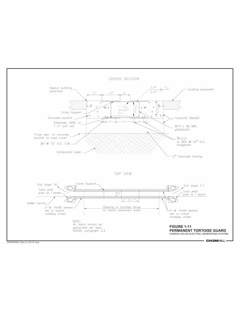
FIGURE 1-11PERMANENT TORTOISE GUARDIVANPAH SOLAR ELECTRIC GENERATING SYSTEM
ES062007009SAC Figure_2.ai 05.01.09 tdaus
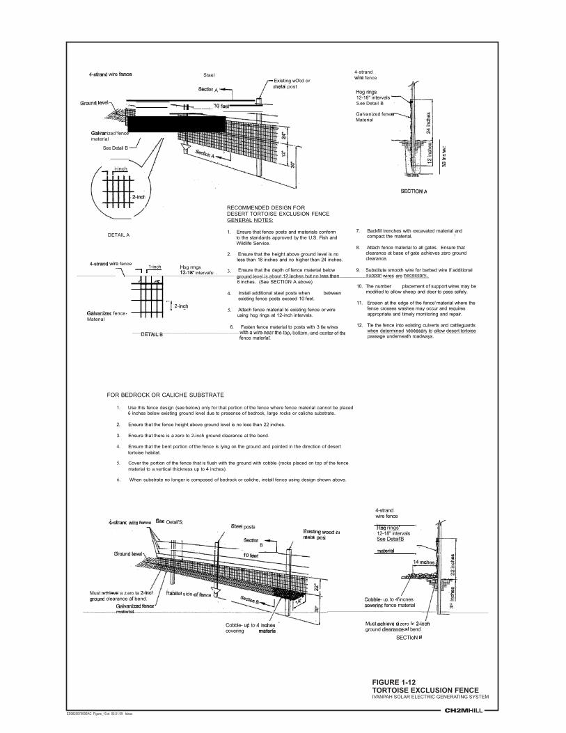
wire StaelExisting wO'cd or
postA
__
ized 'fence' material
See Detail B
i-inch
DETAIL A
wire fence 1 inch Hog rrngs-intervafs: .
fenceMatenal
RECOMMENDED DESIGN FORDESERT TORTOISE EXCLUSION FENCEGENERAL NOTES:
1. Ensure that fence posts and materials conformto the standards approved by the U.S. Fish andWildlife Service.
2. Ensure that the height above ground level is noless than 18 inches and no higher than 24 inches.
3. Ensure that the depth of fence material belowwires are
6 inches. (See SECTION A above)
4. Install additional steel posts when betweenexisting fence posts exceed 10 feet.
5. Attach fence material to existing fence or wireusing hog rings at 12-inch intervals.
6. Fasten fence material to posts with 3 tie wires
fence material.
4-strandfence
Hog rings 12-18" intervals S.ee Detail B
Galvanized fene Material
lIJ
7. Backfill trenches with excavated material andcompact the material. '
8. Attach fence material to all gates. Ensure thatclearance at base of gate achieves zero groundclearance.
9. Substitute smooth wire for barbed wire if additional
10. The number placement of support wires may bemodified to allow sheep and deer to pass safely.
11. Erosion at the edge of the fence' material where thefence crosses washes may occur and requiresappropriate and timely monitoring and repair.
12. Tie the fence into existing culverts and cattleguardswhen determined to allow desert tortoisepassage underneath roadways.
FOR BEDROCK OR CALICHE SUBSTRATE
1. Use this fence design (see below) only for that portion of the fence where fence material cannot be placed6 inches below existing ground level due to presence of bedrock, large rocks or caliche substrate.
2. Ensure that the fence height above ground level is no less than 22 inches.
3. Ensure that there is a zero to 2-inch ground clearance at the bend.
4. Ensure that the bent portion of the fence is lying on the ground and pointed in the direction of desert tortoise habitat.
5. Cover the portion of the fence that is flush with the ground with cobble (rocks placed on top of the fence material to a vertical thickness up to 4 inches).
6. When substrate no longer is composed of bedrock or caliche, install fence using design shown above.
4-strandwire fence
Oetall'S:posts rings'
12-18" intervalsSee Detail'B
B
Must a z.ero ta side .' clearance af bend. up. to 4'incnes
ofence material
Must zeroground bend
SECTIoN
Cobble- tocovering
FIGURE 1-12TORTOISE EXCLUSION FENCEIVANPAH SOLAR ELECTRIC GENERATING SYSTEM
ES062007009SAC Figure_10.ai 05.01.09 tdaus

SECTION 2
Rehabilitation Logistics
Rehabilitation as used in this Plan refers to the removal of temporary or long-term structures, mechanical recontouring of the surface, mechanical measures to enhance soil conditions such as compaction or decompaction, and surface stabilization through revegetation. The rehabilitation activities discussed in this Plan address the three major periods of the Ivanpah SEGS project: construction, operations, and ultimate decommissioning. Temporary disturbance areas are those areas that receive short-term, construction-related disturbance, but soils will be not covered with impervious surfaces. After construction is completed, these areas will be rehabilitated and revegetated, as necessary, to return the areas to preproject conditions to the extent practicable. Long-term disturbances are those associated with relatively permanent structures and facilities, such as power block foundations and paved roads. These disturbed areas will be rehabilitated and revegetated following the planned 50-year lifespan of the project. Areas associated with both temporary and long-term disturbance are identified and quantified in Tables 1-2 and 1-3.
Rehabilitation and revegetation will be conducted for temporary impact areas as construction activities are completed for each project phase. For areas with long-term impacts (i.e., over the 50-year life of the project), rehabilitation and revegetation will be conducted as part of closure of each plant. During project operations, rehabilitation activities will be performed if erosion or sedimentation from storm events occur that threaten landscape stability. Rehabilitation logistics for each period of the project are described below.
2.2 Construction Period Ivanpah SEGS consists of three separate facilities that will be built sequentially, Ivanpah 1, 2, and 3. Facilities that will be shared among the three phases will be built with Ivanpah 1. Facilities and structures to be constructed with each phase include the following bulleted items. For a thorough description of each item, please refer to the project description in Section 1.
2.2.1 Construction Phase 1: Ivanpah 1 and Shared Facilities Phase 1 of construction will entail the following (not necessarily in the order listed).
� Prior to the start of all construction activities, if not done previously, install combined security/tortoise fencing or temporary tortoise fencing (depending on the location and activity) and conduct tortoise clearance surveys. Install permanent tortoise guards where appropriate to prevent tortoise from entering a cleared area.
� Install erosion and sediment control BMPs in accordance with the Construction Stormwater Pollution Prevention Plan (SWPPP).
2-1 SAC/357891/091680015 (ISEGS_SEC2_REHAB LOGISTICS.DOC)

SECTION 2: REHABILITATION LOGISTICS
� Construct water supply wells and groundwater monitoring well; mow dirt access roads to wells.
� Construct paved roads: Colosseum Road from the Golf Club around the south side of Ivanpah 2; with an access road going south to the SCE Substation, and a road going south to the Administration/warehouse Building and on to the Ivanpah 1 power block.
� Construct gravel road to connect the paved section of the realigned Colosseum Road to the existing Colosseum Road dirt trail through the CLA.
� Construct an equipment washing station off Colosseum Road prior to the project entrance.
� Clear and grade sections of the CLA; store topsoil in designated stockpile area; create areas for parking, stockpiling, trailers, heliostat fabrication, and materials storage.
� Construct the KRGT tap station and 6-mile natural gas pipeline from tap station to the Ivanpah 1 power block.
� Remove any large boulders that would impede construction access and heliostat placement, and stockpile in designated location within the CLA.
� Salvage succulents and move them to the succulent storage and stockpile area.
� Mow vegetation to create access roads that run diagonally through Ivanpah 1 and follow existing contours.
� Install permanent combined security/tortoise fencing and construct substation.
� Construct administration/maintenance building.
� Construct Ivanpah 1 power block and appurtenant facilities.
� Construct stormwater berms and diversion channels around the substation and administration building.
� Construct water pipeline to administration building and to Ivanpah 1 power block.
� Construct overhead transmission line from Ivanpah 1 power block to substation.
� Mow heliostat maintenance paths and install heliostats.
� Install heliostat control mechanism and string conduit command and control wiring. Wiring for heliostat control will installed aboveground.
� Rehabilitate and stabilize areas with temporary construction-related disturbance, once construction is completed.
2.2.2 Construction Phase 2: Ivanpah 2 Phase 2 of construction will entail the following.
� Prior to the start of all construction activities, if not done previously, install combined security/tortoise fencing or temporary tortoise fencing (depending on the location and
2-2 SAC/357891/091680015 (ISEGS_SEC2_REHAB LOGISTICS.DOC)

SECTION 2: REHABILITATION LOGISTICS
activity) and conduct tortoise clearance surveys. Install permanent tortoise guards where appropriate to prevent tortoise from entering a cleared area.
� Mow vegetation to create internal perimeter path on Ivanpah 2; install fencing.
� Install erosion and sediment control BMPs in accordance with the project SWPPP.
� Construct paved road from realigned Colosseum Road to Ivanpah 2 power block.
� Reroute trail (699198) on the north side of Ivanpah 2 to follow the solar field perimeter to where it reconnects with the existing trail (see Figure 1-10).
� Construct crossings over ephemeral washes and stabilized channel crossings.
� Remove large boulders that would impede construction access and heliostat placement, and stockpile in designated location within CLA.
� Salvage succulents and move them to the succulent storage and stockpile area.
� Mow vegetation to create dirt access roads that run diagonally following existing topography through Ivanpah 2.
� Perform light grading according to project grading plans; store topsoil in designated stockpile area.
� Construct Ivanpah 2 power block and appurtenant facilities.
� Construct storm water diversion channel and rock filters (if needed).
� Construct water and gas pipelines to serve power block.
� Construct overhead transmission line from Ivanpah 2 power block to substation.
� Mow heliostat maintenance paths and install heliostats.
� Install heliostat control mechanism and string conduit command and control wiring. Wiring for heliostat control will installed aboveground.
� Rehabilitate and stabilize areas with temporary construction-related disturbance.
2.2.3 Construction Phase 3: Ivanpah 3 Phase 3 of construction will entail the following.
� Prior to the start of all construction activities, if not done previously, install combined security/tortoise fencing or temporary tortoise fencing (depending on the location and activity) and conduct tortoise clearance surveys. Install permanent tortoise guards where appropriate to prevent tortoise from entering a cleared area.
� Install erosion and sediment control BMPs in accordance with the project SWPPP.
� Construct paved road from power block to Colosseum Road at southeast corner of Ivanpah 2.
SAC/357891/091680015 (ISEGS_SEC2_REHAB LOGISTICS.DOC) 2-3

SECTION 2: REHABILITATION LOGISTICS
� Reroute trail (699226) around the north end of Ivanpah 3; construct new mining access road.
� Mow vegetation to create internal perimeter path on Ivanpah 3; install fencing.
� Construct crossings over ephemeral washes.
� Remove large boulders that would impede construction access and heliostat placement, and stockpile in designated location within the CLA or Ivanpah 3.
� Salvage succulents and move them to the succulent storage and stockpile area.
� Mow vegetation to create access roads that run diagonally through Ivanpah 3 and follow existing contours.
� Perform light grading according to project grading plans; store topsoil in designated stockpile area.
� Construct Ivanpah 3 power block and appurtenant facilities.
� Construct storm water diversion channel and holding basins.
� Construct water and gas pipelines to serve power block.
� Construct overhead transmission line from Ivanpah 3 power block to substation.
� Construct heliostat maintenance paths and install heliostats.
� Install heliostat control mechanism and string conduit command and control wiring. Wiring for heliostat control will installed aboveground.
� Rehabilitate and stabilize areas with temporary construction-related disturbance.
2.2.4 Rehabilitation of Temporary Construction Impact Areas Rehabilitation and revegetation of temporary disturbance areas will occur as soon as practical following completion of construction activities in the affected area. For example, rehabilitation of the natural gas pipeline impact area during construction of Phase 1 will begin as soon as pipeline construction is completed, even if construction of other project elements is still underway. The CLA will be located between Ivanpah 1 and 2 and will be used throughout construction of Ivanpah 1, 2, and 3. Therefore, rehabilitation and revegetation of this area will not occur until construction of Ivanpah 3 is complete.
Methods of soil rehabilitation for temporary construction impacts associated with each project element and criteria for revegetation are discussed in Section 7, Site Rehabilitation Plan.
2-4 SAC/357891/091680015 (ISEGS_SEC2_REHAB LOGISTICS.DOC)

SECTION 2: REHABILITATION LOGISTICS
2.3 Operations Phase Rehabilitation activities during the operational phase of Ivanpah SEGS will include the following.
� Rehabilitation of areas that have been affected by erosion and sedimentation resulting from flood events that are a dominant geomorphic element on this bajada.
� Weed management per criteria and requirements of the WMP (Appendix B).
Any affected areas will be rehabilitated and revegetated according to the procedures outlined in Section 7, Site Rehabilitation Plan. Other surface management activities implemented during the operations phase are described in Section 5, Surface Management Plan.
2.4 Decommissioning Decommissioning of the facility will occur sequentially in the order of construction, with Ivanpah 1 being the first to be decommissioned, followed by Ivanpah 2, then Ivanpah 3 and the shared facilities. Decommissioning activities will likely require coverage under the State’s General Construction Permit, since the area of ground disturbance will be more than 1 acre. A decommissioning logistics area will be required, and likely the CLA will be used for that purpose.
Site rehabilitation will include the following general activities (not necessarily in the order listed below).
� Access roads that are no longer required by the land management agencies will be rehabilitated (see Figure 1-3). Asphalt will be removed, soils will be decompacted, and the roadway areas will be revegetated.
� Physical components of the generation facilities and appurtenant utilities will be removed using practicable methods that are least disruptive to soils and surrounding habitat to a depth that will not impede growth of vegetative cover.
� Poles and wiring will be removed with the transmission wiring spooled for transport to the recycler. Transmission pole foundations will be removed to a depth of approximately 4 feet.
� Heliostat command and control wiring will be aboveground and will simply be picked up for recycling.
� The substation, its diversion berm and channels, and access from Colosseum Road will remain (see Figure 1-3).
� Stormwater diversion channels no longer needed will be filled using soil materials from adjacent berms. The concrete holding basins will also be filled.
� Water supply wells will be abandoned and pipelines will be sealed off and abandoned in place.
SAC/357891/091680015 (ISEGS_SEC2_REHAB LOGISTICS.DOC) 2-5

SECTION 2: REHABILITATION LOGISTICS
2-6 SAC/357891/091680015 (ISEGS_SEC2_REHAB LOGISTICS.DOC)
� Stabilized channel crossings will be left in place.
� Surfaces will be recontoured, the soil environment rehabilitated, and the revegetation protocol using native species implemented as described in Section 7.
� Temporary disturbance areas from decommissioning activities will also be rehabilitated and revegetated.
� The revegetated areas will be monitored for noxious weeds, for unacceptable densities of invasive species, and for reasonable progress in the vegetation succession. Section 8 describes the site closure plan, which includes a more detailed description of decommissioning activities.

CHAPTER 3
Existing Site Conditions
3.2 Project Location and Jurisdiction The three solar thermal plants collectively referred to as Ivanpah SEGS would be located in the Ivanpah Valley in southern California’s Mojave Desert, near the Nevada border, to the west of Ivanpah Dry Lake (Figure 1-1). The project would be located in San Bernardino County, California, on federal land managed by the BLM. It lies a few miles north of the I-15 corridor, and a few miles east of the boundary of the Mojave National Preserve managed by the National Park Service. The BLM’s management responsibilities under FLPMA include ensuring that lands under its jurisdiction are available for multiple uses, including appropriate economic pursuits such as mining, grazing, and energy development.
3.3 Physiographic Setting The Ivanpah Valley lies in the Basin and Range physiographic province of the western United States. Hydrographically, it is part of the Great Basin because it possesses no drainage outlet to the sea. The Ivanpah Valley is typical of Basin and Range valleys in that it is much longer north-south than it is wide east-west, and it lies at a relatively high altitude with base elevations on the playa of more than a half-mile above sea level. It lies about 45 miles west of the trough of the Colorado River.
The Ivanpah Valley is a topographically closed basin, and surface water drainage that does not evaporate or infiltrate reaches the valley axis, where it evaporates on Ivanpah Dry Lake or Roach Dry Lake. These playas possess a substantial drainage basin that extends about 50 miles from the southern flank of Potosi Mountain, Nevada, in the northeast, to the eastern flank of Cima Dome, California, in the southwest. This drainage basin includes parts of the southern Spring Range, the Lucy Grey and Mescal ranges, the New York and Ivanpah mountains, the Clark Mountains including Clark Mountain proper, and the Mid Hills. Some of these orographic features extend to elevations above 7,000 feet and, together with the size of the drainage basin, generates the capacity for considerable runoff.
The Ivanpah SEGS project area extends over the eastern bajada of Clark Mountain, from an elevation of about 3,400 feet on its western boundary to about 2,800 feet on its eastern boundary. The bajada is composed of a number of coalescing alluvial fans that issue from different canyons on the east side of Clark Mountain. The bajada extends east to the edge of Ivanpah playa, descending over 5.5 to 6 miles from about 4,000 feet above mean sea level at the toe of the mountain, to about 2,610 feet on the edge of the playa. As is typical of these surfaces, the alluvium ranges from coarse, bouldery material near the fan head (also termed the apex or proximal portion of the fan), to fine sands and silts at the toe or distal portion of the fan.
SAC/357891/091800008 (ISEGS_SEC3_EXISTING SITE CONDITIONS.DOC) 3-1

SECTION 3: EXISTING SITE CONDITIONS
3.4 Local Environmental Factors From the point of view of the biota of the Ivanpah SEGS project area, the most significant limiting factor in this ecosystem is drought, or the lack of free water available to plants and animals. Every organism native to this locality is adapted to drought conditions brought on by aridity typical of the Mojave Desert. Other important limiting factors include high temperatures in the summer months, especially high surface temperatures (sustained in excess of 120 degrees Fahrenheit [�F]), sustained intense solar radiation, and the occurrence of winter freezes.
3.4.1 Soils Bainbridge (2007) suggests that two major soil classifications may be representative of most soils in the Mojave Desert: young undifferentiated soils, such as those occurring on flood deposits, and highly structured older soils. Older soils often contain caliche layers that effectively block moisture movement and root penetration, while younger soils can transmit water into deeper horizons. Field reconnaissance suggests that this classification is too simplistic, however, and largely disregards the gradient that exists with intermediate, moderately developed soils also being present at the Ivanpah SEGS.
From a geomorphological perspective, the alluvial fan complex, or bajada, over which the Ivanpah SEGS extends is not a stabilized surface. Relatively recent erosional land forms in the form of channels, bar-and-swale topography, and areas of recent sheet flow typify much of the Clark Mountain bajada. The channels originate not only near the head of the bajada but also along its middle reaches, and extend across its toe, suggesting that the fan surfaces there are also not aggradational. Ongoing dissection across the bajada shows that its current morphology is best classified as erosional. Data also indicate that more than 80 percent of the surface has been subject to relatively recent scour or deposition from washes originating in the hills to the west (CH2M HILL, 2008b).
Older alluvial surfaces at the Ivanpah SEGS are covered by desert pavement. Desert pavement surface is composed of closely packed, interlocking angular or rounded pebble to cobble-sized clasts. Older desert pavement surfaces are darker than younger surfaces lacking desert pavement because the clasts composed of resistant mineralogies support a dark coating of desert varnish. Fine, eolian silt often underlies desert pavement, and once the pavement crust is broken by heavy equipment, disruption of this landscape surface exposes the silt layer, leading to greater wind and water erosion in the absence of mitigation measures. Furthermore, high salt concentrations are typically found in soils underlying desert pavement having small-sized clasts. Therefore, disruption of this type of surface can lead to mobilization of salts, including nitrate (Graham et al., 2008).
The soil types that are primarily affected by the Ivanpah SEGS are Arizo loamy sand, 2 to 8 percent slopes, and Popups sandy loam, 4 to 30 percent slopes. Table 3-1 provides typical pedon descriptions (a pedon is the smallest three-dimensional sampling unit that displays the full range of characteristics of a particular soil, and typically occupies an area ranging from about 1 to 10 square meters (m2) of land area [Brady and Weil, 2002]).
3-2 SAC/357891/091800008 (ISEGS_SEC3_EXISTING SITE CONDITIONS.DOC)

SECTION 3: EXISTING SITE CONDITIONS
TABLE 3-1 Soil Pedon Descriptions
Soil Unit Horizon Depth
(inches) Color Description
Arizo Series (Map unit 3520): These are very deep, excessively drained soils that formed in mixed alluvium. Soils are usually dry, moist throughout for short periods from December through March. Periodically moist in upper part during July through October.
A 0 to 8 Light brownish gray (10R 6/2) dry; dark grayish brown (10YR 4/2) moist
Very gravelly fine sand, weak coarse platy structure; slightly hard, very friable, nonsticky and nonplastic; few fine and medium roots; few fine vesicular and many very fine and fine interstitial pores; 35 percent pebbles; strongly effervescent; moderately alkaline (pH 8.2); abrupt wavy boundary
Bk 8 to 36 Light brownish gray (10YR 6/2) dry; dark grayish brown (10YR 4/2) moist
Extremely gravelly sand; single grained; loose, nonsticky and nonplastic; few fine and medium roots; many very fine and fine interstitial pores; 60 percent pebbles and 10 percent cobbles; few very thin coats of calcium carbonate on undersides of pebbles; strongly effervescent; moderately alkaline (pH 8.2); gradual wavy boundary
C 36 to 62 Light brownish gray (10YR 6/2) dry; dark grayish brown (10YR 4/2) moist)
Extremely gravelly sand; single grained; loose, nonsticky and nonplastic; few very fine and fine roots; many very fine and fine, and few medium interstitial pores; 60 percent pebbles, 20 percent cobbles and 3 percent stones; strongly effervescent; moderately alkaline (pH 8.2).
Popups Series (Map Unit 4122): These are moderately deep to a duripan, well-drained above the duripan
A 0 to 2 Brown (10YR 5/3) dray; dark brown (10YR 3/3) moist
Very gravelly sandy loam; weak medium platy structure; slightly hard, very friable, nonsticky and nonplastic; common very fine and few fine roots; common fine interstitial pores and few very fine and fine tubular pores; 45 percent gravel; noneffervescent; slightly alkaline (pH 7.6); abrupt smooth boundary
SAC/357891/091800008 (ISEGS_SEC3_EXISTING SITE CONDITIONS.DOC) 3-3

SECTION 3: EXISTING SITE CONDITIONS
TABLE 3-1 Soil Pedon Descriptions
Soil Unit Horizon Depth
(inches) Color Description
Bw 2 to 12 Yellowish brown (10YR 5/4) dry; dark yellowish brown (10YR 4/4) moist)
Gravelly sandy loam, weak medium subangular blocky structure; slightly hard, very friable, nonsticky and nonplastic; common very fine and few fine and medium roots; few very fine and fine tubular pores; 30 percent gravel; noneffervescent; slightly alkaline (pH 7.6); gradual wavy boundary.
Btk 12 to 33 Light brown (7.5YR 6/4) dry; brown (7.6YR 4/4) moist
Gravelly sandy loam, moderate coarse sub-angular blocky structure; very hard, very friable, slightly sticky and slightly plastic; common very fine and few fine and medium roots; common very fine and few fine interstitial and tubular pores; many discontinuous faint clay skins on ped faces and sand and gravel coats; few fine irregular soft seams of lime; 15 percent gravel, 3 percent cobbles, and 5 percent stones; strongly effervescent; moderately alkaline (pH 8.0); clear wavy boundary
Bkqm 33 to 60 Very pale brown (10YR 8/2) dry; pale brown (10YR 6/3) moist
Weakly cemented duripan, massive; very hard, very firm, brittle; violently effervescent. Has about 0 to 0.5 percent organic matter; 10 to 18 percent clay; depth to duripan is 20 to 40 inches
Source: NRCS, 2008.
Erosion potential of each Ivanpah facility from water is considered to be negligible to medium; and moderate to high through wind erosion (AFC, Soils Section). Soil map units are identified on a landscape scale. Dominant soil types typically occupy about 75 to 85 percent of the soil map unit; however, other soils that could have dissimilar characteristics can occupy 15 to 25 percent. Across the Ivanpah SEGS, there is also substantial variation in the mineralogy of alluvial parent material, including granitic and metamorphic rocks, Paleozoic limestone, and dolomite. See Section 7 for details on evaluation of soil baseline conditions at the site.
Desert soil temperatures can reach up to 160°F in the summer, and bare soils can exceed ambient air temperature by up to 25 to 32°F. These temperatures can inhibit plant growth; however, some plant species provide sufficient shade such that soil temperatures are reduced
3-4 SAC/357891/091800008 (ISEGS_SEC3_EXISTING SITE CONDITIONS.DOC)

SECTION 3: EXISTING SITE CONDITIONS
SAC/357891/091800008 (ISEGS_SEC3_EXISTING SITE CONDITIONS.DOC) 3-5
to survivable levels for other species rooted beneath their canopies. Soil temperatures in the spring and fall generally range between 70 to 86°F, which is conducive to plant establishment and growth. Soil temperatures are also moderated by summer rains, and some species, such as the cacti, can rapidly extend rootlet systems to take advantage of these periods of high soil moisture and lower temperatures.
Desert soils generally have low fertility, with limited organic matter, low levels of nitrate nitrogen and plant-available phosphorus (Bainbridge, 2007). Because most nutrients are located in surface soils, it is particularly important to prevent erosion and topsoil loss. The high soil pH of desert soils (generally approximately pH 8.3 if calcium carbonate is present) further limits availability of many nutrients. Most desert perennials have been shown to be mycorrhizal (Bainbridge, 2007), and the root-zone symbiosis between these plants and the mycorrhizae can significantly increase the plant’s ability to take up nutrients (especially phosphorus) and water. Only some desert plant species (e.g., mesquite) are able to fix nitrogen by reducing atmospheric nitrogen to ammonia in root nodules formed in association with rhizobial bacteria, and there is no habitat in the project area suitable for mesquite.
3.4.2 Climate and Water Resources Ivanpah Valley is an arid to semiarid, topographically closed basin in the eastern Mojave Desert, about 50 miles west of the Colorado River trough. There are no meteorological stations at or near the Ivanpah SEGS. The closest meteorological station is at Mountain Pass 7 miles to the southwest. At about 4,800 feet elevation, it receives more precipitation and is colder year-round than Ivanpah SEGS, which lies between 2,800 and 3,400 feet elevation. The Ivanpah SEGS AFC provides the precipitation data for Searchlight, Nevada, 32 miles to the east-southeast, as representative of the project site. At an elevation of about 3,540 feet it is near the elevation of Ivanpah SEGS. However, some analyses indicate that precipitation values for Searchlight are likely to be excessive relative to the project site. Although Searchlight is near the elevation of Ivanpah SEGS, its position farther east means that it receives more summer precipitation than comparable elevations to the west (Winograd and Thordarson, 1975).
To estimate the temperature and precipitation of the project site, lapse rate calculations were used based on the meteorological data from Las Vegas, Nevada, a low elevation station about 40 miles to the north-northwest, and from Mountain Pass. These calculations were based on long-term averages, as well as the 1971 through 2000 normalized period of measurement (Tables 3-2 and 3-3). They supersede those values published in the AFC as representative of the Ivanpah SEGS area. The estimated average annual and monthly precipitation and temperature for Ivanpah SEGS are presented as values for the lowest part of the project area (the northeast corner of Ivanpah 1 at ca. 2,760 feet elevation), and for the highest (the northwest corner of Ivanpah 3 at ca. 3,410 feet elevation). This approximately 650-foot elevation gain across the project area results in differences in estimated annual precipitation of more than an inch, and about 1.3�F in mean annual temperature. The differences in estimated monthly precipitation between high and low elevations across the site are largest in the summer because lapse rates of precipitation with elevation are greater in the summer. This reflects the tendency of orographically-induced summer thunderstorms to nucleate over high topography and for higher elevations to receive proportionately more precipitation during this season.

SECTION 3: EXISTING SITE CONDITIONS
TABLE 3-2 Summary of Precipitation Data for Two Nearby Stations and Estimates for Ivanpah SEGS
Average: Jan Feb Mar Apr May Jun Jul Aug Sep Oct Nov Dec Annual
Long-Term period (Las Vegas, 1937 through 2007; Mountain Pass, 1955 through 2005)
Las Vegas; 2,165 feet elevation 0.5 0.58 0.46 0.21 0.15 0.07 0.44 0.45 0.33 0.26 0.37 0.39 4.19
Mountain Pass; 4,790 feet elevation 0.94 0.91 0.89 0.47 0.27 0.2 1.04 1.23 0.59 0.52 0.69 0.64 8.40
Ivanpah SEGS SE (2,760 feet elevation) 0.59 0.65 0.55 0.27 0.18 0.10 0.57 0.62 0.39 0.32 0.44 0.44 5.08
Ivanpah SEGS NW (3,410 feet elevation) 0.71 0.74 0.67 0.34 0.21 0.13 0.73 0.83 0.46 0.39 0.53 0.51 6.24
Normalized period 1971 through 2000
Las Vegas; 2,165 feet elevation 0.6 0.68 0.49 0.23 0.23 0.11 0.38 0.51 0.28 0.24 0.33 0.43 4.51
Mountain Pass; 4,790 feet elevation 1.07 1.19 1.03 0.5 0.36 0.33 0.95 1.27 0.65 0.43 0.74 0.83 9.34
Ivanpah SEGS SE (2,760 feet elevation) 0.70 0.79 0.60 0.29 0.26 0.16 0.50 0.67 0.36 0.28 0.42 0.51 5.53
Ivanpah SEGS NW (3,410 feet elevation) 0.83 0.93 0.75 0.36 0.29 0.22 0.66 0.88 0.46 0.33 0.53 0.62 6.86
Notes: Grey-shaded values are estimates based on elevational lapse rates. All values are in inches. NW = northwest SE = southeast Source: Desert Research Institute, n.d.
3-6 SAC/357891/091800008 (ISEGS_SEC3_EXISTING SITE CONDITIONS.DOC)

SECTION 3: EXISTING SITE CONDITIONS
SAC/357891/091800008 (ISEGS_SEC3_EXISTING SITE CONDITIONS.DOC) 3-7
TABLE 3-3 Summary of Temperature Data for Two Nearby Stations and Estimates for Ivanpah SEGS
Average of Daily Means: Jan Feb Mar Apr May Jun Jul Aug Sep Oct Nov Dec Annual
Average
Long-Term period (Las Vegas, 1937 through 2007; Mountain Pass, 1955 through 2005)
Las Vegas; 2,165 feet elevation 45.7 50.6 56.8 64.9 74.7 84.2 90.4 88.4 80.5 67.8 54.1 46.0 67.0
Mountain Pass; 4,790 feet elevation 39.9 43 47.4 53.7 63 73.1 79.7 77.3 70.2 59.3 47.6 40.6 57.9
Ivanpah SEGS SE (2,720 feet elevation) 44.5 49.0 54.8 62.5 72.2 81.8 88.1 86.0 78.3 66.0 52.7 44.9 65.1
Ivanpah SEGS NW (3,445 feet elevation) 42.9 46.9 52.2 59.4 69.0 78.8 85.2 83.0 75.5 63.7 50.9 43.4 62.6
Normalized period 1971 through 2000
Las Vegas; 2,165 feet elevation 47.0 52.2 58.3 66.0 75.4 85.6 91.2 89.3 81.3 68.7 55.0 47.0 68.1
Mountain Pass; 4,790 feet elevation 39.4 42.6 47.2 54 62.5 73.7 79.5 77.6 70.5 59.1 47.4 39.9 57.8
Ivanpah SEGS SE (2,720 feet elevation) 45.39 50.16 55.94 63.45 72.66 83.07 88.72 86.82 79.01 66.66 53.39 45.49 65.91
Ivanpah SEGS NW (3,445 feet elevation) 43.30 47.52 52.89 60.15 69.11 79.80 85.50 83.60 76.04 64.02 51.30 43.54 63.08
Notes: Grey-shaded values are estimates based on elevational lapse rates. All values are in degrees Fahrenheit. NW = northwest SE = southeast Source: Desert Research Institute, n.d.

SECTION 3: EXISTING SITE CONDITIONS
The average monthly precipitation values show that most of the precipitation in the project site falls as winter rain during December through March, and as summer rains during the monsoon season of the Southwest, in July through September. This bimodal (winter-summer) precipitation regime is shared with the rest of the eastern Mojave Desert (Beatley, 1976), but not with regions farther west in the central and western Mojave Desert, where there is no predictable summer rainfall. Winter rains are associated with frontal systems moving inland from the Pacific Ocean and can result in periods of cloudiness and intermittent precipitation lasting for days. Summer rains are the product of thunderstorms that result from the thermal convection and orographic uplift of maritime tropical air advected into the desert interior from the south and southeast. They are brief and frequently intense rainfall events that can produce considerable runoff.
The estimated rainfall for a 100-year 24-hour event is 3.28 inches, and 2.83 inches for a 6-hour event; a 10-year 24-hour event is 1.92 inches, and 1.60 inches for a 6-hour event. Intense rain events in Southern California deserts can deliver the annual average rainfall in a short period of time, causing extensive sheet erosion and flash floods. The amount of moisture held within the soil depends on the amount of precipitation, rate of infiltration and retention, ground cover, and soil texture. Surface soils can be moist for only short periods of time during the year, and water typically evaporates before it can percolate deeper into the vadose zone. This process also results in the deposition of calcium carbonate leached from the surface, leading to thick caliche or calcrete horizons in older soils. Most water recharge occurs in desert washes, where sufficient moisture could remain to allow for establishment and survival of tree seedlings (Bainbridge, 2007). In the immediate vicinity of Ivanpah SEGS, the arborescent flora of the desert riparian vegetation is restricted to sparse catclaw acacia (Acacia greggii) and desert willow (Chilopsis linearis).
Episodes of inundation of Ivanpah Dry Lake are relatively frequent, although the water seldom exceeds a few inches in depth and concentrates in the lowest, northern end of the basin. There are numerous springs along the faults bordering the Clark and Mescal mountains, and the ephemeral washes of the flanking bajadas are innumerable. Groundwater from the deep Paleozoic carbonate aquifer (Winograd and Thordarson, 1975) is currently pumped from two well sites on the Clark Mountain bajada to supply the Primm Valley Golf Club. This groundwater will be used to supply potable water and process water to the Ivanpah SEGS. As could be expected, this water is relatively high in dissolved carbonates and silica.
3.5 Vegetation Resources1 3.5.1 Biogeography The Ivanpah SEGS project area lies entirely within Mojave Desert scrub vegetation. The Mojave Desert is one of the three warm deserts of North America; the Chihuahuan and Sonoran Deserts are the other two. The Mojave Desert is a temperate desert with cold winters as well as warm summers. In considering its latitudinal position, it is comparatively
1The following section on biogeography through vegetation zonation were prepared by W.G. Spaulding. Dr. Spaulding is a former Research Professor of Botany with more than 25 years experience in the study of Mojave Desert phytogeography and plant ecology. Prior to joining private industry, he published extensively on the effects if environmental change on desert scrub plant communities.
3-8 SAC/357891/091800008 (ISEGS_SEC3_EXISTING SITE CONDITIONS.DOC)

SECTION 3: EXISTING SITE CONDITIONS
far to the north. The frequency and severity of winter freezes in this area is one of the principal limiting factors preventing the occurrence of a suite of warm-desert species typical of the Colorado Desert, not more than 100 miles to the south. These include distinctive forms such as smoke tree (Psorothamnus spinosus), palo verde (Cercidium microphyllum, C. floridum), and ocotillo (Fouquieria splendens). Catclaw acacia and desert willow are two arborescent desert plants that range far enough north to occur in and near the project site.
3.5.2 Vegetation Zonation From the point of view of elevationally controlled vegetation zonation lying between about 2,700 and 3,445 feet elevation, the Ivanpah SEGS project area is near the upper limit of creosote bush (Larrea tridentata)-burrobush (Ambrosia dumosa) desert scrub. While creosote bush occurs at an elevation as high as 6,000 feet on south-facing slopes near its northern limit, creosote bush-dominated scrub does not typically extend above about 3,600 feet. The relative diversity of creosote bush-burrobush scrub here reflects its mesic character. At slightly higher elevations, mixed desert scrub is found, in which several woody perennials maintain codominance. Above this mixed desert scrub, generally between about 4,800 and 6,000 feet, blackbrush (Coleogyne ramosissima) scrub is the typical vegetation cover on alluvial slopes. Above this elevation, woodland can be found especially in mesic habitats. On the lower flanks and piedmont of Clark Mountain, the hallmark of the lower edge of woodland is the California juniper (Juniperus californica), which gives way at higher elevations to the more mesophytic Utah juniper (J. osteosperma)-pinyon (Pinus monophylla) woodland.
The hallmark of the Mojave Desert, the Joshua tree (Yucca brevifolia), does not occur on the bajada extending from the edge of Ivanpah Dry Lake to the flanks of Clark Mountain. It occurs about 12 miles to the southwest near Mountain Pass, as well as in the southern Ivanpah Valley along the Cima Road. Its absence in the project site is a manifestation of the Joshua tree’s typically patchy distribution (Rowlands, 1978). Recent reconnaissance located Joshua trees on the piedmont of Clark Mountain to the west, where it occurs primarily as an associate of woodland at elevations exceeding about 4,800 feet.
3.5.3 Local Plant Associations The creosote bush-burrobush desert scrub of the Ivanpah SEGS project area is itself composed of several different plant associations that describe a continuum from xeric, low diversity scrub to mesophytic, mixed desert scrub at high elevations, and from disturbance-adapted scrub of recently scoured washes to the mature scrub of stable interfluves. Creosote bush is usually the visually prominent shrub species, while burrobush is usually the more abundant but smaller shrub. Common shrub and subshrub associates, especially at higher elevations near the transition with mixed desert scrub, include the following.
� Box-thorn or wolfberry (Lycium andersonii; L. cooperi) � Ratany (Krameria erecta) � Ground thorn (Menodora spinescens) � California buckwheat (Eriogonum fasiculatum) � Paddle-leaf sage (Salvia dorrii) � Virgin River brittlebush (Encelia virginensis) � Mormon tea (Ephedra nevadensis; E. torreyana)
SAC/357891/091800008 (ISEGS_SEC3_EXISTING SITE CONDITIONS.DOC) 3-9

SECTION 3: EXISTING SITE CONDITIONS
Different succulent species occur in the project site and are distributed throughout the creosote bush-burrobush desert scrub. A few are visually prominent because of their size, such as the Mojave yucca (Yucca schidigera) and the staghorn cholla (Opuntia acanthocarpa). Barrel cacti present include both the California barrel cactus (Ferocactus cylindraceus var. lecontei) that ranges chiefly into the southern Mojave and Colorado deserts, and the cotton-top barrel cactus (Echinocactus polycephalus) of the northern Mojave. Prickly-pear cacti include the relatively common beavertail prickly-pear (Opuntia basilaris), as well as the flapjack prickly-pear (Opuntia chlorotica) and the grizzly bear prickly-pear (O. erinacea), both of which have affinities with higher elevation desert scrub. Cholla species also include the diamond cholla (Opuntia ramosissima), the Mojave silver cholla (O. echinocarpa), and the club cholla (O. parishii). There appears to be a higher diversity and density of cacti on alluvial surfaces composed primarily of limestone clasts or older surfaces that appear underlain by a well-developed carbonate horizon.
There is a diverse annual and short-lived biennial flora in the Ivanpah SEGS project area. The annual habit is an effective adaptation to desert environments. For most of the year and for most years, the plant remains as a seed in the soil, germinating and flowering only on those rare occasions when soil moisture is high and sustained for a sufficient period of time. Most are winter annuals (e.g. Bromus madritensis, Cryptantha spp., Eriogonum spp., Erodium cicutarium, and Lepidium spp.), while a smaller proportion are summer annuals (Kallestroemia spp., and Tribulis terrestris).
Disturbance-Adapted Plant Associations There is a different and distinct desert scrub plant association that occupies recently disturbed areas, such as the washes and arroyos that occur in abundance throughout the desert west (Bradley and Deacon, 1967; Thorne et al., 1981; Spaulding, 1981). Ephemeral washes have poorly developed soils and usually support a distinctive, disturbance-adapted flora. The following perennials, although adapted chiefly to such desert riparian habitats, also occasionally occur on the interfluves on more mature soils.
� Cheesebush (Hymenoclea salsola) � Black-band rabbitbrush (Chrysothamnus paniculatus) � Desert almond (Prunus fasciculata) � Wooly bursage (Ambrosia eriocentra) � Bladder-sage (Salazaria mexicana) � Catclaw acacia (Acacia greggii) � Desert willow (Chilopsis linearis)
Catclaw acacia and desert willow are the only two small trees that occur near the Ivanpah SEGS.
Weedy Flora The WMP (Appendix B) lists the weed species that occur or could occur in the project area. There are a few woody perennials such as salt cedar (Tamarix ramosissima), tree-of-heaven (Ailanthus altissima), and camel thorn (Alhagi camelorum), but most are annual plants. The annual weeds include several species that have become well-naturalized in the region; that is, they occur in many different habitats and in areas far removed from human disturbance. Ubiquitous weed species in the region include the following.
3-10 SAC/357891/091800008 (ISEGS_SEC3_EXISTING SITE CONDITIONS.DOC)

SECTION 3: EXISTING SITE CONDITIONS
� Red brome or red chess (Bromus madritensis ssp. rubens) � Filaree or storksbill (Erodium cicutarium) � Mediterranean grass (Schismus arabicus, S. barbatus) � Tumble-weed or Russian thistle (Salsola tragus)
The term “weed” is normally applied to non-native plant species that typically colonize recently disturbed ground, but certain native annuals also share the trait of being adapted to recently disturbed soil. These include members of the Polygonaceae, especially species in the genus Eriogonum, some annual Asteraceae such as Malacothrix and Geraea, and the globe mallow Sphaeralcea ambigua.
While in portions of the Mojave Dessert some of the species above may contribute to fire hazard, that is generally not the case in the Ivanpah SEGS area, where even in a wet season these species may only reach 2 to 3 inches in height, and densities less than 10 or 15 percent (see Vegetation Survey Results, Appendix E). In addition, they are typically at comparable canopy densities in either disturbed or undisturbed sites.
3.5.4 Vegetation Surveys Site vegetation surveys and analyses were conducted at Ivanpah SEGS and surrounding areas in April 2009 to characterize existing vegetation conditions and in support of rehabilitation and revegetation efforts. The full report of these surveys and findings are provided in Appendix E, Vegetation Survey and Results.
Survey Objectives The objectives of these surveys were as follows.
1. To characterize vegetation at sites within Ivanpah Valley with a disturbance history comparable to the disturbance that will occur at the Ivanpah SEGS site
2. To collect vegetation data at disturbed and adjacent undisturbed sites, including species composition, percent cover, species abundance, species diversity, species density, weedy species composition, and individual vigor
3. To identify and document vegetation conditions at sites in varying stages of recovery based on differing dates of disturbance
4. To document species composition and diversity within the footprint of the proposed Ivanpah SEGS and, specifically, to estimate the number and diversity of all succulent species, which had previously not been determined
5. To identify and develop appropriate criteria for revegetation progress based on conditions and findings at comparable revegetation sites and to identify temporal expectations of progress
6. To identify and develop appropriate criteria and thresholds for weed management based on risks to native vegetation development and establishment
SAC/357891/091800008 (ISEGS_SEC3_EXISTING SITE CONDITIONS.DOC) 3-11

SECTION 3: EXISTING SITE CONDITIONS
Survey Protocol Sample sites were chosen at areas with known disturbance history and regime, along with adjacent undisturbed habitats (relatively). Additional sampling was conducted within each of the three Ivanpah units. Sampling for abundance, density, percent cover, diversity (Smith, 1992), and richness were conducted using a combination of line transects, belt transects, and circular relevé plots. Sampling at disturbed sites included three 30-meter-long line and belt transects, with independent sampling of shrub and herbaceous strata. In adjacent undisturbed sites, a comparative 30-meter line transect and one 12-meter radius relevé (a term used in vegetation ecology for an arbitrarily assigned vegetation sampling plot) (CNPS, 2000) were sampled in the undisturbed desert adjacent to each disturbed site. Within the undisturbed areas in the Ivanpah units, three 12-meter radius relevés per unit were sampled.
Sample locations were as follows.
� The borrow pit (BP) site is located between Ivanpah Unit 1 and I-15 where material was most likely taken between 1960 and 1965 to build the I-15 Yates Well Road exit; it is assumed that there were no revegetation efforts, only natural recovery.
� Two other disturbed sites were sampled on the KRGT ROW. KRGT 1 is located northeast of Ivanpah Unit 3, and KRGT 2 is located within the Ivanpah SEGS proposed transmission corridor. The KRGT ROW was disturbed around year 2000 and appears to have been revegetated using seeding with native species and soil manipulation.
� Three additional sites were sampled within the Ivanpah units, one each on Ivanpah 1, Ivanpah 2, and Ivanpah 3 (I1, I2, I3, respectively).
Survey Findings Complete data findings are reported in Appendix E, including raw data and summary tables. Findings are summarized here.
Shrub Strata The most abundant shrub in the three disturbed sites is cheesebush (Hymenoclea salsola). In two of the disturbed sites (BP and KRGT1), burrobush (Ambrosia dumosa) is the next most common shrub. Burrobush and creosote bush (Larrea tridentata) are the most common shrubs in the undisturbed sites, including the sites on Ivanpah 1, 2, and 3.
Shrub cover, density, diversity, and richness are provided in Table 3-4. Data presented are the means of up to three samples at each location. Shrub density in the disturbed sites was lowest at the BP site and highest at the KRGT2 site, where a high number of cheesebush were present. Within the undisturbed sites, density of shrubs was greater in the lower elevation sites in the southern portion of the valley (Borrow Pit, Ivanpah 1), generally owing to a greater number of burrobush, with an overall reduced diversity of shrubs. The disturbed sites sampled generally had a lower percent shrub cover (13 to 18 percent) than the undisturbed sites (14 to 31 percent); however, in KRGT1, the disturbed sites sampled had a higher mean shrub cover (18 percent) than the undisturbed site (14 percent). The range of shrub cover in disturbed sites (9 to 33 percent) was greater than in undisturbed sites (14 to 31 percent) (see Appendix E).
3-12 SAC/357891/091800008 (ISEGS_SEC3_EXISTING SITE CONDITIONS.DOC)

SECTION 3: EXISTING SITE CONDITIONS
Shrub diversity and richness are greater in two of the disturbed sites (BP and KRGT1) than in the associated undisturbed sites. In KRGT2, shrub diversity and richness are greater in the undisturbed site. Within undisturbed sites, there appeared to be a consistent increase in diversity and richness trending from the lower elevation sample sites at BP and Ivanpah 1 near the bottom of the valley, toward the higher elevation sites to the north at the head of the bajada, and at the base of the foothills.
TABLE 3-4 Mean Vegetation Data Findings for the Shrub Strata from Vegetation Surveys
Cover (percent)
Density (plants/acre)
Diversity (Simpson’s Index of Diversity)
Richness (number)
Site Disturbed Undisturbed Disturbed Undisturbed Disturbed Undisturbed Disturbed Undisturbed
Borrow Pit 13 23 2,341 3,849 0.55 0.27 7 3
KRGT1 18 14 3,506 3,009 0.66 0.56 13 11
KRGT2 18 31 4,743 2,359 0.2 0.67 6 19
Ivanpah 1 --- --- --- 4,053 --- 0.40 --- 12
Ivanpah 2 --- --- --- 3,195 --- 0.45 --- 15
Ivanpah 3 --- --- --- 2,421 --- 0.62 --- 19
Succulents Succulents encountered during surveys at all sites included Opuntia acanthocarpa, O. ramosissima, O. basilaris, O. echinocarpa, Echinocactus polycephalus, Ferocactus cylindraceus, and Yucca schidigera. The barrel cacti (Echinocactus, Ferocactus) were mapped across the Ivanpah sites during early botanical surveys in support of the AFC. These data would represent undisturbed sites within the proposed footprint of Ivanpah SEGS.
Table 3-5 shows data from vegetation surveys and the original barrel cacti mapping. As evidenced in the comparative density between barrel cacti and density of all succulents, barrel cacti represent only a minor portion of the succulent community. Within undisturbed sites, density of succulents appeared to increase with increasing elevation, generally trending from the southern most sampling sites (Ivanpah 1, BP) to the northern sites at the base of the foothills and at the head of the bajada (KRGT, Ivanpah 3).
TABLE 3-5 Succulent Density in Disturbed and Undisturbed Sites at Ivanpah SEGS
Total Succulent Density from Vegetation Surveys (plants/acre)
Site Disturbed* Undisturbed
Borrow Pit 10.1 8.1
KRGT1 20.3 153.3
KRGT2 0 314.7
Ivanpah 1* --- 91.4
Ivanpah 2* --- 134.5
SAC/357891/091800008 (ISEGS_SEC3_EXISTING SITE CONDITIONS.DOC) 3-13

SECTION 3: EXISTING SITE CONDITIONS
TABLE 3-5 Succulent Density in Disturbed and Undisturbed Sites at Ivanpah SEGS Ivanpah 3* --- 156.0
Barrel Cacti Density from Botanical Surveys (plants/acre)
Ivanpah 1 0.8
Ivanpah 2 0.6
Ivanpah 3 1.6
TOTAL 1.2
*Value represents a mean of three replicates.
Herbaceous Strata The most abundant herbs in the disturbed sites are redstem filaree (Erodium cicutarium), bluegrass (Poa bigelovii), and Mediterranean grass (Schismus sp.). The most common herbs in the undisturbed sites are pepperweed (Lepidium sp.), bluegrass, redstem filaree, and Mediterranean grass.
Herbaceous cover at all sampling plots (including native herbaceous cover) and canopy height are provided in Table 3-6. In the herbaceous layer, results for canopy cover are varied. The most notable difference was at the KRGT2 site, where herbaceous cover was substantially greater in the disturbed site (15 percent) than the undisturbed (7 percent). At this latter site, the native bluegrass was abundant, representing between 30 and 80 percent of the herbaceous cover.
TABLE 3-6 Mean Vegetation Data Findings for the Herbaceous Strata from Vegetation Surveys
Total (Native) Cover
(Percent) Canopy Height
(m)
Site Disturbed Undisturbed Disturbed Undisturbed
Borrow Pit 3.4 (0.5%) 2.0 (0.4%) 0.030 0.050
KRGT1 8.7 (4.2%) 15.3 (5.0%) 0.043 0.030
KRGT2 21.0 (15.3%) 6.8 (6.5%) 0.053 0.070
3.5.5 Discussion of Vegetation Survey Results Although the variability is high (13 to 31 percent) shrub cover in this area (Table 3-4) is generally greater than that expected for desert ecosystems on a global basis, where cover is normally less than 10 percent (Spaulding, et al., 1983). This reflects the relatively high altitude of the project area and increased effective moisture relative to desert lowlands, which in turn support a density of shrubs that would technically meet the criterion for steppe vegetation, and not desert scrub. Nonetheless, since the term steppe is rarely used in
3-14 SAC/357891/091800008 (ISEGS_SEC3_EXISTING SITE CONDITIONS.DOC)

SECTION 3: EXISTING SITE CONDITIONS
North America, we will not employ it here. Rather we note that the natural vegetation of the project area is relatively dense relative to most desert scrub communities.
Revegetation As expected (see Section 3.4.3), the disturbed sites are dominated by native disturbance-adapted, early successional species (Hymenoclea salsola); whereas, the undisturbed sites are dominated by native late successional, climax species (Ambrosia dumosa and Larrea tridentata). Succession over the last 40 to 50 years at the disturbed Borrow Pit site (BP) has resulted in late successional/climax species (A. dumosa and L. tridentata) as the second and third most common species. Even at disturbed site KRGT1, which has had less than 10 years to recover, late successional, climax species are becoming dominant (A. dumosa is the second most common species). In addition, L. tridentata were establishing on the site in low numbers.
In two of the three sites, shrub cover has not returned to predisturbance levels. Disturbed site BP has undergone 40 to 50 years of natural succession, yet still does not have the same shrub cover as the adjacent undisturbed area (13 percent vs. 23 percent). One of the two KRGT sites that underwent active revegetation efforts has returned to greater than undisturbed shrub cover levels. This suggests that revegetation efforts accelerate and improve shrub cover recovery. In establishing shrub cover criteria, it is important to note that even in undisturbed habitats shrub cover is naturally low and can be variable (ranging from 14 to 31 percent).
Succulent density was much lower on disturbed sites along the KRGT ROW than adjacent undisturbed sites. Judging from the low number of succulents, it can be surmised that no or very few succulent transplants occurred during the KRGT revegetation. Given the generally accepted success rates of succulent transplants, this approach as proposed for Ivanpah SEGS would be expected to improve revegetation results.
As indicated, shrub diversity and richness within undisturbed transects at the BP, KRGT1, and KRGT2 sites showed a steady increase with elevation (Table 3-4), which increased between the three sites (2685 feet, 2834 feet, and 3270 feet, respectively), with the higher elevation sites (KRGT 1 and 2) trending toward the northern foothills and the head of the bajada. A similar trend is evident in the relevé data from the Ivanpah sites, with an increase in diversity and richness from Ivanpah 1 to Ivanpah 2, and then to Ivanpah 3. Again, these sites are successively higher in elevation (means are 2830 feet, 3019 feet, and 3126 feet) and trend from south to north towards the head of the bajada. Interestingly, the density data show an inverse trend and decreases with elevation in the two sets of undisturbed plots. This appears to be due to fewer burrobush in the canopy in the higher sites. At these sites, a number of other shrubs make up a greater portion of the shrub canopy, but they grow in reduced densities compared to burrobush (Table 3-4). While insufficient data is available to determine causative factors or establish relationships, consideration of the difference in natural diversity and richness is necessary in establishing criteria for these parameters.
Exotic Weeds Exotic weed species are present in both the disturbed and undisturbed sites. Schismus sp. and E. cicutarium are present in both the disturbed and undisturbed sites. B. madritensis is only present in the disturbed sites; however, it is not a dominant species in the herbaceous
SAC/357891/091800008 (ISEGS_SEC3_EXISTING SITE CONDITIONS.DOC) 3-15

SECTION 3: EXISTING SITE CONDITIONS
3-16 SAC/357891/091800008 (ISEGS_SEC3_EXISTING SITE CONDITIONS.DOC)
layer. Total herbaceous cover is 21 percent or less in both the disturbed and undisturbed sites. KRGT2 was the only site where there was a noticeably higher percent of herbaceous cover in the disturbed than the undisturbed, but the dominant herbaceous species was a native grass (Poa bigelovii). Generally, the exotic proportion of the herbaceous layer is dominated by small annual plants with average heights of 0.03 to 0.07 meters and cover less than 10 percent. This is comparable to exotic species present in undisturbed sites.
Based on the percent cover and short stature of the canopy, it is anticipated that the exotic weed growth in disturbed areas is not likely to pose an elevated fire risk compared to the undisturbed areas. This represents conditions during a relatively wet year (as described earlier). During drier than normal years, the herbaceous strata would be expected to have even less cover or stature, or be absent altogether.

SECTION 4
Native Plant Salvage and Reuse
As further discussed in the Technical Basis Document (TBD, Appendix D) it is rarely the practice to salvage desert shrubs for later transplant because those transplant efforts generally experience a low success rate. Therefore, Ivanpah SEGS will not salvage shrubs, not because they are unnecessary, but because such salvage efforts would be impractical. Certain succulent species (especially some cacti) are exceptions that are not only of relatively high aesthetic value, but have physiological adaptations that result in a significantly higher success rate on attempts to salvage and maintain. Within each subsection, preliminary background information is presented on the topic, followed by a subsection on the proposed protocol, including a numbered list of proposed actions to which the project proponent is committed.
4.1 Cacti and Yucca of the Project Area 4.1.1 Growth Forms The cacti and yucca (collectively termed “succulents”) of the project site are all native species; there are no introduced non-native succulents in the area. All share the trait of storing moisture in plant tissues above the ground, and in some (barrel cacti), their entire aboveground biomass can be thought of as a single water storage organ; hence, the name succulent. Cacti are also leafless, and their chlorophylous surfaces consist of the tissue covering their stems. Most taxa are heavily armed with stout siliceous spines. Many species of Opuntia are also armed with glochids, which are millimeter-scale spines that readily detach and penetrate the skin. Cactus species readily generate rootlets and root systems in response to seasonal increases in soil moisture. However, even with these commonalities, there are several distinct morphologies among the Mojave Desert succulents that are relevant to their handling and salvage.
4.1.1.1 Single-stemmed Cacti The single-stemmed cacti, or cylindrocacti, are those cactus species characterized by a single stem, usually slightly inflated. They range from very large barrel cacti (for example, the California barrel cactus [Ferocactus lecontii var. cylindraceus], the cotton-top barrel cactus [Echinocactus polycephalus]), to slightly small pincushion and fishhook cacti (Coryphantha chlorantha, Mammilaria microcarpa). One plant can be composed of a single stem, such as the California barrel cactus, or there can be up to a dozen stems sprouting out to make up one individual, such as the many-headed barrel cactus and the hedgehog cactus (Echinocereus engelmannii). However, these stems always branch from the ground-level perennating (that is, persistent from year-to-year) buds, and the stems neither branch nor are they segmented.
4.1.1.2 Segmented Cacti Segmented cacti in the Ivanpah SEGS include prickly-pears (Opuntia subgen. Platyopuntia) and chollas (Opuntia subgen. Cylindropuntia), the latter also including Grusonia (Table 4-1),
SAC/357891/091800007(ISEGS_SEC4_PLANT SALVAGE AND REUSE.DOC) 4-1

SECTION 4: NATIVE PLANT SALVAGE AND REUSE
which is doubtfully distinct from Opuntia (Hickman, 1993). Prickly-pears are ascendant plants with an architecture composed of flat, jointed, succulent pads. Some prickly-pears (Opuntia chlorotica) can grow up to 5 feet in this area, while other taxa (O. basilaris) can be diminutive and consist of a few to approximately a dozen pads that do not branch extensively. Chollas are more typically ascendant and shrublike, although their branching architecture consists of succulent, cylindrical joints. Buckhorn chollas (Opuntia acanthocarpa) can exceed 5 feet in height and, with dense golden spines, can be more visually appealing compared to the nondescript and smaller silver cholla (O. echinocarpa). Cholla joints are cylindrical, and those of most species are relatively short and detach easily from the mother plant with no injury to the plant. Their spines are typically sheathed with microscopic recurved barbs and are of a design that allows the joints to “hitchhike” once they attach to the foot of an animal. Accordingly, cholla cacti often reproduce vegetatively as dropped joints are scattered beyond the parent plant, and then take root.
TABLE 4-1 Succulents Found Growing Within the Ivanpah SEGS Project Area
Taxon Common Name Notes
Cactaceae
Coryphantha chlorantha; C. vivipara Desert pincushion C; cryptic
Echinocactus polycephalus Cotton-top or clustered barrel cactus C
Echinocereus engelmannii Hedgehog cactus C
Ferocactus cylindraceus var. lecontei California barrel cactus C; highly valued as a landscaping element
Grusonia [Opuntia] parishii Parish club-cholla S; the only cholla with a prostrate habit
Mammillaria tetrancistra fish-hook cactus C; cryptic
Opuntia acanthocarpa var. coloradensis buckhorn cholla S
Opuntia basilaris var. basilaris beavertail prickly-pear S
Opuntia chlorotica pancake prickly-pear S; more common in higher elevation mixed scrub habitats
Opuntia echinocarpa silver cholla S
Opuntia echinocarpa x O. ramosissima hybrid silver x pencil cholla S
Opuntia erinacea Mojave prickly-pear S
Opuntia ramosissima pencil or diamond cholla S
Liliaceae
Yucca schidigera Mojave yucca Y
Notes: C = cylindrocacti (single-stemmed cacti) S = segmented or jointed cacti Y = yucca
4-2 SAC/357891/091800007(ISEGS_SEC4_PLANT SALVAGE AND REUSE.DOC)

SECTION 4: NATIVE PLANT SALVAGE AND REUSE
4.1.1.3 Yucca Although technically succulents, yucca species are unrelated to cacti. They are actually perennial monocots (grasses and allies) and are classified in the lily family (Table 4-1). There are several yucca native to the Mojave Desert although only one species, the Mojave yucca (Yucca schidigera), occurs in the Ivanpah SEGS project area. Younger Mojave yucca plants lack trunks and possess stout, inflexible leaves that are more than 24 inches long with sharp, piercing tips. Older Mojave yucca possess single or simple-branching trunks sheathed in dead leaves, with a rosette of live leaves at the top of the trunk. Leaves of these older plants are generally less than 18 inches long, but still quite stout and sharp-pointed.
4.2 Ecophysiologically Relevant Notes The ecophysiology of North American cacti was a principal subject of study during the first decades of the 20th Century, as summarized by McGinnies (1981). Cacti resist desiccation partly because they lack leaves and have a very small surface-to-mass ratio. Their cuticle is also thick, with stomata that close tightly during the day, open after dark, and respire at night to reduce moisture loss. Their root systems can also grow rapidly in response to increases in soil moisture, and rootlets also dieback readily, minimizing moisture loss caused by soil desiccation. Injuries, whether to the stem or root system of cacti, also callous quickly in the absence of fungi or other pathogens. Cacti are also rich in water and nutrients.
Many of the physiological adaptations of succulents to desert environments also mean that they are relatively easy to transplant successfully if appropriate measures are taken. Some of these measures anticipate the vulnerability of cacti to soil pathogens. Rooted primarily in dry soils, cacti typically do not have the resistance to fungal pathogens possessed by most plants of more humid habitats.
The transplant success rates for yucca species are significantly below those for cactus species.
4.3 Relevant Laws, Ordinances, Regulations, and Standards 4.3.1 Federal LORS The Federal Endangered Species Act, Section 7 (FESA; 16 United States Code, Section [§] 1531 et seq., 50 Code of Federal Regulations §17.1 et seq.) provides for the designation and protection of threatened and endangered plant, as well as animal species, and habitat critical to their survival. The FESA authorizes the USFWS to review a proposed federal action to assess potential impacts on listed species. Listed species are those that have been determined to be endangered or threatened after study, and have been listed in the Federal Register. The FESA prohibits the “take” of listed species. The FESA and implementing regulations define “take” to include mortality and other actions that could result in adverse impacts such as harassment, harm, or loss of critical habitat. No succulent species, federally listed as threatened or endangered, were observed during comprehensive biological surveys at the Ivanpah SEGS, and none are anticipated to occur at the project site.
SAC/357891/091800007(ISEGS_SEC4_PLANT SALVAGE AND REUSE.DOC) 4-3
SECTION 4: NATIVE PLANT SALVAGE AND REUSE
4.3.2 State and Local LORS The Native Plant Protection Act (NPPA) of the 1977 Fish and Game Code (Sections 1900 through 1913) directed the CDFG to carry out the Legislature's intent to “preserve, protect and enhance rare and endangered plants in this State.” The NPPA gave the California Fish and Game Commission the power to designate native plants as “endangered” or “rare” and protect endangered and rare plants from take.
The California Desert Native Plants Act of 1983 (Division 23 [commencing with Section 80001]) of the Food and Agricultural Code is intended to protect California desert plants from unlawful harvesting on both public and privately held lands, and to provide information necessary to legally harvest native plants. This code allows removal of certain nonlisted desert plants under permits issued by the county agricultural commissioner or sheriff. The Act specifically defines plants that may have limited harvest with appropriate landowner approval and permitting. "Landowner" includes the public agency administering any public lands within the areas subject to this division. The county agricultural commissioner may establish specific cutting, harvesting, and plant care criteria that would include the most favorable and practical horticultural methods and seasons to ensure the survivability of the plants, as well as to ensure compliance with existing local, state, and federal regulations.
Title 8 of the San Bernardino County Development Code, Division 9, Plant Protection and Management, includes regulations on removing and salvaging desert plants. Chapter 4, Desert Native Plant Protection, prohibits removal of protected desert plants, except as approved by the State Department of Food and Agriculture, and as specified in the Desert Native Plant Act of 1983, as amended. The San Bernardino County Agricultural Commissioner will be responsible for issuing the appropriate tags, seals, and permits required by the state. However, this regulation generally applies only to private lands, or unincorporated county land, and does not apply to federal government lands.
4.3.3 Standards The BLM does not allow the collection or the take of cacti and yucca on federally managed lands without a special use or other applicable permit. Although most cactus species are not on the BLM’s Sensitive Plant List (2004), the BLM typically requires some level of salvage of succulent species in the Mojave Desert of California and adjacent Nevada. These standards usually follow a hierarchy of perceived horticultural value, whereby those species most valued by landscapers and collectors (hence those most commonly lost as a result of poaching on federal lands) are most frequently identified for salvage.
4.4 Succulents to be Salvaged Table 4-1 lists the succulents within the Ivanpah SEGS project area and notes their growth forms and other information. During biological surveys of the project site, the locations of barrel cacti (both cotton-top and California barrels) were recorded with handheld geographic positioning system (GPS) units. The data indicate that there are several thousand barrel cacti within the Ivanpah SEGS project area, although densities do not appear high at less than 15 plants per acre, as discussed in the Ivanpah SEGS Draft Biological Assessment for the Ivanpah Solar Electric Generating Station (Ivanpah SEGS, 2008). More recent
4-4 SAC/357891/091800007(ISEGS_SEC4_PLANT SALVAGE AND REUSE.DOC)

SECTION 4: NATIVE PLANT SALVAGE AND REUSE
analysis of density and diversity of perennial species in vegetation plots within and adjacent to the Ivanpah SEGS project boundary confirms the low frequency of occurrence of succulent species in this Mojave Desert scrub (Appendix E).
The species listed in Table 4-2 will be salvaged by transplanting (removing the entire plant) in cases where they will be threatened with destruction by construction activities (blading, crushing, or flail mowing). These cylindrocacti are not adapted to vegetative propagation like species of the genus Opuntia. Therefore, their salvage will involve transplantation of whole plants.
TABLE 4-2 Succulents to be Salvaged by Transplanting the Entire Individual
Genus and Species Common Name(s) ID Code
Coryphantha chlorantha; C. vivipara desert pincushion Coch; Covi
Echinocactus polycephalus cotton-top or clustered barrel cactus Ecpo
Echinocereus engelmannii hedgehog cactus Ecen
Ferocactus cylindraceus var. lecontei California barrel cactus Fecy
Mammillaria tetrancistra fish-hook cactus Mate
The species listed in Table 4-3 can be vegetatively propagated and, therefore, their salvage will be primarily through the recovery of cuttings of pads (prickly-pears) or joints (chollas).
TABLE 4-3 Succulents to be Salvaged Using Pads or Joints Removed from the Plant
Genus and Species Common Name(s) ID Code
Grusonia [Opuntia] parishii Parish club-cholla Oppa
Opuntia acanthocarpa var. coloradensis
buckhorn cholla Opac
Opuntia basilaris var. basilaris beavertail prickly-pear Opba
Opuntia chlorotica pancake prickly-pear Opch
Opuntia echinocarpa silver cholla Opec
Opuntia erinacea Mojave prickly-pear Oper
Opuntia ramosissima diamond or pencil cholla Opra
Yuccas (including Yucca schidigera) are also often transplanted on desert restoration sites. They are a common element of the flora at Ivanpah SEGS, occurring in much higher densities than barrel cacti. However, survivorship is notably reduced in yucca transplants compared to other succulents, and the costs may be much higher (Bainbridge, 2007; Bamberg Ecological, 2006). At Castle Mountain Mine, transplanted Mojave yucca (Yucca schidigera mortality within 3 years after planting was reported from 30 to over 50 percent. Subsequent years saw higher mortality rates, and in the end, the transplant program for
SAC/357891/091800007(ISEGS_SEC4_PLANT SALVAGE AND REUSE.DOC) 4-5

SECTION 4: NATIVE PLANT SALVAGE AND REUSE
yuccas was not considered successful (Bamberg Ecological, 2005; Bamberg Ecological, 2006). In a study reported by Abella and Newton (2009), double-transplanted Y. schidigera had survival rates of only 39 to 53 percent over the limited (2-year) monitoring period; rainfall was potentially above average for the study period. For these reasons, salvage of yuccas is not proposed for the Ivanpah SEGS project.
4.5 Salvage Techniques All personnel engaged in succulent salvage will wear appropriate protective clothing and receive safety training that will include coaching regarding how best to avoid Opuntia glochids and the crushing hazard posed by the weight of a mature barrel cactus.
4.5.1 Flagging during Tortoise Clearance Qualified field technicians will be responsible for locating and flagging succulents during the sweeps of areas to be disturbed before construction kickoff. The scheduling of areas to be flagged for succulent salvage will be the same as that for the desert tortoise clearance activities. The surveyor’s tape to be used will bear a specific color/striping scheme to distinguish it from the marking tapes used by other crews, such as the tortoise biologists. Particularly small cacti, such as the pincushion and fish-hook cacti, will be marked with a 3-foot lathe to which the appropriate flagging will be affixed.
For all areas except the heliostat fields and the Construction Logistics Area (CLA), all succulents located will be salvaged. For the heliostat fields and the Shared Facilities area, succulents will be salvaged only from those areas where clearing, blading and/or crushing will occur. In the heliostat fields where flail-mowing is planned, succulents less than approximately 1 foot in height will not be salvaged, but will be allowed to remain. Succulents higher than 1 foot to 1.5 feet occurring where flail-mowing is planned (for example, mature California barrel cacti and mature staghorn cholla) will be salvaged according to the methods described in Section 4.5.2.
4.5.2 Succulent Salvage and Cleaning 4.5.2.1 Cylindrocacti Prior field work included the recording the location of all barrel cacti within the project area on a GPS system, and these data will be used for planning and relocation. The larger cylindrocacti, such as the larger California and cotton-top barrel cacti, will be salvaged using a three-man crew, a small bobcat-style front-end loader, and a flatbed utility truck. The plant will first be wrapped with burlap, and a guide rope will be affixed, if necessary. The bucket of the front-end loader will then scoop the plant (including the proximal portion of the root mass) out of the ground. The plant will then be carried to the flatbed truck and heeled over on the bed of the truck. The base of the single-stemmed succulents will be brushed with a coarse fiber brush or broom to remove excess dirt. Roots will then be clipped manually to a length not to exceed 4 inches. Care will be taken to minimize subsequent disturbance to the root mass, and to minimize damage to the plant from truck transportation. Succulents will be arrayed just one layer thick during transportation to avoid damage and to accommodate the great weight of mature barrel cacti.
4-6 SAC/357891/091800007(ISEGS_SEC4_PLANT SALVAGE AND REUSE.DOC)

SECTION 4: NATIVE PLANT SALVAGE AND REUSE
Smaller single-stemmed succulents will be salvaged using two-man crews with shovels. The succulent will be manually dug out of the ground, taking care to minimize damage to the roots proximal to the plant. The plant will then be heeled over onto a pallet and the roots clipped to within 2 inches of the plant. When full, the pallet will be secured with burlap. When a number of secured pallets are ready, they will be picked up by a forklift-equipped bobcat and placed in a flatbed utility truck for transport to the stockpile area. The base of the single-stemmed succulents will be brushed with a coarse fiber brush or broom to remove excess dirt. The roots and rootlets will be trimmed with clippers to a length of 2 to 6 inches from the mother plant. This will allow the root system to callous and dry, thereby minimizing the chance of fungal growth. Each plant will bear a metal or ceramic tag identifying its provenance and date of harvest. For efficiency, the tags can be color-coded and labeled prior to the beginning of each day’s work.
4.5.2.2 Opuntia Species Because they grow readily from cuttings (actual cuttings, or just joints or pads removed from the plant), most species of Opuntia (Table 4-3) can be more efficiently salvaged by removing parts of the plant, rather than transplanting the entire plant. This also allows for economy of scale to the extent that one plant can yield a number of new plants depending on how many of its cuttings are propagated. Two to four cuttings will be recovered from each plant.
Prickly-pear species will be salvaged by taking cuttings of the pads, or by breaking off pads if they detach readily. Prickly-pears that are too young to branch, and most beavertail that never branch, will be transplanted in the same fashion as the small cylindrocacti. For most of the chollas, the easily detachable joints will be simply broken off. In the case of the diamond cholla, which has joints that do not detach easily, cuttings of 6-inch to 10-inch segments of the branches will be made. The perenating bud at the tip of the branch must be included for each diamond cholla cutting.
Simple paper bags will be used for transport and storage of cuttings. The bag will be labeled with the four-letter code for the species (Tables 4-2 and 4-3), the number of the cutting and total number of cuttings (for example, “3/4” for the third of four cuttings), and the work area. The paper bags allow easy handling and labeling of the specimens, and allow the specimens to dry and detachment points to callous without promoting fungal growth. This drying is an important component of succulent recovery because succulents are very susceptible to fungal attack.
4.5.3 Transplanting, Temporary Storage, and Long-term Stockpiling 4.5.3.1 Short-term Storage The salvaged succulents and cuttings will be logged into the short-term succulent storage area if the plants are not immediately donated or transferred to another party and transported offsite. An open-air nursery, used to house a short-term succulent storage area and a long-term succulent stockpile, will be separately designated and fenced. Short-term succulent storage is an important component of salvage and is intended prior to transplanting; it allows the damaged roots and the base of cuttings to callous over and the base of entire plants to dry, thereby minimizing the chance of fungal growth, which is frequently fatal to cacti. Cacti to be temporarily stored will first need their roots trimmed as
SAC/357891/091800007(ISEGS_SEC4_PLANT SALVAGE AND REUSE.DOC) 4-7

SECTION 4: NATIVE PLANT SALVAGE AND REUSE
previously described. The plant will then be gently laid on its side on a pallet and allowed to air dry for at least 2 weeks but not longer than 6 months. Cuttings (cholla joints and prickly-pear pads) should also be allowed to dry under cover for a period of one to several weeks. Because they are generally smaller, cuttings as well as the pincushion and fish-hook cacti, cannot be subject to desiccation for as long as the large cylindrocacti, and should be replanted within 4 months of harvesting. Storage areas can be simple wooden palettes elevated at least 10 inches off the ground surface. Shading will be provided by simple canvas or heavy-duty plastic cover anchored effectively against the occasional strong desert winds and will include extra awning projection to the south and west to protect from intense afternoon sun.
4.5.3.2 Long-Term Stockpiling For long-term stockpiling, required for long-term revegetation, cacti will be planted in windrows created by excavating a linear trench; and then heeling one cactus into the trench at generally regular intervals so that each cactus is spaced sufficiently (1.5 to 3 feet) to allow maintenance activities and mechanical recovery of the plant with no injury to adjacent plants. Larger plants (for example, barrel cacti) can be heeled into the ground with the use of a backhoe and an assistant with a shovel. The cactus should be buried so that its base is underground. The soil to be used will be the native soil screened to remove cobble-sized and larger rocks. The succulents planted for long-term stockpiling in pre-dug linear trenches will not be watered unless it is determined that there has been a significant rainfall deficit at the nursery site for more than 4 months. A single pass with a watering truck every 3 months should be sufficient to permit most plants to survive. Each plant will bear a metal or ceramic tag identifying its provenance, date of collection, and date of planting into the stockpile.
The basic features and functions of the Succulent Storage and Stockpile Area are described in Section 5.
4.6 Succulent Reuse, Donation, or Sale Although it has been suggested for this project that salvaged succulents could be used for seed source, this practice is not widely used in revegetation in the arid west because vegetative propagation of cacti is simple and effective. Cuttings of Opuntia species (prickly-pear and cholla) and transplants of single-stem cacti are far more hardy that cactus seedlings. Cacti planted in the open-air nursery for long-term stockpiling can be accessed to collect seed in favorable years after they set fruit. Their close proximity in the nursery should promote good pollination.
Approved donation or approved sale of cacti may be identified by Ivanpah SEGS and the BLM as appropriate manners of disposition of the cacti in long-term stockpiles, in addition to use for revegetation. There would be some use for cacti in revegetation of temporary disturbance areas, but this use would be limited. Succulents will be transplanted into recently seeded areas to provide increased microhabitat heterogeneity. Nevertheless, there would be large areas occupied by Ivanpah SEGS that would not be available for revegetation until after decommissioning, which is planned to occur about a half-century after build-out. Ivanpah SEGS will maintain a long-term stockpile of succulents for use in revegetation after decommissioning.
4-8 SAC/357891/091800007(ISEGS_SEC4_PLANT SALVAGE AND REUSE.DOC)

SECTION 4: NATIVE PLANT SALVAGE AND REUSE
4.7 Salvage Protocol 4.7.1 Flagging 1. Flag succulents species to be salvaged as listed in Tables 4-2 and 4-3. For all areas except
the heliostat fields and the CLA, all succulents located will be salvaged. For the heliostat fields and CLA, succulents will be salvaged only from those areas where clearing, blading or crushing will occur.
2. In the heliostat fields where flail-mowing is planned, succulents less than 1 foot tall will not be salvaged, but will be allowed to remain. Succulents taller than 1 foot occurring where flail-mowing is planned will be salvaged.
3. Mark succulents with flagging (and/or stakes for smaller, less visible plants).
4.7.2 Salvaging Cylindrocacti 1. Salvage larger cylindrocacti using a three-man crew; wrap plant with burlap, and affix
guide rope if necessary.
2. Scoop the plant (including the proximal portion of the root mass) out of the ground using the bucket of a small front-end loader; load plant onto flatbed truck and heel over in the bed of the truck. Array plants just one layer thick during transportation to avoid damage and to accommodate the great weight of mature barrel cacti.
3. Brush base of single-stemmed succulents with a coarse fiber brush or broom to remove excess dirt; clip roots manually to a length not to exceed 4 inches; minimize subsequent disturbance to the root mass.
4. Salvage smaller single-stemmed succulents using two-man crews with shovels. Manually dig succulent out of the ground, taking care to minimize damage to the roots proximal to the plant.
5. Heel plant over onto a pallet and clip roots to within 2 inches of the plant; secure pallet with burlap when fully loaded.
6. Pick up pallets with a forklift-equipped bobcat, and place pallets on a flatbed utility truck for transport to the stockpile area.
7. Brush the base of the single-stemmed succulents with a coarse fiber brush or broom to remove excess dirt; trim roots and rootlets with clippers to a length of 2 to 6 inches from the plant; allow root system to callous and dry.
8. Provide each plant with a metal or ceramic tag identifying its provenance and date of harvest.
4.7.3 Salvaging Opuntia 1. Salvage two to four cuttings from each opuntia plant; salvage prickly-pear species by
taking cuttings of the pads or by breaking off pads if they detach readily.
2. Salvage prickly-pears that are too young to branch and beavertail that never branch in the same fashion as the small cylindrocacti, as previously described.
SAC/357891/091800007(ISEGS_SEC4_PLANT SALVAGE AND REUSE.DOC) 4-9

SECTION 4: NATIVE PLANT SALVAGE AND REUSE
3. Break off easily detachable joints on cholla; on diamond cholla, make cuttings of 6-inch to 10-inch segments of branches; for each diamond cholla cutting, including the perenating bud at the tip of the branch.
4. Transport and store cuttings in simple paper bags; on bag, note species, the number of the cutting and total number of cuttings (for example, “3/4” for the third of four cuttings), and the collection and work area.
4.7.4 Short-term Storage 1. Create open-air nursery separately designated and fenced, and use it to house a short-
term succulent storage area and a long-term succulent stockpile. Log salvaged succulents and cuttings into short-term succulent storage area if plants are not immediately donated or transferred.
2. Construct storage areas on simple wooden palettes elevated at least 10 inches off the ground surface; provide shading by simple canvas or heavy-duty plastic cover anchored effectively against strong winds; provide extra awning protection to the south and west to protect from afternoon sun.
3. Ensure cacti for temporary storage have roots trimmed as previously described; lay plant on its side on a pallet and allow to air dry for at least 2 weeks but not longer than 6 months.
4. Allow cuttings (cholla joints and prickly-pear pads) to dry under cover for a period of one to several weeks, but not longer than 4 months; for smaller cuttings, replant within 4 months of harvesting.
4.7.5 Long-term Stockpiling 1. For stockpiling longer than time periods specified for short-term storage, plant cacti in
windrows; excavate a linear trench, and then heel cacti into the trench at regular intervals with minimum spacing (1.5 to 3 feet or more); space each cactus is sufficiently to allow maintenance activities and mechanical recovery of the plant with no injury to adjacent plants.
2. Heel larger plants (for example, barrel cacti) into the trench with the use of a backhoe; assist with shovel as needed.
3. Bury cacti so that the base is underground; cover cacti base with native soil screened to remove cobble-sized and larger rocks.
4. Do not water succulents planted for long-term stockpiling unless it is determined that there has been a significant rainfall deficit at the nursery site for more than 4 months; water with a maximum of a single pass with a watering truck every 3 months.
5. Provide each plant with a metal or ceramic tag identifying its provenance, date of collection, and of planting into the stockpile.
4-10 SAC/357891/091800007(ISEGS_SEC4_PLANT SALVAGE AND REUSE.DOC)

SECTION 4: NATIVE PLANT SALVAGE AND REUSE
SAC/357891/091800007(ISEGS_SEC4_PLANT SALVAGE AND REUSE.DOC) 4-11
4.7.6 Transplanting 1. For transplanting (removal and replanting) of succulents stored in short-term storage or
long-term stockpiling, implement methods as already described for succulent removal or planting.

SECTION 5
Surface Management Plan
5.1 Erosion and Sediment Control Because the proposed site is located on federal land managed by the BLM, the project is not under the direct authority of San Bernardino County. However, for design purposes, erosion and sedimentation control BMPs will be engineered to meet the requirements of San Bernardino County, subject to review by the BLM and CEC. Because stormwater runoff from the project site potentially discharges into Ivanpah Dry Lake, a water body under federal jurisdiction, project construction is subject to requirements of the NPDES General Permit for Stormwater Discharges Associated with Construction Activities (the Construction General Permit), which has been adopted by the State Water Resources Control Board (SWRCB). BMPs will be developed and implemented to provide an effective combination of erosion and sediment controls, as provided in the project’s SWPPP (Appendix C) and Drainage, Erosion, and Sediment Control Plan (DESCP, Appendix F). The SWPPP and DESCP are incorporated into this plan by reference.
Because LID practices are incorporated into the project design, construction, and operation, the sediment yield from the project site is not expected to be substantially greater than preproject conditions. In the heliostat fields, vegetation height will be controlled with mowing. Clearing and grubbing (which removes plant roots) will only be performed in areas that require foundations for long-term structures. By limiting disturbance of existing vegetation surface, stability will be maintained and vegetation will continue to anchor the soil.
Source controls and structural controls are proposed for managing erosion and sedimentation, and include the following (see Appendices F and G for structural BMPs along with their sizing and placement location will be finalized by the Engineering, Procurement and Construction (EPC) contractor during final design). BMPs that will be implemented during construction include but are not limited to the following.
� Existing vegetation will be mowed, and root systems will be left in place to minimize wind and water erosion, except where land is required for structural foundations or access.
� Stone filters and check dams will be strategically placed throughout the project site to provide areas for sediment deposition and to promote stormwater runoff by sheet flow. Where available, native materials (rock and gravel) will be used to construct the stone filter and check dams. A stone crusher may be provided onsite to allow for use of local stone to produce gravel during construction.
� Storm flows in ephemeral washes that convey offsite drainage onto the project site toward critical facilities, such as the power blocks, will be redirected via berms into diversion channels to control velocities and redirect flows. Diversion channels will be armored with rip-rap to prevent erosion and scouring.
SAC/357891/091680016 (ISEGS_SEC5_SURFACE MGMT PLAN.DOC) 5-1

SECTION 5: SURFACE MANAGEMENT PLAN
� Where roads cross major drainages, measures will be implemented to stabilize channels and prevent erosion and scour.
� Calculations will be performed to verify stormwater velocities and size diversion channels and riprap.
� Silt fences and other sediment control BMPs will be used extensively during each phase of construction. Silt fence locations will provided on the 90 percent engineering drawings.
� To reduce fugitive dust emissions, construction parking areas and other high traffic areas will be graveled and principal access roads paved.
� Stockpiles will be stabilized to prevent loss of soil during storms and in high winds.
� Inspections of stormwater BMPs will occur following storm events, and maintenance will be conducted as required after major storm events and when the volume of material behind the check dams exceeds 50 percent of the original volume, based on visual observations. Stone filters and check dams are not intended to alter drainage patterns but to minimize sediment transport and promote sheet flow.
� Erosion and sedimentation control BMP design will be in accordance with applicable federal, state, and local codes and standards.
5.2 Postconstruction Site Stabilization Postconstruction BMPs will minimize erosion and sedimentation following completion of construction activities. Permanent stabilization is required before termination of the Construction General Permit. Minimization of dust generation through wind erosion is important to the function of the facility as well. Dust fallout on the heliostats can substantially reduce the efficiency of power generation. Site areas disturbed during construction will be permanently stabilized with source and structural controls including the following.
� Areas that will be frequently used during operation, such as access roads and parking lots, will be covered with aggregate paving, bituminous paving, or gravel.
� For disturbed areas that will not receive use during operation, the surfaces will be prepared and then revegetated with native plant species.
� Equipment traffic will be confined to access roads and maintenance paths to minimize landscape and vegetation disturbance, which otherwise would lead to accelerated erosion.
� The speed limit for vehicular traffic on dirt roads and service tracks will be 15 miles per hour to minimize dust generation.
� Stabilization measures will be implemented at channel crossings and on embankments, as identified in the DESCP, to reduce scour and erosion within channels.
5-2 SAC/357891/091680016 (ISEGS_SEC5_SURFACE MGMT PLAN.DOC)

SECTION 5: SURFACE MANAGEMENT PLAN
5.3 Heliostat Washing Heliostat washing will occur at night and will use high-quality deionized water at a rate of 2.5 gallons per heliostat (1.25 gallons per each of the two, 75.6-square-foot mirrors in one heliostat), at 2-week intervals. An estimate of mirror wash water quality is provided in Table 5-1, along with the estimated loading of each constituent over the 50-year life of the project. These extremely low concentrations will not affect rehabilitation efforts; at less than a pound per acre over 50 years, mineral loading will be negligible. Although the wash water is alkaline (pH = 8.5), it is not substantially different than the existing soil pH (about 8.2).
TABLE 5-1 Estimated Wash Water Quality and 50-Year Buildup
Constituent Concentration Estimated 50-year Buildup
(lbs/ac)
Hardness as CaCO3 0.005 mg/L 0.008
Copper 0.01 mg/L 0.016
Iron 0.03 mg/L 0.047
Silica 0.3 mg/L 0.474
Conductivity <1 μS/cm (<.001 dS/m)
pH 8.5 —
Source: (Table DR137-1 from Data Response, Set 2B) Notes: μS/cm = microSiemens/cm CaCO3 = calcium carbonate dS/m = deciSiemens per meter lbs/ac = pounds per acre mg/L = milligrams per liter
Evaporation will leave a minimal amount of residual salt accumulation. The wash water is not expected to have an adverse effect on soil permeability because sodium concentrations are negligible and soils have a gravelly sand texture.
Assuming uniform dispersion of the water across the mirror surface from the washer, and no evaporation of the 1.25 gallons per 7.2-foot-wide mirror surface, runoff onto the ground will be about 0.17 gal, (~22 fluid ounces) per linear foot, or a little less than 2 ounces of liquid per inch per washing episode. Due to the high evaporation rates in the area (annual pan evaporation in the Mojave Desert can exceed 100 inches), the unsaturated nature of the soils column, and the minimal amount of runoff, it is likely that wash water will evaporate at or just below the ground surface and leave no water available to promote weed establishment.
However, if growth of weedy species is promoted by mirror washing to the extent that they pose a fire hazard, appropriate control measures will be taken pursuant to the WMP. Chemical weed control, if needed, would likely be required only once per year, in the spring, and would be implemented according to the protocol specified in the approved WMP for this project (Appendix B).
SAC/357891/091680016 (ISEGS_SEC5_SURFACE MGMT PLAN.DOC) 5-3

SECTION 5: SURFACE MANAGEMENT PLAN
5.4 Wildlife and Habitat Management As previously noted, the LID approach to project development will limit the extent of major grading onsite. On most of the site, no grading will occur, access tracks will be unimproved, and vegetation height will be controlled by flail mowing only where necessary along the heliostat rows. Therefore, substantial populations of small vertebrates and insects will persist within the boundaries of the heliostat fields. Burrows would remain at least partly intact, and persistence of many shrubs after flail mowing is expected. Therefore, ecosystem function will persist within the heliostat fields during the operational phase of the Ivanpah SEGS. The fauna of the Ivanpah SEGS heliostat fields is likely to include packrats (Neotoma lepida), kangaroo rats (Dipodomys sp.), smaller rodents such as pocket mice and deer mice (Perognathus sp., Peromyscus sp.), snakes including rattlesnakes (Crotalus sp.), a number of lizard species, and a variety of insects. Desert tortoise will be removed prior to construction, and larger vertebrates would likely be kept out of the heliostat fields by the tortoise and security fencing. This is likely to include larger predators including the ubiquitous coyote (Canis latrans), but perhaps not the smaller predators such as the kit fox (Vulpes macrotis) or the badger (Taxidea taxus). Measures to manage the ecosystem within the boundaries of Ivanpah 1, 2, and 3 should be guided by a hands-off principal as much as is practical and consistent with health and safety concerns. The water from nocturnal mirror washing may attract small vertebrates, but these are expected to congregate after the washing device passes. Should there be high population growth rates of small vertebrates within the fence line, it could attract predators and some, such as the badgers, are industrious diggers. Therefore, careful and frequent monitoring of the tortoise fence will be necessary.
The flowing planning measures will be implemented to anticipate the opportunities and effects of LID during the operational phase. In most cases these will be green measures if at all feasible. For example, many communications and substation facilities in the Mountain Pass area—not far to the west—use lethal rodent traps to minimize the potential of rodent damage to electrical circuitry from gnawing and burrowing. Ivanpah SEGS would use such measures only as a last resort.
5.4.1 Heliostat Fields and Perimeters � Ivanpah SEGS will retain a BLM-approved wildlife management specialist to assist with
wildlife management opportunities and issues during the operational phase of the project
� Tortoise-proof guards as well as fencing will be installed.
� All tortoise-proof fencing will be inspected biweekly during the summer half-year, and bimonthly during the winter half-year.
� Heliostat wash crews and other workers with out-of-doors duties will receive special wildlife awareness training.
5-4 SAC/357891/091680016 (ISEGS_SEC5_SURFACE MGMT PLAN.DOC)

SECTION 5: SURFACE MANAGEMENT PLAN
5.4.2 Power Blocks and Built Facilities � All doors except garage doors will be rodent-proof.
� Night-time lighting will be limited to that required for safety and will be of a wavelength to minimize insect attraction.
� Night-time lighting will be designed to be turned off when not in use.
� Walk-in doors to garages and maintenance bays will be rodent-proof.
� Storage cabinets, electrical boxes, and electronics modules will be rodent proof or placed in sealed rodent-proof containers and interconnected through a rodent- and insect-proof conduit.
� Special measures to mitigate potential rodent gnawing of conduit and the effects of harvester ants (if any) will be incorporated at the final design phase.
� To the extent practicable, packrat nests will not be allowed to accumulate in or under stored materials or buildings; they will be dismantled and the packrat driven off humanely.
� To minimize the creation of new habitats for small vertebrates and arthropods, all outdoor storage will be off the ground on racks and stacks, except for large steel items.
� Wherever possible, clearances in storage areas, equipment yards, and in and around built facilities will be high enough to allow easy access for maintenance and clearing.
Aside from their legendary habit of making off with personal property including small tools and electronic components, packrats (primarily Neotoma lepida in this area) typically host a number of parasites, which in turn can be vectors for a number of serious illnesses. They also prefer sheltered areas in which to construct their dens (Spaulding et al., 1990). Therefore, there is a health and safety basis for preventing the built facilities from becoming packrat habitat.
A strict policy of trash and refuse collection and sequestration will be enforced throughout the Ivanpah SEGS facilities operation. This includes removing and bagging any material, including tumbleweed or tumblemustard plants that have fetched-up on fences as a result of high winds.
5.5 Succulent Storage and Stockpile Area In this section storage refers to activities focused on the temporary (5 years or less) retention of biological materials. “Stockpiling” as used in this section refers to the long-term (up to 60 years) retention of cacti and yucca. The reader is referred to Section 4 for more details on the Ivanpah SEGS succulent salvage program.
In the CLA northwest of the SCE switchyard and south of the Ivanpah 2 perimeter fence, 40 acres is to be set aside for the Succulent Storage and Stockpile Area (SSSA). It will be accessed chiefly by Colosseum Road that is to be rerouted through the CLA (see Figure 1-3). Some clearing of the area to be used will be necessary, but that will be minimized to the extent feasible. The functions required of the SSSA and the features to be constructed or
SAC/357891/091680016 (ISEGS_SEC5_SURFACE MGMT PLAN.DOC) 5-5

SECTION 5: SURFACE MANAGEMENT PLAN
5-6 SAC/357891/091680016 (ISEGS_SEC5_SURFACE MGMT PLAN.DOC)
assembled to meet those requirements are listed in Table 5-2, below. They range from racks for the temporary storage of succulent cuttings and small cacti, to plantation rows for long-term succulent stockpiling.
TABLE 5-2 Functional Requirements of the SSSA and Corresponding Features or Constructs
Function Feature or Construct
Preparing and Sorting Salvaged Material
Cleared area with portable tables for cutting processing, and a 200-foot x 200-foot area for preparation of larger succulents prior to stockpiling.a
Temporary Storage of Cuttings and Small Succulents
Open-air racks 2 to 3 feet wideb, elevated at least 1.5 feet above the ground. The material will be protected from direct sunlight by an awning, and from high winds by flexible screen curtain fixed to each rack when not in use.
Temporary Storage of Large Succulents (> 1 foot in length and/or >10 lbs in weight)
Windrows of drying succulents placed with a bobcat-style front-end loader and crew. If not to be used immediately after drying for up to 3 months they will be planted in trenches dug immediately in front of the row.
Succulent Stockpiling Plantation rows of succulents no closer to one another than 2 feet, staggered placement, with service tracks between every 2 to 3 rows.
Soil Amendment Supplies Individual stockpiles of organic mulch and sand, stabilized by tarpaulins weighted with reclaimed tires.
Storage for Tools and Materials
One or two shipping containers elevated at least 1.5 feet off the desert floor, and painted a neutral color such as light tan or light grey, and appropriately vented to allow superheated air to escape during the summer.
aPreparation can include cleaning and trimming the root mass, replacing or removing protective covers, and mixing soil amendments. bThe steel pipe and plank makeup of construction scaffolding would serve well for this and should be easily obtainable in Las Vegas.
Some safety features would be shared by all the constructed facilities within the SSSA. These include stabilization with guy wires, or by other means, against the occasional destructively strong desert winds that are typical of the area and elevation of the constructed facilities above the desert floor. This latter measure is to accommodate sheet flow that will occur during episodic downpours and to allow periodic inspection and clearing of the spaces under structures to prevent packrat dens and other debris from accumulating in these sheltered spaces.

SECTION 6
Preliminary Landscape Design
It is anticipated that some onsite facilities would require landscaping. This section describes appropriate low water use conceptual landscaping plans that provide soil stabilization, aesthetic benefits, and microhabitat improvement at plant facilities. Areas that would benefit from landscape improvements include the Administrative/Warehouse Building, and potentially the facility entrance plaza. These landscape plans would require minimal irrigation (with recycled plant water), consist of California natives present in the region, and provide some shade and visual relief.
6.1 Landscape Design 6.1.1 Planting Design The landscape design goal is to produce a robust and manageable desert landscape. The landscaping would use an entirely native palette using natural clumping patterns with select plants used as highlights. The design will include small desert trees, accents, shrubs, and groundcovers and may be seasonally enhanced with native wildflowers. Ongoing management of the landscape would ensure a relatively manicured appearance appropriate for developed facilities. Supplemental irrigation using recycled water will be available, as needed, to minimize normal seasonal diebacks.
6.1.2 Plant Palette The plant palette for landscaping will consist of all native California desert plants, primarily consisting of those found onsite during the biological investigation, and all naturally present in the desert region near the Ivanpah SEGS project area. This is required by the resource agencies and committed to in the AFC. Table 6-1 provides the proposed conceptual plant palette.
TABLE 6-1 Preliminary Plant Palette, Ivanpah 1 Landscaped Areas
Botanical Epithet Common Name Acacia greggii catclaw acacia Ambrosia dumosa burrobush Chilopsis linearis var. arcuata desert willow Echinocactus polycephalus cotton-top barrel cactus Encelia virginensis Virgin River brittlebush Eriogonum deflexum flat-topped buckwheat Eriogonum fasciculatum ssp. polifolium California buckwheat Ferocactus cylindraceus var. lecontei California barrel cactus Hymenoclea salsola Cheesebush Yucca schidigera Mojave yucca Salvia dorrii desert sage
SAC/357891/091690001 (ISEGS_SEC6_PRELIM LANDSCAPE PLAN.DOC) 6-1

SECTION 6: PRELIMINARY LANDSCAPE DESIGN
Figure 6-1 provides a conceptual planting plan for the administrative/warehouse building and the adjacent parking area.
6.2 Planting Requirements 6.2.1 Plant Stock Plant material used for facility landscaping would include salvaged material from developed sites (succulents), along with native plant material acquired locally or contract-grown for landscaping.
6.2.2 Soil Preparation Soil preparation will require native topsoils to be banked during construction and replaced to a depth of 2 to 3 inches. Prior to topsoil replacement, decompaction will be implemented, if needed, to loosen lower soil horizons after parking and building construction activities are complete.
6.2.3 Fertilizers and Additives Mycorrhizae inoculum may be used to increase plant growth; however, native soils may have adequate inoculum depending on duration of stockpiling. Native plants are normally adapted to low nutrient conditions, and fertilizers are generally not required. However, if necessary, low doses of organic fertilizer supplements can be used. To discourage weed growth, no chemical fertilizers will be used.
6.2.4 Mulch Vegetation cleared from the site during construction may be shredded and used as mulch. Alternatively, decorative gravel soil coverings are sometimes used in desert landscaping.
6.3 Irrigation Requirements The limited landscape planting areas are proposed to use treated wastewater for supplemental irrigation to extend growth and flowering periods for the desert palette. Irrigation would be applied through drip tubing directly to the base of plants. In general, irrigation requirements are anticipated to be small, and application should be monitored to avoid overwatering, which can damage dry-adapted desert vegetation.
6.4 Operations and Maintenance Typical operations and maintenance requirements for native landscapes are low, once established. Anticipated measures include weeding, annual pruning, and soil monitoring.
6.4.1 Weeding Weeding would occur frequently, typically weekly, during the initial growth period to ensure that invasive plants do not mature and set seed. Weeding activities will follow the
6-2 SAC/357891/091690001 (ISEGS_SEC6_PRELIM LANDSCAPE PLAN.DOC)

SECTION 6: PRELIMINARY LANDSCAPE DESIGN
SAC/357891/091690001 (ISEGS_SEC6_PRELIM LANDSCAPE PLAN.DOC) 6-3
approved WMP. Once the native materials are established, weeding frequency would drop to a quarterly interval.
6.4.2 Pruning Pruning dead vegetation for plant health would occur annually, or as desired, to maintain plant health and aesthetic value.
6.4.3 Soil Monitoring Treated wastewater often has a mild salt content. Soil monitoring would occur on a yearly basis to ensure that irrigation application is appropriate and to manage salt accumulation in soils.

LANDSCAPE PALETTE
Botanical Epithet Common name Form Acacia greggii catclaw acacia Tree Ambrosia dumosa burrobush, white bursage Shrub Chilopsis linearis var. arcuata desert willow Tree Echinocactus polycephalus cotton-top barrel cactus Accent Encelia farinosa Brittle bush Shrub Encelia virginensis Virgin River brittlebush Shrub Eriogonum deflexum flat-topped buckwheat Groundcover Eriogonum fasciculatum ssp. polifolium California buckwheat Shrub Ferocactus cylindraceus var. lecontei California barrel cactus Accent Hymenoclea salsola cheesebush Shrub Yucca schidigera Mojave yucca Accent Salvia dorrii desert sage Accent
ES062007009SAC Figure_6-1.ai 09.23.08 afint
FIGURE 6-1CONCEPTUAL LANDSCAPE PLAN AND PALETTE FOR THE ADMINISTRATIVE/WAREHOUSE BUILDINGIVANPAH SOLAR ELECTRIC GENERATING SYSTEM

SECTION 7
Site Rehabilitation Plan
7.1 Introduction This section provides the detailed methodology to proposed rehabilitation and revegetation of temporarily disturbed sites at Ivanpah SEGS. The approach presented here is developed on principles provided in the Technical Basis Document (TBD, Appendix D), which is only briefly summarized here. Within each subsection, preliminary background information is presented on the topic, with a subsequent subsection on the proposed protocol, including a numbered list of proposed actions to which the project proponent is committed.
The sections that follow describe soil rehabilitation and plant revegetation tasks that will be performed for temporarily impacted areas (that is, those affected by construction activities). Areas impacted in the long-term (during the life of the solar plant) may receive the same or similar treatments, but precise commitments for long-term impacts will be provided in the Final Closure, Revegetation and Rehabilitation Plan (Final Closure Plan), which will be reviewed and approved by the agencies involved (assumed to be CEC and BLM) prior to final closure and decommissioning (Section 8, Closure, Decommissioning and Rehabilitation, for more detail on this). If a Final Closure Plan is not approved prior to the start of closure activities, then the relevant treatments in this section and elsewhere in this Draft Plan will be followed.
7.2 Soil Rehabilitation Soil characteristics that must be considered to ensure successful rehabilitation of the site include potential for water and wind erosion; soil structure; potential for water to infiltrate the soil; soil texture; fertility, organic matter; soil organisms; and soil crusts. Because project construction will disrupt the fragile, undisturbed soil environment, surface management during implementation of rehabilitation activities and project operations should be conducted with the goal to speed recovery of native soil functions, by encouraging restoration of soil biological activity and encouraging plant establishment (Bainbridge, 2007).
Soils associated with short-term, temporary construction impacts will be rehabilitated immediately upon completion of construction activities. Areas with temporary impacts include the pipeline construction corridor, lightly graded areas within heliostat fields, and laydown areas (Table 1-4). Long-term impacts to soils that will involve rehabilitation following the approximate 50-year lifetime of each phase of the project include footprints of structures and paved roads, as well as drainage and erosion control features (Table 1-3).
7.2.1 Baseline Condition Mapped soils on the sites for Ivanpah 1, 2, and 3 are primarily in the Arizo series, which are poorly developed soils with a very gravelly, fine sand texture from a depth of 0 to 8 inches. Subsoils are extreme gravelly sand to a depth of over 60 inches, and calcium carbonate may be present between the 8- to 36-inch depth. Because natural variation occurs within
SAC/357891/091800017 (ISEGS_SEC7_SITE REHAB PLAN.DOC) 7-1

SECTION 7: SITE REHABILITATION PLAN
individual soil map units, soils at the Ivanpah SEGS will be initially characterized to set a baseline with which: (1) soil physical and chemical properties at the end of the 50-year project lifetime will be compared to determine whether soil decompaction or other activities will need to be performed to facilitate rehabilitation; and (2) rehabilitation and revegetation success can be evaluated over time.
7.2.2 Soil Testing/Augmentation Baseline soil testing to determine reference conditions in the soil will be conducted, with the primary objective to characterize and preserve data on soil conditions prior to disturbance. Additional testing will be limited to compaction tests performed within temporary disturbance areas in support of rehabilitation work; no additional testing beyond this is anticipated to be required as part of soil rehabilitation efforts.
While baseline data on soils will be preserved for the life of the project, initial need for the data is limited to evaluation of compaction results both within undisturbed (baseline) and postconstruction (disturbed) conditions. Substantial deviations from baseline conditions will trigger the need for decompaction. Generally, soil augmentation will be limited to mulch addition; in addition, other types of augmentation will be evaluated as an option during long-term rehabilitation monitoring if revegetation criteria are not being met. Augmentation with fertilizers is generally avoided in native revegetation for the following reasons: (1) nitrogen additions will encourage vegetative growth such that soil moisture could be depleted too early in the growing season and, thus, hinder plant establishment; (2) addition of nutrients reduces mycorrhizal activity; (3) increasing plant nutrients can indirectly increase plant herbivory by making the plant material more attractive as food items; and (4) fertilization can favor weeds over native plants. On the other hand, it may be desirable to add organic matter that has a high carbon to nitrogen (C:N) ratio. Addition of wood chips or mulched woody debris will encourage microbial activity as well as termite activity and, thus, improve soil structure.
Proposed soil testing protocol are provided in Section 7.2.5, Soil Rehabilitation Protocol.
7.2.3 Topsoil Storage The top 2 inches of desert soils generally contain the majority of seeds, nutrients, biotic crust organisms, and organic matter (Scoles-Sciulla and DeFalco, 2009). Therefore, to facilitate soil rehabilitation and plant reestablishment in temporary disturbance areas, the topsoil will be removed and stockpiled, and then returned to the surface when earthwork is complete. Removal and stockpiling of topsoil can cause changes in soil properties, and care will be taken to limit adverse effects. For example, stockpiling has been shown to reduce organic carbon (especially at the surface), and reduce microbial activity and mycorrhizal inoculum potential for vesicular-arbuscular mycorrhizae (Bainbridge, 2007). Wet stockpiles show a greater reduction of vesicular arbuscular mycorrhizae propagules than dry stockpiles (Bainbridge, 2007); therefore stockpiles will be maintained in a dry condition as much as possible. Nutrients, organic matter, and the seed bank will be diluted if topsoil is mixed with subsoil material, so care will be taken to ensure a minimum thickness of topsoil is removed and stockpiled, and topsoil will not be stored together with subsoil. Long-term storage of soil material generally destroys the seed bank and biological activity (Scoles-Sciulla and DeFalco, 2009). Therefore, long-term stockpiling over the 50-year lifetime of the project will be detrimental with respect to viability of the seed bank, and the practice
7-2 SAC/357891/091800017 (ISEGS_SEC7_SITE REHAB PLAN.DOC)

SECTION 7: SITE REHABILITATION PLAN
will limited to the soil from temporary disturbance areas created as a result of construction-phase activities.
In those few areas where trenching or ground clearance will be required in the context of LID, prior to topsoil removal, vegetation will be removed by mechanical clearing. To ensure soil function remains as similar to that of undisturbed soils as possible, some plant material will be left unstripped prior to soil salvaging to reduce losses of organic carbon and to maintain healthier microbial communities. For construction of pipelines and other linear features, topsoil will be stockpiled in windrows adjacent to the alignment for ease of replacement once grading activities are completed.
Stockpiles will be sized such that impacts to underlying topsoil are minimized. In general, it is anticipated that topsoil (and subsoil) stockpiles may be placed over uncleared desert scrub to minimize long-term impacts to stockpile footprints. While some damage to vegetation may occur during placement, storage, or removal, impacts will be lesser than with complete clearing for stockpile storage. Stockpile footprints will subsequently be subjected to rehabilitation after soil removal using the same methods and criteria as revegetation areas, but recovery will be expected to be more rapid than completely clearing and stripping areas.
7.2.4 Temporary Construction Impacts 7.2.4.1 Pipelines Each phase of the project will include installation of gas and water pipelines (Table 1-3). The initial phase will include installation of the main gas pipeline and tap station, with a maximum 50-foot-wide construction corridor for the gas line. Water pipelines will have a maximum 40-foot-wide construction corridor. Where feasible, linear construction corridors will be reduced to minimum width required for trenching, stockpiling, and equipment access. As indicated above, stockpile areas will not be cleared prior to depositing soils to maximize potential for subsequent rapid recovery.
Subsequent pipeline phases will include the installation of gas metering sets along the main gas line that runs from the KGRT tap to the power block of Ivanpah 1, gas lines from the metering set to the power block, and a water supply line.
Pipeline installation for the individual Ivanpah generation units will be in the same corridor as that used for the all-weather access roads to the power blocks; and the service road for the gas line will use the asphalt road whenever they are adjacent to each other. Assuming an open trench construction method is used, preparation of these roadway utility corridors will entail mowing vegetation within the construction corridor and clearing vegetation immediately over the trench and roadway bed. This will be followed by removing and stockpiling topsoil, trenching, installing the pipelines, refilling the trench, and paving the road (or leaving it as a dirt road). Generally, the soil removed will be able to be placed back in the trench. However, any extra subsoil or topsoil will be placed in the cleared areas not taken by the roadway and compacted/decompacted to a similar density as undisturbed soils. Once soil replacement and preparation is complete, the temporary disturbance area will be revegetated (see below).
SAC/357891/091800017 (ISEGS_SEC7_SITE REHAB PLAN.DOC) 7-3

SECTION 7: SITE REHABILITATION PLAN
7.2.4.2 Heliostat Arrays The heliostat fields will consist of concentric linear arrays of heliostats alternately separated by undisturbed habitat and service roads. The majority of Ivanpah 1, 2, and 3 will not be cleared and will remain ungraded. Vegetation will be flail-mowed where necessary but otherwise left in place to the extent possible. After construction and during project operations, shrub height will be managed by mowing or hand trimming.
Access roads and maintenance paths will receive minimal grading, and vegetation clearing only within the direct roadbed itself, if the road is to be paved. Some limited grading within heliostat fields will be implemented to level or contour for individual heliostat or array placement. In general, this will be limited to the most incongruous landscapes, where significant relief is present, such as in landscapes dissected by deep washes. Other areas may receive minor grading for flood control. Areas proposed for grading are shown in Attachment 1, Figure 11, and the areal extent of grading for each phase is provided in Tables 1-1 and 1-2. Temporary topsoil stockpile locations will be immediately adjacent to graded areas, but physically separated from subsoil, which will be used for onsite fill or exported.
Large rocks and boulders will be removed, as necessary, to allow for construction and maintenance access and heliostat placement. Where feasible, rocks and boulders will be moved to immediately adjacent areas and placed in natural patterns to avoid interference with facilities, or they may be crushed and used to stabilize soil in washes. The largest area with rocks and boulders to be removed is in the northeastern 170 acres of Ivanpah 3, with up to 135,000 cubic yards of material to be graded and rocks removed.
7.2.4.3 Construction Logistics Area/Laydown Areas The CLA is located between Ivanpah 1 and 2 and will be used for staging during construction of all three project phases (see Attachment 1, Figure 19). Other construction laydown areas will be associated with construction of the KRGT Tap Station (0.9 acre) and the construction laydown area for the Ivanpah 1 and 2 metering sets1 (0.9 acre). These areas will be mowed but not graded.
Following construction, soils may be compacted as the result of equipment traffic and material storage. Compaction can reduce the ability of water to enter the soil and inhibit root growth of plants; and therefore, decompaction may be necessary for successful revegetation. The method of decompaction will depend on how compacted the soil has become following construction of the project, based on test results. For areas that have minor to moderate compaction, a spader will be used. Spaders can reach a depth of about 8 inches (that is, the approximate thickness of the A horizon in the Arizo soils), and can break up the soil without inverting it (Bainbridge, 2007). Where compaction is severe, deep ripping to a depth of at least 24 inches will be implemented. Soil testing and decompaction will be implemented on all temporary disturbance areas as needed, with the extent and method of decompaction determined from soil testing results.
7.2.5 Soil Rehabilitation Protocol This section provides specific measures to be implemented to provide soil protection and/or rehabilitation on temporarily disturbed soils. In addition to the measures presented here,
1 Construction of the Ivanpah 3 metering set will use the 50-foot-wide construction corridor for the gas line construction.
7-4 SAC/357891/091800017 (ISEGS_SEC7_SITE REHAB PLAN.DOC)

SECTION 7: SITE REHABILITATION PLAN
additional soil/site rehabilitation measures to capture rainwater are proposed, and described in Section 7.5, Irrigation and Natural Precipitation, including natural catchments and imprinting.
7.2.5.1 Soil Baseline Characterization A soil baseline characterization will be conducted as described below.
1. A baseline soil characterization will be performed prior to construction-related disturbance on each of the sites, within an area anticipated to receive temporary impacts. A total of one test per 10 acres of disturbance will be conducted and will include the following:
a. Profile description of three representative pedons. (A pedon is the smallest three-dimensional sampling unit displaying the full range of characteristics of a particular soil and typically occupies an area ranging from about 1 to 10 square yards [Brady and Weil, 2002]).
b. Characterization of surface condition (that is, is desert pavement or cryptogamic crust present)
c. Documentation of soil biota (that is, presence of ants, termites)
d. Soil texture (that is, percent sand, silt, and clay)
e. Bulk density
f. Fertility (that is, nutrient status, electrical conductivity, sodium adsorption ratio)
g. Organic matter content and total carbon and nitrogen content
2. Physical and chemical properties will be measured on one composite sample obtained by combining subsamples taken from the three representative pedons at each site. Subsamples will be obtained from two depths: 0 to 3 inches and 18 inches.
3. The soil baseline characterization records will be kept on file through the 50-year lifetime of the project.
7.2.5.2 Soil Protection and Rehabilitation Protocol The following measures will be performed to avoid adverse effects to soils during construction of pipelines, heliostat fields, and construction laydown areas, and to rehabilitate soils to allow for revegetation following completion of construction activities. No construction activities will commence until the area is properly secured to prevent harm to the desert tortoise and the preconstruction activities described in the most recent version of the Draft Desert Tortoise Translocation/Relocation Plan have been implemented.
1. Measures to reduce impacts to soils that are identified in the DESCP (Appendix F) and Construction SWPPP (Appendix C) will be followed. Measures will include appropriate erosion and sediment controls; appropriate storage of chemicals and construction materials; and spill controls.
SAC/357891/091800017 (ISEGS_SEC7_SITE REHAB PLAN.DOC) 7-5

SECTION 7: SITE REHABILITATION PLAN
2. Temporary construction areas requiring soil disturbance (that is, the pipelines, portions of the heliostat fields, and CLA) will be flagged or staked prior to earth disturbance. No construction activities will occur outside the flagged area.
3. Low Impact Design (LID) measures to minimize soil disturbance include minimizing vegetation impacts. Instead of clearing vegetation, the native desert scrub will be left in place wherever feasible; it will be mowed where reduction of height is needed, or driven over without removal where feasible.
4. Subsoil and topsoil stockpile areas will be stored directly on or within existing vegetation. Where necessary because of tall plants or dense vegetation, vegetation will be mowed. Storage and removal of temporarily stockpiled soils will be implemented in a way to minimize damage to vegetation as feasible, such as through use of small, bobcat style equipment or long-armed excavators that operate from the side of stockpile areas.
5. Rocks and boulders that impede site construction and maintenance access or facility placement will be handled as follows, in order of preference, based on practicality: (1) relocated to adjacent areas, where they will be placed in natural, random patterns; (2) placed in drainages for grade control or bank stabilization per design requirements; (3) to an onsite storage location for distribution and replacement after completion of construction or final plant closure; or (4) crushed into gravel for placement on dirt roads to control dust.
6. Woody plant material generated during clearing and grubbing operations will be preserved (windrowed) onsite as mulch for later use in soil rehabilitation of temporary impact areas. Prior to use, windrowed vegetation will be chipped or shredded to a large particle size (1 to 3 inches).
7. Following vegetation reduction, the top 2 to 3 inches of topsoil will be carefully removed by an experienced operator using a dragline, excavator, scraper, or dozer. Topsoil will be removed only from areas where subsurface disturbance will occur (that is, trenched areas), or areas proposed for significant surface disturbance (for example, roads, parking areas). Topsoil will be stored in shallow windrows adjacent to the removal area. Topsoil stockpiles will be kept separate from stockpiles of subsoil material.
8. To minimize impacts to existing vegetation and soil structure in topsoil and subsoil stockpile areas, soil will be stored directly on or within existing native vegetation. Where necessary because of tall plants or dense vegetation, vegetation will be mowed. Storage and removal of temporarily stockpiled soils will be implemented in a way to minimize damage to vegetation where feasible, such as through use of small, bobcat style equipment or long-armed excavators that operate from the side of stockpile areas. Vegetation that breaks off and mixes with topsoil will be left within the topsoil when replaced.
9. Measures will be taken to ensure vehicle traffic over stockpiles does not occur. Topsoil stockpiles will be kept dry during storage by covering with tarps. All stockpiles will be stabilized by spraying with a tackifier (that is, soil stabilizer) or by covering with tarps.
10. Following site clearing, excavation, and facility (for example, pipeline) construction activities, subsoil will be carefully replaced and compacted to achieve a similar bulk
7-6 SAC/357891/091800017 (ISEGS_SEC7_SITE REHAB PLAN.DOC)

SECTION 7: SITE REHABILITATION PLAN
density as native subsoil (that is, soil B or C horizons). For cut and fill areas within the heliostat arrays, care will be taken to achieve soil layering that, to the extent practicable, is similar to that of undisturbed soils (that is, materials conforming to A and B horizons should be layered accordingly).
11. Soil bulk density will be measured following construction completion at the soil surface and at a depth of 18 inches and compared to baseline soil bulk density. If measured bulk density is greater than 1.6 g/cm3 or more than 15 percent greater than the baseline condition at either depth, then soil decompaction will be performed prior to revegetation.
12. If compaction is severe2, deep ripping will be performed to a depth of up to 24 inches. Organic material (stored woody plant residue, if available) will be incorporated prior to or during decompaction activities. Following soil decompaction and site preparation, bulk density will not exceed 1.6 g/cm3.
13. For areas that have minor to moderate compaction3 but less than severe (as defined in No. 12), a spader will be used to a depth of up to 8 inches to break up the soil without inverting it.
14. To the extent possible, spading, deep ripping, or other decompaction techniques will avoid creating linear, preferential paths of water movement and revegetation patterns.
15. Following decompaction, the soil surface will be shaped with fine grading to provide small pits, swales, or microcatchments to capture water, as described below.
16. Topsoil will be placed over subsoil to achieve a final thickness of approximately 2 inches at grade. Using appropriate disc or harrowing equipment, soil will be chopped into the subsoil to improve hydraulic connectivity with underlying materials. Topsoil will be compacted to achieve a bulk density similar to the undisturbed surface soils, but in no instance will bulk density be greater than 1.6 g/cm3.
17. Temporary impact areas will be revegetated in accordance with the revegetation procedures described below.
7.3 Plant Materials and Handling 7.3.1 Plant Species Selection After vegetation and soil disturbance in the Mojave Desert, in the vicinity of the proposed project, even in the absence of human intervention, recolonization by pioneer plant species (in some cases, non-native weeds) typically occurs within a year, and the first successional perennials are usually present within 2 to 3 years. A practical, attainable approach to revegetation at Ivanpah SEGS will be to accelerate the natural successional process by emphasizing seeding of early successional native plants (Appendix D, TBD). This strategy
2 Severe compaction is where average bulk density is greater than 15 percent of baseline condition, or bulk density greater
than 1.6 g/cm3 occurs to a depth greater than 8 inches; or compaction in the surface soil (top 8 inches) is greater than 2 g/cm3.
3 Minor to moderate compaction is where bulk density is greater than 1.6 g/cm3 but less than 2g/cm3, or within 15 percent of baseline condition; or compaction is limited to surface soils and subsurface bulk density is less than 1.6 g/cm3 or similar to baseline condition.
SAC/357891/091800017 (ISEGS_SEC7_SITE REHAB PLAN.DOC) 7-7

SECTION 7: SITE REHABILITATION PLAN
maximizes the probability of success; it has been used on comparable desert areas. The primary challenge with seeding in the Mojave (and other arid climates) is the highly variable and typically sparse rainfall; additional challenges include seed predation (Appendix D; Bainbridge, 2007). However, if the seedbank persists for some years after sowing, chances of survival until an ample rainfall year occurs are increased.
The plant species most appropriate to revegetation efforts can be identified with the available information on the flora of Ivanpah SEGS. The last 2 years of vegetation surveys are sufficient to identify the native species adapted to ground disturbance present in the area, as well as late successional and climax species; published studies are available to support these determinations. Focused vegetation surveys of disturbed and adjacent undisturbed sites were conducted in April 2009, as reported in Section 3, Existing Site Conditions, and Appendix E, Vegetation Survey and Results. These surveys confirm conclusions about site successional vegetation, and support the selection of successional plant species for seed collection and revegetation. The following sections detail the proposed approach based on this information.
7.3.1.1 Succession after Disturbance As detailed in the TBD (Appendix D), studies have affirmed a basic feature of vegetation recovery after disturbance in desert environs. After vegetation has been removed from an area, “pioneer species” are the first to establish on the barren ground. In the Mojave Desert, pioneer species typically include weedy, non-native species such as tumbleweed or Russian thistle (Salsola spp.), filaree or storksbill (Erodium cicutarium), and red brome (Bromus madritensis ssp. rubens). Native pioneer species include skeleton weed (Eriogonum deflexum, E. inflatum), plantain (Plantago jonesii), and spurge (Euphorbia albomarginata). These plants, often annuals, are the first to naturally colonize disturbed sites. Seeds of non-native pioneer species will not be included in revegetation seed mixes, and where management is necessary, they will be managed according to the Weed Management Plan (Appendix B). As time passes, additional species naturally colonize disturbed Mojave Desert sites, typically consisting of early-successional perennial species. At Ivanpah SEGS, early-successional perennial species identified during botanical surveys included fourwing saltbush (Atriplex canescens), cheesebush (Hymenoclea salsola), black-banded rabbitbrush (Chrysothamnus paniculatus), and others. These species are ideal candidates for seeding, and will be emphasized in revegetation seed mix.
Species typical of late-successional stages of vegetation succession after disturbance in low desert habitats typically include creosote bush (Larrea tridentata), burrobush (Ambrosia dumosa), and ratany (Krameria erecta) (Appendix D). Because they represent plants that are not as well adapted to disturbed soil conditions, success rates using these plants to revegetate disturbed areas can be expected to be lower, although inclusion of such species in revegetation plans is nevertheless common in the region. For Ivanpah SEGS, it is recognized that these species are less likely to colonize the revegetation sites in timeframes relevant to the site rehabilitation, and they will not be emphasized in the revegetation approach. However, because seed will be partly collected in bulk or opportunistically, some late-successional plants will be included in the seed mix.
An exception to this general pattern of succession might be seen on sites with consistent surface moisture or high groundwater, where the woody perennial Mediterranean tamarisk
7-8 SAC/357891/091800017 (ISEGS_SEC7_SITE REHAB PLAN.DOC)

SECTION 7: SITE REHABILITATION PLAN
or saltcedar (Tamarix ramosissima) is often the first to invade after disturbance, and which can also establish dense stands that preclude establishment of any subsequent vegetation types. This is effectively achieved through aggressive competition for light and water resources, altered soil chemistry (that is, increased salinity), and a heavy litter layer that precludes seeds of most other desert vegetation from germinating (Shafroth et al. 2005; Glenn and Nager, 2005; Ryan, 2006). Revegetation sites at Ivanpah SEGS will not have surface or ground moisture suitable to support Mediterranean tamarisk, and this species is not anticipated to be a problem.
These findings and the revegetation approach proposed for Ivanpah SEGS are supported by recent research in success of Mojave desert revegetation efforts. Abella and Newton (2009) provide a review of species performance and treatment effectiveness for various published Mojave Desert revegetation projects. In studies that relied on seeding for revegetation, as proposed at Ivanpah SEGS, creosote bush established in only one of the four sites it was seeded in, and in an apparently very low survival rate within that site. Species that became well established with good survival rates included Eriogonum fasciculatum, Atriplex canescens, A. polycarpa, and Ambrosia dumosa. Cheesebush was apparently not included in seed mixes in any of the studies. Failure of creosote bush seeding was generally attributed to restrictive germination and seedling survival requirements, which are rarely met in natural communities, and even less in disturbed environments.
7.3.1.2 Plant Species and Genetic Diversity Promoting species diversity in the revegetation approach has various benefits, such as: (1) different species are adapted to slightly different microsites and physical conditions; (2) plant community stressors, such as periods of excessive drought, could affect different species with differential survival; and (3) greater diversity can provide a more acceptable visual landscape and promote more suitable wildlife habitat. A wide range of perennial and annual plants were identified in the Ivanpah SEGS botanical surveys, as reported in the AFC (CH2M HILL, 2007). Promoting genetic diversity within species is also important to ensure seed supply reflects individual plants adapted to the range of soil and site conditions (Bainbridge, 2007). Therefore, seed collection from many well-dispersed parent plants is necessary.
7.3.1.3 Local Ecotypes The use of seeds from onsite or adjacent lands or from the nearest vendor providing locally harvested seeds is important, because seed from distant or unidentified sources could have genotypes that are less likely to survive conditions on the site (Bossard et al., 2000; Bainbridge, 2007). To achieve this objective on remote revegetation sites like that at Ivanpah SEGS, it is often necessary to collect local seed specifically for the project or contract with a seed vendor. Seed should be collected within 25 miles of the site and at similar elevations and conditions as those found at the Ivanpah SEGS project area.
7.3.1.4 Selected Plants for Seeding Seed collection will be performed in support of the Ivanpah SEGS project. This will be conducted by contract with a native seed collection company, according to the project owner’s specifications. Seed will be collected primarily from individual plants, but may be augmented on an opportunistic basis from bulk seed deposits, such as in depressions or other natural catchments. As a result, the seed collection will have a built-in diversity.
SAC/357891/091800017 (ISEGS_SEC7_SITE REHAB PLAN.DOC) 7-9
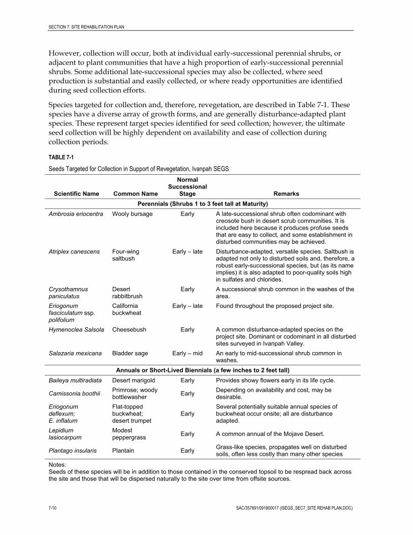
SECTION 7: SITE REHABILITATION PLAN
However, collection will occur, both at individual early-successional perennial shrubs, or adjacent to plant communities that have a high proportion of early-successional perennial shrubs. Some additional late-successional species may also be collected, where seed production is substantial and easily collected, or where ready opportunities are identified during seed collection efforts.
Species targeted for collection and, therefore, revegetation, are described in Table 7-1. These species have a diverse array of growth forms, and are generally disturbance-adapted plant species. These represent target species identified for seed collection; however, the ultimate seed collection will be highly dependent on availability and ease of collection during collection periods.
TABLE 7-1
Seeds Targeted for Collection in Support of Revegetation, Ivanpah SEGS
Scientific Name Common Name
Normal Successional
Stage Remarks Perennials (Shrubs 1 to 3 feet tall at Maturity)
Ambrosia eriocentra Wooly bursage Early A late-successional shrub often codominant with creosote bush in desert scrub communities. It is included here because it produces profuse seeds that are easy to collect, and some establishment in disturbed communities may be achieved.
Atriplex canescens Four-wing saltbush
Early – late Disturbance-adapted, versatile species. Saltbush is adapted not only to disturbed soils and, therefore, a robust early-successional species, but (as its name implies) it is also adapted to poor-quality soils high in sulfates and chlorides.
Crysothamnus paniculatus
Desert rabbitbrush
Early A successional shrub common in the washes of the area.
Eriogonum fasciculatum ssp. polifolium
California buckwheat
Early – late Found throughout the proposed project site.
Hymenoclea Salsola Cheesebush Early A common disturbance-adapted species on the project site. Dominant or codominant in all disturbed sites surveyed in Ivanpah Valley.
Salazaria mexicana Bladder sage Early – mid An early to mid-successional shrub common in washes.
Annuals or Short-Lived Biennials (a few inches to 2 feet tall) Baileya multiradiata Desert marigold Early Provides showy flowers early in its life cycle.
Camissonia boothii Primrose; woody bottlewasher Early Depending on availability and cost, may be
desirable. Eriogonum deflexum; E. inflatum
Flat-topped buckwheat; desert trumpet
Early Several potentially suitable annual species of buckwheat occur onsite; all are disturbance adapted.
Lepidium lasiocarpum
Modest peppergrass Early A common annual of the Mojave Desert.
Plantago insularis Plantain Early Grass-like species, propagates well on disturbed soils, often less costly than many other species
Notes: Seeds of these species will be in addition to those contained in the conserved topsoil to be respread back across the site and those that will be dispersed naturally to the site over time from offsite sources.
7-10 SAC/357891/091800017 (ISEGS_SEC7_SITE REHAB PLAN.DOC)

SECTION 7: SITE REHABILITATION PLAN
7.3.1.5 Selected Plants for Transplanting Attempts at transplanting desert plants have often met with unsatisfactory results. Even when supported by the extensive research and testing facilities at Castle Mountain Mine, transplant success was reported as very low and generally ineffective (Bamberg Ecological, 2006). Even efforts initially reported as successful were clouded by later reports of high mortality after several years of monitoring. However, because of their ecophyisological adaptations, transplanting succulents can be quite successful. This includes barrel cacti (Echinocactus; Ferocactus) and various species of cholla and prickly-pear (Opuntia), which establish well from individual joints and pads. These transplants can be especially advantageous in acting as “nurse plants,” that is, grown plants in revegetation areas that provide beneficial modifications to the microclimate, such as shading or wind protection, which can enhance establishment of seeded plant species (Kigel, 1995).
Yuccas (Yucca schidigera) are also often transplanted on desert restoration sites. They are a common element of the flora at Ivanpah SEGS, occurring in much higher densities than barrel cacti. However, survivorship is notably reduced in yucca transplants compared to other succulents, and the costs may be much higher (Bainbridge, 2007; Bamberg Ecological, 2006). At Castle Mountain Mine, transplanted Yucca schidigera mortality within 3 years after planting was reported from 30 to over 50 percent. Subsequent years saw higher mortality rates, and in the end, the transplant program for yuccas was not considered successful (Bamberg Ecological, 2005; Bamberg Ecological, 2006). In a study reported by Abella and Newton (2009), double-transplanted Y. schidigera had survival rates of only 39 to 53 percent over the limited (2-year) monitoring period; rainfall was potentially above average for the study period. For these reasons, salvage of yuccas is not proposed for the Ivanpah SEGS project.
Transplanting of succulents is proposed on Ivanpah SEGS revegetation sites, as described in more detail in Section 4.
7.3.2 Seed and Native Stock Collection and Storage 7.3.2.1 Seed Bank Protection In temporary disturbance areas at Ivanpah SEGS, the existing seed bank will have a substantial contribution to successful revegetation. This seed has advantages over subsequently sown seed in that it has originated locally, and is best adapted to the local microclimate and site conditions; and secondly, it has resided in the topsoil and/or litter for some unknown period of time, during which seed dormancy may have been broken.
However, soil disturbance is likely to excessively disrupt the position of seeds in the soil column, and seed buried at depths greater than 2 to 3 centimeters might not emerge (Kigel, 1995). Measures have been proposed for vegetation windrowing, which will capture seed still on the plant, and topsoil salvage and banking, as described above. These measures will, to some extent, preserve at least a portion of the seed bank intact.
7.3.2.2 Seed Supply Production of native seeds is highly cyclical, depending largely on annual precipitation timing and amount, but may be affected by other factors such as untimely storms during pollination (Bainbridge, 2007). However, in general, soil moisture is the limiting factor in desert ecosystems, and will ultimately determine the extent to which: (1) annual plants
SAC/357891/091800017 (ISEGS_SEC7_SITE REHAB PLAN.DOC) 7-11

SECTION 7: SITE REHABILITATION PLAN
germinate; (2) germinated plants mature to produce fruit and set seeds; (3) perennial plants produce fruit and set seed; and (4) seed crop is productive and viable (Delph, 1986; Kigel, 1995). For optimal seed collection of perennials, a relatively wet rainy season will result in higher seed production. However, even a single, large rain occurring during late fall or early winter can result in annual germination and seed production; however, soil moisture must persist long enough for plants to mature and set seeds. When plants are able to germinate earlier in the normal germination season (fall and winter), they generally produce a higher seed crop (Narita, 1998; Kigel, 1995). However, if heavy rains occur too early in the fall, and annual plants respond by germinating, they can be vulnerable to subsequent heat and desiccation.
Because it requires responding to precipitation events that are not effectively predictable, advanced planning of seed collection will be required to ensure early and continuous seed collection, as needed, up to the time of planting. A seed collection program will be initiated as soon as the CEC license and BLM grant are received, and continue through until revegetation seed broadcast is complete. This will allow for some variation in annual seed production while still ensuring a robust collection. If sufficient seed are not recovered prior to the start of ground disturbance of areas that will need to be restored first, the collection area will be expanded to the surrounding area until sufficient seed quantity has been collected.
7.3.2.3 Seed Viability and Testing Seed production can vary widely in both quantity and quality, and seed viability may show enormous variability depending on the year of collection (Bainbridge, 2007). Quality of seed collected is also influenced by the maturity at collection, which must be closely monitored. Seed production, quality, and maturity should be monitored ahead of and throughout the collection season to ensure collection is valuable. Ongoing testing will be performed as collections are obtained (for example, cut tests, described below), to gauge maturity and viability of seed. Testing may include the following (Bainbridge, 2007):
� Filled seed percentage will be conducted by cut tests, where a sampling of seeds is cut open and inspected for seed filling, maturity, or insect damage. Cut tests must include comparisons with data on expected filled seed percentages per species.
� X-ray evaluation will provide information on filled seed percentage, insect damage, physical damage, and potentially tissue condition and maturity. X-ray evaluation is generally performed by skilled technicians familiar with wild seed evaluations.
� Seed weight, purity, and germination analysis are typically performed on commercial seed, and include the 1,000-seed weight, purity (proportion of seed to impurities such as chaff, other seed species, and debris), and percent germination. Germination tests must be performed by skilled technicians familiar with the challenges of germinating arid land seed.
7.3.2.4 Seed Collection Seed collection will be initiated as soon as the CEC license and BLM grant are received, or at least 2 years prior to ground disturbing activity, as needed to ensure adequate collection quantities, and will continue until adequate seed has been acquired for site revegetation, or until revegetation is complete. Seed collection is intended to support all revegetation efforts,
7-12 SAC/357891/091800017 (ISEGS_SEC7_SITE REHAB PLAN.DOC)

SECTION 7: SITE REHABILITATION PLAN
including temporary disturbance areas where reclamation and revegetation will occur after construction is complete, but during continued facility operations, or reclamation and revegetation upon site closure and decommissioning. Long-term seed storage (that is, greater than 5 to 10 years) is not proposed; rather, seed will be collected only far enough in advance to ensure availability at the time of seeding requirements based on concluding construction or initiating closure plans.
The seed to be collected will be of local origin, collected preferably at the site, but no farther than 25 miles from the Ivanpah SEGS project area, and at similar elevations and vegetation conditions. Under the following conditions, seed will be collected directly from the Ivanpah SEGS project area before site disturbance: (1) appropriate early successional species are available within the proposed disturbance area; and (2) seeds from these species meet collection criteria—specifically, criteria on filled seed percentage and maturity, to be developed per species and as described in Section 7.5.3, Protocol for Seed Collection and Storage.
A seed “collection” will represent seed collected from a single “collection area” (generally defined to be no more than a 0.25-mile radius) on a single day. Mature seed will be collected from healthy, robust stands. To increase genetic diversity, no more than 10 percent of each collection will come from an individual plant. Bulk seed (that is, accumulated in depressions or at the base of shrubs) will also be collected, focusing on locations where a high proportion of early-successional native plants are present and seed is sufficiently mature. The plants targeted for direct seed collection are listed in Table 7-1.
To avoid overharvest of a specific area, no more than 40 percent of seeding plants in a collection area will be harvested. A collection area will only be harvested one year for the duration of the collection effort. Each collection area will be visited as frequently as necessary during the seed production period of the year, staying within these specified parameters. Access to collection areas will be via open, well-traveled routes, or on foot, with no cross-county vehicle travel. The only exception to these access limitations will be for seed collections within the Ivanpah SEGS construction areas proposed for vegetation clearing within a 2-year period following seed collection. In these areas, no limits to the amount of seed or method of seed collection will be placed on seed collection efforts, because all vegetation will be removed during construction, and maintaining natural seed stock for a self-perpetuating plant community will not be necessary. However, the limits of these areas will be flagged prior to seed collection efforts. Total quantity of anticipated seed for temporary revegetation areas is provided below in the section on Seed Quantity.
Diversity will be achieved in the seed mix by collecting bulk seed from locations where it accumulates, such as depressions or at the base of shrubs. Additional seed, which is easy to collect, may be added from late-successional species, such as burro bush. Site characteristics and seed-lot tracking will be performed, including notes on collection date, dominant species, stand conditions, and expected species composition of seed. Seed will not be collected from areas with noxious weeds present, unless collected directly from native plants in the area. Bulk seed will be handled, processed, and applied independent of single-species seed collections, as described in sections that follow.
SAC/357891/091800017 (ISEGS_SEC7_SITE REHAB PLAN.DOC) 7-13

SECTION 7: SITE REHABILITATION PLAN
7-14 SAC/357891/091800017 (ISEGS_SEC7_SITE REHAB PLAN.DOC)
7.3.2.5 Seed Processing Cleaning, dewinging, and upgrading seed before storage can: (1) reduce weight and bulk, (2) improve storage life, and (3) increase germination. Seed processing may include removal of leaves, twigs, and other debris, and rubbing seed to free it from the fruiting structure. Sieving seed can separate debris. Commercial threshers, dehullers, and harvesters are available (Bainbridge, 2007). Seed processing for single-species lots will be implemented by skilled technicians knowledgeable about individual species requirements, because some treatments can damage seed.
Native seed vendors who are familiar with native, wild desert seed collection will be contracted to collect, process, and store seed for the Ivanpah SEGS project.
Bulk seed collections will not be processed. These collections will be applied as collected and as available in addition to single-species seed quantity specified in this Plan to increase diversity, and add additional litter and debris to the seed application.
7.3.2.6 Native Seed Vendors Native seed vendors will be contracted to collect seeds as specified in this Plan. Under this Plan, federal certification content of seed will be negotiated to include, at a minimum, collection location, collection date, and approximate seed content by species, purity, germination, origin, test data, and net weight (as pure live seed). Seed must contain a zero percent noxious weed seed to be acceptable. Tests performed by vendors will be specified in contract documents, and are outlined in sections to follow.
Native seed vendors that may serve this project are provided in Table 7-2. Vendors will be brought under contract so that collection can begin once the project obtains a license from the CEC and a ROW grant from BLM, ideally at least 2 years prior to ground-disturbing activities. Vendors will be responsible to ensure appropriate permitting for seed collection on BLM land within the Ivanpah SEGS site, or other public and private lands in the area. Vendors will be responsible for handling, processing, and storing native seed per the requirements of this plan.
7.3.2.7 Seed Quantity Table 7-3 provides a preliminary seeding plan on a per acre basis for temporarily disturbed areas, and provides estimates of quantities of seed that will be applied to meet target application rates. Where bulk seed is collected, it will not be distinguished by species, nor cleaned or processed, but it will be used to augment single-species seed quantity as previously discussed to increase diversity.
Based on seeding rates of 22 lbs/ac, total anticipated seed required for temporary disturbance areas is provided in Table 7-4. This represents a preliminary estimate and will be revised based on final impact acres and seed availability.

SECTION 7: SITE REHABILITATION PLAN
TABLE 7-2 Native Seed Vendors Potentially Servicing the Southwest United States
Company Name City State Web Site
Constance Vadheim Redondo Beach CA www.nativeseednetwork.org/viewuser?id=10696
Arkansas Valley Seed Richard Avila Denver CO avseeds.com
Armenta Seed Ray Armenta Gilbert AZ
Autumn Seeds, LLC Roger Williamson Spokane Valley WA www.autumnseeds.com
Clearwater Seed Mark Mustoe Spokane WA
Comstock Seed Ed Kleiner Gardnerville NV www.comstockseed.com
Detwiler's Native Grass Seed Co. Joe Detwiler Bonham TX
Granite Seed Company Daryle Bennett Lehi UT www.graniteseed.com
Great Basin Seed Jason Stevens Ephraim UT www.greatbasinseeds.com
Intermountain Seed Co. Eric Christensen Ephraim UT
Los milagros de Lara A. Subero Loxahatchee FL
Mimbres Valley Sweetwater Farms Brooke Feldman Mimbres NM
Native and Xeric Plants Stew Churchwell Emmett ID www.nxplants.com
Native Seed Network Rob Fiegener Corvallis OR
Noorani Seeds Usman Hayat Hyderabad Sindh, Pakistan www.nooraniseeds.com
RECON Native Plants Ryan West San Diego CA www.reconnativeplants.com
Seeds Trust, High Altitude Gardens Bill McDorman Cornville AZ seedstrust.com
S&S Seeds Jodi Miller Carpinteria CA www.ssseeds.com
Stevenson Intermountain Seed, Inc. Ron Stevenson Ephraim UT www.stevensonintermountainseed.com
Stock Seed Farms, Inc John Shipp Murdock NE www.stockseed.com
Stover Seed Company Stephen Knutson Los Angeles CA www.stoverseed.com
Source: http://www.nativeseednetwork.org/
SAC/357891/091800017 (ISEGS_SEC7_SITE REHAB PLAN.DOC) 7-15

SECTION 7: SITE REHABILITATION PLAN
7-16 SAC/357891/091800017 (ISEGS_SEC7_SITE REHAB PLAN.DOC)
TABLE 7-3 Preliminary Seeding Plan for Ivanpah SEGS, Temporarily Disturbed Areas
Scientific Name Common Name Bulk lbs/ Acre ~Live Seeds/ Bulk lb
Total Live Seeds/Acre
Total Live Seeds/m2
Ambrosia eriocentra Wooly bursage 2 30,000 60,000 14.8
Atriplex canescens Four-wing saltbush 10 26,000 260,000 64.2
Crysothamnus paniculatus Desert rabbitbrush 1 65,000 65,000 16.1
Eriogonum fasciculatum ssp. polifolium
California buckwheat 3 35,000 105,000 25.9
Hymenoclea Salsola Cheesebush 6 35,000 210,000 51.9
TOTAL 22 700,000 173.0
TABLE 7-4 Construction Disturbance Areas at Ivanpah SEGS and Preliminary Estimated Seed Requirements
Project Component/
Phase
Temporary Disturbance (Reclamation
within 5 Years, Acres)
Seed Requirement for Temporary Impact Area
(Total Bulk lbs)*
Long-term Disturbance
(Reclamation after Decommissioning,
Acres)
Seed Requirement for Long-term Impact Area
(Total Bulk lbs)
TOTAL AREA (Temporary + Long-term) TOTAL SEED
KRGT Line Area 2.67 59 0.90 20 3.57 79
Ivanpah 3 400.33 8807 277.64 6108 686.50 14915
Ivanpah 2 129.43 2848 184.27 4054 314.56 6901
CLA 298.07 6558 53.18 1170 388.10 7727
Ivanpah 1 1.37 30 182.19 4008 183.56 4038
TOTAL 831.88 18301 698.17 15360 1576.30 33661
* Assumes seeding rate of 22 pounds per acre.

SECTION 7: SITE REHABILITATION PLAN
7.3.2.8 Seed Storage The seeds of many native plants can lose their viability quickly if they are not stored under controlled conditions. Because seeds are hygroscopic (that is, they pick up and release moisture from the air), their moisture content can increase to a point where they are vulnerable to storage fungi or mold. Seed moisture content of 10 percent or less is preferred (Elias et al., 2002) and can be achieved by drying seed and maintaining low storage temperature and relative humidity. Seeds in storage must also be protected from rodents and insect pests, such as weevils.
Seed for Ivanpah SEGS will be dried to less than 10 percent moisture using air flow methods with no heat (Bainbridge, 2007), and stored immediately in seed storage units, which may include walk-in freezers or temperature and humidity controlled rooms or vaults. Seed should not be frozen unless first dried. Seed should be stored in sealed containers to keep out insect pests. Native seed vendors will be responsible for appropriate seed storage in compliance with contract documents.
Dormancy is common in the seeds of many native species. Specialized methods, or specific storage conditions, are often necessary to break seed dormancy effectively. This can be complicated by year-to-year and plant-to-plant variation.
The seed storage approach at Ivanpah SEGS will include packing seeds in sealed containers and storing in temperature and humidity controlled seed storage units until 2 months prior to use. Prior to use, seeds will be relocated to mesh covered containers to keep insects out, stored within rodent proof cages. These will be placed at ground level at the actual revegetation sites in an effort to break dormancy. Bulk, unprocessed seed collections will be stored using same methods for single-species seed collections.
Long-term seed storage (that is, greater than 5 to 10 years) is not proposed; rather, seed will be collected only far enough in advance to ensure availability at the time of seeding requirements based on site development or closure plans.
7.3.3 Protocol for Collection and Storage 7.3.3.1 Seed Collection 1. Seed collection will be implemented as soon as the CEC license and BLM grant are
received or a minimum of 2 years prior to ground disturbing activity; and continue until adequate seed has been acquired for site revegetation, or until revegetation is complete. Adequate seed quantity is based on Table 7-4.
2. Seed of local origin will be collected within 25 miles of the Ivanpah SEGS project area and at similar elevations and vegetation conditions. Seed will be collected directly from the Ivanpah SEGS project area before site disturbance where conditions permit.
3. The contractor will define a seed “collection” to represent seed collected from a single “collection area” (generally defined to be no more than a 0.25-mile radius) on a single day and label as such.
4. To avoid overharvest of a specific area, no more than 40 percent of seeding plants in a collection area will be harvested. A collection area will only be harvested 1 year for the duration of the collection effort. Each collection area will be visited as frequently as
SAC/357891/091800017 (ISEGS_SEC7_SITE REHAB PLAN.DOC) 7-17

SECTION 7: SITE REHABILITATION PLAN
necessary during the seed production period of the year, staying within these specified parameters. The only exception will be for seed collections within the Ivanpah SEGS construction areas proposed for vegetation clearing within a 2-year period following seed collection. At these locations, there will be no limits on overharvest because vegetation will be removed during construction.
5. Access to collection areas will be via open, well-traveled routes, or on foot, with no cross-county vehicle travel.
6. Contractor will collect mature seed from healthy, robust stands. To increase genetic diversity, collect no more than 10 percent by weight of each collection from an individual plant.
7. Contractor will collect from a minimum of 20 collection areas.
8. Contractor will collect single-species seed, focusing on locations where a high proportion of early-successional native plants (Table 7-1) with sufficiently mature seed are present.
9. Contractor will collect additional seed from directly beneath plants or collect bulk seed to increase diversity from locations where it accumulates, such as depressions or at the base of shrubs.
10. Contractor will opportunistically collect high concentrations of ripe seed from native annuals or perennials, where available, while collecting target successional species.
11. Contractor will perform site characterization and seed-lot tracking, including notes on collection date, collection location, elevation, dominant species at location, stand conditions, approximate seed content by species, purity, germination, origin, test data, and net weight (as pure live seed).
12. Contractor will not collect from areas with noxious weeds present, unless collected directly from native plants in the area.
7.3.3.2 Seed Testing 1. For single-species collections, Bright Source Energy will develop criteria for filled seed
percentage based on literature review, preliminary field findings, and independent review for each species. Criteria will be standard for seed collections, and collection quantity will be adjusted appropriately where filled seed percentage criteria are not met.
2. For single-species collections, contractor will sample and perform field tests prior to and during seed collection. Field testing will include the following:
� Filled seed percentage conducted by cut tests, sampling a minimum of 50 seeds from each species at each collection area; all results per seed collection will be documented and reported.
� Seed maturity conducted by field observations and cut tests. All results per seed collection will be documented and reported.
3. For single-species collections, contractor will sample and perform laboratory tests on each seed collection to document seed weight (1000-seed weight), purity, and
7-18 SAC/357891/091800017 (ISEGS_SEC7_SITE REHAB PLAN.DOC)

SECTION 7: SITE REHABILITATION PLAN
germination. A minimum of 1 percent of each collection will be sampled by weight, by species, and by randomly selecting a minimum of 3 samples from each collection. All results per seed collection will be documented and reported.
7.3.3.3 Seed Processing 1. For single-species collections, contractor will clean seed of leaves, twigs, and other
debris; free seed from fruiting structures, and sieve seed as appropriate for individual species of seed, and to do so in a way that does not damage seed.
2. Bulk seed collections are not to be processed.
7.3.3.4 Seed Storage 1. After collection and processing, Contractor will dry seeds using forced air and no heat,
to a moisture content of 10 percent or less, and store in airtight storage containers.
2. Contractor will store seed in a temperature-controlled seed storage unit until 2 months prior to sowing at a constant temperature of 55°F or less and a controlled relative humidity (RH) of 45 percent or less.
3. If seed storage is required for more than 1 year, storage temperature will be reduced to 50°F or less, and RH will be reduced to 40 percent or less.
4. Prior to sowing, seeds will be relocated in paper bags, stored within nylon mesh (for example bug netting, nylon stockings) and rodent-proof cages. Seeds will be stored at ground level at the site of revegetation for a minimum period of 2 months in an effort to break dormancy. Within storage cages, seed lots will be covered with burlap.
5. Bulk seed collections will be stored identically to single-species seed collections.
6. Seeds will be stored a maximum of 10 years; seed stores will be replenished based on anticipated need thus precluding the need to store beyond 10 years.
7. Salvage plant storage is addressed in Section 4, Native Plant Salvage and Reuse.
7.3.4 Propagation 7.3.4.1 Germination Germination is the most vulnerable phase in plant development, representing the risky transition from seeds, which are the most resistant to drought and temperature extremes, to seedlings, which are the most sensitive. Hence, complex adaptations have developed in plants to regulate germination in arid environments (Kigel, 1995). This ensures that when germination occurs, there is likely to be ample soil moisture to support the developing plant, and temperatures will be favorable to plant growth. In desert annuals, a successful germination strategy will lead to rapid flower and seed production. In perennials, this strategy will lead to better chances of seedling survival and long-term plant establishment.
Mass germination occurs only after a certain threshold of precipitation occurs (effective rain), and typically in desert environments, that can vary depending on microtopography, substrate permeability, and evaporation. Rain events less than the needed threshold can result in patchy germination, primarily where runoff has collected. Multiple mass germination events can occur throughout the season if episodic rain events occur, resulting
SAC/357891/091800017 (ISEGS_SEC7_SITE REHAB PLAN.DOC) 7-19

SECTION 7: SITE REHABILITATION PLAN
in different cohorts of developing plants. Generally, early germinants will have a competitive advantage, unless an extended drought period occurs after the early-germination effective rain, in which case, high mortality could occur among early germinants (Kigel, 1995).
7.3.4.2 Dormancy Moisture availability is not the only factor in determining germination of seeds in arid areas. Seeds of arid land plants often have an inherent dormancy and will not germinate even in a controlled setting until that dormancy is broken. Dormancy can be either intrinsic to the embryo, or imposed by the coat of the seed or the dispersal mechanism (Kigel, 1995). It can result from chemical inhibitors that are released upon initial seed hydration, but could take additional water to ultimately leach away. Mechanical or physical barriers can also be imposed by the seed or dispersal mechanism coat that: (1) prevent embryo growth or root elongation, (2) are impermeable to water or gases, or (3) release chemical inhibitors (Kigel, 1995).
Because multiple dormancy mechanisms are often present, methods for breaking dormancy can be complex and are commonly species-specific. Chemical inhibition to germination can often be broken by repeated leaching (Bainbridge et al., 1995; Kigel, 1995); however, this could also be affected by seed age, which plays a role in breaking physical dormancy. Changes in the physical environment, such as temperature or photoperiod changes (termed stratification), or physical alteration of the seed coat (scarification), can play a critical role in releasing dormancy in some desert plants (Bamberg Ecological, 2005).
Rinsing seeds prior to seeding to remove inhibiting chemicals is a commonly used practice to improve germination success rates for some species. Rinsing is particularly effective for creosote to remove inhibiting chemicals (Bainbridge et al., 1995). Scarification can be achieved by physically roughening seed coats by tumbling with sand, or chemically attacking seed coats with compounds such as sulfuric acid. Stratification can be achieved by storage under cold-moist or warm-moist conditions. Requirements of some seeds may include remaining in the soil for 1 or more years before they are able to germinate (Bamberg Ecological, 2005). Capon and Van Asdall (1967) found that annuals native to the Mojave and Sonora deserts reached maximum germination when subjected to up to 5 weeks of higher temperatures (122°F) prior to planting. Daily temperature fluctuations are reported as an important requirement for breaking dormancy in arid and semi-arid species of hard-seeded annuals (Kigel, 1995).
Because seed will not be irrigated in the field, but left to germinate with natural precipitation, dormancy may be broken by natural conditions after sowing. The targeted early-successional species tend to have less rigorous requirements for breaking dormancy than late-successional species (Bamberg Ecological, 1995). Treatment implemented on seed supplies to break dormancy will include: (1) storing seeds in the field prior to sowing to affect a natural warm and cold regime, which may result in stratification; and (2) sowing seeds in the fall when field conditions should be optimal to break dormancy naturally.
7.4 Applicable Planting Techniques The seeding techniques discussed in this section are restricted to those that will be applicable at the Ivanpah SEGS. Other techniques are not discussed. For example,
7-20 SAC/357891/091800017 (ISEGS_SEC7_SITE REHAB PLAN.DOC)

SECTION 7: SITE REHABILITATION PLAN
hydroseeding is rarely used in desert restoration; Bainbridge et al. (1995) strongly discourage its use for any desert revegetation, primarily because precipitation or irrigation must follow seeding, or the pre-soaked seed will fail. In addition, large quantities of water are needed. These are consistent with the findings of other desert revegetation studies.
7.4.1 Seeding Relative to other project costs, seed is a small component, and seeding rates should be high to account for the potential for poor germination as well as predator loss. Specific challenges with seeding and appropriate remedies to those challenges are summarized in this section.
A major drawback of seeds is that they are very vulnerable to predation from mice, birds, and seed-eating insects. Up to 95 percent of seed sown can be expected to be lost to predation prior to germination and establishment. Ants, in particular, are a significant factor in the loss of seeds prior to germination in the Mojave (Anderson and Ostler, 2002). A possible approach to reducing ant predation is to apply cracked wheat to the soil surface prior to seeding so the ants are satiated; however, where germination relies on natural rainfall, this method might not be effective because it could be a period of one or more years from seeding to germination (Bainbridge et al., 1995).
Compensating for variability in annual rainfall by ensuring seed are persistent once sown increases chances of germination. Effective rainfall events might not occur every year, but chances substantially increase over a 2- to 3-year period. Ensuring seed persistency requires reducing predation by burying seed, which can be achieved by dragging seed with a light drag or drilling seed with a rangeland seed driller. While buried seed may also be predated, it is likely to persist at greater rates than surface seed. Surface seed not predated by ants can be collected by wind in basins and depressions, where if discovered by rodents, it becomes a concentrated resource visited continuously. Kangaroo rats (Dipodomys spp.) are adapted to exploit concentrated seed collections (such as shedding plants or seeds collected in depressions). Alternatively, pocket mice (Perognathus spp.) are better adapted to sift surface soils for shallowly buried seeds.
The low cost of a seeding approach relative to vegetative container-grown plants will be, at least partially, offset by the lower expected success rate. It takes many seeds to result in one plant seedling. For most species, seeding rates of 100 to 500 seeds per square meter are recommended (Bainbridge et al., 1995; Bainbridge, 2007).
Most desert seeds under natural conditions are located at or near the soil surface. As many as 80 or 90 percent of the seedbank is within 2 centimeters of the soil surface with many located within millimeters of the surface or in surface litter. Seedlings of many desert annuals cannot emerge from depths greater than 1 centimeter, and desert shrubs usually do not emerge from depths greater than 4 centimeters (Kigel, 1995). These data are important in planning seed broadcasting. However, the depth of seed placement must be balanced against the risks of predation.
Typical seed application methods are summarized in the following sections.
7.4.1.1 Imprint Seeding Placing seeds in a pattern of small mechanically created depressions is a potentially useful technology for areas with finer textured soils. Seeds remain trapped in depressions, which
SAC/357891/091800017 (ISEGS_SEC7_SITE REHAB PLAN.DOC) 7-21

SECTION 7: SITE REHABILITATION PLAN
subsequently capture water during rainfall events or irrigation. Imprinting is not useful on loose and sandy soils, where erosive forces may quickly relevel the surface (Bainbridge et al., 1995). Imprinting may be most effective in areas where infiltration is limited by surface crusts and areas with summer and winter rains (Bainbridge et al., 1995).
Imprint seeding is not proposed for Ivanpah SEGS, primarily because imprinted seed is still exposed to surface predation, and seed might not persist over the long time periods that may be required for natural germination. Imprint seeding was successfully used during revegetation efforts at Edwards Air Force Base, but irrigation was used in that effort (CH2M HILL, 2006). However, post-seeding imprinting is proposed in limited instances at Ivanpah SEGS to increase water retention.
7.4.1.2 Broadcast Seeding Broadcast seeding can be a viable approach for desert restoration. Seeding can be distributed by hand, by manual wheeled devices, or by seeding equipment. On large sites, seed has also been aerial broadcast by cropdusters (Bainbridge et al., 1995). An implement that can lightly disturb the soil surface is needed after seeding for incorporation (covering the seeds with soil). One example of equipment effective at incorporating seed is a drag consisting of a flat framework supporting small tines that disturb the soil. Seeding rates should be 50 to 100 percent higher for broadcast as compared with drill seeding because predation losses tend to be greater for broadcast seed than for drilled seed (Bainbridge et al., 1995).
7.4.1.3 Rangeland Drill Seeding A rangeland drill is a seeding implement designed to open a slot in the soil, place seeds in the slot, and firmly cover the seeds with soil. Rangeland drill seeding is effective on relatively level terrain; but debris and rocks could be problematic, and a rangeland drill might not operate in rough or rocky terrain. In addition, resulting seeding may be in rows when germination occurs, and may not appear natural. The appearance of rows diminishes with time. Using multiple seed bins on the drill may be required to accommodate differences in seed characteristics.
7.4.1.4 Pitting and Seeding Bainbridge (2007) described sowing seeds in pits as a means to improve germination and seedling establishment. Pits can be created with machinery designed for the task, or by hand. Pit size varies depending on the equipment, but may be from a few to 8 inches deep, and up to 16 inches square. Seed is sown directly into each pit, and mulch or other material can be placed into the pit to increase moisture retention. Pits have been created by modified disk plows, and specialized equipment is also available that both pits and seeds simultaneously (for example, the Kimseed camel pitter-seeder).
Limitations to this approach are comparable to imprintin—that is, seed is not buried during the pitting process, but is left exposed (or covered with light mulch) in the bottom of the pit. Unburied seed runs the highest risk of predation. It is not proposed at Ivanpah SEGS, because the approach of waiting for natural precipitation to germinate seed requires seed persistence.
7-22 SAC/357891/091800017 (ISEGS_SEC7_SITE REHAB PLAN.DOC)

SECTION 7: SITE REHABILITATION PLAN
7.4.2 Mulch Distribution of mulch after or during seeding allows for protection of the soil surface from erosion, could provide some seed protection, and may enhance water infiltration and retention (Bainbridge, 2007). While weed-free certified mulch is available from commercial vendors, the recommendation for Ivanpah SEGS is that mulch be shredded from existing windrowed vegetation or mowed vegetation from the heliostat fields. This material will potentially be supplemented with commercial products with high carbon to nitrogen ratios (C:N), as excess nitrogen can favor weed growth. Suitable products may include barley or wheat straw, rice hulls, wood chips, corn cobs, or bark. Only weed-free certified products from commercial vendors will be used, and only if material collected from onsite sources is substantially insufficient in quantity. Between 10 and 20 cubic yards (cy) of mulch per acre (approximately 0.5 to 4 tons per acre of dry mulch, depending on product) represents a light mulch application with scattered coverage that will collect in depressions or rough spots, appropriate for desert applications where mulch degrades slowly. Mulch applied at this rate will be expected to collect in pockets of low soil along with seed, and where water will also concentrate after rain events, maximizing potential for resource conditions that will promote vegetation establishment. Table 7-5 provides data on bulk density of select mulch products.
TABLE 7-5 Mulch Material Bulk Density Measurements
Product Material Moisture Bulk Density (lbs/cy) Bulk Density (cy/ton)
Alfalfa hay Low 202 9.9
Hop straw Low 60 33.0
Wood chips ~30% 424 4.7
Cereal straw Low 60 33.0
Shredded paper Low 60 33.0
Newsprint Low 220 9.1
Sawdust/shavings ~40% 424 4.7
Source: Granatstein et al., 2002
7.4.3 Container-grown Plants Container-grown plants have been used on desert revegetation projects, although this practice is generally confined to relatively small restoration areas (CH2M HILL, 2006). Container stock installation requires an associated irrigation method to supply irrigation through the first year at a minimum. While container-grown stock could provide rapid cover in the short-term, it may not provide any greater cover or density over the long-term compared with other seeding approaches to warrant the additional expense. In addition, the irrigation required provides additional challenges in remote locations, as described in Section 7.5, Irrigation and Natural Precipitation. For this reason, installation of container-stock is not proposed at Ivanpah SEGS, except for landscaping with native vegetation around some facilities, as described in Section 6.
SAC/357891/091800017 (ISEGS_SEC7_SITE REHAB PLAN.DOC) 7-23

SECTION 7: SITE REHABILITATION PLAN
7.4.4 Natural Colonization This alternative relies only on natural processes, such as viable seeds that may remain in the topsoil after disturbance or seeds that blow in or are transported by animals to revegetate the site. Revegetation will ultimately occur through natural colonization, or at a slower rate than seeding approaches and with less predictable results. This approach is particularly hampered by the loss of a portion of the natural seed bank during soil disturbance. As such, this approach is not considered viable at Ivanpah SEGS.
7.4.5 Planting Protocol Planting protocol will consist of augmenting the native seed bank with additional seed, as summarized in this section:
1. Topsoil will be reapplied to temporary disturbance areas prior to seed application.
2. All soil rehabilitation and preparation will be completed prior to seed application.
3. Seed will be removed from site stratification storage at the time of seeding.
4. Seed from multiple lots will be thoroughly blended into a single application batch. Seed count in pure live seed by weight will be determined in the application batch from individual seed lot statistics contributing to the batch.
5. Seed will be distributed in rates as specified in Table 7-4, or at a minimum rate of 150 seeds per square meter of seeded area. Final seed type and application rates will be consistent with intent of Table 7-3, but will be based on local availability and collections at the time of seeding and a minimum seeding rate of 150 seeds per square meter.
6. Seed will be distributed using a rangeland drill seeder through two passes. One half of the seed application will be drilled into the soil to a depth no greater than 0.5 inch. The second half of the seed application will be applied with a rangeland drill seeder with no disk openers or press wheels (essentially dropping the seed on the ground as a broadcast seeding).
7. The drill seeder will be followed with a light drag constructed from chain link fence, or otherwise harrowed to incorporate the seed into the top 0.5 inch of topsoil. Under no circumstances will seed be left exposed for more than 4 hours without dragging or harrowing. No seed will be buried greater than 1 inch.
8. Seeding will occur between October 15 and December 15.
9. Windrowed vegetation or mown vegetation will be preserved and stockpiled. Vegetation will be mulched to a large particle size (1 to 3 inches) using a chipper and preserved onsite under tarps. Apply mulch to temporary revegetation areas at a rate of 20 cy/ac after seed has been applied and dragged or furrowed.
10. If mulched vegetation quantity is not sufficient to apply 20 cy/ac, apply as available to a minimum of 10 cy/ac. If mulched vegetation quantity is not sufficient to apply 10 cy/ac, supplement to a 10 cy/ac application with certified weed-free straw mulch, sawdust, or other material as approved.
7-24 SAC/357891/091800017 (ISEGS_SEC7_SITE REHAB PLAN.DOC)

SECTION 7: SITE REHABILITATION PLAN
7.5 Irrigation and Natural Precipitation Even desert-adapted plants require water. Once established, plants have a transpiration demand, whereby they take up water by the roots and move it through the plant until it exits through the leaves. Some species are better able to reduce transpiration demand in dry periods or have other water-saving strategies such as storing water in leaves as with succulents. Regardless of the species, without water there is no germination, growth, and survival. Because of this, many desert revegetation efforts introduce additional water using irrigation techniques. This section discusses the relative merits, limitations, and typical methods of ensuring sufficient water on desert revegetation sites.
7.5.1 Water Demand Water to support plant germination, growth, and survival must either come from precipitation or irrigation, unless plant roots can access groundwater. Supplemental irrigation is often a revegetation strategy on smaller desert revegetation sites. Where irrigation is used, it is needed during the key establishment period of the first year and generally extends into the second year. Where planting consists of seeding, irrigation may be used to germinate seed and establish seedlings, along with supporting young plants through the first one or two seasons. Where planting consists of container stock, irrigation is always used to establish the plants through the first summer, at a minimum, and potentially into the second year. The objective is to provide greater predictability in the initial establishment period, while ensuring perennial vegetation can develop to the point where it relies on natural precipitation. Where there is enough precipitation during key establishment periods, little or no supplemental irrigation is needed.
7.5.2 Irrigation Irrigation approaches used in desert revegetation include truck irrigation, portable irrigation systems, and temporary pipe irrigation. These approaches all face challenges on larger desert revegetation efforts, and irrigation systems are generally not practical on desert revegetation projects greater than a few acres. Major challenges and disadvantages of irrigation on large desert sites include the following:
� Extensive pipe irrigation systems in remote locations are subjected to vandalism and rodent damage.
� Truck and portable irrigation systems are generally only able to supply smaller sites practicably, up to a few acres.
� Costs of providing and maintaining irrigation on larger or remote sites can be significant, and results may not be any better than nonirrigation approaches.
� Approaches that rely on irrigation could promote vegetation growth during periods of drought, when desert plants are normally in a period of inactivity, or are persisting in a seed stage that is most resistant to drought.
� Irrigation may not allow plants to become sufficiently hardened to persist after irrigation is turned off, or if sufficient irrigation is not provided.
SAC/357891/091800017 (ISEGS_SEC7_SITE REHAB PLAN.DOC) 7-25

SECTION 7: SITE REHABILITATION PLAN
� Irrigation promotes greater establishment of noxious weeds, which often outcompete natives in enhanced resource conditions, such as with increased water supply.
To minimize water efficiency, and to conform to the environmental conditions of the Mojave Desert, no irrigation is planned for revegetation of the Ivanpah SEGS.
7.5.3 Natural Precipitation Approach A detailed discussion of local climate is provided in Section 3. At about 5.1 to 6.2 inches (Table 3-2) per year, the amount of precipitation falling on the project area is low, with approximately one-third occurring as summer rains during the Southwest’s monsoon (July through September) and a half falling during the winter season (November through March). During the Mojave Desert’s arid foresummer (May through June), almost no precipitation can be expected while daily surface temperatures often exceed 110°F. As is typical of all deserts, rainfall varies dramatically from year to year. Sometimes there is scant rainfall for more than a year. The irregularity of rainfall is as much a feature of the precipitation climatology of Ivanpah SEGS as is the scant amount of rainfall received.
In wetter than normal years, rainfall is sufficient to trigger the germination and allow the establishment of annual and perennial plants. In normal to drier than normal years, seeds are unlikely to germinate, and they remain dormant in the soil, persisting until sufficient rainfall occurs. This form of adaptation to aridity (avoidance of drought by remaining dormant in the seed stage) is shared by virtually all annual plant species that occur in the Ivanpah SEGS project area. An important implication for revegetation is that seed, once broadcast and incorporated into the soils column, can persist until climatic conditions are favorable for germination and growth, even if it takes years (Shreve, 1964).
To maximize potential for seed to encounter favorable rainfall conditions for germination and establishment at Ivanpah SEGS, it will be lightly buried where it may persist for years. Under those conditions, when a wet year does occur, seed will still be available in the seed bank to establish a good cohort of perennial shrubs.
7.5.4 Rainwater Capture Methods Methods of soil preparation suitable to increase rainwater capture and management have been described by Bainbridge (2007). These methods include: (1) decompaction through deep ripping or surface scarification promoting infiltration; (2) surface shaping including microcatchments, swales, imprinting, pitting, furrowing or other methods; (3) soil pitting achieved through hand shaping or equipment specialized for this purpose, such as a disk plower with cutoff or elliptical discs; (4) imprinting (achieved by a rolling disk with teeth), which may create small depressions with less disruption to the topsoil, and effective water penetration; and, (5) rainwater harvesting through surface aprons or check dams, which may be effective to provide irrigation on small sites.
7.5.5 Proposed Approach To maximize potential for increased infiltration at Ivanpah SEGS, the following measures will be implemented:
1. Decompaction, where determined necessary by soil testing, will be implemented as described above.
7-26 SAC/357891/091800017 (ISEGS_SEC7_SITE REHAB PLAN.DOC)

SECTION 7: SITE REHABILITATION PLAN
2. In final recontouring of temporary disturbance areas, small basins or microcatchments will be shaped into the landscape, consisting of approximately 100 square foot depressions and creation of up to 100 to 200 depressions per acre; basins will be no deeper than 4 inches with slopes of 10 feet horizontal to 1 foot vertical (10:1) or less.
3. A light imprinting device will be passed over revegetation areas with suitable soils (loams or loamy sand) after distribution and dragging of seed. This will be anticipated to provide additional infiltration while still allowing seed to remain buried.
7.6 Herbivory and Granivory Revegetation sites are vulnerable to predation, herbivory, and other forms of animal damage. Specific problems include: (1) predation on seeds from ants, rodents, birds, or other granivores; (2) damage to irrigation lines, which would not be a problem because Ivanpah SEGS is not proposing irrigation; or (3) herbivory on seedlings or establishing plants.
Seed predation by ants and rodents is a major issue on seeded sites. To mitigate the effects of this predation, shallow burying is implemented, achieved through drill seeding combined with broadcast seeding and a drag or furrowing device being used to disperse seed and bury it in the top 1 to 2 centimeters of soil.
The concern of herbivory on seedlings and young growing plants can be lessened when relying on natural precipitation to germinate and establish seedlings. This is because the revegetation site will be established under the same precipitation regime as adjacent non-disturbed habitats. When effective-rain events occur, germination of annuals and perennials will be widespread throughout the entire area, providing an abundance of growing vegetation for herbivores and generally satiating the herbivore population. Therefore, grazing pressure on the revegetation site will be less than if it was irrigated, in which case the revegetated site will be the only actively growing site during dry periods.
Fencing of portions of the active facility is proposed to exclude wildlife. However, fencing is not proposed for temporary disturbance areas not within the active facility, for example, along the gas pipeline route. In these locations, continued herbivory of plants may occur. However, because the project relies on natural rainfall, herbivory is expected to be less, as described previously.
7.7 Weed Management The Weed Management Plan for the Ivanpah Solar Electric Generating System (Appendix B) describes the weed species that occur or are likely to occur in the project site and prescribes management actions that may be taken to monitor for an eradicate-specified species. Appropriate management thresholds for weeds are provided in the Weed Management Plan (WMP). The WMP also describes applicable regulations for the use of herbicides on federally managed lands in California and provides the basis for proper control of herbicides at Ivanpah SEGS.
The WMP is focused on ‘‘noxious weeds,’’ defined as any plant or plant product that can directly or indirectly injure or cause damage to crops, livestock, poultry, or other interests of agriculture; irrigation; navigation; the natural resources of the United States; the public health; or the environment. Noxious weeds are typically characterized by non-native plants
SAC/357891/091800017 (ISEGS_SEC7_SITE REHAB PLAN.DOC) 7-27

SECTION 7: SITE REHABILITATION PLAN
that aggressively colonize new areas and can grow to dominate or otherwise influence native plant communities if uncontrolled. This plan includes a list and an assessment of noxious weeds that could potentially occur, or do occur, in the project site; a target list of weeds that will be controlled; survey methods for weed presence during construction and operation; weed control methods; and reporting requirements. Weeds are further classified by their levels of impassivity to: (1) eradication, (2) suppression, or (3) containment.
Special consultations with respect to ubiquitous exotic species (for example, Bromus madritensis ssp. rubens, Erodium cicutarium, Schismus spp.) are anticipated because control of these may be impractical. These species are present throughout the Ivanpah Valley region in both disturbed and undisturbed habitats. In general, in this portion of the Mojave Desert, they do not exert excessive influence on the perennial shrub plant community structure either through dominance or potential fire hazard. However, they are a common component of the herbaceous strata in low to moderate density.
General measures to prevent the spread of weed propagules and inhibit their germination in the WMP include the following:
� Managing soil to promote native plant establishment � Limiting disturbance areas by defining ingress and egress routes � Worker environmental training � Maintaining vehicle wash and inspection stations � Reestablishing vegetation as quickly as practicable on disturbed sites � Monitoring weed infestations � Rapid implementation of weed management measures
The WMP is provided as Appendix B, and the requirements of the WMP are fully incorporated into the requirements of this document.
7.8 Revegetation Monitoring Monitoring and adaptive management of revegetation sites is generally necessary to ensure long-term native plant community establishment. Data collected prior to site development at Ivanapah SEGS is reported in Appendix E, Field Vegetation Sampling. This, in addition to reference site data that will be collected adjacent to revegetation sites in undisturbed areas, will support long-term evaluation of revegetation targets and results. The data will chronicle predisturbance conditions. While these conditions are not specifically targeted (per discussion of succession in the TBD), documenting these conditions beforehand will provide long-term data to evaluate changes in vegetation communities in the region resulting from other factors, including climate change, not related to the Project itself.
7.8.1 Criteria for Progress Reference sites representing intact, native vegetative communities with similar composition and conditions, and near the area being revegetated, can be used as a standard of comparison for determining revegetation success. In this approach, revegetation success can be evaluated based on how similar the structure and function of the revegetated plant community is to the structure and function of the plant community in the reference area. There is utility to this approach in humid to subhumid ecosystems where vegetational succession takes place on the scales of years to decades. However, as noted in the TBD, no
7-28 SAC/357891/091800017 (ISEGS_SEC7_SITE REHAB PLAN.DOC)

SECTION 7: SITE REHABILITATION PLAN
such rapid response can be expected with Mojave Desert scrub vegetation, where vegetation succession occurs on the scale of decades to centuries. Monitoring of a reference site can theoretically be used to understand the effects of climatic trends (Bainbridge, 2007). For example, if a severe drought occurs in undisturbed areas, native plants die, and poor seedling establishment is observed, it will be unreasonable to expect more from the restored site. However, in this region where drought is more the rule than the exception, reference to climate data from regional meteorological stations will be sufficient.
At the Ivanpah SEGS project area, revegetation will occur through seeding with pioneer and early-successional species, in addition to seedling establishment resulting from dispersal of the native seedbank and, for temporary disturbance areas, transplanting salvaged succulent species. Therefore, the species composition of the revegetated sites will not be directly comparable to any reference site in a mature desert scrub community. Success will be realistically linked to seedling establishment and survival, increase in the cover and species richness of perennial shrubs, and evolution of the site toward a mature, climax community. To realistically measure the establishment of plants in this harsh environment, poor results during dry years will not be considered to reflect poor progress in revegetation.
7.8.2 Field Monitoring Field monitoring will be conducted using line or belt transects as well as quadrat or circular plot techniques. Line transects will provide effective cover data, while data from quadrats or circular plots more effectively evaluate density, richness, and diversity of the plant community. The transect length and quadrat/plot area will be representative of the plant community and large enough to capture 90 percent of the species that are present in the immediate vicinity (the association). Initially, the California Native Plant Society (CNPS) methodology recommendation of a 400 square meter (m2) plot for richness data within shrublands (CNPS, 2000) will be followed. Field sampling efforts at Ivanpah used circular plots with a 12 meter radius (450 m2) and the results (Appendix D; also summarized in Section 3.4.4) indicate that adequate quantitative representations were collected of the associations present.
7.8.2.1 Schedule Monitoring will be conducted for a period of 9 years from the date of revegetation, except at sites where revegetation is not proceeding satisfactorily. In that case, monitoring may be extended on a year-by-year basis until success criteria are met. Monitoring will be performed annually during the first 3 years following revegetation, and biannually thereafter. Monitoring sessions will occur between March 15 and April 15.
The monitoring term will be conducted independently to all revegetation areas including revegetation of temporary disturbance areas and revegetation following cessation of operations.
7.8.2.2 Survey Methods Visual inspections will be conducted to document germination, growth, and survival of seeded species, and growth and survival of transplanted succulents. Data collected will include species composition and cover, general size and vigor of the plants, percent live versus dead plants for succulents, observed soil erosion, evidence of wildlife use, and any
SAC/357891/091800017 (ISEGS_SEC7_SITE REHAB PLAN.DOC) 7-29

SECTION 7: SITE REHABILITATION PLAN
other information that will be useful in evaluating success. The following factors will be evaluated on revegetated sites, and where appropriate, adjacent undisturbed reference sites.
Germination and Survivorship The first monitoring event will occur at the end of the winter/spring rainy season, several months following seeding. At that time, percent seed germination will be estimated based on the known seeding rate. The populations present at the first sampling (to) define the original cohort. Survivorship will be set to 1.0 for the original cohort and will be equal to the proportion of the population surviving at subsequent monitoring dates (Barbour et al., 1987). Species density measurements (that is, number of live individuals present per unit area for each species) will be used to estimate survivorship for perennials. Numbers of live versus dead individuals observed for each species will be recorded along with overall plant vitality and size.
Cover and Density Density refers to the number of individuals per unit area (for example, individual plants per hectare), while diversity refers to the number of species present per unit area. Cover refers to the measured area along a linear transect or within a quadrat that is occupied by a particular species’ canopy. It can be measured or expressed as percent cover of the total vegetated canopy (relevant), or more relevant for desert communities, as the percent cover of the total transect (absolute).
For Ivanpah SEGS, preliminary field data has been collected on existing undisturbed and disturbed sites in the area through a combination of line, belt, and circular relevé plots (see Appendix E, Field Vegetation Sampling). Within disturbed and undisturbed areas, similar methods were employed. They included a minimum of three, 30-meter line transects, a 30-meter by 4-meter-wide belt transect, and a 12-meter radius relevé plot at each sampling location. Herbaceous and shrub cover were recorded independently along each line transect as absolute percent of total transect. Shrub richness was recorded within the belt transect centered along each line transect as the number of individuals of each shrub species located within the belt. Shrub diversity was measured within each relevé plot by counting the number of individuals of each species in the plot and analyzing against total number of individuals.
At revegetation sites, a minimum of one sampling location will be established within each 10 acres of revegetation area, with an adjacent sampling location in undisturbed, reference habitat. Each sample location will contain the suite of sampling methods described above, including a 30-meter line transect, a 30-meter by 4-meter belt transect, and a 12-meter radius relevé plot. These permanent monitoring locations within the revegetation area and adjacent undisturbed areas will be recorded using GPS and will be staked in the field. A map will be created, using an aerial photograph as a base layer, showing each monitoring site and photo stations within the sites.
Species Richness and Diversity Species richness refers to the number of different species per unit area within a given community. Diversity can be described as the total number of species in the sample (Barbour et al., 1987) relative to the total number of individuals. Shrub species diversity will be calculated from Simpson’s Index of Diversity, using the following formula:
7-30 SAC/357891/091800017 (ISEGS_SEC7_SITE REHAB PLAN.DOC)

SECTION 7: SITE REHABILITATION PLAN
)1()1(
11�
���� �
NNnn
D
Where,
1 – D = Index of diversity
N = Total number of individual shrubs
n = Number of individuals of a particular species
Species richness is the total number of unique shrub species at each site. This value is totaled over three 120-m2 belt transects in the disturbed sites and one 452-m2 relevé in the associated undisturbed sites.
Photographic Documentation At each revegetation site, multiple permanent photo locations will be identified and recorded using GPS. Photo locations will be shown on maps of the monitoring sites and permanently marked in the field. Whenever feasible, a meter stick or range pole will be used as a scale to illustrate the relative size of plants in photographs.
7.8.3 Data Analysis Data that will be collected at each revegetation monitoring site include the following. Generally, information will be collected by strata (limited to herbaceous and shrub).
� Percent cover by species (of total transect length) � Percent vegetative cover (all species combined, of total transect length) � Exotic and/or noxious weed cover � Species density � Species richness and diversity � Mean canopy height, by species � Evidence of biological activity (for example, ant mounds, rodent disturbance, fecal
pellets) � Evidence of erosion
7.9 Revegetation Criteria Based on the site findings, as previously reported in Section 3, Existing Conditions, and Appendix E, criteria for revegetation are proposed. Table 7-6 provides criteria to be met at years 2, 5, and 10.
SAC/357891/091800017 (ISEGS_SEC7_SITE REHAB PLAN.DOC) 7-31

SECTION 7: SITE REHABILITATION PLAN
TABLE 7-6. Revegetation Criteria, Ivanpah SEGS
Parameter 2-year 5-year 10-year
Shrub Cover No cover criteria; however, a minimum of 1,500 shrubs per acre establishing
8% 12%
Shrub Diversity* 0.10 0.20 0.40
Shrub Richness 3 5 10
Non-native Herbaceous – Cover
< 15% < 15% < 15%
Weed Management Criteria Manage per WMP Manage per WMP Manage per WMP
*Simpson’s Index of Diversity
7.10 Revegetation Site Management Where revegetation criteria are not met, remediation measures will be implemented. Remediation measures will be developed based on specific deficiencies, but are anticipated to include the following, in combinations, as appropriate:
� Soil testing; specifically for compaction
� Ripping, discing, furrowing as needed
� Import and distribution of topsoil if cleared and available from other permanent facility development areas at Ivanpah SEGS
� Enhancement of water capture characteristics of site through microcontouring, imprinting, vertical mulch, or other appropriate techniques
� Reseeding with seed per original specifications
� Mulching with natural vegetation debris or appropriate imported mulch materials
Remediated areas will be more intensively monitored to gauge success of remediation. Monitoring frequency will increase to annual evaluations of seed germination and success, in addition to other required monitoring information. The duration of monitoring will be extended where remediation is necessary to ensure the full 10-year criteria are met prior to cessation of monitoring.
7.11 Recordkeeping and Reporting Annual monitoring and management reports will be prepared, to include all relevant data, findings, and management actions. Contents will include:
� Maps showing revegetation areas and monitoring locations, including photo-documentation points
7-32 SAC/357891/091800017 (ISEGS_SEC7_SITE REHAB PLAN.DOC)

SECTION 7: SITE REHABILITATION PLAN
SAC/357891/091800017 (ISEGS_SEC7_SITE REHAB PLAN.DOC) 7-33
� For each monitoring site, information including original plant community type; site preparation; method of application; source, purity, and application rate; type and quantity of soil amendment; type and quantity of mulch; total acreage treated for each site; date of backfilling; date of seeding; results of any prior monitoring at the site
� For each monitoring site, the data and analyses as collected and analyzed (as described above)
� Results and trends will be shown graphically with statistics applied, as applicable
� Any corrective or remedial actions that were taken, and results
� Status of revegetation relevant to interim and final criteria, and proposed measures to implement to remediate substandard performance, to be implemented in the year following the report
� Field data sheets or other relevant documents, included as appendices
The report will be submitted annually to the following entities:
Bureau of Land Management Needles Field Office, California Desert Conservation Area 1303 South U.S. Highway 95 Needles, CA 92363 California Energy Commission 07-AFC-5C 1516 Ninth Street (MS-2000) Sacramento, CA 95814

SECTION 8
Closure, Decommissioning and Rehabilitation
8.1 Facility Closure Plan Facility closure can be temporary or permanent. Temporary closure is a shutdown for a period exceeding the time required for normal maintenance, including closure for overhaul or replacement of a steam turbine. Causes for temporary closure could include disruption in the supply of natural gas, damage to an integral component from natural events such as earthquake or flood, or a radical change in the market for electrical energy. Permanent closure is defined as a cessation in operations with no intent to restart operations because of plant age, damage to the plant beyond repair, economic conditions, or other reasons. Temporary closures are not discussed in this Plan, because it assumes that the plant will be restarted once repairs are made or the condition causing the temporary closure is corrected. However, it is possible for a temporary closure to become a permanent closure. Although there may be every intention of resuming operations, if a temporary closure continues for longer than 3 years, then unless the project owner can present reasonable evidence of its plan to resume operations, BLM can assume permanent closure and ask the project owner to begin the decommissioning and restoration process, or access the performance bond funds and begin the process itself (see Section 8.4.2, below).
Because the conditions that would affect the decommissioning decision and overall goals for rehabilitation are uncertain, this Plan will be reviewed at least 5 years prior to planned permanent closure and a Final Closure Plan will be prepared. The activities and processes described in Section 7 for revegetation and restoration of the construction areas will be updated and incorporated into the Final Closure Plan. However, if unplanned closure occurs, and a Final Closure Plan is not prepared, the relevant processes in Section 7 will be implemented unless, in the judgment of the regulatory agencies, the process has become outmoded.
It is also assumed that decommissioning would take place in the same sequence as project construction, with Ivanpah 1 being the first to be decommissioned, followed by Ivanpah 2, then the Ivanpah 3 along with the shared facilities being part of the final phase. Because the BLM ROW grant is anticipated to be for a 50-year duration, decommissioning of each phase would begin sometime after 40 years of operation so that construction, operation, decommissioning and restoration do not exceed the term of the 50-year grant.
In general, the decommissioning plan for the facility would attempt to maximize the recycling of all facility components. The project owner would attempt to sell unused chemicals back to the suppliers or other purchasers or users. Equipment containing chemicals would be drained and shut down to ensure public health and safety and to protect the environment. All nonhazardous wastes would be collected and disposed of in appropriate landfills or waste collection facilities. Hazardous wastes would be disposed of according to all applicable laws, ordinances, regulations, and standards (LORS). The site would be secured 24 hours per day during the decommissioning activities.
SAC/357891/091800010 (ISEGS_SEC8_CLOSURE.DOC) 8-1

SECTION 8: CLOSURE, DECOMMISSIONING AND REHABILITATION
For the purpose of this Plan, it is assumed that the removal of all equipment and appurtenant facilities would be required, and would be achieved in conformance with all applicable LORS and local/regional plans. Aboveground structures would be removed through mechanical or other approved methods, and trucked offsite. Foundations would be physically removed to a depth of 3 feet through excavation, breakup, and pulling. Once all structural elements are removed, the ground surface would be recontoured to minimize the topographic variability between onsite and offsite areas, and to ensure that the gradient across the alluvial fans is restored. Pipelines would be closed off and removed.
As used here, “closure” is synonymous with decommissioning and includes removal of the facilities and materials that were employed to support the operation of the Ivanpah SEGS, and the physical operations necessary to return the surface to a condition wherein the revegetation and rehabilitation activities such as those described in Section 7 may then take place. Based on the terms of the current lease being negotiated between the project owners and the BLM, and assuming a full lease lifetime, this process will begin more than 40 years after the beginning of commercial operation of the first component of the project, Ivanpah 1. With construction estimated to begin in 2010, closure of Ivanpah 1 would commence as early as 2037 or as late as 2058 and be completed in approximately 2 years.
8.1.1 Accommodating Uncertainty and Affirming Requirements Given current circumstances and the history of vast changes in the landscape of the American west in the last century, it would be unrealistic to assume that closure of the Ivanpah SEGS, beginning in 27 to 47 years, would involve wholesale decommissioning and dismantling of the facility, followed by rehabilitation and revegetation efforts to return the landscape to desert scrub similar to what exists at the site in 2008. Energy transmission facilities exist within a few miles of Ivanpah SEGS that are much older than 50 years, and there are of course hydroelectric facilities that are of the same age and that can be anticipated to be in operation for at least decades to come. It is also possible that other development may occur in this portion of the Ivanpah Valley in response to regional economic priorities and societal demands. Finally, it is widely acknowledged among scientists that global climate change is accelerating with impacts that are now measurable (e.g. Barnett et al., 2008; Westerling et al., 2006), and therefore, the constraints of the physical environment on everything from energy demand to potential natural vegetation will be substantively different 27-50 years in the future compared with the present and recent past. Therefore, adopting the components of an adaptive management approach to the decommissioning of the Ivanpah SEGS is important to address these uncertainties. These include a programmed assessment of circumstances, and reaffirmation of goals and requirements, and then the preparation of a Final Closure Plan to implement those goals as well as all relevant requirements.
8.1.2 Assessment and Affirmation Not less than 5 years prior to the required beginning of closure activities, or as currently planned, the project owners will meet with the state and federal agencies responsible for land management and oversight of decommissioning to confirm the overarching goals of decommissioning and site rehabilitation. These goals and objectives will then be codified in the Final Closure Plan, which will be reviewed and approved by the agencies involved
8-2 SAC/357891/091800010 (ISEGS_SEC8_CLOSURE.DOC)

SECTION 8: CLOSURE, DECOMMISSIONING AND REHABILITATION
(assumed to be CEC and BLM). The two fundamental questions to be addressed should include, but not necessarily be restricted to, the following:
� Is the required action moving forward with the decommissioning of this energy generation facility?
� If so, then is the desired goal of closure and rehabilitation the return of the land to desert scrub vegetation?
The answers to these two questions will frame the context of the decommissioning of the Ivanpah SEGS, as well as subsequent reclamation and revegetation activities and result in amendments to processes described in this Plan. Obviously, if in the next 27-50 years urbanization has spread to this valley, then it would be incorrect to assume that the goal of reclamation would be the return of this land to desert scrub. To follow this hypothetical line of reasoning, the best use of the land may then be for residential, commercial, or industrial development. Therefore, this meeting to assess circumstances in the mid or late 21st Century and affirm appropriate goals of closure and rehabilitation will be an appropriate and important action considering the uncertainty involved in predicting the future.
8.1.3 Assumptions in This Document This document is not the Final Closure, Revegetation and Rehabilitation Plan; nor, given the uncertainty of the future, could a closure plan be written that would adequately anticipate the circumstances that need to be addressed more than half a century from now. Nevertheless, there are some basic assumptions made in this document to address current agency requirements for a closure plan, as well as the actions that are necessary and appropriate to effect rehabilitation and revegetation of temporarily disturbed areas that will be created during construction activities. These will, to a certain extent, appear to be at odds with the prudent uncertainty articulated above, but they serve to provide goals and objectives that can be used as benchmarks, or a baseline, in the latter half of this century during the development of the Final Closure, Revegetation and Rehabilitation Plan.
This Draft Plan has been prepared with the primary objective of returning the land to desert scrub habitat in as close a condition to its present state as reasonably possible. If, based on the response to the two questions above, it is determined that another course of action would better benefit the objectives of the land owner, then the following actions will be revised accordingly. To satisfy the primary objective of returning the land to desert scrub habitat in as close a condition to its present state as reasonably possible, the project owner will do the following:
� All facility components within 3 feet of the recontoured grade and all pipelines will be physically removed from Ivanpah SEGS.
� Clean concrete debris will be used as contour fill material at depths greater than 3 feet from final grade.
� All service roads (except those used to connect existing trails) would be abandoned and the land surface recontoured where necessary to make it similar with the surrounding topography.
SAC/357891/091800010 (ISEGS_SEC8_CLOSURE.DOC) 8-3

SECTION 8: CLOSURE, DECOMMISSIONING AND REHABILITATION
� The land surface would be rehabilitated preparatory to revegetation activities that would occur, as previously described in Sections 5 and 7.
� Revegetation measures would be implemented such as those described in Sections 5 and 7.
As noted, events in the next 5 decades may render one or more of these assumptions invalid or inappropriate. Their articulation nevertheless addresses current agency requirements, gives appropriate guidance and methodologies should they indeed prove to be valid. It also provides a baseline from which plan changes in 50 years can be described.
8.1.4 Final Closure Plan The Final Closure Plan for the Site facilities will include the following major elements:
� The establishment and continuing implementation of worker health, safety and environmental protection procedures through out the decommissioning and restoration process.
� Complete rehabilitation planning pursuant to Section 8.1 that addresses the closure and rehabilitation objectives. That is, will the objective be a return to desert scrub or another objective that better meets the federal government’s plans for the area?
� A plan for conducting pre-closure activities such as seed collection for revegetation efforts and establish timing of habitat restoration.
� Revision of any elements of this Plan (such as Sections 5, and 7) so that they are relevant and conform with practices and procedures in place at the time closure commences, and are consistent with the final restoration objectives of BLM.
� Review success criteria to ensure final objectives are clearly stated and measureable.
8.2 Decommissioning Plan This section follows closely and incorporates portions of the Conceptual Decommissioning and Reclamation Plan for the Ivanpah SEGS developed by Process Unlimited (2009, Appendix G). This section provides more detail on the physical steps that will be taken to effect closure and decommissioning of Ivanpah SEGS, as part of the effort to return the land to a status consistent with land management policies and priorities as they may exist at the time of closure.
8.2.1 Decommissioning Objectives The project goals for Site decommissioning include:
� Removal of all improvements within 3 feet of final grade; remove all pipelines
� Restoration of the lines and grades in the disturbed areas of the Ivanpah SEGS site to match the gradients of the surround land
� Do so in such a manner so as to facilitate the effectiveness of the reclamation and revegetation procedures outlined in this Plan.
8-4 SAC/357891/091800010 (ISEGS_SEC8_CLOSURE.DOC)

SECTION 8: CLOSURE, DECOMMISSIONING AND REHABILITATION
The proposed implementation strategies to achieve these goals include:
� Use industry standard demolition means and methods to decrease personnel and environmental safety exposures by minimizing time and keeping personnel from close proximity to actual demolition activities to the extent practical.
� Plan each component of the decommissioning project such that personnel and environmental safety are maintained while efficiently executing the work.
� Train field personnel for decommissioning actions to be taken in proportion to the personnel, project or environmental risk for those actions.
� Demolition of the aboveground structures (dismantling and removal of improvements and materials) in a phased approach while still using some facilities until close to the end of the project. For instance, the water supply, administrative facilities, and some electrical power components will be modified to be used until very late in the restoration process.
� Demolition and removal of belowground facilities (floor slabs, footings, and underground utilities) as needed to meet the decommissioning goals.
� Soils cleanup, if needed, with special attention applied to retention pond and hazardous materials use/storage areas to ensure that clean closure is achieved.
� Disposal of materials in appropriate facilities for treatment/disposal or recycling.
� Recontouring of lines and grades to match the natural gradient and function of the alluvial fan, as reflected by current or planned land uses at the time of Final Closure.
� Evaluate the execution of the Final Closure Plan through project oversight and quality assurance.
� Document implementation of the Final Closure Plan and compliance with environmental requirements.
8.2.2 Pre-demolition Activities Pre-decommissioning activities consist of preparing the Site area for demolition. These activities include removal of remaining residues such as in the boilers, as well as products such as diesel fuel, hydraulic, lubricating, and mineral oils, and other materials in order to reduce personnel health and environmental risk. All operational liquids and chemicals are expected to be removed at this time as well, such as boiler feed/condensate waters, laboratory equipment and chemicals, boiler/condensate addition chemicals as well as any maintenance lubricants, and solvents, etc. Hazardous material and petroleum containers and pipelines will be rinsed clean when feasible and the rinsate collected for offsite disposal. In general, these materials will be place directly into tanker trucks or other transport vessels and removed from the site at the point of generation to minimize the need for hazardous material and waste storage at the Site.
Decommissioning operations of the site are assumed to span several years, and will, therefore, leave access, fencing, electrical power, and raw/sanitary water facilities available for limited use by the decommissioning and restoration workers.
SAC/357891/091800010 (ISEGS_SEC8_CLOSURE.DOC) 8-5

SECTION 8: CLOSURE, DECOMMISSIONING AND REHABILITATION
8.2.3 Demolition of Aboveground Structures Various types of decommissioning/demolition equipment will be used to dismantle each type of structure or facility, and dismantling will proceed according to the following general staging process: The dismantling and demolition of aboveground structures will be followed by concrete removal as needed to ensure that no concrete structure remains within 3 feet of final grade (i.e., floor slabs, belowground walls, and footings). The third stage consists of removal/dismantling of underground utilities, followed by excavation and removal of soils as needed, and then final site contouring.
Demolition entails breakdown and removal of aboveground structures and facilities, including transmission lines and overland piping between the reheat tower and collecting tower at Ivanpah 3. Residual materials from these activities will be transported via heavy haul dump truck to a central recycling/staging area where the debris will be processed for transport to an offsite recycler. A project recycle center (either within each solar field as the work progresses or in the heliostat field of Ivanpah 1) will be established to:
� Size reduce and stage metals and mirrors for transport to an offsite recycler
� Crush concrete and remove rebar
� Stage rebar for transport to an offsite recycler
� Temporarily store and act as a shipping point for any hazardous materials to an approved treatment, storage or disposal facility
During demolition, mechanized equipment and trained personnel will be used to safely dismantle and remove aboveground structures including:
� Heliostats, their support pylons and control equipment
� Collector and reheat towers using explosives to put the towers on the ground, then conventional heavy equipment to size-reduce and transport for recycling (this is the industry standard for safe demolition of large towers and massive concrete structures)
� Removal of the turbine generators, condensers and related equipment, transmission lines and towers, and aboveground pipelines
� Near the very end of the project (after initial revegetation efforts have been completed), the removal of site-related fencing and tortoise gates that are no longer necessary
8.2.4 Belowground Facilities and Utilities The belowground facilities to be removed include concrete slabs and footings that would that would be removed to a depth of 3 feet below grade after final contouring. Pipelines would be closed off and removed. These materials will be excavated and transported to the onsite processing area(s) for processing and transport for ultimate recycling. Any resulting cavities will be backfilled with suitable material of similar consistency and permeability as the surrounding native materials and compacted according to the guidelines for revegetation described in Section 7 (as updated), while all access roads will be decompacted according to Section 7 guidelines.
8-6 SAC/357891/091800010 (ISEGS_SEC8_CLOSURE.DOC)

SECTION 8: CLOSURE, DECOMMISSIONING AND REHABILITATION
8.2.5 Demolition Debris Management, Disposal, and Recycling Demolition debris will be placed in temporary onsite storage area(s) pending treatment at the processing area, and final transportation and disposal/recycling according to the procedures listed below. The sequential phasing of decommissioning will be used such that a portion of the decommissioned Ivanpah 1 heliostat field will be used to accommodate the onsite storage areas needed to process the materials from Ivanpah 2 and 3, as well.
The demolition debris and removed equipment will be cut or dismantled into pieces that can be safely lifted or carried with the onsite equipment being used. The vast majority of glass and steel will be processed for transportation and delivery to an offsite recycling center. Some specific equipment such as boilers, transformers, turbine and generators may be transported as intact components, or sized-reduced onsite with cutting torches or similar equipment.
A front-end loader, backhoe, or other appropriate equipment will be used to crush or compact compressible materials. These materials will be laid out in a processing area to facilitate crushing or compacting with equipment prior to transport for disposal/recycling. steel, glass and other materials will be temporarily stockpiled at or near the processing location pending transport to an appropriate offsite recycling facility. Concrete foundations will be removed to a depth of at least 3 feet below final grade. Upon removal of the rebar material from concrete rubble, the residual crushed concrete will be layered beneath the ground surface to fill cavities but only at locations that will remain greater than 3 feet below the final grade elevation. This will reduce waste volume and transportation requirements.
8.2.6 Soils Cleanup and Excavation The need for, depth and extent of, contaminated soil excavation will be based on observation of conditions and analysis of soil samples after removal of the hazardous materials storage areas, and upon closure of the temporary recycling center(s) and waste storage areas using during decommissioning. Removal will be conducted to the extent required to meet regulatory cleanup criteria for the protection of groundwater and the environment. If contaminated soil removal occurs, the resulting excavations would be backfilled with native soil of similar permeability and consistency as the surrounding materials and compacted and revegetated according to the guidelines provided in Section 7, as updated in the Final Closure Plan.
8.2.7 Recontouring Recontouring of affected areas of the site (such as the power blocks) will be conducted using standard grading equipment to return the land to match (within reason) the surrounding terrain topography and function at that time. Grading activities will be limited to previously disturbed areas that require recontouring. Efforts will be made to disturb as little of the natural drainage and vegetation as possible. Concrete rubble, crushed to approximately 2-inches in diameter or smaller (2-inch minus size), will be placed in the lower portions of fills, at depths at least 3 feet below final grade. Fills will be compacted to approximately 85 percent relative compaction by wheel or track rolling to avoid over-compaction of the soils. To the extent feasible and if consistent with revegetation prescriptions, efforts will be made to place a layer of coarser materials at the ground surface to add stability.
SAC/357891/091800010 (ISEGS_SEC8_CLOSURE.DOC) 8-7

SECTION 8: CLOSURE, DECOMMISSIONING AND REHABILITATION
Revegetation and habitat rehabilitation will be implemented as discussed in Section 7 and this Section 8.
8.2.8 Areas Disturbed by Decommissioning Activities The decommissioning activities involve the use of heavy machinery to disassemble and remove buildings and fixtures used during operations. To the extent possible, these activities are to use existing disturbed areas rather than vegetated areas. For example, the recycling center described above, should not be located in the CLA which was revegetated following the conclusion of plant construction. Rather, it should be located in a part of Ivanpah 1, or other area that has been disturbed, but not yet restored. Regardless of taking pains to reduce impacts to vegetated areas, there are likely some areas will require recontouring or will otherwise be impacted during the decommissioning process. These areas will need to be included in the Final Closure Plan, which will include a requirement that areas disturbed during decommissioning be identified and included for restoration and revegetation.
8.2.9 Hazardous Waste Management Hazardous materials expected to be handled during the decommissioning process are listed in Table 8-1. These materials included lead-acid batteries, sulfur hexafluoride, diesel, hydraulic oil, lubricating oil, and mineral oil. Any other operational chemicals listed as hazardous in the AFC will be removed as part of the decommissioning activities.
Fuel, hydraulic fluids and oils will be transferred directly to a tanker truck from the respective tanks and vessels. Storage tanks/vessels will be rinsed and rinsate will also be transferred to tanker trucks. Other items that are not feasible to remove at the point of generation, such as smaller containers lubricants, paints, thinners, solvents, cleaners, batteries and sealants will be kept in a locked utility building with integral secondary containment, meeting all requirements for hazardous waste storage until removal for proper disposal. It is anticipated that all oils and batteries will be recycled offsite at an appropriately licensed facility. Site personnel involved in handling these materials will be trained to properly handle them. Containers used to store hazardous materials will be inspected regularly for any signs of failure or leakage.
As part of the preparation for closure, the Spill Containment and Countermeasures Plan (SPCC) for the site will be updated to cover spill prevention and countermeasures for handling of these materials during decommissioning. Procedures to decrease the potential for release of contaminants to the environment and contact with stormwater will be specified in the SWPPP.
8-8 SAC/357891/091800010 (ISEGS_SEC8_CLOSURE.DOC)

SECTION 8: CLOSURE, DECOMMISSIONING AND REHABILITATION
TABLE 8-1 Hazardous Materials to be Handled During Closure
Material Site Use Location & Estimated Quantity D&R Project Strategy
Lead-Acid Batteries (Sulfuric Acid and Lead) size of batteries approx 10cm x 5cm x 7cm
Electrical power Heliostats 214,000 batteries
Remove prior to heliostat stanchion processing or demolition
Sulfur hexafluoride Switchyard / switchgear devices
Contained within equipment 200 lbs.
Remove prior to switchgear removal
Diesel No 2 Fuel for pump engine/generators
Near fire pump; max quantity 9,000 gallons.
Hydraulic Oil Used in turbine starter system, turbine control valve actuators.
Contained within equipment; max quantity onsite 500 gallons.
Lubricating Oil Used to lubricate rotating equipment.
Contained within equipment; max quantity onsite 30,000 gallons.
Mineral Oil Used in transformers Contained within transformers; max quantity onsite 105,000 gallons
Drain liquid from equipment prior to removal. Triple-rinse tanks and piping prior to processing and recycling. Rinsate fluid will be disposed offsite.
Source: WorleyParsons, 2008.
8.2.10 Worker Safety A site-specific Health and Safety Plan will also be prepared to specify requirements for establishing and maintaining a safe working environment during the implementation of the planned closure and rehabilitation activities.
8.3 Rehabilitation Plan The Rehabilitation Plan provides guidelines, methods, and criteria for measuring the progress of rehabilitation and revegetation of the project site upon facility decommissioning either at the end of the project’s planned 50-year life, or upon unplanned premature closure. The goals of the Rehabilitation Plan are to restore the land to a pre-project condition; establish quality habitat for desert tortoise and other fauna; and to minimize potential erosion through proper restoration activities and implementation of appropriate BMPs.
Rehabilitation Plan objectives can be summarized as follows:
� Describe the methods for rehabilitation and revegetation of disturbance areas that will create natural-appearing topography, and reduce potential for erosion, especially through deflation.
SAC/357891/091800010 (ISEGS_SEC8_CLOSURE.DOC) 8-9

SECTION 8: CLOSURE, DECOMMISSIONING AND REHABILITATION
� Implement a practical revegetation program that will accelerate natural vegetation succession and, over time, promote the establishment of a plant community dominated by native perennials.
� Establish a weed management program applicable to the decommissioning of the project site that will identify the non-native species requiring eradication, and the means to accomplish that eradication.
� Identify means and methods that will minimize, to the extent practicable, long-term maintenance and support requirements, such as irrigation, weeding, or reseeding.
� Reduce the visual contrasts between disturbed areas that have been decommissioned and adjacent undisturbed areas through revegetation.
� Anticipate wildlife management needs as habitat suitable to support cover and breeding opportunities for desert fauna development in reclaimed areas.
The proposed implementation strategies to achieve these objectives include:
� At least 5 years prior to planned closure, a Final Closure Plan will be prepared and submitted to BLM and CEC for review and approval. That Plan will include, among other things, the timing for seed collection, as described in Section 7.3.2, to ensure that sufficient seed stock is available for restoration efforts.
� Once areas have been decommissioned and facilities and structures removed, the surface will contoured to match the lines and grades of the natural gradient of the surrounding area. An updated Construction SWPPP will be prepared and appropriate BMPs will be implemented to provide an effective combination of erosion and sediment control until revegetation efforts have sufficiently stabilized the soil.
� Final surface preparation (unless revised in the Final Closure Plan) will be in concert with reseeding and other revegetation activities described in Section 7.2.6.
� A practically attainable approach to revegetation at Ivanpah SEGS will be to accelerate the natural successional process by emphasizing seeding of early successional native plants (Appendix D). This strategy maximizes the probability of success; it has been used on comparable desert areas and is considered viable. However, if new techniques have been demonstrated to be viable prior to the initiation of closure, the Final Closure Plan will be prepared so that it incorporates those techniques.
� Unless revised in the Final Closure Plan, revegetation efforts will commence as described in Section 7.4. Prior to seeding succulents in excess of 200 lbs and therefore requiring heavy equipment to move will be retrieved from the Succulent Storage and Stockpile Area for transplanting in the area being reclaimed. Smaller succulents that can be handled by a 3-person crew, or fewer, will be planted after seeding to avoid their potential damage during final seeding and ground preparation activities. Succulents will be planted in such a way as to be representative of the density and diversity that existed prior to construction.
� Unless revised in the Final Closure Plan, weed management will be implemented as described in Section 7.7.
8-10 SAC/357891/091800010 (ISEGS_SEC8_CLOSURE.DOC)

SECTION 8: CLOSURE, DECOMMISSIONING AND REHABILITATION
SAC/357891/091800010 (ISEGS_SEC8_CLOSURE.DOC) 8-11
� At the conclusion of the restoration activities, fences and tortoise guards will be removed and the area will be opened to wildlife for use as habitat. (No restoration work will occur outside of fenced areas without the presence of an Authorized Biologist or Tortoise Monitor.)
� Unless revised in the Final Closure Plan, revegetation monitoring will be implemented as described in Section 7.8 to ensure that revegetation efforts meet or exceed the criteria set forth in Section 7.9. If revegetation does not meet these criteria, remediation measures would be implemented as described in Section 7.10, unless revised in the Final Closure Plan.
� Subject to confirmation in the Final Closure Plan, during the 2-, 5- and 10- year monitoring episodes any and all desert tortoise sign noted in the vegetation plots, as well as elsewhere within the boundaries of the decommissioned project, will be recorded and reported.
8.4 Financing Decommissioning and Restoration 8.4.1 Cost Estimate BrightSource Energy is in the process of preparing a cost estimate that covers both decommissioning and restoration. On the decommissioning side, the cost estimate addresses the pre-decommissioning activities; the dismantling of equipment and demolition of aboveground structures; removal of belowground facilities and utilities; debris management, disposal, and recycling; recontouring of the land; and hazardous waste management. In addition, decommissioning costs are offset by revenues that can be obtained by recycling materials and obtaining salvage values for the sale of used plant equipment. On the restoration side, the cost estimate addresses the cost of site preparation; succulent salvage; facility landscaping; seed collection, testing, storage and preparation; and site revegetation. Due to the nature of these cost estimates, they will only be provided to BLM under cover of confidentiality.
8.4.2 Performance Bond As required by BLM, the Applicant will purchase a performance bond, which will be issued either by an insurance company or a financial institution to guarantee the satisfactory decommissioning and restoration of the project site. The bond will be obtained prior to start of construction and will be structured so the funds will be returned to the project owner upon completion of the decommissioning and restoration activities (with an amount held in reserve until the restoration monitoring is completed). It will also be structured in such a manner that BLM will be able access those funds to pay for the decommissioning and restoration of the site, in the event that the project owner becomes insolvent, or that the duration of a temporary closure continues so long, that the closure is considered permanent, as described n Section 8.1.

SECTION 9
References
Abella, S.R., A.C. Newton. 2009. A Systematic Review of Species Performance and Treatment Effectiveness for Revegetation in the Mojave Desert, USA. In: Arid Environments. Editors: A. Fernandez-Bernal et al. Nova Science Publishers, Inc.
Anderson, D.C. and W.K. Ostler. 2002. Revegetation of Degraded Lands at U.S. Department of Energy and U.S. Department of Defense Installations: Strategies and Successes. Arid Land Research and Management. 16:197-212.
Bainbridge, D., R. Franson, C.A. Williams, L. Lippitt, R. MacAller, and M. Fidelibus. 1995. A Beginner’s Guide to Desert Restoration. U.S. Department of the Interior (USDI), National Park Service, Denver Service Center.
Bainbridge, D.R. 2007. A Guide for Desert and Dryland Restoration: New Hope for Arid Lands. Island Press, Washington, D.C. 391 pp.
Bamberg Ecological. 2005. Castle Mountain Mine, San Bernardino County, California, Research and Reclamation, 1990-2005, Summary Report. Prepared for Viceroy Gold Corporation, Castle Mountain Mine. December.
Bamberg Ecological. 2006. 2005 Report, Fourth Revegetation Monitoring Report, Castle Mountain Mine, San Bernardino County, California. Prepared for Viceroy Gold Corporation, Castle Mountain Mine. December.
Barbour, M.G., J.H. Burk, and W.D. Pitts. 1987. Terrestrial Plant Ecology. 2nd Edition. The Benjamin/Cummings Publishing Company, Inc., Menlo Park, CA. 634 pp.
Barnett, T.P., D.W. Piece, H.G. Hidalgo, et al. 2008. Human-induced changes in the Hydrology of the Western United States. Science 319: 1080- 1083.
Beatley, J.C. 1976. Vascular plants of the Nevada Test Site, and central-southern Nevada. National Technical Information Service Report TID-26881, 308 p.
BLM- see U.S.D.I. Bureau of Land Management, below.
Bossard, C. C., J.M. Randall, and M.C. Hoshovsky. 2000. Invasive Plants of California's Wildlands. University of California Press. Berkeley, California.
Bradley, W.G., and Deacon, J.E. 1967. The biotic communities of southern Nevada. In Pleistocene studies in southern Nevada (H.M. Wormington and D. Ellis, Eds.), pp. 129-200. Nevada State Museum Anthropological Papers 13.
Brady, N.C. and R.R. Weil. 2002. The Nature and Properties of Soils, 13th edition. Prentice Hall, Upper Saddle River, New Jersey. 960 pp.
California Energy Commission (CEC). 2007. Data Requests 1 through 116 for the Ivanpah Solar Electric Generating System (ISEGS) (07-AFC-5). Sacramento, California. December 12.
SAC/357891/091800009 (ISEGS_SEC9_REFERENCES.DOC) 9-1

SECTION 9: REFERENCES
California Energy Commission (CEC). 2008. Data Requests 117 through 151 for the Ivanpah Solar Electric Generating System (ISEGS) (07-AFC-5). Sacramento, California. May 8.
California Native Plant Society (CNPS). 2000. Relevé Protocol. CNPS Vegetation Committee. October 20 (Revised 2/5/03).
Capon, B. and W. Van Asdall. 1967. Heat Pre-Treatment as a Means of Increasing Germination of Desert Annual Seeds. Ecology 48-2: 305-306.
CH2M HILL. 2006. Henderson Landfill Response Program Revegetation Evaluation. Technical Memorandum to City of Henderson. June.
CH2M HILL. 2007. Application for Certification for the Ivanpah Solar Electric Generating System. Prepared by CH2M HILL. Sacramento, California.
CH2M HILL. 2008a. Technical Basis Document for Revegetation and Reclamation Planning Ivanpah Solar Electric Generating System, Eastern Mojave Desert, San Bernardino County, California. Prepared on behalf of BrightSource Energy, Inc. Sacramento, California.
CH2M HILL. 2008b. Data Response No. 40. Submitted to the California Energy Commission on behalf of BrightSource Energy, Inc. Sacramento, California.
CH2M HILL. 2008c. Weed Management Plan for the Ivanpah Solar Electric Generating System Eastern Mojave Desert San Bernardino County, California. Prepared on behalf of BrightSource Energy, Inc. Sacramento, California.
Clements, F.E. 1916. Plant Succession. Carnegie Institute Miscellaneous Publication 242, Washington, D.C. 512 pp.
Delph, L.F. 1986. Factors regulating fruit and seed production in the desert annual Lesquerella gordonii. Oecologia 69-3: 471-476.
Desert Research Institute (n.d.). Western regional Climate Data Center. http://www.wrcc.dri.edu/summary/Climsmnv.html
Elias, S., A. Garay, B. Young, and T. Chastain. 2002. Maintaining Seed Viability in Storage: A brief review of management principles with emphasis on grass seeds stored in Oregon. Oregon State University Seed Laboratory – Technical Brochures. http://www.seedlab.oscs.orst.edu/Page_Technical_Brochures/MaintainingSeedViabilityInStorage.htm
Glenn, E.P. and P.L. Nagler. 2005. Comparative ecophysiology of Tamarix ramosissima and native trees in western U.S. riparian zones. Journal of Arid Environments 61:419–446.
Graham, R.C., Hirmas, D.R., Wood, Y. A., and Amrhein, C. 2008. Large near-surface nitrate pools in soils capped by desert pavement in the Mojave Desert, California. Geology. 36:259-262.
Granatstein, D., E. Kirby, and L. VanWechel. 2002. Availability of Mulch Material for Orchards in Central Washington - 2002. Center for Sustaining Agriculture and Natural Resources, Washington State University, Wenatchee, WA. Feb 10.
9-2 SAC/357891/091800009 (ISEGS_SEC9_REFERENCES.DOC)

SECTION 9: REFERENCES
Hickman, J. C. (Ed.) 1993. The Jepson Manual: Higher plants of California. University of California Press, Berkeley.
Ivanpah Solar Electric Generating System (Ivanpah ISEGS). 2008. Draft Biological Assessment for the Ivanpah Solar Electric Generating System.
Kigel, J. 1995. Seed germination in arid and semi-arid environments. In: Kigel, J. and G. Galili. 1995. Seed Development and Germination. CRC Press. 872 pp.
McGinnies, W. G. 1981. Discovering the Desert. University of Arizona Press, Tucson.
Milton, S.J. 1995. Effect of rain, sheep, and tephridit flies on seed production of two arid Karoo shrubs in South Africa. Journal of Applied Ecology. 32: 137-144.
Narita, K. 1998. Effects of seed release timing on plant life-history and seed production in a population of a desert annual, shape Blepharis sindica (Acanthaceae). Plant Ecology. 136-2: 195.
Prigge, B. A. 1975. Flora of the Clark Mountain Range, San Bernardino County, California. M.S. Thesis, California State University at Los Angeles.
Rowlands, P. G. 1978. The vegetation dynamics of the Joshua tree (Yucca brevifolia) in the southwestern United States of America. Ph.D. dissertation, University of California, Riverside. 192 pp.
Ryan, T. 2006. Water Augmentation through Tamarisk Management and Its Potential Usefulness to the Colorado River Basin States. Colorado River Basin States Review Draft. Metropolitan Water District of Southern California, Los Angeles, California.
Scoles-Sciulla, S.J. and L.A. DeFalco. 2009. Seed reserves diluted during surface soil reclamation in eastern Mojave Desert. Arid Land Research and Management. 23:1-13.
Shafroth, P.B., J.R. Cleverly, et al. 2005. Control of tamarix in the western United States: Implications for water salvage, wildlife use, and riparian restoration. Environmental Management. 35(3):231-246.
Shreve, Forrest. 1964. Vegetation of the Sonoran Desert, in Shreve, F. and I. L. Wiggins, Vegetation and flora of the Sonoran Desert. pp. 9-187. Stanford University Press, California.
Smith, R.L. 1992. Elements of Ecology, 3rd Ed. HarperCollins Publishers, Inc. New York. p. 304.
Spaulding, W.G. 1981. The late Quaternary vegetation of a southern Nevada mountain range. Ph.D. thesis, University of Arizona, Tucson.
Spaulding, W. G., E. B. Leopold, and T. R. Van Devender. 1983. Late Wisconsin paleoecology of the American Southwest. in S.C. Porter, ed., The Late Pleistocene. University of Minnesota Press, Minneapolis. pp. 259-293.
Spaulding, W. G., J.L. Betancourt, K.L. Cole, and L.K. Croft. 1990. Packrat middens: Their composition and methods of analysis. In Packrat middens: The last 40,000 years of biotic change (J.L. Betancourt, P.S. Martin, and T.R. Van Devender, Eds.). University of Arizona Press, Tucson. pp. 59-84.
SAC/357891/091800009 (ISEGS_SEC9_REFERENCES.DOC) 9-3

SECTION 9: REFERENCES
9-4 SAC/357891/091800009 (ISEGS_SEC9_REFERENCES.DOC)
Thorne, R. F., B. A. Prigge, and J. Henrickson, 1981. A flora of the higher ranges and the Kelso Dunes of the eastern Mojave Desert in California. Aliso 10(1): 71-186.
U.S. Department of Agriculture, Natural Resources Conservation Services. 2008. Official Soil Series Descriptions (OSD) with Series Extent Mapping Capabilities. http://soils.usda.gov/technical/classification/osd/index.html. Accessed July 24, 2008.
U.S.D.I., Bureau of Land Management (BLM). 1980 (amended 1999). California Desert Conservation Area Plan. U.S. Department of the Interior, Bureau of Land Management, California Desert District, Riverside.
U.S.D.I., Bureau of Land Management (BLM). 2002. Northern and Eastern Mojave Desert Management Plan. U.S. Department of the Interior, Bureau of Land Management, California Desert District, Riverside.
U.S. Department of the Interior (USDI). 2007. Final Programmatic Environmental Impact Statement Vegetation Treatments Using Herbicides on Bureau of Land Management Lands in 17 Western States. Washington, D.C.
Westerling, A.L., H.G. Hidalgo, D.R. Cayan, and T.W. Swetnam. 2006. Warming and Early Spring increase Western U.S. Forest Wildfire Activity. Science 313: 940-943.
Winograd, I.J., and W. Thordarson. 1975. Hydrogeologic and Hydrochemical framework, south-central Great Basin, with special reference to the Nevada Test Site. U.S. Geological Survey Professional Paper 712-C. Denver, Colorado.
WorleyParsons. 2008. Conceptual Decommissioning and Reclamation Plan for the Ivanpah Solar Electric Generating System Eastern Mojave Desert San Bernadino (sic) County, California. WorleyParsons Infrastructure and Environment, Folsom, California. 5 September.

APPENDIX A
Project Drawings

APPENDIX A
Project Drawings
Appendix A, Project Drawings was submitted as Appedix A to Attachment DR130-2B, filed as Data Response Set 2I to the California Energy Commission on May 18, 2009. Electronic copies will be provided upon request.

APPENDIX B
Weed Management Plan

APPENDIX B
Weed Management Plan
Appendix B, Weed Management Plan, was submitted as Attachment DR13-1A to the California Energy Commission as Data Response Set 1F on August 6, 2008. Electronic copies will be provided upon request.

APPENDIX C
Construction Stormwater PollutionPrevention Plan

APPENDIX C
Construction Stormwater Pollution Prevention Plan
Appendix C, Construction Stormwater Pollution Prevention Plan was submitted as Appendix 5.15A2 to the California Energy Commission in Supplemental Data Response Set 2B, filed on May 13, 2009. Electronic copies will be provided upon request.

APPENDIX D
Technical Basis Document

APPENDIX D
Technical Basis Document
Appendix D, Technical Basis Document for Revegetation and Reclamation Planning, was submitted to the California Energy Commission as Attachment DR125-1A in DataResponse Set 2B, filed on July 22, 2008. Electronic copies will be provided upon request.

APPENDIX E
Vegetation Survey and Results

APPENDIX E
Site Vegetation Surveys
Survey Objectives Site vegetation surveys and analyses were conducted at Ivanpah Solar Electric Generating System (Ivanpah SEGS) and surrounding areas in April 2009 to characterize existing vegetation conditions, and in support of planning rehabilitation and revegetation efforts. The objectives of these surveys were as follows:
1. Identify and characterize vegetation at sites within Ivanpah Valley with a disturbance history comparable to the disturbance that will occur at the Ivanpah SEGS site.
2. Collect data at disturbed and adjacent undisturbed sites, including species composition, percent cover, species abundance, species diversity, species density, weedy species composition, and individual vigor.
3. Identify and document vegetation conditions at sites in varying stages of recovery resulting from differing dates of disturbance.
4. Sample species composition and diversity within the footprint of the proposed Ivanpah SEGS, and gather data on the number and diversity of cholla and prickly-pear, which had previously not been determined in inventory of cacti.
5. Identify appropriate criteria for revegetation progress based on conditions and findings at comparable revegetation sites, and to identify temporal expectations of progress.
6. Develop appropriate criteria and thresholds for weed management based on risks to native vegetation development and establishment.
Survey Protocol Sampling Dates and Staff Preliminary site selection and review was conducted by CH2M HILL senior ecologists and biologists Geof Spaulding, James Gorham, and Cindy Newman on April 21, 2009. Sampling was conducted by CH2M HILL biologists Cindy Newman and Megan Karl over a period of four days between April 23 and April 28, 2009.
Disturbance Sample Sites Sample sites were chosen at areas with known disturbance history and regime, along with adjacent relatively “undisturbed” habitats. Three disturbed sites were sampled. The borrow pit (BP) site at 2,685 ft elevation is located between Ivanpah Unit 1 and Interstate 15 (I-15). Material (sand and gravel) was most likely taken from this site between 1960 and 1965 and used to build the I-15 Yates Well Road exit, and the cut area serves as a drainage detention/diversion for the I-15 roadway. It is assumed that there were no revegetation efforts and that the site has been in the process of natural succession since the disturbance.
SAC/357891(APPENDIX E_ISEGS_REVEG_SURVEY.DOC) 1

APPENDIX E: SITE VEGETATION SURVEYS
2 SAC/357891(APPENDIX E_ISEGS_REVEG_SURVEY.DOC)
The other two disturbed sites are located within the Kern River Gas Transmission (KRGT) Right-of-Way (ROW). KRGT 1(2,834 ft elevation) is located northeast of Ivanpah Unit 3. KRGT 2 (3,270 ft elevation) is located within the Ivanpah SEGS proposed transmission corridor. The KRGT ROW was disturbed around year 2000 and appears to have been revegetated using seeding with native species and soil manipulation. Figure E-1 shows the sampling site locations.
At each site, three 30 meter (m) long line and belt transects were randomly placed within the disturbed area. Herbaceous and shrub cover were recorded independently along each 30 m line transect. Shrub diversity was recorded within a 4 m wide belt transect centered along each 30 m line transect. Number of individuals of each shrub species located within the belt was recorded.
One comparative 30 m line transect and one 12 m radius relevé plot (CNPS 2000) were sampled in the undisturbed desert adjacent to each disturbed site. The line transects and relevé plots were co-located and centered on a cactus, or if none were available, randomly placed. Herbaceous and shrub cover were recorded independently along each 30 m line transect. Data to support analysis of shrub diversity and density was collected within each relevé plot by counting the number of individuals of each species in the plot.
Ivanpah SEGS Sampling Sites Areas directly within the Ivanpah SEGS footprint were also sampled, one within each of the three solar plants. Three 12 m radius relevé plots were sampled within each Ivanpah unit (Ivanpah 1, 2, and 3 at average elevations of 2,830, 3,019 and 3,126 ft, respectively). Relevéplots were centered on a cactus, or if none are available, randomly placed. Relevé plots were sampled for shrub diversity and density by counting the number of individuals of each species in the plot.
Rainfall Analysis To estimate the temperature and precipitation of the project site, lapse rate calculations were used based on the meteorological data from a Las Vegas, Nevada, low elevation station about 40 miles to the north-northwest, and from Mountain Pass, along I-15 a few miles west of the Ivanpah Valley. These calculations were based on long-term averages, as well as the 1971 through 2000 “normalized” period of measurement. These data were reported in the Rehabilitation and Revegetation Plan to which this document is an appendix. Data for precipitation from these same stations from October 2008 to April 2009 were collected to evaluate precipitation during the portion of the rainfall year (October to April) when annual vegetation sampled in this study would have germinated and developed. These data are provided in Table E-1. As indicated, a higher than normal rainfall year was documented at the Mountain Pass station for this time period (October to April; 7.25 inches, or 125 percent of normal), but a lower than normal rainfall year was documented at Las Vegas (2.5 inches, or 83 percent of normal). This data is relevant in evaluating herbaceous plant establishment and growth, as reflected in percent cover, canopy height, and other data collected for this stratum. While rainfall at the sample sites was not recorded, their proximity to Mountain Pass suggests it can be expected to be within the range of 100 to 125 percent of normal.

FIGURE E-1Vegetation Sampling Sites Ivanpah Solar Electric Generating System ProjectSan Bernardino County, CA
SAC \\ZION\SACGIS\PROJ\352897_IVANPAH\MAPFILES\2009_UPDATED_FIGURES\ATTACHMENTF-1_FIGURE1.MXD SSCOPES 6/17/2009 13:07:28
VICINITY MAP
Notes:KRGT1: Kern River Gas Transmission Site 1KRGT2: Kern River Gas Transmission Site 2BP: Borrow Pit
KRGT2
BP
KRGT1
Ivanpah 3
Ivanpah 2
Ivanpah 1
Substation
I2-R3
I3-R2I3-R3
I1-R1
I1-R2
I1-R3
I2-R1
I2-R2
I3-R1
0 3,0001,500
Feet
LEGENDIvanpah Unit Sampling
Kern River Gas Line
Proposed Gas LineProposed Transmisison LinesProposed Water Lines
Proposed Dirt RoadsProposed Paved Roads
Disturbed SitesUndisturbed Sites
Project Site
Project Site
California
Nevada15
Clark
San Bernardino
Inyo

TABLE E-1 2009 and Average Precipitation Data for Weather Stations in Ivanapah SEGS Vicinity
Elevation Oct Nov Dec Jan Feb Mar Apr Oct-Apr
Wat-Yr
Mountain Pass (2008-2009)a 1.27 1.13 0.76 0.60 1.96 1.03 0.50 7.25 9.82
Mountain Pass (Normalizedb)
4,730'
0.43 0.74 0.83 1.07 1.19 1.03 0.50 5.79 9.34
Las Vegas (2008-2009)c 0.01 0.47 1.15 0.04 0.78 T 0.05 2.50 ---
Las Vegas (Normalizedb)
2,165'
0.24 0.33 0.43 0.60 0.68 0.49 0.23 3.00 4.51
Sources: aDept. of Water Resources, California Data Exchange Center, http://cdec.water.ca.gov/cgi-progs/precip/PRECIPOUT bNormalized period 1971 through 2000. See DRAFT Closure, Revegetation and Rehabilitation Plan for the Ivanpah Solar Electric Generating System, Eastern Mojave Desert, San Bernardino County, California; CH2M HILL, January, 2009 cNational Weather Service Forecast Office, Las Vegas, NV, http://www.nws.noaa.gov/climate/index.php?wfo=vef
Survey Findings
Data from the three disturbed sites (BP, KRGT1, and KRGT2), associated undisturbed sites, and the three Ivanpah units (I1, I2, and I3) are summarized below. Data summary tables are provided in Attachment E-1.
Species Composition Table E-2 provides the most abundant vegetation at sampled sites based on percent cover, provided for each strata (shrub and herbaceous), and generally indicates the dominant vegetation for that strata. The most abundant shrub in the three disturbed sites is cheesebush (Hymenoclea salsola). In two of the disturbed sites (BP and KRGT1), burrobush (Ambrosia dumosa) is the next most common shrub. Burrobush and creosote bush (Larrea tridentata) are the most common shrubs in the undisturbed sites.
The most abundant herbs in the disturbed sites are redstem filaree (Erodium cicutarium), bluegrass (Poa bigelovii), and Mediterranean grass (Schismus sp.). The most common herbs in the undisturbed sites are pepperweed (Lepidium sp.), bluegrass, redstem filaree, and Mediterranean grass.
SAC/357891(APPENDIX E_ISEGS_REVEG_SURVEY.DOC) 5

APPENDIX E: SITE VEGETATION SURVEYS
TABLE E-2 The Most Common Taxa in Disturbed and Undisturbed Sites by Percent Cover at Ivanpah SEGS
Shrub Layer Herbaceous Layer Site Disturbed Undisturbed Disturbed Undisturbed
Borrow Pit (BP); 2,685 ft elevation 1 Hymenoclea salsola Ambrosia dumosa Erodium cicutarium Erodium cicutarium 2 Ambrosia dumosa Larrea tridentata Pectocarya sp. Lepidium sp. 3 Larrea tridentata N/A Lepidium sp. Schismus sp.
Kern River Gas Transmission – Site 1 (KRGT-1); 2,834 ft elevation 1 Hymenoclea salsola Larrea tridentata Schismus sp. Lepidium sp. 2 Ambrosia dumosa Ambrosia dumosa Poa bigelovii Poa bigelovii 3 Atriplex canenscens Krameria erecta Erodium cicutarium Schismus sp.
Kern River Gas Transmission – Site 2 (KRGT-2); 3,126 ft elevation 1 Hymenoclea salsola Ambrosia dumosa Poa bigelovii Poa bigelovii 2 Eriogonum fasciculatum Ephedra torreyana Erodium cicutarium Erioneuron pulchellum 3 Encelia farinosa Yucca schidigera Schismus sp. Xylorhiza tortifolia
Shrub Density Shrub density was determined as plants per hectare based on shrub numbers in each sampling unit. In determining shrub density, shrubs were counted as separate individuals when clumps of stems protruded from distinctly different locations on the ground. This was most common for creosote bush and burrobush. Each Mojave yucca (Yucca schidigera) stem was counted as a separate individual. Shrub density is provided in Table E-3. Shrub density in the disturbed sites was lowest at the BP site and highest at the KRGT2 site. A high number cheesebush are responsible for the high shrub density values at the KRGT2 site.
Within the undisturbed sites, density of shrubs was greater in the lower elevation sites in the southern portion of the valley (Borrow Pit, Ivanpah 1 at 2,685 and 2,830 ft elevation, respectively) than at higher elevation sites in the northern portion of the valley (KRGT 1, KRGT2, Ivanpah2, Ivanpah 3 at 2,834, 3,126, 3,019 and 3,126 ft respectively), generally owing to a greater number of burrobush, and an overall reduced diversity of shrubs.
TABLE E-3 Shrub Density in Disturbed and Undisturbed Sites at Ivanpah SEGS
Shrub Density (plants/hectare) Site Disturbed* Undisturbed
Borrow Pit 6,417 10,549 KRGT1 9,611 8,249
KRGT2 13,000 8,824
Ivanpah 1* --- 11,110 Ivanpah 2* --- 8,758 Ivanpah 3* --- 6,635
*Value represents a mean of three replicates
6 SAC/357891(APPENDIX E_ISEGS_REVEG_SURVEY.DOC)

APPENDIX E: SITE VEGETATION SURVEYS
Succulent Density Succulents encountered on site surveys in all sites included the following: Opuntia acanthocarpa, O. ramosissima, O. basilaris, O. echinocarpa, Echinocactus polycephalus, Ferocactus cylindraceus, and Yucca schidigera. Succulent density was determined as plants per hectare based on succulent numbers in each sampling unit. In determining density, succulents were counted as separate individuals when clumps of stems protruded from distinctly different locations on the ground, more specifically, each Yucca schidigera stem was counted as a separate individual. Succulent density is provided in Table E-4A.
The barrel cacti (Echinocactus, Ferocactus) were mapped across the Ivanpah sites during early botanical surveys in support of the AFC. These data were analyzed to determine density of these genera based on site-wide surveys, and are provided in Table E-4B. These data represent undisturbed sites within the proposed footprint of Ivanpah SEGS. Comparing the density of barrel cacti to the density of all succulents, it can be seen that barrel cacti represent only a minor portion of the succulent community.
Within undisturbed sites, density of succulents appeared to increase with increasing elevation, generally trending from the southern most sampling sites (Ivanpah 1, BP) to the northern sites at the base of the foothills and nearer the head of the bajada (KRGT, Ivanpah 3).
TABLE E-4A Succulent Density in Disturbed and Undisturbed Sites at Ivanpah SEGS
Succulent Density
(plants/hectare)
Site Disturbed* Undisturbed
Borrow Pit 27.8 22.1
KRGT1 55.6 420.2
KRGT2 0.0 862.5
Ivanpah 1* --- 250.6
Ivanpah 2* --- 368.6
Ivanpah 3* --- 427.6
*Value represents a mean of three replicates
SAC/357891(APPENDIX E_ISEGS_REVEG_SURVEY.DOC) 7

APPENDIX E: SITE VEGETATION SURVEYS
TABLE E-4B Barrel Cactus Observed Within the Ivanpah SEGS
California barrel cactus (Ferocactus cylindraceus var. lecontei)
Location Observed Number of Localities
Number of Individuals Hectares
Density (Plants/ Hectare)
Ivanpah 1 40 74 344 0.22
Ivanpah 2 279 389 344 1.13
Ivanpah 3 906 1,615 672 2.40
Total California barrel cactus 1,294 2,206 1,360 1.62
Clustered barrel cactus (Echinocactus polycephalus)
Ivanpah 1 516 706 344 2.05
Ivanpah 2 127 156 344 0.45
Ivanpah 3 901 1,353 672 2.01
Total Clustered barrel cactus 1,674 2,430 1,360 1.79
TOTAL BARREL CACTUS 2,968 4,636 1,360 3.41
Live Plant Cover The disturbed sites sampled generally had a lower percent shrub cover (13 to 18 percent) than the undisturbed sites (14 to 31 percent); however, in KRGT1, the disturbed sites sampled had a higher mean shrub cover (18 percent) than the undisturbed site (14 percent) (Table E-3). The range of shrub cover in disturbed sites (9 to 33 percent) was greater than in undisturbed sites (14 to 31 percent) (see Attachment E-1).
In the herbaceous layer, results are mixed, with disturbed cover greater or lesser than undisturbed cover varying by sample site. At the borrow pit, results between disturbed and undisturbed sites were comparable (3 percent and 2 percent, respectively). Herbaceous cover was greater in the undisturbed KRGT1 site (15 percent) versus the disturbed site (9 percent). However, at the KRGT2 site, herbaceous cover was substantially greater in the disturbed site (15 percent) than the undisturbed (7 percent). At this latter site, the native bluegrass Poa bigelovii was abundant, representing between 30 and 80 percent of the herbaceous cover (Table E-5).
8 SAC/357891(APPENDIX E_ISEGS_REVEG_SURVEY.DOC)

APPENDIX E: SITE VEGETATION SURVEYS
TABLE E-5 Percent Shrub and Herbaceous Cover in Disturbed and Undisturbed Sites at Ivanpah SEGS
Shrub Layer Total Percent Cover1
Herbaceous Layer Total (Native) Percent Cover
Site Disturbed2 Undisturbed Disturbed2 Undisturbed
Borrow Pit 13.4 22.9 3.4 (0.5) 2.0 (0.4)
KRGT1 17.6 13.8 8.7 (4.2) 15.3 (5.0)
KRGT2 17.5 30.7 21.0 (15.3) 6.8 (6.5)
Notes 1All shrubs documented on the sample sites were native 2Represents a mean of three replicates
Species Diversity and Richness Shrub species diversity was calculated from Simpson’s Index of Diversity (Smith, 1992), using the following formula:
)1()1(
1��
�� �NNnn
Diversity
Where,
N = Total number of individual shrubs
n = Number of individuals of a particular species
Species richness is the total number of unique shrub species at each site. This value is totaled over three 120 m2 belt transects in the disturbed sites, one 452 m2 relevé in the associated undisturbed sites, and three 452 m2 relevés in each Ivanpah unit. Because sampling area was different at each site, and between disturbed and undisturbed, data can’t be directly compared. However, sample size may have been sufficient to capture and illustrate trends.
Shrub diversity and richness is presented in Table E-6 for each site. Shrub diversity and richness appear to be greater in two of the disturbed sites (BP and KRGT1) than in the associated undisturbed sites. In KRGT2, shrub diversity and richness appear to be greater in the undisturbed site. The results were relatively homogeneous within the three belt transects at each disturbed site in terms of diversity. Simpson’s Index of Diversity ranges from 0.52 to 0.57 in disturbed site BP, from 0.64 to 0.69 in disturbed site KRGT1, and from 0.15 to 0.27 in disturbed site KRGT2 (see Attachment E-1). As with succulent density, species diversity and richness appear to increase with elevation.
Shrub diversity was more heterogeneous between the relevés in the Ivanpah units than between belt transects in the disturbed sites (however, areas were different, so this must be interpreted with caution). Simpson’s Index of Diversity ranges from 0.29 to 0.5 in Site I1, from 0.39 to 0.52 in Site I2, and from 0.37 to 0.80 in Site I3.
SAC/357891(APPENDIX E_ISEGS_REVEG_SURVEY.DOC) 9

APPENDIX E: SITE VEGETATION SURVEYS
TABLE E-6 Shrub Diversity and Richness in Disturbed and Undisturbed Sites at Ivanpah SEGS
Simpson's Index of Diversitya Species Richnessb
Site Disturbedc Undisturbed Disturbedc Undisturbed
Borrow Pit 0.55 0.27 7 3
KRGT1 0.66 0.56 13 11
KRGT2 0.20 0.67 6 19
Ivanpah 1c --- 0.40 --- 12
Ivanpah 2c --- 0.45 --- 15
Ivanpah 3c --- 0.62 --- 19
Notes: aIndex of diversity was averaged among the three belt transects or three relevés at a site; The higher the index of diversity, the greater the diversity at a site. Shrubs were counted as separate individuals when clumps of stems protruded from distinctly different locations on the ground. This was most common for Larrea tridentata and Ambrosia dumosa. Each Yucca schidigera stem was counted as a separate individual. Baileya multiradiata was present, but not included in the shrub diversity count in Kern River Gas Transmission Site 2, Disturbed plots 2 and 3. bSpecies richness calculated as the total number of species per site (360 m2 per disturbed site, 452 m2 per associated undisturbed site, 1,357 m2 per Ivanpah unit). cValue represents a mean of three replicates
Canopy Height The typical maximum height of the shrub and herbaceous canopies is similar between disturbed and undisturbed sites (Table E-7). The typical maximum height of the shrub strata (0.45 m) is an order of magnitude greater than the height of the herbaceous strata (0.046 m).
TABLE E-7 Typical Maximum Canopy Height in Disturbed and Undisturbed Sites at Ivanpah SEGS
Shrub Canopy Height (m) Herbaceous Canopy Height (m)
Site Disturbed* Undisturbed Disturbed* Undisturbed
Borrow Pit 0.51 0.46 0.030 0.050
KRGT1 0.43 0.40 0.043 0.030
KRGT2 0.35 0.53 0.053 0.070
*Represents a mean of three replicates
10 SAC/357891(APPENDIX E_ISEGS_REVEG_SURVEY.DOC)

APPENDIX E: SITE VEGETATION SURVEYS
Discussion
Succession As expected, the disturbed sites are dominated by native disturbance-adapted, early successional species (Hymenoclea salsola), whereas the undisturbed sites are dominated by native late successional(“climax”) species (Ambrosia dumosa and Larrea tridentata). Succession over the last 40-50 years at disturbed site BP has resulted in late successional, climax species (A. dumosa and L. tridentata) as the second and third most common species. Even at disturbed site KRGT1, which has had less than 10 years to recover, late successional, climax species are becoming dominant (A. dumosa is the second most common species). In addition, L. tridentata were establishing on the site in low numbers.
Cover and Diversity In two of the three disturbed sites, shrub cover has not returned to pre-disturbance levels. Disturbed site BP has undergone 40-50 years of natural succession, yet still does not have the same shrub cover as the adjacent undisturbed area (13 percent vs. 23 percent). One of the two KRGT sites that underwent active revegetation efforts has returned to greater-than-undisturbed shrub cover levels. This suggests that revegetation efforts accelerate and improve shrub cover recovery. In establishing shrub cover criteria, it is important to note that even in undisturbed habitats in the area, shrub cover is naturally low in this Mojave Desert scrub vegetation (ranging from 14 to 31 percent).
Succulent density was much lower on disturbed sites along the KRGT ROW than adjacent undisturbed sites. Judging from the low number of succulents, it can be surmised that no succulent transplants occurred during the KRGT revegetation. Given the generally accepted success rates of succulent transplants, this approach as proposed for Ivanpah SEGS would be expected to improve revegetation results.
Shrub diversity and species richness within undisturbed transects at the BP, KRGT1, and KRGT2 sites (diversity – 0.27, 0.56, 0.67 respectively; richness – 3, 11, 19 respectively) showed a steady increase with elevation, which increased between the three sites (2,685 ft, 2,834 ft, 3,270 ft elevation, respectively), with the higher sites (KRGT 1 & 2) trending toward the northern foothills and the head of the bajada. A similar trend is evident in the relevé data from the Ivanpah sites, with an increase in diversity and species richness between Ivanpah 1, 2, and 3 (diversity 0.40, 0.45, 0.62 respectively; richness – 12, 15, 19 respectively). Succulent diversity also increases. Again, these sites are successively higher in elevation (means of the relevés at 2,830 ft, 3,019 ft, 3,126 ft, respectively), and trend from south to north towards the head of the bajada. While insufficient data is available to determine causative factors (increased precipitation and lowered evapotranspiration with increased elevation no doubt play a role) or establish relationships, consideration of the difference in natural diversity and richness is necessary in establishing criteria for these parameters. Not knowing exactly how site parameters may affect diversity and richness, criteria are established at the lower range of possibilities for undisturbed sites.
Achieving natural shrub diversity, cover, and canopy height appeared to be more challenged on the KRGT2 site than on the KRGT1 site. Nine years after revegetation, KRGT1 had recovered to greater than pre-disturbance diversity, richness, cover, and canopy height.
SAC/357891(APPENDIX E_ISEGS_REVEG_SURVEY.DOC) 11

APPENDIX E: SITE VEGETATION SURVEYS
However, KRGT2 was deficient in all these parameters when compared to the adjacent undisturbed transect. The KRGT2 site was dominated by cheesebush, with few other shrub species contributing to the canopy. However, cover was still 18 percent, which is within the range of cover found on undisturbed sites (14 to 31 percent), and the density of cheesebush exceeded shrub densities in nearby undisturbed habitats, and in fact was the highest shrub density in all sampling conducted (mean 13,000 plants/hectare). In addition, a significant stand of the native grass Poa bigelovii was present (21 percent cover); this may improve conditions over the long haul to make the site more suitable for native shrubs.
Exotic Weeds Exotic weed species are present in both the disturbed and undisturbed sites. Schismus sp. and E. cicutarium are present in both the disturbed and undisturbed sites. B. madritensis is only present in the disturbed sites; however it is not a dominant species in the herbaceous layer. Total herbaceous cover is 21% or less in both the disturbed and undisturbed sites. KRGT2 was the only site where there was a noticeably higher percent of herbaceous cover in the disturbed than the undisturbed, but the dominant herbaceous species was a native grass (Poa bigelovii). Generally, the exotic proportion of the herbaceous layer is dominated by small annual plants with average heights of 0.03 – 0.07 m, and percent cover less than 10 percent. This is comparable to exotic species present in undisturbed sites.
Based on the percent cover and short stature of the canopy, it is anticipated that the exotic weed growth in disturbed areas is not likely to pose an elevated fire risk compared to the undisturbed areas. We note that these results represent conditions during a relatively wet year (as described earlier). During drier than normal years, the herbaceous strata would be expected to have even less cover and stature, or be absent altogether.
Revegetation and Weed Management Criteria Based on these site findings, criteria for revegetation are proposed. Table E-8 provides criteria to be met at years 2, 5, and 10.
TABLE E-8 Revegetation Criteria, Ivanpah SEGS
Parameter 2-year 5-year 10-year
Shrub Cover No cover criteria; however, a minimum of 1,500 shrubs
per acre establishing
8 percent 12 percent
Shrub Diversity* 0.10 0.20 0.40
Shrub Richness 3 5 10
Non-native Herbaceous – Cover
< 15% < 15% < 15%
Weed Management Criteria Manage per Weed Control Plan
Manage per Weed Control Plan
Manage per Weed Control Plan
*Simpson’s Index of Diversity
12 SAC/357891(APPENDIX E_ISEGS_REVEG_SURVEY.DOC)

APPENDIX E: SITE VEGETATION SURVEYS
SAC/357891(APPENDIX E_ISEGS_REVEG_SURVEY.DOC) 13
Revegetation Site Management Where revegetation criteria are not met, remediation measures would be implemented. Remediation measures will be developed based on specific deficiencies, but are anticipated to include the following, in combinations as appropriate:
� Soil testing; specifically for compaction;
� Ripping, discing, furrowing as needed;
� Import and distribution of topsoil if cleared and available from other permanent facility development areas at Ivanpah SEGS;
� Enhancement of water capture characteristics of site through microcontouring, imprinting, vertical mulch, or other appropriate techniques;
� Reseeding with seed per original specifications;
� Mulching with natural vegetation debris or appropriate imported mulch materials.
Remediated areas would be more intensively monitored to gauge success of remediation. Monitoring frequency would increase to annual evaluations of seed germination and success, in addition to other required monitoring information. The duration of monitoring would be extended where remediation was necessary to ensure the full 10-year criteria were met prior to cessation of monitoring.
References California Native Plant Society (CNPS). 2000. Relevé Protocol. CNPS Vegetation Committee. October 20 (Revised 2/5/03).
Smith, R.L. 1992. Elements of Ecology, 3rd Ed. HarperCollins Publishers, Inc. New York. p. 304.


Attachment E-1

Exhibit E-1, Table 1Vegetation Sampling: Shrub and Herbaceous Vegetation Data
Parameter BP
-D1
BP
-D2
BP
-D3
BP
- M
ean
BP
-UD
1
KR
GT
1-D
1
KR
GT
1-D
2
KR
GT
1-D
3
KR
GT
1 -
Mea
n
KR
GT
1-U
D
KR
GT
2-D
1
KR
GT
2-D
2
KR
GT
2-D
3
KR
GT
2 -
Mea
n
KR
GT
2-U
D
Shrub LayerLive shrub cover 16.6% 11.0% 12.7% 13.4% 22.9% 9.2% 11.0% 32.6% 17.6% 13.8% 14.3% 14.2% 24.0% 17.5% 30.7%Dead shrub cover 1.3% 0.0% 3.3% 1.5% 0.0% 1.4% 0.0% 1.8% 1.1% 0.6% 2.0% 2.3% 0.0% 1.4% 0.0%Shrub height (m) 0.52 0.43 0.58 0.5 0.46 0.43 0.43 0.42 0.4 0.4 0.34 0.38 0.33 0.4 0.53Shrub density (count/hectare) 5667 8167 5417 6417 10549 10167 6750 11917 9611 8249 12333 11917 14750 13000 8824Succulent density (count/hectare) 83.3 0.0 0.0 27.8 22.1 0.0 83.3 83.3 55.6 420.2 0.0 0.0 0.0 0.0 862.5Species with greatest cover AMDU HYSA HYSA HYSA AMDU ATCA HYSA AMDU HYSA LATR HYSA HYSA HYSA HYSA AMDU
8.9% 10.5% 9.2% 11.9% 3.9% 10.5% 7.2% 4.3% 12.1% 10.2% 23.7% 13.9%Species with 2nd greatest cover LATR AMDU LATR AMDU LATR AMDU AMDU ATCA AMDU AMDU ENFA ERFA BAMU ERFA EPTO
7.7% 0.5% 1.7% 11.0% 3.6% 0.5% 5.8% 4.2% 2.0% 4.0% 0.3% 5.8%Species with 3rd greatest cover N/A N/A AMDU LATR N/A HYSA N/A HYSA ATCA KRER ERFA LATR N/A ENFA YUSC
N/A N/A 1.70% N/A 1.70% N/A 1.90% 1.3 0.2 0.10% N/A 6.30%Herbaceous LayerLive herb cover 1.9% 4.9% 3.4% 3.4% 2.0% 11.2% 4.9% 9.9% 8.7% 15.3% 35.5% 19.2% 8.3% 21.0% 6.8%Native herb cover 0.1% 0.9% 0.3% 0.5% 0.4% 4.7% 0.9% 7.1% 4.2% 5.0% 33.0% 7.0% 6.0% 15.3% 6.5%Mean herb height (m) 0.03 0.03 0.03 0.03 0.05 0.04 0.03 0.06 0.04 0.03 0.05 0.06 0.05 0.05 0.07Species with greatest cover ERCI ERCI ERCI ERCI ERCI SCSP ERCI POSP SCSP LESP POSP POSP POSP POSP POSP
1.40% 2.20% 2.10% 0.70% 10.70% 2.20% 2.50% 6.50% 29.10% 5.70% 5.30% 3%Species with 2nd greatest cover LESP PESP LESP PESP LESP POSP SCSP PESP POSP POSP ERCI ERCI SCSP ERCI ERPO
0.20% 0.80% 0.60% 0.60% 0.45% 0.80% 1.20% 2% 0.80% 3.20% 1.20% 1.50%Species with 3rd greatest cover PESP SCSP PESP LESP SCSP LESP LESP ERPO ERCI SCSP SCSP SCSP CRAN SCSP XYTO
0.10% 0.80% 0.20% 0.40% 0.30% 0.70% 0.70% 0.80% 0.70% 3.20% 0.80% 1.70%Notes:N/A - Not applicableSee text for sample site codesSpecies Codes-AMDU - Ambrosia dumosa ERCI - Erodium cicutarium LESP - Lepidium sp.ATCA - Atriplex canescens ERFA - Eriogonum fasciculatum PESP - Pectocarya sp.BAMU - Baileya multiradiata ERPO - Erioneuron pulchellum POSP - Poa secundaCRAN - Cryptantha angustifolia HYSA- Hymenoclea salsola SCSP - Schismus sp.ENFA- Encelia farinosa KRER- Krameria erecta XYTO - Xylorhiza tortifoliaEPTO - Ephedra torreyana LATR - Larrea tridentata YUSC - Yucca schidigera

Exhibit E-1, Table 2Vegetation Sampling: Shrub and Succulent Species Density
SiteShrub Density
(plants/hectare)Succulent Density
(plants/hectare)
Mean Shrub Density
(plants/hectare)
Mean Succulent Density
(plants/hectare)Ivanpah Unit 1 11,110 251I1-R1 10,947 310I1-R2 10,505 288I1-R3 11,876 155Ivanpah Unit 2 8,758 369I2-R1 8,382 310I2-R2 10,660 619I2-R3 7,232 177Ivanpah Unit 3 6,635 428I3-R1 7,166 686I3-R2 8,537 221I3-R3 4,202 376
OVERALL MEAN 8,834 349Notes:
2. Each Yucca schidigera stem was counted as a separate individual.
1. Shrubs were counted as separate individuals when clumps of stems protruded from distinctly different locations on the ground. This was most common for Larrea tridentata and Ambrosia dumosa .

Exhibit E-1, Table 3Vegetation Sampling: Shrub Species Diversity and Richness
SiteSimpson's Index of
Diversity (1-D)Mean Site Diversity
Species Richness
Mean Species Richness
Borrow Pit Disturbed 0.55 4.7BP-D1 0.52 4BP-D2 0.57 5BP-D3 0.56 5Borrow Pit Undisturbed 0.27 3.0BP-UD 0.27 3Kern River Gas Transmission Site 1, Disturbed 0.66 7.0KRGT1-D1 0.64 7KRGT1-D2 0.65 6KRGT1-D3 0.69 8Kern River Gas Transmission Site 1, Undisturbed 0.56 11.0KRGT1-UD 0.56 11Kern River Gas Transmission Site 2, Disturbed 0.20 5.0KRGT2-D1 0.18 6KRGT2-D2 0.27 6KRGT2-D3 0.15 3Kern River Gas Transmission Site 2, Undisturbed 0.67 19.0KRGT2-UD 0.67 19Ivanpah Unit 1 0.40 8.7I1-R1 0.50 9I1-R2 0.40 11I1-R3 0.29 6Ivanpah Unit 2 0.45 9.3I2-R1 0.39 9I2-R2 0.52 10I2-R3 0.43 9Ivanpah Unit 3 0.62 12.0I3-R1 0.80 16I3-R2 0.37 8I3-R3 0.70 12
Notes:
2. Each Yucca schidigera stem was counted as a separate individual.
4. Raw species richness calculated as number of species found per belt transect or releve'
1. Shrubs were counted as separate individuals when clumps of stems protruded from distinctly different locations on the ground. This was most common for Larrea tridentata and Ambrosia dumosa .
3. Baileya multiradiata was present, but not included in the shrub diversity count in Kern River Gas Transmission Site 2, Disturbed plots 2 and 3.
5. Adjusted species richness calculated by adjusting for the number of sq. meters sampled and presented per 100 sq. m. Belt transects were 120 sq. m and releve' were 452 sq. m.

APPENDIX F
Drainage, Erosion, and Sediment Control Plan

APPENDIX F
Drainage, Erosion, and Sediment Control Plan
Appendix F, Drainage, Erosion, and Sediment Control Plan, was submitted to the CaliforniaEnergy Commission as Attachment DR140-1B in Data Response Set 2H, filed on May 13, 2009. Electronic copies will be provided upon request.

APPENDIX G
Conceptual Decommissioning andReclamation Plan

Conceptual Decommissioning and Reclamation Plan Ivanpah Solar Electric Generating System Eastern Mojave DesertSan Bernadino County, California
June 2009

CONCEPTUAL DECOMMISSIONING AND RECLAMATION PLAN, IVANPAH SEGS IVANPAH BASIN, CALIFORNIA
PROJECT 52003207 – CONCEPTUAL DECOMMISSIONING AND RECLAMATION PLAN
REV DESCRIPTION ORIG REVIEW PROU APPROVAL
DATE CLIENT APPROVAL
DATE
B Submittal Draft
Submittal Combined ISEGS Decommissioning Reclamation Plan rev 4 docketed version (JLC).docx Page ii Rev B : May 2009
_______________, a Professional Engineer in the State of California as an employee of Processes Unlimited International, Inc., has reviewed the report with the title Conceptual Decommissioning and Reclamation Plan, Ivanpah SEGS. His stamp and signature appears below.
_, PE May 2009

CONCEPTUAL DECOMMISSIONING AND RECLAMATION PLAN, IVANPAH SEGS IVANPAH BASIN, CALIFORNIA
\\Yosemite\proj\BrightSourceEnergyIn\357891\Revegetation & Rehabilitation\Closure & Reveg Plan\2_Revision 1 RnR Plan\Appendixes\Submittal Combined ISEGS Decommissioning Reclamation Plan rev 4 docketed version (JLC).docx 1
Disclaimer
The information presented in this document was compiled and interpreted exclusively for the purposes stated in Section 1 of the document.This document was originally prepared by WorleyParsons for Luz II, Inc.
This revision consists of a compilation of the following documents into one summary document:
-Conceptual Decommissioning and Reclamation Plan, Ivanpah SEGS, Rev. A 5-Sept-08 by Worley Parsons
-Memorandum – “Scrap Value Evaluation” for Ivanpah SEGS, 23-Jan-09 by Worley Parsons
-Memorandum – “Nevada Reclamation Cost Estimator Comparison” for Ivanpah SEGS, 26-Jan-09 by Worley Parsons
-Report – “BrightSource Ivanpah SEGS Closure Costs, 30-Mar-09 by ProU.
-Report – “Addendum to Conceptual Decommissioning and Reclamation Plan, 1-May-2009 by ProU
This summary document is intended to combine the above listed documents in to a single, updated Conceptual Decommissioning and Reclamation Plan for Ivanpah SEGS. Updates from the Worley Parsons Rev. A Plan include the following:
� Incorporate the value of scrap commodities as determined by Worley Parsons into the Plan � Incorporate the Nevada SRCE cost basis as determined by Worley Parsons into the Plan � Incorporate estimates for value of used equipment sales into the plan as prepared by Processes Unlimited. � Incorporate the fact that no detention ponds in the solar field are anticipated. � The anticipated ROW grant for the land is 50 years. The PPA’s for the facility are 25 years, so a 25 year
plant equipment life is assumed.
__________________________________________________________________________________

CONCEPTUAL DECOMMISSIONING AND RECLAMATION PLAN, IVANPAH SEGS IVANPAH BASIN, CALIFORNIA
\\Yosemite\proj\BrightSourceEnergyIn\357891\Revegetation & Rehabilitation\Closure & Reveg Plan\2_Revision 1 RnR Plan\Appendixes\Submittal Combined ISEGS Decommissioning Reclamation Plan rev 4 docketed version (JLC).docx 2
CONTENTS1. INTRODUCTION ................................................................................................................4
2. SITE CONDITIONS ............................................................................................................5
2.1 Location and Land Use 5
2.2 Topography 5
2.3 Geology 5
2.4 Climate and Hydrology 6
2.5 Area Hydrogeology 6
3. IVANPAH SEGS DESCRIPTION AND STRUCTURES.....................................................7
4. RECLAMATION AND DECOMMISSIONING CRITERIA AND PLANNING.......................8
5. PLANT DECOMMISSIONING ............................................................................................9
5.1 Decommissioning Objectives 9
5.2 Decommissioning Strategy 10
5.2.1 Health and Safety Procedures.............................................................................11
5.2.2 Used Equipment Marketing Activities ..................................................................11
5.2.3 Pre-Decommissioning Activities...........................................................................11
5.2.4 Dismantling of Equipment and Demolition of Above-Ground Structures.............11
5.2.5 Below-Ground Facilities and Utilities ...................................................................12
5.2.6 Soils Cleanup and Excavation .............................................................................12
5.2.7 Demolition Debris Management, Disposal, and Recycling..................................13
5.2.8 Recontouring........................................................................................................13
6. HAZARDOUS WASTE MANAGEMENT...........................................................................14
7. SALVAGE VALUES ..........................................................................................................16
8. USED EQUIPMENT STUDY ............................................................................................20
8.1 Used Equipment Market 20
8.2 Marketing Strategy 21
8.3 Dismantling Strategy 21
8.4 Effects of Equipment Sales on Closure Costs 21

CONCEPTUAL DECOMMISSIONING AND RECLAMATION PLAN, IVANPAH SEGS IVANPAH BASIN, CALIFORNIA
\\Yosemite\proj\BrightSourceEnergyIn\357891\Revegetation & Rehabilitation\Closure & Reveg Plan\2_Revision 1 RnR Plan\Appendixes\Submittal Combined ISEGS Decommissioning Reclamation Plan rev 4 docketed version (JLC).docx 3
8.5 Used Equipment Value Analysis 22
9. COST ESTIMATE.............................................................................................................24
9.1 Purpose 24
9.2 Project Scope and Sequencing Description 24
9.3 Methodology 24
9.4 Summary and Approach 24
9.5 Estimate Classification 25
9.6 Design Basis 25
9.7 Planning Basis 25
9.8 Assumptions 26
9.9 Exclusions and Exceptions 26
9.10 Risks and Opportunities 26
9.11 Contingencies 26
9.12 Management Reserve 26
9.13 Reconciliation 27
9.14 Benchmarking 27
9.15 Estimated Quality Assurance 27
9.16 Cost Tables 27
10. REFERENCES .................................................................................................................28
Figures
FIGURE 1 VICINITY MAP
FIGURE 2 SITE PLAN

CONCEPTUAL DECOMMISSIONING AND RECLAMATION PLAN, IVANPAH SEGS IVANPAH BASIN, CALIFORNIA
\\Yosemite\proj\BrightSourceEnergyIn\357891\Revegetation & Rehabilitation\Closure & Reveg Plan\2_Revision 1 RnR Plan\Appendixes\Submittal Combined ISEGS Decommissioning Reclamation Plan rev 4 docketed version (JLC).docx 4
1. INTRODUCTION This report presents a Conceptual Decommissioning and Reclamation Plan for three proposed solar energy plants and shared facilities, collected known as the Ivanpah Solar Electric Generating System (SEGS), located in San Bernardino County, California, and hereinafter referred to as “the Site”. This plan was prepared for Luz II, a subsidiary of Brightsource Energy, Inc. The three solar plants will be separately owned and operated by Solar Partners I, LLC; Solar Partners II, LLC; and Solar Partners VIII, LLC. The shared facilities will be owned by Solar Partners IV, LLC. These four limited liability companies are also subsidiaries of Brightsource Energy, Inc. An Application for Certification (AFC) for the Ivanpah SEGS was submitted to the California Energy Commission on August 31, 2007. An Application for Right of Way (Form 299) was submitted to the United States Department of the Interior, Bureau of Land Management (BLM) on November 16, 2006, and a Plan of Development (POD) was submitted to the BLM on October 8, 2007
This Decommissioning and Reclamation Plan includes the following components:
� A summary of applicable regulatory requirements and standards;
� A facility description, including major plant features and equipment, unit quantities and unit areas affected;
� Conceptual procedures for demolition and removal of equipment and for site reclamation;
� Procedures for management of each material/waste stream, including rough order of magnitude estimates of anticipated quantities, handling procedures, and disposition (disposal and recycling);
� Procedures for Health, Safety and Environment (HSE) management, including identification and management of hazardous waste substances and use of low impact methods; and
� An indicative cost estimate based on assumed exit quantities, labor/equipment costs and disposal costs using an existing data base not specific to the Site.
This Decommissioning and Reclamation Plan is intended to be a companion to the Closure, Revegetation and Rehabilitation Plan prepared for the Site by CH2M Hill, dated May 2009 (CH2M Hill, 2009). This plan presents procedures for decommissioning and removal of the proposed improvements associated with the Ivanpah SEGS; whereas, the companion document by CH2M Hill outlines procedures for Site revegetation and habitat rehabilitation.

CONCEPTUAL DECOMMISSIONING AND RECLAMATION PLAN, IVANPAH SEGS IVANPAH BASIN, CALIFORNIA
\\Yosemite\proj\BrightSourceEnergyIn\357891\Revegetation & Rehabilitation\Closure & Reveg Plan\2_Revision 1 RnR Plan\Appendixes\Submittal Combined ISEGS Decommissioning Reclamation Plan rev 4 docketed version (JLC).docx 5
2. SITE CONDITIONS
2.1 Location and Land Use The Site is located in an unincorporated area of San Bernardino County in the Ivanpah Valley, which is 4.5 miles southwest of Primm, Nevada and 3.1 miles west of the California/Nevada border (Figure 1). The Site is located in Township 17 North, Range 14 East, and Township 16 North, Range 14 East on land which is administered by the Bureau of Land Management (BLM). The total area required for construction and operation of all three solar plant sites including the shared infrastructure is approximately 4,073 acres (minus the acreage for existing established dirt roads equals about 4,065 acres, net). This includes approximately 3,723 acres of permanent effects and approximately 313 acres1 of work area that would be subject to restoration following construction. The Site is currently undeveloped, vacant land, and under federal jurisdiction.
2.2 Topography
The Site is situated in the eastern Mohave Desert in Ivanpah Valley, a north-trending elongate valley near the California-Nevada border in northeast San Bernardino County. The elevation of the valley floor ranges from 2,595 feet at Ivanpah (dry) Lake to approximately 4,000 feet above mean sea level at the south end of the valley. The valley is bordered by the Ivanpah Range on the west, the New York Mountains on the southeast, and the Clark Mountains on the northwest (Waring, 1920; DWR, 1964). Ivanpah Valley is a topographically closed basin ringed by broad, coalescing alluvial fans (bajadas) that extend from canyons draining the surrounding mountains to the playa deposits of Ivanpah Lake. The Site is located on the west side of the valley on a bajada that runs along the eastern foot of Clark Mountain, and has a relatively uniform natural slope from east to west of approximately 5 percent. The Site elevation ranges from about 3,200 feet on its western boundary to about 2,900 feet on its eastern boundary.
2.3 Geology The Site lies within the Basin and Range Geomorphic Province, an area characterized by block faulted north-northwest trending mountain ranges that are separated by down-dropped alluvial valleys. Several small faults, including the Ivanpah and Stateline faults, are located in the area. The mountain ranges and basement rocks underlying Ivanpah Valley consist largely of Precambrian and Paleozoic limestone and dolomite. Valley fill consists of Recent and Quaternary unconsolidated alluvial and playa deposits. The Site is underlain by Recent and Quaternary alluvial fan deposits (Jennings, 1961). As is typical of these deposits, the alluvium ranges from coarse, bouldery material near the fan head (also termed the apex or proximal portion of the fan), to fine sands and silts at the toe or distal portion of the fan. Deposits at the Site may be characterized as mid-fan facies.
The alluvial fan deposits underlying the Site consist of both Older and Younger alluvial deposits, which are distinguished based on the formation of desert pavement (an interlocking crust of pebbles and rocks formed as finer sediment is removed from near surface deposits by wind and rain, and the coarser deposits consolidate). However, both the Older and Younger alluvium are dissected by numerous active washes and signs of recent sheet flow reportedly typify much of the Clark Mountain bajada (CH2M Hill, 2008). Ongoing dissection across the bajada
1 These numbers may change once the stormwater plan is completed.

CONCEPTUAL DECOMMISSIONING AND RECLAMATION PLAN, IVANPAH SEGS IVANPAH BASIN, CALIFORNIA
\\Yosemite\proj\BrightSourceEnergyIn\357891\Revegetation & Rehabilitation\Closure & Reveg Plan\2_Revision 1 RnR Plan\Appendixes\Submittal Combined ISEGS Decommissioning Reclamation Plan rev 4 docketed version (JLC).docx 6
shows that its current morphology is best classified as “erosional.” Data indicate that more than 80 percent of the surface has been subject to relatively recent scour or deposition from washes originating in the hills to the west. Additional information regarding the near surface soils at the Site is presented in the Closure, Revegetation and Rehabilitation Plan prepared by CH2M Hill, dated May 2009 (CH2M Hill, 2009).
2.4 Climate and Hydrology The Ivanpah Valley is located in the eastern Mojave Desert, and is arid to semi-arid. The annual average precipitation in the basin ranges from approximately 4 to 10 inches (Jennings, 1961). In this region of California, temperatures are extreme with cold winters accompanied by sporadic rainfall from Pacific frontal storms, and hot, dry summers with infrequent, but occasionally intense monsoonal thunderstorms. There are no perennial streams in Ivanpah Valley, and surface flow in channels generally occurs only after local thunderstorms or, more commonly, a strong winter storm. Precipitation enters the valley from incised canyons in the surrounding mountains and runs off rapidly from hillslopes and alluvial fans. Runoff usually infiltrates into the ground before reaching the playas at the low points in the valley, but in some years water temporarily ponds in these usually dry lake beds. The valley is a closed basin in terms of surface drainage, and the playas along the valley axis represent terminal lakes. Additional information regarding the climatic and hydrologic setting of the Site is presented in the Closure, Revegetation and Rehabilitation Plan prepared by CH2M Hill, dated June 2009 (CH2M Hill, 2009).
2.5 Area Hydrogeology Quaternary alluvium forms the primary water-bearing unit within the Ivanpah Valley Groundwater Basin. This alluvium includes unconsolidated younger alluvial fan material, which overlays a semi-consolidated, older alluvium. The alluvium has a maximum thickness of at least 825 feet (DWR, 1964). There are several northwest-trending faults that may impede the flow and movement of groundwater. Among these are the State Line, Ivanpah, and Clark Mountain faults (Jennings, 1961; DWR, 1964).
The primary source of recharge to the basin is the percolation of runoff via alluvial deposits found in Wheaton Wash and at the base of the bordering mountains. Recharge may also be derived from the infiltration of precipitation that falls on the floor surface of the valley. Both surface runoff and groundwater in the alluvium move toward Ivanpah Lake, where there is an existing pressure zone beneath subsurface lacustrine and deposits. From Ivanpah Lake, groundwater migrates towards the Nevada side of the basin (Waring, 1920; DWR, 1964).

CONCEPTUAL DECOMMISSIONING AND RECLAMATION PLAN, IVANPAH SEGS IVANPAH BASIN, CALIFORNIA
\\Yosemite\proj\BrightSourceEnergyIn\357891\Revegetation & Rehabilitation\Closure & Reveg Plan\2_Revision 1 RnR Plan\Appendixes\Submittal Combined ISEGS Decommissioning Reclamation Plan rev 4 docketed version (JLC).docx 7
3. IVANPAH SEGS DESCRIPTION AND STRUCTURES Three solar energy plants are proposed to be constructed at the Site. The project will be comprised of two 100-megawatt (MW) plants and one 200-MW plant utilizing thermal concentrating solar power generation technology, as well as shared facilities (Figure 2). Each plan consists of a field of heliostat mirrors that focus the sun’s energy on a central receiver tower, where the heat is used to produce steam that in turn powers a steam turbine generator. The total area required for construction and operation of all three solar plant sites including the shared infrastructure is approximately 4,073 acres (minus the acreage for existing established dirt roads equals about 4,065 acres, net). This includes approximately 3,723 acres of permanent effects and approximately 313 acres2 of work area that would be subject to restoration following construction.
The heliostat (or mirror) fields, which are the basis of the solar technology, are arranged in an array around power tower receivers near the center of each of the heliostat arrays. The solar field and power generators will be started up each morning after sunrise and will be shut down in the evenings. Per the AFC, each of the three plants will consist of the following components:
� Heliostat fields (the 100-MW plants will each have one array; the 200-MW plant will have five arrays); � Power block containing a Rankine-cycle reheat steam turbine, solar reheating tower, package boiler,
condenser, deaerator, water storage tanks, emergency generator, diesel fire pump, and switchyard; � A transmission line connecting to a substation to be constructed by Southern California Edison (SCE); � A gas metering set; � An air-cooled condenser to minimize the use of water in the desert; and � A perimeter access/maintenance road.
Shared Site improvements include an administrative and maintenance complex, a natural gas distribution pipeline, two water supply wells and shared access roads. Prior to construction, portions of the Site will be cleared and graded. Clearing and grubbing (roots to be removed) of the site is to be performed as required for each facility and in common areas where the existing topography requires modification in order to provide access for installation equipment and materials during construction (areas requiring leveling or grading). Grading and leveling will be performed as needed for building site preparation and for construction and maintenance access. Where existing site topography is favorable the natural drainage features and grades will be maintained; however, grades of at least 2 percent will be maintained away from building walls and equipment. A Low Impact Development (LID) strategy that minimizes grading in the solar field and makes use of the natural terrain including existing washes and small swales to allow storm water to travel over the site rather than capturing and metering the water with massive retention ponds.
All of the components and improvements mentioned will be dismantled, regraded, and/or removed during the decommissioning and reclamation process with the intention of removing all improvements within 3 feet of the final grade and restoring the ground surface to match the natural alluvial fan gradient.
2 These numbers may change once the stormwater plan is completed.

CONCEPTUAL DECOMMISSIONING AND RECLAMATION PLAN, IVANPAH SEGS IVANPAH BASIN, CALIFORNIA
\\Yosemite\proj\BrightSourceEnergyIn\357891\Revegetation & Rehabilitation\Closure & Reveg Plan\2_Revision 1 RnR Plan\Appendixes\Submittal Combined ISEGS Decommissioning Reclamation Plan rev 4 docketed version (JLC).docx 8
4. RECLAMATION AND DECOMMISSIONING CRITERIA AND PLANNING The Site is located on land managed by the U.S. Department of the Interior, Bureau of Land Management (BLM), which is responsible to process right-of-way applications for projects on its land, conduct the federal environmental review under the National Environmental Policy Act (NEPA) and administer resulting requirements and mitigation. Additionally, the CEC reviews all applications to construct and/or operate thermal electric power plants in California that are 50 MW and greater, conducts the state environmental review under the California Environmental Quality Act (CEQA) and administers the resulting mitigation measures (Conditions of Certification). In addition, the CEC assures compliance with its Power Plant Site Certification Regulations (March 2007).
All activities will be in compliance with the requirements of the federal right-of-way grant, CEC power plant licensing and associated environmental reviews. Requirements pertinent to this Decommissioning and Reclamation Plan include the following.
Final Decommissioning and Reclamation Plan – Because conditions can change during the course of a 25-year project life, a final Decommissioning and Reclamation Plan will be submitted for BLM and CEC review and approval based on conditions as found at the time of facility closure.
Health and Safety Plan - In order to comply with regulations set forth by the Occupational Health and Safety Administration (OSHA), a project-specific Health and Safety Plan (HASP) will be prepared, which will document health and safety requirements for establishing and maintaining a safe working environment during the implementation of the planned Site activities.
Construction Stormwater Pollution Prevention Plan (SPPP). – The project will comply with the requirements of the National Pollutant Discharge Elimination System (NPDES) through preparation and implementation of a SWPPP and filing of a Notice of Intent (NOI) to comply with the General Construction Stormwater NPDES Permit. The plan will include procedures to be followed during construction to prevent erosion and sedimentation, non-stormwater discharges, and contact between stormwater and potentially polluting substances.
Dust Control – Per the requirements of the Mojave Desert AQMD, standard dust control mitigation measures will be implemented to reduce dust particulate emissions during demolition and grading activities.
Hazardous Materials Business Plan (HMBP) – A closure plan will be filed with the San Bernadino County Fire Department detailing procedures for closure of the facility’s HMBP including removal of hazardous substances from the site, their handling during removal, their ultimate disposition, and any required confirmation soil sampling.
Spill Prevention Control and Countermeasure Plan (SPCC) - The SPCC Plan for the Site will be amended to include spill prevention and countermeasures procedures to be implemented during the removal of petroleum and hazardous substances from the Site. The Plan is comprised of several key items, including (but not limited to) a spill record (if applicable), description of facilities, spill response procedures, personnel training and spill prevention.
Surface Impoundment Closure Plan – A plan will be submitted to the California Integrated Water Management Board (CIWMB) and the Regional Water Quality Control Board (RWQCB) for clean closure of the evaporation pond through removal of all residue that has accumulated, all liner and containment systems, and any underlying impacted soils, as required.
Construction Fire Prevention Plan – A plan will be prepared that outlines procedures and equipment to be used for fire detection and prevention.

CONCEPTUAL DECOMMISSIONING AND RECLAMATION PLAN, IVANPAH SEGS IVANPAH BASIN, CALIFORNIA
\\Yosemite\proj\BrightSourceEnergyIn\357891\Revegetation & Rehabilitation\Closure & Reveg Plan\2_Revision 1 RnR Plan\Appendixes\Submittal Combined ISEGS Decommissioning Reclamation Plan rev 4 docketed version (JLC).docx 9
Transportation Plan – A transportation plan will be prepared that outlines approved routes of travel and times and procedures for permit-required loads, as well as procedures to comply with Department of Transportation (DOT) regulations.
County Permits – The required planning and building permits normally required from the County of San Bernadino, are subsumed under the CEC permitting process.
5. PLANT DECOMMISSIONING
The procedures described for decommissioning are designed to ensure public health and safety, environmental protection, and compliance with applicable regulations. It is assumed that decommissioning would begin 25 years after the commercial operation date of the solar plant. It is also assumed that decommissioning of the facility would occur in a phased sequential manner. That is, work would start at Ivanpah 1, followed by similar work at Ivanpah 2 and then Ivanpah 3, while the later phases of demolition / restoration work are finished and Ivanpah 1 and Ivanpah 2. In this way, the work would pass sequentially across all three units, with phases of work occurring at the same time at different locations. The shared facilities in the central administration area will be used to support the decommissioning work and therefore are expected to be some of the last to be decommissioned. Decommissioning of these facilities would be accomplished as they become available. The current plans for decommissioning of the Ivanpah SEGS would last a total of 2-3 years including the used equipment marketing process. They are outlined below.
5.1 Decommissioning Objectives
The project goals for Site decommissioning are as follows:
� Remove all improvements within 3 feet of final grade;
� Restore the lines and grades in the disturbed area of the Ivanpah SEGS site to match the natural gradients of the alluvial fan; and
� Facilitate the effectiveness of the reclamation and restoration procedures outlined in the Draft Closure, Revegetation and Rehabilitation Plan prepared for the Site by CH2M Hill, dated June 2009 (CH2M Hill, 2009). .
The proposed implementation strategy to achieve the goals for Site decommissioning is as follows:
� Use industry standard demolition means and methods to decrease personnel and environmental safety exposures by minimizing time and keeping personnel from close proximity to actual demolition activities to the extent practical;
� Plan each component of the decommissioning project such that personnel and environmental safety are maintained while efficiently executing the work;
� The final decommissioning plan will specify in detail how each major effort will be performed and integrated to achieve the project goals.
� Train field personnel for decommissioning actions to be taken in proportion to the personnel, project or environmental risk for those actions;

CONCEPTUAL DECOMMISSIONING AND RECLAMATION PLAN, IVANPAH SEGS IVANPAH BASIN, CALIFORNIA
\\Yosemite\proj\BrightSourceEnergyIn\357891\Revegetation & Rehabilitation\Closure & Reveg Plan\2_Revision 1 RnR Plan\Appendixes\Submittal Combined ISEGS Decommissioning Reclamation Plan rev 4 docketed version (JLC).docx 10
� Evaluate the execution of the decommissioning and restoration plan through project oversight and quality assurance;
� Document implementation of the plan and compliance with environmental requirements.
5.2 Decommissioning Strategy The decommissioning plan for the Site facilities consists of the following major elements:
� Documentation and establishment of health and safety procedures;
� Used equipment marketing activities
� Conducting pre-decommissioning activities such as final decommissioning and restoration planning that addresses the “as-found” site conditions at the start of the project. Also included are planning activities for marketing and showing used equipment;
� Dismantling of equipment items that are to be sold on the used equipment market;
� Demolition of the above-ground structures (dismantling and removal of improvements and materials) in a phased approach while still using some items until close to the end of the project. For instance, the water supply, administrative building and some electrical power components will be modified so as to continue use until very late in the decommissioning project;
� Demolition and removal of below-ground facilities (floor slabs, footings, and underground utilities) as needed to meet the decommissioning goals;
� Soils cleanup, if needed, with special attention applied to retention pond and hazardous materials use/storage areas to ensure that clean closure is achieved;
� Disposal of materials in appropriate facilities for treatment / disposal or recycling; and
� Recontouring of lines and grades to match the natural gradient and function of the alluvial fan.
Although various types of decommissioning / demolition equipment will be utilized to dismantle each type of structure or equipment, dismantling will proceed according to the following general staging process. The first stage consists of dismantling and demolition of above-ground structures. The second stage consists of concrete removal as needed to ensure that no concrete structure remains within 3 feet of final grade (i.e., floor slabs, below-ground walls, and footings). The third stage consists of removal/dismantling of underground utilities within 3 feet of final grade. The fourth stage is excavation and removal of soils, and final site contouring to return the originally disturbed area of the Site to near original conditions while disturbing as little of the other Site areas as is practical.

CONCEPTUAL DECOMMISSIONING AND RECLAMATION PLAN, IVANPAH SEGS IVANPAH BASIN, CALIFORNIA
\\Yosemite\proj\BrightSourceEnergyIn\357891\Revegetation & Rehabilitation\Closure & Reveg Plan\2_Revision 1 RnR Plan\Appendixes\Submittal Combined ISEGS Decommissioning Reclamation Plan rev 4 docketed version (JLC).docx 11
5.2.1 Health and Safety Procedures
The health and safety procedures to be established prior to decommissioning are listed below.
� General safety and hazard responsibilities;
� Establishment of an effective hazard communications program;
� Task hazard analysis and control;
� Personal protection equipment (PPE) requirements;
� Occupational and environmental monitoring requirements;
� Medical and other emergency procedures;
� Operational issues;
� Personnel training;
� Incident reporting; and
� Self audit and compliance procedures.
5.2.2 Used Equipment Marketing Activities
Prior to cessation of plant operations, final details and implementation of an equipment sales plan will be initiated. Activities will consist of equipment dealer/broker selections and showing equipment to prospective end users. More information on this subject can be found in section 8.
5.2.3 Pre-Decommissioning Activities
Pre-decommissioning activities consist of preparing the Site area for demolition. These activities include removal of remaining residues (such as boilers or storage tanks), and products such as diesel fuel, hydraulic oil, lubricating oil, and mineral oils, and other materials (where feasible) in order to reduce potential personnel and environmental exposure and to facilitate decommissioning. All operational liquids and chemicals are expected to be removed at this time as well, such as boiler feed / condensate waters, laboratory equipment and chemicals, boiler / condensate addition chemicals as well as any maintenance lubricants, and solvents, etc. Hazardous material and petroleum containers and pipelines will be rinsed clean when feasible and the rinsate collected for off-site disposal. In general, these materials will be place directly into tanker trucks or other transport vessels and removed from the site at the point of generation to reduce the need for hazardous material and waste storage at the Site.
Terminal operations of the site are assumed to leave electrical power, raw / sanitary water available for limited use by the decommissioning project team.
5.2.4 Dismantling of Equipment and Demolition of Above-Ground Structures
Prior to general demolition, equipment that is to be sold on the used equipment market will be dismantled and removed from the site in an orderly fashion.

CONCEPTUAL DECOMMISSIONING AND RECLAMATION PLAN, IVANPAH SEGS IVANPAH BASIN, CALIFORNIA
\\Yosemite\proj\BrightSourceEnergyIn\357891\Revegetation & Rehabilitation\Closure & Reveg Plan\2_Revision 1 RnR Plan\Appendixes\Submittal Combined ISEGS Decommissioning Reclamation Plan rev 4 docketed version (JLC).docx 12
General demolition entails breakdown and removal of above-ground structures and facilities, including transmission lines (Generator Tie Lines) and overland piping between the reheat tower and collecting tower at Unit 3. Residual materials from these activities will be transported via heavy haul dump truck to a central recycling / staging area where the debris will be processed for transport to an off-site recycler. A project recycle center (either at each power unit as the work progresses or at the central admin area) will be established to:
� Size reduce and stage metals and mirrors for transport to an off-site recycler:
� Crush concrete and remove rebar;
� Stockpile concrete for later use at the Site;
� Stage rebar for transport to an off-site recycler; and
� Temporarily store and act as a shipping point for any hazardous materials to an approved TSD facility.
The strategy for demolition consists of using mechanized equipment and trained personnel in the safe dismantling and removal of the following above-ground structure.
� Heliostats and related equipment using low environmental impact equipment;
� Collector and reheat towers using explosives to put the towers on the ground, then conventional heavy equipment to size reduce and transport for recycling (this is the industry standard for safe demolition of large towers and massive concrete structures);
� Removal of remaining equipment, transmission lines and towers, and aboveground pipelines using conventional demolition equipment and techniques; and
� Near the very end of the project, the removal of site-related fencing.
5.2.5 Below-Ground Facilit ies and Utilities
The below-ground facilities to be removed include concrete slabs and footings that would remain within 3 feet of final grade at the end of the project. It is anticipated (though Agencies may recommend some or all of these facilities to be abandoned in place to minimize soil disturbance) that any and all Site related piping and utilities, including water lines, below ground electric / control / communication lines, and gas lines will be completely removed, regardless of the depth below final grade. These materials will be excavated and transported to the recycling area(s) for processing and ultimate recycling. The resulting trenches will be backfilled with suitable material of similar consistency and permeability as the surrounding native materials and compacted to 85 percent relative compaction.
5.2.6 Soils Cleanup and Excavation
The need for, depth and extent of contaminated soil excavation will be based on observation of conditions and analysis of soil samples after removal of the concrete holding basins and hazardous materials storage areas, and upon closure of the recycling center(s) and waste storage areas used during decommissioning. At this time, removal of contaminated soil is assumed to not be needed. If required, removal will be conducted to the extent feasible and as required to meet regulatory cleanup criteria for the protection of groundwater and the environment. If contaminated soil removal is required, the resulting excavations would be backfilled with native soil of similar permeability and consistency as the surrounding materials and compacted to 85 percent relative compaction.

CONCEPTUAL DECOMMISSIONING AND RECLAMATION PLAN, IVANPAH SEGS IVANPAH BASIN, CALIFORNIA
\\Yosemite\proj\BrightSourceEnergyIn\357891\Revegetation & Rehabilitation\Closure & Reveg Plan\2_Revision 1 RnR Plan\Appendixes\Submittal Combined ISEGS Decommissioning Reclamation Plan rev 4 docketed version (JLC).docx 13
5.2.7 Demolition Debris Management, Disposal, and Recycling
Demolition debris will be placed in temporary onsite storage area(s) or piled onsite pending processing at the recycling center and transportation/disposal/recycling according to the procedures listed below.
� The demolition debris and removed equipment will be cut or dismantled into pieces that can be safely lifted or carried with the onsite equipment being utilized. The vast majority of glass, steel and concrete rubble will be processed at the recycling center but some specific equipment, e.g. boilers, etc. may be transported as intact components or size reduced on site with cutting torches or similar equipment.
� A front-end loader, backhoe, or equivalent appropriate equipment will be utilized to crush or compact compressible materials. These materials will be laid out in a staging area or other approved area to facilitate crushing or compacting with equipment pending disposal/recycling.
� Materials such as steel, glass and other materials will be temporarily stockpiled at or near the processing location pending transport to an appropriate off site recycling facility.
� Concrete foundations will be removed to a depth of at least three feet below (final) grade. Upon removal of the rebar material from concrete rubble, the residual crushed concrete will be layered beneath the ground surface but only at locations that will remain greater than 3 feet below the final grade elevation. This will reduce waste volume and transportation.
5.2.8 Recontouring Recontouring of the Site will be conducted using standard grading equipment to return the land to match within reason the previously existing surface and surrounding alluvial fan grade and function. Grading activities will be limited to previously disturbed areas that require recontouring. Efforts will be made to disturb as little of the natural drainage and vegetation as possible. Concrete rubble, crushed to approximately 2-inch minus size, will be placed in the lower portions of fills, at depths at least 3 feet below final grade. Fills will be compacted to approximately 85 percent relative compaction by wheel or track rolling to avoid over-compaction of the soils. To the extent feasible, efforts will be made to place a layer of coarser materials at the ground surface to add stability. Revegetation and habitat restoration is discussed in the Draft Closure, Revegetation, and Rehabilitation Plan, dated June 2009 by CH2M Hill (CH2M Hill, 2009).
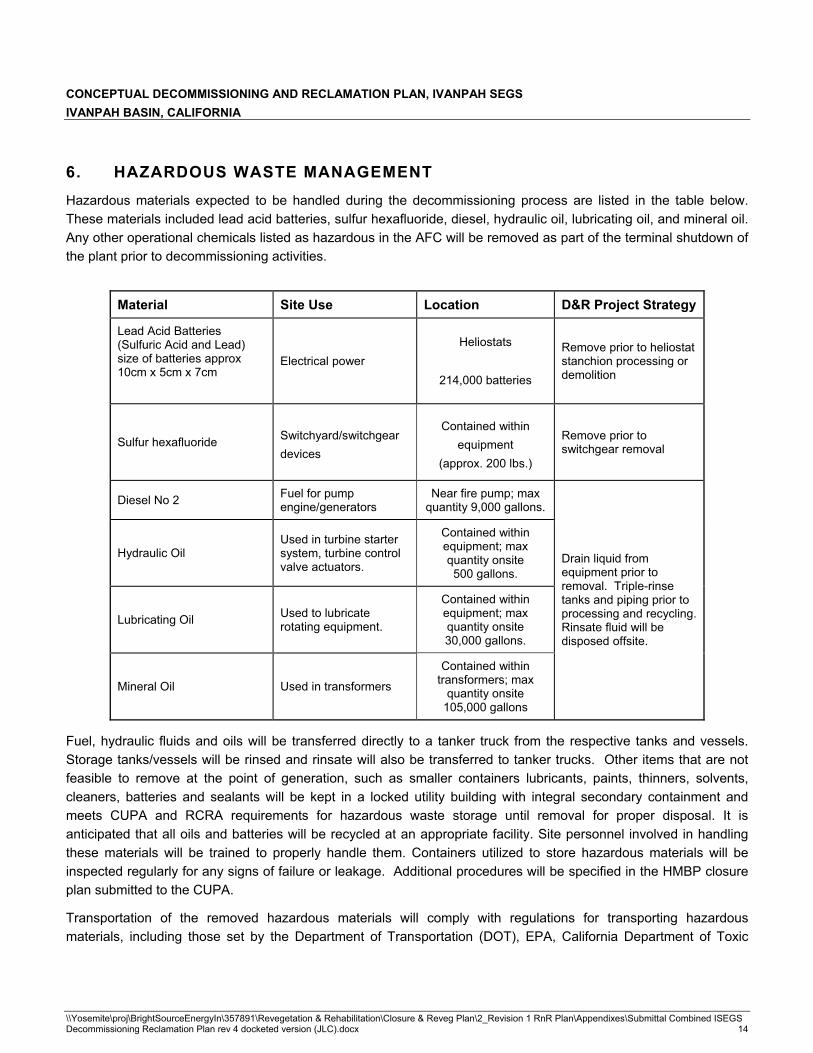
CONCEPTUAL DECOMMISSIONING AND RECLAMATION PLAN, IVANPAH SEGS IVANPAH BASIN, CALIFORNIA
\\Yosemite\proj\BrightSourceEnergyIn\357891\Revegetation & Rehabilitation\Closure & Reveg Plan\2_Revision 1 RnR Plan\Appendixes\Submittal Combined ISEGS Decommissioning Reclamation Plan rev 4 docketed version (JLC).docx 14
6. HAZARDOUS WASTE MANAGEMENT Hazardous materials expected to be handled during the decommissioning process are listed in the table below. These materials included lead acid batteries, sulfur hexafluoride, diesel, hydraulic oil, lubricating oil, and mineral oil. Any other operational chemicals listed as hazardous in the AFC will be removed as part of the terminal shutdown of the plant prior to decommissioning activities.
Material Site Use Location D&R Project Strategy
Lead Acid Batteries (Sulfuric Acid and Lead) size of batteries approx 10cm x 5cm x 7cm
Electrical power Heliostats
214,000 batteries
Remove prior to heliostat stanchion processing or demolition
Sulfur hexafluoride Switchyard/switchgear devices
Contained within equipment
(approx. 200 lbs.)
Remove prior to switchgear removal
Diesel No 2 Fuel for pump engine/generators
Near fire pump; max quantity 9,000 gallons.
Hydraulic Oil Used in turbine starter system, turbine control valve actuators.
Contained within equipment; max quantity onsite 500 gallons.
Lubricating Oil Used to lubricate rotating equipment.
Contained within equipment; max quantity onsite 30,000 gallons.
Mineral Oil Used in transformers
Contained within transformers; max
quantity onsite 105,000 gallons
Drain liquid from equipment prior to removal. Triple-rinse tanks and piping prior to processing and recycling. Rinsate fluid will be disposed offsite.
Fuel, hydraulic fluids and oils will be transferred directly to a tanker truck from the respective tanks and vessels. Storage tanks/vessels will be rinsed and rinsate will also be transferred to tanker trucks. Other items that are not feasible to remove at the point of generation, such as smaller containers lubricants, paints, thinners, solvents, cleaners, batteries and sealants will be kept in a locked utility building with integral secondary containment and meets CUPA and RCRA requirements for hazardous waste storage until removal for proper disposal. It is anticipated that all oils and batteries will be recycled at an appropriate facility. Site personnel involved in handling these materials will be trained to properly handle them. Containers utilized to store hazardous materials will be inspected regularly for any signs of failure or leakage. Additional procedures will be specified in the HMBP closure plan submitted to the CUPA.
Transportation of the removed hazardous materials will comply with regulations for transporting hazardous materials, including those set by the Department of Transportation (DOT), EPA, California Department of Toxic

CONCEPTUAL DECOMMISSIONING AND RECLAMATION PLAN, IVANPAH SEGS IVANPAH BASIN, CALIFORNIA
\\Yosemite\proj\BrightSourceEnergyIn\357891\Revegetation & Rehabilitation\Closure & Reveg Plan\2_Revision 1 RnR Plan\Appendixes\Submittal Combined ISEGS Decommissioning Reclamation Plan rev 4 docketed version (JLC).docx 15
Substances Control (DTSC), California Highway Patrol (CHP), and California State Fire Marshal. The following table lists the properties and toxicity of hazardous waste materials that will be removed.
Material Physical Description Health Hazard Flammability
Sulfuric Acid Oily, colorless liquid Corrosive to skin, eyes, and digestive tract. Respiratory tract irritant.
Non-flammable
Sulfurhexafluoride
Colorless gas, odorless Hazardous when inhaled Non-flammable
Diesel No 2 Oily, light liquid Skin irritant, aspiration hazard Flammable Hydraulic Oil Oily, dark liquid Hazardous if ingested Combustible
Lubricating Oil
Oily, dark liquid Hazardous if ingested Flammable
Mineral Oil Oily, clear liquid Minor health hazard Combustible
The SPCC plan for the site will be updated to cover spill prevention and countermeasures for handling of these materials during decommissioning. As previously discussed, a Site-specific Health and Safety Plan (HASP) will document health and safety requirements for establishing and maintaining a safe working environment during the implementation of the planned Site activities. Additional procedures to decrease the potential release of contaminants to the environment and contact with storm water will be specified in the SWPPP.
CONCEPTUAL DECOMMISSIONING AND RECLAMATION PLAN, IVANPAH SEGS IVANPAH BASIN, CALIFORNIA
\\Yosemite\proj\BrightSourceEnergyIn\357891\Revegetation & Rehabilitation\Closure & Reveg Plan\2_Revision 1 RnR Plan\Appendixes\Submittal Combined ISEGS Decommissioning Reclamation Plan rev 4 docketed version (JLC).docx 16
7. SALVAGE VALUES
Worley Parsons was commissioned to estimate quantities and anticipated values for scrap commodities.
This is a re-print of the Worley Parsons memorandum “Scrap Value Evaluation 23-Jan-09”
Scrap Value Evaluation
Provided herein is an evaluation of the recycle market and transportation costs for recyclable materials included in the draft cost estimate developed using scrap values and transportation costs as of November/December 2008.
The results of this evaluation indicate that, based on current scrap value and transportation cost data, considerable scrap value may derived from recycling copper, aluminum, carbon steel, glass and batteries at a Las Vegas or southern California recycle center. For perspective, a positive revenue stream between $9M and $12M would be expected using current values, with aluminum and copper being the primary contributors and glass resulting in a net cost. This represents a reduction of the estimated decommissioning and reclamation cost by approximately one third. While mirror and plate glass recycling alone is generally a negative revenue stream regardless of the recycling center location, other scrap recycling will provide positive revenue with transport to centers within 700 to 1500 miles from the Ivanpah site if the parameters comparable to those used for this analysis are applicable when the decommissioning occurs. Adjustment of the estimated decommissioning and reclamation cost using the above scrap value leads to an improved understanding of anticipated costs, and should be incorporated into the cost estimate.
SCRAP VALUE ANALYSIS APPROACH AND RESULTS
Definitions
Mix Scrap Iron & Steel- Assorted iron & steel scrap up to any maximum size, must be free of white goods & light gauge materials under 1/8” in thickness.
White Goods- Major household appliances including stoves, fridges freezers, clothes washers, dryer & dish washers
No. 2 HMS- No. 2 Steel shall consist of clean iron & steel with a minimum thickness of 1/8”, and a maximum size of 60”x18”, material handling compatible to feed a furnace charge box.
No. 1 HMS (2 foot) - No. 1 HMS (2 foot) shall consist of clean iron & steel with a minimum thickness of ¼”, and a maximum size of 24”x18”, material handling compatible to feed a furnace charge box. This grade may include ISRI code 201.
ISRI Code 201- Heavy melting steel 3 feet x 18 inches. Wrought iron and/or steel scrap ¼ inch and over in thickness. Individual pieces not over 36 x 18 inches (charging box size) prepared in a manner to insure compact charging.
Aluminum Extrusions- Clean aluminum extrusions including window & door frames. Must be free of iron inserts, screws and plastic, rubber or other foreign materials.

CONCEPTUAL DECOMMISSIONING AND RECLAMATION PLAN, IVANPAH SEGS IVANPAH BASIN, CALIFORNIA
\\Yosemite\proj\BrightSourceEnergyIn\357891\Revegetation & Rehabilitation\Closure & Reveg Plan\2_Revision 1 RnR Plan\Appendixes\Submittal Combined ISEGS Decommissioning Reclamation Plan rev 4 docketed version (JLC).docx 17
Soldered Copper Pipe Scrap- Used to represent wiring recycle values and best represents the air cooled condenser materials that make up a very large percentage of the copper. Soldered Copper Pipe shall consist of assorted copper pipe (of any length) with soldered joints or ends, free of brass or bronze or non-copper fittings.
Whole Prepared Car Bodies- Used to represent galvanized steel materials. Unflattened car bodies, with tires, radiator and battery removed gas tanks acceptable but must be removed and punctured, (no propane tanks allowed). Engine and transmission may or may not be included.
LTL- The Less than Truck Load (LTL) prices shown on the website refer to the over the scale value of miscellaneous quantities of materials. LTL quantity refers to weights of less than 40,000 lbs. unless otherwise stipulated. This is the value used for comparison for the Ivanpah recycle materials.
TL- Truck Load (TL) Prices refer to sorted and prepared materials, packaged and ready for shipment in typical TL quantity weights of 40,000 lbs. unless otherwise stipulated. This is the value used for comparison for the Ivanpah recycle materials.
Mirror Scrap Glass- Mirror Scrap Glass shall contain clean whole or broken mirrors, free frames or foreign backing materials.
3/8 inch Plate Glass- 3/8” Plate Glass shall contain un-laminated plate glass scrap processed and sized to minus 3/8” (inch). This is equivalent to Andela #6.
1/8 inch Plate Glass- 1/8” Plate Glass shall contain un-laminated plate glass scrap processed and sized to minus 1/8” (inch). This is equivalent to Andela #3.
Approach to Development of 2008 Scrap Value Data and Transportation Costs
The spot price of recyclable materials used for this analysis was obtained from the websites listed below, with copies of the site information on 11/25/08 and 1/7/09.
Site use for the scrap aluminum (1/7/09) - http://www.recycle.net/Metal-N/Aluminum/index.html
Site used for scrap copper (1/7/09) - http://www.recycle.net/Metal-N/Copper/index.html
Site used for scrap steel (11/25/08) - http://www.scrapspot.com/03-0115.html
Site used for glass (11/25/09) - http://www.universalwrecking.com/Sections-read-47.html
Site used for batteries (11/25/09) - http://www.rex-change.com/cgi-bin/exchsview.cgi?ex=REX%3A000028&acc= IN000941&gid=01-020120-001&p=0&affilid=&sender_email=&Contact+Listing.x=14&Contact+Listing.y=9
The estimate for transportation cost was as follows. A reference for round trip trucks shipments was found in NUREG/CR-5884 Revised Analyses of Decommissioning for the Reference Pressurized Water Reactor, Appendix C for non-nuclear recyle and waste disposal transportation. While a directly applicable source, the data was from 1993 and was converted to 2008 presents value using the annual Consumer Price Index inflation rates from the website shown below.
http://inflationdata.com/inflation/Inflation_ Rate/HistoricalInflation.aspx
Based on this adjustment, the transportation cost for a fully loaded truck was calculated to be $36.84/ton for a dealer located in Las Vegas NV, or $89.91/ton if the recycle materials had to be transported to Long Beach CA. The

CONCEPTUAL DECOMMISSIONING AND RECLAMATION PLAN, IVANPAH SEGS IVANPAH BASIN, CALIFORNIA
\\Yosemite\proj\BrightSourceEnergyIn\357891\Revegetation & Rehabilitation\Closure & Reveg Plan\2_Revision 1 RnR Plan\Appendixes\Submittal Combined ISEGS Decommissioning Reclamation Plan rev 4 docketed version (JLC).docx 18
Port of Long Beach was included in the analysis since it is both big enough that finding a dealer for handling the volume of scrap from the project would be very reasonable, and Long Beach has good port facilities if ocean transport to Asia was needed. Mesa, AZ was also included as a possible destination (at $134.13 per ton) for the battery recycling since that is the location of the processer that was used for this comparison.
The inflation escalation used may be seen in Table 1, and the recycle transportation cost calculation is presented in Table 2.
Table 1 – 1993 to 2008 Escalation Due to Inflation
Note that the 2008 value is the Jan to Oct average
Year CPI Inflation Rate Cumulative Inflation Rate 1993 1.0296 1 1994 1.0261 1.0261 1995 1.0281 1.054933 1996 1.0293 1.085843 1997 1.0234 1.111252 1998 1.0155 1.128476 1999 1.0219 1.15319 2000 1.0338 1.192168 2001 1.0283 1.225906 2002 1.0159 1.245398 2003 1.0227 1.273668 2004 1.0268 1.307803 2005 1.0339 1.352137 2006 1.0324 1.395946 2007 1.0285 1.435731 2008 1.045 1.500339

CONCEPTUAL DECOMMISSIONING AND RECLAMATION PLAN, IVANPAH SEGS IVANPAH BASIN, CALIFORNIA
\\Yosemite\proj\BrightSourceEnergyIn\357891\Revegetation & Rehabilitation\Closure & Reveg Plan\2_Revision 1 RnR Plan\Appendixes\Submittal Combined ISEGS Decommissioning Reclamation Plan rev 4 docketed version (JLC).docx 19
Table 2 – Transportation Cost Calculation
Reference trip costs RT (1993) = $1,212 Reference trip distance Dt = 257 Inflation to 2008 from CPI RT (2008) = $1,818 d1 and d2 =Ivanpah to scrap dealer d1 Las Vegas = 45 d2 Long Beach = 240 d3 Mesa, Az = 365 Permit costs per trip P = $100 Round trip costs = [RT*{d1 or d2}/dt] +P from the NUREG/CR-5884 Appendix C $ per round trip with 20 $/ton Tons transport Round trip cost for Las Vegas dealer $737 $36.84 Round trip cost for Long Beach dealer $1,798 $89.91 Round trip cost for Mesa, AZ dealer $2683 $134.13
Quantities for Recycling
Estimated quantities of recyclable materials were taken from the total quantities and construction information used in the project estimate for all three units performed earlier. The following quantities were estimated:
Steel (4,383 tons) – Includes structural steel, piping, equipment and rebar.
Aluminum (6,528 tons) – Includes heliostat grounding rods, air-cooled condensers, pipe racks/cable trays, 30-foot utility poles and HVAC refrigeration systems.
Copper (1,229 tons) – Includes power supply cabling, air compressors/inst air, turbine generators, 115 kV wire, air cooled condensers, and HVAC refrigeration systems.
Mirror glass(37,684 tons) – 214,000 mirrors (3 to 4 per heliostat for a total surface of 7’ to 10’ per heliostat) at 352 pounds each.
Batteries (2,158 tons) – Includes 214,000 heliostat batteries at 20lbs each and 360 station batteries at 120lbs each.
Methodology
Revenue streams from recycling were estimated from combined analysis of current market price (which can decrease or increase frequently dependent upon market demand), estimated scrap quantities and weights, and transportation costs to derive Reasonable Maximum, Most Likely, and Reasonable Minimum scrap value estimates. While bronze, brass and other metals would be expected to be utilized, the steel, aluminum and copper items are most identifiable at this point in the project, which dictated the application of the per ton scrap spot prices obtained from the sources cited above as the cost basis. In addition, spot values for glass and battery recycling were utilized based on assumed mirror and battery weights. All quantities and weights are assumptions derived from the conceptual design information available, modeled from existing facilities, and/or taken from industry standards.

CONCEPTUAL DECOMMISSIONING AND RECLAMATION PLAN, IVANPAH SEGS IVANPAH BASIN, CALIFORNIA
\\Yosemite\proj\BrightSourceEnergyIn\357891\Revegetation & Rehabilitation\Closure & Reveg Plan\2_Revision 1 RnR Plan\Appendixes\Submittal Combined ISEGS Decommissioning Reclamation Plan rev 4 docketed version (JLC).docx 20
Results
The ranges of scrap values estimated based on current spot prices and transportation costs are presented below. Based on this analysis, the market value of aluminum and copper will have the largest effect on the overall revenue stream. Steel and batteries will generate much less revenue Under current conditions, glass will result in net negative revenue, with significantly greater cost with increased transport distance. Other than for glass, the location of the recycling facility (Las Vegas vs. ong beach) does not make an appreciable difference in the overall expected scrap revenue.
Table 3 – Estimated Recycling Value
NOTES:1. Estimated material values were taken from WorleyParsons report dated January 23, 2009, “Scrap Value
Evaluation.”2. Estimated values for copper were reduced to 15% of the WorleyParsons values to reflect the removal of turbine
generators from the list of items to be recycled. 3. Major Equipment values were obtained from the totals found in Section 8.5 on Table 1: Major Equipment.
8. USED EQUIPMENT STUDY
The purpose of this study was to look at pieces of equipment that might have significantly higher value on the used equipment market as opposed to scrap value. Equipment that was considered includes steam turbine generators with air cooled condensers, boiler feed pumps, major transformers and load centers.
8.1 Used Equipment Market
A substantial market exists for used power plant equipment. Used equipment dealers/brokers locate equipment and agree to purchase or agree to market the equipment. For large items, such as the steam turbine generators, the usual practice is to have the item remain in place until a sale to an end buyer is made. The dealer (or sometimes the end buyer) will then go in and dismantle and remove the equipment from the owner’s site. For a site like Ivanpah SEGS, this is an added benefit in that the site owner will avoid the substantial cost of demolition and removal for all equipment sold on the used market.
IVANPAH SEGS ESTIMATED 25 YEAR SALVAGE VALUES
ESTIMATED VALUE[1]
MaterialLOW HIGH MOST LIKELY
Steel $657,831.00 $1,284,862.00 $1,021,894.00Aluminum $7,899,310.00 $8,486,205.00 $8,245,720.00Copper[2] $341,009.25 $357,580.80 $350,790.45
Glass/Mirrors ($3,218,457.00) ($427,332.00) ($1,218,698.00)Batteries $314,791.00 $524,740.00 $410,222.00
Major Equipment[3] $3,625,400.00 $22,019,000.00 $12,822,200.00
Totals $9,619,884.25 $32,245,055.80 $21,632,128.45

CONCEPTUAL DECOMMISSIONING AND RECLAMATION PLAN, IVANPAH SEGS IVANPAH BASIN, CALIFORNIA
\\Yosemite\proj\BrightSourceEnergyIn\357891\Revegetation & Rehabilitation\Closure & Reveg Plan\2_Revision 1 RnR Plan\Appendixes\Submittal Combined ISEGS Decommissioning Reclamation Plan rev 4 docketed version (JLC).docx 21
The user market exists both domestically and off-shore. By far, the most significant driving forces that feed this market are reduced pricing and significantly reduced delivery times when compared to purchase and manufacture of similar new equipment. Smaller, generic items tend to sell rather quickly while large, custom items require significant time to match to the needs of perspective end purchasers. It is not uncommon to require a year or more to find an end buyer for a large steam turbine-generator.
8.2 Marketing Strategy
The used equipment will typically bring best prices if it is operational at the time of sale agreement. Strategy is to solicit proposals from used equipment dealers/brokers approximately fifteen months in advance of the actual cease of plant operation. Two to three months should be allowed to reach agreements with equipment dealers. The dealers/brokers would, in turn, initiate efforts to advertise the equipment on the market. This would allow about twelve months for perspective end purchasers to visit the facility while equipment is operational and view the O&M records, manufacturer’s documentation and equipment installation documentation. The end goal is to have end user sales agreements for each item before plant shutdown. The agreements should include clear definition of terminal points and a schedule for dismantling availability and duration.
8.3 Dismantl ing Strategy
Once the plant is shut down, all power feeds should be physically disconnected from all equipment to be sold. All fluids and operational chemicals would be removed as per Section 5.2.3:Pre-Decommissioning Activities. The exception would be if a buyer has prearranged for power to turning gear and lube oil pumps and motors to remain until the purchased equipment is actually dismantled and removed from the site.
The equipment dismantling contractor (buyer’s contractor) would then move on site and methodically prepare the equipment for breakdown and shipping. For safety reasons, it is recommended that general demolition (5.2.4 Demolition of Above-Ground Structures) be delayed in affected areas until used equipment dismantling is completed.
8.4 Effects of Equipment Sales on Closure Costs
The sale of used equipment will have a significant effect on the closure cost of Ivanpah SEGS. This study focused on steam turbine generators with air cooled condensers, boiler feed pumps, standby diesel generators, major transformers and load centers. The estimate of “most likely” estimated values falls into a Class 5 category as defined by Recommended Practice No. 18R-97 of AACE International.

CONCEPTUAL DECOMMISSIONING AND RECLAMATION PLAN, IVANPAH SEGS IVANPAH BASIN, CALIFORNIA
\\Yosemite\proj\BrightSourceEnergyIn\357891\Revegetation & Rehabilitation\Closure & Reveg Plan\2_Revision 1 RnR Plan\Appendixes\Submittal Combined ISEGS Decommissioning Reclamation Plan rev 4 docketed version (JLC).docx 22
8.5 Used Equipment Value Analysis
Processes Unlimited International, Inc. estimated future salvage values for several pieces of major equipment associated with the proposed Ivanpah Solar Electric Generating System (SEGS) after a 25 year service life. (For a full copy of study refer to Appendix1) Equipment to be estimated is shown in the following table: Equipment List.
EQUIPMENT LIST EQUIPMENT DESCRIPTION QUANTITY ADDITIONAL NOTES
Main Steam Temperature: 1004°F Main Steam Pressure: 2400 psig Reheat at 900°F Steam Rate: 845,238 lb/hr
100 MW Steam Turbine Generator with A/C Condenser (After study was commissioned, ISEGS elected to have all STG’s be the same class units.)
24
Generators to be 3600 RPM, 2 poles Main Steam Temperature: 1004°F Main Steam Pressure: 2400 psig Reheat at 900°F Steam Rate: 1,680,000 lb/hr
200 MW Steam Turbine Generator with A/C Condenser (After study was commissioned, ISEGS elected to have all STG’s be the same class units.)
10
Generators to be 3600 RPM, 2 poles
Emergency/Standby GenSet(s) with Diesel Driver 4 Capacity: 2,000KW/4.16KV
13.8 KV Unit Transformers 3 13.8KV to 115KV Step-up Transformers 3 4000A 480VAC Load Centers 3
1000A 4160VAC Load Center 1
FW Pumps 9 3@60% per plant
The study consisted of interviews with used or surplus equipment dealers. Their responses were then pooled to arrive at predicted ranges of costs for the equipment. It should also be noted that the prices solicited were what an owner might realize from sale to the used equipment dealers, as this pricing may be substantially less than what the dealer might ask on re-sale. Contact with the vendors quickly revealed that they were not willing to give dollar values based on the brief descriptions furnished.
Vendor input was analyzed to arrive at general probable residual value ranges (generally 0 to 33% of new cost). These ranges were considered and applied to new equipment cost estimates to arrive at probable ranges. The results are shown in the following table: Major Equipment. Footnotes on Table 1 indicate varying sources for new equipment pricing and also show that the ranges were adjusted for the various types of equipment based on past experience. A “most likely” column was added that shows an average of the high and low numbers. With varying market conditions and the vast uncertainty of equipment condition after 25 years, it is suggested that the “most likely” column be used as a guide for values. The “most likely” value of selling used equipment in today’s dollar is $12,822,200.00.

CONCEPTUAL DECOMMISSIONING AND RECLAMATION PLAN, IVANPAH SEGS IVANPAH BASIN, CALIFORNIA
\\Yosemite\proj\BrightSourceEnergyIn\357891\Revegetation & Rehabilitation\Closure & Reveg Plan\2_Revision 1 RnR Plan\Appendixes\Submittal Combined ISEGS Decommissioning Reclamation Plan rev 4 docketed version (JLC).docx 23
LOW HIGH MOST�LIKELY LOW HIGH MOST�LIKELY
100�MW�Steam�Turbine�Generator�with�A/C�Condenser�[2] $640,000.00 $4,800,000.00 $2,720,000.00 4 $2,560,000.00 $19,200,000.00 $10,880,000.00
200�MW�Steam�Turbine�Generator�with�A/C�Condenser�[2] $1,200,000.00 $9,000,000.00 $5,100,000.00 0 $0.00 $0.00 $0.00
2,000�KW�Emergency/Standby�GenSet(s)�with�Diesel�Driver�[3] $75,000.00 $175,000.00 $125,000.00 4 $300,000.00 $700,000.00 $500,000.00
Boiler�Feed�Pump�1100�GPM�@�3500�PSI�[4] $4,500.00 $112,500.00 $58,500.00 6 $27,000.00 $675,000.00 $351,000.00
Boiler�Feed�Pump�2200�GPM�@�3500�PSI�[4] $7,800.00 $195,000.00 $101,400.00 3 $23,400.00 $585,000.00 $304,200.00
13.8�KV�Unit�Transformers�2500KVA�[5] $13,000.00 $15,000.00 $14,000.00 3 $39,000.00 $45,000.00 $42,000.00
13.8�KV�Unit�Transformers�7500KVA�[5] $26,000.00 $30,000.00 $28,000.00 2 $52,000.00 $60,000.00 $56,000.00
13.8KV�to�115KV�Step�up�Transformers�200�MW�[5] $160,000.00 $200,000.00 $180,000.00 2 $320,000.00 $400,000.00 $360,000.00
13.8KV�to�115KV�Step�up�Transformers�100�MW�[5] $260,000.00 $300,000.00 $280,000.00 1 $260,000.00 $300,000.00 $280,000.00
4000A�480VAC�Load�Centers�[6] $8,000.00 $10,000.00 $9,000.00 3 $24,000.00 $30,000.00 $27,000.00
1000A�4160VAC�Load�Center�[6] $10,000.00 $12,000.00 $11,000.00 2 $20,000.00 $24,000.00 $22,000.00
TOTALS $3,625,400.00 $22,019,000.00 $12,822,200.00
TOTAL�ESTIMATED�VALUE�RANGE
IVANPAH�SEGS�ESTIMATED�25�YEAR�SALVAGE�VALUES
TABLE 1: Major Equipment
6.�Load�center�values�are�based�on�value�near�estimated�scrap�prices.�Experience�has�shown�that�equipment�of�this�type�is�typically�obsolete�by�the�end�of�a�25�year�service�life�due�to�lack�of�replacement�parts�availability.
ESTIMATED�VALUE�RANGE�(EACH)�[1]
2.�STG�value�based�on�approximate�range�of�4%�to�30%�of�present�value�of�new�equipment.�New�prices�were�estimated�from�experience�based�on�performance�parameters�and�steam�conditions.
3.�Diesel�GenSet�values�based�on�approximate�range�of�15%�to�35%�of�present�value�of�new�equipment.�New�prices�were�based�on�factoring�other�sized�GenSet�costs�and�further�confirmed�by�comparing�to�nearly�new,�low�hour�sets�found�on�the�internet.
1.�Methodology�for�determination�of�future�salvage�values�is�generally�a�function�of�the�present�value�of�new�equipment�(see�Attachment�B�for�explanation).�With�the�vague�specifics�given�for�equipment�design�(see�Attachment�A),�present�cost�is�somewhat�speculative.�Most�ranges�were�derived�from�equipment�vendor�interviews,�with�adjustments�based�on�type�of�equipment
5.�Transformer�value�based�on�approximate�range�of�25%�(plus�or�minus)�of�present�value�of�new�equipment.�New�prices�were�estimated�using�Icarus�estimating�software.
4.�BFP�value�based�on�approximate�range�of�1%�to�20%�of�present�value�of�new�equipment.�New�prices�are�estimated.
EQUIPMENT�DESCRIPTIONQUANTITY�AVAILABLE
NOTES:

CONCEPTUAL DECOMMISSIONING AND RECLAMATION PLAN, IVANPAH SEGS IVANPAH BASIN, CALIFORNIA
\\Yosemite\proj\BrightSourceEnergyIn\357891\Revegetation & Rehabilitation\Closure & Reveg Plan\2_Revision 1 RnR Plan\Appendixes\Submittal Combined ISEGS Decommissioning Reclamation Plan rev 4 docketed version (JLC).docx 24
9. COST ESTIMATE
9.1 Purpose
The purpose of this section is to describe the costs associated with the decommissioning of the three-unit Ivanpah Solar Electric Generating System, and restoration of Bureau of Land Management right of way lands to near original conditions following the decommissioning.
9.2 Project Scope and Sequencing Description
The decommissioning/restoration scope included in this estimate covers the three solar station units as well as the administrative area. The assumption is made that the plant was built and operated as currently proposed. Furthermore, the plant is assumed to have operated without major spills, mishaps or casualty and was shutdown, and that systems drained and bulk chemicals were removed by the operating staff. The project is then initiated at the Site. Mobilization activities by the project professional staff are in place for approximately six months. These activities include planning, permitting and procurement activities. Early in this phase, all equipment that is to be sold will be dismantled and removed from the facility. A large recycling center will be established in a central location to support project field work startup near the end of the planning phase. The decommissioning and restoration project is envisioned to last approximately 36 months during which all solar collection and power generation equipment will be removed and the land restored to near original condition.
As discussed in Section 5, decommissioning of the facility would occur in a phased sequential manner, with work starting at Ivanpah 1, followed by similar work at Ivanpah 2 and 3. In this method decommissioning work will be initiated at Ivanpah 3 while later stage demolition / restoration work is finished at Ivanpah 1 and Ivanpah 2.
9.3 Methodology
The tools used for this estimate followed a “bottom up” approach; work units were used that covered major work items on a lineal foot, cubic yard, pound or ton basis. However, conceptual design information for the power plants is available for Unit 1 only, and was used in preparing this estimate. The Unit 1 information was then replicated for major equipment at Ivanpah 2 and scaled up or down using engineering judgment to arrive at the quantities piping at Ivanpah 2 and all elements of Ivanpah 3. Adjustments to the estimates were made to indicate reductions due to the sale of equipment.
9.4 Summary and Approach
The estimated valuations used to generate this cost estimate were derived utilizing RS Means and historically accurate cost data and production rates used for the demolition industry at current capture rates. As a comparison to this cost estimate, unit labor and equipment rates from the Nevada Standardized Reclamation Cost Estimator (SRCE) database (http://www,nvbond,orql) were incorporated into the original cost estimate to generate a revised estimate for comparison. The SRCE software was developed as a cooperative effort between the Nevada Division of Environmental Protection, Bureau of Mining Regulation and Reclamation (NDEP), the U.S. Department of Interior, Bureau of Land Management (BLM) and the Nevada Mining Association (NvMA) to facilitate accuracy,

CONCEPTUAL DECOMMISSIONING AND RECLAMATION PLAN, IVANPAH SEGS IVANPAH BASIN, CALIFORNIA
\\Yosemite\proj\BrightSourceEnergyIn\357891\Revegetation & Rehabilitation\Closure & Reveg Plan\2_Revision 1 RnR Plan\Appendixes\Submittal Combined ISEGS Decommissioning Reclamation Plan rev 4 docketed version (JLC).docx 25
completeness and consistency in the calculation of costs for mine site reclamation. While this tool is not developed for preparation of solar power plant decommissioning and reclamation cost estimates, it nevertheless represents a potential benchmark with which BLM is familiar. Both estimates also included an adjustment to the work units to more accurately capture anticipated costs associated with the removal of large storage tanks at the site.
9.5 Estimate Classification
The waste volume forecast and other commodities were used from current conceptual designs / commodities estimates from Unit 1 and scaled for Unit 2 and Unit 3. The quantities, design parameters and assumptions for both estimates are consistent and classified as order of magnitude estimates as discussed in this Decommissioning and Reclamation Plan. The method of this evaluation resulted in changed labor rates to match SRCE labor rates for craftlabor where craft titles matched, including fringe benefit values. Other craft labor rates (not listed in the SRCE tables) werechanged to approximately correspond to values for similar labor categories. Non-manual labor rates were changed, except no fringe benefit values were added since none were listed in the SRCE table. Rates for all demolition, recycling and earthmoving equipment were changed to correspond with or approximate SRCE monthly rates, and include operating costs (preventive maintenance and fuel) within the monthly value used.
To achieve a comparable cost estimate, the work units from the SRCE database were manipulated as necessary to correlate to the design parameters and assumptions contained in the original Decommissioning and Reclamation Plan (August 2008) cost estimate. Because the SRCE approach to work units and estimate building differs from the original approach in some respects, slight variations in the quantities, hours or other values of measurements resulted as these work units were used to generate the SRCE based estimate. For purposes of this comparison, however, the individual work units directly correspond from one estimate to the other.
9.6 Design Basis
The designs for this decommissioning and restoration project includes operation of a glass and steel recycling center, mirror and stanchion removal of each heliostat using low environmental impact equipment, explosive demolition of collector and reheat towers, and conventional demolition of all remaining equipment, structures, pavements and fencing. Clean closure of the retention ponds is included in this planning. Re-contouring of land in the in three solar fields of the units and central administration area to approximate the surrounding terrain is also included.
Glass, steel (structural, equipment and re-bar) and asphalt materials resulting from the decommissioning will be recycled. Clean concrete debris (i.e., crushed to about 2-inch minus and no rebar) and foundations that will be greater than 3 feet below final grade will be left on site. The concrete debris will be used as fill materials and in all cases be greater than 3 feet below final grade and place as to not interfere with planned revegetation of the area.
9.7 Planning Basis
This estimate is based on a six-month planning window and 36-month performance period. Extensions of this plan due to limited resources or other restrictions will add to the Project Management / hotel costs and the equipment lease elements of the estimate.

CONCEPTUAL DECOMMISSIONING AND RECLAMATION PLAN, IVANPAH SEGS IVANPAH BASIN, CALIFORNIA
\\Yosemite\proj\BrightSourceEnergyIn\357891\Revegetation & Rehabilitation\Closure & Reveg Plan\2_Revision 1 RnR Plan\Appendixes\Submittal Combined ISEGS Decommissioning Reclamation Plan rev 4 docketed version (JLC).docx 26
9.8 Assumptions
The following assumptions are incorporated into the estimate.
� All three units are decommissioned in a phased sequential manner as discussed previously, and within one project management structure.
� The value of the steel, glass, and asphalt recycle material was based on values per Section 7 of this report.
� The changes that occur during the definitive design, construction, and operation of the plants do not change the overall quantities used in this estimate appreciably.
� All steam turbine generators with air cooled condensers, boiler feed pumps, major transformers and load centers are assumed to be sold on the used equipment market as outlined in Section 8.
� Approximately 40% of the mass of the poured concrete at the Site will be left in situ, i.e., not broken up, since it will ultimately be covered by greater than three feet of native soils in the recontouring process to place the land in its near-original condition.
9.9 Exclusions and Exceptions
Re-vegetation, habitat restoration and post-implementation monitoring is excluded from this cost estimate. No other exclusions and/or exceptions are present at this time.
9.10 Risks and Opportunities
No “time value of money” adjustments were made to this estimate. Only present value costs are included. As with any work conducted after 25 years of operation, the misapplication or misunderstanding of any escalation or inflation adjustments can far outweigh any precision thought to be included with the estimate.
By leaving foundations at greater than 3 feet below final grade, approximately 40% of the concrete used in the demolition effort is saved. Otherwise an appreciable increase in demolition and concrete processing costs will be incurred. Likewise, if the option to leave clean concrete rubble buried on site (at greater than 3 feet deep and not interfering with revegetation) is not permitted, transport and disposal of this low value/high mass waste stream will increase the cost of the project.
9.11 Contingencies
Contingency costs are not included in this project estimate.
9.12 Management Reserve
No management reserve was included in this project estimate.

CONCEPTUAL DECOMMISSIONING AND RECLAMATION PLAN, IVANPAH SEGS IVANPAH BASIN, CALIFORNIA
\\Yosemite\proj\BrightSourceEnergyIn\357891\Revegetation & Rehabilitation\Closure & Reveg Plan\2_Revision 1 RnR Plan\Appendixes\Submittal Combined ISEGS Decommissioning Reclamation Plan rev 4 docketed version (JLC).docx 27
9.13 Reconciliation
This is the first published decommissioning and restoration estimate to be developed for this project and as such, no reconciliation was completed with this effort.
9.14 Benchmarking
No benchmarking was performed; however, estimates are based on past activities in the U.S. and internationally, particularly in the use of steam power plants.
9.15 Estimated Quality Assurance
The estimate was peer reviewed and reviewed for consistency by WorleyParsons project management. The estimate was adjusted to account for the sale of equipment data provided by Processes Unlimited International, Inc.
9.16 Cost Tables
Tables 1, 2, 3 and 4 of this Section present a side-by-side comparison of the cost estimates for Units 1,2 and 3, and the Administration Area/Overall Project Management/Equipment segments of the total cost estimate, respectively. Table 5 summarizes the total cost estimate. In these tables, the updated original cost estimate is referred to as the August 2008 Cost Estimate; whereas, the new cost estimate based on Nevada SRCE labor and equipment rates is referred to as the January 2009 Estimate. The evaluation indicates that an increase in the total estimate of approximately $5,000,000 occurs when using the labor and equipment rates from the Nevada SRCE. Most labor rates were higher for the SRCE, but the estimate increase was offset slightly by a small decrease in equipment costs.
Note to readers: Due to the confidential nature of these cost tables, they will be furnished only to BLM staff under a request for confidentiality.

CONCEPTUAL DECOMMISSIONING AND RECLAMATION PLAN, IVANPAH SEGS IVANPAH BASIN, CALIFORNIA
\\Yosemite\proj\BrightSourceEnergyIn\357891\Revegetation & Rehabilitation\Closure & Reveg Plan\2_Revision 1 RnR Plan\Appendixes\Submittal Combined ISEGS Decommissioning Reclamation Plan rev 4 docketed version (JLC).docx 28
10. REFERENCES
California Department of Water Resources (DWR). 1964. Bulletin No. 106-1, Ground Water Occurrence and Quality Lahontan Region. 439 p.
CH2M Hill. 2008 and 2009. Closure, Revegetation, and Rehabilitation Plan. September 2008 and May 2009.
Jennings, C.W., 1961. Geologic Map of California: Kingman Sheet. Olaf P. Jenkins Edition. California Department of Conservation, Division of Mines and Geology. Scale 1:250,000.
Waring, G.A., 1920. Ground water in Pahrump, Mesquite, and Ivanpah Valleys Nevada and California. Water-Supply Paper 450-C. pp. 51-85.
Conceptual Decommissioning and Reclamation Plan, Ivanpah SEGS, Rev. A 5-Sept-08 by Worley Parsons
Memorandum – “Scrap Value Evaluation” for Ivanpah SEGS, 23-Jan-09 by Worley Parsons
Memorandum – “Nevada Reclamation Cost Estimator Comparison” for Ivanpah SEGS, 26-Jan-09 by Worley Parsons
Report – “BrightSource Ivanpah SEGS Closure Costs, 30-Mar-09 by Processes Unlimited International, Inc.
Report – “Addendum to Conceptual Decommissioning and Reclamation Plan, 1-May-2009 by Processes Unlimited International, Inc.

CONCEPTUAL DECOMMISSIONING AND RECLAMATION PLAN, IVANPAH SEGS IVANPAH BASIN, CALIFORNIA
Submittal Combined ISEGS Decommissioning Reclamation Plan rev 4 docketed version (JLC).docx 52003207
Figures

Proposed Ivanpah Project Site
!Primm
!Jean
Mojave National Preserve
Toiyabe National Forest
!"a$
%&h(
Mojave National Preserve
Desert Tortoise Critical Habitat
Las VegasPahrumpPahrump
¬«160
¬«159
¬«164
¬«161
¬«160
15
95
Cima Rd
Kelbaker Rd
515
Las
Vega
s B
lvd
King
ston
Rd
Nipton Rd
Craig Rd
Excelsior Mine Rd
In dustri al Rd
Lesl
ie S
t
Old Sp anish Trail Hwy
Kels
o C
ima
Rd
Sandy Valley Rd
Old Spanish T
rl
Smith Talc Rd
Baker B
lvd
Lone Mountain Rd
Kingston Rd
Soda Lake
Ivanpah Lake
Silver Lake
Mesquite Lake
Roach Lake
1:506,880
FIGURE 1VICINITY MAPIVANPAH SOLAR ELECTRIC GENERATING SYSTEM
!
!
!
!
!
San Jose
San Diego
Sacramento
Los Angeles
San Francisco
_̂§̈¦40
§̈¦15§̈¦5
AÎ
LEGENDCOUNTY BOUNDARIES
STATE BOUNDARIES
DESERT TORTOISE CRITICAL HABITAT*
PROPOSED PROJECT SITE
NevadaCalifornia
0 84Miles
Project Site
\\ZION\SACGIS\PROJ\352897_IVANPAH\MAPFILES\REPORT\VICINITY_MAP.MXD SSCOPES 4/23/2009 10:18:55
*Source: USFWS, Region 2, desert tortoise critical habitat (Final), February 8, 1994

TAP STATION
METERING SET
METERING SET
SUBSTATION
ADMINISTRATION AND STORAGE
IVANPAH 1
IVANPAH 2
IVANPAH 3
WELLS
REROUTED COLOSSEUM ROAD
PROPOSEDMONITORING WELL
ColosseumRoad
Colosseum Road
Colosseum Road
\\ZION\SACGIS\PROJ\352897_IVANPAH\MAPFILES\2008FIELDMAPS\IVANPAH_TOWNSHIPRANGE.MXD SSCOPES 3/10/2009 14:16:37
0 3,000Feet
LEGENDWELLS
DIRT ROAD
PAVED ROAD
UTILITIES CORRIDOR
NATURAL GAS LINE
GEN-TIE LINE
KERN RIVER GAS LINE
4WD TOURING/TRAILS
SECTION LINES
PROJECT SITE FIGURE 2SITE PLAN AND LINEAR FACILITIESIVANPAH SOLAR ELECTRIC GENERATING SYSTEM³

APPENDIX C
Recommended Specifications for Desert Tortoise Exclusion Fencing and Tortoise Guard

~~~~~~~~~-I
DESERT TORTOISE EXCLUSION FENCE (2005)
wire Stael posts Existing wO'cd or
postA
__
ized 'fence' material
See Detail B
i-inch
DETAIL A
wire fence 1 inch Hog rrngs
intervafs: .
fence Matenal
RECOMMENDED DESIGN FOR DESERT TORTOISE EXCLUSION FENCE GENERAL NOTES:
1. Ensure that fence posts and materials conform to the standards approved by the U.S. Fish and Wildlife Service.
2. Ensure that the height above ground level is no less than 18 inches and no higher than 24 inches.
3. Ensure that the depth of fence material below wires are
6 inches. (See SECTION A above)
4. Install additional steel posts when span between existing fence posts exceed 10 feet.
5. Attach fence material to existing fence or wire using hog rings at 12-inch intervals.
6. Fasten fence material to posts with 3 tie wires
fence material.
4-strand fence
Hog rings 12-18" intervals S.ee Detail B
Galvanized fene Material
lIJ
7. Backfill trenches with excavated material and compact the material. '
8. Attach fence material to all gates. Ensure that clearance at base of gate achieves zero ground clearance.
9. Substitute smooth wire for barbed wire if additional
10. The number anti placement of support wires may be modified to allow sheep and deer to pass safely.
11. Erosion at the edge of the fence' material where the fence crosses washes may occur and requires appropriate and timely monitoring and repair.
12. Tie the fence into existing culverts and cattleguards when determined to allow desert tortoise passage underneath roadways.

Section
FOR BEDROCK OR CALICHE SUBSTRATE
1. Use this fence design (see below) only for that portion of the fence where fence material cannot be placed 6 inches below existing ground level due to presence of bedrock, large rocks or caliche substrate.
2. Ensure that the fence height above ground level is no less than 22 inches.
3. Ensure that there is a zero to 2-inch ground clearance at the bend.
4. Ensure that the bent portion of the fence is lying on the ground and pointed in the direction of desert tortoise habitat.
5. Cover the portion of the fence that is flush with the ground with cobble (rocks placed on top of the fence material to a vertical thickness up to 4 inches).
6. When substrate no longer is composed of bedrock or caliche, install fence using design shown above.
4-strand wire fence
Oetall'S: posts rings'
12-18" intervals See Detail'B
B Galvanized fence
Must a z.ero ta side .' clearance af bend. up. to 4'incnes
ofence material
Must zero ground bend
SECTIoN
Cobble- to covering fence


Attachment D
Desert Tortoise Translocation/Relocation Plan for the
Ivanpah Solar Electric Generating System
Prepared for
Solar Partners I, LLC; Solar Partners II, LLC; Solar Partners IV, LLC; and Solar Partners VIII, LLC
May 2009
2485 Natomas Park Drive, Suite 600
Sacramento, CA 95833

II
Contents
Section Page
1.0 Introduction ............................................................................................................................. 1 1.1 Background .......................................................................................................................... 1 1.2 Plan Purpose......................................................................................................................... 2 1.3 Plan Goals ............................................................................................................................. 2
2.0 Translocation/Relocation Plan ............................................................................................. 5 2.1 Permanent Fencing .............................................................................................................. 5 2.2 Temporary Construction Fencing ..................................................................................... 7 2.3 Clearance Surveys of Permanent Exclusion Areas ......................................................... 9 2.4 Transportation and Release .............................................................................................. 10 2.5 Scheduling .......................................................................................................................... 12 2.6 Translocation/Relocation Areas ...................................................................................... 12 2.7 Monitoring and Reporting ............................................................................................... 13
3.0 References .............................................................................................................................. 16
Figures BR5-1 Vicinity Map BR5-2 Site Plan and Linear Facilities BR5-3 Proposed Relocation/Translocation Area

ES062007009SAC/357891/091460006(ATTACHBR5-1_DRAFT_ TRANSLOCATION_PLAN_FINAL) 1
1.0 Introduction
Solar Partners I, LLC; Solar Partners II, LLC; Solar Partners IV, LLC and Solar Partners VIII, LLC (the Applicant), which are subsidiaries of BrightSource Energy, Inc., propose to develop a solar power project consisting of three adjacent solar energy facilities to be located in the Ivanpah Valley near the Interstate 15 (I-15) crossing of the California/Nevada border in San Bernardino County, California (Figure BR5-1, figures are located at the end of each section). The proposed project site is located on land administered by the Bureau of Land Management (BLM) and is less than 2 miles east of the Mojave National Preserve, less than 2 miles west of Ivanpah Dry Lake, less than a mile south of the Stateline Wilderness and Mesquite Wilderness areas of the Clark Mountains; approximately 0.5 miles west of the Primm Valley Golf Club; approximately 0.8 miles northwest of I-15; and approximately 4.5 miles southwest of the Primm Valley casinos.
This Desert Tortoise Translocation/Relocation Plan (Plan) has been prepared for the Bureau on behalf of the Applicant following guidelines developed by the U.S. Fish and Wildlife Service (Service).
1.1 Background The Ivanpah SEGS site is located in Township 17N, Range 14E, and Township 16N, Range 14E on land administered by the BLM. Access to the site is via the Yates Well Road interchange on I-15 and Colosseum Road to the west of the Primm Valley Golf Club. The project will be built in three phases. The first 100-megawatt (MW) plant at the south end of the project, known as Ivanpah 1, would be owned by Solar Partners II, LLC. Solar Partners I, LLC, would own the middle 100-MW plant known as Ivanpah 2. The northernmost 200-MW plant, known as Ivanpah 3, would be owned by Solar Partners VIII, LLC. The three proposed facilities and their shared operations (owned by Solar Partners IV) are collectively known as the “Ivanpah Solar Electric Generating System” or “Ivanpah SEGS” (see Figure BR5-2).
In order to permit the three plants and the common facilities the Applicant has consulted the BLM, Service, California Department of Fish and Game (CDFG) and the California Energy Commission (CEC) the state lead agency under the CEC’s California Environmental Quality Act (CEQA) equivalent certified regulatory program.
The total area required for construction and operation of all three solar plant sites including the shared infrastructure is approximately 4,072 acres (minus the acreage for existing established dirt roads equals about 4,065 acres, net). This includes approximately 3,715 acres of permanent effects and approximately 357 acres1 of work area that would be subject to restoration following construction. Based on the protocol surveys, the proposed action would likely result in the need to relocate about 25 tortoises.
1 These numbers may be less once the stormwater plan is completed.

1.0 INTRODUCTION
ES062007009SAC/357891/091460006(ATTACHBR5-1_DRAFT_ TRANSLOCATION_PLAN_FINAL) 2
1.2 Plan Purpose This Plan will be incorporated into the Ivanpah SEGS Biological Resources Mitigation, Implementation and Monitoring Plan (BRMIMP), as part of the proposed action. This Plan has incorporated the Guidelines for Clearance and Translocation of Desert Tortoises from the Ivanpah SEGS Project prepared by the Service’s Ventura Office as technical assistance for the Project on December 12, 2008 (Service 2008). This document is provided in Appendix A. This Plan, in turn, conforms to the Translocation Guidelines specified in Appendix B of the Desert Tortoise Recovery Plan (Service 1994; reproduced here in Appendix B). Once this Plan meets BLM approval, it will become part of the project’s proposed action upon which the Service would base its biological opinion. The BLM will seek CDFG concurrence with this Plan prior to initiating formal Section 7 consultation with the Service. Any necessary, unforeseeable actions taken that are not anticipated by this Plan would be approved by all agencies involved prior to implementation. This would include newly developed adaptive management measures.
The Service’s (2008) Guidance (Appendix A) defines “translocation” as when a tortoise must be moved more than 1000 meters to clear it from the project site, while a “relocation” requires a movement of less than 1000 meters. Both are referred to in the Guidance as well as this Plan. In the long-term interests of the tortoise requiring clearance from the site, the preference of all stakeholders is relocating tortoises as long as all other conditions can be met (e.g., density constraints).
1.3 Plan Goals The goals of this translocation/relocation effort are to:
• Translocate/relocate all desert tortoises from the fenced sites to nearby suitable habitat • Minimize impacts on resident desert tortoises outside fenced areas • Minimize stress, disturbance and injuries to translocated/relocated tortoises • Assess the success of the translocation/relocation effort through monitoring
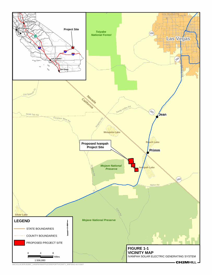
Proposed Ivanpah Project Site
!Primm
!Jean
Mojave National Preserve
Toiyabe National Forest
Mojave National Preserve
Las VegasPahrumpPahrump
¬«160
¬«159
¬«164
¬«161
¬«160
15
95
Cima Rd
Kelbaker Rd
515
Las
Vega
s B
lvd
King
ston
Rd
Nipton Rd
Craig Rd
Excelsior Mine Rd
In dustri al Rd
Lesl
ie S
t
Old Sp anish Trail Hwy
Kel
so C
ima
Rd
Sandy Valley Rd
Old Spanish T
rl
Smith Talc Rd
Baker B
lvd
Lone Mountain Rd
Kingston Rd
Soda Lake
Ivanpah Lake
Silver Lake
Mesquite Lake
Roach Lake
1:506,880
FIGURE 1-1VICINITY MAPIVANPAH SOLAR ELECTRIC GENERATING SYSTEM
!
!
!
!
!
San Jose
San Diego
Sacramento
Los Angeles
San Francisco
_̂§̈¦40
§̈¦15§̈¦5
AÎ
LEGEND
STATE BOUNDARIES
COUNTY BOUNDARIES
PROPOSED PROJECT SITE
NevadaCalifornia
0 84Miles
Project Site
SAC\\GLACIER\352897_IVANPAH\MAPFILES\REPORT\VICINITY_MAP.MXD 8/17/2007

TAP STATION
METERING SET
METERING SET
SUBSTATION
ADMINISTRATION AND STORAGE
IVANPAH 1
IVANPAH 2
IVANPAH 3
WELLS
REROUTED COLOSSEUM ROAD
PROPOSEDMONITORING WELL
ColosseumRoad
Colosseum Road
Colosseum Road
\\ZION\SACGIS\PROJ\352897_IVANPAH\MAPFILES\2008FIELDMAPS\IVANPAH_TOWNSHIPRANGE.MXD SSCOPES 3/10/2009 14:16:37
0 3,000Feet
LEGENDWELLS
DIRT ROAD
PAVED ROAD
UTILITIES CORRIDOR
NATURAL GAS LINE
GEN-TIE LINE
KERN RIVER GAS LINE
4WD TOURING/TRAILS
SECTION LINES
PROJECT SITE FIGURE 2-1SITE PLAN AND LINEAR FACILITIESIVANPAH SOLAR ELECTRIC GENERATING SYSTEM³

ES062007009SAC/357891/091460006(ATTACHBR5-1_DRAFT_ TRANSLOCATION_PLAN_FINAL) 5
2.0 Translocation/Relocation Plan
2.1 Permanent Fencing Prior to translocation/relocation activities the site boundary of the unit being developed would be permanently fenced with an 8-foot-high chain link fence for security purposes and permanent desert tortoise exclusionary fencing would either be attached to the base of the security fence or installed outside the security fence for construction of linear facilities. In areas where a security fence is not required, such as along Colosseum Road or the access road along the west side of the project going from Colosseum Road to the power blocks in Ivanpah 2 and 3, only a tortoise exclusion fence would be installed. A permanent I-beam design desert tortoise guard would be installed to allow equipment access to the fenced sites and exclude desert tortoises. The specifications for the proposed desert tortoise guard are included in Appendix C. If monitoring indicates that the proposed permanent I-beam barriers for use as desert tortoise guards across roads proves to be ineffective or problematic these barriers would be replaced with another means of exclusion. This would be implemented with input from the permitting agencies if monitoring of the facility indicates that they are needed. Tortoise guards will be maintained and monitored as part of the permanent fence inspections and maintenance.
The boundaries of all areas to be disturbed would be flagged before beginning any activities, and all disturbances would be confined to the flagged areas. All project vehicles and equipment would be confined to the flagged areas. Survey crew vehicles would remain on existing roads. To reduce the potential for tortoise strikes by vehicles, a 35 mph speed limit will be enforced on paved roads and 20 mph speed limit on dirt roads. Disturbance beyond the construction zone would be prohibited except to complete a specific task within designated areas or emergency situations.
Once flagged, the next step prior to any site clearance work is fencing the perimeter of the area to be cleared. Within 24 hours prior to the initiation of construction of the desert tortoise-exclusion fence, a desert tortoise survey would be conducted using techniques providing 100-percent coverage of the construction area and an additional transect along both sides of the fence line transect to provide coverage of an area approximately 90 feet wide centered on the fence alignment. Transects would be no greater than 10 feet apart. Two passes of complete coverage would be conducted. All desert tortoise burrows, and burrows constructed by other species that might be used by desert tortoises, would be examined to determine occupancy. Any burrow within the fence line would be collapsed after confirmation that it is not occupied by a desert tortoise, or if occupied, the desert tortoise has been removed (CH2M HILL 2008).
Next, an approximate 10-foot-wide linear swath of vegetation along the entire outer edge of the area to be developed would be cleared to create an internal perimeter path for installation of either the tortoise fencing, or combined tortoise and security fence. All fencing will be constructed with durable materials (i.e., 11 gauge or heavier) suitable to resist desert environments, alkaline and acidic soils, wind, and erosion. Tortoise

2.0 TRANSLOCATION/RELOCATION PLAN
ES062007009SAC/357891/091460006(ATTACHBR5-1_DRAFT_ TRANSLOCATION_PLAN_FINAL) 6
exclusionary fence material will consist of 1-inch horizontal by 2-inch vertical, galvanized welded wire, 36 inches high. This fence material will be buried a minimum of 12 inches below the ground surface, leaving 22 to 24 inches above ground. A trench will be dug to allow 12 inches of fence to be buried below the natural level of the ground. Specifications for desert tortoise-proof fencing are provided in Appendix C and can be found at the following website: http://www.fws.gov/ventura/speciesinfo/ protocols_guidelines/ docs/dt/DT_Exclusion-Fence_2005.pdf
Where a combined security/tortoise fence is needed, 6-foot-high standard chain link fencing will be placed above the tortoise fence with about 1 inch overlap creating a combined security/tortoise fence about 8 feet tall. The top end of the tortoise fence will be secured to the security fence with hog rings at 12- to 18-inch intervals. Distance between posts will not exceed 10 feet. Concrete footings for metal posts will not be required. The fence is to be perpendicular to the ground surface, or slightly angled away from the road, towards the side encountered by tortoises. After the fence has been installed, excavated soil will be replaced and compacted to minimize soil erosion. Fence installation will be monitored by a desert Tortoise Monitor (TM) and an Authorized Biologist (AB) would be available at all times to move any desert tortoises that are within the path of the fence line work.
Areas requiring permanent fencing include:
• Colosseum Road from the golf club to the Construction Logistics Area (CLA) where the road will be widened and paved
• The portion of the Construction Logistics Area that will be used for construction activities. It is possible that the entire CLA would not need to be fenced at the outset. Figure BR5-3 shows the portion of the CLA that would likely be fenced as part of the initial construction activity. Regardless, permanent fencing would be required around the substation and the Administration/warehouse building.
• The individual heliostat fields
• Gas tap station and gas metering sets
The location of all permanent tortoise exclusion fencing will be identified on construction drawings and preapproved by the permitting agencies prior to the start of construction activities. The installation of permanent tortoise fencing along roadways (e.g., Colosseum Road) would occur as described below for the installation of temporary construction fence, except that permanent fencing would be installed.
Prior to translocation/relocation activities, the Applicant (or Caltrans) will fence the north side of I-15 with desert tortoise-proof fencing from Nipton Road to the Primm Valley Golf Club. The Applicant will work with Caltrans regarding the appropriate location for this fencing along the I-15. The Applicant will also coordinate the location of the proposed Joint Port of Entry in locating this fencing. A records of conversations with Caltrans is provided in Appendix D.
Any damage to the permanent fencing will be repaired immediately. Following installation, the permanent fencing would be inspected bimonthly (i.e., every other month) and after major rainfall events. A major rainfall event would be any rainfall that causes the ephemeral

2.0 TRANSLOCATION/RELOCATION PLAN
ES062007009SAC/357891/091460006(ATTACHBR5-1_DRAFT_ TRANSLOCATION_PLAN_FINAL) 7
washes in the project vicinity to flow and thereby potentially damage the fencing. Extra fencing material would be kept onsite to accommodate needed repairs.
2.2 Temporary Construction Fencing Temporary fencing, such as chicken wire, snow fencing, chain link, and other suitable materials will be used in designated areas to reduce encounters with tortoises on short-term projects. The fencing material will be attached to metal posts with a minimum of 12-gauge steel wire. The grid opening of the wire will not exceed 1 inch by 2 inches and the fence height will be no less than 30 inches. Posts will be metal and not less than approximately 40 inches long. Concrete footings for metal posts will not be required. Because of the short duration of the work, the fencing need not be buried but any high or low points along the wire mesh fence line will be hand-excavated to maintain integrity with the ground. If non-metal fencing is use, it will be staked to the ground at minimum intervals of 10 feet.
Areas that would require temporary construction fencing include:
• Construction of the gas line from the Kern River Gas Transmission tap station to the power block at Ivanpah 1
• Construction of the tap station and gas metering set construction areas
• Construction of any trails or temporary access roads outside of the fenced heliostat fields
• Construction of any transmission lines, other utilities or access roads located outside of the permanently fenced areas that are specifically attributable to the ISEGS project.
The location of temporary construction fencing will be identified on construction drawings and approved by the permitting agencies prior to the start of construction activities.
• Within 24 hours prior to the initiation of construction of the temporary desert tortoise-exclusion fence, a desert tortoise survey would be conducted using techniques providing 100-percent coverage of the construction area and an additional transect along both sides of the fence line transect to provide coverage of an area approximately 90 feet wide centered on the fence alignment. Transects would be no greater than 10 feet apart. Two passes of complete coverage would be conducted. All desert tortoise burrows, and burrows constructed by other species that might be used by desert tortoises, would be examined to determine occupancy. Any burrow within the fence line would be collapsed after confirmation that it is not occupied by a desert tortoise, or if occupied, the desert tortoise has been removed by an AB.
• An AB or TM will be onsite during installation of the temporary desert tortoise fence. If installation of temporary fencing, surveying or clearing is occurring at more than one location, more than one AB may need to be onsite to provide appropriate supervision. After installation of this temporary fencing and prior to initiation of construction activities, an AB and/or TM will perform a pre-construction sweep for desert tortoises. An AB will relocate any desert tortoises found in the project impact area. Desert tortoises will be moved to suitable habitat outside the impact area and placed in a natural or artificial burrow or under a shrub, depending on time of day and year. An AB

2.0 TRANSLOCATION/RELOCATION PLAN
ES062007009SAC/357891/091460006(ATTACHBR5-1_DRAFT_ TRANSLOCATION_PLAN_FINAL) 8
will also be available to relocate any desert tortoises that may wander into the impact area during construction.
• To avoid any additional disturbance beyond what is proposed, the undisturbed areas outside the temporary desert tortoise exclusion fence will be designated Environmentally Sensitive Areas. All construction activities will be confined within the fenced project impact area. Equipment or personnel will not be allowed within the Environmentally Sensitive Areas.
• Prior to performing onsite work, all personnel involved in the construction project will participate in Worker Environmental Awareness Program (WEAP) training that includes desert tortoise protection training approved by the permitting agencies. At a minimum, training will include discussion of the fragility of desert habitats, the importance of the desert tortoise to the environment, the protections afforded to the desert tortoise by the Endangered Species Act, locations of Environmentally Sensitive Areas, and the correct protocol to follow should a desert tortoise be encountered.
• Once temporary exclusion fencing has been installed, the area within the temporary fencing may be mowed to facilitate access by the construction equipment. Unlike installation of the permanent fencing, clearing of vegetation would not be done for installation of the temporary fence. Vegetation clearing would be limited to the areas required for construction.
• At the end of each working day, the contractor will inspect the integrity of all temporary desert tortoise fencing to ensure that desert tortoises are prohibited from entry. If the fence is compromised, repairs must be completed at that time. Extra fencing material will be kept onsite during periods when construction requiring the use of temporary fencing is occurring.
• Prior to the start of work each day the AB or TM will re-check the site to ensure that it is clear of tortoises. If work in the area has been delayed more than 24 hours (e.g., weekend or due to a storm), a more detailed search for tortoises will be required prior to the start of work.
• Open trenches, auger holes, or other excavations that may act as pit-fall traps will be inspected by an AB before back filling. Any desert tortoise found will be safely removed and relocated out of harm’s way by an AB. For open trenches, earthen escape ramps will be maintained at intervals of no greater than 0.25 mile. The open trenches will be inspected three times per day (four times per day during the summer) by a qualified biologist. Other excavations that remain open overnight will be covered to prevent them from becoming traps.
• Project personnel will carefully check under parked vehicles and equipment for desert tortoises before operation. An AB will move desert tortoises found within the parking, staging, construction or other traffic areas to a location away from danger and only as specified in the biological opinion.
• At water and trash sources, measures will be implemented by the AB to preclude access by common ravens (Corvus corax). Trash will be placed in sealed containers and emptied at the close of business each day. Each water source will be caged. Fencing and netting

2.0 TRANSLOCATION/RELOCATION PLAN
ES062007009SAC/357891/091460006(ATTACHBR5-1_DRAFT_ TRANSLOCATION_PLAN_FINAL) 9
will prevent desert tortoises and common ravens from accessing water sources in construction areas.
• If a desert tortoise that is either dead, injured, or entrapped, is found, the contractor will immediately notify the AB/TM who will then immediately notify the permitting agencies directly or through the CEC’s biology staff. Work in the immediate area will be temporarily halted while the AB consults with the permitting agencies. Any entrapped desert tortoise will be permitted to escape. The disposition of any carcasses or recovery of dead animals will be coordinated through the CEC.
• If a desert tortoise is injured during the course of construction, the CEC will be notified and the AB will transport the animal to a qualified veterinarian2. If a desert tortoise is killed during the course of construction, it will be left in place as is and the permitting agencies will be notified. The AB will document and remove the carcass.
2.3 Clearance Surveys of Permanent Exclusion Areas Within 72 hours after the area to be cleared is fully enclosed with combined security and/or tortoise fencing, a desert tortoise clearance survey would be performed per Service protocol (Service 1992) and recent Guidelines (Service 2008). Two complete passes with complete coverage would be conducted as described above. If no desert tortoises are observed during the second survey, a third survey would not be conducted. Each separate survey would be walked in a perpendicular direction to allow opposing angles of observation. If a desert tortoise is located on the second survey, a third survey would be conducted. Once the area surveyed is deemed free of desert tortoises the areas may be open to a vegetation salvage program, if the BLM desires to do so (CH2M HILL 2008).
The ABs would be primarily responsible for the clearance surveys. Some ABs may be substituted with TMs who would be placed between ABs during the surveys. Once the sites are deemed free of desert tortoises after at least two consecutive clearance surveys then heavy equipment would be allowed to enter the construction site to perform earth work such as clearing or cutting vegetation, grubbing, leveling, and trenching. A TM would monitor initial clearing and grading activities to find and relocate any tortoises missed during the initial tortoise clearance survey. Should a tortoise be discovered, then the AB would be responsible for relocating it outside the fence or translocating it.
The specific instructions for handling and processing of tortoises as outlined in the Guidelines for Handling Desert Tortoises During Construction Projects (Desert Tortoise Council, 1999) will be followed. The ABs will maintain a record of all desert tortoises encountered and relocated or translocated during project surveys and monitoring. This information would include for each individual: the location (narrative, vegetation type, and maps) and dates of observations; borrow data; general conditions and health; measurements; any apparent injuries and state of healing; if moved, the location from which it was captured and the location in which it was released (whether animals voided their bladders); and diagnostic markings (i.e., identification numbers).
2 A list of licensed veterinarians in the Las Vegas area who treat desert tortoises can be found on the internet at: http://www.deserttortoise.org/answeringquestions/appendix2.html

2.0 TRANSLOCATION/RELOCATION PLAN
ES062007009SAC/357891/091460006(ATTACHBR5-1_DRAFT_ TRANSLOCATION_PLAN_FINAL) 10
All potential desert tortoise burrows located would be excavated by hand by an AB, desert tortoises removed, and collapsed or blocked to prevent occupation by desert tortoises. The AB would also search for desert tortoise nests/eggs, which are typically located near the entrance to burrows. All desert tortoise handling and removal, and burrow excavations, including nests, would be conducted by ABs in accordance with the Service-approved protocol (Desert Tortoise Council 1994, revised 1999). If the Desert Tortoise Council releases a revised protocol for handling of desert tortoises before initiation of project activities, the revised protocol would be implemented for the project (CH2M HILL 2008).
All Service (2008) Guidelines for clearance surveys (Appendix A) will be followed.
2.4 Transportation and Release Activities addressed here include excavation, handling, and artificial burrow construction.
All potential desert tortoise burrows within the fenced area would be searched for presence. In some cases, a fiber optic scope may be used to determine presence or absence within a deep burrow. Burrows inhabited by tortoises would be excavated by ABs or by TMs supervised by an AB using hand tools. To prevent reentry by a tortoise or other wildlife, all burrows would be collapsed once absence has been determined. Tortoises excavated from burrows would be relocated or translocated to unoccupied natural or artificial burrows outside the fenced site immediately following excavation. Prior to excavating and transporting a tortoise a suitable burrow will have been located, or an artificial burrow constructed, to expedite the process and minimize handling time. The receiving burrow will be of the same size and orientation as the original burrow. The final determinations on placement of relocated/translocated tortoises would take place during Service-approved protocol level surveys of the areas prior to handling activities.
Tortoise excavation, handling, artificial burrow construction, egg handling and other procedures would follow those described in the Guidelines for Handling Desert Tortoise During Construction Projects (Desert Tortoise Council, 1994 (Revised 1999)). Processing of tortoises found during the clearance surveys will be done in an appropriate facility to provide shade, should temperatures require such. A processing facility may use temporary shade structures (e.g., E-Z Ups) or a temperature-controlled facility (e.g., a recreational vehicle).
If desert tortoises need to be moved at a time of day when ambient temperatures could harm them (less than 40 degrees Fahrenheit (°F) or greater than 90 °F), they would be held overnight in a clean cardboard box or plastic tote. These tortoises would be kept in the care of the AB under appropriate controlled temperatures and released the following day when temperatures are favorable. All cardboard boxes would be appropriately discarded after one use and never hold more than one tortoise. Plastic totes will be disinfected with a 20 percent bleach solution.
Data will be collected on all tortoises handled, as described above. They will also be photographed and closely examined for clinical signs of animal disease at the time of capture. All ABs and TMs performing examinations for health characteristics would be required to have experience identifying the clinical signs of URTD, herpes virus, and cutaneous dyskeratosis in tortoises. Desert tortoises will be transported in clean cardboard

2.0 TRANSLOCATION/RELOCATION PLAN
ES062007009SAC/357891/091460006(ATTACHBR5-1_DRAFT_ TRANSLOCATION_PLAN_FINAL) 11
boxes or plastic tote. If a cardboard box is used, a new box would be used for each individual tortoise and would be properly discarded after a single use. If a plastic tote is used, it will be sterilized with a 20 percent bleach solution between each use. The new burrow would be located at least 300 feet from the outside of the permanently fenced sites and would be of similar size, shape and orientation to the original burrow. The new burrow locations would be determined by the AB. Relocated tortoises would not be placed in existing occupied burrows.
The ABs would wear disposable surgical gloves when handling desert tortoises. A new pair would be donned for each tortoise handled to avoid the transmission of upper respiratory tract disease (URTD). Shell notching would not be performed. Any equipment used to handle tortoises will be sterilized with a 20 percent bleach solution between each use.
All Service (2008) Guidelines for transportation and release (Appendix A) will be followed unless modified herein. All standard handling procedures, such as keeping desert tortoises upright during handling, will be followed by the ABs and TMs.
Per the protocol, tortoises that can be relocated will be moved less than 1,000 meters to the west side of the project fencing within the relocation area (see Figure BR5-3). The translocation area beyond 1,000 meters would be used to accommodate all project-site desert tortoises that cannot be moved to safe locations within 1,000 meters of their capture location. Should it be determined that a tortoise needs to be transported more the 1,000 meters it will be relocated within the preferred translocation area as specified by the agencies approving this plan. Once the agencies concur as to the location of the translocation areas, they will be assessed as to their habitat suitability and a technical memo prepared documenting the findings. The memo will also describe the presence or absence of potential desert tortoise predators observed during the habitat characterization. This habitat characterization will be done to confirm that the proposed translocation areas are suitable to sustain tortoises.
The translocation areas will be surveyed to estimate tortoise densities and the distribution of resident tortoises prior to the relocation/translocation activities. Surveys will be conducted using Service protocols. The results of these surveys will be used to determine whether the area meets the requirement of having a density of resident and relocated/translocated tortoises that does not exceed 39 tortoises per square kilometer. The first protocol survey would be within the one square kilometer translocation area for Ivanpah 1 to determine tortoise density, distribution, and further assess habitat suitability. If this area were determined to meet the relocation criteria, the subject tortoises would be relocated to this area. The survey results will also be used to determine the placement of translocated tortoises with an emphasis on avoiding resident tortoises and active burrows as well as areas supporting potential predators, most notably ravens. Subsequent protocol surveys would be conducted in one square kilometer areas of suitable habitat prior to the development of each of the Ivanpah SEGS units. An additional one square kilometer area will be surveyed at the time the Ivanpah 1 translocation area is surveyed to provide a pre-approved area should additional space be needed. Hence, prior to the commencement of the translocation activities, at least two 1-square-kilometer areas will have been surveyed and pre-approved.

2.0 TRANSLOCATION/RELOCATION PLAN
ES062007009SAC/357891/091460006(ATTACHBR5-1_DRAFT_ TRANSLOCATION_PLAN_FINAL) 12
As shown in Figure BR5-3, four 1-square-kilometer areas have been initially identified. This provides an area for each of the Ivanpah SEGS units, with an additional area as a reserve, should the first area have insufficient capacity. As stated earlier, once the initial translocation areas are approved by the agencies, the habitat assessment of those areas will be performed and a technical memo of the results prepared. A copy of the proposed habitat assessment protocol is included as Appendix E.
The survey results of the proposed translocation areas will be submitted to the permitting agencies prior to the commencement of each construction phase. This will ensure these proposed locations are in a suitable area.
2.5 Scheduling Construction of the generating facility, from site preparation and grading to commercial operation, is expected to take place as early as late Fourth Quarter of 2009 to the Fourth Quarter of 2013 (48 months total). It is anticipated that Ivanpah 1 (southern site) will be constructed first, followed by Ivanpah 2 (middle site), then Ivanpah 3 (northern site), though the order of construction may change. Construction of the shared facilities would occur with the first plant.
Translocations/relocations will take place in the fall (i.e., late August/September to October/November) and in the spring (i.e., March/April – May) to avoid extremely high thermal conditions (Cook et al. 1978, Nussear 2004, in Esque et al. 2005). No desert tortoise would be captured, moved, transported, released, or purposefully caused to leave its burrow for whatever reason when the ambient air temperature is above 95ºF (35ºC). Ambient air temperature would be measured in the shade, protected from wind, at a height of 2 inches (5 centimeters) above the ground surface. No desert tortoise would be captured if the ambient air temperature is anticipated to exceed 95ºF (35ºC) before handling and relocation can be completed. If the ambient air temperature exceeds 95ºF (35ºC) during handling or processing, desert tortoises would be kept shaded in an environment that does not exceed 95ºF (35ºC), and the animals would not be released until ambient air temperature declines to below 95ºF (35ºC). As stated in the Service (2008) Guidelines (Appendix A, item I.F), “BrightSource must obtain approval of the translocation area and timing of the translocation activities from the Service, CDFG, and the Bureau prior to initiating any translocation activities.”
2.6 Translocation/Relocation Areas Tortoises will be translocated/relocated in the Ivanpah Valley adjacent to the site areas or in areas depicted in Figure BR5-3. This area meets the Guidelines provided by the Service (2008). Tortoises excavated from burrows would be relocated to unoccupied natural or artificial burrows outside the fenced sites immediately following excavation. Prior to translocation and relocation activities this area will be surveyed to locate suitable unoccupied burrows and/or construction of a sufficient number artificial burrows. Ideally all tortoises would be relocated to within 1000 meters of the site(s). The primary constraint is that resident and relocated desert tortoises do not exceed 39 individuals per square kilometer. To obtain approval for the proposed translocation area, a habitat assessment will be

2.0 TRANSLOCATION/RELOCATION PLAN
ES062007009SAC/357891/091460006(ATTACHBR5-1_DRAFT_ TRANSLOCATION_PLAN_FINAL) 13
conducted to determine whether habitat of the proposed translocation area is suitable to sustain tortoises. The proposed protocol for this assessment is provided in Appendix E.
All Service (2008) Guidelines for the selection of translocation/relocation area (Appendix A) will be met. Included in the Service (2008) Guidelines in item II.B.3 are guidelines to ensure proper rehydration. Further, as stipulated in these Guidelines (item I. F); “BrightSource must obtain approval of the translocation area and timing of the translocation activities from the Service, CDFG, and the Bureau prior to initiating any translocation activities. Translocations shall not be permitted if these agencies determine that environmental conditions such as an extended drought might significantly reduce the survival of the translocated desert tortoise.”
2.7 Monitoring and Reporting To monitor for survivorship and health, for a period of 3 years following their translocation/relocation, the desert tortoises will be located at least monthly by the AB. In order to locate all translocated/relocated tortoises, it will be necessary that they be marked and fitted with radio transmitters. Tortoises would be marked with Passive Integrated Transducer (PIT) tags (Gibbons and Andrews 2004) (e.g., Biomark model TX1400L); 2) fitted with an external label (ASIH 2004), and 3) have a light-weight radio transmitter attached with a battery life of at least one year (e.g., Holohil model AI-2F). This redundant method of marking tortoises ensures that tortoises are easily identified by field workers, even in the case of predation or shell wear. Transmitters will be attached using methods similar to those described in Boarman et al. (1998). All transmitters would be removed at the end of this monitoring period.
Juvenile tortoises located during clearance surveys would be treated differently than adult tortoises. Before being released, all juvenile tortoises located would be affixed with specially designed radio transmitters that are small enough to minimize stress. Due to the small size of these transmitters and the subsequent short battery life, these juvenile transmitters will have to be exchanged out approximately every 10 weeks. Juveniles will also be marked using either a Passive Integrated Transducer (PIT) tag and/or fitted with an external label using appropriate standards (ASIH 2004) (adapted from Esque et al. 2005).
Upon locating the translocated/relocated tortoises, all pertinent information will be recorded, such as behavior, physical characteristics, health characteristics, as well as any potential anomalies the individual desert tortoise might display. All ABs and TMs performing examinations for health characteristics would be required to have experience identifying the clinical signs of URTD, herpes virus, and cutaneous dyskeratosis in tortoises. As stated in the item II.A.5 of the Service (2008) Guidelines, “the authorized biologist(s) will remove and quarantine any desert tortoises showing clinical signs of disease. They must then contact the Service within 24 hours to determine the disposition of these individuals.” Quarantined tortoises will be kept in a temperature-controlled area away from all other tortoises that are being processed for translocation. The AB will be responsible to ensure that quarantined tortoises have adequate food. If blood testing is warranted, a licensed

2.0 TRANSLOCATION/RELOCATION PLAN
ES062007009SAC/357891/091460006(ATTACHBR5-1_DRAFT_ TRANSLOCATION_PLAN_FINAL) 14
veterinarian in the Las Vegas area3 will be used to draw blood and ship it to an appropriate laboratory for testing.
All observations will be reported to the AB who will record the following information for the monthly compliance report: (1) species name; (2) location (global positioning system coordinates, narrative and maps) and dates of observations; (3) general condition and health, including injuries and state of healing; (4) diagnostic markings, including identification numbers or markers; and (5) locations moved from and to.
All Service (2008) Guidelines for monitoring and reporting (Appendix A) will be followed unless modified herein. Including the requirements in item III.2 about adaptive management should abnormally high mortality rates among the translocated desert tortoises occur. Hence, if monitoring shows a mortality rate of 10 percent or higher among the translocated population, the project owner will consult with the permitting agencies to develop a remedial action plan prior to further phased translocation activities.
3 A list of licensed veterinarians in the Las Vegas area who treat desert tortoises can be found on the internet at: http://www.deserttortoise.org/answeringquestions/appendix2.html

!( !(
!(
!(!(
!(
!(
!(
!(
!(
!(
!(
!(
!(
!(
!(
!(
!(
!(
!(
!(
!(
!(
!(!(
!(
!(
!(
!(
!(
!(
")
§̈¦15
SUBSTATION
ADMINISTRATION AND STORAGE
IVANPAH 1
IVANPAH 2
IVANPAH 3
BP
KRGT1
KRGT2
I2-R3
I3-R2I3-R3
I1-R1
I1-R2I1-R3
I2-R1
I2-R2
I3-R1
TS3-R3
RI3-R1
I3-R5
I3-R4
TS1-R1
TS2-R3
TS2-R2TS2-R1
TS3-R2
TS3-R1
RI3-R2
RI2-R1
RI3-R3
RI1-R2
RI1-R1
TS1-R3TS1-R2
RIST-R2
RIST-R1
Translocation Area S2
Translocation Area S3
Translocation Area S1
Translocation N2
Translocation N4
Translocation N1
Translocation N3
7N 13Eection: 1
16N 14ESection: 6
16N 13ESection: 1
16N 14ESection: 316N 14E
Section: 516N 14ESection: 4
16N 14ESection: 7
16N 14ESection: 2
16N 14ESection: 1
16N 14ESection: 9
16N 14ESection: 8
16N 13ESection: 13
16N 14ESection: 29
16N 14ESection: 24
16N 14ESection: 22
16N 14ESection: 23
16N 13ESection: 24
16N 14ESection: 21
16N 14ESection: 34
17N 13Eection: 12
17N 14ESection: 36
17N 14ESection: 22
17N 14ESection: 34
17N 14ESection: 17
16N 14ESection: 20
16N 13ESection: 12
17N 14ESection: 15
16N 14ESection: 27
17N 13ESection: 13
16N 14ESection: 11
17N 13ESection: 25
16N 14ESection: 10
16N 14ESection: 30
17N 14ESection: 35
16N 14ESection: 18
17N 14ESection: 13
17N 14ESection: 23
16N 14ESection: 25
16N 14ESection: 15
17N 14ESection: 14
16N 14ESection: 28
17N 14ESection: 24
17N 14ESection: 25
16N 14ESection: 12
16N 14ESection: 19
16N 14ESection: 33
17N 13ESection: 24
16N 14ESection: 13
16N 14ESection: 26
16N 14ESection: 14
16N 14ESection: 35
17N 14ESection: 21
17N 14ESection: 16
17N 14ESection: 20
16N 14ESection: 32
16N 14ESection: 31
16N 14ESection: 36
17N 14ESection: 18
17N 14ESection: 27
17N 13ESection: 36
17N 14ESection: 28
17N 14ESection: 19
16N 14ESection: 16
17N 14ESection: 29
16N 14ESection: 17
17N 14ESection: 33
17N 14ESection: 30
17N 14ESection: 26
17N 14ESection: 31
17N 14ESection: 32
7.5N13Ection: 36
15.5N14ESection: 20
15.5N14ESection: 21
15.5N14ESection: 23
15.5N14ESection: 22
15.5N14ESection: 24
17N 14ESection: 8
17N 14ESection: 7
17N 14ESection: 9
17N 14ESection: 10
17N 14ESection: 11
17N 14ESection: 12
15.5N14ESection: 19
15.5N15ESection: 19
Corral
\\ZION\SACGIS\PROJ\352897_IVANPAH\MAPFILES\PROPOSEDRELOCATION_TRANSLOCATION_ZOOMEDOUT_UNCPATHS.MXD KSWANSO3 8/5/2009 09:27:53
006,30Feet
LEGEND!( Shrub & Succulent Sampling Sites
") Corral Location
Train Line Option 4B
Train Line Option 4C
Trails
Project Site
Relocation Area
Translocation Area
FIGURE 4-3VEGETATION SAMPLING FOR PROPOSED DESERT TORTOISE RELOCATION AND TRANSLOCATION AREASIVANPAH SOLAR ELECTRIC GENERATING SYSTEM³
KEYI1-R1 through I1-R3: Ivanpah 1, relevés 1 - 3I2-R1 through I2-R3: Ivanpah 2, relevés 1 - 3I3-R1 through I3-R5: Ivanpah 3, relevés 1 - 5RI1-R1 and RI1-R2: Relocation Area for Ivanpah 1, relevés 1 and 2RI2-R1: Relocation Area for Ivanpah 2, relevé 1RIST-R1 and RIST-R2: Relocation Area for Ivanpah Substation, relevés 1 and 2RI3-R1 through RI3-R3: Relocation Area for Ivanpah 3, relevés 1 - 3TS1-R1 through TS1-R3: Southern Translocation Area 1, relevés 1 - 3TS2-R1 through TS2-R3: Southern Translocation Area 2, relevés 1 - 3TS3-R1 through TS3-R3: Southern Translocation Area 3, relevés 1 - 3KRGT1 and KRGT2: Kern River Gas Transmission Line Undisturbed Relevés 1 and 2BP: Borrow Pit Undisturbed Relevé
ES062007009SAC Figure_1_AUG_2009.ai 08.10.09 tdaus
Proposed Joint Point of Entry (JPOE) Facilities
Tortoise Fence

ES062007009SAC/357891/091460006(ATTACHBR5-1_DRAFT_ TRANSLOCATION_PLAN_FINAL) 16
3.0 References
AMEC Earth & Environmental, Inc. 2008. Victorville 2 Hybrid Power Project; Desert Tortoise (Gopherus agassizi) Translocation Plan. Prepared for City of Victorville, on behalf of Inland Energy and ENSR Corporation. February. 37 pp.
ASIH. 2004 Guidelines for use of live amphibians and reptiles in field a laboratory research. Second Edition. Revised by the Herpetological Animal Care and Use Committee (HACC) of the American Society of Ichthyologists and Herpetologists. (Committee Chair: Steven J. Beaupre, Members: Elliott R. Jacobson, Harvey B. Lillywhite, and Kelly Zamudio).
Boarman, W. I., T. Goodlett, and P. Hamilton. 1998. Review of radio transmitter attachment techniques for turtle research and recommendations for improvement. Herpetological Review 29:26-33.
CH2M HILL. 2008. Attachment DR124-1A, Draft Biological Assessment for the Ivanpah Solar Electric Generating System (Ivanpah SEGS) Project. Prepared for Bureau of Land Management. Prepared on behalf of Solar Partners I, LLC; Solar Partners II, LLC; Solar Partners IV, LLC; and Solar Partners VIII, LLC. September.
CH2M HILL. 2009. Attachment DR125-3A, Closure, Revegetation and Rehabilitation Plan for the Ivanpah Solar Electric Generating System Eastern Mojave Desert San Bernardino County, California. Prepared for Bureau of Land Management. Prepared on behalf of Solar Partners I, LLC; Solar Partners II, LLC; Solar Partners IV, LLC; and Solar Partners VIII, LLC. January 28.
Desert Tortoise Council. 1994 (Revised 1999). Guidelines for Handling Desert Tortoise During Construction Projects. Edward L. LaRue, Jr., editor. Wrightwood, California.
Esque, T.C., K.E. Nussear, and P.A. Medica. 2005. Desert Tortoise Translocation Plan for Fort Irwin’s Land Expansion Program at the U.S. Army National Training Center (NTC) & Fort Irwin. Prepared for U.S. Army National Training Center, Directorate of Public Works. 122 pp.
Gibbons, J. W., and K. M. Andrews. 2004. PIT tagging: simple technology at its best. BioScience. 54:447-454.
U.S. Fish and Wildlife Service (Service). 2008. Guidelines for Clearance and Translocation of Desert Tortoises from the Ivanpah Solar Electric Generating System (Ivanpah SEGS) Project. U.S. FWS, Ventura Office. December 12.
U.S. Fish and Wildlife Service (Service). 1992. Field Survey Protocol for Any Federal Action That May Occur within the Range of the Desert Tortoise. January.
Sundance Biology, Inc. 2008. Presence/Absence Survey for the Desert Tortoise (Gopherus agassizii), on the proposed Ivanpah Solar Electric Generating System in Ivanpah Valley, San Bernardino County, CA. Prepared for: CH2M HILL, Inc. June.

A t t a c h m e n t D R 2 9 - 1 A
Draft Raven Management Plan Ivanpah Solar Electric Generating System
Prepared for
Solar Partners I, LLC; Solar Partners II, LLC; Solar Partners IV, LLC; and Solar Partners VIII, LLC
September 2008
2485 Natomas Park Drive, Suite 600
Sacramento, CA 95833

SAC/357891/082530006 (DRAFT_ISEGS_RAVEN_MGMT_PLAN.DOC) iii
Contents Section Page
1 Introduction.........................................................................................................................1-1 2 Background..........................................................................................................................2-1
2.1 Environmental Setting of Ivanpah Valley...........................................................2-1 2.2 Desert Tortoise Biology .........................................................................................2-3
2.2.1 Status ...........................................................................................................2-3 2.2.2 Natural History, Distribution, Abundance, and Habitat.....................2-4
2.3 Raven Biology .........................................................................................................2-6 2.4 Raven Predation of Tortoise, Existing Raven Attractants, and Threats .........2-7
2.4.1 Threats and Attractants in the Ivanpah Valley .....................................2-9 2.5 Ivanpah SEGS Project Features, Construction, and Operation......................2-10
2.5.1 Project Features........................................................................................2-10 2.5.2 Construction.............................................................................................2-13 2.5.3 Operation..................................................................................................2-15
3 Raven Management ...........................................................................................................3-1
3.1 Management Goals.................................................................................................3-1 3.2 Raven Management Measures..............................................................................3-1
3.2.1 Reduce Access to Anthropogenic Food and Water Resources ...........3-1 3.2.2 Discourage Nesting...................................................................................3-3 3.2.3 Discourage Roosting .................................................................................3-6 3.2.4 Avoid Increased Predation Risk Associated with Tortoise Translocation...........................................................................................................3-8 3.2.5 Removal of Problem Ravens....................................................................3-8
3.3 Success Criteria .......................................................................................................3-9 3.4 Adaptive Management ........................................................................................3-10
4 Raven Monitoring Plan .....................................................................................................4-1
4.1 Raven Population Monitoring ..............................................................................4-1 4.1.1 Methodology..............................................................................................4-1
4.2 Survey Participants ................................................................................................4-2 4.3 Monitoring Reports ................................................................................................4-2
5 References ............................................................................................................................5-1
Figures
1 Vicinity Map 2 Project Area 3 Artist Rendering 4 Site Plan 5 Construction Logistics Area

SAC/357891/082530006 (DRAFT_ISEGS_RAVEN_MGMT_PLAN.DOC) 1-1
SECTION 1
Introduction
Solar Partners I, LLC; Solar Partners II, LLC; Solar Partners IV, LLC and Solar Partners VIII, LLC (the Applicant), which are subsidiaries of BrightSource Energy, Inc., propose to develop a solar power project consisting of three adjacent solar energy facilities to be located in the Ivanpah Valley near the Interstate 15 (I-15) crossing of the California/Nevada border in San Bernardino County, California (Figure 1, figures are located at the end of each section). The proposed project site is located on land administered by the Bureau of Land Management (BLM) and is less than 2 miles east of the Mojave National Preserve, less than 2 miles west of Ivanpah Dry Lake, less than a mile south of the Stateline Wilderness and Mesquite Wilderness areas of the Clark Mountains; approximately 0.5 miles west of the Primm Valley Golf Club; approximately 0.8 miles northwest of I-15; and approximately 4.5 miles southwest of the Primm Valley casinos. Access to the site is via the Yates Well Road interchange on I-15 and Colosseum Road to the west of the Primm Valley Golf Club.
The project will be built in three phases. Each of the three facilities will be owned by different investors but will be constructed and managed in conjunction with one another. The first 100-megawatt (MW) plant at the south end of the project, known as Ivanpah 1, would be owned by Solar Partners II, LLC. Solar Partners I, LLC, would own the middle 100-MW plant known as Ivanpah 2. The northernmost 200-MW plant, known as Ivanpah 3, would be owned by Solar Partners VIII, LLC. The three proposed facilities and their shared operations (owned by Solar Partners IV) will be collectively known as the “Ivanpah Solar Electric Generating System” or “Ivanpah SEGS” and will be designed, constructed, and operated by Bright Source Energy. The Applicant is seeking a separate ROW grant from the BLM for each of the three facilities and for the shared support and utility operations.
The Applicants have filed SF 299 ROW grant applications for use of the land with the BLM Needles Field Office. The completed project will account for approximately 3,760 acres of permanent disturbance and approximately 300 acres of temporary disturbance that will be subject to restoration efforts. The facilities will be accessed by the existing Colosseum Road and the gas and water utility tie-ins will occur locally within the fenced facilities.
The Ivanpah Valley and the proposed Ivanpah SEGS is occupied by the desert tortoise (Gopherus agassizii). This Raven Management Plan has been developed as a measure to minimize the effects of the project construction and operation on the desert tortoise by minimizing the introduction of anthropomorphic subsidies that could attract and benefit the common raven (Corvus corax) and result in the increased probability of tortoise predation.
The objective of this Raven Management Plan is to reduce potential direct and cumulative effects of raven predation on desert tortoise and other native wildlife species in the Ivanpah Valley as a result of construction activities, increased human presence, the addition of potential roost and nest site structures, and facility operation. This Raven Management Plan is being submitted to the California Department of Fish and Game (CDFG), the California Energy Commission (CEC), BLM, and the U.S. Fish and Wildlife Service (USFWS) for approval prior to implementation. Raven management plans are a typical component of

SECTION 1: INTRODUCTION
1-2 SAC/357891/082530006 (DRAFT_ISEGS_RAVEN_MGMT_PLAN.DOC)
biological opinions issued for desert tortoise. As stated in the BLM Northern and Eastern Mojave (NEMO) Planning Area Boundary Desert Tortoise Conservation Strategy, the BLM is compelled to review the design and operation features of the proposed Ivanpah SEGS to reduce or eliminate the opportunity for proliferation of ravens (BLM 2001). Once approved, the Applicant will be responsible for implementing the management plan.

Proposed Ivanpah Project Site
!Primm
!Jean
Mojave National Preserve
Toiyabe National Forest
Mojave National Preserve
Las VegasPahrumpPahrump
¬«160
¬«159
¬«164
¬«161
¬«160
15
95
Cima Rd
Kelbaker Rd
515
Las
Vega
s B
lvd
King
ston
Rd
Nipton Rd
Craig Rd
Excelsior Mine Rd
In dustri al Rd
Lesl
ie S
t
Old Sp anish Trail Hwy
Kel
so C
ima
Rd
Sandy Valley Rd
Old Spanish T
rl
Smith Talc Rd
Baker B
lvd
Lone Mountain Rd
Kingston Rd
Soda Lake
Ivanpah Lake
Silver Lake
Mesquite Lake
Roach Lake
1:506,880
FIGURE 1VICINITY MAPIVANPAH SOLAR ELECTRIC GENERATING SYSTEM
!
!
!
!
!
San Jose
San Diego
Sacramento
Los Angeles
San Francisco
_̂§̈¦40
§̈¦15§̈¦5
AÎ
LEGEND
STATE BOUNDARIES
COUNTY BOUNDARIES
PROPOSED PROJECT SITE
NevadaCalifornia
0 84Miles
Project Site
SAC\\GLACIER\352897_IVANPAH\MAPFILES\REPORT\VICINITY_MAP.MXD 8/17/2007

SAC/357891/082530006 (DRAFT_ISEGS_RAVEN_MGMT_PLAN.DOC) 2-1
SECTION 2
Background
This section describes the Ivanpah Valley natural setting and includes background information regarding desert tortoise and raven biology.
2.1 Environmental Setting of Ivanpah Valley The Ivanpah Valley is bounded by the Lucy Grey Range and McCullough Mountains to the east, the New York Mountains and the Mid-Hills to the south, the Ivanpah Mountains, Mescal Range, and Clark Mountain to the west, and the Clark Mountain and southernmost Spring Range to the north. The valley-facing slopes of these mountain ranges empty into Ivanpah and Roach dry lakes. From the rugged mountains to the dry lake basins, Ivanpah Valley encompasses a diverse assemblage of landscape features and vegetation communities for such a limited defined geographical area in the eastern Mojave Desert region.
The proposed 3,760-acre (5.9 square mile) solar site is located on an alluvial fan, or bajada, that extends eastward from the Clark Mountains to Ivanpah Dry Lake (Figure 2). The alluvial fan topography slopes gradually (3 to 5 percent grade) to the east and southeast from an elevation of approximately 3,150 feet in the northwest corner to about 2,850 feet in the southeast corner. The alluvial fan is dissected by numerous ephemeral washes. Most are small (active channels 1 to 3 feet wide), but a few are larger, with bank-to-bank widths of more than 50 feet and active channels 5 to 15 feet (or more) wide. Drainage within Ivanpah SEGS flows eastward, ultimately reaching Ivanpah Dry Lake.
Mojave Creosote Bush Scrub, Mojave Yucca-Nevada Ephedra Scrub, and Mojave Wash Scrub were the predominant vegetation types identified in the proposed Ivanpah SEGS construction area during 2007 botanical surveys. Vegetation complexity and density within the proposed Ivanpah SEGS are dependent on elevation. The higher elevations, up against the base of the Clark Mountains, support a higher diversity of vegetation and the greatest density of shrubs, cacti, and Mojave yucca. The vegetation diversity and density decreases with elevation and is more limited to Creosote White Bursage Scrub and a Mixed Saltbush series as the project site extends toward the more alkaline soils of the dry lake.
The diversity of vegetation and landscape features in and around the proposed Ivanpah SEGS provides habitat for a rich variety of Mojave Desert and non-native wildlife. These includes the desert tortoise and other reptiles such as side-blotched lizard (Uta stansburiana), desert iguana (Dipsosaurus dorsalis), long-nosed leopard lizard (Gambelia wislizenii), western whiptail (Cnemidophorus tigris), zebra-tailed lizard (Callisaurus draconoides), common collared lizard (Crotaphytus collaris), sidewinder (Crotalus cerastes), and gopher snake (Pituophis melanoleucus). Developing knowledge of the banded Gila monster (Heloderma suspectum cinctum) distribution in California suggests that this large but seldom seen lizard may occur in the project vicinity.
Although human influences are primarily responsible for the year-round presence of the common raven in the Ivanpah Valley, the Ivanpah SEGS project area provides forage, cover,

SECTION 2: BACKGROUND
2-2 SAC/357891/082530006 (DRAFT_ISEGS_RAVEN_MGMT_PLAN.DOC)
roosting, and nesting habitat for a variety of bird species. Resident and migratory birds use the resources during the winter, migratory, and breeding seasons. This includes birds such as Say’s phoebe (Sayornis saya), black-throated sparrow (Amphispiza bilineata), white-crowned sparrow (Zonotrichia leucophrys), sage sparrow (Amphispiza belli), blue-gray gnatcatcher (Polioptila caerulea), cactus wren (Campylorhynchus brunneicapillus), Verdin (Auriparus flaviceps), western kingbird (Tyrannus verticalis), sage thrasher (Oreoscoptes montanus), house finch (Carpodacus mexicanus), lesser nighthawk (Chordeiles acutipennis), common ground-dove (Columbina passerine), mourning dove (Zenaida macroura), Gambel’s quail (Callipepla gambelii), American kestrel (Falco sparverius), burrowing owl (Athene cunicularia), and red-tailed hawk (Buteo jamaicensis).
A diverse collection of landscape features, vegetation diversity, forage, and prey availability in the Ivanpah SEGS project area is likely to attract a variety of mammal species such as Audubon’s cottontail (Sylvilagus audubonii), black-tailed jackrabbit (Lepus californicus), whitetail antelope squirrel (Ammospermophilus leucurus), desert kit fox (Vulpes macrotis), and coyote (Canis latrans). The regional mule deer (Odocoileus hemionus hemionus) population is considered low despite efforts in 1948 to reintroduce the species to the New York and Providence mountains, installation of guzzlers, and efforts to control the introduced feral burro (Equus asinus) (NPS 2006). Given the proximity of the Clark Mountains, it is likely that deer and desert bighorn sheep (Ovis canadensis nelsoni) move down into the upper elevations of the valley, including the Ivanpah SEGS project area to forage. It is also likely that areas of Ivanpah Valley provide important movement corridors for mule deer and this bighorn sheep subspecies. The BLM also issues year-round cattle grazing allotments in the Ivanpah Valley, including areas within the nearby Ivanpah Valley Desert Wildlife Management Areas (DWMA) (BLM 2001).
The biological value of the area has been recognized with the inclusion of portions of the Ivanpah Valley within the Mojave National Preserve (Preserve). The northern extent, or Clark Mountain portion, of the Preserve is less than 2 miles to the east of the Ivanpah SEGS. Significant portions of the valley are also within designated DWMAs, which are focus areas for desert tortoise recovery (USFWS 1994). The Ivanpah DWMA is located approximately 5 miles southeast of the Ivanpah SEGS and the Piute-Eldorado DWMA is approximately 18 miles northeast of Ivanpah SEGS.
The Ivanpah Valley has a human history of occupation and various land uses with early wide range grazing, hunting, mining, rock hounding, recreational shooting, and military training that is now overshadowed by casinos, small residential development (at Primm, Jean, Nipton, and Mountain Pass), commercial facilities, a power plant, utility corridors, golf courses, and other recreation. Interstate 15 (I-15) and a railroad bisect the valley and form the major transportation corridor between southern California and Las Vegas. Proximity to a major traffic corridor makes Ivanpah Valley vulnerable to additional in-fill projects, such as a proposed master plan community, airport, high speed rail, wind farms, and solar power fields. The Nevada portion of the Ivanpah Valley is within the coverage area for the Clark County Multiple Species Habitat Conservation Plan (HCP).
The BLM has transferred 6,500 acres of undeveloped land on the Nevada side of the Ivanpah Valley for the proposed Southern Nevada Supplemental Airport and plans to transfer an additional 16,903 acres to Clark County to serve as a noise compatibility area for the new airport. According to one news report “A land rush is already underway in the

SECTION 2: BACKGROUND
SAC/357891/082530006 (DRAFT_ISEGS_RAVEN_MGMT_PLAN.DOC) 2-3
Ivanpah valley” and BLM “says it has been swamped with land requests from developers who are betting that a major boom will accompany the construction of the new airport (Knapp 2008).”
The proposed project site is located in close proximity to golf courses, casinos, and I-15. Utility lines and existing dirt roads run through, and adjacent to, the Ivanpah SEGS project area. There are also nearby wells as well as historic and large-scale active mines (Molycorp Mine). The dirt roads are used for various recreational pursuits and for access to utility lines that have been recently constructed or upgraded. The nearby Ivanpah Dry Lake is a popular land sailing location and has been used for large-scale sanctioned competitions.
Past and ongoing development and intrusion within Ivanpah Valley has resulted in habitat loss, degradation, fragmentation, and the introduction of non-native species. Further development will be a source of cumulative effects to the desert tortoise.
2.2 Desert Tortoise Biology 2.2.1 Status On August 4, 1989, the USFWS published an emergency rule listing the Mojave Desert population of the desert tortoise as endangered (USFWS 1989). The USFWS final rule, dated April 2, 1990, determined the Mojave population of the desert tortoise to be threatened under the Federal Endangered Species Act (USFWS 1990). The tortoise was listed in response to loss and degradation of habitat caused by numerous human activities including urbanization, agricultural development, military training, recreational use, mining, and livestock grazing. The loss of individual desert tortoises to increased predation by common ravens, collection by humans for pets or consumption, collisions with vehicles on paved and unpaved roads, and mortality resulting from diseases also contributed to the listing. The tortoise was state-listed in California as threatened in 1989, and is classified as State Protected and Threatened by the neighboring state of Nevada. Prior to state and federal listing, BLM initiated efforts to protect the tortoise in 1988 with a range-wide management plan (BLM 2001).
The USFWS desert tortoise recovery plan is the key strategy for recovery and delisting of this species (USFWS 1994). As part of the recovery strategy, the USFWS designated critical habitat for the desert tortoise in portions of California, Nevada, Arizona, and Utah (USFWS 1994). Further, the plan recommends implementation of reserve level protection of desert tortoise populations and habitat within Desert Wildlife Management Areas (DWMAs), while maintaining and protecting other sensitive species and ecosystem functions. DWMAs were developed to provide “reserve level” protection for the tortoise (USFWS 1994). Critical habitat was designated to identify areas containing key biological and physical attributes that are essential to the desert tortoise’s survival and conservation, such as space, food, water, nutrition, cover, shelter, and reproductive sites. As part of the actions needed to accomplish the recovery of this species, land management goals within all DWMAs include restriction of human activities that adversely affect desert tortoises (USFWS 1994).

SECTION 2: BACKGROUND
2-4 SAC/357891/082530006 (DRAFT_ISEGS_RAVEN_MGMT_PLAN.DOC)
2.2.2 Natural History, Distribution, Abundance, and Habitat The desert tortoise is a long-lived reptile with a high domed shell, stocky, elephant-like limbs and a short tail. Gopherus agassizii is one of four tortoise species found in North America. The desert tortoise’s range includes the Mojave Desert region of Nevada, southern California, and the southwest corner of Utah and the Sonoran Desert region of Arizona and northern Mexico. The desert tortoise is divided into two primary populations, the Mojave and the Sonoran. The Mojave population is located north and west of the Colorado River and the Sonoran includes all tortoises south and east of the river in Arizona and Mexico (in Averill-Murray and Swann 2002). The Mojave population is primarily found in creosote bush (Larrea tridentata) dominated valleys with adequate annual forbs for forage.
Adult desert tortoises typically weigh 10 pounds or more and reach lengths of 11 to 16 inches (in USFWS 1994). Desert tortoises have been known to live up to 70 years or more but the typical adult likely lives 25 to 35 years (in USFWS 1994). Like many long-lived species, the tortoise has a relatively slow rate of reproduction. Sexual maturity is primarily size dependent (≥ 180 to 208 millimeters) with tortoises typically achieving breeding status at 15 to 20 years of age. Mating generally occurs in the spring (mid-March to late-May), with nesting and egg-laying occurring from April to July (Rostral et al. 1994, USFWS 1994). Desert tortoises have also been known to lay eggs in the fall (in USFWS 1994). The female tortoise typically lays her eggs in an earthen chamber approximately 2.7 to 3.9 inches deep, excavated near the mouth of a burrow or under a bush (Woodbury and Hardy 1948, USFWS 1994). Following egg-laying, the female covers the eggs with soil. Clutch size ranges from 2 to 14 eggs, with an average of 5 to 6 eggs (Luckenbach 1982). Females can produce as much as three clutches in a season. Eggs are subject to predation from a variety of predators, and female tortoises have been observed apparently defending their clutches from Gila monsters (Gienger and Tracy 2008). The eggs typically hatch 90 to 120 days later, between August and October. Hatchlings are born with a yolk sac that protrudes through the plastron. Eggs incubated above 89.3 degrees Fahrenheit (°F) develop into females and males are the result of cooler incubation (in USFWS 1994). This yolk sac typically sustains the animal for up to 6 months. Hatchling desert tortoises often go into hibernation in the late fall but often emerge for short active periods on warm sunny or rainy days (Luckenbach 1982).
Desert tortoise activity is seasonally variable. Peak adult and juvenile desert tortoise-activity in California typically coincides with the greatest annual forage availability during the early spring and summer. However, tortoises will emerge from their burrows at any time of year when the weather is suitable. Hatchling desert tortoises typically become active earlier than adults and their greatest activity period can be expected between late winter and spring. During active periods, tortoises feed on a wide variety of herbaceous plants, including cactus, grasses, and annual flowers (USFWS 1994).
Annual home ranges have been estimated between 10 and 450 acres and are age, sex, seasonal, and resource density dependent (USFWS 1994). Although adult males can be aggressive toward each other during the breeding season, there can be a great deal of overlap in individual home ranges (USFWS 1994). More than 1.5 square miles of habitat may be required to meet the life history needs of a tortoise and individuals have been known to travel as much or more than 7 miles at a time (BLM 2001). In drought years, tortoises can be expected to wander farther in search of forage.

SECTION 2: BACKGROUND
SAC/357891/082530006 (DRAFT_ISEGS_RAVEN_MGMT_PLAN.DOC) 2-5
During their active period, desert tortoises retreat to shallow burrows and aboveground shade to escape the heat of the day. They will also retire to burrows at nighttime. Desert tortoises are primarily dormant in winter in underground burrows and sometimes congregate in communal dens.
Tortoise population densities have changed over time, resulting in their federal and state listing. Estimated densities of the total desert tortoise population in the 1980s ranged from 10 to 84 individuals per 0.5 hectare (in Boarman 2002). The same estimate for tortoises less than 140 millimeters in length ranged from 2 to 63 individuals for every 0.5 hectares, with the realization that juvenile tortoises are more difficult to find and likely underrepresented in population estimates based solely on survey data. As presented in Boarman 2002, juvenile survivorship of 75 percent per year may be necessary to maintain population stability and survivorship of upwards to 97 percent may be required for the recovery of a declining population, making raven predation a major cause for concern.
The proposed Ivanpah SEGS is located in the southeastern portion of the NEMO Planning Area Boundary. The recent amendment to the NEMO addresses threatened and endangered species conservation and recovery (BLM 2001). This includes alternatives to address mortality caused by raven predation (BLM 2001). The NEMO defines five geographical areas of tortoise habitat in the planning area that include an Ivanpah Valley and a North Ivanpah Valley area, the Ivanpah SEGS being located with the Ivanpah Valley habitat area. The BLM has designated both Ivanpah areas as Category III desert tortoise habitat with a management goal to maintain a viable tortoise population (BLM 2001). According to the NEMO, the non-lakebed portion of Ivanpah Valley area is excellent quality tortoise habitat with some of the highest population densities in the East Mojave while the North Ivanpah Valley area is quantified as good quality tortoise habitat (BLM 2001).
The proposed Ivanpah SEGS project area is within the Northeastern Mohave Recovery Unit, one of six designated evolutionarily significant units within the range of the tortoise (USFWS 1994). When determining the size and location of DWMAs, the Service estimated that stable tortoise populations are likely to have densities of at least 10 adults per square mile (USFWS 1994). When the 1994 Recovery Plan was being issued some of the highest known tortoise densities were in southern Ivanpah Valley, with 200 to 250 adults per square mile (USFWS 1994). These 1990s densities were less than estimates for the southern Ivanpah Valley in the 1970s. That 20-year decline has been heavily attributed to raven predation (USFWS 1994). Densities for the northern Ivanpah Valley in the 1990s were typically less than 50 adults per square mile (USFWS 1994). (Note: the referenced density surveys for the southern and northern Ivanpah Valley did not include transects within the currently proposed Ivanpah SEGS project area.) According to the 1994 recovery plan, tortoise densities in the Ivanpah Valley DWMA were estimated between 5 and 250 adult tortoises per square mile and the area was given a threat level of 3 out of 5 (5 = extremely high) (USFWS 1994). The Desert Tortoise Recovery Planning Assessment Committee (DTRPAC) recommended revising the threat level for the Ivanpah Valley DWMA to a 4 to reflect 2003 conditions (DTRPAC 2004).
As a result of 2002 line distance sampling surveys in the Ivanpah Valley plots within the Mojave National Preserve, live tortoises were found on 16 percent of the transects while carcasses were found on 46 percent, but there was not enough statistical data to suggest a recent decline in the adult population (DTRPAC 2004).

SECTION 2: BACKGROUND
2-6 SAC/357891/082530006 (DRAFT_ISEGS_RAVEN_MGMT_PLAN.DOC)
It is well established that the desert tortoise is distributed throughout Ivanpah Valley with the exception of the dry lakes and developed areas. Twenty-five live tortoises, 97 carcasses, 214 burrows, and 50 other tortoise sign were encountered during the 2007 and 2008 USFWS protocol tortoise survey of the Ivanpah SEGS
2.3 Raven Biology The Corvidae family includes birds such as magpies, jays, crows, and ravens. These medium to large-sized passerines are typically bold, vocal, and resourceful. In general, corvids are highly intelligent and have quickly adapted to human-dominated landscapes. Species such as crows and ravens have expanded their geographical distribution with the aid of irrigation, agriculture, landscaping, and organic trash accumulation that accompanies human encroachment.
The common raven has expanded its distribution in arid regions of the Western United States largely due to introduced food and water resources accompanying increasing human development. Increased human disturbance in and around Ivanpah Valley has likely increased the abundance of ravens in the area and additional local development has the potential to further exasperate the situation. Ravens are known predators of hatchling and juvenile desert tortoise. Measures directed at discouraging ravens by removing the availability of anthropogenic subsidies is an important component of maintaining a stable tortoise population in Ivanpah Valley.
An understanding of life history is important for effective management of a species. The following section includes a summary of life history information for the common raven, the primary corvid species with the potential to have a significant adverse affect on desert tortoise populations.
The common raven is a large, formidable, and adaptive bird that occupies a range of habitats in North America from the northern tundra to the southern deserts. They are found in both forested and open natural communities but have also adapted to human disturbance, particularly agricultural development. Raven abundance and distribution is increasing and expanding in some areas largely due to human encroachment. Human-occupation often introduces crucial food, water, and structural resources that were not previously available. In the Mojave Desert the raven is truly a subsidized predator in that due to their association with humans their populations have been allowed to grow beyond the natural carrying capacity of the habitat (Boarman 1992).
Ravens are opportunistic omnivores and are successful scavengers consuming carrion, agricultural fruits and grains, as well as organic material from landfills. They have been known to travel long distance between their territories and roost sites to visit “subsidized” food resources. Ravens are also adept predators preying upon a variety of wildlife including hatchling and juvenile desert tortoises. Raven foraging is typically concentrated in the morning and late afternoon, incidentally coinciding with peak tortoise activity in the summer (in Liebezeit and Gorge 2002).
Breeding raven pairs form long-term bonds and defend year-round territories. According to Kristan and Boarman (2003) the average spacing between occupied territories is approximately 1134 meters (3,720 feet). They travel beyond those territories throughout

SECTION 2: BACKGROUND
SAC/357891/082530006 (DRAFT_ISEGS_RAVEN_MGMT_PLAN.DOC) 2-7
their “home range” in search of food. Average nesting territories of 5.1 square kilometers (2.0 square miles) have been described in coastal California (in Kristan and Boarman 2003), 1.2 square kilometers (0.5 square miles) at Camp Pendleton, California (in Liebezeit and George 2002), and 40.5 square kilometers (15.6 square miles) in Minnesota (in Liebezeit and George 2002); however, both territories and home ranges are highly variable, dependent on the abundance of local resources and it is not uncommon for other ravens to intrude upon those territories. Juvenile or otherwise non-paired birds rely on a home range for foraging and often return to communal roosts. Roost sites are typically located in trees, cliffs, or human structures and are usually near important food resources. Generally, the number of birds roosting at an individual site is dependent on the abundance of local food resources. Paired and juvenile birds can be found together at unique sites with abundant food resources, though pairs typically roost in their territory.
Ravens typically reach maturity at 2 to 4 years (in Liebezeit and George 2002). The raven breeding season characteristically begins in early to late winter with the onset of nest site establishment and nest building. Nest sites are often located on cliffs and trees and elevated structures such as utility poles/towers, billboards, and abandoned buildings. Established nests are often used in successive years. Three to seven eggs are laid in early March to mid-April; chicks hatch after 20 to 25 days; and typically fledge by mid-June (Liebezeit and George 2002). Chicks and fledglings are susceptible to predators such as large raptors, martens (Martes americana), and other ravens.
2.4 Raven Predation of Tortoise, Existing Raven Attractants, and Threats The raven is an intelligent and resourceful scavenger and predator that has effectively expanded its range and/or presence in various locations in large part due to their close association with human encroachment. The expansion of this range has introduced a new or increased threat to the recovery of several at-risk species. Raven nest predation has become a concern in the recovery of species such as common murres (Uria aalge) (USFWS 2006, Schauer and Murphy 1996), western snowy plovers (Charadrius alexandrinus nivosus) (USFWS 2002), California least tern (Sterna antillarum browni) (Avery et al. 1995), marbled murrelets (Brachyramphus marmoratus) (Herbet and Golightly 2007), San Clemente Island loggerhead shrike (Lanius ludovicianus mearnsi), greater sandhill crane (Grus canadensis), and California condor (Gymnogyps californianus) (USFWS 2007). Ravens have also been observed mobbing northern spotted owls (Strix occidentalis caurina) (CH2M Hill personal observation in 2003).
Although much of the management emphasis in North America is given to raven nest predation of other bird species’ eggs and nestlings, ravens are also known to prey on a variety of small to medium-sized mammals, amphibians, and reptiles. Ravens have been observed killing ground squirrels, weasels, invertebrates, chickens, and mice (in Boarman 1992). The Ueno Zoological Gardens in Tokyo, Japan, recently installed netting over some exhibits after crows (Corvid sp.) began attacking and carrying away prairie dog pups (Cynomys sp.) (Chris Nagano/USFWS, personal communication with Mikio Ohga/Ueno Zoological Gardens on May 10, 2008). Brown-necked ravens (Corvus ruficollis) are known to
SECTION 2: BACKGROUND
2-8 SAC/357891/082530006 (DRAFT_ISEGS_RAVEN_MGMT_PLAN.DOC)
prey on juvenile Mediterranean spur-thighed tortoises (Testudo graeca) and Egyptian tortoises (Testudo kleinmanni) in Israel (in Boarman 1997).
Ravens scavenge on larger animal carcasses and can be common alongside turkey vultures (Cathartes aura) and other scavengers feeding on road kill and dead livestock. Studies have shown that ravens tend to be more common along heavily-traveled roads than away from them (Boarman et al. 1997). Despite their physical limitations, ravens have been known to be aggressive and attack livestock such as sheep (O’Gara et al. 1983, personal communication with William Boarman on May 12, 2008). In the United Kingdom ravens have increased their numbers by as much as 1000 percent since the late 1990s and have been recently accused of attacking a substantial number of adult sheep and calves (Fryer 2008).
Desert dwelling sub-adult or otherwise non-breeding ravens are typically concentrated at areas with dependable food resources such as landfills; while breeding pairs are more evenly distributed throughout the desert, as nest site availability and territorial behavior allows (Kristan and Boarman 2003). Due to this difference in distribution, non-breeding and breeding ravens likely have varied effects on juvenile tortoises. Non-breeding ravens likely have a more concentrated effect on juvenile tortoise nearby their reliable anthropogenic food resources while the predation effects from breeding ravens as a whole is likely more widespread. The term “spillover predation” (in Kristan and Boarman 2003) has been used to describe the typically communal non-breeding raven take of juvenile tortoises near their primary food resources. The breeding raven take of tortoises has been described as “hyperpredation” (in Kristan and Boarman 2003) because the juvenile tortoises are likely incidental to the raven diet and, therefore, the relationship lacks the classic long-term predator-prey population association . The predation risk posed by nesting ravens can be widespread throughout tortoise habitat as successful nest locations change from year-to-year (Kristan and Boarman 2003). Kristan and Boarman (2003) also found that the greatest risk of predation was near large groups of ravens that were distant from successful nests and near successful nests that had relatively small numbers of nearby ravens.
Raven predation of juvenile tortoise has been evidenced in the Mojave Desert by the remains of tortoise carcasses under raven nests, direct observations, and carcasses with distinctive raven damage (Boarman 1992). The shells of juvenile tortoises are also soft and pliable making it possible for ravens to puncture them. Therefore, for the desert tortoise it is primarily the smaller tortoises (< 100 to 110 millimeters) from hatchling to 8-year-olds that are at risk (Boarman 2003, Kristan and Boarman 2003, in USFWS 1994). Predation appears to include piercing of the carcass or biting of the head and/or limbs (in Kristan and Boarman 2003). Boarman (1992) suggests that more juvenile carcasses were found in Mojave during the 1980s because there were more juvenile tortoises in the population at that time. It is important to note that juvenile tortoises are unlikely an important component of the raven’s diet in the Mojave. This is a classic situation for subsidized predators where the availability of subsidies insulates the raven from the effects of declines in the juvenile tortoise population (Boarman et al. 2006).
Ravens are not the only avian species that preys on desert tortoise. Other potential avian predators include golden eagles (Aquila chrysaetos), greater roadrunner (Geococcyx californianus), red-tailed hawk, burrowing owl and loggerhead shrike (Lanius ludovicianus) but no other birds are known to prey on juvenile tortoises in as great a quantity (Boarman 2002).

SECTION 2: BACKGROUND
SAC/357891/082530006 (DRAFT_ISEGS_RAVEN_MGMT_PLAN.DOC) 2-9
2.4.1 Threats and Attractants in the Ivanpah Valley Ravens depend on human encroachment to expand into areas where they were previously absent or in low abundance. Ravens habituate to human activities and are subsidized by the food and water, as well as roosting and nesting resources that are introduced or augmented by human encroachment. The Ivanpah Valley includes several unauthorized public and open community dumps (BLM 2001), and the casinos at Primm generate a considerable amount of food-related trash that enable the presence of ravens and other bird species that are otherwise not as prevalent in the Mojave Desert. Associated structures, such as buildings, signs, lamps, and utility poles provide roosting and nesting opportunities that otherwise would be unavailable. Landscape irrigation, swimming pools, decorative fountains and ponds provide valuable water. The casinos are approximately 4.5 miles from the proposed Ivanpah SEGS site, and the Primm Valley Golf Club is approximately 0.5 mile from the project site.
The golf course is landscaped with trees and water features, which provide valuable resources for the raven that otherwise would be very limited if at all available. The Golf Club has two courses: the Desert Course and the Lakes Course. The lakes course is landscaped with large ponds, flowing streams, and trees; three features that are important to ravens and were previously unavailable as year-round attractants in the Ivanpah Valley. The Primm Valley Golf Club website describes the Lakes Course as “complete with dense groves of tall pine trees, an extensive lakes and river system…1”. The desert tortoise was listed prior to construction of the Golf Club; however, developers did not initiate formal or informal consultation to address the likely take of tortoise during construction, or the management of ravens during operation (personal communication with Ray Bransfield/USFWS on May 15, 2008). Therefore, this development adjacent to the proposed Ivanpah SEGS provides year-round water, and trash subsidies for the raven as well as nesting opportunities.
Small mammal, fox, coyote, rabbit, lizard, snake, and tortoise road kill along I-15, Nipton Road, Yates Well Road, Colosseum Road, and other local roads provides an additional attractant and subsidy for opportunistic predators/scavengers such as ravens. These existing human activities and associated development present difficulties in controlling raven activities at, and adjacent to, the proposed solar site despite measures that will be implemented at Ivanpah SEGS.
It is unlikely that ravens were ever abundant in the Mojave prior to large scale human presence. Historical information suggests that in the 1930s, ravens were rare in the eastern Mojave Desert, did not overwinter, and were likely limited to migratory birds (in FWS 2007). Breeding Bird Surveys conducted by USFWS between 1968 and 1988 suggest that the number of ravens in the Mojave Desert had increased by over 1,500 percent (in Boarman 1992). Boarman and Berry (1995) estimated an over 1,000 percent increase between 1968 and 1992 in the Mojave and Colorado deserts. A current estimate for ravens in the California desert is approximately 37,500 birds (USFWS 2007). As stated in the NEMO, raven numbers around Stateline are likely to continue to increase with development (BLM 2001). Therefore, ravens can be expected to increase in numbers in the Ivanpah Valley as development continues.
1 http://www.primmvalleyresorts.com/golf_lakecourse.html

SECTION 2: BACKGROUND
2-10 SAC/357891/082530006 (DRAFT_ISEGS_RAVEN_MGMT_PLAN.DOC)
Ambitious large-scale raven management plans have been drafted for the purposes of tortoise recovery but implementation and success have been difficult. The BLM drafted its own plan in 1990 (BLM 1990), raven management goals are also stated in the NEMO (BLM 2006), and it has become standard for project applicants to implement a raven management plan as a result of Endangered Species Act section 7 or section 10 consultation with USFWS. According to the 2004 Desert Tortoise Recovery Plan Assessment, the evaluation of raven use and raven control has not been implemented in the Ivanpah DWMA (DTRPAC 2004).
The Ivanpah SEGS area is already likely subject to elevated raven predation pressure and any cumulative loss of juvenile tortoise due to the further addition of raven subsidies would have a long-term effect on the Ivanpah tortoise population by reducing the recruitment of juvenile tortoises into the adult life stages (Boarman 2003). The effects of this shortage may not be apparent for several years since tortoise do not typically reach sexual maturity until approximately 15 to 20 years of age.
2.5 Ivanpah SEGS Project Features, Construction, and Operation There are aspects associated with the design, construction, and operation of Ivanpah SEGS that have the potential to provide resources for ravens.
2.5.1 Project Features Solar Fields The following sections describe the major components of the solar fields.
Heliostats and Solar Receivers The solar fields would consist of one heliostat array constructed within each 100-MW plant (Ivanpah 1 and 2) and five heliostat arrays constructed within the 200-MW plant. Each heliostat array would be arranged around a single centralized solar receiver tower (or solar power tower, SPT) that will be 459 feet tall. An artist rendering is provided as Figure 3. The heliostats will automatically track the sun throughout the day and reflect the solar energy to the solar tower. It is estimated that the 100- and 200-MW sites would contain approximately 55,000 and 104,000 heliostats, respectively. Each heliostat would support two mirrors. Each mirror is 7.2 feet high by 10.5 feet wide (2.20 meters by 3.20 meters) yielding a reflecting surface of 75.6 square feet (7.04 square meters).
Solar Power Tower Height The SPT tower height for all three solar plants would be 459 feet (140 meters). In addition, FAA-required lighting and a lightening pole would extend above the top of the towers approximately 5 to 10 feet (1.5 to 3 meters).
Electrical System Ivanpah 1, 2, and 3 would be interconnected to an existing Southern California Edison (SCE) grid through an upgraded SCE 115-kV line passing between Ivanpah 1 and 2 on a northeast-southwest utility corridor. A substation will be constructed between Ivanpah 1 and 2 that

SECTION 2: BACKGROUND
SAC/357891/082530006 (DRAFT_ISEGS_RAVEN_MGMT_PLAN.DOC) 2-11
will be used to connect Ivanpah SEGS to the electrical grid. Two options (A and B) are being considered for the location of the substation (see Figure 4).
The 115-kV transmission generation tie line (gen-tie line) from Ivanpah 1 to the substation will be approximately 5,700 feet long for location A and 6,600 feet long for location B. The Ivanpah 2 and 3 gen-tie lines extend approximately 2,300 feet and 13,100 feet, respectively, before coming together. The combined gen-tie line then extends 1,200 feet to the Ivanpah Substation at location A and approximately 1,500 feet to location B.
Each circuit will be supported by single-pole structures at appropriate intervals with final heights as determined during detailed design. The shared gen-tie line for Ivanpah 2 and 3 will be carried on a double-circuit pole line. The lines will be insulated from the poles using porcelain insulators.
The proposed Ivanpah substation would also require new telecommunication infrastructure to be installed to provide protective relay circuit, Supervisory Control and Data Acquisition (SCADA) circuit, data, and telephone services. The telecommunication path from Ivanpah substation to local carrier facility interface at Mountain Pass area consists of approximately 8 miles of fiber optic cable to be installed overhead on existing poles and new underground conduits to be constructed in the substation and Telecom Carrier interface point. This fiber optic route consists of two segments. The first segment is from Ivanpah substation to Mountain Pass substation using the existing Nipton 33-kV distribution line poles built along the transmission line corridor that crosses between Ivanpah 1 and 2. The second segment is from Mountain Pass substation to the telecommunications facility approximately 1.5 miles away at an interface point to be designated by the local telecommunication carrier. The fiber cable would be installed on the existing 12 kV distribution line poles.
Fuel System Natural gas will be used as a supplementary fuel for facility operation. It will be obtained by the construction of a new 6-mile-long, 4- to 6-inch distribution pipeline from the existing Kern River Gas Transmission (KRGT) pipeline located approximately 0.5 mile north of the Ivanpah 3 site (see Figure 4). A permanent gas metering station (100 feet x 150 feet) and a temporary construction area (200 feet x 200 feet) will be located at the point of connection. From the tap station, the natural gas line will head south along the western edge of Ivanpah 3 to a metering station (10 feet x 40 feet) along its southeast fence line. Although the gas line and metering station will be within the area that was surveyed, they will be located outside the project’s fenced heliostat fields and a dirt access road will follow the pipeline so that the gas company has access to it for maintenance.
From the metering station at Ivanaph 3, the gas line (and dirt access road) will continue along the eastern edge of Ivanpah 2 to another metering station (20 feet x 40 feet) on the southeast corner, below Colosseum Road that would service Ivanaph 1 and 2. Again, the gas line and metering station will be located within the project area, but outside the fenced heliostat fields. From that metering station, the gas line to Ivanaph 1 will be located within the paved access road that goes from Colosseum Road past the Administration building to the Ivanpah 1 site.
A gas-metering station would be required at the KRGT tap point to measure and record gas volumes. In addition, facilities would be installed to regulate the gas pressure and to

SECTION 2: BACKGROUND
2-12 SAC/357891/082530006 (DRAFT_ISEGS_RAVEN_MGMT_PLAN.DOC)
remove any liquids or solid particles. Construction activities related to the metering station and metering sets would include grading a pad and installing above- and below-ground gas piping, metering equipment, gas conditioning, pressure regulation, and possibly pigging facilities. A distribution power line for metering-station-operation lighting, communication equipment, and perimeter chain-link fencing for security would also be installed.
The primary method of construction includes excavation of an open trench approximately 36 inches wide and 4 to 10 feet deep, depending on the site-specific soil type. With loose soil, a trench up to 8 feet wide at the top and 3 feet wide at the bottom may be required. The pipeline would be buried to provide a minimum cover of 36 inches. During construction, a 75-foot-wide ROW may be disturbed. This temporary construction corridor would be used to store the excavated soil, provide access for equipment and vehicles, and space for fitting the pipeline prior to installation and backfill via backhoe. The cathodic protection system would be designed to control the electrochemical corrosion of designated metal piping buried in the soil. Depending upon the corrosion potential and the site soils, either passive or impressed current cathodic protection would be provided.
Construction would require temporary disturbance of the ROW (e.g., vegetation clearing, trench excavation, soil compaction, dust generation, and restoration). The temporary construction disturbance area for the natural gas pipeline would be a 200-foot by 200-foot area required for the KRGT tap point. Construction of the Ivanpah 3 metering set would use a temporary laydown area within the Ivanpah 3 site; whereas, construction of the Ivanpah 1 and 2 metering set would use a temporary 1.37-acre triangular area just south of the metering set.
Water System Two new wells would be drilled and developed to provide raw water for the Ivanpah SEGS project. The water would be drawn daily from one of the two wells that would be located near the northwest corner of Ivanpah 1 (see Figure 4), with the other well serving as 100 percent redundant backup. To reduce impacts on the land and provide operating efficiencies, the wells would provide water to all three plants. The complete 400-MW Ivanpah SEGS project would require up to 46 gallons per minute (gpm) of raw water make-up, which would be drawn from the wells and distributed to the plants via underground high density polyethylene (HDPE) or polyvinyl chloride (PVC) pipe. Each plant would have a raw water tank with a capacity of 250,000 gallons. A portion of the raw water (100,000 gallons) is for plant use while the majority would be reserved for fire water.
There will be a dirt access road to the wells. The water supply line would go from the wells to the paved road on the northwest corner of Ivanpah 1 and run north to Administration Building, Ivanpah 2 and Ivanpah 3 along the same corridor as the gas line; and south to Ivanpah 1 along the paved access road leading to the power block. This new water distribution line will be approximately 600 feet long from the wells to the main line going to each of the sites.
The primary method of construction of the water supply line includes excavation of an open trench approximately 36 inches wide and 5 to 10 feet deep, depending on the site-specific soil type. With loose soil, a trench up to 8 feet wide at the top and 3 feet wide at the bottom may be required. The pipeline would be buried to provide a minimum cover of 36 inches.

SECTION 2: BACKGROUND
SAC/357891/082530006 (DRAFT_ISEGS_RAVEN_MGMT_PLAN.DOC) 2-13
During construction, a 50-foot wide right-of-way may be disturbed. This temporary construction corridor would be used to store the excavated soil, provide access for equipment and vehicles, and space for fitting the pipeline prior to installation and backfill via backhoe.
Construction would require temporary disturbance to the corridor (e.g., vegetation clearing, trench excavation, soil compaction, dust generation, and restoration). The temporary construction disturbance area for the water supply line outside of the footprint for three solar fields encompasses 1.2 acres, with permanent disturbance of 0.38 acres.
In addition, a monitoring well will be installed southeast of the Administration Building near a northwest corner of Ivanpah 1 (see Figure 4). The permanent area required for the installation of the monitoring well and access to it is 0.23 acres.
2.5.2 Construction Schedule, Workforce, Access, and Laydown Construction of Ivanpah SEGS, from site preparation and grading to commercial operation, is expected to begin after the First Quarter of 2009 and be completed within 48 months. The phasing is planned so that Ivanpah 1 (southern site) would be constructed first, followed by Ivanpah 2 (middle site), then Ivanpah 3 (northern site), though the order of construction may change. Construction of each site would begin about 12 months following the start of the prior site. Construction of the shared facilities would occur with the first solar facility.
There would be an average and peak workforce of approximately 474 and 959, respectively, of construction craft people, supervisory, support, and construction management personnel onsite during construction. The peak construction site workforce level is expected to occur in Month 32.
Typically, construction would be scheduled to occur between 5 a.m. and 7 p.m. on weekdays and Saturdays. Additional hours may be necessary to make up schedule deficiencies, or to complete critical construction activities (e.g., pouring concrete at night during hot weather and working around time-critical shutdowns and constraints). During some construction periods and during the startup phase of the project, some activities would continue 24 hours per day, 7 days per week.
The construction laydown and parking would occupy areas of the solar sites within the heliostat fields and in the area between Ivanpah 1 and Ivanaph 2 (see Figure 5). The temporary construction support facilities in these areas (primarily located in Area F on Figure 5) will include:
• 10 single-wide full-length trailer offices or equivalent • Chemical toilets • Parking for 200 vehicles • 5 tool sheds/containers • Equipment parking for 20 pieces of construction equipment • Construction material laydown area • Solar field equipment laydown area • Fabrication sheds

SECTION 2: BACKGROUND
2-14 SAC/357891/082530006 (DRAFT_ISEGS_RAVEN_MGMT_PLAN.DOC)
A construction equipment noxious weed wash station will be constructed within the project site (currently planned in Area F6) or within an alternate area approved by BLM.
Construction access would be from Colosseum Road to the plant entrance road (Figure 4). Colosseum Road is an existing dirt road, which is planned to be asphalted from the Primm Valley Golf Club to the project site. The project would re-route a portion of Colosseum Road around the southern end of the Ivanpah 2 site. In addition, paved access roads would be created to access the power blocks of the three Ivanpah sites.
Clearing and Grading Prior to clearing and grading, each site boundary would be permanently fenced with an 8-foot-high chain-link for security purposes and permanent desert tortoise exclusionary fencing would either be attached to the base of the security fence or installed outside the security fence to allow construction of linear facilities. Cattle grating would be installed to allow equipment access to the fenced sites and exclude desert tortoises. The first step would include clearing an approximate 10-foot-wide linear swath of vegetation along the entire outer edge of each facility boundary to create a perimeter road and install the fencing. The perimeter road would be within the fence line or site boundary. Once the fence is installed and prior to site clearing and grading, a desert tortoise clearance survey according to USFWS protocol and a project-specific translocation plan would be performed. Upon completion of the desert tortoise clearance survey and translocation, and prior to clearing and grading, the barrel cactus and Mojave yucca that would otherwise be removed or impacted during construction would be offered up for public salvage per BLM policy. These activities would be coordinated with the BLM.
The estimated size of the area for Ivanpah 1 (Phase 1) is 914 acres; for Ivanpah 2 (Phase 2) the area is 921 acres; and for Ivanpah 3 (Phase 3) the area is 1,843 acres. To construct the heliostat array fields located within these sites, clearing and grading would occur. The amount of the site subject to grading varies with each site. In areas where general grading is not required for stormwater management, grading would be performed only between every other row of the heliostat arrays that radiate outward in concentric arcs from their associated receiving towers. The cleared rows would provide access from either side of the road for service and cleaning of the heliostat mirrors, thus minimizing soil disturbance within the heliostat array fields. Although soil disturbance would be minimized to the degree possible, the entire site would be permanently affected because it would no longer be available to tortoises. The sites would be surrounded by a fence and tortoises excluded during construction and operation. Inclusive of these sites and the area used for access roads, transmission poles, and the substation and administration buildings, the total area that would be permanently disturbed by clearing and grading activities consists of approximately 3,760 acres or approximately 5.9 square miles, with approximately 300 acres being revegetated once construction of all three phases of Ivanpah SEGS is complete.
Existing root systems would remain in place to anchor the soil reducing the potential for erosion. Occasional cutting of the vegetation may be required to control plant re-growth that could affect mirror movement. All cut vegetation would handled as described in Chapter 7 of the Closure, Revegetation and Rehabilitation Plan (Attachment DR125-2A).

SECTION 2: BACKGROUND
SAC/357891/082530006 (DRAFT_ISEGS_RAVEN_MGMT_PLAN.DOC) 2-15
In regard to stormwater runoff and hydrologic connectivity, the solar field development would maintain unobstructed sheet flow to the degree possible. The finish grade of the power block and power tower areas would be 3 feet above the surrounding grade with moderate transition slopes to protect them from floods and return the relatively small local diversions to sheet flow through the solar fields. Detention ponds will be used on the west side of the project to reduce the stormwater velocity and allow sediment to drop out. Also, a few drainage channels would be required to redirect the stormwater and minimize erosion. Access roads would be protected from floods via ditches and local fords with reinforced concrete shoulders. Overall the project would be designed to maintain, to the extent possible, the existing sheet flow patterns and ephemeral drainages.
2.5.3 Operation Ivanpah SEGS will be designed for an operating life of 50 years.
Solar Fields Management, engineering, administrative staff, skilled workers, and operators would serve the three Ivanpah SEGS plants. Ivanpah SEGS is expected to employ up to 90 full-time employees. The facility would be operated 7 days a week, 14 hours per day. Ivanpah SEGS is expected to have an annual power plant performance availability of 92 to 98 percent.
Water System Operation requirements necessitate the washing of some portion of the project’s solar heliostats on a nightly basis. Individual heliostats are thus washed about once every 2 weeks. Because of dust created during site grading, this washing cycle may be more frequent (but not likely more than double) when Ivanpah 1 is operating and Ivanpah 3 is being graded. Thus, for no more than the first 5 months of construction of Ivanpah 3, Ivanpah 1 could use twice as much water as it would during standard operations. However, the total amount used would not exceed 100 acre-feet/year.
Best Management Practices (BMPs) for the use of wash water is outlined in a Draft Drainage, Erosion, and Sediment Control Plan (DESCP) (see Attachment DR140-1A, Data Response Set 2B). The water used for heliostat washing would be deionized water, and thus, very high quality containing only minimal iron and copper from the water piping. A pressure washer or other method would be used to wash the heliostats to minimize the amount of water used (about 2.5 gallons per heliostat), and no water is anticipated to run offsite as a result of these washing activities. Due to the high evaporation rates in the area, and the minimal amount of water used, it is likely that wash water would evaporate at or just below the ground surface. Stormwater discharge during construction would adhere to a Stormwater Pollution Prevention Plan (SWPPP) and the DESCP and to state water quality standards.
Water consumption is considered minimal (estimated at less than 100 acre-feet/year for all three solar plants) and would mainly be used to provide water for washing heliostats and to replace boiler feedwater blowdown. Groundwater would go through a treatment system for use as boiler make-up water and to wash the heliostats.

SECTION 2: BACKGROUND
2-16 SAC/357891/082530006 (DRAFT_ISEGS_RAVEN_MGMT_PLAN.DOC)
Concrete Holding Basins Any reject streams from water treatment (for example from the reverse osmosis system, if used) would be trucked offsite for treatment or disposal. However, two concrete-lined holding basins of about 40 feet by 60 feet are included in the power block area. They can serve for boiler commissioning and emergency outfalls from any of the processes.
Waste Management Waste management is the process whereby all operational wastes produced at Ivanpah SEGS are properly collected, treated (if necessary), and disposed of in a closed system. Wastes include process and sanitary wastewater, nonhazardous waste and hazardous waste, both liquid and solid. A large sewage package treatment plant would be located at the Administration Building/Operations and Maintenance area, located between Ivanpah 1 and 2. This primary wastewater collection system would collect process wastewater from all of the plant equipment, including the boilers and water treatment equipment. Additionally, each phase would include a small onsite wastewater plant located in the power block that would treat wastewater from domestic waste streams such as showers and toilets. Sewage sludge would be removed from the site by a sanitary service provider. All wastewater would be recycled in the system, except for a small stream that would be treated and used for landscape irrigation or possibly re-injected into the process water stream. If necessary, a small filter/purification system would be used to provide potable water at the Administration Building.
Fire Protection The fire protection system would be designed to protect personnel and limit property loss and plant downtime in the event of a fire. The primary source of fire protection water would be the raw water storage tank. An electric jockey pump and electric-motor-driven main fire pump would be provided to increase the water pressure in the plant fire main to the level required to serve all fire fighting systems. In addition, a back-up diesel engine-driven fire pump would be provided to pressurize the fire loop if the power supply to the electric-motor-driven main fire pump fails. A fire pump controller would be provided for each fire pump.
The fire pump would discharge to a dedicated underground firewater loop piping system. Normally, the jockey pump would maintain pressure in the firewater loop. Both the fire hydrants and the fixed suppression systems would be supplied from the firewater loop. Fixed fire suppression systems would be installed at determined fire risk areas such as the transformers and turbine lube oil equipment. Sprinkler systems would also be installed in the Administration/Control/Warehouse/Maintenance Building and Fire Pump enclosure as required by National Fire Protection Association (NFPA) and local code requirements. Handheld fire extinguishers of the appropriate size and rating would be located in accordance with NFPA throughout the facility.

Project Location
NevadaCalifornia
!"a$
Primm ValleyGolf Club
Ivanaph Dry Lake
SAC \\ZION\SACGIS\PROJ\352897_IVANPAH\MAPFILES\2008FIELDMAPS\FIGURE2_PROJECTAREA.MXD SSCOPES 9/8/2008 07:41:30
0 1.5Miles
LEGEND FIGURE 2PROJECT AREAIVANPAH SOLAR ELECTRIC GENERATING SYSTEM³
CLARK MOUNTAINCLARK MOUNTAINCLARK MOUNTAIN
CLARK M
OUNTAIN
RANGE
CLARK M
OUNTAIN
RANGE
CLARK M
OUNTAIN
RANGE
SOUTHERMOSTSOUTHERMOSTSPRING RANGESPRING RANGESOUTHERMOSTSPRING RANGE
LUCY GRAY RANGE LUCY GRAY RANGE LUCY GRAY RANGE
ES062007009SAC Figure_3-1_ProjectArea.ai 09.10.08 afint

ES062007009SAC Figure_3.ai 09.05.08 afint
FIGURE 3ARTIST RENDERINGIVANPAH SOLAR ELECTRIC GENERATING SYSTEM

TAP STATION
METERING SET
METERING SET
SUBSTATION
ADMINISTRATION AND STORAGE
IVANPAH 1
IVANPAH 2
IVANPAH 3
WELLS
REROUTED COLOSSEUM ROAD
PROPOSEDMONITORING WELL
A
B
ColosseumRoad
Colosseum Road
Colosseum Road
SAC \\ZION\SACGIS\PROJ\352897_IVANPAH\MAPFILES\2008FIELDMAPS\IVANPAH_TOWNSHIPRANGE.MXD SSCOPES 7/29/2008 13:37:56
0 3,000Feet
LEGENDWELLS
DIRT ROAD
PAVED ROAD
UTILITIES CORRIDOR
NATURAL GAS LINE
GEN-TIE LINE
KERN RIVER GAS LINE
4WD TOURING/TRAILS
SECTION LINES
PROJECT SITE FIGURE 4SITE PLANIVANPAH SOLAR ELECTRIC GENERATING SYSTEM³

FIGURE 5CONSTRUCTION LOGISTICS AREAIVANPAH SOLAR ELECTRIC GENERATING SYSTEM
SAC \\ZION\SACGIS\PROJ\352897_IVANPAH\MAPFILES\2008FIELDMAPS\CONSTRUCTIONLOGISTICSAREA.MXD SSCOPES 7/17/2008 10:24:49
VICINITY MAP
F5
Asphalt Access Rd
D
C
F4
F3
F6
AA
E
BF1
F2
H
G
Asphalt Access Rd
B
B
F7
0 1,200600
Feet
LEGEND
A: 99.4 acresB: 29.1 acresC: 35.6 acresD: 25.7 acresE: 47.9 acresF1: 21.5 acresF2: 12.6 acresF3: 45.5 acresF4: 30.7 acres
F5: 6.1 acresF6: 7.0 acresF7: 9.4 acresH: 5.7 acresG: 1.6 acresAsphalt Access Rd: Not included in acreage calculationsProject Site
IVANPAH 3
IVANPAH 2
IVANPAH 1
$
Mapped Area
Construction Logistics Area

SAC/357891/082530006 (DRAFT_ISEGS_RAVEN_MGMT_PLAN.DOC) 3-1
SECTION 3
Raven Management
3.1 Management Goals The goal of the Raven Management Plan is to implement non-lethal measures to deter raven depredation of hatchling and juvenile desert tortoise such that overall numbers of desert tortoise and the recruitment of young tortoises into the local breeding population do not decrease due to conditions enabled by the construction or operation of the Ivanpah SEGS.
3.2 Raven Management Measures Raven management measures were designed to discourage ravens by limiting the availability of subsidized food and water resources as well as roost and nest site opportunities. Lethal methods of raven control, such as shooting or poisoning, will be avoided to the greatest extent due to public and government agency concerns and associated implementation risks. The non-lethal measures outlined below are primarily based on guidance from the preferred Alternative B in the USFWS Draft Environmental Assessment to Implement a Desert Tortoise Recovery Plan Task: Reduce Common Raven Predation on the Desert Tortoise (FWS 2007), Summary of Predation by Corvids on Threatened and Endangered Species in California and Management Recommendations to Reduce Corvid Predation (Liebezeit. and George 2002), and Boarman’s extensive research and guidance for reducing raven predation on desert tortoises (Boarman 2003).
3.2.1 Reduce Access to Anthropogenic Food and Water Resources It is unlikely that the Ivanpah Valley would provide sufficient year-round food and water resources for ravens without the availability of anthropogenic sources. Ravens are opportunistic feeders with a varied diet and are known to make long distance daily flights of at least 40 miles in search of food and water (Engel and Young 1992, Boarman 2003). Trash associated with the nearby casinos, golf club, and other services at Stateline are not adequately controlled and provide a consistent local source of food for ravens. Water is a vital and limited resource in the desert and breeding ravens in the eastern Mojave Desert have been observed leaving their territories every day to find water (Boarman 2003). The Primm Valley Golf Club is adjacent to the proposed solar site and includes a “Lakes Course” that is landscaped with large ponds and simulated streams. These existing anthropogenic influences enable ravens to remain in Ivanpah Valley and provide reliable food and water to facilitate greater survival and reproductive success. These baseline conditions make it difficult to discourage raven presence in around the proposed Ivanpah SEGS.
Ivanpah SEGS construction activities and the completed solar facilities are likely to attract the attention of ravens that are bound to investigate the site. To prevent the addition of food and water subsidies, as well as attracting ravens to the proposed solar facility, the project owner will implement the following:

SECTION 3: RAVEN MANAGEMENT
3-2 SAC/357891/082530006 (DRAFT_ISEGS_RAVEN_MGMT_PLAN.DOC)
• Trash management. All trash associated with the project during construction and operation will be contained in secure receptacles to prevent the introduction of subsidized food resources for ravens, coyotes, and other predators. Self-closing trash bins will be used during construction for organic waste. To reduce the possibility of ravens or other scavengers such as coyotes from ripping into the bags and exposing the trash, plastic bags containing trash will not be left out for pickup. This is consistent with the NEMO Desert Tortoise Conservation Strategy that states that all trash and food items generated by construction and maintenance activities shall be promptly contained and regularly removed from project sites to reduce the attractiveness of the area to common ravens and other desert predators (BLM 2001).
The environmental awareness program will also inform construction and operation personnel that they are prohibited from intentionally feeding ravens.
The project owner will dispose of any animal roadkills on the project site and along the access road in self-closing trash bins or another secure method. To discourage tortoise and other wildlife from crossing over the road, and thereby decreasing the potential of tortoise and other small animal roadkill, fencing will be installed along Colosseum Road from the existing paved road (near the Golf Club) to the project site. The proposed tortoise exclusion fencing along the access road also meets NEMO Desert Tortoise Conservation Strategy guidelines that state that fence design standards need to consider the prevention of roadkills to discourage ravens and coyotes (BLM 2001). This fence should be used in concert with culverts to allow animals the size of an adult tortoise to cross under the access road. Boarman and Sazaki (1996) found that a 6-millimeter mesh barrier fence reduced vertebrate mortality by 90 percent on one Mojave Desert transportation project. The exclusion fence will comply with the USFWS-approved design (as seen at http://fws.gov/nevada/desert%5Ftortoise/documents/ misc/dt_exclusion_fence2005.pdf)
• Facility fencing. The solar facility will be surrounded by a security fence that will also be designed and maintained to exclude coyotes and foxes from entering the site and exposing garbage for raven access. Tortoise exclusion fencing will be attached to the bottom of and inside the security fence with the previously mentioned specifications. Cattle grating will be installed at the security fence access breaks to deter tortoises from entering at these open locations. The facility gates will be closed at the end of each construction day. The entry gates will be automated to open and close for individual vehicles following construction and during facility operation.
• Reduce availability of water. Water is a valuable resource in the Mojave Desert and predictably limited during the late spring and summer. Therefore, unnatural sources have the likelihood to facilitate a higher raven population by providing water during the very dry times of the year. Water subsidies may also allow ravens to range further out in the desert from natural water sources (Boarman 2002).
Access to standing water on the project site will be limited during construction and operation. Truck cleaning areas will be kept free of standing water during construction. Water used for dust suppression during construction will be applied at a rate that discourages puddling.

SECTION 3: RAVEN MANAGEMENT
SAC/357891/082530006 (DRAFT_ISEGS_RAVEN_MGMT_PLAN.DOC) 3-3
Operational requirements necessitate the washing of some portion of the project’s solar heliostats on a nightly basis while ravens are inactive. Using high pressure water will limit the amount needed. The water will run off the mirrors to the ground below. No puddling is expected and runoff should be absorbed in the soil by morning. Surface drainage will be re-established through the solar fields such that runoff due to rain events continues to flow through the three solar sites. The surface drainage will be rerouted around the administration building, the power block, and other large facility features built on a foundation. This design is intended to discourage the interruption of the existing landscape surface hydrology that could result in ponding or other water accumulation.
Water used during operation for all three solar facilities will be drawn from one of two wells located at the northwest corner of Ivanpah 1. This water will be distributed to the facilities via underground HDPE or PVC pipe. Water for facility use and fire prevention will be stored onsite in a closed 250,000-gallon tank. Water used for operation will be processed in a closed onsite wastewater treatment system and recycled for facility use. There will be two approximately 40- by 60-foot concrete-lined drying beds at each of the three solar facilities that will be used on a temporary basis for boiler commissioning and emergency outfalls. These drying beds will be covered with netting or metal grating to exclude ravens during inundation. Any water used for vegetation restoration or landscape irrigation will be delivered via a drip system that will be regularly checked to prevent leaks and puddling. Operations maintenance will prevent dripping faucets, and water misters used for comfort in hot weather will not be installed or used.
As suggested by Boarman (2003), reducing raven access to standing water will be accomplished by covering the water, altering the edge of the pond with vertical walls, placing monofilament line or screening over the water, and/or adding methyl anthranilate or other harmless taste aversive chemicals to the water. Screening the basins is the preferred option. As part of the adaptive management, one or a combination of these alternatives will be used if exclusion screening is not effective.
3.2.2 Discourage Nesting Raven predation of juvenile tortoise has been evidenced in the Mojave Desert by the remains of tortoise carcasses under raven nests, direct observations, and carcasses with distinctive raven damage (Boarman 1992). One hundred eighty-five juvenile carcasses that were collected near one raven nest in 1987 near Kramer Hills were attributed to raven predation (in Boarman 2002). The addition of buildings, billboards, signs, utility poles, landscape trees, and other structures in Ivanpah Valley have introduced raven nesting opportunities that were otherwise very limited. Although most ravens observed in one study at Edwards Air Force Base nested in Joshua trees (Yucca brevifolia) others were observed nesting on various structures such as radar towers, power poles, telephone poles, and buildings (Boarman 2002). Transmission line structures have been shown to increase raptor and raven nesting densities relative to other nesting substrates (Steenhof et al. 1993) and ravens that nest in close proximity to anthropogenic resources have exhibited increased probability of their fledglings surviving to at least 2 years of age (in Boarman et al. 2006).
According to Boarman (2003), the majority of raven predation on tortoises can be expected to occur in the spring (April and May) when tortoises are most active and ravens are feeding

SECTION 3: RAVEN MANAGEMENT
3-4 SAC/357891/082530006 (DRAFT_ISEGS_RAVEN_MGMT_PLAN.DOC)
their young. Ravens feeding chicks have been observed spending most of their time foraging within 0.25 miles of their nest site (in Boarman 2003). Other data suggests that ravens in the eastern Mojave Desert spend 75 percent of their foraging time within 400 meters of their nest (=0.5 hectare foraging area) (in Boarman 2002). Therefore, the establishment of a new nest can have significant adverse effects on the local juvenile tortoise population. Although a nesting raven pair has the potential to prey on a large number of juvenile tortoises, nesting pairs actively defend their territories against intruding ravens; thereby, limiting the number of ravens within a given area during the breeding season.
The proposed three solar facilities are located within 1.5 miles of 6 transmission lines, including a transmission corridor that runs between Ivanpah 1 and 2.
The NEMO Desert Tortoise Conservation Strategy states that poles and towers of electrical distribution lines must be designed to discourage raven nesting (BLM 2001). The NEMO also states that structures which may function as common raven nesting or perching sites are not authorized except as specifically stated in the appropriate BLM document and project applicants must provide a graphic description of all structures to be erected on the site.
To prevent nesting on structures associated with the Ivanpah SEGS, the project owner will implement the following:
• Utility structures. The Ivanpah SEGS generation tie-lines will be installed on utility poles designed to be incompatible with the establishment of raven nests. Transmission towers and other anthropogenic structures may provide nesting ravens with greater protection from the elements, avoidance of mammalian predators, and greater productivity than cliff or tree nest site alternatives (APLIC 2006). Lattice towers typically provide more protection than pole towers. Knight and Kawashima (1993) found that ravens nested on power line structures in greater numbers than expected based on the availability of potential nest substrates.
Conversely, nests on utility structures also include increased risk of electrocution and entanglement as well as increased risk of nest failure due to disturbance from maintenance and construction operations and persecution. According to avian studies in North America and in Europe, corvids, and especially ravens, have some of the highest incidence of electrocution (APLIC 2006). A new transmission line in northern Mexico was retrofitted to help reduce the high incidence of Chihuahuan raven (C. cryptoleucus) electrocutions (and resulting power outages) that peaked during the nesting and fledging season (April to September) (APLIC 2006). Raven nests on anthropogenic structures are likely to be more conspicuous to biologist with the desire to monitor and manage the species. In one study, 98 percent of raven nests were found on the uppermost portion of transmission towers (Steenhof et. al 1993).
As suggested in APLIC guidelines, the project owner will attach PVC pipe or corrugated drain pipe to transmission line structures to discourage nesting (APLIC 2006). However, ravens are resourceful and have nested around such perch and nest discouraging features (APLIC 2006). Therefore, it is important to monitor the usefulness of the deterrence measures and implement different measures if the current effort is unsuccessful. The installation of triangles, plastic owls, and spikes has also been used to

SECTION 3: RAVEN MANAGEMENT
SAC/357891/082530006 (DRAFT_ISEGS_RAVEN_MGMT_PLAN.DOC) 3-5
discourage nesting but are often unsuccessful (APLIC 2006). The use of spikes can even stabilize the nest and aide the accumulation of nest material (APLIC 2006). Even successful nest deterrent materials or measures will require occasional maintenance and replacement.
As stated in the NEMO Desert Tortoise Conservation Strategy, all new transmission lines associated with Ivanpah SEGS will be designed in a manner that would reduce the likelihood of nesting by common ravens and the project owner will remove any raven nests that are found on its structures in cooperation with BLM, CDFG, and USFWS (BLM 2001). The NEMO clarifies that take of ravens or active nests require a permit from the USFWS’s Division of Law Enforcement (BLM 2001). Even if an identified nest is free of eggs or young, BLM, CDFG, and USFWS will be contacted should those agencies be interested in attempting to trap, tag, and/or transmitter the raven pair.
When inspecting or removing nests, species identification is important in order to avoid disturbing the nest of a non-target species such as a red-tailed hawk (Buteo jamaicensis) or a barn owl (Tyto alba). Boarman (2002) suggests the benefits to removing a raven nest with an egg in it are: (1) it may be too late for them to re-nest that year and if they do, it is more likely to be unsuccessful; (2) there will be chicks to feed after the eggs hatch; and (3) it decreases the likelihood of juvenile tortoise predation. Removing unoccupied nests during or outside the breeding season may also be beneficial because there is some evidence from Edwards Air Force Base (in the Mojave Desert) that birds with no nest in their territory at the beginning of the breeding season were less likely to commence nesting than those ravens with an intact nest (in Boarman 2002). Therefore, the project owner will rely on biologists from the BLM or other resource agencies and/or a BLM-approved biologist to conduct or direct any raven nest disturbance or removal during the breeding season. According to the NEMO Desert Tortoise Conservation Strategy, BLM will require some actions to mitigate actual raven nesting on authorized structures, such as requiring the proponent to secure necessary permits to remove nests in a timely fashion (BLM 2001). The BLM also clarifies that due to protection provided the raven by the Migratory Bird Treaty Act (MBTA), the USFWS rarely authorizes nest removal if birds are present in the nest, but does authorize removal after the birds have left (BLM 2001). It is important to note that nests used by raptors can be used by ravens in following years.
• Building structures. The project owner will contact BLM when raven nests are found in any of the structures associated with the Ivanpah SEGS.
• Structure Removal Following Decommission. Elevated structures including utility poles will be removed from the Ivanpah SEGS site when decommissioned and dormant.
• Limiting Raptor Enhancement Measures. Utility pole and tower construction will not include raptor-friendly designs or retrofits outlined in the APLIC guidelines (APLIC 2006) intended to encourage or enhance the potential for raptor nests that could also be used by ravens.
• Hazing. The long term effectiveness of hazing/harassment techniques such as noise making, displaying bright objects, pyrotechnics, and chemical agents are often limited when used to deter frequent nuisance species such as Canada geese (Branta canadensis),
SECTION 3: RAVEN MANAGEMENT
3-6 SAC/357891/082530006 (DRAFT_ISEGS_RAVEN_MGMT_PLAN.DOC)
striped skunk (Mephitis mephitis), and corvid species. To be effective, hazing must be continuous, focused on the target individual(s), and bothersome enough to drive the target animal away from the resource of attraction. Even when hazing seems to yield results, the animal is likely to move on to become a nuisance elsewhere. Hazing also does not address the problem associated with source of the animal’s attraction to the location.
The Applicant will focus on limiting raven attractants rather than hazing. Unless implemented properly, hazing could have unintended consequences. Therefore, hazing will only be implemented under the direction of BLM, CDFG, and USFWS in situations where it is considered the best course of action.
3.2.3 Discourage Roosting The addition of power poles and towers and other elevated structures provides roosting opportunities that are otherwise limited in the Mojave Desert. Elevated roost locations offer ravens a view of their surroundings and prey below.
The solar technology used at the Ivanpah SEGS involves the concentration of sunlight on a central power tower. The heat at the concentration point will be intense enough during the daylight hours such that birds that fly into the reflected sunlight between the heliostats and the power towers could be inflamed. Therefore, it is unlikely that ravens or other birds will be roosting on the solar collection power towers during daylight hours.
The installation of transmission lines and poles will be constructed according to the most recent “raptor-friendly” guidelines (APLIC 2005), ensuring that conductor wires are appropriately spaced to minimize the potential of raptor electrocution. Additionally, all overhead power lines will be equipped with raptor perch guards. The transmission line structures will not be designed to otherwise accommodate nesting or perching.
The security fence around each of the three sites, along with faculty buildings and other facility structures, will provide likely locations for ravens to perch. The interior structures are unlikely to provide optimal foraging roost for ravens since tortoises should be effectively excluded from the fenced sites during operation. Juvenile tortoises outside the solar sites and adjacent to the security fences will likely experience an increased predation risk if ravens regularly perch on the fence.
The largest known communal raven roost included as many as 2,103 ravens on transmission towers in southwestern Idaho (in APLIC 2006). During 1995-1997 raven surveys at Fort Irwin, an average of 446 ravens were observed at one night roost and over 1,000 ravens were observed at the location on a single winter evening even though only an average of 18.6 ravens were observed during daytime surveys (Boarman et al. 2006). Boarman (2003) states that there is little value in modifying structures to prevent perching because ravens primarily hunt on the wing and readily perch on shrubs or the ground. Boarman (1995) also maintains that although anti-perching measures could be successful in keeping ravens from perching on particular features, ravens are too resourceful for broad-scale application to be successful.
The Avian Power Line Interaction Committee’s (APLIC) Suggested Practices for Avian Protection on Power Lines addresses the desire for land managers to prevent corvids from

SECTION 3: RAVEN MANAGEMENT
SAC/357891/082530006 (DRAFT_ISEGS_RAVEN_MGMT_PLAN.DOC) 3-7
perching on power line structures where it may adversely affect at risk species, such as desert tortoise (APLIC 2006). According to the APLIC guidelines perch discouragers may not be appropriate on the Ivanpah ISEGS project because: (1) perch discouragers are intended to move birds from an unsafe location to a safe location and do not prevent perching, (2) predation can occur regardless of the presence of a power line, and (3) electrocution risk for non-target bird species, such as raptors, may be increased if perch discouragers are installed on long consecutive spans without providing alternative perch sites. The APLIC guidelines do not offer alternatives to perch discouragers primarily due to the increased electrocution risk it may pose to raptors. The guidelines state that utilities and agencies should work together to identify predation risk to sensitive species that results from corvid use of poles; determine retrofitting methods or designs that are appropriate, effective, and commensurate with the level of risk; and develop best management practices or guidelines.
However, it is prudent that the Ivanpah SEGS project avoid the introduction of new perching opportunities for ravens. If ravens are strongly attracted to the project vicinity it will be difficult to eliminate or control perching. Even if anti-perching measures are effective within the project site, ravens are likely to find other perching opportunities immediately adjacent to the project site. To discourage perching on structures associated with the Ivanpah SEGS, the Applicant will implement the following:
• Roost Prevention as a Contingency. As stated in the USFWS Draft Environmental Assessment to Implement a Desert Tortoise Recovery Plan Task: Reduce Common Raven Predation on the Desert Tortoise it is questionable whether modification of utility poles and towers to preclude raven perching and nesting is feasible or effective (USFWS 2007). According to the Environmental Assessment, USFWS dismissed such modifications because perch availability may not limit raven population size, modification would adversely affect other avian species, potential perch and nest sites are already too numerous, and the measure would require considerable cooperation with the utility companies (USFWS 2007).
The objective of this plan is to avoid the introduction of new roost and nest locations for ravens (and consequently non-target avian species). Given the questionable utility of physical perch deterrents, Ivanpah SEGS will not include such features on structures greater than 60 inches in height. However, contingency measures will be implemented when it becomes apparent that a particular structure is providing a favorable location for daytime perches or evening roosting. In such a case, bird barrier spikes or the functional equivalent will be used to minimize the opportunity. Such a contingency measure will be implemented following specific discussion with the BLM, CDFG, and USFWS.
• Hazing. As stated in the preceding nest deterrence section, hazing will only be implemented under the direction of BLM, CDFG, and USFWS in situations where it is considered the best course of action.
• Structure Removal Following Decommission. Elevated structures including utility poles will be removed from the Ivanpah SEGS site when decommissioned.

SECTION 3: RAVEN MANAGEMENT
3-8 SAC/357891/082530006 (DRAFT_ISEGS_RAVEN_MGMT_PLAN.DOC)
3.2.4 Avoid Increased Predation Risk Associated with Tortoise Translocation Measures developed to minimize and avoid adverse effects to desert tortoise as a result of the Ivanpah SEGS development include the implementation of a tortoise translocation plan. This plan remains in development with the cooperation and guidance of BLM, CDFG, USFWS, and the National Park Service (NPS). Based on the 2007 and 2008 tortoise surveys of the project area, an estimated minimum of 25 tortoises will likely be displaced from the fenced heliostat arrays for Ivanpah 1, 2, and 3 as well as the temporary work areas for the utility tie-ins. The optimal alternative is to move individuals the shortest distance possible beyond harm’s way and, at a minimum, emphasis is being placed on keeping the tortoises within the Ivanpah Valley, north of I-15 and west of the Nevada state line. Other factors include avoiding areas adjacent to human activity, roads, overhead utility structures, and the host of anthropogenic raven subsidies.
Even tortoises captured, processed, and moved a short distance are likely to experience some level of disorientation and confusion as they encounter physical barriers that exclude them from all or portions of their former home range, unfamiliar surroundings, no personal or familiar burrow or cover locations, and possible competition with resident tortoises. This displacement is likely to leave adult and juvenile tortoises more vulnerable to starvation, exposure, disease, and predation. This is possibly a factor in the high mortality due to canid predation recently observed for tortoises translocated out of the expansion area for the Fort Irwin National Training Center.
These concerns should also extend to the potential for increased raven predation of translocated juvenile tortoises. This issue should be recognized and addressed in the translocation plan with measures to minimize this increased risk. Such measures may include efforts to ensure that translocation of individuals does not occur when ravens are present. Translocation typically includes monitoring of tortoises with the use of radio telemetry. Juvenile tortoises may not be likely candidates for this method of monitoring due to the size of the telemetry units. Therefore, another option to increase their post-translocation survival may be to move juvenile tortoises to a predator-proof enclosure designed to support their life history needs until they reach sufficient size. The Mojave National Preserve plans to construct such a juvenile tortoise holding facility in the Ivanpah Valley that would likely be supported as a recovery action under the soon-to-be revised recovery plan for the Mojave population of the desert tortoise (personal communication with Debra Hughson/NPS). This enclosure may be completed prior to implementation of the Ivanpah SEGS translocation plan and should be considered as an option to increase the survivorship of juvenile tortoises displaced by the Ivanpah SEGS. Another concern of note, translocation may occur in late winter or early spring, which coincides with the period when breeding raven pairs are becoming more active and therefore, compounding the potential risk to juvenile tortoises. Other juvenile-specific components of the translocation plan are likely to be incorporated into the Ivanpah SEGS translocation plan given guidance from the various agencies.
3.2.5 Removal of Problem Ravens Corvids were not protected under the original 1918 MBTA because they were considered agricultural pests. However, a 1972 amendment to the MBTA provided legal protection of corvids, including active raven nests.

SECTION 3: RAVEN MANAGEMENT
SAC/357891/082530006 (DRAFT_ISEGS_RAVEN_MGMT_PLAN.DOC) 3-9
Boarman (1992) believes that lethal removal would be the most effective means for broad-scale, short-term raven population reduction and localized removal on a more permanent basis. In the early 1990s, BLM initiated a pilot program in cooperation with other resource agencies in tortoise habitat to control ravens with lethal poisoning by way of treated hard-boiled eggs (in Boarman 1992). The project was terminated following a temporary restraining order filed by the Humane Society of the United States.
The Applicant prefers to avoid lethal removal except in cases where problem ravens have been identified and other deterrent or harassment methods have not been effective. Lethal removal would only be conducted by, or under the direction of the BLM, CDFG, and USFWS, and would be considered a short-term solution. As outlined in the NEMO Desert Tortoise Conservation Strategy, the BLM is committed to remove ravens that are known to prey on tortoises through selective shooting or trapping and euthanasia where there is evidence of raven predation in or within one mile of a DWMA (BLM 2001). Although not within a mile of a DWMA, the Applicant would cooperate with the BLM to implement this measure at the Ivanpah SEGS if warranted. Boarman (2002) recommends removal of any territorial raven found within 1.6 kilometers (estimated territorial radius) of at least one tortoise shell showing evidence of being killed by a raven within the prior 15 months. Boarman (2002) suggests target ravens that cannot be shot with a rifle or shotgun be trapped and humanely euthanized and that young ravens in the nest be euthanized. The effectiveness of removing individual ravens can be limited because other ravens are likely to move in to occupy the vacant territory. Given their intelligence, lethal removal of subsequent individuals in a shared area can be difficult and lethal removal can also be unpopular with the public. It is important to note that removal does not address the issues that enable raven presence and vacated nesting territories are likely to be quickly occupied by another raven pair.
3.3 Success Criteria The effectiveness of the Raven Management Plan will be monitored through the construction of all three site construction phases during which previous phases will be in operation. Reporting associated with the implementation of the plan will continue for 2 years following completion of all three sites.
It will be difficult to determine if the project is contributing to a decline in the local desert tortoise population because it is difficult to monitor juvenile tortoise densities and raven predation. Furthermore, it will be difficult to attribute raven abundance over time to the Ivanpah SEGS given the existing human presence and planned development throughout the Ivanpah Valley and the proximity to the large population centers of the Las Vegas Valley. Therefore, the success of this Raven Management Plan will be based on how successful the project design features and implementation of the Plan is in discouraging ravens from gaining food, water, nesting, or perching opportunities associated with the Ivanpah SEGS project. Much of the plan’s success lies in the effectiveness in discouraging human practices that would attract ravens to the area. Despite the challenges associated with managing an intelligent and resourceful animal such as the raven, implementation of this management plan will likely have a better chance of success given ravens may be more likely to frequent

SECTION 3: RAVEN MANAGEMENT
3-10 SAC/357891/082530006 (DRAFT_ISEGS_RAVEN_MGMT_PLAN.DOC)
other nearby areas of human activity and occupation where they are less likely to be harassed and valuable resources are more available.
The Applicant proposes to discontinue the survey and reporting requirements after 2 years if it can be determined that the project design, operation, and raven management plan have been successful. The site maintenance; waste and water management; identification of problem ravens, roost, and nest sites; and the reporting of juvenile tortoise predation aspects of the management plan will need to be continued for the life of the solar facility.
It would be ideal if the Ivanpah SEGS raven monitoring efforts could eventually be incorporated into a large-scale inter-agency regional plan for the Ivanpah Valley. Such a plan may aid the long-term goals of two of the largest local land managers, the BLM and NPS.
3.4 Adaptive Management Adaptive management will be required if existing raven management measures are not effective in controlling significant raven predation of the desert tortoise. Ravens are notoriously adaptive, resourceful, and clever, further necessitating the need for adaptive management. Given that ravens threaten the recovery of other at-risk species, deterrent and aversion methods continue to be developed and tested in a variety of situations. For example, biologists found some success in using nonlethal conditioned aversion to reduce predation by ravens on the eggs of California least terns (Avery et al. 1995) and similar methods may be developed to reduce predation on juvenile tortoises. An experimental program was recently initiated in Japan where honey bees are being used to deter crows from the nests of little terns (Sterna albifrons), demonstrating the need for creative solutions when dealing with corvids (Ryall 2008). Resource agencies also continue to work on ways to better monitor and find juvenile tortoises and learn more about the dynamics of raven territoriality, dispersal, daily movements, and use of anthropogenic subsidies (Boarman 1997). Flexibility, and a willingness to adopt new or experimental methods and measures, are likely to be crucial for the effectiveness of any long-term raven management plan.
The project owner will consult with the CDFG, BLM, and the USFWS prior to implementing adaptive management changes. The minimum 5-year monitoring period will be re-initiated following the implementation of any adaptive management changes.

SAC/357891/082530006 (DRAFT_ISEGS_RAVEN_MGMT_PLAN.DOC) 4-1
SECTION 4
Raven Monitoring Plan
4.1 Raven Population Monitoring The objective of raven monitoring is to determine raven abundance, distribution, nest site locations, and behavior exhibited in the Ivanpah Valley prior to, during, and for a minimum of 2 years following completion of all three solar facilities.
4.1.1 Methodology Abundance and Behavior Surveys Depending on the project permitting and licensing schedule, surveys for raven monitoring may begin as early as the late winter or early spring of 2009. The object of the surveys will be to characterize raven presence in the project vicinity and to monitor abundance and behavior in those areas over time. The purpose of the surveys will be to identify the local sources of anthropogenic subsidies and raven activity relative to the Ivanpah SEGS.
The investigation will consist of driving surveys that will target the Ivanpah SEGS site, the translocation site (location yet to be determined), the nearby transmission line corridors, the Primm Valley Golf Club, and the community of Primm, NV. Due to likely access problems, surveys of the golf club would be completed from the perimeter road.
The survey coverage will be revised if it becomes apparent that the route is not providing adequate observation of raven activity centers in the general project area. Most of the survey coverage is based around the Ivanpah SEGS site vicinity. Primm is included for reference as the closest area of significant human activity.
The roads will be driven slowly. With the use of binoculars and spotting scopes it is estimated that conspicuous raven activity will be observable within 2 kilometers of the road, dependant on landscape and other barriers. All raven observations will be documented and will include date, time, location, habitat, number of individuals, and behavior. The locations of occupied and potential nests will also be recorded.
Survey visits will occur twice a month during the peak of tortoise and breeding raven activity (March to June) and once a month for the remainder of the year (July to February). Each survey visit will consist of a 2- day effort. Each day the survey route will be driven once in the early morning (starting 30 minutes prior to sunrise), a second time in the mid-day (starting between noon and 2 p.m.), and a third time in the evening (timed such that the survey can be completed within one hour following sunset).
Nest Surveys The areas under occupied and potential nests will be surveyed during the March through June visits for sign of juvenile tortoise predation. The feasibility of the survey will depend

SECTION 4: RAVEN MONITORING PLAN
4-2 SAC/357891/082530006 (DRAFT_ISEGS_RAVEN_MGMT_PLAN.DOC)
on access. It is unlikely that access will be provided to investigate nests observed within the golf club.
The carcass survey will cover a 50-meter radius originating from the nest location. This area will be walked with 10-meter interval transects. The location of all juvenile tortoise carcasses or other sign of predation will be mapped and photographed. The sign will be collected or marked based on guidance from the resource agencies.
Incidental Observations Biologists will have a year-round presence during Ivanpah SEGS construction conducting clearance surveys, monitoring construction activity, monitoring environmental compliance, translocating tortoises, and monitoring translocated tortoises. While conducting these activities, biologists will be instructed to document raven observations. Relevant incidental observations will be included in the yearly monitoring reports and will be immediately reported to the appropriate resource agency of particular interest or concern.
4.2 Survey Participants The desert tortoise and raven surveys associated with the Ivanpah SEGS project will be conducted by experienced desert biologists that will be subject to BLM, CDFG, and USFWS approval.
4.3 Monitoring Reports The project owner will submit monitoring reports to the CDFG, BLM, and USFWS no later than December 31 of each raven management year. If after 2 years of reporting following the operation of all three facilities, the agencies determine that the raven management program is effective, and ravens are not adversely affecting the local tortoise population due to Ivanpah SEGS operation, then the raven surveys and reporting schedule will be phased out. However, the raven management practices, such as employee education, trash containment, and reporting raven nests, will be implemented for the life of the solar facility.
The annual report will include:
• The number and behavior of observed ravens • Raven nest and perch locations • Results of the management techniques; • The observed effectiveness of the techniques in minimizing raven presence • Suggestions for improving raven management
Observations of raven predation of juvenile tortoises (including sign) and occupied raven nests will be reported to the designated contacts at BLM, CDFG, and USFWS by an electronic mail message within 2 days of the observation.

SAC/357891/082530006 (DRAFT_ISEGS_RAVEN_MGMT_PLAN.DOC) 5-1
SECTION 5
References
Averill-Murray, R. C. and D. E. Swann. 2002. Impacts of Urbanization on Desert Tortoises at Saguaro National Park: Tortoise Density along the Southern Park Boundary. Technical Report 199, Nongame and Endangered Wildlife Program, Arizona Game and Fish Department. Phoenix, Arizona.
Avery, M. L., M. A. Pavelka, D. L. Bergman, D. G. Decker, C. E. Knittle, and G. M. Linz. 1995. Aversive Conditioning to Reduce Raven Predation on California Least Tern Eggs. Colonial Waterbirds 18(2): 131-138.
Avian Power Line Interaction Committee (APLIC). 2006. Suggested Practices for Avian Protection on Power Lines: The State of the Art in 2006. Edison Electric Institute, APLIC, and the California Energy Commission. Washington, D.C and Sacramento, California.
Boarman, W. I. 1992. Problems with Management of a Native Predator on a Threatened Species: Raven Predation on Desert Tortoises. Proceedings of the Fifteenth Vertebrate Pest Conference at the University of Nebraska, Lincoln. J. E. Borrecco and R. E. Marsh Editors. Published at the University of California, Davis.
Boarman, W. I. 1997. Predation on Turtles and Tortoises by a “Subsidized Predator.” New York Turtle and Tortoise Society. Proceedings: Conservation, Restoration, and Management of Tortoises and Turtles-An International Conference. Pages 103-104.
Boarman, W. I. 2002. Reducing Predation by Common Ravens on Desert Tortoises in the Mojave and Colorado Deserts. Prepared for the U. S. Bureau of Land Management. U. S. Geological Survey Western Ecological Research Center. San Diego, California.
Boarman, W.I. 2003. Managing a subsidized predator population: reducing common raven predation on desert tortoises. Environmental Management. 32:205-217.
Boarman, W. I. and K. H. Berry. 1995. Common ravens in the southwestern U.S. In Our living resources: A report to the nation on the distribution, abundance, and health of U.S. plants, animals, and ecosystems, pages 73-201. National Biological Service, Washington, D.C.
Boarman, W. I., M. A. Patten, R. J. Camp, and S. J. Collis. 2006. Ecology of a population of subsidized predators: Common ravens in the central Mojave Desert, California. Journal of Arid Environments 67: 248-261.
Boarman, W. I., and M. Sazaki. 1996. Highway mortality in desert tortoises and small vertebrates: success of barrier fences and culverts. Pages 169-173 in G. J. Evink, P. Garret, D. Zeigler, and J. Berry. Editors. Trends in addressing transportation-related wildlife mortality: Proceedings of the transportation-related wildlife mortality seminar. Environmental Management Office, Department of Transportation, Tallahassee, Florida.
SECTION 5: REFERENCES
5-2 SAC/357891/082530006 (DRAFT_ISEGS_RAVEN_MGMT_PLAN.DOC)
Boarman, W. I, M. Sazaki, and W. B. Jennings. 1997. The Effects of Roads, Barrier Fences, and Culverts on Desert Tortoise Populations in California, USA. New York Turtle and Tortoise Society. Proceedings: Conservation, Restoration, and Management of Tortoises and Turtles-An International Conference. Pages 54-58.
Clark County Department of Comprehensive Planning. 2000. Final Clark County Multiple Species Habitat Conservation Plan and Environmental Impact Statement for Issuance of a Permit to Allow Incidental Take of 79 Species in Clark County, Nevada. September 2000. Las Vegas, Nevada.
Gienger, C., R. C. Tracy. 2008. Ecological Interactions Between Gila Monsters (Heloderma suspectum) and Desert Tortoises (Gopherus agassizii). The Southwestern Naturalist: 53(2): 265–268.
Herbet, P. N. and R. T. Golightly. 2007. Observations of predation by corvids at Marbled Murrelet nest. Journal of Field Ornithology. 78(2): 221-224.
Desert Tortoise Recovery Plan Assessment Committee (DTRPAC). 2004. Desert Tortoise Recovery Plan Assessment. October 2004 Desert Tortoise Recovery Plan Assessment
Knapp, G. 2008. Lawsuit Hovers Over Proposed Ivanpah Airport. Investigative report filed for CBS Channel 8, Las Vegas Now. February 10. Available at http://www.lasvegasnow.com/Global/story.asp?S=2932555.
Knight, R. L. and J. Y. Kawashima. 1993. Responses of ravens and red-tailed hawk populations to linear right-of-ways. Journal of Wildlife Management 57:266-271.
Kristan, W. B. and W. I. Boarman. 2003. Spatial Pattern of Risk of Common Raven Predation on Desert Tortoises. Ecology 84(9): 2432-2443.
Liebezeit, J. R. and T. L. George. 2002. A Summary of Predation by Corvids on Threatened and Endangered Species in California and Management Recommendations to Reduce Corvid Predation. Calif. Dept. Fish and Game, Species Conservation and Recovery Program Report 2002-02, Sacramento, CA. 103 pages.
Luckenbach, R. A. 1982. Ecology and management of the Desert Tortoise (Gopherus agassizii) in California. Pages 1-37 in R.B. Bury, ed., North American Tortoise and Conservation Ecology. U.S. Department of Interior, Fish and Wildlife Service, Wildlife Research Report 12.
Fryer, J. 2008. Attack of the killer ravens: Flocks are suddenly slaughtering lambs – what is going on? Reported in Daily Mail Online on May 4, 2008. Associated Newspapers Ltd. http://www.dailymail.co.uk/news/article-563931/Attack-killer-ravens-Flocks-suddenly-slaughtering-lambs--going-on.html
O’Gara, B. W., K. C. Brawley, J. R. Munoz, D. R. Henne. 1983. Predation on Domestic Sheep on a Western Montana Ranch. Wildlife Society Bulletin. 11(3): 253-264.
U.S. Bureau of Land Management (BLM). 1990. Draft raven management plan for the California Desert Conservation Area. U.S. Department of the Interior, Bureau of Land Management, Riverside, California.

SECTION 5: REFERENCES
SAC/357891/082530006 (DRAFT_ISEGS_RAVEN_MGMT_PLAN.DOC) 5-3
________. 2001. Proposed Northern and Eastern Mojave Desert Management Plan (NEMO), Amendment to the California Desert Conservation Area Plan, Draft California Desert Conservation Area Plan Amendments for the Northern and Eastern Mojave Planning Area Final Environmental Impact Statement. January 2001. Available at: http://www.blm.gov/ca/news/pdfs/nemo2002/.
U.S. Fish and Wildlife Service (USFWS). 1989. Endangered and threatened wildlife and plants; emergency determination o endangered status for the Mojave population of the desert tortoise. Federal Register 54(149):32326
________. 1990. Endangered and threatened wildlife and plants; determination of threatened status for the Mojave population of the desert tortoise. Federal Register 55(63):12178-1219
________. 1994. Desert tortoise (Mojave population) Recovery Plan. U. S. Fish and Wildlife Service, Portland, Oregon. 73 pages + appendices.
________. 2002. Western Snowy Plover Nesting at Bolsa Chica, Orange County, California, 2002. Prepared by J. Fancher, L. Hays, and P. Knapp. December 2002. Carlsbad, California.
________. 2006. Restoration of Common Murre Colonies in Central California: Annual Report 2005. Report to the Apex Houston Trustee Council and Command Trustee Council. December 2006. Newark, California.
________. 2007. Draft Environmental Assessment to Implement a Desert Tortoise Recovery Plan Task: Reduce Common Raven Predation on the Desert Tortoise. March 2007. Ventura, California.
U.S National Park Service (NPS). 2006. Mule Deer Genetics and Demographics in Mojave National Preserve. http://www.nps.gov/moja/naturescience/muledeer.htm.
Rostral, D. C., V. A. Lance, J. S. Grimbles, and A. C. Alberts. 1994. Seasonal reproductive cycle of the desert tortoise (Gopherus agassizii) in eastern Mojave Desert. Herpetology Monographs. 8: 72-102.
Ryall, J. 2008. Bees Enlisted to Attack Crows in Tokyo. National Geographic News. July 14, 2008. Available at http://news.nationalgeographic.com/news/2008/07/080714-birds-bees.html.
Schauer, J. H. S. and E. C. Murphy. 1996. Predation on Eggs and Nestlings of Common Murres (Uria aalge) at Bluff, Alaska. Colonial Waterbirds. 19(2): 186-198.
Steenhof, K., M. N. Kohert, and J. N. Rooper. 1993. Nesting raptors and common ravens on electrical transmission line towers. Journal of Wildlife Management 57:271-281.
Woodbury, A. M. and R. Hardy. 1948. Studies of the desert tortoise, Gopherus agassizii. Ecology Monographs. 18(2): 145-200.


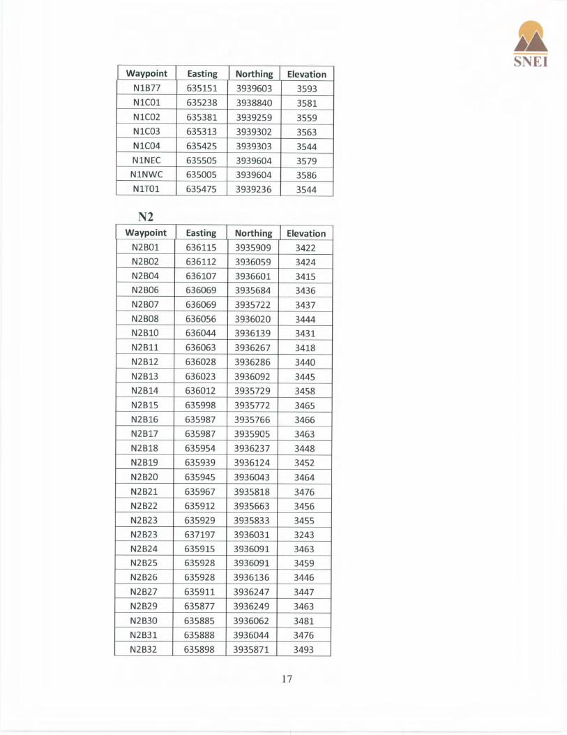


APPENDIX H
2008 Desert Tortoise Survey Report for Additional Ivanpah SEGS Action Area

Mercy Vaughn • (928) 380-5507 • [email protected] Stephen Boland • (928) 380-8850 • [email protected]
PRESENCE/ABSENCE SURVEY FOR THE DESERT TORTOISE (Gopherus agassizii), on the proposed IVANPAH SOLAR ELECTRIC GENERATING SYSTEM in Ivanpah Valley, San Bernardino County, California June 2008 Prepared for:
CH2MHill, Inc. West Region, Environmental Services 2485 Natomas Park Drive, Suite 600 Sacramento, California 95833 Prepared by:
Sundance Biology, Inc. 179 Niblick Rd. PMB 272 Paso Robles, CA 93446

SSuunnddaannccee BBiioollooggyy,, IInncc.. 179 Niblick Road PMB 272, Paso Robles, CA 93446 2
EXECUTIVE SUMMARY As recommended in the US Fish and Wildlife Service (USFWS) Survey Protocol for any Non-Federal Action that may Occur within the Range of the Desert Tortoise, January 1992, a desert tortoise (Gopherus agassizii) presence or absence survey was conducted on 1.6 miles of access road and 13 non-contiguous areas immediately adjacent to the proposed Ivanpah Solar Electric Generating System project site in Ivanpah Valley, San Bernardino County, California. These areas comprise a total of 726 acres all of which could support desert tortoise activity. The access road and 13 areas are additional acreage to the original 3,870 acres surveyed in 2007.
The delineated area was surveyed for desert tortoises and tortoise sign. No Zone of influence (ZOI) transects were conducted, as requested by the proponent, since they were done in 2007 during the survey of the initial 3,870 acres. Three individual tortoises were found onsite, one each in Areas 1, 2, and 13.

SSuunnddaannccee BBiioollooggyy,, IInncc.. 179 Niblick Road PMB 272, Paso Robles, CA 93446 3
TABLE OF CONTENTS EXECUTIVE SUMMARY .......................................................................................................................... 2 INTRODUCTION ........................................................................................................................................ 4 METHODOLOGY....................................................................................................................................... 4
SURVEY METHODOLOGY............................................................................................................................ 4 ZOI TRANSECTS ......................................................................................................................................... 5 DATA RECORDED ....................................................................................................................................... 5 BIOLOGICAL FIELD TEAM........................................................................................................................... 5
RESULTS...................................................................................................................................................... 5 SURVEY AREA............................................................................................................................................ 5 DESERT TORTOISE...................................................................................................................................... 6
DISCUSSION................................................................................................................................................ 6 DESERT TORTOISE...................................................................................................................................... 6
MITIGATION RECOMMENDATIONS................................................................................................... 7 DESERT TORTOISE...................................................................................................................................... 7
TABLE 1. DOMINANT PLANT SPECIES............................................................................................... 9 TABLE 2. DESERT TORTOISE AND SIGN LOCATIONS................................................................. 10 TABLE 3. MAMMAL SPECIES .............................................................................................................. 13 TABLE 4. REPTILE SPECIES ................................................................................................................ 13 TABLE 5. BIRD SPECIES........................................................................................................................ 13 FIGURE 1. IVANPAH SOLAR ELECTRIC GENERATING SYSTEM PROJECT SITE IN IVANPAH VALLEY, CA. ......................................................................................................................... 14 FIGURE 2. DESERT TORTOISE SURVEY AREA AND SIGN ENCOUNTERED ON THE IVANPAH SOLAR ELECTRIC GENERATING SYSTEM PROJECT SITE IN IVANPAH VALLEY, CA.............................................................................................................................................. 15 FIGURE 3. AREA PHOTOS AND TORTOISE PHOTOS ON THE IVANPAH SOLAR ELECTRIC GENERATING SYSTEM PROJECT SITE IN IVANPAH VALLEY, CA.......................................... 16

SSuunnddaannccee BBiioollooggyy,, IInncc.. 179 Niblick Road PMB 272, Paso Robles, CA 93446 4
INTRODUCTION This report addresses the results of a presence/absence survey for the desert tortoise on the additional areas of the proposed Ivanpah Solar Electric Generating System in San Bernardino County, California.
The proposed project is located west of Ivanpah Lake bed and U.S. Interstate 15 in Ivanpah Valley, CA approximately 4.5 miles southwest of Primm, NV on the California-Nevada State line where it intersects U.S. Interstate 15. The site includes portions of Sections 20-22, 27-29, 33-34, T17N, R14E and portions of Sections 2, 3, 4, 10, and 11, T16N, R14E, (Ivanpah Lake, CA quadrangle, 7.5 minute series). The elevation of the proposed project site is between 2,750 ft to 3,450 ft above mean sea level (Figure 1).
A total of 726 acres were surveyed for desert tortoises and tortoise sign between May 15 and May 20, 2008. No Zone of influence (ZOI) transects were conducted, as requested by the proponent, since they were done in 2007 during the survey of the initial 3,870 acres. Additionally, all wildlife species and their sign were noted.
METHODOLOGY
Survey Methodology The following methodology was used to increase efficiency in determining presence or absence of desert tortoises through systematic search and location of tortoises, their burrows and other sign. This methodology has proven accurate on other large-scale presence/absence surveys.
Teams consisting of two or three experienced desert tortoise biologists conducted the survey between May 20 and May 25, 2008 by walking a set of transects that covered each of the 13 survey areas plus the access road. Transect spacing was at 30 feet between transect centerlines, the standard width for desert tortoise presence/absence surveys.
A set of UTM coordinates for transect endpoints for virtual north-south or east-west transects were calculated. This resulted in 390 transects ranging from 1,000-6,800 feet in length. Lowrance iFinder handheld global positioning system (GPS) units were used to navigate transects.
One member of the team was responsible for navigating the selected transects. The other members surveyed 30 feet to either side of the navigator. When the end of each transect was reached, the team shifted to the adjacent transects and the navigator programmed the beginning and ending point of the team center transect for the next trip.
Team members focused on a search area that included 15 feet on either side of them. The members of the team remained close to one another without leading or lagging in order to increase the precision of searching. Team members were instructed to search beneath every shrub.

SSuunnddaannccee BBiioollooggyy,, IInncc.. 179 Niblick Road PMB 272, Paso Robles, CA 93446 5
ZOI Transects ZOI transects are typically conducted in suitable tortoise habitat to the east, west, north, and south of the survey area at 100, 300, 600, 1,200, and 2,400 feet from the survey area perimeter. Since these were done in 2007 around the original 3,870 acres the proponent requested that they not be repeated for this survey (Figure 2).
Data Recorded Any tortoise or large mammal burrows encountered that could potentially be used by tortoises were visually inspected. Very small burrows that could be potentially used by juvenile tortoises but are much more often rodent burrows were also visually checked when encountered. Only definitive tortoise sign was recorded. All other wildlife species encountered were noted.
Biological Field Team The biological team for the survey included Christine Halley, Colin Spake, Ashley Spenceley, Debbie Vaughn, and Jenny Weidensee. The survey was managed by Mercy Vaughn.
RESULTS
Survey Area The survey area ranged in elevation from 2,750 ft to 3,450 ft and is characterized by creosote-bursage desert scrub. Acreages of the areas surveyed are as follows: Area 1 52.63 acres Area 2 32.03 acres Area 3 218.25 acres Area 4 35.43 acres Area 5 55.14 acres Area 6 32.62 acres Area 7 31.56 acres Area 8 56.02 acres Area 9 98.57 acres Area 10 24.61 acres Area 11 20.52 acres Area 12 7.72 acres Area 13 40.61 acres Access road 20 acres
The geomorphology of the survey area ranges from lower bajada at the southeast end of the site with predominantly sandy loam soils to upper bajada at the northwest end with predominantly sandy loam to gravel-cobble soil. Human impacts within the survey area include dirt roads, trash dump sites, and OHV trails.

SSuunnddaannccee BBiioollooggyy,, IInncc.. 179 Niblick Road PMB 272, Paso Robles, CA 93446 6
The condition of the desert scrub is generally good. Plants seen on the site are shown in Table 1. Dominant perennials include creosote bush, bursage, and Mohave yucca. Annual vegetation production appeared to be higher than last year, a low production year.
Desert tortoise sign found are listed in Table 2 and shown in Figure 2. All other wildlife sightings are listed in Tables 3 to 5.
Desert Tortoise
Three live, adult desert tortoises were found onsite, one each in Areas 1, 2, and 13. All three tortoises were adults, two males and one female. The male found in Area 13 was found at the base of a Mojave yucca and appeared healthy. The male found in area 2 was face down in a burrow. Its health could not be determined. The female found in Area 1 was face out in a burrow and appeared healthy. Two sets of tortoise tracks were found one in Area 2 and one in Area 10. The tracks in Area 2 were of an adult tortoise. The tracks in Area 10 were from an immature sized tortoise.
Twenty shell-skeletal remains were found onsite, two of which were juveniles. One juvenile was depredated this year, evidence that reproduction may be occurring on the site. Time since death for 16 of the remains is greater than 4 years, 2 to 4 years for two others and less than 1 year for an adult and the juvenile mentioned above. Remains were found in Areas 1 to 6, 8, 9, and 12.
Thirty tortoise burrows and one pallet were identified onsite. Five of the burrows had tortoise scat in or adjacent to the burrow. Burrows were found in Areas 1, 2, 4, 8, 9, 10, 13, and the access road. The pallet was found in Area 5. Twenty-two of the burrows appeared to be in good condition of which seven have been recently used.
Twenty-four scat events were identified not including those associated with burrows. Twenty-one of these were laid down this year. The scat was found in Areas 1, 2, 3, 5, 6, 8, 9, 10, and 12.
DISCUSSION
Desert Tortoise
The proposed Ivanpah Solar Electric Generating System project site lies well within the desert tortoise’s geographic range. Recent tortoise sign was found in all survey areas except Area 7. All size classes were represented in the recent tortoise sign found including two juvenile shell remains with time since death within the last 2 years. Based on the number of good burrows found, tracks, and recent scat it is likely that more tortoises are using this area than the three found. It is not surprising that more tortoises were not found due to the long narrow shape of the areas surveyed. More tortoises are likely nearby outside the survey area boundaries. Indications are that tortoises are active throughout this valley and have been reproducing suggesting a viable population within the project area.

SSuunnddaannccee BBiioollooggyy,, IInncc.. 179 Niblick Road PMB 272, Paso Robles, CA 93446 7
The proposed Ivanpah Solar Electric Generating System project would have both direct and indirect impacts on desert tortoises on the site and tortoises in the area. Since tortoises use the site indirect impacts would occur through loss of habitat. Direct impacts could occur during construction if a tortoise wanders onto the site and is either injured or killed.
In addition to loss of habitat, the tortoises located onsite would have to be translocated to an appropriate area offsite. The effectiveness of translocation of tortoises is still being researched. Both the translocated tortoises as well as the tortoises located on the recipient site could be affected. This effect could be minimized by translocation within the current home range of tortoises cleared from the site. The long-term use of the site may pose a risk to any tortoises wandering into the area if permanent tortoise proof fencing is not installed and maintained.
MITIGATION RECOMMENDATIONS
Desert Tortoise
In order to mitigate potential direct impacts, the following recommendations will help minimize the potential for “take” of tortoises during and after construction.
1). Develop a translocation plan for the desert tortoises onsite.
2). Develop a biological monitoring plan in consultation with the CEC, USFWS and the CDFG. This plan would delineate all measures to be implemented prior to, during and post-construction which would include but are not limited to the following measures:
a). Permanent and or temporary tortoise-proof fencing (1”x 2” mesh hardware cloth) may need to be erected and maintained between the interface of the project area and any remaining desert tortoise habitat prior to initiating construction and clearance surveys for desert tortoises onsite. The fence will prevent tortoises from wandering onto the site both during construction as well as during use of the facility. Ongoing maintenance of the fencing would be recommended with oversight by an authorized biologist. Fence installation should be monitored by a qualified tortoise biologist.
b). If tortoises are to be cleared from the site it is recommended tortoise clearance surveys be conducted at 15-foot intervals. It is recommended that two coverages without finding any tortoises or new tortoise sign be conducted prior to declaring the site clear of tortoises. All burrows that could provide shelter for a desert tortoise should be excavated during the first clearance survey.
c). All construction personnel should undergo desert tortoise awareness training
d). After the tortoise proof-fence is erected a qualified biologist(s) should remain onsite until all vegetation is cleared and, at a minimum, conduct site and fence inspections on a bi-weekly basis throughout construction in order to maintain compliance with mitigation measures.

SSuunnddaannccee BBiioollooggyy,, IInncc.. 179 Niblick Road PMB 272, Paso Robles, CA 93446 8
e). A qualified biologist(s) should be onsite to survey for tortoises immediately in front of vegetation clearance activities in the event a tortoise was inadvertently missed during clearance surveys.
f). A biologist should remain on-call throughout construction in the event a tortoise wanders onto the site.
g). A raven management plan should be developed for the project site.

SSuunnddaannccee BBiioollooggyy,, IInncc.. 179 Niblick Road PMB 272, Paso Robles, CA 93446 9
Table 1. Dominant Plant Species Latin Name Common name ASTERACEAE Composite Family Ambrosia dumosa Burrobush Chaenactis fremontii Desert pincushion Encelia virginensis Ericameria cooperi var. c. Cooper’s goldenbush Hymenoclea salsola Cheesebush Psilostrophe cooperi Paper-flower Stephanomeria pauciflora Wire-lettuce ASCLEPIADACEAE Milkweed Family Asclepias nyctaginifolia Mojave milkweed Cynanchum utahense Utah cynanchum APOCYNACEAE Dogbane Family Amsonia tomentosa Small-leaved amsonia Cryptantha sp. BORAGINACEAE Borage Family Amsinckia tessellata Devil’s lettuce BRASSICACEAE Mustard Family Descurainia pinnata ssp. Glabra Yellow tansy mustard Dithyrea californica Spectacle-pod Lepidium fremontii Desert alyssum Lepidium lasiocarpum var. l. CACTACEAE Cactus Family Echinocactus polycephalus Cottontop cactus Echinocerus engelmannii Hedgehog cactus Escobaria vivipara Beehive cactus Ferocactus cylindraceus California barrel cactus Mammillaria tetrancistra Corkseed cactus Opuntia acanthocarpa Buckhorn cholla Opuntia basilaris Beavertail cactus Opuntia echinocarpa Golden cholla Opuntia parishii Mat cholla Opuntia ramosissima Diamond cholla EPHEDRACEAE Ephedra Family Ephedra nevadensis Nevada joint-fir EUPHORBIACEAE Spurge Family Chamaesyce albomarginata Spurge FABACEAE Legume Family Acacia greggii Catclaw GENTIANACEAE Gentian Family Erodium cicutarium Filaree

SSuunnddaannccee BBiioollooggyy,, IInncc.. 179 Niblick Road PMB 272, Paso Robles, CA 93446 10
Table 1. Dominant Plant Species HYDROPHYLLACEAE Waterleaf Family Phacelia sp. LAMIACEAE Mint Family Salazaria mexicana Bladder sage Salvia dorrii LILIACEAE Lily Family Yucca schidigera Mohave yucca LOASACEAE Loasa Family Mentzelia sp. ONAGRACEAE Primrose Family Camissonia sp. Sun cup POACEAE Grass Family Achnatherum hymenoides Indian rice grass Achnatherum speciosum Needle grass Erioneuron pulchellum Split grass Enneapogon desvauxii Pappus grass POLEMONIACEAE Phlox Family Eriastrum sp. Gilia sp. POLYGONACEAE Buckwheat Family Chorizanthe rigida Spiny-herb Chorizanthe brevicornu Brittle spineflower Eriogunum fasciiculatum ssp. polifolium California buckwheat Eriogonum inflatum var. inflatum Desert trumpet SOLANACEAE Nightshade Family Lycium andersonii Anderson thornbush Lycium cooperi Peach-thorn ZYGOPHYLLACEAE Caltrop Family Larrea tridentata Creosote
Table 2. Desert Tortoise and Sign Locations (Datum NAD 27 CONUS) Sign Area Easting Northing Notes burrow 1 641268 3932429 fresh tracks burrows 1 641149 3932434 burrow 1 641466 3932454 burrow 1 640855 3932455 burrow with scat 1 641148 3932445 scat 1 641128 3932416 scat 1 641249 3932431 scat 1 641381 3932460 scat 1 641434 3932463

SSuunnddaannccee BBiioollooggyy,, IInncc.. 179 Niblick Road PMB 272, Paso Robles, CA 93446 11
Table 2. Desert Tortoise and Sign Locations (Datum NAD 27 CONUS) scat 1 641436 3932463 within 10' of previous scat scat 1 641452 3932467
tortoise in burrow 1 641465 3932496 adult female, MCL ~190, in burrow but looks healthy
shell-skeletal remains 2 639438 3932604 fragments shell-skeletal remains 2 639381 3932970 fragments shell-skeletal remains 2 639426 3933879 fragments shell-skeletal remains 2 639111 3937972 juvenile scat 2 639371 3933602
tortoise in burrow 2 639421 3933349 adult male, ~240 MCL, facing into burrow health unknown.
tracks 2 639444 3933915 shell-skeletal remains 3 639177 3933969 female, ~230 MCL shell-skeletal remains 3 639287 3934312 sub-adult scat 3 639305 3934105 burrow 4 640104 3934948 shell-skeletal remains 4 639990 3934925 female shell-skeletal remains 4 640048 3934942 female shell-skeletal remains 5 637757 3934829 shell-skeletal remains 5 637841 3936387 pallet 5 637766 3936089 adult Shell-skeletal remains 6 637206 3456579 Scat 6 638193 3936544 Burrow 8 636846 3939045 Adult, w/ scat Burrow 8 636852 3939049 Adult Burrow 8 636411 3939011 under yucca, much scat inside Burrow 8 636858 3939047 caliche cave Burrow 8 636818 3939069 Adult, series of caves w/scat Burrow 8 636584 3938990 Burrow 8 636845 3939046 Adult, caliche cave Burrow 8 636837 3939052 Burrow 8 636494 3938954 Adult Burrow 8 636128 3938969 Adult Burrow 8 636797 3939073 1 pc bone on apron Burrow 8 636273 3939120 Adult Burrow 8 636290 3939116 Adult Burrow 8 636929 3939222 Adult Shell-skeletal remains 8 636797 3939073 1 piece only
Shell-skeletal remains 8 636393 3939082 1 piece only, assoc. w/ packrat midden
Shell-skeletal remains 8 636954 3939040 Male est MCL 240
Shell-skeletal remains 8 636229 3939147 Adult,est MCL 255 mm, Some tissue remains (tail, legs), ants

SSuunnddaannccee BBiioollooggyy,, IInncc.. 179 Niblick Road PMB 272, Paso Robles, CA 93446 12
Table 2. Desert Tortoise and Sign Locations (Datum NAD 27 CONUS)
scavenging Shell-skeletal remains 8 636396 3939218 Adult Scat 8 636606 3939005 Adult Scat 8 636649 3939023 Adult Scat 8 636761 3939034 Adult Scat 8 636341 3939111 in wash bottom
Scat 8 636634 3939008 3 pieces adult, 2 pieces sub-adult
Scat 8 636086 3938595 0.18mi S of area 8 Scat 8 636411 3939018 Scat 8 636904 3939250 3 pieces burrow 9 638618 3939471 shell-skeletal remains 9 638638 3939277 shell-skeletal remains 9 638501 3939501 scutes attached scat 9 638101 3939327 scat 9 637865 3939378 scat 9 637706 3939385 2 pieces scat 9 637818 3939400 burrow 10 639040 3936967 scat 10 638866 3937963 scat 10 638891 3938976 tracks 10 638861 3937962 immature size burrow 11 639135 3937503 burrow 11 639115 3937649 burrow 11 639123 3937592 burrow with scat 11 639054 3937472 shell-skeletal remains 11 639153 3937318 whole juvenile carcass shell-skeletal remains 12 639056 3936914 with scutes scat 12 639102 3936998 6 pieces Burrow 13 636781 3940531 Burrows and scat 13 636847 3940654 burrows in wash w/ scat
Tortoise 13 636707 3940608 Male, est MCL 250 mm, sinking scutes vertebral & costal, @ base of yucca
burrow Access road 640575 3935115 old, unoccupied, in need of
repair
burrow Access road 640541 3935110 sub-adult size

SSuunnddaannccee BBiioollooggyy,, IInncc.. 179 Niblick Road PMB 272, Paso Robles, CA 93446 13
Table 3. Mammal Species Scientific Name Common name Dipodomys merriami Merriam’s kangaroo rat Desert woodrat Wood rat Amnospermophilus leucurus White-tailed antelope ground squirrel Lepus californicus Black-tailed jackrabbit Sylvilagus audubonii Desert cottontail Canis latrans Coyote Vulpes macrotis Kit fox Homo sapiens Human Equus asinus Wild Burro
Table 4. Reptile Species Scientific Name Common Name Gopherus agassizii Desert tortoise Phrynosoma platyrhinos Desert horned lizard Gambelia wislizenii Longnose leopard lizard Sceloporus grasiosus Sagebrush lizard Callisaurus draconoides Zebratail lizard Cnemidophorus tigris Western whiptail lizard
Table 5. Bird Species Scientific Name Common Name Buteo jamaicensis Red-tailed hawk Zenaida macroura Mourning dove Myiarchus crinitus Ash-throated flycatcher Lanius ludovicianus Loggerhead shrike Corvus corax Common raven Eremophila alpestris Horned lark Campylorhynchus brunneicapilus Cactus wren Polioptila melanura Black tailed gnatcatcher Amphispiza bilineata Black-throated sparrow Amphispiza belli Sage sparrow Icterus parisorum Scott’s oriole

SSuunnddaannccee BBiioollooggyy,, IInncc.. 179 Niblick Road PMB 272, Paso Robles, CA 93446 14
Figure 1. Ivanpah Solar Electric Generating System project site in Ivanpah Valley, CA.

SSuunnddaannccee BBiioollooggyy,, IInncc.. 179 Niblick Road PMB 272, Paso Robles, CA 93446 15
Figure 2. Desert tortoise survey area and sign encountered on the Ivanpah Solar Electric Generating System project site in Ivanpah Valley, CA.

SSuunnddaannccee BBiioollooggyy,, IInncc.. 179 Niblick Road PMB 272, Paso Robles, CA 93446 16
Figure 3. Area photos and tortoise photos on the Ivanpah Solar Electric Generating System project site in Ivanpah Valley, CA.
Area 1 and 2 -View to the north Area 3- View to the north
Area 4 and access road -View to the east Area 5- View to the north

SSuunnddaannccee BBiioollooggyy,, IInncc.. 179 Niblick Road PMB 272, Paso Robles, CA 93446 17
Area 6 -View to the north Area 7- View to the north
Area 8 -View to the north Area 9- View to the north

SSuunnddaannccee BBiioollooggyy,, IInncc.. 179 Niblick Road PMB 272, Paso Robles, CA 93446 18
Area 10 -View to the east Area 11- View to the north
Area 12 -View to the north Area 13- View to the north

SSuunnddaannccee BBiioollooggyy,, IInncc.. 179 Niblick Road PMB 272, Paso Robles, CA 93446 19
Area 13 –Active adult male tortoise Area 1- Adult male tortoise in burrow
Area 2 – Adult female tortoise in burrow Area 11- Juvenile tortoise died within the last year

APPENDIX I
List of Observed Desert Tortoise Sign at Ivanpah SEGS in 2007

Desert Tortoise Data Tables
Row #
Field Personnel
InitialsCollection
DateEstimated
MCL SexAge
Class
Location Coversite
Type
Location At
Coversite
Location Not At
CoversiteLocation Comment Activity
Activity Comment Temperature
Cloud Cover %
Wind Direction
Wind Speed
General Comment
Maximum PDOP
1 dhh 4/14/2007 210 Unknown Subadult Pallet Inside coversite.
Not applicable.
Resting 0 50-60% South 15 5.8
2 rsf 4/15/2007 270 Unknown Shrub Inside coversite.
Not applicable.
Resting 0 10-20% South 5 2
3 gg 4/15/2007 200 Unknown Subadult Burrow Inside coversite.
Resting 52.200001 80-90% Southwest 13.3 colosseum rd 2400 ft south zoi transect
4.2
4 rsf 4/21/2007 190 Female Subadult Shrub Other no sign of urtd Resting 69 10-20% Northwest 7 3.1
5 ew 4/27/2007 250 Unknown Adult Other Not applicable.
In the open.
Walking 86 0-10% North 5 found by veg crew, then point located by tortoise biologist. tort not found.
3.8
6 rsf 4/28/2007 250 Female Adult Burrow Inside coversite.
Resting 82 0-10% North 3 sex iis uncertain 4.9
7 ew 5/7/2007 235 Female Adult Burrow Inside coversite.
facing outside Resting 78 0-10% North 10 no sign of urtd 4.4
8 ew 5/8/2007 230 Female Adult Burrow On coversite mound.
In the open.
facing outward from burrow opening.
Resting 85 0-10% North 5 2.8
9 dh 5/12/2007 140 Unknown Immature Burrow Inside coversite.
Resting 92 20-30% South 3 2.7
10 gg 5/13/2007 150 Unknown Immature Burrow Inside coversite.
Resting 89 10-20% 0 3.8
11 dhh 5/13/2007 190 Unknown Subadult Burrow Inside coversite.
Not applicable.
Resting 91 30-40% Southwest 3 3
12 gg 5/18/2007 250 Unknown Adult Burrow Entering coversite.
Not applicable.
Resting 89 Northeast 1 1 turd 2.2
13 dhh 5/19/2007 220 Unknown Adult Burrow Inside coversite.
Resting 0 0-10% Northwest 10 3.6
14 dhh 5/20/2007 230 Unknown Adult Burrow Inside coversite.
Resting 76 0-10% 0 clear nares 2.5
15 ew 5/22/2007 200 Unknown Adult Burrow Entering coversite.
Not applicable.
Resting 79 10-20% North 2 4.8
APPENDIX I

Desert Tortoise Data Tables
Row #
Field Personnel
InitialsCollection
DateEstimated
MCL SexAge
Class
Location Coversite
Type
Location At
Coversite
Location Not At
CoversiteLocation Comment Activity
Activity Comment Temperature
Cloud Cover %
Wind Direction
Wind Speed
General Comment
Maximum PDOP
16 gcg 5/22/2007 240 Female Adult In the open.
walking Walking 68 10-20% Southeast 2 in open walking apparently healthy
2.8
17 ew 5/24/2007 240 Unknown Adult Burrow Inside coversite.
Not applicable.
Resting 85 20-30% Northeast 3 no sign of urtd 3.6
18 gcg 5/29/2007 240 Female Adult Other In the open.
in open walking
Walking walking 88 0-10% North 2 3.3
19 gcg 6/4/2007 0 Unknown Adult Burrow Inside coversite.
Not applicable.
Resting 92 60-70% South 8 1.8
20 gcg 6/5/2007 0 Unknown Adult Burrow Inside coversite.
Resting 87 70-80% Northwest 10 1.7
21 <Null> <Null> <Null> <Null> <Null> <Null> <Null> <Null> <Null> <Null> <Null> <Null> <Null> <Null> <Null> <Null> <Null>
22 <Null> <Null> <Null> <Null> <Null> <Null> <Null> <Null> <Null> <Null> <Null> <Null> <Null> <Null> <Null> <Null> <Null>
APPENDIX I 2

Desert Tortoise Data Tables
Row #
Field Personnel
InitialsCollection
Date1 dhh 4/14/2007
2 rsf 4/15/2007
3 gg 4/15/2007
4 rsf 4/21/2007
5 ew 4/27/2007
6 rsf 4/28/2007
7 ew 5/7/2007
8 ew 5/8/2007
9 dh 5/12/2007
10 gg 5/13/2007
11 dhh 5/13/2007
12 gg 5/18/2007
13 dhh 5/19/2007
14 dhh 5/20/2007
15 ew 5/22/2007
Maximum HDOP
Correction Type
Receiver Type GPS Date GPS Time
Update Status
Feature Name
Datafile Name
Unfiltered Positions
Filtered Positions
Data Dictionary Name
GPS Week
GPS Second
GPS Height
Vertical Precision
2.5 Postprocessed Code
GeoXH 2005
4/14/2007 02:06:47pm New Tortoise BSE14APR07UNIT1.cor
236 235 BSE_Tortoise_v1 1422 594421 2923.074 1.4
1.2 Postprocessed Carrier Float
GeoXH 2005
4/15/2007 09:49:19am New Tortoise BSE15APR07UNIT1.cor
319 319 BSE_Tortoise_v1 1423 60573 2932.548 0.7
1.7 Postprocessed Code
GeoXH 2005
4/15/2007 05:07:12pm New Tortoise BSE15APR07UNIT1.cor
238 238 BSE_Tortoise_v1 1423 86846 2733.809 6.5
2.3 Postprocessed Code
GeoXH 2005
4/21/2007 11:16:44am New Tortoise BSE21APR07UNIT1.cor
373 373 BSE_Tortoise_v1 1423 584218 3024.444 3.4
3 Postprocessed Code
GeoXH 2005
4/27/2007 01:18:09pm New Tortoise BSE27APR07UNIT2.cor
260 260 BSE_Tortoise_v1 1424 505103 2821.394 4.3
2.3 Postprocessed Code
GeoXH 2005
4/28/2007 10:01:18am New Tortoise BSE28APR07UNIT1.cor
394 394 BSE_Tortoise_v1 1424 579692 2824.094 5
2.4 Postprocessed Code
GeoXH 2005
5/7/2007 02:34:38pm New Tortoise BSE7MAY07UNIT1.cor
207 206 BSE_Tortoise_v1 1426 164092 2905.317 3.9
1.6 Postprocessed Code
GeoXH 2005
5/8/2007 12:05:35pm New Tortoise BSE8MAY07UNIT2.cor
134 134 BSE_Tortoise_v1 1426 241549 2950.021 3.5
1.5 Postprocessed Carrier Float
GeoXH 2005
5/12/2007 12:31:04pm New Tortoise BSE12MAY07UNIT1.cor
109 109 BSE_Tortoise_v1 1426 588678 3021.449 1.1
3 Postprocessed Code
GeoXH 2005
5/13/2007 10:07:30am New Tortoise BSE13MAY07UNIT1.cor
166 165 BSE_Tortoise_v1 1427 61664 3045.795 0.9
1.5 Postprocessed Code
GeoXH 2005
5/13/2007 11:36:30am New Tortoise BSE13MAY07UNIT1.cor
84 84 BSE_Tortoise_v1 1427 67004 3041.556 1.1
1.1 Postprocessed Code
GeoXH 2005
5/18/2007 09:15:09am New Tortoise BSE18MAY07UNIT1.cor
16 16 BSE_Tortoise_v1 1427 490523 3155.298 3.5
1.9 Postprocessed Code
GeoXH 2005
5/19/2007 04:32:39pm New Tortoise BSE19MAY07UNIT1.cor
142 141 BSE_Tortoise_v1 1427 603173 3191.703 5.7
1.4 Postprocessed Code
GeoXH 2005
5/20/2007 07:17:48am New Tortoise BSE20MAY07UNIT1.cor
132 131 BSE_Tortoise_v1 1428 51482 3193.166 3.1
3.3 Postprocessed Code
GeoXH 2005
5/22/2007 07:10:48am New Tortoise BSE22MAY07UNIT1.cor
187 187 BSE_Tortoise_v1 1428 223862 2958.114 3.1
APPENDIX I 3

Desert Tortoise Data Tables
Row #
Field Personnel
InitialsCollection
Date16 gcg 5/22/2007
17 ew 5/24/2007
18 gcg 5/29/2007
19 gcg 6/4/2007
20 gcg 6/5/2007
21 <Null> <Null>
22 <Null> <Null>
Maximum HDOP
Correction Type
Receiver Type GPS Date GPS Time
Update Status
Feature Name
Datafile Name
Unfiltered Positions
Filtered Positions
Data Dictionary Name
GPS Week
GPS Second
GPS Height
Vertical Precision
1.5 Postprocessed Code
GeoXH 2005
5/22/2007 07:56:56am New Tortoise BSE22MAY2007UNIT2.co
202 202 BSE_Tortoise_v1 1428 226630 3517.189 3.7
2 Real-time SBAS Corrected
GeoXH 2005
5/24/2007 12:33:27pm New Tortoise BSE24MAY07UNIT1.cor
156 108 BSE_Tortoise_v1 1428 416021 3263.746 4.9
1.8 Postprocessed Code
GeoXH 2005
5/29/2007 08:49:28am New Tortoise BSE29MAY2007UNIT2.co
139 138 BSE_Tortoise_v1 1429 229782 3326.763 4
1 Postprocessed Carrier Float
GeoXH 2005
6/4/2007 11:20:48am New Tortoise BSE4JUNE07UNIT1.cor
91 91 BSE_Tortoise_v1 1430 152462 3274.956 1
0.9 Postprocessed Carrier Float
GeoXH 2005
6/5/2007 08:26:17am New Tortoise BSE5JUNE07UNIT1.cor
99 99 BSE_Tortoise_v1 1430 228391 3314.414 0.8
<Null> <Null> <Null> 5/30/2007 09:35:11am <Null> <Null> MK053007.cor
<Null> <Null> <Null> <Null> <Null> <Null> <Null>
<Null> <Null> <Null> 4/29/2007 08:56:36am <Null> <Null> RH04292007.cor
<Null> <Null> <Null> <Null> <Null> <Null> <Null>
APPENDIX I 4

Desert Tortoise Data Tables
Row #
Field Personnel
InitialsCollection
Date1 dhh 4/14/2007
2 rsf 4/15/2007
3 gg 4/15/2007
4 rsf 4/21/2007
5 ew 4/27/2007
6 rsf 4/28/2007
7 ew 5/7/2007
8 ew 5/8/2007
9 dh 5/12/2007
10 gg 5/13/2007
11 dhh 5/13/2007
12 gg 5/18/2007
13 dhh 5/19/2007
14 dhh 5/20/2007
15 ew 5/22/2007
Horizontal Precision
Standard Deviation Latitude Longitude Point ID
X Coordinate
Y Coordinate
GPS Processing
NotesSurvey
ID SITE LOCID0.9 1.312661 35.55976845 -115.461984 4 7316532.5 2399584 <Null> <Null> IVANPAH 2 16
0.5 0.396565 35.56172397 -115.462709 1 7316298.5 2400290.8 <Null> <Null> IVANPAH 2 15
3.1 1.155647 35.54276802 -115.437511 8 7323967 2393582.5 <Null> <Null> WITHIN 1-MILE BUFFER
19
2.4 1.453962 35.56300937 -115.470261 2 7314041.5 2400701.8 <Null> <Null> IVANPAH 2 14
3 0.830541 35.53041526 -115.445201 5 7321794 2389029.5 <Null> <Null> IVANPAH 3 22
3.2 2.623661 35.53220285 -115.446003 4 7321539.5 2389674 <Null> <Null> IVANPAH 3 21
3.2 1.229448 35.54342791 -115.456991 4 7318168 2393675.5 <Null> <Null> IVANPAH 3 18
2.3 1.214191 35.54408088 -115.461216 1 7316905.5 2393881.5 <Null> <Null> IVANPAH 3 17
1 0.459985 35.57305077 -115.470445 10 7313895 2404354.8 <Null> <Null> IVANPAH 1 12
0.6 2.076773 35.58152242 -115.472113 4 7313321.5 2407424.8 <Null> <Null> IVANPAH 1 9
0.8 1.683126 35.57225791 -115.472219 6 7313374 2404052.8 <Null> <Null> IVANPAH 1 11
2.2 0.693083 35.58238259 -115.479912 2 7310995 2407679.3 <Null> <Null> IVANPAH 1 8
3.6 0.777587 35.58542943 -115.482003 9 7310346 2408773 <Null> <Null> IVANPAH 1 5
2.4 1.18383 35.58455923 -115.482693 2 7310149 2408451.3 <Null> <Null> IVANPAH 1 6
2.7 60.253356 35.57466032 -115.444293 1 7321655.5 2405136.8 <Null> <Null> OUT 1-MILE BUFFER
13
APPENDIX I 5

Desert Tortoise Data Tables
Row #
Field Personnel
InitialsCollection
Date16 gcg 5/22/2007
17 ew 5/24/2007
18 gcg 5/29/2007
19 gcg 6/4/2007
20 gcg 6/5/2007
21 <Null> <Null>
22 <Null> <Null>
Horizontal Precision
Standard Deviation Latitude Longitude Point ID
X Coordinate
Y Coordinate
GPS Processing
NotesSurvey
ID SITE LOCID2.6 49.791174 35.58708014 -115.48489 5 7309472.5 2409352.3 <Null> <Null> IVANPAH 1 4
3 2.883802 35.58624957 -115.487029 5 7308844 2409033.5 <Null> <Null> IVANPAH 1 3
2.5 1.463365 35.56820163 -115.491595 1 7307651 2402432.3 <Null> <Null> IVANPAH 1 10
0.7 0 35.590213 -115.486746 8 7308892.5 2410478 <Null> <Null> 1000' GAS LINE CORRIDOR
2
0.5 0.260513 35.59444181 -115.488766 5 7308253 2412002.5 <Null> <Null> 1000' GAS LINE CORRIDOR
1
<Null> <Null> <Null> <Null> <Null> 7308601.5 2406543.8 Added from generic_point (BRD)
<Null> IVANPAH 1 7
<Null> <Null> <Null> <Null> <Null> 7318627 2391045.3 Added from generic_point (BRD)
<Null> IVANPAH 3 20
APPENDIX I 6

SITE GPS_POINTS1000' GAS LINE CORRIDOR 2IVANPAH 1 10IVANPAH 2 3IVANPAH 3 5OUT 1-MILE BUFFER 1WITHIN 1-MILE BUFFER 1
Tortoise by Site
APPENDIX I 7

Desert Tortoise Carcass Data
Row #
Field Personnel
InitialsCollection
DateEstimated
MCL Sex Age Class
Location Coversite
Type
Location At
Coversite
Location Not At
CoversiteLocation Comment
Sun Exposure
PercentageCarcass Position
Time Since Death
Cause Of Death
Death Comment
Cloud Cover
%Wind
Direction1 ew 4/10/2007 250 Unknown Adult Other Not applicaIn the open 80-100% DisarticulatGreater thaUnknown
2 ew 4/12/2007 0 Unknown Adult Other Not applicaOther under creo 80-100% DisarticulatGreater thaUnknown 3 gg 4/13/2007 270 Unknown Adult In the open 80-100% DisarticulatGreater thaUnknown 4 rsf 4/14/2007 220 Unknown Adult 80-100% DisarticulatGreater thaUnknown 5 jg 4/15/2007 200 Unknown Subadult Other Other In the open 80-100% Disarticulat Unknown 30-40% 6 gg 4/15/2007 200 Unknown Subadult In the open 80-100% Disarticulat Unknown 7 gg 4/16/2007 250 Unknown Adult In the open 80-100% DisarticulatGreater thaUnknown 8 ew 4/17/2007 140 Unknown Subadult Other Not applicaIn the open 80-100% Disarticulat2-4 years. Unknown 9 ew 4/17/2007 230 Female Adult Other Not applicaIn the open 80-100% Inverted 1-2 years. Unknown 10 ew 4/19/2007 250 Unknown Adult Other middle of la60-80% DisarticulatGreater thaUnknown 11 ew 4/19/2007 250 Unknown Adult In the open 80-100% Disarticulat Unknown 12 ew 4/19/2007 250 Unknown Adult In the open 80-100% DisarticulatGreater thaUnknown 13 gg 4/19/2007 250 Unknown Adult In the open 80-100% DisarticulatGreater thaUnknown 14 ew 4/20/2007 250 Male Adult In the open 80-100% Upright Greater thaUnknown 15 jg 4/21/2007 260 Male Adult Greater thaUnknown 16 jg 4/21/2007 200 Unknown Subadult Other under smal60-80% Upright Greater thaUnknown 17 jg 4/22/2007 180 Unknown Subadult Other Other In the open 80-100% DisarticulatGreater thaUnknown 18 dh 4/22/2007 180 Unknown Shrub Other 80-100% Greater thaUnknown 19 jg 4/22/2007 250 Unknown Adult 80-100% DisarticulatGreater thaOther 20 ew 4/25/2007 0 Unknown Adult Other Other In the open 80-100% DisarticulatGreater thaUnknown 21 ew 4/25/2007 190 Female Subadult Other Not applicaIn the open 80-100% Upright 1-2 years. Unknown 22 ew 4/26/2007 0 Unknown Adult Other Not applicaIn the open 80-100% DisarticulatGreater tha 23 gg 4/27/2007 0 Unknown Adult 80-100% DisarticulatGreater thaUnknown 24 ew 4/27/2007 0 Unknown Adult Other Not applicaIn the open 80-100% DisarticulatGreater thaUnknown 25 gg 4/28/2007 0 Unknown Adult Other 80-100% Greater thaUnknown 26 rsf 4/28/2007 0 Unknown Adult Other 80-100% DisarticulatGreater thaUnknown 27 gg 4/28/2007 250 Male Adult Other Other In the open 80-100% Upright 2-4 years. Unknown 28 rsf 4/28/2007 0 Unknown Adult Greater thaUnknown 29 ew 4/30/2007 200 Female Adult Other Not applicaIn the open 80-100% Inverted Greater thaUnknown 30 ew 4/30/2007 0 Unknown Adult Not applicaIn the open 80-100% DisarticulatGreater thaUnknown 31 ew 5/1/2007 250 Female Adult In the open 80-100% DisarticulatGreater thaUnknown 80-90%South32 gg 5/4/2007 0 Unknown Adult 80-100% DisarticulatGreater thaUnknown 33 gg 5/4/2007 240 Female Adult In the open 80-100% Inverted 2-4 years. Unknown 34 gg 5/7/2007 0 Unknown Adult In the open 80-100% DisarticulatGreater thaUnknown 35 ew 5/8/2007 0 Unknown Adult In the open 80-100% DisarticulatGreater thaUnknown 36 ew 5/9/2007 260 Male Adult Not applicaIn the open 80-100% Upright 2-4 years. Unknown 37 gcg 5/9/2007 0 Unknown Adult Not applicaIn the openscattered 80-100% DisarticulatGreater thaUnknown 38 gcg 5/9/2007 0 Unknown Adult Not applicadisarticulat 80-100% DisarticulatGreater thaUnknown 39 gcg 5/9/2007 0 Unknown Adult Not applica 80-100% DisarticulatGreater thaUnknown 40 ew 5/10/2007 0 Unknown Adult In the open 80-100% DisarticulatGreater thaUnknown 41 ew 5/11/2007 220 Female Adult Not applicaIn the open 80-100% Upright 2-4 years. Unknown 42 sf 5/12/2007 245 Male Adult 80-100% Upright Greater thaUnknown
APPENDIX I 8

Desert Tortoise Carcass Data
Row #
Field Personnel
InitialsCollection
DateEstimated
MCL Sex Age Class
Location Coversite
Type
Location At
Coversite
Location Not At
CoversiteLocation Comment
Sun Exposure
PercentageCarcass Position
Time Since Death
Cause Of Death
Death Comment
Cloud Cover
%Wind
Direction43 sf 5/12/2007 220 Female Adult 80-100% Upright Greater thaUnknown 44 gg 5/12/2007 275 Male Adult Other In the open 80-100% Inverted Unknown 45 gg 5/13/2007 250 Female Adult 80-100% Inverted Unknown 46 dhh 5/13/2007 260 Unknown Adult 80-100% DisarticulatGreater thaUnknown 47 dhh 5/13/2007 0 Unknown Adult 80-100% DisarticulatGreater thaUnknown 48 dhh 5/13/2007 230 Unknown Adult 80-100% DisarticulatGreater thaUnknown 49 dhh 5/13/2007 0 Unknown Adult 80-100% DisarticulatGreater thaUnknown 50 gg 5/14/2007 270 Unknown Adult Other Not applicaIn the open 80-100% DisarticulatGreater thaUnknown
51 gcg 5/14/2007 80 Unknown Junvenile In the open 80-100% Inverted <1 YR Common Rpeck hole in plastron
52 gg 5/14/2007 120 Unknown Immature Other Not applica found at be80-100% Disarticulat<1 YR Unknown 53 gg 5/14/2007 140 Unknown Immature Other Not applicaIn the open 80-100% Disarticulat<1 YR Unknown
54 gcg 5/16/2007 70 Unknown Junvenile In the open 80-100% Upright <1 YR Unknownpossibly crushed
55 gcg 5/17/2007 180 Female Adult In the open 80-100% Disarticulat1-2 years. 56 rr 5/17/2007 0 Unknown Adult Other Not applicaIn the open 80-100% DisarticulatGreater thaUnknown 57 gg 5/18/2007 260 Female Adult Other Not applicaOther 80-100% DisarticulatGreater thaUnknown 58 gg 5/18/2007 0 Unknown Adult 80-100% DisarticulatGreater thaUnknown 59 dhh 5/19/2007 140 Unknown Immature Other Other 80-100% DisarticulatGreater thaUnknown 60 dhh 5/19/2007 0 Unknown 80-100% DisarticulatGreater thaUnknown 61 gg 5/19/2007 0 Unknown Adult 80-100% DisarticulatGreater thaUnknown 62 ew 5/21/2007 250 Female Adult Other Not applicaIn the open 80-100% Upright Greater thaUnknown 63 ew 5/21/2007 300 Unknown Adult In the open 80-100% Disarticulat2-4 years. Unknown 64 gcg 5/21/2007 260 Male Adult 60-80% DisarticulatGreater thaUnknown 65 gcg 5/21/2007 0 Unknown Adult 80-100% DisarticulatGreater thaUnknown 66 gcg 5/22/2007 240 Female Adult In the open 80-100% Disarticulat2-4 years. Unknown
67 gcg 5/24/2007 140 Unknown Immature Other on i15 sb s 80-100% Disarticulat1-2 years. Vehicle
likely vehicle impact
68 ew 5/28/2007 225 Female Adult In the open 80-100% Inverted Greater thaUnknown 69 gcg 5/28/2007 260 Male Adult 80-100% DisarticulatGreater thaUnknown 70 gg 6/1/2007 265 Male Adult 80-100% Upright 2-4 years. Unknown 71 dhh 6/2/2007 0 Unknown Adult 80-100% Disarticulat2-4 years. Unknown 72 gg 6/2/2007 270 Unknown Adult 80-100% Disarticulat Unknown 73 gg 6/5/2007 265 Male Adult In the open 80-100% Inverted Greater thaUnknown 74 gog 6/5/2007 250 Unknown Adult In the open 80-100% DisarticulatGreater thaUnknown 75 <Null> <Null> <Null> <Null> <Null> <Null> <Null> <Null> <Null> <Null> <Null> <Null> <Null> <Null> <Null> <Null>76 <Null> <Null> <Null> <Null> <Null> <Null> <Null> <Null> <Null> <Null> <Null> <Null> <Null> <Null> <Null> <Null>77 <Null> <Null> <Null> <Null> <Null> <Null> <Null> <Null> <Null> <Null> <Null> <Null> <Null> <Null> <Null> <Null>
APPENDIX I 9

Desert Tortoise Carcass Data
Row #
Field Personnel
InitialsCollection
Date1 ew 4/10/2007
2 ew 4/12/20073 gg 4/13/20074 rsf 4/14/20075 jg 4/15/20076 gg 4/15/20077 gg 4/16/20078 ew 4/17/20079 ew 4/17/200710 ew 4/19/200711 ew 4/19/200712 ew 4/19/200713 gg 4/19/200714 ew 4/20/200715 jg 4/21/200716 jg 4/21/200717 jg 4/22/200718 dh 4/22/200719 jg 4/22/200720 ew 4/25/200721 ew 4/25/200722 ew 4/26/200723 gg 4/27/200724 ew 4/27/200725 gg 4/28/200726 rsf 4/28/200727 gg 4/28/200728 rsf 4/28/200729 ew 4/30/200730 ew 4/30/200731 ew 5/1/200732 gg 5/4/200733 gg 5/4/200734 gg 5/7/200735 ew 5/8/200736 ew 5/9/200737 gcg 5/9/200738 gcg 5/9/200739 gcg 5/9/200740 ew 5/10/200741 ew 5/11/200742 sf 5/12/2007
General Comment
Maximum PDOP
Maximum HDOP
Correction Type
Receiver Type GPS Date GPS Time
Update Status
Feature Name
Datafile Name
Unfiltered Positions
Filtered Positions
Data Dictionary
NameGPS Week
5.4 2.2 PostprocesGeoXH 2004/10/2007 01:10:26pmNew Carcass BSE10APR 201 201 BSE_Torto 1422just a few bone fragments 2.9 1.3 PostprocesGeoXH 2004/12/2007 03:19:00pmNew Carcass BSE12APR 264 264 BSE_Torto 1422 2.4 1.5 PostprocesGeoXH 2004/13/2007 04:33:55pmNew Carcass BSE1APR0 106 106 BSE_Torto 1422 1.8 0.9 PostprocesGeoXH 2004/14/2007 11:13:06amNew Carcass BSE14APR 221 221 BSE_Torto 1422 1.7 0.9 PostprocesGeoXH 2004/15/2007 11:30:19amNew Carcass BSE15APR 125 125 BSE_Torto 1423 2.2 1.2 PostprocesGeoXH 2004/15/2007 11:39:42amNew Carcass BSE15APR 58 58 BSE_Torto 1423 1.8 1 PostprocesGeoXH 2004/16/2007 09:38:33amNew Carcass BSE16APR 62 62 BSE_Torto 1423 2 1.1 PostprocesGeoXH 2004/17/2007 02:40:38pmNew Carcass BSE17APR 17 17 1423 2.9 1.3 PostprocesGeoXH 2004/17/2007 03:05:09pmNew Carcass BSE17APR 21 21 1423 1.9 1 PostprocesGeoXH 2004/19/2007 11:15:27amNew Carcass BSE19APR 29 29 1423 1.9 1.1 PostprocesGeoXH 2004/19/2007 11:25:48amNew Carcass BSE19APR 29 29 1423 1.7 0.9 PostprocesGeoXH 2004/19/2007 11:34:22amNew Carcass BSE19APR 66 66 1423 1.8 0.9 PostprocesGeoXH 2004/19/2007 11:40:18amNew Carcass BSE19APR 40 40 1423 3.7 2.1 PostprocesGeoXH 2004/20/2007 02:24:58pmNew Carcass BSE20APR 65 65 1423 5.4 2.1 PostprocesGeoXH 2004/21/2007 11:55:42amNew Carcass BSE21APR 60 59 BSE_Torto 1423 1.9 1 PostprocesGeoXH 2004/21/2007 02:20:03pmNew Carcass BSE21APR 166 166 BSE_Torto 1423 4.7 2.5 Real-time SGeoXH 2004/22/2007 08:12:09amNew Carcass BSE22APF 72 51 BSE_Torto 1424 4.5 1.9 PostprocesGeoXH 2004/22/2007 12:25:54pmNew Carcass BSE22APF 59 58 BSE_Torto 1424 2.3 1.4 PostprocesGeoXH 2004/22/2007 10:36:05amNew Carcass BSE22APR 73 73 BSE_Torto 1424 2.3 1.1 PostprocesGeoXH 2004/25/2007 10:17:16amNew Carcass BSE25APR 43 43 BSE_Torto 1424 2 1 PostprocesGeoXH 2004/25/2007 10:22:06amNew Carcass BSE25APR 39 39 BSE_Torto 1424 3 1.7 PostprocesGeoXH 2004/26/2007 10:19:32amNew Carcass BSE26APR 48 48 BSE_Torto 1424 3.7 1.3 PostprocesGeoXH 2004/27/2007 05:01:24pmNew Carcass BSE27APR 37 37 BSE_Torto 1424 4.4 2.9 PostprocesGeoXH 2004/27/2007 10:32:11amNew Carcass BSE27APR 58 58 BSE_Torto 1424 3.2 1.6 PostprocesGeoXH 2004/28/2007 09:41:42amNew Carcass BSE28APR 70 70 BSE_Torto 1424 2.9 1.4 PostprocesGeoXH 2004/28/2007 09:51:19amNew Carcass BSE28APR 73 72 BSE_Torto 1424 6 4.8 PostprocesGeoXH 2004/28/2007 11:12:53amNew Carcass BSE28APR 154 154 BSE_Torto 1424 2.5 1.8 PostprocesGeoXH 2004/28/2007 01:13:18pmNew Carcass BSE28APR 18 17 BSE_Torto 1424 2.4 1.1 PostprocesGeoXH 2004/30/2007 07:21:26amNew Carcass BSE30APR 54 54 1425 3.4 2 PostprocesGeoXH 2004/30/2007 07:54:49amNew Carcass BSE30APR 40 40 1425 2.3 1.3 Real-time SGeoXH 200 5/1/2007 08:51:41amNew Carcass BSE1MAY0 88 88 1425 3.1 1.4 PostprocesGeoXH 200 5/4/2007 11:16:22amNew Carcass BSE4MAY0 20 20 1425 3.6 1.8 PostprocesGeoXH 200 5/4/2007 02:34:54pmNew Carcass BSE4MAY0 57 56 1425single bone 4.2 2.1 PostprocesGeoXH 200 5/7/2007 11:36:47amNew Carcass BSE7MAY0 54 54 BSE_Torto 1426 2.7 1.7 PostprocesGeoXH 200 5/8/2007 02:18:09pmNew Carcass BSE8MAY0 49 48 BSE_Torto 1426 5.2 2.3 PostprocesGeoXH 200 5/9/2007 09:12:41amNew Carcass BSE9MAY0 91 91 BSE_Torto 1426 2.7 1.6 PostprocesGeoXH 200 5/9/2007 10:16:42amNew Carcass BSE9MAY0 26 26 BSE_Torto 1426 2.8 1.3 PostprocesGeoXH 200 5/9/2007 01:40:14pmNew Carcass BSE9MAY0 105 105 BSE_Torto 1426 2.4 1.5 PostprocesGeoXH 200 5/9/2007 02:49:27pmNew Carcass BSE9MAY0 71 71 BSE_Torto 1426 1.7 0.9 PostprocesGeoXH 2005/10/2007 10:05:43amNew Carcass BSE10MAY 30 30 BSE_Torto 1426 4.1 3.2 PostprocesGeoXH 2005/11/2007 10:23:24amNew Carcass BSE11MAY 81 81 BSE_Torto 1426 1.9 1.1 PostprocesGeoXH 2005/12/2007 07:48:08amNew Carcass BSE12MAY 79 79 BSE_Torto 1426
APPENDIX I 10

Desert Tortoise Carcass Data
Row #
Field Personnel
InitialsCollection
Date43 sf 5/12/200744 gg 5/12/200745 gg 5/13/200746 dhh 5/13/200747 dhh 5/13/200748 dhh 5/13/200749 dhh 5/13/200750 gg 5/14/2007
51 gcg 5/14/200752 gg 5/14/200753 gg 5/14/2007
54 gcg 5/16/200755 gcg 5/17/200756 rr 5/17/200757 gg 5/18/200758 gg 5/18/200759 dhh 5/19/200760 dhh 5/19/200761 gg 5/19/200762 ew 5/21/200763 ew 5/21/200764 gcg 5/21/200765 gcg 5/21/200766 gcg 5/22/2007
67 gcg 5/24/200768 ew 5/28/200769 gcg 5/28/200770 gg 6/1/200771 dhh 6/2/200772 gg 6/2/200773 gg 6/5/200774 gog 6/5/200775 <Null> <Null>76 <Null> <Null>77 <Null> <Null>
General Comment
Maximum PDOP
Maximum HDOP
Correction Type
Receiver Type GPS Date GPS Time
Update Status
Feature Name
Datafile Name
Unfiltered Positions
Filtered Positions
Data Dictionary
NameGPS Week
2.4 1.3 PostprocesGeoXH 2005/12/2007 08:12:22amNew Carcass BSE12MAY 29 29 BSE_Torto 1426 4.4 2 PostprocesGeoXH 2005/12/2007 11:22:12amNew Carcass BSE12MAY 88 88 BSE_Torto 1426 2.5 1.3 PostprocesGeoXH 2005/13/2007 09:22:10amNew Carcass BSE13MAY 47 47 BSE_Torto 1427 3 2.8 PostprocesGeoXH 2005/13/2007 12:01:24pmNew Carcass BSE13MAY 54 54 BSE_Torto 1427 5.9 4.2 PostprocesGeoXH 2005/13/2007 12:04:48pmNew Carcass BSE13MAY 36 36 BSE_Torto 1427 2.4 1 PostprocesGeoXH 2005/13/2007 06:02:47amNew Carcass BSE13MAY 34 34 BSE_Torto 1427 1.7 0.9 PostprocesGeoXH 2005/13/2007 09:53:07amNew Carcass BSE13MAY 53 53 BSE_Torto 1427 2.5 1.2 PostprocesGeoXH 2005/14/2007 07:14:53amNew Carcass BSE14MAY 80 80 BSE_Torto 1427
1.9 1.1 PostprocesGeoXH 2005/14/2007 08:17:18amNew Carcass BSE14MAY 157 156 BSE_Torto 1427 2.4 1.2 PostprocesGeoXH 2005/14/2007 10:46:31amNew Carcass BSE14MAY 88 88 BSE_Torto 1427 5.6 4.3 PostprocesGeoXH 2005/14/2007 11:39:58amNew Carcass BSE14MAY 108 108 BSE_Torto 1427
3.2 2 PostprocesGeoXH 2005/16/2007 07:24:07amNew Carcass BSE16MAY 176 176 BSE_Torto 1427 2.5 1.2 PostprocesGeoXH 2005/17/2007 06:23:46amNew Carcass BSE 17 MA 52 52 BSE_Torto 1427 3.7 1.8 PostprocesGeoXH 2005/17/2007 06:41:22amNew Carcass BSET17MA 18 18 BSE_Torto 1427 2.4 1.3 PostprocesGeoXH 2005/18/2007 07:03:56amNew Carcass BSE18MAY 52 52 BSE_Torto 1427 2.3 1.2 PostprocesGeoXH 2005/18/2007 11:15:03amNew Carcass BSE18MAY 220 220 BSE_Torto 1427 3.9 2.8 PostprocesGeoXH 2005/19/2007 11:35:26amNew Carcass BSE19MAY 121 120 BSE_Torto 1427 3.2 2 PostprocesGeoXH 2005/19/2007 12:12:05pmNew Carcass BSE19MAY 39 39 BSE_Torto 1427 3.1 1.4 PostprocesGeoXH 2005/19/2007 12:56:22pmNew Carcass BSE19MAY 21 21 BSE_Torto 1427 5.4 2.5 Real-time SGeoXH 2005/21/2007 07:54:10amNew Carcass BSE21MAY 265 238 BSE_Torto 1428 3.9 2.8 Real-time SGeoXH 2005/21/2007 10:16:01amNew Carcass BSE21MAY 60 47 BSE_Torto 1428 2.9 1.5 Real-time SGeoXH 2005/21/2007 09:13:17amNew Carcass BSE21MAY 32 31 BSE_Torto 1428 3.1 1.5 Real-time SGeoXH 2005/21/2007 11:15:29amNew Carcass BSE21MAY 20 10 BSE_Torto 1428 3.1 2.1 PostprocesGeoXH 2005/22/2007 09:21:07amNew Carcass BSE22MAY 73 71 BSE_Torto 1428
2.8 1.5 Real-time SGeoXH 2005/24/2007 07:52:31amNew Carcass BSE24MAY 129 54 BSE_Torto 1428 4.1 1.6 PostprocesGeoXH 2005/28/2007 10:13:17amNew Carcass BSE28MAY 174 174 BSE_Torto 1429 3.8 2.9 PostprocesGeoXH 2005/28/2007 11:09:44amNew Carcass BSE28MAY 31 31 BSE_Torto 1429 2.1 1.1 PostprocesGeoXH 200 6/1/2007 10:13:42amNew Carcass BSE01JUN 30 30 BSE_Torto 1429 5.4 3.5 PostprocesGeoXH 200 6/2/2007 12:29:06pmNew Carcass BSE02JUN 104 103 BSE_Torto 1429 3.6 3 PostprocesGeoXH 200 6/2/2007 12:52:36pmNew Carcass BSE02JUN 17 16 BSE_Torto 1429 1.9 1.1 PostprocesGeoXH 200 6/5/2007 06:34:33amNew Carcass BSE5JUNE 66 66 BSE_Torto 1430 1.8 0.9 PostprocesGeoXH 200 6/5/2007 07:56:54amNew Carcass BSE5JUNE 25 25 BSE_Torto 1430<Null> <Null> <Null> <Null> <Null> 4/17/2007 11:42:16am<Null> <Null> JB041708A<Null> <Null> <Null> <Null>tortoise she <Null> <Null> <Null> <Null> 4/20/2007 09:28:41am<Null> <Null> R042007AS<Null> <Null> <Null> <Null><Null> <Null> <Null> <Null> <Null> 4/18/2007 12:21:41pm<Null> <Null> JB041809A<Null> <Null> <Null> <Null>
APPENDIX I 11

Desert Tortoise Carcass Data
Row #
Field Personnel
InitialsCollection
Date1 ew 4/10/2007
2 ew 4/12/20073 gg 4/13/20074 rsf 4/14/20075 jg 4/15/20076 gg 4/15/20077 gg 4/16/20078 ew 4/17/20079 ew 4/17/200710 ew 4/19/200711 ew 4/19/200712 ew 4/19/200713 gg 4/19/200714 ew 4/20/200715 jg 4/21/200716 jg 4/21/200717 jg 4/22/200718 dh 4/22/200719 jg 4/22/200720 ew 4/25/200721 ew 4/25/200722 ew 4/26/200723 gg 4/27/200724 ew 4/27/200725 gg 4/28/200726 rsf 4/28/200727 gg 4/28/200728 rsf 4/28/200729 ew 4/30/200730 ew 4/30/200731 ew 5/1/200732 gg 5/4/200733 gg 5/4/200734 gg 5/7/200735 ew 5/8/200736 ew 5/9/200737 gcg 5/9/200738 gcg 5/9/200739 gcg 5/9/200740 ew 5/10/200741 ew 5/11/200742 sf 5/12/2007
GPS Second
GPS Height
Vertical Precision
Horizontal Precision
Standard Deviation Latitude Longitude Point ID X Coord Y Coord SITE LOCID
245440 2893.48 5 2.7 0.928607 35.5547 -115.458 2 7317725 2397768 WITHIN 1-M 52
425954 2902.807 0.8 0.4 0 35.55491 -115.459 1 7317430 2397838 WITHIN 1-M 51516849 2906.279 1.4 1.2 0 35.55976 -115.46 2 7317103 2399595 IVANPAH 2 45584000 2915.134 0.6 0.4 0 35.5635 -115.461 1 7316750 2400947 IVANPAH 2 4066633 2939.84 0.9 0.7 0.220467 35.56006 -115.463 4 7316209 2399684 IVANPAH 2 4467196 2936.376 1.1 0.8 0 35.56157 -115.463 5 7316213 2400232 IVANPAH 2 42
146327 2828.177 2.9 2.1 0.37342 35.55216 -115.452 1 7319646 2396894 WITHIN 1-M 54250852 2959.038 2 1.3 0 35.55753 -115.465 316 7315757 2398748 IVANPAH 2 46252323 2951.714 1.5 0.7 0 35.56459 -115.465 317 7315648 2401319 IVANPAH 2 38411341 2965.24 1.1 0.8 0 35.55987 -115.465 182 7315561 2399595 IVANPAH 2 43411962 2971.426 1.4 1 0 35.56153 -115.466 183 7315282 2400193 IVANPAH 2 41412476 2966.958 1.1 0.8 0 35.56378 -115.466 184 7315374 2401016 IVANPAH 2 37412832 2970.756 1 0.7 0 35.56434 -115.466 186 7315235 2401217 IVANPAH 2 36509112 3001.478 3.6 3 0.630873 35.56632 -115.469 103 7314399 2401916 IVANPAH 1 32586556 3029.735 3.6 2.6 1.109737 35.56254 -115.471 5 7313910 2400528 IVANPAH 2 35595217 3042.572 1.4 0.9 0 35.55594 -115.471 6 7313762 2398122 IVANPAH 2 4854743 3065.671 6.5 3.9 0.846664 35.56311 -115.473 3 7313108 2400714 IVANPAH 2 3469968 3093.4 1.4 0.7 0.610201 35.55447 -115.475 6 7312613 2397558 IVANPAH 2 4963379 3082.04 3.6 3.4 1.018079 35.55391 -115.474 7 7312887 2397360 IVANPAH 2 50
321450 2766.395 1.2 0.7 0.254143 35.54104 -115.442 3 7322730 2392921 IVANPAH 3 65321740 2766.872 1.1 0.6 0.211082 35.5407 -115.442 4 7322716 2392797 IVANPAH 3 67407986 2780.58 0.9 0.5 0.142445 35.53723 -115.442 2 7322539 2391530 IVANPAH 3 69518498 2814.771 6.5 2.6 0.251553 35.53322 -115.445 1 7321771 2390048 IVANPAH 3 75495145 2796.42 3.7 2.9 1.082164 35.53622 -115.444 3 7322074 2391149 IVANPAH 3 73578516 2810.308 4.1 3.1 2.375886 35.53828 -115.446 2 7321457 2391885 IVANPAH 3 68579093 2818.264 3.9 2.4 0.49052 35.53514 -115.446 3 7321507 2390741 IVANPAH 3 74583987 2805.425 4 3.1 2.736622 35.54441 -115.446 8 7321281 2394112 IVANPAH 3 59591212 2820.386 3.4 3.5 1.043593 35.53601 -115.447 10 7321325 2391053 IVANPAH 3 72138100 2846.002 1.3 0.7 0 35.5407 -115.45 218 7320153 2392733 IVANPAH 3 64140103 2885.724 1.4 0.9 0.369219 35.52863 -115.451 219 7320229 2388339 IVANPAH 3 76229915 2861.308 3.4 2.3 0.155753 35.53824 -115.452 377 7319681 2391826 IVANPAH 3 66497796 2917.607 3 1.4 0 35.53723 -115.456 132 7318444 2391427 IVANPAH 3 70509708 2931.144 2 1.3 0.363388 35.53611 -115.457 136 7318182 2391012 IVANPAH 3 71153421 2826.628 5.2 2.6 1.564242 35.54255 -115.448 3 7320772 2393421 IVANPAH 3 63249503 2954.026 4.6 3.8 1.240025 35.54412 -115.462 4 7316732 2393890 IVANPAH 3 57317575 2799.707 4.4 2.8 0.935369 35.54442 -115.446 6 7321281 2394116 IVANPAH 3 60321416 2794.873 3.4 2.6 0.700406 35.54477 -115.446 8 7321526 2394249 IVANPAH 3 61333628 2780.578 1.3 0.6 0 35.54487 -115.444 9 7321976 2394299 IVANPAH 3 62337781 2843.824 1.5 1.2 0 35.54504 -115.451 10 7319880 2394305 WITHIN 1-M 58407157 3063.664 1.6 1.2 0 35.55084 -115.472 2 7313569 2396261 IVANPAH 2 53494618 2981.236 1 0.8 0.507069 35.57205 -115.467 4 7315074 2404018 WITHIN 1-M 27571702 3005.446 1.1 0.9 0.551771 35.56632 -115.469 1 7314398 2401916 IVANPAH 1 33
APPENDIX I 12

Desert Tortoise Carcass Data
Row #
Field Personnel
InitialsCollection
Date43 sf 5/12/200744 gg 5/12/200745 gg 5/13/200746 dhh 5/13/200747 dhh 5/13/200748 dhh 5/13/200749 dhh 5/13/200750 gg 5/14/2007
51 gcg 5/14/200752 gg 5/14/200753 gg 5/14/2007
54 gcg 5/16/200755 gcg 5/17/200756 rr 5/17/200757 gg 5/18/200758 gg 5/18/200759 dhh 5/19/200760 dhh 5/19/200761 gg 5/19/200762 ew 5/21/200763 ew 5/21/200764 gcg 5/21/200765 gcg 5/21/200766 gcg 5/22/2007
67 gcg 5/24/200768 ew 5/28/200769 gcg 5/28/200770 gg 6/1/200771 dhh 6/2/200772 gg 6/2/200773 gg 6/5/200774 gog 6/5/200775 <Null> <Null>76 <Null> <Null>77 <Null> <Null>
GPS Second
GPS Height
Vertical Precision
Horizontal Precision
Standard Deviation Latitude Longitude Point ID X Coord Y Coord SITE LOCID
573156 3003.564 2 1.1 0 35.57333 -115.469 2 7314344 2404469 IVANPAH 1 26584546 3024.134 1.6 0.8 0.423279 35.58422 -115.47 7 7313909 2408422 IVANPAH 1 1258944 3039.104 1.5 0.9 0 35.56699 -115.472 2 7313550 2402140 IVANPAH 1 3068498 3046.674 1.3 1.2 0.55087 35.581 -115.472 9 7313271 2407234 IVANPAH 1 1568702 3047.744 1.5 1.6 0.809992 35.58163 -115.472 10 7313260 2407460 IVANPAH 1 1446981 3035.205 1.5 0.6 0 35.58746 -115.471 11 7313675 2409598 IVANPAH 1 960801 3040.725 1.6 1.3 0 35.57606 -115.472 14 7313442 2405438 IVANPAH 1 23
137707 3063.252 1.1 0.8 0 35.58358 -115.473 1 7313060 2408167 IVANPAH 1 13
141452 3050.168 0.9 0.6 0.180904 35.57852 -115.473 3 7313200 2406329 IVANPAH 1 19150405 3081.337 1.1 0.6 0 35.58494 -115.474 6 7312714 2408655 IVANPAH 1 10153612 3067.469 1.1 0.9 0.88522 35.57637 -115.474 7 7312865 2405537 IVANPAH 1 22
311061 3080.938 3.6 3.1 1.651307 35.57573 -115.475 2 7312404 2405294 IVANPAH 1 21393840 3097.68 1.5 0.8 0 35.56878 -115.476 1 7312187 2402758 IVANPAH 1 28394896 3113.284 1.1 0.7 0 35.58377 -115.477 2 7311971 2408209 IVANPAH 1 11482650 3135.947 3.7 2.7 1.013694 35.57281 -115.479 1 7311403 2404204 IVANPAH 1 25497717 2888.791 0.8 0.5 0.314071 35.54794 -115.457 4 7318191 2395321 WITHIN 1-M 56585340 3165.716 4.3 4.5 0.906 35.57876 -115.482 4 7310509 2406348 IVANPAH 1 18587539 3165.147 3.8 2.7 2.620116 35.58532 -115.481 6 7310631 2408741 IVANPAH 1 8590196 2958.896 5.2 3.2 0.654194 35.57814 -115.465 13 7315547 2406249 WITHIN 1-M 20140064 2971.645 3.1 2.1 0.862607 35.56797 -115.466 1 7315150 2402535 WITHIN 1-M 31148575 2839.677 4.6 3.3 2.038775 35.5578 -115.454 4 7319008 2398931 WITHIN 1-M 47144811 3207.69 3.6 2.5 0.59069 35.58469 -115.484 8 7309891 2408492 IVANPAH 1 7152143 3223.425 4.6 2.6 0.141203 35.58724 -115.484 12 7309779 2409417 IVANPAH 1 4231681 3305.436 4.1 3.9 61.05252 35.57254 -115.485 6 7309623 2404062 IVANPAH 1 24
399165 2708.238 3.3 2.1 0.382531 35.52371 -115.428 8 7327082 2386724 WITHIN 1-M 77148411 3506.702 5 2.7 0.817428 35.56307 -115.502 1 7304479 2400486 WITHIN 1-M 29151798 3280.816 5.2 4.8 2.365424 35.57706 -115.49 7 7307937 2405667 IVANPAH 1 17494036 3326.147 2.4 1.6 0 35.57628 -115.494 1 7306933 2405357 WITHIN 1-M 16588560 3398.799 6.7 4.4 1.951788 35.58135 -115.497 6 7305970 2407178 IVANPAH 1 5589970 3364.717 4.7 5.6 0.89821 35.58208 -115.494 7 7306773 2407464 IVANPAH 1 6221687 3304.759 1 0.6 0 35.59759 -115.488 1 7308357 2413150 1000' GAS 2226628 3298.32 1.6 1.1 0 35.59155 -115.488 3 7308511 2410957 1000' GAS 3
<Null> <Null> <Null> <Null> <Null> <Null> <Null> <Null> 7294553 2410733 OUT 1-MIL 1<Null> <Null> <Null> <Null> <Null> <Null> <Null> <Null> 7323286 2397034 WITHIN 1-M 55<Null> <Null> <Null> <Null> <Null> <Null> <Null> <Null> 7318409 2401777 WITHIN 1-M 39
APPENDIX I 13

SITE GPS_POINTS1000' GAS LINE CORRIDOR 2IVANPAH 1 25IVANPAH 2 16IVANPAH 3 19OUT 1-MILE BUFFER 1WITHIN 1-MILE BUFFER 14
Carcass by Site
APPENDIX I 14

Other Tortoise Sign
Row #
Field Personnel
InitialsCollection
DateScat
PresenceNumber Of Scat Scat Condition Courtship Ring Eggshell Fragments General Comment
Maximum PDOP
Maximum HDOP GPS Date GPS Time
1 ew 4/10/2007 0 Eggshell fragments present.
intact nonviable tort egg near neotoma midden, in opening of small mammal burrow.
3.4 1.5 4/10/2007 01:23:29pm
2 ew 4/19/2007 0 Eggshell fragments present.
fragment. 2.4 1.5 4/19/2007 04:06:49pm
3 4/19/2007 0 Eggshell fragments present.
more probably same egg. 2.4 1.5 4/19/2007 04:08:57pm
4 ew 4/26/2007 Scat present. 1 Scat from this year. Courtship ring not present.
found off site, on walk back to truck
2.6 1.2 4/26/2007 12:37:30pm
5 ew 5/1/2007 Scat present. 1 Scat from this year. one scat, not at a burrow. 3.6 1.8 5/1/2007 02:46:37pm
6 ew 5/1/2007 Scat present. 1 Scat from this year. one scat, not at a burrow. 3.5 1.8 5/1/2007 02:51:00pm
7 gcg 5/9/2007 1 Scat from this year. 3 1.7 5/9/2007 08:34:42am
8 gg 5/13/2007 Scat present. 1 Scat from this year. 3.2 2 5/13/2007 09:46:00am
9 dhh 5/19/2007 Scat present. 1 Scat from this year. not associated with burrow. 2.8 1.5 5/19/2007 12:14:24pm
10 gcg 5/21/2007 Scat present. 2 Scat from this year. 2.9 1.8 5/21/2007 11:07:49am
11 gcg 5/22/2007 Scat present. 1 Scat from this year. 3.8 3 5/22/2007 11:34:26am
12 gcg 5/22/2007 Scat present. 2 Scat from this year. 3.4 1.4 5/22/2007 12:09:18pm
13 gcg 5/23/2007 Scat present. 1 Scat from this year. scat 1ad ty 2.7 1.2 5/23/2007 03:37:06pm
14 gg 5/24/2007 Scat present. 1 Scat from this year. 3.9 2 5/24/2007 09:36:06am
15 gcg 5/25/2007 Scat present. 1 Scat from this year. 1 ad ty 2.6 1.4 5/25/2007 07:52:39am
16 gcg 5/25/2007 Scat present. 1 Scat from this year. 1 ad ty 1.7 0.9 5/25/2007 09:08:10am
17 gcg 5/28/2007 Scat present. 1 Scat not from this year. 2.1 1.2 5/28/2007 10:52:09am
18 gcg 5/28/2007 Scat present. 1 Scat not from this year. 1 ad nty 3 1.3 5/28/2007 03:07:06pm
19 gcg 5/30/2007 Scat present. 1 Scat not from this year. 1 ad nty 2.9 1.9 5/30/2007 09:41:19am
20 ew 5/31/2007 Scat present. 1 Scat from this year. 3.1 1.5 5/31/2007 10:19:15am
21 gcg 5/31/2007 Scat present. 1 Scat from this year. 4.3 2.6 5/31/2007 09:27:02am
22 gg 6/2/2007 Scat present. 1 Scat from this year. 2.6 1.3 6/2/2007 07:29:57am
23 gg 6/3/2007 Scat present. 2 2 1.1 6/3/2007 10:38:42am
24 dhh 6/3/2007 Scat present. 1 Scat not from this year. 2.7 1.5 6/3/2007 11:26:18am
25 <Null> <Null> <Null> <Null> <Null> <Null> <Null> adult tortoise tracks in wash <Null> <Null> 5/4/2007 03:04:31pm
APPENDIX I 15

Other Tortoise Sign
Row #1
2
3
4
5
6
7
8
9
10
11
12
13
14
15
16
17
18
19
20
21
22
23
24
25
Datafile NameUnfiltered Positions
Filtered Positions
GPS Week
GPS Second
GPS Height
Vertical Precision
Horizontal Precision
Standard Deviation Latitude Longitude Point ID
X Coordinate
Y Coordinate SITE LOCID
BSE10APR07UNI 119 119 1422 246223 2896.189 6.3 3.2 1.035722 35.55513828 -115.458255 3 7317683.5 2397927.8 WITHIN 1-MILE BUFFER 19
BSE19APR07UNI 58 58 1423 428823 2988.252 1.2 1 0 35.55729982 -115.4673 190 7314974 2398646.5 IVANPAH 2 17
BSE19APR07UNI 57 57 1423 428951 2991.613 1.1 0.9 0 35.55729705 -115.467375 191 7314952.5 2398644.5 IVANPAH 2 18
BSE26APR07UNI 96 95 1424 416264 2788.079 0.9 0.6 0.337776 35.543838 -115.444427 6 7321901 2393919.3 IVANPAH 3 22
BSE1MAY07UNIT 53 52 1425 251211 2905.673 1.9 1.2 0.428282 35.52902198 -115.452729 381 7319567.5 2388465.3 IVANPAH 3 24
BSE1MAY07UNIT 33 33 1425 251474 2906.766 1.9 1.1 0.670134 35.52812135 -115.452659 382 7319597.5 2388138.5 WITHIN 1-MILE BUFFER 25
BSE9MAY07UNIT 29 29 1426 315296 2942.476 4.4 3.5 0.942967 35.54433594 -115.461012 4 7316963 2393975.5 IVANPAH 3 20
BSE13MAY07UN 33 32 1427 60374 3043.96 1.9 1.9 0.932711 35.57493837 -115.472118 3 7313380 2405029 IVANPAH 1 10
BSE19MAY07UN 46 46 1427 587678 3175.747 4.7 3 0.744857 35.58531572 -115.481114 7 7310611 2408738.5 IVANPAH 1 6
BSE21MAY07UN 21 16 1428 151683 3216.397 3.7 2.2 1.123503 35.58573207 -115.483948 10 7309764.5 2408868.3 IVANPAH 1 5
BSE22MAY2007U 48 16 1428 239680 3221.536 2.9 5.1 0.786806 35.56939765 -115.485342 7 7309499.5 2402914.3 IVANPAH 1 16
BSE22MAY2007U 85 39 1428 241772 3204.2 3.1 2 1.302605 35.57895246 -115.485137 8 7309472.5 2406392.3 IVANPAH 1 7
BSE23MAY2007U 60 60 1428 340640 2729.005 0.9 0.6 0 35.54127199 -115.436827 1 7324185 2393043 WITHIN 1-MILE BUFFER 23
BSE24MAY07UN 19 19 1428 405380 3241.254 5.9 4 1.726328 35.57080686 -115.486205 1 7309229 2403420.3 IVANPAH 1 12
BSE25MAY2007U 53 53 1428 485573 3267.351 1.5 0.8 0 35.58636448 -115.487266 2 7308772.5 2409074 IVANPAH 1 4
BSE25MAY2007U 73 73 1428 490104 3252.112 1.3 0.9 0 35.57818378 -115.487863 3 7308669.5 2406092.3 IVANPAH 1 8
BSE28MAY07UN 15 15 1429 150743 3304.119 3.7 2.8 0.742771 35.56891764 -115.490421 6 7307993.5 2402701.5 IVANPAH 1 14
BSE28MAY07UN 35 35 1429 166040 3307.521 1.7 1 0 35.56844443 -115.490687 10 7307918.5 2402527.3 IVANPAH 1 15
BSE30MAY2007U 28 27 1429 319293 3332.673 2.5 1.4 4.728563 35.56926858 -115.492142 2 7307479 2402816.3 IVANPAH 1 13
BSE31MAY07UN 57 57 1429 407969 3318.728 3.7 2.4 0.389108 35.57720529 -115.492692 1 7307243 2405700.3 IVANPAH 1 9
BSE31MAY2007U 61 60 1429 404836 3220.164 4.2 3.2 0.802714 35.60156075 -115.483333 4 7309803.5 2414633 WITHIN 1-MILE BUFFER 1
BSE02JUNE07UN 21 21 1429 570611 3357.001 3.9 2.3 0.453205 35.57351344 -115.494207 2 7306825.5 2404345.8 WITHIN 1-MILE BUFFER 11
BSE03JUNE07UN 21 21 1430 63536 3261.146 2.1 2 0 35.59687359 -115.484579 2 7309475.5 2412918.3 1000' GAS LINE CORRIDOR 2
BSE03JUNE07UN 25 24 1430 66392 3233.745 2.5 1.7 1.651795 35.59202199 -115.483972 3 7309700.5 2411157 1000' GAS LINE CORRIDOR 3
BSE4MAY07U1.c <Null> <Null> <Null> <Null> <Null> <Null> <Null> <Null> <Null> <Null> <Null> 7318116.5 2393166.8 IVANPAH 3 21
APPENDIX I 16

SITE GPS_POINTS1000' GAS LINE CORRIDOR 2IVANPAH 1 12IVANPAH 2 2IVANPAH 3 4WITHIN 1-MILE BUFFER 5
Other Sign By Site
APPENDIX I 17

Tortoise Burrows
Row #
Field Personnel
InitialsCollection
DateBurrow Length
Burrow Width
Burrow Height
Burrow Entry Soil
Burrow Aspect
Burrow Condition Scat Presence
Number Of Scat
Scat Condition
Courtship Ring
Eggshell Fragments
Drinking Depression
General Comment
Maximum PDOP
Maximum HDOP
Correction Type GPS Date
1 DHH 5/12/2007 1000 340 190 180 SE Fair 0 2 1 Postproces 5/12/20072 gg 5/14/2007 600 200 80 70 s Excellent Scat not present. 0 4 2.1 Postproces 5/14/20073 gcg 5/16/2007 1000 240 120 20 se Fair Scat not present. 0 4.1 2.2 Postproces 5/16/20074 5/17/2007 800 275 100 225 ne Fair 0 2.1 1.2 Postproces 5/17/2007
5 gg 5/18/2007 500 260 200 75 s Excellent Scat present. 1Scat from this year.
Eggshell fragments not present. dt in burrow 5.2 2.3 Postproces 5/18/2007
6 5/19/2007 1000 300 130 50 se Excellent Scat present. 0Scat from this year.
Courtship ring not present.
Eggshell fragments not present.
Drinking depression not present. 2.5 1.3 Postproces 5/19/2007
7 dhh 5/19/2007 1000 280 130 120 southeast Excellent Scat not present. 0
Courtship ring not present.
tortoise inside 4.3 2 Postproces 5/19/2007
8 gg 5/19/2007 500 325 100 125 sw Fair Scat not present. 0 2.6 1.5 Postproces 5/19/2007
9 dhh 5/20/2007 800 230 110 60 south Excellent 0 tortoise inside 3.2 1.6 Postproces 5/20/2007
10 gg 5/20/2007 900 225 175 90 e Fair Scat not present. 0 5.9 4 Postproces 5/20/200711 gg 5/21/2007 800 250 125 300 ne Fair Scat not present. 0 5.7 2 Real-time S5/21/2007
12 ew 5/22/2007 400 300 200 30 ne Fair Scat not present. 0 2.8 1.5 Postproces 5/22/2007
13 ew 5/24/2007 700 300 175 70 w Excellent Scat present. 2Scat from this year.
tort in burrow 3.4 1.7 Real-time S5/24/2007
14 ew 5/24/2007 700 275 175 225 nw Good Scat not present. 0 3.7 1.7 Real-time S5/24/200715 dh 5/26/2007 460 290 110 180 ne Fair 0 3.1 2.6 Postproces 5/26/2007
16 dh 5/26/2007 660 290 110 100 ese Excellent Scat present. 3Scat from this year.
Courtship ring not present.
Eggshell fragments not present.
Drinking depression not present. 2.4 1.3 Postproces 5/26/2007
17 gg 5/28/2007 700 175 50 75 s Good Scat not present. 0 5.9 2.3 Postproces 5/28/2007
18 gcg 5/28/2007 1000 275 150 200 sw Good Scat present. 2
Scat not from this
year. 5 2.6 Postproces 5/28/2007
19 gcg 5/29/2007 1000 350 180 100 se Excellent Scat present. 1Scat from this year.
tracks in burrow 3.5 1.4 Postproces 5/29/2007
20 gcg 5/29/2007 1000 250 300 60 se Good Scat present. 1Scat from this year. 3.8 1.9 Postproces 5/29/2007
21 gcg 5/30/2007 1000 280 120 60 east Good Scat not present. 0 1.6 0.9 Postproces 5/30/2007
22 gcg 5/31/2007 1000 400 200 300 south Good Scat present. 1
Scat not from this
year. caliche cave 5.1 2.2 Postproces 5/31/2007
23 gcg 6/1/2007 1000 250 120 60 east Good Scat present. 1
Scat not from this
year. 3.9 2 Postproces 6/1/2007
24 gcg 6/1/2007 500 250 120 40 north Excellent Scat not present. 0 tracks in burrow 4 2.2 Postproces 6/1/2007
25 dh 6/2/2007 500 240 160 80 se Fair 0 2 1.2 Postproces 6/2/200726 dh 6/2/2007 1000 400 200 150 sw Excellent Scat not present. 0 3.3 3.3 Postproces 6/2/2007
27 gg 6/3/2007 1000 275 225 150 n Fair Scat not present. 0 3.2 1.7 Postproces 6/3/2007
28 dh 6/3/2007 1000 375 130 90 ne Good Scat not present. 0 2.8 1.3 Postproces 6/3/2007
29 gcg 6/5/2007 1000 275 90 150 s Fair Scat not present. 0 2.7 1.5 Postproces 6/5/200730 gcg 6/5/2007 1000 425 225 300 ne Good 0 1.9 1.1 Postproces 6/5/2007
APPENDIX I 18

Tortoise Burrows
Row #
Field Personnel
InitialsCollection
DateBurrow Length
Burrow Width
Burrow Height
Burrow Entry Soil
Burrow Aspect
Burrow Condition Scat Presence
Number Of Scat
Scat Condition
Courtship Ring
Eggshell Fragments
Drinking Depression
General Comment
Maximum PDOP
Maximum HDOP
Correction Type GPS Date
31 gg 6/5/2007 1000 300 175 90 ne Excellent Scat not present. 0 tort in
burrow. 2.4 1.2 Postproces 6/5/2007
32 gog 6/5/2007 800 375 150 40 ne Good Scat not present. 0 2.6 1.2 Postproces 6/5/2007
33 ew 6/4/2007 600 325 200 50 sw Good Scat not present. 0 1.9 1.1 Postproces 6/4/2007
34 gg 6/4/2007 100 350 175 70 se Excellent Scat present. 10Scat from this year. 1.9 1.1 Postproces 6/4/2007
35 gg 6/4/2007 600 375 175 50 se Fair Scat not present. 0 1.4 0.8 Postproces 6/4/2007
36 ew 6/4/2007 1000 325 200 350 ne Fair Scat not present. 0 4.1 3.3 Postproces 6/4/2007
37 gcg 6/4/2007 600 350 150 30 south Good Scat present. 1Scat from this year. 2.1 1 Postproces 6/4/2007
38 gg 6/4/2007 800 350 150 75 ne Good Scat not present. 0 3.5 2.9 Postproces 6/4/2007
39 gcg 6/4/2007 1000 375 150 30 nne Good Scat not present. 0 3.1 1.9 Postproces 6/4/2007
40 gcg 6/4/2007 1000 350 175 250 n Excellent Scat not present. 0 tortoise in burrow. 2 1.1 Postproces 6/4/2007
41 jg 5/6/2007 900 330 110 120 east Fair Scat not present. 0
Courtship ring not present.
Eggshell fragments not present. 2.5 1.2 Postproces 5/6/2007
42 jg 5/5/2007 700 310 120 110 east Good Scat not present. 0
Courtship ring not present.
Eggshell fragments not present.
Drinking depression not present. 2 1.1 Postproces 5/5/2007
43 gg 5/5/2007 800 550 350 400 nnw Good Scat not present. 0 2.1 1.2 Postproces 5/5/200744 ew 5/4/2007 1000 400 175 275 s Good Scat not present. 0 2.6 1.2 Postproces 5/4/2007
45 ew 5/4/2007 800 275 175 30 ne Good Scat not present. 0
Eggshell fragments present.
egg shell fragments
outside burrow. 2 1.1 Postproces 5/4/2007
46 gg 5/4/2007 500 325 90 125 ene Good Scat not present. 0 3.6 2 Postproces 5/4/2007
47 ew 5/1/2007 1000 375 250 200 e Excellent Scat present. 2Scat from this year. 2.2 1.2 Postproces 5/1/2007
48 jg 4/28/2007 740 190 85 70 south east Poor Scat not present. 0
Courtship ring not present.
Eggshell fragments not present.
Drinking depression not present. 3 1.8 Postproces 4/28/2007
49 ew 4/27/2007 1000 350 275 50 n Good Scat not present. 0 3.1 1.5 Postproces 4/27/200750 gg 4/26/2007 1000 325 175 90 se Good Scat not present. 0 2.4 1.1 Postproces 4/26/200751 ew 4/25/2007 500 400 300 100 n Fair Scat not present. 0 2.6 1.2 Postproces 4/25/200752 ew 5/4/2007 900 350 225 200 n Fair Scat not present. 0 3.7 1.8 Postproces 5/4/200753 gg 4/26/2007 1000 275 175 200 se Fair Scat not present. 0 2.6 1.2 Postproces 4/26/2007
54 gg 5/25/2007 1000 325 325 150 ne Good Scat not present. 0 2.4 1.2 Postproces 5/25/2007
55 jg 5/6/2007 1000 190 140 100 east Good Scat not present. 0
Courtship ring not present.
Eggshell fragments not present.
Drinking depression not present. 3 2.2 Postproces 5/6/2007
56 gg 5/3/2007 800 325 250 125 e Fair Scat not present. 0 2.9 1.5 Real-time S 5/3/200757 gg 4/28/2007 900 230 140 110 ne Good 0 4.6 2.8 Postproces 4/28/2007
58 jg 4/28/2007 630 260 135 160 south Good Scat not present. 0
Courtship ring not present.
Eggshell fragments not present.
Drinking depression not present. 5.2 2.3 Postproces 4/28/2007
59 gg 4/27/2007 800 400 200 250 ne Fair Scat not present. 0 5.6 4.5 Postproces 4/27/200760 gg 4/26/2007 900 325 200 200 sw Good Scat not present. 0 2.6 1.4 Postproces 4/26/200761 gg 5/4/2007 800 350 200 50 ne Fair Scat not present. 0 1.3 0.7 Postproces 5/4/2007
APPENDIX I 19

Tortoise Burrows
Row #
Field Personnel
InitialsCollection
DateBurrow Length
Burrow Width
Burrow Height
Burrow Entry Soil
Burrow Aspect
Burrow Condition Scat Presence
Number Of Scat
Scat Condition
Courtship Ring
Eggshell Fragments
Drinking Depression
General Comment
Maximum PDOP
Maximum HDOP
Correction Type GPS Date
62 jg 4/29/2007 850 310 140 145 south east Fair Scat not present. 0
Courtship ring not present.
Eggshell fragments not present.
Drinking depression not present. 1.7 0.9 Postproces 4/29/2007
63 rsf 4/28/2007 800 350 150 80 south ea t Fair Scat not present. 0
Courtship ring not present.
Eggshell fragments not present. 5.8 3.2 Postproces 4/28/2007
64 ew 5/4/2007 1000 350 250 50 e Excellent Scat present. 4
Scat not from this
year. 2.2 1.1 Postproces 5/4/200765 ew 5/3/2007 500 275 200 100 ne Fair Scat not present. 0 3.5 2 Postproces 5/3/200766 ew 5/1/2007 1000 350 200 100 n Good Scat not present. 0 4.6 2.3 Postproces 5/1/2007
67 jg 4/28/2007 190 250 155 150 south west Fair Scat not present. 0
Courtship ring not present.
Eggshell fragments not present.
Drinking depression not present. 5.9 2 Postproces 4/28/2007
68 jg 4/28/2007 480 220 160 40 north Good Scat not present. 0
Courtship ring not present.
Eggshell fragments not present.
Drinking depression not present. 2.8 1.5 Postproces 4/28/2007
69 ew 4/27/2007 1000 350 250 200 e Good Scat not present. 0 2.5 1.6 Postproces 4/27/2007
70 gg 4/26/2007 1000 200 90 30 n Good Scat not present. 0 2.9 1.7 Postproces 4/26/2007
71 gcg 5/24/2007 1000 280 160 40 south Good Scat not present. 0 5.5 3.8 Real-time S5/24/2007
72 gcg 5/24/2007 1000 260 140 30 se Good Scat present. 1
Scat not from this
year. 2.5 1.5 Postproces 5/24/200773 gg 5/3/2007 500 275 90 30 e Good Scat not present. 0 5.8 2.2 Postproces 5/3/200774 gg 5/4/2007 800 250 125 200 w Fair Scat not present. 0 4.5 1.5 Postproces 5/4/200775 gg 4/13/2007 400 250 70 250 sw Poor Scat not present. 0 2.5 1.6 Postproces 4/13/200776 gg 5/24/2007 1000 325 175 150 se Fair Scat not present. 0 5.5 2.1 Postproces 5/24/200777 rh 5/15/2007 600 450 375 100 nw Poor 0 4.6 3.5 Postproces 5/15/200778 dhh 5/20/2007 580 260 120 50 south Excellent Scat not present. 0 3.7 3 Postproces 5/20/200779 gg 5/13/2007 700 175 80 30 east Excellent Scat not present. 0 2.2 1.1 Postproces 5/13/200780 dhh 6/2/2007 700 275 150 30 SE Good 0 2.8 1.3 Postproces 6/2/200781 gg 5/21/2007 1000 425 175 75 ne Poor Scat not present. 0 3.5 1.6 Real-time S5/21/200782 dhh 5/19/2007 1000 270 110 90 N Good Scat not present. 0 3.5 3 Postproces 5/19/200783 <Null> <Null> <Null> <Null> <Null> <Null> <Null> <Null> <Null> <Null> <Null> <Null> <Null> <Null> burrow <Null> <Null> <Null> 6/5/200784 dhh 5/13/2007 900 350 200 125 N Fair 0 2.3 1.3 Postproces 5/13/2007
85 gg 6/2/2007 800 325 200 350 east Fair 0 2.9 2.9 Postproces 6/2/2007
86 dhh 6/3/2007 420 230 190 150 north Fair 0
other similar burrow nearby 5.7 2.3 Postproces 6/3/2007
87 gg 4/9/2007 1000 350 200 90 nw Fair Scat not present. 0 5.7 2.2 Postproces 4/9/2007
88 ew 4/9/2007 700 250 250 40 se Poor Scat not present. 0 3.4 1.3 Postproces 4/9/2007
89 ew 4/10/2007 700 350 250 40 nw Fair Scat not present. 0 3.1 1.4 Postproces 4/10/2007
90 ew 4/10/2007 700 375 175 40 ene Fair Scat not present. 0 2.7 1.7 Postproces 4/10/2007
91 jg 4/14/2007 800 260 150 50 east Fair Scat not present. 0
Eggshell fragments not present.
Drinking depression not present.
3 burros near by in
wash probably not
tortoie 5.5 2.4 Postproces 4/14/2007
APPENDIX I 20
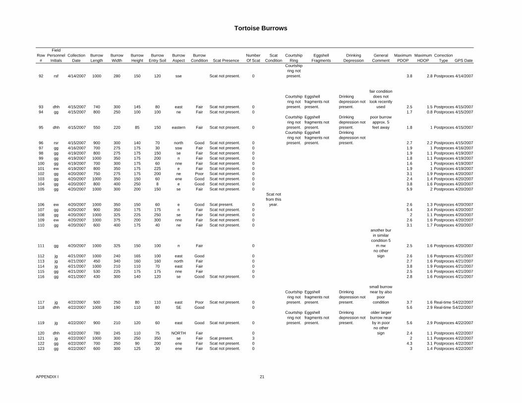
Tortoise Burrows
Row #
Field Personnel
InitialsCollection
DateBurrow Length
Burrow Width
Burrow Height
Burrow Entry Soil
Burrow Aspect
Burrow Condition Scat Presence
Number Of Scat
Scat Condition
Courtship Ring
Eggshell Fragments
Drinking Depression
General Comment
Maximum PDOP
Maximum HDOP
Correction Type GPS Date
92 rsf 4/14/2007 1000 280 150 120 sse Scat not present. 0
Courtship ring not present. 3.8 2.8 Postproces 4/14/2007
93 dhh 4/15/2007 740 300 145 80 east Fair Scat not present. 0
Courtship ring not present.
Eggshell fragments not present.
Drinking depression not present.
fair condition does not
look recently used 2.5 1.5 Postproces 4/15/2007
94 gg 4/15/2007 800 250 100 100 ne Fair Scat not present. 0 1.7 0.8 Postproces 4/15/2007
95 dhh 4/15/2007 550 220 85 150 eastern Fair Scat not present. 0
Courtship ring not present.
Eggshell fragments not present.
Drinking depression not present.
poor burrow approx. 5 feet away 1.8 1 Postproces 4/15/2007
96 rsr 4/15/2007 900 300 140 70 north Good Scat not present. 0
Courtship ring not present.
Eggshell fragments not present.
Drinking depression not present. 2.7 2.2 Postproces 4/15/2007
97 gg 4/16/2007 700 275 175 30 ssw Fair Scat not present. 0 1.9 1 Postproces 4/16/200798 gg 4/19/2007 800 275 175 150 se Fair Scat not present. 0 1.9 1.1 Postproces 4/19/200799 gg 4/19/2007 1000 350 175 200 n Fair Scat not present. 0 1.8 1.1 Postproces 4/19/2007100 gg 4/19/2007 700 300 175 60 nne Fair Scat not present. 0 1.6 1 Postproces 4/19/2007101 ew 4/19/2007 800 350 175 225 e Fair Scat not present. 0 1.9 1 Postproces 4/19/2007102 gg 4/20/2007 750 275 175 200 ne Poor Scat not present. 0 3.1 1.9 Postproces 4/20/2007103 gg 4/20/2007 1000 350 150 60 ene Good Scat not present. 0 2.4 1.4 Postproces 4/20/2007104 gg 4/20/2007 800 400 250 8 e Good Scat not present. 0 3.8 1.6 Postproces 4/20/2007105 gg 4/20/2007 1000 300 200 150 se Fair Scat not present. 0 5.9 2 Postproces 4/20/2007
106 ew 4/20/2007 1000 350 150 60 e Good Scat present. 0
Scat not from this
year. 2.6 1.3 Postproces 4/20/2007107 gg 4/20/2007 900 350 175 175 n Fair Scat not present. 0 5.4 3.4 Postproces 4/20/2007108 gg 4/20/2007 1000 325 225 250 se Fair Scat not present. 0 2 1.1 Postproces 4/20/2007109 ew 4/20/2007 1000 375 200 300 nne Fair Scat not present. 0 2.6 1.6 Postproces 4/20/2007110 gg 4/20/2007 600 400 175 40 ne Fair Scat not present. 0 3.1 1.7 Postproces 4/20/2007
111 gg 4/20/2007 1000 325 150 100 n Fair 0
another bur in similar
condition 5 m nw 2.5 1.6 Postproces 4/20/2007
112 jg 4/21/2007 1000 240 165 100 east Good 0 no other
sign 2.6 1.6 Postproces 4/21/2007113 jg 4/21/2007 450 340 160 160 north Fair 0 2.7 1.6 Postproces 4/21/2007114 jg 4/21/2007 1000 210 110 70 east Fair 0 3.8 1.9 Postproces 4/21/2007115 gg 4/21/2007 530 225 175 175 nne Fair 0 2.5 1.6 Postproces 4/21/2007116 gg 4/21/2007 430 300 140 120 se Good Scat not present. 0 2.8 1.6 Postproces 4/21/2007
117 jg 4/22/2007 500 250 80 110 east Poor Scat not present. 0
Courtship ring not present.
Eggshell fragments not present.
Drinking depression not present.
small burrow near by also
poor condition 3.7 1.6 Real-time S4/22/2007
118 dhh 4/22/2007 1000 190 110 80 SE Good 0 5.6 2.9 Real-time S4/22/2007
119 jg 4/22/2007 900 210 120 60 east Good Scat not present. 0
Courtship ring not present.
Eggshell fragments not present.
Drinking depression not present.
older larger burrow near by in poor 5.6 2.9 Postproces 4/22/2007
120 dhh 4/22/2007 780 245 110 75 NORTH Fair 0 no other
sign 2.4 1.1 Postproces 4/22/2007121 jg 4/22/2007 1000 300 250 350 se Fair Scat present. 3 2 1.1 Postproces 4/22/2007122 gg 4/22/2007 700 250 90 200 ene Fair Scat not present. 0 4.3 3.1 Postproces 4/22/2007123 gg 4/22/2007 600 300 125 30 ene Fair Scat not present. 0 3 1.4 Postproces 4/22/2007
APPENDIX I 21

Tortoise Burrows
Row #
Field Personnel
InitialsCollection
DateBurrow Length
Burrow Width
Burrow Height
Burrow Entry Soil
Burrow Aspect
Burrow Condition Scat Presence
Number Of Scat
Scat Condition
Courtship Ring
Eggshell Fragments
Drinking Depression
General Comment
Maximum PDOP
Maximum HDOP
Correction Type GPS Date
124 ew 4/23/2007 600 325 175 30 se Fair Scat not present. 0 2 1.1 Postproces 4/23/2007125 ew 4/24/2007 1000 350 250 300 w Good Scat not present. 0 1.9 1.1 Postproces 4/24/2007126 ew 4/24/2007 750 300 250 50 se Fair Scat not present. 0 2.6 1.2 Postproces 4/24/2007127 ew 4/24/2007 750 350 300 100 e Fair Scat not present. 0 2.7 1.5 Postproces 4/24/2007128 ew 4/25/2007 300 250 200 100 n Good Scat not present. 0 2.2 1.1 Postproces 4/25/2007129 ew 4/26/2007 1000 400 350 200 nw Fair Scat not present. 0 2.2 1.1 Postproces 4/26/2007
130 rsf 4/28/2007 1000 210 170 60 nne Fair Scat not present. 0
Courtship ring not present.
Eggshell fragments not present. 4 2.4 Postproces 4/28/2007
131 ew 5/2/2007 500 300 300 400 n Good Scat not present. 0
in the bank of a small
wash. 2.3 1.5 Postproces 5/2/2007132 gg 5/3/2007 800 325 175 350 sw Good Scat not present. 0 3 2 Postproces 5/3/2007133 gg 5/6/2007 700 450 275 400 n Good Scat not present. 0 2.5 1.8 Postproces 5/6/2007134 ew 5/7/2007 800 350 175 150 e Fair Scat not present. 0 4 2.1 Postproces 5/7/2007
135 ew 5/7/2007 600 300 150 40 se Excellent Scat not present. 0 tortoise inside 2.6 1.7 Postproces 5/7/2007
136 ew 5/8/2007 1000 300 250 100 ne Excellent Scat not present. 0 tortoise on
mound. 4.2 2.8 Postproces 5/8/2007137 ew 5/8/2007 1000 375 200 125 e Good Scat not present. 0 3.3 2.8 Postproces 5/8/2007
138 gcg 5/9/2007 450 350 140 15 s Good Scat not present. 0 tracks in burrow 2.3 1.3 Postproces 5/9/2007
139 ew 5/9/2007 1000 400 160 25 e Good Scat not present. 0 tracks in burrow 3.1 2 Postproces 5/9/2007
140 gcg 5/9/2007 1000 550 140 100 ne Fair Scat not present. 0 2.4 1.3 Postproces 5/9/2007
141 ew 5/9/2007 1000 450 220 100 s Fair Scat present. 4
Scat not from this
year. 2.2 1.1 Postproces 5/9/2007142 gcg 5/9/2007 1000 400 200 60 ne Good Scat not present. 0 2.6 1.3 Postproces 5/9/2007143 gg 5/10/2007 700 325 125 70 s Fair Scat not present. 0 2.2 1.1 Postproces 5/10/2007144 gg 5/10/2007 800 275 250 175 sw Fair Scat not present. 0 2.6 1.3 Postproces 5/10/2007145 gg 5/11/2007 700 250 200 100 n Fair Scat not present. 0 1.9 1 Postproces 5/11/2007146 gcg 5/11/2007 1000 325 200 70 northeast Fair Scat not present. 0 2.5 1.2 Postproces 5/11/2007147 gcg 5/11/2007 1000 425 175 50 ne Good 0 2.5 1.2 Postproces 5/11/2007148 dhh 5/12/2007 800 425 200 150 NE Fair 0 1.9 1.1 Postproces 5/12/2007149 DHH 5/12/2007 1000 330 155 80 NE Excellent 0 1.9 1.1 Postproces 5/12/2007150 GG 5/12/2007 770 180 75 40 se Fair Scat not present. 0 2.2 1.1 Postproces 5/12/2007151 gg 5/12/2007 570 310 140 120 ne Fair Scat not present. 0 2.1 1.1 Postproces 5/12/2007152 gg 5/12/2007 540 240 130 35 se Fair 0 2.3 1.3 Postproces 5/12/2007153 dh 5/12/2007 300 180 60 20 se Excellent Scat not present. 0 2.7 1.5 Postproces 5/12/2007154 gg 5/12/2007 840 290 180 70 ne Fair Scat not present. 0 4.3 3.3 Postproces 5/12/2007155 dhh 5/12/2007 300 210 90 60 SE Fair 0 3.4 2 Postproces 5/12/2007156 gg 5/13/2007 900 325 175 30 se Good Scat not present. 0 1.6 0.9 Postproces 5/13/2007
157 dhh 5/13/2007 700 250 175 30 NE Excellent 0 tortoise inside 2.3 1.3 Postproces 5/13/2007
158 dhh 5/13/2007 340 180 90 100 N Fair 0 2.8 1.3 Postproces 5/13/2007159 dhh 5/13/2007 1000 210 90 100 S Good 0 1.4 0.8 Postproces 5/13/2007
160 gcg 5/14/2007 800 400 175 30 east Good Scat present. 1
Scat not from this
year. 1.9 1.1 Postproces 5/14/2007
161 gcg 5/14/2007 1000 375 225 350 north Good Scat present. 3
Scat not from this
year. 2.1 1.1 Postproces 5/14/2007
162 rh 5/15/2007 1000 700 350 100 e Poor Scat present. 1
Scat not from this
year. 2.3 1.4 Postproces 5/15/2007
APPENDIX I 22

Tortoise Burrows
Row #
Field Personnel
InitialsCollection
DateBurrow Length
Burrow Width
Burrow Height
Burrow Entry Soil
Burrow Aspect
Burrow Condition Scat Presence
Number Of Scat
Scat Condition
Courtship Ring
Eggshell Fragments
Drinking Depression
General Comment
Maximum PDOP
Maximum HDOP
Correction Type GPS Date
163 gcg 5/15/2007 1000 260 140 200 north Good Scat not present. 0 3 1.6 Postproces 5/15/2007
164 gcg 5/15/2007 1000 270 140 40 east Excellent Scat present. 8Scat from this year.
tracks on mound 3.6 1.5 Postproces 5/15/2007
165 gcg 5/15/2007 1000 180 110 20 north Good Scat not present. 0 1.8 0.9 Postproces 5/15/2007166 gcg 5/16/2007 1000 200 160 20 east Fair Scat not present. 0 5.9 1.8 Postproces 5/16/2007167 dhh 5/19/2007 380 340 150 180 S Fair 0 3.9 2 Postproces 5/19/2007168 dhh 5/19/2007 600 300 180 210 ne Fair Scat present. 0 5.8 2.3 Postproces 5/19/2007169 dhh 5/19/2007 680 260 180 160 NE Fair Scat not present. 0 3.1 1.2 Postproces 5/19/2007
170 gg 5/19/2007 700 200 90 30 ne Fair Scat not present. 0 2.7 1.7 Postproces 5/19/2007
171 ew 5/21/2007 500 300 225 300 e Fair Scat not present. 0 4.3 2.3 Real-time S5/21/2007
172 gcg 5/21/2007 350 200 90 20 se Excellent Scat not present. 0 tracks in burrow 4.4 3.4 Real-time S5/21/2007
173 gg 5/21/2007 1000 250 175 100 se Fair Scat not present. 0 3.6 2.5 Real-time S5/21/2007
174 ew 5/22/2007 500 250 250 50 s Excellent Scat present. 0
Scat not from this
year. 2.7 1.8 Postproces 5/22/2007
175 ew 5/22/2007 450 200 175 75 nw Excellent Scat not present. 0 5.8 2 Postproces 5/22/2007176 gg 5/24/2007 800 375 175 80 ne Fair Scat not present. 0 4.5 3.2 Postproces 5/24/2007177 gg 5/24/2007 1000 300 200 100 ne Fair Scat not present. 0 2.3 1.7 Postproces 5/24/2007
178 gg 5/26/2007 700 325 225 150 n Fair Scat not present. 0 2.1 1 Postproces 5/26/2007
179 gg 5/26/2007 1000 425 200 450 sw Good Scat not present. 0 2.6 1.3 Postproces 5/26/2007180 gg 5/28/2007 800 225 150 50 ne Fair Scat not present. 0 4.9 4.5 Postproces 5/28/2007181 gg 5/28/2007 1000 325 300 75 se Good Scat not present. 0 2.7 1.7 Real-time S5/28/2007
182 gcg 5/28/2007 1000 325 175 150 south Good Scat present. 1Scat from this year. 3.3 1.9 Postproces 5/28/2007
183 gcg 5/28/2007 700 325 175 150 south Excellent Scat present. 4Scat from this year. 4.4 2.3 Postproces 5/28/2007
184 gcg 5/29/2007 1000 225 75 350 sw Fair Scat not present. 0 5.6 3 Postproces 5/29/2007
APPENDIX I 23

Tortoise Burrows
Row #1234
5
6
7
8
9
1011
12
131415
1617
18
19
2021
22
23
242526
27
28
2930
GPS TimeDatafile Name
Unfiltered Positions
Filtered Positions
Data Dictionary
NameGPS Week
GPS Second
GPS Height
Vertical Precision
Horizontal Precision
Standard Deviation Latitude Longitude Point ID
X Coordinate
Y Coordinate SITE LOCID BURROW
09:12:49amBSE12MAY 66 66 BSE_Torto 1426 576783 3015.28 1.5 0.9 0 35.58421 -115.4691 5 7314191 2408424.8 IVANPAH 1 27 BURROW10:12:13amBSE14MAY 16 16 BSE_Torto 1427 148347 3076.213 4.1 2.4 1.000191 35.58367 -115.4732 5 7312967.5 2408199 IVANPAH 1 26 BURROW06:36:46amBSE16MAY 19 19 BSE_Torto 1427 308220 3089.788 5.6 3.5 0.94962 35.58443 -115.475 1 7312436.5 2408463.3 IVANPAH 1 25 BURROW08:12:39amBSET17MA 16 16 BSE_Torto 1427 400373 3118.936 2.4 1.4 0 35.58168 -115.4773 3 7311766.5 2407443.5 IVANPAH 1 41 BURROW
09:18:54amBSE18MAY 79 78 BSE_Torto 1427 490748 3156.064 3.9 2.5 0.867458 35.58239 -115.4799 3 7310995 2407681.3 IVANPAH 1 39 BURROW
06:00:31amBSE19MAY 95 95 BSE_Torto 1427 565245 3156.629 3.9 2.3 0.404439 35.58277 -115.4801 1 7310938 2407818.8 IVANPAH 1 38 BURROW
04:36:51pmBSE19MAY 219 219 BSE_Torto 1427 603425 3191.099 6.8 3.9 0.4958 35.58543 -115.482 10 7310345 2408773 IVANPAH 1 24 BURROW
12:21:12pmBSE19MAY 53 53 BSE_Torto 1427 588086 2939.72 4.4 3.2 0.943937 35.58187 -115.4633 11 7315943.5 2407618.8WITHIN 1-MILE BUFFER 28 BURROW
07:22:28amBSE20MAY 79 79 BSE_Torto 1428 51762 3193.455 4 2.9 0.68731 35.58456 -115.4827 3 7310149 2408451.3 IVANPAH 1 33 BURROW
07:03:30amBSE20MAY 77 77 BSE_Torto 1428 50624 3108.284 4.5 3.2 0.645928 35.59179 -115.475 4 7312366.5 2411138.3WITHIN 1-MILE BUFFER 10 BURROW
01:10:54pmBSE21MAY 65 44 BSE_Torto 1428 159068 3212.581 8.9 3.4 0.860229 35.58453 -115.4844 13 7309627 2408426.5 IVANPAH 1 32 BURROW
07:41:06amBSE22MAY 65 64 BSE_Torto 1428 225680 3000.063 3.7 2.5 120.6912 35.58363 -115.4479 3 7320506 2408373.3OUT 1-MILE BUFFER 29 BURROW
12:36:07pmBSE24MAY 76 76 BSE_Torto 1428 416181 3264.921 4.7 2.9 0.099325 35.58625 -115.487 6 7308842 2409034.5 IVANPAH 1 22 BURROW12:37:38pmBSE24MAY 56 56 BSE_Torto 1428 416272 3261.74 5.2 2.6 0.74024 35.58623 -115.487 7 7308856 2409028.5 IVANPAH 1 23 BURROW07:22:12amBSE26MAY 93 93 BSE_Torto 1428 570146 3274.326 3.8 3 0.86315 35.58441 -115.4878 3 7308637 2408359.3 IVANPAH 1 31 BURROW
10:46:06amBSE26MAY 198 198 BSE_Torto 1428 582380 3295.619 0.7 0.5 0.530137 35.58623 -115.4888 4 7308321.5 2409013.8 IVANPAH 1 21 BURROW07:41:18amBSE28MAY 32 32 BSE_Torto 1429 139292 3296.439 5.1 2.9 1.144152 35.58316 -115.4896 3 7308103.5 2407891 IVANPAH 1 37 BURROW
11:44:24amBSE28MAY 91 90 BSE_Torto 1429 153878 3306.294 4.6 3.3 0.740611 35.58402 -115.4901 9 7307943 2408201 IVANPAH 1 30 BURROW
12:13:07pmBSE29MAY 44 44 BSE_Torto 1429 242001 3330.219 6.6 2.9 0.792835 35.58322 -115.4915 3 7307557 2407900 IVANPAH 1 35 BURROW
12:15:52pmBSE29MAY 49 49 BSE_Torto 1429 242166 3328.275 5.2 3.1 0.907272 35.58319 -115.4914 4 7307567 2407889 IVANPAH 1 36 BURROW09:03:08amBSE30MAY 26 26 BSE_Torto 1429 317002 3339.741 2.7 1.8 0 35.58653 -115.4919 1 7307405.5 2409099.8 IVANPAH 1 20 BURROW
07:08:36amBSE31MAY 67 67 BSE_Torto 1429 396530 3338.672 4.4 3.2 1.993422 35.60086 -115.4909 3 7307568 24143221000' GAS LINE CORRIDOR 1 BURROW
07:50:33amBSE01JUN 33 33 BSE_Torto 1429 485447 2833.693 5.9 3.7 2.197591 35.5929 -115.4517 2 7319279.5 2411716.5WITHIN 1-MILE BUFFER 11 BURROW
07:54:18amBSE01JUN 36 35 BSE_Torto 1429 485672 2835.675 3.9 2.6 2.671558 35.5931 -115.4517 3 7319280.5 2411791.5WITHIN 1-MILE BUFFER 12 BURROW
11:22:27amBSE02JUN 46 46 BSE_Torto 1429 584561 3399.91 3.2 2.2 0.480577 35.58207 -115.4965 4 7306066 2407442.5 IVANPAH 1 40 BURROW12:57:44pmBSE02JUN 55 55 BSE_Torto 1429 590278 3372.515 4.6 3.6 0.788733 35.58328 -115.4942 8 7306724.5 2407899 IVANPAH 1 34 BURROW
11:58:18amBSE03JUN 42 41 BSE_Torto 1430 68312 3257.738 1.3 0.6 0.525668 35.59701 -115.485 4 7309338 2412964.81000' GAS LINE CORRIDOR 3 BURROW
11:59:59amBSE03JUN 85 85 BSE_Torto 1430 68413 3252.795 1.3 0.6 1.944752 35.59704 -115.4848 5 7309397.5 2412977.81000' GAS LINE CORRIDOR 5 BURROW
06:40:48amBSE5JUNE 25 25 BSE_Torto 1430 222062 3304.957 1.7 1 0.469492 35.5965 -115.4881 2 7308425 24127551000' GAS LINE CORRIDOR 4 BURROW
08:08:00amBSE5JUNE 34 34 BSE_Torto 1430 227294 3273.92 1.7 1.2 0.442283 35.5873 -115.4871 4 7308814.5 2409415.5 IVANPAH 1 19 BURROW
APPENDIX I 24

Tortoise Burrows
Row #
31
32
33
34
35
36
37
38
39
40
41
424344
4546
47
484950515253
54
555657
58596061
GPS TimeDatafile Name
Unfiltered Positions
Filtered Positions
Data Dictionary
NameGPS Week
GPS Second
GPS Height
Vertical Precision
Horizontal Precision
Standard Deviation Latitude Longitude Point ID
X Coordinate
Y Coordinate SITE LOCID BURROW
08:28:02amBSE5JUNE 102 102 BSE_Torto 1430 228496 3314.152 0.8 0.6 0 35.59444 -115.4888 6 7308253 2412002.51000' GAS LINE CORRIDOR 6 BURROW
09:33:30amBSE5JUNE 35 35 BSE_Torto 1430 232424 3309.828 1.8 0.9 0 35.59187 -115.489 7 7308222.5 24110671000' GAS LINE CORRIDOR 8 BURROW
06:37:58amBSE4JUNE 47 47 BSE_Torto 1430 135492 3247.189 1.5 0.9 0 35.59207 -115.4848 1 7309466.5 24111691000' GAS LINE CORRIDOR 9 BURROW
07:24:43amBSE4JUNE 33 33 BSE_Torto 1430 138297 3239.938 1.5 0.9 0 35.58946 -115.4846 2 7309533 2410218.5 IVANPAH 1 17 BURROW
08:28:24amBSE4JUNE 25 25 BSE_Torto 1430 142118 3267.514 1.7 1.3 0 35.59338 -115.4858 3 7309135 2411638.31000' GAS LINE CORRIDOR 7 BURROW
08:48:42amBSE4JUNE 33 33 BSE_Torto 1430 143336 3256.649 1.9 1.2 0.320509 35.58947 -115.4856 4 7309248 2410217.51000' GAS LINE CORRIDOR 16 BURROW
09:57:30amBSE4JUNE 45 45 BSE_Torto 1430 147464 3262.606 1.7 1 0 35.5894 -115.4861 5 7309093.5 2410185.81000' GAS LINE CORRIDOR 15 BURROW
10:42:18amBSE4JUNE 18 18 BSE_Torto 1430 150152 3300.601 1.5 1.6 0.985718 35.59861 -115.488 6 7308456 2413523.31000' GAS LINE CORRIDOR 2 BURROW
11:05:42amBSE4JUNE 24 24 BSE_Torto 1430 151556 3266.918 2.8 2.4 0.601801 35.58951 -115.4864 7 7309009.5 2410226.51000' GAS LINE CORRIDOR 14 BURROW
11:22:30amBSE4JUNE 84 84 BSE_Torto 1430 152564 3276.962 1 0.7 0 35.59021 -115.4867 9 7308891.5 24104781000' GAS LINE CORRIDOR 13 BURROW
11:25:23amBSE6MAY2 26 26 BSE_Torto 1426 66337 2959.61 4.7 2.4 0.214219 35.53726 -115.4601 2 7317302.5 2391406.5 IVANPAH 3 151 BURROW
01:28:39pmBSE5MAY0 19 19 BSE_Torto 1425 592133 2951.05 2 1.3 0 35.53687 -115.4589 2 7317661 2391276.8 IVANPAH 3 152 BURROW10:24:24amBSE05MAY 35 35 BSE_Torto 1425 581078 2935.847 3.8 2.5 0.268683 35.53716 -115.458 1 7317937 2391386.8 IVANPAH 3 153 BURROW11:51:54amBSE4MAY0 47 47 1425 499928 2917.503 2.5 1.3 0 35.53704 -115.4565 133 7318383.5 2391355 IVANPAH 3 154 BURROW
12:38:21pmBSE4MAY0 97 97 1425 502715 2919.068 1 0.9 0 35.53769 -115.4567 134 7318307.5 2391590.8 IVANPAH 3 155 BURROW09:55:30amBSE4MAY0 51 50 1425 492944 2912.324 1 0.7 0.249764 35.53743 -115.456 130 7318529 2391500.5 IVANPAH 3 156 BURROW
12:37:22pmBSE1MAY0 54 54 1425 243456 2875.817 1.1 0.9 1.078373 35.53698 -115.4523 378 7319612 2391365 IVANPAH 3 157 BURROW
10:55:42amBSE28APR 63 63 BSE_Torto 1424 582956 2812.32 3.7 3 1.783027 35.53858 -115.4465 7 7321337 2391989.8 IVANPAH 3 158 BURROW10:40:42amBSE27APR 47 46 BSE_Torto 1424 495656 2792.345 4 2.3 0.651765 35.53893 -115.4442 4 7322029 2392134.3 IVANPAH 3 159 BURROW04:28:35pmBSE26APR 11 11 BSE_Torto 1424 430129 2783.529 4.1 2.4 0 35.53848 -115.4439 8 7322110 2391972.8 IVANPAH 3 161 BURROW08:23:20amBSE25APR 25 25 BSE_Torto 1424 314614 2771.555 0.9 0.7 0 35.53796 -115.4416 1 7322796 2391800.5 IVANPAH 3 163 BURROW02:31:03pmBSE4MAY0 58 58 1425 509477 2932.828 2.1 1.2 0.633934 35.53534 -115.457 135 7318227 2390733.3 IVANPAH 3 164 BURROW12:17:06pmBSE26APR 32 32 BSE_Torto 1424 415040 2784.632 1.8 0.9 0 35.5369 -115.4431 5 7322373.5 2391406.5 IVANPAH 3 165 BURROW
07:50:24amBSE25MAY 33 33 BSE_Torto 1428 485438 3111.382 1.7 0.9 1.667771 35.53368 -115.4704 1 7314278 2390027.5WITHIN 1-MILE BUFFER 166 BURROW
11:10:22amBSE6MAY2 31 31 BSE_Torto 1426 65436 2995.722 3.8 2.7 1.042372 35.53187 -115.4607 1 7317172 2389442.3 IVANPAH 3 167 BURROW09:57:38amBSE3MAY0 24 24 1425 406672 2909.185 4.7 2.9 0.261341 35.53351 -115.4543 424 7319059 2390085.8 IVANPAH 3 168 BURROW01:22:07pmBSE28APR 89 89 BSE_Torto 1424 591741 2827.572 6.4 4.2 1.459704 35.53313 -115.4467 11 7321338 2390004.8 IVANPAH 3 169 BURROW
10:38:06amBSE28APR 64 63 BSE_Torto 1424 581900 2829.817 4.5 2.7 1.949615 35.53302 -115.4465 6 7321398 2389967 IVANPAH 3 170 BURROW05:25:06pmBSE27APR 45 45 BSE_Torto 1424 519920 2814.53 4.8 4.1 1.63122 35.53268 -115.4454 2 7321727 2389851.3 IVANPAH 3 171 BURROW10:32:18amBSE26APR 36 35 BSE_Torto 1424 408752 2789.36 1.2 0.9 0.592527 35.53298 -115.4425 3 7322586 2389985 IVANPAH 3 172 BURROW10:40:18amBSE4MAY0 45 45 1425 495632 2937.281 2.6 1.8 0 35.53167 -115.4561 131 7318548 2389404.8 IVANPAH 3 173 BURROW
APPENDIX I 25

Tortoise Burrows
Row #
62
63
646566
67
6869
70
71
72737475767778798081828384
85
86
87
88
89
90
91
GPS TimeDatafile Name
Unfiltered Positions
Filtered Positions
Data Dictionary
NameGPS Week
GPS Second
GPS Height
Vertical Precision
Horizontal Precision
Standard Deviation Latitude Longitude Point ID
X Coordinate
Y Coordinate SITE LOCID BURROW
10:31:53amBSE29APR 75 75 BSE_Torto 1425 63127 2866.859 1.3 0.9 0 35.53131 -115.4496 2 7320473.5 2389322.5 IVANPAH 3 174 BURROW
10:09:48amBSE28APR 111 111 BSE_Torto 1424 580202 2817.628 6.5 4.2 4.111653 35.53221 -115.446 5 7321537 2389676 IVANPAH 3 175 BURROW
09:33:19amBSE4MAY0 183 183 1425 491613 2942.065 0.9 0.5 0.692693 35.52953 -115.4557 129 7318667 2388627.5 IVANPAH 3 176 BURROW08:17:39amBSE3MAY0 55 55 1425 400673 2920.498 4.9 3.2 0.515631 35.52918 -115.4537 427 7319273.5 2388516.8 IVANPAH 3 177 BURROW01:03:30pmBSE1MAY0 43 43 1425 245024 2904.415 1.4 1.4 0.448582 35.52948 -115.4525 379 7319618 2388634.5 IVANPAH 3 178 BURROW
02:48:09pmBSE28APR 105 105 BSE_Torto 1424 596903 2836.41 9.3 4 0.653149 35.53069 -115.4473 13 7321180.5 2389111.8 IVANPAH 3 179 BURROW
08:45:25amBSE28APR 84 84 BSE_Torto 1424 575139 2825.571 3.2 2.6 1.176184 35.52941 -115.4454 1 7321739.5 2388661.3 IVANPAH 3 180 BURROW01:41:40pmBSE27APR 53 53 BSE_Torto 1424 506514 2816.502 4 2.7 0.374585 35.52855 -115.4445 6 7322024 2388354.3 IVANPAH 3 181 BURROW
02:45:09pmBSE26APR 23 22 BSE_Torto 1424 423923 2804.894 2.7 1.3 1.491499 35.52813 -115.4433 7 7322367.5 2388211.8WITHIN 1-MILE BUFFER 182 BURROW
01:09:18pmBSE24MAY 55 25 BSE_Torto 1428 418172 2765.648 6.7 6.6 0.282544 35.52783 -115.4396 12 7323498 2388132.5WITHIN 1-MILE BUFFER 183 BURROW
09:09:25amBSE24MAY 55 55 BSE_Torto 1428 403779 2915.51 3.7 2.6 1.22518 35.52248 -115.4516 9 7319961.5 2386092.3WITHIN 1-MILE BUFFER 184 BURROW
02:07:03pmBSE3MAY0 27 26 1425 421637 2895.257 6.4 3.1 0.282071 35.53626 -115.4552 425 7318763 2391081.8 IVANPAH 3 160 BURROW04:23:01pmBSE4MAY0 21 21 1425 516195 2922.331 5.4 2.5 0 35.53653 -115.4572 138 7318166 2391166 IVANPAH 3 162 BURROW04:26:27pmBSE1APR0 128 128 BSE_Torto 1422 516401 2908.965 1.1 0.9 0 35.55984 -115.4603 1 7317037 2399624.5 IVANPAH 2 111 BURROW10:27:19amBSE24MAY 45 44 BSE_Torto 1428 408453 3244.288 4.4 2.6 0.801813 35.58131 -115.4863 4 7309115 2407240.5 IVANPAH 1 42 BURROW08:07:51amBSE15MAY 89 89 BSE_Torto 1427 227285 3075.547 3.8 3.1 4.928001 35.58158 -115.4742 1 7312691 2407428.8 IVANPAH 1 43 BURROW07:06:34amBSE20MAY 50 50 BSE_Torto 1428 50808 3188.984 3.6 2.9 1.83804 35.58226 -115.4827 1 7310178.5 2407615.8 IVANPAH 1 44 BURROW10:10:24amBSE13MAY 77 77 BSE_Torto 1427 61838 3045.742 0.9 0.7 0 35.58152 -115.4721 5 7313321 2407425.8 IVANPAH 1 45 BURROW12:08:06pmBSE02JUN 29 29 BSE_Torto 1429 587300 3403.457 4.3 2.6 1.84106 35.58051 -115.497 5 7305934.5 2406871.3 IVANPAH 1 46 BURROW06:49:58amBSE21MAY 63 61 BSE_Torto 1428 136212 3201.921 2.8 1.8 0.25476 35.58069 -115.4838 5 7309849 2407034.8 IVANPAH 1 47 BURROW11:46:24amBSE19MAY 36 35 BSE_Torto 1427 585998 3178.906 3.5 5.3 1.168774 35.58073 -115.4818 5 7310458.5 2407065.3 IVANPAH 1 48 BURROW06:22:41amVL060507. <Null> <Null> <Null> <Null> <Null> <Null> <Null> <Null> <Null> <Null> <Null> <Null> 7312041.5 2406971.3 IVANPAH 1 49 BURROW11:57:36amBSE13MAY 62 61 BSE_Torto 1427 68270 3046.23 1.3 1.1 0.703395 35.58021 -115.4723 8 7313271.5 2406944.5 IVANPAH 1 50 BURROW
11:03:39amBSE02JUN 53 53 BSE_Torto 1429 583433 3394.835 3.8 3.5 2.655894 35.57845 -115.4965 3 7306099.5 2406124.8WITHIN 1-MILE BUFFER 51 BURROW
07:23:54amBSE03JUN 246 246 BSE_Torto 1430 51848 3203.58 4.5 2.7 1.288757 35.58898 -115.4822 1 7310242 2410062 IVANPAH 1 18 BURROW
11:05:07amBSE9APR0 144 144 BSE_Torto 1422 151521 2864.141 4.5 2.6 1.498023 35.55803 -115.4561 1 7318308.5 2398995WITHIN 1-MILE BUFFER 118 BURROW
01:26:28pmBSE9APR0 174 174 BSE_Torto 1422 160002 2872.611 0.8 0.4 0.39227 35.55683 -115.4564 2 7318228 2398558.3WITHIN 1-MILE BUFFER 127 BURROW
08:59:07amBSE10APR 74 74 BSE_Torto 1422 230361 2877.104 4.9 2.6 0.535292 35.55964 -115.4575 1 7317880.5 2399571WITHIN 1-MILE BUFFER 112 BURROW
04:07:58pmBSE10APR 109 109 BSE_Torto 1422 256092 2892.913 2.5 1.4 0 35.56651 -115.4589 4 7317377 2402059WITHIN 1-MILE BUFFER 87 BURROW
11:37:30amBSE14APR 406 406 BSE_Torto 1422 585464 2918.747 0.7 0.5 0.696991 35.55874 -115.4612 2 7316781 2399214.8 IVANPAH 2 117 BURROW
APPENDIX I 26

Tortoise Burrows
Row #
92
9394
95
96979899100101102103104105
106107108109110
111
112113114115116
117118
119
120121122123
GPS TimeDatafile Name
Unfiltered Positions
Filtered Positions
Data Dictionary
NameGPS Week
GPS Second
GPS Height
Vertical Precision
Horizontal Precision
Standard Deviation Latitude Longitude Point ID
X Coordinate
Y Coordinate SITE LOCID BURROW
01:18:45pmBSE14APR 213 213 BSE_Torto 1422 591539 2921.201 0.9 1.1 0.607614 35.5587 -115.4614 3 7316717.5 2399200.8 IVANPAH 2 116 BURROW
10:28:54amBSE15APR 247 246 BSE_Torto 1423 62948 2932.681 0.8 0.4 1.07303 35.55846 -115.4626 2 7316369 2399104.8 IVANPAH 2 115 BURROW11:16:53amBSE15APR 50 50 BSE_Torto 1423 65827 2942.538 1 0.7 0.808228 35.5563 -115.463 3 7316262 2398315.8 IVANPAH 2 126 BURROW
11:49:27amBSE15APR 148 148 BSE_Torto 1423 67781 2935.809 1 0.7 0 35.56383 -115.4632 6 7316125.5 2401053 IVANPAH 2 94 BURROW
12:22:43pmBSE15APR 127 127 BSE_Torto 1423 69777 2945.713 1.2 1.3 0 35.5604 -115.4637 7 7316028.5 2399802.8 IVANPAH 2 110 BURROW02:38:39pmBSE16APR 54 54 BSE_Torto 1423 164333 2952.055 1.3 1 0 35.55735 -115.464 2 7315954 2398690 IVANPAH 2 125 BURROW11:37:10amBSE19APR 46 46 1423 412644 2972.669 0.8 0.6 0 35.56402 -115.4663 185 7315217.5 2401097.8 IVANPAH 2 93 BURROW12:06:45pmBSE19APR 21 21 1423 414419 2977.392 1.1 0.7 0 35.56127 -115.4666 187 7315141.5 2400095.8 IVANPAH 2 108 BURROW01:51:54pmBSE19APR 55 55 1423 420728 2986.107 1.2 1.2 0 35.55735 -115.4667 188 7315158 2398669.3 IVANPAH 2 124 BURROW02:34:00pmBSE19APR 44 44 1423 423254 2981.481 1.5 1 0 35.56164 -115.467 189 7315015.5 2400228.5 IVANPAH 2 107 BURROW09:05:44amBSE20APR 25 25 1423 489958 2996.788 5.5 5.5 0.764824 35.55638 -115.4677 97 7314865 2398306.8 IVANPAH 2 123 BURROW09:28:19amBSE20APR 45 45 1423 491313 2981.518 3.9 2.9 0.522113 35.56284 -115.4674 98 7314889 2400663 IVANPAH 2 106 BURROW09:31:36amBSE20APR 67 67 1423 491510 2992.929 4.2 2.7 0.72818 35.56298 -115.4678 99 7314777 2400708.5 IVANPAH 2 105 BURROW09:59:11amBSE20APR 45 45 1423 493165 2997.61 4 2.5 0.881297 35.55883 -115.4678 100 7314799 2399197.8 IVANPAH 2 114 BURROW
10:42:31amBSE20APR 120 119 1423 495765 2995.229 3.8 2.2 1.211611 35.56255 -115.4681 101 7314683 2400551.3 IVANPAH 2 104 BURROW12:14:09pmBSE20APR 34 33 1423 501263 3003.936 5.9 3.4 2.303942 35.56222 -115.4684 102 7314595 2400428.5 IVANPAH 2 103 BURROW02:35:48pmBSE20APR 47 47 1423 509762 3008.544 3.5 2.5 0.275527 35.56548 -115.4691 104 7314372 2401608.5 IVANPAH 2 90 BURROW02:40:22pmBSE20APR 22 22 1423 510036 3004.591 4.2 3 0.885133 35.56498 -115.4691 105 7314373 2401428.3 IVANPAH 2 92 BURROW02:53:18pmBSE20APR 74 73 1423 510812 3008.45 4.1 2.7 0.672695 35.5605 -115.469 106 7314440.5 2399797.8 IVANPAH 2 109 BURROW
03:56:45pmBSE20APR 26 26 1423 514619 3015.081 3.9 3.3 0.532349 35.55613 -115.4691 107 7314455.5 2398208.8 IVANPAH 2 122 BURROW
11:07:19amBSE21APR 34 34 BSE_Torto 1423 583653 3014.315 3.9 2.4 0.388873 35.56202 -115.4694 1 7314292 2400347.3 IVANPAH 2 102 BURROW11:29:07amBSE21APR 107 107 BSE_Torto 1423 584961 3011.549 3.9 2.9 0.595612 35.56372 -115.4697 3 7314196 2400965 IVANPAH 2 95 BURROW11:37:18amBSE21APR 77 77 BSE_Torto 1423 585452 3016.336 3.6 2.5 2.186208 35.56482 -115.4698 4 7314152.5 2401366 IVANPAH 2 91 BURROW03:50:45pmBSE21APR 129 129 BSE_Torto 1423 600659 3056.25 1.2 0.9 0 35.55591 -115.4724 7 7313479 2398103 IVANPAH 2 121 BURROW06:02:32pmBSE21APR 59 59 BSE_Torto 1424 3766 3069.252 1.4 0.9 0.337203 35.55229 -115.4732 8 7313261.5 2396777.3 IVANPAH 2 132 BURROW
07:58:54amBSE22APF 149 149 BSE_Torto 1424 53948 3064.186 3.9 2.1 3.176764 35.56195 -115.4734 1 7313117 2400292.8 IVANPAH 2 101 BURROW08:06:00amBSE22APF 48 15 BSE_Torto 1424 54374 3065.378 8 5 0.933076 35.56227 -115.4735 2 7313089 2400408.5 IVANPAH 2 100 BURROW
09:59:26amBSE22APF 162 162 BSE_Torto 1424 61180 3080.114 5.4 3.4 1.753394 35.56534 -115.4746 4 7312730.5 2401516.5 IVANPAH 2 89 BURROW
12:14:24pmBSE22APF 17 17 BSE_Torto 1424 69278 3094.936 2.4 1.2 0 35.55704 -115.4754 5 7312567.5 2398491 IVANPAH 2 120 BURROW10:41:51amBSE22APR 52 52 BSE_Torto 1424 63725 3083.148 3.2 2.2 1.059917 35.5539 -115.4745 8 7312879 2397357.5 IVANPAH 2 129 BURROW11:03:45amBSE22APR 70 70 BSE_Torto 1424 65039 3083.772 3.3 2.3 0.635008 35.56168 -115.4749 9 7312663.5 2400181 IVANPAH 2 99 BURROW12:02:28pmBSE22APR 51 51 BSE_Torto 1424 68562 3098.392 2.6 1.3 0 35.55461 -115.4756 10 7312518 2397604 IVANPAH 2 128 BURROW
APPENDIX I 27

Tortoise Burrows
Row #
124125126127128129
130
131132133134
135
136137
138
139140
141142143144145146147148149150151152153154155156
157158159
160
161
162
GPS TimeDatafile Name
Unfiltered Positions
Filtered Positions
Data Dictionary
NameGPS Week
GPS Second
GPS Height
Vertical Precision
Horizontal Precision
Standard Deviation Latitude Longitude Point ID
X Coordinate
Y Coordinate SITE LOCID BURROW
09:36:11amBSE23APR 37 37 BSE_Torto 1424 146185 3103.688 1.7 1 0 35.56195 -115.4764 1 7312236.5 2400272 IVANPAH 2 98 BURROW11:52:23amBSE24APR 62 62 BSE_Torto 1424 240757 3133.97 1.6 0.9 0 35.56087 -115.4786 1 7311593 2399861.3 IVANPAH 2 96 BURROW12:19:23pmBSE24APR 62 62 BSE_Torto 1424 242377 3135.805 2.1 1 0 35.5613 -115.4785 2 7311622 2400018.5 IVANPAH 2 97 BURROW01:36:04pmBSE24APR 61 61 BSE_Torto 1424 246978 3136.364 1.4 1.3 0.464616 35.55233 -115.4783 3 7311755.5 2396756.5 IVANPAH 2 131 BURROW10:04:47amBSE25APR 48 48 BSE_Torto 1424 320701 2762.68 1.1 0.6 0.391792 35.54196 -115.4416 2 7322749.5 2393255.8 IVANPAH 3 148 BURROW09:58:56amBSE26APR 56 56 BSE_Torto 1424 406750 2775.377 1.2 0.7 0 35.54097 -115.4425 1 7322514 2392890.5 IVANPAH 3 150 BURROW
01:00:48pmBSE28APR 101 101 BSE_Torto 1424 590462 2811.506 5.4 3.9 1.049971 35.54016 -115.4467 9 7321269.5 2392564.8 IVANPAH 3 149 BURROW
08:54:58amBSE2MAY0 107 107 1425 316512 2867.787 0.9 0.6 0 35.54185 -115.4533 489 7319294.5 2393129.3 IVANPAH 3 147 BURROW03:05:48pmBSE3MAY0 66 65 1425 425162 2892.172 4.7 3.6 1.397648 35.5417 -115.4553 426 7318701.5 2393059.8 IVANPAH 3 146 BURROW12:38:27pmBSE06MAY 56 56 BSE_Torto 1426 70721 2955.051 1.2 1.4 0 35.54217 -115.4615 3 7316836 2393182.5 IVANPAH 3 145 BURROW10:37:59amBSE7MAY0 24 24 BSE_Torto 1426 149893 2961.293 6.1 4 0.4896 35.54286 -115.4611 1 7316951 2393438 IVANPAH 3 143 BURROW
02:38:30pmBSE7MAY0 70 70 BSE_Torto 1426 164324 2906.058 3.7 3.1 0.274833 35.54343 -115.457 5 7318167 2393675.5 IVANPAH 3 144 BURROW
12:09:33pmBSE8MAY0 40 40 BSE_Torto 1426 241787 2946.171 4.5 3.3 2.163164 35.54409 -115.4612 2 7316904.5 2393884.5 IVANPAH 3 136 BURROW12:22:24pmBSE8MAY0 53 52 BSE_Torto 1426 242558 2893.673 3.6 3.1 1.54683 35.54405 -115.4561 3 7318413.5 2393908.3 IVANPAH 3 138 BURROW
08:11:57amBSE9MAY0 139 139 BSE_Torto 1426 313931 2886.114 3.5 2.5 0.787737 35.54435 -115.4553 1 7318653 2394022 IVANPAH 3 140 BURROW
08:18:07amBSE9MAY0 91 91 BSE_Torto 1426 314301 2889.573 3.8 2.7 1.221975 35.54433 -115.4557 2 7318552 2394013.3 IVANPAH 3 139 BURROW08:23:33amBSE9MAY0 49 49 BSE_Torto 1426 314627 2896.572 3.1 2.2 1.101072 35.54435 -115.4564 3 7318335 2394015.3 IVANPAH 3 137 BURROW
09:09:21amBSE9MAY0 30 30 BSE_Torto 1426 317375 2801.487 3.7 2.3 0.708164 35.54445 -115.4466 5 7321244.5 2394124 IVANPAH 3 141 BURROW09:26:30amBSE9MAY0 36 35 BSE_Torto 1426 318404 2765.571 4.2 2.5 0.629854 35.54437 -115.442 7 7322607 2394132 IVANPAH 3 142 BURROW09:09:14amBSE10MAY 78 78 BSE_Torto 1426 403768 3069.985 1.1 0.7 1.01074 35.55095 -115.4726 1 7313454.5 2396295.3 IVANPAH 2 135 BURROW10:24:12amBSE10MAY 38 37 BSE_Torto 1426 408266 3116.179 2.1 1.4 0.900609 35.55068 -115.4762 3 7312375.5 2396169.5 IVANPAH 2 134 BURROW09:48:11amBSE11MAY 70 70 BSE_Torto 1426 492505 3153.178 1.2 0.8 0.433566 35.55637 -115.4797 1 7311304 2398215.8 IVANPAH 2 119 BURROW11:32:55amBSE11MAY 96 96 BSE_Torto 1426 498789 2985.559 1.1 0.6 0 35.56783 -115.4672 2 7314895 2402479.8 IVANPAH 1 84 BURROW11:39:24amBSE11MAY 47 46 BSE_Torto 1426 499178 2985.683 1.2 0.8 0.429722 35.56668 -115.4672 3 7314928.5 2402062 IVANPAH 1 86 BURROW08:14:00amBSE12MAY 51 51 BSE_Torto 1426 573254 3003.069 1.6 1 0 35.57339 -115.469 3 7314335.5 2404488.5 IVANPAH 1 73 BURROW08:17:11amBSE12MAY 61 61 BSE_Torto 1426 573445 2999.096 1.6 1 0.554118 35.57386 -115.4687 4 7314402 2404660.8 IVANPAH 1 68 BURROW10:11:29amBSE12MAY 79 79 BSE_Torto 1426 580303 3013.333 1.2 0.9 0.361935 35.57214 -115.4699 6 7314074 2404029 IVANPAH 1 74 BURROW11:45:26amBSE12MAY 25 25 BSE_Torto 1426 585940 3020.011 1.4 1 0 35.57512 -115.4702 8 7313938.5 2405108.3 IVANPAH 1 66 BURROW12:01:24pmBSE12MAY 40 39 BSE_Torto 1426 586898 3021.941 1.4 1.2 0.348014 35.56913 -115.4702 9 7313992 2402930.3 IVANPAH 1 78 BURROW12:33:07pmBSE12MAY 41 41 BSE_Torto 1426 588801 3020.77 1.2 1.1 0 35.57306 -115.4704 11 7313898 2404356.8 IVANPAH 1 72 BURROW12:46:07pmBSE12MAY 62 62 BSE_Torto 1426 589581 3024.076 1.7 1.6 0.816769 35.57638 -115.4706 12 7313814 2405564.5 IVANPAH 1 63 BURROW12:49:18pmBSE12MAY 60 60 BSE_Torto 1426 589772 3020.935 1.4 1.1 0 35.57645 -115.4706 13 7313821.5 2405589.3 IVANPAH 1 64 BURROW07:39:03amBSE13MAY 37 37 BSE_Torto 1427 52757 3031.778 1.9 1.5 0 35.57652 -115.4713 1 7313607 2405609 IVANPAH 1 61 BURROW
11:38:11amBSE13MAY 80 80 BSE_Torto 1427 67105 3041.894 1 0.7 0 35.57226 -115.4722 7 7313375 2404052.8 IVANPAH 1 71 BURROW07:03:20amBSE13MAY 42 42 BSE_Torto 1427 50614 3028.782 2.4 1.6 0 35.57035 -115.471 12 7313751.5 2403365.8 IVANPAH 1 75 BURROW07:44:54amBSE13MAY 21 21 BSE_Torto 1427 53108 3024.864 1.8 1.4 0 35.57635 -115.4708 13 7313763.5 2405553.8 IVANPAH 1 62 BURROW
08:03:09amBSE14MAY 89 89 BSE_Torto 1427 140603 3052.744 0.8 0.6 0 35.5724 -115.4728 2 7313208 2404100.3 IVANPAH 1 70 BURROW
10:00:07amBSE14MAY 62 62 BSE_Torto 1427 147621 3057.809 2.4 1.5 0 35.57894 -115.4732 4 7313018 2406477.3 IVANPAH 1 57 BURROW
08:58:12amBSE15MAY 54 53 BSE_Torto 1427 230306 3079.668 3.6 2.9 1.057255 35.57968 -115.4747 2 7312559.5 2406733.8 IVANPAH 1 54 BURROW
APPENDIX I 28

Tortoise Burrows
Row #
163
164165166167168169
170
171
172173
174
175176177
178
179180181
182
183184
GPS TimeDatafile Name
Unfiltered Positions
Filtered Positions
Data Dictionary
NameGPS Week
GPS Second
GPS Height
Vertical Precision
Horizontal Precision
Standard Deviation Latitude Longitude Point ID
X Coordinate
Y Coordinate SITE LOCID BURROW
07:25:43amBSE 15 MA 59 59 BSE_Torto 1427 224757 2991.163 4.4 2.8 0.281689 35.56917 -115.4676 3 7314776 2402961.8 IVANPAH 1 80 BURROW
07:34:15amBSE 15 MA 105 105 BSE_Torto 1427 225269 2988.005 3.4 2.4 1.400789 35.56738 -115.4676 4 7314797 2402312.3 IVANPAH 1 85 BURROW09:53:13amBSE 15 MA 25 25 BSE_Torto 1427 233607 2997.197 1 0.7 0 35.56864 -115.4681 5 7314641.5 2402768.8 IVANPAH 1 79 BURROW10:31:38amBSE16MAY 40 39 BSE_Torto 1427 322312 3095.06 5.3 2.9 0.370352 35.57253 -115.4761 3 7312213 2404123 IVANPAH 1 69 BURROW06:51:31amBSE19MAY 44 43 BSE_Torto 1427 568305 3157.231 5.1 3.4 0.799439 35.56665 -115.4806 2 7310926 2401951 IVANPAH 1 83 BURROW08:21:25amBSE19MAY 26 26 BSE_Torto 1427 573699 3156.481 5.4 3 1.39387 35.58005 -115.4808 3 7310751.5 2406825.8 IVANPAH 1 53 BURROW12:39:27pmBSE19MAY 42 42 BSE_Torto 1427 589181 3166.311 4.8 2.6 0.161686 35.57876 -115.4817 8 7310483.5 2406349.5 IVANPAH 1 56 BURROW
12:30:33pmBSE19MAY 38 38 BSE_Torto 1427 588647 2932.689 4.2 2.5 1.244558 35.57831 -115.4627 12 7316154 2406325.8WITHIN 1-MILE BUFFER 58 BURROW
08:09:24amBSE21MAY 225 182 BSE_Torto 1428 140978 2975.098 3.3 2.1 1.948592 35.56961 -115.4665 2 7315113.5 2403131WITHIN 1-MILE BUFFER 81 BURROW
06:53:01amBSE21MAY 142 123 BSE_Torto 1428 136395 3198.578 2.6 2.1 0.897804 35.58011 -115.4837 6 7309900.5 2406823.8 IVANPAH 1 52 BURROW07:19:24amBSE21MAY 62 34 BSE_Torto 1428 137978 3197.581 4.5 4.3 1.048566 35.57458 -115.4838 7 7309897.5 2404811.3 IVANPAH 1 65 BURROW
07:14:07amBSE22MAY 74 74 BSE_Torto 1428 224061 3024.464 3.4 3.2 81.65085 35.57478 -115.4442 2 7321670.5 2405180.5OUT 1-MILE BUFFER 67 BURROW
10:00:10amBSE22MAY 146 145 BSE_Torto 1428 234024 3039.822 5.9 3.1 87.05085 35.56184 -115.4339 4 7324860 2400552.3OUT 1-MILE BUFFER 113 BURROW
09:46:12amBSE24MAY 48 47 BSE_Torto 1428 405986 3246.018 4.5 2.8 1.045949 35.56692 -115.4866 2 7309139 2402001.5 IVANPAH 1 82 BURROW09:59:24amBSE24MAY 21 21 BSE_Torto 1428 406778 3262.831 2.6 2.3 2.925731 35.56866 -115.4867 3 7309113.5 2402636 IVANPAH 1 77 BURROW
10:36:16amBSE26MAY 42 42 BSE_Torto 1428 581790 3193.921 1.6 1 0 35.55186 -115.4819 1 7310686.5 2396557.5WITHIN 1-MILE BUFFER 130 BURROW
10:41:08amBSE26MAY 54 54 BSE_Torto 1428 582082 3193.142 1.5 1 0.997685 35.55063 -115.482 2 7310666.5 2396110WITHIN 1-MILE BUFFER 133 BURROW
07:11:05amBSE28MAY 45 45 BSE_Torto 1429 137479 3273.549 3.8 3.4 1.577697 35.57731 -115.4897 2 7308121.5 2405761.5 IVANPAH 1 60 BURROW08:41:32amBSE28MAY 58 58 BSE_Torto 1429 142906 3297.319 3.5 2.5 1.616059 35.56892 -115.4899 4 7308139 2402705.5 IVANPAH 1 76 BURROW
10:16:09amBSE28MAY 74 74 BSE_Torto 1429 148583 3283.719 4.8 3.1 1.028874 35.57804 -115.4901 5 7308010.5 2406025.8 IVANPAH 1 55 BURROW
11:13:54amBSE28MAY 71 70 BSE_Torto 1429 152048 3286.23 4.7 4.1 0.443197 35.57775 -115.4904 8 7307926 2405916 IVANPAH 1 59 BURROW11:28:16amBSE29MAY 70 70 BSE_Torto 1429 239310 3324.765 6.4 4.5 4.139342 35.56562 -115.4914 2 7307727.5 2401492.8 IVANPAH 1 88 BURROW
APPENDIX I 29

SITE GPS_POINTS1000' GAS LINE CORRIDOR 13IVANPAH 1 65IVANPAH 2 41IVANPAH 3 45OUT 1-MILE BUFFER 3WITHIN 1-MILE BUFFER 17
Burrows by Site
APPENDIX I 30

BEFORE THE ENERGY RESOURCES CONSERVATION AND DEVELOPMENT
COMMISSION OF THE STATE OF CALIFORNIA 1516 NINTH STREET, SACRAMENTO, CA 95814
1-800-822-6228 – WWW.ENERGY.CA.GOV
APPLICATION FOR CERTIFICATION DOCKET NO. 07-AFC-5 FOR THE IVANPAH SOLAR ELECTRIC PROOF OF SERVICE GENERATING SYSTEM (Revised 11/23/09)
APPLICANT Solar Partners, LLC John Woolard, Chief Executive Officer 1999 Harrison Street, Suite #500 Oakland, CA 94612 Todd A. Stewart, Project Manager Ivanpah SEGS [email protected] E-mail Preferred Steve De Young, Project Manager Ivanpah SEGS. 1999 Harrison Street, Ste. 2150 Oakland, CA 94612 [email protected]
APPLICANT’S CONSULTANTS John L. Carrier, J. D. 2485 Natomas Park Dr. #600 Sacramento, CA 95833-2937 [email protected]
COUNSEL FOR APPLICANT Jeffery D. Harris Ellison, Schneider & Harris L.L.P. 2600 Capitol Avenue, Ste. 400 Sacramento, CA 95816-5905 [email protected]
INTERESTED AGENCIES California ISO [email protected] Tom Hurshman, Project Manager Bureau of Land Management 2465 South Townsend Ave. Montrose, CO 81401 [email protected]
Raymond C. Lee, Field Manager Bureau of Land Management 1303 South U.S. Highway 95 Needles, CA 92363 [email protected] Becky Jones California Department of Fish & Game 36431 41st Street East Palmdale, CA 93552 [email protected]
INTERVENORS California Unions for Reliable Energy (“CURE”) Tanya A. Gulesserian Marc D. Joseph Adams Broadwell Joseph & Cardozo 601 Gateway Boulevard, Ste 1000 South San Francisco, CA 94080 [email protected] Western Watersheds Project Michael J. Connor, Ph.D. P.O. Box 2364 Reseda, CA 91337-2364 [email protected]
Gloria Smith, Joanne Spalding Sidney Silliman, Devorah Ancel Sierra Club 85 Second Street, 2nd Fl. San Francisco, CA 94105 E-mail Service Preferred [email protected] [email protected] [email protected] [email protected]

INTERVENORS CONT. Joshua Basofin, CA Rep. Defenders of Wildlife 1303 J Street, Ste. 270 Sacramento, CA 95814 E-mail Service Preferred [email protected] Basin and Range Watch Laura Cunningham Kevin Emmerich P.O. Box 70 Beatty, NV 89003 [email protected] Center for Biological Diversity Lisa T. Belenky, Sr. Attorney Ileene Anderson, Public Lands Desert Director 351 California Street, Ste. 600 San Francisco, CA 94104 E-mail Service Preferred [email protected] [email protected] California Native Plant Society Greg Suba, Tara Hansen & Jim Andre 2707 K Street, Suite 1 Sacramento, California, 95816-5113 E-mail Service Preferred [email protected] [email protected] [email protected] *County of San Bernardino Bart W. Brizzee, Deputy Co. Counsel 385 N. Arrowhead Avenue, 4th Fl. San Bernardino, California, 92415 [email protected]
ENERGY COMMISSION JEFFREY D. BYRON Commissioner and Presiding Member [email protected] JAMES D. BOYD Vice Chairman and Associate Member [email protected] Paul Kramer Hearing Officer [email protected] John Kessler Project Manager [email protected] Dick Ratliff Staff Counsel [email protected] Public Adviser [email protected]

DECLARATION OF SERVICE
I, April Albright, declare that on December 30, 2009, I served and filed copies of the attached, Bureau of Land Management’s Biological Assessment of the Ivanpah Solar Electric Generating System, dated December 7, 2009. The original document, filed with the Docket Unit, is accompanied by a copy of the most recent Proof of Service list, located on the web page for this project at: [www.energy.ca.gov/sitingcases/ivanpah]. The documents have been sent to both the other parties in this proceeding (as shown on the Proof of Service list) and to the Commission’s Docket Unit, in the following manner: (Check all that Apply)
FOR SERVICE TO ALL OTHER PARTIES:
sent electronically to all email addresses on the Proof of Service list; by personal delivery or by depositing in the United States mail at Sacramento, California with first-
class postage thereon fully prepaid and addressed as provided on the Proof of Service list above to those addresses NOT marked “email preferred.”
AND
FOR FILING WITH THE ENERGY COMMISSION:
sending an original paper copy and one electronic copy, mailed and emailed respectively, to the address below (preferred method);
OR depositing in the mail an original and 12 paper copies, as follows:
CALIFORNIA ENERGY COMMISSION Attn: Docket No. 07-AFC-5 1516 Ninth Street, MS-4 Sacramento, CA 95814-5512
[email protected] I declare under penalty of perjury that the foregoing is true and correct. Original signed by: April Albright