Preparation and characterization of supported Pt–Ru catalysts with a high Ru content
Upload
khangminh22Category
view
9download
0
The content of this service document is the subject of intellectual property rights reserved by DNV GL AS ("DNV GL"). The useraccepts that it is prohibited by anyone else but DNV GL and/or its licensees to offer and/or perform classification, certificationand/or verification services, including the issuance of certificates and/or declarations of conformity, wholly or partly, on thebasis of and/or pursuant to this document whether free of charge or chargeable, without DNV GL's prior written consent.DNV GL is not responsible for the consequences arising from any use of this document by others.
The electronic pdf version of this document, available free of chargefrom http://www.dnvgl.com, is the officially binding version.
DNV GL AS
RULES FOR CLASSIFICATION
Ships
Edition July 2019
Part 5 Ship types
Chapter 10 Vessels for special operations
FOREWORD
DNV GL rules for classification contain procedural and technical requirements related to obtainingand retaining a class certificate. The rules represent all requirements adopted by the Society asbasis for classification.
© DNV GL AS July 2019
Any comments may be sent by e-mail to [email protected]
This service document has been prepared based on available knowledge, technology and/or information at the time of issuance of thisdocument. The use of this document by others than DNV GL is at the user's sole risk. Unless otherwise stated in an applicable contract,or following from mandatory law, the liability of DNV GL AS, its parent companies and subsidiaries as well as their officers, directors andemployees ("DNV GL") for proved loss or damage arising from or in connection with any act or omission of DNV GL, whether in contract or intort (including negligence), shall be limited to direct losses and under any circumstance be limited to 300,000 USD.
Part
5 C
hapt
er 1
0 Cha
nges
- c
urre
nt
Rules for classification: Ships — DNVGL-RU-SHIP Pt.5 Ch.10. Edition July 2019 Page 3Vessels for special operations
DNV GL AS
CHANGES – CURRENT
This document supersedes the July 2018 edition of DNVGL-RU-SHIP Pt.5 Ch.10.Changes in this document are highlighted in red colour. However, if the changes involve a whole chapter,section or subsection, normally only the title will be in red colour.
Changes July 2019, entering into force 1 January 2020Topic Reference Description
Sec.1 Table 4 Documentation for Crane vessel, Lifting operational andplanning manual has been added for approval, see Sec.2[4.4.1].
Sec.2 [4] For notation Crane vessel, most of the stability requirementshave been replaced with references to new requirements in theInternational Code on Intact Stability, 2008 (2008 IS Code).
New requirements for towing,anchor handling and liftingin the International Codeon Intact Stability (2008IS Code), effective from2020-01-01
From Sec.11 [5.1.3]to Sec.11 [5.1.6] andSec.11 [6.6.1]
For notation Tug and Escort tug, the stability parts havegenerally been replaced with references to new requirements inthe International Code on Intact Stability, 2008 (2008 IS Code).
Sounding systems for ballasttanks
Sec.5 [3.3] Requirements for remote sounding systems moved from Pt.4Ch.6.
Sec.10 [7] Updates on the following:
— Formulation of design vertical ice force at the stem andintroducing new class factors for this purpose.
— Position of load application considering the mostunfavourable draughts.
— Formulation of the extent of load distribution along thestem.
— Direct calculation and acceptance criteria.
Overall strength ofsubstructure in fore ship
Sec.10 [8.1] Design vertical shear force and bending moment are updated toconsider the new design vertical ice force formulation.
Editorial correctionsIn addition to the above stated changes, editorial corrections may have been made.

Part
5 C
hapt
er 1
0 Con
tent
s
Rules for classification: Ships — DNVGL-RU-SHIP Pt.5 Ch.10. Edition July 2019 Page 4Vessels for special operations
DNV GL AS
CONTENTS
Changes – current.................................................................................................. 3
Section 1 General..................................................................................................141 Introduction.......................................................................................14
1.1 Introduction................................................................................... 141.2 Scope............................................................................................ 141.3 Application..................................................................................... 14
2 Class notations.................................................................................. 142.1 Ship type notations.........................................................................142.2 Additional notations........................................................................ 18
3 Definitions..........................................................................................193.1 Terms............................................................................................ 19
4 Documentation...................................................................................204.1 Documentation requirements............................................................20
5 Certification....................................................................................... 325.1 Certification requirements................................................................ 32
6 Testing...............................................................................................366.1 Testing during newbuilding...............................................................36
Section 2 Crane vessel.......................................................................................... 371 Introduction.......................................................................................37
1.1 Introduction................................................................................... 371.2 Scope............................................................................................ 371.3 Application..................................................................................... 371.4 Testing requirements.......................................................................37
2 Hull.................................................................................................... 372.1 General..........................................................................................37
3 Systems and equipment.................................................................... 383.1 Crane with substructure.................................................................. 38
4 Stability............................................................................................. 384.1 Requirements for lifting operations....................................................384.2 Loading conditions.......................................................................... 394.3 Stability manual............................................................................. 394.4 Operational and planning manual......................................................394.5 Alternative damage stability criteria during heavy crane lift.................. 394.6 Alternative methods for analysing stability after accidental drop ofload.................................................................................................... 40
Part
5 C
hapt
er 1
0 Con
tent
s
Rules for classification: Ships — DNVGL-RU-SHIP Pt.5 Ch.10. Edition July 2019 Page 5Vessels for special operations
DNV GL AS
Section 3 Cable laying vessel................................................................................411 Introduction.......................................................................................41
1.1 Introduction................................................................................... 411.2 Scope............................................................................................ 411.3 Application..................................................................................... 41
2 Hull.................................................................................................... 412.1 Hull structural strength....................................................................412.2 Special hull configuration................................................................. 41
3 Equipment..........................................................................................413.1 Equipment for mooring and anchoring...............................................41
Section 4 Pipe laying vessel..................................................................................421 Introduction.......................................................................................42
1.1 Introduction................................................................................... 421.2 Scope............................................................................................ 421.3 Application..................................................................................... 42
2 Hull.................................................................................................... 422.1 Hull structural strength....................................................................422.2 Special hull configuration................................................................. 42
3 Equipment..........................................................................................423.1 Equipment for mooring and anchoring...............................................42
Section 5 Semi-submersible heavy transport vessel............................................. 431 Introduction.......................................................................................43
1.1 Introduction................................................................................... 431.2 Scope............................................................................................ 431.3 Application..................................................................................... 431.4 Testing requirements.......................................................................43
2 Hull.................................................................................................... 432.1 Hull girder strength.........................................................................432.2 Local strength................................................................................ 442.3 Integrated high-pressure tanks.........................................................442.4 Primary supporting members........................................................... 452.5 Fatigue strength............................................................................. 45
3 Systems and equipment.................................................................... 453.1 Additional anchors.......................................................................... 453.2 Watertight seals for propeller axle and rudder stock............................ 453.3 Sounding systems for ballast tanks...................................................45
4 Stability............................................................................................. 46
Part
5 C
hapt
er 1
0 Con
tent
s
Rules for classification: Ships — DNVGL-RU-SHIP Pt.5 Ch.10. Edition July 2019 Page 6Vessels for special operations
DNV GL AS
4.1 Stability requirements in transit condition.......................................... 464.2 Intact stability criteria in temporarily submerged conditions..................464.3 Damage stability in temporarily submerged conditions.........................47
5 Openings and closing appliances....................................................... 475.1 Freeboard assignment transit draught............................................... 475.2 Temporarily submerged conditions.................................................... 475.3 Reserve buoyancy........................................................................... 485.4 Requirements for water- and weathertight integrity.............................495.5 Miscellaneous requirements..............................................................49
6 Fire safety and lifesaving appliances.................................................496.1 Fire extinguishing equipment............................................................496.2 Escape ways.................................................................................. 506.3 Location of survival craft................................................................. 50
7 Navigation and communication..........................................................507.1 Navigation......................................................................................50
Section 6 Diving support vessels.......................................................................... 521 Introduction.......................................................................................52
1.1 Introduction................................................................................... 521.2 Scope............................................................................................ 521.3 Application..................................................................................... 521.4 Survey and testing requirements...................................................... 531.5 Verbal forms and definitions.............................................................531.6 Marking and signboards...................................................................541.7 DSV(Ready)................................................................................... 541.8 Handling of diving systems in class with other class societies................54
2 General requirements........................................................................ 552.1 Location and arrangement of the diving system onboard......................552.2 External and internal environmental conditions................................... 56
3 Hull.................................................................................................... 583.1 Supporting structure for diving system equipment.............................. 58
4 Stability and floatation...................................................................... 605 Position keeping................................................................................ 60
5.1 General..........................................................................................606 Life support....................................................................................... 61
6.1 Piping............................................................................................ 616.2 Gas storage................................................................................... 61
7 Power provisions, control and communications.................................627.1 Electrical systems........................................................................... 62
Part
5 C
hapt
er 1
0 Con
tent
s
Rules for classification: Ships — DNVGL-RU-SHIP Pt.5 Ch.10. Edition July 2019 Page 7Vessels for special operations
DNV GL AS
7.2 Communication...............................................................................628 Fire protection................................................................................... 63
8.1 Fire prevention............................................................................... 638.2 Fire detection and alarm systems..................................................... 638.3 Fire extinguishing........................................................................... 638.4 Miscellaneous equipment................................................................. 64
9 Hyperbaric evacuation....................................................................... 659.1 General..........................................................................................65
Section 7 Seismographic research vessels............................................................661 Introduction.......................................................................................66
1.1 Introduction................................................................................... 661.2 Scope............................................................................................ 661.3 Application..................................................................................... 66
2 Racking of seismic hangar.................................................................662.1 Transverse racking.......................................................................... 66
3 Loads................................................................................................. 673.1 Loads for racking strength assessment of seismic hangar in transitcondition............................................................................................. 673.2 Loads for primary supporting members............................................. 68
4 Hull local scantling............................................................................ 704.1 Primary supporting members being part of seismic equipment hangar....704.2 Supporting structures for seismic handling equipment......................... 714.3 Strengthening for side-by-side mooring............................................. 71
5 Systems and equipment.................................................................... 725.1 High pressure air system.................................................................72
Section 8 Well stimulation vessels........................................................................741 Introduction.......................................................................................74
1.1 Introduction................................................................................... 741.2 Scope............................................................................................ 741.3 Application..................................................................................... 74
2 Hull.................................................................................................... 742.1 General..........................................................................................74
3 Arrangement......................................................................................743.1 Tanks and pumping arrangement......................................................743.2 Tank venting.................................................................................. 753.3 Access openings............................................................................. 753.4 Acid spill protection.........................................................................753.5 Drainage........................................................................................ 75

Part
5 C
hapt
er 1
0 Con
tent
s
Rules for classification: Ships — DNVGL-RU-SHIP Pt.5 Ch.10. Edition July 2019 Page 8Vessels for special operations
DNV GL AS
4 Ventilation......................................................................................... 764.1 Ventilation of spaces containing installations for storage or handling ofacid.................................................................................................... 764.2 Ventilation of other spaces containing equipment for well stimulation..... 76
5 Electrical equipment, instrumentation and emergency shut-downsystem.................................................................................................. 76
5.1 Electrical equipment or other ignition sources in enclosed spacescontaining acid tanks and acid pumping arrangements..............................765.2 Vapour detection.............................................................................765.3 Gauging and level detection.............................................................765.4 Emergency shut-down system.......................................................... 77
6 Liquid nitrogen system...................................................................... 776.1 Materials........................................................................................776.2 Storage tanks.................................................................................776.3 Pumping and piping........................................................................ 77
7 Acid system....................................................................................... 777.1 Materials........................................................................................777.2 Storage tanks.................................................................................777.3 Pumping and piping........................................................................ 77
8 Personnel protection..........................................................................788.1 Decontamination showers and eye washes.........................................788.2 Personnel protective equipment........................................................ 78
9 Intact and damage stability...............................................................789.1 General..........................................................................................78
10 Operation manual............................................................................ 7810.1 General........................................................................................78
Section 9 Fire fighters...........................................................................................791 Introduction.......................................................................................79
1.1 Introduction................................................................................... 791.2 Scope............................................................................................ 791.3 Application..................................................................................... 791.4 Testing requirements.......................................................................80
2 Basic requirements............................................................................ 802.1 Operation manual........................................................................... 802.2 Manoeuvrability.............................................................................. 812.3 Searchlights................................................................................... 81
3 Protection of the vessel against external heat radiation.................... 813.1 Active fire protection (class notation qualifiers I and I+)..................... 813.2 Passive fire protection - class notation qualifier I+ only....................... 82

Part
5 C
hapt
er 1
0 Con
tent
s
Rules for classification: Ships — DNVGL-RU-SHIP Pt.5 Ch.10. Edition July 2019 Page 9Vessels for special operations
DNV GL AS
4 Water monitor system....................................................................... 824.1 Capacities...................................................................................... 824.2 Arrangement.................................................................................. 834.3 Monitor control............................................................................... 834.4 Design and support of monitors........................................................83
5 Foam monitor system - class notation qualifier III............................845.1 Capacities...................................................................................... 845.2 Arrangement.................................................................................. 845.3 Monitor control............................................................................... 845.4 Monitor design................................................................................84
6 Pumps and piping..............................................................................846.1 General..........................................................................................846.2 Pumps........................................................................................... 856.3 Seawater inlets and sea chests........................................................ 856.4 Piping systems............................................................................... 85
7 Mobile fire fighting equipment...........................................................867.1 Fire hydrants manifolds and hoses for external use............................. 867.2 Foam generator.............................................................................. 87
8 Fire fighter’s outfit............................................................................ 878.1 Number and extent of the outfits......................................................878.2 Location of the fire fighter’s outfits................................................... 878.3 Compressed air supply.................................................................... 88
9 Stability and watertight integrity...................................................... 889.1 General requirements...................................................................... 88
Section 10 Icebreaker........................................................................................... 891 Introduction.......................................................................................89
1.1 Introduction................................................................................... 891.2 Scope............................................................................................ 891.3 Application..................................................................................... 89
2 General principles..............................................................................893 General arrangement.........................................................................89
3.1 Bow form.......................................................................................893.2 Stem and stern region.................................................................... 893.3 Position of collision bulkhead............................................................90
4 Structural design............................................................................... 914.1 Materials........................................................................................91
5 Loads................................................................................................. 915.1 Hull area factors.............................................................................91
Part
5 C
hapt
er 1
0 Con
tent
s
Rules for classification: Ships — DNVGL-RU-SHIP Pt.5 Ch.10. Edition July 2019 Page 10Vessels for special operations
DNV GL AS
6 Hull local scantlings...........................................................................936.1 General..........................................................................................93
7 Overall strength of substructure in fore ship.....................................937.1 General..........................................................................................937.2 Design vertical ice force at the stem................................................937.3 Direct calculations and acceptance criteria......................................... 96
8 Longitudinal hull girder strength....................................................... 968.1 Design vertical shear force and bending moment................................ 968.2 Longitudinal strength acceptance criteria........................................... 96
9 Stability............................................................................................. 969.1 General..........................................................................................969.2 Intact stability................................................................................ 979.3 Requirements for watertight integrity................................................ 97
10 Machinery........................................................................................ 9710.1 Propeller ice interaction................................................................. 9710.2 Design ice loads for open propeller................................................. 9710.3 Design ice loads for propulsion line................................................. 9810.4 Fatigue evaluation of propulsion line................................................9910.5 Steering system............................................................................99
Section 11 Tugs and escort vessels.................................................................... 1011 Introduction.....................................................................................101
1.1 Introduction..................................................................................1011.2 Scope.......................................................................................... 1011.3 Application................................................................................... 1011.4 Class notations............................................................................. 1011.5 Testing requirements..................................................................... 102
2 Hull arrangement and strength....................................................... 1052.1 Draught for scantlings................................................................... 1052.2 Fore body, bow structure............................................................... 1052.3 Side structure...............................................................................1062.4 Engine room casing, superstructures and deckhouses........................ 1062.5 Foundations of towing gear............................................................ 1062.6 Deck structure.............................................................................. 1072.7 Stern frame..................................................................................107
3 Systems and equipment.................................................................. 1073.1 Anchoring and mooring equipment.................................................. 1073.2 Steering gear/steering arrangement................................................ 1073.3 Towing gear/towing arrangement.................................................... 108

Part
5 C
hapt
er 1
0 Con
tent
s
Rules for classification: Ships — DNVGL-RU-SHIP Pt.5 Ch.10. Edition July 2019 Page 11Vessels for special operations
DNV GL AS
3.4 Materials for equipment................................................................. 1093.5 Towing hook and quick release....................................................... 1093.6 Towlines....................................................................................... 1103.7 Towing winch................................................................................1103.8 Towing winch emergency release mechanism....................................1113.9 Marking........................................................................................113
4 Fire safety and escape routes..........................................................1134.1 Emergency exit from engine room.................................................. 1134.2 Companionways............................................................................ 1134.3 Rudder compartment.....................................................................1134.4 Access to bridge........................................................................... 1134.5 Fire safety....................................................................................114
5 Stability and openings and closing appliances................................. 1145.1 General stability requirements........................................................ 1145.2 Openings and closing appliances..................................................... 114
6 Additional requirements for escort tugs.......................................... 1156.1 General........................................................................................1156.2 Hull arrangement.......................................................................... 1156.3 Equipment....................................................................................1166.4 Propulsion system......................................................................... 1166.5 General stability requirements........................................................ 1176.6 Additional stability criteria..............................................................1176.7 Load line......................................................................................1176.8 Methods for establishing the escort rating number (Fs, t, v)...............1176.9 Full scale testing requirements for notation Escort tug (F, (FS, t, v)). 1176.10 Numerical calculations for notation Escort tug (N, (FS, t, v)).......... 118
Section 12 Dredgers............................................................................................1191 Introduction.....................................................................................119
1.1 Introduction..................................................................................1191.2 Scope.......................................................................................... 1191.3 Application................................................................................... 119
2 Hull arrangement and strength....................................................... 1202.1 General requirements.................................................................... 1202.2 Hull girder strength.......................................................................1202.3 Hull local scantlings.......................................................................1202.4 Single bottom - transversely stiffened............................................. 1212.5 Single bottom - longitudinally stiffened............................................1212.6 Double bottom..............................................................................122
Part
5 C
hapt
er 1
0 Con
tent
s
Rules for classification: Ships — DNVGL-RU-SHIP Pt.5 Ch.10. Edition July 2019 Page 12Vessels for special operations
DNV GL AS
2.7 Hopper and well construction......................................................... 1232.8 Box keel...................................................................................... 124
3 Systems and equipment.................................................................. 1243.1 Stern frame..................................................................................1243.2 Rudder stock................................................................................ 1253.3 Anchoring and mooring equipment.................................................. 125
4 Fire safety........................................................................................1254.1 Closed hopper spaces.................................................................... 125
5 Openings and closing appliances..................................................... 1255.1 General requirements.................................................................... 1255.2 Bulwark, overflow arrangements..................................................... 125
Section 13 Pushers..............................................................................................1271 Introduction.....................................................................................127
1.1 General........................................................................................1271.2 Scope.......................................................................................... 1271.3 Application................................................................................... 127
2 Definitions........................................................................................1272.1 Terms.......................................................................................... 127
3 Subdivision arrangement design......................................................1283.1 Subdivision arrangement................................................................128
4 Hull.................................................................................................. 1284.1 General........................................................................................1284.2 Draught for scantlings................................................................... 1284.3 Structure in the forebody...............................................................128
5 Equipment........................................................................................1285.1 Rudder.........................................................................................1285.2 Steering gear............................................................................... 1295.3 Anchoring and mooring..................................................................129
Section 14 Slop reception vessel........................................................................ 1301 Introduction.....................................................................................130
1.1 Introduction..................................................................................1301.2 Scope.......................................................................................... 1301.3 Application................................................................................... 130
2 Hull strength and arrangement....................................................... 1312.1 General requirements.................................................................... 1312.2 Transfer arrangement for transfer of oily water and oil residues...........1322.3 Lightning......................................................................................132

Part
5 C
hapt
er 1
0 Con
tent
s
Rules for classification: Ships — DNVGL-RU-SHIP Pt.5 Ch.10. Edition July 2019 Page 13Vessels for special operations
DNV GL AS
2.4 Separating system........................................................................ 1322.5 Oil content monitoring................................................................... 1322.6 Protection against fire and explosion............................................... 133
3 Operational instructions and log book............................................. 1333.1 Instruction materials..................................................................... 1333.2 Safety and oily water/oil residues log book...................................... 135
Section 15 Refrigerated cargo vessels................................................................ 1361 Introduction.....................................................................................136
1.1 Introduction..................................................................................1361.2 Scope.......................................................................................... 1361.3 Application................................................................................... 1361.4 Class notations............................................................................. 136
2 Operational performance................................................................. 1372.1 General........................................................................................137
Section 16 Tanker for potable water...................................................................1381 General............................................................................................ 138
1.1 Objective......................................................................................1381.2 Scope.......................................................................................... 1381.3 Application................................................................................... 1381.4 Class notation...............................................................................1381.5 Assumption.................................................................................. 138
2 Documentation.................................................................................1392.1 General........................................................................................1392.2 Certification requirements.............................................................. 1402.3 Surveys and Testing...................................................................... 140
3 Requirement for carriage of potable water......................................1403.1 Material........................................................................................1403.2 Tank Arrangement.........................................................................1413.3 Piping System...............................................................................141
Changes – historic.............................................................................................. 142

Part
5 C
hapt
er 1
0 Sec
tion
1
Rules for classification: Ships — DNVGL-RU-SHIP Pt.5 Ch.10. Edition July 2019 Page 14Vessels for special operations
DNV GL AS
SECTION 1 GENERALSymbolsFor symbols and definitions not defined in this chapter, see Pt.3 Ch.1 Sec.4.
1 Introduction
1.1 Introduction
1.1.1 These rules provide requirements to vessels performing special operations including sub-sea lifting,cable and pipe laying services, heavy lift and transport, diving support, seismographic research services, wellstimulation, fire-fighting, icebreaking, dredging and towing and escort services.
1.2 Scope
1.2.1 The rules in this chapter give requirements to hull strength, systems and equipment, safety andavailability, stability and load line and the relevant procedural requirements applicable to vessels performingspecial operations.
1.3 Application
1.3.1 The requirements in this chapter shall be regarded as supplementary to those given for the assignmentof main class Pt.2, Pt.3 and Pt.4.
2 Class notations
2.1 Ship type notations
2.1.1 Vessels built in compliance with the requirements as specified in Table 1 will be assigned the classnotations as follows:
Table 1 Ship type notations
Class notation Purpose Qualifier DescriptionDesign
requirements,rule reference
Crane vessel Vessels specially intendedfor lifting operations. <none> Sec.1 and Sec.2
<none> Sec.1 and Sec.3
Cable laying vessel
Pipe laying vessel
Vessels specially intendedfor laying cables on the seabottom
Vessels specially intendedfor laying pipelines on thesea bottom
<none> Sec.1 and Sec.4

Part
5 C
hapt
er 1
0 Sec
tion
1
Rules for classification: Ships — DNVGL-RU-SHIP Pt.5 Ch.10. Edition July 2019 Page 15Vessels for special operations
DNV GL AS
Class notation Purpose Qualifier DescriptionDesign
requirements,rule reference
Semi-submersibleheavy transportvessel
Specially intended forloading and unloadingcargo by submerging thefreeboard deck throughballast operations
<none> Sec.1 and Sec.5
SAT
Equipped with a saturationdiving system classified bythe Society in compliancewith DNVGL-RU-OU-0375Diving systems.
Vessels arrangedfor support of divingoperations applying ropeand/or umbilical connectionbetween the submergedbell and the diving supportvessel Surface
Equipped with a surfacediving system classified bythe Society in compliancewith DNVGL-RU-OU-0375Diving systems.
Sec.1 and Sec.6
(Ready)
Vessel prepared forinstallation of divingsystem with the supportedinterfaces listed in theappendix of class.
Diving supportvessel
(OCS)IACS Classed saturationdiving system installed asper Sec.6 [1.8]
<none>
Seismic vessel Vessels designed forseismographic research A
Advanced design forseismographic research.Vessels with class notationqualifier A shall hold thefollowing additional classnotations:
— RP(+) or RP(3,x%,+), see Pt.6 Ch.2; or
DYNPOS(AUTR) orDYNPOS(AUTRO), seePt.6 Ch.3;
or DYNPOS(ER), seePt.6 Ch.3
— E0 or ECO, see Pt.6Ch.2
— NAUT(OSV), see Pt.6Ch.3
Sec.1 and Sec.7
Well stimulationvessel
Arranged and equippedfor stimulation of wells forproduction of oil and/orgas
<none> Sec.1 and Sec.8

Part
5 C
hapt
er 1
0 Sec
tion
1
Rules for classification: Ships — DNVGL-RU-SHIP Pt.5 Ch.10. Edition July 2019 Page 16Vessels for special operations
DNV GL AS
Class notation Purpose Qualifier DescriptionDesign
requirements,rule reference
<none>
I
Active protection, giving itthe capability to withstandhigher heat radiation loadsfrom external fires
I+
Active and passiveprotection, giving it thecapability to withstandthe higher heat radiationloads also when theactive protection fails.In addition, the vesselincorporates a longer throwlength
II
Continuous fighting oflarge fires and coolingof structures. May beassigned in combinationwith Fire fighter(I)
III
Continues fighting oflarge fires and coolingof structures with largerwater pumping capacityand more comprehensivefire fighting equipmentthan for II. May beassigned in combinationwith Fire fighter(I)
Fire fighterFire fighting on boardships and on offshore andonshore structures
Capability Vessels with special firefighting capabilities
Sec.1 and Sec.9
Icebreaker Vessels primarily designedfor ice breaking operations <none> Sec.1 and Sec.10
Tug
Ships primarily designedfor towing and/or pushingoperations or assistingother vessels or floatingobjects in manoeuvring
<none> Sec.1 and Sec.11
Part
5 C
hapt
er 1
0 Sec
tion
1
Rules for classification: Ships — DNVGL-RU-SHIP Pt.5 Ch.10. Edition July 2019 Page 17Vessels for special operations
DNV GL AS
Class notation Purpose Qualifier DescriptionDesign
requirements,rule reference
F Escort rating numbersbased on full scale test
NEscort rating numbersbased on numericalcalculations
OEscort rating numbersestablished by anotherclassification society
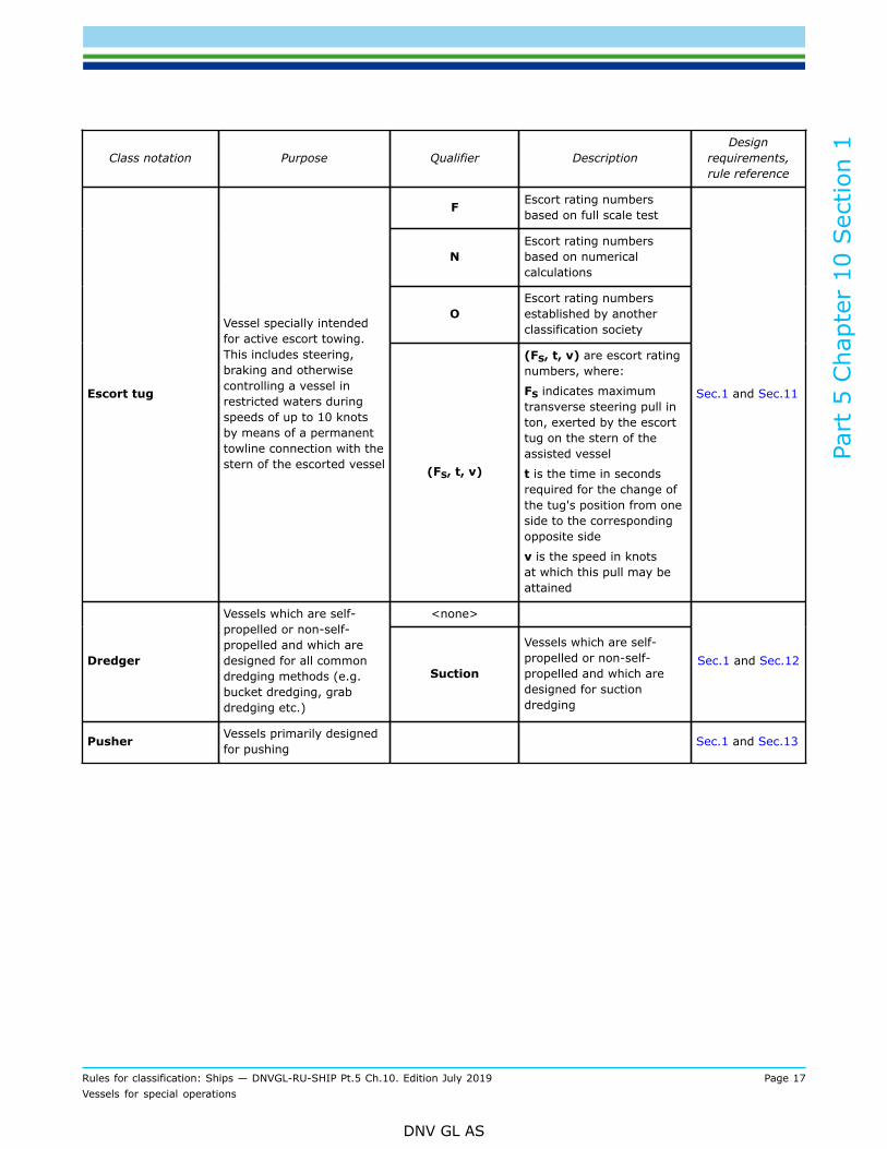
Escort tug
Vessel specially intendedfor active escort towing.This includes steering,braking and otherwisecontrolling a vessel inrestricted waters duringspeeds of up to 10 knotsby means of a permanenttowline connection with thestern of the escorted vessel (FS, t, v)
(FS, t, v) are escort ratingnumbers, where:
FS indicates maximumtransverse steering pull inton, exerted by the escorttug on the stern of theassisted vessel
t is the time in secondsrequired for the change ofthe tug's position from oneside to the correspondingopposite side
v is the speed in knotsat which this pull may beattained
Sec.1 and Sec.11
<none>
Dredger
Vessels which are self-propelled or non-self-propelled and which aredesigned for all commondredging methods (e.g.bucket dredging, grabdredging etc.)
Suction
Vessels which are self-propelled or non-self-propelled and which aredesigned for suctiondredging
Sec.1 and Sec.12
Pusher Vessels primarily designedfor pushing Sec.1 and Sec.13

Part
5 C
hapt
er 1
0 Sec
tion
1
Rules for classification: Ships — DNVGL-RU-SHIP Pt.5 Ch.10. Edition July 2019 Page 18Vessels for special operations
DNV GL AS
2.2 Additional notations
2.2.1 The following additional notations, as specified in Table 2, are typically applied to vessels performingspecial operations:
Table 2 Additional notations
Class notation Description Application Rule reference
NAUT
Requirements for bridge design,instrumentation, location of equipment andbridge procedures for enhanced safety formanoeuvring of the ship
All ships Pt.6 Ch.3
SPS Ships carrying special personnel who areneither crew members nor passengers Case by case Pt.6 Ch.5 Sec.7
Clean Vessel designed for controlling and limitingoperational emissions and discharges All ships Pt.6 Ch.7 Sec.2
DYNPOS Vessel equipped with dynamic positioningsystem All ships
Pt.6 Ch.3 Sec.2
Pt.6 Ch.3 Sec.3
COMF Comfort class covering requirements fornoise and vibration and indoor climate All ships Pt.6 Ch.8 Sec.1
HELDKRequirements to helicopter landing area orerected platform covering basic strengthrequirements and safety
All ships Pt.6 Ch.5 Sec.5
Crane Requirements to certification of crane All ships except for Cranevessel Pt.6 Ch.5 Sec.3
SF
Compliance with the damage stabilityrequirements of IMO Res.MSC.235(82)(Guidelines for the Design and Constructionof Offshore Supply Vessels, 2006),alternatively as amended by IMO Res.MSC.335(90) (Amendments to the Guidelinesfor the Design and Construction of OffshoreSupply Vessels, 2006)
Offshore service vessel Pt.6 Ch.5 Sec.6
Strengthened(DK) Decks strengthened for heavy cargo All ships Pt.6 Ch.1 Sec.2

Part
5 C
hapt
er 1
0 Sec
tion
1
Rules for classification: Ships — DNVGL-RU-SHIP Pt.5 Ch.10. Edition July 2019 Page 19Vessels for special operations
DNV GL AS
3 Definitions
3.1 Terms3.1.1
Table 3 Definitions of terms
Terms Definition
cargo deck on semi-submersibleheavy transport vessel the deck being submerged for carrying the cargo, as well as its horizontal extension
exposed surfaces superstructures, casings and other buoyant volumes above the cargo deck, or itshorizontal extension, that may become damaged if coming in contact with the cargoat any stage during loading or unloading operationsThe cargo deck is also to be considered as an exposed surface.
maximum submerged draught the maximum draught to which the vessel is allowed to be submerged
semi-submersible heavy transportvessel
a vessel designed to load and unload deck cargo by temporarily submerging its cargodeck through ballast operations
temporarily submerged condition any ballasting or de-ballasting with the load line mark submerged
transit condition the condition from when the vessel has completed loading, with the cargo properlysecured, to when the vessel has reached its intended destination and preparation forunloading can commence
control stand is a station in which one or more of the following control or indicating functions arecentralized:
1) indication and operation of all vital life support conditions, including pressurecontrol
2) visual observation, communication systems including telephones, audio-recording and microphones to public address systems
3) disconnection of all electrical installations and Insulation monitoring4) provisions for calibration of and comparison between gas analysing5) indication of temperature and humidity in the inner area6) alarms for abnormal conditions of environmental control systems7) fixed fire detection and fire alarm systems8) ventilation fans9) automatic sprinkler, fire detection and fire alarm systems10) launch and recovery systems, including interlock safety functions11) operation and control of the hyperbaric evacuation system
fore ship substructure fore ship substructure includes bow area B and bow intermediate ice belt BIi asdefined in Pt.6 Ch.6 Sec.6 Figure 1
towline rope/wire used for towing
escort service the service includes steering, braking and otherwise controlling the assisted vessel.The steering force is provided by the hydrodynamic forces acting on the tug's hull.
escort test speed this is the speed at which the full scale measurements shall be carried out, normally8 knots and/or 10 knots
Part
5 C
hapt
er 1
0 Sec
tion
1
Rules for classification: Ships — DNVGL-RU-SHIP Pt.5 Ch.10. Edition July 2019 Page 20Vessels for special operations
DNV GL AS
Terms Definition
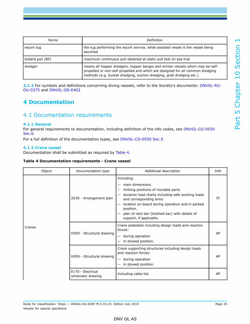
escort tug the tug performing the escort service, while assisted vessel is the vessel beingescorted
bollard pull (BP) maximum continuous pull obtained at static pull test on sea trial
dredger means all hopper dredgers, hopper barges and similar vessels which may be self-propelled or non-self-propelled and which are designed for all common dredgingmethods (e.g. bucket dredging, suction dredging, grab dredging etc.).
3.1.2 For symbols and definitions concerning diving vessels, refer to the Society's documents: DNVGL-RU-OU-0375 and DNVGL-OS-E402
4 Documentation
4.1 Documentation requirements4.1.1 GeneralFor general requirements to documentation, including definition of the info codes, see DNVGL-CG-0550Sec.6.For a full definition of the documentation types, see DNVGL-CG-0550 Sec.5.
4.1.2 Crane vesselDocumentation shall be submitted as required by Table 4.
Table 4 Documentation requirements - Crane vessel
Object Documentation type Additional description Info
Z030 - Arrangement plan
Including:
— main dimensions— limiting positions of movable parts— dynamic load charts including safe working loads
and corresponding arms— location on board during operation and in parked
position.— plan of rack bar (toothed bar) with details of
support, if applicable.
FI
H050 - Structural drawing
Crane pedestals including design loads and reactionforces:
— during operation— in stowed position.
AP
H050 - Structural drawing
Crane supporting structures including design loadsand reaction forces:
— during operation— in stowed position.
AP
Cranes
E170 - Electricalschematic drawing Including cable list. AP
Part
5 C
hapt
er 1
0 Sec
tion
1
Rules for classification: Ships — DNVGL-RU-SHIP Pt.5 Ch.10. Edition July 2019 Page 21Vessels for special operations
DNV GL AS
Object Documentation type Additional description Info
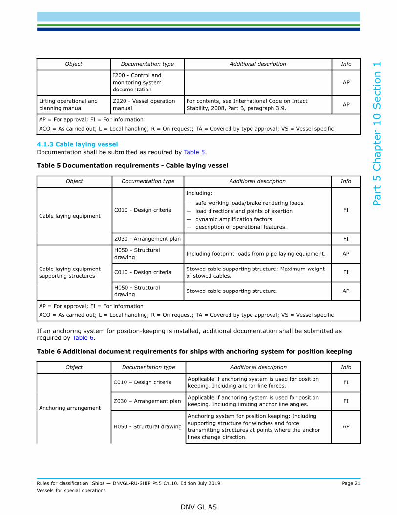
I200 - Control andmonitoring systemdocumentation
AP
Lifting operational andplanning manual
Z220 - Vessel operationmanual
For contents, see International Code on IntactStability, 2008, Part B, paragraph 3.9. AP
AP = For approval; FI = For information
ACO = As carried out; L = Local handling; R = On request; TA = Covered by type approval; VS = Vessel specific
4.1.3 Cable laying vesselDocumentation shall be submitted as required by Table 5.
Table 5 Documentation requirements - Cable laying vessel
Object Documentation type Additional description Info
C010 - Design criteria
Including:
— safe working loads/brake rendering loads— load directions and points of exertion— dynamic amplification factors— description of operational features.
FICable laying equipment
Z030 - Arrangement plan FI
H050 - Structuraldrawing Including footprint loads from pipe laying equipment. AP
C010 - Design criteria Stowed cable supporting structure: Maximum weightof stowed cables. FICable laying equipment
supporting structures
H050 - Structuraldrawing Stowed cable supporting structure. AP
AP = For approval; FI = For information
ACO = As carried out; L = Local handling; R = On request; TA = Covered by type approval; VS = Vessel specific
If an anchoring system for position-keeping is installed, additional documentation shall be submitted asrequired by Table 6.
Table 6 Additional document requirements for ships with anchoring system for position keeping
Object Documentation type Additional description Info
C010 – Design criteria Applicable if anchoring system is used for positionkeeping. Including anchor line forces. FI
Z030 – Arrangement plan Applicable if anchoring system is used for positionkeeping. Including limiting anchor line angles. FI
Anchoring arrangement
H050 - Structural drawing
Anchoring system for position keeping: Includingsupporting structure for winches and forcetransmitting structures at points where the anchorlines change direction.
AP

Part
5 C
hapt
er 1
0 Sec
tion
1
Rules for classification: Ships — DNVGL-RU-SHIP Pt.5 Ch.10. Edition July 2019 Page 22Vessels for special operations
DNV GL AS
Object Documentation type Additional description Info
Anchor racks for stowage for mooring anchor duringvoyage at sea. AP
AP = For approval; FI = For information
ACO = As carried out; L = Local handling; R = On request; TA = Covered by type approval; VS = Vessel specific
4.1.4 Pipe laying vesselDocumentation shall be submitted as required by Table 7.
Table 7 Documentation requirements - Pipe laying vessel
Object Documentation type Additional description Info
C010 – Design criteria
Including:
— safe working loads/brake rendering loads— load directions and points of exertion— dynamic amplification factors— description of operational features.
FIPipe laying arrangement
Z030 – Arrangement plan FI
Pipe laying equipmentsupporting structures H050 – Structural drawing Including footprint loads from pipe laying equipment. AP
C010 – Design criteriaIncluding maximum weight of reel with pipe, includingwater if the pipe shall be hydraulically tested onboard.
FIPipe reel
H050 – Structural drawing Pipe reel supporting structure. AP
C010 – Design criteria Including maximum weight of stowed pipes. FIPipe stowage equipment
H050 – Structural drawing Stowed pipe supporting structure. AP
AP = For approval; FI = For information
ACO = As carried out; L = Local handling; R = On request; TA = Covered by type approval; VS = Vessel specific
If an anchoring system for position-keeping is installed, additional documentation shall be submitted asrequired by Table 8.
Table 8 Additional document requirements for ships with anchoring system for position keeping
Object Documentation type Additional description Info
C010 – Design criteria Applicable if anchoring system is used for positionkeeping. Including anchor line forces. FI
Z030 – Arrangement plan Applicable if anchoring system is used for positionkeeping. Including limiting anchor line angles. FI
Anchoring arrangement
H050 – Structural drawing
Anchoring system for position keeping: Includingsupporting structure for winches and force-transmitting structures at points where the anchorlines change direction.
AP

Part
5 C
hapt
er 1
0 Sec
tion
1
Rules for classification: Ships — DNVGL-RU-SHIP Pt.5 Ch.10. Edition July 2019 Page 23Vessels for special operations
DNV GL AS
Object Documentation type Additional description Info
AP = For approval; FI = For information
ACO = As carried out; L = Local handling; R = On request; TA = Covered by type approval; VS = Vessel specific
4.1.5 Semi-submersible heavy transport vesselDocumentation shall be submitted as required by Table 9.
Table 9 Documentation requirements - Semi-submersible heavy transport vessel
Object Documentation type Additional description Info
Z100 – Specification Maximum submerged draught, maximum transitdraught and minimum transit draught with cargo. FI
Ship hull structure
H084 - Wave load analysis FI
B030 – Internal watertightintegrity plan FI
B070 – Preliminary damagestability calculation APStability
B130 – Final damage stabilitycalculation
Stability calculations in accordance with Sec.5 [4] fortransit and temporarily submerged conditions.
AP
Z265 – Calculation report Reserve buoyancy calculations. FIExternal watertight andweathertight integrity
Escape routes G120 – Escape route drawing AP
S010 – Piping diagram (PD) AP
S030 – Capacity analysis APFire water system
Z030 – Arrangement plan AP
Helicopter deck foamfire extinguishingsystem
G200 – Fixed fireextinguishing systemdocumentation
AP
Machinery spaces fixedwater spaying fireextinguishing system
G200 – Fixed fireextinguishing systemdocumentation
AP
Cargo holds waterspraying fireextinguishing system
G200 – Fixed fireextinguishing systemdocumentation
AP
Navigation systems Z090 - Equipment list AP
N010 – Bridge designdrawing AP
N020 – Vertical field of visiondrawing AP
N030 – Horizontal field ofvision drawing AP
Navigation bridge
Z090 – Equipment list AP

Part
5 C
hapt
er 1
0 Sec
tion
1
Rules for classification: Ships — DNVGL-RU-SHIP Pt.5 Ch.10. Edition July 2019 Page 24Vessels for special operations
DNV GL AS
Object Documentation type Additional description Info
Internal communicationsystems Z030 – Arrangement plan AP
Vessel operation Z250 – Procedure Submersion operation, including generic ballastingsequence during submersion and re-emersion. FI
AP = For approval; FI = For information
ACO = As carried out; L = Local handling; R = On request; TA = Covered by type approval; VS = Vessel specific
4.1.6 Diving support vesselDocumentation shall be submitted as required by Table 10.
Table 10 Documentation requirements - DSV
Object Documentation type Additional description Info
B030 – Internal watertightintegrity plan FI
B070 – Preliminarydamage stabilitycalculation
APDamage stability
B130 – Final damagestability calculation AP
B130 – Final damagestability calculation
Stability calculations showing recovery of bell afterdamage.
Cables and umbilicals E030 – Cable selectionphilosophy AP
E170 – Electricalschematic drawing
Single line diagrams for all intrinsically safe circuits,for each circuit including data for verification ofthe compatibility between the barrier and the fieldcomponents.
AP
Z030 – Arrangement plan
Electrical equipment in hazardous areas. Whererelevant, based on an approved hazardous areaclassification drawing where location of electricequipment in hazardous area is added (exceptbattery room, paint stores and gas bottle store).
APExplosion (Ex) protection
E250 – Explosionprotected equipmentmaintenance manual
AP
G060 – Structural fireprotection drawing AP
Structural fire protectionarrangements G061 – Penetration
drawing AP
I200 – Control andmonitoring system APFire detection and alarm
systemZ030 – Arrangement plan AP
Part
5 C
hapt
er 1
0 Sec
tion
1
Rules for classification: Ships — DNVGL-RU-SHIP Pt.5 Ch.10. Edition July 2019 Page 25Vessels for special operations
DNV GL AS
Object Documentation type Additional description Info
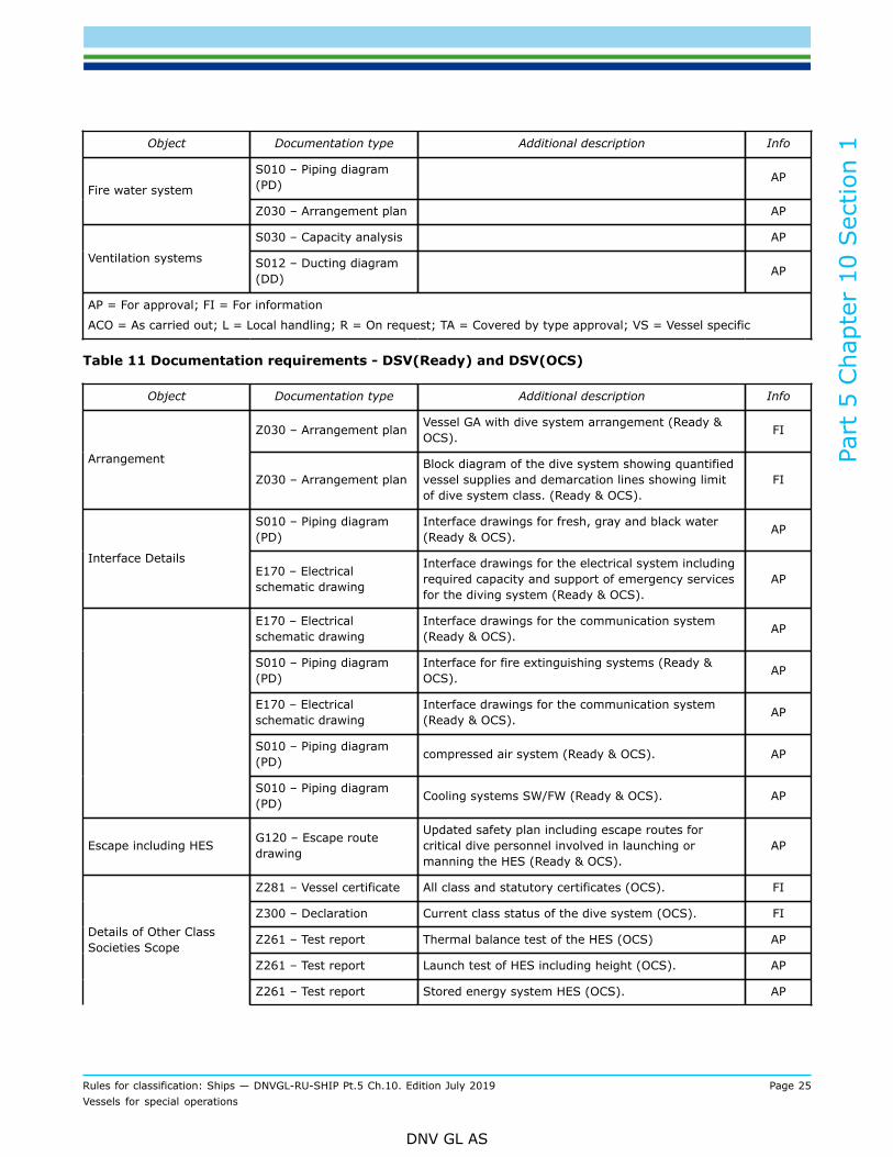
S010 – Piping diagram(PD) AP
Fire water system
Z030 – Arrangement plan AP
S030 – Capacity analysis AP
Ventilation systems S012 – Ducting diagram(DD) AP
AP = For approval; FI = For information
ACO = As carried out; L = Local handling; R = On request; TA = Covered by type approval; VS = Vessel specific
Table 11 Documentation requirements - DSV(Ready) and DSV(OCS)
Object Documentation type Additional description Info
Z030 – Arrangement plan Vessel GA with dive system arrangement (Ready &OCS). FI
Arrangement
Z030 – Arrangement planBlock diagram of the dive system showing quantifiedvessel supplies and demarcation lines showing limitof dive system class. (Ready & OCS).
FI
S010 – Piping diagram(PD)
Interface drawings for fresh, gray and black water(Ready & OCS). AP
Interface DetailsE170 – Electricalschematic drawing
Interface drawings for the electrical system includingrequired capacity and support of emergency servicesfor the diving system (Ready & OCS).
AP
E170 – Electricalschematic drawing
Interface drawings for the communication system(Ready & OCS). AP
S010 – Piping diagram(PD)
Interface for fire extinguishing systems (Ready &OCS). AP
E170 – Electricalschematic drawing
Interface drawings for the communication system(Ready & OCS). AP
S010 – Piping diagram(PD) compressed air system (Ready & OCS). AP
S010 – Piping diagram(PD) Cooling systems SW/FW (Ready & OCS). AP
Escape including HES G120 – Escape routedrawing
Updated safety plan including escape routes forcritical dive personnel involved in launching ormanning the HES (Ready & OCS).
AP
Z281 – Vessel certificate All class and statutory certificates (OCS). FI
Z300 – Declaration Current class status of the dive system (OCS). FI
Z261 – Test report Thermal balance test of the HES (OCS) AP
Z261 – Test report Launch test of HES including height (OCS). AP
Details of Other ClassSocieties Scope
Z261 – Test report Stored energy system HES (OCS). AP

Part
5 C
hapt
er 1
0 Sec
tion
1
Rules for classification: Ships — DNVGL-RU-SHIP Pt.5 Ch.10. Edition July 2019 Page 26Vessels for special operations
DNV GL AS
Object Documentation type Additional description Info
Z300 – DeclarationEvidence of a review by the diving systems classsociety for installation on the vessel. Normally thisshould include stamped drawings (OCS).
AP
Installation Z162 – Installationmanual Mobilisation plan (Ready). AP
AP = For approval; FI = For information
ACO = As carried out; L = Local handling; R = On request; TA = Covered by type approval; VS = Vessel specific
4.1.7 Seismic vesselDocumentation shall be submitted as required by Table 12.
Table 12 Documentation requirements - Seismic vessel
Object Documentation type Additional description Info
C010 – Design criteria
Design loads (safe working load, fleet angles, brakerendering load and wire breaking load as relevant).Self weights of equipment in operational and intransit modes.
FI
Z030 – Arrangement planHeavy machinery in hangar and on deck andequipment for handling and storage and mooring atsea.
FI
Seismic handlingequipment
Z265 – Calculation report Hangar: Design loads and racking calculationscovering operational and transit modes. FI
Seismic equipmentsupporting structures H050 – Structural drawing Including foundations. Design loads, footprint loads
and fastening details. AP
C060 – Mechanicalcomponent documentation
Including: Safe working load, heel/trim if applicableand dynamic factor if above 1.5. AP
Z161 – Operation manual FI
Z162 – Installationmanual FI
Work boat davits, Workboat winches
Z163 – Maintenancemanual FI
Work boat davits andwinches supportingstructures
H050 – Structural drawing Including foundations. Design loads, footprint loadsand fastening details. AP
AP = For approval; FI = For information
ACO = As carried out; L = Local handling; R = On request; TA = Covered by type approval; VS = Vessel specific
4.1.8 Well stimulation vesselDocumentation shall be submitted as required by Table 13.

Part
5 C
hapt
er 1
0 Sec
tion
1
Rules for classification: Ships — DNVGL-RU-SHIP Pt.5 Ch.10. Edition July 2019 Page 27Vessels for special operations
DNV GL AS
Table 13 Documentation requirements - Well stimulation vessel
Object Documentation type Additional description Info
Cargo compartments Z030 – Arrangement plan Tanks for well stimulation. FI
H050 – Structural drawing Acid tanks, including lining specification. AP
H050 – Structural drawing Support and staying. APCargo tank arrangements,independent
C050 – Non-destructive testing(NDT) plan Acid tanks. FI
Cargo independent tankarrangements type C H050 – Structural drawing Including supports and anti-flotation
arrangement. AP
B030 – Internal watertightintegrity plan FI
B070 – Preliminary damagestability calculation APDamage stability
B130 – Final damage stabilitycalculation AP
Ventilation systems forhazardous cargo areas S012 – Ducting diagram (DD) Closed and semi-enclosed spaces containing
acid tanks, pipes, pumps and mixing units. AP
C030 – Detailed drawing Drawings and particulars including stressanalysis of nitrogen vaporiser. FI
Cargo piping system
S010 – Piping diagram (PD) Acid, nitrogen and liquid additives. AP
Cargo piping S070 – Pipe stress analysis Piping for liquid nitrogen and other highpressure piping. FI
Cargo hoses Z100 – Specification High pressure flexible hoses with endconnections. FI
Cargo main pumpingarrangement C030 – Detailed drawing Including mixers. FI
Cargo handling arrangement Z161 – Operation manual Well stimulation procedures. AP
Cargo compartmentsover- and under pressureprevention arrangements
S010 – Piping diagram (PD) AP
Emergency shut down (ESD)system
I200 – Control and monitoringsystem documentation AP
Hydrogen gas detection andalarm system, fixed
I200 – Control and monitoringsystem documentation AP
Oxygen indication system,fixed sample extraction
I200 – Control and monitoringsystem documentation AP
Toxic gases detection andalarm system
I200 – Control and monitoringsystem documentation Hydrogen chloride. AP
Cargo tanks level monitoringsystem
I200 – Control and monitoringsystem documentation AP

Part
5 C
hapt
er 1
0 Sec
tion
1
Rules for classification: Ships — DNVGL-RU-SHIP Pt.5 Ch.10. Edition July 2019 Page 28Vessels for special operations
DNV GL AS
Object Documentation type Additional description Info
Cargo tanks overflowprotection system
I200 – Control and monitoringsystem documentation AP
Hazardous area classification G080 – Hazardous areaclassification drawing AP
E250 – Explosion protectedequipment maintenance manual AP
E170 – Electrical schematicdrawing
Single line diagrams for all intrinsically safecircuits, for each circuit including data forverification of the compatibility between thebarrier and the field components.
AP
Explosion (EX) protection
Z030 – Arrangement plan
Electrical equipment in hazardous areas.Where relevant, based on an approvedhazardous area classification drawing wherelocation of electric equipment in hazardousarea is added (except battery room, paintstores and gas bottle store).
AP
AP = For approval; FI = For information
ACO = As carried out; L = Local handling; R = On request; TA = Covered by type approval; VS = Vessel specific
4.1.9 Fire fighterDocumentation shall be submitted as required by Table 14.
Table 14 Documentation requirements - Fire fighter
Object Documentation type Additional description Relevancefor qualifier Info
Sea chest Z030 – Arrangement plan Fire fighting pumps. All AP
Structural fireprotectionarrangements
G060 – Structural fire protectiondrawing
Outer boundaries, includingexternal doors and windows. I+ AP
Fire fighting systemsZ161 – Operation manualZ163 – Maintenance manual
FIFI operation. All AP
Fire water supplyand distributionarrangement
S010 – Piping diagramS030 – Capacity analysis
Z030 – Arrangement planAll AP
External surfaceprotection waterspraying fireextinguishing system
G200 – Fixed fire extinguishingsystem documentation I, I+ AP
Fire fighting vesselfire extinguishingsystem
H050 – Structural drawingSupporting structure forpumps, pump drivers andmonitors.
All AP
Part
5 C
hapt
er 1
0 Sec
tion
1
Rules for classification: Ships — DNVGL-RU-SHIP Pt.5 Ch.10. Edition July 2019 Page 29Vessels for special operations
DNV GL AS
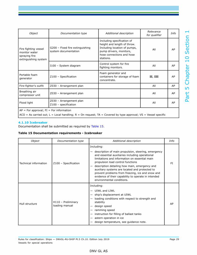
Object Documentation type Additional description Relevancefor qualifier Info
G200 – Fixed fire extinguishingsystem documentation
Including specification ofheight and length of throw.Including location of pumps,pump drivers, monitors,hose connections and hosestations.
All APFire fighting vesselmonitor waterspraying fireextinguishing system
I100 – System diagram Control system for firefighting monitors. All AP
Portable foamgenerator Z100 – Specification
Foam generator andcontainers for storage of foamconcentrate.
II, III AP
Fire-fighter's outfit Z030 – Arrangement plan All AP
Breathing aircompressor unit Z030 – Arrangement plan All AP
Flood lightZ030 – Arrangement planZ100 – specification
All AP
AP = For approval; FI = For information
ACO = As carried out; L = Local handling; R = On request; TA = Covered by type approval; VS = Vessel specific
4.1.10 IcebreakerDocumentation shall be submitted as required by Table 15.
Table 15 Documentation requirements - Icebreaker
Object Documentation type Additional description Info
Technical information Z100 – Specification
Including:
— description of main propulsion, steering, emergencyand essential auxiliaries including operationallimitations and information on essential mainpropulsion load control functions
— description detailing how main, emergency andauxiliary systems are located and protected toprevent problems from freezing, ice and snow andevidence of their capability to operate in intendedenvironmental conditions.
FI
Hull structure H110 – Preliminaryloading manual
Including:
— UIWL and LIWL— ship’s displacement at UIWL— loading conditions with respect to strength and
stability— design speed— ramming speed— instruction for filling of ballast tanks— astern operation in ice— design temperature, see guidance note.
AP

Part
5 C
hapt
er 1
0 Sec
tion
1
Rules for classification: Ships — DNVGL-RU-SHIP Pt.5 Ch.10. Edition July 2019 Page 30Vessels for special operations
DNV GL AS
Object Documentation type Additional description Info
Propulsion torque andthrust transmissionarrangement
C040 – Design analysis Ice load response simulation. AP
Propeller arrangements C040 – Design analysis Finite element analysis of blade stresses introduced byice loads. AP
AP = For approval; FI = For information
ACO = As carried out; L = Local handling; R = On request; TA = Covered by type approval; VS = Vessel specific
Guidance note:The design temperature reflects the lowest mean daily average air temperature in the intended area of operation. An extremeair temperature about 20°C below this may be tolerable to the structures and equipment from a material point of view. Forcalculations where the most extreme temperature over the day is relevant, the air temperature may be set 20°C lower than thedesign temperature in the notation.
---e-n-d---o-f---g-u-i-d-a-n-c-e---n-o-t-e---
4.1.11 TugDocumentation shall be submitted as required by Table 16.
Table 16 Documentation requirements - Tug
Object Document type Additional description Info
Z030 – Arrangement plan
Including:
— towline paths showing extreme sectors and wrap ontowing equipment towline points of attack
— maximum expected BP— maximum design load for each component— emergency release capabilities.
FI
Z253 – Test procedure forquay and sea trial Bollard pull. AP, L
Towing arrangement
Z253 – Test procedure forquay and sea trial
Winch and other equipment required by the classnotation. AP, L
C010 – Design criteria
Including:
— design force T and the expected maximum BP— hoisting capacity, rendering and braking force of the
winch— release capabilities (response time and intended
remaining holding force after release).
FI
C020 – Assembly orarrangement drawing FI
C030 – Detailed drawing AP
C040 – Design analysis Strength calculation of the drum with flanges, shaftswith couplings, framework and brakes. FI
Towing winch
C050 – Non-destructivetesting (NDT) plan AP
Part
5 C
hapt
er 1
0 Sec
tion
1
Rules for classification: Ships — DNVGL-RU-SHIP Pt.5 Ch.10. Edition July 2019 Page 31Vessels for special operations
DNV GL AS
Object Document type Additional description Info
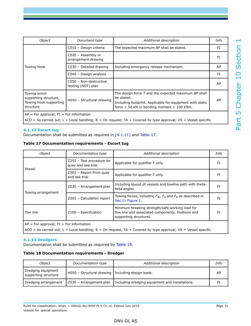
C010 – Design criteria The expected maximum BP shall be stated. FI
C020 – Assembly orarrangement drawing FI
C030 – Detailed drawing Including emergency release mechanism. AP
C040 – Design analysis FI
Towing hook
C050 – Non-destructivetesting (NDT) plan AP
Towing winchsupporting structure,Towing hook supportingstructure
H050 – Structural drawing
The design force T and the expected maximum BP shallbe stated.Including footprint. Applicable for equipment with staticforce > 50 kN or bending moment > 100 kNm.
AP
AP = For approval; FI = For information
ACO = As carried out; L = Local handling; R = On request; TA = Covered by type approval; VS = Vessel specific
4.1.12 Escort tugDocumentation shall be submitted as required in [4.1.11] and Table 17.
Table 17 Documentation requirements - Escort tug
Object Documentation type Additional description Info
Z253 – Test procedure forquay and sea trial Applicable for qualifier F only. FI
VesselZ263 – Report from quayand sea trial Applicable for qualifier F only. FI
Z030 – Arrangement plan Including layout of vessels and towline path with theta-beta angles. FI
Towing arrangement
Z265 – Calculation report Towing forces, including FW, FS and FB as described inSec.11 Figure 1. FI
Tow line Z100 – SpecificationMinimum breaking strength/safe working load fortow line and associated components, fixations andsupporting structures.
FI
AP = For approval; FI = For information
ACO = As carried out; L = Local handling; R = On request; TA = Covered by type approval; VS = Vessel specific
4.1.13 DredgersDocumentation shall be submitted as required by Table 18.
Table 18 Documentation requirements - Dredger
Object Documentation type Additional description Info
Dredging equipmentsupporting structure H050 – Structural drawing Including design loads. AP
Dredging arrangement Z030 – Arrangement plan Including dredging equipment and installations. FI

Part
5 C
hapt
er 1
0 Sec
tion
1
Rules for classification: Ships — DNVGL-RU-SHIP Pt.5 Ch.10. Edition July 2019 Page 32Vessels for special operations
DNV GL AS
Object Documentation type Additional description Info
AP = For approval; FI = For information
ACO = As carried out; L = Local handling; R = On request; TA = Covered by type approval; VS = Vessel specific
4.1.14 PusherDocumentation shall be submitted as required by Table 19.
Table 19 Documentation requirements - Pusher
Object Documentation type Additional description Info
Pushing arrangement Z030 – Arrangement plan Pusher/barge unit. FI
Pushing arrangement H080 – Strength analysis In connection equipment and on contact areas. FI
Pusher-bargeconnectionarrangement on pusher
Z030 – Arrangement plan FI
Pusher-bargeconnection on pusher H050 – Structural drawing AP
AP = For approval; FI = For information
ACO = As carried out; L = Local handling; R = On request; TA = Covered by type approval; VS = Vessel specific
5 Certification
5.1 Certification requirements5.1.1 GeneralFor a definition of the certificate types, see DNVGL-CG-0550 Sec.4 and DNVGL-CG-0550 Sec.3.
5.1.2 Crane vesselProducts shall be certified as required by Table 20
Table 20 Certification required for Crane vessel
Object Certificatetype Issued by Certification standard* Additional description
Crane PC Society DNVGL-ST-0378
In agreement with the Society thecrane may be certified based on otherinternationally recognised standards.Cranes certified by other Societiesmay be accepted based on specialconsideration.
* Unless otherwise specified the certification standard is the rules
5.1.3 Cable laying vesselEquipment subjected to cable loads when the vessel is in operation shall be certified as required by Table 21.Cable handling equipment which is not used while the vessel is in operation, e.g. spooling towers, need notbe certified.

Part
5 C
hapt
er 1
0 Sec
tion
1
Rules for classification: Ships — DNVGL-RU-SHIP Pt.5 Ch.10. Edition July 2019 Page 33Vessels for special operations
DNV GL AS
Table 21 Certification required for Cable laying vessel
Object Certificatetype Issued by Certification standard* Additional description
Cable laying equipment PC Society DNVGL-ST-0378
DNVGL-RP-0232 provides guidanceand clarifications with respect tocertification and verification of design,materials, fabrication, safety, testing ofcable laying equipment and systems.
Electrical equipment PC Society
Associated electrical equipment(motors, frequency converters,switchgear and control gear) servingan item that is required to be deliveredwith the Society's product certificate isalso required to have a DNV GL productcertificate. Such electrical equipment isregarded as important equipment, seePt.4 Ch.8 Sec.1 [2.3.2].
* Unless otherwise specified the certification standard is the rules
5.1.4 Pipe laying vesselEquipment subjected to pipe loads when the vessel is in operation shall be certified as required by Table 22.Pipe handling equipment which is not used while the vessel is in operation, e.g. spooling towers, need not becertified.
Table 22 Certification required for Pipe laying vessel
Object Certificatetype Issued by Certification standard* Additional description
Pipe laying equipment PC Society DNVGL-ST-0378
DNVGL-RP-0232 provides guidanceand clarifications with respect tocertification and verification of design,materials, fabrication, safety, testing ofpipe laying equipment and systems.
Electrical equipment PC Society
Associated electrical equipment(motors, frequency converters,switchgear and control gear) servingan item that is required to be deliveredwith a the Society's product certificateis also required to have a DNV GLproduct certificate. Such electricalequipment is regarded as importantequipment, see Pt.4 Ch.8 Sec.1[2.3.2].
* Unless otherwise specified the certification standard is the rules
5.1.5 Seismic vesselProducts shall be certified as required by Table 23.

Part
5 C
hapt
er 1
0 Sec
tion
1
Rules for classification: Ships — DNVGL-RU-SHIP Pt.5 Ch.10. Edition July 2019 Page 34Vessels for special operations
DNV GL AS
Table 23 Certification requirements for Seismic vessel
Object Certificatetype Issued by Certification standard* Additional description
Work boats PC Society DNVGL-ST-0342
Wide tow equipment PC Society DNVGL-ST-0378
Handling and towingbooms PC Society
PC Society DNVGL-ST-0498
Work boat davitsMC Society Or material certificate 3.1 according to
ISO 10474
PC Society
Work boat winchesMC Society Or material certificate 3.1 according to
ISO 10474
Electrical equipment PC Society
Associated electrical equipment(motors, frequency converters,switchgear and control gear) servingan item that is required to be deliveredwith the Society's product certificate isalso required to have a DNV GL productcertificate. Such electrical equipment isregarded as important equipment, seePt.4 Ch.8 Sec.1 [2.3.2].
* Unless otherwise specified the certification standard is the rules
5.1.6 Well stimulation vesselProducts shall be certified as required by Table 24.
Table 24 Certification requirements for Well stimulation vessel
Object Certificatetype Issued by Certification standard* Additional description
Cargo tank levelmeasurement system
Cargo tank overflowprotection system
Emergency shut-downsystem
PC Society
Electrical equipment PC Society
Associated electrical equipment(motors, frequency converters,switchgear and control gear) servingan item that is required to be deliveredwith the Society's product certificate isalso required to have a DNV GL productcertificate. Such electrical equipment isregarded as important equipment, seePt.4 Ch.8 Sec.1 [2.3.2].

Part
5 C
hapt
er 1
0 Sec
tion
1
Rules for classification: Ships — DNVGL-RU-SHIP Pt.5 Ch.10. Edition July 2019 Page 35Vessels for special operations
DNV GL AS
Object Certificatetype Issued by Certification standard* Additional description
* Unless otherwise specified the certification standard is the rules
5.1.7 Fire fighterProducts shall be certified as required by Table 25.
Table 25 Certification requirements for Fire fighter
Object Certificatetype Issued by Certification standard* Additional description
Fire fighting pumps andtheir prime movers PC Society
Compressor forrecharging the breathingair cylinders
PC Society
Pipes and valves MC Manufacturer
Foam concentrate suitablefor its intended use TR Recognized
test laboratory
MSC/Circ.670 orMSC.1/Circ.1312 asapplicable
* Unless otherwise specified the certification standard is the rules
5.1.8 Tug and Escort tugProducts shall be certified as required by Table 26.
Table 26 Certification requirements for Tug and Escort tug
Object Certificatetype Issued by Certification standard* Additional description
Towing winch
Towing hookPC Society
Towing hook For load transmitting elements,including slip device.
Winch Including drum and flanges.
Shafts for drum
Brake
Society
Material certificate type3.1 according to ISO10474 may be acceptedfor standard itemsif the manufactureris approved by theSociety
Couplings
Winch frame
Gear shaft and wheels
Tow ropes
MC
Manufacturer
Including breaking force.
* Unless otherwise specified the certification standard is the rules
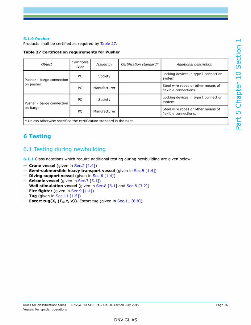
Part
5 C
hapt
er 1
0 Sec
tion
1
Rules for classification: Ships — DNVGL-RU-SHIP Pt.5 Ch.10. Edition July 2019 Page 36Vessels for special operations
DNV GL AS
5.1.9 PusherProducts shall be certified as required by Table 27.
Table 27 Certification requirements for Pusher
Object Certificatetype Issued by Certification standard* Additional description
PC Society Locking devices in type I connectionsystem.Pusher - barge connection
on pusherPC Manufacturer Steel wire ropes or other means of
flexible connections.
PC Society Locking devices in type I connectionsystem.Pusher - barge connection
on bargePC Manufacturer Steel wire ropes or other means of
flexible connections.
* Unless otherwise specified the certification standard is the rules
6 Testing
6.1 Testing during newbuilding
6.1.1 Class notations which require additional testing during newbuilding are given below:
— Crane vessel (given in Sec.2 [1.4])— Semi-submersible heavy transport vessel (given in Sec.5 [1.4])— Diving support vessel (given in Sec.6 [1.4])— Seismic vessel (given in Sec.7 [5.1])— Well stimulation vessel (given in Sec.8 [3.1] and Sec.8 [3.2])— Fire fighter (given in Sec.9 [1.4])— Tug (given in Sec.11 [1.5])— Escort tug(X, (Fs, t, v)). Escort tug (given in Sec.11 [6.8]).

Part
5 C
hapt
er 1
0 Sec
tion
2
Rules for classification: Ships — DNVGL-RU-SHIP Pt.5 Ch.10. Edition July 2019 Page 37Vessels for special operations
DNV GL AS
SECTION 2 CRANE VESSELSymbols
For symbols not defined in this section, see Sec.1 [3.1].
φ1 = heeling angle of equilibrium during crane operation, in deg
φ2 = allowable limit heeling angle, equal to lesser of φF or φR, or the second intercept of the rightinglever curve with the heeling lever curve, in deg
φ3 = maximum (dynamic) heeling angle, in deg
φC = static heeling angle of equilibrium after loss of load, in deg
φF = angle of down flooding,as defined in Pt.3 Ch.15, in deg
φR = angle of vanishing stability, in deg.
1 Introduction
1.1 Introduction
1.1.1 These rules provide requirements for vessels intended for lifting operations, and for that purpose areequipped with crane(s) or similar lifting appliance(s) and comprise heavy lift ships, crane ships, crane barges,floating cranes, or similar floating structures, with special attention on safety against capsizing.
1.2 Scope
1.2.1 These rules include requirements for hull strength, systems and equipment, stability and floatabilityapplicable to crane vessels, including the crane(s) itself with respect to structural strength, safety equipmentand functionality.
1.3 Application
1.3.1 Vessels built in compliance with the relevant requirements in this section may be given the classnotation Crane vessel.
1.4 Testing requirements1.4.1 CranesAfter completed installation on board, functional testing of the crane shall be carried out as specified inDNVGL-ST-0378 Offshore and platform lifting appliances.
2 Hull
2.1 General
2.1.1 The hull structural strength is in general to be as required for the main class taking into accountnecessary strengthening for supporting the crane during operation and in parked position at sea.
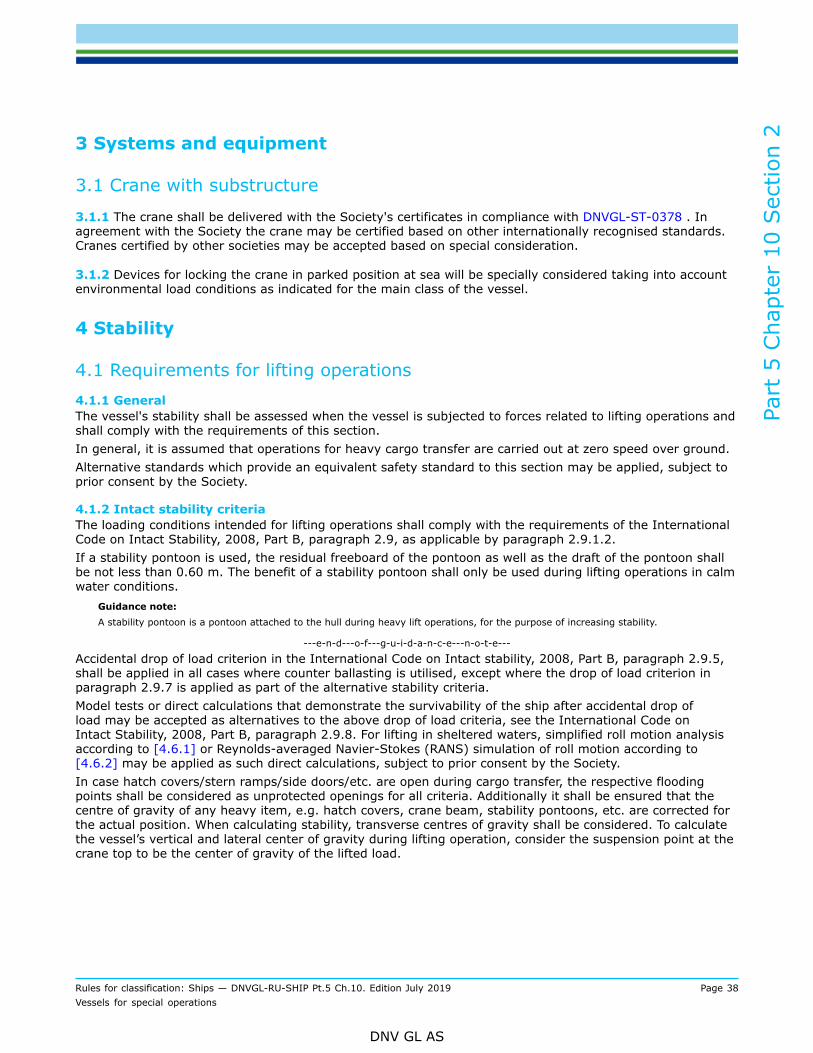
Part
5 C
hapt
er 1
0 Sec
tion
2
Rules for classification: Ships — DNVGL-RU-SHIP Pt.5 Ch.10. Edition July 2019 Page 38Vessels for special operations
DNV GL AS
3 Systems and equipment
3.1 Crane with substructure
3.1.1 The crane shall be delivered with the Society's certificates in compliance with DNVGL-ST-0378 . Inagreement with the Society the crane may be certified based on other internationally recognised standards.Cranes certified by other societies may be accepted based on special consideration.
3.1.2 Devices for locking the crane in parked position at sea will be specially considered taking into accountenvironmental load conditions as indicated for the main class of the vessel.
4 Stability
4.1 Requirements for lifting operations4.1.1 GeneralThe vessel's stability shall be assessed when the vessel is subjected to forces related to lifting operations andshall comply with the requirements of this section.In general, it is assumed that operations for heavy cargo transfer are carried out at zero speed over ground.Alternative standards which provide an equivalent safety standard to this section may be applied, subject toprior consent by the Society.
4.1.2 Intact stability criteriaThe loading conditions intended for lifting operations shall comply with the requirements of the InternationalCode on Intact Stability, 2008, Part B, paragraph 2.9, as applicable by paragraph 2.9.1.2.If a stability pontoon is used, the residual freeboard of the pontoon as well as the draft of the pontoon shallbe not less than 0.60 m. The benefit of a stability pontoon shall only be used during lifting operations in calmwater conditions.
Guidance note:A stability pontoon is a pontoon attached to the hull during heavy lift operations, for the purpose of increasing stability.
---e-n-d---o-f---g-u-i-d-a-n-c-e---n-o-t-e---
Accidental drop of load criterion in the International Code on Intact stability, 2008, Part B, paragraph 2.9.5,shall be applied in all cases where counter ballasting is utilised, except where the drop of load criterion inparagraph 2.9.7 is applied as part of the alternative stability criteria.Model tests or direct calculations that demonstrate the survivability of the ship after accidental drop ofload may be accepted as alternatives to the above drop of load criteria, see the International Code onIntact Stability, 2008, Part B, paragraph 2.9.8. For lifting in sheltered waters, simplified roll motion analysisaccording to [4.6.1] or Reynolds-averaged Navier-Stokes (RANS) simulation of roll motion according to[4.6.2] may be applied as such direct calculations, subject to prior consent by the Society.In case hatch covers/stern ramps/side doors/etc. are open during cargo transfer, the respective floodingpoints shall be considered as unprotected openings for all criteria. Additionally it shall be ensured that thecentre of gravity of any heavy item, e.g. hatch covers, crane beam, stability pontoons, etc. are corrected forthe actual position. When calculating stability, transverse centres of gravity shall be considered. To calculatethe vessel’s vertical and lateral center of gravity during lifting operation, consider the suspension point at thecrane top to be the center of gravity of the lifted load.

Part
5 C
hapt
er 1
0 Sec
tion
2
Rules for classification: Ships — DNVGL-RU-SHIP Pt.5 Ch.10. Edition July 2019 Page 39Vessels for special operations
DNV GL AS
4.1.3 Damage stability criteriaThe damage stability criteria applicable to the ship shall be complied with at all times including when thecrane is in use. This includes the statutory damage stability requirements and damage stability requirementsof voluntary class notations when applicable.Alternatively, where lifting shall be carried out within clearly defined environmental and operationallimitations as set forth in the International Code on Intact Stability, 2008 ), Part B, paragraph 2.9.4 and theassociated intact stability criteria are applied, the alternative damage stability criteria as set forth in [4.5]may be applied, subject to prior consent by the Society and the Administration.
4.2 Loading conditions4.2.1 Standard loading conditionsIn addition to the standard loading conditions for cargo ships in Pt.3 Ch.15 Sec.1 [4.3.4], standard loadingconditions given in the International Code on Intact Stability, 2008, Part B, paragraph 3.4.1.9 and 3.4.10,shall apply, including the assumptions of paragraph 3.4.2.9.
4.3 Stability manual4.3.1 Additional information in stability manualThe vessel's stability manual shall additionally contain information as given in the International Code onIntact Stability, 2008, Part B, paragraph 3.6.5.
4.4 Operational and planning manual
4.4.1 To assist the master an operational and planning manual containing guidelines for planning andperforming specific operations shall be provided with contents according to the International Code on IntactStability, 2008 , Part B, paragraph 3.9.
4.5 Alternative damage stability criteria during heavy crane lift
4.5.1 The flooding scenario given in [4.5.2] and survival criteria given in [4.5.3] may be applied:
— in lieu of the damage stability criteria according to Pt.3 Ch.15 and additional class notations— for the crane loading conditions— when operational and environmental limitations are imposed as set forth in the International Code on
Intact Stability, 2008 Part B, paragraph 2.9.4.
4.5.2 Accidental flooding of any one compartment bounded by the shell or which contains pipe systemsleading to the sea shall be investigated for the relevant loading conditions. In addition, column-stabilisedcrane units shall be able to withstand the flooding of any watertight compartment fully or partially belowthe waterline in question, which is a pump room or a room containing machinery with a sea water coolingsystem.
4.5.3 In the flooded condition the following criteria shall be complied with:
— the maximum angle of heel shall be less than 15°, or 17° in case deck edge is not immersed— in sheltered waters an angle of heel of 20° is acceptable— no immersion of openings through which progressive flooding may occur— the area under the GZ-curve shall not be less than 0.015 metre-radians.
Other concepts may be applied if deemed appropriate for the vessel, subject to prior consent by the Society.

Part
5 C
hapt
er 1
0 Sec
tion
2
Rules for classification: Ships — DNVGL-RU-SHIP Pt.5 Ch.10. Edition July 2019 Page 40Vessels for special operations
DNV GL AS
4.6 Alternative methods for analysing stability after accidental drop of load4.6.1 Simplified roll motion analysisThe dynamic heel angle after a sudden loss of hook load may be estimated by performing a simplified time-domain numerical simulation of the ship’s roll motion. With the ship at equilibrium, start the analysis byreleasing the hook load, simulating a sudden failure of the lifting gear. To represent the roll motion as a one-degree-of-freedom system, numerically solve its motion equation:
where:
Iroll = mass roll moment of inertia of the ship in loading condition after loss of hook load, in kNm-s2
I’roll = added mass roll moment of inertia of the ship in loading condition after loss of hook load, inkNm-s2
φ'' = roll acceleration, in deg/s2
φ' = roll velocity, in deg/sφ = roll motion, in degΒ = linearised roll damping coefficientC(φ)φ = roll restoring moment, in kNm, as a function of roll angle
= GZ (φ) ∆LgGZ (φ) = righting arm as a function of roll angle after loss of hook load, in mΔL = ship displacement after loss of hook load, in t.
The linearised roll damping coefficient may be taken as two percent of critical damping. If a stability pontoonis situated on the side of the vessel opposite the hook load, a damping coefficient of five percent may beapplied.
Higher damping coefficients are acceptable if respective results of roll decay tests or validated numericalcalculations are provided.
The righting moment curve shall not be linearised; that is, the actual GZ curve after loss of hook load asa function of roll angle shall be used. The influence of the stability pontoon shall be considered. The initialworking list, φ1, shall be accounted for.
The maximum list, φ3, which occurs during the roll motion, shall not exceed the smaller of φF with a safetymargin of 3° or φR with a safety margin of 7°:
φ3 < min (φF- 3°, φR- 7°)
4.6.2 Reynolds-averaged Navier-Stokes (RANS) simulation of roll motionThe dynamic heel angle after sudden loss of hook load may also be assessed by carrying out non-linearnumerical simulations using a RANS equations solver. The RANS simulations shall account for not only theship’s hull and the stability pontoon, but also those parts of the superstructure that contribute to the rightingmoment. The predicted time-dependent dynamic behaviour of the floating ship after a sudden loss of hookload yields the maximum list, φ3, which shall not exceed the smaller of φF with a safety margin of 2° or φRwith a safety margin of 7°:
φ3 < min (φF- 2°, φR- 7°)An example of a RANS simulation is set out in DNVGL-CG-0157 Sec.2 Stability documentation for approval.

Part
5 C
hapt
er 1
0 Sec
tion
3
Rules for classification: Ships — DNVGL-RU-SHIP Pt.5 Ch.10. Edition July 2019 Page 41Vessels for special operations
DNV GL AS
SECTION 3 CABLE LAYING VESSEL
1 Introduction
1.1 Introduction
1.1.1 These rules provide requirements for vessels intended for laying cables on the sea bottom.
1.2 Scope
1.2.1 These rules include requirements for hull strength, systems and equipment applicable to cable layingvessels, including:
— hull structural details related to the cable laying operation— equipment and installations for cable laying— supporting structures for equipment applied in the cable laying operations— equipment for anchoring and mooring related to the cable laying operations— equipment for positioning during cable laying.
1.3 Application
1.3.1 Vessels built in compliance with the relevant requirements in this section may be given the classnotation Cable laying vessel.
2 Hull
2.1 Hull structural strengthThe hull structural strength shall in general be as required for the main class taking into account necessarystrengthening of supporting structures for equipment applied in the cable laying operations.
2.2 Special hull configurationFor catamarans, semi-submersibles and other special hull configurations, the hull structural strength will bespecially considered.
3 Equipment
3.1 Equipment for mooring and anchoring
3.1.1 The equipment for mooring and anchoring, i.e. anchors, chain cables windlass, mooring ropes, shall ingeneral be as required for the main class.
3.1.2 For catamarans, semi-submersibles and other special hull configurations, the equipment will bespecially considered.
3.1.3 Equipment for positioning during cable laying will be specially considered.
Part
5 C
hapt
er 1
0 Sec
tion
4
Rules for classification: Ships — DNVGL-RU-SHIP Pt.5 Ch.10. Edition July 2019 Page 42Vessels for special operations
DNV GL AS
SECTION 4 PIPE LAYING VESSEL
1 Introduction
1.1 Introduction
1.1.1 These rules provide requirements for vessels intended for laying pipelines on the sea bottom.
1.2 Scope
1.2.1 These rules include requirements for hull strength, systems and equipment applicable to pipe layingvessels, including:
— hull structural details related to the pipe laying operations— supporting structures for equipment applied in the pipe laying operations— equipment for anchoring and mooring— equipment and installations for pipe laying— equipment for positioning during pipe laying.
1.3 Application
1.3.1 Vessels built in compliance with the relevant requirements in this section may be given the classnotation Pipe laying vessel.
2 Hull
2.1 Hull structural strengthThe hull structural strength shall be as required for the main class taking into account necessarystrengthening of supporting structures for equipment applied in the pipe laying operations.
2.2 Special hull configurationFor catamarans, semi-submersibles and other special hull configurations, the hull structural strength will bespecially considered.
3 Equipment
3.1 Equipment for mooring and anchoring
3.1.1 The equipment for mooring and anchoring, i.e. anchors, chain cables, windlass, mooring ropes, shall ingeneral be as required for the main class.
3.1.2 For catamarans, semi-submersibles and other special hull configurations, the equipment will bespecially considered.
3.1.3 Equipment for positioning during pipe laying will be specially considered.
Part
5 C
hapt
er 1
0 Sec
tion
5
Rules for classification: Ships — DNVGL-RU-SHIP Pt.5 Ch.10. Edition July 2019 Page 43Vessels for special operations
DNV GL AS
SECTION 5 SEMI-SUBMERSIBLE HEAVY TRANSPORT VESSEL
1 Introduction
1.1 Introduction
1.1.1 These rules provide requirements for vessels intended for loading or unloading of deck cargo bysubmerging the cargo deck through ballast operations.
1.2 Scope
1.2.1 These rules include requirements for hull strength, systems and equipment, stability and load line, firesafety and lifesaving, navigation and communication applicable to semi-submersible heavy transport vessels.
1.3 Application
1.3.1 Vessels built in compliance with the relevant requirements in this section will be assigned themandatory ship type notation Semi-submersible heavy transport vessel.The additional notation Strengthened(DK) is mandatory for vessels assigned the notation Semi-submersible heavy transport vessel.
1.4 Testing requirements1.4.1 Sea trialA sea trial including submersion to maximum submerged draft and function testing of all equipment relatedto submersion shall be performed before final certificates are issued.
2 Hull
2.1 Hull girder strength
2.1.1 A direct wave load analysis shall be carried out to establish the vertical wave bending moments Mwvand vertical wave shear forces Qwv.
Guidance note:DNVGL-CG-0130 provides method to carry out direct wave load analysis.
---e-n-d---o-f---g-u-i-d-a-n-c-e---n-o-t-e---
2.1.2 Temporarily submerged conditions (float-on/ float-off) are special operations taking place at limitedsea states. The global wave loads shall be taken as 50% of the values given in [2.1.1] unless otherwisespecified.The temporarily submerged conditions shall be reviewed for both static (S) and static + dynamic (S + D) perdesign load scenario 6 and 7, see Pt.3 Ch.4 Sec.7 Table 1. Relevant acceptance criteria are given in Pt.3 Ch.1Sec.2 Table 1 and Pt.3 Ch.6 Sec.2 [2].
2.1.3 Non-submerged loading and unloading with the vessel moored at quay (skid-on/ skid-off) are specialoperations taking place at very limited sea states. This will be evaluated per design load scenario 6 providedthe operation is carried out in conditions with a significant wave height not exceeding 0.5 m. This conditionwill be stated in the appendix to the class certificate.

Part
5 C
hapt
er 1
0 Sec
tion
5
Rules for classification: Ships — DNVGL-RU-SHIP Pt.5 Ch.10. Edition July 2019 Page 44Vessels for special operations
DNV GL AS
2.1.4 Due to the low depth of the hull girder, special attention should be paid to the requirement to momentof inertia given in Pt.3 Ch.5 Sec.2 [1.5]. This requirement shall be satisfied over a minimum of 0.25 L in themidship area.
2.2 Local strength
2.2.1 External hull boundaries shall be able to withstand the sea pressure at maximum submergeddraught. In temporarily submerged conditions, the dynamic part of the sea pressure shall be taken as50% of the values according to Pt.3 Ch.4 Sec.5 [1.3], unless otherwise documented.(applicable values foraccelerations and motions in temporarily submerged condition will be considered in a similar manner or maybe disregarded based on a case-by-case evaluation).
2.2.2 The design pressure for internal watertight bulkheads, including doors, hatches, pipe penetrationsand other piercings, shall be based on the deepest equilibrium waterline in damaged transit or damagedsubmerged condition, as applicable, depending on relevant damage scenario. Damage stability requirementsin transit and submerged conditions are given in [4.1] and [4.3], respectively. Flooding scenarios related toaccess openings in submerged conditions, see [5.4.5], shall also be taken into account.
2.2.3 Bolted connections between buoyancy towers and hull are subject to special consideration.
2.2.4 The boundaries of the ballast tanks shall be designed according to the pressures given in Pt.3 Ch.4Sec.6 [1] and where the height of the air pipes exceed the deepest waterline in damaged submergedcondition and maximum submerged draught.
Guidance note:Other levels may be accepted case-by-case as basis for the evaluation provided automatic stop of ballast pumps or automaticclosing of valve in the ballast filling line is arranged for prevention of over-pumping of tanks. Such means should be activated by aremote level gauging system or equivalent. In addition, an independent visual and audible high level or high-pressure alarm shouldbe arranged. The alarm should be activated prior to stop of pumps or closing of valve. Arrangements for functional testing of theautomatic stop or closing and alarm systems should be provided.
---e-n-d---o-f---g-u-i-d-a-n-c-e---n-o-t-e---
2.3 Integrated high-pressure tanks
2.3.1 Ballast tanks emptied by means of air overpressure are subject to special consideration. The strengthof such tanks shall minimum satisfy the static acceptance criteria AC-I according to the design load setsgiven in Pt.3 Ch.6 Sec.2 Table 1 with corresponding permissible stresses as given in Pt.3 Ch.6 Sec.4 and Pt.3Ch.6 Sec.5, with full tank and maximum overpressure, e.g. de-ballasting condition. The air overpressure shallnormally not be taken greater than 70 kN/m2.For primary supporting members net loading, internal minus external pressure, shall be applied, see Pt.3Ch.6 Sec.2 [2].
Guidance note:In designs where air overpressure is applied for emptying integrated ballast tanks, exemptions from the rules for pressurevessels in Pt.4 Ch.7 may be granted on a case-by-case basis when the air overpressure is greater than 70 kN/m2, provided thatsatisfactory alternative safety measures are presented. Examples of such safety measures are increased safety margin by loweringthe allowable stress levels, installation of cofferdams, reduced size of ballast tanks, pressure monitoring systems, increased NDTduring construction, and more thorough inspections in the operation phase.
---e-n-d---o-f---g-u-i-d-a-n-c-e---n-o-t-e---

Part
5 C
hapt
er 1
0 Sec
tion
5
Rules for classification: Ships — DNVGL-RU-SHIP Pt.5 Ch.10. Edition July 2019 Page 45Vessels for special operations
DNV GL AS
2.4 Primary supporting members2.4.1 Direct strength analysisA partial ship structural analysis, seePt.3 Ch.7 Sec.3, shall be performed for strength assessment of thecargo area. The extent of the analysis shall be agreed with the Society case by case.
2.4.2 Loading conditionsThe loading conditions need to be determined case by case to cover the most demanding of static, static +dynamic and accidental flooding conditions including:
— permissible local and distributed loads as specified in the loading manual— transit condition considering extreme combination of deck loads and tank loads for AC-II— operational including submerged conditions for AC-II with reduced dynamic loads— de-ballasting condition, e.g. full tank with maximum overpressure, for AC-I.
2.4.3 Buckling check of plate panelsThe normal stresses and shear stress taken from strength assessment to be applied for buckling capacitycalculation of deck plate panels shall be corrected as given in Pt.3 Ch.8 and DNVGL-CG-0128 Buckling.
2.5 Fatigue strength
2.5.1 For vessels with L ≥ 150 m, the fatigue strength requirements in Pt.3 Ch.9 are applicable. Due concernshall be taken to use loading conditions describing the intended operational pattern of the actual vessel.
2.5.2 Additional fatigue analysis may be required for details considered prone to failure or consideredparticular critical for watertight integrity.
3 Systems and equipment
3.1 Additional anchors
3.1.1 Anchors and associated equipment in excess of that required in Pt.3 Ch.11 Sec.1 Table 1 need not becertified.
3.2 Watertight seals for propeller axle and rudder stock
3.2.1 Watertight seal on propeller axle and rudder stock shall be approved for the maximum submergeddraught.
3.3 Sounding systems for ballast tanksIf a remote sounding system is installed, this shall be type approved.For tanks not always accessible for checking of level, two independent remote sounding systems arerequired.
Part
5 C
hapt
er 1
0 Sec
tion
5
Rules for classification: Ships — DNVGL-RU-SHIP Pt.5 Ch.10. Edition July 2019 Page 46Vessels for special operations
DNV GL AS
4 Stability
4.1 Stability requirements in transit condition
4.1.1 The intact stability requirements of The International Code on Intact Stability (2008 IS Code) Part A,Ch. 2.2 and 2.3 apply. The windage area in loading conditions shall include deck cargo.
4.1.2 If the vessel's characteristics render compliance with The International Code on Intact Stability (2008IS Code) Part A, Ch. 2.2 impracticable, then the alternative criteria for maximum righting lever in theexplanatory notes to IMO 2008 IS Code may be used.
4.1.3 For intact stability the buoyancy provided by a part of large deck cargo such as semi-submersibleunits, jack-up units, barges or ships may be taken into account, provided that the securing arrangementis separately approved. The watertight integrity of the cargo shall be defined and taken into account in thecalculations.
4.1.4 The damage stability standard shall be in accordance with SOLAS Ch.II-1 or ICLL 1966 Reg.27,including IACS UI LL65, as applicable.
4.1.5 Ships with B-60 or B-100 freeboardB-60 freeboard requires one-compartment damage, while B-100 requires two-compartment damage inaccordance with Reg.27 of the ICLL 1966. The calculations shall be carried out assuming the damaged tanksempty and for representative loads, such as a semi-submersible unit and a jack-up unit, as far as applicable.Damage extent shall be taken according to ICLL Reg. 27. The buoyancy of watertight volumes of the deckcargo not located within the damage extent for each damage case may be taken into account. In all cases,transverse penetration shall be taken from the ship’s side.
4.1.6 Ships with ordinary B freeboardIf, in addition to the SOLAS limit curves, it is desired to take the buoyancy of the deck cargo into account,calculations as for ICLL Reg. 27 corresponding to B-60 damage may be considered equivalent, i.e. sameapproach as the case of ships with reduced freeboard.
Guidance note:As there are no international rules or interpretations regarding whether the buoyancy of deck cargo may be taken into account inorder to make these operations feasible, the flag state shall be approached for acceptance of the application of the requirementsgiven in [4.1.3] and [4.1.5] for statutory purposes.
---e-n-d---o-f---g-u-i-d-a-n-c-e---n-o-t-e---
4.2 Intact stability criteria in temporarily submerged conditions
4.2.1 All loading and unloading sequences shall have acceptable stability. The buoyancy provided by a part oflarge deck cargo such as semi-submersible units, jack-up units, barges or ships may be taken into account,provided that proper environmental limitations have been defined.
4.2.2 The GM at equilibrium shall not be less than 0.3 m. The positive range of the GZ curve shall beminimum 15° in conjunction with a height of not less than 0.1 m within this range. The maximum rightingarm shall occur at an angle of heel not less than 7°. Unprotected openings shall not be immersed withinthis range. It may be required to calculate the stability about additional axis to determine the most onerousresult.
4.2.3 Whenever free liquid surface exists in a tank, the effect shall be considered. The calculations shallaccount for the real filling of the tanks, i.e. in particular the location of air pipes needs to be taken into
Part
5 C
hapt
er 1
0 Sec
tion
5
Rules for classification: Ships — DNVGL-RU-SHIP Pt.5 Ch.10. Edition July 2019 Page 47Vessels for special operations
DNV GL AS
account. If the complete filling of the tanks is dependent on certain trim or heel during the submergingsequence this shall be clearly stated in the stability manual.
4.3 Damage stability in temporarily submerged conditions
4.3.1 The risks of accidental flooding of any one compartment on the ship shall be considered. Damage to beconsidered is that which might occur following an uncontrolled movement of the deck cargo during loading oroff-loading leading to puncture of exposed surfaces. This study shall cover all relevant phases of the loading/off-loading sequence as required by [4.2.1].
4.3.2 Accidental flooding of watertight compartment described in [5.4.4] shall be considered in addition ifthis would result in a more severe condition.
4.3.3 The permeability μ of a damaged compartment shall be assumed to be 0.95 except for full ballasttanks, where μ = 0. For machinery spaces, μ = 0.85.
4.3.4 In the final stage of flooding after damage, the positive range of the GZ curve shall be minimum7° in conjunction with a height of not less than 0.05 m within this range. Unprotected openings shall notbe immersed within this range unless the space concerned is assumed to be flooded. The angle of heelafter flooding shall not exceed 15°. The final waterline after flooding shall be below the lower edge of anyweathertight opening through which progressive flooding may take place unless the space concerned isassumed to be flooded. It may be required to calculate the stability about additional axis to determine themost onerous result.
4.3.5 The stability at intermediate stages of flooding after damage shall not be significantly less than in thefinal stage.
4.3.6 The flooding of any damaged compartment shall not render vital safety functions inoperative.
4.3.7 For the purpose of damage stability calculations, a damage extent of 5 m horizontally along the surfaceshall be assumed for all exposed surfaces except the cargo deck. Watertight bulkheads may be considered toremain intact provided that the distance between adjacent bulkheads exceeds 5 m. The damage penetrationinto the structure shall be assumed to be equal to 0.76 m and the vertical extent of damage is assumed tobe from the cargo deck or its horizontal extension upwards without limit. For the cargo deck a damage extentof 5 × 5 m shall be assumed. Watertight bulkheads may be considered to remain intact provided that thedistance between adjacent bulkheads exceeds 5 m. The damage penetration into the cargo deck shall beassumed to be equal to 0.76 m.
5 Openings and closing appliances
5.1 Freeboard assignment transit draught
5.1.1 Freeboard will be calculated and assigned according to ICLL 1966 and standard procedures.Compliance with requirements for weathertight and watertight closing appliances shall be documented with afreeboard plan.
5.2 Temporarily submerged conditions
5.2.1 Requirements for reserve buoyancy and water- and weathertight integrity given in [5.3] and [5.4] shallbe complied with in the maximum submerged draught condition.
Part
5 C
hapt
er 1
0 Sec
tion
5
Rules for classification: Ships — DNVGL-RU-SHIP Pt.5 Ch.10. Edition July 2019 Page 48Vessels for special operations
DNV GL AS
Guidance note:International load line exemption certificateIndependent of class approval, an exemption from ICLL 1966, Article 12 Submersion will have to be applied for as the load linemark will be submerged during cargo operations. This exemption may only be granted by the flag administration and should bebased on an application from the owner. The flag administration will normally require the Society to give their comments to theapplication. The Society will give recommendation/comments based on the compliance with the requirements in this section.
---e-n-d---o-f---g-u-i-d-a-n-c-e---n-o-t-e---
5.3 Reserve buoyancy
5.3.1 The ratio of reserve buoyancy shall not be less than:
— 4.5% for the vessel— 1.5% for the forward and aft end buoyancy structures considered separately.
5.3.2 The reserve buoyancy requirements in [5.3.1] shall be documented by a calculation according to theprinciples given in a) to d).
a) Ratio of reserve buoyancy is the reserve buoyancy divided by the volume displacement of the vessel atmaximum submerged draught with no trim.
b) Reserve buoyancy is defined as the volume providing buoyancy, positioned above the waterline with notrim at maximum submerged draught. In the calculation of the total reserve buoyancy for the vessel, nobuoyancy shall be assumed above the lowest of the zero trim waterlines corresponding to:
— the position of the lowest opening which can not be closed and secured to prevent water fromentering the buoyant volume
— the uppermost point of the deck limiting the buoyancy structure forward— the uppermost point of the deck limiting the buoyancy structure aft.
c) Calculations for end structures considered separately need only take account of openings and decks inthe end under consideration. Trim shall be taken into account if it is consistent with practice to operatethe vessel with trim and the maximum draught at the perpendicular is larger than the mean maximumsubmerged draught. Reserve buoyancy is then defined as the volume providing buoyancy for the endunder consideration, above the waterline with no trim at maximum perpendicular draught.
d) Openings which can not be closed and secured to prevent water from entering the buoyant volumeshall be considered as down flooding points in the reserve buoyancy calculation. These openings shallinclude all air pipes, but need not include weathertight doors, hatches, ventilators, side scuttles andsmall windows with deadlights. This is provided that the relevant opening will be closed and securedduring submerged stages, and that the closing appliance has been found to be adequate and of at leastthe same strength as the bulkhead or deck where it is fitted.
The calculation shall be submitted as a separate document and not be part of the stability documentation.
5.3.3 As an alternative to the requirements in [5.3.1], the reserve buoyancy may be evaluated based onreal intact and flooded scenarios with the intact vessel at maximum submerged draught, including trimwhen relevant. In intact scenarios, ship movements shall be evaluated to determine the risk of submergenceof decks limiting buoyancy structures. In flooded scenarios, the freeboard to a deck limiting a buoyancystructure shall not be less than 1 m.
Guidance note:Intact scenarios should consider ship movements in defined worst operating sea condition(s) and as the result of forces transferredfrom cargo.Flooded scenarios should at least cover the effect of filling additional tank space by mistake and the effect of tanks and dry spacesbeing flooded due to valve failure. The possibility of spaces being flooded progressively should be taken into account wherenecessary. Partial flooding stages should be considered where this may give a more severe waterline.
---e-n-d---o-f---g-u-i-d-a-n-c-e---n-o-t-e---

Part
5 C
hapt
er 1
0 Sec
tion
5
Rules for classification: Ships — DNVGL-RU-SHIP Pt.5 Ch.10. Edition July 2019 Page 49Vessels for special operations
DNV GL AS
5.4 Requirements for water- and weathertight integrity
5.4.1 All openings below the first deck above the maximum submerged draught shall be arranged withwatertight closing appliances.
5.4.2 Access openings which are submerged at the maximum submerged draught shall be protected bytwo watertight doors or hatches in series. A leakage detection device shall be provided in the compartmentbetween the two doors or hatches. Drainage of this compartment to bilges controlled by a readily accessiblescrew-down valve shall be arranged.
5.4.3 A watertight closing appliance shall be provided for any internal opening leading to the compartmentrequired by [5.4.2].
5.4.4 The effect of flooding the watertight compartment required by [5.4.2] shall be investigated in thestability calculations for all stages where the outer door or hatch is submerged.
5.4.5 Bulkheads bounding the compartment required by [5.4.2] shall be of sufficient strength to withstandthe water pressure that could occur after flooding. Doors and hatches shall be approved and pressure tested.
5.4.6 All openings between the first and second deck above the maximum submerged draught shall complywith ICLL 1966 position 2 requirements for weathertight closing.
5.4.7 Scuppers shall be of substantial thickness below the first deck above the maximum submergeddraught.
5.5 Miscellaneous requirements
5.5.1 On-board instruction manuals and check lists containing operating procedures for submerging shalllist the closing appliances which shall be closed before operation commences. Examples are watertight doorsand hatches, closing appliances as given in [5.4.2] and [5.4.3], and closing valves in sanitary discharges.Signboards shall be fitted at the relevant closing appliance.
5.5.2 Guard rails shall be arranged so that they do not interfere with cargo operations. Removable guardrails with steel wire rope may be acceptable, provided that the arrangement is according to ICLL 1966 andscantlings are found sufficient. Wires should have steel cores of not less than 10 mm in diameter and beplastic coated.
5.5.3 In order to provide access to the ends of the vessel when deck cargo covers the whole breadth of thevessel, an under-deck passage way in compliance with Pt.3 Ch.11 Sec.3 [3.2.2] item a) shall be provided.
6 Fire safety and lifesaving appliances
6.1 Fire extinguishing equipment
6.1.1 The cargo deck shall be protected by fixed fire-fighting equipment consisting of water monitors or firehydrants with hoses, or a combination thereof.
6.1.2 If water monitors are selected in lieu of fire hydrants, then the monitors shall be capable of coveringthe cargo deck area and may be positioned fore and/or aft of the cargo area, as applicable. The fire monitorsshall also comply with [6.1.1] to [6.1.6].
Part
5 C
hapt
er 1
0 Sec
tion
5
Rules for classification: Ships — DNVGL-RU-SHIP Pt.5 Ch.10. Edition July 2019 Page 50Vessels for special operations
DNV GL AS
6.1.3 The main control station for the system shall be suitably located outside the cargo deck area, adjacentto the accommodation spaces and readily accessible and operable in the event of fire in the areas protected.For monitors arranged at the end of the cargo area opposite to the accommodation spaces, remote controlof the monitor(s) from the bridge will be required. Alternatively, these monitors shall be of oscillating typecapable of sweeping the protected area.
6.1.4 The protected area shall be within 75% of the water monitor throw in still air conditions taking intoaccount the distance from the monitor to the farthest extremity of the protected area forward of thatmonitor.
6.1.5 The capacity of each monitor shall not be less than 1250 litres/minute. The additional water supply tothe monitors shall be based on one monitor operated at a time, and shall be in addition to the requirementsgiven in SOLAS Reg. II-2/10.2.2.4.
6.1.6 Fixed arrangement for possible dispersion of the monitor water jet shall be delivered as part of eachmonitor.
6.1.7 Fire hydrants arranged with two hydrants at both port and starboard side just aft and forward of thecargo area, with sufficient number of hoses to reach the entire cargo area with two jets of water from thesehydrants, will be accepted as equivalent to the position of hydrants required by SOLAS Reg. II-2/10.2.1.5.For SOLAS convention ships, this equivalent arrangement is subject to acceptance by the flag administration.These will ensure flexibility during fire-fighting operations, and will cover areas screened from the monitors.
6.2 Escape ways
6.2.1 The under-deck passage way required by [5.5.3] shall not be used as an escape way in submergedconditions.
6.2.2 If buoyancy towers are manned during cargo handling operations, then these shall be providedwith escape ways to the life saving appliances. Such arrangement will be subject to special consideration,depending on the design.
6.3 Location of survival craft
6.3.1 If buoyancy towers are manned during cargo handling operations, then these shall be fitted with lifesaving appliances, such as life buoys or rafts. The type and arrangement of such appliances will be subject tospecial consideration, depending on the design.
Guidance note:Survival craft forward of wide deck cargo should be specially considered by the body approving the life saving arrangement, toensure that they are positioned in a way such as to avoid damage from the cargo.
---e-n-d---o-f---g-u-i-d-a-n-c-e---n-o-t-e---
7 Navigation and communication
7.1 Navigation
7.1.1 In cases where the cargo is partially blocking the view from the bridge, a secondary look-out point(crows nest) shall be arranged.
Part
5 C
hapt
er 1
0 Sec
tion
5
Rules for classification: Ships — DNVGL-RU-SHIP Pt.5 Ch.10. Edition July 2019 Page 51Vessels for special operations
DNV GL AS
Guidance note:Unless the secondary look-out point is fully duplicated, manning of both wheel house and look-out point will normally be requiredby the flag administration during transport.
---e-n-d---o-f---g-u-i-d-a-n-c-e---n-o-t-e---
Equipment in the secondary look-out point shall at least include:
— conning position with un-obscured view to the sea surface looking forward over an arc of 225° (seeSOLAS Reg. V/22)
— a gyro bearing repeater— rudder, propeller, thrust, pitch and operational mode indicators— external communication system, one VHF— internal communication system for communication with main bridge.
Guidance note:Acceptance of alternative solutions may be granted by the flag administration.
---e-n-d---o-f---g-u-i-d-a-n-c-e---n-o-t-e---

Part
5 C
hapt
er 1
0 Sec
tion
6
Rules for classification: Ships — DNVGL-RU-SHIP Pt.5 Ch.10. Edition July 2019 Page 52Vessels for special operations
DNV GL AS
SECTION 6 DIVING SUPPORT VESSELS
1 Introduction
1.1 IntroductionThese rules provide requirements for vessels intended for diving support services with particular focus on theability to maintain position safely during diving operations through built-in redundancy.
1.2 ScopeThese rules include requirements for hull strength, arrangements and support systems for diving systemsand diving equipment as applicable to diving support vessels.
1.3 Application
1.3.1 Vessels built in compliance with the relevant requirements in this section and arranged for support ofdiving operations applying rope and/or umbilical connection between the submerged bell may be given theship type notation DSV with the qualifiers listed in Table 1.
Table 1 Overview of qualifiers
Class notation Description Qualifier Description
SurfaceEquipped with a surface diving system classified by theSociety in compliance with DNVGL-RU-OU-0375 Divingsystems.
SATEquipped with a saturation diving system classified by theSociety in compliance with DNVGL-RU-OU-0375 Divingsystems.
Ready Vessel prepared for installation of diving systems with thesupported interfaces listed in the appendix of class.
DSV Diving supportvessel
OCS IACS classed saturation diving system installed as per [1.8].
1.3.2 The qualifiers Surface and SAT may be combined, i.e. DSV(Surface, SAT).
1.3.3 When a vessel with notation DSV(Ready) has a dive system mobilized onboard, the qualifier Readywill be replaced by either SAT for a DNV GL classed system or OCS for a system classed by another IACSmember. Likewise, the notation will revert to DSV(Ready) upon demobilisation of the system.
1.3.4 Requirements for surveying of diving systems in service are given Pt.7 Ch.1 Sec.6.
1.3.5 Requirements in this section are in general applicable unless referred to a specific qualifier.
1.3.6 Operational limitations, especially the limitations on wave height for diving operations, are listed in theappendix of class ,see Pt.1 Ch.1 Sec.3 [1.1.2].
Guidance note:These requirements are specifically intended for vessels but may be applied to offshore units, fixed offshore installations or on anonshore site as applicable.
---e-n-d---o-f---g-u-i-d-a-n-c-e---n-o-t-e---

Part
5 C
hapt
er 1
0 Sec
tion
6
Rules for classification: Ships — DNVGL-RU-SHIP Pt.5 Ch.10. Edition July 2019 Page 53Vessels for special operations
DNV GL AS
1.3.7 For saturation diving systems on DNV GL classed vessels it is mandatory for the vessel to carry eitherthe DSV(SAT) or DSV(OCS) class notations.
Guidance note:Applicable standards may be those of a recognized classification society which has rules for diving systems acceptable to theadministration as stated in 2.1.4 of the IMO Code of Safety for Diving Systems, 1995 (Res. 831(19)).
---e-n-d---o-f---g-u-i-d-a-n-c-e---n-o-t-e---
1.3.8 For surface oriented diving systems the following minimum requirements apply when in use:
a) All pressure components requiring certification shall be certified by a recognised authority.b) Certified pressure components shall be tested according to schedules defined in these rules.
1.4 Survey and testing requirements1.4.1 GeneralThis subsection covers survey and testing requirements as applicable for newbuilding and mobilisation.
1.4.2 When a diving system is built and installed according to these rules, the following shall bedocumented:
a) Design and scantlings comply with the approved plans and the requirements in these rules and otherspecified recognized standards, codes, and national regulations.
b) Materials and components are certified according to these rules and the terms of delivery.c) All work is carried out in accordance with the specified fabrication tolerances and required quality of
welds.d) Piping systems conducting gas in life support systems are cleaned in accordance with an approved
cleaning procedure.e) Gas cylinders are clean and sealed.f) All required tests are carried out.
1.4.3 The inspection shall be carried out during the assembly and during installation. The extent and methodof examination shall be agreed prior to the work being carried out.
1.4.4 For integrated systems, the builder shall follow the quality plan as approved under the diving systeminstallation, see DNVGL-RU-OU-0375.
1.4.5 Test plan for testing after completed installation and mobilisationA comprehensive test plan for the fully installed system shall be submitted for approval. This plan shallinclude testing details for, as a minimum:
a) pressure testsb) purity tests gas leakage testsc) handling systemsd) life support systemse) safety systemsf) electrical systemsg) instrumentationh) environmental control systems after installation onboardi) sea trials.
1.5 Verbal forms and definitionsFor verbal forms and definitions, see Pt.1 Ch.1 Sec.1, DNVGL-RU-OU-0375 and DNVGL-OS-E402.
Part
5 C
hapt
er 1
0 Sec
tion
6
Rules for classification: Ships — DNVGL-RU-SHIP Pt.5 Ch.10. Edition July 2019 Page 54Vessels for special operations
DNV GL AS
1.6 Marking and signboards1.6.1 Pressure vessels, gas containers and piping systemsPressure vessels, gas containers and piping systems shall be consistently colour coded.There shall be a chart posted in the control room explaining the colour code.
1.6.2 Handling systemThe handling system shall, in an easily visible place, be fitted with a nameplate giving the followingparticulars:
a) identification numberb) static test loadc) functional test loadd) working weighte) surveyor's mark and identification.
The above loads shall be specified for each transportation system involved.
1.7 DSV(Ready)1.7.1 GeneralDSV(Ready) is intended to allow simplified mobilisations of transportable saturation diving systems. Eitherby pre-approving the installation of a specific dive system or by preparing vessel supplies to support anassumed capacity of dive system.At a minimum DSV(Ready) shall either cover a specific dive system, or include at least one of the servicesunder 6, 7 or 8.DSV(Ready) will not be issued for vessels prepared for surface systems only.As diving systems vary significantly in layout, the requirements under 3 will normally be handled uponmobilization and in connection with assigning either the OCS or SAT qualifier.
1.7.2 Preparation for a specific dive systemAll services provided by the vessel shall be redundant to the extent required by the dive system philosophy.Test and mobilization program shall also be submitted for approval.Hull structure/arrangement may be pre-approved.Preparations for a surface orientated system may be included while preparing for a known saturation system,both will be listed specifically within the appendix.
1.8 Handling of diving systems in class with other class societies1.8.1 GeneralThe requirements in this subsection are applicable for vessels with qualifier OCS.
The applicable class society for the diving system has the responsibility for the conditions of the divingsystem and shall also handle all statutory issues related to the diving system.The owner of the diving system shall clearly define the interfaces and capacities required by the divingsystem prior to the installation. In cases were a diving system has capacity requirements in excess ofwhat the vessel is designed for or if the technical solution is insufficient with respect to support of essentialservices for the diving system as defined in Pt.3 Ch.4 Sec.6 [2.3], a solution meeting these requirementsshall be commonly designed by the owners and relevant documentation shall be sent to the society forapproval.

Part
5 C
hapt
er 1
0 Sec
tion
6
Rules for classification: Ships — DNVGL-RU-SHIP Pt.5 Ch.10. Edition July 2019 Page 55Vessels for special operations
DNV GL AS
The society will verify that the interfaces, required capacity and technical solutions are within the capabilitiesbuilt into the vessel and that the technical solutions and possible additional requirements are dealt with insuch a way that the vessel systems are not compromised.Compliance shall be verified by the Society on a case by case basis.
1.8.2 Documentation and informationThe following class documents and information shall be submitted by the owner(s):
a) diving system class certificate issued by a recognised classification societyb) current class status of the diving systemc) drawings and load calculations in accordance to the requirements given in Pt.3 Ch.11 Sec.2d) interface drawings for fresh water including required capacity for the diving systeme) interface drawings for grey and black water including required capacity for the diving systemf) interface drawings for fire extinguishing system including required capacity for the diving systemg) interface drawings for the electrical system including required capacity and support of emergency
services for the diving system as defined in DNVGL-OS-E402 Ch.3 Sec.4 [1.5] item b)h) interface drawings for the communication system as given in [7.2]i) evidence of review by the diving system class society for installation on the vessel. Normally this should
include stamped drawings, for info or approved as relevantj) vessel general arrangement drawing with dive system arrangementsk) block diagram of the dive system showing quantified vessel supplies and demarcation lines showing the
limits of the dive system classl) details of intended area of operation including environmental conditions and contingency planningm) details of instrumentation and alarm system integration.
1.8.3 Statutory documentation and information requiredThe following statutory documents and information shall be submitted by the owner(s):
a) IMO diving system safety certificate (DSS-C), see IMO Code of Safety for diving systems adopted 23November 1995 as res. A.831(19), as required by the vessel's maritime administration
b) updated safety plan including escape routes for critical dive personnel involved in launching or manningof HES
c) show that the launching system for the hyperbaric evacuation system (HES) has sufficient stored energyfor launch
d) thermal balance test of the HES.
2 General requirements
2.1 Location and arrangement of the diving system onboard
2.1.1 The diving system shall be so located that diving operations shall not be affected by propellers,thrusters or anchors.
Guidance note:Some national regulations will limit the length of the umbilical so that the diver, or his umbilical, cannot be drawn into thepropellers or thrusters. Requirements for the use of wet-bell may also apply in some regions.
---e-n-d---o-f---g-u-i-d-a-n-c-e---n-o-t-e---
Where, due to the requirements of diving operations, systems are sited in hazardous areas, the electricalequipment shall comply with the requirements for such equipment in hazardous areas. Diving systems shouldnot be permitted in hazardous areas designated as zone 0.

Part
5 C
hapt
er 1
0 Sec
tion
6
Rules for classification: Ships — DNVGL-RU-SHIP Pt.5 Ch.10. Edition July 2019 Page 56Vessels for special operations
DNV GL AS
Guidance note:The above implies that the location of a DSV(SAT) or DSV(Surface) diving system on a ship, mobile unit, fixed offshore structureor land site, shall be in a safe area with respect to explosive gas-air mix. Safe areas are in this context areas not defined ashazardous zones in IEC 60079-10-1 Explosive atmospheres - Part 10-1: Classification of areas - Explosive gas atmospheres, andIMO (MODU) code, chapter 6, as follows:
a) Zone 0: in which an explosive gas-air mixture is continuously present or present for long periods.
b) Zone I: in which an explosive gas-air mixture is likely to occur in normal operation.
c) Zone 2: in which an explosive gas-air mixture is not likely to occur, and if it occurs it will only exist for a short time.
Upon special consideration and agreement in each case, diving systems as covered by the qualifiers SAT and Ready may belocated in spaces which normally would be defined as zone 2.
---e-n-d---o-f---g-u-i-d-a-n-c-e---n-o-t-e---
2.1.2 When any part of the diving system is sited on deck, particular consideration should be given toproviding reasonable protection from the sea, icing or any damage which may result from other activities onboard the ship or floating structure. This includes the hyperbaric evacuation system (HES).
2.1.3 Diving systems situated on open decks shall not be located in the vicinity of ventilation openings frommachinery spaces, exhausts or ventilation outlets from galley.
Guidance note:Dive systems should not be exposed to temperatures outside the range they have been certified for. This shall be speciallyconsidered when the diving system is not positioned in a temperature controlled environment, e.g. open deck.
---e-n-d---o-f---g-u-i-d-a-n-c-e---n-o-t-e---
2.1.4 The diving system should not be installed close to sources of noise that may expose divers to harmfulnoise. Personnel in the outer area shall have the possibility to communicate in an acceptable way where75 dB(A) should be the noise limit. If the diving support vessel does not carry the class notation COMF(V-crn), the diver’s accommodation area (inner area) shall be subject to the relevant vibration and noisemeasurements applicable to the remaining accommodation. The noise limit 60 dB(A) shall not be exceeded,while 55 dB(A) is recommended.
2.1.5 The diving system and breathing gas storage facilities shall not be sited in machinery spaces if themachinery is not associated with the diving system.
2.2 External and internal environmental conditions2.2.1 GeneralSystems and components shall be designed for the environmental conditions expected at their installedlocation (on the diving support vessel or otherwise) and their geographic site of operation.Additional requirements for various systems and components may be given elsewhere in the rules.Consideration shall be taken to external environment in terms of toxic, e.g. H2S and hydro carbon gas.Where diving systems shall be operated in known geographical locations were such gases exist, contingenciesshall be provided and operational response to mitigate exposed risk.The effects of environmental phenomena relevant for the particular location and operation in question shallbe taken into account.
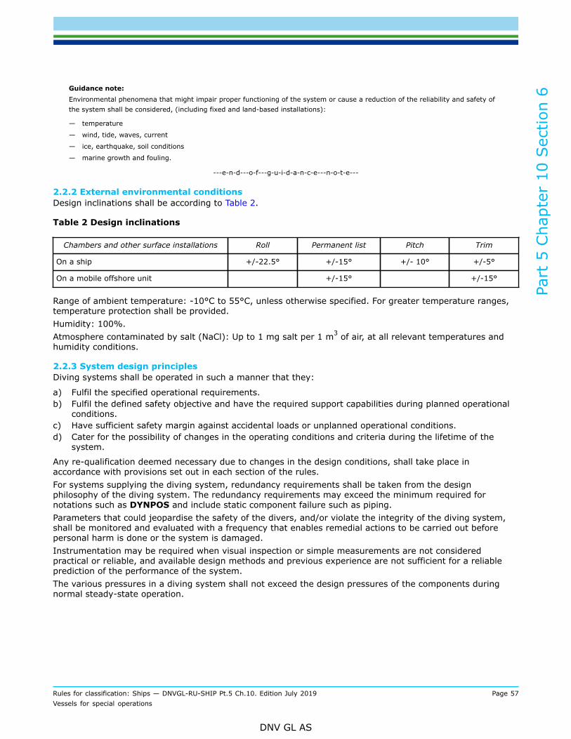
Part
5 C
hapt
er 1
0 Sec
tion
6
Rules for classification: Ships — DNVGL-RU-SHIP Pt.5 Ch.10. Edition July 2019 Page 57Vessels for special operations
DNV GL AS
Guidance note:Environmental phenomena that might impair proper functioning of the system or cause a reduction of the reliability and safety ofthe system shall be considered, (including fixed and land-based installations):
— temperature
— wind, tide, waves, current
— ice, earthquake, soil conditions
— marine growth and fouling.
---e-n-d---o-f---g-u-i-d-a-n-c-e---n-o-t-e---
2.2.2 External environmental conditionsDesign inclinations shall be according to Table 2.
Table 2 Design inclinations
Chambers and other surface installations Roll Permanent list Pitch Trim
On a ship +/-22.5° +/-15° +/- 10° +/-5°
On a mobile offshore unit +/-15° +/-15°
Range of ambient temperature: -10°C to 55°C, unless otherwise specified. For greater temperature ranges,temperature protection shall be provided.Humidity: 100%.Atmosphere contaminated by salt (NaCl): Up to 1 mg salt per 1 m3 of air, at all relevant temperatures andhumidity conditions.
2.2.3 System design principlesDiving systems shall be operated in such a manner that they:
a) Fulfil the specified operational requirements.b) Fulfil the defined safety objective and have the required support capabilities during planned operational
conditions.c) Have sufficient safety margin against accidental loads or unplanned operational conditions.d) Cater for the possibility of changes in the operating conditions and criteria during the lifetime of the
system.
Any re-qualification deemed necessary due to changes in the design conditions, shall take place inaccordance with provisions set out in each section of the rules.For systems supplying the diving system, redundancy requirements shall be taken from the designphilosophy of the diving system. The redundancy requirements may exceed the minimum required fornotations such as DYNPOS and include static component failure such as piping.Parameters that could jeopardise the safety of the divers, and/or violate the integrity of the diving system,shall be monitored and evaluated with a frequency that enables remedial actions to be carried out beforepersonal harm is done or the system is damaged.Instrumentation may be required when visual inspection or simple measurements are not consideredpractical or reliable, and available design methods and previous experience are not sufficient for a reliableprediction of the performance of the system.The various pressures in a diving system shall not exceed the design pressures of the components duringnormal steady-state operation.

Part
5 C
hapt
er 1
0 Sec
tion
6
Rules for classification: Ships — DNVGL-RU-SHIP Pt.5 Ch.10. Edition July 2019 Page 58Vessels for special operations
DNV GL AS
Guidance note:As a minimum the monitoring and inspection frequency should be such that the diving system, and consequently the divingoperation, shall not be endangered due to any realistic degradation or deterioration that may occur between two consecutiveinspection intervals.
---e-n-d---o-f---g-u-i-d-a-n-c-e---n-o-t-e---
3 Hull
3.1 Supporting structure for diving system equipment3.1.1 GeneralProvisions shall be made to ensure that the diving system installations and auxiliary equipment are securelyfastened to the ship or floating structure and that adjacent equipment is similarly secured. Considerationshall be given to the relative movement between the components of the system. In addition, the fasteningarrangements shall be able to meet any required survival conditions of the ship or floating structure. Whenthe diving system is taken onboard and mobilised for use, the equipment related to the diving system shallbe permanently attached to the hull structure, e.g. by welding, bolted connection or similar.
Guidance note:Fitting by means of lashing is not considered as permanent fitting.
---e-n-d---o-f---g-u-i-d-a-n-c-e---n-o-t-e---
All supporting structure(s) shall be according to Pt.3 Ch.11 Sec.2 with additional requirements as givenbelow.
Guidance note:Foundations are generally understood to be part of the diving system, whereas the supporting structures structural supports aregenerally understood to be part of the ship's structure/hull.
---e-n-d---o-f---g-u-i-d-a-n-c-e---n-o-t-e---
In addition to [3.1.1], foundation supporting structures supporting diving system equipment shall havescantlings based on the supported mass.The forces FU-x, FU-y and FU-z, in kN, due to the unit load for the static plus dynamic (S+D) design loadscenarios shall be derived for each dynamic load case as given in Pt.3 Ch.4 Sec.5 [2.3.2] for exposed decks.For non-exposed decks and platforms the design forces shall be as given in Pt.3 Ch.4 Sec.6 [2.3].The forces FU-x, FU-y, in kN, in longitudinal and transverse direction shall in no case be taken less than0,5gmU.Acceptable stresses, in N/mm2, for the supporting structure resulting from bending moments and shearingforces calculated for the load given above, shall be according to AC-I for primary supporting members givenin Pt.3 Ch.6 Sec.6 [2.1] or Pt.3 Ch.6 Sec.6 [2.2], depending on calculation method used.In case of direct strength calculations the equivalent von Mises stress, in N/mm2, shall satisfy:
The supporting structures and foundations shall be calculated for values of accelerations determined asshown in Pt.3 Ch.4 Sec.3 or other recognized standards. Design loads for external sea pressure on deckmounted diving system modules essential to the diving operations, shall be calculated according to Pt.3 rulesfor deck housing sides and ends, including supporting structures.The supporting structures of other equipment, not categorised under [3.1.2] or [3.1.3], shall be considered.Drawings showing the deck structure below the foundation shall be submitted for approval when the staticforces exceed 50 kN or when the resulting bending moments at deck exceed 100 kNm. The drawings shallclearly indicate the relevant forces and bending moments acting on the supporting structure.
Part
5 C
hapt
er 1
0 Sec
tion
6
Rules for classification: Ships — DNVGL-RU-SHIP Pt.5 Ch.10. Edition July 2019 Page 59Vessels for special operations
DNV GL AS
3.1.2 Supporting structures and foundations for pressure vessels for human occupancy and forgas storagePressure vessel(s) exposed to static and dynamic loads while allowing contraction and expansion of thepressure vessel(s) under pressure and temperature variations, shall be supported in a proper manner. Thestress level in the pressure vessel(s), connected pipes, the supporting structures and foundations shall bekept within acceptable level. Deflections allowed for by the required stiffness of supporting structure shall begiven as a design input to the pressure vessel manufacturer(s).Assessment of deflection shall include design still water and wave bending moment at the applicablelongitudinal position. If heavy deck loads or crane operation can influence local deck deflections under thechamber system it shall be included in deck deflection study. Extent of model shall be discussed with class oncase by case basis.Where chockfast or similar is used to support pressure vessels for human occupancy (PVHOs), this shall befitted with a clear sliding surface toward the chamber support to avoid undue stresses caused by expansioncontraction. The sliding surface shall be the levelled surface. A report after installation shall be submittedshowing the chockfast is within manufacturers guidance for thickness and surface pressure at all pointswithin the chamber complex.The pressure vessels with supports shall be designed for a static inclination of 30° without exceeding theallowable stresses as specified in [3.1.1].Suitable supporting structures and foundations shall be provided to withstand a collision force acting on thepressure vessels corresponding to one half the weights of the pressure vessels in the forward direction andone quarter the weight of the pressure vessels in the aft direction.Unless removal of the pressure vessel(s) is a simple operation, the supporting structure(s) shall be able tosustain the static load of the pressure vessel(s) during periodic hydro testing or it shall be possible to shore/support the supporting structure(s) in order to avoid unacceptable deflections.The collision loads and the hydro testing loads mentioned above need not to be combined with each other orwith wave-induced loads.
Guidance note:Typically the chambers and large gas storage tubes will expand and contract considerably in service due to pressure variations. Allsupporting structures and foundations for these pressure vessels should allow for this movement.
---e-n-d---o-f---g-u-i-d-a-n-c-e---n-o-t-e---
3.1.3 Supporting structures and foundations for handling systems and lifting appliancesSupporting structures and foundations for handling systems and lifting appliances shall be determinedaccording to Pt.3 Ch.11 Sec.2 or according to other recognized standards. Interfaces between the handlingsystem structure and the vessel shall be especially considered. Drawings showing scantlings and jointconfiguration including maximum design loads shall be approved including (but not limited to) supportingstructures for winches, sheaves and dampers.The dynamic coefficient shall as a minimum be taken as 2.2 when the lifting appliance is used for handlingmanned objects such as surface bells, baskets or hyperbaric evacuation systems. For other lifting appliances,not used for lifting people, the dynamic coefficient shall as a minimum be 1.5.The side structure of the moon pool shall be strengthened with respect to possible impact loads from divingequipment guided through the moon pool.Design loads for supporting structure(s) of bell launch and recovery systems shall be based on DNVGL-OS-E402 or Pt.3 Ch.11 Sec.2 whichever is greater.
Guidance note:All lifting appliances used in the operation of the diving system should be considered offshore lifting appliances.
---e-n-d---o-f---g-u-i-d-a-n-c-e---n-o-t-e---
Part
5 C
hapt
er 1
0 Sec
tion
6
Rules for classification: Ships — DNVGL-RU-SHIP Pt.5 Ch.10. Edition July 2019 Page 60Vessels for special operations
DNV GL AS
4 Stability and floatationThe diving support vessel shall comply with the damage stability requirements given in Pt.6 Ch.5 Sec.7 foradditional class notation SF or Pt.6 Ch.5 Sec.7 for additional class notation SPS.Essential diving equipment on or above main deck shall remain accessible and operable in any stage offlooding as required for compliance with the above. Equipment below the main deck for special purpose shipswill be considered protected if side divisions are equivalent to that required under class notation SF.
Guidance note:For the purpose of stability calculations, essential diving equipment should be treated similar to the requirements to controlstations in SOLAS II-1/7-2.5.3.2, i.e. defined as flooding points and located above the worst intermediate or final damagedwaterline.
---e-n-d---o-f---g-u-i-d-a-n-c-e---n-o-t-e---
Examination and approval of stability documents carried out by national administrations having equivalentstability requirements to the above may be accepted as a basis for assignment of class notation DSV. Insuch cases the stability manual approved by the national authorities shall be submitted as documentation ofcompliance with the rule requirements.In order to recover the bell after side damage in accordance with the extents given in class notation SF, thefinal list and trim in these conditions shall be below the design limits of list and trim for the LARS system.Ballasting post damage may be used as a means to achieve this.
5 Position keeping
5.1 General
5.1.1 The diving support vessel shall be able to keep its position safely during diving operations. This impliesa system with built in redundancy for position keeping. The position keeping system may be a mooringsystem with anchors or a dynamic positioning system.
5.1.2 For diving support vessels, equipped with a dynamic positioning system, the class notationDYNPOS(AUTR) or higher is mandatory. Alarms shall be initiated and set accordingly.
Guidance note:In this context, equipment class 2 in accordance with IMO MSC/ Circ.645 of 6 June 1994 Guidelines for Vessels with dynamicpositioning systems may be considered as an alternative to AUTR dependent on region and operation. Some diving operationsmay require a higher class, which then should be stated in the contract.
---e-n-d---o-f---g-u-i-d-a-n-c-e---n-o-t-e---
5.1.3 For mooring systems with anchors, the notation POSMOOR-V or higher is mandatory.
5.1.4 Between the operation centre for the positioning system and the dive operation centre there shall be:
a) redundant communication systemsb) a manually operated alarm system.

Part
5 C
hapt
er 1
0 Sec
tion
6
Rules for classification: Ships — DNVGL-RU-SHIP Pt.5 Ch.10. Edition July 2019 Page 61Vessels for special operations
DNV GL AS
6 Life support
6.1 Piping6.1.1 GeneralGases vented from the diving system shall be vented to the open air away from sources of ignition, personnelor any area where the presence of those gases could be hazardous. Means shall be provided to prevent anydangerous accumulation of gases. The discharge from overpressure relief devices and exhaust shall be led toa location where hazard is not created.Piping systems carrying mixed gas or oxygen under high pressure shall not be arranged insideaccommodation spaces, engine rooms or similar compartments. Piping systems shall comply with thetechnical requirements for class I piping in Pt.4 Ch.6.All high-pressure piping shall be well protected against mechanical damage.Piping for gas and electrical cables shall be separated.All filters/strainers shall be arranged so that they can be isolated without interrupting the supply to essentialsystems.Diving system sanitary and drainage systems connected to ship systems shall be designed to avoid anunintentional pressure rise in the ship system in case of malfunction or rupture of the diving systems.Piping systems intended to be used in breathing gas and oxygen systems shall be cleaned and tested forpurity in accordance with an approved test method. The minimum acceptable cleanliness levels, as defined inASTM G93 Standard Practice for Cleaning Methods and Cleanliness Levels for Materials and Equipment Usedin Oxygen-Enriched Environments, shall be:
1) ASTM Level B for non volatile residue in oxygen lines2) ASTM Level D for non volatile residue in breathing gas lines3) ASTM Level 175 for particulate contamination.
6.1.2 Oxygen systemsThe discharge from overpressure relief devices and exhaust from O2 systems shall be ducted to a safe placeand not close to a source of ignition, engine room exhaust or ventilation from galley.
6.2 Gas storage6.2.1 GeneralWhere gas mixtures with oxygen content less than 20% are stored in enclosed spaces, there shall be twooxygen analysers with an audio-visual low level alarm in addition to the ventilation requirements in [6.2.3].These analysers shall be mounted such that one is reading the upper levels and the other is reading thelower levels of the enclosed space.
6.2.2 CapacityThere shall be a permanently installed gas storage plant or suitable space for portable gas containers. Therequirements with respect to the capacity of stored gas are defined in DNVGL-OS-E402 Ch.3 Sec.3 [2].For the qualifier Ready the capacity of the permanently installed gas storage plant shall be the basis for thesize of the diving system that can be installed on board.
Guidance note:The capacity will be stated in the appendix to class. For diving systems with larger capacity, the total gas capacity may beincreased using portable gas containers, provided that suitable space for storage is provided.
---e-n-d---o-f---g-u-i-d-a-n-c-e---n-o-t-e---
Part
5 C
hapt
er 1
0 Sec
tion
6
Rules for classification: Ships — DNVGL-RU-SHIP Pt.5 Ch.10. Edition July 2019 Page 62Vessels for special operations
DNV GL AS
6.2.3 Oxygen gas storageOxygen bottles shall be installed in a well ventilated location. If stored in a room instead of open deck, theroom shall be separated from adjacent spaces,shall be ventilated according to [8.1.3] and shall be fitted withan audio-visible oxygen alarm, at a manned control station.Oxygen bottles shall not be stored near flammable substances. Oxygen shall not be stored or ducted in anyform close to combustible substances or hydraulic equipment. Working decks are considered sources ofcombustible substancesFor diving support vessels with class notation Fire fighter, the oxygen gas bottles shall be speciallyprotected from heat that may radiate from a fire that is being extinguished.
7 Power provisions, control and communications
7.1 Electrical systems7.1.1 ObjectiveGeneral requirements for electrical systems are given in Pt.4 Ch.8 and DNVGL-OS-E402. The purpose of thissection is to specify additional requirements for electrical systems and equipment serving diving systems.Emphasis is therefore placed on the special needs associated with the design and manufacture of divingsystems.
Guidance note:For the qualifier Ready the capacity of the installed main and emergency source of power will be stated in the appendix to class.Diving systems being installed may be supplied using a separate power generator and own distribution system provided that thesystems meet the requirements as defined in Pt.4 Ch.8.
---e-n-d---o-f---g-u-i-d-a-n-c-e---n-o-t-e---
7.1.2 Capacity
7.1.3 Design philosophy of electrical systems serving diving systemsAll electrical equipment and installation, including power supply arrangements, shall be designed for theenvironment in which they will operate to minimize the risk of fire, explosion, electrical shock and emissionof toxic gases to personnel, and galvanic action of the surface compression chamber or diving bell. Electricalcables and piping for gas shall be separated.In the event of failure of the main source of electrical power supply to the diving system an independentsource of electrical power should be available for the safe termination of the diving operation.It is admissible to use the ship's emergency source of electrical power as an emergency source of electricalpower if it has sufficient electrical power capacity to supply the diving system and the emergency load for thevessel at the same time.The alternative source of electrical power shall be located outside the machinery casings to ensure itsfunctioning in the event of fire or other casualty causing failure to the main electrical installation.Interface between diving system and the ship or floating structure shall be provided with suitable electriclighting. Primary and emergency lighting in all critical handling areas shall be provided.
7.2 Communication7.2.1 GeneralThe communication system shall be arranged for a fixed direct two-way communication between the controlstands and:
a) diving system handling positionsb) dynamic position control centrec) bridge, ship's command centre or drilling floor

Part
5 C
hapt
er 1
0 Sec
tion
6
Rules for classification: Ships — DNVGL-RU-SHIP Pt.5 Ch.10. Edition July 2019 Page 63Vessels for special operations
DNV GL AS
d) cranee) ROV control stand.
This fixed communication systems shall also be arranged for direct two-way voice communication betweenthe dive control room and, for the qualifier SAT the SAT control room.
7.2.2 TestingThe communication system shall be functionally tested after installation.
8 Fire protection
8.1 Fire prevention8.1.1 ObjectiveGeneral requirements for fire protection are given in the rules Pt.4 Ch.10. The purpose of this section is tospecify additional requirements for fire protection of areas containing diving equipment with auxiliaries andsystems to be connected to the diving compression chambers and diving bells.
8.1.2 Application and scopeThese requirements apply to all systems. However, some systems may be located on open deck. In thesecases the requirements for insulation against adjacent spaces and requirements for sprinkler systems shallbe evaluated on a case by case basis.
8.1.3 Arrangement and materialsEnclosed outer area shall have A-60 class towards other enclosed spaces. Outer area may be subdivided intoseveral spaces by A-0 class. There shall be no direct access between categories A machinery spaces outsideof outer area. At least one of the required escape routes from spaces not being part of outer area shall beindependent of outer area. All doors between outer area and other adjacent enclosed spaces shall be of self-closing type.Piping and cables essential for the operation of the diving system are regarded as part of the system andshall be laid in separate structural ducts insulated to A-60 class standard where these transit from otherspaces as main switch board room or engine room into outer area.Outer area in the ship or floating structure shall be arranged in spaces or locations which are adequatelyventilated. When situated in enclosed spaces the outer area shall be fitted with separate mechanicalventilation with minimum 8 air changes per hour.Insulation materials used in connection with the diving system shall be of fire-retardant type in order tominimize the risk of fire and sources of ignition.
8.2 Fire detection and alarm systemsWhen situated in enclosed spaces, the outer area shall be equipped with automatic fire detection and alarmsystems complying with SOLAS Reg. II-2/7.1 and FSS Code Ch 9 as mandated by Pt.4 Ch.11 Sec.4. Thesection or loop of detectors covering the outer area shall not cover other spaces. Fire detection panels shallbe placed on the bridge, with repeater panel at dive control room and in engine control room and provisionsshall be made for warning of faults. A visual repeater, showing the alarm condition, shall be placed at thesaturation- and diving control stand.
8.3 Fire extinguishingInterior spaces containing diving equipment such as surface compression chambers, diving bells, gasstorage, compressors and control stands shall be covered with a suitable fixed fire extinguishing system.When situated in enclosed spaces, the outer area shall be equipped with a fixed, manually actuated fire
Part
5 C
hapt
er 1
0 Sec
tion
6
Rules for classification: Ships — DNVGL-RU-SHIP Pt.5 Ch.10. Edition July 2019 Page 64Vessels for special operations
DNV GL AS
extinguishing system with such a layout as to cover the complete system. Release positions for thesesystems shall be at the dive control room, bridge and/or other positions as required case by case.Coverage shall be sufficient to cover at least the largest area enclosed by A-0 class.The extinguishing system shall be either:
a) a pressure water spraying system approved for use in machinery spaces of cat. Ab) an equivalent fixed gas fire extinguishing system in accordance with the FSS Code and IMO MSC/circ.
848, amended by MSC/Circ. 1267.
If a gas system is selected, the agent shall be of a type not hazardous to humans in the concentrationforeseeable in the protected space. The concentration shall be below the NOAEL as defined in IMO MSC/Circ.848/1267.
Guidance note:Where sea water is used as the extinguishing agent it is recommended to arrange a fresh water flushing system for maintenancepurposes.
---e-n-d---o-f---g-u-i-d-a-n-c-e---n-o-t-e---
When pressure vessels are situated in enclosed spaces, a manually actuated water spray system having anapplication rate of 10 l/m2/per minute of the horizontal projected area should be provided to cool and protectsuch pressure vessels in the event of external fire. For equivalent water-mist fire-extinguishing systems withapplication rate less than 5 l/min/m2, an additional object protection of 5 l/min/m2 is accepted as equivalentto 10 l/min/m2.Release positions for these systems shall be at the dive control room, bridge and/or other positions asrequired case by case. The arrangement of zones shall follow the physical arrangement of the dive systemrelease in one area should not hamper the operation of other areas.Where water is used as the fire extinguishing medium the IP rating of essential controls shall be considered.
Guidance note:Release of fire fighting within the hanger should not also release within control rooms or areas on other decks.
---e-n-d---o-f---g-u-i-d-a-n-c-e---n-o-t-e---
When the outer area is subdivided by A0 or higher divisions, the extinguishing capacity shall be sized to beable to activate all zones within the largest subdivision enclosed by the A0 or higher class divisions.When pressure vessels are situated on open decks, fire hoses may be considered as providing the necessaryprotection.When situated on open deck, the outer area shall be provided with fire extinguishing equipment, which shallbe considered in each case.Hyperbaric evacuation systems shall be provided with fire extinguishing systems enabling launching of thehyperbaric evacuation unit in the event of a fire. Release of the Object protection for hyperbaric evacuationsystems shall be available at a central control stand
8.4 Miscellaneous equipment8.4.1 Fire-fighter’s outfitA complete set of fire-fighter's outfit complying with Pt.4 Ch.11 Sec.2 for each person required for operationof the diving system during a fire shall be located at the main control stands. The sets are additional toother sets on board. Breathing apparatus are required for control stations manned during recovery of bell orlaunching of hyperbaric evacuation unit.
Guidance note:Fire-fighter's outfit is recommended in consideration of the time it may take for recovery of the divers from the water, into the belland all the way up to the hyperbaric evacuation system. The operator(s) of the diving system may be exposed to hot environmentswhich render evacuation impossible unless they are protected whilst performing their work.
---e-n-d---o-f---g-u-i-d-a-n-c-e---n-o-t-e---
Part
5 C
hapt
er 1
0 Sec
tion
6
Rules for classification: Ships — DNVGL-RU-SHIP Pt.5 Ch.10. Edition July 2019 Page 65Vessels for special operations
DNV GL AS
8.4.2 Portable fire extinguishersPortable fire extinguishers shall be of approved type and comply with the provisions of the FSS Code.Portable fire extinguishers shall be distributed throughout the space containing the diving system so that nopoint in the space is more than 10 m walking distance from an extinguisher.One of the portable fire extinguishers shall be fitted near each entrance.A portable fire extinguisher shall be fitted at the control stand.Spare charges or extinguishers shall be provided on board as follows:
— 100% for the first 10, and— 50% for remaining extinguishers.
9 Hyperbaric evacuation
9.1 General9.1.1 GeneralAn evacuation system shall be provided having sufficient capacity to evacuate all divers under pressure,in the event of the ship having to be abandoned, and shall be in accordance with the provisions of theGuidelines and Specifications for Hyperbaric Evacuation Systems adopted by the IMO organization byresolution A.692(17).Hyperbaric evacuation systems shall comply with these statutory requirements as interpreted in DNV-RP-E403.
Guidance note:As life saving appliances are governed by statutory regulations, there may be overriding requirements for hyperbaric evacuationsystems (HES). Consequently, it is important to inform the Society at an early stage what flag administration is intended for thediving support vessel.It is the Society’s intention to apply SOLAS requirements for hyperbaric evacuation systems as far as is practical. This includes thelaunching arrangement.In the cases where the system does not comply with the prescriptive requirements in SOLAS, the Society shall verify evaluationsand tests that show substantially equivalent conformance with the recommendations. This is in accordance with recommendationsgiven in SOLAS Ch. III Part A Regulation 4.Guidelines and Specifications for Hyperbaric Evacuation Systems, adopted by the IMO organization by Resolution A.692(17) on 6November 1991, shall be included as normative references under SOLAS. The Society interpretations to these guidelines are givenin DNV-RP-E403 Hyperbaric Evacuation Systems.Yards, owners or designers will have to carry out engineering analyses according to the new SOLAS Ch. III, Reg. 38 as amendedby IMO Res. 216(82).
---e-n-d---o-f---g-u-i-d-a-n-c-e---n-o-t-e---
Part
5 C
hapt
er 1
0 Sec
tion
7
Rules for classification: Ships — DNVGL-RU-SHIP Pt.5 Ch.10. Edition July 2019 Page 66Vessels for special operations
DNV GL AS
SECTION 7 SEISMOGRAPHIC RESEARCH VESSELS
1 Introduction
1.1 Introduction
1.1.1 These rules provide requirements for vessels intended for seismographic research operations withparticular focus on the robust design of the seismic equipment hangar; the ability to maintain propulsionpower and vessel manoeuvrability through adapted bridge design and navigation systems.
1.2 Scope
1.2.1 These rules include requirements for hull strength, systems and equipment applicable to seismographicresearch vessels.
1.3 Application
1.3.1 Vessels built in compliance with the relevant requirements in [4] of this section may be given the classnotation Seismic vessel.Vessels built in compliance with the relevant additional requirements in [5] of this section may be given theclass notation Seismic vessel(A).Qualifier A is optional.Vessels with qualifier A shall hold the following additional class notations:
— RP(+) or RP(3,x%,+), see Pt.6 Ch.2;or DYNPOS(AUTR) or DYNPOS(AUTRO), see Pt.6 Ch.3;or DYNPOS(ER), see Pt.6 Ch.3
— E0 or ECO, see Pt.6 Ch.2— NAUT(OSV), see Pt.6 Ch.3
2 Racking of seismic hangar
2.1 Transverse racking2.1.1 GeneralA transverse racking strength assessment shall be carried out for the seismic hangar following therequirements given in this subsection. Special attention shall be given to the connections between transversestructural members to the bulkhead deck or the uppermost deck level with high racking rigidity.Intersections between horizontal and transverse members shall be assessed in areas subjected to highracking deformations, i.e. response caused by roll motion acting on the cargo at multiple decks combinedwith self-weight of structure and equipment.
2.1.2 Scope of racking calculations in way of seismic hangarTransverse strength is provided by the deep vertical web frames in the ship’s side and/or transversebulkheads in the forward area of the seismic hangar. For vessels with length L < 120 m, a simplified rackingassessment model using beam elements (grillage analysis) will be accepted for the evaluation of theadequacy of the transverse strength for the ultimate limit state (ULS).Fatigue assessment will not be required if the dynamic nominal stress is less than 80 N/mm2.
Part
5 C
hapt
er 1
0 Sec
tion
7
Rules for classification: Ships — DNVGL-RU-SHIP Pt.5 Ch.10. Edition July 2019 Page 67Vessels for special operations
DNV GL AS
Under special consideration finite element analysis based on partial ship structural model may be required ona case by case basis. Acceptable calculation and modelling methods are given in Pt.3 Ch.7.For vessels with length L ≥ 120 m, calculation scope based on FE partial ship structural analysis shall beapplied. A separate fatigue limit state analysis (FLS) shall be carried out according to Ch.3 Sec.2 [4].
3 Loads
3.1 Loads for racking strength assessment of seismic hangar in transitcondition3.1.1 Loading condition for rackingThe loading condition, which in combination with relevant dynamic load cases defined in [3.1.3] results in themaximum racking moment about the bulkhead, shall be chosen for the ULS transverse strength analysis. Thedesign racking moment shall be calculated according to [3.1.2].The actual GM value for this design load case shall be determined and applied since it has a significantinfluence on the dynamic load cases. In no case shall the GM value for the design still water loading conditionbe smaller than 0.05B.
3.1.2 Racking moment calculation (screening of highest design load)The racking moment is calculated using both cargo and fully loaded equipment weight (mc) and the self-weight (ms) to obtain the total mass. If not specified by the designer, an average minimum distributedload equal to 0.2 t/m2 shall be applied for the accommodation decks, in addition to the self-weight. Forunloaded weather decks, it is sufficient to include the load corresponding to the self-weight if no deadweightis specified. The transverse force on each deck level is obtained as the total mass times the transverseacceleration corresponding to the relevant equivalent design wave (EDW) given in [3.1.3]. Thus, the rackingmoment in kNm, may be estimated as:
where:
mc,i = mass on deck number i, in tms,i = self-weight of deck number i, in tay,i = transverse acceleration at deck number i, in m/s2, for the dynamic load cases specified in [3.1.3]zi = vertical distance above base line for deck number i, in mzmain = vertical position above base line for bulkhead deck, in m.
Guidance note:A high racking moment is achieved if the load is located on the upper decks. However this result in lower GM values and thus alsolower transverse accelerations which will reduce the racking moment. Usually, several loading conditions for racking analysis shouldbe reviewed using the simplified racking moment calculation described in this paragraph.
---e-n-d---o-f---g-u-i-d-a-n-c-e---n-o-t-e---
3.1.3 Dynamic load casesThe design wave load cases which shall be used to evaluate the transverse strength of the ship structureis the beam sea load cases BSR (1P/2P) and/ or BSR (1S/2S). For ship structures with symmetricalarrangement of racking constraining elements, only BSR(1P/2P) or BSR(1S/2S) needs to be examined.
3.1.4 Load combinations in transit condition for ULSThe loading condition from [3.1.1] shall be combined with the dynamic load cases as described in [3.1.3].The external sea pressure shall be applied according to Pt.3 Ch.4 Sec.5 Table 8. Load combination factors
Part
5 C
hapt
er 1
0 Sec
tion
7
Rules for classification: Ships — DNVGL-RU-SHIP Pt.5 Ch.10. Edition July 2019 Page 68Vessels for special operations
DNV GL AS
for hull girder loads and accelerations shall be applied according to Pt.3 Ch.4 Sec.2 Table 3 with the internalcargo, equipment and steel weight loads.Transverse accelerations shall not be taken less than 0.5g.
3.1.5 FE load applicationThe deck load may generally be applied as distributed vertical and transverse loads based on loadcombination as described in [3.1.4].The steel self-weight shall be included.
3.2 Loads for primary supporting members3.2.1 Design load sets for prescriptive rule checkDesign load sets and load combinations of static and dynamic loads for tank and watertight boundarystructure, external shell envelope structure e.g. bottom structure, side shell primary members and deckstructure is given in Pt.3 Ch.6 Sec.2 Table 3.
3.2.2 Load sets and load combinations for direct analysisThe load pattern described in Table 1 shall be assessed to ensure that the primary support members havesufficient strength.
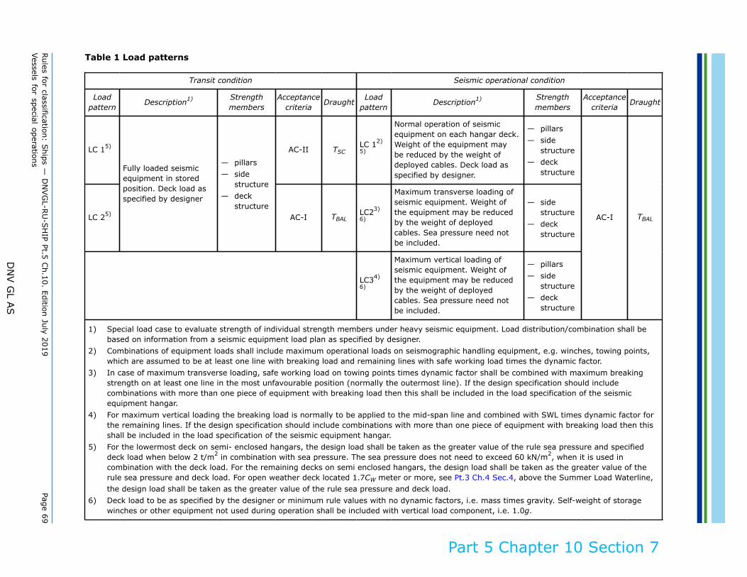
Rules for classification: S
hips — D
NVG
L-RU
-SH
IP Pt.5 Ch.10. Edition July 2019
Page 69Vessels for special operations
DN
V G
L AS
Part 5 Chapter 10 Section 7
Table 1 Load patterns
Transit condition Seismic operational condition
Loadpattern Description1) Strength
membersAcceptance
criteria Draught Loadpattern Description1) Strength
membersAcceptance
criteria Draught
LC 15) AC-II TSCLC 12)
5)
Normal operation of seismicequipment on each hangar deck.Weight of the equipment maybe reduced by the weight ofdeployed cables. Deck load asspecified by designer.
— pillars— side
structure— deck
structure
LC 25)
Fully loaded seismicequipment in storedposition. Deck load asspecified by designer
— pillars— side
structure— deck
structureAC-I TBAL
LC23)
6)
Maximum transverse loading ofseismic equipment. Weight ofthe equipment may be reducedby the weight of deployedcables. Sea pressure need notbe included.
— sidestructure
— deckstructure
LC34)
6)
Maximum vertical loading ofseismic equipment. Weight ofthe equipment may be reducedby the weight of deployedcables. Sea pressure need notbe included.
— pillars— side
structure— deck
structure
AC-I TBAL
1) Special load case to evaluate strength of individual strength members under heavy seismic equipment. Load distribution/combination shall bebased on information from a seismic equipment load plan as specified by designer.
2) Combinations of equipment loads shall include maximum operational loads on seismographic handling equipment, e.g. winches, towing points,which are assumed to be at least one line with breaking load and remaining lines with safe working load times the dynamic factor.
3) In case of maximum transverse loading, safe working load on towing points times dynamic factor shall be combined with maximum breakingstrength on at least one line in the most unfavourable position (normally the outermost line). If the design specification should includecombinations with more than one piece of equipment with breaking load then this shall be included in the load specification of the seismicequipment hangar.
4) For maximum vertical loading the breaking load is normally to be applied to the mid-span line and combined with SWL times dynamic factor forthe remaining lines. If the design specification should include combinations with more than one piece of equipment with breaking load then thisshall be included in the load specification of the seismic equipment hangar.
5) For the lowermost deck on semi- enclosed hangars, the design load shall be taken as the greater value of the rule sea pressure and specifieddeck load when below 2 t/m2 in combination with sea pressure. The sea pressure does not need to exceed 60 kN/m2, when it is used incombination with the deck load. For the remaining decks on semi enclosed hangars, the design load shall be taken as the greater value of therule sea pressure and deck load. For open weather deck located 1.7CW meter or more, see Pt.3 Ch.4 Sec.4, above the Summer Load Waterline,the design load shall be taken as the greater value of the rule sea pressure and deck load.
6) Deck load to be as specified by the designer or minimum rule values with no dynamic factors, i.e. mass times gravity. Self-weight of storagewinches or other equipment not used during operation shall be included with vertical load component, i.e. 1.0g.
Part
5 C
hapt
er 1
0 Sec
tion
7
Rules for classification: Ships — DNVGL-RU-SHIP Pt.5 Ch.10. Edition July 2019 Page 70Vessels for special operations
DNV GL AS
3.2.3 Design load sets for beam analysisRelevant design load sets for transit condition are described in the rules Pt.3 Ch.6 Sec.2 Table 3 and Pt.3Ch.6 Sec.8 Table 1 shall be applied to the model.For internal decks in transit condition for load pattern LC1, the UDL design load sets applies and the Pdl-d maybe based on envelope acceleration according to Pt.3 Ch.4 Sec.3 [3.3]. The following design load sets thenapplies:
a) UDL-1h: (Pdl-s + Pdl-d) combined with maximum hull girder vertical bending moment in hogging, i.e. Mwv-h + Msw-h based on HSM-2
b) UDL-1s: (Pdl-s + Pdl-d) combined with maximum hull girder vertical bending moment in sagging, i.e. Mwv-s + Msw-s based on HSM-2.
Optionally, the accelerations for the considered dynamic load case may be applied. Then the number ofapplicable load sets will double, in order to maximize both local pressure and hull girder vertical bendingmoment, as described in Pt.3 Ch.6 Sec.2 Table 3.
3.2.4 Breaking load need not to be taken greater than the force causing the winch to render.
3.2.5 A design dynamic factor of not less than 1.3 shall be applied to the static SWL of the seismic handlingequipment.
4 Hull local scantling
4.1 Primary supporting members being part of seismic equipment hangar4.1.1 GeneralThe strength of primary structural members that form part of a grillage system, such as deck girders, sideweb frames, pillars, floors and girders in double bottom shall be determined by direct strength analysis eitherby the use of a beam- or FE part ship model.
4.1.2 Beam analysisBeam analysis may be accepted in order to evaluate bending and shear stresses in webs and flanges ofgrillage structure under lateral loads such as decks, double bottom and side structure under cargo or liquidpressure, e.g. sea pressure, tank pressure etc. The effective plate breadth in bending of the primary strengthmembers shall be calculated according to Pt.3 Ch.3 Sec.7 [1.3].
4.1.3 Buckling check of plate panelsThe normal stresses and shear stresses taken from strength assessment to be applied for buckling capacitycalculation of plate panels, as given in Pt.3 Ch.8 Sec.4, shall be corrected as given in DNVGL-CG-0128 Sec.3[2.2].Buckling strength shall be considered for panels with high in-plane stresses, e.g. decks and ship sides, withacceptance criteria given in Ch.8 Sec.4. For buckling assessment fully effective plate flange may be used.
4.1.4 Acceptable stress levelAcceptable stresses, in N/mm2, for the supporting structure resulting from bending moments and shearingforces calculated for the loads given above, shall be according to AC-I and AC-II for primary supportingmembers given in Pt.3 Ch.6 Sec.6 [2.2].In case of direct strength calculations the equivalent von Mises stress, in N/mm2, shall satisfy:
Part
5 C
hapt
er 1
0 Sec
tion
7
Rules for classification: Ships — DNVGL-RU-SHIP Pt.5 Ch.10. Edition July 2019 Page 71Vessels for special operations
DNV GL AS
4.2 Supporting structures for seismic handling equipment
4.2.1 Local structural strength in way of the equipment foundation shall be in compliance with Pt.3 Ch.11Sec.2.
4.2.2 In case the winch is supported by two deck levels, then local support at one deck level shall becapable of bearing all vertical loads from the winch.
4.2.3 When part of the equipment is acting as structural hull support, i.e. winch frame providing pillarsupport for the decks, it shall comply with the strength requirements as for the main structure with respectto the design loads and rule acceptance criteria.
4.2.4 In cases when equipment is being used as hull structural support this shall be stated in memorandumto owner (MO) and appendix to classification certificate.
4.3 Strengthening for side-by-side mooring
4.3.1 The SWL for the mooring bollard shall be at least three (3) times the minimum breaking load of themooring lines according to the vessel’s equipment letter, or based upon the designer’s specification for theminimum breaking load to be used for side-by-side mooring lines.
4.3.2 The mooring line specification and restrictions on operation of the mooring bollards shall be stated inthe appendix to classification certificate and in a memorandum to owner.
4.3.3 The strength of supporting deck structure shall be based on the mooring bollard’s SWL times 1.5.
4.3.4 Acceptable stresses, in N/mm2, for the scantlings of the supporting deck structure resulting frombending moment M, in kNm, and shear force Q, in kN, calculated for the load given above are:
σb = bending stress, in N/mm2, taken as:
τ = average shear stress, in N/mm2, taken as:
Ashr = net shear area, in cm3
Z = net section modulus, in cm3.
In case of direct strength calculations the equivalent von Mises stress, in N/mm2, shall satisfy:

Part
5 C
hapt
er 1
0 Sec
tion
7
Rules for classification: Ships — DNVGL-RU-SHIP Pt.5 Ch.10. Edition July 2019 Page 72Vessels for special operations
DNV GL AS
5 Systems and equipment
5.1 High pressure air system
5.1.1 The piping system shall comply with the requirements in Pt.4 Ch.6. In addition, the requirementsspecified in [5.1.2] to [5.1.11] shall be fulfilled.
5.1.2 High pressure pipes shall not be installed in the vicinity of gangways or other spaces which are innormal use by personnel. If this cannot be avoided, shielding or equivalent arrangement shall be applied.Any manifold and pressure relief valve shall be shielded to safeguard any operator. The pressure relief valvesshall be arranged for venting to exhaust or overboard.
Guidance note:Example of appropriate shielding may be punched steel shields. The shielding may also be removable in order for accessing de-pressurized equipment.
---e-n-d---o-f---g-u-i-d-a-n-c-e---n-o-t-e---
5.1.3 Pipes should be inclined relative to the horizontal. Water pockets in the pipeline shall be avoided as faras practicable. If this cannot be avoided, means of drainage shall be arranged.
5.1.4 All manifolds and other locations where liquid may accumulate shall be arranged with possibilities forefficient drainage. Automated drains shall be arranged for air receivers, with additional possibility for manualoperation.
5.1.5 Lubricating oil points for the air guns shall not be located in the vicinity of manifolds. If this cannotbe avoided, there shall be arranged automatic shut-down of lubrication pumps when the high pressure airsystem is not pressurized.
5.1.6 All valves shall be automatically operated in order to prevent adiabatic compression or water hammerin the system. Alternatively, the system shall always be de-pressurized before operating any valves.
Guidance note 1:Opening time of a valve should be at least 10 seconds.Controlled pressure adjustment before opening a high pressure valve may, in some cases serve as an equivalent to automaticallyoperated valves. By adjusting the system pressure to 1:8 of design pressure, the risk of generating high temperatures throughadiabatic compression is negligible.
---e-n-d---o-f---g-u-i-d-a-n-c-e---n-o-t-e---
Guidance note 2:In cases where automatic operation is not possible to install, each valve should be permanently marked with warning against rapidopening.
---e-n-d---o-f---g-u-i-d-a-n-c-e---n-o-t-e---
5.1.7 Air intakes for the compressors shall be so located as to minimize the intake of oil or watercontaminated air.
5.1.8 Pipes from air compressors with automatic start shall be fitted with a separator or similar device toprevent condensate and HP piping shall be done in a way to prevent condensate from draining back intocompressors.
5.1.9 Cylinder banks shall be located in areas which are not in normal use by personnel. The area shall bearranged for high pressure air to expand in case of an explosion.
Part
5 C
hapt
er 1
0 Sec
tion
7
Rules for classification: Ships — DNVGL-RU-SHIP Pt.5 Ch.10. Edition July 2019 Page 73Vessels for special operations
DNV GL AS
Guidance note:Proper shielding of connected piping and valves may be considered as an equivalent solution if designated areas cannot bearranged.
---e-n-d---o-f---g-u-i-d-a-n-c-e---n-o-t-e---
5.1.10 There shall be at least one burst disc installed at the manifold, and one at the cylinder bank. Thediscs shall be directed away from working areas.
5.1.11 The piping shall be hydrostatically tested for at least 30 minutes in the presence of a surveyor afterinstallation on board with the following test pressure:
PH = 1.5 P
where:
PH = test pressure in barP = design pressure in bar as defined in Pt.4 Ch.6 Sec.7.
The test pressure need not exceed the design pressure by more than 70 bar.
Part
5 C
hapt
er 1
0 Sec
tion
8
Rules for classification: Ships — DNVGL-RU-SHIP Pt.5 Ch.10. Edition July 2019 Page 74Vessels for special operations
DNV GL AS
SECTION 8 WELL STIMULATION VESSELS
1 Introduction
1.1 Introduction
1.1.1 These rules provide requirements for vessels intended for stimulation of wells for production of oil andor gas.
1.2 Scope
1.2.1 These rules include requirements for tank systems and equipment, piping systems, control andmonitoring systems applicable to well stimulation vessels, including:
— personnel protective equipment— intact and damage stability of the vessel.
Guidance note:Arrangements involving return of fluids from the well are not covered by the rules.
---e-n-d---o-f---g-u-i-d-a-n-c-e---n-o-t-e---
1.3 Application
1.3.1 Vessels built in compliance with the relevant requirements in this section may be given the classnotation Well stimulation vessel.
2 Hull
2.1 General
2.1.1 The hull structural strength shall be as required for the main class taking into account necessarystrengthening of supporting structures for the well stimulation equipment during transit and operation.
2.1.2 All load effects caused by heavy well stimulation deck equipment shall be taken into account in thestructural design for both transit and operational condition.
3 Arrangement
3.1 Tanks and pumping arrangement
3.1.1 Tanks for acid and liquefied nitrogen shall be located at a minimum distance of 760 mm from thevessel's side and bottom.
3.1.2 Tanks and pumping arrangements shall not be located within accommodation areas or machineryspaces.
3.1.3 Tanks and piping systems for the well stimulation plant shall be separated from the machinery and shippiping systems.
Part
5 C
hapt
er 1
0 Sec
tion
8
Rules for classification: Ships — DNVGL-RU-SHIP Pt.5 Ch.10. Edition July 2019 Page 75Vessels for special operations
DNV GL AS
3.1.4 Remote control of the well stimulation processing plant shall be arranged from a position outside thearea where the well stimulation systems are located.
3.1.5 Tanks and pumping arrangements for liquid additives having flashpoint below 60°C shall comply withrelevant requirements of Pt.6 Ch.5.Arrangement of pump room for LFL (low flashpoint liquids) substances adjacent to the LFL tanks and withoutseparating cofferdams may be considered in each case.
3.1.6 Requirements for tanks and pumping arrangements for chemicals other than acids dealt with under[7] will be considered in each case with due regard to the properties of the chemicals and applicablerequirements of Ch.6.
3.2 Tank venting
3.2.1 Outlets from safety valves of nitrogen tanks shall be lead to open deck. Outlet pipes shall be arrangedand supported in order to allow thermal expansion during release of cold gas. Penetrations of decks orbulkheads shall be such that the structures are thermally isolated from the cold pipes.
3.2.2 Vent outlets from acid tanks shall be lead to open deck. The outlets shall have a minimum height of 4m above the deck and located at a minimum horizontal distance of 5 m from openings to accommodation andservice spaces.
3.2.3 Vent outlets from acid tanks shall have pressure/vacuum valves. The outlets shall be provided withflame screens.
3.3 Access openings
3.3.1 Enclosed spaces containing tanks, piping, pumps and blenders for uninhibited acid shall have entrancesdirect from open deck or through air locks from other spaces. The air lock shall have independent mechanicalventilation.
3.4 Acid spill protection
3.4.1 Floors or decks under acid storage tanks and pumps and piping for uninhibited acid shall have a liningof corrosion resistant material extending up to a minimum height of 500 mm on the bounding bulkheads orcoamings. Hatches or other openings in such floors or decks shall be raised to a minimum height of 500 mmabove.
3.4.2 Flanges or other detachable pipe connections shall be covered by spray shields.
3.4.3 Portable shield covers for connecting flanges of loading manifold shall be provided. Drip trays ofcorrosion resistant material shall be provided under loading manifold for acid.
3.5 Drainage
3.5.1 Spaces housing tanks and pumping and piping for acids or additives shall have a separate drainagesystem not connected to the drainage system for other areas.
3.5.2 Drainage arrangement for acids shall be of corrosion resistant materials.
Part
5 C
hapt
er 1
0 Sec
tion
8
Rules for classification: Ships — DNVGL-RU-SHIP Pt.5 Ch.10. Edition July 2019 Page 76Vessels for special operations
DNV GL AS
4 Ventilation
4.1 Ventilation of spaces containing installations for storage or handling ofacid
4.1.1 The spaces shall have an independent mechanical ventilation with a capacity of minimum 30 airchanges per hour.
4.2 Ventilation of other spaces containing equipment for well stimulation
4.2.1 Spaces containing installations for liquid nitrogen and liquids containing inhibited acid shall have amechanical ventilation system with a minimum capacity of 20 air changes per hour. The ventilation systemshall be independent of the ventilation system for the accommodation.
4.2.2 Ventilation of spaces for storage and handling of dry and liquid additives will be considered in eachcase depending on the flammability, toxicity and reactivity properties of the additives to be used.
5 Electrical equipment, instrumentation and emergency shut-downsystem
5.1 Electrical equipment or other ignition sources in enclosed spacescontaining acid tanks and acid pumping arrangements
5.1.1 Only equipment certified as safe for operation in hydrogen/air atmosphere shall be used.
5.2 Vapour detection
5.2.1 Vapour detection and alarm systems for hydrogen or hydrogen chloride gas shall be provided inenclosed or semi-enclosed spaces containing installations for uninhibited acid.
5.2.2 Spaces containing tanks and piping for liquid nitrogen shall be equipped with oxygen deficiencymonitoring.
5.3 Gauging and level detection
5.3.1 Tanks for liquefied nitrogen shall have gauging and level detection arrangements in accordance withCh.7 Sec.13.
5.3.2 Tanks for hydrochloric acid shall have a closed gauging system. A high level alarm shall be provided.The alarm shall be activated by a level sensing device independent of the gauging system.
5.3.3 Spaces containing equipment and storage tanks for the well stimulation system shall be provided withdetection and alarm system for liquid leakages.

Part
5 C
hapt
er 1
0 Sec
tion
8
Rules for classification: Ships — DNVGL-RU-SHIP Pt.5 Ch.10. Edition July 2019 Page 77Vessels for special operations
DNV GL AS
5.4 Emergency shut-down system
5.4.1 Emergency stop of all pumps in the oil well stimulation system shall be arranged from one or morepositions located outside the area accommodating the system.
5.4.2 Emergency shut-off valves shall be provided in liquid nitrogen outlet lines from each nitrogen tank. Theshut off valves shall be remotely controlled from one or more positions outside the area accommodating theoil well stimulation system.
5.4.3 Emergency de-pressurising and disconnection of the transfer hose shall be arranged from the centralcontrol position and from the bridge.
6 Liquid nitrogen system
6.1 Materials
6.1.1 The materials shall be in accordance with Ch.7 Sec.6.
6.2 Storage tanks
6.2.1 The design and testing of the tanks for liquid nitrogen shall be in accordance withCh.7 Sec.22 as required for independent cylindrical tanks type C.
6.3 Pumping and piping
6.3.1 The requirements of Ch.7 Sec.5 apply.
7 Acid system
7.1 Materials
7.1.1 In general Ch.6 Sec.2 applies.
7.1.2 Storage tanks, pumping and piping for uninhibited acid shall be of corrosion resistant material or shallhave internal lining of corrosion resistant material.
7.2 Storage tanks
7.2.1 The rules in Ch.6 Sec.5 apply.
7.3 Pumping and piping
7.3.1 The rules in Pt.4 Ch.6 apply.
7.3.2 The flexible hose with end connectors shall be in accordance with a recognised standard.

Part
5 C
hapt
er 1
0 Sec
tion
8
Rules for classification: Ships — DNVGL-RU-SHIP Pt.5 Ch.10. Edition July 2019 Page 78Vessels for special operations
DNV GL AS
8 Personnel protection
8.1 Decontamination showers and eye washes
8.1.1 Decontamination showers and eye washes shall be fitted at convenient locations.
8.1.2 The showers and eye washers shall be operable also under freezing conditions. Temperature control ofthe water shall be provided in order to avoid excessive temperatures.
8.2 Personnel protective equipment
8.2.1 Protective equipment shall be kept onboard in suitable locations as required by the IMO InternationalCode for the Construction and Equipment of Ships Carrying Dangerous Chemicals in Bulk (IBC Code) Res.MSC.4(48) as amended, for carriage of hydrochloric acid.
9 Intact and damage stability
9.1 General
9.1.1 The vessel shall comply with the requirements for intact and damage stability given in Ch.9 Sec.2 [5]and Pt.6 Ch.5 Sec.6 (SF notation).
10 Operation manual
10.1 General
10.1.1 The vessel shall have an approved operation manual readily available on board. The manual shall giveinstructions and information on safety aspects related to well stimulation processing.
10.1.2 The operation manual shall give particulars on:
— protective equipment— storage and handling of fluids and dry additives— transfer operations— emergency shut-down and disconnection.
Part
5 C
hapt
er 1
0 Sec
tion
9
Rules for classification: Ships — DNVGL-RU-SHIP Pt.5 Ch.10. Edition July 2019 Page 79Vessels for special operations
DNV GL AS
SECTION 9 FIRE FIGHTERS
1 Introduction
1.1 Introduction
1.1.1 These rules provide requirements for vessels capable of fighting fires onboard ships and on offshoreand onshore structures. The vessels shall be able to operate as additional fire-fighting stations by providingwater to combat fire and to support ongoing rescue operations.
1.2 Scope
1.2.1 The requirements for fire fighter vessels encompass the following:
— the vessel's fire fighting capability— the vessel's stability and its ability to keep its position when the fire fighting water monitors are in
operation— the vessel's passive and active heat radiation protection against external fires.
1.2.2 Arrangements for survivor rescue and recovery is not part of the Fire fighter notation.
1.2.3 Granting of Fire fighter notation is based on the assumption that the following has been compliedwith when operating the vessel as a fire fighter:
— the instructions laid down in the operation manual for fire fighting are being followed— the vessel will carry a sufficient quantity of fuel oil for continuous fire fighting operations, with all fixed
water monitors in use for a period of not less than: 24 hours for class notation qualifiers I and I+, and 96hours for class notation qualifiers II and III
— foam-forming liquid for at least 30 minutes continuous foam production for the fixed foam monitors isstored onboard vessels with class notation qualifier III
— foam-forming liquid for at least 30 minutes continuous foam production by the mobile generator is storedin suitable containers onboard vessels with class notation qualifiers II or III
— the crew operating the fire fighting systems and equipment has been trained for such operations,including the use of air breathing apparatus
— the skill of the crew is maintained by exercises (drills).
1.3 Application
1.3.1 Vessels built in compliance with the relevant requirements specified in this section may be given theclass notation Fire fighter with one or more of the following class notation qualifiers I, I+, II or III.
1.3.2 The class notation qualifiers I and I+ imply that the vessel has been built for early stage fire fightingand for support of rescue operations onboard or close to structures or ships on fire.
1.3.3 To meet its objectives, a Fire fighter(I) vessel shall be designed with active protection, giving itthe capability to withstand higher heat radiation loads from external fires. In addition, the vessel includes asufficient set of fire fighting equipment.
1.3.4 Class notation qualifier I+ differentiates itself from I with a higher reliability and capability. In additionto active protection as named in [1.3.3], the vessel shall have passive protection, giving it the capabilityto withstand the higher heat radiation loads also when the active protection fails. In addition, the vesselincorporates a longer throw length.
Part
5 C
hapt
er 1
0 Sec
tion
9
Rules for classification: Ships — DNVGL-RU-SHIP Pt.5 Ch.10. Edition July 2019 Page 80Vessels for special operations
DNV GL AS
1.3.5 The class notation qualifiers II and III imply that the vessel has been built for continuous fighting oflarge fires from a safe distance and for the cooling of structures on fire.
1.3.6 Qualifier III requires a larger water pumping capacity and more comprehensive fire fighting equipmentwhen compared to the II.
1.3.7 If a vessel has been fitted with a fire fighting systems and equipment in accordance with the classnotation qualifiers II or III and has also been designed with passive and/or active heat radiation protectionin accordance with the class notation I+ or I, then a combination of the two notations may be given.
1.3.8 A detailed scope for the different class notation qualifiers follows from the content of this chapter byan indication or a statement in wording to which class notation qualifier the requirements applies to. Withoutsuch an indication or statement, the requirement is applicable for any class notation qualifier.
Guidance note:[3.1] Active fire protection (Qualifiers I and I+) indicates that the paragraph is applicable for class notation qualifiers I and I+only.
---e-n-d---o-f---g-u-i-d-a-n-c-e---n-o-t-e---
1.3.9 Vessels not fully in compliance with this section or not specifically built for the services intended to becovered by this section but which have special fire fighting capabilities in addition to their regular service,may be specially considered and reviewed under the intent of this section as they relate to fire fighting.Such vessels, complying as a minimum with [9] of this section, may be given the class notation Fire fighter(Capability). The standard applied, with relevant data on the extent of this special fire fighting capabilitywill be entered into the appendix to the class certificate and such special fire fighting systems will be subjectto annual surveys.
1.4 Testing requirements
1.4.1 Testing shall be carried out to verify that the vessel, fitted with fire fighting systems and equipment,is able to operate as intended and has the required capacities. The height and length of throw of the watermonitors shall be demonstrated. The angle of list, with water monitors in operation in the most unfavourableposition, shall also be measured.
1.4.2 For class notation qualifiers I and I+, fire main capacities shall be tested as follows:
— The static pressure measured at the fire hydrant manifold shall be not less than 0.25 N/mm2 with four (4)jets of water from hoses simultaneously engaged to one of the fire hydrant manifolds required in [7.1].
— In a separate test, both water monitors shall be tested in operations simultaneously with the active heatradiation protection system in operation for not less than one (1) hour or until the temperature of thededicated fire fighter pumps' prime movers are stabilised.
1.4.3 For class notation qualifier II, the number of hoses simultaneously engaged shall be not less than six(6) and for class notation qualifier III not less than eight (8) for the test specified in [1.4.2].
2 Basic requirements
2.1 Operation manual
2.1.1 The following information shall be included in an approved operation manual kept onboard:
— line of responsibility and delegation of tasks— description of each fire fighting system and the equipment covered by the classification— safety precautions and start-up procedures

Part
5 C
hapt
er 1
0 Sec
tion
9
Rules for classification: Ships — DNVGL-RU-SHIP Pt.5 Ch.10. Edition July 2019 Page 81Vessels for special operations
DNV GL AS
— instructions for use, testing and maintenance of the fire fighting installations and the equipment (or maybe only referred to)
— instructions for operation of the vessel during fire fighting— plan and records for periodically testing and drills.
2.2 Manoeuvrability
2.2.1 The vessel shall have side thrusters and propulsion machinery of sufficient power for adequatemanoeuvrability during fire fighting operations.
2.2.2 Side thruster(s) and main propeller(s) shall be able to keep the vessel at a standstill in calm watersat all combinations of capacity and direction of throw of the water monitors, and the most unfavourablecombination shall not require more than 80% of the available propulsion force in any direction.
2.2.3 If the system design is such that, in any operating combination, it will be possible to overload thepower supply, a power management system shall be arranged. This system shall include alarm at 80% ofavailable power and automatic action at 100% available power.
2.2.4 The operation of the side thruster(s) and the main propeller(s) shall be simple and limited to theadjustment of:
— resultant thrust vector for the vessel— possible adjustment of the turning moment— possible adjustment of heading (gyro stabilised).
Operation shall be arranged at the workstation where the monitors are controlled.
2.2.5 It shall be visually indicated when this workstation has control. Failure in the control system shallinitiate an alarm.
2.3 Searchlights
2.3.1 As an aid for operations in darkness, at least two adjustable searchlights shall be fitted onboard,capable of providing an illumination level of 50 lux in clear air, within an area not less than 10 m diameter, toa distance of 250 m.
3 Protection of the vessel against external heat radiation
3.1 Active fire protection (class notation qualifiers I and I+)
3.1.1 The vessel shall be protected by a permanently in stalled water-spraying system. Water shall beapplied by means of sprinkler nozzles, monitor nozzles and water shield nozzles or a combination thereof.Vertical sides of superstructures shall be protected by spray nozzles.
3.1.2 The fixed water-spraying system shall provide protection for all outside vertical areas of hull,superstructures and deckhouses including foundations for water monitors, essential external equipment forfire fighting operations and external life rafts and lifeboats and rescue boats. Water spray may be omitted forbulwark and rails.
3.1.3 The arrangement for the water-spraying system shall be such that necessary visibility from thewheelhouse and the control station for remote control of the fire fighting water monitors can be maintainedduring the water spraying.

Part
5 C
hapt
er 1
0 Sec
tion
9
Rules for classification: Ships — DNVGL-RU-SHIP Pt.5 Ch.10. Edition July 2019 Page 82Vessels for special operations
DNV GL AS
3.1.4 The pipelines and nozzles shall be so arranged and protected that they will not be exposed to damageduring the operations for which the vessel is intended.
3.1.5 The fixed water-spraying system shall have a capacity not less than 10 l/min/m2 of the areas to beprotected. For areas internally insulated to class A-60, a capacity of 5 l/min/m2 may be accepted.
3.1.6 The pumping capacity for the fixed water-spraying system shall be sufficient to deliver water at therequired pressure for simultaneous operation of all nozzles in the total system.
3.1.7 The pumps for the fire fighting water monitors may also serve the water-spraying system, providedthe pump capacity is increased by the capacity required for the water spraying system. A connection withshut-off valve is then to be fitted between the fire main for the monitors and the main pipeline for the waterspraying system. Such arrangements shall allow for separate as well as simultaneous operation of both thefire fighting water monitors and the water spray system.
3.1.8 All pipes for the fixed water-spraying systems shall be protected against corrosion both externallyand internally, by hot galvanizing or equivalent. Drainage plugs shall be fitted to avoid damages by freezingwater.
3.1.9 The spray nozzles shall provide an effective and even distribution of water spray over the areas to beprotected. The spray nozzles are subject to the Society's approval for their purpose.
3.2 Passive fire protection - class notation qualifier I+ only
3.2.1 Hull and superstructure shall be constructed of steel. External doors and hatches shall be of steel.Windows in boundary of superstructure/deckhouse, including bridge shall comply with A-0 class. Externalplatforms and exposed piping systems shall be of steel.
4 Water monitor system
4.1 Capacities
4.1.1 The requirements for the various class notations are given in Table 1.
Table 1 Water monitor system capacities
Class notation Fire fighter(I) and (I+) Fire fighter (II) Fire fighter (III)
Number of monitors 2 2 3 4 3 4
Capacity of each monitor (m3/h) 1200 3600 2400 1800 3200 2400
Number of pumps 1-2 2-4 2-4
Total pump capacity (m3/h) 2400 7200 9600
Length of throw (m) 1) 120 180 150 180 150
Height of throw (m) 2) 50 110 80 110 90
Fuel oil capacity in hours 3) 24 96 96
Part
5 C
hapt
er 1
0 Sec
tion
9
Rules for classification: Ships — DNVGL-RU-SHIP Pt.5 Ch.10. Edition July 2019 Page 83Vessels for special operations
DNV GL AS
1) For class notation qualifier I, measured horizontally from the monitor outlet to the mean impact area. For I+, IIand III, measured horizontally from the mean impact area to the nearest part of the vessel when all monitors are insatisfactory operation simultaneously.
2) Measured vertically from sea level to mean impact area at a horizontal distance of at least 70 m from the nearestpart of the vessel.
3) Capacity for continuous operation of all monitors, to be included in the total capacity of the vessel's fuel oil tanks.
4.2 Arrangement
4.2.1 The monitors shall play either forward or aft. The horizontal angular movement of each monitor shallbe at least 90°, with minimum play across the vessels centre line of 30°. The necessary angular movement inthe vertical direction is determined by the required height of throw of the water jet.The monitors shall be so positioned that they will have a free line for the water jet over the horizontal areacovered.
4.2.2 At least two of the water monitors shall have a fixed arrangement making dispersion of the water jetpossible.
4.2.3 The monitors shall be so arranged that the required length and height of throw can be achieved withall monitors operating simultaneously along the centre line of the vessel.
4.3 Monitor control
4.3.1 The activating and the manoeuvring of the monitors shall be remotely controlled. The remote controlstation shall be arranged in a protected control room with a good general view.The valve control shall be designed to avoid water hammer.
4.3.2 As a minimum, there shall be arranged two independent control systems such that a single failure willnot disable more than 50% of the monitors installed. Failure in any remote control system shall initiate analarm at the workstation from where the monitors are controlled.
4.3.3 Open and closed indication of remotely controlled valves, if fitted, shall be indicated at the remotecontrol station.
4.3.4 Where an electrical control system is applied, each control unit shall be provided with overload andshort-circuit protection, giving selective disconnection of the circuit in case of failure.Where a hydraulic or pneumatic control system is applied, the control power units shall be duplicated.
4.3.5 In addition to the remote control, local and manual control of each monitor shall be arranged.Guidance note:It is advised that the local and manual control devices are automatically disconnected when remote operation is applied.
---e-n-d---o-f---g-u-i-d-a-n-c-e---n-o-t-e---
4.3.6 All shut-off and control equipment shall be clearly marked.
4.4 Design and support of monitors
4.4.1 The monitors and their foundations shall be capable of withstanding the loads to which they may besubjected on the open deck, dynamic loads resulting from the vessel's movement at sea, as well as thereaction forces from the water jet.

Part
5 C
hapt
er 1
0 Sec
tion
9
Rules for classification: Ships — DNVGL-RU-SHIP Pt.5 Ch.10. Edition July 2019 Page 84Vessels for special operations
DNV GL AS
4.4.2 The monitors shall be able to give a solid water jet, so that the impact area will be concentrated andlimited. The materials applied shall be selected with due regard to the corrosive properties of seawater andsaline air. The monitors shall be of a design approved by the Society.
5 Foam monitor system - class notation qualifier III
5.1 Capacities
5.1.1 In addition to the water monitors, the vessel shall be equipped with 2 foam monitors, each of acapacity not less than 5000 litres/minute with a foam expansion ratio of maximum 15 to 1.
5.1.2 The foam system, together with the arrangement and location of the monitors, shall give a heightof throw at least 50 m above sea level when both monitors are used simultaneously with maximum foamgeneration.
5.1.3 The foam concentrate tank shall have capacity for at least 30 minutes of maximum foam generationfrom both foam monitors. When determining the necessary quantity of foam concentrate, the admixture isassumed to be 5%.
5.2 Arrangement
5.2.1 The arrangement shall comply with the same principles as given under [4.2.1].
5.2.2 The foam generating system shall be of a fixed type with separate foam concentrate tank, foam-mixingunit and pipelines to the monitors. The water supply to the system may be taken from the main pumps forthe water monitors. In such cases it may be necessary to reduce the main pump pressure to ensure correctwater pressure for maximum foam generation.
5.3 Monitor control
5.3.1 The foam monitors shall be remotely controlled. This also concerns the operation of the valvesnecessary for control of water and foam concentrate. The remote control of the foam monitors shall bearranged from the same location as the control of the water monitors and the control system shall complywith the same principles as given in [4.3.2] to [4.3.4]. Local/manual control of each monitor shall also bearranged.
5.3.2 All shut-off and remote control equipment shall be clearly marked.
5.4 Monitor design
5.4.1 The foam monitors shall be of a design approved by the Society.
6 Pumps and piping
6.1 General
6.1.1 The arrangement shall be such that the water monitors will be able to deliver an even jet of waterwithout pulsations of significance.

Part
5 C
hapt
er 1
0 Sec
tion
9
Rules for classification: Ships — DNVGL-RU-SHIP Pt.5 Ch.10. Edition July 2019 Page 85Vessels for special operations
DNV GL AS
6.1.2 The requirements for pumping and piping systems given for systems covered by the main class, aswell as the requirements for standard water extinguishing appliances and equipment for fire extinguishing onopen decks given for main class, shall be complied with as far as applicable to systems fighting fires outsidethe vessel.
6.2 Pumps
6.2.1 The pumps for the fire fighting system and the machinery driving the pumps shall be adequatelyprotected, and shall be so located that they will be easily accessible during operation and maintenance.
6.3 Seawater inlets and sea chests
6.3.1 Seawater suctions for fire fighting pumps shall not be arranged for other purposes. The seawatersuction valve, the pressure valve and the pump motor shall be operable from the same position. Valves withnominal diameter exceeding 450 mm shall be power actuated as well as manually operable.
6.3.2 An interlock shall prevent start or engagement of the gear for the fire fighting pumps when the waterinlet valve is closed and the pressure valve is open.Alternatively, warning by means of audible and visual alarm shall be given if starting of the fire fightingpumps or engaging gears for the pumps is carried out with the inlet valve closed and the pressure valveopen. This alarm shall be given at all control positions for the start or engagement of the gear for the firefighting pumps.
6.3.3 Suitable means for filling the water monitors' supply piping downstream of the pressure valves and upthrough the monitors whilst the pressure valves are in the closed position, shall be arranged.
6.3.4 Seawater inlets and sea chests shall be of a design ensuring an even and sufficient supply of waterto the pumps. The location of the seawater inlets and sea chests shall be such that the water supply is notimpeded by the ship's motions or by the water flow to and from bow thrusters, side thrusters, azimuththrusters or main propellers.
6.3.5 Strums shall be fitted to the sea chest openings in the shell plating. The design maximum watervelocity through the strum holes shall not exceed 2 m/s.
6.4 Piping systems
6.4.1 The piping system from the pumps to the water monitors shall be separate from the piping system tothe hose connections required for the mobile fire fighting equipment.
6.4.2 The piping systems shall have arrangements to avoid overheating of the pumps at low delivery rates.
6.4.3 Suctions lines shall be designed to avoid cavitation in the water flow. The lines shall be as short and asstraight as practicable. Pumps shall preferably be located below the water line.The net positive suction head (NPSH) for the pump system shall be designed according to the followingformula:NPSH available – 1 meter water column > NPSH requiredFor pumps located above water line an approved self-priming system shall be provided.
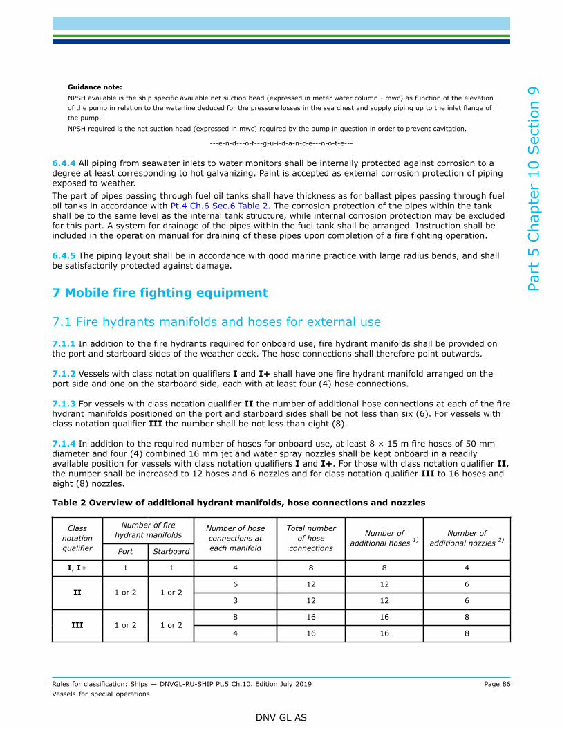
Part
5 C
hapt
er 1
0 Sec
tion
9
Rules for classification: Ships — DNVGL-RU-SHIP Pt.5 Ch.10. Edition July 2019 Page 86Vessels for special operations
DNV GL AS
Guidance note:NPSH available is the ship specific available net suction head (expressed in meter water column - mwc) as function of the elevationof the pump in relation to the waterline deduced for the pressure losses in the sea chest and supply piping up to the inlet flange ofthe pump.NPSH required is the net suction head (expressed in mwc) required by the pump in question in order to prevent cavitation.
---e-n-d---o-f---g-u-i-d-a-n-c-e---n-o-t-e---
6.4.4 All piping from seawater inlets to water monitors shall be internally protected against corrosion to adegree at least corresponding to hot galvanizing. Paint is accepted as external corrosion protection of pipingexposed to weather.The part of pipes passing through fuel oil tanks shall have thickness as for ballast pipes passing through fueloil tanks in accordance with Pt.4 Ch.6 Sec.6 Table 2. The corrosion protection of the pipes within the tankshall be to the same level as the internal tank structure, while internal corrosion protection may be excludedfor this part. A system for drainage of the pipes within the fuel tank shall be arranged. Instruction shall beincluded in the operation manual for draining of these pipes upon completion of a fire fighting operation.
6.4.5 The piping layout shall be in accordance with good marine practice with large radius bends, and shallbe satisfactorily protected against damage.
7 Mobile fire fighting equipment
7.1 Fire hydrants manifolds and hoses for external use
7.1.1 In addition to the fire hydrants required for onboard use, fire hydrant manifolds shall be provided onthe port and starboard sides of the weather deck. The hose connections shall therefore point outwards.
7.1.2 Vessels with class notation qualifiers I and I+ shall have one fire hydrant manifold arranged on theport side and one on the starboard side, each with at least four (4) hose connections.
7.1.3 For vessels with class notation qualifier II the number of additional hose connections at each of the firehydrant manifolds positioned on the port and starboard sides shall be not less than six (6). For vessels withclass notation qualifier III the number shall be not less than eight (8).
7.1.4 In addition to the required number of hoses for onboard use, at least 8 × 15 m fire hoses of 50 mmdiameter and four (4) combined 16 mm jet and water spray nozzles shall be kept onboard in a readilyavailable position for vessels with class notation qualifiers I and I+. For those with class notation qualifier II,the number shall be increased to 12 hoses and 6 nozzles and for class notation qualifier III to 16 hoses andeight (8) nozzles.
Table 2 Overview of additional hydrant manifolds, hose connections and nozzles
Number of firehydrant manifolds
Classnotationqualifier Port Starboard
Number of hoseconnections ateach manifold
Total numberof hose
connections
Number ofadditional hoses 1)
Number ofadditional nozzles 2)
I, I+ 1 1 4 8 8 4
6 12 12 6II 1 or 2 1 or 2
3 12 12 6
8 16 16 8III 1 or 2 1 or 2
4 16 16 8
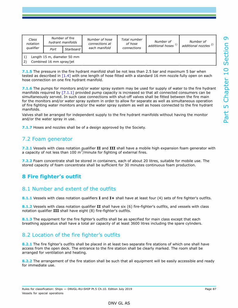
Part
5 C
hapt
er 1
0 Sec
tion
9
Rules for classification: Ships — DNVGL-RU-SHIP Pt.5 Ch.10. Edition July 2019 Page 87Vessels for special operations
DNV GL AS
Number of firehydrant manifolds
Classnotationqualifier Port Starboard
Number of hoseconnections ateach manifold
Total numberof hose
connections
Number ofadditional hoses 1)
Number ofadditional nozzles 2)
1) Length 15 m, diameter 50 mm2) Combined 16 mm spray/jet
7.1.5 The pressure in the fire hydrant manifold shall be not less than 2.5 bar and maximum 5 bar whentested as described in [1.4] with one length of hose fitted with a standard 16 mm nozzle fully open on eachhose connection on one fire hydrant manifold.
7.1.6 The pumps for monitors and/or water spray system may be used for supply of water to the fire hydrantmanifolds required by [7.1.1] provided pump capacity is increased so that all connected consumers can besimultaneously served. In such case connections with shut-off valves shall be fitted between the fire mainfor the monitors and/or water spray system in order to allow for separate as well as simultaneous operationof fire fighting water monitors and/or the water spray system as well as hoses connected to the fire hydrantmanifolds.Valves shall be arranged for independent supply to the fire hydrant manifolds without having the monitorand/or the water spray in use.
7.1.7 Hoses and nozzles shall be of a design approved by the Society.
7.2 Foam generator
7.2.1 Vessels with class notation qualifier II and III shall have a mobile high expansion foam generator witha capacity of not less than 100 m3/minute for fighting of external fires.
7.2.2 Foam concentrate shall be stored in containers, each of about 20 litres, suitable for mobile use. Thestored capacity of foam concentrate shall be sufficient for 30 minutes continuous foam production.
8 Fire fighter’s outfit
8.1 Number and extent of the outfits
8.1.1 Vessels with class notation qualifiers I and I+ shall have at least four (4) sets of fire fighter's outfits.
8.1.2 Vessels with class notation qualifier II shall have six (6) fire-fighter's outfits, and vessels with classnotation qualifier III shall have eight (8) fire-fighter's outfits.
8.1.3 The equipment for the fire fighter’s outfits shall be as specified for main class except that eachbreathing apparatus shall have a total air capacity of at least 3600 litres including the spare cylinders.
8.2 Location of the fire fighter’s outfits
8.2.1 The fire fighter's outfits shall be placed in at least two separate fire stations of which one shall haveaccess from the open deck. The entrance to the fire station shall be clearly marked. The room shall bearranged for ventilation and heating.
8.2.2 The arrangement of the fire station shall be such that all equipment will be easily accessible and readyfor immediate use.
Part
5 C
hapt
er 1
0 Sec
tion
9
Rules for classification: Ships — DNVGL-RU-SHIP Pt.5 Ch.10. Edition July 2019 Page 88Vessels for special operations
DNV GL AS
8.3 Compressed air supply
8.3.1 A high pressure compressor with accessories suitable for recharging the breathing air cylinders, shallbe installed onboard in the safest possible location. The capacity of the compressor shall be at least 75 litres/minute. The air intake for the compressor shall be equipped with a filter.
9 Stability and watertight integrity
9.1 General requirements
9.1.1 For vessels with a length LLL of 24 m and above, the stability shall be assessed when the watermonitors are in operation at full capacity in the most unfavourable direction with respect to stability. Acalculation showing the point of balance between the reaction forces from the water monitors and the forcesfrom the vessel's propulsion machinery and its side thrusters shall be presented.The monitor heeling moment shall be calculated based on the assumption in [9.1.2]. The criterion in [9.1.3]shall be complied with.
9.1.2 Monitor heeling momentThe heeling force F from the water monitor(s) shall be assumed in the transverse direction, based on fullcapacity as given in Table 1.The monitor heeling arm a shall be taken as the vertical distance between the centre of side thruster(s) andthe centre line of the monitor(s).
9.1.3 CriterionThe monitor heeling lever, calculated as F · a/displacement, shall not exceed 0.5 times the maximum GZcorresponding to maximum allowable VCG.If the maximum GZ occurs after 30°, the GZ at 30° shall be used instead of the maximum GZ.Additional information on the monitor capacity, position, heeling force and moment as well as plotting themonitors' heeling lever on the GZ diagram of the most unfavourable loading conditions shall be included inthe stability manual.
Part
5 C
hapt
er 1
0 Sec
tion
10
Rules for classification: Ships — DNVGL-RU-SHIP Pt.5 Ch.10. Edition July 2019 Page 89Vessels for special operations
DNV GL AS
SECTION 10 ICEBREAKERSymbolsFor symbols and definitions not defined in this chapter, see Pt.3 Ch.1 Sec.4.
1 Introduction
1.1 IntroductionThese rules provide requirements for ships intended to operate in ice-infested waters with the main purposeof ice breaking for the intention of escort and ice management.
1.2 ScopeThe rules in this section give requirements for hull strength, stability and machinery, applicable to anicebreaker.
1.3 ApplicationVessels built in compliance with the requirement in this section and that are assigned a polar class notationPC(1) to PC(7) (see Pt.6 Ch.6 Sec.6), may be assigned the class notation Icebreaker.
2 General principlesVessels with class notation Icebreaker shall be able to carry out ice management and assist other vessels inice conditions described in Pt.6 Ch.6 Sec.6 Table 1 and may make several consecutive attempts to break ice.
3 General arrangement
3.1 Bow formIce knife may be required fitted in the icebreaking bow to avoid excessive beaching and submersion ofthe deck in the aft ship. This requirement will be based on consideration of design speed, stability and thefreeboard. See Figure 1.Vessels with class notation Icebreaker shall have a bow shape so that the bow will ride up on the ice whenencountering pressure ridges or similar ice features which will not break during the first ramming.
Guidance note:At the UIWL the angle between the stem and the waterline should be 22°-35°. The bow-lines in the fore body below the waterlineshould be parallel to the stem.
---e-n-d---o-f---g-u-i-d-a-n-c-e---n-o-t-e---
3.2 Stem and stern regionThe stem reinforcement in Pt.6 Ch.6 Sec.6 [5.8] shall be extended vertically from the keel to the horizontalline x m above the UIWL, and horizontally to a line 0.06 L aft of the stem line or 0.125 B outboard from thecentre line, whichever is reached first. See Figure 1.The fore boundary of the stern region shall be at least 0.04 L fore of the aftermost point where the hull linesare parallel to the centre line at upper ice waterline (UIWL), see Figure 1.

Part
5 C
hapt
er 1
0 Sec
tion
10
Rules for classification: Ships — DNVGL-RU-SHIP Pt.5 Ch.10. Edition July 2019 Page 90Vessels for special operations
DNV GL AS
Figure 1 Stem and hull area extents
3.3 Position of collision bulkheadThe distance from the vertical ram bow, i.e. forward ice knife, to the collision bulkhead shall be at least 2s, inm, where s is the frame spacing. See Figure 2.
Figure 2 Position of collision bulkhead

Part
5 C
hapt
er 1
0 Sec
tion
10
Rules for classification: Ships — DNVGL-RU-SHIP Pt.5 Ch.10. Edition July 2019 Page 91Vessels for special operations
DNV GL AS
In the case where the maximum distance xc from the perpendicular FE to the collision bulkhead as specifiedin Pt.3 Ch.2 Sec.2 [4] is exceeded, the following shall be submitted:
— Floatability and stability calculations showing that, with the ship fully loaded to summer draught on evenkeel, flooding of the space forward of the collision bulkhead will not result in any other compartmentsbeing flooded, nor in an unacceptable loss of stability.
4 Structural design
4.1 Materials
4.1.1 Material in fore ship substructure in vessels with class notations DAT(t) shall be of class III.
4.1.2 Within 0.2 L aft of amidships and 0.3 L forward of amidships for vessel with class notations DAT(t),material classes shall be according to Pt.6 Ch.6 Sec.5 Table 5.Where there is overlap of material class requirement of Pt.3 Ch.3 Sec.1, the class giving the highest steelgrade shall be applied.
5 Loads
5.1 Hull area factorsThe area factors (AF) reflecting the relative magnitude of the ice load expected in that area for each PC polarclass notation are listed in Table 1, Table 2 and Table 3.Table 1, Table 2 and Table 3 in this section shall be used as an alternative to Pt.6 Ch.6 Sec.6 Table 6, Pt.6Ch.6 Sec.6 Table 7 and Pt.6 Ch.6 Sec.6 Table 8, respectively.
Table 1 Hull area factors (AF) for ships with class notation Icebreaker
Polar classHull area Area
PC(1) PC(2) PC(3) PC(4) PC(5) PC(6) PC(7)
Bow (B) All B 1.00 1.00 1.00 1.00 1.00 1.00 1.00
Icebelt BIi 0.90 0.85 0.85 0.85 0.85 1.00* 1.00*
Lower BIl 0.70 0.65 0.65 0.65 0.65 0.65 0.65Bow intermediate(BI)
Bottom BIb 0.55 0.50 0.45 0.45 0.45 0.45 0.45
Icebelt Mi 0.70 0.65 0.55 0.55 0.55 0.55 0.55
Lower Ml 0.50 0.45 0.40 0.40 0.40 0.40 0.40Midbody (M)
Bottom Mb 0.30 0.30 0.25 0.25 0.25 0.25 0.25
Icebelt Si 0.95 0.90 0.80 0.80 0.80 0.80 0.80
Lower Sl 0.55 0.50 0.45 0.45 0.45 0.45 0.45Stern (S)
Bottom Sb 0.35 0.30 0.30 0.30 0.30 0.30 0.30
Notes:* See Pt.6 Ch.6 Sec.6 [4.1.3].

Part
5 C
hapt
er 1
0 Sec
tion
10
Rules for classification: Ships — DNVGL-RU-SHIP Pt.5 Ch.10. Edition July 2019 Page 92Vessels for special operations
DNV GL AS
Table 2 Hull area factors (AF) for ships with class notation Icebreaker with thrusters/poddedpropulsion
Polar classHull area Area
PC(1) PC(2) PC(3) PC(4) PC(5) PC(6) PC(7)
Bow (B) All B 1.00 1.00 1.00 1.00 1.00 1.00 1.00
Icebelt BIi 0.90 0.85 0.85 0.80 0.80 1.00* 1.00*
Lower BIl 0.70 0.65 0.65 0.65 0.55 0.55 0.50Bow intermediate(BI)
Bottom BIb 0.55 0.50 0.50 0.45 0.35 0.30 0.25
Icebelt Mi 0.70 0.65 0.55 0.55 0.55 0.55 0.55
Lower Ml 0.55 0.45 0.40 0.40 0.40 0.40 0.40Midbody (M)
Bottom Mb 0.30 0.30 0.25 0.25 0.25 0.25 0.25
Icebelt Si 0.95 0.90 0.80 0.80 0.80 0.80 0.80
Lower Sl 0.70 0.65 0.60 0.60 0.60 0.60 0.60Stern (S)
Bottom Sb 0.35 0.30 0.30 0.30 0.30 0.30 0.30
Notes:* See Pt.6 Ch.6 Sec.6 [4.1.3].
Table 3 Hull area factors (AF) for ships with class notation Icebreaker intended to operate astern
Polar classHull area Area
PC(1) PC(2) PC(3) PC(4) PC(5) PC(6) PC(7)
Bow (B) All B 1.00 1.00 1.00 1.00 1.00 1.00 1.00
Icebelt BIi 0.90 0.85 0.85 0.85 0.85 1.00* 1.00*
Lower BIl 0.70 0.65 0.65 0.65 0.65 0.65 0.65Bow intermediate(BI)
Bottom BIb 0.55 0.50 0.45 0.45 0.45 0.45 0.45
Icebelt Mi 0.70 0.65 0.55 0.55 0.55 0.55 0.55
Lower Ml 0.50 0.45 0.40 0.40 0.40 0.40 0.40Midbody (M)
Bottom Mb 0.30 0.30 0.25 0.25 0.25 0.25 0.25
Icebelt SIi 0.90 0.85 0.85 0.85 0.85 1.00* 1.00*
Lower SIl 0.70 0.65 0.65 0.65 0.65 0.65 0.65Stern intermediate(SI)**
Bottom SIb 0.55 0.50 0.45 0.45 0.45 0.45 0.45
Icebelt Si 1.00 1.00 1.00 1.00 1.00 1.00 1.00
Lower Sl 0.77 0.72 0.72 0.72 0.72 0.72 0.72Stern (S)
Bottom Sb 0.61 0.55 0.50 0.50 0.50 0.50 0.50
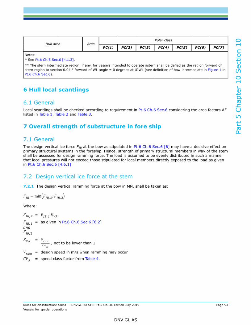
Part
5 C
hapt
er 1
0 Sec
tion
10
Rules for classification: Ships — DNVGL-RU-SHIP Pt.5 Ch.10. Edition July 2019 Page 93Vessels for special operations
DNV GL AS
Polar classHull area Area
PC(1) PC(2) PC(3) PC(4) PC(5) PC(6) PC(7)
Notes:* See Pt.6 Ch.6 Sec.6 [4.1.3].
** The stern intermediate region, if any, for vessels intended to operate astern shall be defied as the region forward ofstern region to section 0.04 L forward of WL angle = 0 degrees at UIWL (see definition of bow intermediate in Figure 1 inPt.6 Ch.6 Sec.6).
6 Hull local scantlings
6.1 GeneralLocal scantlings shall be checked according to requirement in Pt.6 Ch.6 Sec.6 considering the area factors AFlisted in Table 1, Table 2 and Table 3.
7 Overall strength of substructure in fore ship
7.1 GeneralThe design vertical ice force FIB at the bow as stipulated in Pt.6 Ch.6 Sec.6 [6] may have a decisive effect onprimary structural systems in the foreship. Hence, strength of primary structural members in way of the stemshall be assessed for design ramming force. The load is assumed to be evenly distributed in such a mannerthat local pressures will not exceed those stipulated for local members directly exposed to the load as givenin Pt.6 Ch.6 Sec.6 [4.6.1]
7.2 Design vertical ice force at the stem
7.2.1 The design vertical ramming force at the bow in MN, shall be taken as:
Where:
=
and= as given in Pt.6 Ch.6 Sec.6 [6.2]
= , not to be lower than 1
= design speed in m/s when ramming may occur
= speed class factor from Table 4.

Part
5 C
hapt
er 1
0 Sec
tion
10
Rules for classification: Ships — DNVGL-RU-SHIP Pt.5 Ch.10. Edition July 2019 Page 94Vessels for special operations
DNV GL AS
Table 4 Speed class factors
Polar Class CFR
PC(1) 5.7
PC(2) 4.4
PC(3) 3.5
PC(4) 2.75
PC(5) 2.25
PC(6) 2.25
PC(7) 2
7.2.2 Ramming speed Vram shall be stated in the appendix to the classification certificate.
7.2.3 The design vertical ramming force shall be applied with its center on the stem line as a patch or lineload as shown by Figure 3. The most unfavorable design draught forward shall be assumed for the applicationof the load.
Figure 3 Ice pach on the stem due to ramming
7.2.4 The extent of load distribution along the stem can be calculated as follow:

Part
5 C
hapt
er 1
0 Sec
tion
10
Rules for classification: Ships — DNVGL-RU-SHIP Pt.5 Ch.10. Edition July 2019 Page 95Vessels for special operations
DNV GL AS
where:
= design vertical ice force as given in [7.2] , in MN
= average patch pressure as given in Pt.6 Ch.6 Sec.6 [4.6.1]
= stem angle to be measured between the horizontal axis and the stem tangent at the upper icewaterline, [o]
B = ship molded breadth [m]C =
LB =bow length used in the equation measured from the stem to the full half breath of the
ship at the UIWL, in m, see Figure 4 and Figure 5eb = bow shape exponent which best describes the waterplane. (see Figure 4 and Figure 5 )
= 1 for a simple wedge bow form.
Figure 4 Bow shape definition

Part
5 C
hapt
er 1
0 Sec
tion
10
Rules for classification: Ships — DNVGL-RU-SHIP Pt.5 Ch.10. Edition July 2019 Page 96Vessels for special operations
DNV GL AS
Figure 5 Illustration of eb effect on the bow shape for B=20 and LB=16
7.3 Direct calculations and acceptance criteriaRecognized structural idealization and calculation methods shall be applied.Direct calculations and acceptance criteria according to Pt.6 Ch.6 Sec.6 [8] shall be used for evaluation of thefore ship sub-structural strength.
8 Longitudinal hull girder strength
8.1 Design vertical shear force and bending momentVertical shear and bending moment along the hull girder shall be calculated as required in Pt.6 Ch.6 Sec.6[6.3] and Pt.6 Ch.6 Sec.6 [6.4] with FIB calculated according to [7.2] in this section.
8.2 Longitudinal strength acceptance criteriaLongitudinal strength criteria in Pt.6 Ch.6 Sec.6 Table 9 shall be satisfied with .
9 Stability
9.1 General
9.1.1 Vessels with a freeboard length LLL of 24 meters and above and class notation Icebreaker shallcomply with the requirements of Pt.3 Ch.15 and IMO Polar Code Chapter 4 Subdivision and Stability, as wellas the requirements of this subsection.
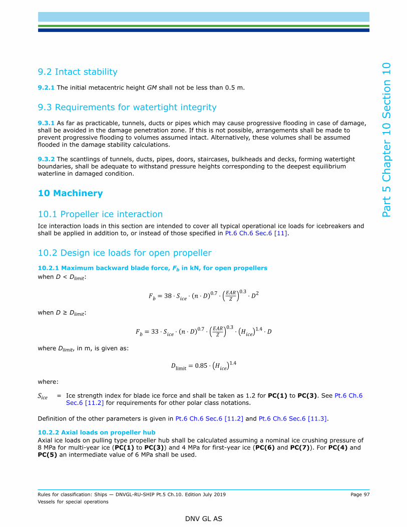
Part
5 C
hapt
er 1
0 Sec
tion
10
Rules for classification: Ships — DNVGL-RU-SHIP Pt.5 Ch.10. Edition July 2019 Page 97Vessels for special operations
DNV GL AS
9.2 Intact stability
9.2.1 The initial metacentric height GM shall not be less than 0.5 m.
9.3 Requirements for watertight integrity
9.3.1 As far as practicable, tunnels, ducts or pipes which may cause progressive flooding in case of damage,shall be avoided in the damage penetration zone. If this is not possible, arrangements shall be made toprevent progressive flooding to volumes assumed intact. Alternatively, these volumes shall be assumedflooded in the damage stability calculations.
9.3.2 The scantlings of tunnels, ducts, pipes, doors, staircases, bulkheads and decks, forming watertightboundaries, shall be adequate to withstand pressure heights corresponding to the deepest equilibriumwaterline in damaged condition.
10 Machinery
10.1 Propeller ice interactionIce interaction loads in this section are intended to cover all typical operational ice loads for icebreakers andshall be applied in addition to, or instead of those specified in Pt.6 Ch.6 Sec.6 [11].
10.2 Design ice loads for open propeller10.2.1 Maximum backward blade force, Fb in kN, for open propellerswhen D < Dlimit:
when D ≥ Dlimit:
where Dlimit, in m, is given as:
where:
Sice = Ice strength index for blade ice force and shall be taken as 1.2 for PC(1) to PC(3). See Pt.6 Ch.6Sec.6 [11.2] for requirements for other polar class notations.
Definition of the other parameters is given in Pt.6 Ch.6 Sec.6 [11.2] and Pt.6 Ch.6 Sec.6 [11.3].
10.2.2 Axial loads on propeller hubAxial ice loads on pulling type propeller hub shall be calculated assuming a nominal ice crushing pressure of8 MPa for multi-year ice (PC(1) to PC(3)) and 4 MPa for first-year ice (PC(6) and PC(7)). For PC(4) andPC(5) an intermediate value of 6 MPa shall be used.

Part
5 C
hapt
er 1
0 Sec
tion
10
Rules for classification: Ships — DNVGL-RU-SHIP Pt.5 Ch.10. Edition July 2019 Page 98Vessels for special operations
DNV GL AS
Propeller hub and affected parts in the propeller and shaft line shall have safety factor 1.5 against yieldstrength.
Guidance note:A method for calculating these loads is described in DNVGL-CG-0041.
---e-n-d---o-f---g-u-i-d-a-n-c-e---n-o-t-e---
10.2.3 Maximum spindle torque for controllable pitch propellersThe maximum spindle torque Qsex due to a blade failure load acting at 0.8R shall be determined.
It is assumed that the force that causes blade failure typically reduces when moving from the propellercentre towards the leading and trailing edges. At a certain distance from the blade centre of rotation themaximum spindle torque will occur. This maximum spindle torque in kNm, shall be defined by an appropriatestress analysis or using equation below:
where:
Cspex = Csp ∙ Cfex
Csp = ratio between the distance from spindle axis to the position giving maximum spindle torque, andthe distance between spindle axis and leading or trailing edge, all at 0.8 R chord
Cfex = ratio between load at position of maximum spindle torque and blade failure loadcLE0.8 = leading edge portion of the chord length at 0.8 RcTE0.8 = trailing edge portion of the chord length at 0.8 RFex = blade failure load, in kN, as defined in Pt.6 Ch.6 Sec.6 [11.6].
If the values Csp and Cfex are not known, the following approximation may be used:
If the values Cspex is below 0.3, a value of 0.3 shall be used for Cspex.
10.3 Design ice loads for propulsion lineDynamic torsional analysis of ice impacts on the propeller shall be carried out for all propulsion plants.
The propeller ice torque excitation for shaft line transient dynamic analysis (time domain) is defined as asequence of blade impacts which are of half sine shape and occur at the blade. The torque due to a singleblade ice impact as a function of the propeller rotation angle, in kNm, is then defined as:
when φ rotates from 0 to i plus integer revolutions, or:
Q(φ) = 0
when φ rotates from i to 360 plus integer revolutions.

Part
5 C
hapt
er 1
0 Sec
tion
10
Rules for classification: Ships — DNVGL-RU-SHIP Pt.5 Ch.10. Edition July 2019 Page 99Vessels for special operations
DNV GL AS
Where:
φ = rotation angle starting when the first impact occursQmax = maximum propeller ice torque (also referred to as Tmax in Pt.6 Ch.6 Sec.6).
The parameters Cq and i are given in Table 5. i is the duration of propeller blade/ice interaction expressedin propeller rotation angle.
Table 5
i (deg.)Torque excitation Propeller-ice interaction Cq
Z = 3 Z = 4 Z = 5 Z = 6
Excitation case 1 Single ice block 1.0 90 90 72 60
Excitation case 2 Single ice block 1.0 135 135 135 135
Excitation case 3 Two ice blocks (phase shift360 deg/(2·Z) 0.5 45 45 36 30
Excitation case 4 Single ice block 1.0 45 45 36 30
The total ice torque is obtained by summing the torque of single blades, taking into account the phase shift360 deg/Z. At the beginning and at the end of the milling sequence (within calculated duration) linear rampfunctions shall be used to increase Cq to its maximum within one propeller revolution and vice versa todecrease it to zero.
The number of propeller revolutions during a milling sequence shall be obtained from the formula:
NQ = 2 Hice
The number of impacts is Z · NQ for blade order excitation.
The dynamic simulation shall be performed for all excitation cases at bollard condition with correspondingpropeller speed and maximum available output of the engine.
10.4 Fatigue evaluation of propulsion lineFor the evaluation of fatigue, the number of load cycles shall be multiplied by a factor 3 to account for theassumed operational profile of icebreakers:
Definition of parameters is given in Pt.6 Ch.6 Sec.6 [12.1].
10.5 Steering systemAdditional fast acting torque relief arrangements (acting at 15% higher pressure than set pressure of safetyvalves) shall be fitted in order to provide effective protection of the rudder actuator in case of the rudderbeing pushed rapidly hard over against the rudder stops. The rudder turning speed to be assumed for eachice class is shown in Table 6.The arrangement shall be designed such that steering capacity can be speedily regained.

Part
5 C
hapt
er 1
0 Sec
tion
10
Rules for classification: Ships — DNVGL-RU-SHIP Pt.5 Ch.10. Edition July 2019 Page 100Vessels for special operations
DNV GL AS
Table 6 Turning speeds for dimensioning of fast acting torque relief arrangements
Ice class PC(1) and PC(2) PC(3) to PC(5) PC(6) and PC(7)
Turning speeds in deg/s 40 20 15
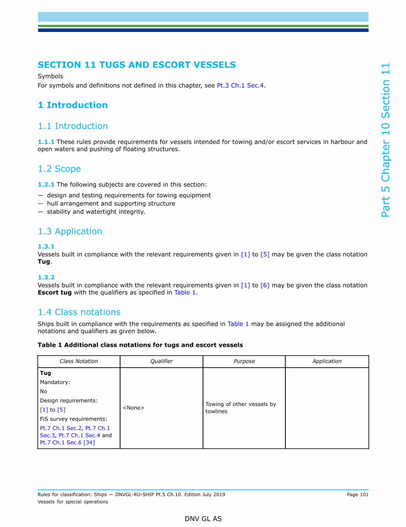
Part
5 C
hapt
er 1
0 Sec
tion
11
Rules for classification: Ships — DNVGL-RU-SHIP Pt.5 Ch.10. Edition July 2019 Page 101Vessels for special operations
DNV GL AS
SECTION 11 TUGS AND ESCORT VESSELSSymbolsFor symbols and definitions not defined in this chapter, see Pt.3 Ch.1 Sec.4.
1 Introduction
1.1 Introduction
1.1.1 These rules provide requirements for vessels intended for towing and/or escort services in harbour andopen waters and pushing of floating structures.
1.2 Scope
1.2.1 The following subjects are covered in this section:
— design and testing requirements for towing equipment— hull arrangement and supporting structure— stability and watertight integrity.
1.3 Application1.3.1 Vessels built in compliance with the relevant requirements given in [1] to [5] may be given the class notationTug.
1.3.2 Vessels built in compliance with the relevant requirements given in [1] to [6] may be given the class notationEscort tug with the qualifiers as specified in Table 1.
1.4 Class notationsShips built in compliance with the requirements as specified in Table 1 may be assigned the additionalnotations and qualifiers as given below.
Table 1 Additional class notations for tugs and escort vessels
Class Notation Qualifier Purpose Application
Tug
Mandatory:
No
Design requirements:
[1] to [5]
FiS survey requirements:
Pt.7 Ch.1 Sec.2, Pt.7 Ch.1Sec.3, Pt.7 Ch.1 Sec.4 andPt.7 Ch.1 Sec.6 [34]
<None> Towing of other vessels bytowlines

Part
5 C
hapt
er 1
0 Sec
tion
11
Rules for classification: Ships — DNVGL-RU-SHIP Pt.5 Ch.10. Edition July 2019 Page 102Vessels for special operations
DNV GL AS
Class Notation Qualifier Purpose Application
F
Steering and manoeuvringoperations of other vesselsby towlines
Escort rating numbers basedon full scale test
N
Steering and manoeuvringoperations of other vesselsby towlines
Escort rating numbers basedon numerical calculations
O
Steering and manoeuvringoperations of other vesselsby towlines
Escort rating numbersestablished by anotherclassification society
One of the qualifiers F, N orO is mandatory
Only one of the qualifiers F,N or O may be assigned
Escort tug
Mandatory:
No
Design requirements:
[1] to [6]
FiS survey requirements:
Pt.7 Ch.1 Sec.2, Pt.7 Ch.1Sec.3, Pt.7 Ch.1 Sec.4 andPt.7 Ch.1 Sec.6 [34]
(FS, t, v)
(FS, t, v) are escort ratingnumbers, where:
FS indicates maximumtransverse steering pull inmetric tonnes, exerted bythe escort tug on the sternof the assisted vessel
t is the time in secondsrequired for the change ofthe tug's position from oneside to the correspondingopposite side
v is the speed in knotsat which this pull may beattained
Mandatory qualifier
Maximum two sets of escortrating numbers may beassigned
1.5 Testing requirements1.5.1 Workshop testing
Towing hook and quick release:
Towing hooks with a mechanical quick release, the movable towing arm and other load transmitting elementsshall be subjected to a test force PL with the aid of an approved testing facility. In connection with this test,the quick release shall be tested likewise; the release force shall be measured and shall not exceed 150 N,see [3.5.3].
When towing hooks are provided with a pneumatic quick release, both the pneumatic and the mechanicalquick release required by [3.5.4] shall be tested.
Also towing hooks with a hydraulic quick release shall be tested, but the quick release itself need not besubjected to the test load. If a cylinder tested and approved by the Society is employed as a loaded gear

Part
5 C
hapt
er 1
0 Sec
tion
11
Rules for classification: Ships — DNVGL-RU-SHIP Pt.5 Ch.10. Edition July 2019 Page 103Vessels for special operations
DNV GL AS
component, during the load test the cylinder may be replaced by a load transmitting member not pertainingto the gear, the operability of the gear being restored subsequently. The operability of the quick release shallbe proved with the towline loosely resting on the hook.
Following each satisfactory testing at manufacturer's, a test certificate will be issued by the attendingsurveyor and shall be handed on board, together with the towing hook.
Towing winches:
The winch power unit shall be subjected to a test bed trial at the manufacturer's. A works test certificate shallbe presented on the occasion of the final inspection of the winch, see [1.5.2] under Towing hooks on board.
Components exposed to pressure shall be pressure-tested to a test pressure PD of:
PD = 1.5 P
where:
P = admissible working pressure or opening pressure of the safety valves, in bar. However, with workingpressures exceeding 200, it is acceptable that test pressure does not exceed P by more than 100 bar.
Tightness tests shall be carried out at the relevant components.
Upon completion, towing winches shall be subjected to a final inspection and an operational test to the ratedload. The hauling speed shall be determined during an endurance test under the rated tractive force. Duringthese trials, in particular the braking and safety equipment shall be tested and adjusted.
The brake shall be tested to a test load equal to the rated holding capacity, but at least equal to the bollardpull.
If manufacturers do not have at their disposal the equipment required, a testonfirming the design winchcapacity, and including adjustment of the overload protection device, may be carried out after installation onboard, see [1.5.2].
In that case only the operational trials without applying the prescribed loads will be carried out at themanufacturers.
Accessory towing gear components and towlines:
Accessories subjected to towing loads, where not already covered by [1.5.1], are generally to be tested totest force PL at the manufacturer.
For all accessories certificates, CG 3, and for the towline, CG 4, shall be submitted.
The Society reserve the right of stipulating an endurance test to be performed of the towing gearcomponents, where considered necessary for assessment of their operability.
Following each satisfactory testing at manufacturer's workshop, a test certificate will be issued by theattending surveyor and shall be handed on board, together with the towing winch.
1.5.2 On board testing Towing gear testing requirements:The installed towing gear shall be tested on the tug using the bollard pull (BP) test to simulate the towlinepull.
Part
5 C
hapt
er 1
0 Sec
tion
11
Rules for classification: Ships — DNVGL-RU-SHIP Pt.5 Ch.10. Edition July 2019 Page 104Vessels for special operations
DNV GL AS
The winch and other equipment made mandatory in this section shall be function tested according toapproved procedure in order to verify:
— the ability for the arrangement and equipment to operate within the specified limitations, towline paths,towline sectors etc. specified by the arrangement drawing
— the correct function of the normal operation modes— the correct function of the emergency operation modes, including emergency release mechanism and
dead ship operations.
Bollard pull test:In general a BP test should be carried out before entering into service of the vessel. The test may bewitnessed and certified by DNV GL. Based upon the results of the test a bollard pull certificate will be issued.The expected BP may be preliminarily applied for design approval purposes prior to sea trial. If sea trialreveals that the expected BP is exceeded by more than 10%, such design approvals shall be re-considered.The following test procedure should be adhered to and possible deviations shall be recorded in the bollardpull certificate:
1) Approved test programme shall be submitted prior to the testing.2) During testing of continuous static BP the main engine(s) shall be run at the manufacturer's
recommended maximum continuous rating (MCR).3) During testing of overload pull, the main engines shall be run at the manufacturer's recommended
maximum rating that can be maintained for a minimum of 1 hour. The overload test may be omitted.4) The propeller(s) fitted when performing the test shall be the propeller(s) used when the vessel is in
normal operation.5) All auxiliary equipment such as pumps, generators and other equipment, which are driven from the main
engine(s) or propeller shaft(s) in normal operation of the vessel shall be connected during the test.6) The vessel shall be trimmed at even keel or at a trim by stern not exceeding 2% of the vessel's length.7) The vessel shall be able to maintain a fixed course for not less than 10 minutes while pulling as specified
in items 2 or 3 above.8) The test shall be performed with a fair wind speed not exceeding 5 m/s.9) The co-current at the test location shall not exceed 1 knot.10) The load cell used for the test shall be approved by the Society and be calibrated at least once a year.
The accuracy of the load cell shall be ± 2% within a temperature range and a load range relevant for thetest.
11) An instrument giving a continuous read-out and also a recording instrument recording the bollard pullgraphically as a function of the time shall both be connected to the load cell.
12) The arrangement of bollard, towline and load cell shall ensure a force reading in horizontal direction bymeans of minimizing the influence from friction and force components in vertical direction.
13) The figure certified as the vessel's continuous static BP shall be the towing force recorded as beingmaintained without any tendency to decline for a duration of not less than 10 minutes.
14) Certification of BP figures recorded when running the engine(s) at overload, reduced r.p.m. or with areduced or an increased number of engines or propellers operating may be given and noted on thecertificate. The angular position of turn able propulsion devices shall be recorded.
15) Both the load cell reading, engine power, and other essential parameters shall be continuously availableto the surveyor.
16) The recorded load cell readings shall be made available to the surveyor immediately upon completion ofthe test.
Towing hooks on board:For all towing hooks (independent of the magnitude of the test force PL, as defined in Table 3), the quickrelease shall be tested with an upward towline direction against the horizontal line of 60° or 45° respectivelyas outlined in [3.5.5]. If the towline will never be operated in such upward direction due to the tug isequipped with a towrope guidance at stern, then this release test may be carried out in the maximumoccurring upward direction.
Part
5 C
hapt
er 1
0 Sec
tion
11
Rules for classification: Ships — DNVGL-RU-SHIP Pt.5 Ch.10. Edition July 2019 Page 105Vessels for special operations
DNV GL AS
In addition, the towing hook shall be load tested with a load equal to BP.The surveyor certifies the initial on board test by an entry into the test certificate for towing hooks.Towing winches on board:After installation on board, the safe operation of the winch(es) from all control stands shall be checked. Itshall be proved that for both cases a) with the drum brake engaged and b) during hoisting and pay out,the emergency release mechanism for the drum operates well under both normal and dead ship operationmodes. These checks may be combined with the bollard pull test.The towing winch shall be subjected to a trial during the bollard pull test to a test load corresponding to theholding power of the winch.
2 Hull arrangement and strength
2.1 Draught for scantlings
2.1.1 For determining the scantlings of strength members based on the ship's draught, the latter shall not betaken less than 0.85 D.
2.2 Fore body, bow structure
2.2.1 On tugs for ocean towage, strengthening in way of the fore body, i.e. stringers, tripping brackets etc.shall conform to the indications given in Pt.3 Ch.10 Sec.1. The stringers shall be effectively connected to thecollision bulkhead. Depending on the type of service expected, additional strengthening may be required.
2.2.2 For harbour tugs frequently engaged in berthing operations, the bow shall be suitably protected byfendering and be structurally strengthened.
2.2.3 The bulwark shall be arranged with an inward inclination in order to reduce the probability andfrequency of damages. Square edges shall be chamfered.
2.2.4 The bow structure of tugs in pushing operation for maneuvering at narrow, sheltered waters shall bestrengthened as noted in [2.2.5], [2.2.6] and [2.2.7].
2.2.5 Forward of the collision bulkhead stringers shall be arranged on the ship's side not more than 2 mapart. The stringers shall be connected to the collision bulkhead by brackets forming gradual transition to thebulkhead.
2.2.6 The design push force and the extent of the push force area shall be marked on the foreship drawings.Based on this design push force times a dynamic factor of 1.3 and based on net scantlings, the stresses inthe supporting structures shall not exceed:
— Normal stress = — Shear stress = — Equivalent stress =
2.2.7 The frames shall be connected to the stringers by lugs or brackets at every frame.
2.2.8 For pusher tugs for inland navigation, see rules for inland navigation vessels DNVGL-RU-INV Pt.5 Ch.6.

Part
5 C
hapt
er 1
0 Sec
tion
11
Rules for classification: Ships — DNVGL-RU-SHIP Pt.5 Ch.10. Edition July 2019 Page 106Vessels for special operations
DNV GL AS
2.3 Side structure
2.3.1 The side structure of areas frequently subjected to impact loads shall be reinforced by increasing thesection modulus of side frames by 20%. Besides, fendering may be necessary to reduce indenting damagesof the shell plating.
2.3.2 A continuous and suitable strong fender shall be arranged along the upper deck, extending the wholelength of the vessel.
2.4 Engine room casing, superstructures and deckhouses
2.4.1 The gross plate thickness of the casing walls and casing tops shall not be less than 5 mm. The grossthickness of the coamings shall not be less than 6 mm. The coamings shall extend to the lower edges of thebeams.
2.4.2 The stiffeners of the casing shall be connected to the beams of the casing top and shall extend to thelower edge of the coamings.
2.4.3 The following requirements shall be observed for superstructures and deckhouses of tugs assigned forthe restricted services areas R0 to R4 or for unlimited range of service:
— The plate thickness of the external boundaries of superstructures and deckhouses shall be increased by 1mm above the thickness as required in Pt.3 Ch.6 Sec.8 [3].
— The section modulus of stiffeners shall be increased by 50% above the values as required in Pt.3 Ch.6Sec.8 [3].
2.5 Foundations of towing gear
2.5.1 The substructure of the towing hook attachment and the foundations of the towing winch, and of anyguiding elements such as towing posts or fairleads, where provided, shall be thoroughly connected to theship's structure, considering all possible directions of the towline, see [3.5.5].
2.5.2 The stresses in the supporting structure, foundations and fastening elements shall not exceed thepermissible stresses shown in Table 2 (based on the gross thickness), assuming a load equal to the test loadof the towing hook in case of hook arrangements, see [3.3.3], and a load of the winch holding capacity incase of towing winches, see also [3.5.5] and [3.7.3].
Table 2 Permissible stresses
Type of stress Permissible stress
Axial and bending tension and axial and bending compression withbox type girders and tubes σ = 0.83 ReH
Axial and bending compression with girders of open cross sectionsor with girders consisting of several members σ = 0.72 ReH
Shear τ = 0.48 ReH
Equivalent stress σvm = 0.85 ReH

Part
5 C
hapt
er 1
0 Sec
tion
11
Rules for classification: Ships — DNVGL-RU-SHIP Pt.5 Ch.10. Edition July 2019 Page 107Vessels for special operations
DNV GL AS
2.6 Deck structure
2.6.1 On tugs for ocean towage, the deck, particularly in the forward region, shall be suitably protected orstrengthened against sea impact.
2.6.2 Depending on the towline arrangement, the deck in the aft region shall be strengthened (beams, platethickness), if considerable chafing and/or impact shall be expected. See also [3.3.2].
2.7 Stern frame
2.7.1 The cross sectional area of a solid stern frame shall be 20% greater than required according to Pt.3Ch.10 Sec.6 [2]. For fabricated stern frames, the thickness of the propeller post plating shall be increased by20% compared to the requirements given in Pt.3 Ch.10 Sec.6 [2]. The section modulus Z1 of the sole pieceshall be increased by 20% compared to the modulus determined according to Pt.3 Ch.14 Sec.1 [5].
3 Systems and equipment
3.1 Anchoring and mooring equipment3.1.1 Equipment numberTugs shall have anchoring and mooring equipment corresponding to its equipment number, see Pt.3 Ch.11Sec.1 [3.1]. The term 2 BH in the formula may, however, be substituted by:
2(aB + Σ hi bi)
where:
bi = breadth, in m, of the widest superstructure or deckhouse of each tier having a breadth greater thanB/4.
3.1.2 General requirementsFor tugs with restricted service the equipment specified in Pt.3 Ch.11 Sec.1 Table 1 may be reduced inaccordance with Pt.3 Ch.11 Sec.1 Table 3. No reductions are given for class notations R0 and R1. For tugs inthe service range RE, see rules for classification: DNVGL-RU-INV.For tugs engaged only in berthing operations, one anchor is sufficient, if a spare anchor is readily available onland.
3.1.3 Tugs operating as pusher unitsThe anchoring equipment for tugs operating as pusher units will be considered according to the particularservice. Normally, the equipment is intended to be used for anchoring the tug alone, the pushed unit beingprovided with its own anchoring equipment.
3.2 Steering gear/steering arrangement3.2.1 Steering stabilitySteering stability, i.e. stable course maintaining capability of the tug, shall be ensured under all normallyoccurring towing conditions. Rudder size and rudder force shall be suitable in relation to the envisaged towingconditions and speed.
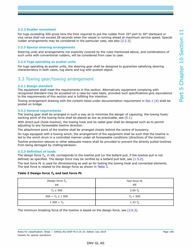
Part
5 C
hapt
er 1
0 Sec
tion
11
Rules for classification: Ships — DNVGL-RU-SHIP Pt.5 Ch.10. Edition July 2019 Page 108Vessels for special operations
DNV GL AS
3.2.2 Rudder movementFor tugs exceeding 500 gross tons the time required to put the rudder from 35° port to 30° starboard orvice versa shall not exceed 28 seconds when the vessel is running ahead at maximum service speed. Specialrudder arrangements may be considered in the particular case, see also [3.2.3].
3.2.3 Special steering arrangementsSteering units and arrangements not explicitly covered by the rules mentioned above, and combinations ofsuch units with conventional rudders, will be considered from case to case.
3.2.4 Tugs operating as pusher unitsFor tugs operating as pusher units, the steering gear shall be designed to guarantee satisfying steeringcharacteristics in both cases, tug alone and tug with pushed object.
3.3 Towing gear/towing arrangement3.3.1 Design standardThe equipment shall meet the requirements in this section. Alternatively equipment complying withrecognized standard may be accepted on a case-by-case basis, provided such specifications give equivalenceto the requirements of this section and is fulfilling the intention.Towing arrangement drawing with the content listed under documentation requirement in Sec.1 [4] shall beposted on bridge.
3.3.2 General requirementsThe towing gear shall be arranged in such a way as to minimise the danger of capsizing; the towing hook/working point of the towing force shall be placed as low as practicable, see [5.1].With direct-pull (hook-towline), the towing hook and its radial gear shall be designed such as to permitadjusting to any foreseeable towline direction.The attachment point of the towline shall be arranged closely behind the centre of buoyancy.On tugs equipped with a towing winch, the arrangement of the equipment shall be such that the towline isled to the winch drum in a controlled manner under all foreseeable conditions (directions of the towline).Towline protection sleeves or other adequate means shall be provided to prevent the directly pulled towlinesfrom being damaged by chafing/abrasion.
3.3.3 Definition of loadsThe design force Tb, in kN, corresponds to the towline pull (or the bollard pull, if the towline pull is notdefined) as specified. The design force may be verified by a bollard pull test, see [1.5.2].The test force PL is used for dimensioning as well as for testing the towing hook and connected elements.The test force is related to the design force as shown in Table 3.
Table 3 Design force Tb and test force PL
Design force Tb
kNTest force PL
kN
Tb ≤ 500 2.00 Tb
500 < Tb ≤ 1 500 Tb + 500
1 500 < Tb 1.33 Tb
The minimum breaking force of the towline is based on the design force, see [3.6.3].

Part
5 C
hapt
er 1
0 Sec
tion
11
Rules for classification: Ships — DNVGL-RU-SHIP Pt.5 Ch.10. Edition July 2019 Page 109Vessels for special operations
DNV GL AS
The winch holding capacity shall be based on the minimum breaking force, see [3.7.3], the rated winch forceis the hauling capacity of the winch drive when winding up the towline, see [1.5.1].For forces at the towing hook foundation see [3.5.5].
3.4 Materials for equipment
3.4.1 Towing hook with attachment shall be made of rolled, forged or cast steel in accordance with Pt.2.
3.4.2 Towing winch materials shall comply with relevant specifications given in Pt.2.
3.4.3 For forged and cast steel with minimum specified tensile strength above 650 N/mm2, specificationsof chemical composition and mechanical properties shall be submitted for approval for the equipment inquestion.
3.4.4 Plate material in welded parts shall be of the grades as given in Pt.3 Ch.11 Sec.1 Table 11.
3.4.5 When ReH is greater than 80% of Rm, the following value shall be used as ReH in calculations forstructural strength as given in [3.7]:
ReH = min(ReH; 0.8 Rm)
3.4.6 Fabrication of towing hook with attachments is generally to be in accordance with the Society'sdocument DNVGL-ST-0378
3.5 Towing hook and quick release
3.5.1 The towing hook shall be fitted with an adequate device guaranteeing slipping, i.e. emergency release,of the towline in case of an emergency. Slipping shall be possible from the bridge as well as from at least oneother place in the vicinity of the hook itself, from where in both cases the hook can be easily seen.
3.5.2 The towing hook shall be equipped with a mechanical, hydraulic or pneumatic quick release. The quickrelease shall be designed such as to guarantee that unintentional slipping is avoided.
3.5.3 A mechanical quick release shall be designed such that the required release force under test force PLdoes not exceed neither 150 N at the towing hook nor 250 N when activating the device on the bridge. Incase of a mechanical quick release, the releasing rope shall be guided adequately over sheaves. If necessary,slipping should be possible by downward pulling, using the whole body weight.
3.5.4 Where a pneumatic or hydraulic quick release is used, a mechanical quick release shall be providedadditionally.
3.5.5 Dimensioning of towing hook and towing gearThe dimensioning of the towing gear is based on the test force PL, see [3.3.3].The towing hook, the towing hook foundation, the corresponding substructures and the quick release shall bedesigned for the following directions of the towline:
— For a test force PL ≤ 500 kN:
— in the horizontal plane, directions from abeam over astern to abeam— in the vertical plane, from horizontal to 60° upwards.
— For a test force PL > 500 kN:
— in the horizontal plane, as above— in the vertical plane, from horizontal to 45° upwards.
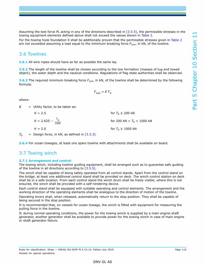
Part
5 C
hapt
er 1
0 Sec
tion
11
Rules for classification: Ships — DNVGL-RU-SHIP Pt.5 Ch.10. Edition July 2019 Page 110Vessels for special operations
DNV GL AS
Assuming the test force PL acting in any of the directions described in [3.5.5], the permissible stresses in thetowing equipment elements defined above shall not exceed the values shown in Table 2.For the towing hook foundation it shall be additionally proven that the permissible stresses given in Table 2are not exceeded assuming a load equal to the minimum breaking force Fmin, in kN, of the towline.
3.6 Towlines
3.6.1 All wire ropes should have as far as possible the same lay.
3.6.2 The length of the towline shall be chosen according to the tow formation (masses of tug and towedobject), the water depth and the nautical conditions. Regulations of flag state authorities shall be observed.
3.6.3 The required minimum breaking force Fmin, in kN, of the towline shall be determined by the followingformula:
where:
K = Utility factor, to be taken as:
K = 2.5 for Tb ≤ 200 kN
K = 2.625 − for 200 kN < Tb < 1000 kN
K = 2.0 for Tb ≥ 1000 kN
Tb = Design force, in kN, as defined in [3.3.3].
3.6.4 For ocean towages, at least one spare towline with attachments shall be available on board.
3.7 Towing winch3.7.1 Arrangement and controlThe towing winch, including towline guiding equipment, shall be arranged such as to guarantee safe guidingof the towline in all directions according to [3.5.5].The winch shall be capable of being safely operated from all control stands. Apart from the control stand onthe bridge, at least one additional control stand shall be provided on deck. The winch control station on deckshall be in a safe location. From each control stand the winch drum shall be freely visible; where this is notensured, the winch shall be provided with a self-rendering device.Each control stand shall be equipped with suitable operating and control elements. The arrangement and theworking direction of the operating elements shall be analogous to the direction of motion of the towline.Operating levers shall, when released, automatically return to the stop position. They shall be capable ofbeing secured in the stop position.It is recommended that, on vessels for ocean towage, the winch is fitted with equipment for measuring thepulling force in the towline.If, during normal operating conditions, the power for the towing winch is supplied by a main engine shaftgenerator, another generator shall be available to provide power for the towing winch in case of main engineor shaft generator failure.

Part
5 C
hapt
er 1
0 Sec
tion
11
Rules for classification: Ships — DNVGL-RU-SHIP Pt.5 Ch.10. Edition July 2019 Page 111Vessels for special operations
DNV GL AS
3.7.2 Winch drumSpecific requirements for winch drums:
1) The towline shall be fastened on the winch drum by a breaking link.2) The winch drum shall be capable of being declutched from the drive.3) The diameter of the winch drum shall be not less than 14 times the towline diameter. However, for all
towline types, the towline bending radius should not be less than specified by the towline manufacturer.4) To ensure security of the rope end fastening, at least three (3) dead turns shall remain on the drum.5) At the ends, drums shall have disc sheaves whose outer edges shall surmount the top layer of the rope
at least by 2.5 rope diameters, if no other means is provided to prevent the rope from slipping off thedrum.
6) If a multi-drum winch is used, then each winch drum shall be capable of independent operation.7) Items 3 to 4 above are not applicable to towlines of austenitic steels and fibre ropes. In case these
towline materials are utilized, dimensioning of the winch drum is subject to the Society’s approval.8) The in-board end of the towline shall be attached to the winch drum with a weak link or similar
arrangement that is designed to release the towline at low load.
3.7.3 Holding capacity/dimensioningThe holding capacity of the towing winch (towline in the first layer) shall correspond to 80% of the minimumbreaking load Fmin of the towline.When dimensioning the towing winch components, which - with the brake engaged - are exposed to the pullof the towline (rope drum, drum shaft, brakes, foundation frame and its fastening to the deck), a designtractive force equal to the holding capacity shall be assumed. When calculating the drum shaft the dynamicstopping forces of the brakes shall be considered. The drum brake shall not give way under this load.
3.7.4 BrakesIf the drum brakes are power-operated, manual operation of the brake shall be provided additionally.Drum brakes shall be capable of being quickly released from the control stand on the bridge, as well as fromany other control stand. The emergency release shall be functional under all working conditions, includingfailure of the power drive.The operating levers for the brakes shall be secured against unintentional operation.Following operation of the emergency release device, normal operation of the brakes shall be restoredimmediately.Following operation of the emergency release device, the winch driving motor shall not start againautomatically.Towing winch brakes shall be capable of preventing the towline from paying out when the vessel is towing atthe design force Tb and shall not be released automatically in case of power failure.
3.7.5 Tricing winchesControl stands for the tricing winches shall be located at safe distance off the sweep area of the towing gear.Apart from the control stands on deck, at least one other control stand shall be available on the bridge.Tricing winches are not subject to classification. In order to assess the supporting structure, maximumreaction forces and its locations shall be provided.
3.8 Towing winch emergency release mechanism3.8.1 ScopeEmergency release system refers to the mechanism and associated control arrangements that are used torelease the load on the towline in a controller manner under both normal and dead-ship conditions.

Part
5 C
hapt
er 1
0 Sec
tion
11
Rules for classification: Ships — DNVGL-RU-SHIP Pt.5 Ch.10. Edition July 2019 Page 112Vessels for special operations
DNV GL AS
Guidance note:For definitions of 'girting' and 'fleet angle' refer to IACS M79 - Towing winch emergency release systems.
---e-n-d---o-f---g-u-i-d-a-n-c-e---n-o-t-e---
3.8.2 GeneralThe winch shall be designed to allow drum release in an emergency, and in all operational modes.After an emergency release the winch brakes shall be in normal function without delay. It shall always bepossible to carry out the emergency release sequence (emergency release and/or application of brake), evenduring a black-out.
3.8.3 Performence generalThe emergency release system is to function as quickly as is reasonably practicable and within a maximum ofthree seconds after activation. The emergency release system shall allow the winch drum to rotate and thetowline to pay out in a controlled manner such that, when the emergency release system is activated, thereis sufficient resistance to rotation to avoid uncontrolled unwinding of the towline from the drum. Spinning(free, uncontrolled rotation) of the winch drum shall be avoided, as this could cause the towline to get stuckand disable the release function of the winch.
3.8.4 Performence requirementsOnce the emergency release is activated, the towline load required to rotate the winch drum shall be nogreater than:
1) the lesser of 49 kN or 5% of the holding capacity of the towing winch when two layers of towline are onthe drum, or
2) 15% of the holding capacity of the towing winch where it is demonstrated that this resistance to rotationshall not exceed 25% of the force that will result in listing sufficient for the immersion of the lowestunprotected opening.
3.8.5 Source of energyAn alternative source of energy shall be provided such that normal operation of the emergency releasesystem can be sustained under dead-ship conditions. The alternative source of energy shall be sufficient toachieve the most onerous of the following conditions (as applicable):
1) sufficient for at least three attempts to release the towline (i.e. three activations of the emergencyrelease system). Where the system provides energy for more than one winch it shall be sufficient forthree activations of the most demanding winch connected to it.
2) Where the winch design is such that the drum release mechanism requires continuous application ofpower (e.g. where the brake is applied by spring tension and released using hydraulic or pneumaticpower) sufficient power shall be provided to operate the emergency release system (e.g. hold the brakeopen and allow release of the towline) in a dead-ship situation for a minimum of five minutes.
Guidance note:This may be reduced to the time required for the full length of the towline to feed off the winch drum at the load in [3.8.4] ifthis is less than five minutes.
---e-n-d---o-f---g-u-i-d-a-n-c-e---n-o-t-e---
3.8.6 Operational requirementsEmergency release operation shall be possible from all control stands.The emergency release control shall be located in close proximity to the emergency stop button for winchoperation and both shall be clearly identifiable, clearly visible, easily accessible and positioned to allow safeoperability.The emergency release function shall take priority over any emergency stop function. Activation of the winchemergency stop from any location shall not to inhibit operation of the emergency release system from anylocation.Emergency release system control buttons shall have positive action to cancel.
Part
5 C
hapt
er 1
0 Sec
tion
11
Rules for classification: Ships — DNVGL-RU-SHIP Pt.5 Ch.10. Edition July 2019 Page 113Vessels for special operations
DNV GL AS
Guidance note:The positive action may be made at a different control position from the one where the emergency release was activated.
---e-n-d---o-f---g-u-i-d-a-n-c-e---n-o-t-e---
It shall always be possible to cancel the emergency release from the bridge regardless of the activationlocation and without manual intervention on the working deck.Control handles, buttons, etc. for emergency release shall be protected against accidental operation.Indications shall be provided on the bridge for all power supply and/or pressure levels related to the normaloperation of the emergency release system. Alarms shall be activated automatically if any level falls outsideof the limits within which the emergency release system is fully operational.Wherever practicable, control of the emergency release system shall be provided by a hard-wired system,fully independent of programmable electronic systems.Computer based systems that operate or may affect the control of emergency release systems shall meet therequirements for category III systems of UR E22.Components critical for the safe operation of the emergency release system shall be identified by themanufacturer.The method for annual survey of the winch shall be documented.The performance capabilities and operating instructions of the emergency release system shall bedocumented and made available on board.
3.9 Marking
3.9.1 Equipment shall be marked to enable them to be readily related to their specifications andmanufacturer. When the Society's product certificate is required, the equipment shall be clearly marked bythe Society for identification.
4 Fire safety and escape routes
4.1 Emergency exit from engine room
4.1.1 In the engine room an emergency exit shall be provided on or near the centerline of the vessel, whichcan be used at any inclination of the ship. The cover shall be weather tight and shall be capable of beingopened easily from outside and inside. The axis of the cover shall run in athwart ship direction.
4.2 Companionways
4.2.1 Companionways to spaces below deck see [5.2.1].
4.3 Rudder compartment
4.3.1 Where, for larger ocean going tugs, an emergency exit is provided from the rudder compartmentto the upper deck, the arrangement, sill height and further details shall be designed according to therequirements given in [5.2.3].
4.4 Access to bridge
4.4.1 Safe access to the bridge shall be ensured for all anticipated operating and heeling conditions, also inheavy weather during ocean towage.

Part
5 C
hapt
er 1
0 Sec
tion
11
Rules for classification: Ships — DNVGL-RU-SHIP Pt.5 Ch.10. Edition July 2019 Page 114Vessels for special operations
DNV GL AS
4.5 Fire safety
4.5.1 Structural fire protection measures shall be as outlined in Pt.4 Ch.10, as applicable according to thesize of the vessel.
4.5.2 Additional or deviating regulations of the competent administration shall be observed.
5 Stability and openings and closing appliances
5.1 General stability requirements
5.1.1 The requirements in this section apply to vessels with freeboard length LLL of 24 m and above.
5.1.2 Vessels with a freeboard length LLL less than 24 m should as far as practicable comply with therequirements given in this section. Other stability requirements may however be applied provided the Societyupon consideration in each case finds these requirements to be appropriate for the vessel.
5.1.3 The vessel's stability shall be assessed when the vessel is subjected to forces related to towingoperations, based on the requirements of [5.1.4].
Guidance note:It is acceptable that compliance is demonstrated for actual loading conditions only. The approval will then be limited to thepresented loading conditions. These initial conditions shall also comply with the applicable intact and damage stability criteriabefore applying the heeling moment.
---e-n-d---o-f---g-u-i-d-a-n-c-e---n-o-t-e---
5.1.4 Stability criteria, stern freeboard and towing heeling leversVessels engaged in harbour, coastal or ocean-going towing shall in the applicable loading conditions in thestability manual comply with the criteria of the International Code on Intact Stability, 2008 (effective from2020-01-01), Part B, paragraphs 2.8.4.2, 2.8.4.3 and 2.8.6.2, assuming towing heeling levers according toparagraph 2.8.2.
5.1.5 Loading conditionsIn addition to the standard loading conditions for cargo ships in Pt.3 Ch.15 Sec.1 [4.3.4], standard loadingconditions given in the International Code on Intact Stability, 2008 (effective from 2020-01-01), Part B,paragraph 3.4.1.8, shall apply, including the assumptions of paragraph 3.4.2.9.
5.1.6 Additional information in stability manualThe vessel's stability manual shall contain detailed information on the calculated heeling levers with allapplied parameters. The heeling lever curves shall be plotted together with the GZ curve for all intendedtowing conditions. The manual shall additionally contain information as given in the International Code onIntact Stability, 2008 (effective from 2020-01-01), Part B, paragraph 3.6.4.
5.2 Openings and closing appliances
5.2.1 In general, openings and closing appliances shall be in compliance with the requirements of Pt.3 Ch.12except as otherwise specified in this subsection.
5.2.2 Side scuttles and windowsSide scuttles in the ship's sides and in sides of superstructures on freeboard deck shall at least satisfy therequirements for type B side scuttles as per ISO 1751.
Part
5 C
hapt
er 1
0 Sec
tion
11
Rules for classification: Ships — DNVGL-RU-SHIP Pt.5 Ch.10. Edition July 2019 Page 115Vessels for special operations
DNV GL AS
For windows in a wheelhouse in the second tier, Type E windows as per ISO 3903 are required when directaccess to spaces below is provided. Glass thicknesses for intermediate sizes, not covered by ISO 3903, shallbe determined using ISO 21005.
5.2.3 Weather deck openingsSkylights in freeboard deck shall be arranged with coamings not less than 900mm high and scantlings shallbe as for exposed casings.Skylights leading to machinery spaces shall be of steel and not contain glass panels.
5.2.4 Tugs with L<24m and tugs in domestic tradeVentilators necessary to continuously supply the machinery space shall be positioned as close to thecentreline as possible, and have coamings exceeding 1.8m at the centreline of the vessel, linearly increasedto 4.5m at the ship's side above the lower part of the weather deck. Weathertight closing appliances are notmandatory, under the conditions described above.
6 Additional requirements for escort tugs
6.1 General
6.1.1 The escort rating number (Fs, t, v) should be established by full scale measurement tests.Alternatively, numerical calculations by suitable software, possible in combination with model tests, may beaccepted. Requirements to the full scale testing and numerical calculations are outlined in [6.8].
6.1.2 Escort rating numbers based on full scale test will have a qualifier F, while escort rating numbers basedon calculations confirmed by the Society will have a qualifier N. Escort rating numbers established by otherclass societies (e.g. due to class entry of the vessel) will have a qualifier O.
6.1.3 Escort rating number (Fs, t, v) is defined in [6.2.4]. If one or more of these parameters are notestablished (e.g. "t"), the value will be replaced by "-".
6.1.4 Full scale measurement test may be commenced either before delivery or anytime during theoperational life of the vessel. The class notation and the appendix to the class certificate will then be updatedto reflect the results of the test.
6.2 Hull arrangement
6.2.1 The hull of the tug shall be designed to provide adequate hydrodynamic lift and drag forces when inindirect towing mode. Due attention shall be paid to the balance between hydrodynamic forces, towline pulland propulsion forces, as well as sudden loss of thrust.
6.2.2 The vessel shall be designed so that forces are in equilibrium with a minimum use of propulsive forceexcept for providing forward thrust and balancing transverse forces during escorting service.
6.2.3 The escort rating number (FS, t, v) shall be determined by numerical calculations or full scale trials,performed within acceptable limits set by stability and winch criteria specified in these rules, and furtherdescribed in DNVGL-CG-0155. A test certificate indicating the escort rating number may be issued oncompletion of successful full scale trials. If trials take place at both 8 and 10 knots, the escort rating numberwill consist of 6 parts.
6.2.4 FS indicates maximum transverse steering pull, in metric tonnes, exerted by the escort tug on thestern of the assisted vessel with the intention of controlling it, t is the time required for the change of thetug's position from one side to the corresponding opposite side, and v is the speed at which this pull may beattained (see Figure 1).
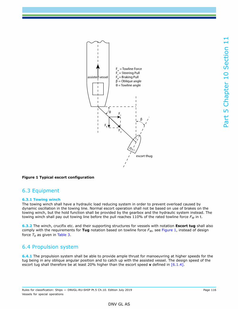
Part
5 C
hapt
er 1
0 Sec
tion
11
Rules for classification: Ships — DNVGL-RU-SHIP Pt.5 Ch.10. Edition July 2019 Page 116Vessels for special operations
DNV GL AS
Figure 1 Typical escort configuration
6.3 Equipment6.3.1 Towing winchThe towing winch shall have a hydraulic load reducing system in order to prevent overload caused bydynamic oscillation in the towing line. Normal escort operation shall not be based on use of brakes on thetowing winch, but the hold function shall be provided by the gearbox and the hydraulic system instead. Thetowing winch shall pay out towing line before the pull reaches 110% of the rated towline force FW in t.
6.3.2 The winch, crucifix etc. and their supporting structures for vessels with notation Escort tug shall alsocomply with the requirements for Tug notation based on towline force FW, see Figure 1, instead of designforce Tb as given in Table 3.
6.4 Propulsion system
6.4.1 The propulsion system shall be able to provide ample thrust for manoeuvring at higher speeds for thetug being in any oblique angular position and to catch up with the assisted vessel. The design speed of theescort tug shall therefore be at least 20% higher than the escort speed v defined in [6.1.4].

Part
5 C
hapt
er 1
0 Sec
tion
11
Rules for classification: Ships — DNVGL-RU-SHIP Pt.5 Ch.10. Edition July 2019 Page 117Vessels for special operations
DNV GL AS
6.4.2 The propulsion system shall also have sufficient thrust so that the tug can maneuver safely aft of theescorted vessel when transferring the tow line etc.
6.4.3 In case of loss of propulsion, the remaining forces shall be so balanced that the resulting turningmoment will turn the escort tug to a safer position with reduced heel.
6.5 General stability requirements
6.5.1 The general stability criteria in [5.1] shall be complied with, in addition to stability criteria given below.
6.6 Additional stability criteria6.6.1 Stability criteria, stern freeboard and heeling lever for escort operationVessels engaged in escort operations shall in the applicable loading conditions in the stability manual complywith the criteria of the International Code on Intact Stability, 2008 , Part B, paragraphs 2.8.4.4 and 2.8.6.2,assuming heeling levers according to paragraph 2.8.3.
6.7 Load line6.7.1 FreeboardFreeboard shall be arranged so as to avoid excessive trim at higher heeling angles. Bulwark shall be fitted allaround exposed weather deck.
6.8 Methods for establishing the escort rating number (Fs, t, v)
6.8.1 Requirements to full scale measurement tests are given in [6.9] and in DNVGL-CG-0155, whilerequirements to numerical calculations are described in [6.10] and in DNVGL-CG-0155. These tests areadditional to the tests given in [1.5].
6.8.2 The presented steering pull Fs is intended to represent the force the escort tug can exert under normalsea trial conditions. If the vessel is intended to operate in higher sea conditions the expected pull may belower.
6.9 Full scale testing requirements for notation Escort tug (F, (FS, t, v))
6.9.1 The following tests shall be undertaken:
— Measurement of maximum transverse steering pull Fs, in metric tonnes: The escort tug will connect itstowing line wire to the assisted vessel's stern and follow it with the wire slack, both ships travelling at thesame speed. The tug will then position itself at an agreed angle of attack relative to the flow of water andthe resulting towline tension Fs shall be recorded. These readings combined with the respective θ-β anglescombinations shall be then used to establish Fs.
— Manoeuvre test: The escort tug will shift its position from a steering position minimum 30° from one sideof the assisted vessel (i.e. θ is max 60°) to the mirror position in the opposite side and t will be the timerequired.
The escort test speed should be 8 knots and/or 10 knots. A surveyor will attend the test for the purpose ofwitnessing compliance with the agreed test program.
6.9.2 Approved escort departure and escort arrival loading conditions from the stability manual shall definethe way the tug will be loaded for the trial.

Part
5 C
hapt
er 1
0 Sec
tion
11
Rules for classification: Ships — DNVGL-RU-SHIP Pt.5 Ch.10. Edition July 2019 Page 118Vessels for special operations
DNV GL AS
6.9.3 Recordings during full scale trialsAt least the following data shall be recorded continuously in real time mode during trials for later analysis.Assisted vessel:
— speed relative to the sea— time for the manoeuvre test— weather condition (speed and direction) and sea state— position— heading— rudder angle— towline angle θ.
Active escort tug:
— towline tension Fw— towline length— oblique angle β— heeling angle of tug— weather condition (speed and direction) and sea state.— heading— speed relative to the sea.
6.9.4 Sea trials exceeding critical heeling angle from approved stability calculations shall not be accepted.
6.10 Numerical calculations for notation Escort tug (N, (FS, t, v))
6.10.1 The calculations shall be based on hydrodynamic loads established by model tests or CFD calculationsrelevant for the actual vessel design.
6.10.2 The calculations shall be done by suitable software/calculation method for which the results havebeen aligned with results from full scale measurement tests.
6.10.3 The documentation shall contain information about the actual propulsion system and the availablethrust in the given directions.

Part
5 C
hapt
er 1
0 Sec
tion
12
Rules for classification: Ships — DNVGL-RU-SHIP Pt.5 Ch.10. Edition July 2019 Page 119Vessels for special operations
DNV GL AS
SECTION 12 DREDGERSSymbolsFor symbols not defined in this chapter, see Pt.3 Ch.1 Sec.4.
1 Introduction
1.1 Introduction
1.1.1 These rules provide requirements for vessels intended for dredging operations in harbour and openwaters.
1.2 Scope
1.2.1 The following subjects are covered in this section:
— hull structural details related to the dredging operations— supporting structures for the dredging equipment.
Guidance note:The Society may on request supervise the construction and testing of the following items nor covered by the classification:
— equipment for anchoring and mooring during dredging
— equipment and installations for dredging.
---e-n-d---o-f---g-u-i-d-a-n-c-e---n-o-t-e---
1.3 Application
1.3.1 Vessels built in compliance with the relevant requirements in this section may be given the classnotation Dredger, or Dredger(Suction).Requirements for split hopper barges used in dredging operations are found in Ch.11.The requirements of the Guidelines for the Assignment of Reduced Freeboards for Dredgers (DR-68)developed by the joint working group on dredgers operating at reduced freeboards apply.
1.3.2 Dredgers intended for unusual dredging methods and/or of unusual form will be specially considered.
1.3.3 Dredgers engaged in international service shall comply with the requirements of the ICLL.
1.3.4 Dredgers with a restricted service area operating exclusively in national waters shall comply, as far aspossible, with the requirements of the ICLL. The height of companionway coamings above deck shall not beless than 300 mm.
Guidance note:For dredgers with a restricted service area according to Pt.1 Ch.2 Sec.5 operating exclusively in national waters, a special dredgerfreeboard is assigned by some administrations.
---e-n-d---o-f---g-u-i-d-a-n-c-e---n-o-t-e---

Part
5 C
hapt
er 1
0 Sec
tion
12
Rules for classification: Ships — DNVGL-RU-SHIP Pt.5 Ch.10. Edition July 2019 Page 120Vessels for special operations
DNV GL AS
2 Hull arrangement and strength
2.1 General requirements
2.1.1 Local structures and deviations from the principal design dimensions associated with the attachment ofthe dredging gear, shall be ignored when determining the principal dimensions in accordance with Pt.3 Ch.1Sec.4 [3.1].
2.1.2 The thickness of main structural members which are particularly exposed to abrasion by a mixtureof spoil and water, e.g. where special loading and discharge methods are employed, shall be adequatelystrengthened. Upon approval by the Society such members may alternatively be constructed of specialabrasion resistant materials.
2.2 Hull girder strength
2.2.1 For dredgers of 100 m in length and more, the scantlings of the longitudinal hull structure shall bedetermined on the basis of longitudinal bending moments and shear forces calculations according to Pt.3Ch.5 Sec.1.For dredgers classed for particular service areas, dispensations of Pt.3 Ch.5 Sec.1 may be approved.
2.2.2 For dredgers of less than 100 m in length, the minimum midship section modulus according to Pt.3Ch.5 Sec.1 [2.2] shall be fulfilled.For dredgers less than 100 m in length, the submittal of longitudinal strength calculations may in some casesbe waived upon request.
2.3 Hull local scantlings
2.3.1 The thickness of the bottom shell plating of dredgers intended or expected to operate while aground,shall be increased by 20% above the value required in Pt.3 Ch.6 Sec.3 and Sec.4.
2.3.2 Where hopper doors are fitted on the vessel's centreline or where there is a centreline well fordredging gear (bucket ladder, suction tube etc.), a plate strake shall be fitted on each side of the well or dooropening. The width shall not be less than 50% of the rule width of the flat keel, and the thickness shall notbe less than that of the rule flat keel.The same applies where the centreline box keel is located above the base line at such a distance that itcannot serve as a docking keel.In this case, thickness of the bottom plating of the box keel, equal to the rule bottom shell plating, isacceptable.
2.3.3 The flat bottom plating of raked ends which deviate from common ship forms, shall have a thicknessnot less than that of the rule bottom shell plating within 0.4 L amidships, up to 500 mm above the maximumload waterline. The shell plating above that shall have a thickness not less than the rule side shell plating.The reinforcements required in [2.3.1] shall be observed.
2.3.4 The corners of hopper door openings and of dredging gear wells shall comply with Pt.3 Ch.3 Sec.5 [5].The design of structural details and welded connections in this area shall be carried out with particular care.

Part
5 C
hapt
er 1
0 Sec
tion
12
Rules for classification: Ships — DNVGL-RU-SHIP Pt.5 Ch.10. Edition July 2019 Page 121Vessels for special operations
DNV GL AS
2.4 Single bottom - transversely stiffened
2.4.1 Abreast of hoppers and centreline dredging wells, the floors shall be dimensioned in accordance withPt.3 Ch.6. The depth, in mm, of floor shall satisfy the following formula:
2.4.2 Floors, longitudinal girders etc. below dredging machinery and pump seats shall be adequatelydesigned for the additional loads.
2.4.3 Where floors are additionally stressed by the reactions of the pressure required for closing the hopperdoors, their section modulus and their depth shall be increased accordingly.
2.4.4 Where the unsupported span of floors exceeds 3 m, one side girder shall be fitted with web netthickness, in mm, and flange sectional net area, in cm2, shall satisfy:
Towards the ends, the web thickness and the sectional area of the flange may be reduced by 10%.
2.4.5 Floors in line with the hopper lower cross members fitted between hopper doors shall be connectedwith the hopper side wall by brackets of approx. equal legs. The brackets shall be flanged or fitted with facebars and shall extend to the upper edge of the cross members.
2.4.6 Floors of dredgers intended or expected to operate while aground shall be stiffened by vertical bucklingstiffeners the spacing of which is such as to guarantee that the reference degree of slenderness λ for theplate field is less than 1.0. For λ see the Society's document DNVGL-CG-0128 Sec.3 [2.2.2].
2.5 Single bottom - longitudinally stiffened
2.5.1 The spacing of primary supporting bottom transverses is generally not to exceed 3.6 m. The grossoffered section modulus, in cm3, and gross offered web cross sectional area, in cm2, shall not be less thandetermined by the following formulas:
where:
e = spacing, in m, of bottom transverses between each other or from bulkheads.ℓ = unsupported span, in m, any longitudinal girders not considered.P = design pressure for the considered design load set, see Pt.3 Ch.6 Sec.2 [2], calculated at the load
calculation point defined in Pt.3 Ch.3 Sec.7 [2.2], in kN/m2.
The web depth shall not be less than the depth of floors according to [2.4.1].
2.5.2 The bottom longitudinals shall be determined in accordance with Pt.3 Ch.6 Sec.5 [1].

Part
5 C
hapt
er 1
0 Sec
tion
12
Rules for classification: Ships — DNVGL-RU-SHIP Pt.5 Ch.10. Edition July 2019 Page 122Vessels for special operations
DNV GL AS
2.5.3 Where the centerline box keel cannot serve as a docking keel, brackets shall be fitted on either side ofthe centre girder or at the longitudinal bulkheads of dredging wells and of hopper spaces. The brackets shallextend to the adjacent longitudinals and longitudinal stiffeners. Where the spacing of bottom transverses isless than 2.5 m, one bracket shall be fitted. For larger spacings, two brackets shall be fitted.The thickness of the brackets shall at least to be equal to the web thickness of the adjacent bottomtransverses. The brackets shall be flanged or fitted with face bars.
2.5.4 Where longitudinal bulkheads and the side shell are framed transversely, the brackets according to[2.5.3] shall be fitted at every frame and shall extend to the bilge.
2.5.5 The bottom transverses shall be stiffened by means of flat bar stiffeners at every longitudinal.
2.5.6 The bottom structure of dredgers intended or expected to operate while aground shall be dimensionedas follows:
— the spacing of the bottom transverses according to [2.5.1] shall not exceed 1.8 m. The webs shall bestiffened according to [2.4.6]
— the section modulus of the bottom longitudinals according to [2.5.2] shall be increased by 50%.
2.5.7 The requirements of [2.4.2] to [2.4.5] shall be applied analogously.
2.6 Double bottom
2.6.1 Fitting of double bottoms adjacent to the hopper spaces, is not required.
2.6.2 In addition to the requirements given in Pt.3 Ch.3 Sec.5 [6] and Pt.3 Ch.6, plate floors shall be fitted inway of hopper spaces intended to be unloaded by means of grabs.
2.6.3 Where brackets are fitted in accordance with [2.6.6], the requirements according to [2.5.3] and[2.5.4] shall be observed where applicable.
2.6.4 The bottom structure of dredgers intended or expected to operate while aground shall be strengthenedas follows:
— Where transverse framing system is adopted, plate floors shall be fitted at every frame and the spacing ofthe side girders shall be reduced to half the spacing of what is required in [2.6.5].
— When the longitudinal framing system is adopted, and the longitudinal girders are fitted instead oflongitudinals, the spacing of floors may be greater than five (5) times the mean longitudinal framespacing, proven that adequate strength of the structure is proved. The required net plate thickness, t inmm, of the longitudinal girders shall not be less than obtained from the following formula:
Where applicable, [2.5.6] shall be applied analogously.The net thickness of bottom plating shall be increased by 10%, compared to the plate thickness requirementgiven in Pt.3 Ch.6.
2.6.5 Bottom side girder arrangementThe distance of the side girders from each other and from centre girder and ship's side respectively shall notbe greater than:
— 1.8 m in the engine room within the engine seatings— 4.5 m where one side girder is fitted in the other parts of double bottom— 4.0 m where two side girders are fitted in the other parts of double bottom— 3.5 m where three side girders are fitted in the other parts of double bottom.
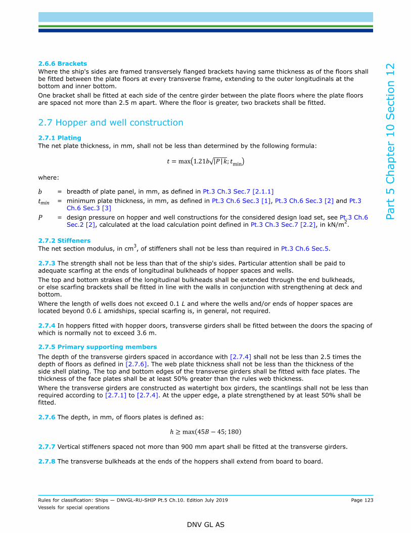
Part
5 C
hapt
er 1
0 Sec
tion
12
Rules for classification: Ships — DNVGL-RU-SHIP Pt.5 Ch.10. Edition July 2019 Page 123Vessels for special operations
DNV GL AS
2.6.6 BracketsWhere the ship's sides are framed transversely flanged brackets having same thickness as of the floors shallbe fitted between the plate floors at every transverse frame, extending to the outer longitudinals at thebottom and inner bottom.One bracket shall be fitted at each side of the centre girder between the plate floors where the plate floorsare spaced not more than 2.5 m apart. Where the floor is greater, two brackets shall be fitted.
2.7 Hopper and well construction2.7.1 PlatingThe net plate thickness, in mm, shall not be less than determined by the following formula:
where:
b = breadth of plate panel, in mm, as defined in Pt.3 Ch.3 Sec.7 [2.1.1]tmin = minimum plate thickness, in mm, as defined in Pt.3 Ch.6 Sec.3 [1], Pt.3 Ch.6 Sec.3 [2] and Pt.3
Ch.6 Sec.3 [3]P = design pressure on hopper and well constructions for the considered design load set, see Pt.3 Ch.6
Sec.2 [2], calculated at the load calculation point defined in Pt.3 Ch.3 Sec.7 [2.2], in kN/m2.
2.7.2 StiffenersThe net section modulus, in cm3, of stiffeners shall not be less than required in Pt.3 Ch.6 Sec.5.
2.7.3 The strength shall not be less than that of the ship's sides. Particular attention shall be paid toadequate scarfing at the ends of longitudinal bulkheads of hopper spaces and wells.The top and bottom strakes of the longitudinal bulkheads shall be extended through the end bulkheads,or else scarfing brackets shall be fitted in line with the walls in conjunction with strengthening at deck andbottom.Where the length of wells does not exceed 0.1 L and where the wells and/or ends of hopper spaces arelocated beyond 0.6 L amidships, special scarfing is, in general, not required.
2.7.4 In hoppers fitted with hopper doors, transverse girders shall be fitted between the doors the spacing ofwhich is normally not to exceed 3.6 m.
2.7.5 Primary supporting membersThe depth of the transverse girders spaced in accordance with [2.7.4] shall not be less than 2.5 times thedepth of floors as defined in [2.7.6]. The web plate thickness shall not be less than the thickness of theside shell plating. The top and bottom edges of the transverse girders shall be fitted with face plates. Thethickness of the face plates shall be at least 50% greater than the rules web thickness.Where the transverse girders are constructed as watertight box girders, the scantlings shall not be less thanrequired according to [2.7.1] to [2.7.4]. At the upper edge, a plate strengthened by at least 50% shall befitted.
2.7.6 The depth, in mm, of floors plates is defined as:
2.7.7 Vertical stiffeners spaced not more than 900 mm apart shall be fitted at the transverse girders.
2.7.8 The transverse bulkheads at the ends of the hoppers shall extend from board to board.

Part
5 C
hapt
er 1
0 Sec
tion
12
Rules for classification: Ships — DNVGL-RU-SHIP Pt.5 Ch.10. Edition July 2019 Page 124Vessels for special operations
DNV GL AS
2.7.9 Regardless of whether the longitudinal or the transverse framing system is adopted, web frames inaccordance with Pt.3 Ch.6 Sec.6 shall be fitted in line with the transverse girders according to [2.7.4].The density of the spoil shall be considered when determining the scantlings.
2.7.10 Strong beams shall be fitted transversely at deck level in line with the web frames according to[2.7.9]. The scantlings shall be determined, for the actual loads complying with an equivalent stress, in N/mm2, of:
The maximum reactions of hydraulically operated rams for hopper door operation are, for instance, to betaken as actual load.The strong beams shall be supported by means of pillars according to Pt.3 Ch.6 Sec.6 [3] at the box keel, iffitted.
2.7.11 On bucket dredgers, the ladder wells shall be isolated by transverse and longitudinal cofferdams atthe bottom, of such size as to prevent the adjacent compartments from being flooded in case of any damageto the shell by dredging equipment and dredged objects. The cofferdams shall be accessible.
2.8 Box keel2.8.1 Bottom plating
— Where the box keel can serve as a docking keel, the requirements for flat plate keels according to Pt.3Ch.6 Sec.3 [1.1] and Pt.3 Ch.3 Sec.5 [6] apply.
— Where the box keel cannot serve as a docking keel (see also [2.3.2]), the requirements for bottom platingaccording to Pt.3 Ch.6 Sec.3 [1.1] and Pt.3 Ch.6 Sec.4 [1] apply.
2.8.2 Plating other than bottom plating
— Outside the hopper space, the requirements for bottom plating according to Pt.3 Ch.6 Sec.3 [1.1] and Pt.3Ch.6 Sec.4 [1] apply.
— Within the hopper space the requirements for hopper space plating according to [2.7.1] apply. Thethickness of the upper portion particularly subjected to damage shall be increased by not less than 50%.
2.8.3 FloorsThe requirements according to [2.4.1] and [2.4.2] respectively apply.
2.8.4 StiffenersThe requirements for hopper stiffeners according to [2.7.2] apply.
2.8.5 Primary supporting membersStrong webs of plate floors shall be fitted within the box keel in line with the web frames according to [2.7.9]to ensure continuity of strength across the vessel.
2.8.6 With regard to adequate scarphing at the ends of a box keel, [2.7.3] shall be observed.
3 Systems and equipment
3.1 Stern frame
3.1.1 Where dredgers with stern wells for bucket ladders and suction tubes are fitted with two rudders, thestern frame scantlings shall be determined in accordance with Pt.3 Ch.10 Sec.6 [2].

Part
5 C
hapt
er 1
0 Sec
tion
12
Rules for classification: Ships — DNVGL-RU-SHIP Pt.5 Ch.10. Edition July 2019 Page 125Vessels for special operations
DNV GL AS
3.2 Rudder stock
3.2.1 Where dredgers are fitted with auxiliary propulsion and their speed does not exceed 5 kn at maximumdraught, the value V0 = 7 kn shall be taken for determining the rudder stock diameter.
3.3 Anchoring and mooring equipment
3.3.1 The equipment of anchors, chain cables, wires and recommended ropes for dredgers for unrestrictedservice area having normal ship shape of the underwater part of the hull shall be determined in accordancewith Pt.3 Ch.11 Sec.1.When calculating the equipment number according to Pt.3 Ch.11 Sec.1 [3], bucket ladders and gallows neednot to be included. For dredgers of unusual design of the underwater part of the hull, the determination ofthe equipment requires special consideration.The equipment for dredgers for restricted service area shall be determined according to the service notationsgiven in Pt.3 Ch.11 Sec.1 [3.2].
3.3.2 The equipment of non self-propelled dredgers shall be determined as for barges, in accordance withCh.11 Sec.3.
3.3.3 Considering rapid wear and tear, it is recommended to strengthen the anchor chain cables which arealso employed for positioning of the vessel during dredging operations.
3.3.4 Dredgers intended to work in conjunction with other vessels shall be fitted with strong fenders.
4 Fire safety
4.1 Closed hopper spaces
4.1.1 On dredgers with closed hopper spaces suitable structural measures shall be taken in order to preventaccumulation of inflammable gas-air mixture in the hopper vapour space. The requirements given in Pt.4Ch.8 Electrical installations, shall be observed.
5 Openings and closing appliances
5.1 General requirements
5.1.1 Where a dredger freeboard is assigned in accordance with [1.3.3], the length LLL, draught TLL andblock coefficient CB-LL according to Pt.3 Ch.1 Sec.4 [3.1] shall be determined for this freeboard.
5.2 Bulwark, overflow arrangements
5.2.1 Bulwarks shall not be fitted in way of hoppers where the hopper weirs discharge onto the deck insteadof into enclosed overflow trunks. Even where overflow trunks are provided, it is recommended not to fitbulwarks.If bulwarks are fitted, freeing ports shall be provided throughout their length. They shall be of sufficient widthto permit undisturbed overboard discharge of any spoil spilling out of the hopper in the event of rolling.
Part
5 C
hapt
er 1
0 Sec
tion
12
Rules for classification: Ships — DNVGL-RU-SHIP Pt.5 Ch.10. Edition July 2019 Page 126Vessels for special operations
DNV GL AS
5.2.2 Dredgers without restricted service range notation shall be fitted with overflow trunks on either sidesuitably arranged and of sufficient size to permit safe overboard discharge of excess water during dredgingoperations.The construction shall be such as not to require cut-outs at the upper edge of the sheer strake. Whereoverflow trunks are carried through the wing compartments, they shall be arranged such as to pierce thesheer strake at an adequate distance from the deck.
5.2.3 Dredgers with restricted service area notation may have overflow arrangements which permitdischarge of excess water during dredging operations onto the deck.

Part
5 C
hapt
er 1
0 Sec
tion
13
Rules for classification: Ships — DNVGL-RU-SHIP Pt.5 Ch.10. Edition July 2019 Page 127Vessels for special operations
DNV GL AS
SECTION 13 PUSHERSSymbolsFor symbols and definitions not defined in this chapter, see Pt.3 Ch.1 Sec.4.
1 Introduction
1.1 GeneralThese rules provide requirements for ships specially intended for pushing.
1.2 ScopeThe rules in this section give requirements for hull strength, and systems and equipment, applicable to apusher.
1.3 Application
1.3.1 Vessels built in compliance with the relevant requirements in this section may be given the classnotation Pusher.
1.3.2 A pusher vessel intended for operation in combination with a number of barges/pontoons speciallydesigned to accommodate the pusher will be subject to special consideration. Additional requirements to thebarge/pontoon is given in Ch.11.
1.3.3 For a pusher/barge or a pusher/pontoon combination the identification numbers of the barges/pontoons associated with the pusher will be given in the appendix to classification certificate.
2 Definitions
2.1 TermsTable 1 Definitions of terms
Term Definition
type I pusher barge/pontoon unit
The connection between the pusher and the barge/pontoon is assumed to be rigid, i.e. itshould be designed to transmit the static and dynamic shearing forces and bending momentsin such a manner that the combination behaves like one integrated structure
type II pusher barge/pontoon unit
The connection between the pusher is free to heave and/or pitch relatively to the barge/pontoon.This type of connection will normally not be applicable under severe sea conditions or in ice-infested waters.
Part
5 C
hapt
er 1
0 Sec
tion
13
Rules for classification: Ships — DNVGL-RU-SHIP Pt.5 Ch.10. Edition July 2019 Page 128Vessels for special operations
DNV GL AS
3 Subdivision arrangement design
3.1 Subdivision arrangement3.1.1 Watertight bulkhead arrangementThe pusher shall have a number of transverse bulkheads corresponding to its own length, as given in Pt.3Ch.2 Sec.2 [4].
4 Hull
4.1 General
4.1.1 The pusher shall be regarded as a separate unit and the hull structural strength is in general to be asrequired for the main class.
4.1.2 When the pusher is connected as an integrated part of a combined system (pusher/barge unit orpusher/pontoon unit), the hull scantlings of exposed parts of the pusher shall satisfy the main class rules foraft structures as calculated for the combined unit.
4.1.3 Pushers being part of a flexible system, type II, shall be equipped also for towing the barge/pontoon.
4.2 Draught for scantlingsFor determining the scantlings of strength members based on the vessel's draught, the latter shall not betaken less than 0.85 D.
4.3 Structure in the forebody
4.3.1 The structure in the forebody shall be satisfactorily reinforced to sustain the reaction forces occurringduring the pushing operation. For complex structures stress analysis shall be carried out to show that thestress level will be within acceptable limits.
4.3.2 In combined pusher/barge or pusher/pontoon systems the connection forces and allowable stressesshall comply with the requirements given in Ch.11 Sec.2 [10.4].
4.3.3 In combined pusher/barge or pusher/pontoon systems the deflections of the structure during operationshall be limited to avoid hammering when pusher/barge or pusher/pontoon units are heeled.
5 Equipment
5.1 RudderThe design rudder force on which scantlings shall be based, shall be calculated as indicated for the mainclass. The speed of the vessel is however not to be taken less than V = 10 knots.
Part
5 C
hapt
er 1
0 Sec
tion
13
Rules for classification: Ships — DNVGL-RU-SHIP Pt.5 Ch.10. Edition July 2019 Page 129Vessels for special operations
DNV GL AS
5.2 Steering gearThe steering gear shall be capable of bringing the rudder from 35 degrees on one side to 30 degrees on theother side in 20 seconds, when the vessel is running ahead at maximum service speed. For the combinedpusher/barge unit, the requirement is 28 seconds.
5.3 Anchoring and mooringPushers shall have anchoring and mooring equipment corresponding to its equipment number, see Pt.3 Ch.11Sec.1 [3.1]. The term 2 BH in the formula may, however, be substituted by:
2(aB + Σ hibi)
where:
bi = breadth, in m, of the widest superstructure or deckhouse of each tier having a breadth greater thanB/4.

Part
5 C
hapt
er 1
0 Sec
tion
14
Rules for classification: Ships — DNVGL-RU-SHIP Pt.5 Ch.10. Edition July 2019 Page 130Vessels for special operations
DNV GL AS
SECTION 14 SLOP RECEPTION VESSEL
1 Introduction
1.1 Introduction
1.1.1 These rules provide requirements for vessels intended to serve as floating facilities for reception andprocessing of oily water and oil residues.
1.2 Scope
1.2.1 These rules include requirements for hull strength, systems and equipment and procedures applicableto vessels serving as a floating facility for reception and processing of oily water and oil residues.
1.2.2 The classification of the facility will be based upon the following assumptions:
— That oily water and oil residues originating from oil with flash point below 60°C are considered to maintaina flash point below 60°C and that such liquids are not transferred to the facility's engine room.
— That transfer of oily water and oil residues between delivery vessel and the facility is only done underfavorable weather conditions.
— That the facility is operated by qualified personnel.— That a two-way communication system is provided between the delivery vessel and the facility during the
transfer operation, ensuring reliable and direct contact with the personnel controlling the transfer pump.
1.2.3 The above basic assumptions will be stated in the appendix to the classification certificate.
1.3 Application
1.3.1 The rules in this chapter apply to newbuildings as well as to conversions of existing vessels to serveas floating facilities for reception and processing of oily water and oil residues. The subsequent requirementsshall be regarded as supplementary to the requirements for main class and relevant requirements as given inCh.5 for ships intended for carriage of oil with flashpoint below 60°C.
1.3.2 Facilities designed and built, surveyed and tested in compliance with the requirements in this sectionand other relevant requirements may be given the class notation Slop reception vessel.
1.3.3 The classification is aimed at safety against hazards to the personnel, the facility and the environment.
1.3.4 The assignment of class will be based upon:
— approval of documentation i.e specifications, plans, calculations, etc.— approval of the instruction manuals for the facility— inspection during manufacturing of materials and equipment— inspection during construction, installation and testing of the facility— inspection upon completion, including testing of the separating system for proper function.
Guidance note:In addition to the requirements of the Society, relevant requirements in the regulations of national authorities will have to becomplied with in connection with the registration and or location of the facility.
---e-n-d---o-f---g-u-i-d-a-n-c-e---n-o-t-e---

Part
5 C
hapt
er 1
0 Sec
tion
14
Rules for classification: Ships — DNVGL-RU-SHIP Pt.5 Ch.10. Edition July 2019 Page 131Vessels for special operations
DNV GL AS
1.3.5 In addition to the relevant parts of the documentation as required for oil tankers in Ch.5 Sec.1 [4.2],the following shall be submitted for approval:
— drawings and specification for the separating system— drawing of the fendering arrangement— specification of transfer hoses— drawings of deck lightning arrangement— instruction manuals for the facility.
1.3.6 The following control and monitoring systems shall be approved by the Society:
— oil separating system— fire extinguishing system— fire detection system— inert gas system.
For requirements to documentation, see Pt.4 Ch.9.
1.3.7 The following control and monitoring system shall be certified according to Pt.4 Ch.9:
— oil separating system— fire detection system— inert gas system.
2 Hull strength and arrangement
2.1 General requirements
2.1.1 In addition to the hull strength requirements of the rules for main class, the following shall be givenspecial consideration:
— Additional openings in strength members. The local strength shall be considered in connection withopenings and cut-outs in deck, bulkheads, etc.
— Loading conditions. The longitudinal strength shall be satisfactory for all relevant loading conditions andconditions during transfer to new location. In addition to a loading manual, the facility shall be equippedwith a loading instrument.
— Tank pressure. The local strength shall be considered for increased internal pressure in the tanks causedby the separating process.
2.1.2 An efficient fender arrangement, effectively supported by hull strength members, shall be fitted.The fenders shall be able to keep the hulls of the delivery vessel and the reception facility apart at a safedistance, at least 3 meters. The fenders shall efficiently prevent steel to steel contact, in order to avoid riskfor sparks.
2.1.3 The vessel shall comply with all requirements of MARPOL Annex I as applicable for an oil tanker, unlessalternative acceptance is obtained from the flag and port state(s) in the area in which the vessel is goingto operate. The requirements to double hull and segregated ballast are however considered to be minimumrequirements. It is recognized that for vessels primarily operating within port limits or MARPOL Annex Ispecial areas, certain requirements, such as those to oil discharge monitoring systems may not be applicable,provided all tank washings and oily mixtures are discharged to shore or alternative means for preventingdischarge of oil to sea are provided.

Part
5 C
hapt
er 1
0 Sec
tion
14
Rules for classification: Ships — DNVGL-RU-SHIP Pt.5 Ch.10. Edition July 2019 Page 132Vessels for special operations
DNV GL AS
2.2 Transfer arrangement for transfer of oily water and oil residues
2.2.1 The minimum bursting pressure for the hose assembly shall be 20 bar. The maximum allowableworking pressure shall be at least 8 bar.
2.2.2 Hose diameters shall be sufficient for the maximum specified transfer rate for the facility in order toavoid excessive pressure drop. Hoses shall be suspended by suitable equipment. Excessive bending of thehoses shall be avoided.
2.2.3 A pressure gauge shall be fitted in the transfer line, before the reception tanks.
2.2.4 It shall be possible to drain or close mechanical loading arms or hoses before disconnection. Coamingsof suitable height shall be arranged below manifolds and hose connections in order to minimize spill.
2.3 Lightning
2.3.1 Deck lighting shall be arranged. Adequate illumination shall be provided:
— for the transfer area to facilitate control and handling of the equipment— for the fire extinguishing equipment— for visual observation of possible oil in the processed water being discharged to the sea (see [2.4.4]).
2.4 Separating system
2.4.1 The separating system shall be designed to reduce the oil content in the water being dischargedinto the sea to a concentration not exceeding 15 parts per million or any other lower value specified by thebuilder/owner. The actual design performance will be stated in the appendix to the classification certificate forthe facility.
2.4.2 Precautions shall be taken to avoid overpressuring of the process tanks. When the separating systemis arranged for pumping oil/water into a tank or series of tanks which by the design of the process pipingarrangement will operate in the full condition, an overflow pipe with sectional area at least 25% greater thanthe area of the filling pipe shall be arranged from the first tank to another tank with surplus capacity.
2.4.3 Means for locating the oil/water interface in the tanks shall be provided.
2.4.4 Visual control of oil content in the processed water being discharged into the sea shall be possibleby observing the sea surface at the outlet. Visual inspection of the surface in the last separating tank mayalternatively be accepted.
2.4.5 Discharges of processed water from the separating process shall take place above waterline.
2.4.6 The maximum flow rate through the separating tanks shall be specified in the instruction manuals forthe types of oil in question (different gravities, etc.).
2.4.7 Arrangements for handling and storage of sediments and separated oil residues shall comply withapplicable requirements for cargo systems on oil tankers as given in Ch.5 of the rules.
2.5 Oil content monitoring
2.5.1 Automatic monitoring of oil content in the processed water shall be arranged. When the specified limitis exceeded, automatic stop of the discharge and an alarm shall be activated.
Part
5 C
hapt
er 1
0 Sec
tion
14
Rules for classification: Ships — DNVGL-RU-SHIP Pt.5 Ch.10. Edition July 2019 Page 133Vessels for special operations
DNV GL AS
2.5.2 The oil content meter shall be type tested in accordance with relevant IMO specifications andguidelines (Res. MEPC.107(49) or revised version of the same).
2.5.3 The oil content monitor shall be located outside gas dangerous spaces or zones unless the monitor iscertified safe.
2.6 Protection against fire and explosion
2.6.1 Precautions shall be taken to prevent hydrocarbon gas from the delivery vessel to enter gas-safespaces or zones on the facility and vice versa. The location and the periodical closing of doors and air intakesfor ventilating systems, etc., shall be considered as well as the provision of air locks.
2.6.2 Means for preventing sparks from the funnel of the facility to reach gas dangerous spaces or zones(i.e. spark arrester) shall be provided.
2.6.3 The fire protection, extinguishing and detection arrangements shall in general comply with the relevantrequirements of Ch.5 for oil tankers.
2.6.4 A fixed deck foam system in accordance with SOLAS Ch. II-2 Reg.10.8 and FSS Code Ch.14 shall beinstalled.
2.6.5 An inert gas system complying with the rules for the class notation Inert shall be arranged forsupplying inert gas to all tanks which may contain hydrocarbon gases under normal operating conditions.
2.6.6 The capacity of the inert gas plan shall be at least 25% greater than the maximum discharge rate forprocessed water.
2.6.7 Electrical installations shall comply with applicable requirements in Ch.5.
2.6.8 Oil residues with flash point above 60°C originating from engine rooms may be transferred to tankswithin the facility’s engine room, and may be burnt or incinerated within the engine room.
3 Operational instructions and log book
3.1 Instruction materials
3.1.1 Instruction manuals for the facility shall be prepared and kept onboard. The manuals are subject toapproval by the Society. The manuals shall contain necessary information on:
— operation— maintenance— testing— identification of faults— repair.
For the following equipment and systems:
— fire detection and extinguishing equipment— inert gas system— O2-content analyzer— oily water and oil residues transfer arrangement— oil content monitoring system— other equipment onboard necessary for a safe and pollution-free operation

Part
5 C
hapt
er 1
0 Sec
tion
14
Rules for classification: Ships — DNVGL-RU-SHIP Pt.5 Ch.10. Edition July 2019 Page 134Vessels for special operations
DNV GL AS
— the complete separating system, including possible limitations (pumping rates, types of oil, etc.).
3.1.2 The instruction manuals shall also contain relevant information about the operational procedures to beapplied onboard, such as:
— mooring— safety actions (required closing of doors and ventilating intakes, etc.) to be carried out before
commencing the transfer between the delivery vessel and the facility— general procedures for operation of the separating system and the inert gas system.
3.1.3 The operational procedures shall include the following:
— The O2-content of storage and separating tanks which are not completely filled, shall be checked upondischarge, and in any case at least twice a week.
— Two-way communication between the reception facility and the delivery vessel shall be established beforethe transfer commences.
— Before discharge into the sea is begun, visual inspection of the surface (see [2.4.4]) shall be carried outand the automatic oil content monitor checked and started.
3.1.4 The maintenance procedures shall include:
— Intervals for checking and maintenance of the exhaust spark arrestors.

Part
5 C
hapt
er 1
0 Sec
tion
14
Rules for classification: Ships — DNVGL-RU-SHIP Pt.5 Ch.10. Edition July 2019 Page 135Vessels for special operations
DNV GL AS
3.2 Safety and oily water/oil residues log bookGuidance note:For the purpose of record keeping and for documentation versus local/national authorities it is recommended that the followingguidelines are complied with:
1) General.
The facility should be provided with a safety and oily water/oil residues log book.
The officer in charge of the operations concerned should be responsible for the entries in the log book. The log book shouldbe kept onboard available for inspection.
The log book entries should be kept onboard for a period of at least three years.
2) Entries in the log book.
The log book should be arranged for entries of the following which should be recorded without delay:
— before the transfer operations are commenced:
— what will be transferred
— stipulated pumping rate
— total volume to be transferred
— safety actions carried out
— rate of transfer
— total volume to be transferred
— weather conditions during transfer
— volume and the exact time when processed water is discharged into the sea
— exact time when the oil content in the processed water being discharged into the sea exceeds the specified limit
— internal transfer of oily water and oil residues
— use of the inert gas plant
— result and the exact time of checking O2-content in the tanks
— inspection and testing of fire detection and extinguishing equipment
— inspection and maintenance of the inert gas plant
— inspection and maintenance of the exhaust spark arrester
— inspection and maintenance of the transfer arrangement
— inspection and maintenance of the oil content monitor.
---e-n-d---o-f---g-u-i-d-a-n-c-e---n-o-t-e---

Part
5 C
hapt
er 1
0 Sec
tion
15
Rules for classification: Ships — DNVGL-RU-SHIP Pt.5 Ch.10. Edition July 2019 Page 136Vessels for special operations
DNV GL AS
SECTION 15 REFRIGERATED CARGO VESSELS
1 Introduction
1.1 Introduction
1.1.1 These rules provide requirements for vessels intended to carry refrigerated cargoes.
1.2 Scope
1.2.1 These rules include the class notations and references to the requirements for refrigerated cargovessels.
1.3 Application
1.3.1 The rules, as relevant, in this chapter apply to ships with refrigerating plants for:
— carriage of refrigerated dry cargo— carriage of fruit or vegetables under a controlled atmosphere— carriage in bulk of refrigerated fruit juices and similar liquid cargoes
when a class notation in [1.4] is requested.
1.4 Class notations
1.4.1 Ships designed, built, equipped and tested under the supervision of the Society in compliance with therequirements of this chapter and the requirements to class notation RM(X°C/Y°C sea) in Pt.6 Ch.4 Sec.9may be given one of the additional class notations in [1.4.2] and [1.4.3].
1.4.2 Ships primarily constructed for the for carriage of refrigerated dry cargo may be given the classnotation Reefer RM(X°C/Y°C sea).
1.4.3 Ships primarily constructed for the carriage of fruit juices and similar cargoes in bulk in refrigeratedtanks shall be given the class notation Refrigerated fruit juice carrier RM(X°C/Y°C sea) provided theyalso comply with relevant parts of the rules in Ch.6 (e.g. for cargo handling systems and independent cargotanks).
Guidance note:For dry cargo ships having a partial cargo carrying capacity for refrigerated cargo or fishing vessels with refrigerating plant forcooling or freezing catches of fish, the class notation RM(X°C/Y°C sea) as specified in Pt.6 Ch.4 Sec.9 may be assigned.For ships built and fully equipped for carriage of bananas and fruit in general under a controlled cargo chamber atmosphere in atleast 50% of the ship's total refrigerated cargo chamber volume may be given the class notation CA as specified in the rules Pt.6Ch.4 Sec.9 may be assigned.For ships built and equipped for carriage of bananas and fruit in general under a controlled cargo chamber atmosphere in at least50% of the ship's total refrigerated cargo chamber volume except that a nitrogen generating unit and possibly parts of the alarmand monitoring equipment have not been permanently installed may be given the class notation CA(port.) as specified in the rulesPt.6 Ch.4 Sec.9 may be assigned.
---e-n-d---o-f---g-u-i-d-a-n-c-e---n-o-t-e---
Part
5 C
hapt
er 1
0 Sec
tion
15
Rules for classification: Ships — DNVGL-RU-SHIP Pt.5 Ch.10. Edition July 2019 Page 137Vessels for special operations
DNV GL AS
2 Operational performance
2.1 General
2.1.1 The ship shall be designed, arranged and equipped to make it suitable for cooling down and/or carryingcargo, freezing catches of fish etc. as relevant according to the design operating conditions specified by thebuilders and subsequently to be stated in the appendix to the classification certificate. The builders' andpossible subcontractors' specifications of the ship's operational performances and abilities will together withthe specific requirements of this chapter be used as basis for assignment of class.
Part
5 C
hapt
er 1
0 Sec
tion
16
Rules for classification: Ships — DNVGL-RU-SHIP Pt.5 Ch.10. Edition July 2019 Page 138Vessels for special operations
DNV GL AS
SECTION 16 TANKER FOR POTABLE WATER
1 General
1.1 ObjectiveThese rules establishes requirements for vessels intended to carry potable water in bulk.
1.2 ScopeThe rules in this chapter provide requirements to material, tank arrangement and piping systems with theobjective of assuring transport in bulk of potable water with minimal risk of contaminating the cargo orotherwise reduce delivered quality.
Guidance note:The quality of the water loaded may comply with the directive 98/83/EC of the European Union or with a quality standard specifiedby the receiving country or port.
---e-n-d---o-f---g-u-i-d-a-n-c-e---n-o-t-e---
1.3 ApplicationThese rules apply to vessels dedicated to the transportation of potable water. The requirements shall beregarded as supplementary to those given for the assignment of main class.
1.4 Class notationVessels complying with the requirements of this section may be assigned the class notation Tanker forpotable water.
1.5 AssumptionIt is assumed that cargo tanks are not used for any other purpose than transport of potable water exceptunder emergency conditions.

Part
5 C
hapt
er 1
0 Sec
tion
16
Rules for classification: Ships — DNVGL-RU-SHIP Pt.5 Ch.10. Edition July 2019 Page 139Vessels for special operations
DNV GL AS
2 Documentation
2.1 General2.1.1 The following plans and particulars shall be submitted:
Table 1 Documentation
Object Documentation type Additional description Info
General arrangement Z010 - Generalarrangement plan
Including:
- Cargo hatches, Butterworth hatches and anyother opening to cargo tank.
- Cargo pipes over the deck with shoreconnections including stern pipes for cargodischarge and loading.
FI
S010 - Piping diagram(PD)
Including cargo stripping system. For vacuumstripping systems, details shall includetermination of air pipes and openings fromdrain tanks and other tanks.
APCargo piping arrangements
C030 - Detailed drawing Cargo pump (s) AP
Cargo tank venting system S010 - Piping diagram(PD) AP
I200 - Control andmonitoring systemdocumentation
APCargo tank level measurementsystem
Z030 - Arrangement plan Shall indicate type and location of levelindicators. FI
Specification of tank coating withcertificate of acceptance for toxicityand tainting testing by recognisedlaboratory or health authority
Z261 - Test report FI
Specifications of metallic and non-metallic materials in contact with thecargo
M010 - Materialspecification, metals
Yard's declaration of materials in contact withcargo. FI
2.1.2 For general requirements for documentation, including definition of the info codes, see DNVGL-CG-0550Sec.6.
2.1.3 For full definition of the documentation types, see DNVGL-CG-0550 Sec.5.
2.1.4 For general requirement for documentation of instrumentation and automation, including computer basedcontrol and monitoring, see Pt.4 Ch.9 Sec.1 Table 5.

Part
5 C
hapt
er 1
0 Sec
tion
16
Rules for classification: Ships — DNVGL-RU-SHIP Pt.5 Ch.10. Edition July 2019 Page 140Vessels for special operations
DNV GL AS
2.2 Certification requirements2.2.1 The following control and monitoring system shall be approved by the society: Documentation shall besubmitted as required by Table 2
Table 2 Certification requirements
Object Certificate type Issued by Certificationstandard 1) Additional description
Water quality instrument PC Society
1) Unless otherwise specified the certification standard is the Society`s rules.PC = product certificate, MC = material certificate, TR = test report
2.2.2 For full definition of the documentation types, see DNVGL-CG-0550 Sec.5.
2.2.3 For full definition of certificate types, see DNVGL-CG-0550 Sec.4.
2.3 Surveys and Testing2.3.1 General
2.3.1.1 All systems and installations covered by this section shall be surveyed and tested to the satisfaction of thesurveyor.
3 Requirement for carriage of potable water
3.1 Material3.1.1 Cargo piping and cargo tank materials
3.1.1.1 Materials in contact with water, including coatings shall not give off harmful substances in contact with waternor cause tainting or discoloration.
3.1.1.2 For non-metallic materials and coatings documentation showing their suitability for use in contact withwater intended for human consumption shall be submitted, e.g. test documentation according to BS 6920 orequivalent.
Part
5 C
hapt
er 1
0 Sec
tion
16
Rules for classification: Ships — DNVGL-RU-SHIP Pt.5 Ch.10. Edition July 2019 Page 141Vessels for special operations
DNV GL AS
3.2 Tank Arrangement3.2.1 Cargo tanks
3.2.1.1 Cargo tanks shall be separated from tanks containing fuel oil, lubricating oil or any other liquid, except ballastwater, by mean of cofferdams.
3.2.1.2 Cargo tanks shall be provided with means to guard against liquid rising in the venting system to a heightwhich will exceed the design head of cargo tanks. This shall be accomplished by high level alarms or overflowcontrol systems or other equivalent means.
3.2.2 Ballast tanksThe vessel shall have sufficient segregated ballast capacity in order to enable safe operation under allconditions in normal operation of the vessel, i.e. sufficient for propeller submergence and draught forward inaccordance with Pt.3 Ch.10.
3.3 Piping System3.3.1 Cargo piping and tank vent
3.3.1.1 Cargo piping shall be separated from all other piping systems, i.e. no physical connection is allowed.
3.3.1.2 Tank vents shall be designed so as to prevent ingress of sea water.
3.3.1.3 The height of cargo tank vent outlets shall comply with load line requirements.
3.3.1.4 The venting system may consist of individual vents from each tank or vents from each individual tank may beconnected to a common header.
3.3.1.5 Hydraulically operated valves shall not be located inside cargo tanks unless the hydraulic fluid used isharmless to the water quality in case a leakage should occur.
3.3.1.6 Submerged cargo pumps are not accepted if leakage of hydraulic fluid or lubricants may contaminate thecargo.

Part
5 C
hapt
er 1
0 Cha
nges
– h
isto
ric
Rules for classification: Ships — DNVGL-RU-SHIP Pt.5 Ch.10. Edition July 2019 Page 142Vessels for special operations
DNV GL AS
CHANGES – HISTORIC
July 2018 edition
Changes July 2018, entering into force 1 January 2019Topic Reference Description
Review of requirements forsemi-submersible heavy liftvessels
Sec.5 The main improvements of this review are:
— clarification of submerged operating— the wave load analyses are now linked to operational
conditions— clarification of design loads for damages and submerged
conditions and water ballast tanks— clarification of scope of FE and fatigue analyses.
Sec.6 Updated entire section.General restructure andupdate of rule text focus
Sec.6 [2] New subsection with general requirements.
Renamed ship type notation Sec.6 [1.3.1] Changed name of notation Diving Support Vessel to DSV.
New qualifier OCS Sec.6 [1.3.1] Qualifier for vessel with saturation diving system classed byanother IACS member.
Sec.6 [1.7] General requirements.
Sec.6 [6.2.2] Requirements for capacity of gas storage.
New qualifier Ready
Sec.6 [7.1] Requirements for main and emergency source of power.
Sec.6 [1.3.7] DSV(SAT) or DVS(OCS) made mandatory class notations forsaturation diving systems on board DNV GL classed vessels.
Sec.6 [2.2.3] System design principles for diving systems. Redundancyrequirements from design philosophy.
Sec.6 [4] Added guidance on how to handle vessels with class notationSPS with respect to stability. Added requirements to assessphysical locations of essential equipment after damage and howto recover the diving bell.
Sec.6 [8.3] Added requirement to split the extinguishing zones withinthe outer area. Added requirement for ingress protectionrating within the control rooms protected by water basedextinguishing systems.
Update of rule requirementsfor diving support vessels
Sec.6 [3.1.2] Clarification of loads to be applied in the deck deflection studyand of the extent of model to be discussed with class.
January 2018 edition

Part
5 C
hapt
er 1
0 Cha
nges
– h
isto
ric
Rules for classification: Ships — DNVGL-RU-SHIP Pt.5 Ch.10. Edition July 2019 Page 143Vessels for special operations
DNV GL AS
Changes January 2018, entering into force 1 July 2018Topic Reference Description
New ship type notation -Tanker for potable water
Sec.16 For vessels intended to carry potable water in bulk.
July 2017 edition
Changes July 2017, entering into force 1 January 2018Topic Reference Description
Sec.11 [1.3] andSec.11 [1.4]
Introduction of additional qualifiers and definitionsMethods for establishingescort rating number forescort tugs
Sec.11 [6.8] toSec.11 [6.10]
Introduction of additional qualifiers and definitions
Removed classrequirements to tricingwinch
Sec.11 [3.6.4] andSec.11 [3.7.5]
Deletion of paragraph
winch drumrequirements
Sec.11 [3.7.2] For smaller tugs this requirement was not practicable due to smallernecessary winches.
Loadline requirements Sec.11 [5.2] Rephrased and aligned to general loadline requirements for shipsand introduced special requirements for side scuttles and windows.Introduced special requirements for ventilation of machinery spaceapplicable to small tugs and tugs in domestic trade.
Requirements toPropulsion system
Sec.11 [6.4] Clarification and adding requirement for escort tugs
Sec.11 [1.3.2] Moved to Sec.11 [6.2.3]
Sec.11 [1.3.3] Moved to Sec.11 [6.3.2]
Sec.11 [1.3.4] Moved to Sec.11 [6.2.4]
Restructuring of Section11
Sec.11 [1.5] Moved to Sec.11 [6.9] (including all sub-paragraphs)
January 2017 edition
Main changes January 2017, entering into force July 2017
• Sec.2 Crane vessels— Sec.2 [4.4.4]: Correction has been made to the explanation of ARL and AHL.
• Sec.10 Icebreaker— Sec.10 [5.1]: Table reference Pt.6 Ch.6 Sec.5 Table 8 has been added to be aligned with Pt.6 Ch.6 Sec.5.
Part
5 C
hapt
er 1
0 Cha
nges
– h
isto
ric
Rules for classification: Ships — DNVGL-RU-SHIP Pt.5 Ch.10. Edition July 2019 Page 144Vessels for special operations
DNV GL AS
— Sec.10 Table 1: Minor adjustments have been made to be aligned with IACS Polar class requirements, UR12.
July 2016 edition
Main changes July 2016, entering into force as from date ofpublication
• Sec.1 General— Sec.1 [2.1]: Class notation Pipe laying vessel is added to the table.
• Sec.5 Semi-submersible heavy transport vessel— Sec.5 [2.1]: Changing acceptance criteria to AC-II, with reduced dynamic wave loads in temporarily
submerged condition and in aft loading/aft-unloading condition (non-submerged condition). Permissiblestresses will be based on AC-II.
— Sec.5 [2.2]: Changing acceptance criteria to AC-II, with reduced dynamic wave loads in temporarilysubmerged condition and in aft loading/aft-unloading condition (non-submerged condition). Permissiblestresses will be based on AC-II.
— Sec.5 [2.3]: Changing acceptance criteria to AC-II, with reduced dynamic wave loads in temporarilysubmerged condition and in aft loading/aft-unloading condition (non-submerged condition). Permissiblestresses will be based on AC-II.
— Sec.5 [2.4]: Changing acceptance criteria to AC-II, with reduced dynamic wave loads in temporarilysubmerged condition and in aft loading/aft-unloading condition (non-submerged condition). Permissiblestresses will be based on AC-II.
• Sec.7 Seismographic research vessels— Sec.7 [3.1.2]: Improvement of the minimum GM value used in racking analysis is needed to be in line
with minimum value given in Pt.3 Ch.4. Some minor improvement and clarifications of the rackingmoment calculation is also needed.
— Sec.7 [3.1.3]: Correction typo.— Sec.7 [3.1.5]: Missing requirement related to general FE load application included.— Sec.7 [3.2.2]: Requirements for design load sets for beam analysis has been included.— Sec.7 [3.2.3]: New paragraph: Design Load sets for beam analysis.
• Sec.10 Icebreaker— Sec.10 [3.2]: Figure 1 has been amended with respect to hull area extensions for aft ship region in order
to get it aligned with the rule text given in [3.2].— Sec.10 [5.1]: Hull Area Factors (AF) for ships with class notation Icebreaker with thrusters/podded
propulsion.
• Sec.12 Dredgers— Sec.12 [2.6.3]: The January 2016 version was missing the requirements to brackets in double bottom.
During the merging of the LGL rules these requirements were by mistake forgotten. The requirements arestill valid.
— Sec.12 [2.6.6]: New paragraph: Brackets.
• Sec.14 Slop reception vessel
Part
5 C
hapt
er 1
0 Cha
nges
– h
isto
ric
Rules for classification: Ships — DNVGL-RU-SHIP Pt.5 Ch.10. Edition July 2019 Page 145Vessels for special operations
DNV GL AS
— Sec.14 [1.3.2]: Requirements for Slop Reception Vessels are included in the rules due to customerinterest (copied from legacy DNV Rules).
— Sec.14 [2.1.3]: New requirement regarding compliance with MARPOL AnnexI.
• Sec.15 Refrigerated cargo vesselsA section Refrigerated Cargo Vessels is included in the Rules due to customer interest in Fruit Juice Carriersand other refrigerated fruit vessels.
January 2016 editionThis document supersedes the October 2015 edition.
Main changes January 2016, entering into force as from date ofpublication
• Sec.10 Icebreaker— [5]: Old Table 1 is deleted since the ramming speed, Vram, is not applied in any formula.— Table 2: Hull area factors for podded/thruster propulsion was missing and is now included.— [7.2]: The requirements for overall strength of substructure in the fore ship has been amended.
October 2015 editionThis is a new document.The rules enter into force 1 January 2016.

About DNV GLDNV GL is a global quality assurance and risk management company. Driven by our purpose ofsafeguarding life, property and the environment, we enable our customers to advance the safetyand sustainability of their business. We provide classification, technical assurance, software andindependent expert advisory services to the maritime, oil & gas, power and renewables industries.We also provide certification, supply chain and data management services to customers across awide range of industries. Operating in more than 100 countries, our experts are dedicated to helpingcustomers make the world safer, smarter and greener.
SAFER, SMARTER, GREENER
Copyright © 2022 FDOKUMEN