DNVGL-CG-0162 Robotic welding - Rules and standards
21
CLASS GUIDELINE DNVGL-CG-0162 Edition December 2020 Robotic welding The content of this service document is the subject of intellectual property rights reserved by DNV GL AS ("DNV GL"). The user accepts that it is prohibited by anyone else but DNV GL and/or its licensees to offer and/or perform classification, certification and/or verification services, including the issuance of certificates and/or declarations of conformity, wholly or partly, on the basis of and/or pursuant to this document whether free of charge or chargeable, without DNV GL's prior written consent. DNV GL is not responsible for the consequences arising from any use of this document by others. The electronic PDF version of this document, available at the DNV GL website dnvgl.com, is the official, binding version. DNV GL AS
-
Upload
khangminh22 -
Category
Documents
-
view
1 -
download
0
Transcript of DNVGL-CG-0162 Robotic welding - Rules and standards
CLASS GUIDELINE
DNVGL-CG-0162 Edition December 2020
Robotic welding
The content of this service document is the subject of intellectual property rights reserved by DNV GL AS ("DNV GL"). The useraccepts that it is prohibited by anyone else but DNV GL and/or its licensees to offer and/or perform classification, certificationand/or verification services, including the issuance of certificates and/or declarations of conformity, wholly or partly, on thebasis of and/or pursuant to this document whether free of charge or chargeable, without DNV GL's prior written consent.DNV GL is not responsible for the consequences arising from any use of this document by others.
The electronic PDF version of this document, available at the DNV GL website dnvgl.com, is the official, binding version.
DNV GL AS
FOREWORD
DNV GL class guidelines contain methods, technical requirements, principles and acceptancecriteria related to classed objects as referred to from the rules.
© DNV GL AS December 2020
Any comments may be sent by e-mail to [email protected]
This service document has been prepared based on available knowledge, technology and/or information at the time of issuance of thisdocument. The use of this document by others than DNV GL is at the user's sole risk. Unless otherwise stated in an applicable contract,or following from mandatory law, the liability of DNV GL AS, its parent companies and subsidiaries as well as their officers, directors andemployees ("DNV GL") for proved loss or damage arising from or in connection with any act or omission of DNV GL, whether in contract or intort (including negligence), shall be limited to direct losses and under any circumstance be limited to 300,000 USD.
CHANGES – CURRENT
This is a new document.
Changes - current
Class guideline — DNVGL-CG-0162. Edition December 2020 Page 3Robotic welding
DNV GL AS
CONTENTS
Changes – current.................................................................................................. 3
Section 1 General....................................................................................................51 Introduction.........................................................................................52 Objective..............................................................................................53 Scope................................................................................................... 54 Application...........................................................................................55 Welding processes...............................................................................56 Safety.................................................................................................. 57 References........................................................................................... 68 Definitions and abbreviations.............................................................. 6
Section 2 Qualification of procedures for robotic welding.......................................91 General................................................................................................ 92 Qualification and approval of procedures for robotic welding -joining and overlay/clad welding........................................................... 93 Qualification and approval of procedures for robotic welding -additive manufacturing.........................................................................104 WPS and MPS.................................................................................... 12
Appendix A Conventional robotic welding (informative).......................................131 General.............................................................................................. 132 Programming of robotic welding system........................................... 133 Robotic welding for AM processes - layer by layer.............................15
Appendix B Typical robotic welding processes in shipbuilding industry(informative)........................................................................................................ 17
1 General for robotic systems...............................................................172 Robotic arc welding........................................................................... 173 Robotic laser welding........................................................................ 184 Robotic friction stir welding.............................................................. 185 Robotic resistance welding................................................................196 Robotic plasma welding.....................................................................19
Changes – historic................................................................................................20
Contents
Class guideline — DNVGL-CG-0162. Edition December 2020 Page 4Robotic welding
DNV GL AS
SECTION 1 GENERAL
1 Introduction
1.1 GeneralShipyards and welding workshops are seeking innovative new ways to maximize the production via theuse of automated solutions, including robotic applications. The robotic automation is changing the way ofconstructing components and vessels. It may increase the productivity at shipyards, original equipmentmanufacturer (OEM) may obtain competitive advantage, it increases safety of personnel and reducesexposure to detrimental/dangerous environments, as well as improving consistency in quality. Theseare some of key the drivers contributing to the increased use of robotic welding. As a result of increasedindustry use of automated system, robots are key to improve productivity. Currently, most robotic weldingis for welding of products with highly standardised dimensions and repetitive welding tasks, but which isalso changing to more flexible systems. The most rapid advances in automation are driven by softwareprogramming techniques that enable application and analysis of vast amount of data, finding patterns in thedata and transferring these to production welding. By this, accuracy, quality and speed of specific processescan be improved and increased. The cost of robots and software is decreasing with the consequence thatmore of the workshop welding will be done by robots.
1.2 Relation to other DNV GL service documentsThis class guideline gives additional/specific guidance to the requirements given in DNVGL-RU-SHIP Pt.2Ch.4, DNVGL-OS-C401, DNVGL-CG-0044, DNVGL-CG-0287 or DNVGL-CP-0267.
2 ObjectiveThe objective of this document is to provide guidelines for the qualification and approval of robotic welding. Itforms the basis for accepting the use of robotic welding in the construction of vessels classed to the Society.
3 ScopeThis class guideline provides guidance for the:
— qualification process for robotic welding procedures— qualification process for additive manufacturing procedures— background information on robotic welding for maritime industry and typical welding processes.
4 ApplicationThe document is applicable for manufacturers and shipyards applying robotic welding.
5 Welding processesTypical welding processes for robotic welding are given in App.A.
6 SafetyIt is important that hazard identification and risk assessment are done before using a robotic system.Sufficient safety requirements and protective measures should be taken before the robotic welding is putin production, safety barriers should be marked and recommendation from the manufacturer of the robotshould be adhered to. See also ISO 10218-1 or AWS D16.1M.
Section 1
Class guideline — DNVGL-CG-0162. Edition December 2020 Page 5Robotic welding
DNV GL AS
7 ReferencesApplicable references are given in Table 1 and Table 2.
Table 1 DNV GL references
Document code Title
DNVGL-CG-0044 Metal coating and clad welding
DNVGL-CG-0197 Additive manufacturing - qualification and certification process for materials and components
DNVGL-CG-0287 Hybrid laser-arc welding
DNVGL-CP-0267 Additive manufacturing
DNVGL-CP-0291 Additive manufacturing feedstock
DNVGL-CG-0550 Maritime services
DNVGL-OS-C401 Fabrication and testing of offshore structures
DNVGL-RU-SHIP Pt.2Ch.4 Fabrication and testing
DNVGL-ST-B203 Additive manufacturing of metallic parts
Table 2 Other references
Document code Title
AWS D16.2M Guide for Components of Robotic and Automatic Arc Welding Installations
ISO 8373 Robots and robotic devices — Vocabulary
ISO 9283 Manipulating industrial robots — Performance criteria and related test methods
ISO 9787 Robots and robotic devices — Coordinate systems and motion nomenclatures
ISO 10218-1 Robots and robotic devices — Safety requirements for industrial robots - Part 1: Robots
ISO 14732 Welding personnel — Qualification testing of welding operators and weld setters formechanized and automatic welding of metallic materials
ISO 25239 Friction stir welding — Aluminium
8 Definitions and abbreviations
8.1 Definition of verbal formsThe verbal forms in Table 3 are used in this document.
Table 3 Definition of verbal forms
Term Definition
shall verbal form used to indicate requirements strictly to be followed in order to conform to thedocument
Section 1
Class guideline — DNVGL-CG-0162. Edition December 2020 Page 6Robotic welding
DNV GL AS
Term Definition
should verbal form used to indicate that among several possibilities one is recommended as particularlysuitable, without mentioning or excluding others
may verbal form used to indicate a course of action permissible within the limits of the document
8.2 DefinitionsDefinitions of terms are given in Table 4.
Table 4 Definition of terms
Term Definition
fully automatic welding welding processes where all operations are mechanized, including handling of the workpiece
fully mechanized welding welding where all main operations excluding the handling of the work piece aremechanized
industrial robot automatically controlled, reprogrammable, multipurpose manipulator, programmablein three or more axes, which can be either fixed in place or mobile for use in industrialautomation applications.
Note:The industrial robot includes:
— the manipulator, including actuators
— the controller, including teach pendant and any communication interface (hardware andsoftware).
---e-n-d---o-f---n-o-t-e---
Note:This includes any integrated additional axes.
---e-n-d---o-f---n-o-t-e---
robotic welding welding using an industrial robot, automatically controlling the welding process includinghandling of the part where relevant
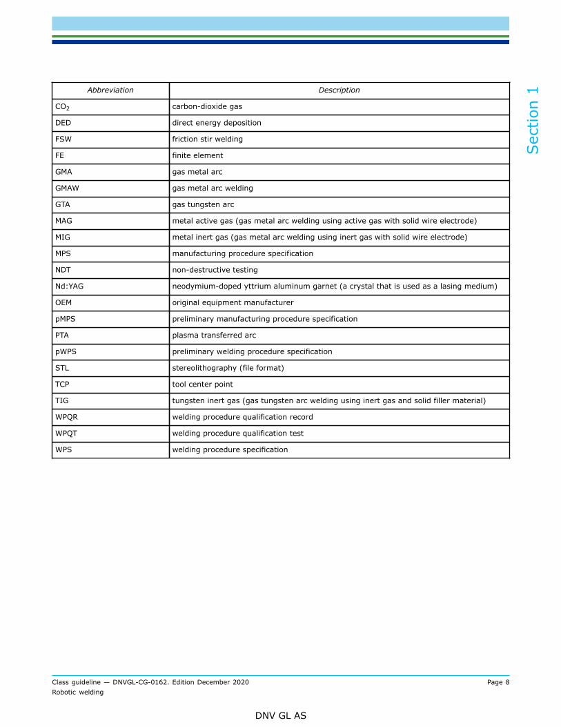
8.3 AbbreviationsAbbreviations used in this document are given in Table 5.
Table 5 Abbreviations
Abbreviation Description
AM additive manufacturing
AMF additive manufacturing format (file format)
CAD computer-aided design
CAM computer-aided manufacturing
CG class guideline
Section 1
Class guideline — DNVGL-CG-0162. Edition December 2020 Page 7Robotic welding
DNV GL AS
Abbreviation Description
CO2 carbon-dioxide gas
DED direct energy deposition
FSW friction stir welding
FE finite element
GMA gas metal arc
GMAW gas metal arc welding
GTA gas tungsten arc
MAG metal active gas (gas metal arc welding using active gas with solid wire electrode)
MIG metal inert gas (gas metal arc welding using inert gas with solid wire electrode)
MPS manufacturing procedure specification
NDT non-destructive testing
Nd:YAG neodymium-doped yttrium aluminum garnet (a crystal that is used as a lasing medium)
OEM original equipment manufacturer
pMPS preliminary manufacturing procedure specification
PTA plasma transferred arc
pWPS preliminary welding procedure specification
STL stereolithography (file format)
TCP tool center point
TIG tungsten inert gas (gas tungsten arc welding using inert gas and solid filler material)
WPQR welding procedure qualification record
WPQT welding procedure qualification test
WPS welding procedure specification
Section 1
Class guideline — DNVGL-CG-0162. Edition December 2020 Page 8Robotic welding
DNV GL AS

SECTION 2 QUALIFICATION OF PROCEDURES FOR ROBOTICWELDING
1 GeneralThe welding operators shall document adequate technical training for operation of the system and its controland limitations, e.g. according to ISO 14732 or AWS D16.4M.
2 Qualification and approval of procedures for robotic welding -joining and overlay/clad weldingDNV GL rules and offshore standards, and other relevant international standards for welding proceduresqualification require that a change from manual (or semi-automatic) to fully mechanized (or fully automatic)welding process shall be re-qualified, see DNVGL-RU-SHIP Pt.2 Ch.4 Sec.5 and DNVGL-OS-C401.The process for qualification and approval of robotic welding procedures is similar to that described inDNVGL-CG-0287 Hybrid laser-arc welding.The qualification consists of the following main steps, as illustrated in Figure 1:
1) Defining the essential process parameters and tolerance ranges.This would typically be established through systematic trials using different welding parameters, andresult in target parameters for the process, including process parameter ranges giving acceptableresults. It is recommended to use multi-dimensional statistical modelling which has proven to be apowerful tool to handle this task.
2) Implementing the results into practical welding.A stable and repeatable welding process shall be achieved. When a novel welding process is introducedin a workshop, there is by experience always a 'trial and error phase' before the process becomes stableand repeatable. Formal class approval work should not start in this turbulent phase, but wait until theprocess is under control, and can be demonstrated to be stable and repeatable.
3) Approval, comprising establishment of a pWPS, WPQT, WPQR and WPS.This step follows the same strategy as described in the Society's rules for conventional weldingprocesses. In the WPS, reference to welding program shall be added, but the principle is still the same asfor conventional welds. In the WPQT, the same tests as for conventional welds are required.But as indicated, programs for robotic welding cannot be evaluated on simulated production parts andwelding of actual prototypical parts is required. Prototypical parts should be agreed for each applicationof robotic welding.The need for fatigue testing shall be evaluated. See also relevant requirements in DNVGL-CG-0287.
4) Initial operation of the process in actual production welding.In this phase the inspection by the builder and where relevant, witnessing/inspection by the Societyshould be higher than for conventional welding, subject to agreement.
Section 2
Class guideline — DNVGL-CG-0162. Edition December 2020 Page 9Robotic welding
DNV GL AS
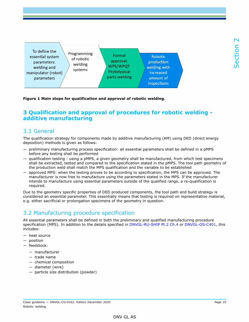
Figure 1 Main steps for qualification and approval of robotic welding.
3 Qualification and approval of procedures for robotic welding -additive manufacturing
3.1 GeneralThe qualification strategy for components made by additive manufacturing (AM) using DED (direct energydeposition) methods is given as follows:
— preliminary manufacturing process specification: all essential parameters shall be defined in a pMPSbefore any testing shall be performed
— qualification testing : using a pMPS, a given geometry shall be manufactured, from which test specimensshall be extracted, tested and compared to the specification stated in the pMPS. The tool path geometry ofthe production weld shall match the MPS qualification and the variable to be established
— approved MPS: when the testing proves to be according to specification, the MPS can be approved. Themanufacturer is now free to manufacture using the parameters stated in the MPS. If the manufacturerintends to manufacture using essential parameters outside of the qualified range, a re-qualification isrequired.
Due to the geometry specific properties of DED produced components, the tool path and build strategy isconsidered an essential parameter. This essentially means that testing is required on representative material,e.g. either sacrificial or prolongation specimens of the geometry in question.
3.2 Manufacturing procedure specificationAll essential parameters shall be defined in both the preliminary and qualified manufacturing procedurespecification (MPS). In addition to the details specified in DNVGL-RU-SHIP Pt.2 Ch.4 or DNVGL-OS-C401, thisincludes:
— heat source— position— feedstock:
— manufacturer— trade name— chemical composition— diameter (wire)— particle size distribution (powder)
Section 2
Class guideline — DNVGL-CG-0162. Edition December 2020 Page 10Robotic welding
DNV GL AS
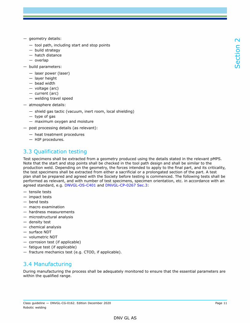
— geometry details:
— tool path, including start and stop points— build strategy— hatch distance— overlap
— build parameters:
— laser power (laser)— layer height— bead width— voltage (arc)— current (arc)— welding travel speed
— atmosphere details:
— shield gas tactic (vacuum, inert room, local shielding)— type of gas— maximum oxygen and moisture
— post processing details (as relevant):
— heat treatment procedures— HIP procedures.
3.3 Qualification testingTest specimens shall be extracted from a geometry produced using the details stated in the relevant pMPS.Note that the start and stop points shall be checked in the tool path design and shall be similar to theproduction weld. Depending on the geometry, the forces intended to apply to the final part, and its criticality,the test specimens shall be extracted from either a sacrificial or a prolongated section of the part. A testplan shall be prepared and agreed with the Society before testing is commenced. The following tests shall beperformed as relevant, and with number of test specimens, specimen orientation, etc. in accordance with anagreed standard, e.g. DNVGL-OS-C401 and DNVGL-CP-0267 Sec.3:
— tensile tests— impact tests— bend tests— macro examination— hardness measurements— microstructural analysis— density test— chemical analysis— surface NDT— volumetric NDT— corrosion test (if applicable)— fatigue test (if applicable)— fracture mechanics test (e.g. CTOD, if applicable).
3.4 ManufacturingDuring manufacturing the process shall be adequately monitored to ensure that the essential parameters arewithin the qualified range.
Section 2
Class guideline — DNVGL-CG-0162. Edition December 2020 Page 11Robotic welding
DNV GL AS
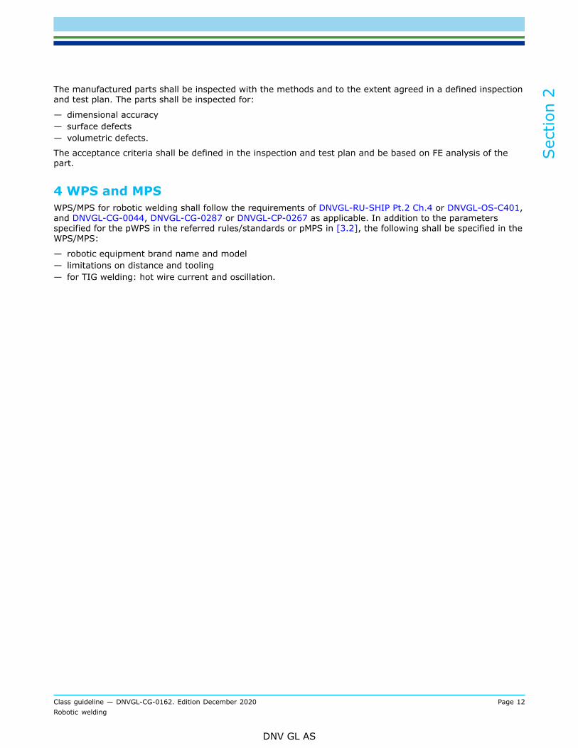
The manufactured parts shall be inspected with the methods and to the extent agreed in a defined inspectionand test plan. The parts shall be inspected for:
— dimensional accuracy— surface defects— volumetric defects.
The acceptance criteria shall be defined in the inspection and test plan and be based on FE analysis of thepart.
4 WPS and MPSWPS/MPS for robotic welding shall follow the requirements of DNVGL-RU-SHIP Pt.2 Ch.4 or DNVGL-OS-C401,and DNVGL-CG-0044, DNVGL-CG-0287 or DNVGL-CP-0267 as applicable. In addition to the parametersspecified for the pWPS in the referred rules/standards or pMPS in [3.2], the following shall be specified in theWPS/MPS:
— robotic equipment brand name and model— limitations on distance and tooling— for TIG welding: hot wire current and oscillation.
Section 2
Class guideline — DNVGL-CG-0162. Edition December 2020 Page 12Robotic welding
DNV GL AS
APPENDIX A CONVENTIONAL ROBOTIC WELDING (INFORMATIVE)
1 GeneralRobots are used in welding to increase level of automatization of the work processes and to reduce weldingoperator involvement in the performance of welding operations. Due to the big variations in design anddimensions in the maritime and offshore industries, robots have until now not found the same wideapplication as they have e.g. in automotive industry. However, some robotic welding processes have becomesuccessful because of high level of automatization and have been utilized in shipbuilding for quite some time,and these could be called conventional welding. For example:
— laser-MAG hybrid welding of butt welds on deck plates of cruise ships (DNVGL-CG-0287)— laser-MAG hybrid welding of T-joints (DNVGL-CG-0287)— friction stir welding (FSW) of aluminum structures (ISO 25239)— clad welding (DNVGL-CG-0044).
It's important to have high accuracy in joint preparation for the laser-MAG hybrid welding. For laser-MAGhybrid welding of butt welds on deck plates it is therefore not only welding itself that is fully automated, butalso preparation and machining of welding grooves, on the same gantry-based welding station, where bothtack welding and final hybrid laser welding will be done. I.e. all three steps; groove preparation, tack weldingand final welding could be fully automated for the laser-MAG hybrid welding.Robots will typically be applied for different welding processes and for different types of weld joints, like buttjoints, T-joints, fillet welds and clad welds. Robotic arc welding systems are typically utilizing the gas metalarc or flux cored arc welding processes.The term robot is defined as "automatically controlled, re-programmable multipurpose manipulator,programmable in the three axes or more which may be either fixed in place or mobile for use in industrialautomation application". Main characteristics of robots for welding are:
— motion capabilities and working range— end-of arm load capacity (typically 3 kg to 16 kg for welding robots)— working speed— repeatability and accuracy (typically welding head returns within 0,1 mm of the same point after eachcycle)
— reliability.
There are two common types of robots, articulated and rectilinear:
— articulated robots employ arms with rotary joints and their working zone is irregularly shaped— rectilinear robots move in line of three axes (X, Y, Z). In additional to linear movement of the robot alongaxes, the welding head attached to the robot often allows rotational movement. Their working zone is boxshaped.
Furthermore, these may be combined in different combinations, e.g. spherical robots that are call so becausetheir working zone is spherically shaped, where the robots consist of at least one rotary joint that can rotatein two planes, and one extension arm (two rotary axes and one linear axis).
2 Programming of robotic welding systemComputer-aided manufacturing (CAM) systems are used to program the sequence of motions of the robot todo welding.Programs are usually evaluated using actual production workpieces or parts. Simulated production partscannot yet simulate the effects of heat input on distortion and clamping. It is therefore done by welding ofprototypical parts.Welding software in robot controllers performs:
— a periodical checks of the wire placement in relation to the programmed tool center point (TCP)
Appendix A
Class guideline — DNVGL-CG-0162. Edition December 2020 Page 13Robotic welding
DNV GL AS
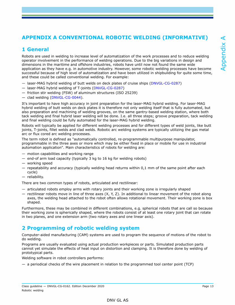
— a localization of the workpiece and welding seam.
Figure 1 Typical measurement positions
For example, the wire or the cup of the welding torch is used for searching seam in tactile electrical sensor.In Figure 1 the position 1, 2, 3 and 4 denotes the typical measurement of distance to the test piece that willbe detected and define the starting point of the weld, i.e. position 4. This means that besides the torch itselfno additional equipment is mounted onto the robot, and that access even into edges and corners is in no waylimited by the sensor system. The search instructions and position/orientation calculations are programmed,and is continuously tracking and adjusting the torch position relative to the joint in real time.The sensor system operates also by measuring the welding parameters like arc voltage during weavingmotions of the welding gun. If a weld diverges from the pre-programmed path, the torch-to-work piecedistance will be adjusted, and as a result the arc voltage will change, etc. The system detects these changesand corrects the robot movement accordingly, see Figure 2.
Appendix A
Class guideline — DNVGL-CG-0162. Edition December 2020 Page 14Robotic welding
DNV GL AS
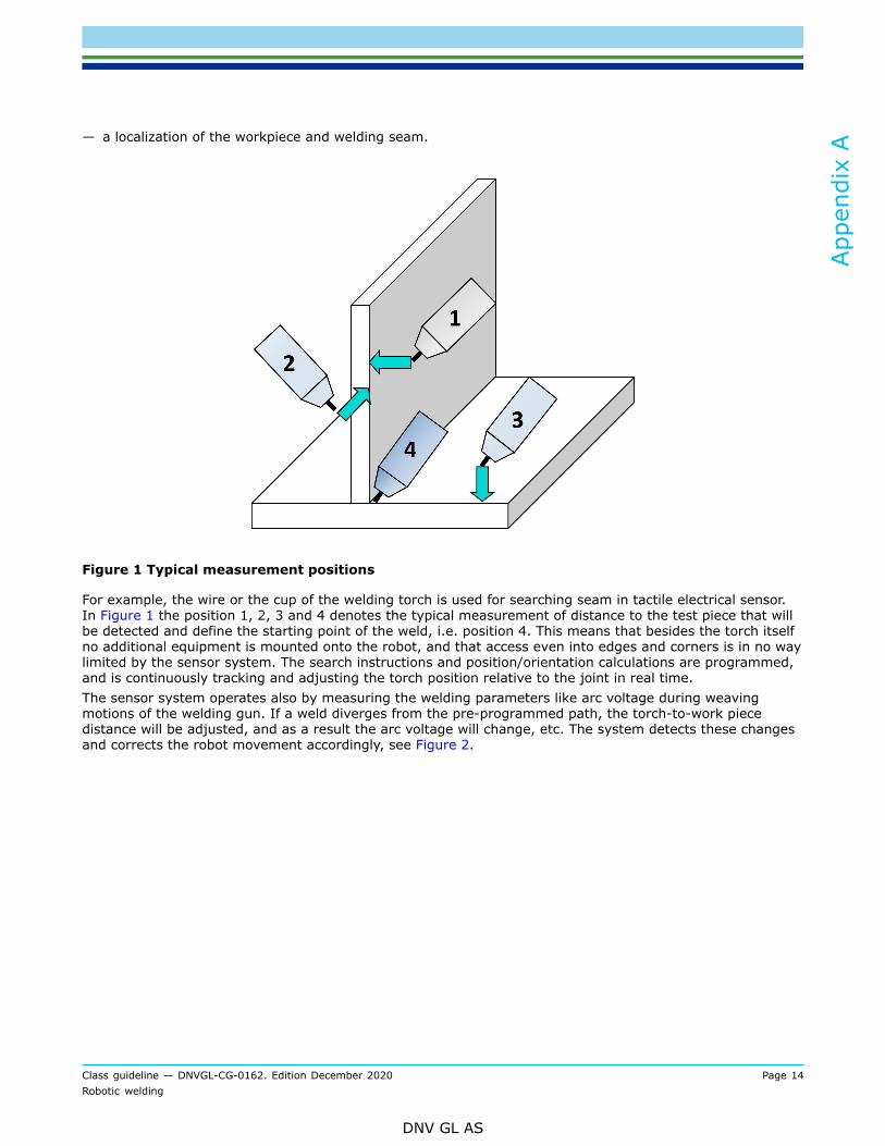
Figure 2 Tracking of the joint in real time, to keep the torch in correct position at all times.Indicating control for weaving and torch-to-work distance.
Some of the available welding softwares allows downloading of existing computer programs to check weldingparameters.
3 Robotic welding for AM processes - layer by layerRobotic welding for additive manufacturing (AM) processes are usually termed DED (direct energydeposition). There are different methods for DED, which are differentiated based on the type of feedstock andtype of heat source. The different feedstocks and heat sources are given below:
— feedstock:
— wire— powder.
— heat source:
— laser beam (CO2, Nd:YAG)— electron beam— arc plasma (GTA, GMA, PTA, etc.).
Common for all methods are that they produce parts by a layer by layer approach. When a CAD-file isdefined, it is translated to an AM-system compatible format, like AMF or STL, from which it is sliced in a AM-specific slicing software. The output of the slicing is a gcode-file, in which the information on how to buildthe part is given; the tool path, tool velocity, feed rate, power, etc. The gcode can then be transferred to theappropriate AM system, which will build the defined part.Also common for all methods above is that the systems comprise of four main components:
— heat source— positioner— feedstock feed mechanism— computer control system.
It is common that these four main components are delivered by different suppliers. It is then important toensure that they communicate with each other properly.
Appendix A
Class guideline — DNVGL-CG-0162. Edition December 2020 Page 15Robotic welding
DNV GL AS
One of the challenges with parts manufactured with DED is the presence of significant residual stresses. Theresidual stresses are a product of thermal contraction and high thermal gradients between the material beingdeposited and the material previously deposited which have cooled down significantly in comparison. Dueto the challenge of residual stresses, the building of the relevant part will be simulated with the relevantessential parameters, defined in the pMPS. The result of simulation will typically be reviewed and assessedwith the results of an FE analysis.
Appendix A
Class guideline — DNVGL-CG-0162. Edition December 2020 Page 16Robotic welding
DNV GL AS
APPENDIX B TYPICAL ROBOTIC WELDING PROCESSES INSHIPBUILDING INDUSTRY (INFORMATIVE)
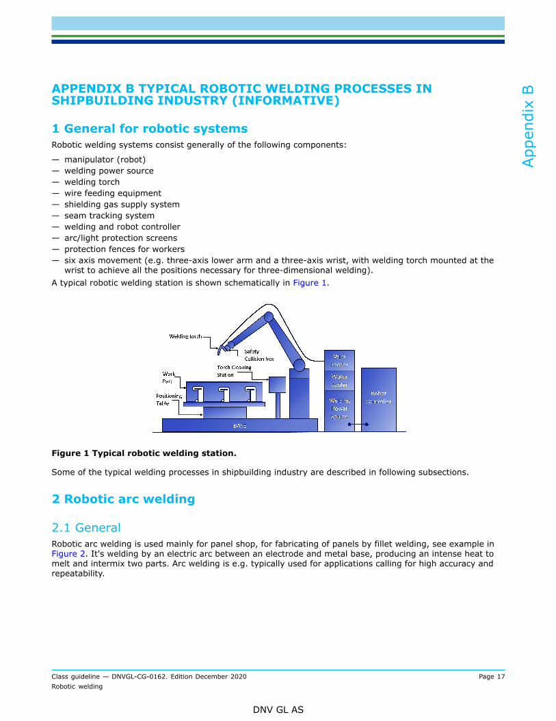
1 General for robotic systemsRobotic welding systems consist generally of the following components:
— manipulator (robot)— welding power source— welding torch— wire feeding equipment— shielding gas supply system— seam tracking system— welding and robot controller— arc/light protection screens— protection fences for workers— six axis movement (e.g. three-axis lower arm and a three-axis wrist, with welding torch mounted at thewrist to achieve all the positions necessary for three-dimensional welding).
A typical robotic welding station is shown schematically in Figure 1.
Figure 1 Typical robotic welding station.
Some of the typical welding processes in shipbuilding industry are described in following subsections.
2 Robotic arc welding
2.1 GeneralRobotic arc welding is used mainly for panel shop, for fabricating of panels by fillet welding, see example inFigure 2. It's welding by an electric arc between an electrode and metal base, producing an intense heat tomelt and intermix two parts. Arc welding is e.g. typically used for applications calling for high accuracy andrepeatability.
Appendix B
Class guideline — DNVGL-CG-0162. Edition December 2020 Page 17Robotic welding
DNV GL AS
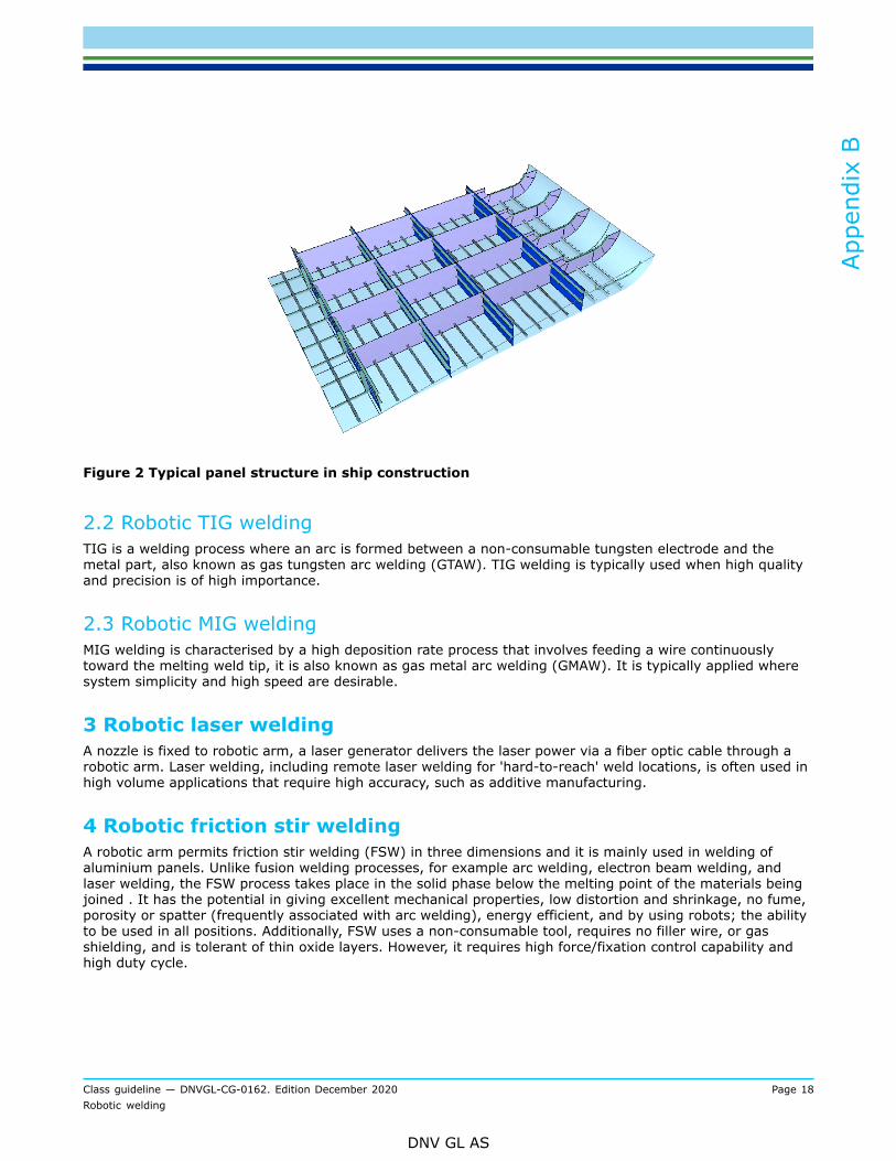
Figure 2 Typical panel structure in ship construction
2.2 Robotic TIG weldingTIG is a welding process where an arc is formed between a non-consumable tungsten electrode and themetal part, also known as gas tungsten arc welding (GTAW). TIG welding is typically used when high qualityand precision is of high importance.
2.3 Robotic MIG weldingMIG welding is characterised by a high deposition rate process that involves feeding a wire continuouslytoward the melting weld tip, it is also known as gas metal arc welding (GMAW). It is typically applied wheresystem simplicity and high speed are desirable.
3 Robotic laser weldingA nozzle is fixed to robotic arm, a laser generator delivers the laser power via a fiber optic cable through arobotic arm. Laser welding, including remote laser welding for 'hard-to-reach' weld locations, is often used inhigh volume applications that require high accuracy, such as additive manufacturing.
4 Robotic friction stir weldingA robotic arm permits friction stir welding (FSW) in three dimensions and it is mainly used in welding ofaluminium panels. Unlike fusion welding processes, for example arc welding, electron beam welding, andlaser welding, the FSW process takes place in the solid phase below the melting point of the materials beingjoined . It has the potential in giving excellent mechanical properties, low distortion and shrinkage, no fume,porosity or spatter (frequently associated with arc welding), energy efficient, and by using robots; the abilityto be used in all positions. Additionally, FSW uses a non-consumable tool, requires no filler wire, or gasshielding, and is tolerant of thin oxide layers. However, it requires high force/fixation control capability andhigh duty cycle.
Appendix B
Class guideline — DNVGL-CG-0162. Edition December 2020 Page 18Robotic welding
DNV GL AS
5 Robotic resistance weldingThis would typically be spot welding. A current is passed between two pieces of metal, a melting pool isformed by resistance heating, and the two pieces are joined together. It is an economical form of weldinge.g. of aluminum and stainless steel.
6 Robotic plasma weldingRobotic plasma welding is characterised by ionized gas passing through a copper nozzle to produce extremelyhigh temperatures. Plasma welding is used when flexibility is required, as velocity and temperatures can beeasily adjusted.
Appendix B
Class guideline — DNVGL-CG-0162. Edition December 2020 Page 19Robotic welding
DNV GL AS
CHANGES – HISTORICThere are currently no historical changes for this document.
Changes – historic
Class guideline — DNVGL-CG-0162. Edition December 2020 Page 20Robotic welding
DNV GL AS
About DNV GLDNV GL is a global quality assurance and risk management company. Driven by our purpose ofsafeguarding life, property and the environment, we enable our customers to advance the safetyand sustainability of their business. We provide classification, technical assurance, software andindependent expert advisory services to the maritime, oil & gas, power and renewables industries.We also provide certification, supply chain and data management services to customers across awide range of industries. Operating in more than 100 countries, our experts are dedicated to helpingcustomers make the world safer, smarter and greener.
SAFER, SMARTER, GREENER