CG 1 Pyrgeometer and CG 2 Net Pyrgeometer - Kippzonen.com
65
0305 206 PYRGEOMETER & NET PYRGEOMETER INSTRUCTION MANUAL
-
Upload
khangminh22 -
Category
Documents
-
view
0 -
download
0
Transcript of CG 1 Pyrgeometer and CG 2 Net Pyrgeometer - Kippzonen.com

manual
0305 2
06
PYRGEOMETER & NET PYRGEOMETER
INSTRUCTION MANUAL

IMPORTANT USER INFORMATION
1
IMPORTANT USER INFORMATION
Reading this entire manual is recommended for full
understanding of the use of this product. Should you have any comments on this manual we will be pleased to receive them at: Kipp & Zonen B.V. Röntgenweg 1 2624 BD Delft Holland P.O. Box 507 2600 AM Delft Holland Phone +31 (0)15 2698000 Fax +31 (0)15 2620351 Email [email protected] Kipp & Zonen reserve the right to make changes to the specifications without prior notice.
WARRANTY AND LIABILITY
Kipp & Zonen guarantees that the product delivered has been thoroughly tested to ensure that it meets its published specifications. The warranty included in the conditions of delivery is valid only if the product has been installed and used according to the instructions supplied by Kipp & Zonen. Kipp & Zonen shall in no event be liable for incidental or consequential damages, including without limitation, lost profits, loss of income, loss of business opportunities, loss of use and other related exposures, however caused, arising from the faulty and incorrect use of the product. User made modifications can affect the validity of the CE declaration.
COPYRIGHT© 2003 KIPP & ZONEN
All rights reserved. No part of this publication may be reproduced, stored in a retrieval system or transmitted in any form or by any means, without permission in written form from the company.
Manual version: 0204

IMPORTANT USER INFORMATION
2
DECLARATION OF CONFORMITY
According to EC guideline 89/336/EEC 73/23/EEC We Kipp & Zonen B.V. Röntgenweg 1 2624 BD Delft Declare under our sole responsibility that the product Types: CG 1, Pyrgeometer CG 2, Net Pyrgeometer To which this declaration relates is in conformity with the following standards Imissions EN 50082-1 Group standard Emissions EN 50081-1 Group standard EN 55022 Safety standard IEC 1010-1 Following the provisions of the directive
R.E. Ringoir
Product management KIPP & ZONEN B.V.

TABLE OF CONTENTS
3
TABLE OF CONTENTS IMPORTANT USER INFORMATION...............................................................1 DECLARATION OF CONFORMITY ................................................................2 TABLE OF CONTENTS...................................................................................3 1 GENERAL INFORMATION ..................................................................5 1.1 INTRODUCTION .......................................................................................5 1.2 PHYSICAL PRINCIPLES OF THE PYRGEOMETER ..............................6 1.2.1 Properties of the Silicon window................................................................7 1.3 DOWNWARD ATMOSPHERIC LONGWAVE RADIATION .....................9 1.4 WINDOW HEATING EFFECT................................................................ 11 1.4.1 How to perform the check?..................................................................... 12 1.5 LOW TEMPERATURE DEPENDENCY OF SENSITIVITY ................... 13 2 TECHNICAL DATA ............................................................................15 2.1 SPECIFICATIONS OF THE CG 1 PYRGEOMETER ............................ 15 2.2 ACCURACY............................................................................................ 19 3 INSTALLATION..................................................................................21 3.1 DELIVERY .............................................................................................. 21 3.2 MECHANICAL INSTALLATION ............................................................. 22 3.2.1 Location................................................................................................... 22 3.2.2 Mounting.................................................................................................. 22 3.2.3 Levelling .................................................................................................. 24 3.2.4 Mounting of net pyrgeometer CG 2 ........................................................ 25 3.3 ELECTRICAL CONNECTION ................................................................ 25 4 OPERATION.......................................................................................31 4.1 CALCULATING THE DOWNWARD RADIATION ................................. 31 4.1.1 Example .................................................................................................. 31 4.1.2 Cloudy overcast sky................................................................................ 32 4.1.3 Clear sky conditions................................................................................ 32 4.1.4 Measurements during a sunny day ........................................................ 33 4.2 MEASURING NET RADIATION WITH TWO PYRGEOMETERS......... 34 4.3 THERMAL STRESS STUDIES .............................................................. 35 5 MAINTENANCE..................................................................................37 6 CALIBRATION ...................................................................................39 6.1 THE CALIBRATION FACTOR................................................................ 39 6.2 CALIBRATION PROCEDURE AT KIPP & ZONEN............................... 39 6.2.1 The indoor calibration ............................................................................. 39 6.2.2 The outdoor procedure for the reference pyrgeometer.......................... 40 6.2.3 Traceability to the World Radiometric reference .................................... 40

TABLE OF CONTENTS
4
6.3 RECALIBRATION................................................................................... 41 7 FREQUENTLY ASKED QUESTIONS (FAQ’S) .................................43 8 TROUBLE SHOOTING.......................................................................45 9 DELIVERY ..........................................................................................47 10 PART NUMBERS / SPARE PARTS / OPTIONS................................49 APPENDIX I WORLD RADIATION CENTRE INFORMATION...............51 APPENDIX II THERMISTOR PT-100 SPECIFICATIONS........................53 APPENDIX III PT-100 SPECIFICATIONS ................................................55 APPENDIX IV RECALIBRATION SERVICE.............................................57
GENERAL INFORMATION
5
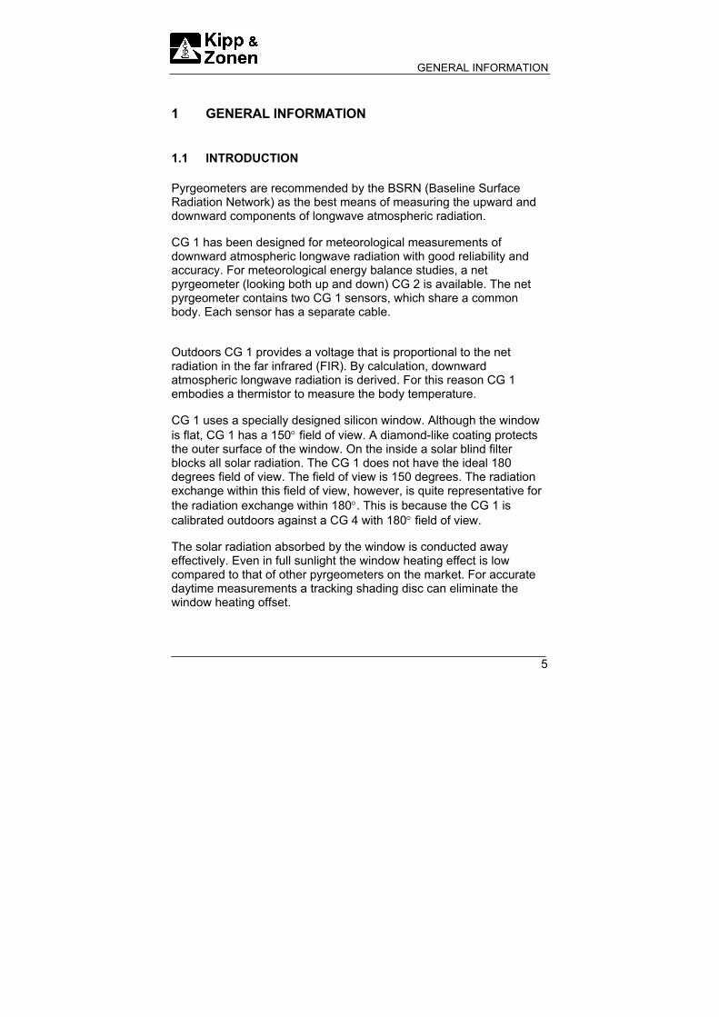
1 GENERAL INFORMATION 1.1 INTRODUCTION Pyrgeometers are recommended by the BSRN (Baseline Surface Radiation Network) as the best means of measuring the upward and downward components of longwave atmospheric radiation. CG 1 has been designed for meteorological measurements of downward atmospheric longwave radiation with good reliability and accuracy. For meteorological energy balance studies, a net pyrgeometer (looking both up and down) CG 2 is available. The net pyrgeometer contains two CG 1 sensors, which share a common body. Each sensor has a separate cable. Outdoors CG 1 provides a voltage that is proportional to the net radiation in the far infrared (FIR). By calculation, downward atmospheric longwave radiation is derived. For this reason CG 1 embodies a thermistor to measure the body temperature. CG 1 uses a specially designed silicon window. Although the window is flat, CG 1 has a 150° field of view. A diamond-like coating protects the outer surface of the window. On the inside a solar blind filter blocks all solar radiation. The CG 1 does not have the ideal 180 degrees field of view. The field of view is 150 degrees. The radiation exchange within this field of view, however, is quite representative for the radiation exchange within 180°. This is because the CG 1 is calibrated outdoors against a CG 4 with 180° field of view. The solar radiation absorbed by the window is conducted away effectively. Even in full sunlight the window heating effect is low compared to that of other pyrgeometers on the market. For accurate daytime measurements a tracking shading disc can eliminate the window heating offset.

GENERAL INFORMATION
6
CG 1 features are:
• Sensitive to infrared radiation in a wavelength range from 5 to approx. 40 µm.
• Reduced window heating offset. • 150° field of view. • Diamond like coating for optimal protection against
environmental influences. • Low temperature dependence of sensitivity For meteorological energy balance studies, a net pyrgeometer (looking both up and down) CG 2 is available. The net pyrgeometer contains two CG1 sensors, which share a common body. Each sensor has a separate cable. 1.2 PHYSICAL PRINCIPLES OF THE PYRGEOMETER The CG 1 pyrgeometer is provided with a thermal detector. The thermal detector is a 64-thermocouple thermopile. The body temperature sensor, either a thermistor (YSI44031) or Pt-100 (optional), is built-in at the edge of the thermal detector, at the cold junctions. The radiant energy is absorbed by a black painted disk. The heat generated flows through a thermal resistance to the heat sink (the pyrgeometer body). The temperature difference across the thermal resistance of the detector is converted into a voltage. The thermopile output can be easily affected by wind and rain. Therefore a Silicon window shields the detector. On both sides of the Silicon window a coating is deposited. The outer side of the window is protected with a diamond-like layer against environmental influences such as wind and rain. On the inner side an interference filter is deposited for passing the longwave radiation only. The Silicon window allows equal transmittance of the atmospheric longwave radiation in a range from 4.5 (cut-on) to approx. 40 µm. A construction drawing of the CG 1 pyrgeometer is shown in figure 1.1

GENERAL INFORMATION
7
Figure 1.1 Schematic construction of the CG 1 pyrgeometer 1.2.1 Properties of the Silicon window CG 1 uses a specially designed pure silicon window. Although the window isn’t hemispherical, CG 1 has still a 150° field of view. A big advantage of the flat window over the typical spherical window is the ability of the coating manufacturer to deposit a more uniform coating on the window surface. Deposition of a uniform filter coating on a strongly curved surface is a rather difficult, possibly impossible process. With that knowledge Kipp & Zonen developed a window with a good optical quality due to an optimal shape and coating uniformity. In this way a CG 1 window allows equal dome transmittance over the whole window surface.

GENERAL INFORMATION
8
The diamond-like coating also called “ Hard carbon coating “ is a carbon layer of a few microns thickness, with the main purpose of providing optimal protection against environmental influences. An additional advantage is that the hard carbon acts as an anti-reflection coating, which leads to an increase of transmittance. The solar blind filter is opaque for radiation under the 5 µm known as the cut-on wavelength. The low-pass filter deposited at the inside of the window is an interference filter. Currently most pyrgeometers have their cut-on at a lower wavelength. Problems may occur in case of clear sunny days with low humidity. In the solar spectrum between 2.5 and 5 µm, there can be still an amount of infrared solar radiation up to 10 W/m2. This unwanted fraction would increase the amount of downward radiation unavoidable. In the CG 1 this signal is blocked by the filter coating. The CG 1 window transmittance curve is given in figure 1.2 The transmittance is given at normal incidence. Figure 1.2 Typical transmittance of a CG 1 window.
CG 1 WINDOW TRANSMITTANCE
0
50
100
1 10 100
Wavelength [µm]
Tran
smitt
ance
[%
]

GENERAL INFORMATION
9
1.3 DOWNWARD ATMOSPHERIC LONGWAVE RADIATION The atmosphere is a gaseous envelope surrounding the earth, held by gravity, having its maximum density just above the solid surface and becoming gradually thinner with distance from the ground, until it finally becomes indistinguishable from the interplanetary gas. There is, therefore, no defined upper limit or “top” of the atmosphere. As we go away from the surface of the earth, different regions can be defined, with widely different properties, being the seats of a great variety of physical and chemical phenomena. One of these fascinating phenomena is the thermal or longwave radiation. An important, but rather difficult to measure, component of the radiation budget is the atmospheric longwave radiation balance. The atmosphere is transparent to longwave radiation emitted by the Earth’s surface in certain wavelength intervals, particular within a spectral range of approximately 8 to 14 µm, which is called the atmospheric window (see figure 1.3). Within this spectral range the earth is able to maintain an equilibrium temperature by losing a certain quantity of heat gained each day from the sun. The sun radiates approximately as a blackbody at an equivalent temperature of nearly 5770K. Almost 99% of its emitted energy is contained in wavelengths less than 4µm and is called short-wave radiation. The equivalent radiant temperature of the Earth’s surface is about 275K. More than 99% of this energy is emitted at wavelengths more than 5 µm and is called long-wave, thermal, or infrared radiation. Downward longwave radiation is a result of atmospheric re-emission. Re-emission is the reversible effect of absorption of earthly emitted longwave radiation by chemical elements like water (H2O), Oxygen (O2), Ozone (O3), Carbon dioxide (CO2) etc. These elements are the main emitters of longwave radiation in the atmosphere. The remaining unabsorbed portion of the earth’s radiation escapes into the outer space. Under clear skies an object can be cooled below ambient air temperature by radiative heat loss to the sky. Observing the earth from outer space, a blackbody is seen in a range of 8 to 14 µm with a temperature of 14 °C and outside this wavelength range a

GENERAL INFORMATION
10
blackbody of -60 °C. Under clear sky conditions in a reverse direction, outer space can be observed in the same spectral range. The longwave radiation exchange mainly occurs in the spectral range of 8 to 14µm. In this range the pyrgeometer also loses its thermal energy upward. Figure 1.3 Atmospheric radiation (atmospheric window 8 to 14 µm) Where as a pyranometer only receives solar radiation, pyrgeometers can emit their own radiation by losing energy to a relatively cold sky. The pyrgeometer signal therefore is the difference between the downward longwave radiation emitted from the atmosphere and the upward emitted radiation from the pyrgeometer. The downward atmospheric longwave radiation can be calculated with formula 1 by measuring the thermopile output voltage Uemf [µV], the body temperature Tb [K], and taking the calibration factor S [µV/W/m2] into account.

GENERAL INFORMATION
11
TL bd SUemf 481067.5 ⋅⋅+= − (formula 1)
This formula is given by the WMO, 1996 = Downward atmospheric longwave radiation [W/m2] = Net radiation (Difference between the downward longwave radiation emitted from the atmosphere and the upward irradiance of the CG 1 sensor ) [W/m2] = Upward irradiance of the CG 1 sensor [W/m2] Note that the net radiation term (Uemf / S) is mostly negative, so the calculated downward atmospheric longwave radiation is smaller than the sensor’s upward irradiance ( T b
481067.5 ⋅⋅ − ). 1.4 WINDOW HEATING EFFECT Currently the major source of error concerning common pyrgeometer measurements is caused by window heating. When a pyrgeometer is exposed to the sun, window heating occurs due to absorption of solar radiation with wavelength < 1.1 µm in the window material. As a consequence the windows of certain types of pyrgeometers will heat up proportional to the amount of solar radiation. The resulting temperature difference between window and thermopile will cause heat transfer by radiation and convection to the sensor. This affects the net thermal radiation as measured by the thermopile. This error is commonly referred to as the “Window heating offset”, and results in the measurement of a too high value for downward longwave radiation. This offset is not easily reduced by (for example) ventilation; ventilation only cools off 50 W/m2/°C at maximum while solar radiation can be absorbed at a rate of about 500 W/m2 on a sunny day. Currently, certain types of pyrgeometers are equipped with one or
T b481067.5 ⋅⋅ −
Ld
Uemf S

GENERAL INFORMATION
12
more window thermistors to measure the windows absolute temperature that represents the appearing offset. During window temperature measurements a complex calculation must be performed to eliminate the offset. Window heating can be checked by doing the following experiment. The experiment is illustrated with an example. 1.4.1 How to perform the check? The check must be performed under clear sky conditions. The CG 1 pyrgeometer is operated with thermopile and thermistor readout for measuring the downward radiation. To perform the outdoor check, follow next steps: 1. Stand in line with the sun and the pyrgeometer under the
condition that the pyrgeometer is still illuminated by solar radiation.
2. Wait for at least 1 minute until the pyrgeometer thermopile output is stabilised (your body contributes to the pyrgeometer signal) record the reading. 3. Raise your hand in line with the sun and pyrgeometer so that
the pyrgeometer is shaded completely. 4. Wait for at least 1 minute until the pyrgeometer thermopile
output is stabilised, record the reading. 5. Check performed, data can be interpreted. The difference in
readings found after steps 2 and 4 gives the amount of window heating.

GENERAL INFORMATION
13
1.5 LOW TEMPERATURE DEPENDENCY OF SENSITIVITY The sensitivity is correlated to the temperature as a consequence of typical physical material properties of the thermopile. For a given heat flow the sensitivity of the pyrgeometer is a function of the thermal conductivity of the sensor materials and of the thermo-electric power of the sensor material. Both physical parameters show temperature dependency. Due to the thermopile construction the temperature response drops not below -2%, at -20 °C resp. +50 °C.

GENERAL INFORMATION
14

TECHNICAL DATA
15
2 TECHNICAL DATA 2.1 SPECIFICATIONS OF THE CG 1 PYRGEOMETER Performance Spectral range: 4.5 to 42 µm, 50% points. Sensitivity: 10 µV/W/m2 (nominal). Impedance: 40 to 200 Ω (nominal). Response time: 25 s (95% response). < 8 s (63% response). Non-linearity: <± 1% (at -250 to +250 W/m2 irradiance). Temperature dependence of sensitivity: Max. -2 % (at -20 °C resp +50 °C). Tilt error: Max. 1 % deviation when facing downwards. Zero offset due to temperature changes: < 2 W/m2 offset at 5 K/h temp. change. Operating temperature: -40 °C to +80 °C. Field of view: 150° Irradiance: -250 to +250 W/m2. Non-stability: <±1% sensitivity change per year. Spectral selectivity within the range 8 to 14 µm: Max. approx. ±5 %. Window heating offset: Max. 25 W/m2 (1000 W/m2 normal incidence solar radiation). Accuracy 10 % for daily totals

TECHNICAL DATA
16
Estimated inaccuracy of measurement: < 20 W/m2. Thermistor specifications (only for thermistor version): Type YSI 44031. See Appendix II. Pt-100 specifications (only for Pt-100 version): Type Heraeus M-GX 1013,
DIN IEC 751. Class A. See appendix III. Construction Receiver paint: Carbon Black. Window: Silicon with solar blind filter and diamond-like coating. Desiccant: Silica gel. Spirit level: Sensitivity of 0.5 ° (bubble half out of the ring)
Coincide with base of the instrument. Materials: Anodised aluminium case with aluminium levelling screws. Stainless steel screws. White plastic screen of ASA/PC. Drying cartridge PMMA. Weight CG 1: 750 g CG 2: 1700 g Cable length: 10 m. Dimensions in mm: See figure 2.1 and 2.2

TECHNICAL DATA
17
Figure 2.1 CG 1 pyrgeometer outline dimensions

TECHNICAL DATA
18
Figure 2.1 CG 2 pyrgeometer outline dimensions

TECHNICAL DATA
19
2.2 ACCURACY As listed in paragraph 2.1 the sensitivity is cross-correlated to a number of parameters such as temperature and level of irradiance. Normally, the supplied sensitivity figure is used to calculate the irradiances. If the conditions differ from the calibration conditions, errors in the calculated irradiances must be expected. These remaining errors can be reduced if the actual sensitivity of the pyrgeometer is used by the conversion of voltage to irradiance. The actual sensitivity can be calculated when it is a well-known function of simply measured parameters (sometimes called transfer function or sensitivity function). This is especially convenient in connection with a programmable data acquisition system. For the CG 1 the effect of each parameter on the sensitivity can be shown separately, because the parameters exhibit less interaction. The non-linearity error, the sensitivity variation with irradiance, is similar for any CG 1. See figure 2.2 Figure 2.2 Non linear sensitivity variation with irradiance of the CG 1
pyrgeometer.

TECHNICAL DATA
20
The temperature dependence of the sensitivity is an individual function. For any given CG 1 the curve lies in the region between the limit lines in figure 2.3
Figure 2.3 Curves of relative sensitivity variation with instrument temperature of CG 1 pyrgeometers. A typical curve is shown.

INSTALLATION
21
3 INSTALLATION Reading these instructions before installation is recommended. 3.1 DELIVERY Check the contents of the shipment for completeness (see below) and note whether any damage has occurred during transport. If there is damage, a claim should be filed with the carrier immediately. In this case, or if the contents are not complete, your dealer should be notified in order to facilitate the repair or replacement of the instrument. The CG 1 pyrgeometer delivery will include the following items: 1 CG 1 pyrgeometer 2 White sun screen 3 2 x Mounting bolts 4 2 x Nylon insulators 5 Calibration certificate 6 This manual Unpacking Keep the original packaging for later shipments (e.g. recalibration) ! Although all sensors are weatherproof and suitable for harsh ambient conditions, they do partially consist of delicate mechanical parts. It is recommended to use the original shipment packaging to safely transport the equipment to the measurement site.

INSTALLATION
22
3.2 MECHANICAL INSTALLATION The mechanical installation of the pyrgeometer must be carried out depending on the application. Different measuring methods will be explained in chapter 4. Generally for measuring downward atmospheric longwave radiation the following steps must be carefully considered for optimal performance of the instrument: 3.2.1 Location Ideally the site for the pyrgeometer should be free from any obstructions above the plane of the sensing element, and at the same time the pyrgeometer should be readily accessible to clean the window and inspect the dessicator. Obstructions on the horizon with angular height less than 15° are outside the field of view of the CG 1 and not relevant. In principle no special orientation of the instrument is required. The World Meteorological Organisation recommends that the emerging leads are pointed to the north, to minimise heating of the electrical connections. 3.2.2 Mounting The CG 1 pyrgeometer is provided with two holes for 5 mm bolts. Two stainless steel bolts and two nylon rings are provided. The pyrgeometer should first be secured lightly with the bolts to a mounting stand or platform ( Shown in figure 3.1). The nylon insulators must be placed under the bolt heads to avoid electrolytic corrosion between bolt and body.

INSTALLATION
23
Note: After recalibration and/or reinstallation the nylon insulators must be replaced with new ones to maintain durability.
The mounting stand temperature can vary over a wider range than the air temperature. Temperature fluctuations of the pyrgeometer body can produce offset signals. It is recommended to isolate the pyrgeometer thermally from the mounting stand,

INSTALLATION
24
e.g. by placing it on its levelling screws. But keep an electric contact with earth to lead off currents in the cable induced by lightning. Figure 3.1 Mounting the CG 1 pyrgeometer 3.2.3 Levelling Level the instrument by turning the levelling screws to bring the bubble of the spirit level within the marked ring (For easy levelling first use the screw nearest to the spirit level). When the CG 1 is placed horizontally with the spirit level, or when it is mounted with its base parallel to a horizontal plane, the thermopile is horizontal within 0.25°. The pyrgeometer should be secured tightly with the two stainless steel bolts. Ensure that the pyrgeometer maintains the proper levelled position!
Screw M5x80 Nylon insulator
Washer M5 Nut M5

INSTALLATION
25
3.2.4 Mounting of net pyrgeometer CG 2 As with all net radiation measurements, a location that is representative for the whole area of study should be found. For the two, possible ventilated, CG 1’s a mounting plate with a 500 mm rod is available (see chapter 9). CG 2 has a mounting rod, diamater 16 mm and length 500 mm. Typical is a height of 2 m above short homogeneous vegetation. The mast on which the rod is clamped can block the downwelling or upward radiation with a fraction of max. (D / 2⋅π⋅S), in which D is the diameter of the mast and S the distance of sensor to mast. The mast itself also emits infrared radiation, so keep the mast and CG 1 temperatures close to each other or the emissivity low (reflecting mast). 3.3 ELECTRICAL CONNECTION CG 1 and CG 2 are offered standard with a four wire Pt-100 temperature measurement and a 12V heating resistor. Options are a two wire thermistor temperature measurement and a 24V heating resistor, replacing respectively the Pt-100 and 12V resistor. The colour code is: Red: Plus thermopile Blue: Minus thermopile Yellow: Pt-100 (combined with brown) or thermistor Brown: Pt-100 (combined with yellow) or not present Green: Pt-100 (combined with grey) or not present Grey: Pt-100 (combined with green) or thermistor Black: Heating resistor 12V or 24V White: Heating resistor 12V or 24V Shield surge arrestor to case Circuit diagrams of CG 1 and CG 2 are shown in figures 3.3 and 3.4.

INSTALLATION
26
Readout equipment with an input impedance over 150 kOhm is advised. Important characteristics for signal amplification are zero-offset, and sensitivity per bit. The typical sensitivity of a pyrgeometer is 10 µV/Wm-2. A zero offset greater than 10 µV will produce an offset of more than 1 W/m2. If a resolution of W/m2 is desired, a readout resolution of 10 µV per bit is necessary. A surge arrester is installed to lead off induced lightning currents to the case. It is recommended to ground the case for this reason. The surge arrester is noble gas filled, has infinite impedance and recovers after breakdown. Breakdown voltage is 90 V. Peak pulse current is 10 kA. The shield is isolated from the case, so no shield-current can exist. Shield and white lead may be connected to the same ground at the readout equipment. The cable must be firmly secured to minimise spurious response during stormy weather (deforming standard cable produces voltage spikes, a tribo electric effect and capacitance effect). Kipp & Zonen pyrgeometer cables are of low noise type, however take care that the terminals '+' and '-' at a connection box have the same temperature, to prevent thermal EMF's. A junction box or connector with a metal outer case is advised. Looking at the circuit diagram of figure 3.3, it is clear that the impedance of the readout equipment is loading the thermopile. The sensitivity is affected more than 0.1% when the load resistance is under 100 kΩ. For this reason we recommend the use of readout equipment with input impedance’s of 1 MΩ or more such as potentiometric recorders, digital voltmeters, etc.

INSTALLATION
27
Figure 3.3 Circuit diagram of the CG 1(CG 2) pyrgeometer and the
connection to the readout equipment.

INSTALLATION
28
The data loggers and chart recorders manufactured by Kipp & Zonen meet these requirements. Longer cables may be applied, but the cable resistance must be less than 0.1% of the impedance of the readout equipment. Kipp & Zonen supplies shielded low-noise extension cables up to lengths of 200 m which are coupled by waterproof connectors to the CG 1 cable. The lead resistance is 8 Ohm/100 m. A considerable input bias current of the readout equipment can produce a voltage of several micro Volts across the impedance of the pyrgeometer. The correct measured zero signal can be verified with a resistance replacing the pyrgeometer impedance at the input terminals. The pyrgeometer can also be connected to a computer or data acquisition system. A low voltage analog input module with A to D converter must be available for thermopile readout. The span and resolution of the A to D converter in the module must allow a system sensitivity of about 1 bit per W/m2. For calculation of the downward radiation, temperature data has to be converted to absolute body temperatures in Kelvin units. A thermistor connection to the Campbell datalogger is shown in figure 3.4 The connection of the Pt-100 is shown in figure 3.5 Figure 3.4 Example of a CG 1 with a thermistor connected to a Campbell
datalogger

INSTALLATION
29
Figure 3.5 Example of a CG 1 with a Pt-100 connected to a Campbell
datalogger For amplification of the pyrgeometer signal, Kipp & Zonen recommends the CT 24 amplifier, available from Kipp & Zonen. This amplifier will convert the output voltage from the pyrgeometer into a standard 4 – 20 mA output current. Voltage output and/or amplification adjustment to the pyrgeometers calibration factor are also possible. In order to allow negative values for the CG 1, the zero of the CT 24 (normally 4 mA) will be shifted to 8 mA.

INSTALLATION
30

OPERATION
31
4 OPERATION After completing the installation the pyrgeometer will be ready for operation. At the end of the paragraph an example is given to illustrate a downward atmospheric longwave radiation measurement under two different atmospheric conditions. 4.1 CALCULATING THE DOWNWARD RADIATION The downward atmospheric longwave radiation can be calculated with formula 1 by measuring the thermopile output voltage Uemf [µV], the body temperature Tb [K], and taking the calibration factor S [µV/W/m2] into account.
TL bd SUemf 481067.5 ⋅⋅+= − (formula 1)
= Downward atmospheric longwave radiation [W/m2] = Net - radiation (Difference between the downward longwave radiation emitted from the atmosphere and the upward irradiance of the CG 1 sensor ) [W/m2] = Upward irradiance of the CG 1 sensor [W/m2] Mind that the net radiation term (Uemf / S) is mostly negative, so the calculated downward atmospheric longwave radiation is smaller than the sensor’s upward irradiance (5.67⋅10-8⋅Tb
4). 4.1.1 Example During field measurements the pyrgeometer is exposed to varying atmospheric conditions with typical radiating properties. Therefore we
SUemf
Ld
T b481067.5 ⋅⋅ −

OPERATION
32
define the two most common conditions known as, cloudy overcast sky and clear sky. 4.1.2 Cloudy overcast sky Typical for a cloudy overcast sky is that radiation emitted by the earth is absorbed 100%. Therefore the overcast sky will re-emit the radiation (Ld). In case of mist the net radiation is zero. With higher clouds the thermopile output shows a little negative voltage (a few tenths of Watts per meter square), due to a small heat exchange between a relatively warm pyrgeometer and a colder sky. In this case the calculated atmospheric longwave radiation (Ld) shows a relatively large positive value. In the case of rain, the thermopile output will read zero, because water deposited at the pyrgeometer window is a perfect infrared absorber. A cloudy overcast sky condition is illustrated in figure 4.1A Figure 4.1A Cloudy overcast sky condition 4.1.3 Clear sky conditions Clear sky conditions differ in the way that there is a relative large heat loss caused by the atmospheric window. In this way the amount of re-emitted radiation by a clear sky is smaller compared to the cloud overcast sky condition. Because of the heat-lost in upward direction, the sensors hot junctions will cool-down and show a relative large
Downwelling radiation (Relative large value)
Atmosphere Tatm
Earth surface Tearth > Tatm
Upward radiation
Net radiation (from 0 to -20 W/m2)

OPERATION
33
negative net radiation value (from -90 to -130 W/m2) or more. In this case the calculated atmospheric longwave radiation (Ld) shows a relative small positive value. A clear sky condition is illustrated in figure 4.1B Figure 4.1B Clear sky condition 4.1.4 Measurements during a sunny day CG 1 allows only accurate daytime measurements on sunny days with a moving shading device. Without this precautions solar radiation up to 1000 W/m2 results in a window heating offset which affects the overall calculated downward radiation max +25 W/m2. Formula 1 can be applied without any problems with the following exception: One must take note of the amount of Infrared radiation in the solar spectrum. The amount of solar infrared radiation depends on many parameters, for example the water vapour content in the atmosphere (Humidity), location of the CG 1 at a certain altitude and the suns declination angle. The following curve indicates the possible infrared radiation in the solar spectrum in the case of low water content in the atmosphere. The amount of solar infrared at the CG 1 sensor is expected to be very low (0 to 3 W/m2) because of the filter cut-on at 4.5 µm. Other types of pyrgeometers could be affected more (0 – 10 W/m2).
Net radiation (from -90 to -130 W/m2)
Downwelling radiation (Relative small value)
Atmosphere Tatm
Earth surface Tearth >> Tatm
Upward radiation

OPERATION
34
Figure 4.2 Direct solar irradiance in Davos at solar noon, mid of September. 4.2 MEASURING NET RADIATION WITH TWO
PYRGEOMETERS With a CG 2 or two CG 1’s as a net-pyrgeometer, the longwave radiation balance (also called net longwave radiation) can be measured. This balance, combined with the information from an albedometer, gives the net total radiation. A mounting plate with 500 mm rod for 4 possibly ventilated sensors is available (see chapter 9).
1

OPERATION
35
When determining the net-longwave radiation, it is not strictly necessary to measure sensor temperatures. Assuming that the temperatures of upper and lower sensor are equal, it can be cancelled from the equation for net-radiation. The combination of a net pyrgeometer (two ’s) and a CM 7B or CM 14 albedometer for measuring net total radiation has many advantages over conventional net total radiation sensors with plastic (polyethylene) windows. Robustness and maintainability are better, separate information on solar and longwave radiation is offered. Problems with dew deposition are minimised with the Kipp & Zonen CV 2 ventilation unit by ventilating and optional heating of the pyrgeometer. Kipp & Zonen supplies different configurations for net radiation measurements, see figures 4.3 and 4.4 and the partnumber list (chapter 9). 4.3 THERMAL STRESS STUDIES The CG 1 pyrgeometer is suitable for use in building research for thermal stress studies. It may be necessary to keep the CG 1 body at a known temperature, e.g. the human skin temperature, to get realistic results.

OPERATION
36

MAINTENANCE
37
5 MAINTENANCE Once installed the pyrgeometer needs little maintenance. The Silicon window must be inspected at regular intervals and cleaned regularly, e.g. every morning. On clear windless nights the window temperature of horizontally placed pyrgeometers will decrease, even to the dew point temperature of the air, due to IR radiation exchange with the cold sky (The effective sky temperature can be 30 °C lower than the ground temperature). In this case dew, glazed frost or hoar frost can be precipitated on the top of the window and can stay there for several hours in the morning. An ice cap on the window is a strong infrared absorber and set the pyrgeometer signal up to 0 µV in the first hours after sunrise. Hoar frost disappears due to solar radiation during the morning, but should be wiped off manually as soon as possible. Another periodic check should ensure that the instrument is level and that the silica gel is still coloured blue. When the blue silica gel in the drying cartridge is turned completely pink (normally after several months), it must be replaced by active material. Pink silica gel can be activated again by heating in an oven at 130 ºC for several hours. In some networks, the exposed window of the pyrgeometer is ventilated continuously by a blower to keep the window above the dew point temperature. Preheating of the air is not necessary in principle. The Kipp & Zonen CV 2 ventilation unit is specially designed to maintain accurate unattended operation under most weather conditions. CV 2 is able to prevent dew deposition and will remove water droplets much quicker. Note: During maintenance or operation be aware that everything
emits thermal radiation, so hot gasses, persons, birds can affect the signal if they subtend a considerable angle in the field of view.

MAINTENANCE
38
It is normal in humid areas to replace the desiccant twice a year. The exchange interval is affected by humidity, change in air pressure and the frequency of temperature changes. Apart from that it is good to visit the site regularly to check the condition of the pyrgeometer (desiccant, dirt on window, levelling of instrument and condition of the cabling). Water transport through the cable is possible when the open end of the cable and the connected device are in a humid environment. Some tips when changing the desiccant: A Make sure the surfaces of the pyrgeometer and the cartridge,
that touch the rubber ring, are clean (corrosion can do a lot of harm here, and dirt in combination with water can cause this).
B The rubber ring is normally coated with a silicon grease
(Vaseline will also do) to make the seal even better. If the rubber ring looks dry apply some grease to it.
C Check that the metal spring that retains the drying cartridge
applies enough force. It is normal that you have to use two hands to open and close it.
It is very difficult to make the pyrgeometers hermetically sealed. The only way to do this properly is to put the inside of the instrument under pressure (> 1.0 Bar), but this has to be checked at yearly intervals. So, due to pressure differences inside and outside the instrument there will always be some exchange of (humid) air.
CALIBRATION
39
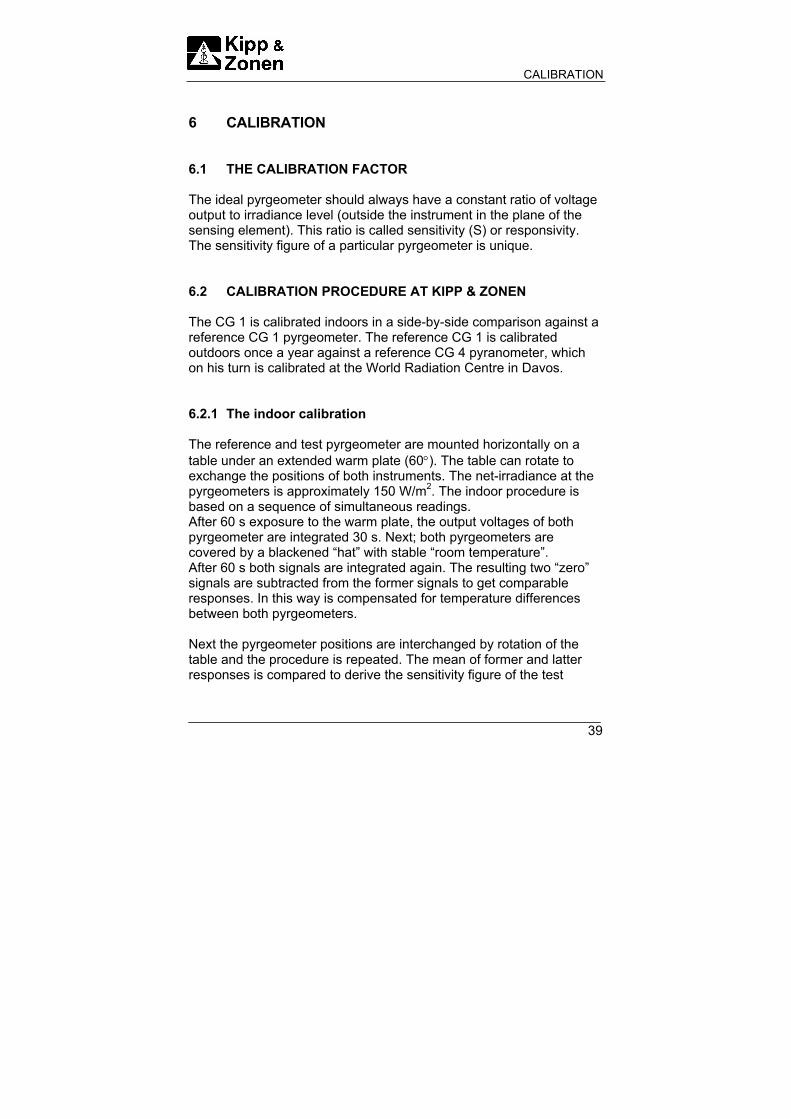
6 CALIBRATION 6.1 THE CALIBRATION FACTOR The ideal pyrgeometer should always have a constant ratio of voltage output to irradiance level (outside the instrument in the plane of the sensing element). This ratio is called sensitivity (S) or responsivity. The sensitivity figure of a particular pyrgeometer is unique. 6.2 CALIBRATION PROCEDURE AT KIPP & ZONEN The CG 1 is calibrated indoors in a side-by-side comparison against a reference CG 1 pyrgeometer. The reference CG 1 is calibrated outdoors once a year against a reference CG 4 pyranometer, which on his turn is calibrated at the World Radiation Centre in Davos. 6.2.1 The indoor calibration The reference and test pyrgeometer are mounted horizontally on a table under an extended warm plate (60°). The table can rotate to exchange the positions of both instruments. The net-irradiance at the pyrgeometers is approximately 150 W/m2. The indoor procedure is based on a sequence of simultaneous readings. After 60 s exposure to the warm plate, the output voltages of both pyrgeometer are integrated 30 s. Next; both pyrgeometers are covered by a blackened “hat” with stable “room temperature”. After 60 s both signals are integrated again. The resulting two “zero” signals are subtracted from the former signals to get comparable responses. In this way is compensated for temperature differences between both pyrgeometers. Next the pyrgeometer positions are interchanged by rotation of the table and the procedure is repeated. The mean of former and latter responses is compared to derive the sensitivity figure of the test

CALIBRATION
40
pyrgeometer. In this way asymmetry in the warm plate configuration and IR environment is cancelled out. 6.2.2 The outdoor procedure for the reference pyrgeometer The reference CG 1 is calibrated outdoors at Kipp & Zonen under a mainly clear sky during night time. The instrument is installed side by side next to a reference pyrgeometer CG 4. For a period of three or four hours the pyrgeometer thermopile output (Uemf) and body temperature (Tb) is measured. Afterwards the downward radiation (Ld) is determined for each instrument by using the formula given in chapter 4. For the CG 1 a preliminary sensitivity of S = 10 µV/W/m2 is used. The calculated resulting curve of Ld shows consequently different curves compared to the CG 4 reference curve. By changing the sensitivity (S) of the reference CG 1 an optimal curve fit with the reference CG 4 finally yields the exact calibration factor (S). The fitting is made best for the periods with high IR exchange (Clear sky) but under cloud fields and consequently lower signal the curves fit still within ± 2%. By this procedure the effect of the restricted field of view of the reference CG 1 is “calibrated out” for clear sky conditions. With the indoor procedure the outdoors sensitivity of the reference CG 1 is “transferred” to the other CG 1’s. So at principle the CG 1 sensitivity should be best for the outdoors conditions (clear sky) at which the reference CG 1 was calibrated. However tolerances in spectral response of reference CG 1 and test CG 1’s limit the accuracy of the transfer. (The blackbody radiation spectrum of the hot plate differ significantly from the atmospheric window spectrum). 6.2.3 Traceability to the World Radiometric reference The reference CG 4 pyrgeometer is calibrated during a WMO/BSRN pyrgeometer comparison in Oklahoma USA, 1999. The reference CG 4 pyrgeometer is calibrated in a standard absolute blackbody cavity. In the future the reference CG 4 will be calibrated at the World Radiation Centre in Davos, Switzerland (see appendix I).

CALIBRATION
41
6.3 RECALIBRATION Pyrgeometer sensitivity changes with time and with exposure to radiation. Periodic calibration (at least every two years) is advised. Accurate calibrations can be done outdoors under clear sky conditions by comparison to a reference pyrgeometer.

CALIBRATION
42

FREQUENTLY ASKED QUESTIONS
43
7 FREQUENTLY ASKED QUESTIONS (FAQ’s) The most frequently asked questions are listed below. For an update, please refer to the Kipp & Zonen website: http://www.kippzonen.com 1. What are typical values for downwelling atmospheric longwave
radiation?
Clouded sky (Lnet = 0 W/m2)
Clear sky (Lnet = -150 W/m2)
Ambient
temperature
Ld in W/m2
-20 °C 230 80
0 °C 315 165
+30 °C 480 330
2. The values calculated with the formula, given in chapter 4, show
a very strange value. What could be the reason? - Check whether the (instrument) temperature (Tb) is given in
Kelvin. - Check that the net radiation (Uemf / S) is a negative value, if
not, the wires are possibly interchanged. 3. What is the primary entry point for humidity ?
The desiccant cartridge and cable gland have equal chances to transport some moisture, but also the silicon glue of the window is not fully watertight. However,

FREQUENTLY ASKED QUESTIONS
44
normally the cable gland is never touched while the cartridge is removed frequently. So when no care is taken, one can easily make the desiccant cartridge the primary entry point. Note: Water transport through the cable is also possible when the
open end of the cable and the connected device are in a humid environment.
TROUBLE SHOOTING
45
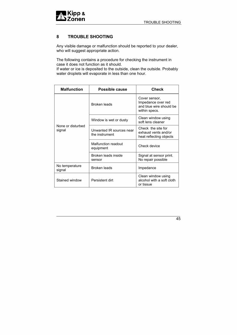
8 TROUBLE SHOOTING Any visible damage or malfunction should be reported to your dealer, who will suggest appropriate action. The following contains a procedure for checking the instrument in case it does not function as it should. If water or ice is deposited to the outside, clean the outside. Probably water droplets will evaporate in less than one hour.
Malfunction Possible cause Check
Broken leads
Cover sensor, Impedance over red and blue wire should be within specs.
Window is wet or dusty Clean window using soft lens cleaner
Unwanted IR sources near the instrument
Check the site for exhaust vents and/or heat reflecting objects
Malfunction readout equipment Check device
None or disturbed signal
Broken leads inside sensor
Signal at sensor print. No repair possible
No temperature signal Broken leads Impedance
Stained window Persistent dirt Clean window using alcohol with a soft cloth or tissue

TROUBLE SHOOTING
46

DELIVERY
47
9 DELIVERY Delivery of CG 1 • Pyrgeometer CG 1 • Calibration certificate • Sun screen Delivery of CG 2 • Net pyrgeometer CG 2 • Calibration certificate • Sun screen • Glare screen Both the CG 1 and CG 2 can be delivered in four configurations: CG 1 CG 2 • Thermistor, 12 V 1305-990 1305-994 • Thermistor, 24 V 1305-991 1305-995 • Pt-100, 12 V 1305-992 1305-996 • Pt-100, 24 V 1305-993 1305-997

DELIVERY
48

PART NUMBERS / SPARE PARTS / OPTIONS
49
10 PART NUMBERS / SPARE PARTS / OPTIONS Description Part no. CG 1 filter on metal ring 0305-408 CG 1 sensor with Pt-100 0305-407 CG 1 sensor with thermistor 10 K 0305-406 Upper sunscreen (plastic) 0305-166 Lower sunscreen (metal) 0012-053 Levelling screw (2 required per pyrgeometer) 0012-117 Fixed foot 0012-116 Complete drying cartridge consisting of: Clamp-Spring 0305-165 Drying cartridge (without cover) 9012-106 Cover for cartridge 9012-107 Rubber ring 2132-153 Silica gel container (1kg) 2643 943 Manual CG 1/2 pyrgeometer 0305 206 CV 2 ventilation unit 0349 900 CV 2 ventilation unit with heater 0349 901 CT 24 solar sensor 4 – 20 mA amplifier 0305 710

PART NUMBERS / SPARE PARTS / OPTIONS
50
Description Part no. Mounting plates with a 500 mm rod to install radiometers for net radiation measurements: Mounting plate for 4 sensors, all 4 can be ventilated (2 upper and 2 lower) 0012 067 Mounting plate for 2 possibly ventilated sensors (1 upper and 1 lower) 0012 069 Mounting plate for 4 unventilated sensors (2 upper and 2 lower) 0012 092 10 meters cable extension and connectors 0305 666 15 meters cable extension and connectors 0305 631 20 meters cable extension and connectors 0305 632 25 meters cable extension and connectors 0305 633 30 meters cable extension and connectors 0305 634 50 meters cable extension and connectors 0305 635 75 meters cable extension and connectors 0305 636 100 meters cable extension and connectors 0305 637 200 meters cable extension and connectors 0305 638

APPENDIX I
51
APPENDIX I WORLD RADIATION CENTRE INFORMATION The World Radiation Centre capable of Pyrgeometer calibration is: Physikalisch-Meterologisches Observatorium Dorfstrasse 33 CH-7260 Davos Dorf Switzerland. Website: http://www.pmodwrc.ch

APPENDIX I
52
APPENDIX II
53
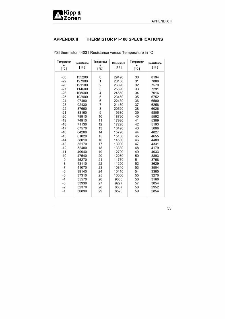
APPENDIX II THERMISTOR PT-100 SPECIFICATIONS YSI thermistor 44031 Resistance versus Temperature in °C
Temperature
[ °C ]
Resistance [ Ω ]
Temperature
[ °C ]
Resistance [ Ω ]
Temperature
[ °C ]
Resistance [ Ω ]
-30 -29 -28 -27 -26 -25 -24 -23 -22 -21 -20 -19 -18 -17 -16 -15 -14 -13 -12 -11 -10 -9 -8 -7 -6 -5 -4 -3 -2 -1
135200 127900 121100 114600 108600 102900 97490 92430 87660 83160 78910 74910 71130 67570 64200 61020 58010 55170 52480 49940 47540 45270 43110 41070 39140 37310 35570 33930 32370 30890
0 1 2 3 4 5 6 7 8 9
10 11 12 13 14 15 16 17 18 19 20 21 22 23 24 25 26 27 28 29
29490 28150 26890 25690 24550 23460 22430 21450 20520 19630 18790 17980 17220 16490 15790 15130 14500 13900 13330 12790 12260 11770 11290 10840 10410 10000 9605 9227 8867 8523
30 31 32 33 34 35 36 37 38 39 40 41 42 43 44 45 46 47 48 49 50 51 52 53 54 55 56 57 58 59
8194 7880 7579 7291 7016 6752 6500 6258 6026 5805 5592 5389 5193 5006 4827 4655 4489 4331 4179 4033 3893 3758 3629 3504 3385 3270 3160 3054 2952 2854

APPENDIX II
54

APPENDIX III
55
APPENDIX III Pt-100 SPECIFICATIONS Pt-100 Resistance versus Temperature in °C
Temperature
[ °C ]
Resistance [ Ω ]
Temperature
[ °C ]
Resistance [ Ω ]
Temperature
[ °C ]
Resistance [ Ω ]
-30 -29 -28 -27 -26 -25 -24 -23 -22 -21 -20 -19 -18 -17 -16 -15 -14 -13 -12 -11 -10 -9 -8 -7 -6 -5 -4 -3 -2 -1
88.22 88.62 89.01 89.40 89.80 90.19 90.59 90.98 91.37 91.77 92.16 92.55 92.95 93.34 93.73 94.12 94.52 94.91 95.30 95.69 96.09 96.48 96.87 97.26 97.65 98.04 98.44 98.83 99.22 99.61
0 1 2 3 4 5 6 7 8 9
10 11 12 13 14 15 16 17 18 19 20 21 22 23 24 25 26 27 28 29
100.00 100.39 100.78 101.17 101.56 101.95 102.34 102.73 103.12 103.51 103.90 104.29 104.68 105.07 105.46 105.85 106.24 106.63 107.02 107.40 107.79 108.18 108.57 108.96 109.35 109.73 110.12 110.51 110.90 110.28
30 31 32 33 34 35 36 37 38 39 40 41 42 43 44 45 46 47 48 49 50 51 52 53 54 55 56 57 58 59
111.67 112.06 112.45 112.83 113.22 113.61 113.99 114.38 114.77 115.15 115.54 115.93 116.31 116.70 117.08 117.47 117.85 118.24 118.62 119.01 119.40 119.78 120.16 120.55 120.93 121.32 121.70 122.09 122.47 122.86

APPENDIX III
56

APPENDIX IV
57
APPENDIX IV RECALIBRATION SERVICE
Pyranometers, UV-meters, Pyrgeometers & Sunshine duration sensors
Kipp & Zonen solar radiation measurement instruments comply with the most demanding international standards. In order to maintain the specified performance of these instruments, Kipp & Zonen recommends calibration of their instruments at least every two years. This can be done at the Kipp & Zonen factory. Here, recalibration to the highest standards can be performed at low cost. Recalibration can usually be performed within four weeks. If required, urgent recalibration can be accomplished in three weeks or less (subject to scheduling restrictions). Kipp & Zonen will confirm the duration of recalibration at all times. Please note that special quantity recalibration discounts are available. For your convenience we added three fax forms to schedule the recalibration of your instrument(s) at Kipp & Zonen.

APPENDIX IV
58

APPENDIX IV
59
NAME : COMPANY/INSTITUTE : ADDRESS : POSTCODE +CITY : COUNTRY : PHONE : FAX :
I would like to receive a price list for recalibration
I would like to submit my instruments for recalibration
Type/Model: Qty: Requested delivery time
I intend to send the instruments to Kipp & Zonen on:
. . . . . ./. . . . . ./. . . . . .
I would like to receive the instrument(s) back on:
. . . . . ./. . . . . ./. . . . . .
Conformation by Kipp & Zonen
Yes, the dates are acceptable to us
No, unfortunately the dates do not fit into our calibration schedule. We suggest the following dates:
. . . . . ./. . . . . ./. . . . . .
. . . . . ./. . . . . ./. . . . . .
Fax +31-15-2620351 or mail to:
Kipp & Zonen P.O. Box 507 2600AM Delft The Netherlands

APPENDIX IV
60

APPENDIX IV
61
NAME : COMPANY/INSTITUTE : ADDRESS : POSTCODE +CITY : COUNTRY : PHONE : FAX :
I would like to receive a price list for recalibration
I would like to submit my instruments for recalibration
Type/Model: Qty: Requested delivery time
I intend to send the instruments to Kipp & Zonen on:
. . . . . ./. . . . . ./. . . . . .
I would like to receive the instrument(s) back on:
. . . . . ./. . . . . ./. . . . . .
Conformation by Kipp & Zonen
Yes, the dates are acceptable to us
No, unfortunately the dates do not fit into our calibration schedule. We suggest the following dates:
. . . . . ./. . . . . ./. . . . . .
. . . . . ./. . . . . ./. . . . . .
Fax +31-15-2620351 or mail to:
Kipp & Zonen P.O. Box 507 2600AM Delft The Netherlands

APPENDIX IV
62

APPENDIX IV
63
NAME : COMPANY/INSTITUTE : ADDRESS : POSTCODE +CITY : COUNTRY : PHONE : FAX :
I would like to receive a price list for recalibration
I would like to submit my instruments for recalibration
Type/Model: Qty: Requested delivery time
I intend to send the instruments to Kipp & Zonen on:
. . . . . ./. . . . . ./. . . . . .
I would like to receive the instrument(s) back on:
. . . . . ./. . . . . ./. . . . . .
Conformation by Kipp & Zonen
Yes, the dates are acceptable to us
No, unfortunately the dates do not fit into our calibration schedule. We suggest the following dates:
. . . . . ./. . . . . ./. . . . . .
. . . . . ./. . . . . ./. . . . . .
Fax +31-15-2620351 or mail to:
Kipp & Zonen P.O. Box 507 2600AM Delft The Netherlands

Holland Kipp & Zonen B.V.
Röntgenweg 1
2624 BD DELFT
T +31 15 269 8000
F +31 15 262 0351
UK Kipp & Zonen Ltd.
P.O. Box 819,
LINCOLN, Lincolnshire LN6 0WY
T +44 1522 695 403
F +44 1522 696 598
Germany Gengenbach Messtechnik
Heinrich-Otto-Strasse 3
D-73262 REICHENBACH/FILS
T +49 7153 9258 0
F +49 7153 9258 160
USA Kipp & Zonen USA Inc.
125, Wilbur Place
BOHEMIA/NY 11716
T +1 631 589 2065
F +1 631 589 2068
France Kipp & Zonen S.A.R.L.
7, avenue Clément Ader
ZA Ponroy - Bât. M
F-94420 LE PLESSIS TREVISE
T +33 1 49 62 4104
F +33 1 49 62 4102
Our customer support
remains at your disposal
for any maintenance or
repair, calibration,
supplies and spares.
The address is as
follows:
Für Servicearbeiten und
Kalibrierung, Verbrauchs-
material und Ersatzteile
steht Ihnen unsere
Customer Support
Abteilung unter folgender
Adresse zur Verfügung:
Notre service 'Support Clientèle'
reste à votre entière disposition
pour tout problème de
maintenance, réparation ou
d'étalonnage ainsi que pour les
accessoires et pièces de
rechange. Leur adresse est la
suivante :
Customer Support
www.kippzonen.com
KippZonen
&

![CHHATTISGARH HOUSING BOARD RAIPUR [CG.]](https://static.fdokumen.com/doc/165x107/63259b6f6d480576770c5eea/chhattisgarh-housing-board-raipur-cg.jpg)