
ABSTRACT Title of Dissertation - UMD DRUM - University of ...
Upload
khangminh22Category
view
1download
0
DISSERTATION
submitted to the
Combined Faculty of the Natural Sciences and Mathematics
of the
Ruprecht-Karls UniversityHeidelberg
for the degree of
Doctor of Natural Sciences
put forward by
Diplom-Informatikerin Sarah Marie Neuwirth
Born inMannheim, Germany
Heidelberg, 2018


Accelerating NetworkCommunication and I/O inScientific High PerformanceComputing Environments
Advisor: Prof. Dr.-Ing. Ulrich Brüning
Date of oral examination: .............................

Abstract
High performance computing has become one of the major drivers behind technologyinventions and science discoveries. Originally driven through the increase of operatingfrequencies and technology scaling, a recent slowdown in this evolution has led tothe development of multi-core architectures, which are supported by acceleratordevices such as graphics processing units (GPUs). With the upcoming exascale era,the overall power consumption and the gap between compute capabilities and I/Obandwidth have become major challenges. Nowadays, the system performance isdominated by the time spent in communication and I/O, which highly depends on thecapabilities of the network interface. In order to cope with the extreme concurrencyand heterogeneity of future systems, the software ecosystem of the interconnect needsto be carefully tuned to excel in reliability, programmability, and usability.
This work identifies and addresses three major gaps in today’s interconnect softwaresystems. The I/O gap describes the disparity in operating speeds between thecomputing capabilities and second storage tiers. The communication gap is introducedthrough the communication overhead needed to synchronize distributed large-scaleapplications and the mixed workload. The last gap is the so called concurrency gap,which is introduced through the extreme concurrency and the inflicted learning curveposed to scientific application developers to exploit the hardware capabilities.The first contribution is the introduction of the network-attached accelerator
approach, which moves accelerators into a “stand-alone” cluster connected throughthe Extoll interconnect. The novel communication architecture enables the directaccelerators communication without any host interactions and an optimal application-to-compute-resources mapping. The effectiveness of this approach is evaluated fortwo classes of accelerators: Intel Xeon Phi coprocessors and NVIDIA GPUs.The next contribution comprises the design, implementation, and evaluation of
the support of legacy codes and protocols over the Extoll interconnect technology.By providing TCP/IP protocol support over Extoll, it is shown that the performancebenefits of the interconnect can be fully leveraged by a broader range of applications,including the seamless support of legacy codes.

The third contribution is twofold. First, a comprehensive analysis of the Lustrenetworking protocol semantics and interfaces is presented. Afterwards, these insightsare utilized to map the LNET protocol semantics onto the Extoll networking tech-nology. The result is a fully functional Lustre network driver for Extoll. An initialperformance evaluation demonstrates promising bandwidth and message rate results.The last contribution comprises the design, implementation, and evaluation of
two easy-to-use load balancing frameworks, which transparently distribute the I/Oworkload across all available storage system components. The solutions maximizethe parallelization and throughput of file I/O. The frameworks are evaluated on theTitan supercomputing systems for three I/O interfaces. For example for large-scaleapplication runs, POSIX I/O and MPI-IO can be improved by up to 50% on a perjob basis, while HDF5 shows performance improvements of up to 32%.

Zusammenfassung
Hochleistungsrechnen hat sich zu einem der bedeutendsten Standbeine im Bereich dertechnischen und wissenschaftlichen Errungenschaften entwickelt. Ursprünglich wurdedie Leistungssteigerung solcher Systeme durch die kontinuierliche Steigerung der Takt-frequenz gewährleistet. Die Verlangsamung dieses Trends hat zu der Entwicklung vonMehrkernarchitekturen geführt, welche zusätzlich durch sogenannte Beschleuniger wieetwa Graphikprozessoren unterstützt werden. In Verbindung mit der bevorstehendenExascale Ära haben sich vor allem der Gesamtstromverbrauch und die Kluft zwischenRechenkapazität und I/O Bandbreite als limitierende Faktoren herauskristallisiert.Die gegenwärtige Systemleistung wird vor allem durch die Kommunikations- undI/O-Zeit beschränkt. Dieses Phänomen hängt insbesondere mit den Eigenschaftender Netzwerkschnittstelle zusammen. Um den extremen Anforderungen in Hinblickauf Parallelität und Heterogenität zukünftiger Systeme gerecht zu werden, bedarf eseiner sorgfältigen Abstimmung der Software-Komponenten, insbesondere im Hinblickauf Zuverlässigkeit, Programmierbarkeit und Benutzerfreundlichkeit.
Diese Arbeit identifiziert und widmet sich insbesondere drei Leistungslücken (engl.gaps), die in den heutigen Softwareumgebungen im Bereich der Verbindungsnetzwerkebeobachtet werden können. Die sogenannte I/O Gap beschreibt die Leistungslücke,die entsteht durch die unterschiedlichen Taktfrequenzen von Rechenkapazitäten undder Speicherhierarchie. Die sogenannte Communication Gap beschreibt den Kom-munikationsoverhead, der bei der Synchronisierung von Großanwendungen entsteht,aber auch die gemischte Kommunikationslast, die auf das Netzwerk ausgeübt wird.Die letzte Leistungslücke wird durch die sogenannte Concurrency Gap beschrieben.Diese Leistungslücke entsteht durch die extreme Parallelität von modernen Hochleis-tungsrechnern und dem für Programmierer dadurch verbundenen Mehraufwand, dieHardware-Eigenschaften dieser Systeme auszunutzen.
Im ersten Beitrag wird der Ansatz der Network-Attached Accelerators („Netzwerk-Beschleuniger“) als neue Kommunikationsarchitektur vorgestellt. Dieses neuartigeKonzept ermöglicht es, Beschleuniger aus der bislang statischen Hardware-Anordnungzu entkoppeln und diese über das Netzwerk allen Rechenknoten gleichförmig zur
Verfügung zu stellen. Vorteile dieser Architekturform sind unter anderem, dassGrafikprozessoren direkt über das Netzwerk miteinander kommunizieren können,aber auch das dynamische Abbilden von Anwendungen auf Rechenressourcen zurLaufzeit. Die Leistungsfähigkeit dieses Ansatzes wird anhand der Intel Xeon PhiCo-Prozessoren und NVIDIA Grafikprozessoren analysiert.
Im nächsten Beitrag wird der Fokus auf die Unterstützung von sogenannten LegacyAnwendungen und Protokollen über Hochgeschwindigkeitsnetzwerke wie Extoll gelegt.Durch die Erweiterung der Extoll Softwareumgebung zur Unterstützung der TCP/IPProtokollfamilie können Legacy Anwendungen das Leistungsspektrum der ExtollTechnologie voll ausschöpfen, ohne dafür modifiziert werden zu müssen. Dies öffnetdie Tür für ein breiteres Spektrum an Anwedungen.Der dritte Beitrag liefert zunächst eine ausführliche Analyse des Lustre Netz-
werkprotokolls, welches LNET genannt wird. Im Anschluss werden diese Erkenntnissegenutzt, um die Protokoll-Semantik von LNET effizient auf die Extoll Netzwerk-technologie abzubilden. Es wird ein voll funktionsfähiger Lustre Netzwerktreiber(Lustre Network Driver) für Extoll implementiert. Eine initiale Leistungsanalysezeigt vielsprechende Ergebnisse, gerade im Hinblick auf die erzielte Bandbreite undNachrichtenrate.Der letzte Beitrag besteht in der Konzeption, Implementierung und Evalua-
tion zweier benutzerfreundlicher Anwender-Frameworks, welche die Datenlast einerGroßanwendung transparent über alle verfügbaren Komponenten des Speichersys-tems verteilen. Diese beiden Lösungen dienen der optimalen Parallelisierung undMaximierung der Bandbreite in Bezug auf das Lesen und Schreiben von Dateien. Diebeiden Frameworks werden auf dem Hochleistungsrechner Titan mit drei verschiede-nen I/O Schnittstellen (I/O interfaces) evaluiert. Für Großanwendungen kann dieLeistung von POSIX und MPI-IO beispielsweise um bis zu 50% gesteigert werden,für HDF5 kann eine Leistungssteigerung von bis zu 32% erzielt werden.

Acknowledgements
First and foremost, I would like to thank my parents, Manfred (†14.01.2011) andMichaela Neuwirth, for their unconditional love and endless support. They havealways encouraged me, and are still encouraging me, to pursue my dreams and havelit the fire for my passion in sciences at a very young age. A special thank you goesto my mother for always motivating me. Without her support, I would not havebeen able to accomplish this work. I will always be grateful for being blessed withsuch wonderful parents and dedicate this work to them.I would like to express my sincere gratitude to Prof. Dr. Ulrich Brüning for his
invaluable advice and support during the course of this work. With his knowledgeand experience, he has been a fantastic counterpart in countless discussions andhas provided valuable input to my research. I am also grateful to all the members,staff and students, of the Computer Architecture Group and the employees of theEXTOLL GmbH for all the valuable discussions and advice throughout this work.In addition, I would like to express my gratitude to the Ruprecht-Karls Universityand the Faculty for Mathematics and Computer Science for providing me with theopportunity to pursue a doctoral degree.Special thanks go to James H. Rogers, Dr. Sarp Oral, Dr. Feiyi Wang, and the
Technology Integration Group of the Oak Ridge National Laboratory for providingme with the opportunity to spend two summers as a visiting research scholar in theirteam. The insights in the operation and evaluation of large-scale systems such as theTitan supercomputer have provided me with a unique chance to expand my horizonin the area of scientific high performance computing systems.
Given that it is impossible to thank every single person who has accompanied meduring the journey of my PhD, I would like to express my sincere gratitude to all theinspiring people I have met throughout the years. Thank you for all the cheering,support, discussions, and friendships. I am grateful to each one of you.

Contents
1 Introduction 11.1 Motivation and Challenges . . . . . . . . . . . . . . . . . . . . . . . . 41.2 Contributions . . . . . . . . . . . . . . . . . . . . . . . . . . . . . . . 51.3 Outline . . . . . . . . . . . . . . . . . . . . . . . . . . . . . . . . . . . 7
2 Communication and I/O in HPC Systems 92.1 Generic Communication Architecture Overview . . . . . . . . . . . . 102.2 Network Communication Hardware . . . . . . . . . . . . . . . . . . . 12
2.2.1 Interconnection Networks . . . . . . . . . . . . . . . . . . . . 122.2.2 Network Interface Controllers . . . . . . . . . . . . . . . . . . 14
2.3 Communication in Distributed Memory Systems . . . . . . . . . . . . 152.3.1 Communication Schemes . . . . . . . . . . . . . . . . . . . . . 152.3.2 Synchronization . . . . . . . . . . . . . . . . . . . . . . . . . . 182.3.3 Performance Metrics . . . . . . . . . . . . . . . . . . . . . . . 182.3.4 Interprocess Communication Interfaces . . . . . . . . . . . . . 19
2.4 Introduction to Parallel I/O . . . . . . . . . . . . . . . . . . . . . . . 252.4.1 Scientific I/O . . . . . . . . . . . . . . . . . . . . . . . . . . . 262.4.2 Parallel File Systems . . . . . . . . . . . . . . . . . . . . . . . 272.4.3 High-level I/O Libraries and Middleware . . . . . . . . . . . . 282.4.4 Access Patterns . . . . . . . . . . . . . . . . . . . . . . . . . . 31
3 Extoll System Environment 353.1 Technology Overview . . . . . . . . . . . . . . . . . . . . . . . . . . . 353.2 Functional Units . . . . . . . . . . . . . . . . . . . . . . . . . . . . . 36
3.2.1 Remote Memory Access Unit . . . . . . . . . . . . . . . . . . 373.2.2 Virtualized Engine for Low Overhead Unit . . . . . . . . . . . 393.2.3 Virtual Process ID . . . . . . . . . . . . . . . . . . . . . . . . 403.2.4 Shared Memory Functional Unit . . . . . . . . . . . . . . . . . 413.2.5 Address Translation Unit . . . . . . . . . . . . . . . . . . . . . 43
Contents
3.2.6 Register File . . . . . . . . . . . . . . . . . . . . . . . . . . . . 453.2.7 PCIe Bridge . . . . . . . . . . . . . . . . . . . . . . . . . . . . 45
3.3 Software Environment . . . . . . . . . . . . . . . . . . . . . . . . . . 473.3.1 Kernel Space . . . . . . . . . . . . . . . . . . . . . . . . . . . 473.3.2 User Space . . . . . . . . . . . . . . . . . . . . . . . . . . . . . 483.3.3 EMP: Network Discovery and Setup . . . . . . . . . . . . . . 48
3.4 Related Interconnection Standards . . . . . . . . . . . . . . . . . . . 493.4.1 Infiniband . . . . . . . . . . . . . . . . . . . . . . . . . . . . . 493.4.2 PCI Express . . . . . . . . . . . . . . . . . . . . . . . . . . . . 50
3.5 Performance Overview . . . . . . . . . . . . . . . . . . . . . . . . . . 523.5.1 Test Setup . . . . . . . . . . . . . . . . . . . . . . . . . . . . . 523.5.2 Performance Results . . . . . . . . . . . . . . . . . . . . . . . 53
4 Network-Attached Accelerators 554.1 Motivation . . . . . . . . . . . . . . . . . . . . . . . . . . . . . . . . . 564.2 DEEP Project Series . . . . . . . . . . . . . . . . . . . . . . . . . . . 574.3 Introduction to the PCI Express Subsystem . . . . . . . . . . . . . . 58
4.3.1 PCI Express Address Spaces . . . . . . . . . . . . . . . . . . . 594.3.2 Linux PCI Express Enumeration . . . . . . . . . . . . . . . . 624.3.3 PCI Express Expansion Cards . . . . . . . . . . . . . . . . . . 64
4.4 Related Work . . . . . . . . . . . . . . . . . . . . . . . . . . . . . . . 664.4.1 Intel Xeon Phi Coprocessor-based Communication Models . . 664.4.2 GPU Virtualization and Communication Techniques . . . . . 674.4.3 Hardware-related Research . . . . . . . . . . . . . . . . . . . . 69
4.5 NAA Software Design . . . . . . . . . . . . . . . . . . . . . . . . . . . 694.5.1 System Architecture and Problem Statement . . . . . . . . . . 704.5.2 Objectives and Strategy . . . . . . . . . . . . . . . . . . . . . 724.5.3 Design Space Analysis . . . . . . . . . . . . . . . . . . . . . . 77
4.6 DEEP Booster Architecture . . . . . . . . . . . . . . . . . . . . . . . 794.6.1 Hardware Components . . . . . . . . . . . . . . . . . . . . . . 794.6.2 Prototype Implementation . . . . . . . . . . . . . . . . . . . . 804.6.3 Prototype Performance Evaluation . . . . . . . . . . . . . . . 844.6.4 GreenICE – An Immersive Cooled DEEP Booster . . . . . . . 904.6.5 Lessons Learned . . . . . . . . . . . . . . . . . . . . . . . . . . 90
4.7 Virtualization of Remote PCI Express Devices . . . . . . . . . . . . . 914.7.1 Concept Overview of VPCI . . . . . . . . . . . . . . . . . . . 914.7.2 PCI Express Device Emulation . . . . . . . . . . . . . . . . . 92

Contents
4.7.3 Forwarding PCI Configuration Space Requests . . . . . . . . . 934.7.4 Device Enumeration . . . . . . . . . . . . . . . . . . . . . . . 944.7.5 Forwarding Memory-Mapped I/O Requests . . . . . . . . . . . 944.7.6 Interrupt Delivery . . . . . . . . . . . . . . . . . . . . . . . . . 954.7.7 Overall Picture . . . . . . . . . . . . . . . . . . . . . . . . . . 964.7.8 Experimental Evaluation . . . . . . . . . . . . . . . . . . . . . 97
4.8 NAA Summary . . . . . . . . . . . . . . . . . . . . . . . . . . . . . . 99
5 RDMA-Accelerated TCP/IP Communication 1015.1 Introduction to the Internet Protocol Suite . . . . . . . . . . . . . . . 102
5.1.1 The Network Layer: IP . . . . . . . . . . . . . . . . . . . . . . 1035.1.2 The Transport Layer . . . . . . . . . . . . . . . . . . . . . . . 1045.1.3 Data Transmission and Reception in Linux . . . . . . . . . . . 1065.1.4 Interrupt Coalescing and NIC Polling with NAPI . . . . . . . 1075.1.5 TCP/IP Protocol Overhead and Bottlenecks . . . . . . . . . . 109
5.2 Related Work . . . . . . . . . . . . . . . . . . . . . . . . . . . . . . . 1115.2.1 OpenFabrics Enterprise Distribution . . . . . . . . . . . . . . 1115.2.2 Sockets-like Interfaces . . . . . . . . . . . . . . . . . . . . . . 114
5.3 Objectives and Strategy . . . . . . . . . . . . . . . . . . . . . . . . . 1155.4 Transmission of Ethernet Frames over Extoll . . . . . . . . . . . . . . 117
5.4.1 Link Frame Transmission and Reception . . . . . . . . . . . . 1175.4.2 Message Matching and Resource Management . . . . . . . . . 1205.4.3 Maximum Transmission Unit . . . . . . . . . . . . . . . . . . 1225.4.4 Address Mapping – Unicast . . . . . . . . . . . . . . . . . . . 1235.4.5 Multicast Routing . . . . . . . . . . . . . . . . . . . . . . . . 1255.4.6 EXN: Extoll Network Interface . . . . . . . . . . . . . . . . . 128
5.5 Direct Sockets over Extoll . . . . . . . . . . . . . . . . . . . . . . . . 1315.5.1 Protocol Overview . . . . . . . . . . . . . . . . . . . . . . . . 1315.5.2 Setup and Connection Management . . . . . . . . . . . . . . . 1325.5.3 Data Transfer Mechanisms . . . . . . . . . . . . . . . . . . . . 1355.5.4 AF_EXTL: A Prototype Implementation of EXT-DS . . . . . 139
5.6 Performance Analysis . . . . . . . . . . . . . . . . . . . . . . . . . . . 1455.6.1 TCP/IP Configuration Tuning in Linux Systems . . . . . . . . 1455.6.2 Test System . . . . . . . . . . . . . . . . . . . . . . . . . . . . 1475.6.3 Microbenchmark Evaluation . . . . . . . . . . . . . . . . . . . 1475.6.4 MPI Performance . . . . . . . . . . . . . . . . . . . . . . . . . 151
5.7 TCP/IP Summary . . . . . . . . . . . . . . . . . . . . . . . . . . . . 153
Contents
6 Efficient Lustre Networking Protocol Support 1556.1 Introduction to the Lustre File System . . . . . . . . . . . . . . . . . 156
6.1.1 File System Components . . . . . . . . . . . . . . . . . . . . . 1566.1.2 Network Communication Protocol . . . . . . . . . . . . . . . . 1586.1.3 Client Services and File I/O . . . . . . . . . . . . . . . . . . . 161
6.2 Lustre Networking Semantics and Interfaces . . . . . . . . . . . . . . 1646.2.1 Naming Conventions and API Summary . . . . . . . . . . . . 1656.2.2 Memory-Oriented Communication Semantics . . . . . . . . . . 1666.2.3 Credit System . . . . . . . . . . . . . . . . . . . . . . . . . . . 1706.2.4 Available Lustre Network Drivers . . . . . . . . . . . . . . . . 171
6.3 Design Challenges and Strategy . . . . . . . . . . . . . . . . . . . . . 1726.4 Efficient RDMA with Vectored I/O Operations . . . . . . . . . . . . 173
6.4.1 Memory Management . . . . . . . . . . . . . . . . . . . . . . . 1736.4.2 Infiniband Verbs and Scatter/Gather Elements . . . . . . . . . 1746.4.3 Scatter/Gather DMA Operation Support for Extoll . . . . . . 176
6.5 Support for LNET Protocol Semantics . . . . . . . . . . . . . . . . . 1776.5.1 Data Transmission Protocols . . . . . . . . . . . . . . . . . . . 1776.5.2 Message Matching and Descriptor Queues . . . . . . . . . . . 180
6.6 EXLND: Extoll Lustre Network Driver . . . . . . . . . . . . . . . . . 1826.7 Preliminary Performance Results . . . . . . . . . . . . . . . . . . . . 183
6.7.1 System Setup and Methodology . . . . . . . . . . . . . . . . . 1836.7.2 LNET Self-Test Results . . . . . . . . . . . . . . . . . . . . . 184
6.8 EXLND Summary . . . . . . . . . . . . . . . . . . . . . . . . . . . . 186
7 Resource Contention Mitigation at Scale 1897.1 Spider II – A Leadership-Class File System . . . . . . . . . . . . . . . 1907.2 The Need for Balanced Resource Usage . . . . . . . . . . . . . . . . . 1917.3 Related Work . . . . . . . . . . . . . . . . . . . . . . . . . . . . . . . 1937.4 Observations and Best Practices for File I/O . . . . . . . . . . . . . . 1957.5 End-to-End Performance Tuning . . . . . . . . . . . . . . . . . . . . 196
7.5.1 Fine-Grained Routing Methodology . . . . . . . . . . . . . . . 1967.5.2 Balanced Placement I/O Strategy . . . . . . . . . . . . . . . . 199
7.6 Design Objectives and Strategy . . . . . . . . . . . . . . . . . . . . . 2017.7 Aequilibro – An I/O Middleware Integration . . . . . . . . . . . . . . 202
7.7.1 Transport Methods . . . . . . . . . . . . . . . . . . . . . . . . 2037.7.2 Software Design and Implementation . . . . . . . . . . . . . . 204

Contents
7.8 TAPP-IO Framework . . . . . . . . . . . . . . . . . . . . . . . . . . . 2067.8.1 Parallel I/O Support . . . . . . . . . . . . . . . . . . . . . . . 2077.8.2 Runtime Environment . . . . . . . . . . . . . . . . . . . . . . 210
7.9 Data Collection and Analysis . . . . . . . . . . . . . . . . . . . . . . 2127.9.1 Benchmarking Methodology . . . . . . . . . . . . . . . . . . . 2127.9.2 Experimental Setup . . . . . . . . . . . . . . . . . . . . . . . . 2157.9.3 Synthetic Benchmark Evaluation . . . . . . . . . . . . . . . . 2167.9.4 HPC Workload Evaluation . . . . . . . . . . . . . . . . . . . . 222
7.10 Summary . . . . . . . . . . . . . . . . . . . . . . . . . . . . . . . . . 223
8 Conclusion 2258.1 Outlook . . . . . . . . . . . . . . . . . . . . . . . . . . . . . . . . . . 227
List of Abbreviations 229
List of Figures 235
List of Tables 239
Listings 241
References 243

Ch
ap
te
r
1Introduction
In recent years, the major driver behind technology inventions and science discoverieshas been the computational science domain. Nowadays, High Performance Computing(HPC), in particular large-scale simulation codes [1], complements the two traditionalpillars of science, theory and experiment, and enables researchers to build and testmodels of complex phenomena, including molecular dynamics, quantum mechanics,weather forecasting, climate research, and astrophysics.
For years, the performance of supercomputing systems has been scaled throughincreased clock frequencies, larger, faster memories, and high-bandwidth, low-latencyinterconnects. With the end of frequency and Dennard [2, 3] scaling in the early 2000’s,parallel computing has become the new paradigm to increase the computationalpower of HPC deployments. In order to maintain the traditional growth rates,multi-core architectures have been developed and the overall system performance isscaled by constantly increasing components and node counts.
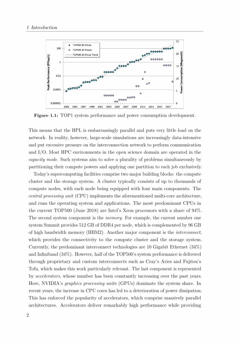
The success of this strategy until now is outlined in Figure 1.1 for the number onesystems of the TOP500 [4] over the past two decades. A superficial reading of thisgraph provides no conclusive indication that future HPC systems might encounterany difficulties in increasing their performance at the same pace. This impression ismainly inflicted by the nature of the High-Performance Linpack (HPL) benchmark[5], which is utilized for the ranking. To obtain the HPL benchmarking results,HPC systems are typically operated in the capability mode, which aims at solving asingle huge problem as quickly as possible by applying the system’s entire computepower to that particular problem. The HPL solves a large dense system of linearequations and heavily relies on re-using cached data from local registers and caches.
1
1 Introduction
Figure 1.1: TOP1 system performance and power consumption development.
This means that the HPL is embarrassingly parallel and puts very little load on thenetwork. In reality, however, large-scale simulations are increasingly data-intensiveand put excessive pressure on the interconnection network to perform communicationand I/O. Most HPC environments in the open science domain are operated in thecapacity mode. Such systems aim to solve a plurality of problems simultaneously bypartitioning their compute powers and applying one partition to each job exclusively.
Today’s supercomputing facilities comprise two major building blocks: the computecluster and the storage system. A cluster typically consists of up to thousands ofcompute nodes, with each node being equipped with four main components. Thecentral processing unit (CPU) implements the aforementioned multi-core architecture,and runs the operating system and applications. The most predominant CPUs inthe current TOP500 (June 2018) are Intel’s Xeon processors with a share of 94%.The second system component is the memory. For example, the current number onesystem Summit provides 512 GB of DDR4 per node, which is complemented by 96 GBof high bandwidth memory (HBM2). Another major component is the interconnect,which provides the connectivity to the compute cluster and the storage system.Currently, the predominant interconnect technologies are 10 Gigabit Ethernet (34%)and Infiniband (34%). However, half of the TOP500’s system performance is deliveredthrough proprietary and custom interconnects such as Cray’s Aries and Fujitsu’sTofu, which makes this work particularly relevant. The last component is representedby accelerators, whose number has been constantly increasing over the past years.Here, NVIDIA’s graphics processing units (GPUs) dominate the system share. Inrecent years, the increase in CPU cores has led to a deterioration of power dissipation.This has enforced the popularity of accelerators, which comprise massively parallelarchitectures. Accelerators deliver remarkably high performance while providing
2

an unprecedented energy efficiency. However, with their introduction, the extremeconcurrency and heterogeneity in HPC systems has been further intensified. Thisposes major challenges to application developers as the code needs to be carefullyparallelized to exploit the benefits of such heterogeneous systems.
The second major building block of supercomputing facilities are storage and I/Osystems, which typically consist of hundreds of storage servers and up to thousands ofdisks. Designed for capacity and capability, storage systems are inherently complexand shared among concurrently running jobs. With the emergence of data-intensiveapplications, storage systems are further contended for performance and scalability.Given that storage capabilities are typically much lower than those of a processor, theprocessing of large amounts of data has introduced a phenomenon referred to as theI/O gap, which is inflicted by the latency gap between processors and storage tiers.A central component for providing good storage connectivity is the interconnectionnetwork, which requires careful optimization through intermediate software layers toprovide optimal bandwidth performance and mitigate network contention.
In traditional HPC systems, interprocess communication mostly relies on messagepassing in order to synchronize and move data, and involves the interconnection net-work for internode communication. As pointed out by a recent study [6], large-scaleapplications spend an average of about 34% of their runtime with point-to-pointor collective operations, which indicates that communication severely impacts theperformance of an application run. While computation is relatively fast, communica-tion has been proven to be one of the major bottlenecks [7] for parallel computingsystems, especially with regard to power consumption.
The next major challenge will be to provide exascale performance [8], i.e., to performa quintillion (1018) floating point operations per second, which will be impacted bythe power consumption, resiliency, memory hierarchies and I/O, and concurrency.Modern HPC facilities comprise heterogeneous system architectures, which heavilyrely on the interconnection network. With the paradigm shift to parallel computingand the upcoming exascale challenge, the system performance is dominated by thetime spent in communication and I/O. In order to cope with the extreme concurrencyand heterogeneity of future systems, the software ecosystem needs to be carefullytuned to excel in reliability, programmability, power consumption, and usability.With the interconnection network being the backbone for both message exchangeand I/O, this work focuses on the gaps in today’s intermediate software environmentswith regard to direct accelerator and internode communication, storage connectivity,and optimal resource utilization for both compute and storage components.
3

1 Introduction
Application Execution Time
Computation Time Communication Time I/O Time+ +
Figure 1.2: Key factors influencing the total application execution time.
1.1 Motivation and ChallengesThe motivation for this work is based on the observation that the total applicationexecution time is affected by the computation, communication, and I/O time, asdisplayed in Figure 1.2. In order to maximize the overall system performance, allcomponents of the equation need to be carefully addressed. As previously described,a major contributing factor is the efficient network communication and I/O, which isheavily impacted by the following three observations:
I/O Gap Large-scale applications often do I/O for reading initial datasets or writingnumerical data from simulations out to the distributed disk arrays, but alsoperiodically store application-level checkpoints. Compared to other componentsof an HPC platform, I/O subsystems are typically slow. Different hardwarecomponents operate at different speeds, thus, resulting in the so called I/O gap.The anatomy of a disk access comprises of the latency and bandwidth inflictedby the CPU, the memory, the interconnect, and the actual hard drive access.For example, the memory access latency is 100 times slower than the CPU.Since a pioneering technological breakthrough is not expected any time soon,optimizing the I/O time is just as important as optimizing the computation andcommunication time. Thus, it is necessary to carefully optimize and implementa number of intermediate layers for the coordination of the data accesses. Thisincludes the efficient mapping of a parallel file system’s network protocol tothe chosen interconnect technology, but also the allocation of storage resourcesin a balanced manner to maximize the aggregate file access bandwidth.
Communication Gap In the past, the conventional wisdom has been that compu-tation is rather expensive while communication is cheap. With the paradigmshift to parallel computing, the system size is scaled by adding more and morecompute nodes, which results in the problem that large-scale applications needto be distributed among these resources. This reduces the amount of timespent in computation in relation to the time spent in communication, and thus,
4
1.2 Contributions
produces the communication gap. The workload of bulk data transfers mixedwith the vast amount of small messages for communication and synchroniza-tion purposes requires the utilization of highly efficient network technologies.It is desirable to increase the performance of point-to-point and collectivecommunication through extensive tuning of the intermediate software layers,particularly, the software environment of the chosen interconnect by leveragingits hardware capabilities efficiently.
Concurrency Gap Another gap is introduced through the extreme concurrency oftoday’s heterogeneous system architectures. In order to increase the overallsystem performance while providing a reasonable energy efficiency, more andmore accelerator devices are added to modern HPC systems. They offer anunprecedented computational power per watt, while being optimized for mas-sively parallel computation. However, the efficient utilization of such devicesis significantly limited by the static application-to-compute-resources map-ping, but also through the steep learning curve posed to scientific applicationdevelopers to exploit the hardware capabilities. Another challenge is intro-duced through the overhead associated with direct communication betweendistributed accelerators. Especially with the upcoming exascale era in mind,new communication architectures need to be explored to serve the needs ofextreme-scale applications. By leveraging the innovative hardware featuresof modern interconnects such as Extoll, intermediate software layers can bedesigned that enable the dynamic workload distribution at run time in anN-to-M ratio, e.g., by providing device virtualization over the network whilebypassing the host CPU. Such virtualization techniques also introduce novelconcepts for direct accelerator communication.
1.2 ContributionsThis work aims to resolve the described observations by closing the gaps throughthe design, implementation, and evaluation of intermediate software layers. Thecontributions can be divided in two parts.The first part evolves around the Extoll interconnect technology, which has been
designed to fit the needs of future large-scale simulation codes. The technologyhas mainly been chosen for two reasons. First, as previously presented, customizedinterconnects deliver 50% of the performance share in the TOP500, which makes theman important component for the design and delivery of exascale systems. Second,
5

1 Introduction
Extoll has emerged from a research project conducted at the Heidelberg University.The second part of the contributions evolves around the Titan supercomputingsystem. The research complements this work by providing insights on the effects ofthe I/O gap at larger scales. This research has been enabled through two researchstays at the Oak Ridge National Laboratory and a subsequent research collaboration.The presented work makes the following contributions:
(1) Introduction of the Network-Attached Accelerator approach as a new conceptfor direct accelerator communication and efficient resource utilization – Thenetwork-attached accelerator approach introduces a novel communication ar-chitecture, which allows the disaggregation of PCI Express hosts from theend-points that they control. The key idea is to combine a cluster of multi-coreprocessors with a tightly coupled cluster of many-core processors (e.g., GPUsor coprocessors) employing a highly scalable network. This unique architectureaims at the optimal application-to-compute-resource mapping, energy efficiencyand extreme scalability, and therefore, targets the concurrency and commu-nication gaps. This contribution comprises conference publications [9, 10], aposter paper [11], and a news article [12].
(2) RDMA-Accelerated TCP/IP communication – Modern high performance net-work technologies provide the hardware support for efficient communicationmodels such as remote direct memory access (RDMA) and partitioned globaladdress space (PGAS). However, they also need to support traditional com-munication semantics, e.g., the Sockets interface, to seamlessly support legacyapplications. The challenge is to design a software layer that is capable ofexploiting the innovative hardware features to a legacy code without the needfor any source code modifications or recompilation. This work introduces twodifferent communication protocols targeting the acceleration of traditionalTCP/IP communication. They are implemented as transparent, intermediatesoftware layers, and provide IP addressing and address resolution support whileleveraging the RDMA capabilities of Extoll. This contribution has led to twoworkshop presentations [13, 14].
(3) Efficient storage connectivity and I/O – File I/O is an important part of large-scale applications. In order to maximize the performance, HPC systems aretypically backed by a parallel file and storage system. One popular choice is theLustre file system due to its support for data-intensive applications and POSIX-complaint namespace for large-scale deployments. Using a high-performanceinterconnect such as Extoll to speed up to I/O-bound part of simulation codes
6

1.3 Outline
can improve the overall application execution time, but requires an efficientsoftware layer between Lustre and the network interface. In case of Lustre, thesesoftware layers comprise of the Lustre Networking Protocol (LNET) and LustreNetwork Drivers (LNDs). This work presents the design, implementation,and evaluation of the Extoll LND, which efficiently maps the LNET protocolsemantics onto the Extoll technology. The contribution has been presented ina scientific talk [15] and published at a workshop [16].
(4) Transparent resource contention mitigation in large-scale HPC systems – Besidesthe need to accelerate and optimize the network communication of a parallelfile system through efficient protocol support, the careful management of dataaccesses is another major pillar of improving file I/O. In this work, two easy-to-use load balancing frameworks are designed, implemented, and evaluated, whichtransparently distributes data across all available storage system components.The solutions balance the I/O workload on an end-to-end and per job basis,and maximize the parallelization and throughput of file I/O. The frameworksare evaluated on the Titan supercomputing systems. This contribution hasbeen published in two conference papers [17, 18] and one poster paper [19].
1.3 OutlineChapter 2 provides the basic knowledge about communication and I/O in HPCsystems, which is needed for the entire remainder of this work. In Chapter 3, anoverview of the Extoll system environment is presented. Together with chapter 2,this Chapter provides the foundation for the presented work.
Chapter 4 presents the design and implementation of the network-attached accel-erator (NAA) approach. NAA decouples accelerator devices from the host systemsand enables optimal application-to-compute-resource mapping. NAA is implementedand evaluated with Intel Xeon Phi coprocessors and NVIDIA K20c GPUs.
Chapter 5 focuses on the support of the TCP/IP communication over Extoll. Byefficiently mapping the TCP/IP protocol semantics onto the network technology,two protocols are specified: Ethernet over Extoll (EXT-Eth) and Direct Sockets overExtoll (EXT-DS). EXT-DS emulates the Ethernet protocol over Extoll, provides IPaddressing means and accelerates traditional TCP/IP communication by providingasynchronous, two-sided RDMA for larger payload sizes. EXT-DS complementsEXT-Eth by providing kernel bypass data transfers through RDMA operations fordedicated TCP point-to-point connections.
7
1 Introduction
In Chapter 6, the Lustre network protocol is analyzed followed by the design ofEXLND, which provides peer-to-peer connection semantics for Lustre over Extoll.The evaluation of a prototype implementation of EXLND is presented.
While the previous chapters focus on the design of communication protocols forthe Extoll interconnect technology, Chapter 7 explores resource contention mitigationtechniques for large-scale HPC deployments. The evaluation platform is the Titansupercomputing system, in particular, its parallel file system Spider II, which isbased on Lustre. The chapter presents a transparent auto-tuning framework forfile striping, which transparently distributes stripes of data among available storagesystem components in a fair manner.The thesis concludes in chapter 8 by providing a summary of the contributions,
but also explores potential improvements to the various contributions presentedthroughout this work.
8
Ch
ap
te
r
2Communication and I/O in HPC Systems
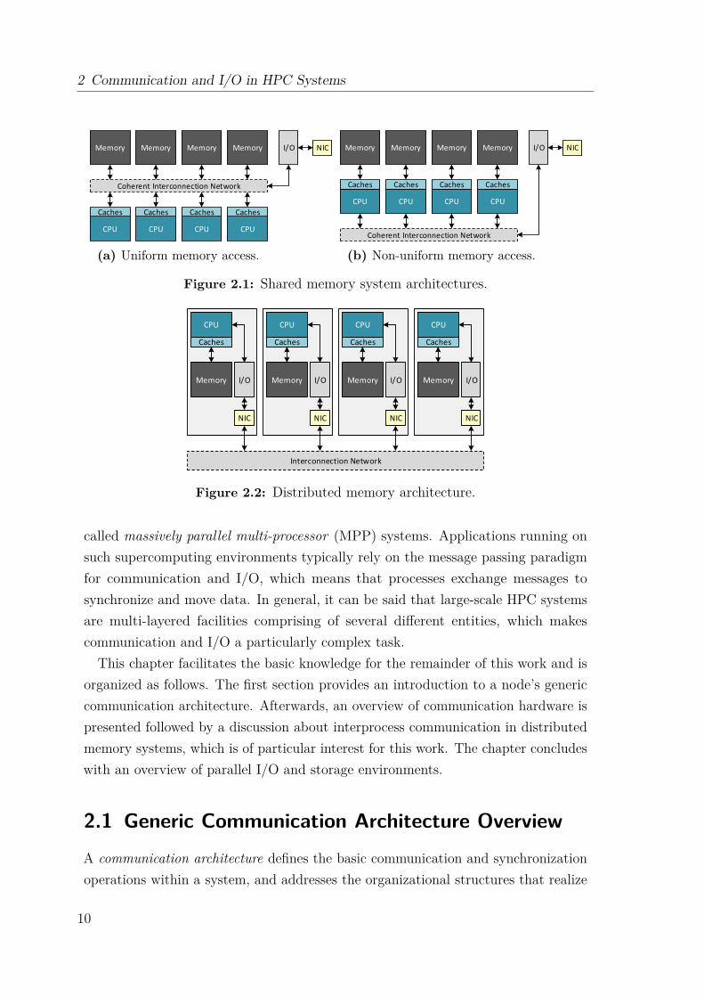
In general, parallel computing systems can be classified in two fundamental cat-egories: shared and distributed memory systems. The distinctive feature for thiscategorization is how the memory can be accessed by processors, which also influencesthe communication model. Figure 2.1 provides an overview of shared memory systemarchitectures. They provide a single address space, which can be accessed by allprocessors, and perform communication through shared variables. Depending onthe arrangement of the memory, uniform memory access (UMA) and non-uniformmemory access (NUMA) systems can be distinguished. In UMA systems, all pro-cessors have a uniform memory access latency. Due to the symmetrical design, it isalso referred to as the dance-hall architecture. In NUMA systems on the other hand,memory modules are assigned to dedicated CPUs, which results in a higher accesslatency when accessing another processor’s local memory. This characteristic alsoknown as the NUMA phenomenon.The second class of parallel computing architectures are distributed memory sys-
tems, as depicted in Figure 2.2. As indicated by the name, the memory modules aredistributed across the system and physically assigned to dedicated CPUs. The com-munication is performed by exchanging messages. This requires address translation,which is performed by the network interface controller (NIC) at both endpoints.
Modern supercomputing architectures typically comprise of a combination of bothdistributed and shared memory architectures. Such systems consist of multiplesymmetric multi-processor (SMP) nodes, which are connected to an interconnectionnetwork. While memory is shared by all processors of the same node, it is notshared between processors on different nodes. In the HPC domain, these systems are
9
2 Communication and I/O in HPC Systems
CPU CPU CPU CPU
Caches Caches Caches Caches
Coherent Interconnection Network
Memory Memory Memory Memory I/O NIC
(a) Uniform memory access.
CPU CPU CPU CPU
Caches Caches Caches Caches
Coherent Interconnection Network
Memory Memory Memory Memory I/O NIC
(b) Non-uniform memory access.
Figure 2.1: Shared memory system architectures.
Interconnection Network
Caches
Memory I/O
NIC
Caches
Memory I/O
NIC
Caches
Memory I/O
NIC
Caches
Memory I/O
NIC
CPU CPU CPU CPU
Figure 2.2: Distributed memory architecture.
called massively parallel multi-processor (MPP) systems. Applications running onsuch supercomputing environments typically rely on the message passing paradigmfor communication and I/O, which means that processes exchange messages tosynchronize and move data. In general, it can be said that large-scale HPC systemsare multi-layered facilities comprising of several different entities, which makescommunication and I/O a particularly complex task.
This chapter facilitates the basic knowledge for the remainder of this work and isorganized as follows. The first section provides an introduction to a node’s genericcommunication architecture. Afterwards, an overview of communication hardware ispresented followed by a discussion about interprocess communication in distributedmemory systems, which is of particular interest for this work. The chapter concludeswith an overview of parallel I/O and storage environments.
2.1 Generic Communication Architecture OverviewA communication architecture defines the basic communication and synchronizationoperations within a system, and addresses the organizational structures that realize
10

2.1 Generic Communication Architecture Overview
Software/Hardware boundary
Parallel applications
Programming models
Compilers and runtime libraries
OS support and device drivers
Communication hardware
Physical communication medium
Processor NIC
Network/Topology
User/System boundary
Communication abstraction
E.g., copper, fiber
E.g., MPI, PGAS
OS bypass
E.g., mmap of MMIO E.g., send/recv
Figure 2.3: Communication architecture abstraction following Culler et al. [20].
these operations. As introduced by Culler et al. [20], a generic communicationarchitecture can be divided in several different layers, which are implemented in bothhardware and software as depicted in Figure 2.3.Parallel applications and programming models compose the top layer. Typically,
programming models are embedded in a parallel language or programming envi-ronment, and provide a communication abstraction to applications, e.g., for sharedand distributed memory systems. A programming model specifies how the differentparts of a parallel application exchange information between each other and whatsynchronization operations are available to coordinate their communication andactivities. This is realized in terms of user-level communication primitives of theunderlying system.In between the programming models and the operating system, compilers and
runtime libraries act as the user/system boundary by utilizing the primitives madeavailable from the underlying operating system and hardware. Libraries depend onthe used programming model and provide a hardware abstraction to the applications.The rule of thumb is that the more generalization is provided by a library, theless control for application and system-specific optimizations can be applied by theuser. While less abstraction increases the variety of possible optimizations, it alsoburdens the user with system-specific characteristics when tuning an application’sperformance. Therefore, the level of abstraction is a trade-off between performanceand user-friendliness.The communication hardware and operating system (OS) comprise the bottom
layer. Device drivers and the OS directly interface with the communication hardware,which typically consists of a network interface controller (NIC) and an interconnectionnetwork. Modern NICs provide hardware support for different communication
11
2 Communication and I/O in HPC Systems
standards. Depending on the corresponding software stack, NICs can reduce thesoftware overhead, e.g., by providing OS bypass techniques.
2.2 Network Communication HardwareThe following two sections provide an overview of two basic hardware building blocksfor network communication: the interconnection network and the network interfacecontroller.
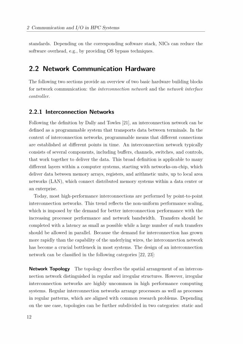
2.2.1 Interconnection Networks
Following the definition by Dally and Towles [21], an interconnection network can bedefined as a programmable system that transports data between terminals. In thecontext of interconnection networks, programmable means that different connectionsare established at different points in time. An interconnection network typicallyconsists of several components, including buffers, channels, switches, and controls,that work together to deliver the data. This broad definition is applicable to manydifferent layers within a computer systems, starting with networks-on-chip, whichdeliver data between memory arrays, registers, and arithmetic units, up to local areanetworks (LAN), which connect distributed memory systems within a data center oran enterprise.Today, most high-performance interconnections are performed by point-to-point
interconnection networks. This trend reflects the non-uniform performance scaling,which is imposed by the demand for better interconnection performance with theincreasing processor performance and network bandwidth. Transfers should becompleted with a latency as small as possible while a large number of such transfersshould be allowed in parallel. Because the demand for interconnection has grownmore rapidly than the capability of the underlying wires, the interconnection networkhas become a crucial bottleneck in most systems. The design of an interconnectionnetwork can be classified in the following categories [22, 23]:
Network Topology The topology describes the spatial arrangement of an intercon-nection network distinguished in regular and irregular structures. However, irregularinterconnection networks are highly uncommon in high performance computingsystems. Regular interconnection networks arrange processors as well as processesin regular patterns, which are aligned with common research problems. Dependingon the use case, topologies can be further subdivided in two categories: static and
12

2.2 Network Communication Hardware
dynamic. Static topologies are fixed point-to-point connections between nodes, whiledynamic topologies possess switching elements, which can be tuned for multiple differ-ent configurations. Static network topologies are mainly used for communication inlarge-scale computing systems. Also, static interconnection networks can be depictedas directed or undirected graphs in which nodes represent processors, compute nodes,switches or devices, and edges represent communication links. Example topologiesare tree, mesh, cube, and hypercube. The chosen topology affects routing, reliability,throughput, latency, and scalability.
Routing Routing algorithms define how a packet is sent from the destination tothe source node. They can be classified in two categories: deterministic and adaptiverouting [24]. As implied by the name, deterministic routing algorithms always choosethe same, predefined path between two nodes, independently from the current networkstate, for example the network traffic. On the contrary, adaptive routing algorithmschoose a path based on the current state of the network, including historical channelinformation and the status of a node.
Switching Methodology and Flow Control Two major switching methodologiescan be distinguished, circuit switching and packet switching. For circuit switching, aphysical path is established between the source and the destination for the entireduration of the transmission. In case of packet switching, data is put in packetsand routed through the interconnection network establishing a logical connectionpath between nodes without the need for a physical connection. In general, circuitswitching is much more suitable for bulk data transmission, and packet switching ismore efficient for short data messages. The switching methodology is tightly coupledwith the chosen flow control. The flow control manages the allocation of resourcesalong the path of a packet, including buffers and channels. Buffers are basicallyregisters or memory, which provide a temporary storage to cache packets. Examplesare circuit switching, virtual-cut-through switching (packet based), store-and-forwardswitching (packet based), and wormhole switching (flit based).
Operation Mode Two types of communication can be identified: synchronous andasynchronous. The asynchronous operation mode is mainly needed in multiprocess-ing environments where connection requests are issued dynamically. Synchronouscommunication is only allowed at certain points in time with communication pathsestablished synchronously. One possible use case is the broadcast.
13

2 Communication and I/O in HPC Systems
2.2.2 Network Interface Controllers
In computing environments, the network interface serves as the software and/orhardware interface between protocol layers or two pieces of equipment in a computernetwork [21]. Examples include network sockets, which provide a software interface tothe network, and network interface controllers (NICs). The NIC connect clients to aninterconnection network and serves as the network interface from a processor’s pointof view. Its key characteristics include low-overhead access and high-throughputmessage transfers. The guarantee that multiple processes can independently accessthe NIC while ensuring process security typically is provided through hardwarevirtualization mechanisms. The access for different processes is multiplexed by theoperating system.There are two different techniques for a NIC to indicate whether packets are
available for transfer: software-driven and interrupt-driven I/O. In software-drivenI/O, also known as polling, the processor actively samples the status of the peripheralunder software control. When using interrupt-driven I/O, the peripheral alerts theprocessor when it is ready to send or receive data.These two techniques are complemented by two data transmission methods [23]:
programmed I/O (PIO) and direct memory access (DMA). In the context of a NIC,PIO requires the CPU to actively move data to or from the main memory to theNIC, while DMA describes an operation in which data is moved from one resourceto another without the involvement of the processor. DMA removes load from theCPU, but requires more logic on the NIC.
One of the major design criteria is the placement of the NIC. In order the minimizethe latency, it is desirable to place it as close to the processor as possible. In general,three different processor-network interfaces can be distinguished [21]: the two-register,the register-mapped, and the descriptor-based interfaces.
The simplest approach is the two-register interface. As indicated by the name, thisconcept utilizes two registers: the network input and the network output registers.Reading from or writing to these registers de- or enqueues the next word of a message.Longer messages are sent by splitting them in word-sized chunks and then writingthem word by word to the output register. This adds a tremendous overhead tothe communication since the processor is tied to serve as a DMA engine. Anotherproblem is that misbehaving processors might occupy the network resources infinitelywhen they write the first part of a message, but fail to send the end.
The safety issue of the two-register interface can be resolved by utilizing theregister-mapped approach where a message is sent atomically from a subset of the
14
2.3 Communication in Distributed Memory Systems
Send/Receive scheme
(asynchronous or synchronous)
Send/Posted-Receive scheme
Put/Get (RMA) scheme
Rendezvous Put/Get scheme
n-copy(two-, one-, zero)
2 1 0
Two-/one-sided Communication
2 1
Implementation
Concept
Figure 2.4: Communication models in distributed memory systems [23].
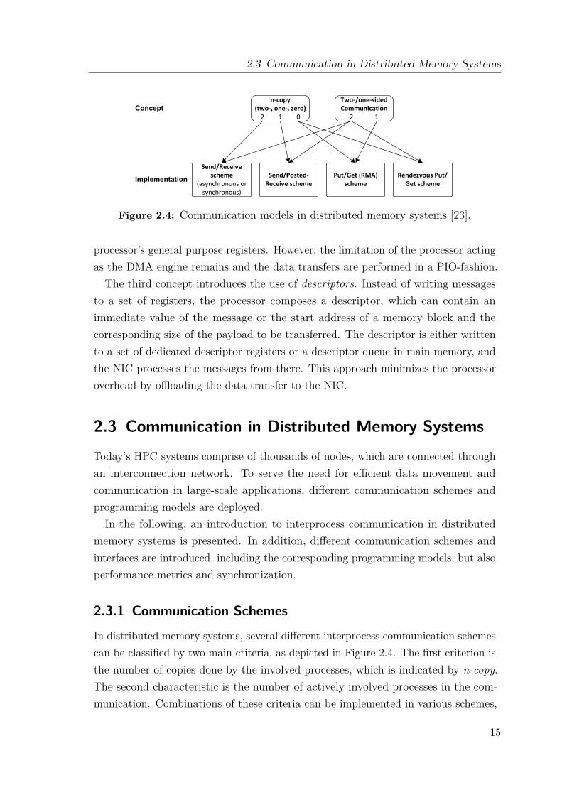
processor’s general purpose registers. However, the limitation of the processor actingas the DMA engine remains and the data transfers are performed in a PIO-fashion.The third concept introduces the use of descriptors. Instead of writing messages
to a set of registers, the processor composes a descriptor, which can contain animmediate value of the message or the start address of a memory block and thecorresponding size of the payload to be transferred. The descriptor is either writtento a set of dedicated descriptor registers or a descriptor queue in main memory, andthe NIC processes the messages from there. This approach minimizes the processoroverhead by offloading the data transfer to the NIC.
2.3 Communication in Distributed Memory SystemsToday’s HPC systems comprise of thousands of nodes, which are connected throughan interconnection network. To serve the need for efficient data movement andcommunication in large-scale applications, different communication schemes andprogramming models are deployed.In the following, an introduction to interprocess communication in distributed
memory systems is presented. In addition, different communication schemes andinterfaces are introduced, including the corresponding programming models, but alsoperformance metrics and synchronization.
2.3.1 Communication Schemes
In distributed memory systems, several different interprocess communication schemescan be classified by two main criteria, as depicted in Figure 2.4. The first criterion isthe number of copies done by the involved processes, which is indicated by n-copy.The second characteristic is the number of actively involved processes in the com-munication. Combinations of these criteria can be implemented in various schemes,
15
2 Communication and I/O in HPC Systems
including the traditional send/receive scheme and PUT/GET. The understanding ofthese communication schemes is an important factor for the actual communicationprotocol design for a given network technology.
2.3.1.1 Two-sided Communication
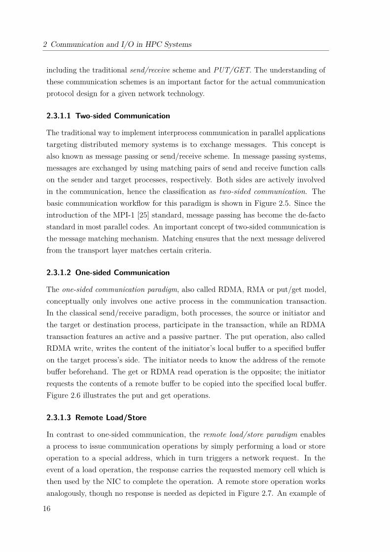
The traditional way to implement interprocess communication in parallel applicationstargeting distributed memory systems is to exchange messages. This concept isalso known as message passing or send/receive scheme. In message passing systems,messages are exchanged by using matching pairs of send and receive function callson the sender and target processes, respectively. Both sides are actively involvedin the communication, hence the classification as two-sided communication. Thebasic communication workflow for this paradigm is shown in Figure 2.5. Since theintroduction of the MPI-1 [25] standard, message passing has become the de-factostandard in most parallel codes. An important concept of two-sided communication isthe message matching mechanism. Matching ensures that the next message deliveredfrom the transport layer matches certain criteria.
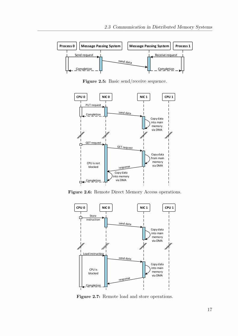
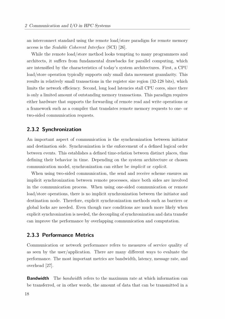
2.3.1.2 One-sided Communication
The one-sided communication paradigm, also called RDMA, RMA or put/get model,conceptually only involves one active process in the communication transaction.In the classical send/receive paradigm, both processes, the source or initiator andthe target or destination process, participate in the transaction, while an RDMAtransaction features an active and a passive partner. The put operation, also calledRDMA write, writes the content of the initiator’s local buffer to a specified bufferon the target process’s side. The initiator needs to know the address of the remotebuffer beforehand. The get or RDMA read operation is the opposite; the initiatorrequests the contents of a remote buffer to be copied into the specified local buffer.Figure 2.6 illustrates the put and get operations.
2.3.1.3 Remote Load/Store
In contrast to one-sided communication, the remote load/store paradigm enablesa process to issue communication operations by simply performing a load or storeoperation to a special address, which in turn triggers a network request. In theevent of a load operation, the response carries the requested memory cell which isthen used by the NIC to complete the operation. A remote store operation worksanalogously, though no response is needed as depicted in Figure 2.7. An example of
16
2.3 Communication in Distributed Memory Systems
Process 0 Message Passing System Message Passing System Process 1
Send request
Completion
Receive request
Completion
Figure 2.5: Basic send/receive sequence.
CPU 0 NIC 0 NIC 1 CPU 1
Completion
GET request
CPU is not blocked
Completion
Copy data into main memory via DMA
Copy data from main memory via DMA
Copy data into memory
via DMA
Figure 2.6: Remote Direct Memory Access operations.
Completion
CPU 0 NIC 0 NIC 1 CPU 1
Load instruction
CPU is blocked
Copy data into main memory via DMA
Copy data into main memory via DMA
Figure 2.7: Remote load and store operations.
17
2 Communication and I/O in HPC Systems
an interconnect standard using the remote load/store paradigm for remote memoryaccess is the Scalable Coherent Interface (SCI) [26].While the remote load/store method looks tempting to many programmers and
architects, it suffers from fundamental drawbacks for parallel computing, whichare intensified by the characteristics of today’s system architectures. First, a CPUload/store operation typically supports only small data movement granularity. Thisresults in relatively small transactions in the register size region (32-128 bits), whichlimits the network efficiency. Second, long load latencies stall CPU cores, since thereis only a limited amount of outstanding memory transactions. This paradigm requireseither hardware that supports the forwarding of remote read and write operations ora framework such as a compiler that translates remote memory requests to one- ortwo-sided communication requests.
2.3.2 Synchronization
An important aspect of communication is the synchronization between initiatorand destination side. Synchronization is the enforcement of a defined logical orderbetween events. This establishes a defined time-relation between distinct places, thusdefining their behavior in time. Depending on the system architecture or chosencommunication model, synchronization can either be implicit or explicit.When using two-sided communication, the send and receive scheme ensures an
implicit synchronization between remote processes, since both sides are involvedin the communication process. When using one-sided communication or remoteload/store operations, there is no implicit synchronization between the initiator anddestination node. Therefore, explicit synchronization methods such as barriers orglobal locks are needed. Even though race conditions are much more likely whenexplicit synchronization is needed, the decoupling of synchronization and data transfercan improve the performance by overlapping communication and computation.
2.3.3 Performance Metrics
Communication or network performance refers to measures of service quality ofas seen by the user/application. There are many different ways to evaluate theperformance. The most important metrics are bandwidth, latency, message rate, andoverhead [27].
Bandwidth The bandwidth refers to the maximum rate at which information canbe transferred, or in other words, the amount of data that can be transmitted in a
18
2.3 Communication in Distributed Memory Systems
given period of time. Aggregate bandwidth refers to the total data bandwidth suppliedby the network, and effective bandwidth or throughput is the fraction of aggregatebandwidth delivered by the network to an application. Typically, bandwidth ismeasured in bytes per second.
Latency The latency or network delay describes the minimum time a packet needsto be transferred from one node to another. The total latency of a packet can beexpressed by the following equation:
Latency = Sending overhead + Time of flight + Packet sizeBandwidth + Receiving overhead
Message Rate The message rate describes the number of messages that can besent by a single process in a specified period of time and indicates how well theprocessing of independent processes can be overlapped. It varies for different messagesizes, is limited by the bandwidth and highly depends on the sending and receivingoverhead.
Overhead The communication overhead describes the time a node, i.e., a proces-sor, needs to send or receive a packet [28], including both software and hardwarecomponents. The sending overhead is the time needed to prepare a packet, while thereceiving overhead describes the time needed to process an incoming packet.
2.3.4 Interprocess Communication Interfaces
Several different application programming interfaces (APIs) for interprocess com-munication exist, which utilize the previously described communication schemes.Of particular interest for this work is interprocess communication in distributedmemory systems. The following sections present an overview of the most widely usedcommunication standards and corresponding example implementations.
2.3.4.1 Message Passing Interface
The Message Passing Interface (MPI) has become the de-facto standard for parallelcommunication in distributed memory systems. The most popular implementationsare MPICH [29], MVAPICH [30], and OpenMPI [31]. In the MPI programmingmodel, a computation comprises of one or more processes that communicate bycalling library routines to send/receive messages to/from other processes. An MPIapplication typically follows the Single Program Multiple Data (SPMD) paradigm
19

2 Communication and I/O in HPC Systems
Data
MPI_Send()
Return
Return
Block – waiting for data
MPI MPINetwork
MPI_Recv()
User Rank 0 User Rank 1
Header
Data
Data
HeaderHeader
Header
Data
1.a
1.b
2
3
4
match
copy
copy
Figure 2.8: MPI eager protocol.
where each program launches multiple processes. A process can be identified byits rank, which is a unique identifier that can be used to address other processesin point-to-point communication. Also, multiple ranks can be grouped togetherin MPI communicators, which restrict communication to ranks within the samecommunicator. In MPI, a message consists of a header and data, which is basicallythe payload. The header contains a tag, a communicator, the length, the source rank,plus implementation specific private data. The data can be identified by naming andordering. The naming defined by the source rank, communicator, and a tag, which isan arbitrary integer value chosen by the user. If multiple messages are identical innaming, the order in which the messages arrive determines which message is matchedwith the corresponding receive request.
There are three basic point-to-point communication protocols in MPI: short, eagerand rendezvous. In the short protocol, the data is directly sent with its header andno buffering is needed on the sending side. Both eager and rendezvous protocolsdiffer in their buffering scheme and the selection of the protocol that is applied isusually based on the message size. The following introduces the two protocols, butalso explains the concept of message matching and collective operations.
Eager Protocol In the eager protocol, the message is sent assuming that thedestination can store the data. This approach reduces synchronization delays andsimplifies the programming, but may require active involvement of the receivingCPU to drain the network at the receiver’s end and may introduce additional copies(intermediate buffer to final destination). Figure 2.8 illustrates the eager protocol.First, the header is written by the sender (1.a) and the receiver (1.b) to the target
20
2.3 Communication in Distributed Memory Systems
Data
MPI_Send()
Return
Return
Block – waiting for data
MPI MPINetwork
MPI_Recv()
User Rank 0 User Rank 1
Header
Data
HeaderHeader
Header
Data
1.a
1.b
2
3
4
match
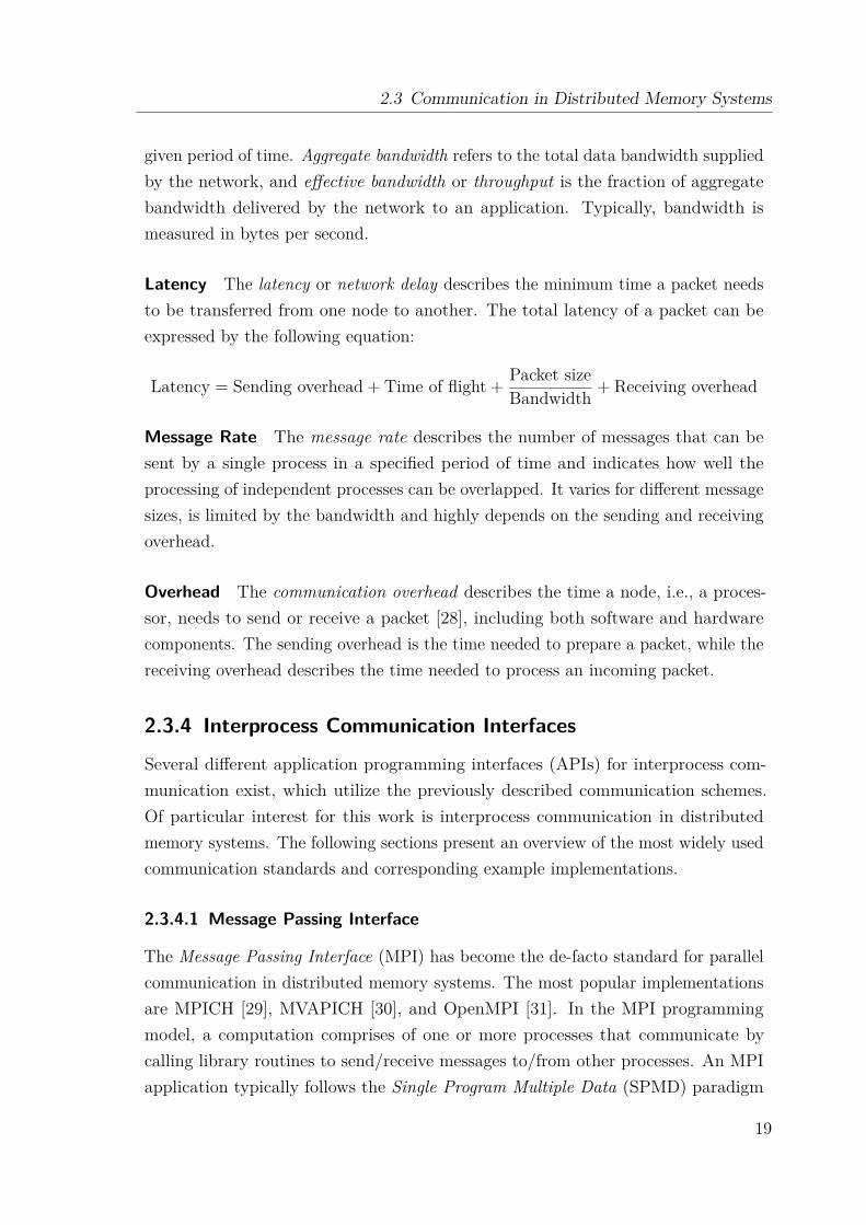
Figure 2.9: MPI rendezvous protocol.
process’ mailbox, where it is later matched with the receive request (3). Dependingon the payload size, the data is either buffered on the sender side (indicated by thedashed line) or directly sent with the header and buffered in the target’s mailbox (2)from where it is copied to its final destination (4).
Rendezvous Protocol While the eager protocol targets smaller payloads, therendezvous protocol is used for large messages, since the extra copy from the systemto the user buffer at the receiver side can significantly add latency and negativelyimpact performance. When using rendezvous, the message is sent once the targetnotifies the sender that sufficient user buffer is available. This approach is robustand safe, but requires more complex programming. In addition, it may introducesynchronization delays. Figure 2.9 illustrates the rendezvous protocol. Similar toeager, the header is sent to the target ((1.a) and (1.b)), where it is matched withthe receive request (2). Provided a matching receive can be found, MPI returnsthe target’s user buffer address (3) to the sender, which in turn initiates the copyoperation (4). Alternatively, the target can use an RDMA transfer, i.e., a getoperation, to fetch the data.
Message Matching An important but also complex feature is message matching.Message matching guarantees that an MPI code is deterministic by matching messageheaders and receive requests. The matching algorithm utilizes the source rank,tag, and communicator including wildcards for tag and source. The first messagecomplying with the MPI matching rules is chosen and the data is transferred tothe target buffer. Messages that arrive but cannot be matched with already posted
21

2 Communication and I/O in HPC Systems
receive requests are added to the so-called Unexpected Message Queue (UMQ).Unexpected messages can be avoided by using the rendezvous protocol, which willadd an additional roundtrip, but perform true zero-copy.
Collective Operations Apart from the point-to-point communication support, MPIalso introduces a set of collective operations, which provides a method of communica-tion which involves participation of all processes in a given communicator. Examplesare synchronization calls like MPI_Barrier, but also MP_Broadcast, MPI_Alltoall,MPI_Gather or MPI_Scatter. One important side effect is that collective communi-cation implies a synchronization point among processes. With the latest release ofthe MPI standard, MPI-3, non-blocking collective operations were introduced, whichaim to maximize the overlap of communication with computation.
2.3.4.2 Partitioned Global Address Space
The Partitioned Global Address Space (PGAS) [32] model is a shared memoryprogramming paradigm that introduces the idea to create a global but logicallypartitioned address space. Parallel processes share one global address space, whichconsists of memory segments in the local memory of participating processes. Forevery process, the global address space is divided into a local, private segment and aglobal, shared segment. While the global memory can be used for communication,the local part cannot be accessed from other processes.The term PGAS is used for both communication libraries and specialized pro-
gramming languages. The most well-known PGAS-based programming languagesare Universal Parallel C (UPC) [33] and Co-Array Fortran [34]. PGAS-languagesare extensions to common programming models and require special compilers. Thecompiler is responsible for the data placement. Therefore, access to a local segmentis always translated to load/store instructions, while remote accesses can be per-formed in several ways. Remote load/store operations are able to use local caches tospeed up some operations, whereas other solutions are two-sided as well as one-sidedcommunication using an underlying communication framework.One communication interface often used in conjunction with UPC is the Global
Address Space Network (GASNet) [35], which provides a high-performance, network-independent interface for PGAS languages. GASNet consists of two layers: the coreand the extended API. The core API leverages the Active Message specification andprovides atomic operations as well as utility functions. Active Messages provide alow level mechanism in which messages trigger the execution of code on the remote
22
2.3 Communication in Distributed Memory Systems
target. The principle of active messages can be compared to remote procedure calls.The extended API of GASNet provides high-level abstractions to exchange activemessages and data, or to ensure synchronization, including data transfer operationsbased on put/get semantics.Besides the PGAS-based languages, there exist several communication libraries,
which provide direct one-sided put and get operations to and from shared memoryregions. In addition to GASNet, openSHMEM [36] and Global Address SpaceProgramming Interface (GASPI) [37] are representatives of such PGAS-APIs.
2.3.4.3 Remote Procedure Call
Remote procedure call (RPC) packages [38] implement a request-response protocoland follow a simple target [39]: to make the process of executing code on a remotemachine as simple and straightforward as calling a local function. An RPC is initiatedby the client, which sends a request message to a known remote server to execute aspecified procedure with supplied parameters. Once the remote server has processedthe request, it sends a response to the client, and the application continues its process.Typically, the client is blocked until the server has finished processing and sent itsresponse, unless an asynchronous request is sent. There are many different RPCimplementations, resulting in a variety of different, incompatible RPC protocols. Oneof the main differences between local and remote procedure calls is that unpredictablenetwork problems can result in a faulty behavior or failure of an RPC. In general,the client must handle such failures without knowing whether the RPC was actuallyinvoked.
2.3.4.4 Portals
The Portals Network Programming Interface [40] is a low-level network API forhigh-performance networking developed by Sandia National Laboratories and theUniversity of New Mexico. Portals provides an interface to support both the MPIstandard as well as various PGAS models, such as Unified Parallel C, Co-ArrayFortran, and SHMEM, and combines the characteristics of both one-sided and two-sided communication. In addition to the traditional put/get semantics, Portals definesmatching put and matching get operations. The destination of a put is not an explicitaddress, but a list entry using the Portals addressing scheme that allows the receiverto determine where an incoming message should be placed. This flexibility allowsPortals to support both traditional one-sided operations and two-sided send/receiveoperations with both bypass mechanism for the operating systems as well as the
23
2 Communication and I/O in HPC Systems
N0,0
N0,m
N1,0
N1,m
Nn,0
Nn,m
......
...
Compute Nodes I/O Nodes Parallel File System
...
...
...
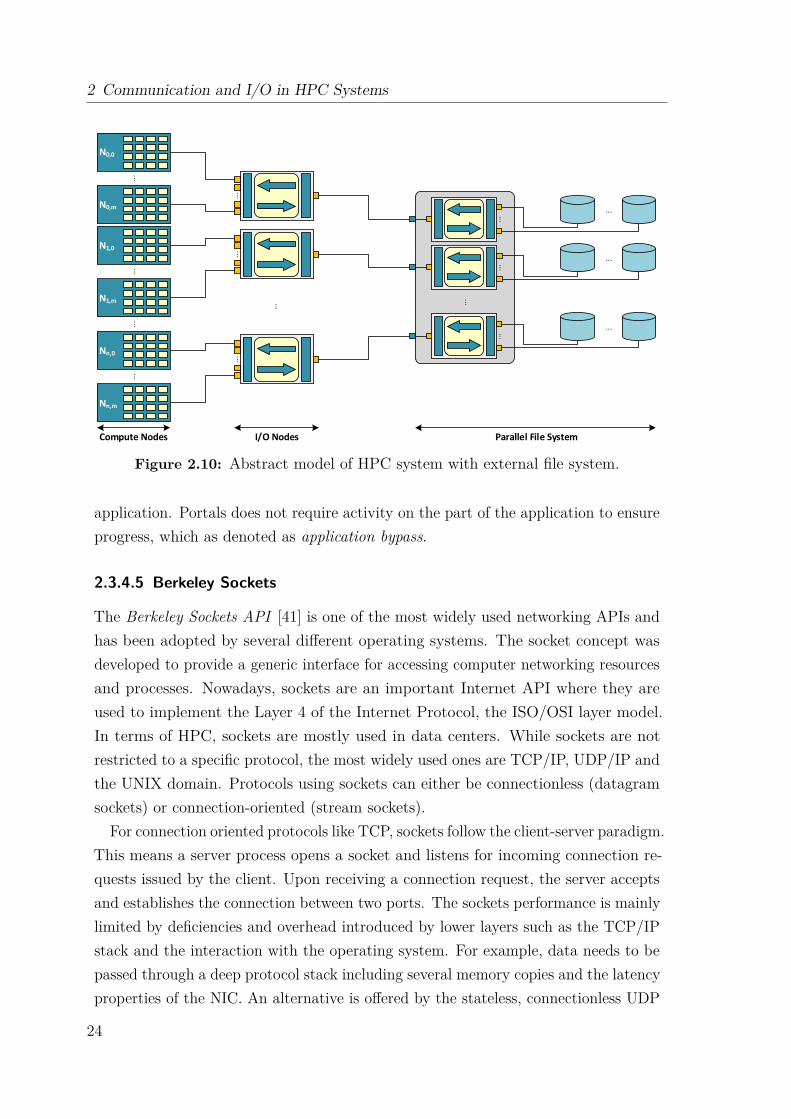
Figure 2.10: Abstract model of HPC system with external file system.
application. Portals does not require activity on the part of the application to ensureprogress, which as denoted as application bypass.
2.3.4.5 Berkeley Sockets
The Berkeley Sockets API [41] is one of the most widely used networking APIs andhas been adopted by several different operating systems. The socket concept wasdeveloped to provide a generic interface for accessing computer networking resourcesand processes. Nowadays, sockets are an important Internet API where they areused to implement the Layer 4 of the Internet Protocol, the ISO/OSI layer model.In terms of HPC, sockets are mostly used in data centers. While sockets are notrestricted to a specific protocol, the most widely used ones are TCP/IP, UDP/IP andthe UNIX domain. Protocols using sockets can either be connectionless (datagramsockets) or connection-oriented (stream sockets).
For connection oriented protocols like TCP, sockets follow the client-server paradigm.This means a server process opens a socket and listens for incoming connection re-quests issued by the client. Upon receiving a connection request, the server acceptsand establishes the connection between two ports. The sockets performance is mainlylimited by deficiencies and overhead introduced by lower layers such as the TCP/IPstack and the interaction with the operating system. For example, data needs to bepassed through a deep protocol stack including several memory copies and the latencyproperties of the NIC. An alternative is offered by the stateless, connectionless UDP
24
2.4 Introduction to Parallel I/O
Application
High-level I/O Library
I/O Middleware
I/O Forwarding
Parallel File System
I/O and Storage Hardware
I/O Middlewareorganizes accesses from many processes, especially those using collective I/O.
MPI-IO
Parallel File Systemmaintains logical space and provides efficient access to data.
Lustre, GPFS, PVFS2, BeeGFS
I/O Forwardingbridges between application tasks and storage system and provides aggregation for uncoordinated I/O.
IBM CIOD, IOFSL, Cray DVS
High-level I/O Librarymaps application abstractions onto storage abstractions and provides data portability.
HDF5, (p)netCDF, ADIOS
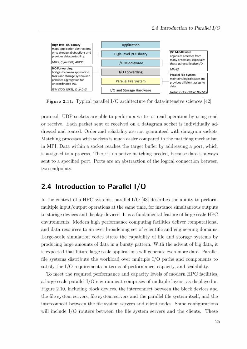
Figure 2.11: Typical parallel I/O architecture for data-intensive sciences [42].
protocol. UDP sockets are able to perform a write- or read-operation by using sendor receive. Each packet sent or received on a datagram socket is individually ad-dressed and routed. Order and reliability are not guaranteed with datagram sockets.Matching processes with sockets is much easier compared to the matching mechanismin MPI. Data within a socket reaches the target buffer by addressing a port, whichis assigned to a process. There is no active matching needed, because data is alwayssent to a specified port. Ports are an abstraction of the logical connection betweentwo endpoints.
2.4 Introduction to Parallel I/OIn the context of a HPC systems, parallel I/O [43] describes the ability to performmultiple input/output operations at the same time, for instance simultaneous outputsto storage devices and display devices. It is a fundamental feature of large-scale HPCenvironments. Modern high performance computing facilities deliver computationaland data resources to an ever broadening set of scientific and engineering domains.Large-scale simulation codes stress the capability of file and storage systems byproducing large amounts of data in a bursty pattern. With the advent of big data, itis expected that future large-scale applications will generate even more data. Parallelfile systems distribute the workload over multiple I/O paths and components tosatisfy the I/O requirements in terms of performance, capacity, and scalability.To meet the required performance and capacity levels of modern HPC facilities,
a large-scale parallel I/O environment comprises of multiple layers, as displayed inFigure 2.10, including block devices, the interconnect between the block devices andthe file system servers, file system servers and the parallel file system itself, and theinterconnect between the file system servers and client nodes. Some configurationswill include I/O routers between the file system servers and the clients. These
25
2 Communication and I/O in HPC Systems
components are then integrated into usable systems through complex software stacks,as presented in Figure 2.11.
2.4.1 Scientific I/O
Compared to traditional I/O, scientific I/O [44] is performed by large-scale applica-tions from the scientific domain. Typically, scientists think about their data in termsof their science problems, e.g., molecules, atoms, grid cells, and particles. Ultimately,physical disks store bytes of data, which makes such workloads difficult to handle forthe storage system. In scientific applications, I/O is commonly used to handle thefollowing data types:
Checkpoint / Restart Files Application checkpointing is a technique that addsfault tolerance into a distributed computing system. In general, checkpoint/restartfiles consist of snapshots, which reflect an application’s current state. These snapshotscan be used to restart an application in case of system or node failures. The mostbasic way to implement checkpointing is to periodically stop an application, copy allthe required data from the main memory to reliable, persistent storage (e.g., parallelfile system), and then continue with the execution.Two primary categories of techniques can be distinguished: uncoordinated check-
pointing and coordinated checkpointing. Uncoordinated checkpointing employs theidea of saving snapshots of each process independently from each other. The prob-lem imposed by this technique is that simply forcing processes to save checkpointinformation at fixed time intervals does not ensure global consistency. Unlike un-coordinated checkpointing, coordinated checkpointing synchronizes the processes’states and dependencies at checkpointing time to ensure that the global state issaved consistently. This is achieved by applying a two-phase commit protocol (i.e.,an atomic commit protocol), which results in periodic, bursty I/O phases.
Data Input / Data Output Data input and data output mainly happens at thebeginning and end phases of an application run. Large amounts of data need to beread, e.g., to fill the main memory with an initial data set, or need to be written,e.g., to store numerical output from simulations for post-processing analysis.
Out-of-core Algorithms Out-of-core algorithms, also called external memory al-gorithms, are designed to deal with data sets that are too large to be stored inthe available main memory. Such algorithms basically implement “demand paging”
26
2.4 Introduction to Parallel I/O
under user application control and are optimized to efficiently fetch and access datathat is stored on a slower storage system, e.g., the underlying distributed file system.
2.4.2 Parallel File Systems
Conventional, local file systems assume that the disk or disks are directly connectedto a compute node. In cluster systems consisting of hundreds or thousands of nodes,this would mean that there is no global name space and every node would have toorganize its own separate data. To cope with this problem at scale, the file systemis outsourced to the network. Distributed file systems utilize a network protocol toaccess the distributed storage. Files are shared between users in a hierarchical andunified view [45]: files are stored on different storage resources, but appear to usersas they are put on a single location. Parallel distributed file system architecturesspread individual files across multiple storage nodes, usually for performance and/orredundancy reasons, and allow concurrent read and write access to the files. Thismechanism is called file striping. Key features [45, 46] of parallel file systems includetransparency, fault tolerance, and scalability:
Transparancy The complexity of the underlying distributed storage system is hiddenfrom the user. File access is provided via the same operations and interfacesas used for local file systems, e.g., mounting/unmounting, read/write at byteboundaries, listing directories, and the system’s native permission model. Also,fault tolerance mechanisms hide storage system failures from the user.
Fault Tolerance As distributed file systems are deployed on large-scale systems,the possibility of failures are the norm rather than the exception. Therefore,distributed file systems provide fault tolerance mechanisms that keep the systemalive in the case of a transient or partial failure. Considered faults are networkand server failures, but also data integrity and consistency in case of concurrentfile accesses.
Scalability The ability to efficiently scale the system to a large number of nodesand also to effectively leverage dynamically and continuously added systemcomponents.
Different architectural approaches can be used to achieve a scalable system archi-tecture [47]. Client-Server architectures have several servers which are responsible tomanage, store, and share metadata and data by providing a global name space tothe clients. Cluster-based Distributed File Systems decouple metadata from the data.
27
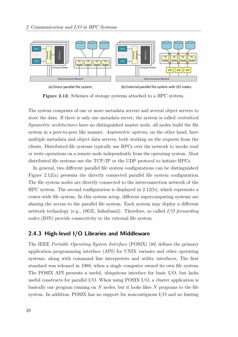
2 Communication and I/O in HPC Systems
Interconnection Network Interconnection Network
CPU
CPUM
em
ory
Inte
rna
l N
etw
ork
...
FS Node
FS Node
FS Node
FS Node
CPU
CPU
Me
mo
ry
Inte
rna
l N
etw
ork
...
FS Node
FS Node
FS Node
FS Node
ION ION IONCompute Nodes Compute Nodes
(a) Direct parallel file system. (b) External parallel file system with I/O nodes.
Figure 2.12: Schemes of storage systems attached to a HPC system.
The system comprises of one or more metadata servers and several object servers tostore the data. If there is only one metadata server, the system is called centralized.Symmetric architectures have no distinguished master node, all nodes build the filesystem in a peer-to-peer like manner. Asymmetric systems, on the other hand, havemultiple metadata and object data servers, both working on the requests from theclients. Distributed file systems typically use RPCs over the network to invoke reador write operations on a remote node independently from the operating system. Mostdistributed file systems use the TCP/IP or the UDP protocol to initiate RPCs.In general, two different parallel file system configurations can be distinguished.
Figure 2.12(a) presents the directly connected parallel file system configuration.The file system nodes are directly connected to the interconnection network of theHPC system. The second configuration is displayed in 2.12(b), which represents acenter-wide file system. In this system setup, different supercomputing systems aresharing the access to the parallel file system. Each system may deploy a differentnetwork technology (e.g., 10GE, Infiniband). Therefore, so called I/O forwardingnodes (ION) provide connectivity to the external file system.
2.4.3 High-level I/O Libraries and Middleware
The IEEE Portable Operating System Interface (POSIX) [48] defines the primaryapplication programming interface (API) for UNIX variants and other operatingsystems, along with command line interpreters and utility interfaces, The firststandard was released in 1988, when a single computer owned its own file system.The POSIX API presents a useful, ubiquitous interface for basic I/O, but lacksuseful constructs for parallel I/O. When using POSIX I/O, a cluster application isbasically one program running on N nodes, but it looks likes N programs to the filesystem. In addition, POSIX has no support for noncontiguous I/O and no hinting
28
2.4 Introduction to Parallel I/O
or prefetching mechanism. Together with its rules such as atomic writes and read-after-write consistency, POSIX I/O has a negative impact on parallel applications.To overcome the limitations of POSIX I/O, high-level I/O libraries and middlewaresolutions have been developed to provide data abstraction and to organize accessesfrom many processes, especially those using collective I/O. The following sectionsintroduce MPI-IO and selected libraries.
2.4.3.1 MPI-IO
in distributed memory architectures, parallel I/O systems needs a mechanism tospecify collective operations, user-defined data types to describe noncontiguous datalayouts in both memory and file, communicators to separate application-level messagepassing from I/O-related message passing, and non-blocking operations. MPI-IO,which was released in 1997 as part of MPI-2, is an I/O interface specification foruse in MPI applications and provides a low-level interface for carrying out parallelI/O. Internally, it uses the same data model as POSIX, i.e., streams of bytes in afile. MPI-IO’s features include collective I/O, noncontiguous I/O with MPI datatypes and file views, non-blocking I/O, and Fortran and additional language bindings.Collective I/O is a critical optimization strategy for reading from, and writing to,a parallel file system. The collective read and write calls force all processes in acommunicator to read/write data simultaneously and to wait for each other. The MPIimplementation optimizes the read/write request based on the combined requests ofall processes and can merge the requests of different processes for efficiently servicingthe requests. Given N processes, each process participates in reading or writing aportion of a common file.
There are several different MPI-IO implementations. One of the widely used onesis ROMIO [49] from the Argonne National Laboratory. ROMIO leverages MPI-1communication and supports local file systems, network file systems, and parallelfile systems such as GPFS and Lustre. The implementation includes data sievingtechniques and two-phase optimizations.
2.4.3.2 HDF5 and Parallel HDF5
The Hierarchical Data Format v5 (HDF5) [50] consists of three components: adata model, an open source software, and an open file format. The HDF5 fileformat is defined by the HDF5 file format specification [51] and defines the bit-level organization of an HDF5 file on storage media. HDF5 is designed to supporthigh volume and/or complex data, every size and type of system (portability), and
29
2 Communication and I/O in HPC Systems
flexible, efficient storage and I/O. An HDF5 file is basically a container consistingof data objects, which can either be datasets or groups. Datasets organize andcontain multidimensional arrays of a homogeneous type, while groups are containerstructures consisting of datasets or other groups.
Altogether, HDF5 provides a simple way to store scientific data in a database-likeorganization. The data model complements the file format by providing an abstractdata model independent of the storage medium or programming environment. Itspecifies the logical organization and access of HDF5 data from an applicationperspective, and enables scientists to focus on high-level concepts of relationshipsbetween data objects rather than descending into the details of the specific layout.The HDF5 software provides a portable I/O library, language interfaces, and toolsfor managing, manipulating, viewing, and analyzing data in the HDF5 format. TheI/O library is written in C, and includes optional C++, Fortran 90, and high-levelAPIs. For flexibility, the API is extensive with over 300 functions. Parallel HDF5 isa configuration of the HDF5 library, which can be used to share open files acrossmultiple parallel processes. It uses the MPI standard for interprocess communication.
2.4.3.3 ADIOS
The Adaptable I/O System (ADIOS) [52, 53] is an extendable framework whichallows scientists to plug-in several different I/O methods, data management services,file formats, and other services such as analytic and visualization tools. It provides asimple I/O application programming interface (API) and allows the usage of differentcomputational technologies to achieve good, predictable, performance. ADIOSprovides a mechanism to externally describe an application’s I/O requirements usingan XML-based configuration file. One of its salient features is that I/O methods canbe exchanged between runs by modifying the configuration file without the need tomodify or recompile the application code. ADIOS has demonstrated impressive I/Operformance results on leadership class machines and clusters, and has been deployedon several supercomputing sites including the Argonne Leadership Computing Facility(ALCF), the Oak Ridge Leadership Computing Facility (OLCF), the National EnergyResearch Scientific Computing Center (NERSC), the Swiss National SupercomputingCentre (CSCS), Tianhe-1 and 2, and the Pawsey Supercomputing Centre.
ADIOS is implemented as a user library. It can be used like any other I/O library,except that it has a declarative approach for I/O. The user defines in the applicationsource code the “what” and “when” while the framework takes care of the “how”.There are two key ideas. First, users do not need to be aware of the low-level layout
30
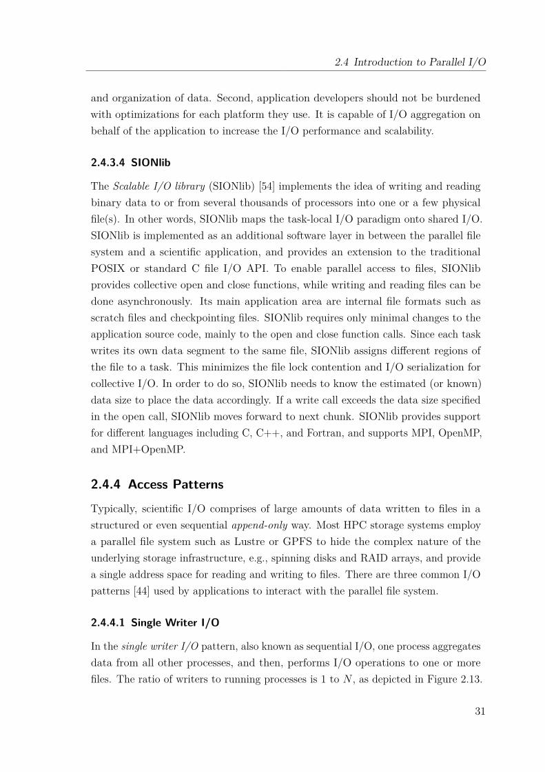
2.4 Introduction to Parallel I/O
and organization of data. Second, application developers should not be burdenedwith optimizations for each platform they use. It is capable of I/O aggregation onbehalf of the application to increase the I/O performance and scalability.
2.4.3.4 SIONlib
The Scalable I/O library (SIONlib) [54] implements the idea of writing and readingbinary data to or from several thousands of processors into one or a few physicalfile(s). In other words, SIONlib maps the task-local I/O paradigm onto shared I/O.SIONlib is implemented as an additional software layer in between the parallel filesystem and a scientific application, and provides an extension to the traditionalPOSIX or standard C file I/O API. To enable parallel access to files, SIONlibprovides collective open and close functions, while writing and reading files can bedone asynchronously. Its main application area are internal file formats such asscratch files and checkpointing files. SIONlib requires only minimal changes to theapplication source code, mainly to the open and close function calls. Since each taskwrites its own data segment to the same file, SIONlib assigns different regions ofthe file to a task. This minimizes the file lock contention and I/O serialization forcollective I/O. In order to do so, SIONlib needs to know the estimated (or known)data size to place the data accordingly. If a write call exceeds the data size specifiedin the open call, SIONlib moves forward to next chunk. SIONlib provides supportfor different languages including C, C++, and Fortran, and supports MPI, OpenMP,and MPI+OpenMP.
2.4.4 Access Patterns
Typically, scientific I/O comprises of large amounts of data written to files in astructured or even sequential append-only way. Most HPC storage systems employa parallel file system such as Lustre or GPFS to hide the complex nature of theunderlying storage infrastructure, e.g., spinning disks and RAID arrays, and providea single address space for reading and writing to files. There are three common I/Opatterns [44] used by applications to interact with the parallel file system.
2.4.4.1 Single Writer I/O
In the single writer I/O pattern, also known as sequential I/O, one process aggregatesdata from all other processes, and then, performs I/O operations to one or morefiles. The ratio of writers to running processes is 1 to N , as depicted in Figure 2.13.
31
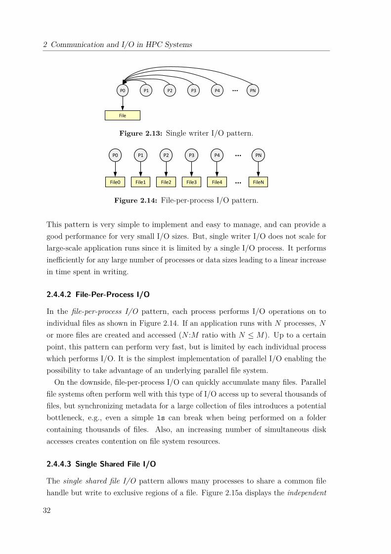
2 Communication and I/O in HPC Systems
File
P0 P1 P2 P3 P4 PN...
Figure 2.13: Single writer I/O pattern.
File0
P0 P1 P2 P3 P4 PN
File2File1 File3 File4 FileN...
...
Figure 2.14: File-per-process I/O pattern.
This pattern is very simple to implement and easy to manage, and can provide agood performance for very small I/O sizes. But, single writer I/O does not scale forlarge-scale application runs since it is limited by a single I/O process. It performsinefficiently for any large number of processes or data sizes leading to a linear increasein time spent in writing.
2.4.4.2 File-Per-Process I/O
In the file-per-process I/O pattern, each process performs I/O operations on toindividual files as shown in Figure 2.14. If an application runs with N processes, Nor more files are created and accessed (N :M ratio with N ≤ M). Up to a certainpoint, this pattern can perform very fast, but is limited by each individual processwhich performs I/O. It is the simplest implementation of parallel I/O enabling thepossibility to take advantage of an underlying parallel file system.
On the downside, file-per-process I/O can quickly accumulate many files. Parallelfile systems often perform well with this type of I/O access up to several thousands offiles, but synchronizing metadata for a large collection of files introduces a potentialbottleneck, e.g., even a simple ls can break when being performed on a foldercontaining thousands of files. Also, an increasing number of simultaneous diskaccesses creates contention on file system resources.
2.4.4.3 Single Shared File I/O
The single shared file I/O pattern allows many processes to share a common filehandle but write to exclusive regions of a file. Figure 2.15a displays the independent
32
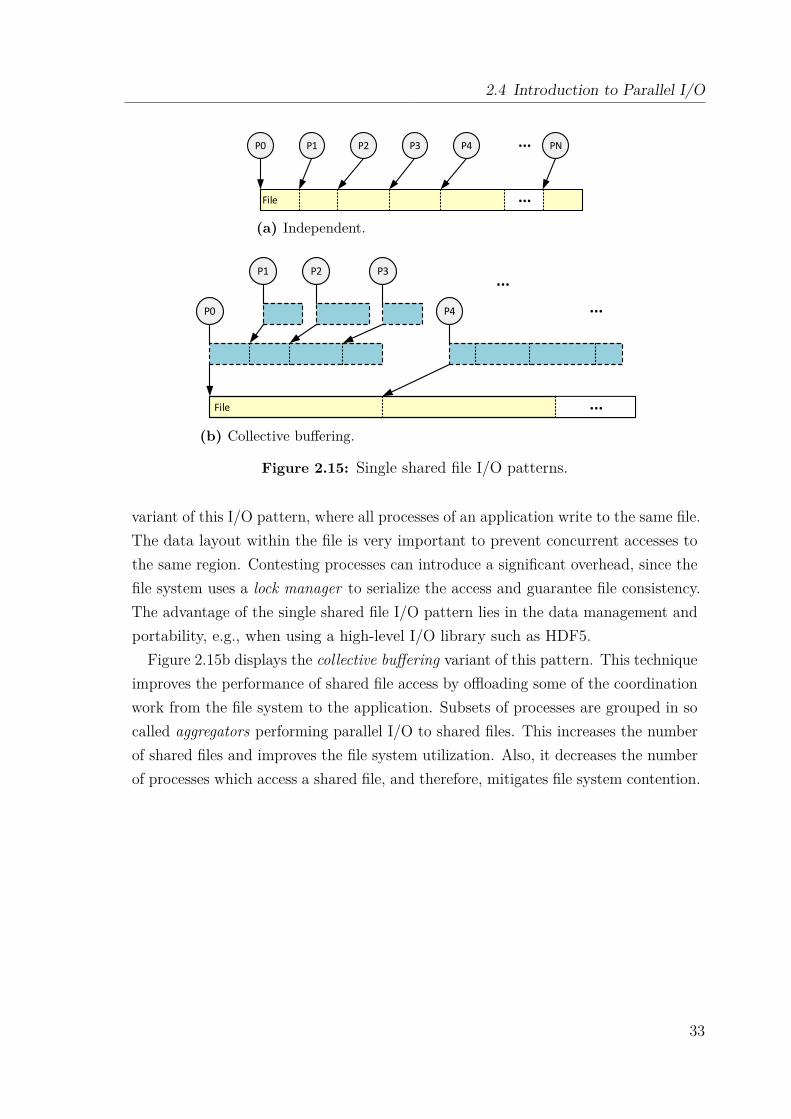
2.4 Introduction to Parallel I/O
File
P0 P1 P2 P3 P4 PN
...
...
(a) Independent.
File
P0 P4
...
...P1 P2 P3
...
(b) Collective buffering.
Figure 2.15: Single shared file I/O patterns.
variant of this I/O pattern, where all processes of an application write to the same file.The data layout within the file is very important to prevent concurrent accesses tothe same region. Contesting processes can introduce a significant overhead, since thefile system uses a lock manager to serialize the access and guarantee file consistency.The advantage of the single shared file I/O pattern lies in the data management andportability, e.g., when using a high-level I/O library such as HDF5.
Figure 2.15b displays the collective buffering variant of this pattern. This techniqueimproves the performance of shared file access by offloading some of the coordinationwork from the file system to the application. Subsets of processes are grouped in socalled aggregators performing parallel I/O to shared files. This increases the numberof shared files and improves the file system utilization. Also, it decreases the numberof processes which access a shared file, and therefore, mitigates file system contention.
33

Ch
ap
te
r
3Extoll System Environment
Interconnection networks are a key component in large-scale HPC deployments andplay a vital role in the overall system performance. They must offer high commu-nication bandwidth and low latency to cope with the nature of the mixed systemworkloads, which include data-intensive and communication-intensive applications.Essentially, networks are the backbone for both communication and I/O, and con-nect compute nodes, I/O devices, and storage devices. The design of future HPCinterconnect technologies faces multiple challenges, including scalability, efficiency,heterogeneity, resiliency, virtualization, cost and power consumption.
Extoll is such a high-performance interconnect technology [55, 56], which startedoff as a research project at the Heidelberg University in 2009. Its key objective is tofit the needs of future HPC applications in terms of latency, bandwidth, messagerate [57], and scalability. Released in 2016, the first Application Specific IntegratedCircuit (ASIC) version of Extoll is the Tourmalet chip. Extoll has been chosen asthe fundamental technology for the research work presented in Chapters 4 through 6and is described in the following sections.
3.1 Technology OverviewThe top-level diagram of the Extoll technology is displayed in Figure 3.1. The designis divided into three parts: the host interface, the network interface, and the network.The network part of the NIC provides six links to build a 3D torus network
topology. The Extoll NIC implements a direct network approach by integrating aswitching logic on-chip, which removes the need for external switches. An additional
35
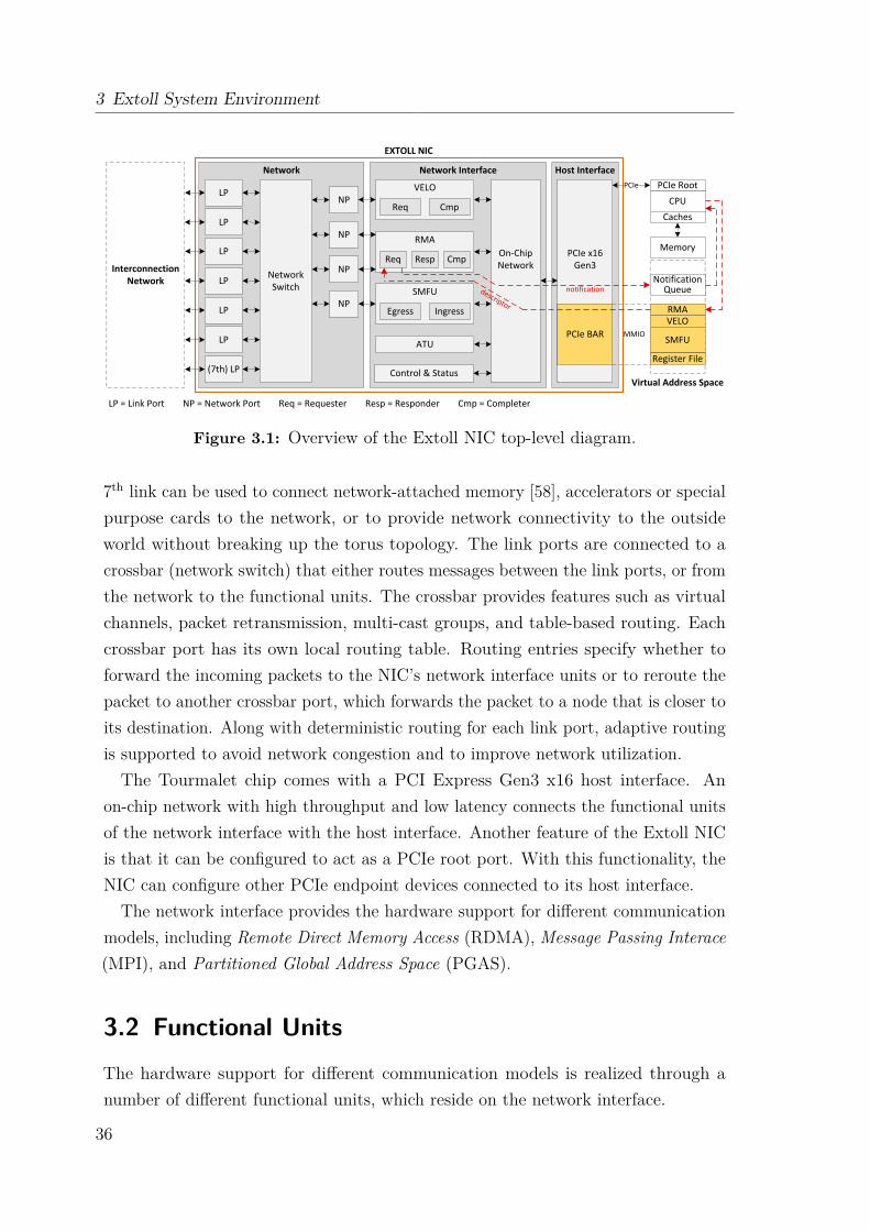
3 Extoll System Environment
Host InterfaceNetwork InterfaceNetwork
NetworkSwitch
LP
LP
LP
(7th) LP
LP
LP
LP
NP
NP
NP
NP
Control & Status
ATU
SMFU
Egress Ingress
RMA
Req CmpResp
VELO
Req Cmp
PCIe RootCPU
Caches
Memory
Notification Queue
RMAVELO
SMFU
Register File
Virtual Address Space
LP = Link Port NP = Network Port Req = Requester Resp = Responder Cmp = Completer
Interconnection Network
PCIe BAR
PCIe
descriptor
On-Chip Network
PCIe x16 Gen3
notification
MMIO
EXTOLL NIC
Figure 3.1: Overview of the Extoll NIC top-level diagram.
7th link can be used to connect network-attached memory [58], accelerators or specialpurpose cards to the network, or to provide network connectivity to the outsideworld without breaking up the torus topology. The link ports are connected to acrossbar (network switch) that either routes messages between the link ports, or fromthe network to the functional units. The crossbar provides features such as virtualchannels, packet retransmission, multi-cast groups, and table-based routing. Eachcrossbar port has its own local routing table. Routing entries specify whether toforward the incoming packets to the NIC’s network interface units or to reroute thepacket to another crossbar port, which forwards the packet to a node that is closer toits destination. Along with deterministic routing for each link port, adaptive routingis supported to avoid network congestion and to improve network utilization.The Tourmalet chip comes with a PCI Express Gen3 x16 host interface. An
on-chip network with high throughput and low latency connects the functional unitsof the network interface with the host interface. Another feature of the Extoll NICis that it can be configured to act as a PCIe root port. With this functionality, theNIC can configure other PCIe endpoint devices connected to its host interface.
The network interface provides the hardware support for different communicationmodels, including Remote Direct Memory Access (RDMA), Message Passing Interace(MPI), and Partitioned Global Address Space (PGAS).
3.2 Functional UnitsThe hardware support for different communication models is realized through anumber of different functional units, which reside on the network interface.
36
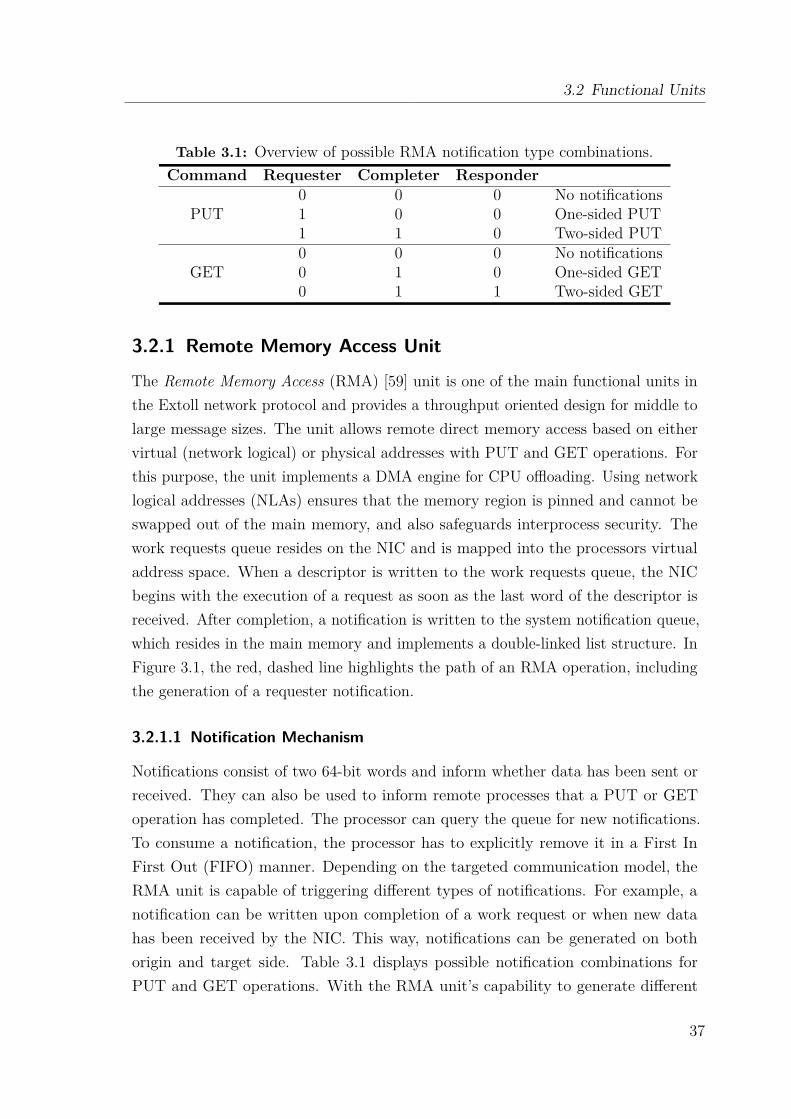
3.2 Functional Units
Table 3.1: Overview of possible RMA notification type combinations.Command Requester Completer Responder
0 0 0 No notificationsPUT 1 0 0 One-sided PUT
1 1 0 Two-sided PUT0 0 0 No notifications
GET 0 1 0 One-sided GET0 1 1 Two-sided GET
3.2.1 Remote Memory Access Unit
The Remote Memory Access (RMA) [59] unit is one of the main functional units inthe Extoll network protocol and provides a throughput oriented design for middle tolarge message sizes. The unit allows remote direct memory access based on eithervirtual (network logical) or physical addresses with PUT and GET operations. Forthis purpose, the unit implements a DMA engine for CPU offloading. Using networklogical addresses (NLAs) ensures that the memory region is pinned and cannot beswapped out of the main memory, and also safeguards interprocess security. Thework requests queue resides on the NIC and is mapped into the processors virtualaddress space. When a descriptor is written to the work requests queue, the NICbegins with the execution of a request as soon as the last word of the descriptor isreceived. After completion, a notification is written to the system notification queue,which resides in the main memory and implements a double-linked list structure. InFigure 3.1, the red, dashed line highlights the path of an RMA operation, includingthe generation of a requester notification.
3.2.1.1 Notification Mechanism
Notifications consist of two 64-bit words and inform whether data has been sent orreceived. They can also be used to inform remote processes that a PUT or GEToperation has completed. The processor can query the queue for new notifications.To consume a notification, the processor has to explicitly remove it in a First InFirst Out (FIFO) manner. Depending on the targeted communication model, theRMA unit is capable of triggering different types of notifications. For example, anotification can be written upon completion of a work request or when new datahas been received by the NIC. This way, notifications can be generated on bothorigin and target side. Table 3.1 displays possible notification combinations forPUT and GET operations. With the RMA unit’s capability to generate different
37
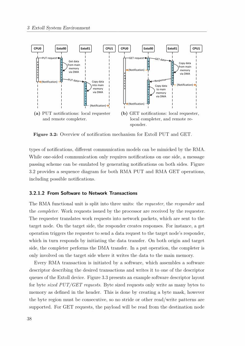
3 Extoll System Environment
REQUESTER
PROCESS
COMPLETER
PUT request
(Notification) Copy data into main memory via DMA
Get data from main memory via DMA
(Notification)
(a) PUT notifications: local requesterand remote completer.
REQ
PROCESS
COMPLETER
GET request
(Notification)
Copy data from main memory via DMA
Copy data to main memory via DMA
(Notification)
RESPONDER
(Notification)
(b) GET notifications: local requester,local completer, and remote re-sponder.
Figure 3.2: Overview of notification mechanism for Extoll PUT and GET.
types of notifications, different communication models can be mimicked by the RMA.While one-sided communication only requires notifications on one side, a messagepassing scheme can be emulated by generating notifications on both sides. Figure3.2 provides a sequence diagram for both RMA PUT and RMA GET operations,including possible notifications.
3.2.1.2 From Software to Network Transactions
The RMA functional unit is split into three units: the requester, the responder andthe completer. Work requests issued by the processor are received by the requester.The requester translates work requests into network packets, which are sent to thetarget node. On the target side, the responder creates responses. For instance, a getoperation triggers the requester to send a data request to the target node’s responder,which in turn responds by initiating the data transfer. On both origin and targetside, the completer performs the DMA transfer. In a put operation, the completer isonly involved on the target side where it writes the data to the main memory.Every RMA transaction is initiated by a software, which assembles a software
descriptor describing the desired transactions and writes it to one of the descriptorqueues of the Extoll device. Figure 3.3 presents an example software descriptor layoutfor byte sized PUT/GET requests. Byte sized requests only write as many bytes tomemory as defined in the header. This is done by creating a byte mask, howeverthe byte region must be consecutive, so no stride or other read/write patterns aresupported. For GET requests, the payload will be read from the destination node
38
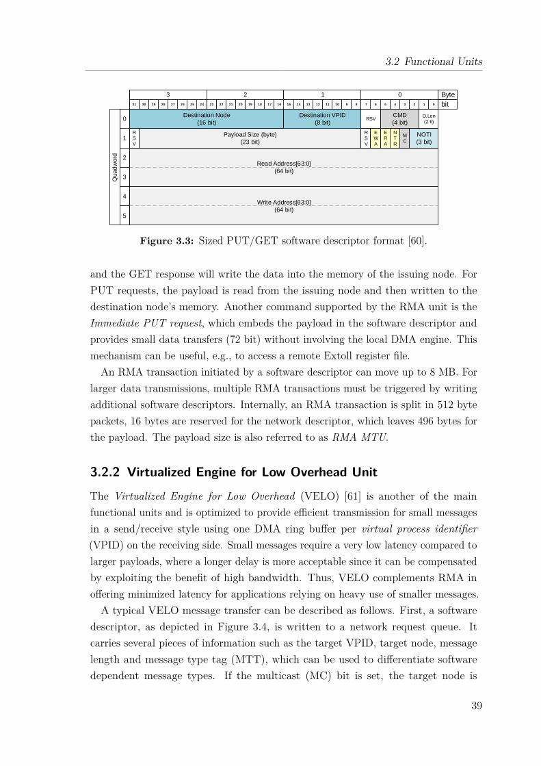
3.2 Functional Units
3 2 1 0
1
0
2
Quad
word
4
3
5
1011 89 67 45 23 11920 1718 1516 1314 122122232425 0262728293031
Read Address[63:0]
(64 bit)
Write Address[63:0]
(64 bit)
Destination Node
(16 bit)
Payload Size (byte)
(23 bit)
RSV
D.Len (2 b)
CMD
(4 bit)
NOTI
(3 bit)
ERA
NTR
MC
RSV
RSV
EWA
Destination VPID
(8 bit)
Byte
bit
Figure 3.3: Sized PUT/GET software descriptor format [60].
and the GET response will write the data into the memory of the issuing node. ForPUT requests, the payload is read from the issuing node and then written to thedestination node’s memory. Another command supported by the RMA unit is theImmediate PUT request, which embeds the payload in the software descriptor andprovides small data transfers (72 bit) without involving the local DMA engine. Thismechanism can be useful, e.g., to access a remote Extoll register file.
An RMA transaction initiated by a software descriptor can move up to 8 MB. Forlarger data transmissions, multiple RMA transactions must be triggered by writingadditional software descriptors. Internally, an RMA transaction is split in 512 bytepackets, 16 bytes are reserved for the network descriptor, which leaves 496 bytes forthe payload. The payload size is also referred to as RMA MTU.
3.2.2 Virtualized Engine for Low Overhead Unit
The Virtualized Engine for Low Overhead (VELO) [61] is another of the mainfunctional units and is optimized to provide efficient transmission for small messagesin a send/receive style using one DMA ring buffer per virtual process identifier(VPID) on the receiving side. Small messages require a very low latency compared tolarger payloads, where a longer delay is more acceptable since it can be compensatedby exploiting the benefit of high bandwidth. Thus, VELO complements RMA inoffering minimized latency for applications relying on heavy use of smaller messages.A typical VELO message transfer can be described as follows. First, a software
descriptor, as depicted in Figure 3.4, is written to a network request queue. Itcarries several pieces of information such as the target VPID, target node, messagelength and message type tag (MTT), which can be used to differentiate softwaredependent message types. If the multicast (MC) bit is set, the target node is
39

3 Extoll System Environment
0
Destination Node / Multicast ID
(16 bit)
Qua
dw
ord
User Tag
(8 bit)
Length (Coding 1=1)
(12 bit)
MTT
(2 b)reservedreserved
INT
Target VPID
(10 bit)reserved
MC
3 2 1 0
1011 89 67 45 23 11920 1718 1516 1314 122122232425 0262728293031
Byte
bit
Figure 3.4: VELO message software descriptor format.
interpreted as a multicast group ID and the crossbar can match the multicast ID tothe corresponding entry in the routing table to forward the message accordingly. Afterwriting the software descriptor, messages are posted automatically and performed asPIO operations by the CPU. The sender copies the data from the original buffer toa requester address, which decodes to the VELO requester. On the receiving side,the DMA ring buffer corresponding to the target VPID is divided into slots of 128bytes. When a receiving a new message, the VELO completer writes a status word(8 bytes in size) to the first quadword of the slot. The rest of the slot is filled withthe payload. The maximum VELO packet size is 128 bytes with 8 bytes reserved forthe status word (network descriptor).The VELO unit combines several different techniques including stateless work
processing, secure and atomic PIO message triggering from user space, integratedend-to-end flow control, and virtual cut through in all pipeline stages.
3.2.3 Virtual Process ID
In the Extoll system environment, user and kernel level processes initiate RMA andVELO transmissions by writing a software descriptor either to the work request queueresiding on the Extoll NIC or to a dedicated area in the main memory respectively. Inorder to ensure process security, Extoll utilizes a resource virtualization mechanismcalled virtual process identifiers (VPID), which provides process separation.Each VPID identifies a process or a group of processes, which can communicate
with each other. A process can only access memory registered for its VPID. Inaddition, an in-memory mailbox is allocated for each registered VPID. The Extollhardware writes hardware-specific notifications to these memory areas. The VPID isassigned by the Extoll device driver and stored in hardware, and must be requestedby a process before any communication can be performed. Extoll is designed forsystems with up to 256 processors. Therefore for both RMA and VELO, 256 VPIDsare available. For each VPID, one 4 KB page is mapped into the main memory.
40
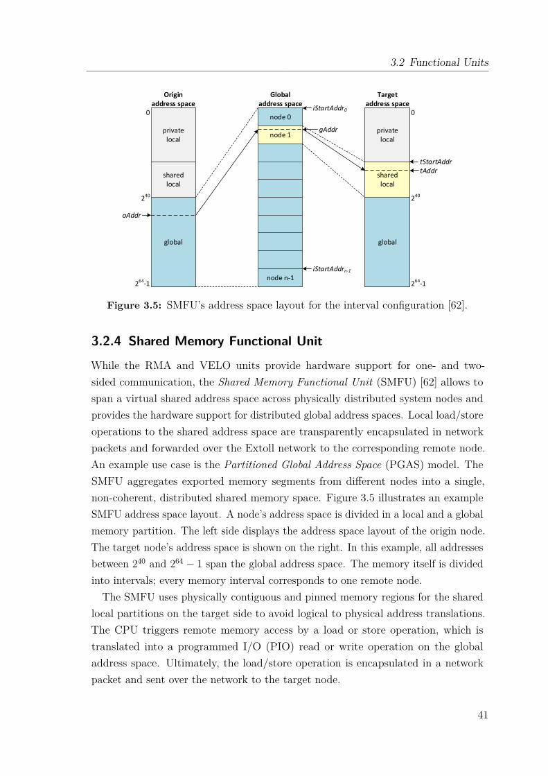
3.2 Functional Units
global
sharedlocal
privatelocal
global
sharedlocal
private local
node 0
node 1
node n-1
Origin address space
Global address space
Target address space
0
240
264-1
0
240
264-1
tStartAddr
oAddr
iStartAddr0
iStartAddrn-1
gAddr
tAddr
Figure 3.5: SMFU’s address space layout for the interval configuration [62].
3.2.4 Shared Memory Functional Unit
While the RMA and VELO units provide hardware support for one- and two-sided communication, the Shared Memory Functional Unit (SMFU) [62] allows tospan a virtual shared address space across physically distributed system nodes andprovides the hardware support for distributed global address spaces. Local load/storeoperations to the shared address space are transparently encapsulated in networkpackets and forwarded over the Extoll network to the corresponding remote node.An example use case is the Partitioned Global Address Space (PGAS) model. TheSMFU aggregates exported memory segments from different nodes into a single,non-coherent, distributed shared memory space. Figure 3.5 illustrates an exampleSMFU address space layout. A node’s address space is divided in a local and a globalmemory partition. The left side displays the address space layout of the origin node.The target node’s address space is shown on the right. In this example, all addressesbetween 240 and 264 − 1 span the global address space. The memory itself is dividedinto intervals; every memory interval corresponds to one remote node.
The SMFU uses physically contiguous and pinned memory regions for the sharedlocal partitions on the target side to avoid logical to physical address translations.The CPU triggers remote memory access by a load or store operation, which istranslated into a programmed I/O (PIO) read or write operation on the globaladdress space. Ultimately, the load/store operation is encapsulated in a networkpacket and sent over the network to the target node.
41

3 Extoll System Environment
Originally, HyperTransport (HT) [63] was chosen as the interface between theSMFU’s communication engine and the host system, but has been replaced withPCI Express. The main reason for this is that HT is not available anymore, sinceAMD changed their processor design. The communication engine passes transactions(e.g., non-posted reads and posted writes) from the origin to the target node. Atransaction can be divided in several sub-tasks, including target node determinationand address translation. There are three different address spaces in the SMFUarchitecture: one global address space and two local address spaces (target andorigin). All three address spaces are traversed by a remote memory access. To avoidunnecessary latency overhead, a simple yet efficient translation scheme is used.The simplest way to utilize the SMFU is the interval configuration. For each
interval, the start (iStartAddr) and end (iEndAddr) addresses, and the respectivenodes are stored in the Extoll register file. In addition, the target address (tStartAddr)is configured, which points to the start of the local shared memory segment andincoming requests are forwarded to this address. As depicted in Figure 3.1, theSMFU has two sub-units, the egress and the ingress unit. Load and store requests toan address (oAddr) residing in the SMFU BAR are forwarded to the egress unit. Forexample if this address hits interval n, the global address (gAddr) can be calculatedby subtracting the start address of interval n (iStartAddrn) from the origin startaddress (oAddr), as shown in Equation 3.1.
gAddr = oAddr − iStartAddrn (3.1)
After matching gAddr with the node the interval is assigned to, the load/storeoperation is transparently encapsulated in a network packet. On the target node, theingress unit calculates the target destination address (tAddr) in the following way:
tAddr = (gAddr + tStartAddr) (3.2)
The interval configuration only supports a limited number of intervals, currently 64intervals. To cope with this limitation, it is possible to use an address mask, whichencodes the target node in the global address (gAddr). The target node identifieris then determined by (1) applying a bit mask to the global address, and then, (2)performing a bitwise right shift operation (refer to Equation 3.3). The resultingvalue represents the target node identification (tNodeID).
tNodeID = (gAddr & mask) >> shift_count (3.3)
42
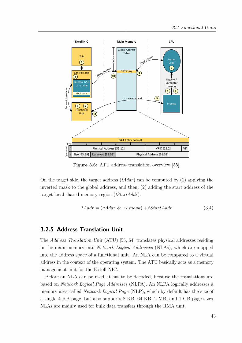
3.2 Functional Units
TLB
Control Logic
Internal GAT base table
GAT base
FunctionalUnit
Global Address Table
GAT Entry
Process
KernelCode
Requ
est t
rans
latio
n
Issue command
Register/unregistermemory
GAT Entry Format3 2 1 0
VDVPID [11:2]Physical Address [31:12]
Physical Address [51:32]Reserved [58:52]Size [63:59]1
0
Byte
Qua
dwor
d
Extoll NIC Main Memory CPU
1
2
3
4
5
6 7
8
9
10
11
Insert/delete
Fetch on miss
Inde
x
Figure 3.6: ATU address translation overview [55].
On the target side, the target address (tAddr) can be computed by (1) applying theinverted mask to the global address, and then, (2) adding the start address of thetarget local shared memory region (tStartAddr):
tAddr = (gAddr & ∼ mask) + tStartAddr (3.4)
3.2.5 Address Translation Unit
The Address Translation Unit (ATU) [55, 64] translates physical addresses residingin the main memory into Network Logical Addresses (NLAs), which are mappedinto the address space of a functional unit. An NLA can be compared to a virtualaddress in the context of the operating system. The ATU basically acts as a memorymanagement unit for the Extoll NIC.Before an NLA can be used, it has to be decoded, because the translations are
based on Network Logical Page Addresses (NLPA). An NLPA logically addresses amemory area called Network Logical Page (NLP), which by default has the size ofa single 4 KB page, but also supports 8 KB, 64 KB, 2 MB, and 1 GB page sizes.NLAs are mainly used for bulk data transfers through the RMA unit.
43
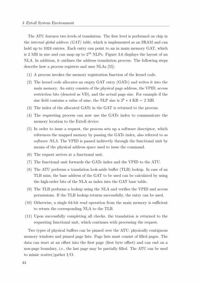
3 Extoll System Environment
The ATU features two levels of translation. The first level is performed on chip inthe internal global address (GAT) table, which is implemented as an SRAM and canhold up to 1024 entries. Each entry can point to an in main memory GAT, whichis 2 MB in size and can map up to 218 NLPs. Figure 3.6 displays the layout of anNLA. In addition, it outlines the address translation process. The following stepsdescribe how a process registers and uses NLAs [55]:
(1) A process invokes the memory registration function of the kernel code.
(2) The kernel code allocates an empty GAT entry (GATe) and writes it into themain memory. An entry consists of the physical page address, the VPID, accessrestriction bits (denoted as VD), and the actual page size. For example if thesize field contains a value of nine, the NLP size is 29 ∗ 4 KB = 2 MB.
(3) The index of the allocated GATe in the GAT is returned to the process.
(4) The requesting process can now use the GATe index to communicate thememory location to the Extoll device.
(5) In order to issue a request, the process sets up a software descriptor, whichreferences the mapped memory by passing the GATe index, also referred to assoftware NLA. The VPID is passed indirectly through the functional unit bymeans of the physical address space used to issue the command.
(6) The request arrives at a functional unit.
(7) The functional unit forwards the GATe index and the VPID to the ATU.
(8) The ATU performs a translation look-aside buffer (TLB) lookup. In case of anTLB miss, the base address of the GAT to be used can be calculated by usingthe high-order bits of the NLA as index into the GAT base table.
(9) The TLB performs a lookup using the NLA and verifies the VPID and accesspermissions. If the TLB lookup returns successfully, the entry can be used.
(10) Otherwise, a single 64-bit read operation from the main memory is sufficientto return the corresponding NLA to the TLB.
(11) Upon successfully completing all checks, the translation is returned to therequesting functional unit, which continues with processing the request.
Two types of physical buffers can be pinned over the ATU: physically contiguousmemory windows and pinned page lists. Page lists must consist of filled pages. Thedata can start at an offset into the first page (first byte offset) and can end on anon-page boundary, i.e., the last page may be partially filled. The ATU can be usedto mimic scatter/gather I/O.
44
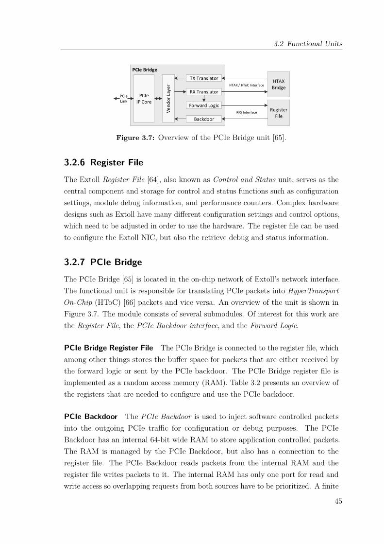
3.2 Functional Units
PCIe Bridge
HTAX Bridge
PCIe IP Core
Ve
nd
or
Laye
r
TX Translator
Backdoor
PCIeLink
RegisterFile
RX Translator
Forward Logic
HTAX / HToC Interface
RFS Interface
Figure 3.7: Overview of the PCIe Bridge unit [65].
3.2.6 Register File
The Extoll Register File [64], also known as Control and Status unit, serves as thecentral component and storage for control and status functions such as configurationsettings, module debug information, and performance counters. Complex hardwaredesigns such as Extoll have many different configuration settings and control options,which need to be adjusted in order to use the hardware. The register file can be usedto configure the Extoll NIC, but also the retrieve debug and status information.
3.2.7 PCIe Bridge
The PCIe Bridge [65] is located in the on-chip network of Extoll’s network interface.The functional unit is responsible for translating PCIe packets into HyperTransportOn-Chip (HToC) [66] packets and vice versa. An overview of the unit is shown inFigure 3.7. The module consists of several submodules. Of interest for this work arethe Register File, the PCIe Backdoor interface, and the Forward Logic.
PCIe Bridge Register File The PCIe Bridge is connected to the register file, whichamong other things stores the buffer space for packets that are either received bythe forward logic or sent by the PCIe backdoor. The PCIe Bridge register file isimplemented as a random access memory (RAM). Table 3.2 presents an overview ofthe registers that are needed to configure and use the PCIe backdoor.
PCIe Backdoor The PCIe Backdoor is used to inject software controlled packetsinto the outgoing PCIe traffic for configuration or debug purposes. The PCIeBackdoor has an internal 64-bit wide RAM to store application controlled packets.The RAM is managed by the PCIe Backdoor, but also has a connection to theregister file. The PCIe Backdoor reads packets from the internal RAM and theregister file writes packets to it. The internal RAM has only one port for read andwrite access so overlapping requests from both sources have to be prioritized. A finite
45
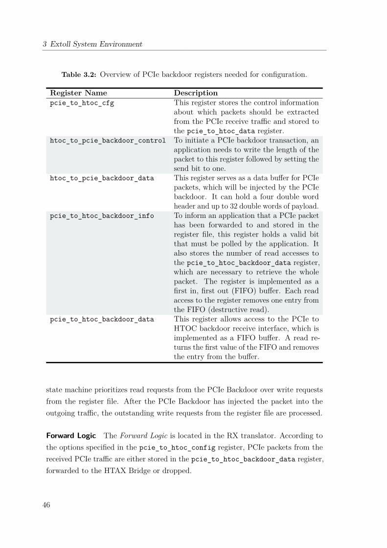
3 Extoll System Environment
Table 3.2: Overview of PCIe backdoor registers needed for configuration.
Register Name Descriptionpcie_to_htoc_cfg This register stores the control information
about which packets should be extractedfrom the PCIe receive traffic and stored tothe pcie_to_htoc_data register.
htoc_to_pcie_backdoor_control To initiate a PCIe backdoor transaction, anapplication needs to write the length of thepacket to this register followed by setting thesend bit to one.
htoc_to_pcie_backdoor_data This register serves as a data buffer for PCIepackets, which will be injected by the PCIebackdoor. It can hold a four double wordheader and up to 32 double words of payload.
pcie_to_htoc_backdoor_info To inform an application that a PCIe packethas been forwarded to and stored in theregister file, this register holds a valid bitthat must be polled by the application. Italso stores the number of read accesses tothe pcie_to_htoc_backdoor_data register,which are necessary to retrieve the wholepacket. The register is implemented as afirst in, first out (FIFO) buffer. Each readaccess to the register removes one entry fromthe FIFO (destructive read).
pcie_to_htoc_backdoor_data This register allows access to the PCIe toHTOC backdoor receive interface, which isimplemented as a FIFO buffer. A read re-turns the first value of the FIFO and removesthe entry from the buffer.
state machine prioritizes read requests from the PCIe Backdoor over write requestsfrom the register file. After the PCIe Backdoor has injected the packet into theoutgoing traffic, the outstanding write requests from the register file are processed.
Forward Logic The Forward Logic is located in the RX translator. According tothe options specified in the pcie_to_htoc_config register, PCIe packets from thereceived PCIe traffic are either stored in the pcie_to_htoc_backdoor_data register,forwarded to the HTAX Bridge or dropped.
46
3.3 Software Environment
Basedriver
ATU
Driver
User Application
libVELO
Middleware & Library
(i.e., MPI, GasNET)
Extoll Hardware
VELO RMARegister
FileATU
User
Space
NIC
Kernel
Space
Application Management
libRMA
RF
Access
RMA
Driver
VELO
Driver
EMP
PCIe
Config-
space
libSMFU
SMFU
Driver
SMFU
Kernel
API
Figure 3.8: Overview of the Extoll software environment.
3.3 Software EnvironmentThe Extoll software environment comprises of several different layers, as depictedin Figure 3.8. The following sections describe the kernel and user space softwarecomponents, but also introduce the Extoll management program.
3.3.1 Kernel Space
The kernel space side of the software stack consists of several kernel modules. extolldrvis the base driver, which controls the hardware and initializes the device. The othermodules are built on top of it to provide different functionality and access to thefunctional units.velodrv implements the kernel interfaces used by libVELO and the kernel API.
rmadrv implements the kernel interfaces used by libRMA and the kernel API.extoll_rf provides the sysfs interface to the register file. smfudrv provides access tothe SMFU functionality and resources. The kernel API module, as indicated by thename, provides a kernel API, which exports functions for RMA and VELO to beaccessed by other kernel code and modules.
47
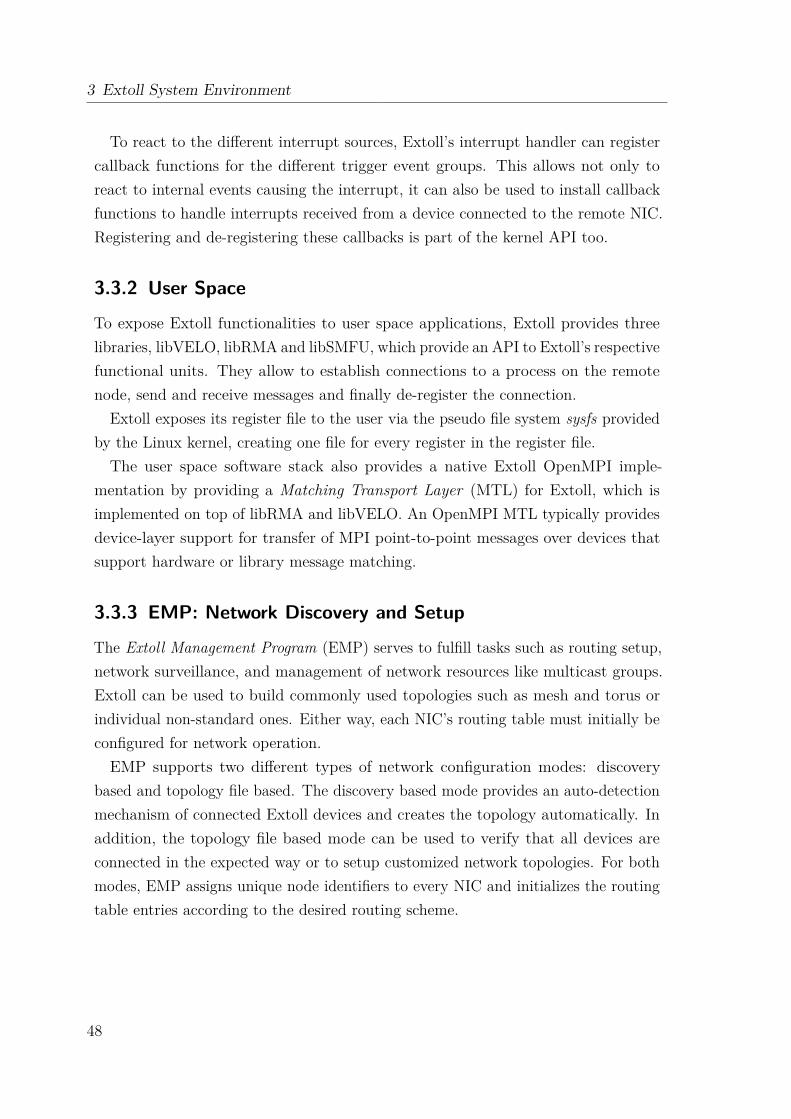
3 Extoll System Environment
To react to the different interrupt sources, Extoll’s interrupt handler can registercallback functions for the different trigger event groups. This allows not only toreact to internal events causing the interrupt, it can also be used to install callbackfunctions to handle interrupts received from a device connected to the remote NIC.Registering and de-registering these callbacks is part of the kernel API too.
3.3.2 User Space
To expose Extoll functionalities to user space applications, Extoll provides threelibraries, libVELO, libRMA and libSMFU, which provide an API to Extoll’s respectivefunctional units. They allow to establish connections to a process on the remotenode, send and receive messages and finally de-register the connection.
Extoll exposes its register file to the user via the pseudo file system sysfs providedby the Linux kernel, creating one file for every register in the register file.The user space software stack also provides a native Extoll OpenMPI imple-
mentation by providing a Matching Transport Layer (MTL) for Extoll, which isimplemented on top of libRMA and libVELO. An OpenMPI MTL typically providesdevice-layer support for transfer of MPI point-to-point messages over devices thatsupport hardware or library message matching.
3.3.3 EMP: Network Discovery and Setup
The Extoll Management Program (EMP) serves to fulfill tasks such as routing setup,network surveillance, and management of network resources like multicast groups.Extoll can be used to build commonly used topologies such as mesh and torus orindividual non-standard ones. Either way, each NIC’s routing table must initially beconfigured for network operation.EMP supports two different types of network configuration modes: discovery
based and topology file based. The discovery based mode provides an auto-detectionmechanism of connected Extoll devices and creates the topology automatically. Inaddition, the topology file based mode can be used to verify that all devices areconnected in the expected way or to setup customized network topologies. For bothmodes, EMP assigns unique node identifiers to every NIC and initializes the routingtable entries according to the desired routing scheme.
48
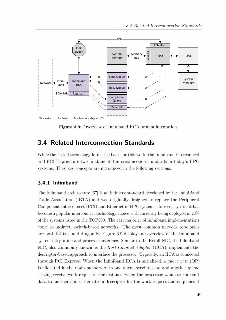
3.4 Related Interconnection Standards
Send Queue
Recv Queue
Completion Queue
Doorbell
PCIe Root
CPU
Caches
CPU
System Memory
PCIeSwitch
InfiniBandHCANetwork
Registers
PCIe
MemoryBus
Infini-Band
PCIe BAR
RR
W
M
W
W
R
W
W = Write R = Read M = Memory Mapped I/O
SystemMemory
Figure 3.9: Overview of Infiniband HCA system integration.
3.4 Related Interconnection StandardsWhile the Extoll technology forms the basis for this work, the Infiniband interconnectand PCI Express are two fundamental interconnection standards in today’s HPCsystems. They key concepts are introduced in the following sections.
3.4.1 Infiniband
The Infiniband architecture [67] is an industry standard developed by the InfiniBandTrade Association (IBTA) and was originally designed to replace the PeripheralComponent Interconnect (PCI) and Ethernet in HPC systems. In recent years, it hasbecome a popular interconnect technology choice with currently being deployed in 28%of the systems listed in the TOP500. The vast majority of Infiniband implementationscome as indirect, switch-based networks. The most common network topologiesare both fat tree and dragonfly. Figure 3.9 displays an overview of the Infinibandsystem integration and processor interface. Similar to the Extoll NIC, the InfinibandNIC, also commonly known as the Host Channel Adapter (HCA), implements thedescriptor-based approach to interface the processor. Typically, an HCA is connectedthrough PCI Express. When the Infiniband HCA is initialized, a queue pair (QP)is allocated in the main memory with one queue serving send and another queueserving receive work requests. For instance, when the processor wants to transmitdata to another node, it creates a descriptor for the work request and enqueues it
49
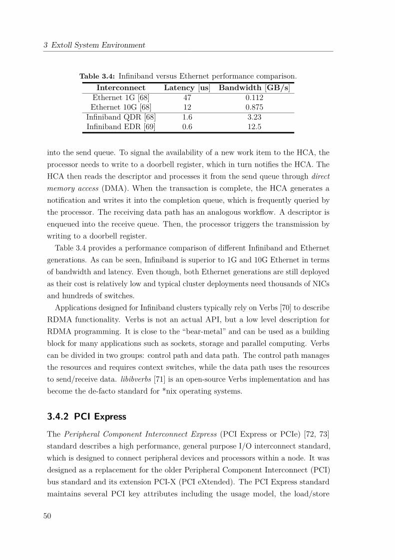
3 Extoll System Environment
Table 3.4: Infiniband versus Ethernet performance comparison.Interconnect Latency [us] Bandwidth [GB/s]
Ethernet 1G [68] 47 0.112Ethernet 10G [68] 12 0.875
Infiniband QDR [68] 1.6 3.23Infiniband EDR [69] 0.6 12.5
into the send queue. To signal the availability of a new work item to the HCA, theprocessor needs to write to a doorbell register, which in turn notifies the HCA. TheHCA then reads the descriptor and processes it from the send queue through directmemory access (DMA). When the transaction is complete, the HCA generates anotification and writes it into the completion queue, which is frequently queried bythe processor. The receiving data path has an analogous workflow. A descriptor isenqueued into the receive queue. Then, the processor triggers the transmission bywriting to a doorbell register.
Table 3.4 provides a performance comparison of different Infiniband and Ethernetgenerations. As can be seen, Infiniband is superior to 1G and 10G Ethernet in termsof bandwidth and latency. Even though, both Ethernet generations are still deployedas their cost is relatively low and typical cluster deployments need thousands of NICsand hundreds of switches.
Applications designed for Infiniband clusters typically rely on Verbs [70] to describeRDMA functionality. Verbs is not an actual API, but a low level description forRDMA programming. It is close to the “bear-metal” and can be used as a buildingblock for many applications such as sockets, storage and parallel computing. Verbscan be divided in two groups: control path and data path. The control path managesthe resources and requires context switches, while the data path uses the resourcesto send/receive data. libibverbs [71] is an open-source Verbs implementation and hasbecome the de-facto standard for *nix operating systems.
3.4.2 PCI Express
The Peripheral Component Interconnect Express (PCI Express or PCIe) [72, 73]standard describes a high performance, general purpose I/O interconnect standard,which is designed to connect peripheral devices and processors within a node. It wasdesigned as a replacement for the older Peripheral Component Interconnect (PCI)bus standard and its extension PCI-X (PCI eXtended). The PCI Express standardmaintains several PCI key attributes including the usage model, the load/store
50
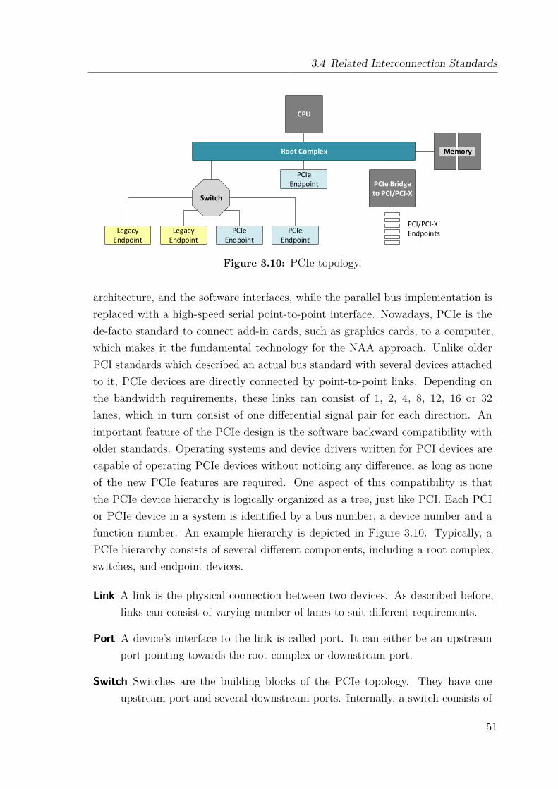
3.4 Related Interconnection Standards
Root Complex
PCIe Endpoint PCIe Bridge
to PCI/PCI-X Switch
PCIe Endpoint
PCIe Endpoint
Legacy Endpoint
Legacy Endpoint
CPU
PCI/PCI-XEndpoints
Memory
Figure 3.10: PCIe topology.
architecture, and the software interfaces, while the parallel bus implementation isreplaced with a high-speed serial point-to-point interface. Nowadays, PCIe is thede-facto standard to connect add-in cards, such as graphics cards, to a computer,which makes it the fundamental technology for the NAA approach. Unlike olderPCI standards which described an actual bus standard with several devices attachedto it, PCIe devices are directly connected by point-to-point links. Depending onthe bandwidth requirements, these links can consist of 1, 2, 4, 8, 12, 16 or 32lanes, which in turn consist of one differential signal pair for each direction. Animportant feature of the PCIe design is the software backward compatibility witholder standards. Operating systems and device drivers written for PCI devices arecapable of operating PCIe devices without noticing any difference, as long as noneof the new PCIe features are required. One aspect of this compatibility is thatthe PCIe device hierarchy is logically organized as a tree, just like PCI. Each PCIor PCIe device in a system is identified by a bus number, a device number and afunction number. An example hierarchy is depicted in Figure 3.10. Typically, aPCIe hierarchy consists of several different components, including a root complex,switches, and endpoint devices.
Link A link is the physical connection between two devices. As described before,links can consist of varying number of lanes to suit different requirements.
Port A device’s interface to the link is called port. It can either be an upstreamport pointing towards the root complex or downstream port.
Switch Switches are the building blocks of the PCIe topology. They have oneupstream port and several downstream ports. Internally, a switch consists of
51
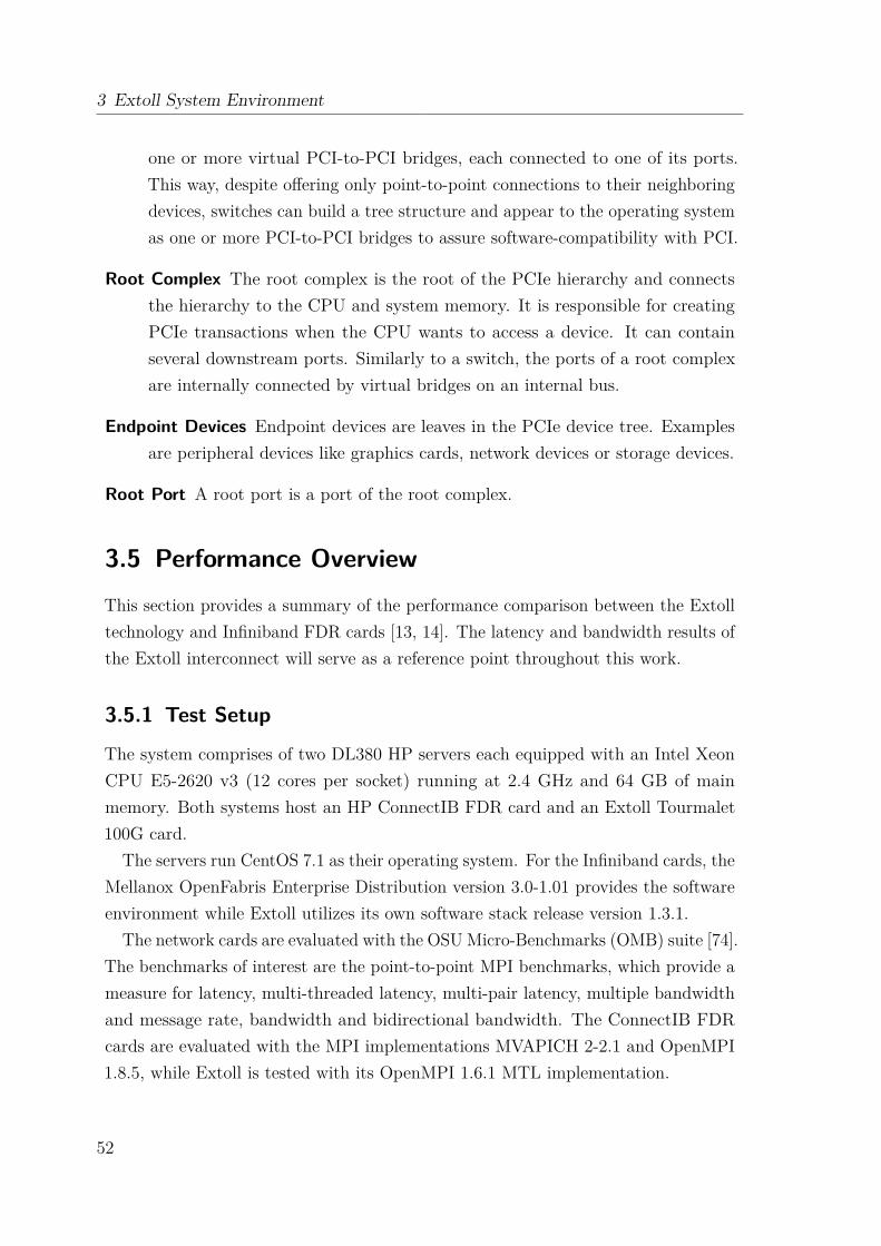
3 Extoll System Environment
one or more virtual PCI-to-PCI bridges, each connected to one of its ports.This way, despite offering only point-to-point connections to their neighboringdevices, switches can build a tree structure and appear to the operating systemas one or more PCI-to-PCI bridges to assure software-compatibility with PCI.
Root Complex The root complex is the root of the PCIe hierarchy and connectsthe hierarchy to the CPU and system memory. It is responsible for creatingPCIe transactions when the CPU wants to access a device. It can containseveral downstream ports. Similarly to a switch, the ports of a root complexare internally connected by virtual bridges on an internal bus.
Endpoint Devices Endpoint devices are leaves in the PCIe device tree. Examplesare peripheral devices like graphics cards, network devices or storage devices.
Root Port A root port is a port of the root complex.
3.5 Performance OverviewThis section provides a summary of the performance comparison between the Extolltechnology and Infiniband FDR cards [13, 14]. The latency and bandwidth results ofthe Extoll interconnect will serve as a reference point throughout this work.
3.5.1 Test Setup
The system comprises of two DL380 HP servers each equipped with an Intel XeonCPU E5-2620 v3 (12 cores per socket) running at 2.4 GHz and 64 GB of mainmemory. Both systems host an HP ConnectIB FDR card and an Extoll Tourmalet100G card.
The servers run CentOS 7.1 as their operating system. For the Infiniband cards, theMellanox OpenFabris Enterprise Distribution version 3.0-1.01 provides the softwareenvironment while Extoll utilizes its own software stack release version 1.3.1.
The network cards are evaluated with the OSU Micro-Benchmarks (OMB) suite [74].The benchmarks of interest are the point-to-point MPI benchmarks, which provide ameasure for latency, multi-threaded latency, multi-pair latency, multiple bandwidthand message rate, bandwidth and bidirectional bandwidth. The ConnectIB FDRcards are evaluated with the MPI implementations MVAPICH 2-2.1 and OpenMPI1.8.5, while Extoll is tested with its OpenMPI 1.6.1 MTL implementation.
52
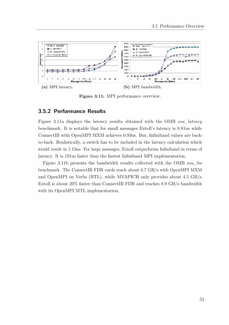
3.5 Performance Overview
(a) MPI latency. (b) MPI bandwidth.
Figure 3.11: MPI performance overview.
3.5.2 Performance Results
Figure 3.11a displays the latency results obtained with the OMB osu_latencybenchmark. It is notable that for small messages Extoll’s latency is 0.81us whileConnectIB with OpenMPI MXM achieves 0.93us. But, Infiniband values are back-to-back. Realistically, a switch has to be included in the latency calculation whichwould result in 1.13us. For large messages, Extoll outperforms Infiniband in terms oflatency. It is 191us faster than the fastest Infiniband MPI implementation.Figure 3.11b presents the bandwidth results collected with the OMB osu_bw
benchmark. The ConnectIB FDR cards reach about 6.7 GB/s with OpenMPI MXMand OpenMPI on Verbs (BTL), while MVAPICH only provides about 4.5 GB/s.Extoll is about 20% faster than ConnectIB FDR and reaches 8.9 GB/s bandwidthwith its OpenMPI MTL implementation.
53


Ch
ap
te
r
4Network-Attached Accelerators
The trend in supercomputing development shows that every decade the computingpower of HPC systems increases by a factor of ten. With the upcoming Exascalechallenge, the design of such systems poses multiple challenges, including powerdemands and consumption, the gap between compute capabilities and I/O bandwidth(also known as the memory wall), and higher hardware failure rates as the systemsgrow in scale. Another challenge is imposed by the extreme concurrency and efficientutilization of the heterogeneous computing resources. By adding accelerator devicessuch as many-core processors (coprocessors) or general purpose graphics processingunits (GPGPUs) to a cluster, the overall energy and cost efficiency can be improved.They offer an unprecedented computational power per watt (Flop/s per Watt). Yet,the current generation of accelerator devices requires a host CPU to configure andoperate them, which limits the number of accelerators per host and results in a staticarrangement of hardware resources.
This chapter introduces the Network-Attached Accelerator (NAA) approach, whichmoves accelerators into a “stand-alone” cluster connected through the Extoll inter-connect. The novel communication architecture enables the direct communicationbetween accelerators through a high-speed network without any host interactions andan optimal application-to-compute-resources mapping, e.g., through the extensionof the batch system capabilities [75]. The architectural idea is derived from theDynamical Exascale Entry Platform (DEEP) project [76]. This chapter summarizesand extents various contributions to international conferences [9, 11, 10].The remainder of the chapter is structured as follows. First, some background
information about the DEEP project series and the PCI Express subsystem are
55

4 Network-Attached Accelerators
0
20
40
60
80
100
120
Nu
mb
er o
f A
ccel
era
tors
TOP500 Release (Year/Month)
PEZY
AMD/ATI GPU
Intel MIC
NVIDIA GPU
Figure 4.1: Accelerator development trend in the TOP500 since 2011.
presented followed by a summary of related work. Afterwards, the design objectivesand strategy of the NAA software environments are presented and implemented fortwo different system setups: the DEEP booster and the VPCI project. For bothimplementations, an initial performance evaluation is presented.
4.1 MotivationTo satisfy the ever growing computational demands, many technologies and con-cepts have been developed and explored. The common scheme is to maximize theexploitable parallelism, which requires more computational power and high-speedinternode communication in a large-scale system. Another important metric forefficient parallelization is scalability. A scalable system adapts well to increasinglevels of parallelization without introducing significant bottlenecks. Considering thisdevelopment cycle, it is questionable whether CPUs will be competitive in the future.Accelerator devices such as GPGPUs or coprocessors offer an unprecedented compu-tational power per watt, while being optimized for massively parallel computation.The use of accelerator devices can significantly increase the system performance whileproviding energy efficiency. Therefore, it comes as no surprise that accelerators havebeen widely adopted in HPC systems and are subject to ongoing research efforts.Many systems in the TOP500 [4] comprise of heterogeneous architectures, which
combine multi-core CPU nodes with a small number of accelerator devices directlyplugged into the node. A total of 110 systems in the current TOP500 list (June2018) are using either coprocessor or GPU technology, including Summit, Tianhe-2A,Titan, and Piz Daint in the TOP10. Figure 4.1 displays the development trendsin the TOP500 since 2011. However for accelerator devices to operate efficiently,sufficient utilization is important, which in turn requires fast network communication.
56
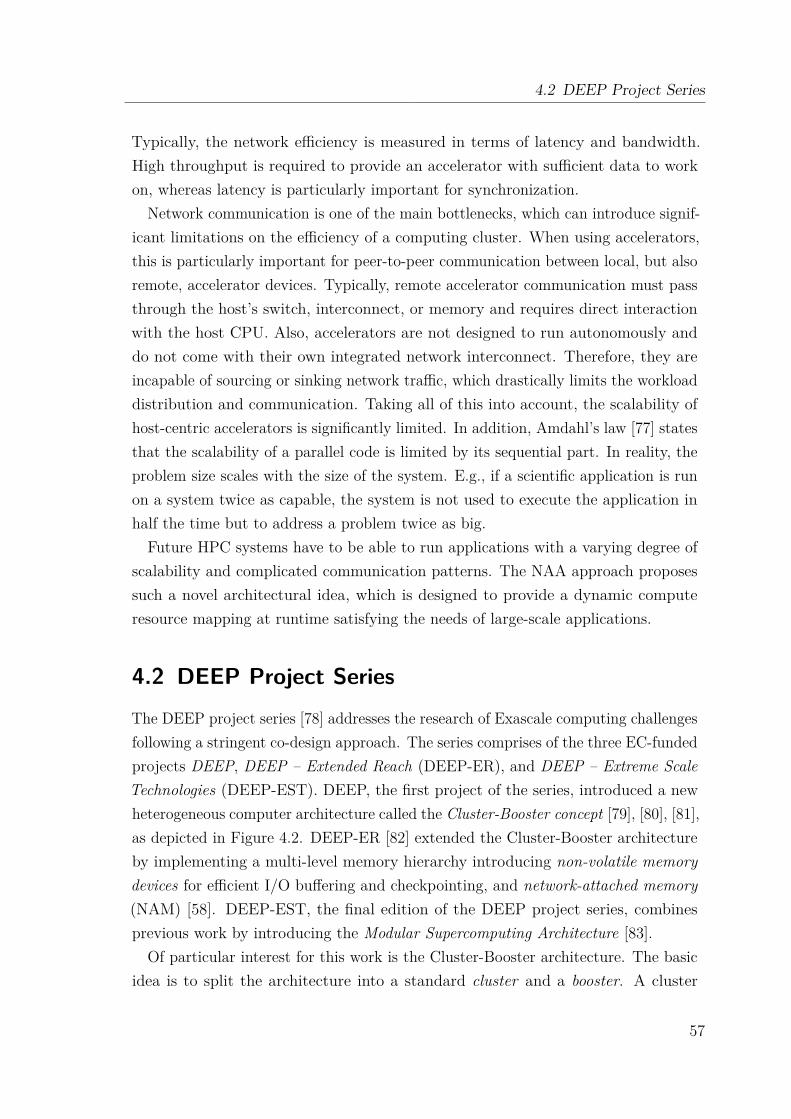
4.2 DEEP Project Series
Typically, the network efficiency is measured in terms of latency and bandwidth.High throughput is required to provide an accelerator with sufficient data to workon, whereas latency is particularly important for synchronization.
Network communication is one of the main bottlenecks, which can introduce signif-icant limitations on the efficiency of a computing cluster. When using accelerators,this is particularly important for peer-to-peer communication between local, but alsoremote, accelerator devices. Typically, remote accelerator communication must passthrough the host’s switch, interconnect, or memory and requires direct interactionwith the host CPU. Also, accelerators are not designed to run autonomously anddo not come with their own integrated network interconnect. Therefore, they areincapable of sourcing or sinking network traffic, which drastically limits the workloaddistribution and communication. Taking all of this into account, the scalability ofhost-centric accelerators is significantly limited. In addition, Amdahl’s law [77] statesthat the scalability of a parallel code is limited by its sequential part. In reality, theproblem size scales with the size of the system. E.g., if a scientific application is runon a system twice as capable, the system is not used to execute the application inhalf the time but to address a problem twice as big.
Future HPC systems have to be able to run applications with a varying degree ofscalability and complicated communication patterns. The NAA approach proposessuch a novel architectural idea, which is designed to provide a dynamic computeresource mapping at runtime satisfying the needs of large-scale applications.
4.2 DEEP Project SeriesThe DEEP project series [78] addresses the research of Exascale computing challengesfollowing a stringent co-design approach. The series comprises of the three EC-fundedprojects DEEP, DEEP – Extended Reach (DEEP-ER), and DEEP – Extreme ScaleTechnologies (DEEP-EST). DEEP, the first project of the series, introduced a newheterogeneous computer architecture called the Cluster-Booster concept [79], [80], [81],as depicted in Figure 4.2. DEEP-ER [82] extended the Cluster-Booster architectureby implementing a multi-level memory hierarchy introducing non-volatile memorydevices for efficient I/O buffering and checkpointing, and network-attached memory(NAM) [58]. DEEP-EST, the final edition of the DEEP project series, combinesprevious work by introducing the Modular Supercomputing Architecture [83].
Of particular interest for this work is the Cluster-Booster architecture. The basicidea is to split the architecture into a standard cluster and a booster. A cluster
57
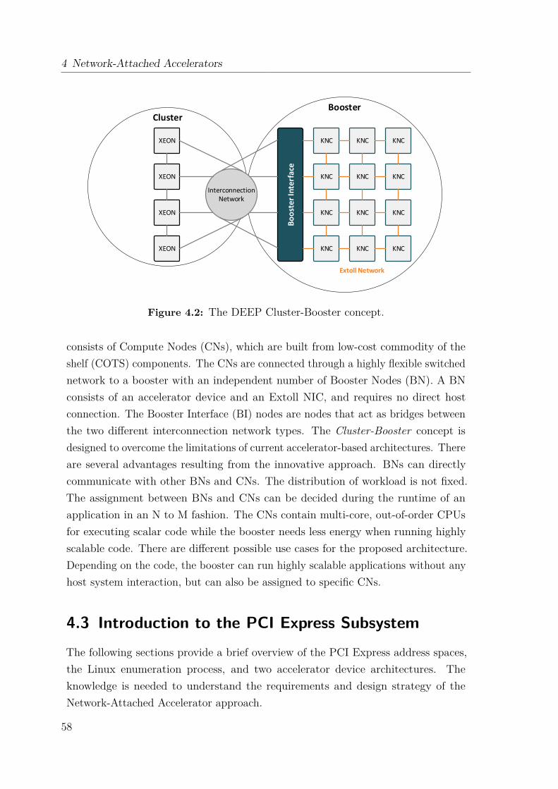
4 Network-Attached Accelerators
XEON
XEON
XEON
XEON
KNC
KNC
KNC
KNC
KNC
KNC
KNC
KNC
KNC
KNC
KNC
KNC
Bo
ost
er
Inte
rfa
ce
Interconnection Network
ClusterBooster
Extoll Network
Figure 4.2: The DEEP Cluster-Booster concept.
consists of Compute Nodes (CNs), which are built from low-cost commodity of theshelf (COTS) components. The CNs are connected through a highly flexible switchednetwork to a booster with an independent number of Booster Nodes (BN). A BNconsists of an accelerator device and an Extoll NIC, and requires no direct hostconnection. The Booster Interface (BI) nodes are nodes that act as bridges betweenthe two different interconnection network types. The Cluster-Booster concept isdesigned to overcome the limitations of current accelerator-based architectures. Thereare several advantages resulting from the innovative approach. BNs can directlycommunicate with other BNs and CNs. The distribution of workload is not fixed.The assignment between BNs and CNs can be decided during the runtime of anapplication in an N to M fashion. The CNs contain multi-core, out-of-order CPUsfor executing scalar code while the booster needs less energy when running highlyscalable code. There are different possible use cases for the proposed architecture.Depending on the code, the booster can run highly scalable applications without anyhost system interaction, but can also be assigned to specific CNs.
4.3 Introduction to the PCI Express SubsystemThe following sections provide a brief overview of the PCI Express address spaces,the Linux enumeration process, and two accelerator device architectures. Theknowledge is needed to understand the requirements and design strategy of theNetwork-Attached Accelerator approach.
58
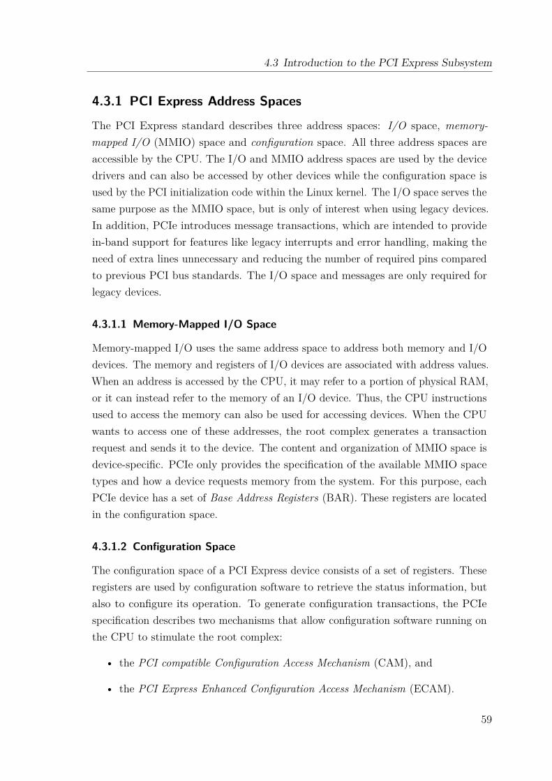
4.3 Introduction to the PCI Express Subsystem
4.3.1 PCI Express Address Spaces
The PCI Express standard describes three address spaces: I/O space, memory-mapped I/O (MMIO) space and configuration space. All three address spaces areaccessible by the CPU. The I/O and MMIO address spaces are used by the devicedrivers and can also be accessed by other devices while the configuration space isused by the PCI initialization code within the Linux kernel. The I/O space serves thesame purpose as the MMIO space, but is only of interest when using legacy devices.In addition, PCIe introduces message transactions, which are intended to providein-band support for features like legacy interrupts and error handling, making theneed of extra lines unnecessary and reducing the number of required pins comparedto previous PCI bus standards. The I/O space and messages are only required forlegacy devices.
4.3.1.1 Memory-Mapped I/O Space
Memory-mapped I/O uses the same address space to address both memory and I/Odevices. The memory and registers of I/O devices are associated with address values.When an address is accessed by the CPU, it may refer to a portion of physical RAM,or it can instead refer to the memory of an I/O device. Thus, the CPU instructionsused to access the memory can also be used for accessing devices. When the CPUwants to access one of these addresses, the root complex generates a transactionrequest and sends it to the device. The content and organization of MMIO space isdevice-specific. PCIe only provides the specification of the available MMIO spacetypes and how a device requests memory from the system. For this purpose, eachPCIe device has a set of Base Address Registers (BAR). These registers are locatedin the configuration space.
4.3.1.2 Configuration Space
The configuration space of a PCI Express device consists of a set of registers. Theseregisters are used by configuration software to retrieve the status information, butalso to configure its operation. To generate configuration transactions, the PCIespecification describes two mechanisms that allow configuration software running onthe CPU to stimulate the root complex:
• the PCI compatible Configuration Access Mechanism (CAM), and
• the PCI Express Enhanced Configuration Access Mechanism (ECAM).
59

4 Network-Attached Accelerators
Base Address 0
Base Address 4
Expansion ROM Base Address
Base Address 1
Base Address 2
Base Address 3
Base Address 5
CardBus CIS Pointer
Reserved
Subsystem Vendor ID
Subsystem Device ID
Device ID Vendor ID
StatusRegister
CommandRegister
IRQLine
IRQPin
MinGNT
MaxLat
Capab.List
Revi-sion IDCache Line
LatencyTimer
HeaderType
BIST
Class Code
00
0
Reserved
01
02
03
04
05
06
07
08
09
10
11
12
13
14
15
123
Double WordNumber
(in decimal)Byte
Required configuration registers
64-BytesPCI Configuration
Header Space
192-Bytes CapabilityStructures
256-Byte Configuration Register Space (per Function)
Type 0 Header
Base Address 0
Expansion ROM Base Address
Base Address 1
PrefetchableMemory Limit
Prefetchable LimitUpper 32 Bits
I/O BaseUpper 16 Bits
I/O LimitUpper 16 Bits
Device ID Vendor ID
StatusRegister
CommandRegister
IRQLine
IRQPin
Bridge Control
Capab.List
Revi-sion IDCache Line
LatencyTimer
HeaderType
BIST
Class Code
00
0
Reserved
01
02
03
04
05
06
07
08
09
10
11
12
13
14
15
123
Double WordNumber
(in decimal)Byte
Prefetchable BaseUpper 32 Bits
PrefetchableMemory Base
Memory Limit Memory Base
I/OBase
I/OLimit
Secondary Status
Secondary Latency Timer
Subordi-nate Bus Number
Secondary Bus
Number
Primary Bus
Number
Type 1 Header
Figure 4.3: PCI Express configuration space header types [73].
Historically, the PCI configuration space was limited to 256 bytes, but has beenextended to 4 KB for PCIe. Therefore, the first 256 bytes are referred to as PCI-compatible space, the rest builds the PCI Express extended configuration space. Thefirst 64 bytes of the PCI-compatible space contain the PCI configuration header,which has a standardized set of registers, whereas the rest contains device-specificinformation and the capabilities list.
Header Types PCIe devices can be distinguished in bridge devices and endpointdevices. To serve their different purposes, they have different configuration spaceheaders: header type 0 for endpoint devices and header type 1 for bridges. Figure 4.3provides on overview of the header types.
Base Address Registers BARs contain the start addresses of the device’s MMIOwindows. Every endpoint device contains six 32-bit wide BARs, which can eitherbe MMIO or I/O regions. Alternatively, two registers can be combined to address
60
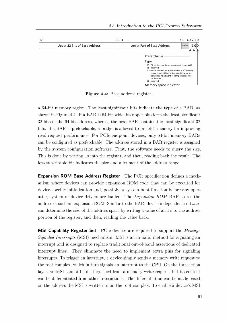
4.3 Introduction to the PCI Express Subsystem
Upper 32 Bits of Base Address Lower Part of Base Address 01 0reserved
03 2 16 47313263
PrefetchableType
00 – 32 bit decoder, locate anywhere in lower 4GB.01 – reserved.10 – 64-bit decoder, locate anywhere in 264 memory
space (implies this register is 64-bits wide andconsumes next dword of config space as wellas this one).
11 – reserved.
Memory space indicator
Figure 4.4: Base address register.
a 64-bit memory region. The least significant bits indicate the type of a BAR, asshown in Figure 4.4. If a BAR is 64-bit wide, its upper bits form the least significant32 bits of the 64 bit address, whereas the next BAR contains the most significant 32bits. If a BAR is prefetchable, a bridge is allowed to prefetch memory for improvingread request performance. For PCIe endpoint devices, only 64-bit memory BARscan be configured as prefetchable. The address stored in a BAR register is assignedby the system configuration software. First, the software needs to query the size.This is done by writing 1s into the register, and then, reading back the result. Thelowest writable bit indicates the size and alignment of the address range.
Expansion ROM Base Address Register The PCIe specification defines a mech-anism where devices can provide expansion ROM code that can be executed fordevice-specific initialization and, possibly, a system boot function before any oper-ating system or device drivers are loaded. The Expansion ROM BAR stores theaddress of such an expansion ROM. Similar to the BAR, device independent softwarecan determine the size of the address space by writing a value of all 1’s to the addressportion of the register, and then, reading the value back.
MSI Capability Register Set PCIe devices are required to support the MessageSignaled Interrupts (MSI) mechanism. MSI is an in-band method for signaling aninterrupt and is designed to replace traditional out-of-band assertions of dedicatedinterrupt lines. They eliminate the need to implement extra pins for signalinginterrupts. To trigger an interrupt, a device simply sends a memory write request tothe root complex, which in turn signals an interrupt to the CPU. On the transactionlayer, an MSI cannot be distinguished from a memory write request, but its contentcan be differentiated from other transactions. The differentiation can be made basedon the address the MSI is written to on the root complex. To enable a device’s MSI
61

4 Network-Attached Accelerators
Message Control Register Pointer to Next ID Capability ID = 05h
078151631
Least Significant 32-bits of Message Address Register
Most Significant 32-bits of Message Address Register
0 0
Message Data Register
Dword 0
Dword 1
Dword 2
Dword 3
reserved
24
Figure 4.5: MSI Capability register set for 64-bit address size.
capability, the target address, the payload written to the target address, and thenumber of messages needs to be configured . The configuration is stored in the MSIcapability register set, which is located in the PCIe configuration space. Figure 4.5shows such a register set. There are two formats defined by the PCIe specification,one for 64-bit and one for 32-bit addresses. The description focuses on the 64-bitformat.
The Message Address Register comprises of two 32-bit values, which specifies theDWORD-aligned address for the MSI memory write transaction. The Message DataRegister configures the payload of the MSI memory write. The Message ControlRegister indicates the function’s capabilities and provides system software controlover MSI. If the MSI enable bit in the message control register is set to 1 by thesystem configuration software, the device is permitted to use MSI.
4.3.2 Linux PCI Express Enumeration
At boot time, the topology of the PCIe device hierarchy is unknown to the operatingsystem. In order to find and configure all connected PCIe devices, the configurationcode, typically the Basic Input/Output System (BIOS) or its successor the UnifiedExtensible Firmware Interface (UEFI), performs a depth-first search until all devicesare discovered. This process is called enumeration. The following steps outline thegeneric steps performed by the enumeration process for a single root complex:
(1) The only bus known at boot time is the primary PCIe bus 0, which is the internalbus inside of the root complex. Each newly discovered bus is consecutivelynumbered by the configuration code.
(2) If the current bus has any devices attached to it, they are initialized andnumbered incrementally starting with 0.
(3) For any device, it is required that the first function number is set to 0. If it isa multi-function device, the remaining functions can have any number between1 and 7, and are not required to be numbered consecutively.
62
4.3 Introduction to the PCI Express Subsystem
Root complex Host bridge
Root port Root port Root port
Bridge Bridge
EndpointEndpoint
bus 0
bus 1
bus 2
bus 3
bus 4
dev 0 dev 1 dev 2
dev 0
dev 0 dev 0dev 1
dev 1
Endpoint
(a) PCIe hierarchy after the Linuxinitialization process.
$ tree /sys/bus/pci/devices
/sys/bus/pci/devices
|--0000:00:00.0 -> …/…/devices/pci0000:00/0000:00:00.0
|--0000:00:01.0 -> …/…/devices/pci0000:00/0000:00:01.0
|--0000:00:02.0 -> …/…/devices/pci0000:00/0000:00:02.0
|--0000:01:00.0 -> …/…/devices/pci0000:00/0000:01:00.0
|--0000:02:00.0 -> …/…/devices/pci0000:00/0000:02:00.0
|--0000:02:01.0 -> …/…/devices/pci0000:00/0000:02:01.0
|--0000:03:00.0 -> …/…/devices/pci0000:00/0000:03:00.0
(b) Output of the command line tool treefor the example hierarchy.
Figure 4.6: Linux PCI Express enumeration example.
(4) When a bridge device is discovered, the search continues recursively on the busconnected to its downstream port and proceeds with step 2.
Figure 4.6a displays an example hierarchy configured by the described enumerationprocess, while Figure 4.6b presents the output of the command line tool tree for theexample hierarchy. A detailed enumeration process example can be found in thebook PCI Express System Architecture [73]. As the Linux kernel initializes the PCIesubsystem, it allocates data structures mirroring the real topology of the system.Each PCIe device (also including the bridges) is described by a data structure oftype struct pci_dev and each bus is described by a data structure of type structpci_bus. The result is a tree structure of buses each of which have a number of childPCIe devices attached to it. As a bus can only be reached using a bridge (except theprimary PCIe bus, bus 0), each PCI bus structure contains a pointer to the parentdevice that it is accessed through. That PCIe device is a child of the PCIe bus’sparent bus. With kernel version 2.6, the Linux kernel developers have introduceda unified new device model to cope with increasing requirements and capabilitiesof modern hardware, which is commonly referred to as the Linux Device Model [84,chapter 14]. The Linux kernel utilizes the tree-like data structure describing the PCItopology and exposes it to the user through the Linux device model, e.g., throughthe sysfs virtual file system.
As described by Rusling [85], the Linux PCI (Express) initialization code is brokeninto three logical parts: the PCI device driver, the PCI BIOS, and the PCI fixup.
PCI Device Driver The PCI device driver, not to be confused with a real devicedriver, is a function of the operating system called at system initialization time.
63
4 Network-Attached Accelerators
The PCI initialization code performs the actual enumeration process and locatesall devices and bridges in the system. It utilizes the PCI BIOS code to determinewhether a slot of the currently scanned bus is occupied. If a PCI slot is occupied,it allocates the corresponding data structure and links it into a double-linked list,which describes the topology of the PCI Express system.
PCI BIOS The PCI BIOS provides a software layer for the services described inthe PCI BIOS specification. The functions are a series of standard routines whichare common across all platforms. They allow the CPU controlled access to all of thePCIe address spaces. Only Linux kernel code and device drivers may use them.
PCI Fixup The system-specific PCI fix-up code tidies up loose ends of the initial-ization. For Intel-based systems, the system BIOS, which ran at boot time, hasalready fully configured the system. This leaves Linux with little to do other thanmap that configuration. For non-Intel based systems, further configuration is needed.
4.3.3 PCI Express Expansion Cards
The PCI Express standard can be employed on different interconnect levels in thesystem, e.g., as a motherboard-level interconnect, a passive backplane interconnect,or as an expansion card interface for add-in boards. The primary purpose ofan expansion card is to provide or expand the features of a computing system.Accelerator devices are typically implemented as expansion cards. In the following,two popular accelerator device technologies are introduced, which rely on the PCIExpress standard.
4.3.3.1 Intel Many Integrated Cores Architecture
The Intel Many Integrated Cores (MIC) architecture [86] is a coprocessor technologydeveloped by Intel and commonly known as Intel Xeon Phi. Besides GPUs, it is oneof the most popular accelerator choices in today’s HPC systems. Figure 4.7 presentsa simplified architecture diagram of an Intel Xeon Phi coprocessor of the KnightsCorner generation. The Intel Xeon Phi provides up to 61 multi-threaded cores, eachwith its own private L2 cache. The global distributed tag directory TD is used tofacilitate cache coherency. The GDDR5 device memory can be accessed throughfour memory controllers. The host interface is PCI Express. All components areconnected through a ring interconnect.
64

4.3 Introduction to the PCI Express Subsystem
Core
L2 Cache
TD
Core
L2 Cache
TDC
ore
L2 Ca
che
TD
Co
re
L2 Ca
che
TD
Core
L2 Cache
TD
Core
L2 Cache
TD
Co
re
L2 C
ach
e
TD
Co
re
L2 C
ach
e
TD
GDDR
GD
DR
GDDR
GD
DR
PCIe Client Logic
...
...
...
...
Figure 4.7: Simplified architectural overview of an Intel Xeon Phi Coprocessor.
The Intel MIC architecture is based on x86 and provides its own embeddedLinux operating system, which allows the compilation of kernel modules. The IntelManycore Platform Software Stack (MPSS) is used on a host system to control andoperate connected MICs. It consists of an embedded Linux, a minimally modifiedGCC and driver software for the Intel MICs. The Intel MIC architecture can beused with different programming models for the MPI mode [87].
4.3.3.2 Graphics Processing Units
The NVIDIA GK110 Kepler GPU architecture [88] is a modern graphics processingunit (GPU) architecture representative. The compute cores of a GPU are groupedin Streaming Multiprocessor Units (SMXs). Depending on the implementation, agraphics card relying on the Kepler architecture can comprise of up to 15 SMXs.One SMX comes with 192 CUDA-cores with each of those cores running at a
maximum frequency of 0.71 GHz. They are complemented by double precisionunits – special cores that can handle 64 bit operations –, load/store units (LD/ST),and 32 special function units. The latter provide fast approximations for complexmathematical operations, such as sinus, and trade speed for precision – they need tobe used explicitly by the programmer. Each SMX has 64 KB of on-chip memorywith 16 KB of L1 cache. SMXs share the same L2 cache with a size of 1536 KiB. Six
65
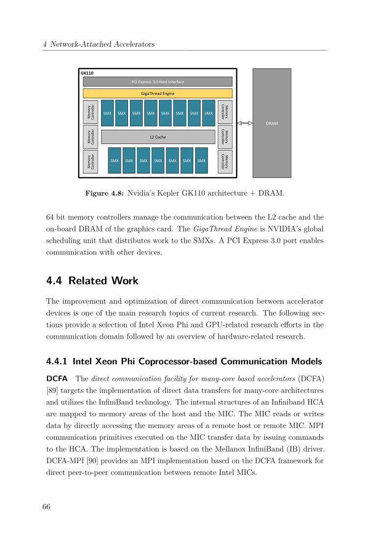
4 Network-Attached Accelerators
Figure 4.8: Nvidia’s Kepler GK110 architecture + DRAM.
64 bit memory controllers manage the communication between the L2 cache and theon-board DRAM of the graphics card. The GigaThread Engine is NVIDIA’s globalscheduling unit that distributes work to the SMXs. A PCI Express 3.0 port enablescommunication with other devices.
4.4 Related WorkThe improvement and optimization of direct communication between acceleratordevices is one of the main research topics of current research. The following sec-tions provide a selection of Intel Xeon Phi and GPU-related research efforts in thecommunication domain followed by an overview of hardware-related research.
4.4.1 Intel Xeon Phi Coprocessor-based Communication Models
DCFA The direct communication facility for many-core based accelerators (DCFA)[89] targets the implementation of direct data transfers for many-core architecturesand utilizes the InfiniBand technology. The internal structures of an Infiniband HCAare mapped to memory areas of the host and the MIC. The MIC reads or writesdata by directly accessing the memory areas of a remote host or remote MIC. MPIcommunication primitives executed on the MIC transfer data by issuing commandsto the HCA. The implementation is based on the Mellanox InfiniBand (IB) driver.DCFA-MPI [90] provides an MPI implementation based on the DCFA framework fordirect peer-to-peer communication between remote Intel MICs.
66

4.4 Related Work
MVAPICH2-MIC MVAPICH2-MIC [91, 92] is a proxy-based communication frame-work using InfiniBand and the symmetric communication interface (SCIF) [87]. Itsgoal is to optimize the collection of communication paths possible in the symmetricmode. The framework provides three different communication designs. DirectIBprovides direct MPI communication through the Coprocessor Communication Link(CCL) driver of the MPSS software stack. The passive proxy handles host-stagedcommunication by setting up staging buffers, but is not directly involved in com-munication between a MIC and a remote MIC. It utilizes the RDMA capability ofSCIF. The active proxy utilizes a dedicated processor core on the host. The one-hopvariant initiates and progresses communication that is staged through the host. SCIFtransfers are initiated on the host. The two-hop variant tries to utilize the highbandwidth channels of the MIC. A MIC-to-remote-MIC transfer is staged to thelocal host then to the remote host and finally to the remote MIC.
HAM and HAM-Offload HAM [93] is implemented as a C++ template library tocreate type-safe heterogeneous active messages (HAM). Active messages can containor reference to code that should be run upon receipt. The main question is how totranslate between handler addresses of heterogeneous binaries with minimal cost.HAM solves the problem by adding a level of indirection that is implemented inpure C++ without any language extensions. The message handler registry actslike a map between keys and handler addresses. Each process has the same set ofkeys, but the handler addresses differ between the individually compiled binariesfor different instruction set architectures. The HAM-offload API [94] completes thefunctionality of HAM with a unified intra- and internode offload API. It providessimilar primitives as other offload programming models. The framework is compilerindependent and provides communication backends for MPI and SCIF.
4.4.2 GPU Virtualization and Communication Techniques
rCUDA rCUDA [95] or remote CUDA is a framework for remote GPU virtualiza-tion in cluster environments. It is fully compatible with the CUDA runtime andtransparently allocates one or more (local or remote) CUDA-enabled GPUs to a singleapplication. rCUDA implements a client-server architecture. On the client side, therCUDA wrapper library intercepts calls to the CUDA runtime and forwards them tothe server side. The rCUDA server daemon, running on each node, offers accelerationservices, receives the forwarded requests and runs the CUDA kernel. The softwareoverhead reduces the performance in comparison to pass-through technologies.
67
4 Network-Attached Accelerators
VirtualCL VirtualCL (VCL) [96] is very similar to rCUDA in its basic concepts.It provides transparent access to accelerator devices on remote nodes and allowsapplications to utilize accelerators on different nodes without requiring the applicationto explicitly split its computations between these different nodes. The applicationitself only runs on a single node and VCL executes OpenCL kernels on other nodeswhen necessary. VCL consists of three components: the VCL library, the brokerand a back-end daemon. The VCL library implements OpenCL and transparentlyaccesses OpenCL devices on the cluster. The broker is a daemon running on eachhost system. It is responsible for monitoring the availability of OpenCL devicesand allocates available devices for a client. It also manages communication betweenapplications and back-ends. The back-end daemon runs on every node that containsusable accelerator devices. It uses vendor-specific OpenCL libraries to run OpenCLkernels on its devices, when requested by a client.
NVIDIA Grid Front-End virtualization, as it is implemented by frameworks likerCUDA or VCL, offers great flexibility and reduces the required hardware whileincreasing the utilization of available devices, but comes with two major disadvantages.First, there is an overhead due to the software involved on client and server side.Second, these frameworks are completely tied to a specific API, like CUDA orOpenCL. To avoid these problems, the NVIDIA Grid technology [97] offers back-endvirtualization for virtual machines. The NVIDIA Kepler GPU design implementsa memory management unit (MMU) and dedicated input buffers for each virtualmachine. This way, different virtual machines can simultaneously use a singleGPU without interfering with each other and without the software overhead of APIinterception. NVIDIA Grid offers high performance without penalizing multiplexing.However, special hardware support is required, restricting this technique to a limitednumber of devices, which can be configured to support such a functionality.
GPUDirect RDMA GPUDirect RDMA [98] is a feature of the CUDA runtimeenvironment and was first introduced in Kepler-class GPUs with CUDA 5.0. Thistechnique provides a direct peer-to-peer data path between two GPUs by mappingthe GPU memory to one of the GPU’s BARs. Other peripheral devices can use thisphysical address to communicate directly with the GPU. Remote RDMA communi-cation is improved by removing unnecessary memory copies between GPU memoryand host memory. But, the ratio between CPUs and GPUs is still fixed.
68

4.5 NAA Software Design
Global GPU Address Space The Global GPU Address Spaces (GGAS) [99] conceptfacilitates direct communication between distributed GPUs while bypassing the CPUsfor all communication and computational tasks. GGAS relies on thread-collectivecommunication, and therefore, maintains the GPUs bulk-synchronous, massivelyparallel programming model. Furthermore, GGAS utilizes a zero-copy techniquefor data movement between distributed GPU memories. This technique relies onoverlapping shared GPU memory segments with SMFU address space of the ExtollNIC building a distributed shared, and therefore global, GPU address space. Themajor limitation of this approach is the requirement that a GPU device needs tosupport GPUDirect RDMA in order to span the global address space.
4.4.3 Hardware-related Research
The discussion about a cluster of accelerators was first introduced with the QPACEsupercomputer [100] prototype. QPACE was a massively parallel quantum chromo-dynamics prototype enhanced by Cell BE processors. In 2010, QPACE was ranked#1 on the Green500 list [101]. Other approaches tend to use PCIe (PeripheralComponent Interconnect Express) as the interconnection network between accel-erators. Non-Transparent Bridges (NTB) [102], [103] connect independent PCIehierarchies of different nodes. Communication between accelerators relies on addresstranslation and table based addressing schemes inside the NTB. This introducesadditional management overhead and does not scale very well. In addition, PCIelacks of some interconnection network features. Advanced Switching Interconnect(ASI) [104] tries to extend the PCIe protocol to support features such as protocoltunneling, routing, and congestion management. The goal of independent scalabil-ity of hosts and accelerators is not achieved with these approaches. Recently, theNVIDIA NVSwitch technology [105] together with the NVIDIA DGX-2 system [106]have been introduced. NVSwitch is an on-node switch with 18 NVLink ports perswitch. Internally, it is a fully connected crossbar. The NVIDIA DGX-2 utilizes theNVSwitch technology to connect 16 NVIDIA Tesla V100 GPUs to one host system.
4.5 NAA Software DesignThe NAA software design is tightly coupled with the architecture of the underlyinghardware. The following sections describe the general hardware architecture of NAAand software requirements followed by an introduction to design and implementationstrategy of the NAA software environment.
69
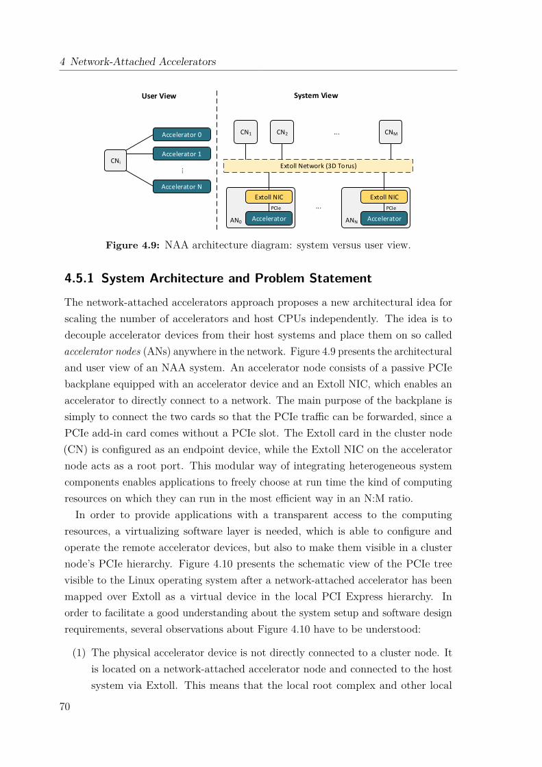
4 Network-Attached Accelerators
AN0Accelerator
Extoll Network (3D Torus)
...
CNi
Accelerator 0
Accelerator 1
Accelerator N..
.
System ViewUser View
Extoll NIC
ANNAccelerator
Extoll NIC
CN1 CNM...CN2
PCIe PCIe
Figure 4.9: NAA architecture diagram: system versus user view.
4.5.1 System Architecture and Problem Statement
The network-attached accelerators approach proposes a new architectural idea forscaling the number of accelerators and host CPUs independently. The idea is todecouple accelerator devices from their host systems and place them on so calledaccelerator nodes (ANs) anywhere in the network. Figure 4.9 presents the architecturaland user view of an NAA system. An accelerator node consists of a passive PCIebackplane equipped with an accelerator device and an Extoll NIC, which enables anaccelerator to directly connect to a network. The main purpose of the backplane issimply to connect the two cards so that the PCIe traffic can be forwarded, since aPCIe add-in card comes without a PCIe slot. The Extoll card in the cluster node(CN) is configured as an endpoint device, while the Extoll NIC on the acceleratornode acts as a root port. This modular way of integrating heterogeneous systemcomponents enables applications to freely choose at run time the kind of computingresources on which they can run in the most efficient way in an N:M ratio.In order to provide applications with a transparent access to the computing
resources, a virtualizing software layer is needed, which is able to configure andoperate the remote accelerator devices, but also to make them visible in a clusternode’s PCIe hierarchy. Figure 4.10 presents the schematic view of the PCIe treevisible to the Linux operating system after a network-attached accelerator has beenmapped over Extoll as a virtual device in the local PCI Express hierarchy. Inorder to facilitate a good understanding about the system setup and software designrequirements, several observations about Figure 4.10 have to be understood:
(1) The physical accelerator device is not directly connected to a cluster node. Itis located on a network-attached accelerator node and connected to the hostsystem via Extoll. This means that the local root complex and other local
70

4.5 NAA Software Design
Cluster Node
Root complexHost bridge
Root port Root port Root port
Bridge Bridge
(Endpoint)Extoll NIC
EndpointEndpoint(Endpoint)
VirtualAccelerator
Accelerator Node
Extoll NIC(Root Port)
(Endpoint)Accelerator
bus 0
bus 1
bus 2
bus 3
bus 4
bus 5
dev 0 dev 1 dev 2
dev 0
dev 0 dev 0 dev 0dev 1
dev 1
Virtual device- part of PCIe tree -
Real hardware device- outside of PCIe tree -
2
1
34
5
Network connection
CPU
PCIe
Figure 4.10: PCI Express tree as seen by the Linux operating system with onenetwork-attached accelerator device.
PCIe devices cannot send any transaction requests to the remote device. Infact, the physical device is not part of the system’s PCIe hierarchy.
(2) In terms of PCI Express, the Extoll NIC connected to the host system is anordinary endpoint device, which only has an upstream port but no downstreamports. Therefore, the local NIC cannot act as a PCI bridge device, which couldsimply forward transactions to the remote accelerator.
(3) While the local NIC cannot be configured to serve as a bridge device, theremote NIC can be configured to act as a root port with the accelerator devicebeing connected to its downstream port. But, it has no upstream port, andtherefore, cannot receive any PCIe transactions from a cluster node. Also, onlya root complex can initiate configuration requests, but the remote NIC, despitebeing configured to act as a root port, is not part of a root complex.
(4) In order to access the accelerator device, the network-attached acceleratorapproach must map both the virtual and physical device in a way such that
71
4 Network-Attached Accelerators
all transactions that involve the remote accelerator – either as a requester orcompleter – are forwarded between the two nodes. In Figure 4.10, the dashedline between both devices illustrates this mapping.
(5) In this example, the logical device is placed behind a root port, just like anactual device would by physically connected to that port. This means thateven though no physical device is attached to the root port, the logical deviceappears to the CPU as if it is locally connected.
4.5.2 Objectives and Strategy
The main objective of the NAA software architecture is to provide a transparentmapping between the network-attached accelerator and cluster nodes by emulating aPCIe device. The implementation of the software stack needs to be transparent toupper software layers, including the accelerator device driver and runtime libraries,while maintaining the commodity aspect of the accelerators. Recapitulating thefindings from section 4.3 and subsection 4.5.1, the NAA software environment needsto fulfill the following tasks:
Configuration Request Forwarding PCIe configuration read and write requestsneed to be forwarded to and from the remote accelerator. The NAA softwarestack needs to be able to recognize and forward such requests accordingly.
Device Enumeration The software environment should be able to emulate the PCIedevice enumeration. After powering an accelerator device, it needs to beconfigured and mapped onto system resources to be ready for operation.
Memory-Mapped I/O The cluster nodes should be able to map and forward accessrequests the accelerators’ BAR windows, which are typically made visible tothe system as MMIO regions in the main memory. This is needed for theconfiguration and communication with the accelerator devices, but also toprovide the compatibility with PCI-specific system calls and functions.
MSI Configuration and Interrupt Delivery During the accelerator device configu-ration, the software has to modify the MSI packet (destination address andpayload) by writing the corresponding values to the MSI capability register set.The layer has to be able to register the accelerator’s interrupt handler withthe Extoll interrupt management. The software needs to distinguish betweenExtoll-based interrupts and interrupts issued by the accelerator.
72
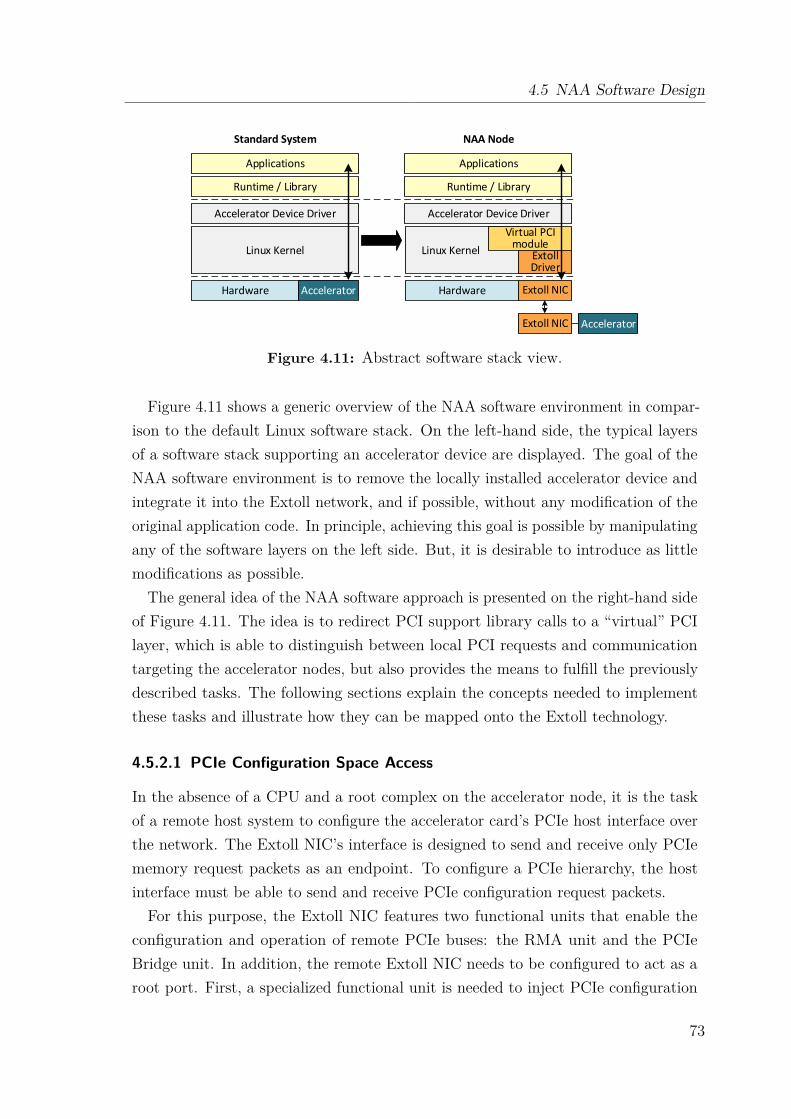
4.5 NAA Software Design
Linux Kernel
Applications
Accelerator Device Driver
Hardware
Applications
Accelerator Device Driver
Hardware
Virtual PCI module
Standard System NAA Node
Extoll Driver
Runtime / Library
Linux Kernel
Runtime / Library
Accelerator
Accelerator
Extoll NIC
Extoll NIC
Figure 4.11: Abstract software stack view.
Figure 4.11 shows a generic overview of the NAA software environment in compar-ison to the default Linux software stack. On the left-hand side, the typical layersof a software stack supporting an accelerator device are displayed. The goal of theNAA software environment is to remove the locally installed accelerator device andintegrate it into the Extoll network, and if possible, without any modification of theoriginal application code. In principle, achieving this goal is possible by manipulatingany of the software layers on the left side. But, it is desirable to introduce as littlemodifications as possible.
The general idea of the NAA software approach is presented on the right-hand sideof Figure 4.11. The idea is to redirect PCI support library calls to a “virtual” PCIlayer, which is able to distinguish between local PCI requests and communicationtargeting the accelerator nodes, but also provides the means to fulfill the previouslydescribed tasks. The following sections explain the concepts needed to implementthese tasks and illustrate how they can be mapped onto the Extoll technology.
4.5.2.1 PCIe Configuration Space Access
In the absence of a CPU and a root complex on the accelerator node, it is the taskof a remote host system to configure the accelerator card’s PCIe host interface overthe network. The Extoll NIC’s interface is designed to send and receive only PCIememory request packets as an endpoint. To configure a PCIe hierarchy, the hostinterface must be able to send and receive PCIe configuration request packets.For this purpose, the Extoll NIC features two functional units that enable the
configuration and operation of remote PCIe buses: the RMA unit and the PCIeBridge unit. In addition, the remote Extoll NIC needs to be configured to act as aroot port. First, a specialized functional unit is needed to inject PCIe configuration
73
4 Network-Attached Accelerators
packets into the Extoll NIC’s outgoing host interface traffic. The PCIe bridge unit,introduced in section 3.2.7, resides in the on-chip network of Extoll’s network interfaceand can be configured by writing to the corresponding registers in the register file.The unit is accessible from every device over the network with Remote Register fileAccess (RRA) transactions, which are basically immediate PUT and GET operationsto the remote registers. With this technique, a host can configure the remote PCIebridge unit to forward incoming PCIe configuration packets to the accelerator deviceby writing to the PCIe backdoor register presented in Table 3.2. By writing PCIeconfiguration packets into the htoc_to_pcie_backdoor_data register in the remoteregister file via RRA transactions, they are inserted into the outgoing PCIe trafficstream from the root port to the accelerator.
4.5.2.2 Device Enumeration
A simplified enumeration process can be used, since only one device resides onthe root port of a remote accelerator node. The important values that need to beconfigured are the bus, device and function number, BARs, and the MSI capabilityregisters. The bus, device and function number is used to identify the acceleratorinside the PCIe hierarchy, whereas the MSI capability registers define the targetaddress and the data that is sent when an interrupt is issued from the accelerator.The BARs define a memory window which is required to enable the internal addresstranslation for incoming request packets targeting the accelerator. This defines theway a host can access and communicate with the accelerator.
Therefore, with the remote device’s configuration space being accessible transpar-ently, all that needs to be done is to rescan the bus, on which it is to be placed.
4.5.2.3 Memory-Mapped I/O Regions
In general, peripheral components are accessed by using load and store operations toreserved address ranges in the PCIe configuration space and the memory-mappedI/O regions. The operations are mapped to an add-in card and translated into readand write requests. The easiest way to give a host access to the accelerator is touse these loads and stores to an MMIO region assigned to the accelerator. Thishas the additional benefit that the upper software and hardware layers can remainunchanged, but leads to the question of how to map physical addresses of the hostmemory to the accelerator’s PCIe address space.The Extoll NIC’s SMFU can export segments of local memory to remote nodes
to build a distributed shared memory system. Loads and stores from the CPU to
74
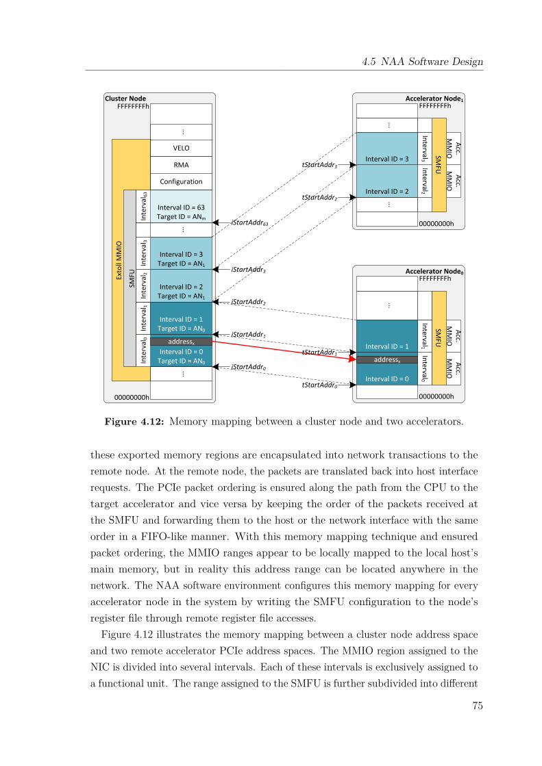
4.5 NAA Software Design
Cluster Node
Exto
ll M
MIO
Interval ID = 0Target ID = AN0
...
SMFU
Inte
rval
0
Interval ID = 2Target ID = AN1
VELO
Configuration
RMA
...
...
00000000h
FFFFFFFFh
addressx
Inte
rval
1In
terv
al2
Interval ID = 1Target ID = AN0
Accelerator Node0
00000000h
FFFFFFFFh
...
Interval0
Acc.
MM
IO
Interval ID = 0
addressx
Interval ID = 1
Inte
rval1
Acc.
MM
IO
Interval ID = 3Target ID = AN1
Interval ID = 63Target ID = ANm
Inte
rval
3In
terv
al6
3
Accelerator Node1
00000000h
FFFFFFFFh
...
...
Inte
rval2
Acc.
MM
IO
Interval ID = 2
Interval ID = 3
Interval3
Acc.
MM
IOSMFU
SMFU
iStartAddr0
iStartAddr3
iStartAddr1
iStartAddr2
iStartAddr63
tStartAddr0
tStartAddr1
tStartAddr2
tStartAddr3
Figure 4.12: Memory mapping between a cluster node and two accelerators.
these exported memory regions are encapsulated into network transactions to theremote node. At the remote node, the packets are translated back into host interfacerequests. The PCIe packet ordering is ensured along the path from the CPU to thetarget accelerator and vice versa by keeping the order of the packets received atthe SMFU and forwarding them to the host or the network interface with the sameorder in a FIFO-like manner. With this memory mapping technique and ensuredpacket ordering, the MMIO ranges appear to be locally mapped to the local host’smain memory, but in reality this address range can be located anywhere in thenetwork. The NAA software environment configures this memory mapping for everyaccelerator node in the system by writing the SMFU configuration to the node’sregister file through remote register file accesses.
Figure 4.12 illustrates the memory mapping between a cluster node address spaceand two remote accelerator PCIe address spaces. The MMIO region assigned to theNIC is divided into several intervals. Each of these intervals is exclusively assigned toa functional unit. The range assigned to the SMFU is further subdivided into different
75
4 Network-Attached Accelerators
intervals. Each of these intervals corresponds to a region of exported memory (BAR)with the size and location defined by a start (iStartAddrn) and an end address. Inaddition, each interval has an interval ID and a Target ID. The Target ID specifiesthe Extoll node ID of the accelerator node the loads and stores are forwarded to,while the interval ID is used to match the source interval ID of these loads and stores.In this example, two BAR windows are mapped per accelerator node. addressx hitsSMFU interval 0, which is translated to an address on AN0 in SMFU interval 0.The SMFU on the accelerator node side adds an offset to incoming network-
encapsulated request packets. The offset defines where the exported region is locatedin the accelerator’s memory space. If the calculated address matches the BARassigned to the accelerator, a load or store to that address is sent to the accelerator.Note, the offset to an address in the SMFU interval has the same offset to an addressin the accelerator’s BAR region. This technique allows the host CPU to directlyaccess any accelerator connected over the Extoll network. Once the Extoll networkis configured, each accelerator node has a unique node ID in the Extoll fabric. Thisnode ID is used to address other accelerators within the system. As a consequence,two accelerator nodes belonging to different hosts are able to communicate with eachother independently from the host systems.
4.5.2.4 MSI Configuration and Interrupt Delivery
Most PCIe devices require interrupts to fulfill their function and to communicateevents between the device and the driver. PCIe devices implement the MessageSignaled Interrupt (MSI) mechanism, which sends a posted write packet towardsan Advanced Programmable Interrupt Controller (APIC). A write to this controllertriggers an interrupt and the operating system forwards the interrupt to the corre-sponding device interrupt handler. In the network-attached accelerator architecture,there is no APIC register on the accelerator node and no direct connection be-tween the accelerator’s PCIe bus and the host systems APICs. To provide interruptfunctionality, some special adjustments have to be made.
The interrupt management for accelerator devices is implemented by extending theExtoll interrupt handling on the host system to handle accelerator interrupts as well.The address of an MSI packet is stored in a PCIe configuration space register, whichmeans that it can be modified from the remote host through configuration packets.The host sends configuration packets to the remote PCIe bus, which modifies theMSI capability registers on the accelerator card. The accelerator’s MSI address ismanipulated in a way that the address is forwarded to the host, and there, it hits a
76
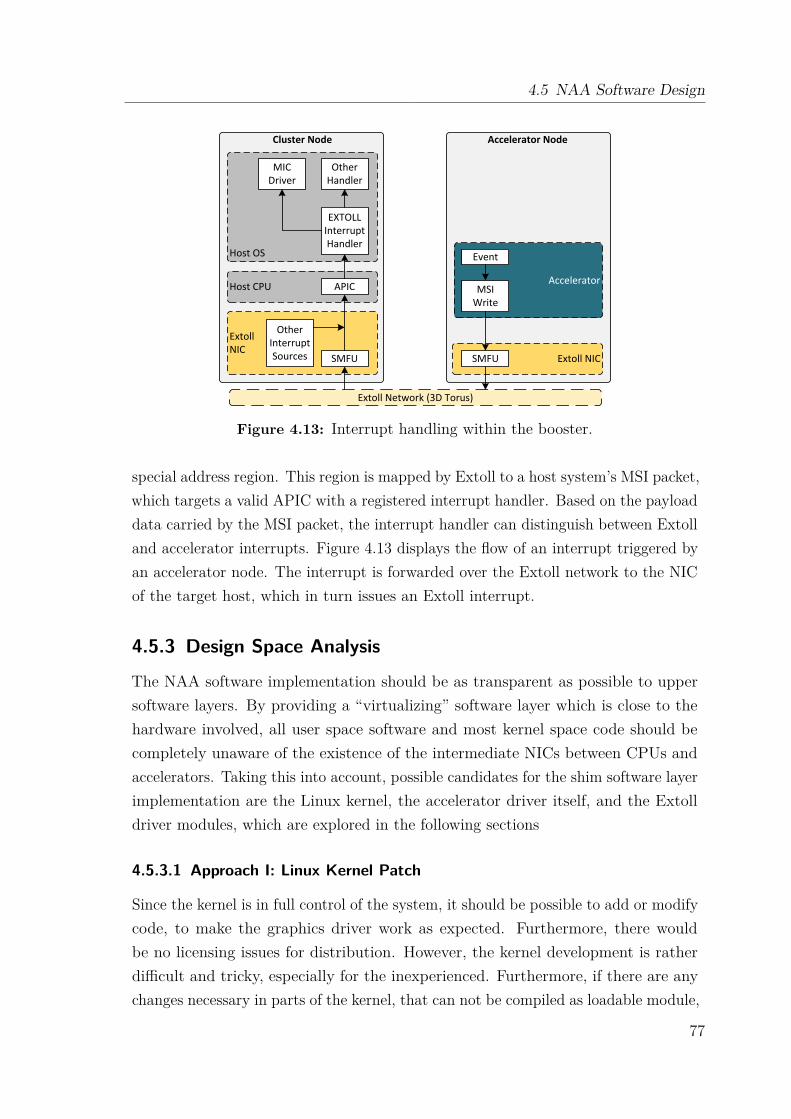
4.5 NAA Software Design
Host OS
MIC Driver
Other Handler
EXTOLL Interrupt Handler
Host CPU APIC
ExtollNIC
SMFU
Other Interrupt Sources Extoll NICSMFU
Accelerator
Event
MSI Write
Extoll Network (3D Torus)
Cluster Node Accelerator Node
Figure 4.13: Interrupt handling within the booster.
special address region. This region is mapped by Extoll to a host system’s MSI packet,which targets a valid APIC with a registered interrupt handler. Based on the payloaddata carried by the MSI packet, the interrupt handler can distinguish between Extolland accelerator interrupts. Figure 4.13 displays the flow of an interrupt triggered byan accelerator node. The interrupt is forwarded over the Extoll network to the NICof the target host, which in turn issues an Extoll interrupt.
4.5.3 Design Space Analysis
The NAA software implementation should be as transparent as possible to uppersoftware layers. By providing a “virtualizing” software layer which is close to thehardware involved, all user space software and most kernel space code should becompletely unaware of the existence of the intermediate NICs between CPUs andaccelerators. Taking this into account, possible candidates for the shim software layerimplementation are the Linux kernel, the accelerator driver itself, and the Extolldriver modules, which are explored in the following sections
4.5.3.1 Approach I: Linux Kernel Patch
Since the kernel is in full control of the system, it should be possible to add or modifycode, to make the graphics driver work as expected. Furthermore, there wouldbe no licensing issues for distribution. However, the kernel development is ratherdifficult and tricky, especially for the inexperienced. Furthermore, if there are anychanges necessary in parts of the kernel, that can not be compiled as loadable module,
77
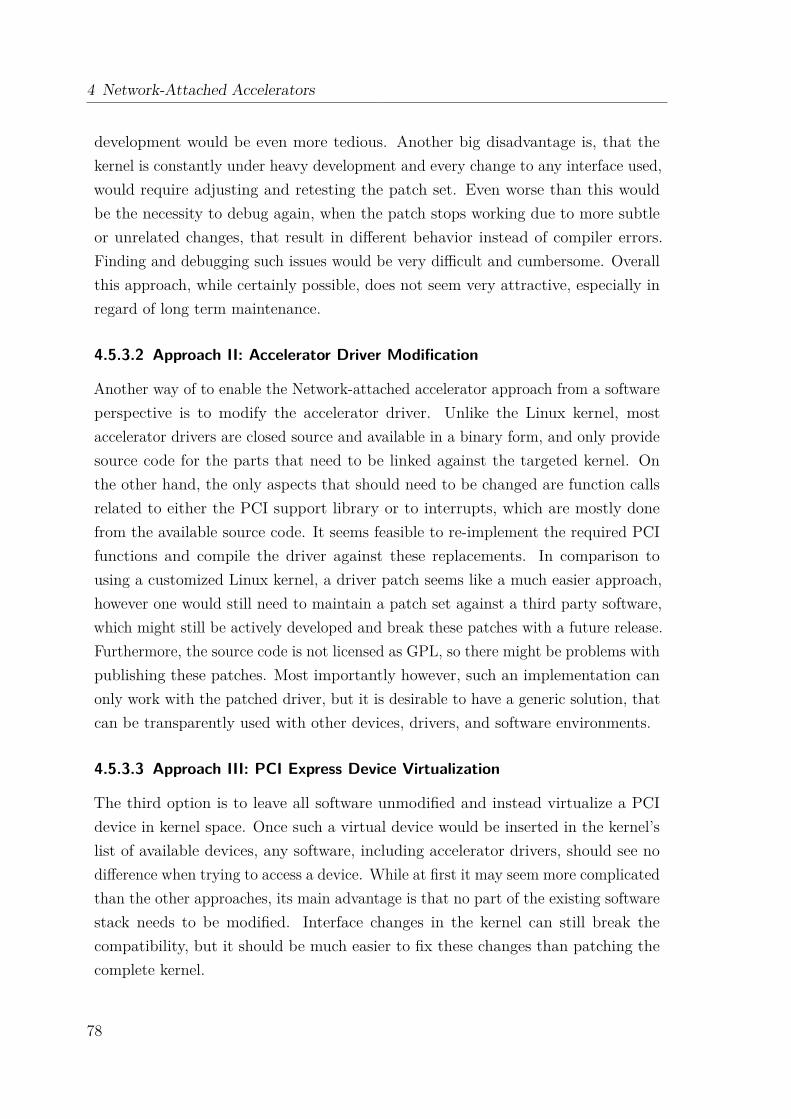
4 Network-Attached Accelerators
development would be even more tedious. Another big disadvantage is, that thekernel is constantly under heavy development and every change to any interface used,would require adjusting and retesting the patch set. Even worse than this wouldbe the necessity to debug again, when the patch stops working due to more subtleor unrelated changes, that result in different behavior instead of compiler errors.Finding and debugging such issues would be very difficult and cumbersome. Overallthis approach, while certainly possible, does not seem very attractive, especially inregard of long term maintenance.
4.5.3.2 Approach II: Accelerator Driver Modification
Another way of to enable the Network-attached accelerator approach from a softwareperspective is to modify the accelerator driver. Unlike the Linux kernel, mostaccelerator drivers are closed source and available in a binary form, and only providesource code for the parts that need to be linked against the targeted kernel. Onthe other hand, the only aspects that should need to be changed are function callsrelated to either the PCI support library or to interrupts, which are mostly donefrom the available source code. It seems feasible to re-implement the required PCIfunctions and compile the driver against these replacements. In comparison tousing a customized Linux kernel, a driver patch seems like a much easier approach,however one would still need to maintain a patch set against a third party software,which might still be actively developed and break these patches with a future release.Furthermore, the source code is not licensed as GPL, so there might be problems withpublishing these patches. Most importantly however, such an implementation canonly work with the patched driver, but it is desirable to have a generic solution, thatcan be transparently used with other devices, drivers, and software environments.
4.5.3.3 Approach III: PCI Express Device Virtualization
The third option is to leave all software unmodified and instead virtualize a PCIdevice in kernel space. Once such a virtual device would be inserted in the kernel’slist of available devices, any software, including accelerator drivers, should see nodifference when trying to access a device. While at first it may seem more complicatedthan the other approaches, its main advantage is that no part of the existing softwarestack needs to be modified. Interface changes in the kernel can still break thecompatibility, but it should be much easier to fix these changes than patching thecomplete kernel.
78
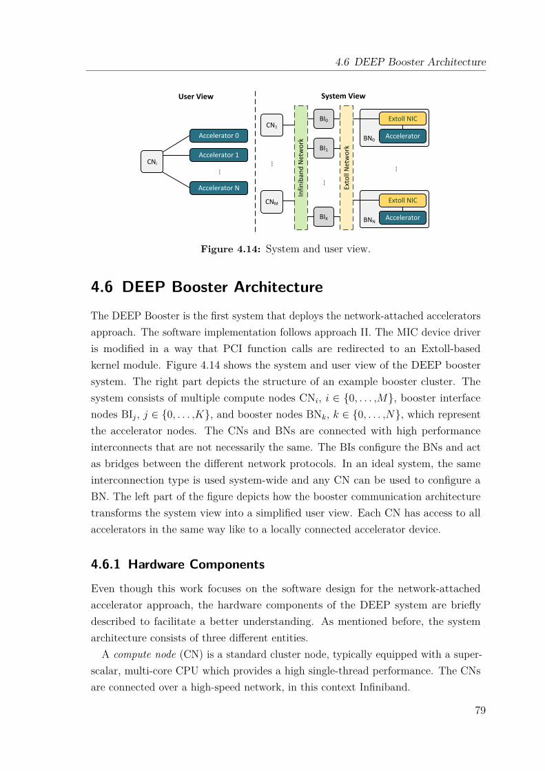
4.6 DEEP Booster Architecture
BN0Accelerator
Exto
llN
etw
ork
...
...
CNi
Accelerator 0
Accelerator 1
Accelerator N
...
System ViewUser View
Extoll NIC
BNNAccelerator
Extoll NIC
Infin
iban
d N
etw
ork
CN1
CNM
BI0
BI1
BIK
...
Figure 4.14: System and user view.
4.6 DEEP Booster ArchitectureThe DEEP Booster is the first system that deploys the network-attached acceleratorsapproach. The software implementation follows approach II. The MIC device driveris modified in a way that PCI function calls are redirected to an Extoll-basedkernel module. Figure 4.14 shows the system and user view of the DEEP boostersystem. The right part depicts the structure of an example booster cluster. Thesystem consists of multiple compute nodes CNi, i ∈ {0, . . . ,M}, booster interfacenodes BIj, j ∈ {0, . . . ,K}, and booster nodes BNk, k ∈ {0, . . . ,N}, which representthe accelerator nodes. The CNs and BNs are connected with high performanceinterconnects that are not necessarily the same. The BIs configure the BNs and actas bridges between the different network protocols. In an ideal system, the sameinterconnection type is used system-wide and any CN can be used to configure aBN. The left part of the figure depicts how the booster communication architecturetransforms the system view into a simplified user view. Each CN has access to allaccelerators in the same way like to a locally connected accelerator device.
4.6.1 Hardware Components
Even though this work focuses on the software design for the network-attachedaccelerator approach, the hardware components of the DEEP system are brieflydescribed to facilitate a better understanding. As mentioned before, the systemarchitecture consists of three different entities.
A compute node (CN) is a standard cluster node, typically equipped with a super-scalar, multi-core CPU which provides a high single-thread performance. The CNsare connected over a high-speed network, in this context Infiniband.
79
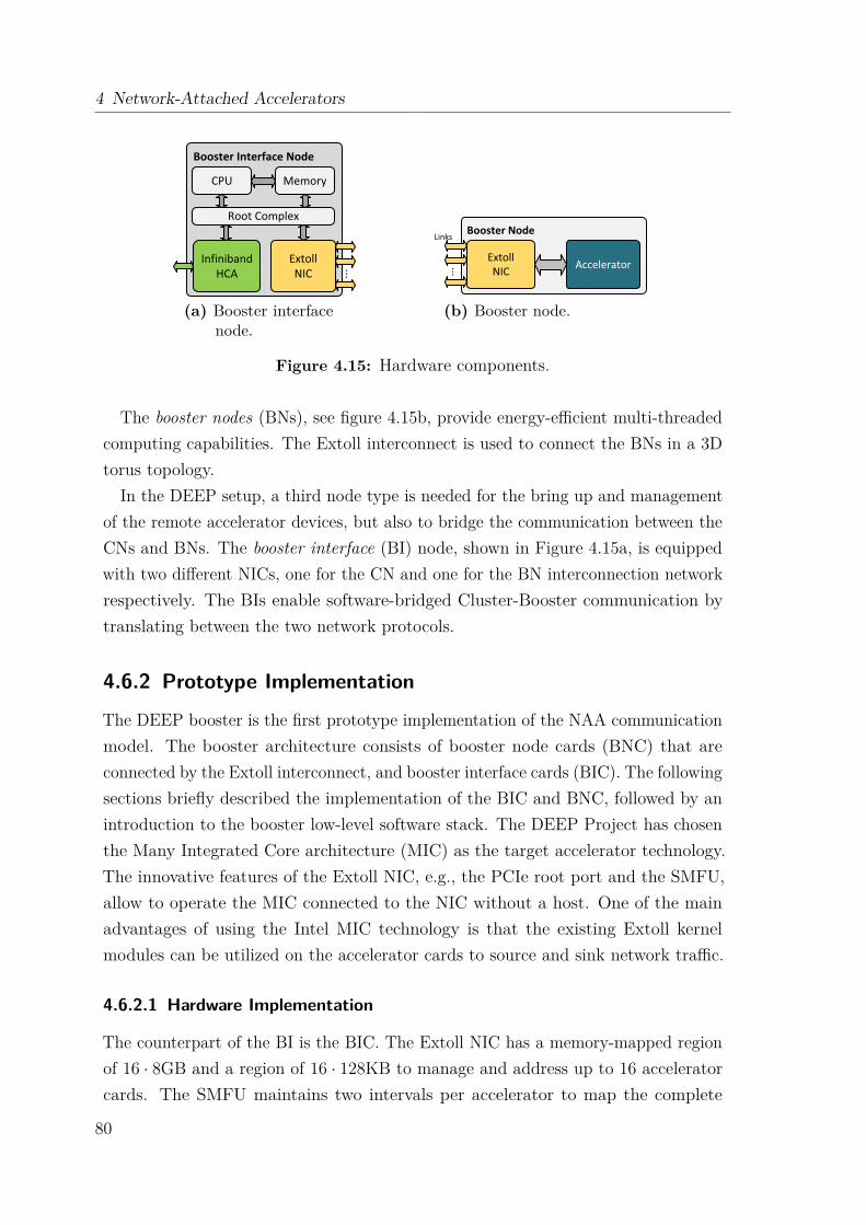
4 Network-Attached Accelerators
(a) Booster interfacenode.
Links
(b) Booster node.
Figure 4.15: Hardware components.
The booster nodes (BNs), see figure 4.15b, provide energy-efficient multi-threadedcomputing capabilities. The Extoll interconnect is used to connect the BNs in a 3Dtorus topology.
In the DEEP setup, a third node type is needed for the bring up and managementof the remote accelerator devices, but also to bridge the communication between theCNs and BNs. The booster interface (BI) node, shown in Figure 4.15a, is equippedwith two different NICs, one for the CN and one for the BN interconnection networkrespectively. The BIs enable software-bridged Cluster-Booster communication bytranslating between the two network protocols.
4.6.2 Prototype Implementation
The DEEP booster is the first prototype implementation of the NAA communicationmodel. The booster architecture consists of booster node cards (BNC) that areconnected by the Extoll interconnect, and booster interface cards (BIC). The followingsections briefly described the implementation of the BIC and BNC, followed by anintroduction to the booster low-level software stack. The DEEP Project has chosenthe Many Integrated Core architecture (MIC) as the target accelerator technology.The innovative features of the Extoll NIC, e.g., the PCIe root port and the SMFU,allow to operate the MIC connected to the NIC without a host. One of the mainadvantages of using the Intel MIC technology is that the existing Extoll kernelmodules can be utilized on the accelerator cards to source and sink network traffic.
4.6.2.1 Hardware Implementation
The counterpart of the BI is the BIC. The Extoll NIC has a memory-mapped regionof 16 · 8GB and a region of 16 · 128KB to manage and address up to 16 acceleratorcards. The SMFU maintains two intervals per accelerator to map the complete
80

4.6 DEEP Booster Architecture
Linux Kernel
Applications
Intel MPSS Driver Stack
Hardware
Applications
Hardware
PCI Surrogate
Standard System Booster Interface Node
Runtime / Library
Linux Kernel
Runtime / Library
Intel MIC
Intel MIC
Extoll NIC
Extoll NIC
MIC-to-ExtollExtoll Driver
Intel MPSS Driver Stack
Figure 4.16: BIC software stack.
MMIO configuration register and the MemBAR GDDR5 memory of the BN’s PCIebus into the BICs address space. Four link ports from the NIC are used to connectthe BIC with the 3D Torus of the booster. The BIC is responsible for bootingand controlling the MICs over the Extoll interconnect. The BNC is a high-densityimplementation with two independent BNs, which are part of the 3D torus. A BNconsists of a NIC and an accelerator, the Intel MIC. Eight BNCs are connected toa single backplane that provides connections to neighboring backplanes and theirBNCs. As described in figure 4.12, the SMFU can be used to map regions of BImemory to BNs. On the BIC, two intervals are exported to the same BN. Oneexported region points to the BAR of the MMIO configuration register and the otherregion points to the BAR of the MemBAR GDDR5 memory. The MMIO registersof the Intel MIC are placed below 4GB, and the MemBAR is placed above 256GBto not interfere with the BIC’s operating system memory map. This configurationis maintained for all BNCs. The communication between a BNC and CN does notrequire any CPU interaction on the BIC.
4.6.2.2 Software Implementation
The NAA Booster software stack implements all of the aforementioned requirementsand consists of a collection of configuration scripts and a kernel module, whichmaps PCI support library calls and device structures onto the Extoll software stackresources. The main advantage of this approach is the transparency to upper softwarelayers. Once the Intel MIC driver is running on top of the virtual PCI software stack,all existing applications can be used without any modification.The configuration scripts are used to setup the SMFU interval mapping and to
configure the PCIe Bridge unit to forward PCIe configuration packets to the remote
81

4 Network-Attached Accelerators
accelerators and vice versa. The scripts perform RRA reads and writes to the remoteExtoll NICs by utilizing the user library libRMA. The kernel module intercepts theIntel MIC driver when it initializes the PCIe device and is responsible for maintainingand mapping necessary device structures onto the Extoll SMFU memory-mappedI/O regions. Figure 4.16 displays the software stack loaded on a BIC. The virtualPCI software layer comprises of two components:
PCI surrogate layer The PCI surrogate layer replaces the PCI support library. AllPCI function calls are redirected to this layer.
MIC-to-EXTOLL Layer PCI structures needed by the Intel MIC driver are mappedto the Extoll data structures for device initialization.
To be able to use the BIC software stack, the Intel MPSS is recompiled againstthe PCI surrogate layer header file, which is built on top of the Extoll kernel API.
Device Configuration And Resource Mapping When the Intel MIC driver isloaded on a BIC, the driver initializes the connected MIC devices. Typically atmodule startup, the driver is registered with the PCI subsystem. The registrationcall is intercepted by redirecting it to the PCI surrogate layer, where a customizedhardware initialization function is called. This is done by replacing the PCI header fileinclude with #include "pci_surrogate.h". Depending on the number of connectedMICs, an array of MIC descriptor structures is initialized with the start and endaddresses of the MemBAR and MMIO regions. These values are needed for bootingthe accelerators, since the PCIe client logic registers, referred to as SBOX registers,are accessed through the MMIO regions and the Linux image is copied into theremapped MemBAR region. Instead of allocating and mapping memory regions foreach MIC, the memory regions are overlapped with the SMFU’s MMIO space, whichis subdivided into several intervals.
MSI Configuration and Interrupt Forwarding The second stage of the deviceinitialization process is the MSI configuration of the MICs. This is done by writingdirectly to the corresponding SBOX registers, which reside in the mapped SMFUmemory regions in the address space of the BIC. The vector is composed of apredefined address, a message, and the vector control. The predefined addressenables the interrupt redirection to the BIC. The last step of the initializationprocess is the registration of the MIC interrupt handler with the EXTOLL interrupthandling subsystem. This is done by keeping a function pointer to the corresponding
82
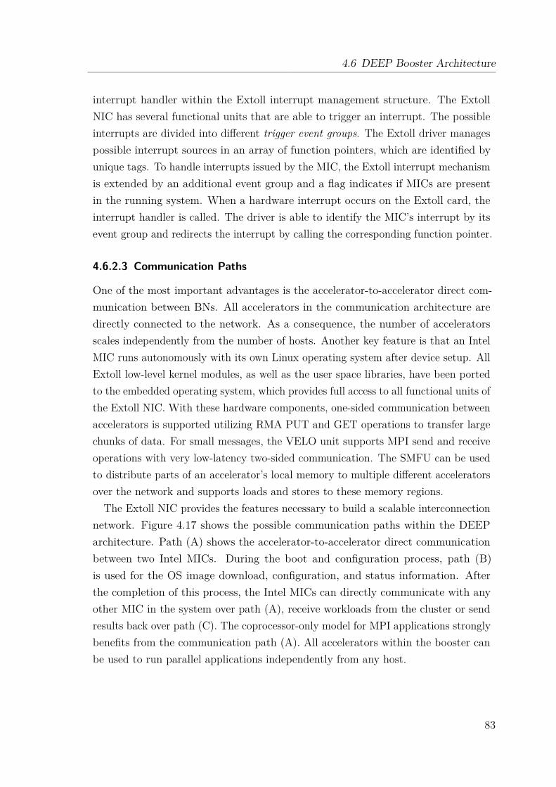
4.6 DEEP Booster Architecture
interrupt handler within the Extoll interrupt management structure. The ExtollNIC has several functional units that are able to trigger an interrupt. The possibleinterrupts are divided into different trigger event groups. The Extoll driver managespossible interrupt sources in an array of function pointers, which are identified byunique tags. To handle interrupts issued by the MIC, the Extoll interrupt mechanismis extended by an additional event group and a flag indicates if MICs are presentin the running system. When a hardware interrupt occurs on the Extoll card, theinterrupt handler is called. The driver is able to identify the MIC’s interrupt by itsevent group and redirects the interrupt by calling the corresponding function pointer.
4.6.2.3 Communication Paths
One of the most important advantages is the accelerator-to-accelerator direct com-munication between BNs. All accelerators in the communication architecture aredirectly connected to the network. As a consequence, the number of acceleratorsscales independently from the number of hosts. Another key feature is that an IntelMIC runs autonomously with its own Linux operating system after device setup. AllExtoll low-level kernel modules, as well as the user space libraries, have been portedto the embedded operating system, which provides full access to all functional units ofthe Extoll NIC. With these hardware components, one-sided communication betweenaccelerators is supported utilizing RMA PUT and GET operations to transfer largechunks of data. For small messages, the VELO unit supports MPI send and receiveoperations with very low-latency two-sided communication. The SMFU can be usedto distribute parts of an accelerator’s local memory to multiple different acceleratorsover the network and supports loads and stores to these memory regions.
The Extoll NIC provides the features necessary to build a scalable interconnectionnetwork. Figure 4.17 shows the possible communication paths within the DEEParchitecture. Path (A) shows the accelerator-to-accelerator direct communicationbetween two Intel MICs. During the boot and configuration process, path (B)is used for the OS image download, configuration, and status information. Afterthe completion of this process, the Intel MICs can directly communicate with anyother MIC in the system over path (A), receive workloads from the cluster or sendresults back over path (C). The coprocessor-only model for MPI applications stronglybenefits from the communication path (A). All accelerators within the booster canbe used to run parallel applications independently from any host.
83
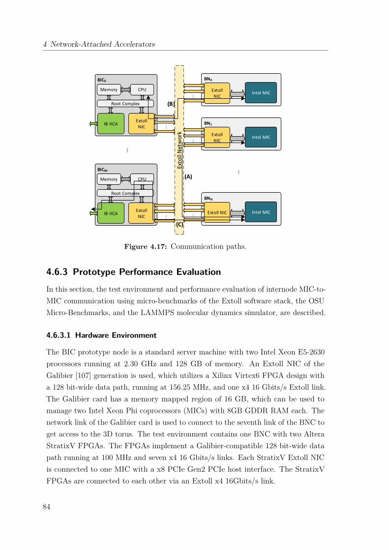
4 Network-Attached Accelerators
BICM
CPU
ExtollNIC
IB HCA
Root Complex
Memory
BIC0
CPU
ExtollNIC
IB HCA
Root Complex
Memory
BNN
Intel MICExtoll NIC
BN1
Intel MICExtollNIC
BN0
Intel MICExtollNIC
Exto
ll N
etw
ork
...
...
...
......
...
...
(A)
(B)
(C)
Figure 4.17: Communication paths.
4.6.3 Prototype Performance Evaluation
In this section, the test environment and performance evaluation of internode MIC-to-MIC communication using micro-benchmarks of the Extoll software stack, the OSUMicro-Benchmarks, and the LAMMPS molecular dynamics simulator, are described.
4.6.3.1 Hardware Environment
The BIC prototype node is a standard server machine with two Intel Xeon E5-2630processors running at 2.30 GHz and 128 GB of memory. An Extoll NIC of theGalibier [107] generation is used, which utilizes a Xilinx Virtex6 FPGA design witha 128 bit-wide data path, running at 156.25 MHz, and one x4 16 Gbits/s Extoll link.The Galibier card has a memory mapped region of 16 GB, which can be used tomanage two Intel Xeon Phi coprocessors (MICs) with 8GB GDDR RAM each. Thenetwork link of the Galibier card is used to connect to the seventh link of the BNC toget access to the 3D torus. The test environment contains one BNC with two AlteraStratixV FPGAs. The FPGAs implement a Galibier-compatible 128 bit-wide datapath running at 100 MHz and seven x4 16 Gbits/s links. Each StratixV Extoll NICis connected to one MIC with a x8 PCIe Gen2 PCIe host interface. The StratixVFPGAs are connected to each other via an Extoll x4 16Gbits/s link.
84
4.6 DEEP Booster Architecture
4.6.3.2 Software Environment
The BIC runs CentOS 6.3 with kernel version 2.6.32-279.19.1.el6.x86_64 as the operat-ing system, and has Intel MPSS 2.1.6720-16 and Intel Composer_xe_2013_sp1.2.144installed. The micro-benchmarks of the Extoll software stack are used to evaluatethe latency and bandwidth of MIC-to-MIC communication over Extoll. In addition,the MPI performance is evaluated between two MICs connected over Extoll (usingOpenMPI 1.6.1) and directly connected to the BIC utilizing SCIF and OFED/SCIF(using Intel MPI Library 4.1.3.049 and OFED-1.5.4.1). OpenFabrics EnterpriseDistribution(OFED) [108] provides an open-source software solution for RDMA andkernel bypass applications. The Symmetric Communications InterFace (SCIF) [87]is used for internode communication within a single system. Four different systemconfigurations are used:
Booster This setup is the DEEP prototype booster system connecting two BNswith one BNC.
TCP/SCIF In this setup, two MICs are directly connected to the BIC over PCIe.The BIC acts as the host and runs the Intel MPSS without any OFED support.All communication is tunneled over SCIF.
OFED/SCIF The setup is an optimized version of the mic0-mic1 TCP/SCIF setup,where the Intel MPSS is run on top of the OFED stack. The communicationis virtualized over the OFED/SCIF software stack, which implements RDMAby virtualizing direct access to a hardware InfiniBand Host Channel Adapter(HCA) between two MICs.
rEXTOLL Two hosts, equivalent to the BIC, are connected over Extoll. Each hosthas one MIC attached over PCIe.
4.6.3.3 Micro-benchmark Evaluation
For the micro-benchmark experiments, two prototype BNs are used, denoted as mic0and mic1. The micro-benchmarks are launched on mic0. The communication is setup over the low-level user-space library of the Extoll NIC. Figure 4.18a displays theresults of the latency benchmark for the FPGA-based booster implementation. Formessages smaller than 64B between mic0 and mic1, the latency performance of VELOoutperforms the RMA unit by about 50%. Figure 4.18b presents the bandwidthresults. For small messages, VELO provides a better bandwidth than RMA. Thepeak bandwidth provided by RMA is about 1.2 GB/s. These performance results
85
4 Network-Attached Accelerators
(a) Latency. (b) Bandwidth.
Figure 4.18: Micro-benchmarks performance of internode MIC-to-MIC commu-nication using the Extoll interconnect.
have a direct impact on the direct accelerator-to-accelerator communication results.All communication traffic between the BNs is tunneled over Extoll.
4.6.3.4 MPI Performance Evaluation
The point-to-point MPI benchmarks of the OSU Micro-Benchmarks 4.3 (OMB) [74]are used for the evaluation. Each benchmark is run 100 times. The results in thegraphs are calculated as the arithmetical average of the runs. All benchmark resultsare verified by the Intel MPI Benchmark 3.2.3 (IMB) [109].
Latency Figure 4.19a displays the half round-trip latency results for small messages(<2 KB). The results for mic0-mic1 TCP/SCIF are not displayed, because thehalf round-trip latency is too large (>300 usec). Even though the prototype onlyuses an FPGA implementation of the NIC, the half round-trip latency using thebooster architecture is improved compared to the latency measured when using theOFED/SCIF software stack. Furthermore, figure 4.19b shows that the half round-triplatency of large messages is also competitive compared to OFED/SCIF, although thebandwidth of the underlying hardware (PCIe Gen2 x16) is much higher (>6 GB/s).With the ASIC implementation of Extoll, the latency will be even smaller. The
mic0-mic1 TCP/SCIF bandwidth is only displayed as a reference since it has avery poor performance. This is probably because of the need to perform a standardkernel-level TCP/IP communication on the MIC.
Bandwidth Figure 4.20 displays the performance results of the bandwidth andbidirectional bandwidth tests. The FPGA implementation is competitive with theOFED/SCIF solution, the peak bandwidth corresponds with the measured low-level
86

4.6 DEEP Booster Architecture
(a) Small messages. (b) Large messages.
Figure 4.19: Half round-trip latency performance of internode MIC-to-MICcommunication using MPI.
(a) Bandwidth. (b) Bidirectional bandwidth.
Figure 4.20: Bandwidth and bidirectional bandwidth performance of internodeMIC-to-MIC communication using MPI.
performance of the RMA unit. It is noteworthy that the peak MPI bandwidth usingOFED/SCIF over PCIe is unable to utilize the bandwidth of the underlying PCIExpress fabric.
4.6.3.5 Application Level Evaluation
In addition to the micro-benchmark and MPI performance evaluation, the communi-cation architecture for network-attached accelerators is evaluated using a life scienceapplication. The MPI version of the LAMMPS (Large-scale Atomic/MolecularMassively Parallel Simulator) molecular dynamics simulator is used. LAMMPS isa classical molecular dynamics code [110]. It is written in C++ and MPI. Thebenchmark considered for the evaluation performs a bead-spring polymer melt of100-mer chains, with finite extensible nonlinear elastic (FENE) bonds, Lennard-Jonesinteractions with a 2(1/6)σ cutoff (5 neighbors per atom), and micro-canonical (NVE)integration. The problem has 32,000 atoms and runs for 100 time steps.
87
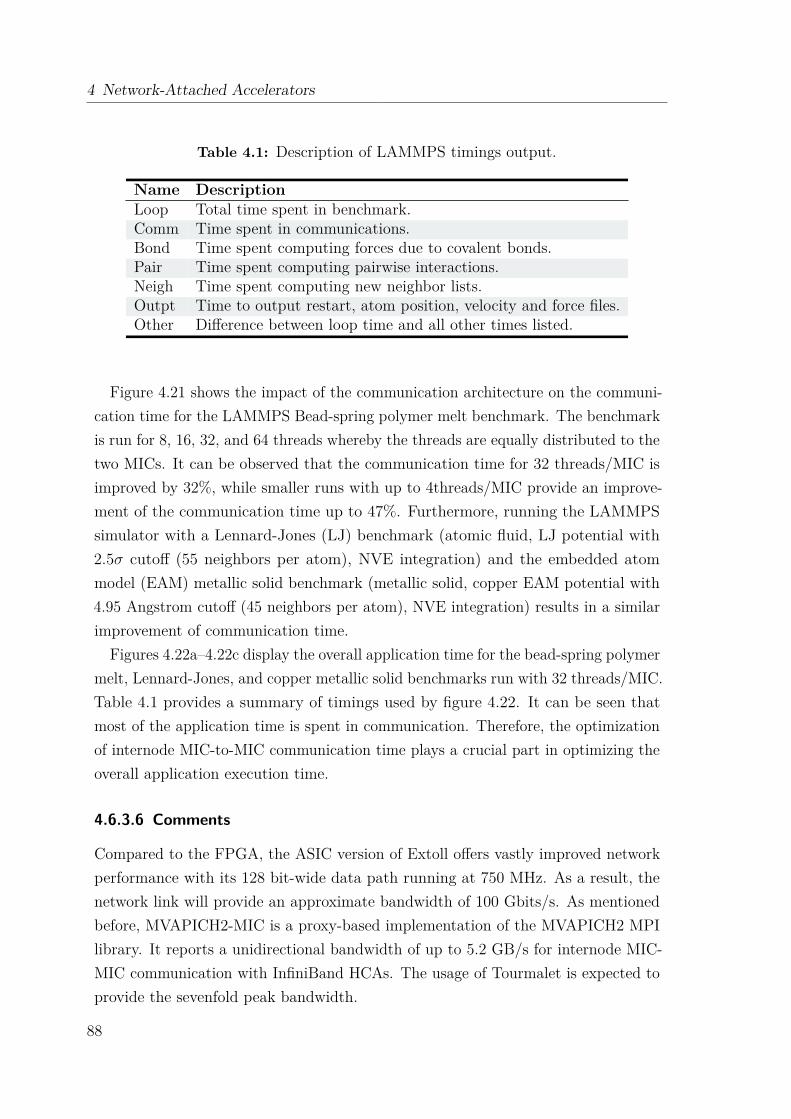
4 Network-Attached Accelerators
Table 4.1: Description of LAMMPS timings output.
Name DescriptionLoop Total time spent in benchmark.Comm Time spent in communications.Bond Time spent computing forces due to covalent bonds.Pair Time spent computing pairwise interactions.Neigh Time spent computing new neighbor lists.Outpt Time to output restart, atom position, velocity and force files.Other Difference between loop time and all other times listed.
Figure 4.21 shows the impact of the communication architecture on the communi-cation time for the LAMMPS Bead-spring polymer melt benchmark. The benchmarkis run for 8, 16, 32, and 64 threads whereby the threads are equally distributed to thetwo MICs. It can be observed that the communication time for 32 threads/MIC isimproved by 32%, while smaller runs with up to 4threads/MIC provide an improve-ment of the communication time up to 47%. Furthermore, running the LAMMPSsimulator with a Lennard-Jones (LJ) benchmark (atomic fluid, LJ potential with2.5σ cutoff (55 neighbors per atom), NVE integration) and the embedded atommodel (EAM) metallic solid benchmark (metallic solid, copper EAM potential with4.95 Angstrom cutoff (45 neighbors per atom), NVE integration) results in a similarimprovement of communication time.
Figures 4.22a–4.22c display the overall application time for the bead-spring polymermelt, Lennard-Jones, and copper metallic solid benchmarks run with 32 threads/MIC.Table 4.1 provides a summary of timings used by figure 4.22. It can be seen thatmost of the application time is spent in communication. Therefore, the optimizationof internode MIC-to-MIC communication time plays a crucial part in optimizing theoverall application execution time.
4.6.3.6 Comments
Compared to the FPGA, the ASIC version of Extoll offers vastly improved networkperformance with its 128 bit-wide data path running at 750 MHz. As a result, thenetwork link will provide an approximate bandwidth of 100 Gbits/s. As mentionedbefore, MVAPICH2-MIC is a proxy-based implementation of the MVAPICH2 MPIlibrary. It reports a unidirectional bandwidth of up to 5.2 GB/s for internode MIC-MIC communication with InfiniBand HCAs. The usage of Tourmalet is expected toprovide the sevenfold peak bandwidth.
88
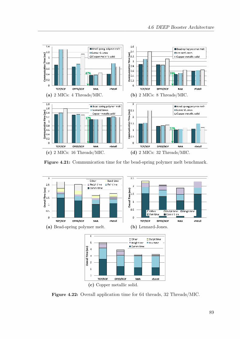
4.6 DEEP Booster Architecture
(a) 2 MICs: 4 Threads/MIC. (b) 2 MICs: 8 Threads/MIC.
(c) 2 MICs: 16 Threads/MIC. (d) 2 MICs: 32 Threads/MIC.
Figure 4.21: Communication time for the bead-spring polymer melt benchmark.
(a) Bead-spring polymer melt. (b) Lennard-Jones.
(c) Copper metallic solid.
Figure 4.22: Overall application time for 64 threads, 32 Threads/MIC.
89
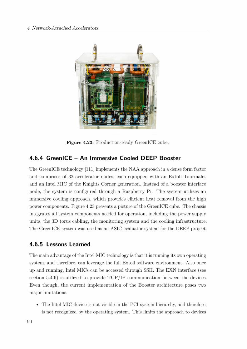
4 Network-Attached Accelerators
Figure 4.23: Production-ready GreenICE cube.
4.6.4 GreenICE – An Immersive Cooled DEEP Booster
The GreenICE technology [111] implements the NAA approach in a dense form factorand comprises of 32 accelerator nodes, each equipped with an Extoll Tourmaletand an Intel MIC of the Knights Corner generation. Instead of a booster interfacenode, the system is configured through a Raspberry Pi. The system utilizes animmersive cooling approach, which provides efficient heat removal from the highpower components. Figure 4.23 presents a picture of the GreenICE cube. The chassisintegrates all system components needed for operation, including the power supplyunits, the 3D torus cabling, the monitoring system and the cooling infrastructure.The GreenICE system was used as an ASIC evaluator system for the DEEP project.
4.6.5 Lessons Learned
The main advantage of the Intel MIC technology is that it is running its own operatingsystem, and therefore, can leverage the full Extoll software environment. Also onceup and running, Intel MICs can be accessed through SSH. The EXN interface (seesection 5.4.6) is utilized to provide TCP/IP communication between the devices.Even though, the current implementation of the Booster architecture poses twomajor limitations:
• The Intel MIC device is not visible in the PCI system hierarchy, and therefore,is not recognized by the operating system. This limits the approach to devices
90
4.7 Virtualization of Remote PCI Express Devices
that are capable of running their own operating systems, and therefore, canrun independently from a local host.
• The Intel MPSS code needs to be modified in order to utilize the PCI surrogatelayer, but also when creating sysfs entries for the devices. This is mainlybecause the Extoll device is already registered in the Linux device model, whichmeans that the same PCI device pointer cannot be registered twice.
4.7 Virtualization of Remote PCI Express DevicesWhile the DEEP Booster software relies on the modification of the accelerator driver,the Virtual PCI (VPCI) [112] software design targets a more generic approachwithout the need to modify driver code or the Linux kernel. VPCI is designed as aloadable Linux kernel module, which emulates a PCIe device by inserting a virtualdevice into the kernel’s list of devices.
4.7.1 Concept Overview of VPCI
The NAA software requirements and design have been explained in section 4.5. TheDEEP booster architecture only supports the Intel MIC technology. In today’s HPCsystems, GPUs are the predominant accelerator technology. Therefore, it is desirableto extend the NAA approach to GPUs. Recapitulating the findings from section4.6.5, the VPCI module needs to fulfill the following tasks:
• The general PCI data structures as expected by the Linux kernel should bemaintained. This way, the virtual PCI device can be added to the operat-ing system’s PCI tree without any modification of the kernel code and theaccelerator device’s software stack remains unchanged.
• The software needs a mechanism to detect and forward PCI configurationrequests to remote accelerator devices, e.g., by implementing a software switchwhich distinguishes accesses to local and network-attached devices.
• The enumeration process for the virtual accelerator device should be triggeredby VPCI. After the successful enumeration of the remote device, its resourcescan be accessed by user- and kernel-level processes, e.g., through sysfs.
• The solution should be able to transparently forward MMIO requests.
91

4 Network-Attached Accelerators
1 struct vpci_device {2 int busnr;3 int devnr;45 /* the actual pci device and bus structures allocated6 and managed by the kernel . */7 struct pci_dev *dev;8 struct pci_bus *bus;9
10 /* BAR addresses as seen by the host. */11 struct vpci_bar host_bars [7];12 /* BAR addresses as seen by the GPU. */13 struct vpci_bar remote_bars [7];14 /* Stores the values read from BAR registers after writing15 all ones to determine the size of the BARs. These should16 be returned , when the kernel rescans the bus. */17 u32 bar_init [7];1819 /* Actual io spaces defined by the BAR registers . */20 struct vpci_bar bar_windows [7];21 };
Listing 4.1: Overview of the VPCI device structure.
• The VPCI module should provide a transparent mechanism to enable anddisable the interrupt forwarding between the accelerator device and a host.
4.7.2 PCI Express Device Emulation
Note that in the context of this work, the concept of device simulation or emulationshould not be confused with the actual emulation of a device’s behavior, as it isdone by programs like QEMU or VirtualBox. Instead, the term simulation refers tothe concept that an accelerator device appears to be locally connected to a host. Ingeneral, there are two possible ways to emulate a PCIe device in the Linux kernel:(1) directly manipulate the kernel’s device list, or (2) utilize abstraction layers.
The first approach would directly interfere with the kernel’s device model. Intheory, it is possible to insert a device structure into the device list and connectit with all related kernel objects. But, this concept is very similar to providing acustomized kernel patch, and therefore, cumbersome and error-prone. Even thoughthe modification of the kernel sources and recompilation could be avoided, the resultwould be similarly difficult to debug and maintain.
The most promising way to implement VPCI is to utilize the abstraction layersprovided by the kernel, particularly the PCI layer and its generic API. All relevantaddresses and values that are required for the virtual device are stored in a structure
92

4.7 Virtualization of Remote PCI Express Devices
1 /* Low -level architecture - dependent routines */2 struct pci_ops {3 int (* read)( struct pci_bus *bus , unsigned int devfn ,4 int where , int size , u32 *val);5 int (* write)( struct pci_bus *bus , unsigned int devfn ,6 int where , int size , u32 val);7 };
Listing 4.2: Generic PCI function pointers defined in <include/linux/pci.h>.
reflecting the virtual PCI device, as shown in Listing 4.1. When the VPCI module’sinitialization function is triggered, the steps explained in sections 4.7.3 to 4.7.6 areperformed, which results in the enumeration of the virtual device and the allocationof all necessary kernel structures.
4.7.3 Forwarding PCI Configuration Space Requests
The Linux kernel offers a set of PCI-specific functions to read from and write to adevice’s configuration space. What is most interesting about these functions is thatthey are all implemented on top of two generic kernel routines. They can be accessedvia pointers stored in struct pci_ops as displayed in Listing 4.2, which in turnare stored in struct pci_bus. All configuration requests are handled internally bythese two functions. The Linux kernel stores its public symbols – global variables andfunctions that are not declared as inline or static – in a symbol table. For a symbol tobe used by other modules, it usually needs to be exported with the EXPORT_SYMBOLor EXPORT_SYMBOL_GPL macros. However, non-exported public symbols are alsostored in the symbol table. Each entry consists of the symbol’s name and address.From user space, this symbol table can be viewed in /proc/kallsyms. The Linuxkernel provides the function kallsyms_lookup_name(), which can be used in kernelmodules to look up a symbol’s address by its name. This way variables or functionsthat are not exported can still be accessed.The idea of VPCI is to replace the generic PCI function pointers with a pair of
functions provided by the VPCI software. These functions check the targeted busand device number, and if these numbers match the information of the virtual device,the request is forwarded to the remote accelerator utilizing Extoll’s remote registerfile access mechanism. Otherwise, the parameters are simply passed to the originalgeneric functions. This mechanism ensures the full functionality of all connectedPCIe devices. Figure 4.24 displays the control flow; the dashed line illustrates thepath of a normal operation.
93

4 Network-Attached Accelerators
PCI Core Module
VPCI Module
Accelerator Node
AcceleratorExtoll NIC
PCIe
vpci_read_cfg()
VirtualDevice? Yes
pci_read_config_dword()
Generic Read Function
Local hardware
No
Linux Kernel
Figure 4.24: Control flow of PCI configuration space accesses.
4.7.4 Device Enumeration
With the configuration space of the accelerator being available, the bus just has to berescanned to perform the enumeration process. For this purpose, the kernel providesa rescan functionality, which can be triggered by the VPCI kernel module. Whenthe rescan has completed, the device is enumerated and all related kernel objectshave been created. One limitation of the current design is that the VPCI designrequires a free port on a host system to operate properly. Before loading VPCI, sucha free port must be found and its secondary bus number be used for the virtualdevice. According to the rules for the actual enumeration process, the device andfunction numbers are both 0. Since the requirement of a free port per device poses aserious constraint on the usability of VPCI, it is possible to emulate a free port viaan additional software abstraction.
4.7.5 Forwarding Memory-Mapped I/O Requests
The concept for forwarding memory requests has previously been described in section4.5.2.3. All that needs to be done is to configure the SMFU on both the cluster andaccelerator nodes in order to fulfill the requirements and to prevent the kernel fromoverwriting the accelerator’s BARs once the setup has been completed. The latterissue can be prevented by simply handling such requests in VPCI’s configurationfunctions. The SMFU is configured via the register file. On the local node, the VPCImodule can directly interface with Extoll driver to configure the SMFU intervals.
94
4.7 Virtualization of Remote PCI Express Devices
The remote SMFU can be configured by issuing RMA put commands to the remoteExtoll NIC’s register file.
It is important that the software on the cluster node only requests BAR addressesthrough the generic PCI routines. In general, the SMFU uses 64-bit addresses, butthe configuration space functions can only return 32-bit addresses for one BAR. Onthe remote side, there is no host from which the SMFU needs to request any memory.So, it has the whole 64-bit address range at hand and can assign a 32-bit address tothe BAR. The same is done with the ROM Base Address, which also can only beassigned a 32-bit address. In summary, VPCI performs the following steps:
(1) Determine how many memory windows the device needs. Also, retrieve infor-mation about their size and whether they are 64 or 32 bits wide.
(2) Retrieve the physical start address of the host’s SMFU memory window.
(3) Configure the individual memory regions on the host SMFU and store theaddresses in the virtual device’s resources.
(4) Configure the individual memory regions on the remote SMFU and write theaddresses into the real accelerator’s BARs. When doing this, the memoryregions need to be matched with the host’s memory windows. This is done bywriting the addresses in the same SMFU register file entries.
4.7.6 Interrupt Delivery
Before the remote accelerator device can send any interrupts to a cluster node, VPCIneeds to provide a way to register and de-register an interrupt handler in the Extollinterrupt mechanism. The following steps need to be performed by VPCI to enableinterrupt delivery from the remote device to a node:
• Configure the MSI address in the device’s configuration space;
• Register or de-register an interrupt handler when an accelerator driver allocatesor frees an interrupt line.
4.7.6.1 MSI Configuration
PCIe devices utilize the MSI interrupts mechanism to communicate events to a hostsystem. To signal an interrupt, the accelerator device sends a memory write packetto a predefined target address with a predefined payload. In order to enable interruptdelivery, VPCI needs to ensure that the MSI capability register set is initialized with
95

4 Network-Attached Accelerators
a target address that will trigger an Extoll interrupt. For this purpose, the addressrange starting at 0xFD00000000 is reserved.
Once the accelerator device’s MSI Address register has been set to such an Extoll-specific address, VPCI needs to ensure that the address is not overwritten by thekernel or the accelerator driver with any other value. Since VPCI is in full control ofall configuration space requests, it simple compares the request’s offset parameter tothe offset of the MSI address register in the configuration space and ignores writerequests to this offset. In general, the exact target address is not defined, but can bedetermined by parsing a device’s capabilities list. In case the kernel tries to check theMSI address to be properly initialized, VPCI returns the value the kernel expects,which ensures that the virtual PCI device passes any validation checks.
4.7.6.2 Interrupt Registration with Kernel Probes
One of the main obstacles of VPCI is proper registration and de-registration ofinterrupt handlers. The problem is that a driver usually does not register its handlerwhen the module is loaded, but whenever its open function is called for the firsttime. E.g., for NVIDIA GPUs, the open function is called when a CUDA kernel isexecuted. Similarly, the handler gets de-registered on the last call to the driver’sclose function, not when the driver module itself is removed. Therefore, there isno deterministic point in time for VPCI to know when to register or de-register anaccelerator driver’s handler to or from the Extoll interrupt mechanism.Originally designed to provide a dynamic kernel debugging mechanism, kernel
probes (KProbes) [113] can be used to hook into any kernel routine. So calledJProbes can be used to intercept any kernel routine, retrieve the routine’s argumentsand forward the call to a function that matches the target function’s signature.Therefore, the generic approach to register and de-register an accelerator devicesinterrupt handler is to install the probes into the kernel’s corresponding routines,which are request_irq() and free_irq(). However, request_irq is defined asan inline function, which directly passes its arguments to request_threaded_irq.Therefore, VPCI hooks functions into request_threaded_irq and free_irq. VPCIcan distinguish the origin of an interrupt registration routine be comparing the drivermodule name with the accelerator device’s driver module.
4.7.7 Overall Picture
The setup and configuration of a remote accelerator device comprises of severalsteps, which can be summarized as follows. The first step is to load the VPCI kernel
96
4.7 Virtualization of Remote PCI Express Devices
module, which in turn initializes and enumerates the remote accelerator device. Inorder to do so, VPCI needs to locate a free port on the system and configures theremote root port. Once the backdoor functionality of the remote Extoll NIC is setup,VPCI determines the types and sizes of the remote BARs, and, the local and remoteSMFUs are configured.The second step of the initialization is to replace the generic PCI read and write
kernel routines. In addition, the VPCI module installs function hooks for interruptregistration and de-registration. Upon completion of the setup of the remote deviceand local device structures, a rescan of the bus where the virtual device is placebehind is triggered to perform the enumeration of the virtual device. The virtualdevice is accessible over sysfs and the accelerator driver can be loaded.
4.7.8 Experimental Evaluation
At the time of this writing, a prototype implementation of VPCI is available, whichis capable of operating one accelerator device. In the following, the test systemconfiguration, benchmarks and initial results are presented.
4.7.8.1 Test System
The test system setup comprises of two server machines: one for the VPCI tests andone traditional setup. The VPCI test system is equipped with an Intel Xeon E5-2670v2 dual socket CPU (10 cores per socket, codename: Ivy Bridge) running at 2.50GHz, 32 GB of main memory and an Extoll Tourmalet 100G card. The traditionalsystem is a server equipped with an Intel Xeon E5-2620 v2 dual socket CPU (6 coresper socket, codename: Ivy Bridge) and 24 GB of main memory.Both systems run Ubuntu 16.04, kernel version 4.4.0, as operating system. Both
systems utilize an NVIDIA Tesla K20c GPU, which is based on the Kepler GK110GLarchitecture. The GPU is operated with the NVIDIA driver version 352.99 for Linuxx86_64 systems and CUDA (Compute Unified Device Architecture) version 7.5.
4.7.8.2 Benchmarks
For the prototype evaluation, two different benchmark suites are utilized: the CUDA7.5 sample programs and the SHOC benchmark suite. The CUDA 7.5 runtimecomes with several different sample programs to test the basic functionality of aconnected CPU device. Of interest for this work are two tests: bandwidthTest andsimpleMultiCopy. bandwidthTest is capable of measuring the memcopy bandwidth
97

4 Network-Attached Accelerators
Table 4.3: Overview of the benchmark results.
Benchmark VPCI TraditionalCUDA – bandwidthTestHost to device 4216 MB/s 5897 MB/sDevice to host 5314 MB/s 6553 MB/sCUDA – simpleMultiCopyMemcopy host to device 4.09 ms (4.1 GB/s) 2.78 ms (6.03 GB/s)Memcopy device to host 3.17 ms (5.29 GB/s) 2.51 ms (6.68 GB/s)Fully serialized execution 4.31 GB/s 5.79 GB/sOverlapped using 4 streams 5.99 GB/s 11.33 GB/sSHOCBusSpeedDownload 4.41 GB/s 6.05 GB/sBusSpeedReadback 5.53 GB/s 6.71 GB/s
across PCI Express from the host to the device and vice versa. simpleMultiCopyillustrates the usage of CUDA streams to achieve overlapping of kernel executionwith data copies to and from the device.
The Scalable Heterogeneous Computing (SHOC) benchmark suite [114, 115] isa collection benchmarking programs written in OpenCL and CUDA to test theperformance and stability of systems using computing devices with non-traditionalarchitectures for general purpose computing. Of particular interest for this work arethe level 0 benchmarks, which measure the low-level characteristics of GPU devices.BusSpeedDownload and BusSpeedReadback measure the bandwidth across the PCIExpress bus connecting the GPU and the host.
4.7.8.3 Results
Table 4.3 presents the results for both the VPCI and the traditional systems withthe previously introduced benchmarks. The SHOC benchmark is used to verify theaccuracy of the CUDA samples. The current implementation of VPCI provides fullaccess to the remote GPU, but comes with some performance limitations. Thereare two possible reasons for this behavior. First, the interrupt management of theaccelerator device is integrated in the default Extoll interrupt handler. Depending onthe amount of incoming interrupts, the serialization of the interrupt delivery poses apotential performance bottleneck. Second, VPCI currently does not configure thePCI Express maximum payload size. If the maximum payload is too small, theExtoll device cannot provide its full throughput capability.
98
4.8 NAA Summary
Besides the design of VPCI, another source of performance limitation can bethe PCIe connection itself. Previous work about GPUDirect RDMA peer-to-peercommunication [116, 117] describes that Intel’s Sandy Bridge and Ivy Bridge chipsets only provide poor support for non-posted peer-to-peer operations. The samebehavior has also been observed for Intel Xeon Phi coprocessors [91].
4.8 NAA SummaryThis chapter has introduced the network-attached accelerator approach, whichdescribes a novel communication architecture for accelerator devices. Acceleratorsare placed on so called accelerator nodes and the Extoll interconnect technologyis used to operate the devices remotely. The disaggregation of PCI Express hostsfrom their end-points (i.e., the accelerators) enables the optimal application-to-compute-resources mapping at runtime in an N to M ratio. In addition, NAAenables the direct communication between accelerator devices without any host CPUinvolvement.
This chapter has presented two NAA prototype implementations targeting differentclasses of accelerators. The first implementation evolved around the Intel Xeon Phicoprocessor of the Knightscorner generation. This particular class of acceleratordevices runs their own operating system. With this unique feature, the Intel XeonPhi coprocessors were used to build a stand-alone cluster of accelerator devices,which is called Booster. After configuring and booting the remote devices, they canbe accessed through SSH and utilize native Extoll communication, e.g., through MPI.In particular, the EXN interface, which is presented in the next chapter, is used inthe DEEP setup to provide IP addressing between the booster nodes. A test setupcomprising of two Intel Xeon Phi coprocessors and two Extoll FPGA cards was used toprovide an initial performance evaluation. The results of the MPI microbenchmarksand application evaluation with LAMMPS provide promising results, indicating thatthe communication time between accelerators can be drastically reduced.The second implementation focused on the utilization of GPU devices. GPUs
pose some unique challenges to the NAA approach. While the Intel Xeon Phicoprocessors can be operated just like real compute nodes, GPUs are typically usedto offload massively parallel code. They are not designed to be operated autonomously.VPCI virtualizes accelerator devices by mapping their address spaces through Extoll.Devices appear to be locally attached and are visible in the Linux operating system’sPCI hierarchy. A prototype has been used to demonstrate that it is possible to run
99
4 Network-Attached Accelerators
CUDA code on remote GPU devices. However, the current implementation providesonly limited performance compared to a conventional heterogeneous system setup.Another question that needs to be addressed by future work is how multiple computenodes can access remote GPU devices.
Nonetheless, this chapter has demonstrated that the Extoll interconnect technologycan be used to build unconventional system architectures. With the upcomingexascale challenge, such innovative architectural approaches are needed to overcomethe limitations of today’s HPC infrastructures.Besides novel communication architectures, the support of traditional communi-
cation schemes and protocols is another important pillar of modern system areanetworks. In the following chapter, the acceleration of traditional TCP/IP communi-cation through RDMA over Extoll is introduced.
100
Ch
ap
te
r
5RDMA-Accelerated TCP/IP Communication
Over the last decades, the Internet protocol suite, commonly referred to as TCP/IP,has become the predominant standard for end-to-end network communication andI/O. A vast majority of protocols relies on TCP/IP and expects IP addressing toidentify network nodes. Yet, these legacy protocols pose some fundamental challengesto modern large-scale systems and applications. In general, traditional TCP/IPimplementations require data copies between the application buffers and socketbuffers in kernel space on both the sender and the receiver side, which typicallyis performed as programmed I/O by the CPU. In addition, traditional TCP/IPcommunication requires segmentation, reassembly, and transport handling. Anotherchallenge is introduced by the Sockets API, which is the common software networkinterface, since it requires two-sided communication.For large-scale HPC environments, these operations consume substantial CPU
resources and memory bandwidth, and introduce potential performance bottlenecks.However, most modern network technologies offer RDMA capabilities, which providethe means to bypass the operating system for data transfers and permit for low-latency, high-throughput networking. Extoll is such an RDMA-capable networkingtechnology, which can be used to accelerate the traditional TCP/IP data path throughRDMA. By providing TCP/IP protocol support over Extoll, the performance benefitsof the interconnect can be leveraged by a broader range of applications, includingthe seamless support of legacy codes.This chapter introduces the design and implementation of Ethernet over Extoll
(EXT-Eth) and Direct Sockets over Extoll (EXT-DS), which provide TCP/IP com-munication means for the Extoll interconnect technology. Both protocols leverage
101
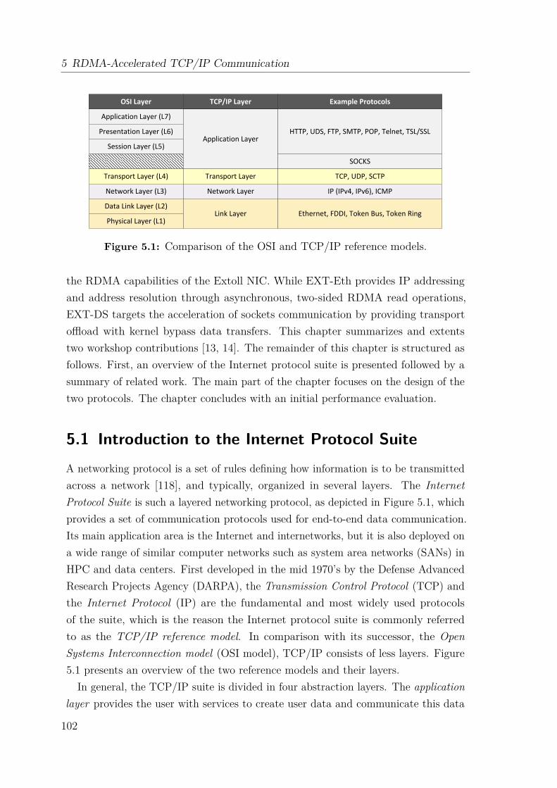
5 RDMA-Accelerated TCP/IP Communication
Application Layer (L7)
Presentation Layer (L6)
Session Layer (L5)
Transport Layer (L4)
Network Layer (L3)
Data Link Layer (L2)
Physical Layer (L1)
OSI Layer TCP/IP Layer
Application Layer
Transport Layer
Network Layer
Link Layer
HTTP, UDS, FTP, SMTP, POP, Telnet, TSL/SSL
SOCKS
TCP, UDP, SCTP
IP (IPv4, IPv6), ICMP
Ethernet, FDDI, Token Bus, Token Ring
Example Protocols
Figure 5.1: Comparison of the OSI and TCP/IP reference models.
the RDMA capabilities of the Extoll NIC. While EXT-Eth provides IP addressingand address resolution through asynchronous, two-sided RDMA read operations,EXT-DS targets the acceleration of sockets communication by providing transportoffload with kernel bypass data transfers. This chapter summarizes and extentstwo workshop contributions [13, 14]. The remainder of this chapter is structured asfollows. First, an overview of the Internet protocol suite is presented followed by asummary of related work. The main part of the chapter focuses on the design of thetwo protocols. The chapter concludes with an initial performance evaluation.
5.1 Introduction to the Internet Protocol SuiteA networking protocol is a set of rules defining how information is to be transmittedacross a network [118], and typically, organized in several layers. The InternetProtocol Suite is such a layered networking protocol, as depicted in Figure 5.1, whichprovides a set of communication protocols used for end-to-end data communication.Its main application area is the Internet and internetworks, but it is also deployed ona wide range of similar computer networks such as system area networks (SANs) inHPC and data centers. First developed in the mid 1970’s by the Defense AdvancedResearch Projects Agency (DARPA), the Transmission Control Protocol (TCP) andthe Internet Protocol (IP) are the fundamental and most widely used protocolsof the suite, which is the reason the Internet protocol suite is commonly referredto as the TCP/IP reference model. In comparison with its successor, the OpenSystems Interconnection model (OSI model), TCP/IP consists of less layers. Figure5.1 presents an overview of the two reference models and their layers.
In general, the TCP/IP suite is divided in four abstraction layers. The applicationlayer provides the user with services to create user data and communicate this data
102
5.1 Introduction to the Internet Protocol Suite
to other applications on the same or another node. The communication can becharacterized by different models such as the client-server model and peer-to-peernetworking. The transport layer provides end-to-end communication services forapplications. The User Datagram Protocol (UDP) and TCP are the main protocols ofthis layer. The network layer provides a uniform networking interface. It defines theaddressing and routing structures, while hiding the actual topology of the underlyingnetwork. The main protocol of this layer is the Internet Protocol (IP). The link layeris the lowest layer and consists of the device driver and the actual hardware interface,i.e., the network interface controller. The layer is concerned with transferring dataacross a physical link. One important characteristic is the maximum transmissionunit (MTU), which defines the upper limit of the size of a frame.
5.1.1 The Network Layer: IP
The network layer is responsible for the packet delivery from the origin to thedestination node and performs a variety of tasks. These tasks include the breaking ofdata into fragments small enough for transmission via the link layer and the routingof data across the Internet, but also the supply of services to the transport layer.The main protocol in the network layer is the Internet protocol (IP). The first
version of IP was introduced in 1981 [119] and is commonly known as the InternetProtocol version 4 (IPv4). It provides a 32-bit addressing scheme for identifyingsubnets and hosts. In 1998, the IP version 6 (IPv6) standard was released [120],which introduces 128-bit addresses, thus, providing a much larger range of addressesto be assigned to hosts.
IP Datagrams IP transmits data in packets called datagrams, which are sentindependently across the network. An IP datagram consists of a header and itspayload. The header can have up to 60 bytes and contains the destination address,so that the datagram can be routed, but also the source address of the packet. Thesize of the payload is specified by the upper limit on the size of a datagram, whichmust at least match the minimum reassembly buffer size specified by IP.
Transmission Mode IP is a connectionless, unreliable protocol. It neither providesthe concept of a virtual circuit connecting two hosts nor guarantees that packets aredelivered in order, will not be duplicated, or even arrive at all. In addition, IP hasno error recovery mechanism. Reliability must be provided either by the transportprotocol or by the application itself.
103
5 RDMA-Accelerated TCP/IP Communication
Fragmentation and Reassembly IPv4 datagrams can be up to 65,535 bytes insize, while the default IPv6 datagram size is 65,575 bytes (with 40 bytes for theheader and 65,535 bytes for the payload) and can be scaled up to 4 GiB with socalled jumbograms. When the IP datagram size exceeds the MTU of the link layerbelow, IP fragments the datagrams into suitably sized units for transmission acrossthe network. The fragments are then reassembled at the destination. A majordisadvantage of this mechanism is that a datagram can only be reassembled if all ofits fragments arrive at the destination; IP does not perform packet retransmission.
5.1.2 The Transport Layer
Residing on top of the network layer, there are two primary transport layer protocols:the Transmission Control Protocol (TCP) [121] and the User Datagram Protocol(UDP) [122]. UDP provides an unreliable datagram service, while TCP providesflow-control, connection establishment and reliable data transmission. To establishend-to-end communication and to be able to differentiate applications running on ahost, both protocols use a 16-bit port number.
5.1.2.1 User Datagram Protocol
UDP mainly adds two features to IP: port numbers and a data checksum for errordetection and data integrity checks. UDP is connectionless and unreliable. If anapplication using UDP as the transport protocol requires reliability, this must beimplemented by the application itself.
When comparing UDP and TCP, one questions that arises is why one should useUDP at all. For extensive details, the reader is referred to chapter 22 of the bookUNIX Network Programming Volume 1 by Stevens et al. [41]. Some reasons can besummarized as follows. A UDP server can receive datagrams from multiple clientswithout the need to establish a connection for each client. UDP can be faster forsimple request-response communications. Also, UDP sockets permit multicasting orbroadcasting of datagrams to multiple or all nodes connected to the network.
5.1.2.2 Transmission Control Protocol
TCP provides a reliable, connection-oriented, bidirectional, error-checked packetdelivery service for byte-streams (octet-streams) between two TCP endpoints (i.e.,applications). It offers a suitable transport method to user applications which relyon reliable session-based data transmission such as client-server databases and e-mail
104
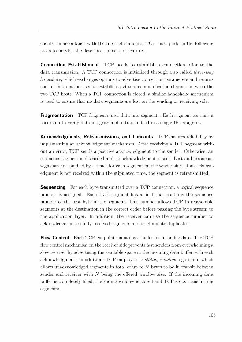
5.1 Introduction to the Internet Protocol Suite
clients. In accordance with the Internet standard, TCP must perform the followingtasks to provide the described connection features.
Connection Establishment TCP needs to establish a connection prior to thedata transmission. A TCP connection is initialized through a so called three-wayhandshake, which exchanges options to advertise connection parameters and returnscontrol information used to establish a virtual communication channel between thetwo TCP hosts. When a TCP connection is closed, a similar handshake mechanismis used to ensure that no data segments are lost on the sending or receiving side.
Fragmentation TCP fragments user data into segments. Each segment contains achecksum to verify data integrity and is transmitted in a single IP datagram.
Acknowledgments, Retransmissions, and Timeouts TCP ensures reliability byimplementing an acknowledgment mechanism. After receiving a TCP segment with-out an error, TCP sends a positive acknowledgment to the sender. Otherwise, anerroneous segment is discarded and no acknowledgment is sent. Lost and erroneoussegments are handled by a timer for each segment on the sender side. If an acknowl-edgment is not received within the stipulated time, the segment is retransmitted.
Sequencing For each byte transmitted over a TCP connection, a logical sequencenumber is assigned. Each TCP segment has a field that contains the sequencenumber of the first byte in the segment. This number allows TCP to reassemblesegments at the destination in the correct order before passing the byte stream tothe application layer. In addition, the receiver can use the sequence number toacknowledge successfully received segments and to eliminate duplicates.
Flow Control Each TCP endpoint maintains a buffer for incoming data. The TCPflow control mechanism on the receiver side prevents fast senders from overwhelming aslow receiver by advertising the available space in the incoming data buffer with eachacknowledgment. In addition, TCP employs the sliding window algorithm, whichallows unacknowledged segments in total of up to N bytes to be in transit betweensender and receiver with N being the offered window size. If the incoming databuffer is completely filled, the sliding window is closed and TCP stops transmittingsegments.
105

5 RDMA-Accelerated TCP/IP Communication
Application
File
Sockets
TCP
IP
Ethernet
NIC Driver
NIC
User
Kernel
Device
write(fd, buf, len)
Validate file descriptor.
Copy/append buf to socket buffer.
Create TCP segment according to TCP state. Compute checksum.
Add IP header, perform IP routing.Compute checksum.
Add Ethernet header, perform ARP.
Tell NIC to send the packet.
Fetch the packet from host memory and send it. Interrupt the host when send is done. IFG Pre. Eth. IP TCP CRC
Eth. IP TCP
IP TCP
TCP
User data
Host
Send socket buffer:
Figure 5.2: Overview of the TCP/IP data transmission path [123].
Congestion Control: Slow-Start and Congestion-Avoidance Algorithms TCPprovides a congestion avoidance method called slow-start algorithm, which is designedto prevent a fast sender from overwhelming the network. Initially, the sender transmitssegments at a slower rate, but exponentially increases the rate as the segments areacknowledged by the receiver until the transmission capacity of the network issaturated. In addition, congestion windows limit the amount of unacknowledgeddata that can be transmitted. Similarly to the slow-start algorithm, the window sizeincreases exponentially until a specified threshold is reached.
5.1.3 Data Transmission and Reception in Linux
Figure 5.2 displays the data transmission path of a packet with the correspondingtasks performed by each layer. The TCP/IP layers can classified in three areas:user area, kernel area, and device area. All tasks in the user and kernel area areperformed by the CPU. The device is represented by a network interface controller.
At the beginning of the send path, a user typically establishes a socket connectionand initializes the send process, e.g., by calling write(). The file layer performs asimple file validation, and then, forwards the data to the sockets layer by calling thesocket send function, which in turn copies the data to the corresponding socket bufferstructure. For this purpose, the kernel socket has two buffers: the send socket bufferand the receive socket buffer. The send socket buffer is fragmented in TCP segmentsand appended with a header including the checksum and sequence number for thesegment. From there, the segment is handed down to the IP layer where the it isencapsulated in an IP datagram. The IP layer adds an IP header and performs IProuting, which determines the next hop IP on the way to the destination node. Next,the Ethernet layer searches for the Media Access Control address (MAC address) of
106
5.1 Introduction to the Internet Protocol Suite
Application
File
Sockets
TCP
IP
Ethernet
NIC Driver
NIC
User
Kernel
Device
read(fd, buf, len)
Validate file descriptor.
Copy data to user space. Remove it from socket buffer. Tell TCP.
Validate the packet. Find TCB and run TCP protocol. Append payload to socket buffer.
Validate the packet. Perform IP routing. De-multiplex based on IP proto.
Validate the packet. De-multiplex based on EtherType.
Validate the packet. Wrap it in OS packet structure (socket buffer).Validate the packet. Transfer it to a pre-allocated host memory buffer. Interrupt the driver that there is a new packet.
IFG Pre. Eth. IP TCP CRC
Eth. IP TCP
IP TCP
TCP
User dataHo
st
skb Eth. IP TCP
Receive socket buffer:
Figure 5.3: Overview of the TCP/IP data reception path [123].
the next IP hop by utilizing the Address Resolution Protocol (ARP). Afterwards, thelayer adds the Ethernet header and then, the transmitting NIC driver is called tosend the packet over the network fabric.
On the receiving side, a similar stack of layers is traversed by an incoming packet.Figure 5.3 displays the different layers and corresponding tasks performed by eachlayer. The NIC transfers the incoming packet to a pre-allocated host memory bufferand sends an interrupt to the host operating system. The NIC driver then checkswhether it can handle the new packet, wraps it in a socket buffer and sends it tothe upper layer. The Ethernet layer checks whether the packet is valid and thende-multiplexes the network protocol, in this case the IP layer. The IP layer alsochecks whether the packet is valid, and then, determines whether the packet’s finaldestination is the host or another system. If it is meant for the local host, the IPlayer de-multiplexes the transport protocol from the IP header. In this example, IPsends the packet to the TCP layer. Like the other layers, TCP also validates thepacket and then, searches the TCP control block of the corresponding connection. Ifnew data has been received, the TCP layer appends the data to the correspondingreceive socket buffer. When the application calls the read system call, the data inthe socket buffer is copied to the user memory and removed from the socket buffer.
5.1.4 Interrupt Coalescing and NIC Polling with NAPI
In traditional, purely interrupt-driven systems, each received packet triggers aninterrupt in order to inform the system that a new packet is waiting to be processed.Under high traffic load, the high priority of interrupts leads to a state known as receivelivelock [124]. When a system enters this state, it will dedicate its CPU resources tointerrupt handling, while the actual packet processing as well as other processes will
107

5 RDMA-Accelerated TCP/IP Communication
Fig. 1. Schematic view of the NAPI functionality
1) The DMA engine copies a packet from the receiving NIChardware Rx Queue to an Input Queue in the mainmemory.
2) The NIC triggers a hardware IRQ which is served by theassigned CPU core. The mapping between an IRQ anda CPU core that is intended to handle the IRQ can bestatically assigned.
3) The IRQ Handler enqueues an entry referring to the In-put Queue into the poll list (napi_schedule()) andraises a so called soft IRQ (NET_RX_SOFTIRQ). EachCPU core provides a dedicated poll list to schedule thequeues that needs to be handled.
4) The soft IRQ Scheduler completes the soft IRQ and invokesthe networking functionality (net_rx_action()).
5) net_rx_action() peeks the first entry of the poll listand initiates the poll (poll()). Since the implementationof poll() is driver-specific, we discuss its behavior inthe next section.
6) A poll returns for two reasons:(a) The corresponding Input Queue is empty.(b) poll() yields after processing a certain quota
(poll size) of packets to prevent other Input Queues fromstarving (Continue with step 8).
7) The respective entry is removed from the poll list(napi_complete()) and the poll finishes. (Continuewith step 9).
8) The current poll is suspended although the Input Queue isnot empty. The respective entry is re-enqueued into thepoll list in a round-robin manner.
9) If the poll list still contains entries NAPI continues withstep 5. Otherwise, the algorithm ends.
Fig. 2. NAPI in conjunction with NIC driver ixgbe; Shaded boxes representfunctions which are part of the Linux kernel (not ixgbe)
The handling of net_rx_action()is also limited to budgetof OS processed packets as well as a timeout to share theCPU core with other competing devices or processes. If budgetpackets were processed or if the timeout expired then aNET_RX_SOFTIRQ soft IRQ is raised again and the CPUcore is released.
B. NIC driver
For the description of the interaction between the NAPIand the NIC driver, we choose the Intel 10 GbE driver ixgbe.The ixgbe driver implements the Input and Output Queues asRx and Tx rings which are continuously allocated memoryblocks made of descriptors. These descriptors point to theactual packet buffers and are used by the DMA engine to copypacket data from the NIC to the main memory (Rx) and viceversa (Tx). In case no ready to use Rx descriptors are availableto the NIC, new packets get dropped in hardware. This way anoverwhelmed system is not bothered by additional incomingpackets that cannot be handled anyway. If an Rx descriptoris available and a packet is received by the NIC, then it isstored in the NIC Rx Queue. The NIC’s Board Logic fetchesa Rx descriptor from the Rx ring and transfers the packetdata via DMA into the associated buffer in the main memory.Afterwards, an IRQ is asserted and handled (cf. Sec. III-A,steps 1 - 6). A detailed view of the most important stepsperformed by the ixgbe driver’s poll() function is providedin Fig. 2.
A feature of the ixgbe driver is that IRQs can be shared byRx and Tx rings to mitigate the number of IRQs. This means anIRQ can indicate that a packet was received and has to be han-dled, or that a packet was transmitted and the Tx ring must becleaned. For this reason the implementation of poll() is splitup into the two following phases: ixgbe_clean_tx_irqand ixgbe_clean_rx_irq.
1) In the ixgbe_clean_tx_irq() phase, the drivercleans Tx descriptors from the Tx ring which are stillassociated to packets the NIC has already sent. Thedriver can clean up to 256 Tx descriptors consecutively(independent from the poll size).
Figure 5.4: Schematic overview of the NAPI functionality [126].
starve. The New API (NAPI) [125] is an interface that implements an extension tothe traditional device driver packet processing framework. Its major design objectiveis to improve the performance of high-speed networking while reducing the workloadon the CPU. The NAPI design incorporates the following two ideas:
Interrupt Mitigation High-speed networking can create thousands of interrupts persecond. NAPI allows device drivers to disable interrupts during times of hightraffic load with a corresponding decrease in system load. Instead, NAPI offersa polling functionality on incoming packets.
Packet Throttling When the system is overwhelmed by the amount of incomingpackets and must eventually drop them, it is better if those packets are droppedbefore much effort goes into processing them. NAPI-compliant device driverscan often cause the packets to be dropped by the network card itself beforethe kernel sees the packets at all.
108
5.1 Introduction to the Internet Protocol Suite
Figure 5.4 outlines the schematic flow of the NAPI functionality. As described inBeifuß et al. [126], a NAPI-compliant device driver performs the following steps toprocess incoming packets:
(1) The NIC’s DMA engine copies an incoming packet from the RX queue residingon the NIC to an input queue in the main memory.
(2) The NIC triggers a hardware IRQ, which is served by the assigned CPU core.The mapping between an IRQ and a CPU core can be statically assigned.
(3) The interrupt request (IRQ) handler then enqueues an entry referring to theinput queue into the poll list and triggers a soft IRQ.
(4) The soft IRQ scheduler completes the soft IRQ and invokes the networkingfunctionality.
(5) net_rx_action() peeks the first entry of the poll list and initiates the pollingfunctionality. The implementation of poll() is device driver-specific.
(6) A poll returns for two reasons:
(a) The corresponding input queue is empty.
(b) poll() yields after processing a certain number (specified by a budget)of packets to prevent other input queues from starving.→ Continue with step 8
(7) The respective entry is removed from the poll list and poll returns.→ Continue with step 9
(8) The current poll is suspended although the input queue is not empty. Therespective entry is re-enqueued into the poll list in a round-robin manner.
(9) If the poll list still contains entries, NAPI continues with step 5. Otherwise,the algorithm terminates.
5.1.5 TCP/IP Protocol Overhead and Bottlenecks
Most modern operating systems implement a networking stack that is based onthe TCP/IP reference model, and therefore, adopt its overhead characteristics andbottlenecks. At the time TCP/IP was developed, system resources such as memorywere limited, network data rates were low, and network processing at line rates wasnot possible due to the limitations in the NIC design. The main objective of thenetworking stack was to provide a good balance between ease of use, performance,and low memory usage.
109
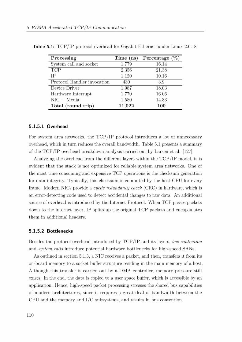
5 RDMA-Accelerated TCP/IP Communication
Table 5.1: TCP/IP protocol overhead for Gigabit Ethernet under Linux 2.6.18.
Processing Time (ns) Percentage (%)System call and socket 1,779 16.14TCP 2,356 21.38IP 1,120 10.16Protocol Handler invocation 430 3.9Device Driver 1,987 18.03Hardware Interrupt 1,770 16.06NIC + Media 1,580 14.33Total (round trip) 11,022 100
5.1.5.1 Overhead
For system area networks, the TCP/IP protocol introduces a lot of unnecessaryoverhead, which in turn reduces the overall bandwidth. Table 5.1 presents a summaryof the TCP/IP overhead breakdown analysis carried out by Larsen et al. [127].Analyzing the overhead from the different layers within the TCP/IP model, it is
evident that the stack is not optimized for reliable system area networks. One ofthe most time consuming and expensive TCP operations is the checksum generationfor data integrity. Typically, this checksum is computed by the host CPU for everyframe. Modern NICs provide a cyclic redundancy check (CRC) in hardware, which isan error-detecting code used to detect accidental changes to raw data. An additionalsource of overhead is introduced by the Internet Protocol. When TCP passes packetsdown to the internet layer, IP splits up the original TCP packets and encapsulatesthem in additional headers.
5.1.5.2 Bottlenecks
Besides the protocol overhead introduced by TCP/IP and its layers, bus contentionand system calls introduce potential hardware bottlenecks for high-speed SANs.
As outlined in section 5.1.3, a NIC receives a packet, and then, transfers it from itson-board memory to a socket buffer structure residing in the main memory of a host.Although this transfer is carried out by a DMA controller, memory pressure stillexists. In the end, the data is copied to a user space buffer, which is accessible by anapplication. Hence, high-speed packet processing stresses the shared bus capabilitiesof modern architectures, since it requires a great deal of bandwidth between theCPU and the memory and I/O subsystems, and results in bus contention.
110
5.2 Related Work
For TCP/IP, there are two important system call properties to be considered.First, software interrupts or traps are used by a CPU to communicate with the kernel.Second, an issued system call has to return before an application can continue towork in user mode. Due to the blocking behavior of system calls such as send() andrecv(), expensive wake-up operations are needed.
5.2 Related WorkNumerous research has been targeting the overall optimization of the TCP/IP stack.A detailed summary can be found in a survey paper by Hanford et al. [128]. Ofparticular interest for this work are implementations of either TCP/IP or Ethernetover high-performance SANs. While implementations such as IP over Gemini Fabric[129] are just briefly mentioned, the Infiniband technology offers a vast variety ofresearch studies targeting the seamless support of legacy applications.The following sections provide an overview of the OpenFabrics Enterprise Dis-
tribution (OFED) targeting Infiniband and Ethernet networks, and a summary ofsockets-like interface implementations.
5.2.1 OpenFabrics Enterprise Distribution
The OpenFabrics Enterprise Distribution (OFED) [108] is an open-source softwarestack offering different network adapter drivers for Infiniband and Ethernet devices,middle/upper layer kernel core modules and related libraries and utilities for RDMAand kernel bypass applications. Figure 5.5 provides an overview of the supportedprotocols and interconnects.
IP over Infiniband IP over InfiniBand (IPoIB) [130, 131, 132] is a protocol thatspecifies how to encapsulate and transmit IPv4/IPv6 and Address Resolution Protocol(ARP) packets over Infiniband. Therefore, IPoIB enables IP-based legacy applicationsto run seamlessly on an Infiniband fabric. IPoIB is implemented using either theunreliable datagram (UD) mode [130] or the reliable connected (RC) mode [132]. InLinux, the ib_ipoib kernel driver implements this protocol by creating a networkinterface [84, chapter 17] for each Infiniband port on the system. This way, an HCAacts like an Ethernet NIC. Every such IPoIB network interface has a 20 bytes MACaddress, which may cause problems since the “standard” Ethernet MAC address is6 bytes (48 bits) in size. Also, the IPoIB protocol does not fully utilize the HCA’scapabilities such as it does not implement any kernel bypass, reliability, RDMA, and
111
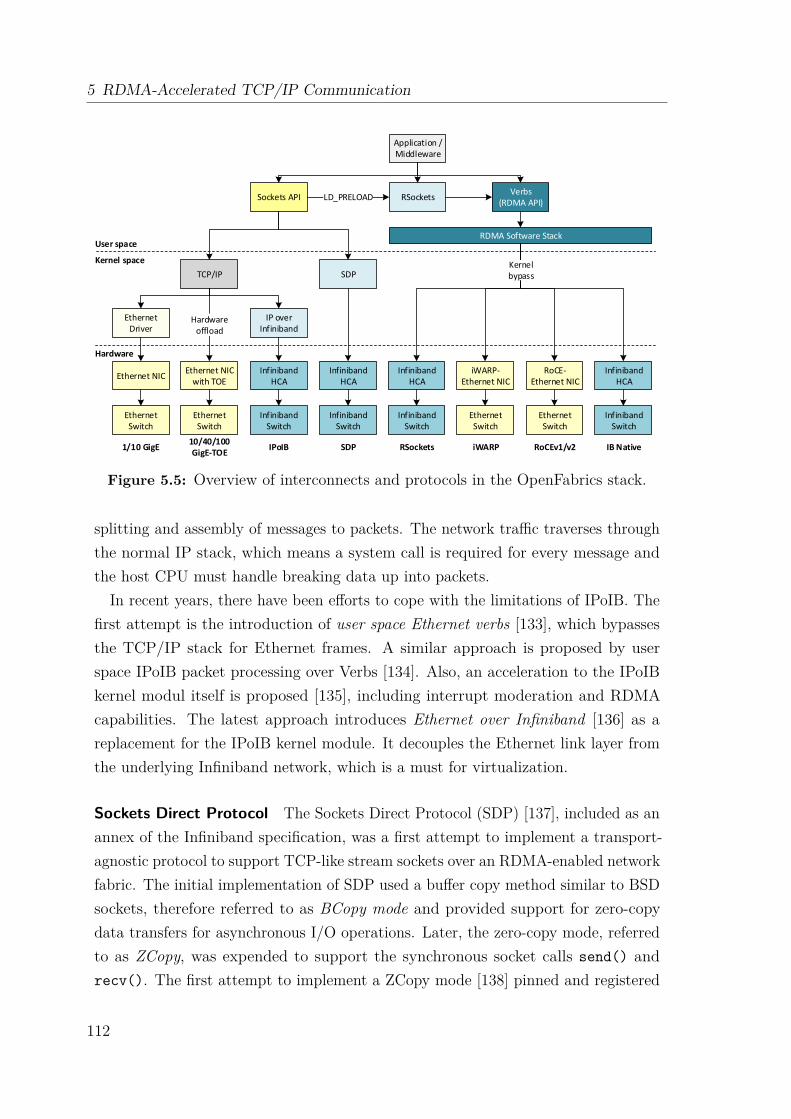
5 RDMA-Accelerated TCP/IP Communication
Application / Middleware
Sockets APIVerbs
(RDMA API)
TCP/IP
Ethernet Driver
Ethernet NIC
IP over Infiniband
Ethernet NIC with TOE
Infiniband HCA
Ethernet Switch
Ethernet Switch
Infiniband Switch
SDP
Infiniband HCA
Infiniband Switch
Infiniband HCA
Infiniband Switch
iWARP-Ethernet NIC
Ethernet Switch
RoCE-Ethernet NIC
Ethernet Switch
Infiniband HCA
Infiniband Switch
RDMA Software Stack
RSocketsLD_PRELOAD
Hardware offload
1/10 GigE10/40/100 GigE-TOE
IPoIB SDP RSockets iWARP RoCEv1/v2 IB Native
Kernel bypass
User space
Kernel space
Hardware
Figure 5.5: Overview of interconnects and protocols in the OpenFabrics stack.
splitting and assembly of messages to packets. The network traffic traverses throughthe normal IP stack, which means a system call is required for every message andthe host CPU must handle breaking data up into packets.
In recent years, there have been efforts to cope with the limitations of IPoIB. Thefirst attempt is the introduction of user space Ethernet verbs [133], which bypassesthe TCP/IP stack for Ethernet frames. A similar approach is proposed by userspace IPoIB packet processing over Verbs [134]. Also, an acceleration to the IPoIBkernel modul itself is proposed [135], including interrupt moderation and RDMAcapabilities. The latest approach introduces Ethernet over Infiniband [136] as areplacement for the IPoIB kernel module. It decouples the Ethernet link layer fromthe underlying Infiniband network, which is a must for virtualization.
Sockets Direct Protocol The Sockets Direct Protocol (SDP) [137], included as anannex of the Infiniband specification, was a first attempt to implement a transport-agnostic protocol to support TCP-like stream sockets over an RDMA-enabled networkfabric. The initial implementation of SDP used a buffer copy method similar to BSDsockets, therefore referred to as BCopy mode and provided support for zero-copydata transfers for asynchronous I/O operations. Later, the zero-copy mode, referredto as ZCopy, was expended to support the synchronous socket calls send() andrecv(). The first attempt to implement a ZCopy mode [138] pinned and registered
112
5.2 Related Work
the application buffers in the SDP implementation and supported two differentmodes: Read ZCopy and Write ZCopy. The ZCopy mode utilized Infiniband’s FastMemory Region mechanism to transfer data between two HCAs. However, it didnot allow simultaneous send requests, a send() call would block until the data wasreceived. This blocking behavior was necessary to prevent the modification of theuser memory involved in the data transfer while being processed.
The Asynchronous Zero-Copy SDP (AZ-SDP) [139] allows multiple simultaneoussend requests and introduces the mprotect() call as a safeguard mechanism, whichforces a segmentation fault whenever a user modifies the memory region of an ongoingtransfer. This protection mechanism results in an additional kernel trap for everydata transfer, which forces the user application to block or copy the memory area.The main objective of SDP is to run with unmodified sockets applications. Therefore,this costly mechanism is needed since applications can reuse memory as soon asthe sockets library returns control to the application. The SDP protocol has beendeprecated by several different user space libraries providing the same functionality.
RSockets The RSockets [140] library implements a user space protocol for bytestreaming transfers over RDMA, which provides parity with standard TCP-basedsockets. It comes with its own blocking API, which is similar to standard socketcalls such as rsend() and rrecv(), and typically performs buffer copies on bothsides. Existing socket applications can utilize RSockets by using the pre-loadableconversion library, which exports socket calls and maps them to RSockets. A zero-copy functionality is available as a set of extra functions on top of RSockets, i.e.,riomap() and riowrite().
Internet Wide Area RDMA Protocol The Internet Wide Area RDMA Protocol(iWARP) enables RDMA over TCP/IP infrastructures, including zero-copy andprotocol offload, if the underlying NIC provides RDMA functionality. iWARP islayered on the congestion-aware protocols TCP and the Stream Control TransmissionProtocol (SCTP) [141] and is defined by a set of RFCs, specifically the RDMAProtocol (RDMAP) [142], Direct Data Placement (DDP) protocol [143], MarkerPDU Aligned (MPA) Framing [144], and DDP over SCTP [145]. DDP is the maincomponent in the protocol, which permits the actual zero-copy transmission. iWARPonly supports reliable connected transport services and is not able to perform RDMAmulticasts. Applications implementing the Verbs API can utilize iWARP.
113
5 RDMA-Accelerated TCP/IP Communication
RDMA over Converged Ethernet In contrast to iWARP, RDMA over ConvergedEthernet (RoCE) [146] is an InfiniBand Trade Association standard designed toprovide Infiniband communication on Ethernet networks. RoCE preserves theInfiniBand Verbs semantics together with its transport and network protocols andreplaces the InfiniBand link and physical layers with those of Ethernet. RoCE packetsare regular Ethernet frames with an EtherType allocated by IEEE which indicatesthat the next header is a RoCE value global route header, but they do not carryan IP header. Therefore, they cannot be routed across the boundaries of EthernetL2 subnets. RoCE version 2 (RoCEv2) is a straightforward extension of the RoCEprotocol that involves a simple modification of the RoCE packet format. Instead ofthe global route header, RoCEv2 packets carry an IP header which allows traversalof IP L3 Routers and a UDP header that serves as a stateless encapsulation layer forthe RDMA transport protocol packets over IP.
5.2.2 Sockets-like Interfaces
GMSOCKS GMSOCKS [147] is a direct sockets implementation that maps stan-dard Windows socket calls onto the Myrinet/GM device driver without the need tomodify the source code, or relink or recompile the application. GM is a messagepassing system for Myrinet networks and includes a driver, a Myrinet-interfacecontrol program, a network mapping program, and the GM API, library and headerfiles. GMSOCKS is implemented as a thin user space software layer in betweenthe Winsock Direct architecture and the GM user library. The Windows socketcalls are intercepted with the Detours runtime library [148], which provides dynamicinterception of arbitrary Win32 binary functions at runtime on x86 machines.Depending on the Winsock version, GMSOCKS utilizes the buffered copy or
write zero-copy mode for data transfers. GMSOCKS uses so-called companionsockets to retrieve information about socket descriptors and match them with thecorresponding GM information. Since GM provides only one receive queue, a workerthread dispatches incoming messages and inserts them into the corresponding receivequeues of established point-to-point connections. GMSOCKS provides full semanticsand is fully functional against the TCP/IP implementation.
Mellanox’s Messaging Accelerator Mellanox’s Messaging Accelerator (VMA)[149], formerly known as Voltaire Messaging Accelerator, is an open source project. Itcomes as a dynamically linked user-space library and implements the native RDMAverbs API. The VMA library does not require any code changes or recompiling of
114

5.3 Objectives and Strategy
user applications. Instead, it is dynamically loaded via the Linux OS environmentvariable, LD_PRELOAD and intercepts the socket receive and send calls made to thestream socket or datagram socket address families. The VMA library bypasses theoperating system by implementing the underlying work in user space.
uStream uStream [150] is a user-level stream protocol over InfiniBand and elimi-nates context switches and data copies between kernel and user space. It utilizesthreads to implement asynchronous send requests and uses internally pre-registeredsend and receive buffers. The communication management is split in two commu-nication channels, a data and a control channel. While this mechanism simplifiesthe data path, it requires extra resources to manage the connections. uStream iscomplemented by jStream, which provides uStream functionality to Java applications.
UNH Extended Sockets Library The UNH EXS library is an implementationof the Extended Sockets API (ES-API) for RDMA over Infiniband. The ES-APIspecification offers a sockets-like interface that defines extensions to the traditionalsocket API in order to provide asynchronous I/O, but also memory registration forRDMA. UNH EXS offers both stream-oriented and message-oriented sockets. UnlikeSDP and VMA, UNH EXS is not designed to run with unmodified sockets applica-tions, which simplifies the design considerably. The library introduces an algorithmthat dynamically switches between buffered and zero-copy transfers over RDMA,depending on current conditions. If a send call exceeds the memory window assignedto the receive call, the additional chunks are written to a “hidden” intermediatebuffer on the receiver side. To enable true zero-copy, the library implements anadvert mechanism that allows direct transfers depending on the receive buffer size.
5.3 Objectives and StrategyThe TCP/IP network stack is the predominant protocol family for network communi-cation, including HPC system networks where system area networks are deployed. Aspresented in section 5.1, the layered architecture of TCP/IP introduces considerablyhigh overhead and performance bottlenecks, especially for interconnection networksthat provide reliable connections. Even though, it is desirable to implement TCP/IPcommunication means for an interconnect such as Extoll. Transparent and seamlesssupport of legacy code, the Socket API and IP address resolution enables a broadrange of applications and services to exploit the benefits of Extoll, including itsRDMA and transport offloading capabilities, without any code modifications.
115
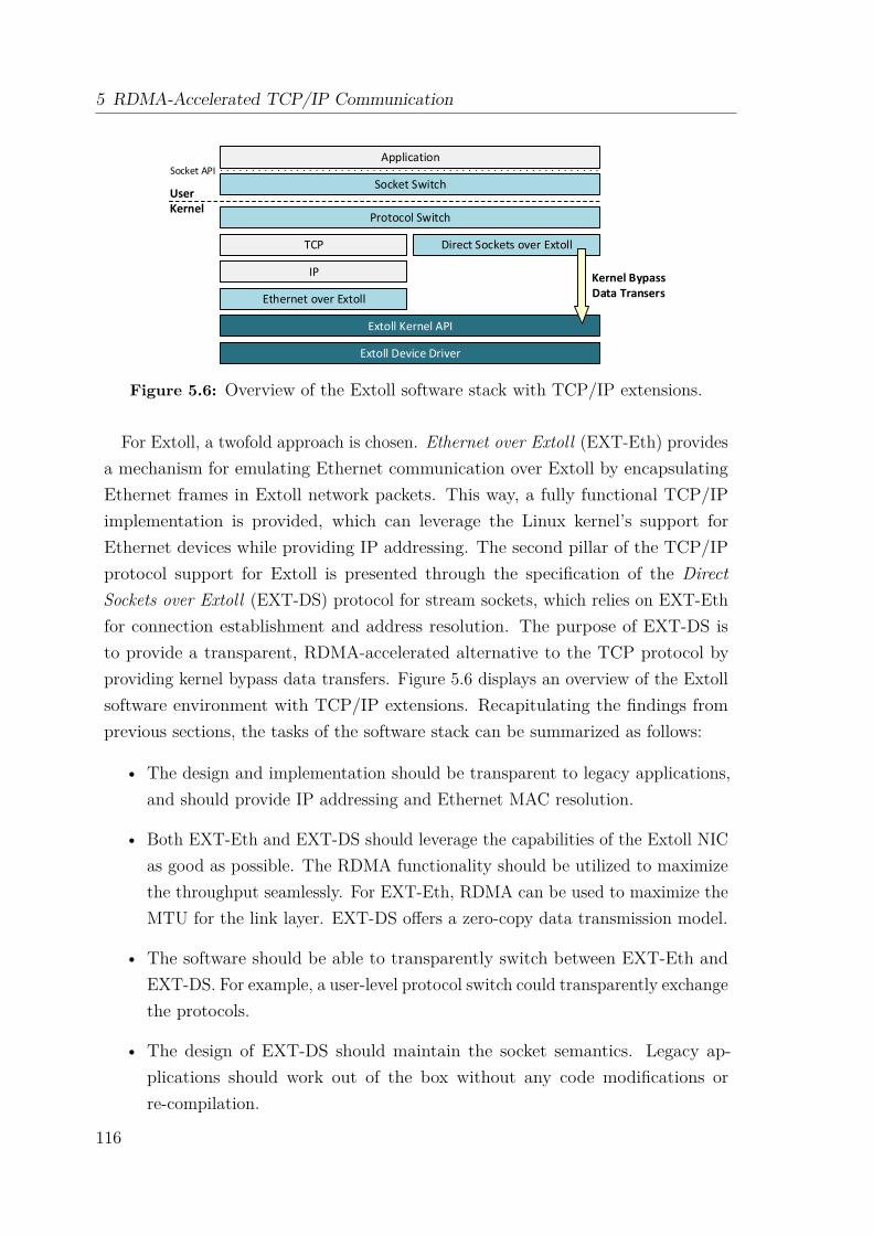
5 RDMA-Accelerated TCP/IP Communication
Application
Socket Switch
Protocol Switch
Ethernet over Extoll
Extoll Kernel API
Extoll Device Driver
Direct Sockets over Extoll
UserKernel
Socket API
IP
TCP
Kernel BypassData Transers
Figure 5.6: Overview of the Extoll software stack with TCP/IP extensions.
For Extoll, a twofold approach is chosen. Ethernet over Extoll (EXT-Eth) providesa mechanism for emulating Ethernet communication over Extoll by encapsulatingEthernet frames in Extoll network packets. This way, a fully functional TCP/IPimplementation is provided, which can leverage the Linux kernel’s support forEthernet devices while providing IP addressing. The second pillar of the TCP/IPprotocol support for Extoll is presented through the specification of the DirectSockets over Extoll (EXT-DS) protocol for stream sockets, which relies on EXT-Ethfor connection establishment and address resolution. The purpose of EXT-DS isto provide a transparent, RDMA-accelerated alternative to the TCP protocol byproviding kernel bypass data transfers. Figure 5.6 displays an overview of the Extollsoftware environment with TCP/IP extensions. Recapitulating the findings fromprevious sections, the tasks of the software stack can be summarized as follows:
• The design and implementation should be transparent to legacy applications,and should provide IP addressing and Ethernet MAC resolution.
• Both EXT-Eth and EXT-DS should leverage the capabilities of the Extoll NICas good as possible. The RDMA functionality should be utilized to maximizethe throughput seamlessly. For EXT-Eth, RDMA can be used to maximize theMTU for the link layer. EXT-DS offers a zero-copy data transmission model.
• The software should be able to transparently switch between EXT-Eth andEXT-DS. For example, a user-level protocol switch could transparently exchangethe protocols.
• The design of EXT-DS should maintain the socket semantics. Legacy ap-plications should work out of the box without any code modifications orre-compilation.
116
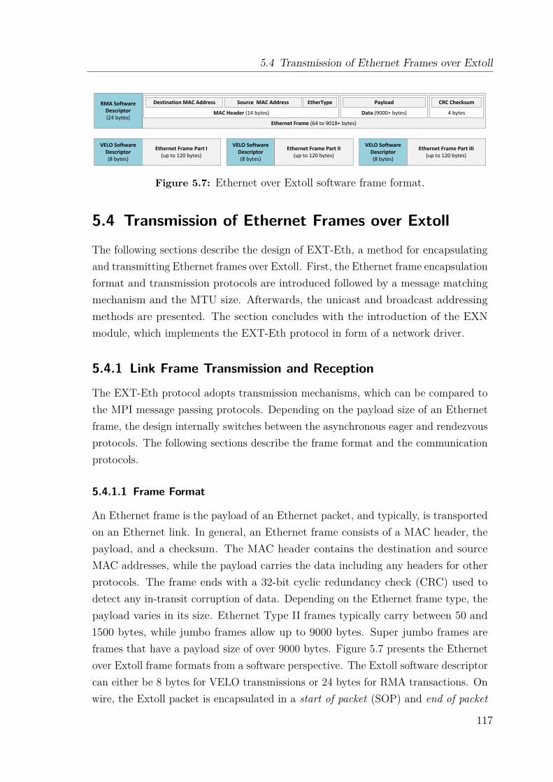
5.4 Transmission of Ethernet Frames over Extoll
Ethernet Frame (64 to 9018+ bytes)
4 bytesData (9000+ bytes)MAC Header (14 bytes)
Destination MAC Address Source MAC Address EtherType Payload CRC ChecksumRMA Software Descriptor(24 bytes)
VELO Software Descriptor(8 bytes)
Ethernet Frame Part I(up to 120 bytes)
VELO Software Descriptor(8 bytes)
Ethernet Frame Part II(up to 120 bytes)
VELO Software Descriptor(8 bytes)
Ethernet Frame Part III(up to 120 bytes)
Figure 5.7: Ethernet over Extoll software frame format.
5.4 Transmission of Ethernet Frames over ExtollThe following sections describe the design of EXT-Eth, a method for encapsulatingand transmitting Ethernet frames over Extoll. First, the Ethernet frame encapsulationformat and transmission protocols are introduced followed by a message matchingmechanism and the MTU size. Afterwards, the unicast and broadcast addressingmethods are presented. The section concludes with the introduction of the EXNmodule, which implements the EXT-Eth protocol in form of a network driver.
5.4.1 Link Frame Transmission and Reception
The EXT-Eth protocol adopts transmission mechanisms, which can be compared tothe MPI message passing protocols. Depending on the payload size of an Ethernetframe, the design internally switches between the asynchronous eager and rendezvousprotocols. The following sections describe the frame format and the communicationprotocols.
5.4.1.1 Frame Format
An Ethernet frame is the payload of an Ethernet packet, and typically, is transportedon an Ethernet link. In general, an Ethernet frame consists of a MAC header, thepayload, and a checksum. The MAC header contains the destination and sourceMAC addresses, while the payload carries the data including any headers for otherprotocols. The frame ends with a 32-bit cyclic redundancy check (CRC) used todetect any in-transit corruption of data. Depending on the Ethernet frame type, thepayload varies in its size. Ethernet Type II frames typically carry between 50 and1500 bytes, while jumbo frames allow up to 9000 bytes. Super jumbo frames areframes that have a payload size of over 9000 bytes. Figure 5.7 presents the Ethernetover Extoll frame formats from a software perspective. The Extoll software descriptorcan either be 8 bytes for VELO transmissions or 24 bytes for RMA transactions. Onwire, the Extoll packet is encapsulated in a start of packet (SOP) and end of packet
117
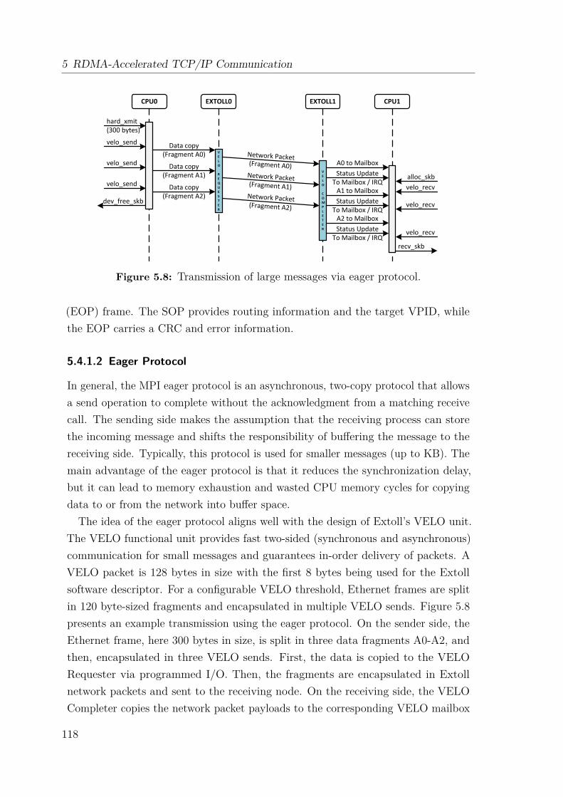
5 RDMA-Accelerated TCP/IP Communication
CPU0 EXTOLL0 EXTOLL1 CPU1
VELO
REQUESTER
VELO
COMPLETER
Data copy(Fragment A0) Network Packet
(Fragment A0)
hard_xmit(300 bytes)
velo_send
A0 to MailboxStatus Update
To Mailbox / IRQalloc_skbvelo_recv
dev_free_skb
recv_skb
velo_send Data copy(Fragment A1)
velo_send Data copy(Fragment A2)
Network Packet(Fragment A1)Network Packet(Fragment A2) velo_recv
velo_recv
A1 to MailboxStatus Update
To Mailbox / IRQA2 to MailboxStatus Update
To Mailbox / IRQ
Figure 5.8: Transmission of large messages via eager protocol.
(EOP) frame. The SOP provides routing information and the target VPID, whilethe EOP carries a CRC and error information.
5.4.1.2 Eager Protocol
In general, the MPI eager protocol is an asynchronous, two-copy protocol that allowsa send operation to complete without the acknowledgment from a matching receivecall. The sending side makes the assumption that the receiving process can storethe incoming message and shifts the responsibility of buffering the message to thereceiving side. Typically, this protocol is used for smaller messages (up to KB). Themain advantage of the eager protocol is that it reduces the synchronization delay,but it can lead to memory exhaustion and wasted CPU memory cycles for copyingdata to or from the network into buffer space.The idea of the eager protocol aligns well with the design of Extoll’s VELO unit.
The VELO functional unit provides fast two-sided (synchronous and asynchronous)communication for small messages and guarantees in-order delivery of packets. AVELO packet is 128 bytes in size with the first 8 bytes being used for the Extollsoftware descriptor. For a configurable VELO threshold, Ethernet frames are splitin 120 byte-sized fragments and encapsulated in multiple VELO sends. Figure 5.8presents an example transmission using the eager protocol. On the sender side, theEthernet frame, here 300 bytes in size, is split in three data fragments A0-A2, andthen, encapsulated in three VELO sends. First, the data is copied to the VELORequester via programmed I/O. Then, the fragments are encapsulated in Extollnetwork packets and sent to the receiving node. On the receiving side, the VELOCompleter copies the network packet payloads to the corresponding VELO mailbox
118

5.4 Transmission of Ethernet Frames over Extoll
CPU0 EXTOLL0 EXTOLL1 CPU1
REQUESTER
Responder Notification
Network Packet
(GET request)
VELO
VELO
Data copy(GET source info)
Network Packet(GET source info)
Network Packet(GET response)
Copy data from main
memory via DMA
Copy data into memory
via DMA
RESPONDER
hard_xmit
velo_send
Payload to Mailbox
Status Update To Mailbox / IRQ alloc_skb
rma_getGET Request
dev_free_skbCOMPLETER Completer
Notification recv_skb
Figure 5.9: Transmission of large messages via rendezvous protocol.
(one mailbox per VPID), which resides in the main memory of the node. After thecompleter writes the status word to the mailbox, an interrupt is triggered to informthe CPU that new messages have been received.
5.4.1.3 Rendezvous Protocol
The MPI rendezvous protocol is used when assumptions about the receiving processbuffer space cannot be made, or when the limits of the eager protocol are exceeded.Before any data can be transmitted, an initial handshake needs to be performedbetween the sender and the receiver. Typically, the sender process informs the targetprocess about the desired data transmission by sending a message that advertisestransmission details such as length and source address. The target process receivesthis information, and when buffer space is available, it replies to sender that themessage can be sent, which in turn, initiates the data transmission. The rendezvousprotocol provides better scalability, when compared to the eager protocol, androbustness by preventing memory exhaustion and termination on receive processes.It also enables true zero-copy communication by eliminating data copies.
Figure 5.9 displays the sequence diagram of the rendezvous protocol over Extoll fortransmitting Ethernet frames. For large messages, the transfer is advertised througha VELO send, which contains the information needed to initiate an RMA GETtransfer from the receiving node. The VELO message provides the length of theEthernet frame and the physical start address of the payload in the main memory of
119
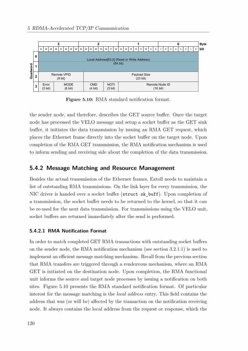
5 RDMA-Accelerated TCP/IP Communication
Local Address[63:0] (Read or Write Address)(64 bit)
Error(3 bit)
CMD(4 bit)
Remote Node ID(16 bit)
Remote VPID(9 bit)
NOTI(3 bit)
Payload Size(23 bit)
MODE(6 bit)
3 2 1 0
1
0
2Quadword
3
1011 89 67 45 23 11920 1718 1516 1314 122122232425 0262728293031
Byte
bit
Figure 5.10: RMA standard notification format.
the sender node, and therefore, describes the GET source buffer. Once the targetnode has processed the VELO message and setup a socket buffer as the GET sinkbuffer, it initiates the data transmission by issuing an RMA GET request, whichplaces the Ethernet frame directly into the socket buffer on the target node. Uponcompletion of the RMA GET transmission, the RMA notification mechanism is usedto inform sending and receiving side about the completion of the data transmission.
5.4.2 Message Matching and Resource Management
Besides the actual transmission of the Ethernet frames, Extoll needs to maintain alist of outstanding RMA transmissions. On the link layer for every transmission, theNIC driver is handed over a socket buffer (struct sk_buff). Upon completion ofa transmission, the socket buffer needs to be returned to the kernel, so that it canbe re-used for the next data transmission. For transmissions using the VELO unit,socket buffers are returned immediately after the send is performed.
5.4.2.1 RMA Notification Format
In order to match completed GET RMA transactions with outstanding socket bufferson the sender node, the RMA notification mechanism (see section 3.2.1.1) is used toimplement an efficient message matching mechanism. Recall from the previous sectionthat RMA transfers are triggered through a rendezvous mechanism, where an RMAGET is initiated on the destination node. Upon completion, the RMA functionalunit informs the source and target node processes by issuing a notification on bothsites. Figure 5.10 presents the RMA standard notification format. Of particularinterest for the message matching is the local address entry. This field contains theaddress that was (or will be) affected by the transaction on the notification receivingnode. It always contains the local address from the request or response, which the
120
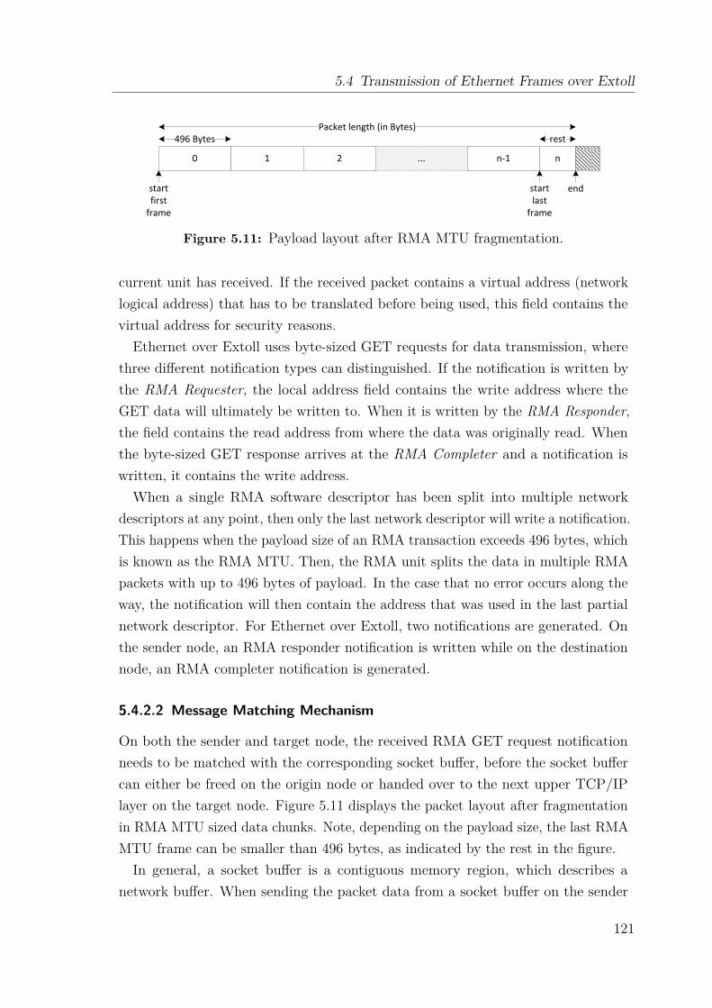
5.4 Transmission of Ethernet Frames over Extoll
...0 1 2 n-1 n
496 BytesPacket length (in Bytes)
startfirst
frame
endstart last
frame
rest
Figure 5.11: Payload layout after RMA MTU fragmentation.
current unit has received. If the received packet contains a virtual address (networklogical address) that has to be translated before being used, this field contains thevirtual address for security reasons.
Ethernet over Extoll uses byte-sized GET requests for data transmission, wherethree different notification types can distinguished. If the notification is written bythe RMA Requester, the local address field contains the write address where theGET data will ultimately be written to. When it is written by the RMA Responder,the field contains the read address from where the data was originally read. Whenthe byte-sized GET response arrives at the RMA Completer and a notification iswritten, it contains the write address.
When a single RMA software descriptor has been split into multiple networkdescriptors at any point, then only the last network descriptor will write a notification.This happens when the payload size of an RMA transaction exceeds 496 bytes, whichis known as the RMA MTU. Then, the RMA unit splits the data in multiple RMApackets with up to 496 bytes of payload. In the case that no error occurs along theway, the notification will then contain the address that was used in the last partialnetwork descriptor. For Ethernet over Extoll, two notifications are generated. Onthe sender node, an RMA responder notification is written while on the destinationnode, an RMA completer notification is generated.
5.4.2.2 Message Matching Mechanism
On both the sender and target node, the received RMA GET request notificationneeds to be matched with the corresponding socket buffer, before the socket buffercan either be freed on the origin node or handed over to the next upper TCP/IPlayer on the target node. Figure 5.11 displays the packet layout after fragmentationin RMA MTU sized data chunks. Note, depending on the payload size, the last RMAMTU frame can be smaller than 496 bytes, as indicated by the rest in the figure.In general, a socket buffer is a contiguous memory region, which describes a
network buffer. When sending the packet data from a socket buffer on the sender
121
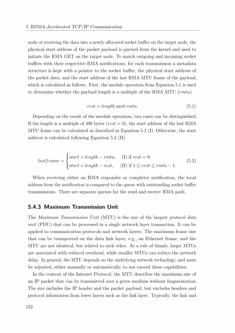
5 RDMA-Accelerated TCP/IP Communication
node or receiving the data into a newly allocated socket buffer on the target node, thephysical start address of the packet payload is queried from the kernel and used toinitiate the RMA GET on the target node. To match outgoing and incoming socketbuffers with their respective RMA notifications, for each transmission a metadatastructure is kept with a pointer to the socket buffer, the physical start address ofthe packet data, and the start address of the last RMA MTU frame of the payload,which is calculated as follows. First, the module operation from Equation 5.1 is usedto determine whether the payload length is a multiple of the RMA MTU (rmtu).
rest = length mod rmtu (5.1)
Depending on the result of the module operation, two cases can be distinguished.If the length is a multiple of 496 bytes (rest = 0), the start address of the last RMAMTU frame can be calculated as described in Equation 5.2 (I). Otherwise, the startaddress is calculated following Equation 5.2 (II).
lastframe =
start+ length− rmtu, (I) if rest = 0;
start+ length− rest, (II) if 1 ≤ rest ≤ rmtu− 1.(5.2)
When receiving either an RMA responder or completer notification, the localaddress from the notification is compared to the queue with outstanding socket buffertransmissions. There are separate queues for the send and receive RMA path.
5.4.3 Maximum Transmission Unit
The Maximum Transmission Unit (MTU) is the size of the largest protocol dataunit (PDU) that can be processed in a single network layer transaction. It can beapplied to communication protocols and network layers. The maximum frame sizethat can be transported on the data link layer, e.g., an Ethernet frame, and theMTU are not identical, but related to each other. As a rule of thumb, larger MTUsare associated with reduced overhead, while smaller MTUs can reduce the networkdelay. In general, the MTU depends on the underlying network technology, and mustbe adjusted, either manually or automatically, to not exceed these capabilities.In the context of the Internet Protocol, the MTU describes the maximum size of
an IP packet that can be transmitted over a given medium without fragmentation.The size includes the IP header and the packet payload, but excludes headers andprotocol information from lower layers such as the link layer. Typically, the link and
122
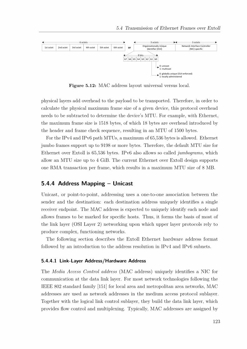
5.4 Transmission of Ethernet Frames over Extoll
1st octet 2nd octet 3rd octet 4th octet 5th octet 6th octet
6 octets 3 octets 3 octetsOrganizationally Unique
Identifier (OUI)Network Interface Controller
(NIC) specific
b7 b6 b5 b4 b3 b2 b1 b0
8 bits
0: unicast1: multicast
0: globally unique (OUI enforced)1: locally administered
or
Figure 5.12: MAC address layout universal versus local.
physical layers add overhead to the payload to be transported. Therefore, in order tocalculate the physical maximum frame size of a given device, this protocol overheadneeds to be subtracted to determine the device’s MTU. For example, with Ethernet,the maximum frame size is 1518 bytes, of which 18 bytes are overhead introduced bythe header and frame check sequence, resulting in an MTU of 1500 bytes.
For the IPv4 and IPv6 path MTUs, a maximum of 65,536 bytes is allowed. Ethernetjumbo frames support up to 9198 or more bytes. Therefore, the default MTU size forEthernet over Extoll is 65,536 bytes. IPv6 also allows so called jumbograms, whichallow an MTU size up to 4 GiB. The current Ethernet over Extoll design supportsone RMA transaction per frame, which results in a maximum MTU size of 8 MB.
5.4.4 Address Mapping – Unicast
Unicast, or point-to-point, addressing uses a one-to-one association between thesender and the destination: each destination address uniquely identifies a singlereceiver endpoint. The MAC address is expected to uniquely identify each node andallows frames to be marked for specific hosts. Thus, it forms the basis of most ofthe link layer (OSI Layer 2) networking upon which upper layer protocols rely toproduce complex, functioning networks.The following section describes the Extoll Ethernet hardware address format
followed by an introduction to the address resolution in IPv4 and IPv6 subnets.
5.4.4.1 Link-Layer Address/Hardware Address
The Media Access Control address (MAC address) uniquely identifies a NIC forcommunication at the data link layer. For most network technologies following theIEEE 802 standard family [151] for local area and metropolitan area networks, MACaddresses are used as network addresses in the medium access protocol sublayer.Together with the logical link control sublayer, they build the data link layer, whichprovides flow control and multiplexing. Typically, MAC addresses are assigned by
123
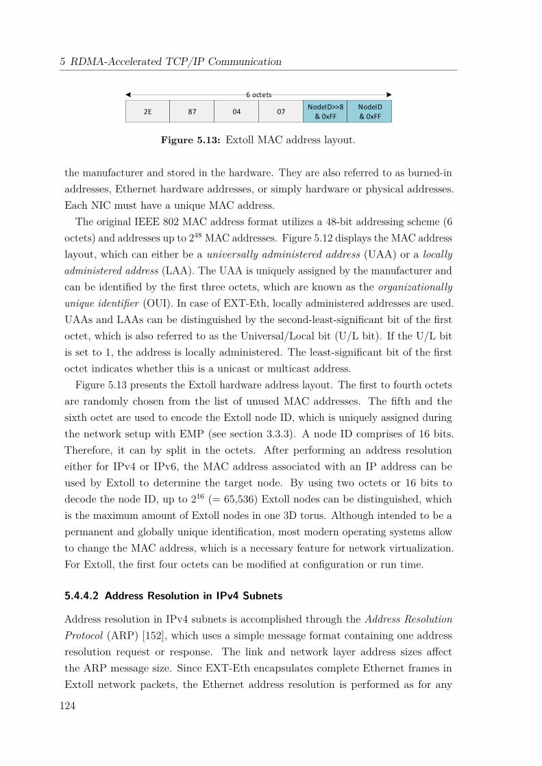
5 RDMA-Accelerated TCP/IP Communication
2E 87 04 07NodeID>>8
& 0xFFNodeID & 0xFF
6 octets
Figure 5.13: Extoll MAC address layout.
the manufacturer and stored in the hardware. They are also referred to as burned-inaddresses, Ethernet hardware addresses, or simply hardware or physical addresses.Each NIC must have a unique MAC address.
The original IEEE 802 MAC address format utilizes a 48-bit addressing scheme (6octets) and addresses up to 248 MAC addresses. Figure 5.12 displays the MAC addresslayout, which can either be a universally administered address (UAA) or a locallyadministered address (LAA). The UAA is uniquely assigned by the manufacturer andcan be identified by the first three octets, which are known as the organizationallyunique identifier (OUI). In case of EXT-Eth, locally administered addresses are used.UAAs and LAAs can be distinguished by the second-least-significant bit of the firstoctet, which is also referred to as the Universal/Local bit (U/L bit). If the U/L bitis set to 1, the address is locally administered. The least-significant bit of the firstoctet indicates whether this is a unicast or multicast address.
Figure 5.13 presents the Extoll hardware address layout. The first to fourth octetsare randomly chosen from the list of unused MAC addresses. The fifth and thesixth octet are used to encode the Extoll node ID, which is uniquely assigned duringthe network setup with EMP (see section 3.3.3). A node ID comprises of 16 bits.Therefore, it can by split in the octets. After performing an address resolutioneither for IPv4 or IPv6, the MAC address associated with an IP address can beused by Extoll to determine the target node. By using two octets or 16 bits todecode the node ID, up to 216 (= 65,536) Extoll nodes can be distinguished, whichis the maximum amount of Extoll nodes in one 3D torus. Although intended to be apermanent and globally unique identification, most modern operating systems allowto change the MAC address, which is a necessary feature for network virtualization.For Extoll, the first four octets can be modified at configuration or run time.
5.4.4.2 Address Resolution in IPv4 Subnets
Address resolution in IPv4 subnets is accomplished through the Address ResolutionProtocol (ARP) [152], which uses a simple message format containing one addressresolution request or response. The link and network layer address sizes affectthe ARP message size. Since EXT-Eth encapsulates complete Ethernet frames inExtoll network packets, the Ethernet address resolution is performed as for any
124
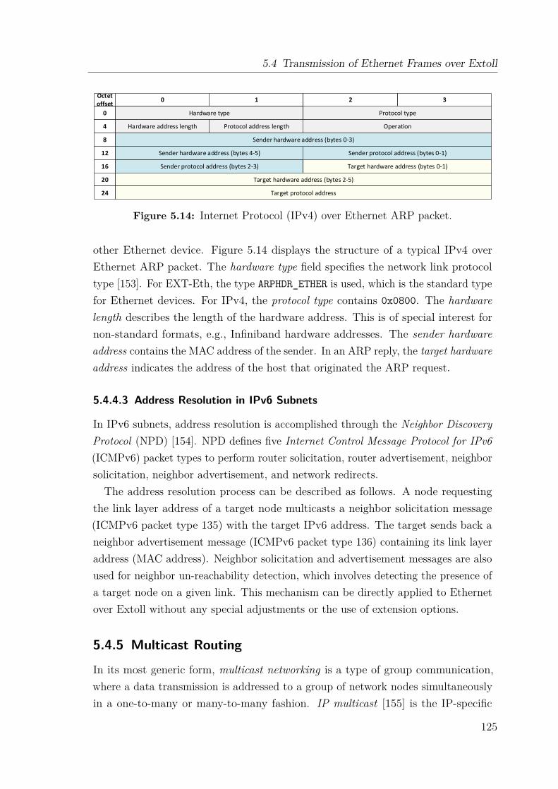
5.4 Transmission of Ethernet Frames over Extoll
10Octet offset
0
4
8
12
16
20
24
Hardware type Protocol type
OperationProtocol address lengthHardware address length
Sender hardware address (bytes 0-3)
Sender protocol address (bytes 0-1)
Sender protocol address (bytes 2-3) Target hardware address (bytes 0-1)
Target hardware address (bytes 2-5)
Target protocol address
Sender hardware address (bytes 4-5)
32
Figure 5.14: Internet Protocol (IPv4) over Ethernet ARP packet.
other Ethernet device. Figure 5.14 displays the structure of a typical IPv4 overEthernet ARP packet. The hardware type field specifies the network link protocoltype [153]. For EXT-Eth, the type ARPHDR_ETHER is used, which is the standard typefor Ethernet devices. For IPv4, the protocol type contains 0x0800. The hardwarelength describes the length of the hardware address. This is of special interest fornon-standard formats, e.g., Infiniband hardware addresses. The sender hardwareaddress contains the MAC address of the sender. In an ARP reply, the target hardwareaddress indicates the address of the host that originated the ARP request.
5.4.4.3 Address Resolution in IPv6 Subnets
In IPv6 subnets, address resolution is accomplished through the Neighbor DiscoveryProtocol (NPD) [154]. NPD defines five Internet Control Message Protocol for IPv6(ICMPv6) packet types to perform router solicitation, router advertisement, neighborsolicitation, neighbor advertisement, and network redirects.The address resolution process can be described as follows. A node requesting
the link layer address of a target node multicasts a neighbor solicitation message(ICMPv6 packet type 135) with the target IPv6 address. The target sends back aneighbor advertisement message (ICMPv6 packet type 136) containing its link layeraddress (MAC address). Neighbor solicitation and advertisement messages are alsoused for neighbor un-reachability detection, which involves detecting the presence ofa target node on a given link. This mechanism can be directly applied to Ethernetover Extoll without any special adjustments or the use of extension options.
5.4.5 Multicast Routing
In its most generic form, multicast networking is a type of group communication,where a data transmission is addressed to a group of network nodes simultaneouslyin a one-to-many or many-to-many fashion. IP multicast [155] is the IP-specific
125
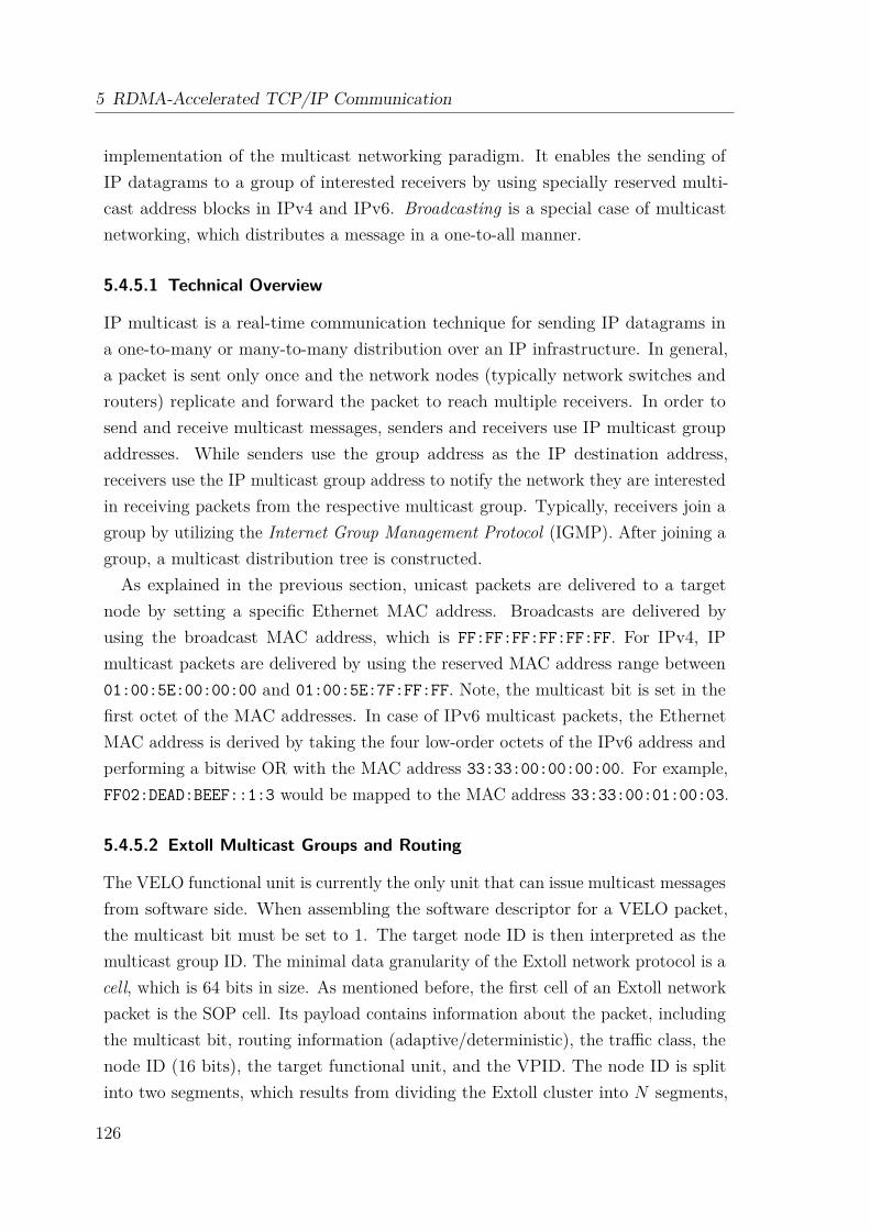
5 RDMA-Accelerated TCP/IP Communication
implementation of the multicast networking paradigm. It enables the sending ofIP datagrams to a group of interested receivers by using specially reserved multi-cast address blocks in IPv4 and IPv6. Broadcasting is a special case of multicastnetworking, which distributes a message in a one-to-all manner.
5.4.5.1 Technical Overview
IP multicast is a real-time communication technique for sending IP datagrams ina one-to-many or many-to-many distribution over an IP infrastructure. In general,a packet is sent only once and the network nodes (typically network switches androuters) replicate and forward the packet to reach multiple receivers. In order tosend and receive multicast messages, senders and receivers use IP multicast groupaddresses. While senders use the group address as the IP destination address,receivers use the IP multicast group address to notify the network they are interestedin receiving packets from the respective multicast group. Typically, receivers join agroup by utilizing the Internet Group Management Protocol (IGMP). After joining agroup, a multicast distribution tree is constructed.As explained in the previous section, unicast packets are delivered to a target
node by setting a specific Ethernet MAC address. Broadcasts are delivered byusing the broadcast MAC address, which is FF:FF:FF:FF:FF:FF. For IPv4, IPmulticast packets are delivered by using the reserved MAC address range between01:00:5E:00:00:00 and 01:00:5E:7F:FF:FF. Note, the multicast bit is set in thefirst octet of the MAC addresses. In case of IPv6 multicast packets, the EthernetMAC address is derived by taking the four low-order octets of the IPv6 address andperforming a bitwise OR with the MAC address 33:33:00:00:00:00. For example,FF02:DEAD:BEEF::1:3 would be mapped to the MAC address 33:33:00:01:00:03.
5.4.5.2 Extoll Multicast Groups and Routing
The VELO functional unit is currently the only unit that can issue multicast messagesfrom software side. When assembling the software descriptor for a VELO packet,the multicast bit must be set to 1. The target node ID is then interpreted as themulticast group ID. The minimal data granularity of the Extoll network protocol is acell, which is 64 bits in size. As mentioned before, the first cell of an Extoll networkpacket is the SOP cell. Its payload contains information about the packet, includingthe multicast bit, routing information (adaptive/deterministic), the traffic class, thenode ID (16 bits), the target functional unit, and the VPID. The node ID is splitinto two segments, which results from dividing the Extoll cluster into N segments,
126

5.4 Transmission of Ethernet Frames over Extoll
each M nodes large. Otherwise, the routing tables would need 65,536 entry RAMs,which is too large to handle. Currently, N is set to be 64 and M is set to be 1024.The table for the segments is called global routing table, the table for the nodes insidethese segments local routing table.
The Extoll on-chip network switch (crossbar) connects the functional units throughlink ports with the network ports of the NIC, and provides hardware support forefficient multicast networking, especially for broadcasts. The routing in the networklayer relies on table-based routing. Each crossbar inport has its own global, local, andmulticast routing tables, but the entries in these tables are the same over all crossbarinports. The multicast routing table can distinguish up to 64 Extoll multicast groupsand provides information about where to forward the multicast packet to. In general,the routing tables are written to the Extoll register file for every crossbar inportduring network configuration time, when the EMP initializes the network.
5.4.5.3 IP Multicasts and Broadcasts over Extoll
IP multicast routing requires a network interface to be configured to listen to all linklayer IP multicast group addresses. For an Ethernet interface, this is achieved byturning on the promiscuous multicast mode on the interface. When the promiscuousmode is enabled, the MAC filtering is disabled on the interface and all packetsreceived are sent to the CPU regardless of the destination address of the packet.The Extoll NIC is not an Ethernet NIC and utilizes the Extoll network protocol
to transmit packets. Therefore, it does not provide any hardware support for thepromiscuous multicast mode. Extoll can only route packets according to their networkdescriptors and corresponding routing table entries. Consequently, all multicast andbroadcast support comprises of the correct configuration of the routing tables onevery Extoll NIC and a software layer, which identifies IP multicast group andbroadcast addresses and encapsulates them in corresponding VELO packets with themulticast bit set. By default, the EMP configures multicast group ID 63 on everyExtoll NIC to broadcast a packet sent to this ID to every node in the Extoll network.On the software side, the software identifies a broadcast based on the matchingbroadcast Ethernet MAC address and encapsulate the corresponding Ethernet framein VELO multicast messages. Besides from the broadcast, EXT-Eth currently doesnot support IP multicast. In theory, it is possible to define multiple Extoll multicastgroups, but the software would need to keep track of group members and facilitatethe routing tables accordingly.
127
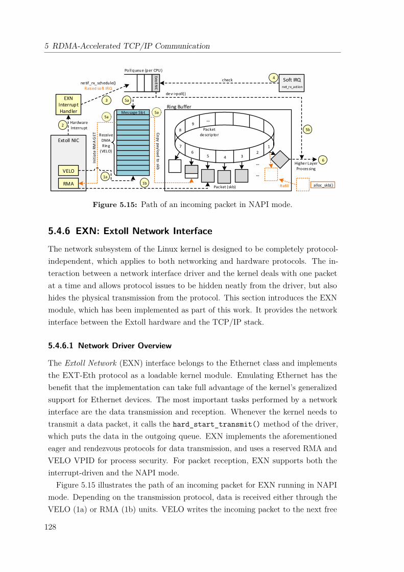
5 RDMA-Accelerated TCP/IP Communication
Message Slot
Receive
DMA
Ring
(VELO)
Extoll NIC
VELO
RMA
EXN Interrupt Handler
Extoll N
IC
Soft IRQnet_rx_action
Hardware
Interrupt
Highe r Layer
Processing
Packet (skb) alloc_skb()Refill
Ring Buffer
de v->poll()
1
2345
6
7
8
9...
...
...
Packet de scriptor
ne tif_rx_ schedule()Raised soft IRQ
check
Poll queue (per CPU)
Co
py
pa
ylo
ad
to sk
b
1a
1b
2
3
4
5a
5b
6
5a5a
Init
iate
RM
A G
ET
Figure 5.15: Path of an incoming packet in NAPI mode.
5.4.6 EXN: Extoll Network Interface
The network subsystem of the Linux kernel is designed to be completely protocol-independent, which applies to both networking and hardware protocols. The in-teraction between a network interface driver and the kernel deals with one packetat a time and allows protocol issues to be hidden neatly from the driver, but alsohides the physical transmission from the protocol. This section introduces the EXNmodule, which has been implemented as part of this work. It provides the networkinterface between the Extoll hardware and the TCP/IP stack.
5.4.6.1 Network Driver Overview
The Extoll Network (EXN) interface belongs to the Ethernet class and implementsthe EXT-Eth protocol as a loadable kernel module. Emulating Ethernet has thebenefit that the implementation can take full advantage of the kernel’s generalizedsupport for Ethernet devices. The most important tasks performed by a networkinterface are the data transmission and reception. Whenever the kernel needs totransmit a data packet, it calls the hard_start_transmit() method of the driver,which puts the data in the outgoing queue. EXN implements the aforementionedeager and rendezvous protocols for data transmission, and uses a reserved RMA andVELO VPID for process security. For packet reception, EXN supports both theinterrupt-driven and the NAPI mode.
Figure 5.15 illustrates the path of an incoming packet for EXN running in NAPImode. Depending on the transmission protocol, data is received either through theVELO (1a) or RMA (1b) units. VELO writes the incoming packet to the next free
128

5.4 Transmission of Ethernet Frames over Extoll
1 exn0: flags =67<UP ,BROADCAST ,RUNNING > mtu 655362 inet 10.2.0.8 netmask 255.255.255.0 broadcast 10.2.0.2553 inet6 fe80 ::2 c87 :4ff:fe07 :1 prefixlen 64 scopeid 0x20 <link >4 ether 2e :87:04:07:00:01 txqueuelen 1000 ( Ethernet )5 RX packets 22 bytes 1572 (1.5 KiB)6 RX errors 0 dropped 0 overruns 0 frame 07 TX packets 22 bytes 1572 (1.5 KiB)8 TX errors 0 dropped 0 overruns 0 carrier 0 collisions 0
Listing 5.1: Example output of ifconfig for Extoll network interface exn0.
message slot in a receive ring buffer associated with the used VPID. RMA, on the otherhand, writes the packet directly to a pre-allocated socket buffer. Upon completion,the Extoll NIC triggers a hardware interrupt (2). Extoll can distinguish differentsources of interrupts, e.g., different functional units. Therefore, EXN has two differentinterrupt handlers, one for VELO and one for RMA interrupts. As the processingin the interrupt context should be as low as possible, netif_rx_schedule() putsa reference to the Extoll device into the poll queue (3), which moves the packetprocessing in the software interrupt context. Then, net_rx_action() peeks the firstentry of the poll list (4). If there are packets available for reception, the functiondisables all interrupts and calls the poll() method of the driver. In case of EXN,there are two different poll() methods registered, one to process VELO interrupts(5a) and one for RMA (5b). Depending on the message tag, a VELO message caneither carry the payload of a packet or advertise an RMA GET operation. If itcontains a payload fragment, the data is copied to a free socket buffer entry in thering buffer, and after receiving the complete payload, passed to the upper layers (6).If it advertises an RMA operation, the poll() method writes the RMA softwaredescriptor and initiates the GET operation. In case of an RMA interrupt (5b), thepacket has already been received in a pre-allocated socket buffer and can be passedto the upper layers (6) for further processing.Listing 5.1 displays the command line output of the ifconfig tool for the EXN
interface. It can be seen that EXN utilizes the described MAC address format toencode the node ID information. IP addresses can either be statically or dynamicallyassigned. For static IP addresses, the interface can be configured with a preassignedIP address through an interface configuration file. Otherwise, the Dynamic HostConfiguration Protocol (DHCP) can be utilized for assigning IP addresses. By default,the interface supports IP broadcasts; IP multicasting is currently not supported.
129
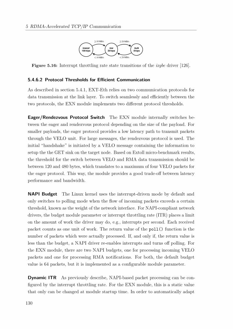
5 RDMA-Accelerated TCP/IP Communication
2) The ixgbe_clean_rx_irq() phase startswith the recycling of Rx descriptors, which isdone before they are returned to the hardware(ixgbe_alloc_rx_buffers()).
3) The packet data is fetched from the Rx ring: A Rxdescriptor is read from the ring and a socket bufferstructure (SKB) is created that points to the respectivebuffer (ixgbe_fetch_rx_buffer()).
4) After several sanity checks, the processing of the SKB isinitiated (netif_receive_skb()).
5) The Ethertype determines how the SKB is processed.
With Open vSwitch, the actual packet processing for IP packetsis defined by (ovs_vport_receive()). Open vSwitchdetermines the outgoing interface and the output queue. Atthis point, the packet transmission based on NAPI and ixgbestarts.
1’) In the end of the processing, the SKB containing the packetgets scheduled for transmission (sch_direct_xmit).
2’) A Tx descriptor is prepared in the Tx ring(ixgbe_xmit_frame_ring()). If more packetsare available on the Rx ring and if the poll size is notreached, the algorithm continues with step 2.
3’) In case the Tx and Rx rings were cleaned, the respectiveIRQ is re-enabled. If the dynamic interrupt throttling rate(ITR) is enabled, the ITR is recalculated to reprogram theNIC. Then, the poll returns to the NAPI (cf. section III-A,step 7).
C. Interrupt Throttling Rate
NAPI-based packet processing can be configured by severalparameters. In case of using the ixgbe driver one of the mostimportant parameters is the ITR. The ITR defines an upperbound of IRQs per second for a set of Tx and Rx rings.The ITR relies on a ITR timer which is set to 1
ITR after anIRQ was asserted. Until the ITR timer is expired, no furtherIRQs can be generated. If packet transmission or receptionhappened before the ITR timer expired, the IRQ is fired ontimer expiration. Otherwise the next reception or transmissionevent immediately causes an IRQ. The ITR can be configuredas static, dynamic, or disabled.
Disabling the ITR results in short packet latencies but hasa negative impact on the maximum throughput, especially inhigh traffic load situations, where the CPU is often occupiedwith IRQ handling. Using a static ITR is suitable for manuallysetting the upper bound of IRQs per second which is thenindependent of the offered load. The increase of the ITR lowersthe latency but increases the CPU utilization and may lowerthe maximum throughput. Hence, the appropriate configurationof the ITR is a trade-off between latency and maximumthroughput.
With a dynamic ITR, the ITR is adopted according tothe current traffic load. When a poll finishes, a new ITR isrecalculated. The three ITR states lowest, low (initial state)and bulk are defined where each ITR state is associated to aspecific ITR value in thousand interrupts per second (kips) asdepicted in Fig. 3.
The current ITR state s and the throughput determine thetransition to a new ITR state s′. The new ITR r′ is calculated
lowest100 kips
low20 kips
bulk8 kips
≥10 MB/s ≥20 MB/s
<20 MB/s<10 MB/s
Fig. 3. Interrupt throttling rate states of the ixgbe NIC driver
on basis of the current ITR r and the ITR value of the newITR state s′ according to Eq. (1).
r′ =10 · s′ · r9 · s′ + r
(1)
For instance, if the current offered load is low, and thus thethroughput is low, then the ITR becomes high and vice versa.
IV. LATENCY EVALUATION WITH MEASUREMENTS
For the measurement of the NAPI performance a networkstack is required that utilizes the NAPI. This network stackmust not introduce any unpredictable effects into the measureddata to avoid corruption of our packet reception and transmis-sion measurements. In the best case it only utilizes a constantadditional share of the CPU and adds a constant additionallatency per packet to the measurements. Therefore, we decidedto use Open vSwitch [25]–[27] as a representative NAPI-basedin-kernel packet forwarding application. Open vSwitch is partof Linux and is able to operate in layer 2 of the ISO OSI stackbut also in higher layers. Previously we have shown that OpenvSwitch has a predictable average per packet processing costin terms of CPU cycles [16].
A. Measurement Setup
Our test setup is based on recommendations byRFC 2544 [28]. The device under test (DuT) is connectedto a device which runs a load generator and a packet counterin order to measure the achieved throughput. For profiling ofsoftware the DuT runs the Linux tool perf to gather statisticslike the interrupt rate. Profiling measurements were run for fiveminutes per test to get accurate results. Our tests indicate thatrunning this utility on the DuT introduces an overhead thatreduces the maximum throughput by 1 %.
The DuT uses an Intel X540-T2 dual 10 GbE NIC andis equipped with a 3.3 GHz Intel Xeon E3-1230 V2 CPU.We disabled Hyper-Threading, Turbo Boost, and power savingfeatures that scale the frequency with the CPU load becausewe observed measurement artefacts with these features.
The DuT runs the Debian-based live Linux distributionGrml with a 3.7 kernel, the ixgbe 3.14.5 NIC driver withinterrupts statically assigned to CPU cores. Open vSwitch isused in version 2.0.0 with manually created OpenFlow rulesto match the traffic.
B. Load Generation
Our load generator is based on the high-performance packetprocessing framework DPDK [8]. This packet generator canreliably generate constant bit rate (CBR) traffic by utilizingrate control hardware features of a X540-based NIC [20].
Figure 5.16: Interrupt throttling rate state transitions of the ixgbe driver [126].
5.4.6.2 Protocol Thresholds for Efficient Communication
As described in section 5.4.1, EXT-Eth relies on two communication protocols fordata transmission at the link layer. To switch seamlessly and efficiently between thetwo protocols, the EXN module implements two different protocol thresholds.
Eager/Rendezvous Protocol Switch The EXN module internally switches be-tween the eager and rendezvous protocol depending on the size of the payload. Forsmaller payloads, the eager protocol provides a low latency path to transmit packetsthrough the VELO unit. For large messages, the rendezvous protocol is used. Theinitial “handshake” is initiated by a VELO message containing the information tosetup the the GET sink on the target node. Based on Extoll micro-benchmark results,the threshold for the switch between VELO and RMA data transmission should bebetween 120 and 480 bytes, which translates to a maximum of four VELO packets forthe eager protocol. This way, the module provides a good trade-off between latencyperformance and bandwidth.
NAPI Budget The Linux kernel uses the interrupt-driven mode by default andonly switches to polling mode when the flow of incoming packets exceeds a certainthreshold, known as the weight of the network interface. For NAPI-compliant networkdrivers, the budget module parameter or interrupt throttling rate (ITR) places a limiton the amount of work the driver may do, e.g., interrupts per second. Each receivedpacket counts as one unit of work. The return value of the poll() function is thenumber of packets which were actually processed. If, and only if, the return value isless than the budget, a NAPI driver re-enables interrupts and turns off polling. Forthe EXN module, there are two NAPI budgets, one for processing incoming VELOpackets and one for processing RMA notifications. For both, the default budgetvalue is 64 packets, but it is implemented as a configurable module parameter.
Dynamic ITR As previously describe, NAPI-based packet processing can be con-figured by the interrupt throttling rate. For the EXN module, this is a static valuethat only can be changed at module startup time. In order to automatically adapt
130
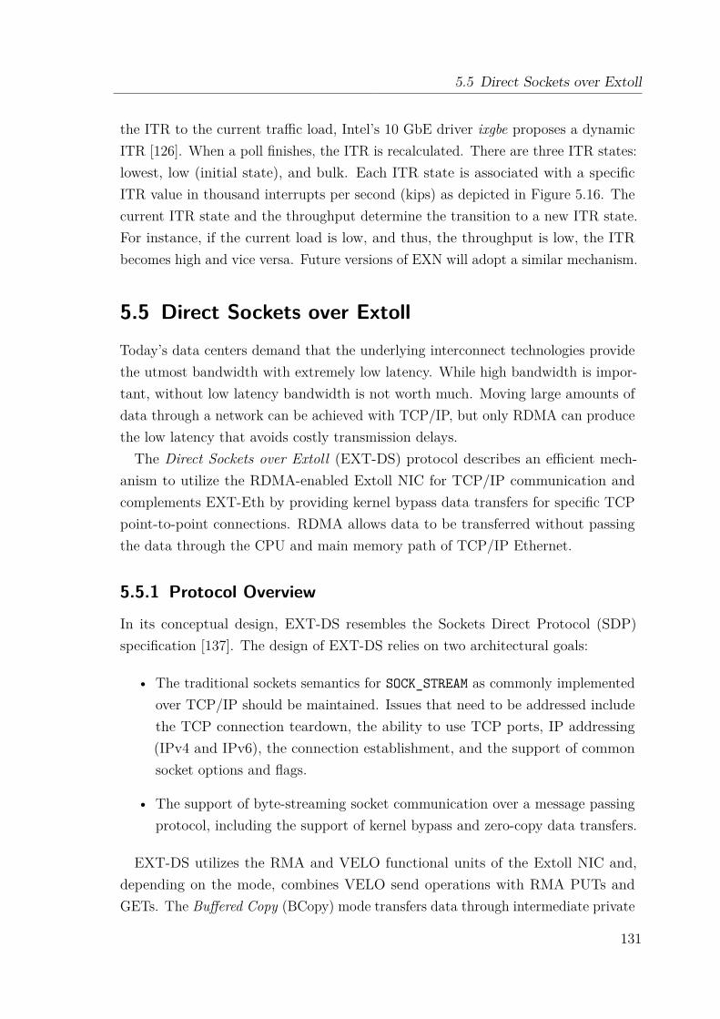
5.5 Direct Sockets over Extoll
the ITR to the current traffic load, Intel’s 10 GbE driver ixgbe proposes a dynamicITR [126]. When a poll finishes, the ITR is recalculated. There are three ITR states:lowest, low (initial state), and bulk. Each ITR state is associated with a specificITR value in thousand interrupts per second (kips) as depicted in Figure 5.16. Thecurrent ITR state and the throughput determine the transition to a new ITR state.For instance, if the current load is low, and thus, the throughput is low, the ITRbecomes high and vice versa. Future versions of EXN will adopt a similar mechanism.
5.5 Direct Sockets over ExtollToday’s data centers demand that the underlying interconnect technologies providethe utmost bandwidth with extremely low latency. While high bandwidth is impor-tant, without low latency bandwidth is not worth much. Moving large amounts ofdata through a network can be achieved with TCP/IP, but only RDMA can producethe low latency that avoids costly transmission delays.The Direct Sockets over Extoll (EXT-DS) protocol describes an efficient mech-
anism to utilize the RDMA-enabled Extoll NIC for TCP/IP communication andcomplements EXT-Eth by providing kernel bypass data transfers for specific TCPpoint-to-point connections. RDMA allows data to be transferred without passingthe data through the CPU and main memory path of TCP/IP Ethernet.
5.5.1 Protocol Overview
In its conceptual design, EXT-DS resembles the Sockets Direct Protocol (SDP)specification [137]. The design of EXT-DS relies on two architectural goals:
• The traditional sockets semantics for SOCK_STREAM as commonly implementedover TCP/IP should be maintained. Issues that need to be addressed includethe TCP connection teardown, the ability to use TCP ports, IP addressing(IPv4 and IPv6), the connection establishment, and the support of commonsocket options and flags.
• The support of byte-streaming socket communication over a message passingprotocol, including the support of kernel bypass and zero-copy data transfers.
EXT-DS utilizes the RMA and VELO functional units of the Extoll NIC and,depending on the mode, combines VELO send operations with RMA PUTs andGETs. The Buffered Copy (BCopy) mode transfers data through intermediate private
131
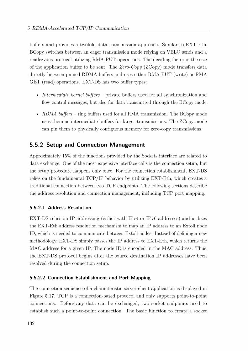
5 RDMA-Accelerated TCP/IP Communication
buffers and provides a twofold data transmission approach. Similar to EXT-Eth,BCopy switches between an eager transmission mode relying on VELO sends and arendezvous protocol utilizing RMA PUT operations. The deciding factor is the sizeof the application buffer to be sent. The Zero-Copy (ZCopy) mode transfers datadirectly between pinned RDMA buffers and uses either RMA PUT (write) or RMAGET (read) operations. EXT-DS has two buffer types:
• Intermediate kernel buffers – private buffers used for all synchronization andflow control messages, but also for data transmitted through the BCopy mode.
• RDMA buffers – ring buffers used for all RMA transmission. The BCopy modeuses them as intermediate buffers for larger transmissions. The ZCopy modecan pin them to physically contiguous memory for zero-copy transmissions.
5.5.2 Setup and Connection Management
Approximately 15% of the functions provided by the Sockets interface are related todata exchange. One of the most expensive interface calls is the connection setup, butthe setup procedure happens only once. For the connection establishment, EXT-DSrelies on the fundamental TCP/IP behavior by utilizing EXT-Eth, which creates atraditional connection between two TCP endpoints. The following sections describethe address resolution and connection management, including TCP port mapping.
5.5.2.1 Address Resolution
EXT-DS relies on IP addressing (either with IPv4 or IPv6 addresses) and utilizesthe EXT-Eth address resolution mechanism to map an IP address to an Extoll nodeID, which is needed to communicate between Extoll nodes. Instead of defining a newmethodology, EXT-DS simply passes the IP address to EXT-Eth, which returns theMAC address for a given IP. The node ID is encoded in the MAC address. Thus,the EXT-DS protocol begins after the source destination IP addresses have beenresolved during the connection setup.
5.5.2.2 Connection Establishment and Port Mapping
The connection sequence of a characteristic server-client application is displayed inFigure 5.17. TCP is a connection-based protocol and only supports point-to-pointconnections. Before any data can be exchanged, two socket endpoints need toestablish such a point-to-point connection. The basic function to create a socket
132
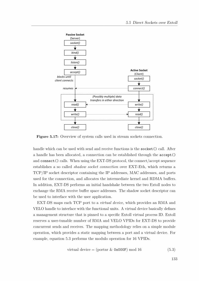
5.5 Direct Sockets over Extoll
socket()
bind()
listen()
accept()
socket()
connect()
read()
read()
write()
write()
close() close()
blocks untilclient connects
resumes
(Possibly multiple) datatransfers in either direction
Passive Socket(Server)
Active Socket(Client)
Figure 5.17: Overview of system calls used in stream sockets connection.
handle which can be used with send and receive functions is the socket() call. Aftera handle has been allocated, a connection can be established through the accept()and connect() calls. When using the EXT-DS protocol, the connect/accept sequenceestablishes a so called shadow socket connection over EXT-Eth, which returns aTCP/IP socket descriptor containing the IP addresses, MAC addresses, and portsused for the connection, and allocates the intermediate kernel and RDMA buffers.In addition, EXT-DS performs an initial handshake between the two Extoll nodes toexchange the RMA receive buffer space addresses. The shadow socket descriptor canbe used to interface with the user application.EXT-DS maps each TCP port to a virtual device, which provides an RMA and
VELO handle to interface with the functional units. A virtual device basically definesa management structure that is pinned to a specific Extoll virtual process ID. Extollreserves a user-tunable number of RMA and VELO VPIDs for EXT-DS to provideconcurrent sends and receives. The mapping methodology relies on a simple moduleoperation, which provides a static mapping between a port and a virtual device. Forexample, equation 5.3 performs the modulo operation for 16 VPIDs.
virtual device = (portnr & 0x000F) mod 16 (5.3)
133

5 RDMA-Accelerated TCP/IP Communication
Process 0
Socket 0
Socket 1
Socket 2
Process 0
Socket 0
Socket 1
TCP Ports
Port 0
Port 1
Port 216-1
Port N-1
Port N
Virtual Devices
Device 0
Device 1
Device N-1
User Space Kernel Space
Figure 5.18: Relation between socket handles, ports, and virtualized hardware.
The relation between the socket handles in user space, the TCP port numbers, andthe Extoll virtual devices in kernel space is displayed in Figure 5.18. Multiple portsare mapped to the same virtual device. The virtual device also contains a pointerto the corresponding shadow socket descriptor, which can be used to de-multiplexincoming data to the correct TCP port.
5.5.2.3 Connection Teardown
The TCP protocol defines two ways to tear a connection down: (1) a gracefulclose, where any posted and outstanding data transmission is completed before theconnection is closed, and (2) the abortive close, where the connection is immediatelyterminated. EXT-DS emulates the TCP connection teardown functionality.
Graceful Close Depending on the set socket options, the graceful close, also knownas half-closed connections, can describe two types of behavior:
(1) Graceful shutdown with delaying – delays return until all queued messageshave been successfully sent or the linger timeout has been reached.
(2) Graceful shutdown with immediate return – immediately returns, allowing theshutdown sequence to complete in the background.
When the shutdown sequence is initiated by calling close(), EXT-DS needs tocheck whether the socket option SO_LINGER is set for the socket. If the option is setand the socket has outstanding data transmissions, then close() shall block for upto the current linger interval or until all data is transmitted. In addition, a VELOmessage with the user tag SHUTDOWN (refer to section 5.5.3.1) is triggered to initiatethe shutdown on both sides of the connection.
134

5.5 Direct Sockets over Extoll
Table 5.3: Overview of VELO user tags.
Type DescriptionVELO The user tag VELO indicates that the payload of the incoming VELO
message carries a fragment of user data, which needs to be copiedinto the application buffer space.
VELO_LAST The user tag VELO_LAST indicates that the payload of the incomingVELO message carries a fragment of user data, but also notifies thereceiver that the complete buffer has been transmitted and can bepassed to the application.
RMA_INFO This user tag indicates that the next user buffer will be transferredeither through a RMA PUT or RMA GET operation. The tag ensuresmessage ordering between VELO and RMA transfers.
RMA_AVAIL The RMA_AVAIL tag is used to notify the sender that a user applicationhas read data from the RMA sink buffer. The VELO message alsoprovides the amount of data (in bytes) that has been freed.
SHUTDOWN The SHUTDOWN user tag indicates that one side has triggered the TCPshutdown sequence.
Abortive Close The abortive shutdown sequence returns immediately for theclose() call. If the EXT-DS protocol is violated, e.g., an Extoll error occurs, theconnection is abortively closed and all outstanding transmissions are dropped.
5.5.3 Data Transfer Mechanisms
The EXT-DS protocol introduces three different transfer mechanisms:
• Buffered Copy – transfers application data from private send into private receivebuffers. This mode requires an additional data copy from / to user space.
• Zero-Copy Read – transfers application data directly through RMA GEToperation. This mode requires the application buffers to mapped via Extoll.
• Zero-Copy Write –transfers application data directly through RMA PUToperation. This mode requires the application buffers to mapped via Extoll.
In case of an error or insufficient memory space, a fall back mechanism over EXT-Eth is provided. The following sections present an overview of available messagetypes and describe the different transfer modes.
135

5 RDMA-Accelerated TCP/IP Communication
5.5.3.1 Message Types and Flow Control Orchestration
EXT-DS utilizes the VELO and RMA functional units for data transmission. TCPis a protocol that provides connection-based, reliable data exchange. Therefore, animportant issue is the synchronization of the VELO and RMA data streams. EXT-DSdescribes five different data transfer and flow control message types. All of themare transmitted using VELO sends and can be distinguished by their VELO-specificuser tags in the software descriptor. Table 5.3 presents an overview of the VELOmessage user tags defined by EXT-DS.
In order to establish a flow control between incoming VELO and RMA transmis-sions, the VELO messages are organized in a FIFO-like structure. Extoll guaranteesthe ordering of VELO messages. Thus in combination with the different messagetypes, they can be used to enforce the ordering of data fragments.
5.5.3.2 Buffered Copy Mode
Per established connection, the BCopy mode uses dedicated, pre-registered privateEXT-DS buffers. Typically, application data is copied from the user space into anEXT-DS buffer, and then, transferred over the network. There are two different typesof private buffers, intermediate kernel buffers for VELO sends and receives, which areorganized in a FIFO-like structure, and RMA buffers for rendezvous PUT operations.Depending on the size of the application buffer and a user-tunable threshold, theBCopy mode switches between a VELO-based eager protocol similar to the protocolspecified by EXT-Eth (refer to section 5.4.1.2) and a rendezvous PUT protocol.Figure 5.19 displays the two data transmission protocols.
The sender-side RMA buffer can be seen as a mirrored version of the receiver-sideRMA buffer. When the sender buffer is full, the protocol provides a fall back totransmit data using multiple VELO sends until a message of type RMA_AVAIL isreceived. The flow control messages advertise how much RMA buffer has beenfreed on the receiver side and re-enable the RMA path. Figure 5.20 presents aBCopy rendezvous PUT transfer sequence including the RMA buffer on sender andreceiver side with corresponding pointer updates. The physical address of the freereceiver-side RMA space can be calculated by adding the write pointer offset to theremote start address.
136
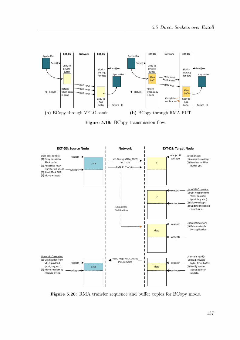
5.5 Direct Sockets over Extoll
Send()
VELO send
VELO send
VELO send
Return
Copy to privatebuffer
Return when copy is done
Return
Recv()Block -waiting for data
App buffer
App buffer
EXT-DS EXT-DSNetwork
Copy to App
buffer
(a) BCopy through VELO sends.
RMAbuff
Send()
VELO send: RMA advertRMA PUT
RMAbuff
Return
Copy to privatebuffer
Return when copy is done
Return
Recv()Block -waiting for data
App buffer
App buffer
EXT-DS EXT-DSNetwork
Copy to App
buffer
Completer Notification
(b) BCopy through RMA PUT.
Figure 5.19: BCopy transmission flow.
data
readptr
writeptr
User calls send():(1) Copy data into
RMA buffer.(2) Advertise RMA
transfer via VELO.(3) Start RMA PUT.(4) Move writeptr.
?
readptr & writeptr
Initial phase:(1) readprt = writeptr(2) No data in RMA
buffer yet.
VELO msg: RMA_INFOincl. size
RMA PUT of size
?
readptr
writeptr
data
data
readptr
writeptr
readptr
writeptrdata
readptr
writeptr
VELO msg: RMA_AVAILincl. recvsize
CompleterNotification
Upon VELO receive:(1) Get header from
VELO payload (port, tag, etc.).
(2) Move writeptr. (3) Update metadata
structures.
Upon notification:(1) Data available
for application.
User calls read():(1) Read recvsize
bytes from buffer.(2) Notify sender
about pointer update.
Upon VELO receive:(1) Get header from
VELO payload (port, tag, etc.).
(2) Move readptr by recvsize bytes.
EXT-DS: Source Node EXT-DS: Target NodeNetwork
Figure 5.20: RMA transfer sequence and buffer copies for BCopy mode.
137
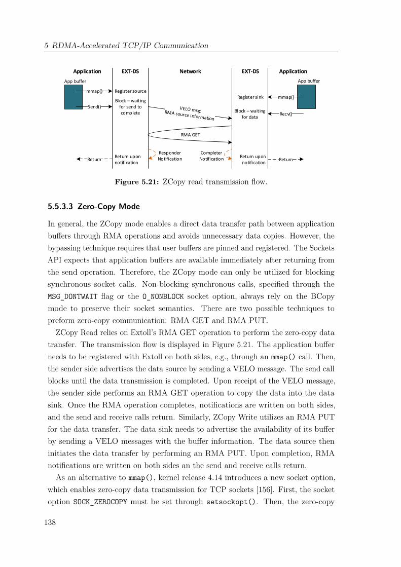
5 RDMA-Accelerated TCP/IP Communication
Send()
ReturnReturn upon notification
Return
mmap()
Block – waiting for data
App buffer App buffer
EXT-DS EXT-DSNetwork
Completer Notification
Responder Notification
Recv()
mmap()
Block – waiting for send to complete
Return upon notification
Register sourceRegister sink
Application Application
RMA GET
Figure 5.21: ZCopy read transmission flow.
5.5.3.3 Zero-Copy Mode
In general, the ZCopy mode enables a direct data transfer path between applicationbuffers through RMA operations and avoids unnecessary data copies. However, thebypassing technique requires that user buffers are pinned and registered. The SocketsAPI expects that application buffers are available immediately after returning fromthe send operation. Therefore, the ZCopy mode can only be utilized for blockingsynchronous socket calls. Non-blocking synchronous calls, specified through theMSG_DONTWAIT flag or the O_NONBLOCK socket option, always rely on the BCopymode to preserve their socket semantics. There are two possible techniques topreform zero-copy communication: RMA GET and RMA PUT.
ZCopy Read relies on Extoll’s RMA GET operation to perform the zero-copy datatransfer. The transmission flow is displayed in Figure 5.21. The application bufferneeds to be registered with Extoll on both sides, e.g., through an mmap() call. Then,the sender side advertises the data source by sending a VELO message. The send callblocks until the data transmission is completed. Upon receipt of the VELO message,the sender side performs an RMA GET operation to copy the data into the datasink. Once the RMA operation completes, notifications are written on both sides,and the send and receive calls return. Similarly, ZCopy Write utilizes an RMA PUTfor the data transfer. The data sink needs to advertise the availability of its bufferby sending a VELO messages with the buffer information. The data source theninitiates the data transfer by performing an RMA PUT. Upon completion, RMAnotifications are written on both sides an the send and receive calls return.As an alternative to mmap(), kernel release 4.14 introduces a new socket option,
which enables zero-copy data transmission for TCP sockets [156]. First, the socketoption SOCK_ZEROCOPY must be set through setsockopt(). Then, the zero-copy
138
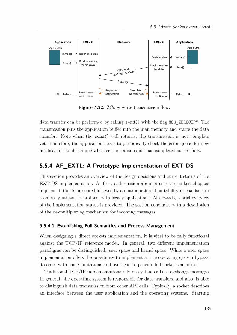
5.5 Direct Sockets over Extoll
Send()
ReturnReturn upon notification
Return
mmap()
Block – waiting for data
App buffer App buffer
EXT-DS EXT-DSNetwork
Completer Notification
Requester Notification
Recv()
mmap()
Block – waiting for sink avail
Return upon notification
Register sourceRegister sink
Application Application
Figure 5.22: ZCopy write transmission flow.
data transfer can be performed by calling send() with the flag MSG_ZEROCOPY. Thetransmission pins the application buffer into the man memory and starts the datatransfer. Note when the send() call returns, the transmission is not completeyet. Therefore, the application needs to periodically check the error queue for newnotifications to determine whether the transmission has completed successfully.
5.5.4 AF_EXTL: A Prototype Implementation of EXT-DS
This section provides an overview of the design decisions and current status of theEXT-DS implementation. At first, a discussion about a user versus kernel spaceimplementation is presented followed by an introduction of portability mechanisms toseamlessly utilize the protocol with legacy applications. Afterwards, a brief overviewof the implementation status is provided. The section concludes with a descriptionof the de-multiplexing mechanism for incoming messages.
5.5.4.1 Establishing Full Semantics and Process Management
When designing a direct sockets implementation, it is vital to be fully functionalagainst the TCP/IP reference model. In general, two different implementationparadigms can be distinguished: user space and kernel space. While a user spaceimplementation offers the possibility to implement a true operating system bypass,it comes with some limitations and overhead to provide full socket semantics.Traditional TCP/IP implementations rely on system calls to exchange messages.
In general, the operating system is responsible for data transfers, and also, is ableto distinguish data transmission from other API calls. Typically, a socket describesan interface between the user application and the operating systems. Starting
139
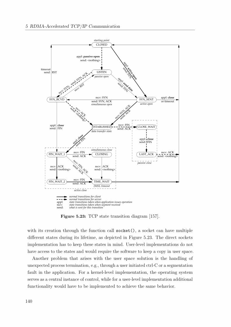
5 RDMA-Accelerated TCP/IP Communication
TCP/IP State Transition Diagram (RFC793)
Gordon McKinney (10 Feb 2004)
A connection progresses through a series of states during its lifetime (listed below). CLOSED is fictionalbecause it represents the state when there is no TCB, and therefore, no connection. Briefly the meaningsof the states are:
LISTEN represents waiting for a connection request from any remote TCP
and port.
SYN-SENT represents waiting for a matching connection request after having
sent a connection request.
SYN-RECEIVED represents waiting for a confirming connection request acknowl-
edgment after having both received and sent a connection request.
ESTABLISHED represents an open connection, data received can be delivered
to the user. The normal state for the data transfer phase of the
connection.
FIN-WAIT-1 represents waiting for a connection termination request from the
remote TCP, or an acknowledgment of the connection termination
request previously sent.
FIN-WAIT-2 represents waiting for a connection termination request from the
remote TCP.
CLOSE-WAIT represents waiting for a connection termination request from the
local user.
CLOSING represents waiting for a connection termination request acknowl-
edgment from the remote TCP.
LAST-ACK represents waiting for an acknowledgment of the connection
termination request previously sent to the remote TCP (which in-
cludes an acknowledgment of its connection termination request).
TIME-WAIT represents waiting for enough time to pass to be sure the remote
TCP received the acknowledgment of its connection termination
request.
CLOSED represents no connection state at all.
A TCP connection progresses from one state to another in response to events. The events are the usercalls, OPEN, SEND, RECEIVE, CLOSE, ABORT, and STATUS; the incoming segments, particularly thosecontaining the SYN, ACK, RST and FIN flags; and timeouts.
CLOSED
LISTEN
SYN_RCVD SYN_SENT
ESTABLISHED
FIN_WAIT_1
CLOSE_WAIT
FIN_WAIT_2
CLOSING
TIME_WAIT
LAST_ACK
data transfer state
starting point
2MSL timeout
passive open
active open
simultaneous close
appl: passive open
send: <nothing> appl: active open
send: SYN
appl: send data
send: SYNrecv
: SYN;
send: S
YN, ACK
recv: R
ST
timeoutsend: RST
recv: SYN
send: SYN, ACKsimultaneous open
recv
: SYN
, ACK
send: A
CK
appl: closesend: FIN
recv: ACKsend: <nothing>
recv: FIN
send: ACK
recv: ACKsend: <nothing>
recv: FIN, A
CK
send: ACK
recv: ACK
send: <nothing>
appl:
close
send: F
IN
recv: FIN
send: ACK
recv: FIN
send: ACK
appl: closesend: FIN
appl: close
or timeout
recv: ACK
send: <nothing>
active close
passive close
normal transitions for clientnormal transitions for server
appl: state transitions taken when application issues operationrecv: state transitions taken when segment receivedsend: what is sent for this transition
TCP state transition diagram.
Reprinted from TCP/IP Illustrated, Volume 2: The Implementationby Gary R. Wright and W. Richard Stevens,
Copyright © 1995 by Addison-Wesley Publishing Company, Inc.
Figure 5.23: TCP state transition diagram [157].
with its creation through the function call socket(), a socket can have multipledifferent states during its lifetime, as depicted in Figure 5.23. The direct socketsimplementation has to keep these states in mind. User-level implementations do nothave access to the states and would require the software to keep a copy in user space.Another problem that arises with the user space solution is the handling of
unexpected process termination, e.g., through a user initiated ctrl-C or a segmentationfault in the application. For a kernel-level implementation, the operating systemserves as a central instance of control, while for a user-level implementation additionalfunctionality would have to be implemented to achieve the same behavior.
140
5.5 Direct Sockets over Extoll
Single point-to-point connections are considered as standard situations. Functioncalls such as fork() introduce a new level of complexity. For instance, fork()creates a child process by duplicating the parent process. The support of fork iscrucial since many services make heavy use of it. For a user-level implementation,a dispatching instance such as the operating system is outside of the critical path.When calling fork(), all file descriptors including the socket descriptor of a processare shared between two or more processes. In user space, this poses a problem forthe data receiving path and would require additional control tokens.In summary, it is possible to design a user-level implementation, but it requires
additional code to handle exceptions and functions such as fork(). To ensure abroad applicability, the implementation of EXT-DS relies on the introduction of anew sockets address family called AF_EXTL and a shared user library, which providesa transparent switching functionality between standard TCP sockets and EXT-DS.
5.5.4.2 Direct Sockets Portability and Adaptability
The Sockets interface is one of the most widely used APIs for network communication.Besides the explicit source code modification to use the AF_EXTL address familyinstead of AF_INET, it is of importance to provide portability mechanisms, whichallow legacy applications to seamlessly utilize the direct sockets implementation. Byproviding a user library that utilizes library interposition, it is possible to interceptSockets API calls and automatically switch between the different protocols.Library interposition [158], also known as function interposition, is a powerful
linking technique that allows programmers to intercept calls to arbitrary libraryfunctions. Linking can be described as the process of collecting and combiningvarious pieces of code and data into a single binary file that can be loaded intomemory and executed. Interposition can occur at different times:
• Compile time – when the source code is compiled.
• Link time – when the relocatable object files are statically linked to form anexecutable object.
• Load/run time – when an executable object file is loaded into memory, dynam-ically linked, and then executed.
The following discusses possible automatic address family conversion mechanismsthrough function interposition at link and at run time and introduces the conceptsof static and dynamic linking.
141
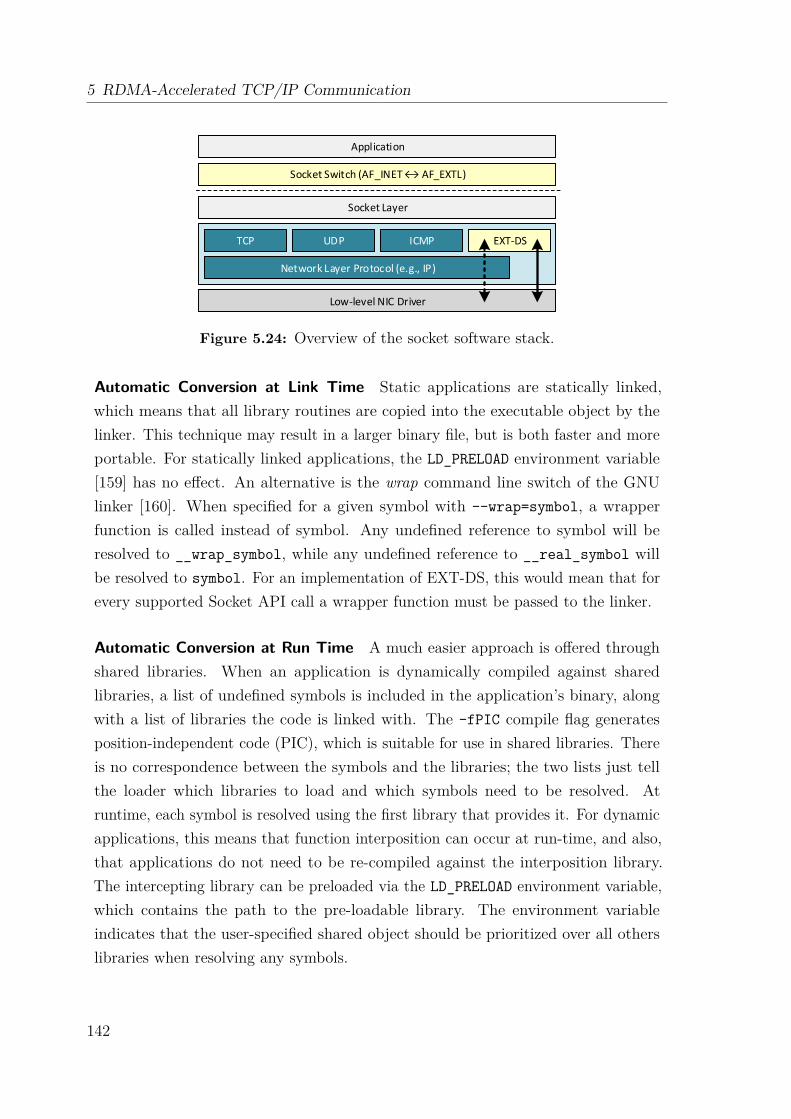
5 RDMA-Accelerated TCP/IP Communication
Low-level NIC Driver
TCP UDP ICMP EXT-DS
Network Layer Protocol (e.g., IP)
Socket Layer
Socket Switch (AF_INET ↔ AF_EXTL)
Application
Figure 5.24: Overview of the socket software stack.
Automatic Conversion at Link Time Static applications are statically linked,which means that all library routines are copied into the executable object by thelinker. This technique may result in a larger binary file, but is both faster and moreportable. For statically linked applications, the LD_PRELOAD environment variable[159] has no effect. An alternative is the wrap command line switch of the GNUlinker [160]. When specified for a given symbol with --wrap=symbol, a wrapperfunction is called instead of symbol. Any undefined reference to symbol will beresolved to __wrap_symbol, while any undefined reference to __real_symbol willbe resolved to symbol. For an implementation of EXT-DS, this would mean that forevery supported Socket API call a wrapper function must be passed to the linker.
Automatic Conversion at Run Time A much easier approach is offered throughshared libraries. When an application is dynamically compiled against sharedlibraries, a list of undefined symbols is included in the application’s binary, alongwith a list of libraries the code is linked with. The -fPIC compile flag generatesposition-independent code (PIC), which is suitable for use in shared libraries. Thereis no correspondence between the symbols and the libraries; the two lists just tellthe loader which libraries to load and which symbols need to be resolved. Atruntime, each symbol is resolved using the first library that provides it. For dynamicapplications, this means that function interposition can occur at run-time, and also,that applications do not need to be re-compiled against the interposition library.The intercepting library can be preloaded via the LD_PRELOAD environment variable,which contains the path to the pre-loadable library. The environment variableindicates that the user-specified shared object should be prioritized over all otherslibraries when resolving any symbols.
142
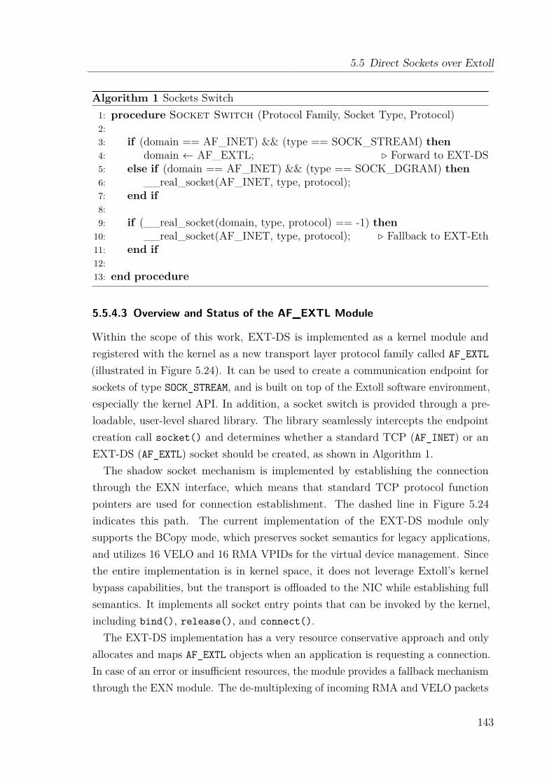
5.5 Direct Sockets over Extoll
Algorithm 1 Sockets Switch1: procedure Socket Switch (Protocol Family, Socket Type, Protocol)2:3: if (domain == AF_INET) && (type == SOCK_STREAM) then4: domain ← AF_EXTL; . Forward to EXT-DS5: else if (domain == AF_INET) && (type == SOCK_DGRAM) then6: __real_socket(AF_INET, type, protocol);7: end if8:9: if (__real_socket(domain, type, protocol) == -1) then10: __real_socket(AF_INET, type, protocol); . Fallback to EXT-Eth11: end if12:13: end procedure
5.5.4.3 Overview and Status of the AF_EXTL Module
Within the scope of this work, EXT-DS is implemented as a kernel module andregistered with the kernel as a new transport layer protocol family called AF_EXTL(illustrated in Figure 5.24). It can be used to create a communication endpoint forsockets of type SOCK_STREAM, and is built on top of the Extoll software environment,especially the kernel API. In addition, a socket switch is provided through a pre-loadable, user-level shared library. The library seamlessly intercepts the endpointcreation call socket() and determines whether a standard TCP (AF_INET) or anEXT-DS (AF_EXTL) socket should be created, as shown in Algorithm 1.The shadow socket mechanism is implemented by establishing the connection
through the EXN interface, which means that standard TCP protocol functionpointers are used for connection establishment. The dashed line in Figure 5.24indicates this path. The current implementation of the EXT-DS module onlysupports the BCopy mode, which preserves socket semantics for legacy applications,and utilizes 16 VELO and 16 RMA VPIDs for the virtual device management. Sincethe entire implementation is in kernel space, it does not leverage Extoll’s kernelbypass capabilities, but the transport is offloaded to the NIC while establishing fullsemantics. It implements all socket entry points that can be invoked by the kernel,including bind(), release(), and connect().
The EXT-DS implementation has a very resource conservative approach and onlyallocates and maps AF_EXTL objects when an application is requesting a connection.In case of an error or insufficient resources, the module provides a fallback mechanismthrough the EXN module. The de-multiplexing of incoming RMA and VELO packets
143

5 RDMA-Accelerated TCP/IP Communication
Tag: VELO
Size
Data
Tag: RMA_INFO
Size
(no data)
Tag: VELO
Size
Data
Tag: VELO
Size
Data
Tag: RMA_RDY
Size
(no data)
Tag: VELO
Size
Data
Kernel FIFO(1) (2)
(3) (4)
Kernel FIFO
Tag: RMA_INFO
Size
(no data)
Tag: VELO
Size
Data
Kernel FIFO Kernel FIFO
Figure 5.25: Overview of the Kernel FIFO usage with different message types.
to the ports is handled through a kernel FIFO structure, which is presented in thenext section. At the time of this writing, only the VELO path is fully functionaland used as a proof of concept.
5.5.4.4 De-Multiplexing of Incoming Messages
Each virtual device relates to one RMA VPID and one VELO VPID, and is sharedamong multiple port numbers. VELO and RMA notifications arrive at a virtualdevice and need to be forwarded to the right port structure. The de-multiplexingof incoming messages is handled by a kernel thread, which implements a progressfunction that snoops on the mailboxes for a given VPID for VELO and RMA. Inorder to avoid an interrupt-driven mechanism, the progress function either is calledwhenever a socket system call is triggered by the user or when the module internaltimer expires. To establish a flow control for the RMA buffer resources, VELOmessages are utilized and can be distinguished by their user tag, as described insection 5.5.3.1. The progress function retrieves the port number from the payload ofa VELO message, and then, enqueues it to the corresponding kernel FIFO. Figure5.25 displays different scenarios:
• When the kernel thread is running, incoming VELO messages are enqueuedin the kernel FIFO. They can either indicate that (1) the VELO message has
144
5.6 Performance Analysis
payload attached, or (2) state that the next chunk of the payload is to bereceived through an RMA PUT operation (RMA_INFO).
• When calling the receive function, the user can only read messages up to theRMA_INFO entry (3). Then, the user gets blocked until new data is available.
• When an RMA PUT completes, a notification is written to the correspondingmailbox. The progress function retrieves the notification, matches it with thecorresponding message in the kernel FIFO and sets the user tag to RMA_RDY(4), which indicates the data can be read.
5.6 Performance AnalysisIn this section, a performance evaluation of the EXN module and the direct socketsaddress family AF_EXTL is presented. The section starts with an introduction todifferent TCP/IP tuning techniques for Linux operating systems deploying 40G or100G network cards. Afterwards, several microbenchmarks are utilized to evaluatethe bandwidth and latency performance followed by a brief discussion about the hostCPU utilization. The section concludes with an evaluation of the MPI performanceover EXN. Note that at the time of this writing, AF_EXTL is still in an early prototypestage and can only be used for simple latency benchmarks.
5.6.1 TCP/IP Configuration Tuning in Linux Systems
Most Linux operating systems are configured to provide optimal performance withGigabit Ethernet NICs. This configuration can drastically limit the performanceof 10G, 40G and 100G network cards. The Linux kernel offers a vast majority ofuser-tunable parameters and system configurations. The following system settingshave the biggest impact on the TCP performance: CPU governor, TCP host kernelparameters, and application and interrupt binding.
5.6.1.1 TCP Host Kernel Parameters
By default, the Linux network stack is not configured for high-speed large file transfersacross SAN links. The main reason for this is to save memory resources and power.Therefore, the default size of the TCP buffers are way too small. The same appliesto the default size of the send and receive socket buffers. Another important kernelparameter set configures the TCP receive window scaling and congestion control.
145

5 RDMA-Accelerated TCP/IP Communication
1 # add to /etc/ sysctl .conf2 # allow testing with 2GB buffers for send/ receive socket buffers3 net.core. rmem_max = 21474836474 net.core. wmem_max = 21474836475 # allow auto - scaling up to 2GB buffers for TCP buffers6 net.ipv4. tcp_rmem = 4096 87380 21474836477 net.ipv4. tcp_wmem = 4096 65536 21474836478 # receive window scaling9 net.ipv4. tcp_no_metrics_save = 0
10 net.ipv4. tcp_window_scaling = 111 # congestion control12 net.ipv4. tcp_congestion_control = htcp13 net.ipv4. tcp_timestamps = 0
Listing 5.2: TCP host kernel parameters configuration via sysctl.
Listing 5.2 displays the recommended sysctl settings for 40G and 100G NICs,including setting the default buffer sizes to the maximum of 2 GB.
5.6.1.2 CPU Governor
The CPU governor defines the power characteristics of the system CPUs, whichin turn affects the overall CPU performance. CPU frequency scaling allows theoperating system to scale the CPU frequency up and down in order to save power.The default setting for most modern operating systems is to run the CPU in its powersaving mode, which can heavenly impact the performance of high-speed networktechnologies. Depending on the Linux distribution, there are different command linetools, which allow the user to adjust the default clock speed of the processor on thefly. For CentOS, the governor can be changed to the performance mode by runningthe tool cpupower with the following command line:
$ cpupower frequency-set -g performance
5.6.1.3 Interrupt and Application Binding
Today’s system architectures typically comprise of NUMA nodes. To fully maximizethe single stream performance for both TCP and UDP on such architectures (i.e.,Intel Sandy and Ivy Bridge), it is essential to observe which CPU socket is beingused. In general, it is advised to bind both applications and interrupts to the CPUsocket that is closest to the PCIe slot the NIC connected to. This can be achievedby disabling the interrupt balance option in the Linux, e.g., by modifying the bootoptions, and then, bind the NIC’s interrupts to a specific CPU socket.
146
5.6 Performance Analysis
5.6.2 Test System
The test setup comprises of two systems named after the codename of their CPUarchitecture: Haswell and Skylake. The Haswell system comprises of two nodeseach equipped with an Intel Xeon E5-2640 v3 dual socket CPU (8 cores per socket)running at 2.6 GHz and 32 GB of main memory. The Haswell system has twoon-board Intel 10-Gigabit X540-AT2 Ethernet controllers. One provides GigabitEthernet (GigE), the other one 10 Gigabit Ethernet (10GigE). The Skylake systemcomprises of three nodes. Each node has an Intel Xeon Silver 4110 CPU (one socketwith 8 cores) running at 2.10 GHz and 32 GB of main memory.
For both systems, all system nodes are equipped with an Extoll Tourmalet 100GNIC and run CentOS Linux version 7.3.1611 with kernel release 3.10.0-514.26.2.el7.For the Extoll NICs, the software environment version 1.4 is installed on every node.
5.6.3 Microbenchmark Evaluation
The following three microbenchmarks have been used for the performance evaluation:
netperf The netperf benchmark [161] can be used to measure various aspects ofnetworking performance with a particular focus on bulk data transfers andand request/response time. The benchmark is available for TCP and UDPconnections, and relies on the Berkeley Sockets interface. Originally designedby Hewlett Packard, it has become the de-facto standard for the bandwidthand latency evaluation of interconnect technologies.
TCP-PingPong The TCP-PingPong benchmark provides a simple benchmarkingtool to measure the half round trip latency for TCP and UDP socket connectionswith message sizes ranging between 1 and 2048 bytes.
SockPerf The SockPerf tool [162] is an open-source network benchmarking utilityprovided by Mellanox Technologies. It is designed for testing the performanceof high-performance systems, with a focus on throughput and latency. Sock-Perf utilizes most of the Sockets API calls and options. It is used to verifybenchmarking results obtained through netperf.
In addition to the microbenchmarks, vmstat and numactl are utilized. numactlcan be used to control the NUMA policy for processes or shared memory. Examplesare NUMA-aware socket binding and memory placement policies. vmstat can beutilized to monitor system resources such as main memory and CPU utilization.
147
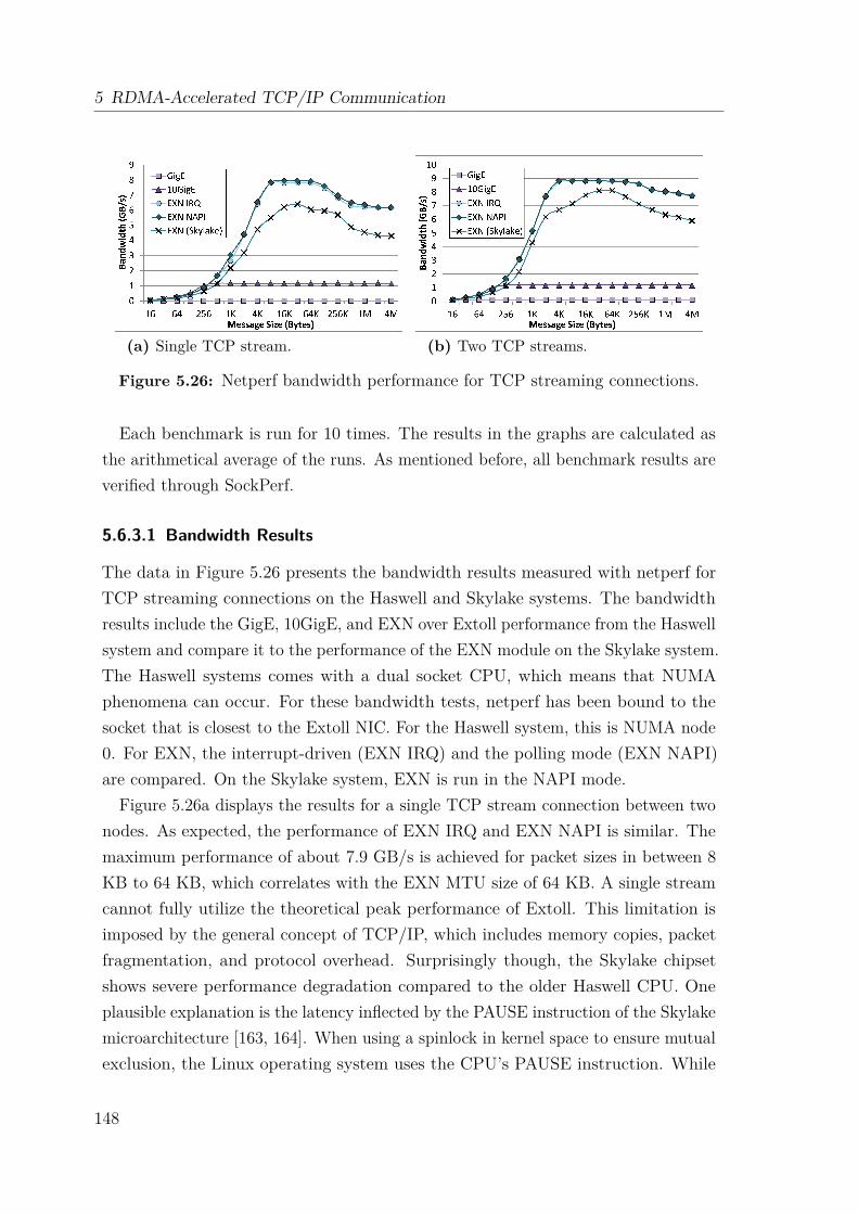
5 RDMA-Accelerated TCP/IP Communication
(a) Single TCP stream. (b) Two TCP streams.
Figure 5.26: Netperf bandwidth performance for TCP streaming connections.
Each benchmark is run for 10 times. The results in the graphs are calculated asthe arithmetical average of the runs. As mentioned before, all benchmark results areverified through SockPerf.
5.6.3.1 Bandwidth Results
The data in Figure 5.26 presents the bandwidth results measured with netperf forTCP streaming connections on the Haswell and Skylake systems. The bandwidthresults include the GigE, 10GigE, and EXN over Extoll performance from the Haswellsystem and compare it to the performance of the EXN module on the Skylake system.The Haswell systems comes with a dual socket CPU, which means that NUMAphenomena can occur. For these bandwidth tests, netperf has been bound to thesocket that is closest to the Extoll NIC. For the Haswell system, this is NUMA node0. For EXN, the interrupt-driven (EXN IRQ) and the polling mode (EXN NAPI)are compared. On the Skylake system, EXN is run in the NAPI mode.
Figure 5.26a displays the results for a single TCP stream connection between twonodes. As expected, the performance of EXN IRQ and EXN NAPI is similar. Themaximum performance of about 7.9 GB/s is achieved for packet sizes in between 8KB to 64 KB, which correlates with the EXN MTU size of 64 KB. A single streamcannot fully utilize the theoretical peak performance of Extoll. This limitation isimposed by the general concept of TCP/IP, which includes memory copies, packetfragmentation, and protocol overhead. Surprisingly though, the Skylake chipsetshows severe performance degradation compared to the older Haswell CPU. Oneplausible explanation is the latency inflected by the PAUSE instruction of the Skylakemicroarchitecture [163, 164]. When using a spinlock in kernel space to ensure mutualexclusion, the Linux operating system uses the CPU’s PAUSE instruction. While
148
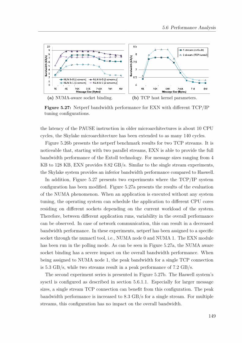
5.6 Performance Analysis
(a) NUMA-aware socket binding. (b) TCP host kernel parameters.
Figure 5.27: Netperf bandwidth performance for EXN with different TCP/IPtuning configurations.
the latency of the PAUSE instruction in older microarchitectures is about 10 CPUcycles, the Skylake microarchitecture has been extended to as many 140 cycles.Figure 5.26b presents the netperf benchmark results for two TCP streams. It is
noticeable that, starting with two parallel streams, EXN is able to provide the fullbandwidth performance of the Extoll technology. For message sizes ranging from 4KB to 128 KB, EXN provides 8.82 GB/s. Similar to the single stream experiments,the Skylake system provides an inferior bandwidth performance compared to Haswell.In addition, Figure 5.27 presents two experiments where the TCP/IP system
configuration has been modified. Figure 5.27a presents the results of the evaluationof the NUMA phenomenon. When an application is executed without any systemtuning, the operating system can schedule the application to different CPU coresresiding on different sockets depending on the current workload of the system.Therefore, between different application runs, variability in the overall performancecan be observed. In case of network communication, this can result in a decreasedbandwidth performance. In these experiments, netperf has been assigned to a specificsocket through the numactl tool, i.e., NUMA node 0 and NUMA 1. The EXN modulehas been run in the polling mode. As can be seen in Figure 5.27a, the NUMA awaresocket binding has a severe impact on the overall bandwidth performance. Whenbeing assigned to NUMA node 1, the peak bandwidth for a single TCP connectionis 5.3 GB/s, while two streams result in a peak performance of 7.2 GB/s.
The second experiment series is presented in Figure 5.27b. The Haswell system’ssysctl is configured as described in section 5.6.1.1. Especially for larger messagesizes, a single stream TCP connection can benefit from this configuration. The peakbandwidth performance is increased to 8.3 GB/s for a single stream. For multiplestreams, this configuration has no impact on the overall bandwidth.
149
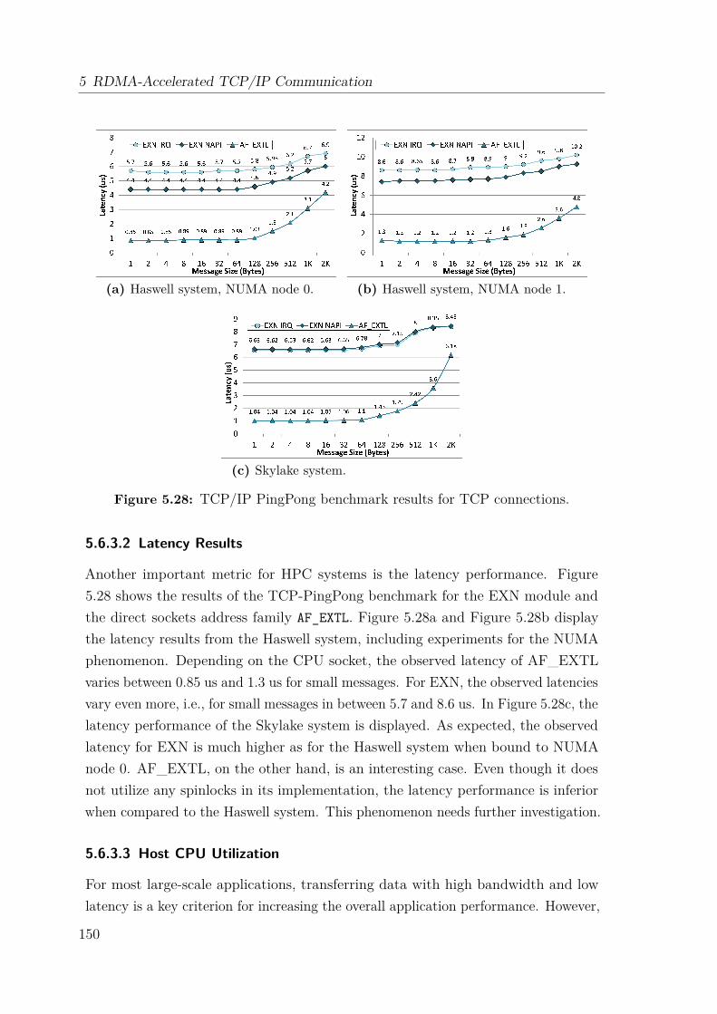
5 RDMA-Accelerated TCP/IP Communication
(a) Haswell system, NUMA node 0. (b) Haswell system, NUMA node 1.
(c) Skylake system.
Figure 5.28: TCP/IP PingPong benchmark results for TCP connections.
5.6.3.2 Latency Results
Another important metric for HPC systems is the latency performance. Figure5.28 shows the results of the TCP-PingPong benchmark for the EXN module andthe direct sockets address family AF_EXTL. Figure 5.28a and Figure 5.28b displaythe latency results from the Haswell system, including experiments for the NUMAphenomenon. Depending on the CPU socket, the observed latency of AF_EXTLvaries between 0.85 us and 1.3 us for small messages. For EXN, the observed latenciesvary even more, i.e., for small messages in between 5.7 and 8.6 us. In Figure 5.28c, thelatency performance of the Skylake system is displayed. As expected, the observedlatency for EXN is much higher as for the Haswell system when bound to NUMAnode 0. AF_EXTL, on the other hand, is an interesting case. Even though it doesnot utilize any spinlocks in its implementation, the latency performance is inferiorwhen compared to the Haswell system. This phenomenon needs further investigation.
5.6.3.3 Host CPU Utilization
For most large-scale applications, transferring data with high bandwidth and lowlatency is a key criterion for increasing the overall application performance. However,
150

5.6 Performance Analysis
Figure 5.29: Host CPU utilization during netperf bandwidth test.
the overhead associated with a message transfer is also an important factor forthe overall system performance. As described in section 2.2.2, there are two datatransmission methods: PIO and DMA. PIO is typically utilized for small messagetransfers and performed by the CPU. In case of DMA, a descriptor is usuallyassembled, which describes the data to be transferred. The actual data transfer isperformed by a DMA controller without the involvement of a CPU, which allows theoverlapping of communication and computation.
In order to monitor the host CPU utilization, two methods have been used duringthe experiments. netperf provides a command line option to enable the monitoringof the local and remote host CPU. In addition, vmstat can be used to collect anddisplay a summary about the main memory and CPU utilization, but also to monitorprocesses, interrupts and block I/O. Both methods have been utilized to monitorthe system statistics of the EXN module on the Haswell system. Figure 5.29 showsthe CPU utilization results for interrupt-driven and polling mode. Note that bothmodes have a moderate CPU utilization even though both need to traverse theTCP/IP stack. Recall that EXN has an internal switch between the eager protocolutilizing the VELO unit and the rendezvous protocol, which relies on the RMA unitfor data transmission. With increasing message sizes, both modes consume less CPUresources. This is mainly because VELO enforces a PIO data transfer mechanismwhile RMA offloads the data transfer to the Extoll NIC.
5.6.4 MPI Performance
Besides the microbenchmark analysis, the point-to-point MPI benchmark collection ofthe OSU Micro-Benchmarks suite 4.3 [74] is evaluated. The intention of this analysisis to receive an understanding about the potential performance an application wouldobserve when being run over EXN. As before, each benchmark is run 10 times andthe results are calculated as the arithmetical average of the runs.
151
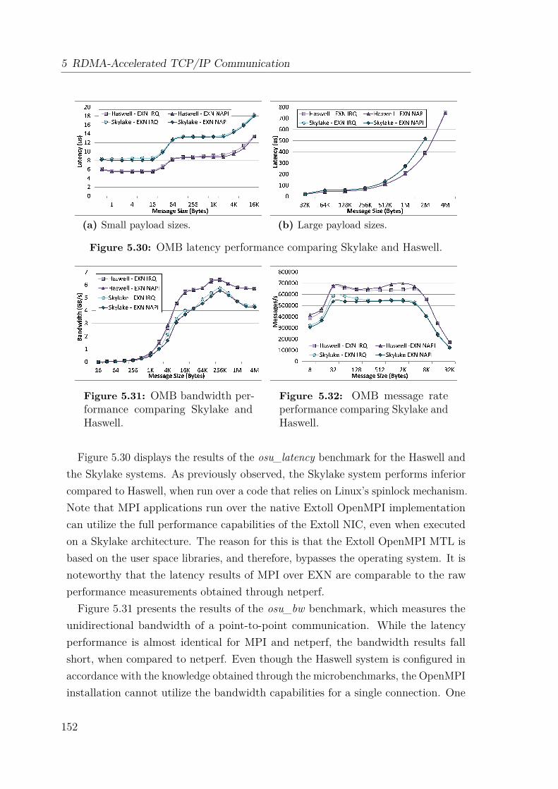
5 RDMA-Accelerated TCP/IP Communication
(a) Small payload sizes. (b) Large payload sizes.
Figure 5.30: OMB latency performance comparing Skylake and Haswell.
Figure 5.31: OMB bandwidth per-formance comparing Skylake andHaswell.
Figure 5.32: OMB message rateperformance comparing Skylake andHaswell.
Figure 5.30 displays the results of the osu_latency benchmark for the Haswell andthe Skylake systems. As previously observed, the Skylake system performs inferiorcompared to Haswell, when run over a code that relies on Linux’s spinlock mechanism.Note that MPI applications run over the native Extoll OpenMPI implementationcan utilize the full performance capabilities of the Extoll NIC, even when executedon a Skylake architecture. The reason for this is that the Extoll OpenMPI MTL isbased on the user space libraries, and therefore, bypasses the operating system. It isnoteworthy that the latency results of MPI over EXN are comparable to the rawperformance measurements obtained through netperf.Figure 5.31 presents the results of the osu_bw benchmark, which measures the
unidirectional bandwidth of a point-to-point communication. While the latencyperformance is almost identical for MPI and netperf, the bandwidth results fallshort, when compared to netperf. Even though the Haswell system is configured inaccordance with the knowledge obtained through the microbenchmarks, the OpenMPIinstallation cannot utilize the bandwidth capabilities for a single connection. One
152
5.7 TCP/IP Summary
possibly reason could be that the OpenMPI configuration is suboptimal and needsto be tuned for TCP/IP.
Besides bandwidth and latency, another important metric is the message rate. Asintroduced in chapter 2, the message rate describes the number of messages thatcan be sent by a single process or rank in a specified period of time. The messagerate is a good indicator for how well the processing of independent processes canbe overlapped, but varies for different message sizes, is limited by the bandwidthand highly depends on the sending and receiving overhead. Figure 5.32 presentsthe message rate results for MPI over EXN. It can be seen that the message rate ispretty stable for message sizes between 32 bytes and 8 KB.
5.7 TCP/IP SummaryEven though the traditional TCP/IP communication stack introduces significantoverhead, the support of legacy application codes enables the broad utilization ofspecialized SAN technologies. In addition, TCP/IP is supported by almost everycommunication environment. By providing TCP/IP communication means, differentsolutions can be tested before providing a native software implementation.This chapter introduced two TCP/IP-based communication protocols for Extoll:
EXT-Eth and EXT-DS. EXT-Eth describes the transmission of Ethernet frames overExtoll and emulates Ethernet communication. The protocol adds IP addressing andaddress resolution support to the Extoll interconnect and provides asynchronous,two-sided RDMA operations for large message sizes. The default MTU size enablesthe usage of super jumbo frames, which allows the protocol two fully utilize Extoll’sbandwidth capabilities, and provides L3 routing support. The EXN module imple-ments the EXT-Eth protocol and provides a traditional network interface to theLinux kernel. An initial performance evaluation with two Extoll Tourmalet ASICsshows promising results. While the latency is impacted by the latency of traversingthe TCP/IP stack, the peak bandwidth of Extoll can be fully leveraged by EXN.EXT-DS, on the other hand, introduced the acceleration of TCP point-to-point
connections by providing kernel bypass data transfers, while maintaining traditionalstreaming socket semantics. The protocol describes two modes: BCopy and ZCopy.The BCopy mode provides seamless support for legacy applications, which meansthat the additional buffer copy from user to kernel space is still required. The ZCopymode provides a true zero-copy data path, but expects application buffers to bepinned to the Extoll card, which allows physical addressing of the memory and
153

5 RDMA-Accelerated TCP/IP Communication
prevents the exemption of the buffer through the operating system. Besides theprotocol specification, a prototype implementation of EXT-DS was presented throughthe introduction of a new transport protocol called AF_EXTL. Currently, the addressfamily supports the BCopy mode and is limited to VELO communication. However,an initial evaluation showed that the latency performance of EXT-DS is able toprovide similar results as the native Extoll communication. For small messages, thelatency is about 0.85 us. Given that the EXN module was able to provide the peakbandwidth of Extoll, it is expected that EXT-DS will be able to achieve similarresults while minimizing the host CPU utilization even further.
154
Ch
ap
te
r
6Efficient Lustre Networking Protocol Support
Top-tier scientific HPC systems are constantly increasing in scale to improve appli-cation resolution and reduce the time to solution. Such an increase in scale alsointensifies the system complexity and decreases the overall system reliability. Tocope with system failures, most scientific applications periodically write out memorystates. Besides storing numerical output from simulations, this defensive, bursty I/O(i.e., checkpointing) is one of the main sources of I/O activity in HPC environments.Therefore, the efficient storage connectivity is an essential requirement to serve theneeds of large-scale scientific codes. This chapter discusses how a parallel file systemsuch as Lustre can effectively leverage the capabilities of the Extoll interconnect.Lustre is an open-source, parallel, distributed file system for Linux-based system
environments [165, 166]. Its design targets massive scalability, high performance,and high availability. Within the scientific HPC community, Lustre is one of themost deployed file system solutions due to its support for data-intensive applications,which makes it an attractive choice for this work. The majority of the worldwideTOP100 supercomputing deployments utilizes Lustre for their high-performanceparallel file and storage systems. For example in the TOP500 list from November2017, nine of the TOP10 and more than 70 of the TOP100 systems deployed Lustre.However, one of the key disadvantages of Lustre is its lack of implementation-specificdocumentation, in particular the Lustre networking protocol called LNET.The contributions of this chapter are twofold. First, it provides a comprehensive
analysis and summary of the Lustre networking protocol semantics and interfaces,which need to be understood in order to design the protocol support for a custominterconnect such as Extoll. The second contribution is the design and implementation
155
6 Efficient Lustre Networking Protocol Support
of the Extoll Lustre Networking Driver (EXLND), which maps the LNET protocolsemantics onto the Extoll networking technology. This chapter summarizes andextends contributions to international workshops and conferences [15, 16].
6.1 Introduction to the Lustre File SystemLustre provides a single, POSIX-compliant name space for small to medium-scaledeployments, but also for large-scale storage platforms with hundreds of petabytes.Lustre’s architecture employs a client-server network where distributed, object-basedstorage is managed by servers and accessed by clients utilizing an efficient networkprotocol. On a client, the mounted Lustre file system is represented as a coherentPOSIX file system to applications. But, clients do not access storage directly; allI/O transactions are sent over the network.The key concept of Lustre is to separate large, throughput-intensive block I/O
from its small, random, IOPS-intensive metadata traffic. In other words, Lustreseparates the metadata storage (inode) and block data storage (file content).
The following sections provide an introduction to the Lustre file system components,the network protocol, I/O operations and file striping. More details about the Lustrefile system internals can be found in a technical report written by Wang et al. [167]and the Lustre Operations Manual [168].
6.1.1 File System Components
Lustre is a parallel file system utilizing distributed, object-based storage, whichis managed by servers and accessed by client computers over a high performanceinterconnection network. Three different categories of servers can be distinguished:management, metadata, and object storage servers. The following provides anoverview of the major Lustre hardware components [168]:
MGS + MGT The Management Server (MGS) acts as a global registry and storesthe configuration information and service state for all active Lustre file systemcomponents. There is usually only one MGS for a given network and all Lustrecomponents register with the MGS during startup. Lustre clients retrieveinformation from the MGS when mounting the file system. The MGS storesthe configuration data on the Management Target (MGT).
MDS + MDT The Metadata Server (MDS) records and presents the file systemnamespace (file and directories) and is responsible for defining the file layout, i.e.,
156

6.1 Introduction to the Lustre File System
Lustre’sarchitectureusesdistributed,object-basedstoragemanagedbyserversandaccessedbyclientcomputersusinganefficientnetworkprotocol.Therearemetadataservers,responsibleforstorageallocation,andmanagingthefilesystemnamespace,andobjectstorageservers,responsibleforthedatacontentitself.AfileinLustreiscomprisedofametadatainode objectandoneormoredataobjects.
Lustreisaclient-server,parallel,distributed,networkfilesystem.Serversmanagethepresentationofstoragetoanetworkofclients,andwritedatasentfromclientstopersistentstoragetargets.
Therearethreedifferentclassesofserver:• Managementserverprovidesconfigurationinformation,filesystemregistries• Metadataserversrecordfilesystemnamespace,inodes.Themetadataserversmaintain
thefilesystemindex.• Objectstorageserversrecordfilecontentindistributedbinaryobjects.Asinglefileis
comprisedof1ormoreobjects,andthedataforthatfileisorganizedinstripesacrosstheobjects.Objectsaredistributedacrosstheavailablestoragetargets.
Lustreseparatesmetadata(inode)storagefromblockdatastorage(filecontent).Allfilemetadataoperations(creatinganddeletingfiles,allocatingdataobjects,managingpermissions)aremanagedbythemetadataservers.Metadataserversprovidetheindextothefilesystem.Metadataisstoredinkey-valueindexobjectsthatstorefilesysteminodes:fileanddirectorynames,permissions,blockdatalocations,extendedattributes,etc.
Lustre Scalable Storage
4
Object StorageTargets (OSTs)
MetadataTarget (MDT0)
ManagementTarget (MGT)
Storage servers grouped
into failover pairs
Lustre Clients (1 – 100,000+)
High Performance Data Network(Omni-Path, InfiniBand, Ethernet)
ManagementNetwork
Object StorageServers
Object StorageServers
Management& Metadata
Servers
AdditionalMetadataServers
DNE MetadataTargets (MDTi - MDTj)
Figure 6.1: Lustre file system components in a basic setup [165].
the location of data objects. The MGS stores the metadata in key-value indexobjects, which contain the file system inodes (such as filenames, directories,permissions and file layout), on the Metadata Target (MDT). The MGS andMDS can be co-located and share storage space. To improve metadata scalingand system-wide fault tolerance, the Distributed Namespace (DNE) feature canbe used to store metadata across multiple MDTs.
OSS + OST The main task of Object Storage Servers (OSSs) is to provide file I/Oservices and network request handling for their local Object Storage Targets(OSTs). An OSS serves as a block device to the clients. Files can be stripedacross multiple OSTs and written to concurrently.
Clients Lustre clients can be computational, visualization or desktop nodes. Each ofthe clients expose the Lustre file system to the operating system by mountinga POSIX-compliant instance utilizing the Lustre network protocol (LNET).Applications can use standard POSIX calls for Lustre I/O.
Network One of the most crucial components is the network. Lustre is a network-based file system and all I/O transactions are sent over the network usingRPCs. It is common that clients have no local persistent storage.
Each type of server has its storage target devices directly attached. Various formsof data storage are possible, including simple hard disks, but also enterprise gradenetwork attached storage. Recent versions of Lustre (≥ 2.6) utilize the Zettabyte FileSystem (ZFS), based on the OpenZFS implementation, as the default data storageback end [168], older versions use Lustre’s native LDISKFS, a modified version of
157
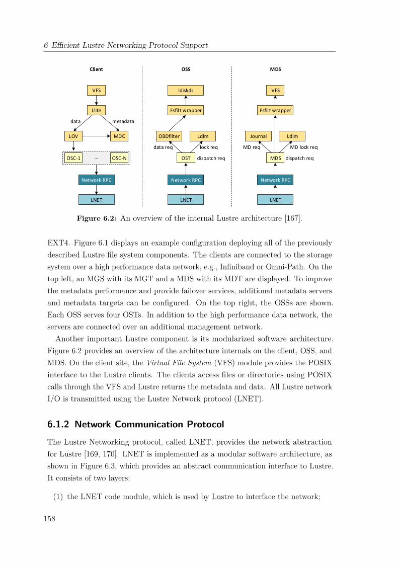
6 Efficient Lustre Networking Protocol Support
LNET
Network RPC
OSC-1 OSC-N
LOV MDC
Llite
VFS
...
data metadata
LNET
Network RPC
OST
OBDfilter Ldlm
Fsfilt wrapper
ldiskds
data req lock req
dispatch req
LNET
Network RPC
MDS
Journal Ldlm
Fsfilt wrapper
Client OSS MDS
MD req MD lock req
dispatch req
VFS
Figure 6.2: An overview of the internal Lustre architecture [167].
EXT4. Figure 6.1 displays an example configuration deploying all of the previouslydescribed Lustre file system components. The clients are connected to the storagesystem over a high performance data network, e.g., Infiniband or Omni-Path. On thetop left, an MGS with its MGT and a MDS with its MDT are displayed. To improvethe metadata performance and provide failover services, additional metadata serversand metadata targets can be configured. On the top right, the OSSs are shown.Each OSS serves four OSTs. In addition to the high performance data network, theservers are connected over an additional management network.Another important Lustre component is its modularized software architecture.
Figure 6.2 provides an overview of the architecture internals on the client, OSS, andMDS. On the client site, the Virtual File System (VFS) module provides the POSIXinterface to the Lustre clients. The clients access files or directories using POSIXcalls through the VFS and Lustre returns the metadata and data. All Lustre networkI/O is transmitted using the Lustre Network protocol (LNET).
6.1.2 Network Communication Protocol
The Lustre Networking protocol, called LNET, provides the network abstractionfor Lustre [169, 170]. LNET is implemented as a modular software architecture, asshown in Figure 6.3, which provides an abstract communication interface to Lustre.It consists of two layers:
(1) the LNET code module, which is used by Lustre to interface the network;
158
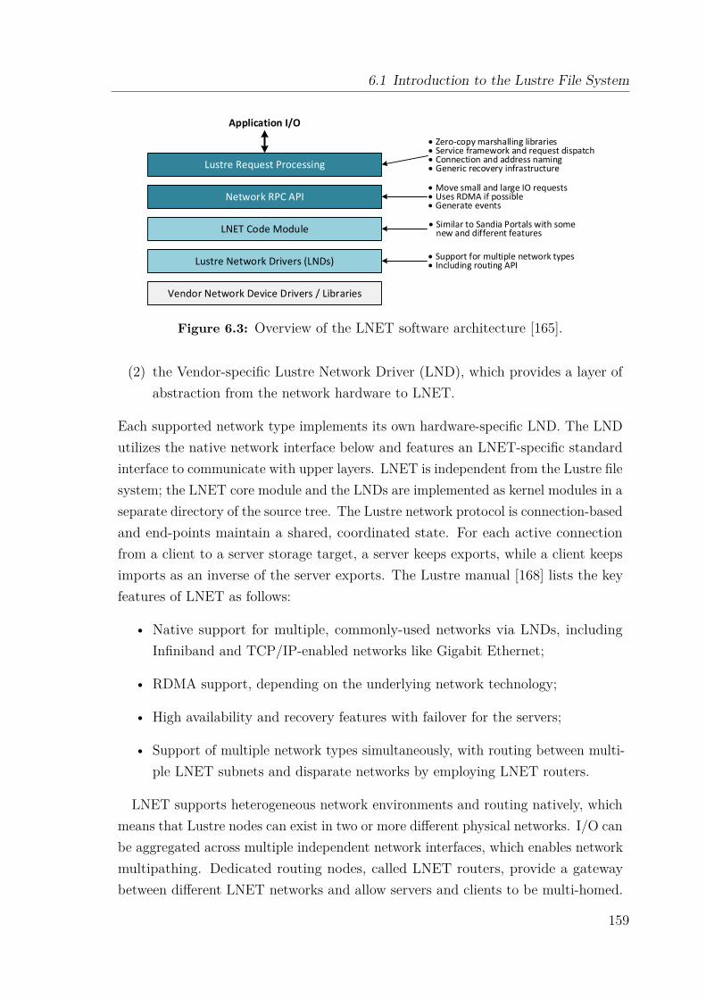
6.1 Introduction to the Lustre File System
Vendor Network Device Drivers / Libraries
Lustre Network Drivers (LNDs)
LNET Code Module
Network RPC API
Lustre Request Processing
Application I/O
• Move small and large IO requests• Uses RDMA if possible• Generate events
• Similar to Sandia Portals with some new and different features
• Support for multiple network types• Including routing API
• Zero-copy marshalling libraries• Service framework and request dispatch• Connection and address naming• Generic recovery infrastructure
Figure 6.3: Overview of the LNET software architecture [165].
(2) the Vendor-specific Lustre Network Driver (LND), which provides a layer ofabstraction from the network hardware to LNET.
Each supported network type implements its own hardware-specific LND. The LNDutilizes the native network interface below and features an LNET-specific standardinterface to communicate with upper layers. LNET is independent from the Lustre filesystem; the LNET core module and the LNDs are implemented as kernel modules in aseparate directory of the source tree. The Lustre network protocol is connection-basedand end-points maintain a shared, coordinated state. For each active connectionfrom a client to a server storage target, a server keeps exports, while a client keepsimports as an inverse of the server exports. The Lustre manual [168] lists the keyfeatures of LNET as follows:
• Native support for multiple, commonly-used networks via LNDs, includingInfiniband and TCP/IP-enabled networks like Gigabit Ethernet;
• RDMA support, depending on the underlying network technology;
• High availability and recovery features with failover for the servers;
• Support of multiple network types simultaneously, with routing between multi-ple LNET subnets and disparate networks by employing LNET routers.
LNET supports heterogeneous network environments and routing natively, whichmeans that Lustre nodes can exist in two or more different physical networks. I/O canbe aggregated across multiple independent network interfaces, which enables networkmultipathing. Dedicated routing nodes, called LNET routers, provide a gatewaybetween different LNET networks and allow servers and clients to be multi-homed.
159
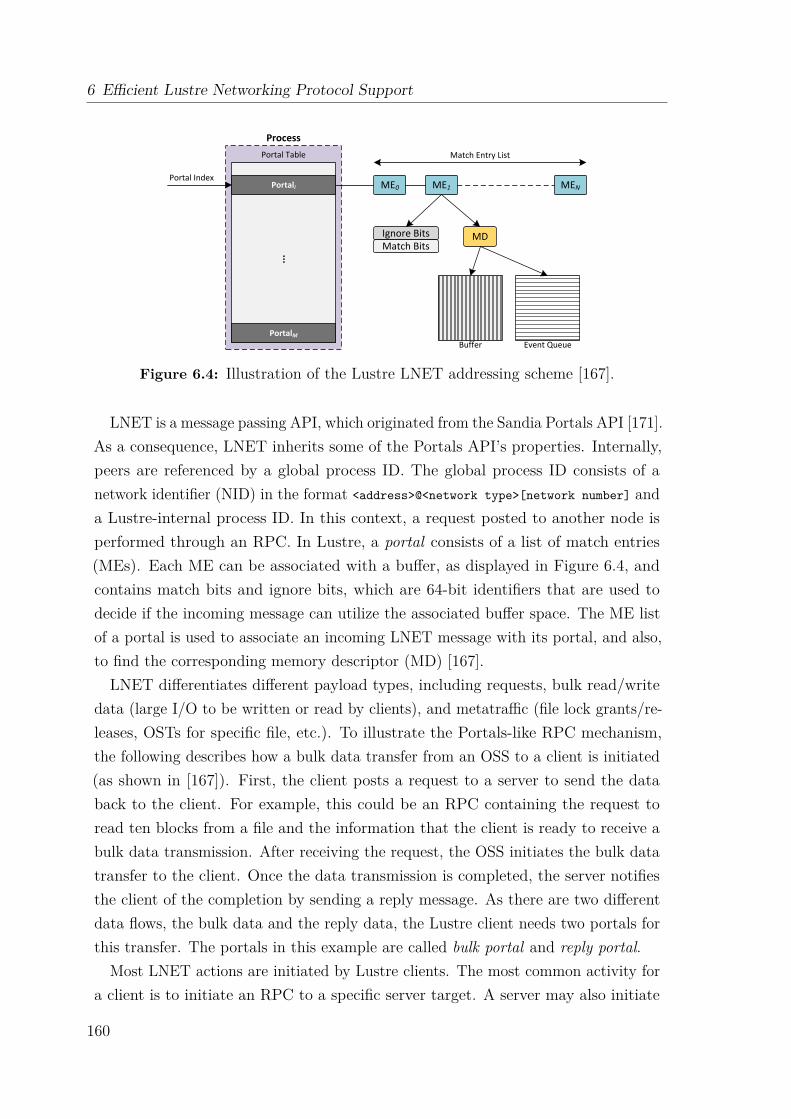
6 Efficient Lustre Networking Protocol Support
Portal Table
Portali ME0 ME1 MEN
MDIgnore BitsMatch Bits
Portal Index
Match Entry List
Process
Buffer Event QueuePortalM
...
Figure 6.4: Illustration of the Lustre LNET addressing scheme [167].
LNET is a message passing API, which originated from the Sandia Portals API [171].As a consequence, LNET inherits some of the Portals API’s properties. Internally,peers are referenced by a global process ID. The global process ID consists of anetwork identifier (NID) in the format <address>@<network type>[network number] anda Lustre-internal process ID. In this context, a request posted to another node isperformed through an RPC. In Lustre, a portal consists of a list of match entries(MEs). Each ME can be associated with a buffer, as displayed in Figure 6.4, andcontains match bits and ignore bits, which are 64-bit identifiers that are used todecide if the incoming message can utilize the associated buffer space. The ME listof a portal is used to associate an incoming LNET message with its portal, and also,to find the corresponding memory descriptor (MD) [167].LNET differentiates different payload types, including requests, bulk read/write
data (large I/O to be written or read by clients), and metatraffic (file lock grants/re-leases, OSTs for specific file, etc.). To illustrate the Portals-like RPC mechanism,the following describes how a bulk data transfer from an OSS to a client is initiated(as shown in [167]). First, the client posts a request to a server to send the databack to the client. For example, this could be an RPC containing the request toread ten blocks from a file and the information that the client is ready to receive abulk data transmission. After receiving the request, the OSS initiates the bulk datatransfer to the client. Once the data transmission is completed, the server notifiesthe client of the completion by sending a reply message. As there are two differentdata flows, the bulk data and the reply data, the Lustre client needs two portals forthis transfer. The portals in this example are called bulk portal and reply portal.
Most LNET actions are initiated by Lustre clients. The most common activity fora client is to initiate an RPC to a specific server target. A server may also initiate
160

6.1 Introduction to the Lustre File System
an RPC to a target on another server. For example, an MDS sends an RPC to theMGS to retrieve configuration data; or an RPC from MDS to an OST to updatethe MDS’s state with available space data. An OSS is relatively passive: it waits forincoming requests from either an MDS or Lustre clients.
6.1.3 Client Services and File I/O
The Lustre client is implemented as a kernel module. It provides an interface betweenthe Linux virtual file system and the Lustre servers, and presents an aggregate viewof the Lustre services to the host operating system as a POSIX-compliant file system.To applications, a Lustre client mount looks just like any other file system, with filesbeing organized in a directory hierarchy.
6.1.3.1 Client I/O Overview
Lustre employs a client-server communication model. Each connection has an initiator(the client end of the connection) and a target (the server process). The client mustbe able to retrieve file-specific metadata from the MDS when opening or closing a file,but also needs to interface with the OSTs for direct data access. The main Lustreclient services [165] are the management client (MGC), one or more metadata clients(MDC) and one object storage client (OSC) per configured OST in the file system.
The logical metadata volume (LMV) aggregates the MDCs and presents a singlelogical metadata namespace to the Lustre clients, which enables the transparentaccess to all MDTs. This allows the client to see the directory tree stored on multipleMDTs as a single coherent namespace, and striped directories are merged on theclients to form a single visible directory to users and applications.
The logical object volume (LOV) aggregates the OSCs to provide transparent accessacross all the OSTs. Thus, a client with a mounted Lustre file system sees a single,coherent, synchronized namespace, and files are presented within that namespace assingle addressable data objects, even when striped across multiple OSTs. Severalclients can write to different parts of the same file simultaneously, while, at the sametime, other clients can read from the file. Figure 6.5a provides an overview of theclient services and possible client-server interactions
Figure 6.5b illustrates an exemplary file access initiated by a Lustre client. First,the Lustre client sends an RPC to the MDS to request a file lock (1). This can eitherbe a read lock with look-up intent or a write lock with create intent. When the MDShas processed the request, it returns a file lock and all available metadata and filelayout extended attributes to the Lustre client (2). If the file is new, the MDS will
161
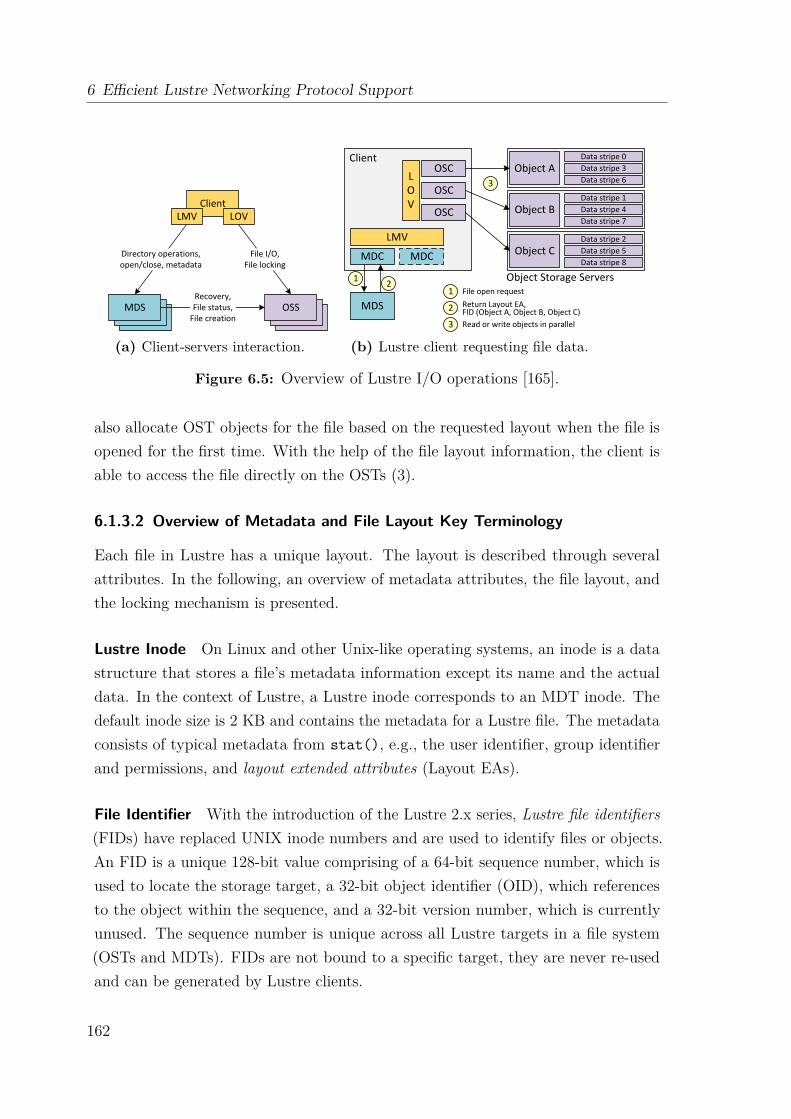
6 Efficient Lustre Networking Protocol Support
(a) Client-servers interaction.
Data stripe 0Data stripe 3Data stripe 6
Data stripe 1Data stripe 4Data stripe 7
Data stripe 2Data stripe 5Data stripe 8
1 2
3
1
2
3
File open requestReturn Layout EA,FID (Object A, Object B, Object C)Read or write objects in parallel
(b) Lustre client requesting file data.
Figure 6.5: Overview of Lustre I/O operations [165].
also allocate OST objects for the file based on the requested layout when the file isopened for the first time. With the help of the file layout information, the client isable to access the file directly on the OSTs (3).
6.1.3.2 Overview of Metadata and File Layout Key Terminology
Each file in Lustre has a unique layout. The layout is described through severalattributes. In the following, an overview of metadata attributes, the file layout, andthe locking mechanism is presented.
Lustre Inode On Linux and other Unix-like operating systems, an inode is a datastructure that stores a file’s metadata information except its name and the actualdata. In the context of Lustre, a Lustre inode corresponds to an MDT inode. Thedefault inode size is 2 KB and contains the metadata for a Lustre file. The metadataconsists of typical metadata from stat(), e.g., the user identifier, group identifierand permissions, and layout extended attributes (Layout EAs).
File Identifier With the introduction of the Lustre 2.x series, Lustre file identifiers(FIDs) have replaced UNIX inode numbers and are used to identify files or objects.An FID is a unique 128-bit value comprising of a 64-bit sequence number, which isused to locate the storage target, a 32-bit object identifier (OID), which referencesto the object within the sequence, and a 32-bit version number, which is currentlyunused. The sequence number is unique across all Lustre targets in a file system(OSTs and MDTs). FIDs are not bound to a specific target, they are never re-usedand can be generated by Lustre clients.
162
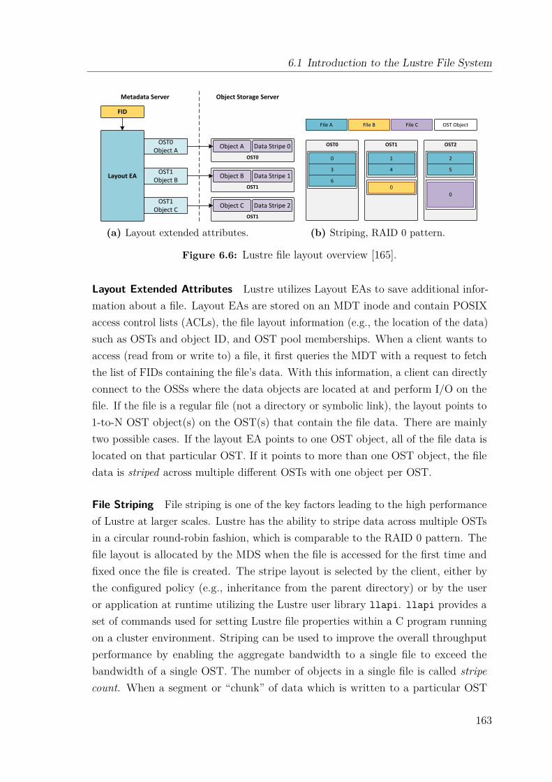
6.1 Introduction to the Lustre File System
FID
Layout EA
OST0Object A
OST1Object B
OST1Object C
OST0
OST1
OST1
Object A Data Stripe 0
Object B Data Stripe 1
Object C Data Stripe 2
Metadata Server Object Storage Server
(a) Layout extended attributes.
File A File B File C OST Object
OST0 OST1 OST2
0
3
6
1
4
2
5
00
(b) Striping, RAID 0 pattern.
Figure 6.6: Lustre file layout overview [165].
Layout Extended Attributes Lustre utilizes Layout EAs to save additional infor-mation about a file. Layout EAs are stored on an MDT inode and contain POSIXaccess control lists (ACLs), the file layout information (e.g., the location of the data)such as OSTs and object ID, and OST pool memberships. When a client wants toaccess (read from or write to) a file, it first queries the MDT with a request to fetchthe list of FIDs containing the file’s data. With this information, a client can directlyconnect to the OSSs where the data objects are located at and perform I/O on thefile. If the file is a regular file (not a directory or symbolic link), the layout points to1-to-N OST object(s) on the OST(s) that contain the file data. There are mainlytwo possible cases. If the layout EA points to one OST object, all of the file data islocated on that particular OST. If it points to more than one OST object, the filedata is striped across multiple different OSTs with one object per OST.
File Striping File striping is one of the key factors leading to the high performanceof Lustre at larger scales. Lustre has the ability to stripe data across multiple OSTsin a circular round-robin fashion, which is comparable to the RAID 0 pattern. Thefile layout is allocated by the MDS when the file is accessed for the first time andfixed once the file is created. The stripe layout is selected by the client, either bythe configured policy (e.g., inheritance from the parent directory) or by the useror application at runtime utilizing the Lustre user library llapi. llapi provides aset of commands used for setting Lustre file properties within a C program runningon a cluster environment. Striping can be used to improve the overall throughputperformance by enabling the aggregate bandwidth to a single file to exceed thebandwidth of a single OST. The number of objects in a single file is called stripecount. When a segment or “chunk” of data which is written to a particular OST
163

6 Efficient Lustre Networking Protocol Support
LNET LND NICRPC API
lnd_
lnet_
LNet_
Figure 6.7: LNET API naming conventions.
object exceeds the specified stripe size, the next chunk of data is written to the nextobject. The maximum number of OSTs that a single file can be striped across is2000, even though a Lustre file system can comprise of more than 2000 OSTs.
Lustre Distributed Lock Manager The Lustre Distributed Lock Manager (LDLM)provides byte-granular file and fine-grained metadata locking. It ensures that filesare coherent between all clients and servers. Each MDT and OST has its own LDLM.Metadata servers use inode bit-locks for file lockup, state, extended attributes, andlayout. Object storage servers provide extent-based locks for OST objects. File datalocks are managed for each OST. Clients can be granted read extent locks for a partor all of a file, allowing multiple concurrent readers access to the same file. Clientscan be granted non-overlapping write extent locks for regions of the file. MultipleLustre clients may access a single file concurrently for both read and write, whichshould minimize potential bottlenecks during file I/O.
6.2 Lustre Networking Semantics and InterfacesLNET is designed to be lightweight and efficient. It supports message passing forprocessing RPCs and RDMA for bulk data transfers. Even though the Lustre projectis open source, there is almost no documentation available about its implementationdetails. Especially for LNET, the documentation is limited to its source code, amaster thesis by T. Groschup [172] focusing on Lustre version 2.4, and a technicalreport by Wang et al. [167], which describes Lustre’s internals for version 1.8, andtherefore, is mostly outdated.
In order to map the Lustre network protocol to a new interconnect technology suchas Extoll, it is particularly important to understand Lustre’s networking semanticsand interfaces. The following sections present a comprehensive overview of LNET’sbuilding blocks, including an API summary, LNET’s communication semantics, andthe credit system. In addition, an overview of existing LNDs is provided.
164
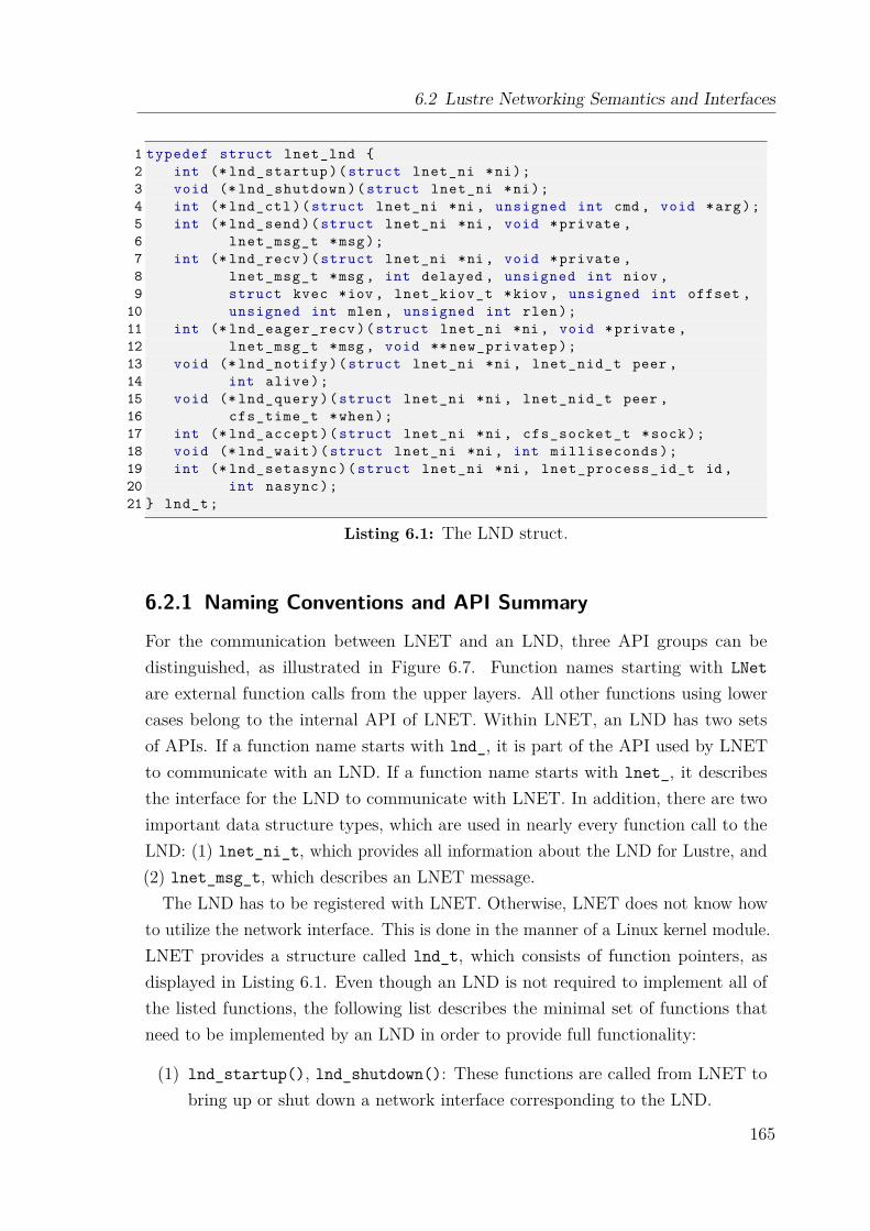
6.2 Lustre Networking Semantics and Interfaces
1 typedef struct lnet_lnd {2 int (* lnd_startup )( struct lnet_ni *ni);3 void (* lnd_shutdown )( struct lnet_ni *ni);4 int (* lnd_ctl )( struct lnet_ni *ni , unsigned int cmd , void *arg);5 int (* lnd_send )( struct lnet_ni *ni , void *private ,6 lnet_msg_t *msg);7 int (* lnd_recv )( struct lnet_ni *ni , void *private ,8 lnet_msg_t *msg , int delayed , unsigned int niov ,9 struct kvec *iov , lnet_kiov_t *kiov , unsigned int offset ,
10 unsigned int mlen , unsigned int rlen);11 int (* lnd_eager_recv )( struct lnet_ni *ni , void *private ,12 lnet_msg_t *msg , void ** new_privatep );13 void (* lnd_notify )( struct lnet_ni *ni , lnet_nid_t peer ,14 int alive);15 void (* lnd_query )( struct lnet_ni *ni , lnet_nid_t peer ,16 cfs_time_t *when);17 int (* lnd_accept )( struct lnet_ni *ni , cfs_socket_t *sock);18 void (* lnd_wait )( struct lnet_ni *ni , int milliseconds );19 int (* lnd_setasync )( struct lnet_ni *ni , lnet_process_id_t id ,20 int nasync );21 } lnd_t;
Listing 6.1: The LND struct.
6.2.1 Naming Conventions and API Summary
For the communication between LNET and an LND, three API groups can bedistinguished, as illustrated in Figure 6.7. Function names starting with LNetare external function calls from the upper layers. All other functions using lowercases belong to the internal API of LNET. Within LNET, an LND has two setsof APIs. If a function name starts with lnd_, it is part of the API used by LNETto communicate with an LND. If a function name starts with lnet_, it describesthe interface for the LND to communicate with LNET. In addition, there are twoimportant data structure types, which are used in nearly every function call to theLND: (1) lnet_ni_t, which provides all information about the LND for Lustre, and(2) lnet_msg_t, which describes an LNET message.
The LND has to be registered with LNET. Otherwise, LNET does not know howto utilize the network interface. This is done in the manner of a Linux kernel module.LNET provides a structure called lnd_t, which consists of function pointers, asdisplayed in Listing 6.1. Even though an LND is not required to implement all ofthe listed functions, the following list describes the minimal set of functions thatneed to be implemented by an LND in order to provide full functionality:
(1) lnd_startup(), lnd_shutdown(): These functions are called from LNET tobring up or shut down a network interface corresponding to the LND.
165
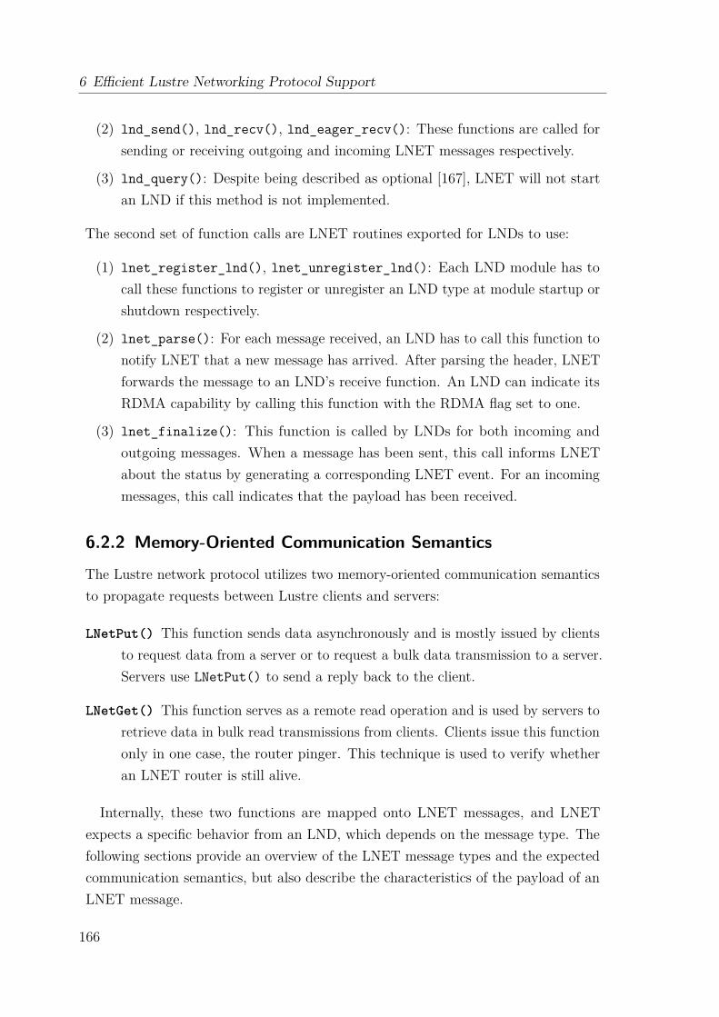
6 Efficient Lustre Networking Protocol Support
(2) lnd_send(), lnd_recv(), lnd_eager_recv(): These functions are called forsending or receiving outgoing and incoming LNET messages respectively.
(3) lnd_query(): Despite being described as optional [167], LNET will not startan LND if this method is not implemented.
The second set of function calls are LNET routines exported for LNDs to use:
(1) lnet_register_lnd(), lnet_unregister_lnd(): Each LND module has tocall these functions to register or unregister an LND type at module startup orshutdown respectively.
(2) lnet_parse(): For each message received, an LND has to call this function tonotify LNET that a new message has arrived. After parsing the header, LNETforwards the message to an LND’s receive function. An LND can indicate itsRDMA capability by calling this function with the RDMA flag set to one.
(3) lnet_finalize(): This function is called by LNDs for both incoming andoutgoing messages. When a message has been sent, this call informs LNETabout the status by generating a corresponding LNET event. For an incomingmessages, this call indicates that the payload has been received.
6.2.2 Memory-Oriented Communication Semantics
The Lustre network protocol utilizes two memory-oriented communication semanticsto propagate requests between Lustre clients and servers:
LNetPut() This function sends data asynchronously and is mostly issued by clientsto request data from a server or to request a bulk data transmission to a server.Servers use LNetPut() to send a reply back to the client.
LNetGet() This function serves as a remote read operation and is used by servers toretrieve data in bulk read transmissions from clients. Clients issue this functiononly in one case, the router pinger. This technique is used to verify whetheran LNET router is still alive.
Internally, these two functions are mapped onto LNET messages, and LNETexpects a specific behavior from an LND, which depends on the message type. Thefollowing sections provide an overview of the LNET message types and the expectedcommunication semantics, but also describe the characteristics of the payload of anLNET message.
166
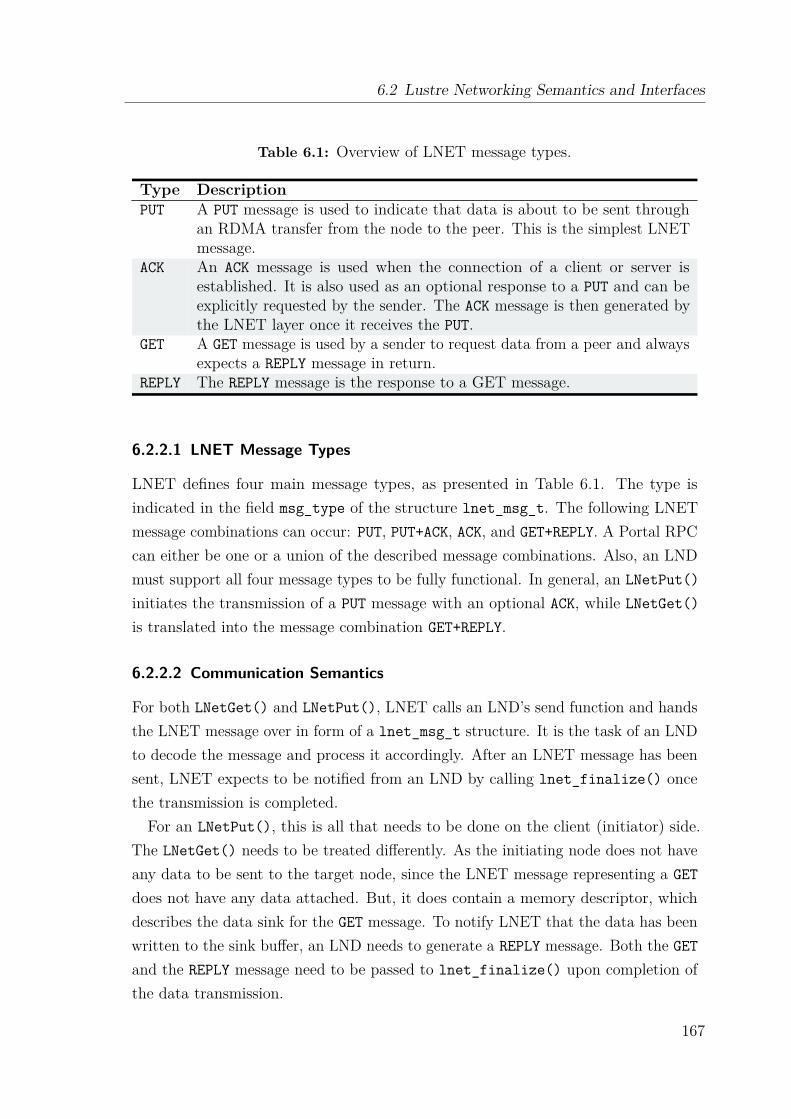
6.2 Lustre Networking Semantics and Interfaces
Table 6.1: Overview of LNET message types.
Type DescriptionPUT A PUT message is used to indicate that data is about to be sent through
an RDMA transfer from the node to the peer. This is the simplest LNETmessage.
ACK An ACK message is used when the connection of a client or server isestablished. It is also used as an optional response to a PUT and can beexplicitly requested by the sender. The ACK message is then generated bythe LNET layer once it receives the PUT.
GET A GET message is used by a sender to request data from a peer and alwaysexpects a REPLY message in return.
REPLY The REPLY message is the response to a GET message.
6.2.2.1 LNET Message Types
LNET defines four main message types, as presented in Table 6.1. The type isindicated in the field msg_type of the structure lnet_msg_t. The following LNETmessage combinations can occur: PUT, PUT+ACK, ACK, and GET+REPLY. A Portal RPCcan either be one or a union of the described message combinations. Also, an LNDmust support all four message types to be fully functional. In general, an LNetPut()initiates the transmission of a PUT message with an optional ACK, while LNetGet()is translated into the message combination GET+REPLY.
6.2.2.2 Communication Semantics
For both LNetGet() and LNetPut(), LNET calls an LND’s send function and handsthe LNET message over in form of a lnet_msg_t structure. It is the task of an LNDto decode the message and process it accordingly. After an LNET message has beensent, LNET expects to be notified from an LND by calling lnet_finalize() oncethe transmission is completed.For an LNetPut(), this is all that needs to be done on the client (initiator) side.
The LNetGet() needs to be treated differently. As the initiating node does not haveany data to be sent to the target node, since the LNET message representing a GETdoes not have any data attached. But, it does contain a memory descriptor, whichdescribes the data sink for the GET message. To notify LNET that the data has beenwritten to the sink buffer, an LND needs to generate a REPLY message. Both the GETand the REPLY message need to be passed to lnet_finalize() upon completion ofthe data transmission.
167
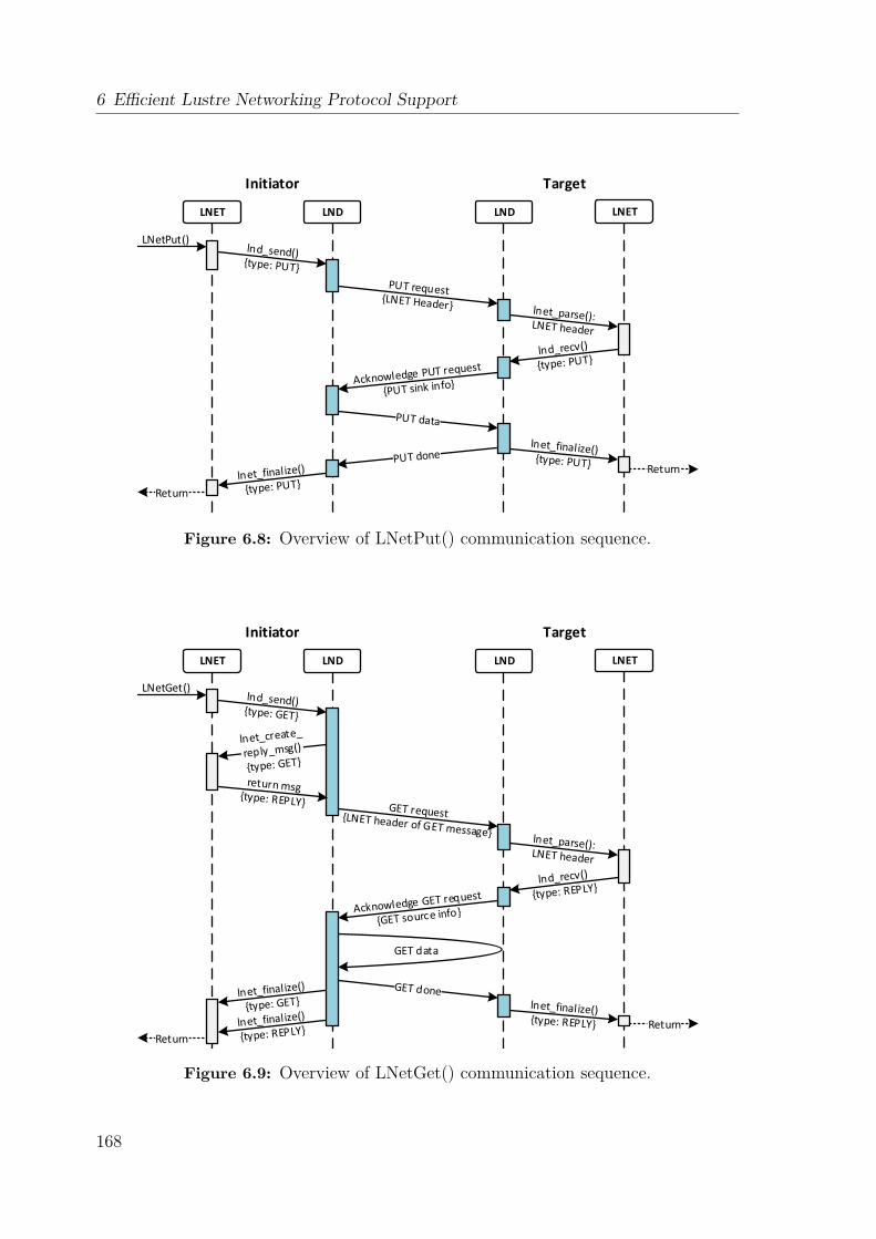
6 Efficient Lustre Networking Protocol Support
LNET LND LND LNET
LNetPut()
Return
Initiator Target
Figure 6.8: Overview of LNetPut() communication sequence.
LNET LND LND LNET
LNetGet()
Return
GET data
Return
Initiator Target
Figure 6.9: Overview of LNetGet() communication sequence.
168
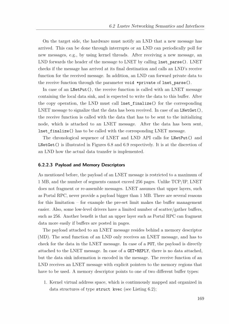
6.2 Lustre Networking Semantics and Interfaces
On the target side, the hardware must notify an LND that a new message hasarrived. This can be done through interrupts or an LND can periodically poll fornew messages, e.g., by using kernel threads. After receiving a new message, anLND forwards the header of the message to LNET by calling lnet_parse(). LNETchecks if the message has arrived at its final destination and calls an LND’s receivefunction for the received message. In addition, an LND can forward private data tothe receive function through the parameter void *private of lnet_parse().In case of an LNetPut(), the receive function is called with an LNET message
containing the local data sink, and is expected to write the data to this buffer. Afterthe copy operation, the LND must call lnet_finalize() for the correspondingLNET message to signalize that the data has been received. In case of an LNetGet(),the receive function is called with the data that has to be sent to the initializingnode, which is attached to an LNET message. After the data has been sent,lnet_finalize() has to be called with the corresponding LNET message.The chronological sequence of LNET and LND API calls for LNetPut() and
LNetGet() is illustrated in Figures 6.8 and 6.9 respectively. It is at the discretion ofan LND how the actual data transfer is implemented.
6.2.2.3 Payload and Memory Descriptors
As mentioned before, the payload of an LNET message is restricted to a maximum of1 MB, and the number of segments cannot exceed 256 pages. Unlike TCP/IP, LNETdoes not fragment or re-assemble messages. LNET assumes that upper layers, suchas Portal RPC, never provide a payload bigger than 1 MB. There are several reasonsfor this limitation – for example the pre-set limit makes the buffer managementeasier. Also, some low-level drivers have a limited number of scatter/gather buffers,such as 256. Another benefit is that an upper layer such as Portal RPC can fragmentdata more easily if buffers are posted in pages.The payload attached to an LNET message resides behind a memory descriptor
(MD). The send function of an LND only receives an LNET message, and has tocheck for the data in the LNET message. In case of a PUT, the payload is directlyattached to the LNET message. In case of a GET+REPLY, there is no data attached,but the data sink information is encoded in the message. The receive function of anLND receives an LNET message with explicit pointers to the memory regions thathave to be used. A memory descriptor points to one of two different buffer types:
1. Kernel virtual address space, which is continuously mapped and organized indata structures of type struct kvec (see Listing 6.2);
169
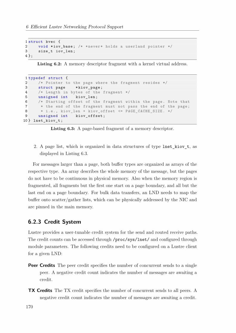
6 Efficient Lustre Networking Protocol Support
1 struct kvec {2 void * iov_base ; /* *never* holds a userland pointer */3 size_t iov_len ;4 };
Listing 6.2: A memory descriptor fragment with a kernel virtual address.
1 typedef struct {2 /* Pointer to the page where the fragment resides */3 struct page * kiov_page ;4 /* Length in bytes of the fragment */5 unsigned int kiov_len ;6 /* Starting offset of the fragment within the page. Note that7 * the end of the fragment must not pass the end of the page;8 * i.e., kiov_len + kiov_offset <= PAGE_CACHE_SIZE . */9 unsigned int kiov_offset ;
10 } lnet_kiov_t ;
Listing 6.3: A page-based fragment of a memory descriptor.
2. A page list, which is organized in data structures of type lnet_kiov_t, asdisplayed in Listing 6.3.
For messages larger than a page, both buffer types are organized as arrays of therespective type. An array describes the whole memory of the message, but the pagesdo not have to be continuous in physical memory. Also when the memory region isfragmented, all fragments but the first one start on a page boundary, and all but thelast end on a page boundary. For bulk data transfers, an LND needs to map thebuffer onto scatter/gather lists, which can be physically addressed by the NIC andare pinned in the main memory.
6.2.3 Credit System
Lustre provides a user-tunable credit system for the send and routed receive paths.The credit counts can be accessed through /proc/sys/lnet/ and configured throughmodule parameters. The following credits need to be configured on a Lustre clientfor a given LND:
Peer Credits The peer credit specifies the number of concurrent sends to a singlepeer. A negative credit count indicates the number of messages are awaiting acredit.
TX Credits The TX credit specifies the number of concurrent sends to all peers. Anegative credit count indicates the number of messages are awaiting a credit.
170

6.2 Lustre Networking Semantics and Interfaces
Every send consumes one peer credit and one TX credit. In addition, Lustreprovides credits accounting when routers receive a message destined for another peer.The peer and TX credits have an impact on how well a network connection scaleswith an increasing number of concurrent accesses. But, the higher the credit count,the more memory resources are consumed by an LND. For communication to routersnot only the TX and peer credits must be tuned, but also the global router bufferand peer router buffer credits need to be configured:
Peer Router Credit The peer router credit governs the number of concurrent re-ceives from a single peer. Its main objective is to prevent a single peer fromusing all router buffer resources. A credit is given back when the receivecompletes.
Global Router Buffer Credit This credit allows messages to be queued in order toselect non-data RPCs versus data RPCs with the intent to avoid congestion.LNET router nodes have a limited number buffers. The router buffer creditsensure that a receive only succeeds if appropriate buffer space is available.
6.2.4 Available Lustre Network Drivers
The most widely used network technologies for Lustre storage systems are TCP/IPnetworks and RDMA-capable networks that support the OFED software environment(refer to section 5.2.1). For TCP/IP networks, the ksocklnd.ko module, also referredto as Sockets LND, implements the LNET driver. Its implementation differs fromthe presented LNET semantics and message types. The Sockets LND utilizesits own message type called HELLO, which is used to mimic traditional TCP/IPcommunication, and does not support any other message type.
For RDMA network technologies, the ko2iblnd.ko module, also referred to as o2ibLND, supports Infiniband, Omni-Path, and RoCE in conjunction with the OFEDenvironment. The LND supports all of the described message types. Its implementa-tion follows closely the described memory-oriented communication semantics. Itsbulk data transmission relies on Scatter/Gather Elements (see section 6.4.2).
Besides these two main LNDs, several other LNDs have been introduced over time.Examples are the Gemini LND [173] and the Portals4 LND [174]. As indicated by itsname, the Gemini LND provides support for Cray’s Gemini interconnect technology.The Portals4 LND implements the LNET driver for the BXI interconnect [175] andrelies on the Portals 4 API. Currently, it is not included in the official Lustre release.
171
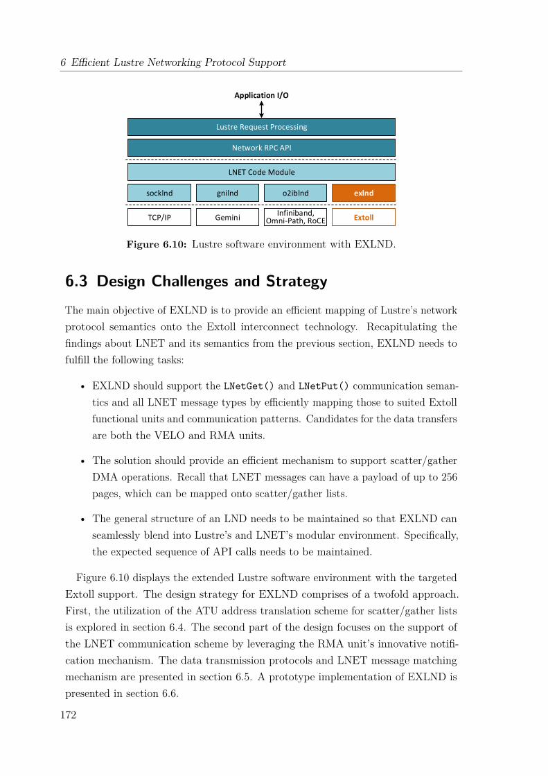
6 Efficient Lustre Networking Protocol Support
TCP/IP
socklnd
LNET Code Module
Network RPC API
Lustre Request Processing
Application I/O
gnilnd o2iblnd exlnd
GeminiInfiniband,
Omni-Path, RoCE Extoll
Figure 6.10: Lustre software environment with EXLND.
6.3 Design Challenges and StrategyThe main objective of EXLND is to provide an efficient mapping of Lustre’s networkprotocol semantics onto the Extoll interconnect technology. Recapitulating thefindings about LNET and its semantics from the previous section, EXLND needs tofulfill the following tasks:
• EXLND should support the LNetGet() and LNetPut() communication seman-tics and all LNET message types by efficiently mapping those to suited Extollfunctional units and communication patterns. Candidates for the data transfersare both the VELO and RMA units.
• The solution should provide an efficient mechanism to support scatter/gatherDMA operations. Recall that LNET messages can have a payload of up to 256pages, which can be mapped onto scatter/gather lists.
• The general structure of an LND needs to be maintained so that EXLND canseamlessly blend into Lustre’s and LNET’s modular environment. Specifically,the expected sequence of API calls needs to be maintained.
Figure 6.10 displays the extended Lustre software environment with the targetedExtoll support. The design strategy for EXLND comprises of a twofold approach.First, the utilization of the ATU address translation scheme for scatter/gather listsis explored in section 6.4. The second part of the design focuses on the support ofthe LNET communication scheme by leveraging the RMA unit’s innovative notifi-cation mechanism. The data transmission protocols and LNET message matchingmechanism are presented in section 6.5. A prototype implementation of EXLND ispresented in section 6.6.
172
6.4 Efficient RDMA with Vectored I/O Operations
6.4 Efficient RDMA with Vectored I/O OperationsMost modern NICs provide on-chip support for RDMA operations and address trans-lation, which enables scatter/gather DMA. Among other things, those scatter/gatheroperations, also referred to as vectored I/O, have two major benefits: atomicityand efficiency. Atomicity means that one process can write into or read from aset of physical buffers, which can be scattered throughout the physical memory,without the risk that another process might perform I/O on the same data. Inaddition, this mechanism improves the efficiency since one vectored I/O operationcan replace multiple ordinary reads or writes, and therefore, reduces the overhead.Scatter/gather DMA controllers provide the hardware support for scatter/gatherI/O. To initiate such an operation, a controller needs the input modifier, also knownas scatter/gather list, to offload the transfer to the NIC.As described in section 6.2.2.3, the payload of an LNET message can consist of
up to 256 pages. It is desirable to transfer the payload in one operation instead ofmultiple RDMA reads or writes. Other LNDs, such O2IB LND, implement vectoredI/O by mapping the attached memory regions onto so called scatterlists. Within thekernel, a buffer to be used in a scatter/gather DMA operation is represented by anarray of one or more scatterlist structures. As presented in section 3.2.5, the Extolldesign features the address translation unit, which can be utilized to map page listsand contiguous kernel buffers into the Extoll address space. This functionality isused to provide scatter/gather DMA over Extoll.The remainder of this section is organized as follows. First, the term physical
buffer list is introduced followed by an overview of how Infiniband utilizes so calledscatter/gather elements to support vectored I/O. The last part of this section focuseson the design and its limitations of scatter/gather DMA support for Extoll.
6.4.1 Memory Management
In the context of RDMA-enabled NICs, memory regions refer to continuous memoryareas, which have been pinned in main memory and registered with a NIC. Suchnon-shared memory regions are also called physical buffer lists and consist of pageor block lists, as depicted in Figure 6.11. NICs can access these physical buffers byusing their physical addresses. Another important characteristic is that they cannotbe swapped out of the main memory, which enables scatter/gather transfers.
For page lists, the page size has to be an integral power of two and all pages haveto have the same size. The data can start at an offset into the first page, referred
173
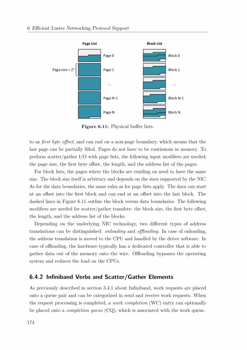
6 Efficient Lustre Networking Protocol Support
Page List
Page 0
Page 1
Page N-1
Page N
...
Block List
Block 0
Block 1
Block N-1
Block N
...
Page size = 2x
Figure 6.11: Physical buffer lists.
to as first byte offset, and can end on a non-page boundary, which means that thelast page can be partially filled. Pages do not have to be continuous in memory. Toperform scatter/gather I/O with page lists, the following input modifiers are needed:the page size, the first byte offset, the length, and the address list of the pages.
For block lists, the pages where the blocks are residing on need to have the samesize. The block size itself is arbitrary and depends on the sizes supported by the NIC.As for the data boundaries, the same rules as for page lists apply. The data can startat an offset into the first block and can end at an offset into the last block. Thedashed lines in Figure 6.11 outline the block versus data boundaries. The followingmodifiers are needed for scatter/gather transfers: the block size, the first byte offset,the length, and the address list of the blocks.Depending on the underlying NIC technology, two different types of address
translations can be distinguished: onloading and offloading. In case of onloading,the address translation is moved to the CPU and handled by the driver software. Incase of offloading, the hardware typically has a dedicated controller that is able togather data out of the memory onto the wire. Offloading bypasses the operatingsystem and reduces the load on the CPUs.
6.4.2 Infiniband Verbs and Scatter/Gather Elements
As previously described in section 3.4.1 about Infiniband, work requests are placedonto a queue pair and can be categorized in send and receive work requests. Whenthe request processing is completed, a work completion (WC) entry can optionallybe placed onto a completion queue (CQ), which is associated with the work queue.
174
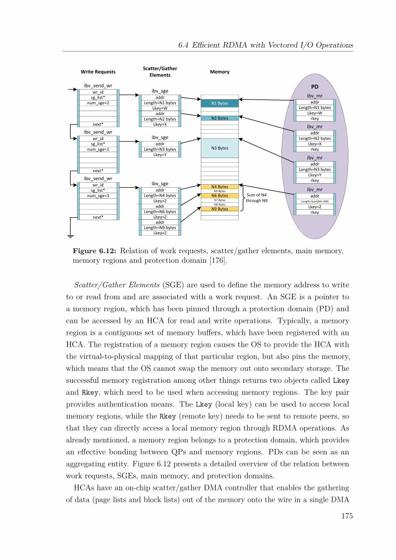
6.4 Efficient RDMA with Vectored I/O Operations
PDwr_id
sg_list*num_sge=2
next*
wr_idsg_list*
num_sge=1
next*
wr_idsg_list*
num_sge=3
next*
addrLength=N1 bytes
Lkey=Waddr
Length=N2 bytesLkey=X
addrLength=N3 bytes
Lkey=Y
addrLength=N4 bytes
Lkey=Zaddr
Length=N6 bytesLkey=Z
addrLength=N9 bytes
Lkey=Z
N1 Bytes
N2 Bytes
N3 Bytes
N4 BytesN5 Bytes
N6 BytesN7 BytesN8 Bytes
N9 Bytes
addrLength=N1 bytes
Lkey=Wrkey
addrLength=N2 bytes
Lkey=Xrkey
addrLength=N3 bytes
Lkey=Yrkey
addrLength=Sum(N4->N9)
Lkey=Zrkey
Sum of N4 through N9
ibv_send_wr
ibv_send_wr
ibv_send_wr
ibv_sge
ibv_sge
ibv_sge
ibv_mr
ibv_mr
ibv_mr
ibv_mr
Write Requests Scatter/Gather Elements Memory
Figure 6.12: Relation of work requests, scatter/gather elements, main memory,memory regions and protection domain [176].
Scatter/Gather Elements (SGE) are used to define the memory address to writeto or read from and are associated with a work request. An SGE is a pointer toa memory region, which has been pinned through a protection domain (PD) andcan be accessed by an HCA for read and write operations. Typically, a memoryregion is a contiguous set of memory buffers, which have been registered with anHCA. The registration of a memory region causes the OS to provide the HCA withthe virtual-to-physical mapping of that particular region, but also pins the memory,which means that the OS cannot swap the memory out onto secondary storage. Thesuccessful memory registration among other things returns two objects called Lkeyand Rkey, which need to be used when accessing memory regions. The key pairprovides authentication means. The Lkey (local key) can be used to access localmemory regions, while the Rkey (remote key) needs to be sent to remote peers, sothat they can directly access a local memory region through RDMA operations. Asalready mentioned, a memory region belongs to a protection domain, which providesan effective bonding between QPs and memory regions. PDs can be seen as anaggregating entity. Figure 6.12 presents a detailed overview of the relation betweenwork requests, SGEs, main memory, and protection domains.
HCAs have an on-chip scatter/gather DMA controller that enables the gatheringof data (page lists and block lists) out of the memory onto the wire in a single DMA
175
6 Efficient Lustre Networking Protocol Support
transaction. This means that scatter/gather I/O can be completely offloaded to theHCA. This feature is utilized by the O2IB LND for bulk data transmissions.
6.4.3 Scatter/Gather DMA Operation Support for Extoll
Recall from section 3.2.5 that the ATU acts as an MMU for the Extoll NIC, especiallyfor the RMA unit, and therefore, is suitable to provide scatter/gather support forRDMA operations through the RMA unit. By default, the ATU kernel moduleallocates 128 GATs with an NLP size of 4 KB. Each GAT can map up to 218 NLPs,which translates to 218 ∗ 4 KB = 1 GB of mappable main memory per GAT. TheATU provides address translation offloading for two types of memory regions: pageslists and continuously allocated kernel virtual buffers.The payload of an LNET message is limited by the LNET MTU, which is 1 MB
per transmission, and can comprise of up to 256 pages with a page size of 4 KB.The payload is described by a memory descriptor, which points to an associatedbuffer that is allocated utilizing GFP (get free pages) flags. The GFP flags ensurethat the returned buffer consists of pages, but do not pin the buffer into the mainmemory. The buffer either consists of an array of pages (array of lnet_kiov_ts) ora continuously allocated kernel virtual buffer of type struct kvec, which can betranslated into a scatterlist consisting of pages. This means that the LNET designaligns well with the capabilities of the ATU design, which indicates that for Lustrethe address translation can be completely offloaded to the Extoll NIC.
Within the scope of this work, the Extoll kernel API has been extended to provideATU memory registration services for kernel modules such as LNDs. There aretwo functions available for memory registration, one for scatterlists and one forpage lists. Both return a software NLA, which can be used to build RMA softwaredescriptors. In addition, a de-registration function has been implemented, whichexpects the software NLA, the corresponding VPID, and the number of mappedpages as parameters. For example for page lists, the ATU expects the following inputmodifiers in order to perform a correct address translation: the VPID of the kernelprocess, the pointer to the first entry in page list of type struct page, the numberof list entries, and the number of bytes (also called stride) that need to be added toreach the next entry of type struct page in the list.When using the Extoll kernel API to register memory regions, the requesting
process needs to make sure that the provided buffer is pinned into main memory sothat the buffer can not be exempt by the OS and be swapped out onto secondarystorage. This is a necessary requirement when working with physical addresses.
176
6.5 Support for LNET Protocol Semantics
When memory is swapped out before the RMA operation gets completed, the addresstranslation results in a general protection error, which ultimately leads to a computenode failure.In general besides the support for page lists and continuous buffer space, it is
desirable to provide scatter/gather DMA operations for block lists. However, thecurrent ATU design does not support address translation offloading for such physicalbuffer lists. It requires an additional piece of kernel code, which handles such buffertypes. One idea is to copy memory blocks into continuously allocated buffer space,e.g., for small fragments, and then, map this buffer to an NLA.
6.5 Support for LNET Protocol SemanticsThe mapping of the LNET protocol semantics onto the Extoll technology comprises oftwo components: the data transmission protocols themselves and a message matchingmechanism on both the initiating and the target side. The following sections providethe specification of the data transmission protocols followed by the description ofhow incoming messages are matched with their corresponding LNET messages.
6.5.1 Data Transmission Protocols
EXLND distinguishes two types of transmission protocols: immediate sends and bulkdata transfers. The transmission protocol is chosen depending on the message type,but also the size of the payload.
6.5.1.1 Immediate Send
Similar to the eager protocol of EXT-Eth presented in section 5.4.1.2, the immediatesend splits the payload of an LNET message in 120 byte-sized fragments and sendsthe data directly through multiple VELO sends. The immediate send is used formessages of type ACK, which typically have no payload attached, and fit in one VELOmessage. It can also be used for messages of type PUT or GET for small payloadsizes. A user-tunable threshold, similar to EXT-Eth, defines the upper limit for theimmediate send path. On the receiving side, the VELO message containing the lastfragment of the payload notifies EXLND that all data has been received, re-assemblesthe payload, and then, passes it to the upper layers.
177
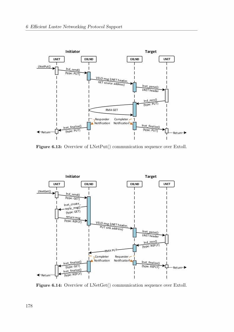
6 Efficient Lustre Networking Protocol Support
LNET EXLND EXLND LNET
LNetPut()
Responder Notification
Completer Notification
RMA GET
Return Return
Initiator Target
Figure 6.13: Overview of LNetPut() communication sequence over Extoll.
LNET EXLND EXLND LNET
LNetGet()
Completer Notification
Requester Notification
Return
Return
Initiator Target
Figure 6.14: Overview of LNetGet() communication sequence over Extoll.
178
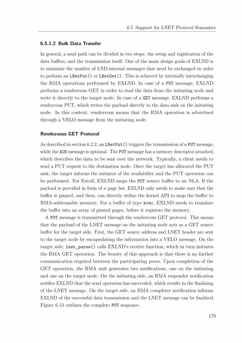
6.5 Support for LNET Protocol Semantics
6.5.1.2 Bulk Data Transfer
In general, a send path can be divided in two steps: the setup and registration of thedata buffers, and the transmission itself. One of the main design goals of EXLND isto minimize the number of LND-internal messages that need be exchanged in orderto perform an LNetPut() or LNetGet(). This is achieved by internally interchangingthe RMA operations performed by EXLND. In case of a PUT message, EXLNDperforms a rendezvous GET in order to read the data from the initiating node andwrite it directly to the target node. In case of a GET message, EXLND performs arendezvous PUT, which writes the payload directly to the data sink on the initiatingnode. In this context, rendezvous means that the RMA operation is advertisedthrough a VELO message from the initiating node.
Rendezvous GET Protocol
As described in section 6.2.2, an LNetPut() triggers the transmission of a PUT message,while the ACK message is optional. The PUT message has a memory descriptor attached,which describes the data to be sent over the network. Typically, a client needs tosend a PUT request to the destination node. Once the target has allocated the PUTsink, the target informs the initiator of the availability and the PUT operation canbe performed. For Extoll, EXLND maps the PUT source buffer to an NLA. If thepayload is provided in form of a page list, EXLND only needs to make sure that thebuffer is pinned, and then, can directly utilize the kernel API to map the buffer toRMA-addressable memory. For a buffer of type kvec, EXLND needs to translatethe buffer into an array of pinned pages, before it registers the memory.
A PUT message is transmitted through the rendezvous GET protocol. This meansthat the payload of the LNET message on the initiating node acts as a GET sourcebuffer for the target side. First, the GET source address and LNET header are sentto the target node by encapsulating the information into a VELO message. On thetarget side, lnet_parse() calls EXLND’s receive function, which in turn initiatesthe RMA GET operation. The beauty of this approach is that there is no furthercommunication required between the participating peers. Upon completion of theGET operation, the RMA unit generates two notifications, one on the initiatingand one on the target node. On the initiating side, an RMA responder notificationnotifies EXLND that the send operation has succeeded, which results in the finalizingof the LNET message. On the target side, an RMA completer notification informsEXLND of the successful data transmission and the LNET message can be finalized.Figure 6.13 outlines the complete PUT sequence.
179
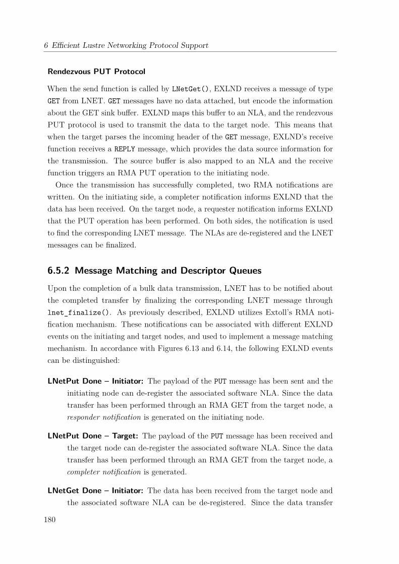
6 Efficient Lustre Networking Protocol Support
Rendezvous PUT Protocol
When the send function is called by LNetGet(), EXLND receives a message of typeGET from LNET. GET messages have no data attached, but encode the informationabout the GET sink buffer. EXLND maps this buffer to an NLA, and the rendezvousPUT protocol is used to transmit the data to the target node. This means thatwhen the target parses the incoming header of the GET message, EXLND’s receivefunction receives a REPLY message, which provides the data source information forthe transmission. The source buffer is also mapped to an NLA and the receivefunction triggers an RMA PUT operation to the initiating node.Once the transmission has successfully completed, two RMA notifications are
written. On the initiating side, a completer notification informs EXLND that thedata has been received. On the target node, a requester notification informs EXLNDthat the PUT operation has been performed. On both sides, the notification is usedto find the corresponding LNET message. The NLAs are de-registered and the LNETmessages can be finalized.
6.5.2 Message Matching and Descriptor Queues
Upon the completion of a bulk data transmission, LNET has to be notified aboutthe completed transfer by finalizing the corresponding LNET message throughlnet_finalize(). As previously described, EXLND utilizes Extoll’s RMA noti-fication mechanism. These notifications can be associated with different EXLNDevents on the initiating and target nodes, and used to implement a message matchingmechanism. In accordance with Figures 6.13 and 6.14, the following EXLND eventscan be distinguished:
LNetPut Done – Initiator: The payload of the PUT message has been sent and theinitiating node can de-register the associated software NLA. Since the datatransfer has been performed through an RMA GET from the target node, aresponder notification is generated on the initiating node.
LNetPut Done – Target: The payload of the PUT message has been received andthe target node can de-register the associated software NLA. Since the datatransfer has been performed through an RMA GET from the target node, acompleter notification is generated.
LNetGet Done – Initiator: The data has been received from the target node andthe associated software NLA can be de-registered. Since the data transfer
180
6.5 Support for LNET Protocol Semantics
Un
mat
ched
LN
ET m
ess
age
de
scri
pto
rs
Po
ol o
f un
use
d LN
ET
me
ssage
de
scripto
rs
......
Sending LNET header via VELO or starting a RMA transfer
Upon reception of matching RMA Notification
......
Figure 6.15: The movement of list elements representing unfinished transfers.
has been performed through an RMA PUT from the target node, a completernotification is generated on the initiating node of the GET message.
LNetGet Done – Target: The data has been written to the initiating node of theGET message and the target node can de-register the associated software NLA.Since the data transfer has been performed through an RMA PUT from thetarget node, a requester notification is generated.
To match incoming RMA notifications with pending LNET messages, EXLNDdefines three descriptor queues, with each of them corresponding to one of the threenotifications types. Each peer (clients and servers) implements these queues.Recall from section 5.4.2.1 that RMA notifications contain a field with the start
address (physical or NLA) of the last read or write performed by the RMA unit.Extoll divides RMA transfers larger than the RMA’s MTU in multiple frames of thesize of the RMA MTU. This fragmentation is performed by the requester, whichmeans that the requester knows the original start address of a read or write operation.The other two RMA subunits, responder and completer, only know where the read orwrite of the last frame has started, which means that the corresponding notificationcontains the start address of the last frame. This address needs to be calculated oneach node perform initiating the bulk data transmission. Depending on the expectedEXLND event, this either happens in EXLND’s send or receive function.
Since EXLND knows all possible event types and their expected RMA notifications,EXLND adds the pending LNET message to the corresponding descriptor queue andconnects it with the address that is expected to be seen in the RMA notification.
181
6 Efficient Lustre Networking Protocol Support
1 # add to /etc/ modprobe .d/ lustre .conf2 options lnet networks ="ex(ex0)"
Listing 6.4: Lustre configuration for EXLND.
For the address calculation, the equation presented in section 5.4.2.2 can be reused.Afterwards, EXLND initiates the data transfer by sending the header of the LNETmessage through VELO or performing an RMA operation. When EXLND receives anew RMA notification, the corresponding descriptor queue is searched. When theaddress can be matched, EXLND has found the corresponding LNET message andthe message is finalized it through lnet_finalize().
The descriptor queues are realized as double linked lists. At module startup time,EXLND initializes a pool of empty message descriptors. When a new transfer isstarted, EXLND’s send and receive functions search for an empty entry, initialize itsvalues, and put it into the correct descriptor queue, depending on the expected RMAnotification. After an LNET message has been freed, the corresponding list item ismoved back into the pool of free descriptors. This is done to avoid allocating andfreeing memory for every send and receive, which would be rather time-consumingcompared. Figure 6.15 illustrates the movement of list elements.
6.6 EXLND: Extoll Lustre Network DriverWithin the scope of this work, a prototype implementation of the Extoll LustreNetwork Driver (EXLND) is realized in form of the kernel module kexlnd.ko, whichutilizes Extoll’s kernel API to interface the Extoll NIC. The prototype is compatiblewith Lustre versions 2.8 and 2.10, which are currently the most widely deployedLustre releases. EXLND implements the mandatory function pointers, as describedin section 6.2.1, and register the LND type EXLND in LNET’s subsystem.The current version of EXLND implements the immediate send protocol for
messages of ACK. For all other message transmission, the module relies on therendezvous PUT and rendezvous GET protocols, as presented in section 6.5.1.2. Tosupport efficient bulk data transfers through scatter/gather DMA, EXLND utilizesthe address translation mechanism introduced in section 6.4.3 and maps the payloadbuffers to software NLAs. The default LNET credit configuration is as follows: TXcredits = 256, peer credits = 8, and peer router credits = 0. This is the recommendedstandard configuration for LNET credits. To configure EXLND as an LNET interface,a Lustre configuration file needs to be created in the normal modprobe configuration
182
6.7 Preliminary Performance Results
options directory (typically /etc/modprobe.d/), which contains an entry for EXLND.Listing 6.4 displays the line that configures EXLND as an LNET interface with thename ex. The current state of the prototype is able to configure and mount a smallscale Lustre file system.
6.7 Preliminary Performance ResultsThis section provides a preliminary performance evaluation of the prototype imple-mentation of EXLND. The LNET self-test facility is leveraged to simulate Lustremetadata and I/O traffic over EXLND.
6.7.1 System Setup and Methodology
The Haswell and Skylake test systems presented in section 5.6.2 are utilized for aninitial evaluation of EXLND. The systems run CentOS Linux version 7.3.1611 withkernel release 3.10.0-514.26.2.el7. In order to compile EXLND, a self-compiled Lustreversion 2.10.1 is installed on the system nodes.
Testing a self-written LND is not an easy task. The main reason for this is thatan LND lives inside of LNET. The functionality of an LND and LNET are tightlycoupled; almost every function implemented by an LND interfaces with the upperLNET layer. Therefore, it cannot be simply loaded and tested like a normal kernelmodule. For evaluation purposes, LNET provides its own testing facility calledLNET self-test [168]. The LNET self-test is implemented as a kernel module, whichruns on top of LNET and the Lustre network drivers. Its main purposes are to (1)test the connection ability, (2) run regression tests, and (3) test the performance fora given Lustre network. The self-test provides the following two benchmarks, whichmeasure the bandwidth and the count of remote procedure calls (RPCs) per secondfor a configured LNET interface:
ping The ping benchmark generates short request messages, which in turn generateshort response messages. It can be used to measure the latency and overheadfor small messages, but also to simulate the Lustre metadata traffic.
brw The brw (bulk read write) benchmark can be used to transfer data from thetarget to the source (read benchmark) or from the source to the target (writebenchmark) in bulk data transfers. The payload size can be configured throughthe size parameter. This test is used to measure the network bandwidth for agiven LND and simulates Lustre I/O traffic of a mounted file system.
183

6 Efficient Lustre Networking Protocol Support
(a) Thread scaling, I/O size = 1 MB. (b) I/O scaling, #threads = 8.
Figure 6.16: LNET self-test: bulk read test simulating Lustre I/O traffic.
In general, LNET is not interested in the normal network latency. Recall thatLNET was derived from the Portals API, and therefore, relies on the abstraction ofremote procedure calls for communication purposes. Instead of sending a message,LNET calls a procedure on another node and the node responds in the same way.Therefore, LNET measures how many RPCs can be performed per second. However,the equivalent to an RPC is the count of ping packets that can be sent per second.Consequently, the inverse of the RPCs per second count can be interpreted as thehalf round trip latency through the LNET stack with latency = 1
RPCs .LNET provides an LND for TCP/IP networks. Therefore, it can be used out-of-the
box for Ethernet networks, i.e., EXN can be used to configure a Lustre network. Tofacilitate a baseline, all benchmarks were performed over Gigabit Ethernet (GigE),10 Gigabit Ethernet (10GigE), EXN, and EXLND.
6.7.2 LNET Self-Test Results
Figure 6.16 presents the results of the brw read benchmark. This benchmark simulatesa client server communication where the client wants to read data from the server,and therefore, sends a read request. Internally, this means that the client sends a PUTmessage to the server, which in turn initiates the bulk data transfer from the serverin form of a PUT message. Considering the design of the rendezvous GET protocol,which is used to transmit messages of type PUT, and the related communicationoverhead, EXLND performs surprisingly well, since EXLND has to perform twoRMA GET operations to perform the communication sequence.
In Figure 6.16a, the payload size is fixed to 1 MB and the number of concurrentlyreading threads is scaled up to 256 threads. Starting with eight concurrent threads,the network is saturated and provides 6.8 GB/s of read performance. Figure 6.16b,
184

6.7 Preliminary Performance Results
(a) Thread scaling, I/O size = 1 MB. (b) I/O scaling, #threads = 8.
Figure 6.17: LNET self-test: bulk write test simulating Lustre I/O traffic.
Figure 6.18: LNET self-test: ping test simulating Lustre metadata traffic.
on the other hand, presents the I/O scaling results. The number of concurrentlyreading threads is fixed to 16 and the size of the payload is scaled up to 1 MB. Thelimit of 1 MB is inflicted by the LNET MTU. Starting with a payload size of 192KB, the network is saturated with a peak bandwidth of 6.8 GB/s.
Figure 6.17 shows the results of the brw write benchmark. In contrast to the readbenchmark, the write benchmark simulates a client server communication where theclient wants to write data to the server, and therefore, sends a write request in formof a PUT message to the server. In turn, the server initiates the bulk read transfer bysending a GET message to the client. In comparison to the read sequence, the writesequence comprises of an RMA GET and an RMA PUT operation, which introducesless overhead then two RMA GET operations. Figures 6.17a and 6.17b present thethread scaling and I/O scaling results for the write benchmark respectively. It canbe seen that the peak bandwidth of about 7.7 GB/s is reached for eight concurrentthreads starting with a payload size of 128 KB.Figure 6.18 displays the results of the ping benchmark. As mentioned before,
the ping benchmark measures how the number of RPCs that can be performed persecond. While the payload size is fixed, the number of concurrent threads can be
185
6 Efficient Lustre Networking Protocol Support
configured for the benchmark. For EXLND, the maximum bandwidth is reachedstarting with four concurrent threads. An interesting observation can be made forone thread. As mentioned before, the the inverse of the RPCs per second can be usedto calculate the half round trip latency for LNET. EXN achieves 245000 RPCs/sfor one thread, which results in a latency of approximately 4.1 us. EXLND, on theother hand, performs 33100 RPC/s for one thread. This translates to a latency ofabout 1.5 us. Considering the microbenchmark results presented in section 5.6.3,these results align well with previously measured network latencies.In addition to the benchmark results presented in this section, the same set of
benchmarks has been performed on the Skylake system. As previously presentedfor EXN, the same performance degradation effects have been measured. Like EXN,EXLND riles on the spinlock mechanism of the Linux operating system, whichintroduces the latency of the PAUSE instruction every time a descriptor is en- ordequeued in one of the descriptor queues.
6.8 EXLND SummaryThe contributions of this chapter were twofold. The first part focused on the analysisand summary of the Lustre networking protocol, which is an essential prerequisiteto develop a custom LND. Even though Lustre is one of the most popular parallelfile systems, its developer community is very small and most features are barelydocumented, especially from a developer’s point of view. Therefore, providing acomprehensive overview is a valuable contribution to the entire HPC community.The second contribution comprised the design and implementation of EXLND,
which leverages the capabilities of Extoll to provide efficient storage connectivityin large-scale HPC deployments. One of the key characteristics of EXLND is theminimized communication overhead needed to transfer messages between networkingpeers. The innovative notification mechanism of the RMA unit can be used to reduceunnecessary RDMA sink or source availability advertisements, but also eliminatesthe need to send a completion message after successfully reading or writing data.In addition, the support of scatter/gather DMA operations has been added to theExtoll software stack, which enables efficient bulk data transmissions. This featureis needed to support the LNET message payloads of up to 1 MB in size.
The evaluation of the EXLND prototype implementation has demonstrated goodperformance characteristics. It can be seen that read requests initiated by a clientperform slightly worse than write requests to a server. This is due to the protocol
186
6.8 EXLND Summary
overhead introduced by the nature of LNET. Another metric evaluated for EXLND isthe RPCs per second count. The results indicate that a single thread has a half-roundtrip latency of 1.5 us. Given that this benchmark measures the latency including thecomplete LNET stack, this result is rather promising.
Parallel file systems provide great performance and scalability. However, projectingthese to the user applications can be a challenge, mainly due to load imbalancesand resource contentions of network and storage system components. The followingchapter leaves the world of the Extoll interconnect and presents two user space tools,which attempt to resolve I/O contention in busy HPC environments, where multiple,concurrent applications compete for resources. The target system is the Titansupercomputer, which utilizes the Cray Gemini interconnect in a 3D torus topology.Therefore, it is expected that the presented results can be directly transfered to alarge-scale system utilizing the Extoll technology, which also employs a 3D torustopology.
187

Ch
ap
te
r
7Resource Contention Mitigation at Scale
While the previous chapters have evolved around the Extoll technology and focusedon the improvement of network communication, this chapter discusses transparentload balancing and resource contention mitigation techniques from the client side.This research project was made possible through a collaboration between the OakRidge National Laboratory and the Computer Architecture Group.Proportional to the scale increases in HPC systems, many scientific applications
are becoming increasingly data-intensive, and parallel I/O has become one of thedominant factors impacting the large-scale application performance. The lack ofa global workload coordination coupled with the shared nature of storage systemscause load imbalance and resource contention over the end-to-end I/O paths, whichresults in severe performance degradation. Efficient use of extreme-scale computingresources often requires extensive application tuning and code modification. Thisresults in a steep learning curve for scientific application developers to understand thecomplex I/O subsystem, but also to address the I/O load imbalance and contentionissues. Therefore, it is a major hurdle for applications to adopt and take advantageof any underlying improvements.To ease this transition in the most transparent way, this chapter introduces two
easy-to-use load balancing frameworks: Aequilibro and TAPP-IO. Both solutionsrely on the topology-aware Balanced Placement I/O (BPIO) algorithm [177], whichtransparently balances data across all available storage system components. Aequili-bro translates the benefits of BPIO into the platform-neutral middleware ADIOS.With this unification, ADIOS-enabled applications can effortlessly take advantage ofBPIO’s performance benefits without any further modifications. TAPP-IO (Trans-
189
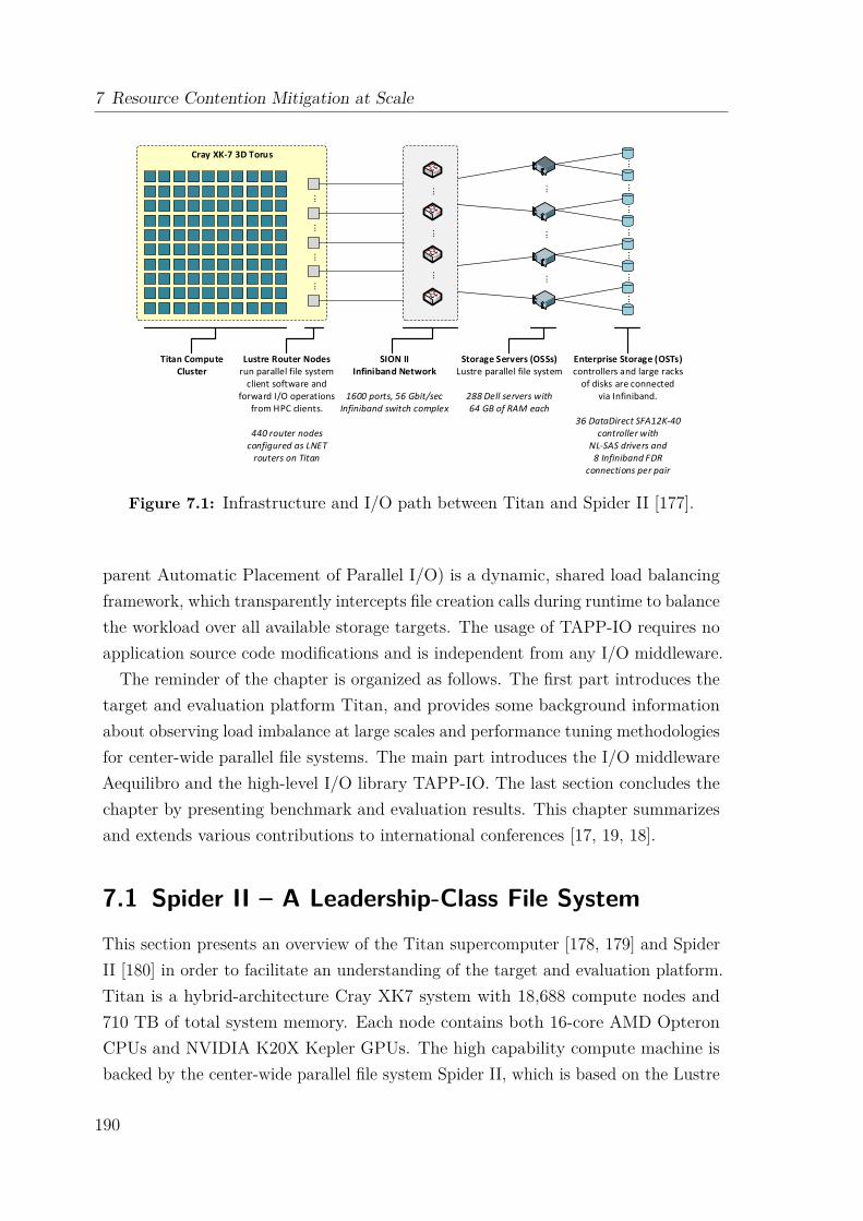
7 Resource Contention Mitigation at Scale
Cray XK-7 3D Torus
...
...
...
...
...
...
...
...
...
...
...
...
...
...
...
...
...
Lustre Router Nodesrun parallel file system
client software and forward I/O operations
from HPC clients.
440 router nodesconfigured as LNET
routers on Titan
SION IIInfiniband Network
1600 ports, 56 Gbit/secInfiniband switch complex
Storage Servers (OSSs)Lustre parallel file system
288 Dell servers with64 GB of RAM each
Enterprise Storage (OSTs)controllers and large racks
of disks are connectedvia Infiniband.
36 DataDirect SFA12K-40controller with
NL-SAS drivers and8 Infiniband FDR
connections per pair
Titan Compute Cluster
Figure 7.1: Infrastructure and I/O path between Titan and Spider II [177].
parent Automatic Placement of Parallel I/O) is a dynamic, shared load balancingframework, which transparently intercepts file creation calls during runtime to balancethe workload over all available storage targets. The usage of TAPP-IO requires noapplication source code modifications and is independent from any I/O middleware.
The reminder of the chapter is organized as follows. The first part introduces thetarget and evaluation platform Titan, and provides some background informationabout observing load imbalance at large scales and performance tuning methodologiesfor center-wide parallel file systems. The main part introduces the I/O middlewareAequilibro and the high-level I/O library TAPP-IO. The last section concludes thechapter by presenting benchmark and evaluation results. This chapter summarizesand extends various contributions to international conferences [17, 19, 18].
7.1 Spider II – A Leadership-Class File SystemThis section presents an overview of the Titan supercomputer [178, 179] and SpiderII [180] in order to facilitate an understanding of the target and evaluation platform.Titan is a hybrid-architecture Cray XK7 system with 18,688 compute nodes and710 TB of total system memory. Each node contains both 16-core AMD OpteronCPUs and NVIDIA K20X Kepler GPUs. The high capability compute machine isbacked by the center-wide parallel file system Spider II, which is based on the Lustre
190
7.2 The Need for Balanced Resource Usage
technology. Spider II is one of fastest and largest POSIX-complaint parallel filesystems and is designed to serve write-heavy I/O workloads. Figure 7.1 shows thetopology diagram, and in particular, the multi-layered end-to-end I/O path.
On the back-end storage side, Spider II has 20,160 Near-Line SAS disks organizedin RAID 6 arrays. Each of these RAID arrays acts as an OST. The OSTs areconnected to the OSSs over direct InfiniBand (IB) FDR links. At the time of thiswriting, a patched version of Lustre 2.8 was running on the I/O servers. The storagesystem is split into two distinct, non-overlapping sections, atlas1 and atlas2, andeach is formatted as a separate name space to increase reliability, availability, andoverall metadata performance. Each file system has 144 OSSs and 1,008 OSTs. EachOSS is connected to a 36-port IB FDR top-of-the-rack (TOR) switch and two DDNcontrollers. Each TOR switch (36 in total) is connected with a total of 8 OSSs. Eachswitch also connects to two 108-port aggregation switches. The aggregation switchesprovide connectivity for the Lustre metadata and management servers.On the front-end at the compute side, there are two different types of nodes on
Titan: compute and Lustre I/O router, also known as LNET router, nodes. Bothtypes of nodes are part of the Gemini network [129] connected in a 3D torus topology.Each node has a unique network ID (NID) for addressing purposes. 440 XK7 servicenodes are configured as Lustre LNET router nodes. Of these, 432 are used for fileI/O and 8 are used for metadata operations. Titan’s I/O routers are connected tothe Spider II TOR switches via InfiniBand FDR links. Note that the Spider II TORswitches enable these I/O routers to reach to the back-end storage system (OSSsand OSTs). By default, Lustre uses a round-robin algorithm to pick routers. Thefirst alive router on top of the list will be picked to route the message and then willbe placed at the end of the list for the next round to provide a load balance amongmultiple routers. Each Spider II TOR switch is assigned an LNET route.
7.2 The Need for Balanced Resource UsageTo cope with system failures, most scientific applications periodically write outmemory states. These bursty writes, i.e., checkpointing data, can cause resource con-tention leading to hotspots which are detrimental to parallel application performance.Hotspots lead to variations in completion times across processes, and therefore, toa blocking behavior and wasted computational capacity. The rule of thumb forcheckpointing is that it should not take more than 10% of the application run timeper hour. As the HPC systems grow in scale, the cumulative memory size also grows,
191

7 Resource Contention Mitigation at Scale
0123456789101112
0 250 500 750 1000
OST index
Frequency
(a) Default OST Placement
0
10
20
30
40
0 50 100 150
OSS index
Frequency
(b) Default OSS Placement
200210220230240250260270280290300
200 202 204 206 208 210 212 214 216 218
LNET index
Frequency
(c) Default LNET Placement
0
1
2
3
4
5
0 250 500 750 1000
OST index
Frequency
(d) Balanced OST Placement
2021222324252627282930
0 50 100 150
OSS index
Frequency
(e) Balanced OSS Placement
220221222223224225226227228229230
200 205 210 215
LNET index
Frequency
(f) Balanced LNET Placement
FIG. 2: COMPARISON OF RESOURCE USAGE DISTRIBUTION: DEFAULT VS. BALANCED
Another congestion control mechanism was presented in [15].The proposed method was again based on throttling resourcesand specifically designed for HPC clusters with InfiniBandnetworks. The design concept was to limit and load-controlthe multipath expansion in order to maintain low and boundednetwork latency for I/O traffic. A Step-Back-on-Blocking(SBB) flow-control mechanism that primarily addresses theallocation effectiveness in high-radix interconnection networkswas proposed in [16]. This method combined the advantagesof the wormhole and cut-through routing algorithms for torusnetworks, while adding a means for adaptive allocation of thecommunication resources.
We have demonstrated [17] that such congestion and loadimbalance can still occur at scale, and have a great negativeimpact on I/O performance on systems such as Cray’s propri-etary Gemini interconnect [11], which has adopted adaptiverouting techniques for mitigating congestions. By and large,despite a large body of existing research works, it remains anactive topic for further investigation.
The second research thread takes a file and storage-systemcentric view to tackle such problem. In [18], it was proposedto modify the PVFS file system [19] to achieve better I/Oload balancing. In [20], authors described a load imbalanceproblem for cloud data centers. Their algorithm was designedto adjust the two end points on the I/O path, computationalvirtual machines and virtual disks, to balance the overall loadin a data center. Other approaches have been proposed suchas, replicating data or moving the I/O intensive compute jobsto eliminate hot spots [21].
Our proposed approach differs from previous work in thatit combines the optimization done at the interconnect network(fine grain routing with topology-awareness) and balanced dataplacement tracked and set at the application layer to tackle theI/O load imbalance problem. It is also more applicable in atypical HPC computing environment. We discuss the detailed
design of proposed placement strategy in the next section.
III. BALANCED PLACEMENT STRATEGY
In this section, we describe our placement algorithm thataims to balance per job I/O resource allocation. In the mostgeneral case, the problem can be formulated as:
C = w1R1 + w2R2 + w3R3 . . .+ wnRn,
subject to w1 + w2 + w3 + . . . wn = 1, where C is the costof an I/O path being evaluated, Ri is the resource componentalong the I/O path, and wi is the weight factor assigned tothe resources. If the goal is to minimize the I/O cost, then aweight factor reflects the likelihood of the particular type ofresource to be a point of contention. Resources in our case canbe logical I/O routes (i.e., LNET), or actual file system andnetworking devices (i.e., Lustre I/O routers, OSSes, OSTs, andSION InfiniBand TOR leaf switches). We aim at distributingthe I/O traffic evenly across resource components to avoidpoints of contention. However, such a scheme needs to takeinto consideration the topology and resource dependencies.
A. Need for Balanced Resource Usage
To understand the need for balanced placement and justifywhy the proposed algorithm works, we conduct the followingillustrative experiment.
We launch 4096 processes with each process doing a singlefile I/O operation against half of the Spider II file system. Thetraces of those files are analyzed to examine the utilizationdistribution of different components.
Figure 2 (a), (b) and (c) shows the resource usage distri-bution for OSTs, OSSes, and LNETs, respectively. Recall thatthere are a total of 1008 OSTs, 144 OSSes, and 18 LNETSin one half of the Spider II file system. We observe thatthere exists a significant variation in usage across components
(a) OST utilization.
0123456789101112
0 250 500 750 1000
OST index
Frequency
(a) Default OST Placement
0
10
20
30
40
0 50 100 150
OSS index
Frequency
(b) Default OSS Placement
200210220230240250260270280290300
200 202 204 206 208 210 212 214 216 218
LNET index
Frequency
(c) Default LNET Placement
0
1
2
3
4
5
0 250 500 750 1000
OST index
Frequency
(d) Balanced OST Placement
2021222324252627282930
0 50 100 150
OSS index
Frequency
(e) Balanced OSS Placement
220221222223224225226227228229230
200 205 210 215
LNET index
Frequency
(f) Balanced LNET Placement
FIG. 2: COMPARISON OF RESOURCE USAGE DISTRIBUTION: DEFAULT VS. BALANCED
Another congestion control mechanism was presented in [15].The proposed method was again based on throttling resourcesand specifically designed for HPC clusters with InfiniBandnetworks. The design concept was to limit and load-controlthe multipath expansion in order to maintain low and boundednetwork latency for I/O traffic. A Step-Back-on-Blocking(SBB) flow-control mechanism that primarily addresses theallocation effectiveness in high-radix interconnection networkswas proposed in [16]. This method combined the advantagesof the wormhole and cut-through routing algorithms for torusnetworks, while adding a means for adaptive allocation of thecommunication resources.
We have demonstrated [17] that such congestion and loadimbalance can still occur at scale, and have a great negativeimpact on I/O performance on systems such as Cray’s propri-etary Gemini interconnect [11], which has adopted adaptiverouting techniques for mitigating congestions. By and large,despite a large body of existing research works, it remains anactive topic for further investigation.
The second research thread takes a file and storage-systemcentric view to tackle such problem. In [18], it was proposedto modify the PVFS file system [19] to achieve better I/Oload balancing. In [20], authors described a load imbalanceproblem for cloud data centers. Their algorithm was designedto adjust the two end points on the I/O path, computationalvirtual machines and virtual disks, to balance the overall loadin a data center. Other approaches have been proposed suchas, replicating data or moving the I/O intensive compute jobsto eliminate hot spots [21].
Our proposed approach differs from previous work in thatit combines the optimization done at the interconnect network(fine grain routing with topology-awareness) and balanced dataplacement tracked and set at the application layer to tackle theI/O load imbalance problem. It is also more applicable in atypical HPC computing environment. We discuss the detailed
design of proposed placement strategy in the next section.
III. BALANCED PLACEMENT STRATEGY
In this section, we describe our placement algorithm thataims to balance per job I/O resource allocation. In the mostgeneral case, the problem can be formulated as:
C = w1R1 + w2R2 + w3R3 . . .+ wnRn,
subject to w1 + w2 + w3 + . . . wn = 1, where C is the costof an I/O path being evaluated, Ri is the resource componentalong the I/O path, and wi is the weight factor assigned tothe resources. If the goal is to minimize the I/O cost, then aweight factor reflects the likelihood of the particular type ofresource to be a point of contention. Resources in our case canbe logical I/O routes (i.e., LNET), or actual file system andnetworking devices (i.e., Lustre I/O routers, OSSes, OSTs, andSION InfiniBand TOR leaf switches). We aim at distributingthe I/O traffic evenly across resource components to avoidpoints of contention. However, such a scheme needs to takeinto consideration the topology and resource dependencies.
A. Need for Balanced Resource Usage
To understand the need for balanced placement and justifywhy the proposed algorithm works, we conduct the followingillustrative experiment.
We launch 4096 processes with each process doing a singlefile I/O operation against half of the Spider II file system. Thetraces of those files are analyzed to examine the utilizationdistribution of different components.
Figure 2 (a), (b) and (c) shows the resource usage distri-bution for OSTs, OSSes, and LNETs, respectively. Recall thatthere are a total of 1008 OSTs, 144 OSSes, and 18 LNETSin one half of the Spider II file system. We observe thatthere exists a significant variation in usage across components
(b) OSS utilization.
0123456789101112
0 250 500 750 1000
OST index
Frequency
(a) Default OST Placement
0
10
20
30
40
0 50 100 150
OSS index
Frequency
(b) Default OSS Placement
200210220230240250260270280290300
200 202 204 206 208 210 212 214 216 218
LNET index
Frequency
(c) Default LNET Placement
0
1
2
3
4
5
0 250 500 750 1000
OST index
Frequency
(d) Balanced OST Placement
2021222324252627282930
0 50 100 150
OSS index
Frequency
(e) Balanced OSS Placement
220221222223224225226227228229230
200 205 210 215
LNET index
Frequency
(f) Balanced LNET Placement
FIG. 2: COMPARISON OF RESOURCE USAGE DISTRIBUTION: DEFAULT VS. BALANCED
Another congestion control mechanism was presented in [15].The proposed method was again based on throttling resourcesand specifically designed for HPC clusters with InfiniBandnetworks. The design concept was to limit and load-controlthe multipath expansion in order to maintain low and boundednetwork latency for I/O traffic. A Step-Back-on-Blocking(SBB) flow-control mechanism that primarily addresses theallocation effectiveness in high-radix interconnection networkswas proposed in [16]. This method combined the advantagesof the wormhole and cut-through routing algorithms for torusnetworks, while adding a means for adaptive allocation of thecommunication resources.
We have demonstrated [17] that such congestion and loadimbalance can still occur at scale, and have a great negativeimpact on I/O performance on systems such as Cray’s propri-etary Gemini interconnect [11], which has adopted adaptiverouting techniques for mitigating congestions. By and large,despite a large body of existing research works, it remains anactive topic for further investigation.
The second research thread takes a file and storage-systemcentric view to tackle such problem. In [18], it was proposedto modify the PVFS file system [19] to achieve better I/Oload balancing. In [20], authors described a load imbalanceproblem for cloud data centers. Their algorithm was designedto adjust the two end points on the I/O path, computationalvirtual machines and virtual disks, to balance the overall loadin a data center. Other approaches have been proposed suchas, replicating data or moving the I/O intensive compute jobsto eliminate hot spots [21].
Our proposed approach differs from previous work in thatit combines the optimization done at the interconnect network(fine grain routing with topology-awareness) and balanced dataplacement tracked and set at the application layer to tackle theI/O load imbalance problem. It is also more applicable in atypical HPC computing environment. We discuss the detailed
design of proposed placement strategy in the next section.
III. BALANCED PLACEMENT STRATEGY
In this section, we describe our placement algorithm thataims to balance per job I/O resource allocation. In the mostgeneral case, the problem can be formulated as:
C = w1R1 + w2R2 + w3R3 . . .+ wnRn,
subject to w1 + w2 + w3 + . . . wn = 1, where C is the costof an I/O path being evaluated, Ri is the resource componentalong the I/O path, and wi is the weight factor assigned tothe resources. If the goal is to minimize the I/O cost, then aweight factor reflects the likelihood of the particular type ofresource to be a point of contention. Resources in our case canbe logical I/O routes (i.e., LNET), or actual file system andnetworking devices (i.e., Lustre I/O routers, OSSes, OSTs, andSION InfiniBand TOR leaf switches). We aim at distributingthe I/O traffic evenly across resource components to avoidpoints of contention. However, such a scheme needs to takeinto consideration the topology and resource dependencies.
A. Need for Balanced Resource Usage
To understand the need for balanced placement and justifywhy the proposed algorithm works, we conduct the followingillustrative experiment.
We launch 4096 processes with each process doing a singlefile I/O operation against half of the Spider II file system. Thetraces of those files are analyzed to examine the utilizationdistribution of different components.
Figure 2 (a), (b) and (c) shows the resource usage distri-bution for OSTs, OSSes, and LNETs, respectively. Recall thatthere are a total of 1008 OSTs, 144 OSSes, and 18 LNETSin one half of the Spider II file system. We observe thatthere exists a significant variation in usage across components
(c) LNET utilization.
Figure 7.2: Default resource usage distribution on Spider II [177].
resulting in larger amounts of data to be written out during each checkpoint window.This pushes the limits and capabilities of parallel file and storage systems; the growthtrajectories for these two are not always the same. Most scientific HPC applicationsmake no difference between defensive I/O and scientific output. In fact, they do I/Ooperations at regular pre-defined intervals and expect a minimal amount of time tobe spent in I/O subroutines.
As can be seen in section 7.1, parallel I/O systems are inherently complex, partic-ularly in the context of end-to-end I/O paths. For example at the starting point of atypical I/O path, an application can use a high-level I/O library, such as HDF5 [50],for various reasons including portability, improved data management, and enhancedmetadata capabilities. HDF5 is implemented on top of MPI-IO [181] which, inturn, performs POSIX I/O calls against a parallel file system such as Lustre [166].Furthermore before an I/O request reaches its eventual storage target, it may haveto traverse through the compute fabric (e.g., a 3D torus or Dragonfly, or a plainfat-tree), and a large-scale storage network fabric (e.g., InfiniBand). Finally, therequest reaches the backend storage that provides a block interface, though the par-allel file system sits on top and across these backend storage devices. In large-scaleHPC deployments, file systems are often shared among applications concurrentlyrunning on a single system and sometimes among applications running on multiplesystems (e.g., a center-wide file system). This often results in file system and networkcontention. The observed I/O bandwidth at the application level is much lower thanthe theoretical peak bandwidth of the underlying storage system.
Resource contention has a negative impact on the performance and scalability in alarge-scale file and storage system such as Spider II. A simple experiment [177] can beused to illustrate the need for balanced resource utilization. An application with 4096processes is launched on Titan with each of the processes creating and performing asingle write operation to an individual file on the parallel file system. Afterwards,
192
7.3 Related Work
the striping pattern and file traces for every created file are evaluated, which can beused to determine the utilized OSTs, OSSs and LNET routers. Figure 7.2 presentsthe default Lustre resource usage distribution for OSTs, OSSs, and LNET routers,respectively. It can be observed that there is a significant variation in usage acrossdifferent Lustre components, even though Lustre employs a round-robin resourceallocation scheme. This variation and the resulting contention is due to the lack ofa system-wide I/O load organizer on modern distributed large-scale HPC systems.Parallel file and storage systems supporting these large-scale systems only have apartial view of the overall I/O activity and can only try to optimize the resourceusage at one end of the I/O path. Also, Xie et al. [182] observed that most I/O loadimbalances are the result of improper resource allocation within a given scientificapplication, which makes this work particularly relevant.
7.3 Related WorkWhile moving towards the exascale era, resource contention and performance variabil-ity in HPC systems remain a major challenge. I/O workload imbalance paired withthe increasing gap between compute capabilities of HPC systems and the underlyingstorage system are known issues in the HPC domain [183, 184].Several research studies have addressed these problems to provide better I/O
techniques. For example, Gainaru et al. [185] introduce a global scheduler thatminimizes congestion caused by I/O interference by considering the application’spast behaviors when scheduling I/O requests. Herbein et al. [186] present a jobscheduling technique that reduces contention by integrating I/O-awareness intoscheduling policies. As shown by Yildiz et al. [184], scheduler-level solutions notalways lead to improved performance even though it helps to control the level ofinterferences.
Some research efforts consider network contention as the major contributor to I/Oload imbalance. Luo et al. [187] introduce a preemptive, core-stateless optimizationapproach based on open loop end-point throttling. Jiang et al. [188] introduce newendpoint congestion-control protocols to address the differentiation between networkand endpoint congestion more properly. Li et al. [189] present ASCAR, a storagetraffic management system for improving the bandwidth utilization and fairness ofresource allocation. But, these techniques cannot be adopted for scientific HPCsystems like Titan. There are too many applications and the I/O patterns changedrastically between different job runs.
193
7 Resource Contention Mitigation at Scale
Another area takes a file and storage-system centric view. Zhu et al. [190] presentCEFT-PVFS, a modification of the PVFS file system [191], to achieve a betterworkload balance. Singh et al. [192] address the problem of load imbalance in thesetting of cloud data centers. Congestion and load imbalance can still occur atlarge scale as demonstrated by Dillow et al. [193]. Luu et al. [194] analyze theproblem of low I/O performance on leading HPC systems. They use Darshan [195]logs of over a million jobs representing a combined total of six years of I/O. Eventhough the platforms’ file systems have a peak throughput of hundreds of GB/s, onlyfew applications experience high I/O throughput. Lofstead et al. [196] introduceAdaptive IO, a set of dynamic and proactive methods for managing I/O interference.The methods are bundled in a new ADIOS transport method that dynamically shiftswork from heavily used areas of the storage system to areas that are more lightlyloaded. The design is limited on how quickly a coordinator can react to storage loaddynamics. Liu et al. [197] introduce an ADIOS transport method that attempts tore-route I/O to less loaded storage areas while applying a throttling technique thatlimits how much data can be re-routed during writing.
A third area of related work is introduced by commercial data centers where loadimbalance and Quality of Service (QoS) are also major concerns for multi-tenantsystems. Such methods and techniques are exemplified by Pulsar [198], Baraat [199],and Corral [200]. Pulsar consists of a logically centralized controller with full visibilityof the data center topology and a rate enforcer inside the hypervisor at each computenode. It offers tenants their own dedicated virtual data centers (VDC) to ensureend-to-end throughput guarantees. Baraat is a decentralized, task-aware schedulingsystem. It schedules tasks in a FIFO order, and avoids head-of-line blocking bydynamically changing the level of multiplexing in the network. Based on data frompast data center studies, the application behavior is characterized in order to applythe task-aware scheduling heuristic. Corral is based on the assumption that a largefraction of production jobs are recurring with predictable characteristics. It usescharacteristics of future workloads to determine an offline schedule which coordinatesthe placement of data and tasks.
In the scientific HPC context though, the application requirement and expectation,the highly specialized workload, and the architectural design and integration workflowpresent some unique challenges on leveraging techniques developed in cloud computingand data center settings [201]. Many of the assumptions made for commercialdata center performance optimizations are not applicable to large-scale scientificsimulation systems. For example, scientific HPC systems do not have a global view
194
7.4 Observations and Best Practices for File I/O
on all available system resources and allocations. Also, storage and I/O systems havebeen shifting from a machine-exclusive paradigm to a data-centric paradigm wherethe mixed workload becomes a norm and much less predictable than before [202].The scientific workloads itself differ from commercial workloads, e.g. search queries,data analytics jobs, and social news-feeds. Commercial and scientific applicationshave different requirements [201]. While commercial codes can be classified ashigh-throughput computing, scientific workloads are categorized as latency-sensitive,large-scale, and tightly coupled computations. They assume the presence of a high-bandwidth, low-latency interconnect, a parallel distributed file system shared betweencompute nodes, and a head node that can submit MPI jobs to all worker nodes.
7.4 Observations and Best Practices for File I/OWhen working with parallel file systems such as Lustre, several different researchstudies and papers have addressed the question of how to optimize the file stripingpattern. The following provides an overview of best practices and key observations.
(1) The stripe alignment [42, 203] of data can be critical. When using the file-per-process access pattern with a large number of files/processes, it is best to setthe stripe count to one (i.e., no striping is used). For the single-shared-fileaccess pattern, the stripe count should equal the number of writing processes(i.e., aggregators). This limits the OST contention and decreases the possibilitythat multiple processes communicate with the same OST at the same time.
(2) Besides stripe alignment, the size and location of I/O operations should becarefully managed. By mapping writing processes to specific servers, thenumber of concurrent operations on a single server can be reduced. This isespecially helpful when file locks are handed out on a per-server basis (e.g.,Lustre) to minimize the file locking contention [42, 204].
(3) The I/O request size (i.e., the transfer size) should be large [42], i.e., a fullstripe width or greater. In general, large files, large transfers, and a largernumber of I/O clients results in a larger aggregate bandwidth.
(4) When working with large data sets, it is recommended to use high-level I/Olibraries or middleware such as ADIOS, HDF5, or SIONlib [42, 205]. Theymap application abstractions onto storage abstractions and provide portability,but also organize accesses from many processes. Also, MPI, not the file system,should be used for communication.
195
7 Resource Contention Mitigation at Scale
(5) Besides the file access organization from the application side, the computesystem itself can play a key factor in limiting the overall performance, e.g.,network congestion can lead to a suboptimal I/O performance. By identifyingand eliminating hotspots, providing better routing algorithms and carefulplacement of I/O routers, network congestion can be mitigated [206].
(6) Even though a data-centric file system may have a high theoretical peakbandwidth, the real performance is what the users observe under file systemcongestion. For advanced users, it is a good practice to expose low-levelinfrastructure details in a programmable fashion, e.g., through a user library,to achieve better performance [177, 206].
Recapitulating the observations and best practices, the rule of thumb for Lustre filestriping, in particular the stripe count, can be summarized as follows [207]:
• #files ≥ #OSTs → reduce the Lustre contention and OST file locking:
stripe count = 1 (7.1)
• #files < #OSTs → utilize as many OSTs as possible:
stripe count =⌊
#OSTs#files
⌋(7.2)
• #files = 1 → maximize the parallel access performance:
stripe count =
#Aggregators, if #Aggregators ≤ #OSTs;
#OSTs, otherwise.(7.3)
7.5 End-to-End Performance TuningOver the past decade, the Oak Ridge Leadership Computing Facility has presentedseveral different strategies to address system performance variability [206]. Thefollowing sections present two performance tuning methodologies, which addressobservations (5) and (6) introduced in section 7.4.
7.5.1 Fine-Grained Routing Methodology
The fine-grained routing (FGR) congestion avoidance methodology [193, 208] was firstintroduced with the Jaguar supercomputing system [209]. The system utilized two
196
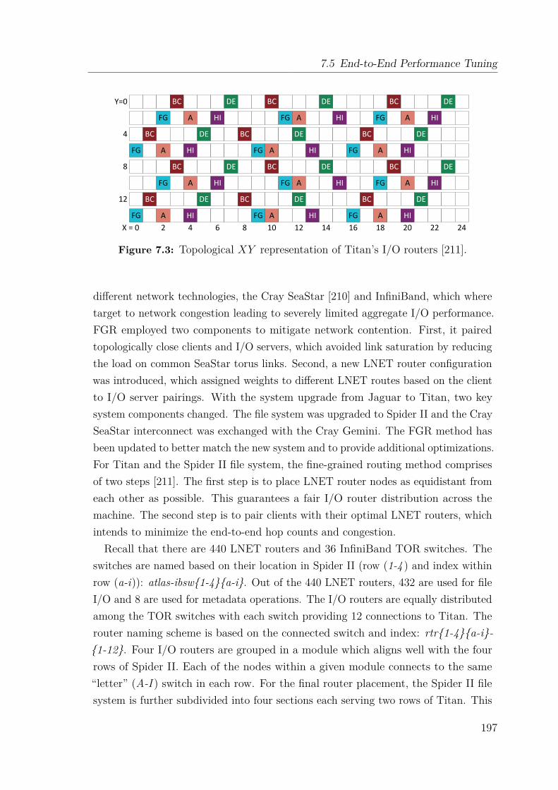
7.5 End-to-End Performance Tuning
BC DE BC DE BC DE
FG A HI FG A HI FG A HI
BC DE BC DE BC DE
FG A HI FG A HI FG A HI
BC DE BC DE BC DE
FG A HI FG A HI FG A HI
BC DE BC DE BC DE
FG A HI FG A HI FG A HI
X = 0 2 4 6 8 10 12 14 16 18 20 22 24
Y=0
4
8
12
Figure 7.3: Topological XY representation of Titan’s I/O routers [211].
different network technologies, the Cray SeaStar [210] and InfiniBand, which wheretarget to network congestion leading to severely limited aggregate I/O performance.FGR employed two components to mitigate network contention. First, it pairedtopologically close clients and I/O servers, which avoided link saturation by reducingthe load on common SeaStar torus links. Second, a new LNET router configurationwas introduced, which assigned weights to different LNET routes based on the clientto I/O server pairings. With the system upgrade from Jaguar to Titan, two keysystem components changed. The file system was upgraded to Spider II and the CraySeaStar interconnect was exchanged with the Cray Gemini. The FGR method hasbeen updated to better match the new system and to provide additional optimizations.For Titan and the Spider II file system, the fine-grained routing method comprisesof two steps [211]. The first step is to place LNET router nodes as equidistant fromeach other as possible. This guarantees a fair I/O router distribution across themachine. The second step is to pair clients with their optimal LNET routers, whichintends to minimize the end-to-end hop counts and congestion.Recall that there are 440 LNET routers and 36 InfiniBand TOR switches. The
switches are named based on their location in Spider II (row (1-4 ) and index withinrow (a-i)): atlas-ibsw{1-4}{a-i}. Out of the 440 LNET routers, 432 are used for fileI/O and 8 are used for metadata operations. The I/O routers are equally distributedamong the TOR switches with each switch providing 12 connections to Titan. Therouter naming scheme is based on the connected switch and index: rtr{1-4}{a-i}-{1-12}. Four I/O routers are grouped in a module which aligns well with the fourrows of Spider II. Each of the nodes within a given module connects to the same“letter” (A-I ) switch in each row. For the final router placement, the Spider II filesystem is further subdivided into four sections each serving two rows of Titan. This
197
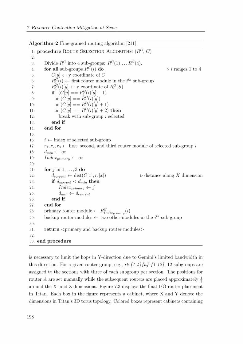
7 Resource Contention Mitigation at Scale
Algorithm 2 Fine-grained routing algorithm [211]1: procedure Route Selection Algorithm (RG, C)2:3: Divide RG into 4 sub-groups: RG(1) . . .RG(4).4: for all sub-groups RG(i) do . i ranges 1 to 45: C[y] ← y coordinate of C6: RG
1 (i) ← first router module in the ith sub-group7: RG
1 (i)[y] ← y coordinate of RGi (S)
8: if (C[y] == RG1 (i)[y]− 1)
9: or (C[y] == RG1 (i)[y])
10: or (C[y] == RG1 (i)[y] + 1)
11: or (C[y] == RG1 (i)[y] + 2) then
12: break with sub-group i selected13: end if14: end for15:16: i ← index of selected sub-group17: r1, r2, r3 ← first, second, and third router module of selected sub-group i18: dmin ← ∞19: Indexprimary ← ∞20:21: for j in 1, . . . , 3 do22: dcurrent ← dist(C[x], rj[x]) . distance along X dimension23: if dcurrent < dmin then24: Indexprimary ← j25: dmin ← dcurrent
26: end if27: end for28: primary router module ← RG
Indexprimary(i)
29: backup router modules ← two other modules in the ith sub-group30:31: return <primary and backup router modules>32:33: end procedure
is necessary to limit the hops in Y-direction due to Gemini’s limited bandwidth inthis direction. For a given router group, e.g., rtr{1-4}{a}-{1-12}, 12 subgroups areassigned to the sections with three of each subgroup per section. The positions forrouter A are set manually while the subsequent routers are placed approximately 1
3
around the X- and Z-dimensions. Figure 7.3 displays the final I/O router placementin Titan. Each box in the figure represents a cabinet, where X and Y denote thedimensions in Titan’s 3D torus topology. Colored boxes represent cabinets containing
198
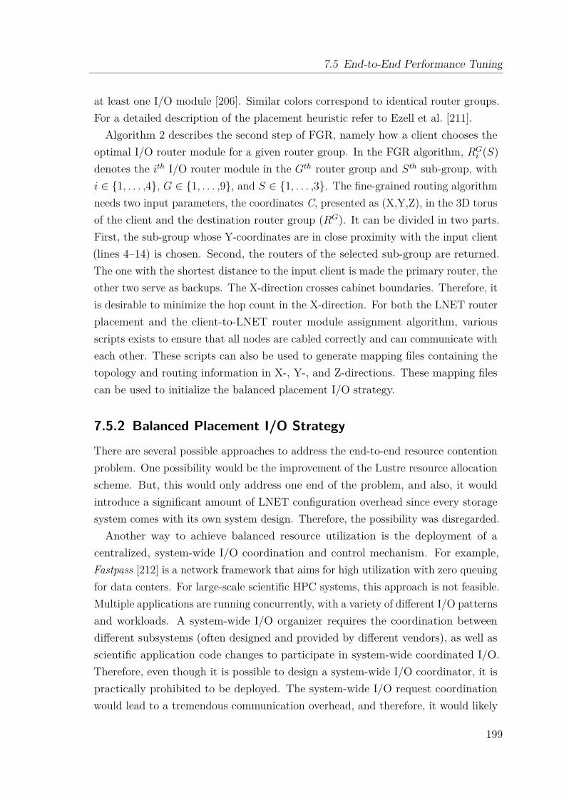
7.5 End-to-End Performance Tuning
at least one I/O module [206]. Similar colors correspond to identical router groups.For a detailed description of the placement heuristic refer to Ezell et al. [211].Algorithm 2 describes the second step of FGR, namely how a client chooses the
optimal I/O router module for a given router group. In the FGR algorithm, RGi (S)
denotes the ith I/O router module in the Gth router group and Sth sub-group, withi ∈ {1, . . . ,4}, G ∈ {1, . . . ,9}, and S ∈ {1, . . . ,3}. The fine-grained routing algorithmneeds two input parameters, the coordinates C, presented as (X,Y,Z), in the 3D torusof the client and the destination router group (RG). It can be divided in two parts.First, the sub-group whose Y-coordinates are in close proximity with the input client(lines 4–14) is chosen. Second, the routers of the selected sub-group are returned.The one with the shortest distance to the input client is made the primary router, theother two serve as backups. The X-direction crosses cabinet boundaries. Therefore, itis desirable to minimize the hop count in the X-direction. For both the LNET routerplacement and the client-to-LNET router module assignment algorithm, variousscripts exists to ensure that all nodes are cabled correctly and can communicate witheach other. These scripts can also be used to generate mapping files containing thetopology and routing information in X-, Y-, and Z-directions. These mapping filescan be used to initialize the balanced placement I/O strategy.
7.5.2 Balanced Placement I/O Strategy
There are several possible approaches to address the end-to-end resource contentionproblem. One possibility would be the improvement of the Lustre resource allocationscheme. But, this would only address one end of the problem, and also, it wouldintroduce a significant amount of LNET configuration overhead since every storagesystem comes with its own system design. Therefore, the possibility was disregarded.Another way to achieve balanced resource utilization is the deployment of a
centralized, system-wide I/O coordination and control mechanism. For example,Fastpass [212] is a network framework that aims for high utilization with zero queuingfor data centers. For large-scale scientific HPC systems, this approach is not feasible.Multiple applications are running concurrently, with a variety of different I/O patternsand workloads. A system-wide I/O organizer requires the coordination betweendifferent subsystems (often designed and provided by different vendors), as well asscientific application code changes to participate in system-wide coordinated I/O.Therefore, even though it is possible to design a system-wide I/O coordinator, it ispractically prohibited to be deployed. The system-wide I/O request coordinationwould lead to a tremendous communication overhead, and therefore, it would likely
199
7 Resource Contention Mitigation at Scale
Algorithm 3 Balanced placement algorithm [177]1: procedure Balanced Placement (List of NIDs, List of OSTs)2:3: lnet_freq ← 0, rtr_freq ← 0, oss_freq ← 0, ost_freq ← 04: random_offset ← randomly selected reachable LNETs5:6: for all NIDs in the input NID list do7: lnet ← random_offset8:9: for all reachable OSTs do10: cost ← MAX11: oss ← ost2oss() . map OST to OSS12: mycost ← placement_cost(lnet_freq, rtr_freq, oss_freq, ost_freq)13: if (mycost < cost) then14: mycost ← cost15: picked_ost ← ost16: picked_oss ← oss17: end if18: end for19:20: record NID and the selected OST21: increment lnet_freq, rtr_freq, oss_freq, ost_freq22: end for23:24: end procedure
lead to a sub-optimal utilization of the available computational resources. The thirdapproach is to balance the I/O workload on an end-to-end and per job basis.This technique is adopted by the Balanced Placement I/O (BPIO) library [177],
which uses a lightweight placement cost function that takes a weighted average ofhow frequently different file and storage system resources have been traversed byprevious I/O requests issued by the same application. The most general case isdefined by
C = w1R1 + w2R2 + ...+ wnRn =n∑
i=1wiRi (7.4)
where C is the cost of an I/O path, Ri is a resource component, and wi is the relativeweight factor with ∑n
i=1 wi = 1. For Lustre, possible resource components are logicalI/O routes (i.e., LNETs), or actual file system and networking resources (i.e., LustreI/O routers, OSSs, and OSTs). BPIO intelligently allocates I/O paths for a parallelfile system and employs a placement strategy that provides a binding between anI/O client (compute node or MPI rank ID) and a storage target for a given I/O
200
7.6 Design Objectives and Strategy
phase while aiming at an even I/O traffic distribution across resource componentsto avoid points of contention. This is ensured by taking the topology and resourcedependencies into consideration. The library utilizes the mapping files generated bythe previously described fine-grained routing congestion avoidance method. FGRorganizes I/O paths to minimize end-to-end hop counts and congestion. This is doneby pairing clients with their closest possible, and in the case of Titan, optimal LNETrouter. When the BPIO library is initialized, it parses the mapping files to retrieve alist of all available file system and storage components, but also extracts the routinginformation between different system components. For Lustre based systems, theplacement cost function C is defined as shown in Equation 7.5.
C = w1 × rtr_freq + w2 × lnet_freq + w3 × oss_freq + w4 × ost_freq (7.5)
rtr_freq, lnet_freq, oss_freq, and ost_freq are the usage frequency of I/O routers,LNETs, OSSs, and OSTs, respectively, and w1, w2, w3, and w4 are the relative weightfactors. For the Spider II system, the weight factors are set to the following values:w1 = w2 = w3 = 0.2, w4 = 0.4. These values are chosen based on the observationthat storage targets are typically more imbalanced than other storage components.
For a given I/O client, the BPIO library employs Algorithm 3, which loops over allreachable storage targets to choose one with the lowest placement cost per computenode. This is repeated for all active I/O processes of an application only once beforeit enters the I/O write phase. An initial performance evaluation of the library wasperformed on the Titan supercomputer [178].
7.6 Design Objectives and StrategyRecapitulating the last section, it can be said that the BPIO library provides alightweight, tunable placement mechanism, which utilizes a placement cost functionthat can be tuned to meet the target system. The introduced overhead is keptto a minimum since the balancing function is called only once per I/O phase andthe internal data structures are kept as simple as possible. But, it is importantto understand that the BPIO library simply returns a list containing the optimalbinding between an I/O client and an OST for the next I/O phase. It does notprovide a mechanism for the actual data placement nor file layout. The applicationdeveloper has to modify the scientific code and needs to know how to set Lustre fileproperties in a C/C++ program using the llapi [168]. This is particularly difficultwhen taking different I/O interfaces and workload patterns into consideration.
201
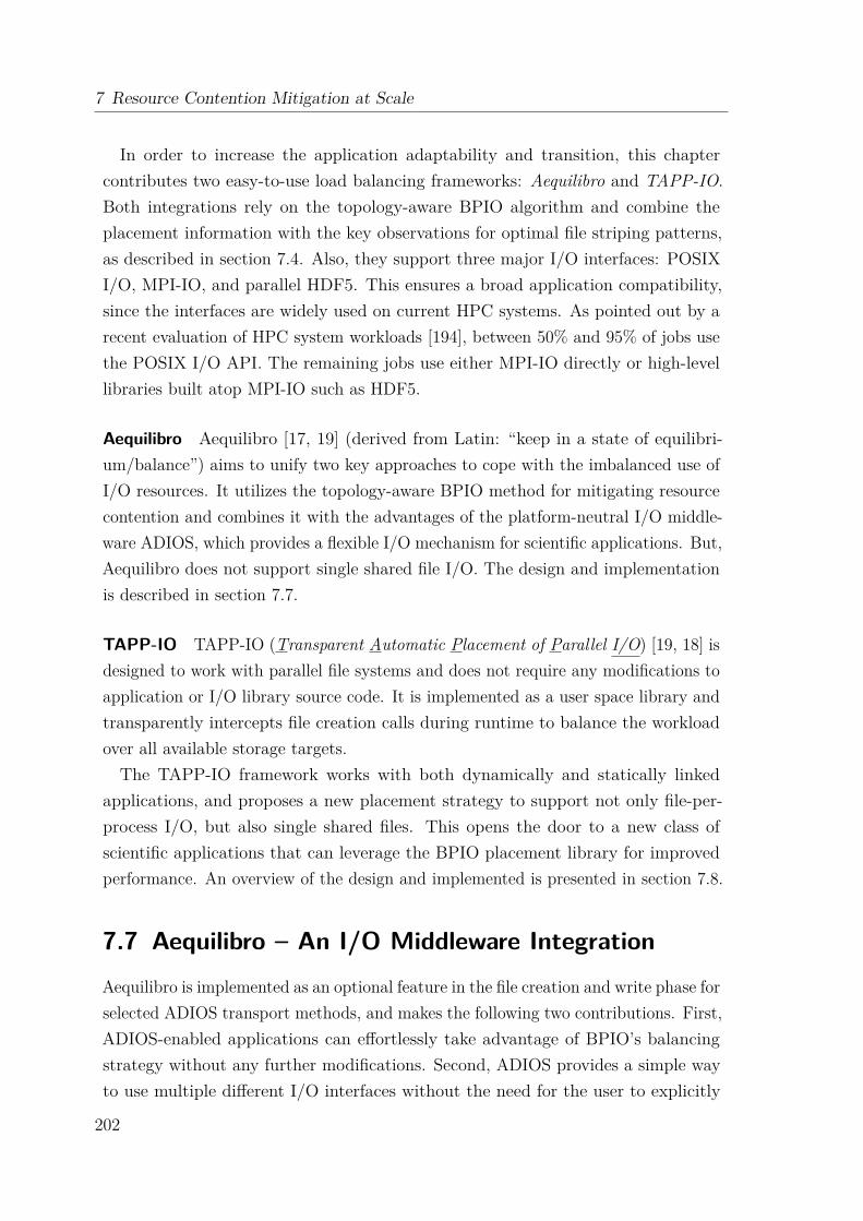
7 Resource Contention Mitigation at Scale
In order to increase the application adaptability and transition, this chaptercontributes two easy-to-use load balancing frameworks: Aequilibro and TAPP-IO.Both integrations rely on the topology-aware BPIO algorithm and combine theplacement information with the key observations for optimal file striping patterns,as described in section 7.4. Also, they support three major I/O interfaces: POSIXI/O, MPI-IO, and parallel HDF5. This ensures a broad application compatibility,since the interfaces are widely used on current HPC systems. As pointed out by arecent evaluation of HPC system workloads [194], between 50% and 95% of jobs usethe POSIX I/O API. The remaining jobs use either MPI-IO directly or high-levellibraries built atop MPI-IO such as HDF5.
Aequilibro Aequilibro [17, 19] (derived from Latin: “keep in a state of equilibri-um/balance”) aims to unify two key approaches to cope with the imbalanced use ofI/O resources. It utilizes the topology-aware BPIO method for mitigating resourcecontention and combines it with the advantages of the platform-neutral I/O middle-ware ADIOS, which provides a flexible I/O mechanism for scientific applications. But,Aequilibro does not support single shared file I/O. The design and implementationis described in section 7.7.
TAPP-IO TAPP-IO (Transparent Automatic Placement of Parallel I/O) [19, 18] isdesigned to work with parallel file systems and does not require any modifications toapplication or I/O library source code. It is implemented as a user space library andtransparently intercepts file creation calls during runtime to balance the workloadover all available storage targets.The TAPP-IO framework works with both dynamically and statically linked
applications, and proposes a new placement strategy to support not only file-per-process I/O, but also single shared files. This opens the door to a new class ofscientific applications that can leverage the BPIO placement library for improvedperformance. An overview of the design and implemented is presented in section 7.8.
7.7 Aequilibro – An I/O Middleware IntegrationAequilibro is implemented as an optional feature in the file creation and write phase forselected ADIOS transport methods, and makes the following two contributions. First,ADIOS-enabled applications can effortlessly take advantage of BPIO’s balancingstrategy without any further modifications. Second, ADIOS provides a simple wayto use multiple different I/O interfaces without the need for the user to explicitly
202

7.7 Aequilibro – An I/O Middleware Integration
1 <?xml version ="1.0" encoding ="UTF -8"?>2 <adios - config host - language ="C">3 <adios -group name=" example ">4 <var name=" var_test " type=" integer "/>5 </adios -group >6 <method group=" example " method =" MPI_AGGREGATE ">7 num_aggregators =64; num_ost =5128 </ method >9 <buffer max -size -MB="32" allocate -time="now"/>
10 </adios - config >
Listing 7.1: Example ADIOS XML configuration file.
adopt and integrate BPIO library calls. Therefore, it can be used as a simple, yetefficient evaluation framework for BPIO.
7.7.1 Transport Methods
ADIOS provides a mechanism to externally describe an application’s I/O requirementsby providing an XML-based configuration file. This results in a runtime selectabletechnique, which replaces I/O interface calls with basic ADIOS operations such asadios_open() and adios_write(). Depending on the specified transport method, adifferent application I/O pattern and I/O interface is used to access files. Listing 7.1shows an example XML configuration file for the ADIOS framework.Two example transport methods are POSIX and MPI_AGGREGATE. POSIX takes
advantage of the concurrency of parallel file systems and implements the simplestparallel I/O pattern, known as file-per-process. Each writing process is responsiblefor writing data to its own output file. One of the processes is managing an indexfile. Overall, the transport method creates an index file along with a subdirectorycontaining all of the files written individually by the application’s processes.
MPI_AGGREGATE is a sophisticated, MPI-IO-based technique derived from the MPItransport methods. Instead of using the default data aggregation model of the localMPI installation, it provides a user-tunable method, which aggregates data frommultiple MPI processes into larger chunks of data before writing them out to thefile system. A subset of application processes acts as an aggregator for a subset ofpeers. This pattern is also known as single shared file I/O with collective buffering.The number of aggregators (i.e., writing MPI ranks) and the number of OSTs aretunable, and can be set by the user at runtime. The method creates a collection ofindividual files, with one file corresponding to each of the aggregators. In addition,the user can provide Lustre-specific striping information, e.g., stripe count and size.
203
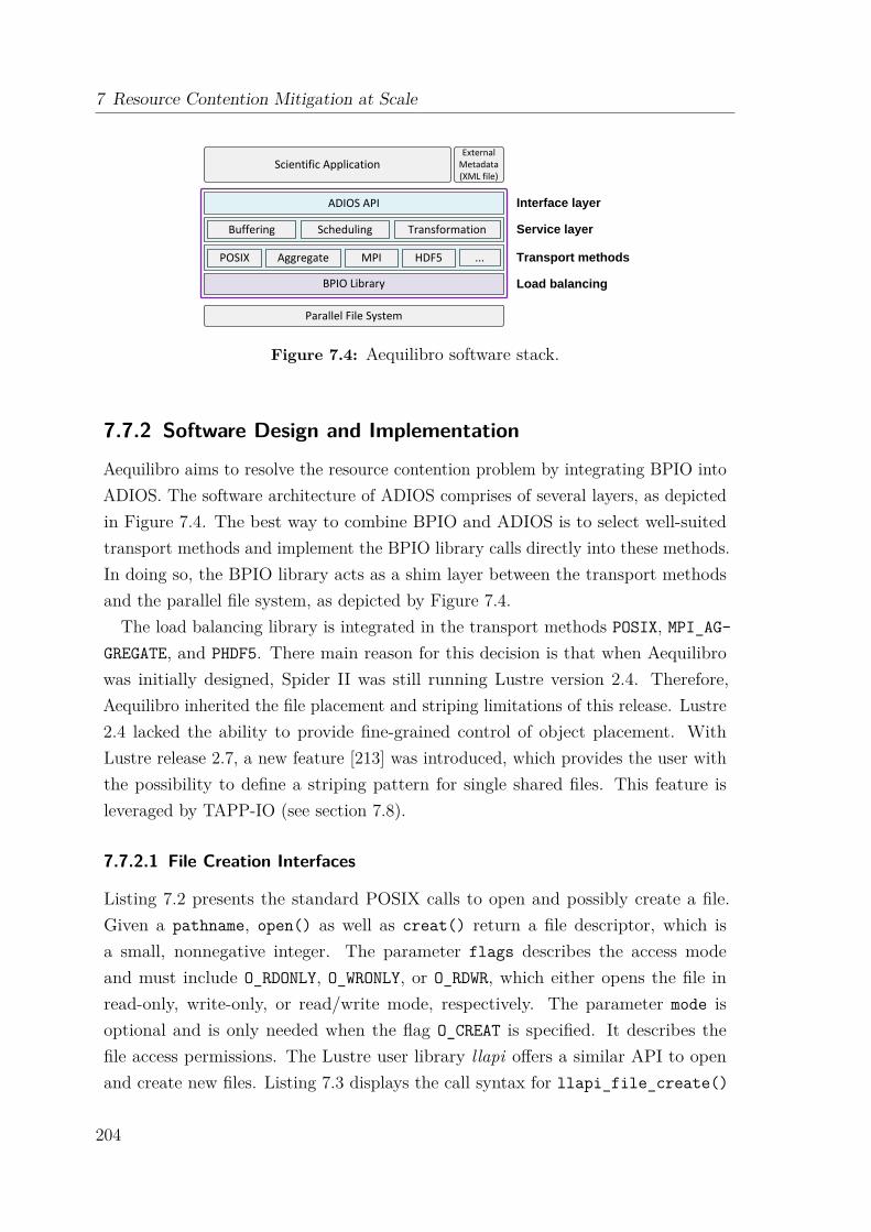
7 Resource Contention Mitigation at Scale
Scientific Application
Buffering Scheduling Transformation
POSIX MPIAggregate HDF5 ...
BPIO Library
External Metadata (XML file)
ADIOS API
Parallel File System
Interface layer
Service layer
Transport methods
Load balancing
Figure 7.4: Aequilibro software stack.
7.7.2 Software Design and Implementation
Aequilibro aims to resolve the resource contention problem by integrating BPIO intoADIOS. The software architecture of ADIOS comprises of several layers, as depictedin Figure 7.4. The best way to combine BPIO and ADIOS is to select well-suitedtransport methods and implement the BPIO library calls directly into these methods.In doing so, the BPIO library acts as a shim layer between the transport methodsand the parallel file system, as depicted by Figure 7.4.
The load balancing library is integrated in the transport methods POSIX, MPI_AG-GREGATE, and PHDF5. There main reason for this decision is that when Aequilibrowas initially designed, Spider II was still running Lustre version 2.4. Therefore,Aequilibro inherited the file placement and striping limitations of this release. Lustre2.4 lacked the ability to provide fine-grained control of object placement. WithLustre release 2.7, a new feature [213] was introduced, which provides the user withthe possibility to define a striping pattern for single shared files. This feature isleveraged by TAPP-IO (see section 7.8).
7.7.2.1 File Creation Interfaces
Listing 7.2 presents the standard POSIX calls to open and possibly create a file.Given a pathname, open() as well as creat() return a file descriptor, which isa small, nonnegative integer. The parameter flags describes the access modeand must include O_RDONLY, O_WRONLY, or O_RDWR, which either opens the file inread-only, write-only, or read/write mode, respectively. The parameter mode isoptional and is only needed when the flag O_CREAT is specified. It describes thefile access permissions. The Lustre user library llapi offers a similar API to openand create new files. Listing 7.3 displays the call syntax for llapi_file_create()
204
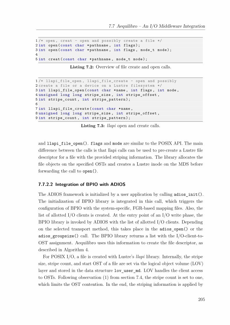
7.7 Aequilibro – An I/O Middleware Integration
1 /* open , creat - open and possibly create a file */2 int open(const char *pathname , int flags);3 int open(const char *pathname , int flags , mode_t mode);45 int creat(const char *pathname , mode_t mode);
Listing 7.2: Overview of file create and open calls.
1 /* llapi_file_open , llapi_file_create - open and possibly2 create a file or a device on a Lustre filesystem */3 int llapi_file_open (const char *name , int flags , int mode ,4 unsigned long long stripe_size , int stripe_offset ,5 int stripe_count , int stripe_pattern );67 int llapi_file_create (const char *name ,8 unsigned long long stripe_size , int stripe_offset ,9 int stripe_count , int stripe_pattern );
Listing 7.3: llapi open and create calls.
and llapi_file_open(). flags and mode are similar to the POSIX API. The maindifference between the calls is that llapi calls can be used to pre-create a Lustre filedescriptor for a file with the provided striping information. The library allocates thefile objects on the specified OSTs and creates a Lustre inode on the MDS beforeforwarding the call to open().
7.7.2.2 Integration of BPIO with ADIOS
The ADIOS framework is initialized by a user application by calling adios_init().The initialization of BPIO library is integrated in this call, which triggers theconfiguration of BPIO with the system-specific, FGR-based mapping files. Also, thelist of allotted I/O clients is created. At the entry point of an I/O write phase, theBPIO library is invoked by ADIOS with the list of allotted I/O clients. Dependingon the selected transport method, this takes place in the adios_open() or theadios_groupsize() call. The BPIO library returns a list with the I/O-client-to-OST assignment. Aequilibro uses this information to create the file descriptor, asdescribed in Algorithm 4.
For POSIX I/O, a file is created with Lustre’s llapi library. Internally, the stripesize, stripe count, and start OST of a file are set via the logical object volume (LOV)layer and stored in the data structure lov_user_md. LOV handles the client accessto OSTs. Following observation (1) from section 7.4, the stripe count is set to one,which limits the OST contention. In the end, the striping information is applied by
205
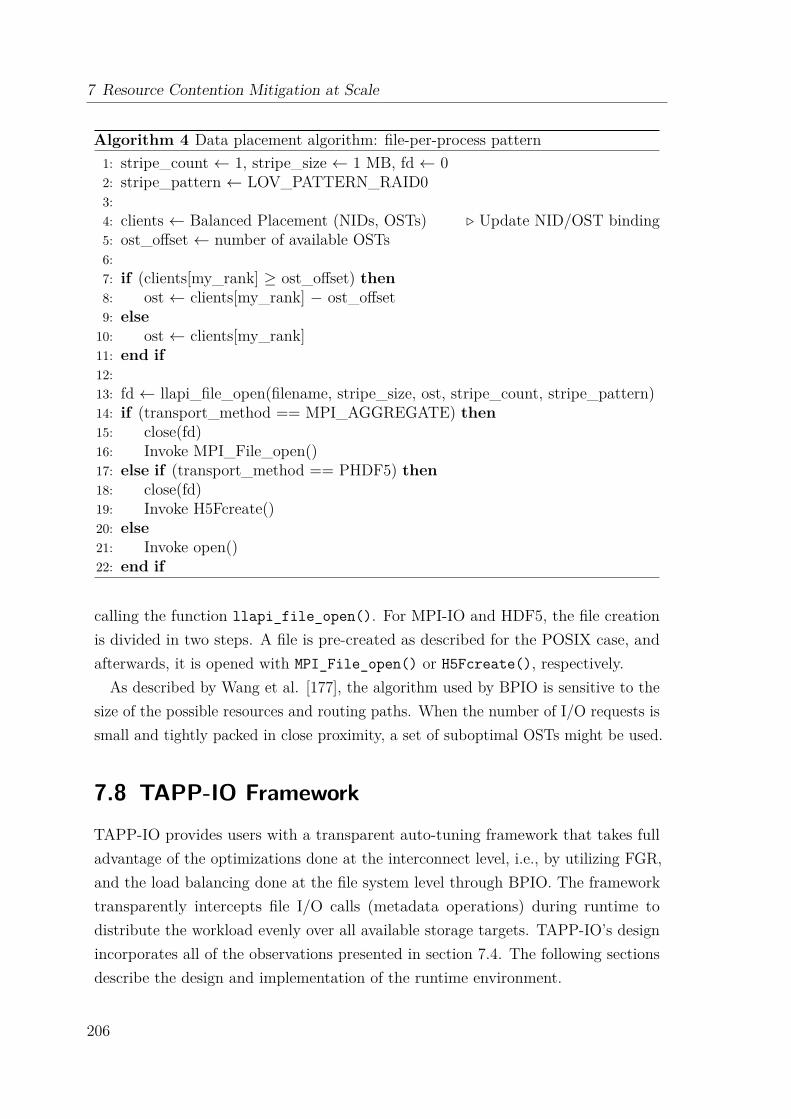
7 Resource Contention Mitigation at Scale
Algorithm 4 Data placement algorithm: file-per-process pattern1: stripe_count ← 1, stripe_size ← 1 MB, fd ← 02: stripe_pattern ← LOV_PATTERN_RAID03:4: clients ← Balanced Placement (NIDs, OSTs) . Update NID/OST binding5: ost_offset ← number of available OSTs6:7: if (clients[my_rank] ≥ ost_offset) then8: ost ← clients[my_rank] − ost_offset9: else10: ost ← clients[my_rank]11: end if12:13: fd ← llapi_file_open(filename, stripe_size, ost, stripe_count, stripe_pattern)14: if (transport_method == MPI_AGGREGATE) then15: close(fd)16: Invoke MPI_File_open()17: else if (transport_method == PHDF5) then18: close(fd)19: Invoke H5Fcreate()20: else21: Invoke open()22: end if
calling the function llapi_file_open(). For MPI-IO and HDF5, the file creationis divided in two steps. A file is pre-created as described for the POSIX case, andafterwards, it is opened with MPI_File_open() or H5Fcreate(), respectively.
As described by Wang et al. [177], the algorithm used by BPIO is sensitive to thesize of the possible resources and routing paths. When the number of I/O requests issmall and tightly packed in close proximity, a set of suboptimal OSTs might be used.
7.8 TAPP-IO FrameworkTAPP-IO provides users with a transparent auto-tuning framework that takes fulladvantage of the optimizations done at the interconnect level, i.e., by utilizing FGR,and the load balancing done at the file system level through BPIO. The frameworktransparently intercepts file I/O calls (metadata operations) during runtime todistribute the workload evenly over all available storage targets. TAPP-IO’s designincorporates all of the observations presented in section 7.4. The following sectionsdescribe the design and implementation of the runtime environment.
206

7.8 TAPP-IO Framework
7.8.1 Parallel I/O Support
The TAPP-IO framework proposes a file placement strategy that supports bothfile-per-process and single-shared-file I/O access patterns, as described in section2.4.4. File-per-process scales the single writer I/O pattern to encompass all processesinstead of just one process. Each process performs I/O operations on their ownseparate file. Thus, for an application run of N processes, N or more files arecreated. In a single-shared-file application I/O pattern, multiple processes performI/O operations either independently or concurrently to the same file. The possibleHPC application I/O patterns can roughly be classified as follows (the ratio can beread as writer count : file count):
(1) N : N , stripe count ≥ 1;
(2) N : M , stripe count ≥ 1, M > N ;
(3) N : M , stripe count ≥ 1, M < N ;
(4) N : 1, stripe count > 1.
Case (1) and (2) describe the file-per-process I/O patterns, case (3) presents astrategy where the writing is aggregated in M shared files, and case (4) is the single-shared-file strategy where multiple clients write to multiple ranges within the samefile. With a file-per-process I/O pattern, it is best to use no striping (stripe count of1), as presented in section 7.4. This limits the storage target contention when dealingwith a large number of files and processes. Therefore, case (2) is disregarded for theTAPP-IO framework. Case (3) is a special case of case (4) where multiple writersare aggregated in multiple shared files. TAPP-IO currently supports cases (1), (3),and (4) with the limitation that the balancing algorithm needs the expected file sizefor the shared files. For single shared files, TAPP-IO tries to minimize both theoverhead associated with splitting an operation between storage targets (i.e., stripealignment) and contention between writing processes over a single storage target(i.e., file locking contention). Figure 7.5 displays two possible shared file layouts.The segmented file layout keeps the data from a process in a contiguous block, whilethe strided file layout strides the data throughout the file.
When accessing a single shared file from many processes, the stripe count shouldequal the number of processes (refer to section 7.4). The size and location of I/Ooperations from the processes should be carefully managed to allow as much stripealignment as possible resulting in each writing process accessing only a single storagetarget. Analogous to the file-per-process pattern, the algorithm follows the placement
207

7 Resource Contention Mitigation at Scale
Memory buffer
A B C
Memory buffer Memory buffer
A CBACB A CBACB A CBACB
B BBBBB C CCCCCSegmented File
Strided File CBA CBA
CCBBA AAAAA AA
Figure 7.5: Shared file layout patterns.
strategy implied by the segmented file layout. A naive approach would be to set thestripe count to the number of writer processes and the stripe size to file size
stripe count . Butfor Lustre, the stripe size needs to be an even multiple of 65536 bytes. Equation 7.6describes how the file size can be aligned to match an even multiple of 65536 bytes.
aligned filesize =⌈
real filesize65536× 2× number of writers
⌉(in Bytes) (7.6)
With these parameters, the algorithm tries to achieve high levels of performancewhile mitigating storage targets contention at large process counts. The placementalgorithm is invoked only once for every I/O write phase which adds minimal overhead.The optimal set of storage targets is determined similarly to the balanced placementalgorithm introduced in Algortihm 3. For each stripe of a shared file, the optimalstripe-to-storage-target assignment is calculated by utilizing of the BPIO placementcost function.Algorithm 5 displays a simplified version of the TAPP-IO balancing algorithm.
The implementation of the TAPP-IO balancing framework has been deployed andtested on Titan’s Spider II file system. In order to specify the striping informationfor the file-per-process strategy, it is sufficient to set a file descriptor’s Lustrestriping information via the l lapi library before opening the file via the correspondingI/O interface (MPI_File_open() or H5Fcreate()). llapi_file_create() allows aclient to specify the stripe size, stripe count, and OST offset of a file via the logicalobject volumn manager. When MPI-IO or HDF5 tries to create a file, the I/O layerstransparently adopts the Lustre file descriptor that was previously created. Theexisting descriptor is used by Lustre when opening the corresponding file.With Lustre 2.7 [213], a new feature was introduced that provides the user with
the ability to explicitly specify the striping pattern via an ordered list of OSTs.The Lustre llapi can be utilized to specify the Lustre striping parameter struct
208
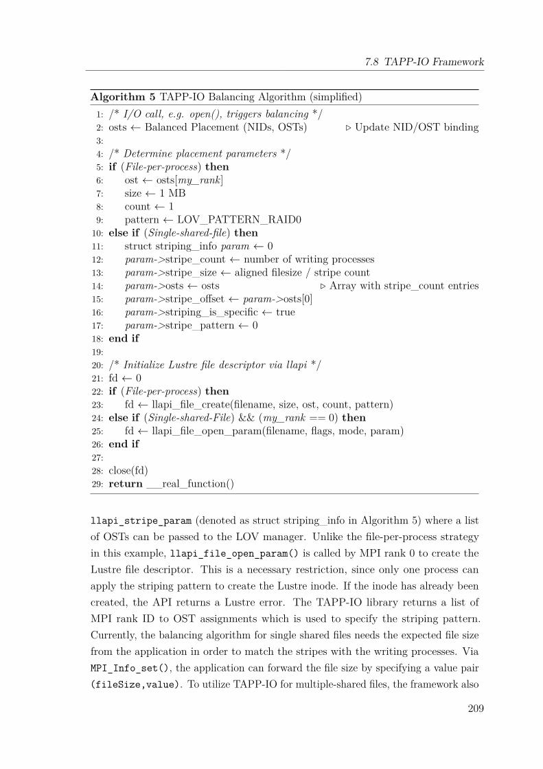
7.8 TAPP-IO Framework
Algorithm 5 TAPP-IO Balancing Algorithm (simplified)1: /* I/O call, e.g. open(), triggers balancing */2: osts ← Balanced Placement (NIDs, OSTs) . Update NID/OST binding3:4: /* Determine placement parameters */5: if (File-per-process) then6: ost ← osts[my_rank]7: size ← 1 MB8: count ← 19: pattern ← LOV_PATTERN_RAID010: else if (Single-shared-file) then11: struct striping_info param ← 012: param->stripe_count ← number of writing processes13: param->stripe_size ← aligned filesize / stripe count14: param->osts ← osts . Array with stripe_count entries15: param->stripe_offset ← param->osts[0]16: param->striping_is_specific ← true17: param->stripe_pattern ← 018: end if19:20: /* Initialize Lustre file descriptor via llapi */21: fd ← 022: if (File-per-process) then23: fd ← llapi_file_create(filename, size, ost, count, pattern)24: else if (Single-shared-File) && (my_rank == 0) then25: fd ← llapi_file_open_param(filename, flags, mode, param)26: end if27:28: close(fd)29: return __real_function()
llapi_stripe_param (denoted as struct striping_info in Algorithm 5) where a listof OSTs can be passed to the LOV manager. Unlike the file-per-process strategyin this example, llapi_file_open_param() is called by MPI rank 0 to create theLustre file descriptor. This is a necessary restriction, since only one process canapply the striping pattern to create the Lustre inode. If the inode has already beencreated, the API returns a Lustre error. The TAPP-IO library returns a list ofMPI rank ID to OST assignments which is used to specify the striping pattern.Currently, the balancing algorithm for single shared files needs the expected file sizefrom the application in order to match the stripes with the writing processes. ViaMPI_Info_set(), the application can forward the file size by specifying a value pair(fileSize,value). To utilize TAPP-IO for multiple-shared files, the framework also
209
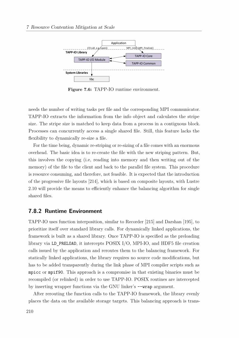
7 Resource Contention Mitigation at Scale
Application
TAPP-IO I/O ModuleTAPP-IO Core
TAPP-IO Common
libc
MPI_Init(), MPI_Finalize()I/O call, e.g. open()
TAPP-IO Library
System Libraries
Figure 7.6: TAPP-IO runtime environment.
needs the number of writing tasks per file and the corresponding MPI communicator.TAPP-IO extracts the information from the info object and calculates the stripesize. The stripe size is matched to keep data from a process in a contiguous block.Processes can concurrently access a single shared file. Still, this feature lacks theflexibility to dynamically re-size a file.
For the time being, dynamic re-striping or re-sizing of a file comes with an enormousoverhead. The basic idea is to re-create the file with the new striping pattern. But,this involves the copying (i.e, reading into memory and then writing out of thememory) of the file to the client and back to the parallel file system. This procedureis resource consuming, and therefore, not feasible. It is expected that the introductionof the progressive file layouts [214], which is based on composite layouts, with Lustre2.10 will provide the means to efficiently enhance the balancing algorithm for singleshared files.
7.8.2 Runtime Environment
TAPP-IO uses function interposition, similar to Recorder [215] and Darshan [195], toprioritize itself over standard library calls. For dynamically linked applications, theframework is built as a shared library. Once TAPP-IO is specified as the preloadinglibrary via LD_PRELOAD, it intercepts POSIX I/O, MPI-IO, and HDF5 file creationcalls issued by the application and reroutes them to the balancing framework. Forstatically linked applications, the library requires no source code modifications, buthas to be added transparently during the link phase of MPI compiler scripts such asmpicc or mpif90. This approach is a compromise in that existing binaries must berecompiled (or relinked) in order to use TAPP-IO. POSIX routines are interceptedby inserting wrapper functions via the GNU linker’s --wrap argument.After rerouting the function calls to the TAPP-IO framework, the library evenly
places the data on the available storage targets. This balancing approach is trans-
210
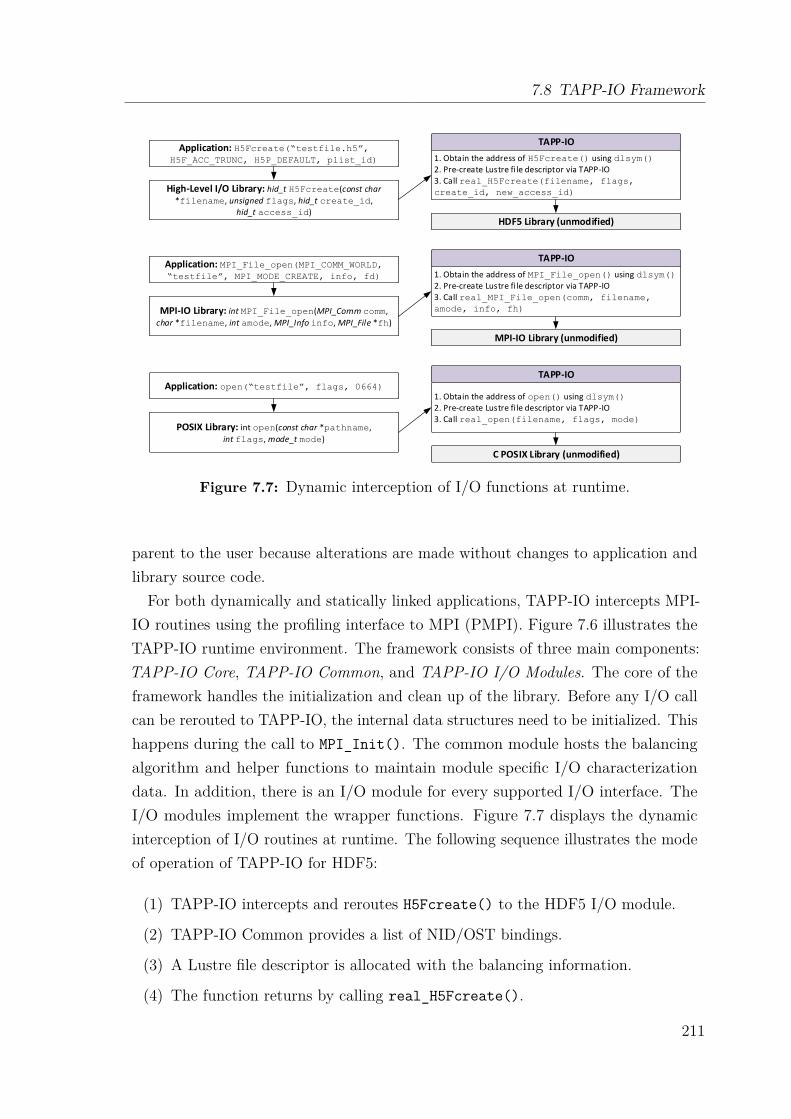
7.8 TAPP-IO Framework
Application: MPI_File_open(MPI_COMM_WORLD,“testfile”, MPI_MODE_CREATE, info, fd)
TAPP-IO
1. Obtain the address of MPI_File_open() using dlsym()2. Pre-create Lustre fi le descriptor via TAPP-IO3. Call real_MPI_File_open(comm, filename, amode, info, fh)MPI-IO Library: int MPI_File_open(MPI_Comm comm,
char *filename, int amode, MPI_Info info, MPI_File *fh)
Application: open(“testfile”, flags, 0664)TAPP-IO
1. Obtain the address of open() using dlsym()2. Pre-create Lustre fi le descriptor via TAPP-IO3. Call real_open(filename, flags, mode)
POSIX Library: int open(const char *pathname,
int flags, mode_t mode)
MPI-IO Library (unmodified)
C POSIX Library (unmodified)
Application: H5Fcreate(“testfile.h5”, H5F_ACC_TRUNC, H5P_DEFAULT, plist_id)
TAPP-IO
1. Obtain the address of H5Fcreate() using dlsym()2. Pre-create Lustre fi le descriptor via TAPP-IO3. Call real_H5Fcreate(filename, flags, create_id, new_access_id)High-Level I/O Library: hid_t H5Fcreate(const char
*filename, unsigned flags, hid_t create_id, hid_t access_id)
HDF5 Library (unmodified)
Figure 7.7: Dynamic interception of I/O functions at runtime.
parent to the user because alterations are made without changes to application andlibrary source code.
For both dynamically and statically linked applications, TAPP-IO intercepts MPI-IO routines using the profiling interface to MPI (PMPI). Figure 7.6 illustrates theTAPP-IO runtime environment. The framework consists of three main components:TAPP-IO Core, TAPP-IO Common, and TAPP-IO I/O Modules. The core of theframework handles the initialization and clean up of the library. Before any I/O callcan be rerouted to TAPP-IO, the internal data structures need to be initialized. Thishappens during the call to MPI_Init(). The common module hosts the balancingalgorithm and helper functions to maintain module specific I/O characterizationdata. In addition, there is an I/O module for every supported I/O interface. TheI/O modules implement the wrapper functions. Figure 7.7 displays the dynamicinterception of I/O routines at runtime. The following sequence illustrates the modeof operation of TAPP-IO for HDF5:
(1) TAPP-IO intercepts and reroutes H5Fcreate() to the HDF5 I/O module.
(2) TAPP-IO Common provides a list of NID/OST bindings.
(3) A Lustre file descriptor is allocated with the balancing information.
(4) The function returns by calling real_H5Fcreate().
211
7 Resource Contention Mitigation at Scale
The mechanism is the same for the MPI-IO and POSIX I/O. It offers per joband end-to-end I/O performance improvement in the most transparent way. Cur-rently, the framework supports the following I/O calls: open[64](), creat[64](),MPI_File_open(), and H5Fcreate(). These mechanisms have been tested withthe MPICH MPI implementation for both GNU and Cray C, C++, and Fortrancompilers. It also works correctly for both static and dynamic compilation, requiresno additional supporting infrastructure for instrumentation, and is compatible withother MPI implementations and compilers.
7.9 Data Collection and AnalysisThis section presents the analysis results of Aequilibro and TAPP-IO. First, the bench-marking methodology and test setup are introduced followed by the experimentalevaluation results obtained from the Spider II system.
7.9.1 Benchmarking Methodology
The benchmarking methodology utilizes two benchmarks, the synthetic IOR bench-mark and the real-world HPC workload S3D. They are used to evaluate to overallperformance improvement, bandwidth, execution time, and I/O interference.
7.9.1.1 IOR Benchmark
The well-known IOR [216] synthetic benchmark tool is adopted to exploit thestrengths and weaknesses of Aequilibro and TAPP-IO. IOR provides a flexible wayof measuring I/O performance under different read or write sizes, concurrencies, fileformats, and access pattern strategies. It supports different I/O interfaces rangingfrom traditional POSIX I/O to advanced high-level I/O libraries like MPI-IO andHDF5, and differentiates parallel I/O strategies between file-per-process and single-shared-file approaches. Shan et al. [217] have demonstrated that IOR can be usedto characterize and predict the I/O performance on large-scale HPC systems. IORis utilized to evaluate the direct exploitation of the BPIO library in comparison toAequilibro and TAPP-IO transparently handling I/O for an application.
Table 7.1 displays the IOR benchmark variants used with the file-per-processstrategy. The evaluation is divided into three different I/O performance comparisons.First, the original version of BPIO is directly used for the data placement bymodifying the IOR source code, referred to as IOR BPIO. Before creating a file
212
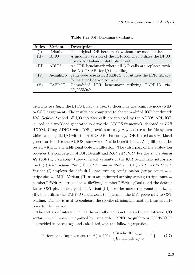
7.9 Data Collection and Analysis
Table 7.1: IOR benchmark variants.
Index Variant Description(I) Default The original IOR benchmark without any modification.(II) BPIO A modified version of the IOR tool that utilizes the BPIO
library for balanced data placement.(III) ADIOS An IOR benchmark where all I/O calls are replaced with
the ADIOS API for I/O handling.(IV) Aequilibro Same code base as IOR ADIOS, but utilizes the BPIO library
for balanced data placement.(V) TAPP-IO Unmodified IOR benchmark utilizing TAPP-IO via
LD_PRELOAD.
with Lustre’s llapi, the BPIO library is used to determine the compute node (NID)to OST assignment. The results are compared to the unmodified IOR benchmarkIOR Default. Second, all I/O interface calls are replaced by the ADIOS API. IORis used as a workload generator to drive the ADIOS framework, denoted as IORADIOS. Using ADIOS with IOR provides an easy way to stress the file systemwhile handling file I/O with the ADIOS API. Essentially, IOR is used as a workloadgenerator to drive the ADIOS framework. A side benefit is that Aequilibro can betested without any additional code modification. The third part of the evaluationprovides the comparison of IOR Default and IOR TAPP-IO. For the single sharedfile (SSF) I/O strategy, three different variants of the IOR benchmark setups areused: (I) IOR Default SSF, (II) IOR Optimized SSF, and (III) IOR TAPP-IO SSF.Variant (I) employs the default Lustre striping configuration (stripe count = 4,stripe size = 1MB). Variant (II) uses an optimized striping setting (stripe count =numberOfWriters, stripe size = fileSize / numberOfWritingTask) and the defaultLustre OST placement algorithm. Variant (III) uses the same stripe count and size as(II), but utilizes the TAPP-IO framework to determine the MPI process ID to OSTbinding. The list is used to configure the specific striping information transparentlyprior to file creation.
The metrics of interest include the overall execution time and the end-to-end I/Operformance improvement gained by using either BPIO, Aequilibro or TAPP-IO. Itis provided in percentage and calculated with the following equation:
Performance Improvement (in %) = 100 ∗(Bandwidth balanced
Bandwidth default
− 1)
(7.7)
213
7 Resource Contention Mitigation at Scale
In order to accurately model a typical HPC workload behavior, the benchmarkparameters need to be aligned with the desired workloads. The IOR benchmarkprovides a wide range of parameters including the API, FilePerProc, WriteFile,NumTasks, BlockSize, and TransferSize. On Titan, the memory size per node is32 GB with 2 GB per processor. IOR is run with different block sizes to evaluatethe impact of caching effects and a TransferSize of 1 MB. For POSIX I/O, the fsyncand useO_DIRECT options are set. O_DIRECT bypasses I/O and file systembuffers. For MPI-IO, the same effect can be achieved by enabling the direct_ioMPI-IO optimization hint. For Lustre-specific settings, each file is created with astripe size of 1 MB and in the case of file-per-process pattern, a StripeCount of 1 isused. The stripe size should be aligned with the TransferSize in order to get the bestperformance. StripeCount specifies the number of OSTs where the data is stripedacross while StripeSize defines the size of one stripe.
7.9.1.2 I/O Interference
Large-scale HPC systems waste a significant amount of computing capacity becauseof I/O interferences caused by multiple running applications concurrently accessingshared parallel file system and storage resources. Lofstead et al. [196] provide adefinition of internal and external interferences to characterize the variability in I/Operformance. The definition is used to evaluate the performance of TAPP-IO interms of I/O interferences.
Internal interference When too many write processes from one specific applicationtry to write to a single storage target at the same time, internal interference can occur.Write caches are exceeded which leads to a blocking behavior of the application untilthe buffers are cleared. The IOR benchmark is to evaluate the internal interferenceby writing data of different sizes to OSTs while scaling the number of nodes/writers.For simplicity reasons, the IOR benchmark is configured to use 1,008 OSTs andPOSIX I/O.
External interference Even if an application would try to evenly use all availablestorage system resources, external interference can still occur. This is caused by thefact that a parallel file system is a shared resource where accesses are shared betweenall compute nodes and running applications. To demonstrate the I/O performancevariability, hourly IOR tests with an 1,008 node allocation are performed, one processper node (one writer per node), and POSIX I/O with the file-per-process I/O strategy.
214
7.9 Data Collection and Analysis
Another characterization metric is the imbalance factor of an I/O action as definedby Lofstead et al. [196]. It describes the ratio of the slowest (wtimemax) versus thefastest write (wtimemin) times across all writers:
Imbalance factor = wtimemax
wtimemin
(7.8)
The imbalance factor reflects the impact of the slowest writer on the overall per-formance. Therefore, the factor can be utilized to characterize the imbalance of anapplication.
7.9.1.3 HPC Workload
S3D [218] is a combustion code simulation that is employed on many different HPCsystems. When executed, it generates a large amount of I/O requests. Verifying theI/O performance of S3D with TAPP-IO is a good indicator for the impact on otherlarge-scale applications. Unfortunately, S3D is a proprietary code. Genarray3D [219]is a skeletal I/O application, which utilizes the ADIOS middleware’s XML I/Ospecification with additional runtime parameters to emulate the I/O behavior ofS3D. By default, the MPI_AGGREGATE transport method sets the striping informationfor a file. In order to run ADIOS with TAPP-IO, the part that specifies the stripinginformation has to be removed.In Genarray3D, three dimensions of a global array are partitioned among MPI
processes along X-Y-Z dimensions in the same block-block-block fashion. Eachprocess writes an N3 partition. The size of each data element is 4 bytes, leading tothe total data size of N3 ∗ P ∗ 4 bytes, where P is the number of processes. One keydifference between the IOR benchmark and Genarray3D is that all cores present on acompute node are utilized by default. This improves the computational efficiency ofthe simulation. On the other hand, Genarray3D generates pressure on single storagetargets, because each compute node hosts its own operating system with a singlemount point per file system.
7.9.2 Experimental Setup
All tests were performed on the Titan supercomputer. In order to get representativeresults, two major issues were addressed. First, all experiments were conducted in abusy production environment. No tests were run during the quiet maintenance mode.The results show that performance gains can be achieved in an active productionenvironment. Second, a broad set of compute nodes were used instead of just a
215

7 Resource Contention Mitigation at Scale
certain subset of nodes. This demonstrates that independently from any specificnode set on Titan, an application can readily benefit from the presented balancingframework. The application level placement scheduler (ALPS) on Titan returnsa node allocation list where nodes tend to be logically close to each other. Thereare two attempts to get a higher node coverage. The first one is to submit scalingtests one after another independently, in the hope that a different set of computenodes is covered with every run. The second attempt is to submit scaling runs inparallel to occupy a larger set of nodes. Both approaches are used to get a broadercoverage. More than 30 scaled runs were obtained for IOR variants (I) to (IV) (seeTable I), with each run ranging from 8 to 4,096 nodes. For each node allocation,three iterations are performed to obtain the average badwidth results.All of the described experiments are conducted in a noisy, active production
environment. Therefore, performance numbers may not always be conclusive. Tocope with this issue and to draw consistent observation, multiple tests were performedwith at least three repetitions per run. Iterations within the same run get the samenode allocation. Each iteration executes IOR variants (I) to (IV). This is essential inorder to average out the variance across the same set of allocated nodes. In addition,a large set of Titan compute nodes were covered throughout these tests. For theinternal interference, more than 30 scaled IOR runs per node allocation have beenperformed. The number of allocated nodes ranges from 16 to 1,024 with 16 MPIprocesses per node which corresponds to a range from 128 to 16,384 processes intotal. Each process writes a separate file. For the external interference, more than100 samples were obtained.
7.9.3 Synthetic Benchmark Evaluation
The following sections present the IOR benchmark performance results, includingthe overall performance improvement, the application execution time, the achievedbandwidth, the standard deviation, and the interference results.
7.9.3.1 Performance Imrovement
The results of the scaling runs with a 4 GB file size per writing process and file-per-process strategy are summarized in Figure 7.8 for 64, 512, 2,048, and 4,096 nodesrespectively. Over a period of four months, more than 30 scaled runs per nodeallocation size were obtained. Each sub-figure represents a particular node allocation.The X -axis represents the enumeration of runs with the same count of node allocation,but for different sets of nodes. The bandwidth performance of IOR Default and IOR
216
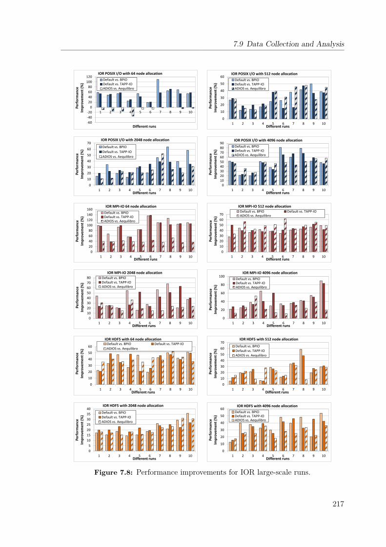
7.9 Data Collection and Analysis
-60
-40
-20
0
20
40
60
80
100
120
1 2 3 4 5 6 7 8 9 10
Pe
rfo
rman
ce
Imp
rove
me
nt
(%)
Different runs
IOR POSIX I/O with 64 node allocation
Default vs. BPIO Default vs. TAPP-IO ADIOS vs. Aequilibro
0
10
20
30
40
50
60
1 2 3 4 5 6 7 8 9 10
Pe
rfo
rman
ce
Imp
rove
me
nt
(%)
Different runs
IOR POSIX I/O with 512 node allocation
Default vs. BPIO Default vs. TAPP-IO ADIOS vs. Aequilibro
0
10
20
30
40
50
60
70
1 2 3 4 5 6 7 8 9 10
Per
form
ance
Im
pro
vem
ent
(%)
Different runs
IOR POSIX I/O with 2048 node allocation
Default vs. BPIO
Default vs. TAPP-IO
ADIOS vs. Aequilibro
0 10 20 30 40 50 60 70 80 90
1 2 3 4 5 6 7 8 9 10
Pe
rfo
rman
ce
Imp
rove
men
t (%
)
Different runs
IOR POSIX I/O with 4096 node allocation
Default vs. BPIO Default vs. TAPP-IO ADIOS vs. Aequilibro
0
20
40
60
80
100
120
140
160
1 2 3 4 5 6 7 8 9 10
Per
form
ance
Im
pro
vem
ent
(%)
Different runs
IOR MPI-IO 64 node allocation
Default vs. BPIO Default vs. TAPP-IO ADIOS vs. Aequilibro
0
10
20
30
40
50
60
70
1 2 3 4 5 6 7 8 9 10
Per
form
ance
Im
pro
vem
ent
(%)
Different runs
IOR MPI-IO 512 node allocation Default vs. BPIO Default vs. TAPP-IO ADIOS vs. Aequilibro
0
10
20
30
40
50
60
70
80
1 2 3 4 5 6 7 8 9 10
Per
form
ance
Im
pro
vem
ent
(%)
Different runs
IOR MPI-IO 2048 node allocation Default vs. BPIO Default vs. TAPP-IO ADIOS vs. Aequilibro
0
20
40
60
80
100
1 2 3 4 5 6 7 8 9 10
Per
form
ance
Im
pro
vem
ent
(%)
Different runs
IOR MPI-IO 4096 node allocation
Default vs. BPIO Default vs. TAPP-IO ADIOS vs. Aequilibro
0
10
20
30
40
50
60
1 2 3 4 5 6 7 8 9 10
Pe
rfo
rman
ce
Imp
rove
me
nt
(%)
Different runs
IOR HDF5 with 64 node allocation Default vs. BPIO Default vs. TAPP-IO
ADIOS vs. Aequilibro
0
10
20
30
40
50
60
70
1 2 3 4 5 6 7 8 9 10
Pe
rfo
rman
ce
Imp
rove
me
nt
(%)
Different runs
IOR HDF5 with 512 node allocation
Default vs. BPIO Default vs. TAPP-IO ADIOS vs. Aequilibro
0
5
10
15
20
25
30
35
40
1 2 3 4 5 6 7 8 9 10
Per
form
ance
Im
pro
vem
ent
(%)
Different runs
IOR HDF5 with 2048 node allocation
Default vs. BPIO Default vs. TAPP-IO ADIOS vs. Aequilibro
0
10
20
30
40
50
60
1 2 3 4 5 6 7 8 9 10
Per
form
ance
Im
pro
vem
ent
(%)
Different runs
IOR HDF5 with 4096 node allocation
Default vs. BPIO Default vs. TAPP-IO ADIOS vs. Aequilibro
Figure 7.8: Performance improvements for IOR large-scale runs.
217
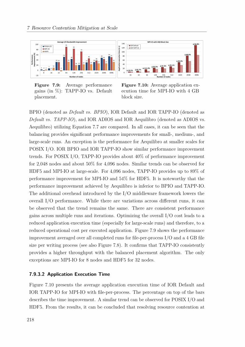
7 Resource Contention Mitigation at Scale
3 7
32
52
44
21
31 32
49 54
-2 0
31
91
83
73
46
38 44
51
3 10
-3
33
20 23 23 27 27
32
-20
0
20
40
60
80
100
8 16 32 64 128 256 512 1024 2048 4096
Per
form
ance
Im
pro
vem
ent
(%)
Number of nodes
Average I/O Bandwidth Improvement
POSIX I/O
MPI-IO
HDF5
Figure 7.9: Average performancegains (in %): TAPP-IO vs. Defaultplacement.
0
20
40
60
80
100
120
140
16 32 64 128 256 512 1024 2048 4096
Ap
plic
atio
n e
xecu
tio
n t
ime
(in
s)
Number of nodes
MPI-IO with 4GB Block Size
IOR Default
IOR TAPP-IO
↓56.8%
↓48.8%
↓39.3%
↓35.1% ↓37.3% ↓35.5% ↓111.3%
↓92.7% ↓10.5%
Figure 7.10: Average application ex-ecution time for MPI-IO with 4 GBblock size.
BPIO (denoted as Default vs. BPIO), IOR Default and IOR TAPP-IO (denoted asDefault vs. TAPP-IO), and IOR ADIOS and IOR Aequilibro (denoted as ADIOS vs.Aequilibro) utilizing Equation 7.7 are compared. In all cases, it can be seen that thebalancing provides significant performance improvements for small-, medium-, andlarge-scale runs. An exception is the performance for Aequilibro at smaller scales forPOSIX I/O. IOR BPIO and IOR TAPP-IO show similar performance improvementtrends. For POSIX I/O, TAPP-IO provides about 40% of performance improvementfor 2,048 nodes and about 50% for 4,096 nodes. Similar trends can be observed forHDF5 and MPI-IO at large-scale. For 4,096 nodes, TAPP-IO provides up to 89% ofperformance improvement for MPI-IO and 54% for HDF5. It is noteworthy that theperformance improvement achieved by Aequilibro is inferior to BPIO and TAPP-IO.The additional overhead introduced by the I/O middleware framework lowers theoverall I/O performance. While there are variations across different runs, it canbe observed that the trend remains the same. There are consistent performancegains across multiple runs and iterations. Optimizing the overall I/O cost leads to areduced application execution time (especially for large-scale runs) and therefore, to areduced operational cost per executed application. Figure 7.9 shows the performanceimprovement averaged over all completed runs for file-per-process I/O and a 4 GB filesize per writing process (see also Figure 7.8). It confirms that TAPP-IO consistentlyprovides a higher throughput with the balanced placement algorithm. The onlyexceptions are MPI-IO for 8 nodes and HDF5 for 32 nodes.
7.9.3.2 Application Execution Time
Figure 7.10 presents the average application execution time of IOR Default andIOR TAPP-IO for MPI-IO with file-per-process. The percentage on top of the barsdescribes the time improvement. A similar trend can be observed for POSIX I/O andHDF5. From the results, it can be concluded that resolving resource contention at
218
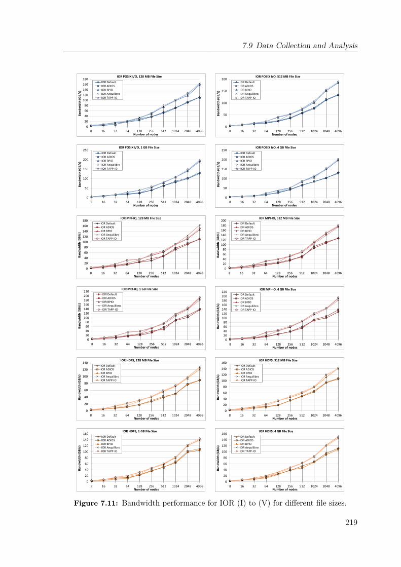
7.9 Data Collection and Analysis
0
20
40
60
80
100
120
140
160
180
8 16 32 64 128 256 512 1024 2048 4096
Ban
dw
idth
(G
B/s
)
Number of nodes
IOR POSIX I/O, 128 MB File Size
IOR Default IOR ADIOS IOR BPIO IOR Aequilibro IOR TAPP-IO
0
50
100
150
200
8 16 32 64 128 256 512 1024 2048 4096
Ban
dw
idth
(G
B/s
)
Number of nodes
IOR POSIX I/O, 512 MB File Size
IOR Default IOR ADIOS IOR BPIO IOR Aequilibro IOR TAPP-IO
0
50
100
150
200
250
8 16 32 64 128 256 512 1024 2048 4096
Ban
dw
idth
(G
B/s
)
Number of nodes
IOR POSIX I/O, 1 GB File Size
IOR Default IOR ADIOS IOR BPIO IOR Aequilibro IOR TAPP-IO
0
50
100
150
200
250
8 16 32 64 128 256 512 1024 2048 4096
Ban
dw
idth
(G
B/s
)
Number of nodes
IOR POSIX I/O, 4 GB File Size
IOR Default IOR ADIOS IOR BPIO IOR Aequilibro IOR TAPP-IO
0
20
40
60
80
100
120
140
160
180
8 16 32 64 128 256 512 1024 2048 4096
Ban
dw
idth
(G
B/s
)
Number of nodes
IOR MPI-IO, 128 MB File Size
IOR Default IOR ADIOS IOR BPIO IOR Aequilibro IOR TAPP-IO
0
20
40
60
80
100
120
140
160
180
200
8 16 32 64 128 256 512 1024 2048 4096
Ban
dw
idth
(G
B/s
)
Number of nodes
IOR MPI-IO, 512 MB File Size
IOR Default IOR ADIOS IOR BPIO IOR Aequilibro IOR TAPP-IO
0
20
40
60
80
100
120
140
160
180
200
220
8 16 32 64 128 256 512 1024 2048 4096
Ban
dw
idth
(G
B/s
)
Number of nodes
IOR MPI-IO, 1 GB File Size
IOR Default IOR ADIOS IOR BPIO IOR Aequilibro IOR TAPP-IO
0
20
40
60
80
100
120
140
160
180
200
220
8 16 32 64 128 256 512 1024 2048 4096
Ban
dw
idth
(G
B/s
)
Number of nodes
IOR MPI-IO, 4 GB File Size
IOR Default IOR ADIOS IOR BPIO IOR Aequilibro IOR TAPP-IO
0
20
40
60
80
100
120
140
8 16 32 64 128 256 512 1024 2048 4096
Ban
dw
idth
(G
B/s
)
Number of nodes
IOR HDF5, 128 MB File Size
IOR Default IOR ADIOS IOR BPIO IOR Aequilibro IOR TAPP-IO
0
20
40
60
80
100
120
140
160
8 16 32 64 128 256 512 1024 2048 4096
Ban
dw
idth
(G
B/s
)
Number of nodes
IOR HDF5, 512 MB File Size
IOR Default IOR ADIOS IOR BPIO IOR Aequilibro IOR TAPP-IO
0
20
40
60
80
100
120
140
160
8 16 32 64 128 256 512 1024 2048 4096
Ban
dw
idth
(G
B/s
)
Number of nodes
IOR HDF5, 1 GB File Size
IOR Default IOR ADIOS IOR BPIO IOR Aequilibro IOR TAPP-IO
0
20
40
60
80
100
120
140
160
8 16 32 64 128 256 512 1024 2048 4096
Ban
dw
idth
(G
B/s
)
Number of nodes
IOR HDF5, 4 GB File Size
IOR Default IOR ADIOS IOR BPIO IOR Aequilibro IOR TAPP-IO
Figure 7.11: Bandwidth performance for IOR (I) to (V) for different file sizes.
219

7 Resource Contention Mitigation at Scale
0
20
40
60
80
8 16 32 64 128 256 512 1024
Ban
dw
idth
(G
B/s
)
Number of nodes
IOR MPI-IO, 512 MB Block Size, Single Shared File
IOR Default IOR Optimized IOR TAPP-IO
0
20
40
60
80
100
8 16 32 64 128 256 512 1024
Ban
dw
idth
(G
B/s
)
Number of nodes
IOR MPI-IO, 2 GB Block Size, Single Shared File
IOR Default IOR Optimized IOR TAPP-IO
Figure 7.12: IOR bandwidth performance for MPI-IO and single shared file.
the storage system level directly impacts the overall execution time of the application.With the advent of big data and the increasing amount of defensive I/O in mind,it is expected that the balancing mechanism will have a tremendous effect on anapplication’s performance.
7.9.3.3 Bandwidth Results
Figure 7.11 summarizes the IOR bandwidth results for different file sizes scaling from8 to 4,096 nodes for file-per-process. The results illustrate the average bandwidthper second from over more than 40 scaled runs with at least three repetitions perIOR variant (refer to Table I) per node allocation within one run. The results werecollected over the period of four months. From the throughput results, the followingobservations can be made. First, starting from small-scale runs with at least 16nodes, our load balancing framework TAPP-IO and the BPIO library both provideconsistent bandwidth improvements. Aequilibro does not provide any significantimprovement for less than 128 nodes. Second, with an increasing number of I/Oprocesses and allocated computing nodes, POSIX, MPI-IO, and HDF5 benefit fromutilizing TAPP-IO with IOR. For example, IOR TAPP-IO with POSIX I/O achievesup to 202.7 GB/s on average for a 4,096 node allocation and a 4 GB file size perwriting process. This can be translated to 54% performance improvement comparedto the default data placement with IOR Default. For smaller file sizes, the maximumbandwidth is less, but the average performance improvement trend remains the samecompared with the default data placement. This consistent improvement can beobserved for MPI-IO and HDF5 as well. Another noteworthy aspect is that theexpected caching effects for smaller file sizes were non-existent. In summary, it canbe said that all IOR variants utilizing a data balancing algorithm are able to providesimilar performance results. But, TAPP-IO makes the application independent fromthe need to actively adopt the BPIO mechanism by integrating it into the applicationor using an I/O framework such as Aequilibro.
220
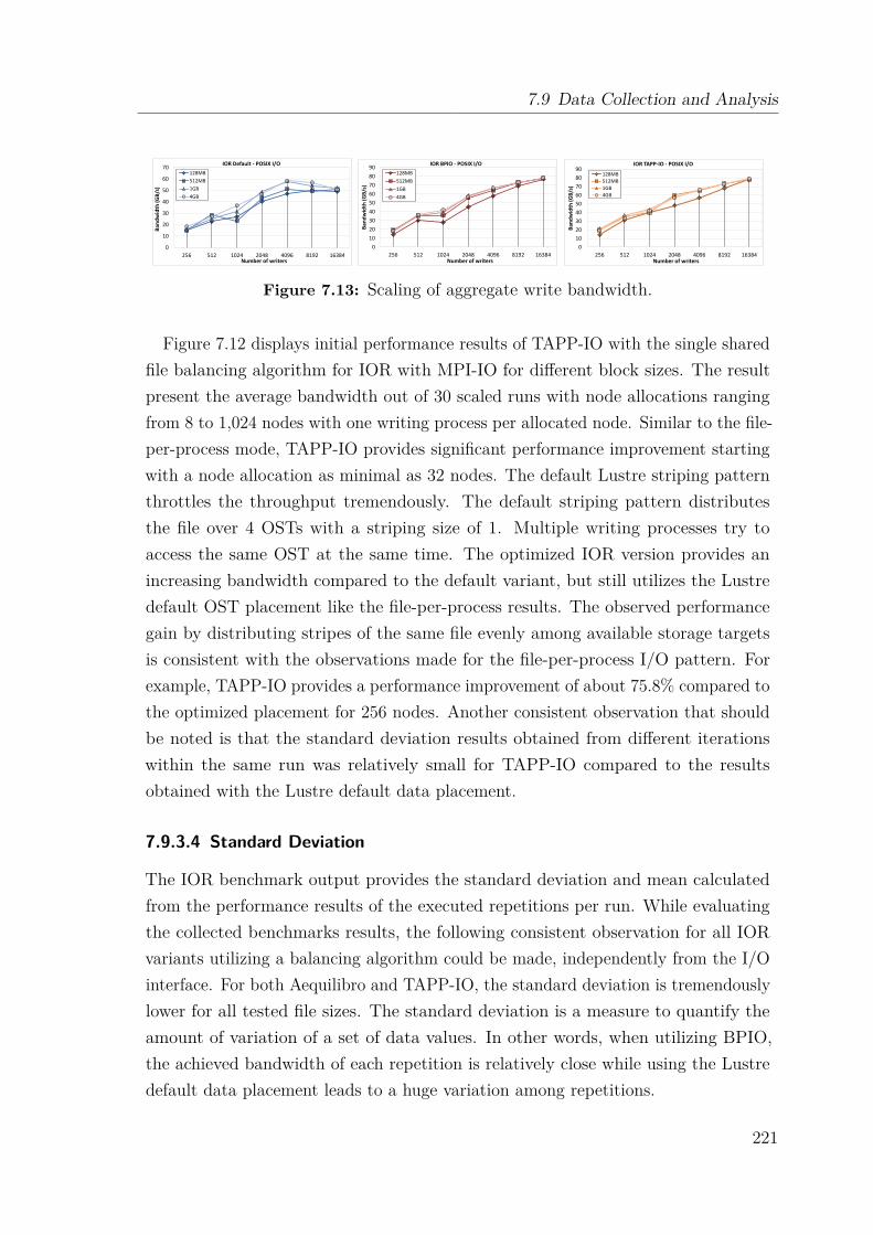
7.9 Data Collection and Analysis
0
10
20
30
40
50
60
70
256 512 1024 2048 4096 8192 16384
Ban
dw
idth
(G
B/s
)
Number of writers
IOR Default - POSIX I/O
128MB
512MB
1GB
4GB
0
10
20
30
40
50
60
70
80
90
256 512 1024 2048 4096 8192 16384
Ban
dw
idth
(G
B/s
)
Number of writers
IOR BPIO - POSIX I/O
128MB
512MB
1GB
4GB
0
10
20
30
40
50
60
70
80
90
256 512 1024 2048 4096 8192 16384
Ban
dw
idth
(GB
/s)
Number of writers
IOR TAPP-IO - POSIX I/O
128MB
512MB
1GB
4GB
Figure 7.13: Scaling of aggregate write bandwidth.
Figure 7.12 displays initial performance results of TAPP-IO with the single sharedfile balancing algorithm for IOR with MPI-IO for different block sizes. The resultpresent the average bandwidth out of 30 scaled runs with node allocations rangingfrom 8 to 1,024 nodes with one writing process per allocated node. Similar to the file-per-process mode, TAPP-IO provides significant performance improvement startingwith a node allocation as minimal as 32 nodes. The default Lustre striping patternthrottles the throughput tremendously. The default striping pattern distributesthe file over 4 OSTs with a striping size of 1. Multiple writing processes try toaccess the same OST at the same time. The optimized IOR version provides anincreasing bandwidth compared to the default variant, but still utilizes the Lustredefault OST placement like the file-per-process results. The observed performancegain by distributing stripes of the same file evenly among available storage targetsis consistent with the observations made for the file-per-process I/O pattern. Forexample, TAPP-IO provides a performance improvement of about 75.8% compared tothe optimized placement for 256 nodes. Another consistent observation that shouldbe noted is that the standard deviation results obtained from different iterationswithin the same run was relatively small for TAPP-IO compared to the resultsobtained with the Lustre default data placement.
7.9.3.4 Standard Deviation
The IOR benchmark output provides the standard deviation and mean calculatedfrom the performance results of the executed repetitions per run. While evaluatingthe collected benchmarks results, the following consistent observation for all IORvariants utilizing a balancing algorithm could be made, independently from the I/Ointerface. For both Aequilibro and TAPP-IO, the standard deviation is tremendouslylower for all tested file sizes. The standard deviation is a measure to quantify theamount of variation of a set of data values. In other words, when utilizing BPIO,the achieved bandwidth of each repetition is relatively close while using the Lustredefault data placement leads to a huge variation among repetitions.
221
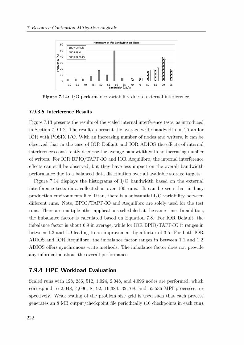
7 Resource Contention Mitigation at Scale
0
10
20
30
40
50
60
30 35 40 45 50 55 60 65 70 75 80 85 90 95
Freq
uen
cy (
%)
Bandwidth (GB/s)
Histogram of I/O Bandwidth on Titan
IOR Default
IOR BPIO
IOR TAPP-IO
Figure 7.14: I/O performance variability due to external interference.
7.9.3.5 Interference Results
Figure 7.13 presents the results of the scaled internal interference tests, as introducedin Section 7.9.1.2. The results represent the average write bandwidth on Titan forIOR with POSIX I/O. With an increasing number of nodes and writers, it can beobserved that in the case of IOR Default and IOR ADIOS the effects of internalinterferences consistently decrease the average bandwidth with an increasing numberof writers. For IOR BPIO/TAPP-IO and IOR Aequilibro, the internal interferenceeffects can still be observed, but they have less impact on the overall bandwidthperformance due to a balanced data distribution over all available storage targets.Figure 7.14 displays the histograms of I/O bandwidth based on the external
interference tests data collected in over 100 runs. It can be seen that in busyproduction environments like Titan, there is a substantial I/O variability betweendifferent runs. Note, BPIO/TAPP-IO and Aequilibro are solely used for the testruns. There are multiple other applications scheduled at the same time. In addition,the imbalance factor is calculated based on Equation 7.8. For IOR Default, theimbalance factor is about 6.9 in average, while for IOR BPIO/TAPP-IO it ranges inbetween 1.3 and 1.9 leading to an improvement by a factor of 3.5. For both IORADIOS and IOR Aequilibro, the imbalance factor ranges in between 1.1 and 1.2.ADIOS offers synchronous write methods. The imbalance factor does not provideany information about the overall performance.
7.9.4 HPC Workload Evaluation
Scaled runs with 128, 256, 512, 1,024, 2,048, and 4,096 nodes are performed, whichcorrespond to 2,048, 4,096, 8,192, 16,384, 32,768, and 65,536 MPI processes, re-spectively. Weak scaling of the problem size grid is used such that each processgenerates an 8 MB output/checkpoint file periodically (10 checkpoints in each run).
222

7.10 Summary
0
10
20
30
40
50
60
64 128 256 512 1024 2048 4096
Per
form
ance
Im
pro
vem
ent
(%)
Number of nodes
Genarray3D - S3D Workload Benchmark
POSIX I/O MPI-IO HDF5
Figure 7.15: Average I/O bandwidth improvement for S3D workload.
The I/O bandwidth measurement is performed for default (ADIOS) and balanceddata placement (ADIOS with TAPP-IO) by running three Genarray3D simulationswithin the same allocation.
Figure 7.15 displays the summary of the I/O bandwidth improvements observedfor S3D-IO. The improvements are averaged over ten runs for each configuration.It can be observed that even for small node count runs the performance can beimproved. For large-scale runs, we observe that TAPP-IO significantly improves theI/O bandwidth. This is consistent with the IOR synthetic benchmark performanceresults. For large node/processor counts, applications can directly benefit fromTAPP-IO without any additional code changes.
7.10 SummaryThis chapter has introduced Aequilibro, a transparent unification of BPIO and ADIOS,and TAPP-IO, a dynamic, shared data placement framework, which transparentlyintercepts file creation calls. Both tools provide the user with a transparent solutionthat takes full advantage of the optimizations done at the interconnect level and theload balancing done at the file system level. Large-scale applications can directlybenefit from the BPIO end-to-end and per job I/O performance improvements, andalso leverage the optimization presented through the fine-grained routing methodology.Also, both solutions tune the file layout in accordance with the presented best practicesfor large-scale file I/O. While Aequilibro only supports the file-per-process accesspattern, TAPP-IO also provides a balancing mechanism for single shared file accesses.
The effectiveness of both Aequilibro and TAPP-IO has been evaluated on the Titansupercomputer. IOR, a synthetic benchmark, and S3D, a real-world HPC workload,have been utilized to analyze the performance for POSIX I/O, MPI-IO, and HDF5in terms of bandwidth, application execution time, and interferences. The evaluation
223

7 Resource Contention Mitigation at Scale
has been performed over an extended period of time (i.e., over three months) inorder to provide conclusive results. The evalation results have demonstrated thatboth Aequilibro and TAPP-IO translate the benefits of BPIO transparently intoan application, while providing consistent performance improvements for differentnode allocations. For example, POSIX I/O and MPI-IO can be improved by up to50% for large-scale runs (i.e., more than 1024 allocated nodes), while HDF5 showsperformance improvements of up to 32%.
224

Ch
ap
te
r
8Conclusion
Today’s supercomputing systems comprise heterogeneous system architectures. Theirsoftware environments require to be carefully tuned to excel in reliability, programma-bility, and usability, but also to cope with the extreme concurrency and heterogeneityof today’s and future systems. One key observation has been that the performance ofsuch systems is dominated by the time spent in communication and I/O, which highlydepends on the capabilities of the interconnection network and its software ecosystem.The aim of this work was to resolve the I/O, communication, and concurrency gaps bydesigning, implementing, and evaluating intermediate software layers for the Extollnetwork technology. In addition, the work has been complemented by a researchstudy targeting the Titan supercomputing system in order to gain valuable insightson the impact of the I/O gap at larger scales.The first contribution has presented the network-attached accelerator (NAA)
approach, which proposes a novel communication architecture for scaling the numberof accelerators and compute nodes independently. The NAA design leverages twoinnovative features of the Extoll technology, the SMFU and remote register fileaccesses, which allow the remote configuration and operation of accelerator devicesover the network. This work has focused on the design and the implementationof an intermediate software layer, which allows the disaggregation of acceleratordevices from their PCIe hosts, and introduces a unique technique to virtualize remoteaccelerator devices. NAA enables accelerator-to-accelerator direct communicationwithout local host interaction and dynamic compute resources allocation, whichmakes this work particularly interesting for the design of future exascale systems. Twoprototype systems have been evaluated for two different classes of accelerator devices:
225
8 Conclusion
Intel Xeon Phi coprocessors and NVIDIA GPUs. The performance evaluation hasdemonstrated that the communication time for direct accelerator communicationcan be significantly reduced. Also, the NAA design has been utilized to enable thebooster cluster, which has been deployed in the DEEP prototype system.
The second contribution has evolved around the need to provide high-performanceSANs with the support for legacy codes and protocols. Even today, the TCP/IPprotocol suite, together with the Sockets interface, is one of the most dominantstandards for end-to-end network communication. This work has introduced twoprotocols, which target the acceleration of traditional TCP/IP communication overExtoll. First, Ethernet over Extoll (EXT-Eth) has been presented. The protocolprovides IP addressing and address resolution, but also leverages Extoll’s highperformance capabilities through two-sided, asynchronous RDMA read operations.The second protocol is Direct Sockets over Extoll (EXT-DS), which provides kernelbypass data transfers for TCP point-to-point communication. For both protocols,the evaluation of the prototype implementations has shown promising results. Inaddition, EXN, the network driver implementing EXT-Eth, has actively been usedin the DEEP and DEEP-ER prototype systems. In DEEP, EXN has been used toprovide the SSH login channel between the booster nodes. In DEEP-ER, BeeGFShas been run on top of EXN to provide the storage connectivity [220].Another important building block of large-scale HPC facilities is the parallel file
and storage system. The third contribution of this work has focused on the Lustrefile system and its network protocol semantics. Even though Lustre is one of themost popular file system solutions in the world, its implementation details are barelydocumented. Therefore, the first part of this work has focused on the comprehensiveanalysis of the Lustre network protocol (LNET) semantics. These insights have beenused to efficiently map the LNET protocol onto the Extoll technology. One particulargoal was the minimization of the required communication overhead. The prototypeimplementation, called EXLND, leverages the innovative notification mechanism ofExtoll’s RMA unit, which reduces the synchronization overhead to a bare minimum.An initial performance evaluation has shown that the bandwidth and message ratesare on par with the theoretical peak performance. The documentation of LNETin combination with the development cycle of an RDMA-capable LND providesinvaluable insights for the entire open science HPC community.The last but not least contribution of this work has evolved around the Titan
supercomputer and its storage system Spider II, which is based on the Lustretechnology. Load imbalance and resource contention are common problems in large-
226

8.1 Outlook
scale HPC systems. This contribution focuses on the mitigation of these problems andhas introduced the design, implementation, and evaluation of two user-friendly loadbalancing frameworks, which combine the best practices recommended for large-scalefile I/O with the topology-aware BPIO algorithm. The resulting solutions distributethe I/O workload across all available storage system components in an equal manner.The first solution is called Aequilibro and translates the benefits of BPIO into theplatform-neutral I/O middleware ADIOS. The second framework is called TAPP-IOand transparently intercepts file creation calls, i.e., metadata operations, to balancethe workload among all available storage targets, without the need to modify theapplication code. Both frameworks have been evaluated over extended period oftime. The results obtained through these test runs have confirmed the effectivenessof the presented solutions. For example, the performance of POSIX I/O and MPI-IOhave been improved by up to 50% for large-scale application runs, while HDF5 hasdemonstrated performance improvements of up to 32%.In summary, it can be said that the challenges that have been phrased at the
beginning of this work have been successfully addressed. By designing, implementing,and evaluating a variety of intermediate software layers for the Extoll interconnectiontechnology and the Titan supercomputing system, this work contributes a comprehen-sive study of network communication and I/O through the entire software ecosystemin respect to the interconnection network, which makes this a valuable contributionto both system architects and researchers. In addition, this is the first work thatefficiently leverages all hardware capabilities of the Extoll NIC, thus, proving theuniversal applicability of the Extoll research project to the HPC domain.
8.1 OutlookFor future work addressing the Extoll software environment with respect to thesupport of different communication protocols, but also the optimization of thepresented load balancing techniques, several possible improvements can be identified:
Network-Attached Accelerators and VPCI
While the booster implementation has been successful and is rather robust, VPCI iscurrently limited to one host. This limitation is imposed by the fact that Extoll mapsthe accelerator’s device memory over the local SMFU BAR window. In addition,VPCI adds the accelerator as a virtual PCI device to the local PCI hierarchy. Futurework needs to explore how devices such as GPUs can be efficiently accessed by all
227
8 Conclusion
compute nodes in a local network. One possible solution is the adoption of the GlobalGPU Address Space architecture [99]. However, this would require a design shift inthe SMFU configuration. Instead of utilizing the limited interval setup, the addressmask approach could be used to provide a distributed shared address space.
TCP/IP Protocol Support
The current design of EXT-Eth and its network interface EXN does not supportIP multicast groups. To cope with this limitation, a combination of hardware-backed routing table configuration and additional software is needed to emulate thepromiscuous mode. In addition, the current implementation of AF_EXTL does notsupport RMA operations yet, which are required for both the accelerated BCopymode and the true zero-copy data transfer mode.
Lustre Networking Support through EXLND
The present-day implementation of EXLND utilizes the immediate send transmissionprotocol only for messages of type ACK. By extending the usage of immediate sendto small PUT and GET messages, it is expected that the overall network performanceis improved, but also that the associated overhead can be reduced. In addition,EXLND does not support the multi-rail routing feature of recent Lustre releases yet.This feature allows LNET routers to be added as peers with multiple interfaces andensures equal traffic distribution among all routers.
Resource Contention Mitigation Techniques
Aequilibro and TAPP-IO both utilize a load balancing heuristic based on a weightedcost function, but do not consider current system statistics or the filling level ofOSTs. The future version of TAPP-IO will be backed by an “end-to-end controlplane”. The balancing framework will be complemented by a global coordinator,which gathers statistics from the MDSs and OSSs, collects feedback, and suppliesplacement results based on a prediction model back to the clients. On the clientside, TAPP-IO will interact with a MySQL database, which contains the predictedplacement information, i.e., the OSTs and stripe size.
228
List of Abbreviations
ACL . . . . . . . . . . . Access Control ListADIOS . . . . . . . . Adaptable I/O SystemAN . . . . . . . . . . . . Accelerator NodeAPI . . . . . . . . . . . Application Programming InterfaceAPIC . . . . . . . . . Advanced Programmable Interrupt ControllerARP . . . . . . . . . . Address Resolution ProtocolASIC . . . . . . . . . . Application Specific Integrated CircuitATU . . . . . . . . . . . Address Translation UnitAZ-SDP . . . . . . Asynchronous Zero-Copy SDPBAR . . . . . . . . . . Base Address RegisterBCopy . . . . . . . . Buffered CopyBI . . . . . . . . . . . . . Booster InterfaceBIC . . . . . . . . . . . Booster Interface CardBIOS . . . . . . . . . . Basic Input/Output SystemBN . . . . . . . . . . . . Booster NodeBNC . . . . . . . . . . Booster Node CardBPIO . . . . . . . . . . Balanced Placement I/OCN . . . . . . . . . . . . Compute NodeCPU . . . . . . . . . . Central Processing UnitCQ . . . . . . . . . . . . Completion QueueCRC . . . . . . . . . . Cyclic Redundancy CheckCUDA . . . . . . . . Compute Unified Device ArchitectureDARPA . . . . . . . Defense Advanced Research Projects AgencyDDP . . . . . . . . . . Direct Data PlacementDEEP . . . . . . . . . Dynamical Exascale Entry PlatformDEEP-ER . . . . DEEP – Extended ReachDEEP-EST . . . DEEP – Extreme Scale TechnologiesDHCP . . . . . . . . Dynamic Host Configuration ProtocolDMA . . . . . . . . . . Direct Memory Access
229
8 Conclusion
DNE . . . . . . . . . . Lustre Distributed NamespaceEMP . . . . . . . . . . Extoll Management ProgramEOP . . . . . . . . . . . End of PacketEXLND . . . . . . . Extoll Lustre Network DriverEXT-DS . . . . . . Direct Sockets over ExtollEXT-Eth . . . . . . Ethernet over ExtollFGR . . . . . . . . . . Fine-Grained RoutingFID . . . . . . . . . . . File IdentifierFIFO . . . . . . . . . . First In First OutGAT . . . . . . . . . . Global Address TableGATe . . . . . . . . . Global Address Table EntryGGAS . . . . . . . . . Global GPU Address SpacesGPGPU . . . . . . General Purpose Graphics Processing UnitGPU . . . . . . . . . . Graphics Processing UnitHBM2 . . . . . . . . High Bandwidth Memory 2HCA . . . . . . . . . . Host Channel AdapterHDF5 . . . . . . . . . Hierarchical Data Format v5HPC . . . . . . . . . . High Performance ComputingHPL . . . . . . . . . . . High-Performance LinpackHT . . . . . . . . . . . . HyperTransportHToC . . . . . . . . . HyperTransport over CAGI/O . . . . . . . . . . . . Input/OutputIBTA . . . . . . . . . . InfiniBand Trade AssociationICMPv6 . . . . . . Internet Control Message Protocol for IPv6IGMP . . . . . . . . . Internet Group Management ProtocolION . . . . . . . . . . . I/O Forwarding NodesIP . . . . . . . . . . . . . Internet ProtocolIPv4 . . . . . . . . . . . Internet Protocol Version 4IPv6 . . . . . . . . . . . Internet Protocol Version 6IRQ . . . . . . . . . . . Interrupt RequestITR . . . . . . . . . . . Interrupt Throttling RateiWARP . . . . . . . Internet Wide Area RDMA ProtocolLAA . . . . . . . . . . . Locally Administered AddressLAN . . . . . . . . . . Local Area NetworkLDLM . . . . . . . . Lustre Distributed Lock ManagerLMV . . . . . . . . . . Logical Metadata Volume
230
8.1 Outlook
LND . . . . . . . . . . Lustre Network DriverLNET . . . . . . . . . Lustre Network ProtocolLOV . . . . . . . . . . . Logical Object VolumeMAC Address Media Access Control AddressMD . . . . . . . . . . . . Memory DescriptorMDC . . . . . . . . . . Metadata ClientMDS . . . . . . . . . . Metadata ServerMDT . . . . . . . . . . Metadata TargetME . . . . . . . . . . . . Match EntryMGC . . . . . . . . . . Management ClientMGS . . . . . . . . . . Management ServerMGT . . . . . . . . . . Management TargetMIC . . . . . . . . . . . Many Integrated CoreMMIO . . . . . . . . Memory-Mapped I/OMMU . . . . . . . . . Memory Management UnitMPA . . . . . . . . . . Marker PDU AlignedMPI . . . . . . . . . . . Message Passing InterfaceMPP . . . . . . . . . . Massively Parallel Multi-ProcessorMSI . . . . . . . . . . . Message Signaled InterruptMTL . . . . . . . . . . Matching Transport LayerMTT . . . . . . . . . . Message Type TagMTU . . . . . . . . . . Maximum Transmission UnitNAA . . . . . . . . . . Network-Attached AcceleratorsNIC . . . . . . . . . . . Network Interface ControllerNID . . . . . . . . . . . Network IdentifierNLA . . . . . . . . . . Network Logical AddressNLP . . . . . . . . . . . Network Logical PageNLPA . . . . . . . . . Network Logical Page AddressNPD . . . . . . . . . . Neighbor Discovery ProtocolNUMA . . . . . . . . Non-Uniform Memory AccessOFED . . . . . . . . . OpenFabrics Enterprise DistributionOID . . . . . . . . . . . Object IdentifierOMB . . . . . . . . . . OSU Micro-BenchmarksOS . . . . . . . . . . . . . Operating SystemOSC . . . . . . . . . . . Object Storage ClientOSS . . . . . . . . . . . Object Storage Server
231
8 Conclusion
OST . . . . . . . . . . . Object Storage TargetOUI . . . . . . . . . . . Organizationally Unique IdentifierPCI . . . . . . . . . . . Peripheral Component InterconnectPCIe . . . . . . . . . . Peripheral Component Interconnect ExpressPD . . . . . . . . . . . . Protection DomainPDU . . . . . . . . . . Protocol Data UnitPGAS . . . . . . . . . Partitioned Global Address SpacePIC . . . . . . . . . . . Function-independent CodePIO . . . . . . . . . . . Programmed Input/OutputPMPI . . . . . . . . . Profiling interface to MPIPOSIX . . . . . . . . Portable Operating System InterfaceQP . . . . . . . . . . . . Queue PairRAM . . . . . . . . . . Random Access MemoryRC . . . . . . . . . . . . Reliable ConnectedRDMA . . . . . . . . Remote Direct Memory AccessRDMAP . . . . . . RDMA ProtocolRMA . . . . . . . . . . Remote Memory AccessRoCE . . . . . . . . . RDMA over Converged EthernetRPC . . . . . . . . . . Remote Procedure CallRRA . . . . . . . . . . Remote Register File AccessSAN . . . . . . . . . . . System Area NetworkSCI . . . . . . . . . . . . Scalable Coherent InterfaceSCIF . . . . . . . . . . Symmetric Communication InterfaceSCTP . . . . . . . . . Stream Control Transmission ProtocolSDP . . . . . . . . . . . Sockets Direct ProtocolSGE . . . . . . . . . . . Scatter/Gather ElementsSHOC . . . . . . . . . Scalable Heterogeneous ComputingSIONlib . . . . . . . Scalable I/O librarySMFU . . . . . . . . . Shared Memory Functional UnitSMP . . . . . . . . . . Symmetric MultiprocessorSMX . . . . . . . . . . Streaming Multiprocessor UnitSOP . . . . . . . . . . . Start of PacketSPMD . . . . . . . . Single Program Multiple DataSSF . . . . . . . . . . . . Single Shared FileTAPP-IO . . . . . Transparent Automatic Placement of Parallel I/OTCP . . . . . . . . . . . Transmission Control Protocol
232
8.1 Outlook
TLB . . . . . . . . . . . Translation Look-aside BufferTOR . . . . . . . . . . Top-of-the-RackUAA . . . . . . . . . . Universally Administered AddressUD . . . . . . . . . . . . Unreliable DatagramUDP . . . . . . . . . . User Datagram ProtocolUEFI . . . . . . . . . . Unified Extensible Firmware InterfaceUMA . . . . . . . . . . Uniform Memory AccessUPC . . . . . . . . . . Universal Parallel CVELO . . . . . . . . . Virtualized Engine for Low OverheadVFS . . . . . . . . . . . Virtual File SystemVPID . . . . . . . . . Virtual Process IdentifierWC . . . . . . . . . . . . Work CompletionZCopy . . . . . . . . . Zero-CopyZFS . . . . . . . . . . . Zettabyte File System
233

List of Figures
1.1 TOP1 system performance and power consumption development. . . 21.2 Key factors influencing the total application execution time. . . . . . 4
2.1 Shared memory system architectures. . . . . . . . . . . . . . . . . . . 102.2 Distributed memory architecture. . . . . . . . . . . . . . . . . . . . . 102.3 Communication architecture abstraction following Culler et al. . . . . 112.4 Communication models in distributed memory systems. . . . . . . . . 152.5 Basic send/receive sequence. . . . . . . . . . . . . . . . . . . . . . . . 172.6 Remote Direct Memory Access operations. . . . . . . . . . . . . . . . 172.7 Remote load and store operations. . . . . . . . . . . . . . . . . . . . . 172.8 MPI eager protocol. . . . . . . . . . . . . . . . . . . . . . . . . . . . . 202.9 MPI rendezvous protocol. . . . . . . . . . . . . . . . . . . . . . . . . 212.10 Abstract model of HPC system with external file system. . . . . . . . 242.11 Typical parallel I/O architecture for data-intensive sciences. . . . . . 252.12 Schemes of storage systems attached to a HPC system. . . . . . . . . 282.13 Single writer I/O pattern. . . . . . . . . . . . . . . . . . . . . . . . . 322.14 File-per-process I/O pattern. . . . . . . . . . . . . . . . . . . . . . . . 322.15 Single shared file I/O patterns. . . . . . . . . . . . . . . . . . . . . . 33
3.1 Overview of the Extoll NIC top-level diagram. . . . . . . . . . . . . . 363.2 Overview of notification mechanism for Extoll PUT and GET. . . . . 383.3 Sized PUT/GET software descriptor format. . . . . . . . . . . . . . . 393.4 VELO message software descriptor format. . . . . . . . . . . . . . . . 403.5 SMFU’s address space layout for the interval configuration. . . . . . . 413.6 ATU address translation overview. . . . . . . . . . . . . . . . . . . . 433.7 Overview of the PCIe Bridge unit. . . . . . . . . . . . . . . . . . . . . 453.8 Overview of the Extoll software environment. . . . . . . . . . . . . . 473.9 Overview of Infiniband HCA system integration. . . . . . . . . . . . . 493.10 PCIe topology. . . . . . . . . . . . . . . . . . . . . . . . . . . . . . . 51
235
List of Figures
3.11 MPI performance overview. . . . . . . . . . . . . . . . . . . . . . . . 53
4.1 Accelerator development trend in the TOP500 since 2011. . . . . . . 564.2 The DEEP Cluster-Booster concept. . . . . . . . . . . . . . . . . . . 584.3 PCI Express configuration space header types. . . . . . . . . . . . . . 604.4 Base address register. . . . . . . . . . . . . . . . . . . . . . . . . . . . 614.5 MSI Capability register set for 64-bit address size. . . . . . . . . . . . 624.6 Linux PCI Express enumeration example. . . . . . . . . . . . . . . . . 634.7 Simplified architectural overview of an Intel Xeon Phi Coprocessor. . 654.8 Nvidia’s Kepler GK110 architecture + DRAM . . . . . . . . . . . . . 664.9 NAA architecture diagram: system versus user view. . . . . . . . . . 704.10 PCI Express tree as seen by the Linux operating system with one
network-attached accelerator device. . . . . . . . . . . . . . . . . . . 714.11 Abstract software stack view. . . . . . . . . . . . . . . . . . . . . . . 734.12 Memory mapping between a cluster node and two accelerators. . . . . 754.13 Interrupt handling within the booster. . . . . . . . . . . . . . . . . . 774.14 System and user view. . . . . . . . . . . . . . . . . . . . . . . . . . . 794.15 Hardware components. . . . . . . . . . . . . . . . . . . . . . . . . . . 804.16 BIC software stack. . . . . . . . . . . . . . . . . . . . . . . . . . . . . 814.17 Communication paths. . . . . . . . . . . . . . . . . . . . . . . . . . . 844.18 Micro-benchmarks performance of internode MIC-to-MIC communi-
cation using the Extoll interconnect. . . . . . . . . . . . . . . . . . . 864.19 Half round-trip latency performance of internode MIC-to-MIC com-
munication using MPI. . . . . . . . . . . . . . . . . . . . . . . . . . . 874.20 Bandwidth and bidirectional bandwidth performance of internode
MIC-to-MIC communication using MPI. . . . . . . . . . . . . . . . . 874.21 Communication time for the bead-spring polymer melt benchmark. . 894.22 Overall application time for 64 threads, 32 Threads/MIC. . . . . . . . 894.23 Production-ready GreenICE cube. . . . . . . . . . . . . . . . . . . . . 904.24 Control flow of PCI configuration space accesses. . . . . . . . . . . . . 94
5.1 Comparison of the OSI and TCP/IP reference models. . . . . . . . . 1025.2 Overview of the TCP/IP data transmission path. . . . . . . . . . . . 1065.3 Overview of the TCP/IP data reception path. . . . . . . . . . . . . . 1075.4 Schematic overview of the NAPI functionality. . . . . . . . . . . . . . 1085.5 Overview of interconnects and protocols in the OpenFabrics stack. . . 1125.6 Overview of the Extoll software stack with TCP/IP extensions. . . . 116
236
List of Figures
5.7 Ethernet over Extoll software frame format. . . . . . . . . . . . . . . 1175.8 Transmission of large messages via eager protocol. . . . . . . . . . . . 1185.9 Transmission of large messages via rendezvous protocol. . . . . . . . . 1195.10 RMA standard notification format. . . . . . . . . . . . . . . . . . . . 1205.11 Payload layout after RMA MTU fragmentation. . . . . . . . . . . . . 1215.12 MAC address layout universal versus local. . . . . . . . . . . . . . . . 1235.13 Extoll MAC address layout. . . . . . . . . . . . . . . . . . . . . . . . 1245.14 Internet Protocol (IPv4) over Ethernet ARP packet. . . . . . . . . . . 1255.15 Path of an incoming packet in NAPI mode. . . . . . . . . . . . . . . . 1285.16 Interrupt throttling rate state transitions of the ixgbe driver. . . . . . 1305.17 Overview of system calls used in stream sockets connection. . . . . . 1335.18 Relation between socket handles, ports, and virtualized hardware. . . 1345.19 BCopy transmission flow. . . . . . . . . . . . . . . . . . . . . . . . . . 1375.20 RMA transfer sequence and buffer copies for BCopy mode. . . . . . . 1375.21 ZCopy read transmission flow. . . . . . . . . . . . . . . . . . . . . . . 1385.22 ZCopy write transmission flow. . . . . . . . . . . . . . . . . . . . . . 1395.23 TCP state transition diagram. . . . . . . . . . . . . . . . . . . . . . . 1405.24 Overview of the socket software stack. . . . . . . . . . . . . . . . . . 1425.25 Overview of the Kernel FIFO usage with different message types. . . 1445.26 Netperf bandwidth performance for TCP streaming connections. . . . 1485.27 Netperf bandwidth performance for EXN with different TCP/IP
tuning configurations. . . . . . . . . . . . . . . . . . . . . . . . . . . . 1495.28 TCP/IP PingPong benchmark results for TCP connections. . . . . . 1505.29 Host CPU utilization during netperf bandwidth test. . . . . . . . . . 1515.30 OMB latency performance comparing Skylake and Haswell. . . . . . . 1525.31 OMB bandwidth performance comparing Skylake and Haswell. . . . . 1525.32 OMB message rate performance comparing Skylake and Haswell. . . . 152
6.1 Lustre file system components in a basic setup. . . . . . . . . . . . . 1576.2 An overview of the internal Lustre architecture. . . . . . . . . . . . . 1586.3 Overview of the LNET software architecture. . . . . . . . . . . . . . . 1596.4 Illustration of the Lustre LNET addressing scheme. . . . . . . . . . . 1606.5 Overview of Lustre I/O operations. . . . . . . . . . . . . . . . . . . . 1626.6 Lustre file layout overview. . . . . . . . . . . . . . . . . . . . . . . . . 1636.7 LNET API naming conventions. . . . . . . . . . . . . . . . . . . . . . 1646.8 Overview of LNetPut() communication sequence. . . . . . . . . . . . 1686.9 Overview of LNetGet() communication sequence. . . . . . . . . . . . 168
237
List of Figures
6.10 Lustre software environment with EXLND. . . . . . . . . . . . . . . . 1726.11 Physical buffer lists. . . . . . . . . . . . . . . . . . . . . . . . . . . . 1746.12 Relation of work requests, scatter/gather elements, main memory,
memory regions and protection domain. . . . . . . . . . . . . . . . . . 1756.13 Overview of LNetPut() communication sequence over Extoll. . . . . . 1786.14 Overview of LNetGet() communication sequence over Extoll. . . . . . 1786.15 The movement of list elements representing unfinished transfers. . . . 1816.16 LNET self-test: bulk read test simulating Lustre I/O traffic. . . . . . 1846.17 LNET self-test: bulk write test simulating Lustre I/O traffic. . . . . . 1856.18 LNET self-test: ping test simulating Lustre metadata traffic. . . . . . 185
7.1 Infrastructure and I/O path between Titan and Spider II. . . . . . . . 1907.2 Default resource usage distribution on Spider II. . . . . . . . . . . . . 1927.3 Topological XY representation of Titan’s I/O routers. . . . . . . . . 1977.4 Aequilibro software stack. . . . . . . . . . . . . . . . . . . . . . . . . 2047.5 Shared file layout patterns. . . . . . . . . . . . . . . . . . . . . . . . . 2087.6 TAPP-IO runtime environment. . . . . . . . . . . . . . . . . . . . . . 2107.7 Dynamic interception of I/O functions at runtime. . . . . . . . . . . . 2117.8 Performance improvements for IOR large-scale runs. . . . . . . . . . . 2177.9 Average performance gains (in %): TAPP-IO vs. Default placement. . 2187.10 Average application execution time for MPI-IO with 4 GB block size. 2187.11 Bandwidth performance for IOR (I) to (V) for different file sizes. . . . 2197.12 IOR bandwidth performance for MPI-IO and single shared file. . . . . 2207.13 Scaling of aggregate write bandwidth. . . . . . . . . . . . . . . . . . . 2217.14 I/O performance variability due to external interference. . . . . . . . 2227.15 Average I/O bandwidth improvement for S3D workload. . . . . . . . 223
238
List of Tables
3.1 Overview of possible RMA notification type combinations. . . . . . . 373.2 Overview of PCIe backdoor registers needed for configuration. . . . . 463.4 Infiniband versus Ethernet performance comparison. . . . . . . . . . . 50
4.1 Description of LAMMPS timings output. . . . . . . . . . . . . . . . . 884.3 Overview of the benchmark results. . . . . . . . . . . . . . . . . . . . 98
5.1 TCP/IP protocol overhead for Gigabit Ethernet under Linux 2.6.18. . 1105.3 Overview of VELO user tags. . . . . . . . . . . . . . . . . . . . . . . 135
6.1 Overview of LNET message types. . . . . . . . . . . . . . . . . . . . . 167
7.1 IOR benchmark variants. . . . . . . . . . . . . . . . . . . . . . . . . . 213
239

Listings
4.1 Overview of the VPCI device structure. . . . . . . . . . . . . . . . . . 924.2 Generic PCI function pointers defined in <include/linux/pci.h>. . . . 93
5.1 Example output of ifconfig for Extoll network interface exn0. . . . . . 1295.2 TCP host kernel parameters configuration via sysctl. . . . . . . . . . 146
6.1 The LND struct. . . . . . . . . . . . . . . . . . . . . . . . . . . . . . 1656.2 A memory descriptor fragment with a kernel virtual address. . . . . . 1706.3 A page-based fragment of a memory descriptor. . . . . . . . . . . . . 1706.4 Lustre configuration for EXLND. . . . . . . . . . . . . . . . . . . . . 182
7.1 Example ADIOS XML configuration file. . . . . . . . . . . . . . . . . 2037.2 Overview of file create and open calls. . . . . . . . . . . . . . . . . . . 2057.3 llapi open and create calls. . . . . . . . . . . . . . . . . . . . . . . . . 205
241

References
[1] Moshe Y. Vardi. ‘Science Has Only Two Legs’. In: Communications of the ACM53.9 (Sept. 2010), pp. 5–5. issn: 0001-0782. doi: 10.1145/1810891.1810892.
[2] R. H. Dennard, F. H. Gaensslen, V. L. Rideout, E. Bassous, and A. R. LeBlanc.‘Design of ion-implanted MOSFET’s with very small physical dimensions’.In: IEEE Journal of Solid-State Circuits 9.5 (Oct. 1974), pp. 256–268. issn:0018-9200. doi: 10.1109/JSSC.1974.1050511.
[3] H. Esmaeilzadeh, E. Blem, R. S. Amant, K. Sankaralingam, and D. Burger.‘Dark silicon and the end of multicore scaling’. In: 38th Annual InternationalSymposium on Computer Architecture (ISCA). June 2011, pp. 365–376.
[4] TOP500 Supercomputer Sites. url: http://www.top500.org/ (visited on10/01/2018).
[5] E. Strohmaier, H. W. Meuer, J. Dongarra, and H. D. Simon. ‘The TOP500List and Progress in High-Performance Computing’. In: Computer 48.11 (Nov.2015), pp. 42–49. issn: 0018-9162. doi: 10.1109/MC.2015.338.
[6] Benjamin Klenk and Holger Fröning. ‘An Overview of MPI Characteristicsof Exascale Proxy Applications’. In: High Performance Computing. Ed. byJulian M. Kunkel, Rio Yokota, Pavan Balaji, and David Keyes. Cham: SpringerInternational Publishing, 2017, pp. 217–236. isbn: 978-3-319-58667-0.
[7] ASCR Advisory Committee. The Opportunities and Challenges of ExascaleComputing. Exascale Advisory Committee Report. 2010. url: https://science.energy.gov/ascr/ascac/ (visited on 10/07/2018).
[8] Peter Kogge et al. ExaScale Computing Study: Technology Challenges inAchieving Exascale Systems. http://www.cse.nd.edu/Reports/2008/TR-2008-13.pdf. Sept. 2008.
243

References
[9] Sarah Neuwirth, Dirk Frey, Mondrian Nuessle, and Ulrich Bruening. ‘ScalableCommunication Architecture for Network-Attached Accelerators’. In: IEEE21st International Symposium on High Performance Computer Architecture(HPCA). IEEE. 2015, pp. 627–638. doi: 10.1109/HPCA.2015.7056068.
[10] Sarah Neuwirth, Dirk Frey, and Ulrich Bruening. ‘Communication Models forDistributed Intel Xeon Phi Coprocessors’. In: 2015 IEEE 21st InternationalConference on Parallel and Distributed Systems (ICPADS). Dec. 2015, pp. 499–506. doi: 10.1109/ICPADS.2015.69.
[11] Sarah Neuwirth, Dirk Frey, and Ulrich Bruening. ‘Network-Attached Acceler-ators: Host-independent Accelerators for Future HPC Systems’. In: Interna-tional Conference for High Performance Computing, Networking, Storage andAnalysis (SC15). Poster paper. 2015.
[12] Ian Cutress. Host-Independent PCIe Compute: Where We’re Going, We Don’tNeed Nodes. Dec. 2015. url: https://www.anandtech.com/show/9851/hostindependent- pcie- compute- where- were- going- we- dont- need-nodes (visited on 10/04/2018).
[13] Sarah Neuwirth, Ulrich Bruening, and Mondrian Nuessle. ‘Measurements withan Extreme Low-Latency Interconnect on HP Servers’. In: High Performance- Consortium for Advanced Scientific and Technical Computing User GroupMeeting (HP-CAST 25). Nov. 2015.
[14] Sarah Neuwirth, Mondrian Nuessle, and Ulrich Bruening. ‘Alternative Low-latency Interconnect Options’. In: High Performance - Consortium for Ad-vanced Scientific and Technical Computing User Group Meeting (HP-CAST27). Nov. 2016.
[15] Sarah Neuwirth and Tobias Groschup. ‘Evaluation of Lustre RDMA Per-formance over Extoll’. In: ISC High Performance Conference 2018 (ISC18),Exhibitor Forum. June 2018.
[16] Sarah Neuwirth, Tobias Groschup, and Ulrich Bruening. ‘Extoll Lustre Net-work Driver – Overview and Preliminary Results’. In: Lustre Administratorand Developer Workshop 2018 (LAD’18). Sept. 2018.
[17] Sarah Neuwirth, Feiyi Wang, Sarp Oral, Sudharshan Vazhkudai, James Rogers,and Ulrich Bruening. ‘Using Balanced Data Placement to Address I/O Con-tention in Production Environments’. In: 2016 28th International Symposiumon Computer Architecture and High Performance Computing (SBAC-PAD).Oct. 2016, pp. 9–17. doi: 10.1109/SBAC-PAD.2016.10.
244
[18] Sarah Neuwirth, Feiyi Wang, Sarp Oral, and Ulrich Bruening. ‘Automaticand Transparent Resource Contention Mitigation for Improving Large-scaleParallel File System Performance’. In: 2017 IEEE 23rd International Confer-ence on Parallel and Distributed Systems (ICPADS). Dec. 2017, pp. 604–613.doi: 10.1109/ICPADS.2017.00084.
[19] Sarah Neuwirth, Feiyi Wang, Sarp Oral, and Ulrich Bruening. ‘An I/O LoadBalancing Framework for Large-scale Applications (BPIO 2.0)’. In: Interna-tional Conference for High Performance Computing, Networking, Storage andAnalysis (SC16). Poster paper. 2016.
[20] David Culler, Jaswinder Pal Singh, and Anoop Gupta. Parallel Computer Ar-chitecture: A Hardware/Software Approach. San Francisco, CA, USA: MorganKaufmann Publishers Inc., 1998. isbn: 978-0080573076.
[21] William James Dally and Brian Patrick Towles. Principles and Practices ofInterconnection Networks. Morgan Kaufmann Publishers Inc., 2003. isbn:978-0122007514.
[22] Tse-yun Feng. ‘A Survey of Interconnection Networks’. In: Computer 14.12(Dec. 1981), pp. 12–27. issn: 0018-9162. doi: 10.1109/C-M.1981.220290.
[23] Ulrich Bruening. Parallel Computer Architecture. Lecture Notes. 2017.
[24] Jose Duato, Sudhakar Yalamanchili, and Lionel Ni. Interconnection Networks:An Engineering Approach. 1st. Los Alamitos, CA, USA: IEEE ComputerSociety Press, 1997. isbn: 978-0818678004.
[25] MPI Forum. MPI: A Message-Passing Interface Standard – Version 1.3. url:https://www.mpi-forum.org/docs/ (visited on 07/08/2018).
[26] D. B. Gustavson. ‘The Scalable Coherent Interface and related standardsprojects’. In: IEEE Micro 12.1 (Feb. 1992), pp. 10–22. issn: 0272-1732. doi:10.1109/40.124376.
[27] John L. Hennessy and David A. Patterson. Computer Architecture: A Quan-titative Approach. 5th ed. Elsevier, 2011. isbn: 978-8178672663.
[28] David Culler, Richard Karp, David Patterson, Abhijit Sahay, Klaus ErikSchauser, Eunice Santos, Ramesh Subramonian, and Thorsten von Eicken.‘LogP: Towards a Realistic Model of Parallel Computation’. In: Proceedings ofthe Fourth ACM SIGPLAN Symposium on Principles and Practice of ParallelProgramming. PPOPP ’93. San Diego, California, USA: ACM, 1993, pp. 1–12.isbn: 0-89791-589-5. doi: 10.1145/155332.155333.
245
References
[29] MPICH – High-Performance Portable MPI. url: https://www.mpich.org/(visited on 07/20/2018).
[30] Network-Based Computing Laboratory. MVAPICH: MPI over InfiniBand,Omni-Path, Ethernet/iWARP, and RoCE. url: http://mvapich.cse.ohio-state.edu/ (visited on 07/20/2018).
[31] Software in the Public Interest (SPI). Open MPI: Open Source High Per-formance Computing. url: https : / / www . open - mpi . org/ (visited on07/20/2018).
[32] Katherine Yelick et al. ‘Productivity and Performance Using PartitionedGlobal Address Space Languages’. In: Proceedings of the 2007 InternationalWorkshop on Parallel Symbolic Computation. PASCO ’07. London, Ontario,Canada: ACM, 2007, pp. 24–32. isbn: 978-1-59593-741-4. doi: 10.1145/1278177.1278183.
[33] UPC Consortium. UPC Language Specifications Version 1.3. url: https://upc-lang.org/assets/Uploads/spec/upc-lang-spec-1.3.pdf (visitedon 07/22/2018).
[34] Robert W. Numrich and John Reid. ‘Co-array Fortran for Parallel Pro-gramming’. In: SIGPLAN Fortran Forum 17.2 (Aug. 1998), pp. 1–31. issn:1061-7264. doi: 10.1145/289918.289920.
[35] LBNL and U.C. Berkeley. GASNet Specification, Version 1.8.1. url: https://gasnet.lbl.gov/dist/docs/gasnet.html (visited on 07/22/2018).
[36] High Performance Computing Tools group at the University of Houston andExtreme Scale Systems Center, Oak Ridge National Laboratory. OpenSHMEMApplication Programming Interface, Version 1.3. url: http://openshmem.org/site/sites/default/site_files/OpenSHMEM-1.3.pdf (visited on07/22/2018).
[37] GASPI-Forum. GASPI: Global Address Space Programming Interface – Speci-cation of a PGAS API for communication, Version 17.1. Feb. 2017.
[38] Andrew D. Birrell and Bruce Jay Nelson. ‘Implementing Remote ProcedureCalls’. In: ACM Transactions on Computer Systems (TOCS) 2.1 (Feb. 1984),pp. 39–59. issn: 0734-2071. doi: 10.1145/2080.357392.
[39] Remzi H. Arpaci-Dusseau and Andrea C. Arpaci-Dusseau. Operating Systems:Three Easy Pieces. Version 0.92. Arpaci-Dusseau Books, 2015.
246
[40] Sandia National Laboratories (SNL). The Portals 4.1 Network ProgrammingInterface. url: http://www.cs.sandia.gov/Portals/portals41.pdf(visited on 07/22/2018).
[41] W. Richard Stevens, Bill Fenner, and Andrew M. Rudoff. UNIX NetworkProgramming Volume 1, Third Edition: The Sockets Networking API. Addison-Wesley Professional Computing Series. Addison-Wesley, 2003. isbn: 978-0131411555.
[42] Robert Latham, Robert Ross, Brent Welch, and Katie Antypas. Parallel I/Oin Practice. Tutorial held in conjunction with SC12 International Conferencefor High Performance Computing, Networking, Storage and Analysis. Nov.2012.
[43] Prabhat and Quincey Koziol. High Performance Parallel I/O. Ed. by HorstSimon. Chapman & Hall/CRC Computational Science. CRC Press, Oct. 2014.isbn: 978-1466582347.
[44] NERSC. Introduction to Scientific I/O. url: http://www.nersc.gov/users/training/online-tutorials/introduction-to-scientific-i-o/(visited on 07/09/2018).
[45] Benjamin Depardon, Gaël Le Mahec, and Cyril Séguin. Analysis of SixDistributed File Systems. Research Report. SysFera, Feb. 2013, p. 44. url:https://hal.inria.fr/hal-00789086.
[46] Eliezer Levy and Abraham Silberschatz. ‘Distributed File Systems: Conceptsand Examples’. In: ACM Comput. Surv. 22.4 (Dec. 1990), pp. 321–374. issn:0360-0300. doi: 10.1145/98163.98169.
[47] T. D. Thanh, S. Mohan, E. Choi, S. Kim, and P. Kim. ‘A Taxonomy andSurvey on Distributed File Systems’. In: 2008 Fourth International Conferenceon Networked Computing and Advanced Information Management. Vol. 1.Sept. 2008, pp. 144–149. doi: 10.1109/NCM.2008.162.
[48] IEEE and The Open Group. POSIX.1-2017: The Open Group Base Spec-ifications Issue 7, 2018 edition, IEEE Standard 1003.1-2017. url: http://pubs.opengroup.org/onlinepubs/9699919799/ (visited on 07/18/2018).
[49] Argonne National Laboratory. ROMIO: A High-Performance, Portable MPI-IO Implementation. url: http://www.mcs.anl.gov/projects/romio/(visited on 07/18/2018).
247

References
[50] Mike Folk, Gerd Heber, Quincey Koziol, Elena Pourmal, and Dana Robin-son. ‘An Overview of the HDF5 Technology Suite and Its Applications’. In:Proceedings of the EDBT/ICDT 2011 Workshop on Array Databases. AD’11. Uppsala, Sweden: ACM, 2011, pp. 36–47. isbn: 978-1-4503-0614-0. doi:10.1145/1966895.1966900.
[51] The HDF Group. HDF5 File Format Specification Version 3.0. url: https://support.hdfgroup.org/HDF5/doc/H5.format.html (visited on 07/17/2018).
[52] Jay F. Lofstead, Scott Klasky, Karsten Schwan, Norbert Podhorszki, andChen Jin. ‘Flexible IO and Integration for Scientific Codes Through TheAdaptable IO System (ADIOS)’. In: 6th International Workshop on Challengesof Large Applications in Distributed Environments. 2008, pp. 15–24. doi:10.1145/1383529.1383533.
[53] Oak Ridge National Laboratory (ORNL). The Adaptable IO System (ADIOS).url: https://www.olcf.ornl.gov/center-projects/adios/ (visited on03/01/2018).
[54] Wolfgang Frings, Felix Wolf, and Ventsislav Petkov. ‘Scalable MassivelyParallel I/O to Task-local Files’. In: Proceedings of the Conference on HighPerformance Computing Networking, Storage and Analysis (SC09). SC ’09.Portland, Oregon: ACM, 2009, 17:1–17:11. isbn: 978-1-60558-744-8. doi:10.1145/1654059.1654077.
[55] Mondrian B. Nuessle. ‘Acceleration of the hardware-software interface of acommunication device for parallel system’. PhD thesis. Universität Mannheim,2009.
[56] M. Nuessle, B. Geib, H. Froening, and U. Bruening. ‘An FPGA-Based CustomHigh Performance Interconnection Network’. In: 2009 International Confer-ence on Reconfigurable Computing and FPGAs. Dec. 2009, pp. 113–118. doi:10.1109/ReConFig.2009.23.
[57] Holger Froening, Mondrian Nuessle, Heiner Litz, Christian Leber, and UlrichBruening. ‘On Achieving High Message Rates’. In: 2013 13th IEEE/ACMInternational Symposium on Cluster, Cloud and Grid Computing (CCGrid).May 2013, pp. 498–505. doi: 10.1109/CCGrid.2013.43.
[58] Juri Schmidt. ‘Accelerating Checkpoint/Restart Application Performance inLarge-Scale Systems with Network Attached Memory’. PhD thesis. Universityof Heidelberg, Dec. 2017. doi: 10.11588/heidok.00023800.
248
[59] Mondrian Nuessle, Patrick Scherer, and Ulrich Bruening. ‘A resource optimizedremote-memory-access architecture for low-latency communication’. In: The38th International Conference on Parallel Processing (ICCP-09). Sept. 2009.doi: 10.1109/ICPP.2009.62.
[60] Alexander Giese, Benjamin Kalisch, and Mondrian Nuessle. RMA2 Specifica-tion, Revision 2.0.5. CAG Confidential.
[61] Heiner Litz, Mondrian Nuessle, Holger Froening, and Ulrich Bruening. ‘VELO:A Novel Communication Engine for Ultra-low Latency Message Transfers’. In:The 37th International Conference on Parallel Processing (ICCP-08). Sept.2008. doi: 10.1109/ICPP.2008.85.
[62] H. Froening and H. Litz. ‘Efficient Hardware Support for the PartitionedGlobal Address Space’. In: 2010 IEEE International Symposium on ParallelDistributed Processing, Workshops and Phd Forum (IPDPSW). Apr. 2010,pp. 1–6. doi: 10.1109/IPDPSW.2010.5470851.
[63] David Slogsnat, Alexander Giese, Mondrian Nüssle, and Ulrich Brüning. ‘AnOpen-source HyperTransport Core’. In: ACM Trans. Reconfigurable Technol.Syst. 1.3 (Sept. 2008), 14:1–14:21. issn: 1936-7406. doi: 10.1145/1391732.1391734.
[64] Christian Leber. ‘Efficient Hardware for Low Latency Applications’. PhDthesis. Universität Mannheim, 2012.
[65] Dirk Frey. Verification and Implementation of PCI Express Endpoint RemoteConfiguration using EXTOLL. Diploma Thesis. Universität Mannheim. Oct.2012.
[66] Heiner Litz. HyperTransport On-Chip (HTOC) Protocol Specification. Version1.6, Computer Architecture Group, University of Heidelberg.
[67] Gregory F. Pfister. ‘An Introduction to the InfiniBand Architecture’. In: HighPerformance Mass Storage and Parallel I/O: Technologies and Applications.Ed. by Rajkumar Buyya, Toni Cortes, and Hai Jin. Wiley-IEEE Press, 2002.Chap. 42, pp. 617–632. isbn: 9780470544839. doi: 10.1109/9780470544839.ch42.
[68] HPC Advisory Council. Interconnect Analysis: 10GigE and InfiniBand inHigh Performance Computing. url: http://www.hpcadvisorycouncil.com/pdf/IB_and_10GigE_in_HPC.pdf (visited on 08/04/2018).
249
References
[69] Alex Netes. ‘EDR Infiniband’. In: 2015 User Group Workshop. https://www.openfabrics . org / images / eventpresos / workshops2015 / UGWorkshop /Friday/friday_01.pdf. Mar. 2015. (Visited on 09/23/2018).
[70] Jeff Hilland, Paul Culley, Jim Pinkerton, and Renato Recio. RDMA ProtocolVerbs Specification Version 1.0. 2003. url: https://tools.ietf.org/html/draft-hilland-rddp-verbs-00 (visited on 08/28/2018).
[71] RDMA Core Userspace Libraries and Daemons. url: https://github.com/linux-rdma/rdma-core (visited on 08/24/2018).
[72] PCI-SIG. PCI Express Base Specification Revision 3.0. Nov. 2010.
[73] MindShare Inc, Ravi Budruk, Don Anderson, and Tom Shanley. PCI ExpressSystem Architecture. Ed. by Joe Winkles. Addison-Wesley Developer’s Press,2003. isbn: 978-0321156303.
[74] Network-Based Computing Laboratory (NBCL), The Ohio State University.OSU Micro-Benchmarks (OMB). url: http://mvapich.cse.ohio-state.edu/benchmarks/ (visited on 08/02/2018).
[75] S. Prabhakaran, M. Neumann, S. Rinke, F. Wolf, A. Gupta, and L. V. Kale. ‘ABatch System with Efficient Adaptive Scheduling for Malleable and EvolvingApplications’. In: 2015 IEEE International Parallel and Distributed ProcessingSymposium. May 2015, pp. 429–438. doi: 10.1109/IPDPS.2015.34.
[76] European DEEP Project. url: http://www.deep-project.eu/ (visited on07/05/2018).
[77] Gene Amdahl. ‘Validity of the Single Processor Approach to Achieving Large-Scale Computing Capabilities’. In: AFIPS Conference Proceedings. Vol. 30.1967, pp. 483–485. doi: 10.1145/1465482.1465560.
[78] DEEP Projects. url: https : / / www . deep - projects . eu/ (visited on07/05/2018).
[79] Norbert Eicker and Thomas Lippert. ‘An accelerated Cluster-Architecture forthe Exascale’. In: PARS ’11, PARS-Mitteilungen, Mitteilungen - Gesellschaftfür Informatik e.V., Parallel-Algorithmen und Rechnerstrukturen 28 (Oct.2011), pp. 110–119.
250
[80] Norbert Eicker, Thomas Lippert, Thomas Moschny, and Estela Suarez. ‘TheDEEP project: Pursuing cluster-computing in the many-core era’. In: Proceed-ings of the 42nd International Conference on Parallel Processing Workshops(ICPPW) 2013, Workshop on Heterogeneous and Unconventional ClusterArchitectures and Applications. 2013, pp. 885–892. doi: 10.1109/ICPP.2013.105.
[81] Damian A. Mallon, Norbert Eicker, Maria E. Innocenti, Giovanni Lapenta,Thomas Lippert, and Estela Suarez. ‘On the Scalability of the Clusters-boosterConcept: A Critical Assessment of the DEEP Architecture’. In: Proceedings ofthe Future HPC Systems: The Challenges of Power-Constrained Performance.2012. doi: 10.1145/2322156.2322159.
[82] A. Kreuzer, N. Eicker, J. Amaya, and E. Suarez. ‘Application Performanceon a Cluster-Booster System’. In: 2018 IEEE International Parallel andDistributed Processing Symposium Workshops (IPDPSW). May 2018, pp. 69–78. doi: 10.1109/IPDPSW.2018.00019.
[83] Estela Suarez, Norbert Eicker, and Thomas Lippert. ‘Supercomputing Evolu-tion at JSC’. In: vol. 49. Publication Series of the John von Neumann Institutefor Computing (NIC) NIC Series. NIC Symposium 2018, Jülich (Germany),22 Feb 2018 - 23 Feb 2018. John von Neumann Institute for Computing, Feb.2018, pp. 1–12. url: http://hdl.handle.net/2128/17546.
[84] Jonathan Corbet, Alessandro Rubini, and Greg Kroah-Hartman. Linux DeviceDrivers, 3rd Edition. Ed. by Andy Oram. O’Reilly Media, Feb. 2009. isbn:978-0596005900.
[85] David A. Rusling. The Linux Kernel. Online Book. 1999. url: https://www.tldp.org/LDP/tlk/tlk.html (visited on 07/07/2018).
[86] George Chrysos. Intel Xeon Phi X100 Family Coprocessor - the Architecture.url: https://software.intel.com/en-us/articles/intel-xeon-phi-coprocessor-codename-knights-corner (visited on 07/07/2018).
[87] Intel Xeon Phi Coprocessor System Software Developers Guide. Intel Corpo-ration. Mar. 2014.
[88] NVIDIA Corporation. NVIDIA’s Next Generation CUDA Compute Archiec-ture: Kepler GK100. Whitepaper. url: https://www.nvidia.com/content/PDF/kepler/NVIDIA-Kepler-GK110-Architecture-Whitepaper.pdf (vis-ited on 09/05/2018).
251
References
[89] Min Si and Yutaka Ishikawa. ‘Design of Direct Communication Facility forMany-Core Based Accelerators’. In: IEEE 26th International Parallel andDistributed Processing Symposium Workshops PhD Forum (IPDPSW), 2012.May 2012, pp. 924–929. doi: 10.1109/IPDPSW.2012.113.
[90] Min Si, Yutaka Ishikawa, and Masamichi Tatagi. ‘Direct MPI Library for IntelXeon Phi Co-Processors’. In: Parallel and Distributed Processing SymposiumWorkshops PhD Forum (IPDPSW), 2013 IEEE 27th International. May 2013,pp. 816–824. doi: 10.1109/IPDPSW.2013.179.
[91] Sreeram Potluri, Devendar Bureddy, Khaled Hamidouche, Akshay Venkatesh,Krishna Kandalla, Hari Subramoni, and Dhabaleswar K. Panda. ‘MVAPICH-PRISM: A Proxy-based Communication Framework Using InfiniBand andSCIF for Intel MIC Clusters’. In: Proceedings of the International Conferenceon High Performance Computing, Networking, Storage and Analysis (SC13).SC ’13. Denver, Colorado: ACM, 2013, 54:1–54:11. isbn: 978-1-4503-2378-9.doi: 10.1145/2503210.2503288.
[92] Sreeram Potluri, Khaled Hamidouche, Devendar Bureddy, and Dhabaleswar K.Panda. ‘MVAPICH2-MIC: A High Performance MPI Library for Xeon PhiClusters with InfiniBand’. In: Extreme Scaling Workshop (XSW), 2013. Aug.2013, pp. 25–32. doi: 10.1109/XSW.2013.8.
[93] Matthias Noack. HAM-Heterogenous Active Messages for Efficient Offloadingon the Intel Xeon Phi. Tech. rep. Konrad-Zuse-Zentrum für Informationstech-nik Berlin, June 2014.
[94] Matthias Noack, Florian Wende, Thomas Steinke, and Frank Cordes. ‘Aunified programming model for intra-and inter-node offloading on Xeon Phiclusters’. In: Proceedings of the International Conference on High PerformanceComputing, Networking, Storage and Analysis (SC14). IEEE. 2014, pp. 203–214. doi: 10.1109/SC.2014.22.
[95] Antonio J. Peña, Carlos Reaño, Federico Silla, Rafael Mayo, Enrique S.Quintana-Ortí, and José Duato. ‘A complete and efficient CUDA-sharingsolution for HPC clusters’. In: Parallel Computing 40.10 (2014), pp. 574–588.issn: 0167-8191. doi: 10.1016/j.parco.2014.09.011.
[96] Amnon Barak and Amnon Shiloh. The VirtualCL (VCL) cluster platform.2013.
[97] Alex Herrera. ‘NVIDIA GRID: Graphics accelerated VDI with the visualperformance of a workstation’. In: Nvidia Corp (2014).
252

[98] NVIDIA Corporation. Developing a Linux Kernel Module using RDMA forGPUDirect. url: http://docs.nvidia.com/cuda/gpudirect-rdma/index.html (visited on 07/03/2018).
[99] Lena Oden and Holger Froning. ‘GGAS: Global GPU address spaces for effi-cient communication in heterogeneous clusters’. In: 2013 IEEE InternationalConference on Cluster Computing (CLUSTER). IEEE. 2013, pp. 1–8. doi:10.1109/CLUSTER.2013.6702638.
[100] H. Baier et al. ‘QPACE: power-efficient parallel architecture based on IBMPowerXCell 8i’. English. In: Computer Science - Research and Development25.3-4 (2010), pp. 149–154. issn: 1865-2034. doi: 10.1007/s00450-010-0122-4.
[101] The Green500 List. url: http://www.green500.org/ (visited on 07/05/2018).
[102] Ahmed Bu-Khamsin. ‘Socket Direct Protocol over PCI Express Interconnect:Design, Implementation and Evaluation’. MA thesis. Simon Fraser University,Canada, 2012.
[103] Akber Kazmi. ‘PCI Express and Non-Transparent Bridging support HighAvailability’. In: Embedded Computing Design (Nov. 2004). url: http://embedded-computing.com/pdfs/PLXTech.Win04.pdf.
[104] David Mayhew and Venkata Krishnan. ‘PCI Express and Advanced Switching:Evolutionary Path to Building Next Generation Interconnects’. In: Proceedingsof the 11th Symposium on High Performance Interconnects (HOTI’03). 2003.doi: 0-7695-2012-X/03.
[105] NVIDIA Corporation. NVIDIA NVSwitch: The World’s Highest-BandwidthOn-Node Switch. Technical Overview. url: https://images.nvidia.com/content/pdf/nvswitch-technical-overview.pdf (visited on 09/05/2018).
[106] NVIDIA Corporation. NVIDIA DGX-2: The World’s Most Powerful DeepLearning System for the Most Complex AI Challenges. Data sheet. 2018.
[107] Galibier Overview. EXTOLL GmbH. url: http://extoll.de/index.php/productsoverview/galibier (visited on 03/01/2018).
[108] OpenFabrics Alliance. OpenFabrics Enterprise Distribution (OFED) / Open-Fabrics Software Overview. url: https://www.openfabrics.org/ofed-for-linux/ (visited on 08/22/2018).
[109] Intel MPI Benchmarks User Guide and Methodoly Description. Intel Corpo-ration. 2016.
253

References
[110] Sandia National Laboratory (SNL). LAMMPS Molecular Dynamics Simulator.url: http://lammps.sandia.gov/ (visited on 07/05/2018).
[111] Ulrich Bruening, Mondrian Nuessle, and Dirk Frey. ‘An Immersive CooledImplementation of a DEEP Booster’. In: Intel European Exascale Labs AnnualReport 2014 (July 2015).
[112] Kilian Polyak. GPUNAA – Network-Attached Accelerators Architecture withGPGPUs. University of Mannheim. Diploma thesis (supervised by SarahNeuwirth and Dirk Frey). June 2016.
[113] Sudhanshu Goswami. ‘An Introduction to KProbes’. In: LWN.net (Apr. 2005).
[114] Anthony Danalis, Gabriel Marin, Collin McCurdy, Jeremy S. Meredith, PhilipC. Roth, Kyle Spafford, Vinod Tipparaju, and Jeffrey S. Vetter. ‘The ScalableHeterogeneous Computing (SHOC) Benchmark Suite’. In: Proceedings of the3rd Workshop on General-Purpose Computation on Graphics Processing Units.GPGPU-3. ACM, 2010, pp. 63–74. doi: 10.1145/1735688.1735702.
[115] Future Technologies Group @ ORNL. The Scalable HeterOgeneous Computing(SHOC) Benchmark Suite. url: https://github.com/vetter/shoc (visitedon 07/11/2018).
[116] Lena Oden. ‘Direct Communication Models for Distributed GPUs’. PhD thesis.Heidelberg University, Feb. 2015.
[117] S. Potluri, K. Hamidouche, A. Venkatesh, D. Bureddy, and D. K. Panda.‘Efficient Inter-node MPI Communication Using GPUDirect RDMA for Infini-Band Clusters with NVIDIA GPUs’. In: 2013 42nd International Conferenceon Parallel Processing. Oct. 2013, pp. 80–89. doi: 10.1109/ICPP.2013.17.
[118] Michael Kerrisk. The Linux Programming Interface – A Linux and UNIXSystem Programming Handbook. Ed. by Riley Hoffman. No Starch Press, Inc.,2010. isbn: 978-1593272203.
[119] S. Deering and R. Hinden. Internet Protocol, Version 6. RFC8200. July 2017.url: https://tools.ietf.org/html/rfc8200 (visited on 07/15/2018).
[120] Information Sciences Institute, University of Southern California. InternetProtocol. Ed. by Jon Postel. RFC791. Sept. 1981. url: https://tools.ietf.org/html/rfc791 (visited on 07/15/2018).
[121] Information Sciences Institute, University of Southern California. Transmis-sion Control Protocol. Ed. by Jon Postel. RFC793. Sept. 1981. url: https://tools.ietf.org/html/rfc793 (visited on 07/15/2018).
254
[122] Jon Postel. User Datagram Protocol. RFC768. Aug. 1980. url: https://tools.ietf.org/html/rfc768 (visited on 07/16/2018).
[123] Hyeongyeop Kim. Understanding TCP/IP Network Stack & Writing NetworkApps. Feb. 2013. url: http://www.cubrid.org/blog/dev- platform/understanding-tcp-ip-network-stack/ (visited on 07/18/2018).
[124] Jeffrey C. Mogul and K. K. Ramakrishnan. ‘Eliminating Receive Livelockin an Interrupt-driven Kernel’. In: ACM Transactions on Computer Systems(TOCS) 15.3 (Aug. 1997), pp. 217–252. issn: 0734-2071. doi: 10.1145/263326.263335.
[125] Jamal Hadi Salim, Robert Olsson, and Alexey Kuznetsov. ‘Beyonf Softnet’.In: 5th Annual Linux Showcase and Conference. USENIX Association. 2001,pp. 165–172.
[126] A. Beifuß, D. Raumer, P. Emmerich, T. M. Runge, F. Wohlfart, B. E. Wolfin-ger, and G. Carle. ‘A Study of Networking Software Induced Latency’. In: 2015International Conference and Workshops on Networked Systems (NetSys).Mar. 2015, pp. 1–8. doi: 10.1109/NetSys.2015.7089065.
[127] Steen Larsen, Parthasarathy Sarangam, Ram Huggahalli, and SiddharthKulkarni. ‘Architectural Breakdown of End-to-End Latency in a TCP/IPNetwork’. In: International Journal of Parallel Programming 37.6 (Dec. 2009),pp. 556–571. issn: 1573-7640. doi: 10.1007/s10766-009-0109-6.
[128] Nathan Hanford, Vishal Ahuja, Matthew K. Farrens, Brian Tierney, and DipakGhosal. ‘A Survey of End-System Optimizations for High-Speed Networks’.In: ACM Computing Surveys (CSUR) 51.3 (July 2018), 54:1–54:36. issn:0360-0300. doi: 10.1145/3184899.
[129] Robert Alverson, Duncan Roweth, and Larry Kaplan. ‘The Gemini SystemInterconnect’. In: 18th IEEE Symposium on High Performance Interconnects(HOTI ’10). 2010, pp. 83–87. doi: 10.1109/HOTI.2010.23.
[130] J. Chu and V. Kashyap. Transmission of IP over InfiniBand (IPoIB). RFC4391.Apr. 2006. url: https :/ /tools .ietf . org/ html/ rfc4391 (visited on08/22/2018).
[131] V. Kashyap. IP over InfiniBand (IPoIB) Architecture. RFC4392. Apr. 2006.url: https://tools.ietf.org/html/rfc4392 (visited on 08/22/2018).
[132] V. Kashyap. IP Over InfiniBand: Connected Mode. RFC4755. Dec. 2006. url:https://tools.ietf.org/html/rfc4755 (visited on 08/31/2018).
255
References
[133] Tzahi Oved. ‘User Mode Ethernet Verbs’. In: 12th Annual OpenFabrics Al-liance Workshop. Apr. 2016.
[134] Tzahi Oved and Alex Rosenbaum. ‘User Space IPoIB Packet Processing’. In:13th Annual OpenFabrics Alliance Workshop. Mar. 2017.
[135] Tzahi Oved and Rony Efraim. ‘IPoIB Acceleration’. In: 13th Annual Open-Fabrics Alliance Workshop. Mar. 2017.
[136] Evgenii Smirnov and Mikhail Sennikovsky. ‘Ethernet over Infiniband’. In:14th Annual OpenFabrics Alliance Workshop. Apr. 2018.
[137] Infiniband Trade Associaton. Supplement to InfiniBand Architecture Specica-tion Volume 1, Release 1.2.1: Annex A4: Sockets Direct Protocol (SDP). Oct.2011.
[138] D. Goldenberg, M. Kagan, R. Ravid, and M. S. Tsirkin. ‘Zero copy socketsdirect protocol over infiniband-preliminary implementation and performanceanalysis’. In: 13th Symposium on High Performance Interconnects (HOTI’05).Aug. 2005, pp. 128–137. doi: 10.1109/CONECT.2005.35.
[139] P. Balaji, S. Bhagvat, H. W. Jin, and D. K. Panda. ‘Asynchronous zero-copycommunication for synchronous sockets in the sockets direct protocol (SDP)over InfiniBand’. In: Proceedings 20th IEEE International Parallel DistributedProcessing Symposium. Apr. 2006. doi: 10.1109/IPDPS.2006.1639560.
[140] Sean Hefty. ‘RSockets’. In: 2012 OFS Developers’ Workshop. 2012.
[141] Network Working Group. Stream Control Transmission Protocol. RFC4960.Sept. 2007. url: https://tools.ietf.org/html/rfc4960 (visited on08/22/2018).
[142] R. Recio, B. Metzler, P. Culley, J. Hilland, and D. Garcia. A Remote DirectMemory Access Protocol Specification. RFC5040. Oct. 2007. url: https://tools.ietf.org/html/rfc5040 (visited on 08/20/2018).
[143] H. Shah, J. Pinkerton, R. Recio, and P. Culley. Direct Data Placement overReliable Transports. RFC5041. Oct. 2007. url: https://tools.ietf.org/html/rfc5041 (visited on 08/20/2018).
[144] P. Culley, U. Elzur, R. Recio, S. Bailey, and J. Carrier. Marker PDU AlignedFraming for TCP Specification. RFC5044. Oct. 2007. url: https://tools.ietf.org/html/rfc5044 (visited on 08/20/2018).
256

[145] C. Bestler and R. Stewart. Stream Control Transmission Protocol (SCTP)Direct Data Placement (DDP) Adaptation. RFC5043. Oct. 2007. url: https://tools.ietf.org/html/rfc5043 (visited on 08/20/2018).
[146] InfiniBand Trade Association. Supplement to InfiniBand Architecture Specica-tion Volume 1 Release 1.2.1, Annex A17: RoCEv2. Sept. 2014.
[147] Markus Fischer. ‘GMSOCKS - A Direct Sockets Implementation on Myrinet’.In: Proceedings 42nd IEEE Symposium on Foundations of Computer Science.Oct. 2001, pp. 204–211. doi: 10.1109/CLUSTR.2001.959979.
[148] Galen Hunt and Doug Brubacher. ‘Detours: Binaryinterception of Win32functions’. In: 3rd Usenix Windows NT Symposium. 1999.
[149] Mellanox’s Messaging Accelerator (VMA). url: http://www.mellanox.com/vma (visited on 07/31/2018).
[150] Y. Lin, J. Han, J. Gao, and X. He. ‘uStream: A User-Level Stream Protocolover Infiniband’. In: 2009 15th International Conference on Parallel andDistributed Systems. Dec. 2009, pp. 65–71. doi: 10.1109/ICPADS.2009.105.
[151] ‘IEEE Standard for Local and Metropolitan Area Networks: Overview andArchitecture’. In: IEEE Std 802-2001 (Revision of IEEE Std 802-1990) (Feb.2002), pp. 1–48. doi: 10.1109/IEEESTD.2002.93395.
[152] David C. Plummer. Ethernet Address Resolution Protocol – or – ConvertingNetwork Protocol Addresses to 48.bit Ethernet Address for Transmission onEthernet Hardware. RFC826. Nov. 1982. url: https://tools.ietf.org/html/rfc826 (visited on 08/23/2018).
[153] Publich Technical Identifiers. Internet Assigned Numbers Authority. url:https://www.iana.org/ (visited on 08/31/2018).
[154] T. Narten, E. Nordmark, W. Simpson, and H. Soliman. Neighbor Discoveryfor IP version 6 (IPv6). RFC4861. Sept. 2007. url: https://tools.ietf.org/html/rfc4861 (visited on 08/25/2018).
[155] S. Deering. Host Extensions for IP Multicasting. RFC1112. Aug. 1989. url:https://tools.ietf.org/html/rfc1112 (visited on 08/25/2018).
[156] Jonathan Corbet. ‘Zero-Copy Networking’. In: LWN.net (July 2017).
[157] W. Richard Stevens and Gary R. Wright. TCP/IP Illustrated (Vol. 2): TheImplementation. Addison-Wesley, 1995. isbn: 0-201-63354-X.
[158] Timothy W Curry et al. ‘Profiling and Tracing Dynamic Library Usage ViaInterposition’. In: USENIX Summer. 1994, pp. 267–278.
257
References
[159] Linux Manual Page. ld.so, ld-linux.so - dynamic linker/loader. url: http://man7.org/linux/man-pages/man8/ld.so.8.html (visited on 07/23/2018).
[160] Free Software Foundation, Inc. GNU Binutils Version 2.31. url: https://sourceware.org/binutils/docs-2.31/ (visited on 07/23/2018).
[161] Hewlett-Packard. Netperf. url: https://github.com/HewlettPackard/netperf (visited on 09/28/2018).
[162] Mellanox Technologies. SockPerf Network Benchmarking Utility. https://github.com/Mellanox/sockperf. Sept. 2018.
[163] Intel Corporation. Intel 64 and IA-32 Architectures Optimization ReferenceManual. June 2016.
[164] Alois Kraus. Why Skylake CPUs Are Sometimes 50% Slower – How Intel HasBroken Existing Code. url: https://aloiskraus.wordpress.com/2018/06/16/why-skylakex-cpus-are-sometimes-50-slower-how-intel-has-broken-existing-code/ (visited on 09/24/2018).
[165] Lustre Community. Introduction to Lustre Architecture. Oct. 2017. url:http://wiki.lustre.org/images/6/64/LustreArchitecture-v4.pdf(visited on 04/28/2018).
[166] Peter J. Braam et al. The Lustre Storage Architecture. 2004.
[167] Feiyi Wang, Sarp Oral, and Galen Shipman. Understanding Lustre FilesystemsInternals. Tech. rep. Oak Ridge National Laboratory, Apr. 2009.
[168] Lustre Operations Manual 2.x. 2018.
[169] Lustre Networking – High-Performance Features and Flexible Support for aWide Array of Network. Nov. 2008.
[170] Intel. Intel Lustre System and Network Administration – Introduction to LustreNetwork. July 2015. url: https://nci.org.au/wp-content/uploads/2015/08/02-Introduction-LNET.pdf (visited on 06/22/2018).
[171] Peter J. Braama, Phil Schwan, and Ron Brightwell. Portals and Networkingfor the Lustre File System.
[172] Tobias Groschup. Implementation and Evaluation of a Parallel Distributed FileSystem for the EXTOLL High-Performance Network. University of Heidelberg.Master thesis (supervised by Sarah Neuwirth). Mar. 2014.
258

[173] James Simmons and John Lewis. ‘Taking Advantage of Multi-cores for theLustre Gemini LND Driver’. In: Cray User Group Conference (CUG 2013).2013.
[174] Gregoire Pichon. ‘Portals4 LND Overview’. In: Lustre Administrator andDeveloper Workshop 2017 (LAD’17). Oct. 2017.
[175] S. Derradji, T. Palfer-Sollier, J. Panziera, A. Poudes, and F. W. Atos. ‘TheBXI Interconnect Architecture’. In: 2015 IEEE 23rd Annual Symposium onHigh-Performance Interconnects (HOTI). Aug. 2015, pp. 18–25. doi: 10.1109/HOTI.2015.15.
[176] David A. Deming. ‘InfiniBand Software Architecture and RDMA’. In: 2013Storage Developer Conference (SDC13). Sept. 2013.
[177] Feiyi Wang, Sarp Oral, Saurabh Gupta, Devesh Tiwari, and Sudharshan S.Vazhkudai. ‘Improving Large-scale Storage System Performance via Topology-aware and Balanced Data Placement’. In: 20th IEEE International Conferenceon Parallel and Distributed Systems (ICPADS). 2014, pp. 656–663. doi:10.1109/PADSW.2014.7097866.
[178] Arthur S. Bland, Jack C. Wells, Otis E. Messer, Oscar R. Hernandez, andJames H. Rogers. ‘Titan: Early Experience with the Cray XK6 at Oak RidgeNational Laboratory’. In: Cray User Group Conference (CUG). 2012.
[179] Oak Ridge Leadership Computing Facility. Titan, Cray XK7 Compute System.url: https://www.olcf.ornl.gov/olcf-resources/compute-systems/titan/ (visited on 08/29/2018).
[180] Sarp Oral, David A. Dillow, Douglas Fuller, Jason Hill, Dustin Leverman,Sudharshan S. Vazhkudai, Feiyi Wang, Youngjae Kim, James Rogers, JamesSimmons, et al. ‘OLCF’s 1 TB/s, Next-generation Lustre File System’. In:Cray User Group Conference (CUG 2013). 2013.
[181] Rajeev Thakur, William Gropp, and Ewing Lusk. ‘On Implementing MPI-IOPortably and with High Performance’. In: 6th Workshop on I/O in Paralleland Distributed Systems. 1999, pp. 23–32. doi: 10.1145/301816.301826.
[182] Bing Xie, Yezhou Huang, Jeffrey S. Chase, Jong Youl Choi, Scott Klasky,Jay Lofstead, and Sarp Oral. ‘Predicting Output Performance of a PetascaleSupercomputer’. In: Proceedings of the 26th International Symposium on High-Performance Parallel and Distributed Computing (HPDC). Washington, DC,
259
References
USA, 2017, pp. 181–192. isbn: 978-1-4503-4699-3. doi: 10.1145/3078597.3078614.
[183] Sean Ahern et al. Scientific Discovery at the Exascale: Report from theDOE ASCR 2011 Workshop on Exascale Data Management, Analysis andVisualization. Tech. rep. 2011. url: http://science.energy.gov/~/media/ascr / pdf / program - documents / docs / Exascale - ASCR - Analysis . pdf(visited on 03/05/2018).
[184] O. Yildiz, M. Dorier, S. Ibrahim, R. Ross, and G. Antoniu. ‘On the RootCauses of Cross-Application I/O Interference in HPC Storage Systems’. In:2016 IEEE International Parallel and Distributed Processing Symposium(IPDPS). May 2016, pp. 750–759. doi: 10.1109/IPDPS.2016.50.
[185] Ana Gainaru, Guillaume Aupy, Anne Benoit, Franck Cappello, Yves Robert,and Marc Snir. ‘Scheduling the I/O of HPC Applications Under Congestion’.In: 2015 IEEE International Parallel and Distributed Processing Symposium(IPDPS). 2015, pp. 1013–1022. doi: 10.1109/IPDPS.2015.116.
[186] Stephen Herbein, Dong H. Ahn, Don Lipari, Thomas R. W. Scogland, MarcStearman, Mark Grondona, Jim Garlick, Becky Springmeyer, and MichelaTaufer. ‘Scalable I/O-Aware Job Scheduling for Burst Buffer Enabled HPCClusters’. In: Proceedings of the 25th ACM International Symposium on High-Performance Parallel and Distributed Computing. HPDC ’16. Kyoto, Japan:ACM, 2016, pp. 69–80. isbn: 978-1-4503-4314-5. doi: 10.1145/2907294.2907316.
[187] Miao Luo, Dhabaleswar K. Panda, Khaled Z. Ibrahim, and Costin Iancu.‘Congestion Avoidance on Manycore High Performance Computing Systems’.In: 26th ACM International Conference on Supercomputing (ICS ’12). 2012,pp. 121–132. doi: 10.1145/2304576.2304594.
[188] Nan Jiang, Larry Dennison, and William J. Dally. ‘Network Endpoint Con-gestion Control for Fine-grained Communication’. In: Proceedings of theInternational Conference for High Performance Computing, Networking, Stor-age and Analysis (SC15). SC ’15. Austin, Texas: ACM, 2015, 35:1–35:12. isbn:978-1-4503-3723-6. doi: 10.1145/2807591.2807600.
[189] Yan Li, Xiaoyuan Lu, Ethan Miller, and Darrell Long. ‘ASCAR: Automat-ing contention management for high-performance storage systems’. In: 31stSymposium on Mass Storage Systems and Technologies (MSST). IEEE. 2015,pp. 1–16. doi: 10.1109/MSST.2015.7208287.
260
[190] Yifeng Zhu, Hong Jiang, Xiao Qin, Dan Feng, and David R. Swanson. ‘Im-proved Read Performance in a Cost-effective, Fault-tolerant Parallel Vir-tual File System (CEFT-PVFS)’. In: 3rd IEEE/ACM International Sympo-sium on Cluster Computing and the Grid (CCGrid). 2003, pp. 730–735. doi:10.1109/CCGRID.2003.1199440.
[191] Robert B. Ross, Rajeev Thakur, et al. ‘PVFS: A Parallel File System for LinuxClusters’. In: 4th Annual Linux Showcase and Conference. 2000, pp. 391–430.
[192] Aameek Singh, Madhukar Korupolu, and Dushmanta Mohapatra. ‘Server-storage Virtualization: Integration and Load Balancing in Data Centers’. In:2008 ACM/IEEE Conference on Supercomputing (SC08). 2008, 53:1–53:12.doi: 10.1109/SC.2008.5222625.
[193] David Dillow, Galen M. Shipman, Sarp Oral, Zhe Zhang, Youngjae Kim,et al. ‘Enhancing I/O Throughput via Efficient Routing and Placement forLarge-scale Parallel File Systems’. In: IEEE 30th International PerformanceComputing and Communications Conference (IPCCC). 2011, pp. 1–9. doi:10.1109/PCCC.2011.6108062.
[194] Huong Luu, Marianne Winslett, William Gropp, Robert Ross, Philip Carns,Kevin Harms, Mr Prabhat, Suren Byna, and Yushu Yao. ‘A MultiplatformStudy of I/O Behavior on Petascale Supercomputers’. In: 24th InternationalSymposium on High-Performance Parallel and Distributed Computing (HPDC’15). 2015, pp. 33–44. doi: 10.1145/2749246.2749269.
[195] Philip Carns, Kevin Harms, William Allcock, Charles Bacon, Samuel Lang,Robert Latham, and Robert Ross. ‘Understanding and Improving Com-putational Science Storage Access through Continuous Characterization’.In: ACM Transactions on Storage (TOS) 7.3 (Oct. 2011), 8:1–8:26. doi:10.1145/2027066.2027068.
[196] Jay Lofstead, Fang Zheng, Qing Liu, Scott Klasky, Ron Oldfield, Todd Kor-denbrock, Karsten Schwan, and Matthew Wolf. ‘Managing Variability in theIO Performance of Petascale Storage Systems’. In: 2010 ACM/IEEE Interna-tional Conference for High Performance Computing, Networking, Storage andAnalysis (SC10). 2010, pp. 1–12. isbn: 978-1-4244-7559-9. doi: 10.1109/SC.2010.32.
[197] Qing Liu, Norbert Podhorszki, Jeremy Logan, and Scott Klasky. ‘RuntimeI/O Re-Routing + Throttling on HPC Storage’. In: 5th USENIX Workshop
261

References
on Hot Topics in Storage and File Systems (HotStorage ’13). San Jose, CA,2013.
[198] Sebastian Angel, Hitesh Ballani, Thomas Karagiannis, Greg O’Shea, and EnoThereska. ‘End-to-end Performance Isolation Through Virtual Datacenters’. In:11th USENIX Symposium on Operating Systems Design and Implementation(OSDI ’14). 2014, pp. 233–248.
[199] Fahad R. Dogar, Thomas Karagiannis, Hitesh Ballani, and Antony Row-stron. ‘Decentralized Task-aware Scheduling for Data Center Networks’. In:Proceedings of the 2014 ACM Conference on SIGCOMM. SIGCOMM ’14.Chicago, Illinois, USA: ACM, 2014, pp. 431–442. isbn: 978-1-4503-2836-4.doi: 10.1145/2619239.2626322.
[200] Virajith Jalaparti, Peter Bodik, Ishai Menache, Sriram Rao, KonstantinMakarychev, and Matthew Caesar. ‘Network-aware Scheduling for Data-parallel Jobs: Plan When You Can’. In: 2015 ACM Conference on SpecialInterest Group on Data Communication. 2015, pp. 407–420. doi: 10.1145/2829988.2787488.
[201] Katherine Yelick et al. The Magellan Report on Cloud Computing for Sci-ence. Research rep. http://science.energy.gov/~/media/ascr/pdf/program-documents/docs/Magellan_Final_Report.pdf. 2011. (Visited on08/29/2018).
[202] Galen Shipman, D. Dillow, Sarp Oral, and Feiyi Wang. ‘The Spider CenterWide File System: From Concept to Reality’. In: Cray User Group Conference(CUG 2009). 2009.
[203] The National Institute for Computational Sciences, University of Tennessee atKnoxville. Lustre Striping Guide. url: https://www.nics.tennessee.edu/computing-resources/file-systems/lustre-striping-guide (visitedon 08/31/2018).
[204] W. K. Liao and A. Choudhary. ‘Dynamically Adapting File Domain Parti-tioning Methods for Collective I/O Based on Underlying Parallel File SystemLocking Protocols’. In: 2008 SC - International Conference for High Perfor-mance Computing, Networking, Storage and Analysis. Nov. 2008, pp. 1–12.doi: 10.1109/SC.2008.5222722.
[205] Sarp Oral. ‘OLCF I/O Best Practices’. In: OLCF User Group Meeting. June2015.
262
[206] Sarp Oral et al. ‘Best Practices and Lessons Learned from Deploying andOperating Large-scale Data-centric Parallel File Systems’. In: Proceedings ofthe International Conference for High Performance Computing, Networking,Storage and Analysis. SC ’14. New Orleans, Louisana: IEEE Press, 2014,pp. 217–228. isbn: 978-1-4799-5500-8. doi: 10.1109/SC.2014.23.
[207] Tom Edwards. An Introduction to the Lustre Parallel File System. Sept. 2014.
[208] D. A. Dillow, G. M. Shipman, S. Oral, and Z. Zhang. ‘I/O Congestion Avoid-ance via Routing and Object Placement’. In: Cray User Group Conference(CUG 2011). 2011.
[209] Arthur S. Bland, Wayne Joubert, Ricky A. Kendall, Douglas B. Kothe, JamesH. Rogers, and Galen M. Shipman. ‘Jaguar: The World’s Most PowerfulComputer System – An Update’. In: Cray User Group Conference (CUG2010). 2010.
[210] R. Brightwell, K. Pedretti, and K. D. Underwood. ‘Initial Performance Evalu-ation of the Cray SeaStar Interconnect’. In: 13th Symposium on High Perfor-mance Interconnects (HOTI’05). Aug. 2005, pp. 51–57. doi: 10.1109/CONECT.2005.24.
[211] Matt Ezell, Dave Dillow, Sarp Oral, Feiyi Wang, Devesh Tiwari, Don E.Maxwell, Dustin Leverman, and Jason Hill. ‘I/O Router Placement andFine-Grained Routing on Titan to Support Spider II’. In: Cray User GroupConference (CUG 2014). 2014.
[212] Jonathan Perry, Amy Ousterhout, Hari Balakrishnan, Devavrat Shah, andHans Fugal. ‘Fastpass: A Centralized “Zero-queue” Datacenter Network’. In:2014 ACM Conference on SIGCOMM (SIGCOMM ’14). 2014, pp. 307–318.doi: 10.1145/2619239.2626309.
[213] OpenSFS. Lustre 2.7.0 Released. Mar. 2015. url: http://lustre.org/lustre-2-7-0-released/ (visited on 06/24/2018).
[214] Richard Mohr, Michael J. Brim, Sarp Oral, and Andreas Dilger. ‘EvaluatingProgressive File Layouts For Lustre’. In: Cray User Group Conference (CUG2016). 2016.
[215] Huong Luu, Babak Behzad, Ruth Aydt, and Marianne Winslett. ‘A multi-level approach for understanding I/O activity in HPC applications’. In: IEEEInternational Conference on Cluster Computing (CLUSTER). 2013, pp. 1–5.
263
References
[216] Lawrence Livermore National Laboratory (LLNL). Interleaved Or Random(IOR) Benchmark. url: https : / / github . com / LLNL / ior (visited on08/03/2018).
[217] Hongzhang Shan, Katie Antypas, and John Shalf. ‘Characterizing and Pre-dicting the I/O Performance of HPC Applications using a ParameterizedSynthetic Benchmark’. In: 2008 ACM/IEEE Conference on Supercomputing(SC08). 2008, 42:1–42:12. doi: 10.1109/SC.2008.5222721.
[218] Jacqueline H. Chen, Alok Choudhary, B. DeSupinski, M. DeVries, E. R.Hawkes, S. Klasky, W. K. Liao, K. L. Ma, J. Mellor-Crummey, N. Podhorszki,et al. ‘Terascale Direct Numerical Simulations of Turbulent Combustion usingS3D’. In: Computational Science & Discovery 2.1 (Jan. 2009), p. 015001.
[219] J. Logan et al. ‘Skel: Generative Software for Producing Skeletal I/O Ap-plications’. In: 2011 IEEE Seventh International Conference on e-ScienceWorkshops. Dec. 2011, pp. 191–198. doi: 10.1109/eScienceW.2011.26.
[220] Cristina Manzano. ‘BeeGFS in the DEEP/-ER Project’. In: BeeGFS UserMeeting 2016, Kaiserslautern (Germany), 18 May 2016 - 19 May 2016. May 18,2016. url: http://juser.fz-juelich.de/record/811106.
264
Copyright © 2022 FDOKUMEN