
DIRIS Digiware M-50 & M-70 - Socomec
60
DIRIS Digiware M-50 & M-70 Gateway and Power supply interface INSTRUCTION MANUAL EN www.socomec.com/operating-instructions_en.html
-
Upload
khangminh22 -
Category
Documents
-
view
6 -
download
0
Transcript of DIRIS Digiware M-50 & M-70 - Socomec
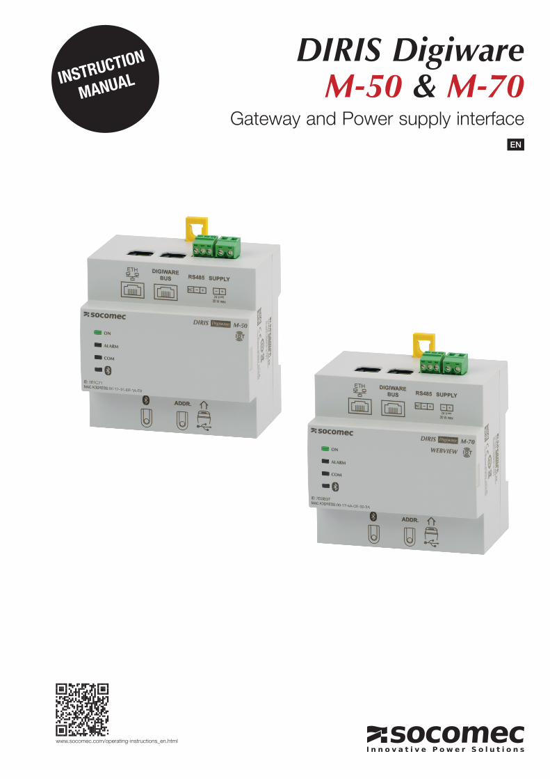
DIRIS Digiware M-50 & M-70
Gateway and Power supply interface
INSTRUCTION
MANUAL
EN
www.socomec.com/operating-instructions_en.html
2 EN DIRIS Digiware M-50 & M-70 - 548751B - SOCOMEC
1. DOCUMENTATION . . . . . . . . . . . . . . . . . . . . . . . . . . . . . . . . . . . . . . . . . . . . . . . . . . . . . . . 4
2. HAZARDS AND WARNINGS . . . . . . . . . . . . . . . . . . . . . . . . . . . . . . . . . . . . . . . . . . . . . . . 52.1. Risk of electrocution, burns or explosion . . . . . . . . . . . . . . . . . . . . . . . . . . . . 52.2. Risk of damaging the device . . . . . . . . . . . . . . . . . . . . . . . . . . . . . . . . . . . . . . 52.3. Responsibility . . . . . . . . . . . . . . . . . . . . . . . . . . . . . . . . . . . . . . . . . . . . . . . . . . 6
3. PRELIMINARY OPERATIONS . . . . . . . . . . . . . . . . . . . . . . . . . . . . . . . . . . . . . . . . . . . . . . 7
4. CYBER SECURITY RECOMMENDATIONS AND BEST PRACTICES* . . . . . . . . . . . . . . . 8
5. INTRODUCTION . . . . . . . . . . . . . . . . . . . . . . . . . . . . . . . . . . . . . . . . . . . . . . . . . . . . . . . . 105.1. Range . . . . . . . . . . . . . . . . . . . . . . . . . . . . . . . . . . . . . . . . . . . . . . . . . . . . . . . 105.2. Introduction to DIRIS Digiware M . . . . . . . . . . . . . . . . . . . . . . . . . . . . . . . . . 11
5.2.1. Introduction to DIRIS Digiware M-50 . . . . . . . . . . . . . . . . . . . . . . . 115.2.2. Introduction to DIRIS Digiware M-70 . . . . . . . . . . . . . . . . . . . . . . . 12
5.3. Front LEDs . . . . . . . . . . . . . . . . . . . . . . . . . . . . . . . . . . . . . . . . . . . . . . . . . . . 135.4. Dimensions (in/mm) . . . . . . . . . . . . . . . . . . . . . . . . . . . . . . . . . . . . . . . . . . . . 14
6. MOUNTING . . . . . . . . . . . . . . . . . . . . . . . . . . . . . . . . . . . . . . . . . . . . . . . . . . . . . . . . . . . 146.1. Recommendations and safety . . . . . . . . . . . . . . . . . . . . . . . . . . . . . . . . . . . . 146.2. DIN rail mounting . . . . . . . . . . . . . . . . . . . . . . . . . . . . . . . . . . . . . . . . . . . . . . 14
7. SYSTEM WIRING . . . . . . . . . . . . . . . . . . . . . . . . . . . . . . . . . . . . . . . . . . . . . . . . . . . . . . . 157.1. Communication architectures . . . . . . . . . . . . . . . . . . . . . . . . . . . . . . . . . . . . 167.2. DIRIS Digiware M-50/M-70 - wiring . . . . . . . . . . . . . . . . . . . . . . . . . . . . . . . . 16
7.2.1. RS485 Master . . . . . . . . . . . . . . . . . . . . . . . . . . . . . . . . . . . . . . . . 167.2.2. RS485 Slave . . . . . . . . . . . . . . . . . . . . . . . . . . . . . . . . . . . . . . . . . 16
8. BLUETOOTH LOW ENERGY . . . . . . . . . . . . . . . . . . . . . . . . . . . . . . . . . . . . . . . . . . . . . . 16
9. AUTOMATIC DETECTION OF DEVICES . . . . . . . . . . . . . . . . . . . . . . . . . . . . . . . . . . . . . 17
10. WEBSERVER EMBEDDED IN THE M-50/M-70 GATEWAYS . . . . . . . . . . . . . . . . . . . . 1910.1. User profiles . . . . . . . . . . . . . . . . . . . . . . . . . . . . . . . . . . . . . . . . . . . . . . . . . 1910.2. Admin profile . . . . . . . . . . . . . . . . . . . . . . . . . . . . . . . . . . . . . . . . . . . . . . . . 21
10.2.1. “Devices” tab . . . . . . . . . . . . . . . . . . . . . . . . . . . . . . . . . . . . . . . 2210.2.2. “Protocols” tab . . . . . . . . . . . . . . . . . . . . . . . . . . . . . . . . . . . . . . 24
10.3. Cyber security profile . . . . . . . . . . . . . . . . . . . . . . . . . . . . . . . . . . . . . . . . . . 2810.3.1. Cyber security menu . . . . . . . . . . . . . . . . . . . . . . . . . . . . . . . . . . 2810.3.2. “Security Policy” tab . . . . . . . . . . . . . . . . . . . . . . . . . . . . . . . . . . 2910.3.3. “HTTPS” tab . . . . . . . . . . . . . . . . . . . . . . . . . . . . . . . . . . . . . . . . 3010.3.4. CAs (FTPS/SMTPS) tab . . . . . . . . . . . . . . . . . . . . . . . . . . . . . . . 3010.3.5. “Firewall” tab . . . . . . . . . . . . . . . . . . . . . . . . . . . . . . . . . . . . . . . . 3110.3.6. Upgrading the firmware of the M-50/M-70 gateway . . . . . . . . . . 31
10.4. WEBVIEW-M . . . . . . . . . . . . . . . . . . . . . . . . . . . . . . . . . . . . . . . . . . . . . . . . 33
11. CONFIGURATION VIA EASY CONFIG SYSTEM . . . . . . . . . . . . . . . . . . . . . . . . . . . . . . 3411.1. USB connection mode . . . . . . . . . . . . . . . . . . . . . . . . . . . . . . . . . . . . . . . . . 3411.2. Ethernet connection mode . . . . . . . . . . . . . . . . . . . . . . . . . . . . . . . . . . . . . . 36
12. ALARMS . . . . . . . . . . . . . . . . . . . . . . . . . . . . . . . . . . . . . . . . . . . . . . . . . . . . . . . . . . . . . 38
13. 10-STEP COMMISSIONING CHECKLIST FOR YOUR DIGIWARE SYSTEM . . . . . . . . 39
14. DIRIS DIGIWARE M-50/M-70 TECHNICAL CHARACTERISTICS . . . . . . . . . . . . . . . . 4014.1. Mechanical characteristics . . . . . . . . . . . . . . . . . . . . . . . . . . . . . . . . . . . . . . 4014.2. Communication characteristics . . . . . . . . . . . . . . . . . . . . . . . . . . . . . . . . . . 4014.3. Electrical characteristics . . . . . . . . . . . . . . . . . . . . . . . . . . . . . . . . . . . . . . . 4014.4. Environmental characteristics . . . . . . . . . . . . . . . . . . . . . . . . . . . . . . . . . . . 4114.5. EMC characteristics . . . . . . . . . . . . . . . . . . . . . . . . . . . . . . . . . . . . . . . . . . . 41
EN CONTENTS
3ENDIRIS Digiware M-50 & M-70 - 548751B - SOCOMEC
15. ANNEX A SNMP COMMUNICATION WITH THE DIRIS DIGIWARE M-50 / M-70 . . . . . . . . . . . . . . . 42
15.1. SNMP generalities . . . . . . . . . . . . . . . . . . . . . . . . . . . . . . . . . . . . . . . . . . . . 4215.2. SNMP functions supported . . . . . . . . . . . . . . . . . . . . . . . . . . . . . . . . . . . . . 4215.3. SNMP versions supported . . . . . . . . . . . . . . . . . . . . . . . . . . . . . . . . . . . . . . 4315.4. SNMP ports . . . . . . . . . . . . . . . . . . . . . . . . . . . . . . . . . . . . . . . . . . . . . . . . . 4415.5. Retrieving data using the DIRIS Digiware M-50 / M-70 MIB file . . . . . . . . . 4415.6. SNMP configuration via EasyConfig System . . . . . . . . . . . . . . . . . . . . . . . . 4615.7. SNMP configuration via the embedded webserver . . . . . . . . . . . . . . . . . . . 47
16. ANNEX B BACNET COMMUNICATION WITH THE DIRIS DIGIWARE M-50 / M-70 . . . . . . . . . . . . . 48
16.1. BACnet Generalities . . . . . . . . . . . . . . . . . . . . . . . . . . . . . . . . . . . . . . . . . . . 4816.2. BACnet Objects . . . . . . . . . . . . . . . . . . . . . . . . . . . . . . . . . . . . . . . . . . . . . . 4816.3. BACnet Services . . . . . . . . . . . . . . . . . . . . . . . . . . . . . . . . . . . . . . . . . . . . . 5416.4. BACnet IP configuration via Easyconfig System . . . . . . . . . . . . . . . . . . . . . 5416.5. BACnet configuration from the embedded webserver . . . . . . . . . . . . . . . . 55
17. ANNEX C FTP CONFIGURATION . . . . . . . . . . . . . . . . . . . . . . . . . . . . . . . . . . . . . . . . . . . . . . . . . . . . . 56
17.1. FTP server activation:. . . . . . . . . . . . . . . . . . . . . . . . . . . . . . . . . . . . . . . . . . 5617.2. FTP planning configuration . . . . . . . . . . . . . . . . . . . . . . . . . . . . . . . . . . . . . 5817.3. Understanding the exported .csv file in EMS mode . . . . . . . . . . . . . . . . . . 59

4 EN DIRIS Digiware M-50 & M-70 - 548751B - SOCOMEC
1. DOCUMENTATIONAll documentation on DIRIS Digiware M-50 and M-70 is available on the SOCOMEC website:www.socomec.com/operating-instructions_en.html
5ENDIRIS Digiware M-50 & M-70 - 548751B - SOCOMEC
2. HAZARDS AND WARNINGS
The term "device" used in this document covers both DIRIS Digiware M-50 and M-70. The assembly, use, servicing and maintenance of this equipment must only be carried out by trained, qualified professionals.
SOCOMEC shall not be held responsible for failure to comply with the instructions in this manual.
2.1. Risk of electrocution, burns or explosion
Caution: risk of electric shock Ref. ISO 7000-0434B (2004-01)
Caution: refer to the accompanying documentation each time this symbol is shown
Ref. ISO 7000-0434B (2004-01)
• Only duly authorised and qualified personnel may work or install/uninstall the device.
• The instructions are valid together with the specific instructions for the device.
• The device is designed only for its intended purpose as set out in the instructions.
• Only accessories authorised or recommended by SOCOMEC may be used in association with the device.
• Before proceeding with installation, maintenance, cleaning, disassembly, connection, or maintenance work, the device and system must be cut off from the mains to avoid electrocution and damaging the system and device.
• This device is not designed to be repaired by the user.
• For any questions related to the disposal of the device, please contact SOCOMEC.
Do NOT clamp or pull out NON-INSULATED conductors carrying DANGEROUS VOLTAGE which could cause an electric shock, burn or arc flash.Ref. IEC 61010-2-032
Failure to comply with the instructions of the device and this safety information can cause bodily injury, electric shock, burns, death or damage to property.
2.2. Risk of damaging the device
Caution: risk of electric shock Ref. ISO 7000-0434B (2004-01)
Caution: refer to the accompanying documentation each time this symbol is shown
Ref. ISO 7010-W001 (2011-05)
To ensure that the device operates correctly, make sure that:
• The device is correctly installed.
• The auxiliary power supply voltage indicated on the device is observed: 24 VDC ± 10%.
• A SOCOMEC 230 VAC / 24 VDC power supply unit (P15 ref. 4829 0120) or a 24 VDC max 20 W class 2 power supply unit / SELV is used.
• If a SOCOMEC power supply is not used, the device must be protected with a 1 A / 24 VDC fuse.
• Only use RJ45 SOCOMEC cables to interconnect the modules via the Digiware bus. When the ambient temperature exceeds +50°C, the minimum temperature rating of the copper cable to be connected to terminal must be +85°C.
• The device must not be cleaned.
• The device must not be installed outdoor.
Failure to respect these precautions could cause damage to the device.

6 EN DIRIS Digiware M-50 & M-70 - 548751B - SOCOMEC
2.3. Responsibility• Assembly, connection and use must be carried out in accordance with the installation standards currently in force.
• The device must be installed in accordance with the rules given in this manual.
• Failure to observe the rules for installing this unit may compromise the device’s intrinsic protection.
• The device must be placed in a system which itself complies with the applicable standards and safety regulations of the country of installation.
• Any cable which needs to be replaced may only be replaced with a cable having the correct rating.
• Despite constantly striving for quality in preparing this manual, errors or omissions are always a possibility and are not the responsibility of SOCOMEC.
7ENDIRIS Digiware M-50 & M-70 - 548751B - SOCOMEC
3. PRELIMINARY OPERATIONS
To ensure the safety of personnel and the product, please carefully read the contents of these instructions before installation.
Check the following points as soon as you receive the package containing the device:
• The packaging is in good condition.
• The device has not been damaged during transportation.
• The device reference number conforms to your order.
• The packaging includes the device fitted with removable terminal blocks and a Quick start guide.
8 EN DIRIS Digiware M-50 & M-70 - 548751B - SOCOMEC
4. CYBER SECURITY RECOMMENDATIONS AND BEST PRACTICES*
The DIRIS Digiware M-50/M-70, as any device connected to a user’s Ethernet network, must be protected against any risk of cyber-attack or data loss/destruction.
(*) Our M-50/M-70 gateways provide certain cyber security features to prevent these attacks and to help users in their responsibility to implement and guarantee adequate IT protection. Some recommendations are listed in the following paragraphs. Make sure they are in line with your IT security policy:
• Awareness of the security policy: Users and administrators of DIRIS Digiware M-xx gateways and WEBVIEW-M must be aware of and trained in proper IT security practice (information and compliance with corporate security policy, authentication procedure management and password safety, online session management, risks of fishing…).
• Network security: The IT system architecture must be able to safeguard resources, by segmenting the network according to their degree of sensitivity and using a variety of protective devices (firewall, demilitarised zone, VLAN, network anti-virus etc.).
How DIRIS Digiware M-50/M-70 gateways can help:
By forcing the user to use secure versions of standard communication protocols:
- FTPS: secure export of data - SMTPS: secure email notification in case of alarms - SNMPv3: secure version of the SNMP communication protocol - HTTPS: secure webserver navigation (WEBVIEW-M) by uploading TLS/SSL certificates
> Refer to paragraph 10.3.2 & 10.3.3 for more information on how to upload digital certificates.
With their firewall, to monitor and control incoming/outgoing traffic: this protects the DIRIS Digiware M-50/M-70 gateways in case of denial-of-service (flooding) attacks, in order to guarantee service continuity of the gateway.
> Refer to paragraph 10.3.4 for more information on how to configure the firewall protection.
• Device security: Device security depends on its network environment, but also user behaviour. In terms of the environment, elementary protective measures (filtering authorised stations by MAC address, opening service ports, selecting authorised applications etc.) are highly recommended. Greater precaution is required on managing removable media (external hard drive, USB flash drive, wireless communication provision etc.). Finally, in terms of a server like the DIRIS Digiware M-50/M-70, it should be protected by controlling and limiting physical access to the rooms and cabinets hosting the device.
How DIRIS Digiware M-50/M-70 gateways can help:
DIRIS Digiware M-50/M-70 gateways reduce the attack exposure by blocking or restraining the access to certain peripherals and services that are not essential to the customer use case.
> Refer to paragraph 10.3.1 for more information on how to configure your gateway’s security policy.
Moreover, the firmware and webserver applications are signed with an asymmetrical key to make sure any firmware upgrade uses the correct matching signature to allow the device to be upgraded. This prevents the diversion of the device from its intended use by Socomec (by uploading a dummy firmware for instance) and guarantees that the firmware stays without virus over time.
9ENDIRIS Digiware M-50 & M-70 - 548751B - SOCOMEC
• Data security: Data security covers several aspects, in particular the confidentiality, integrity, authenticity and availability of data. Special care is required with data security and archiving procedures on backup devices both inside and outside the company.
How DIRIS Digiware M-50/M-70 gateways can help:
It is possible to export data such as energy indexes, load curves and historical measurement (Trends), both manually or automatically for back-up.
It is also possible to save the topology (mapping of slaves connected to the M-50/M-70 gateway) from the embedded webserver and configuration file from Easy Config software.
Confidentiality is addressed by providing 256-bit AES encryption (AES 256) for personal data such as passwords along with product. This means it would take 2256 combinations to break the encryption key.
• Access and authentication management: Managing access to resources and data is a crucial element of the IT system’s security policy. Each user requires an account and access rights corresponding to their profile. Access to the IT system’s resources is controlled by a user authentication process, based on a minimum of a high-security username and password. The password management procedure, specifying the systematic modification of default passwords and their validity period, is included in the IT security policy.
How DIRIS Digiware M-50/M-70 gateways can help:
Multiple profiles are available to access the web application. The highest profile is “Cybersecurity”, which allows you to manage users’ access to the web application based on what is relevant for them.
Profiles are password protected. Certain measures are taken into account in Socomec M-50/M-70 gateways to reduce the risk of password theft:
- Encryption of credentials
- Password must meet minimum security requirements (minimum 10 characters, including at least one upper case, one lower case, one number and a special character).
- Password must be changed at least once a year.
- After 3 failed log-in attempts, account is locked for 1 hour.
- Passphrase for password recovery in case password is lost.
> Refer to paragraph 10.1 for more information regarding the different profiles and their password protection.
10 EN DIRIS Digiware M-50 & M-70 - 548751B - SOCOMEC
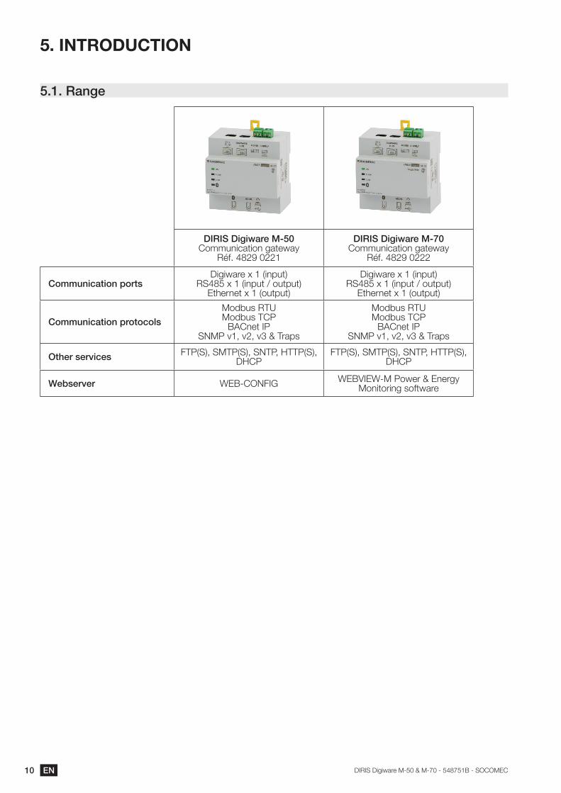
5. INTRODUCTION
5.1. Range
DIRIS Digiware M-50Communication gateway
Réf. 4829 0221
DIRIS Digiware M-70Communication gateway
Réf. 4829 0222
Communication portsDigiware x 1 (input)
RS485 x 1 (input / output)Ethernet x 1 (output)
Digiware x 1 (input)RS485 x 1 (input / output)
Ethernet x 1 (output)
Communication protocols
Modbus RTUModbus TCP
BACnet IPSNMP v1, v2, v3 & Traps
Modbus RTUModbus TCP
BACnet IPSNMP v1, v2, v3 & Traps
Other services FTP(S), SMTP(S), SNTP, HTTP(S), DHCP
FTP(S), SMTP(S), SNTP, HTTP(S), DHCP
Webserver WEB-CONFIG WEBVIEW-M Power & Energy Monitoring software
11ENDIRIS Digiware M-50 & M-70 - 548751B - SOCOMEC
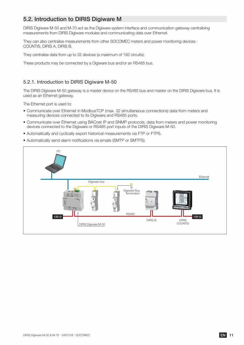
5.2. Introduction to DIRIS Digiware MDIRIS Digiware M-50 and M-70 act as the Digiware system interface and communication gateway centralising measurements from DIRIS Digiware modules and communicating data over Ethernet.
They can also centralise measurements from other SOCOMEC meters and power monitoring devices : COUNTIS, DIRIS A, DIRIS B.
They centralise data from up to 32 devices (a maximum of 192 circuits).
These products may be connected by a Digiware bus and/or an RS485 bus.
5.2.1. Introduction to DIRIS Digiware M-50
The DIRIS Digiware M-50 gateway is a master device on the RS485 bus and master on the DIRIS Digiware bus. It is used as an Ethernet gateway.
The Ethernet port is used to:
• Communicate over Ethernet in ModbusTCP (max. 32 simultaneous connections) data from meters and measuring devices connected to its Digiware and RS485 ports.
• Communicate over Ethernet using BACnet IP and SNMP protocols, data from meters and power monitoring devices connected to the Digiware or RS485 port inputs of the DIRIS Digiware M-50.
• Automatically and cyclically export historical measurements via FTP or FTPS.
• Automatically send alarm notifications via emails (SMTP or SMTPS).
Digiware Bus Termination
Digiware bus
DIRIS Digiware M-50
PC
120 Ω 120 ΩRS485
Ethernet
DIRIS B DIRISCOUNTIS
12 EN DIRIS Digiware M-50 & M-70 - 548751B - SOCOMEC
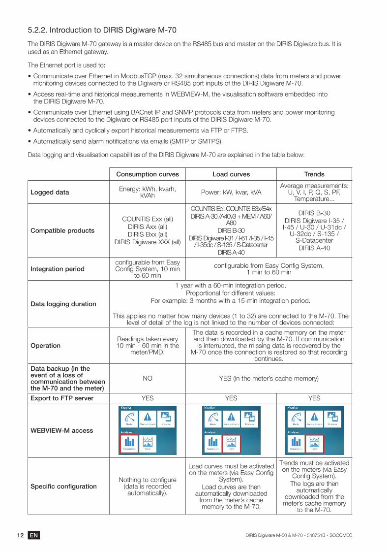
5.2.2. Introduction to DIRIS Digiware M-70
The DIRIS Digiware M-70 gateway is a master device on the RS485 bus and master on the DIRIS Digiware bus. It is used as an Ethernet gateway.
The Ethernet port is used to:
• Communicate over Ethernet in ModbusTCP (max. 32 simultaneous connections) data from meters and power monitoring devices connected to the Digiware or RS485 port inputs of the DIRIS Digiware M-70.
• Access real-time and historical measurements in WEBVIEW-M, the visualisation solftware embedded into the DIRIS Digiware M-70.
• Communicate over Ethernet using BACnet IP and SNMP protocols data from meters and power monitoring devices connected to the Digiware or RS485 port inputs of the DIRIS Digiware M-70.
• Automatically and cyclically export historical measurements via FTP or FTPS.
• Automatically send alarm notifications via emails (SMTP or SMTPS).
Data logging and visualisation capabilities of the DIRIS Digiware M-70 are explained in the table below:
Consumption curves Load curves Trends
Logged data Energy: kWh, kvarh, kVAh Power: kW, kvar, kVA
Average measurements: U, V, I, P, Q, S, PF,
Temperature...
Compatible products
COUNTIS Exx (all)DIRIS Axx (all)DIRIS Bxx (all)
DIRIS Digiware XXX (all)
COUNTIS Eci, COUNTIS E3x/E4xDIRIS A-30 /A40v3 + MEM / A60/
A80DIRIS B-30
DIRIS Digiware I-31 / I-61 /I-35 / I-45 / I-35dc / S-135 / S-Datacenter
DIRIS A-40
DIRIS B-30DIRIS Digiware I-35 /
I-45 / U-30 / U-31dc / U-32dc / S-135 /
S-DatacenterDIRIS A-40
Integration periodconfigurable from Easy Config System, 10 min
to 60 min
configurable from Easy Config System, 1 min to 60 min
Data logging duration
1 year with a 60-min integration period.Proportional for different values:
For example: 3 months with a 15-min integration period.
This applies no matter how many devices (1 to 32) are connected to the M-70. The level of detail of the log is not linked to the number of devices connected:
OperationReadings taken every 10 min - 60 min in the
meter/PMD.
The data is recorded in a cache memory on the meter and then downloaded by the M-70. If communication
is interrupted, the missing data is recovered by the M-70 once the connection is restored so that recording
continues.
Data backup (in the event of a loss of communication between the M-70 and the meter)
NO YES (in the meter’s cache memory)
Export to FTP server YES YES YES
WEBVIEW-M access
Specific configurationNothing to configure
(data is recorded automatically).
Load curves must be activated on the meters (via Easy Config
System).Load curves are then
automatically downloaded from the meter’s cache memory to the M-70.
Trends must be activated on the meters (via Easy
Config System).The logs are then
automatically downloaded from the
meter’s cache memory to the M-70.
13ENDIRIS Digiware M-50 & M-70 - 548751B - SOCOMEC
Digiware Bus Termination
Digiware bus
DIRIS Digiware M-70
PC
120 Ω 120 ΩRS485
Ethernet
DIRIS B DIRISCOUNTIS
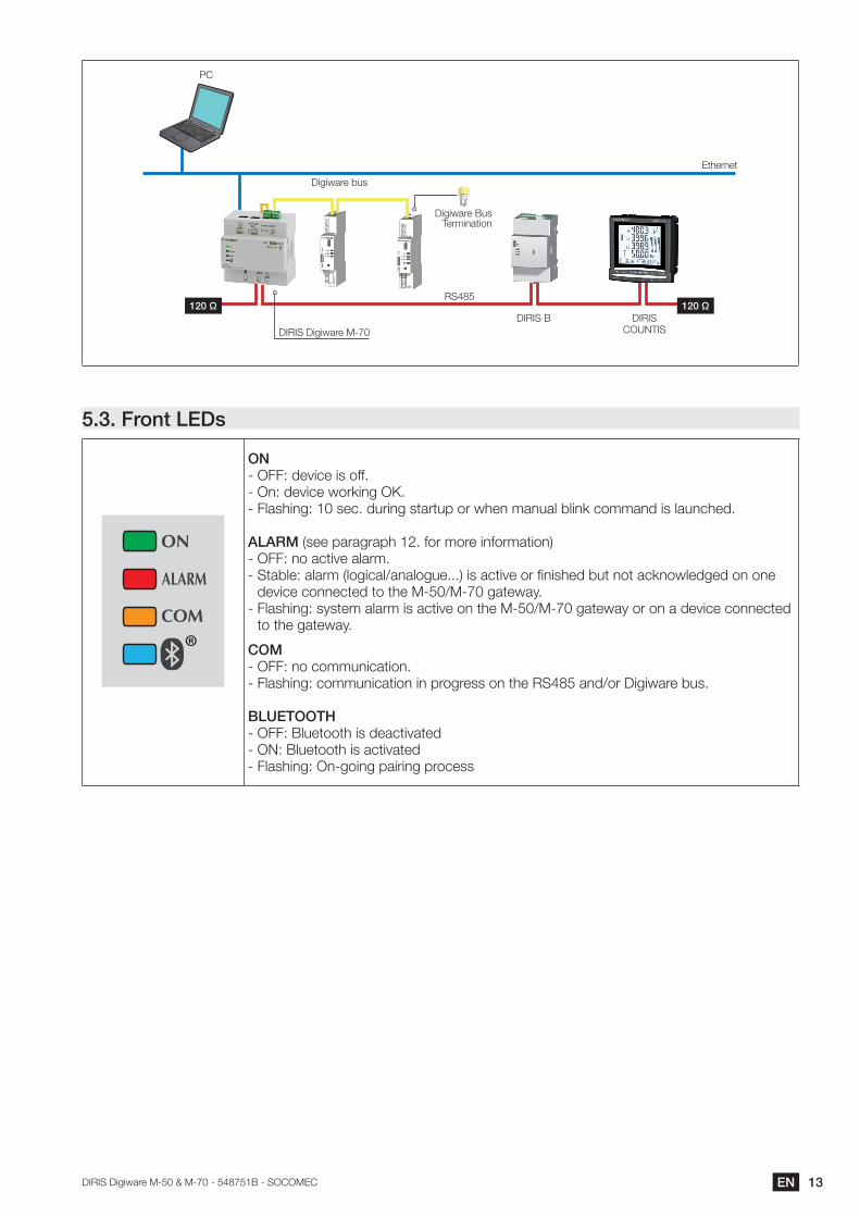
5.3. Front LEDs
ON - OFF: device is off.- On: device working OK.- Flashing: 10 sec. during startup or when manual blink command is launched.
ALARM (see paragraph 12. for more information)- OFF: no active alarm.- Stable: alarm (logical/analogue...) is active or finished but not acknowledged on one
device connected to the M-50/M-70 gateway.- Flashing: system alarm is active on the M-50/M-70 gateway or on a device connected
to the gateway.
COM- OFF: no communication. - Flashing: communication in progress on the RS485 and/or Digiware bus.
BLUETOOTH- OFF: Bluetooth is deactivated- ON: Bluetooth is activated- Flashing: On-going pairing process
14 EN DIRIS Digiware M-50 & M-70 - 548751B - SOCOMEC
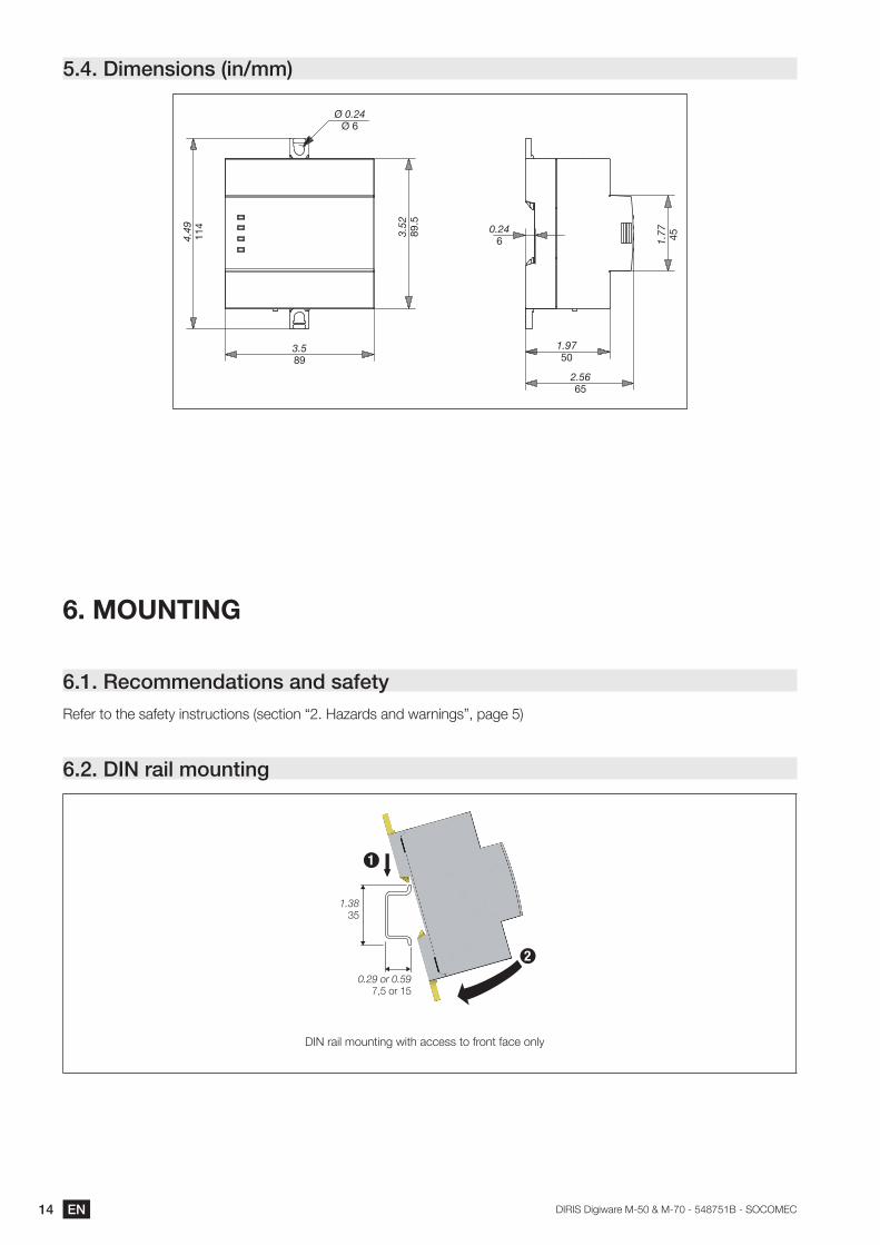
5.4. Dimensions (in/mm)
3.52
89.5
3.589
Ø 0.24Ø 6
0.246
1.9750
1.77 45
2.5665
4.49
114
6. MOUNTING
6.1. Recommendations and safetyRefer to the safety instructions (section “2. Hazards and warnings”, page 5)
6.2. DIN rail mounting
L
1
0.29 or 0.597,5 or 15
1.38 35
2
DIN rail mounting with access to front face only
15ENDIRIS Digiware M-50 & M-70 - 548751B - SOCOMEC
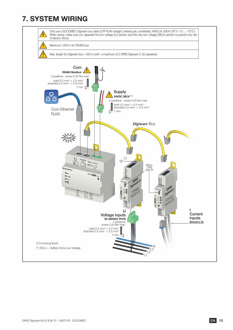
7. SYSTEM WIRING
Only use a SOCOMEC Digiware bus cable (UTP RJ45 straight, twisted pair, unshielded, AWG 24, 600V CAT V -10 ... +70°C).When wiring, make sure you separate the low voltage (LV) section and the very low voltage (SELV) section to prevent any risk of electric shock.
Maximum 1200 m for RS485 bus
Max. length for Digiware bus = 300 m (with a maximum of 2 DIRIS Digiware C-32 repeaters)
DIRIS
Digiware U
Voltage
Inputs (U) DIRIS
Digiware I
Current
Inputs (3I)
Digiware Bus
Com Ethernet RJ45
U Voltage inputs
50-300VAC PH/N
7 mm
solid 0.2 mm2-> 2.5 mm2
stranded 0.2 mm2 -> 2.5 mm2
4 positions screw 0.25 Nm max.
L1L2
L3N
7 mm
solid 0.2 mm2-> 2.5 mm2
stranded 0.2 mm2 -> 2.5 mm2
2 positions - screw 0.25 Nm max.
Supply24VDC SELV (**)
7 mm
solid 0.2 mm2-> 2.5 mm2
stranded 0.2 mm2 -> 2.5 mm2
3 positions - screw 0.25 Nm max.
ComRS485 Modbus
ICurrent inputs Sensors 3x
Micro USB
type B
(*)
(*) Functional Earth
(**) SELV = Saftety Extra Low Voltage
16 EN DIRIS Digiware M-50 & M-70 - 548751B - SOCOMEC
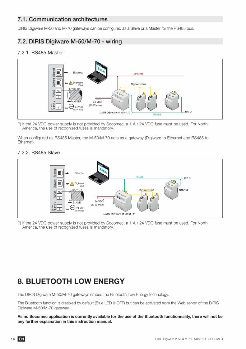
7.1. Communication architecturesDIRIS Digiware M-50 and M-70 gateways can be configured as a Slave or a Master for the RS485 bus.
7.2. DIRIS Digiware M-50/M-70 - wiring
7.2.1. RS485 Master
*24 VDC(20 W max)
ETHETH
ETHDIGIWAREBUS
24 V20 W max
SUPPLY
RS485NC
ADDR.
ALARM
ON
COM DIRIS M-xx
RS485 DIRIS Digiware M-50/M-70
Digiware Bus
Ethernet
120 Ω
NC
RS48
5Di
giw
are
LIYCY-CY
Ethernet
DigiwareBus
MASTER
24 VDC(20 W max)
Ethe
rnet
24 V
SUPP
LY
(*) If the 24 VDC power supply is not provided by Socomec, a 1 A / 24 VDC fuse must be used. For North America, the use of recognized fuses is mandatory.
When configured as RS485 Master, the M-50/M-70 acts as a gateway (Digiware to Ethernet and RS485 to Ethernet).
7.2.2. RS485 Slave
*24 VDC(20 W max)
RS485
DIRIS Digiware M-50/M-70
DIRIS BDigiware Bus
120 Ω
NC
RS48
5Di
giw
are
LIYCY-CY
Ethernet
DigiwareBus
SLAVE
24 VDC(20 W max)
Ethe
rnet
24 V
SUPP
LY
ETHETH
ETHDIGIWAREBUS
24 V20 W max
SUPPLY
RS485NC
ADDR.
ALARM
ON
COM DIRIS M-xx
(*) If the 24 VDC power supply is not provided by Socomec, a 1 A / 24 VDC fuse must be used. For North America, the use of recognized fuses is mandatory.
8. BLUETOOTH LOW ENERGY
The DIRIS Digiware M-50/M-70 gateways embed the Bluetooth Low Energy technology.
The Bluetooth function is disabled by default (Blue LED is OFF) but can be activated from the Web server of the DIRIS Digiware M-50/M-70 gateway.
As no Socomec application is currently available for the use of the Bluetooth functionnality, there will not be any further explanation in this instruction manual.
17ENDIRIS Digiware M-50 & M-70 - 548751B - SOCOMEC
9. AUTOMATIC DETECTION OF DEVICES
Once the system is fully wired and powered, you must launch the auto-discovery process by pressing the “ADDR.” button under the M-50/M-70 for 3 seconds.
The auto-discovery process will discover devices connected to the Digiware bus and RS485 bus and assign them with a unique Modbus address.
2 auto-discovery modes can be used:
- FAST (default mode): this mode will only detect DIRIS Digiware modules on the Digiware bus and RS485 bus, DIRIS B and DIRIS A-40 on the RS485 bus.
- FULL: this mode will also detect other Socomec PMDs (DIRIS A) and meters (COUNTIS E) connected on the RS485 bus.
The EasyConfig System software must be used if you wish to change the auto-discovery process mode to FULL.
If multiple devices have the same Modbus address (which is common as multiple modules and devices may come out with the same factory default settings), there will be an address conflict during the auto-discovery process which is perfectly normal. All devices with an addressing conflict will have a fixed COM LED.
To resolve address conflicts, press the front button of each module that has a fixed COM LED for at least 2 seconds.
Notes:
• The order you will use to press the push buttons on the modules will also determine the order for the Modbus addressing of those modules.
• The auto-discovery process can also be launched from the EasyConfig System software where you can choose an automatic resolution of conflicts, instead of having to press the front button on the modules.
If you would like to assign specific Modbus adresses to the devices connected to the M-50/M-70 gateway, their Modbus address must be manually changed using the EasyConfig System software, before launching the auto-discovery process.
18 EN DIRIS Digiware M-50 & M-70 - 548751B - SOCOMEC
4b 5b
3 3
Digiware Bus U-xx I-xx
1
ALARM
ON
COM
ADDR.
ETHETH
DIRIS M-xx
ETHDIGIWAREBUS
24 V20 W max
SUPPLYRS485
NC
ALARM
ON
COM
ADDR.
ETHETH
DIRIS M-xx
ETHDIGIWAREBUS
24 V20 W max
SUPPLYRS485
NC
ALARM
ON
COM
ADDR.
ETHETH
DIRIS M-xx
ETHDIGIWAREBUS
24 V20 W max
SUPPLYRS485
NC
ALARM
ON
COM
ADDR.
ETHETH
DIRIS M-xx
ETHDIGIWAREBUS
24 V20 W max
SUPPLYRS485
NC
2 2
Flashing LED Stable LED
Steps involved in the auto-discovery process:
Press 3 sec.
≤ 120 sec3
Press 3 sec. 4a Press
3 sec. 5a
6
1. Start the auto-discovery of all devices connected to the Digiware or RS485 buses, by pressing the ADDR. button for 3 seconds.
2. “COM” LEDs of all devices will start blinking synchronously during the process. If com LEDs are not blinking, there could be a configuration issue (inconsistent baudrate between M-xx gateway and slave device etc.).
3. After approximately 1 minute, some address conflicts have been detected, and the COM LED of the M-xx gateway as well as slave devices is lit and stable.
4a/5a. Press the front button on each slave device that has a fixed COM LED, for at least 2 seconds.
4b/5b. COM LEDs of the modules start blinking again.
6. COM LED of the M-xx gateway starts blinking again, and slave devices can now communicate with the M-xx gateway.
19ENDIRIS Digiware M-50 & M-70 - 548751B - SOCOMEC
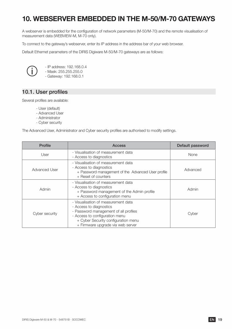
10. WEBSERVER EMBEDDED IN THE M-50/M-70 GATEWAYS
A webserver is embedded for the configuration of network parameters (M-50/M-70) and the remote visualisation of measurement data (WEBVIEW-M, M-70 only).
To connect to the gateway’s webserver, enter its IP address in the address bar of your web browser.
Default Ethernet parameters of the DIRIS Digiware M-50/M-70 gateways are as follows:
- IP address: 192.168.0.4 - Mask: 255.255.255.0 - Gateway: 192.168.0.1
10.1. User profilesSeveral profiles are available:
- User (default) - Advanced User - Administrator - Cyber security
The Advanced User, Administrator and Cyber security profiles are authorised to modify settings.
Profile Access Default password
User - Visualisation of measurement data- Access to diagnostics None
Advanced User
- Visualisation of measurement data- Access to diagnostics + Password management of the Advanced User profile + Reset of counters
Advanced
Admin
- Visualisation of measurement data- Access to diagnostics + Password management of the Admin profile + Access to configuration menu
Admin
Cyber security
- Visualisation of measurement data- Access to diagnostics- Password management of all profiles- Access to configuration menu + Cyber Security configuration menu + Firmware upgrade via web server
Cyber
20 EN DIRIS Digiware M-50 & M-70 - 548751B - SOCOMEC
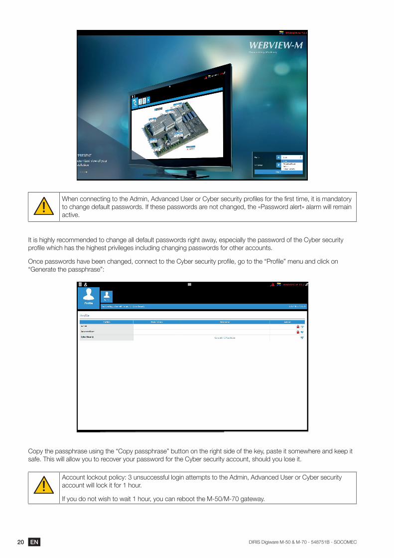
When connecting to the Admin, Advanced User or Cyber security profiles for the first time, it is mandatory to change default passwords. If these passwords are not changed, the «Password alert» alarm will remain active.
It is highly recommended to change all default passwords right away, especially the password of the Cyber security profile which has the highest privileges including changing passwords for other accounts.
Once passwords have been changed, connect to the Cyber security profile, go to the “Profile” menu and click on “Generate the passphrase”:
Copy the passphrase using the “Copy passphrase” button on the right side of the key, paste it somewhere and keep it safe. This will allow you to recover your password for the Cyber security account, should you lose it.
Account lockout policy: 3 unsuccessful login attempts to the Admin, Advanced User or Cyber security account will lock it for 1 hour.
If you do not wish to wait 1 hour, you can reboot the M-50/M-70 gateway.
21ENDIRIS Digiware M-50 & M-70 - 548751B - SOCOMEC
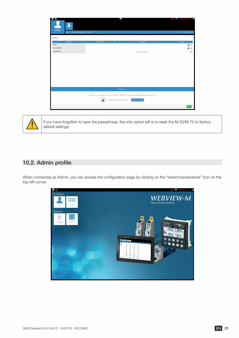
If you have forgotten to save the passphrase, the only option left is to reset the M-50/M-70 to factory default settings.
10.2. Admin profile
When connected as Admin, you can access the configuration page by clicking on the “wrench/screwdriver” icon on the top left corner:
22 EN DIRIS Digiware M-50 & M-70 - 548751B - SOCOMEC
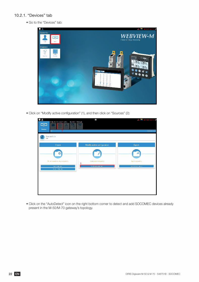
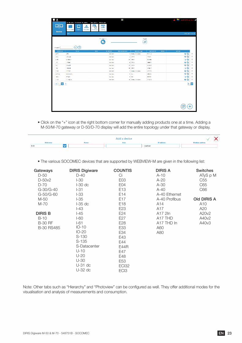
10.2.1. “Devices” tab
• Go to the “Devices” tab:
• Click on “Modify active configuration” (1), and then click on “Sources” (2):
1
2
• Click on the “AutoDetect” icon on the right bottom corner to detect and add SOCOMEC devices already present in the M-50/M-70 gateway’s topology.
23ENDIRIS Digiware M-50 & M-70 - 548751B - SOCOMEC
• Click on the “+” icon at the right bottom corner for manually adding products one at a time. Adding a M-50/M-70 gateway or D-50/D-70 display will add the entire topology under that gateway or display.
• The various SOCOMEC devices that are supported by WEBVIEW-M are given in the following list:
GatewaysD-50D-50v2D-70G-30/G-40G-50/G-60M-50M-70
DIRIS BB-10B-30 RFB-30 RS485
DIRIS DigiwareD-40I-30I-30 dcI-31I-33I-35I-35 dcI-43I-45I-60I-61 IO-10IO-20S-130S-135S-DatacenterU-10U-20U-30U-31 dcU-32 dc
COUNTISCiE03E04E13E14E17E18E23E24E27E28E33E34E43E44E44RE47E48E53ECI32ECI3
DIRIS AA-10A-20A-30A-40A-40 EthernetA-40 ProfibusA14A17A17 2InA17 THDA17 THD InA60A80
SwitchesATyS p MC55C65C66
Old DIRIS AA10A20A20v2A40v2A40v3
Note: Other tabs such as “Hierarchy” and “Photoview” can be configured as well. They offer additional modes for the visualisation and analysis of measurements and consumption.
24 EN DIRIS Digiware M-50 & M-70 - 548751B - SOCOMEC
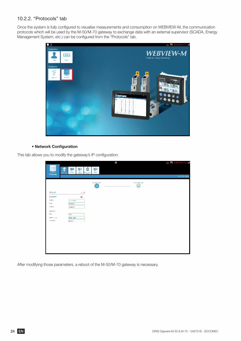
10.2.2. “Protocols” tab
Once the system is fully configured to visualise measurements and consumption on WEBVIEW-M, the communication protocols which will be used by the M-50/M-70 gateway to exchange data with an external supervisor (SCADA, Energy Management System, etc.) can be configured from the “Protocols” tab.
•NetworkConfiguration
This tab allows you to modify the gateway’s IP configuration:
After modifying those parameters, a reboot of the M-50/M-70 gateway is necessary.
25ENDIRIS Digiware M-50 & M-70 - 548751B - SOCOMEC
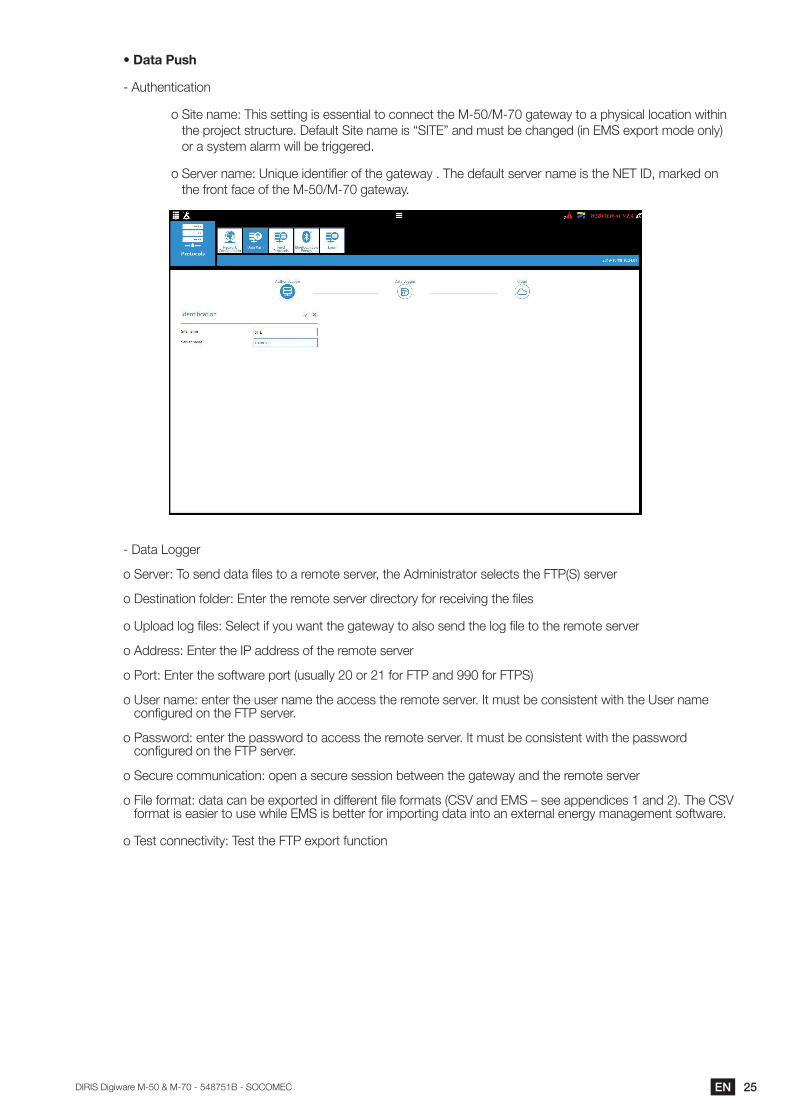
• Data Push
- Authentication
o Site name: This setting is essential to connect the M-50/M-70 gateway to a physical location within the project structure. Default Site name is “SITE” and must be changed (in EMS export mode only) or a system alarm will be triggered.
o Server name: Unique identifier of the gateway . The default server name is the NET ID, marked on the front face of the M-50/M-70 gateway.
- Data Logger
o Server: To send data files to a remote server, the Administrator selects the FTP(S) server
o Destination folder: Enter the remote server directory for receiving the files
o Upload log files: Select if you want the gateway to also send the log file to the remote server
o Address: Enter the IP address of the remote server
o Port: Enter the software port (usually 20 or 21 for FTP and 990 for FTPS)
o User name: enter the user name the access the remote server. It must be consistent with the User name configured on the FTP server.
o Password: enter the password to access the remote server. It must be consistent with the password configured on the FTP server.
o Secure communication: open a secure session between the gateway and the remote server
o File format: data can be exported in different file formats (CSV and EMS – see appendices 1 and 2). The CSV format is easier to use while EMS is better for importing data into an external energy management software.
o Test connectivity: Test the FTP export function
26 EN DIRIS Digiware M-50 & M-70 - 548751B - SOCOMEC
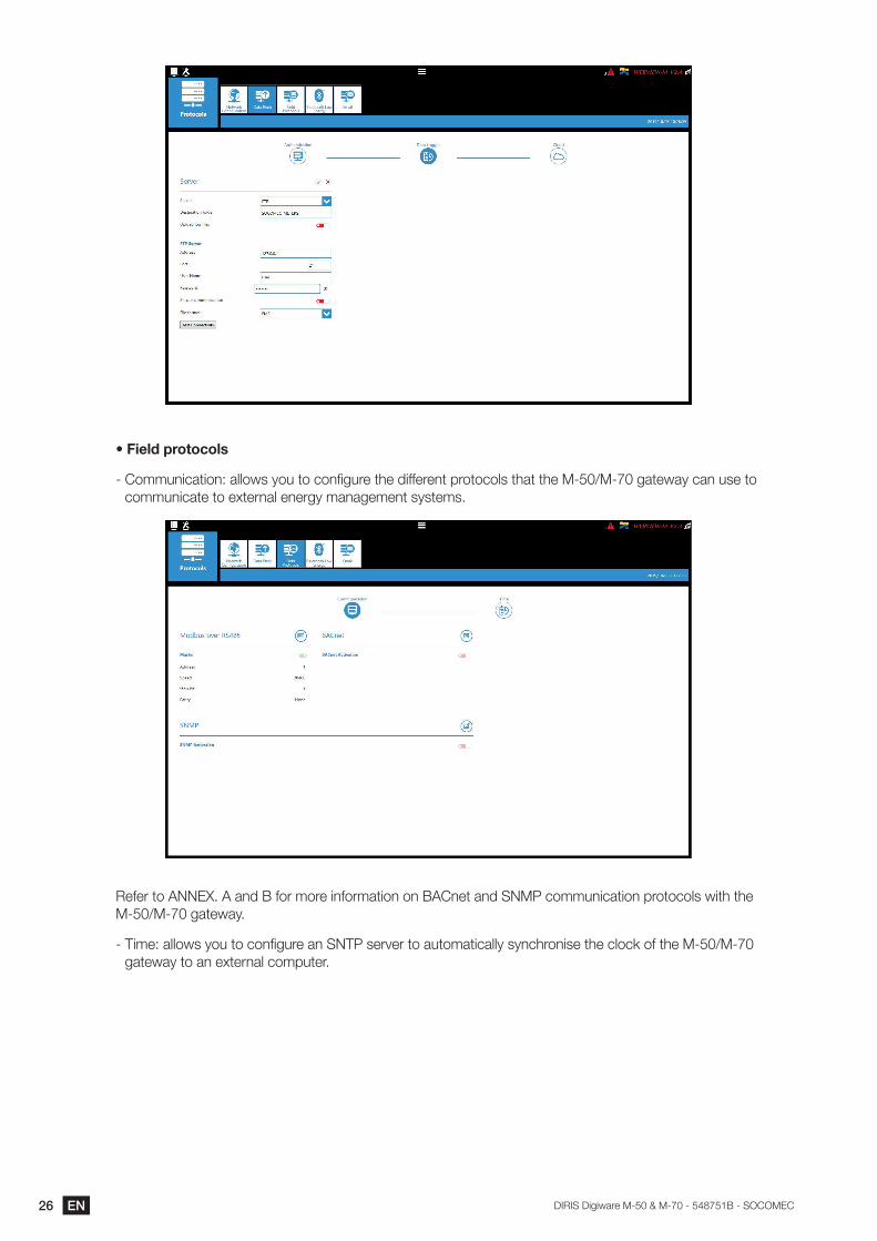
• Field protocols
- Communication: allows you to configure the different protocols that the M-50/M-70 gateway can use to communicate to external energy management systems.
Refer to ANNEX. A and B for more information on BACnet and SNMP communication protocols with the M-50/M-70 gateway.
- Time: allows you to configure an SNTP server to automatically synchronise the clock of the M-50/M-70 gateway to an external computer.
27ENDIRIS Digiware M-50 & M-70 - 548751B - SOCOMEC
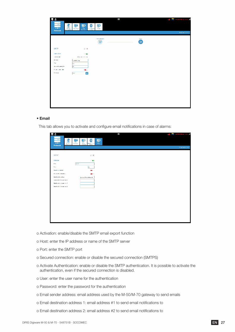
This tab allows you to activate and configure email notifications in case of alarms:
o Activation: enable/disable the SMTP email export function
o Host: enter the IP address or name of the SMTP server
o Port: enter the SMTP port
o Secured connection: enable or disable the secured connection (SMTPS)
o Activate Authentication: enable or disable the SMTP authentication. It is possible to activate the authentication, even if the secured connection is disabled.
o User: enter the user name for the authentication
o Password: enter the password for the authentication
o Email sender address: email address used by the M-50/M-70 gateway to send emails
o Email destination address 1: email address #1 to send email notifications to
o Email destination address 2: email address #2 to send email notifications to
28 EN DIRIS Digiware M-50 & M-70 - 548751B - SOCOMEC
o Email destination address 3: email address #2 to send email notifications to
o Language: language in which emails are sent
o Criticality of alarms to send: choose to send “information” or “Non critical” or “Critical” alarms
o Maximum waiting time: Time to wait to receive the email notification after the alarm is triggered on a device. This allows to limit the number of emails sent by the M-50/M-70 gateway, especially when the alarm repeatedly changes state.
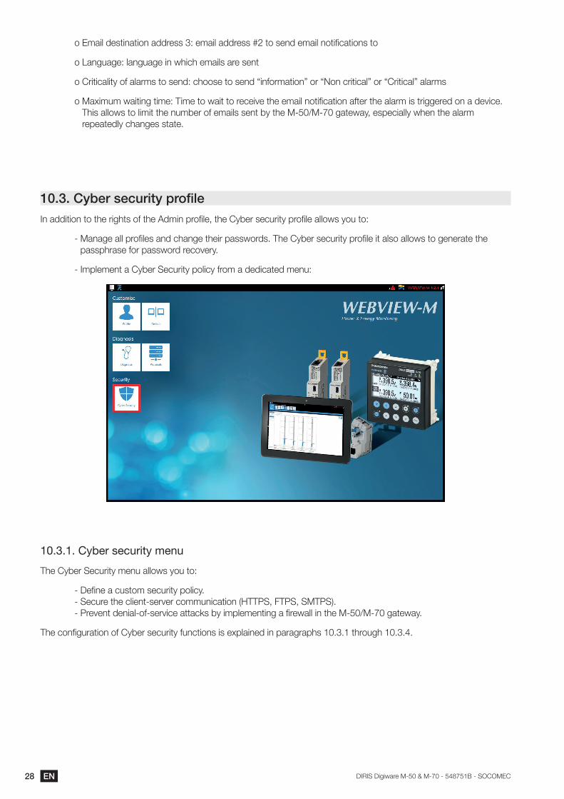
10.3. Cyber security profileIn addition to the rights of the Admin profile, the Cyber security profile allows you to:
- Manage all profiles and change their passwords. The Cyber security profile it also allows to generate the passphrase for password recovery.
- Implement a Cyber Security policy from a dedicated menu:
10.3.1. Cyber security menu
The Cyber Security menu allows you to:
- Define a custom security policy. - Secure the client-server communication (HTTPS, FTPS, SMTPS). - Prevent denial-of-service attacks by implementing a firewall in the M-50/M-70 gateway.
The configuration of Cyber security functions is explained in paragraphs 10.3.1 through 10.3.4.
29ENDIRIS Digiware M-50 & M-70 - 548751B - SOCOMEC
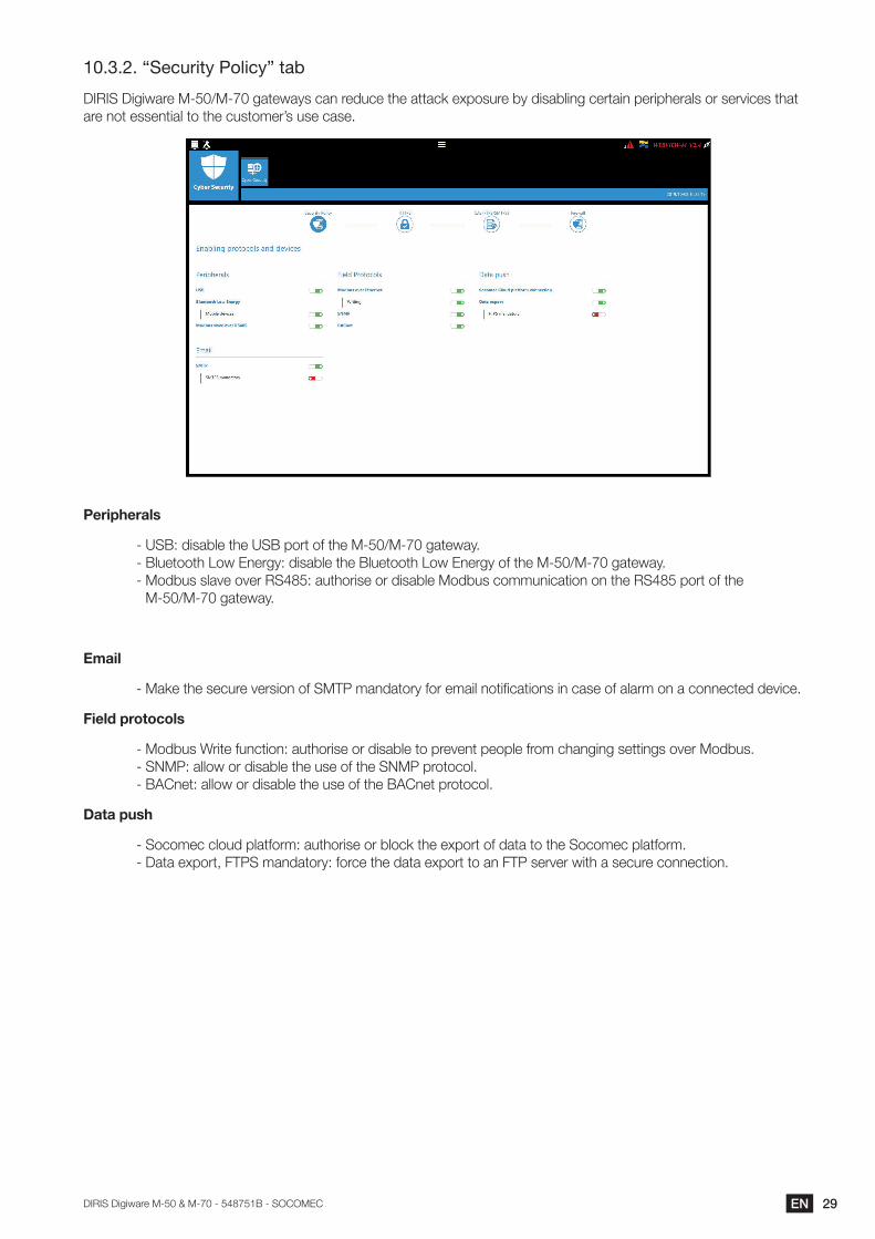
10.3.2. “Security Policy” tab
DIRIS Digiware M-50/M-70 gateways can reduce the attack exposure by disabling certain peripherals or services that are not essential to the customer’s use case.
Peripherals
- USB: disable the USB port of the M-50/M-70 gateway. - Bluetooth Low Energy: disable the Bluetooth Low Energy of the M-50/M-70 gateway. - Modbus slave over RS485: authorise or disable Modbus communication on the RS485 port of the
M-50/M-70 gateway.
- Make the secure version of SMTP mandatory for email notifications in case of alarm on a connected device.
Field protocols
- Modbus Write function: authorise or disable to prevent people from changing settings over Modbus. - SNMP: allow or disable the use of the SNMP protocol. - BACnet: allow or disable the use of the BACnet protocol.
Data push
- Socomec cloud platform: authorise or block the export of data to the Socomec platform. - Data export, FTPS mandatory: force the data export to an FTP server with a secure connection.
30 EN DIRIS Digiware M-50 & M-70 - 548751B - SOCOMEC
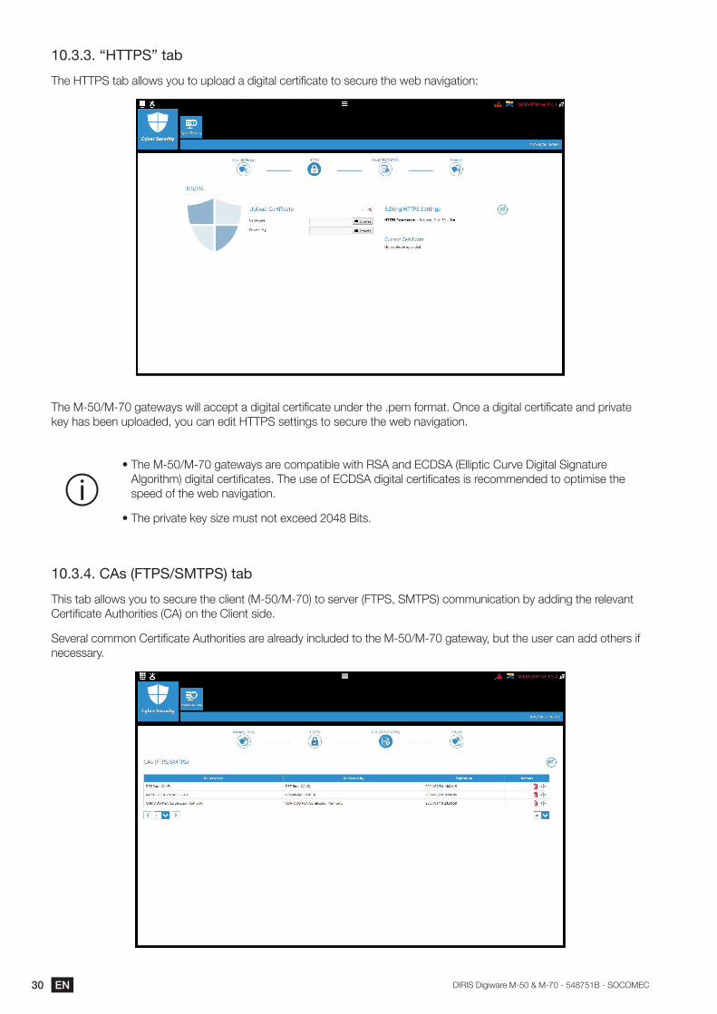
10.3.3. “HTTPS” tab
The HTTPS tab allows you to upload a digital certificate to secure the web navigation:
The M-50/M-70 gateways will accept a digital certificate under the .pem format. Once a digital certificate and private key has been uploaded, you can edit HTTPS settings to secure the web navigation.
• The M-50/M-70 gateways are compatible with RSA and ECDSA (Elliptic Curve Digital Signature Algorithm) digital certificates. The use of ECDSA digital certificates is recommended to optimise the speed of the web navigation.
• The private key size must not exceed 2048 Bits.
10.3.4. CAs (FTPS/SMTPS) tab
This tab allows you to secure the client (M-50/M-70) to server (FTPS, SMTPS) communication by adding the relevant Certificate Authorities (CA) on the Client side.
Several common Certificate Authorities are already included to the M-50/M-70 gateway, but the user can add others if necessary.
31ENDIRIS Digiware M-50 & M-70 - 548751B - SOCOMEC
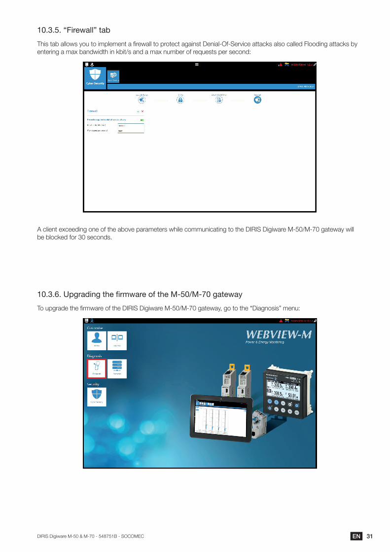
10.3.5. “Firewall” tab
This tab allows you to implement a firewall to protect against Denial-Of-Service attacks also called Flooding attacks by entering a max bandwidth in kbit/s and a max number of requests per second:
A client exceeding one of the above parameters while communicating to the DIRIS Digiware M-50/M-70 gateway will be blocked for 30 seconds.
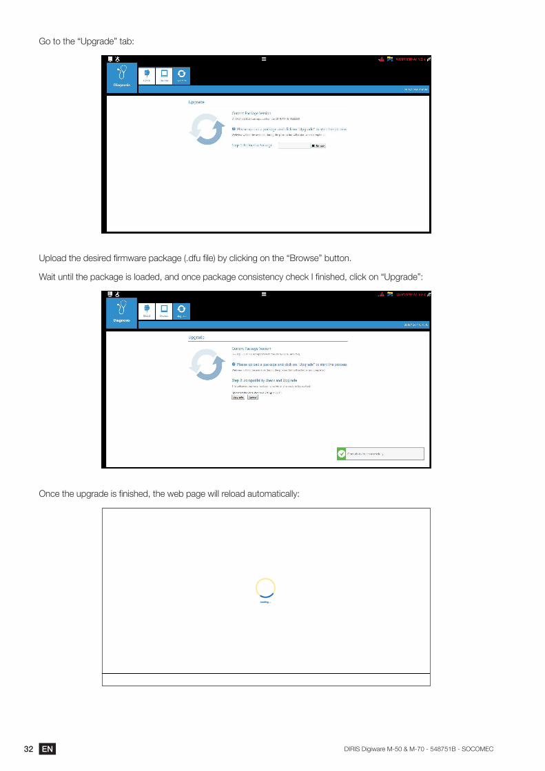
10.3.6. Upgrading the firmware of the M-50/M-70 gateway
To upgrade the firmware of the DIRIS Digiware M-50/M-70 gateway, go to the “Diagnosis” menu:
32 EN DIRIS Digiware M-50 & M-70 - 548751B - SOCOMEC
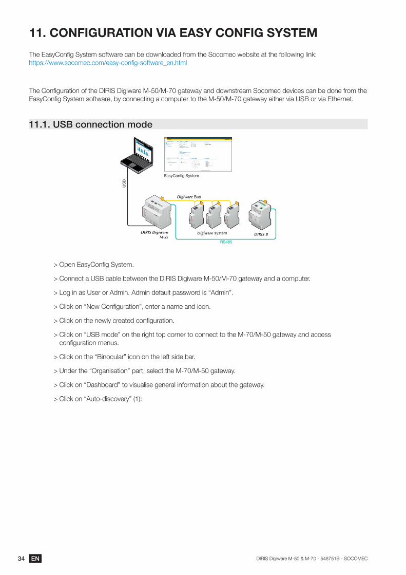
Go to the “Upgrade” tab:
Upload the desired firmware package (.dfu file) by clicking on the “Browse” button.
Wait until the package is loaded, and once package consistency check I finished, click on “Upgrade”:
Once the upgrade is finished, the web page will reload automatically:

33ENDIRIS Digiware M-50 & M-70 - 548751B - SOCOMEC
10.4. WEBVIEW-MFor more information on the visualisation of measurement data, please refer to the WEBVIEW-M instruction manual, available on the Socomec website at the following link:
www.socomec.com/operating-instructions/en/software-solution
34 EN DIRIS Digiware M-50 & M-70 - 548751B - SOCOMEC
11. CONFIGURATION VIA EASY CONFIG SYSTEM
The EasyConfig System software can be downloaded from the Socomec website at the following link:https://www.socomec.com/easy-config-software_en.html
The Configuration of the DIRIS Digiware M-50/M-70 gateway and downstream Socomec devices can be done from the EasyConfig System software, by connecting a computer to the M-50/M-70 gateway either via USB or via Ethernet.
11.1. USB connection mode
DIRIS DigiwareM-xx
DIRIS B
RS485
Digiware Bus
Digiware system
EasyConfig System
ETHETH
ETHDIGIWAREBUS
24 V20 W max
SUPPLY
RS485NC
ADDR.
ALARM
ON
COM DIRIS M-xx
US
B
> Open EasyConfig System.
> Connect a USB cable between the DIRIS Digiware M-50/M-70 gateway and a computer.
> Log in as User or Admin. Admin default password is “Admin”.
> Click on “New Configuration”, enter a name and icon.
> Click on the newly created configuration.
> Click on “USB mode” on the right top corner to connect to the M-70/M-50 gateway and access configuration menus.
> Click on the “Binocular” icon on the left side bar.
> Under the “Organisation” part, select the M-70/M-50 gateway.
> Click on “Dashboard” to visualise general information about the gateway.
> Click on “Auto-discovery” (1):
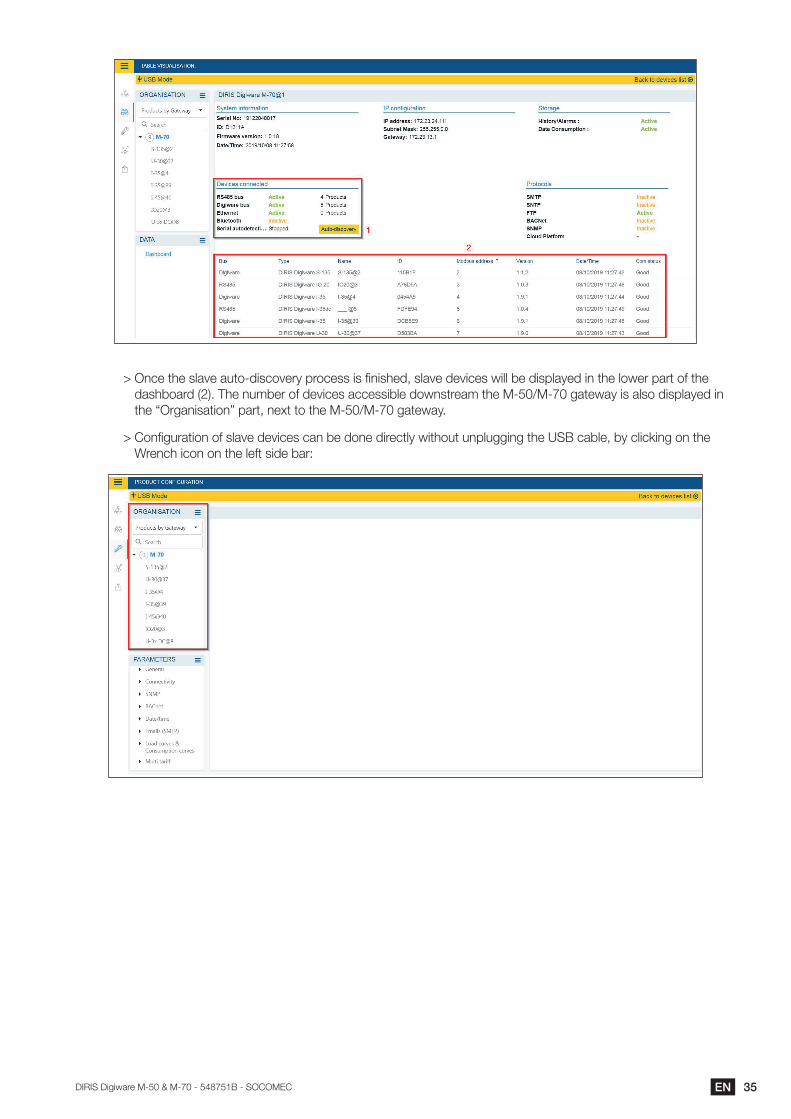
35ENDIRIS Digiware M-50 & M-70 - 548751B - SOCOMEC
> Once the slave auto-discovery process is finished, slave devices will be displayed in the lower part of the dashboard (2). The number of devices accessible downstream the M-50/M-70 gateway is also displayed in the “Organisation” part, next to the M-50/M-70 gateway.
> Configuration of slave devices can be done directly without unplugging the USB cable, by clicking on the Wrench icon on the left side bar:
36 EN DIRIS Digiware M-50 & M-70 - 548751B - SOCOMEC
11.2. Ethernet connection mode
DIRIS DigiwareM-xx
DIRIS B
RS485
Digiware Bus
Digiware system
EasyConfig System
ETHETH
ETHDIGIWAREBUS
24 V20 W max
SUPPLY
RS485NC
ADDR.
ALARM
ON
COM DIRIS M-xx
Eth
erne
t
> Open EasyConfig System.
> Log in as User or Admin. Admin default password is “Admin”.
> Click on “New configuration”, enter a name and icon.
> Click on the newly created configuration.
> Click on the “+” icon to manually add the M-50/M-70 gateway to the topology, by selecting the product, entering the IP address, Modbus address. To be able to communicate with the M-50/M-70 gateway, your computer must be in the same network as the M-50/M-70
> Click on the “Binocular” icon on the left side bar.
> In the “Organisation” part, select the M-70/M-50 gateway.
> In the “Data” part, click on “Dashboard” to visualise general information about the gateway.
> Click on “Auto-discovery” (1).
> Once the slave auto-discovery process is finished, slave devices will be displayed in the lower part of the dashboard menu (2). The number of devices accessible downstream the M-50/M-70 gateway is also displayed in the “Organisation” part, next to the M-50/M-70 gateway.
> Configuration of slave devices can be done directly by clicking on the Wrench icon on the left side bar and selecting the right device:
37ENDIRIS Digiware M-50 & M-70 - 548751B - SOCOMEC
38 EN DIRIS Digiware M-50 & M-70 - 548751B - SOCOMEC
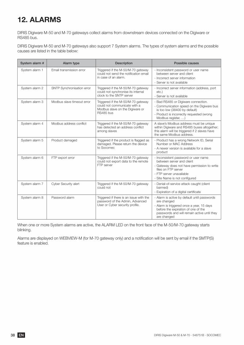
12. ALARMS
DIRIS Digiware M-50 and M-70 gateways collect alarms from downstream devices connected on the Digiware or RS485 bus.
DIRIS Digiware M-50 and M-70 gateways also support 7 System alarms. The types of system alarms and the possible causes are listed in the table below:
System alarm # Alarm type Description Possible causes
System alarm 1 Email transmission error Triggered if the M-50/M-70 gateway could not send the notification email in case of an alarm.
- Inconsistent password or user name between server and client
- Incorrect server information- Server is not available
System alarm 2 SNTP Synchronisation error Triggered if the M-50/M-70 gateway could not synchronise its internal clock to the SNTP server
- Incorrect server information (address, port etc.)
- Server is not available
System alarm 3 Modbus slave timeout error Triggered if the M-50/M-70 gateway could not communicate with a Modbus slave on the Digiware or RS485 bus
- Bad RS485 or Digiware connection.- Communication speed on the Digiware bus
is too low (38400 by default)- Product is incorrectly requested (wrong
Modbus register, …)
System alarm 4 Modbus address conflict Triggered if the M-50/M-70 gateway has detected an address conflict among slaves
A slave’s Modbus address must be unique within Digiware and RS485 buses altogether; this alarm will be triggered if 2 slaves have the same Modbus address.
System alarm 5 Product damaged Triggered if the product is flagged as damaged. Please return the device to Socomec
- Product has a wrong Network ID, Serial Number or MAC Address
- A newer version is available for a slave product
System alarm 6 FTP export error Triggered if the M-50/M-70 gateway could not export data to the remote FTP server
- Inconsistent password or user name between server and client
- Gateway does not have permission to write files on FTP server
- FTP server unavailable- Site Name is not configured
System alarm 7 Cyber Security alert Triggered if the M-50/M-70 gateway could not
- Denial-of-service attack caught (client banned)
- Expiration of a digital certificate
System alarm 8 Password alarm Triggered if there is an issue with the password of the Admin, Advanced User or Cyber security profile.
- Alarm is active by default until passwords are changed
- Alarm is triggered once a year, 15 days before the expiration of one of the passwords and will remain active until they are changed
When one or more System alarms are active, the ALARM LED on the front face of the M-50/M-70 gateway starts blinking.
Alarms are displayed on WEBVIEW-M (for M-70 gateway only) and a notification will be sent by email if the SMTP(S) feature is enabled.
39ENDIRIS Digiware M-50 & M-70 - 548751B - SOCOMEC
13. 10-STEP COMMISSIONING CHECKLIST FOR YOUR DIGIWARE SYSTEM
1) Auto-discovery from M-50/M-70 push button or from EasyConfig System software.
2) Configuration of DIRIS Digiware U and I modules via EasyConfig System software.
3) Connection to the webserver (default IP address is 192.168.0.4).
4) Change default passwords for Admin, Advanced and Cyber security profiles.
5) Connect to the Cyber security profile and generate the passphrase in case you lose your password.
6) Device discovery via “Devices” tab “Sources”.
7) Change load names and usages if necessary.
8) Optional: Hierarchy configuration (M-70 only).
9) Optional: Photoview configuration (M-70 only).
10) Configuration of IP configuration and communication protocols via “Protocols” menu.
Frequently Asked Questions
What happens if you lose your password ?
- If the Admin or Advanced Users lose their password, they can be changed from the Cyber security profile.
- If the Cyber security user loses his password, the passphrase can be used to create a new password.
- If the passphrase was lost, the only option is to reset the M-50/M-70 gateway to factory default settings.
How can I configure my IP configuration and communication protocols for my system ?
- Using EasyConfig System.
- Or directly from the web server under the “Protocols” menu. Do not forget to reboot the M-50/M-70 gateway after modifying the IP configuration.
Why is the ALARM LED on the M-50/M-70 flashing ?
- If this is the first time you are using the DIRIS Digiware M-50/M-70 gateway, it could be that the default passwords for the Advanced User, Admin and Cyber security profiles have not been changed yet. The “Password Alert” system alarm will be active until passwords are changed.
The Auto-discovery process is finished, yet some slave devices have not been detected.
If slave devices have not been detected, it could be because the Auto-discovery mode is set to “FAST”, which only detects DIRIS Digiware modules, DIRIS B and DIRIS A-40 measuring devices. Use EasyConfig System to change the Auto-discovery mode to “FULL” to discovery all devices.
40 EN DIRIS Digiware M-50 & M-70 - 548751B - SOCOMEC
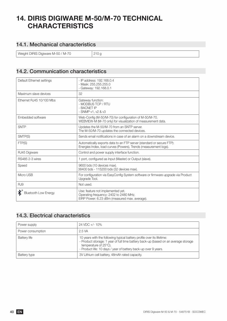
14. DIRIS DIGIWARE M-50/M-70 TECHNICAL CHARACTERISTICS
14.1. Mechanical characteristics
Weight DIRIS Digiware M-50 / M-70 210 g
14.2. Communication characteristics
Default Ethernet settings - IP address: 192.168.0.4- Mask: 255.255.255.0- Gateway: 192.168.0.1
Maximum slave devices 32
Ethernet RJ45 10/100 Mbs Gateway function:- MODBUS TCP / RTU- BACNET IP- SNMP v1, v2 & v3
Embedded software Web-Config (M-50/M-70) for configuration of M-50/M-70.WEBVIEW-M (M-70 only) for visualization of measurement data.
SNTP Updates the M-50/M-70 from an SNTP server.The M-50/M-70 updates the connected devices.
SMTP(S) Sends email notifications in case of an alarm on a downstream device.
FTP(S) Automatically exports data to an FTP server (standard or secure FTP): Energies Index, load curves (Powers), Trends (measurement logs).
RJ45 Digiware Control and power supply interface function.
RS485 2-3 wires 1 port, configured as Input (Master) or Output (slave).
Speed 9600 bds (10 devices max).38400 bds - 115200 bds (32 devices max).
Micro USB For configuration via EasyConfig System software or firmware upgrade via Product Upgrade Tool.
RJ9 Not used.
Bluetooth Low Energy Use: feature not implemented yet.Operating frequency: 2402 to 2480 MHz.EIRP Power: 6.23 dBm (measured max. average).
14.3. Electrical characteristics
Power supply 24 VDC +/- 10%
Power consumption 2.5 VA
Battery life 10 years with the following typical battery profile over its lifetime:- Product storage: 1 year of full time battery back-up (based on an average storage
temperature of 25°C).- Product life: 10 days / year of battery back-up over 9 years.
Battery type 3V Lithium cell battery, 48mAh rated capacity.
41ENDIRIS Digiware M-50 & M-70 - 548751B - SOCOMEC
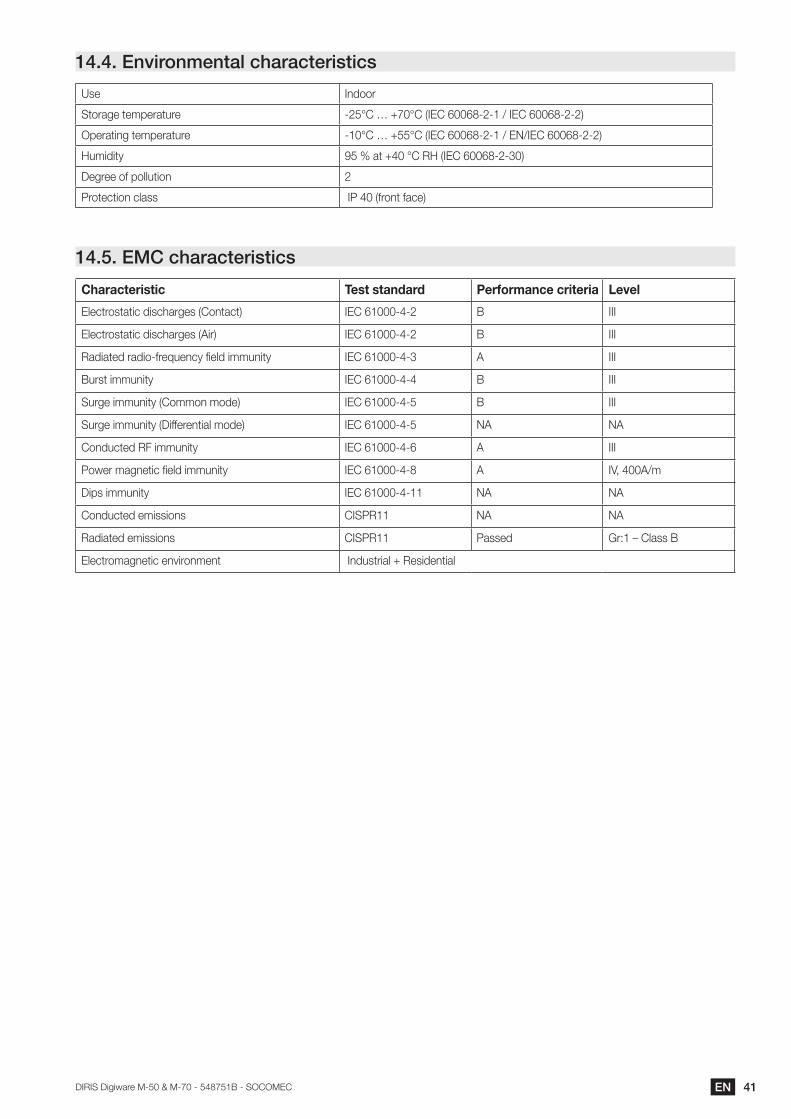
14.4. Environmental characteristics
Use Indoor
Storage temperature -25°C … +70°C (IEC 60068-2-1 / IEC 60068-2-2)
Operating temperature -10°C … +55°C (IEC 60068-2-1 / EN/IEC 60068-2-2)
Humidity 95 % at +40 °C RH (IEC 60068-2-30)
Degree of pollution 2
Protection class IP 40 (front face)
14.5. EMC characteristics
Characteristic Test standard Performance criteria Level
Electrostatic discharges (Contact) IEC 61000-4-2 B III
Electrostatic discharges (Air) IEC 61000-4-2 B III
Radiated radio-frequency field immunity IEC 61000-4-3 A III
Burst immunity IEC 61000-4-4 B III
Surge immunity (Common mode) IEC 61000-4-5 B III
Surge immunity (Differential mode) IEC 61000-4-5 NA NA
Conducted RF immunity IEC 61000-4-6 A III
Power magnetic field immunity IEC 61000-4-8 A IV, 400A/m
Dips immunity IEC 61000-4-11 NA NA
Conducted emissions CISPR11 NA NA
Radiated emissions CISPR11 Passed Gr:1 – Class B
Electromagnetic environment Industrial + Residential
42 EN DIRIS Digiware M-50 & M-70 - 548751B - SOCOMEC
15. ANNEX A SNMP COMMUNICATION WITH THE DIRIS DIGIWARE M-50 / M-70
15.1. SNMP generalities
SNMP stands for Simple Network Management Protocol and is widely used by administrators for an easy network monitoring of devices on IP networks. It works in a client-server communication mode on an Ethernet physical layer.
The DIRIS Digiware M-50 / M-70 supports SNMP v1, v2 and v3.The M-50 / M-70 is an agent SNMP v1, v2, v3 which responds to queries from managers (also called management stations or supervisors).
The M-50 / M-70 allows access through SNMP of measurement data from SOCOMEC slaves connected via the RS485 bus or the Digiware bus.
Data from the slaves can be reached through a file called “MIB” (“Management Information Base”) under a hierarchical and pre-defined structure. The MIB file of the M-50 / M-70 is available from www.socomec.com.The file must be uploaded in the Management station managing your metering system.
The Tree structure of the MIB contains multiple OIDs (Object Identifiers). An OID uniquely identifies and labels a managed object ( parameter from metering devices) in the MIB.
For example, the electrical parameter “Current Inst I1” is identified by one OID. “Current Inst I2” is identified by another one.
Common SNMP terms Description
Agent Corresponds to the DIRIS Digiware M-50 / M-70: Interface between the PMDs and the manager
Managed device The PMDs connected downstream the M-50 / M-70 (ex: I-35, DIRIS B, DIRIS A…)
MIB Management information base where the OIDs are organized in a hierarchical tree
OID An object identifier that uniquely identifies and labels a managed object in the MIB hierarchy
Community strings A text that enables the authentication between an agent and the manager
Traps Notifications sent by the agent and received by the manager
15.2. SNMP functions supported
There are 4 types of SNMP requests supported by the DIRIS Digiware M-50 / M-70:• GetRequest: to retrieve the variable of an OID (I1 Inst for example).• GetNextRequest: to retrieve the variable of the next OID (I2 Inst in this case).• GetBulk: to retrieve multiple variables gathered together.• SetRequest: to change the value of one variable such as the state of a Digital output.• Traps: Unlike the above commands which are initiated by the SNMP manager, Traps are initiated by the Agents with
no solicitation from the Manager. Traps are notifications to the Manager by the Agent of the occurrence of an event and/or alarm.
Traps are sent by the agent in case one of the following alarms occurs:• Alarm on a measurement.• Logical alarm (change of status of a Digital input).• Combination alarms.• PQ events (inrush, voltage swells, voltage sags/dips, voltage interruptions).• System alarms (Phase Rotation, CT disconnect, VI association).
43ENDIRIS Digiware M-50 & M-70 - 548751B - SOCOMEC
Traps are sent automatically when the alarm occurs. They will be sent again once the “Trap report frequency” time is elapsed.
The alarm must be activated in the product (using the EasyConfig System configuration software) in order for the Traps to be sent.
Traps can either be configured for specific hosts or “broadcast” to the whole network. Up to two server IP addresses can be entered for SNMP trap notification of specific hosts.
15.3. SNMP versions supportedThe DIRIS Digiware M-50 / M-70 can use all three versions of SNMP: SNMPv1, v2 and v3.
• SNMPv1 and v2:
The identification is based on Read-only and Read-Write Community passwords. They are non-encrypted and are passed over the network in plaintext.
Both passwords have to be entered in the Agent (DIRIS Digiware M-50 / M-70) and the Manager and must be identical.
A matching Read Community allows the Get functions to be executed on the agent.
A matching Read-Write Community also allows the Set function to be executed on the agent.
- The default Read Community V1 password is “public” and the default Read-Write Community V1 password is “private”.
- The default Read Community V2 password is “publicv2” and the Read-Write Community V2 is “privatev2”.
• SNMPv3:
SNMPv3 uses the USM (User-based Security Module) for controlling access to information available via SNMP. This version offers more security using three important features to prevent the interception and deciphering of data:
- A username (called security username).
- MD5 and SHA1 authentication protocols to hash the passwords.
- DES and AES Privacy protocols to encrypt the data.
44 EN DIRIS Digiware M-50 & M-70 - 548751B - SOCOMEC
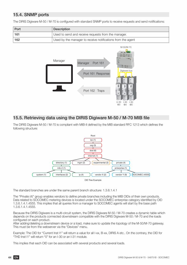
15.4. SNMP portsThe DIRIS Digiware M-50 / M-70 is configured with standard SNMP ports to receive requests and send notifications:
Port Description
161 Used to send and receive requests from the manager.
162 Used by the manager to receive notifications from the agent
Manager
U-30@3
I-30@4
I-30@5
M-50/M-70
Digiware bus
Manager Port 161
Port 161 Response
Port 162 Traps
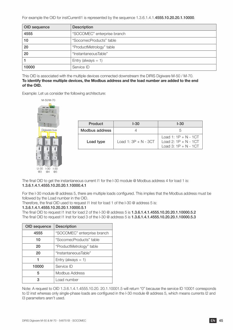
15.5. Retrieving data using the DIRIS Digiware M-50 / M-70 MIB fileThe DIRIS Digiware M-50 / M-70 is compliant with MIB-II defined by the MIB standard RFC 1213 which defines the following structure:
Root
OID Tree Example
iso (1)
org (3)
dod (6)
Internet (1)
directory (1)
mib-2 (1)
interfaces (2) ip (4)system (1)
mgm (2) experimental (3) private (4)
enterprise (1)
vendor X (2) vendor Y (9) SOCOMEC (4555)
The standard branches are under the same parent branch structure: 1.3.6.1.4.1
The “Private (4)” group enables vendors to define private branches including the MIB OIDs of their own products. Data related to SOCOMEC metering devices is located under the SOCOMEC enterprise category identified by OID 1.3.6.1.4.1.4555. This implies that all queries from a manager to SOCOMEC agents will start by the base path 1.3.6.1.4.1.4555.
Because the DIRIS Digiware is a multi-circuit system, the DIRIS Digiware M-50 / M-70 creates a dynamic table which depends on the products connected downstream compatible with the DIRIS Digiware M-50 / M-70 and the loads configured on each product. After adding/deleting a downstream device or a load, make sure to update the topology of the M-50/M-70 gateway. This must be from the webserver via the “Devices” menu.
Example: The OID for “Current Inst I1” will return a value for all I-xx, B-xx, DIRIS A etc.. On the contrary, the OID for “THD Inst I1” will return “0” for an I-30 or an I-31 module.
This implies that each OID can be associated with several products and several loads.
45ENDIRIS Digiware M-50 & M-70 - 548751B - SOCOMEC
For example the OID for instCurrentI1 is represented by the sequence 1.3.6.1.4.1.4555.10.20.20.1.10000.
OID sequence Description
4555 “SOCOMEC” enterprise branch
10 “SocomecProducts” table
20 “ProductMetrology” table
20 “InstantaneousTable”
1 Entry (always = 1)
10000 Service ID
This OID is associated with the multiple devices connected downstream the DIRIS Digiware M-50 / M-70.To identify those multiple devices, the Modbus address and the load number are added to the end of the OID.
Example: Let us consider the following architecture:
Product I-30 I-30
Modbus address 4 5
Load type Load 1: 3P + N - 3CTLoad 1: 1P + N - 1CTLoad 2: 1P + N - 1CTLoad 3: 1P + N - 1CT
U-30@3
I-30@4
I-30@5
M-50/M-70
Digiware bus
The final OID to get the instantaneous current I1 for the I-30 module @ Modbus address 4 for load 1 is: 1.3.6.1.4.1.4555.10.20.20.1.10000.4.1
For the I-30 module @ address 5, there are multiple loads configured. This implies that the Modbus address must be followed by the Load number in the OID. Therefore, the final OID used to request I1 Inst for load 1 of the I-30 @ address 5 is: 1.3.6.1.4.1.4555.10.20.20.1.10000.5.1 The final OID to request I1 Inst for load 2 of the I-30 @ address 5 is 1.3.6.1.4.1.4555.10.20.20.1.10000.5.2 The final OID to request I1 Inst for load 3 of the I-30 @ address 5 is 1.3.6.1.4.1.4555.10.20.20.1.10000.5.3
OID sequence Description
4555 “SOCOMEC” enterprise branch
10 “SocomecProducts” table
20 “ProductMetrology” table
20 “InstantaneousTable”
1 Entry (always = 1)
10000 Service ID
5 Modbus Address
3 Load number
Note: A request to OID 1.3.6.1.4.1.4555.10.20. 20.1.10001.5 will return “0” because the service ID 10001 corresponds to I2 inst whereas only single-phase loads are configured in the I-30 module @ address 5, which means currents I2 and I3 parameters aren’t used.
46 EN DIRIS Digiware M-50 & M-70 - 548751B - SOCOMEC
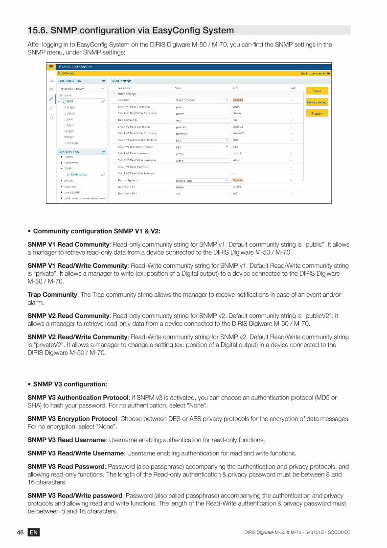
15.6. SNMP configuration via EasyConfig SystemAfter logging in to EasyConfig System on the DIRIS Digiware M-50 / M-70, you can find the SNMP settings in the SNMP menu, under SNMP settings:
• CommunityconfigurationSNMPV1&V2:
SNMP V1 Read Community: Read-only community string for SNMP v1. Default community string is “public”. It allows a manager to retrieve read-only data from a device connected to the DIRIS Digiware M-50 / M-70.
SNMP V1 Read/Write Community: Read-Write community string for SNMP v1. Default Read/Write community string is “private”. It allows a manager to write (ex: position of a Digital output) to a device connected to the DIRIS Digiware M-50 / M-70.
Trap Community: The Trap community string allows the manager to receive notifications in case of an event and/or alarm.
SNMP V2 Read Community: Read-only community string for SNMP v2. Default community string is “publicV2”. It allows a manager to retrieve read-only data from a device connected to the DIRIS Digiware M-50 / M-70.
SNMP V2 Read/Write Community: Read-Write community string for SNMP v2. Default Read/Write community string is “privateV2”. It allows a manager to change a setting (ex: position of a Digital output) in a device connected to the DIRIS Digiware M-50 / M-70.
• SNMPV3configuration:
SNMP V3 Authentication Protocol: If SNPM v3 is activated, you can choose an authentication protocol (MD5 or SHA) to hash your password. For no authentication, select “None”.
SNMP V3 Encryption Protocol: Choose between DES or AES privacy protocols for the encryption of data messages. For no encryption, select “None”.
SNMP V3 Read Username: Username enabling authentication for read-only functions.
SNMP V3 Read/Write Username: Username enabling authentication for read and write functions.
SNMP V3 Read Password: Password (also passphrase) accompanying the authentication and privacy protocols, and allowing read-only functions. The length of the Read-only authentication & privacy password must be between 8 and 16 characters.
SNMP V3 Read/Write password: Password (also called passphrase) accompanying the authentication and privacy protocols and allowing read and write functions. The length of the Read-Write authentication & privacy password must be between 8 and 16 characters.
47ENDIRIS Digiware M-50 & M-70 - 548751B - SOCOMEC
Trapconfiguration: Choose to deactivate or activate the traps. If activated, you can choose to broadcast trap notifications to all supervisers on the network or to notify only specific host stations (up to 2).
Trap Host 1 IP: Enter the IP address of the 1st host station which will receive trap notifications.
Trap Host 1 port: Enter the port used to send traps for the 1st host station.
Trap Host 2 IP: Address: enter the IP address of the 2nd host station which will receive trap notifications.
Trap Host 2 port: Enter the port used to send traps for the 2nd host station.
Trapnotificationcycle: Enter the time after which a trap reminder will be sent for active alarms. By default, it is set to 60min.
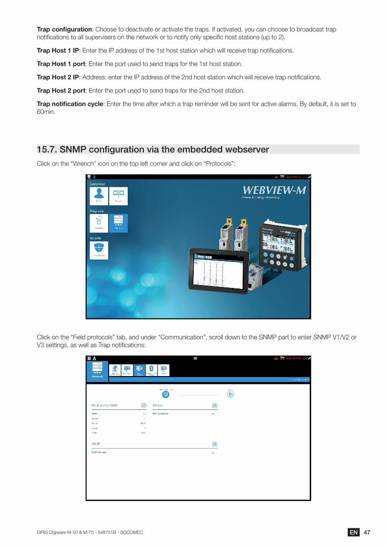
15.7. SNMP configuration via the embedded webserverClick on the “Wrench” icon on the top left corner and click on “Protocols”:
Click on the “Field protocols” tab, and under “Communication”, scroll down to the SNMP part to enter SNMP V1/V2 or V3 settings, as well as Trap notifications:
48 EN DIRIS Digiware M-50 & M-70 - 548751B - SOCOMEC
16. ANNEX B BACNETCOMMUNICATIONWITHTHE DIRIS DIGIWAREM-50 / M-70
The DIRIS Digiware M-50 / M-70 supports the BACnet IP protocol. It acts as a BACnet IP gateway to all devices compatible and connected downstream via RS485 or the Digiware Bus.
The PICS (Protocol Implementation Conformance Statement) of the DIRIS Digiware M-50 / M-70 is available on the Socomec website at www.socomec.com.
16.1. BACnet GeneralitiesBACnet provides a method for computer-based control equipment from different manufacturers to be interoperable. BACnet is designed to handle many types of building controls, including HVAC, lighting, security, fire, access control, maintenance, waste management and so forth.
Common terms used in BACnet communication:
Object: Represents a device and its data. Multiple objects type can be available for each device *analog input, binary input…). Each object has a number of properties which fully describe the BACnet object to the network.
Object identifier: Uniquely identifies an object within a BACnet device.
Property: A property describes a BACnet object to the network.
Present value: It is one of the properties of the Analog_Input Object. It represents the current value of an analog input object.
Service: Message type between one BACnet device to another.
BACnet uses a client/server communication mode between devices. Devices communicate between each other using services describing the type of exchange. A BACnet client is a device that requests a service, and a BACnet server is a device that executes a service. Data inside a BACnet device is organized as a series of objects, each composed of multiple properties.
Ex: the analog_input object defines a property for present_value, a property for average_value etc…
A BACnet client initiates a request to a BACnet server using a service (ex: read_property) to a specific property (ex: present_value) contained in a BACnet object (ex: analog_input).
16.2. BACnet ObjectsBACnet defines a standard set of “Objects”, each of which has a standard set of “Properties” describing the object and its current status to other devices on the BACnet internetwork. The properties allow for the object to be controlled by other BACnet devices.
BACnet defines 54 objects. Each element of the building control system is represented by one or more objects. The DIRIS Digiware M-50 / M-70 supports the below Objects:
Object type Exemple of use
Device To describe the device to the BACnet network.
Analog input Instantaneous current for phase 1 (I1) measured by a DIRIS Digiware I-xx current module with associated current sensor
Binary input Status (ON/OFF) of an auxiliary contact
Binary output Change of status of the output of a DIRIS Digiware IO-10
49ENDIRIS Digiware M-50 & M-70 - 548751B - SOCOMEC
A list of properties defines each BACnet Object. Properties can be:• Required by the BACnet specification.• Optional. In this case, vendors can choose whether to implement them for their devices.• Proprietary. Vendors can add their own created properties.
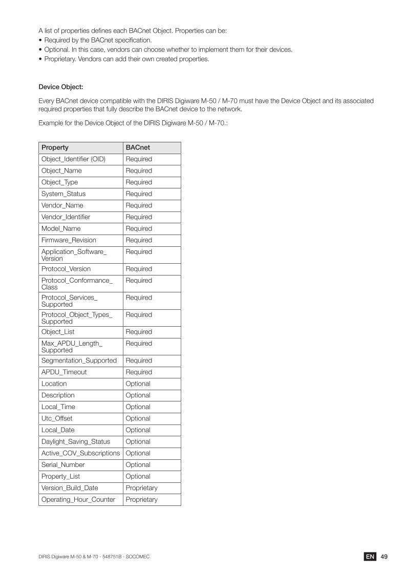
Device Object:
Every BACnet device compatible with the DIRIS Digiware M-50 / M-70 must have the Device Object and its associated required properties that fully describe the BACnet device to the network.
Example for the Device Object of the DIRIS Digiware M-50 / M-70.:
Property BACnet
Object_Identifier (OID) Required
Object_Name Required
Object_Type Required
System_Status Required
Vendor_Name Required
Vendor_Identifier Required
Model_Name Required
Firmware_Revision Required
Application_Software_Version
Required
Protocol_Version Required
Protocol_Conformance_Class
Required
Protocol_Services_Supported
Required
Protocol_Object_Types_Supported
Required
Object_List Required
Max_APDU_Length_Supported
Required
Segmentation_Supported Required
APDU_Timeout Required
Location Optional
Description Optional
Local_Time Optional
Utc_Offset Optional
Local_Date Optional
Daylight_Saving_Status Optional
Active_COV_Subscriptions Optional
Serial_Number Optional
Property_List Optional
Version_Build_Date Proprietary
Operating_Hour_Counter Proprietary
50 EN DIRIS Digiware M-50 & M-70 - 548751B - SOCOMEC
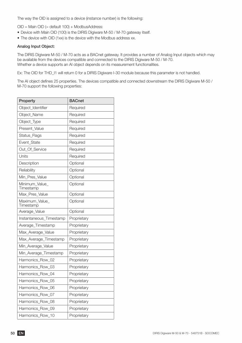
The way the OID is assigned to a device (instance number) is the following:
OID = Main OID (= default 100) + ModbusAddress:• Device with Main OID (100) is the DIRIS Digiware M-50 / M-70 gateway itself.• The device with OID (1xx) is the device with the Modbus address xx.
Analog Input Object:
The DIRIS Digiware M-50 / M-70 acts as a BACnet gateway. It provides a number of Analog Input objects which may be available from the devices compatible and connected to the DIRIS Digiware M-50 / M-70. Whether a device supports an AI object depends on its measurement functionalities.
Ex: The OID for THD_I1 will return 0 for a DIRIS Digiware I-30 module because this parameter is not handled.
The AI object defines 25 properties. The devices compatible and connected downstream the DIRIS Digiware M-50 / M-70 support the following properties:
Property BACnet
Object_Identifier Required
Object_Name Required
Object_Type Required
Present_Value Required
Status_Flags Required
Event_State Required
Out_Of_Service Required
Units Required
Description Optional
Reliability Optional
Min_Pres_Value Optional
Minimum_Value_Timestamp
Optional
Max_Pres_Value Optional
Maximum_Value_Timestamp
Optional
Average_Value Optional
Instantaneous_Timestamp Proprietary
Average_Timestamp Proprietary
Max_Average_Value Proprietary
Max_Average_Timestamp Proprietary
Min_Average_Value Proprietary
Min_Average_Timestamp Proprietary
Harmonics_Row_02 Proprietary
Harmonics_Row_03 Proprietary
Harmonics_Row_04 Proprietary
Harmonics_Row_05 Proprietary
Harmonics_Row_06 Proprietary
Harmonics_Row_07 Proprietary
Harmonics_Row_08 Proprietary
Harmonics_Row_09 Proprietary
Harmonics_Row_10 Proprietary

51ENDIRIS Digiware M-50 & M-70 - 548751B - SOCOMEC
Energy_Total_Residual Proprietary
Energy_Total_Hourmeter Proprietary
Energy_Partial Proprietary
Energy_Partial_Residual Proprietary
Energy_Partial_Hourmeter Proprietary
Energy_Total_Lagging Proprietary
Energy_Total_Lagging_Res Proprietary
Energy_Total_Leading Proprietary
Energy_Total_Leading_Res Proprietary
Energy_Last_Partial Proprietary
Energy_Last_Partial_Res Proprietary
Energy_Last_Partial_Timestamp
Proprietary
Multifluid_Partial Proprietary
Multifluid_Weight Proprietary
Instant_Min_Max_Reset Proprietary
Average_Min_Max_Reset Proprietary
The way the OID is assigned to an Analog Input Object (instance number) is the following: OID = LLMM• with LL = Load # of the device (starting at 1).• with MM = Index of the measurement type (see Analog Input Measurement List).
For example, Analog Input with OID 204 reflects Phasis/Neutral Voltage V1 of Load 2 of corresponding device.
52 EN DIRIS Digiware M-50 & M-70 - 548751B - SOCOMEC
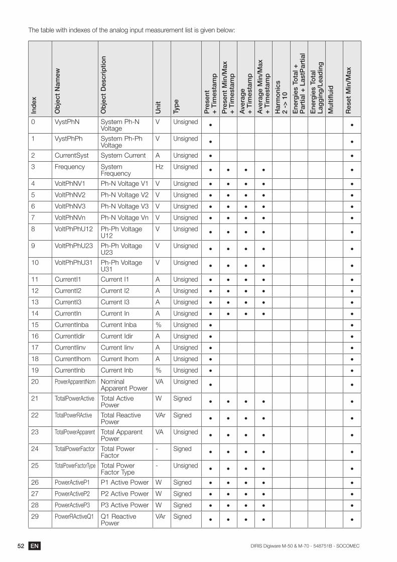
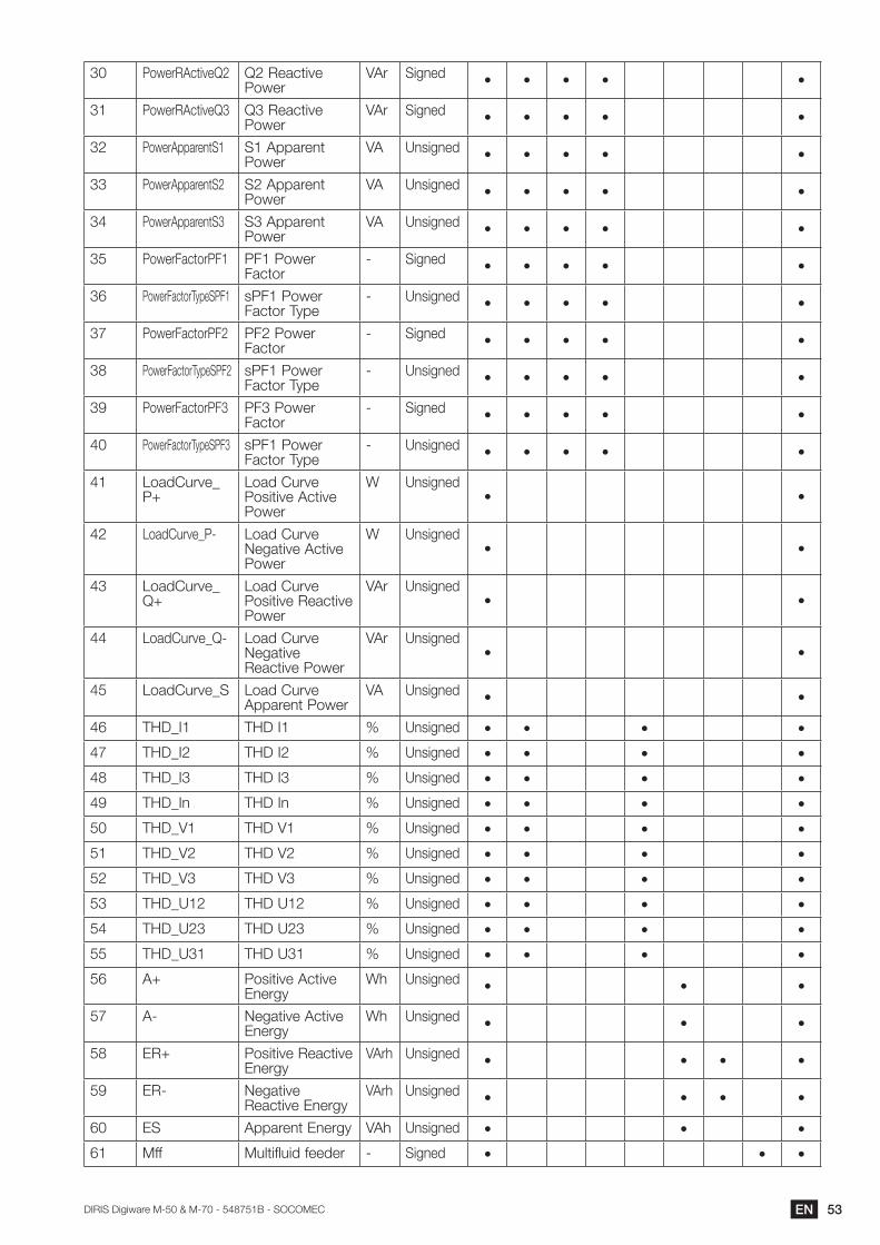
The table with indexes of the analog input measurement list is given below:In
dex
Ob
ject
Nam
ew
Ob
ject
Des
crip
tion
Uni
t
Typ
e
Pre
sent
+ T
imes
tam
p
Pre
sent
Min
/Max
+ T
imes
tam
p
Ave
rag
e+
Tim
esta
mp
Ave
rag
e M
in/M
ax+
Tim
esta
mp
Har
mo
nics
2 ->
10
Ene
rgie
s To
tal +
Par
tial +
Las
tPar
tial
Ene
rgie
s To
tal
Lag
gin
g/L
ead
ing
Mul
tiflu
id
Res
et M
in/M
ax
0 VystPhN System Ph-N Voltage
V Unsigned • •
1 VystPhPh System Ph-Ph Voltage
V Unsigned • •
2 CurrentSyst System Current A Unsigned • •
3 Frequency System Frequency
Hz Unsigned • • • • •
4 VoltPhNV1 Ph-N Voltage V1 V Unsigned • • • • •
5 VoltPhNV2 Ph-N Voltage V2 V Unsigned • • • • •
6 VoltPhNV3 Ph-N Voltage V3 V Unsigned • • • • •
7 VoltPhNVn Ph-N Voltage Vn V Unsigned • • • • •
8 VoltPhPhU12 Ph-Ph Voltage U12
V Unsigned • • • • •
9 VoltPhPhU23 Ph-Ph Voltage U23
V Unsigned • • • • •
10 VoltPhPhU31 Ph-Ph Voltage U31
V Unsigned • • • • •
11 CurrentI1 Current I1 A Unsigned • • • • •
12 CurrentI2 Current I2 A Unsigned • • • • •
13 CurrentI3 Current I3 A Unsigned • • • • •
14 CurrentIn Current In A Unsigned • • • • •
15 CurrentInba Current Inba % Unsigned • •
16 CurrentIdir Current Idir A Unsigned • •
17 CurrentIinv Current Iinv A Unsigned • •
18 CurrentIhom Current Ihom A Unsigned • •
19 CurrentInb Current Inb % Unsigned • •
20 PowerApparentNom Nominal Apparent Power
VA Unsigned • •
21 TotalPowerActive Total Active Power
W Signed • • • • •
22 TotalPowerRActive Total Reactive Power
VAr Signed • • • • •
23 TotalPowerApparent Total Apparent Power
VA Unsigned • • • • •
24 TotalPowerFactor Total Power Factor
- Signed • • • • •
25 TotalPowerFactorType Total Power Factor Type
- Unsigned • • • • •
26 PowerActiveP1 P1 Active Power W Signed • • • • •
27 PowerActiveP2 P2 Active Power W Signed • • • • •
28 PowerActiveP3 P3 Active Power W Signed • • • • •
29 PowerRActiveQ1 Q1 Reactive Power
VAr Signed • • • • •
53ENDIRIS Digiware M-50 & M-70 - 548751B - SOCOMEC
30 PowerRActiveQ2 Q2 Reactive Power
VAr Signed • • • • •
31 PowerRActiveQ3 Q3 Reactive Power
VAr Signed • • • • •
32 PowerApparentS1 S1 Apparent Power
VA Unsigned • • • • •
33 PowerApparentS2 S2 Apparent Power
VA Unsigned • • • • •
34 PowerApparentS3 S3 Apparent Power
VA Unsigned • • • • •
35 PowerFactorPF1 PF1 Power Factor
- Signed • • • • •
36 PowerFactorTypeSPF1 sPF1 Power Factor Type
- Unsigned • • • • •
37 PowerFactorPF2 PF2 Power Factor
- Signed • • • • •
38 PowerFactorTypeSPF2 sPF1 Power Factor Type
- Unsigned • • • • •
39 PowerFactorPF3 PF3 Power Factor
- Signed • • • • •
40 PowerFactorTypeSPF3 sPF1 Power Factor Type
- Unsigned • • • • •
41 LoadCurve_P+
Load Curve Positive Active Power
W Unsigned• •
42 LoadCurve_P- Load Curve Negative Active Power
W Unsigned• •
43 LoadCurve_Q+
Load Curve Positive Reactive Power
VAr Unsigned• •
44 LoadCurve_Q- Load Curve Negative Reactive Power
VAr Unsigned• •
45 LoadCurve_S Load Curve Apparent Power
VA Unsigned • •
46 THD_I1 THD I1 % Unsigned • • • •
47 THD_I2 THD I2 % Unsigned • • • •
48 THD_I3 THD I3 % Unsigned • • • •
49 THD_In THD In % Unsigned • • • •
50 THD_V1 THD V1 % Unsigned • • • •
51 THD_V2 THD V2 % Unsigned • • • •
52 THD_V3 THD V3 % Unsigned • • • •
53 THD_U12 THD U12 % Unsigned • • • •
54 THD_U23 THD U23 % Unsigned • • • •
55 THD_U31 THD U31 % Unsigned • • • •
56 A+ Positive Active Energy
Wh Unsigned • • •
57 A- Negative Active Energy
Wh Unsigned • • •
58 ER+ Positive Reactive Energy
VArh Unsigned • • • •
59 ER- Negative Reactive Energy
VArh Unsigned • • • •
60 ES Apparent Energy VAh Unsigned • • •
61 Mff Multifluid feeder - Signed • • •
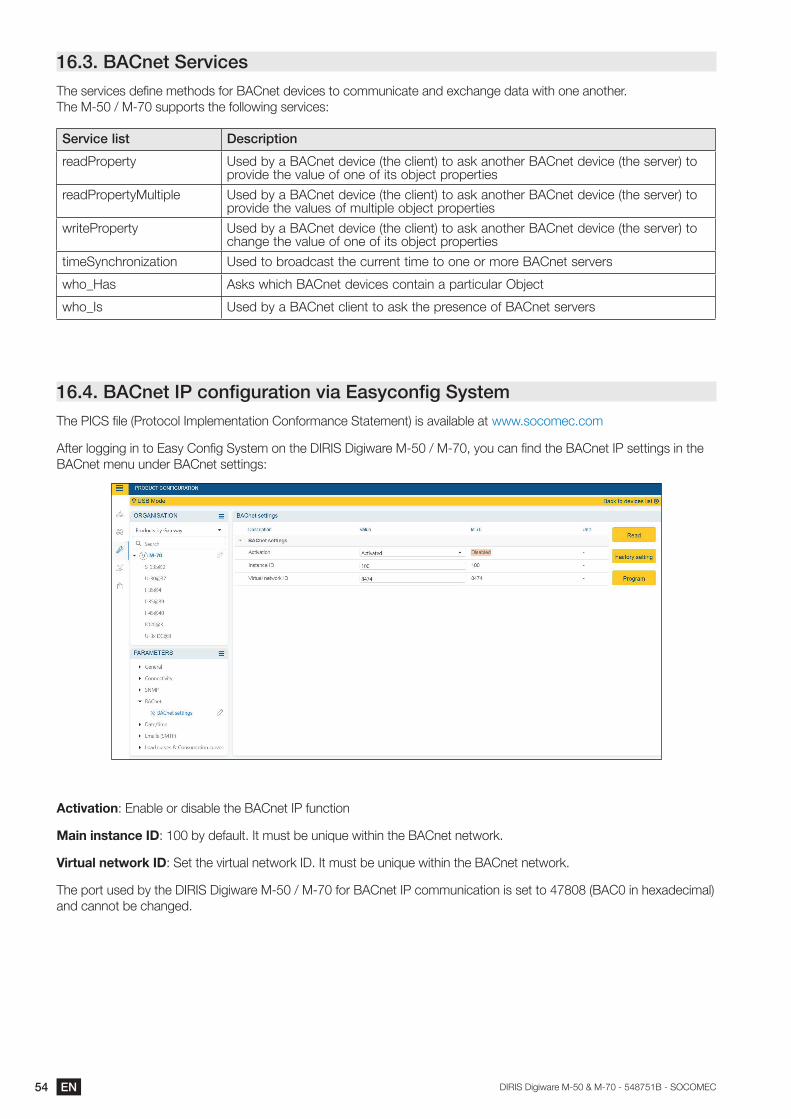
54 EN DIRIS Digiware M-50 & M-70 - 548751B - SOCOMEC
16.3. BACnet ServicesThe services define methods for BACnet devices to communicate and exchange data with one another. The M-50 / M-70 supports the following services:
Service list Description
readProperty Used by a BACnet device (the client) to ask another BACnet device (the server) to provide the value of one of its object properties
readPropertyMultiple Used by a BACnet device (the client) to ask another BACnet device (the server) to provide the values of multiple object properties
writeProperty Used by a BACnet device (the client) to ask another BACnet device (the server) to change the value of one of its object properties
timeSynchronization Used to broadcast the current time to one or more BACnet servers
who_Has Asks which BACnet devices contain a particular Object
who_Is Used by a BACnet client to ask the presence of BACnet servers
16.4. BACnet IP configuration via Easyconfig SystemThe PICS file (Protocol Implementation Conformance Statement) is available at www.socomec.com
After logging in to Easy Config System on the DIRIS Digiware M-50 / M-70, you can find the BACnet IP settings in the BACnet menu under BACnet settings:
Activation: Enable or disable the BACnet IP function
Main instance ID: 100 by default. It must be unique within the BACnet network.
Virtual network ID: Set the virtual network ID. It must be unique within the BACnet network.
The port used by the DIRIS Digiware M-50 / M-70 for BACnet IP communication is set to 47808 (BAC0 in hexadecimal) and cannot be changed.
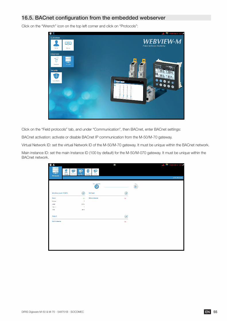
55ENDIRIS Digiware M-50 & M-70 - 548751B - SOCOMEC
16.5. BACnet configuration from the embedded webserverClick on the “Wrench” icon on the top left corner and click on “Protocols”:
Click on the “Field protocols” tab, and under “Communication”, then BACnet, enter BACnet settings:
BACnet activation: activate or disable BACnet IP communication from the M-50/M-70 gateway.
Virtual Network ID: set the virtual Network ID of the M-50/M-70 gateway. It must be unique within the BACnet network.
Main instance ID: set the main Instance ID (100 by default) for the M-50/M-070 gateway. It must be unique within the BACnet network.
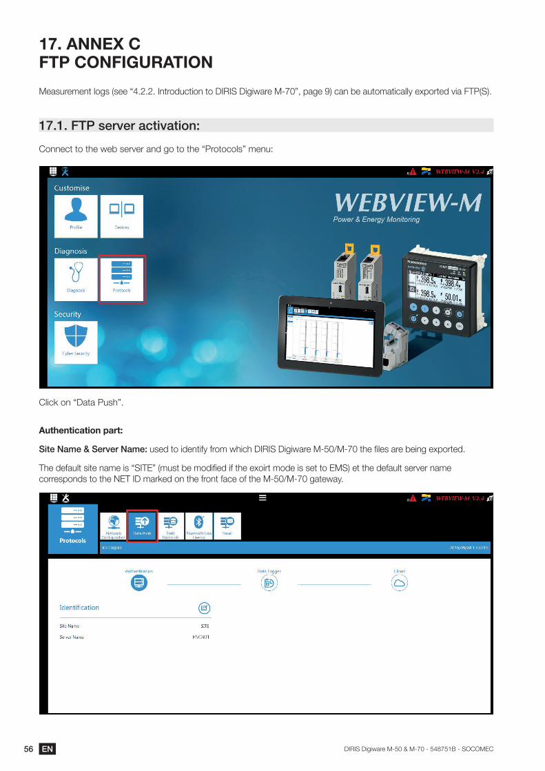
56 EN DIRIS Digiware M-50 & M-70 - 548751B - SOCOMEC
17. ANNEX C FTP CONFIGURATION
Measurement logs (see “4.2.2. Introduction to DIRIS Digiware M-70”, page 9) can be automatically exported via FTP(S).
17.1. FTP server activation:
Connect to the web server and go to the “Protocols” menu:
Click on “Data Push”.
Authenticationpart:
Site Name & Server Name: used to identify from which DIRIS Digiware M-50/M-70 the files are being exported.
The default site name is “SITE” (must be modified if the exoirt mode is set to EMS) et the default server name corresponds to the NET ID marked on the front face of the M-50/M-70 gateway.
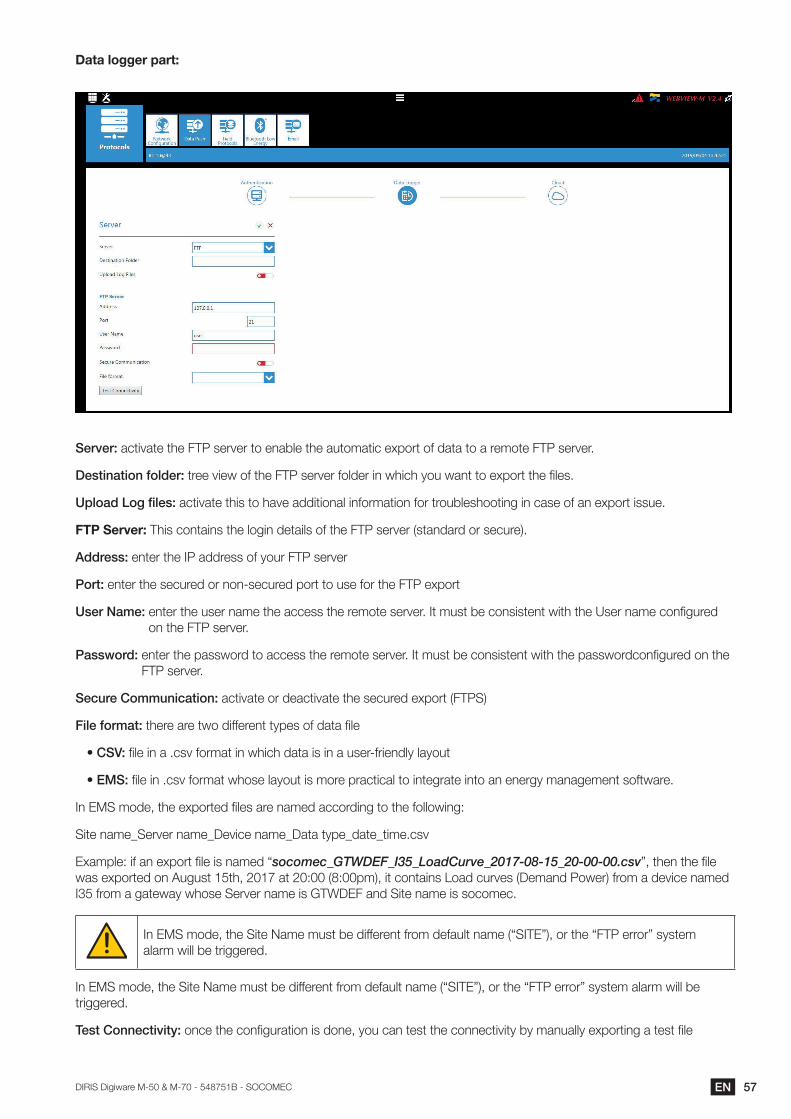
57ENDIRIS Digiware M-50 & M-70 - 548751B - SOCOMEC
Dataloggerpart:
Server: activate the FTP server to enable the automatic export of data to a remote FTP server.
Destination folder: tree view of the FTP server folder in which you want to export the files.
Upload Log files: activate this to have additional information for troubleshooting in case of an export issue.
FTPServer:This contains the login details of the FTP server (standard or secure).
Address: enter the IP address of your FTP server
Port: enter the secured or non-secured port to use for the FTP export
User Name: enter the user name the access the remote server. It must be consistent with the User name configured on the FTP server.
Password: enter the password to access the remote server. It must be consistent with the passwordconfigured on the FTP server.
Secure Communication: activate or deactivate the secured export (FTPS)
File format: there are two different types of data file
• CSV: file in a .csv format in which data is in a user-friendly layout
• EMS: file in .csv format whose layout is more practical to integrate into an energy management software.
In EMS mode, the exported files are named according to the following:
Site name_Server name_Device name_Data type_date_time.csv
Example: if an export file is named “socomec_GTWDEF_I35_LoadCurve_2017-08-15_20-00-00.csv”, then the file was exported on August 15th, 2017 at 20:00 (8:00pm), it contains Load curves (Demand Power) from a device named I35 from a gateway whose Server name is GTWDEF and Site name is socomec.
In EMS mode, the Site Name must be different from default name (“SITE”), or the “FTP error” system alarm will be triggered.
In EMS mode, the Site Name must be different from default name (“SITE”), or the “FTP error” system alarm will be triggered.
Test Connectivity: once the configuration is done, you can test the connectivity by manually exporting a test file
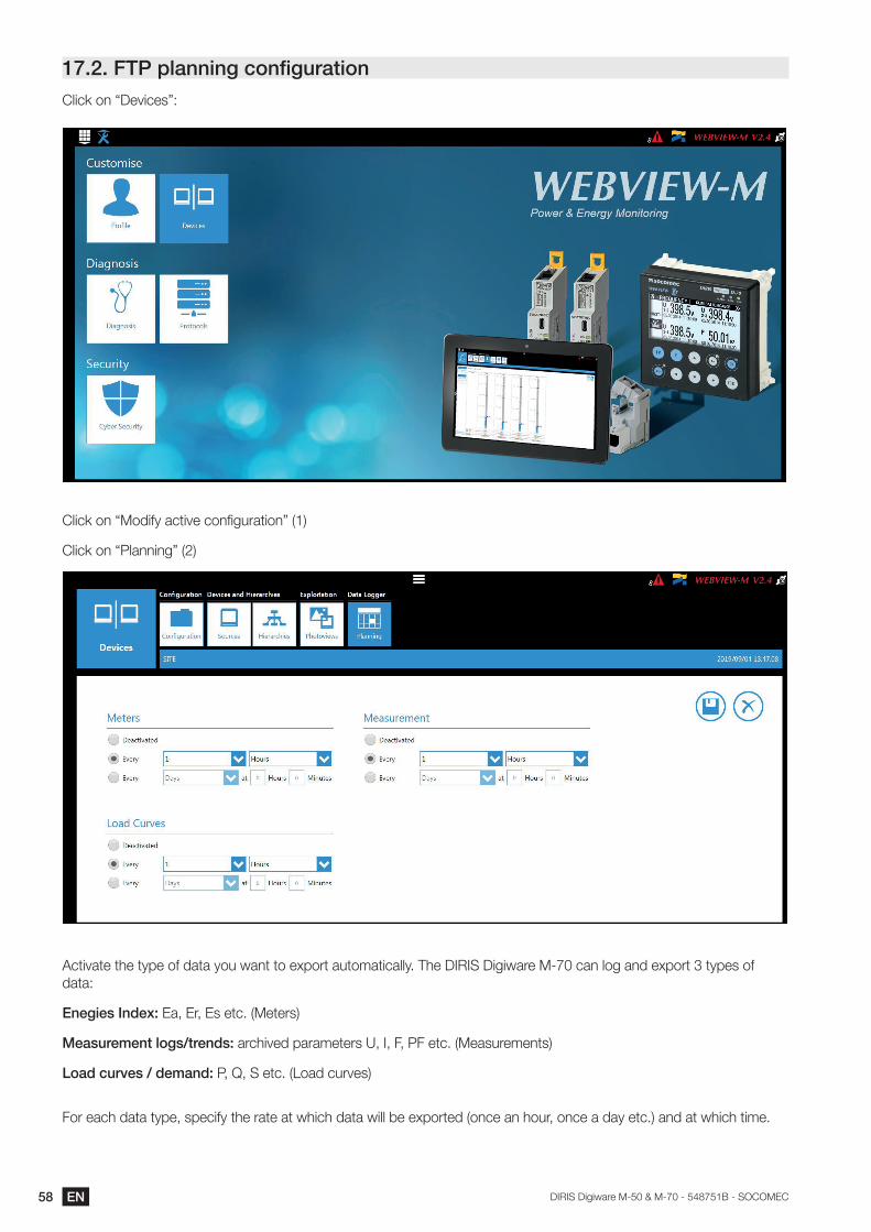
58 EN DIRIS Digiware M-50 & M-70 - 548751B - SOCOMEC
17.2. FTP planning configurationClick on “Devices”:
Click on “Modify active configuration” (1)
Click on “Planning” (2)
Activate the type of data you want to export automatically. The DIRIS Digiware M-70 can log and export 3 types of data:
Enegies Index: Ea, Er, Es etc. (Meters)
Measurement logs/trends: archived parameters U, I, F, PF etc. (Measurements)
Load curves / demand: P, Q, S etc. (Load curves)
For each data type, specify the rate at which data will be exported (once an hour, once a day etc.) and at which time.
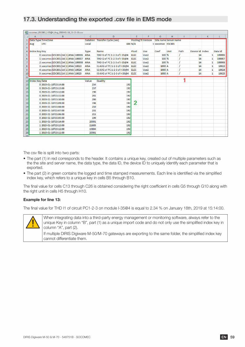
59ENDIRIS Digiware M-50 & M-70 - 548751B - SOCOMEC
17.3. Understanding the exported .csv file in EMS mode
The csv file is split into two parts:• The part (1) in red corresponds to the header. It contains a unique key, created out of multiple parameters such as
the the site and server name, the data type, the data ID, the device ID to uniquely identify each parameter that is exported.
• The part (2) in green contains the logged and time stamped measurements. Each line is identified via the simplified index key, which refers to a unique key in cells B5 through B10.
The final value for cells C13 through C26 is obtained considering the right coefficient in cells G5 through G10 along with the right unit in cells H5 through H10.
Exampleforline13:
The final value for THD I1 of circuit PC1-2-3 on module I-35@4 is equal to 2.34 % on January 18th, 2019 at 15:14:00.
When integrating data into a third-party energy management or monitoring software, always refer to the unique Key in column “B”, part (1) as a unique import code and do not only use the simplified index key in column “A”, part (2).
If multiple DIRIS Digiware M-50/M-70 gateways are exporting to the same folder, the simplified index key cannot differentiate them.

Non
-con
trac
tual
doc
umen
t. ©
201
9, S
ocom
ec S
AS
. All
right
s re
serv
ed.
CORPORATE HQ CONTACT: SOCOMEC SAS 1-4 RUE DE WESTHOUSE 67235 BENFELD, FRANCE
www.socomec.com
548751B