Directional cohesive elements for the simulation of blade cutting of thin shells
22
CMES Manuscript http://www.techscience.com Review Copyright © 2009 Tech Science Press CMES, vol.1, no.1, pp.1-21, 2009 Directional Cohesive elements for the simulation of blade cutting of thin shells published in CMES, vol.57, no.3, pp.205-224, 2010, doi:10.3970/cmes.2010.057.205 A. Frangi 1 , M. Pagani 1 , U. Perego 1 and R. Borsari 2 Abstract: This paper is concerned with the finite element simulation of a thin membrane cutting by a sharp blade. Smeared crack finite element approaches appear to be unsuitable for this purpose, since very small elements would be re- quired to conform to the sharp edge of the cutter. Furthermore, when the membrane material is very ductile, classical interface cohesive elements, where the cohesive forces are transmitted in the direction of the crack opening displacement, cannot correctly reproduce situations where the blade crosses the process zone. A sim- plified approach, based on the new concept of “directional" cohesive elements, is here proposed for a computationally effective simulation of this type of problems. Whenever a crack is opening, cohesive “cable" elements are introduced between the separating nodes. These elements are geometric entities which can be moni- tored throughout the analysis to detect possible contact with the blade. When this happens, the cables transmit in a straightforward way cohesive forces to the crack flanks in different directions. The procedure has been tested against a real cutting process providing encouraging results with relatively coarse meshes. The calibra- tion of the material properties of the cohesive cables is also briefly discussed. Keywords: blade cutting, cohesive crack, finite elements, shells 1 Introduction The numerical simulation of fracture and fragmentation of shells and plates is a timely topic in computational structural engineering and is receiving increasing attention. Since many years, most explicit commercial finite element codes (see e.g. Abaqus and LS-Dyna) offer the possibility to simulate crack propagation in shells by eliminating from the model those finite elements where developing damage has 1 Dept. Structural Engineering, Politecnico di Milano, P.za L. da Vinci 32, 20133 Milan, Italy. 2 Tetra Pak Packaging Solutions, via Delfini 1, 41100 Modena, Italy
Transcript of Directional cohesive elements for the simulation of blade cutting of thin shells

CMES Manuscript http://www.techscience.com
Revi
ewCopyright © 2009 Tech Science Press CMES, vol.1, no.1, pp.1-21, 2009
Directional Cohesive elements for the simulation of bladecutting of thin shells
published in CMES, vol.57, no.3, pp.205-224, 2010, doi:10.3970/cmes.2010.057.205
A. Frangi1, M. Pagani1, U. Perego1 and R. Borsari2
Abstract: This paper is concerned with the finite element simulation of a thinmembrane cutting by a sharp blade. Smeared crack finite element approachesappear to be unsuitable for this purpose, since very small elements would be re-quired to conform to the sharp edge of the cutter. Furthermore, when the membranematerial is very ductile, classical interface cohesive elements, where the cohesiveforces are transmitted in the direction of the crack opening displacement, cannotcorrectly reproduce situations where the blade crosses the process zone. A sim-plified approach, based on the new concept of “directional" cohesive elements, ishere proposed for a computationally effective simulation of this type of problems.Whenever a crack is opening, cohesive “cable" elements are introduced betweenthe separating nodes. These elements are geometric entities which can be moni-tored throughout the analysis to detect possible contact with the blade. When thishappens, the cables transmit in a straightforward way cohesive forces to the crackflanks in different directions. The procedure has been tested against a real cuttingprocess providing encouraging results with relatively coarse meshes. The calibra-tion of the material properties of the cohesive cables is also briefly discussed.
Keywords: blade cutting, cohesive crack, finite elements, shells
1 Introduction
The numerical simulation of fracture and fragmentation of shells and plates is atimely topic in computational structural engineering and is receiving increasingattention. Since many years, most explicit commercial finite element codes (see e.g.Abaqus and LS-Dyna) offer the possibility to simulate crack propagation in shellsby eliminating from the model those finite elements where developing damage has
1 Dept. Structural Engineering, Politecnico di Milano, P.za L. da Vinci 32, 20133 Milan, Italy.2 Tetra Pak Packaging Solutions, via Delfini 1, 41100 Modena, Italy
CMES Manuscript http://www.techscience.com
Revi
ew2 Copyright © 2009 Tech Science Press CMES, vol.1, no.1, pp.1-21, 2009
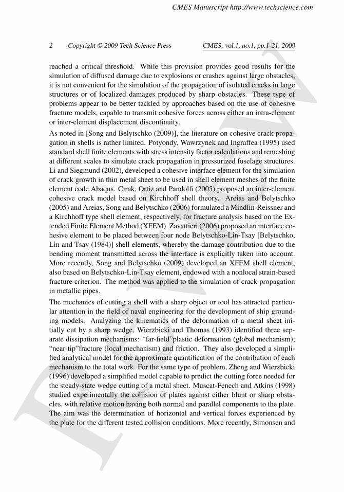
reached a critical threshold. While this provision provides good results for thesimulation of diffused damage due to explosions or crashes against large obstacles,it is not convenient for the simulation of the propagation of isolated cracks in largestructures or of localized damages produced by sharp obstacles. These type ofproblems appear to be better tackled by approaches based on the use of cohesivefracture models, capable to transmit cohesive forces across either an intra-elementor inter-element displacement discontinuity.
As noted in [Song and Belytschko (2009)], the literature on cohesive crack propa-gation in shells is rather limited. Potyondy, Wawrzynek and Ingraffea (1995) usedstandard shell finite elements with stress intensity factor calculations and remeshingat different scales to simulate crack propagation in pressurized fuselage structures.Li and Siegmund (2002), developed a cohesive interface element for the simulationof crack growth in thin metal sheet to be used in shell element meshes of the finiteelement code Abaqus. Cirak, Ortiz and Pandolfi (2005) proposed an inter-elementcohesive crack model based on Kirchhoff shell theory. Areias and Belytschko(2005) and Areias, Song and Belytschko (2006) formulated a Mindlin-Reissner anda Kirchhoff type shell element, respectively, for fracture analysis based on the Ex-tended Finite Element Method (XFEM). Zavattieri (2006) proposed an interface co-hesive element to be placed between four node Belytschko-Lin-Tsay [Belytschko,Lin and Tsay (1984)] shell elements, whereby the damage contribution due to thebending moment transmitted across the interface is explicitly taken into account.More recently, Song and Belytschko (2009) developed an XFEM shell element,also based on Belytschko-Lin-Tsay element, endowed with a nonlocal strain-basedfracture criterion. The method was applied to the simulation of crack propagationin metallic pipes.
The mechanics of cutting a shell with a sharp object or tool has attracted particu-lar attention in the field of naval engineering for the development of ship ground-ing models. Analyzing the kinematics of the deformation of a metal sheet ini-tially cut by a sharp wedge, Wierzbicki and Thomas (1993) identified three sep-arate dissipation mechanisms: “far-field”plastic deformation (global mechanism);“near-tip”fracture (local mechanism) and friction. They also developed a simpli-fied analytical model for the approximate quantification of the contribution of eachmechanism to the total work. For the same type of problem, Zheng and Wierzbicki(1996) developed a simplified model capable to predict the cutting force needed forthe steady-state wedge cutting of a metal sheet. Muscat-Fenech and Atkins (1998)studied experimentally the collision of plates against either blunt or sharp obsta-cles, with relative motion having both normal and parallel components to the plate.The aim was the determination of horizontal and vertical forces experienced bythe plate for the different tested collision conditions. More recently, Simonsen and

CMES Manuscript http://www.techscience.com
Revi
ewManuscript Preparation for CMES 3
Törnqvist (2004) carried out a combined experimental-numerical investigation forthe calibration of crack propagation criteria in large shell structures. The proposedcriteria were then validated by simulating by LS-Dyna a large scale grounding ex-periment where a double bottom shell structure was grounded and torn on a conicalobstacle.
A molecular numerical model for the simulation of cutting has been recently pro-posed by Lin and Ye (2009) at the nanoscale where an assemblage of copper atomsis cut by diamond blades with different shapes.
An accurate numerical tool for the simulation of blade cutting would result ex-tremely useful also in biomedical (especially surgical) applications. Chanthasopeep-han, Desai and Lau (2007), conducted experimental tests and finite element sim-ulations on the scalpel cutting of a pig liver. When open or laparoscopic surgeryinvolves the cutting of thin sheets, the most effective tools are scissors. Mahvash,Voo, Kim, Jeung, Wainer and Okamura (2008) developed an analytical model tocalculate forces applied to scissors during cutting of tissues. The mechanics of scis-sors cutting has also been studied extensively by Atkins and coworkers [Atkins, Xuand Jeronimidis (2004); Atkins and Xu (2005); Atkins (2006)], providing modelsfor the determination of the cutting forces and the definition of the optimal bladeshape.
It is also worth mentioning the recently published treatise [Atkins (2009)] whichpresents a comprehensive account of the state of the art of the research on cuttingengineering.
The present work is concerned with the development of a finite element model forthe simulation of the blade cutting of thin membranes of the type used in the cartonpackaging industry to seal a package containing liquid food. The membrane istypically a layered composite, with a total thickness ranging from 70 to 85 µm,made of a thin aluminium layer (6-9 µm) and various low-density polyethylene(LDPE) coating layers. In most cases, the composite is laminated by extruding theLDPE powder directly onto the aluminium layer. A typical response of a uniaxialtest of one of these materials is shown in Fig. 1, from which the main features canbe noticed:
• the two curves refer to tests on samples extracted in the lamination ma-chine direction (MD) and cross-machine (CD) direction, and only a mildanisotropy can be observed;
• the nominal stress reaches a peak followed by a sudden drop coinciding withthe rupture of the aluminium layer;
• the failure of the aluminium layer is followed by a long plateau, usually cor-

CMES Manuscript http://www.techscience.com
Revi
ew4 Copyright © 2009 Tech Science Press CMES, vol.1, no.1, pp.1-21, 2009
Figure 1: Typical uniaxial response of layered composite for food packaging.
responding to the occurrence of localized necking deformation, where themolecules of the LDPE realign along the direction of loading;
• the limit nominal strain of 500% corresponds to the cross-head limit of thetesting rig and not to the failure of the specimen, which has a typical failurenominal strain of 700-900%.
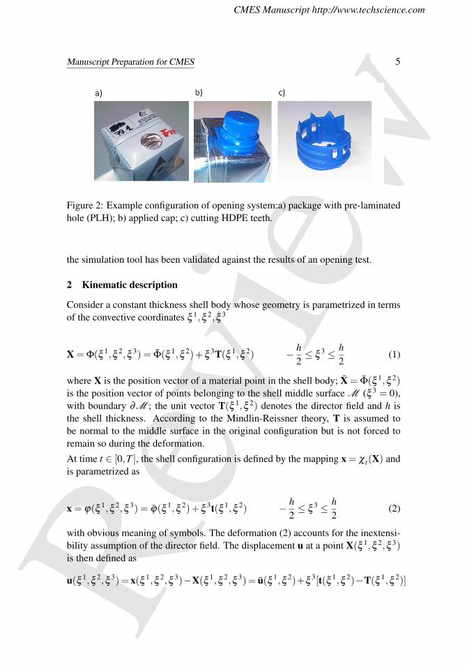
The objective of the opening process is to create a circular hole of a diameter of ap-proximately 15 mm, in a region of the package where a hole has been pre-laminatedin the paperboard (Fig. 2a) to reduce the force necessary to cut the laminate. In thehole region there is no paper and only thin aluminium and polymeric layers have tobe cut. The hole is produced using the applied cap shown in Fig. 2b. Thanks to ascrew thread, the cap rotation transmits the motion to the high-density polyethylene(HDPE) blades of the type shown in Fig. 2c. The opening tool consists of severalteeth (four in the figure) which undergo a motion with both normal and tangentialcomponents to the laminate surface.
As it will be discussed in the following sections, the standard cohesive interfaceelements are not suited for the simulation of this type of cutting, dominated bythe sharpness of the tooth blade and by the extremely high failure opening of thecohesive interface. The objective of this work is then to develop a new concept of“directional" cohesive element, to be placed at the interface between adjacent shellelements, where the cohesive forces can have different directions on the two sidesof the crack whenever the cohesive region is crossed by the cutting blade.
The new cohesive element has been implemented in a shell finite element code and
CMES Manuscript http://www.techscience.com
Revi
ewManuscript Preparation for CMES 5
Figure 2: Example configuration of opening system:a) package with pre-laminatedhole (PLH); b) applied cap; c) cutting HDPE teeth.
the simulation tool has been validated against the results of an opening test.
2 Kinematic description
Consider a constant thickness shell body whose geometry is parametrized in termsof the convective coordinates ξ 1,ξ 2,ξ 3
X = Φ(ξ 1,ξ 2,ξ 3) = Φ(ξ 1,ξ 2)+ξ3T(ξ 1,ξ 2) − h
2≤ ξ
3 ≤ h2
(1)
where X is the position vector of a material point in the shell body; X = Φ(ξ 1,ξ 2)is the position vector of points belonging to the shell middle surface M (ξ 3 = 0),with boundary ∂M ; the unit vector T(ξ 1,ξ 2) denotes the director field and h isthe shell thickness. According to the Mindlin-Reissner theory, T is assumed tobe normal to the middle surface in the original configuration but is not forced toremain so during the deformation.
At time t ∈ [0,T ], the shell configuration is defined by the mapping x = χ t(X) andis parametrized as
x = ϕ(ξ 1,ξ 2,ξ 3) = ϕ(ξ 1,ξ 2)+ξ3t(ξ 1,ξ 2) − h
2≤ ξ
3 ≤ h2
(2)
with obvious meaning of symbols. The deformation (2) accounts for the inextensi-bility assumption of the director field. The displacement u at a point X(ξ 1,ξ 2,ξ 3)is then defined as
u(ξ 1,ξ 2,ξ 3)= x(ξ 1,ξ 2,ξ 3)−X(ξ 1,ξ 2,ξ 3)= u(ξ 1,ξ 2)+ξ3[t(ξ 1,ξ 2)−T(ξ 1,ξ 2)]

CMES Manuscript http://www.techscience.com
Revi
ew6 Copyright © 2009 Tech Science Press CMES, vol.1, no.1, pp.1-21, 2009
(3)
It is convenient to define the covariant basis vectors {Ai} and {ai}, i = 1,2,3, onthe shell middle surface in the original and deformed configurations, respectively.The basis vectors belonging to the local tangent plane are defined as Aα = Φ,α andaα = ϕ,α , α = 1,2, while the unit vectors normal to the middle surface are definedas
A3 =A1×A2
‖A1×A2‖, a3 =
a1×a2
‖a1×a2‖(4)
The Green-Lagrange strain tensor is expressed in the shell body as
E =12(gi ·g j−Gi ·G j)Gi⊗G j = Ei jGi⊗G j (5)
where Gi and Gi are the covariant and contravariant base vectors, respectively, inthe reference configuration and gi is the covariant basis in the current configuration.These are defined as
Gα = Φ,α = Aα +ξ3T,α (6)
G3 = Φ,3= T = A3 (7)
gα = ϕ,α = aα +ξ3t,α (8)
g3 = ϕ,3= t (9)
Let us consider now a through-crack developing in the shell body. In the initialreference system, the image of the crack surface is denoted as Γc× [−h
2 ,h2 ], where
Γc is its intersection with the middle surface. In the current configuration the crackis open and its flanks Γ+
c × [−h2 ,
h2 ] and Γ−c × [−h
2 ,h2 ] are separated.
The displacement jump across the crack is obtained from (3) as
w = JuK = u+−u− = w+ξ3JtK (10)
Points belonging to the crack surface Γc× [−h2 ,
h2 ] in the initial configuration are
defined by the mapping

CMES Manuscript http://www.techscience.com
Revi
ewManuscript Preparation for CMES 7
Xc = Φc(ξ1(η),ξ 2(η))+ξ
3Tc(ξ1(η),ξ 2(η)) (11)
where Φc(η) is the parametric representation of Γc on the middle surface and η isa scalar parameter.
Defining as
Ac =∂ξ α
∂ηΦc,α An =
Ac×Tc
‖Ac×Tc‖= An (12)
the tangent and normal vectors to Γc on the middle surface, a covariant basis forthe crack surface in the original configuration can be defined as
Gc =∂ξ α
∂η(Φc,α +ξ
3Tc,α) = Ac +ξ3 ∂ξ α
∂ηTc,α (13)
G3 = T(ξ 1(η),ξ 2(η)) = Tc (14)
Gn =Gc×G3
‖Gc×G3‖= Gn (15)
3 Weak form of equilibrium
Let pdS be the cohesive force acting on an elementary area dS = ‖Gc×G3‖dξ 3dη
of the crack reference surface Γc× [−h2 ,
h2 ]. Equilibrium is enforced in weak form
through the virtual work equality
δΠint−δΠext = 0 (16)
where
δΠext =∫
Vf ·udV +
∫∂V
p ·udS (17)
δΠint = δΠint,V +δΠint,c = (18)
=∫
M \Γc
∫ h2
− h2
S : δEµdξ3dM +
∫Γc
∫ h2
− h2
(p− ·δu−+p+ ·δu+)γdξ3dΓc
(19)
In equations (17) and (19), V is the volume occupied by the shell body in thereference configuration, ∂V is the portion of the boundary where traction boundary

CMES Manuscript http://www.techscience.com
Revi
ew8 Copyright © 2009 Tech Science Press CMES, vol.1, no.1, pp.1-21, 2009
conditions are prescribed, f and p denote the assigned body and traction forces,respectively, dM = ‖A1×A2‖dξ 1dξ 2 is the middle surface infinitesimal element,S is the second Piola-Kirchhoff stress tensor, µ and γ are defined as
µ =‖G1×G2‖‖A1×A2‖
, γ =‖Gc×G3‖√
Ac ·Ac(20)
and account for the curvature of the middle surface and of Γc, respectively, whileδE, δu− and δu+ are the variations of the kinematic fields, conjugate to S and p−,p+.
In classical cohesive formulations, equilibrium conditions at the interface requirethat p+ =−p− = p and the internal work on the cohesive interface is rewritten as
δΠint,c =∫
Γc
∫ h2
− h2
p ·δwγdξ3dΓc (21)
4 The concept of directional cohesive element
Standard finite element approaches to fracture, based on the introduction of a co-hesive interface between adjacent shell elements, usually follow these steps: thedeformation and the state of stress in the uncracked shell structure is determined;wherever a prescribed propagation criterion is exceeded at a node, that node is du-plicated and a displacement discontinuity is allowed along the element interfaces,in the direction defined by the propagation criterion; opposite cohesive forces areintroduced across the discontinuity. The direction of the opposite forces dependsonly on the direction of the displacement jump and on the adopted cohesive law.When the material is quasi-brittle and/or the impacting object is blunt, there is nointerference between the object and the cohesive region because the ultimate co-hesive opening displacement is much smaller than the typical size of the object.On the contrary, when the material is very ductile, as in the case of the laminateconsidered in Fig. 1, or the cutting blade is sharp, it may well happen that the bladeintersects the trajectory of the cohesive forces, giving rise to inaccurate predictionsof the crack propagation. This problem does not occur when crack propagation issimulated by removing damaged elements from the mesh, as it is currently donein advanced commercial finite element codes. In this case the contact algorithm isactive on the element until the element is removed and penetration of the blade isnot allowed. However, this approach requires a mesh of the shell body fine enoughto conform to the blade edge. If the blade is sharp, as in the case of the cutters ofinterest herein, an accurate description of the propagation can lead to prohibitivecomputational costs.

CMES Manuscript http://www.techscience.com
Revi
ewManuscript Preparation for CMES 9
A different approach is adopted in this work, based on the following specific fea-tures of the fracture nucleation and propagation in the considered aluminium-polymericcomposite.
• The aluminium layer is quasi-brittle, especially if compared to the highlyductile LDPE layers.
• After the aluminium layer has failed, in correspondence to the sudden drop inFig. 1, the load is transmitted entirely by the highly ductile polymeric layersalong the constant stress plateau of Fig. 1.
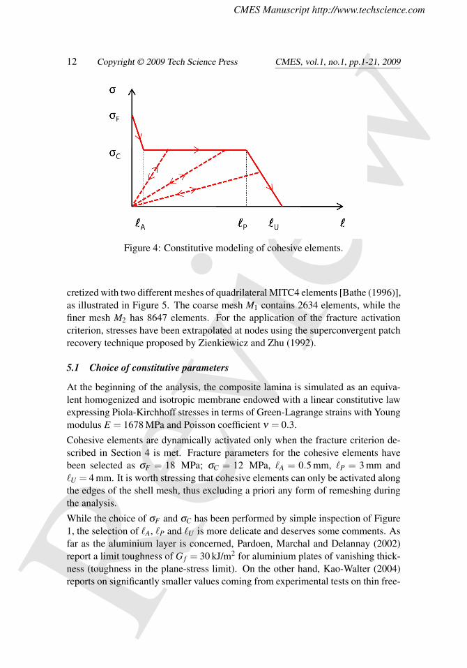
• In the plateau region of Fig. 1, plastic strains localize in a very narrow band,where the aluminium layer is broken, mainly located in the region in contactwith the cutter edge, while the material outside the process zone unloads inthe elastic regime. In fact, the sharper is the blade, the more localized is thedamage produced in the laminate. In a sheet of paper cut by a razor blade, thesheet remains elastic and the cut pieces match almost perfectly to each other[Atkins, Xu and Jeronimidis (2004)]. This observation allows one to interpretthe inelastic part of the stress-strain behavior of Fig. 1, as the behavior ofthe material in the process zone. The cohesive law is then assumed in theform shown in Fig. 4, where ` is the current length of material fibers in thecohesive zone.
• As noted in [Atkins and Xu (2005)] on the basis of experimental tests, thespecific surface work required for crack propagation is unaffected by relativeblade motion and does not depend on the mode of fracture, while it is influ-enced by friction between the blade and the sheet. As a consequence, onlyMode I tearing will be considered in the fracture process and perfect adhe-sion will be postulated between the cutter blade and the polyethylene fibrilsin the process zone.
• In view of the small thickness of the shell and of its small bending inertia, thebending strength in the cohesive region can be neglected. The internal workcontribution of the cohesive interface in Eq. (19) can be rewritten neglectingin Eq. (3) the displacement variations along the thickness:
δΠint,c =∫
Γc
∫ h2
− h2
(p− ·δ u−+p+ ·δ u+)γdξ3dΓc (22)
=∫
Γc
(P− ·δ u−+P+ ·δ u+)dΓc (23)
CMES Manuscript http://www.techscience.com
Revi
ew10 Copyright © 2009 Tech Science Press CMES, vol.1, no.1, pp.1-21, 2009
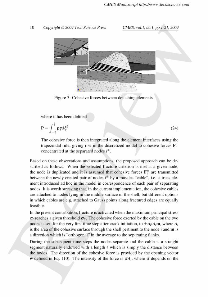
Figure 3: Cohesive forces between detaching elements.
where it has been defined
P =∫ h
2
− h2
pγdξ3 (24)
The cohesive force is then integrated along the element interfaces using thetrapezoidal rule, giving rise in the discretized model to cohesive forces F±iconcentrated at the separated nodes i±.
Based on these observations and assumptions, the proposed approach can be de-scribed as follows. When the selected fracture criterion is met at a given node,the node is duplicated and it is assumed that cohesive forces F±i are transmittedbetween the newly created pair of nodes i± by a massles “cable”, i.e. a truss ele-ment introduced ad hoc in the model in correspondence of each pair of separatingnodes. It is worth stressing that, in the current implementation, the cohesive cablesare attached to nodes lying in the middle surface of the shell, but different optionsin which cables are e.g. attached to Gauss points along fractured edges are equallyfeasible.
In the present contribution, fracture is activated when the maximum principal stressσI reaches a given threshold σF . The cohesive force exerted by the cable on the twonodes is set, for the very first time step after crack initiation, to ±σFAim, where Ai
is the area of the cohesive surface through the shell pertinent to the node i and m isa direction which is “orthogonal” in the average to the separating flanks.
During the subsequent time steps the nodes separate and the cable is a straightsegment naturally endowed with a length ` which is simply the distance betweenthe nodes. The direction of the cohesive force is provided by the opening vectorw defined in Eq. (10). The intensity of the force is σAi, where σ depends on the
CMES Manuscript http://www.techscience.com
Revi
ewManuscript Preparation for CMES 11
specific cohesive constitutive law adopted for the cable. In the present case, thishas been selected as the non-holonomic law of Figure 4. This is the case of the firstcable in the magnified frame on the left in Figure 3, which has not been contactedby the cutter yet.
Unlike in standard cohesive approaches, the cable element is a well defined geo-metric entity, and its contact against the cutting blade can be checked throughoutthe analysis duration, even though, in view of the sharpness of the cutter and to en-hance the computational efficiency of the procedure, contact is here only checkedagainst points belonging to the cutting edge (and not against the cutting sides).
When a point of a cable element is detected to be in contact with the blade, thecable element is subdivided in two truss elements by introducing a joint in cor-respondence of the contact point. The length of the cable is now defined as thesum of the lengths of the two constituent trusses. Due to the high level of frictionbetween the cutter and the LPDE membrane, it is assumed that the contact pointcannot move along the cutting edge of the cutter. Two forces F+
i and F−i of thesame magnitude are assumed to be transmitted by the two branches of the cable tothe crack flanks. The direction of the forces is however different at the two nodesi+ and i−, being determined by the directions of the truss elements connecting thenodes to the contact point (see Fig. 3). The force magnitude in the cable is obtainedfrom the stress in Fig. 4 corresponding to the total cable length `. In this way, thecohesive force can be transmitted between the crack flanks in a direction which isnot along the line connecting the separating nodes, correctly taking into accountthe presence of the cutter. When the current length of the cable exceeds the limitvalue `U , the cable is removed and no cohesive forces are applied to the associatednodes.
5 Example of application
We focus here on the simulation of a specific cutting process where the membraneis a circle of radius R = 10.2 mm and thickness h = 0.074 mm and is assumed to beclamped on the outer boundary. The aluminium foil is approximately 1/10th of theoverall thickness.
The cutting tool employed is depicted in Figure 2 and has an average radius of9.4 mm. The radius of curvature at the cutting edge is approximatively of 0.1 mm.In view of this small size, in the finite element model it is represented as the sharpintersection of two element edges. The tool is treated here as a rigid body under-going a prescribed rotation and vertical displacement simulating the true openingprocess.
In order to test possible mesh-dependence of results, the membrane has been dis-
CMES Manuscript http://www.techscience.com
Revi
ew12 Copyright © 2009 Tech Science Press CMES, vol.1, no.1, pp.1-21, 2009
Figure 4: Constitutive modeling of cohesive elements.
cretized with two different meshes of quadrilateral MITC4 elements [Bathe (1996)],as illustrated in Figure 5. The coarse mesh M1 contains 2634 elements, while thefiner mesh M2 has 8647 elements. For the application of the fracture activationcriterion, stresses have been extrapolated at nodes using the superconvergent patchrecovery technique proposed by Zienkiewicz and Zhu (1992).
5.1 Choice of constitutive parameters
At the beginning of the analysis, the composite lamina is simulated as an equiva-lent homogenized and isotropic membrane endowed with a linear constitutive lawexpressing Piola-Kirchhoff stresses in terms of Green-Lagrange strains with Youngmodulus E = 1678 MPa and Poisson coefficient ν = 0.3.
Cohesive elements are dynamically activated only when the fracture criterion de-scribed in Section 4 is met. Fracture parameters for the cohesive elements havebeen selected as σF = 18 MPa; σC = 12 MPa, `A = 0.5 mm, `P = 3 mm and`U = 4 mm. It is worth stressing that cohesive elements can only be activated alongthe edges of the shell mesh, thus excluding a priori any form of remeshing duringthe analysis.
While the choice of σF and σC has been performed by simple inspection of Figure1, the selection of `A, `P and `U is more delicate and deserves some comments. Asfar as the aluminium layer is concerned, Pardoen, Marchal and Delannay (2002)report a limit toughness of G f = 30 kJ/m2 for aluminium plates of vanishing thick-ness (toughness in the plane-stress limit). On the other hand, Kao-Walter (2004)reports on significantly smaller values coming from experimental tests on thin free-

CMES Manuscript http://www.techscience.com
Revi
ewManuscript Preparation for CMES 13
Figure 5: Different meshes M1 and M2 employed for the deformable shell.
standing aluminium foils (6-7 µm). However, Kao-Walter also notes that unex-pectedly higher values of fracture energy are obtained for LDPE-aluminium lam-inates, hinting that the presence of the other layers constrains the development ofthrough-thickness plastic strains in the aluminium foil, increasing in this way itsfracture energy. For these reasons, and in the absence of further experimental data,a fracture energy G f = 30 kJ/m2 is adopted. In order to estimate the dissipationassociated to LDPE fracture, following Section 4, the concept of essential work offracture [Williams and Rink (2007)] is employed, adopting Wf = 45 kJ/m2, whichis in agreement with the average values obtained from laboratory experiments onfree-standing LDPE foils (see also e.g. [Pegoretti, Castellani, Franchini, Marianiand Penati (2009)]). The average of the dissipation energies, weighted throughthe thickness of the different layers, gives an overall dissipation per unit thick-ness of 43.5 kJ/m2, which corresponds to the area beneath the curve in Figure 4:(1/2)(σF −σC)`A +(1/2)σC(`P + `U). The choice of the values of `A, `P and `U
indicated above avoids steep softening branches which might induce numerical os-cillations. Different choices are not expected to affect results considerably, as longas the dissipation energy is preserved.
5.2 Numerical analysis
Due to the strong geometrical and material non-linearities involved in the problemat hand, the equations of motions are integrated in time by making recourse tothe central difference explicit algorithm. At each time step, the increment of thedirector is computed at every node by expressing the angular velocity in a localframe tangent to the shells, thus eliminating any drilling DoF.
The mass matrix is diagonalized, according to the spirit of explicit approaches.

CMES Manuscript http://www.techscience.com
Revi
ew14 Copyright © 2009 Tech Science Press CMES, vol.1, no.1, pp.1-21, 2009
Figure 6: Evolution of the opening process simulated with mesh M1.
CMES Manuscript http://www.techscience.com
Revi
ewManuscript Preparation for CMES 15
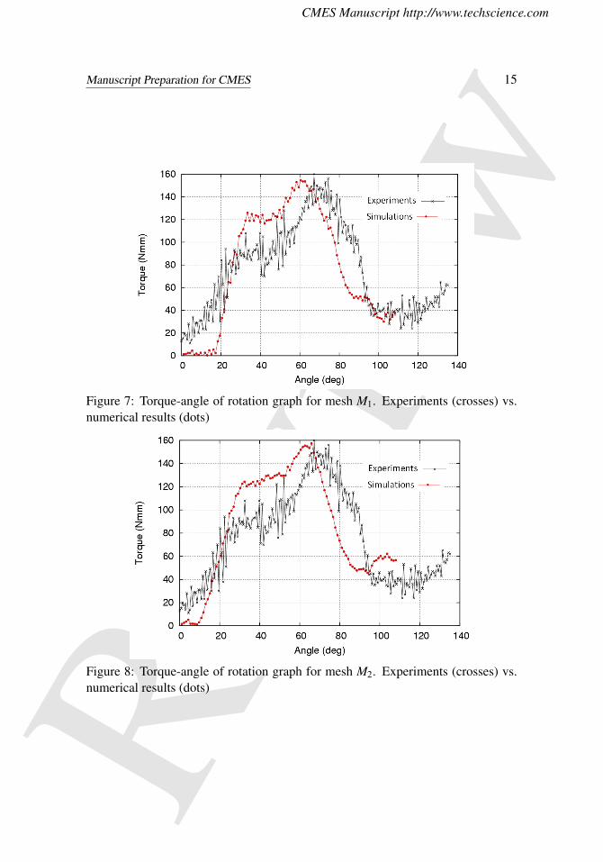
Figure 7: Torque-angle of rotation graph for mesh M1. Experiments (crosses) vs.numerical results (dots)
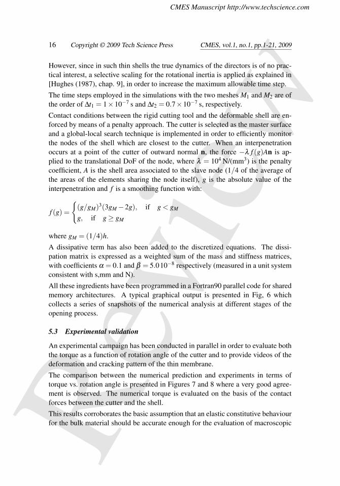
Figure 8: Torque-angle of rotation graph for mesh M2. Experiments (crosses) vs.numerical results (dots)
CMES Manuscript http://www.techscience.com
Revi
ew16 Copyright © 2009 Tech Science Press CMES, vol.1, no.1, pp.1-21, 2009
However, since in such thin shells the true dynamics of the directors is of no prac-tical interest, a selective scaling for the rotational inertia is applied as explained in[Hughes (1987), chap. 9], in order to increase the maximum allowable time step.
The time steps employed in the simulations with the two meshes M1 and M2 are ofthe order of ∆t1 = 1×10⁻⁷ s and ∆t2 = 0.7×10⁻⁷ s, respectively.
Contact conditions between the rigid cutting tool and the deformable shell are en-forced by means of a penalty approach. The cutter is selected as the master surfaceand a global-local search technique is implemented in order to efficiently monitorthe nodes of the shell which are closest to the cutter. When an interpenetrationoccurs at a point of the cutter of outward normal n, the force −λ f (g)An is ap-plied to the translational DoF of the node, where λ = 104 N/(mm3) is the penaltycoefficient, A is the shell area associated to the slave node (1/4 of the average ofthe areas of the elements sharing the node itself), g is the absolute value of theinterpenetration and f is a smoothing function with:
f (g) =
{(g/gM)3(3gM−2g), if g < gM
g, if g≥ gM
where gM = (1/4)h.
A dissipative term has also been added to the discretized equations. The dissi-pation matrix is expressed as a weighted sum of the mass and stiffness matrices,with coefficients α = 0.1 and β = 5.010−8 respectively (measured in a unit systemconsistent with s,mm and N).
All these ingredients have been programmed in a Fortran90 parallel code for sharedmemory architectures. A typical graphical output is presented in Fig, 6 whichcollects a series of snapshots of the numerical analysis at different stages of theopening process.
5.3 Experimental validation
An experimental campaign has been conducted in parallel in order to evaluate boththe torque as a function of rotation angle of the cutter and to provide videos of thedeformation and cracking pattern of the thin membrane.
The comparison between the numerical prediction and experiments in terms oftorque vs. rotation angle is presented in Figures 7 and 8 where a very good agree-ment is observed. The numerical torque is evaluated on the basis of the contactforces between the cutter and the shell.
This results corroborates the basic assumption that an elastic constitutive behaviourfor the bulk material should be accurate enough for the evaluation of macroscopic

CMES Manuscript http://www.techscience.com
Revi
ewManuscript Preparation for CMES 17
Figure 9: Comparison of fracture advancement and pattern in experiments (left)and simulations (right).
CMES Manuscript http://www.techscience.com
Revi
ew18 Copyright © 2009 Tech Science Press CMES, vol.1, no.1, pp.1-21, 2009
quantities like the opening torque. It is also worth stressing that almost no mesh de-pendence is observed, in agreement with the common understanding that the simu-lation of damage and fracture by means of discrete cracking and cohesive elementsallows to eliminate the issue of mesh dependence observed in diffused/smearedcracking approaches.
A visual comparison is also attempted in Figure 9 between the snapshots of the sim-ulation and of the experimental video. A good qualitative agreement is observedin terms of fracture pattern and advancement, though the real membrane displaysa somehow higher toughness (lower brittleness), possibly associated to a slightlygreater bluntness of the real cutter edge with respect to the numerical model, wherethe blade edge results from the intersection of flat elements and is therefore ex-tremely sharp.
6 Conclusions
We have developed a simplified procedure, based on the definition of “directional”cohesive elements, for the simulation of the blade cutting of thin membranes used inthe carton packaging industry to seal packages containing liquid food. The mem-brane consists of a composite lamina made of thin layers of aluminium and lowdensity polyethylene (LPDE). Since LPDE is a highly ductile material, the post-aluminium-fracture behaviour is crucial to reproduce the macroscopic response ofthe membrane as measured, e.g., by the torque-rotation angle graph. In standardinterface cohesive elements, the direction of the cohesive forces simply dependson the crack opening and cannot account for the presence of sharp cutting toolsprogressing between the cohesive flanks. A new kind of “directional” cohesive el-ements has then been introduced which simulate the contact between LPDE andthe cutting tool within the fracture process zone and are able to capture the es-sential phenomena of the opening process. The constitutive law of the cohesiveelements has been calibrated on the basis of ad hoc laboratory experiments andof data available in the literature. A validation of the model has been performedagainst laboratory opening tests and a good agreement has been found with rela-tively coarse meshes. As expected, the adoption of a cohesive model has eliminatedalmost completely the dependence of results on the refinement of the mesh whichis a major issue in standard FEM simulation since LPDE displays a softening be-haviour. One limitation of the present implementation is the absence of plasticityin the shell model for the composite membrane. The introduction of plastic defor-mations, currently in progress, together with specifically conceived experimentaltests for material parameters calibration, should allow to improve the accuracy ofthe simulation both in quantitative and qualitative terms.
CMES Manuscript http://www.techscience.com
Revi
ewManuscript Preparation for CMES 19
Acknowledgement: The financial support by Tetra Pak Packaging Solutions iskindly acknoweledged.
References
Areias, P. M. A. and Belytschko, T. (2005). Non-linear analysis of shells witharbitrary evolving cracks using xfem. International Journal for Numerical Methodsin Engineering 62, 384–415.
Areias, P. M. A., Song, J. H. and Belytschko, T. (2006). Analysis of fracture inthin shells by overlapping paired elements. Computer Methods in Applied Mechan-ics and Engineering 195, 5343–5360.
Atkins, A. and Xu, X. (2005). Slicing of soft flexible solids with industrial applica-tions. International Journal of Mechanical Sciences 47, 479–492. ISSN 00207403.
Atkins, A. G., Xu, X. and Jeronimidis, G. (2004). Cutting, by ’pressing andslicing,’ of thin floppy slices of materials illustrated by experiments on cheddarcheese and salami. Journal of Materials Science 39, 2761–2766.
Atkins, T. (2006). Optimum blade configurations for the cutting of soft solids.Engineering Fracture Mechanics 73, 2523–2531. ISSN 00137944.
Atkins, T. (2009). The science and engineering of cutting. Buttherworth Heine-mann, Oxford, UK. ISBN ISBN-13: 978-0-7506-8531-3, ISBN-10: 0-7506-8531-X.
Bathe, K. (1996). Finite element procedures. Prentice-Hall Int., Englewood Cliffs,NJ, USA. ISBN 0-13-301458-4.
Belytschko, T., Lin, J. I. and Tsay, C. S. (1984). Explicit algorithms for thenonlinear dynamics of shells. Computer Methods in Applied Mechanics and Engi-neering 42, 225–251. ISSN 00457825.
Chanthasopeephan, T., Desai, J. P. and Lau, A. C. W. (2007). Modeling soft-tissue deformation prior to cutting for surgical simulation: Finite element analysisand study of cutting parameters. Biomedical Engineering, IEEE Transactions on54, 349–359.
Cirak, F., Ortiz, M. and Pandolfi, A. (2005). A cohesive approach to thin-shellfracture and fragmentation. Computer Methods in Applied Mechanics and Engi-neering 194, 2604–2618. ISSN 00457825.

CMES Manuscript http://www.techscience.com
Revi
ew20 Copyright © 2009 Tech Science Press CMES, vol.1, no.1, pp.1-21, 2009
Hughes, T. (1987). The Finite Element Method: linear static and dynamic finiteelement analysis. Prentice-Hall Int., Englewood Cliffs, NJ, USA. ISBN 0-13-317017-9.
Kao-Walter, S. (2004). On the Fracture of Thin Laminates. Ph.D. thesis, BlekingeInstitute of Technology, Karlskrona, Sweden.
Li, W. and Siegmund, T. (2002). An analysis of crack growth in thin-sheet metalvia a cohesive zone model. Engineering Fracture Mechanics 69, 2073–2093. ISSN00137944.
Lin, Z.-C. and Ye, J.-R. (2009). Quasi-steady molecular statics model for simu-lation of nanoscale cutting with different diamond cutters. Computer Modeling inEngineering & Science 50, 227–252. ISSN 1526-1492.
Mahvash, M., Voo, L. M., Kim, D., Jeung, K., Wainer, J. and Okamura, A. M.(2008). Modeling the forces of cutting with scissors. Biomedical Engineering,IEEE Transactions on 55, 848–856.
Muscat-Fenech, C. and Atkins, A. G. (1998). Denting and fracture of sheet steelby blunt and sharp obstacles in glancing collisions. International Journal of ImpactEngineering 21, 499–519. ISSN 0734743X.
Pardoen, T., Marchal, Y. and Delannay, F. (2002). Essential work of frac-ture compared to fracture mechanics-towards a thickness independent plane stresstoughness. Engineering Fracture Mechanics 69, 617–631. ISSN 00137944.
Pegoretti, A., Castellani, L., Franchini, L., Mariani, P. and Penati, A. (2009).On the essential work of fracture of linear low-density-polyethylene. i. precision ofthe testing method. Engineering Fracture Mechanics ISSN 00137944.
Potyondy, D. O., Wawrzynek, P. A. and Ingraffea, A. R. (1995). Discrete crackgrowth analysis methodology for through cracks in pressurized fuselage structures.International Journal for Numerical Methods in Engineering 38, 1611–1633.
Simonsen, B. and Törnqvist, R. (2004). Experimental and numerical modellingof ductile crack propagation in large-scale shell structures. Marine Structures 17,1–27. ISSN 09518339.
Song, J. H. and Belytschko, T. (2009). Dynamic fracture of shells subjected toimpulsive loads. Journal of Applied Mechanics 76, 051301_1–051301_9.
Wierzbicki, T. and Thomas, P. (1993). Closed-form solution for wedge cuttingforce through thin metal sheets. International Journal of Mechanical Sciences 35,209–229. ISSN 00207403.
CMES Manuscript http://www.techscience.com
Revi
ewManuscript Preparation for CMES 21
Williams, J. and Rink, M. (2007). The standardisation of the ewf test. EngineeringFracture Mechanics 74, 1009–1017. ISSN 00137944.
Zavattieri, P. D. (2006). Modeling of crack propagation in thin-walled structuresusing a cohesive model for shell elements. Journal of Applied Mechanics 73, 948–958.
Zheng, Z. M. and Wierzbicki, T. (1996). A theoretical study of steady-statewedge cutting through metal plates. International Journal of Fracture 78, 45–66.
Zienkiewicz, O. C. and Zhu, J. Z. (1992). The superconvergent patch recoveryand a posteriori error estimates. part 1: The recovery technique. InternationalJournal for Numerical Methods in Engineering 33, 1331–1364. ISSN 1097-0207.

CMES Manuscript http://www.techscience.com
Revi
ew