Digimatic Mini-Processor DP-1VA LOGGER User's Manual
110
No. 99MAM029A Date of publication: August 1, 2017 (1) User's Manual - Instructions for use - Statistical Processing Printer for Quality Control Digimatic Mini-Processor DP-1VA LOGGER Read this User's Manual thoroughly before operating the instrument. After reading, retain it close at hand for future reference. This English language version of the User's Manual contains the original instructions.
-
Upload
khangminh22 -
Category
Documents
-
view
0 -
download
0
Transcript of Digimatic Mini-Processor DP-1VA LOGGER User's Manual

No. 99MAM029ADate of publication: August 1, 2017 (1)
User's Manual- Instructions for use -
Statistical Processing Printer for Quality ControlDigimatic Mini-Processor
DP-1VA LOGGER
Read this User's Manual thoroughly before operating the instrument. After reading, retain it close at hand for
future reference.This English language version of the User's Manual
contains the original instructions.

No. 99MAM029A
� Notice regarding this document y Mitutoyo Corporation assumes no responsibilities for any damage to the instrument, caused by its use not conforming to the procedure described in this User's Manual.
y Upon loan or transfer of this instrument, be sure to attach this User's Manual to the instrument.
y In the event of loss or damage to this manual, immediately contact a Mitutoyo sales office or your dealer.
y Before operation of the instrument, thoroughly read this manual to comprehend its contents.
y Particularly, for full understanding of information, carefully read "Safety Precautions" and "Precautions for Use" at the outset of this manual before using the instrument.
y The contents in this manual are based on the information current as of July, 2017. y No part or whole of this manual may be transmitted or reproduced by any means with-out prior written permission of Mitutoyo Corporation.
y Some screen displays in this manual may be highlighted, simplified or partially omitted for convenience of explanation. In addition, some of them may differ from actual ones to the extent that no user will misunderstand the functions and operations.
y The corporation, organization and product names that appear in this manual are their trademarks or registered trademarks.
©2017 Mitutoyo Corporation. All rights reserved.
� Correspondence of product names and model numbers
z Product namesDigimatic Mini-Processor
zModel numbersDP-1VA LOGGER

i No. 99MAM029A
CONVENTIONS USED IN THIS USER'S MANUAL
� Safety reminder conventions and wording warning against potential hazardsConventions used in this User's Manual are roughly divided into three types (safety reminders, prohibited and mandatory actions, and referential information and locations). Moreover, these safety symbols include general warnings and specific warnings. Specific warning symbols are provided with specific pictograms inside of them.
General
DANGER
Indicates an immediately hazardous situation which, if not avoided, will result in serious injury or death.
WARNING
Indicates a potentially hazardous situation which, if not avoided, could result in serious injury or death.
CAUTION
Indicates a potentially hazardous situation which, if not avoided, may result in minor injury.
NOTICE Indicates a potentially hazardous situation which, if not avoided, may result in property damage.
Specific Alerts the user to a specific hazardous situation that means "Caution, risk of electric shock".
� Conventions and wording indicating referential information or referential locations
Tips Indicates referential information such as that for when the operating methods and pro-cedures which are printed in these sentences are to be applied to specific conditions.
Indicates referential destinations if there is information that should be referred to in this document or an external manual.E.g.: For further details on XX, refer to "1.3 Names and Main Functions of Each Part" on page 4.

ii No. 99MAM029A
Product Safety LabelThis product has been designed and manufactured with human safety taken as a major consideration.In order to use it more safely, Product Safety Label has been applied to the product. This section describes where the label is applied and warning information.Before operating this product, be sure to carefully read this section to use it safely for an extended period of service life.
� Label locationIN
OUT
� Contents of the labels and precaution statement
Notice labels Precautions
Be aware of cutsBe aware so as to not cut your hand with the paper cutter when setting the printer paper.

iii No. 99MAM029A
Safety PrecautionsRead the "Safety Precautions" thoroughly before operating to use the product properly.As the precaution statements explained here address the contents to prevent the occur-rence of safety hazards to others or damage to property, they are to be strictly observed.
WARNING
• The product is intended for use with general machinery (measuring instruments, machine tools, etc.). Do not use the product with a control instrument whose operation faults or accidents can cause direct bodily injury or death, such as medical equipment, aerospace equipment, trains, and atomic power plant equipment. Contact us if you have ques-tions regarding suitable applications for the product.
• If the product starts to emit smoke or strange odors, or if it otherwise fails to operate correctly, turn off the power switch immediately and disconnect the AC adapter from the electrical outlet, then contact a Mitutoyo sales office or your dealer for repair. Continued use of the product under the above conditions may cause a fire or an electric shock.
• Users should never attempt to repair or modify the product. As it may cause a fire or an electric shock, it shall be avoided under any circumstance.
• The product should not be used in places where volatile gas can be generated. It may cause a fire.
• Use with the designated power-supply voltage. Continued use of the product with a power-supply voltage other than the designated one may cause a fire or an electric shock.
• Use the designated batteries. Use of non-designated batteries may cause a fire or injury due to rupturing or liquid leakage.
• The batteries shall be properly set following the instrument indication paying atten-tion to the batteries' polarity when they are set in it. Improper setting of the batteries may cause a fire or injury due to rupturing or liquid leakage.
CAUTION
• If the product is dropped or otherwise damaged, turn off the power switch and dis-connect the AC adapter from the electrical outlet, then contact a Mitutoyo sales office or your dealer. Continued use of the product under the above conditions may cause a fire or an electric shock.
• The options used with the product shall be the designated ones in this manual with-out fail. Use of the non-designated options may cause a fire, electric shock or failure.
NOTICE • Do not apply excessive external force to the product. It may cause a failure or break-age.
• If foreign matter enters the product, turn off the power switch and disconnect the AC adapter from the electrical outlet, then contact a Mitutoyo sales office or your dealer.

iv No. 99MAM029A
Precautions for Use
� Use application and handling of the product
z The product is a precision instrument.Take sufficient care when handling. Pay sufficient attention not to apply an excessive shock or force to any part when operating.
� Operating environmentThe product shall be used in the following environments.
y Places where the ambient temperature is 0 °C–45 °C (in case batteries are used, 10 °C–45 °C) y Places with a small amount of dust and dirt y Places with a small amount of vibration y Places with low humidity
Avoid use in the following environments. y Places directly affected by cutting oil or water y Places with direct daylight, hot air or cold air y Places where instruments generating electromagnetic noise, such as a welding ma-chine or electric discharge machine, are used.
� Daily maintenance y Wipe dirt off the main body with a lint free cloth or paper moistened with neutral deter-gent. Do not use an organic solvent such as thinner.
y It is necessary to regularly clean the printer head and paper sensor of the printer por-tion.For further details on cleaning method, refer to "6.1 Maintenance" on page 65.
� Power supply y After use, please be sure to turn off the power. y In case an AC adapter is used, connect to the different power supply from that where a large current flows (for machine tools or large scale of CNC controlled measuring machines).

v No. 99MAM029A
Electromagnetic Compatibility (EMC)This product complies with the EU EMC Directive. Note that, in environments where elec-tromagnetic interference exceeds the EMC requirements defined in this directive, appro-priate countermeasures are required to assure product performance.This is an industrial product. It is not intended for use in a residential environment. Use of this product in a residential environment may cause electromagnetic interference with other instruments. In such a case, appropriate measures against electromagnetic interfer-ence are required.
Export Control ComplianceThis product falls into the Catch-All-Controlled Goods and/or Catch-All-Controlled Tech-nologies (including Programs) under Category 16 of Appended Table 1 of the Export Trade Control Order or under Category 16 of the Appended Table of Foreign Exchange Control Order, based on the Foreign Exchange and Foreign Trade Act of Japan.If you intend re-export of the product from a country other than Japan, resale of the prod-uct in a country other than Japan, or re-provision of the technology (including program), you are obligated to observe the regulations of your country.Also, if an option is added or modified to add a function to this product, this product may fall under the category of List-Control Goods and/or List-Control Technology (including Programs) under Category 1 - 15 of Appended Table 1 of the Export Trade Control Or-der or under Category 1 - 15 of the Appended Table of Foreign Exchange Control Order, based on Foreign Exchange and Foreign Trade Act of Japan. In that case, if you intend re-export of the product from a country other than Japan, resale of the product in a coun-try other than Japan, or re-provision of the technology (including program), you are obli-gated to observe the regulations of your country. Please contact Mitutoyo in advance.
Notes on Export to EU Member CountriesWhen you intend export of this product to any of the EU member countries, you may be required to provide User's Manual(s) in English and EU Declaration of Conformity in English (under certain circumstances, User's Manual(s) in the destination country's official language and EU Declaration of Conformity in the destination country's official language). For detailed information, please contact Mitutoyo in advance.

vi No. 99MAM029A
Disposal of Old Electrical & Electronic Equipment under Waste Separation Processing system (in Eu-ropean countries)
This symbol on the product or on its packaging is based on the WEEE Directive (Directive on Waste Electrical and Electronic Equipment), which is a regulation in EU member countries, and this symbol indicates that the product shall not be treat-ed as household waste. To reduce the environmental impact and minimize the volume of landfills, please cooperate in reusing and recycling the product. For how to dispose of the product, please contact the dealer or distributor you purchased it from.
电器电子产品有害物质限制使用管理办法 China RoHS Compliance Information
This product meets China RoHS requirements. See the table below.
产品中有害物质的名称及含量
部件名称
有害物质
铅 汞 镉 六价铬 多溴联苯 多溴二苯醚
(Pb) (Hg) (Cd) (Cr(VI)) (PBB) (PBDE)
本体 × ○ ○ ○ ○ ○
配件 ○ ○ ○ ○ ○ ○
本表格依据 SJ/T 11364 的规定编制。
○:表示该有害物质在该部件所有均质材料中的含量均在 GB/T 26572 规定的限量要求以下。
×:表示该有害物质至少在该部件的某一均质材料中的含量超出 GB/T 26572 规定的限量要求。
10环保使用期限标识,是根据电器电子产品有害物质限制使用管理办法以及,电子电气产品有害物质限制使用标识要求(SJ/T11364-2014),制定的适用于中国境内销售电子电气产品的标识。
电子电气产品只要按照安全及使用说明内容,正常使用情况下,从生产月期算起,在此期限内,产品中含有的有毒有害物质不致发生外泄或突变,不致对环境造成严重污染或对其人身、财产造成严重损害。
产品正常使用后,要废弃在环保使用年限内或者刚到年限的产品时,请根据国家标准采取适当的方法进行处置。
另外,此期限不同于质量/功能的保证期限。

vii No. 99MAM029A
WarrantyThis equipment has been manufactured under strict quality management, but should it develop problems within 1 year of the date of purchase in normal use, repair shall be performed free of charge. Contact a Mitutoyo sales office or your dealer.
In the following cases, repair will be charged even during the term of the warranty. y Failure or damage due to normal wear and tear. y Failure or damage due to inappropriate handling, maintenance or repairs, or to unau-thorized modifications.
y Failure or damage due to transport, dropping, or relocation of the instrument after purchase.
y Failure or damage due to fire, salt, gas, abnormal voltages, lightning surges, or natural disasters, etc.
y Failure or damage due to use in combination with hardware or software other than those designated or permitted by Mitutoyo.
y Failure or damage due to use in ultra-hazardous activities.
This warranty is effective only when the instrument is properly installed in Japan and operated in conformance with the instructions in this manual.
EXCEPT AS SPECIFIED IN THIS WARRANTY, ALL EXPRESS OR IMPLIED CONDI-TIONS, REPRESENTATIONS, AND WARRANTIES OF ANY NATURE WHATSOEVER INCLUDING, WITHOUT LIMITATION, ANY IMPLIED WARRANTY OF MERCHANTABI-LITY, FITNESS FOR A PARTICULAR PURPOSE, NONINFRINGEMENT OR WARRAN-TY ARISING FROM A COURSE OF DEALING, USAGE, OR TRADE PRACTICE, ARE HEREBY EXCLUDED TO THE MAXIMUM EXTENT ALLOWED BY APPLICABLE LAW.You assume all responsibility for all results arising out of its selection on the product to achieve its intended results.
viii No. 99MAM029A
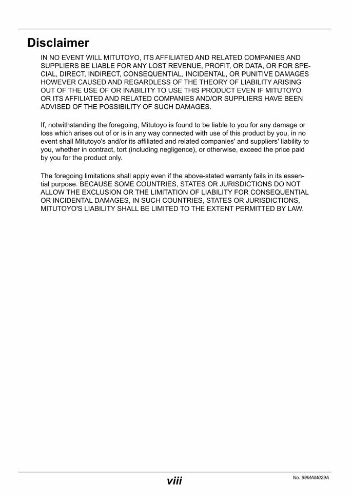
DisclaimerIN NO EVENT WILL MITUTOYO, ITS AFFILIATED AND RELATED COMPANIES AND SUPPLIERS BE LIABLE FOR ANY LOST REVENUE, PROFIT, OR DATA, OR FOR SPE-CIAL, DIRECT, INDIRECT, CONSEQUENTIAL, INCIDENTAL, OR PUNITIVE DAMAGES HOWEVER CAUSED AND REGARDLESS OF THE THEORY OF LIABILITY ARISING OUT OF THE USE OF OR INABILITY TO USE THIS PRODUCT EVEN IF MITUTOYO OR ITS AFFILIATED AND RELATED COMPANIES AND/OR SUPPLIERS HAVE BEEN ADVISED OF THE POSSIBILITY OF SUCH DAMAGES.
If, notwithstanding the foregoing, Mitutoyo is found to be liable to you for any damage or loss which arises out of or is in any way connected with use of this product by you, in no event shall Mitutoyo's and/or its affiliated and related companies' and suppliers' liability to you, whether in contract, tort (including negligence), or otherwise, exceed the price paid by you for the product only.
The foregoing limitations shall apply even if the above-stated warranty fails in its essen-tial purpose. BECAUSE SOME COUNTRIES, STATES OR JURISDICTIONS DO NOT ALLOW THE EXCLUSION OR THE LIMITATION OF LIABILITY FOR CONSEQUENTIAL OR INCIDENTAL DAMAGES, IN SUCH COUNTRIES, STATES OR JURISDICTIONS, MITUTOYO'S LIABILITY SHALL BE LIMITED TO THE EXTENT PERMITTED BY LAW.

ix No. 99MAM029A
This Document
� The target audience and objectives of this document
z Target audienceThe target audience is first time users of Digimatic Mini-Processor DP-1VA LOGGER.
z ObjectivesPlease read through the document to use the product in a safe and correct manner. After reading this, keep it in an easily accessible place for future reference with the product.The objective of this document is to help you to understand the functional outline of the product, functions of each part, how to use and maintenance details.
� Notes for reading this document
This indicates the specific operation procedure.
In other words, this indicates the work proce-dure to implement or its general description.
The sentence with ">>" mark at the head indicates the operation result.
This indicates the supplemental information.
This indicates that the operation procedure which requires a key operation is explained.
� As per the usage of this documentThe contents in this document which are in particular quite frequently used are summarized on the back cover. Utilize them by making a copy of them or clipping them out.

x No. 99MAM029A
� Notation method of parenthesesThe meaning of parentheses used in this documents will be explained.
( ): Round brackets Used to explain the contents of previous items or add auxiliary explanation to it.
" ": Quotation marks Used to emphasize the expression. Or, to indicate the referent in a referential sentence.
[ ]: Square brackets Used to indicate the operation key.

xi No. 99MAM029A
ContentsCONVENTIONS USED IN THIS USER'S MANUAL .................................................... iProduct Safety Label ................................................................................................. iiSafety Precautions ................................................................................................... iiiPrecautions for Use .................................................................................................. ivElectromagnetic Compatibility (EMC)...................................................................... vExport Control Compliance ...................................................................................... vNotes on Export to EU Member Countries .............................................................. vDisposal of Old Electrical & Electronic Equipment under Waste Separation Pro-cessing system (in European countries) ................................................................ vi电器电子产品有害物质限制使用管理办法 China RoHS Compliance Information ..................................................................... viWarranty ................................................................................................................... viiDisclaimer................................................................................................................ viiiThis Document .......................................................................................................... ix
1 Outline .......................................................................................................... 1
1.1 Packing Content Confirmation .............................................................. 1
1.2 Functional Outline ................................................................................. 2
1.3 Names and Main Functions of Each Part.............................................. 41.3.1 Names of Each Part .......................................................................................4
1.3.2 Names and Functions of Operation Key ........................................................5
2 Basic Operations ......................................................................................... 7
2.1 Setup .................................................................................................... 72.1.1 AC Adapter Connecting and Battery Cells Setting ........................................7
2.1.2 Setting the Printer Paper and Power-on ........................................................9
2.1.3 Printing the Parameter Settings List.............................................................11
2.1.4 Date and Time Setting .................................................................................12
2.1.5 Connection of a Measuring Instrument with Digimatic Output .....................14
2.1.6 Connection of the Foot Switch (Option) .......................................................15
2.2 Measuring with a Measuring Instrument with Digimatic Output and Printing .................................................................................................16

xii No. 99MAM029A
2.3 Display and Printing the Tolerance Judgment Results .........................192.3.1 Tolerance Settings .......................................................................................19
2.3.2 Measurement and Display/Printing the Tolerance Judgment Results .........22
2.3.3 Deletion of Upper/Lower Specification Limit Value (Limit Data) ...................23
2.4 Printing the Statistical Calculation Value ..............................................24
3 Advanced Operations and Useful Functions .......................................... 27
3.1 Printing only Measurement Data and Tolerance Judgment Results (MODE0) ..............................................................................................27
3.2 D Chart (Chart Indicating Temporal Changes of Measurement Data) Printing (MODE2) ................................................................................ 29
3.3 Printing the Data for Xbar-R Control Chart (MODE3) ..........................31
3.4 Logging of Measurement Data and Printing/Output of Log Data......... 353.4.1 Parameter Settings for Data Log Function ...................................................35
3.4.2 Start/Stop of Logging, Collective Print/Deletion of Log Data .......................37
3.5 Inputting and Printing of the KA Counter Data with RS-232C ............. 39
3.6 Other Functions .................................................................................. 433.6.1 Timer Input of the Measurement Data .........................................................43
3.6.2 Deletion of the Measurement Data ..............................................................45
3.6.3 Change of a Print Character Font Size ........................................................46
3.6.4 Return to the Initial Settings .........................................................................48
4 Output ......................................................................................................... 49
4.1 USB Output of the Measurement Data ............................................... 494.1.1 Connect to a PC Using a Store-Bought USB Cable ....................................49
4.1.2 USB Output Operation of the Measurement Data .......................................52
4.2 RS-232C Output of Measurement Data .............................................. 534.2.1 Connection of RS-232C Conversion Cable (Option)....................................53
4.2.2 RS-232C Communication Settings ..............................................................56
4.2.3 RS-232C Output Operation of Measurement Data ......................................57
4.3 Tolerance Judgment Result Output ..................................................... 584.3.1 Connection of a GO/±NG Judgment Cable (Option) ....................................58
4.3.2 Tolerance Judgment Result Output Operation .............................................59

xiii No. 99MAM029A
5 Function Settings .......................................................................................61
5.1 Various SYSTEM/WORK MODE and Print Contents/Output to PC .....615.1.1 SYSTEM/WORK MODE Selection and Print Contents ...............................61
5.1.2 Measurement Data Collection and Output (Print and Output to PC) ...........62
5.1.3 WORK MODE and Print Examples ..............................................................62
5.2 Various Parameter Settings and Setting Items ................................... 63
6 Maintenance and Troubleshooting........................................................... 65
6.1 Maintenance ....................................................................................... 65
6.2 Error Displays ......................................................................................676.2.1 Error Displays with Power LED ....................................................................67
6.2.2 Other Error Displays .....................................................................................68
6.3 Troubleshooting ...................................................................................70
7 Specifications .............................................................................................73
7.1 General Specifications .........................................................................73
7.2 Calculation Specifications ....................................................................757.2.1 Effective Digits .............................................................................................75
7.2.2 Formulas ......................................................................................................76
7.3 Connection Diagram with Various Optional Instruments ......................78
7.4 Options ................................................................................................797.4.1 Digimatic Connection Cable List ..................................................................79
7.4.2 Other Options ...............................................................................................80
SERVICE NETWORKRevision History

xiv No. 99MAM029A

1
1 Outline
No. 99MAM029A
1 OutlineThis chapter describes the overview of the product.
1.1 PackingContentConfirmationMake sure all items below are included.Contact a Mitutoyo sales office or your dealer if something is missing.
• User's Manual (This Document)
• Digimatic Mini-Processor DP-1VA LOGGER
• Printer paper
• Warranty card
• AC adapter • Strap
Tips • Note that dry batteries are not supplied. Please prepare them as needed. For further details on the required dry batteries, refer to "2.1.1 AC Adapter Con-necting and Battery Cells Setting" on page 7.
• An optional dedicated cable is required to connect a measuring instrument with Digimatic output. For further details on the dedicated cable, refer to "7.4.1 Digimatic Connection Cable List" on page 79.
� Attaching the strapAttach the strap to the product for drop prevention as needed. Remove the sling from the hook and attach it to the strap eyelet.
Strap eyelet
Sling
Hook

2
1 Outline
No. 99MAM029A
1.2 Functional OutlineThe product is a data processing unit used to print out the measurement data by connect-ing with our measuring instrument with Digimatic output.
"2 Basic Operations" on page 7
The product supports the inputs from a Digimatic out-put and measuring instrument with Digimatic 2 output. This also can be used to automatically fetch the data from the measuring instrument at given intervals. ( "3.6.1 Timer Input of the Measurement Data" on page 43)
Tips This also supports an input of RS-232C output data by connecting an optional dedicated RS-232C output cable to the KA Counter. For further details on the RS-232C input operation of the KA Counter, refer to "3.5 Inputting and Printing of the KA Counter Data with RS-232C" on page 39.
The product has additional functions below. y Data logging and USB output to PC
"3.4 Logging of Measurement Data and Printing/Output of Log Data" on page 35
Up to a maximum of 1,000 entries of measurement data can be logged (stored) in the internal memory of the product. The log data stored can be printed or output to PC via USB collectively.
y Data output "4 Output" on page 49
Both the output of the measurement data to PC (USB, RS-232C: TTL level) and the output of the tol-erance judgment result (+NG, GO, -NG) are possible.
Tips Prior tolerance setting is required for the tolerance judgment result output. For further details on the tolerance setting operation, refer to "2.3.1 Tolerance Settings" on page 19.
y LED display and printing of the measurement data tolerance judgment result (A) "2.3.2 Measurement and Display/Printing the Tolerance Judgment Results" on page 22
This is the judgment function on whether the measurement data is within the setting tolerance or not and the judgment results can be indicated with the Tolerance Judg-ment LED or printed on the printer paper.

3
1 Outline
No. 99MAM029A
y Abundant statistical processing (B) "2.4 Printing the Statistical Calculation Value" on page 24
Calculating number of data (N), Maximum value (MAX), Minimum value (MIN), Range (R), Average value (X̄), Standard deviation (σn, σn-1), Number of defectives (±NG), Fraction defective (P) and Process capability index (Cp, Cpk), they can be printed on the printer paper.
y Histogram generation (C) "2.4 Printing the Statistical Calculation Value" on page 24
The histogram shown in the charts below can be printed on the printer paper. y D chart (chart indicating temporal changes of measurement data) generation (D)
"3.2 D Chart (Chart Indicating Temporal Changes of Measurement Data) Printing (MODE2)" on page 29The measurement data in the D chart, which visually represents the change of dis-placement of measurement data, can be printed on the printer paper together with measurement data.
y Calculation and printing of the various calculated values required for the X̄-R control chart (E)
"3.3 Printing the Data for Xbar-R Control Chart (MODE3)" on page 31Number of subgroups, Sample size, Subgroup average value (X̄), Subgroup range (R), Center value (X=), Upper control limit (X̄-UCL), Center (R control) (R̄), Upper con-trol limit (R control) (R̄-UCL), Lower control limit (R control) (R̄-LCL) can be calculated and printed on the printer paper.
(A) (C) (D)
(B)
Tolerance judgment results
(E)
Statistical calculation value Histogram
D chart
Various calculation values required for X̄-R control charts

4
1 Outline
No. 99MAM029A
1.3 Names and Main Functions of Each Part
1.3.1 Names of Each Part
OPEN
EXT.P
Must use the following types of battery for battery operation.
Alkaline battery LR6AA Ni-MH battery
+ −Mitutoyo Corporation MADE IN JAPAN
Code No.ModelSerial No.Power
INPU
TOU
TPUT
ADAP
TER
INO
UT
USB micro connector (B receptacle)
Back Side
Power LED
Tolerance judgment LED
Printer paper cover
DC jack
Output connector *
Input connector
* The output connector is also used as an input connector of the KA Counter.
Foot switch connector
Release lever
Battery box cover
Strap eyelet
Operation key
For further details on the attaching method of the strap, refer to "1.1 Packing Content Confirmation" on page 1.

5
1 Outline
No. 99MAM029A
1.3.2 Names and Functions of Operation Key
POWER
TOL.REC/STOP
PRINTER CLEAR
STAT.OUT LOG
CANCEL
DATAFEED
[POWER] key
[CLEAR] key
[PRINTER] key
Press when switching on/off the power.
Press when deleting all the measurement data.
Press when switching on/off the printing function of measurement data and log data.
[CANCEL] key
[DATA] key
Press to cancel the latest input mea-surement data.Hold down for more than 10 seconds to delete the measurement data/log data and initialize the date and time by hardware reset.
Press to input the data from the measuring instrument.
[STAT. | OUT LOG] keyPress to perform the statistical calculation based on all the input measurement data, print the calculation results and generate the histogram. Hold down to print the log data and output it to USB.
[FEED] keyWhile being pressed the printer paper is fed.
[TOL. | REC/STOP] keyPress to enter or exit the setting mode for the limit data (upper/lower specification limit value). Hold down to start/stop the data logging.
zWhen two key operations are required y Parameter Setup Mode: DATA + POWER (effective only when turning on the power) ( "5.2 Various Parameter Settings and Setting Items" on page 63)
y Timer Input Mode: PRINTER + FEED ( "3.6.1 Timer Input of the Measurement Data" on page 43)
y Print date and time: PRINTER + DATA
Tips The operation will differ from the explanations above when the state falls under the items below.• When entering in parameter setup mode
For further details on the key operation in parameter setup mode, refer to "5.2 Various Parameter Settings and Setting Items" on page 63.
• When WORK MODE is selected to "MODE 3" in parameter setup mode For further details on the key operation with MODE3 setting, refer to "3.3 Printing the Data for Xbar-R Control Chart (MODE3)" on page 31.

6
1 Outline
No. 99MAM029A

7
2 Basic Operations
No. 99MAM029A
2 Basic OperationsThebasicoperationoftheproductwillbeexplainedasaseriesoftheflow.
2.1 Setup
2.1.1 AC Adapter Connecting and Battery Cells SettingA power supply through an AC adapter or batteries is required to power the product.
� Connecting the AC adapterConnect the power plug of the accessory AC adapter to an electrical outlet, and the DC plug to the DC jack on the right side of the product.
NOTICE Use only one of the following of our specified AC adapters. Use of an AC adapter not included in the list below may result in poor print quality and shorten the printing life.• Plug for Japan and North America (Parts No. 06AEG180JA)• Plug for China (Parts No. 06AEG180DC)• Plug for Europe (Parts No. 06AEG180D)• Plug for the UK (Parts No. 06AEG180E)• Plug for Korea (Parts No. 06AEG180K)
DC jack
Tips Insert the DC plug of the AC adapter securely all the way into the DC jack.

8
2 Basic Operations
No. 99MAM029A
� Setting the batteries
1 Detach the battery box cover.
Pressing down the claw portion of the battery box cover, pull out the cover toward this side.
oyo Corporation
IN JAPAN
Code No.Model
Serial No.Power
yo Corporation
IN JAPAN
Code No.Model
Serial No.Power
Must use the following types of battery
for battery operation.Alkaline battery LR6
AA Ni-MH battery
Must use the following types of battery
for battery operation.Alkaline battery LR6
AA Ni-MH battery
Battery box cover
Claw of battery box cover
2 Prepare the dry batteries and set them inside.
1 Prepare the batteries.2 Insert the dry batteries in the battery box
following the battery polarity indication inside the cover.
oyo Corporation
ADE IN JAPAN
Code No.Model
Serial No.Power
NOTICE • Make sure that the coating of the battery terminals is not peeling or swelling before using. Any peeling or swelling of the coating on the battery terminals may cause a malfunction such as poor contact or short circuiting.
• If the product is not used for a long period of time, remove the batteries. If the batteries are left inside, battery liquid leakage may make the product unusable.
Tips • AA alkaline batteries (LR6) or nickel-metal-hydride (Ni-MH Size AA) can be used. Do not use manganese batteries. When alkaline batteries are used, the print may become faint due to the characteristics of the batteries.
• Do not set different types of batteries together.• Be sure to correctly set the polarity of batteries.
3 Press the battery box cover back.
Tips • Press it back into place until it clicks.• When using alkaline batteries or Ni-MH batteries, the printing speed may be slower
compared to when the AC adapter is used.• Batteries can be used as a power supply when the temperature is 10 °C or higher. In
case the temperature is lower than 10 °C, a defect such as a faint printing may occur.• The product does not have a charging function. Use a store-bought charger for
charging.• The battery life of the product is about 10,000 lines (in case printing in "LARGE" char-
acters/5 seconds using 1,600 mAh Ni-MH batteries). The battery life may largely vary depending on the use method or environment.
9
2 Basic Operations
No. 99MAM029A
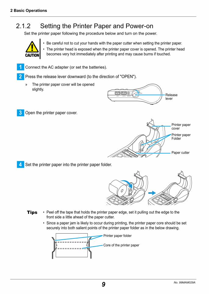
2.1.2 Setting the Printer Paper and Power-onSet the printer paper following the procedure below and turn on the power.
CAUTION
• Be careful not to cut your hands with the paper cutter when setting the printer paper.• The printer head is exposed when the printer paper cover is opened. The printer head
becomes very hot immediately after printing and may cause burns if touched.
1 Connect the AC adapter (or set the batteries).
2 Press the release lever downward (to the direction of "OPEN").
» The printer paper cover will be opened slightly.
OPEN
INPUT OUTPUT ADAPTER Release lever
3 Open the printer paper cover.
Printer paper cover
Printer paper Folder
Paper cutter
4 Set the printer paper into the printer paper folder.
Tips • Peel off the tape that holds the printer paper edge, set it pulling out the edge to the front side a little ahead of the paper cutter.
• Since a paper jam is likely to occur during printing, the printer paper core should be set securely into both salient points of the printer paper folder as in the below drawing.
Core of the printer paper
Printer paper folder

10
2 Basic Operations
No. 99MAM029A
Tips Only our specified paper (Parts No. 09EAA082, 10 rolls/pack) shall be used. The printer paper for the product is a paper with excellent durability. Nevertheless, the print becomes faint over time due to the characteristics of thermal paper. In the case of extended storage (5 years or longer) or use for official documents, the use of photocopies is recommended. As the print disappears, discoloring or paper deterioration may occur if cutting fluid or other substances get on the printer paper, storing of the copies is recommended.
5 Close the printer paper cover with the printer paper edge protruding a little from the paper cutter.
1 Close the cover pressing both ends of the printer paper cover top surface.
Tips Close the cover paying attention so the printer paper does not hang over the right and left side edges of the cover.
6 Switch on the power and feed the printer paper forward.
1 Press POWER , and then release a finger from the key.
» The power LED is lit, the printer paper is fed, and then "Mitutoyo", "DP-1VA LOGGER", the mode number, time/date, number of log data and log condition are printed.
2 Hold down FEED to feed the printer pa-per forward by approximately 100 mm.
Power LED1
2
Tips • After the printer paper is set, it is necessary to feed it by pressing FEED without fail. Self-alignment function for the paper position to reduce the possibility of a paper jam is activated by pressing this button.
• When the power LED is not lit, check whether the batteries with sufficient charge re-maining are firmly set or whether the AC adapter is connected properly.
• If the power LED blinks, change the batteries as promptly as possible. If continuing to use without changing, the malfunction where the power off switch does not work may occur.
• When holding down POWER again, the power turns off. On/Off operation of the power shall be performed at an interval of 5 seconds or more. On/Off operation of the power within a shorter time than the above may cause a malfunction. If it happens, load the batteries or AC adapter again and restart.
11
2 Basic Operations
No. 99MAM029A
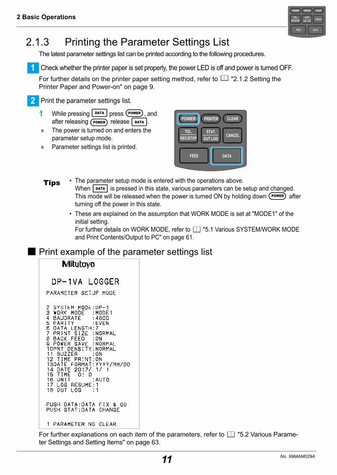
2.1.3 Printing the Parameter Settings ListThe latest parameter settings list can be printed according to the following procedures.
1 Check whether the printer paper is set properly, the power LED is off and power is turned OFF.For further details on the printer paper setting method, refer to "2.1.2 Setting the Printer Paper and Power-on" on page 9.
2 Print the parameter settings list.
1 While pressing DATA press POWER , and after releasing POWER release DATA .
» The power is turned on and enters the parameter setup mode.
» Parameter settings list is printed.
POWER
TOL.REC/STOP
PRINTER CLEAR
STAT.OUT LOG
CANCEL
DATAFEED
Tips • The parameter setup mode is entered with the operations above. When DATA is pressed in this state, various parameters can be setup and changed. This mode will be released when the power is turned ON by holding down POWER after turning off the power in this state.
• These are explained on the assumption that WORK MODE is set at "MODE1" of the initial setting. For further details on WORK MODE, refer to "5.1 Various SYSTEM/WORK MODE and Print Contents/Output to PC" on page 61.
� Print example of the parameter settings list
For further explanations on each item of the parameters, refer to "5.2 Various Parame-ter Settings and Setting Items" on page 63.
POWER
TOL.REC/STOP
PRINTER CLEAR
STAT.OUT LOG
CANCEL
DATAFEED

12
2 Basic Operations
No. 99MAM029A
2.1.4 Date and Time SettingJapan Standard Time is set to the product at the time of factory shipment. When correct-ing this, set to the parameter setup mode ( "2.1.3 Printing the Parameter Settings List" on page 11), and set the date and time by the following operation procedure.For further details on the parameter setup mode, refer to "5.2 Various Parameter Set-tings and Setting Items" on page 63.
1 Move the parameter set item to the date setting position in the parameter setup mode.
1 Press DATA repeatedly until "14 DATE" is printed.
» Whenever DATA is pressed, the param-eter set item/contents are printed by line as shown in the right figure.
» The explanation on key operation for date setting and the date currently set are printed as shown in the right figure.
Tips To change the date, calculate (count) the number of changes from the printed date, and go to 2 .
Date currently set
Explanation on key operation for date setting
2 Input the date. (If change is not required, go to 3 .)
1 Input "Year" by pressing PRINTER or TOL.
REC/STOP the necessary amount of times from the current set value.
2 Input "Month" by pressing CLEAR the necessary amount of times from the current set value.
3 Input "Day" by pressing CANCEL the nec-essary amount of times from the current set value.
POWER
TOL.REC/STOP
PRINTER CLEAR
STAT.OUT LOG
CANCEL
DATAFEED
Day(1 -> 2 -> .. . -> 31 -> 1)
Month(1 -> 2 -> .. . -> 12 -> 1)
Year (2000 -> 2001 -> .. . -> 2100 -> 2000)
Year (2000 -> 2100 -> .. . -> 2001 -> 2000)
The date input is printed
Tips • Press STAT.OUT LOG to print the input date to check the input contents.
• Leap years and the number of days in a month are automatically calculated.
POWER
TOL.REC/STOP
PRINTER CLEAR
STAT.OUT LOG
CANCEL
DATAFEED

13
2 Basic Operations
No. 99MAM029A
3 Fix the date.
1 Press DATA once. » The fixed date is printed. » The explanation on key operation for
time setting, next settings "15 TIME" and the time currently set are printed as shown in the right figure.
Fixed date
Time currently set
Explanation on key operation for time setting
Tips If the desired date is not printed, enter the parameter setup mode again to re-enter it.
4 Input the time. (If change is not required, go to 5 .)
1 Input "Hour" by pressing PRINTER the necessary amount of times from the current set value.
2 Input "Minute" by pressing CLEAR or TOL.
REC/STOP the necessary amount of times from the current set value.
3 Check whether the printed time is the
intended one by pressing STAT.OUT LOG .
4 When the desired time is not printed, change it with procedure 1 or 2.
POWER
TOL.REC/STOP
PRINTER CLEAR
STAT.OUT LOG
CANCEL
DATAFEED
Minute (0 -> 1 -> .. . -> 59 -> 0)
Hour (0 -> 1 -> .. . -> 23 -> 0)
Minute (59 -> 58 -> .. . 0 -> 59)
The time input is printed
Tips Set the time in the 24-hour system format.
5 Fix the time.
1 Press DATA once. » The fixed time is printed.
Fixed time
Tips • If the desired time is not printed by pressing DATA , enter the parameter setup mode again to re-enter it.
• Even if the power is turned off after this operation, the date and time set shall be main-tained. However, when the parameters are cleared with "PARAMETER CLEAR" in the parameter, the date and time is set as "2017/1/1 0:0" and resetting is required.
If it is desired to complete parameter setup after the above, press DATA repeatedly until parameter setup list is printed.
POWER
TOL.REC/STOP
PRINTER CLEAR
STAT.OUT LOG
CANCEL
DATAFEED
14
2 Basic Operations
No. 99MAM029A
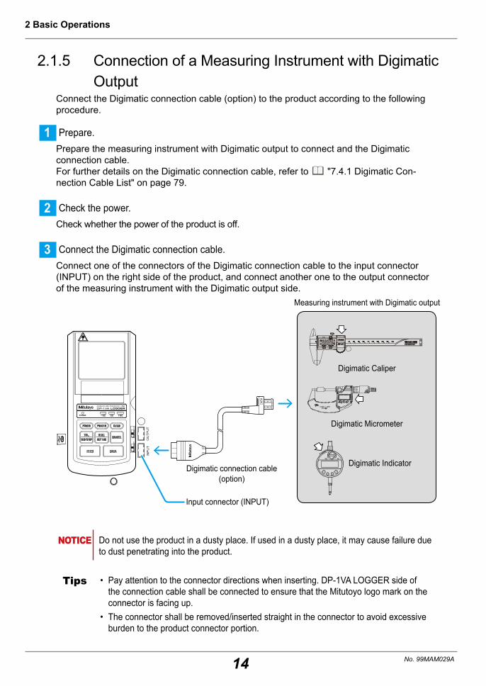
2.1.5 Connection of a Measuring Instrument with Digimatic Output
Connect the Digimatic connection cable (option) to the product according to the following procedure.
1 Prepare.Prepare the measuring instrument with Digimatic output to connect and the Digimatic connection cable. For further details on the Digimatic connection cable, refer to "7.4.1 Digimatic Con-nection Cable List" on page 79.
2 Check the power.Check whether the power of the product is off.
3 Connect the Digimatic connection cable.Connect one of the connectors of the Digimatic connection cable to the input connector (INPUT) on the right side of the product, and connect another one to the output connector of the measuring instrument with the Digimatic output side.
INP
UT
OU
TPU
T
DATA
INO
UT
Input connector (INPUT)
Measuring instrument with Digimatic output
Digimatic Caliper
Digimatic Micrometer
Digimatic IndicatorDigimatic connection cable (option)
NOTICE Do not use the product in a dusty place. If used in a dusty place, it may cause failure due to dust penetrating into the product.
Tips • Pay attention to the connector directions when inserting. DP-1VA LOGGER side of the connection cable shall be connected to ensure that the Mitutoyo logo mark on the connector is facing up.
• The connector shall be removed/inserted straight in the connector to avoid excessive burden to the product connector portion.
15
2 Basic Operations
No. 99MAM029A
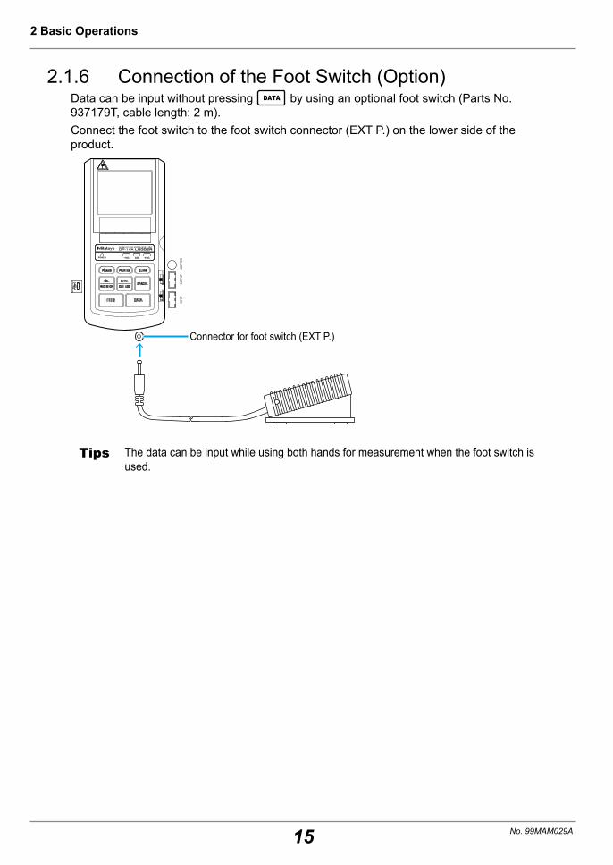
2.1.6 Connection of the Foot Switch (Option)Data can be input without pressing DATA by using an optional foot switch (Parts No. 937179T, cable length: 2 m).Connect the foot switch to the foot switch connector (EXT P.) on the lower side of the product.
INPU
TOU
TPUT
ADAP
TER
INO
UT
Connector for foot switch (EXT P.)
Tips The data can be input while using both hands for measurement when the foot switch is used.
16
2 Basic Operations
No. 99MAM029A
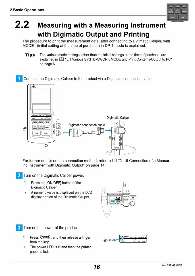
2.2 Measuring with a Measuring Instrument with Digimatic Output and Printing
The procedure to print the measurement data, after connecting to Digimatic Caliper, with MODE1 (initial setting at the time of purchase) in DP-1 mode is explained.
Tips The various mode settings, other than the initial settings at the time of purchase, are explained in "5.1 Various SYSTEM/WORK MODE and Print Contents/Output to PC" on page 61.
1 Connect the Digimatic Caliper to the product via a Digimatic connection cable.
DATA
INP
UT
OU
TPU
T
INO
UT
Digimatic Caliper
Digimatic connection cable
For further details on the connection method, refer to "2.1.5 Connection of a Measur-ing Instrument with Digimatic Output" on page 14.
2 Turn on the Digimatic Caliper power.
1 Press the [ON/OFF] button of the Digimatic Caliper.
» A numeric value is displayed on the LCD display portion of the Digimatic Caliper.
DATA
3 Turn on the power of the product.
1 Press POWER , and then release a finger from the key.
» The power LED is lit and then the printer paper is fed.
Light is on
POWER
TOL.REC/STOP
PRINTER CLEAR
STAT.OUT LOG
CANCEL
DATAFEED
17
2 Basic Operations
No. 99MAM029A
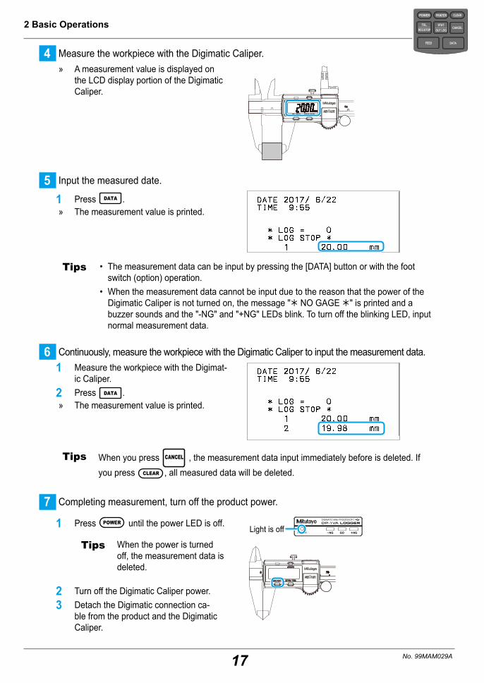
4 Measure the workpiece with the Digimatic Caliper. » A measurement value is displayed on
the LCD display portion of the Digimatic Caliper.
5 Input the measured date.
1 Press DATA . » The measurement value is printed.
Tips • The measurement data can be input by pressing the [DATA] button or with the foot switch (option) operation.
• When the measurement data cannot be input due to the reason that the power of the Digimatic Caliper is not turned on, the message "Û NO GAGE Û" is printed and a buzzer sounds and the "-NG" and "+NG" LEDs blink. To turn off the blinking LED, input normal measurement data.
6 Continuously, measure the workpiece with the Digimatic Caliper to input the measurement data.1 Measure the workpiece with the Digimat-
ic Caliper.2 Press DATA .
» The measurement value is printed.
Tips When you press CANCEL , the measurement data input immediately before is deleted. If you press CLEAR , all measured data will be deleted.
7 Completing measurement, turn off the product power.
1 Press POWER until the power LED is off.
Tips When the power is turned off, the measurement data is deleted.
2 Turn off the Digimatic Caliper power.3 Detach the Digimatic connection ca-
ble from the product and the Digimatic Caliper.
Light is off
POWER
TOL.REC/STOP
PRINTER CLEAR
STAT.OUT LOG
CANCEL
DATAFEED
18
2 Basic Operations
No. 99MAM029A
Tips When printing the measurement value measured with the measuring instrument with Digimatic output other than the Digimatic Caliper, follow the basic procedure described below.• Before the measurement
1 Connect to the measuring instrument with Digimatic output via a Digimatic connection cable in the power off state.
2 Turn on the power of the measuring instrument with Digimatic output.3 Turn on the product power.
• After the measurement
1 Turn off the product power.2 Turn off the power of measuring instrument with Digimatic output.3 Detach the Digimatic connection cable from the product and the measuring instrument
with Digimatic output.

19
2 Basic Operations
No. 99MAM029A
2.3 Display and Printing the Tolerance Judg-ment Results
It is possible to make a tolerance judgment by comparing a set of upper/lower specifica-tion value (limit data) and measurement data.The limit data can be set up to a maximum of five sets.
Measurement data
Display and print the tolerance judgment results
Limit data 1
Upper specification limit value
Lower specification limit value
Limit data 2 Limit data 3 Limit data 4 Limit data 5 Select one
Upper specification limit value
Lower specification limit value
Upper specification limit value
Lower specification limit value
Upper specification limit value
Lower specification limit value
Upper specification limit value
Lower specification limit value
2.3.1 Tolerance SettingsSet the limit data for tolerance judgment following the operation below.
1 Connect a measuring instrument with Digimatic output to the product.For further details on the connection method, refer to "2.1.5 Connection of a Measur-ing Instrument with Digimatic Output" on page 14.
2 Turn on the product power.
3 Turn on the power of the measuring instrument with Digimatic output.
4 Enter the limit input mode.
1 Press TOL.REC/STOP .
Tips • To enter the limit input mode, the product must be in one of the following two states: <1> No input data immediately after power-on, or <2> all data is deleted with CLEAR operation.
• When in the "ÛPRINTER OFFÛ" state, the limit input mode cannot be entered into. Press PRINTER , after "Û PRINTER ON Û" prints, perform the aforementioned opera-tions. Also, the printer will switch on due to the power being on.
• If TOL.REC/STOP is held down, the limit input mode will not be entered into, and the logging
functions will start.
POWER
TOL.REC/STOP
PRINTER CLEAR
STAT.OUT LOG
CANCEL
DATAFEED

20
2 Basic Operations
No. 99MAM029A
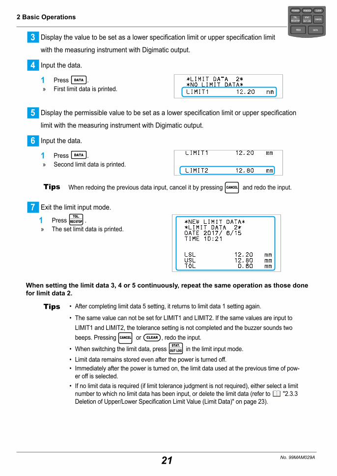
5 Display the value to be set as a lower specification limit or upper specification limit
with the measuring instrument with Digimatic output.
Tips Either the lower specification limit value or the upper specification limit value can be dis-played first. When setting them, the lower value is set to the lower specification limit value and the higher value to the upper specification limit value.
6 Input the data.
1 Press DATA . » First limit data is printed [LIMIT1].
7 Display the value to be set as a lower specification limit or upper specification limit with
the measuring instrument with Digimatic output.
8 Input the data.
1 Press DATA . » Second limit data is printed [LIMIT2].
Tips When redoing the previous data input, cancel it by pressing CANCEL and redo the input.
9 Exit the limit input mode.
1 Press TOL.REC/STOP .
» The set limit data is printed.
lower specifica-tion limit valueUpper specifica-tion limit valueTolerance
�When setting the limit data 2 continuously
1 Enter the limit input mode.
1 Press TOL.REC/STOP .
2 Enter the limit data 2 input mode.
1 Press STAT.OUT LOG .
POWER
TOL.REC/STOP
PRINTER CLEAR
STAT.OUT LOG
CANCEL
DATAFEED
21
2 Basic Operations
No. 99MAM029A
3 Display the value to be set as a lower specification limit or upper specification limit
with the measuring instrument with Digimatic output.
4 Input the data.
1 Press DATA . » First limit data is printed.
5 Display the permissible value to be set as a lower specification limit or upper specification
limit with the measuring instrument with Digimatic output.
6 Input the data.
1 Press DATA . » Second limit data is printed.
Tips When redoing the previous data input, cancel it by pressing CANCEL and redo the input.
7 Exit the limit input mode.
1 Press TOL.
REC/STOP . » The set limit data is printed.
When setting the limit data 3, 4 or 5 continuously, repeat the same operation as those done for limit data 2.
Tips • After completing limit data 5 setting, it returns to limit data 1 setting again.
• The same value can not be set for LIMIT1 and LIMIT2. If the same values are input to LIMIT1 and LIMIT2, the tolerance setting is not completed and the buzzer sounds two beeps. Pressing CANCEL or CLEAR , redo the input.
• When switching the limit data, press STAT.
OUT LOG in the limit input mode.• Limit data remains stored even after the power is turned off.• Immediately after the power is turned on, the limit data used at the previous time of pow-
er off is selected.• If no limit data is required (if limit tolerance judgment is not required), either select a limit
number to which no limit data has been input, or delete the limit data (refer to "2.3.3 Deletion of Upper/Lower Specification Limit Value (Limit Data)" on page 23).
POWER
TOL.REC/STOP
PRINTER CLEAR
STAT.OUT LOG
CANCEL
DATAFEED
22
2 Basic Operations
No. 99MAM029A
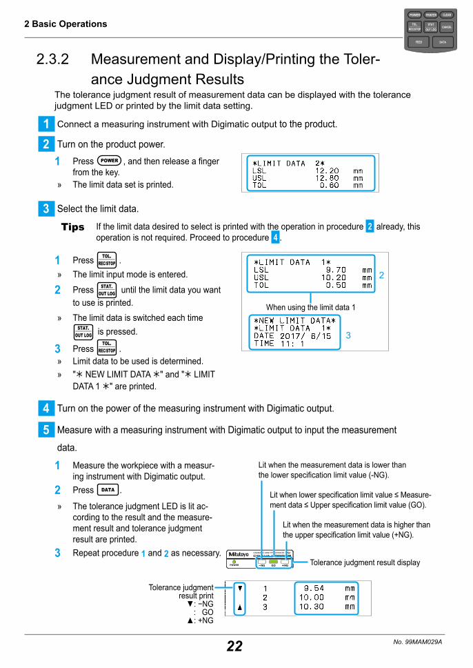
2.3.2 Measurement and Display/Printing the Toler-ance Judgment Results
The tolerance judgment result of measurement data can be displayed with the tolerance judgment LED or printed by the limit data setting.
1 Connect a measuring instrument with Digimatic output to the product.
2 Turn on the product power.
1 Press POWER , and then release a finger from the key.
» The limit data set is printed.
3 Select the limit data.
Tips If the limit data desired to select is printed with the operation in procedure 2 already, this operation is not required. Proceed to procedure 4 .
1 Press TOL.REC/STOP .
» The limit input mode is entered.
2 Press STAT.OUT LOG until the limit data you want
to use is printed. » The limit data is switched each time
STAT.OUT LOG is pressed.
3 Press TOL.
REC/STOP . » Limit data to be used is determined. » "Û NEW LIMIT DATA Û" and "Û LIMIT
DATA 1 Û" are printed.
2
3
When using the limit data 1
4 Turn on the power of the measuring instrument with Digimatic output.
5 Measure with a measuring instrument with Digimatic output to input the measurement
data.
1 Measure the workpiece with a measur-ing instrument with Digimatic output.
2 Press DATA .
» The tolerance judgment LED is lit ac-cording to the result and the measure-ment result and tolerance judgment result are printed.
3 Repeat procedure 1 and 2 as necessary.Tolerance judgment result display
Tolerance judgment result print
▼: −NG : GO
▲: +NG
Lit when the measurement data is lower than the lower specification limit value (-NG).
Lit when lower specification limit value ≤ Measure-ment data ≤ Upper specification limit value (GO).
Lit when the measurement data is higher than the upper specification limit value (+NG).
POWER
TOL.REC/STOP
PRINTER CLEAR
STAT.OUT LOG
CANCEL
DATAFEED

23
2 Basic Operations
No. 99MAM029A
Tips The tolerance judgment result can be output by connecting the GO±NG judgment cable (option) to the output connector. For further details on the tolerance judgment result output function, refer to "4.3 Toler-ance Judgment Result Output" on page 58.
Based on the measurement data here, "2.4 Printing the Statistical Calculation Value" on page 24 is performed.
2.3.3 Deletion of Upper/Lower Specification Limit Value (Limit Data)
When deleting the upper/lower specification limit value (limit data), follow the procedure below.
1 Enter the limit input mode.
1 Press TOL.REC/STOP .
2 Select the limit data.
Tips If the limit data desired to delete is printed with the operation in procedure 1 , this opera-tion is not required. Proceed to procedure 3 .
1 Continue to press STAT.OUT LOG until the limit
data desired to delete is printed. » The limit data is switched each time
STAT.OUT LOG is pressed.
Tips The old data is overwritten and disappears if the new limit data is input to it by selecting the limit data number already set.
3 Delete the limit data.
1 Press CLEAR .
Tips The measurement data can be immediately input following the operation above. However, the tolerance judgment cannot be performed as the limit data is deleted. To perform the tolerance judgment, enter the limit input mode again and measure after selecting the limit data set for the tolerance judgment.
POWER
TOL.REC/STOP
PRINTER CLEAR
STAT.OUT LOG
CANCEL
DATAFEED

24
2 Basic Operations
No. 99MAM029A
2.4 Printing the Statistical Calculation ValueFollowing the operation explained in "2.3.2 Measurement and Display/Printing the Tolerance Judgment Results" on page 22, the operation to print the statistical calculation value and his-togram based on the input data (a distribution chart of the measurement data) is explained here.
Tips When the power is turned off, the measurement data is deleted. In case the power is turned off, the operation below shall be performed after performing the measurement value input operation again.
1 Print the statistical calculation result.
1 Press STAT.
OUT LOG . » The statistical calculation result is printed. Statistical calculation
value (Refer to the next page for the expla-nation on statistical calculation value)
Histogram (only when the tolerance is set)
Lower specification limit valueUpper specification limit valueTolerance
The value range of the symbols used in the histogram
Tips • The maximum number of data that can be handled with MODE1 is 9,999. Once 9,999 measurement data are input, the statistical calculation result is automatically printed.
• If "TIME PRINT" of the parameter is set to "OFF", the date and time are not printed.
2 Turn off the power once the measurement value input and statistical calculation result
printing are completed.
1 Hold down POWER .
Tips On/Off operation of the power shall be performed at an interval of 5 seconds or more.
POWER
TOL.REC/STOP
PRINTER CLEAR
STAT.OUT LOG
CANCEL
DATAFEED

25
2 Basic Operations
No. 99MAM029A
� Statistical calculation valuesPrintout Meaning Calculation formulaN Number of dataMAX Maximum data valueMIN Minimum data value R Data range MAX−MINX̄ Average data value ΣXi/Nσn Standard Deviation σn = ((N•ΣESXi2 − (ΣXi)2) / N2)1/2
σn-1 Sample Standard Deviation σn − 1 = ((N•ΣESXi2 − (ΣXi)2) / N•E(N − 1))1/2
−NG Number of data lower than the lower specification limit value Number of data for which LSL > Xi
+NG Number of data higher than the upper specification limit value Number of data for which USL < Xi
P Fraction defective P = ((-NG) + (+NG))/N
Cp Process capability index Cp = TOL/(6σn − 1) TOL:USL − LSL
Cpk When process capability index bias is considered
Cpk = Zmin/3 Zmin:The lower value of ZUSL and ZLSL ZUSL = (USL − X̄)/σn−1, ZLSL = (X̄ − LSL)/σn−1

26
2 Basic Operations
No. 99MAM029A

27
3 Advanced Operations and Useful Functions
No. 99MAM029A
3 Advanced Operations and Useful Functions
Advanced operations and useful functions are explained.
3.1 Printing only Measurement Data and Toler-ance Judgment Results (MODE0)
The printing contents can be limited to the measurement data and tolerance judgment result by setting WORK MODE to "MODE0" in the parameter setup mode.The operation to measure in "MODE0" and print its result is explained here.
1 Set the WORK MODE to "MODE0".
1 While pressing DATA press POWER , and after releasing POWER , release DATA .
» The power is turned on and enters the parameter setup mode.
2 Press DATA twice. » The WORK MODE currently set is print-
ed (MODE1, here).
3 Press STAT.OUT LOG repeatedly until "3 WORK
MODE :MODE0" is printed.
4 Press DATA . » "MODE0" is determined.
2
3
5 Press DATA repeatedly until the param-eter settings list is printed.
» Parameter setup mode is completed.
POWER
TOL.REC/STOP
PRINTER CLEAR
STAT.OUT LOG
CANCEL
DATAFEED

28
3 Advanced Operations and Useful Functions
No. 99MAM029A
2 Input the measurement data.
1 Measure the workpiece, press DATA . » The measurement data is printed each
time DATA is pressed.
Measurement data
Tips • The maximum number of data that can be handled with MODE0 is 100,000.• Regardless of the SYSTEM MODE (DP-1, MP), only the measurement data and toler-
ance judgment result can be printed maximum 100,000 lines when the WORK MODE is set to "MODE0". - When printing the statistical calculation result or histogram: MODE1 - When printing D chart: MODE2 (when DP-1 mode is set) - When printing calculation result for X̄-R control chart: MODE3 (when DP-1 mode is set)
• The limit data shall be set before entering the measurement data to print the tolerance judgment result. For further details on the limit data setting method, refer to "2.3.1 Tolerance Set-tings" on page 19.
POWER
TOL.REC/STOP
PRINTER CLEAR
STAT.OUT LOG
CANCEL
DATAFEED
29
3 Advanced Operations and Useful Functions
No. 99MAM029A
POWER
TOL.REC/STOP
PRINTER CLEAR
STAT.OUT LOG
CANCEL
DATAFEED
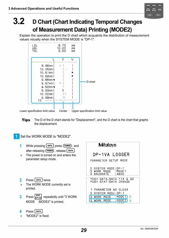
3.2 D Chart (Chart Indicating Temporal Changes of Measurement Data) Printing (MODE2)
Explain the operation to print the D chart which acquaints the distribution of measurement values visually when the SYSTEM MODE is "DP-1".
D chart
Upper specification limit valueCenterLower specification limit value
Tips The D of the D chart stands for "Displacement", and the D chart is the chart that graphs the displacement.
1 Set the WORK MODE to "MODE2".
1 While pressing DATA press POWER , and after releasing POWER , release DATA .
» The power is turned on and enters the parameter setup mode.
2 Press DATA twice. » The WORK MODE currently set is
printed.
23
3 Press STAT.OUT LOG repeatedly until "3 WORK
MODE :MODE2" is printed.
4 Press DATA . » "MODE2" is fixed.

30
3 Advanced Operations and Useful Functions
No. 99MAM029A
5 Press DATA repeatedly until the param-eter settings list is printed.
» Parameter setup mode is completed.
2 Set the tolerance judgment.
For further details on setting and selection method of the tolerance judgment, refer to "2.3.1 Tolerance Settings" on page 19.
3 Input the measurement data.
1 Press DATA . » The measurement data is printed in
D chart format each time DATA is pressed.
D chart
Symbol for the outside toler-ance
Tips • Symbol ▼▼ in the D chart represents that the measurement data is out of the toler-ance.
• The maximum number of measurement data that can be handled with MODE2 is 9,999.
• When pressing STAT.OUT LOG after inputting the measurement data, the statistical calculation
value and histogram are printed as in the case of MODE1. Once 9,999 measurement data are input, the statistical calculation result is automatically printed.
POWER
TOL.REC/STOP
PRINTER CLEAR
STAT.OUT LOG
CANCEL
DATAFEED

31
3 Advanced Operations and Useful Functions
No. 99MAM029A
3.3 Printing the Data for Xbar-R Control Chart (MODE3)
When the SYSTEM MODE is "DP-1", the calculation results for generating the X̄-R con-trol chart, which is one of representative control chart of sampling method of weighing data can be printed. The printing operation is explained here.
The measurement data and calculation result of subgroup 1
The measurement data and calculation result of subgroup 2
Average value
Range
The control limit's calculation result of all the subgroup measured before now
Tips For further details on the formula, refer to "7.2.2 Formulas" on page 76.
POWER
TOL.REC/STOP
PRINTER CLEAR
STAT.OUT LOG
CANCEL
DATAFEED

32
3 Advanced Operations and Useful Functions
No. 99MAM029A
1 Set the WORK MODE to "MODE3".
1 While pressing DATA press POWER , and after releasing POWER , release DATA .
» The power is turned on and enters the parameter setup mode.
2 Press DATA twice. » The WORK MODE currently set is
printed.
233 Press STAT.
OUT LOG repeatedly until "3 WORK MODE :MODE3" is printed.
4 Press DATA . » "MODE3" is determined.
5 Press DATA repeatedly until the param-eter settings list is printed.
» Parameter setup mode is completed.
This completes the parameter setting.Next, move to the subgroup measurement.
When the WORK MODE is set to "MODE3", the key operation differs from usual as shown below.
Key During subgroup measurement
After completion of subgroup measurement
CLEAR Re-input from the No.1 data. Delete all the measurement data (setting con-tents will remain).
CANCEL Cancel the previously inputted measurement data.
Deletes the subgroup for which input was previ-ously completed.
TOL.REC/STOP
Stop measurement and release the measuring mode.
Move to the next subgroup measurement.
STAT.OUT LOG
Calculates X̄ and R to print the result completing the subgroup measurement.
Calculates the control limits with all the sub-groups' data input up to that point of time and prints the results.
POWER
TOL.REC/STOP
PRINTER CLEAR
STAT.OUT LOG
CANCEL
DATAFEED

33
3 Advanced Operations and Useful Functions
No. 99MAM029A
2 Start the subgroup measurement.
1 Press TOL.REC/STOP .
» Subgroup number 1 is printed.
3 Input the measurement data.
1 Press DATA . » The measurement data is printed each
time DATA is pressed.Measurement data
Tips When canceling the previous measurement data, press CANCEL ("ÛCANCELÛ" is printed).
4 After measuring the necessary number of samples, print the calculation result of the sub-
group's X̄-R determining sample size.
1 Press STAT.OUT LOG .
» The number of samples is set to the sub-group sample size and the calculation result of X̄-R is printed.
X̄-R calculation result
Tips The maximum sample data number of the subgroup is 10.
5 Start the next subgroup measurement.
1 Press TOL.REC/STOP .
» Subgroup number is printed.
6 Input the measurement data.
1 Press DATA . » The measurement data is printed each
time DATA is pressed.Measurement data
Tips After the necessary number of samples are measured, further measurement data is not input even if DATA is pressed. Proceed to the next procedure.
POWER
TOL.REC/STOP
PRINTER CLEAR
STAT.OUT LOG
CANCEL
DATAFEED
34
3 Advanced Operations and Useful Functions
No. 99MAM029A
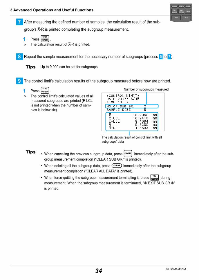
7 After measuring the defined number of samples, the calculation result of the sub-
group's X̄-R is printed completing the subgroup measurement.
1 Press STAT.
OUT LOG . » The calculation result of X̄-R is printed.
8 Repeat the sample measurement for the necessary number of subgroups (process 5 to 7 ).
Tips Up to 9,999 can be set for subgroups.
9 The control limit's calculation results of the subgroup measured before now are printed.
1 Press STAT.
OUT LOG . » The control limit's calculated values of all
measured subgroups are printed (R̄-LCL is not printed when the number of sam-ples is below six).
Number of subgroups measured
The calculation result of control limit with all subgroups' data
Tips • When canceling the previous subgroup data, press CANCEL immediately after the sub-group measurement completion ("CLEAR SUB GR." is printed).
• When deleting all the subgroup data, press CLEAR immediately after the subgroup measurement completion ("CLEAR ALL DATA" is printed).
• When force-quitting the subgroup measurement terminating it, press TOL.REC/STOP during
measurement. When the subgroup measurement is terminated, "Û EXIT SUB GR Û" is printed.
POWER
TOL.REC/STOP
PRINTER CLEAR
STAT.OUT LOG
CANCEL
DATAFEED

35
3 Advanced Operations and Useful Functions
No. 99MAM029A
POWER
TOL.REC/STOP
PRINTER CLEAR
STAT.OUT LOG
CANCEL
DATAFEED
3.4 Logging of Measurement Data and Printing/Output of Log Data
Operations to log the measurement data (to store in the internal memory as log data), to print the log data collectively and to output them to PC collectively using USB interface are explained.Depending on the internal battery, the saved log data is retained even when the power is turned off.
3.4.1 Parameter Settings for Data Log FunctionSet the items below in parameter settings.
Setting items Setting values Setting contents Initial setting
values
LOG RESUME
1 Activate with the log halt state when power is turned on.
12 Activate with the log start state when power is turned on.
3 Activate with the log state when the power was previously turned off when power is turned on.
OUT LOG
1 Print contents: Time/Measurement value USB output data: Time/Measurement value
1 (Time/Measure-
ment value)
2 Print contents: Data number/Measurement value USB output data: Measurement value
3Print contents: Data number/Date/Time/Measure-ment value USB output data: Date/Time/Measurement value
For further details on USB output, refer to "4.1 USB Output of the Measurement Data" on page 49.
� Log data collective print example y In DP-1 mode
In case of OUT LOG setting value 1
In case of OUT LOG setting value 2
In case of OUT LOG setting value 3
Measurement time
Measurement value
Data number
Measurement date and time
Measurement value
Data number
Measurement value
Measurement date

36
3 Advanced Operations and Useful Functions
No. 99MAM029A
y In MP modeLOG OUT1 LOG OUT2 LOG OUT3
Measurement date and time
Measurement valueData number
Data input axes
Measurement valueData input axes
Measurement time
Measurement date
1 Set "LOG RESUME" and "OUT LOG" of the parameters.
1 While pressing DATA press POWER , and after releasing POWER , release DATA .
» The power is turned on and enters the parameter setup mode.
2 Press DATA repeatedly until "17 LOG RESUME" is printed.
» "17 LOG RESUME : 1" is printed.
3 Press STAT.
OUT LOG repeatedly until the de-sired number to set to LOG RESUME is printed.
4 Press DATA .
5 Press STAT.
OUT LOG repeatedly until the de-sired number to set to "18 OUT LOG" is printed.
6 Press DATA . » The parameter settings list is printed. » The parameter settings are completed.
POWER
TOL.REC/STOP
PRINTER CLEAR
STAT.OUT LOG
CANCEL
DATAFEED
37
3 Advanced Operations and Useful Functions
No. 99MAM029A
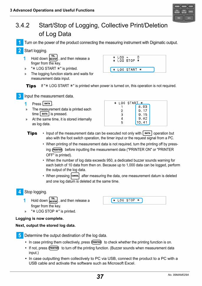
3.4.2 Start/Stop of Logging, Collective Print/Deletion of Log Data
1 Turn on the power of the product connecting the measuring instrument with Digimatic output.
2 Start logging.
1 Hold down TOL.
REC/STOP , and then release a finger from the key.
» "Û LOG START Û" is printed. » The logging function starts and waits for
measurement data input.
Tips If "Û LOG START Û" is printed when power is turned on, this operation is not required.
3 Input the measurement data.
1 Press DATA . » The measurement data is printed each
time DATA is pressed. » At the same time, it is stored internally
as log data.
Tips • Input of the measurement data can be executed not only with DATA operation but also with the foot switch operation, the timer input or the request signal from a PC.
• When printing of the measurement data is not required, turn the printing off by press-ing PRINTER before inputting the measurement data ("PRINTER ON" or "PRINTER OFF" is printed).
• When the number of log data exceeds 950, a dedicated buzzer sounds warning for each batch of 10 data from then on. Because up to 1,000 data can be logged, perform the output of the log data.
• When pressing CANCEL after measuring the data, one measurement datum is deleted and one log datum is deleted at the same time.
4 Stop logging.
1 Hold down TOL.REC/STOP , and then release a
finger from the key. » "Û LOG STOP Û" is printed.
Logging is now complete.
Next, output the stored log data.
5 Determine the output destination of the log data. y In case printing them collectively, press PRINTER to check whether the printing function is on. y If not, press PRINTER to turn off the printing function. (Buzzer sounds when measurement data
input.) y In case outputting them collectively to PC via USB, connect the product to a PC with a USB cable and activate the software such as Microsoft Excel.
POWER
TOL.REC/STOP
PRINTER CLEAR
STAT.OUT LOG
CANCEL
DATAFEED
38
3 Advanced Operations and Useful Functions
No. 99MAM029A
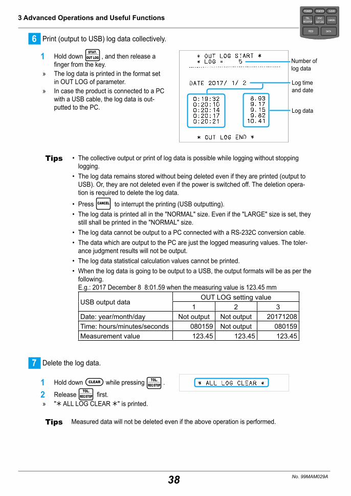
6 Print (output to USB) log data collectively.
1 Hold down STAT.
OUT LOG , and then release a finger from the key.
» The log data is printed in the format set in OUT LOG of parameter.
» In case the product is connected to a PC with a USB cable, the log data is out-putted to the PC. Log data
Number of log data
Log time and date
Tips • The collective output or print of log data is possible while logging without stopping logging.
• The log data remains stored without being deleted even if they are printed (output to USB). Or, they are not deleted even if the power is switched off. The deletion opera-tion is required to delete the log data.
• Press CANCEL to interrupt the printing (USB outputting).• The log data is printed all in the "NORMAL" size. Even if the "LARGE" size is set, they
still shall be printed in the "NORMAL" size.• The log data cannot be output to a PC connected with a RS-232C conversion cable.• The data which are output to the PC are just the logged measuring values. The toler-
ance judgment results will not be output.• The log data statistical calculation values cannot be printed.• When the log data is going to be output to a USB, the output formats will be as per the
following. E.g.: 2017 December 8 8:01.59 when the measuring value is 123.45 mm
USB output dataOUT LOG setting value
1 2 3Date: year/month/day Not output Not output 20171208Time: hours/minutes/seconds 080159 Not output 080159Measurement value 123.45 123.45 123.45
7 Delete the log data.
1 Hold down CLEAR while pressing TOL.REC/STOP .
2 Release TOL.REC/STOP first.
» "Û ALL LOG CLEAR Û" is printed.
Tips Measured data will not be deleted even if the above operation is performed.
POWER
TOL.REC/STOP
PRINTER CLEAR
STAT.OUT LOG
CANCEL
DATAFEED

39
3 Advanced Operations and Useful Functions
No. 99MAM029A
POWER
TOL.REC/STOP
PRINTER CLEAR
STAT.OUT LOG
CANCEL
DATAFEED
3.5 Inputting and Printing of the KA Counter Data with RS-232C
The operation procedure to print the display data of a KA Counter connecting a KA Count-er with a RS-232C counter cable (option) is explained.
Tips • The KA Counter is a counter for linear scale and also used as a counter for projectors such as PV-5110 and PH-3515F.
• Parameter setting or change in parameter setup mode is required beforehand. The dis-play data of the KA Counter can be printed only when SYSTEM MODE is "MP mode" and WORK MODE is "MODE0" or "MODE1".
Set the data input object axes (INPUT AXIS) and the calculation object axes (CUL) as needed.
Initial setting of the parameters Change to MP mode
1 Set the parameters.
1 While pressing DATA press POWER , and after releasing POWER , release DATA .
» The power is turned on and enters the parameter setup mode.
Tips The procedure to print the mea-surement data with "MODE1" of the initial setting is explained here. When printing only measurement data and tolerance judgment, change to "MODE0" ( "3.1 Printing only Measurement Data and Tolerance Judgment Results (MODE0)" on page 27.)
2 Press DATA . » "2 SYSTEM MODE : DP-1" is printed.
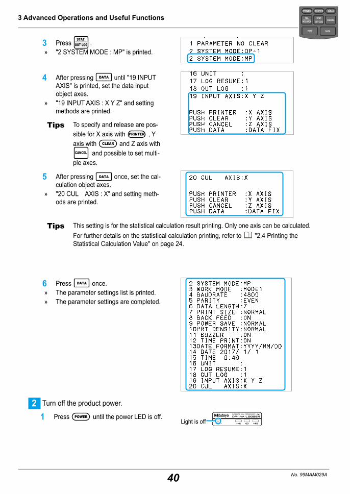
40
3 Advanced Operations and Useful Functions
No. 99MAM029A
3 Press STAT.
OUT LOG . » "2 SYSTEM MODE : MP" is printed.
4 After pressing DATA until "19 INPUT AXIS" is printed, set the data input object axes.
» "19 INPUT AXIS : X Y Z" and setting methods are printed.
Tips To specify and release are pos-sible for X axis with PRINTER , Y axis with CLEAR and Z axis with
CANCEL and possible to set multi-ple axes.
5 After pressing DATA once, set the cal-culation object axes.
» "20 CUL AXIS : X" and setting meth-ods are printed.
Tips This setting is for the statistical calculation result printing. Only one axis can be calculated.For further details on the statistical calculation printing, refer to "2.4 Printing the Statistical Calculation Value" on page 24.
6 Press DATA once. » The parameter settings list is printed. » The parameter settings are completed.
2 Turn off the product power.
1 Press POWER until the power LED is off.Light is off
POWER
TOL.REC/STOP
PRINTER CLEAR
STAT.OUT LOG
CANCEL
DATAFEED

41
3 Advanced Operations and Useful Functions
No. 99MAM029A
3 Connect the output connector of the product (OUTPUT) and the code out unit (for KA-
200 Counter) of the KA Counter with a RS-232C counter cable (option).
INP
UT
OU
TPU
T
INO
UT
Output connector (OUTPUT)
RS-232C counter cable (option)
KA Counter
Code out unit (for KA-200 Counter, option)
4 Turn on the KA Counter power to start the counter display.
Refer to the instruction manual of KA Counter and turn on the power according to its operation method.
Tips The value may not be displayed according to scale specifications. In this case, press [C] key.
5 Turn on the product power.
1 Press POWER , release your finger from the key.
» The power LED is lit and the printer paper is fed.
Light is on
6 Input the displayed data.
1 Press DATA . » The printer paper is fed and the dis-
played data is printed.
POWER
TOL.REC/STOP
PRINTER CLEAR
STAT.OUT LOG
CANCEL
DATAFEED
42
3 Advanced Operations and Useful Functions
No. 99MAM029A
7 Completing measurement, turn off the product power.
8 Turn off the KA Counter power.
9 Detach the connection cable.
Tips • The setting is required in advance when the tolerance judgment of inputted data is performed. For further details on the necessary setting for tolerance judgment, refer to "2.3.1 Tolerance Settings" on page 19.
• When printing the statistical value of input data or the histogram, press STAT.OUT LOG .
For further details on the statistical value or histogram print, refer to "2.4 Printing the Statistical Calculation Value" on page 24.
• When the power is turned off, the input data is deleted and the data number returns to 1.• When deleting only previous data input, press CANCEL .• When deleting all the input data, press CLEAR .
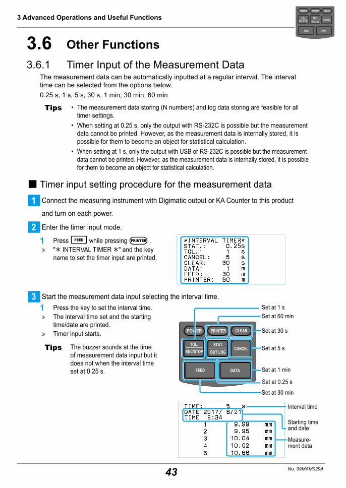
43
3 Advanced Operations and Useful Functions
No. 99MAM029A
POWER
TOL.REC/STOP
PRINTER CLEAR
STAT.OUT LOG
CANCEL
DATAFEED
3.6 Other Functions3.6.1 Timer Input of the Measurement Data
The measurement data can be automatically inputted at a regular interval. The interval time can be selected from the options below.0.25 s, 1 s, 5 s, 30 s, 1 min, 30 min, 60 min
Tips • The measurement data storing (N numbers) and log data storing are feasible for all timer settings.
• When setting at 0.25 s, only the output with RS-232C is possible but the measurement data cannot be printed. However, as the measurement data is internally stored, it is possible for them to become an object for statistical calculation.
• When setting at 1 s, only the output with USB or RS-232C is possible but the measurement data cannot be printed. However, as the measurement data is internally stored, it is possible for them to become an object for statistical calculation.
� Timer input setting procedure for the measurement data
1 Connect the measuring instrument with Digimatic output or KA Counter to this product
and turn on each power.
2 Enter the timer input mode.
1 Press FEED while pressing PRINTER . » "Û INTERVAL TIMER Û" and the key
name to set the timer input are printed.
3 Start the measurement data input selecting the interval time.1 Press the key to set the interval time.
» The interval time set and the starting time/date are printed.
» Timer input starts.
Tips The buzzer sounds at the time of measurement data input but it does not when the interval time set at 0.25 s.
POWER
TOL.REC/STOP
PRINTER CLEAR
STAT.OUT LOG
CANCEL
DATAFEED
Set at 5 s
Set at 30 s
Set at 1 min
Set at 30 min
Set at 60 minSet at 1 s
Interval time
Starting time and date
Measure-ment data
Set at 0.25 s

44
3 Advanced Operations and Useful Functions
No. 99MAM029A
4 Completion of the timer input.
1 Press CLEAR while pressing PRINTER . » "Û INT TIMER OFF Û" and "Û PRINT-
ER ON Û" are printed.
Tips • In case 0.25 s or 1 s is set to the interval time, do not press CANCEL , CLEAR or STAT.OUT LOG .
It may cause a malfunction.• If the data is already fetched when the timer input is completed, that data may be
printed.• The interval time shall not be changed while the timer input of measurement data is
performed. The timer input shall be once terminated to change the interval time.
POWER
TOL.REC/STOP
PRINTER CLEAR
STAT.OUT LOG
CANCEL
DATAFEED
45
3 Advanced Operations and Useful Functions
No. 99MAM029A
3.6.2 Deletion of the Measurement DataAlthough CLEAR is pressed to delete the measurement data stored in the product internal-ly, the deletion target may vary according to the WORK MODE as shown below.
MODE0, MODE1, MODE2MODE3
During subgroup measurement
After completion of subgroup measurement
Only the measurement data is deleted. Press it before tolerance setting (limit data setting) without fail.
Re-input from the No.1 data.
Delete all the measure-ment data.
When deleting the log data, hold down CLEAR while pressing TOL.REC/STOP .
For further details on the logging operation of measurement data, refer to "3.4.2 Start/Stop of Logging, Collective Print/Deletion of Log Data" on page 37.
Tips • The parameter setting is not changed even if CLEAR is pressed. When initializing the parameters, select "PARAMETER CLEAR" in "PARAMETER CLEAR" item of the parameter setting. For further details on the parameter setting, refer to "5.2 Various Parameter Set-tings and Setting Items" on page 63.
• When pressing CANCEL , only the previously input data is deleted. When it is pressed after completion of the subgroup measurement in WORK MODE "MODE3", the previ-ously input subgroup will be deleted. For further details on the operation in WORK MODE "MODE3", refer to "3.3 Print-ing the Data for Xbar-R Control Chart (MODE3)" on page 31.
• Be sure to delete the measurement data by pressing CLEAR before setting the limit data.
POWER
TOL.REC/STOP
PRINTER CLEAR
STAT.OUT LOG
CANCEL
DATAFEED

46
3 Advanced Operations and Useful Functions
No. 99MAM029A
3.6.3 Change of a Print Character Font SizeThe print character font size can be selected from the two types, "NORMAL" (24 (H) x 16 (W) dots) or "LARGE" (36 (H) x 24 (W) dots).Set by switching "7 PRINT SIZE" in the parameter setup mode.
NORMAL LARGE
Tips • 7,000 lines per printer paper with the LARGE font and 10,000 lines with the NORMAL font can be printed.
• The log data is always printed in the NORMAL font. Even if it is set to "LARGE", the print character font size is not changed. When using with "LARGE" setting, the normal measurement data is printed in LARGE font as set.
• The "Digimatic 2" format data is printed in NORMAL font. Even if it is set to "LARGE", it is automatically changed to the NORMAL font print. As the parameter setting remains the same, it returns to LARGE font by switching the power on again after switching it off.
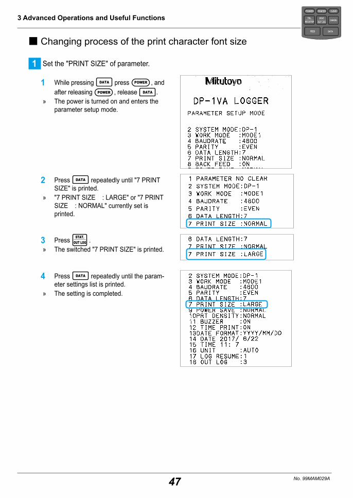
47
3 Advanced Operations and Useful Functions
No. 99MAM029A
� Changing process of the print character font size
1 Set the "PRINT SIZE" of parameter.
1 While pressing DATA press POWER , and after releasing POWER , release DATA .
» The power is turned on and enters the parameter setup mode.
2 Press DATA repeatedly until "7 PRINT SIZE" is printed.
» "7 PRINT SIZE : LARGE" or "7 PRINT SIZE : NORMAL" currently set is printed.
3 Press STAT.OUT LOG .
» The switched "7 PRINT SIZE" is printed.
4 Press DATA repeatedly until the param-eter settings list is printed.
» The setting is completed.
POWER
TOL.REC/STOP
PRINTER CLEAR
STAT.OUT LOG
CANCEL
DATAFEED

48
3 Advanced Operations and Useful Functions
No. 99MAM029A
POWER
TOL.REC/STOP
PRINTER CLEAR
STAT.OUT LOG
CANCEL
DATAFEED
3.6.4 Return to the Initial SettingsThe parameter setting can be returned to the initial setting with the operations below.
1 Return the parameters to the initial setting.
1 While pressing DATA press POWER , and after releasing POWER , release DATA .
» The power is turned on and enters the parameter setup mode.
» After printing the current parameter set-ting contents list, "1 PARAMETER NO CLEAR" is printed.
Current parameter settings list
2 Press STAT.OUT LOG .
» The buzzer sounds and "1 PARAMETER CLEAR" is printed.
3 Press DATA repeatedly until the param-eter settings list is printed.
» The parameter settings list returned to the initial setting is printed.
Parameter settings list returned to the initial setting
Tips • The limit data of tolerance setting and the measurement data are deleted with the operation above.
• Under the power on state, the initialization of parameters and the deletion of limit data of tolerance settings are not performed with the hardware reset when CANCEL is pressed for 10 seconds or more. However, the date and time are initialized and the measure-ment data and log data are deleted.
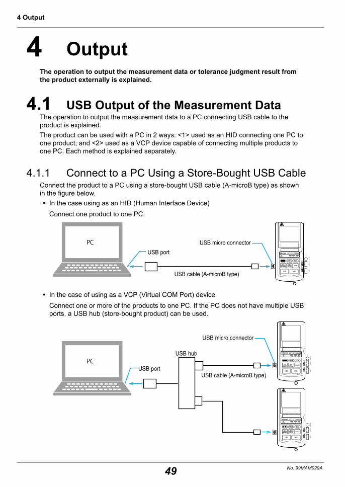
49
4 Output
No. 99MAM029A
4 OutputThe operation to output the measurement data or tolerance judgment result from the product externally is explained.
4.1 USB Output of the Measurement DataThe operation to output the measurement data to a PC connecting USB cable to the product is explained.The product can be used with a PC in 2 ways: <1> used as an HID connecting one PC to one product; and <2> used as a VCP device capable of connecting multiple products to one PC. Each method is explained separately.
4.1.1 Connect to a PC Using a Store-Bought USB CableConnect the product to a PC using a store-bought USB cable (A-microB type) as shown in the figure below.
y In the case using as an HID (Human Interface Device)Connect one product to one PC.
PC
INPU
TOU
TPUT
ADAP
TER
INO
UT
USB portUSB micro connector
USB cable (A-microB type)
y In the case of using as a VCP (Virtual COM Port) deviceConnect one or more of the products to one PC. If the PC does not have multiple USB ports, a USB hub (store-bought product) can be used.
PC
INPU
TOU
TPUT
ADAP
TER
INPU
TOU
TPUT
ADAP
TER
INO
UTIN
OUT
USB cable (A-microB type)USB port
USB hub
USB micro connector
50
4 Output
No. 99MAM029A
� Available PCsPCs with a USB port and an OS listed below installed can be used.
y Windows 7
y Windows 8/8.1
y Windows 10
� Software required on PC z In the case using as an HID (Human Interface Device)It can be used only by connecting to a USB port, no dedicated software or dedicated driver is required. The product operates as if it was a keyboard connected to a PC. The data can be output to the text input software such as Microsoft Excel, Notepad or Wordpad.
y About HID driver installation It can be automatically installed when the USB connector is connected to a PC. No operation is required.
y Connection confirmation method The following operation shall be performed to check whether the product is properly connected. In case of Windows 7:
1 Open [Control Panel]. Pressing the Start button, open the [Control Panel] directly.
2 Open [System] in the [Control Panel].3 Open [Device Manager] in [System].
When an alarm of "User Account Control" is displayed, click [Yes] to proceed to pro-cess 4.
4 Open [Human Interface Device].5 Check whether a [USB Human Interface Device] or a [USB Input Device] is added/re-
moved by inserting/removing the USB connector.In case of Windows 8/8.1, Windows 10:
1 By pressing the [X] key while pressing the Windows Logo key, open [Device Manager] by selecting [Device Manager] from the displayed menu.
2 The processes 4 and 5 in "In case of Windows 7:" above shall be executed.
z In the case of using as a VCP (Virtual COM Port) deviceA measurement data collection software "USB-ITPAK (V2.1 and higher)" (option) is re-quired. It is possible to output the measurement data to an Excel sheet such as an in-spection sheet form with "USB-ITPAK". For further details on the use as a VCP device, refer to the user's manual of "USB-IT-PAK (V2.1 and higher)".

51
4 Output
No. 99MAM029A
� USB communication specifications y Power source: Use the PC's USB connector (Type A plug) as the +5 V power supply. y Supported OS: Windows 7, Windows 8/8.1 Windows 10 (Windows 10 Mobile is not covered by warranty)
y Conformity Standards: USB standard y USB 2.0 certification, communication speed: 12 Mbps (Full Speed) y The product may temporarily deactivate the function due to electromagnetic interfer-ence caused by static electricity, but returns to the normal operation upon its elimina-tion.
y If electromagnetic interference was generated into the AC or DC power supply lines to the PC, then normal measuring results might be unable to be obtained. In that case, measure again checking the state of the power line's surrounding area.
NOTICE The product is compliant with the EU EMC directive. However, this does not guarantee the complete operation to all connections with PCs or USB hubs. In case noise interfer-ence occurs when connecting the product, there is the possibility to fix it with the mea-sures against noise explained below.• Attach a ferrite core to the USB cable (near the USB connector) of the product.• Use a USB hub with a self-power supply (connected AC adapter).• Ground the PC's frame ground.

52
4 Output
No. 99MAM029A
4.1.2 USB Output Operation of the Measurement Data
1 Open Microsoft Excel or Windows software such as Notepad or Wordpad on the PC.
2 Connect a measuring instrument with Digimatic output to the product.For further details on the connection method of measuring instrument with Digimatic output, refer to "2.2 Measuring with a Measuring Instrument with Digimatic Output and Printing" on page 16.
3 Input the measurement data.
1 Press DATA . » Each time DATA is pressed, they are
input to the product and output by USB to the PC.
» As shown in the right figure, it is import-ed and displayed by the software.
In case of Microsoft Excel
Tips • The measurement data can be input by pressing the [DATA] button of a measuring instrument with Digimatic output or with the foot switch (option) operation.
• When the measurement data is input, they are printed at the same time they are trans-mitted to the PC. Press PRINTER to turn the printing off. "Û PRINTER OFF Û" is printed.
• In the case of using as an HID (Human Interface Device), the data input location on the software is the current cell or the cursor position.
POWER
TOL.REC/STOP
PRINTER CLEAR
STAT.OUT LOG
CANCEL
DATAFEED

53
4 Output
No. 99MAM029A
4.2 RS-232C Output of Measurement DataThe operation to output the measurement data to a PC connecting RS-232C conversion cable (option) to the product is explained.
4.2.1 Connection of RS-232C Conversion Cable (Option)Connect the output connector (OUTPUT) of the product and the PC with a RS-232C conversion cable (option, Parts No. 09EAA084, cable length: 1 m as shown in the figure below).
PC
INP
UT
OU
TPU
T
INO
UT
Output connector (OUTPUT)
RS-232C port (D-sub 9 pin)
RS-232C conversion cable (option)
Tips • The RS-232C conversion cable (option) and GO/±NG judgment cable cannot be used simultaneously.
• The RS-232C conversion cable (option) and RS-232C counter cable (Parts No. 09EAA094) cannot be used simultaneously.
• Removal/insertion of the cables shall be done while the power is switched off.
� Software required on PCTo fetch the measurement data to the PC, the software correspondent to the RS-232C communication as shown below are separately required.Mitutoyo's optional software
y Data Collection/Analysis Software : MeasurLink Real-Time (functional three type) y Real-Time Standard Inexpensive standard version dedicated to measuring instruments
y Real-Time Professional High-performance version connectable with measuring instruments and equipment products
y Real-Time Professional 3D Full spec version corresponding to 3D display of workpiece
An example of store-bought software y RS-232C communication software y Microsoft Excel + Communication software y Package software for quality control with communication function
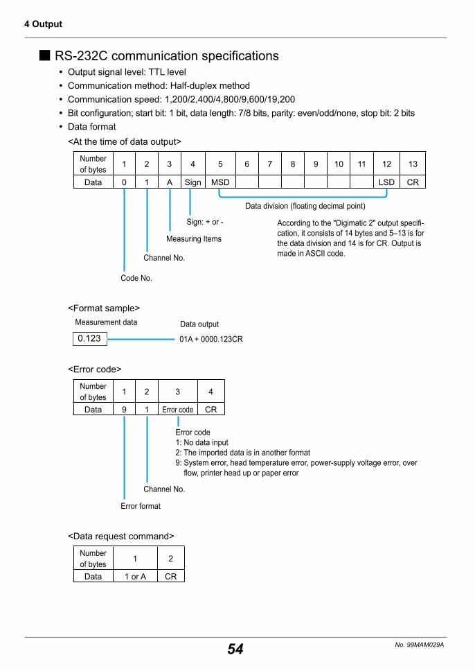
54
4 Output
No. 99MAM029A
� RS-232C communication specifications y Output signal level: TTL level y Communication method: Half-duplex method y Communication speed: 1,200/2,400/4,800/9,600/19,200 y Bit configuration; start bit: 1 bit, data length: 7/8 bits, parity: even/odd/none, stop bit: 2 bits y Data format<At the time of data output>
Number of bytes
1 2 3 4 5 6 7 8 9 10 11 12 13
Data 0 1 A Sign MSD LSD CR
Data division (floating decimal point)
Sign: + or -
Measuring Items
Channel No.
Code No.
According to the "Digimatic 2" output specifi-cation, it consists of 14 bytes and 5–13 is for the data division and 14 is for CR. Output is made in ASCII code.
<Format sample>
0.123
Measurement data Data output
01A + 0000.123CR
<Error code>
Number of bytes
1 2 3 4
Data 9 1 Error code CR
Error code1: No data input2: The imported data is in another format9: System error, head temperature error, power-supply voltage error, over
flow, printer head up or paper error
Channel No.
Error format
<Data request command>
Number of bytes
1 2
Data 1 or A CR

55
4 Output
No. 99MAM029A
y Connector specification: RS-232C conversion cable (option) D-sub 9 pins
Pin number
Signal name Functions IN/OUT
1 - - -2 RD Received data Data output to PC3 SD Sent data Data Input from PC
4 DSR Data set ready(indicates that PC side is ready)
Data output to PC (fixed with H)
5 GND - -
6 DTR Data terminal ready(indicates that PC side is ready)
Data Input from PC(not in use)
7 RSTRequest to send
(asks whether PC can send the data to the product)
Data Input from PC(not in use)
8 CTS Clear to send(tells the PC that the product can receive the data)
Data output to PC (fixed with H)
9 - - -

56
4 Output
No. 99MAM029A
POWER
TOL.REC/STOP
PRINTER CLEAR
STAT.OUT LOG
CANCEL
DATAFEED
4.2.2 RS-232C Communication SettingsIt is required to perform the RS-232C communication setting in parameter settings ac-cording to the usage environment to use RS-232C interface.
Setting order Setting items Setting contents Print Initial setting
4 BAUD RATE RS-232C: communication speed
1200/2400/4800/ 9600/19200
4800
5 PARITY Parity check method at the time of RS-232C commu-nication
NON/EVEN/ODD EVEN (even number)
6 DATA LENGTH Data length at the time of RS-232C communication
7/8 7
1 Set "BAUD RATE", "PARITY", "DATA LENGTH" of the parameters.
1 While pressing DATA press POWER , and after releasing POWER , release DATA .
» The power is turned on and enters the parameter setup mode to print the list.
2 Press DATA repeatedly until "4 BAUD RATE" is printed.
3 Press STAT.
OUT LOG repeatedly until the desired communication speed to set to BAUD RATE is printed.
4 Press DATA . » The communication speed is determined.
5 Press STAT.
OUT LOG repeatedly until the desired parity check method to set to PARITY is printed.
6 Press DATA . » The parity check is determined.
7 Press STAT.
OUT LOG repeatedly until the desired data length to set to DATA LENGTH is printed.
8 Press DATA repeatedly until the param-eter settings list is printed.
» The parameter setting is completed.

57
4 Output
No. 99MAM029A
4.2.3 RS-232C Output Operation of Measurement DataExplained with a PC used as an example.
1 Install the software correspondent to the RS-232C communication on the PC, and acti-
vate it.
2 Connect a measuring instrument with Digimatic output to the product.
3 Input the measurement data.
1 Press DATA . » Each time DATA is pressed, the measurement data is input and the data is sent to the PC.
For further details on the connection of a measuring instrument with Digimatic output and the measurement data input, refer to "2.2 Measuring with a Measuring Instrument with Digimatic Output and Printing" on page 16.
Tips • The measurement data can be input by pressing the [DATA] button of a measuring instrument with Digimatic output or with the foot switch (option) operation.
• When the measurement data is input, they are printed at the same time they are trans-mitted to the PC. Press PRINTER to turn the printing off. "Û PRINTER OFF Û" is printed.
• The log data stored with logging cannot be output with RS-232C output.

58
4 Output
No. 99MAM029A
4.3 Tolerance Judgment Result OutputThe operation to output the tolerance judgment result connecting a GO/±NG judgment cable (option) to the product is explained.
4.3.1 Connection of a GO/±NG Judgment Cable (Option)Connect the GO/±NG judgment cable (Parts No. 965516, digimatic 10 pin terminal - loose wires, cable length: 2 m) connected to the tolerance judgment discrimination equipment to the product (connector of OUTPUT) as shown in the figure below.
INPU
TOU
TPUT
ADAP
TER
INO
UT
Output connector NG lamp or buzzer
GO/±NG judgment cable (option)Judgment discrimination equipment for +NG/GO/-NG
Tips • The GO/±NG judgment cable and RS-232C conversion cable (option) cannot be used simultaneously.
• Removal/insertion of the cables shall be done while the power is turned off.
� Tolerance judgment result output specificationWhen a GO/±NG judgment cable (option), is connected and the limit data are set in MODE0, MODE1 or MODE2, output is performed through an open drain. VDSS (max) = 60 V I D (max) = 250 mA
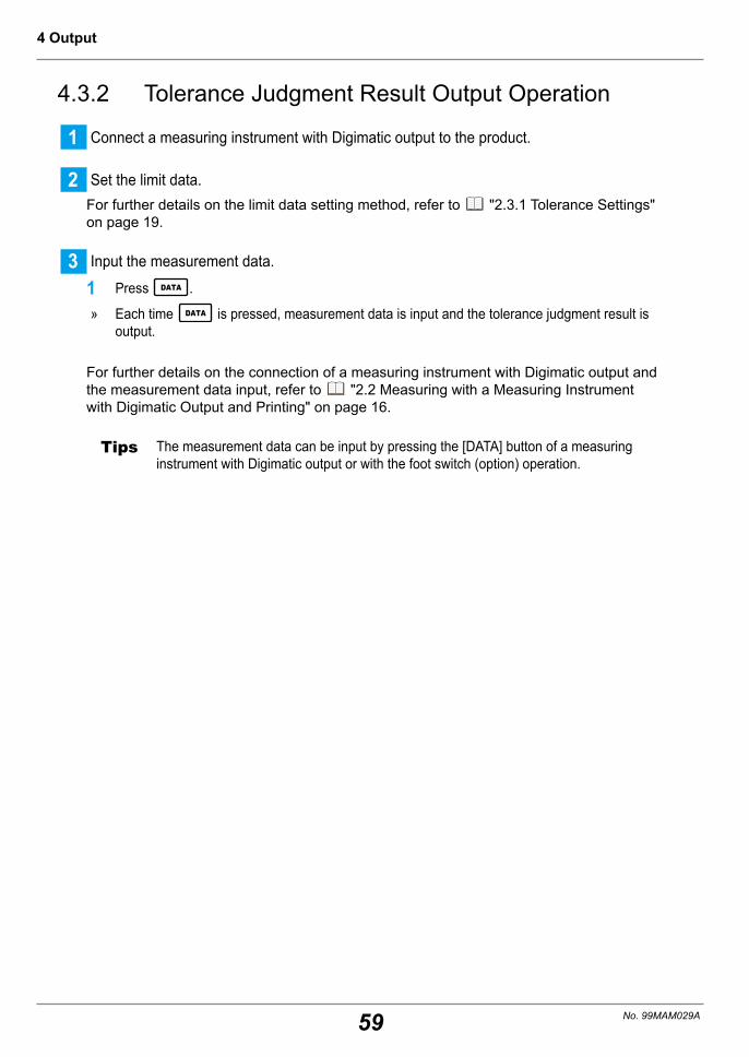
59
4 Output
No. 99MAM029A
4.3.2 Tolerance Judgment Result Output Operation
1 Connect a measuring instrument with Digimatic output to the product.
2 Set the limit data.For further details on the limit data setting method, refer to "2.3.1 Tolerance Settings" on page 19.
3 Input the measurement data.
1 Press DATA .
» Each time DATA is pressed, measurement data is input and the tolerance judgment result is output.
For further details on the connection of a measuring instrument with Digimatic output and the measurement data input, refer to "2.2 Measuring with a Measuring Instrument with Digimatic Output and Printing" on page 16.
Tips The measurement data can be input by pressing the [DATA] button of a measuring instrument with Digimatic output or with the foot switch (option) operation.

60
4 Output
No. 99MAM029A

61
5 Function Settings
No. 99MAM029A
5 Function SettingsFunction setting method for the product is explained.
5.1 Various SYSTEM/WORK MODE and Print Contents/Output to PC
The product shall be used for switching the SYSTEM MODE and WORK MODE with parameter settings in accordance with objectives.
5.1.1 SYSTEM/WORK MODE Selection and Print ContentsEnter "PARAMETER SETUP MODE" by while pressing DATA press POWER , and after releasing the POWER key release DATA with the power turned off.Switch SYSTEM MODE and WORK MODE in this mode.
POWER
TOL.REC/STOP
PRINTER CLEAR
STAT.OUT LOG
CANCEL
DATAFEED
<SYSTEM MODE> <WORK MODE>
(Initial setting)
(Initial setting)
MODE0
MODE1
MODE2
MODE3
MODE0
MODE1
DP-1 mode
MP mode
(Initial setting)
Printing measurement data and tolerance judgment results
Printing measurement data, tolerance judgment results, sta-tistical analysis and histogram
Printing measurement data, tolerance judgment results, statistical analysis, histogram, D chart
Printing measurement data, and calculation result to gener-ate the X̄-R control chart
Printing measurement data and tolerance judgment results
Printing measurement data, tolerance judgment results, sta-tistical analysis and histogram
Connecting the measuring instrument with Digimatic output to use
Connecting the RS-232C output of KA Counter to use

62
5 Function Settings
No. 99MAM029A
5.1.2 Measurement Data Collection and Output (Print and Output to PC)
The operations when STAT.
OUT LOG is pressed may differ depending on the WORK MODE differ-ence as shown in the chart below.
DATA
STAT.OUT LOG
Foot switchTimer input
PC connecting
measuringPrinting each measurementMODE2: D chart
Output to PC• USB output each measurement• RS-232C output each measurement
PrintPrint
MODE0*: Key operations deactivatedMODE1*: Statistical value of measurement
data, HistogramMODE2: Statistical value of measurement
data, HistogramMODE3: Calculation results for creating X̄-R
control charts
*: MODE0 or MODE1 only in MP mode.
5.1.3 WORK MODE and Print ExamplesThe print contents differ as shown in the chart below depending on the WORK MODE difference.
MODE0 MODE1 MODE2 MODE3
Measurement data
Tolerance judgment
Statistical value of measurement data
HistogramD chart
Various calculation values required for X̄-R control charts
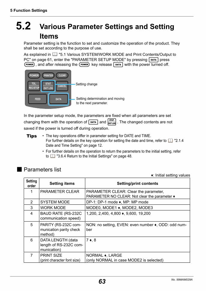
63
5 Function Settings
No. 99MAM029A
5.2 Various Parameter Settings and Setting Items
Parameter setting is the function to set and customize the operation of the product. They shall be set according to the purpose of use.As explained in "5.1 Various SYSTEM/WORK MODE and Print Contents/Output to PC" on page 61, enter the "PARAMETER SETUP MODE" by pressing DATA press
POWER , and after releasing the POWER key release DATA with the power turned off.
POWER
TOL.REC/STOP
PRINTER CLEAR
STAT.OUT LOG
CANCEL
DATAFEED
Setting change
Setting determination and moving to the next parameter.
In the parameter setup mode, the parameters are fixed when all parameters are set changing them with the operation of DATA and STAT.
OUT LOG . The changed contents are not saved if the power is turned off during operation.
Tips • The key operations differ in parameter setting for DATE and TIME. For further details on the key operation for setting the date and time, refer to "2.1.4 Date and Time Setting" on page 12.
• For further details on the operation to return the parameters to the initial setting, refer to "3.6.4 Return to the Initial Settings" on page 48.
� Parameters list♦: Initial setting values
Setting order Setting items Setting/print contents
1 PARAMETER CLEAR PARAMETER CLEAR: Clear the parameter, PARAMETER NO CLEAR: Not clear the parameter ♦
2 SYSTEM MODE DP-1: DP-1 mode ♦, MP: MP mode3 WORK MODE MODE0, MODE1 ♦, MODE2, MODE34 BAUD RATE (RS-232C
communication speed)1,200, 2,400, 4,800 ♦, 9,600, 19,200
5 PARITY (RS-232C com-munication parity check method)
NON: no setting, EVEN: even number ♦, ODD: odd num-ber
6 DATA LENGTH (data length of RS-232C com-munication)
7 ♦, 8
7 PRINT SIZE (print character font size)
NORMAL ♦, LARGE (only NORMAL in case MODE2 is selected)

64
5 Function Settings
No. 99MAM029A
Setting order Setting items Setting/print contents
8 BACK FEED ON ♦, OFF (displayed only when NORMAL is selected in PRINT SIZE)
9 POWER SAVE SAVE: Power save, NORMAL: Standard ♦10 PRT DENSITY
(Density of the print)NORMAL ♦, DARK
11 BUZZER (Buzzer sound)
On: Sound ♦, Off: No sound
12 TIME PRINT (Clock function)
On: Use ♦, Off: Not use
13 DATE FORMAT (Print format of the date)
YYYY/MM/DD ♦, MM/DD/YYYY, DD/MM/YYYY
14 DATE Japan Standard Time ♦ For January 2, 2018:2018/1/2, JAN/2/2018, 2/JAN/2018
15 TIME Japan Standard Time ♦ For 14:25 pm: 14:25
16 UNIT * AUTO can be selected only in DP-1 modeAUTO♦ (Only mm units can be accepted), mm: millimeter, inch: inch, no unit, g: gram, °C: temperature, t: ton, lb: pound, N: newton, Nm: newton-meter, μm: micrometer, μin: microinch
17 LOG RESUME (Log state setting at the time of activation)
1: Log stop ♦, 2: Log start, 3: Assume the log state when the power was turned off last time
18 OUT LOG (Log output setting)
Log print: 1: Time/Measurement value ♦, 2: N number/Measurement value, 3: N number/Date/Time/Measurement value Log USB output: 1: Time/Measurement value ♦, 2: Measurement value, 3: Date/Time/Measurement value
19 INPUT AXIS (Data input object axes setting)
* Set only in MP modeXYZ ♦, X, Y, Z (multiple settings are possible)
20 CUL AXIS (Calculation object axes setting)
* Set only in MP modeX ♦, Y, Z (only 1 axis can be set)
Tips • When setting "PRINT SIZE" (print character font size) to "NORMAL", move to the "BACK FEED" setting subsequently. Normally, use with this setting "ON".
• When this is set to "AUTO" in the "UNIT" setting, length units other than mm cannot be accepted.
• If the setting other than "AUTO" is selected in the "UNIT" setting, the print is performed in the unit set with this parameter regardless of the input data unit. In this case, the input data unit information is ignored.
• If there is no data with the designated axis in the input data in "CUL AXIS" (Calculation object axes setting), the error message is printed (example: if the input data is for the X axis, "NO CUL AX" is printed). In this case, use with "WORK MODE" in Setting Order 3 set to "MODE0". The statistical calculation is not performed but the data can be printed.
• MP mode can be used only for RS-232C output of our KA Counter. The proper operation is not guaranteed if equipment other than the KA Counter is connected for use.

65
6 Maintenance and Troubleshooting
No. 99MAM029A
6 Maintenance and Trouble-shooting
The maintenance work, error display and troubleshooting method of the product are explained.
6.1 MaintenanceTo prevent the product failure, the cleaning described below shall be regularly performed (about once every six months).
CAUTION
• Before cleaning, make sure that the power is turned off.• Be careful not to cut your hands with the paper cutter when cleaning.• For the cleaning of the printer head or sensors alcohol is used.
Be careful with the following items. • The printer head is exposed when the printer paper cover is opened. The printer
head becomes very hot immediately after printing and may cause burns if touched. The heat also may cause the alcohol to ignite.
• Thoroughly dry off any alcohol remaining on the printer head. Powering on while the printer head is not completely dry may cause a fire.
• Treat the alcohol with sufficient care.• Never use volatile chemicals, such as thinner or benzene, other than alcohol.• Turn the power on after the alcohol is thoroughly dried up.
• Pay attention not to scratch the printer head with a finger or something hard.• Pay sufficient attention not to get the printer interior wet.
� Printer head cleaningDirt and stain adhering to the printer head may result in poor printing quality or damage the printer head that makes printing impossible. Clean the printer head regularly.
z Cleaning method1 Press the release lever downward (to the direction of "OPEN") to open the printer paper cover.2 Wipe the printer head with a cotton swab moistened with a little alcohol.3 Wipe off alcohol remaining on the printer head with a dry cotton swab to dry it off.4 Close the printer paper cover.
Printer head(Golden top surface is the cleaning surface of the head.)
Paper cutter

66
6 Maintenance and Troubleshooting
No. 99MAM029A
� Paper sensor cleaningThe paper sensor is built in the printer which detects the presence/absence of the print-er paper. A dirtied paper sensor part may render printer paper detection impossible and prevent normal operation. Clean the paper sensor portion regularly.
z Cleaning method1 Press the release lever downward (to the direction of "OPEN") to open the printer paper cover.2 Wipe the paper sensor with a cotton swab moistened with a little alcohol.3 Wipe off alcohol remaining on the paper sensor with a dry cotton swab to dry it off.4 Close the printer paper cover.
Paper sensor
Paper cutter

67
6 Maintenance and Troubleshooting
No. 99MAM029A
6.2 Error Displays
6.2.1 Error Displays with Power LEDWhen the power is turned on, the power LED is lit on when the product is in the normal state. If it is blinking, there may the errors shown below. Address it according to the error contents.
Power LED blinking pattern State of the Product Data input Handling methodRepetition of blinking at 0.6 s on and 0.6 s off.
Abnormally high volt-age Not possible Turn off the power
and turn it on again.
Repetition of blinking at 1.5 s off, 0.3 s on, 0.3 s off and 0.3 on
Voltage drop alarm (when the voltage drops and the remain-ing battery level be-comes low)
Possible
It is recovered when the voltage returns to the nor-mal range. (Replace batteries)
Repetition of blinking at 0.6 s on and 0.6 s off.
Abnormally low voltage (when voltage drops and operation be-comes impossible)
Not possible Turn off the power and turn it on again.
Tips • When the power of the product is turned off, all the measurement data automatically saved for the statistical calculation up to that point of time is deleted. Also, if the AC adapter is connected/disconnected while the product is operating, all the measurement data automatically saved for the statistical calculation up to that point of time is lost, re-gardless of whether the product is powered with the AC adapter or not. Please handle with care.
• When operating the product with batteries, if the room temperature drops below 10 °C, the battery life becomes considerably shorter. Use an AC adapter when the room tem-perature is below 10 °C.
• When the batteries are consumed, the power LED may malfunction as the voltage becomes below the operating voltage. If the power LED starts blinking, change the batteries as promptly as possible or switch to the AC adapter.

68
6 Maintenance and Troubleshooting
No. 99MAM029A
6.2.2 Other Error DisplaysThere are other error displays (symptoms) below than the power LED blinking. Address them according to the error contents.
Error display (symptom) Types of errors Causes Handling method
Immediately after the power on, all the LEDs start blinking.
System error
y A fatal error is occurring with the product
y The service temperature is either too high or too low.
Turn off the power and turn it on again.
"Û OVER FLOW Û" is printed out.
Overflow The calculable range is exceeded.
Delete the data by pressingCLEAR .
y The [-NG] and [+NG] LEDs are blinking.
y A red line appears on the printer paper.
Out of printer paper.
No printer paper.Replace the printer paper.
"2.1.2 Setting the Printer Pa-per and Power-on" on page 9
The [-NG] and [+NG] LEDs are blinking.
Cover open (head up).
The printer paper cover is opened. Close the printer paper cover.
"Û NO GAGE Û" is printed.
No connect-ed measuring instrument.
y No measuring instrument is connected.
y The connection cable is broken.
y The connection cable has a con-tact failure.
y Connect a measuring instru-ment.
y Replace the connection cables.
y Check the connector portion of the connection cable.
"Û FORMAT ER-ROR Û" is printed.
Data format difference
The format of the input data is differ-ent.
y Delete all the data pressingCLEAR . There may be the
possibility whereas the mea-surement data with digimat-ic specifications 1 and 2 are mixed in input.
"5.1.1 SYSTEM/WORK MODE Selection and Print Contents" on page 61
y Replace the connection cables.
y Check the connector portion of the connection cable.

69
6 Maintenance and Troubleshooting
No. 99MAM029A
Error display (symptom) Types of errors Causes Handling method
"Û UNIT ERROR Û" is printed.
Difference in units.
The units of the input data are dif-ferent.
y This message is printed when the unit differs from that of the data input first. Input the data with the same unit as that of the data input first.
y A unit that differs from that of the set limit data is input. Input the data with the same unit as that of the limit data. "5.2 Various Parameter
Settings and Setting Items" on page 63
"Û POINT ERROR Û" is printed.
Decimal point position error
The position of the decimal point of the input data are dif-ferent.
y This message is printed when the position of the decimal point differs from that of the data input first. Input the data with the same decimal point position as that of the data input first.
y A decimal point position that differs from that of the set limit data is input. Input the data with the same decimal point position as that of the limit data.
The buzzer sounds twice each time the data are input.
Overflow alarm
Overflow of the measurement data storage is about to happen.
Stop the measurement ahead of time to perform the statis-tical calculation. Then, delete the data pressing CLEAR .
The buzzer sounds during logging.
Alarm for num-ber of log data
The number of log data entries ex-ceeds 950.
Up to 1,000 data entries can be logged. Perform the output of the log data.
"3.4 Logging of Measure-ment Data and Printing/Output of Log Data" on page 35
"Û BACKUP BAT-TERY LOW Û" is printed.
Remaining level drop of backup batteries
Remaining level of the backup batter-ies has dropped.
The time for replacement of backup batteries mounted to the circuit board inside the product is approaching. Con-tact our Service department. Noted that the battery life is about 10 years.

70
6 Maintenance and Troubleshooting
No. 99MAM029A
6.3 TroubleshootingThe troubleshooting for other problems than error display is explained here.
Tips • If the problem cannot be solved even through troubleshooting, contact a Mitutoyo sales office or your dealer (the contact number of our service network is listed at the back of this manual).
• The warranty of the product is good for a period of one year from the purchase date. However, some types of repairs may be available only at the customers' expense.
State of the product Causes Handling method
y The state of the product turns to that immediately after power-on during printing.
y The print is faint.
y Manganese batteries are used.
y Use charged nickel-hydride batteries or AA-size alkaline batteries.
"2.1.1 AC Adapter Connect-ing and Battery Cells Setting" on page 7
y Battery electrode plane is peeling or swelling.
y Remove peeling or swelling from the battery electrode plane.
y The designated AC adapter is not used.
y Use the designated AC adapter. "2.1.1 AC Adapter Connect-
ing and Battery Cells Setting" on page 7
y A measuring instrument which is powered by an external power source is connected.
y This product cannot supply power to an external instrument. Separately prepare a dedicated power source.
y The AC adapter shares its power input with high-voltage, large-current use machines.
y Connect the AC adapter to a separate power supply line.
y Printer head is dirty. y Clean the printer head with a cotton swab, etc.
"6.1 Maintenance" on page 65
Cannot print.
y Data printing function is off by the PRINTER operation.
y A foreign object is inside the printer portion or a paper jam has occurred.
y The timer input mode is set and the interval time is set to either 0.25 s or 1 s.
y Press PRINTER to turn the data printing function on.
y Remove the foreign object or jammed paper with tweezers.
y When the interval time is set to 0.25 s or 1 s, the data print-ing function is automatically switched off.
"3.6.1 Timer Input of the Measurement Data" on page 43
Miscounting occurs at the measuring device side.
The AC adapter shares its power input with high-voltage, large-cur-rent use machines.
Connect the AC adapter to a sepa-rate power supply line.

71
6 Maintenance and Troubleshooting
No. 99MAM029A
State of the product Causes Handling method
The power cannot be switched on/off.
y The voltage drops abnormally when the batteries are used.
y The on/off operation is per-formed at short intervals (be-low 5 s).
y Execute the hardware reset by holding CANCEL for 10 s or more.
y Change the batteries and reboot the product.
y Detach the batteries and AC adapter and set them again to reboot the product.
"2.1.1 AC Adapter Connect-ing and Battery Cells Setting" on page 7
The data output cannot be performed properly even if con-necting the product to a PC.
y Contact failure of USB cable. y Broken USB cable. y Abnormality of PC side con-nector.
y Detach the product from the PC, and reconnect it.
y If the product does not perform properly after reconnection, contact a Mitutoyo sales office or your dealer.
The product is not recognized when the PC returns from the suspend mode (sleep mode or standby mode).
This may occur depending on the PC type or the BIOS when the product is connected via a USB hub or an expansion USB board.
Detach the unrecognized product from the PC, and reconnect it. If the product does not perform properly after reconnection, reboot the PC.
Tips The product corresponds to the suspend function (sleep mode or standby mode) as the PC's power supply mode.However, this does not guarantee the complete operation with all the PCs or USB hubs.If there is any obstacle in the operation with the suspend function in your environment, set the PC power control not to be suspended during operation.
72
6 Maintenance and Troubleshooting
No. 99MAM029A

73
7Specifications
No. 99MAM029A
7 SpecificationsInthischapter,generalspecifications,calculationspecifications,connectionwithvarious optional devices and options are explained.
7.1 GeneralSpecificationsItems Description Note
Code No. 264-505
Data input Digimatic, Digimatic 2, RS-232C input (for KA Counter only)
Printing method Thermal Line Printer
Character specifica-tions
Total dot number: 384 dots/line Dot size: 8 dots/mm NORMAL font: 24 (H) x 16 (W) dots LARGE font: 36 (H) x 24 (W) dots
Print speed 0.8 s/line (6.5 mm/s) When using AC adapter
Print line number 7,000 lines/roll (with LARGE font) 10,000 lines/roll (with NORMAL font)
Printer paper to be used
High-durability thermal paper, width: 58 mm, roll length: 48 m
In the case of long-term storage or use for official documents, the use of photocopies is recommended.
Power supply y 100 V 50/60 Hz AC adapter (6 V, 2 A) y AA alkaline batteries (LR6) or nickel-met-al-hydride (Ni-MH Size AA) x 4
Two power source system Dry batteries are not included.
Battery life About 10,000 lines (in case of use at 20 °C, with 1,600 mA Ni-MH and print 1 time/5 s)
Reference value (bat-tery life greatly varies depending on the use conditions)
Data processing capacity
MODE0: 100,000 data entries MODE1, 2: 9,999 data entries MODE3: sample size 10 x subgroup 9,999 = Total number of data entries 99,990
Tolerance judgment Possible to set 5 pairsLogging of the measurement data (to store)
Max. 1,000 points
Timer input 0.25 s, 1 s, 5 s, 30 s, 1 min, 30 min, 60 min
Data OutputUSB output RS-232C output at TTL level Tolerance judgment result output (-NG, GO, +NG)
Clock precision ±2 min max./monthBattery life of the backup batteries About 10 years Reference value

74
7Specifications
No. 99MAM029A
Items Description NoteOperating tempera-ture range
When using the AC adapter: 0 °C–45 °C When using batteries: 10 °C–45 °C
Storage tempera-ture range
-10 °C–50 °C In case of our speci-fied packaging
Weight 390 g Main unit onlyExternal view and dimensions 94 (W) × 201 (D) × 75.2 (H) mm
CE Marking
EMC Directive: EN61326-1 Immunity test requirements: Clause 6.2 Table 2 Emission limit: Class B RoHS Directive: EN50581
� Standard accessoriesAC adapter: 1, Printer paper: 1 roll, Strap: 1 (Parts No. 09EAA079)
� ConsumablesPrinter paper (10 rolls/pack) (Parts No. 09EAA082, width: 58 mm, roll length: 48 m)
� External view and dimensions
INO
UT
OPEN
EXT.P
INPU
TOU
TPUT
ADAP
TER
43.9
75.294
201
Unit: mm

75
7Specifications
No. 99MAM029A
7.2 CalculationSpecifications
7.2.1 Effective DigitsThe essential figures for calculation are as follows.Setting the effective digits (number of digits after the decimal point) of input data as A, the effective digits of each case are shown.
Symbol Meaning Displayed effective digits (after the decimal point) Tolerance
Data Input data A -N Number of data - -MAX Maximum value A -MIN Minimum value A -R Range A -X Average A + 2 Lowermost digit ±1σn Standard deviation A + 2 Lowermost digit ±1σn-1 Sample standard deviation A + 2 Lowermost digit ±1P Fraction defective (%) 3 Lowermost digit ±1Cp Process capability index 3 Lowermost digit ±1Cpk Process capability index 3 Lowermost digit ±1LSL Lower specification limit value A Lowermost digit ±1USL Upper specification limit value A Lowermost digit ±1DIV Number of divisions in histogram Fixed to 10 divisions -
Histogram range display A + 2 Lowermost digit ±1X̄ Center (X̄ control) A + 2 Lowermost digit ±1X̄-UCL Upper control limit (X̄ control) A + 2 Lowermost digit ±1X̄-LCL Lower control limit (X̄ control) A + 2 Lowermost digit ±1R̄ Center (R control) A + 2 Lowermost digit ±1R̄-UCL Upper control limit (R control) A + 2 Lowermost digit ±1R̄-LCL Lower control limit (R control) A + 2 Lowermost digit ±1

76
7Specifications
No. 99MAM029A
7.2.2 Formulas
� Calculation of MODE1 and MODE2Print Meaning Calculation formulaN Number of dataMAX Maximum data valueMIN Minimum data value R Data range MAX−MINX̄ Average data value ΣXi/Nσn Standard deviation σn = ((N•ΣESXi2 − (ΣXi)2) / N2)1/2
σn-1 Sample standard deviation σn − 1 = ((N•ΣESXi2 − (ΣXi)2) / N•E(N − 1))1/2
−NG Number of data lower than the lower specification limit value Number of data for which LSL > Xi
+NG Number of data higher than the upper specification limit value Number of data for which USL < Xi
P Fraction defective P = ((-NG) + (+NG))/N
Cp Process capability index Cp = TOL/(6σn-1) TOL: USL − LSL
Cpk When process capability index bias is considered
Cpk = Zmin/3 Zmin: The lower value of Zusl and Zlsl Zusl = (USL − X̄)/σn-1, Zlsl = (X̄ − LSL)/σn-1
� Calculation of MODE3N: Number of sample dataMAX: Maximum data valueMIN: Minimum data valuen: Number of subgroupsA2: Refer to the conversion table belowD3: Refer to the conversion table belowD4: Refer to the conversion table below* The maximum sample data number of the subgroup is 10.
Variable TableSample size n A2 D3 D4
2345678910
1.8801.0230.7290.5770.4830.4190.3730.3370.308
0.0760.1360.1840.223
3.2672.5742.2822.1142.0041.9241.8641.8161.777

77
7Specifications
No. 99MAM029A
Print Meaning Calculation formulaX̄ Subgroup average value X̄ = ΣXi/NR Subgroup range R = Xmax - XminX= Center value X= = ΣXi/NX̄-UCL Upper control limit X̄-UCL = X̄ + A2 • R̄X̄-LCL Lower control limit X̄-LCL = X̄ + A2 • R̄R̄ Center (R control) R̄ = ΣRi/nR̄-UCL Upper control limit (R control) R̄-UCL = D4 • R̄R̄-LCL*1 Lower control limit (R control) R̄-LCL = D3 • R̄
*1 In case the number of samples is below 6, R̄-LCL is not printed.

78
7Specifications
No. 99MAM029A
7.3 Connection Diagram with Various Optional Instruments
RS-232C
D-sub 9 pin
INPU
TOU
TPUT
ADAP
TER
PC
PC
A
B
C
C
D
E
INO
UT
ARC SIN COSπ
UNIT ABS
7 8 94 5 61 2 30
TAN
MODE
Digimatic Mini-ProcessorDP-1VA LOGGER
RS-232C code out unit(for KA-200 Counter)Digimatic connection cable
(refer to next page)
Digimatic Caliper
KA Counter
Foot switch
AC adapter
any one
USB port
USB micro connector
USB cable (commercial-
release)
Connector for foot switch
(EXT P.)
RS-232C port
Digimatic Micrometer
Digimatic Indicator
Output connector (OUT)DC jack (ADAPTER)
Input connector (IN)
NG lamp or buzzer
GO/±NG judgment cable
RS-232C counter cable
RS-232C conversion cable
Measuring instrument with Digimatic output
* Each connection cable is optional. They are not included.
A Measurement data input Connect a measuring instrument with Digimatic output and the input connector (IN) with the Digimatic connection cable.
B Measurement data input of KA Counter
Connect the RS-232C port of the KA Counter and the output con-nector (OUT) with an optional dedicated RS-232C counter cable (Parts No. 09EAA094).
C Measurement data out-put
y Connect the PC USB port and USB micro connector with a store-bought USB cable.
y Connect the PC RS-232C connector and the output connector with the RS-232C conversion cable (Parts No. 09EAA084).
D Input measurement data with foot switch operation
Connect the foot switch (Parts No. 937179T) cable to the foot switch connector.
E Tolerance judgment result output
Connect the output connector (OUT) and the tolerance judgment discrimination equipment etc. with a GO/±NG judgment cable (Parts No. 965516).

79
7Specifications
No. 99MAM029A
7.4 Options7.4.1 Digimatic Connection Cable List
Main Digimatic connection cables are shown below. For further details on the measuring instruments specifications, refer to our General Catalog.
Connector typeMeasuring instru-
ment side connector shapes
Part No. Main corresponding measuring instruments1 m 2 m
Waterproof type with output button
05CZA624 05CZA625ABS Coolant Proof Caliper CD-P_M/-30PMX Length Measuring Unit SD-G
Waterproof type with output button
05CZA662 05CZA663Digimatic Micrometer MDC-MX/MDH-25M QuantuMike MDE-MX Digimatic Holtest HTD-R
Straight type with output button 959149 959150
ABS Digimatic Caliper CD-AX/CD-C Length Measuring Unit SD-AX/SD-D/SDV-D
L type with out-put switch (cable outlet is right)
04AZB512 04AZB513 Digimatic Micrometer MDC-MB/OMC-MB/PMU300-MB
Flat 10-pin type 936937 965014
Digimatic Indicator ID-H/-F Height Gauge QM-Height QMH Digital MU-Checker M-561 Laser Scan Micrometer LSM-9506 Linear Gauge Counter EC-101D/EB/EH Litematic VL-B/S-B Portable Surface Roughness Tester SJ-210/310/410 Hardness Testing Machine HM-210/220
Round 6-pin type 937387 965013Digimatic Micrometer MDQ-M/CLM1-QM/PDM-QM Portable Hardness Gauge HH-411
Flat straight type 905338 905409ABS Digimatic Indicator ID-CX/ID-CAX/ID-CGX/ID-CRX/ID-SX/ID-SS/ID-U Digimatic Height Gauge HDM-AX/HD-AX/HDS-HC/HDS-C ABS Borematic SBM-CX Digimatic Cylinder Gauge CG-D Length Measuring Unit SD-E/SDV-E/SD-F/SDV-F Hardness Testing Machine H-300
Flat L-shape (cable outlet is back)
905689 905690
Flat L-shape (cable outlet is right)
905691 905692
Flat L-shape (ca-ble outlet is left) 905693 905694
Flat straight wa-ter-proof type 21EAA194 21EAA190 ABS Digimatic Indicator ID-N/-B
Tips The designs and specifications of Digimatic connection cables are subject to partial change without prior notice for product improvement. We appreciate your understanding.

80
7Specifications
No. 99MAM029A
7.4.2 Other OptionsPart No. Product name Note
09EAA084 RS-232C conversion cableTo output the measurement data to the RS-232C port. Cable length 1 m, D-sub 9 pins
965516 GO/±NG judgment cableTo output the tolerance judgment result. Cable length 2 m, 10 pins terminal - loose wires
937179T Foot switch This switch enables the measurement data input with foot operation.
09EAA094 RS-232C counter cable Use to connect with a KA Counter. Cable length 1 m, D-sub 9 pins
06AET993 Code Out Unit (for KA-200 Counter)
This unit enables RS-232C output from a KA Counter.
06AFM386Measurement Data Collection Software USB-ITPAK (corre-sponding to V2.1 and higher)
This software enables the measurement data of the measuring instrument with Digimatic output connected to the prod-uct to be fetched into a Microsoft Excel sheet prepared by the customer by sending it to a PC via a USB cable. As the cursor movement can be automa-tized by registering the fetching process to Microsoft Excel, this displays its full power in the operational efficiency im-provement of inspection operation for the mass-produced products which have a lot of repetitive works.
Tips Use the store-bought USB cable (A to Micro-B type) to output the measurement data to a PC.

No. 99MAM029A

No. 99MAM029A

SERVICE NETWORK*As of Sep. 2017
EuropeMitutoyo Europe GmbHBorsigstrasse 8-10, 41469 Neuss, GERMANYTEL: 49 (0)2137 102-0 FAX: 49 (0)2137 102-351Mitutoyo CTL Germany GmbHVon-Gunzert-Strasse 17, 78727 Oberndorf, GERMANYTEL: 49 (0)7423 8776-0 FAX: 49 (0)7423 8776-99KOMEG Industrielle Messtechnik GmbHZum Wasserwerk 3, 66333 Völklingen, GERMANYTEL: 49 (0)6898 91110 FAX: 49 (0)6898 9111100
GermanyMitutoyo Deutschland GmbHBorsigstrasse 8-10, 41469 Neuss, GERMANYTEL: 49 (0)2137 102-0 FAX: 49 (0)2137 86 85M3 Solution Center HamburgTempowerkring 9·im HIT-Technologiepark 21079 Hamburg, GERMANYTEL: 49 (0)40 791894-0 FAX: 49 (0)40 791894-50M3 Solution Center BerlinParadiesstrasse 208, 12526 Berlin, GERMANYTEL:49(0)30 2611 267 FAX:49(0)30 26 29 209M3 Solution Center EisenachHeinrich-Ehrhardt-Platz 1, 99817 Eisenach,GERMANYTEL: 49 (0)3691 88909-0 FAX: 49 (0)3691 88909-9M3 Solution Center IngolstadtMarie-Curie-Strasse 1a, 85055 Ingolstadt, GERMANYTEL: 49 (0)841 954920 FAX: 49 (0)841 9549250M3 Solution Center Leonberg GmbHSteinbeisstrasse 2, 71229 Leonberg, GERMANYTEL: 49 (0)7152 6080-0 FAX: 49 (0)7152 608060
Mitutoyo-Messgeräte Leonberg GmbHHeidenheimer Strasse 14, 71229 Leonberg, GERMANYTEL: 49 (0)7152 9237-0 FAX: 49 (0)7152 9237-29
U.K.Mitutoyo (UK) Ltd.Joule Road, West Point Business Park, Andover, Hampshire SP10 3UX, UNITED KINGDOMTEL: 44 (0)1264 353 123 FAX: 44 (0)1264 354883M3 Solution Center CoventryUnit6, Banner Park, Wickmans Drive, Coventry, Warwickshire CV4 9XA, UNITED KINGDOMTEL: 44 (0)2476 426300 FAX: 44 (0)2476 426339M3 Solution Center HalifaxLowfields Business Park, Navigation Close, Elland, West Yorkshire HX5 9HB, UNITED KINGDOMTEL: 44 (0)1422 375566 FAX: 44 (0)1422 328025M3 Solution Center East KilbrideThe Baird Bulding, Rankine Avenue, Scottish Enterprise Technology Park, East Killbride G75 0QF, UNITED KINGDOMTEL: 44 (0)1355 581170 FAX: 44 (0)1355 581171
FranceMitutoyo FranceParis Nord 2-123 rue de la Belle Etoile, BP 59267 ROISSY EN FRANCE 95957 ROIS-SY CDG CEDEX, FRANCE TEL: 33 (0)149 38 35 00 M3 Solution Center LYONParc Mail 523, cours du 3éme millénaire, 69791 Saint-Priest, FRANCETEL: 33 (0)149 38 35 70 M3 Solution Center STRASBOURGParc de la porte Sud, Rue du pont du péage, 67118 Geispolsheim, FRANCETEL: 33 (0)149 38 35 80

M3 Solution Center CLUSESEspace Scionzier 480 Avenue des Lacs, 74950 Scionzier, FRANCETEL: 33 (0)1 49 38 35 90M3 Solution Center TOULOUSE12 rue de Caulet, Cellule B08, 31300 TOULOUSE, FRANCETEL: 33 (0)1 49 38 42 90M3 Solution Center RENNESZAC MivoieLe Vallon35230 Noyal-Châtillon sur Seiche, FRANCETEL: 33 (0)1 49 38 42 10
ItalyMITUTOYO ITALIANA S.r.l.Corso Europa, 7 - 20020 Lainate (Ml), ITALYTEL: 39 02 935781 FAX: 39 02 9373290•93578255M3 Solution Center BOLOGNAVia dei Carpini1/A - 40011 Anzola Emilia (BO), ITALYTEL: 39 02 93578215 FAX: 39 02 93578255M3 Solution Center CHIETIContrada Santa Calcagna - 66020 Rocca S. Giovanni (CH), ITALYTEL: 39 02 93578280 FAX: 39 02 93578255M3 Solution Center PADOVAVia G. Galilei 21/F - 35035 Mestrino (PD), ITALYTEL: 39 02 93578268 FAX: 39 02 93578255
Belgium / NetherlandsMitutoyo BeNeLuxMitutoyo Belgium N.V.Hogenakkerhoekstraat 8, 9150 Kruibeke, BELGIUMTEL: 32 (0)3-2540444 FAX: 32(0)3-2540445Mitutoyo Nederland B.V.Wiltonstraat 25, 3905 KW Veenendaal, THE NETHERLANDSTEL: 31(0)318-534911
SwedenMitutoyo Scandinavia ABSläntvägen 6, 194 61 Upplands Väsby, SWEDENTEL: 46 (0)8 594 109 50 FAX: 46 (0)8 590 924 10M3 Solution Center AlingsåsÄngsvaktaregatan 3A, 441 38 Alingsås, SWEDENTEL: 46 (0)8 594 109 50 FAX:46 (0)322 63 31 62M3 Solution Center VärnamoStorgatsbacken 1, 331 30 Värnamo, SWEDENTEL: 46 (0)8 594 109 50 FAX: 46 (0)370 463 34
SwitzerlandMitutoyo (Schweiz) AGSteinackerstrasse 35, 8902 Urdorf, SWITZERLANDTEL: 41 (0)447361150 FAX: 41(0)447361151Mitutoyo (Suisse) SARue Galilée 4, 1400 Yverdon-les Bains, SWITZERLANDTEL: 41 (0)244259422 FAX: 41 (0)447361151
PolandMitutoyo Polska Sp.z o.o.Ul.Graniczna 8A, 54-610 Wroclaw, POLANDTEL: 48 (0)71354 83 50 FAX: 48 (0)71354 83 55
Czech RepublicMitutoyoČeskos.r.o.Dubská 1626, 415 01 Teplice, CZECH REPUBLICTEL: 420 417-514-011 FAX: 420 417-579-867MitutoyoČeskos.r.o.M3SolutionCenterIvančiceKe Karlovu 62/10, 664 91 Ivančice, CZECH REPUBLICTEL: 420 417-514-011 FAX: 420 417-579-867MitutoyoČeskos.r.o.M3SolutionCenterOstrava MošnovMošnov 314, 742 51 Mošnov, CZECH REPUBLICTEL: 420 417-514-050 FAX:420 417-579-867
MitutoyoČeskos.r.o.SlovakiaBranchHviezdoslavova 124, 017 01 Povážská Bystrica, SLOVAKIATEL: 421 948-595-590
HungaryMitutoyo Hungária Kft.Záhony utca 7, D-épület / fsz, 1031 Budapest, HUNGARYTEL: 36 (0)1 2141447 FAX: 36 (0)1 2141448
RomaniaMitutoyo Romania SRL1A Drumul Garii Odai Street, showroom, Ground Floor, 075100 OTOPENI-ILFOV, ROMANIATEL: 40 (0)311012088 FAX: +40 (0)311012089Showroom in BrasovStrada Ionescu Crum Nr.1, Brasov Business Park Turnul 1, Mezanin, 500446 Brasov-Judetul Brasov, ROMANIATEL/FAX: 40 (0)371020017
Russian FederationMitutoyo RUS LLC13 Sharikopodshipnikovskaya, bld.2, 115088 Moscow, RUSSIAN FEDERATIONTEL: 7 495 7450 752
FinlandMitutoyo Scandinavia AB Finnish BranchViherkiitäjä 2A, 33960, Pirkkala, FinlandTEL: 358 (0)40 355 8498
AustriaMitutoyo Austria GmbHJohann Roithner Straße 131 A-4050 Traun, AUSTRIATEL: 43 (0)7229 23850 FAX: 43 (0)7229 23850-90
SingaporeMitutoyoAsiaPacificPte.Ltd.Headoffice/M3SolutionCenter24 Kallang Avenue, Mitutoyo Building, SINGAPORE 339415TEL:(65)62942211 FAX:(65)62996666
MalaysiaMitutoyo (Malaysia) Sdn. Bhd.KualaLumpurHeadOffice/M3SolutionCenterMah Sing Intergrated Industrial Park, 4, Jalan Utarid U5/14, Section U5, 40150 Shah Alam, Selangor, MALAYSIA TEL:(60)3-78459318 FAX:(60)3-78459346PenangBranchoffice/M3SolutionCenterNo.30, Persiaran Mahsuri 1/2, Sunway Tunas, 11900 Bayan Lepas, Penang, MALAYSIA TEL:(60)4-6411998 FAX:(60)4-6412998JohorBranchoffice/M3SolutionCenterNo. 70, Jalan Molek 1/28, Taman Molek, 81100 Johor Bahru, Johor, MALAYSIATEL:(60)7-3521626 FAX:(60)7-3521628
ThailandMitutoyo(Thailand)Co., Ltd.BangkokHeadOffice/M3SolutionCenter76/3-5, Chaengwattana Road, Kwaeng Anusaowaree, Khet Bangkaen, Bangkok 10220, THAILAND TEL:(66)2-080-3500 FAX:(66)2-521-6136Chonburi Branch / M3 Solution Center7/1, Moo 3, Tambon Bowin, Amphur Sriracha, Chonburi 20230, THAILANDTEL:(66)2-080-3563 FAX:(66)3-834-5788Amata Nakorn Branch / M3 Solution Center700/199, Moo 1, Tambon Bankao, Amphur Phanthong, Chonburi 20160, THAILAND TEL:(66)2-080-3565 FAX:(66)3-846-8978
IndonesiaPT. Mitutoyo IndonesiaHeadOffice/M3SolutionCenterJalan Sriwijaya No.26 Desa cibatu Kec. Cikarang Selatan Kab. Bekasi 17530, INDONESIA TEL: (62)21-2962 8600 FAX: (62)21-2962 8604
VietnamMitutoyo Vietnam Co., LtdHanoiHeadOffice/M3SolutionCenterNo. 07-TT4, My Dinh - Me Tri Urban Zone, My Dinh 1 Ward, Nam Tu Liem District, Hanoi, VIETNAM TEL:(84)4-3768-8963 FAX:(84)4-3768-8960HoChiMinhCityBranchOffice/M3 Solution Center123 Dien Bien Phu Street,Ward 15,Binh Thanh District, Ho Chi Minh City, VIETNAM TEL:(84)8-3840-3489 FAX:(84)8-3840-3498
Mitutoyo Philippines, Inc.HeadOffice/M3SolutionCenterUnit 2103, Bldg 2 GMV Building 2, 107 North Main Avenue, Laguna Technopark, Binan, Laguna 4024, PhilippinesTEL:(63)49 544 0272 FAX:(63)49 544 0272
IndiaMitutoyo South Asia Pvt. Ltd.HeadOffice/M3SolutionCenterC-122, Okhla Industrial Area, Phase-l, New Delhi-110 020, INDIATEL:91(11)2637-2090 FAX:91(11)2637-2636MSA Gurgaon technical centerPlot No. 65, Phase-IV, Udyog Vihar, Gurgaon – 122016TEL : 91 (0124) – 2340294MumbaiRegionHeadoffice303, Sentinel Hiranandani Business Park Powai, Mumbai-400 076, INDIATEL:91(22)2570-0684, 837, 839 FAX:91(22)2570-0685
PuneOffice/M3SolutionCenterG2/G3, Pride Kumar Senate, F.P. No. 402 Off. Senapati Bapat Road, Pune-411 016, INDIA TEL:91(20)6603-3643, 45, 46 FAX:91(20)6603-3644VadodaraofficeS-1&S-2, Olive Complex, Nr. Haveli, Nizampura, Vadodara-390 002, INDIATEL: 91 265-2750781 FAX: (91) 265-2750782BengaluruRegionHeadoffice/M3 Solution CenterNo. 5, 100 Ft. Road, 17th Main, Koramangala, 4th Block, Bengaluru-560 034, INDIA TEL:91(80)2563-0946, 47, 48 FAX:91(80)2563-0949ChennaiOffice/M3SolutionCenterNo. 624, Anna Salai Teynampet, Chennai-600 018, INDIATEL:91(44)2432-8823, 24, 27, 28 FAX:91(44)2432-8825KolkataOfficeUnit No. 1208,Om Tower, 32,J.L..Nehru Road, Kolkata-700 071, INDIATel: 91 33-22267088/40060635 Fax: (91) 33-22266817
TaiwanMitutoyo Taiwan Co., Ltd. / M3 Solution Center Taipei4F., No.71, Zhouzi St., Neihu Dist.,Taipei City 114, TAIWAN (R.O.C.)TEL:886(2)5573-5902 FAX:886(2)8752-3267Taichung Branch / M3 Solution Center Taichung1F., No.758, Zhongming S. Rd., South Dist., Taichung City 402, TAIWAN(R.O.C.) TEL:886(4)2262-9188 FAX:886(4) 2262-9166Kaohsiung Branch / M3 Solution Center Kaohsiung1F., No.31-1, Haibian Rd., Lingya Dist., Kaohsiung City 802, Taiwan (R.O.C.)TEL:886(7)334-6168 FAX:886(7)334-6160
South KoreaMitutoyo Korea CorporationHeadOffice/M3SolutionCenter(Sanbon-Dong, Geumjeong High View Build.), 6F, 153-8, Ls-Ro, Gunpo-Si, Gyeonggi-Do, 15808 KOREA TEL:82(31)361-4200 FAX:82(31)361-4202BusanOffice/M3SolutionCenter(3150-3, Daejeo 2-dong) 8,Yutongdanji 1-ro 49beon-gil, Gangseo-gu, Busan, 46721 KOREA TEL:82(51)718-2140 FAX:82(51)324-0104DaeguOffice/M3SolutionCenter371-12, Hosan-Dong, Dalseo-Gu, Daegu, 42704, KOREATEL:82(53)593-5602 FAX:82(53)593-5603
ChinaMitutoyo Measuring Instruments (Shanghai) Co., Ltd.12F, Nextage Business Center, No.1111 Pudong South Road, Pudong New District, Shanghai 200120, CHINA TEL:86(21)5836-0718 FAX:86(21)5836-0717SuzhouOffice/M3SolutionCenter (Suzhou)No. 46 Baiyu Road, Suzhou 215021, CHINATEL:86(512)6522-1790 FAX:86(512)6251-3420WuhanOfficeRoom 1701, Wuhan Wanda Center, No. 96, Linjiang Road, Wuchang District, Wuhan Hubei 430060, CHINATEL:86(27)8544-8631 FAX:86(27)8544-6227ChengduOffice1-701, New Angle Plaza, 668# Jindong Road, Jinjiang District, Chengdu, Sichuan 610066,CHINATEL:86(28)8671-8936 FAX:86(28)8671-9086HangzhouOfficeRoom 804, Eastern International Business Center Building 1, No.600 Jinsha RoadHangzhou Economic and Technological Development Zone, 310018, ChinaTEL: 86(571)8288-0319 FAX: 86(571)8288-0320
TianjinOffice/M3SolutionCenterTianjinRoom A 15/F, TEDA Building, No.256 Jie-fang Nan Road Hexi District,Tianjin 300042, CHINA TEL:86(22)5888-1700 FAX:86(22)5888-1701ChangchunOfficeRoom 815, 8F, Building A1, Upper East International No.3000 Dongsheng Street, Erdao District, Changchun, Jilin, 130031, CHINATEL:86(431)8192-6998 FAX:86(431)8192-6998ChongqingOfficeRoom 1312, Building 3, Zhongyu Plaza, No.86, Hongjin Avenue,Longxi Street, Yubei District, Chongqing, 400000, CHINATEL:86(23)6595-9950 FAX:86(23)6595-9950QingdaoOfficeRoom 638, 6F, No.192 Zhengyang Road, Chengyang District, Qingdao, Shandong, 266109, CHINA TEL:86(532)8096-1936 FAX:86(532)8096-1937Xi’anOfficeRoom 805, Xi’an International Trade Center, No. 196 Xiaozhai East Road, Xi’an, 710061, CHINATEL:86(29)8538-1380 FAX:86(29)8538-1381DalianOffice/M3SolutionCenterDalianRoom 1008, Grand Central IFC, No.128 Jin ma Road, Economic Development Zone, Dalian 116600, CHINATEL:86(411)8718 1212 FAX:86(411)8754-7587ZhengzhouOfficeRoom1801,18/F,Unit1,Building No.23, Shangwu Inner Ring Road, Zhengdong New District,Zhengzhou City, Henan Province, 450018,CHINATEL:86(371)6097-6436 FAX:86(371)6097-6981Mitutoyo Leeport Metrology (Hong Kong) LimitedRoom 818, 8/F, Vanta Industrial Centre, No.21-33, Tai Lin Pai Road, Kwai Chung, NT, Hong KongTEL:86(852)2992-2088 FAX:86(852)2670-2488
Mitutoyo Leeport Metrology (Dongguan) Limited / M3 Solution Center DongguanNo.26, Guan Chang Road, Chong Tou Zone, Chang An Town, Dong Guan, 523855 CHINATEL:86(769)8541 7715 FAX:86(769)-8541 7745 Mitutoyo Leeport Metrology (Dongguan) Limited–FuzhouofficeRoom 2104, City Commercial Centre, No.129 Wu Yi Road N., Fuzhou City, Fujian Province, CHINATEL 86 591 8761 8095 FAX 86 591 8761 8096Mitutoyo Leeport Metrology (Dongguan) Limited–ChangshaofficeRoom 2207, Shiner International Plaza, No. 88, Kaiyuan Middle Road, Changsha City, Hunan, ChinaTEL 86 731 8401 9276 FAX 86 731 8401 9376Mitutoyo Measuring Instruments (Suzhou) Co., Ltd.No. 46 Baiyu Road, Suzhou 215021, CHINATEL:86(512)6252-2660 FAX:86(512)6252-2580
U.S.A.Mitutoyo America Corporation965 Corporate Boulevard, Aurora, IL 60502, U.S.A.TEL:1-(630)820-9666 Toll Free No. 1-(888)648-8869 FAX:1-(630)978-3501M3 Solution Center-Illinois965 Corporate Boulevard, Aurora, IL 60502, U.S.A.TEL:1-(888)648-8869 FAX:1-(630)978-3501M3 Solution Center-Ohio6220 Hi-Tek Court, Mason, OH 45040, U.S.A.TEL:1-(888)648-8869 FAX:1-(513)754-0718M3 Solution Center-Michigan46850 Magellan Drive, Suite 100, Novi, MI 48377, U.S.A.TEL:1-(888)648-8869 FAX: 1-(248)926-0928M3 Solution Center-California16925 E. Gale Avenue, City of Industry, CA 91745, U.S.A.TEL:1-(888)648-8869 FAX:1-(626)369-3352
M3 Solution Center-North Carolina11515 Vanstory Drive, Suite 140, Huntersville, NC 28078, U.S.A.TEL:1-(888)648-8869 FAX:1-(704)875-9273M3 Solution Center-Alabama2100 Riverchase Center, Suite 106, Hoover, AL 35244, U.S.ATEL:1-(888)648-8869 FAX:1-(205)988-3423M3 Solution Center-Washington1000 SW 34th Street Suite G, Renton WA 98057 U.S.A.TEL:1-(888)648-8869 M3 Solution Center-Texas4560 Kendrick Plaza Drive, Suite 120, Houston, TX 77032, U.S.A.TEL:1-(888)648-8869 FAX:1-(281)227-0937M3 Solution Center-Massachusetts753 Forest Street, Suite 110, Marlborough,MA 01752, U.S.A.TEL:1-(888)648-8869 FAX:1-(508)485-0782Mitutoyo America Corporation Calibration Lab965 Corporate Boulevard, Aurora, IL 60502, U.S.A.TEL:1-(888)648-8869 FAX:1-(630)978-6477Micro Encoder, Inc.11533 NE 118th Street, Kirkland, WA 98034, U.S.A.TEL:1-(425)821-3906 FAX:1-(425)821-3228Micro Encoder Los Angeles, Inc.16925 E. Gale Avenue, City of Industry, CA 91745 U.S.A.TEL:1-(626)271-1075
CanadaMitutoyo Canada Inc.2121 Meadowvale Blvd., Mississauga, Ont. L5N 5N1., CANADATEL:1-(905)821-1261 FAX:1-(905)821-4968MontrealOffice7075 Place Robert-Joncas Suite 129, Montreal, Quebec H4M 2Z2, CANADATEL:1-(514)337-5994 FAX:1-(514)337-4498

BrazilMitutoyo Sul Americana Ltda.Rodovia Índio Tibiriça 1555, Bairro Raffo, CEP 08620-000 Suzano – SP, Brasil TEL:55 (11)4746-5858
ArgentinaMitutoyo Sul Americana Ltda.Argentina BranchAv. B. Mitre 891/899 – C.P. (B1603CQI) Vicente López –Pcia. Buenos Aires – ArgentinaTEL:54(11)4730-1433 FAX:54(11)4730-1411Sucursal CordobaAv. Amadeo Sabattini, 1296, esq. Madrid Bº Crisol Sur – CP 5000, Cordoba, ARGENTINATEL/FAX:54 (351) 456-6251
MexicoMitutoyo Mexicana, S.A. de C.V.Prolongación Industria Eléctrica No. 15 Parque Industrial Naucalpan Naucalpan de Juárez, Estado de México C.P. 53370, MÉXICOTEL: 52 (01-55) 5312-5612MonterreyOffice/M3SolutionCenterMonterreyAv. Morones Prieto No 914, Oriente Local, 105 Plaza Matz Col. La Huerta, C.P. 67140 Guadalupe, N.L.., MÉXICOTEL: 52 (01-81) 8398-8227, 8398-8228, 8398-8244, 8398-8245 and 8398-8246 FAX: 52 (01-81) 8398-8245TijuanaOffice/M3SolutionCenterTijuanaAv. 2o. eje Oriente-Poniente No. 19075 Int. 18 Col. Cd. Industrial Nueva Tijuana C.P. 22500 Tijuana, B. C., MÉXICOTEL: 52 (01-664) 647-5024 QuerétaroOffice/M3SolutionCenterQuerétaroAv. Cerro Blanco No.500-1, Colonia Centro Sur, Querétaro, Querétaro, C.P. 76090, MÉXICOTEL: 52 (01-442) 340-8018, 340-8019 and 340-8020 FAX: 52 (01-442) 340-8017
Mitutoyo Mexicana, S.A. de C.V. Querétaro Calibration LaboratoryAv. Cerro Blanco 500 30 Centro Sur, Querétaro, Querétaro, C.P. 76090, MÉXICOTEL: 52 (01-442) 340-8018, 340-8019 and 340-8020 FAX: 52 (01-442) 340-8017AguascalientesOffice/M3SolutionCenterAv. Aguascalientes No. 622, Local 15 Centro Comercial El Cilindro Fracc. Pulgas Pandas Norte, C.P. 20138, Aguascalientes, Ags. MÉXICOTEL: 52 (01-449) 174-4140 and 174-4143IrapuatoOffice/M3SolutionCenterBoulevard a Villas de Irapuato No. 1460 L.1 Col. EjidoIrapuato C.P. 36643Irapuato, Gto., MÉXICOTEL: 52 (01-462) 144-1200 and 144-1400


No. 99MAM029A
Revision History
Date of publication Revision status Details of revisionAugust 1, 2017 First edition Publication

� DP-1VA LOGGER parameters list y With the power off, press POWER while holding down DATA , release POWER
and then release DATA , the mode will be "PARAMETER SETUP MODE". y Set and change the parameters by DATA and STAT.
OUT LOG operations.
♦:InitialsettingvaluesSetting order Setting items Setting/print contents
1 PARAMETER CLEAR PARAMETER CLEAR: Clear the parameter, PARAMETER NO CLEAR: Not clear the parameter ♦
2 SYSTEM MODE DP-1: DP-1 mode ♦, MP: MP mode3 WORK MODE MODE0, MODE1 ♦, MODE2, MODE34 BAUD RATE (RS-232C
communication speed)1,200, 2,400, 4,800 ♦, 9,600, 19,200
5 PARITY (RS-232C commu-nication parity check method)
NON: no setting, EVEN: even number ♦, ODD: odd number
6 DATA LENGTH (data length of RS-232C communication)
7 ♦, 8
7 PRINT SIZE (print character font size)
NORMAL ♦, LARGE (only NORMAL in case MODE2 is selected)
8 BACK FEED ON ♦, OFF (displayed only when NORMAL is selected in PRINT SIZE)
9 POWER SAVE SAVE: Power save, NORMAL: Standard ♦10 PRT DENSITY
(Density of the print)NORMAL ♦, DARK
11 BUZZER (Buzzer sound) On: Sound ♦, Off: No sound12 TIME PRINT (Clock function) On: Use ♦, Off: Not use13 DATE FORMAT
(Print format of the date)YYYY/MM/DD ♦, MM/DD/YYYY, DD/MM/YYYY
14 DATE Japan Standard Time ♦ For January 2, 2018:2018/1/2, JAN/2/2018, 2/JAN/2018
15 TIME Japan Standard Time ♦ For 14:25 pm: 14:25
16 UNIT * AUTO can be selected only in DP-1 modeAUTO♦ (Only mm units can be accepted), mm: millimeter, inch: inch, no unit, g: gram, °C: temperature, t: ton, lb: pound, N: newton, Nm: newton-meter, μm: micrometer, μin: microinch
17 LOG RESUME (Log state setting at the time of activation)
1: Log stop ♦, 2: Log start, 3: Assume the log state when the power was turned off last time
18 OUT LOG (Log output setting)
Log print: 1: Time/Measurement value ♦, 2: N number/Measurement value, 3: N number/Date/Time/Measurement value Log USB output: 1: Time/Measurement value ♦, 2: Measurement value, 3: Date/Time/Measurement value
19 INPUT AXIS (Data input object axes setting)
* Set only in MP modeXYZ ♦, X, Y, Z (multiple settings are possible)
20 CUL AXIS (Calculation object axes setting)
* Set only in MP modeX ♦, Y, Z (only 1 axis can be set)
POWER
TOL.REC/STOP
PRINTER CLEAR
STAT.OUT LOG
CANCEL
DATAFEED
Change settings
Fix settings, move next parameter
DP-1VA LOGGER No. 99MAM029A

� Names and functions of operation key
POWER
TOL.REC/STOP
PRINTER CLEAR
STAT.OUT LOG
CANCEL
DATAFEED
[POWER] key
[CLEAR] key
[PRINTER] key
Press when switching on/off the power.
Press when deleting all the measurement data.
Press when switching on/off the printing function of measurement data and log data.
[CANCEL] key
[DATA] key
Press to cancel the latest input mea-surement data.Hold down for more than 10 seconds to delete the measurement data/log data and initialize the date and time by hardware reset.
Press to input the data from the measuring instrument.
[STAT. | OUT LOG] keyPress to perform the statistical calculation based on all the input measurement data, print the calculation results and generate the histogram. Hold down to print the log data and output it to USB.
[FEED] keyWhile being pressed the printer paper is fed.
[TOL. | REC/STOP] keyPress to enter or exit the setting mode for the limit data (upper/lower specification limit value). Hold down to start/stop the data logging.
zWhen two key operations are required y Parameter Setup Mode: DATA + POWER (effective only when turning on the power) ( "5.2 Various Parameter Settings and Setting Items" on page 63)
y Timer Input Mode: PRINTER + FEED ( "3.6.1 Timer Input of the Measurement Data" on page 43)
y Print date and time: PRINTER + DATA
� SYSTEM/WORK MODE selection and print contents<SYSTEM MODE> <WORK MODE>
(Initial setting)
(Initial setting)
MODE0
MODE1
MODE2
MODE3
MODE0
MODE1
DP-1 mode
MP mode
(Initial setting)
Printing measurement data and tolerance judgment results
Printing measurement data, tolerance judgment results, sta-tistical analysis and histogram
Printing measurement data, tolerance judgment results, statistical analysis, histogram, D chart
Printing measurement data, and calculation result to gener-ate the X̄-R control chart
Printing measurement data and tolerance judgment results
Printing measurement data, tolerance judgment results, sta-tistical analysis and histogram
Connecting the measuring instrument with Digimatic output to use
Connecting the RS-232C output of KA Counter to use
DP-1VA LOGGER No. 99MAM029A

No. 99MAM029APrinted in Japan
Mitutoyo Corporation20-1, Sakado 1-Chome, Takatsu-ku, Kawasaki-shi, Kanagawa 213-8533, Japan Tel: +81 (0)44 813-8230 Fax: +81 (0)44 813-8231Home page: http://www.mitutoyo.co.jp/global.html
For the EU Directive, Authorized representative and importer in the EU:Mitutoyo Europe GmbHBorsigstrasse 8-10, 41469 Neuss, Germany