DATA LOGGER USER MANUAL - Enertronica Santerno
106
• 15G0851B100 • DATA LOGGER ES851 USER MANUAL -Programming Instructions- Issued on 21/01/11 R.00 Ver. 1.69x Enertronica Santerno S.p.A. Via della Concia, 7 - 40023 Castel Guelfo (BO) Tel. +39 0542 489711 - Fax +39 0542 489722 santerno.com [email protected] • This manual is integrant and essential to the product. Carefully read the instructions contained herein as they provide important hints for use and maintenance safety. • This device is to be used only for the purposes it has been designed to. Other uses should be considered improper and dangerous. The manufacturer is not responsible for possible damages caused by improper, erroneous and irrational uses. • Enertronica Santerno S.p.A. is responsible for the device in its original setting. • Any changes to the structure or operating cycle of the device must be performed or authorized by the Engineering Department of Enertronica Santerno S.p.A.. • Enertronica Santerno S.p.A. assumes no responsibility for the consequences resulting by the use of non-original spare-parts. • Enertronica Santerno S.p.A. reserves the right to make any technical changes to this manual and to the device without prior notice. If printing errors or similar are detected, the corrections will be included in the new releases of the manual. • Enertronica Santerno S.p.A. is responsible for the information contained in the original version of the Italian manual. • The information contained herein is the property of Enertronica Santerno S.p.A. and cannot be reproduced. Enertronica Santerno S.p.A. enforces its rights on the drawings and catalogues according to the law. English
-
Upload
khangminh22 -
Category
Documents
-
view
0 -
download
0
Transcript of DATA LOGGER USER MANUAL - Enertronica Santerno

• 15G0851B100 •
DATA LOGGER ES851
USER MANUAL
-Programming Instructions-
Issued on 21/01/11
R.00
Ver. 1.69x
Enertronica Santerno S.p.A.
Via della Concia, 7 - 40023 Castel Guelfo (BO)
Tel. +39 0542 489711 - Fax +39 0542 489722
santerno.com [email protected]
• This manual is integrant and essential to the product. Carefully read the instructions contained herein as they
provide important hints for use and maintenance safety.
• This device is to be used only for the purposes it has been designed to. Other uses should be considered improper
and dangerous. The manufacturer is not responsible for possible damages caused by improper, erroneous and
irrational uses.
• Enertronica Santerno S.p.A. is responsible for the device in its original setting.
• Any changes to the structure or operating cycle of the device must be performed or authorized by the Engineering
Department of Enertronica Santerno S.p.A..
• Enertronica Santerno S.p.A. assumes no responsibility for the consequences resulting by the use of non-original
spare-parts.
• Enertronica Santerno S.p.A. reserves the right to make any technical changes to this manual and to the device
without prior notice. If printing errors or similar are detected, the corrections will be included in the new releases of
the manual.
• Enertronica Santerno S.p.A. is responsible for the information contained in the original version of the Italian
manual.
• The information contained herein is the property of Enertronica Santerno S.p.A. and cannot be reproduced.
Enertronica Santerno S.p.A. enforces its rights on the drawings and catalogues according to the law.
E n g l i s h

DATA LOGGER Programming
Instructions
2/106

Programming
Instructions
DATA LOGGER
3/106
0. TABLE OF CONTENTS
0.1. Chap ters
0. TABLE OF CONTENTS .................................................................................................................................3 0.1. Chapters ................................................................................................................................................... 3 0.2. Figures ...................................................................................................................................................... 4 0.3. Tables ....................................................................................................................................................... 4
1. OVERVIEW ..................................................................................................................................................5 1.1. Main Features ............................................................................................................................................ 5 1.2. How to Use this Manual ............................................................................................................................. 5
2. FIRST STARTUP ............................................................................................................................................6 2.1. Connections .............................................................................................................................................. 6
2.1.1. Connection to the Link Service ............................................................................................................... 7 2.1.2. LAN Connection .................................................................................................................................... 7
2.2. ES851 Status Display .................................................................................................................................. 8 2.3. Setting the Routing Table ............................................................................................................................ 8 2.4. Programming the LOGGING Function ........................................................................................................ 8 2.5. Engineering Level for Logging .................................................................................................................... 9 2.6. Parameter Save ......................................................................................................................................... 9
3. MENU LIST ................................................................................................................................................10 3.1. Menus and Submenus .............................................................................................................................. 11
3.1.1. Synoptic Table for M Measures............................................................................................................. 11 3.1.2. Synoptic Table for P, R, I, C Parameters ................................................................................................ 11
3.2. List of the BASIC Measures and Parameters ............................................................................................... 13 3.3. List of the ADVANCED Measures and Parameters ...................................................................................... 15 3.1. List of the ENGINEERING Measures and Parameters .................................................................................. 17
4. DATA LOGGER MENU ...............................................................................................................................21 5. DATA LOGGING CONSOLE MENU ...........................................................................................................27 6. SCAN DEVICE 11-40 MENU ......................................................................................................................36 7. UPLOAD CONSOLE MENU ........................................................................................................................39 8. LOG MONITOR MENU ..............................................................................................................................40 9. EVENT MONITOR MENU ...........................................................................................................................43 10. MODBUS CONFIGURATION MENU ......................................................................................................46 11. CONNECTION CONFIGURATION MENU .............................................................................................50 12. TCP/IP PROXY CONFIGURATION MENU ...............................................................................................53 13. REAL TIME DATA MENU ........................................................................................................................59 14. SMS MENU ...........................................................................................................................................60 15. CLOCK/CALENDAR MENU ....................................................................................................................62 16. ROUTING TABLE ZONE MENU .........................................................................................................67 17. ROUTING TABLE 1-10 MENU................................................................................................................69 18. ROUTING TABLE 11-160 MENU............................................................................................................71 19. LOG 1 MENU ........................................................................................................................................72 20. LOG 1 D1 MENU ..................................................................................................................................74 21. LOG 1 D2 MENU ..................................................................................................................................80 22. LOG 1 D3-D8 MENU .............................................................................................................................81 23. LOG 1 D9-D14 MENU ...........................................................................................................................83 24. LOG 1 D15-D20 MENU .........................................................................................................................84 25. LOG 1 D21-D25 MENU .........................................................................................................................85 26. OTHER LOG-TYPE MENUS ....................................................................................................................86 27. EVENT1 MENU .....................................................................................................................................88 28. EVENT2-EVENT40 MENU ......................................................................................................................92 29. DOWNLOAD CONSOLE MENU ............................................................................................................93 30. APPENDIX .............................................................................................................................................94
30.1. Sunway TG (ST) ....................................................................................................................................... 94 30.2. Sunway M XR (SM) ................................................................................................................................... 96 30.3. Smart String Box (QF) ............................................................................................................................... 97 30.4. Penta Drive (PD) ....................................................................................................................................... 98 30.5. Penta Multipump (PM) .............................................................................................................................. 99 30.6. Penta Regenerative (PR) .......................................................................................................................... 100 30.7. String Box (QS) ...................................................................................................................................... 101 30.8. Sunway M PLUS (SP) ............................................................................................................................... 102 30.9. Meteo Center (MZ) ................................................................................................................................. 103 30.10. Etesian D – Motor Monitoring (WD) .................................................................................................... 103
Formattato: Collegamento ipertestuale, Non eseguirecontrollo ortografia o grammatica, Non Evidenziato

DATA LOGGER Programming
Instructions
4/106
30.11. Etesian Mini (WM) ............................................................................................................................. 104 30.12. Etesian One (WO) ............................................................................................................................. 105 30.13. Etesian D – Grid-side Inverter (WG) .................................................................................................... 106
0.2. Figures
Figure 1: The RemoteDrive/Sunway UPLOAD Console. ................................................................................................ 39 Figure 2: SMS format. ................................................................................................................................................ 60 Figure 3: DOWNLOAD Console as displayed in the RemoteDrive/Sunway. ................................................................... 93
0.3. Tab les
Table 1: Default configurations of the available connections. ......................................................................................... 6 Table 2: Menu List. ..................................................................................................................................................... 10 Table 3: List of the BASIC measures and parameters. .................................................................................................. 14 Table 4: List of the ADVANCED measures and parameters. ......................................................................................... 16 Table 5: List of ENGINEERING measures and parameters ............................................................................................ 20 Table 6: List of the parameters and measures in the Data Logger menu. ...................................................................... 21 Table 7: List of the parameters and measures in the Data Logging Console menu. ....................................................... 28 Table 8: Bit-map of the devices boxed after SCANNING. ............................................................................................. 34 Table 9: Bit-map of the recognized devices. ................................................................................................................ 34 Table 10: Bit-map of the type of logging for the connected devices. ............................................................................. 34 Table 11: Bit-map for Event 0 firing for the connected devices. ..................................................................................... 35 Table 12: List of parameters and measures, Scan Device 11-40 ................................................................................... 36 Table 13: Bit-map of the devices boxed after SCANNING. ........................................................................................... 37 Table 14: Bit-map of the recognized devices. .............................................................................................................. 38 Table 15: Bit-map of the type of logging. .................................................................................................................... 38 Table 16: Bit-map of Event 0 fired for the connected devices. ....................................................................................... 38 Table 17: List of the measures in the Log Monitor menu. .............................................................................................. 40 Table 18: Bit-map of the Log Status. ........................................................................................................................... 41 Table 19: List of the measures in the Event Monitor menu. ........................................................................................... 43 Table 20: Bit-map of the Log Status. ........................................................................................................................... 43 Table 21: Default settings for serial ports COM1 and COM2. ...................................................................................... 46 Table 22: Parameter in the Modbus configuration menu. ............................................................................................. 46 Table 23: Serial port configuration parameters of ENGINEERING level ......................................................................... 47 Table 24: List of the parameters in the TCP/IP Configuration menu. ............................................................................. 50 Table 25: List of the parameters in the TCP/IP Proxy Configuration menu...................................................................... 53 Table 26: Parameter in the Real Time Data menu. ....................................................................................................... 59 Table 27: List of the measures and parameters in the SMS menu ................................................................................. 60 Table 28: List of the measures and parameters in the Clock/Calendar menu. ............................................................... 62 Table 29: Conventional MODBUS addresses. .............................................................................................................. 67 Table 30: List of the measures and parameters in the Routing Table ---> ZONE menu. ................................................. 67 Table 31: List of the parameters in the Routing Table menu. ........................................................................................ 69 Table 32: List of the parameters in the Routing Table 11-20 menus .............................................................................. 71 Table 33: List of Log 1 general parameters ................................................................................................................. 72 Table 34: List of the parameters for datum 1 (multi-source) of log 1 ............................................................................. 74 Table 35: Bit-map for the enabling of the storage function on variation % data ............................................................. 79 Table 36: List of parameters for datum 2 (multi-source) of log 1 ................................................................................... 80 Table 37: List of parameters for data 3 to 8 of log 1 .................................................................................................... 81 Table 38: List of parameters for data 9 to 14 of log 1 .................................................................................................. 83 Table 39: List of parameters for data 15 to 20 of log 1 ................................................................................................ 84 Table 40: List of parameters for data 21 to 25 of log 1 ................................................................................................ 85 Table 41: List of the menus for log 2 ........................................................................................................................... 86 Table 42: List of the menus for log 3 ........................................................................................................................... 86 Table 43: List of the menus for log 4 ........................................................................................................................... 86 Table 44: List of the menus for log 5 ........................................................................................................................... 87 Table 45: List of the menus for log 6 ........................................................................................................................... 87 Table 46: Parameters of the Event1 menu ................................................................................................................... 88 Table 47: Bit-map for events enable ........................................................................................................................... 89 Table 48: List of the menus for the events 2 to 40 ........................................................................................................ 92
Codice campo modificato
Codice campo modificato

Programming
Instructions
DATA LOGGER
5/106
1. OVERVIEW
1.1. Ma in Fea tures
ES851 Data Logger board allows logging weather variables and operating variables of a photovoltaic (industrial) plant
and allows interfacing the PV plant to a supervisor computer, even a remote computer, through different connecting
modes for data logging and monitoring of the devices connected to the PV plant.
Data is logged to 7 files (Log 1, Log 2, Log 3, Log 4, Log 5, Log 6, Event Log) and can be used to create a database that
can be displayed and graphically represented through the RemoteDrive/Sunway software provided by Enertronica
Santerno S.p.A. (see “How to Use this Manual” below).
ES851 Data Logger board can be handled through dedicated parameters that are divided into menus and submenus.
Each menu includes programmable parameters, measures, and commands.
Data/information is exchanged through COM1 and COM2 serial ports provided with ES851, through the Ethernet socket
for a LAN and the Internet.
1.2. How to Use th i s Manua l
This manual covers functionality and first startup of ES851 Data Logger board.
The RemoteDrive/Sunway software provided by Enertronica Santerno S.p.A. allows full exploitation of ES851 Data Logger
functionality. The RemoteDrive/Sunway allows the following functions:
• image acquisition;
• oscilloscope functions and multifunction tester functions;
• table compiler and displayer including operation data log;
• parameter setup and data reception-transmission-storage from and to a computer;
• scan function for the automatic detection of the connected devices (up to 247 devices may be connected).
You can also create your own dedicated software. This manual provides any information concerning addressing (Address
field) and scaling (Range field) for interfacing with the Data Logger.
Some of the operations above can be performed via serial link, through standard RS485 port of the inverter where ES851
is installed, or using the display/keypad unit.
This manual covers the parameter settings as displayed by the RemoteDrive/Sunway; functions implemented in the
display/keypad as well are highlighted accordingly. For more details about functionality of the display/keypad, please
refer to the Programming Instructions manuals relating to the inverters provided with ES851 Data Logger board.
Formattato: Non Evidenziato
Formattato: Non Evidenziato
Codice campo modificato
Formattato: Non Evidenziato
Formattato: Non Evidenziato
Formattato: Non Evidenziato

DATA LOGGER Programming
Instructions
6/106
2. FIRST STARTUP
This section outlines the basic setup of ES851 Data Logger board with reference to the parameterization detailed in the
sections below. You can use the RemoteDrive/Sunway from a computer connected in local mode to ES851 via COM1
(which is factory set as RS232, Modbus slave).
The first startup of ES851 control board consists of two steps:
1. Connection configuration (see Connections below);
2. Configuration of the data acquisition function (see Setting the Routing Table and Programming the LOGGING
Function).
2.1. Connect ions
ES851 Data Logger board can be connected to a computer in one of the following modes:
• Local mode: through COM1 and COM2 ports—RS232, RS485 or Ethernet port—for a direct LAN;
• Remote mode: through the Ethernet port.
The following sections explain how ES851 is started when using connecting modes other than the default modes, which
are given in the table below.
Note that all parameters relating to ES851 connections are R parameters, which are read and acquired only after resetting
ES851 Data Logger board.
NOTE Configurations other than the default connections can be required when ordering the
equipment.
CONNECTION DEFAULT CONFIGURATION
COM1 RS232 in Modbus Slave mode
COM2 RS485 in Modbus Master mode
Ethernet Link Service with DHCP and DNS
Table 1: Default configurations of the available connections.
Formattato: Non Evidenziato
Formattato: Non Evidenziato
Formattato: Non Evidenziato
Formattato: Non Evidenziato
Formattato: Non Evidenziato
Formattato: Non Evidenziato
Formattato: Non Evidenziato
Formattato: Non Evidenziato
Formattato: Non Evidenziato
Formattato: Non Evidenziato
Codice campo modificato

Programming
Instructions
DATA LOGGER
7/106
2.1.1. CONNECTION TO THE LINK SERVICE
The connection via the Internet to the Link service is the default connecting mode. The connection to the Link service
can be implemented using a router.
CAUTION
The connection to the Link service requires the DHCP in the network where ES851
Data Logger board is installed. If the DHCP is not available, disable the DHCP via
parameter R450 in the TCP/IP PROXY CONFIGURATION MENU by selecting one
of the options that do not require using this protocol (e.g. “5: PROXY Ethernet (No
DHCP, DNS )”, “6:PROXY Ethernet (No DHCP, No DNS )”), then enter the static IP
address, the IP mask and the Gateway in the
CONNECTION CONFIGURATION MENU.
2.1.2. LAN CONNECTION
The LAN connection is always active and can be accessed using the IP address of the Data Logger board.
Set parameter P270 to “1: Link Proxy OFF” to disable the Link service.
CAUTION
The LAN administrator must reserve a STATIC IP address so that it is uniquely
identified, as a dynamic control of IP addresses can change the association
between the MAC address of the Data Logger and the IP address whenever the
equipment is started. As a result, the address required for communication cannot
be known beforehand.
Formattato: Non Evidenziato
Formattato: Non Evidenziato
Formattato: Non Evidenziato
Formattato: Non Evidenziato
Formattato: Non Evidenziato
Codice campo modificato
Formattato: Non Evidenziato
Codice campo modificato
Formattato: Maiuscoletto, Non Evidenziato

DATA LOGGER Programming
Instructions
8/106
2.2. ES851 Sta tus Disp la y
From the DATA LOGGER MENU, you can display the status of ES851, which is programmed with factory settings. In
particular, the MAC address is displayed.
Make sure that no alarm trips. If so, try to reset the alarm; if the alarm persists, please contact Enertronica Santerno S.p.A..
2.3. Sett ing the R out ing Tab le
The routing table defines the map where the identifier of each device connected to the Data Logger through a given
transmitting device matches with the virtual identifier which the connected device responds to through the Data Logger
itself. In that way, the networked devices can also connected to different apparatuses and can be controlled exactly in the
same way via the Data Logger.
The Routing Table is preset for the automatic detection of the devices connected to RS485 serial link (COM2), if their
identifiers have been previously set to values higher than or equal to 3. Unique identifiers are to be assigned to avoid
conflicts. According to factory settings, COM2 port is already set as Master Modbus, thus allowing handling all the
connected devices. Each address mapped in the table is enabled by default.
The ROUTING TABLE ZONE MENU can be used for easier programming of ES851 controlling very complex plants.
2.4. P rog ramming the LOGGING Funct ion
The default LOGGING parameters have been studied by Enertronica Santerno’s technicians in respect to the variables to
be monitored (see APPENDIX). As a result, no modification is required for the DATA LOGGING CONSOLE MENU.
If the number of devices connected to ES851 is limited, an extended (C161) LOGGING can be performed, allowing
monitoring more variables than factory-set variables.
Once the type of LOGGING is selected, activate the SCANNING of the connected devices through I160, allowing
detecting the acronym and the routing address for all the devices connected to ES851. Measure M5049 displays the status
of the LOGGING commands allowing checking if they are correct.
After sending the SCAN command, ES851 performs automatic settings of the parameters for the monitoring of the device
variables (BOXING).
If no LOGGING is required for some of the detected devices, they can be excluded by setting the ‘Type’ field of
parameters C300-C419. BOXING will be automatically performed by ES851 based on the new information.
You can now start LOGGING through I160. From the LOG MONITOR MENU and the EVENT MONITOR MENU, check if
LOGGING is correct.
To view the logged data, follow the procedure explained in the UPLOAD CONSOLE MENU.
Codice campo modificato
Formattato: Non Evidenziato
Formattato: Non Evidenziato
Formattato: Non Evidenziato
Codice campo modificato
Formattato: Maiuscoletto, Non Evidenziato
Formattato: Maiuscoletto, Non Evidenziato
Formattato: Maiuscoletto, Non Evidenziato
Formattato: Non Evidenziato
Formattato: Non Evidenziato
Codice campo modificato
Codice campo modificato
Formattato: Non Evidenziato
Formattato: Non Evidenziato
Formattato: Non Evidenziato
Formattato: Non Evidenziato
Formattato: Non Evidenziato
Codice campo modificato

Programming
Instructions
DATA LOGGER
9/106
NOTE
LOGGING is to be activated as the last installation step. Any procedure for the
connection configuration (see sections below) must be performed before LOGGING
is activated.
NOTE The type of LOGGING (extended or standard logging) can be changed for any boxed
device.
To sum up, do the following to activate the LOGGING function in the “DATA LOGGING CONSOLE MENU”:
• Select the type of LOGGING from parameter C161;
• Press the SCAN button;
• Activate LOGGING , I160 “ENABLE All Logs”.
2.5. Eng ineer ing Lev el for Logg ing
The ENGINEERING level allows the user to manually configure the LOGGING parameters included in the Log1, Log2…
menus and the Event1, Event2… menu. To do so, disable the BOXING function from P258, or change the result of a
BOXING operation, but make sure that the SCAN function is not performed again when LOGGING is enabled to avoid
overwriting the log parameters. This can be useful when boxing is not performed automatically, as it is the case for some
devices.
You can define the following data for each log: sampling time, number of data items, number of IDs, Modbus addresses
for each datum to be sampled.
For each Evt Log, you can define the active events, the measure to be monitored as a trigger event, the trigger condition
and the data items to be logged when the event fires.
2.6. P a rameter Sa v e
After entering the new settings, execute the Eeprom command “5: Save All” (see the “DATA LOGGER MENU”) to keep
them stored even after ES851 is reset. If you are using the RemoteDrive/Sunway software, just press the S key after
changing a parameter, or send the Save All Command.
Formattato: Non Evidenziato
Codice campo modificato
Formattato: Non Evidenziato
Formattato: Non Evidenziato
Codice campo modificato
Formattato: Non Evidenziato
DATA LOGGER Programming
Instructions
10/106
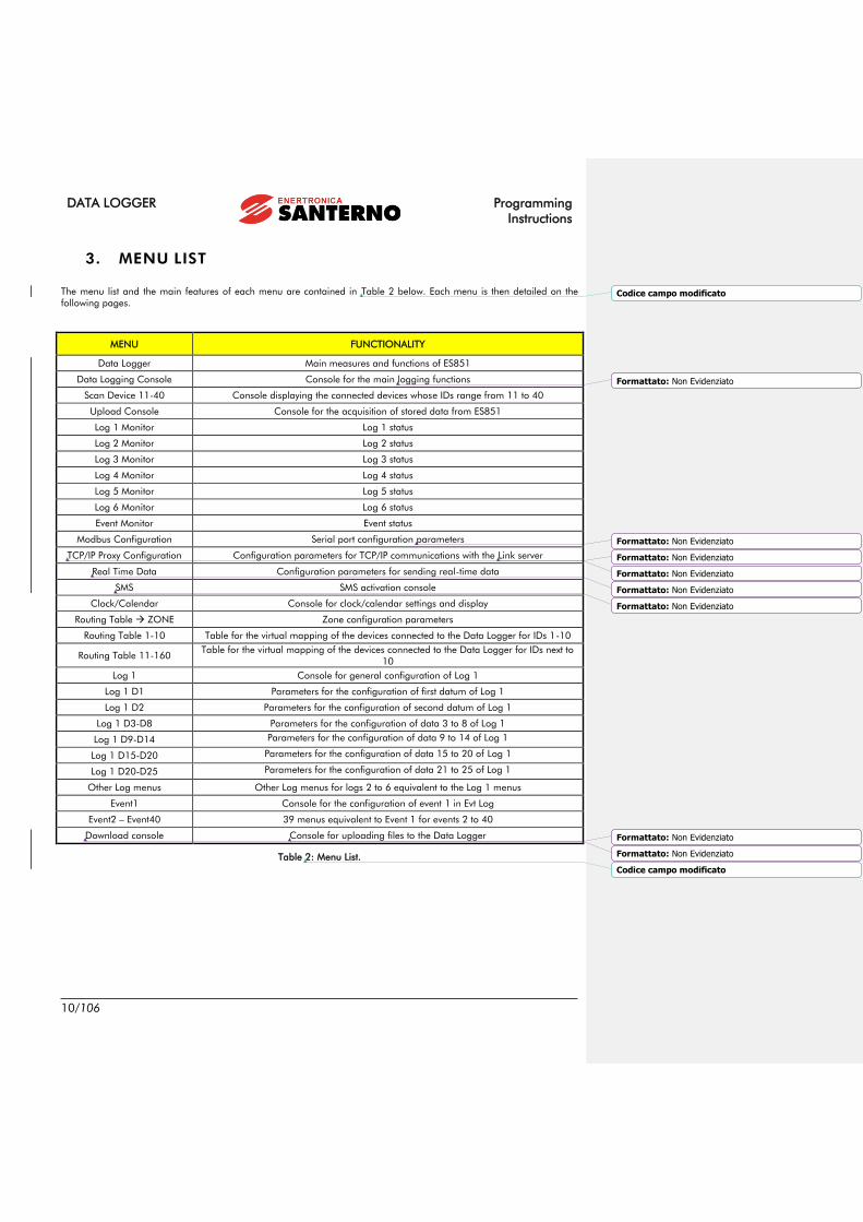
3. MENU LIST
The menu list and the main features of each menu are contained in Table 2 below. Each menu is then detailed on the
following pages.
MENU FUNCTIONALITY
Data Logger Main measures and functions of ES851
Data Logging Console Console for the main logging functions
Scan Device 11-40 Console displaying the connected devices whose IDs range from 11 to 40
Upload Console Console for the acquisition of stored data from ES851
Log 1 Monitor Log 1 status
Log 2 Monitor Log 2 status
Log 3 Monitor Log 3 status
Log 4 Monitor Log 4 status
Log 5 Monitor Log 5 status
Log 6 Monitor Log 6 status
Event Monitor Event status
Modbus Configuration Serial port configuration parameters
TCP/IP Proxy Configuration Configuration parameters for TCP/IP communications with the Link server
Real Time Data Configuration parameters for sending real-time data
SMS SMS activation console
Clock/Calendar Console for clock/calendar settings and display
Routing Table ZONE Zone configuration parameters
Routing Table 1-10 Table for the virtual mapping of the devices connected to the Data Logger for IDs 1-10
Routing Table 11-160 Table for the virtual mapping of the devices connected to the Data Logger for IDs next to
10
Log 1 Console for general configuration of Log 1
Log 1 D1 Parameters for the configuration of first datum of Log 1
Log 1 D2 Parameters for the configuration of second datum of Log 1
Log 1 D3-D8 Parameters for the configuration of data 3 to 8 of Log 1
Log 1 D9-D14 Parameters for the configuration of data 9 to 14 of Log 1
Log 1 D15-D20 Parameters for the configuration of data 15 to 20 of Log 1
Log 1 D20-D25 Parameters for the configuration of data 21 to 25 of Log 1
Other Log menus Other Log menus for logs 2 to 6 equivalent to the Log 1 menus
Event1 Console for the configuration of event 1 in Evt Log
Event2 – Event40 39 menus equivalent to Event 1 for events 2 to 40
Download console Console for uploading files to the Data Logger
Table 2: Menu List.
Codice campo modificato
Formattato: Non Evidenziato
Formattato: Non Evidenziato
Formattato: Non Evidenziato
Formattato: Non Evidenziato
Formattato: Non Evidenziato
Formattato: Non Evidenziato
Formattato: Non Evidenziato
Formattato: Non Evidenziato
Codice campo modificato

Programming
Instructions
DATA LOGGER
11/106
3.1. Menus and Submenus
Three programming levels are available. They can be changed by setting P298 accordingly.
BASIC (factory setting): permits to view the main measures and to set parameters P298 (programming level) and allows
changing basic programming;
ADVANCED: permits to access the BASIC parameters and the parameters relating to the programming of the available
connections;
ENGINEERING: allows accessing all parameters.
3.1.1. SYNOPTIC TABLE FOR M MEASURES
(Read-only)
Mxxx Range Device representation
(integer)
Display on the display/keypad and the
RemoteDrive/Sunway software
(may be a decimal figure)
plus unit of measure
Measure Name
Level Access Level (BASIC / ADVANCED )
Address Modbus address which the measure can be read from
(integer)
Function Measure description.
3.1.2. SYNOPTIC TABLE FOR P, R, I, C PARAMETERS
(Read-Write)
Pxxx Range Device representation
(integer)
Display on the display/keypad and the
RemoteDrive/Sunway software (may be
a decimal figure)
plus unit of measure
Parameter Name
Default Parameter factory-setting
(as represented for ES851 board)
Parameter factory-setting (as
displayed)
plus unit of measure
Level Access Level (BASIC / ADVANCED/ ENGINEERING)
Address ModBus address which the parameter can be read from/written to
(integer)
Function Parameter description
Formattato: Non Evidenziato
Formattato: Non Evidenziato
Formattato: Non Evidenziato
Formattato: Non Evidenziato
Formattato: Non Evidenziato
Formattato: Non Evidenziato

DATA LOGGER Programming
Instructions
12/106
NOTE
Pxxx Parameters (Always R/W).
Cxxx Parameters (Read-only with LOGGING function activated; R/W with
LOGGING function deactivated).
Rxxx Parameters Always R/W, but they activate only when the device is next
powered on.
Ixxx Inputs These are not parameters, but inputs (the values assigned to these
inputs are not stored to non-volatile memory. They are always set to 0 when the
inverter is powered on).
Formattato: Non Evidenziato

Programming
Instructions
DATA LOGGER
13/106
3.2. L i st of the BASIC Measures and P a rameters
Menu Parameter FUNCTION MODBUS
Address Default
4 DATA LOGGER MENU P298 Access Level 298 BASIC
I012 EEPROM Command 2003 No Command
M475 Software Version 475 -
M5000 Alarm Condition 5000 -
M5003 Active Access Level 5003 -
M5004 Flash Card Error 5004 -
M5006 MAC Address 5006, 5007,
5008 -
M5199 Latest EEPROM command not
executed 5199 -
8 LOG 1 MONITOR MENU M5050 Log 1 Length 5050 -
M5057 Log 1 Status 5057 -
M5070a-b Year and Month of Activation of Log 1 5070 -
M5071a-b Day and Time of Activation of Log 1 5071 -
M5072a-b Minutes and Seconds of Activation of
Log 1 5072 -
8 LOG 2 MONITOR MENU M5051 Log 2 Length 5051 -
M5058 Log 2 Status 5058 -
M5073a-b Year and Month of Activation of Log 2 5073 -
M5074a-b Day and Time of Activation of Log 2 5074 -
M5075a-b Minutes and Seconds of Activation of
Log 2 5075 -
8 LOG 3 MONITOR MENU M5052 Log 3 Length 5052 -
M5059 Log 3 Status 5059 -
M5076a-b Year and Month of Activation of Log 3 5076 -
M5077a-b Day and Time of Activation of Log 3 5077 -
M5078a-b Minutes and Seconds of Activation of
Log 3 5078 -
8 LOG 4 MONITOR MENU M5053 Log 4 Length 5053 -
M5060 Log 4 Status 5060 -
M5079a-b Year and Month of Activation of Log 4 5079 -
M5080a-b Day and Time of Activation of Log 4 5080 -
M5081a-b Minutes and Seconds of Activation of
Log 4 5081 -
8 LOG 5 MONITOR MENU M5054 Log 5 Length 5054 -
M5061 Log 5 Status 5061 -
M5082a-b Year and Month of Activation of Log 5 5082 -
M5083a-b Day and Time of Activation of Log 5 5083 -
M5084a-b Minutes and Seconds of Activation of
Log 5 5084 -
Codice campo modificato
Codice campo modificato
Formattato: Non Evidenziato
Formattato: Non Evidenziato
Formattato: Non Evidenziato
Formattato: Non Evidenziato
Formattato: Non Evidenziato
Formattato: Non Evidenziato
Formattato: Non Evidenziato
Formattato: Non Evidenziato
Formattato: Non Evidenziato
Formattato: Non Evidenziato
Formattato: Non Evidenziato
Formattato: Non Evidenziato
Formattato: Non Evidenziato
Formattato: Non Evidenziato
Formattato: Non Evidenziato
Formattato: Non Evidenziato
Formattato: Non Evidenziato
Formattato: Non Evidenziato
Formattato: Non Evidenziato
Formattato: Non Evidenziato
Formattato: Non Evidenziato
Formattato: Non Evidenziato
Formattato: Non Evidenziato
Formattato: Non Evidenziato
Formattato: Non Evidenziato
Formattato: Non Evidenziato
Formattato: Non Evidenziato
Formattato: Non Evidenziato
Formattato: Non Evidenziato
Formattato: Non Evidenziato
Formattato: Non Evidenziato
Formattato: Non Evidenziato
Formattato: Non Evidenziato
Formattato: Non Evidenziato
Formattato: Non Evidenziato

DATA LOGGER Programming
Instructions
14/106
Menu Parameter FUNCTION MODBUS
Address Default
8 LOG 6 MONITOR
MENU M5055 Log 6 Length 5055 -
M5062 Log 6 Status 5062 -
M5085a-b Year and Month of Activation of Log 6 5085 -
M5086a-b Day and Time of Activation of Log 6 5086 -
M5087a-b Minutes and Seconds of Activation of
Log 6 5087 -
9 EVENT MONITOR
MENU M5056 Evt Log Length 5056 -
M5063 Evt Log Status 5063 -
M5088a-b Year and Month of Activation of Evt
Log 5088 -
M5089a-b Day and Time of Activation of Evt Log 5089 -
M5090a-b Minutes and Seconds of Activation of
Evt Log 5090 -
15 CLOCK/CALENDAR
MENU M5010a Year 5010 -
M5010b Month 5010 -
M5011a Day of the Week 5011 Mon
M5011b Day of the Month 5011 1
M5012a Hours 5012 -
M5012b Minutes 5012 -
M5013 Seconds 5013 -
Table 3: List of the BASIC measures and parameters.
Formattato: Non Evidenziato
Formattato: Non Evidenziato
Formattato: Non Evidenziato
Formattato: Non Evidenziato
Formattato: Non Evidenziato
Formattato: Non Evidenziato
Formattato: Non Evidenziato
Formattato: Non Evidenziato
Formattato: Non Evidenziato
Formattato: Non Evidenziato
Codice campo modificato

Programming
Instructions
DATA LOGGER
15/106
3.3. L i st of the ADVANCED Measures and
P a rameters
Menu Parameter FUNCTION MODBUS
Address Default Setting
5 DATA LOGGING
CONSOLE MENU M164 Min. Sampling Time 164 -
P229 Initial SCANNING Address 229 1
P230 Final SCANNING Address 230 40
C238 Fast Sampling Only 238 No
C161 Type of Data Logging 161 Standard
C162 Fast Log Sampling Time 162 60 s (1 min)
C163 Fast Log Sample N. 163 1
C245 Fast Log Min. Variation Percent 245 0,0%
C242 Slow Log Sampling Time 242 3600s (1 hour)
C243 Slow Log Sample N. 243 1
C244 Slow Log Min. Variation Percent 244 0.0%
I160 Logger Command 160 No command
M5049 LOGGING Command Status 5049 -
M5016 N. of Devices Detected when
SCANNING 5016 -
M5017 Modbus ID of the Device being
SCANNED 5017 -
C300, ... C327
(one every three) ID of the Connected Device
300, 303, ...,
327
(one every three)
0
C301, ... C328
(one every three) Type of Connected Device
301, 304, ...,
328
(one every three)
No device
detected
M214 Connected Device Boxing 214 -
M215 Recognized Connected Device 215 -
C241 Extended Logging for the
Connected Device 241
Standard logging
for each device
M512 Event 0 Fired for the Connected
Device 512 -
6 SCAN DEVICE 11-40
MENU
C330, ... C417
(one every three) Connected Device ID
330, 333, ...,
417
(one every three)
0
C330, ... C418
(one every three) Type of Connected Device
331, 334, ...,
418
(one every three)
No device
detected
M204, M205 Boxing of the Connected Device 204, 205 -
M207, M208 Connected Device Recognized 207, 208 -
C239, C240 Extended Logging for the
Connected Device 239, 240
Long standard for
each device
M510, M511 Event 0 Active for the Connected
Device 510, 511 -
10 MODBUS
CONFIGURATION MENU R297 ES851 Device Id 297 1
Formattato: Non Evidenziato
Formattato: Non Evidenziato
Formattato: Non Evidenziato
Formattato: Non Evidenziato
Formattato: Non Evidenziato
Formattato: Non Evidenziato
Formattato: Non Evidenziato
Formattato: Non Evidenziato
Formattato: Non Evidenziato
Formattato: Non Evidenziato
Formattato: Non Evidenziato
Formattato: Non Evidenziato
Formattato: Non Evidenziato
Formattato: Non Evidenziato
Formattato: Non Evidenziato
Formattato: Non Evidenziato
Formattato: Non Evidenziato
Formattato: Non Evidenziato
Formattato: Non Evidenziato
Formattato: Non Evidenziato
Formattato: Non Evidenziato
Formattato: Non Evidenziato
Formattato: Non Evidenziato
Formattato: Non Evidenziato
Formattato: Non Evidenziato
Formattato: Non Evidenziato
Formattato: Non Evidenziato
Formattato: Non Evidenziato
Formattato: Non Evidenziato
Codice campo modificato
Codice campo modificato
Formattato: Non Evidenziato
Formattato: Non Evidenziato

DATA LOGGER Programming
Instructions
16/106
Menu Parameter FUNCTION MODBUS
Address Default Setting
11 CONNECTION
CONFIGURATION MENU R450 Type of Remote Connection 450
PROXY Ethernet
(DCHP, DNS )
R270 Type of Proxy Connection 270 Link Proxy ON
R276 R277 IP Address 276, 277 192.168.0.2
R278 R279 Network Mask 278, 279 255.255.255.0
R247 R248 Gateway 247, 248 0.0.0.0
M5037 RemoteDrive/Sunway Connection
Status 5037 -
13 REAL TIME DATA MENU P578 Time Period for Sending Real-time
Data 578
1441 (Data Send
Disabled)
14 SMS MENU M5066 SMS Status 5066 -
P3150 P3177 Message Heading 3150 3177 -
P294 SMS Sent after Event Resolved 294 Yes
15 CLOCK/CALENDAR
MENU P2010a Year To Be Changed 2010 2000
P2010b Month To Be Changed 2010 January
P2011a Day Of The Week To Be Changed 2011 Mon
P2011b Day Of The Month To Be
Changed 2011 1
P2012a Time (Hour) To Be Changed 2012 0
P2012b Time (Minutes) To Be Changed 2012 0
I2013b Clock/Calendar Editing
Command 2013 0
R3200 Time Lag (Hours) of the Local
Time Zone 3200 1
R3201 Time Lag (Minutes) of the Local
Time Zone 3201 0
16 ROUTING TABLE
ZONE P200 ZONE Start ID 200 23
P201 ZONE End ID 201 44
I200 Enable Zone Command 160 -
M5049 Enable Zone Status 5049 -
17 ROUTING TABLE 1-10
MENU P00a P009a Medium for Virtual Address 1-10 0-9
1: ES851 Local
2: ES821 DPR
3 ÷ 9: RS485
Modbus
P00b P009b Device ID for Virtual Address 1-10 0-9 1 ÷ 10
P00c P009c Virtual Address 1-10 Enable 0-9 1
Table 4: List of the ADVANCED measures and parameters.
Formattato: Tipo di carattere: Grassetto, Non Evidenziato
Formattato: Non Evidenziato
Formattato: Non Evidenziato
Formattato: Non Evidenziato
Formattato: Non Evidenziato
Formattato: Non Evidenziato
Formattato: Non Evidenziato
Formattato: Non Evidenziato
Formattato: Non Evidenziato
Formattato: Non Evidenziato
Formattato: Non Evidenziato
Formattato: Non Evidenziato
Formattato: Non Evidenziato
Formattato: Non Evidenziato
Formattato: Non Evidenziato
Formattato: Non Evidenziato
Formattato: Non Evidenziato
Formattato: Non Evidenziato
Formattato: Non Evidenziato
Formattato: Non Evidenziato
Formattato: Non Evidenziato
Formattato: Non Evidenziato
Formattato: Non Evidenziato
Formattato: Non Evidenziato
Formattato: Non Evidenziato
Formattato: Non Evidenziato
Formattato: Non Evidenziato
Formattato: Non Evidenziato
Formattato: Non Evidenziato
Formattato: Non Evidenziato
Formattato: Non Evidenziato
Formattato: Tipo di carattere: Grassetto, Maiuscoletto, NonEvidenziato
Formattato: Tipo di carattere: Grassetto, Maiuscoletto, NonEvidenziato
Formattato: Tipo di carattere: Grassetto, Maiuscoletto, NonEvidenziato
Codice campo modificato

Programming
Instructions
DATA LOGGER
17/106
3.1. L i st of the ENGINEER ING Measures and
P a rameters
NOTE
Only Log 1 parameters are specified below, since equivalent parameters apply to the
other logs. The same is valid for the Event1 menu, since the parameters of the other
event-type menus are the same.
Menu Parameter FUNCTION MODBUS
Address Default
4 DATA LOGGER
MENU P259
Timeout at the end of the early
warning 259 60 s
M5038 Early warning counter 5038 -
M5039 Early warning status 5039 -
P257 Ignore early warning 257 For all logs
M5197 Flash recovery status 5197 -
P296 BLH idle timeout 296 600 s
P618 Timeout log in stop 618 120 s
5 DATA LOGGING
CONSOLE P258 Boxing enabled 258 Yes
9 EVENT MONITOR M5200a ID of the first device that
generated the 0 event 5200 -
10 MODBUS
CONFIGURATION R218 COM1 type 218 RS232
R260 COM1 configuration 260 Slave
R261 COM1 baudrate 261 38400
R262 COM1 parity 262 2 stop bit, mark
R263 COM1 lag time between
packets 263 20 ms
R264 COM1 timeout 264 500 ms
R265 COM2 configuration 265 Master
R266 COM2 baudrate 266 38400
R267 COM2 parity 267 2 stop bit, mark
R268 COM2 lag time between
packets 268 20 ms
R269 COM2 timeout 269 500 ms
R213 COM2 RTS signal polarity 213 Low signal enable
11 CONNECTION
CONFIGURATION
MENU
R271 TCP/IP Port 271 6767
12 TCP/IP PROXY
CONFIGURATION M246 DHCP enable 246 -
M5165
M5166 IP address (from DHCP) 5165 5166 -
M5092
M5093
Gateway IP address (from
DHCP) 5092 5093 -
M5176 DHCP lease 5176 -
M5177 DHCP renew 5177 -
M596 DNS enable 596 -
R220 R221 Main DNS 220 221 208.67.222.222
Formattato: Tipo di carattere: Grassetto, Non Evidenziato
Formattato: Tipo di carattere: Grassetto, Non Evidenziato
Formattato: Tipo di carattere: Grassetto, Non Evidenziato

DATA LOGGER Programming
Instructions
18/106
Menu Parameter FUNCTION MODBUS
Address Default
R222 R223 Secondary DNS 222 223 208.67.220.220
R597 R598 Proxy static IP 597 598 213.174.178.156
M560 M561 IP address solved and stored 560 561 -
R295 Keepalive message timeout 295 5 min
R599 Proxy TCP/IP port 599 15100
M5190 NCI machine status 5190 -
M5191 NCI machine sub-status 5191 -
M5192 Proxy connection status 5192 -
M5193 Tunnel error 5193 -
M5194 Tunnel via Proxy to RD 5194 -
R3280 R3309 Proxy URL 3280 3309 link.elettronicasanterno.it
18 ROUTING TABLE
11-160 MENU P10a P159a Virtual address medium 11-160 10-159 RS485 Modbus
P10b P159b Virtual address device ID 1-10 10-159 11 ÷ 160
P10c P159c Virtual address enable 1-10 10-159 0
19 LOG 1 MENU C700 Storing enable 700 Disabled
C701 Sampling time 701 3600 s
C702 No. of samples for storing 702 1
C703 % of variation for storing 703 0
C704 No. of data per record 704 5
20 LOG 1 D1 MENU C705 L1D1 Multiplier coefficient K 705 1
C706 L1D1 Composition function 706 K*(a*Ka* + b*Kb* +
c*Kc)
C707 L1D1 Statistical function 707 Sampling average
C708 L1D1-A Multiplier coefficient Ka 708 1
C709a L1D1-A Type of datum 709 Integer, no sign
C709b L1D1-A Word no. 709 Word 16 bit
C709c L1D1-A Device ID 709 0
C710 L1D1-A Modbus address 710 0
C711 L1D1-B Multiplier coefficient Kb 711 1
C712a L1D1-B Type of datum 712 Integer, no sign
C712b L1D1-B Word no. 712 Word 16 bit
C712c L1D1-B Device ID 712 0
C713 L1D1-B Modbus address 713 0
C714 L1D1-C Multiplier coefficient Kc 714 1
C715a L1D1-C Type of datum 715 Integer, no sign
C715b L1D1-C Word no. 715 Word 16 bit
C715c L1D1-C Device ID 715 0
C716 L1D1-C Modbus address 716 0
C798a L1D1 % variation disabled 798 No
21 LOG 1 D2 MENU C717 L1D2 Multiplier coefficient K 717 1
C718 L1D2 Composition function 718 K*(a*Ka* + b*Kb* +
c*Kc)
C719 L1D2 Statistical function 719 Sampling average
C720 L1D2-A Multiplier coefficient Ka 720 1
C721a L1D2-A Type of datum 721 Integer, no sign
C721b L1D2-A Word no. 721 Word 16 bit
C721c L1D2-A Device ID 721 0
C722 L1D2-A Modbus address 722 0
C723 L1D2-B Multiplier coefficient Kb 723 1
C724a L1D2-B Type of datum 724 Integer, no sign
C724b L1D2-B Word no. 724 Word 16 bit
C724c L1D2-B Device ID 724 0
C725 L1D2-B Modbus address 725 0
C726 L1D2-C Multiplier coefficient Kc 726 1

Programming
Instructions
DATA LOGGER
19/106
Menu Parameter FUNCTION MODBUS
Address Default
C727a L1D2-C Type of datum 727 Integer, no sign
C727b L1D2-C Word no. 727 Word 16 bit
C727c L1D2-C Device ID 727 0
C728 L1D2-C Modbus address 728 0
C798b L1D2 % variation disabled 798 No
22 LOG 1 D3-D8
MENU
C729, C732,
C735, C738,
C741, C744
L1D3 Statistical function
729, 732,
735, 738,
741, 744
Sampling average
C730a, C733a,
C736a, C739a,
C742a, C745a
L1D3 Type of datum
730, 733,
736, 739,
742, 745
Integer, no sign
C730b, C733b,
C736b, C739b,
C742b, C745b
L1D3 Word no.
730, 733,
736, 739,
742, 745
Word 16 bit
C730c, C733c,
C736c, C739c,
C742c, C745c
L1D3 Device ID
730, 733,
736, 739,
742, 745
0
C731, C734,
C737, C740,
C743, C746
L1D3 Modbus address
731, 734,
737, 740,
743, 746
0
C798c, C798d,
C798e, C798f,
C798g, C798h
L1D3 % variation disabled 798 No
23 LOG 1 D9-D14
MENU
C747, C750,
C753, C756,
C759, C762
L1D9 Statistical function
747, 750,
753, 756,
759, 762
Sampling average
C748a, C751a,
C754a, C757a,
C760a, C763a
L1D9 Type of datum
748a, 751a,
754a, 757a,
760a, 763a
Integer, no sign
C748b, C751b,
C754b, C757b,
C760b, C763b
L1D9 Word no.
748b, 751b,
754b, 757b,
760b, 763b
Word 16 bit
C748c, C751c,
C754c, C757c,
C760c, C763c
L1D9 Device ID
748c, 751c,
754c, 757c,
760c, 763c
0
C749, C752,
C755, C758,
C761, C764
L1D9 Modbus address
749, 752,
755, 758,
761, 764
0
C798i, C798l,
C798m,
C798m, C798o,
C798p
L1D9 % variation disabled 798 No
24 LOG 1 D15-D20
MENU
C765, C768,
C771, C774,
C777, C780
L1D15 Statistical function
765, 768,
771, 774,
777, 780
Sampling average
C766a, C769a,
C772a, C775a,
C778a, C781a
L1D15 Type of datum
766a, 769a,
772a, 775a,
778a, 781a
Integer, no sign
C766b, C769b,
C772b, C775b,
C778b, C781b
L1D15 Word no.
766b, 769b,
772b, 775b,
778b, 781b
Word 16 bit
C766c, C769c,
C772c, C775c,
C778c, C781c
L1D15 Device ID
766c, 769c,
772c, 775c,
778c, 781c
0
C767, C770,
C773, C776,
C779, C782
L1D15 Modbus address
767, 770,
773, 776,
779, 782
0
C798q, C798r, L1D15 % variation disabled 798, 799 No

DATA LOGGER Programming
Instructions
20/106
Menu Parameter FUNCTION MODBUS
Address Default
C799a, C799b,
C799c, C799d
25 LOG 1 D21-D25
MENU
C783, C786,
C789, C792,
C795
L1D21 Statistical function 783, 786,
789, 792, 795 Sampling average
C784a, C787a,
C790a, C793a,
C796a
L1D21 Type of datum
784a, 787a,
790a, 793a,
796a
Integer, no sign
C784b, C787b,
C790b, C793b,
C796b
L1D21 Word no.
784b, 787b,
790b, 793b,
796b
Word 16 bit
C784c, C787c,
C790c, C793c,
C796c
L1D21 device ID
784c, 787c,
790c, 793c,
796c
0
C785, C788,
C791, C794,
C797
L1D21 Modbus address 785, 788,
791, 794, 797 0
C799e, C799f,
C799g, C799h,
C798i
L1D21 % variation disabled 799 No
27 EVENT1 MENU C520a E1 Enable 520 No
C1420 E1 Threshold function 1420 Less than
C1421a E1 Datum type trigger 1421 Integer, no sign
C1421c E1 Device ID trigger 1421 0
C1422 E1 Modbus address trigger 1422 0
C1423 E1 Threshold value 1423 0
C1424 E1 Offset from threshold 1424 0
C1425a E1D1 Type of datum 1425 Integer, no sign
C1425b E1D1 Word no. 1425 Word 16 bit
C1425c E1D1 Device ID 1425 0
C1426 E1D1 Modbus address 1426 0
C1427a E1D2 Type of datum 1427 Integer, no sign
C1427b E1D2 Word no. 1427 Word 16 bit
C1427c E1D2 Device ID 1427 0
C1428 E1D2 Modbus address 1428 0
Table 5: List of ENGINEERING measures and parameters

Programming
Instructions
DATA LOGGER
21/106
4. DATA LOGGER MENU
The Data Logger menu contains all data relating to ES851 and its basic settings. The first parameter being displayed is the
MAC Address, which uniquely identifies ES851 Data Logger board.
The Data Logger menu allows changing the programming level (P298) and displaying the software version (M475)
implemented in ES851. It also allows restoring default values and storing and deleting data acquired by ES851 through
the EEPROM (I012) command. ES851 Data Logger board is provided with two Flash cards for data storage. Parameters
are contained in the DATA FLASH; the Restore Default or Save All commands affect this portion of memory. The Restore
Default command also restores the parameters relating to ES851 for the inverter where the Data Logger is installed. On
the other hand, data stored when LOGGING are stored to 8-Mb FLASH CARD of ES851. As a result, any log operation
(e.g. Erase Log) affects ES851 Flash Card.
M5199 indicates the latest EEPROM command that has not been executed, as well as the alarm tripped and its fault code.
Parameter FUNCTION Access Level MODBUS Address
P298 Access Level BASIC 298
I012 EEPROM Command BASIC 2003
M475 Software Version BASIC 475
M5000 Alarm Condition BASIC 5000
M5003 Active Access Level BASIC 5003
M5004 Flash Card Error BASIC 5004
M5006 MAC Address BASIC 5006, 5007, 5008
M5199 Latest EEPROM command not executed BASIC 5199
P259 Early warning Timeout ENGINEERING 259
M5038 Early Warning Counter ENGINEERING 5038
M5039 Early Warning ENGINEERING 5039
P257 Ignore Early Warning ENGINEERING 257
M5197 Flash Recovery Status ENGINEERING 5197
P296 BLH Idle Timeout ENGINEERING 296
P618 Timeout Log in Stop ENGINEERING 618
Table 6: List of the parameters and measures in the Data Logger menu.
P298 Access Level
P298 Range 0 2
0: Basic
1: Advanced
2: Engineering
Access Level
Default 0 Basic
Level BASIC
Address 298
Function
The programming parameters for ES851 are grouped by access levels based on
their functions (more or less complex functions).
Some menus, or some parts of menus, are not displayed when a given access level
is selected.
When the BASIC access level is selected if the ES851 parameterization is correct,
navigation is easier, as only frequently accessed parameters are displayed.
In this manual, the Access Level is stated for each parameter.
Formattato: Tipo di carattere: 5 pt
Codice campo modificato
Formattato: Non Evidenziato

DATA LOGGER Programming
Instructions
22/106
I012 EEPROM Command
I012 Range 0, 5, 11, 30 36, 777
0: No Command
5: Save all
11: Restore Default
30: Erase Log 1
31: Erase Log 2
32: Erase Log 3
33: Erase Log 4
34: Erase Log 5
35: Erase Log 6
35: Erase Event Log
37: Erase All Logs
777: Erase Fault List
EEPROM Command
Default This is not a parameter: I012 is set to zero at power on and whenever the
EEPROM command is executed.
Level BASIC
Address 2003
Function
This parameter saves and restores the entire set of parameters that can be
accessed by the user:
5: Save All, The current value of the RAM parameters is stored to non-volatile
memory (DATA FLASH). All parameters are saved at a time.
11: Restore Default, Factory-set values are restored for all parameters; each
factory-set value is stored to non-volatile memory (DATA FLASH).
30 to 35: Erase Log1,2,3,4,5,6,Event Log, Erases any data in the specified log
(data is stored to FLASH CARD).
36: Erase All Logs, Erases data acquired in all logs (data is stored to FLASH
CARD).
777: Erase Fault List, Erases the fault list stored to DATA FLASH memory.
M475 Software Version
M475 Range 10009999
1000 9999
Software Version
Level BASIC
Address 475
Function This measure indicates the software version implemented in ES851.
Formattato: Italiano (Italia)
Formattato: Non Evidenziato
Formattato: Controllo ortografia e grammatica
Formattato: Non Evidenziato
Tabella formattata

Programming
Instructions
DATA LOGGER
23/106
M5000 Alarm Condition
M5000 Range 0 6, 99 103
0: No Alarm
1: Par Save KO
2: Log Write Failure
3: ES821 Init. Failure
4: RS232 Init. Failure
5: RS485 Init.Failure
6: TCP/IP Stack Init. Failure
99: No Flash Card
100: Invalid Stream
101: TCP/IP Socket
103: ES821 Clock
104: Modem Init.
105: Modem KO
Alarm Condition
Default 0 0: No Alarm
Level BASIC
Address 5000
Function
This measure indicates the current alarm tripped for ES851. Please contact
Enertronica Santerno S.p.A. and state the alarm number and name.
0: No Alarm
1: Parameter Save Error
2: Log Write Error
3: FBS Configuration Error
4: Modbus RS232 Configuration Error
5: Modbus RS485 Configuration Error
6: TCP/IP Stack Configuration Error
99: Flash Card Missing or Inaccessible
100: Invalid Access to Stream
101: TCP/IP Socket Error
103: Clock 821 Error
104: Modem Initialization Error
105: Modem Off or Not Connected
M5003 Active Access Level
M5003 Range 0 2
0: Basic
1: Advanced
2: Engineering
Active Access Level
Level BASIC
Address 5003
Function This measure indicates the access level that is currently selected.
Formattato: Non Evidenziato
Formattato: Non Evidenziato

DATA LOGGER Programming
Instructions
24/106
M5004 Flash Card Error
M5004 Range 0 7
0: No Error
1: Stream Full
2: Checksum Error
3: Invalid Descriptor
4: Invalid Stream
5: Chain Error
6: Invalid Partitioning
7: Stream Busy
Flash Card Error
Level BASIC
Address 5004
Function
The errors above concern the flash card (the memory zone where logs are
stored) and its relevant operations. If an alarm trips, please contact Enertronica
Santerno S.p.A. and mention the alarm number and name.
M5006 MAC Address
M5006 Range 0 248
0 248
MAC Address
Level BASIC
Address 5006, 5007, 5008
Function The MAC Address is the physical address for ES851 network interface.
A unique MAC Address is assigned to each ES851 board.
M5199 Latest EEPROM Command Not Executed
M5199 Range 0, 32773, 32779, 32798 32805,
33545
0: No Command
5: Save all
11: Restore Default
30: Erase Log 1
31: Erase Log 2
32: Erase Log 3
33: Erase Log 4
34: Erase Log 5
35: Erase Log 6
36: Erase Event Log
37: Erase All Logs
777: Erase Fault List
Latest EEPROM
Command Not
Executed
Level BASIC
Address 5199
Function
This measure indicates the latest EEPROM command that has not been correctly
executed.
Codification is the same as for I012, but the most significant bit is set to one,
thus changing the range of values that can be assigned to this measure.
Formattato: Non Evidenziato
Formattato: Italiano (Italia)
Formattato: Non Evidenziato

Programming
Instructions
DATA LOGGER
25/106
P259 Early Warning Timeout
P259 Range 1 3600 1 s 3600 s
Early Warning
Timeout
Default 60 60 s
Level ENGINEERING
Address 259
Function Indicates the timeout (in seconds) elapsing after the early warning signal sent from
the inverter.
M5038 Early Warning Counter
M5038 Range 0 Max (Max = value in P259)
0 s Max s
Level ENGINEERING
Address 5038
Function
The early warning counter is set to the value in P259 when the early warning
finish signal is sent. The early warning counter is decremented every second.
The counter stops as soon as the early warning signal is reactivated.
M5039 Early Warning Status
M5039 Range 0 1
0: Inactive
1: Active
Early Warning Status
Level ENGINEERING
Address 5039
Function If it is worth 1, this means that the early warning signal is active or the early
warning signal is other than 0.
P257 Ignore Early Warning
P257 Range 0 2
0: Never
1: For the Event log only
2: For any log
Ignore Early Warning
Default 2 For any log
Level ENGINEERING
Address 257
Function
It indicates when the early warning status (M5039=1) has to be ignored.
0: Never. When the early warning status is active no log is recorded.
1: Events log only. When the early warning status is active only the events log is
recorded.
2: All logs. When the early warning status is active, this status is ignored and all the
logs can be recorded.
NOTA
The early warning signal is notified by the inverter to the Data Logger via the dual
port RAM. This signal is active when the inverter detects voltage values that presume
the board will switch off in a few seconds.

DATA LOGGER Programming
Instructions
26/106
M5197 Flash Recovery Status
M5197 Range 0 1
0: Recovery not in progress
1: Recovery in progress
Flash Recovery Status
Level ENGINEERING
Address 5197
Function This measure indicates whether the Data Logger is carrying out the initial checks
on the consistency status of the Data Flash.
P296 BLH Idle Timeout
P296 Range 0 65535 0 s 65535 s
BLH Idle Timeout
Default 600 600 s
Level ENGINEERING
Address 296
Function It indicates after how many seconds of idling the Data Logger should deactivate the
upload and download status.
P618 Timeout Log in stop
P618 Range 10 3600 10 s 3600 s
Timeout Log in Stop
Default 120 120 s
Level ENGINEERING
Address 618
Function It indicates after how many seconds a log in stop status (with no upload in progress)
should return to the running status.
Programming
Instructions
DATA LOGGER
27/106
5. DATA LOGGING CONSOLE MENU
This is the main operating menu. The parameters contained in this menu permit to SCAN the devices controlled by the
Data Logger, to automatically program the parameters relating to the variables monitored by the device LOGGING (this
function is called BOXING) and to activate/deactivate/delete the files containing LOGGING-monitored data.
The parameters specific to the variables monitored by the LOGGING (BOXING) function are automatically programmed
after SCANNING (I160) and after programming certain parameters that can be modified by the user. Parameters specific
to the monitored variables can be accessed only if the Engineering access level is selected. Variables that can be
monitored are automatically divided into 6 groups, which are called Log1, 2, 3, 4, 5, 6.
Automatic LOGGING can be either standard or extended logging (C161). When extended logging is activated, more
variables are monitored if compared to the standard logging.
According to factory setting (standard LOGGING for each device), each ES851 board can perform the LOGGING
function for each device connected to the plant, up to max. 40 devices. The type of LOGGING can be selected for each
connected device, for the optimization of the number of devices that can be boxed.
In both cases, the acquired variables are detected within a parameter set contained in a table which is unique to each
device and which is stored to ES851 when factory setting is performed (see APPENDIX).
Two log groups are available: Fast Log (C162, C163, C245) and Slow Log (C242, C243, C244), which are characterized
by a different factory-set sampling time of the logged variables. The parameters above allow the user to change the
sample number and the minimum variation percent of a data item for its logging.
ES851 Data Logger is also capable of logging data relating to each connected inverter when one of its variables changes.
Besides recording the alarms of the connected devices, ES851records to the Event file the non-response from one of the
connected devices (a non-response event is an Event 0). The parameters specific to the Event Log are inaccessible at a
Basic level and are automatically BOXED along with the parameters of the other logs. Their values are stated in the tables
stored during the factory setting stage (see APPENDIX).
After SCANNING, you can manually deselect some of the detected devices.
This menu views the first 10 devices that are detected from ES851 Data Logger. The setting of the next 30 devices, if
detected, can be viewed and changed in the SCAN DEVICE 11-40 MENU.
After each operation on the parameters above, ES851 performs automatic BOXING based on the new stored values.
The Data Logging Console menu also includes a set of measures indicating the command status and the programming
status of ES851.
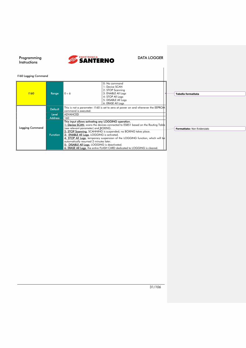
NOTE
The factory-settings of the parameters included in the Data Logging Console menu
do not require any customization. You can just use the SCAN command and the Log
Enable command through parameter I160.
Formattato: Non Evidenziato
Formattato: Non Evidenziato
Codice campo modificato
Formattato: Non Evidenziato
Codice campo modificato
Formattato: Non Evidenziato
Formattato: Non Evidenziato
Formattato: Non Evidenziato

DATA LOGGER Programming
Instructions
28/106
Parameter FUNCTION Access Level MODBUS Address
M164 Min. Sampling Time ADVANCED 164
P229 Initial SCANNING Address ADVANCED 229
P230 Final SCANNING Address ADVANCED 230
C238 Fast Sampling Only ADVANCED 238
C161 Type of Data Logging ADVANCED 161
C162 Fast Log Sampling Time ADVANCED 162
C163 Fast Log Sample N. ADVANCED 163
C245 Fast Log Min. Variation Percent ADVANCED 245
C242 Slow Log Sampling Time ADVANCED 242
C243 Slow Log Sample N. ADVANCED 243
C244 Slow Log Min. Variation Percent ADVANCED 244
I160 Logger Command ADVANCED 160
M5049 LOGGING Command Status ADVANCED 5049
M5016 N. of Devices Detected when SCANNING ADVANCED 5016
M5017 Address of the Device being SCANNED ADVANCED 5017
C300 C327 ID of the Connected Device ADVANCED 300, 303, … 327
(one every three)
C301 C328 Type of Connected Device ADVANCED 301, 304, … 328
(one every three)
M214 Connected Device Boxing ADVANCED 214
M215 Recognized Connected Device ADVANCED 215
C241 Extended Logging for the Connected Device ADVANCED 241
M512 Event 0 Fired for the Connected Device ADVANCED 512
P258 Boxing enabled ENGINEERING 258
Table 7: List of the parameters and measures in the Data Logging Console menu.
M164 Min. Sampling Time
M164 Range 1 65535 1 65535 sec
Min. Sampling Time
Level ADVANCED
Address 164
Function
Min. sampling time which is automatically detected by the LOGGING system. This
is updated whenever a scanning function is performed. The sampling time (C162
and C242) cannot be set up to a value lower than the one set in M164.
P229 Initial SCANNING Address
P229 Range 0 160 0 160
Initial SCAN Address
Default 23
Level ADVANCED
Address 229
Function The initial address for ES851 SCAN is defined in this parameter.
Formattato: Non Evidenziato
Formattato: Non Evidenziato
Formattato: Non Evidenziato
Formattato: Non Evidenziato
Formattato: Non Evidenziato
Formattato: Non Evidenziato
Formattato: Non Evidenziato
Formattato: Non Evidenziato
Formattato: Non Evidenziato
Formattato: Non Evidenziato
Codice campo modificato
Formattato: Non Evidenziato
Formattato: Non Evidenziato
Tabella formattata
Formattato: Non Evidenziato
Formattato: Non Evidenziato
Formattato: Non Evidenziato
Formattato: Non Evidenziato

Programming
Instructions
DATA LOGGER
29/106
P230 Final SCANNING Address
P230 Range 0 160 0 160
Final SCANNING
Address
Default 40
Level ADVANCED
Address 230
Function This parameter sets the max. allowable address for ES851 SCANNING.
C238 Fast Sampling Only
C238 Range 0 1 0: No
1: Yes
FAST Sampling Only
Default 0 0: No
Level ADVANCED
Address 238
Function If this parameter is set to 1, all the variables to be monitored will be sampled in
“fast” mode by ES851; this means that even the slow logs will be acquired as “fast”.
C161 Type of Data Logging
C161 Range 0-1 0: Standard Data Logging
1: Extended Data Logging
Type of Data Logging
Default 0 0: Standard
Level ADVANCED
Address 161
Function
This parameter sets the amount of data items to be stored for each device detected
in the logging network. If the Extended Data Logging is selected, a greater number
of variables is acquired for the selected device; as a result, the number of devices to
LOG is reduced.
C162 Fast Log Sampling Time
C162 Range 1 65535 1 65535 s
Fast Log Sampling
Time
Default 60 60 s (1 min)
Level ADVANCED
Address 162
Function
This parameter sets the sampling time of data stored to fast logs.
Note: The sampling time cannot be set to lower values than the value set in M164.
This value is automatically computed each time scanning takes place and depends
on the number of detected devices and the number of data items to store.
C163 Fast Log Sample N.
C163 Range 1 50 1 50
Fast Log Sample N.
Default 1 1
Level ADVANCED
Address 163
Function
Number of samples to acquire for the statistic computation of the data to be stored.
If this parameter is set to 1, no statistic operation takes place and the sample is just
stored as data.
Formattato: Non Evidenziato
Formattato: Non Evidenziato
Formattato: Non Evidenziato
Formattato: Non Evidenziato
Formattato: Non Evidenziato
Formattato: Non Evidenziato
Formattato: Non Evidenziato
Formattato: Non Evidenziato

DATA LOGGER Programming
Instructions
30/106
C245 Fast Log Min. Variation Percent
C245 Range 0 65535 0.0 6553.5 %
Fast Log Min.
Variation Percent
Default 0 0.0 %
Level ADVANCED
Address 245
Function
Variance for the data storage to the FLASH CARD. When C245 is other than 0,
logging occurs if at least one of the variables to be acquired varies from the last
logging of a value percent (considered as raw data) which is higher than C245.
C242 Slow Log Sampling Time
C242 Range 1 65535 1 65535 s
Slow Log Sampling
Time
Default 3600 3600 s (1 h)
Level ADVANCED
Address 242
Function
This parameter sets the sampling time of data stored to slow logs.
Note: The sampling time cannot be set to lower values than the value set in M164.
This value is automatically computed each time scanning takes place and depends
on the number of detected devices and the number of data items to store.
C243 Slow Log Sample N.
C243 Range 1 50 1 50
Slow Log Sample N.
Default 1 1
Level ADVANCED
Address 243
Function
Number of samples to acquire for the statistic computation of the data to store. If
this parameter is set to 1, no statistic operation takes place and the sample is just
stored as data.
C244 Slow Log Min. Variation Percent
C244 Range 0 65535 0.0 6553.5 %
Slow Log Min.
Variation Percent
Default 0 0.0 %
Level ADVANCED
Address 244
Function
Variance for the data storage to the FLASH CARD. When C244 is other than 0,
logging occurs if at least one of the variables to be acquired varies from the last
logging of a value percent (considered as raw data) which is higher than C244.
Formattato: Non Evidenziato
Formattato: Non Evidenziato
Formattato: Non Evidenziato
Formattato: Non Evidenziato
Programming
Instructions
DATA LOGGER
31/106
I160 Logging Command
I160 Range 0 6
0: No command
1: Device SCAN
2: STOP Scanning
3: ENABLE All Logs
4: STOP All Logs
5: DISABLE All Logs
6: ERASE All Logs
Logging Command
Default This is not a parameter: I160 is set to zero at power on and whenever the EEPROM
command is executed.
Level ADVANCED
Address 160
Function
This input allows activating any LOGGING operation.
1: Device SCAN, scans the devices connected to ES851 based on the Routing Table
(see relevant parameter) and BOXING.
2: STOP Scanning, SCANNING is suspended; no BOXING takes place.
3: ENABLE All Logs, LOGGING is activated.
4: STOP All Logs, temporary suspension of the LOGGING function, which will be
automatically resumed 2 minutes later.
5: DISABLE All Logs, LOGGING is deactivated.
6: ERASE All Logs, the entire FLASH CARD dedicated to LOGGING is cleared.
Tabella formattata
Formattato: Non Evidenziato

DATA LOGGER Programming
Instructions
32/106
M5049 LOGGING Command Status
M5049 Range 0 14, 25 31
0: Command Executed
1: Scan Impossible, Active Logs
2: Scan in Progress
3: Logs Locked, Active Upload
4: Logs Locked, Logs Already Active
5: Stop Logs Impossible, Inactive Logs
6: Erase Log Impossible, Active Upload
7: Erase Log Impossible, Active Logs
8: Disable Logs Imposs., Active Upload
9: Disable Logs Imposs., Inactive Logs
10: Boxing in Progress
11: Scan Finished
12: Busy
13: Enable Log Impossible, Erasing
14: Erasing Imposs., Early Warning Active
25: Erase Log 1
26: Erase Log 2
27: Erase Log 3
28: Erase Log 4
29: Erase Log 5
30: Erase Log 6
31: Erase Event Log
LOGGING Command
Status
Level ADVANCED
Address 5049
Function Status and result of the LOGGING commands.
M5016 N. of Devices Detected when SCANNING
M5016 Range 0 50 0 50
N. of Devices Detected
when SCANNING
Level ADVANCED
Address 5016
Function
Number of devices connected to ES851 detected when SCANNING. The device
number is automatically refreshed whenever a new device is detected. This
measure is stored to non-volatile memory only and is cleared when ES851 is
reset.
Formattato: Italiano (Italia)
Formattato: Non Evidenziato
Formattato: Non Evidenziato

Programming
Instructions
DATA LOGGER
33/106
M5017 Address of the Device being SCANNED
M5017 Range 0 247 0 247
Address of the Device
being SCANNED
Level ADVANCED
Address 5017
Function Current address that ES851 board is querying while SCANNING. This measure
is stored to non-volatile memory only and is cleared when ES851 is reset.
C300 C327 ID of the Connected Device
C300 C327 Range 0 255 0 255
ID of the Connected
Device
Default 0 0
Level ADVANCED
Address 300, 303, …, 327 (one every three)
Function
The high byte of the parameters for these addresses represents the routing ID of
the device detected when SCANNING.
(Note: This is a read-only parameter).
C301 C328 Type of Connected Device
C301 C328 Range 0 100
0: No Device Detected
1: ST
2: SM
3: SG
4: D4
5: D7
6: AM
7: PV
8: PD
9: PM
10: PR
11: PT
12: NG
13: IP
14: DL
15: IK
16: VK
17: LK
18: AC
19: AS
20: DB
21: DC
22: IF
23: IP
24: IZ
25: LT
26: OD
27: PB
28: SF
29: VD
30: VM
31: VN
32: VT
33: AO
34: DI
35: DO
36: QF
….
100: Unknown Device
Type of Connected
Device
Default 0 0: No Device Detected
Level ADVANCED
Address 301, 304, …, 328 (one every three)
Function
The low byte of these parameters represents the type of device detected when
SCANNING. If one or more of these parameters are manually set to 0 after
scanning, the respective devices are ignored when LOGGING.
Formattato: Non Evidenziato
Formattato: Non Evidenziato
Tabella formattata
Formattato: Francese (Francia)
Formattato: Italiano (Italia)

DATA LOGGER Programming
Instructions
34/106
M214 Connected Device Boxing
M214 Range Bit-controlled parameter. See Table 8.
Connected Device
Boxing
Level ADVANCED
Address 214
Function
If the j-th bit is worth 1, this means that the corresponding device is boxed (i.e.
the device will be monitored by the Data Logger as its acquired variables have
been added to the log’s parameters). If the j-th bit is worth 0, it has not been
boxed either because logs are full or because it has not been recognized.
Modbus Address Bits Devices Bit Description
214 0-15 1-16 If the i-th bit = 1, the i-th device is boxed.
Table 8: Bit-map of the devices boxed after SCANNING.
M215 Recognized Connected Device
M207, M208, M215 Range Bit-controlled parameter See Table 9
Recognized Connected
Device
Level ADVANCED
Address 215
Function
If the j-th bit is worth 1, this means that the corresponding device has been
recognized by ES851 (i.e. it has the routing table for that device, which contains
the log parameters values to be used when programming the Data Logger while
BOXING; see APPENDIX). If the j-th bit is worth 0, the corresponding device has
not been recognized because ES851 is not provided with the tables required.
Modbus Address Bits Devices Bit Description
215 0-15 1-16 If the i-th bit = 0, the i-th device is recognized.
Table 9: Bit-map of the recognized devices.
C241 Type of Logging for the Connected Device
C239, C240, C241 Range Bit-controlled parameter See Table 10
Type of Logging for
the Connected Device
Default 0 Standard Logging for each device
Level ADVANCED
Address 241
Function
If the j-th bit is worth 1, this means that the type of logging for the connected
device is “extended”, otherwise, it is “standard”. After SCANNING, ES851 board
will assign the same value to all the devices that are recognized and boxed
according to parameter C161. However, each value can be individually
changed.
Modbus Address Bit Devices Bit Description
241 0-15 1-16 If the i-th bit= 1, extended logging is implemented for the i-th
device
Table 10: Bit-map of the type of logging for the connected devices.
Formattato: Non Evidenziato
Formattato: Non Evidenziato
Codice campo modificato
Formattato: Non Evidenziato
Formattato: Non Evidenziato
Formattato: Non Evidenziato
Formattato: Non Evidenziato
Formattato: Non Evidenziato
Codice campo modificato
Formattato: Non Evidenziato
Codice campo modificato
Formattato: Non Evidenziato
Formattato: Non Evidenziato
Formattato: Non Evidenziato
Formattato: Non Evidenziato
Formattato: Non Evidenziato
Formattato: Non Evidenziato
Formattato: Tipo di carattere: 9 pt
Formattato: Normale
Formattato: Non Evidenziato
Codice campo modificato
Formattato: Non Evidenziato
Tabella formattata
Codice campo modificato
Formattato: Non Evidenziato
Formattato: Non Evidenziato
Formattato: Non Evidenziato
Formattato: Non Evidenziato
Codice campo modificato

Programming
Instructions
DATA LOGGER
35/106
M512 Event 0 Fired for the Connected Device
M512 Range Bit-controlled parameter See Table 11
Event 0 Fired for the
Connected Device
Default 65535 Event 0 fired for any device
Level ADVANCED
Address 512
Function
If the j-th bit is worth 1, event 0 is fired. This means that ES851 will NOT ignore
this device when checking the connection status, and that this device can cause
event 0 to fire.
Modbus Address Bits Devices Bit Description
512 0-15 1-16 If the i-th bit = 1, Event 0 for the i-th device has fired.
Table 11: Bit-map for Event 0 firing for the connected devices.
NOTE Event 0 is generated from the Data Logger when a device cannot be reached for 3
consecutive times.
P258 Boxing Enabled
P258 Range 0 1 No Yes
Boxing Enabled
Default 1 Yes
Level ENGINEERING
Address 258
Function It indicates if the mechanism for the automatic configuration of the logs at the end
of the SCAN is active.
Formattato: Non Evidenziato
Formattato: Non Evidenziato
Codice campo modificato
Formattato: Non Evidenziato
Formattato: Non Evidenziato
Formattato: Non Evidenziato
Formattato: Non Evidenziato
Codice campo modificato
Formattato: Non Evidenziato
Formattato: Non Evidenziato

DATA LOGGER Programming
Instructions
36/106
6. SCAN DEVICE 11-40 MENU
This menu is an extension of the DATA LOGGING CONSOLE menu displaying only the first 10 detected devices. After
scanning, the parameters relating to devices 11-40 are displayed.
Parameter FUNCTION Access Level MODBUS Address
C330 ÷ C417 Connected Device ID ADVANCED 330, 333, ..., 417
(one every three)
C331 ÷ C418 Type of the Connected Device ADVANCED 331, 334, ..., 418
(one every three)
M204, M205 Boxing of the Connected Device ADVANCED 204, 205
M207, M208 Recognition of the Connected Device ADVANCED 207, 208
C239, C240 Logging for the “Extended” Connected
Device ADVANCED 239, 240
M510, M511 Event 0 Activated for the Connected Device ADVANCED 510, 511
Table 12: List of parameters and measures, Scan Device 11-40
C330 ÷ C417 Connected Device ID
C175a C180a,
C480a C503a Range 0 255 0 255
Connected Device ID
Default 0 0
Level ADVANCED
Address 330, 333, …, 417 (one every three)
Function
The high byte of the parameters at these addresses represents the routing ID of
the device detected when SCANNING.
IMPORTANT: This parameter is read-only.
Formattato: Non Evidenziato
Formattato: Non Evidenziato
Formattato: Non Evidenziato
Formattato: Non Evidenziato
Formattato: Non Evidenziato
Codice campo modificato
Formattato: Non Evidenziato
Formattato: Non Evidenziato
Formattato: Non Evidenziato
Formattato: Non Evidenziato
Formattato: Non Evidenziato
Formattato: Non Evidenziato
Formattato: Non Evidenziato
Formattato: Non Evidenziato
Formattato: Non Evidenziato
Formattato: Non Evidenziato
Formattato: Non Evidenziato
Formattato: Non Evidenziato

Programming
Instructions
DATA LOGGER
37/106
C331 ÷ C418 Type of Connected Device
C331 ÷ C418 Range 0 100
0: No Device Detected
1: ST
2: SM
3: SG
4: D4
5: D7
6: AM
7: PV
8: PD
9: PM
10: PR
11: PT
12: NG
13: IP
14: DL
15: IK
16: VK
17: LK
18: AC
19: AS
20: DB
21: DC
22: IF
23: IP
24: IZ
25: LT
26: OD
27: PB
28: SF
29: VD
30: VM
31: VN
32: VT
33: AO
34: DI
35: DO
36: QF
….
100: Unknown Device
Type of Connected
Device
Default 0 0: No Device Detected
Level ADVANCED
Address 331, 334, ..., 418 (one every three)
Function
The low byte of these parameters indicates the type of device detected when
SCANNING. If one or more of these parameters are manually set to 0, the
respective devices are ignored from the LOGGING function.
M204, M205 Boxing of the Connected Device
M204, M205 Range Bit-controlled parameter See Table 13
Boxing of the
Connected Device
Level ADVANCED
Address 204, 205
Function
If the j-th is worth 1, this means that the respective device has been boxed (i.e. the
device will be monitored from the Data Logger, because the variables to be
acquired have been entered in the log parameters). If the j-th bit is worth 0, this
means that it has not been boxed either because logs are full or because it has not
been recognized.
Modbus Address Bits Connected Devices Bit Description
204 0-8 33-40 If the i-th bit is worth 1, this means that the i-th device
has been boxed
205 0-15 17-32 If the i-th bit is worth 1, this means that the i-th device
has been boxed
Table 13: Bit-map of the devices boxed after SCANNING.
Formattato: Non Evidenziato
Formattato: Non Evidenziato
Formattato: Non Evidenziato
Formattato: Non Evidenziato
Formattato: Francese (Francia), Non Evidenziato
Formattato: Non Evidenziato
Formattato: Italiano (Italia), Non Evidenziato
Formattato: Non Evidenziato
Formattato: Non Evidenziato
Tabella formattata
Formattato: Non Evidenziato
Codice campo modificato
Formattato: Non Evidenziato

DATA LOGGER Programming
Instructions
38/106
M207, M208 Connected Device Recognized
M207, M208 Range Bit-controlled parameter See Table 14
Connected Device
Recognized
Level ADVANCED
Address 207, 208
Function
If the j-th bit is worth 0, this means that ES851 has recognized the connected
device (i.e. ES851 contains a table including a parameter set which is unique to
each device. These parameters are used for programming the Data Logger
when BOXING is performed; see APPENDIX). If the j-th bit is worth 1, the
connected device has not been recognized because ES851 does not contain the
respective table with the parameter set.
Modbus Address Bits Connected Devices Bit Description
207 0-8 33-40 If the i-th bit is worth 0, this means that the i-th device
has been boxed
208 0-15 17-32 If the i-th bit is worth 0, this means that the i-th device
has been boxed
Table 14: Bit-map of the recognized devices.
C239, C240 Type of Logging of the Connected Device
C239, C240 Range Bit-controlled parameter See Table 15
Type of Logging of the
Connected Device
Default 0 Standard log for each device
Level ADVANCED
Address 239, 240
Function
If the j-th is worth 1, this means that the type of logging for the device is
“extended”, otherwise it is “standard”. After SCANNING, ES851 control board
will assign the same value to all the devices recognized and boxed based on
parameter C161. Each value can be individually changed.
Modbus Address Bit Connected Devices Bit Description
239 0-8 33-40 If the i-th bit is worth 1, this means that “extended” logging is
performed for the i-th device
240 0-15 17-32 If the i-th bit is worth 1, this means that “extended” logging is
performed for the i-th device
Table 15: Bit-map of the type of logging.
M510, M511 Event 0 Fired for the Connected Device
M510, M511 Range Bit-controlled parameter See Table 16
Event 0 Fired for the
Connected Device
Default 65535 Event 0 fired for each device
Level ADVANCED
Address 510, 511
Function
If the j-th bit is worth 1, this means that event 0 is activated for the connected
device. As a result, ES851 will NOT ignore the device when checking the
connection status, so the device is likely to cause the event fired.
Modbus Address Bits Connected Devices Bit Description
510 0-8 33-40 If the i-th bit is worth 1, event “0” for the i-th event has fired
511 0-15 1-16 If the i-th bit is worth 1, event “0” for the i-th event has fired
Table 16: Bit-map of Event 0 fired for the connected devices.
Formattato: Non Evidenziato
Formattato: Non Evidenziato
Formattato: Non Evidenziato
Codice campo modificato
Formattato: Non Evidenziato
Tabella formattata
Formattato: Non Evidenziato
Formattato: Non Evidenziato
Formattato: Non Evidenziato
Formattato: Non Evidenziato
Formattato: Non Evidenziato
Formattato: Non Evidenziato
Formattato: Non Evidenziato
Formattato: Non Evidenziato

Programming
Instructions
DATA LOGGER
39/106
7. UPLOAD CONSOLE MENU
The UPLOAD function allows viewing data stored while LOGGING. Upload is possible only if you are using the
RemoteDrive/Sunway. The Upload function allows viewing the logs and their sizes and allows selecting the logs to be
saved to your computer.
Select logs and press the Start button; the Windows menu for file save pops up, allowing choosing the file destination. All
the log filenames have the same root (chosen by the user) and are automatically distinguished by the
RemoteDrive/Sunway with an acronym (1, 2, 3, 4, 5, 6, evt) added at the end of the filename. Any log can be deleted
after being uploaded from the Options menu in the RemoteDrive/Sunway (see RemoteDrive/Sunway User Manual).
Logs are stored in CSV (Comma Separated Values) format; the created files are read-only file. The RemoteDrive/Sunway
also allows recorded data to be graphically represented.
Do the following to activate the Upload function:
• Press the “Scan Logs” button;
• Select the logs to be saved;
• Press Start. The Windows menu for file save pops up;
• Enter the path and name for the file(s) to be saved. The RemoteDrive/Sunway will automatically add the number
of the selected log to its filename.
• Once files are saved, you can use the RemoteDrive/Sunway to display and/or graphically represent them (see
RemoteDrive/Sunway User Manual).
Figure 1: The RemoteDrive/Sunway UPLOAD Console.
Formattato: Non Evidenziato
Formattato: Non Evidenziato
Formattato: Non Evidenziato
Formattato: Non Evidenziato
Formattato: Non Evidenziato
Formattato: Non Evidenziato
Formattato: Non Evidenziato
Formattato: Non Evidenziato
Codice campo modificato
Formattato: Non Evidenziato

DATA LOGGER Programming
Instructions
40/106
8. LOG MONITOR MENU
The measures relating to the Log status are contained into 6 menus: “LOG1 MONITOR”, “LOG2 MONITOR”, “LOG3
MONITOR”, “LOG4 MONITOR”, “LOG5 MONITOR”, “LOG6 MONITOR”.
Parameter FUNCTION Access Level MODBUS Address
M5050, M5051,
M5052, M5053,
M5054, M5055
Log Length BASIC
5050, 5051,
5052, 5053,
5054, 5055
M5057, M5058,
M5059, M5060,
M5061, M5062
Log Status BASIC
5057, 5058,
5059, 5060,
5061, 5062
M5070a-b, M5073a-b,
M5076a-b, M5079a-b,
M5082a-b, M5085a-b
Year and Month of Activation of the
Log BASIC
5070, 5073,
5076, 5079,
5082, 5085
M5071a-b, M5074a-b,
M5077a-b, M5080a-b,
M5083a-b, M5086a-b
Day and Time of Activation of the Log BASIC
5071, 5074,
5077, 5080,
5083, 5086
M5072a-b, M5075a-b,
M5078a-b, M5081a-b,
M5084a-b, M5087a-b
Minutes and Seconds of Activation of the
Logs BASIC
5072, 5075,
5078, 5081,
5084, 5087
Table 17: List of the measures in the Log Monitor menu.
M5050 (M051, M5052, M5053, M5054, M5055) Log Length
M5050 (Log 1)
M5051 (Log 2)
M5052 (Log 3)
M5053 (log 4)
M5054 (Log 5)
M5055 (Log 6)
Range 0 2000 0 2000 Kbyte
Log Length
Level BASIC
Address 5050, 5051, 5052, 5053, 5054, 5055
Function Length of the data stored to the FLASH CARD for each log (Kbytes).
M5057 (M5058, M5059, M5060, M5061, M5062) Log Status
M5057 (Log 1)
M5058 (Log 2)
M5059 (Log 3)
M5060 (Log 4)
M5061 (Log 5)
M5062 (Log 6)
Range Bit-controlled measure See Table 18
Log Status
Level BASIC
Address 5057, 5058, 5059, 5060, 5061, 5062
Function Current status of the logs.
Formattato: Non Evidenziato
Formattato: Non Evidenziato
Formattato: Non Evidenziato
Formattato: Non Evidenziato
Formattato: Non Evidenziato
Formattato: Non Evidenziato
Formattato: Non Evidenziato
Formattato: Non Evidenziato
Formattato: Non Evidenziato
Formattato: Non Evidenziato
Formattato: Non Evidenziato
Formattato: Non Evidenziato
Codice campo modificato
Formattato: Non Evidenziato
Formattato: Non Evidenziato
Formattato: Non Evidenziato
Formattato: Francese (Francia)
Formattato: Francese (Francia), Non Evidenziato
Formattato: Non Evidenziato
Formattato: Non Evidenziato
Formattato: Non Evidenziato
Formattato: Non Evidenziato
Formattato: Francese (Francia)
Formattato: Francese (Francia), Non Evidenziato
Formattato: Non Evidenziato
Formattato: Non Evidenziato
Formattato: Non Evidenziato

Programming
Instructions
DATA LOGGER
41/106
Bit N. Status Bit N. Status
0 Empty Log 4 Locked Log
1 Active Log 9 Wrapped Log
2 Stopped Log 10 Log Data Fatally Corrupted
3 Checked Log
Table 18: Bit-map of the Log Status.
M5070a (M073a, M5076a, M5079a, M5082a, M5085a) Year of Activation of the Log
M5070a (Log 1)
M5073a (Log 2)
M5076a (Log 3)
M5079a (Log 4)
M5082a (Log 5)
M5085a (Log 6)
Range 0 99 2000 2099 Years
Year of Activation of
the Log
Level BASIC
Address 5070, 5073, 5076, 5079, 5082, 5085
Function Year of activation of the log.
M5070b (M073b, M5076b, M5079b, M5082b, M5085b, M5088b) Month of Activation of the Log
M5070b (Log 1)
M5073b (Log 2)
M5076b (Log 3)
M5079b (Log 4)
M5082b (log 5)
M5085b (Log 6)
Range 1 12
1: January
2. February
3: March
4: April
5: May
6: June
7: July
8: August
9: September
10: October
11: November
12: December
Month of Activation of
the Log
Level BASIC
Address 5070, 5073, 5076, 5079, 5082, 5085
Function Month of activation of the log.
Formattato: Non Evidenziato
Codice campo modificato
Formattato: Non Evidenziato
Formattato: Non Evidenziato
Formattato: Non Evidenziato
Formattato: Non Evidenziato
Formattato: Non Evidenziato
Formattato: Non Evidenziato
Formattato: Non Evidenziato

DATA LOGGER Programming
Instructions
42/106
M5071a (M074a, M5077a, M5080a, M5083a, M5086a) Day of Activation of the Log
M5071a (Log 1)
M5074a (Log 2)
M5077a (Log 3)
M5080a (Log 4)
M5083a (Log 5)
M5086a (Log 6)
Range 1 31 1 31 Days
Day of Activation of the
Log
Level BASIC
Address 5071, 5074, 5077, 5080, 5083, 5086
Function Day of activation of the log.
M5071b (M074b, M5077b, M5080b, M5083b, M5086b) Time (Hours) of Activation of the Log
M5071b (Log 1)
M5074b (Log 2)
M5077b (Log 3)
M5080b (Log 4)
M5083b (Log 5)
M5086b (Log 6)
Range 0 23 0 23 Hours
Time (Hours) of
Activation of the Log
Level BASIC
Address 5071, 5074, 5077, 5080, 5083, 5086
Function Time of activation of the log (expressed in hours).
M5072a (M075a, M5078a, M5081a, M5084a, M5087a) Time (Minutes) of Activation of the Log
M5072a (Log 1)
M5075a (Log 2)
M5078a (Log 3)
M5081a (Log 4)
M5084a (Log 5)
M5087a (Log 6)
Range 0 59 0 59 min
Time (Minutes) of
Activation of the Log
Level BASIC
Address 5072, 5075, 5078, 5081, 5084, 5087
Function Time of activation of the log (expressed in minutes).
M5072b (M075b, M5078b, M5081b, M5084b, M5087b) Time (Seconds) of Activation of the Log
M5072b (Log 1)
M5075b (Log 2)
M5078b (Log 3)
M5081b (Log 4)
M5084b (Log 5)
M5087b (Log 6)
Range 0 59 0 59 sec
Time (Seconds) of
Activation of the Log
Level BASIC
Address 5072, 5075, 5078, 5081, 5084, 5087
Function Time of activation of the log (expressed in seconds).
Formattato: Non Evidenziato
Formattato: Non Evidenziato
Formattato: Non Evidenziato
Formattato: Non Evidenziato
Formattato: Non Evidenziato
Formattato: Non Evidenziato
Formattato: Non Evidenziato
Formattato: Non Evidenziato
Formattato: Non Evidenziato
Formattato: Non Evidenziato
Formattato: Non Evidenziato
Formattato: Non Evidenziato

Programming
Instructions
DATA LOGGER
43/106
9. EVENT MONITOR MENU
This menu contains the measures relating to the status of the Event Log. The Event Log records the events fired in each
device controlled by the Data Logger. Unlike the logs covered in the previous section, the Event log cannot be graphically
represented, but it can be viewed as a table from the RemoteDrive/Sunway software.
Parameter FUNCTION Access Level MODBUS Address
M5056 EVT Log Length BASIC 5056
M5063 EVT Log Status BASIC 5063
M5088a-b Year and Month of Activation of the EVT Log BASIC 5088
M5089a-b Day and Time of Activation of the EVT Log BASIC 5089
M5090a-b Minutes and Seconds of Activation of the
EVT Log BASIC 5090
M5200a ID of the first device that fired event 0 ENGINEERING 5200
Table 19: List of the measures in the Event Monitor menu.
M5056 EVT Log Length
M5056 Range 0 2000 0 2000 Kbyte
EVT Log Length
Level BASIC
Address 5056
Function Length in Kbytes of the data stored to the FLASH CARD.
M5063 EVT Log Status
M5063 Range Bit-controlled measure See Table 18
EVT Log Status
Level BASIC
Address 5063
Function Status of the EVT Log.
Bit N. Status Bit N. Status
0 EVT Log Empty 4 Locked Log
1 EVT Log Active 9 Wrapped Log
2 EVT Log Stopped 10 Log Data Fatally Corrupted
3 EVT Log Checked
Table 20: Bit-map of the Log Status.
Formattato: Non Evidenziato
Formattato: Non Evidenziato
Formattato: Non Evidenziato
Formattato: Non Evidenziato
Codice campo modificato
Formattato: Non Evidenziato
Formattato: Non Evidenziato
Formattato: Non Evidenziato
Formattato: Non Evidenziato
Formattato: Non Evidenziato
Formattato: Non Evidenziato
Formattato: Non Evidenziato
Formattato: Non Evidenziato
Formattato: Non Evidenziato
Formattato: Non Evidenziato
Formattato: Non Evidenziato

DATA LOGGER Programming
Instructions
44/106
M5088a Year of Activation of the EVT Log
M5088a Range 0 99 2000 2099
Year of Activation of
the EVT Log
Level BASIC
Address 5088
Function Year of activation of the EVT Log.
M5088b Month of Activation of the EVT Log
M5088b
Range 1 12
1: January
2. February
3: March
4: April
5: May
6: June
7: July
8: August
9: September
10: October
11: November
12: December
Month of Activation of
the EVT Log
Level BASIC
Address 5088
Function Month of activation of the EVT Log.
M5089a Day of Activation of the EVT Log
M5089a Range 1 31 1 31 days
Day of Activation of the
EVT Log
Level BASIC
Address 5089
Function Day of Activation of the EVT Log.
M5089b Time of Activation of the EVT Log
M5089b Range 0 23 0 23 hours
Time of Activation of
the EVT Log
Level BASIC
Address 5089
Function Time of Activation of the EVT Log.
Formattato: Non Evidenziato
Formattato: Non Evidenziato
Formattato: Non Evidenziato
Formattato: Non Evidenziato
Formattato: Non Evidenziato
Formattato: Non Evidenziato
Formattato: Non Evidenziato
Formattato: Non Evidenziato
Formattato: Non Evidenziato
Formattato: Non Evidenziato
Formattato: Non Evidenziato
Formattato: Non Evidenziato
Formattato: Non Evidenziato
Formattato: Non Evidenziato

Programming
Instructions
DATA LOGGER
45/106
M5090a Minutes of Activation of the EVT Log
M5090a Range 0 59 0 59 min
Minutes of Activation of
the EVT Log
Level BASIC
Address 5090
Function Minutes of activation of the EVT Log.
M5090b Seconds of Activation of the EVT Log
M5090b Range 0 59 0 59 sec
Seconds of Activation
of the EVT Log
Level BASIC
Address 5090
Function Seconds of activation of the EVT log.
M5200a ID of the First Device that Fired Event 0
M5200a Range 0 255 0 255
ID of the First Device
that Fired Event 0
Level BASIC
Address 5200
Function The highest byte indicates the ID of the first device with active 0 event. If
M5200a is 0, then event 0 is not active for any of the devices monitored.
Formattato: Non Evidenziato
Formattato: Non Evidenziato
Formattato: Non Evidenziato
Formattato: Non Evidenziato
Formattato: Non Evidenziato
Formattato: Non Evidenziato
Formattato: Non Evidenziato
Formattato: Non Evidenziato

DATA LOGGER Programming
Instructions
46/106
10. MODBUS CONFIGURATION MENU
Two serial ports are implemented in ES851 control board. COM1 port is able to operate both as a standard RS232 port
(default setting) and as a standard RS485 port, while port COM2 is a standard RS485 port.
If a different baud rate for ports COM1/COM2 is required, the ENGINEERING access level must be selected.
CAUTION
If you need COM1 to operate as a standard RS485 port, you must state that ONLY
when ordering the equipment, as this implies both software and hardware
modifications.
The Modbus configuration by default of ports COM1 and COM2 is as follows:
Port Default
COM1 Port enabled in Slave Modbus mode
COM2 Port enabled in Modbus mode
Table 21: Default settings for serial ports COM1 and COM2.
.
NOTE
You can change the configuration of Modbus COM 1 port by setting parameter R450
to one of the two values relating to serial communications, i.e. “9: Local Serial Slave”
or “10: Local Serial Master”.
CAUTION The parameters in this menu are “R” parameters; they activate only when the device is
next powered on.
When multiple ES851 control boards are installed in a PV field, it can be necessary to change their addresses to avoid
conflicts. To do so, parameter R297 must be changed following the procedure below.
Parameter FUNCTION Access Level MODBUS
Address
R297 ES851 Device ID ADVANCED 297
Table 22: Parameter in the Modbus configuration menu.
R297 ES851 Device ID
R297 Range 0 247 0 247
ES851 Device ID
Default 1 1
Level ADVANCED
Address 297
Function
This parameter allows changing the ID of ES851 control board. When multiple
ES851 control boards are installed in a PV field, it can be necessary to change their
addresses to avoid conflicts.
Procedure for changing the address of ES851 control board:
• Enter the new address for parameter R297;
• Disconnect ES851 control board;
• Reset ES851 control board;
• Connect ES851 control board using the new address;
• Manually disable the old address. Please refer to the ROUTING TABLE 1-10 MENU.
Formattato: Non Evidenziato
Formattato: Non Evidenziato
Formattato: Non Evidenziato
Formattato: Non Evidenziato
Formattato: Non Evidenziato
Codice campo modificato
Formattato: Non Evidenziato
Formattato: Non Evidenziato
Formattato: Non Evidenziato
Formattato: Non Evidenziato
Formattato: Non Evidenziato
Formattato: Non Evidenziato
Formattato: Non Evidenziato
Formattato: Non Evidenziato
Formattato: Non Evidenziato
Formattato: Non Evidenziato
Formattato: Non Evidenziato
Formattato: Non Evidenziato
Formattato: Non Evidenziato
Formattato: Non Evidenziato
Formattato: Non Evidenziato

Programming
Instructions
DATA LOGGER
47/106
In ENGINEERING mode it is possible to configure COM1 and COM2 at low level.
Parameter FUNCTION Access Level MODBUS
address
R218 COM1 Type ENGINEERING 218
R260 COM1 Configuration ENGINEERING 260
R261 COM1 Baudrate ENGINEERING 261
R262 COM1 Parity ENGINEERING 262
R263 COM1 Lag Time Between Packets ENGINEERING 263
R264 COM1 Timeout ENGINEERING 264
R265 COM2 Configuration ENGINEERING 265
R266 COM2 Baudrate ENGINEERING 266
R267 COM2 Parity ENGINEERING 267
R268 COM2 Lag Time Between Packets ENGINEERING 268
R269 COM2 Timeout ENGINEERING 269
R213 COM2 RTS Signal Polarity ENGINEERING 213
Table 23: Serial port configuration parameters of ENGINEERING level
P218 COM1 Type
P218 Range 0 1 RS232 RS485
COM1 Type
Default 0 RS232
Level ENGINEERING
Address 218
Function It indicates whether the first serial port should operate as RS232 or RS485.
P260 COM1 Configuration
P260 Range 0 2
0: Modbus disabled
1: Modbus enabled in slave mode
2: Modbus enabled in master mode
COM1 Configuration
Default 1 Modbus enabled in slave mode
Level ENGINEERING
Address 260
Function It indicates if the first serial port is enabled in Modbus slave protocol, Modbus
master, or if it is free.
P261 COM1 Baudrate
P261 Range 1 8
1: 1200bps
2: 2400bps
3: 4800bps
4: 9600bps
5: 19200bps
6: 38400bps
7: 57600bps
8: 115200bps
COM1 Baudrate
Default 6 38400bps
Level ENGINEERING
Address 261
Function It indicates the baudrate of the first serial port.

DATA LOGGER Programming
Instructions
48/106
P262 COM1 Parity
P262 Range 0 4
0: no parity 1 stop bit
1: even parity 1 stop bit
2: odd parity 1 stop bit
3: mark parity 2 stop bits
4: space parity 2 stop bits
COM1 Parity
Default 3 mark parity 2 stop bits
Level ENGINEERING
Address 262
Function It indicates the parity bit of the first serial port.
P263 COM1 Lag Time Between Packets
P263 Range 1 50 1 ms 50 ms
COM1 Lag Time
Between Packets
Default 20 20 ms
Level ENGINEERING
Address 263
Function It indicates the lag time between packets for the first serial port.
P264 COM1 Timeout
P264 Range 1 1000 1 ms 1000 ms
COM1 Timeout
Default 500 500 ms
Level ENGINEERING
Address 264
Function It indicates the timeout for the first serial port.
P265 COM2 Configuration
P265 Range 0 2
0: Modbus disabled
1: Modbus enabled in slave mode
2: Modbus enabled in master mode
COM2 Configuration
Default 1 Modbus enabled in slave mode
Level ENGINEERING
Address 265
Function It indicates if the second serial port is enabled in Modbus slave protocol, Modbus
master, or if it is free.
P266 COM2 Baudrate
P266 Range 1 8
1: 1200bps
2: 2400bps
3: 4800bps
4: 9600bps
5: 19200bps
6: 38400bps
7: 57600bps
8: 115200bps
COM2 Baudrate
Default 6 38400bps
Level ENGINEERING
Address 266
Function It indicates the baudrate of the second serial port.

Programming
Instructions
DATA LOGGER
49/106
P267 COM2 Parity
P267 Range 0 4
0: no parity 1 stop bit
1: even parity 1 stop bit
2: odd parity 1 stop bit
3: mark parity 2 stop bits
4: space parity 2 stop bits
COM2 Parity
Default 3 mark parity 2 stop bits
Level ENGINEERING
Address 267
Function It indicates the parity bit of the second serial port.
P268 COM2 Lag Time Between Packets
P268 Range 1 50 1 ms 50 ms
COM2 Lag Time
Between Packets
Default 20 20 ms
Level ENGINEERING
Address 268
Function It indicates the lag time between packets for the second serial port.
P269 COM2 Timeout
P269 Range 1 1000 1 ms 1000 ms
COM2 Timeout
Default 500 500 ms
Level ENGINEERING
Address 269
Function It indicates the timeout for the second serial port.
COM2 RTS Signal Polarity
P213 Range 0 1 0: enable with higher signal
1: enable with lower signal
COM2 RTS Signal
Polarity
Default 1 enable with lower signal
Level ENGINEERING
Address 213
Function It indicates the polarity of the RTS signal for the second serial port.

DATA LOGGER Programming
Instructions
50/106
11. CONNECTION CONFIGURATION MENU
This is the main menu for configuring the connections of the ES851 board.
Parameter R450 contained in this menu allows to easily configure the connections available for ES851 control board by
means of a selection menu that automatically sets all the parameters related to the desired type of connection.
The menu options allow choosing between several Ethernet connections, depending on the presence and use of the DNS
and DHCP protocols.
The other parameters are to be programmed for Ethernet connections where the DHCP (proxy connection) is not present
or cannot be used.
Parameter R270 can be used only to disable the connection service to the Link.
CAUTION The following parameters are R parameters, which activate only after resetting the
ES851 control board.
Parameter FUNCTION Access Level MODBUS
Address
R450 Type of Connection ADVANCED 450
R270 Type of Proxy Connection ADVANCED 270
R276, R277 IP address ADVANCED 276, 277
R278, R279 Network Mask ADVANCED 278, 279
R247, R248 Gateway ADVANCED 247, 248
M5037 Connection Status of the
RemoteDrive/Sunway ADVANCED 5037
R271 TCP/IP Port ENGINEERING 271
Table 24: List of the parameters in the TCP/IP Configuration menu.
R450 Type of Connection
R450 Range 1 4
1: Proxy Ethernet (DHCP, DNS)
2: Proxy Ethernet (no DHCP, DNS)
3: Proxy Ethernet (no DHCP, no DNS)
4: Proxy Ethernet (DHCP, no DNS)
Tipo di
connessioneType of
Connection
Default 1 Proxy Ethernet (DHCP, DNS)
Level ADVANCED
Address 450
Function
This parameter sets the connectivity of ES851 Data Logger board.
• Proxy Ethernet (DHCP, DNS): the Link service via the Internet is used for
connection. The grid parameters are automatically obtained through a
DHCP service, and the name of the Link server is resolved from a DNS
service.
• Proxy Ethernet (no DHCP, DNS): the Link service via the Internet is used for
connection. The network is configured by setting parameters P276-P277 (IP
address of ES851), P278-P279 (netmask of ES851) and R247-R248
(gateway of ES851). The name of the Link server is resolved from a DNS
service.
• Proxy Ethernet (no DHCP, no DNS): the Link service via the Internet is used
for connection. The network is configured by setting parameters P276-
P277 (IP address of ES851), P278-P279 (netmask of ES851) and R247-
R248 (gateway of ES851). The Link server is referred to through its IP
address. The ENGINEERING access level is required.
Formattato: Non Evidenziato
Formattato: Non Evidenziato
Formattato: Non Evidenziato
Formattato: Non Evidenziato
Formattato: Non Evidenziato
Formattato: Non Evidenziato
Formattato: Non Evidenziato
Formattato: Non Evidenziato
Formattato: Non Evidenziato
Formattato: Non Evidenziato
Formattato: Non Evidenziato
Formattato: Non Evidenziato
Formattato: Non Evidenziato
Formattato: Non Evidenziato
Formattato: Non Evidenziato
Formattato: Non Evidenziato
Formattato: Non Evidenziato
Formattato: Non Evidenziato
Codice campo modificato
Formattato: Non Evidenziato
Formattato: Non Evidenziato
Formattato: Non Evidenziato
Formattato: Non Evidenziato
Formattato: Non Evidenziato
Formattato: Non Evidenziato
Formattato: Non Evidenziato
Formattato: Non Evidenziato
Formattato: Non Evidenziato
Formattato: Non Evidenziato

Programming
Instructions
DATA LOGGER
51/106
R270 Type of Proxy Connection
R270 Range 1 2 1: Link Proxy OFF
2: Link Proxy ON
Type of Proxy
Connection
Default 2 Link Proxy ON
Level ADVANCED
Address 270
Function This parameter sets the use of the Link service by the Data Logger.
R276 IP Address High
R276 Range 0 0xFFFF 0.0 255.255
IP Address High
Default 0xC0A8 192.168
Level ADVANCED
Address 276
Function This parameter sets the two high bytes of the static IP address of ES851 board.
R277 IP Address Low
R277 Range 0 0xFFFF 0.0 255.255
IP Address Low
Default 0x2 0.2
Level ADVANCED
Address 277
Function This parameter sets the two low bytes of the static IP address of ES851 board.
R278 IP Mask High
R278 Range 0 0xFFFF 0.0 255.255
IP Mask High
Default 0xFFFF 255.255
Level ADVANCED
Address 278
Function This parameter sets the two high bytes of ES851 netmask.
R279 IP Mask Low
R279 Range 0 0xFFFF 0.0 255.255
IP Mask Low
Default 0xFF00 255.0
Level ADVANCED
Address 279
Function This parameter sets the two low bytes of ES851 netmask.
R247 Gateway High
R247 Range 0 0xFFFF 0.0 255.255
Gateway High
Default 0x0000 0.0
Level ADVANCED
Address 247
Function This parameter sets the two high bytes of ES851 gateway.
Formattato: Non Evidenziato
Formattato: Non Evidenziato
Formattato: Tipo di carattere: Grassetto
Formattato: Non Evidenziato
Formattato: Non Evidenziato
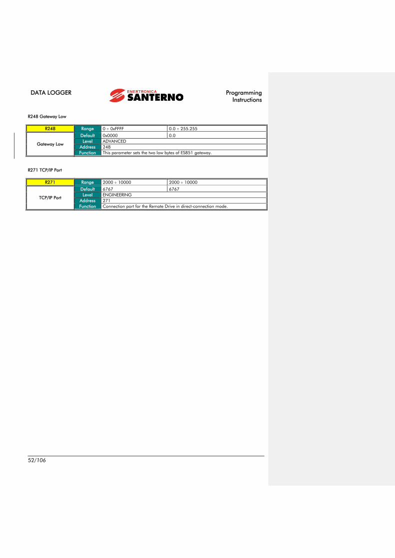
DATA LOGGER Programming
Instructions
52/106
R248 Gateway Low
R248 Range 0 0xFFFF 0.0 255.255
Gateway Low
Default 0x0000 0.0
Level ADVANCED
Address 248
Function This parameter sets the two low bytes of ES851 gateway.
R271 TCP/IP Port
R271 Range 2000 10000 2000 10000
TCP/IP Port
Default 6767 6767
Level ENGINEERING
Address 271
Function Connection port for the Remote Drive in direct-connection mode.

Programming
Instructions
DATA LOGGER
53/106
12. TCP/IP PROXY CONFIGURATION MENU
This menu includes some parameters and measures for the connection to the Internet via proxy server. In particular, this
menu allows enabling the DHCP, writing the APN (for GPRS connections) and monitoring the DHCP status, the IP address
assigned to ES851 and the IP address of the proxy server resolved by the DNS.
Parameter FUNCTION Access Level MODBUS Address
M246 DHCP Enable ENGINEERING 246
M5165 M5166 IP Address (from DHCP) ENGINEERING 5165 5166
M5092 M5093 Gateway IP Address (from
DHCP)
ENGINEERING 5092 5093
M5176 DHCP lease ENGINEERING 5176
M5177 DHCP renew ENGINEERING 5177
M596 DNS enable ENGINEERING 596
R220 R221 Primary DNS ENGINEERING 220 221
R222 R223 Secondary DNS ENGINEERING 222 223
R597 R598 Proxy Static IP Address ENGINEERING 597 598
M560 M561 IP Address Solved and Stored ENGINEERING 560 561
R295 Keepalive Message Timeout ENGINEERING 295
R599 Proxy TCP/IP Port ENGINEERING 599
M5190 NCI Machine Status ENGINEERING 5190
M5191 NCI Machine Sub-Status ENGINEERING 5191
M5192 Proxy Connection Status ENGINEERING 5192
M5193 Tunnel error ENGINEERING 5193
M5194 Tunnel via Proxy to RD ENGINEERING 5194
R3280 R3309 Proxy URL ENGINEERING 3280 3309
Table 25: List of the parameters in the TCP/IP Proxy Configuration menu.
M246 DHCP Enable
M246 Range 0 1 No Yes
DHCP Enable
Level ENGINEERING
Address 246
Function It indicates if the DHCP is enabled (DHCP can be configured through R450).
M5165 IP Address (from DHCP) First Part
M5165 Range 0 0xFFFF 0.0 255.255
IP Address (from
DHCP) First Part
Level ENGINEERING
Address 5165
Function It indicates the first two bytes of the Data Logger IP Address obtained through
the DHCP.
Codice campo modificato

DATA LOGGER Programming
Instructions
54/106
M5166 IP Address (from DHCP) Second Part
M5166 Range 0 0xFFFF 0.0 255.255
IP Address (from
DHCP) Second Part
Level ENGINEERING
Address 5166
Function It indicates the second two bytes of the Data Logger IP Address obtained
through the DHCP.
M5092 IP Gateway Address (from DHCP) First Part
M5092 Range 0 0xFFFF 0.0 255.255
IP Gateway Address
(from DHCP) First Part
Level ENGINEERING
Address 5092
Function It indicates the first two bytes of the Gateway IP address of the Data Logger
obtained through the DHCP.
M5093 IP Gateway Address (from DHCP) Second Part
M5093 Range 0 0xFFFF 0.0 255.255
IP Gateway Address
(from DHCP) Second
Part
Level ENGINEERING
Address 5093
Function It indicates the second two bytes of the Gateway IP address of the Data Logger
obtained through the DHCP.
M5176 DHCP Lease
M5176 Range 0 65535 0 min 65535 min
DHCP Lease
Level ENGINEERING
Address 5176
Function It indicates the DHCP lease time in minutes.
M5177 DHCP Renew
M5177 Range 0 65535 0 min 65535 min
DHCP Renew
Level ENGINEERING
Address 5177
Function It indicates the DHCP renew time in minutes.
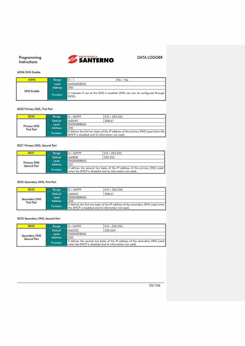
Programming
Instructions
DATA LOGGER
55/106
M596 DNS Enable
M596 Range 0 1 No Yes
DNS Enable
Level ENGINEERING
Address 596
Function It indicates if use of the DNS is enabled (DNS use can be configured through
R450).
R220 Primary DNS, First Part
R220 Range 0 0xFFFF 0.0 255.255
Primary DNS
First Part
Default 0xD043 208.67
Level ENGINEERING
Address 220
Function It defines the first two bytes of the IP address of the primary DNS (used when the
DHCP is disabled and its information not used).
R221 Primary DNS, Second Part
R221 Range 0 0xFFFF 0.0 255.255
Primary DNS
Second Part
Default 0xDEDE 222.222
Level ENGINEERING
Address 221
Function It defines the second two bytes of the IP address of the primary DNS (used
when the DHCP is disabled and its information not used).
R222 Secondary DNS, First Part
R222 Range 0 0xFFFF 0.0 255.255
Secondary DNS
First Part
Default 0xD043 208.67
Level ENGINEERING
Address 222
Function It defines the first two bytes of the IP address of the secondary DNS (used when
the DHCP is disabled and its information not used).
R223 Secondary DNS, Second Part
R223 Range 0 0xFFFF 0.0 255.255
Secondary DNS
Second Part
Default 0xDCDC 220.220
Level ENGINEERING
Address 223
Function It defines the second two bytes of the IP address of the secondary DNS (used
when the DHCP is disabled and its information not used).

DATA LOGGER Programming
Instructions
56/106
R597 Proxy Static IP Address, First Part
R597 Range 0 0xFFFF 0.0 255.255
Proxy Static IP
Address, First Part
Default 0xD5AE 213.174
Level ENGINEERING
Address 597
Function It defines the first two bytes of the static IP address of the Proxy (used when the
DNS is disabled or it is not possible to use it).
R598 Proxy Static IP Address, Second Part
R598 Range 0 0xFFFF 0.0 255.255
Proxy Static IP
Address, Second Part
Default 0xB29C 178.156
Level ENGINEERING
Address 598
Function It defines the second two bytes of the static IP address of the Proxy (used when
the DNS is disabled or it is not possible to use it).
M560 IP Address Solved and Stored, First Part
M560 Range 0 0xFFFF 0.0 255.255
IP Address Solved and
Stored, First Part
Level ENGINEERING
Address 560
Function It indicates the first two bytes of the IP Address of the Proxy solved through the
DNS and used as first try in case the DNS is enabled but not used.
M561 IP Address Solved and Stored, Second Part
M561 Range 0 0xFFFF 0.0 255.255
IP Address Solved and
Stored, Second Part
Level ENGINEERING
Address 561
Function It indicates the second two bytes of the IP Address of the Proxy solved through
the DNS and used as first try in case the DNS is enabled but not used.
R295 Keepalive Message Timeout
R295 Range 0 65535 Disabled, 1 min 65535 min
Keepalive Message
Timeout
Default 5 5 min
Level ENGINEERING
Address 295
Function
It defines the interval in minutes at which the Data Logger, in Proxy-connection
mode, should send the Keepalive message.
Note: If the parameter is set to 0, delivery of keepalive and logsnapshot
messages is disabled.

Programming
Instructions
DATA LOGGER
57/106
R599 Proxy TCP/IP Port
R599 Range 0 65535 0 65535
Proxy TCP/IP Port
Default 15100 15100
Level ENGINEERING
Address 599
Function Port for the connection to the Proxy of the Link service.
M5190 NCI Machine Status
M5190 Range 0 65535 0 65535
NCI Machine Status
Level ENGINEERING
Address 5190
Function
It indicates the status of the Data Logger with respect to the Proxy connection:
0: waiting for a command
1: connecting to the proxy
2: tunnel activation
3: ppp disconnection (only if connected as ppp).
M5191 NCI Machine Sub-Status
M5191 Range 0 65535 0 65535
NCI Machine Sub-
Status
Level ENGINEERING
Address 5191
Function
It indicates the sub-status of the Data Logger when status (M5192) is
“connecting to the proxy”:
0: proxy URL resolution through DNS
1: connecting to the server
2: decoding server response
3: building and delivering the response to the server
4: connection status termination
5: SMS delivery failed
6: building the response
M5192 Proxy Connection Status
M5192 Range 0 65535 0 65535
Proxy Connection
Status
Level ENGINEERING
Address 5192
Function
It indicates the error detected during the last connection to the Proxy:
0: no error
1: error on TCP/IP socket low level
2: DNS name not solved
3: generic Proxy connection error
4: timeout while waiting communication with the Proxy
5: R/W error with the Proxy
6: tunnel connection error
7: tunnel connection timeout error
8: R/W error in the tunnel with RD
9: Proxy response 'bad http'
10: Proxy response 'not authorized'
11: Proxy response 'not found'
12: Proxy response 'bad param'
13: Proxy response unknown error
14: Proxy response 'tunnelling not possible’
15: Proxy numerical address not defined and DNS disabled
16: timezone not found

DATA LOGGER Programming
Instructions
58/106
M5193 Tunnel Error
M5193 Range 0 65535 0 65535
Tunnel Error
Level ENGINEERING
Address 5193
Function
It indicates the last error detected in the Remote Drive control tunnel:
6: timeout
7: pipe error
M5194 Tunnel via Proxy to RD
M5194 Range 0 65535 0 65535
Tunnel via Proxy to RD
Level ENGINEERING
Address 5194
Function
It indicates if the remote monitoring tunnel through Remote Drive is active:
0: not active
1: active
2: closing tunnel
R3280 R3309 Proxy URL
P3280 R3309 Range 60-characters string
Proxy URL
Default ‘link.elettronicasanterno.it’ ‘link.elettronicasanterno.it’
Level ENGINEERING
Address 3280 3309
Function Proxy URL (server Link) to be used when the DNS is active

Programming
Instructions
DATA LOGGER
59/106
13. REAL TIME DATA MENU
The Real Time Data menu allows configuring ES851 Data Logger when the Link service is activated (more details are given
in the REMOTE MONITORING SERVICES User Manual).
The Data Logger periodically sends the last valid record of every log to the Link server. Some status variables of the Data
Logger itself are also sent to the Link server. This menu also configures the time period (in minutes) for sending real-time
data to the Link server, which is used for the Realtime service of the Remote Monitoring service.
Parameter FUNCTION Access Level MODBUS Address
P578 Time Period (min.) for Sending
Real-time Data ADVANCED 578
Table 26: Parameter in the Real Time Data menu.
P578 Time Period (min.) for Sending Real-time Data
P578 Range 5 1440 5 1440 min (24 h)
Time Period (min.) for
Sending Real-time
Data
Default 1441 Data send disabled
Level ADVANCED
Address 578
Function This parameter defines the time period (in minutes) for sending real-time data.
Formattato: Non Evidenziato
Formattato: Non Evidenziato
Formattato: Non Evidenziato
Formattato: Non Evidenziato
Formattato: Non Evidenziato
Formattato: Non Evidenziato
Formattato: Non Evidenziato
Formattato: Non Evidenziato
Formattato: Non Evidenziato
Formattato: Non Evidenziato

DATA LOGGER Programming
Instructions
60/106
14. SMS MENU
ES851 Data Logger board sends an SMS each time an event is stored to the EVENT Log, provided that communication via
GSM modem is allowed or that the Link Service via the Internet is activated. To activate this function, in parameters R420,
R421, R422 enter the mobile phone number receiving SMS. The SMS sent contains information about the event fired. SMS
can be sent only if the LOGGING function is active, otherwise, events cannot be either monitored or logged.
CAUTION The parameters contained in this menu are R parameters, which activate only after
resetting ES851 control board.
Any SMS has the following format:
Figure 2: SMS format.
NOTE
You can configure how to send SMS with the Link service (P580) when establishing a
connection via a GPRS modem and for any other type of connection using the Link
service. Please contact Enertronica Santerno S.p.A. to configure the SMS format.
Parameter FUNCTION Access Level MODBUS Address
M5066 SMS Status ADVANCED 5066
P3150 P3177 SMS Header ADVANCED 3150 3177
Table 27: List of the measures and parameters in the SMS menu
MAC of ES851 which
recorded the event
Event N. with status indication
(ON/OFF)
Address and value of the
monitored variable that caused
the event to fire
Enertronica
Santerno S.p.A.
Data Logger:
00-50-C2-44-AX-XX
Device: QF102X
Id=<077>
EVENT 10 OFF
AddEvt= 1668
ValEvt= 00000
09-Aug-2007
10:37
Header;
can be changed using pars. P3150-P3177
Date and time of the event
Type and virtual ID of the device causing the
event to fire
Formattato: Non Evidenziato
Formattato: Non Evidenziato
Formattato: Non Evidenziato
Formattato: Non Evidenziato
Formattato: Non Evidenziato
Formattato: Non Evidenziato
Codice campo modificato
Formattato: Non Evidenziato
Formattato: Non Evidenziato
Formattato: Non Evidenziato
Codice campo modificato
Formattato: Non Evidenziato

Programming
Instructions
DATA LOGGER
61/106
M5066 SMS Status
M5068a Range 0 2,4,5
0: No SMS
1: SMS Sent
2: No Digital Modem
3: Modem Not initialized
4: Modem Init KO
5: SMS KO
6: Connection Busy
SMS Status
Level ADVANCED
Address 5066
Function
This measure indicates the status of the SMS function.
0: No SMS, No SMS sent.
1: SMS Sent, Successful SMS.
2: No Digital Modem, No digital modem is connected, so the SMS function
cannot be executed.
3: Modem Not Initialized, The connected modem is not initialized; no SMS can
be sent.
4: Modem Init KO, Modem initialization failed; no SMS can be sent.
5: SMS KO, SMS failed.
6: Connection Busy, SMS will be sent later because the modem connection is
busy.
P3150 P3177 SMS Header
P3150 P3177 Range 48-character string (ASCII encoding)
SMS Header
Default
Enertronica
Santerno S.p.A.
Data Logger:
Level ADVANCED
Address 3150 3177
Function This parameter includes three words and the header of the SMS sent by the
Data Logger when an event fires.
Formattato: Non Evidenziato
Formattato: Italiano (Italia)
Formattato: Italiano (Italia)
Formattato: Italiano (Italia)
Formattato: Non Evidenziato

DATA LOGGER Programming
Instructions
62/106
15. CLOCK/CALENDAR MENU
This menu allows updating the clock/calendar of ES851 Data Logger.
ES851 is not currently considering daylight saving time.
It displays its clock/calendar in measure parameters M5010 to M5013. To change the clock/calendar settings, execute a
special command (I2013) after storing the new settings of the clock/calendar in parameters P0210 to P2012.
CAUTION When the Data Logger is connected to the Link Service, the date and time is
automatically set up, so the parameters below must not be changed!
Parameter FUNCTION Access Level MODBUS Address
P2010a Year To Be Changed ADVANCED 2010
P2010b Month To Be Changed ADVANCED 2010
P2011a Day Of The Week To Be Changed ADVANCED 2011
P2011b Day Of The Month To Be Changed ADVANCED 2011
P2012a Time (Hour) To Be Changed ADVANCED 2012
P2012b Time (Minutes) To Be Changed ADVANCED 2012
I2013b Clock/Calendar Editing Command ADVANCED 2013
M5010a Year BASIC 5010
M5010b Month BASIC 5010
M5011a Day of the Week BASIC 5011
M5011b Day of the Month BASIC 5011
M5012a Hours BASIC 5012
M5012b Minutes BASIC 5012
M5013 Seconds BASIC 5013
P3200 Time Lag (Hours) of the Local Time Zone ADVANCED 3200
P3201 Time Lag (Minutes) of the Local Time Zone ADVANCED 3201
Table 28: List of the measures and parameters in the Clock/Calendar menu.
P2010a Year To Be Changed
P2010a Range 0 99 2000 2099 Year
Year To Be Changed
Default 0 2000
Level ADVANCED
Address 2010
Function The high byte of this parameter contains the value of the year to be changed.
Formattato: Non Evidenziato
Formattato: Non Evidenziato
Formattato: Non Evidenziato
Formattato: Non Evidenziato
Formattato: Non Evidenziato
Formattato: Non Evidenziato
Formattato: Non Evidenziato
Formattato: Non Evidenziato
Formattato: Non Evidenziato
Formattato: Non Evidenziato
Formattato: Non Evidenziato
Codice campo modificato
Formattato: Non Evidenziato
Formattato: Non Evidenziato

Programming
Instructions
DATA LOGGER
63/106
P2010b Month To Be Changed
P2010b Range 1 12
1: January
2. February
3: March
4: April
5: May
6: June
7: July
8: August
9: September
10: October
11: November
12: December
Month To Be
Changed
Default 1 1: January
Level ADVANCED
Address 2010
Function The low byte of this parameter contains the value of the month to be changed.
P2011a Day of the Week To Be Changed
P2011a Range 1 7
1: Mon
2: Tues
3: Wed
4: Thur
5: Fri
6: Sat
7: Sun
Day of the Week To
Be Changed
Default 1 1: Mon
Level ADVANCED
Address 2011
Function The high byte of this parameter contains the value of the day of the week to be
changed.
P2011b Day of the Month To Be Changed
P2011b Range 1 31 1 31 Days
Day of the Month To
Be Changed
Default 1 1
Level ADVANCED
Address 2011
Function The low byte of this parameter contains the value of the day of the month to be
changed.
P2012a Time (Hour) To Be Changed
P2012a Range 0 23 0 23 hours
Time (Hour) To Be
Changed
Default 0 0
Level ADVANCED
Address 2012
Function The high byte of this parameter contains the time (hours) to be changed.
Formattato: Non Evidenziato
Formattato: Non Evidenziato
Formattato: Non Evidenziato
Formattato: Non Evidenziato

DATA LOGGER Programming
Instructions
64/106
P2012b Time (Minutes) To Be Changed
P2012b Range 0 59 0 59 minutes
Time (Minutes) To Be
Changed
Default 0 0
Level ADVANCED
Address 2012
Function The low byte of this parameter contains the value of the time (minutes) to be
changed.
I2013 Clock/Calendar Editing Command
P2013 Range 0 1 0 1
Clock/Calendar
Editing Command
Default 0 0
Level ADVANCED
Address 2013
Function
If this parameter is set to 1, all values set in parameters P2010 to P2012 are written
and stored to the clock/calendar of ES851 and measures M5010 to M5012 are
instantly changed.
CAUTION
Unchanged parameters are also written to the
clock/calendar. Make sure that unchanged
parameters are correct.
M5010a Year
M5010a Range 0 99 2000 2099
Level BASIC
Address 5010
Function Year.
M5010b Month
M5010b Range 1 12
1: January
2. February
3: March
4: April
5: May
6: June
7: July
8: August
9: September
10: October
11: November
12: December
Level BASIC
Address 5010
Function Month.
Formattato: Non Evidenziato
Formattato: Non Evidenziato
Tabella formattata
Formattato: Non Evidenziato
Tabella formattata
Formattato: Non Evidenziato
Formattato: Non Evidenziato
Formattato: Non Evidenziato
Formattato: Non Evidenziato

Programming
Instructions
DATA LOGGER
65/106
M5011a Day of the Week
M5011a Range 1 7
1: Mon
2: Tues
3: Wed
4: Thur
5: Fri
6: Sat
7: Sun
Level BASIC
Address 5011
Function Day of the week.
M5011b Day of the Month
M5011b Range 1 31 1 31 Days
Level BASIC
Address 5011
Function Day of the month.
M5012a Hour
M5012a Range 0 23 0 23 Hours
Level BASIC
Address 5012
Function Hour.
M5012b Minutes
M5012b Range 0 59 0 59 Minutes
Level BASIC
Address 5012
Function Minutes.
M5013 Seconds
M5013 Range 0 59 0 59 Seconds
Level BASIC
Address 5013
Function Seconds.
Tabella formattata
Formattato: Non Evidenziato
Tabella formattata
Formattato: Non Evidenziato
Formattato: Non Evidenziato
Formattato: Non Evidenziato
Formattato: Non Evidenziato
Tabella formattata
Formattato: Non Evidenziato
Formattato: Non Evidenziato
Formattato: Non Evidenziato
Formattato: Non Evidenziato
Tabella formattata
Formattato: Non Evidenziato
Formattato: Non Evidenziato
Formattato: Non Evidenziato
Formattato: Non Evidenziato
Tabella formattata
Formattato: Non Evidenziato
Formattato: Non Evidenziato
Formattato: Non Evidenziato
Formattato: Non Evidenziato

DATA LOGGER Programming
Instructions
66/106
P3200 Time Lag (Hours) of the Local Time Zone
P3200 Range -12 13 -12 13 hours
Time Lag (Hours) of
the Local Time Zone
Default 1 1 hour
Level ADVANCED
Address 3200
Function This parameter sets the time lag (in hours) based on the GMT (Greenwich Mean
Time).
P3201 Time Lag (Minutes) of the Local Time Zone
P3201 Range 0 59 0 59 min
Time Lag (Minutes) of
the Local Time Zone
Default 0 0 min
Level ADVANCED
Address 3201
Function Along with P3200, this parameter sets the time lag (in minutes) based on the GMT.
Formattato: Non Evidenziato
Formattato: Non Evidenziato
Formattato: Non Evidenziato
Formattato: Non Evidenziato
Formattato: Non Evidenziato
Formattato: Non Evidenziato
Formattato: Non Evidenziato
Formattato: Non Evidenziato
Formattato: Non Evidenziato

Programming
Instructions
DATA LOGGER
67/106
16. ROUTING TABLE ZONE MENU
The Routing Table defines the map containing matches between the ID of the devices connected to ES851 through a given
medium (e.g. RS485) and the virtual ID for the device response through ES851 board. A device network is then created;
devices can be connected to different media and can be detected and controlled through ES851 in the same way.
When multiple ES851 control boards are networked together, their routing tables are to be properly programmed to avoid
any address conflicts. Command I200 along with parameters P200 and P201 allows dividing the routing tables between
ZONES with enabled addresses and “disabled” ZONES with no need to operate on each connected device. In that way,
each ES851 is allocated to ZONES whose addresses are completely separate from each other.
The function described above is used for complex PV plants. They are virtually composed of ZONES comprising one ES851
control board, the inverter where it is installed and a variable number of monitoring devices (such as Smart String Boxes or
I/Os). Each ZONE is characterised by a group of addresses that is assigned to physical devices.
NOTE
Conventionally, the Data Logger boards are assigned the smallest Modbus
address within the Zone, while the inverter where the Data Logger is installed—that
has a privileged connection through a dedicated medium (Dual Port RAM)— is
assigned the address that comes next. See Table 29.
CAUTION
The MODBUS CONFIGURATION explains how to change the ID of ES851 Data
Logger. The Modbus ID of the Data Logger must NOT range between the values
given in parameters P200 and P201. Otherwise, command I200 fails.
NOTE
Once the address of ES851 has been changed and I200 command has been
activated for the subsequent addresses, you have to set up the type of connection
between ES851 Data Logger and the inverter where it is installed (ES821 DPR:
Dual Port RAM). To do so, select the Engineering level; in the Routing table,
change the parameter relating to the inverter address (see the ROUTING TABLE 1-
10 MENU).
ZONE ES851 Modbus Address Inverter Modbus
Address
1 23 24
2 45 46
3 67 68
4 89 90
5 111 112
6 133 134
Table 29: Conventional MODBUS addresses.
Parameter FUNCTION Access Level MODBUS Address
P200 ZONE Start ID ADVANCED 200
P201 ZONE End ID ADVANCED 201
I200 Enable Zone Command ADVANCED 160
M5049 Enable Zone Status ADVANCED 5049
Table 30: List of the measures and parameters in the Routing Table ---> ZONE menu.
Formattato: Non Evidenziato
Formattato: Non Evidenziato
Formattato: Non Evidenziato
Formattato: Non Evidenziato
Formattato: Non Evidenziato
Formattato: Non Evidenziato
Formattato: Non Evidenziato
Formattato: Non Evidenziato
Formattato: Non Evidenziato
Formattato: Non Evidenziato
Formattato: Non Evidenziato
Formattato: Non Evidenziato
Formattato: Non Evidenziato
Codice campo modificato
Formattato: Non Evidenziato
Formattato: Non Evidenziato
Formattato: Non Evidenziato

DATA LOGGER Programming
Instructions
68/106
P200 ZONE Start ID
P200 Range 1 160 1 160
ZONE Start ID
Default 23 23
Level ADVANCED
Address 200
Function Smallest Modbus address for the device detection.
P201 ZONE End ID
P201 Range 1 160 1 160
ZONE End ID
Default 44 44
Level ADVANCED
Address 201
Function Greatest Modbus address for the device detection.
I200 Commands for Zone
I200 Range 0, 7 0: No cmd
7: Enable zone
Commands for Zone
Default This is not a parameter. This input is set to 7 at power on and whenever the
command is executed.
Level ADVANCED
Address 160
Function Zone enable command.
M5049 Zone Executed
M5049 Range 0, 15 17
0: None
15: Zone in progress
16: Zone OK
17: Zone KO
Zone Executed
\Level ADVANCED
Address 5049
Function This measure shows the status of the Zone Enable command.
Formattato: Non Evidenziato
Formattato: Non Evidenziato
Formattato: Non Evidenziato
Formattato: Non Evidenziato
Formattato: Non Evidenziato
Formattato: Non Evidenziato
Formattato: Non Evidenziato
Formattato: Non Evidenziato
Tabella formattata
Formattato: Non Evidenziato
Formattato: Non Evidenziato
Formattato: Italiano (Italia), Non Evidenziato
Formattato: Non Evidenziato

Programming
Instructions
DATA LOGGER
69/106
17. ROUTING TABLE 1-10 MENU
This menu displays the configuration of the Routing Table from address 1 to address 10 and allows manual changes to
the Routing Table.
The first two locations (Virtual Address 1 and Virtual Address 2) in the table are dedicated to ES851 board (factory
presetting for Virtual Address 1) and to the inverter where ES851 is installed (Virtual Address 2). The remaining locations
are free for the other devices connected to the plant.
Besides displaying the active devices, this menu also allows changing the zone configuration by individually selecting their
valid Modbus addresses.
NOTE
The virtual addresses of the Routing Table are 160, but when the ADVANCED access
level is selected, only the first 10 location of the Routing Table can be viewed. Select the
ENGINEERING level to access the remaining locations.
Parameter FUNCTION Access Level MODBUS Address
P00a P009a Medium for Virtual Address 1-10 ADVANCED 0 -9
P00b P009b Device ID for Virtual Address 1-10 ADVANCED 0 -9
P00c P009c Virtual Address 1-10 Enable ADVANCED 0 -9
Table 31: List of the parameters in the Routing Table menu.

DATA LOGGER Programming
Instructions
70/106
P00a P009a Medium for Virtual Address 1-10
P00a P009a Range 0 3
0: ES851 Local
1: ES821 DPR
2: RS232 Modbus
3: RS485 Modbus
Medium for Virtual
Address 1-10
Default
Virtual address 1: ES851 Local
Virtual address 2: ES821 DPR
Remaining virtual addresses: RS485 Modbus
Level ADVANCED
Address 0 - 9
Function You can select the medium for the virtual address assigned to this parameter.
P00b P009b Device ID for Virtual Address 1-10
P00b P009b Range 1 247 1 247
Device ID for Virtual
Address 1-10
Default
Virtual Address 1: 1
Virtual Address 2: 1
Virtual Address i: i (i in 3 10)
Level ADVANCED
Address 0 - 9
Function You can set up the real address of the device mapped to the virtual address
assigned to this parameter.
P00c P009c Virtual Address 1-10 Enable
Range 0 1 0: Virtual Address Disabled
1: Virtual Address Enabled
Virtual Address 1-10
Enable
Default 1 1: Virtual Address Disabled
Level ADVANCED
Address 0 -9
Function You can enable or disable the map for the virtual address assigned to this
parameter.

Programming
Instructions
DATA LOGGER
71/106
18. ROUTING TABLE 11-160 MENU
At ENGINEERING level it is possible to access a series of menus similar to the Routing Table 1-10 menus. Such menus
contain a series of parameters of the same type as P00a, P00b, P00c. For further details, refer to chapter 17 ROUTING
TABLE 1-10.
NOTE The tables below only specify the parameters for the Routing Table 11-20 menus. The
following menus are equivalent.
Parameter FUNCTION Access Level MODBUS Address
P10a P019a Virtual Address Medium 11-20 ENGINEERING 10 -19
P10b P019b Virtual Address Device ID 11-20 ENGINEERING 10 -19
P10c P019c Virtual Address Enable 11-20 ENGINEERING 10 -19
Table 32: List of the parameters in the Routing Table 11-20 menus
P10a P19a Virtual Address Medium 11-20
P10a P19a Range 0 3
0: ES851 Local
1: ES821 DPR
2: RS232 Modbus
3: RS485 Modbus
Virtual Address
Medium 11-20
Default RS485 Modbus
Level ENGINEERING
Address 10 – 19
Function It defines the transmission medium for the virtual address associated with this
parameter.
P10b P19b Virtual Address Device ID 11-20
P10b P19b Range 1 247 1 247
Virtual Address Device
ID 11-20
Default 11 20 11 20
Level ENGINEERING
Address 10 – 19
Function It defines the real address of the device mapped at the virtual address associated
with this parameter.
P10c P19c Virtual Address Enable 11-20
P10c P19c Range 0 1 0: virtual address disabled
1: virtual address enabled
Virtual Address
Enable 11-20
Default 0 0: virtual address disabled
Level ENGINEERING
Address 10 – 19
Function It indicates if the map for the virtual address associated with this parameter is active or
not.
Formattato: Non Tutto maiuscole

DATA LOGGER Programming
Instructions
72/106
19. LOG 1 MENU
This menu contains the general parameters for the configuration of Log 1. It is possible to enable or disable the log,
setting its sampling time, the number of sampling to be stores, the number of data in the log record, and whether or not
the data storage should occur only in case of any variations to the values.
CAUTION
Log parameters are also recorded by the boxing mechanism, if this mechanism is
active. The parameters are overwritten at the end of the SCAN.
It is not possible to modify the parameters when the log is active.
Any modifications come into effect only upon next restarting of the log.
If the parameters differ from the previous recording, the Data Logger automatically
deletes the log before starting.
It is possible to calculate the recording frequency of the log by multiplying the
sampling time by the number of samples for storing (C701 x C702).
Parameter FUNCTION Access Level MODBUS Address
C700 Storing Enable ENGINEERING 700
C701 Sampling Time ENGINEERING 701
C702 No. of Samples for storing ENGINEERING 702
C703 % of Variation for Storing ENGINEERING 703
C704 No. of data per record ENGINEERING 704
Table 33: List of Log 1 general parameters
C700 Storing Enable
C700 Range 0 1 Disabled Enabled
Storing Enable
Default 0 Disabled
Level ENGINEERING
Address 700
Function It defines if log 1 is enabled or disabled.
C701 Sampling time
C701 Range 1 65535 1 s 65535
Sampling time
Default 3600 3600 s
Level ENGINEERING
Address 701
Function It defines the sampling time for log 1.
NOTE C801 (log 2) has 3600s by default, as C701, while C901, C1001, C1201, C1301
(logs 3, 4, 5, 6) have 60s by default for the sampling time.

Programming
Instructions
DATA LOGGER
73/106
C702 Number of Samples for Storing
C702 Range 1 50 1 50
Number of Samples
for Storing
Default 1 1
Level ENGINEERING
Address 702
Function
It defines the number of samplings that the Logger should process before storing
the log. The value recorded for each datum is a function of the samples processed,
and is defined independently for each datum by means of a specific parameter
(Statistical Function).
NOTE It is possible to calculate the recording frequency of the log by multiplying the sampling
time by the number of samples for storing (C701 x C702).
C703 % of Variation for Storing
C703 Range 0 1000 0.0% 100.0%
% of Variation for
Storing
Default 0 0
Level ENGINEERING
Address 703
Function
Offset value for the storage, in percentage. When this parameter is not 0, the
storage occurs only if at least one of the values to be recorded differs from the
previous recording by a higher value than that specified by the parameter
(considering the value as a raw datum).
If the parameter is set to 0, the data are always stored.
C704 No. of Data per Record
C704 Range 1 25 1 25
No. of Data per
Record
Default 5 5
Level ENGINEERING
Address 704
Function It indicates the number of data to be sampled to make up the record of this log.

DATA LOGGER Programming
Instructions
74/106
20. LOG 1 D1 MENU
This menu allows displaying the parameters for the configuration of datum 1 of log 1.
Datum 1 is a multi-source datum, i.e. it allows for the setting of three sub-data (A, B, C) and the calculation of the final
datum as a function of the three sub-data.
Parameter FUNCTION Access Level MODBUS Address
C705 L1D1 Multiplier Coefficient K ENGINEERING 705
C706 L1D1 Composition Function ENGINEERING 706
C707 L1D1 Statistical Function ENGINEERING 707
C708 L1D1-A Multiplier Coefficient Ka ENGINEERING 708
C709a L1D1-A Type of Datum ENGINEERING 709
C709b L1D1-A Word no. ENGINEERING 709
C709c L1D1-A Device ID ENGINEERING 709
C710 L1D1-A Modbus Address ENGINEERING 710
C711 L1D1-B Multiplier Coefficient Kb ENGINEERING 711
C712a L1D1-B Type of Datum ENGINEERING 712
C712b L1D1-B Word no. ENGINEERING 712
C712c L1D1-B Device ID ENGINEERING 712
C713 L1D1-B Modbus Address ENGINEERING 713
C714 L1D1-C Multiplier Coefficient Kc ENGINEERING 714
C715a L1D1-C Type of Datum ENGINEERING 715
C715b L1D1-C Word no. ENGINEERING 715
C715c L1D1-C Device ID ENGINEERING 715
C716 L1D1-C Modbus Address ENGINEERING 716
C798a L1D1 % of Variation Disabled ENGINEERING 798
Table 34: List of the parameters for datum 1 (multi-source) of log 1

Programming
Instructions
DATA LOGGER
75/106
C705 L1D1 Multiplier Coefficient K
C705 Range 0 65535 0 6553.5
L1D1 Multiplier
Coefficient K
Default 10 1
Level ENGINEERING
Address 705
Function Multiplier coefficient for datum 1 of log 1
C706 L1D1 Composition Function
C706 Range 1 7 1 7
L1D1 Composition
Function
Default 1 K*(a*Ka* + b*Kb* + c*Kc)
Level ENGINEERING
Address 706
Function
It indicates how to compose the three sub-data A, B, C to obtain datum 1.
In the formulas, values of A, B, C are referred to with a, b, c
K is C705, Ka is C708, Kb is C711, Kc is C714
1: K*(a*Ka* + b*Kb* + c*Kc)
2: K*(a*Ka * b*Kb + c*Kc)
3: K*(( a*Ka) / b*Kb + c*Kc)
4: K*a*Ka * b*Kb * c*Kc
5: K*(a*Ka )/ (b*Kb* * c*Kc)
6: K*(a*Ka * b*Kb) / ( c*Kc)
7: K/(a*Ka * b*Kb * c*Kc )
C707 L1D1 Statistical Function
C707 Range 0 3 0 3
L1D1 Statistical
Function
Default 0 Samples Average
Level ENGINEERING
Address 707
Function
It indicates how to compose the samples to obtain datum 1. This parameter is
effective only if C702 is different from 1.
0: samples average
1: samples minimum
2: samples maximum
3: last sample
C708 L1D1-A Multiplier Coefficient Ka
C708 Range 0 65535 -327.68 327.67
L1D1-A Multiplier
Coefficient Ka
Default 100 1
Level ENGINEERING
Address 708
Function Multiplier Coefficient for the sub-datum A of datum 1 of log 1 (see C706).

DATA LOGGER Programming
Instructions
76/106
C709a L1D1-A Type of Datum
C709a Range 0 1 Integer without sign Integer with sign
L1D1-A Type of
Datum
Default 0 Integer without sign
Level ENGINEERING
Address 709 Bit 15
Function It defines whether the sub-datum A of datum 1 of log 1 is with or without sign.
C709b L1D1-A Word no.
C709b Range 0 4 0 4
L1D1-A Word no.
Default 0 16-bit word
Level ENGINEERING
Address 709 Bit 14-8
Function
It indicates if the sub-datum A is a 16-bit datum or a word of a longer datum.
0: 16-bit word
1: word 0 of a multivariable
2: word 1 of a multivariable
3: word 2 of a multivariable
4: word 3 of a multivariable
C709c L1D1-A Device ID
C709c Range 0 255 0 255
L1D1-A Device ID
Default 0 0
Level ENGINEERING
Address 709 Bit 7-0
Function Modbus ID for the sub-datum A (if ID is 0, the sub-datum is not sampled and its
value is 0).
C710 L1D1-A Modbus Address
C710 Range 0 65535 0 65535
L1D1-A Modbus
Address
Default 0 0
Level ENGINEERING
Address 710
Function Modbus address for sub-datum A.
C711 L1D1-B Multiplier Coefficient Kb
C711 Range 0 65535 -327.68 327.67
L1D1-B Multiplier
Coefficient Kb
Default 100 1
Level ENGINEERING
Address 711
Function Multiplier coefficient for the sub-datum B of datum 1 of log 1 (see C706).
C712a L1D1-B Type of Datum

Programming
Instructions
DATA LOGGER
77/106
C712a Range 0 1 Integer without sign Integer with sign
L1D1-B Type of
Datum
Default 0 Integer without sign
Level ENGINEERING
Address 712 Bit 15
Function It defines whether the sub-datum B of datum 1 of the log is with or without sign.
C712b L1D1-B Word no.
C712b Range 0 4 0 4
L1D1-B Word no.
Default 0 Word a 16 bit
Level ENGINEERING
Address 712 Bit 14-8
Function
It indicates if the sub-datum B is a 16-bit datum or a word of a longer datum.
0: 16-bit word
1: word 0 of a multivariable
2: word 1 of a multivariable
3: word 2 of a multivariable
4: word 3 of a multivariable
C712c L1D1-B Device ID
C712c Range 0 255 0 255
L1D1-B Device ID
Default 0 0
Level ENGINEERING
Address 712 Bit 7-0
Function Modbus ID for the sub-datum B (if ID is 0, the sub-datum is not sampled and its
value is 0).
C713 L1D1-B Modbus Address
C713 Range 0 65535 0 65535
L1D1-B Modbus
Address
Default 0 0
Level ENGINEERING
Address 713
Function Modbus address for sub-datum B.
C714 L1D1-C Multiplier Coefficient Kc
C714 Range 0 65535 -327.68 327.67
L1D1-C Multiplier
Coefficient Kc
Default 100 1
Level ENGINEERING
Address 714
Function Multiplier coefficient for sub-datum C of datum 1 of log 1 (see C706).
C715a L1D1-C Type of Datum
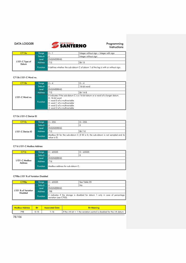
DATA LOGGER Programming
Instructions
78/106
C715a Range 0 1 Integer without sign Integer with sign
L1D1-C Type of
Datum
Default 0 Integer without sign
Level ENGINEERING
Address 715 Bit 15
Function It defines whether the sub-datum C of datum 1 of the log is with or without sign.
C715b L1D1-C Word no.
C715b Range 0 4 0 4
L1D1-C Word no.
Default 0 16-bit word
Level ENGINEERING
Address 715 Bit 14-8
Function
It indicates if the sub-datum C is a 16-bit datum or a word of a longer datum.
0: 16-bit word
1: word 0 of a multivariable
2: word 1 of a multivariable
3: word 2 of a multivariable
4: word 3 of a multivariable
C715c L1D1-C Device ID
C715c Range 0 255 0 255
L1D1-C Device ID
Default 0 0
Level ENGINEERING
Address 715 Bit 7-0
Function Modbus ID for the sub-datum C (if ID is 0, the sub-datum is not sampled and its
value is 0).
C716 L1D1-C Modbus Address
C716 Range 0 65535 0 65535
L1D1-C Modbus
Address
Default 0 0
Level ENGINEERING
Address 716
Function Modbus address for sub-datum C.
C798a L1D1 % of Variation Disabled
C798a Range 0 65535 See Table 35
L1D1 % of Variation
Disabled
Default 0 No
Level ENGINEERING
Address 798
Function It indicates if the storage is disabled for datum 1 only in case of percentage
variation (see C703).
Modbus Address Bit Associated Data Bit Meaning
798 0-15 1-16 If the i-th bit = 1 the variation control is disabled for the i-th datum

Programming
Instructions
DATA LOGGER
79/106
799 0-8 17-25 If the i-th bit = 1 the variation control is disabled for the i-th datum
Table 35: Bit-map for the enabling of the storage function on variation % data

DATA LOGGER Programming
Instructions
80/106
21. LOG 1 D2 MENU
This menu allows displaying the parameters for the configuration of datum 2 of log 1.
Datum 2 is a multi-source datum, i.e. it allows for the setting of three sub-data (A, B, C) and the calculation of the final
datum as a function of the three sub-data.
NOTE The parameters of this menu are equivalent to the ones of datum 1 as described in
section 20 LOG 1 D1 MENU.
Parameter FUNCTION Access Level MODBUS Address
C717 L1D2 Multiplier Coefficient K ENGINEERING 717
C718 L1D2 Composition Function ENGINEERING 718
C719 L1D2 Statistical Function ENGINEERING 719
C720 L1D2-A Multiplier Coefficient Ka ENGINEERING 720
C721a L1D2-A Type of datum ENGINEERING 721
C721b L1D2-A Word no. ENGINEERING 721
C721c L1D2-A Device ID ENGINEERING 721
C722 L1D2-A Modbus Address ENGINEERING 722
C723 L1D2-B Multiplier Coefficient Kb ENGINEERING 723
C724a L1D2-B Type of datum ENGINEERING 724
C724b L1D2-B Word no. ENGINEERING 724
C724c L1D2-B Device ID ENGINEERING 724
C725 L1D2-B Modbus Address ENGINEERING 725
C726 L1D2-C Multiplier Coefficient Kc ENGINEERING 726
C727a L1D2-C Type of datum ENGINEERING 727
C727b L1D2-C Word no. ENGINEERING 727
C727c L1D2-C Device ID ENGINEERING 727
C728 L1D2-C Modbus Address ENGINEERING 728
C798b L1D2 % of Variation Disabled ENGINEERING 798
Table 36: List of parameters for datum 2 (multi-source) of log 1

Programming
Instructions
DATA LOGGER
81/106
22. LOG 1 D3-D8 MENU
This menu allows displaying the parameters for the configuration of data 3 to 8 of log 1.
NOTE
The parameters are repeated by groups of six for each datum.
Only the parameters for datum 3 are specified here, since the values are the same for
the remaining parameters.
Parameter FUNCTION Access Level MODBUS Address
C729, C732,
C735, C738,
C741, C744
L1D3 Statistical Function ENGINEERING 729, 732, 735,
738, 741, 744
C730a, C733a,
C736a, C739a,
C742a, C745a
L1D3 Type of Datum ENGINEERING 730, 733, 736,
739, 742, 745
C730b, C733b,
C736b, C739b,
C742b, C745b
L1D3 Word no. ENGINEERING 730, 733, 736,
739, 742, 745
C730c, C733c,
C736c, C739c,
C742c, C745c
L1D3 Device ID ENGINEERING 730, 733, 736,
739, 742, 745
C731, C734,
C737, C740,
C743, C746
L1D3 Modbus Address ENGINEERING 731, 734, 737,
740, 743, 746
C798c, C798d,
C798e, C798f,
C798g, C798h
L1D3 % of Variation Disabled ENGINEERING 798
Table 37: List of parameters for data 3 to 8 of log 1
C729 L1D3 Statistical Function
C729 Range 0 3 0 3
L1D3 Statistical
Function
Default 0 Samples Average
Level ENGINEERING
Address 729
Function
It indicates how to compose the samples to obtain datum 3. This parameter is
effective only if C702 is different from 1.
0: samples average
1: samples minimum
2: samples maximum
3: last sample

DATA LOGGER Programming
Instructions
82/106
C730a L1D3 Type of Datum
C730a Range 0 1 Integer without sign Integer with sign
L1D3 Type of Datum
Default 0 Integer without sign
Level ENGINEERING
Address 730 Bit 15
Function It defines whether datum 3 of log 1 is with or without sign.
C730b L1D3-Word no.
C730b Range 0 4 0 4
L1D3-Word no.
Default 0 16-bit word
Level ENGINEERING
Address 730 Bit 14-8
Function
It indicates if the datum 3 of log 1 is a 16-bit datum or a word of a longer datum.
0: 16-bit word
1: word 0 of a multivariable
2: word 1 of a multivariable
3: word 2 of a multivariable
4: word 3 of a multivariable
C730c L1D3 Device ID
C730c Range 0 255 0 255
L1D3 Device ID
Default 0 0
Level ENGINEERING
Address 730 Bit 7-0
Function Modbus ID for datum 3 of log 1 (if ID is 0, the datum is not sampled and its value is
0).
C731 L1D3 Modbus Address
C731 Range 0 65535 0 65535
L1D3 Modbus
Address
Default 0 0
Level ENGINEERING
Address 731
Function Modbus address for datum 3 of log 1.
C798c L1D3 % of Variation Disabled
C798c Range 0 65535 See Table 35
L1D3 % of Variation
Disabled
Default 0 No
Level ENGINEERING
Address 798
Function It indicates if the storage function for datum 3 is disabled only in case of percentage
variation (see C703).

Programming
Instructions
DATA LOGGER
83/106
23. LOG 1 D9-D14 MENU
This menu allows displaying the parameters for the configuration of data 9 to 14 of log 1.
NOTA The parameters are repeated by groups of six for each datum.
The same parameters of datum 3 apply (see section 22 LOG 1 D3-D8 MENU)
Parameter FUNCTION Access Level MODBUS Address
C747, C750,
C753, C756,
C759, C762
L1D9 Statistical Function ENGINEERING 747, 750, 753,
756, 759, 762
C748a, C751a,
C754a, C757a,
C760a, C763a
L1D9 Type of Datum ENGINEERING
748a, 751a,
754a, 757a,
760a, 763a
C748b, C751b,
C754b, C757b,
C760b, C763b
L1D9 Word no. ENGINEERING
748b, 751b,
754b, 757b,
760b, 763b
C748c, C751c,
C754c, C757c,
C760c, C763c
L1D9 Device ID ENGINEERING
748c, 751c, 754c,
757c, 760c, 763c
C749, C752,
C755, C758,
C761, C764
L1D9 Modbus Address ENGINEERING 749, 752, 755,
758, 761, 764
C798i, C798l,
C798m, C798m,
C798o, C798p
L1D9 % of Variation Disabled ENGINEERING 798
Table 38: List of parameters for data 9 to 14 of log 1

DATA LOGGER Programming
Instructions
84/106
24. LOG 1 D15-D20 MENU
This menu allows displaying the parameters for the configuration of data 15 to 20 of log 1.
NOTA The parameters are repeated by groups of six for each datum.
The same parameters of datum 3 apply (see section 22 LOG 1 D3-D8 MENU)
Parameters FUNCTION Access Level MODBUS Address
C765, C768,
C771, C774,
C777, C780
L1D15 Statistical Function ENGINEERING 765, 768, 771,
774, 777, 780
C766a, C769a,
C772a, C775a,
C778a, C781a
L1D15 Type of Datum ENGINEERING
766a, 769a,
772a, 775a,
778a, 781a
C766b, C769b,
C772b, C775b,
C778b, C781b
L1D15 Word no. ENGINEERING
766b, 769b,
772b, 775b,
778b, 781b
C766c, C769c,
C772c, C775c,
C778c, C781c
L1D15 Device ID ENGINEERING
766c, 769c, 772c,
775c, 778c, 781c
C767, C770,
C773, C776,
C779, C782
L1D15 Modbus Address ENGINEERING 767, 770, 773,
776, 779, 782
C798q, C798r,
C799a, C799b,
C799c, C799d
L1D15 % of Variation Disabled ENGINEERING 798, 799
Table 39: List of parameters for data 15 to 20 of log 1

Programming
Instructions
DATA LOGGER
85/106
25. LOG 1 D21-D25 MENU
This menu allows displaying the parameters for the configuration of data 21 to 25 of log 1.
NOTA The parameters are repeated by groups of six for each datum.
The same parameters of datum 3 apply (see section 22 LOG 1 D3-D8 MENU)
Parameters FUNCTION Access Level MODBUS Address
C783, C786,
C789, C792,
C795
L1D21 Statistical Function ENGINEERING 783, 786, 789,
792, 795
C784a, C787a,
C790a, C793a,
C796a
L1D21 Type of Datum ENGINEERING 784a, 787a,
790a, 793a, 796a
C784b, C787b,
C790b, C793b,
C796b
L1D21 Word no. ENGINEERING
784b, 787b,
790b, 793b, 796b
C784c, C787c,
C790c, C793c,
C796c
L1D21 Device ID ENGINEERING
784c, 787c, 790c,
793c, 796c
C785, C788,
C791, C794,
C797
L1D21 Modbus Address ENGINEERING 785, 788, 791,
794, 797
C799e, C799f,
C799g, C799h,
C798i
L1D21 % of Variation Disabled ENGINEERING 799
Table 40: List of parameters for data 21 to 25 of log 1

DATA LOGGER Programming
Instructions
86/106
26. OTHER LOG-TYPE MENUS
Other log-type menus are available in the Data Logger for logs 2 to 6. Such menus are fully equivalent to the ones of
log 1, as described in the previous sections.
Menu FUNCTION Access Level
Log 2 General parameters for log 2 ENGINEERING
Log 2 D1 Parameters for datum 1 of log 2 ENGINEERING
Log 2 D2 Parameters for datum 2 of log 2 ENGINEERING
Log 2 D3-D8 Parameters for data 3 to 8 of log 2 ENGINEERING
Log 2 D9-D14 Parameters for data 9 to 14 of log 2 ENGINEERING
Log 2 D15-D20 Parameters for data 15 to 20 of log 2 ENGINEERING
Log 2 D21-D25 Parameters for data 21 to 25 of log 2 ENGINEERING
Table 41: List of the menus for log 2
Menu FUNCTION Access Level
Log 3 General parameters for log 3 ENGINEERING
Log 3 D1 Parameters for datum 1 of log 3 ENGINEERING
Log 3 D2 Parameters for datum 2 of log 3 ENGINEERING
Log 3 D3-D8 Parameters for data 3 to 8 of log 3 ENGINEERING
Log 3 D9-D14 Parameters for data 9 to 14 of log 3 ENGINEERING
Log 3 D15-D20 Parameters for data 15 to 20 of log 3 ENGINEERING
Log 3 D21-D25 Parameters for data 21 to 25 of log 3 ENGINEERING
Table 42: List of the menus for log 3
Menu FUNCTION Access Level
Log 4 General parameters for log 4 ENGINEERING
Log 4 D1 Parameters for datum 1 of log 4 ENGINEERING
Log 4 D2 Parameters for datum 2 of log 4 ENGINEERING
Log 4 D3-D8 Parameters for data 3 to 8 of log 4 ENGINEERING
Log 4 D9-D14 Parameters for data 9 to 14 of log 4 ENGINEERING
Log 4 D15-D20 Parameters for data 15 to 20 of log 4 ENGINEERING
Log 4 D21-D25 Parameters for data 21 to 25 of log 4 ENGINEERING
Table 43: List of the menus for log 4

Programming
Instructions
DATA LOGGER
87/106
Menu FUNCTION Access Level
Log 5 General parameters for log 5 ENGINEERING
Log 5 D1 Parameters for datum 1 of log 5 ENGINEERING
Log 5 D2 Parameters for datum 2 of log 5 ENGINEERING
Log 5 D3-D8 Parameters for data 3 to 8 of log 5 ENGINEERING
Log 5 D9-D14 Parameters for data 9 to 14 of log 5 ENGINEERING
Log 5 D15-D20 Parameters for data 15 to 20 of log 5 ENGINEERING
Log 5 D21-D25 Parameters for data 21 to 25 of log 5 ENGINEERING
Table 44: List of the menus for log 5
Menu FUNCTION Access Level
Log 6 General parameters for log 6 ENGINEERING
Log 6 D1 Parameters for datum 1 of log 6 ENGINEERING
Log 6 D2 Parameters for datum 2 of log 6 ENGINEERING
Log 6 D3-D8 Parameters for data 3 to 8 of log 6 ENGINEERING
Log 6 D9-D14 Parameters for data 9 to 14 of log 6 ENGINEERING
Log 6 D15-D20 Parameters for data 15 to 20 of log 6 ENGINEERING
Log 6 D21-D25 Parameters for data 21 to 25 of log 6 ENGINEERING
Table 45: List of the menus for log 6
CAUTION
Log parameters are also recorded by the boxing mechanism, if this mechanism is
active. The parameters are overwritten at the end of the SCAN.
It is not possible to modify the parameters when the log is active.
Any modifications come into effect only upon next restarting of the log.
If the parameters differ from the previous recording, the Data Logger automatically
deletes the log before starting.

DATA LOGGER Programming
Instructions
88/106
27. EVENT1 MENU
This menu contains the parameters for the configuration of event 1. Together, the configurations of the events 1 to 40
make up the Log Evt (event log) configuration.
CAUTION
Log parameters are also recorded by the boxing mechanism, if this mechanism is
active. The parameters are overwritten at the end of the SCAN.
It is not possible to modify the parameters when the log is active.
Any modifications come into effect only upon next restarting of the log.
If the parameters differ from the previous recording, the Data Logger automatically
deletes the log before starting.
NOTE
Event 1 occurs when the sampled trigger specified in C1421 and C1422 “differs”
(with respect to function C1420) from the value specified in C1423 by a max. value
as per C1424.
When the condition turns from false to true an ON event is generated, when it turns
back from true to false, an OFF event is generated.
Parameter FUNCTION Access Level MODBUS Address
C520a E1 Enable ENGINEERING 520
C1420 E1 Threshold function ENGINEERING 1420
C1421a E1 Datum type trigger ENGINEERING 1421
C1421c E1 Device ID trigger ENGINEERING 1421
C1422 E1 Modbus address trigger ENGINEERING 1422
C1423 E1 Threshold value ENGINEERING 1423
C1424 E1 Offset from threshold ENGINEERING 1424
C1425a E1D1 Type of datum ENGINEERING 1425
C1425b E1D1 Word no. ENGINEERING 1425
C1425c E1D1 Device ID ENGINEERING 1425
C1426 E1D1 Modbus address ENGINEERING 1426
C1427a E1D2 Type of datum ENGINEERING 1427
C1427b E1D2 Word no. ENGINEERING 1427
C1427c E1D2 Device ID ENGINEERING 1427
C1428 E1D2 Modbus address ENGINEERING 1428
Table 46: Parameters of the Event1 menu
C520, C519, C518 Events 1-40 Enable
C518, C519, C520 Range Bit-managed parameter See Table 47
Events 1-40 Enable
Default 0 No event enabled
Level ENGINEERING
Address 518, 519, 520
Function If the j-th bit is 1, then event j is active.

Programming
Instructions
DATA LOGGER
89/106
Modbus Address Bit Associated Events Bit Meaning
518 0-8 33-40 If bit i-th = 1 the i-th event is active
519 0-15 17-32 If bit i-th = 1 the i-th event is active
520 0-15 1-16 If bit i-th = 1 the i-th event is active
Table 47: Bit-map for events enable
C1420 E1 Threshold Function
C1420 Range 0 5 0 5
E1 Threshold Function
Default 0 Less than
Level ENGINEERING
Address 1420
Function
It indicates the threshold function to be used to define if event 1 has fired. Values
available are:
0: < less than
1: <= less than or equal to
2: == equal to
3: >= greater than or equal to
4: > greater than
5: != different from
C1421a E1 Datum Type Trigger
C1421a Range 0 1 Integer without sign Integer with sign
E1 Datum Type
Trigger
Default 0 Integer without sign
Level ENGINEERING
Address 1421 Bit 15
Function It determines whether the trigger value of event 1 is with or without sign.
C1421c E1 Device ID Trigger
C1421c Range 0 255 0 255
E1 Device ID Trigger
Default 0 0
Level ENGINEERING
Address 1421 Bit 7-0
Function Modbus ID for trigger measurement of event 1 (if ID is 0, the datum is not sampled
and its value is 0).
C1422 E1 Modbus Address Trigger
C1422 Range 0 65535 0 65535
E1 Modbus Address
Trigger
Default 0 0
Level ENGINEERING
Address 1422
Function Modbus address for trigger measurement of event 1.

DATA LOGGER Programming
Instructions
90/106
C1423 E1 Threshold Value
C1423 Range 0 65535 0 65535
E1 Threshold Value
Default 0 0
Level ENGINEERING
Address 1423
Function Threshold value for event 1.
C1424 E1 Threshold Value Offset
C1424 Range 0 65535 0 65535
E1 Threshold Value
Offset
Default 0 0
Level ENGINEERING
Address 1424
Function Threshold value offset for event 1.
C1425a E1D1 Type of Datum
C1425a Range 0 1 Integer without sign Integer with sign
E1D1 Type of Datum
Default 0 Integer without sign
Level ENGINEERING
Address 1425 Bit 15
Function It determines whether datum 1 to be sampled for event 1 of the event log is with or
without sign.
C1425b E1D1-Word no.
C1425b Range 0 4 0 4
E1D1-Word no.
Default 0 16-bit word
Level ENGINEERING
Address 1425 Bit 14-8
Function
It indicates if the datum 1 to be sampled for event 1 is a 16-bit datum or a word of
a longer datum.
0: 16-bit word
1: word 0 of a multivariable
2: word 1 of a multivariable
3: word 2 of a multivariable
4: word 3 of a multivariable
C1425c E1D1 Device ID
C1425c Range 0 255 0 255
E1D1 Device ID
Default 0 0
Level ENGINEERING
Address 1425 Bit 7-0
Function Modbus ID for datum 1 to be sampled for event 1 (if ID is 0, the datum is not
sampled and its value is 0).

Programming
Instructions
DATA LOGGER
91/106
C1426 E1D1 Modbus Address
C1426 Range 0 65535 0 65535
E1D1 Modbus
Address
Default 0 0
Level ENGINEERING
Address 1426
Function Modbus Address for datum 1 to be sampled for event 1.
C1427a E1D2 Type of Datum
C1427a Range 0 1 Integer without sign Integer with sign
E1D2 Type of Datum
Default 0 Integer without sign
Level ENGINEERING
Address 1427 Bit 15
Function It determines whether datum 2 to be sampled for event 1 of the event log is with or
without sign.
C1427b E1D2-Word no.
C1427b Range 0 4 0 4
E1D2-Word no.
Default 0 16-bit word
Level ENGINEERING
Address 1427 Bit 14-8
Function
It indicates if the datum 2 to be sampled for event 1 is a 16-bit datum or a word of
a longer datum.
0: 16-bit word
1: word 0 of a multivariable
2: word 1 of a multivariable
3: word 2 of a multivariable
4: word 3 of a multivariable
C1427c E1D2 Device ID
C1427c Range 0 255 0 255
E1D2 Device ID
Default 0 0
Level ENGINEERING
Address 1427 Bit 7-0
Function Modbus ID for datum 2 to be sampled for event 1 (if ID is 0, the datum is not
sampled and its value is 0).
C1428 E1D2 Modbus Address
C1428 Range 0 65535 0 65535
E1D2 Modbus
Address
Default 0 0
Level ENGINEERING
Address 1428
Function Modbus address for datum 2 to be sampled for event 1.

DATA LOGGER Programming
Instructions
92/106
28. EVENT2-EVENT40 MENU
Menus from Event2 to Event40 contain the parameters for the configuration of the events next to 1. Together, these
configurations make up the Event Log configuration. The parameters available in each menu are similar to the ones
described for Event 1 in section 27 EVENT1 MENU.
Menu FUNCTION Access Level
Event2 Menu for Event 2 ENGINEERING
Event3 Menu for Event 3 ENGINEERING
Event4 Menu for Event 4 ENGINEERING
Event5 Menu for Event 5 ENGINEERING
Event6 Menu for Event 6 ENGINEERING
Event7 Menu for Event 7 ENGINEERING
Event8 Menu for Event 8 ENGINEERING
Event9 Menu for Event 9 ENGINEERING
Event10 Menu for Event 10 ENGINEERING
Event11 Menu for Event 11 ENGINEERING
Event12 Menu for Event 12 ENGINEERING
Event13 Menu for Event 13 ENGINEERING
Event14 Menu for Event 14 ENGINEERING
Event15 Menu for Event 15 ENGINEERING
Event16 Menu for Event 16 ENGINEERING
Event17 Menu for Event 17 ENGINEERING
Event18 Menu for Event 18 ENGINEERING
Event19 Menu for Event 19 ENGINEERING
Event20 Menu for Event 20 ENGINEERING
Event21 Menu for Event 21 ENGINEERING
Event22 Menu for Event 22 ENGINEERING
Event23 Menu for Event 23 ENGINEERING
Event24 Menu for Event 24 ENGINEERING
Event25 Menu for Event 25 ENGINEERING
Event26 Menu for Event 26 ENGINEERING
Event27 Menu for Event 27 ENGINEERING
Event28 Menu for Event 28 ENGINEERING
Event29 Menu for Event 29 ENGINEERING
Event30 Menu for Event 30 ENGINEERING
Event31 Menu for Event 31 ENGINEERING
Event32 Menu for Event 32 ENGINEERING
Event33 Menu for Event 33 ENGINEERING
Event34 Menu for Event 34 ENGINEERING
Event35 Menu for Event 35 ENGINEERING
Event36 Menu for Event 36 ENGINEERING
Event37 Menu for Event 37 ENGINEERING
Event38 Menu for Event 38 ENGINEERING
Event39 Menu for Event 39 ENGINEERING
Event40 Menu for Event 40 ENGINEERING
Table 48: List of the menus for the events 2 to 40

Programming
Instructions
DATA LOGGER
93/106
29. DOWNLOAD CONSOLE MENU
The Download function allows downloading the configuration files of the log parameters (see APPENDIX). This function is
available only when using the RemoteDrive/Sunway software. The files contained in ES851 Data Logger can be
individually deleted.
Figure 3: DOWNLOAD Console as displayed in the RemoteDrive/Sunway.
Press the Refr. button to view the files contained in ES851 Data Logger board. Each file can be individually selected and
deleted by pressing the Del. button.
The file download allows configuring the DL Tables, i.e. the files allowing ES851 Data Logger to recognize each connected
device. The variables to be monitored and recorded for each device can be recognized as well. The extension for the
configuration files is ”.out”. These files can be downloaded from the download section of Enertronica Santerno’s website.
To do so, point to the directory of the PC; all the available ”.out” files are viewed on the left of the screen. Press the “>”
button to download the selected files.
Formattato: Non Evidenziato
Formattato: Non Evidenziato
Formattato: Non Evidenziato
Codice campo modificato
Formattato: Non Evidenziato
Formattato: Non Evidenziato
Formattato: Non Evidenziato

DATA LOGGER Programming
Instructions
94/106
30. APPENDIX
The sections below include the tables containing the references of the variables monitored by the LOGGING.
CAUTION
The tables related to the variables monitored by the LOGGING may vary
depending on the type of device and its software version. Refer to santerno.com
for the updates.
Updates or tables relating to new devices can be downloaded using the special function implemented in ES851
(Download Console function) that can be used with the RemoteDrive/Sunway (see the DOWNLOAD CONSOLE MENU).
LOGGING is currently available for the following products: Sunway TG, Sunway M XR, Smart String Box, Penta Drive,
Multipump Penta, Regenerative Penta, QS String Boxes, Sunway M Plus, Weather Station, Etesian Mini, Etesian One,
Etesian D.
30.1. Sunw ay TG (ST)
Standard Mode
Parameter Modbus Address Description Type of Log
M013 1504,1505 Energy Delivered to the Grid SLOW Log
A1-FL01 7712 Last Alarm Tripped SLOW Log
M10 1509 PV Field Voltage FAST Log
M003 1498 Active Power Delivered FAST Log
M007 1502 Grid Voltage FAST Log
M024 1674 Module Radiation FAST Log
M089 1494 Inverter Status FAST Log
Extended Mode – Additional Parameters
Parameter Modbus Address Description Type of Log
M000 1508 PV-Voltage Reference SLOW Log
M19 1669 Grid KO Events SLOW Log
M20 1670 Radiation KO Events SLOW Log
M21 1671,1672 Delivery Time FAST Log
M001 1497 Grid Frequency FAST Log
M009 1503 Grid Current FAST Log
M012 1511 PV Field Power FAST Log
M025 1675 Ambient Measure 2 FAST Log
M026 1676 Ambient Measure 3 FAST Log
M027 1677 Ambient Measure 4 FAST Log
Formattato: Non Evidenziato
Formattato: Non Evidenziato

Programming
Instructions
DATA LOGGER
95/106
Event Parameters:
Trigger Par. Modbus Address Description
M0XX 3400 Alarm Tripped
Detected Parameter Modbus Address Description
FL01c 7717 Inverter Status
FL01s 7731 Active Power Delivered

DATA LOGGER Programming
Instructions
96/106
30.2. Sunw ay M X R (SM)
Standard Mode
Parameter Modbus Address Description Type of Log
M010 1661,1662 Energy Delivered to the Grid SLOW Log
A1-FL01 7712 Last Alarm Tripped SLOW Log
M000 1650 PV Field Voltage FAST Log
M004 1654 Grid Voltage FAST Log
M008 1658 Active Power Delivered FAST Log
M050 1739 Inverter Status FAST Log
M110 1564 Module Radiation FAST Log
Extended Mode – Additional Parameters
Parameter Modbus Address Description Type of Log
M015 1669 Grid KO Events SLOW Log
M016 1670 Radiation KO Events SLOW Log
M009 1659,1660 Delivery Time SLOW Log
M002 1652 PV-Field Current FAST Log
M005 1655 Grid Frequency FAST Log
M006 1656 Grid Current FAST Log
M111 1565 Horizontal Radiation FAST Log
M112 1566 Ambient Temperature FAST Log
M113 1567 Module Temperature FAST Log
M114 1568 Ambient Measure FAST Log
Event Parameters:
Trigger Par. Modbus Address Description
M0XX 3400 Alarm Tripped
Detected Parameter Modbus Address Description
FL01c 7717 Inverter Status
FL01v 7735 Active Power Delivered

Programming
Instructions
DATA LOGGER
97/106
30.3. Smart Str ing Box (QF)
Standard Mode
Parameter Modbus Address Description Type of Log
M009 1659 Average Current FAST Log
M010 1660 Maximum Current FAST Log
M011 1661 Minimum Current FAST Log
M014 1664 Module Temperature FAST Log
M020 1670 String Performance Status+ Board I/O FAST Log
Extended Mode – Additional Parameters
Parameter Modbus Address Description Type of Log
M001 1651 String 1 Current FAST Log
M002 1652 String 2 Current FAST Log
M003 1653 String 3 Current FAST Log
M004 1654 String 4 Current FAST Log
M005 1655 String 5 Current FAST Log
M006 1656 String 6 Current FAST Log
M007 1657 String 7 Current FAST Log
M008 1658 String 8 Current FAST Log
M015 1665 Ambient Temperature FAST Log
Event Parameters:
Trigger Par. Modbus Address Description
M018 1668 Alarm Tripped/String Theft
Detected Parameter Modbus Address Description
M019 1669 Strings KO
M009 1659 Average Current

DATA LOGGER Programming
Instructions
98/106
30.4. P enta Dr iv e (P D)
Standard Mode
Parameter Modbus Address Description Type of Log
M062 1712 Ambient Temperature SLOW Log
M002 1652 Speed Ramp Output FAST Log
M004 1654 Motor Speed FAST Log
M006 1656 Output Frequency FAST Log
M026 1676 Output Current FAST Log
M027 1677 Output Voltage FAST Log
Extended Mode – Additional Parameters
Parameter Modbus Address Description Type of Log
M064 1714 IGBT Temperature SLOW Log
M028 1678 Output Power FAST Log
M031 1681 Delayed Digital Inputs FAST Log
M056 1706 Digital Outputs FAST Log
M089 1739 Drive Status FAST Log
M090 1740 Alarm Tripped FAST Log

Programming
Instructions
DATA LOGGER
99/106
30.5. P enta Mul t ipump (P M)
Standard Mode
Parameter Modbus Address Description Type of Log
M621 1951, 1952 Operating Time of Pump 1 SLOW Log
M623 1953, 1954 Operating Time of Pump 2 SLOW Log
M625 1955, 1956 Operating Time of Pump 3 SLOW Log
M627 1957, 1958 Operating Time of Pump 4 SLOW Log
M629 1959, 1960 Operating Time of Pump 5 SLOW Log
M600 1551 Available Pumps FAST Log
M601 1552 Pumps On FAST Log
M604 1555 Status of Serial Communications to Slave
Devices FAST Log
M605 1556 Multipump Operating Conditions FAST Log
M006 1656 Output Frequency FAST Log
Extended Mode – Additional Parameters
Parameter Modbus Address Description Type of Log
M062 1712 Ambient Temperature SLOW Log
M018 1668 PID Reference at Constant RPM FAST Log
M022 1672 PID Output FAST Log
M020 1670 PID Feedback FAST Log
M026 1676 Output Current FAST Log
M028 1678 Output Power FAST Log
M031 1681 Delayed Digital Inputs FAST Log
M056 1706 Delayed Digital Outputs FAST Log
M089 1739 Drive Status FAST Log
M090 1740 Alarm Tripped FAST Log

DATA LOGGER Programming
Instructions
100/106
30.6. P enta R egenera t i v e (P R )
Standard Mode
Parameter Modbus Address Description Type of Log
M562 1712 Ambient Temperature SLOW Log
M564 1714 IGBT Temperature SLOW Log
M501 1651 DC-Bus Voltage FAST Log
M502 1652 Mains Voltage FAST Log
M503 1653 Drive Current FAST Log
M504 1654 Mains Frequency FAST Log
M505 1655 Active Power Delivered FAST Log
M506 1656 Reactive Power Delivered FAST Log
M508 1658 Power Factor FAST Log
M515 1665 PLL Status FAST Log
M516 1666 Status of Mains 2 FAST Log
M517 1667 Status of Mains 1 FAST Log
Extended Mode – Additional Parameters
Parameter Modbus Address Description Type of Log
M531 1681 Digital Inputs FAST Log
M556 1706 Digital Outputs FAST Log
M589 1739 Drive Status FAST Log
M590 1740 Alarm Tripped FAST Log

Programming
Instructions
DATA LOGGER
101/106
30.7. Str ing Box (QS)
Standard Mode
Parameter Modbus Address Description Type of Log
Ist1 14 String 1 Current SLOW Log
Ist1 14 String 1 Current FAST Log
Ist2 15 String 2 Current FAST Log
Ist3 16 String 3 Current FAST Log
Ist4 17 String 4 Current FAST Log
Extended Mode – Additional Parameters
Parameter Modbus Address Description Type of Log
Ist5 18 String 5 Current FAST Log
Ist6 19 String 6 Current FAST Log
Ist7 20 String 7 Current FAST Log
Ist8 21 String 8 Current FAST Log

DATA LOGGER Programming
Instructions
102/106
30.8. Sunw ay M P LUS (SP )
Standard Mode
Parameter Modbus Address Description Type of Log
M010 1661,1662 Energy Delivered SLOW Log
A1-FL01 7712 Last Alarm SLOW Log
M000 1650 PV Field Voltage FAST Log
M004 1654 Grid Voltage FAST Log
M008 1658 Active Power Delivered FAST Log
M089 1739 Inverter Status FAST Log
M110 1688 Module Radiation FAST Log
Extended Mode – Additional Parameters
Parameter Modbus Address Description Type of Log
M097 1659,1660 Delivery Time SLOW Log
M015 1669 Grid KO Events SLOW Log
M016 1670 Radiation KO Events SLOW Log
M002 1652 PV Field Current FAST Log
M005 1655 Grid Frequency FAST Log
M006 1656 Grid Current FAST Log
M111 1689 Horizontal Radiation FAST Log
M112 1690 Ambient Temperature FAST Log
M113 1691 Module Temperature FAST Log
M114 1692 Ambient Measurement FAST Log
Events Parameters:
Trigger Par. Modbus Address Description
M0XX 3400 Current Alarm Image
Detected Parameter Modbus Address Description
FL01c 7717 Inverter Status
FL01v 7735 Active Power Delivered

Programming
Instructions
DATA LOGGER
103/106
30.9. Meteo Center (MZ )
Standard Mode
Parameter Modbus Address Description Type of Log
M001 0,1 Ambient Temperature FAST Log
M002 2,3 Module Temperature FAST Log
M003 4,5 Module Radiation FAST Log
M004 6,7 Wind Direction FAST Log
M005 8,9 Wind Speed FAST Log
M006 10,11 Battery Level FAST Log
M007 12,13 Average Radiation FAST Log
M008 14,15 Total Radiation FAST Log
M009 16,17 Average Wind Direction FAST Log
M010 18,19 Average Wind Speed FAST Log
30.10. Etesian D – Motor Moni tor ing (WD)
Standard Mode
Parameter Modbus Address Description Type of Log
M073 1723 Rotor RMS Current SLOW Log
M064 1714 IGBT Temperature SLOW Log
M091 1739 Inverter Status FAST Log
M092 1740 Alarm Code FAST Log
M015 1665 RS Grid Voltage (RMS) FAST Log
M016 1666 ST Grid Voltage (RMS) FAST Log
M019 1669 TR Grid Voltage (RMS) FAST Log
M701 3361 PLL Alarm Codes FAST Log
M702 3362 GRID KO Alarm Codes FAST Log
M077 1727 Stator Active Power FAST Log
M078 1728 Rotor Active Power FAST Log
M012 1662 R-phase Stator Current (RMS) FAST Log
M013 1663 S-phase Stator Current (RMS) FAST Log
M014 1664 T-phase Stator Current (RMS) FAST Log
C208 100 Validated Zero Mark FAST Log
C209 101 Enc Error FAST Log
C210 102 No. of Pulses Recovered FAST Log

DATA LOGGER Programming
Instructions
104/106
30.11. Etesian M ini (WM)
Standard Mode
Parameter Modbus Address Description Type of Log
M000 1650 DC Bus Voltage FAST Log
M001 1651 DC Bus Voltage Ref. FAST Log
M100 1674 Input Voltage FAST Log
M102 1676 Input Current FAST Log
M008 1658 Active Power Delivered FAST Log
M057 1707 CPU Temperature FAST Log
M059 1709 Heatsink Temperature FAST Log
M050 1739 Inverter Status FAST Log
Event Parameters:
Trigger Par. Modbus Address Description
M0XX 3400 Current Alarm Image
Detected Parameter Modbus Address Description
FL01d 7718 Inverter Status
FL01I 7724 Active Power Delivered

Programming
Instructions
DATA LOGGER
105/106
30.12. Etesian One (WO)
Standard Mode
Parameter Modbus Address Description Type of Log
M013 1504 Energy Delivered SLOW Log
A1-FL01 7712 Last Alarm SLOW Log
M097 1933,1934 Delivery Time SLOW Log
M010 1509 Input Voltage FAST Log
M003 1498 Active Power Delivered FAST Log
M007 1502 Grid Voltage FAST Log
M089 1739 Inverter Status FAST Log
M062 1712 Ambient Temperature FAST Log
M064 1714 Heatsink Temperature FAST Log
M001 1497 Grid Frequency FAST Log
Extended Mode – Additional Parameters
Parameter Modbus Address Description Type of Log
M009 1503 Grid Current FAST Log
M012 1511 Input Power FAST Log
M028 1678 Wind Direction FAST Log
M029 1679 Wind Speed FAST Log
Event Parameters:
Trigger Par. Modbus Address Description
M0XX 3400 Current Alarm Image
Detected Parameter Modbus Address Description
FL01c 7717 Inverter Status
FL01s 7731 Active Power Delivered
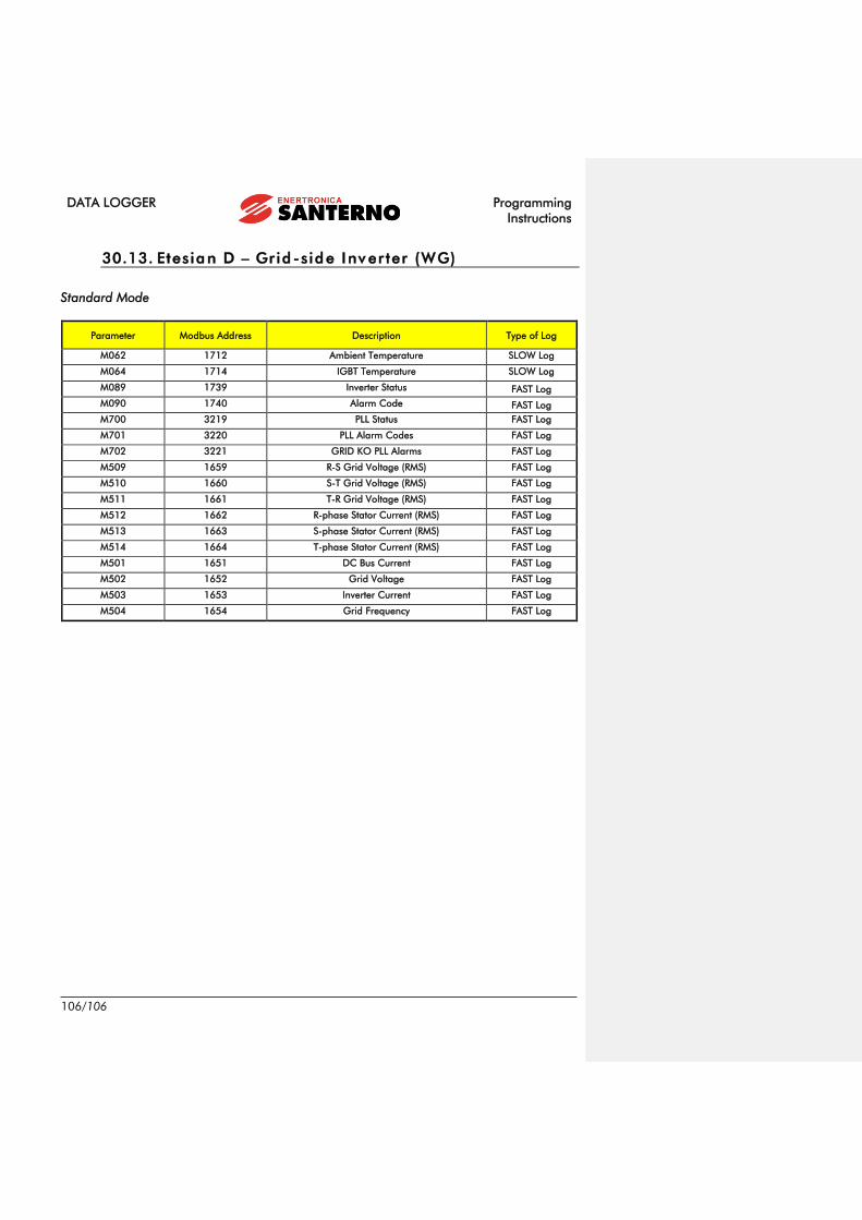
DATA LOGGER Programming
Instructions
106/106
30.13. Etesian D – Gr id -side Inv er ter (WG)
Standard Mode
Parameter Modbus Address Description Type of Log
M062 1712 Ambient Temperature SLOW Log
M064 1714 IGBT Temperature SLOW Log
M089 1739 Inverter Status FAST Log
M090 1740 Alarm Code FAST Log
M700 3219 PLL Status FAST Log
M701 3220 PLL Alarm Codes FAST Log
M702 3221 GRID KO PLL Alarms FAST Log
M509 1659 R-S Grid Voltage (RMS) FAST Log
M510 1660 S-T Grid Voltage (RMS) FAST Log
M511 1661 T-R Grid Voltage (RMS) FAST Log
M512 1662 R-phase Stator Current (RMS) FAST Log
M513 1663 S-phase Stator Current (RMS) FAST Log
M514 1664 T-phase Stator Current (RMS) FAST Log
M501 1651 DC Bus Current FAST Log
M502 1652 Grid Voltage FAST Log
M503 1653 Inverter Current FAST Log
M504 1654 Grid Frequency FAST Log