Nanofibers and nanowires for disordered photonics - nanojets
Upload
khangminh22Category
view
0download
0
TOPTICA Photonics AGLochhamer Schlag 19
D-82166 Graefelfing/MunichTel.: +49 89 85837-0
Fax: +49 89 85837-200
email: [email protected]://www.toptica.com
(June 2015 Subject to change without notice)
Manual: M-038 Version 03Copyright 2015 TOPTICA Photonics AG
Digilock 110 RCI
Remote ControlInterface
Manual


Feedback Controlyzer DigiLock 110
Status: 16.6.15
Dear Customer,
Welcome to the TOPTICA community!
We have designed this product to be easy to use and reliable so that you can focus on your work. If you have questions or need advice on how to integrate it into your setup, please contact us immediately so we can walk you through the process. We will provide you with quick and competent help through our service staff and product managers.
You can contact us in the following ways:
- Internet: service.toptica.com. In our support section you can find a list of frequently asked ques-tions and a service contact form
- Email: [email protected] Phone: +49-89-85837-150.
Our customers in the USA and Canada may contact TOPTICA Photonics Inc.:
- Phone: +1-585-657-6663
Please have your product -ID and serial number ready when contacting us so we can quickly retrieve all relevant information.
As we are constantly improving our products, we greatly value all customer feedback. We encourage you to tell us what you like about our products as well as any suggestions for improvement.
Best regards,
Harald EllmannService ManagerTOPTICA Photonics AG


DigiLock 110 Remote Control Interface
Status: 16.6.15
Contents
1 DigiLock 110 Control Architecture 3
2 DigiLock Module Server (DMS) 4
3 Remote Control Interface (RCI) 53.1 Telnet Client Connection 63.2 DigiLock-Application Programming Interface (API) Description 8
3.2.1 Command Syntax 83.2.2 Command Types 83.2.3 Data Types 93.2.4 Limitations 93.2.5 Error Handling 9
3.3 LabVIEW® Driver VIs 10
4 Appendix 114.1 Directories of the DigiLock 110 Software 114.2 Application Programming Interface (API) Commands 12
4.2.1 Digilock Module Server (DMS) RCI 124.2.2 Digilock User Interface (DUI) RC 13

DigiLock 110 Remote Control Interface
Status: 16.6.15

DigiLock 110 Remote Control Interface
Page 3
Status: 16.6.15
1 DigiLock 110 Control Architecture
The DigiLock 110 Feedback Controlyzer is a very fast and flexible controller solution based on FPGA tech-nology. The combination of a fast FPGA with a dedicated PC software package allows to implement theadvanced locking capabilities.
An overview of the DigiLock 110 control architecture is shown in Figure 1. It consists of two levels: The DigiLock 110 software initially starts the DigiLock Module Server (DMS). The DMS automaticallydetects multiple DigiLock 110 modules connected to the computer via USB. It can start and manage oneinstance of the DigiLock User Interface (DUI) for each of the detected modules. The user can thus controlthe DigiLocks via independent DUIs.
The DigiLock 110 is always controlled via the dedicated software running on a Windows PC (for adetailed software description please see the DigiLock 110 Manual). However, to allow for the integrationof application specific features like scripting and the integration into the general software environmentof a larger experiment, the DigiLock Module Server (DMS) and each instance of the DUI has a build-inRemote Control Interface (RCI). Nearly all controls of the DMS and DUI can be accessed remotely bysending corresponding commands via a TCP/IP connection.
Figure 1 Overview of the DigiLock 110 control architecture
NOTE ! The Remote Control Interface (RCI) and the DigiLock Module Server (DMS) are only imple-mented in software versions 1.5.4.70 and higher. If you are still running an earlier versionplease contact TOPTICA Photonics AG for a software update.
NOTE ! The DigiLock 110 RCI is a supplementary free add-on developed by TOPTICA Photonics AGon customers requests. However, due to the complexity of individual hard- and softwareconfigurations there is no support provided for the DigiLock 110 RCI.

DigiLock 110 Remote Control Interface
Page 4
Status: 16.6.15
2 DigiLock Module Server (DMS)
Figure 2 DigiLock Module Server front end
Figure 2 shows the front end of the DigiLock Module Server. It automatically detects and lists allDigiLock 110 modules that are connected to the computer when the software starts up1. The list isupdated by pressing the Update module list button. A specific module can be selected by clicking any-where on the corresponding row in the list. The selected module is indicated by the highlighted modulename. The modules are identified by their serial number and can be given a name by double-clickingthe module name column for editing.
To connect to the selected DigiLock 110 press the Connect button. This will open an instance of theDigiLock User Interface (DUI). Once connected, the button changes to Disconnect. Pressing the buttonagain will close the DUI and disconnect the DigiLock 110.
By clicking the Show/Hide module button, the DigiLock Interface can be (un)hidden from the user.Hiding the DUI is useful to clean up the desktop or to avoid excessive traffic on the USB system. When aDUI is hidden, the sampling is disabled by default. This setting can be changed in the Settings|Generaltab of the DUI.
The IP Address and Port Number fields display the corresponding values for the RCI of the DMS whichare defined in the configuration file. This configuration file (DigiLock-ModuleServer-Profile.pro) is found inthe profile directory (see section 4.1). The Port Numbers of the RCIs of the DUIs are listed in the last column"port number". For details on the remote control see section 3.
1. In addition to the physically present DigiLocks it also lists a dummy to allow to start a DUI with no DigiLock 110 present.

3. Remote Control Interface (RCI)
Page 5
Status: 16.6.15
3 Remote Control Interface (RCI)
An overview of the DigiLock 110 control architecture is shown in Figure 1: The DigiLock 110 software ini-tially starts the DigiLock Module Server (DMS). The DMS automatically detects multiple DigiLock 110 mod-ules connected to the computer via USB. It can start and manage one instance of the DigiLock UserInterface (DUI) for each of the detected modules. The user can thus control the DigiLocks via indepen-dent DUIs. For remote control the DigiLock Module Server (DMS) has a built-in remote control interface(RCI) which can be connected to the TCP/IP port 600002, by default. The remote commands of the DMSallow to identify the DigiLock 110 modules and start the corresponding DigiLock User Interface (DUI).Each instance of the DUI provides its own remote control interface (RCI) running on a corresponding sub-sequent port, by default 6000x, where x is the number of the DigiLock 110. Nearly all elements on the con-trol panel of the DUI can be accessed remotely by sending commands from an external program.Sending the corresponding command has the same effect as operating the DUI directly (e.g. with themouse). The command that corresponds to a given control on the DUI can be determined via descrip-tion and tip in the context menu.
Each remote control interface (RCI) can be used with any client via TCP (Transmission Control Proto-col). The functionality of the RCI can easily be tested with a telnet client like, e.g., the HyperTerminal3(see section 3.1). Alternatively, there are a number of free Terminal programs that provide additionalfunctionality. For programming with LabVIEW® 4 a set of VIs is provided to access the remote commands(see section 3.3).
2. The port number can be defined in the configuration file "DigiLock-ModuleServer-Profile.pro" of the DMS (see section 4.1).3. HyperTerminal is normally installed together with the Windows Operating System4. Graphical programming environment by National Instruments
NOTE ! Only one remote control connection can be established to the DMS and to each instanceof the DUI.

DigiLock 110 Remote Control Interface
Page 6
Status: 16.6.15
3.1 Telnet Client Connection
To get used to the remote control we suggest to start the DigiLock Module Server (DMS) and the DigiLockUser Interface (DUI) and open connections via a telnet client, like e.g. the Hyper Terminal.
Figure 3 Setting-Up a Telnet connection with the Hyper Terminal
The Hyper Terminal is part of the Windows operating system. A TCP/IP telnet connection can be estab-lished in the following steps:
1. Start Hyper Terminal: Start|Programs|Accessories|Communications|HyperTerminal.
2. Assign a name to the connection.
3. Select Connect using: TCP/IP (Winsock).
4. Enter the Host Address: If the DigiLock 110 software and HyperTerminal run on the same computer, enter localhost; otherwise enter the IP address of the computer that is connected to the DigiLock 110 with at leastthe DigiLock Module Server (DMS) started5.
5. The IP address can, e.g., be determined by resolving the computer name using ping or on the computer where the DigiLock 110 software runs using ipconfig in the command line interface.

3. Remote Control Interface (RCI)
Page 7
Status: 16.6.15
5. Enter Port Number: 60000 for the RCI of the DMS, 6000x (x ≥ 1) for the RCI of the DigiLock User Interfaces6
When a connection is established, the DMS or DUI will answer with a welcome message. Afterwards acommand prompt appears (> <space>) and the connection is ready to be used. All commands are fol-lowed by a <CR><LF> sequence (ASCII 13 and 10) to finish the command entry.
6. These are the default port numbers which can be changed in the configuration file (DigiLock-ModuleServer-Profile.pro, see section 4.1).
NOTE ! A good starting point is "commandlist?" which will return a list of all possible commands forthe RCI. To query for a value add a questionmark to the command. To find the range ofpossible values add ".range?". The help to a command is accessible with ".help?"

DigiLock 110 Remote Control Interface
Page 8
Status: 16.6.15
3.2 DigiLock-Application Programming Interface (API) Description
In the following the DigiLock-Application Programming Interface (API) is described. To accelerate soft-ware development in LabVIEW® a complete set of VIs provides easy access to the DigiLock 110 func-tions. A full list of the available commands can be found in section 4.2.
3.2.1 Command Syntax
The DMS and the DUI each have their own command set. The command to remotely operate a givencontrol can be found in Description and Tip of the context menu accessible via a right-click on the con-trol in the corresponding program window.
3.2.2 Command Types
There are five different types of commands as illustrated by the examples below (with the correspondingreply of the RCI where applicable). For explanation the lines are commented after the two backslashes.After sending the command and display of the possible reply the terminal will return to a commandprompt for further input.
� Query commandsQuery commands are used to retrieve the current value of a control are given by the commandstring followed directly by a questionmark:> pid2: proportional // query command followed by <CR><LF>pid2: proportional=10000 // answer> // command prompt
� Set commandsSet commands are used to set the value of a control are given by the command string followedby an equality sign and the value of the corresponding data type (see below):> pid2: proportional=100 // <command name>=<value> followed by <CR><LF>
� Query control rangeThe control range query gets the allowed parameter range which also indicates the data type. Itis formed by the command followed by .range?> scan module: frequency.range? // query command followed by <CR><LF>scan module: frequency.range=0.1 ... 10000// answer with the allowed range
� Query control helpThe control help query gets the help description. It is formed by the command followed by .help?> pid2:integral.help? // query command followed by <CR><LF>pid2:integral.help=integral gain of PID 2
� Special query commands are mostly related to the interfaces and the communication: > messages waiting? // query command followed by <CR><LF>messages waiting=0 // answer
NOTE ! The Remote Control Interfaces (RCIs) acts in the same way as a direct user manipulationof the controls on the DMS and DUI, e.g. by a mouse action. Note that if you want to work with the graphs in the lower display area you have to acti-vate the appropriate display. The display can be chosen by a software command. Allother functions can be remote controlled without selecting the corresponding tab.
NOTE ! Not all control values can be set, some are read-only. Please see the remote command listin section 4.2 for details.

3. Remote Control Interface (RCI)
Page 9
Status: 16.6.15
3.2.3 Data Types
There are three different data types for controls: Booleans, Numeric Values and Enumerations. The rangeof values for the data types can be found by the range command, i.e. <command name>.range?.
Examples:
� Boolean: <pid1:enable=true> // {true, false}� Numeric: <pid1:gain=25> // separator according to setting in the operating system� Enumeration: <pid1:input=main in>
3.2.4 Limitations
The concept of remotely controlling the user interface allows to access nearly all functionality that is pro-vided by the dedicated DUI. However, the reaction time is limited by the performance of the DUI andcan be affected by the general performance of the control computer as well as the network connec-tion. Currently only a few functions can not be controlled remotely, e.g. setting the module name in theDMS or detailed handling of profiles in the DUI.
3.2.5 Error Handling
To ensure a error free operation the remote software provides feedback if an error occurs. There are sev-eral kinds of error messages starting with %% Error:<space> .
Error Description
bad command-<expression entered> command does not exist
bad parameter-<command> command exists but the parameter is invalid
value out of range-<command> parameter is out of the allowed range
read only command-<command> parameter is read only

DigiLock 110 Remote Control Interface
Page 10
Status: 16.6.15
3.3 LabVIEW® Driver VIs
LabVIEW® is a graphical programming language often used in the laboratory environment. In order toaccelerate the software development of experiments written in LabVIEW®, TOPTICA Photonics AG pro-vides a full set of driver VIs which enables the user to implement the DigiLock 110 in an easy manner.These VIs are developed with LabVIEW® version 7.1.1 Therefore you only can use the driver with versions≥ 7.1.1
Before the drivers can be used, they have to be installed in the LabVIEW® palette of VIs. To do so fol-low the steps below (consult the LabVIEW® documentation for further details):
1. Open the folder �Remote Control \LabVIEW� on the Digilock 110 Software Installation CD.
2. Copy the folder �DigiLock110� found in the above folder to the following destination: <LabVIEW installation directory>\instr.lib\.
3. When LabVIEW® is started the next time, a new subpalette is available. It can be found in Instrument I/O|Instrument Drivers|DigiLock110 (see Figure 4).
Figure 4 Set of LabVIEW® VIs to control the DigiLock 110

4. Appendix
Page 11
Status: 16.6.15
4 Appendix
4.1 Directories of the DigiLock 110 Software
Table 1
NOTE ! %SystemDrive% refers to the harddrive partition where Windows and the user specificapplication data are installed, typically C:\.<UserProfile> is the currently active Windows user account.
English Version German Version
Standard installation directory %SystemDrive%\Program Files (x86)\Toptica\DigiLock
%SystemDrive%\Programme\Toptica\DigiLock
Default configuration files Windows 2000 and XP:%SystemDrive%\Documentsand Settings\<UserProfile>\ApplicationData\Toptica\DigiLock_<SW-Version-Number>\Program Files\Profiles
Windows Vista and Win 7:%SystemDrive%\Users\<UserPro-file>\AppData\Roaming\Top-tica\DigiLock_<SW-Version-Number>\Program Files\Profiles
Windows 2000 and XP:%SystemDrive%\Dokumenteund Einstellungen\<UserProfile>\Anwendungs-daten\Toptica\DigiLock_<SW-Version-Number>\Program Files\Profiles
Windows Vista and Win 7:%SystemDrive%\Benutzer\<UserProfile>\AppData\Roam-ing\Toptica\DigiLock_<SW-Ver-sion-Number>\ProgramFiles\Profiles
Module dependent calibrationfiles
Windows 2000 and XP:%SystemDrive%\Documentsand Settings\<UserProfile>\ApplicationData\Toptica\DigiLock_<SW-Version-Number>\Program Files\Calibration
Windows Vista and Win 7:%SystemDrive%\Users\<UserPro-file>\AppData\Roaming\Top-tica\DigiLock_<SW-Version-Number>\Program Files\Calibration
Windows 2000 and XP:%SystemDrive%\Dokumenteund Einstellungen\<UserProfile>\Anwendungs-daten\Toptica\DigiLock_<SW-Version-Number>\Program Files\Calibration
Windows Vista and Win 7:%SystemDrive%\Benutzer\<UserProfile>\AppData\Roam-ing\Toptica\DigiLock_<SW-Ver-sion-Number>\Program Files\Calibration

DigiLock 110 Remote Control Interface
Page 12
Status: 16.6.15
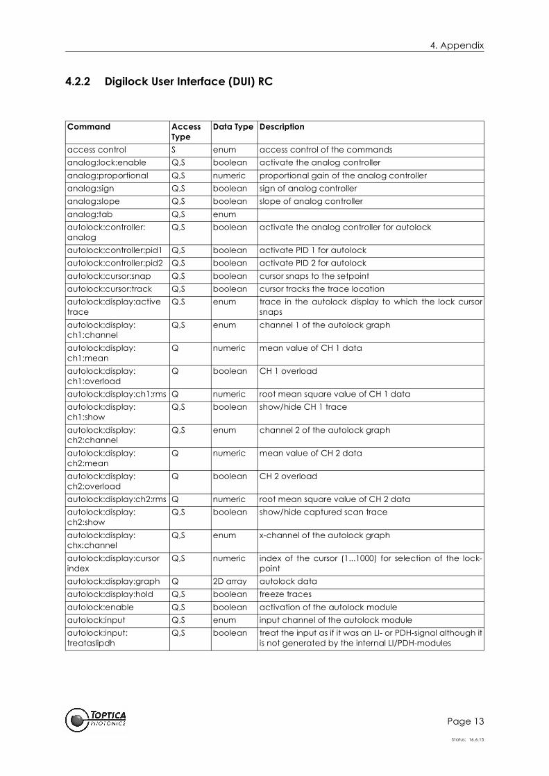
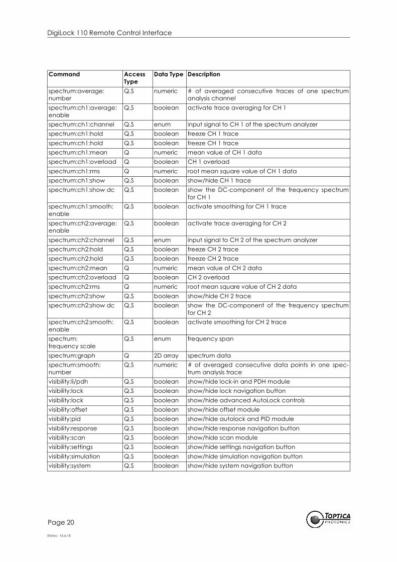
4.2 Application Programming Interface (API) Commands
The following tables list all available commands of the DigiLock remote API. In addition to the accesstype and the data type a short description is given. More details on the command functions can befound in the explanations of the corresponding control in the DigiLock 110 manual.
4.2.1 Digilock Module Server (DMS) RCI
Command Access Type
Data Type Description
access control S enum access control of the commandscommandlist Q array displays all available commandsecho S boolean echoes the sent charactersmessages waiting Q numeric messages waiting in the command queuemodule:connect Q,S boolean establish a connection to the selected DigiLock mod-
ulemodule:show Q,S boolean show user interface of active DigiLock modulemodules:connection sta-tus
Q array list of connection statuses of modules
modules:names Q array list of module namesmodules:port numbers Q array list of port numbers of modulesmodules:serial numbers Q array list of serial numbers of modulesnumber connectedmodules
Q numeric number of DigiLock modules with a connection estab-lished
number of modules Q numeric number of DigiLock modules connected to the com-puter
program:exit Q,S boolean stops the applicationprogram:ip address Q,S string ip address of this computerprogram:port number Q,S numeric port number of the module serverprogram:update mod-ule list
Q,S boolean search for connected DigiLock modules
selected module Q,S numeric index of the currently active module
4. Appendix
Page 13
Status: 16.6.15
4.2.2 Digilock User Interface (DUI) RC
Command AccessType
Data Type Description
access control S enum access control of the commandsanalog:lock:enable Q,S boolean activate the analog controlleranalog:proportional Q,S numeric proportional gain of the analog controlleranalog:sign Q,S boolean sign of analog controlleranalog:slope Q,S boolean slope of analog controlleranalog:tab Q,S enumautolock:controller:analog
Q,S boolean activate the analog controller for autolock
autolock:controller:pid1 Q,S boolean activate PID 1 for autolockautolock:controller:pid2 Q,S boolean activate PID 2 for autolockautolock:cursor:snap Q,S boolean cursor snaps to the setpointautolock:cursor:track Q,S boolean cursor tracks the trace locationautolock:display:activetrace
Q,S enum trace in the autolock display to which the lock cursorsnaps
autolock:display:ch1:channel
Q,S enum channel 1 of the autolock graph
autolock:display:ch1:mean
Q numeric mean value of CH 1 data
autolock:display:ch1:overload
Q boolean CH 1 overload
autolock:display:ch1:rms Q numeric root mean square value of CH 1 dataautolock:display:ch1:show
Q,S boolean show/hide CH 1 trace
autolock:display:ch2:channel
Q,S enum channel 2 of the autolock graph
autolock:display:ch2:mean
Q numeric mean value of CH 2 data
autolock:display:ch2:overload
Q boolean CH 2 overload
autolock:display:ch2:rms Q numeric root mean square value of CH 2 dataautolock:display:ch2:show
Q,S boolean show/hide captured scan trace
autolock:display:chx:channel
Q,S enum x-channel of the autolock graph
autolock:display:cursorindex
Q,S numeric index of the cursor (1...1000) for selection of the lock-point
autolock:display:graph Q 2D array autolock dataautolock:display:hold Q,S boolean freeze tracesautolock:enable Q,S boolean activation of the autolock moduleautolock:input Q,S enum input channel of the autolock moduleautolock:input:treataslipdh
Q,S boolean treat the input as if it was an LI- or PDH-signal although itis not generated by the internal LI/PDH-modules

DigiLock 110 Remote Control Interface
Page 14
Status: 16.6.15
Command AccessType
Data Type Description
autolock:lock:enable Q,S boolean lock the controllers configured for autolockautolock:lock:hold Q,S boolean hold the autolock controllersautolock:lock:mode Q,S enum operating mode of the autolock module autolock:lock:strategy Q,S enum strategy the autolock module uses in full automatic
locking modeautolock:relock:amplitude
Q,S numeric relock scan amplitude
autolock:relock:enable Q,S boolean turn the relock option on/offautolock:relock:frequency
Q,S numeric relock scan frequency
autolock:relock:output Q,S enum output channel that starts to scanautolock:setpoint Q,S numeric setpoint of the autolock moduleautolock:smart:engage Q,S boolean intelligent detection of a slope or extremum to engage
a proper lockautolock:smart:setpoint Q,S boolean automatic detection of the setpointautolock:spectrum Q,S enum display channel for the autolock graphautolock:spectrum:enable
Q,S boolean automatic setting of the spectrum channel
autolock:tab Q,S enumautolock:window:channel
Q,S enum detection channel for supervision limits
autolock:window:enable Q,S boolean turn the lock window option on/offautolock:window:maxin Q,S numeric controller continous working below this signal levelautolock:window:maxout
Q,S numeric controller halts above this signal level
autolock:window:minin Q,S numeric controller continous working above this signal levelautolock:window:minout Q,S numeric controller halts below this signal levelautolock:window:reset:delay
Q,S numeric time to wait from triggering the window to reset/relock
aux in:invert Q,S boolean inversion of the aux in signalaux in:low pass:bypass Q,S boolean bypass the low-pass filteraux in:low pass:frequency
Q,S numeric cut-off frequency of the low-pass filter
aux in:low pass:order Q,S numeric order of the low-pass filtercommandlist Q array displays all available commandscontroller:tab Q,S enumdio out:function Q,S enum function of the DIO outputdio out:manual state Q,S boolean manual state of the DIO outputdisplay:sampling Q,S boolean turn the sampling on/offdisplay:update rate Q,S numeric display update ratedisplay:view Q,S enum select the corresponding display viewecho S boolean echos the sent charactersfunction:view Q,S enum select the corresponding function view

4. Appendix
Page 15
Status: 16.6.15
Command AccessType
Data Type Description
li/pdh:aio1outselection Q,S enum output LI/PDH-signal on AIO1out channelli/pdh:modulation:signal type
Q,S enum signal type of the modulation signal for LI and PDH
li/pdh:tab Q,S enumli:first filter notch Q,S enum frequency of the first filter notch in fractions of the mod-
ulation frequencyli:input Q,S enum input channel of LI-moduleli:modulation:amplitude Q,S numeric modulation amplitudeli:modulation:enable Q,S boolean turn the modulation on/offli:modulation:frequency act
Q numeric actual modulation frequency
li:modulation:frequency set
Q,S numeric set modulation frequency
li:modulation:output Q,S enum modulation output channelli:offset Q,S numeric offset value that is subtracted from the original LI-signalli:phase adjust Q,S boolean automatic adjustment of phase shiftli:phase shift Q,S numeric phase shift between modulation and reference signalmain in:gain Q,S enum analog gain valuemain in:high pass:bypass Q,S boolean bypass the high-pass filtermain in:high pass:frequency
Q,S numeric cut-off frequency of the high-pass filter
main in:high pass:order Q,S numeric order of the high-pass filtermain in:input offset Q,S numeric input offset subtraced from <Main in>main in:invert Q,S boolean inversion of the main in signalmain in:low pass:bypass Q,S boolean bypass the low-pass filtermain in:low pass:frequency
Q,S numeric cut-off frequency of the low-pass filter
main in:low pass:order Q,S numeric order of the low-pass filtermessages waiting Q numeric messages waiting in the command queueoffset:output Q,S enum output destination for DC-offsetoffset:value Q,S numeric DC-offset voltage of the selected output channelpdh:input Q,S enum input channel of PDH-modulepdh:modulation:amplitude
Q,S numeric modulation amplitude
pdh:modulation:enable Q,S boolean turn the modulation on/offpdh:modulation:frequency set
Q,S enum set modulation frequency
pdh:modulation:output Q,S enum modulation output channelpdh:offset Q,S numeric offset value that is subtracted from the original PDH-sig-
nalpdh:phase adjust Q,S boolean automatic adjustment of phase shiftpdh:phase shift Q,S numeric phase shift between modulation and reference signal

DigiLock 110 Remote Control Interface
Page 16
Status: 16.6.15
Command AccessType
Data Type Description
pid1:differential Q,S numeric differential gain of PID 1pid1:gain Q,S numeric overall gain of PID 1pid1:hold:state Q boolean hold status of the PID 1 controllerpid1:input Q,S enum input channel of PID 1pid1:integral Q,S numeric integral gain of PID 1pid1:integral:cutoff:enable
Q,S boolean activation of I cut-off
pid1:integral:cutoff:frequency
Q,S numeric cut-off frequency for integral gain
pid1:limit enable Q,S boolean activation of output limitspid1:limit:max Q,S numeric maximum relative output level of PID 1pid1:limit:min Q,S numeric minimum relative output level of PID 1pid1:lock:enable Q,S boolean lock the PID1 controllerpid1:lock:hold Q,S boolean hold PID1 controllerpid1:lock:state Q boolean lock status of the PID 1 controllerpid1:output Q,S enum output channel of PID 1pid1:proportional Q,S numeric proportional gain of PID 1pid1:relock:amplitude Q,S numeric relock scan amplitudepid1:relock:enable Q,S boolean turn the relock option on/offpid1:relock:frequency Q,S numeric relock scan frequencypid1:relock:output Q,S enum output channel that starts to scanpid1:setpoint Q,S numeric setpoint of PID 1pid1:sign Q,S boolean sign of PID 1pid1:slope Q,S boolean slope to lock to for PID 1pid1:regulating state Q boolean regulating status of the PID 1 controllerpid1:tab Q,S enumpid1:turnoff reset:autolock
Q,S boolean when turning off PID 1 in autolock mode a reset is per-formed
pid1:turnoff reset:manual Q,S boolean when turning off PID 1 in manual mode a reset is per-formed
pid1:window:channel Q,S enum detection channel for supervision limitspid1:window:enable Q,S boolean turn the lock window option on/offpid1:window:maxin Q,S numeric controller continous working below this signal levelpid1:window:maxout Q,S numeric controller halts above this signal levelpid1:window:minin Q,S numeric controller continous working above this signal levelpid1:window:minout Q,S numeric controller halts below this signal levelpid1:window:reset:delay Q,S numeric time to wait from triggering the window to reset/relockpid1:window:reset:enable
Q,S boolean reset the PID if the window is triggered
pid1:window:reset:rate Q,S numeric rate at which the PID output is reset

4. Appendix
Page 17
Status: 16.6.15
Command AccessType
Data Type Description
pid2:differential Q,S numeric differential gain of PID 2pid2:gain Q,S numeric overall gain of PID 2pid2:hold:state Q boolean hold status of the PID 1 controllerpid2:input Q,S enum input channel of PID 2pid2:integral Q,S numeric integral gain of PID 2pid2:limit:enable Q,S boolean activation of output limitspid2:limit:max Q,S numeric maximum relative output level of PID 2pid2:limit:min Q,S numeric minimum relative output level of PID 2pid2:lock:enable Q,S boolean lock the PID2 controllerpid2:lock:hold Q,S boolean hold PID2 controllerpid2:lock:state Q boolean lock status of the PID 2 controllerpid2:low pass:bypass Q,S boolean bypass the low-pass filterpid2:low pass:frequency Q,S numeric cut-off frequency of the low-pass filterpid2:low pass:order Q,S numeric order of the low-pass filterpid2:output Q,S enum output channel of PID 2pid2:proportional Q,S numeric proportional gain of PID 2pid2:relock:amplitude Q,S numeric relock scan amplitudepid2:relock:enable Q,S boolean turn the relock option on/offpid2:relock:frequency Q,S numeric relock scan frequencypid2:relock:output Q,S enum output channel that starts to scanpid2:setpoint Q,S numeric setpoint of PID 2pid2:sign Q,S boolean sign of PID 2pid2:slope Q,S boolean slope to lock to for PID 2pid2:regulating state Q boolean regulating status of the PID 2 controllerpid2:tab Q,S enumpid2:turnoffreset:autolock
Q,S boolean when turning off PID 2 in autolock mode a reset is per-formed
pid2:turnoff reset:manual Q,S boolean when turning off PID 2 in manual mode a reset is per-formed
pid2:window:channel Q,S enum detection channel for supervision limitspid2:window:enable Q,S boolean turn the lock window option on/offpid2:window:maxin Q,S numeric controller continous working below this signal levelpid2:window:maxout Q,S numeric controller halts above this signal levelpid2:window:minin Q,S numeric controller continous working above this signal levelpid2:window:minout Q,S numeric controller halts below this signal levelpid2:window:reset:delay Q,S numeric time to wait from triggering the window to reset/relockpid2:window:reset:enable
Q,S boolean reset the PID if the window is triggered
pid2:window:reset:rate Q,S numeric rate at which the PID output is resetpid:scanlockbutton Q,S enum function of the scan-lock button

DigiLock 110 Remote Control Interface
Page 18
Status: 16.6.15
Command AccessType
Data Type Description
program:disable popup windows
Q,S boolean disable all popup windows during runtime
program:exit Q,S booleanprogram:sample when hidden
Q,S boolean set the sampling option when the frontend is hidden
program:status bar Q numeric display of the progress of a procedureprogram:system message
Q,S string display of system messages
response:graph Q,S 2D array response dataresponse:input Q,S enum response signal inputresponse:modulation:amplitude
Q,S numeric modulation amplitude
response:modulation:input:overload
Q boolean input channel overload
response:modulation:output
Q,S enum stimulus signal output
response:modulation:output:overload
Q boolean output channel overload
response:show:reference
Q,S boolean show/hide the reference tracks in the graph
response:show:time signal
Q,S boolean show/hide the response signal on the scope
response:start Q,S boolean start the measurementresponse:sweep:averaging
Q,S numeric # of averaging points per measurement frequency
response:sweep:samples Q,S numeric # of samples within the frequency sweep rangeresponse:sweep:scaling Q,S enum mode of spreading the measurement points across the
frequency sweep rangeresponse:sweep:start Q,S numeric start frequency of the sweepresponse:sweep:stop Q,S numeric stop frequency of the sweepscan:amplitude Q,S numeric scan amplitudescan:enable Q,S boolean turn scan control on / offscan:frequency Q,S numeric scan frequencyscan:output Q,S enum output destination of scan signalscan:signal type Q,S enum waveform type of output signalscope:average:number Q,S numeric # of averaged consecutive traces of one scope chan-
nelscope:ch1:average:enable
Q,S boolean activate trace averaging for CH 1
scope:ch1:channel Q,S enum input signal to CH 1 of the scopescope:ch1:mean Q numeric mean value of CH 1 datascope:ch1:overload Q boolean CH 1 overloadscope:ch1:rms Q numeric root mean square value of CH 1 datascope:ch1:show Q,S boolean show/hide CH 1 tracescope:ch1:smooth:enable
Q,S boolean activate smoothing for CH 1 trace

4. Appendix
Page 19
Status: 16.6.15
Command AccessType
Data Type Description
scope:ch2:average:enable
Q,S boolean activate trace averaging for CH 2
scope:ch2:channel Q,S enum input signal to CH 2 of the scopescope:ch2:mean Q numeric mean value of CH 2 datascope:ch2:overload Q boolean CH 2 overloadscope:ch2:rms Q numeric root mean square value of CH 2 datascope:ch2:show Q,S boolean show/hide CH 2 tracescope:ch2:smooth:enable
Q,S boolean activate smoothing for CH 2 trace
scope:chx:channel Q,S enum input signal to the x-channel in the xy-modescope:graph Q 2D array scope datascope:smooth:number Q,S numeric # of averaged consecutive data points in one scope
tracescope:timescale Q,S enum time spanscope:xymode Q,S boolean activate the xy-modesettings:tab Q,S enumsimulation:frequency:start
Q,S numeric minimum display frequency
simulation:frequency:stop
Q,S numeric maximum display frequency
simulation:frequency:unit Q,S enum units used on the frequency axissimulation:graph Q 2D array simulation datasimulation:includecontroller
Q,S boolean include controllers in transfer function calculation
simulation:includeconverters
Q,S boolean include ADC- and DAC-delays in transfer function cal-culation
simulation:includeinputfilter
Q,S boolean include input filter in transfer function calculation
simulation:includelipdh Q,S boolean include LI or PDH in transfer function calculationsimulation:pid:differential Q,S numeric derivative gainsimulation:pid:gain Q,S numeric overall gainsimulation:pid:getparameters
S boolean get parameters of the selected PID controller
simulation:pid:input Q,S enum input channel for the selected PIDsimulation:pid:integral Q,S numeric integral gainsimulation:pid:integral:cutoff:enable
Q,S boolean activate the I cut-off
simulation:pid:integral:cutoff:frequency
Q,S numeric cut-off frequency for integral gain
simulation:pid:output Q,S enum output channel of the selected controllersimulation:pid:proportional
Q,S numeric proportional gain
simulation:pid:send parameters
S boolean send the chosen parameters to the selected PID con-troller
simulation:selected pid Q,S enum selected PID controller
DigiLock 110 Remote Control Interface
Page 20
Status: 16.6.15
Command AccessType
Data Type Description
spectrum:average:number
Q,S numeric # of averaged consecutive traces of one spectrumanalysis channel
spectrum:ch1:average:enable
Q,S boolean activate trace averaging for CH 1
spectrum:ch1:channel Q,S enum input signal to CH 1 of the spectrum analyzerspectrum:ch1:hold Q,S boolean freeze CH 1 tracespectrum:ch1:hold Q,S boolean freeze CH 1 tracespectrum:ch1:mean Q numeric mean value of CH 1 dataspectrum:ch1:overload Q boolean CH 1 overloadspectrum:ch1:rms Q numeric root mean square value of CH 1 dataspectrum:ch1:show Q,S boolean show/hide CH 1 tracespectrum:ch1:show dc Q,S boolean show the DC-component of the frequency spectrum
for CH 1spectrum:ch1:smooth:enable
Q,S boolean activate smoothing for CH 1 trace
spectrum:ch2:average:enable
Q,S boolean activate trace averaging for CH 2
spectrum:ch2:channel Q,S enum input signal to CH 2 of the spectrum analyzerspectrum:ch2:hold Q,S boolean freeze CH 2 tracespectrum:ch2:hold Q,S boolean freeze CH 2 tracespectrum:ch2:mean Q numeric mean value of CH 2 dataspectrum:ch2:overload Q boolean CH 2 overloadspectrum:ch2:rms Q numeric root mean square value of CH 2 dataspectrum:ch2:show Q,S boolean show/hide CH 2 tracespectrum:ch2:show dc Q,S boolean show the DC-component of the frequency spectrum
for CH 2spectrum:ch2:smooth:enable
Q,S boolean activate smoothing for CH 2 trace
spectrum:frequency scale
Q,S enum frequency span
spectrum:graph Q 2D array spectrum dataspectrum:smooth:number
Q,S numeric # of averaged consecutive data points in one spec-trum analysis trace
visibility:li/pdh Q,S boolean show/hide lock-in and PDH modulevisibility:lock Q,S boolean show/hide lock navigation buttonvisibility:lock Q,S boolean show/hide advanced AutoLock controlsvisibility:offset Q,S boolean show/hide offset modulevisibility:pid Q,S boolean show/hide autolock and PID modulevisibility:response Q,S boolean show/hide response navigation buttonvisibility:scan Q,S boolean show/hide scan modulevisibility:settings Q,S boolean show/hide settings navigation buttonvisibility:simulation Q,S boolean show/hide simulation navigation buttonvisibility:system Q,S boolean show/hide system navigation button

4. Appendix
Page 21
Status: 16.6.15

Copyright © 2022 FDOKUMEN