
Die sets made of steel and aluminium - Champion Tools
461
Die sets made of steel and aluminium according to drawing Steinel steel or aluminium columnar frames can be rapidly manufactured according to your specifications or drawings in any desired dimensions or forms within the maximal production limits. Plate machining Burned or machine clean on all sides, heated tension-free, polish plano-parallel up to a maximum of: 2000 x 800 mm Larger plates finally milled up to: 2500 x 1250 mm Plate thicknesses up to: 20 – 250 mm Further dimensions available on request. Machining services Breakthroughs, countersinks, hollowing, drilling patterns, coordinate grinding, eroding etc. can be done according to your specifi- cations or sketches. usw. führen wir nach Ihren Angaben oder Skizzen aus. 1.02 Champion Die-Tool champion-dietool.com 1 (866) 957-9993
-
Upload
khangminh22 -
Category
Documents
-
view
3 -
download
0
Transcript of Die sets made of steel and aluminium - Champion Tools
Die sets made of steel and aluminiumaccording to drawing
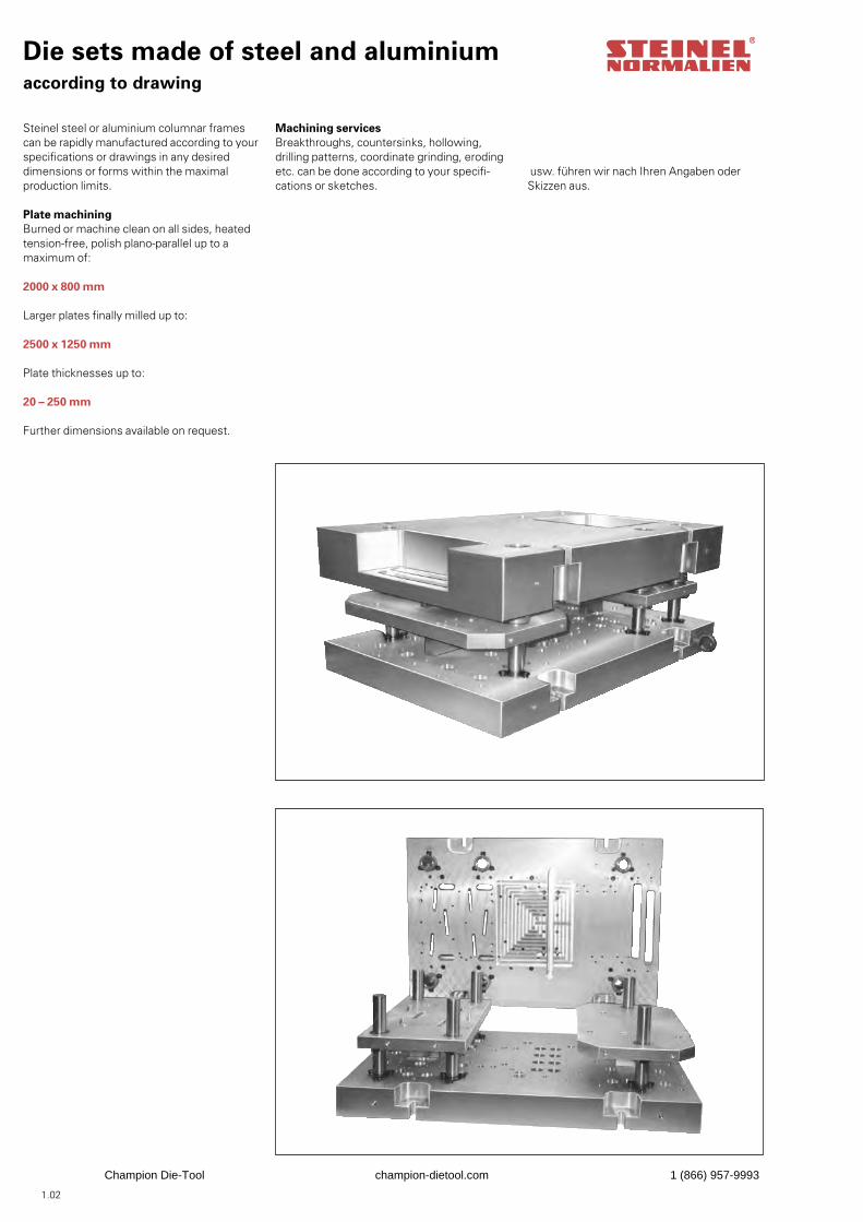
Steinel steel or aluminium columnar frames can be rapidly manufactured according to yourspecifications or drawings in any desired dimensions or forms within the maximal production limits.
Plate machiningBurned or machine clean on all sides, heated tension-free, polish plano-parallel up to a maximum of:
2000 x 800 mm
Larger plates finally milled up to:
2500 x 1250 mm
Plate thicknesses up to:
20 – 250 mm
Further dimensions available on request.
Machining servicesBreakthroughs, countersinks, hollowing, drilling patterns, coordinate grinding, eroding etc. can be done according to your specifi-cations or sketches.
usw. führen wir nach Ihren Angaben oder Skizzen aus.
1.02
Champion Die-Tool champion-dietool.com 1 (866) 957-9993
Die sets made of steel and aluminium
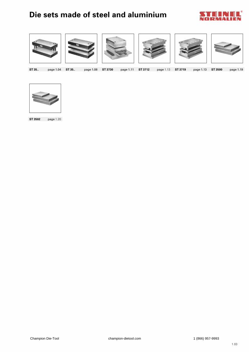
ST 35.. page 1.04 ST 35.. page 1.08 ST 3730 page 1.11 ST 3712 page 1.13 ST 3719 page 1.13 ST 3500 page 1.19
ST 3502 page 1.20
1.03
Champion Die-Tool champion-dietool.com 1 (866) 957-9993
Die sets ST 35..without stripper plate
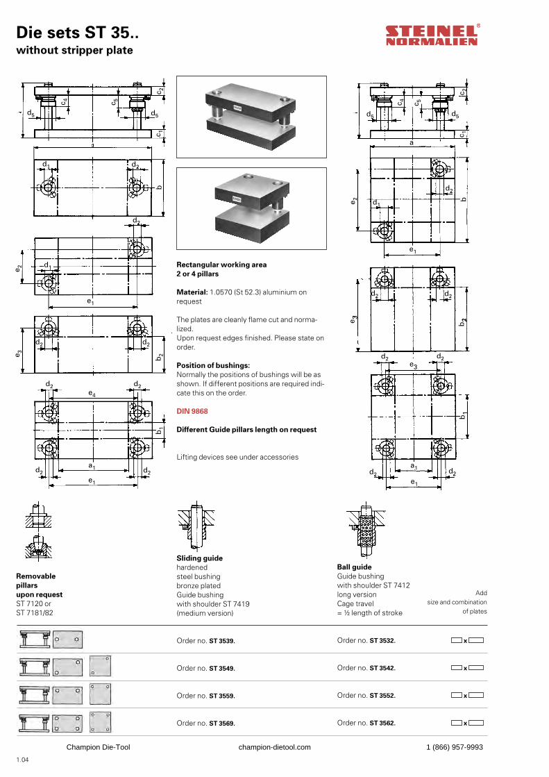
Rectangular working area2 or 4 pillars
Material: 1.0570 (St 52.3) aluminium onrequest
The plates are cleanly flame cut and norma-lized.Upon request edges finished. Please state onorder.
Position of bushings:Normally the positions of bushings will be asshown. If different positions are required indi-cate this on the order.
DIN 9868
Different Guide pillars length on request
Lifting devices see under accessories
Sliding guidehardenedsteel bushingbronze platedGuide bushingwith shoulder ST 7419(medium version)
Order no. ST 3539. Order no. ST 3549. Order no. ST 3559. Order no. ST 3569.
Ball guideGuide bushingwith shoulder ST 7412long versionCage travel= ½ length of stroke
Order no. ST 3532. Order no. ST 3542.
Order no. ST 3552. Order no. ST 3562.
Addsize and combination
of plates
x
x
x
x
Removablepillarsupon request ST 7120 or ST 7181/82
1.04
d5
c 4 c 5
c 2
d5
d2d1
c 1
d2
e 2
e1
b
d1
e 3 b2
b1
d2 d2
d2 d2
d2 d2
e4
e1
a1
d5
c 4 c 5
c 2
d5
c 1
d1
d2
a
b1
e 2
e1
d2 d2
e 3 b2
b
d2
d2 d2
e3
a1
e1
d2
Champion Die-Tool champion-dietool.com 1 (866) 957-9993
Die sets ST 35..without stripper plate
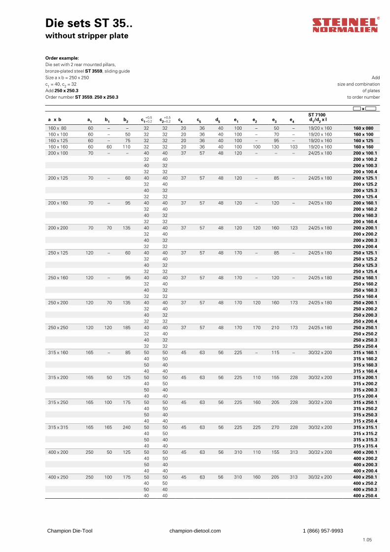
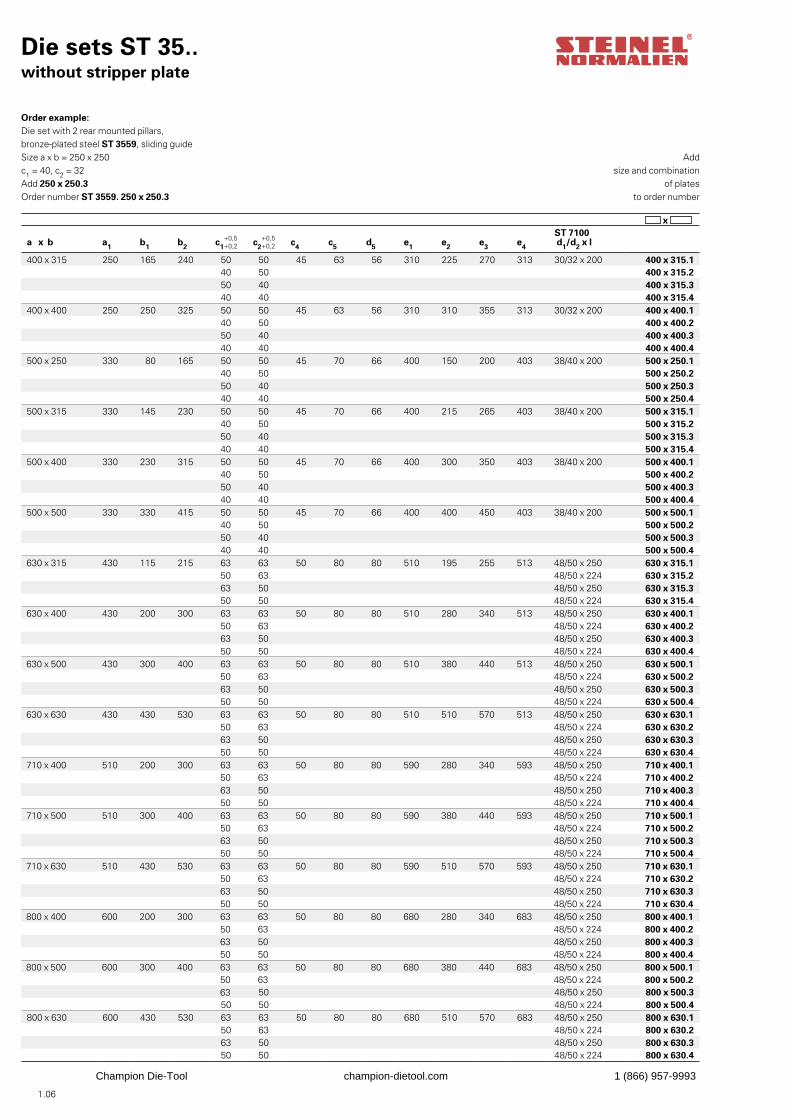
Order example:Die set with 2 rear mounted pillars,bronze-plated steel ST 3559, sliding guideSize a x b = 250 x 250c1 = 40, c2 = 32Add 250 x 250.3Order number ST 3559. 250 x 250.3
Addsize and combination
of platesto order number
x
a x b a1 b1 b2 c1 c2 c4 c5 d5 e1 e2 e3 e4
ST 7100 d1/d2 x l
160 x 80 60 – – 32 32 20 36 40 100 – 50 – 19/20 x 160 160 x 080160 x 100 60 – 50 32 32 20 36 40 100 – 70 – 19/20 x 160 160 x 100160 x 125 60 – 75 32 32 20 36 40 100 – 95 – 19/20 x 160 160 x 125160 x 160 60 60 110 32 32 20 36 40 100 100 130 103 19/20 x 160 160 x 160200 x 100 70 – – 40 40 37 57 48 120 – – – 24/25 x 180 200 x 100.1
32 40 200 x 100.240 32 200 x 100.332 32 200 x 100.4
200 x 125 70 – 60 40 40 37 57 48 120 – 85 – 24/25 x 180 200 x 125.132 40 200 x 125.240 32 200 x 125.332 32 200 x 125.4
200 x 160 70 – 95 40 40 37 57 48 120 – 120 – 24/25 x 180 200 x 160.132 40 200 x 160.240 32 200 x 160.332 32 200 x 160.4
200 x 200 70 70 135 40 40 37 57 48 120 120 160 123 24/25 x 180 200 x 200.132 40 200 x 200.240 32 200 x 200.332 32 200 x 200.4
250 x 125 120 – 60 40 40 37 57 48 170 – 85 – 24/25 x 180 250 x 125.132 40 250 x 125.240 32 250 x 125.332 32 250 x 125.4
250 x 160 120 – 95 40 40 37 57 48 170 – 120 – 24/25 x 180 250 x 160.132 40 250 x 160.240 32 250 x 160.332 32 250 x 160.4
250 x 200 120 70 135 40 40 37 57 48 170 120 160 173 24/25 x 180 250 x 200.132 40 250 x 200.240 32 250 x 200.332 32 250 x 200.4
250 x 250 120 120 185 40 40 37 57 48 170 170 210 173 24/25 x 180 250 x 250.132 40 250 x 250.240 32 250 x 250.332 32 250 x 250.4
315 x 160 165 – 85 50 50 45 63 56 225 – 115 – 30/32 x 200 315 x 160.140 50 315 x 160.250 40 315 x 160.340 40 315 x 160.4
315 x 200 165 50 125 50 50 45 63 56 225 110 155 228 30/32 x 200 315 x 200.140 50 315 x 200.250 40 315 x 200.340 40 315 x 200.4
315 x 250 165 100 175 50 50 45 63 56 225 160 205 228 30/32 x 200 315 x 250.140 50 315 x 250.250 40 315 x 250.340 40 315 x 250.4
315 x 315 165 165 240 50 50 45 63 56 225 225 270 228 30/32 x 200 315 x 315.140 50 315 x 315.250 40 315 x 315.340 40 315 x 315.4
400 x 200 250 50 125 50 50 45 63 56 310 110 155 313 30/32 x 200 400 x 200.140 50 400 x 200.250 40 400 x 200.340 40 400 x 200.4
400 x 250 250 100 175 50 50 45 63 56 310 160 205 313 30/32 x 200 400 x 250.140 50 400 x 250.250 40 400 x 250.340 40 400 x 250.4
1.05
Champion Die-Tool champion-dietool.com 1 (866) 957-9993
Die sets ST 35..without stripper plate
Addsize and combination
of platesto order number
x
Order example:Die set with 2 rear mounted pillars,bronze-plated steel ST 3559, sliding guideSize a x b = 250 x 250c1 = 40, c2 = 32Add 250 x 250.3Order number ST 3559. 250 x 250.3
a x b a1 b1 b2 c1 c2 c4 c5 d5 e1 e2 e3 e4
ST 7100 d1/d2 x l
400 x 315 250 165 240 50 50 45 63 56 310 225 270 313 30/32 x 200 400 x 315.140 50 400 x 315.250 40 400 x 315.340 40 400 x 315.4
400 x 400 250 250 325 50 50 45 63 56 310 310 355 313 30/32 x 200 400 x 400.140 50 400 x 400.250 40 400 x 400.340 40 400 x 400.4
500 x 250 330 80 165 50 50 45 70 66 400 150 200 403 38/40 x 200 500 x 250.140 50 500 x 250.250 40 500 x 250.340 40 500 x 250.4
500 x 315 330 145 230 50 50 45 70 66 400 215 265 403 38/40 x 200 500 x 315.140 50 500 x 315.250 40 500 x 315.340 40 500 x 315.4
500 x 400 330 230 315 50 50 45 70 66 400 300 350 403 38/40 x 200 500 x 400.140 50 500 x 400.250 40 500 x 400.340 40 500 x 400.4
500 x 500 330 330 415 50 50 45 70 66 400 400 450 403 38/40 x 200 500 x 500.140 50 500 x 500.250 40 500 x 500.340 40 500 x 500.4
630 x 315 430 115 215 63 63 50 80 80 510 195 255 513 48/50 x 250 630 x 315.150 63 48/50 x 224 630 x 315.263 50 48/50 x 250 630 x 315.350 50 48/50 x 224 630 x 315.4
630 x 400 430 200 300 63 63 50 80 80 510 280 340 513 48/50 x 250 630 x 400.150 63 48/50 x 224 630 x 400.263 50 48/50 x 250 630 x 400.350 50 48/50 x 224 630 x 400.4
630 x 500 430 300 400 63 63 50 80 80 510 380 440 513 48/50 x 250 630 x 500.150 63 48/50 x 224 630 x 500.263 50 48/50 x 250 630 x 500.350 50 48/50 x 224 630 x 500.4
630 x 630 430 430 530 63 63 50 80 80 510 510 570 513 48/50 x 250 630 x 630.150 63 48/50 x 224 630 x 630.263 50 48/50 x 250 630 x 630.350 50 48/50 x 224 630 x 630.4
710 x 400 510 200 300 63 63 50 80 80 590 280 340 593 48/50 x 250 710 x 400.150 63 48/50 x 224 710 x 400.263 50 48/50 x 250 710 x 400.350 50 48/50 x 224 710 x 400.4
710 x 500 510 300 400 63 63 50 80 80 590 380 440 593 48/50 x 250 710 x 500.150 63 48/50 x 224 710 x 500.263 50 48/50 x 250 710 x 500.350 50 48/50 x 224 710 x 500.4
710 x 630 510 430 530 63 63 50 80 80 590 510 570 593 48/50 x 250 710 x 630.150 63 48/50 x 224 710 x 630.263 50 48/50 x 250 710 x 630.350 50 48/50 x 224 710 x 630.4
800 x 400 600 200 300 63 63 50 80 80 680 280 340 683 48/50 x 250 800 x 400.150 63 48/50 x 224 800 x 400.263 50 48/50 x 250 800 x 400.350 50 48/50 x 224 800 x 400.4
800 x 500 600 300 400 63 63 50 80 80 680 380 440 683 48/50 x 250 800 x 500.150 63 48/50 x 224 800 x 500.263 50 48/50 x 250 800 x 500.350 50 48/50 x 224 800 x 500.4
800 x 630 600 430 530 63 63 50 80 80 680 510 570 683 48/50 x 250 800 x 630.150 63 48/50 x 224 800 x 630.263 50 48/50 x 250 800 x 630.350 50 48/50 x 224 800 x 630.4
1.06
Champion Die-Tool champion-dietool.com 1 (866) 957-9993
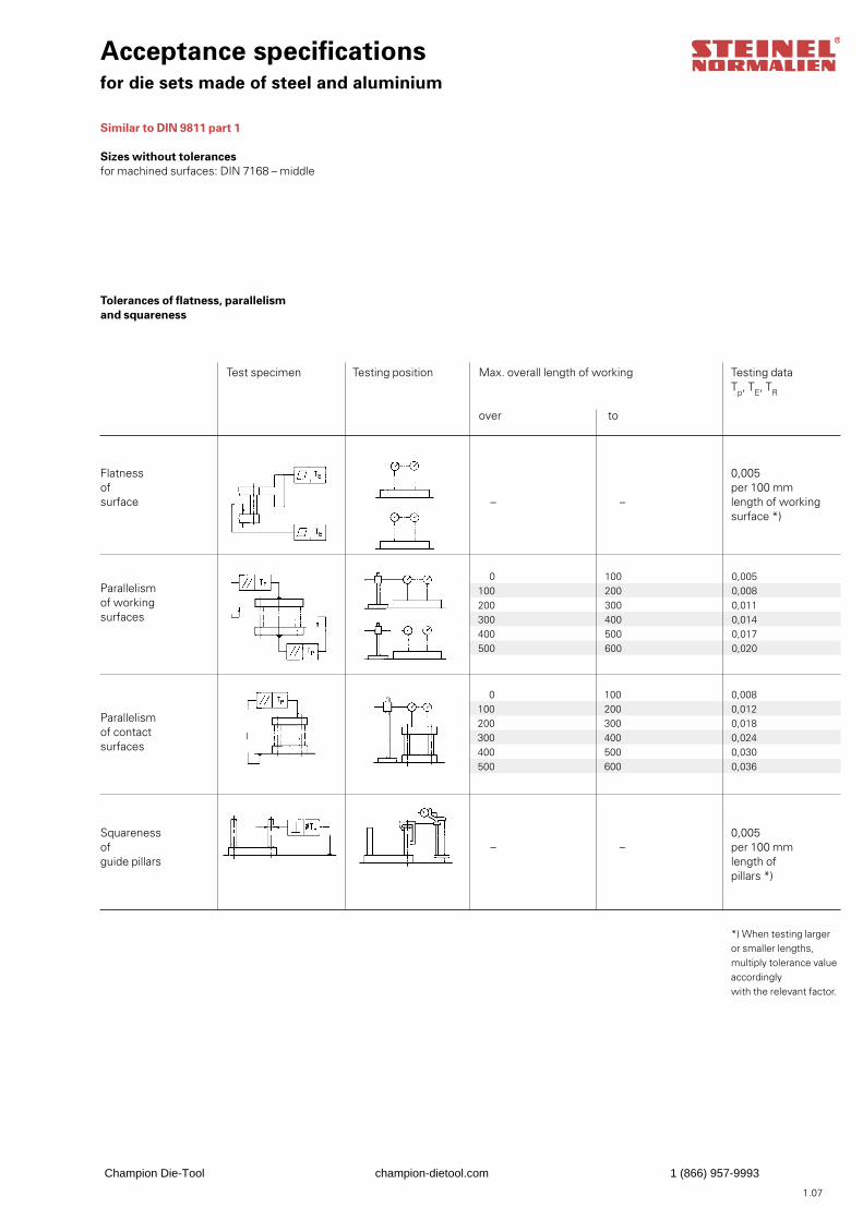
Acceptance specificationsfor die sets made of steel and aluminium
Similar to DIN 9811 part 1
Sizes without tolerancesfor machined surfaces: DIN 7168 – middle
Tolerances of flatness, parallelismand squareness
0 100 0,005100 200 0,008200 300 0,011300 400 0,014400 500 0,017500 600 0,020
0 100 0,008100 200 0,012200 300 0,018300 400 0,024400 500 0,030500 600 0,036
Flatnessofsurface
Test specimen Testing position Max. overall length of working
over to
– –
– –
Testing dataTp, TE, TR
Parallelismof workingsurfaces
Parallelismof contactsurfaces
Squarenessofguide pillars
0,005per 100 mmlength of working surface *)
0,005per 100 mmlength ofpillars *)
*) When testing larger or smaller lengths,multiply tolerance value accordinglywith the relevant factor.
1.07
Champion Die-Tool champion-dietool.com 1 (866) 957-9993
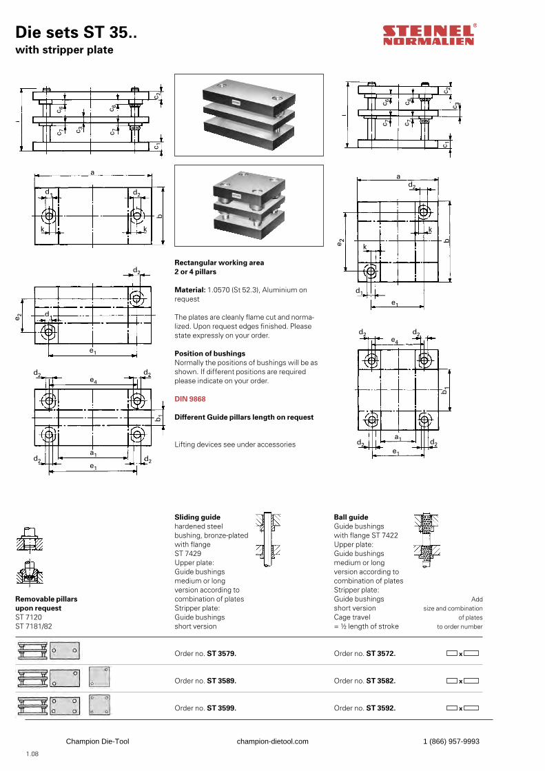
Die sets ST 35..with stripper plate
Rectangular working area2 or 4 pillars
Material: 1.0570 (St 52.3), Aluminium onrequest
The plates are cleanly flame cut and norma-lized. Upon request edges finished. Please state expressly on your order.
Position of bushingsNormally the positions of bushings will be asshown. If different positions are required please indicate on your order.
DIN 9868
Different Guide pillars length on request
Lifting devices see under accessories
Sliding guidehardened steel bushing, bronze-platedwith flangeST 7429Upper plate:Guide bushingsmedium or longversion according tocombination of platesStripper plate:Guide bushingsshort version Order no. ST 3579. Order no. ST 3589. Order no. ST 3599.
Ball guideGuide bushingswith flange ST 7422Upper plate:Guide bushingsmedium or longversion according tocombination of platesStripper plate:Guide bushingsshort versionCage travel= ½ length of stroke
Order no. ST 3572. Order no. ST 3582. Order no. ST 3592.
Addsize and combination
of platesto order number
x
x
x
Removable pillars upon request ST 7120 ST 7181/82
1.08
c 3
d2
c 7 c 7
c 6 c 6
c 1c 2
a
d1
b
kk
d2
d1
d2d2
e1
e 2
e4
d2 d2e1
a1
b1
c 2c 3c 6c 6
c 7 c 7
c 1
ad2
k
ke 2 b
d1
e1
e4
d2d2
b1
d2 d2a1
e1
Champion Die-Tool champion-dietool.com 1 (866) 957-9993

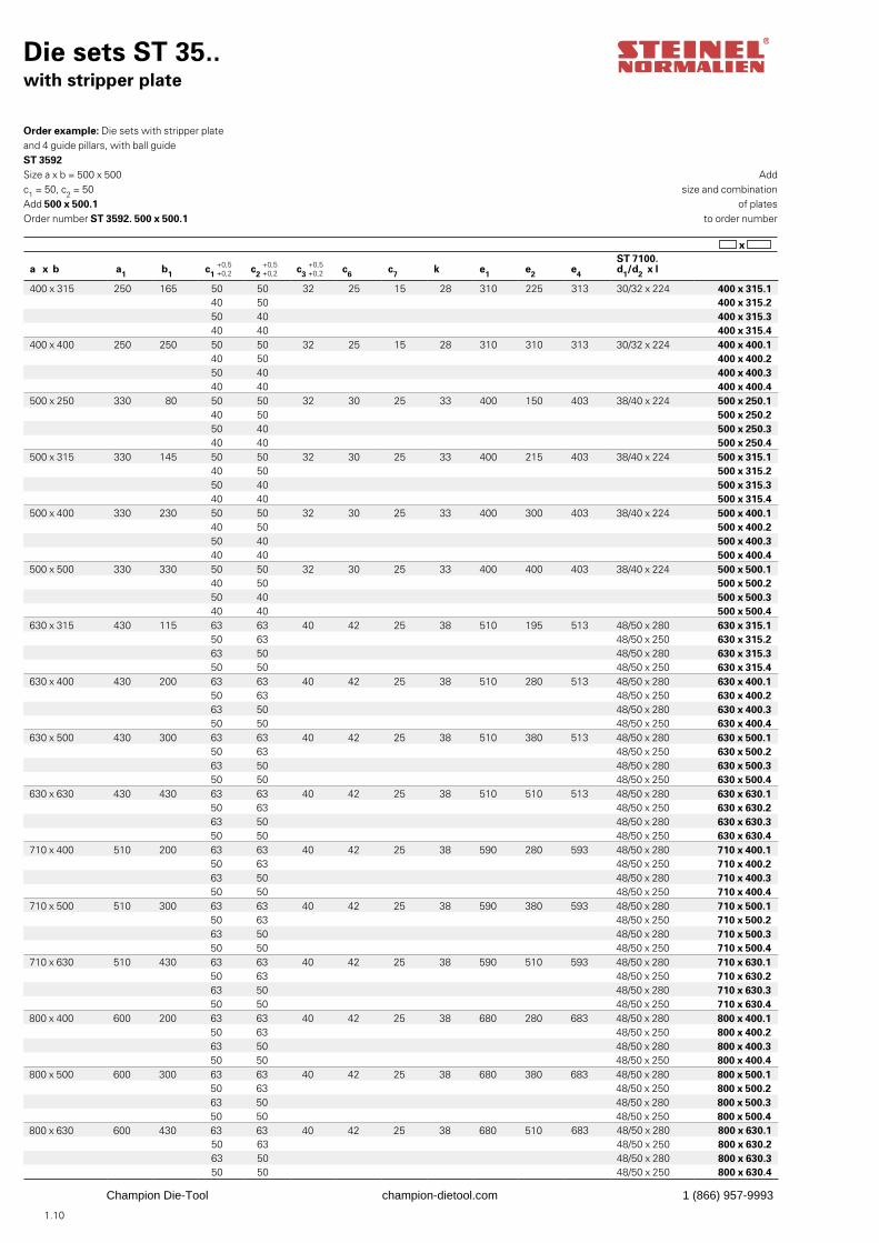
Order example: Die sets with stripper plateand 4 guide pillars, with ball guideST 3592Size a x b = 500 x 500c1 = 50, c2 = 50Add 500 x 500.1Order number ST 3592. 500 x 500.1
Die sets ST 35..with stripper plate
a x b a1 b1 c1 c2 c3 c6 c7 k e1 e2 e4
ST 7100. d1/d2 x l
160 x 80 60 – 32 32 25 15 15 18 100 – – 19/20 x 180 160 x 080160 x 100 60 – 32 32 25 15 15 18 100 – – 19/20 x 180 160 x 100160 x 125 60 – 32 32 25 15 15 18 100 – – 19/20 x 180 160 x 125160 x 160 60 60 32 32 25 15 15 18 100 100 103 19/20 x 180 160 x 160200 x 100 70 – 40 40 25 25 15 23 120 – – 24/25 x 200 200 x 100.1
32 40 200 x 100.240 32 200 x 100.332 32 200 x 100.4
200 x 125 70 – 40 40 25 25 15 23 120 – – 24/25 x 200 200 x 125.132 40 200 x 125.240 32 200 x 125.332 32 200 x 125.4
200 x 160 70 – 40 40 25 25 15 23 120 – – 24/25 x 200 200 x 160.132 40 200 x 160.240 32 200 x 160.332 32 200 x 160.4
200 x 200 70 70 40 40 25 25 15 23 120 120 123 24/25 x 200 200 x 200.132 40 200 x 200.240 32 200 x 200.332 32 200 x 200.4
250 x 125 120 – 40 40 25 25 15 23 170 – – 24/25 x 200 250 x 125.132 40 250 x 125.240 32 250 x 125.332 32 250 x 125.4
250 x 160 120 – 40 40 25 25 15 23 170 – – 24/25 x 200 250 x 160.132 40 250 x 160.240 32 250 x 160.332 32 250 x 160.4
250 x 200 120 70 40 40 25 25 15 23 170 120 173 24/25 x 200 250 x 200.132 40 250 x 200.240 32 250 x 200.332 32 250 x 200.4
250 x 250 120 120 40 40 25 25 15 23 170 170 173 24/25 x 200 250 x 250.132 40 250 x 250.240 32 250 x 250.332 32 250 x 250.4
315 x 160 165 – 50 50 32 25 15 28 225 – – 30/32 x 224 315 x 160.140 50 315 x 160.250 40 315 x 160.340 40 315 x 160.4
315 x 200 165 50 50 50 32 25 15 28 225 110 228 30/32 x 224 315 x 200.140 50 315 x 200.250 40 315 x 200.340 40 315 x 200.4
315 x 250 165 100 50 50 32 25 15 28 225 160 228 30/32 x 224 315 x 250.140 50 315 x 250.250 40 315 x 250.340 40 315 x 250.4
315 x 315 165 165 50 50 32 25 15 28 225 225 228 30/32 x 224 315 x 315.140 50 315 x 315.250 40 315 x 315.340 40 315 x 315.4
400 x 200 250 50 50 50 32 25 15 28 310 110 313 30/32 x 224 400 x 200.140 50 400 x 200.250 40 400 x 200.340 40 400 x 200.4
400 x 250 250 100 50 50 32 25 15 28 310 160 313 30/32 x 224 400 x 250.140 50 400 x 250.250 40 400 x 250.340 40 400 x 250.4
1.09
x
Champion Die-Tool champion-dietool.com 1 (866) 957-9993
1.10
Addsize and combination
of platesto order number
x
Die sets ST 35..with stripper plate
Order example: Die sets with stripper plateand 4 guide pillars, with ball guideST 3592Size a x b = 500 x 500c1 = 50, c2 = 50Add 500 x 500.1Order number ST 3592. 500 x 500.1
a x b a1 b1 c1 c2 c3 c6 c7 k e1 e2 e4
ST 7100. d1/d2 x l
400 x 315 250 165 50 50 32 25 15 28 310 225 313 30/32 x 224 400 x 315.140 50 400 x 315.250 40 400 x 315.340 40 400 x 315.4
400 x 400 250 250 50 50 32 25 15 28 310 310 313 30/32 x 224 400 x 400.140 50 400 x 400.250 40 400 x 400.340 40 400 x 400.4
500 x 250 330 80 50 50 32 30 25 33 400 150 403 38/40 x 224 500 x 250.140 50 500 x 250.250 40 500 x 250.340 40 500 x 250.4
500 x 315 330 145 50 50 32 30 25 33 400 215 403 38/40 x 224 500 x 315.140 50 500 x 315.250 40 500 x 315.340 40 500 x 315.4
500 x 400 330 230 50 50 32 30 25 33 400 300 403 38/40 x 224 500 x 400.140 50 500 x 400.250 40 500 x 400.340 40 500 x 400.4
500 x 500 330 330 50 50 32 30 25 33 400 400 403 38/40 x 224 500 x 500.140 50 500 x 500.250 40 500 x 500.340 40 500 x 500.4
630 x 315 430 115 63 63 40 42 25 38 510 195 513 48/50 x 280 630 x 315.150 63 48/50 x 250 630 x 315.263 50 48/50 x 280 630 x 315.350 50 48/50 x 250 630 x 315.4
630 x 400 430 200 63 63 40 42 25 38 510 280 513 48/50 x 280 630 x 400.150 63 48/50 x 250 630 x 400.263 50 48/50 x 280 630 x 400.350 50 48/50 x 250 630 x 400.4
630 x 500 430 300 63 63 40 42 25 38 510 380 513 48/50 x 280 630 x 500.150 63 48/50 x 250 630 x 500.263 50 48/50 x 280 630 x 500.350 50 48/50 x 250 630 x 500.4
630 x 630 430 430 63 63 40 42 25 38 510 510 513 48/50 x 280 630 x 630.150 63 48/50 x 250 630 x 630.263 50 48/50 x 280 630 x 630.350 50 48/50 x 250 630 x 630.4
710 x 400 510 200 63 63 40 42 25 38 590 280 593 48/50 x 280 710 x 400.150 63 48/50 x 250 710 x 400.263 50 48/50 x 280 710 x 400.350 50 48/50 x 250 710 x 400.4
710 x 500 510 300 63 63 40 42 25 38 590 380 593 48/50 x 280 710 x 500.150 63 48/50 x 250 710 x 500.263 50 48/50 x 280 710 x 500.350 50 48/50 x 250 710 x 500.4
710 x 630 510 430 63 63 40 42 25 38 590 510 593 48/50 x 280 710 x 630.150 63 48/50 x 250 710 x 630.263 50 48/50 x 280 710 x 630.350 50 48/50 x 250 710 x 630.4
800 x 400 600 200 63 63 40 42 25 38 680 280 683 48/50 x 280 800 x 400.150 63 48/50 x 250 800 x 400.263 50 48/50 x 280 800 x 400.350 50 48/50 x 250 800 x 400.4
800 x 500 600 300 63 63 40 42 25 38 680 380 683 48/50 x 280 800 x 500.150 63 48/50 x 250 800 x 500.263 50 48/50 x 280 800 x 500.350 50 48/50 x 250 800 x 500.4
800 x 630 600 430 63 63 40 42 25 38 680 510 683 48/50 x 280 800 x 630.150 63 48/50 x 250 800 x 630.263 50 48/50 x 280 800 x 630.350 50 48/50 x 250 800 x 630.4
Champion Die-Tool champion-dietool.com 1 (866) 957-9993
1.11
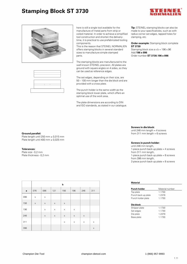
Stamping Block ST 3730
here is still a single tool available for the manufacture of metal parts from strip or coiled material. In order to achieve a simplified tool construction and shorten the delivery-time, it is practical to use prefabricated tooling components. This is the reason that STEINEL NORMALIENoffers stamping blocks in several standardsizes to manufacture simple stampedparts.
The stamping blocks are manufactured to thewell known STEINEL precision. All plates areground with square angles on 4 sides, so theycan be used as reference edges.
The set edges, depending on their size, are50 – 100 mm longer than the die block and areprovided with a cross plate.
The punch holder is the same width as thestamping block lower plate, which offers anoptimal use of the work area.
The plate dimensions are according to DIN and ISO standards, as stated in our catalogue.
Ground parallel:Plate length until 250 mm ± 0,015 mmPlate length until 400 mm ± 0,025 mm
Tolerances: Plate size - 0,2 mmPlate thickness - 0,2 mm
Screws in die block:until 246 mm length = 4 screwsfrom 311 mm length = 6 screws
Screws in punch holder:until 246 mm length, 1-piece punch back-up plate = 4 screwsfrom 311 mm length, 1-piece punch back-up plate = 8 screwsfrom 396 mm length, 2-piece punch back-up plate = 8 screws
Material
Punch holder Material numberTop plate 1.1730Punch back-up plate 1.2379Punch holder plate 1.1730
Die blockStripper plate 1.1730Set edges 1.1730Die plate 1.2379Base plate 1.1730
Tip: STEINEL-stamping blocks can also bemade to your specificatiobs, such as with radius corner set edges, tapped holes for clamping, etc.
b
a 076 096 121 156 196 246 311
096 x x
156 x x x x
196 x x x x
246 x x x x x
311 x x x x
396 x
Order example: Stamping block completeST 3730Stamping block size a x b = 196 x 96Add 196 x 096Order number ST 3730.196 x 096
Champion Die-Tool champion-dietool.com 1 (866) 957-9993
1.12
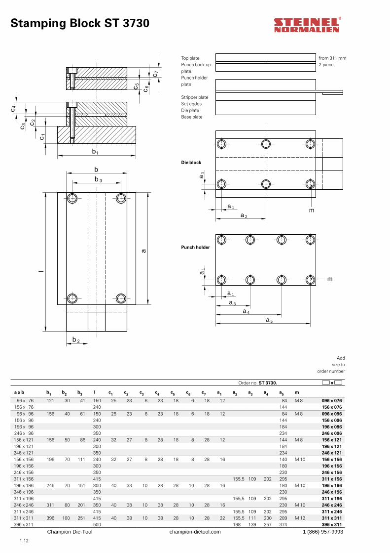
Stamping Block ST 3730
a 1
a1
a1
a 3
a 4
a 5
a 1
a 2
m
m
Top platePunch back-up platePunch holder plate
Stripper plateSet egdesDie plateBase plate
Die block
Punch holder
from 311 mm2-piece
Addsize to
order number
x Order no. ST 3730.
a x b b1 b2 b3 l c1 c2 c3 c4 c5 c6 c7 a1 a2 a3 a4 a5 m
96 x 76 121 30 41 150 25 23 6 23 18 6 18 12 84 M 8 096 x 076156 x 76 240 144 156 x 076 96 x 96 156 40 61 150 25 23 6 23 18 6 18 12 84 M 8 096 x 096
156 x 96 240 144 156 x 096196 x 96 300 184 196 x 096246 x 96 350 234 246 x 096156 x 121 156 50 86 240 32 27 8 28 18 8 28 12 144 M 8 156 x 121196 x 121 300 184 196 x 121246 x 121 350 234 246 x 121156 x 156 196 70 111 240 32 27 8 28 18 8 28 16 140 M 10 156 x 156196 x 156 300 180 196 x 156246 x 156 350 230 246 x 156311 x 156 415 155,5 109 202 295 311 x 156196 x 196 246 70 151 300 40 33 10 28 28 10 28 16 180 M 10 196 x 196246 x 196 350 230 246 x 196311 x 196 415 155,5 109 202 295 311 x 196246 x 246 311 80 201 350 40 38 10 38 28 10 28 16 230 M 10 246 x 246311 x 246 415 155,5 109 202 295 311 x 246311 x 311 396 100 251 415 40 38 10 38 28 10 28 22 155,5 111 200 289 M 12 311 x 311396 x 311 500 198 139 257 374 396 x 311
Champion Die-Tool champion-dietool.com 1 (866) 957-9993
1.13
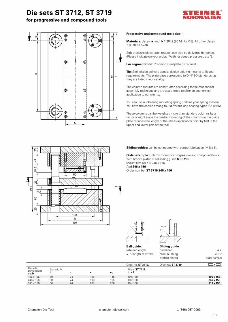
Outside Dimensionsa x b
Slot width b1 c e e1
Pillars ST 7117. d1 x l
196 x 156 60 24 148 145 19 x 180 196 x 156246 x 156 60 24 198 195 19 x 180 246 x 156311 x 156 60 24 263 260 19 x 180 311 x 156
Die sets ST 3712, ST 3719for progressive and compound tools
Progressive and compound tools size: 1
Materials: plates a and b 1.2842 (90 Mn Cr V 8). All other plates1.0570 (St 52-3).
Soft pressure plate: upon request can also be delivered hardened.(Please indicate on your order. “With hardened pressure plate”).
For segmentation: Precision steel plate on request.
Tip: Steinel also delivers special design column mounts to fit yourrequirements. The plate sizes correspond to DIN/ISO standards, as they are listed in our catalog.
The column mounts are constructed according to the mechanicalassembly technique and are guaranteed to offer an economicalapplication to our clients.
You can use our bearing mounting spring units as your spring system.You have the choice among four different load bearing types (SZ 8565).
These columns can be weighted more than standard columns by a factor of eight since the central mounting of the columns in the guide plate reduces the length of the stress application point by half in the upper and lower part of the tool.
Sliding guides: can be connected with central lubrication (M 8 x 1).
Order example: Column mount for progressive and compound tools with bronze plated steel sliding guide ST 3719.Mount size a x b = 246 x 156Add 246 x 156Order number ST 3719.246 x 156
Ball guide:retainer length= ½ length of stroke
Order no. ST 3712.
Sliding guide:hardenedsteel bushingbronze plated Order no. ST 3719.
Addsize to
order number
x
Champion Die-Tool champion-dietool.com 1 (866) 957-9993
1.14
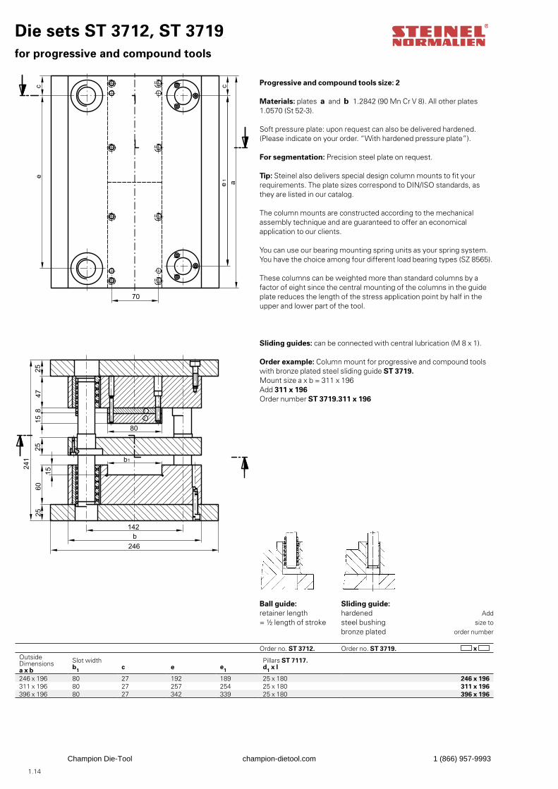
Die sets ST 3712, ST 3719for progressive and compound tools
Progressive and compound tools size: 2
Materials: plates a and b 1.2842 (90 Mn Cr V 8). All other plates1.0570 (St 52-3).
Soft pressure plate: upon request can also be delivered hardened.(Please indicate on your order. “With hardened pressure plate”).
For segmentation: Precision steel plate on request.
Tip: Steinel also delivers special design column mounts to fit yourrequirements. The plate sizes correspond to DIN/ISO standards, as they are listed in our catalog.
The column mounts are constructed according to the mechanicalassembly technique and are guaranteed to offer an economicalapplication to our clients.
You can use our bearing mounting spring units as your spring system.You have the choice among four different load bearing types (SZ 8565).
These columns can be weighted more than standard columns by a factor of eight since the central mounting of the columns in the guide plate reduces the length of the stress application point by half in the upper and lower part of the tool.
Sliding guides: can be connected with central lubrication (M 8 x 1).
Order example: Column mount for progressive and compound tools with bronze plated steel sliding guide ST 3719.Mount size a x b = 311 x 196Add 311 x 196Order number ST 3719.311 x 196
Ball guide:retainer length= ½ length of stroke
Order no. ST 3712.
Sliding guide:hardenedsteel bushingbronze plated Order no. ST 3719.
Addsize to
order number
x Outside Dimensionsa x b
Slot width b1 c e e1
Pillars ST 7117. d1 x l
246 x 196 80 27 192 189 25 x 180 246 x 196311 x 196 80 27 257 254 25 x 180 311 x 196396 x 196 80 27 342 339 25 x 180 396 x 196
Champion Die-Tool champion-dietool.com 1 (866) 957-9993
1.15
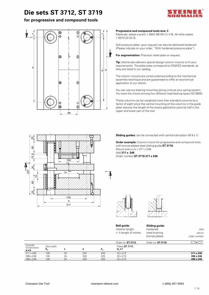
Die sets ST 3712, ST 3719for progressive and compound tools
Progressive and compound tools size: 3Materials: plates a and b 1.2842 (90 Mn Cr V 8). All other plates1.0570 (St 52-3).
Soft pressure plate: upon request can also be delivered hardened.(Please indicate on your order. “With hardened pressure plate”).
For segmentation: Precision steel plate on request.
Tip: Steinel also delivers special design column mounts to fit yourrequirements. The plate sizes correspond to DIN/ISO standards, as they are listed in our catalog.
The column mounts are constructed according to the mechanicalassembly technique and are guaranteed to offer an economicalapplication to our clients.
You can use our bearing mounting spring units as your spring system.You have the choice among four different load bearing types (SZ 8565).
These columns can be weighted more than standard columns by a factor of eight since the central mounting of the columns in the guide plate reduces the length of the stress application point by half in the upper and lower part of the tool.
Sliding guides: can be connected with central lubrication (M 8 x 1).
Order example: Column mount for progressive and compound tools with bronze plated steel sliding guide ST 3719.Mount size a x b = 311 x 246Add 311 x 246Order number ST 3719.311 x 246
Ball guide:retainer length= ½ length of stroke
Order no. ST 3712.
Sliding guide:hardened steel bushingbronze plated
Order no. ST 3719.
Addsize to
order number
x Outside Dimensionsa x b
Slot width b1 c e e1
Pillars ST 7117. d1 x l
311 x 246 100 34 243 240 32 x 210 311 x 246396 x 246 100 34 328 325 32 x 210 396 x 246496 x 246 100 34 428 425 32 x 210 496 x 246
Champion Die-Tool champion-dietool.com 1 (866) 957-9993
1.16
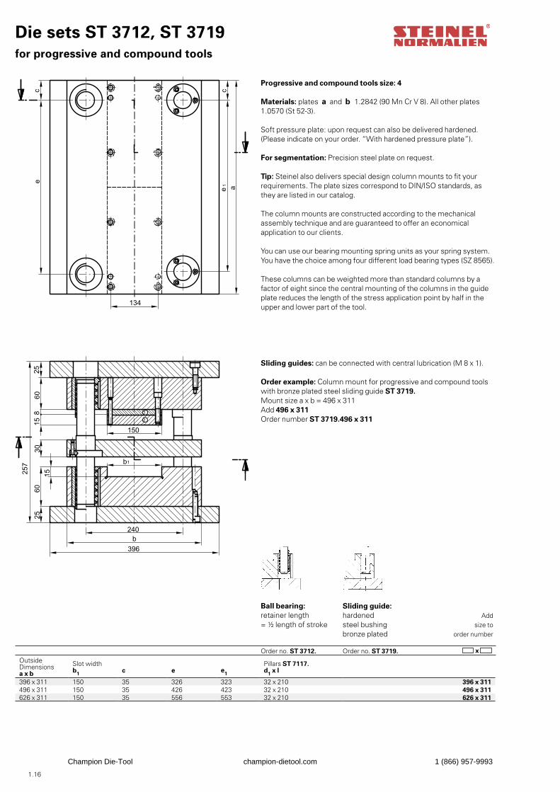
Die sets ST 3712, ST 3719for progressive and compound tools
Progressive and compound tools size: 4
Materials: plates a and b 1.2842 (90 Mn Cr V 8). All other plates1.0570 (St 52-3).
Soft pressure plate: upon request can also be delivered hardened.(Please indicate on your order. “With hardened pressure plate”).
For segmentation: Precision steel plate on request.
Tip: Steinel also delivers special design column mounts to fit yourrequirements. The plate sizes correspond to DIN/ISO standards, as they are listed in our catalog.
The column mounts are constructed according to the mechanicalassembly technique and are guaranteed to offer an economicalapplication to our clients.
You can use our bearing mounting spring units as your spring system.You have the choice among four different load bearing types (SZ 8565).
These columns can be weighted more than standard columns by a factor of eight since the central mounting of the columns in the guide plate reduces the length of the stress application point by half in the upper and lower part of the tool.
Sliding guides: can be connected with central lubrication (M 8 x 1).
Order example: Column mount for progressive and compound tools with bronze plated steel sliding guide ST 3719.Mount size a x b = 496 x 311Add 496 x 311Order number ST 3719.496 x 311
Ball bearing:retainer length= ½ length of stroke
Order no. ST 3712.
Sliding guide:hardenedsteel bushingbronze plated Order no. ST 3719.
Addsize to
order number
x Outside Dimensionsa x b
Slot width b1 c e e1
Pillars ST 7117. d1 x l
396 x 311 150 35 326 323 32 x 210 396 x 311496 x 311 150 35 426 423 32 x 210 496 x 311626 x 311 150 35 556 553 32 x 210 626 x 311
Champion Die-Tool champion-dietool.com 1 (866) 957-9993
1.17
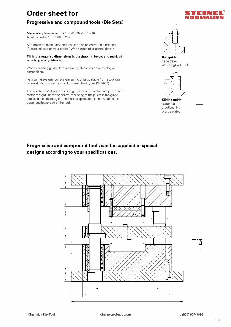
Order sheet forProgressive and compound tools (Die Sets)
Materials: plates a and b 1.2842 (90 Mn Cr V 8).All other plates 1.0570 (ST 52-3).
Soft pressure plate, upon request can also be delivered hardened.(Please indicate on your order: ”With hardened pressure plate“).
Fill in the required dimensions in the drawing below and mark offwhich type of guidance.
When choosing guide elements/units, please note the catalogue dimensions.
As a spring system, our system spring units available from stock can be used. There is a choice of 4 different load types (SZ 8565).
These columns/pillars can be weighted more than standard pillars by afactor of eight, since the central mounting of the pillars in the guide plate reduces the length of the stress application point by half in the upper and lower part of the tool.
Ball guide:Cage travel=1/2 length of stroke
Sliding guide:hardenedsteel bushingbronze plated
Progressive and compound tools can be supplied in specialdesigns according to your specifications.
Champion Die-Tool champion-dietool.com 1 (866) 957-9993
1.18
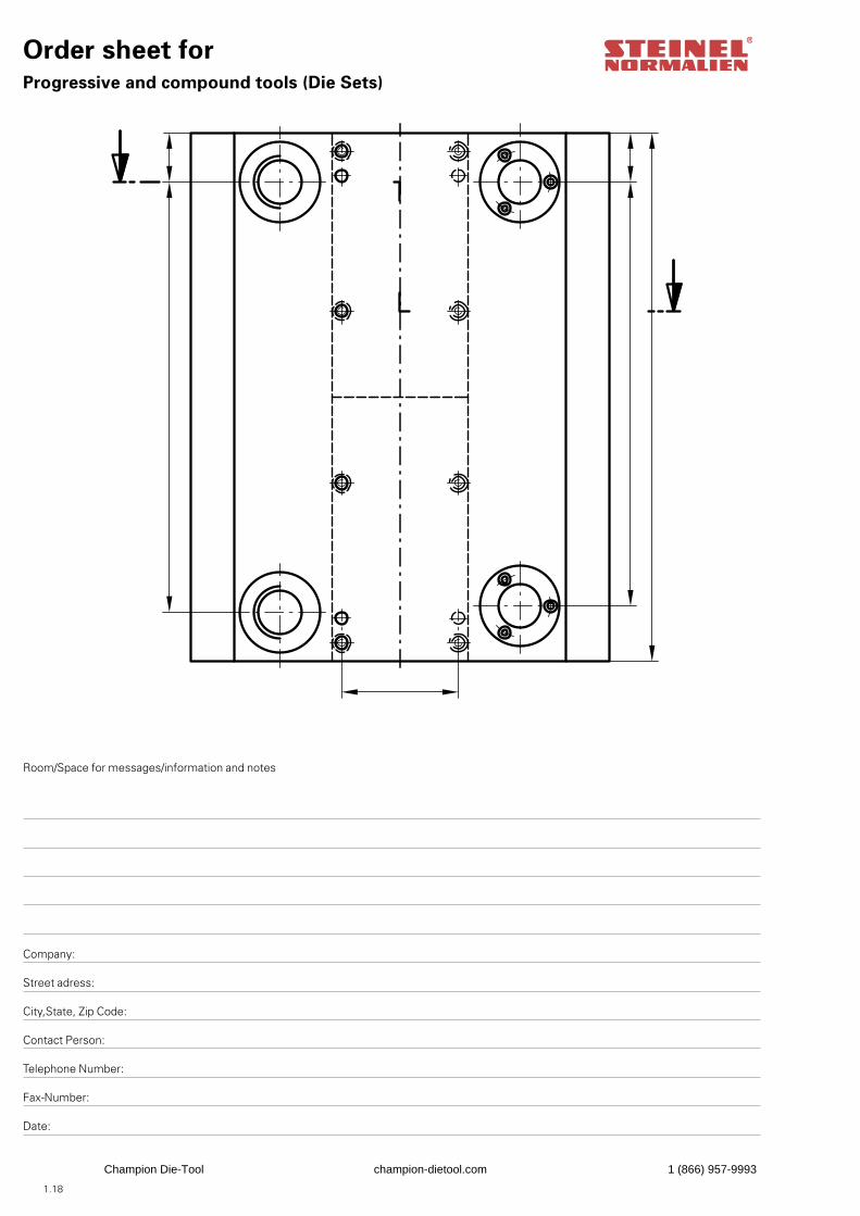
Order sheet forProgressive and compound tools (Die Sets)
Room/Space for messages/information and notes
Company:
Street adress:
City,State, Zip Code:
Contact Person:
Telephone Number:
Fax-Number:
Date:
Champion Die-Tool champion-dietool.com 1 (866) 957-9993
1.19
Order no. ST 3500.Order no. ST 3500.Order no. ST 3500.
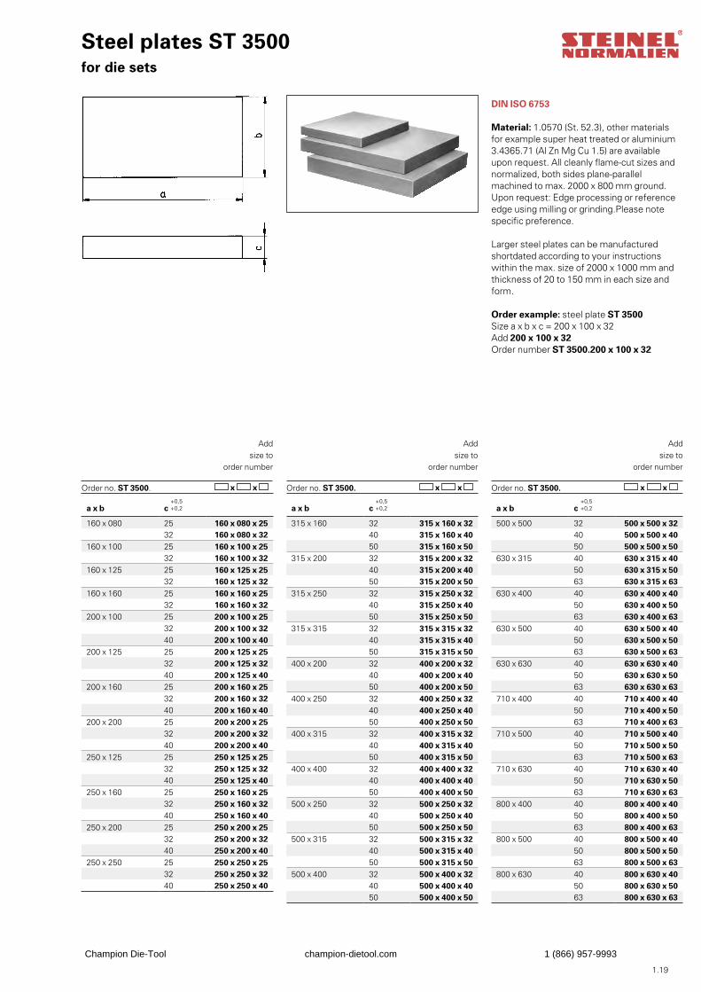
Steel plates ST 3500for die sets
DIN ISO 6753
Material: 1.0570 (St. 52.3), other materialsfor example super heat treated or aluminium3.4365.71 (Al Zn Mg Cu 1.5) are available upon request. All cleanly flame-cut sizes andnormalized, both sides plane-parallel machined to max. 2000 x 800 mm ground. Upon request: Edge processing or reference edge using milling or grinding.Please note specific preference.
Larger steel plates can be manufactured shortdated according to your instructions within the max. size of 2000 x 1000 mm and thickness of 20 to 150 mm in each size and form.
Order example: steel plate ST 3500Size a x b x c = 200 x 100 x 32Add 200 x 100 x 32Order number ST 3500.200 x 100 x 32
Addsize to
order number
x x x x x x
Addsize to
order number
Addsize to
order number
a x b c
160 x 080 25 160 x 080 x 2532 160 x 080 x 32
160 x 100 25 160 x 100 x 2532 160 x 100 x 32
160 x 125 25 160 x 125 x 2532 160 x 125 x 32
160 x 160 25 160 x 160 x 2532 160 x 160 x 32
200 x 100 25 200 x 100 x 2532 200 x 100 x 3240 200 x 100 x 40
200 x 125 25 200 x 125 x 2532 200 x 125 x 3240 200 x 125 x 40
200 x 160 25 200 x 160 x 2532 200 x 160 x 3240 200 x 160 x 40
200 x 200 25 200 x 200 x 2532 200 x 200 x 3240 200 x 200 x 40
250 x 125 25 250 x 125 x 2532 250 x 125 x 3240 250 x 125 x 40
250 x 160 25 250 x 160 x 2532 250 x 160 x 3240 250 x 160 x 40
250 x 200 25 250 x 200 x 2532 250 x 200 x 3240 250 x 200 x 40
250 x 250 25 250 x 250 x 2532 250 x 250 x 3240 250 x 250 x 40
a x b c
315 x 160 32 315 x 160 x 3240 315 x 160 x 4050 315 x 160 x 50
315 x 200 32 315 x 200 x 3240 315 x 200 x 4050 315 x 200 x 50
315 x 250 32 315 x 250 x 3240 315 x 250 x 4050 315 x 250 x 50
315 x 315 32 315 x 315 x 3240 315 x 315 x 4050 315 x 315 x 50
400 x 200 32 400 x 200 x 3240 400 x 200 x 4050 400 x 200 x 50
400 x 250 32 400 x 250 x 3240 400 x 250 x 4050 400 x 250 x 50
400 x 315 32 400 x 315 x 3240 400 x 315 x 4050 400 x 315 x 50
400 x 400 32 400 x 400 x 3240 400 x 400 x 4050 400 x 400 x 50
500 x 250 32 500 x 250 x 3240 500 x 250 x 4050 500 x 250 x 50
500 x 315 32 500 x 315 x 3240 500 x 315 x 4050 500 x 315 x 50
500 x 400 32 500 x 400 x 3240 500 x 400 x 4050 500 x 400 x 50
a x b c
500 x 500 32 500 x 500 x 3240 500 x 500 x 4050 500 x 500 x 50
630 x 315 40 630 x 315 x 4050 630 x 315 x 5063 630 x 315 x 63
630 x 400 40 630 x 400 x 4050 630 x 400 x 5063 630 x 400 x 63
630 x 500 40 630 x 500 x 4050 630 x 500 x 5063 630 x 500 x 63
630 x 630 40 630 x 630 x 4050 630 x 630 x 5063 630 x 630 x 63
710 x 400 40 710 x 400 x 4050 710 x 400 x 5063 710 x 400 x 63
710 x 500 40 710 x 500 x 4050 710 x 500 x 5063 710 x 500 x 63
710 x 630 40 710 x 630 x 4050 710 x 630 x 5063 710 x 630 x 63
800 x 400 40 800 x 400 x 4050 800 x 400 x 5063 800 x 400 x 63
800 x 500 40 800 x 500 x 4050 800 x 500 x 5063 800 x 500 x 63
800 x 630 40 800 x 630 x 4050 800 x 630 x 5063 800 x 630 x 63
Champion Die-Tool champion-dietool.com 1 (866) 957-9993
1.20
Order no. ST 3502.Order no. ST 3502.Order no ST 3502. x x x x x x
Addsize to
order number
Addsize to
order number
Addsize to
order number
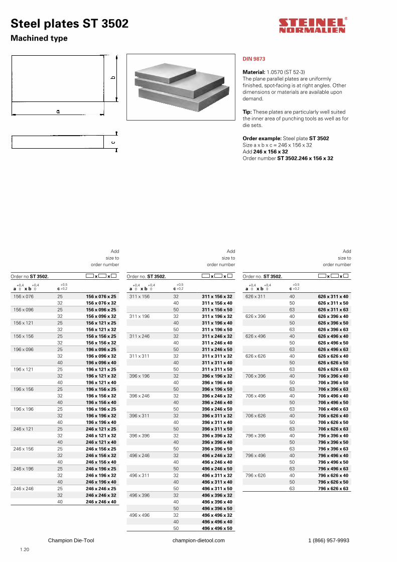
Steel plates ST 3502Machined type
DIN 9873
Material: 1.0570 (ST 52-3)The plane parallel plates are uniformly finished, spot-facing is at right angles. Other dimensions or materials are available upon demand.
Tip: These plates are particularly well suitedthe inner area of punching tools as well as fordie sets.
Order example: Steel plate ST 3502Size a x b x c = 246 x 156 x 32Add 246 x 156 x 32Order number ST 3502.246 x 156 x 32
a x b c
156 x 076 25 156 x 076 x 2532 156 x 076 x 32
156 x 096 25 156 x 096 x 2532 156 x 096 x 32
156 x 121 25 156 x 121 x 2532 156 x 121 x 32
156 x 156 25 156 x 156 x 2532 156 x 156 x 32
196 x 096 25 196 x 096 x 2532 196 x 096 x 3240 196 x 096 x 40
196 x 121 25 196 x 121 x 2532 196 x 121 x 3240 196 x 121 x 40
196 x 156 25 196 x 156 x 2532 196 x 156 x 3240 196 x 156 x 40
196 x 196 25 196 x 196 x 2532 196 x 196 x 3240 196 x 196 x 40
246 x 121 25 246 x 121 x 2532 246 x 121 x 3240 246 x 121 x 40
246 x 156 25 246 x 156 x 2532 246 x 156 x 3240 246 x 156 x 40
246 x 196 25 246 x 196 x 2532 246 x 196 x 3240 246 x 196 x 40
246 x 246 25 246 x 246 x 2532 246 x 246 x 3240 246 x 246 x 40
a x b c
311 x 156 32 311 x 156 x 3240 311 x 156 x 4050 311 x 156 x 50
311 x 196 32 311 x 196 x 3240 311 x 196 x 4050 311 x 196 x 50
311 x 246 32 311 x 246 x 3240 311 x 246 x 4050 311 x 246 x 50
311 x 311 32 311 x 311 x 3240 311 x 311 x 4050 311 x 311 x 50
396 x 196 32 396 x 196 x 3240 396 x 196 x 4050 396 x 196 x 50
396 x 246 32 396 x 246 x 3240 396 x 246 x 4050 396 x 246 x 50
396 x 311 32 396 x 311 x 3240 396 x 311 x 4050 396 x 311 x 50
396 x 396 32 396 x 396 x 3240 396 x 396 x 4050 396 x 396 x 50
496 x 246 32 496 x 246 x 3240 496 x 246 x 4050 496 x 246 x 50
496 x 311 32 496 x 311 x 3240 496 x 311 x 4050 496 x 311 x 50
496 x 396 32 496 x 396 x 3240 496 x 396 x 4050 496 x 396 x 50
496 x 496 32 496 x 496 x 3240 496 x 496 x 4050 496 x 496 x 50
a x b c
626 x 311 40 626 x 311 x 4050 626 x 311 x 5063 626 x 311 x 63
626 x 396 40 626 x 396 x 4050 626 x 396 x 5063 626 x 396 x 63
626 x 496 40 626 x 496 x 4050 626 x 496 x 5063 626 x 496 x 63
626 x 626 40 626 x 626 x 4050 626 x 626 x 5063 626 x 626 x 63
706 x 396 40 706 x 396 x 4050 706 x 396 x 5063 706 x 396 x 63
706 x 496 40 706 x 496 x 4050 706 x 496 x 5063 706 x 496 x 63
706 x 626 40 706 x 626 x 4050 706 x 626 x 5063 706 x 626 x 63
796 x 396 40 796 x 396 x 4050 796 x 396 x 5063 796 x 396 x 63
796 x 496 40 796 x 496 x 4050 796 x 496 x 5063 796 x 496 x 63
796 x 626 40 796 x 626 x 4050 796 x 626 x 5063 796 x 626 x 63
Champion Die-Tool champion-dietool.com 1 (866) 957-9993
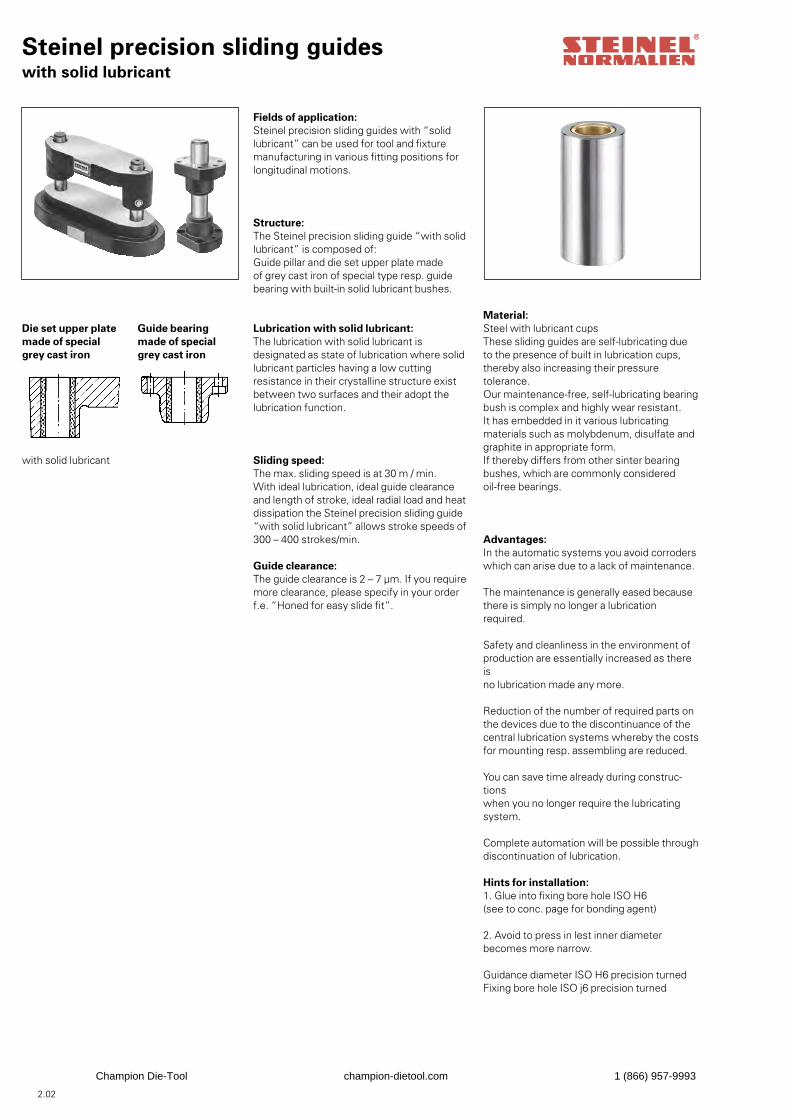
Steinel precision sliding guideswith solid lubricant
Fields of application:Steinel precision sliding guides with “solidlubricant” can be used for tool and fixturemanufacturing in various fitting positions forlongitudinal motions.
Structure:The Steinel precision sliding guide “with solidlubricant” is composed of:Guide pillar and die set upper plate madeof grey cast iron of special type resp. guidebearing with built-in solid lubricant bushes.
Lubrication with solid lubricant:The lubrication with solid lubricant is designated as state of lubrication where solid lubricant particles having a low cutting resistance in their crystalline structure exist between two surfaces and their adopt the lubrication function.
Sliding speed:The max. sliding speed is at 30 m / min.With ideal lubrication, ideal guide clearance and length of stroke, ideal radial load and heatdissipation the Steinel precision sliding guide“with solid lubricant” allows stroke speeds of300 – 400 strokes/min.
Guide clearance:The guide clearance is 2 – 7 μm. If you requiremore clearance, please specify in your order f.e. “Honed for easy slide fit”.
Die set upper platemade of specialgrey cast iron
Guide bearingmade of specialgrey cast iron
with solid lubricant
Material:Steel with lubricant cupsThese sliding guides are self-lubricating dueto the presence of built in lubrication cups,thereby also increasing their pressuretolerance.Our maintenance-free, self-lubricating bearingbush is complex and highly wear resistant.It has embedded in it various lubricatingmaterials such as molybdenum, disulfate andgraphite in appropriate form.If thereby differs from other sinter bearingbushes, which are commonly consideredoil-free bearings.
Advantages:In the automatic systems you avoid corroderswhich can arise due to a lack of maintenance.
The maintenance is generally eased becausethere is simply no longer a lubrication required.
Safety and cleanliness in the environment ofproduction are essentially increased as there isno lubrication made any more.
Reduction of the number of required parts onthe devices due to the discontinuance of thecentral lubrication systems whereby the costsfor mounting resp. assembling are reduced.
You can save time already during construc-tionswhen you no longer require the lubricatingsystem.
Complete automation will be possible through discontinuation of lubrication.
Hints for installation:1. Glue into fixing bore hole ISO H6(see to conc. page for bonding agent)
2. Avoid to press in lest inner diameterbecomes more narrow.
Guidance diameter ISO H6 precision turnedFixing bore hole ISO j6 precision turned
2.02
Champion Die-Tool champion-dietool.com 1 (866) 957-9993
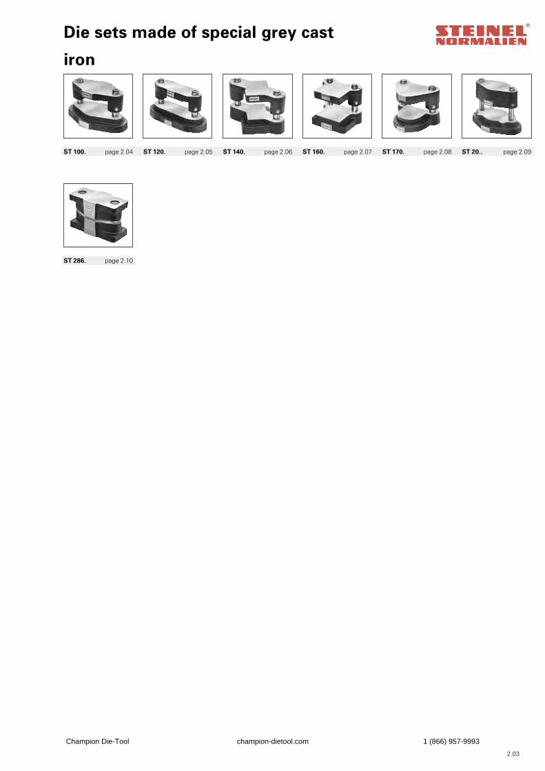
Die sets made of special grey cast
iron
ST 100. page 2.04 ST 120. page 2.05 ST 140. page 2.06 ST 160. page 2.07 ST 170. page 2.08 ST 20.. page 2.09
ST 286. page 2.10
2.03
Champion Die-Tool champion-dietool.com 1 (866) 957-9993
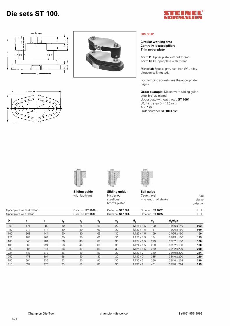
Die sets ST 100.
DIN 9812
Circular working areaCentrally located pillarsThin upper plate
Form D: Upper plate without threadForm DG: Upper plate with thread
Material: Special grey cast iron GGL alloyultrasonically tested.
For clamping sockets see the appropriatepages.
Order example: Die set with sliding guide,steel bronze plated.Upper plate without thread ST 1001Working area D = 125 mmAdd 125Order number ST 1001.125
Upper plate without threadUpper plate with thread
Sliding guidewith lubricant
Order no. ST 1006. Order no. ST 1007.
Sliding guideHardenedsteel bushbronze plated
Order no. ST 1001. Order no. ST 1004.
Ball guideCage travel= ½ length of stroke
Order no. ST 1002. Order no. ST 1005.
Addsize to
order no.
D a b c1 c2 c3 c4 d3 e1 d1/d2 x l
63 171 92 40 25 50 20 M 16 x 1,5 100 15/16 x 140 06380 217 114 50 30 63 30 M 20 x 1,5 131 19/20 x 160 080
100 263 144 50 30 63 30 M 20 x 1,5 159 24/25 x 160 100125 288 169 50 30 63 30 M 20 x 1,5 184 24/25 x 160 125160 345 204 56 40 80 30 M 24 x 1,5 229 30/32 x 180 160180 366 224 56 40 80 30 M 24 x 1,5 250 30/32 x 180 180200 385 244 56 40 80 30 M 24 x 1,5 269 30/32 x 200 200224 448 278 56 50 80 30 M 30 x 2 310 38/40 x 200 224250 473 304 56 50 80 30 M 30 x 2 335 38/40 x 200 250280 504 335 63 50 80 30 M 30 x 2 366 38/40 x 224 280315 539 370 63 50 80 30 M 30 x 2 401 38/40 x 224 315
2.04
Champion Die-Tool champion-dietool.com 1 (866) 957-9993
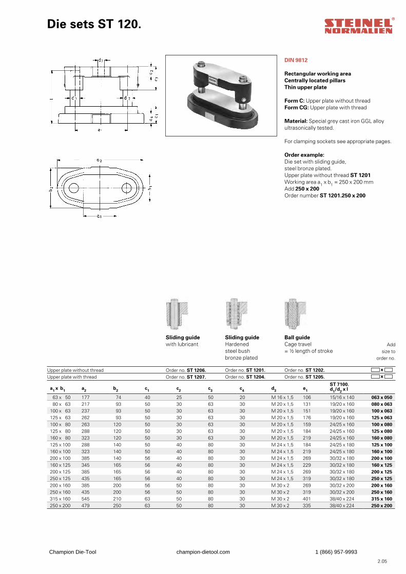
Die sets ST 120.
DIN 9812
Rectangular working areaCentrally located pillarsThin upper plate
Form C: Upper plate without threadForm CG: Upper plate with thread
Material: Special grey cast iron GGL alloyultrasonically tested.
For clamping sockets see appropriate pages.
Order example: Die set with sliding guide,steel bronze plated.Upper plate without thread ST 1201Working area a1 x b1 = 250 x 200 mmAdd 250 x 200Order number ST 1201.250 x 200
Upper plate without threadUpper plate with thread
Sliding guidewith lubricant
Order no. ST 1206. Order no. ST 1207.
Sliding guideHardenedsteel bushbronze plated Order no. ST 1201. Order no. ST 1204.
Ball guideCage travel= ½ length of stroke
Order no. ST 1202. Order no. ST 1205.
Addsize to
order no.
x x
a1 x b1 a2 b2 c1 c2 c3 c4 d3 e1
ST 7100. d1/d2 x l
63 x 50 177 74 40 25 50 20 M 16 x 1,5 106 15/16 x 140 063 x 05080 x 63 217 93 50 30 63 30 M 20 x 1,5 131 19/20 x 160 080 x 063
100 x 63 237 93 50 30 63 30 M 20 x 1,5 151 19/20 x 160 100 x 063125 x 63 262 93 50 30 63 30 M 20 x 1,5 176 19/20 x 160 125 x 063100 x 80 263 120 50 30 63 30 M 20 x 1,5 159 24/25 x 160 100 x 080125 x 80 288 120 50 30 63 30 M 20 x 1,5 184 24/25 x 160 125 x 080160 x 80 323 120 50 30 63 30 M 20 x 1,5 219 24/25 x 160 160 x 080125 x 100 288 140 50 40 80 30 M 24 x 1,5 184 24/25 x 180 125 x 100160 x 100 323 140 50 40 80 30 M 24 x 1,5 219 24/25 x 180 160 x 100200 x 100 385 140 56 40 80 30 M 24 x 1,5 269 30/32 x 180 200 x 100160 x 125 345 165 56 40 80 30 M 24 x 1,5 229 30/32 x 180 160 x 125200 x 125 385 165 56 40 80 30 M 24 x 1,5 269 30/32 x 180 200 x 125250 x 125 435 165 56 40 80 30 M 24 x 1,5 319 30/32 x 180 250 x 125200 x 160 385 200 56 50 80 30 M 30 x 2 269 30/32 x 200 200 x 160250 x 160 435 200 56 50 80 30 M 30 x 2 319 30/32 x 200 250 x 160315 x 160 545 210 63 50 80 30 M 30 x 2 401 38/40 x 224 315 x 160250 x 200 479 250 63 50 80 30 M 30 x 2 335 38/40 x 224 250 x 200
2.05
Champion Die-Tool champion-dietool.com 1 (866) 957-9993
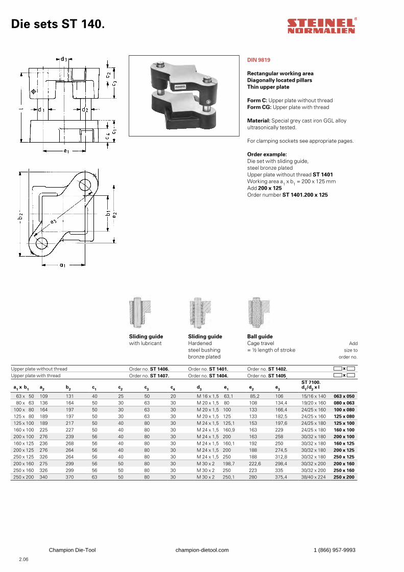
Die sets ST 140.
DIN 9819
Rectangular working areaDiagonally located pillarsThin upper plate
Form C: Upper plate without threadForm CG: Upper plate with thread
Material: Special grey cast iron GGL alloyultrasonically tested.
For clamping sockets see appropriate pages.
Order example: Die set with sliding guide,steel bronze platedUpper plate without thread ST 1401Working area a1 x b1 = 200 x 125 mmAdd 200 x 125Order number ST 1401.200 x 125
Upper plate without threadUpper plate with thread
Sliding guidewith lubricant
Order no. ST 1406. Order no. ST 1407.
Sliding guideHardenedsteel bushingbronze plated
Order no. ST 1401. Order no. ST 1404.
Ball guideCage travel= ½ length of stroke
Order no. ST 1402. Order no. ST 1405.
Addsize to
order no.
x x
a1 x b1 a2 b2 c1 c2 c3 c4 d3 e1 e2 e3
ST 7100. d1/d2 x l
63 x 50 109 131 40 25 50 20 M 16 x 1,5 63,1 85,2 106 15/16 x 140 063 x 05080 x 63 136 164 50 30 63 30 M 20 x 1,5 80 108 134,4 19/20 x 160 080 x 063
100 x 80 164 197 50 30 63 30 M 20 x 1,5 100 133 166,4 24/25 x 160 100 x 080125 x 80 189 197 50 30 63 30 M 20 x 1,5 125 133 182,5 24/25 x 160 125 x 080125 x 100 189 217 50 40 80 30 M 24 x 1,5 125,1 153 197,6 24/25 x 180 125 x 100160 x 100 225 227 50 40 80 30 M 24 x 1,5 160,9 163 229 24/25 x 180 160 x 100200 x 100 276 239 56 40 80 30 M 24 x 1,5 200 163 258 30/32 x 180 200 x 100160 x 125 236 268 56 40 80 30 M 24 x 1,5 160,1 192 250 30/32 x 180 160 x 125200 x 125 276 264 56 40 80 30 M 24 x 1,5 200 188 274,5 30/32 x 180 200 x 125250 x 125 326 264 56 40 80 30 M 24 x 1,5 250 188 312,8 30/32 x 180 250 x 125200 x 160 275 299 56 50 80 30 M 30 x 2 198,7 222,6 298,4 30/32 x 200 200 x 160250 x 160 326 299 56 50 80 30 M 30 x 2 250 223 335 30/32 x 200 250 x 160250 x 200 340 370 63 50 80 30 M 30 x 2 250,1 280 375,4 38/40 x 224 250 x 200
2.06
Champion Die-Tool champion-dietool.com 1 (866) 957-9993
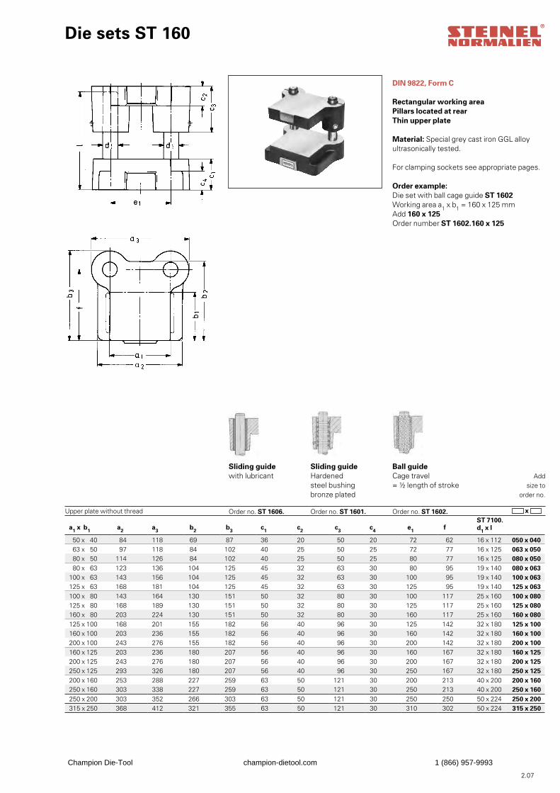
Die sets ST 160
DIN 9822, Form C
Rectangular working areaPillars located at rearThin upper plate
Material: Special grey cast iron GGL alloyultrasonically tested.
For clamping sockets see appropriate pages.
Order example: Die set with ball cage guide ST 1602Working area a1 x b1 = 160 x 125 mmAdd 160 x 125Order number ST 1602.160 x 125
Upper plate without thread
Sliding guidewith lubricant
Order no. ST 1606.
Sliding guideHardenedsteel bushingbronze plated
Order no. ST 1601.
Ball guideCage travel= ½ length of stroke
Order no. ST 1602.
Addsize to
order no.
x
a1 x b1 a2 a3 b2 b3 c1 c2 c3 c4 e1 fST 7100. d1 x l
50 x 40 84 118 69 87 36 20 50 20 72 62 16 x 112 050 x 04063 x 50 97 118 84 102 40 25 50 25 72 77 16 x 125 063 x 05080 x 50 114 126 84 102 40 25 50 25 80 77 16 x 125 080 x 05080 x 63 123 136 104 125 45 32 63 30 80 95 19 x 140 080 x 063
100 x 63 143 156 104 125 45 32 63 30 100 95 19 x 140 100 x 063125 x 63 168 181 104 125 45 32 63 30 125 95 19 x 140 125 x 063100 x 80 143 164 130 151 50 32 80 30 100 117 25 x 160 100 x 080125 x 80 168 189 130 151 50 32 80 30 125 117 25 x 160 125 x 080160 x 80 203 224 130 151 50 32 80 30 160 117 25 x 160 160 x 080125 x 100 168 201 155 182 56 40 96 30 125 142 32 x 180 125 x 100160 x 100 203 236 155 182 56 40 96 30 160 142 32 x 180 160 x 100200 x 100 243 276 155 182 56 40 96 30 200 142 32 x 180 200 x 100160 x 125 203 236 180 207 56 40 96 30 160 167 32 x 180 160 x 125200 x 125 243 276 180 207 56 40 96 30 200 167 32 x 180 200 x 125250 x 125 293 326 180 207 56 40 96 30 250 167 32 x 180 250 x 125200 x 160 253 288 227 259 63 50 121 30 200 213 40 x 200 200 x 160250 x 160 303 338 227 259 63 50 121 30 250 213 40 x 200 250 x 160250 x 200 303 352 266 303 63 50 121 30 250 250 50 x 224 250 x 200315 x 250 368 412 321 355 63 50 121 30 310 302 50 x 224 315 x 250
2.07
Champion Die-Tool champion-dietool.com 1 (866) 957-9993
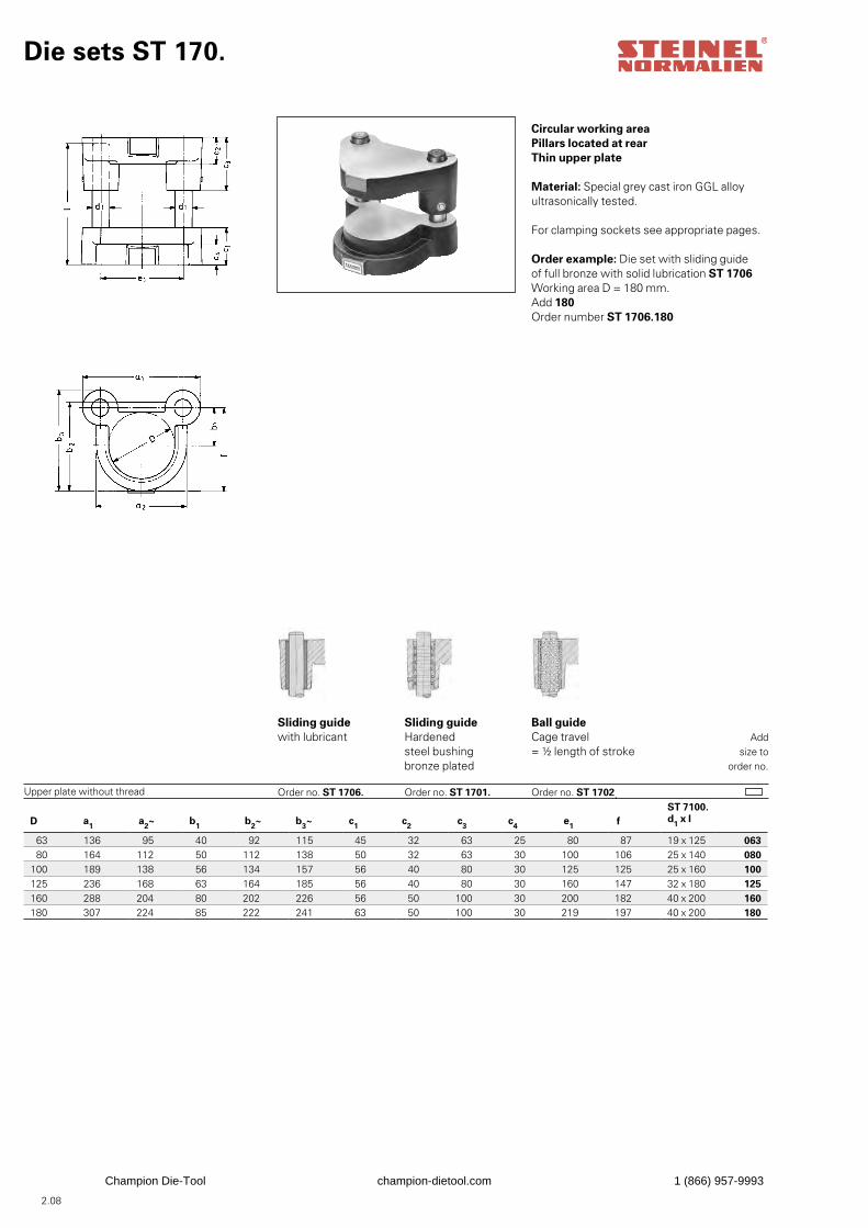
D a1 a2~ b1
b2~ b3~ c1 c2 c3 c4
e1 f
ST 7100. d1 x l
63 136 95 40 92 115 45 32 63 25 80 87 19 x 125 06380 164 112 50 112 138 50 32 63 30 100 106 25 x 140 080
100 189 138 56 134 157 56 40 80 30 125 125 25 x 160 100125 236 168 63 164 185 56 40 80 30 160 147 32 x 180 125160 288 204 80 202 226 56 50 100 30 200 182 40 x 200 160180 307 224 85 222 241 63 50 100 30 219 197 40 x 200 180
Die sets ST 170.
Circular working areaPillars located at rearThin upper plate
Material: Special grey cast iron GGL alloyultrasonically tested.
For clamping sockets see appropriate pages.
Order example: Die set with sliding guideof full bronze with solid lubrication ST 1706Working area D = 180 mm.Add 180Order number ST 1706.180
Upper plate without thread
Sliding guidewith lubricant
Order no. ST 1706.
Sliding guideHardenedsteel bushingbronze plated
Order no. ST 1701.
Ball guideCage travel= ½ length of stroke
Order no. ST 1702.
Addsize to
order no.
2.08
Champion Die-Tool champion-dietool.com 1 (866) 957-9993
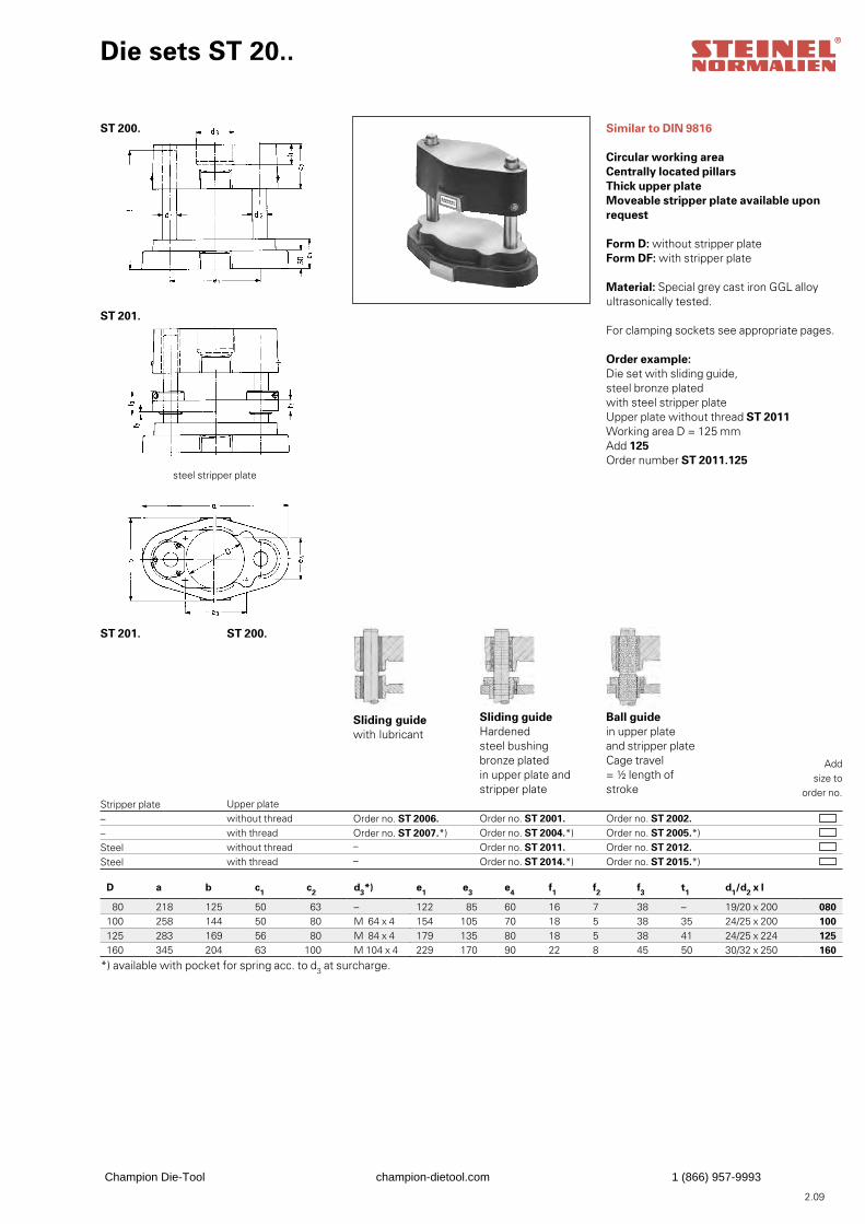
Die sets ST 20..
Similar to DIN 9816
Circular working areaCentrally located pillarsThick upper plateMoveable stripper plate available upon request
Form D: without stripper plateForm DF: with stripper plate
Material: Special grey cast iron GGL alloyultrasonically tested.
For clamping sockets see appropriate pages.
Order example: Die set with sliding guide,steel bronze platedwith steel stripper plateUpper plate without thread ST 2011Working area D = 125 mmAdd 125Order number ST 2011.125
Stripper plate –– Steel Steel
Sliding guidewith lubricant
Order no. ST 2006.
Order no. ST 2007.*) ––
Sliding guideHardenedsteel bushingbronze platedin upper plate andstripper plate Order no. ST 2001. Order no. ST 2004.*) Order no. ST 2011. Order no. ST 2014.*)
Ball guidein upper plateand stripper plateCage travel= ½ length ofstroke Order no. ST 2002. Order no. ST 2005.*) Order no. ST 2012. Order no. ST 2015.*)
Addsize to
order no.
ST 200.
ST 201.
steel stripper plate
ST 201. ST 200.
Upper platewithout threadwith threadwithout threadwith thread
D a b c1 c2 d3*) e1 e3 e4 f1 f2 f3 t1 d1/d2 x l
80 218 125 50 63 – 122 85 60 16 7 38 – 19/20 x 200 080100 258 144 50 80 M 64 x 4 154 105 70 18 5 38 35 24/25 x 200 100125 283 169 56 80 M 84 x 4 179 135 80 18 5 38 41 24/25 x 224 125160 345 204 63 100 M 104 x 4 229 170 90 22 8 45 50 30/32 x 250 160
2.09
*) available with pocket for spring acc. to d3 at surcharge.
Champion Die-Tool champion-dietool.com 1 (866) 957-9993
2.10
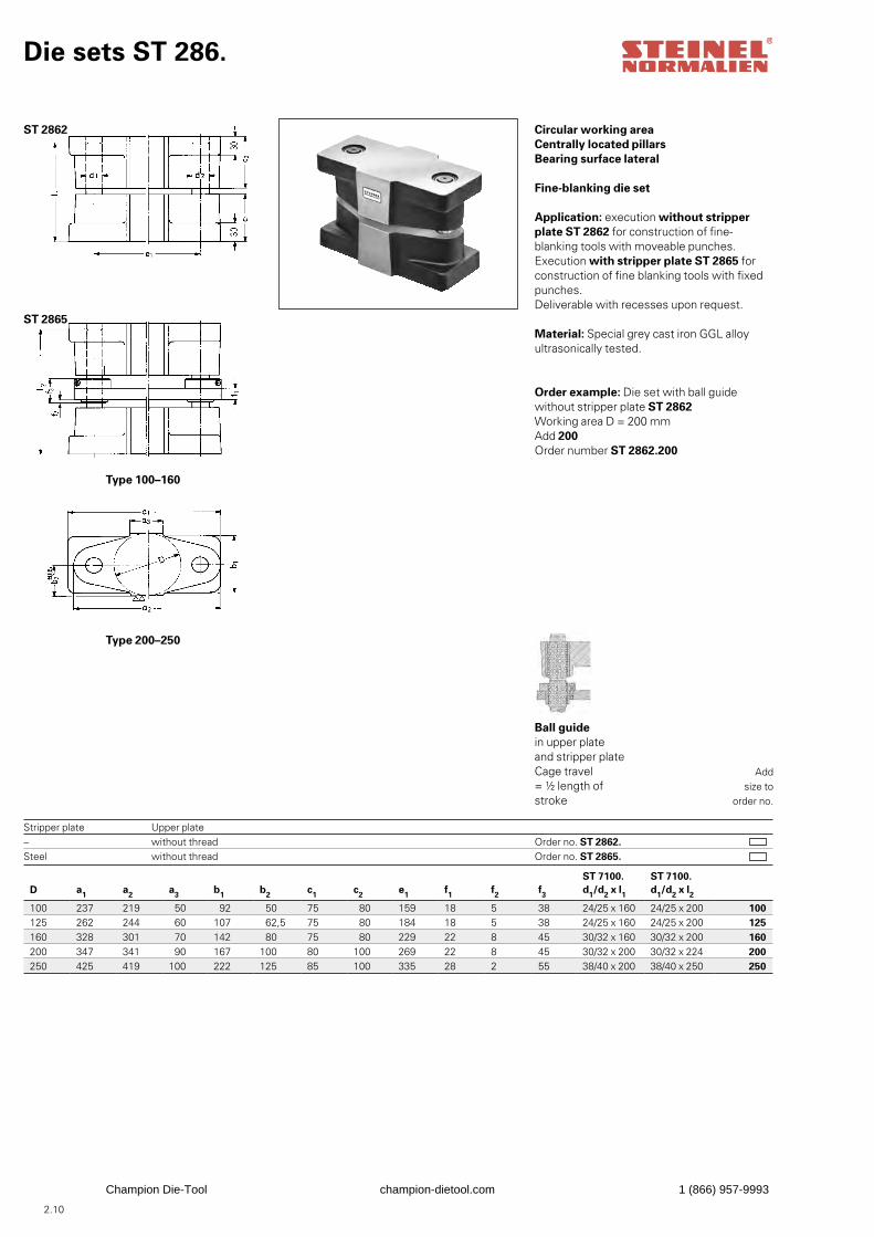
Die sets ST 286.
Circular working areaCentrally located pillarsBearing surface lateral
Fine-blanking die set
Application: execution without stripper plate ST 2862 for construction of fine-blanking tools with moveable punches.Execution with stripper plate ST 2865 forconstruction of fine blanking tools with fixedpunches. Deliverable with recesses upon request.
Material: Special grey cast iron GGL alloyultrasonically tested.
Order example: Die set with ball guidewithout stripper plate ST 2862Working area D = 200 mmAdd 200Order number ST 2862.200
Stripper plate –Steel
Ball guidein upper plateand stripper plateCage travel= ½ length ofstroke
Order no. ST 2862. Order no. ST 2865.
Addsize to
order no.
ST 2862
ST 2865
Type 100–160
Type 200–250
Upper platewithout threadwithout thread
D a1 a2 a3 b1 b2 c1 c2 e1 f1 f2 f3
ST 7100. d1/d2 x l1
ST 7100. d1/d2 x l2
100 237 219 50 92 50 75 80 159 18 5 38 24/25 x 160 24/25 x 200 100125 262 244 60 107 62,5 75 80 184 18 5 38 24/25 x 160 24/25 x 200 125160 328 301 70 142 80 75 80 229 22 8 45 30/32 x 160 30/32 x 200 160200 347 341 90 167 100 80 100 269 22 8 45 30/32 x 200 30/32 x 224 200250 425 419 100 222 125 85 100 335 28 2 55 38/40 x 200 38/40 x 250 250
Champion Die-Tool champion-dietool.com 1 (866) 957-9993
2.11
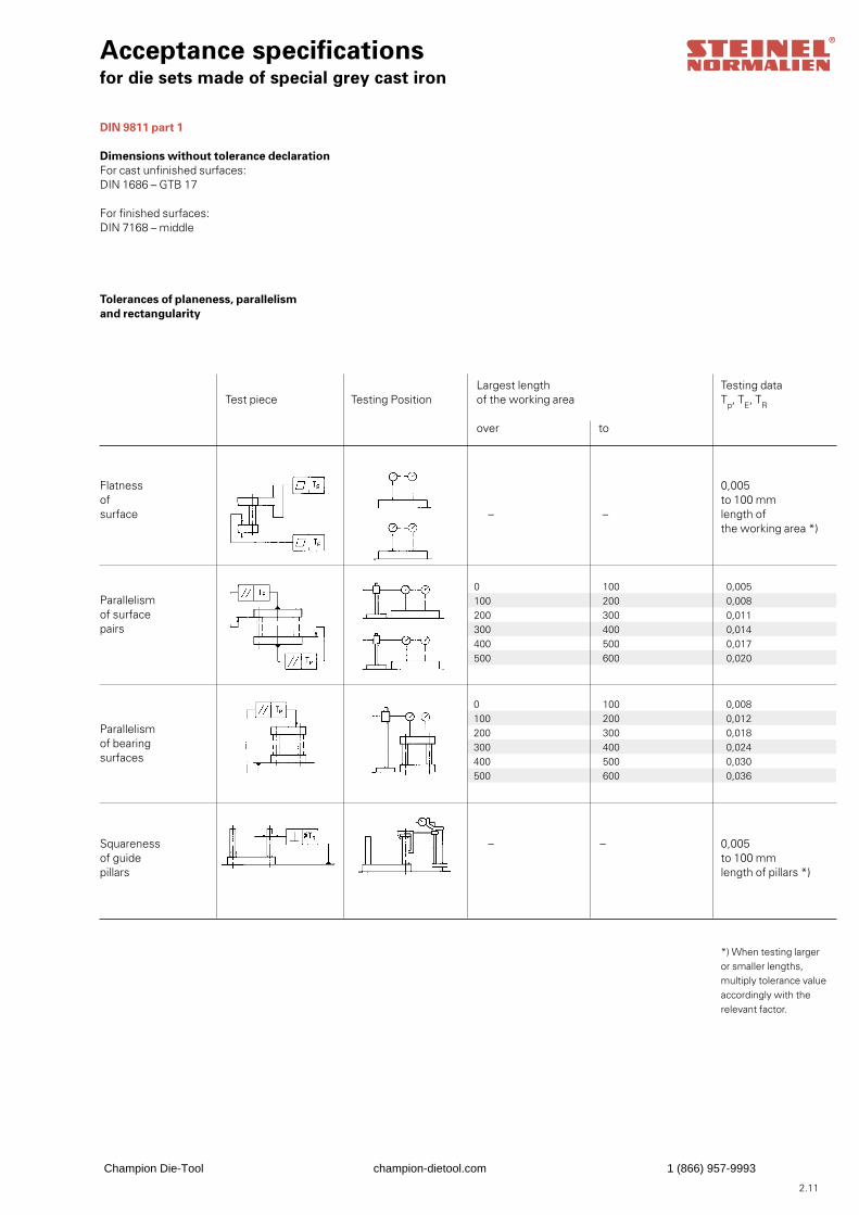
0 100 0,008100 200 0,012200 300 0,018300 400 0,024400 500 0,030500 600 0,036
0 100 0,005100 200 0,008200 300 0,011300 400 0,014400 500 0,017500 600 0,020
Acceptance specificationsfor die sets made of special grey cast iron
DIN 9811 part 1
Dimensions without tolerance declarationFor cast unfinished surfaces:DIN 1686 – GTB 17
For finished surfaces:DIN 7168 – middle
Tolerances of planeness, parallelismand rectangularity
Flatnessofsurface
Test pieceLargest length of the working area
over to
– –
– –
Testing PositionTesting dataTp, TE, TR
Parallelismof surfacepairs
Parallelismof bearingsurfaces
Squarenessof guidepillars
0,005to 100 mmlength ofthe working area *)
0,005to 100 mmlength of pillars *)
*) When testing larger or smaller lengths, multiply tolerance value accordingly with the relevant factor.
Champion Die-Tool champion-dietool.com 1 (866) 957-9993
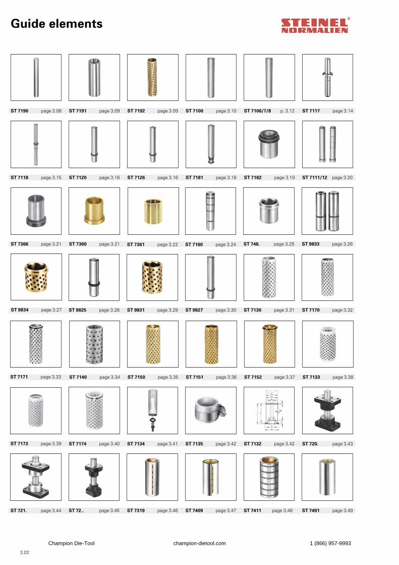
Guide elements
ST 72.. page 3.45 ST 7319 page 3.46 ST 7409 page 3.47 ST 7411 page 3.48 ST 7491 page 3.49
k
l
d 1
d 2
d 4
l1
d 5
d 3
2
15°
ST 7174 page 3.40 ST 7134 page 3.41 ST 7135 page 3.42 ST 7132 page 3.42 ST 720. page 3.43
ST 721. page 3.44
ST 7140 page 3.34 ST 7150 page 3.35 ST 7151 page 3.36 ST 7152 page 3.37 ST 7133 page 3.38
ST 7173 page 3.39
ST 9825 page 3.28 ST 9831 page 3.29 ST 9827 page 3.30 ST 7130 page 3.31 ST 7170 page 3.32
ST 7171 page 3.33
ST 7366 page 3.21 ST 7360 page 3.21 ST 7160 page 3.24 ST 746. page 3.25 ST 9833 page 3.26
ST 9834 page 3.27
ST 7118 page 3.15 ST 7120 page 3.16 ST 7126 page 3.16 ST 7181 page 3.18 ST 7182 page 3.19 ST 7111/12 page 3.20
ST 7190 page 3.08 ST 7191 page 3.09 ST 7192 page 3.09 ST 7100 page 3.10 ST 7106/7/8 p. 3.12 ST 7117 page 3.14
3.02
ST 7361 page 3.22
Champion Die-Tool champion-dietool.com 1 (866) 957-9993
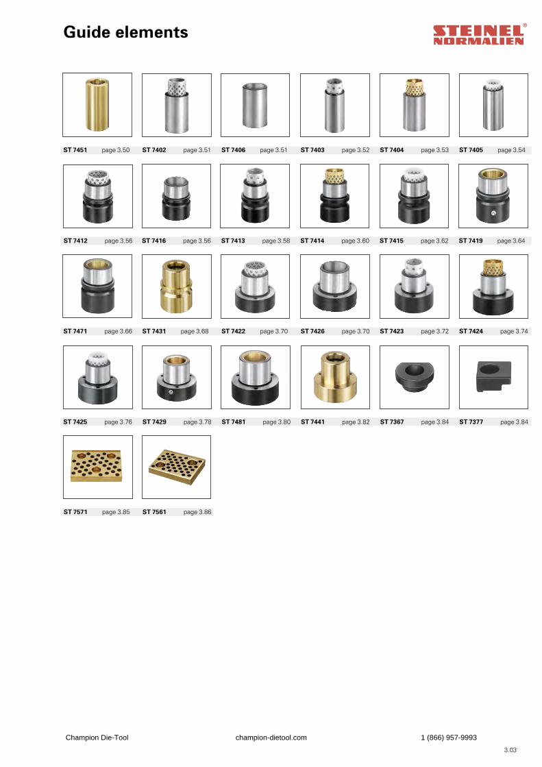
Guide elements
ST 7561 page 3.86
ST 7429 page 3.78 ST 7481 page 3.80 ST 7441 page 3.82 ST 7367 page 3.84 ST 7377 page 3.84
ST 7431 page 3.68 ST 7422 page 3.70 ST 7426 page 3.70 ST 7423 page 3.72 ST 7424 page 3.74
ST 7416 page 3.56 ST 7413 page 3.58 ST 7414 page 3.60 ST 7415 page 3.62 ST 7419 page 3.64
ST 7402 page 3.51 ST 7406 page 3.51 ST 7403 page 3.52 ST 7404 page 3.53 ST 7405 page 3.54
3.03
ST 7571 page 3.85
ST 7425 page 3.76
ST 7471 page 3.66
ST 7412 page 3.56
ST 7451 page 3.50
Champion Die-Tool champion-dietool.com 1 (866) 957-9993
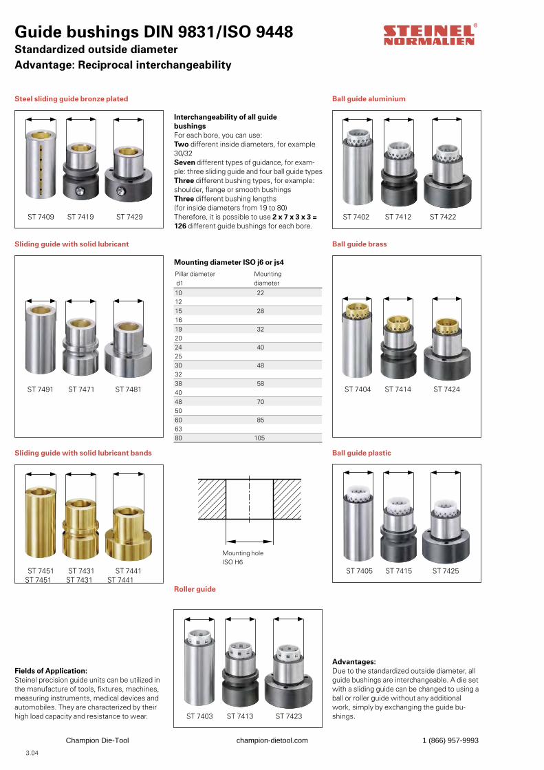
Steel sliding guide bronze plated
Sliding guide with solid lubricant
Sliding guide with solid lubricant bands
Fields of Application:Steinel precision guide units can be utilized inthe manufacture of tools, fixtures, machines,measuring instruments, medical devices and automobiles. They are characterized by their high load capacity and resistance to wear.
Interchangeability of all guidebushingsFor each bore, you can use:Two different inside diameters, for example30/32Seven different types of guidance, for exam-ple: three sliding guide and four ball guide typesThree different bushing types, for example:shoulder, flange or smooth bushingsThree different bushing lengths(for inside diameters from 19 to 80)Therefore, it is possible to use 2 x 7 x 3 x 3 =126 different guide bushings for each bore.
Mounting diameter ISO j6 or js4
Roller guide
Ball guide aluminium
Ball guide brass
Ball guide plastic
Advantages:Due to the standardized outside diameter, allguide bushings are interchangeable. A die setwith a sliding guide can be changed to using aball or roller guide without any additional work, simply by exchanging the guide bu-shings.
Guide bushings DIN 9831/ISO 9448Standardized outside diameterAdvantage: Reciprocal interchangeability
ST 7409 ST 7419 ST 7429
ST 7491 ST 7471 ST 7481
ST 7451 ST 7431 ST 7441
ST 7404 ST 7414 ST 7424
ST 7405 ST 7415 ST 7425
Mounting holeISO H6
ST 7402 ST 7412 ST 7422
Pillar diameter d1
Mountingdiameter
10 221215 281619 322024 402530 483238 584048 705060 856380 105
ST 7403 ST 7413 ST 7423
3.04
ST 7451 ST 7431 ST 7441
Champion Die-Tool champion-dietool.com 1 (866) 957-9993
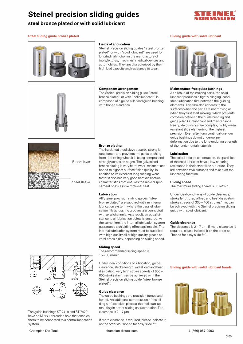
Sliding guide with solid lubricant
Maintenance-free guide bushingsAs a result of the moving parts, the solid lubricant produces a tightly clinging, consi-stent lubrication film between the guiding elements. This film also adheres to the surfaces when the parts are not moving or when they first start moving, which prevents corrosion between the guide bushing and guide pillar. Our lubricant and maintenance free guide bushings are complex, highly wear-resistant slide elements of the highest precision. Even after long continual use, our guide bushings do not undergo any deformation due to the long-enduring strength of the fundamental materials.
LubricationThe solid lubricant construction, the particles of the solid lubricant have a low shearing resistance in their crystalline structure. They are between two surfaces and take over the lubricating function.
Sliding speedThe maximum sliding speed is 30 m/min.
Under ideal conditions of guide clearance,stroke length, radial load and heat dissipationstroke speeds of 300 – 400 strokes/min. can be achieved with the Steinel precision sliding guide with solid lubricant.
Guide clearanceThe clearance is 2 – 7 μm. If more clearance isrequired, please indicate it on the order as”honed for easy slide fit“.
Sliding guide with solid lubricant bands
Steel sliding guide bronze plated
The guide bushings ST 7419 and ST 7429 have an M 8 x 1 threaded hole that enables them to be connected to a central lubrication system.
Steinel precision sliding guidessteel bronze plated or with solid lubricant
Fields of applicationSteinel precision sliding guides ”steel bronzeplated“ or with ”solid lubricant“ are used forlongitudinal motion in the manufacture of tools,fixtures, machines, medical devices and automobiles. They are characterized by their high load capacity and resistance to wear.
Component arrangementThe Steinel precision sliding guide ”steel bronze plated“ or with ”solid lubricant“ is composed of a guide pillar and guide bushing with honed clearance.
Bronze platingThe hardened steel sleve absorbs strong la-teral forces and prevents the guide bushing from deforming when it is being compressed strongly across its edges. The galvanized bronze plating is very hard, wear- resistant and honed to highest surface finish quality. In addition to its excellent long running wear factor it also has very good heat dissipation characteristics that ensures the rapid dispur-sement of excessive frictional heat.
LubricationAll Steinel precision sliding guides ”steel bronze plated“ are supplied with an internal lubrication system, where the parallel lubri-cation rills across the grooves are connected with axial channels. As a result, an equal di-stance to all lubrication points is ensured. At the same time, the internal lubrication system guarantees a shielding effect against dirt. The internal lubrication system must be supplied with high-quality oil or high-quality grease se-veral times a day, depending on sliding speed.
Sliding speedThe recommended sliding speed is15 – 30 m/min.
Under ideal conditions of lubrication, guideclearance, stroke length, radial load and heatdissipation, very high stroke speeds of 600 –800 strokes/min. can be achieved with theSteinel precision sliding guide ”steel bronzeplated“.
Guide clearanceThe guide bushings are precision turned andhoned. An additional compression of the sli-ding surface takes place at the tool start-up, resulting in better sliding characteristics. The clearance is 2 – 7 μm.
If more clearance is required, please indicate it on the order as ”honed for easy slide fit“.
Bronze layer
Steel sleeve
3.05
Champion Die-Tool champion-dietool.com 1 (866) 957-9993
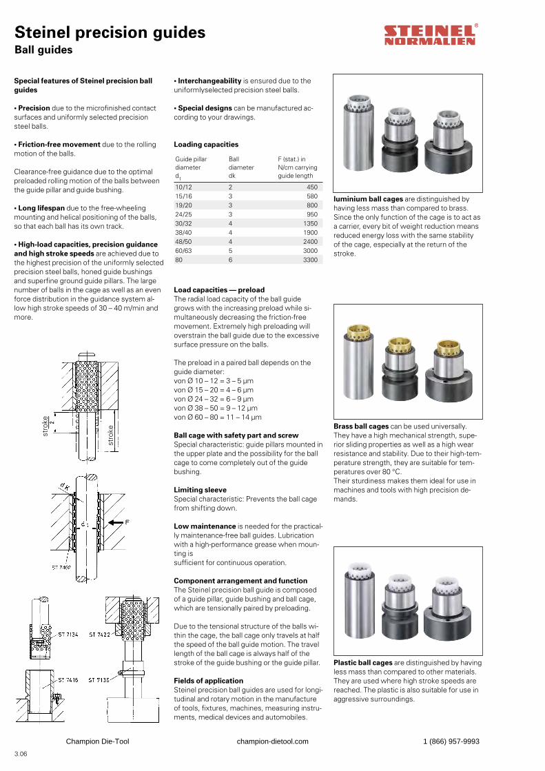
luminium ball cages are distinguished byhaving less mass than compared to brass.Since the only function of the cage is to act as a carrier, every bit of weight reduction means reduced energy loss with the same stability of the cage, especially at the return of the stroke.
Brass ball cages can be used universally. They have a high mechanical strength, supe-rior sliding properties as well as a high wear resistance and stability. Due to their high-tem-perature strength, they are suitable for tem-peratures over 80 °C.Their sturdiness makes them ideal for use in machines and tools with high precision de-mands.
Plastic ball cages are distinguished by havingless mass than compared to other materials.They are used where high stroke speeds arereached. The plastic is also suitable for use inaggressive surroundings.
Steinel precision guidesBall guides
Special features of Steinel precision ballguides
• Precision due to the microfinished contact surfaces and uniformly selected precision steel balls.
• Friction-free movement due to the rolling motion of the balls.
Clearance-free guidance due to the optimalpreloaded rolling motion of the balls between the guide pillar and guide bushing.
• Long lifespan due to the free-wheeling mounting and helical positioning of the balls, so that each ball has its own track.
• High-load capacities, precision guidanceand high stroke speeds are achieved due tothe highest precision of the uniformly selectedprecision steel balls, honed guide bushings and superfine ground guide pillars. The large number of balls in the cage as well as an even force distribution in the guidance system al-low high stroke speeds of 30 – 40 m/min and more.
• Interchangeability is ensured due to the uniformlyselected precision steel balls.
• Special designs can be manufactured ac-cording to your drawings.
Loading capacities
Load capacities — preloadThe radial load capacity of the ball guide grows with the increasing preload while si-multaneously decreasing the friction-free movement. Extremely high preloading will overstrain the ball guide due to the excessive surface pressure on the balls.
The preload in a paired ball depends on theguide diameter:von Ø 10 – 12 = 3 – 5 μm von Ø 15 – 20 = 4 – 6 μmvon Ø 24 – 32 = 6 – 9 μmvon Ø 38 – 50 = 9 – 12 μmvon Ø 60 – 80 = 11 – 14 μm Ball cage with safety part and screwSpecial characteristic: guide pillars mounted inthe upper plate and the possibility for the ballcage to come completely out of the guide bushing.
Limiting sleeveSpecial characteristic: Prevents the ball cagefrom shifting down.
Low maintenance is needed for the practical-ly maintenance-free ball guides. Lubrication with a high-performance grease when moun-ting issufficient for continuous operation.
Component arrangement and functionThe Steinel precision ball guide is composed of a guide pillar, guide bushing and ball cage,which are tensionally paired by preloading.
Due to the tensional structure of the balls wi-thin the cage, the ball cage only travels at half the speed of the ball guide motion. The travel length of the ball cage is always half of the stroke of the guide bushing or the guide pillar.
Fields of applicationSteinel precision ball guides are used for longi-tudinal and rotary motion in the manufactureof tools, fixtures, machines, measuring instru-ments, medical devices and automobiles.
Guide pillardiameterd1
Balldiameter dk
F (stat.) in N/cm carryingguide length
10/12 2 45015/16 3 58019/20 3 80024/25 3 95030/32 4 135038/40 4 190048/50 4 240060/63 5 300080 6 3300
3.06
stro
kestro
ke
Champion Die-Tool champion-dietool.com 1 (866) 957-9993
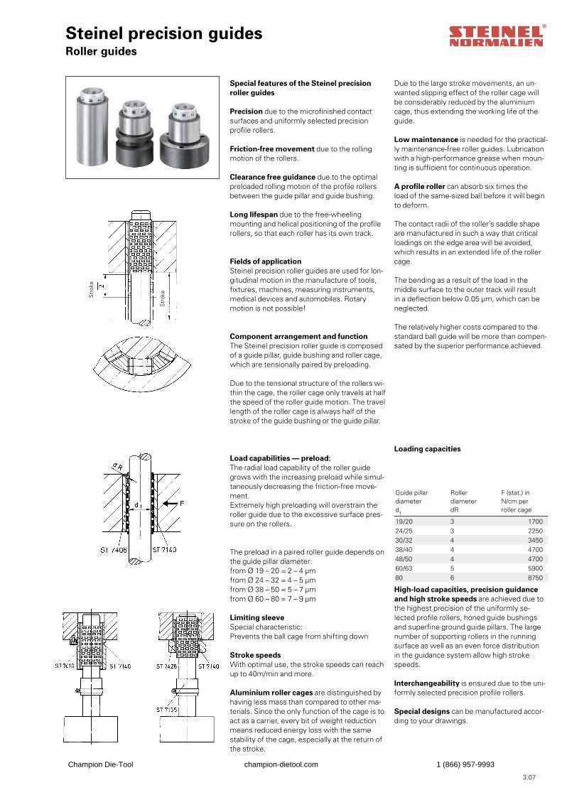
Due to the large stroke movements, an un-wanted slipping effect of the roller cage will be considerably reduced by the aluminium cage, thus extending the working life of the guide.
Low maintenance is needed for the practical-ly maintenance-free roller guides. Lubrication with a high-performance grease when moun-ting is sufficient for continuous operation.
A profile roller can absorb six times theload of the same-sized ball before it will beginto deform.
The contact radii of the roller’s saddle shapeare manufactured in such a way that criticalloadings on the edge area will be avoided, which results in an extended life of the roller cage.
The bending as a result of the load in the middle surface to the outer track will result in a deflection below 0.05 μm, which can be neglected.
The relatively higher costs compared to thestandard ball guide will be more than compen-sated by the superior performance achieved.
Loading capacities
High-load capacities, precision guidanceand high stroke speeds are achieved due tothe highest precision of the uniformly se-lected profile rollers, honed guide bushings and superfine ground guide pillars. The large number of supporting rollers in the running surface as well as an even force distribution in the guidance system allow high stroke speeds.
Interchangeability is ensured due to the uni-formly selected precision profile rollers.
Special designs can be manufactured accor-ding to your drawings.
Guide pillardiameterd1
Roller diameterdR
F (stat.) in N/cm per roller cage
19/20 3 170024/25 3 225030/32 4 345038/40 4 470048/50 4 470060/63 5 590080 6 8750
Steinel precision guidesRoller guides
Special features of the Steinel precisionroller guides
Precision due to the microfinished contact surfaces and uniformly selected precision profile rollers.
Friction-free movement due to the rolling motion of the rollers.
Clearance free guidance due to the optimalpreloaded rolling motion of the profile rollers between the guide pillar and guide bushing.
Long lifespan due to the free-wheeling mounting and helical positioning of the profile rollers, so that each roller has its own track.
Fields of applicationSteinel precision roller guides are used for lon-gitudinal motion in the manufacture of tools, fixtures, machines, measuring instruments, medical devices and automobiles. Rotary motion is not possible!
Component arrangement and functionThe Steinel precision roller guide is composed of a guide pillar, guide bushing and roller cage,which are tensionally paired by preloading.
Due to the tensional structure of the rollers wi-thin the cage, the roller cage only travels at half the speed of the roller guide motion. The travel length of the roller cage is always half of the stroke of the guide bushing or the guide pillar.
Load capabilities — preload:The radial load capability of the roller guidegrows with the increasing preload while simul-taneously decreasing the friction-free move-ment.Extremely high preloading will overstrain theroller guide due to the excessive surface pres-sure on the rollers.
The preload in a paired roller guide depends on the guide pillar diameter:from Ø 19 – 20 = 2 – 4 μmfrom Ø 24 – 32 = 4 – 5 μmfrom Ø 38 – 50 = 5 – 7 μmfrom Ø 60 – 80 = 7 – 9 μm
Limiting sleeveSpecial characteristic:Prevents the ball cage from shifting down
Stroke speedsWith optimal use, the stroke speeds can reach up to 40m/min and more.
Aluminium roller cages are distinguished byhaving less mass than compared to other ma-terials. Since the only function of the cage is to act as a carrier, every bit of weight reduction means reduced energy loss with the same stability of the cage, especially at the return of the stroke.
3.07
Str
oke
Str
oke
Champion Die-Tool champion-dietool.com 1 (866) 957-9993
d 1
d 3
d 2
Ball bearings – Mini series
Steinel ball-bearings are distinguished byexceptional precision and friction-free move-ment. There for they find a wide acceptance as a construction element for electrical and optical measuring instruments and measuring systems. They will be used successfully in machines, instruments and technical equip-ment of high precision.
Special features of Steinel precision ball guides
• Friction-free movement due to the roll motion.
• Zero clearance guiding is achieved due to the precision preloaded rolling motion on the balls between guide pillar and bush.
• Interchangeability will be achieved byuniformly selected steel balls.
• Special designs can be manufacturedaccording to your drawing.
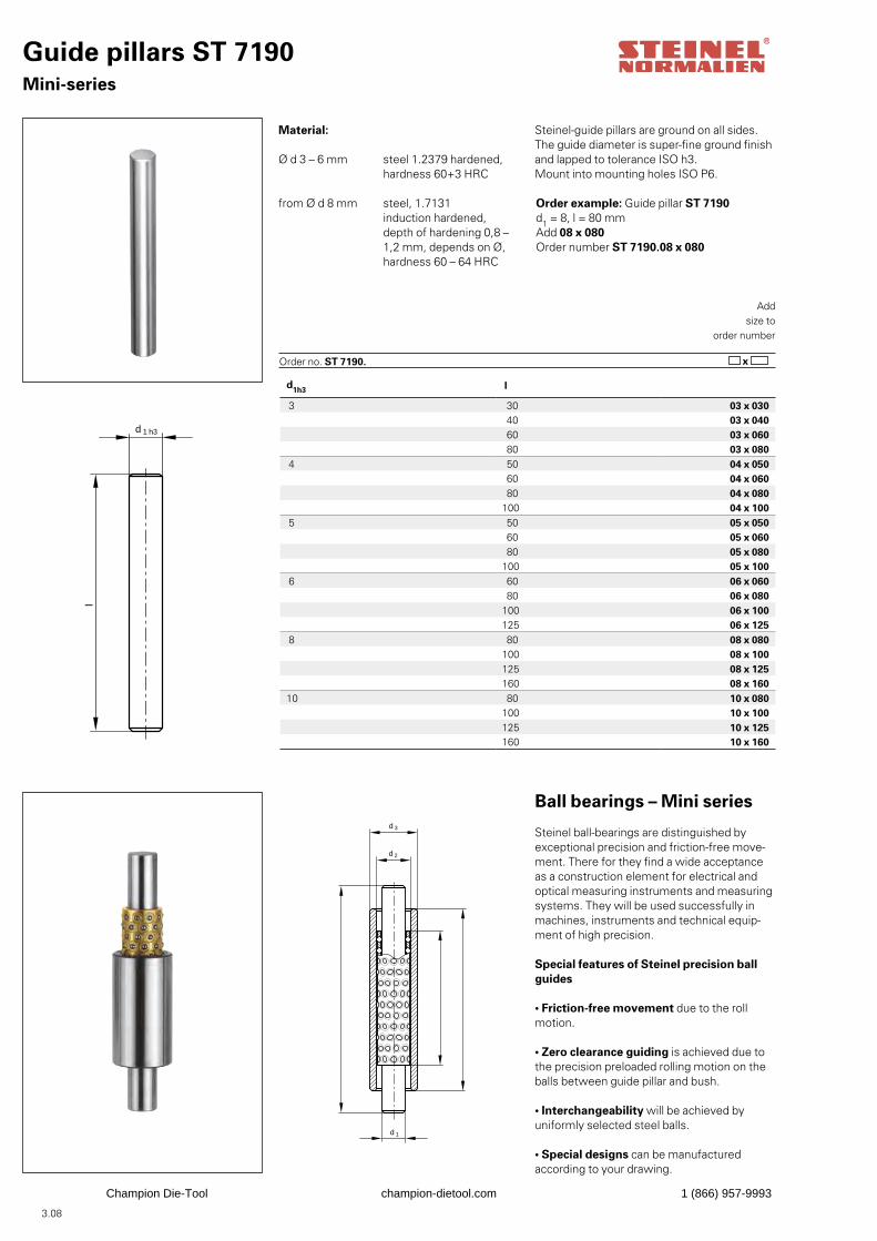
Guide pillars ST 7190Mini-series
d 1 h3
l
Material:
Ø d 3 – 6 mm steel 1.2379 hardened, hardness 60+3 HRC
from Ø d 8 mm steel, 1.7131 induction hardened, depth of hardening 0,8 – 1,2 mm, depends on Ø, hardness 60 – 64 HRC
Order example: Guide pillar ST 7190d1 = 8, l = 80 mmAdd 08 x 080Order number ST 7190.08 x 080
Addsize to
order number
Order no. ST 7190. x
d1h3 l
3 30 03 x 030 40 03 x 040 60 03 x 060 80 03 x 080
4 50 04 x 050 60 04 x 060 80 04 x 080100 04 x 100
5 50 05 x 050 60 05 x 060 80 05 x 080100 05 x 100
6 60 06 x 060 80 06 x 080100 06 x 100125 06 x 125
8 80 08 x 080100 08 x 100125 08 x 125160 08 x 160
10 80 10 x 080100 10 x 100125 10 x 125160 10 x 160
Steinel-guide pillars are ground on all sides.The guide diameter is super-fine ground finishand lapped to tolerance ISO h3.Mount into mounting holes ISO P6.
3.08
Champion Die-Tool champion-dietool.com 1 (866) 957-9993
d1 d2l
3 5 10 03 x 10 03 x 1020 03 x 20 03 x 2030 03 x 30 03 x 30
4 6 10 04 x 10 04 x 1020 04 x 20 04 x 2030 04 x 30 04 x 30
5 7 10 05 x 10 05 x 1020 05 x 20 05 x 2030 05 x 30 05 x 30
6 9 20 06 x 20 06 x 2030 06 x 30 06 x 3040 06 x 40 06 x 40
8 11 20 08 x 20 08 x 2030 08 x 30 08 x 3040 08 x 40 08 x 40
10 13 20 10 x 20 10 x 2030 10 x 30 10 x 3040 10 x 40 10 x 40
d1h3 d2 d3h5l
3 5 7 10 03 x 1020 03 x 2030 03 x 30
4 6 8 10 04 x 1020 04 x 2030 04 x 30
5 7 10 10 05 x 1020 05 x 2030 05 x 30
6 9 12 20 06 x 2030 06 x 3040 06 x 40
8 11 15 20 08 x 2030 08 x 3040 08 x 40
10 13 19 20 10 x 2030 10 x 3040 10 x 40
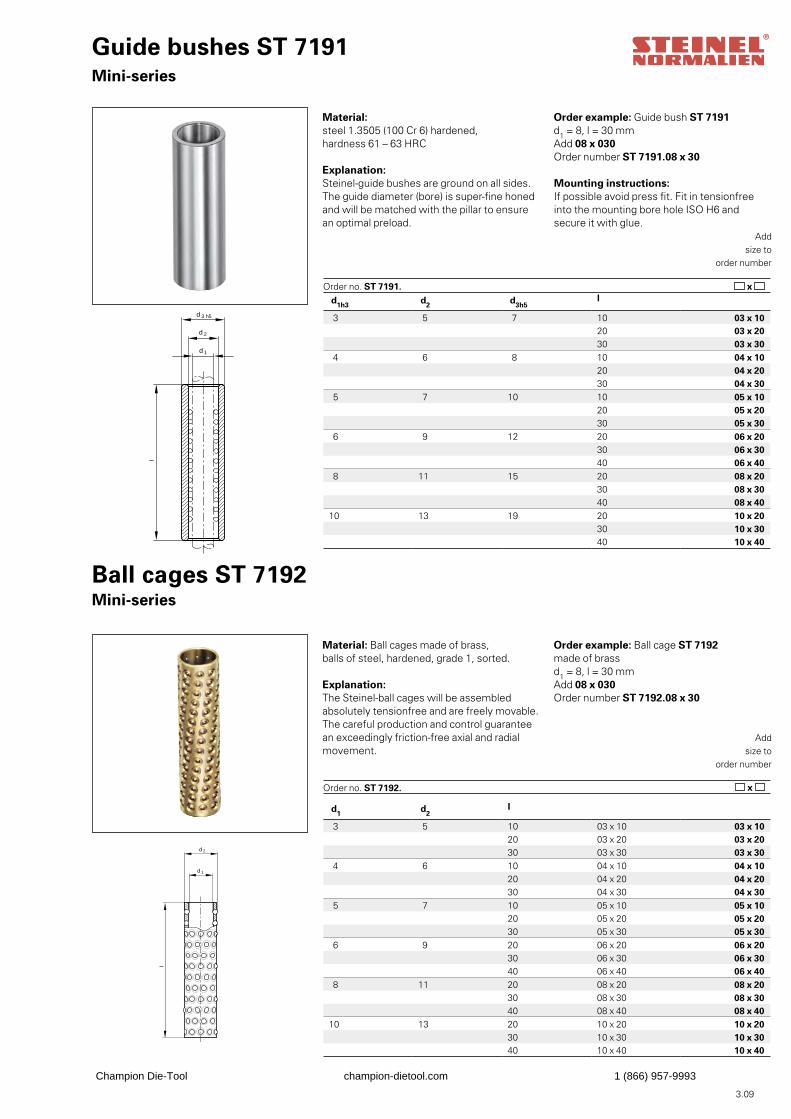
Guide bushes ST 7191Mini-series
d 1
d 2
l
d 3 h5
Material:steel 1.3505 (100 Cr 6) hardened,hardness 61 – 63 HRC
Explanation:Steinel-guide bushes are ground on all sides.The guide diameter (bore) is super-fine honedand will be matched with the pillar to ensure an optimal preload.
Order example: Guide bush ST 7191d1 = 8, l = 30 mmAdd 08 x 030Order number ST 7191.08 x 30
Addsize to
order number
Order no. ST 7191. x
Ball cages ST 7192Mini-series
d 2
l
d 1
Material: Ball cages made of brass,balls of steel, hardened, grade 1, sorted.
Explanation:The Steinel-ball cages will be assembledabsolutely tensionfree and are freely movable.The careful production and control guaranteean exceedingly friction-free axial and radialmovement.
Order example: Ball cage ST 7192made of brassd1 = 8, l = 30 mmAdd 08 x 030Order number ST 7192.08 x 30
Addsize to
order number
Order no. ST 7192. x
Mounting instructions:If possible avoid press fit. Fit in tensionfreeinto the mounting bore hole ISO H6 andsecure it with glue.
3.09
Champion Die-Tool champion-dietool.com 1 (866) 957-9993
3.10
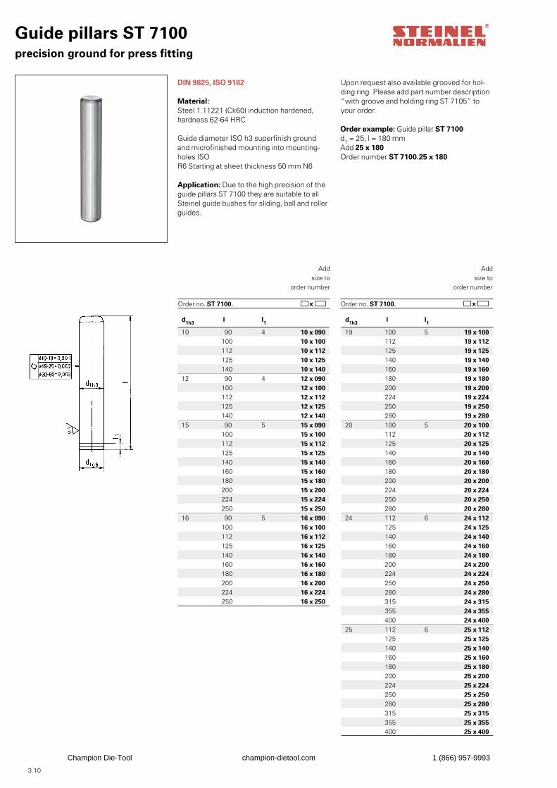
Guide pillars ST 7100precision ground for press fitting
DIN 9825, ISO 9182
Material:Steel 1.11221 (Ck60) induction hardened, hardness 62-64 HRC
Guide diameter ISO h3 superfinish groundand microfinished mounting into mounting-holes ISO R6 Starting at sheet thickness 50 mm N6
Application: Due to the high precision of theguide pillars ST 7100 they are suitable to allSteinel guide bushes for sliding, ball and rollerguides.
Order example: Guide pillar ST 7100d1 = 25, l = 180 mmAdd 25 x 180Order number ST 7100.25 x 180
Addsize to
order number
Order no. ST 7100. x
Addsize to
order number
x Order no. ST 7100.
Upon request also available grooved for hol-ding ring. Please add part number description “with groove and holding ring ST 7105” to your order.
d1h3 l l1
10 90 4 10 x 090100 10 x 100112 10 x 112125 10 x 125140 10 x 140
12 90 4 12 x 090100 12 x 100112 12 x 112125 12 x 125140 12 x 140
15 90 5 15 x 090100 15 x 100112 15 x 112125 15 x 125140 15 x 140160 15 x 160180 15 x 180200 15 x 200224 15 x 224250 15 x 250
16 90 5 16 x 090100 16 x 100112 16 x 112125 16 x 125140 16 x 140160 16 x 160180 16 x 180200 16 x 200224 16 x 224250 16 x 250
d1h3 l l1
19 100 5 19 x 100112 19 x 112125 19 x 125140 19 x 140160 19 x 160180 19 x 180200 19 x 200224 19 x 224250 19 x 250280 19 x 280
20 100 5 20 x 100112 20 x 112125 20 x 125140 20 x 140160 20 x 160180 20 x 180200 20 x 200224 20 x 224250 20 x 250280 20 x 280
24 112 6 24 x 112125 24 x 125140 24 x 140160 24 x 160180 24 x 180200 24 x 200224 24 x 224250 24 x 250280 24 x 280315 24 x 315355 24 x 355400 24 x 400
25 112 6 25 x 112125 25 x 125140 25 x 140160 25 x 160180 25 x 180200 25 x 200224 25 x 224250 25 x 250280 25 x 280315 25 x 315355 25 x 355400 25 x 400
Champion Die-Tool champion-dietool.com 1 (866) 957-9993
3.11
Addsize to
order number
x Order no. ST 7100.
Addsize to
order number
x Order no. ST 7100.
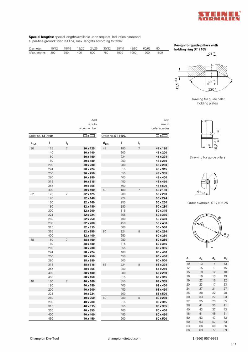
Special lengths: special lengths available upon request. Induction hardened, super-fine ground finish ISO h4, max. lenghts according to table:
d
d
5
1
h3
10,2
+0,
2
90°
d 7 -0,2
+0,1
d1 R6
11,5
+0,
4
2
120°
d6
ø 3
d1 d5 d6 d7
10 13 7 1312 15 9 1515 18 12 1816 19 13 1919 22 16 2220 23 17 2324 27 21 2725 28 22 2830 33 27 3332 35 29 3538 41 35 4140 43 37 4348 51 45 5150 53 47 5360 63 57 6363 66 60 6680 83 77 83
Drawing for guide pillar holding plates
Drawing for guide pillars
Order example: ST 7105.25
Design for guide pillars withholding ring ST 7105Diameter 10/12 15/16 19/20 24/25 30/32 38/40 48/50 60/63 80
Max.lengths 200 350 400 500 750 1000 1000 1200 1500
d
d
5
1
h3
10,2
+0,
2
90°
d 7 -0,2
+0,1
d1 R6
11,5
+0,
4
2
120°
d6
ø 3
d
d
5
1
h3
10,2
+0,
2
90°
d 7 -0,2
+0,1
d1 R6
11,5
+0,
4
2
120°
d6
ø 3
d
d
5
1
h3
10,2
+0,
2
90°
d 7 -0,2
+0,1
d1 R6
11,5
+0,
4
2
120°
d6
ø 3
d1h3 l l1
30 125 7 30 x 125140 30 x 140160 30 x 160180 30 x 180200 30 x 200224 30 x 224250 30 x 250280 30 x 280315 30 x 315355 30 x 355400 30 x 400
32 125 7 32 x 125140 32 x 140160 32 x 160180 32 x 180200 32 x 200224 32 x 224250 32 x 250280 32 x 280315 32 x 315355 32 x 355400 32 x 400
38 160 7 38 x 160180 38 x 180200 38 x 200224 38 x 224250 38 x 250280 38 x 280315 38 x 315355 38 x 355400 38 x 400450 38 x 450
40 160 7 40 x 160180 40 x 180200 40 x 200224 40 x 224250 40 x 250280 40 x 280315 40 x 315355 40 x 355400 40 x 400450 40 x 450
d1h3 l l1
48 180 7 48 x 180200 48 x 200224 48 x 224250 48 x 250280 48 x 280315 48 x 315355 48 x 355400 48 x 400450 48 x 450500 48 x 500
50 180 7 50 x 180200 50 x 200224 50 x 224250 50 x 250280 50 x 280315 50 x 315355 50 x 355400 50 x 400450 50 x 450500 50 x 500
60 224 8 60 x 224250 60 x 250280 60 x 280315 60 x 315355 60 x 355400 60 x 400450 60 x 450500 60 x 500
63 224 8 63 x 224250 63 x 250280 63 x 280315 63 x 315355 63 x 355400 63 x 400450 63 x 450500 63 x 500
80 280 8 80 x 280315 80 x 315355 80 x 355400 80 x 400450 80 x 450500 80 x 500
Champion Die-Tool champion-dietool.com 1 (866) 957-9993
3.12
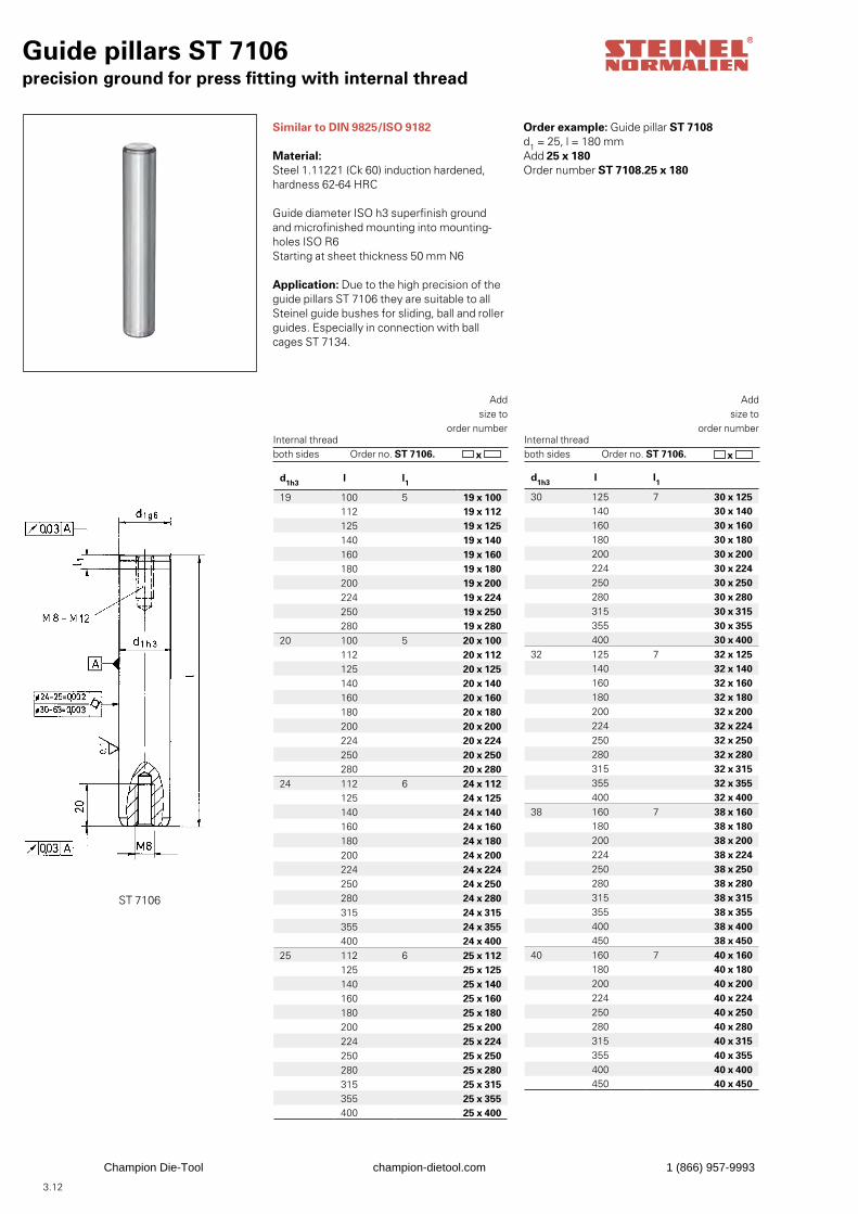
Guide pillars ST 7106precision ground for press fitting with internal thread
Similar to DIN 9825/ISO 9182
Material: Steel 1.11221 (Ck 60) induction hardened, hardness 62-64 HRC
Guide diameter ISO h3 superfinish groundand microfinished mounting into mounting-holes ISO R6Starting at sheet thickness 50 mm N6
Application: Due to the high precision of theguide pillars ST 7106 they are suitable to allSteinel guide bushes for sliding, ball and rollerguides. Especially in connection with ball cages ST 7134.
Order example: Guide pillar ST 7108d1 = 25, l = 180 mmAdd 25 x 180Order number ST 7108.25 x 180
Addsize to
order number
Order no. ST 7106. x Internal threadboth sides
Addsize to
order number
Order no. ST 7106. x
Internal threadboth sides
d1h3 l l1
19 100 5 19 x 100112 19 x 112125 19 x 125140 19 x 140160 19 x 160180 19 x 180200 19 x 200224 19 x 224250 19 x 250280 19 x 280
20 100 5 20 x 100112 20 x 112125 20 x 125140 20 x 140160 20 x 160180 20 x 180200 20 x 200224 20 x 224250 20 x 250280 20 x 280
24 112 6 24 x 112125 24 x 125140 24 x 140160 24 x 160180 24 x 180200 24 x 200224 24 x 224250 24 x 250280 24 x 280315 24 x 315355 24 x 355400 24 x 400
25 112 6 25 x 112125 25 x 125140 25 x 140160 25 x 160180 25 x 180200 25 x 200224 25 x 224250 25 x 250280 25 x 280315 25 x 315355 25 x 355400 25 x 400
d1h3 l l1
30 125 7 30 x 125140 30 x 140160 30 x 160180 30 x 180200 30 x 200224 30 x 224250 30 x 250280 30 x 280315 30 x 315355 30 x 355400 30 x 400
32 125 7 32 x 125140 32 x 140160 32 x 160180 32 x 180200 32 x 200224 32 x 224250 32 x 250280 32 x 280315 32 x 315355 32 x 355400 32 x 400
38 160 7 38 x 160180 38 x 180200 38 x 200224 38 x 224250 38 x 250280 38 x 280315 38 x 315355 38 x 355400 38 x 400450 38 x 450
40 160 7 40 x 160180 40 x 180200 40 x 200224 40 x 224250 40 x 250280 40 x 280315 40 x 315355 40 x 355400 40 x 400450 40 x 450
ST 7106
Champion Die-Tool champion-dietool.com 1 (866) 957-9993
3.13
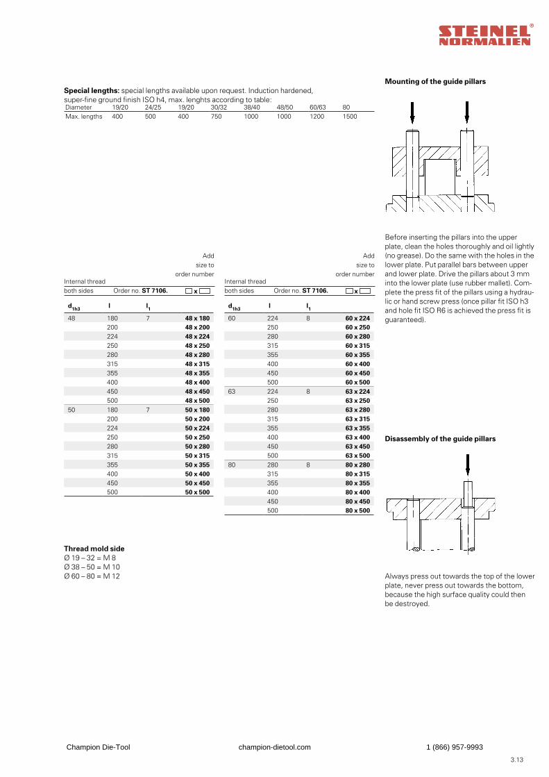
Before inserting the pillars into the upper plate, clean the holes thoroughly and oil lightly(no grease). Do the same with the holes in thelower plate. Put parallel bars between upper and lower plate. Drive the pillars about 3 mm into the lower plate (use rubber mallet). Com-plete the press fit of the pillars using a hydrau-lic or hand screw press (once pillar fit ISO h3 and hole fit ISO R6 is achieved the press fit is guaranteed).
Disassembly of the guide pillars
Always press out towards the top of the lowerplate, never press out towards the bottom,because the high surface quality could then be destroyed.
Thread mold side Ø 19 – 32 = M 8Ø 38 – 50 = M 10Ø 60 – 80 = M 12
Special lengths: special lengths available upon request. Induction hardened, super-fine ground finish ISO h4, max. lenghts according to table:
Mounting of the guide pillars
Addsize to
order number
Order no. ST 7106. x Internal thread both sides
Addsize to
order number
Order no. ST 7106. x Internal thread both sides
Diameter 19/20 24/25 19/20 30/32 38/40 48/50 60/63 80Max. lengths 400 500 400 750 1000 1000 1200 1500
d1h3 l l1
48 180 7 48 x 180200 48 x 200224 48 x 224250 48 x 250280 48 x 280315 48 x 315355 48 x 355400 48 x 400450 48 x 450500 48 x 500
50 180 7 50 x 180200 50 x 200224 50 x 224250 50 x 250280 50 x 280315 50 x 315355 50 x 355400 50 x 400450 50 x 450500 50 x 500
d1h3 l l1
60 224 8 60 x 224250 60 x 250280 60 x 280315 60 x 315355 60 x 355400 60 x 400450 60 x 450500 60 x 500
63 224 8 63 x 224250 63 x 250280 63 x 280315 63 x 315355 63 x 355400 63 x 400450 63 x 450500 63 x 500
80 280 8 80 x 280315 80 x 315355 80 x 355400 80 x 400450 80 x 450500 80 x 500
Champion Die-Tool champion-dietool.com 1 (866) 957-9993
3.14
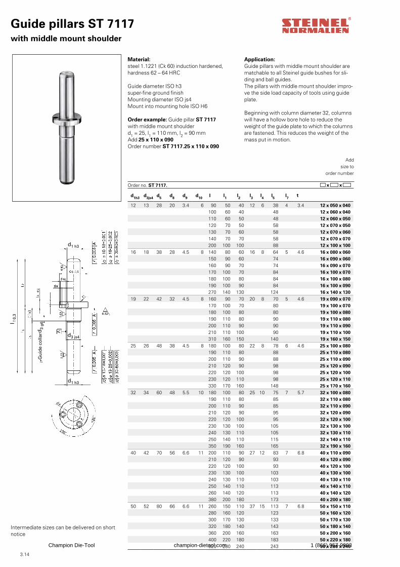
d1h3 d3js4 d5 d8 d9 d10 l l1 l2 l3 l4 l5 l7 t
12 13 28 20 3.4 6 90 50 40 12 6 38 4 3.4 12 x 050 x 040100 60 40 48 12 x 060 x 040110 60 50 48 12 x 060 x 050120 70 50 58 12 x 070 x 050130 70 60 58 12 x 070 x 060140 70 70 58 12 x 070 x 070200 100 100 88 12 x 100 x 100
16 18 38 28 4.5 8 140 80 60 16 8 64 5 4.6 16 x 080 x 060150 90 60 74 16 x 090 x 060160 90 70 74 16 x 090 x 070170 100 70 84 16 x 100 x 070180 100 80 84 16 x 100 x 080190 100 90 84 16 x 100 x 090270 140 130 124 16 x 140 x 130
19 22 42 32 4.5 8 160 90 70 20 8 70 5 4.6 19 x 090 x 070170 100 70 80 19 x 100 x 070180 100 80 80 19 x 100 x 080190 110 80 90 19 x 110 x 080200 110 90 90 19 x 110 x 090210 110 100 90 19 x 110 x 100310 160 150 140 19 x 160 x 150
25 26 48 38 4.5 8 180 100 80 22 8 78 6 4.6 25 x 100 x 080190 110 80 88 25 x 110 x 080200 110 90 88 25 x 110 x 090210 120 90 98 25 x 120 x 090220 120 100 98 25 x 120 x 100230 120 110 98 25 x 120 x 110330 170 160 148 25 x 170 x 160
32 34 60 48 5.5 10 180 100 80 25 10 75 7 5.7 32 x 100 x 080190 110 80 85 32 x 110 x 080200 110 90 85 32 x 110 x 090210 120 90 95 32 x 120 x 090220 120 100 95 32 x 120 x 100230 130 100 105 32 x 130 x 100240 130 110 105 32 x 130 x 110250 140 110 115 32 x 140 x 110350 190 160 165 32 x 190 x 160
40 42 70 56 6.6 11 200 110 90 27 12 83 7 6.8 40 x 110 x 090210 120 90 93 40 x 120 x 090220 120 100 93 40 x 120 x 100230 130 100 103 40 x 130 x 100240 130 110 103 40 x 130 x 110250 140 110 113 40 x 140 x 110260 140 120 113 40 x 140 x 120380 200 180 173 40 x 200 x 180
50 52 80 66 6.6 11 260 150 110 37 15 113 7 6.8 50 x 150 x 110280 160 120 123 50 x 160 x 120300 170 130 133 50 x 170 x 130320 180 140 143 50 x 180 x 140360 200 160 163 50 x 200 x 160400 220 180 183 50 x 220 x 180520 280 240 243 50 x 280 x 240
Guide pillars ST 7117with middle mount shoulder
Material:steel 1.1221 (Ck 60) induction hardened,hardness 62 – 64 HRC
Guide diameter ISO h3 super-fine ground finishMounting diameter ISO js4Mount into mounting hole ISO H6 Order example: Guide pillar ST 7117with middle mount shoulderd1 = 25, l1 = 110 mm, l2 = 90 mmAdd 25 x 110 x 090Order number ST 7117.25 x 110 x 090
Addsize to
order number
Order no. ST 7117. x x
Application: Guide pillars with middle mount shoulder are matchable to all Steinel guide bushes for sli-ding and ball guides.The pillars with middle mount shoulder impro-ve the side load capacity of tools using guide plate.
Beginning with column diameter 32, columns will have a hollow bore hole to reduce the weight of the guide plate to which the columns are fastened. This reduces the weight of the mass put in motion.
Intermediate sizes can be delivered on short notice
l 0
,3-+
d3
g6
d3 js4
d1 h3
d1 h3
Gu
ide
colla
r
Champion Die-Tool champion-dietool.com 1 (866) 957-9993
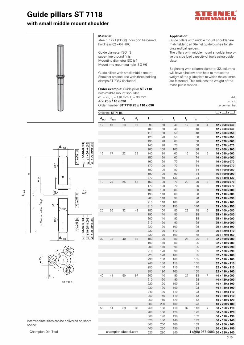
3.15
d1h3 d3js4 d5 d8 l l1 l2 l3 l5 l7
12 13 18 35 90 50 40 12 38 4 12 x 050 x 040100 60 40 48 12 x 060 x 040110 60 50 48 12 x 060 x 050120 70 50 58 12 x 070 x 050130 70 60 58 12 x 070 x 060140 70 70 58 12 x 070 x 070200 100 100 88 12 x 100 x 100
16 17 22 39 140 80 60 16 64 5 16 x 080 x 060150 90 60 74 16 x 090 x 060160 90 70 74 16 x 090 x 070170 100 70 84 16 x 100 x 070180 100 80 84 16 x 100 x 080190 100 90 84 16 x 100 x 090270 140 130 124 16 x 140 x 130
19 20 25 42 160 90 70 20 70 5 19 x 090 x 070170 100 70 80 19 x 100 x 070180 100 80 80 19 x 100 x 080190 110 80 90 19 x 110 x 080200 110 90 90 19 x 110 x 090210 110 100 90 19 x 110 x 100310 160 150 140 19 x 160 x 150
25 26 32 49 180 100 80 22 78 6 25 x 100 x 080190 110 80 88 25 x 110 x 080200 110 90 88 25 x 110 x 090210 120 90 98 25 x 120 x 090220 120 100 98 25 x 120 x 100230 120 110 98 25 x 120 x 110330 170 160 148 25 x 170 x 160
32 33 40 57 180 100 80 25 75 7 32 x 100 x 080190 110 80 85 32 x 110 x 080200 110 90 85 32 x 110 x 090210 120 90 95 32 x 120 x 090220 120 100 95 32 x 120 x 100230 130 100 105 32 x 130 x 100240 130 110 105 32 x 130 x 110250 140 110 115 32 x 140 x 110350 190 160 165 32 x 190 x 160
40 41 50 67 200 110 90 27 83 7 40 x 110 x 090210 120 90 93 40 x 120 x 090220 120 100 93 40 x 120 x 100230 130 100 103 40 x 130 x 100240 130 110 103 40 x 130 x 110250 140 110 113 40 x 140 x 110260 140 120 113 40 x 140 x 120380 200 180 173 40 x 200 x 180
50 51 63 80 260 150 110 37 113 7 50 x 150 x 110280 160 120 123 50 x 160 x 120300 170 130 133 50 x 170 x 130320 180 140 143 50 x 180 x 140360 200 160 163 50 x 200 x 160400 220 180 183 50 x 220 x 180520 280 240 243 50 x 280 x 240
Guide pillars ST 7118with small middle mount shoulder
Material:steel 1.1221 (Ck 60) induction hardened,hardness 62 – 64 HRC
Guide diameter ISO h3 super-fine ground finishMounting diameter ISO js4Mount into mounting hole ISO H6
Guide pillars with small middle mountShoulder are secured with three holdingclamps ST 7367 (included). Order example: Guide pillar ST 7118with middle mount shoulderd1 = 25, l1 = 110 mm, l2 = 90 mmAdd 25 x 110 x 090Order number ST 7118.25 x 110 x 090
Addsize to
order number
Order no. ST 7118. x x
Application:Guide pillars with middle mount shoulder are matchable to all Steinel guide bushes for sli-ding and ball guides.The pillars with middle mount shoulder impro-ve the side load capacity of tools using guide plate.
Beginning with column diameter 32, columns will have a hollow bore hole to reduce the weight of the guide plate to which the columns are fastened. This reduces the weight of the mass put in motion.
Intermediate sizes can be delivered on short notice
d3
g6
d3 js4
d1 h3
d1 h3
l 0
,3-+
Gu
ide
colla
r
Champion Die-Tool champion-dietool.com 1 (866) 957-9993
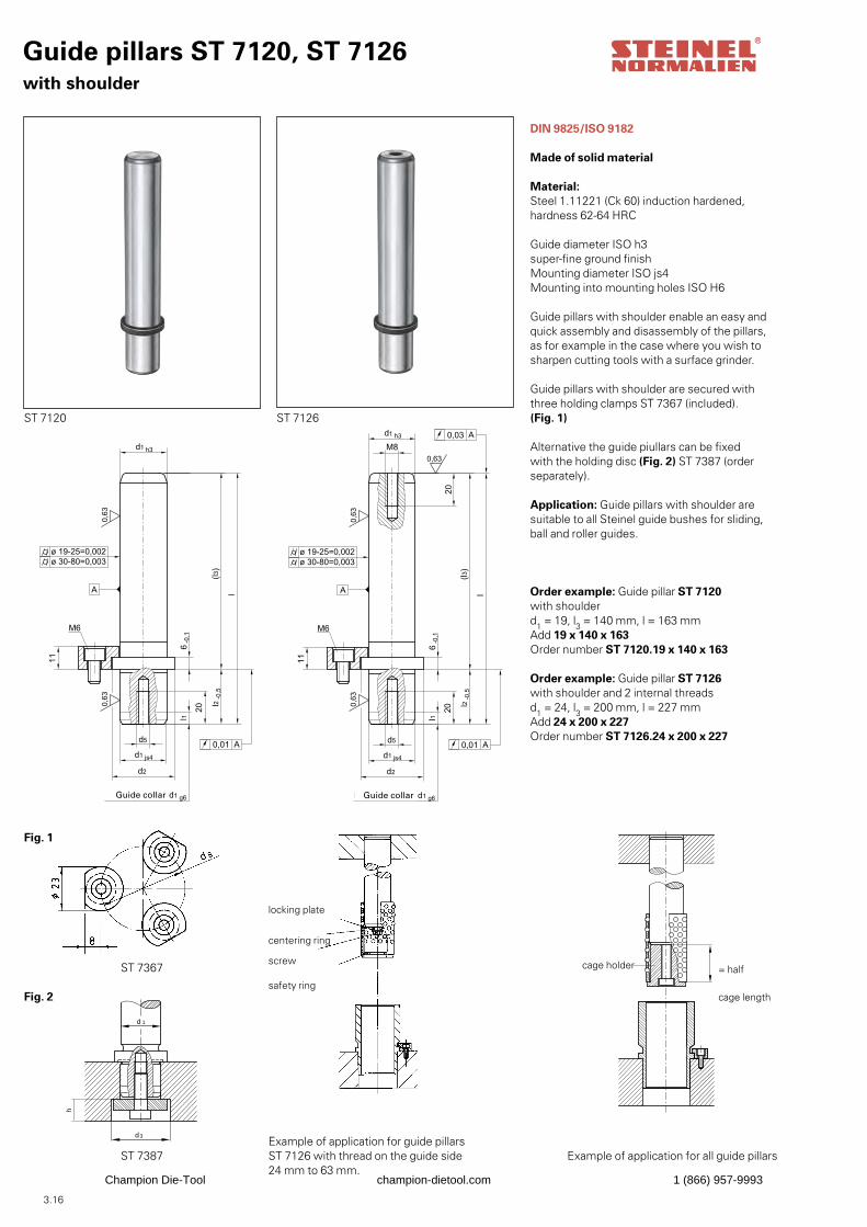
3.16
Fig. 2
ST 7387
Guide pillars ST 7120, ST 7126with shoulder
DIN 9825/ISO 9182
Made of solid material
Material: Steel 1.11221 (Ck 60) induction hardened, hardness 62-64 HRC
Guide diameter ISO h3 super-fine ground finishMounting diameter ISO js4Mounting into mounting holes ISO H6
Guide pillars with shoulder enable an easy andquick assembly and disassembly of the pillars,as for example in the case where you wish tosharpen cutting tools with a surface grinder.
Guide pillars with shoulder are secured with three holding clamps ST 7367 (included). (Fig. 1)
Alternative the guide piullars can be fixedwith the holding disc (Fig. 2) ST 7387 (orderseparately).
Application: Guide pillars with shoulder aresuitable to all Steinel guide bushes for sliding,ball and roller guides.
Order example: Guide pillar ST 7120with shoulderd1 = 19, l3 = 140 mm, l = 163 mmAdd 19 x 140 x 163Order number ST 7120.19 x 140 x 163
Order example: Guide pillar ST 7126with shoulder and 2 internal threadsd1 = 24, l3 = 200 mm, l = 227 mmAdd 24 x 200 x 227Order number ST 7126.24 x 200 x 227
h
d 1
d3
ST 7120 ST 7126
Fig. 1
ST 7367
locking plate
centering ring screw safety ring
Example of application for guide pillars ST 7126 with thread on the guide side24 mm to 63 mm.
cage holder = half
cage length
Example of application for all guide pillars
Guide collar Guide collar
Champion Die-Tool champion-dietool.com 1 (866) 957-9993
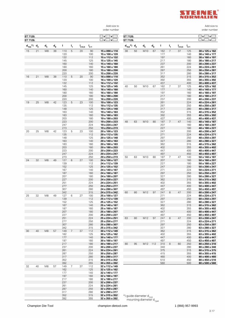
3.17
Add size toorder number
ST 7120. ST 7126.
x x x x
Add size toorder number
ST 7120. ST 7126.
x x x x
*) guide diameter d1h3
mounting diameter d1js4
d1h3*) d2 d5 d8 l l1 l2-0,5 l3-1
15 21 M8 38 110 5 20 90 15 x 090 x 110120 100 15 x 100 x 120132 112 15 x 112 x 132145 125 15 x 125 x 145160 140 15 x 140 x 160180 160 15 x 160 x 180200 180 15 x 180 x 200220 200 15 x 200 x 220
16 21 M8 38 110 5 20 90 16 x 090 x 110120 100 16 x 100 x 120132 112 16 x 112 x 132145 125 16 x 125 x 145160 140 16 x 140 x 160180 160 16 x 160 x 180200 180 16 x 180 x 200220 200 16 x 200 x 220
19 25 M8 42 123 5 23 100 19 x 100 x 123135 112 19 x 112 x 135148 125 19 x 125 x 148163 140 19 x 140 x 163183 160 19 x 160 x 183203 180 19 x 180 x 203223 200 19 x 200 x 223247 224 19 x 224 x 247273 250 19 x 250 x 273
20 25 M8 42 123 5 23 100 20 x 100 x 123135 112 20 x 112 x 135148 125 20 x 125 x 148163 140 20 x 140 x 163183 160 20 x 160 x 183203 180 20 x 180 x 203223 200 20 x 200 x 223247 224 20 x 224 x 247273 250 20 x 250 x 273
24 32 M8 49 127 6 27 100 24 x 100 x 127139 112 24 x 112 x 139152 125 24 x 125 x 152167 140 24 x 140 x 167187 160 24 x 160 x 187207 180 24 x 180 x 207227 200 24 x 200 x 227251 224 24 x 224 x 251277 250 24 x 250 x 277307 280 24 x 280 x 307342 315 24 x 315 x 342
25 32 M8 49 127 6 27 100 25 x 100 x 127139 112 25 x 112 x 139152 125 25 x 125 x 152167 140 25 x 140 x 167187 160 25 x 160 x 187207 180 25 x 180 x 207227 200 25 x 200 x 227251 224 25 x 224 x 251277 250 25 x 250 x 277307 280 25 x 280 x 307342 315 25 x 315 x 342
30 40 M8 57 149 7 37 112 30 x 112 x 149162 125 30 x 125 x 162177 140 30 x 140 x 177197 160 30 x 160 x 197217 180 30 x 180 x 217237 200 30 x 200 x 237261 224 30 x 224 x 261287 250 30 x 250 x 287317 280 30 x 280 x 317352 315 30 x 315 x 352392 355 30 x 355 x 392
32 40 M8 57 149 7 37 112 32 x 112 x 149162 125 32 x 125 x 162177 140 32 x 140 x 177197 160 32 x 160 x 197217 180 32 x 180 x 217237 200 32 x 200 x 237261 224 32 x 224 x 261287 250 32 x 250 x 287317 280 32 x 280 x 317352 315 32 x 315 x 352392 355 32 x 355 x 392
d1h3*) d2 d5 d8 l l1 l2-0,5 l3-1
38 50 M10 67 162 7 37 125 38 x 125 x 162177 140 38 x 140 x 177197 160 38 x 160 x 197217 180 38 x 180 x 217237 200 38 x 200 x 237261 224 38 x 224 x 261287 250 38 x 250 x 287317 280 38 x 280 x 317352 315 38 x 315 x 352392 355 38 x 355 x 392437 400 38 x 400 x 437
40 50 M10 67 162 7 37 125 40 x 125 x 162177 140 40 x 140 x 177197 160 40 x 160 x 197217 180 40 x 180 x 217237 200 40 x 200 x 237261 224 40 x 224 x 261287 250 40 x 250 x 287317 280 40 x 280 x 317352 315 40 x 315 x 352392 355 40 x 355 x 392437 400 40 x 400 x 437
48 63 M10 80 187 7 47 140 48 x 140 x 187207 160 48 x 160 x 207227 180 48 x 180 x 227247 200 48 x 200 x 247271 224 48 x 224 x 271297 250 48 x 250 x 297327 280 48 x 280 x 327362 315 48 x 315 x 362402 355 48 x 355 x 402447 400 48 x 400 x 447497 450 48 x 450 x 497
50 63 M10 80 187 7 47 140 50 x 140 x 187207 160 50 x 160 x 207227 180 50 x 180 x 227247 200 50 x 200 x 247271 224 50 x 224 x 271297 250 50 x 250 x 297327 280 50 x 280 x 327362 315 50 x 315 x 362402 355 50 x 355 x 402447 400 50 x 400 x 447497 450 50 x 450 x 497
60 80 M12 97 247 8 47 200 60 x 200 x 247271 224 60 x 224 x 271297 250 60 x 250 x 297327 280 60 x 280 x 327362 315 60 x 315 x 362402 355 60 x 355 x 402447 400 60 x 400 x 447497 450 60 x 450 x 497
63 80 M12 97 247 8 47 200 63 x 200 x 247271 224 63 x 224 x 271297 250 63 x 250 x 297327 280 63 x 280 x 327362 315 63 x 315 x 362402 355 63 x 355 x 402447 400 63 x 400 x 447497 450 63 x 450 x 497
80 95 M12 112 310 8 60 250 80 x 250 x 310340 280 80 x 280 x 340375 315 80 x 315 x 375415 355 80 x 355 x 415460 400 80 x 400 x 460510 450 80 x 450 x 510560 500 80 x 500 x 560
Champion Die-Tool champion-dietool.com 1 (866) 957-9993
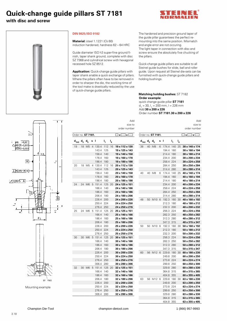
3.18
Quick-change guide pillars ST 7181with disc and screw
DIN 9825/ISO 9182
Material: steel 1.1221 (Ck 60)induction hardened, hardness 62 – 64 HRC
Guide diameter ISO h3 super-fine ground fi-nish, taper shank ground, complete with discSZ 7368 and cylindrical screw with hexagonalrecessed hole SZ 8512.
Application: Quick-change guide pillars withtaper shank enable a quick exchange of pillars.Where the pillars often have to be removed inorder to sharper the die, the working time of the tool make is drastically reduced by the use of quick-change guide pillars.
Order example: quick change guide pillar ST 7181d1 = 30, l1 = 200 mm, l = 226 mmAdd 30 x 200 x 226Order number ST 7181.30 x 200 x 226
Addsize to
order number
Order no. ST 7181. x x
The hardened and precision ground taper of the guide pillar guarantees the perfect re-mounting into the same position. Mismatch and angle error are not occuring. The light taper in connection with disc and screw ensure the absolutely fixe chucking of the pillars.
Quick-change guide pillars are suitable to allSteinel guide bushes for slide, ball and rollerguide. Upon request all Steinel die-sets can befurnished with quick-change guide pillars andholding bushings.
Matching holding bushes: ST 7182
Addsize to
order number
Order no. ST 7181. x x
Mounting example
d1h3 d3 d5 s l l1 l4
19 18 M5 4 130.4 112 16 19 x 112 x 130143.4 125 19 x 125 x 143158.4 140 19 x 140 x 158178.4 160 19 x 160 x 178198.4 180 19 x 180 x 198
20 18 M5 4 130.4 112 16 20 x 112 x 130143.4 125 20 x 125 x 143158.4 140 20 x 140 x 158178.4 160 20 x 160 x 178198.4 180 20 x 180 x 198
24 24 M6 5 151.4 125 20 24 x 125 x 151166.4 140 24 x 140 x 166186.4 160 24 x 160 x 186206.4 180 24 x 180 x 206226.4 200 24 x 200 x 226250.4 224 24 x 224 x 250276.4 250 24 x 250 x 276
25 24 M6 5 151.4 125 20 25 x 125 x 151166.4 140 25 x 140 x 166186.4 160 25 x 160 x 186206.4 180 25 x 180 x 206226.4 200 25 x 200 x 226250.4 224 25 x 224 x 250276.4 250 25 x 250 x 276
30 30 M6 5 151.4 125 20 30 x 125 x 151166.4 140 30 x 140 x 166186.4 160 30 x 160 x 186206.4 180 30 x 180 x 206226.4 200 30 x 200 x 226250.4 224 30 x 224 x 250276.4 250 30 x 250 x 276306.4 280 30 x 280 x 306
32 30 M6 5 151.4 125 20 32 x 125 x 151166.4 140 32 x 140 x 166186.4 160 32 x 160 x 186206.4 180 32 x 180 x 206226.4 200 32 x 200 x 226250.4 224 32 x 224 x 250276.4 250 32 x 250 x 276306.4 280 32 x 280 x 306
d1h3 d3 d5 s l l1 l4
38 40 M8 6 174.4 140 25 38 x 140 x 174194.4 160 38 x 160 x 194214.4 180 38 x 180 x 214234.4 200 38 x 200 x 234258.4 224 38 x 224 x 258284.4 250 38 x 250 x 284314.4 280 38 x 280 x 314
40 40 M8 6 174.4 140 25 40 x 140 x 174194.4 160 40 x 160 x 194214.4 180 40 x 180 x 214234.4 200 40 x 200 x 234258.4 224 40 x 224 x 258284.4 250 40 x 250 x 284314.4 280 40 x 280 x 314
48 50 M10 6 192.3 160 30 48 x 160 x 192212.3 180 48 x 180 x 212232.3 200 48 x 200 x 232256.3 224 48 x 224 x 256282.3 250 48 x 250 x 282312.3 280 48 x 280 x 312347.3 315 48 x 315 x 347
50 50 M10 6 192.3 160 30 50 x 160 x 192212.3 180 50 x 180 x 212232.3 200 50 x 200 x 232256.3 224 50 x 224 x 256282.3 250 50 x 250 x 282312.3 280 50 x 280 x 312347.3 315 50 x 315 x 347
60 56 M12 6 229.8 180 30 60 x 180 x 230249.8 200 60 x 200 x 250273.8 224 60 x 224 x 274299.8 250 60 x 250 x 300329.8 280 60 x 280 x 330364.8 315 60 x 315 x 365404.8 355 60 x 355 x 405
63 56 M12 6 229.8 180 30 63 x 180 x 230249.8 200 63 x 200 x 250273.8 224 63 x 224 x 274299.8 250 63 x 250 x 300329.8 280 63 x 280 x 330364.8 315 63 x 315 x 365404.8 355 63 x 355 x 405
Champion Die-Tool champion-dietool.com 1 (866) 957-9993
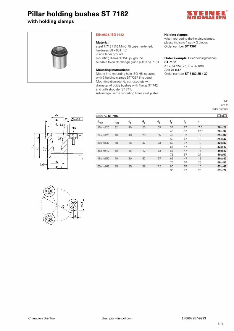
3.19
Pillar holding bushes ST 7182with holding clamps
DIN 9825/ISO 9182
Material:steel 1.7131 (16 Mn Cr 5) case hardened,hardness 58 – 60 HRCinside taper groundmounting diameter ISO j6, groundSuitable to quick-change guide pillars ST 7181
Mounting instructions:Mount into mounting hole ISO H6, secured with 3 holding clamps ST 7367 (included).Mounting diameter d3 corresponds withdiameter of guide bushes with flange ST 742,and with shoulder ST 741.Advantage: same mounting holes in all plates.
Order example: Pillar holding bushes ST 7182d1 = 24 bzw. 25, l3 = 37 mmAdd 25 x 37Order number ST 7182.25 x 37
Addsize to
order number
Order no. ST 7182. x
Holding clamps:when reordering the holding clamps,please indicate 1 set = 3 piecesOrder number ST 7367
d1h3 d3j6 d5 d6 d8 l1 l3 t
19 and 20 32 40 20 59 39 27 7.5 20 x 2749 37 17.5 20 x 37
24 and 25 40 48 26 65 49 37 9 25 x 3759 47 19 25 x 47
30 and 32 48 56 32 73 52 37 9 32 x 3762 47 19 32 x 47
38 and 40 58 66 42 83 62 47 11 40 x 4772 57 21 40 x 57
48 and 50 70 80 52 97 65 47 13 50 x 4775 57 23 50 x 57
60 and 63 85 95 58 112 85 67 15 63 x 6795 77 25 63 x 77
Champion Die-Tool champion-dietool.com 1 (866) 957-9993
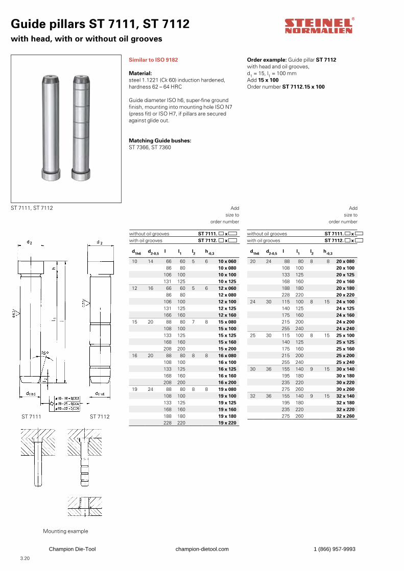
3.20
Guide pillars ST 7111, ST 7112with head, with or without oil grooves
Similar to ISO 9182
Material:steel 1.1221 (Ck 60) induction hardened,hardness 62 – 64 HRC
Guide diameter ISO h6, super-fine groundfinish, mounting into mounting hole ISO N7(press fit) or ISO H7, if pillars are secured against glide out.
Matching Guide bushes: ST 7366, ST 7360
Order example: Guide pillar ST 7112with head and oil grooves,d1 = 15, l1 = 100 mmAdd 15 x 100Order number ST 7112.15 x 100
ST 7111 ST 7112
Mounting example
Addsize to
order number
ST 7111. ST 7112.
x x
without oil grooves with oil grooves
Addsize to
order number
ST 7111. ST 7112.
x x
without oil grooves with oil grooves
d1h6 d2-0,5 l l1 l2 h-0,3
10 14 66 60 5 6 10 x 06086 80 10 x 080
106 100 10 x 100131 125 10 x 125
12 16 66 60 5 6 12 x 06086 80 12 x 080
106 100 12 x 100131 125 12 x 125166 160 12 x 160
15 20 88 80 7 8 15 x 080108 100 15 x 100133 125 15 x 125168 160 15 x 160208 200 15 x 200
16 20 88 80 8 8 16 x 080108 100 16 x 100133 125 16 x 125168 160 16 x 160208 200 16 x 200
19 24 88 80 8 8 19 x 080108 100 19 x 100133 125 19 x 125168 160 19 x 160188 180 19 x 180228 220 19 x 220
d1h6 d2-0,5 l l1 l2 h-0,3
20 24 88 80 8 8 20 x 080108 100 20 x 100133 125 20 x 125168 160 20 x 160188 180 20 x 180228 220 20 x 220
24 30 115 100 8 15 24 x 100140 125 24 x 125175 160 24 x 160215 200 24 x 200255 240 24 x 240
25 30 115 100 8 15 25 x 100140 125 25 x 125175 160 25 x 160215 200 25 x 200255 240 25 x 240
30 36 155 140 9 15 30 x 140195 180 30 x 180235 220 30 x 220275 260 30 x 260
32 36 155 140 9 15 32 x 140195 180 32 x 180235 220 32 x 220275 260 32 x 260
ST 7111, ST 7112
Champion Die-Tool champion-dietool.com 1 (866) 957-9993
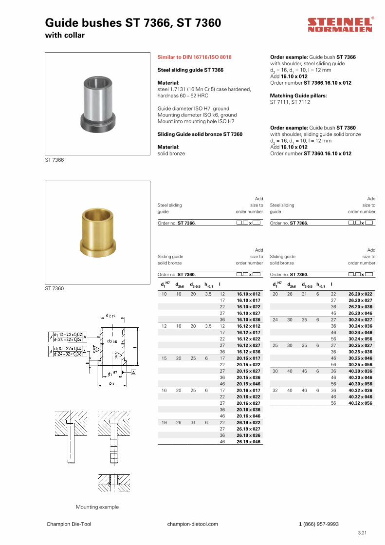
3.21
Guide bushes ST 7366, ST 7360with collar
Similar to DIN 16716/ISO 8018
Steel sliding guide ST 7366
Material:steel 1.7131 (16 Mn Cr 5) case hardened,hardness 60 – 62 HRC
Guide diameter ISO H7, groundMounting diameter ISO k6, groundMount into mounting hole ISO H7
Sliding Guide solid bronze ST 7360
Material:solid bronze
Order example: Guide bush ST 7366with shoulder, steel sliding guided2 = 16, d1 = 10, l = 12 mmAdd 16.10 x 012Order number ST 7366.16.10 x 012
Order example: Guide bush ST 7360with shoulder, sliding guide solid bronzed2 = 16, d1 = 10, l = 12 mmAdd 16.10 x 012Order number ST 7360.16.10 x 012
ST 7366
Mounting example
Addsize to
order number
Order no. ST 7366. . x
Steel slidingguide
ST 7360
Addsize to
order number
Order no. ST 7360. . x
Sliding guidesolid bronze
Addsize to
order number
Order no. ST 7366. . x
Steel slidingguide
Addsize to
order number
Order no. ST 7360. . x
Sliding guidesolid bronze
Matching Guide pillars:ST 7111, ST 7112
d1H7 d2k6 d3-0,5 h-0,1 l
10 16 20 3.5 12 16.10 x 01217 16.10 x 01722 16.10 x 02227 16.10 x 02736 16.10 x 036
12 16 20 3.5 12 16.12 x 01217 16.12 x 01722 16.12 x 02227 16.12 x 02736 16.12 x 036
15 20 25 6 17 20.15 x 01722 20.15 x 02227 20.15 x 02736 20.15 x 03646 20.15 x 046
16 20 25 6 17 20.16 x 01722 20.16 x 02227 20.16 x 02736 20.16 x 03646 20.16 x 046
19 26 31 6 22 26.19 x 02227 26.19 x 02736 26.19 x 03646 26.19 x 046
d1H7 d2k6 d3-0,5 h-0,1 l
20 26 31 6 22 26.20 x 02227 26.20 x 02736 26.20 x 03646 26.20 x 046
24 30 35 6 27 30.24 x 02736 30.24 x 03646 30.24 x 04656 30.24 x 056
25 30 35 6 27 30.25 x 02736 30.25 x 03646 30.25 x 04656 30.25 x 056
30 40 46 6 36 40.30 x 03646 40.30 x 04656 40.30 x 056
32 40 46 6 36 40.32 x 03646 40.32 x 04656 40.32 x 056
Champion Die-Tool champion-dietool.com 1 (866) 957-9993
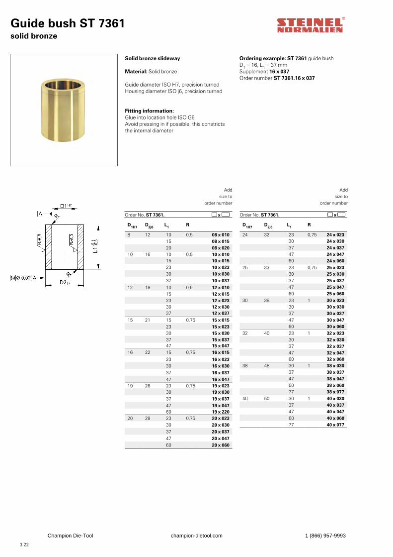
3.22
x x
D1H7 D2j6 L1 R
24 32 23 0,75 24 x 02330 24 x 03037 24 x 03747 24 x 04760 24 x 060
25 33 23 0,75 25 x 02330 25 x 03037 25 x 03747 25 x 04760 25 x 060
30 38 23 1 30 x 02330 30 x 03037 30 x 03747 30 x 04760 30 x 060
32 40 23 1 32 x 02330 32 x 03037 32 x 03747 32 x 04760 32 x 060
38 48 30 1 38 x 03037 38 x 03747 38 x 04760 38 x 06077 38 x 077
40 50 30 1 40 x 03037 40 x 03747 40 x 04760 40 x 06077 40 x 077
D1H7 D2j6 L1 R
8 12 10 0,5 08 x 01015 08 x 01520 08 x 020
10 16 10 0,5 10 x 01015 10 x 01523 10 x 02330 10 x 03037 10 x 037
12 18 10 0,5 12 x 01015 12 x 01523 12 x 02330 12 x 03037 12 x 037
15 21 15 0,75 15 x 01523 15 x 02330 15 x 03037 15 x 03747 15 x 047
16 22 15 0,75 16 x 015
23 16 x 02330 16 x 03037 16 x 03747 16 x 047
19 26 23 0,75 19 x 02330 19 x 03037 19 x 03747 19 x 04760 19 x 220
20 28 23 0,75 20 x 02330 20 x 03037 20 x 03747 20 x 04760 20 x 060
Guide bush ST 7361solid bronze
Solid bronze slideway
Material: Solid bronze
Guide diameter ISO H7, precision turnedHousing diameter ISO j6, precision turned
Fitting information: Glue into location hole ISO G6Avoid pressing in if possible, this constricts the internal diameter
Addsize to
order number
Order No. ST 7361.
Addsize to
order number
Order No. ST 7361.
Ordering example: ST 7361 guide bushD1 = 16, L1 = 37 mmSupplement 16 x 037Order number ST 7361.16 x 037
Champion Die-Tool champion-dietool.com 1 (866) 957-9993

3.23
Champion Die-Tool champion-dietool.com 1 (866) 957-9993
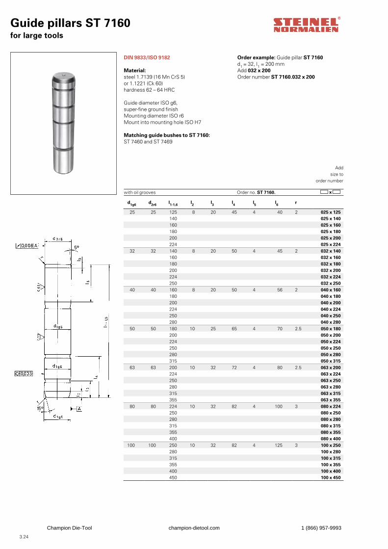
3.24
Guide pillars ST 7160for large tools
DIN 9833/ISO 9182
Material:steel 1.7139 (16 Mn CrS 5)or 1.1221 (Ck 60)hardness 62 – 64 HRC
Guide diameter ISO g6, super-fine ground finishMounting diameter ISO r6Mount into mounting hole ISO H7
Matching guide bushes to ST 7160:ST 7460 and ST 7469
Order example: Guide pillar ST 7160d1 = 32, l1 = 200 mmAdd 032 x 200Order number ST 7160.032 x 200
Addsize to
order number
with oil grooves x Order no. ST 7160.
d1g6 d2r6 l1-1,6 l2 l3 l4 l5 l6 r
25 25 125 8 20 45 4 40 2 025 x 125140 025 x 140160 025 x 160180 025 x 180200 025 x 200224 025 x 224
32 32 140 8 20 50 4 45 2 032 x 140160 032 x 160180 032 x 180200 032 x 200224 032 x 224250 032 x 250
40 40 160 8 20 50 4 56 2 040 x 160180 040 x 180200 040 x 200224 040 x 224250 040 x 250280 040 x 280
50 50 180 10 25 65 4 70 2.5 050 x 180200 050 x 200224 050 x 224250 050 x 250280 050 x 280315 050 x 315
63 63 200 10 32 72 4 80 2.5 063 x 200224 063 x 224250 063 x 250280 063 x 280315 063 x 315355 063 x 355
80 80 224 10 32 82 4 100 3 080 x 224250 080 x 250280 080 x 280315 080 x 315355 080 x 355400 080 x 400
100 100 250 10 32 82 4 125 3 100 x 250280 100 x 280315 100 x 315355 100 x 355400 100 x 400450 100 x 450
Champion Die-Tool champion-dietool.com 1 (866) 957-9993
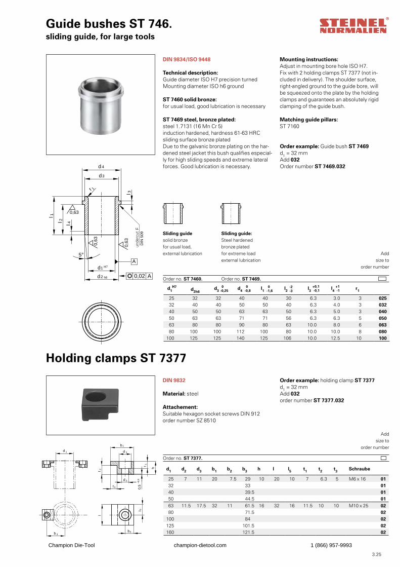
3.25
d1H7
d2h6 d3 d4 l1 l2 l3 l4 r1
25 32 32 40 40 30 6.3 3.0 3 02532 40 40 50 50 40 6.3 4.0 3 03240 50 50 63 63 50 6.3 5.0 3 04050 63 63 71 71 56 6.3 6.3 5 05063 80 80 90 80 63 10.0 8.0 6 06380 100 100 112 100 80 10.0 10.0 8 080
100 125 125 140 125 106 10.0 12.5 10 100
Guide bushes ST 746.sliding guide, for large tools
r 1
A
0,63
0,63
0,63
0,02 A
d
H7
d
3
4
d1
d2 h6
l 1
l 2 l 4
l 3
5°
Fre
istic
h F
DIN
509
DIN 9834/ISO 9448
Technical description:Guide diameter ISO H7 precision turnedMounting diameter ISO h6 ground
ST 7460 solid bronze:for usual load, good lubrication is necessary
ST 7469 steel, bronze plated:steel 1.7131 (16 Mn Cr 5)induction hardened, hardness 61-63 HRCsliding surface bronze platedDue to the galvanic bronze plating on the har-dened steel jacket this bush qualifies especial-ly for high sliding speeds and extreme lateral forces. Good lubrication is necessary.
Order example: Guide bush ST 7469d1 = 32 mmAdd 032Order number ST 7469.032
Addsize to
order number
Sliding guidesolid bronzefor usual load,external lubrication
Order no. ST 7460.
Sliding guide:Steel hardened bronze plated for extreme load external lubrication
Order no. ST 7469.
Mounting instructions:Adjust in mounting bore hole ISO H7.Fix with 2 holding clamps ST 7377 (not in-cluded in delivery). The shoulder surface, right-angled ground to the guide bore, will be squeezed onto the plate by the holding clamps and guarantees an absolutely rigid clamping of the guide bush.
Matching guide pillars:ST 7160
h
l
0,5
+0,
5
b 1
d 3
l 5t 1
t 2
d 2
t3
b2b 3
d 1
Holding clamps ST 7377
DIN 9832
Material: steel
Attachement:Suitable hexagon socket screws DIN 912order number SZ 8510
Order example: holding clamp ST 7377d1 = 32 mmAdd 032order number ST 7377.032
Addsize to
order number
Order no. ST 7377.
-2-3
+0,1 -0,1
+1 -1
d1 d2 d3 b1 b2 b3 h l l5 t1 t2 t3 Schraube
25 7 11 20 7.5 29 10 20 10 7 6.3 5 M6 x 16 0132 33 0140 39.5 0150 44.5 0163 11.5 17.5 32 11 61.5 16 32 16 11.5 10 10 M10 x 25 0280 71.5 02
100 84 02125 101.5 02160 121.5 02
unde
rcut
Champion Die-Tool champion-dietool.com 1 (866) 957-9993
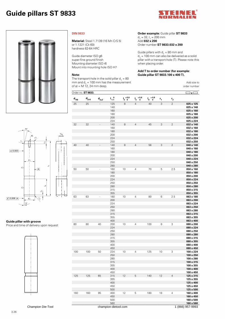
3.26
d1f6d2r6 d3±2 l 1-1
0 l2+
0 0,8 l3 +
0 0,8 l4 +
0 0,8 r1 r2
25 25 - 125 8 4 40 3 2 025 x 125140 025 x 140160 025 x 160180 025 x 180200 025 x 200224 025 x 224
32 32 - 140 8 4 45 3 2 032 x 140160 032 x 160180 032 x 180200 032 x 200224 032 x 224250 032 x 250
40 40 - 140 8 4 56 3 2 040 x 140 160 040 x 160
180 040 x 180200 040 x 200224 040 x 224250 040 x 250280 040 x 280
50 50 - 160 10 4 70 5 2.5 050 x 160 180 050 x 180
200 050 x 200224 050 x 224250 050 x 250280 050 x 280315 050 x 315355 050 x 355
63 63 - 180 10 4 80 6 2.5 063 x 180200 063 x 200224 063 x 224250 063 x 250280 063 x 280315 063 x 315355 063 x 355
400 063 x 40080 80 40 200 10 4 100 8 3 080 x 200
224 080 x 224250 080 x 250280 080 x 280315 080 x 315355 080 x 355400 080 x 400450 080 x 450
100 100 50 224 10 4 125 10 3 100 x 224250 100 x 250280 100 x 280315 100 x 315355 100 x 355400 100 x 400450 100 x 450
125 125 65 315 12 5 140 12 4 125 x 315355 125 x 355400 125 x 400450 125 x 450500 125 x 500
160 160 95 400 12 5 180 18 4 160 x 400450 160 x 450500 160 x 500560 160 x 560
Guide pillars ST 9833
DIN 9833
Material: Steel 1.7139 (16 Mn CrS 5)or 1.1221 (Ck 60)hardness 62-64 HRC
Guide diameter ISO g6 super-fine ground finishMounting diameter ISO r6Mount into mounting hole ISO H7
Note:The transport-hole in the solid pillar d1 = 80 mm and d1 = 100 mm has the measurement of a) = M 12, 24 mm deep.
Order example: Guide pillar ST 9833d1 = 32, l1 = 200 mmAdd 032 x 200Order number ST 9833.032 x 200
Guide pillars with d1 = 80 mm and d1 = 100 mm can also be delivered as a solid pillar with a transport-hole (T). Please note this when placing order.
Add T to order number (for example:Guide pillar ST 9833.100 x 400 T).
Add size toorder number
Order no. ST 9833. x
Guide pillar with groovePrice and time of delivery upon request
Champion Die-Tool champion-dietool.com 1 (866) 957-9993
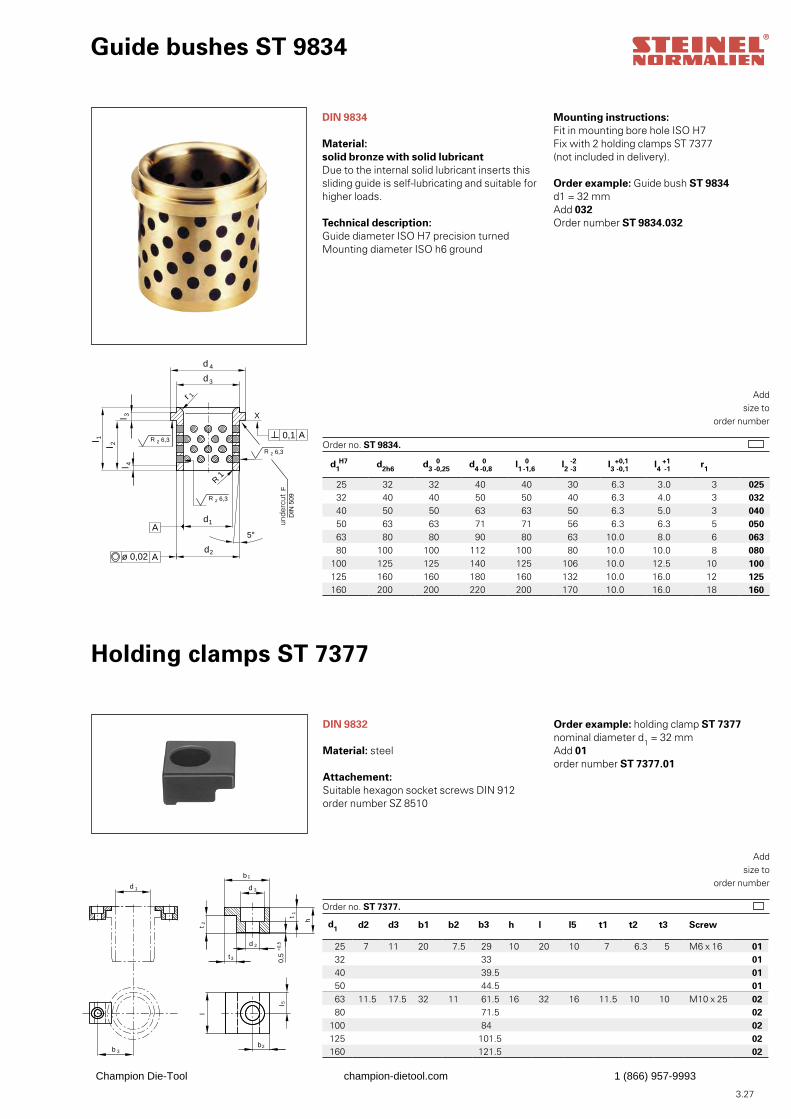
3.27
d1
d2
d3
l 1l 2
d 4
A
R 1
5°
X
A0,1
l 3
r 1
R 6,3z
l 4
R 6,3z
R 6,3z
ø 0,02 A
Fre
istic
h F
DIN
509
Guide bushes ST 9834
Material:solid bronze with solid lubricantDue to the internal solid lubricant inserts thissliding guide is self-lubricating and suitable forhigher loads.
Technical description:Guide diameter ISO H7 precision turnedMounting diameter ISO h6 ground
Order example: Guide bush ST 9834d1 = 32 mmAdd 032Order number ST 9834.032
Addsize to
order number
Order no. ST 9834.
Holding clamps ST 7377
DIN 9832
Material: steel
Attachement:Suitable hexagon socket screws DIN 912order number SZ 8510
Order example: holding clamp ST 7377nominal diameter d1 = 32 mmAdd 01order number ST 7377.01
Addsize to
order number
Order no. ST 7377.
d1 d2 d3 b1 b2 b3 h l l5 t1 t2 t3 Screw
25 7 11 20 7.5 29 10 20 10 7 6.3 5 M6 x 16 0132 33 0140 39.5 0150 44.5 0163 11.5 17.5 32 11 61.5 16 32 16 11.5 10 10 M10 x 25 0280 71.5 02
100 84 02125 101.5 02160 121.5 02
d1H7 d2h6 d3 0-0,25 d4 0-0,8 l1 0-1,6 l2 -2-3 l3
+0-0
,1,1 l4
+1-1 r1
25 32 32 40 40 30 6.3 3.0 3 025 32 40 40 50 50 40 6.3 4.0 3 032 40 50 50 63 63 50 6.3 5.0 3 040 50 63 63 71 71 56 6.3 6.3 5 050 63 80 80 90 80 63 10.0 8.0 6 063 80 100 100 112 100 80 10.0 10.0 8 080
100 125 125 140 125 106 10.0 12.5 10 100125 160 160 180 160 132 10.0 16.0 12 125160 200 200 220 200 170 10.0 16.0 18 160
DIN 9834 Mounting instructions:Fit in mounting bore hole ISO H7Fix with 2 holding clamps ST 7377(not included in delivery).
h
l
0,5
+0,
5
b 1
d 3
l 5t 1
t 2
d 2
t3
b2b 3
d 1
unde
rcut
Champion Die-Tool champion-dietool.com 1 (866) 957-9993
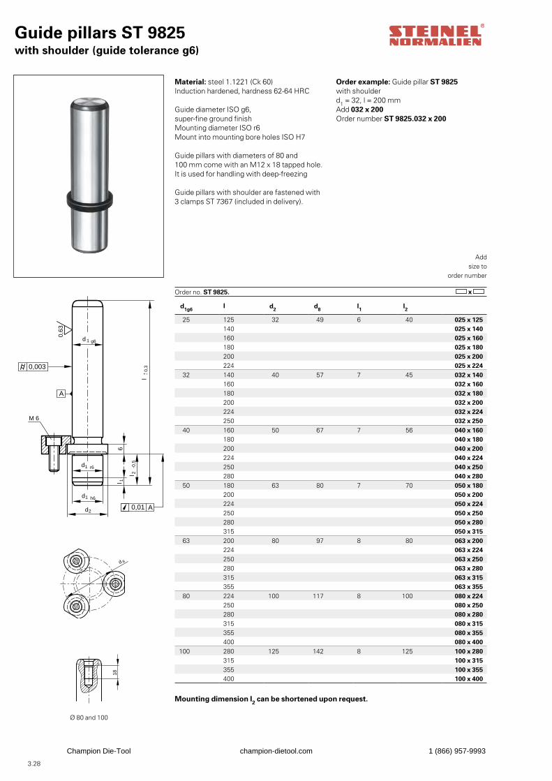
3.28
Guide pillars ST 9825with shoulder (guide tolerance g6)
0,01 A
g6d 1
0,63
A
r6d1
h6d1
d2
M 6
6l 1
l 2-0
,5
l0,
3+ -
0,003
Material: steel 1.1221 (Ck 60)Induction hardened, hardness 62-64 HRC
Guide diameter ISO g6, super-fine ground finishMounting diameter ISO r6Mount into mounting bore holes ISO H7
Guide pillars with diameters of 80 and100 mm come with an M12 x 18 tapped hole.It is used for handling with deep-freezing
Guide pillars with shoulder are fastened with3 clamps ST 7367 (included in delivery).
Order example: Guide pillar ST 9825with shoulderd1 = 32, l = 200 mmAdd 032 x 200Order number ST 9825.032 x 200
Addsize to
order number
Order no. ST 9825. x
18
d 8
d 8
18
d 8
d 8
Ø 80 and 100
Mounting dimension l2 can be shortened upon request.
d1g6l d2 d8 l1 l2
25 125 32 49 6 40 025 x 125140 025 x 140160 025 x 160180 025 x 180200 025 x 200224 025 x 224
32 140 40 57 7 45 032 x 140160 032 x 160180 032 x 180200 032 x 200224 032 x 224250 032 x 250
40 160 50 67 7 56 040 x 160180 040 x 180200 040 x 200224 040 x 224250 040 x 250280 040 x 280
50 180 63 80 7 70 050 x 180200 050 x 200224 050 x 224250 050 x 250280 050 x 280315 050 x 315
63 200 80 97 8 80 063 x 200224 063 x 224250 063 x 250280 063 x 280315 063 x 315355 063 x 355
80 224 100 117 8 100 080 x 224250 080 x 250280 080 x 280315 080 x 315355 080 x 355400 080 x 400
100 280 125 142 8 125 100 x 280315 100 x 315355 100 x 355400 100 x 400
Champion Die-Tool champion-dietool.com 1 (866) 957-9993
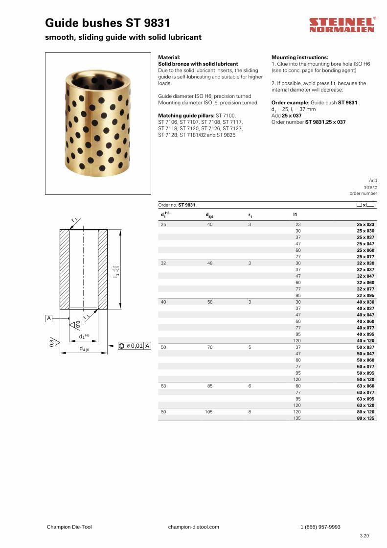
3.29
Guide bushes ST 9831smooth, sliding guide with solid lubricant
A
d4 j6
H6
l 1-0
,2-0
,5
0,01 Aø
d1
r 1
0,8
0,8
r 1
Material:Solid bronze with solid lubricantDue to the solid lubricant inserts, the slidingguide is self-lubricating and suitable for higherloads.
Guide diameter ISO H6, precision turnedMounting diameter ISO j6, precision turned
Matching guide pillars: ST 7100, ST 7106, ST 7107, ST 7108, ST 7117, ST 7118, ST 7120, ST 7126, ST 7127, ST 7128, ST 7181/82 and ST 9825
Order example: Guide bush ST 9831d1 = 25, l1 = 37 mmAdd 25 x 037Order number ST 9831.25 x 037
Addsize to
order number
Order no. ST 9831. x
Mounting instructions:1. Glue into the mounting bore hole ISO H6(see to conc. page for bonding agent)
2. If possible, avoid press fit, because theinternal diameter will decrease.
d1H6 d4j6 r1 l1
25 40 3 23 25 x 023 30 25 x 030 37 25 x 037 47 25 x 047 60 25 x 060 77 25 x 077
32 48 3 30 32 x 030 37 32 x 037 47 32 x 047 60 32 x 060 77 32 x 077 95 32 x 095
40 58 3 30 40 x 030 37 40 x 037 47 40 x 047 60 40 x 060 77 40 x 077 95 40 x 095
120 40 x 12050 70 5 37 50 x 037
47 50 x 047 60 50 x 060 77 50 x 077 95 50 x 095
120 50 x 12063 85 6 60 63 x 060
77 63 x 077 95 63 x 095
120 63 x 12080 105 8 120 80 x 120
135 80 x 135
Champion Die-Tool champion-dietool.com 1 (866) 957-9993
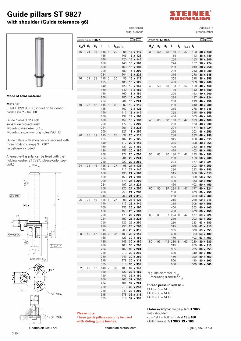
3.30
dg6*) d2 d8 l l1 l2-0,5 l3
38 50 67 160 7 37 123 38 x 160180 143 38 x 180200 163 38 x 200224 187 38 x 224250 213 38 x 250280 243 38 x 280315 278 38 x 315355 318 38 x 355400 363 38 x 400
40 50 67 160 7 37 123 40 x 160180 143 40 x 180200 163 40 x 200224 187 40 x 224250 213 40 x 250280 243 40 x 280315 278 40 x 315355 318 40 x 355400 363 40 x 400
48 63 80 180 7 47 133 48 x 180200 153 48 x 200224 177 48 x 224250 203 48 x 250280 233 48 x 280315 268 48 x 315355 308 48 x 355400 353 48 x 400450 403 48 x 450
50 63 80 180 7 47 133 50 x 180200 153 50 x 200224 177 50 x 224250 203 50 x 250280 233 50 x 280315 268 50 x 315355 308 50 x 355400 353 50 x 400450 403 50 x 450
60 80 97 224 8 47 177 60 x 224250 203 60 x 250280 233 60 x 280315 268 60 x 315355 308 60 x 355400 353 60 x 400450 403 60 x 450
63 80 97 224 8 47 177 63 x 224250 203 63 x 250280 233 63 x 280315 268 63 x 315355 308 63 x 355400 353 63 x 400450 403 63 x 450
80 95 112 280 8 60 220 80 x 280315 255 80 x 315355 295 80 x 355400 340 80 x 400450 390 80 x 450500 440 80 x 500560 500 80 x 560
dg6*) d2 d8 l l1 l2-0,5 l3
15 21 38 115 5 20 95 15 x 115125 105 15 x 125140 120 15 x 140160 140 15 x 160180 160 15 x 180200 180 15 x 200224 204 15 x 224
16 21 38 115 5 20 95 16 x 115125 105 16 x 125140 120 16 x 140160 140 16 x 160180 160 16 x 180200 180 16 x 200224 204 16 x 224
19 25 42 115 5 23 92 19 x 115125 102 19 x 125140 117 19 x 140160 137 19 x 160180 157 19 x 180200 177 19 x 200224 201 19 x 224250 227 19 x 250
20 25 42 115 5 23 92 20 x 115125 102 20 x 125140 117 20 x 140160 137 20 x 160180 157 20 x 180200 177 20 x 200224 201 20 x 224250 227 20 x 250
24 32 49 125 6 27 98 24 x 125140 113 24 x 140160 133 24 x 160180 153 24 x 180200 173 24 x 200224 197 24 x 224250 223 24 x 250280 253 24 x 280315 288 24 x 315
25 32 49 125 6 27 98 25 x 125140 113 25 x 140160 133 25 x 160180 153 25 x 180200 173 25 x 200224 197 25 x 224250 223 25 x 250280 253 25 x 280315 288 25 x 315
30 40 57 140 7 37 103 30 x 140160 123 30 x 160180 143 30 x 180200 163 30 x 200224 187 30 x 224250 213 30 x 250280 243 30 x 280315 278 30 x 315355 318 30 x 355
32 40 57 140 7 37 103 32 x 140160 123 32 x 160180 143 32 x 180200 163 32 x 200224 187 32 x 224250 213 32 x 250280 243 32 x 280315 278 32 x 315355 318 32 x 355
Guide pillars ST 9827with shoulder (Guide tolerance g6)
Made of solid material
Material:Steel 1.1221 (Ck 60) induction hardened,hardness 62 – 64 HRC
Guide diameter ISO g6 super-fine ground finishMounting diameter ISO j6Mounting into mounting holes ISO H6
Guide pillars with shoulder are secured withthree holding clamps ST 7367 (in delivery included).
Alternative this pillar can be fixed with theholding washer ST 7387. (please order spe-cially)
Order example: Guide pillar ST 9827with shoulderd1 = 19, l = 160 mm, Add 19 x 160Order number ST 9827.19 x 160
h
d 1
d3
*) guide diameter d1g6 mounting diameter d1j6
thread press-in side M =Ø 15 – 32 = M 8Ø 38 – 50 = M 10Ø 60 – 80 = M 12
Add size toorder number
Order no. ST 9827. x
Add size toorder number
Order no. ST 9827.
Please note:These guide pillars can only be used with sliding guide bushes.
x
ST 7367
ST 7387
guiding neck
Champion Die-Tool champion-dietool.com 1 (866) 957-9993
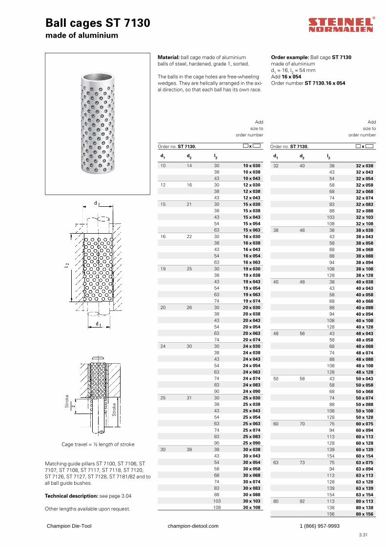
3.31
Ball cages ST 7130made of aluminium
Matching guide pillars ST 7100, ST 7106, ST 7107, ST 7108, ST 7117, ST 7118, ST 7120, ST 7126, ST 7127, ST 7128, ST 7181/82 and toall ball guide bushes.
Technical description: see page 3.04
Other lengths available upon request.
Order example: Ball cage ST 7130made of aluminiumd1 = 16, l2 = 54 mmAdd 16 x 054Order number ST 7130.16 x 054
Addsize to
order number
Order no. ST 7130. x
Addsize to
order number
Order no. ST 7130. x
Cage travel = ½ length of stroke
Material: ball cage made of aluminium balls of steel, hardened, grade 1, sorted.
The balls in the cage holes are free-wheelingwedges. They are helically arranged in the axi-al direction, so that each ball has its own race.
d1 d2 l2
10 14 30 10 x 030 38 10 x 038 43 10 x 043
12 16 30 12 x 030 38 12 x 038 43 12 x 043
15 21 30 15 x 030 38 15 x 038 43 15 x 043 54 15 x 054 63 15 x 063
16 22 30 16 x 030 38 16 x 038 43 16 x 043 54 16 x 054 63 16 x 063
19 25 30 19 x 030 38 19 x 038 43 19 x 043 54 19 x 054 63 19 x 063 74 19 x 074
20 26 30 20 x 030 38 20 x 038 43 20 x 043 54 20 x 054 63 20 x 063 74 20 x 074
24 30 30 24 x 030 38 24 x 038 43 24 x 043 54 24 x 054 63 24 x 063 74 24 x 074 83 24 x 083 90 24 x 090
25 31 30 25 x 030 38 25 x 038 43 25 x 043 54 25 x 054 63 25 x 063 74 25 x 074 83 25 x 083 90 25 x 090
30 38 38 30 x 038 43 30 x 043 54 30 x 054 58 30 x 058 68 30 x 068 74 30 x 074 83 30 x 083 88 30 x 088103 30 x 103108 30 x 108
d1 d2 l2
32 40 38 32 x 038 43 32 x 043 54 32 x 054 58 32 x 058 68 32 x 068 74 32 x 074 83 32 x 083 88 32 x 088
103 32 x 103108 32 x 108
38 46 38 38 x 038 43 38 x 043 58 38 x 058 68 38 x 068 88 38 x 088 94 38 x 094
108 38 x 108128 38 x 128
40 48 38 40 x 038 43 40 x 043 58 40 x 058 68 40 x 068 88 40 x 088 94 40 x 094
108 40 x 108128 40 x 128
48 56 43 48 x 043 58 48 x 058 68 48 x 068 74 48 x 074 88 48 x 088
108 48 x 108128 48 x 128
50 58 43 50 x 043 58 50 x 058 68 50 x 068 74 50 x 074 88 50 x 088
108 50 x 108128 50 x 128
60 70 75 60 x 075 94 60 x 094
113 60 x 113128 60 x 128139 60 x 139154 60 x 154
63 73 75 63 x 075 94 63 x 094
113 63 x 113128 63 x 128139 63 x 139154 63 x 154
80 92 113 80 x 113138 80 x 138156 80 x 156
Str
oke
Str
oke
Champion Die-Tool champion-dietool.com 1 (866) 957-9993
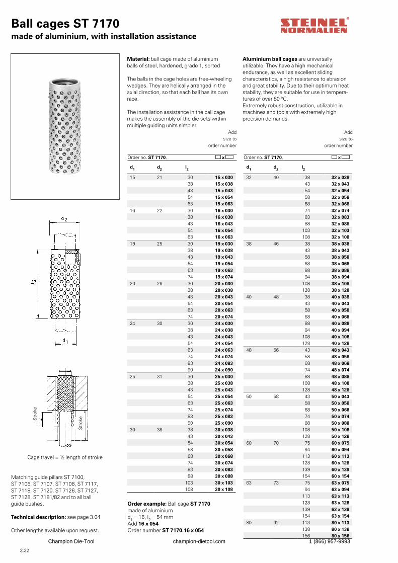
3.32
Ball cages ST 7170made of aluminium, with installation assistance
Matching guide pillars ST 7100, ST 7106, ST 7107, ST 7108, ST 7117, ST 7118, ST 7120, ST 7126, ST 7127, ST 7128, ST 7181/82 and to all ballguide bushes.
Technical description: see page 3.04
Other lengths available upon request.
Order example: Ball cage ST 7170made of aluminiumd1 = 16, l2 = 54 mmAdd 16 x 054Order number ST 7170.16 x 054
Addsize to
order number
Order no. ST 7170. x
Addsize to
order number
Order no. ST 7170. x
Str
oke
Material: ball cage made of aluminiumballs of steel, hardened, grade 1, sorted
The balls in the cage holes are free-wheelingwedges. They are helically arranged in the axial direction, so that each ball has its own race.
The installation assistance in the ball cagemakes the assembly of the die sets withinmultiple guiding units simpler.
Cage travel = ½ length of stroke
Str
oke
Aluminium ball cages are universally utilizable. They have a high mechanical endurance, as well as excellent sliding characteristics, a high resistance to abrasion and great stability. Due to their optimum heat stability, they are suitable for use in tempera-tures of over 80 °C.Extremely robust construction, utilizable inmachines and tools with extremely high precision demands.
d1 d2 l2
32 40 38 32 x 038 43 32 x 043 54 32 x 054 58 32 x 058 68 32 x 068 74 32 x 074 83 32 x 083 88 32 x 088
103 32 x 103108 32 x 108
38 46 38 38 x 038 43 38 x 043 58 38 x 058 68 38 x 068 88 38 x 088 94 38 x 094
108 38 x 108128 38 x 128
40 48 38 40 x 038 43 40 x 043 58 40 x 058 68 40 x 068 88 40 x 088 94 40 x 094
108 40 x 108128 40 x 128
48 56 43 48 x 043 58 48 x 058 68 48 x 068 74 48 x 074 88 48 x 088
108 48 x 108128 48 x 128
50 58 43 50 x 043 58 50 x 058 68 50 x 068 74 50 x 074 88 50 x 088
108 50 x 108128 50 x 128
60 70 75 60 x 075 94 60 x 094
113 60 x 113128 60 x 128139 60 x 139154 60 x 154
63 73 75 63 x 075 94 63 x 094
113 63 x 113128 63 x 128139 63 x 139154 63 x 154
80 92 113 80 x 113138 80 x 138156 80 x 156
d1 d2 l2
15 21 30 15 x 030 38 15 x 038 43 15 x 043 54 15 x 054 63 15 x 063
16 22 30 16 x 030 38 16 x 038 43 16 x 043 54 16 x 054 63 16 x 063
19 25 30 19 x 030 38 19 x 038 43 19 x 043 54 19 x 054 63 19 x 063 74 19 x 074
20 26 30 20 x 030 38 20 x 038 43 20 x 043 54 20 x 054 63 20 x 063 74 20 x 074
24 30 30 24 x 030 38 24 x 038 43 24 x 043 54 24 x 054 63 24 x 063 74 24 x 074 83 24 x 083 90 24 x 090
25 31 30 25 x 030 38 25 x 038 43 25 x 043 54 25 x 054 63 25 x 063 74 25 x 074 83 25 x 083 90 25 x 090
30 38 38 30 x 038 43 30 x 043 54 30 x 054 58 30 x 058 68 30 x 068 74 30 x 074 83 30 x 083 88 30 x 088
103 30 x 103108 30 x 108
Champion Die-Tool champion-dietool.com 1 (866) 957-9993
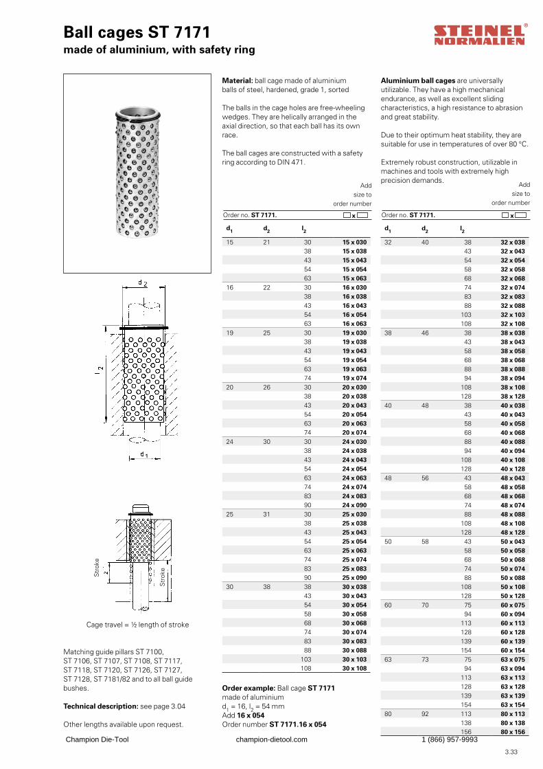
3.33
Ball cages ST 7171made of aluminium, with safety ring
Matching guide pillars ST 7100, ST 7106, ST 7107, ST 7108, ST 7117, ST 7118, ST 7120, ST 7126, ST 7127, ST 7128, ST 7181/82 and to all ball guidebushes.
Technical description: see page 3.04
Other lengths available upon request.
Order example: Ball cage ST 7171made of aluminiumd1 = 16, l2 = 54 mmAdd 16 x 054Order number ST 7171.16 x 054
Add size to
order number
Order no. ST 7171. x
Add size to
order number
Order no. ST 7171. x
Str
oke
Material: ball cage made of aluminiumballs of steel, hardened, grade 1, sorted
The balls in the cage holes are free-wheelingwedges. They are helically arranged in the axial direction, so that each ball has its own race.
The ball cages are constructed with a safety ring according to DIN 471.
Cage travel = ½ length of stroke
Str
oke
Aluminium ball cages are universally utilizable. They have a high mechanical endurance, as well as excellent sliding characteristics, a high resistance to abrasion and great stability.
Due to their optimum heat stability, they aresuitable for use in temperatures of over 80 °C.
Extremely robust construction, utilizable inmachines and tools with extremely high precision demands.
d1 d2 l2
32 40 38 32 x 038 43 32 x 043 54 32 x 054 58 32 x 058 68 32 x 068 74 32 x 074 83 32 x 083 88 32 x 088
103 32 x 103108 32 x 108
38 46 38 38 x 038 43 38 x 043 58 38 x 058 68 38 x 068 88 38 x 088 94 38 x 094
108 38 x 108128 38 x 128
40 48 38 40 x 038 43 40 x 043 58 40 x 058 68 40 x 068 88 40 x 088 94 40 x 094
108 40 x 108128 40 x 128
48 56 43 48 x 043 58 48 x 058 68 48 x 068 74 48 x 074 88 48 x 088
108 48 x 108128 48 x 128
50 58 43 50 x 043 58 50 x 058 68 50 x 068 74 50 x 074 88 50 x 088
108 50 x 108128 50 x 128
60 70 75 60 x 075 94 60 x 094
113 60 x 113128 60 x 128139 60 x 139154 60 x 154
63 73 75 63 x 075 94 63 x 094
113 63 x 113128 63 x 128139 63 x 139154 63 x 154
80 92 113 80 x 113138 80 x 138156 80 x 156
d1 d2 l2
15 21 30 15 x 030 38 15 x 038 43 15 x 043 54 15 x 054 63 15 x 063
16 22 30 16 x 030 38 16 x 038 43 16 x 043 54 16 x 054 63 16 x 063
19 25 30 19 x 030 38 19 x 038 43 19 x 043 54 19 x 054 63 19 x 063 74 19 x 074
20 26 30 20 x 030 38 20 x 038 43 20 x 043 54 20 x 054 63 20 x 063 74 20 x 074
24 30 30 24 x 030 38 24 x 038 43 24 x 043 54 24 x 054 63 24 x 063 74 24 x 074 83 24 x 083 90 24 x 090
25 31 30 25 x 030 38 25 x 038 43 25 x 043 54 25 x 054 63 25 x 063 74 25 x 074 83 25 x 083 90 25 x 090
30 38 38 30 x 038 43 30 x 043 54 30 x 054 58 30 x 058 68 30 x 068 74 30 x 074 83 30 x 083 88 30 x 088
103 30 x 103108 30 x 108
Champion Die-Tool champion-dietool.com 1 (866) 957-9993
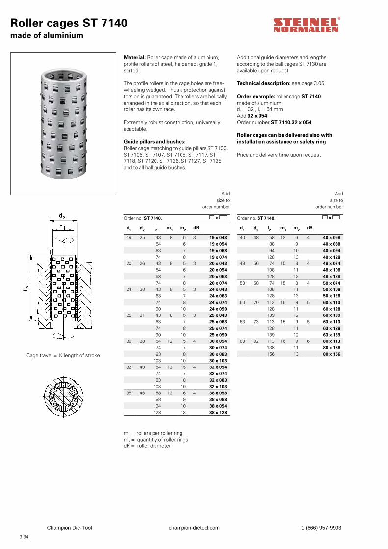
3.34
Roller cages ST 7140made of aluminium
Order example: roller cage ST 7140made of aluminiumd1 = 32 , l2 = 54 mmAdd 32 x 054Order number ST 7140.32 x 054
Roller cages can be delivered also with installation assistance or safety ring
Price and delivery time upon request
Addsize to
order number
Order no. ST 7140. x
Addsize to
order number
Order no. ST 7140. x
Cage travel = ½ length of stroke
Material: Roller cage made of aluminium, profile rollers of steel, hardened, grade 1, sorted.
The profile rollers in the cage holes are free-wheeling wedged. Thus a protection againsttorsion is guaranteed. The rollers are helicallyarranged in the axial direction, so that each roller has its own race.
Extremely robust construction, universally adaptable.
Guide pillars and bushes:Roller cage matching to guide pillars ST 7100, ST 7106, ST 7107, ST 7108, ST 7117, ST 7118, ST 7120, ST 7126, ST 7127, ST 7128 and to all ball guide bushes.
Additional guide diameters and lengthsaccording to the ball cages ST 7130 are available upon request.
Technical description: see page 3.05
m1 = rollers per roller ringm2 = quantitiy of roller ringsdR = roller diameter
d1 d2 l2 m1 m2 dR
19 25 43 8 5 3 19 x 043 54 6 19 x 054 63 7 19 x 063 74 8 19 x 074
20 26 43 8 5 3 20 x 043 54 6 20 x 054 63 7 20 x 063 74 8 20 x 074
24 30 43 8 5 3 24 x 043 63 7 24 x 063 74 8 24 x 074 90 10 24 x 090
25 31 43 8 5 3 25 x 043 63 7 25 x 063 74 8 25 x 074 90 10 25 x 090
30 38 54 12 5 4 30 x 054 74 7 30 x 074 83 8 30 x 083
103 10 30 x 10332 40 54 12 5 4 32 x 054
74 7 32 x 074 83 8 32 x 083
103 10 32 x 10338 46 58 12 6 4 38 x 058
88 9 38 x 088 94 10 38 x 094
128 13 38 x 128
d1 d2 l2 m1 m2 dR
40 48 58 12 6 4 40 x 058 88 9 40 x 088 94 10 40 x 094
128 13 40 x 12848 56 74 15 8 4 48 x 074
108 11 48 x 108128 13 48 x 128
50 58 74 15 8 4 50 x 074108 11 50 x 108128 13 50 x 128
60 70 113 15 9 5 60 x 113128 11 60 x 128139 12 60 x 139
63 73 113 15 9 5 63 x 113128 11 63 x 128139 12 63 x 139
80 92 113 16 9 6 80 x 113138 11 80 x 138156 13 80 x 156
Champion Die-Tool champion-dietool.com 1 (866) 957-9993
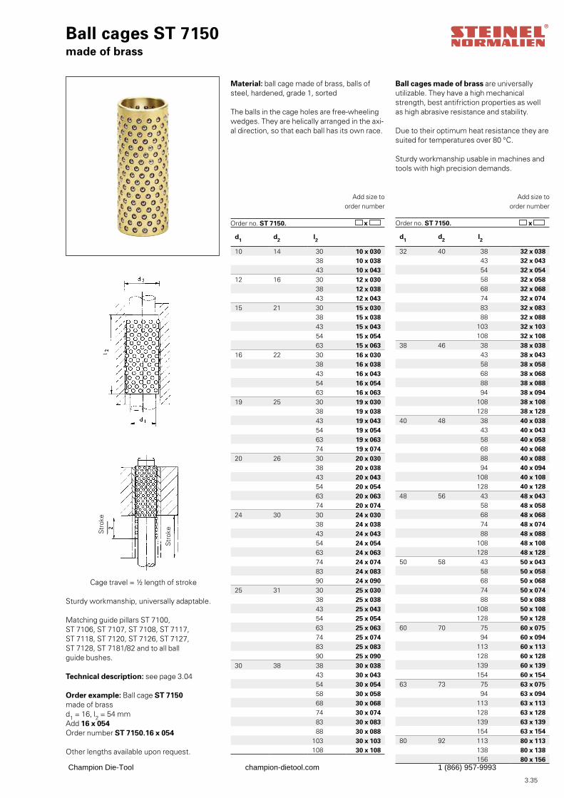
3.35
d1 d2 l2
10 14 30 10 x 030 38 10 x 038 43 10 x 043
12 16 30 12 x 030 38 12 x 038 43 12 x 043
15 21 30 15 x 030 38 15 x 038 43 15 x 043 54 15 x 054 63 15 x 063
16 22 30 16 x 030 38 16 x 038 43 16 x 043 54 16 x 054 63 16 x 063
19 25 30 19 x 030 38 19 x 038 43 19 x 043 54 19 x 054 63 19 x 063 74 19 x 074
20 26 30 20 x 030 38 20 x 038 43 20 x 043 54 20 x 054 63 20 x 063 74 20 x 074
24 30 30 24 x 030 38 24 x 038 43 24 x 043 54 24 x 054 63 24 x 063 74 24 x 074 83 24 x 083 90 24 x 090
25 31 30 25 x 030 38 25 x 038 43 25 x 043 54 25 x 054 63 25 x 063 74 25 x 074 83 25 x 083 90 25 x 090
30 38 38 30 x 038 43 30 x 043 54 30 x 054 58 30 x 058 68 30 x 068 74 30 x 074 83 30 x 083 88 30 x 088
103 30 x 103108 30 x 108
Ball cages ST 7150made of brass
Sturdy workmanship, universally adaptable.
Matching guide pillars ST 7100, ST 7106, ST 7107, ST 7108, ST 7117, ST 7118, ST 7120, ST 7126, ST 7127, ST 7128, ST 7181/82 and to all ballguide bushes.
Technical description: see page 3.04
Order example: Ball cage ST 7150made of brassd1 = 16, l2 = 54 mmAdd 16 x 054Order number ST 7150.16 x 054
Other lengths available upon request.
Add size toorder number
x
Add size toorder number
Order no. ST 7150. x
Str
oke
Material: ball cage made of brass, balls ofsteel, hardened, grade 1, sorted
The balls in the cage holes are free-wheelingwedges. They are helically arranged in the axi-al direction, so that each ball has its own race.
Cage travel = ½ length of stroke
Str
oke
Ball cages made of brass are universallyutilizable. They have a high mechanical strength, best antifriction properties as well as high abrasive resistance and stability.
Due to their optimum heat resistance they aresuited for temperatures over 80 °C.
Sturdy workmanship usable in machines andtools with high precision demands.
d1 d2 l2
32 40 38 32 x 038 43 32 x 043 54 32 x 054 58 32 x 058 68 32 x 068 74 32 x 074 83 32 x 083 88 32 x 088
103 32 x 103108 32 x 108
38 46 38 38 x 038 43 38 x 043 58 38 x 058 68 38 x 068 88 38 x 088 94 38 x 094
108 38 x 108128 38 x 128
40 48 38 40 x 038 43 40 x 043 58 40 x 058 68 40 x 068 88 40 x 088 94 40 x 094
108 40 x 108128 40 x 128
48 56 43 48 x 043 58 48 x 058 68 48 x 068 74 48 x 074 88 48 x 088
108 48 x 108128 48 x 128
50 58 43 50 x 043 58 50 x 058 68 50 x 068 74 50 x 074 88 50 x 088
108 50 x 108128 50 x 128
60 70 75 60 x 075 94 60 x 094
113 60 x 113128 60 x 128139 60 x 139154 60 x 154
63 73 75 63 x 075 94 63 x 094
113 63 x 113128 63 x 128139 63 x 139154 63 x 154
80 92 113 80 x 113138 80 x 138156 80 x 156
Order no. ST 7150.
Champion Die-Tool champion-dietool.com 1 (866) 957-9993
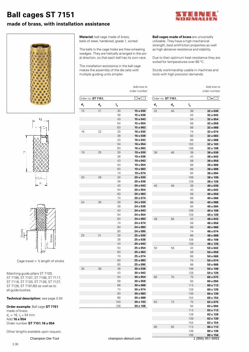
3.36
Ball cages ST 7151made of brass, with installation assistance
Matching guide pillars ST 7100, ST 7106, ST 7107, ST 7108, ST 7117, ST 7118, ST 7120, ST 7126, ST 7127, ST 7128, ST 7181/82 as well as toall guide bushes.
Technical description: see page 3.04
Order example: Ball cage ST 7151made of brassd1 = 16, l2 = 54 mmAdd 16 x 054Order number ST 7151.16 x 054
Other lengths available upon request.
Add size toorder number
Order no. ST 7151. x
Add size toorder number
Order no. ST 7151. x
Str
oke
Material: ball cage made of brass,balls of steel, hardened, grade 1, sorted
The balls in the cage holes are free-wheelingwedges. They are helically arranged in the axi-al direction, so that each ball has its own race.
The installation assistance in the ball cagemakes the assembly of the die sets withmultiple guiding units simpler.
Cage travel = ½ length of stroke
Str
oke
Ball cages made of brass are universallyutilizable. They have a high mechanical strength, best antifriction properties as well as high abrasive resistance and stability.
Due to their optimum heat resistance they aresuited for temperatures over 80 °C.
Sturdy workmanship usable in machines andtools with high precision demands.
d1 d2 l2
15 21 30 15 x 030 38 15 x 038 43 15 x 043 54 15 x 054 63 15 x 063
16 22 30 16 x 030 38 16 x 038 43 16 x 043 54 16 x 054 63 16 x 063
19 25 30 19 x 030 38 19 x 038 43 19 x 043 54 19 x 054 63 19 x 063 74 19 x 074
20 26 30 20 x 030 38 20 x 038 43 20 x 043 54 20 x 054 63 20 x 063 74 20 x 074
24 30 30 24 x 030 38 24 x 038 43 24 x 043 54 24 x 054 63 24 x 063 74 24 x 074 83 24 x 083 90 24 x 090
25 31 30 25 x 030 38 25 x 038 43 25 x 043 54 25 x 054 63 25 x 063 74 25 x 074 83 25 x 083 90 25 x 090
30 38 38 30 x 038 43 30 x 043 54 30 x 054 58 30 x 058 68 30 x 068 74 30 x 074 83 30 x 083 88 30 x 088
103 30 x 103108 30 x 108
d1 d2 l2
32 40 38 32 x 038 43 32 x 043 54 32 x 054 58 32 x 058 68 32 x 068 74 32 x 074 83 32 x 083 88 32 x 088
103 32 x 103108 32 x 108
38 46 38 38 x 038 43 38 x 043 58 38 x 058 68 38 x 068 88 38 x 088 94 38 x 094
108 38 x 108128 38 x 128
40 48 38 40 x 038 43 40 x 043 58 40 x 058 68 40 x 068 88 40 x 088 94 40 x 094
108 40 x 108128 40 x 128
48 56 43 48 x 043 58 48 x 058 68 48 x 068 74 48 x 074 88 48 x 088
108 48 x 108128 48 x 128
50 58 43 50 x 043 58 50 x 058 68 50 x 068 74 50 x 074 88 50 x 088
108 50 x 108128 50 x 128
60 70 75 60 x 075 94 60 x 094
113 60 x 113128 60 x 128139 60 x 139154 60 x 154
63 73 75 63 x 075 94 63 x 094
113 63 x 113128 63 x 128139 63 x 139154 63 x 154
80 92 113 80 x 113138 80 x 138156 80 x 156
Champion Die-Tool champion-dietool.com 1 (866) 957-9993
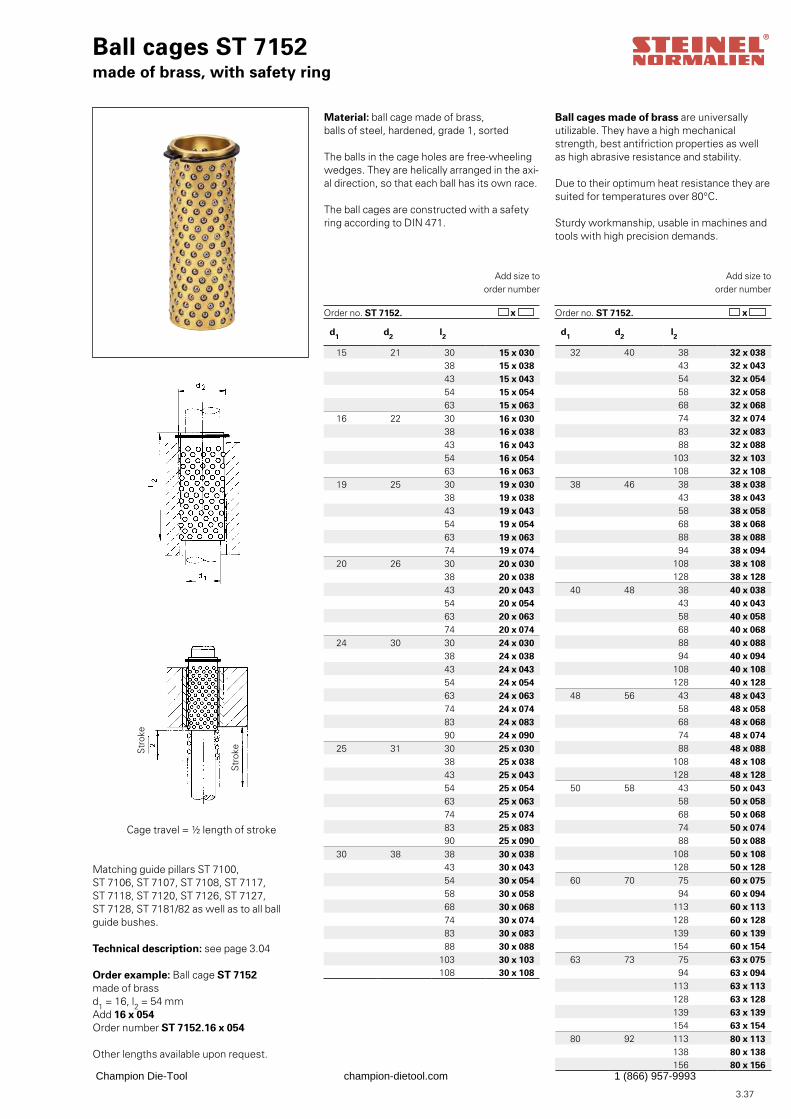
3.37
Ball cages ST 7152made of brass, with safety ring
Matching guide pillars ST 7100, ST 7106, ST 7107, ST 7108, ST 7117, ST 7118, ST 7120, ST 7126, ST 7127, ST 7128, ST 7181/82 as well as to all ball guide bushes.
Technical description: see page 3.04
Order example: Ball cage ST 7152made of brassd1 = 16, l2 = 54 mmAdd 16 x 054Order number ST 7152.16 x 054
Other lengths available upon request.
Add size toorder number
Order no. ST 7152. x
Add size toorder number
Order no. ST 7152. x
Str
oke
Material: ball cage made of brass,balls of steel, hardened, grade 1, sorted
The balls in the cage holes are free-wheelingwedges. They are helically arranged in the axi-al direction, so that each ball has its own race.
The ball cages are constructed with a safety ring according to DIN 471.
Cage travel = ½ length of stroke
Str
oke
Ball cages made of brass are universallyutilizable. They have a high mechanical strength, best antifriction properties as well as high abrasive resistance and stability.
Due to their optimum heat resistance they aresuited for temperatures over 80°C.
Sturdy workmanship, usable in machines andtools with high precision demands.
d1 d2 l2
15 21 30 15 x 030 38 15 x 038 43 15 x 043 54 15 x 054 63 15 x 063
16 22 30 16 x 030 38 16 x 038 43 16 x 043 54 16 x 054 63 16 x 063
19 25 30 19 x 030 38 19 x 038 43 19 x 043 54 19 x 054 63 19 x 063 74 19 x 074
20 26 30 20 x 030 38 20 x 038 43 20 x 043 54 20 x 054 63 20 x 063 74 20 x 074
24 30 30 24 x 030 38 24 x 038 43 24 x 043 54 24 x 054 63 24 x 063 74 24 x 074 83 24 x 083 90 24 x 090
25 31 30 25 x 030 38 25 x 038 43 25 x 043 54 25 x 054 63 25 x 063 74 25 x 074 83 25 x 083 90 25 x 090
30 38 38 30 x 038 43 30 x 043 54 30 x 054 58 30 x 058 68 30 x 068 74 30 x 074 83 30 x 083 88 30 x 088
103 30 x 103108 30 x 108
d1 d2 l2
32 40 38 32 x 038 43 32 x 043 54 32 x 054 58 32 x 058 68 32 x 068 74 32 x 074 83 32 x 083 88 32 x 088
103 32 x 103108 32 x 108
38 46 38 38 x 038 43 38 x 043 58 38 x 058 68 38 x 068 88 38 x 088 94 38 x 094
108 38 x 108128 38 x 128
40 48 38 40 x 038 43 40 x 043 58 40 x 058 68 40 x 068 88 40 x 088 94 40 x 094
108 40 x 108128 40 x 128
48 56 43 48 x 043 58 48 x 058 68 48 x 068 74 48 x 074 88 48 x 088
108 48 x 108128 48 x 128
50 58 43 50 x 043 58 50 x 058 68 50 x 068 74 50 x 074 88 50 x 088
108 50 x 108128 50 x 128
60 70 75 60 x 075 94 60 x 094
113 60 x 113128 60 x 128139 60 x 139154 60 x 154
63 73 75 63 x 075 94 63 x 094
113 63 x 113128 63 x 128139 63 x 139154 63 x 154
80 92 113 80 x 113138 80 x 138156 80 x 156
Champion Die-Tool champion-dietool.com 1 (866) 957-9993
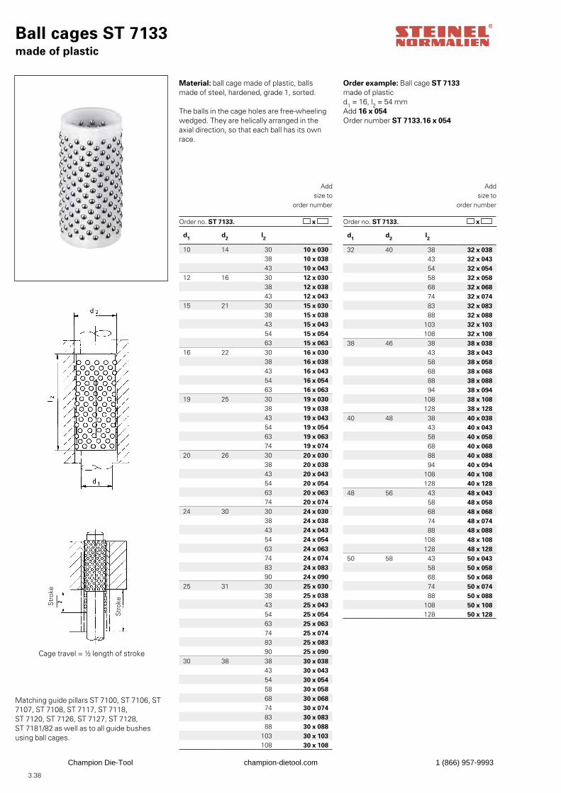
3.38
d1 d2 l2
32 40 38 32 x 03843 32 x 04354 32 x 05458 32 x 05868 32 x 06874 32 x 07483 32 x 08388 32 x 088
103 32 x 103108 32 x 108
38 46 38 38 x 03843 38 x 04358 38 x 05868 38 x 06888 38 x 08894 38 x 094
108 38 x 108128 38 x 128
40 48 38 40 x 038 43 40 x 043 58 40 x 058 68 40 x 068 88 40 x 088 94 40 x 094
108 40 x 108128 40 x 128
48 56 43 48 x 043 58 48 x 058 68 48 x 068 74 48 x 074 88 48 x 088
108 48 x 108128 48 x 128
50 58 43 50 x 043 58 50 x 058 68 50 x 068 74 50 x 074 88 50 x 088
108 50 x 108128 50 x 128
d1 d2 l2
10 14 30 10 x 03038 10 x 03843 10 x 043
12 16 30 12 x 03038 12 x 03843 12 x 043
15 21 30 15 x 03038 15 x 03843 15 x 04354 15 x 05463 15 x 063
16 22 30 16 x 03038 16 x 03843 16 x 04354 16 x 05463 16 x 063
19 25 30 19 x 03038 19 x 03843 19 x 04354 19 x 05463 19 x 06374 19 x 074
20 26 30 20 x 03038 20 x 03843 20 x 04354 20 x 05463 20 x 06374 20 x 074
24 30 30 24 x 03038 24 x 03843 24 x 04354 24 x 05463 24 x 06374 24 x 07483 24 x 08390 24 x 090
25 31 30 25 x 03038 25 x 03843 25 x 04354 25 x 05463 25 x 06374 25 x 07483 25 x 08390 25 x 090
30 38 38 30 x 03843 30 x 04354 30 x 05458 30 x 05868 30 x 06874 30 x 07483 30 x 08388 30 x 088
103 30 x 103108 30 x 108
Ball cages ST 7133made of plastic
Matching guide pillars ST 7100, ST 7106, ST 7107, ST 7108, ST 7117, ST 7118, ST 7120, ST 7126, ST 7127, ST 7128, ST 7181/82 as well as to all guide bushesusing ball cages.
Order example: Ball cage ST 7133made of plasticd1 = 16, l2 = 54 mmAdd 16 x 054Order number ST 7133.16 x 054
Addsize to
order number
Order no. ST 7133. x
Addsize to
order number
Order no. ST 7133. x
Str
oke
Material: ball cage made of plastic, balls made of steel, hardened, grade 1, sorted.
The balls in the cage holes are free-wheelingwedged. They are helically arranged in the axial direction, so that each ball has its own race.
Cage travel = ½ length of stroke
Str
oke
Champion Die-Tool champion-dietool.com 1 (866) 957-9993
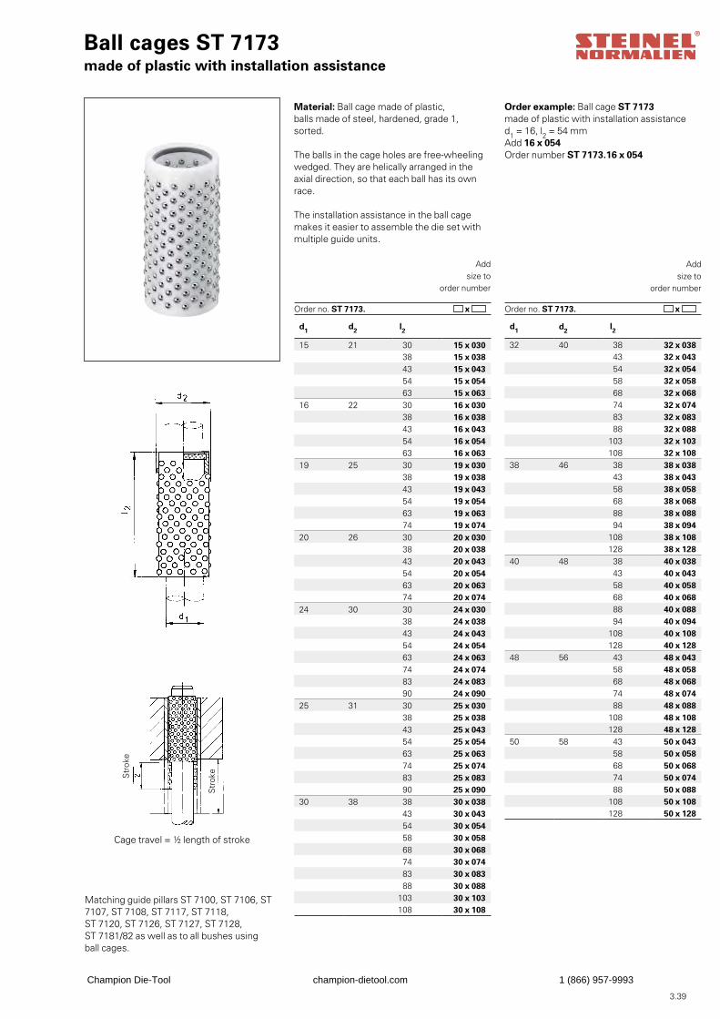
3.39
d1 d2 l2
32 40 38 32 x 038 43 32 x 043 54 32 x 054 58 32 x 058 68 32 x 068 74 32 x 074 83 32 x 083 88 32 x 088
103 32 x 103108 32 x 108
38 46 38 38 x 038 43 38 x 043 58 38 x 058 68 38 x 068 88 38 x 088 94 38 x 094
108 38 x 108128 38 x 128
40 48 38 40 x 038 43 40 x 043 58 40 x 058 68 40 x 068 88 40 x 088 94 40 x 094
108 40 x 108128 40 x 128
48 56 43 48 x 043 58 48 x 058 68 48 x 068 74 48 x 074 88 48 x 088
108 48 x 108128 48 x 128
50 58 43 50 x 043 58 50 x 058 68 50 x 068 74 50 x 074 88 50 x 088
108 50 x 108128 50 x 128
d1 d2 l2
15 21 30 15 x 030 38 15 x 038 43 15 x 043 54 15 x 054 63 15 x 063
16 22 30 16 x 030 38 16 x 038 43 16 x 043 54 16 x 054 63 16 x 063
19 25 30 19 x 030 38 19 x 038 43 19 x 043 54 19 x 054 63 19 x 063 74 19 x 074
20 26 30 20 x 030 38 20 x 038 43 20 x 043 54 20 x 054 63 20 x 063 74 20 x 074
24 30 30 24 x 030 38 24 x 038 43 24 x 043 54 24 x 054 63 24 x 063 74 24 x 074 83 24 x 083 90 24 x 090
25 31 30 25 x 030 38 25 x 038 43 25 x 043 54 25 x 054 63 25 x 063 74 25 x 074 83 25 x 083 90 25 x 090
30 38 38 30 x 038 43 30 x 043 54 30 x 054 58 30 x 058 68 30 x 068 74 30 x 074 83 30 x 083 88 30 x 088
103 30 x 103108 30 x 108
Ball cages ST 7173made of plastic with installation assistance
Matching guide pillars ST 7100, ST 7106, ST 7107, ST 7108, ST 7117, ST 7118, ST 7120, ST 7126, ST 7127, ST 7128, ST 7181/82 as well as to all bushes usingball cages.
Order example: Ball cage ST 7173made of plastic with installation assistanced1 = 16, l2 = 54 mmAdd 16 x 054Order number ST 7173.16 x 054
Addsize to
order number
Order no. ST 7173. x
Addsize to
order number
Order no. ST 7173. x
Str
oke
Material: Ball cage made of plastic,balls made of steel, hardened, grade 1,sorted.
The balls in the cage holes are free-wheelingwedged. They are helically arranged in the axial direction, so that each ball has its own race.
The installation assistance in the ball cagemakes it easier to assemble the die set withmultiple guide units.
Cage travel = ½ length of stroke
Str
oke
Champion Die-Tool champion-dietool.com 1 (866) 957-9993
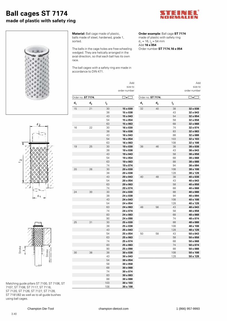
3.40
Ball cages ST 7174made of plastic with safety ring
Matching guide pillars ST 7100, ST 7106, ST 7107, ST 7108, ST 7117, ST 7118, ST 7120, ST 7126, ST 7127, ST 7128, ST 7181/82 as well as to all guide bushesusing ball cages.
Order example: Ball cage ST 7174made of plastic with safety ringd1 = 16, l2 = 54 mmAdd 16 x 054Order number ST 7174.16 x 054
Addsize to
order number
Order no. ST 7174. x
Addsize to
order number
Order no. ST 7174. x
Str
oke
Material: Ball cage made of plastic,balls made of steel, hardened, grade 1,sorted.
The balls in the cage holes are free-wheelingwedged. They are helically arranged in the axial direction, so that each ball has its own race.
The ball cages with a safety ring are made in accordance to DIN 471.
Str
oke
d1 d2 l2
15 21 30 15 x 030 38 15 x 038 43 15 x 043 54 15 x 054 63 15 x 063
16 22 30 16 x 030 38 16 x 038 43 16 x 043 54 16 x 054 63 16 x 063
19 25 30 19 x 030 38 19 x 038 43 19 x 043 54 19 x 054 63 19 x 063 74 19 x 074
20 26 30 20 x 030 38 20 x 038 43 20 x 043 54 20 x 054 63 20 x 063 74 20 x 074
24 30 30 24 x 030 38 24 x 038 43 24 x 043 54 24 x 054 63 24 x 063 74 24 x 074 83 24 x 083 90 24 x 090
25 31 30 25 x 030 38 25 x 038 43 25 x 043 54 25 x 054 63 25 x 063 74 25 x 074 83 25 x 083 90 25 x 090
30 38 38 30 x 038 43 30 x 043 54 30 x 054 58 30 x 058 68 30 x 068 74 30 x 074 83 30 x 083 88 30 x 088
103 30 x 103108 30 x 108
d1 d2 l2
32 40 38 32 x 038 43 32 x 043 54 32 x 054 58 32 x 058 68 32 x 068 74 32 x 074 83 32 x 083 88 32 x 088
103 32 x 103108 32 x 108
38 46 38 38 x 038 43 38 x 043 58 38 x 058 68 38 x 068 88 38 x 088 94 38 x 094
108 38 x 108128 38 x 128
40 48 38 40 x 038 43 40 x 043 58 40 x 058 68 40 x 068 88 40 x 088 94 40 x 094
108 40 x 108128 40 x 128
48 56 43 48 x 043 58 48 x 058 68 48 x 068 74 48 x 074 88 48 x 088
108 48 x 108128 48 x 128
50 58 43 50 x 043 58 50 x 058 68 50 x 068 74 50 x 074 88 50 x 088
108 50 x 108128 50 x 128
Champion Die-Tool champion-dietool.com 1 (866) 957-9993
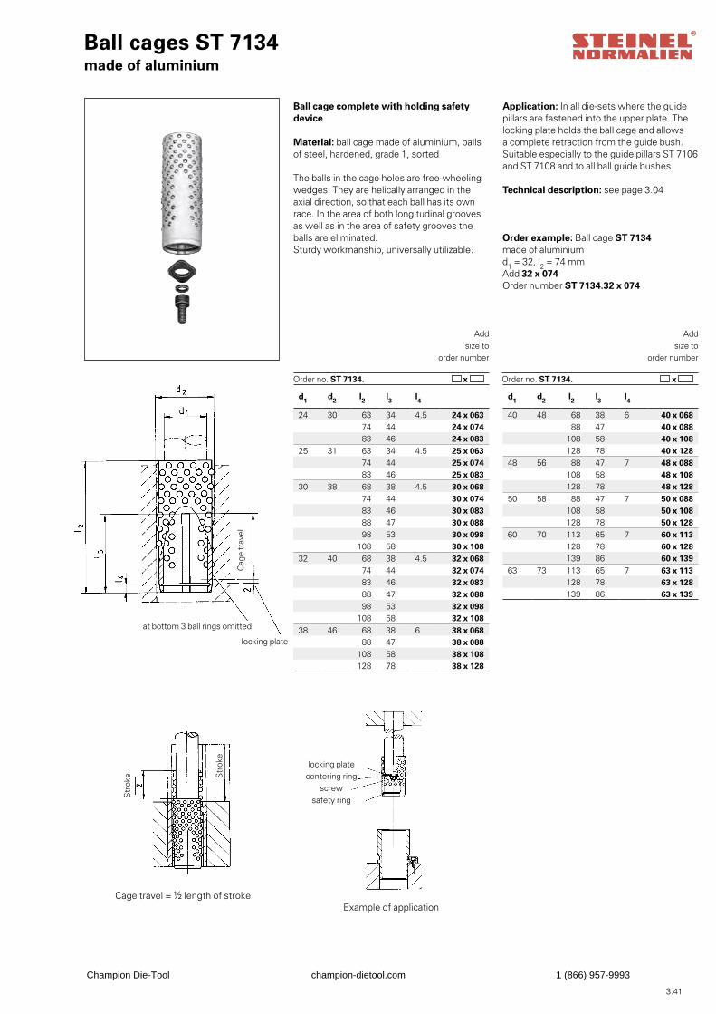
3.41
Ball cages ST 7134made of aluminium
Ball cage complete with holding safety device
Material: ball cage made of aluminium, balls of steel, hardened, grade 1, sorted
The balls in the cage holes are free-wheelingwedges. They are helically arranged in the axial direction, so that each ball has its own race. In the area of both longitudinal grooves as well as in the area of safety grooves the balls are eliminated.Sturdy workmanship, universally utilizable.
Order example: Ball cage ST 7134made of aluminiumd1 = 32, l2 = 74 mmAdd 32 x 074Order number ST 7134.32 x 074
Addsize to
order number
Order no. ST 7134. x
Addsize to
order number
Order no. ST 7134. x
locking plate centering ring
screw safety ring
Application: In all die-sets where the guidepillars are fastened into the upper plate. Thelocking plate holds the ball cage and allowsa complete retraction from the guide bush.Suitable especially to the guide pillars ST 7106and ST 7108 and to all ball guide bushes.
Technical description: see page 3.04
Cag
e tr
avel
at bottom 3 ball rings omitted
locking plate
Str
oke S
trok
e
Cage travel = ½ length of strokeExample of application
d1 d2 l2 l3 l4
24 30 63 34 4.5 24 x 063 74 44 24 x 074 83 46 24 x 083
25 31 63 34 4.5 25 x 063 74 44 25 x 074 83 46 25 x 083
30 38 68 38 4.5 30 x 068 74 44 30 x 074 83 46 30 x 083 88 47 30 x 088 98 53 30 x 098
108 58 30 x 10832 40 68 38 4.5 32 x 068
74 44 32 x 074 83 46 32 x 083 88 47 32 x 088 98 53 32 x 098
108 58 32 x 10838 46 68 38 6 38 x 068
88 47 38 x 088108 58 38 x 108128 78 38 x 128
d1 d2 l2 l3 l4
40 48 68 38 6 40 x 068 88 47 40 x 088
108 58 40 x 108128 78 40 x 128
48 56 88 47 7 48 x 088108 58 48 x 108128 78 48 x 128
50 58 88 47 7 50 x 088108 58 50 x 108128 78 50 x 128
60 70 113 65 7 60 x 113128 78 60 x 128139 86 60 x 139
63 73 113 65 7 63 x 113128 78 63 x 128139 86 63 x 139
Champion Die-Tool champion-dietool.com 1 (866) 957-9993
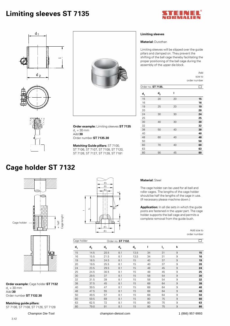
3.42
Limiting sleeves ST 7135
Matching Guide pillars: ST 7100, ST 7106, ST 7107, ST 7108, ST 7120, ST 7126, ST 7127, ST 7128, ST 7181
Order example: Limiting sleeves ST 7135d1 = 30 mmAdd 30Order number ST 7135.30
Addsize to
order number
Order no. ST 7135.
Limiting sleeves
Material: Durethan
Limiting sleeves will be slipped over the guidepillars and clamped on. They prevent theshifting of the ball cage thereby facilitating theproper positioning of the ball cage during the assembly of the upper die block.
Cage holder ST 7132
Order example: Cage holder ST 7132d1 = 30 mmAdd 30Order number ST 7132.30
k
l
d 1
d 2
d 4
l1
d 5
d 3
2
15°
Material: Steel
The cage holder can be used for all ball androller cages. The lengths of the cage holdershould be half the lengths of the cage in use.(If necessary please machine down.)
Application: In all die sets in which the guideposts are fastened in the upper part. The cageholder supports the ball cage and permits acomplete removal from the guide bush.
Add size toorder number
Order no. ST 7132.Cage holder
d1d2 l
15 20 20 1516 1619 25 20 1920 2024 30 30 2425 2530 40 30 3032 3238 50 40 3840 4048 60 40 4850 5060 70 40 6063 6380 90 45 80
d1 d2 d3 d4 d5 l l1 k
15 14.5 20.5 8.1 13,5 34 31 9 1516 15.5 21.5 8.1 13,5 34 31 9 1619 18.5 24.5 8.1 15 40 37 9 1920 19.5 25.5 8.1 15 40 37 9 2024 23.5 29.5 8.1 15 48 45 9 2425 24.5 30.5 8.1 15 48 45 9 2530 29.5 37 8.1 15 58 54 9 3032 31.5 39 8.1 15 58 54 9 3238 37.5 45 8.1 15 68 64 9 3840 39.5 47 8.1 15 68 64 9 4048 47.5 55 8.1 15 68 64 9 4850 49.5 57 8.1 15 68 64 9 5060 59.5 69 8.1 15 80 75 9 6063 62.5 72 8.1 15 80 75 9 6380 79.0 91 8.1 15 80 75 9 80
Matching guide pillars:ST 7106, ST 7108, ST 7126, ST 7128
half
Cag
e le
nght
Cage holder
~ ~
Champion Die-Tool champion-dietool.com 1 (866) 957-9993
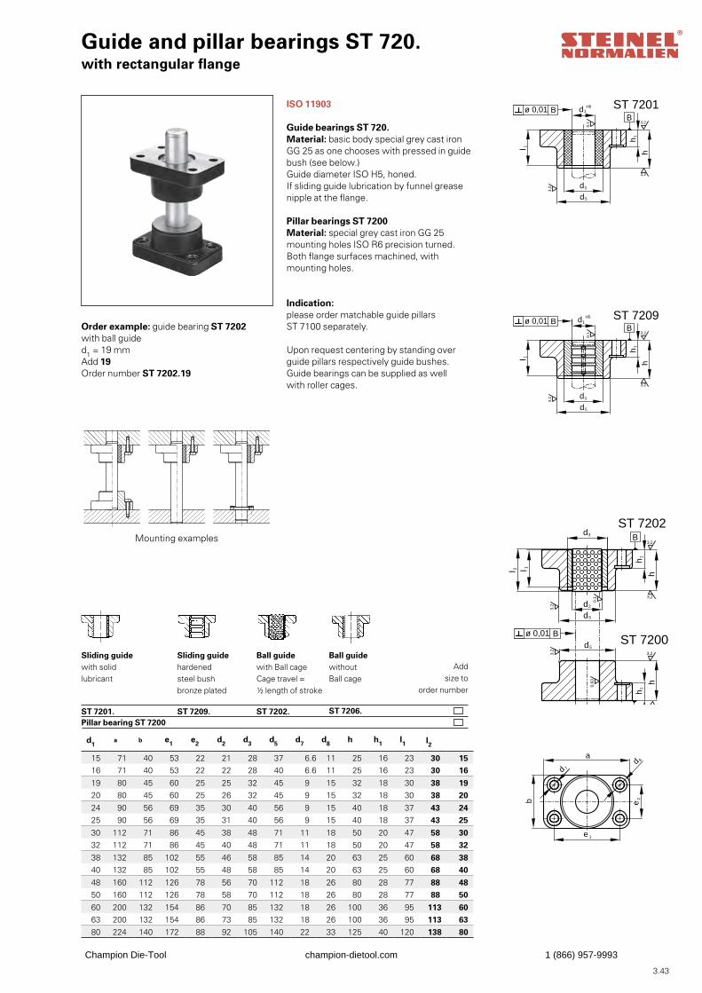
3.43
Addsize to
order number
Sliding guidewith solidlubricant
ST 7201.
Sliding guidehardenedsteel bushbronze plated ST 7209.
Ball guidewith Ball cageCage travel =½ length of stroke ST 7202.
Ball guidewithout Ball cage
ST 7206.
Guide and pillar bearings ST 720.with rectangular flange
Order example: guide bearing ST 7202with ball guided1 = 19 mmAdd 19Order number ST 7202.19
ISO 11903
Guide bearings ST 720.Material: basic body special grey cast ironGG 25 as one chooses with pressed in guidebush (see below.)Guide diameter ISO H5, honed.If sliding guide lubrication by funnel greasenipple at the flange.
Pillar bearings ST 7200Material: special grey cast iron GG 25mounting holes ISO R6 precision turned.Both flange surfaces machined, with mounting holes.
Indication: please order matchable guide pillarsST 7100 separately.
Upon request centering by standing over guide pillars respectively guide bushes.Guide bearings can be supplied as well with roller cages.
Mounting examples
hl 1
d5
d3
h1
3,2
3,2
3,2
0,1
ST 7201
B
hl 1
d5
d3
h1
3,2
3,2
3,2
0,1
d1H5 ST 7209
h1
3,2
3,2
d1R6
h
d5
0,63
d 8
d 7
e 1
e2b
a
ST 72003,2
B
A
ST 7202B
hl 2 l 1
d5
d3
d2
h1
3,2
3,2
3,2
0,1
H6d1ø 0,01 B
ø 0,01 B
ø 0,01 B
ø 0,01 A
d1 a b e1 e2 d2 d3 d5 d7 d8 h h1 l1 l2
15 71 40 53 22 21 28 37 6.6 11 25 16 23 30 1516 71 40 53 22 22 28 40 6.6 11 25 16 23 30 16
19 80 45 60 25 25 32 45 9 15 32 18 30 38 1920 80 45 60 25 26 32 45 9 15 32 18 30 38 20
24 90 56 69 35 30 40 56 9 15 40 18 37 43 2425 90 56 69 35 31 40 56 9 15 40 18 37 43 25
30 112 71 86 45 38 48 71 11 18 50 20 47 58 3032 112 71 86 45 40 48 71 11 18 50 20 47 58 32
38 132 85 102 55 46 58 85 14 20 63 25 60 68 3840 132 85 102 55 48 58 85 14 20 63 25 60 68 40
48 160 112 126 78 56 70 112 18 26 80 28 77 88 4850 160 112 126 78 58 70 112 18 26 80 28 77 88 50
60 200 132 154 86 70 85 132 18 26 100 36 95 113 6063 200 132 154 86 73 85 132 18 26 100 36 95 113 6380 224 140 172 88 92 105 140 22 33 125 40 120 138 80
hl 1
d5
d3
h1
3,2
3,2
3,2
0,1
ST 7201
B
hl 1
d5
d3
h1
3,2
3,2
3,2
0,1
d1H5 ST 7209
h1
3,2
3,2
d1R6
h
d5
0,63
d 8
d 7
e 1
e2b
a
ST 72003,2
B
A
ST 7202B
hl 2 l 1d5
d3
d2
h1
3,2
3,2
3,2
0,1
H6d1ø 0,01 B
ø 0,01 B
ø 0,01 B
ø 0,01 A
hl 1
d5
d3
h1
3,2
3,2
3,2
0,1
ST 7201
B
hl 1
d5
d3
h1
3,2
3,2
3,2
0,1
d1H5 ST 7209
h1
3,2
3,2
d1R6
hd5
0,63
d 8
d 7
e 1
e2b
a
ST 72003,2
B
A
ST 7202B
hl 2 l 1
d5
d3
d2
h1
3,2
3,2
3,2
0,1
H6d1ø 0,01 B
ø 0,01 B
ø 0,01 B
ø 0,01 A
hl 1
d5
d3
h1
3,2
3,2
3,2
0,1
ST 7201
B
hl 1
d5
d3
h1
3,2
3,2
3,2
0,1
d1H5 ST 7209
h1
3,2
3,2
d1R6
h
d5
0,63
d 8
d 7
e 1
e2b
a
ST 72003,2
B
A
ST 7202B
hl 2 l 1
d5
d3
d2h
1
3,2
3,2
3,2
0,1
H6d1ø 0,01 B
ø 0,01 B
ø 0,01 B
ø 0,01 A
Pillar bearing ST 7200
Champion Die-Tool champion-dietool.com 1 (866) 957-9993
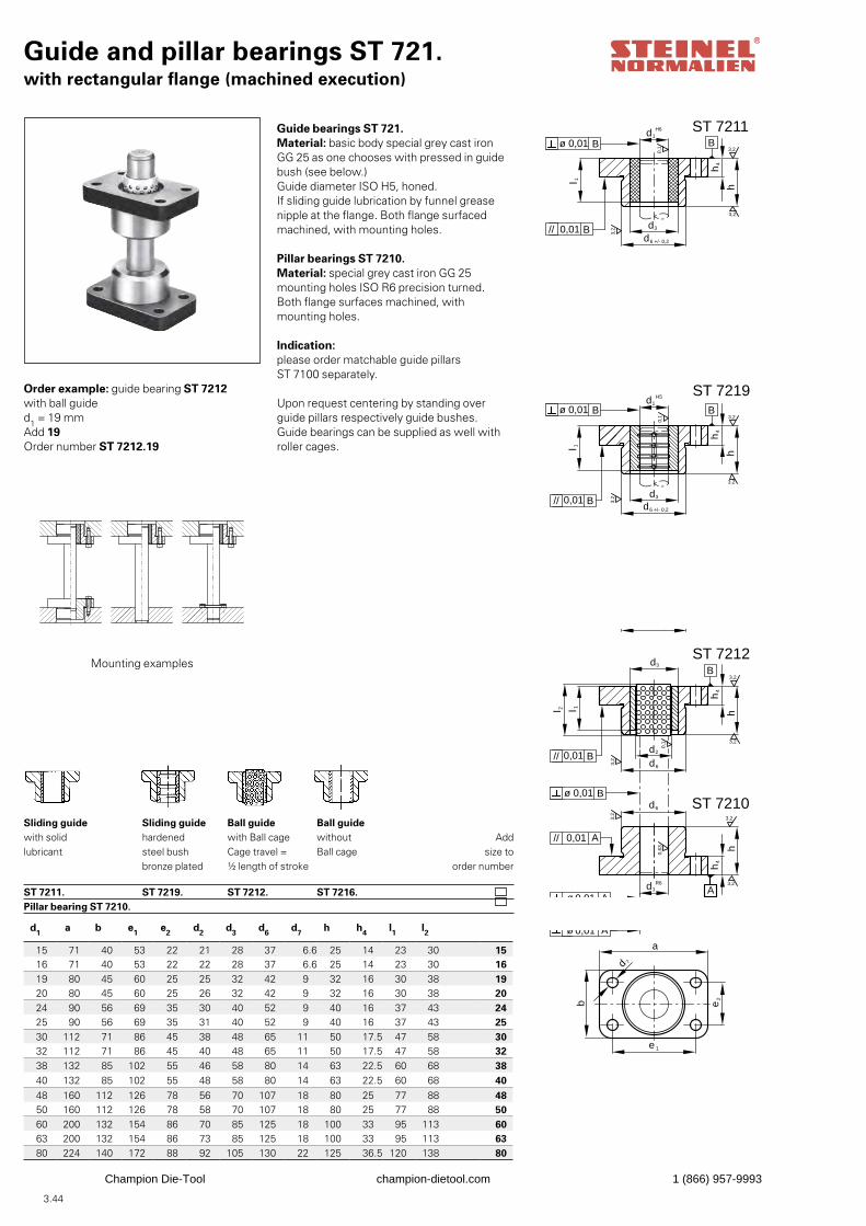
3.44
Guide and pillar bearings ST 721.with rectangular flange (machined execution)
B
d1H6
B3,20,
1
hl 1
d3
3,2
3,2
d3
d1H5
0,1
l 1 h
3,2
3,2
3,2
d6 +/- 0,2
d6 +/- 0,2
hl 2 l 1
d3
d2
3,2
3,2
3,2
0,1
B
3,2
3,2
d1R6
h
0,63
3,2
d6
d6
h4
h4
h4
h4
ST 7211
ST 7219
ST 7212
ST 7210b
a
e 1
e2
d 7
A
ø 0,01 B
B0,01//
ø 0,01 B
B0,01//
B0,01//
ø 0,01 B
0,01// A
ø 0,01 A
Guide bearings ST 721.Material: basic body special grey cast ironGG 25 as one chooses with pressed in guidebush (see below.)Guide diameter ISO H5, honed.If sliding guide lubrication by funnel greasenipple at the flange. Both flange surfaced machined, with mounting holes.
Pillar bearings ST 7210.Material: special grey cast iron GG 25mounting holes ISO R6 precision turned.Both flange surfaces machined, with mounting holes.
Order example: guide bearing ST 7212with ball guided1 = 19 mmAdd 19Order number ST 7212.19
Addsize to
order number
Sliding guidewith solidlubricant
ST 7211.
Indication: please order matchable guide pillarsST 7100 separately.
Upon request centering by standing over guide pillars respectively guide bushes.Guide bearings can be supplied as well withroller cages.
Sliding guidehardenedsteel bushbronze plated ST 7219.
Ball guidewith Ball cageCage travel =½ length of stroke ST 7212.
Ball guidewithoutBall cage
ST 7216.
Pillar bearing ST 7210.
Mounting examples
d1 a b e1 e2 d2 d3 d6 d7 h h4 l1 l2
15 71 40 53 22 21 28 37 6.6 25 14 23 30 1516 71 40 53 22 22 28 37 6.6 25 14 23 30 1619 80 45 60 25 25 32 42 9 32 16 30 38 1920 80 45 60 25 26 32 42 9 32 16 30 38 2024 90 56 69 35 30 40 52 9 40 16 37 43 2425 90 56 69 35 31 40 52 9 40 16 37 43 2530 112 71 86 45 38 48 65 11 50 17.5 47 58 3032 112 71 86 45 40 48 65 11 50 17.5 47 58 3238 132 85 102 55 46 58 80 14 63 22.5 60 68 3840 132 85 102 55 48 58 80 14 63 22.5 60 68 4048 160 112 126 78 56 70 107 18 80 25 77 88 4850 160 112 126 78 58 70 107 18 80 25 77 88 50 60 200 132 154 86 70 85 125 18 100 33 95 113 6063 200 132 154 86 73 85 125 18 100 33 95 113 6380 224 140 172 88 92 105 130 22 125 36.5 120 138 80
B
d1H6
B3,20,
1
hl 1
d3
3,2
3,2
d3
d1H5
0,1
l 1 h
3,2
3,2
3,2
d6 +/- 0,2
d6 +/- 0,2
hl 2 l 1
d3
d2
3,2
3,2
3,2
0,1
B
3,2
3,2
d1R6
h
0,63
3,2
d6
d6
h4
h4
h4
h4
ST 7211
ST 7219
ST 7212
ST 7210
b
a
e 1
e2
d 7
A
ø 0,01 B
B0,01//
ø 0,01 B
B0,01//
B0,01//
ø 0,01 B
0,01// A
ø 0,01 A
B
d1H6
B3,20,
1
hl 1
d3
3,2
3,2
d3
d1H5
0,1
l 1 h
3,2
3,2
3,2
d6 +/- 0,2
d6 +/- 0,2
hl 2 l 1
d3
d2
3,2
3,2
3,2
0,1
B
3,2
3,2
d1R6
h
0,63
3,2
d6
d6
h4
h4
h4
h4
ST 7211
ST 7219
ST 7212
ST 7210
b
a
e 1
e2
d 7
A
ø 0,01 B
B0,01//
ø 0,01 B
B0,01//
B0,01//
ø 0,01 B
0,01// A
ø 0,01 A
B
d1H6
B3,20,
1
hl 1
d3
3,2
3,2
d3
d1H5
0,1
l 1 h
3,2
3,2
3,2
d6 +/- 0,2
d6 +/- 0,2
hl 2 l 1
d3
d2
3,2
3,2
3,2
0,1
B
3,2
3,2
d1R6
h
0,63
3,2
d6
d6
h4
h4
h4
h4
ST 7211
ST 7219
ST 7212
ST 7210
b
a
e 1
e2
d 7
A
ø 0,01 B
B0,01//
ø 0,01 B
B0,01//
B0,01//
ø 0,01 B
0,01// A
ø 0,01 A
Champion Die-Tool champion-dietool.com 1 (866) 957-9993
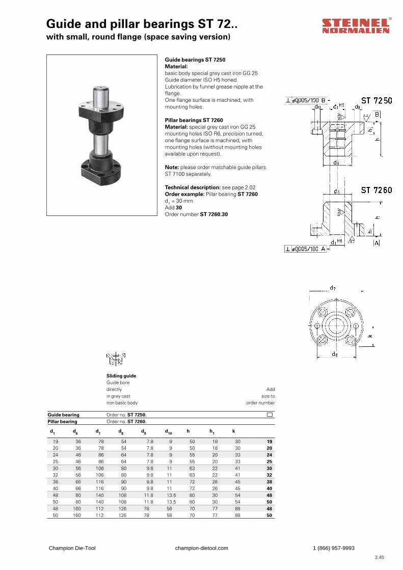
3.45
Guide and pillar bearings ST 72..with small, round flange (space saving version)
Guide bearings ST 7250Material: basic body special grey cast iron GG 25Guide diameter ISO H5 honed.Lubrication by funnel grease nipple at the flange.One flange surface is machined, with mounting holes.
Pillar bearings ST 7260Material: special grey cast iron GG 25mounting holes ISO R6, precision turned,one flange surface is machined, with mounting holes (without mounting holes available upon request).
Note: please order matchable guide pillarsST 7100 separately.
Technical description: see page 2.02Order example: Pillar bearing ST 7260d1 = 30 mmAdd 30Order number ST 7260.30
Addsize to
order number
Sliding guideGuide boredirectlyin grey castiron basic body Order no. ST 7250. Order no. ST 7260.
Guide bearing Pillar bearing
d1 d6 d7 d8 d9 d10 h h1 k
19 36 78 54 7.8 9 50 18 30 1920 36 78 54 7.8 9 50 18 30 2024 46 86 64 7.8 9 55 20 33 2425 46 86 64 7.8 9 55 20 33 2530 56 106 80 9.8 11 63 22 41 3032 56 106 80 9.8 11 63 22 41 3238 66 116 90 9.8 11 72 26 45 3840 66 116 90 9.8 11 72 26 45 4048 80 140 108 11.8 13.5 80 30 54 4850 80 140 108 11.8 13.5 80 30 54 5048 160 112 126 78 56 70 77 88 4850 160 112 126 78 58 70 77 88 50
Champion Die-Tool champion-dietool.com 1 (866) 957-9993
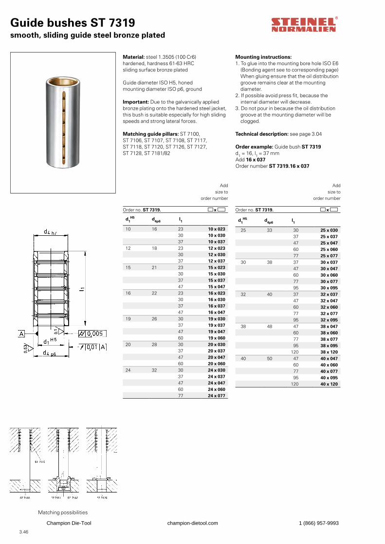
3.46
d1H5 d4p6
l1
25 33 30 25 x 030 37 25 x 037 47 25 x 047 60 25 x 060 77 25 x 077
30 38 37 30 x 037 47 30 x 047 60 30 x 060 77 30 x 077 95 30 x 095
32 40 37 32 x 037 47 32 x 047 60 32 x 060 77 32 x 077 95 32 x 095
38 48 47 38 x 047 60 38 x 060 77 38 x 077 95 38 x 095
120 38 x 12040 50 47 40 x 047
60 40 x 060 77 40 x 077 95 40 x 095
120 40 x 120
d1H5 d4p6
l1
10 16 23 10 x 02330 10 x 03037 10 x 037
12 18 23 12 x 02330 12 x 03037 12 x 037
15 21 23 15 x 02330 15 x 03037 15 x 03747 15 x 047
16 22 23 16 x 02330 16 x 03037 16 x 03747 16 x 047
19 26 30 19 x 03037 19 x 03747 19 x 04760 19 x 060
20 28 30 20 x 03037 20 x 03747 20 x 04760 20 x 060
24 32 30 24 x 03037 24 x 03747 24 x 04760 24 x 06077 24 x 077
Guide bushes ST 7319smooth, sliding guide steel bronze plated
Material: steel 1.3505 (100 Cr6)hardened, hardness 61-63 HRCsliding surface bronze plated
Guide diameter ISO H5, honedmounting diameter ISO p6, ground
Important: Due to the galvanically appliedbronze plating onto the hardened steel jacket,this bush is suitable especially for high slidingspeeds and strong lateral forces.
Matching guide pillars: ST 7100, ST 7106, ST 7107, ST 7108, ST 7117, ST 7118, ST 7120, ST 7126, ST 7127, ST 7128, ST 7181/82
Order example: Guide bush ST 7319d1 = 16, l1 = 37 mmAdd 16 x 037Order number ST 7319.16 x 037
Addsize to
order number
Order no. ST 7319. x
Mounting instructions:1. To glue into the mounting bore hole ISO E6 (Bonding agent see to corresponding page) When gluing ensure that the oil distribution groove remains clear at the mounting diameter. 2. If possible avoid press fit, because the internal diameter will decrease.3. Do not pour in because the oil distribution groove at the mounting diameter will be clogged.
Technical description: see page 3.04
Addsize to
order number
Order no. ST 7319. x
Matching possibilities
Champion Die-Tool champion-dietool.com 1 (866) 957-9993
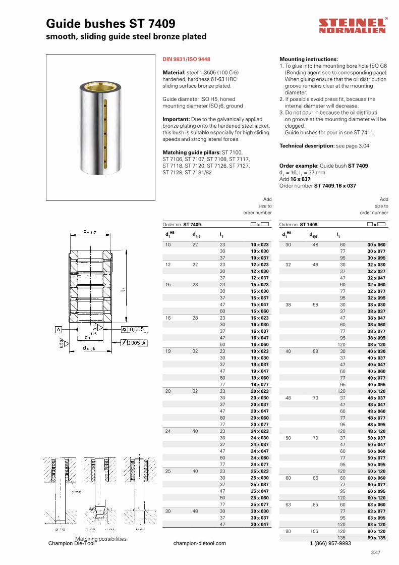
3.47
Guide bushes ST 7409smooth, sliding guide steel bronze plated
DIN 9831/ISO 9448
Material: steel 1.3505 (100 Cr6)hardened, hardness 61-63 HRCsliding surface bronze plated.
Guide diameter ISO H5, honedmounting diameter ISO j6, ground
Important: Due to the galvanically appliedbronze plating onto the hardened steel jacket,this bush is suitable especially for high slidingspeeds and strong lateral forces.
Matching guide pillars: ST 7100, ST 7106, ST 7107, ST 7108, ST 7117, ST 7118, ST 7120, ST 7126, ST 7127, ST 7128, ST 7181/82
Order example: Guide bush ST 7409d1 = 16, l1 = 37 mmAdd 16 x 037Order number ST 7409.16 x 037
Addsize to
order number
Order no. ST 7409. x
Mounting instructions:1. To glue into the mounting bore hole ISO G6 (Bonding agent see to corresponding page) When gluing ensure that the oil distribution groove remains clear at the mounting diameter.2. If possible avoid press fit, because the internal diameter will decrease.3. Do not pour in because the oil distributi on groove at the mounting diameter will be clogged. Guide bushes for pour in see ST 7411.
Technical description: see page 3.04
Addsize to
order number
Order no. ST 7409. x
Matching possibilities
d1H5 d4j6 l1
10 22 23 10 x 02330 10 x 03037 10 x 037
12 22 23 12 x 02330 12 x 03037 12 x 037
15 28 23 15 x 02330 15 x 03037 15 x 03747 15 x 04760 15 x 060
16 28 23 16 x 02330 16 x 03037 16 x 03747 16 x 04760 16 x 060
19 32 23 19 x 02330 19 x 03037 19 x 03747 19 x 04760 19 x 06077 19 x 077
20 32 23 20 x 02330 20 x 03037 20 x 03747 20 x 04760 20 x 06077 20 x 077
24 40 23 24 x 02330 24 x 03037 24 x 03747 24 x 04760 24 x 06077 24 x 077
25 40 23 25 x 02330 25 x 03037 25 x 03747 25 x 04760 25 x 06077 25 x 077
30 48 30 30 x 03037 30 x 03747 30 x 047
d1H5 d4j6 l1
30 48 60 30 x 060 77 30 x 077 95 30 x 095
32 48 30 32 x 030 37 32 x 037 47 32 x 047 60 32 x 060 77 32 x 077 95 32 x 095
38 58 30 38 x 030 37 38 x 037 47 38 x 047 60 38 x 060 77 38 x 077 95 38 x 095
120 38 x 12040 58 30 40 x 030
37 40 x 037 47 40 x 047 60 40 x 060 77 40 x 077 95 40 x 095
120 40 x 12048 70 37 48 x 037
47 48 x 047 60 48 x 060 77 48 x 077 95 48 x 095
120 48 x 12050 70 37 50 x 037
47 50 x 047 60 50 x 060 77 50 x 077 95 50 x 095
120 50 x 12060 85 60 60 x 060
77 60 x 077 95 60 x 095
120 60 x 12063 85 60 63 x 060
77 63 x 077 95 63 x 095
120 63 x 12080 105 120 80 x 120
135 80 x 135Champion Die-Tool champion-dietool.com 1 (866) 957-9993
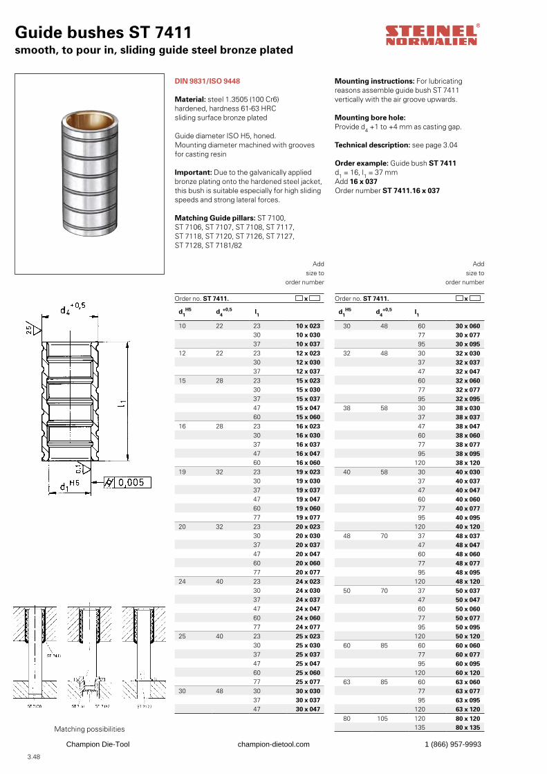
3.48
Guide bushes ST 7411smooth, to pour in, sliding guide steel bronze plated
DIN 9831/ISO 9448
Material: steel 1.3505 (100 Cr6)hardened, hardness 61-63 HRCsliding surface bronze plated
Guide diameter ISO H5, honed.Mounting diameter machined with grooves for casting resin
Important: Due to the galvanically appliedbronze plating onto the hardened steel jacket,this bush is suitable especially for high slidingspeeds and strong lateral forces.
Matching Guide pillars: ST 7100, ST 7106, ST 7107, ST 7108, ST 7117, ST 7118, ST 7120, ST 7126, ST 7127, ST 7128, ST 7181/82
Order example: Guide bush ST 7411d1 = 16, l1 = 37 mmAdd 16 x 037Order number ST 7411.16 x 037
Addsize to
order number
Order no. ST 7411. x
Mounting instructions: For lubricating reasons assemble guide bush ST 7411 vertically with the air groove upwards.
Mounting bore hole:Provide d4 +1 to +4 mm as casting gap.
Technical description: see page 3.04
Addsize to
order number
Order no. ST 7411. x
Matching possibilities
d1H5 d4
+0,5 l1
10 22 23 10 x 02330 10 x 03037 10 x 037
12 22 23 12 x 02330 12 x 03037 12 x 037
15 28 23 15 x 02330 15 x 03037 15 x 03747 15 x 04760 15 x 060
16 28 23 16 x 02330 16 x 03037 16 x 03747 16 x 04760 16 x 060
19 32 23 19 x 02330 19 x 03037 19 x 03747 19 x 04760 19 x 06077 19 x 077
20 32 23 20 x 02330 20 x 03037 20 x 03747 20 x 04760 20 x 06077 20 x 077
24 40 23 24 x 02330 24 x 03037 24 x 03747 24 x 04760 24 x 06077 24 x 077
25 40 23 25 x 02330 25 x 03037 25 x 03747 25 x 04760 25 x 06077 25 x 077
30 48 30 30 x 03037 30 x 03747 30 x 047
d1H5 d4
+0,5 l1
30 48 60 30 x 060 77 30 x 077 95 30 x 095
32 48 30 32 x 030 37 32 x 037 47 32 x 047 60 32 x 060 77 32 x 077 95 32 x 095
38 58 30 38 x 030 37 38 x 037 47 38 x 047 60 38 x 060 77 38 x 077 95 38 x 095
120 38 x 12040 58 30 40 x 030
37 40 x 037 47 40 x 047 60 40 x 060 77 40 x 077 95 40 x 095
120 40 x 12048 70 37 48 x 037
47 48 x 047 60 48 x 060 77 48 x 077 95 48 x 095
120 48 x 12050 70 37 50 x 037
47 50 x 047 60 50 x 060 77 50 x 077 95 50 x 095
120 50 x 12060 85 60 60 x 060
77 60 x 077 95 60 x 095
120 60 x 12063 85 60 63 x 060
77 63 x 077 95 63 x 095
120 63 x 12080 105 120 80 x 120
135 80 x 135
Champion Die-Tool champion-dietool.com 1 (866) 957-9993
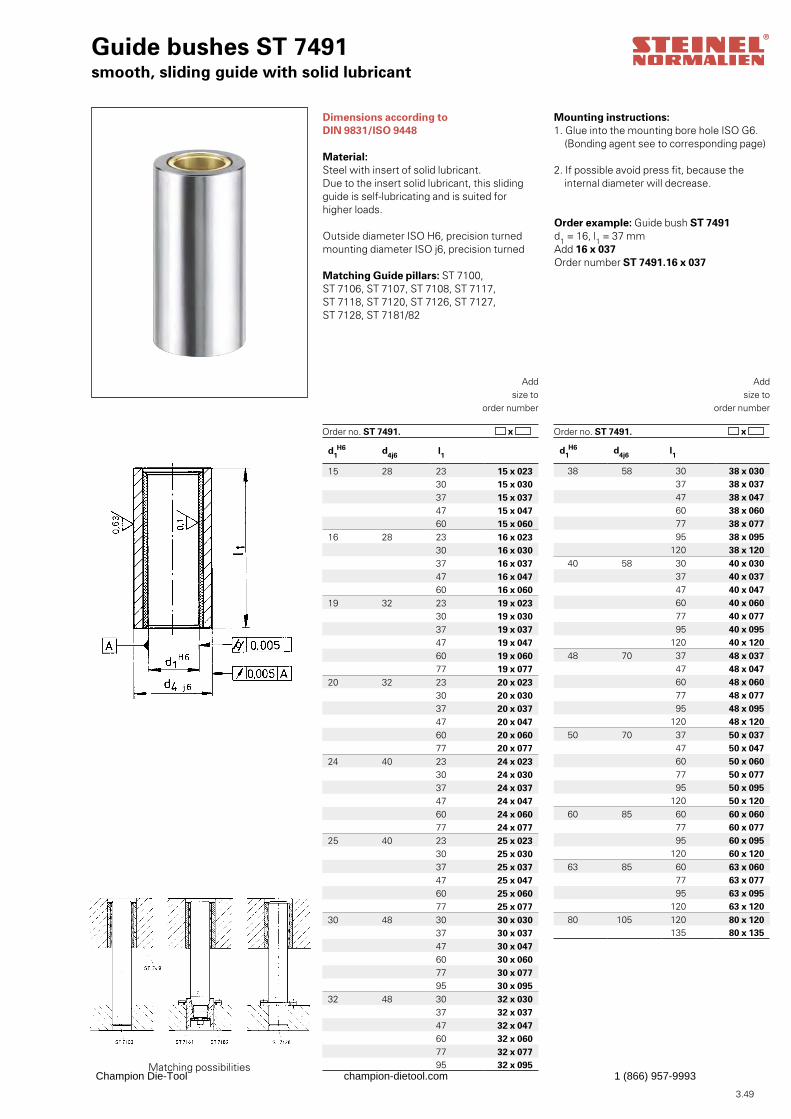
3.49
Guide bushes ST 7491smooth, sliding guide with solid lubricant
Dimensions according to DIN 9831/ISO 9448
Material:Steel with insert of solid lubricant.Due to the insert solid lubricant, this slidingguide is self-lubricating and is suited forhigher loads.
Outside diameter ISO H6, precision turnedmounting diameter ISO j6, precision turned
Matching Guide pillars: ST 7100, ST 7106, ST 7107, ST 7108, ST 7117, ST 7118, ST 7120, ST 7126, ST 7127, ST 7128, ST 7181/82
Order example: Guide bush ST 7491d1 = 16, l1 = 37 mmAdd 16 x 037Order number ST 7491.16 x 037
Addsize to
order number
Order no. ST 7491. x
Mounting instructions:1. Glue into the mounting bore hole ISO G6. (Bonding agent see to corresponding page)
2. If possible avoid press fit, because the internal diameter will decrease.
Addsize to
order number
Order no. ST 7491. x
Matching possibilities
d1H6 d4j6 l1
15 28 23 15 x 02330 15 x 03037 15 x 03747 15 x 04760 15 x 060
16 28 23 16 x 02330 16 x 03037 16 x 03747 16 x 04760 16 x 060
19 32 23 19 x 02330 19 x 03037 19 x 03747 19 x 04760 19 x 06077 19 x 077
20 32 23 20 x 02330 20 x 03037 20 x 03747 20 x 04760 20 x 06077 20 x 077
24 40 23 24 x 02330 24 x 03037 24 x 03747 24 x 04760 24 x 06077 24 x 077
25 40 23 25 x 02330 25 x 03037 25 x 03747 25 x 04760 25 x 06077 25 x 077
30 48 30 30 x 03037 30 x 03747 30 x 04760 30 x 06077 30 x 07795 30 x 095
32 48 30 32 x 03037 32 x 03747 32 x 04760 32 x 06077 32 x 07795 32 x 095
d1H6 d4j6 l1
38 58 30 38 x 030 37 38 x 037 47 38 x 047 60 38 x 060 77 38 x 077 95 38 x 095
120 38 x 12040 58 30 40 x 030
37 40 x 037 47 40 x 047 60 40 x 060 77 40 x 077 95 40 x 095
120 40 x 12048 70 37 48 x 037
47 48 x 047 60 48 x 060 77 48 x 077 95 48 x 095
120 48 x 12050 70 37 50 x 037
47 50 x 047 60 50 x 060 77 50 x 077 95 50 x 095
120 50 x 12060 85 60 60 x 060
77 60 x 077 95 60 x 095
120 60 x 12063 85 60 63 x 060
77 63 x 077 95 63 x 095
120 63 x 12080 105 120 80 x 120
135 80 x 135
Champion Die-Tool champion-dietool.com 1 (866) 957-9993
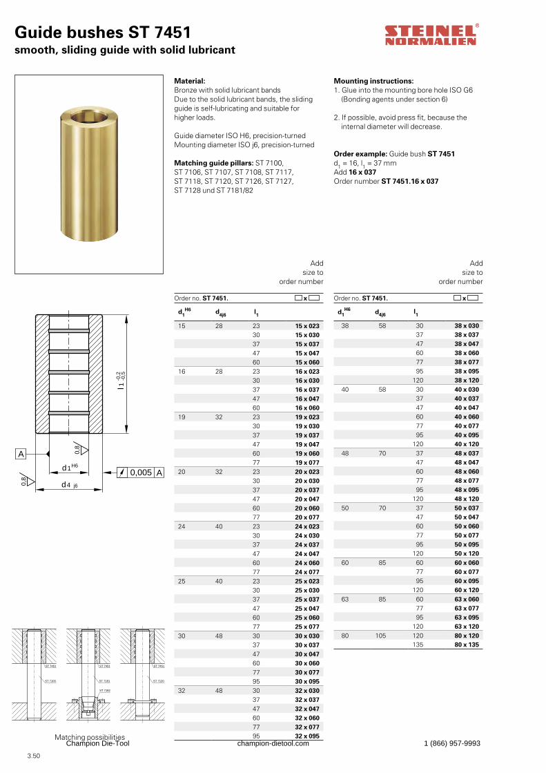
3.50
Guide bushes ST 7451smooth, sliding guide with solid lubricant
l-0
,21
-0,5
d1
d4
0,8
0,005 Aj6
H6
0,8
A
Material: Bronze with solid lubricant bandsDue to the solid lubricant bands, the slidingguide is self-lubricating and suitable for higher loads.
Guide diameter ISO H6, precision-turnedMounting diameter ISO j6, precision-turned
Matching guide pillars: ST 7100, ST 7106, ST 7107, ST 7108, ST 7117, ST 7118, ST 7120, ST 7126, ST 7127, ST 7128 und ST 7181/82
Order example: Guide bush ST 7451d1 = 16, l1 = 37 mmAdd 16 x 037Order number ST 7451.16 x 037
Addsize to
order number
Order no. ST 7451. x
Mounting instructions:1. Glue into the mounting bore hole ISO G6 (Bonding agents under section 6)
2. If possible, avoid press fit, because the internal diameter will decrease.
ST 7100
ST 7182
ST 7451
ST 7181 ST 7120
ST 7451ST 7451
Addsize to
order number
Order no. ST 7451. x
Matching possibilities
d1H6 d4j6
l1
15 28 23 15 x 02330 15 x 03037 15 x 03747 15 x 04760 15 x 060
16 28 23 16 x 02330 16 x 03037 16 x 03747 16 x 04760 16 x 060
19 32 23 19 x 02330 19 x 03037 19 x 03747 19 x 04760 19 x 06077 19 x 077
20 32 23 20 x 02330 20 x 03037 20 x 03747 20 x 04760 20 x 06077 20 x 077
24 40 23 24 x 02330 24 x 03037 24 x 03747 24 x 04760 24 x 06077 24 x 077
25 40 23 25 x 02330 25 x 03037 25 x 03747 25 x 04760 25 x 06077 25 x 077
30 48 30 30 x 03037 30 x 03747 30 x 04760 30 x 06077 30 x 07795 30 x 095
32 48 30 32 x 03037 32 x 03747 32 x 04760 32 x 06077 32 x 07795 32 x 095
d1H6 d4j6
l1
38 58 30 38 x 030 37 38 x 037 47 38 x 047 60 38 x 060 77 38 x 077 95 38 x 095
120 38 x 12040 58 30 40 x 030
37 40 x 037 47 40 x 047 60 40 x 060 77 40 x 077 95 40 x 095
120 40 x 12048 70 37 48 x 037
47 48 x 047 60 48 x 060 77 48 x 077 95 48 x 095
120 48 x 12050 70 37 50 x 037
47 50 x 047 60 50 x 060 77 50 x 077 95 50 x 095
120 50 x 12060 85 60 60 x 060
77 60 x 077 95 60 x 095
120 60 x 12063 85 60 63 x 060
77 63 x 077 95 63 x 095
120 63 x 12080 105 120 80 x 120
135 80 x 135
Champion Die-Tool champion-dietool.com 1 (866) 957-9993
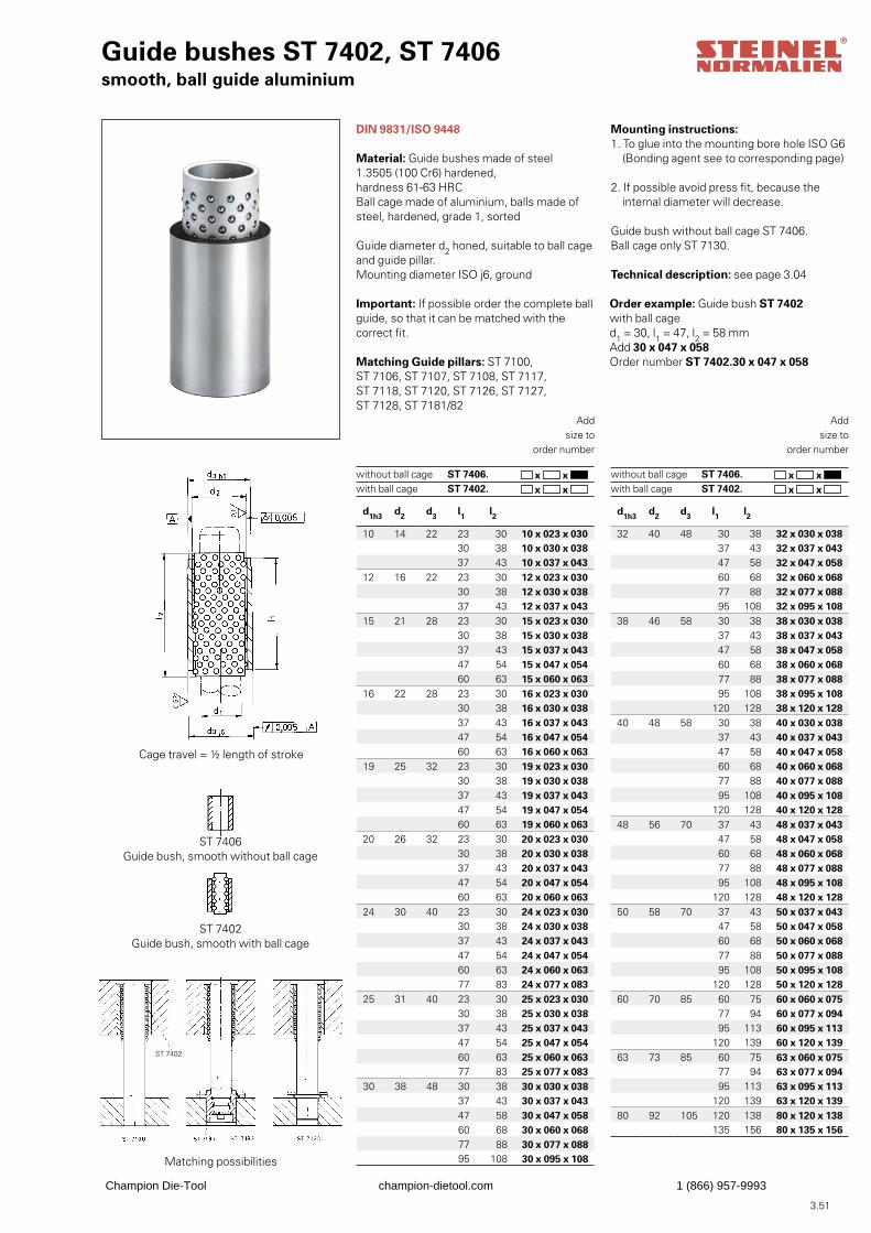
3.51
Guide bushes ST 7402, ST 7406smooth, ball guide aluminium
DIN 9831/ISO 9448
Material: Guide bushes made of steel 1.3505 (100 Cr6) hardened, hardness 61-63 HRCBall cage made of aluminium, balls made of steel, hardened, grade 1, sorted
Guide diameter d2 honed, suitable to ball cage and guide pillar. Mounting diameter ISO j6, ground
Important: If possible order the complete ballguide, so that it can be matched with the correct fit.
Matching Guide pillars: ST 7100, ST 7106, ST 7107, ST 7108, ST 7117, ST 7118, ST 7120, ST 7126, ST 7127, ST 7128, ST 7181/82
Order example: Guide bush ST 7402with ball caged1 = 30, l1 = 47, l2 = 58 mmAdd 30 x 047 x 058Order number ST 7402.30 x 047 x 058
Mounting instructions:1. To glue into the mounting bore hole ISO G6 (Bonding agent see to corresponding page)
2. If possible avoid press fit, because the internal diameter will decrease.
Guide bush without ball cage ST 7406.Ball cage only ST 7130.
Technical description: see page 3.04
Addsize to
order number
ST 7406. ST 7402.
x x x x
without ball cage with ball cage
Addsize to
order number
ST 7406. ST 7402.
x x x x
without ball cage with ball cage
Cage travel = ½ length of stroke
ST 7406 Guide bush, smooth without ball cage
ST 7402 Guide bush, smooth with ball cage
Matching possibilities
d1h3 d2 d3 l1 l2
10 14 22 23 30 10 x 023 x 03030 38 10 x 030 x 03837 43 10 x 037 x 043
12 16 22 23 30 12 x 023 x 03030 38 12 x 030 x 03837 43 12 x 037 x 043
15 21 28 23 30 15 x 023 x 03030 38 15 x 030 x 03837 43 15 x 037 x 04347 54 15 x 047 x 05460 63 15 x 060 x 063
16 22 28 23 30 16 x 023 x 03030 38 16 x 030 x 03837 43 16 x 037 x 04347 54 16 x 047 x 05460 63 16 x 060 x 063
19 25 32 23 30 19 x 023 x 03030 38 19 x 030 x 03837 43 19 x 037 x 04347 54 19 x 047 x 05460 63 19 x 060 x 063
20 26 32 23 30 20 x 023 x 03030 38 20 x 030 x 03837 43 20 x 037 x 04347 54 20 x 047 x 05460 63 20 x 060 x 063
24 30 40 23 30 24 x 023 x 03030 38 24 x 030 x 03837 43 24 x 037 x 04347 54 24 x 047 x 05460 63 24 x 060 x 06377 83 24 x 077 x 083
25 31 40 23 30 25 x 023 x 03030 38 25 x 030 x 03837 43 25 x 037 x 04347 54 25 x 047 x 05460 63 25 x 060 x 06377 83 25 x 077 x 083
30 38 48 30 38 30 x 030 x 03837 43 30 x 037 x 04347 58 30 x 047 x 05860 68 30 x 060 x 06877 88 30 x 077 x 08895 108 30 x 095 x 108
d1h3 d2 d3 l1 l2
32 40 48 30 38 32 x 030 x 038 37 43 32 x 037 x 043 47 58 32 x 047 x 058 60 68 32 x 060 x 068 77 88 32 x 077 x 088 95 108 32 x 095 x 108
38 46 58 30 38 38 x 030 x 038 37 43 38 x 037 x 043 47 58 38 x 047 x 058 60 68 38 x 060 x 068 77 88 38 x 077 x 088 95 108 38 x 095 x 108
120 128 38 x 120 x 12840 48 58 30 38 40 x 030 x 038
37 43 40 x 037 x 043 47 58 40 x 047 x 058 60 68 40 x 060 x 068 77 88 40 x 077 x 088 95 108 40 x 095 x 108
120 128 40 x 120 x 12848 56 70 37 43 48 x 037 x 043
47 58 48 x 047 x 058 60 68 48 x 060 x 068 77 88 48 x 077 x 088 95 108 48 x 095 x 108
120 128 48 x 120 x 12850 58 70 37 43 50 x 037 x 043
47 58 50 x 047 x 058 60 68 50 x 060 x 068 77 88 50 x 077 x 088 95 108 50 x 095 x 108
120 128 50 x 120 x 12860 70 85 60 75 60 x 060 x 075
77 94 60 x 077 x 094 95 113 60 x 095 x 113
120 139 60 x 120 x 13963 73 85 60 75 63 x 060 x 075
77 94 63 x 077 x 094 95 113 63 x 095 x 113
120 139 63 x 120 x 13980 92 105 120 138 80 x 120 x 138
135 156 80 x 135 x 156
ST 7402
Champion Die-Tool champion-dietool.com 1 (866) 957-9993
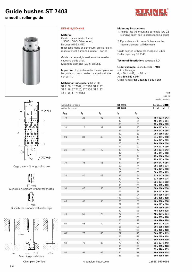
3.52
Guide bushes ST 7403smooth, roller guide
DIN 9831/ISO 9448
Material:Guide bushes made of steel 1.3505 (100 Cr 6) hardened, hardness 61-63 HRC roller cage made of aluminium, profile rollers made of steel, hardened, grade 1, sorted
Guide diameter d2 honed, suitable to roller cage and guide pillar. Mounting diameter ISO j6, ground.
Important: If possible order the complete rol-ler guide, so that it can be matched with thecorrect fit.
Matching Guide pillars: ST 7100, ST 7106, ST 7107, ST 7108, ST 7117, ST 7118, ST 7120, ST 7126, ST 7127, ST 7128, ST 7181/82
Order example: Guide bush ST 7403with roller caged1 = 30, l1 = 47, l2 = 54 mmAdd 30 x 047 x 054Order number ST 7403.30 x 047 x 054
Mounting instructions:1. To glue into the mounting bore hole ISO G6 (Bonding agent see to corresponding page)
2. If possible, avoid press fit, because the internal diameter will decrease.
Guide bushes without roller cage ST 7406Roller cage only ST 7140
Technical description: see page 3.04
Addsize to
order number
ST 7406. ST 7403.
x x x x
without roller cage with roller cage
Cage travel = ½ length of stroke
ST 7406 Guide bush, smooth without roller cage
ST 7403 Guide bush, smooth with roller cage
Matching possibilities
d1h3 d2 d3 l1 l2
19 25 32 37 43 19 x 037 x 043 47 54 19 x 047 x 054 60 63 19 x 060 x 063
20 26 32 37 43 20 x 037 x 043 47 54 20 x 047 x 054 60 63 20 x 060 x 063
24 30 40 37 43 24 x 037 x 043 47 63 24 x 047 x 063 60 74 24 x 060 x 074 77 90 24 x 077 x 090
25 31 40 37 43 25 x 037 x 043 47 63 25 x 047 x 063 60 74 25 x 060 x 074 77 90 25 x 077 x 090
30 38 48 47 54 30 x 047 x 054 60 74 30 x 060 x 074 77 83 30 x 077 x 083 95 103 30 x 095 x 103
32 40 48 47 54 32 x 047 x 054 60 74 32 x 060 x 074 77 83 32 x 077 x 083 95 103 32 x 095 x 103
38 46 58 60 58 38 x 060 x 058 77 88 38 x 077 x 088 95 94 38 x 095 x 094
120 128 38 x 120 x 12840 48 58 60 58 40 x 060 x 058
77 88 40 x 077 x 088 95 94 40 x 095 x 094
120 128 40 x 120 x 12848 56 70 77 74 48 x 077 x 074
95 108 48 x 095 x 108120 128 48 x 120 x 128
50 58 70 77 74 50 x 077 x 074 95 108 50 x 095 x 108
120 128 50 x 120 x 12860 70 85 77 113 60 x 077 x 113
95 128 60 x 095 x 128120 139 60 x 120 x 139
63 73 85 77 113 63 x 077 x 113 95 128 63 x 095 x 128
120 139 63 x 120 x 13980 92 105 120 138 80 x 120 x 138
135 156 80 x 135 x 156
ST 7403
Champion Die-Tool champion-dietool.com 1 (866) 957-9993
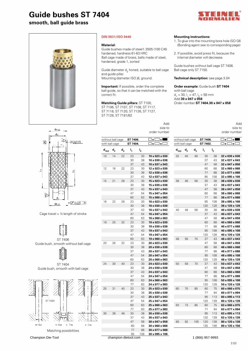
3.53
x x x x
x x x x
d1h3 d2 d3 l1 l2
32 40 48 30 38 32 x 030 x 038 37 43 32 x 037 x 043 47 58 32 x 047 x 058 60 68 32 x 060 x 068 77 88 32 x 077 x 088 95 108 32 x 095 x 108
38 46 58 30 38 38 x 030 x 038 37 43 38 x 037 x 043 47 58 38 x 047 x 058 60 68 38 x 060 x 068 77 88 38 x 077 x 088 95 108 38 x 095 x 108
120 128 38 x 120 x 12840 48 58 30 38 40 x 030 x 038
37 43 40 x 037 x 043 47 58 40 x 047 x 058 60 68 40 x 060 x 068 77 88 40 x 077 x 088 95 108 40 x 095 x 108
120 128 40 x 120 x 12848 56 70 37 43 48 x 037 x 043
47 58 48 x 047 x 058 60 68 48 x 060 x 068 77 88 48 x 077 x 088 95 108 48 x 095 x 108
120 128 48 x 120 x 12850 58 70 37 43 50 x 037 x 043
47 58 50 x 047 x 058 60 68 50 x 060 x 068 77 88 50 x 077 x 088 95 108 50 x 095 x 108
120 128 50 x 120 x 12860 70 85 60 75 60 x 060 x 075
77 94 60 x 077 x 094 95 113 60 x 095 x 113
120 139 60 x 120 x 13963 73 85 60 75 63 x 060 x 075
77 94 63 x 077 x 094 95 113 63 x 095 x 113
120 139 63 x 120 x 13980 92 105 120 138 80 x 120 x 138
135 156 80 x 135 x 156
d1h3 d2 d3 l1 l2
10 14 22 23 30 10 x 023 x 03030 38 10 x 030 x 03837 43 10 x 037 x 043
12 16 22 23 30 12 x 023 x 03030 38 12 x 030 x 03837 43 12 x 037 x 043
15 21 28 23 30 15 x 023 x 03030 38 15 x 030 x 03837 43 15 x 037 x 04347 54 15 x 047 x 05460 63 15 x 060 x 063
16 22 28 23 30 16 x 023 x 03030 38 16 x 030 x 03837 43 16 x 037 x 04347 54 16 x 047 x 05460 63 16 x 060 x 063
19 25 32 23 30 19 x 023 x 03030 38 19 x 030 x 03837 43 19 x 037 x 04347 54 19 x 047 x 05460 63 19 x 060 x 063
20 26 32 23 30 20 x 023 x 03030 38 20 x 030 x 03837 43 20 x 037 x 04347 54 20 x 047 x 05460 63 20 x 060 x 063
24 30 40 23 30 24 x 023 x 03030 38 24 x 030 x 03837 43 24 x 037 x 04347 54 24 x 047 x 05460 63 24 x 060 x 06377 83 24 x 077 x 083
25 31 40 23 30 25 x 023 x 03030 38 25 x 030 x 03837 43 25 x 037 x 04347 54 25 x 047 x 05460 63 25 x 060 x 06377 83 25 x 077 x 083
30 38 48 30 38 30 x 030 x 03837 43 30 x 037 x 04347 58 30 x 047 x 058 60 68 30 x 060 x 068 77 88 30 x 077 x 088 95 108 30 x 095 x 108
Guide bushes ST 7404smooth, ball guide brass
DIN 9831/ISO 9448
Material:Guide bushes made of steel1.3505 (100 Cr6)hardened, hardness 61-63 HRCBall cage made of brass, balls made of steel, hardened, grade 1, sorted
Guide diameter d2 honed, suitable to ball cageand guide pillar.Mounting diameter ISO j6, ground.
Important: If possible, order the complete ball guide, so that it can be matched with the correct fit.
Matching Guide pillars: ST 7100, ST 7106, ST 7107, ST 7108, ST 7117, ST 7118, ST 7120, ST 7126, ST 7127, ST 7128, ST 7181/82
Order example: Guide bush ST 7404with ball caged1 = 30, l1 = 47, l2 = 58 mmAdd 30 x 047 x 058Order number ST 7404.30 x 047 x 058
Mounting instructions:1. To glue into the mounting bore hole ISO G6 (Bonding agent see to corresponding page)
2. If possible, avoid press fit, because the internal diameter will decrease.
Guide bushes without ball cage ST 7406.Ball cage only ST 7150.
Technical description: see page 3.04
Cage travel = ½ length of stroke
ST 7406 Guide bush, smooth without ball cage
ST 7404 Guide bush, smooth with ball cage
Matching possibilities
Addsize to
order number
ST 7406. ST 7404.
without ball cage with ball cage
Addsize to
order number
ST 7406. ST 7402.
without ball cage with ball cage
ST 7404
Champion Die-Tool champion-dietool.com 1 (866) 957-9993
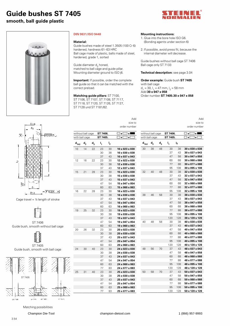
3.54
d1h3 d2 d3 l1 l2
10 14 22 23 30 10 x 023 x 03030 38 10 x 030 x 03837 43 10 x 037 x 043
12 16 22 23 30 12 x 023 x 03030 38 12 x 030 x 03837 43 12 x 037 x 043
15 21 28 23 30 15 x 023 x 03030 38 15 x 030 x 03837 43 15 x 037 x 04347 54 15 x 047 x 05460 63 15 x 060 x 063
16 22 28 23 30 16 x 023 x 03030 38 16 x 030 x 03837 43 16 x 037 x 04347 54 16 x 047 x 05460 63 16 x 060 x 063
19 25 32 23 30 19 x 023 x 03030 38 19 x 030 x 03837 43 19 x 037 x 04347 54 19 x 047 x 05460 63 19 x 060 x 063
20 26 32 23 30 20 x 023 x 03030 38 20 x 030 x 03837 43 20 x 037 x 04347 54 20 x 047 x 05460 63 20 x 060 x 063
24 30 40 23 30 24 x 023 x 03030 38 24 x 030 x 03837 43 24 x 037 x 04347 54 24 x 047 x 05460 63 24 x 060 x 06377 83 24 x 077 x 083
25 31 40 23 30 25 x 023 x 03030 38 25 x 030 x 03837 43 25 x 037 x 04347 54 25 x 047 x 05460 63 25 x 060 x 06377 83 25 x 077 x 083
d1h3 d2 d3 l1 l2
30 38 48 30 38 30 x 030 x 03837 43 30 x 037 x 04347 58 30 x 047 x 05860 68 30 x 060 x 068 77 88 30 x 077 x 08895 108 30 x 095 x 108
32 40 48 30 38 32 x 030 x 03837 43 32 x 037 x 04347 58 32 x 047 x 05860 68 32 x 060 x 06877 88 32 x 077 x 08895 108 32 x 095 x 108
38 46 58 30 38 38 x 030 x 03837 43 38 x 037 x 04347 58 38 x 047 x 05860 68 38 x 060 x 06877 88 38 x 077 x 08895 108 38 x 095 x 108
120 128 38 x 120 x 12840 48 58 30 38 40 x 030 x 038
37 43 40 x 037 x 04347 58 40 x 047 x 05860 68 40 x 060 x 06877 88 40 x 077 x 08895 108 40 x 095 x 108
120 128 40 x 120 x 12848 56 70 37 43 48 x 037 x 043
47 58 48 x 047 x 05860 68 48 x 060 x 06877 88 48 x 077 x 08895 108 48 x 095 x 108
120 128 48 x 120 x 12850 58 70 37 43 50 x 037 x 043
47 58 50 x 047 x 05860 68 50 x 060 x 06877 88 50 x 077 x 08895 108 50 x 095 x 108
120 128 50 x 120 x 128
Guide bushes ST 7405smooth, ball guide plastic
DIN 9831/ISO 9448
Material:Guide bushes made of steel 1.3505 (100 Cr 6)hardened, hardness 61- 63 HRCBall cage made of plastic, balls made of steel, hardened, grade 1, sorted
Guide diameter d2 honed,matched to ball cage and guide pillar.Mounting diameter ground to ISO j6.
Important: If possible, order the complete ball guide so that it can be matched with the correct preload.
Matching guide pillars: ST 7100, ST 7106, ST 7107, ST 7108, ST 7117, ST 7118, ST 7120, ST 7126, ST 7127, ST 7128 und ST 7181/82.
Order example: Guide bush ST 7405with ball caged1 = 30, l1 = 47 mm, l2 = 58 mmAdd 30 x 047 x 058Order number ST 7405.30 x 047 x 058
Mounting instructions: 1. Glue into the bore hole ISO G6. (Bonding agents under section 6)
2. If possible, avoid press fit, because the internal diameter will decrease.
Guide bushes without ball cage ST 7406Ball cage only ST 7133
Technical description: see page 3.04
Cage travel = ½ length of stroke
ST 7406 Guide bush, smooth without ball cage
ST 7405 Guide bush, smooth with ball cage
Matching possibilities
Addsize to
order number
ST 7406. ST 7405.
x x x x
without ball cage with ball cage
Addsize to
order number
ST 7406. ST 7405.
x x x x
without ball cage with ball cage
ST 7405
Champion Die-Tool champion-dietool.com 1 (866) 957-9993
3.55
Champion Die-Tool champion-dietool.com 1 (866) 957-9993

3.56
Guide bushes ST 7412, ST 7416with shoulder, ball guide aluminium
DIN 9831/ISO 9448
Material:Guide bushes made of steel 1.3505 (16 MnCr5), case hardened,hardness 61-63 HRCBall cage made of aluminiumballs made of steel, hardened, grade 1, sorted
Guide diameter honed, suitable to ball cage and guide pillar.Mounting diameter ISO js4, ground.
Important: If possible, order the complete ballguide, so that it can be matched with the correct fit.
Matching Guide pillars:ST 7100, ST 7106, ST 7107, ST 7108, ST 7120, ST 7126, ST 7127, ST 7128 und ST 7181/82
Mounting instructions:Fit in mounting bore hole ISO H6.Fix with 3 holding clamps (included in delivery).The shoulder surface, right-angled ground to the guide bore, will be squeezed onto the plate by the holding clamps and guarantees an absolutely rigid clamping of the guide bush.
Holding clamps:When reordering the holding clamps pleaseorder: 1 set = 3 pieces, order number ST 7367
Guide bush without ball cage ST 7416.Ball cage only ST 7130.
Technical description: see page 3.04
Short version
Mid-length version
Long versionCage travel = ½ length of stroke
Arrangement possibilities of the holding clamps Matching possibilities
Champion Die-Tool champion-dietool.com 1 (866) 957-9993

3.57
Addsize to
order number
Order no. ST 7416. x x without ball cage
Order example:Guide bush ST 7416without ball caged1 = 30, l1 = 93 mmAdd 30 x 093Order number ST 7416. 30 x 093
Addsize to
order number
Order no. ST 7412. x x with ball cage
Order example:Guide bush ST 7412with ball caged1 = 40, l1 = 82, I2 = 94 mmAdd 40 x 082 x 094Order number ST 7412. 40 x 082 x 094
d1h3d2 d3js4 d5 d6 d8 l1 -0,3 l2 l3 -0,2
l4
19 25 32 40 32 59 35 43 23 12 19 x 035 x 043 43 54 20 19 x 043 x 054 59 74 36 19 x 059 x 074
20 26 32 40 32 59 35 43 23 12 20 x 035 x 043 43 54 20 20 x 043 x 054 59 74 36 20 x 059 x 074
24 30 40 48 40 65 35 43 23 12 24 x 035 x 043 60 74 37 24 x 060 x 074 80 90 57 24 x 080 x 090
25 31 40 48 40 65 35 43 23 12 25 x 035 x 043 60 74 37 25 x 060 x 074 80 90 57 25 x 080 x 090
30 38 48 56 48 73 42 54 30 12 30 x 042 x 054 75 83 45 30 x 075 x 083 93 103 63 30 x 093 x 103
32 40 48 56 48 73 42 54 30 12 32 x 042 x 054 75 83 45 32 x 075 x 083 93 103 63 32 x 093 x 103
38 46 58 66 58 83 52 58 37 15 38 x 052 x 058 82 94 45 38 x 082 x 094
107 128 70 38 x 107 x 12840 48 58 66 58 83 52 58 37 15 40 x 052 x 058
82 94 45 40 x 082 x 094107 128 70 40 x 107 x 128
48 56 70 80 70 97 65 74 47 18 48 x 065 x 074 97 108 50 48 x 097 x 108
127 128 80 48 x 127 x 12850 58 70 80 70 97 65 74 47 18 50 x 065 x 074
97 108 50 50 x 097 x 108127 128 80 50 x 127 x 128
60 70 85 95 85 112 80 113 60 20 60 x 080 x 113115 128 55 60 x 115 x 128150 154 90 60 x 150 x 154
63 73 85 95 85 112 80 113 60 20 63 x 080 x 113115 128 55 63 x 115 x 128150 154 90 63 x 150 x 154
80 92 105 118 105 135 80 113 60 20 80 x 080 x 113120 138 60 80 x 120 x 138150 156 90 80 x 150 x 156
Champion Die-Tool champion-dietool.com 1 (866) 957-9993
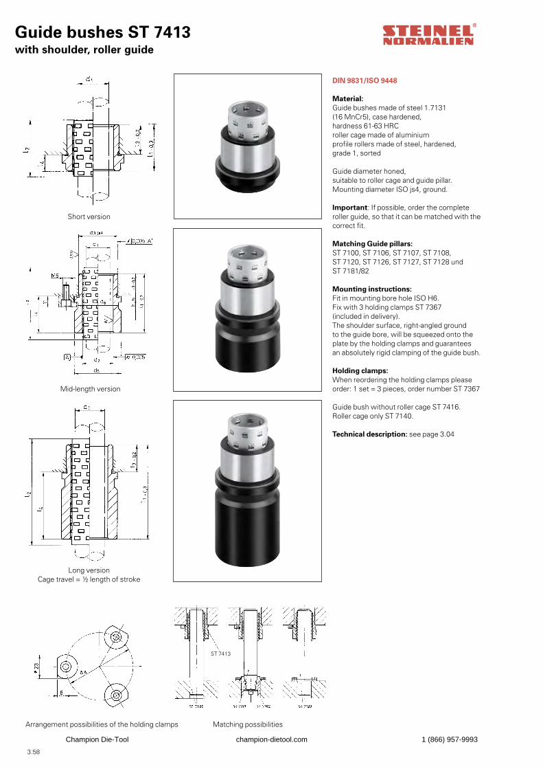
3.58
Guide bushes ST 7413with shoulder, roller guide
DIN 9831/ISO 9448
Material:Guide bushes made of steel 1.7131 (16 MnCr5), case hardened,hardness 61-63 HRCroller cage made of aluminiumprofile rollers made of steel, hardened, grade 1, sorted
Guide diameter honed,suitable to roller cage and guide pillar.Mounting diameter ISO js4, ground.
Important: If possible, order the complete roller guide, so that it can be matched with thecorrect fit.
Matching Guide pillars:ST 7100, ST 7106, ST 7107, ST 7108, ST 7120, ST 7126, ST 7127, ST 7128 und ST 7181/82
Mounting instructions:Fit in mounting bore hole ISO H6.Fix with 3 holding clamps ST 7367 (included in delivery).The shoulder surface, right-angled ground to the guide bore, will be squeezed onto the plate by the holding clamps and guarantees an absolutely rigid clamping of the guide bush.
Holding clamps:When reordering the holding clamps pleaseorder: 1 set = 3 pieces, order number ST 7367
Guide bush without roller cage ST 7416.Roller cage only ST 7140.
Technical description: see page 3.04
Short version
Mid-length version
Long versionCage travel = ½ length of stroke
Arrangement possibilities of the holding clamps
Matching possibilities
ST 7413
Champion Die-Tool champion-dietool.com 1 (866) 957-9993

3.59
Addsize to
order number
Order no. ST 7416. x x without roller cage
with roller cage
Order example:Guide bush ST 7416without roller caged1 = 30, l1 = 93 mmAdd 30 x 093Order number ST 7416. 30 x 093
Addsize to
order number
Order no. ST 7413. x x
Order example:Guide bush ST 7413with roller caged1 = 40, l1 = 82, I2 = 94 mmAdd 40 x 082 x 094Order number ST 7413. 40 x 082 x 094
d1h3 d2 d3js4 d5 d6 d8 l1 -0,3 l2 l3 -0,2l4
19 25 32 40 32 59 35 43 23 12 19 x 035 x 043 43 54 20 19 x 043 x 054 59 74 36 19 x 059 x 074
20 26 32 40 32 59 35 43 23 12 20 x 035 x 043 43 54 20 20 x 043 x 054 59 74 36 20 x 059 x 074
24 30 40 48 40 65 35 43 23 12 24 x 035 x 043 60 74 37 24 x 060 x 074 80 90 57 24 x 080 x 090
25 31 40 48 40 65 35 43 23 12 25 x 035 x 043 60 74 37 25 x 060 x 074 80 90 57 25 x 080 x 090
30 38 48 56 48 73 42 54 30 12 30 x 042 x 054 75 83 45 30 x 075 x 083 93 103 63 30 x 093 x 103
32 40 48 56 48 73 42 54 30 12 32 x 042 x 054 75 83 45 32 x 075 x 083 93 103 63 32 x 093 x 103
38 46 58 66 58 83 52 58 37 15 38 x 052 x 058 82 94 45 38 x 082 x 094
107 128 70 38 x 107 x 12840 48 58 66 58 83 52 58 37 15 40 x 052 x 058
82 94 45 40 x 082 x 094107 128 70 40 x 107 x 128
48 56 70 80 70 97 65 74 47 18 48 x 065 x 074 97 108 50 48 x 097 x 108
127 128 80 48 x 127 x 12850 58 70 80 70 97 65 74 47 18 50 x 065 x 074
97 108 50 50 x 097 x 108127 128 80 50 x 127 x 128
60 70 85 95 85 112 80 113 60 20 60 x 080 x 113115 128 55 60 x 115 x 128150 139 90 60 x 150 x 139
63 73 85 95 85 112 80 113 60 20 63 x 080 x 113115 128 55 63 x 115 x 128150 139 90 63 x 150 x 139
80 92 105 118 105 135 80 113 60 20 80 x 080 x 113120 138 60 80 x 120 x 138150 156 90 80 x 150 x 156
Champion Die-Tool champion-dietool.com 1 (866) 957-9993
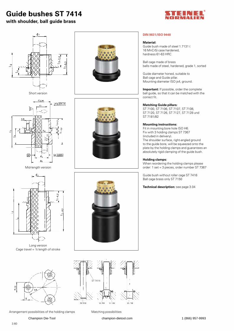
3.60
Guide bushes ST 7414with shoulder, ball guide brass
DIN 9831/ISO 9448
Material:Guide bush made of steel 1.7131 (16 MnCr5) case hardened,hardness 61-63 HRC
Ball cage made of brassballs made of steel, hardened, grade 1, sorted
Guide diameter honed, suitable to Ball cage and Guide pillar.Mounting diameter ISO js4, ground.
Important: If possible, order the complete ball guide, so that it can be matched with the correct fit.
Matching Guide pillars:ST 7100, ST 7106, ST 7107, ST 7108,ST 7120, ST 7126, ST 7127, ST 7128 und ST 7181/82
Mounting instructions:Fit in mounting bore hole ISO H6.Fix with 3 holding clamps ST 7367 (included in delivery).The shoulder surface, right-angled ground to the guide bore, will be squeezed onto the plate by the holding clamps and guarantees an absolutely rigid clamping of the guide bush.
Holding clamps:When reordering the holding clamps pleaseorder: 1 set = 3 pieces, order number ST 7367
Guide bush without roller cage ST 7416Ball cage brass only ST 7150
Technical description: see page 3.04
Short version
Mid-length version
Long versionCage travel = ½ length of stroke
Arrangement possibilities of the holding clamps
Matching possibilities
ST 7414
Champion Die-Tool champion-dietool.com 1 (866) 957-9993

3.61
d1h3 d2 d3js4 d5 d6 d8 l1 -0,3 l2 l3 -0,2 l4
19 25 32 40 32 59 35 43 23 12 19 x 035 x 043 43 54 20 19 x 043 x 054 59 74 36 19 x 059 x 074
20 26 32 40 32 59 35 43 23 12 20 x 035 x 043 43 54 20 20 x 043 x 054 59 74 36 20 x 059 x 074
24 30 40 48 40 65 35 43 23 12 24 x 035 x 043 60 74 37 24 x 060 x 074 80 90 57 24 x 080 x 090
25 31 40 48 40 65 35 43 23 12 25 x 035 x 043 60 74 37 25 x 060 x 074 80 90 57 25 x 080 x 090
30 38 48 56 48 73 42 54 30 12 30 x 042 x 054 75 83 45 30 x 075 x 083 93 103 63 30 x 093 x 103
32 40 48 56 48 73 42 54 30 12 32 x 042 x 054 75 83 45 32 x 075 x 083 93 103 63 32 x 093 x 103
38 46 58 66 58 83 52 58 37 15 38 x 052 x 058 82 94 45 38 x 082 x 094
107 128 70 38 x 107 x 12840 48 58 66 58 83 52 58 37 15 40 x 052 x 058
82 94 45 40 x 082 x 094107 128 70 40 x 107 x 128
48 56 70 80 70 97 65 74 47 18 48 x 065 x 074 97 108 50 48 x 097 x 108
127 128 80 48 x 127 x 12850 58 70 80 70 97 65 74 47 18 50 x 065 x 074
97 108 50 50 x 097 x 108127 128 80 50 x 127 x 128
60 70 85 95 85 112 80 113 60 20 60 x 080 x 113115 128 55 60 x 115 x 128150 154 90 60 x 150 x 154
63 73 85 95 85 112 80 113 60 20 63 x 080 x 113115 128 55 63 x 115 x 128150 154 90 63 x 150 x 154
80 92 105 118 105 135 80 113 60 20 80 x 080 x 113120 138 60 80 x 120 x 138150 156 90 80 x 150 x 156
Addsize to
order number
Order no. ST 7416. x x without ball cage
with ball cage
Order example:Guide bush ST 7416.without ball caged1 = 30, l1 = 93 mmAdd 30 x 093Order number ST 7416. 30 x 093
Addsize to
order number
Order no. ST 7414. x x
Order example:Guide bush ST 7414.with ball cage, brassd1 = 40, l1 = 82, I2 = 94 mmAdd 40 x 082 x 094Order number ST 7414. 40 x 082 x 094
Champion Die-Tool champion-dietool.com 1 (866) 957-9993
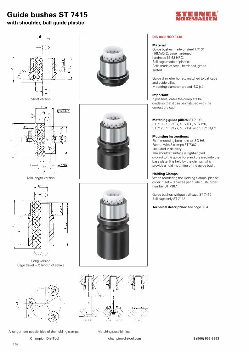
3.62
Guide bushes ST 7415with shoulder, ball guide plastic
DIN 9831/ISO 9448
Material:Guide bushes made of steel 1.7131 (16MnCr5), case hardened, hardness 61-63 HRC.Ball cage made of plastic.Balls made of steel, hardened, grade 1, sorted.
Guide diameter honed, matched to ball cageand guide pillar.Mounting diameter ground ISO js4.
Important:If possible, order the complete ballguide so that it can be matched with the correct preload.
Matching guide pillars: ST 7100, ST 7106, ST 7107, ST 7108, ST 7120,ST 7126, ST 7127, ST 7128 und ST 7181/82
Mounting instructions:Fit in mounting bore hole to ISO H6.Fasten with 3 clamps ST 7367, (included in delivery).The shoulder surface is right-angledground to the guide bore and pressed into thebase plate. It is held by the clamps, whichprovide a rigid mounting of the guide bush.
Holding Clamps:When reordering the Holding clamps, please order: 1 set = 3 pieces per guide bush, order number ST 7367
Guide bushes without ball cage ST 7416Ball cage only ST 7133
Technical description: see page 3.04
Short version
Mid-length version
Long versionCage travel = ½ length of stroke
Arrangement possibilities of the holding clamps
Matching possibilities
ST 7415
Champion Die-Tool champion-dietool.com 1 (866) 957-9993
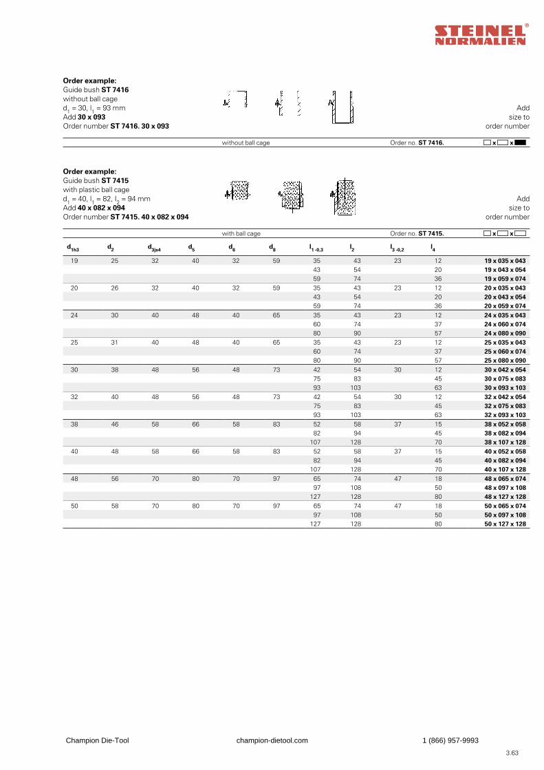
3.63
Addsize to
order number
Order no. ST 7416. x x without ball cage
with ball cage
Order example:Guide bush ST 7416without ball caged1 = 30, l1 = 93 mmAdd 30 x 093Order number ST 7416. 30 x 093
Addsize to
order number
Order no. ST 7415. x x
Order example:Guide bush ST 7415with plastic ball caged1 = 40, l1 = 82, I2 = 94 mmAdd 40 x 082 x 094Order number ST 7415. 40 x 082 x 094
d1h3 d2 d3js4 d5 d6 d8 l1 -0,3 l2 l3 -0,2 l4
19 25 32 40 32 59 35 43 23 12 19 x 035 x 043 43 54 20 19 x 043 x 054 59 74 36 19 x 059 x 074
20 26 32 40 32 59 35 43 23 12 20 x 035 x 043 43 54 20 20 x 043 x 054 59 74 36 20 x 059 x 074
24 30 40 48 40 65 35 43 23 12 24 x 035 x 043 60 74 37 24 x 060 x 074 80 90 57 24 x 080 x 090
25 31 40 48 40 65 35 43 23 12 25 x 035 x 043 60 74 37 25 x 060 x 074 80 90 57 25 x 080 x 090
30 38 48 56 48 73 42 54 30 12 30 x 042 x 054 75 83 45 30 x 075 x 083 93 103 63 30 x 093 x 103
32 40 48 56 48 73 42 54 30 12 32 x 042 x 054 75 83 45 32 x 075 x 083 93 103 63 32 x 093 x 103
38 46 58 66 58 83 52 58 37 15 38 x 052 x 058 82 94 45 38 x 082 x 094
107 128 70 38 x 107 x 12840 48 58 66 58 83 52 58 37 15 40 x 052 x 058
82 94 45 40 x 082 x 094107 128 70 40 x 107 x 128
48 56 70 80 70 97 65 74 47 18 48 x 065 x 074 97 108 50 48 x 097 x 108
127 128 80 48 x 127 x 12850 58 70 80 70 97 65 74 47 18 50 x 065 x 074
97 108 50 50 x 097 x 108127 128 80 50 x 127 x 128
Champion Die-Tool champion-dietool.com 1 (866) 957-9993
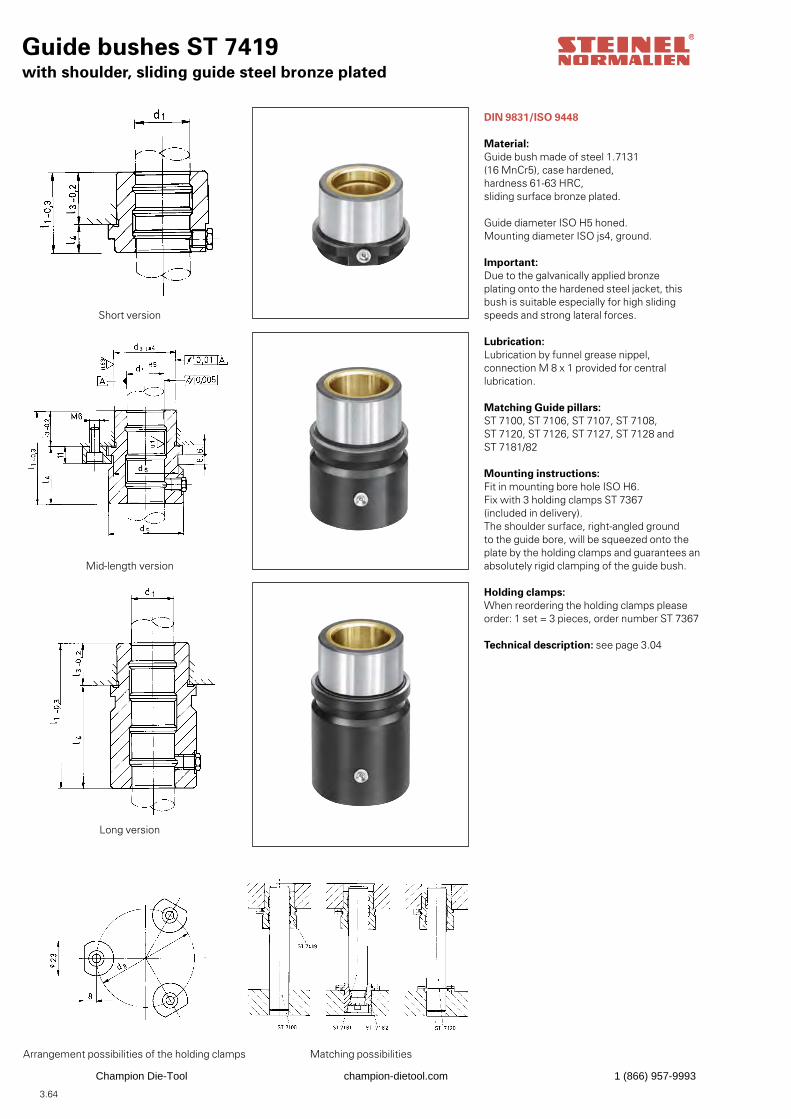
3.64
Guide bushes ST 7419with shoulder, sliding guide steel bronze plated
DIN 9831/ISO 9448
Material:Guide bush made of steel 1.7131 (16 MnCr5), case hardened, hardness 61-63 HRC,sliding surface bronze plated.
Guide diameter ISO H5 honed.Mounting diameter ISO js4, ground.
Important: Due to the galvanically applied bronzeplating onto the hardened steel jacket, this bush is suitable especially for high sliding speeds and strong lateral forces.
Lubrication:Lubrication by funnel grease nippel, connection M 8 x 1 provided for central lubrication.
Matching Guide pillars: ST 7100, ST 7106, ST 7107, ST 7108, ST 7120, ST 7126, ST 7127, ST 7128 and ST 7181/82
Mounting instructions:Fit in mounting bore hole ISO H6.Fix with 3 holding clamps ST 7367 (included in delivery).The shoulder surface, right-angled ground to the guide bore, will be squeezed onto the plate by the holding clamps and guarantees an absolutely rigid clamping of the guide bush.
Holding clamps:When reordering the holding clamps pleaseorder: 1 set = 3 pieces, order number ST 7367
Technical description: see page 3.04
Short version
Mid-length version
Long version
Arrangement possibilities of the holding clamps
Matching possibilities
Champion Die-Tool champion-dietool.com 1 (866) 957-9993

3.65
d1H5 d3js4 d5 d6 d8 l1 -0,3 l3 -0,2 l4
19 32 40 32 59 35 23 12 19 x 035 43 20 19 x 043 59 36 19 x 059
20 32 40 32 59 35 23 12 20 x 035 43 20 20 x 043 59 36 20 x 059
24 40 48 40 65 35 23 12 24 x 035 60 37 24 x 060 80 57 24 x 080
25 40 48 40 65 35 23 12 25 x 035 60 37 25 x 060 80 57 25 x 080
30 48 56 48 73 42 30 12 30 x 042 75 45 30 x 075 93 63 30 x 093
32 48 56 48 73 42 30 12 32 x 042 75 45 32 x 075 93 63 32 x 093
38 58 66 58 83 52 37 15 38 x 052 82 45 38 x 082
107 70 38 x 10740 58 66 58 83 52 37 15 40 x 052
82 45 40 x 082107 70 40 x 107
48 70 80 70 97 65 47 18 48 x 065 97 50 48 x 097
127 80 48 x 12750 70 80 70 97 65 47 18 50 x 065
97 50 50 x 097127 80 50 x 127
60 85 95 85 112 80 60 20 60 x 080115 55 60 x 115150 90 60 x 150
63 85 95 85 112 80 60 20 63 x 080115 55 63 x 115150 90 63 x 150
80 105 118 105 135 80 60 20 80 x 080120 60 80 x 120150 90 80 x 150
Addsize to
order number
Order no. ST 7419. x
Order example:Guide bush ST 7419.d1 = 24, l1 = 35 mmAdd 24 x 035Order number ST 7419. 24 x 035
Champion Die-Tool champion-dietool.com 1 (866) 957-9993
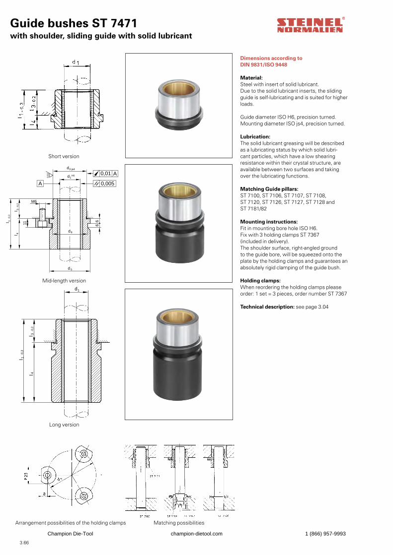
3.66
Guide bushes ST 7471with shoulder, sliding guide with solid lubricant
Dimensions according to DIN 9831/ISO 9448
Material:Steel with insert of solid lubricant.Due to the solid lubricant inserts, the slidingguide is self-lubricating and is suited for higherloads.
Guide diameter ISO H6, precision turned.Mounting diameter ISO js4, precision turned.
Lubrication:The solid lubricant greasing will be described as a lubricating status by which solid lubri-cant particles, which have a low shearing resistance within their crystal structure, are available between two surfaces and taking over the lubricating functions.
Matching Guide pillars:ST 7100, ST 7106, ST 7107, ST 7108, ST 7120, ST 7126, ST 7127, ST 7128 and ST 7181/82
Mounting instructions:Fit in mounting bore hole ISO H6.Fix with 3 holding clamps ST 7367 (included in delivery).The shoulder surface, right-angled ground to the guide bore, will be squeezed onto the plate by the holding clamps and guarantees an absolutely rigid clamping of the guide bush.
Holding clamps:When reordering the holding clamps pleaseorder: 1 set = 3 pieces, order number ST 7367
Technical description: see page 3.04
d1
d3 js4
H6
0,005
0,63 0,01 A
d 5
d6
M6
-0,2
l 1-0
,3
l 3l 4
11
66
A
d1
-0,2
l 3l 4
-0,3
l 1
Short version
Mid-length version
Long version
Arrangement possibilities of the holding clamps Matching possibilities
Champion Die-Tool champion-dietool.com 1 (866) 957-9993
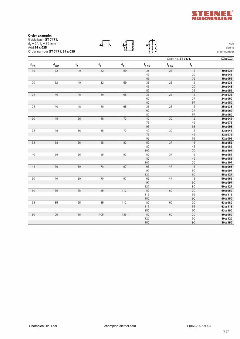
3.67
Addsize to
order number
Order no. ST 7471. x
Order example:Guide bush ST 7471.d1 = 24, l1 = 35 mmAdd 24 x 035Order number ST 7471. 24 x 035
d1H6 d3js4 d5 d6 d8 l1 -0,3 l3 -0,2 l4
19 32 40 32 59 35 23 12 19 x 035 43 20 19 x 043 59 36 19 x 059
20 32 40 32 59 35 23 12 20 x 035 43 20 20 x 043 59 36 20 x 059
24 40 48 40 65 35 23 12 24 x 035 60 37 24 x 060 80 57 24 x 080
25 40 48 40 65 35 23 12 25 x 035 60 37 25 x 060 80 57 25 x 080
30 48 56 48 73 42 30 12 30 x 042 75 45 30 x 075 93 63 30 x 093
32 48 56 48 73 42 30 12 32 x 042 75 45 32 x 075 93 63 32 x 093
38 58 66 58 83 52 37 15 38 x 052 82 45 38 x 082
107 70 38 x 10740 58 66 58 83 52 37 15 40 x 052
82 45 40 x 082107 70 40 x 107
48 70 80 70 97 65 47 18 48 x 065 97 50 48 x 097
127 80 48 x 12750 70 80 70 97 65 47 18 50 x 065
97 50 50 x 097127 80 50 x 127
60 85 95 85 112 80 60 20 60 x 080115 55 60 x 115150 90 60 x 150
63 85 95 85 112 80 60 20 63 x 080115 55 63 x 115150 90 63 x 150
80 105 118 105 135 80 60 20 80 x 080120 60 80 x 120150 90 80 x 150
Champion Die-Tool champion-dietool.com 1 (866) 957-9993
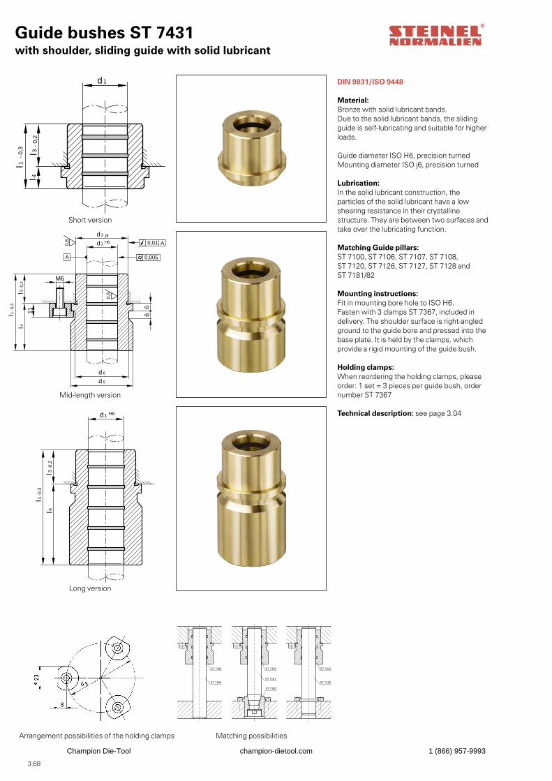
3.68
Guide bushes ST 7431with shoulder, sliding guide with solid lubricant
l 4
d 1
l3
l 1
- 0,
2
- 0,
3
DIN 9831/ISO 9448
Material:Bronze with solid lubricant bands.Due to the solid lubricant bands, the sliding guide is self-lubricating and suitable for higher loads.
Guide diameter ISO H6, precision turnedMounting diameter ISO j6, precision turned
Lubrication:In the solid lubricant construction, the particles of the solid lubricant have a low shearing resistance in their crystalline structure. They are between two surfaces and take over the lubricating function.
Matching Guide pillars:ST 7100, ST 7106, ST 7107, ST 7108, ST 7120, ST 7126, ST 7127, ST 7128 and ST 7181/82
Mounting instructions:Fit in mounting bore hole to ISO H6.Fasten with 3 clamps ST 7367, included indelivery. The shoulder surface is right-angledground to the guide bore and pressed into thebase plate. It is held by the clamps, whichprovide a rigid mounting of the guide bush.
Holding clamps:When reordering the holding clamps, please order: 1 set = 3 pieces per guide bush, order number ST 7367
Technical description: see page 3.04
11
l 4
M6
66
0,8
A
d 5
d 6
0,01 A
0,005
l3-0
,2
-0,3
l 1
j6
H6
d 3
d1
0,8
l 4l 3
-0,2
-0,3
l 1
H6d1
ST 7431
ST 7100
ST 7182
ST 7431 ST 7431
ST 7181ST 7120
Short version
Mid-length version
Long version
Arrangement possibilities of the holding clamps Matching possibilities
Champion Die-Tool champion-dietool.com 1 (866) 957-9993
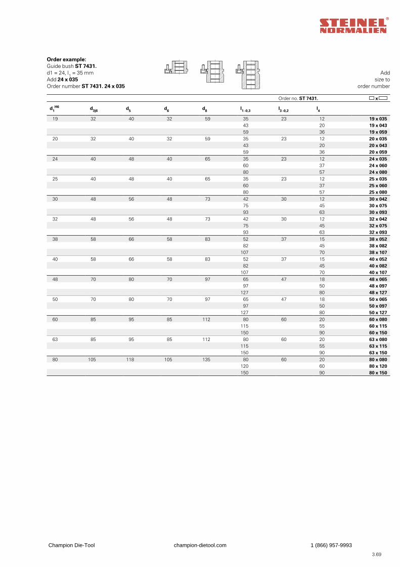
3.69
Addsize to
order number
Order no. ST 7431. x
Order example:Guide bush ST 7431.d1 = 24, l1 = 35 mmAdd 24 x 035Order number ST 7431. 24 x 035
d1H6 d3j6 d5 d6 d8 l1 -0,3 l3 -0,2 l4
19 32 40 32 59 35 23 12 19 x 035 43 20 19 x 043 59 36 19 x 059
20 32 40 32 59 35 23 12 20 x 035 43 20 20 x 043 59 36 20 x 059
24 40 48 40 65 35 23 12 24 x 035 60 37 24 x 060 80 57 24 x 080
25 40 48 40 65 35 23 12 25 x 035 60 37 25 x 060 80 57 25 x 080
30 48 56 48 73 42 30 12 30 x 042 75 45 30 x 075 93 63 30 x 093
32 48 56 48 73 42 30 12 32 x 042 75 45 32 x 075 93 63 32 x 093
38 58 66 58 83 52 37 15 38 x 052 82 45 38 x 082
107 70 38 x 10740 58 66 58 83 52 37 15 40 x 052
82 45 40 x 082107 70 40 x 107
48 70 80 70 97 65 47 18 48 x 065 97 50 48 x 097
127 80 48 x 12750 70 80 70 97 65 47 18 50 x 065
97 50 50 x 097127 80 50 x 127
60 85 95 85 112 80 60 20 60 x 080115 55 60 x 115150 90 60 x 150
63 85 95 85 112 80 60 20 63 x 080115 55 63 x 115150 90 63 x 150
80 105 118 105 135 80 60 20 80 x 080120 60 80 x 120150 90 80 x 150
Champion Die-Tool champion-dietool.com 1 (866) 957-9993
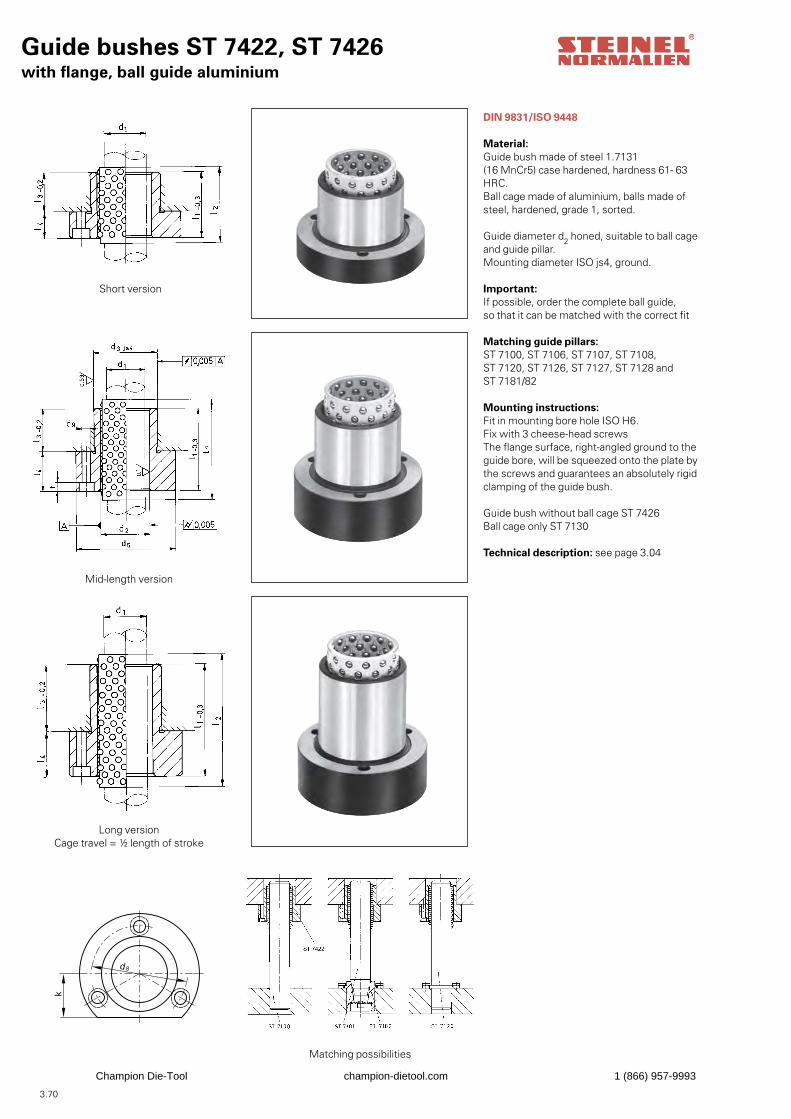
3.70
Guide bushes ST 7422, ST 7426with flange, ball guide aluminium
DIN 9831/ISO 9448
Material:Guide bush made of steel 1.7131 (16 MnCr5) case hardened, hardness 61- 63 HRC.Ball cage made of aluminium, balls made of steel, hardened, grade 1, sorted.
Guide diameter d2 honed, suitable to ball cageand guide pillar.Mounting diameter ISO js4, ground.
Important:If possible, order the complete ball guide,so that it can be matched with the correct fit
Matching guide pillars:ST 7100, ST 7106, ST 7107, ST 7108, ST 7120, ST 7126, ST 7127, ST 7128 and ST 7181/82
Mounting instructions:Fit in mounting bore hole ISO H6.Fix with 3 cheese-head screws The flange surface, right-angled ground to theguide bore, will be squeezed onto the plate by the screws and guarantees an absolutely rigidclamping of the guide bush.
Guide bush without ball cage ST 7426Ball cage only ST 7130
Technical description: see page 3.04
d8
k
Short version
Mid-length version
Long versionCage travel = ½ length of stroke
Matching possibilities
Champion Die-Tool champion-dietool.com 1 (866) 957-9993
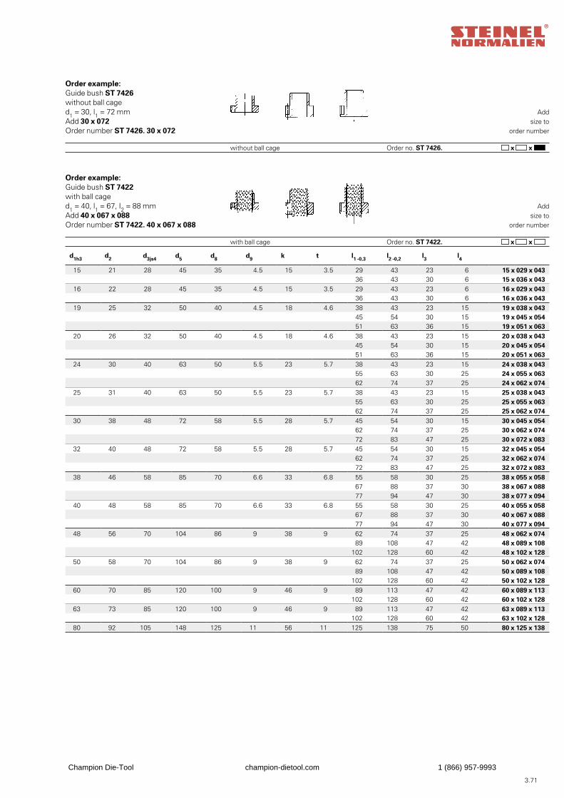
3.71
Addsize to
order number
Order no. ST 7426. x x without ball cage
Order example:Guide bush ST 7426without ball caged1 = 30, l1 = 72 mmAdd 30 x 072Order number ST 7426. 30 x 072
Addsize to
order number
Order no. ST 7422. x x with ball cage
Order example:Guide bush ST 7422with ball caged1 = 40, l1 = 67, I2 = 88 mmAdd 40 x 067 x 088Order number ST 7422. 40 x 067 x 088
d1h3 d2 d3js4 d5 d8 d9 k t l1 -0,3 l2 -0,2 l3 l4
15 21 28 45 35 4.5 15 3.5 29 43 23 6 15 x 029 x 043 36 43 30 6 15 x 036 x 043
16 22 28 45 35 4.5 15 3.5 29 43 23 6 16 x 029 x 043 36 43 30 6 16 x 036 x 043
19 25 32 50 40 4.5 18 4.6 38 43 23 15 19 x 038 x 043 45 54 30 15 19 x 045 x 054 51 63 36 15 19 x 051 x 063
20 26 32 50 40 4.5 18 4.6 38 43 23 15 20 x 038 x 043 45 54 30 15 20 x 045 x 054 51 63 36 15 20 x 051 x 063
24 30 40 63 50 5.5 23 5.7 38 43 23 15 24 x 038 x 043 55 63 30 25 24 x 055 x 063 62 74 37 25 24 x 062 x 074
25 31 40 63 50 5.5 23 5.7 38 43 23 15 25 x 038 x 043 55 63 30 25 25 x 055 x 063 62 74 37 25 25 x 062 x 074
30 38 48 72 58 5.5 28 5.7 45 54 30 15 30 x 045 x 054 62 74 37 25 30 x 062 x 074 72 83 47 25 30 x 072 x 083
32 40 48 72 58 5.5 28 5.7 45 54 30 15 32 x 045 x 054 62 74 37 25 32 x 062 x 074 72 83 47 25 32 x 072 x 083
38 46 58 85 70 6.6 33 6.8 55 58 30 25 38 x 055 x 058 67 88 37 30 38 x 067 x 088 77 94 47 30 38 x 077 x 094
40 48 58 85 70 6.6 33 6.8 55 58 30 25 40 x 055 x 058 67 88 37 30 40 x 067 x 088 77 94 47 30 40 x 077 x 094
48 56 70 104 86 9 38 9 62 74 37 25 48 x 062 x 074 89 108 47 42 48 x 089 x 108
102 128 60 42 48 x 102 x 12850 58 70 104 86 9 38 9 62 74 37 25 50 x 062 x 074
89 108 47 42 50 x 089 x 108102 128 60 42 50 x 102 x 128
60 70 85 120 100 9 46 9 89 113 47 42 60 x 089 x 113102 128 60 42 60 x 102 x 128
63 73 85 120 100 9 46 9 89 113 47 42 63 x 089 x 113102 128 60 42 63 x 102 x 128
80 92 105 148 125 11 56 11 125 138 75 50 80 x 125 x 138
Champion Die-Tool champion-dietool.com 1 (866) 957-9993
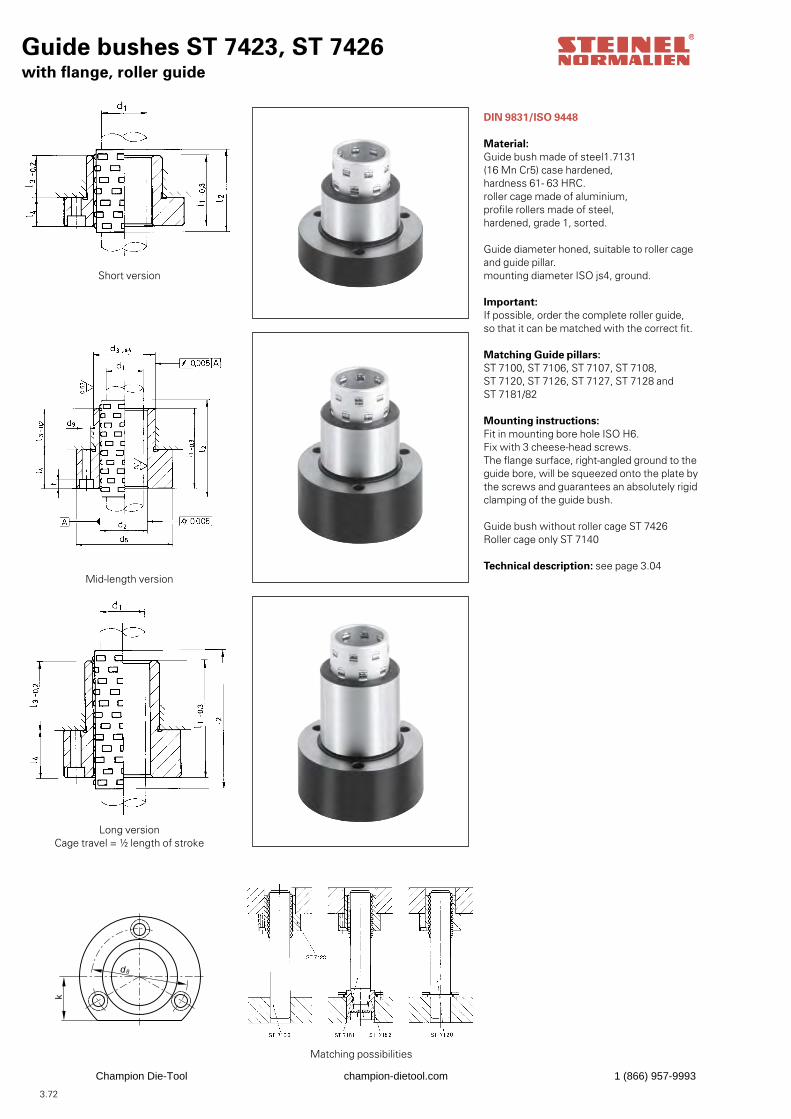
3.72
Guide bushes ST 7423, ST 7426with flange, roller guide
DIN 9831/ISO 9448
Material:Guide bush made of steel1.7131 (16 Mn Cr5) case hardened, hardness 61- 63 HRC.roller cage made of aluminium,profile rollers made of steel, hardened, grade 1, sorted.
Guide diameter honed, suitable to roller cage and guide pillar.mounting diameter ISO js4, ground.
Important:If possible, order the complete roller guide,so that it can be matched with the correct fit.
Matching Guide pillars:ST 7100, ST 7106, ST 7107, ST 7108, ST 7120, ST 7126, ST 7127, ST 7128 and ST 7181/82
Mounting instructions:Fit in mounting bore hole ISO H6.Fix with 3 cheese-head screws.The flange surface, right-angled ground to theguide bore, will be squeezed onto the plate bythe screws and guarantees an absolutely rigidclamping of the guide bush.
Guide bush without roller cage ST 7426Roller cage only ST 7140
Technical description: see page 3.04
d8
k
Short version
Mid-length version
Long versionCage travel = ½ length of stroke
Matching possibilities
Champion Die-Tool champion-dietool.com 1 (866) 957-9993
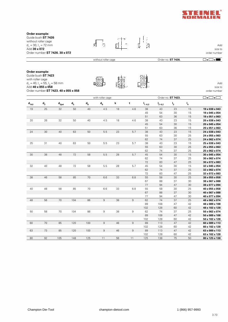
3.73
Addsize to
order number
Order no. ST 7426. x x without roller cage
Order example:Guide bush ST 7426without roller caged1 = 30, l1 = 72 mmAdd 30 x 072Order number ST 7426. 30 x 072
Addsize to
order number
Order no. ST 7423. x x with roller cage
Order example:Guide bush ST 7423with roller caged1 = 40, l1 = 55, I2 = 58 mmAdd 40 x 055 x 058Order number ST 7423. 40 x 055 x 058
d1h3 d2 d3js4 d5 d8 d9 k t l1 -0,3 l2 -0,2 l3 l4
19 25 32 50 40 4.5 18 4.6 38 43 23 15 19 x 038 x 043 45 54 30 15 19 x 045 x 054 51 63 36 15 19 x 051 x 063
20 26 32 50 40 4.5 18 4.6 38 43 23 15 20 x 038 x 043 45 54 30 15 20 x 045 x 054 51 63 36 15 20 x 051 x 063
24 30 40 63 50 5.5 23 5.7 38 43 23 15 24 x 038 x 043 55 63 30 25 24 x 055 x 063 62 74 37 25 24 x 062 x 074
25 31 40 63 50 5.5 23 5.7 38 43 23 15 25 x 038 x 043 55 63 30 25 25 x 055 x 063 62 74 37 25 25 x 062 x 074
30 38 48 72 58 5.5 28 5.7 45 54 30 15 30 x 045 x 054 62 74 37 25 30 x 062 x 074 72 83 47 25 30 x 072 x 083
32 40 48 72 58 5.5 28 5.7 45 54 30 15 32 x 045 x 054 62 74 37 25 32 x 062 x 074 72 83 47 25 32 x 072 x 083
38 46 58 85 70 6.6 33 6.8 55 58 30 25 38 x 055 x 058 67 88 37 30 38 x 067 x 088 77 94 47 30 38 x 077 x 094
40 48 58 85 70 6.6 33 6.8 55 58 30 25 40 x 055 x 058 67 88 37 30 40 x 067 x 088 77 94 47 30 40 x 077 x 094
48 56 70 104 86 9 38 9 62 74 37 25 48 x 062 x 074 89 108 47 42 48 x 089 x 108
102 128 60 42 48 x 102 x 12850 58 70 104 86 9 38 9 62 74 37 25 50 x 062 x 074
89 108 47 42 50 x 089 x 108102 128 60 42 50 x 102 x 128
60 70 85 120 100 9 46 9 89 113 47 42 60 x 089 x 113102 128 60 42 60 x 102 x 128
63 73 85 120 100 9 46 9 89 113 47 42 63 x 089 x 113102 128 60 42 63 x 102 x 128
80 92 105 148 125 11 56 11 125 138 75 50 80 x 125 x 138
Champion Die-Tool champion-dietool.com 1 (866) 957-9993
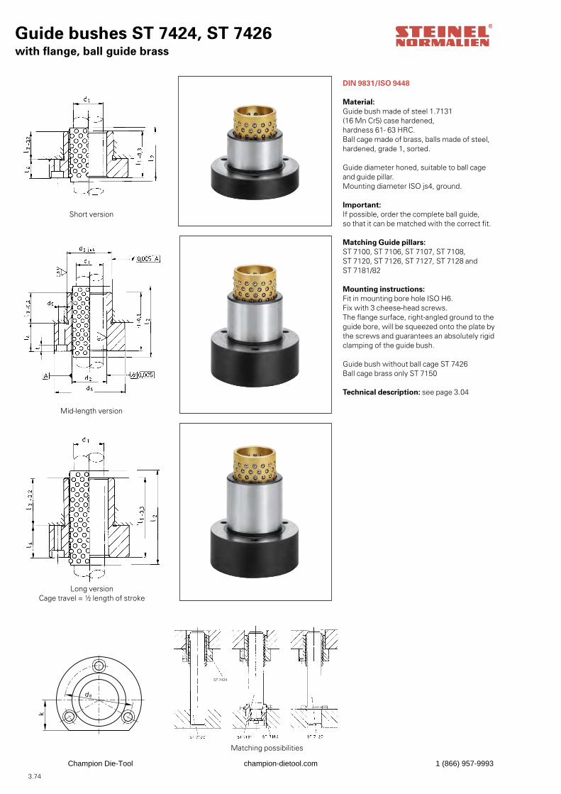
3.74
Guide bushes ST 7424, ST 7426with flange, ball guide brass
DIN 9831/ISO 9448
Material:Guide bush made of steel 1.7131 (16 Mn Cr5) case hardened, hardness 61- 63 HRC.Ball cage made of brass, balls made of steel, hardened, grade 1, sorted.
Guide diameter honed, suitable to ball cage and guide pillar.Mounting diameter ISO js4, ground.
Important:If possible, order the complete ball guide,so that it can be matched with the correct fit.
Matching Guide pillars:ST 7100, ST 7106, ST 7107, ST 7108, ST 7120, ST 7126, ST 7127, ST 7128 and ST 7181/82
Mounting instructions:Fit in mounting bore hole ISO H6.Fix with 3 cheese-head screws.The flange surface, right-angled ground to theguide bore, will be squeezed onto the plate bythe screws and guarantees an absolutely rigidclamping of the guide bush.
Guide bush without ball cage ST 7426Ball cage brass only ST 7150
Technical description: see page 3.04
d8
k
Short version
Mid-length version
Long versionCage travel = ½ length of stroke
Matching possibilities
ST 7424
Champion Die-Tool champion-dietool.com 1 (866) 957-9993
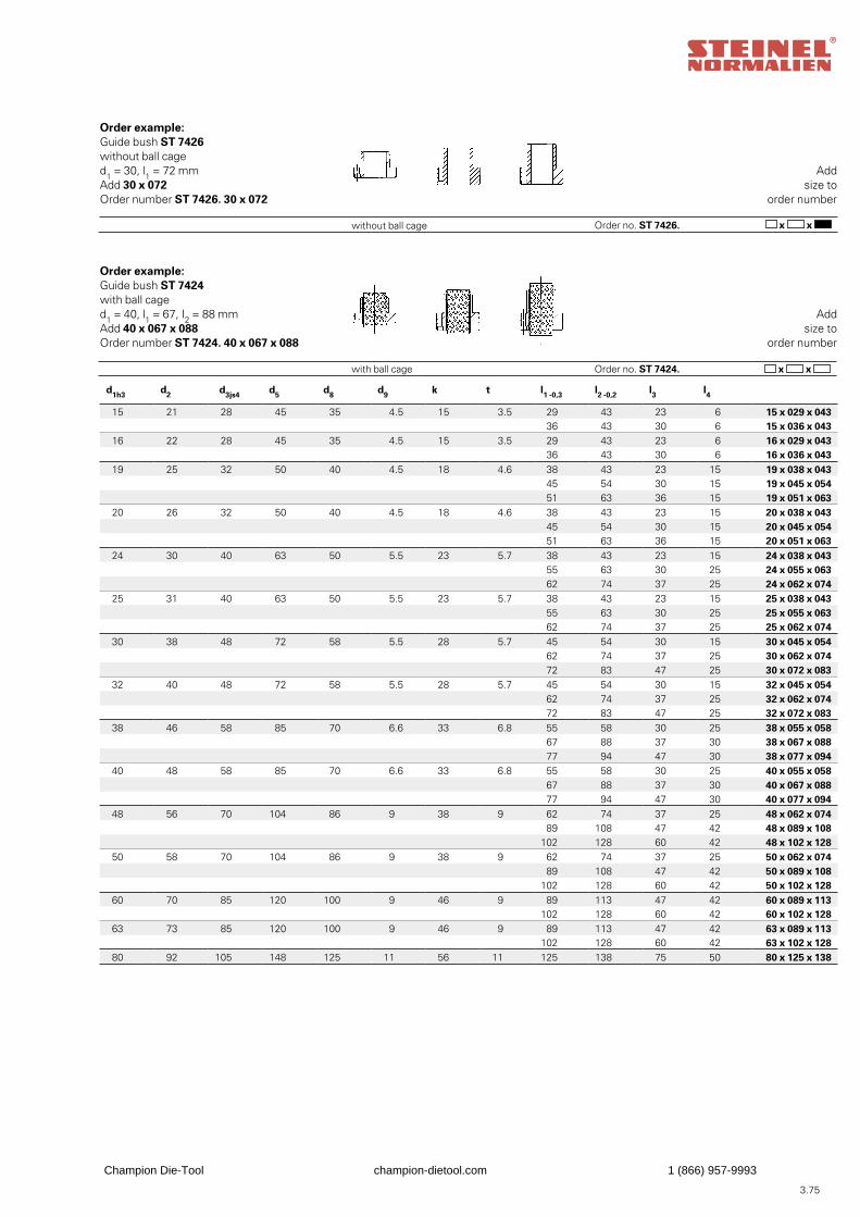
3.75
x x
d1h3 d2 d3js4 d5 d8 d9 k t l1 -0,3 l2 -0,2 l3 l4
15 21 28 45 35 4.5 15 3.5 29 43 23 6 15 x 029 x 043 36 43 30 6 15 x 036 x 043
16 22 28 45 35 4.5 15 3.5 29 43 23 6 16 x 029 x 043 36 43 30 6 16 x 036 x 043
19 25 32 50 40 4.5 18 4.6 38 43 23 15 19 x 038 x 043 45 54 30 15 19 x 045 x 054 51 63 36 15 19 x 051 x 063
20 26 32 50 40 4.5 18 4.6 38 43 23 15 20 x 038 x 043 45 54 30 15 20 x 045 x 054 51 63 36 15 20 x 051 x 063
24 30 40 63 50 5.5 23 5.7 38 43 23 15 24 x 038 x 043 55 63 30 25 24 x 055 x 063 62 74 37 25 24 x 062 x 074
25 31 40 63 50 5.5 23 5.7 38 43 23 15 25 x 038 x 043 55 63 30 25 25 x 055 x 063 62 74 37 25 25 x 062 x 074
30 38 48 72 58 5.5 28 5.7 45 54 30 15 30 x 045 x 054 62 74 37 25 30 x 062 x 074 72 83 47 25 30 x 072 x 083
32 40 48 72 58 5.5 28 5.7 45 54 30 15 32 x 045 x 054 62 74 37 25 32 x 062 x 074 72 83 47 25 32 x 072 x 083
38 46 58 85 70 6.6 33 6.8 55 58 30 25 38 x 055 x 058 67 88 37 30 38 x 067 x 088 77 94 47 30 38 x 077 x 094
40 48 58 85 70 6.6 33 6.8 55 58 30 25 40 x 055 x 058 67 88 37 30 40 x 067 x 088 77 94 47 30 40 x 077 x 094
48 56 70 104 86 9 38 9 62 74 37 25 48 x 062 x 074 89 108 47 42 48 x 089 x 108
102 128 60 42 48 x 102 x 12850 58 70 104 86 9 38 9 62 74 37 25 50 x 062 x 074
89 108 47 42 50 x 089 x 108102 128 60 42 50 x 102 x 128
60 70 85 120 100 9 46 9 89 113 47 42 60 x 089 x 113102 128 60 42 60 x 102 x 128
63 73 85 120 100 9 46 9 89 113 47 42 63 x 089 x 113102 128 60 42 63 x 102 x 128
80 92 105 148 125 11 56 11 125 138 75 50 80 x 125 x 138
Addsize to
order number
Order no. ST 7426.without ball cage
Order example:Guide bush ST 7426without ball caged1 = 30, l1 = 72 mmAdd 30 x 072Order number ST 7426. 30 x 072
Addsize to
order number
Order no. ST 7424. x x with ball cage
Order example:Guide bush ST 7424with ball caged1 = 40, l1 = 67, I2 = 88 mmAdd 40 x 067 x 088Order number ST 7424. 40 x 067 x 088
Champion Die-Tool champion-dietool.com 1 (866) 957-9993
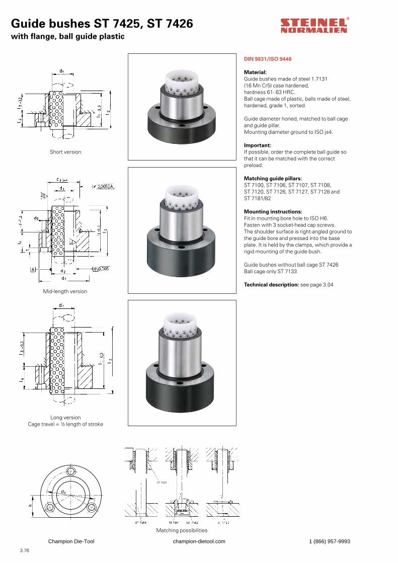
3.76
Guide bushes ST 7425, ST 7426with flange, ball guide plastic
DIN 9831/ISO 9448
Material:Guide bushes made of steel 1.7131 (16 Mn Cr5) case hardened, hardness 61- 63 HRC.Ball cage made of plastic, balls made of steel, hardened, grade 1, sorted.
Guide diameter honed, matched to ball cage and guide pillar.Mounting diameter ground to ISO js4.
Important:If possible, order the complete ball guide so that it can be matched with the correct preload.
Matching guide pillars:ST 7100, ST 7106, ST 7107, ST 7108, ST 7120, ST 7126, ST 7127, ST 7128 and ST 7181/82
Mounting instructions:Fit in mounting bore hole to ISO H6.Fasten with 3 socket-head cap screws.The shoulder surface is right-angled ground tothe guide bore and pressed into the base plate. It is held by the clamps, which provide a rigid mounting of the guide bush.
Guide bushes without ball cage ST 7426Ball cage only ST 7133
Technical description: see page 3.04
d8
k
Short version
Mid-length version
Long versionCage travel = ½ length of stroke
Matching possibilities
ST 7425
Champion Die-Tool champion-dietool.com 1 (866) 957-9993
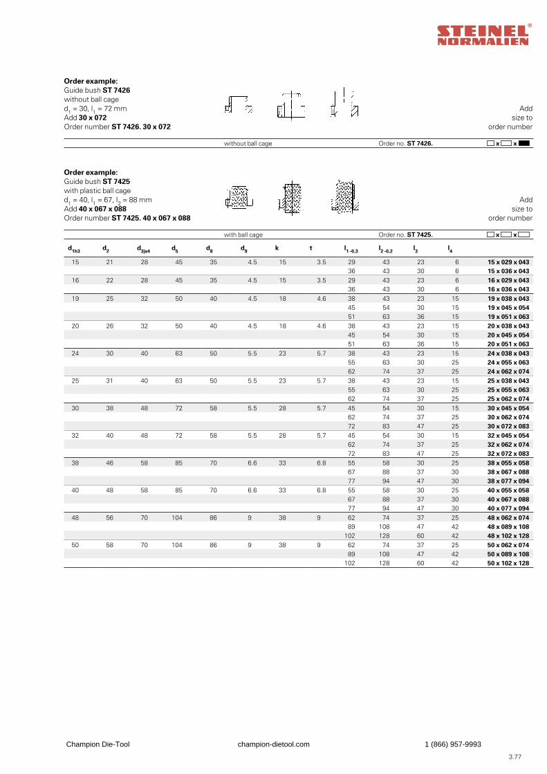
3.77
Addsize to
order number
Order no. ST 7426. x x without ball cage
Order example:Guide bush ST 7426without ball caged1 = 30, l1 = 72 mmAdd 30 x 072Order number ST 7426. 30 x 072
Addsize to
order number
Order no. ST 7425. x x with ball cage
Order example:Guide bush ST 7425with plastic ball caged1 = 40, l1 = 67, I2 = 88 mmAdd 40 x 067 x 088Order number ST 7425. 40 x 067 x 088
d1h3 d2 d3js4 d5 d8 d9 k t l1 -0,3 l2 -0,2 l3 l4
15 21 28 45 35 4.5 15 3.5 29 43 23 6 15 x 029 x 043 36 43 30 6 15 x 036 x 043
16 22 28 45 35 4.5 15 3.5 29 43 23 6 16 x 029 x 043 36 43 30 6 16 x 036 x 043
19 25 32 50 40 4.5 18 4.6 38 43 23 15 19 x 038 x 043 45 54 30 15 19 x 045 x 054 51 63 36 15 19 x 051 x 063
20 26 32 50 40 4.5 18 4.6 38 43 23 15 20 x 038 x 043 45 54 30 15 20 x 045 x 054 51 63 36 15 20 x 051 x 063
24 30 40 63 50 5.5 23 5.7 38 43 23 15 24 x 038 x 043 55 63 30 25 24 x 055 x 063 62 74 37 25 24 x 062 x 074
25 31 40 63 50 5.5 23 5.7 38 43 23 15 25 x 038 x 043 55 63 30 25 25 x 055 x 063 62 74 37 25 25 x 062 x 074
30 38 48 72 58 5.5 28 5.7 45 54 30 15 30 x 045 x 054 62 74 37 25 30 x 062 x 074 72 83 47 25 30 x 072 x 083
32 40 48 72 58 5.5 28 5.7 45 54 30 15 32 x 045 x 054 62 74 37 25 32 x 062 x 074 72 83 47 25 32 x 072 x 083
38 46 58 85 70 6.6 33 6.8 55 58 30 25 38 x 055 x 058 67 88 37 30 38 x 067 x 088 77 94 47 30 38 x 077 x 094
40 48 58 85 70 6.6 33 6.8 55 58 30 25 40 x 055 x 058 67 88 37 30 40 x 067 x 088 77 94 47 30 40 x 077 x 094
48 56 70 104 86 9 38 9 62 74 37 25 48 x 062 x 074 89 108 47 42 48 x 089 x 108
102 128 60 42 48 x 102 x 12850 58 70 104 86 9 38 9 62 74 37 25 50 x 062 x 074
89 108 47 42 50 x 089 x 108102 128 60 42 50 x 102 x 128
Champion Die-Tool champion-dietool.com 1 (866) 957-9993
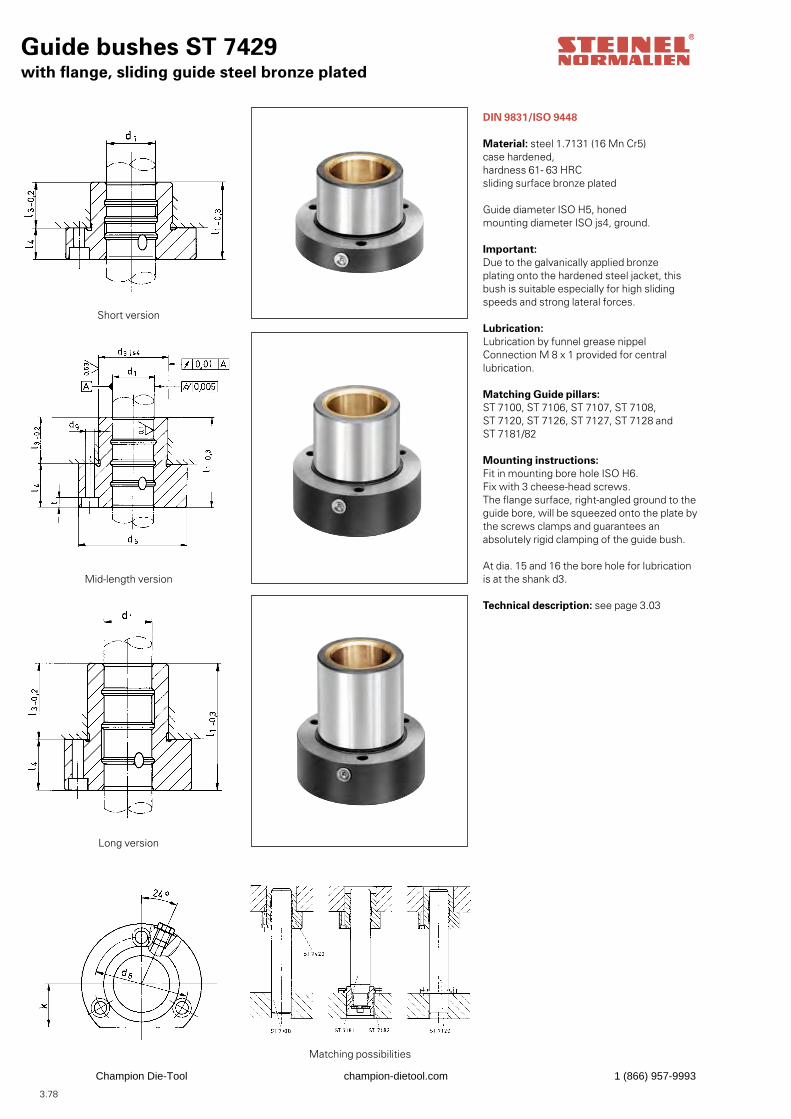
3.78
Guide bushes ST 7429with flange, sliding guide steel bronze plated
DIN 9831/ISO 9448
Material: steel 1.7131 (16 Mn Cr5)case hardened, hardness 61- 63 HRCsliding surface bronze plated
Guide diameter ISO H5, honedmounting diameter ISO js4, ground.
Important:Due to the galvanically applied bronzeplating onto the hardened steel jacket, this bush is suitable especially for high sliding speeds and strong lateral forces.
Lubrication:Lubrication by funnel grease nippelConnection M 8 x 1 provided for centrallubrication.
Matching Guide pillars:ST 7100, ST 7106, ST 7107, ST 7108, ST 7120, ST 7126, ST 7127, ST 7128 and ST 7181/82
Mounting instructions:Fit in mounting bore hole ISO H6.Fix with 3 cheese-head screws.The flange surface, right-angled ground to theguide bore, will be squeezed onto the plate bythe screws clamps and guarantees an absolutely rigid clamping of the guide bush.
At dia. 15 and 16 the bore hole for lubrication is at the shank d3.
Technical description: see page 3.03
Short version
Mid-length version
Long version
Matching possibilities
Champion Die-Tool champion-dietool.com 1 (866) 957-9993
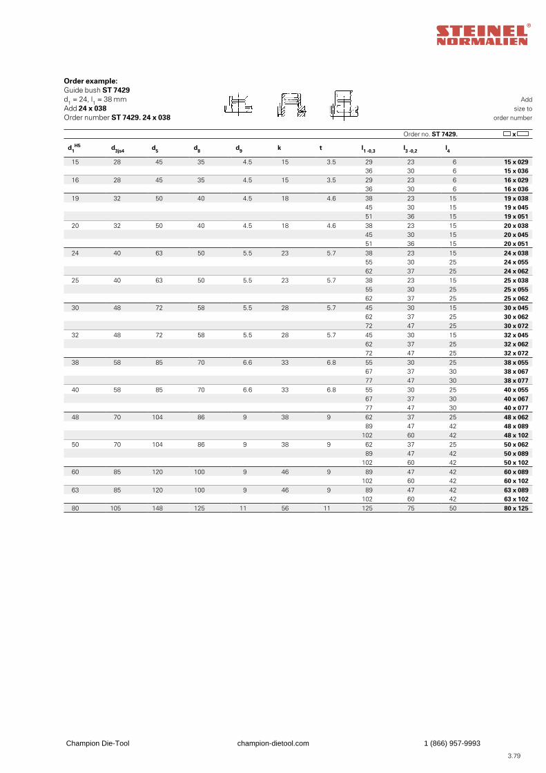
3.79
Addsize to
order number
Order no. ST 7429. x
Order example:Guide bush ST 7429d1 = 24, l1 = 38 mmAdd 24 x 038Order number ST 7429. 24 x 038
d1H5 d3js4 d5 d8 d9 k t l1 -0,3 l3 -0,2 l4
15 28 45 35 4.5 15 3.5 29 23 6 15 x 029 36 30 6 15 x 036
16 28 45 35 4.5 15 3.5 29 23 6 16 x 029 36 30 6 16 x 036
19 32 50 40 4.5 18 4.6 38 23 15 19 x 038 45 30 15 19 x 045 51 36 15 19 x 051
20 32 50 40 4.5 18 4.6 38 23 15 20 x 038 45 30 15 20 x 045 51 36 15 20 x 051
24 40 63 50 5.5 23 5.7 38 23 15 24 x 038 55 30 25 24 x 055 62 37 25 24 x 062
25 40 63 50 5.5 23 5.7 38 23 15 25 x 038 55 30 25 25 x 055 62 37 25 25 x 062
30 48 72 58 5.5 28 5.7 45 30 15 30 x 045 62 37 25 30 x 062 72 47 25 30 x 072
32 48 72 58 5.5 28 5.7 45 30 15 32 x 045 62 37 25 32 x 062 72 47 25 32 x 072
38 58 85 70 6.6 33 6.8 55 30 25 38 x 055 67 37 30 38 x 067 77 47 30 38 x 077
40 58 85 70 6.6 33 6.8 55 30 25 40 x 055 67 37 30 40 x 067 77 47 30 40 x 077
48 70 104 86 9 38 9 62 37 25 48 x 062 89 47 42 48 x 089
102 60 42 48 x 10250 70 104 86 9 38 9 62 37 25 50 x 062
89 47 42 50 x 089102 60 42 50 x 102
60 85 120 100 9 46 9 89 47 42 60 x 089102 60 42 60 x 102
63 85 120 100 9 46 9 89 47 42 63 x 089102 60 42 63 x 102
80 105 148 125 11 56 11 125 75 50 80 x 125
Champion Die-Tool champion-dietool.com 1 (866) 957-9993
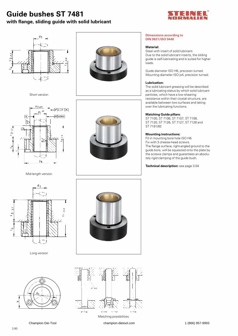
3.80
Guide bushes ST 7481with flange, sliding guide with solid lubricant
Dimensions according to DIN 9831/ISO 9448
Material:Steel with insert of solid lubricant.Due to the solid lubricant inserts, the slidingguide is self-lubricating and is suited for higherloads.
Guide diameter ISO H6, precision turned.Mounting diameter ISO js4, precision turned.
Lubrication:The solid lubricant greasing will be described as a lubricating status by which solid lubricantparticles, which have a low shearing resistance within their crystal structure, are available between two surfaces and taking over the lubricating functions.
Matching Guide pillars:ST 7100, ST 7106, ST 7107, ST 7108, ST 7120, ST 7126, ST 7127, ST 7128 and ST 7181/82
Mounting instructions:Fit in mounting bore hole ISO H6.Fix with 3 cheese-head screws.The flange surface, right-angled ground to theguide bore, will be squeezed onto the plate bythe screws clamps and guarantees an absolu-tely rigid clamping of the guide bush.
Technical description: see page 3.04
d8
k
Short version
Mid-length version
Long version
Matching possibilities
Champion Die-Tool champion-dietool.com 1 (866) 957-9993

3.81
Addsize to
order number
Order no. ST 7481. x
Order example:Guide bush ST 7481.d1 = 24, l1 = 38 mmAdd 24 x 038Order number ST 7481. 24 x 038
d1H6 d3js4 d5 d8 d9 k t l1 -0,3 l3 -0,2 l4
15 28 45 35 4.5 15 3.5 29 23 6 15 x 029 36 30 6 15 x 036
16 28 45 35 4.5 15 3.5 29 23 6 16 x 029 36 30 6 16 x 036
19 32 50 40 4.5 18 4.6 38 23 15 19 x 038 45 30 15 19 x 045 51 36 15 19 x 051
20 32 50 40 4.5 18 4.6 38 23 15 20 x 038 45 30 15 20 x 045 51 36 15 20 x 051
24 40 63 50 5.5 23 5.7 38 23 15 24 x 038 55 30 25 24 x 055 62 37 25 24 x 062
25 40 63 50 5.5 23 5.7 38 23 15 25 x 038 55 30 25 25 x 055 62 37 25 25 x 062
30 48 72 58 5.5 28 5.7 45 30 15 30 x 045 62 37 25 30 x 062 72 47 25 30 x 072
32 48 72 58 5.5 28 5.7 45 30 15 32 x 045 62 37 25 32 x 062
72 47 25 32 x 07238 58 85 70 6.6 33 6.8 55 30 25 38 x 055
67 37 30 38 x 067 77 47 30 38 x 077
40 58 85 70 6.6 33 6.8 55 30 25 40 x 055 67 37 30 40 x 067
77 47 30 40 x 07748 70 104 86 9 38 9 62 37 25 48 x 062
89 47 42 48 x 089102 60 42 48 x 102
50 70 104 86 9 38 9 62 37 25 50 x 062 89 47 42 50 x 089
102 60 42 50 x 10260 85 120 100 9 46 9 89 47 42 60 x 089
102 60 42 60 x 10263 85 120 100 9 46 9 89 47 42 63 x 089
102 60 42 63 x 10280 105 148 125 11 56 11 125 75 50 80 x 125
Champion Die-Tool champion-dietool.com 1 (866) 957-9993
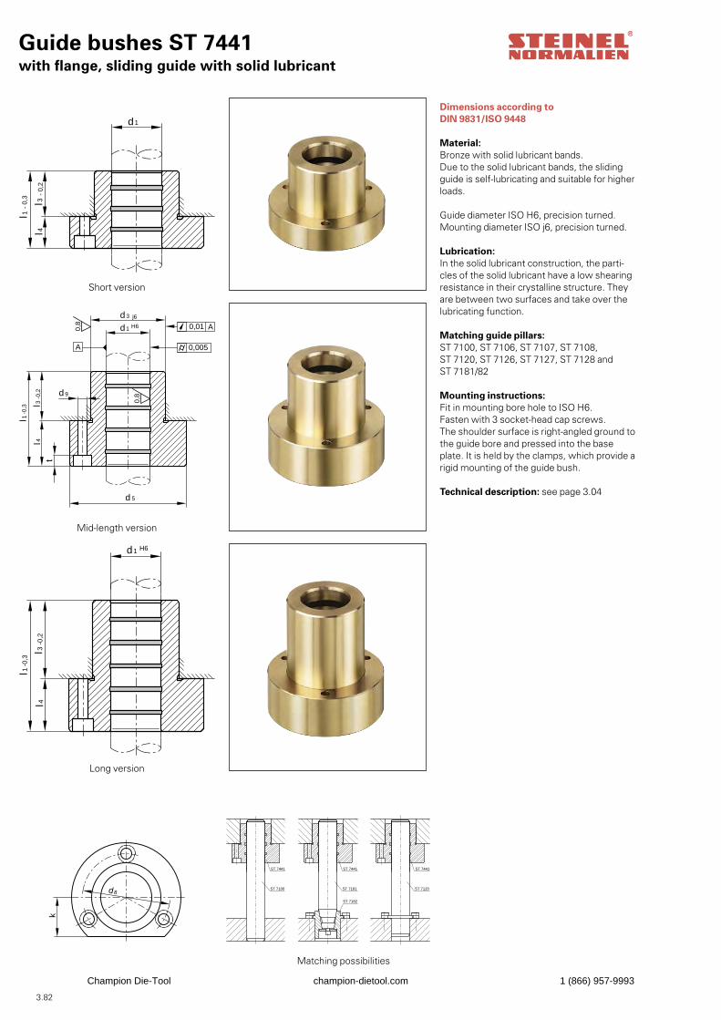
3.82
Guide bushes ST 7441with flange, sliding guide with solid lubricant
l 4
d 1
l1
l 3-
0,2
- 0,
3
Dimensions according to DIN 9831/ISO 9448
Material:Bronze with solid lubricant bands.Due to the solid lubricant bands, the sliding guide is self-lubricating and suitable for higher loads.
Guide diameter ISO H6, precision turned.Mounting diameter ISO j6, precision turned.
Lubrication:In the solid lubricant construction, the parti-cles of the solid lubricant have a low shearing resistance in their crystalline structure. They are between two surfaces and take over the lubricating function.
Matching guide pillars:ST 7100, ST 7106, ST 7107, ST 7108, ST 7120, ST 7126, ST 7127, ST 7128 and ST 7181/82
Mounting instructions:Fit in mounting bore hole to ISO H6.Fasten with 3 socket-head cap screws.The shoulder surface is right-angled ground tothe guide bore and pressed into the base plate. It is held by the clamps, which provide a rigid mounting of the guide bush.
Technical description: see page 3.04
l 4
d 5
t
0,8
A
0,01 A
0,005
d 9
l3-0
,2
-0,3
l 1
j6
H6
d 3
d1
0,8
l 4l 3
-0,2
-0,3
l 1
H6d1
d8
k
ST 7100
ST 7182
ST 7441 ST 7441 ST 7441
ST 7181 ST 7120
Short version
Mid-length version
Long version
Matching possibilities
Champion Die-Tool champion-dietool.com 1 (866) 957-9993
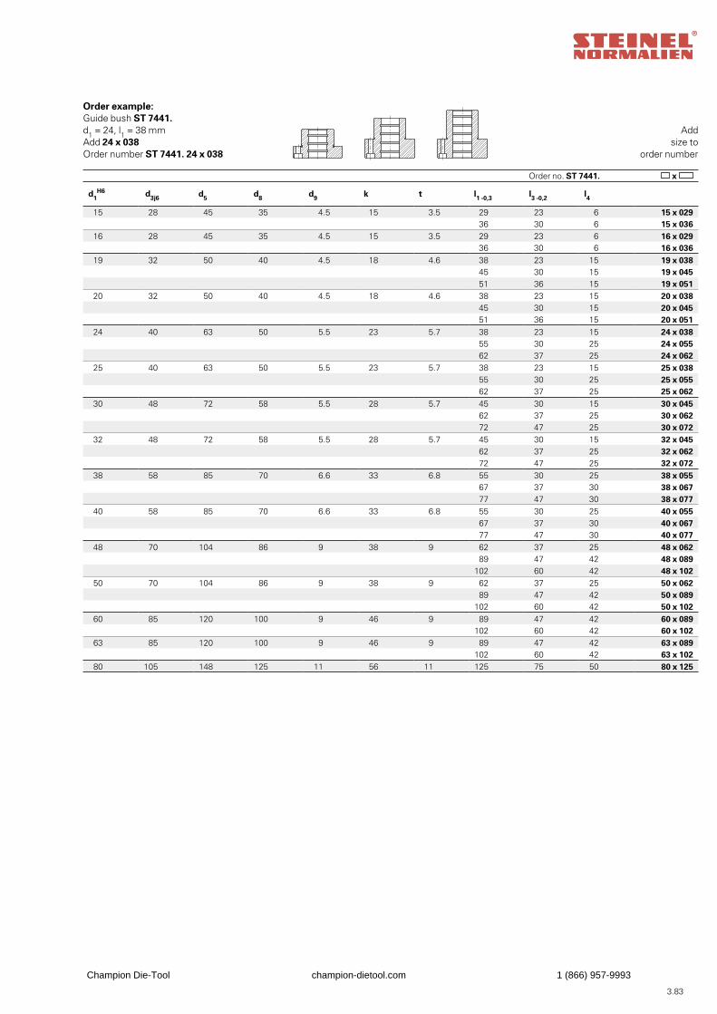
3.83
Addsize to
order number
Order no. ST 7441. x
Order example:Guide bush ST 7441.d1 = 24, l1 = 38 mmAdd 24 x 038Order number ST 7441. 24 x 038
d1H6 d3j6 d5 d8 d9 k t l1 -0,3 l3 -0,2 l4
15 28 45 35 4.5 15 3.5 29 23 6 15 x 029 36 30 6 15 x 036
16 28 45 35 4.5 15 3.5 29 23 6 16 x 029 36 30 6 16 x 036
19 32 50 40 4.5 18 4.6 38 23 15 19 x 038 45 30 15 19 x 045 51 36 15 19 x 051
20 32 50 40 4.5 18 4.6 38 23 15 20 x 038 45 30 15 20 x 045 51 36 15 20 x 051
24 40 63 50 5.5 23 5.7 38 23 15 24 x 038 55 30 25 24 x 055 62 37 25 24 x 062
25 40 63 50 5.5 23 5.7 38 23 15 25 x 038 55 30 25 25 x 055 62 37 25 25 x 062
30 48 72 58 5.5 28 5.7 45 30 15 30 x 045 62 37 25 30 x 062 72 47 25 30 x 072
32 48 72 58 5.5 28 5.7 45 30 15 32 x 045 62 37 25 32 x 062 72 47 25 32 x 072
38 58 85 70 6.6 33 6.8 55 30 25 38 x 055 67 37 30 38 x 067 77 47 30 38 x 077
40 58 85 70 6.6 33 6.8 55 30 25 40 x 055 67 37 30 40 x 067 77 47 30 40 x 077
48 70 104 86 9 38 9 62 37 25 48 x 062 89 47 42 48 x 089
102 60 42 48 x 10250 70 104 86 9 38 9 62 37 25 50 x 062
89 47 42 50 x 089102 60 42 50 x 102
60 85 120 100 9 46 9 89 47 42 60 x 089102 60 42 60 x 102
63 85 120 100 9 46 9 89 47 42 63 x 089102 60 42 63 x 102
80 105 148 125 11 56 11 125 75 50 80 x 125
Champion Die-Tool champion-dietool.com 1 (866) 957-9993
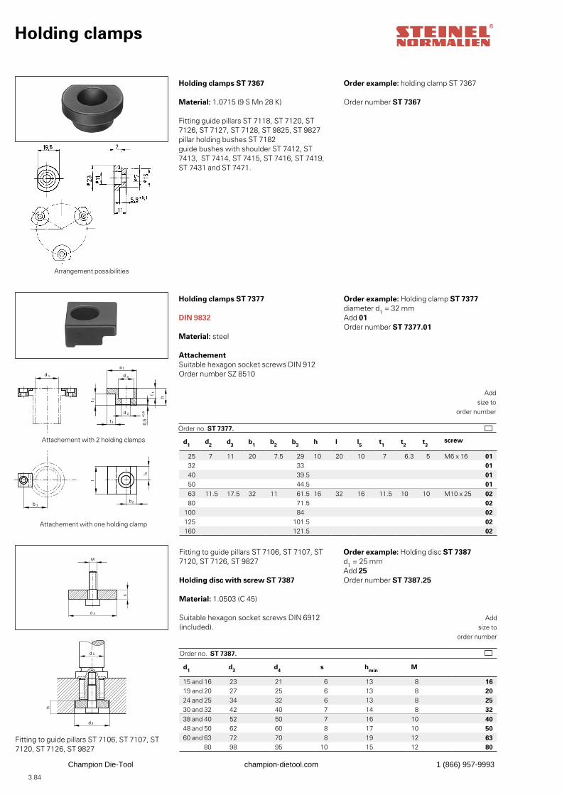
3.84
d1 d3 d4 s hmin M
15 and 16 23 21 6 13 8 1619 and 20 27 25 6 13 8 2024 and 25 34 32 6 13 8 2530 and 32 42 40 7 14 8 3238 and 40 52 50 7 16 10 4048 and 50 62 60 8 17 10 5060 and 63 72 70 8 19 12 63
80 98 95 10 15 12 80
d1 d2 d3 b1 b2 b3 h l l5 t1 t2 t3screw
25 7 11 20 7.5 29 10 20 10 7 6.3 5 M6 x 16 0132 33 0140 39.5 0150 44.5 0163 11.5 17.5 32 11 61.5 16 32 16 11.5 10 10 M10 x 25 0280 71.5 02
100 84 02125 101.5 02160 121.5 02
Holding clamps
Holding clamps ST 7367
Material: 1.0715 (9 S Mn 28 K)
Fitting guide pillars ST 7118, ST 7120, ST 7126, ST 7127, ST 7128, ST 9825, ST 9827pillar holding bushes ST 7182 guide bushes with shoulder ST 7412, ST 7413, ST 7414, ST 7415, ST 7416, ST 7419, ST 7431 and ST 7471.
Order example: holding clamp ST 7367
h
d 1
d3
s
M
d 4
Order example: Holding disc ST 7387d1 = 25 mmAdd 25Order number ST 7387.25
h
l
0,5
+0,
5
b 1
d 3
l 5t 1
t 2
d 2
t3
b2b 3
d 1
Holding clamps ST 7377
DIN 9832
Material: steel
AttachementSuitable hexagon socket screws DIN 912Order number SZ 8510
Order example: Holding clamp ST 7377diameter d1 = 32 mmAdd 01Order number ST 7377.01
Attachement with 2 holding clamps
Attachement with one holding clamp
Addsize to
order number
Order no. ST 7377.
Order number ST 7367
Fitting to guide pillars ST 7106, ST 7107, ST 7120, ST 7126, ST 9827
Holding disc with screw ST 7387
Material: 1.0503 (C 45)
Suitable hexagon socket screws DIN 6912(included).
Addsize to
order number
Order no. ST 7387.
Fitting to guide pillars ST 7106, ST 7107, ST 7120, ST 7126, ST 9827
h
l
0,5
+0,
5
b 1
d 3
l 5t 1
t 2
d 2
t3
b2b 3
d 1
Arrangement possibilities
Champion Die-Tool champion-dietool.com 1 (866) 957-9993
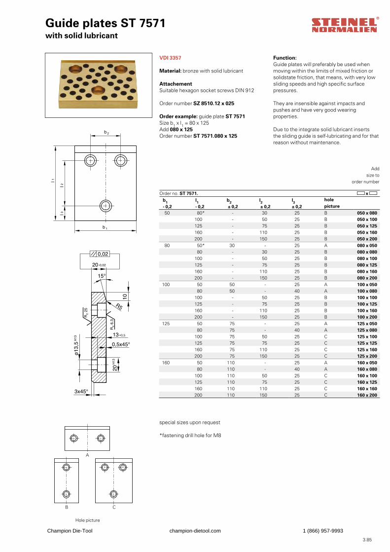
3.85
Guide plates ST 7571with solid lubricant
VDI 3357
Material: bronze with solid lubricant
AttachementSuitable hexagon socket screws DIN 912
Order number SZ 8510.12 x 025
Function:Guide plates will preferably be used whenmoving within the limits of mixed friction or solidstate friction, that means, with very low sliding speeds and high specific surface pressures.
They are insensible against impacts and pushes and have very good wearing properties.
Due to the integrate solid lubricant insertsthe sliding guide is self-lubricating and for thatreason without maintenance.
Order example: guide plate ST 7571Size b1 x l1 = 80 x 125Add 080 x 125Order number ST 7571.080 x 125
Hole picture
Addsize to
order number
Order no. ST 7571. x
special sizes upon request
*fastening drill hole for M8
b1 - 0,2
l1 - 0,2
b2 ± 0,2
l2 ± 0,2
l3 ± 0,2
hole picture
50 80* - 30 25 B 050 x 080100 - 50 25 B 050 x 100125 - 75 25 B 050 x 125160 - 110 25 B 050 x 160200 - 150 25 B 050 x 200
80 50* 30 - 25 A 080 x 050 80 - 30 25 B 080 x 080
100 - 50 25 B 080 x 100125 - 75 25 B 080 x 125160 - 110 25 B 080 x 160200 - 150 25 B 080 x 200
100 50 50 - 25 A 100 x 050 80 50 - 40 A 100 x 080
100 - 50 25 B 100 x 100125 - 75 25 B 100 x 125160 - 110 25 B 100 x 160200 - 150 25 B 100 x 200
125 50 75 - 25 A 125 x 050 80 75 - 40 A 125 x 080
100 75 50 25 C 125 x 100125 75 75 25 C 125 x 125160 75 110 25 C 125 x 160200 75 150 25 C 125 x 200
160 50 110 - 25 A 160 x 050 80 110 - 40 A 160 x 080
100 110 50 25 C 160 x 100125 110 75 25 C 160 x 125160 110 110 25 C 160 x 160200 110 150 25 C 160 x 200
+0,5
+0,5
A
B C
Champion Die-Tool champion-dietool.com 1 (866) 957-9993
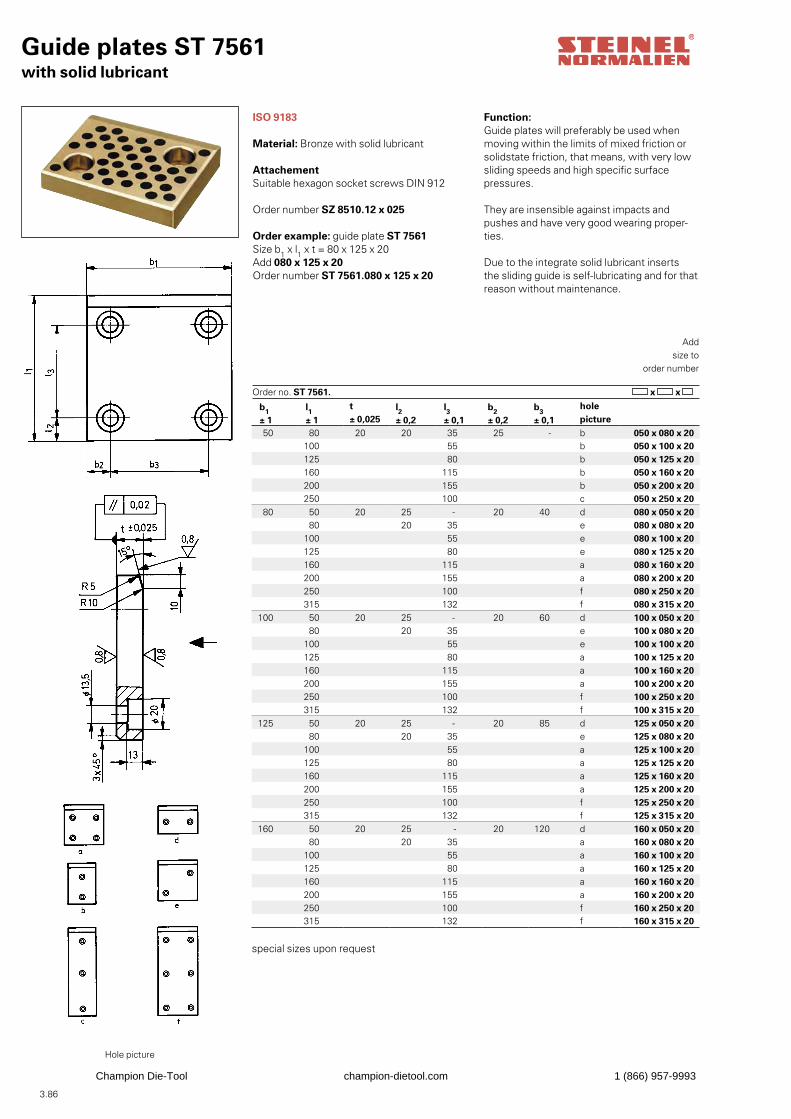
3.86
Guide plates ST 7561with solid lubricant
ISO 9183
Material: Bronze with solid lubricant
AttachementSuitable hexagon socket screws DIN 912
Order number SZ 8510.12 x 025
Function:Guide plates will preferably be used whenmoving within the limits of mixed friction or solidstate friction, that means, with very low sliding speeds and high specific surface pressures.
They are insensible against impacts and pushes and have very good wearing proper-ties.
Due to the integrate solid lubricant insertsthe sliding guide is self-lubricating and for thatreason without maintenance.
Order example: guide plate ST 7561Size b1 x l1 x t = 80 x 125 x 20Add 080 x 125 x 20Order number ST 7561.080 x 125 x 20
Hole picture
Addsize to
order number
Order no. ST 7561. x x
special sizes upon request
b1 ± 1
l1 ± 1
t ± 0,025
l2 ± 0,2
l3 ± 0,1
b2 ± 0,2
b3 ± 0,1
holepicture
50 80 20 20 35 25 - b 050 x 080 x 20100 55 b 050 x 100 x 20125 80 b 050 x 125 x 20160 115 b 050 x 160 x 20200 155 b 050 x 200 x 20250 100 c 050 x 250 x 20
80 50 20 25 - 20 40 d 080 x 050 x 20 80 20 35 e 080 x 080 x 20
100 55 e 080 x 100 x 20125 80 e 080 x 125 x 20160 115 a 080 x 160 x 20200 155 a 080 x 200 x 20250 100 f 080 x 250 x 20315 132 f 080 x 315 x 20
100 50 20 25 - 20 60 d 100 x 050 x 20 80 20 35 e 100 x 080 x 20
100 55 e 100 x 100 x 20125 80 a 100 x 125 x 20160 115 a 100 x 160 x 20200 155 a 100 x 200 x 20250 100 f 100 x 250 x 20315 132 f 100 x 315 x 20
125 50 20 25 - 20 85 d 125 x 050 x 20 80 20 35 e 125 x 080 x 20
100 55 a 125 x 100 x 20125 80 a 125 x 125 x 20160 115 a 125 x 160 x 20200 155 a 125 x 200 x 20250 100 f 125 x 250 x 20315 132 f 125 x 315 x 20
160 50 20 25 - 20 120 d 160 x 050 x 20 80 20 35 a 160 x 080 x 20
100 55 a 160 x 100 x 20125 80 a 160 x 125 x 20160 115 a 160 x 160 x 20200 155 a 160 x 200 x 20250 100 f 160 x 250 x 20315 132 f 160 x 315 x 20
Champion Die-Tool champion-dietool.com 1 (866) 957-9993

3.87
Champion Die-Tool champion-dietool.com 1 (866) 957-9993
3.88
Champion Die-Tool champion-dietool.com 1 (866) 957-9993
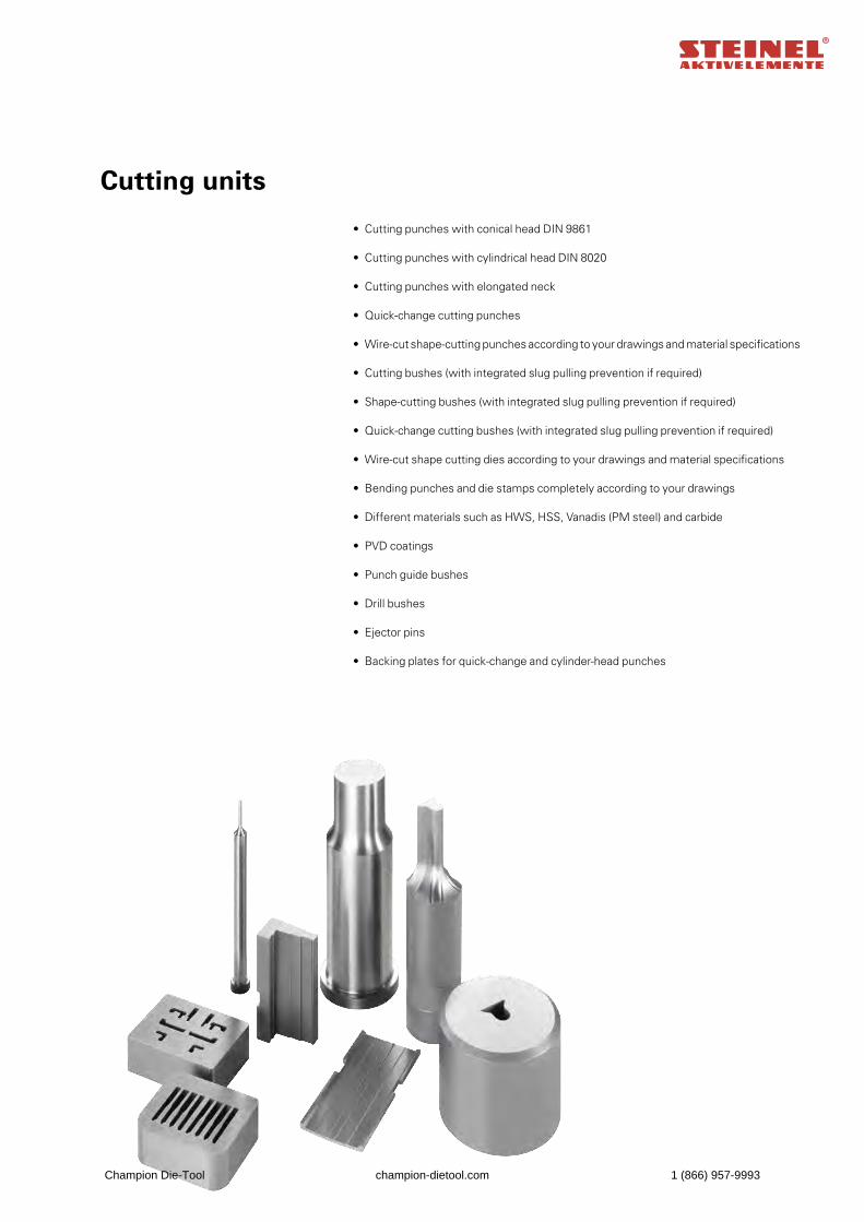
Cutting units
• Cutting punches with conical head DIN 9861 • Cutting punches with cylindrical head DIN 8020 • Cutting punches with elongated neck • Quick-change cutting punches • Wire-cut shape-cutting punches according to your drawings and material specifications • Cutting bushes (with integrated slug pulling prevention if required) • Shape-cutting bushes (with integrated slug pulling prevention if required) • Quick-change cutting bushes (with integrated slug pulling prevention if required) • Wire-cut shape cutting dies according to your drawings and material specifications • Bending punches and die stamps completely according to your drawings • Different materials such as HWS, HSS, Vanadis (PM steel) and carbide • PVD coatings • Punch guide bushes • Drill bushes • Ejector pins • Backing plates for quick-change and cylinder-head punches
Champion Die-Tool champion-dietool.com 1 (866) 957-9993
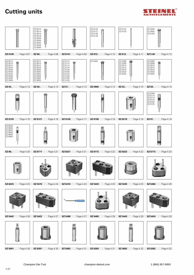
4.02
SZ 6013SZ 6014SZ 6015SZ 6016SZ 6028SZ 6040SZ 6043SZ 6046SZ 6050
SZ 6134SZ 6137SZ 6138SZ 6139
SZ 6124SZ 6129
SZ 5500SZ 5600SZ 5700
SZ 5513SZ 5514SZ 5515SZ 5516SZ 5528SZ 5540SZ 5543SZ 5546SZ 5550SZ 5555
SZ 5613SZ 5614SZ 5615SZ 5616SZ 5628SZ 5640SZ 5643SZ 5646SZ 5650SZ 5655
SZ 5713SZ 5714SZ 5715SZ 5716SZ 5728SZ 5740SZ 5743SZ 5746SZ 5750SZ 5755
SZ 5306SZ 5308SZ 5310SZ 5313SZ 5316SZ 5320SZ 5325
SZ 5906SZ 5908SZ 5910SZ 5913SZ 5916SZ 5920SZ 5925
SZ 6706SZ 6710SZ 6713SZ 6716SZ 6720SZ 6725
SZ 6836SZ 6840SZ 6843SZ 6846SZ 6850SZ 6855
SZ 5300
Cutting units
SZ 5691 Page 4.30 SZ 6391 Page 4.30 SZ 5693 Page 4.31 SZ 6393 Page 4.31 SZ 5692 Page 4.32 SZ 6392 Page 4.32
SZ 5442 Page 4.26 SZ 5422 Page 4.27 SZ 5498 Page 4.27 SZ 5485 Page 4.28 SZ 5443 Page 4.28 SZ 5424 Page 4.29
SZ 6223 Page 4.23 SZ 5470 Page 4.24 SZ 5410 Page 4.24 SZ 5420 Page 4.25 SZ 5430 Page 4.25 SZ 5484 Page 4.26
SZ 68.. Page 4.20 SZ 6771 Page 4.21 SZ 6221 Page 4.21 SZ 6772 Page 4.22 SZ 6222 Page 4.22 SZ 6773 Page 4.23
SZ 6120 Page 4.16 SZ 6121 Page 4.16 SZ 6126 Page 4.17 SZ 6700 Page 4.18 SZ 6210 Page 4.18 SZ 67.. Page 4.19
SZ 55.. Page 4.13 SZ 56.. Page 4.13 SZ 57.. Page 4.13 SZ 5900 Page 4.14 SZ 53.. Page 4.15 SZ 59.. Page 4.15
SZ 6149 Page 4.07 SZ 60.. Page 4.08 SZ 6141 Page 4.09 SZ 613. Page 4.10 SZ 612. Page 4.11 SZ 5.00 Page 4.12
Champion Die-Tool champion-dietool.com 1 (866) 957-9993
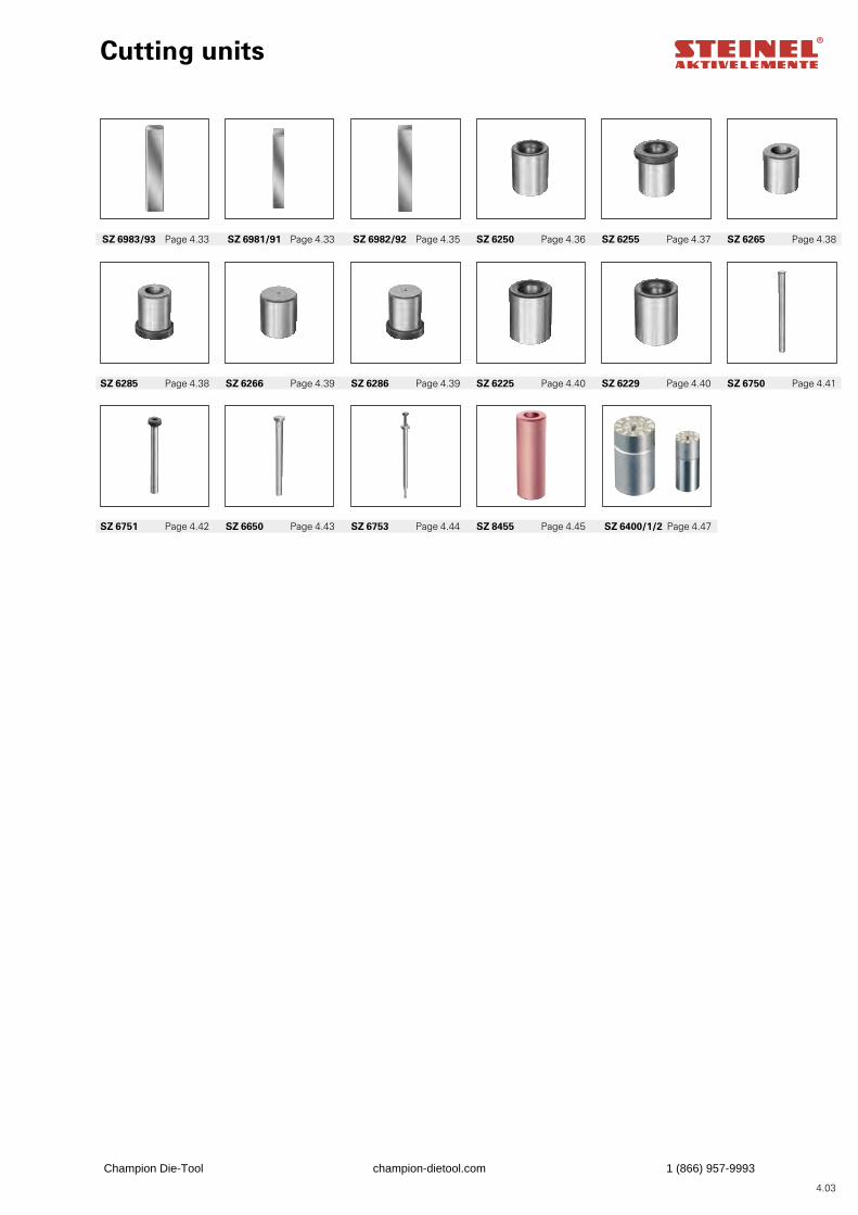
4.03
Cutting units
SZ 6751 Page 4.42 SZ 6650 Page 4.43 SZ 6753 Page 4.44 SZ 8455 Page 4.45
SZ 6285 Page 4.38 SZ 6266 Page 4.39 SZ 6286 Page 4.39 SZ 6225 Page 4.40 SZ 6229 Page 4.40 SZ 6750 Page 4.41
SZ 6983/93 Page 4.33 SZ 6981/91 Page 4.33 SZ 6982/92 Page 4.35 SZ 6250 Page 4.36 SZ 6255 Page 4.37 SZ 6265 Page 4.38
SZ 6400/1/2 Page 4.47
Champion Die-Tool champion-dietool.com 1 (866) 957-9993
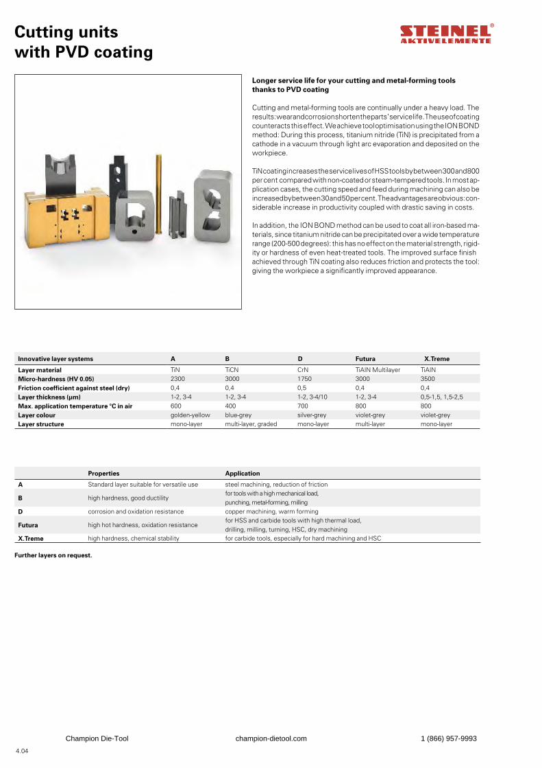
4.04
Cutting units with PVD coating
Longer service life for your cutting and metal-forming tools thanks to PVD coating
Cutting and metal-forming tools are continually under a heavy load. The results: wear and corrosion shorten the parts’ service life. The use of coating counteracts this effect. We achieve tool optimisation using the ION BOND method: During this process, titanium nitride (TiN) is precipitated from a cathode in a vacuum through light arc evaporation and deposited on the workpiece.
TiN coating increases the service lives of HSS tools by between 300 and 800 per cent compared with non-coated or steam-tempered tools. In most ap-plication cases, the cutting speed and feed during machining can also be increased by between 30 and 50 per cent. The advantages are obvious: con-siderable increase in productivity coupled with drastic saving in costs.
In addition, the ION BOND method can be used to coat all iron-based ma-terials, since titanium nitride can be precipitated over a wide temperature range (200-500 degrees): this has no effect on the material strength, rigid-ity or hardness of even heat-treated tools. The improved surface finish achieved through TiN coating also reduces friction and protects the tool: giving the workpiece a significantly improved appearance.
Innovative layer systems A B D Futura X.Treme
Layer material TiN TiCN CrN TiAIN Multilayer TiAINMicro-hardness (HV 0.05) 2300 3000 1750 3000 3500Friction coefficient against steel (dry) 0,4 0,4 0,5 0,4 0,4Layer thickness (µm) 1-2, 3-4 1-2, 3-4 1-2, 3-4/10 1-2, 3-4 0,5-1,5, 1,5-2,5Max. application temperature °C in air 600 400 700 800 800Layer colour golden-yellow blue-grey silver-grey violet-grey violet-greyLayer structure mono-layer multi-layer, graded mono-layer multi-layer mono-layer
Properties Application
A Standard layer suitable for versatile use steel machining, reduction of friction
B high hardness, good ductilityfor tools with a high mechanical load, punching, metal-forming, milling
D corrosion and oxidation resistance copper machining, warm forming
Futura high hot hardness, oxidation resistancefor HSS and carbide tools with high thermal load, drilling, milling, turning, HSC, dry machining
X.Treme high hardness, chemical stability for carbide tools, especially for hard machining and HSC
Further layers on request.
Champion Die-Tool champion-dietool.com 1 (866) 957-9993
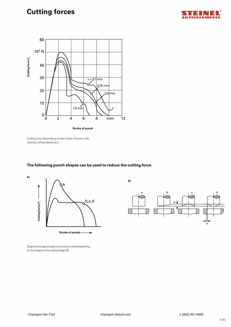
4.05
A)B)
60
·104 N
40
30
20
10
00 2 4 6 8 mm 12
u = 0,1 mm
0,25 mm
0,5 mm
1,0 mm
a
b,c,d
b c d
h
u
a
b c d
h
u
a
60
·104 N
40
30
20
10
00 2 4 6 8 mm 12
u = 0,1 mm
0,25 mm
0,5 mm
1,0 mm
a
b,c,d
Cutting force depending on the stroke of punch with varying cutting clearance u
Cutting forces
Cu
ttin
g fo
rce
F 5
Stroke of punch
Graph showing cutting force-stroke curve (A) depending on the shape of the cutting edge (B)
Cu
ttin
g fo
rce
F 5
Stroke of punch
The following punch shapes can be used to reduce the cutting force.
Champion Die-Tool champion-dietool.com 1 (866) 957-9993
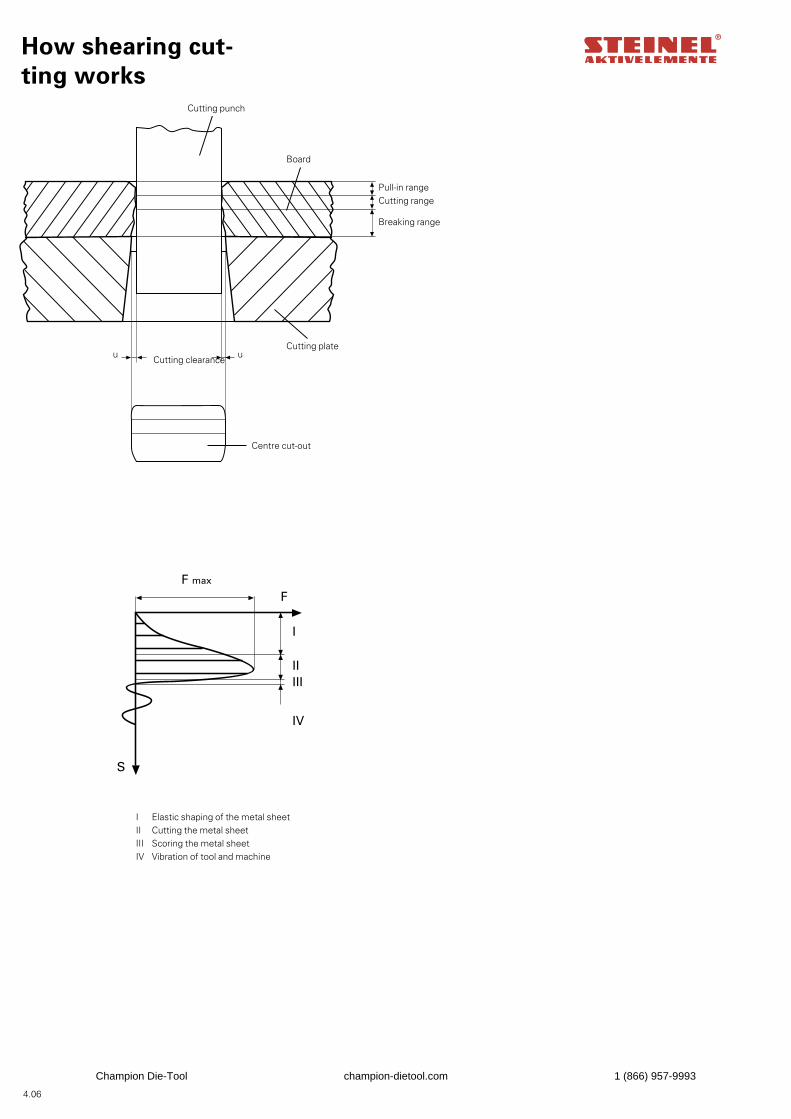
4.06
F max
F
I
IIIII
IV
S
F max
F
I
IIIII
IV
S
I Elastic shaping of the metal sheetII Cutting the metal sheetIII Scoring the metal sheetIV Vibration of tool and machine
How shearing cut-ting works
Cutting punch
Board
Pull-in rangeCutting range
Breaking range
Cutting plateCutting clearance
Centre cut-out
u u
Champion Die-Tool champion-dietool.com 1 (866) 957-9993
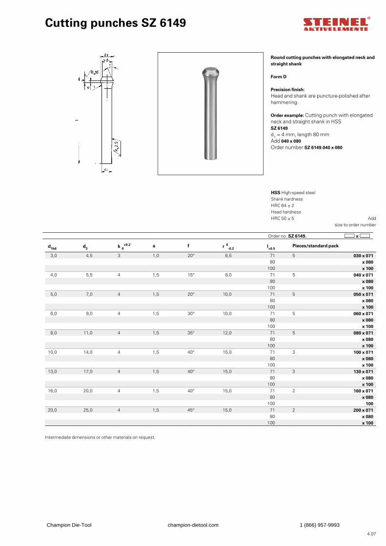
4.07
Round cutting punches with elongated neck and straight shank
Form D
Precision finish:Head and shank are puncture-polished after hammering.
Order example: Cutting punch with elongated neck and straight shank in HSS SZ 6149d1 = 4 mm, length 80 mmAdd 040 x 080Order number SZ 6149.040 x 080
Cutting punches SZ 6149
Add size to order number
HSS High-speed steel Shank hardness HRC 64 ± 2 Head hardness HRC 50 ± 5
d1h6 d3 k 0+0.2 a f r
0-0.2 l+0.5
Pieces/standard pack
3,0 4,5 3 1,0 20° 6,5 71 5 030 x 07180 x 080
100 x 1004,0 5,5 4 1,5 15° 8,0 71 5 040 x 071
80 x 080100 x 100
5,0 7,0 4 1,5 20° 10,0 71 5 050 x 07180 x 080
100 x 1006,0 9,0 4 1,5 30° 10,0 71 5 060 x 071
80 x 080100 x 100
8,0 11,0 4 1,5 35° 12,0 71 5 080 x 07180 x 080
100 x 10010,0 14,0 4 1,5 40° 15,0 71 3 100 x 071
80 x 080100 x 100
13,0 17,0 4 1,5 40° 15,0 71 3 130 x 07180 x 080
100 x 10016,0 20,0 4 1,5 40° 15,0 71 2 160 x 071
80 x 080100 100
20,0 25,0 4 1,5 45° 15,0 71 2 200 x 07180 x 080
100 x 100
Order no. SZ 6149.
Intermediate dimensions or other materials on request.
Champion Die-Tool champion-dietool.com 1 (866) 957-9993
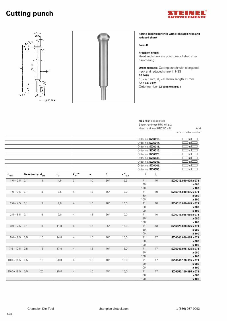
4.08
Cutting punch
Round cutting punches with elongated neck and reduced shank
Form C
Precision finish:Head and shank are puncture-polished after hammering.
Order example: Cutting punch with elongated neck and reduced shank in HSS SZ 6028d1 = 4.5 mm, d2 = 8.0 mm, length 71 mmAdd 045 x 071Order number SZ 6028.045 x 071
Add size to order number
HSS High-speed steel Shank hardness HRC 64 ± 2 Head hardness HRC 50 ± 5
d1h6 Reduction by d2h6 d3 k 0+0.2 a f r
0-0.2 l l1
1,0 – 2,5 0,1 3 4,5 3 1,0 20° 6,5 71 10 SZ 6013.010-025 x 07180 x 080
100 x 1001,0 – 3,5 0,1 4 5,5 4 1,5 15° 8,0 71 10 SZ 6014.010-035 x 071
80 x 080100 x 100
2,0 – 4,5 0,1 5 7,0 4 1,5 20° 10,0 71 10 SZ 6015.020-045 x 07180 x 080
100 x 1002,5 – 5,5 0,1 6 9,0 4 1,5 30° 10,0 71 10 SZ 6016.025-055 x 071
80 x 080100 x 100
3,0 – 7,5 0,1 8 11,0 4 1,5 35° 12,0 71 13 SZ 6028.030-075 x 07180 x 080
100 x 1005,0 – 9,5 0,5 10 14,0 4 1,5 40° 15,0 71 17 SZ 6040.050-095 x 071
80 x 080100 x 100
7,5 – 12,5 0,5 13 17,0 4 1,5 40° 15,0 71 17 SZ 6043.075-125 x 07180 x 080
100 x 10010,0 – 15,5 0,5 16 20,0 4 1,5 40° 15,0 71 17 SZ 6046.100-155 x 071
80 x 080100 x 100
15,0 – 19,5 0,5 20 25,0 4 1,5 45° 15,0 71 17 SZ 6050.150-195 x 07180 x 080
100 x 100
Order no. SZ 6013.Order no. SZ 6014.Order no. SZ 6015.Order no. SZ 6016.Order no. SZ 6028.Order no. SZ 6040.Order no. SZ 6043.Order no. SZ 6046.Order no. SZ 6050.
Champion Die-Tool champion-dietool.com 1 (866) 957-9993
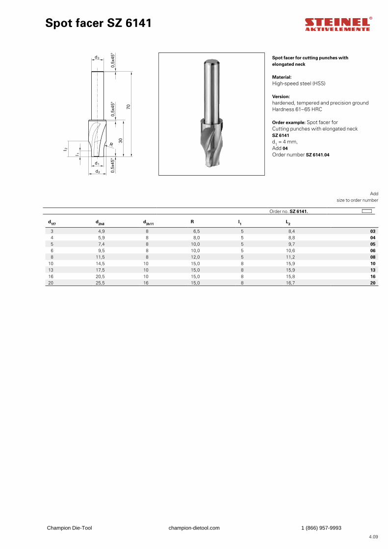
4.09
d1f7 d2h8 d3h11 R l1 L2
3 4,9 8 6,5 5 8,4 034 5,9 8 8,0 5 8,8 045 7,4 8 10,0 5 9,7 056 9,5 8 10,0 5 10,6 068 11,5 8 12,0 5 11,2 08
10 14,5 10 15,0 8 15,9 1013 17,5 10 15,0 8 15,9 1316 20,5 10 15,0 8 15,8 1620 25,5 16 15,0 8 16,7 20
Spot facer SZ 6141
Spot facer for cutting punches with elongated neck
Material:High-speed steel (HSS)
Version:hardened, tempered and precision ground Hardness 61–65 HRC
Order example: Spot facer for Cutting punches with elongated neck SZ 6141d1 = 4 mm,Add 04Order number SZ 6141.04
Add
size to order number
Order no. SZ 6141.
Champion Die-Tool champion-dietool.com 1 (866) 957-9993
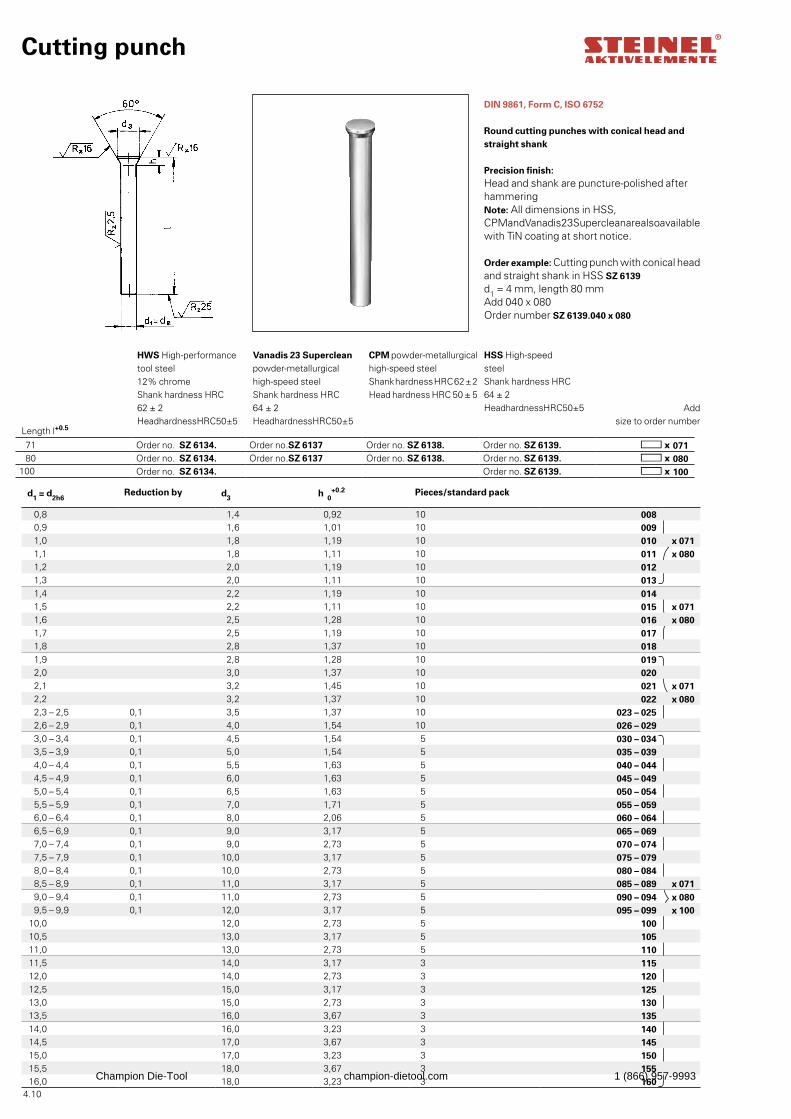
4.10
Add
size to order number
HWS High-performance tool steel 12% chrome Shank hardness HRC 62 ± 2 Head hardness HRC 50 ± 5
Vanadis 23 Superclean powder-metallurgical high-speed steel Shank hardness HRC 64 ± 2 Head hardness HRC 50 ± 5
CPM powder-metallurgical high-speed steel Shank hardness HRC 62 ± 2 Head hardness HRC 50 ± 5
HSS High-speed steel Shank hardness HRC 64 ± 2 Head hardness HRC 50 ± 5
Cutting punch
DIN 9861, Form C, ISO 6752
Round cutting punches with conical head and straight shank
Precision finish:Head and shank are puncture-polished after hammeringNote: All dimensions in HSS, CPM and Vanadis 23 Superclean are also available with TiN coating at short notice.
Order example: Cutting punch with conical head and straight shank in HSS SZ 6139d1 = 4 mm, length 80 mmAdd 040 x 080Order number SZ 6139.040 x 080
Length l+0.5
d1 = d2h6Reduction by d3 h 0
+0.2 Pieces/standard pack
0,8 1,4 0,92 10 0080,9 1,6 1,01 10 0091,0 1,8 1,19 10 010 x 0711,1 1,8 1,11 10 011 x 0801,2 2,0 1,19 10 0121,3 2,0 1,11 10 0131,4 2,2 1,19 10 0141,5 2,2 1,11 10 015 x 0711,6 2,5 1,28 10 016 x 0801,7 2,5 1,19 10 0171,8 2,8 1,37 10 0181,9 2,8 1,28 10 0192,0 3,0 1,37 10 0202,1 3,2 1,45 10 021 x 0712,2 3,2 1,37 10 022 x 0802,3 – 2,5 0,1 3,5 1,37 10 023 – 0252,6 – 2,9 0,1 4,0 1,54 10 026 – 0293,0 – 3,4 0,1 4,5 1,54 5 030 – 0343,5 – 3,9 0,1 5,0 1,54 5 035 – 0394,0 – 4,4 0,1 5,5 1,63 5 040 – 0444,5 – 4,9 0,1 6,0 1,63 5 045 – 0495,0 – 5,4 0,1 6,5 1,63 5 050 – 0545,5 – 5,9 0,1 7,0 1,71 5 055 – 0596,0 – 6,4 0,1 8,0 2,06 5 060 – 0646,5 – 6,9 0,1 9,0 3,17 5 065 – 0697,0 – 7,4 0,1 9,0 2,73 5 070 – 0747,5 – 7,9 0,1 10,0 3,17 5 075 – 0798,0 – 8,4 0,1 10,0 2,73 5 080 – 0848,5 – 8,9 0,1 11,0 3,17 5 085 – 089 x 0719,0 – 9,4 0,1 11,0 2,73 5 090 – 094 x 0809,5 – 9,9 0,1 12,0 3,17 5 095 – 099 x 100
10,0 12,0 2,73 5 10010,5 13,0 3,17 5 10511,0 13,0 2,73 5 11011,5 14,0 3,17 3 11512,0 14,0 2,73 3 12012,5 15,0 3,17 3 12513,0 15,0 2,73 3 13013,5 16,0 3,67 3 13514,0 16,0 3,23 3 14014,5 17,0 3,67 3 14515,0 17,0 3,23 3 15015,5 18,0 3,67 3 15516,0 18,0 3,23 3 160
71 Order no. SZ 6134. Order no.SZ 6137 Order no. SZ 6138. Order no. SZ 6139. 071 80 Order no. SZ 6134. Order no.SZ 6137 Order no. SZ 6138. Order no. SZ 6139. 080100 Order no. SZ 6134. Order no. SZ 6139. 100
Champion Die-Tool champion-dietool.com 1 (866) 957-9993
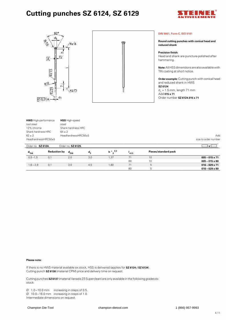
4.11
Order no. SZ 6124. Order no. SZ 6129.
DIN 9861, Form C, ISO 9181
Round cutting punches with conical head and reduced shank
Precision finish:Head and shank are puncture-polished after hammering.
Note: All HSS dimensions are also available with TiN coating at short notice.
Order example: Cutting punch with conical head and reduced shank in HWS SZ 6124d1 = 1.5 mm, length 71 mmAdd 015 x 71Order number SZ 6124.015 x 71
Cutting punches SZ 6124, SZ 6129
Add
size to order number
HWS High-performance tool steel 12% chrome Shank hardness HRC 62 ± 2 Head hardness HRC 50 ± 5
HSS High-speed steel Shank hardness HRC 64 ± 2 Head hardness HRC 50 ± 5
d1h6Reduction by d2h6 d3 h
+ 0
0.2 l+0.5Pieces/standard pack
0,5 –1,5 0,1 2,0 3,0 1,37 71 10 005 – 015 x 7180 10 005 – 015 x 80
1,6 – 2,9 0,1 3,0 4,5 1,80 71 5 016 – 029 x 7180 5 016 – 029 x 80
Please note:
If there is no HWS material available ex stock, HSS is delivered (applies for SZ 6124 / SZ 6134).Cutting punch SZ 6138 (material CPM) price and delivery time on request.
Cutting punches SZ 6137 (material Vanadis 23 Superclean) are only available in the following grades ex stock:
Ø 1.0 –10.0 mm increasing in steps of 0.5.Ø 10.0 –16.0 mm increasing in steps of 1.0.Intermediate dimensions on request.
Champion Die-Tool champion-dietool.com 1 (866) 957-9993
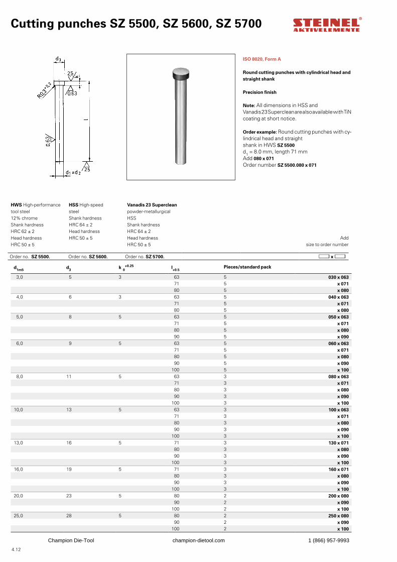
4.12
Cutting punches SZ 5500, SZ 5600, SZ 5700
ISO 8020, Form A
Round cutting punches with cylindrical head and straight shank
Precision finish
Note: All dimensions in HSS and Vanadis 23 Superclean are also available with TiN coating at short notice.
Order example: Round cutting punches with cy-lindrical head and straight shank in HWS SZ 5500d1 = 8.0 mm, length 71 mmAdd 080 x 071Order number SZ 5500.080 x 071
Add
size to order number
HWS High-performance tool steel 12% chrome Shank hardness HRC 62 ± 2 Head hardness HRC 50 ± 5
HSS High-speed steel Shank hardness HRC 64 ± 2 Head hardness HRC 50 ± 5
Vanadis 23 Superclean powder-metallurgical HSS Shank hardness HRC 64 ± 2 Head hardness HRC 50 ± 5
d1m5 d3 k 0+0.25 l+0.5
Pieces/standard pack
3,0 5 3 63 5 030 x 06371 5 x 07180 5 x 080
4,0 6 3 63 5 040 x 06371 5 x 07180 5 x 080
5,0 8 5 63 5 050 x 06371 5 x 07180 5 x 08090 5 x 090
6,0 9 5 63 5 060 x 06371 5 x 07180 5 x 08090 5 x 090
100 5 x 1008,0 11 5 63 3 080 x 063
71 3 x 07180 3 x 08090 3 x 090
100 3 x 10010,0 13 5 63 3 100 x 063
71 3 x 07180 3 x 08090 3 x 090
100 3 x 10013,0 16 5 71 3 130 x 071
80 3 x 08090 3 x 090
100 3 x 10016,0 19 5 71 3 160 x 071
80 3 x 08090 3 x 090
100 3 x 10020,0 23 5 80 2 200 x 080
90 2 x 090100 2 x 100
25,0 28 5 80 2 250 x 08090 2 x 090
100 2 x 100
Order no. SZ 5500. Order no. SZ 5600. Order no. SZ 5700.
Champion Die-Tool champion-dietool.com 1 (866) 957-9993
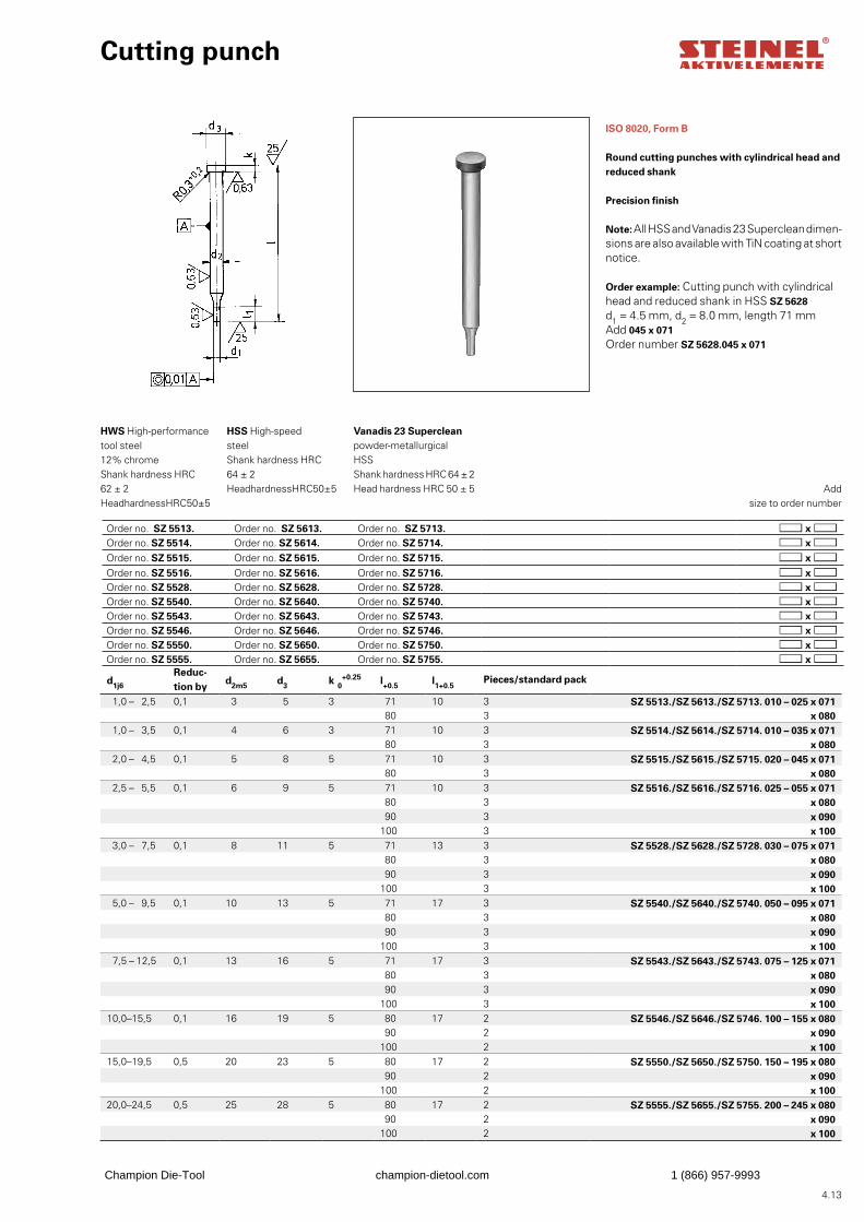
4.13
Cutting punch
ISO 8020, Form B
Round cutting punches with cylindrical head and reduced shank
Precision finish
Note: All HSS and Vanadis 23 Superclean dimen-sions are also available with TiN coating at short notice.
Order example: Cutting punch with cylindrical head and reduced shank in HSS SZ 5628d1 = 4.5 mm, d2 = 8.0 mm, length 71 mmAdd 045 x 071Order number SZ 5628.045 x 071
Add
size to order number
HWS High-performance tool steel 12% chrome Shank hardness HRC 62 ± 2 Head hardness HRC 50 ± 5
HSS High-speed steel Shank hardness HRC 64 ± 2 Head hardness HRC 50 ± 5
Vanadis 23 Superclean powder-metallurgical HSS Shank hardness HRC 64 ± 2 Head hardness HRC 50 ± 5
d1j6
Reduc-tion by
d2m5 d3 k 0+0.25 l+0.5 l1+0.5
Pieces/standard pack
1,0 – 2,5 0,1 3 5 3 71 10 3 SZ 5513./SZ 5613./SZ 5713. 010 – 025 x 07180 3 x 080
1,0 – 3,5 0,1 4 6 3 71 10 3 SZ 5514./SZ 5614./SZ 5714. 010 – 035 x 07180 3 x 080
2,0 – 4,5 0,1 5 8 5 71 10 3 SZ 5515./SZ 5615./SZ 5715. 020 – 045 x 07180 3 x 080
2,5 – 5,5 0,1 6 9 5 71 10 3 SZ 5516./SZ 5616./SZ 5716. 025 – 055 x 07180 3 x 08090 3 x 090
100 3 x 1003,0 – 7,5 0,1 8 11 5 71 13 3 SZ 5528./SZ 5628./SZ 5728. 030 – 075 x 071
80 3 x 08090 3 x 090
100 3 x 1005,0 – 9,5 0,1 10 13 5 71 17 3 SZ 5540./SZ 5640./SZ 5740. 050 – 095 x 071
80 3 x 08090 3 x 090
100 3 x 1007,5 – 12,5 0,1 13 16 5 71 17 3 SZ 5543./SZ 5643./SZ 5743. 075 – 125 x 071
80 3 x 08090 3 x 090
100 3 x 10010,0–15,5 0,1 16 19 5 80 17 2 SZ 5546./SZ 5646./SZ 5746. 100 – 155 x 080
90 2 x 090100 2 x 100
15,0–19,5 0,5 20 23 5 80 17 2 SZ 5550./SZ 5650./SZ 5750. 150 – 195 x 08090 2 x 090
100 2 x 10020,0–24,5 0,5 25 28 5 80 17 2 SZ 5555./SZ 5655./SZ 5755. 200 – 245 x 080
90 2 x 090100 2 x 100
Order no. SZ 5513. Order no. SZ 5613. Order no. SZ 5713.Order no. SZ 5514. Order no. SZ 5614. Order no. SZ 5714.Order no. SZ 5515. Order no. SZ 5615. Order no. SZ 5715.Order no. SZ 5516. Order no. SZ 5616. Order no. SZ 5716.Order no. SZ 5528. Order no. SZ 5628. Order no. SZ 5728.Order no. SZ 5540. Order no. SZ 5640. Order no. SZ 5740.Order no. SZ 5543. Order no. SZ 5643. Order no. SZ 5743.Order no. SZ 5546. Order no. SZ 5646. Order no. SZ 5746.Order no. SZ 5550. Order no. SZ 5650. Order no. SZ 5750.Order no. SZ 5555. Order no. SZ 5655. Order no. SZ 5755.
Champion Die-Tool champion-dietool.com 1 (866) 957-9993
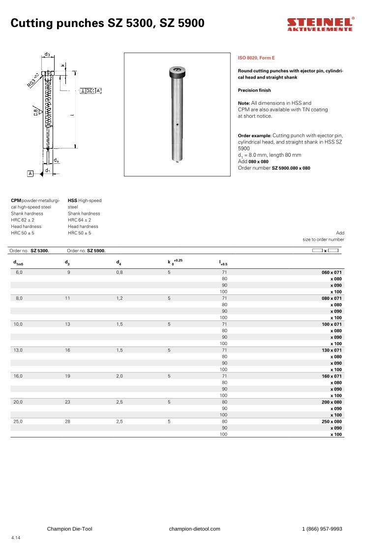
4.14
Cutting punches SZ 5300, SZ 5900
ISO 8020, Form E
Round cutting punches with ejector pin, cylindri-cal head and straight shank
Precision finish
Note: All dimensions in HSS and CPM are also available with TiN coating at short notice.
Order example: Cutting punch with ejector pin, cylindrical head, and straight shank in HSS SZ 5900d1 = 8.0 mm, length 80 mmAdd 080 x 080Order number SZ 5900.080 x 080
Add
size to order number
CPM powder-metallurgi-cal high-speed steel Shank hardness HRC 62 ± 2 Head hardness HRC 50 ± 5
HSS High-speed steel Shank hardness HRC 64 ± 2 Head hardness HRC 50 ± 5
d1m5 d3 d4 k 0+0.25 l+0.5
6,0 9 0,8 5 71 060 x 07180 x 08090 x 090
100 x 1008,0 11 1,2 5 71 080 x 071
80 x 08090 x 090
100 x 10010,0 13 1,5 5 71 100 x 071
80 x 08090 x 090
100 x 10013,0 16 1,5 5 71 130 x 071
80 x 08090 x 090
100 x 10016,0 19 2,0 5 71 160 x 071
80 x 08090 x 090
100 x 10020,0 23 2,5 5 80 200 x 080
90 x 090100 x 100
25,0 28 2,5 5 80 250 x 08090 x 090
100 x 100
Order no. SZ 5300. Order no. SZ 5900.
Champion Die-Tool champion-dietool.com 1 (866) 957-9993
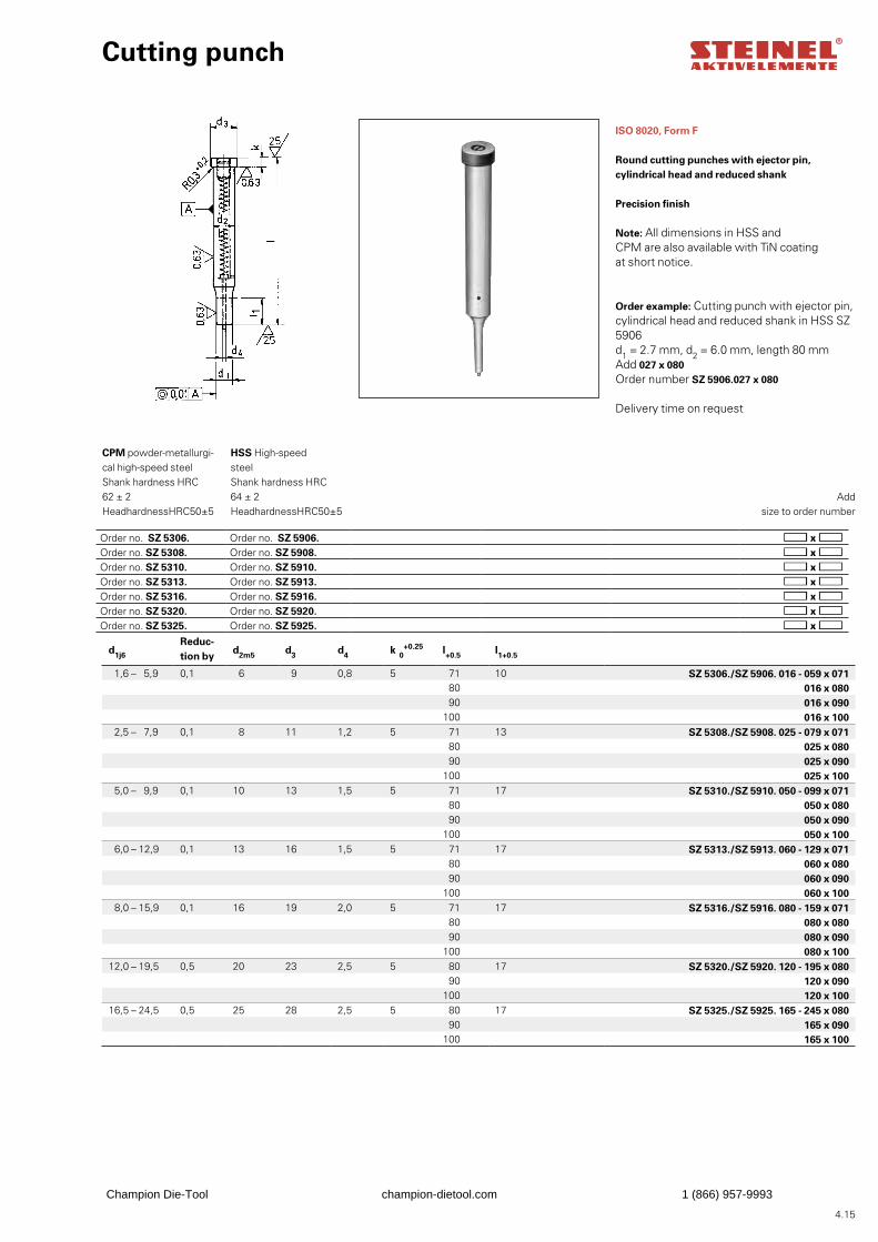
4.15
Order no. SZ 5306. Order no. SZ 5906.Order no. SZ 5308. Order no. SZ 5908.Order no. SZ 5310. Order no. SZ 5910.Order no. SZ 5313. Order no. SZ 5913.Order no. SZ 5316. Order no. SZ 5916.Order no. SZ 5320. Order no. SZ 5920.Order no. SZ 5325. Order no. SZ 5925.
Cutting punch
ISO 8020, Form F
Round cutting punches with ejector pin, cylindrical head and reduced shank
Precision finish
Note: All dimensions in HSS and CPM are also available with TiN coating at short notice.
Order example: Cutting punch with ejector pin, cylindrical head and reduced shank in HSS SZ 5906d1 = 2.7 mm, d2 = 6.0 mm, length 80 mmAdd 027 x 080Order number SZ 5906.027 x 080
Delivery time on request
Add
size to order number
CPM powder-metallurgi-cal high-speed steel Shank hardness HRC 62 ± 2 Head hardness HRC 50 ± 5
HSS High-speed steel Shank hardness HRC 64 ± 2 Head hardness HRC 50 ± 5
d1j6
Reduc-tion by
d2m5 d3 d4 k 0+0.25 l+0.5 l1+0.5
1,6 – 5,9 0,1 6 9 0,8 5 71 10 SZ 5306./SZ 5906. 016 - 059 x 07180 016 x 08090 016 x 090
100 016 x 1002,5 – 7,9 0,1 8 11 1,2 5 71 13 SZ 5308./SZ 5908. 025 - 079 x 071
80 025 x 08090 025 x 090
100 025 x 1005,0 – 9,9 0,1 10 13 1,5 5 71 17 SZ 5310./SZ 5910. 050 - 099 x 071
80 050 x 08090 050 x 090
100 050 x 1006,0 – 12,9 0,1 13 16 1,5 5 71 17 SZ 5313./SZ 5913. 060 - 129 x 071
80 060 x 08090 060 x 090
100 060 x 1008,0 – 15,9 0,1 16 19 2,0 5 71 17 SZ 5316./SZ 5916. 080 - 159 x 071
80 080 x 08090 080 x 090
100 080 x 10012,0 – 19,5 0,5 20 23 2,5 5 80 17 SZ 5320./SZ 5920. 120 - 195 x 080
90 120 x 090100 120 x 100
16,5 – 24,5 0,5 25 28 2,5 5 80 17 SZ 5325./SZ 5925. 165 - 245 x 08090 165 x 090
100 165 x 100
Champion Die-Tool champion-dietool.com 1 (866) 957-9993
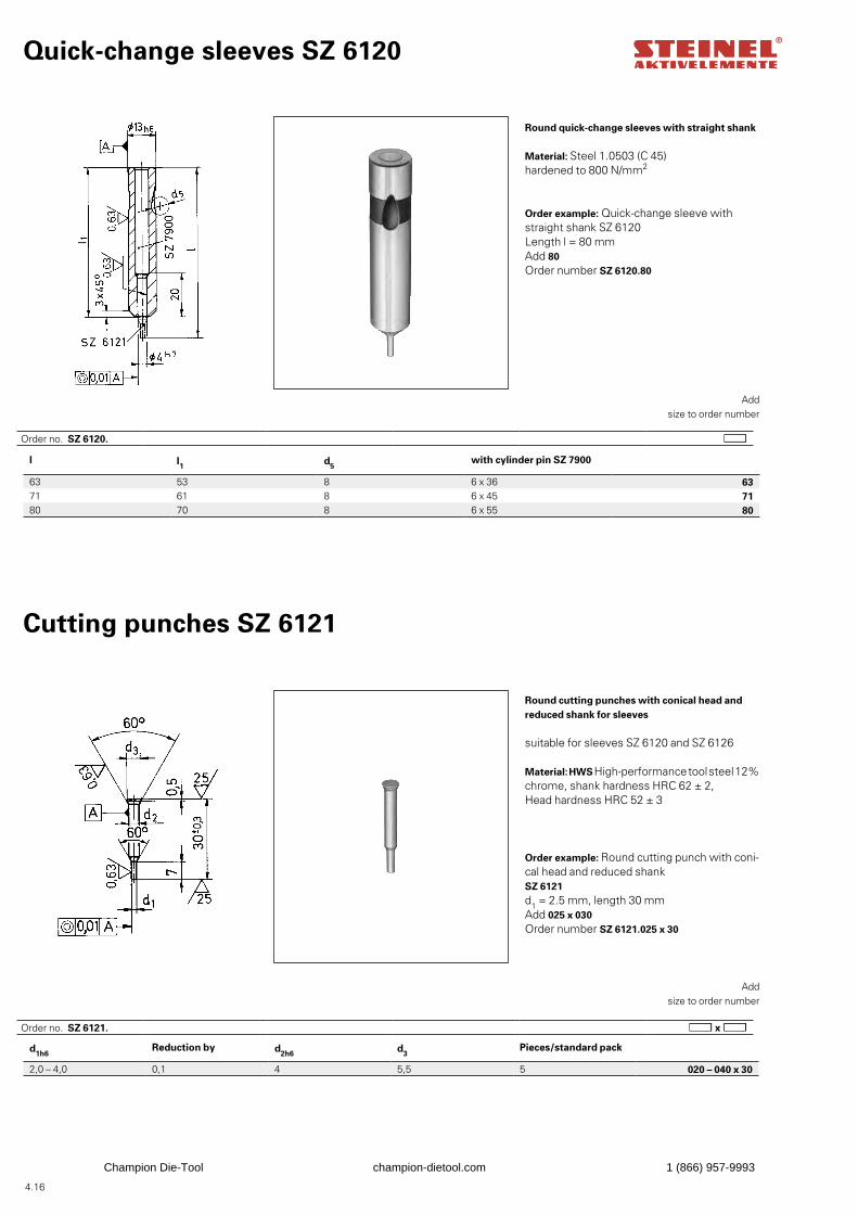
4.16
d1h6Reduction by d2h6 d3
Pieces/standard pack
2,0 – 4,0 0,1 4 5,5 5 020 – 040 x 30
l l1 d5with cylinder pin SZ 7900
63 53 8 6 x 36 6371 61 8 6 x 45 7180 70 8 6 x 55 80
Quick-change sleeves SZ 6120
Round quick-change sleeves with straight shank
Material: Steel 1.0503 (C 45) hardened to 800 N/mm2
Add size to order number
Add size to order number
Order example: Quick-change sleeve with straight shank SZ 6120Length l = 80 mmAdd 80Order number SZ 6120.80
Cutting punches SZ 6121
Round cutting punches with conical head and reduced shank for sleeves
suitable for sleeves SZ 6120 and SZ 6126
Material: HWS High-performance tool steel 12% chrome, shank hardness HRC 62 ± 2, Head hardness HRC 52 ± 3
Order example: Round cutting punch with coni-cal head and reduced shank SZ 6121d1 = 2.5 mm, length 30 mmAdd 025 x 030Order number SZ 6121.025 x 30
Order no. SZ 6120.
Order no. SZ 6121.
Champion Die-Tool champion-dietool.com 1 (866) 957-9993
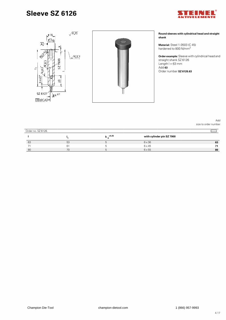
4.17
l l1 k 0+0.25 with cylinder pin SZ 7900
63 53 5 6 x 36 6371 61 5 6 x 45 7180 70 5 6 x 55 80
Sleeve SZ 6126
Round sleeves with cylindrical head and straight shank
Material: Steel 1.0503 (C 45) hardened to 800 N/mm2
Add size to order number
Order example: Sleeve with cylindrical head and straight shank SZ 6126Length l = 63 mmAdd 63Order number SZ 6126.63
Order no. SZ 6126.
Champion Die-Tool champion-dietool.com 1 (866) 957-9993
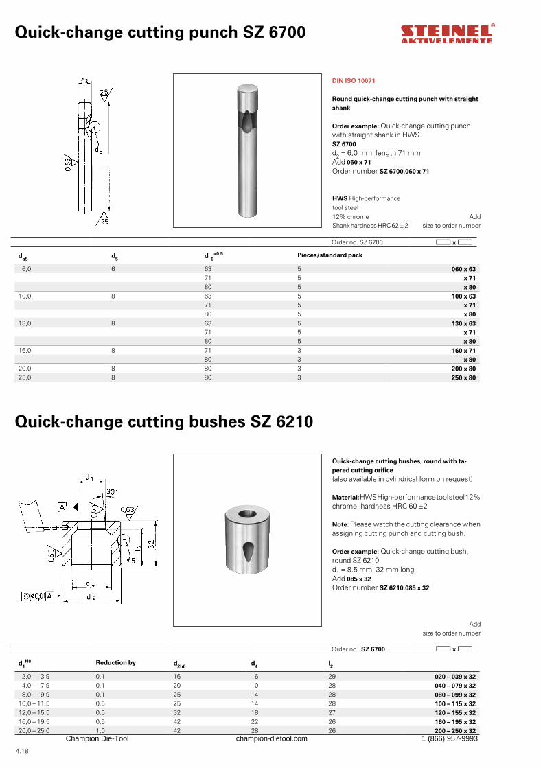
4.18
Order no. SZ 6700.
d1H8 Reduction by d2h6 d4 l2
2,0 – 3,9 0,1 16 6 29 020 – 039 x 324,0 – 7,9 0,1 20 10 28 040 – 079 x 328,0 – 9,9 0,1 25 14 28 080 – 099 x 32
10,0 – 11,5 0,5 25 14 28 100 – 115 x 3212,0 – 15,5 0,5 32 18 27 120 – 155 x 3216,0 – 19,5 0,5 42 22 26 160 – 195 x 3220,0 – 25,0 1,0 42 28 26 200 – 250 x 32
dg5 d5 d 0+0.5 Pieces/standard pack
6,0 6 63 5 060 x 6371 5 x 7180 5 x 80
10,0 8 63 5 100 x 6371 5 x 7180 5 x 80
13,0 8 63 5 130 x 6371 5 x 7180 5 x 80
16,0 8 71 3 160 x 7180 3 x 80
20,0 8 80 3 200 x 8025,0 8 80 3 250 x 80
Quick-change cutting punch SZ 6700
DIN ISO 10071
Round quick-change cutting punch with straight shank
Add size to order number
HWS High-performance tool steel 12% chromeShank hardness HRC 62 ± 2
Order example: Quick-change cutting punch with straight shank in HWS SZ 6700d2 = 6,0 mm, length 71 mmAdd 060 x 71Order number SZ 6700.060 x 71
Quick-change cutting bushes SZ 6210
Quick-change cutting bushes, round with ta-pered cutting orifice(also available in cylindrical form on request)
Material: HWS High-performance tool steel 12% chrome, hardness HRC 60 ±2
Note: Please watch the cutting clearance when assigning cutting punch and cutting bush.
Add
size to order number
Order example: Quick-change cutting bush, round SZ 6210d1 = 8.5 mm, 32 mm longAdd 085 x 32Order number SZ 6210.085 x 32
Order no. SZ 6700.
Champion Die-Tool champion-dietool.com 1 (866) 957-9993
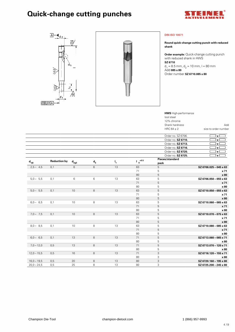
4.19
Quick-change cutting punches
DIN ISO 10071
Round quick-change cutting punch with reduced shank
Add size to order number
HWS High-performance tool steel 12% chrome Shank hardness HRC 64 ± 2
Order example: Quick-change cutting punch with reduced shank in HWS SZ 6710d1 = 8.5 mm, d2 = 10 mm, l = 80 mmAdd 085 x 80Order number SZ 6710.085 x 80
d1j6Reduction by d2g5 d5 l1 l 0
+0.5 Pieces/standard pack
2,5 – 4,5 0,1 6 6 13 63 5 SZ 6706.025 – 045 x 6371 5 x 7180 5 x 80
5,0 – 5,5 0,1 6 6 13 63 5 SZ 6706.050 – 055 x 6371 5 x 7180 5 x 80
5,0 – 5,5 0,1 10 8 13 63 5 SZ 6710.050 – 055 x 6371 5 x 7180 5 x 80
6,0 – 6,5 0,1 10 8 13 63 5 SZ 6710.060 – 065 x 6371 5 x 7180 5 x 80
7,0 – 7,5 0,1 10 8 13 63 5 SZ 6710.070 – 075 x 6371 5 x 7180 5 x 80
8,0 – 8,5 0,1 10 8 13 63 5 SZ 6710.080 – 085 x 6371 5 x 7180 5 x 80
6,0 – 6,5 0,1 13 8 13 71 5 SZ 6713.060 – 065 x 7180 5 x 80
7,0 – 12,0 0,5 13 8 13 71 5 SZ 6713.070 – 120 x 7180 5 x 80
12,0 – 15,5 0,5 16 8 13 71 3 SZ 6716.120 – 155 x 7180 3 x 80
16,0 – 19,5 0,5 20 8 13 80 3 SZ 6720.160 – 195 x 8020,0 – 24,5 0,5 25 8 13 80 3 SZ 6725.200 – 245 x 80
Order no. SZ 6706.Order no. SZ 6710.Order no. SZ 6713.Order no. SZ 6716.Order no. SZ 6720.Order no. SZ 6725.
Champion Die-Tool champion-dietool.com 1 (866) 957-9993
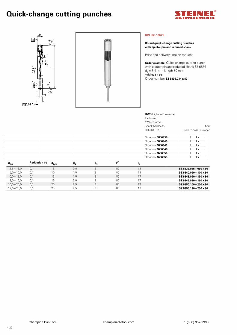
4.20
Quick-change cutting punches
DIN ISO 10071
Round quick-change cutting punches with ejector pin and reduced shank
Price and delivery time on request
Add
size to order number
HWS High-performance tool steel 12% chromeShank hardness HRC 64 ± 2
Order example: Quick-change cutting punch with ejector pin and reduced shank SZ 6836d1 = 3,4 mm, length 80 mmAdd 034 x 80Order number SZ 6836.034 x 80
d1j6Reduction by d2g5 d4 d5 l+1 l1
2,5 – 6,0 0,1 6 0,8 6 80 13 SZ 6836.025 – 060 x 80 5,0 – 10,0 0,1 10 1,5 8 80 13 SZ 6840.050 – 100 x 80 6,0 – 13,0 0,1 13 1,5 8 80 17 SZ 6843.060 – 130 x 80 8,0 – 16,0 0,1 16 2,0 8 80 17 SZ 6846.080 – 160 x 80
10,0 – 20,0 0,1 20 2,5 8 80 17 SZ 6850.100 – 200 x 8012,0 – 25,0 0,1 25 2,5 8 80 17 SZ 6855.120 – 250 x 80
Order no. SZ 6836.Order no. SZ 6840.Order no. SZ 6843.Order no. SZ 6846.Order no. SZ 6850.Order no. SZ 6855.
Champion Die-Tool champion-dietool.com 1 (866) 957-9993
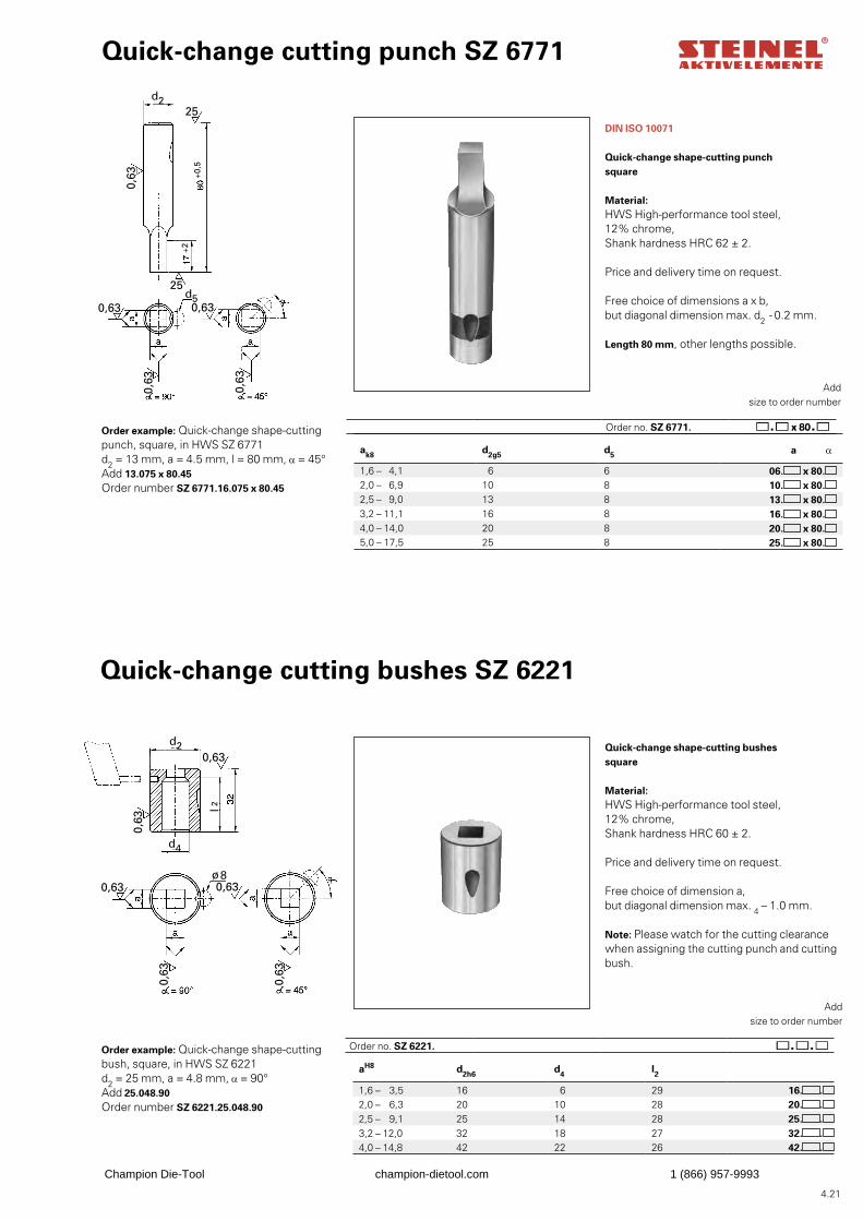
4.21
aH8 d2h6 d4 l2
1,6 – 3,5 16 6 29 16. .2,0 – 6,3 20 10 28 20. .2,5 – 9,1 25 14 28 25. .3,2 – 12,0 32 18 27 32. .4,0 – 14,8 42 22 26 42. .
0,63
0,63
d2
0,63
0,63
0,63
25
25d5
+0,5
+2
0,63 0,63
0,63
0,63
0,63
0,63
d4
d2
l 2
ø8
Quick-change cutting punch SZ 6771
DIN ISO 10071
Quick-change shape-cutting punchsquare
Material:HWS High-performance tool steel,12% chrome,Shank hardness HRC 62 ± 2.
Price and delivery time on request.
Free choice of dimensions a x b, but diagonal dimension max. d2 - 0.2 mm.
Length 80 mm, other lengths possible.
Add
size to order number
Order example: Quick-change shape-cutting punch, square, in HWS SZ 6771d2 = 13 mm, a = 4.5 mm, l = 80 mm, α = 45°Add 13.075 x 80.45Order number SZ 6771.16.075 x 80.45
Quick-change cutting bushes SZ 6221
Quick-change shape-cutting bushessquare
Material: HWS High-performance tool steel,12% chrome,Shank hardness HRC 60 ± 2.
Price and delivery time on request.
Free choice of dimension a,but diagonal dimension max. 4 – 1.0 mm.
Note: Please watch for the cutting clearance when assigning the cutting punch and cutting bush.
Add
size to order number
Order example: Quick-change shape-cutting bush, square, in HWS SZ 6221d2 = 25 mm, a = 4.8 mm, α = 90°Add 25.048.90Order number SZ 6221.25.048.90
ak8 d2g5 d5 a α
1,6 – 4,1 6 6 06. x 80.2,0 – 6,9 10 8 10. x 80.2,5 – 9,0 13 8 13. x 80.3,2 – 11,1 16 8 16. x 80.4,0 – 14,0 20 8 20. x 80.5,0 – 17,5 25 8 25. x 80.
Order no. SZ 6771.
Order no. SZ 6221.
Champion Die-Tool champion-dietool.com 1 (866) 957-9993
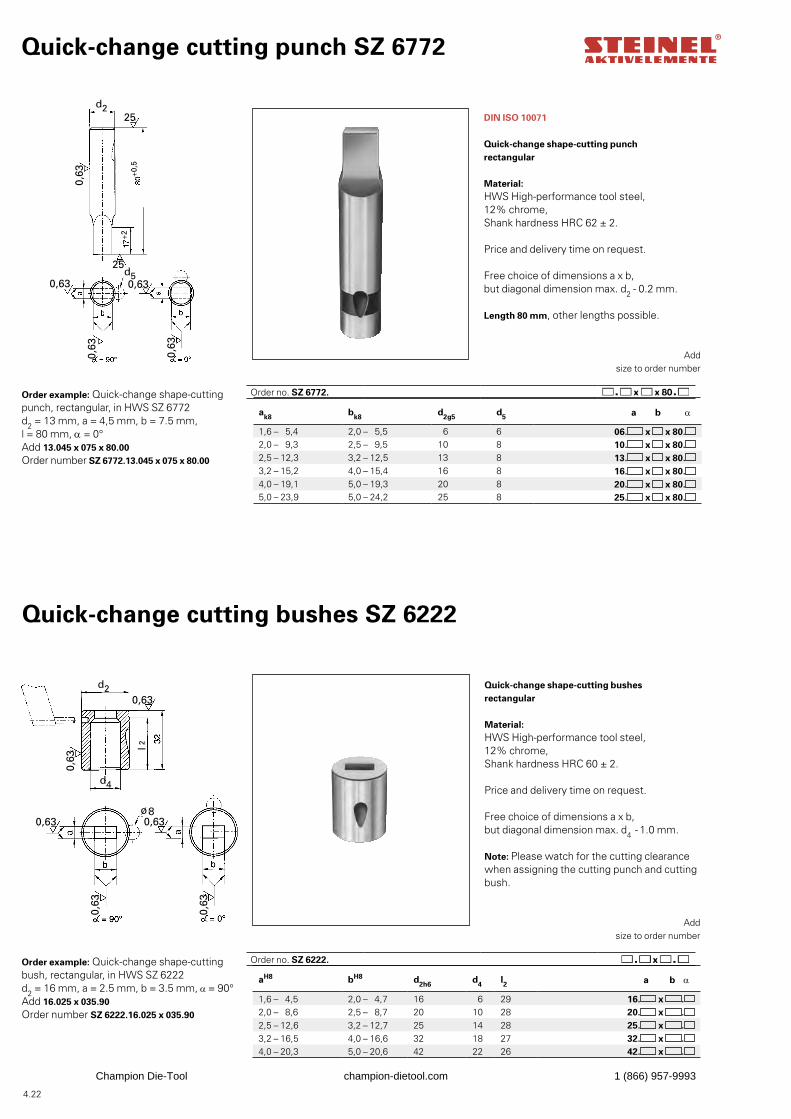
4.22
aH8 bH8 d2h6 d4 l2 a b α
1,6 – 4,5 2,0 – 4,7 16 6 29 16. x .2,0 – 8,6 2,5 – 8,7 20 10 28 20. x .2,5 – 12,6 3,2 – 12,7 25 14 28 25. x .3,2 – 16,5 4,0 – 16,6 32 18 27 32. x .4,0 – 20,3 5,0 – 20,6 42 22 26 42. x .
0,63
0,63
d2
0,63
0,63
0,63
25
25d5
+0,5
+2
0,63 0,63
0,63
0,63
0,63
0,63
d4
d2
l 2
ø8
Quick-change cutting punch SZ 6772
DIN ISO 10071
Quick-change shape-cutting punchrectangular
Material: HWS High-performance tool steel, 12% chrome, Shank hardness HRC 62 ± 2.
Price and delivery time on request.
Free choice of dimensions a x b, but diagonal dimension max. d2 - 0.2 mm.
Length 80 mm, other lengths possible.
Add
size to order number
Order example: Quick-change shape-cutting punch, rectangular, in HWS SZ 6772d2 = 13 mm, a = 4,5 mm, b = 7.5 mm, l = 80 mm, α = 0°Add 13.045 x 075 x 80.00Order number SZ 6772.13.045 x 075 x 80.00
Quick-change cutting bushes SZ 6222
Quick-change shape-cutting bushesrectangular
Material: HWS High-performance tool steel,12% chrome,Shank hardness HRC 60 ± 2.
Price and delivery time on request.
Free choice of dimensions a x b,but diagonal dimension max. d4 - 1.0 mm.
Note: Please watch for the cutting clearance when assigning the cutting punch and cutting bush.
Add
size to order number
Order example: Quick-change shape-cutting bush, rectangular, in HWS SZ 6222d2 = 16 mm, a = 2.5 mm, b = 3.5 mm, α = 90°Add 16.025 x 035.90Order number SZ 6222.16.025 x 035.90
ak8 bk8 d2g5 d5 a b α
1,6 – 5,4 2,0 – 5,5 6 6 06. x x 80.2,0 – 9,3 2,5 – 9,5 10 8 10. x x 80.2,5 – 12,3 3,2 – 12,5 13 8 13. x x 80.3,2 – 15,2 4,0 – 15,4 16 8 16. x x 80.4,0 – 19,1 5,0 – 19,3 20 8 20. x x 80.5,0 – 23,9 5,0 – 24,2 25 8 25. x x 80.
Order no. SZ 6772.
Order no. SZ 6222.
Champion Die-Tool champion-dietool.com 1 (866) 957-9993
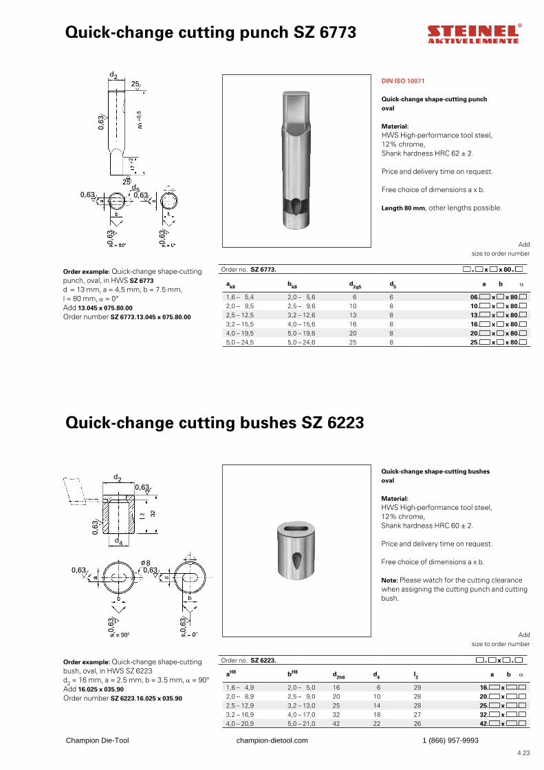
4.23
aH8 bH8 d2h6 d4 l2 a b α
1,6 – 4,9 2,0 – 5,0 16 6 29 16. x .2,0 – 8,9 2,5 – 9,0 20 10 28 20. x .2,5 – 12,9 3,2 – 13,0 25 14 28 25. x .3,2 – 16,9 4,0 – 17,0 32 18 27 32. x .4,0 – 20,9 5,0 – 21,0 42 22 26 42. x .
ak8 bk8 d2g5 d5 a b α
1,6 – 5,4 2,0 – 5,6 6 6 06. x x 80.2,0 – 9,5 2,5 – 9,6 10 8 10. x x 80.2,5 – 12,5 3,2 – 12,6 13 8 13. x x 80.3,2 – 15,5 4,0 – 15,6 16 8 16. x x 80.4,0 – 19,5 5,0 – 19,6 20 8 20. x x 80.5,0 – 24,5 5,0 – 24,6 25 8 25. x x 80.
0,63
0,63
d2
0,63
0,63
0,63
25
25d5
+0,5
+2
0,63 0,63
0,63
0,63
0,63
0,63
d4
d2
l 2
ø8
Quick-change cutting punch SZ 6773
DIN ISO 10071
Quick-change shape-cutting punchoval
Material: HWS High-performance tool steel,12% chrome,Shank hardness HRC 62 ± 2.
Price and delivery time on request.
Free choice of dimensions a x b.
Length 80 mm, other lengths possible.
Add size to order number
Order example: Quick-change shape-cutting punch, oval, in HWS SZ 6773d = 13 mm, a = 4,5 mm, b = 7.5 mm, l = 80 mm, α = 0°Add 13.045 x 075.80.00Order number SZ 6773.13.045 x 075.80.00
Order no. SZ 6773.
Order no. SZ 6223.
Quick-change cutting bushes SZ 6223
Quick-change shape-cutting bushesoval
Material: HWS High-performance tool steel,12% chrome,Shank hardness HRC 60 ± 2.
Price and delivery time on request.
Free choice of dimensions a x b.
Note: Please watch for the cutting clearance when assigning the cutting punch and cutting bush.
Add size to order number
Order example: Quick-change shape-cutting bush, oval, in HWS SZ 6223d2 = 16 mm, a = 2.5 mm, b = 3.5 mm, α = 90°Add 16.025 x 035.90Order number SZ 6223.16.025 x 035.90
Champion Die-Tool champion-dietool.com 1 (866) 957-9993
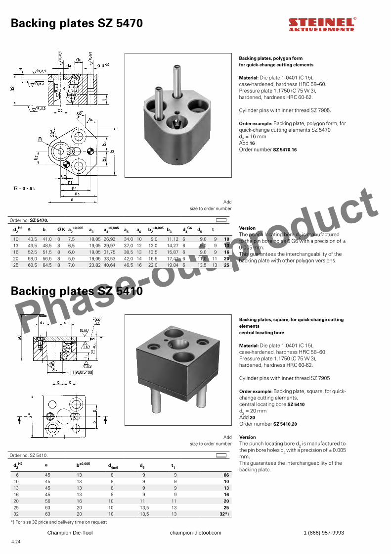
Phase-out product
4.24
d2H6 a b Ø K a2
±0,005 a3 a4±0,005 a5 a6 b2
±0,005 b3 d4G6 d5 t
10 43,5 41,0 8 7,5 19,05 26,92 34,0 10 9,0 11,12 6 9,0 9 1013 49,5 48,5 8 6,5 19,05 29,97 37,0 12 12,0 14,27 6 9,0 9 1316 52,5 51,5 8 6,0 19,05 31,75 38,5 13 13,5 15,87 6 9,0 9 1620 59,0 56,5 8 5,0 19,05 33,53 42,0 14 16,5 17,47 6 11,0 11 2025 68,5 64,5 8 7,0 23,82 40,64 46,5 16 22,0 19,84 6 13,5 13 25
d2H7 a b±0,005 d4m6 d5 t1
6 45 13 8 9 9 0610 45 13 8 9 9 1013 45 13 8 9 9 1316 45 13 8 9 9 1620 56 16 10 11 11 2025 63 20 10 13,5 13 2532 63 20 10 13,5 13 32*)
Order no. SZ 5410.
Backing plates SZ 5470
Backing plates, polygon formfor quick-change cutting elements
Material: Die plate 1.0401 (C 15),case-hardened, hardness HRC 58–60.Pressure plate 1.1750 (C 75 W 3),hardened, hardness HRC 60-62.
Cylinder pins with inner thread SZ 7905.
Add size to order number
Order example: Backing plate, polygon form, for quick-change cutting elements SZ 5470d2 = 16 mmAdd 16Order number SZ 5470.16
Backing plates SZ 5410
Add size to order number
Order example: Backing plate, square, for quick-change cutting elements, central locating bore SZ 5410d2 = 20 mmAdd 20Order number SZ 5410.20
*) For size 32 price and delivery time on request
VersionThe punch locating bore d2 is manufacturedto the pin bore holes 6 G6 with a precision of ± 0.005 mm.This guarantees the interchangeability of the backing plate with other polygon versions.
Order no. SZ 5470.
Version The punch locating bore d2 is manufactured tothe pin bore holes d4 with a precision of ± 0.005mm. This guarantees the interchangeability of the backing plate.
Backing plates, square, for quick-change cutting elementscentral locating bore
Material: Die plate 1.0401 (C 15), case-hardened, hardness HRC 58–60.Pressure plate 1.1750 (C 75 W 3), hardened, hardness HRC 60-62.
Cylinder pins with inner thread SZ 7905
Champion Die-Tool champion-dietool.com 1 (866) 957-9993
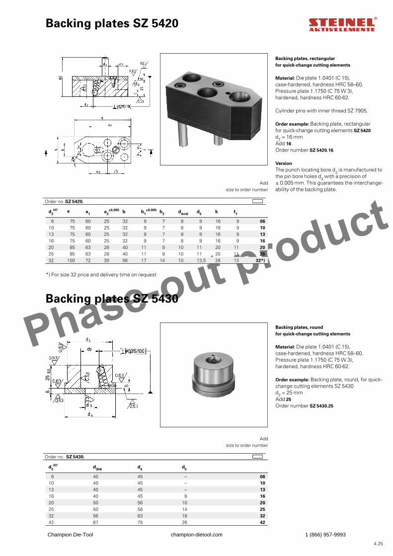
Phase-out product
4.25
d2H7 d3h6 d4 d5
6 40 45 – 0610 40 45 – 1013 40 45 – 1316 40 45 6 1620 50 56 10 2025 50 56 14 2532 56 63 18 3242 67 75 26 42
d2H7 a a1 a2
±0,005 b b1±0,005 b2 d4m6 d5 k t1
6 75 60 25 32 9 7 8 9 16 9 0610 75 60 25 32 9 7 8 9 16 9 1013 75 60 25 32 9 7 8 9 16 9 1316 75 60 25 32 9 7 8 9 16 9 1620 85 63 28 40 11 9 10 11 20 11 2025 85 63 28 40 11 9 10 11 20 11 2532 100 72 30 56 17 14 10 13,5 28 13 32*)
Backing plates, rectangularfor quick-change cutting elements
Material: Die plate 1.0401 (C 15),case-hardened, hardness HRC 58–60.Pressure plate 1.1750 (C 75 W 3),hardened, hardness HRC 60-62.
Cylinder pins with inner thread SZ 7905.
Backing plates SZ 5420
Add size to order number
Order example: Backing plate, rectangular for quick-change cutting elements SZ 5420d2 = 16 mmAdd 16Order number SZ 5420.16
Backing plates SZ 5430
Backing plates, roundfor quick-change cutting elements
Material: Die plate 1.0401 (C 15),case-hardened, hardness HRC 58–60.Pressure plate 1.1750 (C 75 W 3), hardened, hardness HRC 60-62.
Add size to order number
Order example: Backing plate, round, for quick-change cutting elements SZ 5430d2 = 25 mmAdd 25Order number SZ 5430.25
*) For size 32 price and delivery time on request
VersionThe punch locating bore d2 is manufactured tothe pin bore holes d4 with a precision of± 0.005 mm. This guarantees the interchange-ability of the backing plate.
Order no. SZ 5420.
Order no. SZ 5430.
Champion Die-Tool champion-dietool.com 1 (866) 957-9993
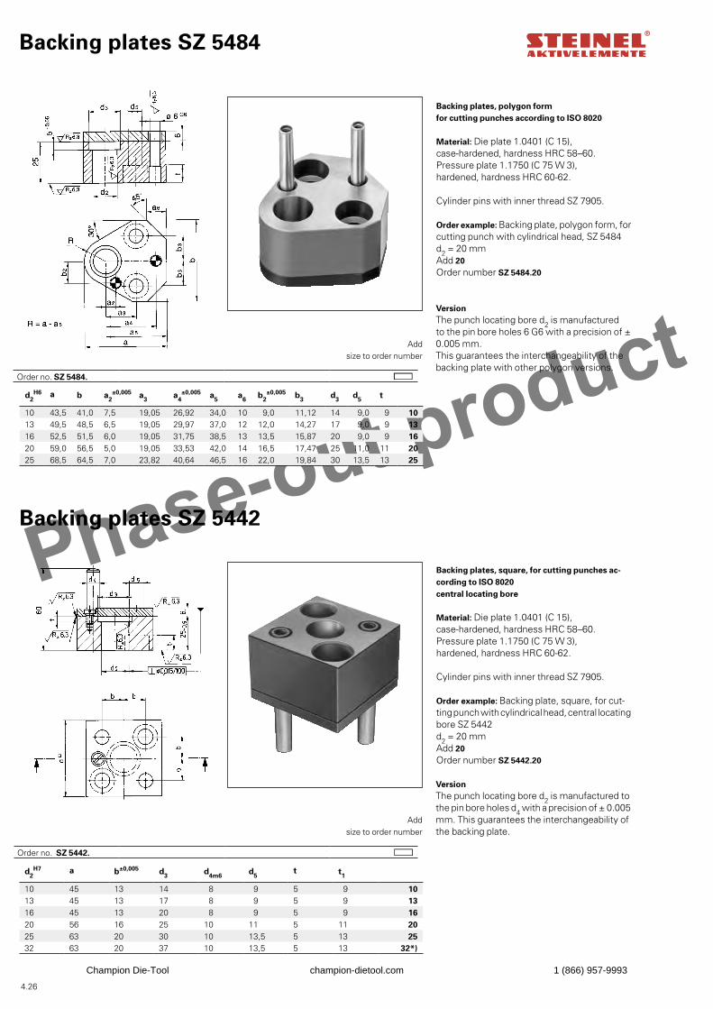
Phase-out product
4.26
d2H7 a b±0,005 d3 d4m6 d5
t t1
10 45 13 14 8 9 5 9 1013 45 13 17 8 9 5 9 1316 45 13 20 8 9 5 9 1620 56 16 25 10 11 5 11 2025 63 20 30 10 13,5 5 13 2532 63 20 37 10 13,5 5 13 32*)
d2H6 a b a2
±0,005 a3 a4±0,005 a5 a6 b2
±0,005 b3 d3 d5 t
10 43,5 41,0 7,5 19,05 26,92 34,0 10 9,0 11,12 14 9,0 9 1013 49,5 48,5 6,5 19,05 29,97 37,0 12 12,0 14,27 17 9,0 9 1316 52,5 51,5 6,0 19,05 31,75 38,5 13 13,5 15,87 20 9,0 9 1620 59,0 56,5 5,0 19,05 33,53 42,0 14 16,5 17,47 25 11,0 11 2025 68,5 64,5 7,0 23,82 40,64 46,5 16 22,0 19,84 30 13,5 13 25
VersionThe punch locating bore d2 is manufactured tothe pin bore holes d4 with a precision of ± 0.005mm. This guarantees the interchangeability of the backing plate.
Backing plates SZ 5484
Backing plates, polygon formfor cutting punches according to ISO 8020
Material: Die plate 1.0401 (C 15),case-hardened, hardness HRC 58–60.Pressure plate 1.1750 (C 75 W 3),hardened, hardness HRC 60-62.
Cylinder pins with inner thread SZ 7905.
Add size to order number
Order example: Backing plate, polygon form, for cutting punch with cylindrical head, SZ 5484d2 = 20 mmAdd 20Order number SZ 5484.20
Backing plates SZ 5442
Backing plates, square, for cutting punches ac-cording to ISO 8020 central locating bore
Material: Die plate 1.0401 (C 15),case-hardened, hardness HRC 58–60.Pressure plate 1.1750 (C 75 W 3), hardened, hardness HRC 60-62.
Cylinder pins with inner thread SZ 7905.
Add size to order number
Order example: Backing plate, square, for cut-ting punch with cylindrical head, central locating bore SZ 5442d2 = 20 mmAdd 20Order number SZ 5442.20
VersionThe punch locating bore d2 is manufacturedto the pin bore holes 6 G6 with a precision of ± 0.005 mm. This guarantees the interchangeability of the backing plate with other polygon versions.
Order no. SZ 5484.
Order no. SZ 5442.
Champion Die-Tool champion-dietool.com 1 (866) 957-9993
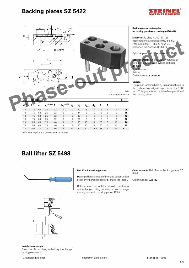
Phase-out product
4.27
d2H7 a a1 a2
±0,005 b b1±0,005 b2 d3 d4m6 d5
k t t1
6 75 60 25 32 9 7 10 8 9 16 5 9 0610 75 60 25 32 9 7 14 8 9 16 5 9 1013 75 60 25 32 9 7 17 8 9 16 5 9 1316 75 60 25 32 9 7 20 8 9 16 5 9 1620 85 63 28 40 11 9 25 10 11 20 5 11 2025 85 63 28 40 11 9 30 10 11 20 5 11 2532 100 72 30 56 17 14 37 10 13,5 28 5 13 32*)
Order no. SZ 5422.
Backing plates SZ 5422
Backing plates, rectangularfor cutting punches according to ISO 8020
Material: Die plate 1.0401 (C 15), case-hardened, hardness HRC 58–60.Pressure plate 1.1750 (C 75 W 3),hardened, hardness HRC 60-62.
Cylinder pins with inner thread SZ 7905.
Add size to order number
Ball lifter SZ 5498
Ball lifter for backing plates
Material: Handle made of bronzed construction steel, cylinder pin made of bronzed tool steel.
Ball lifters are used to lift the balls when replacing quick-change cutting punches or quick-changecutting bushes in backing plates SZ 54.
Order example: Ball lifter for backing plates SZ 5498
Order number SZ 5498
Installation exampleStructure of a punching tool with quick-change cutting elements
*) For size 32 price and delivery time on request
Order example: Backing plate, rectangular for cutting punch with cylindrical head, SZ 5422d2 = 10 mmAdd 10Order number SZ 5422.10
VersionThe punch locating bore d2 is manufactured tothe pin bore holes d4 with a precision of ± 0.005mm. This guarantees the interchangeability of the backing plate.
Champion Die-Tool champion-dietool.com 1 (866) 957-9993

Phase-out product
4.28
d2H6 a b a2
±0,005 a3 a4±0,005 a5 a6 b2
±0,005 b3 b4 d5 t
10 43,5 41,0 7,5 19,05 26,92 34,0 10 9,0 11,12 12 9,0 9 1013 49,5 48,5 6,5 19,05 29,97 37,0 12 12,0 14,27 15 9,0 9 1316 52,5 51,5 6,0 19,05 31,75 38,5 13 13,5 15,87 18 9,0 9 1620 59,0 56,5 5,0 19,05 33,53 42,0 14 16,5 17,47 23 11 11 2025 68,5 64,5 7,0 23,82 40,64 46,5 16 22,0 19,84 28 13,5 13 25
d2H7 d4
m6 d5 a a1
±0,005 a2±0,005 b1
±0,2 b2±0,2 t1
10 8 9 45 13 15,5 12 14 9 1013 8 9 45 13 15,5 15 17 9 1316 8 9 45 13 15,5 18 20 9 1620 10 11 56 16 19,0 22,5 25 11 2025 10 13,5 63 20 22,5 27,5 30 13 25
zR 6,3
zR 6,3
zR
6,3
6
45°
ø6
t
G6
5+
0,05
25
2d
5d
6a
2a
3a
4a
5a
a
3b
3b
b4b
2b
2d
/2 30°
R
zR
6,3
zR 6,3
zR 6,3
zR 6,3
zR
6,3
4d5d
2d
1t
256
5
60
a
1a
1a
2b
2a
1b
1a1a
a
Order no. SZ 5485.
Backing plates, polygon form, for shape-cutting punches according to ISO 8020
Material: Die plate 1.0401 (C 15),case-hardened, hardness HRC 58–60.Pressure plate 1.1750 (C 75 W 3),hardened, hardness HRC 60-62.
Cylinder pins with inner thread SZ 7905.
Backing plates SZ 5485
Add size to order number
Order example: Backing plate, polygon form, for shape-cutting punch with cylindrical head, SZ 5485d2 = 20 mmAdd 20Order number SZ 5485.20
Backing plates SZ 5443
Backing plates, square, for shape-cutting punch-es according to ISO 8020Central locating bore
Material: Die plate 1.0401 (C 15),case-hardened, hardness HRC 58–60.Pressure plate 1.1750 (C 75 W 3),hardened, hardness HRC 60-62.
Cylinder pins with inner thread SZ 7905.
Add size to order number
Order example: Backing plate, square, for shape-cutting punch with cylindrical head, central lo-cating bore SZ 5443d2 = 20 mmAdd 20Order number SZ 5443.20
VersionThe punch locating bore d2 is manufacturedto the pin bore holes 6 G6 with a precision of ± 0.005 mm. This guarantees the interchangeability of the backing plate with other polygon versions.
VersionThe punch locating bore d2 is manufactured tothe pin bore holes d4 with a precision of ± 0.005mm. This guarantees the interchangeability of the backing plate.
Order no. SZ 5443.
Champion Die-Tool champion-dietool.com 1 (866) 957-9993
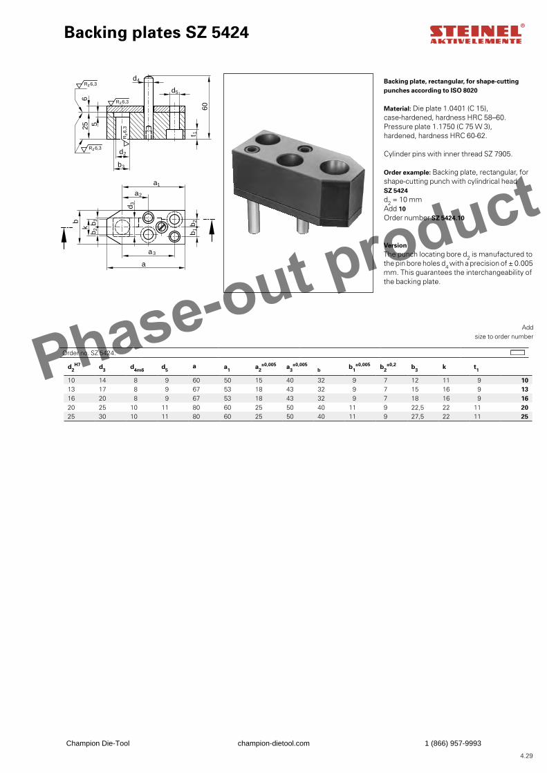
Phase-out product
4.29
d2H7 d3 d4m6 d5
a a1 a2±0,005 a3
±0,005b b1
±0,005 b2±0,2 b3 k t1
10 14 8 9 60 50 15 40 32 9 7 12 11 9 1013 17 8 9 67 53 18 43 32 9 7 15 16 9 1316 20 8 9 67 53 18 43 32 9 7 18 16 9 1620 25 10 11 80 60 25 50 40 11 9 22,5 22 11 2025 30 10 11 80 60 25 50 40 11 9 27,5 22 11 25
zR 6,3
zR 6,3
zR 6,3
zR
6,3
2b1bkb
3d
1b2b
1a
2a
3a
a
256
5
60
4d
5d
2d
3b
1t
Backing plate, rectangular, for shape-cutting punches according to ISO 8020
Material: Die plate 1.0401 (C 15),case-hardened, hardness HRC 58–60.Pressure plate 1.1750 (C 75 W 3),hardened, hardness HRC 60-62.
Cylinder pins with inner thread SZ 7905.
Backing plates SZ 5424
Add size to order number
Order example: Backing plate, rectangular, for shape-cutting punch with cylindrical head SZ 5424d2 = 10 mmAdd 10Order number SZ 5424.10
VersionThe punch locating bore d2 is manufactured tothe pin bore holes d4 with a precision of ± 0.005mm. This guarantees the interchangeability of the backing plate.
Order no. SZ 5424.
Champion Die-Tool champion-dietool.com 1 (866) 957-9993
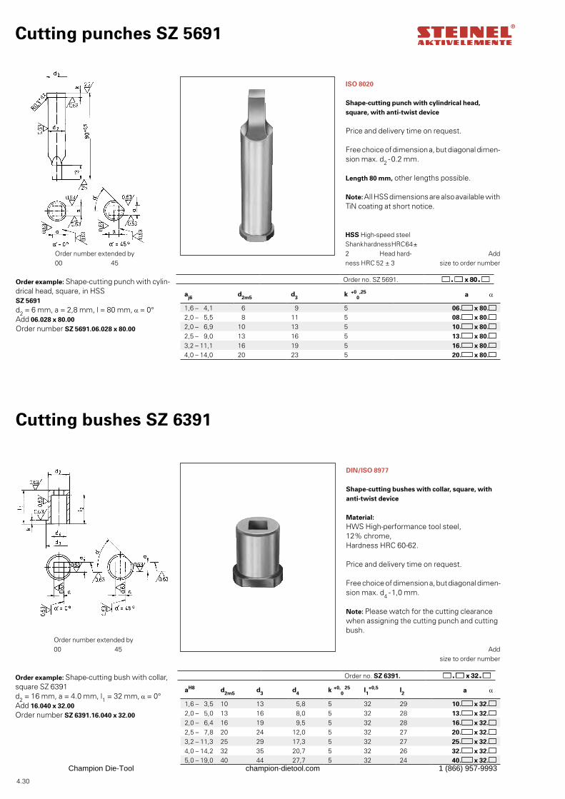
4.30
aj6 d2m5 d3 k +00
,25 a α
1,6 – 4,1 6 9 5 06. x 80.2,0 – 5,5 8 11 5 08. x 80.2,0 – 6,9 10 13 5 10. x 80.2,5 – 9,0 13 16 5 13. x 80.3,2 – 11,1 16 19 5 16. x 80.4,0 – 14,0 20 23 5 20. x 80.
aH8 d2m5 d3 d4 k +0,0
25 l1+0,5 l2 a α
1,6 – 3,5 10 13 5,8 5 32 29 10. x 32.2,0 – 5,0 13 16 8,0 5 32 28 13. x 32.2,0 – 6,4 16 19 9,5 5 32 28 16. x 32.2,5 – 7,8 20 24 12,0 5 32 27 20. x 32.3,2 – 11,3 25 29 17,3 5 32 27 25. x 32.4,0 – 14,2 32 35 20,7 5 32 26 32. x 32.5,0 – 19,0 40 44 27,7 5 32 24 40. x 32.
Order no. SZ 5691.
ISO 8020
Shape-cutting punch with cylindrical head, square, with anti-twist device
Price and delivery time on request.
Free choice of dimension a, but diagonal dimen-sion max. d2 -0.2 mm.
Length 80 mm, other lengths possible.
Note: All HSS dimensions are also available with TiN coating at short notice.
Cutting punches SZ 5691
Order example: Shape-cutting punch with cylin-drical head, square, in HSS SZ 5691d2 = 6 mm, a = 2,8 mm, l = 80 mm, α = 0°Add 06.028 x 80.00Order number SZ 5691.06.028 x 80.00
HSS High-speed steel Shank hardness HRC 64 ± 2 Head hard-ness HRC 52 ± 3
Order number extended by00 45
Cutting bushes SZ 6391
DIN/ISO 8977
Shape-cutting bushes with collar, square, with anti-twist device
Material:HWS High-performance tool steel,12% chrome,Hardness HRC 60-62.
Price and delivery time on request.
Free choice of dimension a, but diagonal dimen-sion max. d4 -1,0 mm.
Note: Please watch for the cutting clearance when assigning the cutting punch and cutting bush.
Order example: Shape-cutting bush with collar, square SZ 6391d2 = 16 mm, a = 4.0 mm, l1 = 32 mm, α = 0°Add 16.040 x 32.00Order number SZ 6391.16.040 x 32.00
Add size to order number
Order number extended by00 45
Order no. SZ 6391.
Add size to order number
Champion Die-Tool champion-dietool.com 1 (866) 957-9993
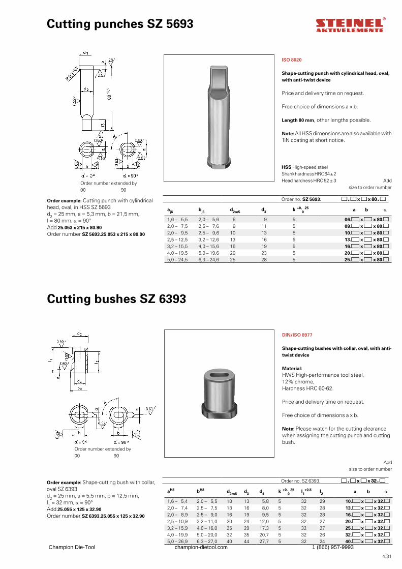
4.31
aj6 bj6 d2m5 d3 k +0,0
25 a b α
1,6 – 5,5 2,0 – 5,6 6 9 5 06. x x 80.2,0 – 7,5 2,5 – 7,6 8 11 5 08. x x 80.2,0 – 9,5 2,5 – 9,6 10 13 5 10. x x 80.2,5 – 12,5 3,2 – 12,6 13 16 5 13. x x 80.3,2 – 15,5 4,0 – 15,6 16 19 5 16. x x 80.4,0 – 19,5 5,0 – 19,6 20 23 5 20. x x 80.5,0 – 24,5 6,3 – 24,6 25 28 5 25. x x 80.
aH8 bH8 d2m5 d3 d4 k +0,0
25 l1+0,5 l2 a b α
1,6 – 5,4 2,0 – 5,5 10 13 5,8 5 32 29 10. x x 32.2,0 – 7,4 2,5 – 7,5 13 16 8,0 5 32 28 13. x x 32.2,0 – 8,9 2,5 – 9,0 16 19 9,5 5 32 28 16. x x 32.2,5 – 10,9 3,2 – 11,0 20 24 12,0 5 32 27 20. x x 32.3,2 – 15,9 4,0 – 16,0 25 29 17,3 5 32 27 25. x x 32.4,0 – 19,9 5,0 – 20,0 32 35 20,7 5 32 26 32. x x 32.5,0 – 26,9 6,3 – 27,0 40 44 27,7 5 32 24 40. x x 32.
Add
size to order number
HSS High-speed steelShank hardness HRC 64 ± 2Head hardness HRC 52 ± 3
Cutting punches SZ 5693
ISO 8020
Shape-cutting punch with cylindrical head, oval, with anti-twist device
Price and delivery time on request.
Free choice of dimensions a x b.
Length 80 mm, other lengths possible.
Note: All HSS dimensions are also available with TiN coating at short notice.
Order example: Cutting punch with cylindrical head, oval, in HSS SZ 5693d2 = 25 mm, a = 5,3 mm, b = 21,5 mm, l = 80 mm, α = 90°Add 25.053 x 215 x 80.90Order number SZ 5693.25.053 x 215 x 80.90
Order number extended by00 90
Cutting bushes SZ 6393
DIN/ISO 8977
Shape-cutting bushes with collar, oval, with anti-twist device
Material: HWS High-performance tool steel,12% chrome,Hardness HRC 60-62.
Price and delivery time on request.
Free choice of dimensions a x b.
Note: Please watch for the cutting clearance when assigning the cutting punch and cutting bush.
Order example: Shape-cutting bush with collar, oval SZ 6393d2 = 25 mm, a = 5,5 mm, b = 12,5 mm, l1 = 32 mm, α = 90°Add 25.055 x 125 x 32.90Order number SZ 6393.25.055 x 125 x 32.90
Add
size to order number
Order number extended by00 90
Order no. SZ 5693.
Order no. SZ 6393.
Champion Die-Tool champion-dietool.com 1 (866) 957-9993
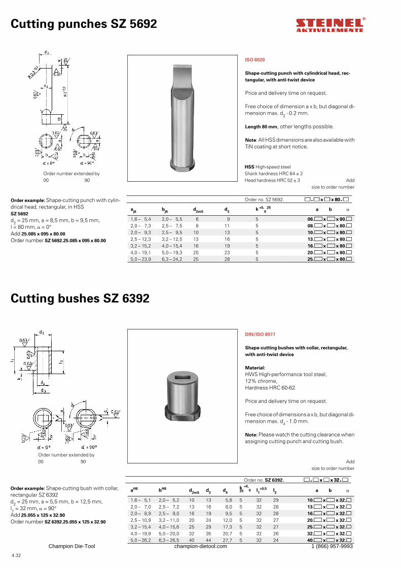
4.32
aj6 bj6 d2m5 d3 k +0,0
25 a b α
1,6 – 5,4 2,0 – 5,5 6 9 5 06. x x 80.2,0 – 7,3 2,5 – 7,5 8 11 5 08. x x 80.2,0 – 9,3 2,5 – 9,5 10 13 5 10. x x 80.2,5 – 12,3 3,2 – 12,5 13 16 5 13. x x 80.3,2 – 15,2 4,0 – 15,4 16 19 5 16. x x 80.4,0 – 19,1 5,0 – 19,3 20 23 5 20. x x 80.5,0 – 23,9 6,3 – 24,2 25 28 5 25. x x 80.
aH8 bH8 d2m5 d3 d4k +0,
0
25 l1+0,5 l2 a b α
1,6 – 5,1 2,0 – 5,2 10 13 5,8 5 32 29 10. x x 32.2,0 – 7,0 2,5 – 7,2 13 16 8,0 5 32 28 13. x x 32.2,0 – 8,9 2,5 – 9,0 16 19 9,5 5 32 28 16. x x 32.2,5 – 10,9 3,2 – 11,0 20 24 12,0 5 32 27 20. x x 32.3,2 – 15,4 4,0 – 15,6 25 29 17,3 5 32 27 25. x x 32.4,0 – 19,9 5,0 – 20,0 32 35 20,7 5 32 26 32. x x 32.5,0 – 26,2 6,3 – 26,5 40 44 27,7 5 32 24 40. x x 32.
Order example: Shape-cutting bush with collar, rectangular SZ 6392d2 = 25 mm, a = 5,5 mm, b = 12,5 mm, l1 = 32 mm, α = 90°Add 25.055 x 125 x 32.90Order number SZ 6392.25.055 x 125 x 32.90
DIN/ISO 8977
Shape-cutting bushes with collar, rectangular, with anti-twist device
Material: HWS High-performance tool steel,12% chrome,Hardness HRC 60-62.
Price and delivery time on request.
Free choice of dimensions a x b, but diagonal di-mension max. d4 - 1.0 mm.
Note: Please watch the cutting clearance when assigning cutting punch and cutting bush.
Cutting bushes SZ 6392
Add
size to order number
Order number extended by00 90
Cutting punches SZ 5692
ISO 8020
Shape-cutting punch with cylindrical head, rec-tangular, with anti-twist device
Price and delivery time on request.
Free choice of dimension a x b, but diagonal di-mension max. d2 -0.2 mm.
Length 80 mm, other lengths possible.
Note: All HSS dimensions are also available with TiN coating at short notice.
Order example: Shape-cutting punch with cylin-drical head, rectangular, in HSS SZ 5692d2 = 25 mm, a = 8,5 mm, b = 9,5 mm, l = 80 mm, α = 0°Add 25.085 x 095 x 80.00Order number SZ 5692.25.085 x 095 x 80.00
Add
size to order number
HSS High-speed steel Shank hardness HRC 64 ± 2 Head hardness HRC 52 ± 3
Order number extended by00 90
Order no. SZ 5692.
Order no. SZ 6392.
Champion Die-Tool champion-dietool.com 1 (866) 957-9993
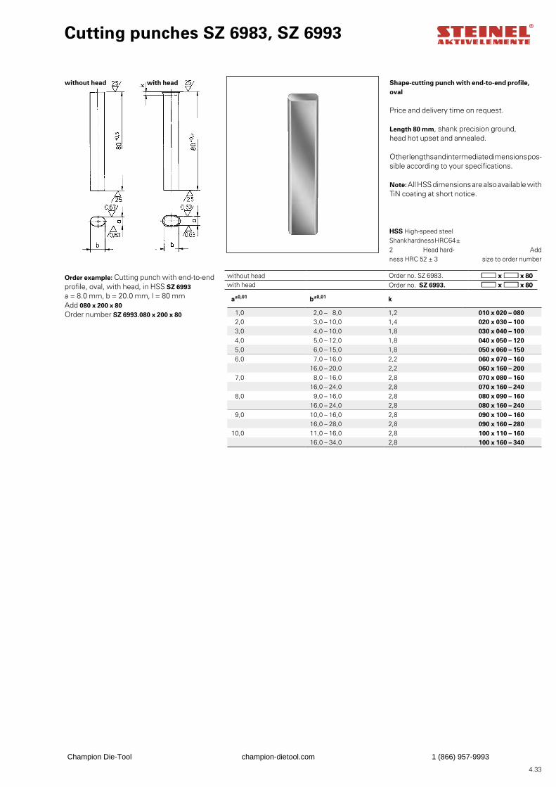
4.33
a±0,01 b±0,01 k
1,0 2,0 – 8,0 1,2 010 x 020 – 0802,0 3,0 – 10,0 1,4 020 x 030 – 1003,0 4,0 – 10,0 1,8 030 x 040 – 1004,0 5,0 – 12,0 1,8 040 x 050 – 1205,0 6,0 – 15,0 1,8 050 x 060 – 1506,0 7,0 – 16,0 2,2 060 x 070 – 160
16,0 – 20,0 2,2 060 x 160 – 2007,0 8,0 – 16,0 2,8 070 x 080 – 160
16,0 – 24,0 2,8 070 x 160 – 2408,0 9,0 – 16,0 2,8 080 x 090 – 160
16,0 – 24,0 2,8 080 x 160 – 2409,0 10,0 – 16,0 2,8 090 x 100 – 160
16,0 – 28,0 2,8 090 x 160 – 28010,0 11,0 – 16,0 2,8 100 x 110 – 160
16,0 – 34,0 2,8 100 x 160 – 340
Cutting punches SZ 6983, SZ 6993
Shape-cutting punch with end-to-end profile, oval
Price and delivery time on request.
Length 80 mm, shank precision ground, head hot upset and annealed.
Other lengths and intermediate dimensions pos-sible according to your specifications.
Note: All HSS dimensions are also available with TiN coating at short notice.
Order example: Cutting punch with end-to-end profile, oval, with head, in HSS SZ 6993a = 8.0 mm, b = 20.0 mm, l = 80 mmAdd 080 x 200 x 80Order number SZ 6993.080 x 200 x 80
Add
size to order number
HSS High-speed steelShank hardness HRC 64 ± 2 Head hard-ness HRC 52 ± 3
without head
without head Order no. SZ 6983.with head Order no. SZ 6993.
with head
Champion Die-Tool champion-dietool.com 1 (866) 957-9993
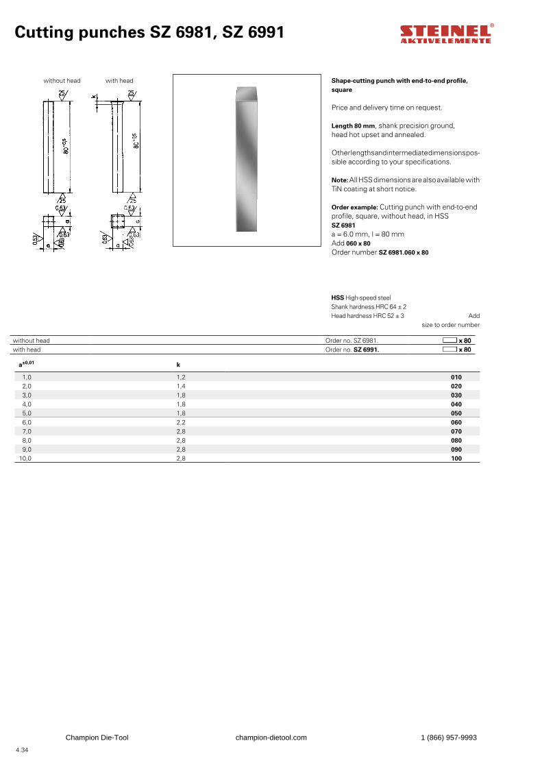
4.34
a±0,01 k
1,0 1,2 010 2,0 1,4 020 3,0 1,8 030 4,0 1,8 040 5,0 1,8 050 6,0 2,2 060 7,0 2,8 070 8,0 2,8 080 9,0 2,8 090
10,0 2,8 100
Cutting punches SZ 6981, SZ 6991
Shape-cutting punch with end-to-end profile, square
Price and delivery time on request.
Length 80 mm, shank precision ground, head hot upset and annealed.
Other lengths and intermediate dimensions pos-sible according to your specifications.
Note: All HSS dimensions are also available with TiN coating at short notice.
Order example: Cutting punch with end-to-end profile, square, without head, in HSS SZ 6981a = 6.0 mm, l = 80 mmAdd 060 x 80Order number SZ 6981.060 x 80
Add
size to order number
HSS High-speed steel Shank hardness HRC 64 ± 2 Head hardness HRC 52 ± 3
without head
without head Order no. SZ 6981.with head Order no. SZ 6991.
with head
Champion Die-Tool champion-dietool.com 1 (866) 957-9993
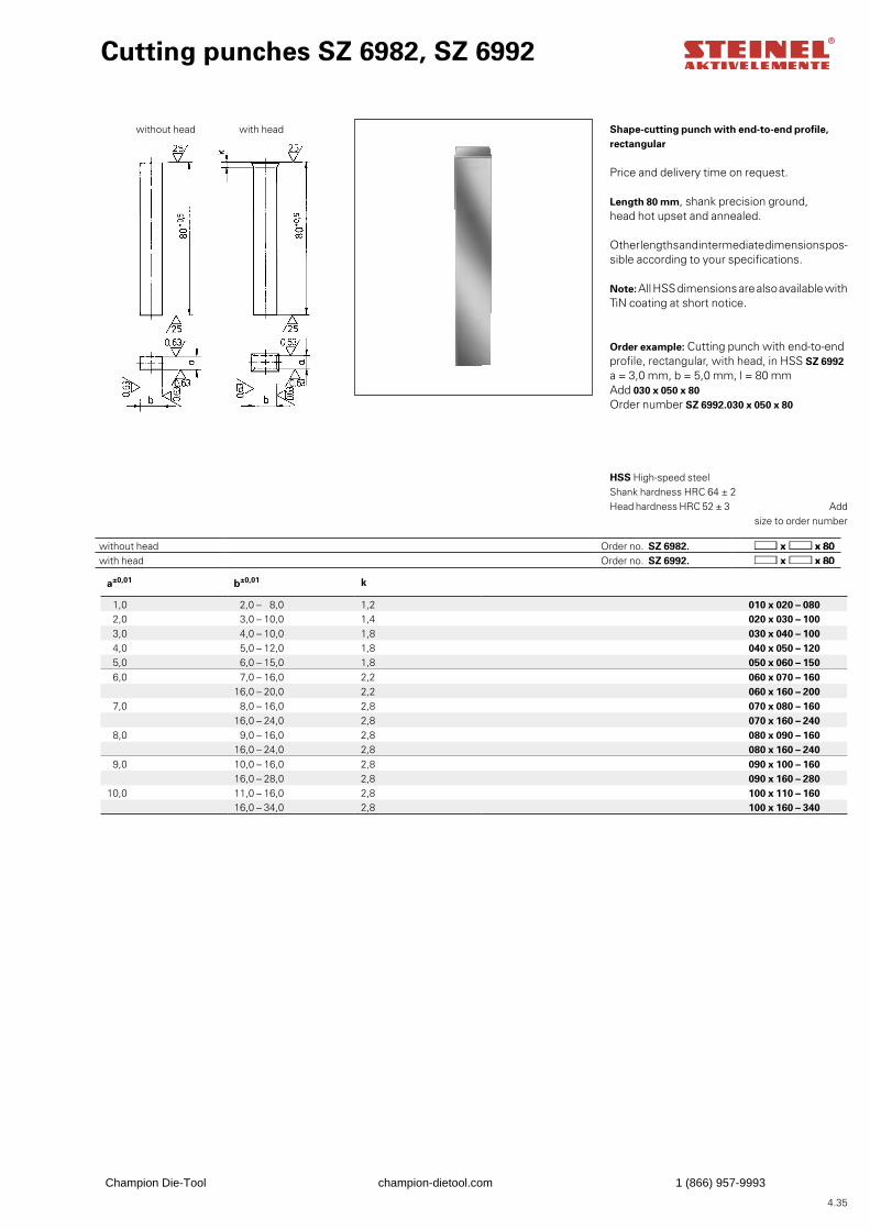
4.35
a±0,01 b±0,01 k
1,0 2,0 – 8,0 1,2 010 x 020 – 0802,0 3,0 – 10,0 1,4 020 x 030 – 1003,0 4,0 – 10,0 1,8 030 x 040 – 1004,0 5,0 – 12,0 1,8 040 x 050 – 1205,0 6,0 – 15,0 1,8 050 x 060 – 1506,0 7,0 – 16,0 2,2 060 x 070 – 160
16,0 – 20,0 2,2 060 x 160 – 2007,0 8,0 – 16,0 2,8 070 x 080 – 160
16,0 – 24,0 2,8 070 x 160 – 2408,0 9,0 – 16,0 2,8 080 x 090 – 160
16,0 – 24,0 2,8 080 x 160 – 2409,0 10,0 – 16,0 2,8 090 x 100 – 160
16,0 – 28,0 2,8 090 x 160 – 28010,0 11,0 – 16,0 2,8 100 x 110 – 160
16,0 – 34,0 2,8 100 x 160 – 340
Cutting punches SZ 6982, SZ 6992
Shape-cutting punch with end-to-end profile, rectangular
Price and delivery time on request.
Length 80 mm, shank precision ground, head hot upset and annealed.
Other lengths and intermediate dimensions pos-sible according to your specifications.
Note: All HSS dimensions are also available with TiN coating at short notice.
Order example: Cutting punch with end-to-end profile, rectangular, with head, in HSS SZ 6992a = 3,0 mm, b = 5,0 mm, l = 80 mmAdd 030 x 050 x 80Order number SZ 6992.030 x 050 x 80
Add
size to order number
HSS High-speed steel Shank hardness HRC 64 ± 2 Head hardness HRC 52 ± 3
without head Order no. SZ 6982.with head Order no. SZ 6992.
without head with head
Champion Die-Tool champion-dietool.com 1 (866) 957-9993
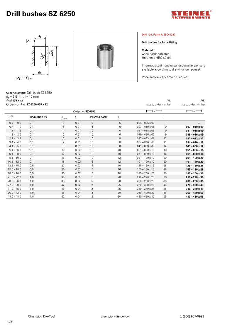
4.36
Drill bushes SZ 6250
DIN 179, Form A, ISO 4247
Drill bushes for force fitting
Material: Case-hardened steel,Hardness HRC 60-64.
Intermediate dimensions and special versions are available according to drawings on request.
Price and delivery time on request.
Order example: Drill bush SZ 6250d1 = 3.5 mm, l = 12 mmAdd 035 x 12Order number SZ 6250.035 x 12
Add
size to order numberAdd
size to order number
d1F7 Reduction by d2n6
t Pcs/std pack l l
0,4 – 0,6 0,1 3 0,01 5 6 004 – 006 x 06 – – 0,7 – 1,0 0,1 3 0,01 5 6 007 – 010 x 06 9 007 – 010 x 09 1,1 – 1,8 0,1 4 0,01 10 6 011 – 018 x 06 9 011 – 018 x 09 1,9 – 2,6 0,1 5 0,01 10 6 019 – 026 x 06 9 019 – 026 x 09 2,7 – 3,3 0,1 6 0,01 10 8 027 – 033 x 08 12 027 – 033 x 12 3,4 – 4,0 0,1 7 0,01 10 8 034 – 040 x 08 12 034 – 040 x 12 4,1 – 5,0 0,1 8 0,01 10 8 041 – 050 x 08 12 041 – 050 x 12 5,1 – 6,0 0,1 10 0,02 10 10 051 – 060 x 10 16 051 – 060 x 16 6,1 – 8,0 0,1 12 0,02 10 10 061 – 080 x 10 16 061 – 080 x 16 8,1 – 10,0 0,1 15 0,02 10 12 081 – 100 x 12 20 081 – 100 x 20
10,1 – 12,0 0,1 18 0,02 5 12 101 – 120 x 12 20 101 – 120 x 2012,5 – 15,0 0,5 22 0,02 5 16 125 – 150 x 16 28 125 – 150 x 2815,5 – 18,0 0,5 26 0,02 5 16 155 – 180 x 16 28 155 – 180 x 2818,5 – 20,0 0,5 30 0,02 5 20 185 – 200 x 20 36 185 – 200 x 3621,0 – 22,0 1,0 30 0,02 5 20 210 – 220 x 20 36 210 – 220 x 3623,0 – 26,0 1,0 35 0,02 5 20 230 – 260 x 20 36 230 – 260 x 3627,0 – 30,0 1,0 42 0,02 2 25 270 – 300 x 25 45 270 – 300 x 4531,0 – 35,0 1,0 48 0,04 2 25 310 – 350 x 25 45 310 – 350 x 4536,0 – 42,0 1,0 55 0,04 2 30 360 – 420 x 30 56 360 – 420 x 5643,0 – 48,0 1,0 62 0,04 2 30 430 – 480 x 30 56 430 – 480 x 56
Order no. SZ 6250.
Champion Die-Tool champion-dietool.com 1 (866) 957-9993
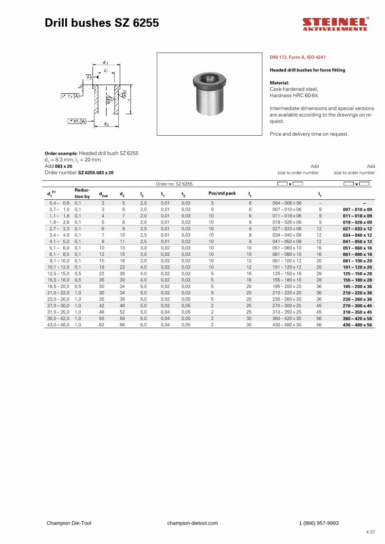
4.37
Order no. SZ 6255.
d1F7 Reduc-
tion byd2n6 d3 l2 t1 t2
Pcs/std pack l1 l1
0,4 – 0,6 0,1 3 5 2,0 0,01 0,03 5 6 004 – 006 x 06 – – 0,7 – 1,0 0,1 3 6 2,0 0,01 0,03 5 6 007 – 010 x 06 9 007 – 010 x 09 1,1 – 1,8 0,1 4 7 2,0 0,01 0,03 10 6 011 – 018 x 06 9 011 – 018 x 09 1,9 – 2,6 0,1 5 8 2,0 0,01 0,03 10 6 019 – 026 x 06 9 019 – 026 x 09 2,7 – 3,3 0,1 6 9 2,5 0,01 0,03 10 8 027 – 033 x 08 12 027 – 033 x 12 3,4 – 4,0 0,1 7 10 2,5 0,01 0,03 10 8 034 – 040 x 08 12 034 – 040 x 12 4,1 – 5,0 0,1 8 11 2,5 0,01 0,03 10 8 041 – 050 x 08 12 041 – 050 x 12 5,1 – 6,0 0,1 10 13 3,0 0,02 0,03 10 10 051 – 060 x 10 16 051 – 060 x 16 6,1 – 8,0 0,1 12 15 3,0 0,02 0,03 10 10 061 – 080 x 10 16 061 – 080 x 16 8,1 – 10,0 0,1 15 18 3,0 0,02 0,03 10 12 081 – 100 x 12 20 081 – 100 x 20
10,1 – 12,0 0,1 18 22 4,0 0,02 0,03 10 12 101 – 120 x 12 20 101 – 120 x 2012,5 – 15,0 0,5 22 26 4,0 0,02 0,03 5 16 125 – 150 x 16 28 125 – 150 x 2815,5 – 18,0 0,5 26 30 4,0 0,02 0,03 5 16 155 – 180 x 16 28 155 – 180 x 2818,5 – 20,0 0,5 30 34 5,0 0,02 0,03 5 20 185 – 200 x 20 36 185 – 200 x 3621,0 – 22,0 1,0 30 34 5,0 0,02 0,03 5 20 210 – 220 x 20 36 210 – 220 x 3623,0 – 26,0 1,0 35 39 5,0 0,02 0,05 5 20 230 – 260 x 20 36 230 – 260 x 3627,0 – 30,0 1,0 42 46 5,0 0,02 0,05 2 25 270 – 300 x 25 45 270 – 300 x 4531,0 – 35,0 1,0 48 52 5,0 0,04 0,05 2 25 310 – 350 x 25 45 310 – 350 x 4536,0 – 42,0 1,0 55 59 5,0 0,04 0,05 2 30 360 – 420 x 30 56 360 – 420 x 5643,0 – 48,0 1,0 62 66 6,0 0,04 0,05 2 30 430 – 480 x 30 56 430 – 480 x 56
Drill bushes SZ 6255
DIN 172, Form A, ISO 4247
Headed drill bushes for force fitting
Material: Case-hardened steel,Hardness HRC 60-64.
Intermediate dimensions and special versions are available according to the drawings on re-quest.
Price and delivery time on request.
Order example: Headed drill bush SZ 6255d1 = 8.3 mm, l1 = 20 mmAdd 083 x 20Order number SZ 6255.083 x 20
Add
size to order numberAdd
size to order number
Champion Die-Tool champion-dietool.com 1 (866) 957-9993
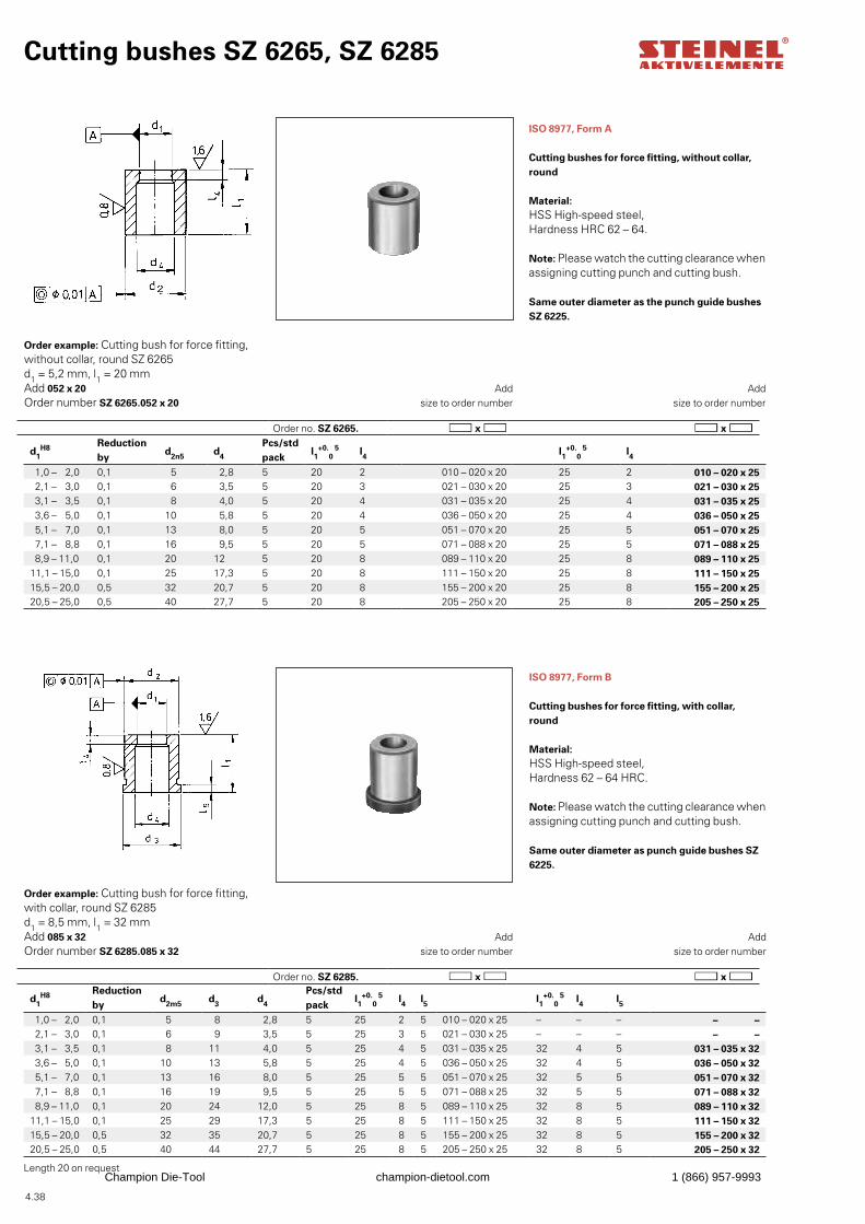
4.38
d1H8 Reduction
byd2m5 d3 d4
Pcs/std pack
l1+0.
0 5 l4 l5 l1
+0.0
5 l4 l5
1,0 – 2,0 0,1 5 8 2,8 5 25 2 5 010 – 020 x 25 – – – – – 2,1 – 3,0 0,1 6 9 3,5 5 25 3 5 021 – 030 x 25 – – – – – 3,1 – 3,5 0,1 8 11 4,0 5 25 4 5 031 – 035 x 25 32 4 5 031 – 035 x 32 3,6 – 5,0 0,1 10 13 5,8 5 25 4 5 036 – 050 x 25 32 4 5 036 – 050 x 32 5,1 – 7,0 0,1 13 16 8,0 5 25 5 5 051 – 070 x 25 32 5 5 051 – 070 x 32 7,1 – 8,8 0,1 16 19 9,5 5 25 5 5 071 – 088 x 25 32 5 5 071 – 088 x 32 8,9 – 11,0 0,1 20 24 12,0 5 25 8 5 089 – 110 x 25 32 8 5 089 – 110 x 32
11,1 – 15,0 0,1 25 29 17,3 5 25 8 5 111 – 150 x 25 32 8 5 111 – 150 x 3215,5 – 20,0 0,5 32 35 20,7 5 25 8 5 155 – 200 x 25 32 8 5 155 – 200 x 3220,5 – 25,0 0,5 40 44 27,7 5 25 8 5 205 – 250 x 25 32 8 5 205 – 250 x 32
Cutting bushes SZ 6265, SZ 6285
ISO 8977, Form A
Cutting bushes for force fitting, without collar, round
Material: HSS High-speed steel,Hardness HRC 62 – 64.
Note: Please watch the cutting clearance when assigning cutting punch and cutting bush.
Same outer diameter as the punch guide bushes SZ 6225.
Order example: Cutting bush for force fitting, without collar, round SZ 6265d1 = 5,2 mm, l1 = 20 mmAdd 052 x 20Order number SZ 6265.052 x 20
Add
size to order number
Add
size to order number
ISO 8977, Form B
Cutting bushes for force fitting, with collar, round
Material: HSS High-speed steel,Hardness 62 – 64 HRC.
Note: Please watch the cutting clearance when assigning cutting punch and cutting bush.
Same outer diameter as punch guide bushes SZ 6225.
Order example: Cutting bush for force fitting, with collar, round SZ 6285d1 = 8,5 mm, l1 = 32 mmAdd 085 x 32Order number SZ 6285.085 x 32
Add
size to order number
Add
size to order number
d1H8 Reduction
byd2n5 d4
Pcs/std pack
l1+0.
0 5 l4 l1
+0.0
5 l4
1,0 – 2,0 0,1 5 2,8 5 20 2 010 – 020 x 20 25 2 010 – 020 x 25 2,1 – 3,0 0,1 6 3,5 5 20 3 021 – 030 x 20 25 3 021 – 030 x 25 3,1 – 3,5 0,1 8 4,0 5 20 4 031 – 035 x 20 25 4 031 – 035 x 25 3,6 – 5,0 0,1 10 5,8 5 20 4 036 – 050 x 20 25 4 036 – 050 x 25 5,1 – 7,0 0,1 13 8,0 5 20 5 051 – 070 x 20 25 5 051 – 070 x 25 7,1 – 8,8 0,1 16 9,5 5 20 5 071 – 088 x 20 25 5 071 – 088 x 25 8,9 – 11,0 0,1 20 12 5 20 8 089 – 110 x 20 25 8 089 – 110 x 2511,1 – 15,0 0,1 25 17,3 5 20 8 111 – 150 x 20 25 8 111 – 150 x 2515,5 – 20,0 0,5 32 20,7 5 20 8 155 – 200 x 20 25 8 155 – 200 x 2520,5 – 25,0 0,5 40 27,7 5 20 8 205 – 250 x 20 25 8 205 – 250 x 25
Order no. SZ 6265.
Order no. SZ 6285.
Length 20 on requestChampion Die-Tool champion-dietool.com 1 (866) 957-9993
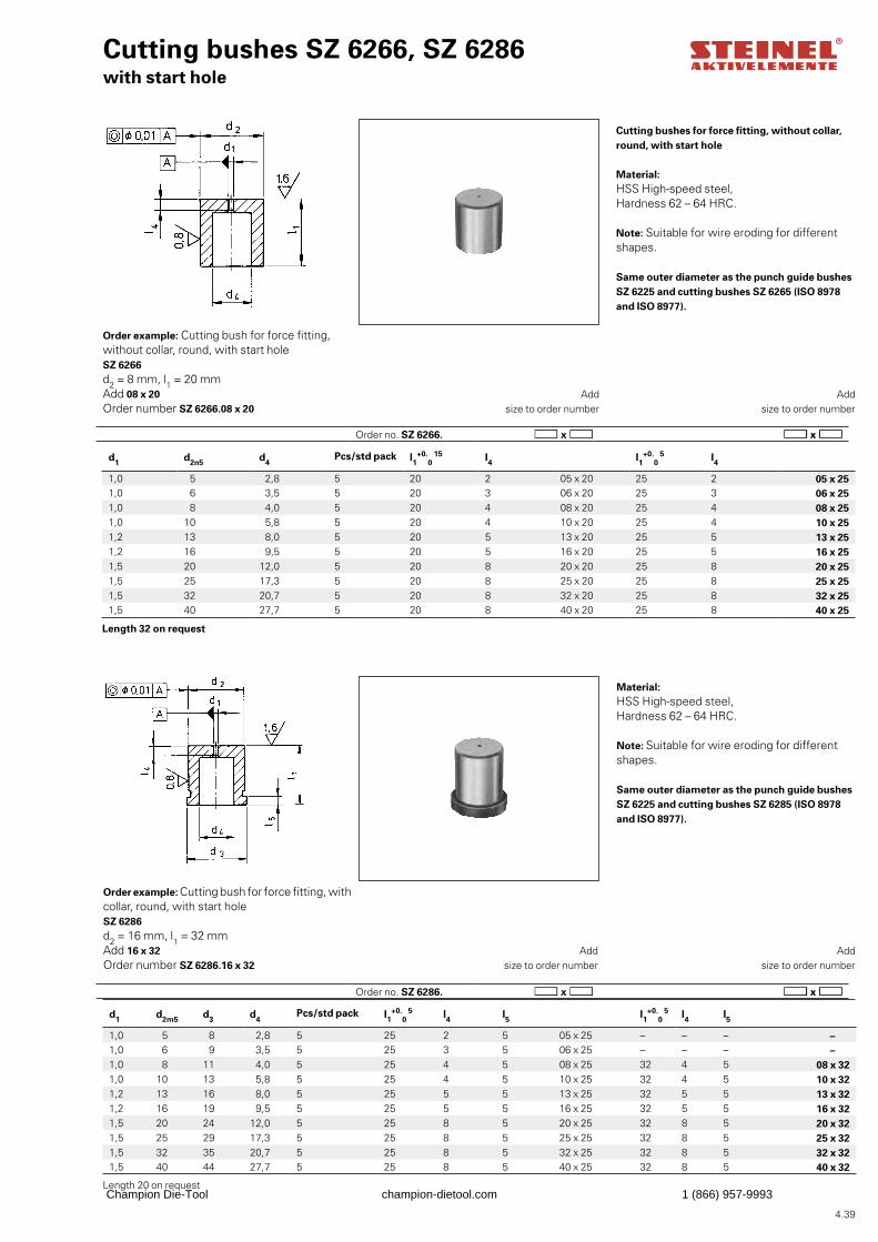
4.39
Length 20 on request
Cutting bushes SZ 6266, SZ 6286with start hole
Cutting bushes for force fitting, without collar, round, with start hole
Material:HSS High-speed steel,Hardness 62 – 64 HRC.
Note: Suitable for wire eroding for different shapes.
Same outer diameter as the punch guide bushes SZ 6225 and cutting bushes SZ 6265 (ISO 8978 and ISO 8977).
Order example: Cutting bush for force fitting, without collar, round, with start hole SZ 6266d2 = 8 mm, l1 = 20 mmAdd 08 x 20Order number SZ 6266.08 x 20
Add
size to order number
Add
size to order number
Material:HSS High-speed steel,Hardness 62 – 64 HRC.
Note: Suitable for wire eroding for different shapes.
Same outer diameter as the punch guide bushes SZ 6225 and cutting bushes SZ 6285 (ISO 8978 and ISO 8977).
Order example: Cutting bush for force fitting, with collar, round, with start hole SZ 6286d2 = 16 mm, l1 = 32 mmAdd 16 x 32Order number SZ 6286.16 x 32
Add
size to order number
Add
size to order number
d1 d2n5 d4Pcs/std pack l1
+0.0
15 l4 l1+0.
0 5 l4
1,0 5 2,8 5 20 2 05 x 20 25 2 05 x 251,0 6 3,5 5 20 3 06 x 20 25 3 06 x 251,0 8 4,0 5 20 4 08 x 20 25 4 08 x 251,0 10 5,8 5 20 4 10 x 20 25 4 10 x 251,2 13 8,0 5 20 5 13 x 20 25 5 13 x 251,2 16 9,5 5 20 5 16 x 20 25 5 16 x 251,5 20 12,0 5 20 8 20 x 20 25 8 20 x 251,5 25 17,3 5 20 8 25 x 20 25 8 25 x 251,5 32 20,7 5 20 8 32 x 20 25 8 32 x 251,5 40 27,7 5 20 8 40 x 20 25 8 40 x 25
d1 d2m5 d3 d4Pcs/std pack l1
+0.0
5 l4 l5 l1+0.
0 5 l4 l5
1,0 5 8 2,8 5 25 2 5 05 x 25 – – – –1,0 6 9 3,5 5 25 3 5 06 x 25 – – – –1,0 8 11 4,0 5 25 4 5 08 x 25 32 4 5 08 x 321,0 10 13 5,8 5 25 4 5 10 x 25 32 4 5 10 x 321,2 13 16 8,0 5 25 5 5 13 x 25 32 5 5 13 x 321,2 16 19 9,5 5 25 5 5 16 x 25 32 5 5 16 x 321,5 20 24 12,0 5 25 8 5 20 x 25 32 8 5 20 x 321,5 25 29 17,3 5 25 8 5 25 x 25 32 8 5 25 x 321,5 32 35 20,7 5 25 8 5 32 x 25 32 8 5 32 x 321,5 40 44 27,7 5 25 8 5 40 x 25 32 8 5 40 x 32
Length 32 on request
Order no. SZ 6266.
Order no. SZ 6286.
Champion Die-Tool champion-dietool.com 1 (866) 957-9993
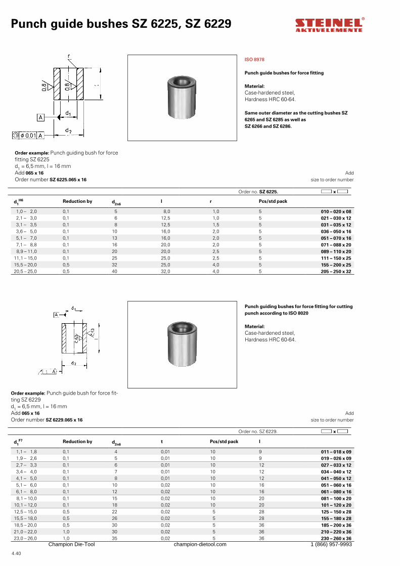
4.40
Order no. SZ 6225.
Punch guide bushes SZ 6225, SZ 6229
ISO 8978
Punch guide bushes for force fitting
Material:Case-hardened steel,Hardness HRC 60-64.
Same outer diameter as the cutting bushes SZ 6265 and SZ 6285 as well as SZ 6266 and SZ 6286.
Order example: Punch guiding bush for force fitting SZ 6225d1 = 6,5 mm, l = 16 mmAdd 065 x 16Order number SZ 6225.065 x 16
Add
size to order number
Punch guiding bushes for force fitting for cutting punch according to ISO 8020
Material:Case-hardened steel,Hardness HRC 60-64.
Order example: Punch guide bush for force fit-ting SZ 6229d1 = 6,5 mm, l = 16 mmAdd 065 x 16Order number SZ 6229.065 x 16
Add
size to order number
d1H6 Reduction by d2n6
l r Pcs/std pack
1,0 – 2,0 0,1 5 8,0 1,0 5 010 – 020 x 08 2,1 – 3,0 0,1 6 12,5 1,0 5 021 – 030 x 12 3,1 – 3,5 0,1 8 12,5 1,5 5 031 – 035 x 12 3,6 – 5,0 0,1 10 16,0 2,0 5 036 – 050 x 16 5,1 – 7,0 0,1 13 16,0 2,0 5 051 – 070 x 16 7,1 – 8,8 0,1 16 20,0 2,0 5 071 – 088 x 20 8,9 – 11,0 0,1 20 20,0 2,5 5 089 – 110 x 20
11,1 – 15,0 0,1 25 25,0 2,5 5 111 – 150 x 2515,5 – 20,0 0,5 32 25,0 4,0 5 155 – 200 x 2520,5 – 25,0 0,5 40 32,0 4,0 5 205 – 250 x 32
d1F7 Reduction by d2n6
t Pcs/std pack l
1,1 – 1,8 0,1 4 0,01 10 9 011 – 018 x 09 1,9 – 2,6 0,1 5 0,01 10 9 019 – 026 x 09 2,7 – 3,3 0,1 6 0,01 10 12 027 – 033 x 12 3,4 – 4,0 0,1 7 0,01 10 12 034 – 040 x 12 4,1 – 5,0 0,1 8 0,01 10 12 041 – 050 x 12 5,1 – 6,0 0,1 10 0,02 10 16 051 – 060 x 16 6,1 – 8,0 0,1 12 0,02 10 16 061 – 080 x 16 8,1 – 10,0 0,1 15 0,02 10 20 081 – 100 x 20
10,1 – 12,0 0,1 18 0,02 10 20 101 – 120 x 2012,5 – 15,0 0,5 22 0,02 5 28 125 – 150 x 2815,5 – 18,0 0,5 26 0,02 5 28 155 – 180 x 2818,5 – 20,0 0,5 30 0,02 5 36 185 – 200 x 3621,0 – 22,0 1,0 30 0,02 5 36 210 – 220 x 3623,0 – 26,0 1,0 35 0,02 5 36 230 – 260 x 36
Order no. SZ 6229.
Champion Die-Tool champion-dietool.com 1 (866) 957-9993
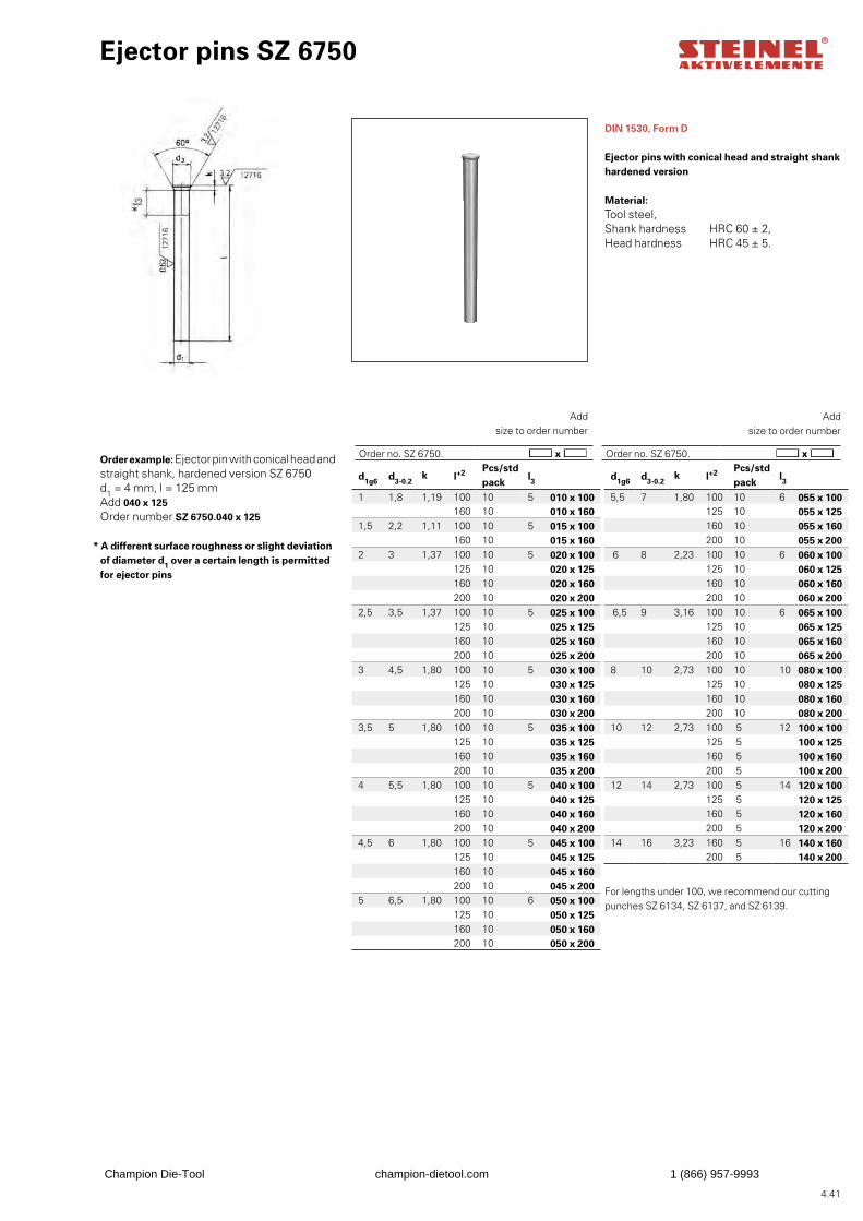
4.41
For lengths under 100, we recommend our cutting punches SZ 6134, SZ 6137, and SZ 6139.
Ejector pins SZ 6750
DIN 1530, Form D
Ejector pins with conical head and straight shankhardened version
Material: Tool steel,Shank hardness HRC 60 ± 2,Head hardness HRC 45 ± 5.
Order example: Ejector pin with conical head and straight shank, hardened version SZ 6750d1 = 4 mm, l = 125 mmAdd 040 x 125Order number SZ 6750.040 x 125
* A different surface roughness or slight deviation of diameter d1 over a certain length is permitted for ejector pins
Add
size to order number
d1g6 d3-0.2k l+2 Pcs/std
packl3
1 1,8 1,19 100 10 5 010 x 100160 10 010 x 160
1,5 2,2 1,11 100 10 5 015 x 100160 10 015 x 160
2 3 1,37 100 10 5 020 x 100125 10 020 x 125160 10 020 x 160200 10 020 x 200
2,5 3,5 1,37 100 10 5 025 x 100125 10 025 x 125160 10 025 x 160200 10 025 x 200
3 4,5 1,80 100 10 5 030 x 100125 10 030 x 125160 10 030 x 160200 10 030 x 200
3,5 5 1,80 100 10 5 035 x 100125 10 035 x 125160 10 035 x 160200 10 035 x 200
4 5,5 1,80 100 10 5 040 x 100125 10 040 x 125160 10 040 x 160200 10 040 x 200
4,5 6 1,80 100 10 5 045 x 100125 10 045 x 125160 10 045 x 160200 10 045 x 200
5 6,5 1,80 100 10 6 050 x 100125 10 050 x 125160 10 050 x 160200 10 050 x 200
Add
size to order number
d1g6 d3-0.2k l+2 Pcs/std
packl3
5,5 7 1,80 100 10 6 055 x 100125 10 055 x 125160 10 055 x 160200 10 055 x 200
6 8 2,23 100 10 6 060 x 100125 10 060 x 125160 10 060 x 160200 10 060 x 200
6,5 9 3,16 100 10 6 065 x 100125 10 065 x 125160 10 065 x 160200 10 065 x 200
8 10 2,73 100 10 10 080 x 100125 10 080 x 125160 10 080 x 160200 10 080 x 200
10 12 2,73 100 5 12 100 x 100125 5 100 x 125160 5 100 x 160200 5 100 x 200
12 14 2,73 100 5 14 120 x 100125 5 120 x 125160 5 120 x 160200 5 120 x 200
14 16 3,23 160 5 16 140 x 160200 5 140 x 200
Order no. SZ 6750. Order no. SZ 6750.
Champion Die-Tool champion-dietool.com 1 (866) 957-9993
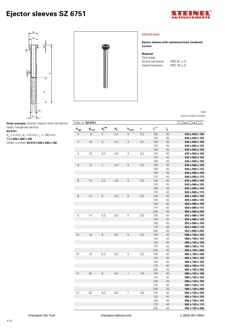
4.42
d1g6 d2-0,2 d4H5 d5 k-0,05 r l1
+1 l2
4 8 2 2,4 3 0,3 100 35 020 x 040 x 100125 35 020 x 040 x 125
5 10 3 3,4 3 0,3 100 45 030 x 050 x 100125 45 030 x 050 x 125150 45 030 x 050 x 150
5 10 3,2 3,6 3 0,3 100 45 032 x 050 x 100125 45 032 x 050 x 125150 45 032 x 050 x 150
6 12 4 4,4 5 0,5 100 45 040 x 060 x 100125 45 040 x 060 x 125150 45 040 x 060 x 150175 45 040 x 060 x 175
8 14 4,2 4,6 5 0,5 100 45 042 x 080 x 100125 45 042 x 080 x 125150 45 042 x 080 x 150175 45 042 x 080 x 175
8 14 5 5,4 5 0,5 100 45 050 x 080 x 100125 45 050 x 080 x 125150 45 050 x 080 x 150175 45 050 x 080 x 175200 45 050 x 080 x 200
8 14 5,2 5,6 5 0,5 100 45 052 x 080 x 100125 45 052 x 080 x 125150 45 052 x 080 x 150175 45 052 x 080 x 175200 45 052 x 080 x 200
10 16 6 6,4 5 0,5 100 45 060 x 100 x 100125 45 060 x 100 x 125150 45 060 x 100 x 150175 45 060 x 100 x 175200 45 060 x 100 x 200
10 16 6,2 6,6 5 0,5 100 45 062 x 100 x 100125 45 062 x 100 x 125150 45 062 x 100 x 150175 45 062 x 100 x 175200 45 062 x 100 x 200
12 20 8 8,4 7 0,8 100 45 080 x 120 x 100125 45 080 x 120 x 125150 45 080 x 120 x 150175 45 080 x 120 x 175200 45 080 x 120 x 200
12 20 8,2 8,6 7 0,8 100 45 082 x 120 x 100125 45 082 x 120 x 125150 45 082 x 120 x 150175 45 082 x 120 x 175200 45 082 x 120 x 200
Ejector sleeves SZ 6751
DIN/ISO 8405
Ejector sleeves with cylindrical head, hardened version
Material: Tool steel,Shank hardness HRC 61 ± 2.Head hardness HRC 45 ± 5.
Order example: Ejector sleeve with cylindrical head, hardened version SZ 6751d4 = 4 mm, d1 = 6 mm, l1 = 100 mmAdd 040 x 060 x 100Order number SZ 6751.040 x 060 x 100
Add
size to order number
Order no. SZ 6751.
Champion Die-Tool champion-dietool.com 1 (866) 957-9993
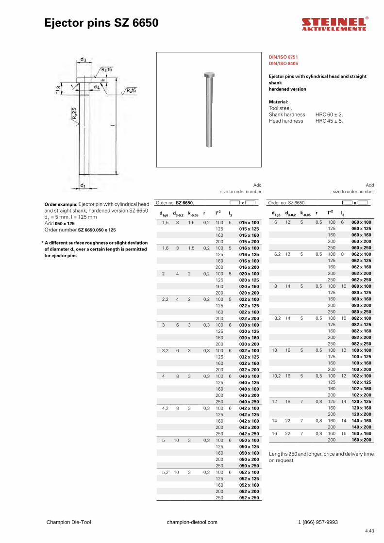
4.43
d1g6 d3-0,2 k-0,05 r l+2 l3
1,5 3 1,5 0,2 100 5 015 x 100125 015 x 125160 015 x 160200 015 x 200
1,6 3 1,5 0,2 100 5 016 x 100125 016 x 125160 016 x 160200 016 x 200
2 4 2 0,2 100 5 020 x 100125 020 x 125160 020 x 160200 020 x 200
2,2 4 2 0,2 100 5 022 x 100125 022 x 125160 022 x 160200 022 x 200
3 6 3 0,3 100 6 030 x 100125 030 x 125160 030 x 160200 030 x 200
3,2 6 3 0,3 100 6 032 x 100125 032 x 125160 032 x 160200 032 x 200
4 8 3 0,3 100 6 040 x 100125 040 x 125160 040 x 160200 040 x 200250 040 x 250
4,2 8 3 0,3 100 6 042 x 100125 042 x 125160 042 x 160200 042 x 200250 042 x 250
5 10 3 0,3 100 6 050 x 100125 050 x 125160 050 x 160200 050 x 200250 050 x 250
5,2 10 3 0,3 100 6 052 x 100125 052 x 125160 052 x 160200 052 x 200250 052 x 250
d1g6 d3-0,2 k-0,05 r l+2 l3
6 12 5 0,5 100 6 060 x 100125 060 x 125160 060 x 160200 060 x 200250 060 x 250
6,2 12 5 0,5 100 8 062 x 100125 062 x 125160 062 x 160200 062 x 200250 062 x 250
8 14 5 0,5 100 10 080 x 100125 080 x 125160 080 x 160200 080 x 200250 080 x 250
8,2 14 5 0,5 100 10 082 x 100125 082 x 125160 082 x 160200 082 x 200250 082 x 250
10 16 5 0,5 100 12 100 x 100125 100 x 125160 100 x 160200 100 x 200
10,2 16 5 0,5 100 12 102 x 100125 102 x 125160 102 x 160200 102 x 200
12 18 7 0,8 125 14 120 x 125160 120 x 160200 120 x 200
14 22 7 0,8 160 14 140 x 160200 140 x 200
16 22 7 0,8 160 16 160 x 160200 160 x 200
Order no. SZ 6650.
Ejector pins SZ 6650
DIN/ISO 6751DIN/ISO 8405
Ejector pins with cylindrical head and straight shankhardened version
Material: Tool steel,Shank hardness HRC 60 ± 2,Head hardness HRC 45 ± 5.
Order example: Ejector pin with cylindrical head and straight shank, hardened version SZ 6650d1 = 5 mm, l = 125 mmAdd 050 x 125Order number SZ 6650.050 x 125
* A different surface roughness or slight deviation of diameter d1 over a certain length is permitted for ejector pins
Add
size to order number
Add
size to order number
Lengths 250 and longer, price and delivery time on request
Order no. SZ 6650.
Champion Die-Tool champion-dietool.com 1 (866) 957-9993
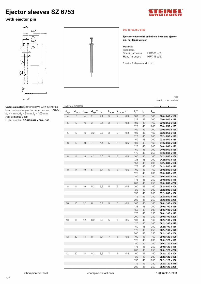
4.44
d1g6 d2-0,2 d3-0,2 d4g6H5 d5 k-0,05 k1 -0,05
r l1+1 l2 l3+2
4 8 4 2 2,4 3 2 0,3 100 35 160 020 x 040 x 100125 35 200 020 x 040 x 125
5 10 6 3 3,4 3 3 0,3 100 45 160 030 x 050 x 100125 45 200 030 x 050 x 125150 45 200 030 x 050 x 150
5 10 6 3,2 3,6 3 3 0,3 100 45 160 032 x 050 x 100125 45 200 032 x 050 x 125150 45 200 032 x 050 x 150
6 12 8 4 4,4 5 3 0,5 100 45 160 040 x 060 x 100125 45 200 040 x 060 x 125150 45 200 040 x 060 x 150175 45 250 040 x 060 x 175
8 14 8 4,2 4,6 5 3 0,5 100 45 160 042 x 080 x 100125 45 200 042 x 080 x 125150 45 200 042 x 080 x 150175 45 250 042 x 080 x 175
8 14 10 5 5,4 5 3 0,5 100 45 160 050 x 080 x 100125 45 200 050 x 080 x 125150 45 200 050 x 080 x 150175 45 250 050 x 080 x 175200 45 250 050 x 080 x 200
8 14 10 5,2 5,6 5 3 0,5 100 45 160 052 x 080 x 100125 45 200 052 x 080 x 125150 45 200 052 x 080 x 150175 45 250 052 x 080 x 175200 45 250 052 x 080 x 200
10 16 12 6 6,4 5 5 0,5 100 45 160 060 x 100 x 100125 45 200 060 x 100 x 125150 45 200 060 x 100 x 150175 45 250 060 x 100 x 175200 45 250 060 x 100 x 200
10 16 12 6,2 6,6 5 5 0,5 100 45 160 062 x 100 x 100125 45 200 062 x 100 x 125150 45 200 062 x 100 x 150175 45 250 062 x 100 x 175200 45 250 062 x 100 x 200
12 20 14 8 8,4 7 5 0,8 100 45 160 080 x 120 x 100125 45 200 080 x 120 x 125150 45 200 080 x 120 x 150175 45 250 080 x 120 x 175200 45 250 080 x 120 x 200
12 20 14 8,2 8,6 7 5 0,8 100 45 160 082 x 120 x 100125 45 200 082 x 120 x 125150 45 200 082 x 120 x 150175 45 250 082 x 120 x 175200 45 250 082 x 120 x 200
Ejector sleeves SZ 6753 with ejector pin
DIN 16756/ISO 8405
Ejector sleeves with cylindrical head and ejector pin, hardened version
Material: Tool steel,Shank hardness HRC 61 ± 2,Head hardness HRC 45 ± 5.
1 set = 1 sleeve and 1 pin.
Order example: Ejector sleeve with cylindrical head and ejector pin, hardened version SZ 6753d4 = 4 mm, d1 = 6 mm, l1 = 100 mmAdd 040 x 060 x 100Order number SZ 6753.040 x 060 x 100
Add
size to order number
Order no. SZ 6753.
Champion Die-Tool champion-dietool.com 1 (866) 957-9993
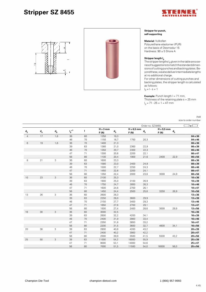
4.45
d2 d4 d6 l0+1 l
H = 3 mm F (N)
d5
H = 6,5 mm F (N)
d5
H = 9,5 mm F (N)
d5
4 17 1,6 36 60 1250 19,3 04 x 3646 70 1150 18,7 1750 20,3 04 x 46
6 19 1,6 36 70 1400 21,3 06 x 3639 63 1380 21,0 2360 22,9 06 x 3946 70 1350 20,7 2300 22,3 06 x 4647 71 1300 20,6 2200 22,1 06 x 4756 80 1100 20,4 1900 21,6 2400 22,9 06 x 56
8 21 3 36 60 1600 23,3 08 x 3639 63 1580 23,0 2400 24,9 08 x 3946 70 1500 22,7 2250 24,3 08 x 4647 71 1450 22,6 2200 24,1 08 x 4756 80 1350 22,4 2000 23,6 3000 24,9 08 x 56
10 23 3 36 60 2100 25,3 10 x 3639 63 1900 25,0 3100 26,9 10 x 3946 70 1750 24,7 2850 26,3 10 x 4647 71 1600 24,6 2700 26,1 10 x 4756 80 1450 24,4 2500 25,6 3250 26,9 10 x 56
13 26 3 36 60 2600 28,3 13 x 3639 63 2250 28,0 3600 29,9 13 x 3946 70 2150 27,7 3400 29,3 13 x 4647 71 1650 27,6 2700 29,1 13 x 4756 80 1500 27,4 2400 28,6 3000 29,9 13 x 56
16 30 3 36 60 3000 32,5 16 x 3639 63 2600 32,2 4200 34,1 16 x 3946 70 2400 31,9 3900 33,4 16 x 4647 71 2350 31,8 3850 33,2 16 x 4756 80 2200 31,5 3600 32,7 4600 34,1 16 x 56
20 38 3 39 63 2800 40,8 4200 43,2 20 x 3947 71 2400 40,2 3900 42,2 20 x 4756 80 2000 39,9 3500 41,5 5500 43,2 20 x 56
25 50 3 39 63 11000 54,2 16000 55,9 25 x 3947 71 9000 53,1 14000 54,6 25 x 4756 80 7000 51,5 11500 54,0 16000 56,0 25 x 56
Stripper SZ 8455
Stripper for punch, self-supporting
Material: VulkollanPolyurethane elastomer (PUR) on the basis of Desmodur 15Hardness: 90 ± 5 Shore A
Stripper length l0The stripper lengths l0 given in the table are a se-ries of suggestions to match the standard dimen-sions of cutting punches and backing plates. Be-yond these, we also deliver intermediate lengths at no additional charge.For other dimensions of cutting punches and backing plates, the stripper length is calculated as follows:l0 = l - s + 1
Example: Punch length l = 71 mm,Thickness of the retaining plate s = 25 mml0 = 71 - 25 + 1 = 47 mm
Add
size to order number
Order no. SZ 8455.
Champion Die-Tool champion-dietool.com 1 (866) 957-9993
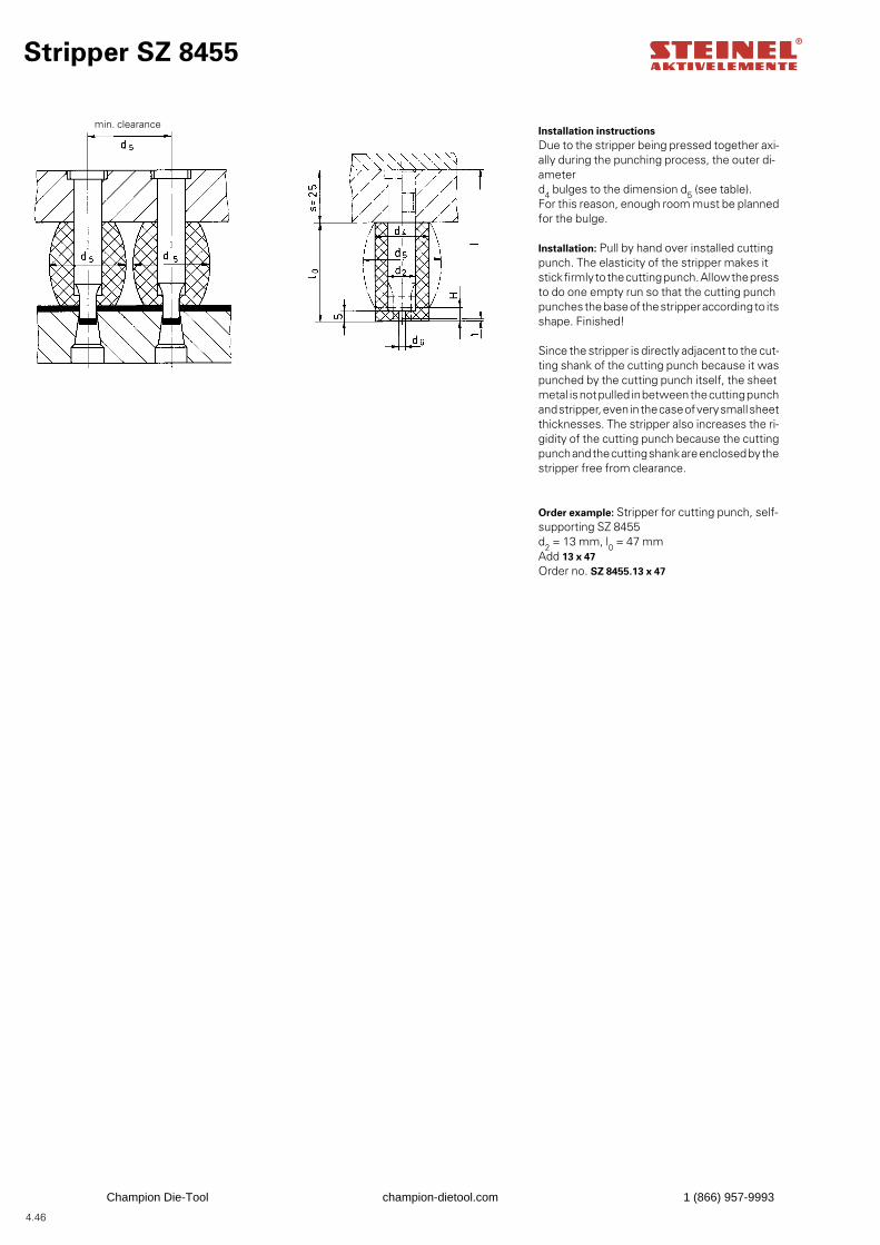
4.46
Stripper SZ 8455
Installation instructionsDue to the stripper being pressed together axi-ally during the punching process, the outer di-ameter d4 bulges to the dimension d5 (see table).For this reason, enough room must be planned for the bulge.
Installation: Pull by hand over installed cutting punch. The elasticity of the stripper makes it stick firmly to the cutting punch. Allow the press to do one empty run so that the cutting punch punches the base of the stripper according to its shape. Finished!
Since the stripper is directly adjacent to the cut-ting shank of the cutting punch because it was punched by the cutting punch itself, the sheet metal is not pulled in between the cutting punch and stripper, even in the case of very small sheet thicknesses. The stripper also increases the ri-gidity of the cutting punch because the cutting punch and the cutting shank are enclosed by the stripper free from clearance.
Order example: Stripper for cutting punch, self-supporting SZ 8455d2 = 13 mm, l0 = 47 mmAdd 13 x 47Order no. SZ 8455.13 x 47
min. clearance
Champion Die-Tool champion-dietool.com 1 (866) 957-9993
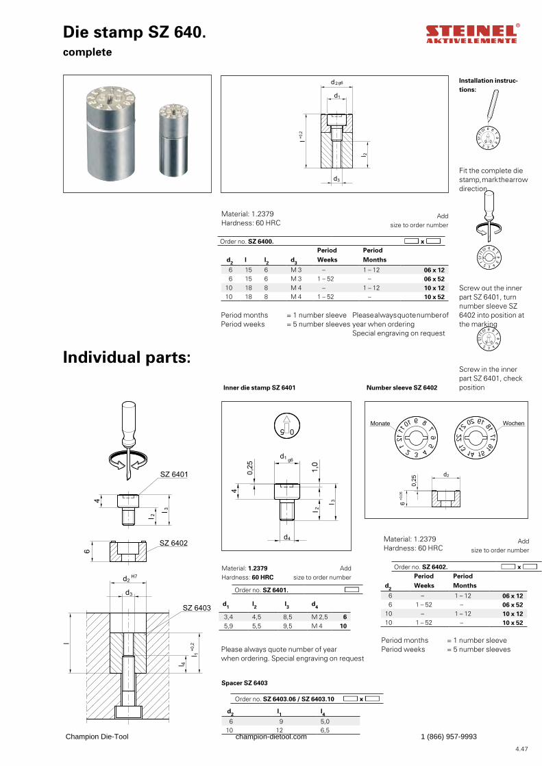
4.47
d1 l2 l3 d4
3,4 4,5 8,5 M 2,5 6 5,9 5,5 9,5 M 4 10
d2 l1 l4 6 9 5,0
10 12 6,5
Installation instruc-tions:
Fit the complete die stamp, mark the arrow direction
Screw out the inner part SZ 6401, turn number sleeve SZ 6402 into position at the marking
Screw in the inner part SZ 6401, check position
Period Periodd2 Weeks Months
6 – 1 – 12 06 x 12 6 1 – 52 – 06 x 52
10 – 1 – 12 10 x 1210 1 – 52 – 10 x 52
Die stamp SZ 640. complete
Individual parts:
Add
size to order number
Material: 1.2379Hardness: 60 HRC
Period months = 1 number sleevePeriod weeks = 5 number sleeves
Inner die stamp SZ 6401 Number sleeve SZ 6402
Spacer SZ 6403
Please always quote number of year when ordering. Special engraving on request
Please always quote number of year when orderingSpecial engraving on request
Material: 1.2379Hardness: 60 HRC
Add
size to order number
Order no. SZ 6401.
Order no. SZ 6402.
Period Period d2 l l2 d3 Weeks Months
6 15 6 M 3 – 1 – 12 06 x 12 6 15 6 M 3 1 – 52 – 06 x 52
10 18 8 M 4 – 1 – 12 10 x 1210 18 8 M 4 1 – 52 – 10 x 52
Material: 1.2379 Hardness: 60 HRC
Add
size to order number
Period months = 1 number sleevePeriod weeks = 5 number sleeves
Order no. SZ 6400.
Order no. SZ 6403.06 / SZ 6403.10
Champion Die-Tool champion-dietool.com 1 (866) 957-9993
Spring elements
• System springs, system spring units
• Nitrogen cylinder
• Helical springs with round, square and flat bottom wire cross-sections
• Disc springs
• Rubber and elastomer spring
• Cushioned thrust piece
• Polyurethan plate an rod
Champion Die-Tool champion-dietool.com 1 (866) 957-9993
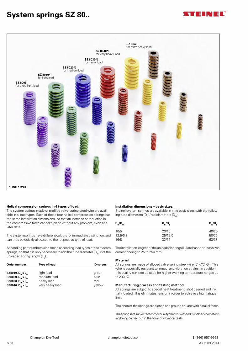
5.06 As at 09.2014
System springs SZ 80..
Installation dimensions – basic sizes:Steinel system springs are available in nine basic sizes with the follow-ing tube diameters (Dh)/rod diameters (Dd).
Dh/Dd Dh/Dd Dh/Dd
10/5 20/10 40/2012,5/6,3 25/12,5 50/2516/8 32/16 63/38
The installation lengths of the unloaded springs (L0) are based on inch sizes corresponding to 25 to 254 mm.
Material:All springs are made of alloyed valve-spring steel wire (Cr-V/Cr-Si). This wire is especially resistant to impact and vibration strains. In addition, this quality can also be used for higher working temperature ranges up to 230 °C.
Manufacturing process and testing method:All springs are subject to special heat treatment, shot peened and ini-tially loaded. This eliminates tension in order to achieve a high fatigue limit.
The ends of the springs are closed and ground square with parallel faces.
The springs are subjected to strick quality checks, with additional service life test-ing being carried out in the form of vibration tests.
Helical compression springs in 4 types of load:The system springs made of profiled valve-spring steel wire are avail-able in 4 load types. Each of these four helical compression springs has the same installation dimensions, so that an increase or reduction in the compressive force can take place without any problem, even at a later date.
The system springs have different colours for immediate distinction, and can thus be quickly allocated to the respective type of load.
Ascending part numbers also mean ascending load types of the system springs, so that it is only necessary to add the tube diameter (Dh) x of the unloaded spring length (L0).
Order number Type of load ID colour
SZ8010. Dh x L0 light load greenSZ8020. Dh x L0 medium load blueSZ8030. Dh x L0 heavy load redSZ8040. Dh x L0 very heavy load yellow
SZ 8020*) for medium load
SZ 8040*) for very heavy load
SZ 8030*) for heavy load
SZ 8010*) for light load
SZ 8005 for extra light load
SZ 8045 for extra heavy load
*) ISO 10243
Champion Die-Tool champion-dietool.com 1 (866) 957-9993
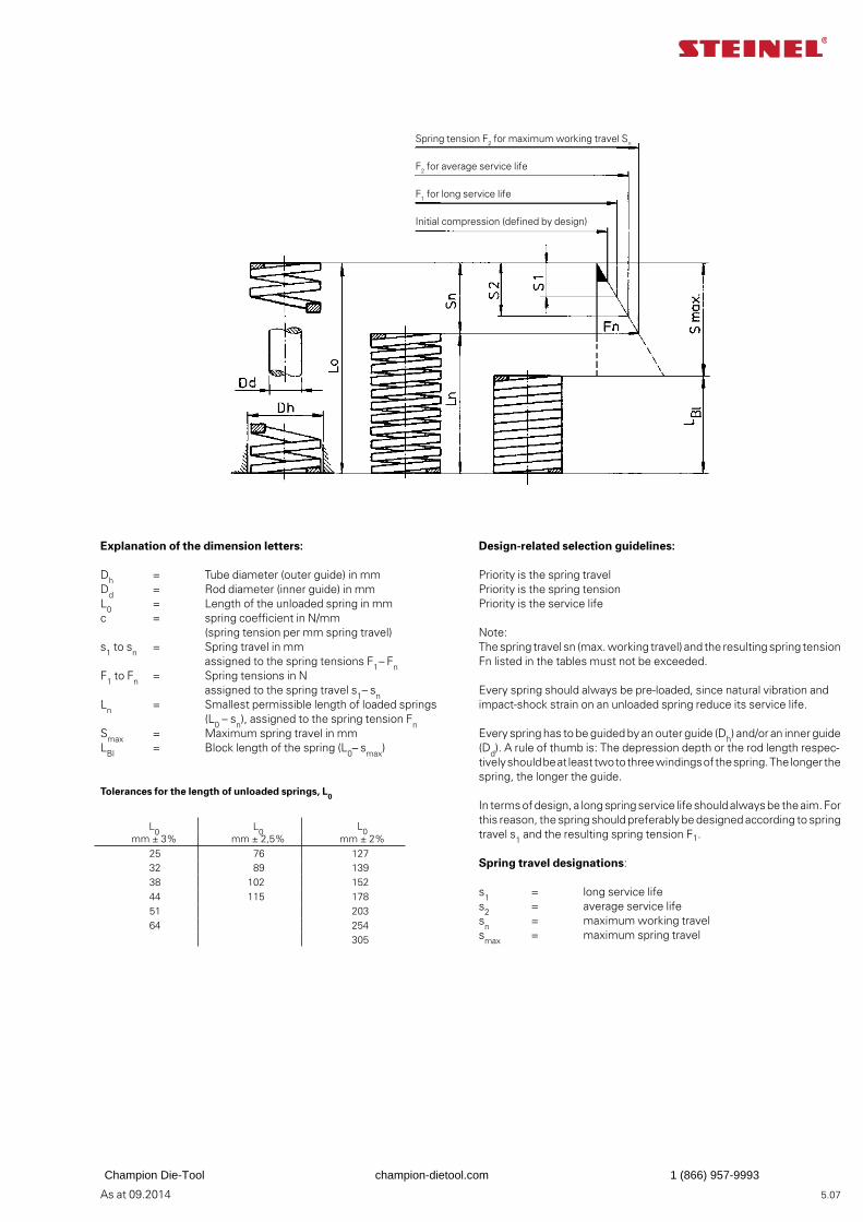
5.07As at 09.2014
Design-related selection guidelines:
Priority is the spring travelPriority is the spring tensionPriority is the service life
Note:The spring travel sn (max. working travel) and the resulting spring tension Fn listed in the tables must not be exceeded.
Every spring should always be pre-loaded, since natural vibration and impact-shock strain on an unloaded spring reduce its service life.
Every spring has to be guided by an outer guide (Dh) and/or an inner guide (Dd). A rule of thumb is: The depression depth or the rod length respec-tively should be at least two to three windings of the spring. The longer the spring, the longer the guide.
In terms of design, a long spring service life should always be the aim. For this reason, the spring should preferably be designed according to spring travel s1 and the resulting spring tension F1.
Spring travel designations:
s1 = long service lifes2 = average service lifesn = maximum working travelsmax = maximum spring travel
Explanation of the dimension letters:
Dh = Tube diameter (outer guide) in mmDd = Rod diameter (inner guide) in mmL0 = Length of the unloaded spring in mmc = spring coefficient in N/mm (spring tension per mm spring travel)s1 to sn = Spring travel in mm assigned to the spring tensions F1 – FnF1 to Fn = Spring tensions in N assigned to the spring travel s1– snLn = Smallest permissible length of loaded springs (L0 – sn), assigned to the spring tension FnSmax = Maximum spring travel in mmLBl = Block length of the spring (L0– smax)
Tolerances for the length of unloaded springs, L0
Spring tension F2 for maximum working travel Sn
F2 for average service life
F1 for long service life
Initial compression (defined by design)
L0 L0L0
mm ± 3% mm ± 2,5% mm ± 2%25 76 12732 89 13938 102 15244 115 17851 20364 254
305
Champion Die-Tool champion-dietool.com 1 (866) 957-9993
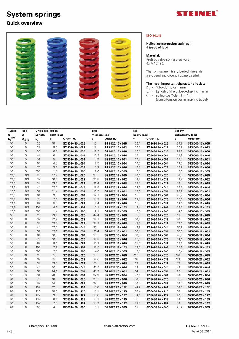
As at 09.2014 5.08
System springs Quick overview
ISO 10243
Helical compression springs in 4 types of load
Material: Profiled valve-spring steel wire,(Cr-V / Cr-Si).
The springs are initially loaded, the ends are closed and ground square parallel.
The most important characteristic data:Dh = Tube diameter in mmL0 = Length of the unloaded spring in mmc = spring coefficient in N/mm (spring tension per mm spring travel)
Tubes Ø
Rod Ø
Unloaded Length
green light load
blue medium load
red heavy load
yellow extra heavy load
DhH15 Ddh15
Lo c Order no. c Order no. c Order no. c Order no.
10 5 25 10 SZ 8010.10 x 025 16 SZ 8020.10 x 025 22,1 SZ 8030.10 x 025 36,8 SZ 8040.10 x 02510 5 32 8,5 SZ 8010.10 x 032 13 SZ 8020.10 x 032 17,5 SZ 8030.10 x 032 27,9 SZ 8040.10 x 03210 5 38 6,8 SZ 8010.10 x 038 11,9 SZ 8020.10 x 038 17,1 SZ 8030.10 x 038 23,7 SZ 8040.10 x 03810 5 44 6 SZ 8010.10 x 044 10,3 SZ 8020.10 x 044 15 SZ 8030.10 x 044 19,2 SZ 8040.10 x 04410 5 51 5 SZ 8010.10 x 051 8,9 SZ 8020.10 x 051 12,8 SZ 8030.10 x 051 16,5 SZ 8040.10 x 05110 5 64 4,3 SZ 8010.10 x 064 7,5 SZ 8020.10 x 064 10,7 SZ 8030.10 x 064 13,2 SZ 8040.10 x 06410 5 76 3,2 SZ 8010.10 x 076 5,3 SZ 8020.10 x 076 7,5 SZ 8030.10 x 076 10,9 SZ 8040.10 x 07610 5 305 1,1 SZ 8010.10 x 305 1,6 SZ 8020.10 x 305 2,1 SZ 8030.10 x 305 2,6 SZ 8040.10 x 30512,5 6,3 25 17,9 SZ 8010.13 x 025 30 SZ 8020.13 x 025 42,1 SZ 8030.13 x 025 58,5 SZ 8040.13 x 02512,5 6,3 32 16,4 SZ 8010.13 x 032 24,8 SZ 8020.13 x 032 33,2 SZ 8030.13 x 032 43,9 SZ 8040.13 x 03212,5 6,3 38 13,6 SZ 8010.13 x 038 21,4 SZ 8020.13 x 038 29,3 SZ 8030.13 x 038 36 SZ 8040.13 x 03812,5 6,3 44 12,1 SZ 8010.13 x 044 18,5 SZ 8020.13 x 044 24,6 SZ 8030.13 x 044 30,3 SZ 8040.13 x 04412,5 6,3 51 11,4 SZ 8010.13 x 051 15,5 SZ 8020.13 x 051 19,6 SZ 8030.13 x 051 26,2 SZ 8040.13 x 05112,5 6,3 64 9,3 SZ 8010.13 x 064 12,1 SZ 8020.13 x 064 15 SZ 8030.13 x 064 21,2 SZ 8040.13 x 06412,5 6,3 76 7,1 SZ 8010.13 x 076 10,2 SZ 8020.13 x 076 13,2 SZ 8030.13 x 076 17,1 SZ 8040.13 x 07612,5 6,3 89 5,4 SZ 8010.13 x 089 8,4 SZ 8020.13 x 089 11,4 SZ 8030.13 x 089 14,5 SZ 8040.13 x 08912,5 6,3 102 4,6 SZ 8010.13 x 102 7,1 SZ 8020.13 x 102 9,4 SZ 8030.13 x 102 12,5 SZ 8040.13 x 10212,5 6,3 305 1,4 SZ 8010.13 x 305 2,1 SZ 8020.13 x 305 2,8 SZ 8030.13 x 305 4,3 SZ 8040.13 x 30516 8 25 23,4 SZ 8010.16 x 025 49,4 SZ 8020.16 x 025 75,7 SZ 8030.16 x 025 118 SZ 8040.16 x 02516 8 32 22,9 SZ 8010.16 x 032 37,1 SZ 8020.16 x 032 52,8 SZ 8030.16 x 032 89 SZ 8040.16 x 03216 8 38 19,3 SZ 8010.16 x 038 33,9 SZ 8020.16 x 038 48,5 SZ 8030.16 x 038 72,1 SZ 8040.16 x 03816 8 44 17,1 SZ 8010.16 x 044 30 SZ 8020.16 x 044 42,8 SZ 8030.16 x 044 60,9 SZ 8040.16 x 04416 8 51 15,7 SZ 8010.16 x 051 26,4 SZ 8020.16 x 051 37,1 SZ 8030.16 x 051 52,3 SZ 8040.16 x 05116 8 64 10,7 SZ 8010.16 x 064 20,5 SZ 8020.16 x 064 30,3 SZ 8030.16 x 064 41,2 SZ 8040.16 x 06416 8 76 10 SZ 8010.16 x 076 17,8 SZ 8020.16 x 076 25,7 SZ 8030.16 x 076 34,1 SZ 8040.16 x 07616 8 89 8,6 SZ 8010.16 x 089 15,2 SZ 8020.16 x 089 21,7 SZ 8030.16 x 089 29,5 SZ 8040.16 x 08916 8 102 7,8 SZ 8010.16 x 102 13,5 SZ 8020.16 x 102 19,3 SZ 8030.16 x 102 25,6 SZ 8040.16 x 10216 8 305 2,5 SZ 8010.16 x 305 4,8 SZ 8020.16 x 305 7,1 SZ 8030.16 x 305 8,4 SZ 8040.16 x 30520 10 25 55,8 SZ 8010.20 x 025 98 SZ 8020.20 x 025 216 SZ 8030.20 x 025 293 SZ 8040.20 x 02520 10 32 45 SZ 8010.20 x 032 72,6 SZ 8020.20 x 032 168 SZ 8030.20 x 032 224 SZ 8040.20 x 03220 10 38 33,3 SZ 8010.20 x 038 56 SZ 8020.20 x 038 129 SZ 8030.20 x 038 177 SZ 8040.20 x 03820 10 44 30 SZ 8010.20 x 044 47,5 SZ 8020.20 x 044 112 SZ 8030.20 x 044 149 SZ 8040.20 x 04420 10 51 24,5 SZ 8010.20 x 051 41,7 SZ 8020.20 x 051 94 SZ 8030.20 x 051 128 SZ 8040.20 x 05120 10 64 20 SZ 8010.20 x 064 32,3 SZ 8020.20 x 064 72,1 SZ 8030.20 x 064 99 SZ 8040.20 x 06420 10 76 16 SZ 8010.20 x 076 25,1 SZ 8020.20 x 076 59,7 SZ 8030.20 x 076 81,7 SZ 8040.20 x 07620 10 89 14 SZ 8010.20 x 089 22 SZ 8020.20 x 089 50,5 SZ 8030.20 x 089 69,5 SZ 8040.20 x 08920 10 102 12 SZ 8010.20 x 102 19,8 SZ 8020.20 x 102 44,2 SZ 8030.20 x 102 60,6 SZ 8040.20 x 10220 10 115 10,9 SZ 8010.20 x 115 18,1 SZ 8020.20 x 115 38,4 SZ 8030.20 x 115 53 SZ 8040.20 x 11520 10 127 9,5 SZ 8010.20 x 127 16,6 SZ 8020.20 x 127 34,1 SZ 8030.20 x 127 47,5 SZ 8040.20 x 12720 10 139 8,4 SZ 8010.20 x 139 15,1 SZ 8020.20 x 139 31 SZ 8030.20 x 139 43 SZ 8040.20 x 13920 10 152 7,5 SZ 8010.20 x 152 13,2 SZ 8020.20 x 152 28,2 SZ 8030.20 x 152 39 SZ 8040.20 x 15220 10 305 4 SZ 8010.20 x 305 6,1 SZ 8020.20 x 305 15 SZ 8030.20 x 305 21,2 SZ 8040.20 x 305
Champion Die-Tool champion-dietool.com 1 (866) 957-9993
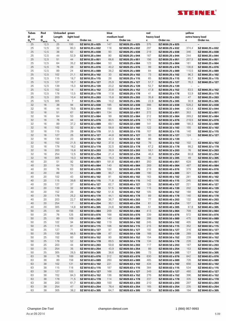
5.09As at 09.2014
Tubes Ø
Rod Ø
Unloaded Length
green light load
blue medium load
red heavy load
yellow extra heavy load
DhH15 Ddh15
Lo c Order no. c Order no. c Order no. c Order no.
25 12,5 25 100 SZ 8010.25 x 025 147 SZ 8020.25 x 025 375 SZ 8030.25 x 025 –25 12,5 32 80,3 SZ 8010.25 x 032 118 SZ 8020.25 x 032 297 SZ 8030.25 x 032 374,4 SZ 8040.25 x 03225 12,5 38 62 SZ 8010.25 x 038 93 SZ 8020.25 x 038 219 SZ 8030.25 x 038 346 SZ 8040.25 x 03825 12,5 44 52,9 SZ 8010.25 x 044 80 SZ 8020.25 x 044 187 SZ 8030.25 x 044 244 SZ 8040.25 x 04425 12,5 51 44 SZ 8010.25 x 051 68,6 SZ 8020.25 x 051 156 SZ 8030.25 x 051 207,5 SZ 8040.25 x 05125 12,5 64 35,2 SZ 8010.25 x 064 53 SZ 8020.25 x 064 123 SZ 8030.25 x 064 161 SZ 8040.25 x 06425 12,5 76 28 SZ 8010.25 x 076 43,2 SZ 8020.25 x 076 99 SZ 8030.25 x 076 130,8 SZ 8040.25 x 07625 12,5 89 24 SZ 8010.25 x 089 38,2 SZ 8020.25 x 089 84 SZ 8030.25 x 089 110,5 SZ 8040.25 x 08925 12,5 102 21,1 SZ 8010.25 x 102 33 SZ 8020.25 x 102 73 SZ 8030.25 x 102 96,3 SZ 8040.25 x 10225 12,5 115 18,7 SZ 8010.25 x 115 28 SZ 8020.25 x 115 65 SZ 8030.25 x 115 85,7 SZ 8040.25 x 11525 12,5 127 16,7 SZ 8010.25 x 127 25,9 SZ 8020.25 x 127 57,7 SZ 8030.25 x 127 76,3 SZ 8040.25 x 12725 12,5 139 15,3 SZ 8010.25 x 139 23,2 SZ 8020.25 x 139 52,7 SZ 8030.25 x 139 – –25 12,5 152 14 SZ 8010.25 x 152 20,8 SZ 8020.25 x 152 47,8 SZ 8030.25 x 152 63,5 SZ 8040.25 x 15225 12,5 178 12,5 SZ 8010.25 x 178 17,8 SZ 8020.25 x 178 41 SZ 8030.25 x 178 53,9 SZ 8040.25 x 17825 12,5 203 10,4 SZ 8010.25 x 203 15,8 SZ 8020.25 x 203 35,8 SZ 8030.25 x 203 47 SZ 8040.25 x 20325 12,5 305 7 SZ 8010.25 x 305 10,2 SZ 8020.25 x 305 22,9 SZ 8030.25 x 305 30,9 SZ 8040.25 x 30532 16 38 94 SZ 8010.32 x 038 185 SZ 8020.32 x 038 388 SZ 8030.32 x 038 528,2 SZ 8040.32 x 03832 16 44 79,5 SZ 8010.32 x 044 158 SZ 8020.32 x 044 324 SZ 8030.32 x 044 424,4 SZ 8040.32 x 04432 16 51 67 SZ 8010.32 x 051 134 SZ 8020.32 x 051 272 SZ 8030.32 x 051 353 SZ 8040.32 x 05132 16 64 53 SZ 8010.32 x 064 99 SZ 8020.32 x 064 212 SZ 8030.32 x 064 269,2 SZ 8040.32 x 06432 16 76 44 SZ 8010.32 x 076 80,5 SZ 8020.32 x 076 172 SZ 8030.32 x 076 218,5 SZ 8040.32 x 07632 16 89 37,2 SZ 8010.32 x 089 69,1 SZ 8020.32 x 089 141 SZ 8030.32 x 089 180,3 SZ 8040.32 x 08932 16 102 32 SZ 8010.32 x 102 58,8 SZ 8020.32 x 102 122 SZ 8030.32 x 102 155 SZ 8040.32 x 10232 16 115 29 SZ 8010.32 x 115 51,5 SZ 8020.32 x 115 107 SZ 8030.32 x 115 140 SZ 8040.32 x 11532 16 127 25 SZ 8010.32 x 127 44,8 SZ 8020.32 x 127 93 SZ 8030.32 x 127 124 SZ 8040.32 x 12732 16 139 23 SZ 8010.32 x 139 42,3 SZ 8020.32 x 139 86 SZ 8030.32 x 139 – –32 16 152 21,5 SZ 8010.32 x 152 37,8 SZ 8020.32 x 152 78 SZ 8030.32 x 152 102 SZ 8040.32 x 15232 16 178 18,2 SZ 8010.32 x 178 32,5 SZ 8020.32 x 178 67,2 SZ 8030.32 x 178 88,2 SZ 8040.32 x 17832 16 203 15,8 SZ 8010.32 x 203 28,9 SZ 8020.32 x 203 59,1 SZ 8030.32 x 203 76 SZ 8040.32 x 20332 16 254 12,5 SZ 8010.32 x 254 21,4 SZ 8020.32 x 254 46,4 SZ 8030.32 x 254 60,8 SZ 8040.32 x 25432 16 305 10,3 SZ 8010.32 x 305 18,3 SZ 8020.32 x 305 38 SZ 8030.32 x 305 49 SZ 8040.32 x 30540 20 51 92 SZ 8010.40 x 051 181,6 SZ 8020.40 x 051 350 SZ 8030.40 x 051 628 SZ 8040.40 x 05140 20 64 73 SZ 8010.40 x 064 140 SZ 8020.40 x 064 269 SZ 8030.40 x 064 487 SZ 8040.40 x 06440 20 76 63 SZ 8010.40 x 076 108 SZ 8020.40 x 076 219 SZ 8030.40 x 076 379 SZ 8040.40 x 07640 20 89 51 SZ 8010.40 x 089 90,7 SZ 8020.40 x 089 190 SZ 8030.40 x 089 321 SZ 8040.40 x 08940 20 102 43 SZ 8010.40 x 102 81 SZ 8020.40 x 102 163 SZ 8030.40 x 102 281 SZ 8040.40 x 10240 20 115 39,6 SZ 8010.40 x 115 71,8 SZ 8020.40 x 115 142 SZ 8030.40 x 115 245 SZ 8040.40 x 11540 20 127 37 SZ 8010.40 x 127 62,7 SZ 8020.40 x 127 128 SZ 8030.40 x 127 221 SZ 8040.40 x 12740 20 139 32 SZ 8010.40 x 139 57,5 SZ 8020.40 x 139 115 SZ 8030.40 x 139 202 SZ 8040.40 x 13940 20 152 28 SZ 8010.40 x 152 51,6 SZ 8020.40 x 152 105 SZ 8030.40 x 152 168 SZ 8040.40 x 15240 20 178 25,2 SZ 8010.40 x 178 44,1 SZ 8020.40 x 178 89 SZ 8030.40 x 178 140 SZ 8040.40 x 17840 20 203 22,7 SZ 8010.40 x 203 36,7 SZ 8020.40 x 203 77 SZ 8030.40 x 203 132 SZ 8040.40 x 20340 20 254 17 SZ 8010.40 x 254 30,1 SZ 8020.40 x 254 61 SZ 8030.40 x 254 107 SZ 8040.40 x 25440 20 305 14,8 SZ 8010.40 x 305 24,6 SZ 8020.40 x 305 51 SZ 8030.40 x 305 87,8 SZ 8040.40 x 30550 25 64 156 SZ 8010.50 x 064 209 SZ 8020.50 x 064 413 SZ 8030.50 x 064 709 SZ 8040.50 x 06450 25 76 125 SZ 8010.50 x 076 168 SZ 8020.50 x 076 339 SZ 8030.50 x 076 572 SZ 8040.50 x 07650 25 89 109 SZ 8010.50 x 089 140 SZ 8020.50 x 089 288 SZ 8030.50 x 089 475 SZ 8040.50 x 08950 25 102 94 SZ 8010.50 x 102 119 SZ 8020.50 x 102 245 SZ 8030.50 x 102 405 SZ 8040.50 x 10250 25 115 81 SZ 8010.50 x 115 106 SZ 8020.50 x 115 215 SZ 8030.50 x 115 352 SZ 8040.50 x 11550 25 127 71 SZ 8010.50 x 127 97 SZ 8020.50 x 127 192 SZ 8030.50 x 127 316 SZ 8040.50 x 12750 25 139 66,5 SZ 8010.50 x 139 87 SZ 8020.50 x 139 168 SZ 8030.50 x 139 289 SZ 8040.50 x 13950 25 152 60 SZ 8010.50 x 152 80 SZ 8020.50 x 152 154 SZ 8030.50 x 152 239 SZ 8040.50 x 15250 25 178 52 SZ 8010.50 x 178 69,5 SZ 8020.50 x 178 134 SZ 8030.50 x 178 226 SZ 8040.50 x 17850 25 203 44 SZ 8010.50 x 203 59,8 SZ 8020.50 x 203 117 SZ 8030.50 x 203 187 SZ 8040.50 x 20350 25 254 35 SZ 8010.50 x 254 43,9 SZ 8020.50 x 254 89 SZ 8030.50 x 254 153 SZ 8040.50 x 25450 25 305 28,5 SZ 8010.50 x 305 38,6 SZ 8020.50 x 305 73 SZ 8030.50 x 305 127 SZ 8040.50 x 30563 38 76 189 SZ 8010.63 x 076 312 SZ 8020.63 x 076 630 SZ 8030.63 x 076 842 SZ 8040.63 x 07663 38 89 158 SZ 8010.63 x 089 260 SZ 8020.63 x 089 485 SZ 8030.63 x 089 726 SZ 8040.63 x 08963 38 102 131 SZ 8010.63 x 102 221 SZ 8020.63 x 102 434 SZ 8030.63 x 102 656 SZ 8040.63 x 10263 38 115 116 SZ 8010.63 x 115 187 SZ 8020.63 x 115 384 SZ 8030.63 x 115 534 SZ 8040.63 x 11563 38 127 103 SZ 8010.63 x 127 168 SZ 8020.63 x 127 349 SZ 8030.63 x 127 480 SZ 8040.63 x 12763 38 152 84,3 SZ 8010.63 x 152 136 SZ 8020.63 x 152 276 SZ 8030.63 x 152 396 SZ 8040.63 x 15263 38 178 71,5 SZ 8010.63 x 178 114 SZ 8020.63 x 178 237 SZ 8030.63 x 178 335 SZ 8040.63 x 17863 38 203 61,7 SZ 8010.63 x 203 100 SZ 8020.63 x 203 210 SZ 8030.63 x 203 297 SZ 8040.63 x 20363 38 254 47 SZ 8010.63 x 254 78,4 SZ 8020.63 x 254 165 SZ 8030.63 x 254 235 SZ 8040.63 x 25463 38 305 38,2 SZ 8010.63 x 305 64,7 SZ 8020.63 x 305 134 SZ 8030.63 x 305 194 SZ 8040.63 x 305
Champion Die-Tool champion-dietool.com 1 (866) 957-9993
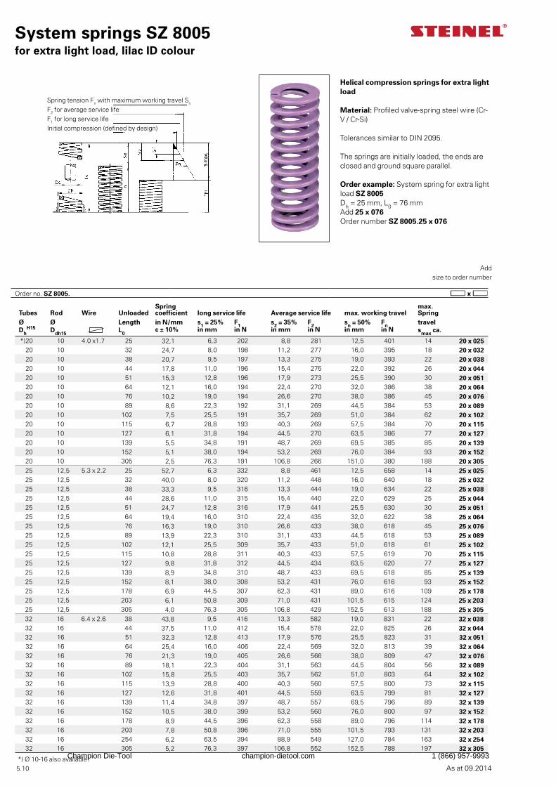
5.10 As at 09.2014
System springs SZ 8005for extra light load, lilac ID colour
Add size to order number
Helical compression springs for extra light load
Material: Profiled valve-spring steel wire (Cr-V / Cr-Si)
Tolerances similar to DIN 2095.
The springs are initially loaded, the ends are closed and ground square parallel.
Order example: System spring for extra light load SZ 8005Dh = 25 mm, L0 = 76 mmAdd 25 x 076Order number SZ 8005.25 x 076
Spring tension Fn with maximum working travel Sn
F2 for average service lifeF1 for long service lifeInitial compression (defined by design)
Tubes Rod Wire UnloadedSpring coefficient long service life Average service life max. working travel
max. Spring
Ø Ø Length in N/mm s1 = 25% F1 s2 = 35% F2 sn = 50% Fn travelDh
H15 Ddh15 L0c ± 10% in mm in N in mm in N in mm in N smax ca.
*)20 10 4.0 x1.7 25 32,1 6,3 202 8,8 281 12,5 401 14 20 x 02520 10 32 24,7 8,0 198 11,2 277 16,0 395 18 20 x 03220 10 38 20,7 9,5 197 13,3 275 19,0 393 22 20 x 03820 10 44 17,8 11,0 196 15,4 275 22,0 392 26 20 x 04420 10 51 15,3 12,8 196 17,9 273 25,5 390 30 20 x 05120 10 64 12,1 16,0 194 22,4 270 32,0 386 38 20 x 06420 10 76 10,2 19,0 194 26,6 270 38,0 386 45 20 x 07620 10 89 8,6 22,3 192 31,1 269 44,5 384 53 20 x 08920 10 102 7,5 25,5 191 35,7 269 51,0 384 62 20 x 10220 10 115 6,7 28,8 193 40,3 269 57,5 384 70 20 x 11520 10 127 6,1 31,8 194 44,5 270 63,5 386 77 20 x 12720 10 139 5,5 34,8 191 48,7 269 69,5 385 85 20 x 13920 10 152 5,1 38,0 194 53,2 269 76,0 384 93 20 x 15220 10 305 2,5 76,3 191 106,8 266 151,0 380 188 20 x 30525 12,5 5.3 x 2.2 25 52,7 6,3 332 8,8 461 12,5 658 14 25 x 02525 12,5 32 40,0 8,0 320 11,2 448 16,0 640 18 25 x 03225 12,5 38 33,3 9,5 316 13,3 444 19,0 634 22 25 x 03825 12,5 44 28,6 11,0 315 15,4 440 22,0 629 25 25 x 04425 12,5 51 24,7 12,8 316 17,9 441 25,5 630 30 25 x 05125 12,5 64 19,4 16,0 310 22,4 435 32,0 622 38 25 x 06425 12,5 76 16,3 19,0 310 26,6 433 38,0 618 45 25 x 07625 12,5 89 13,9 22,3 310 31,1 433 44,5 618 53 25 x 08925 12,5 102 12,1 25,5 309 35,7 433 51,0 618 61 25 x 10225 12,5 115 10,8 28,8 311 40,3 433 57,5 619 70 25 x 11525 12,5 127 9,8 31,8 312 44,5 434 63,5 620 77 25 x 12725 12,5 139 8,9 34,8 310 48,7 433 69,5 618 85 25 x 13925 12,5 152 8,1 38,0 308 53,2 431 76,0 616 93 25 x 15225 12,5 178 6,9 44,5 307 62,3 431 89,0 616 109 25 x 17825 12,5 203 6,1 50,8 309 71,0 431 101,5 615 124 25 x 20325 12,5 305 4,0 76,3 305 106,8 429 152,5 613 188 25 x 30532 16 6.4 x 2.6 38 43,8 9,5 416 13,3 582 19,0 831 22 32 x 03832 16 44 37,5 11,0 412 15,4 578 22,0 825 26 32 x 04432 16 51 32,3 12,8 413 17,9 576 25,5 823 31 32 x 05132 16 64 25,4 16,0 406 22,4 569 32,0 813 39 32 x 06432 16 76 21,3 19,0 405 26,6 566 38,0 809 47 32 x 07632 16 89 18,1 22,3 404 31,1 563 44,5 804 56 32 x 08932 16 102 15,8 25,5 403 35,7 562 51,0 803 64 32 x 10232 16 115 13,9 28,8 400 40,3 560 57,5 800 73 32 x 11532 16 127 12,6 31,8 401 44,5 559 63,5 799 81 32 x 12732 16 139 11,4 34,8 397 48,7 557 69,5 796 89 32 x 13932 16 152 10,5 38,0 399 53,2 560 76,0 800 97 32 x 15232 16 178 8,9 44,5 396 62,3 558 89,0 796 114 32 x 17832 16 203 7,8 50,8 396 71,0 555 101,5 793 131 32 x 20332 16 254 6,2 63,5 394 88,9 549 127,0 784 163 32 x 25432 16 305 5,2 76,3 397 106,8 552 152,5 788 197 32 x 305
Order no. SZ 8005.
*) Ø 10-16 also available!Champion Die-Tool champion-dietool.com 1 (866) 957-9993
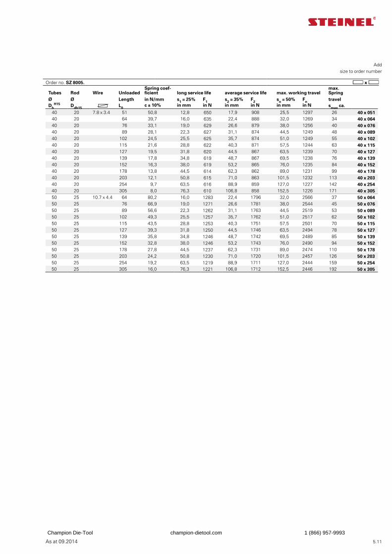
5.11As at 09.2014
Add size to order number
Tubes Rod Wire UnloadedSpring coef-ficient long service life average service life max. working travel
max. Spring
Ø Ø Length in N/mm s1 = 25% F1 s2 = 35% F2 sn = 50% Fn travelDh
H15 Ddh15 L0c ± 10% in mm in N in mm in N in mm in N smax ca.
40 20 7.8 x 3.4 51 50,8 12,8 650 17,9 908 25,5 1297 26 40 x 05140 20 64 39,7 16,0 635 22,4 888 32,0 1269 34 40 x 06440 20 76 33,1 19,0 629 26,6 879 38,0 1256 40 40 x 07640 20 89 28,1 22,3 627 31,1 874 44,5 1249 48 40 x 08940 20 102 24,5 25,5 625 35,7 874 51,0 1249 55 40 x 10240 20 115 21,6 28,8 622 40,3 871 57,5 1244 63 40 x 11540 20 127 19,5 31,8 620 44,5 867 63,5 1239 70 40 x 12740 20 139 17,8 34,8 619 48,7 867 69,5 1238 76 40 x 13940 20 152 16,3 38,0 619 53,2 865 76,0 1235 84 40 x 15240 20 178 13,8 44,5 614 62,3 862 89,0 1231 99 40 x 17840 20 203 12,1 50,8 615 71,0 863 101,5 1232 113 40 x 20340 20 254 9,7 63,5 616 88,9 859 127,0 1227 142 40 x 25440 20 305 8,0 76,3 610 106,8 858 152,5 1226 171 40 x 30550 25 10.7 x 4.4 64 80,2 16,0 1283 22,4 1796 32,0 2566 37 50 x 06450 25 76 66,9 19,0 1271 26,6 1781 38,0 2544 45 50 x 07650 25 89 56,6 22,3 1262 31,1 1763 44,5 2519 53 50 x 08950 25 102 49,3 25,5 1257 35,7 1762 51,0 2517 62 50 x 10250 25 115 43,5 28,8 1253 40,3 1751 57,5 2501 70 50 x 11550 25 127 39,3 31,8 1250 44,5 1746 63,5 2494 78 50 x 12750 25 139 35,8 34,8 1246 48,7 1742 69,5 2489 85 50 x 13950 25 152 32,8 38,0 1246 53,2 1743 76,0 2490 94 50 x 15250 25 178 27,8 44,5 1237 62,3 1731 89,0 2474 110 50 x 17850 25 203 24,2 50,8 1230 71,0 1720 101,5 2457 126 50 x 20350 25 254 19,2 63,5 1219 88,9 1711 127,0 2444 159 50 x 25450 25 305 16,0 76,3 1221 106,8 1712 152,5 2446 192 50 x 305
Order no. SZ 8005.
Champion Die-Tool champion-dietool.com 1 (866) 957-9993
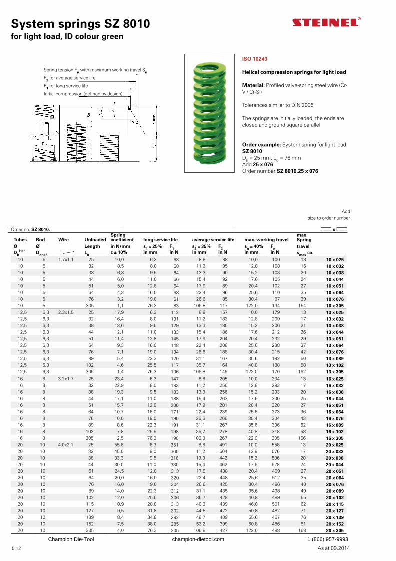
As at 09.2014 5.12
System springs SZ 8010for light load, ID colour green
Add size to order number
ISO 10243
Helical compression springs for light load
Material: Profiled valve-spring steel wire (Cr-V / Cr-Si)
Tolerances similar to DIN 2095
The springs are initially loaded, the ends are closed and ground square parallel
Order example: System spring for light load SZ 8010Dh = 25 mm, L0 = 76 mmAdd 25 x 076Order number SZ 8010.25 x 076
Spring tension Fn with maximum working travel Sn
F2 for average service life
F1 for long service life
Initial compression (defined by design)
Tubes Rod Wire UnloadedSpring coefficient long service life average service life max. working travel
max. Spring
Ø Ø Length in N/mm s1 = 25% F1 s2 = 35% F2 sn = 40% Fn travelDh
H15 Ddh15 L0c ± 10% in mm in N in mm in N in mm in N smax ca.
10 5 1.7x1.1 25 10,0 6,3 63 8,8 88 10,0 100 13 10 x 02510 5 32 8,5 8,0 68 11,2 95 12,8 108 16 10 x 03210 5 38 6,8 9,5 64 13,3 90 15,2 103 20 10 x 03810 5 44 6,0 11,0 66 15,4 92 17,6 105 24 10 x 04410 5 51 5,0 12,8 64 17,9 89 20,4 102 27 10 x 05110 5 64 4,3 16,0 68 22,4 96 25,6 110 35 10 x 06410 5 76 3,2 19,0 61 26,6 85 30,4 97 39 10 x 07610 5 305 1,1 76,3 83 106,8 117 122,0 134 154 10 x 30512,5 6,3 2.3x1.5 25 17,9 6,3 112 8,8 157 10,0 179 13 13 x 02512,5 6,3 32 16,4 8,0 131 11,2 183 12,8 209 17 13 x 03212,5 6,3 38 13,6 9,5 129 13,3 180 15,2 206 21 13 x 03812,5 6,3 44 12,1 11,0 133 15,4 186 17,6 212 26 13 x 04412,5 6,3 51 11,4 12,8 145 17,9 204 20,4 232 29 13 x 05112,5 6,3 64 9,3 16,0 148 22,4 208 25,6 238 37 13 x 06412,5 6,3 76 7,1 19,0 134 26,6 188 30,4 215 42 13 x 07612,5 6,3 89 5,4 22,3 120 31,1 167 35,6 192 50 13 x 08912,5 6,3 102 4,6 25,5 117 35,7 164 40,8 188 58 13 x 10212,5 6,3 305 1,4 76,3 106 106,8 149 122,0 170 162 13 x 30516 8 3.2x1.7 25 23,4 6,3 147 8,8 205 10,0 234 13 16 x 02516 8 32 22,9 8,0 183 11,2 256 12,8 293 17 16 x 03216 8 38 19,3 9,5 183 13,3 256 15,2 293 20 16 x 03816 8 44 17,1 11,0 188 15,4 263 17,6 300 25 16 x 04416 8 51 15,7 12,8 200 17,9 281 20,4 320 27 16 x 05116 8 64 10,7 16,0 171 22,4 239 25,6 273 36 16 x 06416 8 76 10,0 19,0 190 26,6 266 30,4 304 43 16 x 07616 8 89 8,6 22,3 191 31,1 267 35,6 306 52 16 x 08916 8 102 7,8 25,5 198 35,7 278 40,8 318 58 16 x 10216 8 305 2,5 76,3 190 106,8 267 122,0 305 166 16 x 30520 10 4.0x2.1 25 55,8 6,3 351 8,8 491 10,0 558 13 20 x 02520 10 32 45,0 8,0 360 11,2 504 12,8 576 17 20 x 03220 10 38 33,3 9,5 316 13,3 442 15,2 506 20 20 x 03820 10 44 30,0 11,0 330 15,4 462 17,6 528 24 20 x 04420 10 51 24,5 12,8 313 17,9 438 20,4 499 27 20 x 05120 10 64 20,0 16,0 320 22,4 448 25,6 512 35 20 x 06420 10 76 16,0 19,0 304 26,6 425 30,4 486 40 20 x 07620 10 89 14,0 22,3 312 31,1 435 35,6 498 49 20 x 08920 10 102 12,0 25,5 306 35,7 428 40,8 489 55 20 x 10220 10 115 10,9 28,8 313 40,3 439 46,0 501 62 20 x 11520 10 127 9,5 31,8 302 44,5 422 50,8 482 71 20 x 12720 10 139 8,4 34,8 292 48,7 409 55,6 467 76 20 x 13920 10 152 7,5 38,0 285 53,2 399 60,8 456 81 20 x 15220 10 305 4,0 76,3 305 106,8 427 122,0 488 168 20 x 305
Order no. SZ 8010.
Champion Die-Tool champion-dietool.com 1 (866) 957-9993
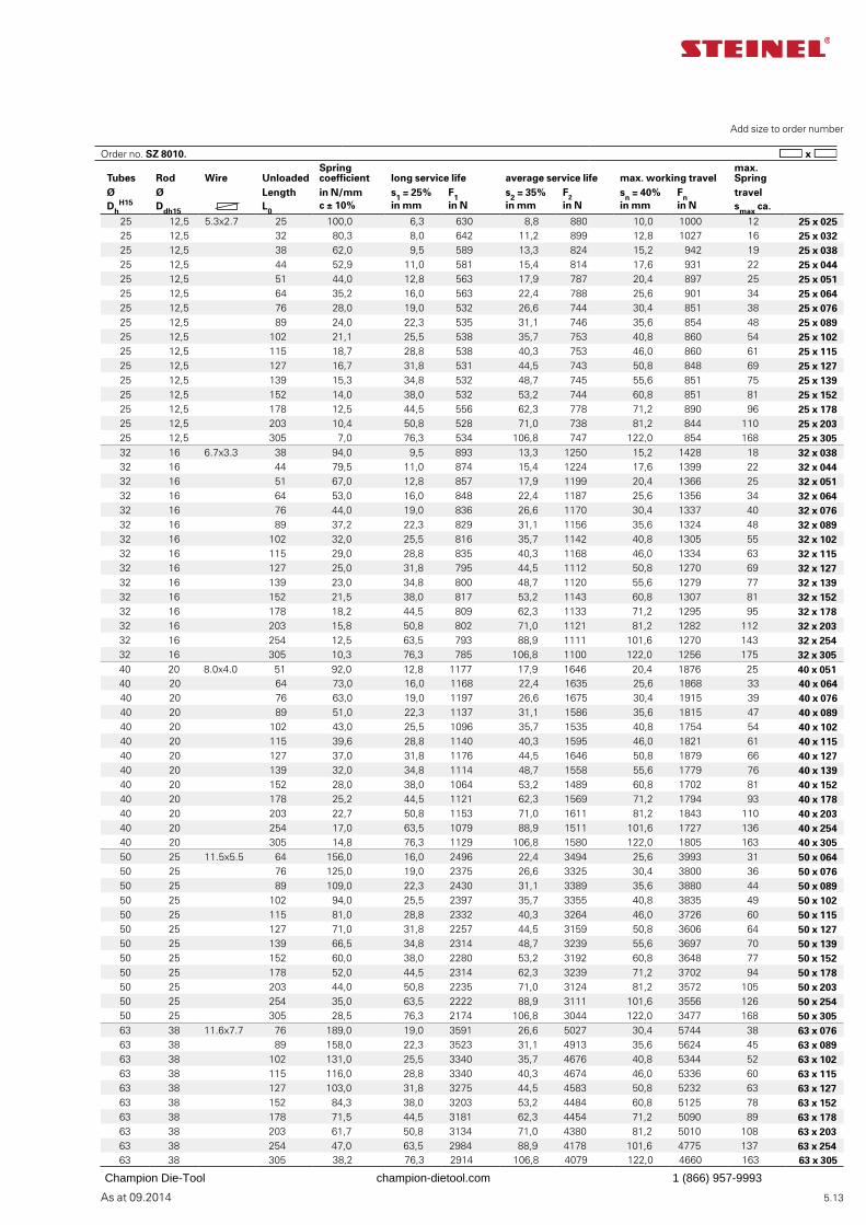
As at 09.2014 5.13
Add size to order number
Tubes Rod Wire UnloadedSpring coefficient long service life average service life max. working travel
max. Spring
Ø Ø Length in N/mm s1 = 25% F1 s2 = 35% F2 sn = 40% Fn travelDh
H15 Ddh15 L0c ± 10% in mm in N in mm in N in mm in N smax ca.
25 12,5 5.3x2.7 25 100,0 6,3 630 8,8 880 10,0 1000 12 25 x 02525 12,5 32 80,3 8,0 642 11,2 899 12,8 1027 16 25 x 03225 12,5 38 62,0 9,5 589 13,3 824 15,2 942 19 25 x 03825 12,5 44 52,9 11,0 581 15,4 814 17,6 931 22 25 x 04425 12,5 51 44,0 12,8 563 17,9 787 20,4 897 25 25 x 05125 12,5 64 35,2 16,0 563 22,4 788 25,6 901 34 25 x 06425 12,5 76 28,0 19,0 532 26,6 744 30,4 851 38 25 x 07625 12,5 89 24,0 22,3 535 31,1 746 35,6 854 48 25 x 08925 12,5 102 21,1 25,5 538 35,7 753 40,8 860 54 25 x 10225 12,5 115 18,7 28,8 538 40,3 753 46,0 860 61 25 x 11525 12,5 127 16,7 31,8 531 44,5 743 50,8 848 69 25 x 12725 12,5 139 15,3 34,8 532 48,7 745 55,6 851 75 25 x 13925 12,5 152 14,0 38,0 532 53,2 744 60,8 851 81 25 x 15225 12,5 178 12,5 44,5 556 62,3 778 71,2 890 96 25 x 17825 12,5 203 10,4 50,8 528 71,0 738 81,2 844 110 25 x 20325 12,5 305 7,0 76,3 534 106,8 747 122,0 854 168 25 x 30532 16 6.7x3.3 38 94,0 9,5 893 13,3 1250 15,2 1428 18 32 x 03832 16 44 79,5 11,0 874 15,4 1224 17,6 1399 22 32 x 04432 16 51 67,0 12,8 857 17,9 1199 20,4 1366 25 32 x 05132 16 64 53,0 16,0 848 22,4 1187 25,6 1356 34 32 x 06432 16 76 44,0 19,0 836 26,6 1170 30,4 1337 40 32 x 07632 16 89 37,2 22,3 829 31,1 1156 35,6 1324 48 32 x 08932 16 102 32,0 25,5 816 35,7 1142 40,8 1305 55 32 x 10232 16 115 29,0 28,8 835 40,3 1168 46,0 1334 63 32 x 11532 16 127 25,0 31,8 795 44,5 1112 50,8 1270 69 32 x 12732 16 139 23,0 34,8 800 48,7 1120 55,6 1279 77 32 x 13932 16 152 21,5 38,0 817 53,2 1143 60,8 1307 81 32 x 15232 16 178 18,2 44,5 809 62,3 1133 71,2 1295 95 32 x 17832 16 203 15,8 50,8 802 71,0 1121 81,2 1282 112 32 x 20332 16 254 12,5 63,5 793 88,9 1111 101,6 1270 143 32 x 25432 16 305 10,3 76,3 785 106,8 1100 122,0 1256 175 32 x 30540 20 8.0x4.0 51 92,0 12,8 1177 17,9 1646 20,4 1876 25 40 x 05140 20 64 73,0 16,0 1168 22,4 1635 25,6 1868 33 40 x 06440 20 76 63,0 19,0 1197 26,6 1675 30,4 1915 39 40 x 07640 20 89 51,0 22,3 1137 31,1 1586 35,6 1815 47 40 x 08940 20 102 43,0 25,5 1096 35,7 1535 40,8 1754 54 40 x 10240 20 115 39,6 28,8 1140 40,3 1595 46,0 1821 61 40 x 11540 20 127 37,0 31,8 1176 44,5 1646 50,8 1879 66 40 x 12740 20 139 32,0 34,8 1114 48,7 1558 55,6 1779 76 40 x 13940 20 152 28,0 38,0 1064 53,2 1489 60,8 1702 81 40 x 15240 20 178 25,2 44,5 1121 62,3 1569 71,2 1794 93 40 x 17840 20 203 22,7 50,8 1153 71,0 1611 81,2 1843 110 40 x 20340 20 254 17,0 63,5 1079 88,9 1511 101,6 1727 136 40 x 25440 20 305 14,8 76,3 1129 106,8 1580 122,0 1805 163 40 x 30550 25 11.5x5.5 64 156,0 16,0 2496 22,4 3494 25,6 3993 31 50 x 06450 25 76 125,0 19,0 2375 26,6 3325 30,4 3800 36 50 x 07650 25 89 109,0 22,3 2430 31,1 3389 35,6 3880 44 50 x 08950 25 102 94,0 25,5 2397 35,7 3355 40,8 3835 49 50 x 10250 25 115 81,0 28,8 2332 40,3 3264 46,0 3726 60 50 x 11550 25 127 71,0 31,8 2257 44,5 3159 50,8 3606 64 50 x 12750 25 139 66,5 34,8 2314 48,7 3239 55,6 3697 70 50 x 13950 25 152 60,0 38,0 2280 53,2 3192 60,8 3648 77 50 x 15250 25 178 52,0 44,5 2314 62,3 3239 71,2 3702 94 50 x 17850 25 203 44,0 50,8 2235 71,0 3124 81,2 3572 105 50 x 20350 25 254 35,0 63,5 2222 88,9 3111 101,6 3556 126 50 x 25450 25 305 28,5 76,3 2174 106,8 3044 122,0 3477 168 50 x 30563 38 11.6x7.7 76 189,0 19,0 3591 26,6 5027 30,4 5744 38 63 x 07663 38 89 158,0 22,3 3523 31,1 4913 35,6 5624 45 63 x 08963 38 102 131,0 25,5 3340 35,7 4676 40,8 5344 52 63 x 10263 38 115 116,0 28,8 3340 40,3 4674 46,0 5336 60 63 x 11563 38 127 103,0 31,8 3275 44,5 4583 50,8 5232 63 63 x 12763 38 152 84,3 38,0 3203 53,2 4484 60,8 5125 78 63 x 15263 38 178 71,5 44,5 3181 62,3 4454 71,2 5090 89 63 x 17863 38 203 61,7 50,8 3134 71,0 4380 81,2 5010 108 63 x 20363 38 254 47,0 63,5 2984 88,9 4178 101,6 4775 137 63 x 25463 38 305 38,2 76,3 2914 106,8 4079 122,0 4660 163 63 x 305
Order no. SZ 8010.
Champion Die-Tool champion-dietool.com 1 (866) 957-9993
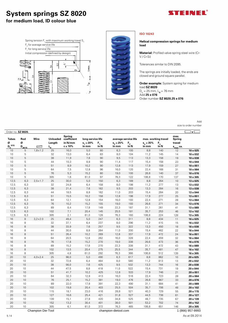
As at 09.2014 5.14
Order no. SZ 8020.
System springs SZ 8020for medium load, ID colour blue
Add
size to order number
ISO 10243
Helical compression springs for medium load
Material: Profiled valve-spring steel wire (Cr-V / Cr-Si)
Tolerances similar to DIN 2095.
The springs are initially loaded, the ends are closed and ground square parallel.
Order example: System spring for medium load SZ 8020Dh = 25 mm, L0 = 76 mmAdd 25 x 076Order number SZ 8020.25 x 076
Spring tension Fn with maximum working travel Sn
F2 for average service life
F1 for long service life
Initial compression (defined by design)
Tubes Rod Wire UnloadedSpring coefficient long service life average service life max. working travel
max. Spring
Ø Ø Length in N/mm s1 = 20% F1 s2 = 25% F2 sn = 35% Fn travelDh
H15 Ddh15 L0c ± 10% in mm in N in mm in N in mm in N smax ca.
10 5 1,8 x 1.2 25 16,0 5,0 80 6,3 100 8,8 140 12 10 x 02510 5 32 13,0 6,4 83 8,0 104 11,2 145 14 10 x 03210 5 38 11,9 7,6 90 9,5 113 13,3 158 19 10 x 03810 5 44 10,3 8,8 90 11,4 117 15,4 158 23 10 x 04410 5 51 8,9 10,2 90 12,8 113 17,9 159 27 10 x 05110 5 64 7,5 12,8 96 16,0 120 22,4 168 31 10 x 06410 5 76 5,3 15,2 80 19,0 100 26,6 140 37 10 x 07610 5 305 1,6 61,0 97 76,3 122 106,8 170 137 10 x 30512,5 6,3 2,5 x 1.7 25 30,0 5,0 150 6,3 189 8,8 264 10 13 x 02512,5 6,3 32 24,8 6,4 158 8,0 198 11,2 277 13 13 x 03212,5 6,3 38 21,4 7,6 162 9,5 203 13,3 284 16 13 x 03812,5 6,3 44 18,5 8,8 162 11,0 203 15,4 284 20 13 x 04412,5 6,3 51 15,5 10,2 158 12,8 198 17,9 277 25 13 x 05112,5 6,3 64 12,1 12,8 154 16,0 193 22,4 271 28 13 x 06412,5 6,3 76 10,2 15,2 155 19,0 193 26,6 271 34 13 x 07612,5 6,3 89 8,4 17,8 149 22,3 187 31,1 261 41 13 x 08912,5 6,3 102 7,1 20,4 145 25,5 181 35,7 253 46 13 x 10212,5 6,3 305 2,1 61,0 128 76,3 160 106,8 224 128 13 x 30516 8 3,2 x 2.0 25 49,4 5,0 247 6,3 311 8,8 434 11 16 x 02516 8 32 37,1 6,4 237 8,0 296 11,2 415 15 16 x 03216 8 38 33,9 7,6 257 9,5 322 13,3 450 18 16 x 03816 8 44 30,0 8,8 264 11,0 330 15,4 462 22 16 x 04416 8 51 26,4 10,2 269 12,8 337 17,9 472 24 16 x 05116 8 64 20,5 12,8 262 16,0 328 22,4 459 32 16 x 06416 8 76 17,8 15,2 270 19,0 338 26,6 473 36 16 x 07616 8 89 15,2 17,8 270 22,3 338 31,1 472 43 16 x 08916 8 102 13,5 20,4 275 25,5 344 35,7 481 47 16 x 10216 8 305 4,8 61,0 292 76,3 366 106,8 512 139 16 x 30520 10 4,0 x 2.4 25 98,0 5,0 490 6,3 617 8,8 862 10 20 x 02520 10 32 72,6 6,4 464 8,0 580 11,2 813 13 20 x 03220 10 38 56,0 7,6 425 9,5 532 13,3 744 16 20 x 03820 10 44 47,5 8,8 418 11,0 522 15,4 731 19 20 x 04420 10 51 41,7 10,2 425 12,8 533 17,9 746 21 20 x 05120 10 64 32,3 12,8 413 16,0 516 22,4 723 28 20 x 06420 10 76 25,1 15,2 381 19,0 476 26,6 667 33 20 x 07620 10 89 22,0 17,8 391 22,3 490 31,1 684 41 20 x 08920 10 102 19,8 20,4 403 25,5 504 35,7 706 48 20 x 10220 10 115 18,1 23,0 416 28,8 521 40,3 729 55 20 x 11520 10 127 16,6 25,4 421 31,8 527 44,5 738 61 20 x 12720 10 139 15,1 27,8 420 34,8 525 48,7 735 67 20 x 13920 10 152 13,2 30,4 401 38,0 501 53,2 702 74 20 x 15220 10 305 6,1 61,0 372 76,3 465 106,8 651 146 20 x 305
Champion Die-Tool champion-dietool.com 1 (866) 957-9993
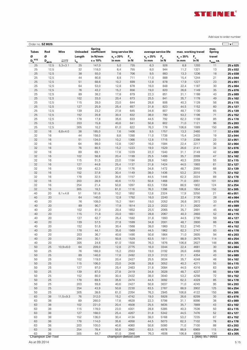
As at 09.2014 5.15
Add size to order number
Tubes Rod Wire UnloadedSpring coefficient long service life average service life max. working travel
max. Spring
Ø Ø Length in N/mm s1 = 20% F1 s2 = 25% F2 sn = 35% Fn travelDh
H15 Ddh15 L0c ± 10% in mm in N in mm in N in mm in N smax ca.
25 12,5 5,3 x 3.1 25 147,0 5,0 735 6,3 926 8,8 1293 11 25 x 02525 12,5 32 118,0 6,4 755 8,0 944 11,2 1321 13 25 x 03225 12,5 38 93,0 7,6 706 9,5 883 13,3 1236 18 25 x 03825 12,5 44 80,8 8,8 711 11,0 888 15,4 1244 21 25 x 04425 12,5 51 68,6 10,2 699 12,8 878 17,9 1227 23 25 x 05125 12,5 64 53,0 12,8 678 16,0 848 22,4 1187 30 25 x 06425 12,5 76 43,2 15,2 656 19,0 820 26,6 1149 35 25 x 07625 12,5 89 38,2 17,8 679 22,3 851 31,1 1188 43 25 x 08925 12,5 102 33,0 20,4 673 25,5 841 35,7 1178 49 25 x 10225 12,5 115 28,0 23,0 644 28,8 806 40,3 1128 56 25 x 11525 12,5 127 25,9 25,4 657 31,8 823 44,5 1152 60 25 x 12725 12,5 139 23,2 27,8 645 34,8 807 48,7 1130 65 25 x 13925 12,5 152 20,8 30,4 632 38,0 790 53,2 1106 71 25 x 15225 12,5 178 17,8 35,6 633 44,5 792 62,3 1108 85 25 x 17825 12,5 203 15,8 40,6 641 50,8 802 71,0 1121 96 25 x 20325 12,5 305 10,2 61,0 622 76,3 778 106,8 1089 150 25 x 30532 16 6,8 x 4.0 38 185,0 7,6 1406 9,5 1757 13,3 2460 17 32 x 03832 16 44 158,0 8,8 1390 11,0 1738 15,4 2433 19 32 x 04432 16 51 134,0 10,2 1366 12,8 1715 17,9 2398 23 32 x 05132 16 64 99,0 12,8 1267 16,0 1584 22,4 2217 30 32 x 06432 16 76 80,5 15,2 1223 19,0 1529 26,6 2141 34 32 x 07632 16 89 69,1 17,8 1229 22,3 1540 31,1 2149 42 32 x 08932 16 102 58,8 20,4 1199 25,5 1499 35,7 2099 47 32 x 10232 16 115 51,5 23,0 1184 28,8 1483 40,3 2059 55 32 x 11532 16 127 44,8 25,4 1137 31,8 1424 44,5 1993 61 32 x 12732 16 139 42,3 27,8 1176 34,8 1472 48,7 2060 68 32 x 13932 16 152 37,8 30,4 1149 38,0 1436 53,2 2010 75 32 x 15232 16 178 32,5 35,6 1157 44,5 1446 62,3 2024 89 32 x 17832 16 203 28,9 40,6 1173 50,8 1468 71,0 2051 101 32 x 20332 16 254 21,4 50,8 1097 63,5 1358 88,9 1902 124 32 x 25432 16 305 18,3 61,0 1116 76,3 1396 106,8 1954 150 32 x 30540 20 8,1 x 4.8 51 181,6 10,2 1852 12,8 2324 17,9 3250 21 40 x 05140 20 64 140,0 12,8 1792 16,0 2240 22,4 3136 28 40 x 06440 20 76 108,0 15,2 1641 19,0 2052 26,6 2872 33 40 x 07640 20 89 90,7 17,8 1614 22,3 2022 31,1 2820 41 40 x 08940 20 102 81,0 20,4 1652 25,5 2065 35,7 2891 45 40 x 10240 20 115 71,8 23,0 1651 28,8 2067 40,3 2893 52 40 x 11540 20 127 62,7 25,4 1592 31,8 1993 44,5 2790 59 40 x 12740 20 139 57,5 27,8 1599 34,8 2001 48,7 2800 66 40 x 13940 20 152 51,6 30,4 1568 38,0 1960 53,2 2745 71 40 x 15240 20 178 44,1 35,6 1569 44,5 1962 62,3 2747 83 40 x 17840 20 203 36,7 40,6 1490 50,8 1864 71,0 2605 94 40 x 20340 20 254 30,1 50,8 1529 63,5 1911 88,9 2675 114 40 x 25440 20 305 24,6 61,0 1500 76,3 1876 106,8 2627 148 40 x 30550 25 10,9 x 6.0 64 209,0 12,8 2775 16,0 3344 22,4 4681 30 50 x 06450 25 76 168,0 15,2 2553 19,0 3192 26,6 4468 36 50 x 07650 25 89 140,0 17,8 2492 22,3 3122 31,1 4354 43 50 x 08950 25 102 119,0 20,4 2427 25,5 3034 35,7 4248 48 50 x 10250 25 115 106,0 23,0 2438 28,8 3052 40,3 4271 55 50 x 11550 25 127 97,0 25,4 2463 31,8 3084 44,5 4316 63 50 x 12750 25 139 87,0 27,8 2419 34,8 3028 48,7 4237 66 50 x 13950 25 152 80,0 30,4 2432 38,0 3040 53,2 4256 72 50 x 15250 25 178 69,5 35,6 2474 44,5 3092 62,3 4329 85 50 x 17850 25 203 59,8 40,6 2427 50,8 3037 71,0 4245 95 50 x 20350 25 254 43,9 50,8 2230 63,5 2787 88,9 3902 125 50 x 25450 25 305 38,6 61,0 2354 76,3 2945 106,8 4122 150 50 x 30563 38 11,5 x 9.3 76 312,0 15,2 4742 19,0 5928 26,6 8299 30 63 x 07663 38 89 260,0 17,8 4628 22,3 5798 31,1 8086 38 63 x 08963 38 102 221,0 20,4 4508 25,5 5635 35,7 7889 43 63 x 10263 38 115 178,0 23,0 4301 28,8 5385 40,3 7536 50 63 x 11563 38 127 168,0 25,4 4267 31,8 5342 44,5 7476 52 63 x 12763 38 152 136,0 30,4 4134 38,0 5168 53,2 7235 67 63 x 15263 38 178 114,0 35,6 4058 44,5 5073 62,3 7102 78 63 x 17863 38 203 100,0 40,6 4060 50,8 5080 71,0 7100 88 63 x 20363 38 254 78,4 50,8 3982 63,5 4978 88,9 6969 115 63 x 25463 38 305 64,7 61,0 3946 76,3 4936 106,8 6909 134 63 x 305
Order no. SZ 8020.
Champion Die-Tool champion-dietool.com 1 (866) 957-9993
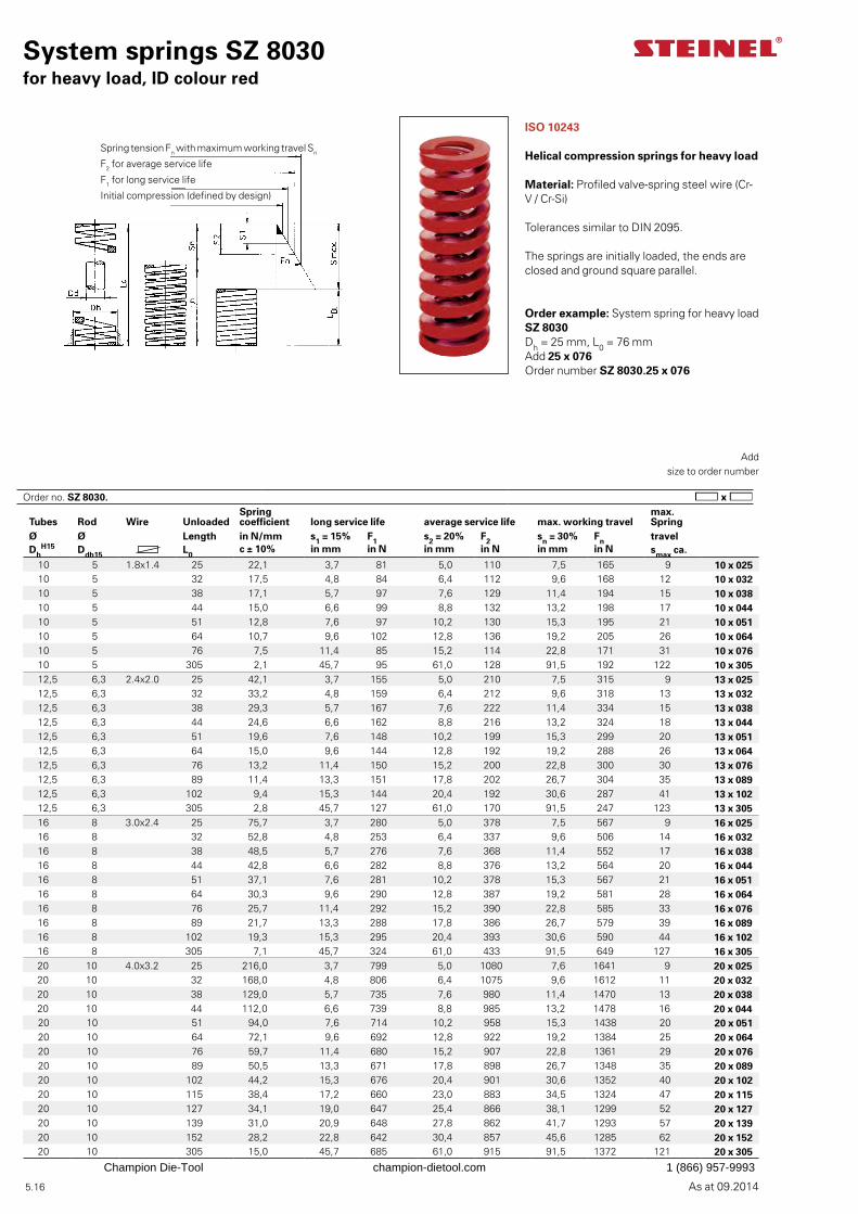
As at 09.2014 5.16
System springs SZ 8030for heavy load, ID colour red
ISO 10243
Helical compression springs for heavy load
Material: Profiled valve-spring steel wire (Cr-V / Cr-Si)
Tolerances similar to DIN 2095.
The springs are initially loaded, the ends are closed and ground square parallel.
Order example: System spring for heavy load SZ 8030Dh = 25 mm, L0 = 76 mmAdd 25 x 076Order number SZ 8030.25 x 076
Spring tension Fn with maximum working travel Sn
F2 for average service life
F1 for long service life
Initial compression (defined by design)
Add
size to order number
Tubes Rod Wire UnloadedSpring coefficient long service life average service life max. working travel
max. Spring
Ø Ø Length in N/mm s1 = 15% F1 s2 = 20% F2 sn = 30% Fn travelDh
H15 Ddh15 L0c ± 10% in mm in N in mm in N in mm in N smax ca.
10 5 1.8x1.4 25 22,1 3,7 81 5,0 110 7,5 165 9 10 x 02510 5 32 17,5 4,8 84 6,4 112 9,6 168 12 10 x 03210 5 38 17,1 5,7 97 7,6 129 11,4 194 15 10 x 03810 5 44 15,0 6,6 99 8,8 132 13,2 198 17 10 x 04410 5 51 12,8 7,6 97 10,2 130 15,3 195 21 10 x 05110 5 64 10,7 9,6 102 12,8 136 19,2 205 26 10 x 06410 5 76 7,5 11,4 85 15,2 114 22,8 171 31 10 x 07610 5 305 2,1 45,7 95 61,0 128 91,5 192 122 10 x 30512,5 6,3 2.4x2.0 25 42,1 3,7 155 5,0 210 7,5 315 9 13 x 02512,5 6,3 32 33,2 4,8 159 6,4 212 9,6 318 13 13 x 03212,5 6,3 38 29,3 5,7 167 7,6 222 11,4 334 15 13 x 03812,5 6,3 44 24,6 6,6 162 8,8 216 13,2 324 18 13 x 04412,5 6,3 51 19,6 7,6 148 10,2 199 15,3 299 20 13 x 05112,5 6,3 64 15,0 9,6 144 12,8 192 19,2 288 26 13 x 06412,5 6,3 76 13,2 11,4 150 15,2 200 22,8 300 30 13 x 07612,5 6,3 89 11,4 13,3 151 17,8 202 26,7 304 35 13 x 08912,5 6,3 102 9,4 15,3 144 20,4 192 30,6 287 41 13 x 10212,5 6,3 305 2,8 45,7 127 61,0 170 91,5 247 123 13 x 30516 8 3.0x2.4 25 75,7 3,7 280 5,0 378 7,5 567 9 16 x 02516 8 32 52,8 4,8 253 6,4 337 9,6 506 14 16 x 03216 8 38 48,5 5,7 276 7,6 368 11,4 552 17 16 x 03816 8 44 42,8 6,6 282 8,8 376 13,2 564 20 16 x 04416 8 51 37,1 7,6 281 10,2 378 15,3 567 21 16 x 05116 8 64 30,3 9,6 290 12,8 387 19,2 581 28 16 x 06416 8 76 25,7 11,4 292 15,2 390 22,8 585 33 16 x 07616 8 89 21,7 13,3 288 17,8 386 26,7 579 39 16 x 08916 8 102 19,3 15,3 295 20,4 393 30,6 590 44 16 x 10216 8 305 7,1 45,7 324 61,0 433 91,5 649 127 16 x 30520 10 4.0x3.2 25 216,0 3,7 799 5,0 1080 7,6 1641 9 20 x 02520 10 32 168,0 4,8 806 6,4 1075 9,6 1612 11 20 x 03220 10 38 129,0 5,7 735 7,6 980 11,4 1470 13 20 x 03820 10 44 112,0 6,6 739 8,8 985 13,2 1478 16 20 x 04420 10 51 94,0 7,6 714 10,2 958 15,3 1438 20 20 x 05120 10 64 72,1 9,6 692 12,8 922 19,2 1384 25 20 x 06420 10 76 59,7 11,4 680 15,2 907 22,8 1361 29 20 x 07620 10 89 50,5 13,3 671 17,8 898 26,7 1348 35 20 x 08920 10 102 44,2 15,3 676 20,4 901 30,6 1352 40 20 x 10220 10 115 38,4 17,2 660 23,0 883 34,5 1324 47 20 x 11520 10 127 34,1 19,0 647 25,4 866 38,1 1299 52 20 x 12720 10 139 31,0 20,9 648 27,8 862 41,7 1293 57 20 x 13920 10 152 28,2 22,8 642 30,4 857 45,6 1285 62 20 x 15220 10 305 15,0 45,7 685 61,0 915 91,5 1372 121 20 x 305
Order no. SZ 8030.
Champion Die-Tool champion-dietool.com 1 (866) 957-9993
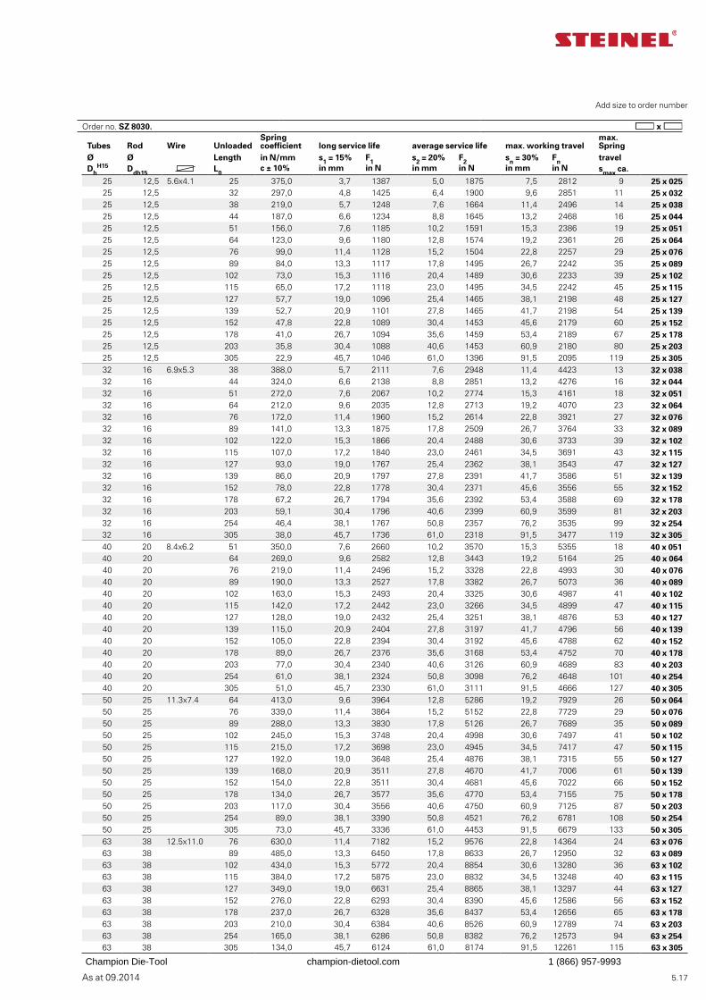
As at 09.2014 5.17
Add size to order number
Tubes Rod Wire UnloadedSpring coefficient long service life average service life max. working travel
max. Spring
Ø Ø Length in N/mm s1 = 15% F1 s2 = 20% F2 sn = 30% Fn travelDh
H15 Ddh15 L0c ± 10% in mm in N in mm in N in mm in N smax ca.
25 12,5 5.6x4.1 25 375,0 3,7 1387 5,0 1875 7,5 2812 9 25 x 02525 12,5 32 297,0 4,8 1425 6,4 1900 9,6 2851 11 25 x 03225 12,5 38 219,0 5,7 1248 7,6 1664 11,4 2496 14 25 x 03825 12,5 44 187,0 6,6 1234 8,8 1645 13,2 2468 16 25 x 04425 12,5 51 156,0 7,6 1185 10,2 1591 15,3 2386 19 25 x 05125 12,5 64 123,0 9,6 1180 12,8 1574 19,2 2361 26 25 x 06425 12,5 76 99,0 11,4 1128 15,2 1504 22,8 2257 29 25 x 07625 12,5 89 84,0 13,3 1117 17,8 1495 26,7 2242 35 25 x 08925 12,5 102 73,0 15,3 1116 20,4 1489 30,6 2233 39 25 x 10225 12,5 115 65,0 17,2 1118 23,0 1495 34,5 2242 45 25 x 11525 12,5 127 57,7 19,0 1096 25,4 1465 38,1 2198 48 25 x 12725 12,5 139 52,7 20,9 1101 27,8 1465 41,7 2198 54 25 x 13925 12,5 152 47,8 22,8 1089 30,4 1453 45,6 2179 60 25 x 15225 12,5 178 41,0 26,7 1094 35,6 1459 53,4 2189 67 25 x 17825 12,5 203 35,8 30,4 1088 40,6 1453 60,9 2180 80 25 x 20325 12,5 305 22,9 45,7 1046 61,0 1396 91,5 2095 119 25 x 30532 16 6.9x5.3 38 388,0 5,7 2111 7,6 2948 11,4 4423 13 32 x 03832 16 44 324,0 6,6 2138 8,8 2851 13,2 4276 16 32 x 04432 16 51 272,0 7,6 2067 10,2 2774 15,3 4161 18 32 x 05132 16 64 212,0 9,6 2035 12,8 2713 19,2 4070 23 32 x 06432 16 76 172,0 11,4 1960 15,2 2614 22,8 3921 27 32 x 07632 16 89 141,0 13,3 1875 17,8 2509 26,7 3764 33 32 x 08932 16 102 122,0 15,3 1866 20,4 2488 30,6 3733 39 32 x 10232 16 115 107,0 17,2 1840 23,0 2461 34,5 3691 43 32 x 11532 16 127 93,0 19,0 1767 25,4 2362 38,1 3543 47 32 x 12732 16 139 86,0 20,9 1797 27,8 2391 41,7 3586 51 32 x 13932 16 152 78,0 22,8 1778 30,4 2371 45,6 3556 55 32 x 15232 16 178 67,2 26,7 1794 35,6 2392 53,4 3588 69 32 x 17832 16 203 59,1 30,4 1796 40,6 2399 60,9 3599 81 32 x 20332 16 254 46,4 38,1 1767 50,8 2357 76,2 3535 99 32 x 25432 16 305 38,0 45,7 1736 61,0 2318 91,5 3477 119 32 x 30540 20 8.4x6.2 51 350,0 7,6 2660 10,2 3570 15,3 5355 18 40 x 05140 20 64 269,0 9,6 2582 12,8 3443 19,2 5164 25 40 x 06440 20 76 219,0 11,4 2496 15,2 3328 22,8 4993 30 40 x 07640 20 89 190,0 13,3 2527 17,8 3382 26,7 5073 36 40 x 08940 20 102 163,0 15,3 2493 20,4 3325 30,6 4987 41 40 x 10240 20 115 142,0 17,2 2442 23,0 3266 34,5 4899 47 40 x 11540 20 127 128,0 19,0 2432 25,4 3251 38,1 4876 53 40 x 12740 20 139 115,0 20,9 2404 27,8 3197 41,7 4796 56 40 x 13940 20 152 105,0 22,8 2394 30,4 3192 45,6 4788 62 40 x 15240 20 178 89,0 26,7 2376 35,6 3168 53,4 4752 70 40 x 17840 20 203 77,0 30,4 2340 40,6 3126 60,9 4689 83 40 x 20340 20 254 61,0 38,1 2324 50,8 3098 76,2 4648 101 40 x 25440 20 305 51,0 45,7 2330 61,0 3111 91,5 4666 127 40 x 30550 25 11.3x7.4 64 413,0 9,6 3964 12,8 5286 19,2 7929 26 50 x 06450 25 76 339,0 11,4 3864 15,2 5152 22,8 7729 29 50 x 07650 25 89 288,0 13,3 3830 17,8 5126 26,7 7689 35 50 x 08950 25 102 245,0 15,3 3748 20,4 4998 30,6 7497 41 50 x 10250 25 115 215,0 17,2 3698 23,0 4945 34,5 7417 47 50 x 11550 25 127 192,0 19,0 3648 25,4 4876 38,1 7315 55 50 x 12750 25 139 168,0 20,9 3511 27,8 4670 41,7 7006 61 50 x 13950 25 152 154,0 22,8 3511 30,4 4681 45,6 7022 66 50 x 15250 25 178 134,0 26,7 3577 35,6 4770 53,4 7155 75 50 x 17850 25 203 117,0 30,4 3556 40,6 4750 60,9 7125 87 50 x 20350 25 254 89,0 38,1 3390 50,8 4521 76,2 6781 108 50 x 25450 25 305 73,0 45,7 3336 61,0 4453 91,5 6679 133 50 x 30563 38 12.5x11.0 76 630,0 11,4 7182 15,2 9576 22,8 14364 24 63 x 07663 38 89 485,0 13,3 6450 17,8 8633 26,7 12950 32 63 x 08963 38 102 434,0 15,3 5772 20,4 8854 30,6 13280 36 63 x 10263 38 115 384,0 17,2 5875 23,0 8832 34,5 13248 40 63 x 11563 38 127 349,0 19,0 6631 25,4 8865 38,1 13297 44 63 x 12763 38 152 276,0 22,8 6293 30,4 8390 45,6 12586 56 63 x 15263 38 178 237,0 26,7 6328 35,6 8437 53,4 12656 65 63 x 17863 38 203 210,0 30,4 6384 40,6 8526 60,9 12789 74 63 x 20363 38 254 165,0 38,1 6286 50,8 8382 76,2 12573 94 63 x 25463 38 305 134,0 45,7 6124 61,0 8174 91,5 12261 115 63 x 305
Order no. SZ 8030.
Champion Die-Tool champion-dietool.com 1 (866) 957-9993
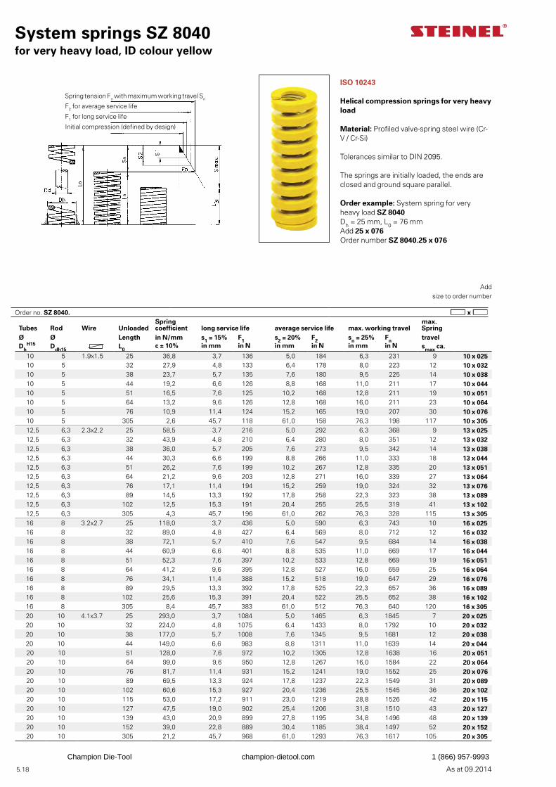
As at 09.2014 5.18
System springs SZ 8040for very heavy load, ID colour yellow
Add
size to order number
ISO 10243
Helical compression springs for very heavy load
Material: Profiled valve-spring steel wire (Cr-V / Cr-Si)
Tolerances similar to DIN 2095.
The springs are initially loaded, the ends are closed and ground square parallel.
Order example: System spring for very heavy load SZ 8040Dh = 25 mm, L0 = 76 mmAdd 25 x 076Order number SZ 8040.25 x 076
Tubes Rod Wire UnloadedSpring coefficient long service life average service life max. working travel
max. Spring
Ø Ø Length in N/mm s1 = 15% F1 s2 = 20% F2 sn = 25% Fn travelDh
H15 Ddh15 L0c ± 10% in mm in N in mm in N in mm in N smax ca.
10 5 1.9x1.5 25 36,8 3,7 136 5,0 184 6,3 231 9 10 x 02510 5 32 27,9 4,8 133 6,4 178 8,0 223 12 10 x 03210 5 38 23,7 5,7 135 7,6 180 9,5 225 14 10 x 03810 5 44 19,2 6,6 126 8,8 168 11,0 211 17 10 x 04410 5 51 16,5 7,6 125 10,2 168 12,8 211 19 10 x 05110 5 64 13,2 9,6 126 12,8 168 16,0 211 23 10 x 06410 5 76 10,9 11,4 124 15,2 165 19,0 207 30 10 x 07610 5 305 2,6 45,7 118 61,0 158 76,3 198 117 10 x 30512,5 6,3 2.3x2.2 25 58,5 3,7 216 5,0 292 6,3 368 9 13 x 02512,5 6,3 32 43,9 4,8 210 6,4 280 8,0 351 12 13 x 03212,5 6,3 38 36,0 5,7 205 7,6 273 9,5 342 14 13 x 03812,5 6,3 44 30,3 6,6 199 8,8 266 11,0 333 18 13 x 04412,5 6,3 51 26,2 7,6 199 10,2 267 12,8 335 20 13 x 05112,5 6,3 64 21,2 9,6 203 12,8 271 16,0 339 27 13 x 06412,5 6,3 76 17,1 11,4 194 15,2 259 19,0 324 32 13 x 07612,5 6,3 89 14,5 13,3 192 17,8 258 22,3 323 38 13 x 08912,5 6,3 102 12,5 15,3 191 20,4 255 25,5 319 41 13 x 10212,5 6,3 305 4,3 45,7 196 61,0 262 76,3 328 115 13 x 30516 8 3.2x2.7 25 118,0 3,7 436 5,0 590 6,3 743 10 16 x 02516 8 32 89,0 4,8 427 6,4 569 8,0 712 12 16 x 03216 8 38 72,1 5,7 410 7,6 547 9,5 684 14 16 x 03816 8 44 60,9 6,6 401 8,8 535 11,0 669 17 16 x 04416 8 51 52,3 7,6 397 10,2 533 12,8 669 19 16 x 05116 8 64 41,2 9,6 395 12,8 527 16,0 659 25 16 x 06416 8 76 34,1 11,4 388 15,2 518 19,0 647 29 16 x 07616 8 89 29,5 13,3 392 17,8 525 22,3 657 36 16 x 08916 8 102 25,6 15,3 391 20,4 522 25,5 652 38 16 x 10216 8 305 8,4 45,7 383 61,0 512 76,3 640 120 16 x 30520 10 4.1x3.7 25 293,0 3,7 1084 5,0 1465 6,3 1845 7 20 x 02520 10 32 224,0 4,8 1075 6,4 1433 8,0 1792 10 20 x 03220 10 38 177,0 5,7 1008 7,6 1345 9,5 1681 12 20 x 03820 10 44 149,0 6,6 983 8,8 1311 11,0 1639 14 20 x 04420 10 51 128,0 7,6 972 10,2 1305 12,8 1638 16 20 x 05120 10 64 99,0 9,6 950 12,8 1267 16,0 1584 22 20 x 06420 10 76 81,7 11,4 931 15,2 1241 19,0 1552 25 20 x 07620 10 89 69,5 13,3 924 17,8 1237 22,3 1549 31 20 x 08920 10 102 60,6 15,3 927 20,4 1236 25,5 1545 36 20 x 10220 10 115 53,0 17,2 911 23,0 1219 28,8 1526 42 20 x 11520 10 127 47,5 19,0 902 25,4 1206 31,8 1510 43 20 x 12720 10 139 43,0 20,9 899 27,8 1195 34,8 1496 48 20 x 13920 10 152 39,0 22,8 889 30,4 1185 38,4 1497 52 20 x 15220 10 305 21,2 45,7 968 61,0 1293 76,3 1617 105 20 x 305
Spring tension Fn with maximum working travel Sn
F2 for average service life
F1 for long service life
Initial compression (defined by design)
Order no. SZ 8040.
Champion Die-Tool champion-dietool.com 1 (866) 957-9993
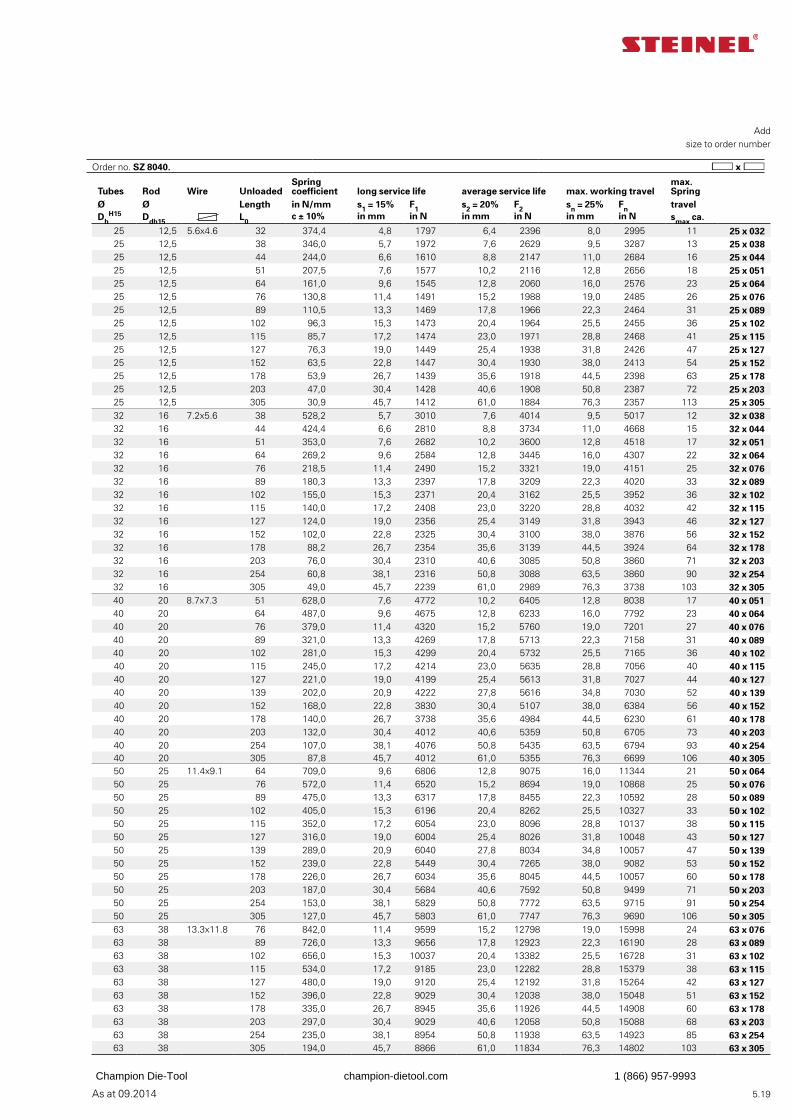
As at 09.2014 5.19
Add
size to order number
Tubes Rod Wire UnloadedSpring coefficient long service life average service life max. working travel
max. Spring
Ø Ø Length in N/mm s1 = 15% F1 s2 = 20% F2 sn = 25% Fn travelDh
H15 Ddh15 L0c ± 10% in mm in N in mm in N in mm in N smax ca.
25 12,5 5.6x4.6 32 374,4 4,8 1797 6,4 2396 8,0 2995 11 25 x 03225 12,5 38 346,0 5,7 1972 7,6 2629 9,5 3287 13 25 x 03825 12,5 44 244,0 6,6 1610 8,8 2147 11,0 2684 16 25 x 04425 12,5 51 207,5 7,6 1577 10,2 2116 12,8 2656 18 25 x 05125 12,5 64 161,0 9,6 1545 12,8 2060 16,0 2576 23 25 x 06425 12,5 76 130,8 11,4 1491 15,2 1988 19,0 2485 26 25 x 07625 12,5 89 110,5 13,3 1469 17,8 1966 22,3 2464 31 25 x 08925 12,5 102 96,3 15,3 1473 20,4 1964 25,5 2455 36 25 x 10225 12,5 115 85,7 17,2 1474 23,0 1971 28,8 2468 41 25 x 11525 12,5 127 76,3 19,0 1449 25,4 1938 31,8 2426 47 25 x 12725 12,5 152 63,5 22,8 1447 30,4 1930 38,0 2413 54 25 x 15225 12,5 178 53,9 26,7 1439 35,6 1918 44,5 2398 63 25 x 17825 12,5 203 47,0 30,4 1428 40,6 1908 50,8 2387 72 25 x 20325 12,5 305 30,9 45,7 1412 61,0 1884 76,3 2357 113 25 x 30532 16 7.2x5.6 38 528,2 5,7 3010 7,6 4014 9,5 5017 12 32 x 03832 16 44 424,4 6,6 2810 8,8 3734 11,0 4668 15 32 x 04432 16 51 353,0 7,6 2682 10,2 3600 12,8 4518 17 32 x 05132 16 64 269,2 9,6 2584 12,8 3445 16,0 4307 22 32 x 06432 16 76 218,5 11,4 2490 15,2 3321 19,0 4151 25 32 x 07632 16 89 180,3 13,3 2397 17,8 3209 22,3 4020 33 32 x 08932 16 102 155,0 15,3 2371 20,4 3162 25,5 3952 36 32 x 10232 16 115 140,0 17,2 2408 23,0 3220 28,8 4032 42 32 x 11532 16 127 124,0 19,0 2356 25,4 3149 31,8 3943 46 32 x 12732 16 152 102,0 22,8 2325 30,4 3100 38,0 3876 56 32 x 15232 16 178 88,2 26,7 2354 35,6 3139 44,5 3924 64 32 x 17832 16 203 76,0 30,4 2310 40,6 3085 50,8 3860 71 32 x 20332 16 254 60,8 38,1 2316 50,8 3088 63,5 3860 90 32 x 25432 16 305 49,0 45,7 2239 61,0 2989 76,3 3738 103 32 x 30540 20 8.7x7.3 51 628,0 7,6 4772 10,2 6405 12,8 8038 17 40 x 05140 20 64 487,0 9,6 4675 12,8 6233 16,0 7792 23 40 x 06440 20 76 379,0 11,4 4320 15,2 5760 19,0 7201 27 40 x 07640 20 89 321,0 13,3 4269 17,8 5713 22,3 7158 31 40 x 08940 20 102 281,0 15,3 4299 20,4 5732 25,5 7165 36 40 x 10240 20 115 245,0 17,2 4214 23,0 5635 28,8 7056 40 40 x 11540 20 127 221,0 19,0 4199 25,4 5613 31,8 7027 44 40 x 12740 20 139 202,0 20,9 4222 27,8 5616 34,8 7030 52 40 x 13940 20 152 168,0 22,8 3830 30,4 5107 38,0 6384 56 40 x 15240 20 178 140,0 26,7 3738 35,6 4984 44,5 6230 61 40 x 17840 20 203 132,0 30,4 4012 40,6 5359 50,8 6705 73 40 x 20340 20 254 107,0 38,1 4076 50,8 5435 63,5 6794 93 40 x 25440 20 305 87,8 45,7 4012 61,0 5355 76,3 6699 106 40 x 30550 25 11.4x9.1 64 709,0 9,6 6806 12,8 9075 16,0 11344 21 50 x 06450 25 76 572,0 11,4 6520 15,2 8694 19,0 10868 25 50 x 07650 25 89 475,0 13,3 6317 17,8 8455 22,3 10592 28 50 x 08950 25 102 405,0 15,3 6196 20,4 8262 25,5 10327 33 50 x 10250 25 115 352,0 17,2 6054 23,0 8096 28,8 10137 38 50 x 11550 25 127 316,0 19,0 6004 25,4 8026 31,8 10048 43 50 x 12750 25 139 289,0 20,9 6040 27,8 8034 34,8 10057 47 50 x 13950 25 152 239,0 22,8 5449 30,4 7265 38,0 9082 53 50 x 15250 25 178 226,0 26,7 6034 35,6 8045 44,5 10057 60 50 x 17850 25 203 187,0 30,4 5684 40,6 7592 50,8 9499 71 50 x 20350 25 254 153,0 38,1 5829 50,8 7772 63,5 9715 91 50 x 25450 25 305 127,0 45,7 5803 61,0 7747 76,3 9690 106 50 x 30563 38 13.3x11.8 76 842,0 11,4 9599 15,2 12798 19,0 15998 24 63 x 07663 38 89 726,0 13,3 9656 17,8 12923 22,3 16190 28 63 x 08963 38 102 656,0 15,3 10037 20,4 13382 25,5 16728 31 63 x 10263 38 115 534,0 17,2 9185 23,0 12282 28,8 15379 38 63 x 11563 38 127 480,0 19,0 9120 25,4 12192 31,8 15264 42 63 x 12763 38 152 396,0 22,8 9029 30,4 12038 38,0 15048 51 63 x 15263 38 178 335,0 26,7 8945 35,6 11926 44,5 14908 60 63 x 17863 38 203 297,0 30,4 9029 40,6 12058 50,8 15088 68 63 x 20363 38 254 235,0 38,1 8954 50,8 11938 63,5 14923 85 63 x 25463 38 305 194,0 45,7 8866 61,0 11834 76,3 14802 103 63 x 305
Order no. SZ 8040.
Champion Die-Tool champion-dietool.com 1 (866) 957-9993
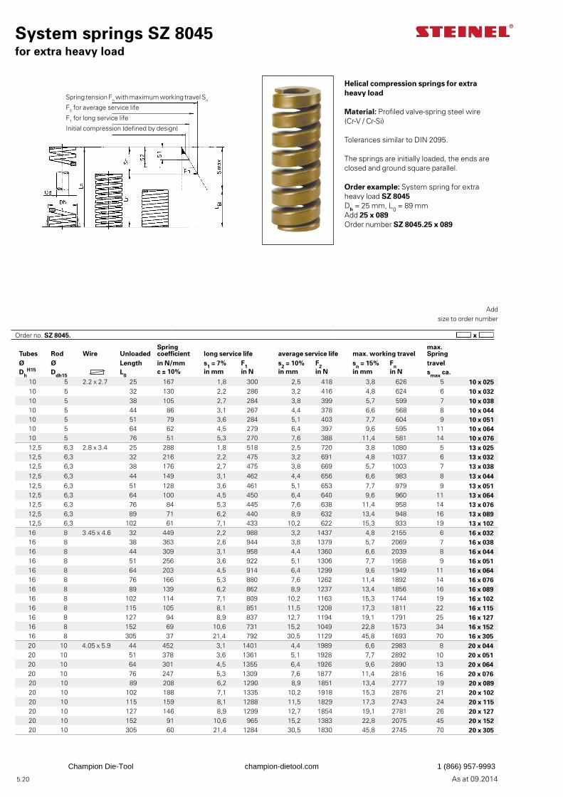
As at 09.2014 5.20
System springs SZ 8045for extra heavy load
Add
size to order number
Helical compression springs for extra heavy load
Material: Profiled valve-spring steel wire (Cr-V / Cr-Si)
Tolerances similar to DIN 2095.
The springs are initially loaded, the ends are closed and ground square parallel.
Order example: System spring for extra heavy load SZ 8045Dh = 25 mm, L0 = 89 mmAdd 25 x 089Order number SZ 8045.25 x 089
Tubes Rod Wire UnloadedSpring coefficient long service life average service life max. working travel
max. Spring
Ø Ø Length in N/mm s1 = 7% F1 s2 = 10% F2 sn = 15% Fn travelDh
H15 Ddh15 L0c ± 10% in mm in N in mm in N in mm in N smax ca.
10 5 2.2 x 2.7 25 167 1,8 300 2,5 418 3,8 626 5 10 x 02510 5 32 130 2,2 286 3,2 416 4,8 624 6 10 x 03210 5 38 105 2,7 284 3,8 399 5,7 599 7 10 x 03810 5 44 86 3,1 267 4,4 378 6,6 568 8 10 x 04410 5 51 79 3,6 284 5,1 403 7,7 604 9 10 x 05110 5 64 62 4,5 279 6,4 397 9,6 595 11 10 x 06410 5 76 51 5,3 270 7,6 388 11,4 581 14 10 x 07612,5 6,3 2.8 x 3.4 25 288 1,8 518 2,5 720 3,8 1080 5 13 x 02512,5 6,3 32 216 2,2 475 3,2 691 4,8 1037 6 13 x 03212,5 6,3 38 176 2,7 475 3,8 669 5,7 1003 7 13 x 03812,5 6,3 44 149 3,1 462 4,4 656 6,6 983 8 13 x 04412,5 6,3 51 128 3,6 461 5,1 653 7,7 979 9 13 x 05112,5 6,3 64 100 4,5 450 6,4 640 9,6 960 11 13 x 06412,5 6,3 76 84 5,3 445 7,6 638 11,4 958 14 13 x 07612,5 6,3 89 71 6,2 440 8,9 632 13,4 948 16 13 x 08912,5 6,3 102 61 7,1 433 10,2 622 15,3 933 19 13 x 10216 8 3.45 x 4.6 32 449 2,2 988 3,2 1437 4,8 2155 6 16 x 03216 8 38 363 2,6 944 3,8 1379 5,7 2069 7 16 x 03816 8 44 309 3,1 958 4,4 1360 6,6 2039 8 16 x 04416 8 51 256 3,6 922 5,1 1306 7,7 1958 9 16 x 05116 8 64 203 4,5 914 6,4 1299 9,6 1949 11 16 x 06416 8 76 166 5,3 880 7,6 1262 11,4 1892 14 16 x 07616 8 89 139 6,2 862 8,9 1237 13,4 1856 16 16 x 08916 8 102 114 7,1 809 10,2 1163 15,3 1744 19 16 x 10216 8 115 105 8,1 851 11,5 1208 17,3 1811 22 16 x 11516 8 127 94 8,9 837 12,7 1194 19,1 1791 25 16 x 12716 8 152 69 10,6 731 15,2 1049 22,8 1573 34 16 x 15216 8 305 37 21,4 792 30,5 1129 45,8 1693 70 16 x 30520 10 4.05 x 5.9 44 452 3,1 1401 4,4 1989 6,6 2983 8 20 x 04420 10 51 378 3,6 1361 5,1 1928 7,7 2892 10 20 x 05120 10 64 301 4,5 1355 6,4 1926 9,6 2890 13 20 x 06420 10 76 247 5,3 1309 7,6 1877 11,4 2816 16 20 x 07620 10 89 208 6,2 1290 8,9 1851 13,4 2777 19 20 x 08920 10 102 188 7,1 1335 10,2 1918 15,3 2876 21 20 x 10220 10 115 159 8,1 1288 11,5 1829 17,3 2743 24 20 x 11520 10 127 146 8,9 1299 12,7 1854 19,1 2781 26 20 x 12720 10 152 91 10,6 965 15,2 1383 22,8 2075 45 20 x 15220 10 305 60 21,4 1284 30,5 1830 45,8 2745 70 20 x 305
Spring tension Fn with maximum working travel Sn
F2 for average service life
F1 for long service life
Initial compression (defined by design)
Order no. SZ 8045.
Champion Die-Tool champion-dietool.com 1 (866) 957-9993
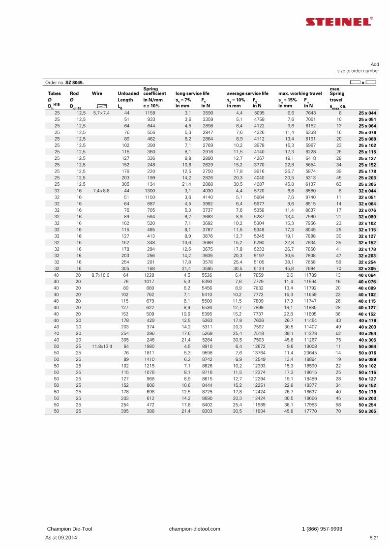
As at 09.2014 5.21
Add
size to order number
Tubes Rod Wire UnloadedSpring coefficient long service life average service life max. working travel
max. Spring
Ø Ø Length in N/mm s1 = 7% F1 s2 = 10% F2 sn = 15% Fn travelDh
H15 Ddh15 L0c ± 10% in mm in N in mm in N in mm in N smax ca.
25 12,5 5,7 x 7.4 44 1158 3,1 3590 4,4 5095 6,6 7643 8 25 x 04425 12,5 51 933 3,6 3359 5,1 4758 7,6 7091 10 25 x 05125 12,5 64 644 4,5 2898 6,4 4122 9,6 6182 13 25 x 06425 12,5 76 556 5,3 2947 7,6 4226 11,4 6338 16 25 x 07625 12,5 89 462 6,2 2864 8,9 4112 13,4 6191 20 25 x 08925 12,5 102 390 7,1 2769 10,2 3978 15,3 5967 23 25 x 10225 12,5 115 360 8,1 2916 11,5 4140 17,3 6228 26 25 x 11525 12,5 127 336 8,9 2990 12,7 4267 19,1 6418 28 25 x 12725 12,5 152 248 10,6 2629 15,2 3770 22,8 5654 34 25 x 15225 12,5 178 220 12,5 2750 17,8 3916 26,7 5874 39 25 x 17825 12,5 203 199 14,2 2826 20,3 4040 30,5 5313 45 25 x 20325 12,5 305 134 21,4 2868 30,5 4087 45,8 6137 63 25 x 30532 16 7,4 x 8.8 44 1300 3,1 4030 4,4 5720 6,6 8580 8 32 x 04432 16 51 1150 3,6 4140 5,1 5864 7,6 8740 11 32 x 05132 16 64 887 4,5 3992 6,4 5677 9,6 8515 14 32 x 06432 16 76 705 5,3 3737 7,6 5358 11,4 8037 17 32 x 07632 16 89 594 6,2 3683 8,9 5287 13,4 7960 21 32 x 08932 16 102 520 7,1 3692 10,2 5304 15,3 7956 23 32 x 10232 16 115 465 8,1 3767 11,5 5348 17,3 8045 25 32 x 11532 16 127 413 8,9 3676 12,7 5245 19,1 7888 30 32 x 12732 16 152 348 10,6 3689 15,2 5290 22,8 7934 35 32 x 15232 16 178 294 12,5 3675 17,8 5233 26,7 7850 41 32 x 17832 16 203 256 14,2 3635 20,3 5197 30,5 7808 47 32 x 20332 16 254 201 17,8 3578 25,4 5105 38,1 7658 58 32 x 25432 16 305 168 21,4 3595 30,5 5124 45,8 7694 70 32 x 30540 20 8.7x10.6 64 1228 4,5 5526 6,4 7859 9,6 11789 13 40 x 06440 20 76 1017 5,3 5390 7,6 7729 11,4 11594 16 40 x 07640 20 89 880 6,2 5456 8,9 7832 13,4 11792 20 40 x 08940 20 102 762 7,1 5410 10,2 7772 15,3 11659 23 40 x 10240 20 115 679 8,1 5500 11,5 7809 17,3 11747 26 40 x 11540 20 127 622 8,9 5536 12,7 7899 19,1 11880 28 40 x 12740 20 152 509 10,6 5395 15,2 7737 22,8 11605 36 40 x 15240 20 178 429 12,5 5363 17,8 7636 26,7 11454 43 40 x 17840 20 203 374 14,2 5311 20,3 7592 30,5 11407 49 40 x 20340 20 254 296 17,6 5269 25,4 7518 38,1 11278 62 40 x 25440 20 305 246 21,4 5264 30,5 7503 45,8 11267 75 40 x 30550 25 11.8x13.4 64 1980 4,5 8910 6,4 12672 9,6 19008 11 50 x 06450 25 76 1811 5,3 9598 7,6 13764 11,4 20645 14 50 x 07650 25 89 1410 6,2 8742 8,9 12549 13,4 18894 19 50 x 08950 25 102 1215 7,1 8626 10,2 12393 15,3 18590 22 50 x 10250 25 115 1076 8,1 8716 11,5 12374 17,3 18615 25 50 x 11550 25 127 968 8,9 8615 12,7 12294 19,1 18489 28 50 x 12750 25 152 806 10,6 8444 15,2 12251 22,8 18377 34 50 x 15250 25 178 698 12,5 8725 17,8 12424 26,7 18637 40 50 x 17850 25 203 612 14,2 8690 20,3 12424 30,5 18666 45 50 x 20350 25 254 472 17,8 8402 25,4 11989 38,1 17983 58 50 x 25450 25 305 388 21,4 8303 30,5 11834 45,8 17770 70 50 x 305
Order no. SZ 8045.
Champion Die-Tool champion-dietool.com 1 (866) 957-9993
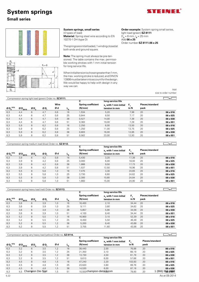
As at 09.2014
Da
Di
d
Dd
Dh
F1
F0 = 0
l Bl l 1
L 0
s 1
5.22
System springsSmall series
Add
size to order number
Order example: System spring small series,light load (green) SZ 8111Da = 6 mm, l0 = 25 mmAdd 06 x 25Order number SZ 8111.06 x 25
C long service lifeWire Spring coefficient s1 with 1 mm initial
tension in mm
F1Pieces/standard
Ø DhH15 Ø Ddh15 Ø Da Ø Di
Ø d L0(N/mm) in N pack
6,3 4,4 6 4,7 0,6 16 1,534 5,20 7,98 20 06 x 0166,3 4,4 6 4,7 0,6 25 0,844 8,50 7,17 20 06 x 0256,3 4,4 6 4,7 0,6 38 0,527 14,00 7,38 20 06 x 0386,3 4,4 6 4,7 0,6 51 0,383 19,00 7,28 20 06 x 0518,3 5,9 8 6,2 0,8 16 2,250 6,00 13,50 20 08 x 0168,3 5,9 8 6,2 0,8 25 1,250 11,00 13,75 20 08 x 0258,3 5,9 8 6,2 0,8 38 0,803 16,00 12,85 20 08 x 0388,3 5,9 8 6,2 0,8 51 0,562 23,00 12,93 20 08 x 051
Compression spring light load (green) Order no. SZ 8111.
C long service lifeSpring coefficient s1 with 1 mm initial
tension in mm
F1Pieces/standard
Ø DhH15 Ø Ddh15 Ø Da Ø Di
Ø d L0(N/mm) in N pack
6,3 3,6 6 3,9 1,0 16 16,400 2,10 34,44 20 06 x 0166,3 3,6 6 3,9 1,0 25 9,111 3,80 34,62 20 06 x 0256,3 3,6 6 3,9 1,0 38 5,857 5,90 34,56 20 06 x 0386,3 3,6 6 3,9 1,0 51 4,100 8,40 34,44 20 06 x 0518,3 5,2 8 5,5 1,2 16 16,900 3,10 52,39 20 08 x 0168,3 5,2 8 5,5 1,2 25 8,450 5,50 46,48 20 08 x 0258,3 5,2 8 5,5 1,2 38 5,200 8,40 43,68 20 08 x 0388,3 5,2 8 5,5 1,2 51 3,755 11,60 43,56 20 08 x 051
Compression spring heavy load (red) Order no. SZ 8113.
C long service lifeSpring coefficient s1 with 1 mm initial
tension in mm
F1Pieces/standard
Ø DhH15 Ø Ddh15 Ø Da Ø Di
Ø d L0(N/mm) in N pack
6,3 3,2 6 3,5 1,2 16 38,440 2,00 76,88 20 06 x 0166,3 3,2 6 3,5 1,2 25 21,350 3,10 66,19 20 06 x 0256,3 3,2 6 3,5 1,2 38 13,730 4,50 61,79 20 06 x 0386,3 3,2 6 3,5 1,2 51 9,610 6,00 57,66 20 06 x 0518,3 4,5 8 4,8 1,5 16 47,240 2,20 103,93 20 08 x 0168,3 4,5 8 4,8 1,5 25 23,620 3,80 89,76 20 08 x 0258,3 4,5 8 4,8 1,5 38 14,530 6,00 87,18 20 08 x 0388,3 4,5 8 4,8 1,5 51 10,500 7,60 79,80 20 08 x 051
Compression spring very heavy load (yellow) Order no. SZ 8114.
System springs, small series (4 types of load)Material: Spring steel wire according to EN 10270-1 DH (type D)
The springs are initial loaded, 1 winding closed at both ends and ground square.
Note: The spring must always be pre-ten-sioned. The table contains the max. permissi-ble working strokes with 1 mm initial tension for long service life.
When initial tension is chosen greater than 1 mm, the max. working stroke is reduced, and DIN EN 13906 must be taken into account for the design.We would be happy to help with design in any way we can.
C long service lifeSpring coefficient s1 with 1 mm initial
tension in mm
F1Pieces/standard
Ø DhH15 Ø Ddh15 Ø Da Ø Di
Ø d L0(N/mm) in N pack
6,3 3,9 6 4,2 0,8 16 5,430 3,20 17,38 20 06 x 0166,3 3,9 6 4,2 0,8 25 3,000 6,00 18,00 20 06 x 0256,3 3,9 6 4,2 0,8 38 1,866 9,50 17,73 20 06 x 0386,3 3,9 6 4,2 0,8 51 1,537 12,50 16,96 20 06 x 0518,3 5,5 8 5,8 1,0 16 7,470 3,30 24,65 20 08 x 0168,3 5,5 8 5,8 1,0 25 3,730 6,60 24,62 20 08 x 0258,3 5,5 8 5,8 1,0 38 2,300 10,80 24,84 20 08 x 0388,3 5,5 8 5,8 1,0 51 1,660 15,00 24,90 20 08 x 051
Compression spring medium load (blue) Order no. SZ 8112.
Champion Die-Tool champion-dietool.com 1 (866) 957-9993

As at 09.2014 5.23
Champion Die-Tool champion-dietool.com 1 (866) 957-9993
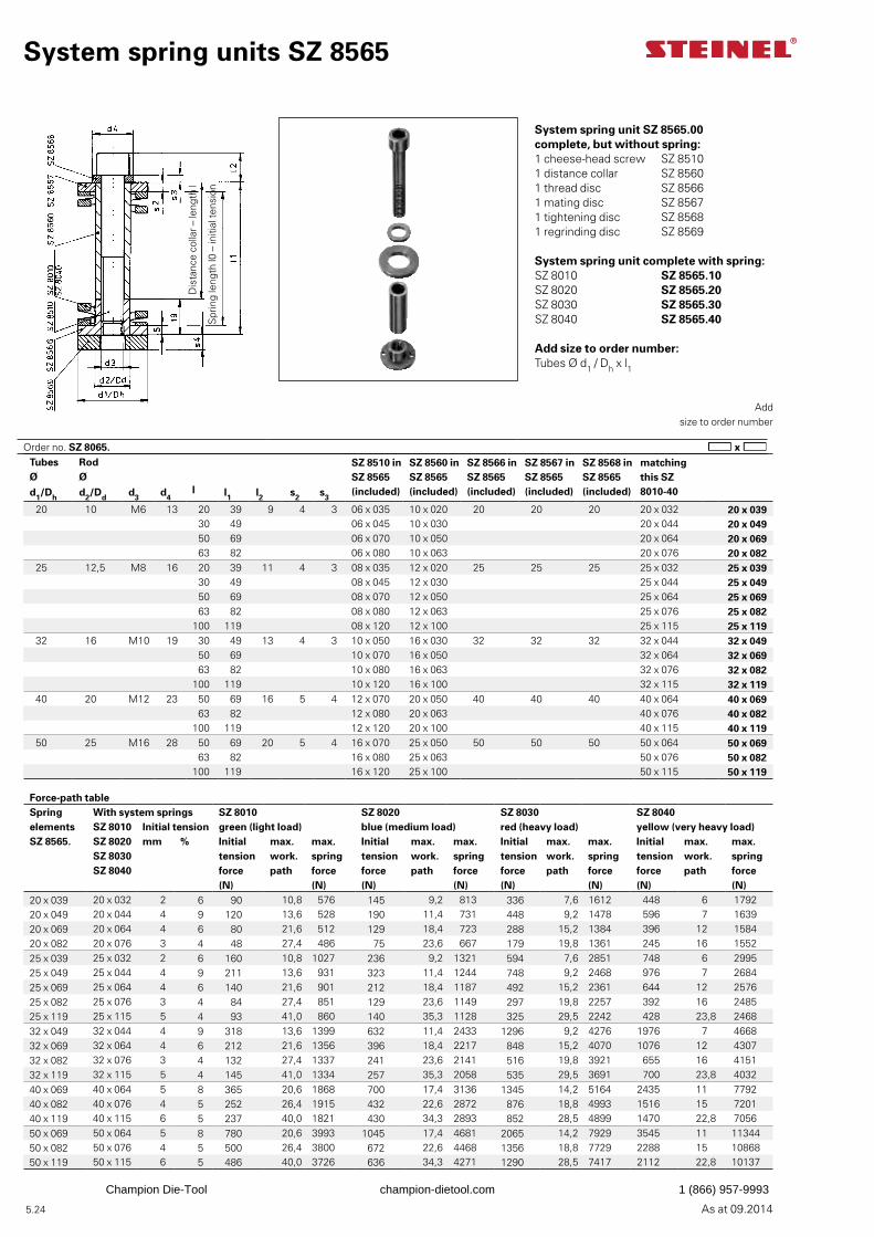
As at 09.2014 5.24
System spring unit SZ 8565.00 complete, but without spring:1 cheese-head screw SZ 85101 distance collar SZ 85601 thread disc SZ 85661 mating disc SZ 85671 tightening disc SZ 85681 regrinding disc SZ 8569
System spring unit complete with spring:SZ 8010 SZ 8565.10SZ 8020 SZ 8565.20SZ 8030 SZ 8565.30SZ 8040 SZ 8565.40
Add size to order number: Tubes Ø d1 / Dh x l1
Order no. SZ 8065.
System spring units SZ 8565
Add
size to order number
Tubes Rod SZ 8510 in SZ 8565(included)
SZ 8560 in SZ 8565 (included)
SZ 8566 in SZ 8565 (included)
SZ 8567 in SZ 8565 (included)
SZ 8568 in SZ 8565 (included)
matching this SZ 8010-40
Ø Ød1/Dh d2/Dd d3 d4
l l1 l2 s2 s3
20 10 M6 13 20 39 9 4 3 06 x 035 10 x 020 20 20 20 20 x 032 20 x 03930 49 06 x 045 10 x 030 20 x 044 20 x 04950 69 06 x 070 10 x 050 20 x 064 20 x 06963 82 06 x 080 10 x 063 20 x 076 20 x 082
25 12,5 M8 16 20 39 11 4 3 08 x 035 12 x 020 25 25 25 25 x 032 25 x 03930 49 08 x 045 12 x 030 25 x 044 25 x 04950 69 08 x 070 12 x 050 25 x 064 25 x 06963 82 08 x 080 12 x 063 25 x 076 25 x 082
100 119 08 x 120 12 x 100 25 x 115 25 x 11932 16 M10 19 30 49 13 4 3 10 x 050 16 x 030 32 32 32 32 x 044 32 x 049
50 69 10 x 070 16 x 050 32 x 064 32 x 06963 82 10 x 080 16 x 063 32 x 076 32 x 082
100 119 10 x 120 16 x 100 32 x 115 32 x 11940 20 M12 23 50 69 16 5 4 12 x 070 20 x 050 40 40 40 40 x 064 40 x 069
63 82 12 x 080 20 x 063 40 x 076 40 x 082100 119 12 x 120 20 x 100 40 x 115 40 x 119
50 25 M16 28 50 69 20 5 4 16 x 070 25 x 050 50 50 50 50 x 064 50 x 06963 82 16 x 080 25 x 063 50 x 076 50 x 082
100 119 16 x 120 25 x 100 50 x 115 50 x 119
Force-path tableSpring With system springs SZ 8010 SZ 8020 SZ 8030 SZ 8040elements SZ 8010 Initial tension green (light load) blue (medium load) red (heavy load) yellow (very heavy load)SZ 8565. SZ 8020 mm % Initial max. max. Initial max. max. Initial max. max. Initial max. max.
SZ 8030 tension work. spring tension work. spring tension work. spring tension work. springSZ 8040 force path force force path force force path force force path force
(N) (N) (N) (N) (N) (N) (N) (N)20 x 039 20 x 032 2 6 90 10,8 576 145 9,2 813 336 7,6 1612 448 6 179220 x 049 20 x 044 4 9 120 13,6 528 190 11,4 731 448 9,2 1478 596 7 163920 x 069 20 x 064 4 6 80 21,6 512 129 18,4 723 288 15,2 1384 396 12 158420 x 082 20 x 076 3 4 48 27,4 486 75 23,6 667 179 19,8 1361 245 16 155225 x 039 25 x 032 2 6 160 10,8 1027 236 9,2 1321 594 7,6 2851 748 6 299525 x 049 25 x 044 4 9 211 13,6 931 323 11,4 1244 748 9,2 2468 976 7 268425 x 069 25 x 064 4 6 140 21,6 901 212 18,4 1187 492 15,2 2361 644 12 257625 x 082 25 x 076 3 4 84 27,4 851 129 23,6 1149 297 19,8 2257 392 16 248525 x 119 25 x 115 5 4 93 41,0 860 140 35,3 1128 325 29,5 2242 428 23,8 246832 x 049 32 x 044 4 9 318 13,6 1399 632 11,4 2433 1296 9,2 4276 1976 7 466832 x 069 32 x 064 4 6 212 21,6 1356 396 18,4 2217 848 15,2 4070 1076 12 430732 x 082 32 x 076 3 4 132 27,4 1337 241 23,6 2141 516 19,8 3921 655 16 415132 x 119 32 x 115 5 4 145 41,0 1334 257 35,3 2058 535 29,5 3691 700 23,8 403240 x 069 40 x 064 5 8 365 20,6 1868 700 17,4 3136 1345 14,2 5164 2435 11 779240 x 082 40 x 076 4 5 252 26,4 1915 432 22,6 2872 876 18,8 4993 1516 15 720140 x 119 40 x 115 6 5 237 40,0 1821 430 34,3 2893 852 28,5 4899 1470 22,8 705650 x 069 50 x 064 5 8 780 20,6 3993 1045 17,4 4681 2065 14,2 7929 3545 11 1134450 x 082 50 x 076 4 5 500 26,4 3800 672 22,6 4468 1356 18,8 7729 2288 15 1086850 x 119 50 x 115 6 5 486 40,0 3726 636 34,3 4271 1290 28,5 7417 2112 22,8 10137
Dis
tanc
e co
llar –
leng
th l
Spr
ing
leng
th l0
– in
itial
tens
ion
Champion Die-Tool champion-dietool.com 1 (866) 957-9993
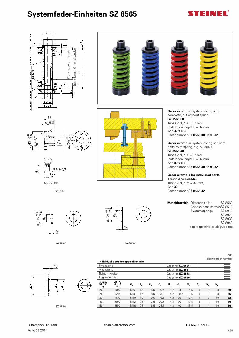
As at 09.2014
Systemfeder-Einheiten SZ 8565
d1/Dh -0
-0,5,8
d2/Dd -0
-0,3,5 d3 d4 d5 d6 d7 d8 d9 s2 s3 s4
20 10,0 M 6 13 6,5 10,5 3,2 14 6,5 4 3 8 2025 12,5 M 8 16 8,5 13,0 4,2 18,5 8,5 4 3 8 2532 16,0 M10 19 10,5 16,5 4,2 25 10,5 4 3 10 3240 20,0 M12 23 12,5 20,5 4,2 30 12,5 5 4 10 4050 25,0 M16 28 16,5 25,5 4,2 40 16,5 5 4 10 50
SZ 8566
SZ 8567 SZ 8569
SZ 8568
s3
s2
d6
d1/D
h -0 -0
,5,8
s4
d9
d1/D
h -0 -0
,5,8
d3
19
5 (14)
d2/D
h -0
,5 -0
,3
X
d8±
0,2
d7 R 0,2-0,3
d1/D
h -0 -0
,5,8
5.25
Dis
tanc
e co
llar –
leng
th l
Spr
ing
leng
th l0
– in
itial
tens
ion
Matching this: Distance collar SZ 8560 Cheese-head screws SZ 8510 System springs SZ 8010 SZ 8020 SZ 8030 SZ 8040
see respective catalogue page
Order example: System spring unit complete, but without spring SZ 8565.00Tubes Ø d1 / Dh = 32 mm,Installation length l1 = 82 mmAdd 32 x 082Order number SZ 8565.00.32 x 082
Order example: System spring unit com-plete, with spring, e.g. SZ 8040 SZ 8565.40Tubes Ø d1 / Dh = 32 mm,Installation length l1 = 82 mmAdd 32 x 082Order number SZ 8565.40.32 x 082
Order example for individual parts:Thread disc SZ 8566Tubes Ø d1 / Dh = 32 mm,Add 32Order number SZ 8566.32
Add
size to order number
Detail X
Scale 2:1
Material: C45
Individual parts for special lengths Thread disc Order no. SZ 8566. Mating disc Order no. SZ 8567. Tightening disc Order no. SZ 8568. Regrinding disc Order no. SZ 8569.
Champion Die-Tool champion-dietool.com 1 (866) 957-9993
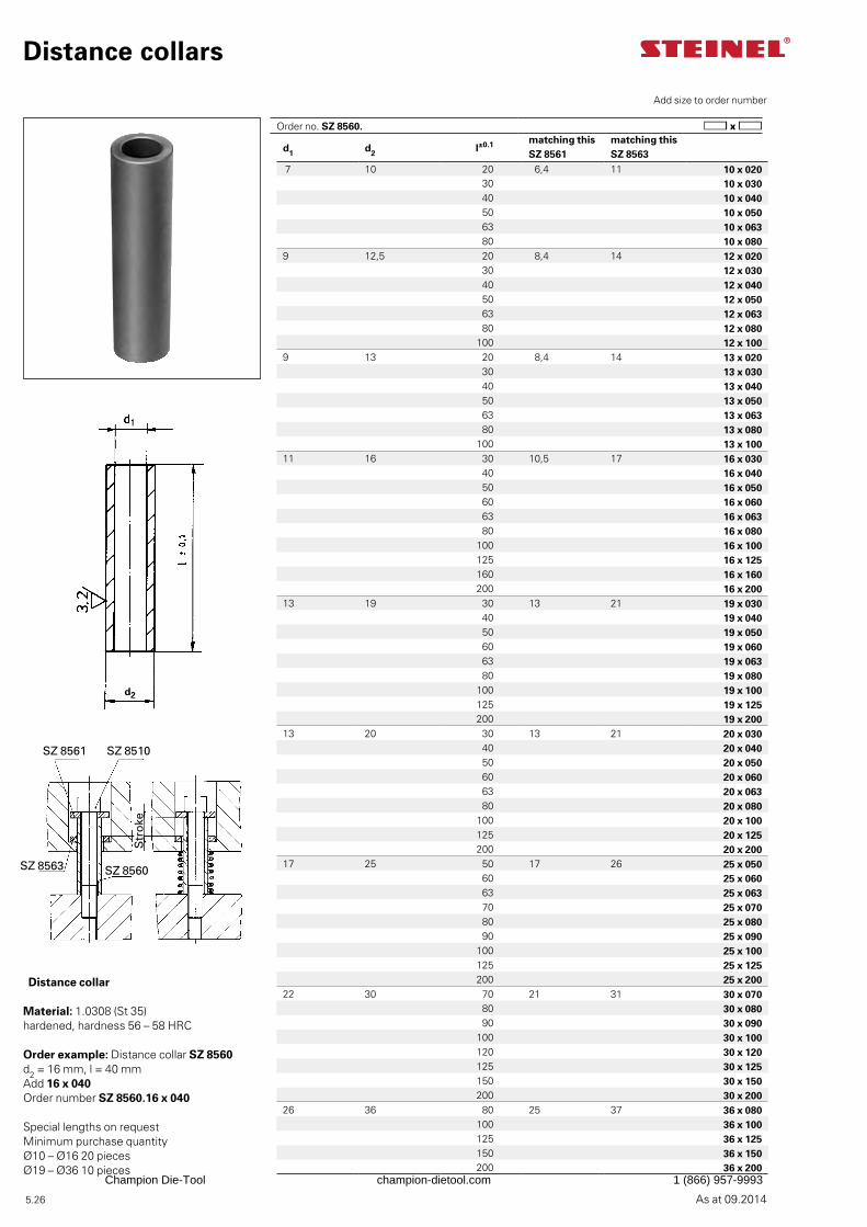
As at 09.2014
d2
SZ 8561 SZ 8510
SZ 8563 SZ 8560
5.26
Distance collar
Material: 1.0308 (St 35) hardened, hardness 56 – 58 HRC
Special lengths on requestMinimum purchase quantity Ø10 – Ø16 20 piecesØ19 – Ø36 10 pieces
Distance collars
Add size to order number
Order example: Distance collar SZ 8560d2 = 16 mm, l = 40 mmAdd 16 x 040Order number SZ 8560.16 x 040
d1 d2 l±0.1 matching this SZ 8561
matching this SZ 8563
7 10 20 6,4 11 10 x 02030 10 x 03040 10 x 04050 10 x 05063 10 x 06380 10 x 080
9 12,5 20 8,4 14 12 x 02030 12 x 03040 12 x 04050 12 x 05063 12 x 06380 12 x 080
100 12 x 1009 13 20 8,4 14 13 x 020
30 13 x 03040 13 x 04050 13 x 05063 13 x 06380 13 x 080
100 13 x 10011 16 30 10,5 17 16 x 030
40 16 x 04050 16 x 05060 16 x 06063 16 x 06380 16 x 080
100 16 x 100125 16 x 125160 16 x 160200 16 x 200
13 19 30 13 21 19 x 03040 19 x 04050 19 x 05060 19 x 06063 19 x 06380 19 x 080
100 19 x 100125 19 x 125200 19 x 200
13 20 30 13 21 20 x 03040 20 x 04050 20 x 05060 20 x 06063 20 x 06380 20 x 080
100 20 x 100125 20 x 125200 20 x 200
17 25 50 17 26 25 x 05060 25 x 06063 25 x 06370 25 x 07080 25 x 08090 25 x 090
100 25 x 100125 25 x 125200 25 x 200
22 30 70 21 31 30 x 07080 30 x 08090 30 x 090
100 30 x 100120 30 x 120125 30 x 125150 30 x 150200 30 x 200
26 36 80 25 37 36 x 080100 36 x 100125 36 x 125150 36 x 150200 36 x 200
Order no. SZ 8560.S
tro
ke
Champion Die-Tool champion-dietool.com 1 (866) 957-9993
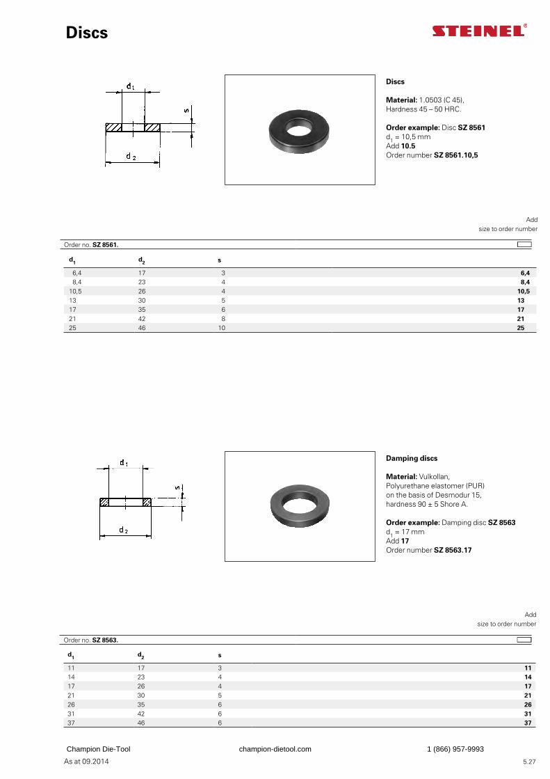
As at 09.2014
d1 d2 s
6,4 17 3 6,4 8,4 23 4 8,4
10,5 26 4 10,513 30 5 1317 35 6 1721 42 8 2125 46 10 25
d1 d2 s
11 17 3 1114 23 4 1417 26 4 1721 30 5 2126 35 6 2631 42 6 3137 46 6 37
5.27
Discs
Discs
Material: 1.0503 (C 45), Hardness 45 – 50 HRC.
Add
size to order number
Order example: Disc SZ 8561d1 = 10,5 mmAdd 10.5Order number SZ 8561.10,5
Damping discs
Material: Vulkollan,Polyurethane elastomer (PUR)on the basis of Desmodur 15,hardness 90 ± 5 Shore A.
Add
size to order number
Order example: Damping disc SZ 8563d1 = 17 mmAdd 17Order number SZ 8563.17
Order no. SZ 8561.
Order no. SZ 8563.
Champion Die-Tool champion-dietool.com 1 (866) 957-9993
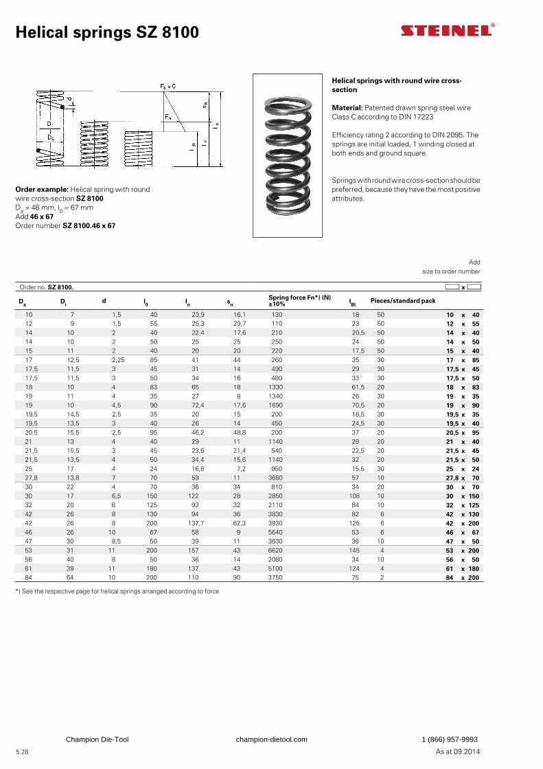
As at 09.2014 5.28
Da Did l0 ln sn
Spring force Fn*) (N) ±10% lBl.
Pieces/standard pack
10 7 1,5 40 23,9 16,1 130 18 50 10 x 4012 9 1,5 55 25,3 29,7 110 23 50 12 x 5514 10 2 40 22,4 17,6 210 20,5 50 14 x 4014 10 2 50 25 25 250 24 50 14 x 5015 11 2 40 20 20 220 17,5 50 15 x 4017 12,5 2,25 85 41 44 260 35 30 17 x 8517,5 11,5 3 45 31 14 490 29 30 17,5 x 4517,5 11,5 3 50 34 16 480 33 30 17,5 x 5018 10 4 83 65 18 1330 61,5 20 18 x 8319 11 4 35 27 8 1340 26 30 19 x 3519 10 4,5 90 72,4 17,6 1690 70,5 20 19 x 9019,5 14,5 2,5 35 20 15 200 18,5 30 19,5 x 3519,5 13,5 3 40 26 14 450 24,5 30 19,5 x 4020,5 15,5 2,5 95 46,2 48,8 200 37 20 20,5 x 9521 13 4 40 29 11 1140 28 20 21 x 4021,5 15,5 3 45 23,6 21,4 540 22,5 20 21,5 x 4521,5 13,5 4 50 34,4 15,6 1140 32 20 21,5 x 5025 17 4 24 16,8 7,2 950 15,5 30 25 x 2427,8 13,8 7 70 59 11 3680 57 10 27,8 x 7030 22 4 70 36 34 810 34 20 30 x 7030 17 6,5 150 122 28 2850 108 10 30 x 15032 20 6 125 93 32 2110 84 10 32 x 12542 26 8 130 94 36 3830 82 6 42 x 13042 26 8 200 137,7 62,3 3830 125 6 42 x 20046 26 10 67 58 9 5640 53 6 46 x 6747 30 8,5 50 39 11 3630 36 10 47 x 5053 31 11 200 157 43 6620 145 4 53 x 20056 40 8 50 36 14 2080 34 10 56 x 5061 39 11 180 137 43 5100 124 4 61 x 18084 64 10 200 110 90 3750 75 2 84 x 200
Helical springs SZ 8100
Helical springs with round wire cross-section
Material: Patented drawn spring steel wire Class C according to DIN 17223
Efficiency rating 2 according to DIN 2095. The springs are initial loaded, 1 winding closed at both ends and ground square.
Springs with round wire cross-section should be preferred, because they have the most positive attributes.
Order example: Helical spring with round wire cross-section SZ 8100Da = 46 mm, l0 = 67 mmAdd 46 x 67Order number SZ 8100.46 x 67
Add
size to order number
*) See the respective page for helical springs arranged according to force
Order no. SZ 8100.
Champion Die-Tool champion-dietool.com 1 (866) 957-9993
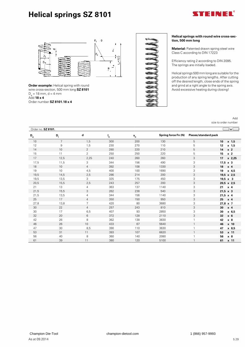
As at 09.2014 5.29
Da Did ln sn
Spring force Fn (N) Pieces/standard pack
10 7 1,5 300 200 130 5 10 x 1,512 9 1,5 230 270 110 5 12 x 1,514 10 2 280 220 210 5 14 x 215 11 2 250 250 220 5 15 x 2
17 12,5 2,25 240 260 260 3 17 x 2,2517,5 11,5 3 344 156 490 3 17,5 x 318 10 4 392 108 1330 3 18 x 419 10 4,5 400 100 1690 3 19 x 4,519,5 14,5 2,5 286 214 200 3 19,5 x 2,519,5 13,5 3 325 175 450 3 19,5 x 320,5 15,5 2,5 243 257 200 3 20,5 x 2,521 13 4 363 137 1140 3 21 x 421,5 15,5 3 262 238 540 3 21,5 x 321,5 13,5 4 344 156 1140 3 21,5 x 425 17 4 350 150 950 3 25 x 427,8 13,8 7 420 80 3680 3 27,8 x 730 22 4 257 243 810 3 30 x 430 17 6,5 407 93 2850 3 30 x 6,532 20 6 372 128 2110 3 32 x 642 26 8 362 138 3830 1 42 x 846 26 10 433 67 5640 1 46 x 1047 30 8,5 390 110 3630 1 47 x 8,553 31 11 393 107 6620 1 53 x 1156 40 8 360 140 2080 1 56 x 861 39 11 380 120 5100 1 61 x 11
Helical springs SZ 8101
Helical springs with round wire cross-sec-tion, 500 mm long
Material: Patented drawn spring steel wire Class C according to DIN 17223
Efficiency rating 2 according to DIN 2095. The springs are initially loaded.
Helical springs 500 mm long are suitable for the production of any spring lengths. After cutting off the desired length, close ends of the spring and grind at a right angle to the spring axis. Avoid excessive heating during closing!
Order example: Helical spring with round wire cross-section, 500 mm long SZ 8101Da = 18 mm, d = 4 mmAdd 18 x 4Order number SZ 8101.18 x 4
Add
size to order number
Order no. SZ 8101.
Champion Die-Tool champion-dietool.com 1 (866) 957-9993
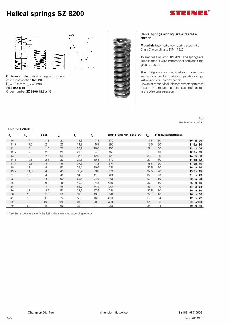
5.30 As at 09.2014
Helical springs SZ 8200
Helical springs with square wire cross-section
Material: Patented drawn spring steel wire Class C according to DIN 17223
Tolerances similar to DIN 2095. The springs are initial loaded, 1 winding closed at both ends and ground square.
The spring force of springs with a square cross-section is higher than that of comparable springs with round wire cross-section. However, the service life is somewhat shorter as a result of the unfavourable distribution of tension in the wire cross-section.
Order example: Helical spring with square wire cross-section SZ 8200Da = 19,5 mm, l0 = 45 mmAdd 19.5 x 45Order number SZ 8200.19.5 x 45
Add
size to order number
*) See the respective page for helical springs arranged according to force
Da Dia x a l0 ln sn
Spring force Fn*) (N) ±10% lBl.Pieces/standard pack
10 7 1,5 20 12,6 7,4 170 11,5 50 10 x 2011,5 7,5 2 20 14,2 5,8 290 13,5 50 11,5x 2012 9 1,5 50 23,2 26,8 130 22 30 12 x 5012,5 7,5 2,5 25 21 4 450 19 40 12,5x 2514 9 2,5 50 37,5 12,5 420 33 30 14 x 5014,5 9,5 2,5 32 21,6 10,4 510 20 30 14,5x 3217,5 9,5 4 45 37,8 7,2 1570 35,5 30 17,5x 4519 11 4 50 39,4 10,6 1720 36,5 20 19 x 5019,5 11,5 4 45 35,2 9,8 1570 32,5 20 19,5x 4521 13 4 45 34 11 1280 32 20 21 x 4523 15 4 83 58,4 24,6 1100 55 10 23 x 8326 14 6 45 40,2 4,8 2950 37 10 26 x 4528 14 7 98 83,5 14,5 7200 82 6 28 x 9830 21 4,5 50 32,5 17,5 1240 30,5 10 30 x 5036 26 5 50 31 19 1340 29 10 36 x 5042 26 8 72 55,5 16,5 4610 53 4 42 x 7260 40 10 120 91 29 5010 84 2 60 x 12070 54 8 60 39 21 1790 36 4 70 x 60
Order no. SZ 8200.
Champion Die-Tool champion-dietool.com 1 (866) 957-9993
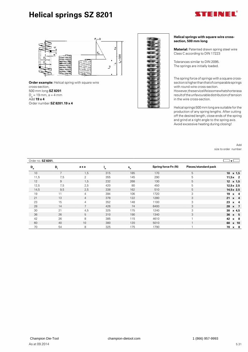
As at 09.2014 5.31
Da Dia x a ln sn
Spring force Fn (N) Pieces/standard pack
10 7 1,5 315 185 170 5 10 x 1,511,5 7,5 2 355 145 290 5 11,5x 212 9 1,5 232 268 130 5 12 x 1,512,5 7,5 2,5 420 80 450 5 12,5x 2,514,5 9,5 2,5 338 162 510 5 14,5x 2,519 11 4 394 106 1720 3 19 x 421 13 4 378 122 1280 3 21 x 423 15 4 352 148 1100 3 23 x 428 14 7 426 74 6400 3 28 x 730 21 4,5 325 175 1240 3 30 x 4,536 26 5 310 190 1340 3 36 x 542 26 8 385 115 4610 1 42 x 860 40 10 380 120 5010 1 60 x 1070 54 8 325 175 1790 1 70 x 8
Helical springs SZ 8201
Helical springs with square wire cross-section, 500 mm long
Material: Patented drawn spring steel wire Class C according to DIN 17223
Tolerances similar to DIN 2095. The springs are initially loaded.
The spring force of springs with a square cross-section is higher than that of comparable springs with round wire cross-section. However, the service life is somewhat shorter as a result of the unfavourable distribution of tension in the wire cross-section.
Helical springs 500 mm long are suitable for the production of any spring lengths. After cutting off the desired length, close ends of the spring and grind at a right angle to the spring axis. Avoid excessive heating during closing!
Order example: Helical spring with square wire cross-section, 500 mm long SZ 8201Da = 19 mm, a = 4 mmAdd 19 x 4Order number SZ 8201.19 x 4
Add size to order number
Order no. SZ 8201.
Champion Die-Tool champion-dietool.com 1 (866) 957-9993
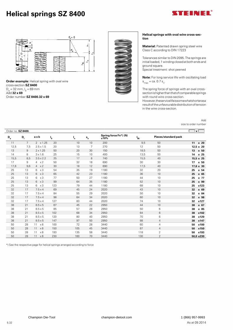
As at 09.2014 5.32
Helical springs SZ 8400
Helical springs with oval wire cross-sec-tion
Material: Patented drawn spring steel wire Class C according to DIN 17223
Tolerances similar to DIN 2095. The springs are initial loaded, 1 winding closed at both ends and ground square. Special treatment: shot peened
Note: For long service life with oscillating load smax = ca. 0.7 sn.
The spring force of springs with an oval cross-section is higher than that of comparable springs with round wire cross-section. However, the service life is somewhat shorter as a result of the unfavourable distribution of tension in the wire cross-section.
Order example: Helical spring with oval wire cross-section SZ 8400Da = 32 mm, l0 = 69 mmAdd 32 x 69Order number SZ 8400.32 x 69
Add
size to order number
*) See the respective page for helical springs arranged according to force
Da Dia x b l0 ln sn
Spring force Fn*) (N) ±10% lBl.
Pieces/standard pack
11 7 2 x 1.25 20 10 10 200 9,5 50 11 x 2012,5 7,5 2.5 x 1.5 20 13 7 270 12 50 12,5 x 2013 9 2 x 1.25 50 20 30 150 18,5 50 13 x 5014 8 3 x 1.6 25 15 10 400 13,5 50 14 x 2515,5 8,5 3.5 x 2.2 25 17 8 740 15,5 40 15,5 x 2517 9 4 x 2 50 32 18 690 30 30 17 x 5017,6 9,6 4 x 2 30 18 12 690 17,5 40 17,6 x 3025 13 6 x 3 54 35 19 1180 32 20 25 x 5425 13 6 x 3 65 42 23 1180 36 10 25 x 6525 13 6 x 3 77 50 27 1180 44 10 25 x 7725 13 6 x 3 99 64 35 1180 52 10 25 x 9925 13 6 x 3 123 79 44 1180 68 10 25 x12332 17 7.5 x 4 69 45 24 2020 43 10 32 x 6932 17 7.5 x 4 84 55 29 2020 50 10 32 x 8432 17 7.5 x 4 98 64 34 2020 60 10 32 x 9832 17 7.5 x 4 127 83 44 2020 74 10 32 x12738 21 8.5 x 5 67 45 22 2950 44 10 38 x 6738 21 8.5 x 5 85 57 28 2950 50 6 38 x 8538 21 8.5 x 5 102 68 34 2950 64 6 38 x10238 21 8.5 x 5 120 80 40 2950 70 6 38 x12038 21 8.5 x 5 147 97 50 2950 88 4 38 x14750 28 11 x 6 100 72 28 3440 60 4 50 x10050 28 11 x 6 150 105 45 3440 87 4 50 x15050 28 11 x 6 193 135 58 3440 118 2 50 x19350 28 11 x 6 230 160 70 3440 130 2 50,0 x230
Order no. SZ 8400.
Champion Die-Tool champion-dietool.com 1 (866) 957-9993
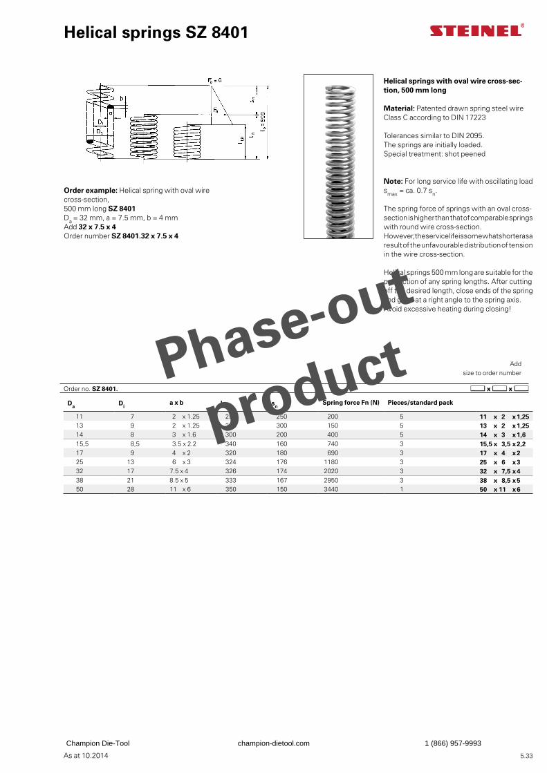
As at 10.2014 5.33
Helical springs SZ 8401
Helical springs with oval wire cross-sec-tion, 500 mm long
Material: Patented drawn spring steel wire Class C according to DIN 17223
Tolerances similar to DIN 2095. The springs are initially loaded. Special treatment: shot peened
Note: For long service life with oscillating load smax = ca. 0.7 sn.
The spring force of springs with an oval cross-section is higher than that of comparable springs with round wire cross-section. However, the service life is somewhat shorter as a result of the unfavourable distribution of tension in the wire cross-section.
Helical springs 500 mm long are suitable for the production of any spring lengths. After cutting off the desired length, close ends of the spring and grind at a right angle to the spring axis. Avoid excessive heating during closing!
Order example: Helical spring with oval wire cross-section, 500 mm long SZ 8401Da = 32 mm, a = 7.5 mm, b = 4 mmAdd 32 x 7.5 x 4Order number SZ 8401.32 x 7.5 x 4
Add
size to order number
Da Dia x b ln sn
Spring force Fn (N) Pieces/standard pack
11 7 2 x 1.25 250 250 200 5 11 x 2 x1,2513 9 2 x 1.25 200 300 150 5 13 x 2 x1,2514 8 3 x 1.6 300 200 400 5 14 x 3 x1,615,5 8,5 3.5 x 2.2 340 160 740 3 15,5 x 3,5 x2,217 9 4 x 2 320 180 690 3 17 x 4 x225 13 6 x 3 324 176 1180 3 25 x 6 x332 17 7.5 x 4 326 174 2020 3 32 x 7,5 x438 21 8.5 x 5 333 167 2950 3 38 x 8,5 x550 28 11 x 6 350 150 3440 1 50 x 11 x6
Order no. SZ 8401.
Phase-out
product
Champion Die-Tool champion-dietool.com 1 (866) 957-9993
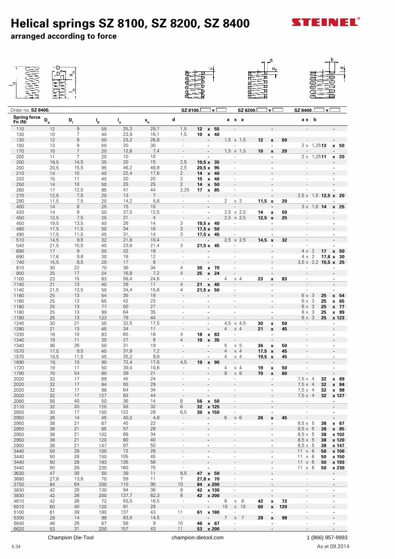
As at 09.2014
l ns n
l o
Di
Da
5.34
Helical springs SZ 8100, SZ 8200, SZ 8400arranged according to force
Spring force Fn (N) Da Di l0 ln sn
d a x a a x b
110 12 9 55 25,3 29,7 1,5 12 x 55 - - - - 130 10 7 40 23,9 16,1 1,5 10 x 40 130 12 9 50 23,2 26,8 - - 1,5 x 1,5 12 x 50 - - 150 13 9 50 20 30 - - - - 2 x 1,2513 x 50 170 10 7 20 12,6 7,4 - - 1,5 x 1,5 10 x 20 - - 200 11 7 20 10 10 - - - - 2 x 1,2511 x 20 200 19,5 14,5 35 20 15 2,5 19,5 x 35 - - - - 200 20,5 15,5 95 46,2 48,8 2,5 20,5 x 95 - - - - 210 14 10 40 22,4 17,6 2 14 x 40 - - - - 220 15 11 40 20 20 2 15 x 40 - - - - 250 14 10 50 25 25 2 14 x 50 - - - - 260 17 12,5 85 41 44 2,25 17 x 85 - - - - 270 12,5 7,5 20 13 7 - - - - 2,5 x 1,5 12,5 x 20 290 11,5 7,5 20 14,2 5,8 - - 2 x 2 11,5 x 20 - - 400 14 8 25 15 10 - - - - 3 x 1,6 14 x 25 420 14 9 50 37,5 12,5 - - 2,5 x 2,5 14 x 50 - - 450 12,5 7,5 25 21 4 - - 2,5 x 2,5 12,5 x 25 - - 450 19,5 13,5 40 26 14 3 19,5 x 40 - - - - 480 17,5 11,5 50 34 16 3 17,5 x 50 - - - - 490 17,5 11,5 45 31, 14 3 17,5 x 45 - - - - 510 14,5 9,5 32 21,6 10,4 - - 2,5 x 2,5 14,5 x 32 - - 540 21,5 15,5 45 23,6 21,4 3 21,5 x 45 - - - - 690 17 9 50 32 18 - - - - 4 x 2 17 x 50 690 17,6 9,6 30 18 12 - - - - 4 x 2 17,6 x 30 740 15,5 8,5 25 17 8 - - - - 3,5 x 2,2 15,5 x 25 810 30 22 70 36 34 4 30 x 70 - - - - 950 25 17 24 16,8 7,2 4 25 x 24 - - - -
1100 23 15 83 58,4 24,6 - - 4 x 4 23 x 83 - -1140 21 13 40 29 11 4 21 x 40 - - - -1140 21,5 13,5 50 34,4 15,6 4 21,5 x 50 - - - -1180 25 13 54 35 19 - - - - 6 x 3 25 x 541180 25 13 65 42 23 - - - - 6 x 3 25 x 651180 25 13 77 50 27 - - - - 6 x 3 25 x 771180 25 13 99 64 35 - - - - 6 x 3 25 x 991180 25 13 123 79 44 - - - - 6 x 3 25 x 1231240 30 21 50 32,5 17,5 - - 4,5 x 4,5 30 x 50 - -1280 21 13 45 34 11 - - 4 x 4 21 x 45 - -1330 18 10 83 65 18 4 18 x 83 - - - -1340 19 11 35 27 8 4 19 x 35 - - - -1340 36 26 50 31 19 - - 5 x 5 36 x 50 - -1570 17,5 9,5 45 37,8 7,2 - - 4 x 4 17,5 x 45 - -1570 19,5 11,5 45 35,2 9,8 - - 4 x 4 19,5 x 45 - -1690 19, 10 90 72,4 17,6 4,5 19 x 90 - - - -1720 19 11 50 39,4 10,6 - - 4 x 4 19 x 50 - -1790 70 54 60 39 21 - - 8 x 8 70 x 60 - -2020 32 17 69 45 24 - - - - 7,5 x 4 32 x 692020 32 17 84 55 29 - - - - 7,5 x 4 32 x 842020 32 17 98 64 34 - - - - 7,5 x 4 32 x 982020 32 17 127 83 44 - - - - 7,5 x 4 32 x 1272080 56 40 50 36 14 8 56 x 50 - - - -2110 32 20 125 93 32 6 32 x 125 - - - -2850 30 17 150 122 28 6,5 30 x 150 - - - -2950 26 14 45 40,2 4,8 - - 6 x 6 26 x 45 - -2950 38 21 67 45 22 - - - - 8,5 x 5 38 x 672950 38 21 85 57 28 - - - - 8,5 x 5 38 x 852950 38 21 102 68 34 - - - - 8,5 x 5 38 x 1022950 38 21 120 80 40 - - - - 8,5 x 5 38 x 1202950 38 21 147 97 50 - - - - 8,5 x 5 38 x 1473440 50 28 100 72 28 - - - - 11 x 6 50 x 1003440 50 28 150 105 45 - - - - 11 x 6 50 x 1503440 50 28 193 135 58 - - - - 11 x 6 50 x 1933440 50 28 230 160 70 - - - - 11 x 6 50 x 2303630 47 30 50 39 11 8,5 47 x 50 - - - -3680 27,8 13,8 70 59 11 7 27,8 x 70 - - - -3750 84 64 200 110 90 10 84 x 200 - - - -3830 42 26 130 94 36 8 42 x 130 - - - -3830 42 26 200 137,7 62,3 8 42 x 200 - - - -4610 42 26 72 55,5 16,5 - - 8 x 8 42 x 72 - -5010 60 40 120 91 29 - - 10 x 10 60 x 120 - -5100 61 39 180 137 43 11 61 x 180 - - - -5300 28 14 98 83,5 14,5 - - 7 x 7 28 x 98 - -5640 46 26 67 58 9 10 46 x 67 - - - -6620 53 31 200 157 43 11 53 x 200 - - - -
Order no. SZ 8400. SZ 8100. SZ 8200. SZ 8400.
Champion Die-Tool champion-dietool.com 1 (866) 957-9993
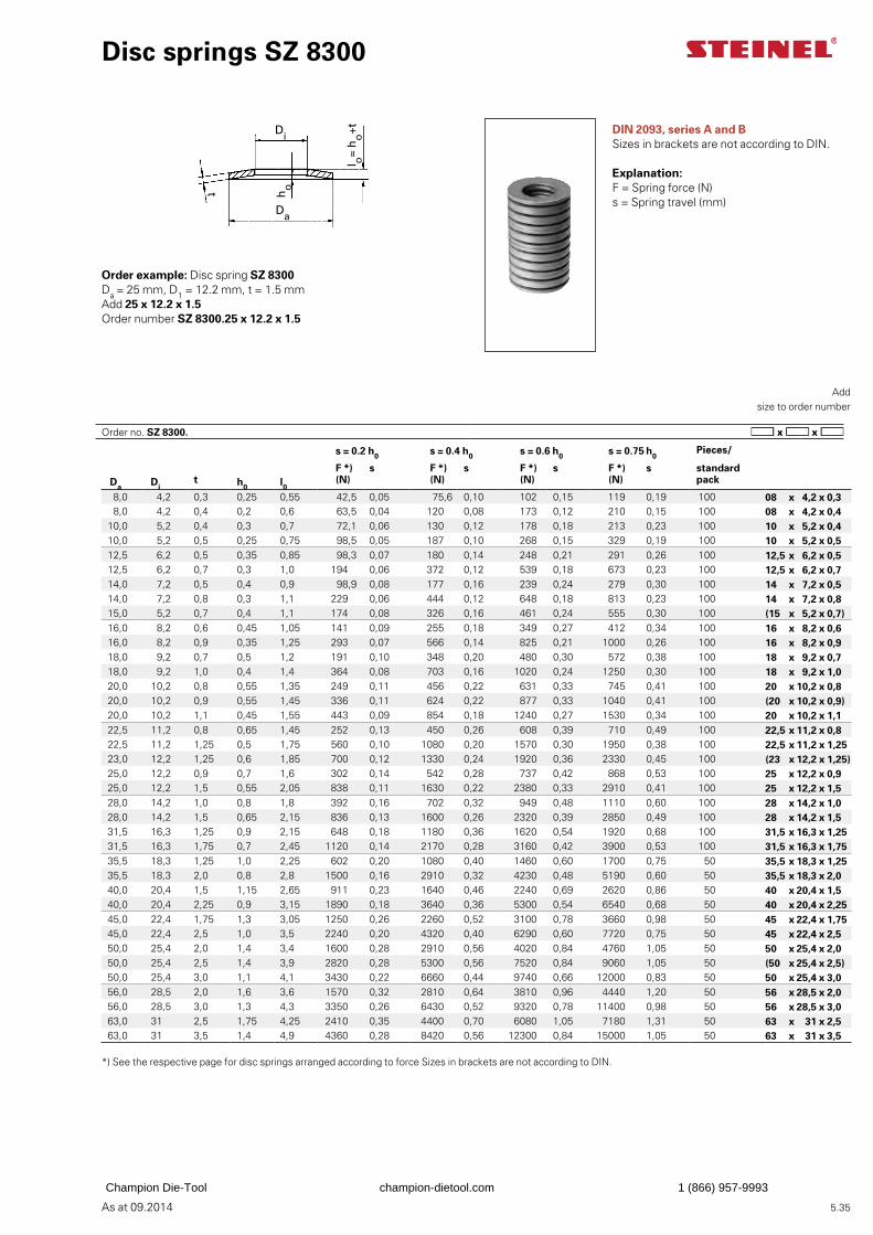
As at 09.2014
l o=
ho+t
Di
Da
ho t
5.35
Disc springs SZ 8300
DIN 2093, series A and BSizes in brackets are not according to DIN.
Explanation:F = Spring force (N)s = Spring travel (mm)
Order example: Disc spring SZ 8300Da = 25 mm, D1 = 12.2 mm, t = 1.5 mmAdd 25 x 12.2 x 1.5Order number SZ 8300.25 x 12.2 x 1.5
Add
size to order number
*) See the respective page for disc springs arranged according to force Sizes in brackets are not according to DIN.
s = 0.2 h0 s = 0.4 h0 s = 0.6 h0 s = 0.75 h0Pieces/
F *) s F *) s F *) s F *) s standard Da Di
t h0 l0(N) (N) (N) (N) pack
8,0 4,2 0,3 0,25 0,55 42,5 0,05 75,6 0,10 102 0,15 119 0,19 100 08 x 4,2 x 0,38,0 4,2 0,4 0,2 0,6 63,5 0,04 120 0,08 173 0,12 210 0,15 100 08 x 4,2 x 0,4
10,0 5,2 0,4 0,3 0,7 72,1 0,06 130 0,12 178 0,18 213 0,23 100 10 x 5,2 x 0,410,0 5,2 0,5 0,25 0,75 98,5 0,05 187 0,10 268 0,15 329 0,19 100 10 x 5,2 x 0,512,5 6,2 0,5 0,35 0,85 98,3 0,07 180 0,14 248 0,21 291 0,26 100 12,5 x 6,2 x 0,512,5 6,2 0,7 0,3 1,0 194 0,06 372 0,12 539 0,18 673 0,23 100 12,5 x 6,2 x 0,714,0 7,2 0,5 0,4 0,9 98,9 0,08 177 0,16 239 0,24 279 0,30 100 14 x 7,2 x 0,514,0 7,2 0,8 0,3 1,1 229 0,06 444 0,12 648 0,18 813 0,23 100 14 x 7,2 x 0,815,0 5,2 0,7 0,4 1,1 174 0,08 326 0,16 461 0,24 555 0,30 100 (15 x 5,2 x 0,7)16,0 8,2 0,6 0,45 1,05 141 0,09 255 0,18 349 0,27 412 0,34 100 16 x 8,2 x 0,616,0 8,2 0,9 0,35 1,25 293 0,07 566 0,14 825 0,21 1000 0,26 100 16 x 8,2 x 0,918,0 9,2 0,7 0,5 1,2 191 0,10 348 0,20 480 0,30 572 0,38 100 18 x 9,2 x 0,718,0 9,2 1,0 0,4 1,4 364 0,08 703 0,16 1020 0,24 1250 0,30 100 18 x 9,2 x 1,020,0 10,2 0,8 0,55 1,35 249 0,11 456 0,22 631 0,33 745 0,41 100 20 x 10,2 x 0,820,0 10,2 0,9 0,55 1,45 336 0,11 624 0,22 877 0,33 1040 0,41 100 (20 x 10,2 x 0,9)20,0 10,2 1,1 0,45 1,55 443 0,09 854 0,18 1240 0,27 1530 0,34 100 20 x 10,2 x 1,122,5 11,2 0,8 0,65 1,45 252 0,13 450 0,26 608 0,39 710 0,49 100 22,5 x 11,2 x 0,822,5 11,2 1,25 0,5 1,75 560 0,10 1080 0,20 1570 0,30 1950 0,38 100 22,5 x 11,2 x 1,2523,0 12,2 1,25 0,6 1,85 700 0,12 1330 0,24 1920 0,36 2330 0,45 100 (23 x 12,2 x 1,25)25,0 12,2 0,9 0,7 1,6 302 0,14 542 0,28 737 0,42 868 0,53 100 25 x 12,2 x 0,925,0 12,2 1,5 0,55 2,05 838 0,11 1630 0,22 2380 0,33 2910 0,41 100 25 x 12,2 x 1,528,0 14,2 1,0 0,8 1,8 392 0,16 702 0,32 949 0,48 1110 0,60 100 28 x 14,2 x 1,028,0 14,2 1,5 0,65 2,15 836 0,13 1600 0,26 2320 0,39 2850 0,49 100 28 x 14,2 x 1,531,5 16,3 1,25 0,9 2,15 648 0,18 1180 0,36 1620 0,54 1920 0,68 100 31,5 x 16,3 x 1,2531,5 16,3 1,75 0,7 2,45 1120 0,14 2170 0,28 3160 0,42 3900 0,53 100 31,5 x 16,3 x 1,7535,5 18,3 1,25 1,0 2,25 602 0,20 1080 0,40 1460 0,60 1700 0,75 50 35,5 x 18,3 x 1,2535,5 18,3 2,0 0,8 2,8 1500 0,16 2910 0,32 4230 0,48 5190 0,60 50 35,5 x 18,3 x 2,040,0 20,4 1,5 1,15 2,65 911 0,23 1640 0,46 2240 0,69 2620 0,86 50 40 x 20,4 x 1,540,0 20,4 2,25 0,9 3,15 1890 0,18 3640 0,36 5300 0,54 6540 0,68 50 40 x 20,4 x 2,2545,0 22,4 1,75 1,3 3,05 1250 0,26 2260 0,52 3100 0,78 3660 0,98 50 45 x 22,4 x 1,7545,0 22,4 2,5 1,0 3,5 2240 0,20 4320 0,40 6290 0,60 7720 0,75 50 45 x 22,4 x 2,550,0 25,4 2,0 1,4 3,4 1600 0,28 2910 0,56 4020 0,84 4760 1,05 50 50 x 25,4 x 2,050,0 25,4 2,5 1,4 3,9 2820 0,28 5300 0,56 7520 0,84 9060 1,05 50 (50 x 25,4 x 2,5)50,0 25,4 3,0 1,1 4,1 3430 0,22 6660 0,44 9740 0,66 12000 0,83 50 50 x 25,4 x 3,056,0 28,5 2,0 1,6 3,6 1570 0,32 2810 0,64 3810 0,96 4440 1,20 50 56 x 28,5 x 2,056,0 28,5 3,0 1,3 4,3 3350 0,26 6430 0,52 9320 0,78 11400 0,98 50 56 x 28,5 x 3,063,0 31 2,5 1,75 4,25 2410 0,35 4400 0,70 6080 1,05 7180 1,31 50 63 x 31 x 2,563,0 31 3,5 1,4 4,9 4360 0,28 8420 0,56 12300 0,84 15000 1,05 50 63 x 31 x 3,5
Order no. SZ 8300.
Champion Die-Tool champion-dietool.com 1 (866) 957-9993
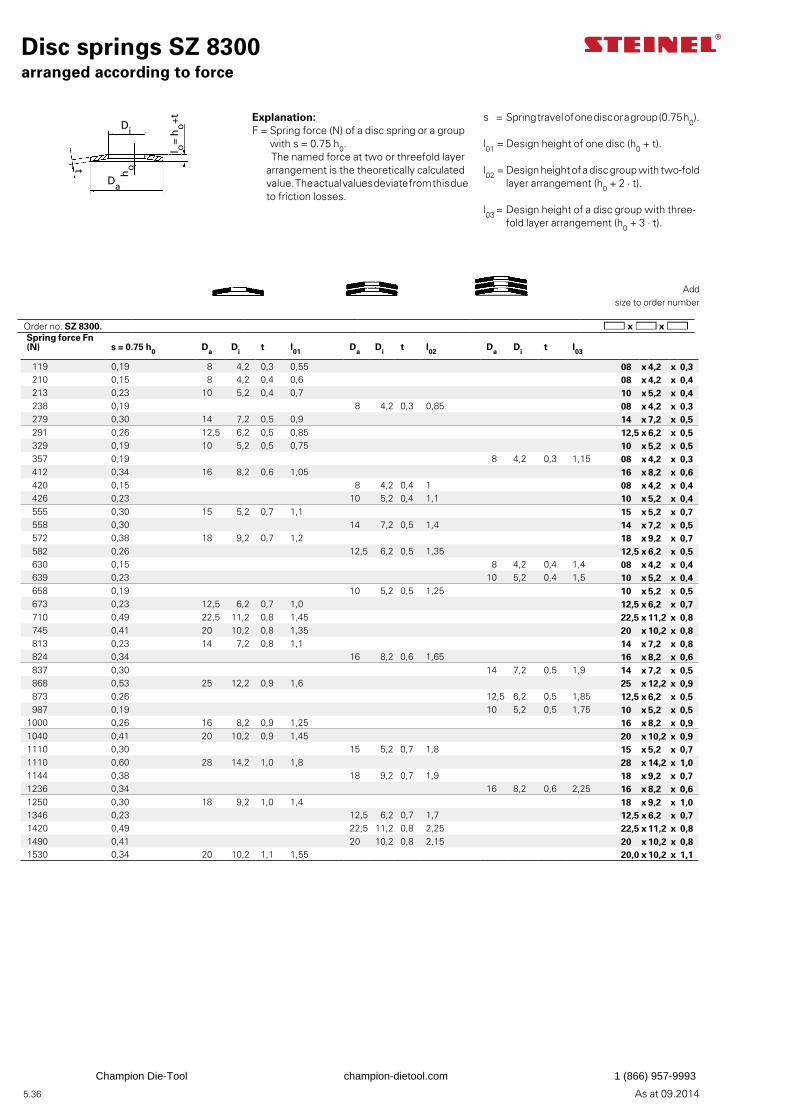
As at 09.2014
t ho
Da
Di
l o=
ho+t
5.36
Explanation:F = Spring force (N) of a disc spring or a group
with s = 0.75 h0. The named force at two or threefold layer
arrangement is the theoretically calculated value. The actual values deviate from this due to friction losses.
s = Spring travel of one disc or a group (0.75 h0).
l01 = Design height of one disc (h0 + t). l02 = Design height of a disc group with two-fold
layer arrangement (h0 + 2 · t).
l03 = Design height of a disc group with three-fold layer arrangement (h0 + 3 · t).
Spring force Fn (N) s = 0.75 h0 Da Di t l01 Da Di t l02 Da Di t l03
119 0,19 8 4,2 0,3 0,55 08 x 4,2 x 0,3210 0,15 8 4,2 0,4 0,6 08 x 4,2 x 0,4213 0,23 10 5,2 0,4 0,7 10 x 5,2 x 0,4238 0,19 8 4,2 0,3 0,85 08 x 4,2 x 0,3279 0,30 14 7,2 0,5 0,9 14 x 7,2 x 0,5291 0,26 12,5 6,2 0,5 0,85 12,5 x 6,2 x 0,5329 0,19 10 5,2 0,5 0,75 10 x 5,2 x 0,5357 0,19 8 4,2 0,3 1,15 08 x 4,2 x 0,3412 0,34 16 8,2 0,6 1,05 16 x 8,2 x 0,6420 0,15 8 4,2 0,4 1 08 x 4,2 x 0,4426 0,23 10 5,2 0,4 1,1 10 x 5,2 x 0,4555 0,30 15 5,2 0,7 1,1 15 x 5,2 x 0,7558 0,30 14 7,2 0,5 1,4 14 x 7,2 x 0,5572 0,38 18 9,2 0,7 1,2 18 x 9,2 x 0,7582 0,26 12,5 6,2 0,5 1,35 12,5 x 6,2 x 0,5630 0,15 8 4,2 0,4 1,4 08 x 4,2 x 0,4639 0,23 10 5,2 0,4 1,5 10 x 5,2 x 0,4658 0,19 10 5,2 0,5 1,25 10 x 5,2 x 0,5673 0,23 12,5 6,2 0,7 1,0 12,5 x 6,2 x 0,7710 0,49 22,5 11,2 0,8 1,45 22,5 x 11,2 x 0,8745 0,41 20 10,2 0,8 1,35 20 x 10,2 x 0,8813 0,23 14 7,2 0,8 1,1 14 x 7,2 x 0,8824 0,34 16 8,2 0,6 1,65 16 x 8,2 x 0,6837 0,30 14 7,2 0,5 1,9 14 x 7,2 x 0,5868 0,53 25 12,2 0,9 1,6 25 x 12,2 x 0,9873 0,26 12,5 6,2 0,5 1,85 12,5 x 6,2 x 0,5987 0,19 10 5,2 0,5 1,75 10 x 5,2 x 0,5
1000 0,26 16 8,2 0,9 1,25 16 x 8,2 x 0,91040 0,41 20 10,2 0,9 1,45 20 x 10,2 x 0,91110 0,30 15 5,2 0,7 1,8 15 x 5,2 x 0,71110 0,60 28 14,2 1,0 1,8 28 x 14,2 x 1,01144 0,38 18 9,2 0,7 1,9 18 x 9,2 x 0,71236 0,34 16 8,2 0,6 2,25 16 x 8,2 x 0,61250 0,30 18 9,2 1,0 1,4 18 x 9,2 x 1,01346 0,23 12,5 6,2 0,7 1,7 12,5 x 6,2 x 0,71420 0,49 22,5 11,2 0,8 2,25 22,5 x 11,2 x 0,81490 0,41 20 10,2 0,8 2,15 20 x 10,2 x 0,81530 0,34 20 10,2 1,1 1,55 20,0 x 10,2 x 1,1
Disc springs SZ 8300arranged according to force
Add
size to order number
Order no. SZ 8300.
Champion Die-Tool champion-dietool.com 1 (866) 957-9993
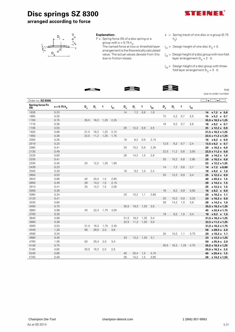
As at 09.2014
Da
Di
t ho
l o=
ho+t
5.37
Explanation:F = Spring force (N) of a disc spring or a
group with s = 0.75 h0. The named force at two or threefold layer
arrangement is the theoretically calculated value. The actual values deviate from this due to friction losses.
s = Spring travel of one disc or a group (0.75 h0).
l01 = Design height of one disc (h0 + t).
l02 = Design height of a disc group with two-fold layer arrangement (h0 + 2 · t).
l03 = Design height of a disc group with three-fold layer arrangement (h0 + 3 · t).
Disc springs SZ 8300arranged according to force
Add
size to order number
Spring force Fn (N) s = 0.75 h0 Da Di
t l01 Da Dit l02 Da Di
t l03
1626 0,23 14 7,2 0,8 1,9 14 x 7,2 x 0,81665 0,30 15 5,2 0,7 2,5 15 x 5,2 x 0,71700 0,75 35,5 18,3 1,25 2,25 35,5 x 18,3 x 1,251716 0,38 18 9,2 0,7 2,6 18 x 9,2 x 0,71736 0,53 25 12,2 0,9 2,5 25 x 12,2 x 0,91920 0,68 31,5 16,3 1,25 2,15 31,5 x 16,3 x 1,251950 0,38 22,5 11,2 1,25 1,75 22,5 x 11,2 x 1,252000 0,26 16 8,2 0,9 2,15 16 x 8,2 x 0,92019 0,23 12,5 6,2 0,7 2,4 12,5 x 6,2 x 0,72080 0,41 20 10,2 0,9 2,35 20 x 10,2 x 0,92130 0,49 22,5 11,2 0,8 3,05 22,5 x 11,2 x 0,82220 0,60 28 14,2 1,0 2,8 28 x 14,2 x 1,02235 0,41 20 10,2 0,8 2,95 20 x 10,2 x 0,82330 0,45 23 12,2 1,25 1,85 23 x 12,2 x 1,252439 0,23 14 7,2 0,8 2,7 14 x 7,2 x 0,802500 0,30 18 9,2 1,0 2,4 18 x 9,2 x 1,02604 0,53 25 12,2 0,9 3,4 25 x 12,2 x 0,92620 0,86 40 20,4 1,5 2,65 40 x 20,4 x 1,52850 0,49 28 14,2 1,5 2,15 28 x 14,2 x 1,52910 0,41 25 12,2 1,5 2,05 25 x 12,2 x 1,53000 0,26 16 8,2 0,9 3,05 16 x 8,2 x 0,93060 0,34 20 10,2 1,1 2,65 20 x 10,2 x 1,13120 0,41 20 10,2 0,9 3,25 20 x 10,2 x 0,93330 0,60 28 14,2 1,0 3,8 28 x 14,2 x 1,03400 0,75 35,5 18,3 1,25 3,5 35,5 x 18,3 x 1,253660 0,98 45 22,4 1,75 3,05 45 x 22,4 x 1,753750 0,30 18 9,2 1,0 3,4 18 x 9,2 x 1,03840 0,68 31,5 16,3 1,25 3,4 31,5 x 16,3 x 1,253900 0,38 22,5 11,2 1,25 3,0 22,5 x 11,2 x 1,253900 0,53 31,5 16,3 1,75 2,45 31,5 x 16,3 x 1,754440 1,20 56 28,5 2,0 3,6 56 x 28,5 x 2,04590 0,34 20 10,2 1,1 3,75 20 x 10,2 x 1,14660 0,45 23 12,2 1,25 3,1 23 x 12,2 x 1,254760 1,05 50 25,4 2,0 3,4 50 x 25,4 x 2,05100 0,75 35,5 18,3 1,25 4,75 35,5 x 18,3 x 1,255190 0,60 35,5 18,3 2,0 2,8 35,5 x 18,3 x 2,05240 0,86 40 20,4 1,5 4,15 40 x 20,4 x 1,55700 0,49 28 14,2 1,5 3,65 28 x 14,2 x 1,50
Order no. SZ 8300.
Champion Die-Tool champion-dietool.com 1 (866) 957-9993
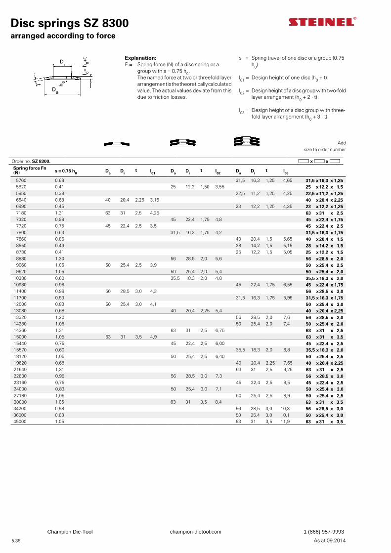
As at 09.2014
t
h0
Da
Di
l 0= h
0+t
5.38
Order no. SZ 8300.
s = Spring travel of one disc or a group (0.75 h0).
l01 = Design height of one disc (h0 + t).
l02 = Design height of a disc group with two-fold layer arrangement (h0 + 2 · t).
l03 = Design height of a disc group with three-fold layer arrangement (h0 + 3 · t).
Explanation:F = Spring force (N) of a disc spring or a
group with s = 0.75 h0. The named force at two or threefold layer
arrangement is the theoretically calculated value. The actual values deviate from this due to friction losses.
Spring force Fn (N) s = 0.75 h0 Da Di
t l01 Da Dit l02 Da Di
t l03
5760 0,68 31,5 16,3 1,25 4,65 31,5 x16,3 x 1,255820 0,41 25 12,2 1,50 3,55 25 x12,2 x 1,55850 0,38 22,5 11,2 1,25 4,25 22,5 x11,2 x 1,256540 0,68 40 20,4 2,25 3,15 40 x20,4 x 2,256990 0,45 23 12,2 1,25 4,35 23 x12,2 x 1,257180 1,31 63 31 2,5 4,25 63 x31 x 2,57320 0,98 45 22,4 1,75 4,8 45 x22,4 x 1,757720 0,75 45 22,4 2,5 3,5 45 x22,4 x 2,57800 0,53 31,5 16,3 1,75 4,2 31,5 x16,3 x 1,757860 0,86 40 20,4 1,5 5,65 40 x20,4 x 1,58550 0,49 28 14,2 1,5 5,15 28 x14,2 x 1,58730 0,41 25 12,2 1,5 5,05 25 x12,2 x 1,58880 1,20 56 28,5 2,0 5,6 56 x28,5 x 2,09060 1,05 50 25,4 2,5 3,9 50 x25,4 x 2,59520 1,05 50 25,4 2,0 5,4 50 x25,4 x 2,0
10380 0,60 35,5 18,3 2,0 4,8 35,5 x18,3 x 2,010980 0,98 45 22,4 1,75 6,55 45 x22,4 x 1,7511400 0,98 56 28,5 3,0 4,3 56 x28,5 x 3,011700 0,53 31,5 16,3 1,75 5,95 31,5 x16,3 x 1,7512000 0,83 50 25,4 3,0 4,1 50 x25,4 x 3,013080 0,68 40 20,4 2,25 5,4 40 x20,4 x 2,2513320 1,20 56 28,5 2,0 7,6 56 x28,5 x 2,014280 1,05 50 25,4 2,0 7,4 50 x25,4 x 2,014360 1,31 63 31 2,5 6,75 63 x31 x 2,515000 1,05 63 31 3,5 4,9 63 x31 x 3,515440 0,75 45 22,4 2,5 6,00 45 x22,4 x 2,515570 0,60 35,5 18,3 2,0 6,8 35,5 x18,3 x 2,018120 1,05 50 25,4 2,5 6,40 50 x25,4 x 2,519620 0,68 40 20,4 2,25 7,65 40 x20,4 x 2,2521540 1,31 63 31 2,5 9,25 63 x31 x 2,522800 0,98 56 28,5 3,0 7,3 56 x28,5 x 3,023160 0,75 45 22,4 2,5 8,5 45 x22,4 x 2,524000 0,83 50 25,4 3,0 7,1 50 x25,4 x 3,027180 1,05 50 25,4 2,5 8,9 50 x25,4 x 2,530000 1,05 63 31 3,5 8,4 63 x31 x 3,534200 0,98 56 28,5 3,0 10,3 56 x28,5 x 3,036000 0,83 50 25,4 3,0 10,1 50 x25,4 x 3,045000 1,05 63 31 3,5 11,9 63 x31 x 3,5
Disc springs SZ 8300arranged according to force
Add
size to order number
Champion Die-Tool champion-dietool.com 1 (866) 957-9993
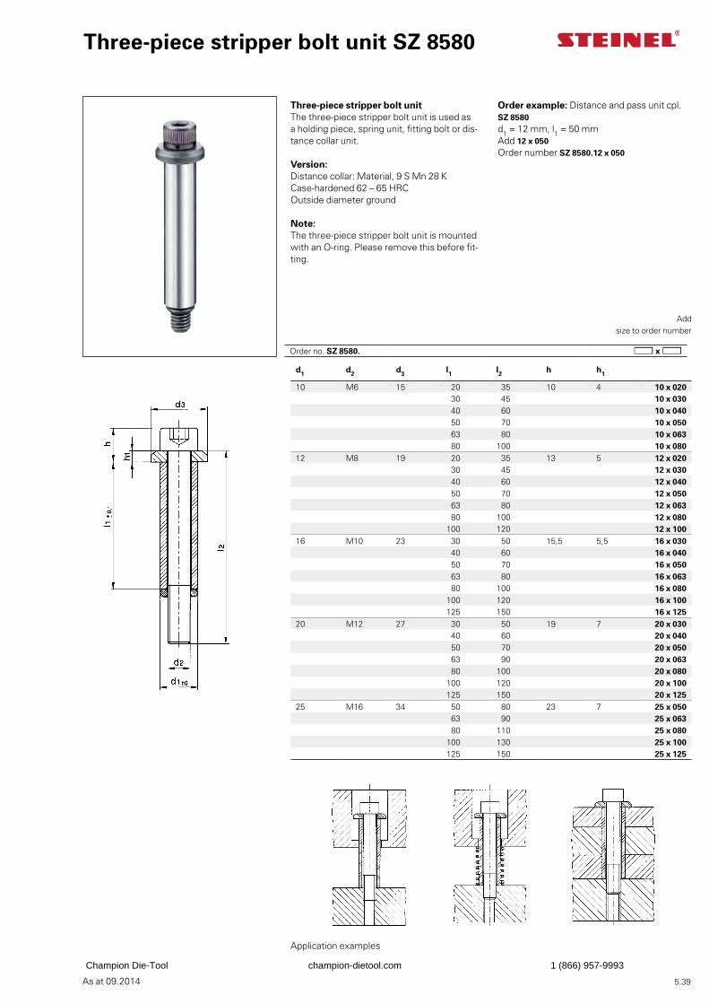
As at 09.2014
d1 d2 d3 l1 l2 h h1
10 M6 15 20 35 10 4 10 x 02030 45 10 x 03040 60 10 x 04050 70 10 x 05063 80 10 x 06380 100 10 x 080
12 M8 19 20 35 13 5 12 x 02030 45 12 x 03040 60 12 x 04050 70 12 x 05063 80 12 x 06380 100 12 x 080
100 120 12 x 10016 M10 23 30 50 15,5 5,5 16 x 030
40 60 16 x 04050 70 16 x 05063 80 16 x 06380 100 16 x 080
100 120 16 x 100125 150 16 x 125
20 M12 27 30 50 19 7 20 x 03040 60 20 x 04050 70 20 x 05063 90 20 x 06380 100 20 x 080
100 120 20 x 100125 150 20 x 125
25 M16 34 50 80 23 7 25 x 05063 90 25 x 06380 110 25 x 080
100 130 25 x 100125 150 25 x 125
5.39
Order example: Distance and pass unit cpl. SZ 8580d1 = 12 mm, l1 = 50 mmAdd 12 x 050Order number SZ 8580.12 x 050
Three-piece stripper bolt unitThe three-piece stripper bolt unit is used as a holding piece, spring unit, fitting bolt or dis-tance collar unit.
Version:Distance collar: Material, 9 S Mn 28 K Case-hardened 62 – 65 HRCOutside diameter ground
Note:The three-piece stripper bolt unit is mounted with an O-ring. Please remove this before fit-ting.
Three-piece stripper bolt unit SZ 8580
Add
size to order number
Application examples
Order no. SZ 8580.
Champion Die-Tool champion-dietool.com 1 (866) 957-9993
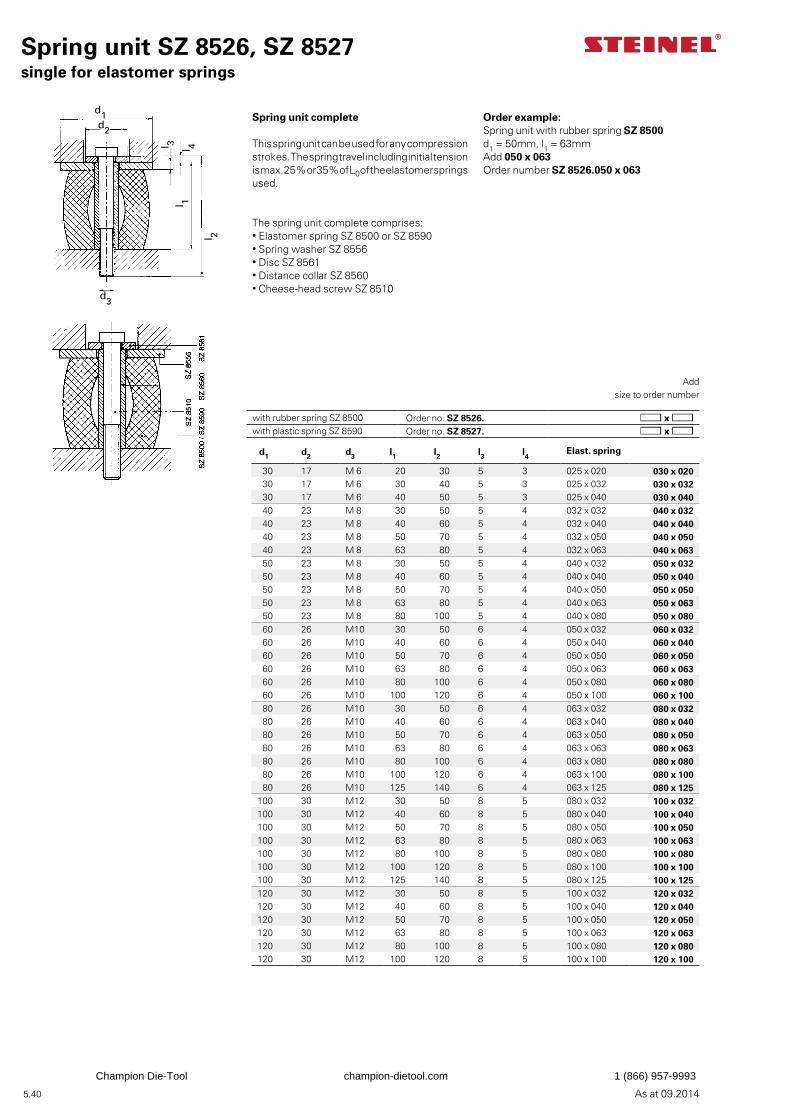
As at 09.2014
d1d2
l 3
l 4 l 1
l 2
d3
5.40
Spring unit SZ 8526, SZ 8527single for elastomer springs
Spring unit complete
This spring unit can be used for any compression strokes. The spring travel including initial tension is max. 25% or 35% of L0 of the elastomer springs used.
The spring unit complete comprises:• Elastomer spring SZ 8500 or SZ 8590• Spring washer SZ 8556• Disc SZ 8561• Distance collar SZ 8560• Cheese-head screw SZ 8510
Add
size to order number
Order example: Spring unit with rubber spring SZ 8500d1 = 50mm, l1 = 63mmAdd 050 x 063Order number SZ 8526.050 x 063
d1 d2 d3 l1 l2 l3 l4 Elast. spring
30 17 M 6 20 30 5 3 025 x 020 030 x 020 30 17 M 6 30 40 5 3 025 x 032 030 x 032 30 17 M 6 40 50 5 3 025 x 040 030 x 040 40 23 M 8 30 50 5 4 032 x 032 040 x 032 40 23 M 8 40 60 5 4 032 x 040 040 x 040 40 23 M 8 50 70 5 4 032 x 050 040 x 050 40 23 M 8 63 80 5 4 032 x 063 040 x 063 50 23 M 8 30 50 5 4 040 x 032 050 x 032 50 23 M 8 40 60 5 4 040 x 040 050 x 040 50 23 M 8 50 70 5 4 040 x 050 050 x 050 50 23 M 8 63 80 5 4 040 x 063 050 x 063 50 23 M 8 80 100 5 4 040 x 080 050 x 080 60 26 M10 30 50 6 4 050 x 032 060 x 032 60 26 M10 40 60 6 4 050 x 040 060 x 040 60 26 M10 50 70 6 4 050 x 050 060 x 050 60 26 M10 63 80 6 4 050 x 063 060 x 063 60 26 M10 80 100 6 4 050 x 080 060 x 080 60 26 M10 100 120 6 4 050 x 100 060 x 100 80 26 M10 30 50 6 4 063 x 032 080 x 032 80 26 M10 40 60 6 4 063 x 040 080 x 040 80 26 M10 50 70 6 4 063 x 050 080 x 050 80 26 M10 63 80 6 4 063 x 063 080 x 063 80 26 M10 80 100 6 4 063 x 080 080 x 080 80 26 M10 100 120 6 4 063 x 100 080 x 100 80 26 M10 125 140 6 4 063 x 125 080 x 125
100 30 M12 30 50 8 5 080 x 032 100 x 032100 30 M12 40 60 8 5 080 x 040 100 x 040100 30 M12 50 70 8 5 080 x 050 100 x 050100 30 M12 63 80 8 5 080 x 063 100 x 063100 30 M12 80 100 8 5 080 x 080 100 x 080100 30 M12 100 120 8 5 080 x 100 100 x 100100 30 M12 125 140 8 5 080 x 125 100 x 125120 30 M12 30 50 8 5 100 x 032 120 x 032120 30 M12 40 60 8 5 100 x 040 120 x 040120 30 M12 50 70 8 5 100 x 050 120 x 050120 30 M12 63 80 8 5 100 x 063 120 x 063120 30 M12 80 100 8 5 100 x 080 120 x 080120 30 M12 100 120 8 5 100 x 100 120 x 100
with rubber spring SZ 8500 Order no. SZ 8526. with plastic spring SZ 8590 Order no. SZ 8527.
Champion Die-Tool champion-dietool.com 1 (866) 957-9993
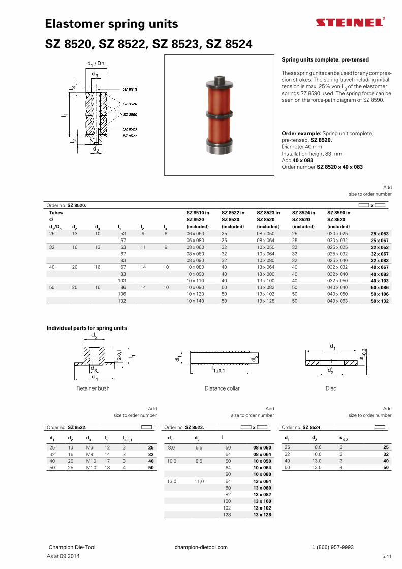
As at 09.2014
d1 d2 s-0,2
25 8,0 3 2532 10,0 3 3240 13,0 3 4050 13,0 4 50
d1 d2l
8,0 6,5 50 08 x 050 64 08 x 06410,0 8,5 50 10 x 050
64 10 x 064 80 10 x 080
13,0 11,0 64 13 x 064 80 13 x 080 82 13 x 082
100 13 x 100102 13 x 102128 13 x 128
d1 d2 d3 l1 l2-0,1
25 13 M6 12 3 2532 16 M8 14 3 3240 20 M10 17 3 4050 25 M10 18 4 50
d1 / Dh l 3
l 1 l 2
d3
d2
d1 l 1
d3
d2
l 2-0,
1
d1
d1
l1±0,1
d2
d1
d2
s-0
,2
5.41
Elastomer spring units
SZ 8520, SZ 8522, SZ 8523, SZ 8524Spring units complete, pre-tensed
These spring units can be used for any compres-sion strokes. The spring travel including initial tension is max. 25% von L0 of the elastomer springs SZ 8590 used. The spring force can be seen on the force-path diagram of SZ 8590.
Add
size to order number
Order example: Spring unit complete, pre-tensed, SZ 8520.Diameter 40 mmInstallation height 83 mmAdd 40 x 083Order number SZ 8520 x 40 x 083
Add
size to order number
Add
size to order number
Add
size to order number
Individual parts for spring units
Retainer bush Distance collar Disc
Tubes SZ 8510 in SZ 8522 in SZ 8523 in SZ 8524 in SZ 8590 inØ SZ 8520 SZ 8520 SZ 8520 SZ 8520 SZ 8520
d1/Dh d2 d3 l1 l2 l3 (included) (included) (included) (included) (included)25 13 10 53 9 6 06 x 060 25 08 x 050 25 020 x 025 25 x 053
67 06 x 080 25 08 x 064 25 020 x 032 25 x 06732 16 13 53 11 8 08 x 060 32 10 x 050 32 025 x 025 32 x 053
67 08 x 080 32 10 x 064 32 025 x 032 32 x 067 83 08 x 090 32 10 x 080 32 025 x 040 32 x 083
40 20 16 67 14 10 10 x 080 40 13 x 064 40 032 x 032 40 x 067 83 10 x 090 40 13 x 080 40 032 x 040 40 x 083
103 10 x 110 40 13 x 100 40 032 x 050 40 x 10350 25 16 86 14 10 10 x 090 50 13 x 082 50 040 x 040 50 x 086
106 10 x 120 50 13 x 102 50 040 x 050 50 x 106132 10 x 140 50 13 x 128 50 040 x 063 50 x 132
Order no. SZ 8524.Order no. SZ 8523.Order no. SZ 8522.
Order no. SZ 8520.
Champion Die-Tool champion-dietool.com 1 (866) 957-9993
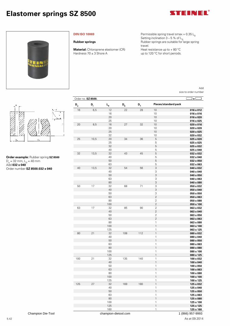
As at 09.2014 5.42
Elastomer springs SZ 8500
Permissible spring travel smax = 0.35 L0Setting inclination 3 – 5 % of L0Rubber springs are suitable for large spring travel.Heat resistance up to + 80 °Cup to 120 °C for short periods.
Add
size to order number
Order example: Rubber spring SZ 8500Da = 32 mm, L0 = 40 mmAdd 032 x 040Order number SZ 8500.032 x 040
Da Di L0 Db D1Pieces/standard pack
16 6,5 12 22 28 10 016 x 01216 10 016 x 01620 10 016 x 02025 10 016 x 025
20 8,5 16 27 32 10 020 x 01620 10 020 x 02025 10 020 x 02532 10 020 x 032
25 10,5 20 34 36 5 025 x 02025 5 025 x 02532 5 025 x 03240 5 025 x 040
32 13,5 32 43 45 5 032 x 03240 5 032 x 04050 5 032 x 05063 5 032 x 063
40 13,5 32 54 56 3 040 x 03240 3 040 x 04050 3 040 x 05063 3 040 x 06380 3 040 x 080
50 17 32 68 71 3 050 x 03240 3 050 x 04050 3 050 x 05063 2 050 x 06380 2 050 x 080
100 2 050 x 10063 17 32 85 90 2 063 x 032
40 2 063 x 04050 2 063 x 05063 2 063 x 06380 1 063 x 080
100 1 063 x 100125 1 063 x 125
80 21 32 108 112 1 080 x 03240 1 080 x 04050 1 080 x 05063 1 080 x 06380 1 080 x 080
100 1 080 x 100125 1 080 x 125
100 21 32 135 140 1 100 x 03240 1 100 x 04050 1 100 x 05063 1 100 x 06380 1 100 x 080
100 1 100 x 100125 1 100 x 125
125 27 32 169 180 1 125 x 03240 1 125 x 04050 1 125 x 05063 1 125 x 06380 1 125 x 080
100 1 125 x 100125 1 125 x 125160 1 125 x 160
DIN ISO 10069
Rubber springs
Material: Chloroprene elastomer (CR) Hardness 70 ± 3 Shore A
Order no. SZ 8500.
Champion Die-Tool champion-dietool.com 1 (866) 957-9993
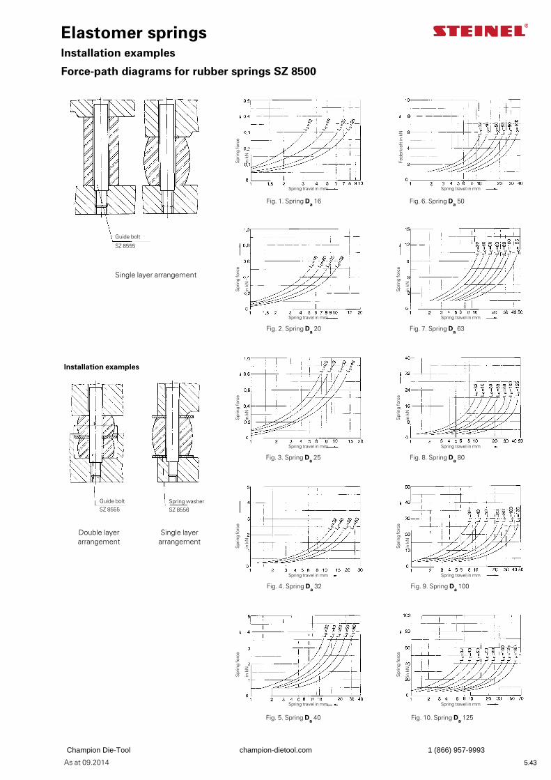
As at 09.2014 5.43
Fede
rkra
ft in
kN
5.43
Guide bolt SZ 8555
Spring washer SZ 8556
Installation examples
Spring travel in mm
Elastomer springsInstallation examples
Force-path diagrams for rubber springs SZ 8500
Double layer arrangement
Single layer arrangement
Guide bolt
SZ 8555
Spring travel in mm
Spring travel in mm
Spring travel in mm
Spring travel in mm
Spring travel in mm
Spring travel in mm
Spring travel in mm
Spring travel in mm
Spring travel in mm
Spr
ing
forc
e
in k
N
Spr
ing
forc
e
in k
N
Spr
ing
forc
e
in k
N
Spr
ing
forc
e
in k
N
Spr
ing
forc
e
in k
N
Spr
ing
forc
e
in k
N
Spr
ing
forc
e
in k
N
Spr
ing
forc
e
in k
N
Spr
ing
forc
e
in k
N
Single layer arrangement
Fig. 1. Spring Da 16 Fig. 6. Spring Da 50
Fig. 2. Spring Da 20 Fig. 7. Spring Da 63
Fig. 3. Spring Da 25 Fig. 8. Spring Da 80
Fig. 4. Spring Da 32 Fig. 9. Spring Da 100
Fig. 5. Spring Da 40 Fig. 10. Spring Da 125
Champion Die-Tool champion-dietool.com 1 (866) 957-9993
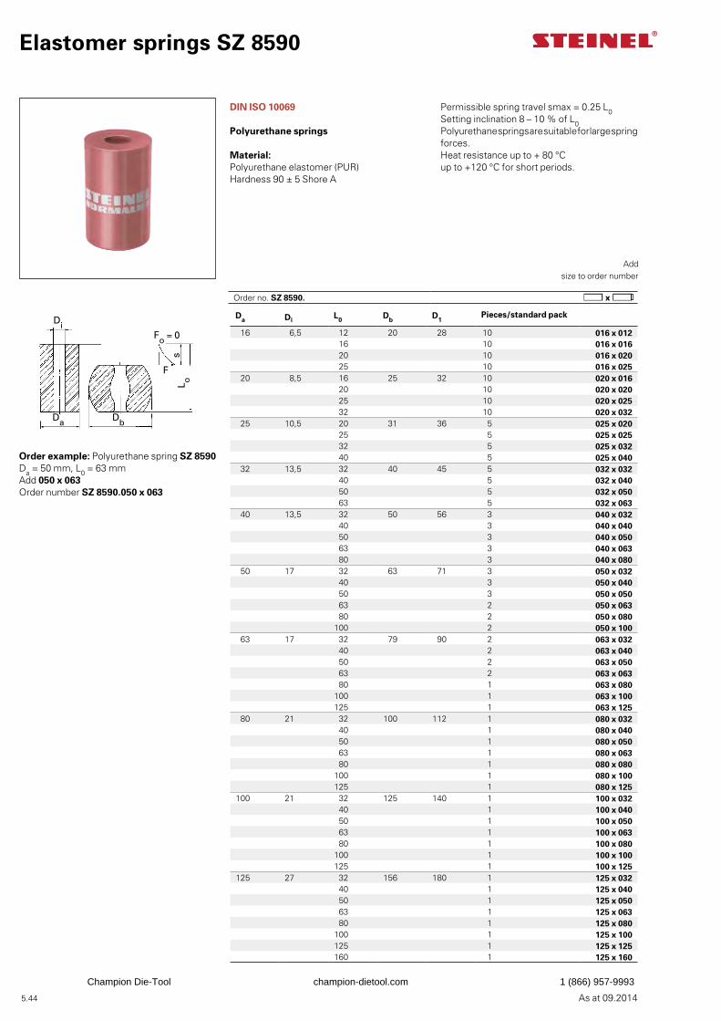
As at 09.2014
x
L o
F
Di
Da Db
Fo = 0
s
5.44
Da Di L0 Db D1Pieces/standard pack
16 6,5 12 20 28 10 016 x 01216 10 016 x 01620 10 016 x 02025 10 016 x 025
20 8,5 16 25 32 10 020 x 01620 10 020 x 02025 10 020 x 02532 10 020 x 032
25 10,5 20 31 36 5 025 x 02025 5 025 x 02532 5 025 x 03240 5 025 x 040
32 13,5 32 40 45 5 032 x 03240 5 032 x 04050 5 032 x 05063 5 032 x 063
40 13,5 32 50 56 3 040 x 03240 3 040 x 04050 3 040 x 05063 3 040 x 06380 3 040 x 080
50 17 32 63 71 3 050 x 03240 3 050 x 04050 3 050 x 05063 2 050 x 06380 2 050 x 080
100 2 050 x 100 63 17 32 79 90 2 063 x 032
40 2 063 x 04050 2 063 x 05063 2 063 x 06380 1 063 x 080
100 1 063 x 100125 1 063 x 125
80 21 32 100 112 1 080 x 03240 1 080 x 04050 1 080 x 05063 1 080 x 06380 1 080 x 080
100 1 080 x 100125 1 080 x 125
100 21 32 125 140 1 100 x 03240 1 100 x 04050 1 100 x 05063 1 100 x 06380 1 100 x 080
100 1 100 x 100125 1 100 x 125
125 27 32 156 180 1 125 x 03240 1 125 x 04050 1 125 x 05063 1 125 x 06380 1 125 x 080
100 1 125 x 100125 1 125 x 125160 1 125 x 160
Elastomer springs SZ 8590
DIN ISO 10069
Polyurethane springs
Material: Polyurethane elastomer (PUR) Hardness 90 ± 5 Shore A
Add
size to order number
Order example: Polyurethane spring SZ 8590Da = 50 mm, L0 = 63 mmAdd 050 x 063Order number SZ 8590.050 x 063
Permissible spring travel smax = 0.25 L0Setting inclination 8 – 10 % of L0Polyurethane springs are suitable for large spring forces.Heat resistance up to + 80 °Cup to +120 °C for short periods.
Order no. SZ 8590.
Champion Die-Tool champion-dietool.com 1 (866) 957-9993
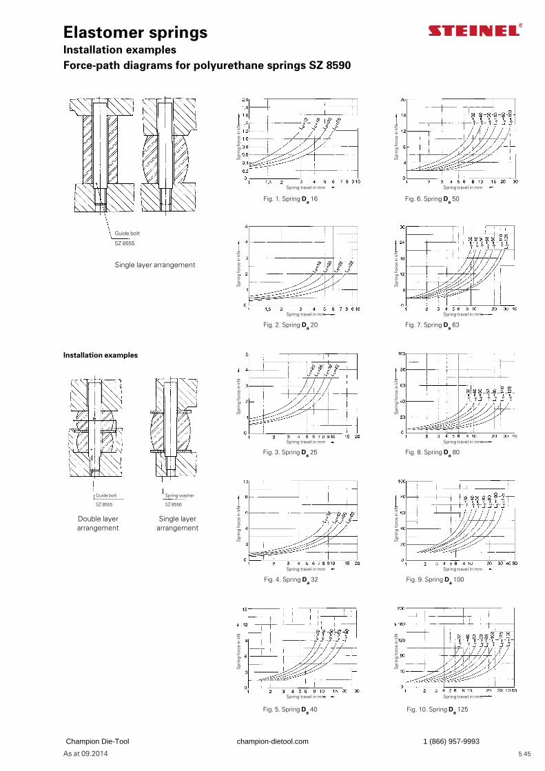
As at 09.2014 5.45
Elastomer springsInstallation examplesForce-path diagrams for polyurethane springs SZ 8590
Guide bolt
SZ 8555
Double layer arrangement
Single layer arrangement
Spr
ing
forc
e in
kN
Spr
ing
forc
e in
kN
Spring travel in mm Spring travel in mm
Spr
ing
forc
e in
kN
Spr
ing
forc
e in
kN
Spring travel in mm Spring travel in mm
Spr
ing
forc
e in
kN
Spr
ing
forc
e in
kN
Spring travel in mm Spring travel in mm
Spr
ing
forc
e in
kN
Spr
ing
forc
e in
kN
Spring travel in mm Spring travel in mm
Spr
ing
forc
e in
kN
Spr
ing
forc
e in
kN
Spring travel in mm Spring travel in mm
Fig. 1. Spring Da 16 Fig. 6. Spring Da 50
Fig. 2. Spring Da 20 Fig. 7. Spring Da 63
Fig. 3. Spring Da 25 Fig. 8. Spring Da 80
Fig. 4. Spring Da 32 Fig. 9. Spring Da 100
Fig. 5. Spring Da 40 Fig. 10. Spring Da 125
Installation examples
Guide bolt
SZ 8555
Spring washer
SZ 8556
Single layer arrangement
Champion Die-Tool champion-dietool.com 1 (866) 957-9993
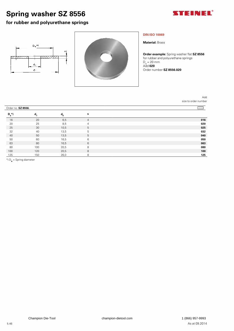
As at 09.2014
Da*) d1 d5s
16 20 6,5 4 016 20 25 8,5 4 020 25 30 10,5 5 025 32 40 13,5 5 032 40 50 13,5 5 040 50 60 16,5 6 050 63 80 16,5 6 063 80 100 20,5 8 080
100 120 20,5 8 100125 150 26,0 8 125
5.46
DIN ISO 10069
Material: Brass
*) Da = Spring diameter
Spring washer SZ 8556for rubber and polyurethane springs
Add
size to order number
Order example: Spring washer flat SZ 8556for rubber and polyurethane springsDa = 20 mmAdd 020Order number SZ 8556.020
Order no. SZ 8556.
Champion Die-Tool champion-dietool.com 1 (866) 957-9993
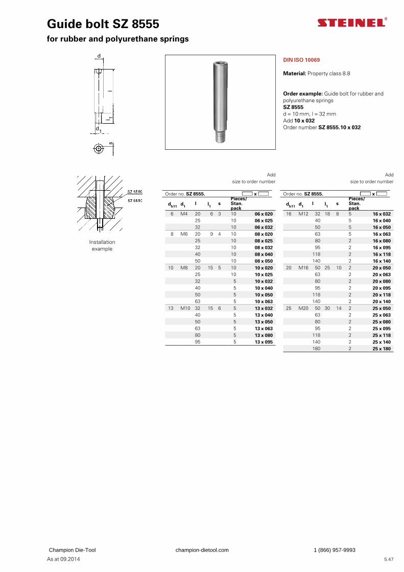
As at 09.2014
d1
l
d
l 1 s
5.47
DIN ISO 10069
Material: Property class 8.8
Guide bolt SZ 8555for rubber and polyurethane springs
Add
size to order number
Add
size to order number
Order example: Guide bolt for rubber and polyurethane springs SZ 8555d = 10 mm, l = 32 mmAdd 10 x 032Order number SZ 8555.10 x 032
dh11 d1l l1 s
Pieces/Stan. pack
6 M4 20 6 3 10 06 x 020 25 10 06 x 025
32 10 06 x 032 8 M6 20 9 4 10 08 x 020
25 10 08 x 02532 10 08 x 03240 10 08 x 04050 10 08 x 050
10 M8 20 15 5 10 10 x 02025 10 10 x 02532 5 10 x 03240 5 10 x 04050 5 10 x 05063 5 10 x 063
13 M10 32 15 6 5 13 x 03240 5 13 x 04050 5 13 x 05063 5 13 x 06380 5 13 x 08095 5 13 x 095
dh11 d1l l1 s
Pieces/Stan. pack
16 M12 32 18 8 5 16 x 03240 5 16 x 04050 5 16 x 05063 5 16 x 06380 2 16 x 08095 2 16 x 095
118 2 16 x 118140 2 16 x 140
20 M16 50 25 10 2 20 x 05063 2 20 x 06380 2 20 x 08095 2 20 x 095
118 2 20 x 118140 2 20 x 140
25 M20 50 30 14 2 25 x 05063 2 25 x 06380 2 25 x 08095 2 25 x 095
118 2 25 x 118140 2 25 x 140180 2 25 x 180
Installation example
Order no. SZ 8555. Order no. SZ 8555.
Champion Die-Tool champion-dietool.com 1 (866) 957-9993
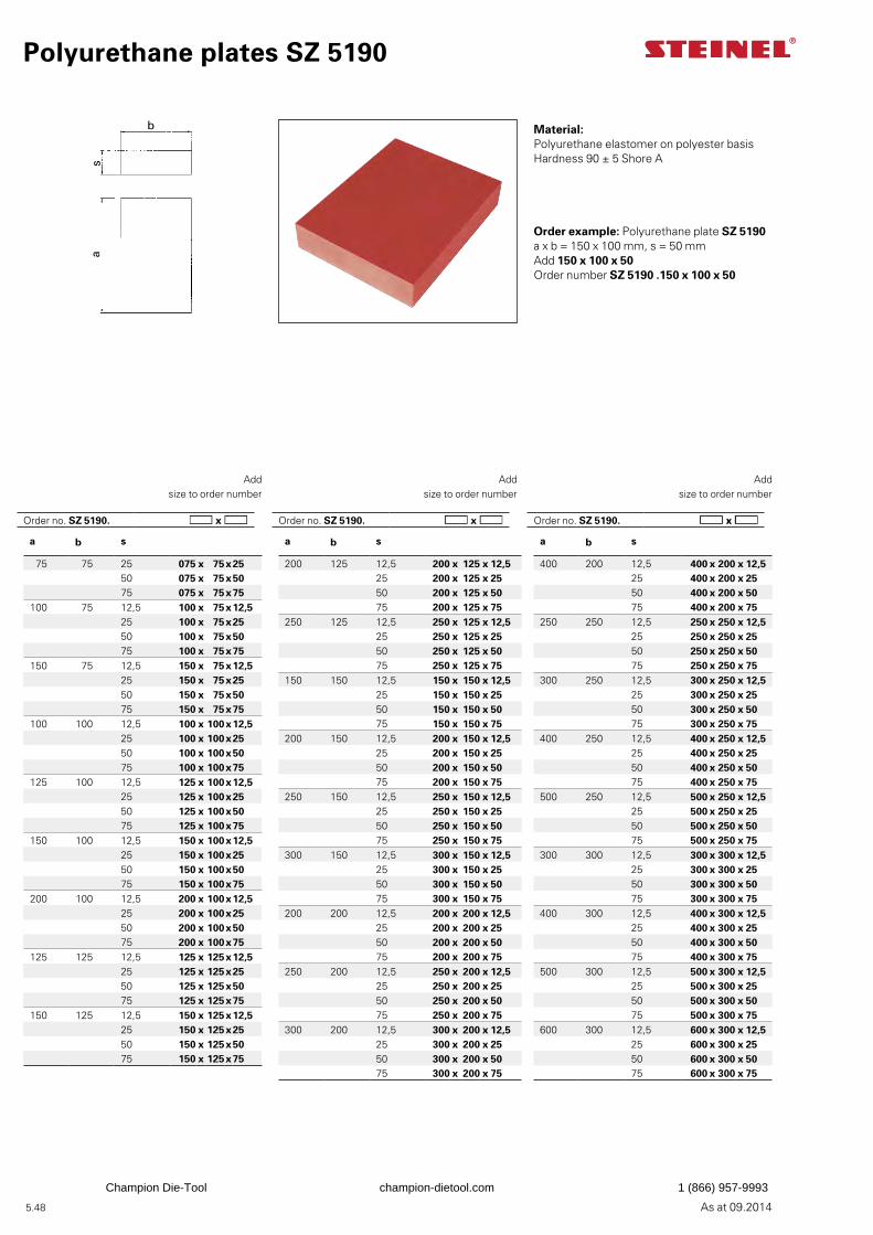
As at 09.2014
a b s
75 75 25 075 x 75x2550 075 x 75x5075 075 x 75x75
100 75 12,5 100 x 75x12,525 100 x 75x2550 100 x 75x5075 100 x 75x75
150 75 12,5 150 x 75x12,525 150 x 75x2550 150 x 75x5075 150 x 75x75
100 100 12,5 100 x 100x12,525 100 x 100x2550 100 x 100x5075 100 x 100x75
125 100 12,5 125 x 100x12,525 125 x 100x2550 125 x 100x5075 125 x 100x75
150 100 12,5 150 x 100x12,525 150 x 100x2550 150 x 100x5075 150 x 100x75
200 100 12,5 200 x 100x12,525 200 x 100x2550 200 x 100x5075 200 x 100x75
125 125 12,5 125 x 125x12,525 125 x 125x2550 125 x 125x5075 125 x 125x75
150 125 12,5 150 x 125x12,525 150 x 125x2550 150 x 125x5075 150 x 125x75
a b s
200 125 12,5 200 x 125 x 12,525 200 x 125 x 2550 200 x 125 x 5075 200 x 125 x 75
250 125 12,5 250 x 125 x 12,525 250 x 125 x 2550 250 x 125 x 5075 250 x 125 x 75
150 150 12,5 150 x 150 x 12,525 150 x 150 x 2550 150 x 150 x 5075 150 x 150 x 75
200 150 12,5 200 x 150 x 12,525 200 x 150 x 2550 200 x 150 x 5075 200 x 150 x 75
250 150 12,5 250 x 150 x 12,525 250 x 150 x 2550 250 x 150 x 5075 250 x 150 x 75
300 150 12,5 300 x 150 x 12,525 300 x 150 x 2550 300 x 150 x 5075 300 x 150 x 75
200 200 12,5 200 x 200 x 12,525 200 x 200 x 2550 200 x 200 x 5075 200 x 200 x 75
250 200 12,5 250 x 200 x 12,525 250 x 200 x 2550 250 x 200 x 5075 250 x 200 x 75
300 200 12,5 300 x 200 x 12,525 300 x 200 x 2550 300 x 200 x 5075 300 x 200 x 75
a b s
400 200 12,5 400 x 200 x 12,525 400 x 200 x 2550 400 x 200 x 5075 400 x 200 x 75
250 250 12,5 250 x 250 x 12,525 250 x 250 x 2550 250 x 250 x 5075 250 x 250 x 75
300 250 12,5 300 x 250 x 12,525 300 x 250 x 2550 300 x 250 x 5075 300 x 250 x 75
400 250 12,5 400 x 250 x 12,525 400 x 250 x 2550 400 x 250 x 5075 400 x 250 x 75
500 250 12,5 500 x 250 x 12,525 500 x 250 x 2550 500 x 250 x 5075 500 x 250 x 75
300 300 12,5 300 x 300 x 12,525 300 x 300 x 2550 300 x 300 x 5075 300 x 300 x 75
400 300 12,5 400 x 300 x 12,525 400 x 300 x 2550 400 x 300 x 5075 400 x 300 x 75
500 300 12,5 500 x 300 x 12,525 500 x 300 x 2550 500 x 300 x 5075 500 x 300 x 75
600 300 12,5 600 x 300 x 12,525 600 x 300 x 2550 600 x 300 x 5075 600 x 300 x 75
b
s a
5.48
Polyurethane plates SZ 5190
Material:Polyurethane elastomer on polyester basisHardness 90 ± 5 Shore A
Add
size to order number
Order example: Polyurethane plate SZ 5190a x b = 150 x 100 mm, s = 50 mmAdd 150 x 100 x 50Order number SZ 5190 .150 x 100 x 50
Add
size to order number
Add
size to order number
Order no. SZ 5190. Order no. SZ 5190. Order no. SZ 5190.
Champion Die-Tool champion-dietool.com 1 (866) 957-9993
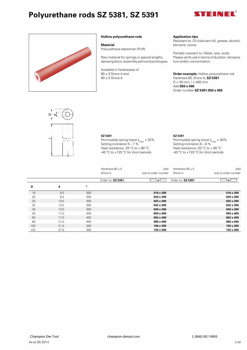
As at 09.2014
D d l
16 6,5 300 016 x 300 016 x 300 20 8,5 300 020 x 300 020 x 300 25 10,5 300 025 x 300 025 x 300 32 13,5 300 032 x 300 032 x 300 40 13,5 300 040 x 300 040 x 300 50 17,0 400 050 x 400 050 x 400 63 17,0 400 063 x 400 063 x 400 80 21,0 400 080 x 400 080 x 400
100 21,0 300 100 x 300 100 x 300125 27,0 300 125 x 300 125 x 300
D l
d
5.49
Hardness 80 ± 5 Shore A
Order example: Hollow polyurethane rod Hardness 80, Shore A, SZ 5381D = 50 mm, l = 400 mmAdd 050 x 400Order number SZ 5381.050 x 400
Hollow polyurethane rods
Material:Polyurethane elastomer (PUR)
Raw material for springs in special lengths, damping discs, assembly parts and prototypes.
Available in hardnesses of80 ± 5 Shore A and90 ± 5 Shore A
Application tipsResistant to: Oil (lubricant oil), grease, alcohol, benzene, ozone.
Partially resistant to: Water, lyes, acids.Please verify use in terms of duration, tempera-ture and/or concentration.
SZ 5381Permissible spring travel smax = 35%Setting inclination 5 – 7 %Heat resistance -20 °C to + 80 °C-40 °C to +120 °C for short periods.
SZ 5391Permissible spring travel smax = 30%Setting inclination 6 – 8 %Heat resistance -20 °C to + 80 °C-40 °C to +120 °C for short periods.
Polyurethane rods SZ 5381, SZ 5391
Add
size to order numberHardness 90 ± 5 Shore A
Order no. SZ 5381. Order no. SZ 5381
Add
size to order number
Champion Die-Tool champion-dietool.com 1 (866) 957-9993
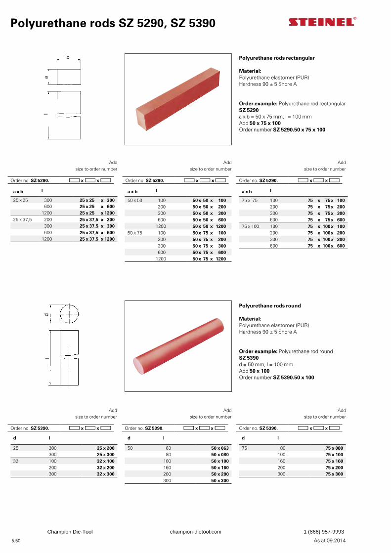
As at 09.2014
a x b l
25 x 25 300 25 x 25 x 300600 25 x 25 x 600
1200 25 x 25 x 120025 x 37,5 200 25 x 37,5 x 200
300 25 x 37,5 x 300600 25 x 37,5 x 600
1200 25 x 37,5 x 1200
a x b l
50 x 50 100 50 x 50 x 100200 50 x 50 x 200300 50 x 50 x 300600 50 x 50 x 600
1200 50 x 50 x 120050 x 75 100 50 x 75 x 100
200 50 x 75 x 200300 50 x 75 x 300600 50 x 75 x 600
1200 50 x 75 x 1200
a x b l
75 x 75 100 75 x 75x 100200 75 x 75x 200300 75 x 75x 300600 75 x 75x 600
75 x 100 100 75 x 100x 100200 75 x 100x 200300 75 x 100x 300600 75 x 100x 600
d l
25 200 25 x 200300 25 x 300
32 100 32 x 100200 32 x 200300 32 x 300
d l
50 63 50 x 06380 50 x 080
100 50 x 100160 50 x 160200 50 x 200300 50 x 300
d l
75 80 75 x 080100 75 x 100160 75 x 160200 75 x 200300 75 x 300
b
a l
d l
5.50
Polyurethane rods SZ 5290, SZ 5390
Polyurethane rods rectangular
Material:Polyurethane elastomer (PUR) Hardness 90 ± 5 Shore A
Add
size to order number
Order example: Polyurethane rod rectangular SZ 5290a x b = 50 x 75 mm, l = 100 mmAdd 50 x 75 x 100Order number SZ 5290.50 x 75 x 100
Add
size to order number
Add
size to order number
Polyurethane rods round
Material:Polyurethane elastomer (PUR) Hardness 90 ± 5 Shore A
Add
size to order number
Order example: Polyurethane rod roundSZ 5390d = 50 mm, l = 100 mmAdd 50 x 100Order number SZ 5390.50 x 100
Add
size to order number
Add
size to order number
Order no. SZ 5290. Order no. SZ 5290. Order no. SZ 5290.
Order no. SZ 5390. Order no. SZ 5390. Order no. SZ 5390.
Champion Die-Tool champion-dietool.com 1 (866) 957-9993
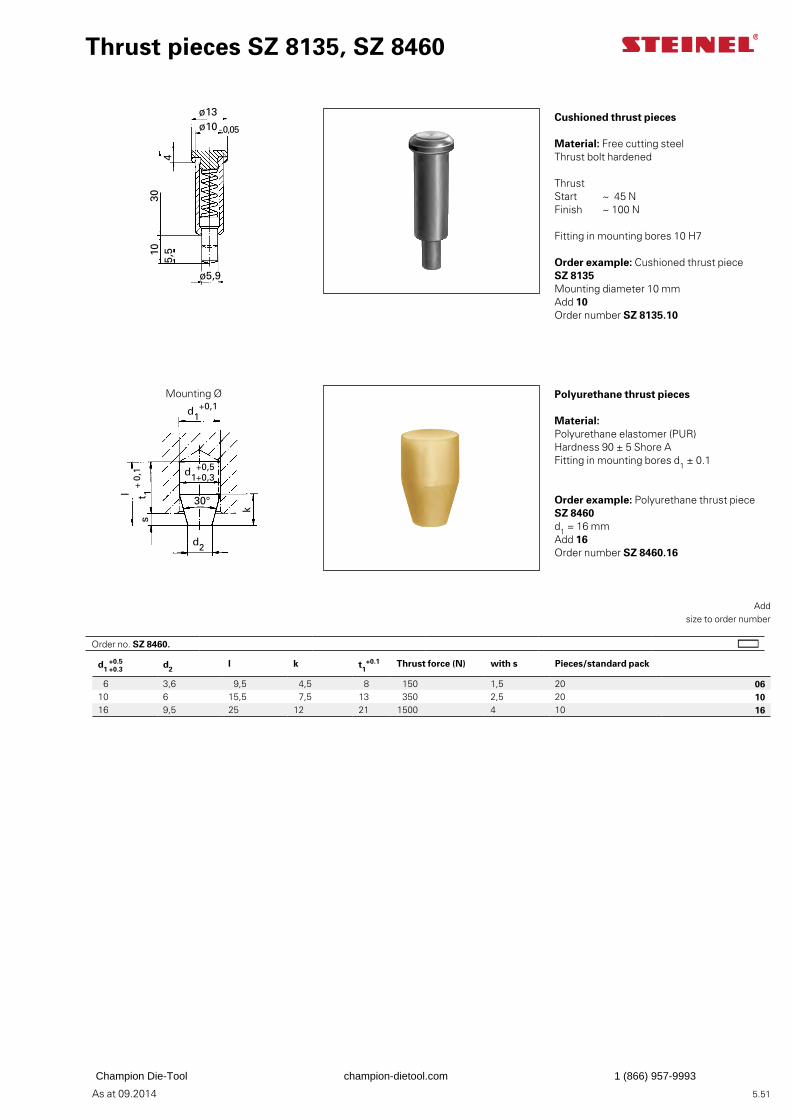
As at 09.2014
ø10 - 0,05
ø13
ø5,9
4 3
0 1
0 5
,5
d1+0,1
t 1 + 0
,1l
s
k
d2
30°
d1+0,5+0,3
5.51
Thrust pieces SZ 8135, SZ 8460
Cushioned thrust pieces
Material: Free cutting steelThrust bolt hardened
ThrustStart ~ 45 NFinish ~ 100 N
Fitting in mounting bores 10 H7
Polyurethane thrust pieces
Material:Polyurethane elastomer (PUR) Hardness 90 ± 5 Shore AFitting in mounting bores d1 ± 0.1
Add
size to order number
Order example: Polyurethane thrust piece SZ 8460d1 = 16 mmAdd 16Order number SZ 8460.16
d1 +0.3 +0.5 d2
l k t1+0.1 Thrust force (N) with s Pieces/standard pack
6 3,6 9,5 4,5 8 150 1,5 20 0610 6 15,5 7,5 13 350 2,5 20 1016 9,5 25 12 21 1500 4 10 16
Order example: Cushioned thrust piece SZ 8135 Mounting diameter 10 mm Add 10Order number SZ 8135.10
Mounting Ø
Order no. SZ 8460.
Champion Die-Tool champion-dietool.com 1 (866) 957-9993
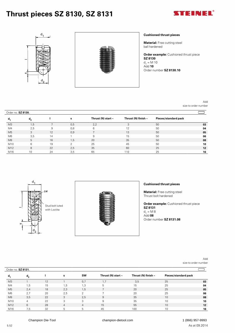
As at 09.2014
d1
ls
d2
d1
ls
d2
5.52
Cushioned thrust pieces
Material: Free cutting steelThrust bolt hardened
Add
size to order number
Order example: Cushioned thrust piece SZ 8131d1 = M 8Add 08Order number SZ 8131.08
Thrust pieces SZ 8130, SZ 8131
Cushioned thrust pieces
Material: Free cutting steelball hardened
Order example: Cushioned thrust piece SZ 8130d1 = M 10Add 10Order number SZ 8130.10
Add
size to order number
d1 d2l s Thrust (N) start ~ Thrust (N) finish ~ Pieces/standard pack
M3 1,5 7 0,5 2,2 3 50 03M4 2,5 9 0,8 6 12 50 04M5 3 12 0,9 7 13 50 05M6 3,5 14 1 9 15 50 06M8 5 16 1,5 20 35 50 08M10 6 19 2 25 45 50 10M12 8 22 2,5 35 60 25 12M16 10 24 3,5 65 110 25 16
d1 d2l s SW Thrust (N) start ~ Thrust (N) finish ~ Pieces/standard pack
M3 1 12 1 0,7 1,7 3,5 25 03M4 1,5 15 1,5 1,3 5 15 25 04M5 2,4 18 2,3 1,5 7 20 25 05M6 2,7 20 2,5 2 7 20 25 06M8 3,5 22 3 2,5 9 35 10 08M10 4 22 3 3 9 35 10 10M12 6 28 4 4 15 55 10 12M16 7,5 32 5 5 45 100 10 16
Stud bolt luted with Loctite
Order no. SZ 8130.
Order no. SZ 8131.
Champion Die-Tool champion-dietool.com 1 (866) 957-9993
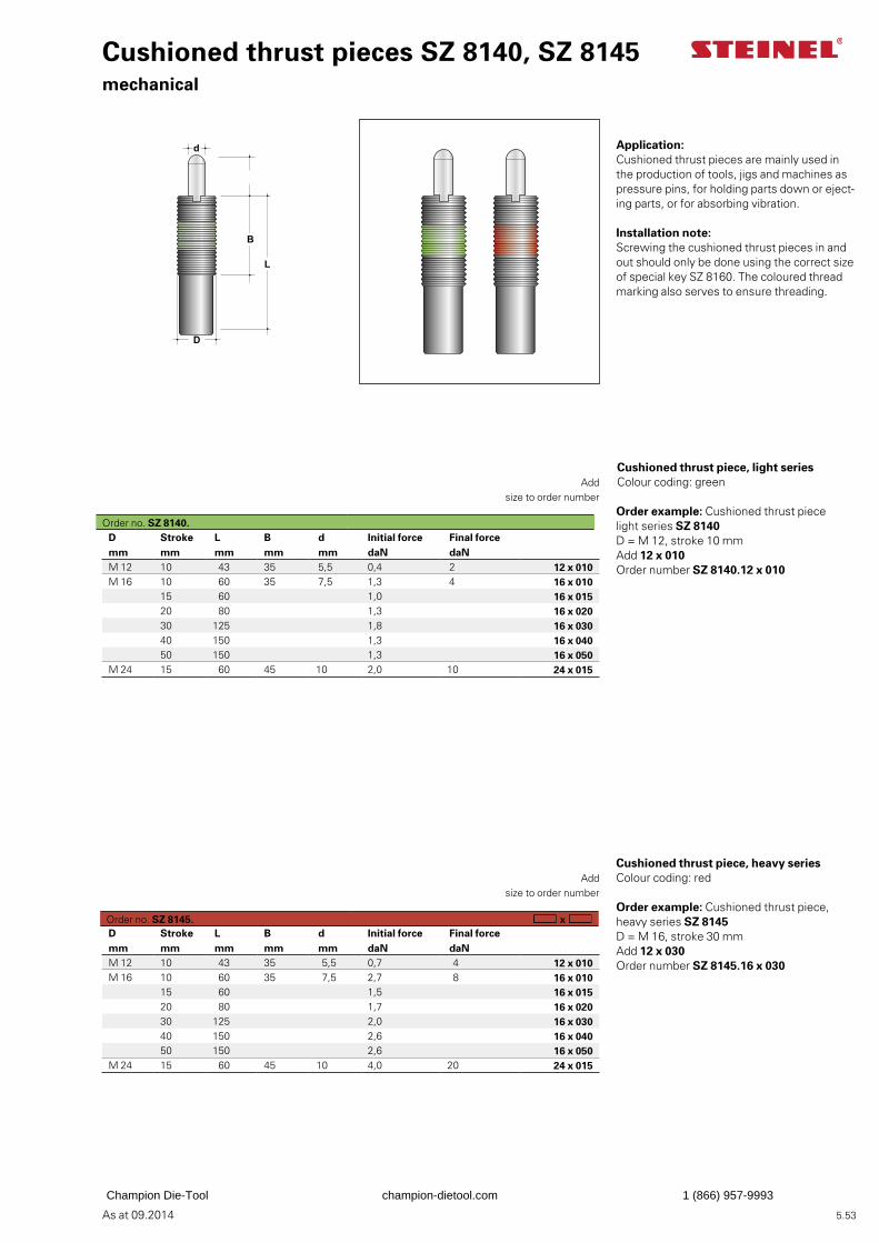
As at 09.2014
L
B
D
d
5.53
D Stroke L B d Initial force Final force mm mm mm mm mm daN daNM 12 10 43 35 5,5 0,4 2 12 x 010M 16 10 60 35 7,5 1,3 4 16 x 010
15 60 1,0 16 x 01520 80 1,3 16 x 02030 125 1,8 16 x 03040 150 1,3 16 x 04050 150 1,3 16 x 050
M 24 15 60 45 10 2,0 10 24 x 015
Cushioned thrust pieces SZ 8140, SZ 8145mechanical
Application:Cushioned thrust pieces are mainly used in the production of tools, jigs and machines as pressure pins, for holding parts down or eject-ing parts, or for absorbing vibration.
Installation note:Screwing the cushioned thrust pieces in and out should only be done using the correct size of special key SZ 8160. The coloured thread marking also serves to ensure threading.
Order example: Cushioned thrust piece light series SZ 8140D = M 12, stroke 10 mmAdd 12 x 010Order number SZ 8140.12 x 010
Add
size to order number
Cushioned thrust piece, heavy series Colour coding: red
Order example: Cushioned thrust piece, heavy series SZ 8145D = M 16, stroke 30 mmAdd 12 x 030Order number SZ 8145.16 x 030
Add
size to order number
x D Stroke L B d Initial force Final force mm mm mm mm mm daN daNM 12 10 43 35 5,5 0,7 4 12 x 010M 16 10 60 35 7,5 2,7 8 16 x 010
15 60 1,5 16 x 01520 80 1,7 16 x 02030 125 2,0 16 x 03040 150 2,6 16 x 04050 150 2,6 16 x 050
M 24 15 60 45 10 4,0 20 24 x 015
Cushioned thrust piece, light series Colour coding: green
Order no. SZ 8140.
Order no. SZ 8145.
Champion Die-Tool champion-dietool.com 1 (866) 957-9993
As at 09.2014 5.54
Champion Die-Tool champion-dietool.com 1 (866) 957-9993
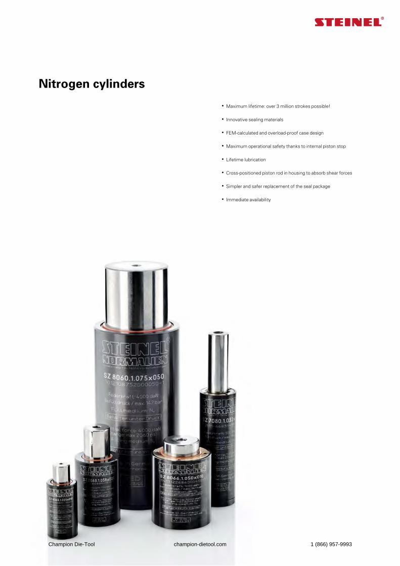
As at 09.2014
Nitrogen cylinders
• Maximum lifetime: over 3 million strokes possible!
• Innovative sealing materials
• FEM-calculated and overload-proof case design
• Maximum operational safety thanks to internal piston stop
• Lifetime lubrication
• Cross-positioned piston rod in housing to absorb shear forces
• Simpler and safer replacement of the seal package
• Immediate availability
Champion Die-Tool champion-dietool.com 1 (866) 957-9993
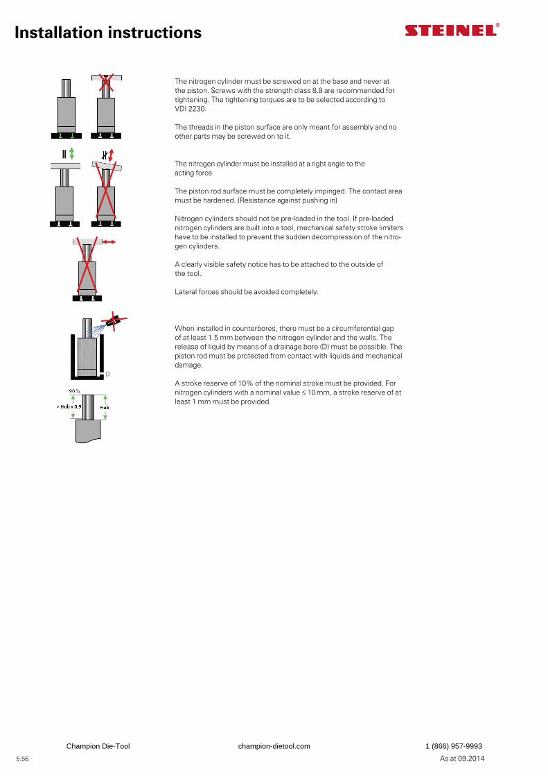
5.56 As at 09.2014
Installation instructions
The nitrogen cylinder must be screwed on at the base and never at the piston. Screws with the strength class 8.8 are recommended for tightening. The tightening torques are to be selected according to VDI 2230.
The threads in the piston surface are only meant for assembly and no other parts may be screwed on to it.
The nitrogen cylinder must be installed at a right angle to the acting force.
The piston rod surface must be completely impinged. The contact area must be hardened. (Resistance against pushing in)
Nitrogen cylinders should not be pre-loaded in the tool. If pre-loaded nitrogen cylinders are built into a tool, mechanical safety stroke limiters have to be installed to prevent the sudden decompression of the nitro-gen cylinders.
A clearly visible safety notice has to be attached to the outside of the tool.
Lateral forces should be avoided completely.
When installed in counterbores, there must be a circumferential gap of at least 1.5 mm between the nitrogen cylinder and the walls. The release of liquid by means of a drainage bore (D) must be possible. The piston rod must be protected from contact with liquids and mechanical damage.
A stroke reserve of 10% of the nominal stroke must be provided. For nitrogen cylinders with a nominal value ≤ 10 mm, a stroke reserve of at least 1 mm must be provided.
Champion Die-Tool champion-dietool.com 1 (866) 957-9993
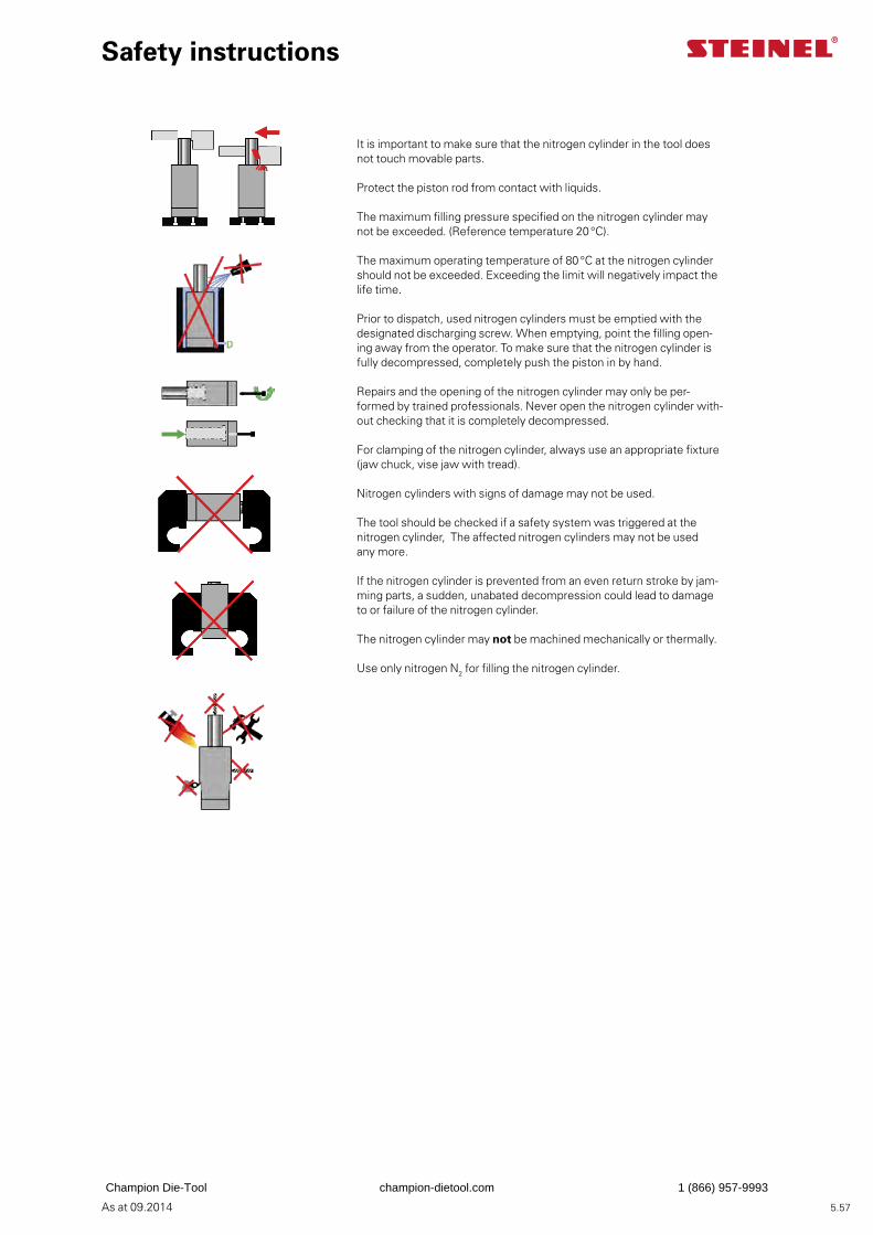
5.57As at 09.2014
Safety instructions
It is important to make sure that the nitrogen cylinder in the tool does not touch movable parts.
Protect the piston rod from contact with liquids.
The maximum filling pressure specified on the nitrogen cylinder may not be exceeded. (Reference temperature 20 °C).
The maximum operating temperature of 80 °C at the nitrogen cylinder should not be exceeded. Exceeding the limit will negatively impact the life time.
Prior to dispatch, used nitrogen cylinders must be emptied with the designated discharging screw. When emptying, point the filling open-ing away from the operator. To make sure that the nitrogen cylinder is fully decompressed, completely push the piston in by hand.
Repairs and the opening of the nitrogen cylinder may only be per-formed by trained professionals. Never open the nitrogen cylinder with-out checking that it is completely decompressed.
For clamping of the nitrogen cylinder, always use an appropriate fixture (jaw chuck, vise jaw with tread).
Nitrogen cylinders with signs of damage may not be used.
The tool should be checked if a safety system was triggered at the nitrogen cylinder, The affected nitrogen cylinders may not be used any more.
If the nitrogen cylinder is prevented from an even return stroke by jam-ming parts, a sudden, unabated decompression could lead to damage to or failure of the nitrogen cylinder.
The nitrogen cylinder may not be machined mechanically or thermally.
Use only nitrogen N2 for filling the nitrogen cylinder.
Champion Die-Tool champion-dietool.com 1 (866) 957-9993
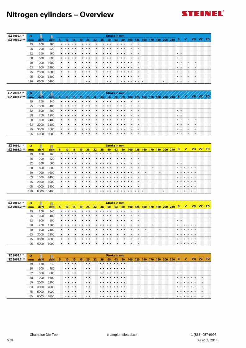
5.58 As at 09.2014
Nitrogen cylinders – Overview
SZ 8080.1.* Ø mm
daN
daN
Stroke in mm B
V
VB
VZ
PDSZ 8080.2.** 5 10 15 19 25 32 38 50 63 80 100 125 160 170 180 200 240
19 100 160 � � � � � � � � � � � � � � � � �
25 200 320 � � � � � � � � � � � � � � � � �
32 350 560 � � � � � � � � � � � � � � � � � � �
38 500 800 � � � � � � � � � � � � � � � � � � �
50 1000 1600 � � � � � � � � � � � � � � � � � � � �
63 1500 2400 � � � � � � � � � � � � � � � � � � � �
75 2500 4000 � � � � � � � � � � � � � � � � � � � �
95 4000 6400 � � � � � � � � � � � � � � � � � � � �
120 6500 10400 � � � � � � � � � � � � � � � �
SZ 7080.1.* Ø mm
daN
daN
Stroke in mm B
V
VB
VZ
PDSZ 7080.2.** 5 10 15 19 25 32 38 50 63 80 100 125 160 170 180 200 240
19 150 240 � � � � � � � � � � � � � � � � �
25 300 480 � � � � � � � � � � � � � � � � �
32 500 800 � � � � � � � � � � � � � � � � � � �
38 750 1200 � � � � � � � � � � � � � � � � � � �
50 1500 2400 � � � � � � � � � � � � � � � � � � �
63 2000 3200 � � � � � � � � � � � � � � � � � � �
75 3000 4800 � � � � � � � � � � � � � � � � � � �
95 5000 8000 � � � � � � � � � � � � � � � � � � �
SZ 8066.1.* Ø mm
daN
daN
Stroke in mm B
V
VB
VZ
PDSZ 8066.2.** 5 10 15 19 25 32 38 50 63 80 100 125 160 170 180 200 240
19 100 160 � � � � � � � � � � � � � � � � � �
25 200 320 � � � � � � � � � � � � � � � � � �
32 350 560 � � � � � � � � � � � � � � � � � � � �
38 500 800 � � � � � � � � � � � � � � � � � � � � � � � � �
50 1000 1600 � � � � � � � � � � � � � � � � � � � � � � � � � � �
63 1500 2400 � � � � � � � � � � � � � � � � � � � � � � � � �
75 2500 4000 � � � � � � � � � � � � � � � � � � � � � � � � �
95 4000 6400 � � � � � � � � � � � � � � � � � � � � � � � �
120 6500 10400 � � � � � � � � � � � � � � � � � � � � � �
SZ 7066.1.* Ø mm
daN
daN
Stroke in mm B
V
VB
VZ
PDSZ 7066.2.** 5 10 15 19 25 32 38 50 63 80 100 125 160 170 180 200 240
19 150 240 � � � � � � � � � � � � � � � � � �
25 300 480 � � � � � � � � � � � � � � � � �
32 500 800 � � � � � � � � � � � � � � � � � � �
38 750 1200 � � � � � � � � � � � � � � � � � � � � � � � � � �
50 1500 2400 � � � � � � � � � � � � � � � � � � � � � � �
63 2000 3200 � � � � � � � � � � � � � � � � � � � �
75 3000 4800 � � � � � � � � � � � � � � � � � � � �
95 5000 8000 � � � � � � � � � � � � � � � � � � � �
SZ 8065.1.* Ø mm
daN
daN
Stroke in mm B
V
VB
VZ
PDSZ 8065.2.** 5 10 15 19 25 32 38 50 63 80 100 125 160 170 180 200 240
19 150 240 � � � � � � � � � � � � � �
25 300 480 � � � � � � � � � � � � � �
32 500 800 � � � � � � � � � � � � � � � �
38 1000 1600 � � � � � � � � � � � � � � � � � � � � �
50 2000 3200 � � � � � � � � � � � � � � � � � � � � �
63 3000 4800 � � � � � � � � � � � � � � � � � � � � �
75 5000 8000 � � � � � � � � � � � � � � � � � � � � �
95 8000 12800 � � � � � � � � � � � � � � � � � � � � �
Champion Die-Tool champion-dietool.com 1 (866) 957-9993
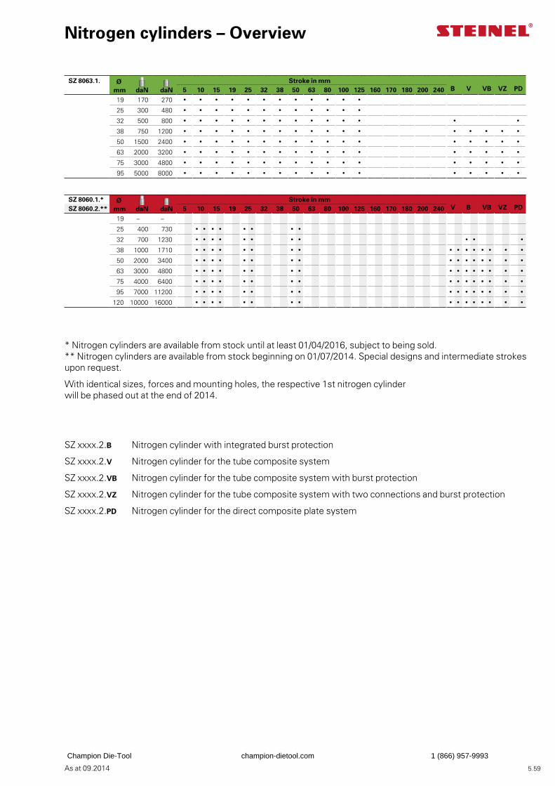
5.59As at 09.2014
Nitrogen cylinders – Overview
SZ 8063.1. Ø mm
daN
daN
Stroke in mm B
V
VB
VZ
PD5 10 15 19 25 32 38 50 63 80 100 125 160 170 180 200 240
19 170 270 � � � � � � � � � � � �
25 300 480 � � � � � � � � � � � �
32 500 800 � � � � � � � � � � � � � �
38 750 1200 � � � � � � � � � � � � � � � � �
50 1500 2400 � � � � � � � � � � � � � � � � �
63 2000 3200 � � � � � � � � � � � � � � � � �
75 3000 4800 � � � � � � � � � � � � � � � � �
95 5000 8000 � � � � � � � � � � � � � � � � �
SZ 8060.1.* Ø mm
daN
daN
Stroke in mm V
B
VB
VZ
PDSZ 8060.2.** 5 10 15 19 25 32 38 50 63 80 100 125 160 170 180 200 240
19 – –
25 400 730 � � � � � � � �
32 700 1230 � � � � � � � � � � �
38 1000 1710 � � � � � � � � � � � � � � � �
50 2000 3400 � � � � � � � � � � � � � � � �
63 3000 4800 � � � � � � � � � � � � � � � �
75 4000 6400 � � � � � � � � � � � � � � � �
95 7000 11200 � � � � � � � � � � � � � � � �
120 10000 16000 � � � � � � � � � � � � � � � �
* Nitrogen cylinders are available from stock until at least 01/04/2016, subject to being sold.** Nitrogen cylinders are available from stock beginning on 01/07/2014. Special designs and intermediate strokes upon request.
With identical sizes, forces and mounting holes, the respective 1st nitrogen cylinder will be phased out at the end of 2014.
SZ xxxx.2.B Nitrogen cylinder with integrated burst protection
SZ xxxx.2.V Nitrogen cylinder for the tube composite system
SZ xxxx.2.VB Nitrogen cylinder for the tube composite system with burst protection
SZ xxxx.2.VZ Nitrogen cylinder for the tube composite system with two connections and burst protection
SZ xxxx.2.PD Nitrogen cylinder for the direct composite plate system
Champion Die-Tool champion-dietool.com 1 (866) 957-9993
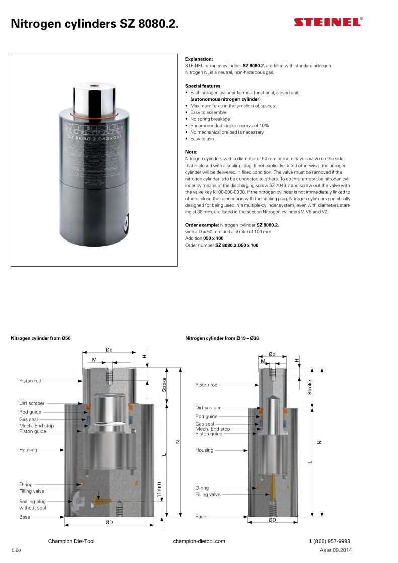
5.60 As at 09.2014
Explanation:STEINEL nitrogen cylinders SZ 8080.2. are filled with standard nitrogen. Nitrogen N2 is a neutral, non-hazardous gas.
Special features:• Each nitrogen cylinder forms a functional, closed unit
(autonomous nitrogen cylinder)• Maximum force in the smallest of spaces• Easy to assemble• No spring breakage• Recommended stroke reserve of 10%• No mechanical preload is necessary• Easy to use
Note:Nitrogen cylinders with a diameter of 50 mm or more have a valve on the side that is closed with a sealing plug. If not explicitly stated otherwise, the nitrogen cylinder will be delivered in filled condition. The valve must be removed if the nitrogen cylinder is to be connected to others. To do this, empty the nitrogen cyl-inder by means of the discharging screw SZ 7046.7 and screw out the valve with the valve key K100-000-0300. If the nitrogen cylinder is not immediately linked to others, close the connection with the sealing plug. Nitrogen cylinders specifically designed for being used in a multiple-cylinder system, even with diameters start-ing at 38 mm, are listed in the section Nitrogen cylinders V, VB and VZ.
Order example: Nitrogen cylinder SZ 8080.2.with a D = 50 mm and a stroke of 100 mm.Addition 050 x 100Order number SZ 8080.2.050 x 100
Nitrogen cylinders SZ 8080.2.
Ød
M
H
11 m
mS
tro
ke
N
L
ØD
Piston rod
Dirt scraper
Rod guide
Gas sealMech. End stopPiston guide
Housing
Filling valve
Sealing plug without seal
Base
O-ring
ØdM H
Str
oke
N
L
ØD
Piston rod
Dirt scraper
Rod guide
Gas sealMech. End stopPiston guide
Housing
Filling valve
Base
O-ring
Nitrogen cylinder from Ø50 Nitrogen cylinder from Ø19 – Ø38
Champion Die-Tool champion-dietool.com 1 (866) 957-9993
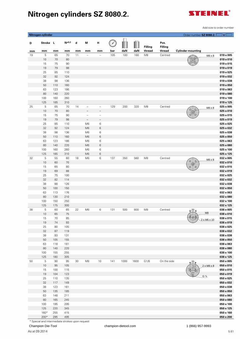
5.61As at 09.2014
Nitrogen cylinders SZ 8080.2.
Add size to order number
D Stroke L N±0,2 d M H Pos. Filling thread
Filling threadmm mm mm mm mm mm mm bar daN daN Cylinder mounting
19 5 65 70 11 – – 105 100 160 M8 Centred 019 x 005
10 70 80 019 x 010
15 75 90 019 x 015
19 79 98 019 x 019
25 85 110 019 x 025
32 92 124 019 x 032
38 98 136 019 x 038
50 110 160 019 x 050
63 123 186 019 x 063
80 140 220 019 x 080
100 160 260 019 x 100
125 185 310 019 x 125
25 5 65 70 14 – – 129 200 320 M8 Centred 025 x 005
10 70 80 – – 025 x 010
15 75 90 – – 025 x 015
19 79 98 – – 025 x 019
25 85 110 M6 6 025 x 025
32 92 124 M6 6 025 x 032
38 98 136 M6 6 025 x 038
50 110 160 M6 6 025 x 050
63 123 186 M6 6 025 x 063
80 140 220 M6 6 025 x 080
100 160 260 M6 6 025 x 100
125 185 310 M6 6 025 x 125
32 5 55 60 18 M6 6 137 350 560 M8 Centred 032 x 005
10 60 70 032 x 010
15 65 80 032 x 015
19 69 88 032 x 019
25 75 100 032 x 025
32 82 114 032 x 032
38 88 126 032 x 038
50 100 150 032 x 050
63 113 176 032 x 063
80 130 210 032 x 080
100 150 250 032 x 100
125 175 300 032 x 125
38 5 60 65 22 M6 6 131 500 800 M8 Centred 038 x 005
10 65 75 038 x 010
15 70 85 038 x 015
19 74 93 038 x 019
25 80 105 038 x 025
32 87 119 038 x 032
38 93 131 038 x 038
50 105 155 038 x 050
63 118 181 038 x 063
80 140 220 038 x 080
100 155 255 038 x 100
125 180 305 038 x 125
50 5 90 95 30 M8 10 141 1000 1600 G1/8 On the side 050 x 005
10 95 105 050 x 010
15 100 115 050 x 015
19 104 123 050 x 019
25 110 135 050 x 025
32 117 149 050 x 032
38 123 161 050 x 038
50 135 185 050 x 050
63 148 211 050 x 063
80 165 245 050 x 080
100 195 295 050 x 100
125 220 345 050 x 125
160* 255 415 050 x 160
200* 295 495 050 x 200
* Special and intermediate strokes upon request
M8 x 8
M8 x 8
M8 x 8
M8
2 x M6 x 10
20
2 x M8 x 8
G 1/8
20
Nitrogen cylinder Order number SZ 8080.2.
Champion Die-Tool champion-dietool.com 1 (866) 957-9993
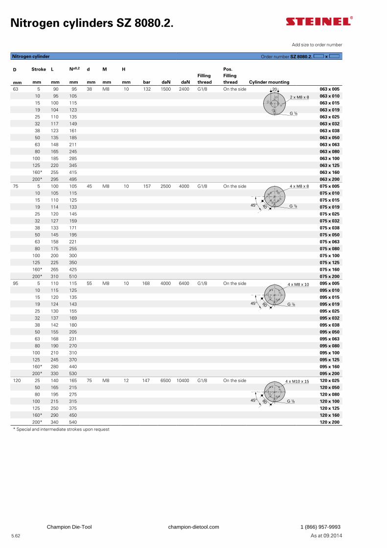
5.62 As at 09.2014
Add size to order number
D Stroke L N±0,2 d M H Pos. Filling thread
Filling threadmm mm mm mm mm mm mm bar daN daN Cylinder mounting
63 5 90 95 38 M8 10 132 1500 2400 G1/8 On the side 063 x 005
10 95 105 063 x 010
15 100 115 063 x 015
19 104 123 063 x 019
25 110 135 063 x 025
32 117 149 063 x 032
38 123 161 063 x 038
50 135 185 063 x 050
63 148 211 063 x 063
80 165 245 063 x 080
100 185 285 063 x 100
125 220 345 063 x 125
160* 255 415 063 x 160
200* 295 495 063 x 200
75 5 100 105 45 M8 10 157 2500 4000 G1/8 On the side 075 x 005
10 105 115 075 x 010
15 110 125 075 x 015
19 114 133 075 x 019
25 120 145 075 x 025
32 127 159 075 x 032
38 133 171 075 x 038
50 145 195 075 x 050
63 158 221 075 x 063
80 175 255 075 x 080
100 200 300 075 x 100
125 225 350 075 x 125
160* 265 425 075 x 160
200* 310 510 075 x 200
95 5 110 115 55 M8 10 168 4000 6400 G1/8 On the side 095 x 005
10 115 125 095 x 010
15 120 135 095 x 015
19 124 143 095 x 019
25 130 155 095 x 025
32 137 169 095 x 032
38 142 180 095 x 038
50 155 205 095 x 050
63 168 231 095 x 063
80 190 270 095 x 080
100 210 310 095 x 100
125 245 370 095 x 125
160* 280 440 095 x 160
200* 330 530 095 x 200
120 25 140 165 75 M8 12 147 6500 10400 G1/8 On the side 120 x 025
50 165 215 120 x 050
80 195 275 120 x 080
100 215 315 120 x 100
125 250 375 120 x 125
160* 290 450 120 x 160
200* 340 540 120 x 200
* Special and intermediate strokes upon request
Nitrogen cylinder Order number SZ 8080.2.
Nitrogen cylinders SZ 8080.2.
20
2 x M8 x 8
G 1/8
4 x M8 x 8
G 1/84045°
4 x M8 x 10
G 1/86045°
4 x M10 x 15
G 1/88045°
Champion Die-Tool champion-dietool.com 1 (866) 957-9993

5.63As at 09.2014
Champion Die-Tool champion-dietool.com 1 (866) 957-9993
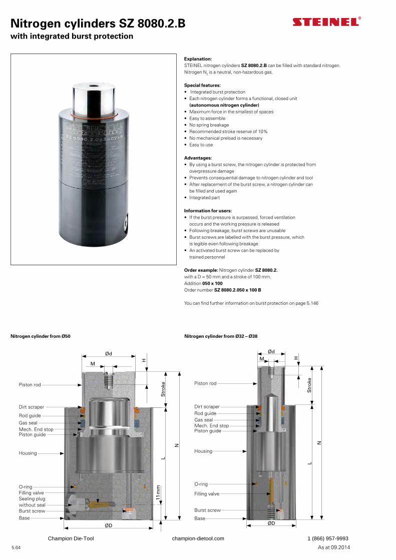
5.64 As at 09.2014
Explanation:STEINEL nitrogen cylinders SZ 8080.2.B can be filled with standard nitrogen. Nitrogen N2 is a neutral, non-hazardous gas.
Special features:• Integrated burst protection• Each nitrogen cylinder forms a functional, closed unit
(autonomous nitrogen cylinder)• Maximum force in the smallest of spaces• Easy to assemble• No spring breakage• Recommended stroke reserve of 10%• No mechanical preload is necessary• Easy to use
Advantages:• By using a burst screw, the nitrogen cylinder is protected from
overpressure damage• Prevents consequential damage to nitrogen cylinder and tool• After replacement of the burst screw, a nitrogen cylinder can
be filled and used again • Integrated part
Information for users:• If the burst pressure is surpassed, forced ventilation
occurs and the working pressure is released• Following breakage, burst screws are unusable• Burst screws are labelled with the burst pressure, which
is legible even following breakage• An activated burst screw can be replaced by
trained personnel
Order example: Nitrogen cylinder SZ 8080.2.with a D = 50 mm and a stroke of 100 mm.Addition 050 x 100Order number SZ 8080.2.050 x 100 B
You can find further information on burst protection on page 5.146
Nitrogen cylinders SZ 8080.2.Bwith integrated burst protection
Ød
M H
Str
oke
N
L
ØD
Piston rod
Dirt scraperRod guideGas sealMech. End stopPiston guide
Housing
Filling valve
Base
Burst screw
O-ring
Ød
M
H
11 m
mS
tro
ke
N
L
ØD
Piston rod
Dirt scraper
Rod guideGas sealMech. End stopPiston guide
Housing
Filling valveSealing plug without seal
BaseBurst screw
O-ring
Nitrogen cylinder from Ø50 Nitrogen cylinder from Ø32 – Ø38
Champion Die-Tool champion-dietool.com 1 (866) 957-9993
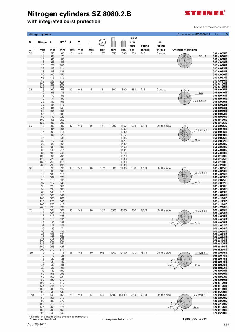
5.65As at 09.2014
Nitrogen cylinders SZ 8080.2.Bwith integrated burst protection
Add size to the order number
Burst pres-sure bar
D Stroke L N±0,2 d M H Pos. Filling thread
Filling threadmm mm mm mm mm mm mm bar daN daN Cylinder mounting
32 5 55 60 18 M6 6 137 350 560 380 M8 Centred 032 x 005 B 10 60 70 032 x 010 B
15 65 80 032 x 015 B19 69 88 032 x 019 B 25 75 100 032 x 025 B32 82 114 032 x 032 B38 88 126 032 x 038 B 50 100 150 032 x 050 B63 113 176 032 x 063 B 80 130 210 032 x 080 B
100 150 250 032 x 100 B125 175 300 032 x 125 B
38 5 60 65 22 M6 6 131 500 800 380 M8 Centred 038 x 005 B 10 65 75 038 x 010 B
15 70 85 038 x 015 B19 74 93 038 x 019 B 25 80 105 038 x 025 B32 87 119 038 x 032 B38 93 131 038 x 038 B 50 105 155 038 x 050 B63 118 181 038 x 063 B 80 140 220 038 x 080 B
100 155 255 038 x 100 B125 180 305 038 x 125 B
50 5 90 95 30 M8 10 141 1000 1167 380 G1/8 On the side 050 x 005 B10 95 105 1252 050 x 010 B15 100 115 1290 050 x 015 B19 104 123 1312 050 x 019 B 25 110 135 1385 050 x 025 B32 117 149 1421 050 x 032 B38 123 161 1439 050 x 038 B 50 135 185 1469 050 x 050 B63 148 211 1491 050 x 063 B 80 165 245 1510 050 x 080 B
100 195 295 1529 050 x 100 B125 220 345 1538 050 x 125 B160* 255 415 1600 050 x 160 B200* 295 495 1600 050 x 200 B
63 5 90 95 38 M8 10 132 1500 2400 380 G1/8 On the side 063 x 005 B10 95 105 063 x 010 B15 100 115 063 x 015 B19 104 123 063 x 019 B
25 110 135 063 x 025 B32 117 149 063 x 032 B38 123 161 063 x 038 B 50 135 185 063 x 050 B63 148 211 063 x 063 B 80 165 245 063 x 080 B
100 185 285 063 x 100 B125 220 345 063 x 125 B160* 255 415 063 x 160 B200* 295 495 063 x 200 B
75 5 100 105 45 M8 10 157 2500 4000 400 G1/8 On the side 075 x 005 B10 105 115 075 x 010 B15 110 125 075 x 015 B19 114 133 075 x 019 B 25 120 145 075 x 025 B32 127 159 075 x 032 B38 133 171 075 x 038 B 50 145 195 075 x 050 B63 158 221 075 x 063 B 80 175 255 075 x 080 B
100 200 300 075 x 100 B125 225 350 075 x 125 B160* 265 425 075 x 160 B200* 310 510 075 x 200 B
95 5 110 115 55 M8 10 168 4000 6400 470 G1/8 On the side 095 x 005 B10 115 125 095 x 010 B15 120 135 095 x 015 B19 124 143 095 x 019 B 25 130 155 095 x 025 B32 137 169 095 x 032 B38 142 180 095 x 038 B 50 155 205 095 x 050 B63 168 231 095 x 063 B 80 190 270 095 x 080 B
100 210 310 095 x 100 B125 245 370 095 x 125 B160* 280 440 095 x 160 B200* 330 530 095 x 200 B
120 25 140 165 75 M8 12 147 6500 10400 350 G1/8 On the side 120 x 025 B50 165 215 120 x 050 B80 195 275 120 x 080 B
100 215 315 120 x 100 B125 250 375 120 x 125 B160* 290 450 120 x 160 B200* 340 540 120 x 200 B
* Special and intermediate strokes upon request
M8 x 8
M8
2 x M6 x 8
20
2 x M8 x 8
G 1/8
20
20
2 x M8 x 8
G 1/8
4 x M8 x 8
G 1/84045°
4 x M8 x 10
G 1/845° 60
4 x M10 x 15
G 1/845° 80
Nitrogen cylinder Order number SZ 8080.2. B
Champion Die-Tool champion-dietool.com 1 (866) 957-9993
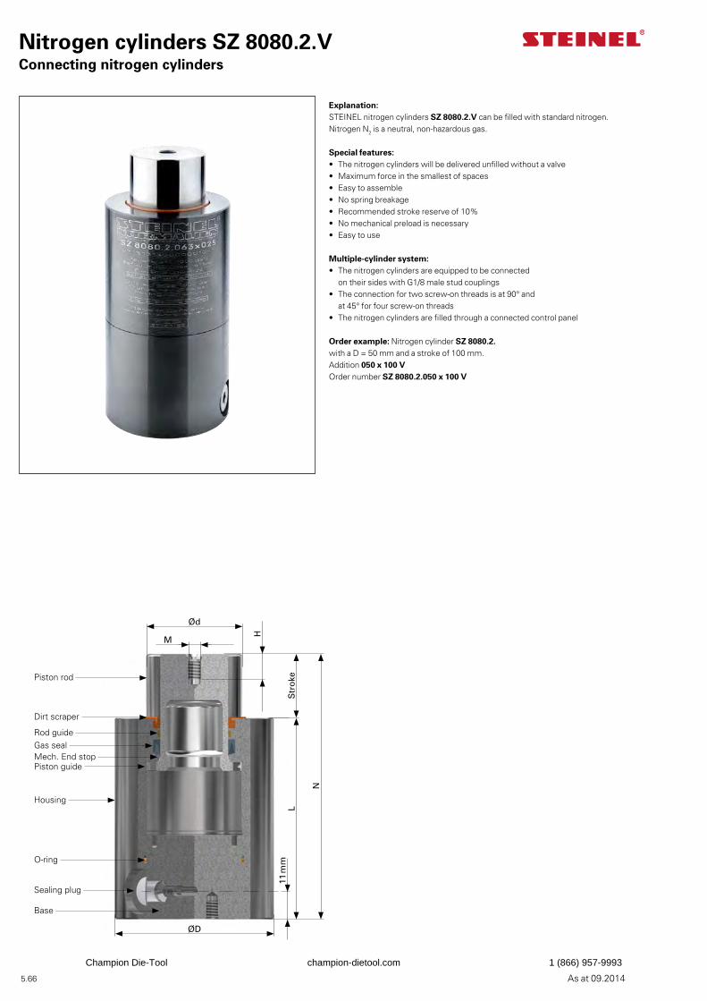
5.66 As at 09.2014
Explanation:STEINEL nitrogen cylinders SZ 8080.2.V can be filled with standard nitrogen. Nitrogen N2 is a neutral, non-hazardous gas.
Special features:• The nitrogen cylinders will be delivered unfilled without a valve• Maximum force in the smallest of spaces• Easy to assemble• No spring breakage• Recommended stroke reserve of 10%• No mechanical preload is necessary• Easy to use
Multiple-cylinder system:• The nitrogen cylinders are equipped to be connected
on their sides with G1/8 male stud couplings• The connection for two screw-on threads is at 90° and
at 45° for four screw-on threads• The nitrogen cylinders are filled through a connected control panel
Order example: Nitrogen cylinder SZ 8080.2.with a D = 50 mm and a stroke of 100 mm.Addition 050 x 100 VOrder number SZ 8080.2.050 x 100 V
Nitrogen cylinders SZ 8080.2.VConnecting nitrogen cylinders
Ød
M
H
Str
oke
N
L
ØD
11 m
m
Piston rod
Dirt scraper
Rod guideGas sealMech. End stopPiston guide
Housing
Sealing plug
Base
O-ring
Champion Die-Tool champion-dietool.com 1 (866) 957-9993
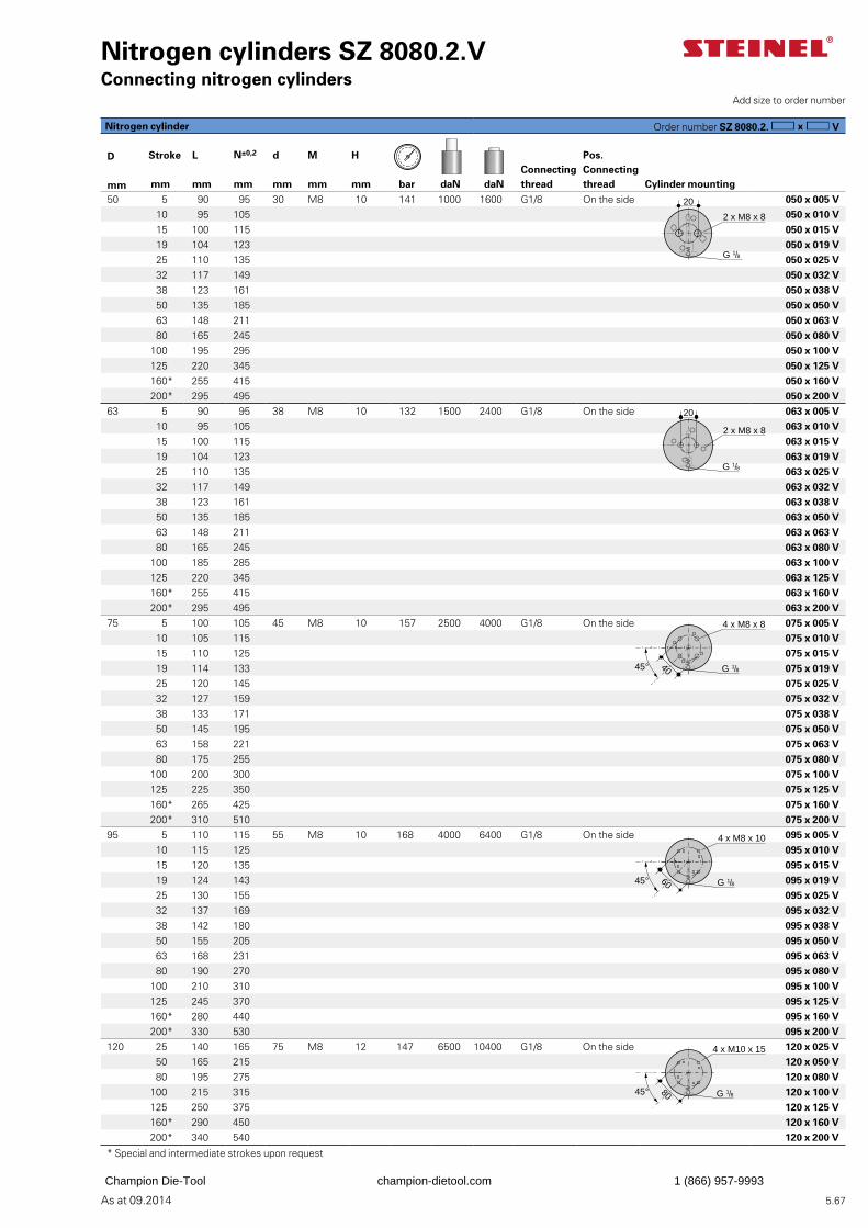
5.67As at 09.2014
Nitrogen cylinders SZ 8080.2.VConnecting nitrogen cylinders
Add size to order number
D Stroke L N±0,2 d M HConnecting thread
Pos. Connecting threadmm mm mm mm mm mm mm bar daN daN Cylinder mounting
50 5 90 95 30 M8 10 141 1000 1600 G1/8 On the side 050 x 005 V10 95 105 050 x 010 V15 100 115 050 x 015 V19 104 123 050 x 019 V 25 110 135 050 x 025 V32 117 149 050 x 032 V38 123 161 050 x 038 V 50 135 185 050 x 050 V63 148 211 050 x 063 V 80 165 245 050 x 080 V
100 195 295 050 x 100 V125 220 345 050 x 125 V160* 255 415 050 x 160 V200* 295 495 050 x 200 V
63 5 90 95 38 M8 10 132 1500 2400 G1/8 On the side 063 x 005 V10 95 105 063 x 010 V15 100 115 063 x 015 V19 104 123 063 x 019 V
25 110 135 063 x 025 V32 117 149 063 x 032 V38 123 161 063 x 038 V 50 135 185 063 x 050 V63 148 211 063 x 063 V 80 165 245 063 x 080 V
100 185 285 063 x 100 V125 220 345 063 x 125 V160* 255 415 063 x 160 V200* 295 495 063 x 200 V
75 5 100 105 45 M8 10 157 2500 4000 G1/8 On the side 075 x 005 V10 105 115 075 x 010 V 15 110 125 075 x 015 V19 114 133 075 x 019 V 25 120 145 075 x 025 V32 127 159 075 x 032 V38 133 171 075 x 038 V 50 145 195 075 x 050 V63 158 221 075 x 063 V 80 175 255 075 x 080 V
100 200 300 075 x 100 V125 225 350 075 x 125 V160* 265 425 075 x 160 V200* 310 510 075 x 200 V
95 5 110 115 55 M8 10 168 4000 6400 G1/8 On the side 095 x 005 V10 115 125 095 x 010 V15 120 135 095 x 015 V19 124 143 095 x 019 V 25 130 155 095 x 025 V32 137 169 095 x 032 V38 142 180 095 x 038 V 50 155 205 095 x 050 V63 168 231 095 x 063 V 80 190 270 095 x 080 V
100 210 310 095 x 100 V125 245 370 095 x 125 V160* 280 440 095 x 160 V200* 330 530 095 x 200 V
120 25 140 165 75 M8 12 147 6500 10400 G1/8 On the side 120 x 025 V50 165 215 120 x 050 V80 195 275 120 x 080 V
100 215 315 120 x 100 V125 250 375 120 x 125 V160* 290 450 120 x 160 V200* 340 540 120 x 200 V
* Special and intermediate strokes upon request
2 x M8 x 8
G 1/8
20
Nitrogen cylinder Order number SZ 8080.2. V
20
2 x M8 x 8
G 1/8
4 x M8 x 8
G 1/84045°
4 x M8 x 10
G 1/86045°
4 x M10 x 15
G 1/88045°
Champion Die-Tool champion-dietool.com 1 (866) 957-9993
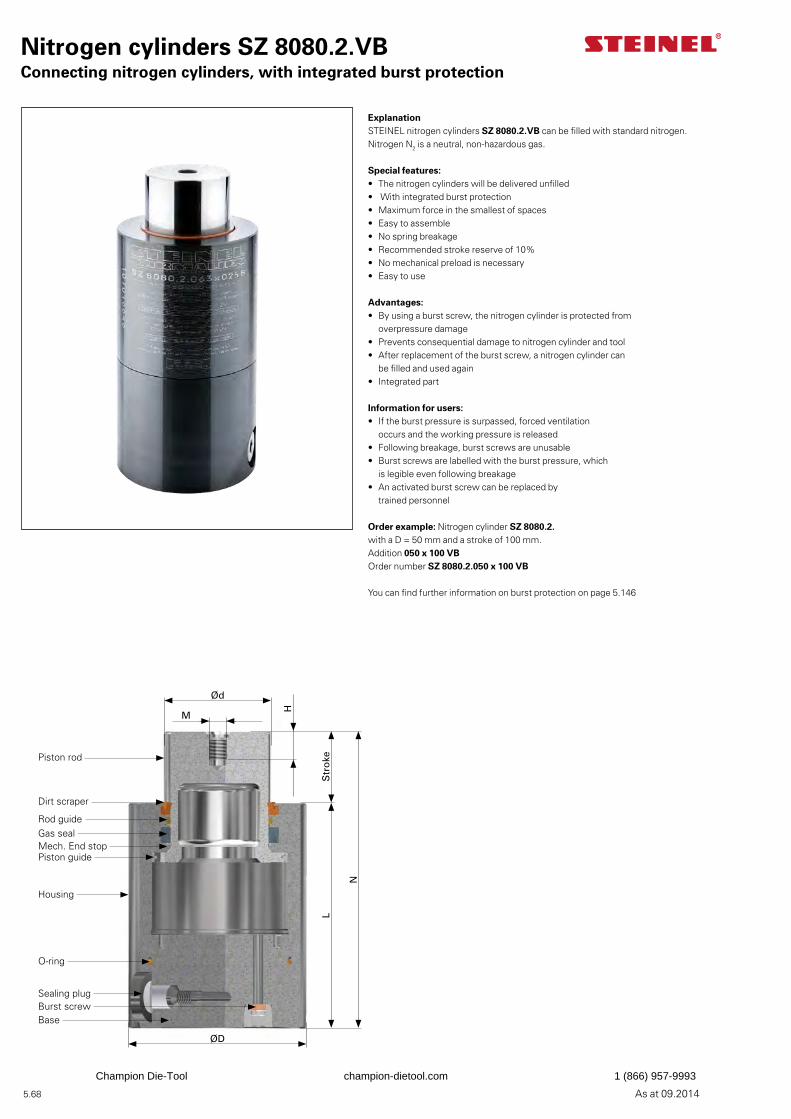
5.68 As at 09.2014
ExplanationSTEINEL nitrogen cylinders SZ 8080.2.VB can be filled with standard nitrogen. Nitrogen N2 is a neutral, non-hazardous gas.
Special features:• The nitrogen cylinders will be delivered unfilled• With integrated burst protection• Maximum force in the smallest of spaces• Easy to assemble• No spring breakage• Recommended stroke reserve of 10%• No mechanical preload is necessary• Easy to use
Advantages:• By using a burst screw, the nitrogen cylinder is protected from
overpressure damage• Prevents consequential damage to nitrogen cylinder and tool• After replacement of the burst screw, a nitrogen cylinder can
be filled and used again• Integrated part
Information for users:• If the burst pressure is surpassed, forced ventilation
occurs and the working pressure is released• Following breakage, burst screws are unusable• Burst screws are labelled with the burst pressure, which
is legible even following breakage• An activated burst screw can be replaced by
trained personnel
Order example: Nitrogen cylinder SZ 8080.2.with a D = 50 mm and a stroke of 100 mm.Addition 050 x 100 VBOrder number SZ 8080.2.050 x 100 VB
You can find further information on burst protection on page 5.146
Nitrogen cylinders SZ 8080.2.VBConnecting nitrogen cylinders, with integrated burst protection
Ød
M
H
Str
oke
N
L
ØD
Piston rod
Dirt scraper
Rod guideGas sealMech. End stopPiston guide
Housing
Sealing plugBurst screwBase
O-ring
Champion Die-Tool champion-dietool.com 1 (866) 957-9993
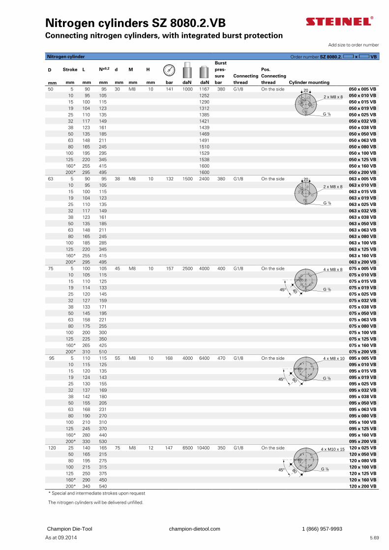
5.69As at 09.2014
Nitrogen cylinders SZ 8080.2.VBConnecting nitrogen cylinders, with integrated burst protection
Add size to order number
Burst pres-sure bar
D Stroke L N±0,2 d M H Pos. Connecting thread
Connecting threadmm mm mm mm mm mm mm bar daN daN Cylinder mounting
50 5 90 95 30 M8 10 141 1000 1167 380 G1/8 On the side 050 x 005 VB10 95 105 1252 050 x 010 VB15 100 115 1290 050 x 015 VB19 104 123 1312 050 x 019 VB 25 110 135 1385 050 x 025 VB32 117 149 1421 050 x 032 VB38 123 161 1439 050 x 038 VB 50 135 185 1469 050 x 050 VB63 148 211 1491 050 x 063 VB 80 165 245 1510 050 x 080 VB
100 195 295 1529 050 x 100 VB125 220 345 1538 050 x 125 VB160* 255 415 1600 050 x 160 VB200* 295 495 1600 050 x 200 VB
63 5 90 95 38 M8 10 132 1500 2400 380 G1/8 On the side 063 x 005 VB10 95 105 063 x 010 VB15 100 115 063 x 015 VB19 104 123 063 x 019 VB
25 110 135 063 x 025 VB32 117 149 063 x 032 VB38 123 161 063 x 038 VB 50 135 185 063 x 050 VB63 148 211 063 x 063 VB 80 165 245 063 x 080 VB
100 185 285 063 x 100 VB125 220 345 063 x 125 VB160* 255 415 063 x 160 VB200* 295 495 063 x 200 VB
75 5 100 105 45 M8 10 157 2500 4000 400 G1/8 On the side 075 x 005 VB10 105 115 075 x 010 VB15 110 125 075 x 015 VB19 114 133 075 x 019 VB 25 120 145 075 x 025 VB32 127 159 075 x 032 VB38 133 171 075 x 038 VB 50 145 195 075 x 050 VB63 158 221 075 x 063 VB 80 175 255 075 x 080 VB
100 200 300 075 x 100 VB125 225 350 075 x 125 VB160* 265 425 075 x 160 VB200* 310 510 075 x 200 VB
95 5 110 115 55 M8 10 168 4000 6400 470 G1/8 On the side 095 x 005 VB10 115 125 095 x 010 VB15 120 135 095 x 015 VB19 124 143 095 x 019 VB 25 130 155 095 x 025 VB32 137 169 095 x 032 VB38 142 180 095 x 038 VB 50 155 205 095 x 050 VB63 168 231 095 x 063 VB 80 190 270 095 x 080 VB
100 210 310 095 x 100 VB125 245 370 095 x 125 VB160* 280 440 095 x 160 VB200* 330 530 095 x 200 VB
120 25 140 165 75 M8 12 147 6500 10400 350 G1/8 On the side 120 x 025 VB50 165 215 120 x 050 VB80 195 275 120 x 080 VB
100 215 315 120 x 100 VB125 250 375 120 x 125 VB160* 290 450 120 x 160 VB200* 340 540 120 x 200 VB
* Special and intermediate strokes upon request
The nitrogen cylinders will be delivered unfilled.
2 x M8 x 8
G 1/8
20
20
2 x M8 x 8
G 1/8
4 x M8 x 8
G 1/84045°
4 x M8 x 10
G 1/845° 60
4 x M10 x 15
G 1/845° 80
Nitrogen cylinder Order number SZ 8080.2. VB
Champion Die-Tool champion-dietool.com 1 (866) 957-9993
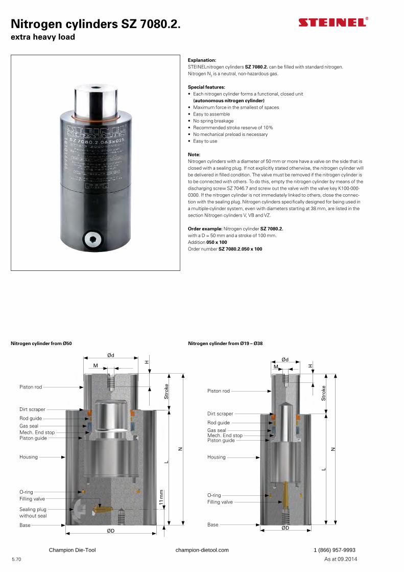
5.70 As at 09.2014
Nitrogen cylinders SZ 7080.2.extra heavy load
Explanation:STEINELnitrogen cylinders SZ 7080.2. can be filled with standard nitrogen. Nitrogen N2 is a neutral, non-hazardous gas.
Special features:• Each nitrogen cylinder forms a functional, closed unit
(autonomous nitrogen cylinder)• Maximum force in the smallest of spaces• Easy to assemble• No spring breakage• Recommended stroke reserve of 10%• No mechanical preload is necessary• Easy to use
Note:Nitrogen cylinders with a diameter of 50 mm or more have a valve on the side that is closed with a sealing plug. If not explicitly stated otherwise, the nitrogen cylinder will be delivered in filled condition. The valve must be removed if the nitrogen cylinder is to be connected with others. To do this, empty the nitrogen cylinder by means of the discharging screw SZ 7046.7 and screw out the valve with the valve key K100-000-0300. If the nitrogen cylinder is not immediately linked to others, close the connec-tion with the sealing plug. Nitrogen cylinders specifically designed for being used in a multiple-cylinder system, even with diameters starting at 38 mm, are listed in the section Nitrogen cylinders V, VB and VZ.
Order example: Nitrogen cylinder SZ 7080.2.with a D = 50 mm and a stroke of 100 mm.Addition 050 x 100Order number SZ 7080.2.050 x 100
Ød
M
H
11 m
mS
tro
ke
N
L
ØD
Piston rod
Dirt scraper
Rod guide
Gas sealMech. End stopPiston guide
Housing
Filling valve
Sealing plug without seal
Base
O-ring
ØdM H
Str
oke
N
L
ØD
Piston rod
Dirt scraper
Rod guide
Gas sealMech. End stopPiston guide
Housing
Filling valve
Base
O-ring
Nitrogen cylinder from Ø50 Nitrogen cylinder from Ø19 – Ø38
Champion Die-Tool champion-dietool.com 1 (866) 957-9993
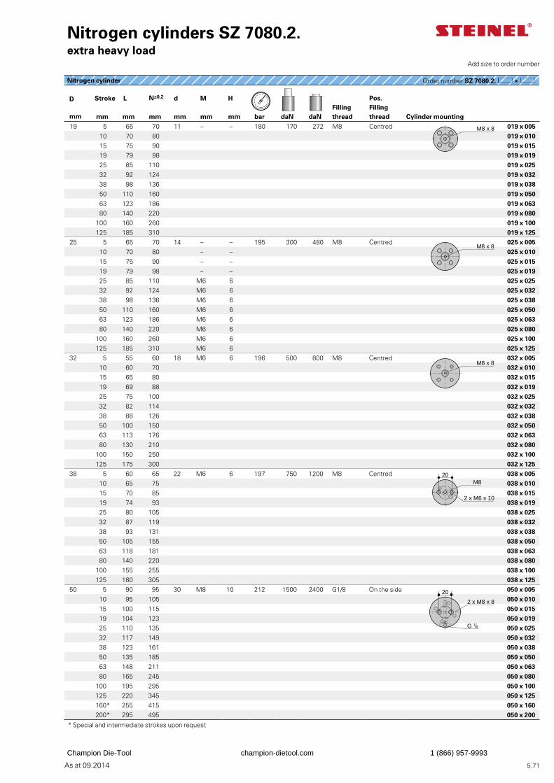
5.71As at 09.2014
Nitrogen cylinder Order number SZ 7080.2.
Nitrogen cylinders SZ 7080.2.extra heavy load
D Stroke L N±0,2 d M H Pos. Filling thread
Filling thread
mm mm mm mm mm mm mm bar daN daN Cylinder mounting 19 5 65 70 11 – – 180 170 272 M8 Centred 019 x 005
10 70 80 019 x 010 15 75 90 019 x 01519 79 98 019 x 019 25 85 110 019 x 02532 92 124 019 x 03238 98 136 019 x 038 50 110 160 019 x 05063 123 186 019 x 063 80 140 220 019 x 080
100 160 260 019 x 100125 185 310 019 x 125
25 5 65 70 14 – – 195 300 480 M8 Centred 025 x 005 10 70 80 – – 025 x 010 15 75 90 – – 025 x 01519 79 98 – – 025 x 019 25 85 110 M6 6 025 x 02532 92 124 M6 6 025 x 03238 98 136 M6 6 025 x 038 50 110 160 M6 6 025 x 05063 123 186 M6 6 025 x 063 80 140 220 M6 6 025 x 080
100 160 260 M6 6 025 x 100125 185 310 M6 6 025 x 125
32 5 55 60 18 M6 6 196 500 800 M8 Centred 032 x 005 10 60 70 032 x 010 15 65 80 032 x 01519 69 88 032 x 019 25 75 100 032 x 02532 82 114 032 x 03238 88 126 032 x 038 50 100 150 032 x 05063 113 176 032 x 063 80 130 210 032 x 080
100 150 250 032 x 100125 175 300 032 x 125
38 5 60 65 22 M6 6 197 750 1200 M8 Centred 038 x 005 10 65 75 038 x 010 15 70 85 038 x 01519 74 93 038 x 019 25 80 105 038 x 02532 87 119 038 x 03238 93 131 038 x 038 50 105 155 038 x 05063 118 181 038 x 063 80 140 220 038 x 080
100 155 255 038 x 100125 180 305 038 x 125
50 5 90 95 30 M8 10 212 1500 2400 G1/8 On the side 050 x 00510 95 105 050 x 01015 100 115 050 x 01519 104 123 050 x 019 25 110 135 050 x 02532 117 149 050 x 03238 123 161 050 x 038 50 135 185 050 x 05063 148 211 050 x 063 80 165 245 050 x 080
100 195 295 050 x 100125 220 345 050 x 125160* 255 415 050 x 160200* 295 495 050 x 200
* Special and intermediate strokes upon request
Add size to order number
M8 x 8
M8 x 8
M8 x 8
M8
2 x M6 x 10
20
2 x M8 x 8
G 1/8
20
Champion Die-Tool champion-dietool.com 1 (866) 957-9993
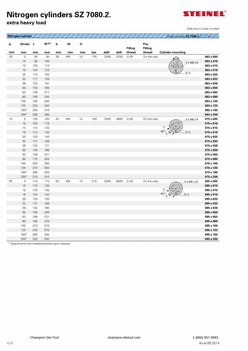
5.72 As at 09.2014
D Stroke L N±0,2 d M H Pos. Filling thread
Filling thread
mm mm mm mm mm mm mm bar daN daN Cylinder mounting
63 5 90 95 38 M8 10 176 2000 3200 G1/8 On the side 063 x 005
10 95 105 063 x 010
15 100 115 063 x 015
19 104 123 063 x 019
25 110 135 063 x 025
32 117 149 063 x 032
38 123 161 063 x 038
50 135 185 063 x 050
63 148 211 063 x 063
80 165 245 063 x 080
100 185 285 063 x 100
125 220 345 063 x 125
160* 255 415 063 x 160
200* 295 495 063 x 200
75 5 100 105 45 M8 10 189 3000 4800 G1/8 On the side 075 x 005
10 105 115 075 x 010
15 110 125 075 x 015
19 114 133 075 x 019
25 120 145 075 x 025
32 127 159 075 x 032
38 133 171 075 x 038
50 145 195 075 x 050
63 158 221 075 x 063
80 175 255 075 x 080
100 200 300 075 x 100
125 225 350 075 x 125
160* 265 425 075 x 160
200* 310 510 075 x 200
95 5 110 115 55 M8 10 210 5000 8000 G1/8 On the side 095 x 005
10 115 125 095 x 010
15 120 135 095 x 015
19 124 143 095 x 019
25 130 155 095 x 025
32 137 169 095 x 032
38 142 180 095 x 038
50 155 205 095 x 050
63 168 231 095 x 063
80 190 270 095 x 080
100 210 310 095 x 100
125 245 370 095 x 125
160* 280 440 095 x 160
200* 330 530 095 x 200
* Special and intermediate strokes upon request
Nitrogen cylinder Order number SZ 7080.2.
Nitrogen cylinders SZ 7080.2.extra heavy load
Add size to order number
20
2 x M8 x 8
G 1/8
4 x M8 x 8
G 1/84045°
4 x M8 x 10
G 1/86045°
Champion Die-Tool champion-dietool.com 1 (866) 957-9993

5.73As at 09.2014
Champion Die-Tool champion-dietool.com 1 (866) 957-9993
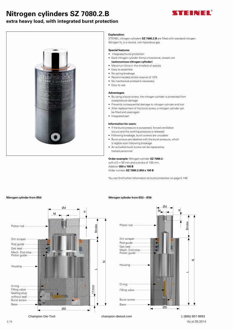
5.74 As at 09.2014
Nitrogen cylinders SZ 7080.2.Bextra heavy load, with integrated burst protection
Explanation:STEINEL nitrogen cylinders SZ 7080.2.B are filled with standard nitrogen. Nitrogen N2 is a neutral, non-hazardous gas.
Special features:• Integrated burst protection• Each nitrogen cylinder forms a functional, closed unit
(autonomous nitrogen cylinder)• Maximum force in the smallest of spaces• Easy to assemble• No spring breakage• Recommended stroke reserve of 10%• No mechanical preload is necessary• Easy to use
Advantages:• By using a burst screw, the nitrogen cylinder is protected from
overpressure damage• Prevents consequential damage to nitrogen cylinder and tool• After replacement of the burst screw, a nitrogen cylinder can
be filled and used again• Integrated part
Information for users:• If the burst pressure is surpassed, forced ventilation
occurs and the working pressure is released• Following breakage, burst screws are unusable• Burst screws are labelled with the burst pressure, which
is legible even following breakage• An activated burst screw can be replaced by
trained personnel
Order example: Nitrogen cylinder SZ 7080.2.with a D = 50 mm and a stroke of 100 mm.Addition 050 x 100 BOrder number SZ 7080.2.050 x 100 B
You can find further information on burst protection on page 5.146
Ød
M H
Str
oke
N
L
ØD
Piston rod
Dirt scraperRod guideGas sealMech. End stopPiston guide
Housing
Filling valve
Base
Burst screw
O-ring
Ød
M
H
11 m
mS
tro
ke
N
L
ØD
Piston rod
Dirt scraper
Rod guideGas sealMech. End stopPiston guide
Housing
Filling valveSealing plug without seal
BaseBurst screw
O-ring
Nitrogen cylinder from Ø50 Nitrogen cylinder from Ø32 – Ø38
Champion Die-Tool champion-dietool.com 1 (866) 957-9993
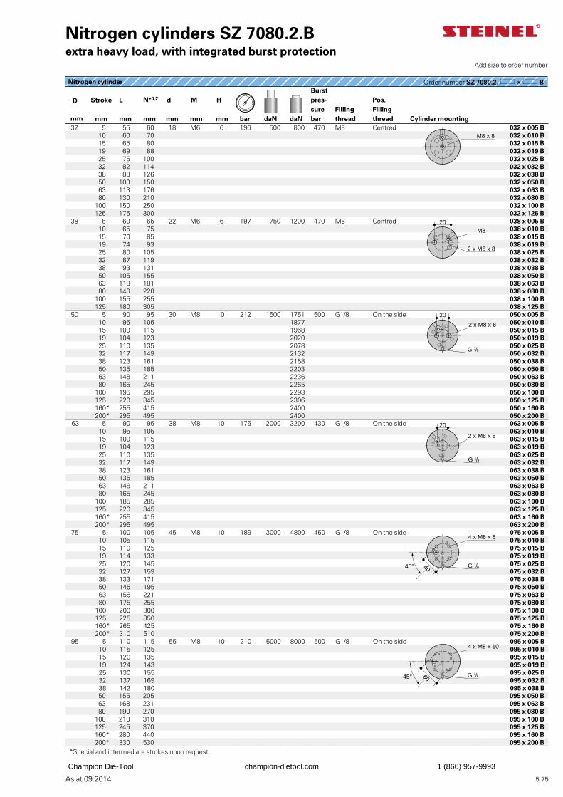
5.75As at 09.2014
Burst pres-sure bar
D Stroke L N±0,2 d M H Pos. Filling thread
Filling thread
mm mm mm mm mm mm mm bar daN daN Cylinder mounting 32 5 55 60 18 M6 6 196 500 800 470 M8 Centred 032 x 005 B
10 60 70 032 x 010 B 15 65 80 032 x 015 B19 69 88 032 x 019 B 25 75 100 032 x 025 B32 82 114 032 x 032 B38 88 126 032 x 038 B 50 100 150 032 x 050 B63 113 176 032 x 063 B 80 130 210 032 x 080 B
100 150 250 032 x 100 B125 175 300 032 x 125 B
38 5 60 65 22 M6 6 197 750 1200 470 M8 Centred 038 x 005 B 10 65 75 038 x 010 B 15 70 85 038 x 015 B19 74 93 038 x 019 B 25 80 105 038 x 025 B32 87 119 038 x 032 B38 93 131 038 x 038 B 50 105 155 038 x 050 B63 118 181 038 x 063 B 80 140 220 038 x 080 B
100 155 255 038 x 100 B125 180 305 038 x 125 B
50 5 90 95 30 M8 10 212 1500 1751 500 G1/8 On the side 050 x 005 B10 95 105 1877 050 x 010 B15 100 115 1968 050 x 015 B19 104 123 2020 050 x 019 B 25 110 135 2078 050 x 025 B32 117 149 2132 050 x 032 B38 123 161 2158 050 x 038 B 50 135 185 2203 050 x 050 B63 148 211 2236 050 x 063 B 80 165 245 2265 050 x 080 B
100 195 295 2293 050 x 100 B125 220 345 2306 050 x 125 B160* 255 415 2400 050 x 160 B200* 295 495 2400 050 x 200 B
63 5 90 95 38 M8 10 176 2000 3200 430 G1/8 On the side 063 x 005 B10 95 105 063 x 010 B15 100 115 063 x 015 B19 104 123 063 x 019 B 25 110 135 063 x 025 B32 117 149 063 x 032 B38 123 161 063 x 038 B 50 135 185 063 x 050 B63 148 211 063 x 063 B 80 165 245 063 x 080 B
100 185 285 063 x 100 B125 220 345 063 x 125 B160* 255 415 063 x 160 B200* 295 495 063 x 200 B
75 5 100 105 45 M8 10 189 3000 4800 450 G1/8 On the side 075 x 005 B10 105 115 075 x 010 B15 110 125 075 x 015 B19 114 133 075 x 019 B 25 120 145 075 x 025 B32 127 159 075 x 032 B38 133 171 075 x 038 B 50 145 195 075 x 050 B63 158 221 075 x 063 B 80 175 255 075 x 080 B
100 200 300 075 x 100 B125 225 350 075 x 125 B160* 265 425 075 x 160 B200* 310 510 075 x 200 B
95 5 110 115 55 M8 10 210 5000 8000 500 G1/8 On the side 095 x 005 B10 115 125 095 x 010 B15 120 135 095 x 015 B19 124 143 095 x 019 B 25 130 155 095 x 025 B32 137 169 095 x 032 B38 142 180 095 x 038 B
50 155 205 095 x 050 B63 168 231 095 x 063 B 80 190 270 095 x 080 B
100 210 310 095 x 100 B125 245 370 095 x 125 B160* 280 440 095 x 160 B200* 330 530 095 x 200 B
*Special and intermediate strokes upon request
Nitrogen cylinder Order number SZ 7080.2. B
Nitrogen cylinders SZ 7080.2.Bextra heavy load, with integrated burst protection
Add size to order number
M8 x 8
M8
2 x M6 x 8
20
2 x M8 x 8
G 1/8
20
20
2 x M8 x 8
G 1/8
4 x M8 x 8
G 1/84045°
4 x M8 x 10
G 1/845° 60
Champion Die-Tool champion-dietool.com 1 (866) 957-9993
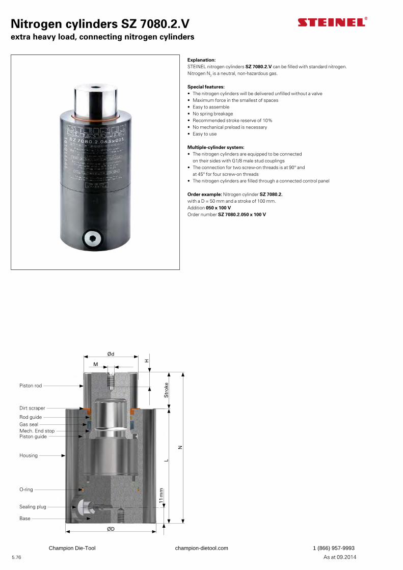
5.76 As at 09.2014
Nitrogen cylinders SZ 7080.2.Vextra heavy load, connecting nitrogen cylinders
Explanation:STEINEL nitrogen cylinders SZ 7080.2.V can be filled with standard nitrogen. Nitrogen N2 is a neutral, non-hazardous gas.
Special features:• The nitrogen cylinders will be delivered unfilled without a valve• Maximum force in the smallest of spaces• Easy to assemble• No spring breakage• Recommended stroke reserve of 10%• No mechanical preload is necessary• Easy to use
Multiple-cylinder system:• The nitrogen cylinders are equipped to be connected
on their sides with G1/8 male stud couplings• The connection for two screw-on threads is at 90° and
at 45° for four screw-on threads• The nitrogen cylinders are filled through a connected control panel
Order example: Nitrogen cylinder SZ 7080.2.with a D = 50 mm and a stroke of 100 mm.Addition 050 x 100 VOrder number SZ 7080.2.050 x 100 V
Ød
M
H
Str
oke
N
L
ØD
11 m
m
Piston rod
Dirt scraper
Rod guideGas sealMech. End stopPiston guide
Housing
Sealing plug
Base
O-ring
Champion Die-Tool champion-dietool.com 1 (866) 957-9993
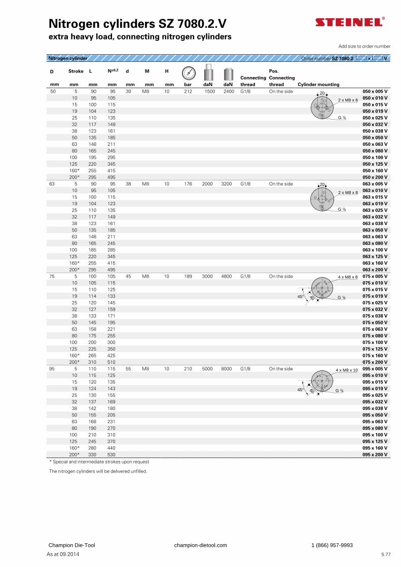
5.77As at 09.2014
Nitrogen cylinder Order number SZ 7080.2. V
Nitrogen cylinders SZ 7080.2.Vextra heavy load, connecting nitrogen cylinders
D Stroke L N±0,2 d M H Pos. Connecting thread
Connecting thread
mm mm mm mm mm mm mm bar daN daN Cylinder mounting 50 5 90 95 30 M8 10 212 1500 2400 G1/8 On the side 050 x 005 V
10 95 105 050 x 010 V15 100 115 050 x 015 V19 104 123 050 x 019 V 25 110 135 050 x 025 V32 117 149 050 x 032 V38 123 161 050 x 038 V 50 135 185 050 x 050 V63 148 211 050 x 063 V 80 165 245 050 x 080 V
100 195 295 050 x 100 V125 220 345 050 x 125 V160* 255 415 050 x 160 V200* 295 495 050 x 200 V
63 5 90 95 38 M8 10 176 2000 3200 G1/8 On the side 063 x 005 V10 95 105 063 x 010 V15 100 115 063 x 015 V19 104 123 063 x 019 V
25 110 135 063 x 025 V32 117 149 063 x 032 V38 123 161 063 x 038 V 50 135 185 063 x 050 V63 148 211 063 x 063 V 80 165 245 063 x 080 V
100 185 285 063 x 100 V125 220 345 063 x 125 V160* 255 415 063 x 160 V200* 295 495 063 x 200 V
75 5 100 105 45 M8 10 189 3000 4800 G1/8 On the side 075 x 005 V10 105 115 075 x 010 V15 110 125 075 x 015 V19 114 133 075 x 019 V 25 120 145 075 x 025 V32 127 159 075 x 032 V38 133 171 075 x 038 V 50 145 195 075 x 050 V63 158 221 075 x 063 V 80 175 255 075 x 080 V
100 200 300 075 x 100 V125 225 350 075 x 125 V160* 265 425 075 x 160 V200* 310 510 075 x 200 V
95 5 110 115 55 M8 10 210 5000 8000 G1/8 On the side 095 x 005 V10 115 125 095 x 010 V15 120 135 095 x 015 V19 124 143 095 x 019 V 25 130 155 095 x 025 V32 137 169 095 x 032 V38 142 180 095 x 038 V 50 155 205 095 x 050 V63 168 231 095 x 063 V 80 190 270 095 x 080 V
100 210 310 095 x 100 V125 245 370 095 x 125 V160* 280 440 095 x 160 V200* 330 530 095 x 200 V
* Special and intermediate strokes upon request
The nitrogen cylinders will be delivered unfilled.
Add size to order number
2 x M8 x 8
G 1/8
20
20
2 x M8 x 8
G 1/8
4 x M8 x 8
G 1/84045°
4 x M8 x 10
G 1/86045°
Champion Die-Tool champion-dietool.com 1 (866) 957-9993
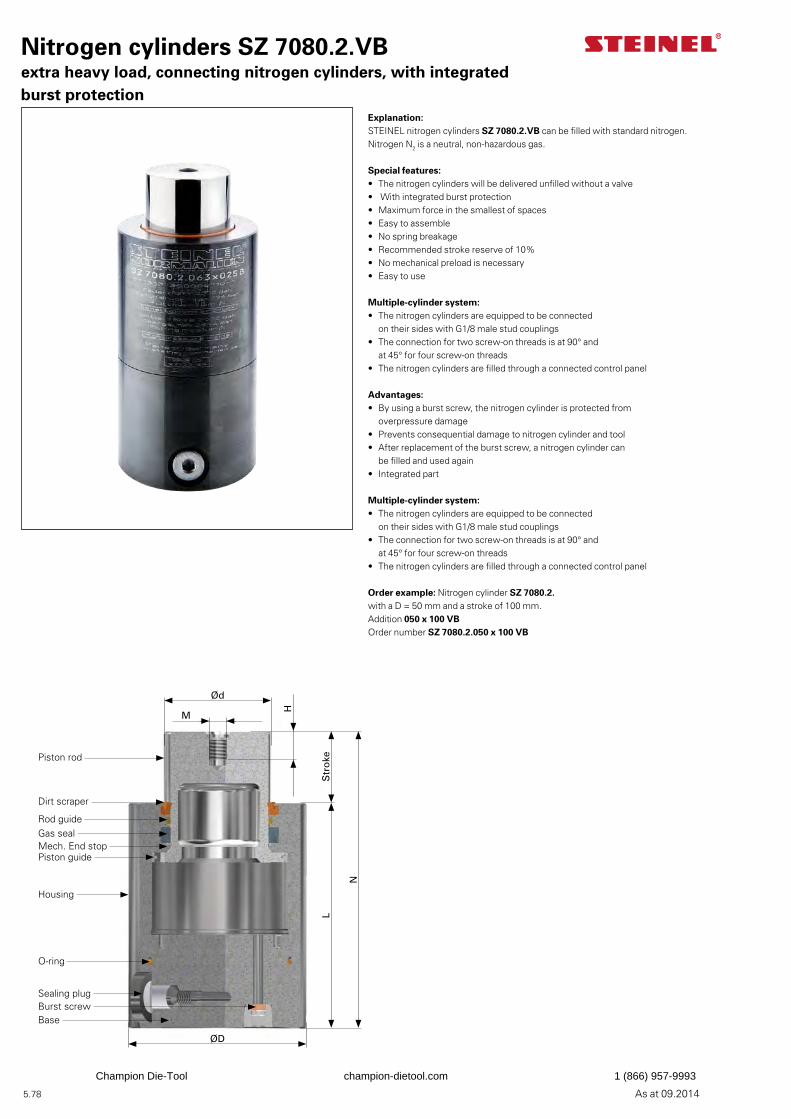
5.78 As at 09.2014
Nitrogen cylinders SZ 7080.2.VBextra heavy load, connecting nitrogen cylinders, with integrated burst protection
Explanation:STEINEL nitrogen cylinders SZ 7080.2.VB can be filled with standard nitrogen. Nitrogen N2 is a neutral, non-hazardous gas.
Special features:• The nitrogen cylinders will be delivered unfilled without a valve• With integrated burst protection• Maximum force in the smallest of spaces• Easy to assemble• No spring breakage• Recommended stroke reserve of 10%• No mechanical preload is necessary• Easy to use
Multiple-cylinder system:• The nitrogen cylinders are equipped to be connected
on their sides with G1/8 male stud couplings• The connection for two screw-on threads is at 90° and
at 45° for four screw-on threads• The nitrogen cylinders are filled through a connected control panel
Advantages:• By using a burst screw, the nitrogen cylinder is protected from
overpressure damage• Prevents consequential damage to nitrogen cylinder and tool• After replacement of the burst screw, a nitrogen cylinder can
be filled and used again• Integrated part
Multiple-cylinder system:• The nitrogen cylinders are equipped to be connected
on their sides with G1/8 male stud couplings• The connection for two screw-on threads is at 90° and
at 45° for four screw-on threads• The nitrogen cylinders are filled through a connected control panel
Order example: Nitrogen cylinder SZ 7080.2.with a D = 50 mm and a stroke of 100 mm.Addition 050 x 100 VBOrder number SZ 7080.2.050 x 100 VB
Ød
M
H
Str
oke
N
L
ØD
Piston rod
Dirt scraper
Rod guideGas sealMech. End stopPiston guide
Housing
Sealing plugBurst screwBase
O-ring
Champion Die-Tool champion-dietool.com 1 (866) 957-9993
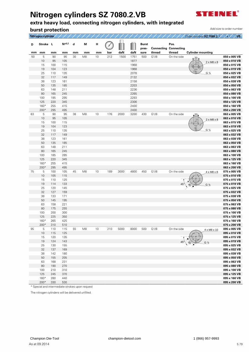
5.79As at 09.2014
D Stroke L N±0,2 d M H Burst pres-sure
Pos. Connecting thread
Connecting thread
mm mm mm mm mm mm mm bar daN daN Cylinder mounting 50 5 90 95 30 M8 10 212 1500 1751 500 G1/8 On the side 050 x 005 VB
10 95 105 1877 050 x 010 VB15 100 115 1968 050 x 015 VB19 104 123 1968 050 x 019 VB 25 110 135 2078 050 x 025 VB32 117 149 2132 050 x 032 VB38 123 161 2158 050 x 038 VB 50 135 185 2203 050 x 050 VB63 148 211 2236 050 x 063 VB 80 165 245 2265 050 x 080 VB
100 195 295 2293 050 x 100 VB125 220 345 2306 050 x 125 VB160* 255 415 2400 050 x 160 VB200* 295 495 2400 050 x 200 VB
63 5 90 95 38 M8 10 176 2000 3200 430 G1/8 On the side 063 x 005 VB10 95 105 063 x 010 VB15 100 115 063 x 015 VB19 104 123 063 x 019 VB
25 110 135 063 x 025 VB32 117 149 063 x 032 VB38 123 161 063 x 038 VB 50 135 185 063 x 050 VB63 148 211 063 x 063 VB 80 165 245 063 x 080 VB
100 185 285 063 x 100 VB125 220 345 063 x 125 VB160* 255 415 063 x 160 VB200* 295 495 063 x 200 VB
75 5 100 105 45 M8 10 189 3000 4800 450 G1/8 On the side 075 x 005 VB10 105 115 075 x 010 VB15 110 125 075 x 015 VB19 114 133 075 x 019 VB 25 120 145 075 x 025 VB32 127 159 075 x 032 VB38 133 171 075 x 038 VB 50 145 195 075 x 050 VB63 158 221 075 x 063 VB 80 175 255 075 x 080 VB
100 200 300 075 x 100 VB125 225 350 075 x 125 VB160* 265 425 075 x 160 VB200* 310 510 075 x 200 VB
95 5 110 115 55 M8 10 210 5000 8000 500 G1/8 On the side 095 x 005 VB10 115 125 095 x 010 VB15 120 135 095 x 015 VB19 124 143 095 x 019 VB 25 130 155 095 x 025 VB32 137 169 095 x 032 VB38 142 180 095 x 038 VB 50 155 205 095 x 050 VB63 168 231 095 x 063 VB 80 190 270 095 x 080 VB
100 210 310 095 x 100 VB125 245 370 095 x 125 VB160* 280 440 095 x 160 VB200* 330 530 095 x 200 VB
* Special and intermediate strokes upon request
The nitrogen cylinders will be delivered unfilled.
Nitrogen cylinder Order number SZ 7080.2. VB
Nitrogen cylinders SZ 7080.2.VBextra heavy load, connecting nitrogen cylinders, with integrated burst protection Add size to order number
2 x M8 x 8
G 1/8
20
20
2 x M8 x 8
G 1/8
4 x M8 x 8
G 1/84045°
4 x M8 x 10
G 1/86045°
Champion Die-Tool champion-dietool.com 1 (866) 957-9993
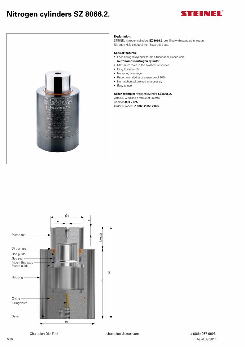
5.80 As at 09.2014
Explanation:STEINEL nitrogen cylinders SZ 8066.2. are filled with standard nitrogen. Nitrogen N2 is a neutral, non-hazardous gas.
Special features:• Each nitrogen cylinder forms a functional, closed unit
(autonomous nitrogen cylinder)• Maximum force in the smallest of spaces• Easy to assemble• No spring breakage• Recommended stroke reserve of 10%• No mechanical preload is necessary• Easy to use
Order example: Nitrogen cylinder SZ 8066.2.with a D = 50 and a stroke of 25 mmAddition 050 x 025Order number SZ 8066.2.050 x 025
Nitrogen cylinders SZ 8066.2.
Ød
M
H
Str
oke
N
L
ØD
Piston rod
Dirt scraper
Rod guideGas sealMech. End stopPiston guide
Housing
Filling valve
Base
O-ring
Champion Die-Tool champion-dietool.com 1 (866) 957-9993
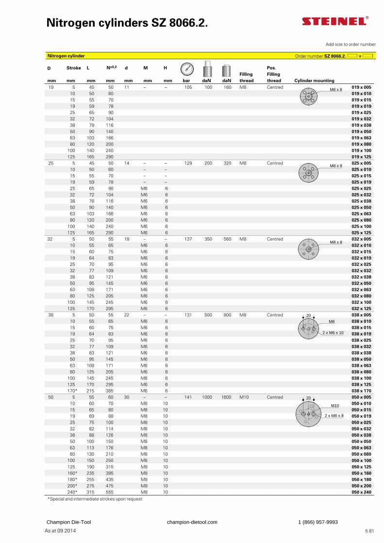
5.81As at 09.2014
Nitrogen cylinders SZ 8066.2.
Add size to order number
Nitrogen cylinder Order number SZ 8066.2.
D Stroke L N±0,2 d M H Pos. Filling thread
Filling threadmm mm mm mm mm mm mm bar daN daN Cylinder mounting
19 5 45 50 11 – – 105 100 160 M8 Centred 019 x 005 10 50 60 019 x 010 15 55 70 019 x 01519 59 78 019 x 019 25 65 90 019 x 02532 72 104 019 x 032 38 78 116 019 x 038 50 90 140 019 x 05063 103 166 019 x 063 80 120 200 019 x 080
100 140 240 019 x 100125 165 290 019 x 125
25 5 45 50 14 – – 129 200 320 M8 Centred 025 x 005 10 50 60 – – 025 x 010 15 55 70 – – 025 x 01519 59 78 – – 025 x 019 25 65 90 M6 6 025 x 02532 72 104 M6 6 025 x 032 38 78 116 M6 6 025 x 038 50 90 140 M6 6 025 x 05063 103 166 M6 6 025 x 063 80 120 200 M6 6 025 x 080
100 140 240 M6 6 025 x 100125 165 290 M6 6 025 x 125
32 5 50 55 18 – – 137 350 560 M8 Centred 032 x 005 10 55 65 M6 6 032 x 010 15 60 75 M6 6 032 x 01519 64 83 M6 6 032 x 019 25 70 95 M6 6 032 x 02532 77 109 M6 6 032 x 032 38 83 121 M6 6 032 x 038 50 95 145 M6 6 032 x 05063 108 171 M6 6 032 x 063 80 125 205 M6 6 032 x 080
100 145 245 M6 6 032 x 100125 170 295 M6 6 032 x 125
38 5 50 55 22 – – 131 500 800 M8 Centred 038 x 005 10 55 65 M6 6 038 x 010 15 60 75 M6 6 038 x 01519 64 83 M6 6 038 x 019 25 70 95 M6 6 038 x 02532 77 109 M6 6 038 x 032 38 83 121 M6 6 038 x 038 50 95 145 M6 6 038 x 05063 108 171 M6 6 038 x 063 80 125 205 M6 6 038 x 080
100 145 245 M6 6 038 x 100125 170 295 M6 6 038 x 125170* 215 385 M6 6 038 x 170
50 5 55 60 30 – – 141 1000 1600 M10 Centred 050 x 005 10 60 70 M8 10 050 x 01015 65 80 M8 10 050 x 01519 69 88 M8 10 050 x 019
25 75 100 M8 10 050 x 02532 82 114 M8 10 050 x 032 38 88 126 M8 10 050 x 038 50 100 150 M8 10 050 x 050 63 113 176 M8 10 050 x 063 80 130 210 M8 10 050 x 080
100 150 250 M8 10 050 x 100125 190 315 M8 10 050 x 125160* 235 395 M8 10 050 x 160180* 255 435 M8 10 050 x 180200* 275 475 M8 10 050 x 200240* 315 555 M8 10 050 x 240
*Special and intermediate strokes upon request
M8 x 8
M8 x 8
M8 x 8
M8
2 x M6 x 10
20
M10
20
2 x M8 x 8
Champion Die-Tool champion-dietool.com 1 (866) 957-9993
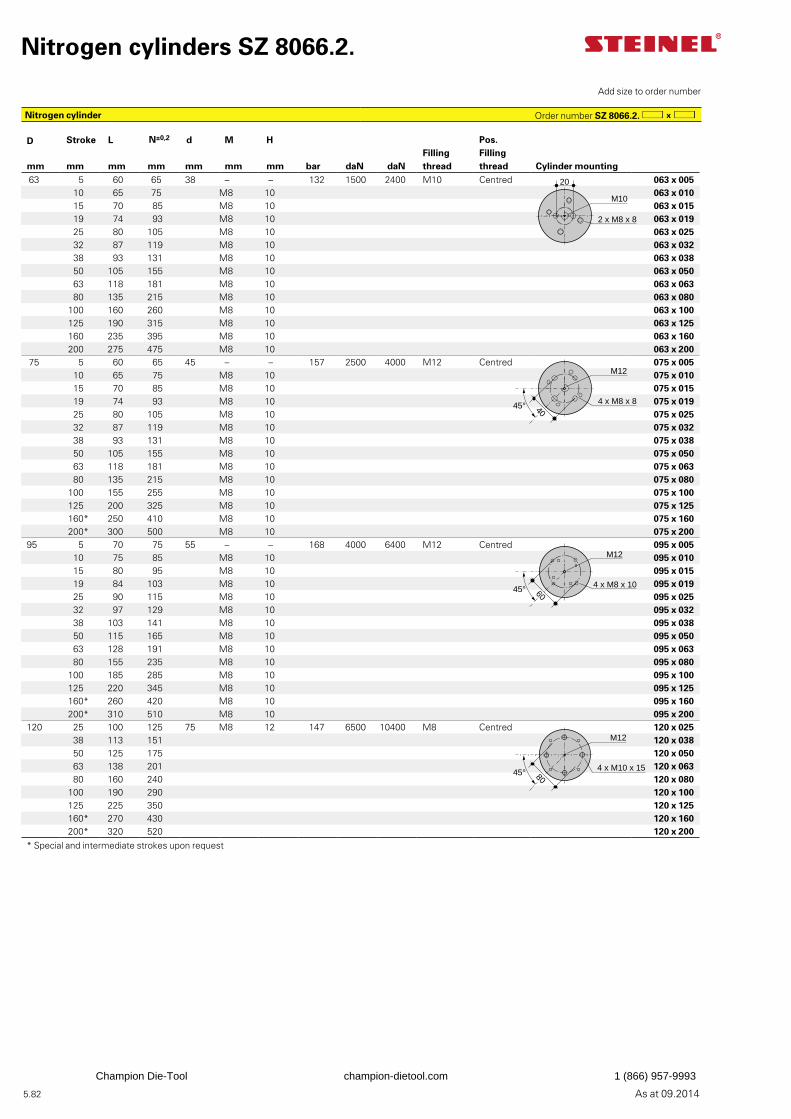
5.82 As at 09.2014
Nitrogen cylinders SZ 8066.2.
Add size to order number
Nitrogen cylinder Order number SZ 8066.2.
D Stroke L N±0,2 d M H Pos. Filling thread
Filling threadmm mm mm mm mm mm mm bar daN daN Cylinder mounting
63 5 60 65 38 – – 132 1500 2400 M10 Centred 063 x 005 10 65 75 M8 10 063 x 01015 70 85 M8 10 063 x 01519 74 93 M8 10 063 x 019
25 80 105 M8 10 063 x 02532 87 119 M8 10 063 x 032 38 93 131 M8 10 063 x 038 50 105 155 M8 10 063 x 050 63 118 181 M8 10 063 x 063 80 135 215 M8 10 063 x 080
100 160 260 M8 10 063 x 100125 190 315 M8 10 063 x 125160 235 395 M8 10 063 x 160200 275 475 M8 10 063 x 200
75 5 60 65 45 – – 157 2500 4000 M12 Centred 075 x 005 10 65 75 M8 10 075 x 01015 70 85 M8 10 075 x 01519 74 93 M8 10 075 x 019
25 80 105 M8 10 075 x 02532 87 119 M8 10 075 x 032 38 93 131 M8 10 075 x 038 50 105 155 M8 10 075 x 050 63 118 181 M8 10 075 x 063 80 135 215 M8 10 075 x 080
100 155 255 M8 10 075 x 100125 200 325 M8 10 075 x 125160* 250 410 M8 10 075 x 160200* 300 500 M8 10 075 x 200
95 5 70 75 55 – – 168 4000 6400 M12 Centred 095 x 00510 75 85 M8 10 095 x 01015 80 95 M8 10 095 x 01519 84 103 M8 10 095 x 019 25 90 115 M8 10 095 x 02532 97 129 M8 10 095 x 032 38 103 141 M8 10 095 x 038 50 115 165 M8 10 095 x 050 63 128 191 M8 10 095 x 063 80 155 235 M8 10 095 x 080
100 185 285 M8 10 095 x 100125 220 345 M8 10 095 x 125160* 260 420 M8 10 095 x 160200* 310 510 M8 10 095 x 200
120 25 100 125 75 M8 12 147 6500 10400 M8 Centred 120 x 02538 113 151 120 x 03850 125 175 120 x 05063 138 201 120 x 06380 160 240 120 x 080
100 190 290 120 x 100125 225 350 120 x 125160* 270 430 120 x 160200* 320 520 120 x 200
* Special and intermediate strokes upon request
20
M10
2 x M8 x 8
45° 40
M12
4 x M8 x 8
6045°
M12
4 x M8 x 10
8045°
M12
4 x M10 x 15
Champion Die-Tool champion-dietool.com 1 (866) 957-9993

5.83As at 09.2014
Champion Die-Tool champion-dietool.com 1 (866) 957-9993
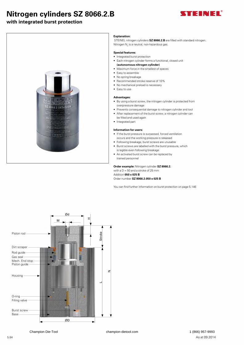
5.84 As at 09.2014
Explanation: STEINEL nitrogen cylinders SZ 8066.2.B are filled with standard nitrogen. Nitrogen N2 is a neutral, non-hazardous gas.
Special features:• Integrated burst protection• Each nitrogen cylinder forms a functional, closed unit
(autonomous nitrogen cylinder)• Maximum force in the smallest of spaces• Easy to assemble• No spring breakage• Recommended stroke reserve of 10%• No mechanical preload is necessary• Easy to use
Advantages:• By using a burst screw, the nitrogen cylinder is protected from
overpressure damage• Prevents consequential damage to nitrogen cylinder and tool• After replacement of the burst screw, a nitrogen cylinder can
be filled and used again• Integrated part
Information for users:• If the burst pressure is surpassed, forced ventilation
occurs and the working pressure is released• Following breakage, burst screws are unusable• Burst screws are labelled with the burst pressure, which
is legible even following breakage• An activated burst screw can be replaced by
trained personnel
Order example: Nitrogen cylinder SZ 8066.2.with a D = 50 and a stroke of 25 mmAddition 050 x 025 BOrder number SZ 8066.2.050 x 025 B
You can find further information on burst protection on page 5.146
Nitrogen cylinders SZ 8066.2.Bwith integrated burst protection
Ød
M
H
Str
oke
N
L
ØD
Piston rod
Dirt scraper
Rod guideGas sealMech. End stopPiston guide
Housing
Filling valve
Burst screwBase
O-ring
Champion Die-Tool champion-dietool.com 1 (866) 957-9993
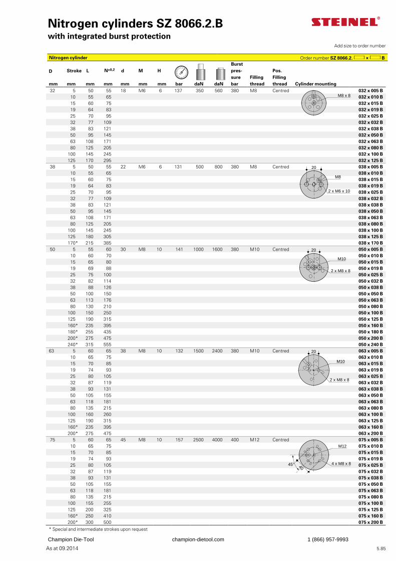
5.85As at 09.2014
Burst pres-surebar
D Stroke L N±0,2 d M H Pos. Filling thread
Filling threadmm mm mm mm mm mm mm bar daN daN Cylinder mounting
32 5 50 55 18 M6 6 137 350 560 380 M8 Centred 032 x 005 B 10 55 65 032 x 010 B 15 60 75 032 x 015 B19 64 83 032 x 019 B 25 70 95 032 x 025 B32 77 109 032 x 032 B 38 83 121 032 x 038 B 50 95 145 032 x 050 B63 108 171 032 x 063 B 80 125 205 032 x 080 B
100 145 245 032 x 100 B125 170 295 032 x 125 B
38 5 50 55 22 M6 6 131 500 800 380 M8 Centred 038 x 005 B 10 55 65 038 x 010 B 15 60 75 038 x 015 B19 64 83 038 x 019 B 25 70 95 038 x 025 B32 77 109 038 x 032 B 38 83 121 038 x 038 B 50 95 145 038 x 050 B63 108 171 038 x 063 B 80 125 205 038 x 080 B
100 145 245 038 x 100 B125 180 305 038 x 125 B170* 215 385 038 x 170 B
50 5 55 60 30 M8 10 141 1000 1600 380 M10 Centred 050 x 005 B 10 60 70 050 x 010 B15 65 80 050 x 015 B19 69 88 050 x 019 B
25 75 100 050 x 025 B32 82 114 050 x 032 B 38 88 126 050 x 038 B 50 100 150 050 x 050 B 63 113 176 050 x 063 B 80 130 210 050 x 080 B
100 150 250 050 x 100 B125 190 315 050 x 125 B160* 235 395 050 x 160 B180* 255 435 050 x 180 B200* 275 475 050 x 200 B240* 315 555 050 x 240 B
63 5 60 65 38 M8 10 132 1500 2400 380 M10 Centred 063 x 005 B 10 65 75 063 x 010 B15 70 85 063 x 015 B19 74 93 063 x 019 B 25 80 105 063 x 025 B32 87 119 063 x 032 B 38 93 131 063 x 038 B 50 105 155 063 x 050 B 63 118 181 063 x 063 B 80 135 215 063 x 080 B
100 160 260 063 x 100 B125 190 315 063 x 125 B160* 235 395 063 x 160 B200* 275 475 063 x 200 B
75 5 60 65 45 M8 10 157 2500 4000 400 M12 Centred 075 x 005 B 10 65 75 075 x 010 B15 70 85 075 x 015 B19 74 93 075 x 019 B
25 80 105 075 x 025 B32 87 119 075 x 032 B 38 93 131 075 x 038 B 50 105 155 075 x 050 B 63 118 181 075 x 063 B 80 135 215 075 x 080 B
100 155 255 075 x 100 B125 200 325 075 x 125 B160* 250 410 075 x 160 B200* 300 500 075 x 200 B
* Special and intermediate strokes upon request
Nitrogen cylinders SZ 8066.2.Bwith integrated burst protection
Add size to order number
Nitrogen cylinder Order number SZ 8066.2. B
M8 x 8
M8
2 x M6 x 10
20
20
M10
2 x M8 x 8
20
M10
2 x M8 x 8
4045°
M12
4 x M8 x 8
Champion Die-Tool champion-dietool.com 1 (866) 957-9993
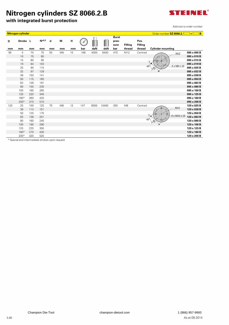
5.86 As at 09.2014
Nitrogen cylinders SZ 8066.2.Bwith integrated burst protection
Burst pres-surebar
D Stroke L N±0,2 d M H Pos. Filling thread
Filling threadmm mm mm mm mm mm mm bar daN daN Cylinder mounting
95 5 70 75 55 M8 10 168 4000 6400 470 M12 Centred 095 x 005 B10 75 85 095 x 010 B15 80 95 095 x 015 B19 84 103 095 x 019 B 25 90 115 095 x 025 B32 97 129 095 x 032 B 38 103 141 095 x 038 B 50 115 165 095 x 050 B 63 128 191 095 x 063 B 80 155 235 095 x 080 B
100 185 285 095 x 100 B125 220 345 095 x 125 B160* 260 420 095 x 160 B200* 310 510 095 x 200 B
120 25 100 125 75 M8 12 147 6500 10400 350 M8 Centred 120 x 025 B38 113 151 120 x 038 B50 125 175 120 x 050 B63 138 201 120 x 063 B80 160 240 120 x 080 B
100 190 290 120 x 100 B125 225 350 120 x 125 B160* 270 430 120 x 160 B200* 320 520 120 x 200 B
* Special and intermediate strokes upon request
Add size to order number
Nitrogen cylinder Order number SZ 8066.2. B
6045°
M12
4 x M8 x 10
8045°
M12
4 x M10 x 15
Champion Die-Tool champion-dietool.com 1 (866) 957-9993

5.87As at 09.2014
Champion Die-Tool champion-dietool.com 1 (866) 957-9993
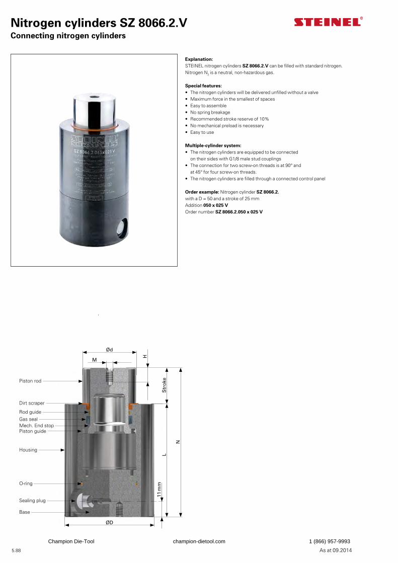
5.88 As at 09.2014
Explanation:STEINEL nitrogen cylinders SZ 8066.2.V can be filled with standard nitrogen. Nitrogen N2 is a neutral, non-hazardous gas.
Special features:• The nitrogen cylinders will be delivered unfilled without a valve• Maximum force in the smallest of spaces• Easy to assemble• No spring breakage• Recommended stroke reserve of 10%• No mechanical preload is necessary• Easy to use
Multiple-cylinder system:• The nitrogen cylinders are equipped to be connected
on their sides with G1/8 male stud couplings• The connection for two screw-on threads is at 90° and
at 45° for four screw-on threads.• The nitrogen cylinders are filled through a connected control panel
Order example: Nitrogen cylinder SZ 8066.2.with a D = 50 and a stroke of 25 mmAddition 050 x 025 VOrder number SZ 8066.2.050 x 025 V
Nitrogen cylinders SZ 8066.2.VConnecting nitrogen cylinders
Ød
M
H
Str
oke
N
L
ØD
11 m
m
Piston rod
Dirt scraper
Rod guideGas sealMech. End stopPiston guide
Housing
Sealing plug
Base
O-ring
Champion Die-Tool champion-dietool.com 1 (866) 957-9993
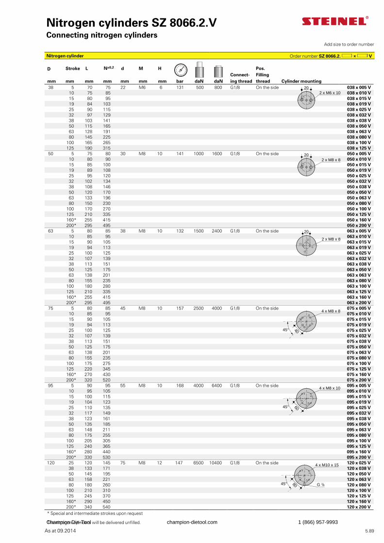
5.89As at 09.2014
D Stroke L N±0,2 d M H Pos. Filling thread
Connect-ing threadmm mm mm mm mm mm mm bar daN daN Cylinder mounting
38 5 70 75 22 M6 6 131 500 800 G1/8 On the side 038 x 005 V 10 75 85 038 x 010 V 15 80 95 038 x 015 V19 84 103 038 x 019 V 25 90 115 038 x 025 V32 97 129 038 x 032 V 38 103 141 038 x 038 V 50 115 165 038 x 050 V63 128 191 038 x 063 V 80 145 225 038 x 080 V
100 165 265 038 x 100 V125 190 315 038 x 125 V
50 5 75 80 30 M8 10 141 1000 1600 G1/8 On the side 050 x 005 V 10 80 90 050 x 010 V15 85 100 050 x 015 V19 89 108 050 x 019 V
25 95 120 050 x 025 V32 102 134 050 x 032 V 38 108 146 050 x 038 V 50 120 170 050 x 050 V 63 133 196 050 x 063 V 80 150 230 050 x 080 V
100 170 270 050 x 100 V125 210 335 050 x 125 V160* 255 415 050 x 160 V200* 295 495 050 x 200 V
63 5 80 85 38 M8 10 132 1500 2400 G1/8 On the side 063 x 005 V 10 85 95 063 x 010 V15 90 105 063 x 015 V19 94 113 063 x 019 V
25 100 125 063 x 025 V32 107 139 063 x 032 V 38 113 151 063 x 038 V 50 125 175 063 x 050 V 63 138 201 063 x 063 V 80 155 235 063 x 080 V
100 180 280 063 x 100 V125 210 335 063 x 125 V160* 255 415 063 x 160 V200* 295 495 063 x 200 V
75 5 80 85 45 M8 10 157 2500 4000 G1/8 On the side 075 x 005 V 10 85 95 075 x 010 V15 90 105 075 x 015 V19 94 113 075 x 019 V 25 100 125 075 x 025 V32 107 139 075 x 032 V 38 113 151 075 x 038 V 50 125 175 075 x 050 V 63 138 201 075 x 063 V 80 155 235 075 x 080 V
100 175 275 075 x 100 V125 220 345 075 x 125 V160* 270 430 075 x 160 V200* 320 520 075 x 200 V
95 5 90 95 55 M8 10 168 4000 6400 G1/8 On the side 095 x 005 V10 95 105 095 x 010 V15 100 115 095 x 015 V19 104 123 095 x 019 V 25 110 135 095 x 025 V32 117 149 095 x 032 V 38 123 161 095 x 038 V 50 135 185 095 x 050 V 63 148 211 095 x 063 V 80 175 255 095 x 080 V
100 205 305 095 x 100 V125 240 365 095 x 125 V160* 280 440 095 x 160 V200* 330 530 095 x 200 V
120 25 120 145 75 M8 12 147 6500 10400 G1/8 On the side 120 x 025 V38 133 171 120 x 038 V50 145 195 120 x 050 V63 158 221 120 x 063 V80 180 260 120 x 080 V
100 210 310 120 x 100 V125 245 370 120 x 125 V160* 290 450 120 x 160 V200* 340 540 120 x 200 V
* Special and intermediate strokes upon request
The nitrogen cylinders will be delivered unfilled.
Nitrogen cylinders SZ 8066.2.VConnecting nitrogen cylinders
Add size to order number
Nitrogen cylinder Order number SZ 8066.2. V
202 x M6 x 10
202 x M8 x 8
20
2 x M8 x 8
4 x M8 x 8
4045°
4 x M8 x 10
6045°
4 x M10 x 15
G 1/88045°
Champion Die-Tool champion-dietool.com 1 (866) 957-9993
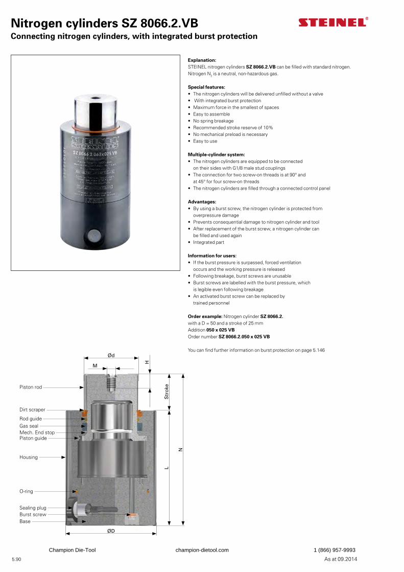
5.90 As at 09.2014
Explanation:STEINEL nitrogen cylinders SZ 8066.2.VB can be filled with standard nitrogen. Nitrogen N2 is a neutral, non-hazardous gas.
Special features:• The nitrogen cylinders will be delivered unfilled without a valve• With integrated burst protection• Maximum force in the smallest of spaces• Easy to assemble• No spring breakage• Recommended stroke reserve of 10%• No mechanical preload is necessary• Easy to use
Multiple-cylinder system:• The nitrogen cylinders are equipped to be connected
on their sides with G1/8 male stud couplings• The connection for two screw-on threads is at 90° and
at 45° for four screw-on threads• The nitrogen cylinders are filled through a connected control panel
Advantages:• By using a burst screw, the nitrogen cylinder is protected from
overpressure damage• Prevents consequential damage to nitrogen cylinder and tool• After replacement of the burst screw, a nitrogen cylinder can
be filled and used again• Integrated part
Information for users:• If the burst pressure is surpassed, forced ventilation
occurs and the working pressure is released• Following breakage, burst screws are unusable• Burst screws are labelled with the burst pressure, which
is legible even following breakage• An activated burst screw can be replaced by
trained personnel
Order example: Nitrogen cylinder SZ 8066.2.with a D = 50 and a stroke of 25 mmAddition 050 x 025 VBOrder number SZ 8066.2.050 x 025 VB
You can find further information on burst protection on page 5.146
Nitrogen cylinders SZ 8066.2.VBConnecting nitrogen cylinders, with integrated burst protection
Ød
M
H
Str
oke
N
L
ØD
Piston rod
Dirt scraper
Rod guideGas sealMech. End stopPiston guide
Housing
Sealing plugBurst screwBase
O-ring
Champion Die-Tool champion-dietool.com 1 (866) 957-9993
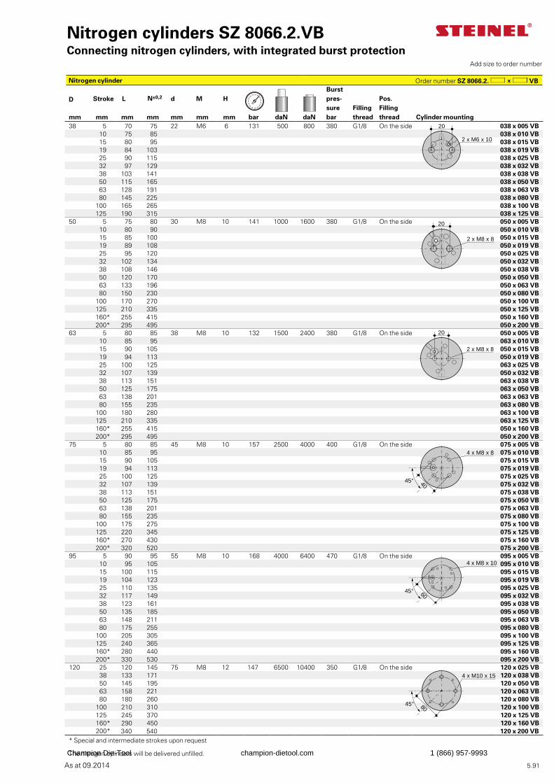
5.91As at 09.2014
Burst pres-surebar
D Stroke L N±0,2 d M H Pos. Filling thread
Filling threadmm mm mm mm mm mm mm bar daN daN Cylinder mounting
38 5 70 75 22 M6 6 131 500 800 380 G1/8 On the side 038 x 005 VB 10 75 85 038 x 010 VB 15 80 95 038 x 015 VB19 84 103 038 x 019 VB 25 90 115 038 x 025 VB32 97 129 038 x 032 VB 38 103 141 038 x 038 VB 50 115 165 038 x 050 VB63 128 191 038 x 063 VB 80 145 225 038 x 080 VB
100 165 265 038 x 100 VB125 190 315 038 x 125 VB
50 5 75 80 30 M8 10 141 1000 1600 380 G1/8 On the side 050 x 005 VB 10 80 90 050 x 010 VB15 85 100 050 x 015 VB19 89 108 050 x 019 VB 25 95 120 050 x 025 VB32 102 134 050 x 032 VB 38 108 146 050 x 038 VB 50 120 170 050 x 050 VB 63 133 196 050 x 063 VB 80 150 230 050 x 080 VB
100 170 270 050 x 100 VB125 210 335 050 x 125 VB160* 255 415 050 x 160 VB200* 295 495 050 x 200 VB
63 5 80 85 38 M8 10 132 1500 2400 380 G1/8 On the side 050 x 005 VB 10 85 95 063 x 010 VB15 90 105 050 x 015 VB19 94 113 050 x 019 VB 25 100 125 063 x 025 VB32 107 139 050 x 032 VB 38 113 151 063 x 038 VB 50 125 175 063 x 050 VB 63 138 201 063 x 063 VB 80 155 235 063 x 080 VB
100 180 280 063 x 100 VB125 210 335 063 x 125 VB160* 255 415 050 x 160 VB200* 295 495 050 x 200 VB
75 5 80 85 45 M8 10 157 2500 4000 400 G1/8 On the side 075 x 005 VB 10 85 95 075 x 010 VB15 90 105 075 x 015 VB19 94 113 075 x 019 VB
25 100 125 075 x 025 VB32 107 139 075 x 032 VB 38 113 151 075 x 038 VB 50 125 175 075 x 050 VB 63 138 201 075 x 063 VB 80 155 235 075 x 080 VB
100 175 275 075 x 100 VB125 220 345 075 x 125 VB160* 270 430 075 x 160 VB200* 320 520 075 x 200 VB
95 5 90 95 55 M8 10 168 4000 6400 470 G1/8 On the side 095 x 005 VB10 95 105 095 x 010 VB15 100 115 095 x 015 VB19 104 123 095 x 019 VB 25 110 135 095 x 025 VB32 117 149 095 x 032 VB 38 123 161 095 x 038 VB 50 135 185 095 x 050 VB 63 148 211 095 x 063 VB 80 175 255 095 x 080 VB
100 205 305 095 x 100 VB125 240 365 095 x 125 VB160* 280 440 095 x 160 VB200* 330 530 095 x 200 VB
120 25 120 145 75 M8 12 147 6500 10400 350 G1/8 On the side 120 x 025 VB38 133 171 120 x 038 VB50 145 195 120 x 050 VB63 158 221 120 x 063 VB80 180 260 120 x 080 VB
100 210 310 120 x 100 VB125 245 370 120 x 125 VB160* 290 450 120 x 160 VB200* 340 540 120 x 200 VB
* Special and intermediate strokes upon request
The nitrogen cylinders will be delivered unfilled.
Nitrogen cylinders SZ 8066.2.VBConnecting nitrogen cylinders, with integrated burst protection
Add size to order number
Nitrogen cylinder Order number SZ 8066.2. VB
20
2 x M6 x 10
2 x M8 x 8
20
2 x M8 x 8
20
4 x M8 x 8
4045°
4 x M8 x 10
6045°
4 x M10 x 15
8045°
Champion Die-Tool champion-dietool.com 1 (866) 957-9993
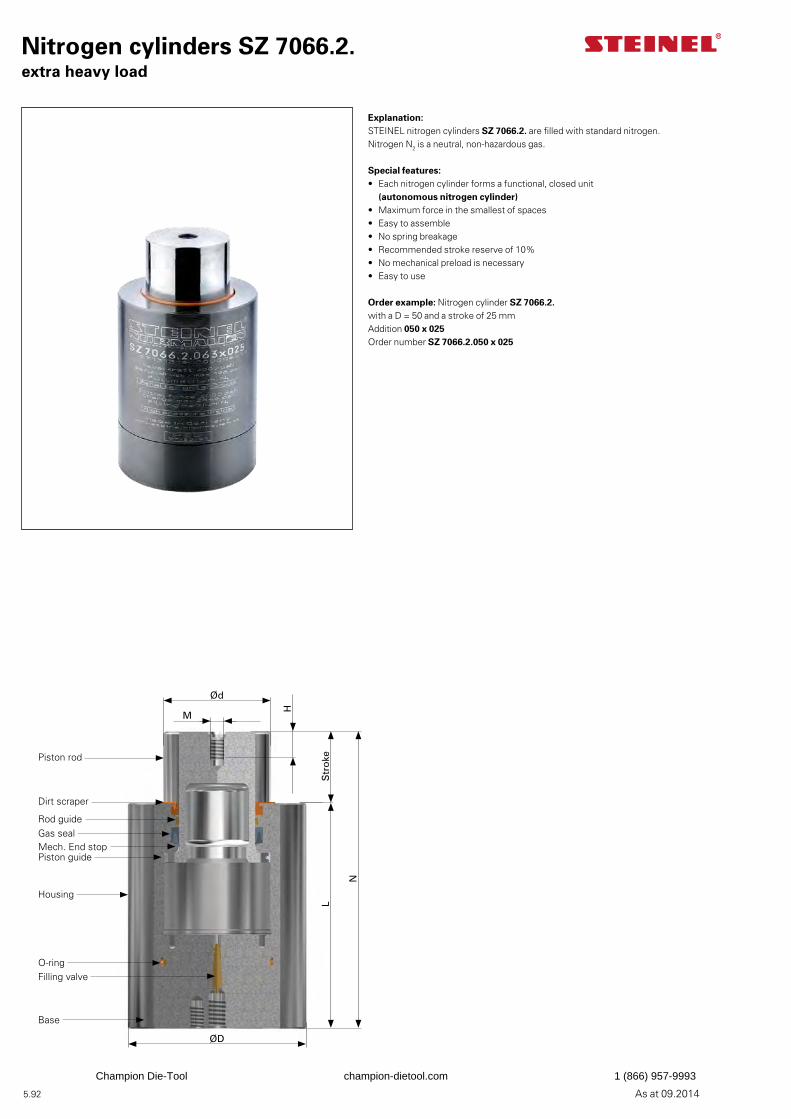
5.92 As at 09.2014
Explanation:STEINEL nitrogen cylinders SZ 7066.2. are filled with standard nitrogen. Nitrogen N2 is a neutral, non-hazardous gas.
Special features:• Each nitrogen cylinder forms a functional, closed unit
(autonomous nitrogen cylinder)• Maximum force in the smallest of spaces• Easy to assemble• No spring breakage• Recommended stroke reserve of 10%• No mechanical preload is necessary• Easy to use
Order example: Nitrogen cylinder SZ 7066.2.with a D = 50 and a stroke of 25 mmAddition 050 x 025Order number SZ 7066.2.050 x 025
Nitrogen cylinders SZ 7066.2.extra heavy load
Ød
M
H
Str
oke
N
L
ØD
Piston rod
Dirt scraper
Rod guideGas sealMech. End stopPiston guide
Housing
Filling valve
Base
O-ring
Champion Die-Tool champion-dietool.com 1 (866) 957-9993

5.93As at 09.2014
D Stroke L N±0,2 d M H Pos. Filling thread
Filling thread
mm mm mm mm mm mm mm bar daN daN Cylinder mounting 19 5 45 50 11 – – 180 170 272 M8 Centred 019 x 005
10 50 60 019 x 010 15 55 70 019 x 01519 59 78 019 x 019 25 65 90 019 x 02532 72 104 019 x 032 38 78 116 019 x 038 50 90 140 019 x 05063 103 166 019 x 063 80 120 200 019 x 080
100 140 240 019 x 100125 165 290 019 x 125
25 5 45 50 14 – – 195 300 480 M8 Centred 025 x 005 10 50 60 – – 025 x 010 15 55 70 – – 025 x 01519 59 78 – – 025 x 019 25 65 90 M6 6 025 x 02532 72 104 M6 6 025 x 032 38 78 116 M6 6 025 x 038 50 90 140 M6 6 025 x 05063 103 166 M6 6 025 x 063 80 120 200 M6 6 025 x 080
100 140 240 M6 6 025 x 100125 165 290 M6 6 025 x 125
32 5 50 55 18 – – 196 500 800 M8 Centred 032 x 005 10 55 65 M6 6 032 x 010 15 60 75 M6 6 032 x 01519 64 83 M6 6 032 x 019 25 70 95 M6 6 032 x 02532 77 109 M6 6 032 x 032 38 83 121 M6 6 032 x 038 50 95 145 M6 6 032 x 05063 108 171 M6 6 032 x 063 80 125 205 M6 6 032 x 080
100 145 245 M6 6 032 x 100125 170 295 M6 6 032 x 125
38 5 50 55 22 – – 197 750 1200 M8 Centred 038 x 005 10 55 65 M6 6 038 x 010 15 60 75 M6 6 038 x 01519 64 83 M6 6 038 x 019 25 70 95 M6 6 038 x 02532 77 109 M6 6 038 x 032 38 83 121 M6 6 038 x 038 50 95 145 M6 6 038 x 05063 108 171 M6 6 038 x 063 80 125 205 M6 6 038 x 080
100 145 245 M6 6 038 x 100125 170 295 M6 6 038 x 125170* 215 385 M6 6 038 x 170
50 5 55 60 30 – – 212 1500 2400 M10 Centred 050 x 005 10 60 70 M8 10 050 x 01015 65 80 M8 10 050 x 01519 69 88 M8 10 050 x 019
25 75 100 M8 10 050 x 02532 82 114 M8 10 050 x 032 38 88 126 M8 10 050 x 038 50 100 150 M8 10 050 x 050 63 113 176 M8 10 050 x 063 80 130 210 M8 10 050 x 080
100 150 250 M8 10 050 x 100125 190 315 M8 10 050 x 125160* 235 395 M8 10 050 x 160180* 255 435 M8 10 050 x 180200* 275 475 M8 10 050 x 200240* 315 555 M8 10 050 x 240
* Special and intermediate strokes upon request
Nitrogen cylinders SZ 7066.2.extra heavy load
Add size to order number
Nitrogen cylinder Order number SZ 7066.2.
M8
2 x M6 x 10
20
2 x M8 x 8
20
M10
M8 x 8
M8 x 8
M8 x 8
Champion Die-Tool champion-dietool.com 1 (866) 957-9993
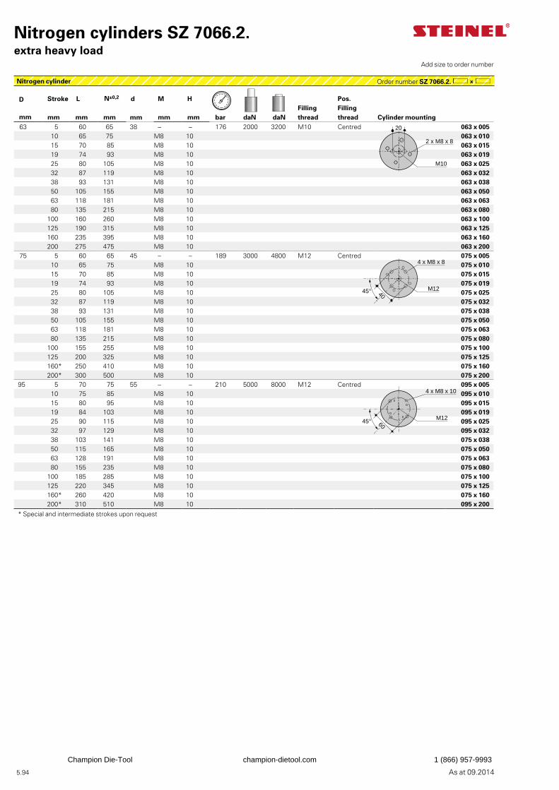
5.94 As at 09.2014
D Stroke L N±0,2 d M H Pos. Filling thread
Filling thread
mm mm mm mm mm mm mm bar daN daN Cylinder mounting 63 5 60 65 38 – – 176 2000 3200 M10 Centred 063 x 005
10 65 75 M8 10 063 x 01015 70 85 M8 10 063 x 01519 74 93 M8 10 063 x 019 25 80 105 M8 10 063 x 02532 87 119 M8 10 063 x 032 38 93 131 M8 10 063 x 038 50 105 155 M8 10 063 x 050 63 118 181 M8 10 063 x 063 80 135 215 M8 10 063 x 080
100 160 260 M8 10 063 x 100125 190 315 M8 10 063 x 125160 235 395 M8 10 063 x 160200 275 475 M8 10 063 x 200
75 5 60 65 45 – – 189 3000 4800 M12 Centred 075 x 005 10 65 75 M8 10 075 x 01015 70 85 M8 10 075 x 01519 74 93 M8 10 075 x 019
25 80 105 M8 10 075 x 02532 87 119 M8 10 075 x 032 38 93 131 M8 10 075 x 038 50 105 155 M8 10 075 x 050 63 118 181 M8 10 075 x 063 80 135 215 M8 10 075 x 080
100 155 255 M8 10 075 x 100125 200 325 M8 10 075 x 125160* 250 410 M8 10 075 x 160200* 300 500 M8 10 075 x 200
95 5 70 75 55 – – 210 5000 8000 M12 Centred 095 x 00510 75 85 M8 10 095 x 01015 80 95 M8 10 095 x 01519 84 103 M8 10 095 x 019 25 90 115 M8 10 095 x 02532 97 129 M8 10 095 x 032 38 103 141 M8 10 075 x 038 50 115 165 M8 10 075 x 050 63 128 191 M8 10 075 x 063 80 155 235 M8 10 075 x 080
100 185 285 M8 10 075 x 100125 220 345 M8 10 075 x 125160* 260 420 M8 10 075 x 160200* 310 510 M8 10 095 x 200
* Special and intermediate strokes upon request
Nitrogen cylinders SZ 7066.2.extra heavy load
Add size to order number
Nitrogen cylinder Order number SZ 7066.2.
2 x M8 x 8
20
M10
4 x M8 x 8
45° 40M12
4 x M8 x 10
6045° M12
Champion Die-Tool champion-dietool.com 1 (866) 957-9993

5.95As at 09.2014
Champion Die-Tool champion-dietool.com 1 (866) 957-9993
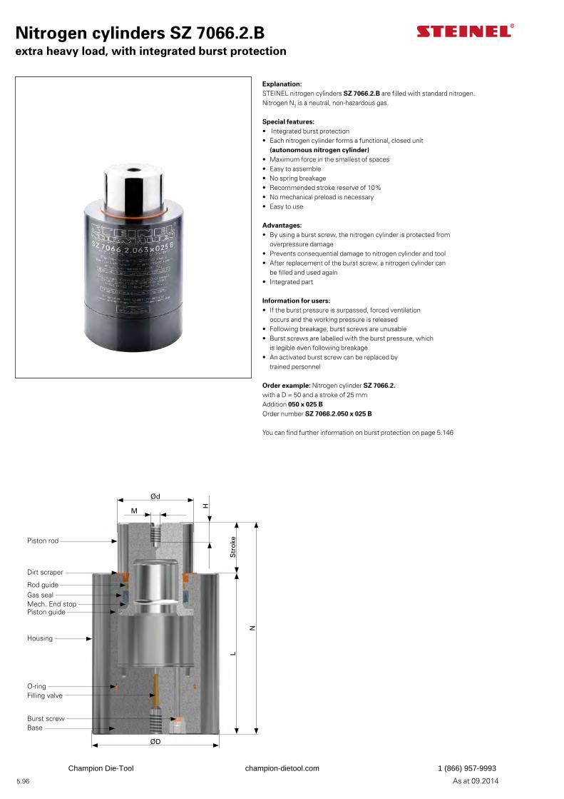
5.96 As at 09.2014
Explanation:STEINEL nitrogen cylinders SZ 7066.2.B are filled with standard nitrogen. Nitrogen N2 is a neutral, non-hazardous gas.
Special features:• Integrated burst protection• Each nitrogen cylinder forms a functional, closed unit
(autonomous nitrogen cylinder)• Maximum force in the smallest of spaces• Easy to assemble• No spring breakage• Recommended stroke reserve of 10%• No mechanical preload is necessary• Easy to use
Advantages:• By using a burst screw, the nitrogen cylinder is protected from
overpressure damage• Prevents consequential damage to nitrogen cylinder and tool• After replacement of the burst screw, a nitrogen cylinder can
be filled and used again• Integrated part
Information for users:• If the burst pressure is surpassed, forced ventilation
occurs and the working pressure is released• Following breakage, burst screws are unusable• Burst screws are labelled with the burst pressure, which
is legible even following breakage• An activated burst screw can be replaced by
trained personnel
Order example: Nitrogen cylinder SZ 7066.2.with a D = 50 and a stroke of 25 mmAddition 050 x 025 BOrder number SZ 7066.2.050 x 025 B
You can find further information on burst protection on page 5.146
Nitrogen cylinders SZ 7066.2.Bextra heavy load, with integrated burst protection
Ød
M
H
Str
oke
N
L
ØD
Piston rod
Dirt scraper
Rod guideGas sealMech. End stopPiston guide
Housing
Filling valve
Burst screwBase
O-ring
Champion Die-Tool champion-dietool.com 1 (866) 957-9993
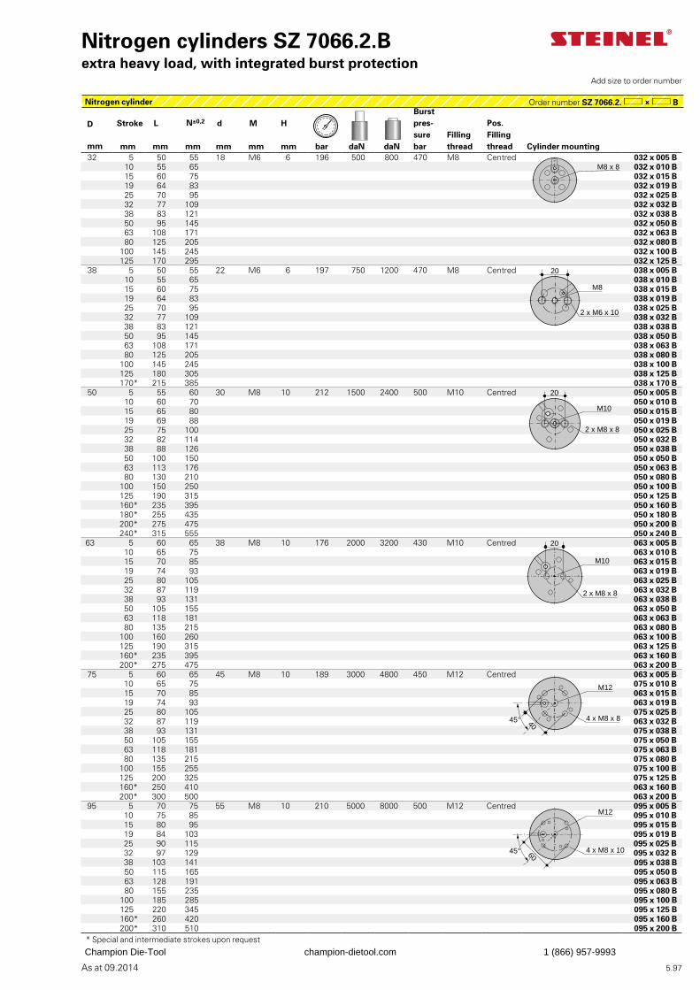
5.97As at 09.2014
Burst pres-surebar
Pos. Filling thread
D Stroke L N±0,2 d M HFilling thread
mm mm mm mm mm mm mm bar daN daN Cylinder mounting 32 5 50 55 18 M6 6 196 500 800 470 M8 Centred 032 x 005 B
10 55 65 032 x 010 B 15 60 75 032 x 015 B19 64 83 032 x 019 B 25 70 95 032 x 025 B32 77 109 032 x 032 B 38 83 121 032 x 038 B 50 95 145 032 x 050 B63 108 171 032 x 063 B 80 125 205 032 x 080 B
100 145 245 032 x 100 B125 170 295 032 x 125 B
38 5 50 55 22 M6 6 197 750 1200 470 M8 Centred 038 x 005 B 10 55 65 038 x 010 B 15 60 75 038 x 015 B19 64 83 038 x 019 B 25 70 95 038 x 025 B32 77 109 038 x 032 B 38 83 121 038 x 038 B 50 95 145 038 x 050 B63 108 171 038 x 063 B 80 125 205 038 x 080 B
100 145 245 038 x 100 B125 180 305 038 x 125 B170* 215 385 038 x 170 B
50 5 55 60 30 M8 10 212 1500 2400 500 M10 Centred 050 x 005 B 10 60 70 050 x 010 B15 65 80 050 x 015 B19 69 88 050 x 019 B
25 75 100 050 x 025 B32 82 114 050 x 032 B 38 88 126 050 x 038 B 50 100 150 050 x 050 B 63 113 176 050 x 063 B 80 130 210 050 x 080 B
100 150 250 050 x 100 B125 190 315 050 x 125 B160* 235 395 050 x 160 B180* 255 435 050 x 180 B200* 275 475 050 x 200 B240* 315 555 050 x 240 B
63 5 60 65 38 M8 10 176 2000 3200 430 M10 Centred 063 x 005 B 10 65 75 063 x 010 B15 70 85 063 x 015 B19 74 93 063 x 019 B
25 80 105 063 x 025 B32 87 119 063 x 032 B 38 93 131 063 x 038 B 50 105 155 063 x 050 B 63 118 181 063 x 063 B 80 135 215 063 x 080 B
100 160 260 063 x 100 B125 190 315 063 x 125 B160* 235 395 063 x 160 B200* 275 475 063 x 200 B
75 5 60 65 45 M8 10 189 3000 4800 450 M12 Centred 063 x 005 B 10 65 75 075 x 010 B15 70 85 063 x 015 B19 74 93 063 x 019 B
25 80 105 075 x 025 B32 87 119 063 x 032 B 38 93 131 075 x 038 B 50 105 155 075 x 050 B 63 118 181 075 x 063 B 80 135 215 075 x 080 B
100 155 255 075 x 100 B125 200 325 075 x 125 B160* 250 410 063 x 160 B200* 300 500 063 x 200 B
95 5 70 75 55 M8 10 210 5000 8000 500 M12 Centred 095 x 005 B10 75 85 095 x 010 B15 80 95 095 x 015 B19 84 103 095 x 019 B 25 90 115 095 x 025 B32 97 129 095 x 032 B 38 103 141 095 x 038 B 50 115 165 095 x 050 B 63 128 191 095 x 063 B 80 155 235 095 x 080 B
100 185 285 095 x 100 B125 220 345 095 x 125 B160* 260 420 095 x 160 B200* 310 510 095 x 200 B
* Special and intermediate strokes upon request
Nitrogen cylinders SZ 7066.2.Bextra heavy load, with integrated burst protection
Nitrogen cylinder Order number SZ 7066.2. B
Add size to order number
M8 x 8
M8
2 x M6 x 10
20
20
M10
2 x M8 x 8
20
M10
2 x M8 x 8
4045°
M12
4 x M8 x 8
6045°
M12
4 x M8 x 10
Champion Die-Tool champion-dietool.com 1 (866) 957-9993
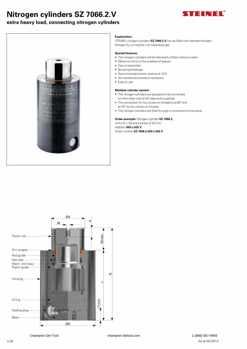
5.98 As at 09.2014
Nitrogen cylinders SZ 7066.2.Vextra heavy load, connecting nitrogen cylinders
Explanation:STEINEL nitrogen cylinders SZ 7066.2.V can be filled with standard nitrogen. Nitrogen N2 is a neutral, non-hazardous gas.
Special features:• The nitrogen cylinders will be delivered unfilled without a valve• Maximum force in the smallest of spaces• Easy to assemble• No spring breakage• Recommended stroke reserve of 10%• No mechanical preload is necessary• Easy to use
Multiple-cylinder system:• The nitrogen cylinders are equipped to be connected
on their sides with G1/8 male stud couplings• The connection for two screw-on threads is at 90° and
at 45° for four screw-on threads• The nitrogen cylinders are filled through a connected control panel
Order example: Nitrogen cylinder SZ 7066.2.with a D = 50 and a stroke of 25 mmAddition 050 x 025 VOrder number SZ 7066.2.050 x 025 V
Ød
M
H
Str
oke
N
L
ØD
11 m
m
Piston rod
Dirt scraper
Rod guideGas sealMech. End stopPiston guide
Housing
Sealing plug
Base
O-ring
Champion Die-Tool champion-dietool.com 1 (866) 957-9993
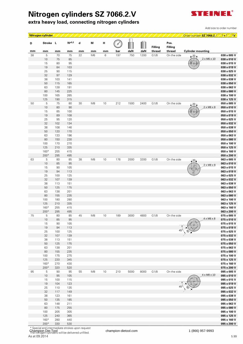
5.99As at 09.2014
Nitrogen cylinder Order number SZ 7066.2. V
D Stroke L N±0,2 d M H Pos. Filling thread
Filling threadmm mm mm mm mm mm mm bar daN daN Cylinder mounting
38 5 70 75 22 M6 6 197 750 1200 G1/8 On the side 038 x 005 V 10 75 85 038 x 010 V 15 80 95 038 x 015 V19 84 103 038 x 019 V 25 90 115 038 x 025 V32 97 129 038 x 032 V 38 103 141 038 x 038 V 50 115 165 038 x 050 V63 128 191 038 x 063 V 80 145 225 038 x 080 V
100 165 265 038 x 100 V125 190 315 038 x 125 V
50 5 75 80 30 M8 10 212 1500 2400 G1/8 On the side 050 x 005 V 10 80 90 050 x 010 V15 85 100 050 x 015 V19 89 108 050 x 019 V 25 95 120 050 x 025 V32 102 134 050 x 032 V 38 108 146 050 x 038 V 50 120 170 050 x 050 V 63 133 196 050 x 063 V 80 150 230 050 x 080 V
100 170 270 050 x 100 V125 210 335 050 x 125 V160* 255 415 050 x 160 V200* 295 495 050 x 200 V
63 5 80 85 38 M8 10 176 2000 3200 G1/8 On the side 063 x 005 V 10 85 95 063 x 010 V15 90 105 063 x 015 V19 94 113 063 x 019 V
25 100 125 063 x 025 V32 107 139 063 x 032 V 38 113 151 063 x 038 V 50 125 175 063 x 050 V 63 138 201 063 x 063 V 80 155 235 063 x 080 V
100 180 280 063 x 100 V125 210 335 063 x 125 V160* 255 415 063 x 160 V200* 295 495 063 x 200 V
75 5 80 85 45 M8 10 189 3000 4800 G1/8 On the side 075 x 005 V 10 85 95 075 x 010 V15 90 105 075 x 015 V19 94 113 075 x 019 V
25 100 125 075 x 025 V32 107 139 075 x 032 V 38 113 151 075 x 038 V 50 125 175 075 x 050 V 63 138 201 075 x 063 V 80 155 235 075 x 080 V
100 175 275 075 x 100 V125 220 345 075 x 125 V160* 270 430 075 x 160 V200* 320 520 075 x 200 V
95 5 90 95 55 M8 10 210 5000 8000 G1/8 On the side 095 x 005 V10 95 105 095 x 010 V15 100 115 095 x 015 V19 104 123 095 x 019 V 25 110 135 095 x 025 V32 117 149 095 x 032 V 38 123 161 095 x 038 V 50 135 185 095 x 050 V 63 148 211 095 x 063 V 80 175 255 095 x 080 V
100 205 305 095 x 100 V125 240 365 095 x 125 V160* 280 440 095 x 160 V200* 330 530 095 x 200 V
* Special and intermediate strokes upon request
The nitrogen cylinders will be delivered unfilled.
Nitrogen cylinders SZ 7066.2.Vextra heavy load, connecting nitrogen cylinders
Add size to order number
202 x M6 x 10
202 x M8 x 8
20
2 x M8 x 8
4 x M8 x 8
4045°
4 x M8 x 10
6045°
Champion Die-Tool champion-dietool.com 1 (866) 957-9993
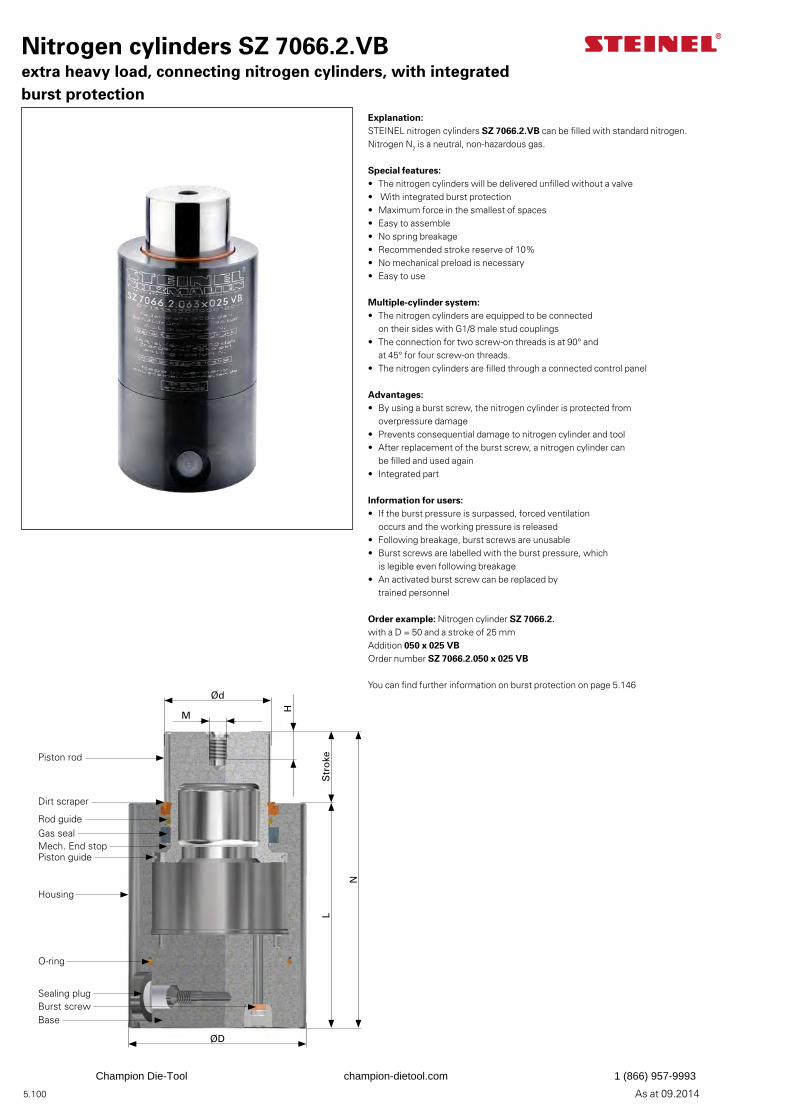
5.100 As at 09.2014
Explanation:STEINEL nitrogen cylinders SZ 7066.2.VB can be filled with standard nitrogen. Nitrogen N2 is a neutral, non-hazardous gas.
Special features:• The nitrogen cylinders will be delivered unfilled without a valve• With integrated burst protection• Maximum force in the smallest of spaces• Easy to assemble• No spring breakage• Recommended stroke reserve of 10%• No mechanical preload is necessary• Easy to use
Multiple-cylinder system:• The nitrogen cylinders are equipped to be connected
on their sides with G1/8 male stud couplings• The connection for two screw-on threads is at 90° and
at 45° for four screw-on threads.• The nitrogen cylinders are filled through a connected control panel
Advantages:• By using a burst screw, the nitrogen cylinder is protected from
overpressure damage• Prevents consequential damage to nitrogen cylinder and tool• After replacement of the burst screw, a nitrogen cylinder can
be filled and used again• Integrated part
Information for users:• If the burst pressure is surpassed, forced ventilation
occurs and the working pressure is released• Following breakage, burst screws are unusable• Burst screws are labelled with the burst pressure, which
is legible even following breakage• An activated burst screw can be replaced by
trained personnel
Order example: Nitrogen cylinder SZ 7066.2.with a D = 50 and a stroke of 25 mmAddition 050 x 025 VBOrder number SZ 7066.2.050 x 025 VB
You can find further information on burst protection on page 5.146
Nitrogen cylinders SZ 7066.2.VBextra heavy load, connecting nitrogen cylinders, with integrated burst protection
Ød
M
H
Str
oke
N
L
ØD
Piston rod
Dirt scraper
Rod guideGas sealMech. End stopPiston guide
Housing
Sealing plugBurst screwBase
O-ring
Champion Die-Tool champion-dietool.com 1 (866) 957-9993
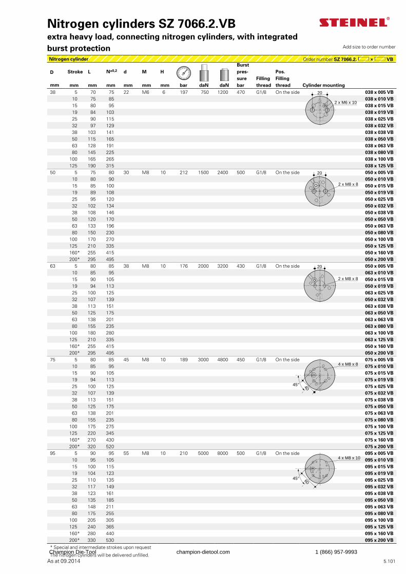
5.101As at 09.2014
Burst pres-surebar
D Stroke L N±0,2 d M H Pos. Fillingthread
Fillingthreadmm mm mm mm mm mm mm bar daN daN Cylinder mounting
38 5 70 75 22 M6 6 197 750 1200 470 G1/8 On the side 038 x 005 VB 10 75 85 038 x 010 VB 15 80 95 038 x 015 VB19 84 103 038 x 019 VB 25 90 115 038 x 025 VB32 97 129 038 x 032 VB 38 103 141 038 x 038 VB 50 115 165 038 x 050 VB63 128 191 038 x 063 VB 80 145 225 038 x 080 VB
100 165 265 038 x 100 VB125 190 315 038 x 125 VB
50 5 75 80 30 M8 10 212 1500 2400 500 G1/8 On the side 050 x 005 VB 10 80 90 050 x 010 VB15 85 100 050 x 015 VB19 89 108 050 x 019 VB 25 95 120 050 x 025 VB32 102 134 050 x 032 VB 38 108 146 050 x 038 VB 50 120 170 050 x 050 VB 63 133 196 050 x 063 VB 80 150 230 050 x 080 VB
100 170 270 050 x 100 VB125 210 335 050 x 125 VB160* 255 415 050 x 160 VB200* 295 495 050 x 200 VB
63 5 80 85 38 M8 10 176 2000 3200 430 G1/8 On the side 050 x 005 VB 10 85 95 063 x 010 VB15 90 105 050 x 015 VB19 94 113 050 x 019 VB 25 100 125 063 x 025 VB32 107 139 050 x 032 VB 38 113 151 063 x 038 VB 50 125 175 063 x 050 VB 63 138 201 063 x 063 VB 80 155 235 063 x 080 VB
100 180 280 063 x 100 VB125 210 335 063 x 125 VB160* 255 415 050 x 160 VB200* 295 495 050 x 200 VB
75 5 80 85 45 M8 10 189 3000 4800 450 G1/8 On the side 075 x 005 VB 10 85 95 075 x 010 VB15 90 105 075 x 015 VB19 94 113 075 x 019 VB 25 100 125 075 x 025 VB32 107 139 075 x 032 VB 38 113 151 075 x 038 VB 50 125 175 075 x 050 VB 63 138 201 075 x 063 VB 80 155 235 075 x 080 VB
100 175 275 075 x 100 VB125 220 345 075 x 125 VB160* 270 430 075 x 160 VB200* 320 520 075 x 200 VB
95 5 90 95 55 M8 10 210 5000 8000 500 G1/8 On the side 095 x 005 VB10 95 105 095 x 010 VB15 100 115 095 x 015 VB19 104 123 095 x 019 VB 25 110 135 095 x 025 VB32 117 149 095 x 032 VB 38 123 161 095 x 038 VB 50 135 185 095 x 050 VB 63 148 211 095 x 063 VB 80 175 255 095 x 080 VB
100 205 305 095 x 100 VB125 240 365 095 x 125 VB160* 280 440 095 x 160 VB200* 330 530 095 x 200 VB
* Special and intermediate strokes upon request
The nitrogen cylinders will be delivered unfilled.
Nitrogen cylinders SZ 7066.2.VBextra heavy load, connecting nitrogen cylinders, with integrated burst protection Add size to order number
Nitrogen cylinder Order number SZ 7066.2. VB
20
2 x M6 x 10
2 x M8 x 8
20
2 x M8 x 8
20
4 x M8 x 8
4045°
4 x M8 x 10
6045°
Champion Die-Tool champion-dietool.com 1 (866) 957-9993
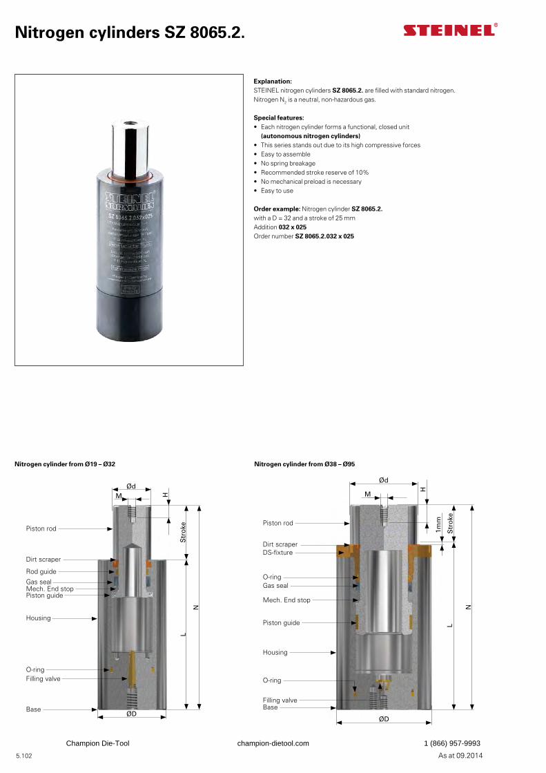
5.102 As at 09.2014
Nitrogen cylinders SZ 8065.2.
Explanation:STEINEL nitrogen cylinders SZ 8065.2. are filled with standard nitrogen. Nitrogen N2 is a neutral, non-hazardous gas.
Special features:• Each nitrogen cylinder forms a functional, closed unit
(autonomous nitrogen cylinders)• This series stands out due to its high compressive forces• Easy to assemble• No spring breakage• Recommended stroke reserve of 10%• No mechanical preload is necessary• Easy to use
Order example: Nitrogen cylinder SZ 8065.2.with a D = 32 and a stroke of 25 mmAddition 032 x 025Order number SZ 8065.2.032 x 025
ØdM H
Str
oke
N
L
ØD
Piston rod
Dirt scraper
Rod guide
Gas sealMech. End stopPiston guide
Housing
Filling valve
Base
O-ring
Ød
M
H
Str
oke
N
L
ØD
1mmPiston rod
Dirt scraperDS-fixture
Gas seal
Mech. End stop
Piston guide
Housing
Filling valveBase
O-ring
O-ring
Nitrogen cylinder from Ø19 – Ø32 Nitrogen cylinder from Ø38 – Ø95
Champion Die-Tool champion-dietool.com 1 (866) 957-9993
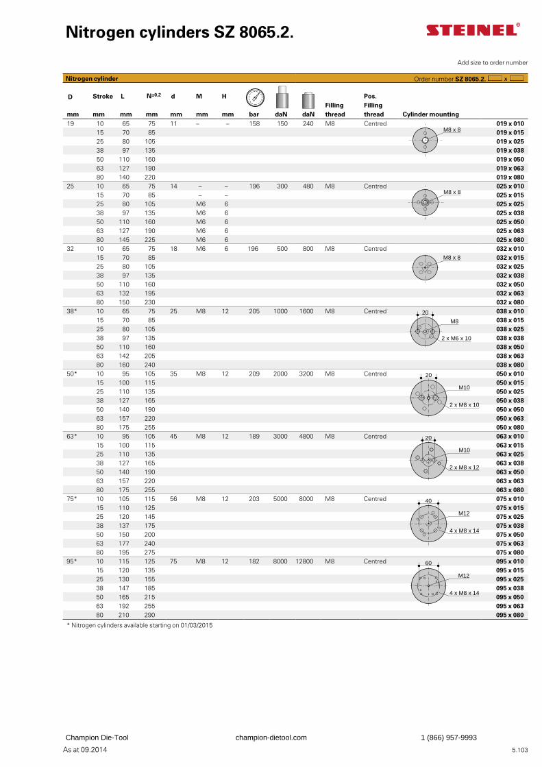
5.103As at 09.2014
D Stroke L N±0,2 d M H Pos. Filling thread
Filling threadmm mm mm mm mm mm mm bar daN daN Cylinder mounting
19 10 65 75 11 – – 158 150 240 M8 Centred 019 x 01015 70 85 019 x 01525 80 105 019 x 02538 97 135 019 x 03850 110 160 019 x 05063 127 190 019 x 06380 140 220 019 x 080
25 10 65 75 14 – – 196 300 480 M8 Centred 025 x 01015 70 85 – – 025 x 01525 80 105 M6 6 025 x 02538 97 135 M6 6 025 x 03850 110 160 M6 6 025 x 05063 127 190 M6 6 025 x 06380 145 225 M6 6 025 x 080
32 10 65 75 18 M6 6 196 500 800 M8 Centred 032 x 01015 70 85 032 x 01525 80 105 032 x 02538 97 135 032 x 03850 110 160 032 x 05063 132 195 032 x 06380 150 230 032 x 080
38* 10 65 75 25 M8 12 205 1000 1600 M8 Centred 038 x 01015 70 85 038 x 01525 80 105 038 x 02538 97 135 038 x 03850 110 160 038 x 05063 142 205 038 x 06380 160 240 038 x 080
50* 10 95 105 35 M8 12 209 2000 3200 M8 Centred 050 x 01015 100 115 050 x 01525 110 135 050 x 02538 127 165 050 x 03850 140 190 050 x 05063 157 220 050 x 06380 175 255 050 x 080
63* 10 95 105 45 M8 12 189 3000 4800 M8 Centred 063 x 01015 100 115 063 x 01525 110 135 063 x 02538 127 165 063 x 03850 140 190 063 x 05063 157 220 063 x 06380 175 255 063 x 080
75* 10 105 115 56 M8 12 203 5000 8000 M8 Centred 075 x 01015 110 125 075 x 01525 120 145 075 x 02538 137 175 075 x 03850 150 200 075 x 05063 177 240 075 x 06380 195 275 075 x 080
95* 10 115 125 75 M8 12 182 8000 12800 M8 Centred 095 x 01015 120 135 095 x 01525 130 155 095 x 02538 147 185 095 x 03850 165 215 095 x 05063 192 255 095 x 06380 210 290 095 x 080
* Nitrogen cylinders available starting on 01/03/2015
Nitrogen cylinders SZ 8065.2.
Add size to order number
Nitrogen cylinder Order number SZ 8065.2.
M8 x 8
M8 x 8
M8 x 8
20
M8
2 x M6 x 10
20
M10
2 x M8 x 10
20
M10
2 x M8 x 12
4 x M8 x 14
M12
40
4 x M8 x 14
M12
60
Champion Die-Tool champion-dietool.com 1 (866) 957-9993
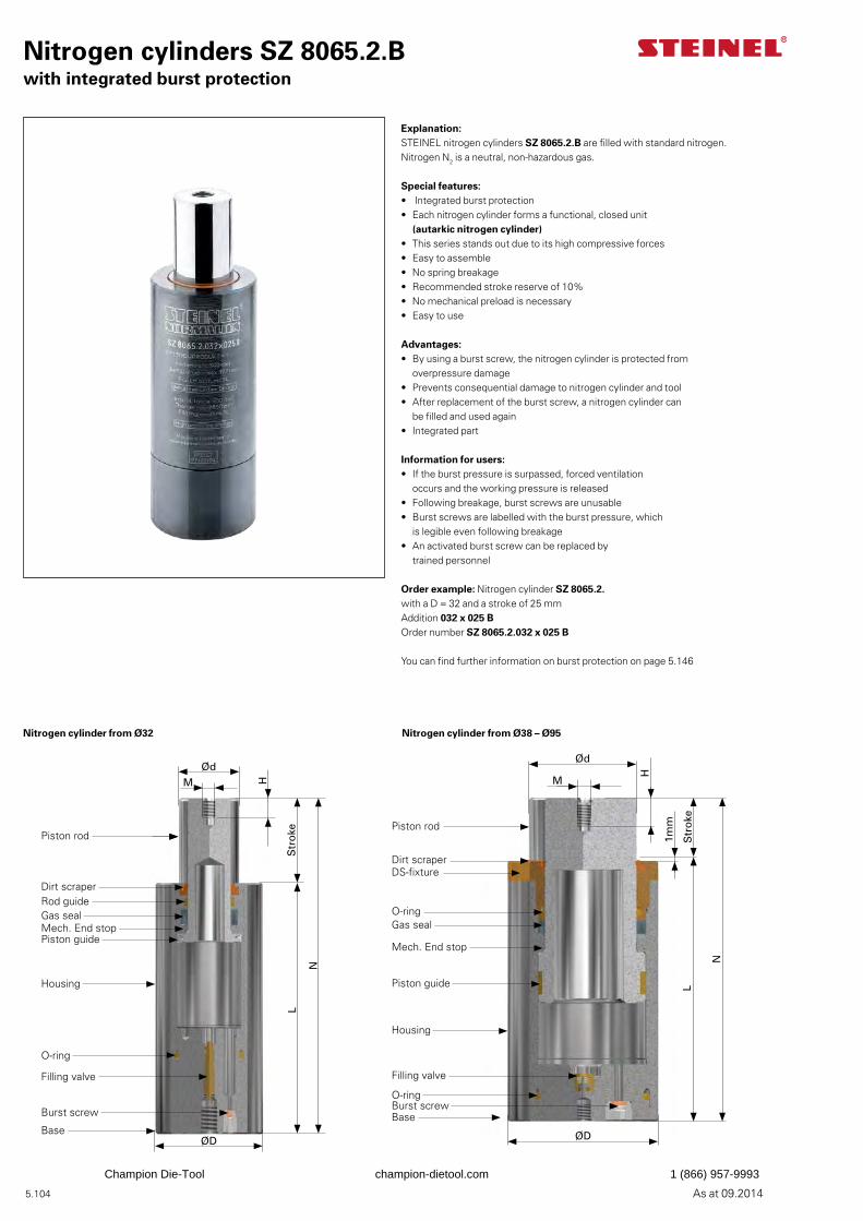
5.104 As at 09.2014
Nitrogen cylinders SZ 8065.2.Bwith integrated burst protection
Explanation:STEINEL nitrogen cylinders SZ 8065.2.B are filled with standard nitrogen. Nitrogen N2 is a neutral, non-hazardous gas.
Special features:• Integrated burst protection• Each nitrogen cylinder forms a functional, closed unit
(autarkic nitrogen cylinder)• This series stands out due to its high compressive forces• Easy to assemble• No spring breakage• Recommended stroke reserve of 10%• No mechanical preload is necessary• Easy to use
Advantages:• By using a burst screw, the nitrogen cylinder is protected from
overpressure damage• Prevents consequential damage to nitrogen cylinder and tool• After replacement of the burst screw, a nitrogen cylinder can
be filled and used again• Integrated part
Information for users:• If the burst pressure is surpassed, forced ventilation
occurs and the working pressure is released• Following breakage, burst screws are unusable• Burst screws are labelled with the burst pressure, which
is legible even following breakage• An activated burst screw can be replaced by
trained personnel
Order example: Nitrogen cylinder SZ 8065.2.with a D = 32 and a stroke of 25 mmAddition 032 x 025 BOrder number SZ 8065.2.032 x 025 B
You can find further information on burst protection on page 5.146
Ød
M H
Str
oke
N
L
ØD
Piston rod
Dirt scraperRod guideGas sealMech. End stopPiston guide
Housing
Filling valve
Base
Burst screw
O-ring
Ød
M
H
Str
oke
N
L
ØD
1mmPiston rod
Dirt scraperDS-fixture
Gas seal
Mech. End stop
Piston guide
Housing
O-ring
Filling valve
Burst screwBase
O-ring
Nitrogen cylinder from Ø32 Nitrogen cylinder from Ø38 – Ø95
Champion Die-Tool champion-dietool.com 1 (866) 957-9993
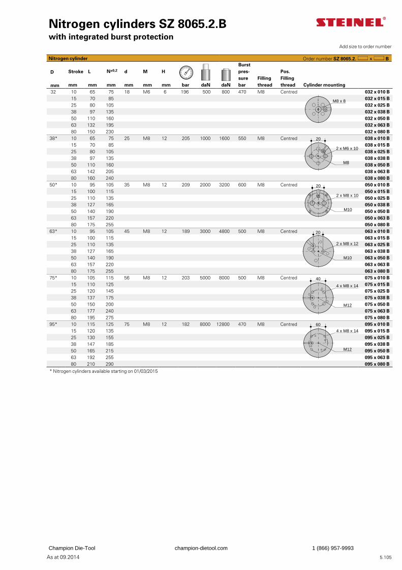
5.105As at 09.2014
Burst pres-surebar
D Stroke L N±0,2 d M H Pos. Filling thread
Filling thread
mm mm mm mm mm mm mm bar daN daN Cylinder mounting 32 10 65 75 18 M6 6 196 500 800 470 M8 Centred 032 x 010 B
15 70 85 032 x 015 B25 80 105 032 x 025 B38 97 135 032 x 038 B50 110 160 032 x 050 B63 132 195 032 x 063 B80 150 230 032 x 080 B
38* 10 65 75 25 M8 12 205 1000 1600 550 M8 Centred 038 x 010 B15 70 85 038 x 015 B25 80 105 038 x 025 B38 97 135 038 x 038 B50 110 160 038 x 050 B63 142 205 038 x 063 B80 160 240 038 x 080 B
50* 10 95 105 35 M8 12 209 2000 3200 600 M8 Centred 050 x 010 B15 100 115 050 x 015 B25 110 135 050 x 025 B38 127 165 050 x 038 B50 140 190 050 x 050 B63 157 220 050 x 063 B80 175 255 050 x 080 B
63* 10 95 105 45 M8 12 189 3000 4800 500 M8 Centred 063 x 010 B15 100 115 063 x 015 B25 110 135 063 x 025 B38 127 165 063 x 038 B50 140 190 063 x 050 B63 157 220 063 x 063 B80 175 255 063 x 080 B
75* 10 105 115 56 M8 12 203 5000 8000 500 M8 Centred 075 x 010 B15 110 125 075 x 015 B25 120 145 075 x 025 B38 137 175 075 x 038 B50 150 200 075 x 050 B63 177 240 075 x 063 B80 195 275 075 x 080 B
95* 10 115 125 75 M8 12 182 8000 12800 470 M8 Centred 095 x 010 B15 120 135 095 x 015 B25 130 155 095 x 025 B38 147 185 095 x 038 B50 165 215 095 x 050 B63 192 255 095 x 063 B80 210 290 095 x 080 B
* Nitrogen cylinders available starting on 01/03/2015
Nitrogen cylinders SZ 8065.2.Bwith integrated burst protection
Nitrogen cylinder Order number SZ 8065.2. B
M8 x 8
2 x M6 x 10
20
M8
2 x M8 x 10
20
M10
20
2 x M8 x 12
M10
4 x M8 x 14
M12
40
4 x M8 x 14
M12
60
Add size to order number
Champion Die-Tool champion-dietool.com 1 (866) 957-9993
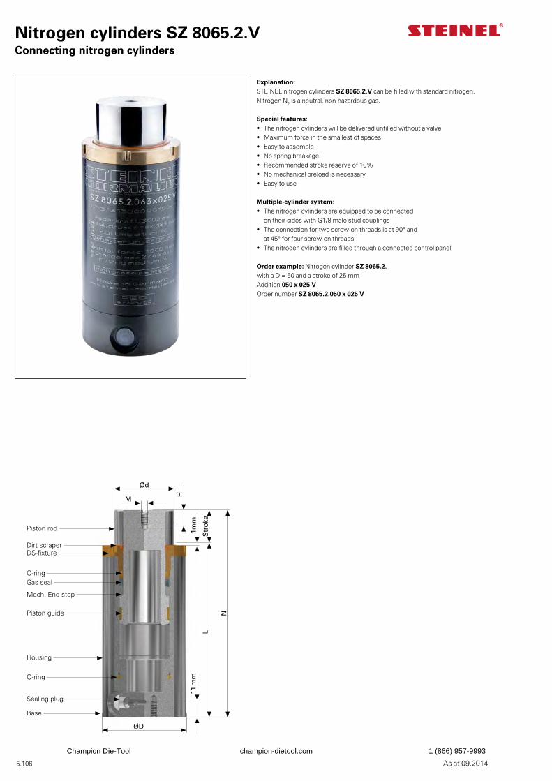
5.106 As at 09.2014
Nitrogen cylinders SZ 8065.2.VConnecting nitrogen cylinders
Explanation:STEINEL nitrogen cylinders SZ 8065.2.V can be filled with standard nitrogen. Nitrogen N2 is a neutral, non-hazardous gas.
Special features:• The nitrogen cylinders will be delivered unfilled without a valve• Maximum force in the smallest of spaces• Easy to assemble• No spring breakage• Recommended stroke reserve of 10%• No mechanical preload is necessary• Easy to use
Multiple-cylinder system:• The nitrogen cylinders are equipped to be connected
on their sides with G1/8 male stud couplings• The connection for two screw-on threads is at 90° and
at 45° for four screw-on threads.• The nitrogen cylinders are filled through a connected control panel
Order example: Nitrogen cylinder SZ 8065.2.with a D = 50 and a stroke of 25 mmAddition 050 x 025 VOrder number SZ 8065.2.050 x 025 V
Ød
M
H
Str
oke
N
L
ØD
1mm
11 m
m
Piston rod
Dirt scraperDS-fixture
Gas seal
Mech. End stop
Piston guide
Housing
O-ring
Sealing plug
Base
O-ring
Champion Die-Tool champion-dietool.com 1 (866) 957-9993
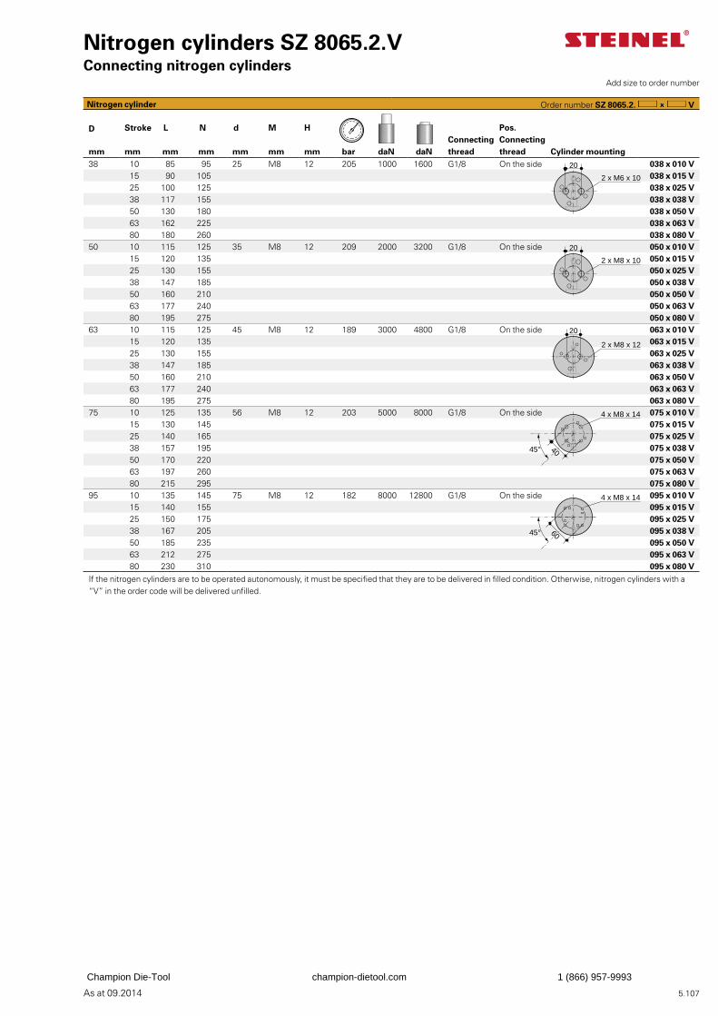
5.107As at 09.2014
Nitrogen cylinders SZ 8065.2.VConnecting nitrogen cylinders
D Stroke L N d M HConnecting thread
Pos. Connecting threadmm mm mm mm mm mm mm bar daN daN Cylinder mounting
38 10 85 95 25 M8 12 205 1000 1600 G1/8 On the side 038 x 010 V15 90 105 038 x 015 V25 100 125 038 x 025 V38 117 155 038 x 038 V50 130 180 038 x 050 V63 162 225 038 x 063 V80 180 260 038 x 080 V
50 10 115 125 35 M8 12 209 2000 3200 G1/8 On the side 050 x 010 V15 120 135 050 x 015 V25 130 155 050 x 025 V38 147 185 050 x 038 V50 160 210 050 x 050 V63 177 240 050 x 063 V80 195 275 050 x 080 V
63 10 115 125 45 M8 12 189 3000 4800 G1/8 On the side 063 x 010 V15 120 135 063 x 015 V25 130 155 063 x 025 V38 147 185 063 x 038 V50 160 210 063 x 050 V63 177 240 063 x 063 V80 195 275 063 x 080 V
75 10 125 135 56 M8 12 203 5000 8000 G1/8 On the side 075 x 010 V15 130 145 075 x 015 V25 140 165 075 x 025 V38 157 195 075 x 038 V50 170 220 075 x 050 V63 197 260 075 x 063 V80 215 295 075 x 080 V
95 10 135 145 75 M8 12 182 8000 12800 G1/8 On the side 095 x 010 V15 140 155 095 x 015 V25 150 175 095 x 025 V38 167 205 095 x 038 V50 185 235 095 x 050 V63 212 275 095 x 063 V80 230 310 095 x 080 V
If the nitrogen cylinders are to be operated autonomously, it must be specified that they are to be delivered in filled condition. Otherwise, nitrogen cylinders with a “V” in the order code will be delivered unfilled.
Add size to order number
Nitrogen cylinder Order number SZ 8065.2. V
2 x M6 x 10
20
2 x M8 x 10
20
20
2 x M8 x 12
4 x M8 x 14
4045°
4 x M8 x 14
6045°
Champion Die-Tool champion-dietool.com 1 (866) 957-9993
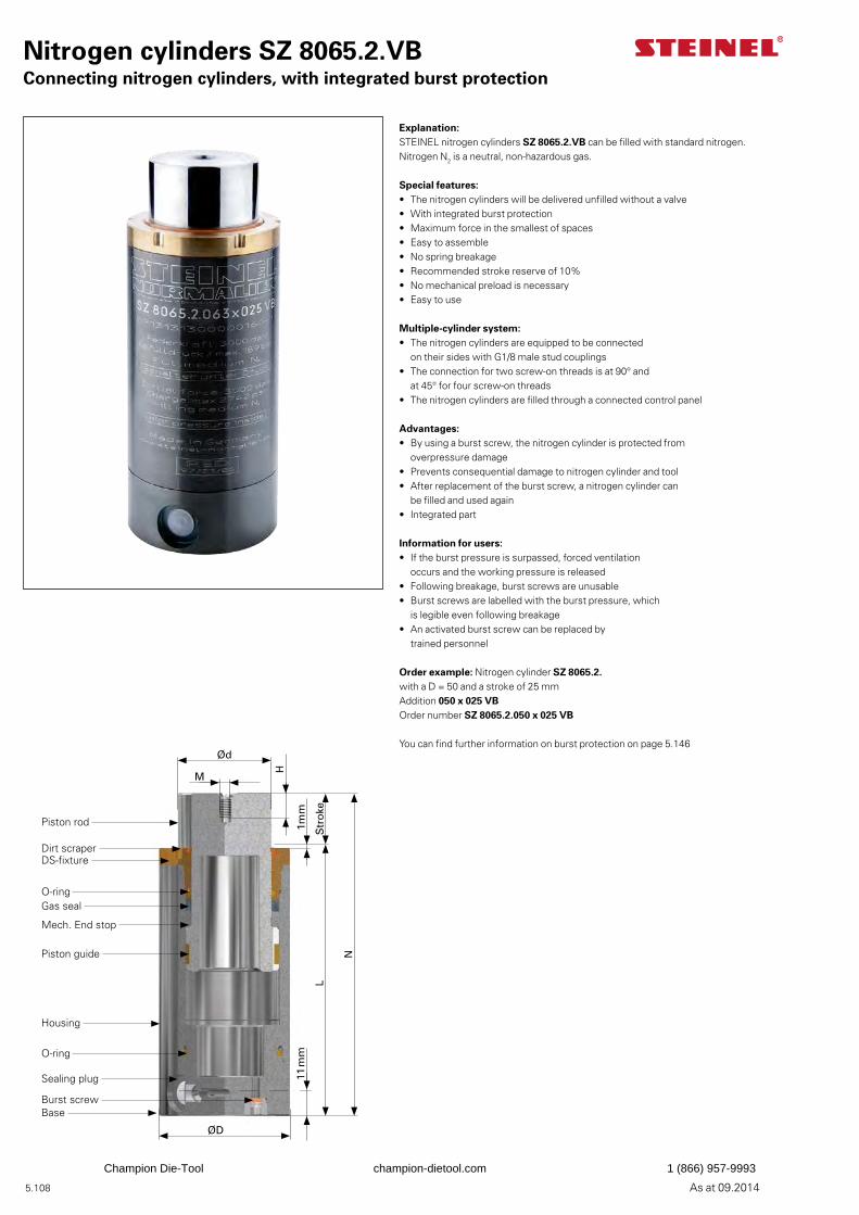
5.108 As at 09.2014
Nitrogen cylinders SZ 8065.2.VBConnecting nitrogen cylinders, with integrated burst protection
Explanation:STEINEL nitrogen cylinders SZ 8065.2.VB can be filled with standard nitrogen. Nitrogen N2 is a neutral, non-hazardous gas.
Special features:• The nitrogen cylinders will be delivered unfilled without a valve• With integrated burst protection• Maximum force in the smallest of spaces• Easy to assemble• No spring breakage• Recommended stroke reserve of 10%• No mechanical preload is necessary• Easy to use
Multiple-cylinder system:• The nitrogen cylinders are equipped to be connected
on their sides with G1/8 male stud couplings• The connection for two screw-on threads is at 90° and
at 45° for four screw-on threads• The nitrogen cylinders are filled through a connected control panel
Advantages:• By using a burst screw, the nitrogen cylinder is protected from
overpressure damage• Prevents consequential damage to nitrogen cylinder and tool• After replacement of the burst screw, a nitrogen cylinder can
be filled and used again• Integrated part
Information for users:• If the burst pressure is surpassed, forced ventilation
occurs and the working pressure is released• Following breakage, burst screws are unusable• Burst screws are labelled with the burst pressure, which
is legible even following breakage• An activated burst screw can be replaced by
trained personnel
Order example: Nitrogen cylinder SZ 8065.2.with a D = 50 and a stroke of 25 mmAddition 050 x 025 VBOrder number SZ 8065.2.050 x 025 VB
You can find further information on burst protection on page 5.146Ød
M
H
Str
oke
N
L
ØD
1mm
11 m
m
Piston rod
Dirt scraperDS-fixture
Gas seal
Mech. End stop
Piston guide
Housing
O-ring
Sealing plug
Base
O-ring
Burst screw
Champion Die-Tool champion-dietool.com 1 (866) 957-9993
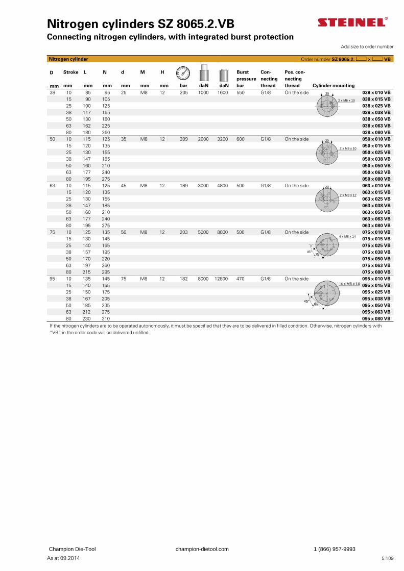
5.109As at 09.2014
Nitrogen cylinders SZ 8065.2.VBConnecting nitrogen cylinders, with integrated burst protection
Burst pressure bar
Con-necting thread
Pos. con-necting thread
D Stroke L N d M H
mm mm mm mm mm mm mm bar daN daN Cylinder mounting38 10 85 95 25 M8 12 205 1000 1600 550 G1/8 On the side 038 x 010 VB
15 90 105 038 x 015 VB25 100 125 038 x 025 VB38 117 155 038 x 038 VB50 130 180 038 x 050 VB63 162 225 038 x 063 VB80 180 260 038 x 080 VB
50 10 115 125 35 M8 12 209 2000 3200 600 G1/8 On the side 050 x 010 VB15 120 135 050 x 015 VB25 130 155 050 x 025 VB38 147 185 050 x 038 VB50 160 210 050 x 050 VB63 177 240 050 x 063 VB80 195 275 050 x 080 VB
63 10 115 125 45 M8 12 189 3000 4800 500 G1/8 On the side 063 x 010 VB15 120 135 063 x 015 VB25 130 155 063 x 025 VB38 147 185 063 x 038 VB50 160 210 063 x 050 VB63 177 240 063 x 063 VB80 195 275 063 x 080 VB
75 10 125 135 56 M8 12 203 5000 8000 500 G1/8 On the side 075 x 010 VB15 130 145 075 x 015 VB25 140 165 075 x 025 VB38 157 195 075 x 038 VB50 170 220 075 x 050 VB63 197 260 075 x 063 VB80 215 295 075 x 080 VB
95 10 135 145 75 M8 12 182 8000 12800 470 G1/8 On the side 095 x 010 VB15 140 155 095 x 015 VB25 150 175 095 x 025 VB38 167 205 095 x 038 VB50 185 235 095 x 050 VB63 212 275 095 x 063 VB80 230 310 095 x 080 VB
If the nitrogen cylinders are to be operated autonomously, it must be specified that they are to be delivered in filled condition. Otherwise, nitrogen cylinders with “VB” in the order code will be delivered unfilled.
Add size to order number
Nitrogen cylinder Order number SZ 8065.2. VB
20
2 x M6 x 10
2 x M8 x 10
20
2 x M8 x 12
20
4 x M8 x 14
4045°
4 x M8 x 14
6045°
Champion Die-Tool champion-dietool.com 1 (866) 957-9993
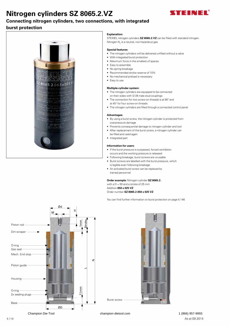
5.110 As at 09.2014
Nitrogen cylinders SZ 8065.2.VZConnecting nitrogen cylinders, two connections, with integrated burst protection
Explanation:STEINEL nitrogen cylinders SZ 8065.2.VZ can be filled with standard nitrogen. Nitrogen N2 is a neutral, non-hazardous gas.
Special features:• The nitrogen cylinders will be delivered unfilled without a valve• With integrated burst protection• Maximum force in the smallest of spaces• Easy to assemble• No spring breakage• Recommended stroke reserve of 10%• No mechanical preload is necessary• Easy to use
Multiple-cylinder system:• The nitrogen cylinders are equipped to be connected
on their sides with G1/8 male stud couplings• The connection for two screw-on threads is at 90° and
at 45° for four screw-on threads• The nitrogen cylinders are filled through a connected control panel
Advantages:• By using a burst screw, the nitrogen cylinder is protected from
overpressure damage• Prevents consequential damage to nitrogen cylinder and tool• After replacement of the burst screw, a nitrogen cylinder can
be filled and used again• Integrated part
Information for users:• If the burst pressure is surpassed, forced ventilation
occurs and the working pressure is released• Following breakage, burst screws are unusable• Burst screws are labelled with the burst pressure, which
is legible even following breakage• An activated burst screw can be replaced by
trained personnel
Order example: Nitrogen cylinder SZ 8065.2.with a D = 50 and a stroke of 25 mmAddition 050 x 025 VZOrder number SZ 8065.2.050 x 025 VZ
You can find further information on burst protection on page 5.146
Ød
M
H
Str
oke
N
L
ØD
1mm
11 m
m
Piston rod
Dirt scraper
Gas seal
Mech. End stop
Piston guide
Housing
O-ring2x sealing plugs
Base
O-ring
Burst screw
Champion Die-Tool champion-dietool.com 1 (866) 957-9993
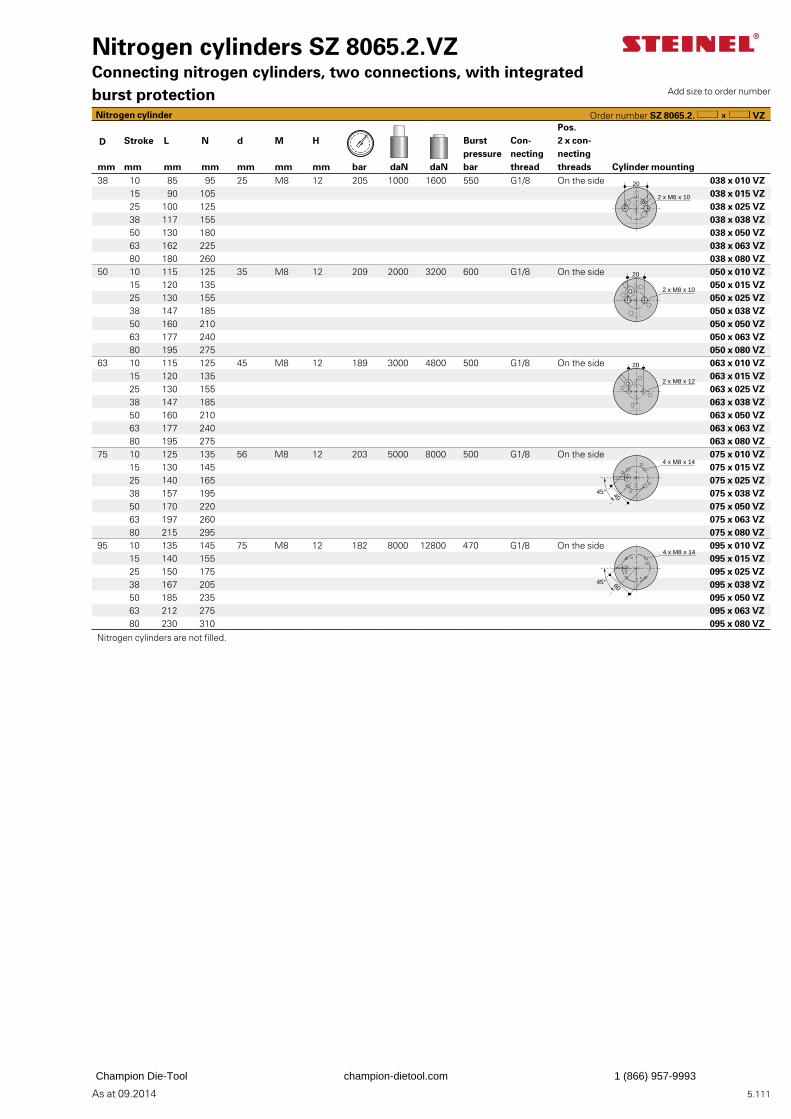
5.111As at 09.2014
Nitrogen cylinders SZ 8065.2.VZConnecting nitrogen cylinders, two connections, with integrated burst protection
Burstpressurebar
Con-necting thread
Pos. 2 x con-necting threads
D Stroke L N d M H
mm mm mm mm mm mm mm bar daN daN Cylinder mounting38 10 85 95 25 M8 12 205 1000 1600 550 G1/8 On the side 038 x 010 VZ
15 90 105 038 x 015 VZ25 100 125 038 x 025 VZ38 117 155 038 x 038 VZ50 130 180 038 x 050 VZ63 162 225 038 x 063 VZ80 180 260 038 x 080 VZ
50 10 115 125 35 M8 12 209 2000 3200 600 G1/8 On the side 050 x 010 VZ15 120 135 050 x 015 VZ25 130 155 050 x 025 VZ38 147 185 050 x 038 VZ50 160 210 050 x 050 VZ63 177 240 050 x 063 VZ80 195 275 050 x 080 VZ
63 10 115 125 45 M8 12 189 3000 4800 500 G1/8 On the side 063 x 010 VZ15 120 135 063 x 015 VZ25 130 155 063 x 025 VZ38 147 185 063 x 038 VZ50 160 210 063 x 050 VZ63 177 240 063 x 063 VZ80 195 275 063 x 080 VZ
75 10 125 135 56 M8 12 203 5000 8000 500 G1/8 On the side 075 x 010 VZ15 130 145 075 x 015 VZ25 140 165 075 x 025 VZ38 157 195 075 x 038 VZ50 170 220 075 x 050 VZ63 197 260 075 x 063 VZ80 215 295 075 x 080 VZ
95 10 135 145 75 M8 12 182 8000 12800 470 G1/8 On the side 095 x 010 VZ15 140 155 095 x 015 VZ25 150 175 095 x 025 VZ38 167 205 095 x 038 VZ50 185 235 095 x 050 VZ63 212 275 095 x 063 VZ80 230 310 095 x 080 VZ
Nitrogen cylinders are not filled.
Add size to order number
Nitrogen cylinder Order number SZ 8065.2. VZ
20
2 x M6 x 10
2 x M8 x 10
20
2 x M8 x 12
20
4 x M8 x 14
4045°
4 x M8 x 14
6045°
Champion Die-Tool champion-dietool.com 1 (866) 957-9993
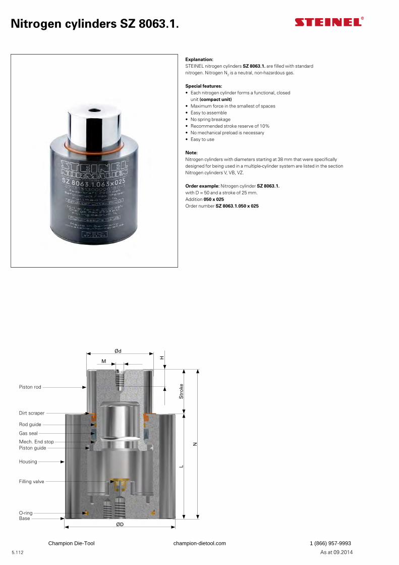
5.112 As at 09.2014
Nitrogen cylinders SZ 8063.1.
Explanation:STEINEL nitrogen cylinders SZ 8063.1. are filled with standard nitrogen. Nitrogen N2 is a neutral, non-hazardous gas.
Special features:• Each nitrogen cylinder forms a functional, closed
unit (compact unit)• Maximum force in the smallest of spaces• Easy to assemble• No spring breakage• Recommended stroke reserve of 10%• No mechanical preload is necessary• Easy to use
Note:Nitrogen cylinders with diameters starting at 38 mm that were specifically designed for being used in a multiple-cylinder system are listed in the section Nitrogen cylinders V, VB, VZ.
Order example: Nitrogen cylinder SZ 8063.1. with D = 50 and a stroke of 25 mm.Addition 050 x 025 Order number SZ 8063.1.050 x 025
Ød
M
H
Str
oke
N
L
ØD
Piston rod
Dirt scraper
Rod guide
Gas seal
Mech. End stopPiston guide
Housing
Filling valve
BaseO-ring
Champion Die-Tool champion-dietool.com 1 (866) 957-9993
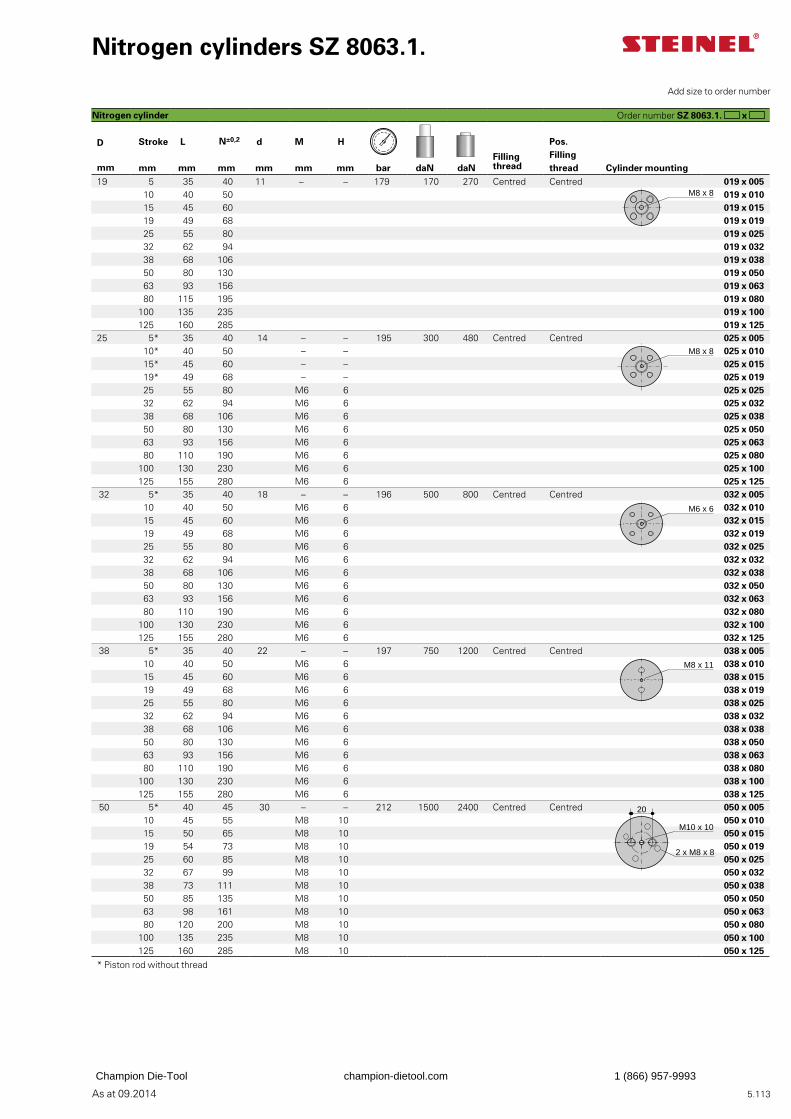
5.113As at 09.2014
Nitrogen cylinders SZ 8063.1.
D Stroke L N±0,2 d M H Pos. Filling thread
Filling threadmm mm mm mm mm mm mm bar daN daN Cylinder mounting
19 5 35 40 11 – – 179 170 270 Centred Centred 019 x 00510 40 50 019 x 01015 45 60 019 x 01519 49 68 019 x 01925 55 80 019 x 02532 62 94 019 x 03238 68 106 019 x 03850 80 130 019 x 05063 93 156 019 x 06380 115 195 019 x 080
100 135 235 019 x 100125 160 285 019 x 125
25 5* 35 40 14 – – 195 300 480 Centred Centred 025 x 00510* 40 50 – – 025 x 01015* 45 60 – – 025 x 01519* 49 68 – – 025 x 01925 55 80 M6 6 025 x 02532 62 94 M6 6 025 x 03238 68 106 M6 6 025 x 03850 80 130 M6 6 025 x 05063 93 156 M6 6 025 x 06380 110 190 M6 6 025 x 080
100 130 230 M6 6 025 x 100125 155 280 M6 6 025 x 125
32 5* 35 40 18 – – 196 500 800 Centred Centred 032 x 00510 40 50 M6 6 032 x 01015 45 60 M6 6 032 x 01519 49 68 M6 6 032 x 01925 55 80 M6 6 032 x 02532 62 94 M6 6 032 x 03238 68 106 M6 6 032 x 03850 80 130 M6 6 032 x 05063 93 156 M6 6 032 x 06380 110 190 M6 6 032 x 080
100 130 230 M6 6 032 x 100125 155 280 M6 6 032 x 125
38 5* 35 40 22 – – 197 750 1200 Centred Centred 038 x 00510 40 50 M6 6 038 x 01015 45 60 M6 6 038 x 01519 49 68 M6 6 038 x 01925 55 80 M6 6 038 x 02532 62 94 M6 6 038 x 03238 68 106 M6 6 038 x 03850 80 130 M6 6 038 x 05063 93 156 M6 6 038 x 06380 110 190 M6 6 038 x 080
100 130 230 M6 6 038 x 100125 155 280 M6 6 038 x 125
50 5* 40 45 30 – – 212 1500 2400 Centred Centred 050 x 00510 45 55 M8 10 050 x 01015 50 65 M8 10 050 x 01519 54 73 M8 10 050 x 01925 60 85 M8 10 050 x 02532 67 99 M8 10 050 x 03238 73 111 M8 10 050 x 03850 85 135 M8 10 050 x 05063 98 161 M8 10 050 x 06380 120 200 M8 10 050 x 080
100 135 235 M8 10 050 x 100125 160 285 M8 10 050 x 125
* Piston rod without thread
Order number SZ 8063.1. x
Add size to order number
Nitrogen cylinder
M8 x 8
M8 x 8
M6 x 6
M8 x 11
2 x M8 x 8
20
M10 x 10
Champion Die-Tool champion-dietool.com 1 (866) 957-9993
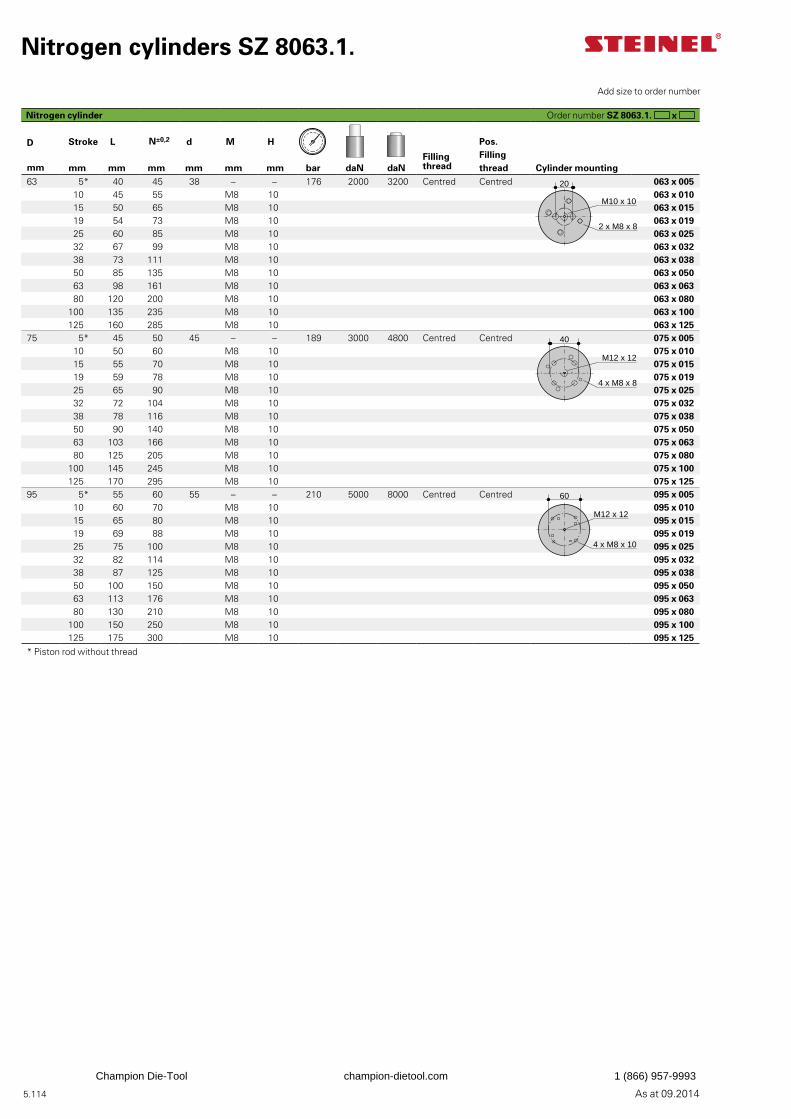
5.114 As at 09.2014
Nitrogen cylinders SZ 8063.1.
D Stroke L N±0,2 d M H Pos. Filling thread
Filling threadmm mm mm mm mm mm mm bar daN daN Cylinder mounting
63 5* 40 45 38 – – 176 2000 3200 Centred Centred 063 x 00510 45 55 M8 10 063 x 01015 50 65 M8 10 063 x 01519 54 73 M8 10 063 x 01925 60 85 M8 10 063 x 02532 67 99 M8 10 063 x 03238 73 111 M8 10 063 x 03850 85 135 M8 10 063 x 05063 98 161 M8 10 063 x 06380 120 200 M8 10 063 x 080
100 135 235 M8 10 063 x 100125 160 285 M8 10 063 x 125
75 5* 45 50 45 – – 189 3000 4800 Centred Centred 075 x 00510 50 60 M8 10 075 x 01015 55 70 M8 10 075 x 01519 59 78 M8 10 075 x 01925 65 90 M8 10 075 x 02532 72 104 M8 10 075 x 03238 78 116 M8 10 075 x 03850 90 140 M8 10 075 x 05063 103 166 M8 10 075 x 06380 125 205 M8 10 075 x 080
100 145 245 M8 10 075 x 100125 170 295 M8 10 075 x 125
95 5* 55 60 55 – – 210 5000 8000 Centred Centred 095 x 00510 60 70 M8 10 095 x 01015 65 80 M8 10 095 x 01519 69 88 M8 10 095 x 01925 75 100 M8 10 095 x 02532 82 114 M8 10 095 x 03238 87 125 M8 10 095 x 03850 100 150 M8 10 095 x 05063 113 176 M8 10 095 x 06380 130 210 M8 10 095 x 080
100 150 250 M8 10 095 x 100125 175 300 M8 10 095 x 125
* Piston rod without thread
Order number SZ 8063.1. x
Add size to order number
Nitrogen cylinder
20
2 x M8 x 8
M10 x 10
4 x M8 x 8
M12 x 12
40
4 x M8 x 10
M12 x 12
60
Champion Die-Tool champion-dietool.com 1 (866) 957-9993
5.115As at 09.2014
Champion Die-Tool champion-dietool.com 1 (866) 957-9993
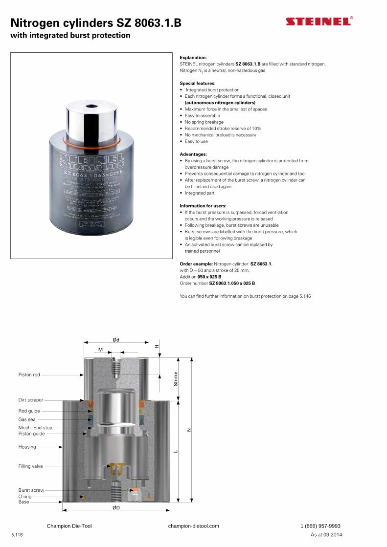
5.116 As at 09.2014
Nitrogen cylinders SZ 8063.1.Bwith integrated burst protection
Explanation:STEINEL nitrogen cylinders SZ 8063.1.B are filled with standard nitrogen. Nitrogen N2 is a neutral, non-hazardous gas.
Special features:• Integrated burst protection• Each nitrogen cylinder forms a functional, closed unit
(autonomous nitrogen cylinders)• Maximum force in the smallest of spaces• Easy to assemble• No spring breakage• Recommended stroke reserve of 10%• No mechanical preload is necessary• Easy to use
Advantages:• By using a burst screw, the nitrogen cylinder is protected from
overpressure damage• Prevents consequential damage to nitrogen cylinder and tool• After replacement of the burst screw, a nitrogen cylinder can
be filled and used again• Integrated part
Information for users:• If the burst pressure is surpassed, forced ventilation
occurs and the working pressure is released• Following breakage, burst screws are unusable• Burst screws are labelled with the burst pressure, which
is legible even following breakage• An activated burst screw can be replaced by
trained personnel
Order example: Nitrogen cylinder: SZ 8063.1. with D = 50 and a stroke of 25 mm.Addition 050 x 025 BOrder number SZ 8063.1.050 x 025 B
You can find further information on burst protection on page 5.146
Ød
M
H
Str
oke
N
L
ØD
Piston rod
Dirt scraper
Rod guide
Gas seal
Mech. End stopPiston guide
Housing
Filling valve
BaseO-ringBurst screw
Champion Die-Tool champion-dietool.com 1 (866) 957-9993
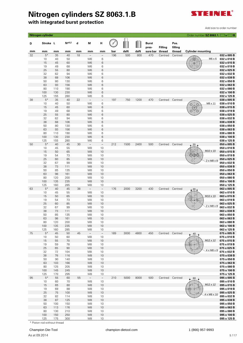
5.117As at 09.2014
Nitrogen cylinders SZ 8063.1.Bwith integrated burst protection
Burst pres-sure bar
Filling thread
Pos. filling thread
D Stroke L N±0,2 d M H
mm mm mm mm mm mm mm bar daN daN Cylinder mounting32 5* 35 40 18 – – 196 500 800 470 Centred Centred 032 x 005 B
10 40 50 M6 6 032 x 010 B15 45 60 M6 6 032 x 015 B19 49 68 M6 6 032 x 019 B25 55 80 M6 6 032 x 025 B32 62 94 M6 6 032 x 032 B38 68 106 M6 6 032 x 038 B50 80 130 M6 6 032 x 050 B63 93 156 M6 6 032 x 063 B80 110 190 M6 6 032 x 080 B
100 130 230 M6 6 032 x 100 B125 155 280 M6 6 032 x 125 B
38 5* 35 40 22 – – 197 750 1200 470 Centred Centred 038 x 005 B10 40 50 M6 6 038 x 010 B15 45 60 M6 6 038 x 015 B19 49 68 M6 6 038 x 019 B25 55 80 M6 6 038 x 025 B32 62 94 M6 6 038 x 032 B38 68 106 M6 6 038 x 038 B50 80 130 M6 6 038 x 050 B63 93 156 M6 6 038 x 063 B80 110 190 M6 6 038 x 080 B
100 130 230 M6 6 038 x 100 B125 155 280 M6 6 038 x 125 B
50 5* 40 45 30 – – 212 1500 2400 500 Centred Centred 050 x 005 B10 45 55 M8 10 050 x 010 B15 50 65 M8 10 050 x 015 B19 54 73 M8 10 050 x 019 B25 60 85 M8 10 050 x 025 B32 67 99 M8 10 050 x 032 B38 73 111 M8 10 050 x 038 B50 85 135 M8 10 050 x 050 B63 98 161 M8 10 050 x 063 B80 120 200 M8 10 050 x 080 B
100 135 235 M8 10 050 x 100 B125 160 285 M8 10 050 x 125 B
63 5* 40 45 38 – – 176 2000 3200 430 Centred Centred 063 x 005 B10 45 55 M8 10 063 x 010 B15 50 65 M8 10 063 x 015 B19 54 73 M8 10 063 x 019 B25 60 85 M8 10 063 x 025 B32 67 99 M8 10 063 x 032 B38 73 111 M8 10 063 x 038 B50 85 135 M8 10 063 x 050 B63 98 161 M8 10 063 x 063 B80 120 200 M8 10 063 x 080 B
100 135 235 M8 10 063 x 100 B125 160 285 M8 10 063 x 125 B
75 5* 45 50 45 – – 189 3000 4800 450 Centred Centred 075 x 005 B10 50 60 M8 10 075 x 010 B15 55 70 M8 10 075 x 015 B19 59 78 M8 10 075 x 019 B25 65 90 M8 10 075 x 025 B32 72 104 M8 10 075 x 032 B38 78 116 M8 10 075 x 038 B50 90 140 M8 10 075 x 050 B63 103 166 M8 10 075 x 063 B80 125 205 M8 10 075 x 080 B
100 145 245 M8 10 075 x 100 B125 170 295 M8 10 075 x 125 B
95 5* 55 60 55 – – 210 5000 8000 500 Centred Centred 095 x 005 B10 60 70 M8 10 095 x 010 B15 65 80 M8 10 095 x 015 B19 69 88 M8 10 095 x 019 B25 75 100 M8 10 095 x 025 B32 82 114 M8 10 095 x 032 B38 87 125 M8 10 095 x 038 B50 100 150 M8 10 095 x 050 B63 113 176 M8 10 095 x 063 B80 130 210 M8 10 095 x 080 B
100 150 250 M8 10 095 x 100 B125 175 300 M8 10 095 x 125 B
* Piston rod without thread
Order number SZ 8063.1. x B
Add size to order number
Nitrogen cylinder
M6 x 6
M8 x 11
20
M10 x 10
2 x M8 x 8
20
M10 x 10
2 x M8 x 8
M12 x 12
40
4 x M8 x 8
M12 x 12
60
4 x M8 x 10
Champion Die-Tool champion-dietool.com 1 (866) 957-9993
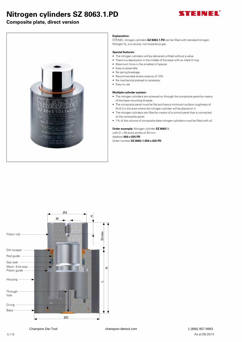
5.118 As at 09.2014
Nitrogen cylinders SZ 8063.1.PDComposite plate, direct version
Ød
M
H
Str
oke
NL
ØD
Piston rod
Dirt scraper
Rod guide
Gas sealMech. End stopPiston guide
Housing
Through- hole
Base
O-ring
Explanation:STEINEL nitrogen cylinders SZ 8063.1.PD can be filled with standard nitrogen. Nitrogen N2 is a neutral, non-hazardous gas.
Special features:• The nitrogen cylinders will be delivered unfilled without a valve• There is a depression in the middle of the base with an inlaid O-ring • Maximum force in the smallest of spaces• Easy to assemble• No spring breakage• Recommended stroke reserve of 10%• No mechanical preload is necessary• Easy to use
Multiple-cylinder system:• The nitrogen cylinders are screwed on through the composite panel by means
of the base mounting threads.• The composite panel must be flat and have a minimum surface roughness of
Rz 6.3 in the area where the nitrogen cylinder will be placed on it• The nitrogen cylinders are filled by means of a control panel that is connected
to the composite panel.• 1% of the volume of composite plate nitrogen cylinders must be filled with oil.
Order example: Nitrogen cylinder SZ 8063.1. with D = 50 and a stroke of 25 mm.Addition 050 x 025 PDOrder number SZ 8063.1.050 x 025 PD
Champion Die-Tool champion-dietool.com 1 (866) 957-9993
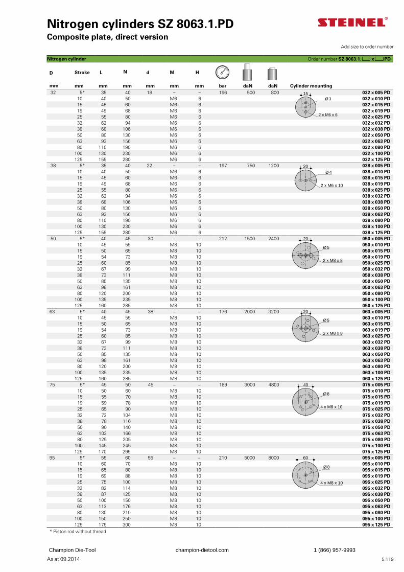
5.119As at 09.2014
Nitrogen cylinders SZ 8063.1.PDComposite plate, direct version
D Stroke L N d M H
mm mm mm mm mm mm mm bar daN daN Cylinder mounting 32 5* 35 40 18 – – 196 500 800 032 x 005 PD
10 40 50 M6 6 032 x 010 PD15 45 60 M6 6 032 x 015 PD19 49 68 M6 6 032 x 019 PD25 55 80 M6 6 032 x 025 PD32 62 94 M6 6 032 x 032 PD38 68 106 M6 6 032 x 038 PD50 80 130 M6 6 032 x 050 PD63 93 156 M6 6 032 x 063 PD80 110 190 M6 6 032 x 080 PD
100 130 230 M6 6 032 x 100 PD125 155 280 M6 6 032 x 125 PD
38 5* 35 40 22 – – 197 750 1200 038 x 005 PD10 40 50 M6 6 038 x 010 PD15 45 60 M6 6 038 x 015 PD19 49 68 M6 6 038 x 019 PD25 55 80 M6 6 038 x 025 PD32 62 94 M6 6 038 x 032 PD38 68 106 M6 6 038 x 038 PD50 80 130 M6 6 038 x 050 PD63 93 156 M6 6 038 x 063 PD80 110 190 M6 6 038 x 080 PD
100 130 230 M6 6 038 x 100 PD125 155 280 M6 6 038 x 125 PD
50 5* 40 45 30 – – 212 1500 2400 050 x 005 PD10 45 55 M8 10 050 x 010 PD15 50 65 M8 10 050 x 015 PD19 54 73 M8 10 050 x 019 PD25 60 85 M8 10 050 x 025 PD32 67 99 M8 10 050 x 032 PD38 73 111 M8 10 050 x 038 PD50 85 135 M8 10 050 x 050 PD63 98 161 M8 10 050 x 063 PD80 120 200 M8 10 050 x 080 PD
100 135 235 M8 10 050 x 100 PD125 160 285 M8 10 050 x 125 PD
63 5* 40 45 38 – – 176 2000 3200 063 x 005 PD10 45 55 M8 10 063 x 010 PD15 50 65 M8 10 063 x 015 PD19 54 73 M8 10 063 x 019 PD25 60 85 M8 10 063 x 025 PD32 67 99 M8 10 063 x 032 PD38 73 111 M8 10 063 x 038 PD50 85 135 M8 10 063 x 050 PD63 98 161 M8 10 063 x 063 PD80 120 200 M8 10 063 x 080 PD
100 135 235 M8 10 063 x 100 PD125 160 285 M8 10 063 x 125 PD
75 5* 45 50 45 – – 189 3000 4800 075 x 005 PD10 50 60 M8 10 075 x 010 PD15 55 70 M8 10 075 x 015 PD19 59 78 M8 10 075 x 019 PD25 65 90 M8 10 075 x 025 PD32 72 104 M8 10 075 x 032 PD38 78 116 M8 10 075 x 038 PD50 90 140 M8 10 075 x 050 PD63 103 166 M8 10 075 x 063 PD80 125 205 M8 10 075 x 080 PD
100 145 245 M8 10 075 x 100 PD125 170 295 M8 10 075 x 125 PD
95 5* 55 60 55 – – 210 5000 8000 095 x 005 PD10 60 70 M8 10 095 x 010 PD15 65 80 M8 10 095 x 015 PD19 69 88 M8 10 095 x 019 PD25 75 100 M8 10 095 x 025 PD32 82 114 M8 10 095 x 032 PD38 87 125 M8 10 095 x 038 PD50 100 150 M8 10 095 x 050 PD63 113 176 M8 10 095 x 063 PD80 130 210 M8 10 095 x 080 PD
100 150 250 M8 10 095 x 100 PD125 175 300 M8 10 095 x 125 PD
* Piston rod without thread
Order number SZ 8063.1. x PD
Add size to order number
Nitrogen cylinder
2 x M6 x 10
20Ø 4
Ø 3
2 x M6 x 6
15
20
2 x M8 x 8
Ø 5
20
2 x M8 x 8
Ø 5
4 x M8 x 10
40
Ø 8
4 x M8 x 10
60
Ø 8
Champion Die-Tool champion-dietool.com 1 (866) 957-9993
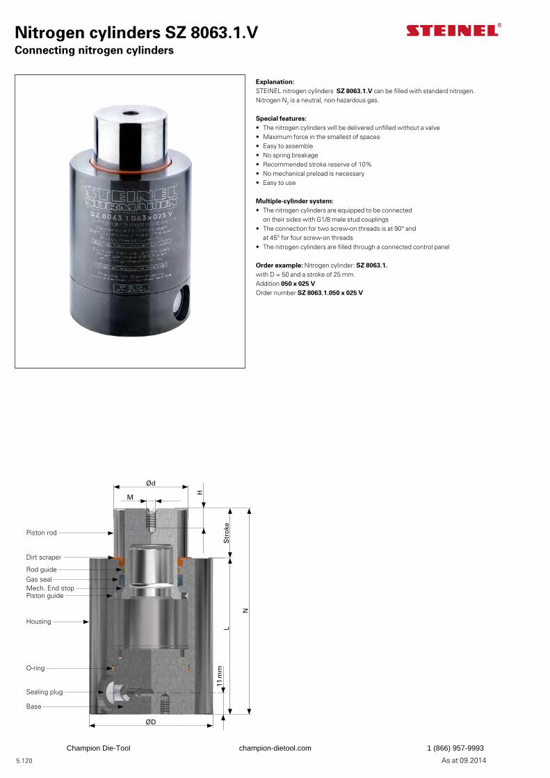
5.120 As at 09.2014
Nitrogen cylinders SZ 8063.1.VConnecting nitrogen cylinders
Explanation:STEINEL nitrogen cylinders SZ 8063.1.V can be filled with standard nitrogen. Nitrogen N2 is a neutral, non-hazardous gas.
Special features:• The nitrogen cylinders will be delivered unfilled without a valve• Maximum force in the smallest of spaces• Easy to assemble• No spring breakage• Recommended stroke reserve of 10%• No mechanical preload is necessary• Easy to use
Multiple-cylinder system:• The nitrogen cylinders are equipped to be connected
on their sides with G1/8 male stud couplings• The connection for two screw-on threads is at 90° and
at 45° for four screw-on threads• The nitrogen cylinders are filled through a connected control panel
Order example: Nitrogen cylinder: SZ 8063.1. with D = 50 and a stroke of 25 mm.Addition 050 x 025 V Order number SZ 8063.1.050 x 025 V
Ød
M
H
Str
oke
N
L
ØD
11 m
m
Piston rod
Dirt scraper
Rod guideGas sealMech. End stopPiston guide
Housing
Base
Sealing plug
O-ring
Champion Die-Tool champion-dietool.com 1 (866) 957-9993
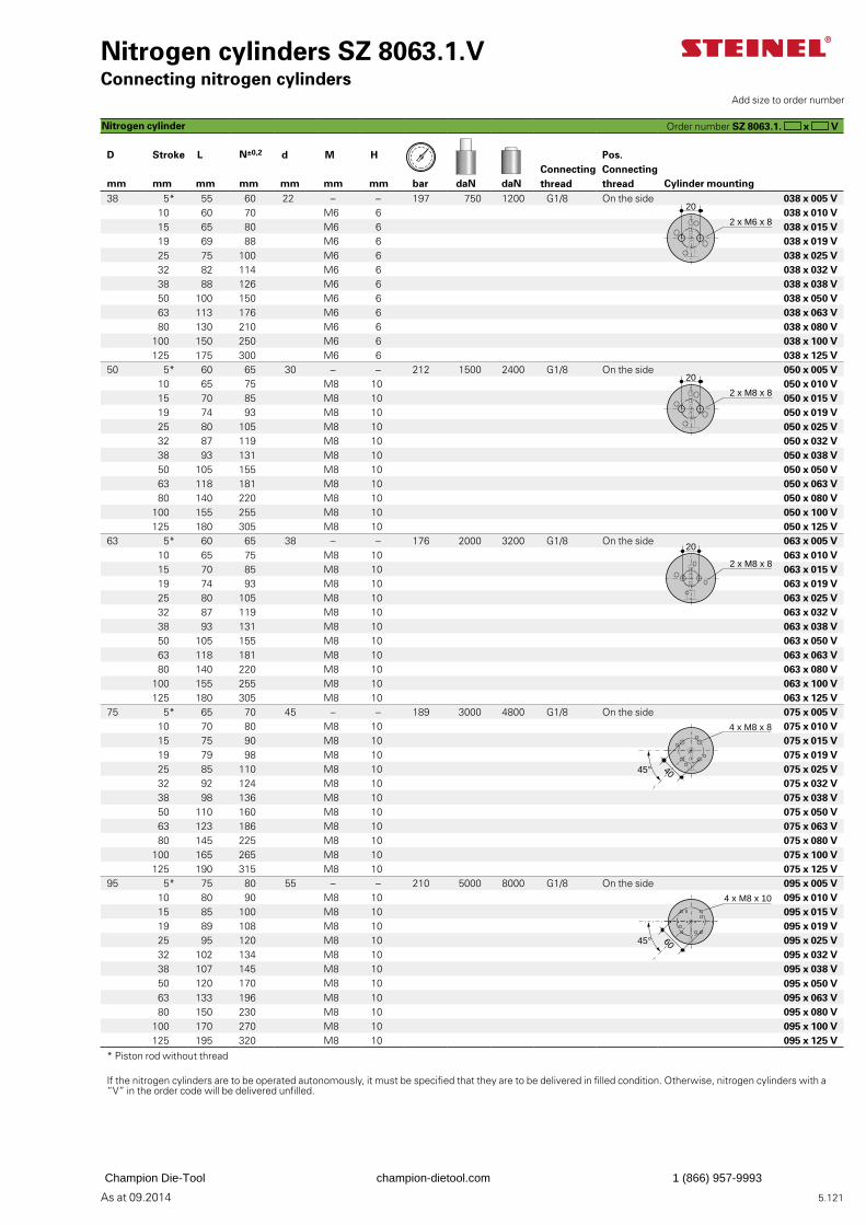
5.121As at 09.2014
Nitrogen cylinders SZ 8063.1.VConnecting nitrogen cylinders
Connecting thread
Pos. Connecting thread
D Stroke L N±0,2 d M H
mm mm mm mm mm mm mm bar daN daN Cylinder mounting38 5* 55 60 22 – – 197 750 1200 G1/8 On the side 038 x 005 V
10 60 70 M6 6 038 x 010 V15 65 80 M6 6 038 x 015 V19 69 88 M6 6 038 x 019 V25 75 100 M6 6 038 x 025 V32 82 114 M6 6 038 x 032 V38 88 126 M6 6 038 x 038 V50 100 150 M6 6 038 x 050 V63 113 176 M6 6 038 x 063 V80 130 210 M6 6 038 x 080 V
100 150 250 M6 6 038 x 100 V125 175 300 M6 6 038 x 125 V
50 5* 60 65 30 – – 212 1500 2400 G1/8 On the side 050 x 005 V10 65 75 M8 10 050 x 010 V15 70 85 M8 10 050 x 015 V19 74 93 M8 10 050 x 019 V25 80 105 M8 10 050 x 025 V32 87 119 M8 10 050 x 032 V38 93 131 M8 10 050 x 038 V50 105 155 M8 10 050 x 050 V63 118 181 M8 10 050 x 063 V80 140 220 M8 10 050 x 080 V
100 155 255 M8 10 050 x 100 V125 180 305 M8 10 050 x 125 V
63 5* 60 65 38 – – 176 2000 3200 G1/8 On the side 063 x 005 V10 65 75 M8 10 063 x 010 V15 70 85 M8 10 063 x 015 V19 74 93 M8 10 063 x 019 V25 80 105 M8 10 063 x 025 V32 87 119 M8 10 063 x 032 V38 93 131 M8 10 063 x 038 V50 105 155 M8 10 063 x 050 V63 118 181 M8 10 063 x 063 V80 140 220 M8 10 063 x 080 V
100 155 255 M8 10 063 x 100 V125 180 305 M8 10 063 x 125 V
75 5* 65 70 45 – – 189 3000 4800 G1/8 On the side 075 x 005 V10 70 80 M8 10 075 x 010 V15 75 90 M8 10 075 x 015 V19 79 98 M8 10 075 x 019 V25 85 110 M8 10 075 x 025 V32 92 124 M8 10 075 x 032 V38 98 136 M8 10 075 x 038 V50 110 160 M8 10 075 x 050 V63 123 186 M8 10 075 x 063 V80 145 225 M8 10 075 x 080 V
100 165 265 M8 10 075 x 100 V125 190 315 M8 10 075 x 125 V
95 5* 75 80 55 – – 210 5000 8000 G1/8 On the side 095 x 005 V10 80 90 M8 10 095 x 010 V15 85 100 M8 10 095 x 015 V19 89 108 M8 10 095 x 019 V25 95 120 M8 10 095 x 025 V32 102 134 M8 10 095 x 032 V38 107 145 M8 10 095 x 038 V50 120 170 M8 10 095 x 050 V63 133 196 M8 10 095 x 063 V80 150 230 M8 10 095 x 080 V
100 170 270 M8 10 095 x 100 V125 195 320 M8 10 095 x 125 V
* Piston rod without thread
If the nitrogen cylinders are to be operated autonomously, it must be specified that they are to be delivered in filled condition. Otherwise, nitrogen cylinders with a “V” in the order code will be delivered unfilled.
Order number SZ 8063.1. x V
Add size to order number
Nitrogen cylinder
2 x M6 x 8
20
2 x M8 x 8
20
20
2 x M8 x 8
4 x M8 x 8
4045°
4 x M8 x 10
6045°
Champion Die-Tool champion-dietool.com 1 (866) 957-9993
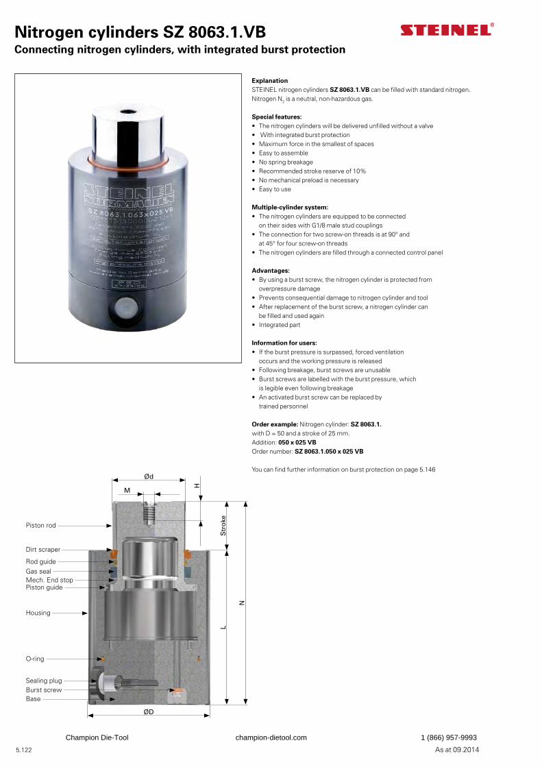
5.122 As at 09.2014
Nitrogen cylinders SZ 8063.1.VBConnecting nitrogen cylinders, with integrated burst protection
ExplanationSTEINEL nitrogen cylinders SZ 8063.1.VB can be filled with standard nitrogen. Nitrogen N2 is a neutral, non-hazardous gas.
Special features:• The nitrogen cylinders will be delivered unfilled without a valve• With integrated burst protection• Maximum force in the smallest of spaces• Easy to assemble• No spring breakage• Recommended stroke reserve of 10%• No mechanical preload is necessary• Easy to use
Multiple-cylinder system:• The nitrogen cylinders are equipped to be connected
on their sides with G1/8 male stud couplings• The connection for two screw-on threads is at 90° and
at 45° for four screw-on threads• The nitrogen cylinders are filled through a connected control panel
Advantages:• By using a burst screw, the nitrogen cylinder is protected from
overpressure damage• Prevents consequential damage to nitrogen cylinder and tool• After replacement of the burst screw, a nitrogen cylinder can
be filled and used again• Integrated part
Information for users:• If the burst pressure is surpassed, forced ventilation
occurs and the working pressure is released• Following breakage, burst screws are unusable• Burst screws are labelled with the burst pressure, which
is legible even following breakage• An activated burst screw can be replaced by
trained personnel
Order example: Nitrogen cylinder: SZ 8063.1. with D = 50 and a stroke of 25 mm.Addition: 050 x 025 VB Order number: SZ 8063.1.050 x 025 VB
You can find further information on burst protection on page 5.146Ød
M
H
Str
oke
N
L
ØD
Piston rod
Dirt scraper
Rod guideGas sealMech. End stopPiston guide
Housing
Base
Sealing plugBurst screw
O-ring
Champion Die-Tool champion-dietool.com 1 (866) 957-9993
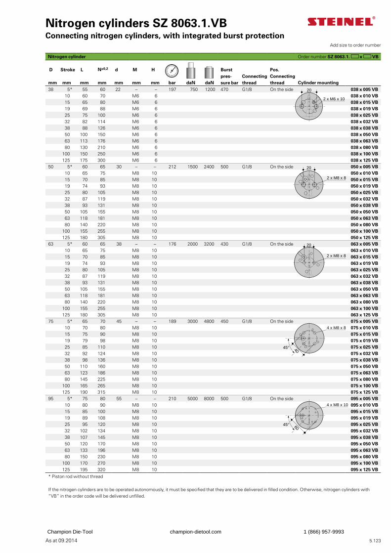
5.123As at 09.2014
Nitrogen cylinders SZ 8063.1.VBConnecting nitrogen cylinders, with integrated burst protection
Burst pres-sure bar
Connecting thread
Pos.Connecting thread
D Stroke L N±0,2 d M H
mm mm mm mm mm mm mm bar daN daN Cylinder mounting38 5* 55 60 22 – – 197 750 1200 470 G1/8 On the side 038 x 005 VB
10 60 70 M6 6 038 x 010 VB15 65 80 M6 6 038 x 015 VB19 69 88 M6 6 038 x 019 VB25 75 100 M6 6 038 x 025 VB32 82 114 M6 6 038 x 032 VB38 88 126 M6 6 038 x 038 VB50 100 150 M6 6 038 x 050 VB63 113 176 M6 6 038 x 063 VB80 130 210 M6 6 038 x 080 VB
100 150 250 M6 6 038 x 100 VB125 175 300 M6 6 038 x 125 VB
50 5* 60 65 30 – – 212 1500 2400 500 G1/8 On the side 050 x 005 VB10 65 75 M8 10 050 x 010 VB15 70 85 M8 10 050 x 015 VB19 74 93 M8 10 050 x 019 VB25 80 105 M8 10 050 x 025 VB32 87 119 M8 10 050 x 032 VB38 93 131 M8 10 050 x 038 VB50 105 155 M8 10 050 x 050 VB63 118 181 M8 10 050 x 063 VB80 140 220 M8 10 050 x 080 VB
100 155 255 M8 10 050 x 100 VB125 180 305 M8 10 050 x 125 VB
63 5* 60 65 38 – – 176 2000 3200 430 G1/8 On the side 063 x 005 VB10 65 75 M8 10 063 x 010 VB15 70 85 M8 10 063 x 015 VB19 74 93 M8 10 063 x 019 VB25 80 105 M8 10 063 x 025 VB32 87 119 M8 10 063 x 032 VB38 93 131 M8 10 063 x 038 VB50 105 155 M8 10 063 x 050 VB63 118 181 M8 10 063 x 063 VB80 140 220 M8 10 063 x 080 VB
100 155 255 M8 10 063 x 100 VB125 180 305 M8 10 063 x 125 VB
75 5* 65 70 45 – – 189 3000 4800 450 G1/8 On the side 075 x 005 VB10 70 80 M8 10 075 x 010 VB15 75 90 M8 10 075 x 015 VB19 79 98 M8 10 075 x 019 VB25 85 110 M8 10 075 x 025 VB32 92 124 M8 10 075 x 032 VB38 98 136 M8 10 075 x 038 VB50 110 160 M8 10 075 x 050 VB63 123 186 M8 10 075 x 063 VB80 145 225 M8 10 075 x 080 VB
100 165 265 M8 10 075 x 100 VB125 190 315 M8 10 075 x 125 VB
95 5* 75 80 55 – – 210 5000 8000 500 G1/8 On the side 095 x 005 VB10 80 90 M8 10 095 x 010 VB15 85 100 M8 10 095 x 015 VB19 89 108 M8 10 095 x 019 VB25 95 120 M8 10 095 x 025 VB32 102 134 M8 10 095 x 032 VB38 107 145 M8 10 095 x 038 VB50 120 170 M8 10 095 x 050 VB63 133 196 M8 10 095 x 063 VB80 150 230 M8 10 095 x 080 VB
100 170 270 M8 10 095 x 100 VB125 195 320 M8 10 095 x 125 VB
* Piston rod without thread
If the nitrogen cylinders are to be operated autonomously, it must be specified that they are to be delivered in filled condition. Otherwise, nitrogen cylinders with “VB” in the order code will be delivered unfilled.
Order number SZ 8063.1. x VB
Add size to order number
20
2 x M6 x 10
2 x M8 x 8
20
2 x M8 x 8
20
4 x M8 x 8
4045°
4 x M8 x 10
6045°
Nitrogen cylinder
Champion Die-Tool champion-dietool.com 1 (866) 957-9993
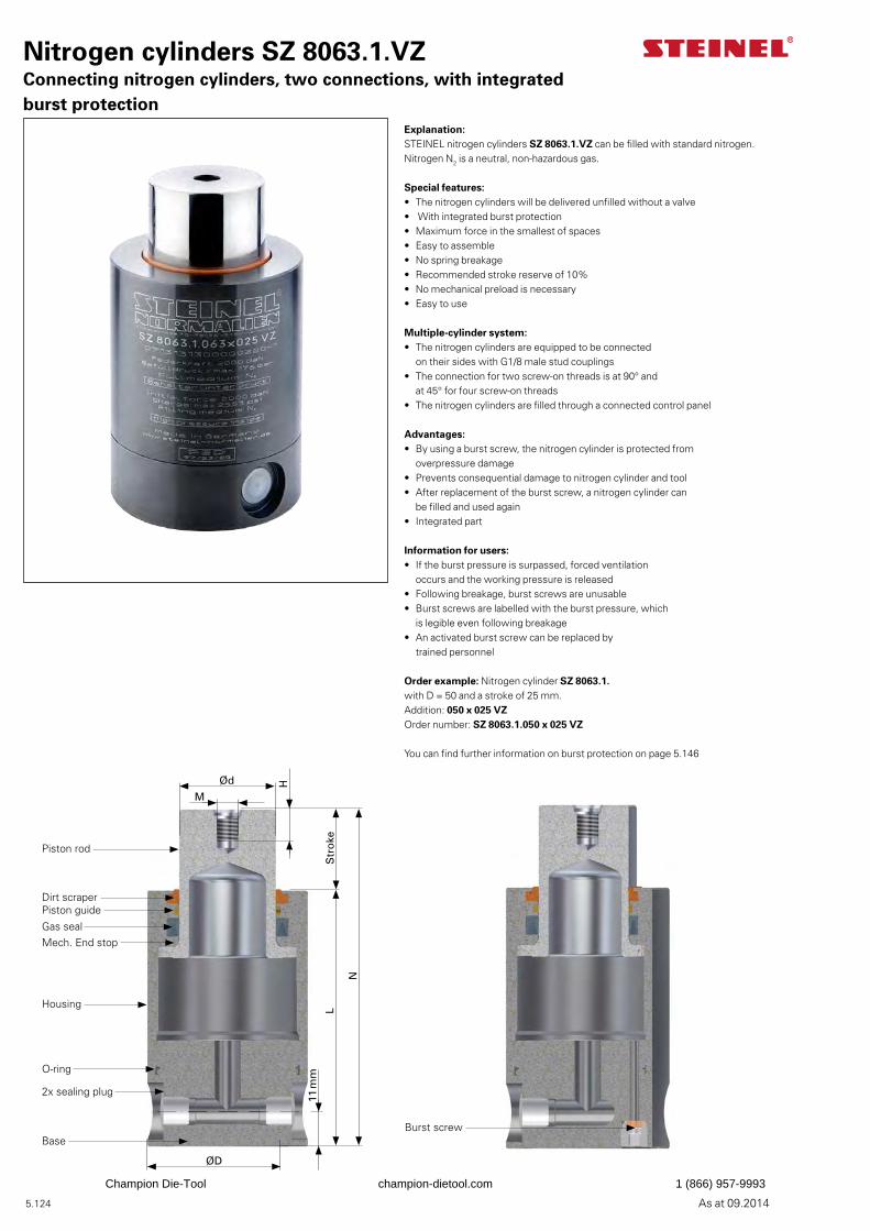
5.124 As at 09.2014
Nitrogen cylinders SZ 8063.1.VZConnecting nitrogen cylinders, two connections, with integrated burst protection
Explanation:STEINEL nitrogen cylinders SZ 8063.1.VZ can be filled with standard nitrogen. Nitrogen N2 is a neutral, non-hazardous gas.
Special features:• The nitrogen cylinders will be delivered unfilled without a valve• With integrated burst protection• Maximum force in the smallest of spaces• Easy to assemble• No spring breakage• Recommended stroke reserve of 10%• No mechanical preload is necessary• Easy to use
Multiple-cylinder system:• The nitrogen cylinders are equipped to be connected
on their sides with G1/8 male stud couplings• The connection for two screw-on threads is at 90° and
at 45° for four screw-on threads• The nitrogen cylinders are filled through a connected control panel
Advantages:• By using a burst screw, the nitrogen cylinder is protected from
overpressure damage• Prevents consequential damage to nitrogen cylinder and tool• After replacement of the burst screw, a nitrogen cylinder can
be filled and used again• Integrated part
Information for users:• If the burst pressure is surpassed, forced ventilation
occurs and the working pressure is released• Following breakage, burst screws are unusable• Burst screws are labelled with the burst pressure, which
is legible even following breakage• An activated burst screw can be replaced by
trained personnel
Order example: Nitrogen cylinder SZ 8063.1. with D = 50 and a stroke of 25 mm.Addition: 050 x 025 VZ Order number: SZ 8063.1.050 x 025 VZ
You can find further information on burst protection on page 5.146
Ød
M
H
Str
oke
N
L
ØD
11 m
m
Piston rod
Dirt scraper
Gas sealMech. End stop
Housing
O-ring
2x sealing plug
Base
Piston guide
Burst screw
Champion Die-Tool champion-dietool.com 1 (866) 957-9993
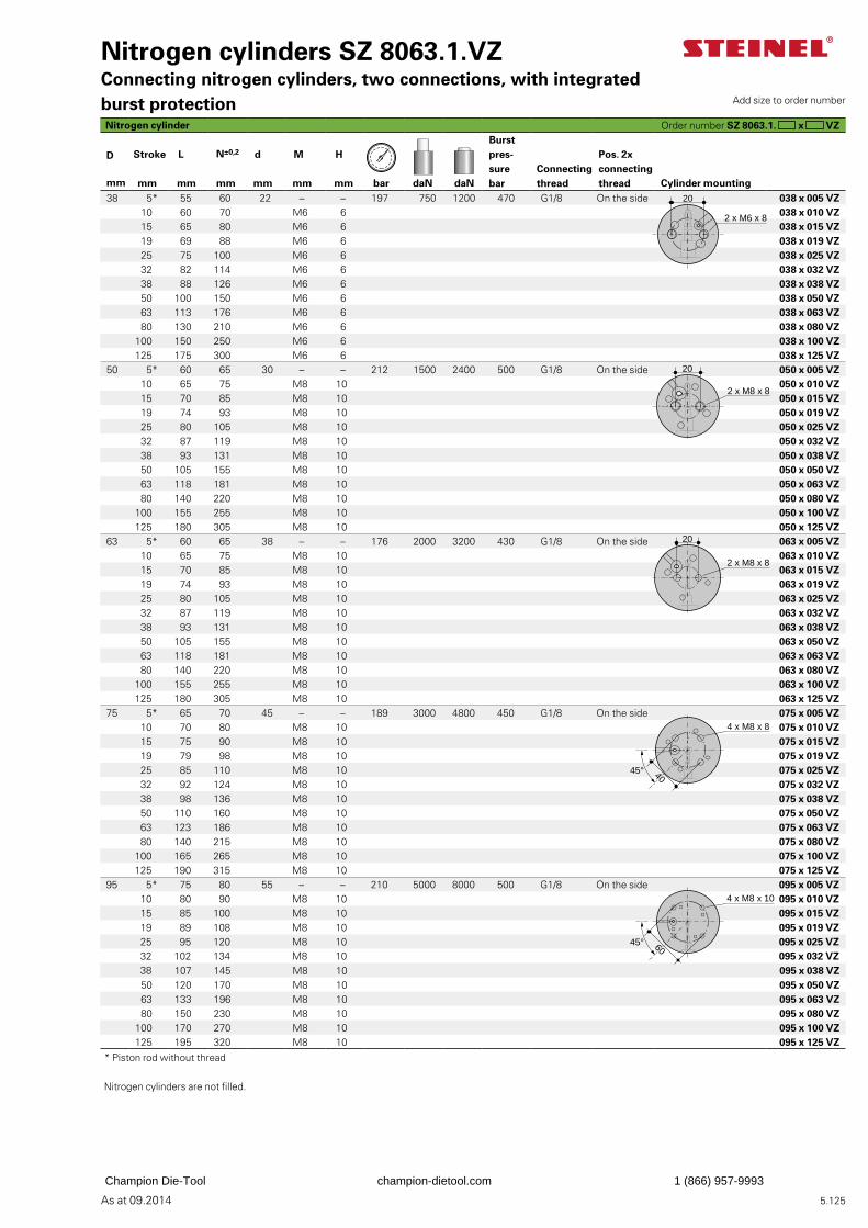
5.125As at 09.2014
Nitrogen cylinders SZ 8063.1.VZConnecting nitrogen cylinders, two connections, with integrated burst protection
Burstpres-sure bar
Connecting thread
Pos. 2x connecting thread
D Stroke L N±0,2 d M H
mm mm mm mm mm mm mm bar daN daN Cylinder mounting 38 5* 55 60 22 – – 197 750 1200 470 G1/8 On the side 038 x 005 VZ
10 60 70 M6 6 038 x 010 VZ15 65 80 M6 6 038 x 015 VZ19 69 88 M6 6 038 x 019 VZ25 75 100 M6 6 038 x 025 VZ32 82 114 M6 6 038 x 032 VZ38 88 126 M6 6 038 x 038 VZ50 100 150 M6 6 038 x 050 VZ63 113 176 M6 6 038 x 063 VZ80 130 210 M6 6 038 x 080 VZ
100 150 250 M6 6 038 x 100 VZ125 175 300 M6 6 038 x 125 VZ
50 5* 60 65 30 – – 212 1500 2400 500 G1/8 On the side 050 x 005 VZ10 65 75 M8 10 050 x 010 VZ15 70 85 M8 10 050 x 015 VZ19 74 93 M8 10 050 x 019 VZ25 80 105 M8 10 050 x 025 VZ32 87 119 M8 10 050 x 032 VZ38 93 131 M8 10 050 x 038 VZ50 105 155 M8 10 050 x 050 VZ63 118 181 M8 10 050 x 063 VZ80 140 220 M8 10 050 x 080 VZ
100 155 255 M8 10 050 x 100 VZ125 180 305 M8 10 050 x 125 VZ
63 5* 60 65 38 – – 176 2000 3200 430 G1/8 On the side 063 x 005 VZ10 65 75 M8 10 063 x 010 VZ15 70 85 M8 10 063 x 015 VZ19 74 93 M8 10 063 x 019 VZ25 80 105 M8 10 063 x 025 VZ32 87 119 M8 10 063 x 032 VZ38 93 131 M8 10 063 x 038 VZ50 105 155 M8 10 063 x 050 VZ63 118 181 M8 10 063 x 063 VZ80 140 220 M8 10 063 x 080 VZ
100 155 255 M8 10 063 x 100 VZ125 180 305 M8 10 063 x 125 VZ
75 5* 65 70 45 – – 189 3000 4800 450 G1/8 On the side 075 x 005 VZ10 70 80 M8 10 075 x 010 VZ15 75 90 M8 10 075 x 015 VZ19 79 98 M8 10 075 x 019 VZ25 85 110 M8 10 075 x 025 VZ32 92 124 M8 10 075 x 032 VZ38 98 136 M8 10 075 x 038 VZ50 110 160 M8 10 075 x 050 VZ63 123 186 M8 10 075 x 063 VZ80 140 215 M8 10 075 x 080 VZ
100 165 265 M8 10 075 x 100 VZ125 190 315 M8 10 075 x 125 VZ
95 5* 75 80 55 – – 210 5000 8000 500 G1/8 On the side 095 x 005 VZ10 80 90 M8 10 095 x 010 VZ15 85 100 M8 10 095 x 015 VZ19 89 108 M8 10 095 x 019 VZ25 95 120 M8 10 095 x 025 VZ32 102 134 M8 10 095 x 032 VZ38 107 145 M8 10 095 x 038 VZ50 120 170 M8 10 095 x 050 VZ63 133 196 M8 10 095 x 063 VZ80 150 230 M8 10 095 x 080 VZ
100 170 270 M8 10 095 x 100 VZ125 195 320 M8 10 095 x 125 VZ
* Piston rod without thread
Nitrogen cylinders are not filled.
Order number SZ 8063.1. x VZ
Add size to order number
Nitrogen cylinder
20
2 x M6 x 8
2 x M8 x 8
20
2 x M8 x 8
20
4 x M8 x 8
4045°
4 x M8 x 10
6045°
Champion Die-Tool champion-dietool.com 1 (866) 957-9993
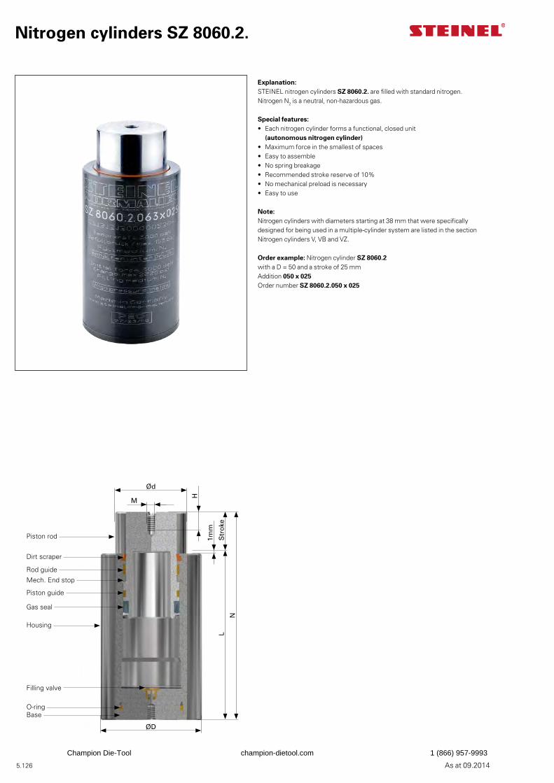
5.126 As at 09.2014
Nitrogen cylinders SZ 8060.2.
Explanation:STEINEL nitrogen cylinders SZ 8060.2. are filled with standard nitrogen. Nitrogen N2 is a neutral, non-hazardous gas.
Special features:• Each nitrogen cylinder forms a functional, closed unit
(autonomous nitrogen cylinder)• Maximum force in the smallest of spaces• Easy to assemble• No spring breakage• Recommended stroke reserve of 10%• No mechanical preload is necessary• Easy to use
Note:Nitrogen cylinders with diameters starting at 38 mm that were specifically designed for being used in a multiple-cylinder system are listed in the section Nitrogen cylinders V, VB and VZ.
Order example: Nitrogen cylinder SZ 8060.2with a D = 50 and a stroke of 25 mmAddition 050 x 025Order number SZ 8060.2.050 x 025
1mm
Ød
M
H
Str
oke
N
L
ØD
Piston rod
Dirt scraper
Rod guide
Gas seal
Mech. End stop
Piston guide
Housing
Filling valve
BaseO-ring
Champion Die-Tool champion-dietool.com 1 (866) 957-9993
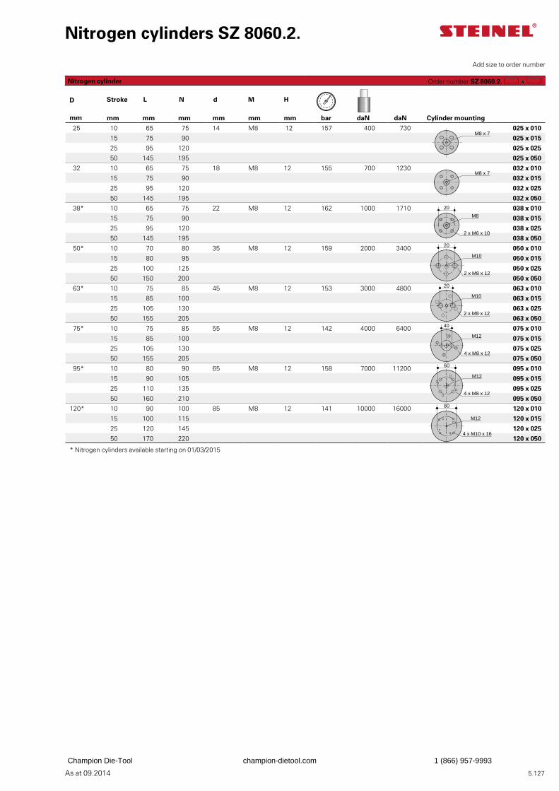
5.127As at 09.2014
Nitrogen cylinders SZ 8060.2.
D Stroke L N d M H
mm mm mm mm mm mm mm bar daN daN Cylinder mounting
25 10 65 75 14 M8 12 157 400 730 025 x 010
15 75 90 025 x 015
25 95 120 025 x 025
50 145 195 025 x 050
32 10 65 75 18 M8 12 155 700 1230 032 x 010
15 75 90 032 x 015
25 95 120 032 x 025
50 145 195 032 x 050
38* 10 65 75 22 M8 12 162 1000 1710 038 x 010
15 75 90 038 x 015
25 95 120 038 x 025
50 145 195 038 x 050
50* 10 70 80 35 M8 12 159 2000 3400 050 x 010
15 80 95 050 x 015
25 100 125 050 x 025
50 150 200 050 x 050
63* 10 75 85 45 M8 12 153 3000 4800 063 x 010
15 85 100 063 x 015
25 105 130 063 x 025
50 155 205 063 x 050
75* 10 75 85 55 M8 12 142 4000 6400 075 x 010
15 85 100 075 x 015
25 105 130 075 x 025
50 155 205 075 x 050
95* 10 80 90 65 M8 12 158 7000 11200 095 x 010
15 90 105 095 x 015
25 110 135 095 x 025
50 160 210 095 x 050
120* 10 90 100 85 M8 12 141 10000 16000 120 x 010
15 100 115 120 x 015
25 120 145 120 x 025
50 170 220 120 x 050
* Nitrogen cylinders available starting on 01/03/2015
Add size to order number
Nitrogen cylinder Order number SZ 8060.2.
M8
20
2 x M6 x 10
20
M10
2 x M8 x 12
20
M10
2 x M8 x 12
40
M12
4 x M8 x 12
M12
4 x M8 x 12
60
M12
4 x M10 x 16
80
M8 x 7
M8 x 7
Champion Die-Tool champion-dietool.com 1 (866) 957-9993
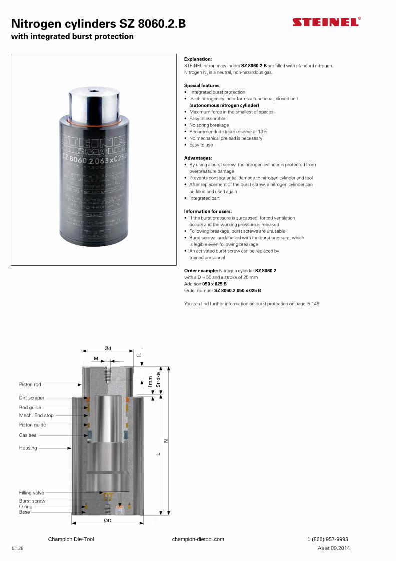
5.128 As at 09.2014
Nitrogen cylinders SZ 8060.2.Bwith integrated burst protection
Explanation:STEINEL nitrogen cylinders SZ 8060.2.B are filled with standard nitrogen. Nitrogen N2 is a neutral, non-hazardous gas.
Special features:• Integrated burst protection• Each nitrogen cylinder forms a functional, closed unit
(autonomous nitrogen cylinder)• Maximum force in the smallest of spaces• Easy to assemble• No spring breakage• Recommended stroke reserve of 10%• No mechanical preload is necessary• Easy to use
Advantages:• By using a burst screw, the nitrogen cylinder is protected from
overpressure damage• Prevents consequential damage to nitrogen cylinder and tool• After replacement of the burst screw, a nitrogen cylinder can
be filled and used again• Integrated part
Information for users:• If the burst pressure is surpassed, forced ventilation
occurs and the working pressure is released• Following breakage, burst screws are unusable• Burst screws are labelled with the burst pressure, which
is legible even following breakage• An activated burst screw can be replaced by
trained personnel
Order example: Nitrogen cylinder SZ 8060.2with a D = 50 and a stroke of 25 mmAddition 050 x 025 BOrder number SZ 8060.2.050 x 025 B
You can find further information on burst protection on page 5.146
1mm
Ød
M
H
Str
oke
N
L
ØD
Piston rod
Dirt scraper
Rod guide
Gas seal
Mech. End stop
Piston guide
Housing
Filling valve
BaseO-ringBurst screw
Champion Die-Tool champion-dietool.com 1 (866) 957-9993
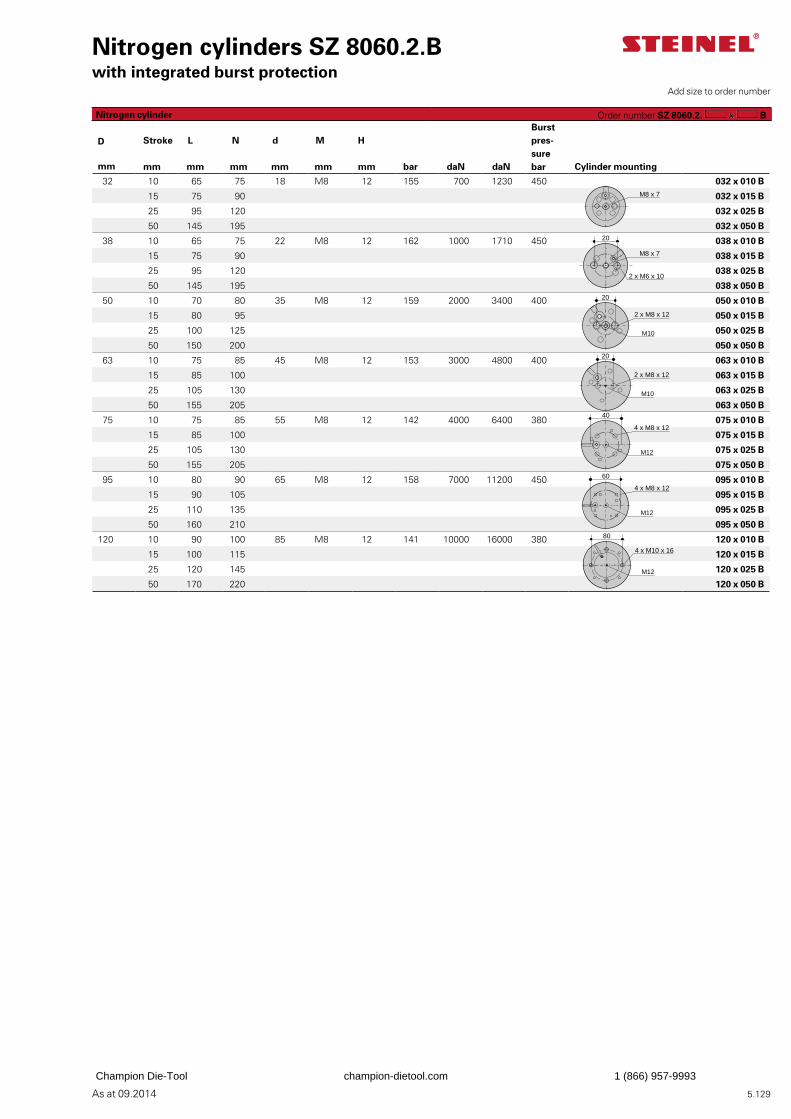
5.129As at 09.2014
Nitrogen cylinders SZ 8060.2.Bwith integrated burst protection
Burst pres-surebar
D Stroke L N d M H
mm mm mm mm mm mm mm bar daN daN Cylinder mounting
32 10 65 75 18 M8 12 155 700 1230 450 032 x 010 B
15 75 90 032 x 015 B
25 95 120 032 x 025 B
50 145 195 032 x 050 B
38 10 65 75 22 M8 12 162 1000 1710 450 038 x 010 B
15 75 90 038 x 015 B
25 95 120 038 x 025 B
50 145 195 038 x 050 B
50 10 70 80 35 M8 12 159 2000 3400 400 050 x 010 B
15 80 95 050 x 015 B
25 100 125 050 x 025 B
50 150 200 050 x 050 B
63 10 75 85 45 M8 12 153 3000 4800 400 063 x 010 B
15 85 100 063 x 015 B
25 105 130 063 x 025 B
50 155 205 063 x 050 B
75 10 75 85 55 M8 12 142 4000 6400 380 075 x 010 B
15 85 100 075 x 015 B
25 105 130 075 x 025 B
50 155 205 075 x 050 B
95 10 80 90 65 M8 12 158 7000 11200 450 095 x 010 B
15 90 105 095 x 015 B
25 110 135 095 x 025 B
50 160 210 095 x 050 B
120 10 90 100 85 M8 12 141 10000 16000 380 120 x 010 B
15 100 115 120 x 015 B
25 120 145 120 x 025 B
50 170 220 120 x 050 B
Add size to order number
Nitrogen cylinder Order number SZ 8060.2. B
4 x M10 x 16
80
M12
M8 x 7
2 x M6 x 10
20
M8 x 7
2 x M8 x 12
20
M10
2 x M8 x 12
20
M10
4 x M8 x 12
40
M12
4 x M8 x 12
60
M12
Champion Die-Tool champion-dietool.com 1 (866) 957-9993
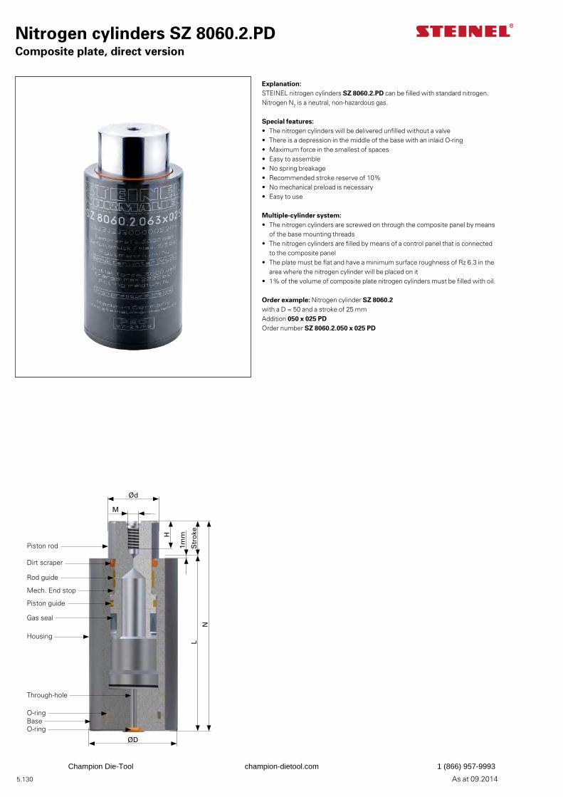
5.130 As at 09.2014
Nitrogen cylinders SZ 8060.2.PDComposite plate, direct version
Explanation:STEINEL nitrogen cylinders SZ 8060.2.PD can be filled with standard nitrogen. Nitrogen N2 is a neutral, non-hazardous gas.
Special features:• The nitrogen cylinders will be delivered unfilled without a valve• There is a depression in the middle of the base with an inlaid O-ring • Maximum force in the smallest of spaces• Easy to assemble• No spring breakage• Recommended stroke reserve of 10%• No mechanical preload is necessary• Easy to use
Multiple-cylinder system:• The nitrogen cylinders are screwed on through the composite panel by means
of the base mounting threads• The nitrogen cylinders are filled by means of a control panel that is connected
to the composite panel• The plate must be flat and have a minimum surface roughness of Rz 6.3 in the
area where the nitrogen cylinder will be placed on it• 1% of the volume of composite plate nitrogen cylinders must be filled with oil.
Order example: Nitrogen cylinder SZ 8060.2with a D = 50 and a stroke of 25 mmAddition 050 x 025 PDOrder number SZ 8060.2.050 x 025 PD
1mm
Ød
M
H
Str
oke
N
L
ØD
Piston rod
Dirt scraper
Rod guide
Gas seal
Mech. End stop
Piston guide
Housing
Through-hole
BaseO-ring
O-ring
Champion Die-Tool champion-dietool.com 1 (866) 957-9993
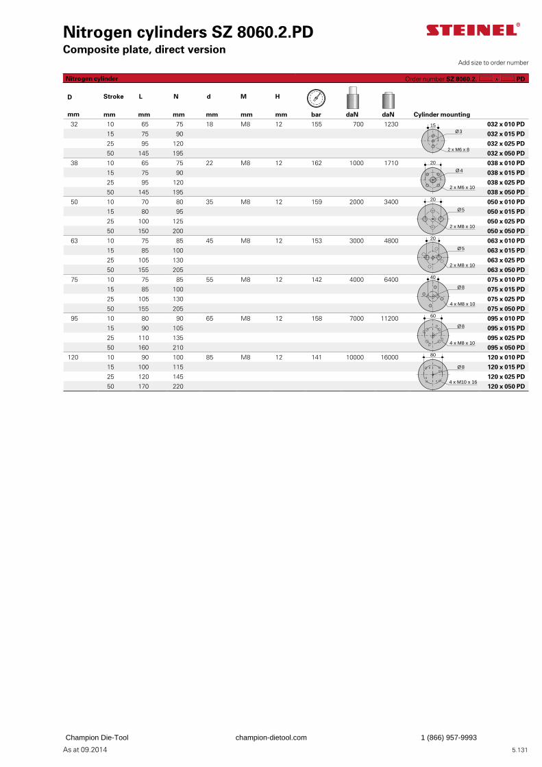
5.131As at 09.2014
Nitrogen cylinders SZ 8060.2.PDComposite plate, direct version
D Stroke L N d M H
mm mm mm mm mm mm mm bar daN daN Cylinder mounting
32 10 65 75 18 M8 12 155 700 1230 032 x 010 PD
15 75 90 032 x 015 PD
25 95 120 032 x 025 PD
50 145 195 032 x 050 PD
38 10 65 75 22 M8 12 162 1000 1710 038 x 010 PD
15 75 90 038 x 015 PD
25 95 120 038 x 025 PD
50 145 195 038 x 050 PD
50 10 70 80 35 M8 12 159 2000 3400 050 x 010 PD
15 80 95 050 x 015 PD
25 100 125 050 x 025 PD
50 150 200 050 x 050 PD
63 10 75 85 45 M8 12 153 3000 4800 063 x 010 PD
15 85 100 063 x 015 PD
25 105 130 063 x 025 PD
50 155 205 063 x 050 PD
75 10 75 85 55 M8 12 142 4000 6400 075 x 010 PD
15 85 100 075 x 015 PD
25 105 130 075 x 025 PD
50 155 205 075 x 050 PD
95 10 80 90 65 M8 12 158 7000 11200 095 x 010 PD
15 90 105 095 x 015 PD
25 110 135 095 x 025 PD
50 160 210 095 x 050 PD
120 10 90 100 85 M8 12 141 10000 16000 120 x 010 PD
15 100 115 120 x 015 PD
25 120 145 120 x 025 PD
50 170 220 120 x 050 PD
Add size to order number
Nitrogen cylinder Order number SZ 8060.2. PD
Ø 3
2 x M6 x 8
15
Ø 4
20
2 x M6 x 10
20
Ø 5
2 x M8 x 10
20
Ø 5
2 x M8 x 10
40
Ø 8
4 x M8 x 10
Ø 8
4 x M8 x 10
60
Ø 8
4 x M10 x 16
80
Champion Die-Tool champion-dietool.com 1 (866) 957-9993
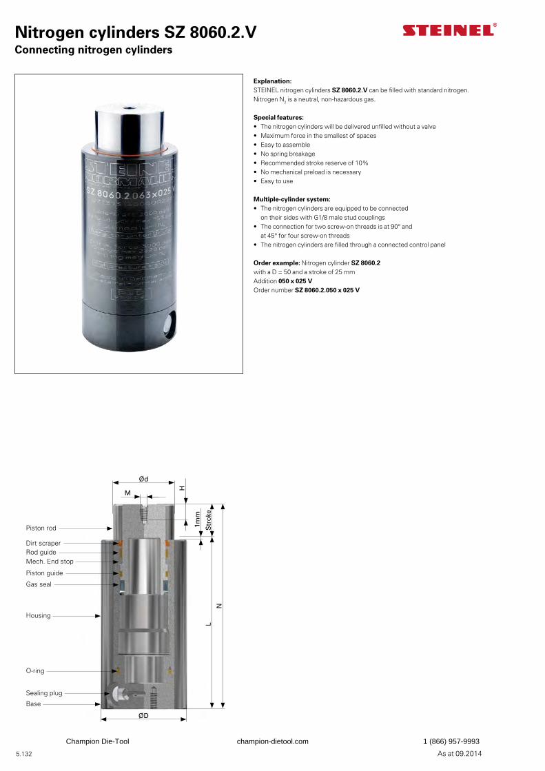
5.132 As at 09.2014
Nitrogen cylinders SZ 8060.2.VConnecting nitrogen cylinders
Explanation:STEINEL nitrogen cylinders SZ 8060.2.V can be filled with standard nitrogen. Nitrogen N2 is a neutral, non-hazardous gas.
Special features:• The nitrogen cylinders will be delivered unfilled without a valve• Maximum force in the smallest of spaces• Easy to assemble• No spring breakage• Recommended stroke reserve of 10%• No mechanical preload is necessary• Easy to use
Multiple-cylinder system:• The nitrogen cylinders are equipped to be connected
on their sides with G1/8 male stud couplings• The connection for two screw-on threads is at 90° and
at 45° for four screw-on threads• The nitrogen cylinders are filled through a connected control panel
Order example: Nitrogen cylinder SZ 8060.2with a D = 50 and a stroke of 25 mmAddition 050 x 025 VOrder number SZ 8060.2.050 x 025 V
1mm
Ød
M
H
Str
oke
N
L
ØD
Piston rod
Dirt scraperRod guide
Gas seal
Mech. End stop
Piston guide
Housing
Sealing plug
Base
O-ring
Champion Die-Tool champion-dietool.com 1 (866) 957-9993
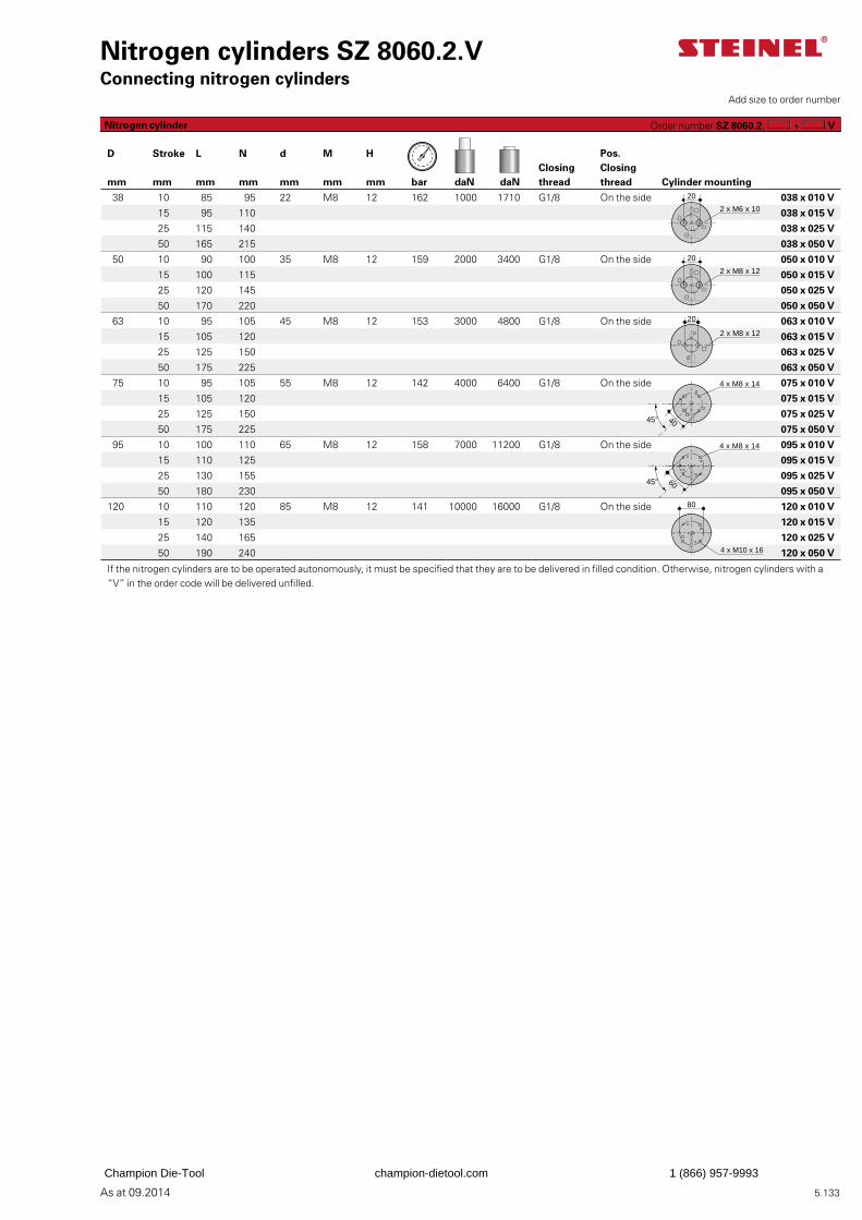
5.133As at 09.2014
Nitrogen cylinders SZ 8060.2.VConnecting nitrogen cylinders
D Stroke L N d M H Pos.Closingthread
Closingthreadmm mm mm mm mm mm mm bar daN daN Cylinder mounting
38 10 85 95 22 M8 12 162 1000 1710 G1/8 On the side 038 x 010 V
15 95 110 038 x 015 V
25 115 140 038 x 025 V
50 165 215 038 x 050 V
50 10 90 100 35 M8 12 159 2000 3400 G1/8 On the side 050 x 010 V
15 100 115 050 x 015 V
25 120 145 050 x 025 V
50 170 220 050 x 050 V
63 10 95 105 45 M8 12 153 3000 4800 G1/8 On the side 063 x 010 V
15 105 120 063 x 015 V
25 125 150 063 x 025 V
50 175 225 063 x 050 V
75 10 95 105 55 M8 12 142 4000 6400 G1/8 On the side 075 x 010 V
15 105 120 075 x 015 V
25 125 150 075 x 025 V
50 175 225 075 x 050 V
95 10 100 110 65 M8 12 158 7000 11200 G1/8 On the side 095 x 010 V
15 110 125 095 x 015 V
25 130 155 095 x 025 V
50 180 230 095 x 050 V
120 10 110 120 85 M8 12 141 10000 16000 G1/8 On the side 120 x 010 V
15 120 135 120 x 015 V
25 140 165 120 x 025 V
50 190 240 120 x 050 V
If the nitrogen cylinders are to be operated autonomously, it must be specified that they are to be delivered in filled condition. Otherwise, nitrogen cylinders with a “V” in the order code will be delivered unfilled.
Add size to order number
Nitrogen cylinder Order number SZ 8060.2. V
2 x M6 x 10
20
2 x M8 x 12
20
20
2 x M8 x 12
4 x M8 x 14
4045°
4 x M8 x 14
6045°
80
4 x M10 x 16
Champion Die-Tool champion-dietool.com 1 (866) 957-9993
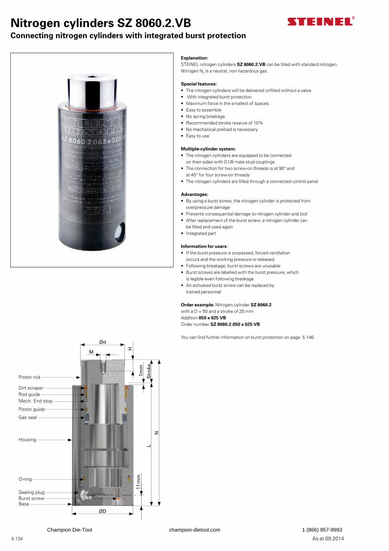
5.134 As at 09.2014
Nitrogen cylinders SZ 8060.2.VBConnecting nitrogen cylinders with integrated burst protection
Explanation:STEINEL nitrogen cylinders SZ 8060.2.VB can be filled with standard nitrogen. Nitrogen N2 is a neutral, non-hazardous gas.
Special features:• The nitrogen cylinders will be delivered unfilled without a valve• With integrated burst protection• Maximum force in the smallest of spaces• Easy to assemble• No spring breakage• Recommended stroke reserve of 10%• No mechanical preload is necessary• Easy to use
Multiple-cylinder system:• The nitrogen cylinders are equipped to be connected
on their sides with G1/8 male stud couplings• The connection for two screw-on threads is at 90° and
at 45° for four screw-on threads• The nitrogen cylinders are filled through a connected control panel
Advantages:• By using a burst screw, the nitrogen cylinder is protected from
overpressure damage• Prevents consequential damage to nitrogen cylinder and tool• After replacement of the burst screw, a nitrogen cylinder can
be filled and used again• Integrated part
Information for users:• If the burst pressure is surpassed, forced ventilation
occurs and the working pressure is released• Following breakage, burst screws are unusable• Burst screws are labelled with the burst pressure, which
is legible even following breakage• An activated burst screw can be replaced by
trained personnel
Order example: Nitrogen cylinder SZ 8060.2with a D = 50 and a stroke of 25 mmAddition 050 x 025 VBOrder number SZ 8060.2.050 x 025 VB
You can find further information on burst protection on page 5.146
1mm
Ød
M
H
Str
oke
N
L
ØD
11 m
m
Piston rod
Dirt scraperRod guide
Gas seal
Mech. End stop
Piston guide
Housing
Sealing plugBurst screwBase
O-ring
Champion Die-Tool champion-dietool.com 1 (866) 957-9993
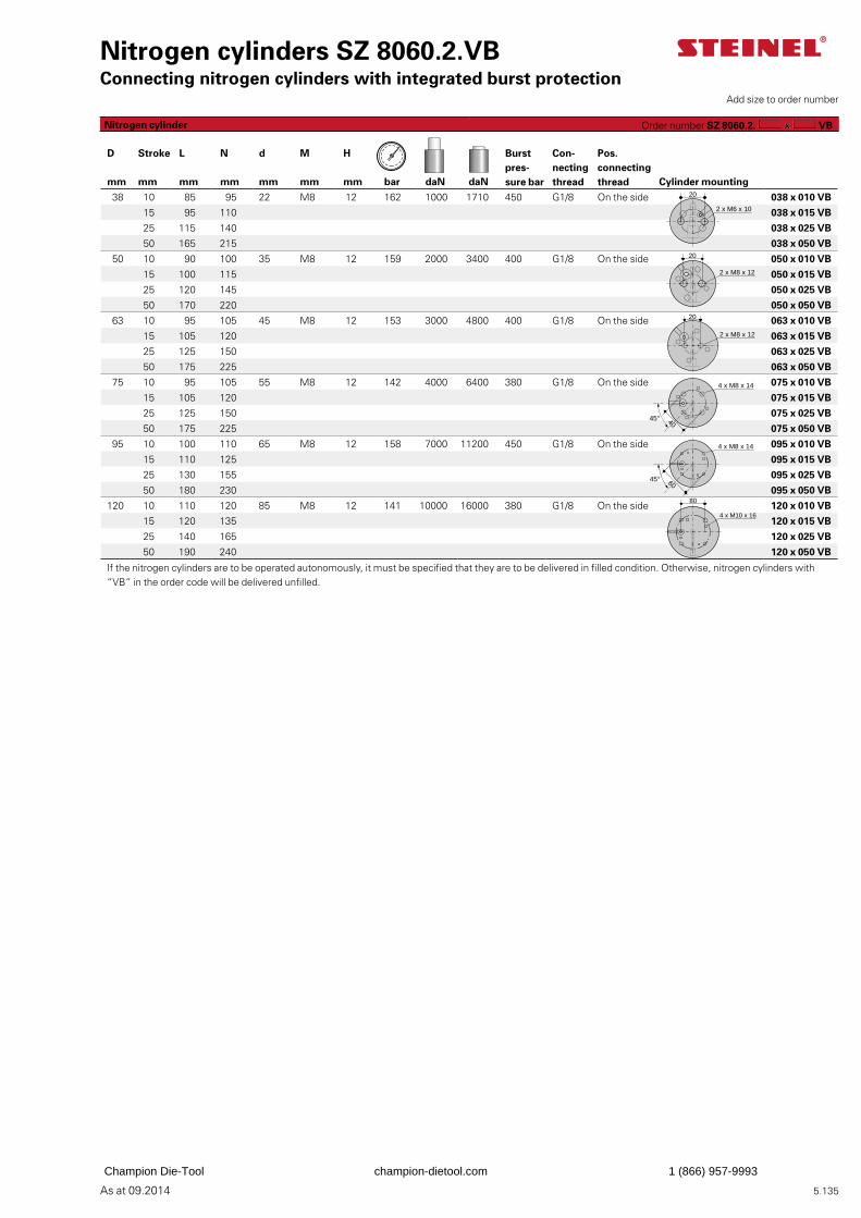
5.135As at 09.2014
Nitrogen cylinders SZ 8060.2.VBConnecting nitrogen cylinders with integrated burst protection
Burst pres-sure bar
Con-necting thread
Pos. connecting thread
D Stroke L N d M H
mm mm mm mm mm mm mm bar daN daN Cylinder mounting
38 10 85 95 22 M8 12 162 1000 1710 450 G1/8 On the side 038 x 010 VB
15 95 110 038 x 015 VB
25 115 140 038 x 025 VB
50 165 215 038 x 050 VB
50 10 90 100 35 M8 12 159 2000 3400 400 G1/8 On the side 050 x 010 VB
15 100 115 050 x 015 VB
25 120 145 050 x 025 VB
50 170 220 050 x 050 VB
63 10 95 105 45 M8 12 153 3000 4800 400 G1/8 On the side 063 x 010 VB
15 105 120 063 x 015 VB
25 125 150 063 x 025 VB
50 175 225 063 x 050 VB
75 10 95 105 55 M8 12 142 4000 6400 380 G1/8 On the side 075 x 010 VB
15 105 120 075 x 015 VB
25 125 150 075 x 025 VB
50 175 225 075 x 050 VB
95 10 100 110 65 M8 12 158 7000 11200 450 G1/8 On the side 095 x 010 VB
15 110 125 095 x 015 VB
25 130 155 095 x 025 VB
50 180 230 095 x 050 VB
120 10 110 120 85 M8 12 141 10000 16000 380 G1/8 On the side 120 x 010 VB
15 120 135 120 x 015 VB
25 140 165 120 x 025 VB
50 190 240 120 x 050 VB
If the nitrogen cylinders are to be operated autonomously, it must be specified that they are to be delivered in filled condition. Otherwise, nitrogen cylinders with “VB” in the order code will be delivered unfilled.
Add size to order number
Nitrogen cylinder Order number SZ 8060.2. VB
20
2 x M6 x 10
2 x M8 x 12
20
2 x M8 x 12
20
4 x M8 x 14
4045°
4 x M8 x 14
6045°
80
4 x M10 x 16
Champion Die-Tool champion-dietool.com 1 (866) 957-9993
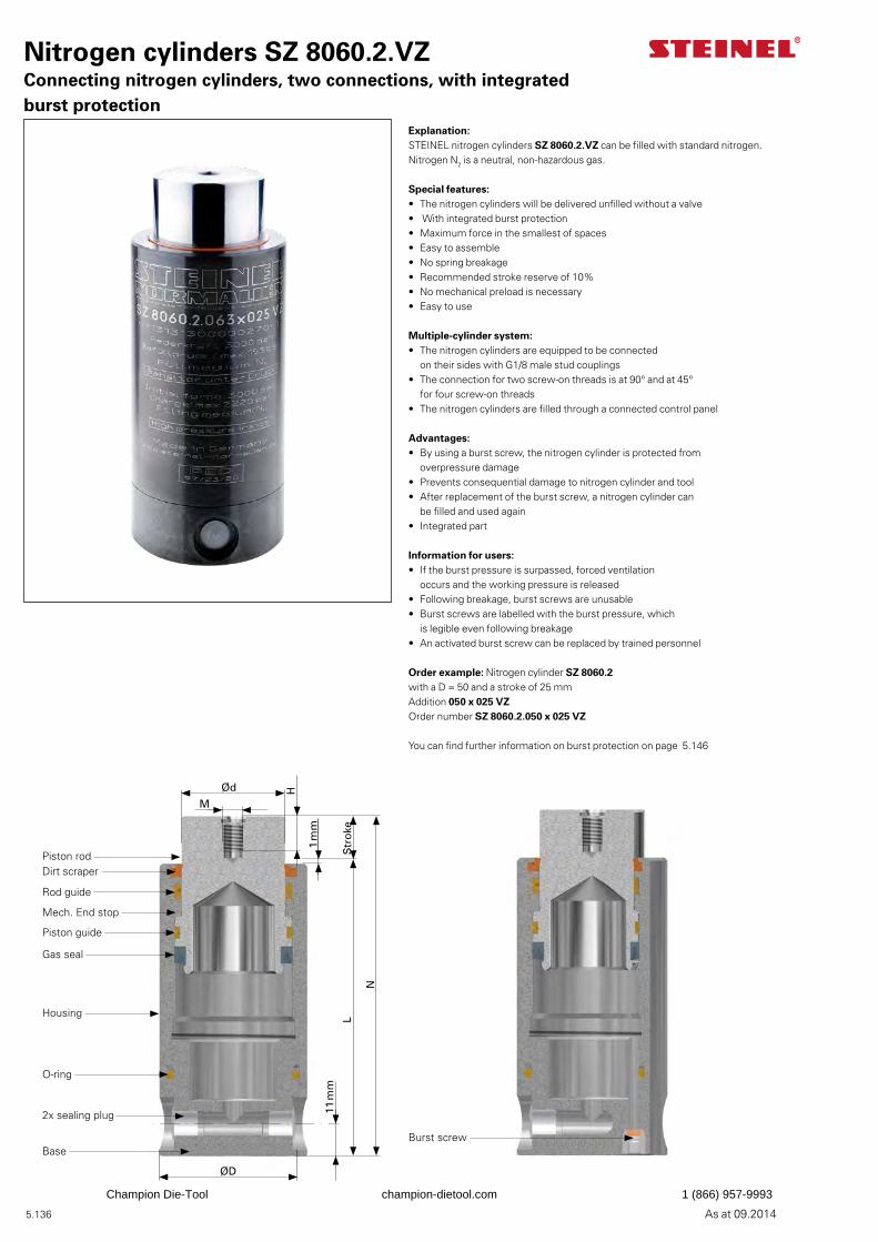
5.136 As at 09.2014
Nitrogen cylinders SZ 8060.2.VZConnecting nitrogen cylinders, two connections, with integrated burst protection
Explanation:STEINEL nitrogen cylinders SZ 8060.2.VZ can be filled with standard nitrogen. Nitrogen N2 is a neutral, non-hazardous gas.
Special features:• The nitrogen cylinders will be delivered unfilled without a valve• With integrated burst protection• Maximum force in the smallest of spaces• Easy to assemble• No spring breakage• Recommended stroke reserve of 10%• No mechanical preload is necessary• Easy to use
Multiple-cylinder system:• The nitrogen cylinders are equipped to be connected on their sides with G1/8 male stud couplings• The connection for two screw-on threads is at 90° and at 45° for four screw-on threads• The nitrogen cylinders are filled through a connected control panel
Advantages:• By using a burst screw, the nitrogen cylinder is protected from overpressure damage• Prevents consequential damage to nitrogen cylinder and tool• After replacement of the burst screw, a nitrogen cylinder can be filled and used again• Integrated part
Information for users:• If the burst pressure is surpassed, forced ventilation occurs and the working pressure is released• Following breakage, burst screws are unusable• Burst screws are labelled with the burst pressure, which is legible even following breakage• An activated burst screw can be replaced by trained personnel
Order example: Nitrogen cylinder SZ 8060.2with a D = 50 and a stroke of 25 mmAddition 050 x 025 VZOrder number SZ 8060.2.050 x 025 VZ
You can find further information on burst protection on page 5.146
Ød
M
H
1 m
m
Str
oke
N
L
ØD
11 m
m
Piston rodDirt scraper
Gas seal
Mech. End stop
Housing
O-ring
2x sealing plug
Base
Rod guide
Burst screw
Piston guide
Champion Die-Tool champion-dietool.com 1 (866) 957-9993
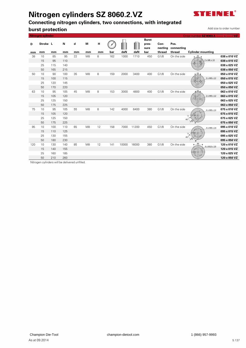
5.137As at 09.2014
Nitrogen cylinders SZ 8060.2.VZConnecting nitrogen cylinders, two connections, with integrated burst protection
Burst pres-sure bar
Con-necting thread
Pos. connecting thread
D Stroke L N d M H
mm mm mm mm mm mm mm bar daN daN Cylinder mounting
38 10 85 95 22 M8 8 162 1000 1710 450 G1/8 On the side 038 x 010 VZ
15 95 110 038 x 015 VZ
25 115 140 038 x 025 VZ
50 165 215 038 x 050 VZ
50 10 90 100 35 M8 8 159 2000 3400 400 G1/8 On the side 050 x 010 VZ
15 100 115 050 x 015 VZ
25 120 145 050 x 025 VZ
50 170 220 050 x 050 VZ
63 10 95 105 45 M8 8 153 3000 4800 400 G1/8 On the side 063 x 010 VZ
15 105 120 063 x 015 VZ
25 125 150 063 x 025 VZ
50 175 225 063 x 050 VZ
75 10 95 105 55 M8 8 142 4000 6400 380 G1/8 On the side 075 x 010 VZ
15 105 120 075 x 015 VZ
25 125 150 075 x 025 VZ
50 175 225 075 x 050 VZ
95 10 100 110 65 M8 12 158 7000 11200 450 G1/8 On the side 095 x 010 VZ
15 110 125 095 x 015 VZ
25 130 155 095 x 025 VZ
50 180 230 095 x 050 VZ
120 10 130 140 85 M8 12 141 10000 16000 380 G1/8 On the side 120 x 010 VZ
15 140 155 120 x 015 VZ
25 160 185 120 x 025 VZ
50 210 260 120 x 050 VZ
Nitrogen cylinders will be delivered unfilled.
Add size to order number
Nitrogen cylinder Order number SZ 8060.2. VZ
20
2 x M6 x 10
2 x M8 x 12
20
2 x M8 x 12
20
4 x M8 x 14
4045°
4 x M8 x 14
6045°
4 x M10 x 1680
Champion Die-Tool champion-dietool.com 1 (866) 957-9993
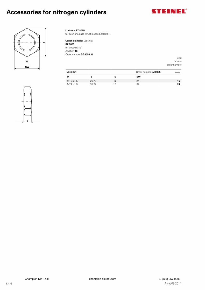
5.138 As at 09.2014
Lock nut Order number SZ 8055.
M E S SW
M16 x 1,5 26.75 8 24 16M24 x 1,5 35.72 10 32 24
Lock nut SZ 8055.for cushioned gas thrust pieces SZ 8150.1.
Order example: Lock nut SZ 8055 for thread M16Addition 16Order number SZ 8055.16
E
M
SWS
Accessories for nitrogen cylinders
Addsize to
order number
E
M
SWS
Champion Die-Tool champion-dietool.com 1 (866) 957-9993
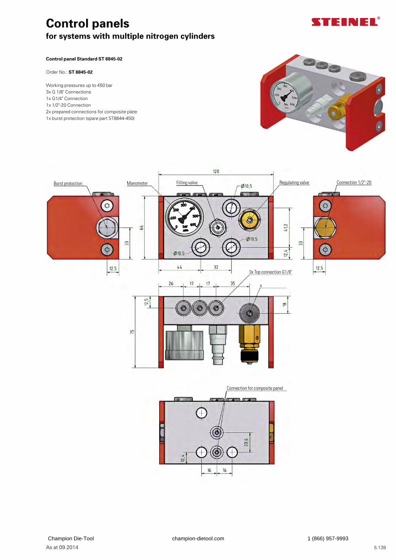
5.139As at 09.2014
Control panel Standard ST 8845-02
Order No.: ST 8845-02
Working pressures up to 450 bar3x G 1/8" Connections1x G1/4" Connection 1x 1/2"-20 Connection2x prepared connections for composite plate1x burst protection (spare part ST8844-450)
Control panelsfor systems with multiple nitrogen cylinders
Burst protection Manometer Filling valve Connection 1/2"-20
3x Top connection G1/8"
x
Connection for composite panel
Regulating valve
Champion Die-Tool champion-dietool.com 1 (866) 957-9993
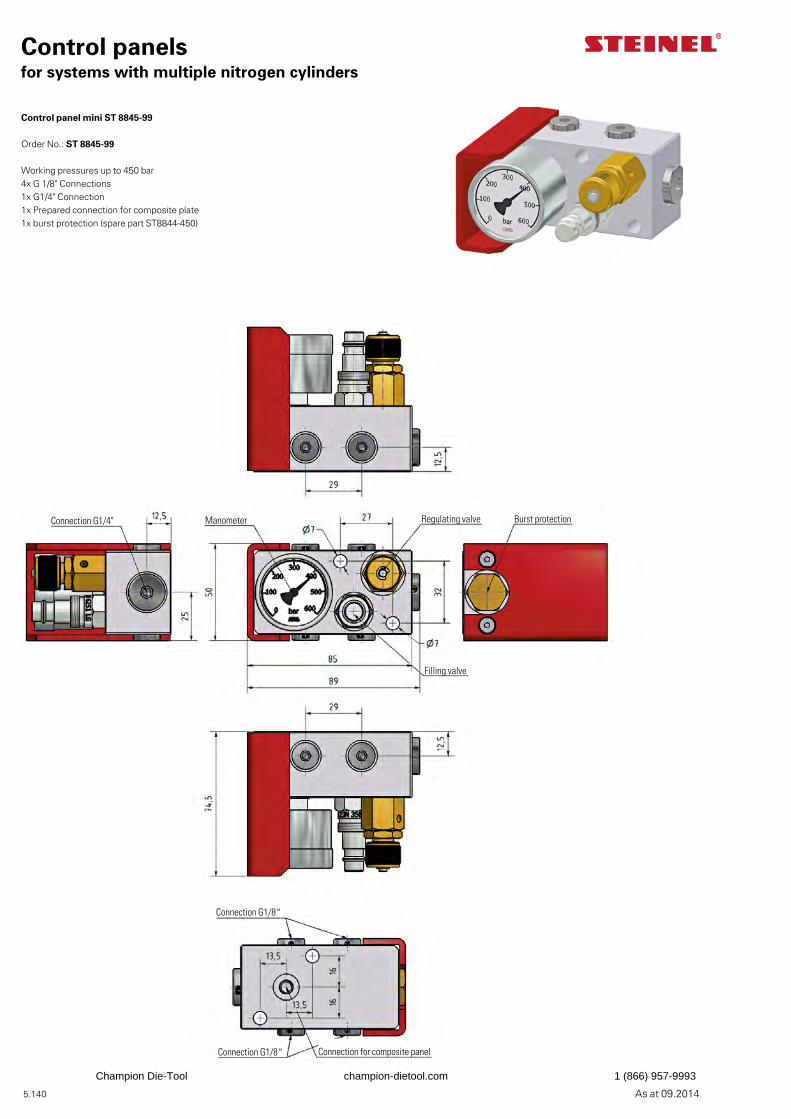
5.140 As at 09.2014
Control panel mini ST 8845-99
Order No.: ST 8845-99
Working pressures up to 450 bar4x G 1/8" Connections1x G1/4" Connection1x Prepared connection for composite plate1x burst protection (spare part ST8844-450)
Control panelsfor systems with multiple nitrogen cylinders
Burst protectionManometer
Filling valve
Regulating valve
Connection G1/8"
Connection G1/8"
Connection G1/4"
Connection for composite panel
Champion Die-Tool champion-dietool.com 1 (866) 957-9993
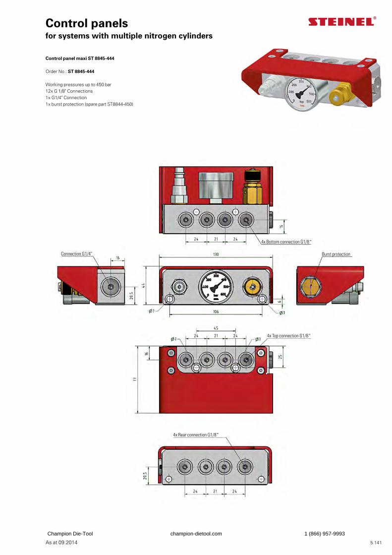
5.141As at 09.2014
Control panel maxi ST 8845-444
Order No.: ST 8845-444
Working pressures up to 450 bar12x G 1/8" Connections1x G1/4" Connection 1x burst protection (spare part ST8844-450)
Control panelsfor systems with multiple nitrogen cylinders
Burst protection
4x Bottom connection G1/8"
Connection G1/4"
4x Top connection G1/8"
4x Rear connection G1/8"
Champion Die-Tool champion-dietool.com 1 (866) 957-9993
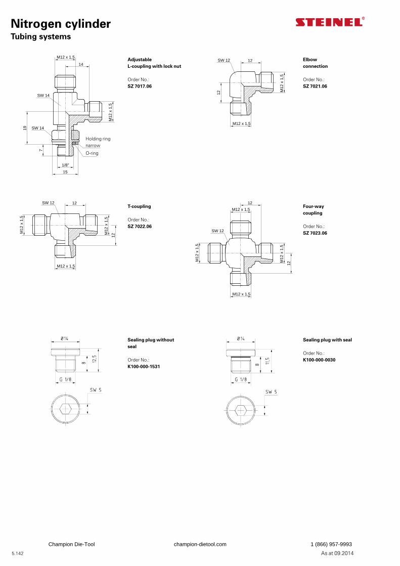
5.142 As at 09.2014
Nitrogen cylinderTubing systems
Adjustable L-coupling with lock nut
Order No.: SZ 7017.06
7
19
M12 x 1,5
14
M12
x 1
,5
SW 14
1/8"
SW 14
15
T-coupling
Order No.: SZ 7022.06
Sealing plug without seal
Order No.: K100-000-1531
M12 x 1,5
12
M12
x 1
,5
SW 12 12
M12
x 1
,5
Four-waycoupling
Order No.: SZ 7023.06
Sealing plug with seal
Order No.: K100-000-0030
M12 x 1,5
12
M12
x 1
,5
SW 12
M12 x 1,5
12
M12
x 1
,5
Elbowconnection
Order No.: SZ 7021.06
M12 x 1,5
12
SW 12 12
M12
x 1
,5
Holding ringnarrow
O-ring
Champion Die-Tool champion-dietool.com 1 (866) 957-9993
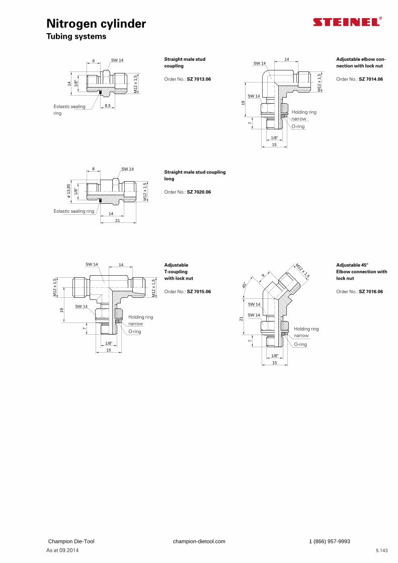
5.143As at 09.2014
7
19
14
M12
x 1
,5
SW 14
1/8"
SW 14
15
8,5
8
M12
x 1
,5
1/8"
14
SW 14
14
21
8
M12
x 1
,5
1/8"
ø 1
3,85
SW 14
Straight male studcoupling
Order No.: SZ 7013.06
Straight male stud coupling long
Order No.: SZ 7020.06
Adjustable T-coupling with lock nut
Order No.: SZ 7015.06
Adjustable elbow con-nection with lock nut
Order No.: SZ 7014.06
Adjustable 45°Elbow connection with lock nut
Order No.: SZ 7016.06
Eolastic sealing ring
Eolastic sealing ring Holding ring
narrow
O-ring
7
19
M12
x 1
,5
14
M12
x 1
,5
SW 14
1/8"
SW 14
15
7
21
9
M12 x 1,5
45°
SW 14
1/8"
SW 14
15
Holding ringnarrow
O-ring Holding ringnarrow
O-ring
Nitrogen cylinderTubing systems
Champion Die-Tool champion-dietool.com 1 (866) 957-9993
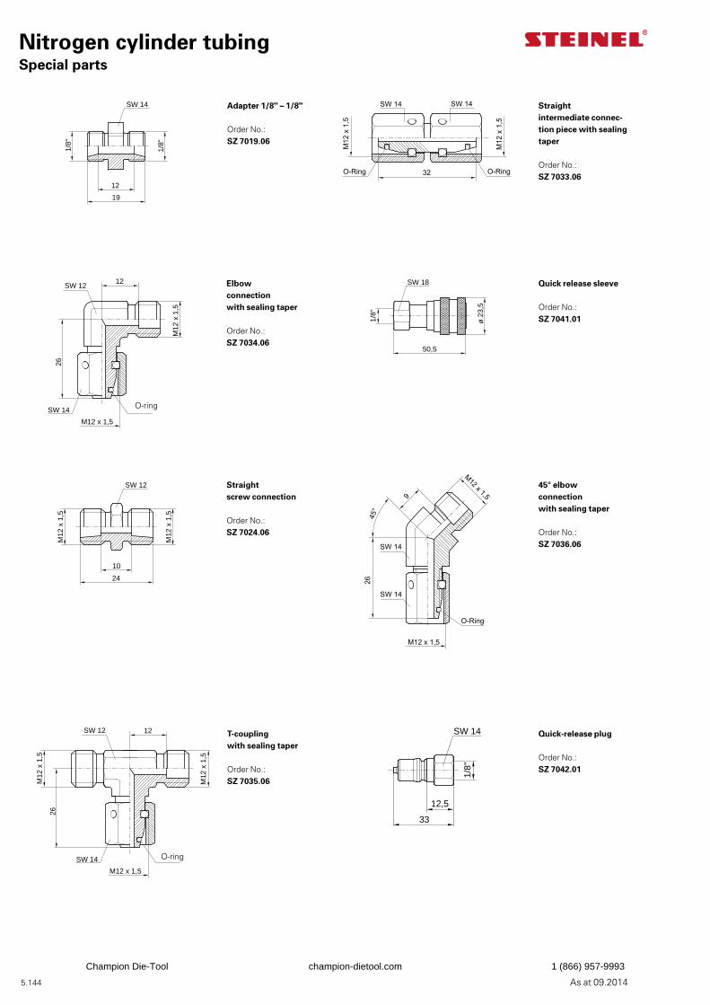
5.144 As at 09.2014
Nitrogen cylinder tubingSpecial parts
Adapter 1/8" – 1/8"
Order No.: SZ 7019.06
Straight intermediate connec-tion piece with sealing taper
Order No.: SZ 7033.06
12
19
1/8"
1/8"
SW 14
Elbow connectionwith sealing taper
Order No.: SZ 7034.06
Quick release sleeve
Order No.: SZ 7041.01
12
M12
x 1
,5
SW 12
26
M12 x 1,5
SW 14
1/8"
50,5
ø 2
3,5
SW 18
Straight screw connection
Order No.: SZ 7024.06
45° elbowconnectionwith sealing taper
Order No.: SZ 7036.06
10
24
M12
x 1
,5
M12
x 1
,5
SW 12
T-couplingwith sealing taper
Order No.: SZ 7035.06
Quick-release plug
Order No.: SZ 7042.01
1/8"
12,5
SW 14
33
12
M12
x 1
,5
SW 12
26
M12 x 1,5
M12
x 1
,5
SW 14 O-ring
O-ring
Champion Die-Tool champion-dietool.com 1 (866) 957-9993
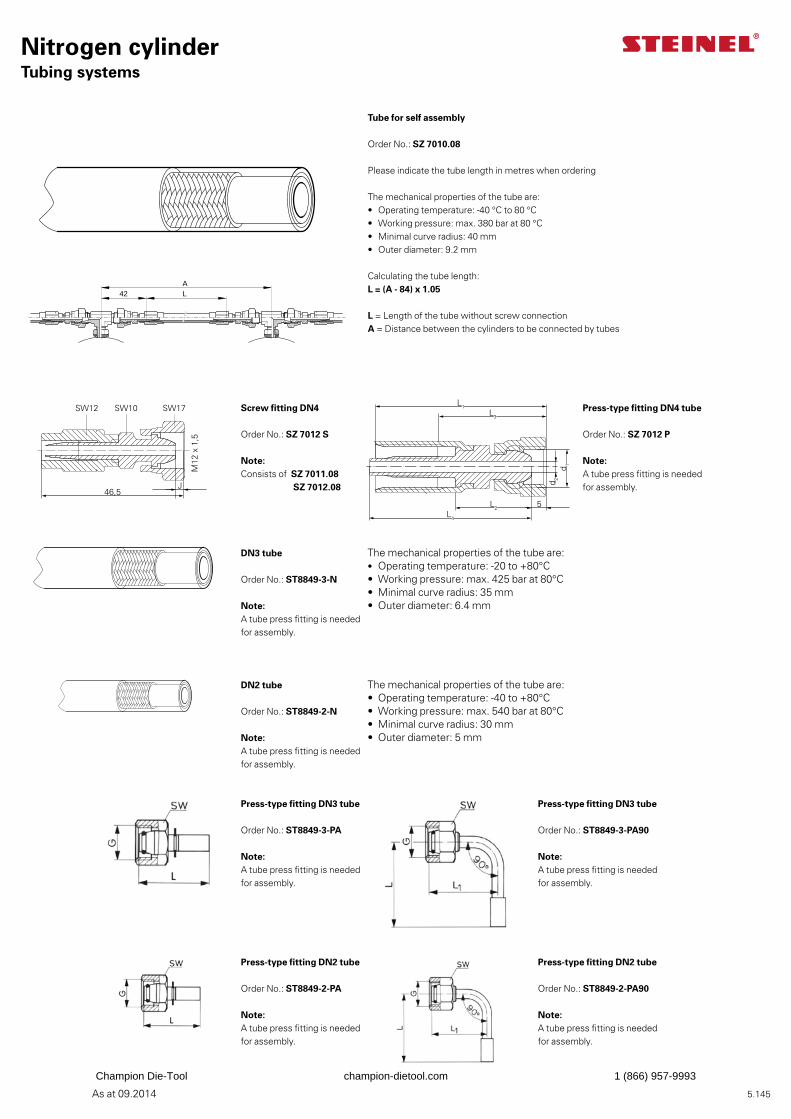
5.145As at 09.2014
Nitrogen cylinderTubing systems
Tube for self assembly
Order No.: SZ 7010.08
Please indicate the tube length in metres when ordering
The mechanical properties of the tube are:• Operating temperature: -40 °C to 80 °C• Working pressure: max. 380 bar at 80 °C• Minimal curve radius: 40 mm• Outer diameter: 9.2 mm Calculating the tube length: L = (A - 84) x 1.05 L = Length of the tube without screw connection A = Distance between the cylinders to be connected by tubes
Screw fitting DN4
Order No.: SZ 7012 S
Note: Consists of SZ 7011.08 SZ 7012.08
DN3 tube
Order No.: ST8849-3-N
Note: A tube press fitting is needed for assembly.
DN2 tube
Order No.: ST8849-2-N
Note: A tube press fitting is needed for assembly.
Press-type fitting DN3 tube
Order No.: ST8849-3-PA
Note: A tube press fitting is needed for assembly.
Press-type fitting DN3 tube
Order No.: ST8849-3-PA90
Note: A tube press fitting is needed for assembly.
Press-type fitting DN2 tube
Order No.: ST8849-2-PA
Note: A tube press fitting is needed for assembly.
Press-type fitting DN2 tube
Order No.: ST8849-2-PA90
Note: A tube press fitting is needed for assembly.
The mechanical properties of the tube are:• Operating temperature: -20 to +80°C• Working pressure: max. 425 bar at 80°C• Minimal curve radius: 35 mm• Outer diameter: 6.4 mm
The mechanical properties of the tube are:• Operating temperature: -40 to +80°C• Working pressure: max. 540 bar at 80°C• Minimal curve radius: 30 mm• Outer diameter: 5 mm
Press-type fitting DN4 tube
Order No.: SZ 7012 P
Note: A tube press fitting is needed for assembly.
SZ 7011.08 mont._1KZ 09/02
AL42
AL42
5
L1L3
d 1
d 2
L2L4
46,5
SW12 SW10 SW17
M12
x 1
,5
J
Champion Die-Tool champion-dietool.com 1 (866) 957-9993
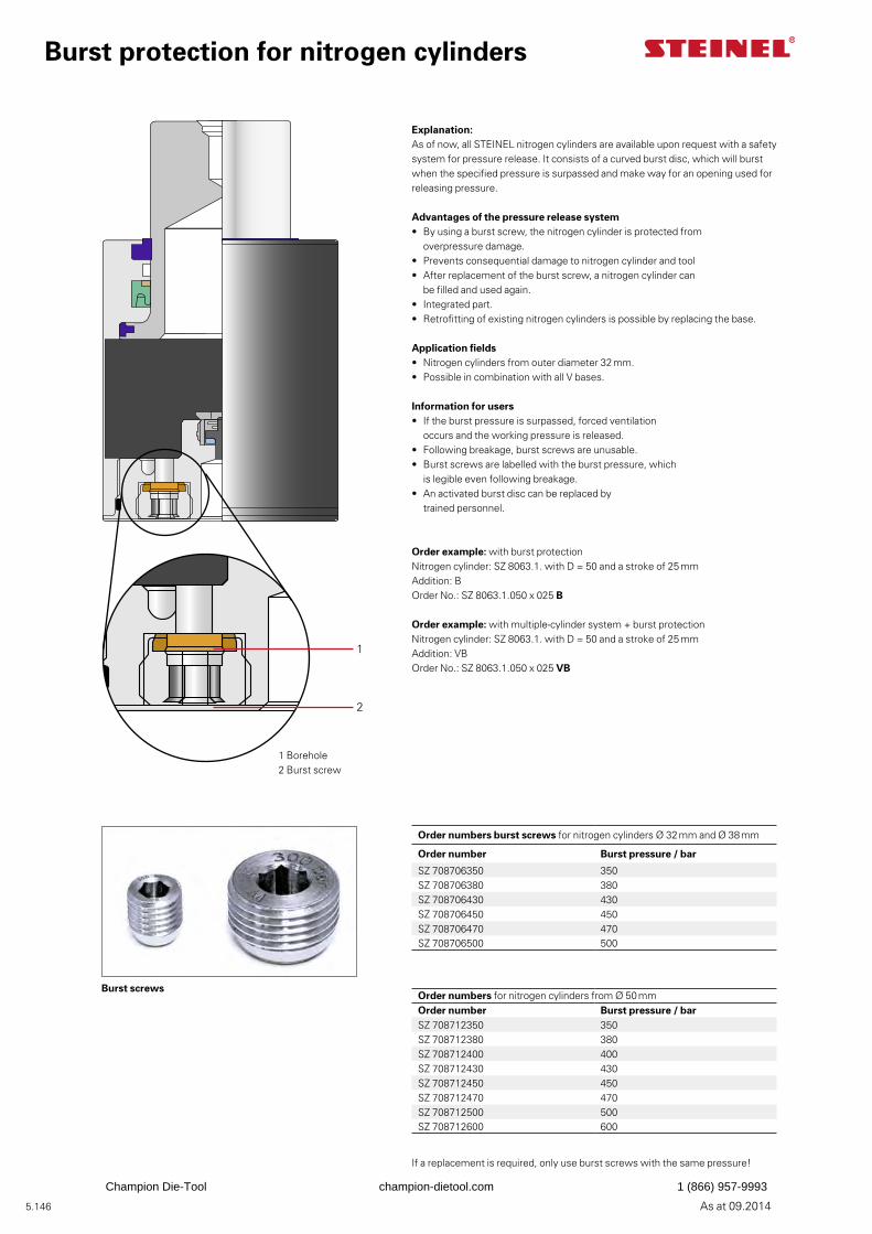
5.146 As at 09.2014
Burst protection for nitrogen cylinders
Explanation:As of now, all STEINEL nitrogen cylinders are available upon request with a safety system for pressure release. It consists of a curved burst disc, which will burst when the specified pressure is surpassed and make way for an opening used for releasing pressure.
Advantages of the pressure release system• By using a burst screw, the nitrogen cylinder is protected from overpressure damage.• Prevents consequential damage to nitrogen cylinder and tool• After replacement of the burst screw, a nitrogen cylinder can be filled and used again.• Integrated part.• Retrofitting of existing nitrogen cylinders is possible by replacing the base.
Application fields• Nitrogen cylinders from outer diameter 32 mm.• Possible in combination with all V bases.
Information for users• If the burst pressure is surpassed, forced ventilation occurs and the working pressure is released.• Following breakage, burst screws are unusable.• Burst screws are labelled with the burst pressure, which is legible even following breakage.• An activated burst disc can be replaced by trained personnel.
Order example: with burst protectionNitrogen cylinder: SZ 8063.1. with D = 50 and a stroke of 25 mmAddition: BOrder No.: SZ 8063.1.050 x 025 B
Order example: with multiple-cylinder system + burst protectionNitrogen cylinder: SZ 8063.1. with D = 50 and a stroke of 25 mmAddition: VBOrder No.: SZ 8063.1.050 x 025 VB
1 Borehole2 Burst screw
1
2
Order numbers burst screws for nitrogen cylinders Ø 32 mm and Ø 38 mm
Order number Burst pressure / bar
SZ 708706350 350SZ 708706380 380SZ 708706430 430SZ 708706450 450SZ 708706470 470SZ 708706500 500
Order numbers for nitrogen cylinders from Ø 50 mm Order number Burst pressure / barSZ 708712350 350SZ 708712380 380SZ 708712400 400SZ 708712430 430SZ 708712450 450SZ 708712470 470SZ 708712500 500SZ 708712600 600
If a replacement is required, only use burst screws with the same pressure!
Burst screws
Champion Die-Tool champion-dietool.com 1 (866) 957-9993
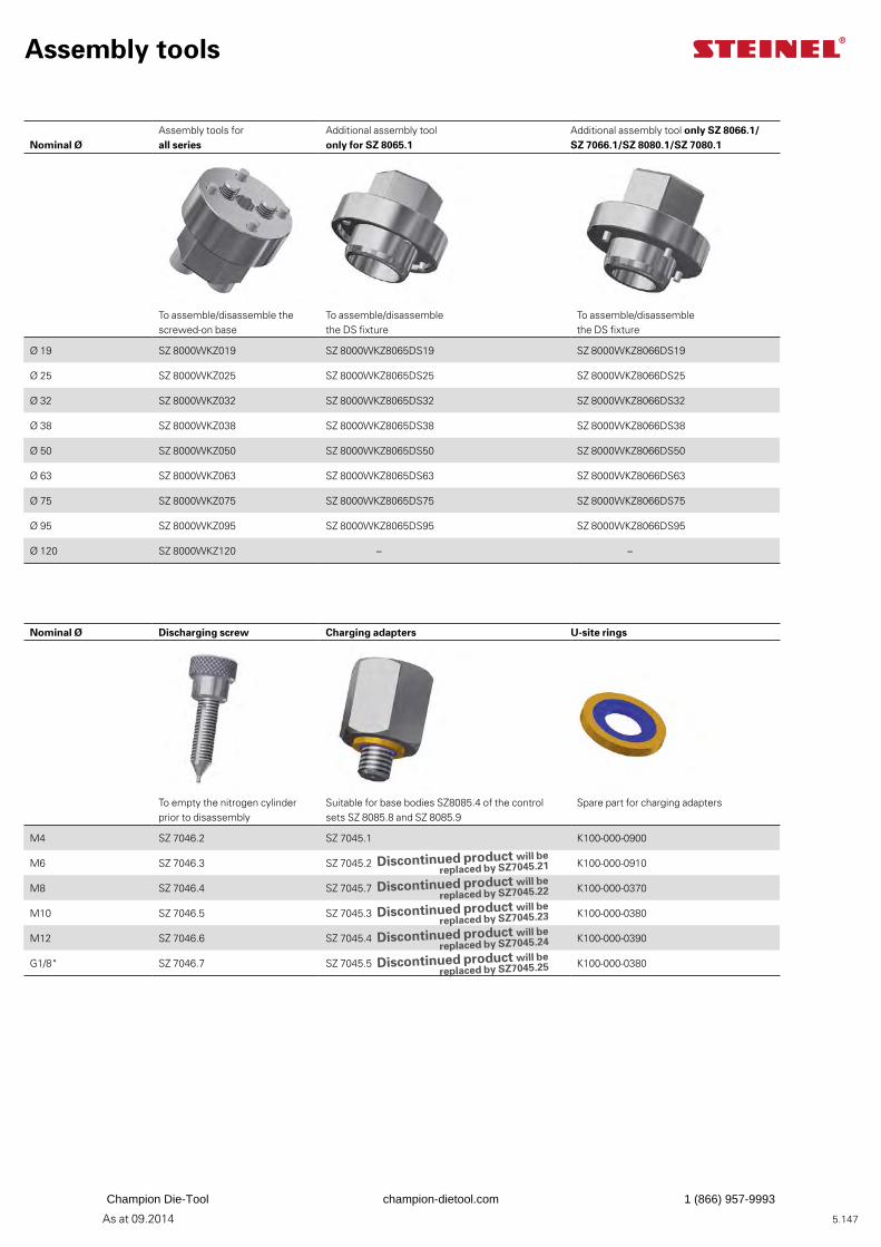
5.147As at 09.2014
Assembly tools
Nominal ØAssembly tools for all series
Additional assembly tool only for SZ 8065.1
Additional assembly tool only SZ 8066.1/SZ 7066.1/SZ 8080.1/SZ 7080.1
To assemble/disassemble the screwed-on base
To assemble/disassemble the DS fixture
To assemble/disassemble the DS fixture
Ø 19 SZ 8000WKZ019 SZ 8000WKZ8065DS19 SZ 8000WKZ8066DS19
Ø 25 SZ 8000WKZ025 SZ 8000WKZ8065DS25 SZ 8000WKZ8066DS25
Ø 32 SZ 8000WKZ032 SZ 8000WKZ8065DS32 SZ 8000WKZ8066DS32
Ø 38 SZ 8000WKZ038 SZ 8000WKZ8065DS38 SZ 8000WKZ8066DS38
Ø 50 SZ 8000WKZ050 SZ 8000WKZ8065DS50 SZ 8000WKZ8066DS50
Ø 63 SZ 8000WKZ063 SZ 8000WKZ8065DS63 SZ 8000WKZ8066DS63
Ø 75 SZ 8000WKZ075 SZ 8000WKZ8065DS75 SZ 8000WKZ8066DS75
Ø 95 SZ 8000WKZ095 SZ 8000WKZ8065DS95 SZ 8000WKZ8066DS95
Ø 120 SZ 8000WKZ120 – –
Nominal Ø Discharging screw Charging adapters U-site rings
To empty the nitrogen cylinder prior to disassembly
Suitable for base bodies SZ8085.4 of the control sets SZ 8085.8 and SZ 8085.9
Spare part for charging adapters
M4 SZ 7046.2 SZ 7045.1 K100-000-0900
M6 SZ 7046.3 SZ 7045.2 K100-000-0910
M8 SZ 7046.4 SZ 7045.7 K100-000-0370
M10 SZ 7046.5 SZ 7045.3 K100-000-0380
M12 SZ 7046.6 SZ 7045.4 K100-000-0390
G1/8" SZ 7046.7 SZ 7045.5 K100-000-0380
Discontinued product will be replaced by SZ7045.21
Discontinued product will be replaced by SZ7045.22
Discontinued product will be replaced by SZ7045.23
Discontinued product will be replaced by SZ7045.24
Discontinued product will be replaced by SZ7045.25
Champion Die-Tool champion-dietool.com 1 (866) 957-9993
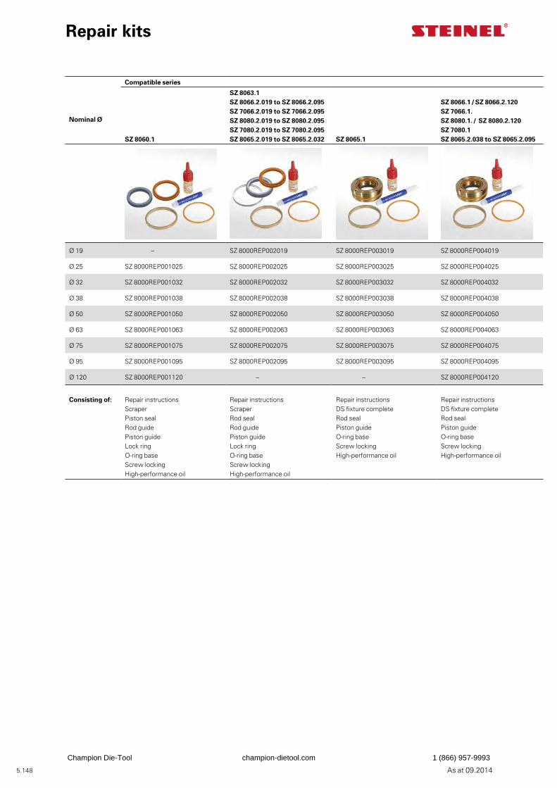
5.148 As at 09.2014
Repair kits
Nominal Ø
Compatible series
SZ 8060.1
SZ 8063.1 SZ 8066.2.019 to SZ 8066.2.095SZ 7066.2.019 to SZ 7066.2.095 SZ 8080.2.019 to SZ 8080.2.095 SZ 7080.2.019 to SZ 7080.2.095SZ 8065.2.019 to SZ 8065.2.032 SZ 8065.1
SZ 8066.1 / SZ 8066.2.120SZ 7066.1. SZ 8080.1. / SZ 8080.2.120 SZ 7080.1 SZ 8065.2.038 to SZ 8065.2.095
Ø 19 – SZ 8000REP002019 SZ 8000REP003019 SZ 8000REP004019
Ø 25 SZ 8000REP001025 SZ 8000REP002025 SZ 8000REP003025 SZ 8000REP004025
Ø 32 SZ 8000REP001032 SZ 8000REP002032 SZ 8000REP003032 SZ 8000REP004032
Ø 38 SZ 8000REP001038 SZ 8000REP002038 SZ 8000REP003038 SZ 8000REP004038
Ø 50 SZ 8000REP001050 SZ 8000REP002050 SZ 8000REP003050 SZ 8000REP004050
Ø 63 SZ 8000REP001063 SZ 8000REP002063 SZ 8000REP003063 SZ 8000REP004063
Ø 75 SZ 8000REP001075 SZ 8000REP002075 SZ 8000REP003075 SZ 8000REP004075
Ø 95 SZ 8000REP001095 SZ 8000REP002095 SZ 8000REP003095 SZ 8000REP004095
Ø 120 SZ 8000REP001120 – – SZ 8000REP004120
Consisting of: Repair instructionsScraperPiston sealRod guidePiston guideLock ringO-ring baseScrew lockingHigh-performance oil
Repair instructionsScraperRod seal Rod guidePiston guideLock ringO-ring baseScrew lockingHigh-performance oil
Repair instructionsDS fixture completeRod sealPiston guideO-ring baseScrew lockingHigh-performance oil
Repair instructionsDS fixture completeRod sealPiston guideO-ring baseScrew lockingHigh-performance oil
Champion Die-Tool champion-dietool.com 1 (866) 957-9993
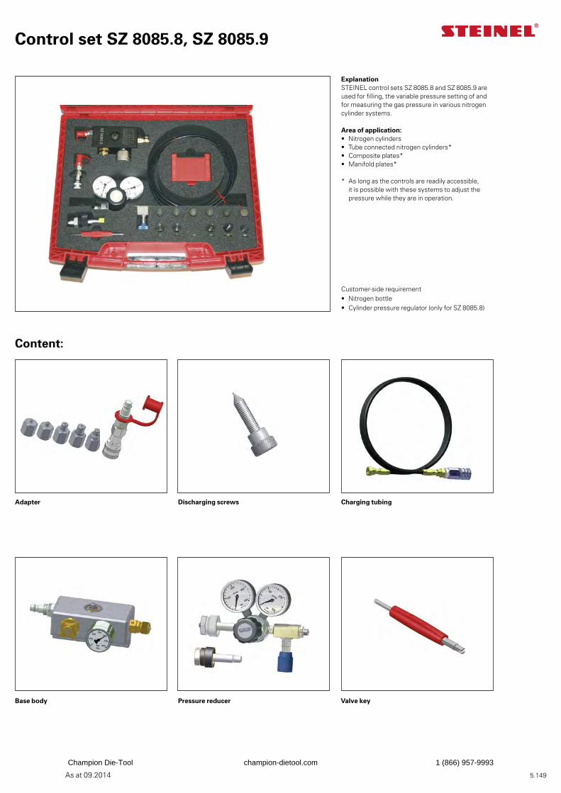
5.149As at 09.2014
Base body Pressure reducer Valve key
Charging tubing Adapter Discharging screws
Content:
Control set SZ 8085.8, SZ 8085.9
ExplanationSTEINEL control sets SZ 8085.8 and SZ 8085.9 are used for filling, the variable pressure setting of and for measuring the gas pressure in various nitrogen cylinder systems.
Area of application:• Nitrogen cylinders• Tube connected nitrogen cylinders*• Composite plates*• Manifold plates*
* As long as the controls are readily accessible, it is possible with these systems to adjust the pressure while they are in operation.
Customer-side requirement• Nitrogen bottle• Cylinder pressure regulator (only for SZ 8085.8)
Champion Die-Tool champion-dietool.com 1 (866) 957-9993
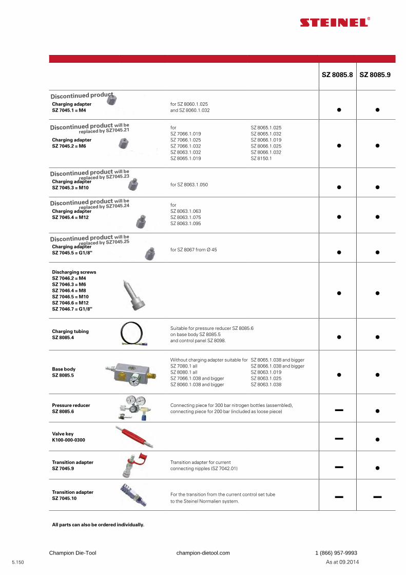
5.150 As at 09.2014
Nitrogen cylinders
SZ 8085.8 SZ 8085.9
Charging adapter SZ 7045.1 = M4
for SZ 8060.1.025and SZ 8060.1.032
Charging adapter SZ 7045.2 = M6
for SZ 7066.1.019SZ 7066.1.025SZ 7066.1.032SZ 8063.1.032SZ 8065.1.019
SZ 8065.1.025SZ 8065.1.032SZ 8066.1.019 SZ 8066.1.025 SZ 8066.1.032SZ 8150.1
Charging adapter SZ 7045.3 = M10
for SZ 8063.1.050
Charging adapter SZ 7045.4 = M12
for SZ 8063.1.063SZ 8063.1.075 SZ 8063.1.095
Charging adapter SZ 7045.5 = G1/8"
for SZ 8067 from Ø 45
Discharging screws SZ 7046.2 = M4SZ 7046.3 = M6SZ 7046.4 = M8SZ 7046.5 = M10 SZ 7046.6 = M12SZ 7046.7 = G1/8"
Charging tubing SZ 8085.4
Suitable for pressure reducer SZ 8085.6 on base body SZ 8085.5 and control panel SZ 8098.
Base bodySZ 8085.5
Without charging adapter suitable for SZ 7080.1 all SZ 8080.1 all SZ 7066.1.038 and biggerSZ 8060.1.038 and bigger
SZ 8065.1.038 and bigger SZ 8066.1.038 and bigger SZ 8063.1.019SZ 8063.1.025SZ 8063.1.038
Pressure reducer SZ 8085.6
Connecting piece for 300 bar nitrogen bottles (assembled), connecting piece for 200 bar (included as loose piece) –
Valve key K100-000-0300 –Transition adapter SZ 7045.9
Transition adapter for current connecting nipples (SZ 7042.01) –
Transition adapterSZ 7045.10
For the transition from the current control set tube to the Steinel Normalien system. – –
All parts can also be ordered individually.
Control set
Discontinued product
Discontinued product will be replaced by SZ7045.21
Discontinued product will be replaced by SZ7045.23
Discontinued product will be replaced by SZ7045.24
Discontinued product will be replaced by SZ7045.25
Champion Die-Tool champion-dietool.com 1 (866) 957-9993
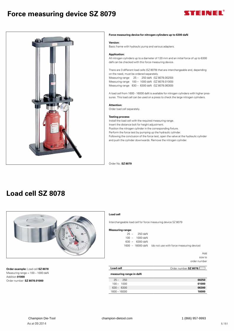
5.151As at 09.2014
Load cell Order number SZ 8078.
measuring range in daN
25 – 250 00250 100 – 1000 01000 630 – 6300 06300 1600 – 16000 16000
Force measuring device SZ 8079
Force measuring device for nitrogen cylinders up to 6300 daN
Version: Basic frame with hydraulic pump and various adapters.
Application: All nitrogen cylinders up to a diameter of 120 mm and an initial force of up to 6300 daN can be checked with this force measuring device.
There are 3 different load cells (SZ 8078) that are interchangeable and, depending on the need, must be ordered separately. Measuring range 25 – 250 daN (SZ 8078.00250)Measuring range 100 – 1000 daN (SZ 8078.01000)Measuring range 630 – 6300 daN (SZ 8078.06300)
A load cell from 1600 - 16000 daN is available for nitrogen cylinders with higher pres-sures. This load cell can be used on a press to check the large nitrogen cylinders.
Attention: Order load cell separately.
Testing process: Install the load cell with the required measuring range.Insert the distance bolt for height adjustment. Position the nitrogen cylinder in the corresponding fixture.Perform the force test by pumping up the hydraulic cylinder.Following the conclusion of the force test, open the valve at the hydraulic cylinder and push the cylinder downwards. Remove the nitrogen cylinder.
Order No. SZ 8079
Load cell SZ 8078
Load cell Interchangeable load cell for force measuring device SZ 8079
Measuring range: 25 – 250 daN 100 – 1000 daN 630 – 6300 daN 1600 – 16000 daN (do not use with force measuring device)
Order example: Load cell SZ 8078Measuring range = 100 – 1000 daNAddition 01000Order number SZ 8078.01000
Addsize to
order number
Nitrogen cylinders
Champion Die-Tool champion-dietool.com 1 (866) 957-9993
5.152 As at 09.2014
Champion Die-Tool champion-dietool.com 1 (866) 957-9993
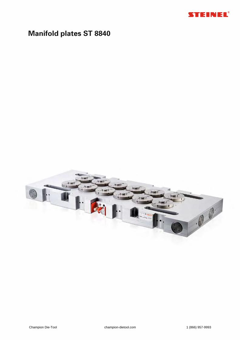
Manifold plates ST 8840
Champion Die-Tool champion-dietool.com 1 (866) 957-9993
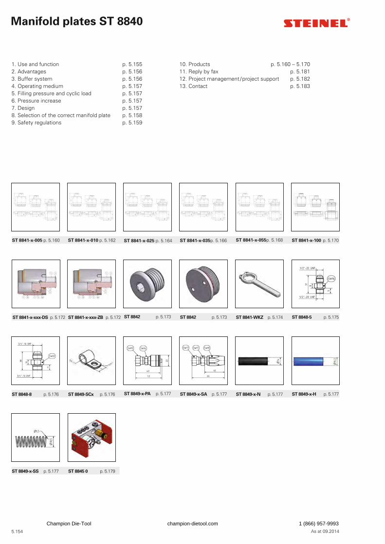
5.154 As at 09.2014
Manifold plates ST 8840
1. Use and function p. 5.1552. Advantages p. 5.1563. Buffer system p. 5.1564. Operating medium p. 5.1575. Filling pressure and cyclic load p. 5.1576. Pressure increase p. 5.1577. Design p. 5.1578. Selection of the correct manifold plate p. 5.1589. Safety regulations p. 5.159
ST 8841-x-005 p. 5.160 ST 8841-x-010 p. 5.162 ST 8841-x-025 p. 5.164 ST 8841-x-035 p. 5.166 ST 8841-x-055 p. 5.168 ST 8841-x-100 p. 5.170
ST 8841-x-xxx-ZB p. 5.172ST 8841-x-xxx-DS p. 5.172 ST 8842 p. 5.173 ST 8842 p. 5.173 ST 8841-WKZ p. 5.174 ST 8848-5 p. 5.175
ST 8849-SCx p. 5.176 ST 8849-x-PA p. 5.177 ST 8849-x-SA p. 5.177 ST 8849-x-N p. 5.177 ST 8849-x-H p. 5.177
ST 8845 0 p. 5.179
10. Products p. 5.160 – 5.17011. Reply by fax p. 5.18112. Project management / project support p. 5.18213. Contact p. 5.183
ST 8849-x-SS p. 5.177
ST 8848-8 p. 5.176
Champion Die-Tool champion-dietool.com 1 (866) 957-9993
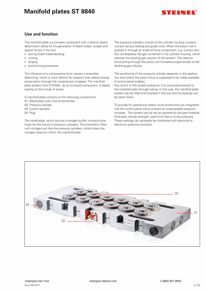
5.155As at 09.2014
Manifold plates ST 8840
Use and function
The manifold plate is a complex component with a distinct elastic deformation ability for the generation of blank holder, scraper and ejector forces in the tool • during sheet metal bending, • cutting, • forging • and forming processes.
The infl uence of a compressive force causes a reversible deforming, which is most distinct for systems that realise energy preservation through the compression of gases. The manifold plate system from STEINEL, as an enclosed component, is based exactly on this mode of action.
A manifold plate consists of the following components:01. Metal plate with volume boreholes02. Pressure cylinder 03. Control panel(s)04. Plug
The metal plate, which acts as a nitrogen buffer, contains bore-holes for the fi xture of pressure cylinders. The manifold is fi lled with nitrogen just like the pressure cylinders, which share the nitrogen reservoir within the manifold plate.
The pressure cylinders consist of the cylinder housing, a piston rod and various sealing and guide units. When the piston rod is pushed in through an external force component, e.g. a press ram, the rod displaces the gas contained in the cylinder housing, which reduces the existing gas volume of the system. The reaction force acting through the piston rod increases proportionally to the declining gas volume.
The positioning of the pressure cylinder depends on the applica-tion and where the piston force is supposed to be made available. A control panel enablesthe control of the system pressure. It is connected directly tothe manifold plate through tubing. In this way, the manifold plate system can be fi lled and emptied in the tool and its readings can be taken there.
To provide for operational safety, burst protections are integrated into the control panel which prevent an unacceptable pressure increase. The system can be set as required by the part (material thickness, tensile strength, yield limit) that is to be produced. These settings can optionally be monitored with electrical or electronic pressure switches.
04
03
02
01
Champion Die-Tool champion-dietool.com 1 (866) 957-9993
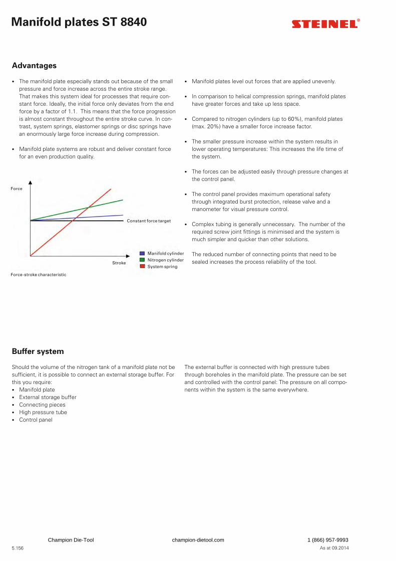
5.156 As at 09.2014
Advantages
• The manifold plate especially stands out because of the small pressure and force increase across the entire stroke range. That makes this system ideal for processes that require con-stant force. Ideally, the initial force only deviates from the end force by a factor of 1.1. This means that the force progression is almost constant throughout the entire stroke curve. In con-trast, system springs, elastomer springs or disc springs have an enormously large force increase during compression.
• Manifold plate systems are robust and deliver constant force for an even production quality.
• Manifold plates level out forces that are applied unevenly.
• In comparison to helical compression springs, manifold plates have greater forces and take up less space.
• Compared to nitrogen cylinders (up to 60%), manifold plates (max. 20%) have a smaller force increase factor.
• The smaller pressure increase within the system results in lower operating temperatures: This increases the life time of the system.
• The forces can be adjusted easily through pressure changes at the control panel.
• The control panel provides maximum operational safety through integrated burst protection, release valve and a manometer for visual pressure control.
• Complex tubing is generally unnecessary. The number of the required screw joint fi ttings is minimised and the system is much simpler and quicker than other solutions.
• The reduced number of connecting points that need to be sealed increases the process reliability of the tool.
Buffer system
Should the volume of the nitrogen tank of a manifold plate not be suffi cient, it is possible to connect an external storage buffer. For this you require: • Manifold plate • External storage buffer • Connecting pieces • High pressure tube • Control panel
The external buffer is connected with high pressure tubes through boreholes in the manifold plate. The pressure can be set and controlled with the control panel: The pressure on all compo-nents within the system is the same everywhere.
Manifold plates ST 8840
Force-stroke characteristic
Force
Manifold cylinder
Nitrogen cylinder
System springStroke
Constant force target
Champion Die-Tool champion-dietool.com 1 (866) 957-9993
5.157As at 09.2014
Operating medium
Solely technical nitrogen may be used as operating medium. Nitrogen is a neutral, non-hazardous gas.
Filling pressure and cyclic load
A manifold plate is a piece of pressure equipment than can be used for cyclic load. That means that manifold plates can be operated under highly fl uctuating operating pressure. The fi lling pressure can vary between 40 and 150 bar. A manifold plate is designed to limit the pressure increase to a maximum of 20%. The maximum pressure within a manifold plate is therefore limited to 180 bar and secured via burst protection. The effective application fi eld is displayed on an identifi cation plate.
Because of the fl uctuating operating pressure, manifold plates are subject to cyclic load. That is why the used parts are not critical in terms of fatigue.
The fl uctuation in pressure between the minimum and maximum operating pressure is referred to as load cycle. The difference be-tween the minimum and maximum operating pressure is referred to as pressure fl uctuation range.
Pressure increase
Retraction of the pressure cylinders leads to a pressure increase. There is an appropriate pressure increase for each application. The pressure increase is defi ned as a percentage and can be calculated easily.
p1 x V1 = p2 x V2
Note:
The pressure increase should generally be as low as possible and ideally be 10%.Please note that a pressure increase that is too high has a nega-tive effect on the life time.We will be happy to assist you with the calculation.
Design
When it comes to the manifold plate design, nitrogen can be con-sidered an ideal gas. Based on this assumption, the behaviour of the gas fi lling in the manifold plate can be described as follows: • The state of a gas is determined by the three state parameters
pressure, volume and temperature. • Changes to two or all of the state parameters are referred to
as change in state. • An isothermal change in state of gases occurs when the
change of the gas buffers in the buffer takes place so slowly that there is enough time for heat exchange and the tempera-ture remains constant as a result.
• An adiabatic change in state of gases occurs when the change of the gas buffers in the buffer takes place rapidly and the temperature does not remain constant.
For determining the required manifold plate volume an isothermal change of state can be assumed for purposes of simplifi cation:
p0 x V0 = p1 x V1 = p2 x V2
Manifold plates ST 8840
Champion Die-Tool champion-dietool.com 1 (866) 957-9993
5.158 As at 09.2014
Selection of the correct manifold plate
Initial questions:
1. How much entire force is needed?2. How many pressure points should this force act on?3. Which working stroke is required?4. What are the maximum dimensions of the manifold plate?5. Which additional milled cavities, boreholes or breakthroughs have to be integrated into the manifold plate?
Design of the manifold plate:
The displaced gas volume during one working stroke of the man-ifold cylinder is calculated by multiplying the piston active surface with the actual stroke and the number of manifold cylinders.
Vzyl
= Azyl
x H x n
Example: 5 cylinders ST 8841.1.025 x 025, Plate size 700 mm x 500 mm x 80 mmVzyl = 5 x 22.8906 cm² x 2.5 cm = 286.1325 cm³
Determining the initial volume with pistons extended
Vzyl
(100 % + p) V = p
286.1325 cm³ x (100 % + 10 %)V = 10 %
V = 3147.4575 cm³ = 3.1474575 l
Determining the manifold plate volume
Vtpl
= V – Vzyl
Vtpl = 3147.4575 cm³ – 286.1325 cm³ = 2861.325 cm³ = 2,861325 l
Determining the maximum volume hole diameter
D = TPL
– (2 x Pmin
)
D = 80 mm – (2 x 10 mm) = 60 mm Bore hole diameter according to table = 45 mm (see p. 5.173)Circular area from the borehole according to table = 15.904 cm²
Determining the borehole length of the volume holes
Vtpl
L
b =
Ab
2861.375 cm³Lb = =180 cm = 1800 mm 15.904 cm²
A borehole length of 1800 mm must be used for the manifold plate 700 x 500 x 80 mm, meaning that boreholes with Ø 45 mm require sealing plugs of the type ST 8842-048. These have an installation length of 20 mm. With a plate length of 700 mm and a through-hole, a storage length of 700 - 20 - 20 = 660 mm is achieved. With a total length of the volume hole of 1800 mm, 1800/660 = 2.7 through holes are required. This is rounded up to 3 through-holes. This reduces the pressure increase from 10% to 9.1% and therefore has a positive infl uence on the life time of the pressure cylinder.
Explanation of the abbreviations:
A zyl
= Piston active surfaceA
b = Circular area of the volume hole
D = Diameter of the volume holeH = Actual stroke moved by the Piston active surface of the cylinderA
b = Length of the volume hole
n = Number of cylindersp = Pressure increaseT
PL = Plate thickness
V = Volume of the manifold plate with piston extendedV
tpl = Volume of the manifold plate
V tpl
= Volume of the cylinders
Manifold plates ST 8840
Champion Die-Tool champion-dietool.com 1 (866) 957-9993
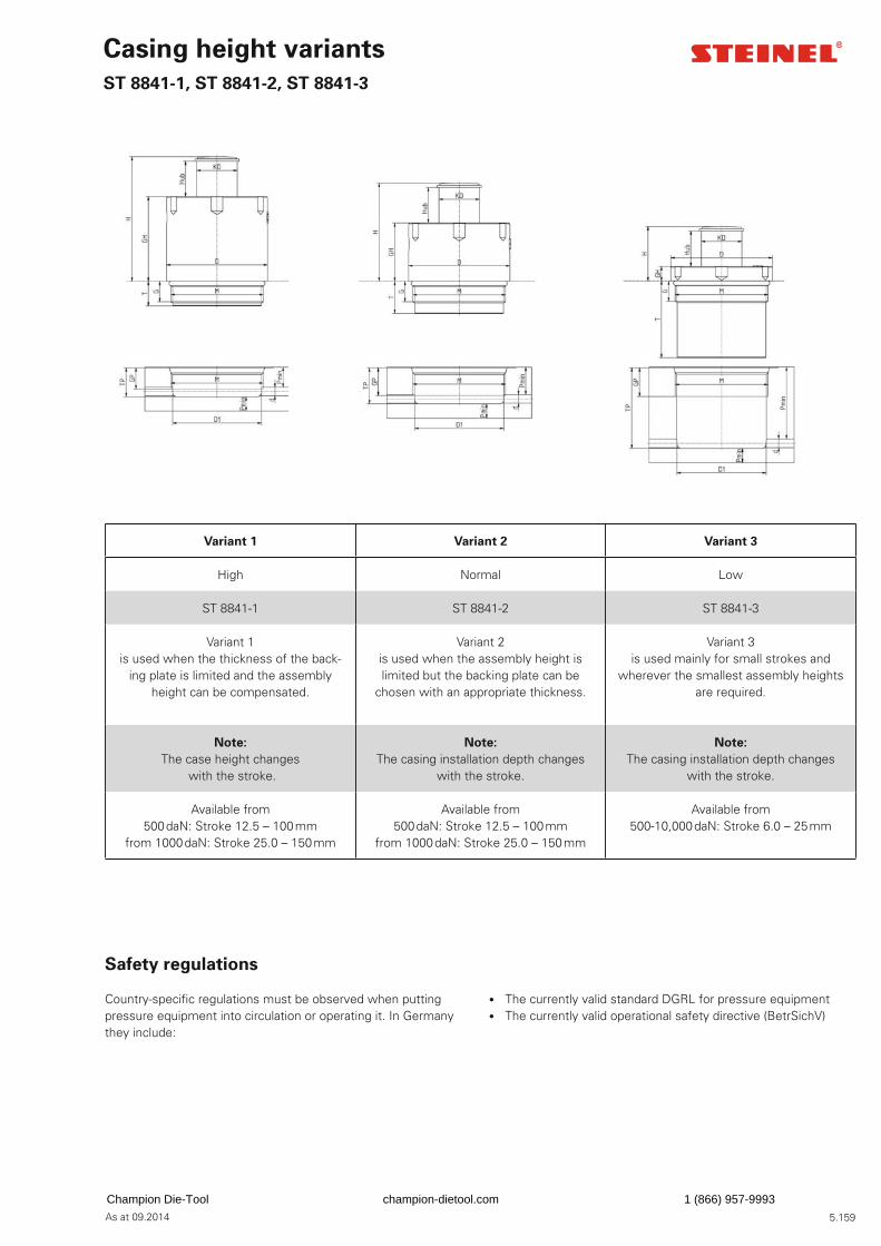
5.159As at 09.2014
Variant 1 Variant 2 Variant 3
High Normal Low
ST 8841-1 ST 8841-2 ST 8841-3
Variant 1is used when the thickness of the back-
ing plate is limited and the assembly height can be compensated.
Variant 2 is used when the assembly height is limited but the backing plate can be
chosen with an appropriate thickness.
Variant 3 is used mainly for small strokes and
wherever the smallest assembly heights are required.
Note:
The case height changes with the stroke.
Note:
The casing installation depth changes with the stroke.
Note:
The casing installation depth changes with the stroke.
Available from500 daN: Stroke 12.5 – 100 mm
from 1000 daN: Stroke 25.0 – 150 mm
Available from500 daN: Stroke 12.5 – 100 mm
from 1000 daN: Stroke 25.0 – 150 mm
Available from500-10,000 daN: Stroke 6.0 – 25 mm
Casing height variants
ST 8841-1, ST 8841-2, ST 8841-3
Safety regulations
Country-specifi c regulations must be observed when putting pressure equipment into circulation or operating it. In Germany they include:
• The currently valid standard DGRL for pressure equipment • The currently valid operational safety directive (BetrSichV)
Champion Die-Tool champion-dietool.com 1 (866) 957-9993
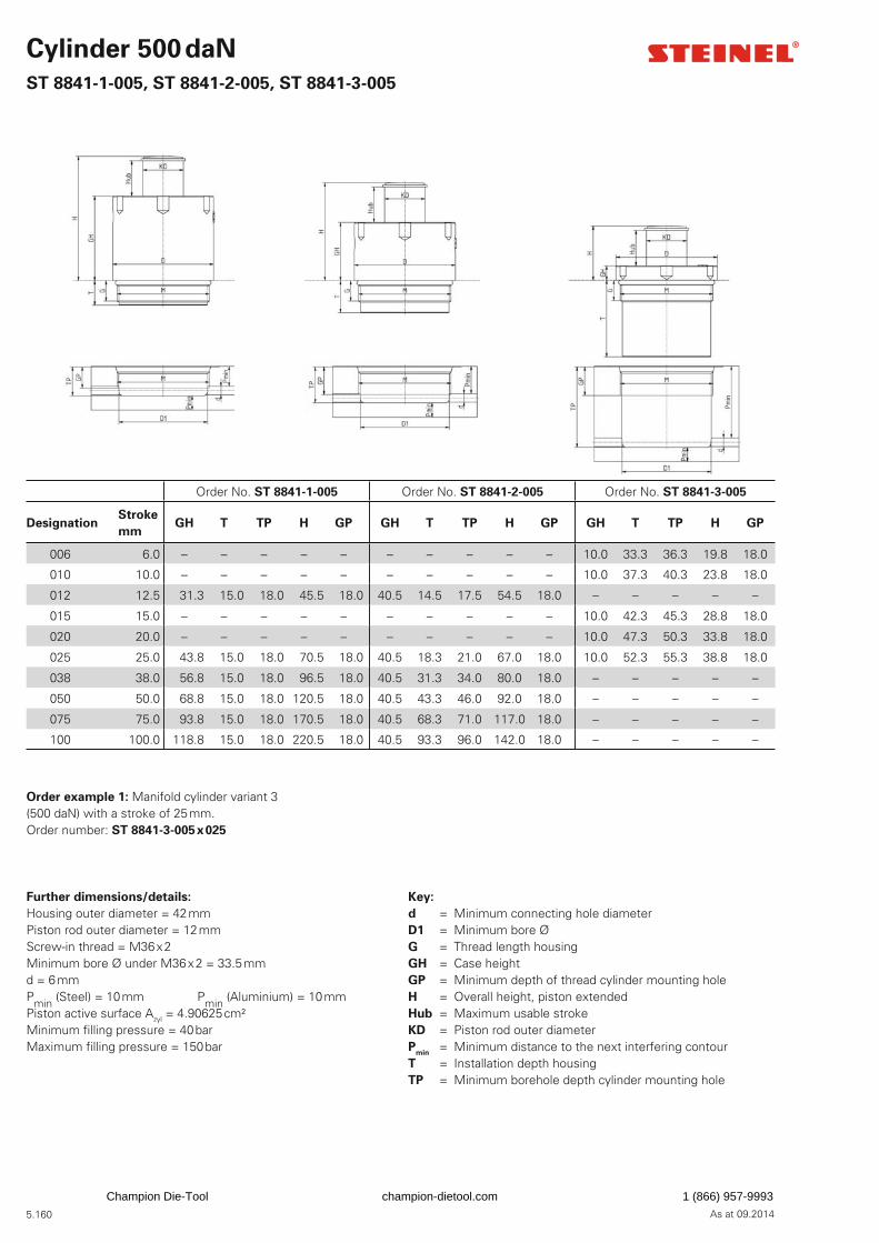
5.160 As at 09.2014
Cylinder 500 daN
ST 8841-1-005, ST 8841-2-005, ST 8841-3-005
Order No. ST 8841-1-005 Order No. ST 8841-2-005 Order No. ST 8841-3-005
DesignationStroke
mmGH T TP H GP GH T TP H GP GH T TP H GP
006 6.0 – – – – – – – – – – 10.0 33.3 36.3 19.8 18.0
010 10.0 – – – – – – – – – – 10.0 37.3 40.3 23.8 18.0
012 12.5 31.3 15.0 18.0 45.5 18.0 40.5 14.5 17.5 54.5 18.0 – – – – –
015 15.0 – – – – – – – – – – 10.0 42.3 45.3 28.8 18.0
020 20.0 – – – – – – – – – – 10.0 47.3 50.3 33.8 18.0
025 25.0 43.8 15.0 18.0 70.5 18.0 40.5 18.3 21.0 67.0 18.0 10.0 52.3 55.3 38.8 18.0
038 38.0 56.8 15.0 18.0 96.5 18.0 40.5 31.3 34.0 80.0 18.0 – – – – –
050 50.0 68.8 15.0 18.0 120.5 18.0 40.5 43.3 46.0 92.0 18.0 – – – – –
075 75.0 93.8 15.0 18.0 170.5 18.0 40.5 68.3 71.0 117.0 18.0 – – – – –
100 100.0 118.8 15.0 18.0 220.5 18.0 40.5 93.3 96.0 142.0 18.0 – – – – –
Further dimensions/details:
Housing outer diameter = 42 mmPiston rod outer diameter = 12 mmScrew-in thread = M36 x 2Minimum bore Ø under M36 x 2 = 33.5 mmd = 6 mmPmin (Steel) = 10 mm Pmin (Aluminium) = 10 mmPiston active surface Azyl = 4.90625 cm²Minimum fi lling pressure = 40 barMaximum fi lling pressure = 150 bar
Key:
d = Minimum connecting hole diameterD1 = Minimum bore ØG = Thread length housingGH = Case height GP = Minimum depth of thread cylinder mounting holeH = Overall height, piston extendedHub = Maximum usable strokeKD = Piston rod outer diameterP
min = Minimum distance to the next interfering contour
T = Installation depth housingTP = Minimum borehole depth cylinder mounting hole
Order example 1: Manifold cylinder variant 3(500 daN) with a stroke of 25 mm.Order number: ST 8841-3-005 x 025
Champion Die-Tool champion-dietool.com 1 (866) 957-9993
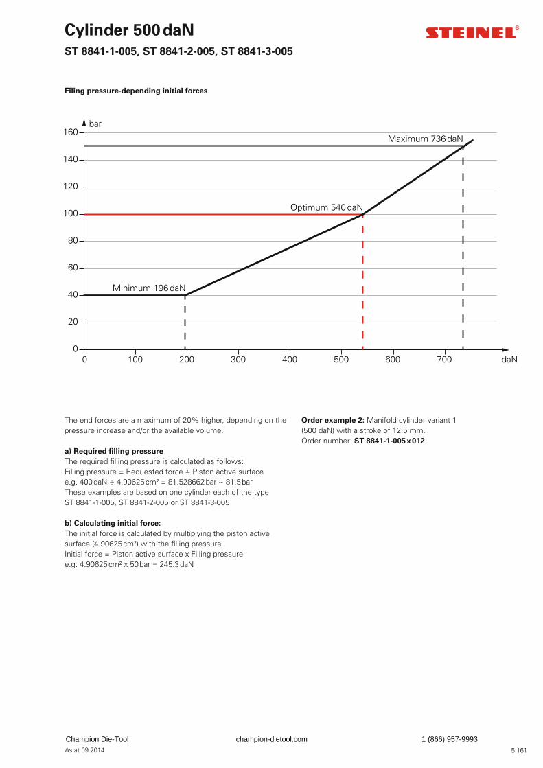
5.161As at 09.2014
The end forces are a maximum of 20% higher, depending on the pressure increase and/or the available volume.
a) Required fi lling pressure
The required fi lling pressure is calculated as follows: Filling pressure = Requested force ÷ Piston active surfacee.g. 400 daN ÷ 4.90625 cm² = 81.528662 bar ~ 81,5 bar These examples are based on one cylinder each of the type ST 8841-1-005, ST 8841-2-005 or ST 8841-3-005
b) Calculating initial force:
The initial force is calculated by multiplying the piston active surface (4.90625 cm²) with the fi lling pressure.Initial force = Piston active surface x Filling pressuree.g. 4.90625 cm² x 50 bar = 245.3 daN
Order example 2: Manifold cylinder variant 1(500 daN) with a stroke of 12.5 mm.Order number: ST 8841-1-005 x 012
Cylinder 500 daN
ST 8841-1-005, ST 8841-2-005, ST 8841-3-005
Filing pressure-depending initial forces
0
20
40
60
80
100
120
140
160bar
Minimum 196 daN
Optimum 540 daN
Maximum 736 daN
0 100 200 300 400 500 600 700 daN
Champion Die-Tool champion-dietool.com 1 (866) 957-9993
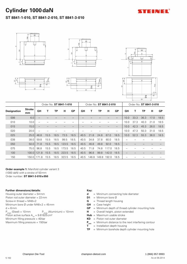
5.162 As at 09.2014
Cylinder 1000 daN
ST 8841-1-010, ST 8841-2-010, ST 8841-3-010
Order No. ST 8841-1-010 Order No. ST 8841-2-010 Order No. ST 8841-3-010
DesignationStroke
mmGH T TP H GP GH T TP H GP GH T TP H GP
006 6.0 – – – – – – – – – – 10.0 33.3 36.3 17.0 18.5
010 10.0 – – – – – – – – – – 10.0 37.3 40.3 21.0 18.5
015 15.0 – – – – – – – – – – 10.0 42.3 45.3 26.0 18.5
020 20.0 – – – – – – – – – – 10.0 47.3 50.3 31.0 18.5
025 25.0 46.8 15.5 18.5 73.5 18.5 40.5 21.8 24.8 67.0 18.5 10.0 52.3 55.3 36.0 18.5
038 38.0 59.8 15.5 18.5 99.5 18.5. 40.5 34.8 37.8 80.0 18.5 – – – – –
050 50.0 71.8 15.5 18.5 123.5 18.5 40.5 46.8 49.8 92.0 18.5 – – – – –
075 75.0 96.8 15.5 18.5 173.5 18.5 40.5 71.8 74.8 117.0 18.5 – – – – –
100 100.0 121.8 15.5 18.5 223.5 18.5 40.5 96.8 99.8 142.0 18.5 – – – – –
150 150.0 171.8 15.5 18.5 323.5 18.5 40.5 146.8 149.8 192.0 18.5 – – – – –
Further dimensions/details:
Housing outer diameter = 54 mmPiston rod outer diameter = 22 mmScrew-in thread = M48 x 2Minimum bore Ø under M48 x 2 = 45 mmd = 6 mmPmin (Steel) = 10 mm Pmin (Aluminium) = 10 mmPiston active surface Azyl = 9.61625 cm²Minimum fi lling pressure = 40 barMaximum fi lling pressure = 150 bar
Key:
d = Minimum connecting hole diameter D1 = Minimum bore ØG = Thread length housingGH = Case heightGP = Minimum depth of thread cylinder mounting holeH = Overall height, piston extendedHub = Maximum usable strokeKD = Piston rod outer diameterP
min = Minimum distance to the next interfering contour
T = Installation depth housingTP = Minimum borehole depth cylinder mounting hole
Order example 1: Manifold cylinder variant 3(1000 daN) with a stroke of 50 mmOrder number: ST 8841-3-010 x 050
Champion Die-Tool champion-dietool.com 1 (866) 957-9993
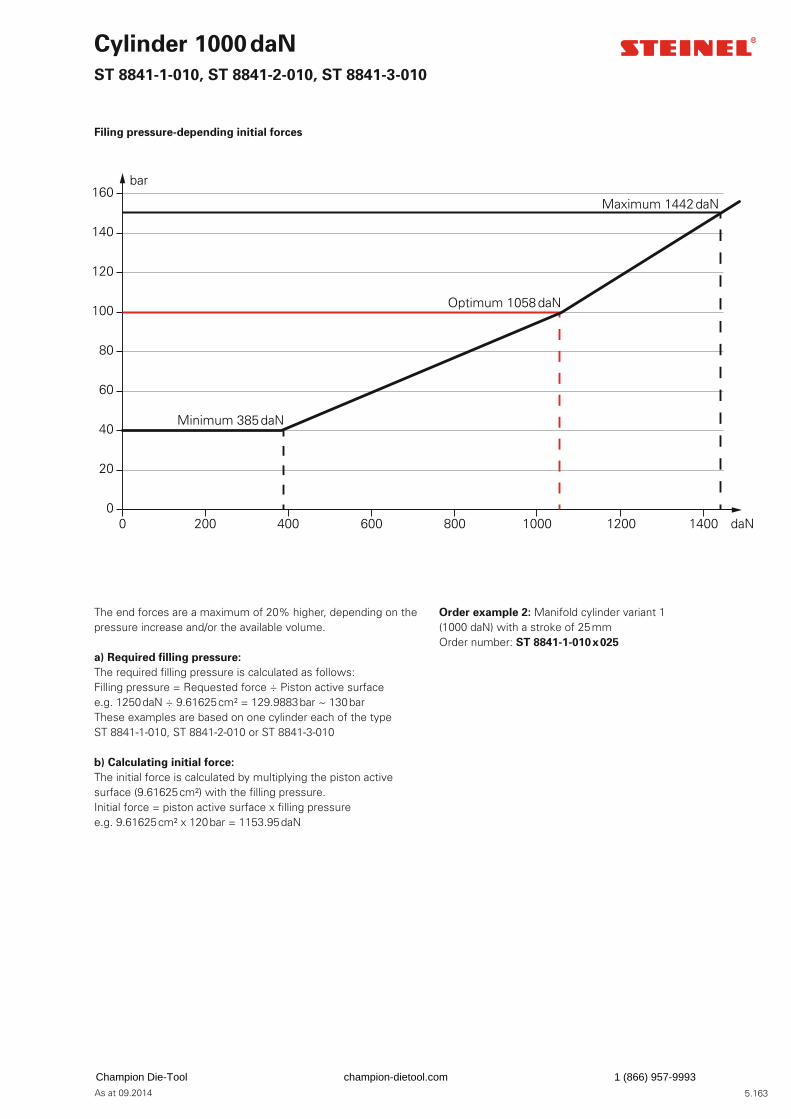
5.163As at 09.2014
The end forces are a maximum of 20% higher, depending on the pressure increase and/or the available volume.
a) Required fi lling pressure:
The required fi lling pressure is calculated as follows: Filling pressure = Requested force ÷ Piston active surfacee.g. 1250 daN ÷ 9.61625 cm² = 129.9883 bar ~ 130 bar These examples are based on one cylinder each of the type ST 8841-1-010, ST 8841-2-010 or ST 8841-3-010
b) Calculating initial force:
The initial force is calculated by multiplying the piston active surface (9.61625 cm²) with the fi lling pressure.Initial force = piston active surface x fi lling pressuree.g. 9.61625 cm² x 120 bar = 1153.95 daN
Order example 2: Manifold cylinder variant 1(1000 daN) with a stroke of 25 mmOrder number: ST 8841-1-010 x 025
Cylinder 1000 daN
ST 8841-1-010, ST 8841-2-010, ST 8841-3-010
Filing pressure-depending initial forces
0
20
40
60
80
100
120
140
160bar
Minimum 385 daN
Optimum 1058 daN
Maximum 1442 daN
0 200 400 600 800 1000 1200 1400 daN
Champion Die-Tool champion-dietool.com 1 (866) 957-9993
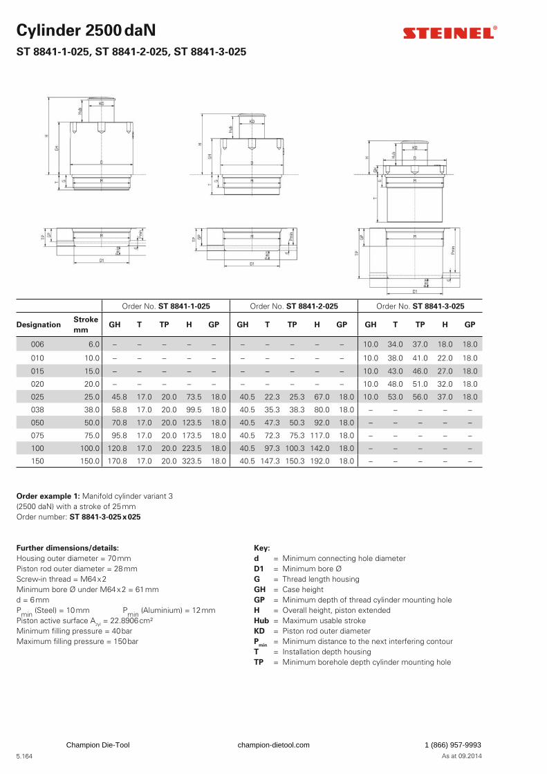
5.164 As at 09.2014
Cylinder 2500 daN
ST 8841-1-025, ST 8841-2-025, ST 8841-3-025
Order No. ST 8841-1-025 Order No. ST 8841-2-025 Order No. ST 8841-3-025
DesignationStroke
mmGH T TP H GP GH T TP H GP GH T TP H GP
006 6.0 – – – – – – – – – – 10.0 34.0 37.0 18.0 18.0
010 10.0 – – – – – – – – – – 10.0 38.0 41.0 22.0 18.0
015 15.0 – – – – – – – – – – 10.0 43.0 46.0 27.0 18.0
020 20.0 – – – – – – – – – – 10.0 48.0 51.0 32.0 18.0
025 25.0 45.8 17.0 20.0 73.5 18.0 40.5 22.3 25.3 67.0 18.0 10.0 53.0 56.0 37.0 18.0
038 38.0 58.8 17.0 20.0 99.5 18.0 40.5 35.3 38.3 80.0 18.0 – – – – –
050 50.0 70.8 17.0 20.0 123.5 18.0 40.5 47.3 50.3 92.0 18.0 – – – – –
075 75.0 95.8 17.0 20.0 173.5 18.0 40.5 72.3 75.3 117.0 18.0 – – – – –
100 100.0 120.8 17.0 20.0 223.5 18.0 40.5 97.3 100.3 142.0 18.0 – – – – –
150 150.0 170.8 17.0 20.0 323.5 18.0 40.5 147.3 150.3 192.0 18.0 – – – – –
Further dimensions/details:
Housing outer diameter = 70 mmPiston rod outer diameter = 28 mmScrew-in thread = M64 x 2Minimum bore Ø under M64 x 2 = 61 mmd = 6 mmPmin (Steel) = 10 mm Pmin (Aluminium) = 12 mmPiston active surface Azyl = 22.8906 cm²Minimum fi lling pressure = 40 barMaximum fi lling pressure = 150 bar
Key:
d = Minimum connecting hole diameter D1 = Minimum bore ØG = Thread length housingGH = Case heightGP = Minimum depth of thread cylinder mounting holeH = Overall height, piston extendedHub = Maximum usable strokeKD = Piston rod outer diameterP
min = Minimum distance to the next interfering contour
T = Installation depth housingTP = Minimum borehole depth cylinder mounting hole
Order example 1: Manifold cylinder variant 3(2500 daN) with a stroke of 25 mmOrder number: ST 8841-3-025 x 025
Champion Die-Tool champion-dietool.com 1 (866) 957-9993
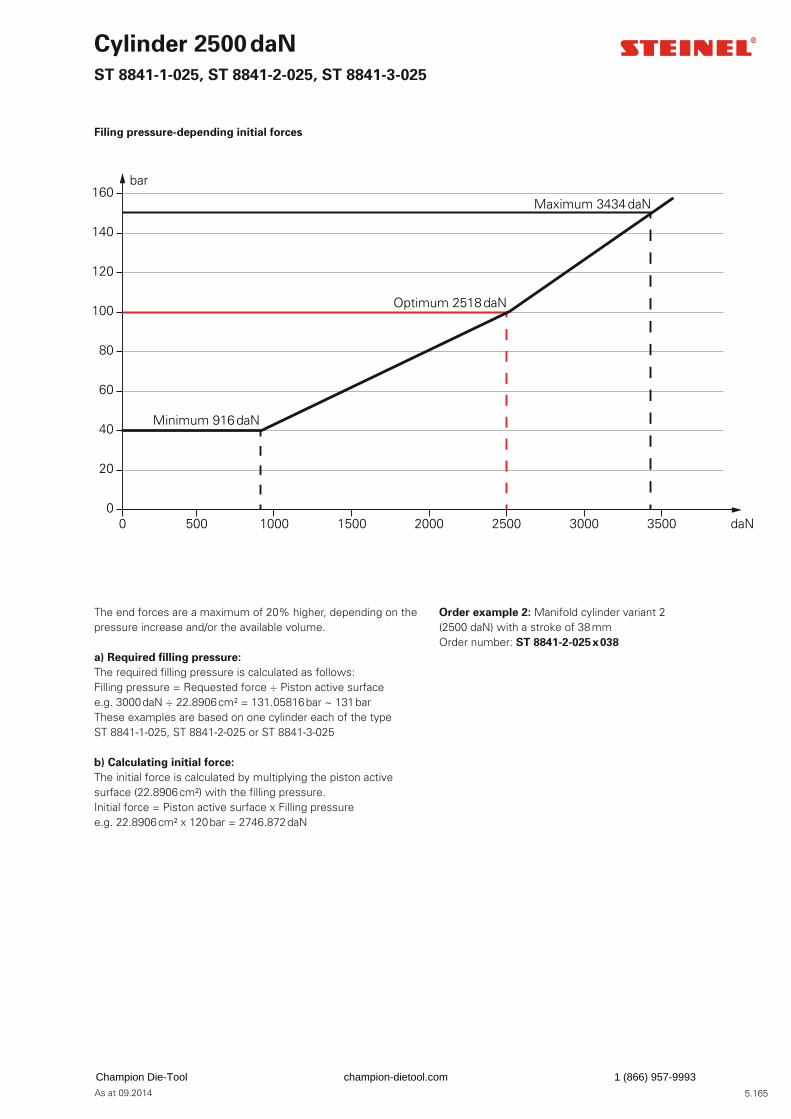
5.165As at 09.2014
The end forces are a maximum of 20% higher, depending on the pressure increase and/or the available volume.
a) Required fi lling pressure:
The required fi lling pressure is calculated as follows: Filling pressure = Requested force ÷ Piston active surfacee.g. 3000 daN ÷ 22.8906 cm² = 131.05816 bar ~ 131 bar These examples are based on one cylinder each of the type ST 8841-1-025, ST 8841-2-025 or ST 8841-3-025
b) Calculating initial force:
The initial force is calculated by multiplying the piston active surface (22.8906 cm²) with the fi lling pressure.Initial force = Piston active surface x Filling pressuree.g. 22.8906 cm² x 120 bar = 2746.872 daN
Order example 2: Manifold cylinder variant 2(2500 daN) with a stroke of 38 mmOrder number: ST 8841-2-025 x 038
Cylinder 2500 daN
ST 8841-1-025, ST 8841-2-025, ST 8841-3-025
Filing pressure-depending initial forces
0
20
40
60
80
100
120
140
160bar
Minimum 916 daN
Optimum 2518 daN
Maximum 3434 daN
0 500 1000 1500 2000 2500 3000 3500 daN
Champion Die-Tool champion-dietool.com 1 (866) 957-9993
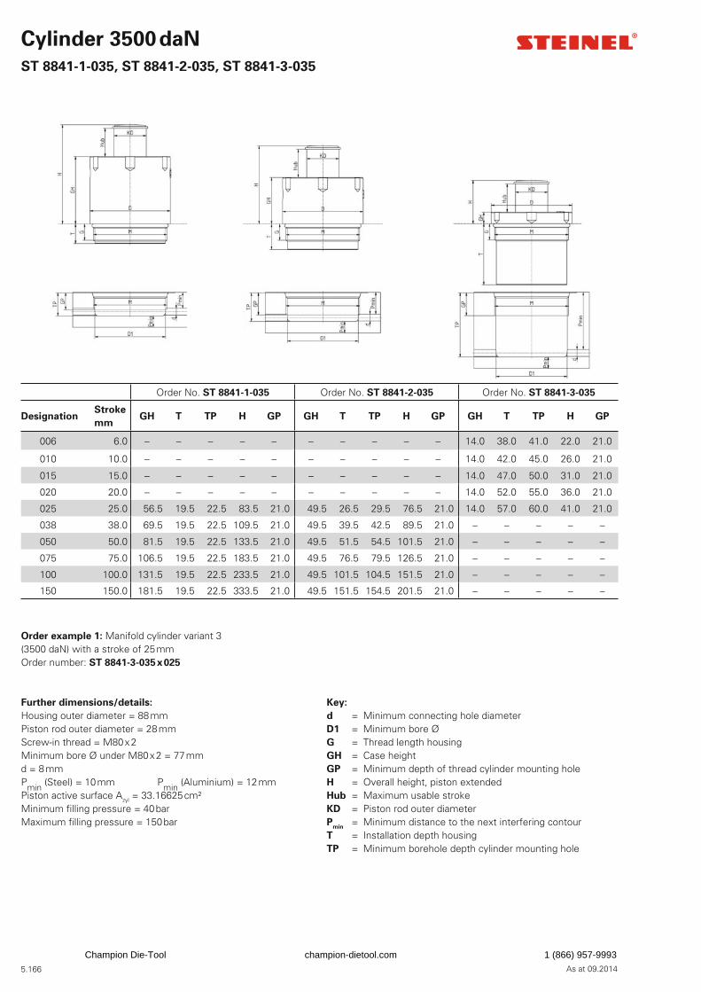
5.166 As at 09.2014
Cylinder 3500 daN
ST 8841-1-035, ST 8841-2-035, ST 8841-3-035
Order No. ST 8841-1-035 Order No. ST 8841-2-035 Order No. ST 8841-3-035
DesignationStroke
mmGH T TP H GP GH T TP H GP GH T TP H GP
006 6.0 – – – – – – – – – – 14.0 38.0 41.0 22.0 21.0
010 10.0 – – – – – – – – – – 14.0 42.0 45.0 26.0 21.0
015 15.0 – – – – – – – – – – 14.0 47.0 50.0 31.0 21.0
020 20.0 – – – – – – – – – – 14.0 52.0 55.0 36.0 21.0
025 25.0 56.5 19.5 22.5 83.5 21.0 49.5 26.5 29.5 76.5 21.0 14.0 57.0 60.0 41.0 21.0
038 38.0 69.5 19.5 22.5 109.5 21.0 49.5 39.5 42.5 89.5 21.0 – – – – –
050 50.0 81.5 19.5 22.5 133.5 21.0 49.5 51.5 54.5 101.5 21.0 – – – – –
075 75.0 106.5 19.5 22.5 183.5 21.0 49.5 76.5 79.5 126.5 21.0 – – – – –
100 100.0 131.5 19.5 22.5 233.5 21.0 49.5 101.5 104.5 151.5 21.0 – – – – –
150 150.0 181.5 19.5 22.5 333.5 21.0 49.5 151.5 154.5 201.5 21.0 – – – – –
Further dimensions/details:
Housing outer diameter = 88 mmPiston rod outer diameter = 28 mmScrew-in thread = M80 x 2Minimum bore Ø under M80 x 2 = 77 mmd = 8 mmPmin (Steel) = 10 mm Pmin (Aluminium) = 12 mmPiston active surface Azyl = 33.16625 cm²Minimum fi lling pressure = 40 barMaximum fi lling pressure = 150 bar
Key:
d = Minimum connecting hole diameter D1 = Minimum bore ØG = Thread length housingGH = Case heightGP = Minimum depth of thread cylinder mounting holeH = Overall height, piston extendedHub = Maximum usable strokeKD = Piston rod outer diameterP
min = Minimum distance to the next interfering contour
T = Installation depth housingTP = Minimum borehole depth cylinder mounting hole
Order example 1: Manifold cylinder variant 3(3500 daN) with a stroke of 25 mmOrder number: ST 8841-3-035 x 025
Champion Die-Tool champion-dietool.com 1 (866) 957-9993
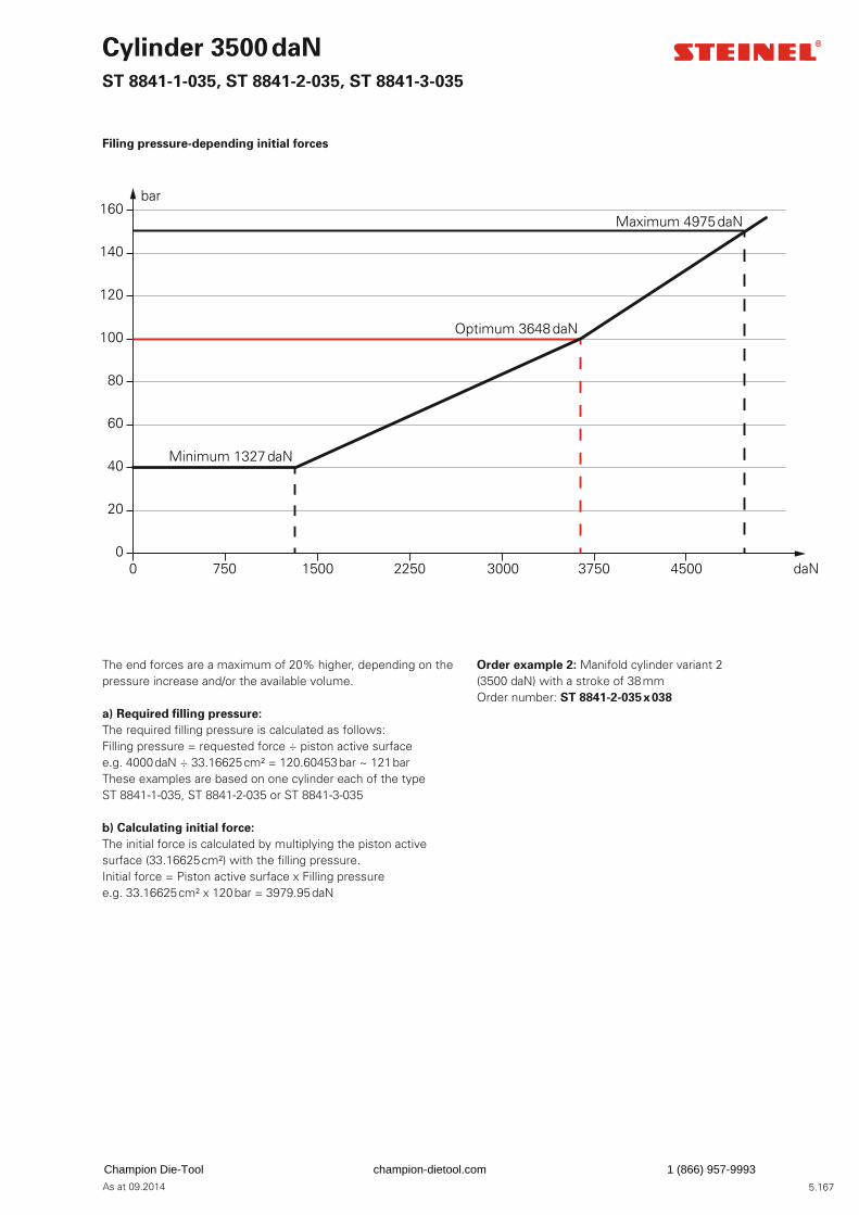
5.167As at 09.2014
The end forces are a maximum of 20% higher, depending on the pressure increase and/or the available volume.
a) Required fi lling pressure:
The required fi lling pressure is calculated as follows: Filling pressure = requested force ÷ piston active surfacee.g. 4000 daN ÷ 33.16625 cm² = 120.60453 bar ~ 121 bar These examples are based on one cylinder each of the type ST 8841-1-035, ST 8841-2-035 or ST 8841-3-035
b) Calculating initial force:
The initial force is calculated by multiplying the piston active surface (33.16625 cm²) with the fi lling pressure.Initial force = Piston active surface x Filling pressuree.g. 33.16625 cm² x 120 bar = 3979.95 daN
Order example 2: Manifold cylinder variant 2(3500 daN) with a stroke of 38 mmOrder number: ST 8841-2-035 x 038
Cylinder 3500 daN
ST 8841-1-035, ST 8841-2-035, ST 8841-3-035
Filing pressure-depending initial forces
0
20
40
60
80
100
120
140
160bar
Minimum 1327 daN
Optimum 3648 daN
Maximum 4975 daN
0 750 1500 2250 3000 3750 4500 daN
Champion Die-Tool champion-dietool.com 1 (866) 957-9993

5.168 As at 09.2014
Cylinder 5500 daN
ST 8841-1-055, ST 8841-2-055, ST 8841-3-055
Order No. ST 8841-1-055 Order No. ST 8841-2-055 Order No. ST 8841-3-055
DesignationStroke
mmGH T TP H GP GH T TP H GP GH T TP H GP
006 6.0 – – – – – – – – – – 14.0 39.5 42.5 22.0 23.0
010 10.0 – – – – – – – – – – 14.0 43.5 46.5 26.0 23.0
015 15.0 – – – – – – – – – – 14.0 48.5 51.5 31.0 23.0
020 20.0 – – – – – – – – – – 14.0 53.5 56.5 36.0 23.0
025 25.0 61.5 25.0 28.0 88.5 23.0 52.5 34.0 37.0 79.5 23.0 14.0 58.5 61.5 41.0 23.0
038 38.0 86.5 25.0 28.0 114.5 23.0 52.5 47.0 50.0 92.5 23.0 – – – – –
050 50.0 86.5 25.0 28.0 138.5 23.0 52.5 59.0 62.0 104.5 23.0 – – – – –
075 75.0 111.5 25.0 28.0 188.5 23.0 52.5 84.0 87.0 129.5 23.0 – – – – –
100 100.0 136.5 25.0 28.0 238.5 23.0 52.5 109.0 112.0 154.5 23.0 – – – – –
150 150.0 186.5 25.0 28.0 338.5 23.0 52.5 159.0 162.0 204.5 23.0 – – – – –
Further dimensions/details:
Housing outer diameter = 108 mmPiston rod outer diameter = 40 mmScrew-in thread = M100 x 2Minimum bore Ø under M100 x 2 = 97 mmd = 12 mmPmin (Steel) = 13 mm Pmin (Aluminium) = 15 mmPiston active surface Azyl = 50.24 cm²Minimum fi lling pressure = 40 barMaximum fi lling pressure = 150 bar
Key:
d = Minimum connecting hole diameter D1 = Minimum bore ØG = Thread length housingGH = Case heightGP = Minimum depth of thread cylinder mounting holeH = Overall height, piston extendedHub = Maximum usable strokeKD = Piston rod outer diameterP
min = Minimum distance to the next interfering contour
T = Installation depth housingTP = Minimum borehole depth cylinder mounting hole
Order example 1: Manifold cylinder variant 3(5500 daN) with a stroke of 6 mmOrder number: ST 8841-3-055 x 006
Champion Die-Tool champion-dietool.com 1 (866) 957-9993

5.169As at 09.2014
The end forces are a maximum of 20% higher, depending on the pressure increase and/or the available volume.
a) Required fi lling pressure:
The required fi lling pressure is calculated as follows: Filling pressure = requested force ÷ piston active surfacee.g. 5000 daN ÷ 50.24 cm² = 99.522293 bar ~ 99,5 bar These examples are based on one cylinder each of the type ST 8841-1-055, ST 8841-2-055 or ST 8841-3-055
b) Calculating initial force:
The initial force is calculated by multiplying the piston active surface (50.24 cm²) with the fi lling pressure.Initial force = piston active surface x fi lling pressuree.g. 50.24 cm² x 120 bar = 6028.8 daN
Order example 2: Manifold cylinder variant 1(5500 daN) with a stroke of 100 mmOrder number: ST 8841-1-055 x 100
Cylinder 5500 daN
ST 8841-1-055, ST 8841-2-055, ST 8841-3-055
Filing pressure-depending initial forces
0
20
40
60
80
100
120
140
160bar
Minimum 2010 daN
Optimum 5526 daN
Maximum 7536 daN
0 1000 3000 4000 5000 6000 70002000 daN
Champion Die-Tool champion-dietool.com 1 (866) 957-9993
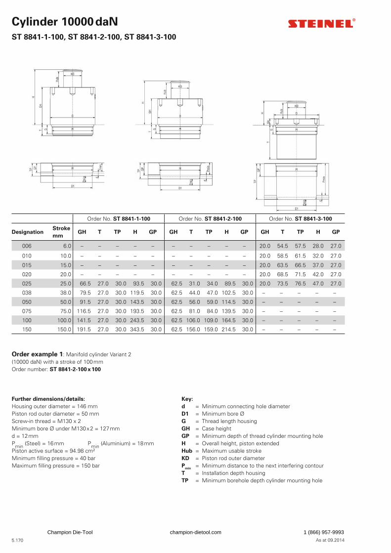
5.170 As at 09.2014
Cylinder 10000 daN
ST 8841-1-100, ST 8841-2-100, ST 8841-3-100
Order No. ST 8841-1-100 Order No. ST 8841-2-100 Order No. ST 8841-3-100
DesignationStroke
mmGH T TP H GP GH T TP H GP GH T TP H GP
006 6.0 – – – – – – – – – – 20.0 54.5 57.5 28.0 27.0
010 10.0 – – – – – – – – – – 20.0 58.5 61.5 32.0 27.0
015 15.0 – – – – – – – – – – 20.0 63.5 66.5 37.0 27.0
020 20.0 – – – – – – – – – – 20.0 68.5 71.5 42.0 27.0
025 25.0 66.5 27.0 30.0 93.5 30.0 62.5 31.0 34.0 89.5 30.0 20.0 73.5 76.5 47.0 27.0
038 38.0 79.5 27.0 30.0 119.5 30.0 62.5 44.0 47.0 102.5 30.0 – – – – –
050 50.0 91.5 27.0 30.0 143.5 30.0 62.5 56.0 59.0 114.5 30.0 – – – – –
075 75.0 116.5 27.0 30.0 193.5 30.0 62.5 81.0 84.0 139.5 30.0 – – – – –
100 100.0 141.5 27.0 30.0 243.5 30.0 62.5 106.0 109.0 164.5 30.0 – – – – –
150 150.0 191.5 27.0 30.0 343.5 30.0 62.5 156.0 159.0 214.5 30.0 – – – – –
Further dimensions/details:
Housing outer diameter = 146 mmPiston rod outer diameter = 50 mmScrew-in thread = M130 x 2Minimum bore Ø under M130 x 2 = 127 mmd = 12 mmPmin (Steel) = 16 mm Pmin (Aluminium) = 18 mmPiston active surface = 94.98 cm²Minimum fi lling pressure = 40 barMaximum fi lling pressure = 150 bar
Key:
d = Minimum connecting hole diameter D1 = Minimum bore ØG = Thread length housingGH = Case heightGP = Minimum depth of thread cylinder mounting holeH = Overall height, piston extendedHub = Maximum usable strokeKD = Piston rod outer diameterP
min = Minimum distance to the next interfering contour
T = Installation depth housingTP = Minimum borehole depth cylinder mounting hole
Order example 1: Manifold cylinder Variant 2(10000 daN) with a stroke of 100 mmOrder number: ST 8841-2-100 x 100
Champion Die-Tool champion-dietool.com 1 (866) 957-9993
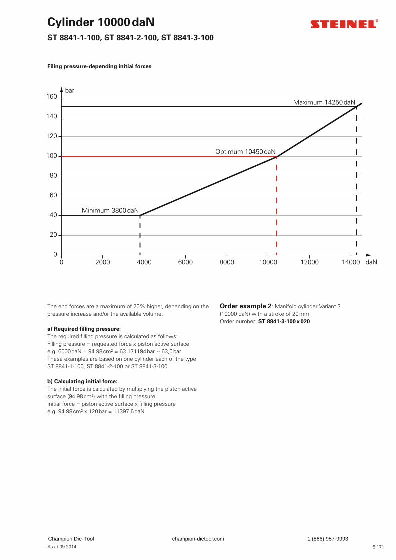
5.171As at 09.2014
The end forces are a maximum of 20% higher, depending on the pressure increase and/or the available volume.
a) Required fi lling pressure:
The required fi lling pressure is calculated as follows: Filling pressure = requested force x piston active surface e.g. 6000 daN ÷ 94.98 cm² = 63.171194 bar ~ 63,0 barThese examples are based on one cylinder each of the type ST 8841-1-100, ST 8841-2-100 or ST 8841-3-100
b) Calculating initial force:
The initial force is calculated by multiplying the piston active surface (94.98 cm²) with the fi lling pressure.Initial force = piston active surface x fi lling pressure e.g. 94.98 cm² x 120 bar = 11397.6 daN
Order example 2: Manifold cylinder Variant 3(10000 daN) with a stroke of 20 mmOrder number: ST 8841-3-100 x 020
Cylinder 10000 daN
ST 8841-1-100, ST 8841-2-100, ST 8841-3-100
Filing pressure-depending initial forces
0
20
40
60
80
100
120
140
160bar
Minimum 3800 daN
Optimum 10450 daN
Maximum 14250 daN
0 2000 4000 6000 8000 10000 12000 14000 daN
Champion Die-Tool champion-dietool.com 1 (866) 957-9993
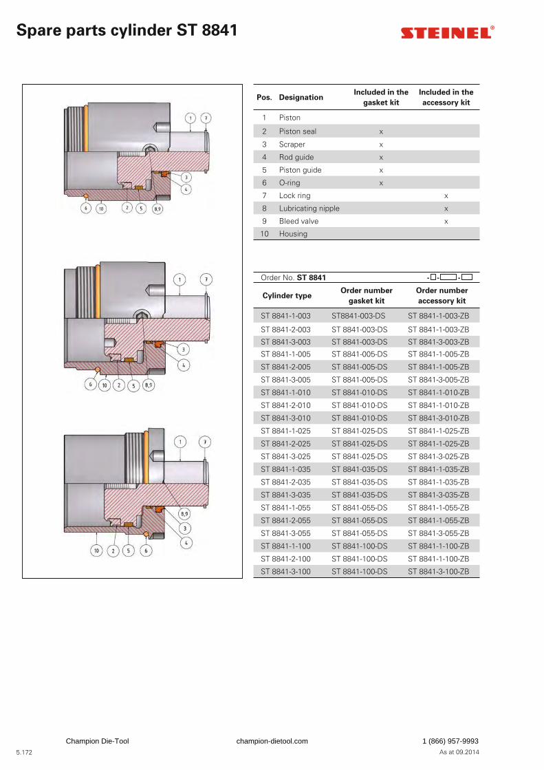
5.172 As at 09.2014
Spare parts cylinder ST 8841
Pos. DesignationIncluded in the
gasket kit
Included in the
accessory kit
1 Piston
2 Piston seal x
3 Scraper x
4 Rod guide x
5 Piston guide x
6 O-ring x
7 Lock ring x
8 Lubricating nipple x
9 Bleed valve x
10 Housing
Order No. ST 8841 - - -
Cylinder typeOrder number
gasket kit
Order number
accessory kit
ST 8841-1-003 ST8841-003-DS ST 8841-1-003-ZB
ST 8841-2-003 ST 8841-003-DS ST 8841-1-003-ZB
ST 8841-3-003 ST 8841-003-DS ST 8841-3-003-ZB
ST 8841-1-005 ST 8841-005-DS ST 8841-1-005-ZB
ST 8841-2-005 ST 8841-005-DS ST 8841-1-005-ZB
ST 8841-3-005 ST 8841-005-DS ST 8841-3-005-ZB
ST 8841-1-010 ST 8841-010-DS ST 8841-1-010-ZB
ST 8841-2-010 ST 8841-010-DS ST 8841-1-010-ZB
ST 8841-3-010 ST 8841-010-DS ST 8841-3-010-ZB
ST 8841-1-025 ST 8841-025-DS ST 8841-1-025-ZB
ST 8841-2-025 ST 8841-025-DS ST 8841-1-025-ZB
ST 8841-3-025 ST 8841-025-DS ST 8841-3-025-ZB
ST 8841-1-035 ST 8841-035-DS ST 8841-1-035-ZB
ST 8841-2-035 ST 8841-035-DS ST 8841-1-035-ZB
ST 8841-3-035 ST 8841-035-DS ST 8841-3-035-ZB
ST 8841-1-055 ST 8841-055-DS ST 8841-1-055-ZB
ST 8841-2-055 ST 8841-055-DS ST 8841-1-055-ZB
ST 8841-3-055 ST 8841-055-DS ST 8841-3-055-ZB
ST 8841-1-100 ST 8841-100-DS ST 8841-1-100-ZB
ST 8841-2-100 ST 8841-100-DS ST 8841-1-100-ZB
ST 8841-3-100 ST 8841-100-DS ST 8841-3-100-ZB
Champion Die-Tool champion-dietool.com 1 (866) 957-9993
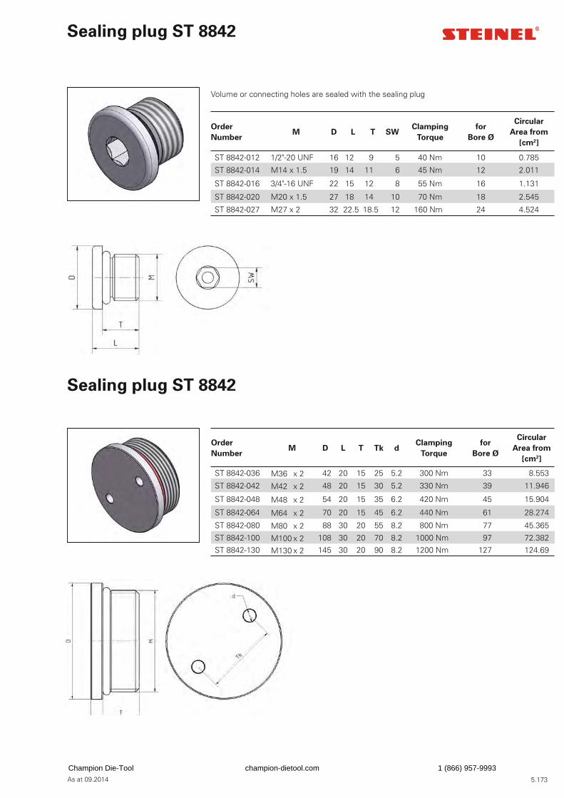
5.173As at 09.2014
Sealing plug ST 8842
Sealing plug ST 8842
Volume or connecting holes are sealed with the sealing plug
Order
NumberM D L T SW
Clamping
Torque
for
Bore Ø
Circular
Area from
[cm2]
ST 8842-012 1/2"-20 UNF 16 12 9 5 40 Nm 10 0.785
ST 8842-014 M14 x 1.5 19 14 11 6 45 Nm 12 2.011
ST 8842-016 3/4"-16 UNF 22 15 12 8 55 Nm 16 1.131
ST 8842-020 M20 x 1.5 27 18 14 10 70 Nm 18 2.545
ST 8842-027 M27 x 2 32 22.5 18.5 12 160 Nm 24 4.524
Order
NumberM D L T Tk d
Clamping
Torque
for
Bore Ø
Circular
Area from
[cm2]
ST 8842-036 M36 x 2 42 20 15 25 5.2 300 Nm 33 8.553
ST 8842-042 M42 x 2 48 20 15 30 5.2 330 Nm 39 11.946
ST 8842-048 M48 x 2 54 20 15 35 6.2 420 Nm 45 15.904
ST 8842-064 M64 x 2 70 20 15 45 6.2 440 Nm 61 28.274
ST 8842-080 M80 x 2 88 30 20 55 8.2 800 Nm 77 45.365
ST 8842-100 M100 x 2 108 30 20 70 8.2 1000 Nm 97 72.382
ST 8842-130 M130 x 2 145 30 20 90 8.2 1200 Nm 127 124.69
Champion Die-Tool champion-dietool.com 1 (866) 957-9993
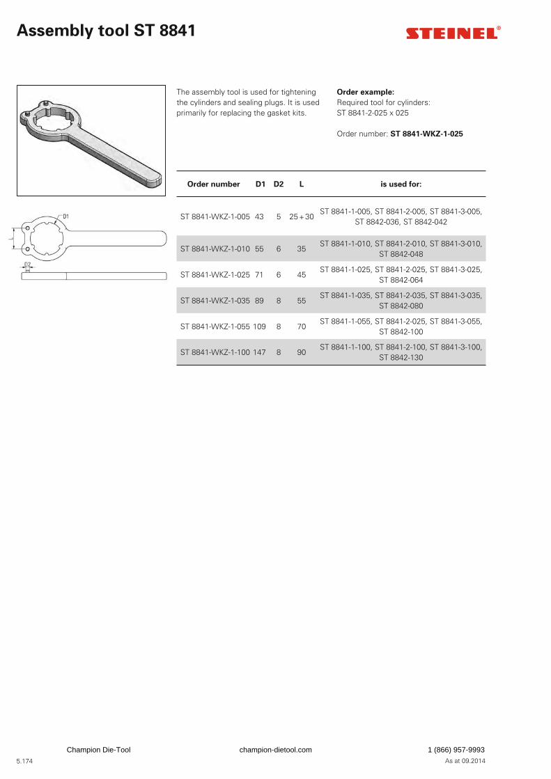
5.174 As at 09.2014
Assembly tool ST 8841
The assembly tool is used for tightening the cylinders and sealing plugs. It is used primarily for replacing the gasket kits.
Order number D1 D2 L is used for:
ST 8841-WKZ-1-005 43 5 25 + 30ST 8841-1-005, ST 8841-2-005, ST 8841-3-005,
ST 8842-036, ST 8842-042
ST 8841-WKZ-1-010 55 6 35ST 8841-1-010, ST 8841-2-010, ST 8841-3-010,
ST 8842-048
ST 8841-WKZ-1-025 71 6 45ST 8841-1-025, ST 8841-2-025, ST 8841-3-025,
ST 8842-064
ST 8841-WKZ-1-035 89 8 55ST 8841-1-035, ST 8841-2-035, ST 8841-3-035,
ST 8842-080
ST 8841-WKZ-1-055 109 8 70ST 8841-1-055, ST 8841-2-025, ST 8841-3-055,
ST 8842-100
ST 8841-WKZ-1-100 147 8 90ST 8841-1-100, ST 8841-2-100, ST 8841-3-100,
ST 8842-130
Order example:
Required tool for cylinders: ST 8841-2-025 x 025
Order number: ST 8841-WKZ-1-025
Champion Die-Tool champion-dietool.com 1 (866) 957-9993
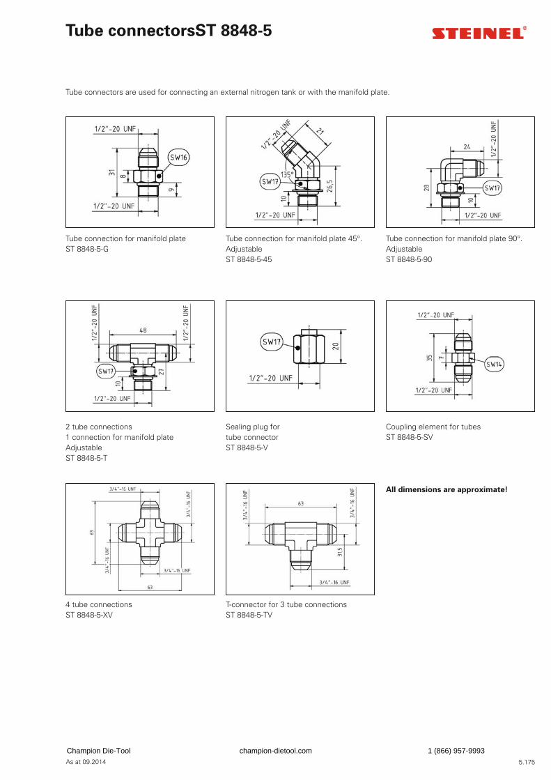
5.175As at 09.2014
Tube connectors ST 8848-5
Tube connectors are used for connecting an external nitrogen tank or with the manifold plate.
Tube connection for manifold plateST 8848-5-G
Tube connection for manifold plate 45°. AdjustableST 8848-5-45
Tube connection for manifold plate 90°. AdjustableST 8848-5-90
All dimensions are approximate!
2 tube connections1 connection for manifold plateAdjustableST 8848-5-T
Sealing plug fortube connectorST 8848-5-V
Coupling element for tubesST 8848-5-SV
4 tube connectionsST 8848-5-XV
T-connector for 3 tube connectionsST 8848-5-TV
Champion Die-Tool champion-dietool.com 1 (866) 957-9993
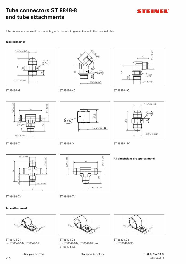
5.176 As at 09.2014
Tube connectors ST 8848-8
and tube attachments
ST 8848-8-G ST 8848-8-45 ST 8848-8-90
ST 8848-8-T ST 8848-8-V ST 8848-8-SV
ST 8848-8-XV ST 8848-8-TV
All dimensions are approximate!
ST 8849-SC1for ST 8849-5-N, ST 8849-5-H
ST 8849-SC2for ST 8849-8-N, ST 8849-8-H andST 8849-5-SS
ST 8849-SC3for ST 8849-8-SS
Tube connector
Tube attachment
Tube connectors are used for connecting an external nitrogen tank or with the manifold plate.
Champion Die-Tool champion-dietool.com 1 (866) 957-9993

5.177As at 09.2014
Tube fi ttings
The press-type tube fi ttings and the tube screw fi ttings are used for normal and extra versions of tubes.
Tubes, tube fi ttings
and tube protection
Tubes
The pressure tubes connect control panels, pressure cylinders and external storage buffers.
Order example:
Special version tubeNominal width 5Length 1200 mmOrder number: ST 8849-5-H x 1200
Tube protection
Since the tube pulsates, ST 8849-5-SS and ST 8849-8-SS are used for tube protection.
Order example:
Tube protection ST 8849-5-SS Length 900mmOrder number: ST 8849-5-SSx0900
ST 8849-5-NMinimum bending radius = 50 mm
ST 8849-8-NMinimum bending radius = 90 mm
Standard version tube suitable for up to 70 °C
ST 8849-5-HMinimum bending radius = 50 mm
ST 8849-8-HMinimum bending radius = 90 mm
Special version tube suitable for up to 100 °C
ST 8849-5-PA ST 8849-8-PA
ST 8849-5-SA ST 8849-8-SA
Tube screw fi ttings
Press-type tube fi ttings
ST 8849-5-SS ST 8849-8-SS
Tube protection
Champion Die-Tool champion-dietool.com 1 (866) 957-9993
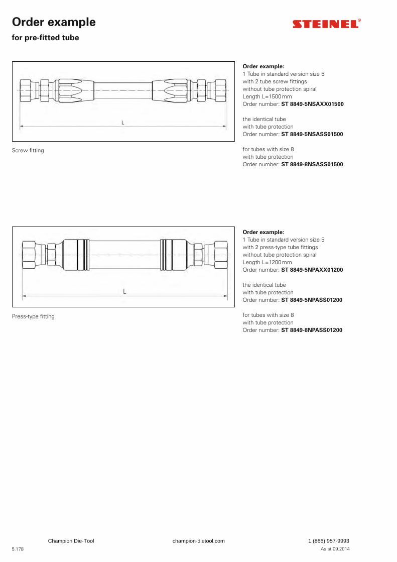
5.178 As at 09.2014
Order example
for pre-fi tted tube
Order example:
1 Tube in standard version size 5with 2 tube screw fi ttingswithout tube protection spiralLength L=1500 mm Order number: ST 8849-5NSAXX01500
the identical tubewith tube protectionOrder number: ST 8849-5NSASS01500
for tubes with size 8with tube protectionOrder number: ST 8849-8NSASS01500
Order example:
1 Tube in standard version size 5with 2 press-type tube fi ttingswithout tube protection spiralLength L=1200 mm Order number: ST 8849-5NPAXX01200
the identical tubewith tube protectionOrder number: ST 8849-5NPASS01200
for tubes with size 8with tube protectionOrder number: ST 8849-8NPASS01200
Screw fi tting
Press-type fi tting
Champion Die-Tool champion-dietool.com 1 (866) 957-9993
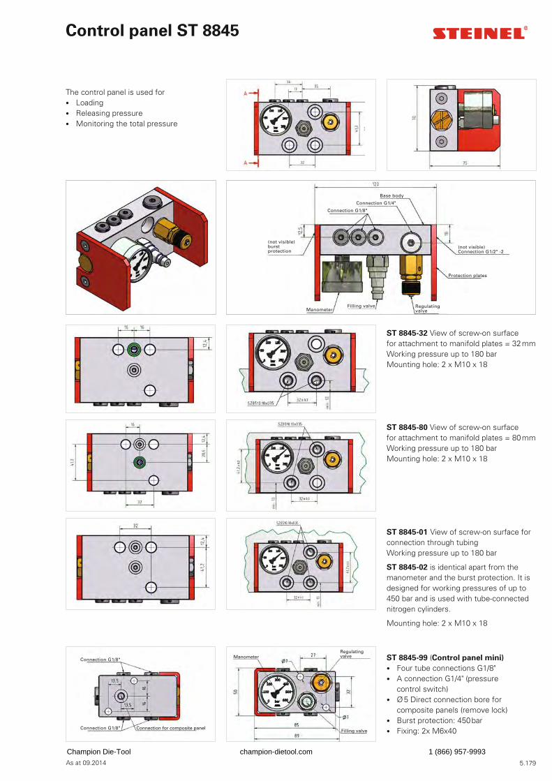
5.179As at 09.2014
Control panel ST 8845
The control panel is used for • Loading • Releasing pressure • Monitoring the total pressure
ST 8845-32 View of screw-on surface for attachment to manifold plates = 32 mmWorking pressure up to 180 barMounting hole: 2 x M10 x 18
ST 8845-80 View of screw-on surface for attachment to manifold plates = 80 mmWorking pressure up to 180 barMounting hole: 2 x M10 x 18
ST 8845-99 (Control panel mini)
• Four tube connections G1/8" • A connection G1/4" (pressure
control switch) • Ø 5 Direct connection bore for
composite panels (remove lock) • Burst protection: 450 bar • Fixing: 2x M6x40
ST 8845-01 View of screw-on surface for connection through tubing Working pressure up to 180 bar
ST 8845-02 is identical apart from the manometer and the burst protection. It is designed for working pressures of up to 450 bar and is used with tube-connected nitrogen cylinders.
Mounting hole: 2 x M10 x 18
Base body
Connection G1/8"
Connection G1/4"
(not visible) burst protection
Regulating valve
(not visible)Connection G1/2" -2
Protection plates
Connection G1/8"
Regulating valveManometer
Filling valveConnection G1/8" Connection for composite panel
Filling valveManometer
Champion Die-Tool champion-dietool.com 1 (866) 957-9993
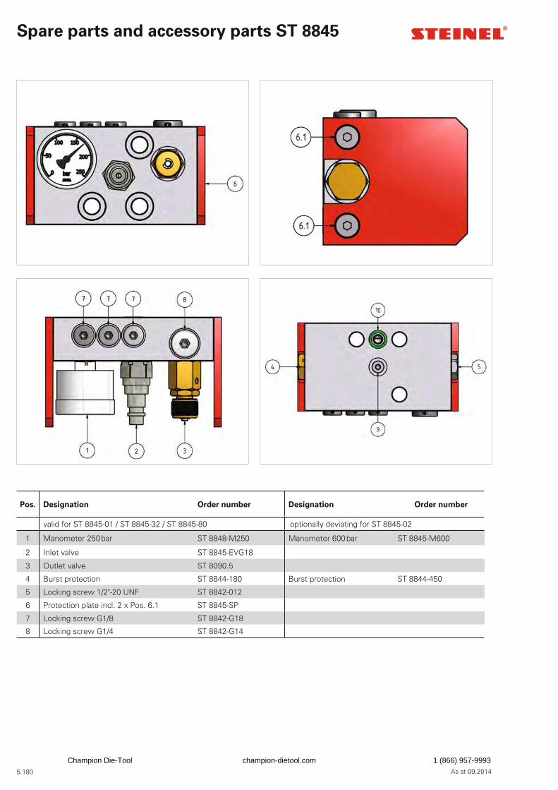
5.180 As at 09.2014
Spare parts and accessory parts ST 8845
Pos. Designation Order number Designation Order number
valid for ST 8845-01 / ST 8845-32 / ST 8845-80 optionally deviating for ST 8845-02
1 Manometer 250 bar ST 8848-M250 Manometer 600 bar ST 8845-M600
2 Inlet valve ST 8845-EVG18
3 Outlet valve ST 8090.5
4 Burst protection ST 8844-180 Burst protection ST 8844-450
5 Locking screw 1/2"-20 UNF ST 8842-012
6 Protection plate incl. 2 x Pos. 6.1 ST 8845-SP
7 Locking screw G1/8 ST 8842-G18
8 Locking screw G1/4 ST 8842-G14
Champion Die-Tool champion-dietool.com 1 (866) 957-9993
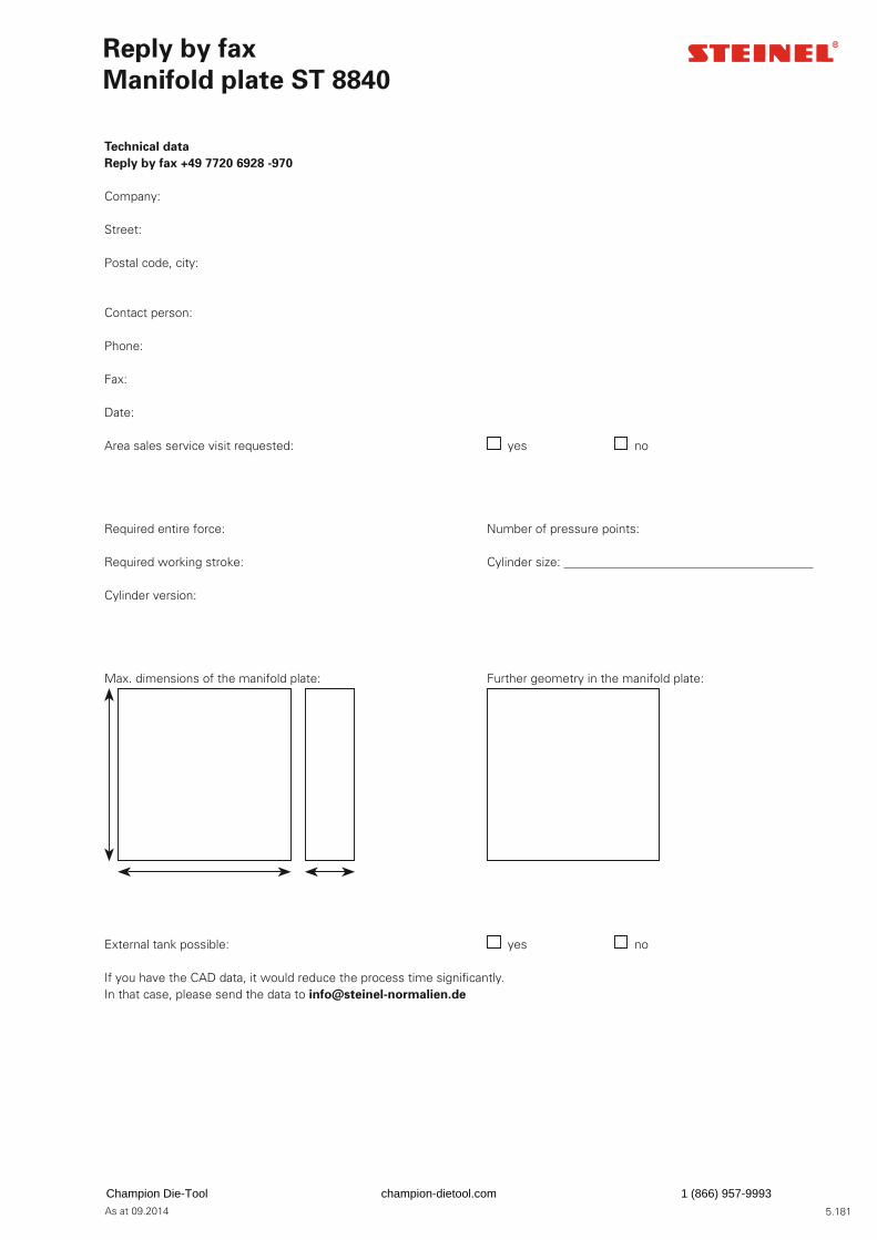
5.181As at 09.2014
Technical data
Reply by fax +49 7720 6928 -970
Company:
Street:
Postal code, city:
Contact person:
Phone:
Fax:
Date:
Area sales service visit requested: yes no
Required entire force: Number of pressure points:
Required working stroke: Cylinder size:
Cylinder version:
Max. dimensions of the manifold plate: Further geometry in the manifold plate:
External tank possible: yes no
If you have the CAD data, it would reduce the process time signifi cantly.In that case, please send the data to [email protected]
Reply by fax
Manifold plate ST 8840
Champion Die-Tool champion-dietool.com 1 (866) 957-9993

5.182 As at 09.2014
Project manager
Project management tool technology
Our subsidiary
Switzerland
Area sales service in Germany
Project management / project support
Gerd Roggatz
Winkelstraße 778056 Villingen-SchwenningenPhone +49 7720 6928-956Fax +49 7720 [email protected]
Hubert Schuhmacher (34)
78588 DenkingenPhone +49 7720 6928-684Fax +49 7720 6928-8684Mobile +49 175 [email protected]
Lothar Weisbach (29)
09395 HormersdorfPhone +49 7720 6928-683Fax +49 7720 6928-8683Mobile +49 171 [email protected]
Christoph Sigg (20)
72622 Nürtingen-ReudernPhone +49 7720 6928-688Fax +49 7720 6928-8688Mobile +49 175 [email protected]
SUVAG Vertriebs AG
Rothusstrasse 17CH-6331 HünenbergPhone +41 44 3 2147-47Fax +41 44 3 [email protected]
Uwe Albrecht (42)
96237 EbersdorfPhone +49 7720 6928-680Fax +49 7720 6928-8680Mobile +49 160 [email protected]
Harald Gotzler (46)
83620 VagenPhone +49 7720 6928-682Fax +49 7720 6928-8682Mobile +49 160 97246014 [email protected]
Ronald Baiker (38)
72186 Empfi ngenPhone +49 7720 6928-686Fax +49 7720 6928-8686Mobile +49 171 [email protected]
STEINEL Normalien AG (28)
Winkelstraße 778056 Villingen-SchwenningenPhone +49 7720 [email protected]
Marc Pakirnus (17)
58513 LüdenscheidPhone +49 7720 6928-687Fax +49 7720 6928-8687Mobile +49 171 [email protected]
STEINEL Normalien AG (11)
Winkelstraße 778056 Villingen-SchwenningenPhone +49 7720 [email protected]
Stephan Jaschusch
Buckesfelder Straße 10158509 LüdenscheidPhone +49 2351 9741-944Fax +49 7720 6828-8685Mobile +49 171 [email protected]
Champion Die-Tool champion-dietool.com 1 (866) 957-9993
5.183As at 09.2014
STEINEL Normalien AG
Winkelstraße 778056 Villingen-SchwenningenGermanyPhone +49 7720 6928-0Fax +49 7720 [email protected]
We assume no liability for misprints and errors. Progress brings with it improvements as well as changes to design, dimensions and materials. We therefore reserve the right to make technical changes. Copyright STEINEL Normalien AG
Contact
Champion Die-Tool champion-dietool.com 1 (866) 957-9993
5.184 As at 09.2014
Champion Die-Tool champion-dietool.com 1 (866) 957-9993
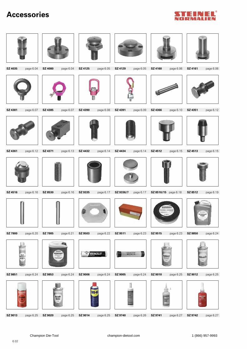
Accessories
SZ 9013 page 6.25 SZ 9020 page 6.25 SZ 9014 page 6.25 SZ 9740 page 6.26 SZ 9741 page 6.27 SZ 9742 page 6.27
SZ 9851 page 6.24 SZ 9853 page 6.24 SZ 9006 page 6.24 SZ 9005 page 6.24 SZ 9010 page 6.25 SZ 9012 page 6.25
SZ 7900 page 6.20 SZ 7905 page 6.21 SZ 9503 page 6.22 SZ 9511 page 6.23 SZ 9515 page 6.23 SZ 9850 page 6.24
SZ 4516 page 6.16 SZ 8530 page 6.16 SZ 9335 page 6.17 SZ 9336/7 page 6.17 SZ 8510/15 page 6.18 SZ 8512 page 6.19
SZ 4361 page 6.12 SZ 4371 page 6.13 SZ 4432 page 6.14 SZ 4434 page 6.14 SZ 4512 page 6.15 SZ 4513 page 6.15
SZ 4381 page 6.07 SZ 4385 page 6.07 SZ 4390 page 6.08 SZ 4391 page 6.09 SZ 4366 page 6.10 SZ 4351 page 6.12
SZ 4035 page 6.04 SZ 4080 page 6.04 SZ 4125 page 6.05 SZ 4129 page 6.05 SZ 4160 page 6.06 SZ 4161 page 6.06
6.02
Champion Die-Tool champion-dietool.com 1 (866) 957-9993
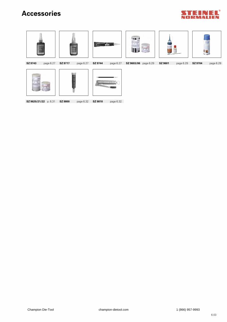
Accessories
SZ 9620/21/22 p. 6.31 SZ 9800 page 6.32 SZ 9810 page 6.32
SZ 9743 page 6.27 SZ 9717 page 6.27 SZ 9744 page 6.27 SZ 9603/06 page 6.29 SZ 9601 page 6.29 SZ 9704 page 6.29
6.03
Champion Die-Tool champion-dietool.com 1 (866) 957-9993
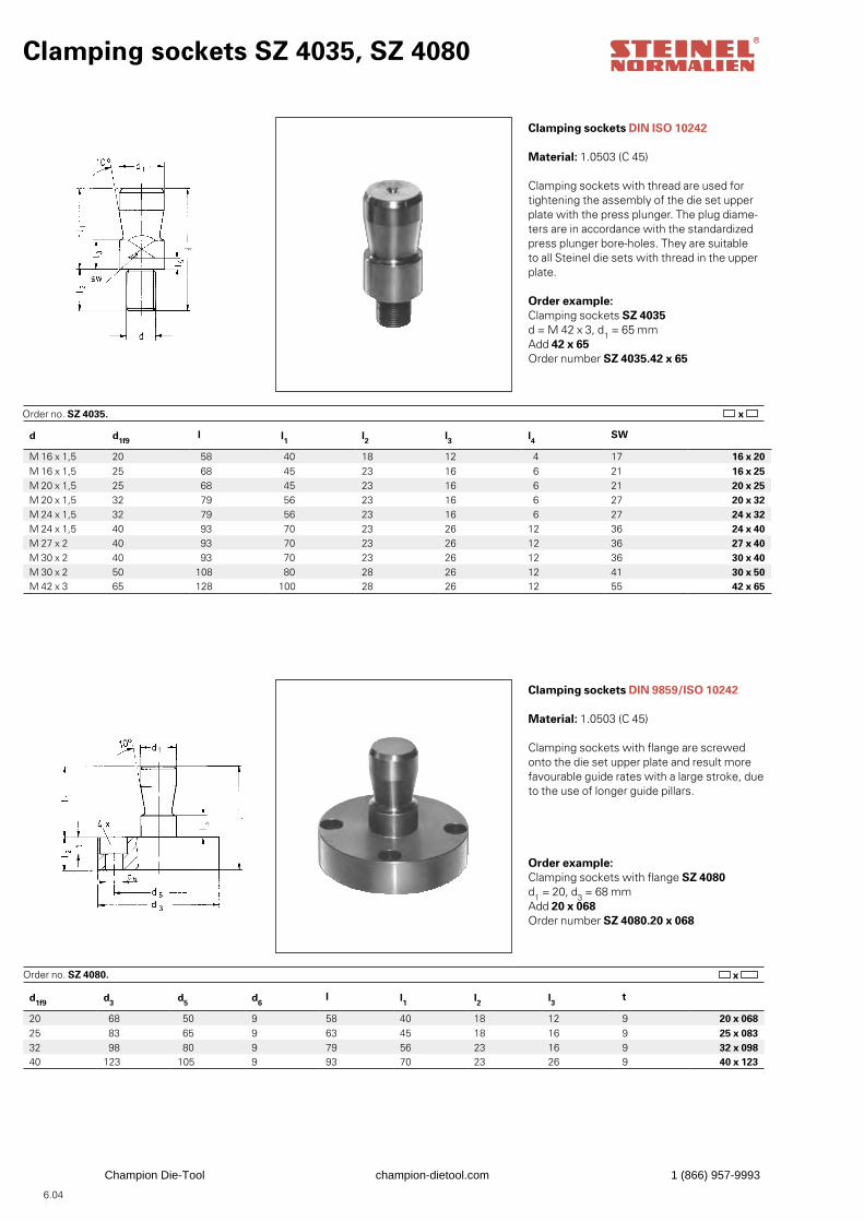
d1f9 d3 d5 d6l l1 l2 l3 t
20 68 50 9 58 40 18 12 9 20 x 06825 83 65 9 63 45 18 16 9 25 x 08332 98 80 9 79 56 23 16 9 32 x 09840 123 105 9 93 70 23 26 9 40 x 123
d d1f9 l l1 l2 l3 l4 SW
M 16 x 1,5 20 58 40 18 12 4 17 16 x 20M 16 x 1,5 25 68 45 23 16 6 21 16 x 25M 20 x 1,5 25 68 45 23 16 6 21 20 x 25M 20 x 1,5 32 79 56 23 16 6 27 20 x 32M 24 x 1,5 32 79 56 23 16 6 27 24 x 32M 24 x 1,5 40 93 70 23 26 12 36 24 x 40M 27 x 2 40 93 70 23 26 12 36 27 x 40M 30 x 2 40 93 70 23 26 12 36 30 x 40M 30 x 2 50 108 80 28 26 12 41 30 x 50M 42 x 3 65 128 100 28 26 12 55 42 x 65
Clamping sockets SZ 4035, SZ 4080
Clamping sockets DIN ISO 10242
Material: 1.0503 (C 45)
Clamping sockets with thread are used fortightening the assembly of the die set upperplate with the press plunger. The plug diame-ters are in accordance with the standardized press plunger bore-holes. They are suitable to all Steinel die sets with thread in the upper plate.
Order example:Clamping sockets SZ 4035d = M 42 x 3, d1 = 65 mmAdd 42 x 65Order number SZ 4035.42 x 65
Order no. SZ 4035.
Clamping sockets DIN 9859/ISO 10242
Material: 1.0503 (C 45)
Clamping sockets with flange are screwed onto the die set upper plate and result more favourable guide rates with a large stroke, due to the use of longer guide pillars.
Order example: Clamping sockets with flange SZ 4080d1 = 20, d3 = 68 mmAdd 20 x 068Order number SZ 4080.20 x 068
Order no. SZ 4080.
6.04
x
x
Champion Die-Tool champion-dietool.com 1 (866) 957-9993
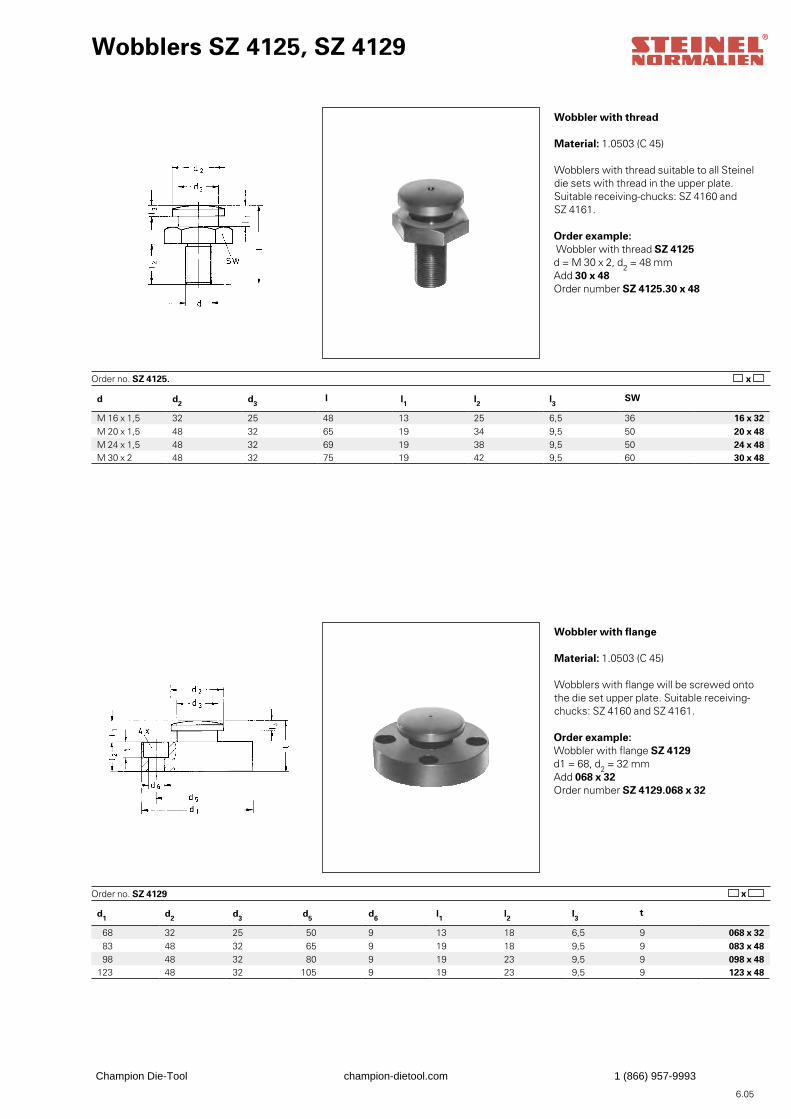
d1 d2 d3 d5 d6 l1 l2 l3 t
68 32 25 50 9 13 18 6,5 9 068 x 32 83 48 32 65 9 19 18 9,5 9 083 x 48 98 48 32 80 9 19 23 9,5 9 098 x 48
123 48 32 105 9 19 23 9,5 9 123 x 48
d d2 d3 l l1 l2 l3 SW
M 16 x 1,5 32 25 48 13 25 6,5 36 16 x 32M 20 x 1,5 48 32 65 19 34 9,5 50 20 x 48M 24 x 1,5 48 32 69 19 38 9,5 50 24 x 48M 30 x 2 48 32 75 19 42 9,5 60 30 x 48
Wobblers SZ 4125, SZ 4129
Wobbler with thread
Material: 1.0503 (C 45)
Wobblers with thread suitable to all Steineldie sets with thread in the upper plate. Suitable receiving-chucks: SZ 4160 and SZ 4161.
Order example: Wobbler with thread SZ 4125d = M 30 x 2, d2 = 48 mmAdd 30 x 48Order number SZ 4125.30 x 48
Order no. SZ 4125.
Wobbler with flange
Material: 1.0503 (C 45)
Wobblers with flange will be screwed ontothe die set upper plate. Suitable receiving-chucks: SZ 4160 and SZ 4161.
Order example: Wobbler with flange SZ 4129d1 = 68, d2 = 32 mmAdd 068 x 32Order number SZ 4129.068 x 32
Order no. SZ 4129
6.05
x
x
Champion Die-Tool champion-dietool.com 1 (866) 957-9993
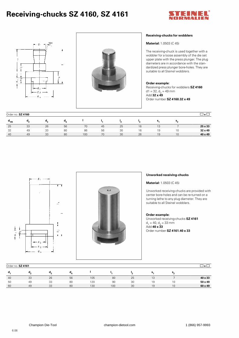
d1 d2 d3 d4l l1 l2 s1 s2
40 33 26 56 105 80 25 13 7 40 x 3350 49 33 80 120 90 30 19 10 50 x 4960 49 33 80 130 100 30 19 10 60 x 49
d1f9 d2 d3 d4l l1 l2 l3 s1 s2
25 33 26 56 70 45 25 16 13 7 25 x 3332 49 33 80 86 56 30 16 19 10 32 x 4940 49 33 80 100 70 30 26 19 10 40 x 49
Receiving-chucks SZ 4160, SZ 4161
Receiving-chucks for wobblers
Material: 1.0503 (C 45)
The receiving-chuck is used together with awobbler for a loose assembly of the die setupper plate with the press plunger. The plugdiameters are in accordance with the stan-dardized press plunger bore-holes. They are suitable to all Steinel wobblers.
Order example: Receiving-chucks for wobblers SZ 4160d1 = 32, d2 = 49 mmAdd 32 x 49Order number SZ 4160.32 x 49
Order no. SZ 4160
Unworked receiving-chucks
Material: 1.0503 (C 45)
Unworked receiving-chucks are provided withcenter bore-holes and can be re-turned on aturning lathe to any plug diameter. They aresuitable to all Steinel wobblers.
Order example:Unworked receiving-chucks SZ 4161d1 = 40, d2 = 33 mmAdd 40 x 33Order number SZ 4161.40 x 33
Order no. SZ 4161
6.06
x
x
Champion Die-Tool champion-dietool.com 1 (866) 957-9993
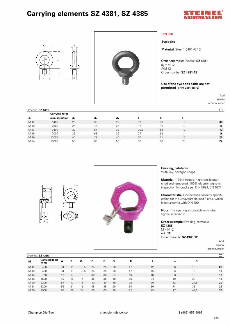
M Carrying loadin kg A B C D E G K L n S
M 8 400 34 11 8,5 25 25 28 47 12 6 16 08M 10 400 34 11 8,5 25 25 28 47 15 6 15 10M 12 750 42 13 10 30 30 34 56 18 8 18 12M 16 1500 49 15 14 35 35 40 65 24 10 22 16M 20 2300 57 17 16 40 40 50 75 30 12 27,5 20M 24 3200 69 21 19 48 48 60 90 36 14 33 24M 30 4500 86 26 24 60 60 75 112 45 17 41,5 30
Carrying force
d1 axial direction d2 d3 d4 l h k
M 8 1400 20 36 20 13 36 8 08M 10 2300 25 45 25 17 45 10 10M 12 3400 30 54 30 20,5 53 12 12M 16 7000 35 63 35 27 62 14 16M 20 12000 40 72 40 30 71 16 20M 24 18000 50 90 50 36 90 20 24
Carrying elements SZ 4381, SZ 4385
DIN 580
Eye bolts
Material: Steel 1.0401 (C 15)
Order example: Eye bolt SZ 4381d1 = M 12Add 12Order number SZ 4381.12
Order no. SZ 4381
Eye ring, rotatableWith key, hexagon shape
Material: 1.6541 forged, high-tensile quen-ched and tempered. 100% electromagnetic inspection for cracks per DIN 5691, EN 1677
Characteristic: Distinct load capacity specifi-cation for the unfavourable load F area, which is not allowed with DIN 580.
Note: The eye ring is rotatable only when tightly screwed in.
Order example: Eye ring, rotatableSZ 4385M = M12Add 12Order number: SZ 4385.12
Order no. SZ 4385.
Addsize to
order number
Addsize to
order number
6.07
Use of the eye bolts aside are notpermitted (only vertically)
Champion Die-Tool champion-dietool.com 1 (866) 957-9993
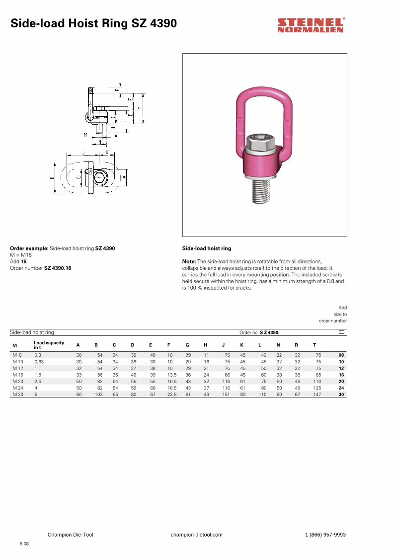
M Load capacityin t A B C D E F G H J K L N R T
M 8 0,3 30 54 34 35 40 10 29 11 75 45 40 32 32 75 08M 10 0,63 30 54 34 36 39 10 29 16 75 45 45 32 32 75 10M 12 1 32 54 34 37 38 10 29 21 75 45 50 32 32 75 12M 16 1,5 33 56 36 46 39 13,5 36 24 86 45 60 38 38 85 16M 20 2,5 50 82 54 55 55 16,5 43 32 116 61 75 50 48 110 20M 24 4 50 82 54 58 66 16,5 43 37 116 61 80 50 48 125 24M 30 5 60 103 65 80 67 22,5 61 49 151 80 110 60 67 147 30
Side-load Hoist Ring SZ 4390
Side-load hoist ring
Note: The side-load hoist ring is rotatable from all directions, collapsible and always adjusts itself to the direction of the load. It carries the full load in every mounting position. The included screw is held secure within the hoist ring, has a minimum strength of a 8.8 and is 100 % inspected for cracks.
Order example: Side-load hoist ring SZ 4390M = M16Add 16Order number SZ 4390.16
Order no. S Z 4390.Side-load hoist ring
Addsize to
order number
6.08
Champion Die-Tool champion-dietool.com 1 (866) 957-9993
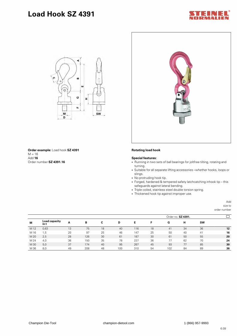
M Load capacityin t A B C D E F G H SW
M 12 0,63 13 75 18 40 116 18 41 34 36 12M 16 1,5 20 97 25 46 147 25 50 40 41 16M 20 2,5 28 126 30 61 187 30 61 50 55 20M 24 4,0 36 150 35 78 227 36 77 62 70 24M 30 5,0 37 174 40 95 267 45 93 77 85 30M 36 8,0 49 208 48 100 310 54 102 84 89 36
Load Hook SZ 4391
Rotating load hook
Special features:• Running in two sets of ball bearings for joltfree tilting, rotating and turning.• Suitable for all separate lifting accessories –whether hooks, loops or slings.• No protruding hook tip.• Forged, hardened & tempered safety latchcatching inhook tip – this safeguards against lateral bending.• Triple coiled, stainless steel double torsion spring.• Thickened hook tip against improper use.
Order example: Load hook SZ 4391M = 16Add 16Order number SZ 4391.16
Order no. SZ 4391.
Addsize to
order number
6.09
AB
C
D
E
GF
H
SWM
Champion Die-Tool champion-dietool.com 1 (866) 957-9993
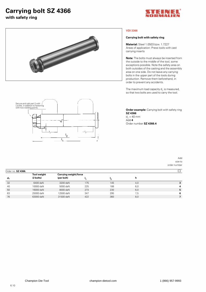
6.10
Tool weight Carrying weight/forced1 (2 bolts) (per bolt) l1 l2 h
32 6400 daN 3200 daN 175 145 4,0 340 10000 daN 5000 daN 225 188 6,0 450 16000 daN 8000 daN 273 230 6,0 563 25000 daN 12500 daN 347 295 7,5 676 63000 daN 31500 daN 422 360 8,0 7
Carrying bolt SZ 4366with safety ring
VDI 3366
Carrying bolt with safety ring
Material: Steel 1.0503 bzw. 1.7227Areas of application: Press tools with castcarrying inserts
Note: The bolts must always be inserted from the outside to the middle of the tool, some exceptions possible. Note the safety area on both outsides of the casting and the assembly area on one side. Do not leave any carrying bolts in the upper part of the tools during production. Remove them beforehand, in order to prevent any accidents.
The maximum load capacity d1 is measured,so that two bolts are used to carry the tool.
Order example: Carrying bolt with safety ringSZ 4366d1 = 40 mmAdd 4Order number SZ 4366.4
Order no. SZ 4366.
Addsize to
order number
Secure and calk part 2 withLoctite, in addition to fasteningwith two welding points.
d1
h
I2I1
Champion Die-Tool champion-dietool.com 1 (866) 957-9993

6.11
Champion Die-Tool champion-dietool.com 1 (866) 957-9993
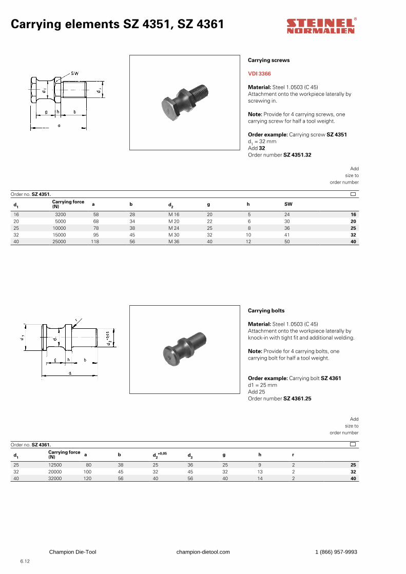
6.12
d1Carrying force (N) a b d2
+0,05 d3g h r
25 12500 80 38 25 36 25 9 2 2532 20000 100 45 32 45 32 13 2 3240 32000 120 56 40 56 40 14 2 40
d1Carrying force (N) a b d2
g h SW
16 3200 58 28 M 16 20 5 24 1620 5000 68 34 M 20 22 6 30 2025 10000 78 38 M 24 25 8 36 2532 15000 95 45 M 30 32 10 41 3240 25000 118 56 M 36 40 12 50 40
Carrying elements SZ 4351, SZ 4361
Carrying screws
VDI 3366
Material: Steel 1.0503 (C 45)Attachment onto the workpiece laterally byscrewing in.
Note: Provide for 4 carrying screws, onecarrying screw for half a tool weight.
Order example: Carrying screw SZ 4351d1 = 32 mmAdd 32Order number SZ 4351.32
Order no. SZ 4351.
Addsize to
order number
Carrying bolts
Material: Steel 1.0503 (C 45)Attachment onto the workpiece laterally byknock-in with tight fit and additional welding.
Note: Provide for 4 carrying bolts, onecarrying bolt for half a tool weight.
Order example: Carrying bolt SZ 4361d1 = 25 mmAdd 25Order number SZ 4361.25
Order no. SZ 4361.
Addsize to
order number
Champion Die-Tool champion-dietool.com 1 (866) 957-9993
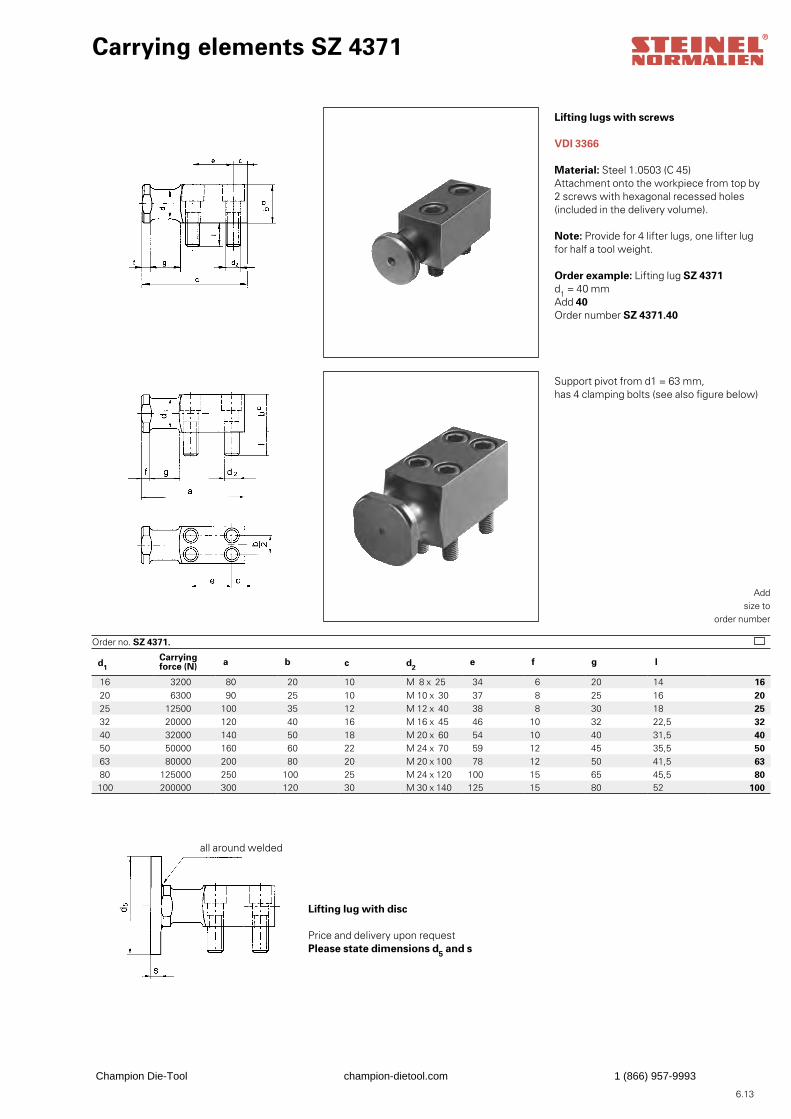
6.13
d1Carrying force (N) a b c d2
e f g l
16 3200 80 20 10 M 8 x 25 34 6 20 14 16 20 6300 90 25 10 M 10 x 30 37 8 25 16 20 25 12500 100 35 12 M 12 x 40 38 8 30 18 25 32 20000 120 40 16 M 16 x 45 46 10 32 22,5 32 40 32000 140 50 18 M 20 x 60 54 10 40 31,5 40 50 50000 160 60 22 M 24 x 70 59 12 45 35,5 50 63 80000 200 80 20 M 20 x 100 78 12 50 41,5 63 80 125000 250 100 25 M 24 x 120 100 15 65 45,5 80100 200000 300 120 30 M 30 x 140 125 15 80 52 100
Carrying elements SZ 4371
Lifting lugs with screws
VDI 3366
Material: Steel 1.0503 (C 45)Attachment onto the workpiece from top by2 screws with hexagonal recessed holes(included in the delivery volume).
Note: Provide for 4 lifter lugs, one lifter lugfor half a tool weight.
Order example: Lifting lug SZ 4371d1 = 40 mmAdd 40Order number SZ 4371.40
Order no. SZ 4371.
Addsize to
order number
all around welded
Lifting lug with disc
Price and delivery upon requestPlease state dimensions d5 and s
Support pivot from d1 = 63 mm, has 4 clamping bolts (see also figure below)
Champion Die-Tool champion-dietool.com 1 (866) 957-9993
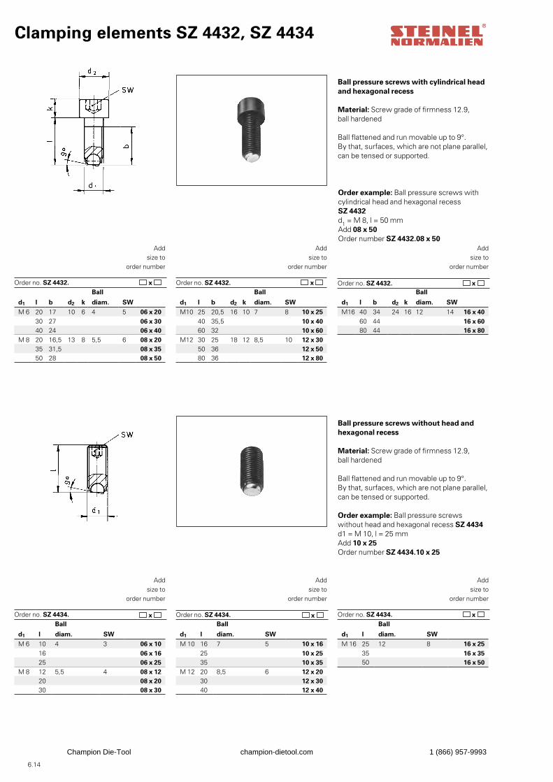
6.14
Clamping elements SZ 4432, SZ 4434
Ball pressure screws with cylindrical headand hexagonal recess
Material: Screw grade of firmness 12.9,ball hardened
Ball flattened and run movable up to 9°.By that, surfaces, which are not plane parallel,can be tensed or supported.
Order example: Ball pressure screws withcylindrical head and hexagonal recess SZ 4432d1 = M 8, l = 50 mmAdd 08 x 50Order number SZ 4432.08 x 50
Order no. SZ 4432.
Addsize to
order number
Ball pressure screws without head andhexagonal recess
Material: Screw grade of firmness 12.9,ball hardened
Ball flattened and run movable up to 9°.By that, surfaces, which are not plane parallel,can be tensed or supported.
Order example: Ball pressure screws without head and hexagonal recess SZ 4434d1 = M 10, l = 25 mmAdd 10 x 25Order number SZ 4434.10 x 25
Order no. SZ 4434.
Addsize to
order number
Addsize to
order number
Addsize to
order number
Order no. SZ 4432.Order no. SZ 4432.
Order no. SZ 4434.
Addsize to
order number
Order no. SZ 4434.
Addsize to
order number
Ball
d1 l b d2 k diam. SWM 6 20 17 10 6 4 5 06 x 20
30 27 06 x 3040 24 06 x 40
M 8 20 16,5 13 8 5,5 6 08 x 2035 31,5 08 x 3550 28 08 x 50
Ball
d1 l b d2 k diam. SWM10 25 20,5 16 10 7 8 10 x 25
40 35,5 10 x 4060 32 10 x 60
M12 30 25 18 12 8,5 10 12 x 3050 36 12 x 5080 36 12 x 80
Ball
d1 l b d2 k diam. SWM16 40 34 24 16 12 14 16 x 40
60 44 16 x 6080 44 16 x 80
Ball
d1 l diam. SWM 6 10 4 3 06 x 10
16 06 x 1625 06 x 25
M 8 12 5,5 4 08 x 1220 08 x 2030 08 x 30
Ball
d1 l diam. SWM 10 16 7 5 10 x 16
25 10 x 2535 10 x 35
M 12 20 8,5 6 12 x 2030 12 x 3040 12 x 40
Ball
d1 l diam. SWM 16 25 12 8 16 x 25
35 16 x 3550 16 x 50
x x x
x x x
Champion Die-Tool champion-dietool.com 1 (866) 957-9993
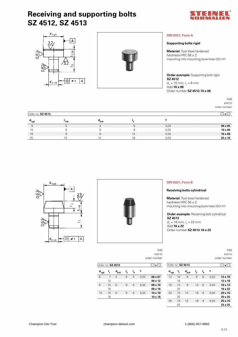
6.15
d1g6 l1h9 d2n6 l2 t
6 5 4 6 0,02 06 x 0510 6 6 9 0,02 10 x 0616 8 8 12 0,04 16 x 0825 10 12 18 0,04 25 x 10
Receiving and supporting boltsSZ 4512, SZ 4513
DIN 6321, Form A
Supporting bolts rigid
Material: Tool steel hardenedhardness HRC 56 ± 2mounting into mounting bore-hole ISO H7
Order example: Supporting bolt rigidSZ 4512d1 = 10 mm, l1 = 6 mmAdd 10 x 06Order number SZ 4512.10 x 06
Order no. SZ 4512.
Addsize to
order number
DIN 6321, Form B
Receiving bolts cylindrical
Material: Tool steel hardenedhardness HRC 56 ± 2mounting into mounting bore-hole ISO H7
Order example: Receiving bolt cylindricalSZ 4513d1 = 16 mm, l1 = 22 mmAdd 16 x 22Order number SZ 4513.16 x 22
Order no. SZ 4513
Addsize to
order number
Order no. SZ 4513
Addsize to
order number
d1g6 l1 d2n6 l2 l4 t
6 7 4 6 4 0,02 06 x 07 12 06 x 128 10 6 9 6 0,02 08 x 10 16 08 x 1610 10 6 9 6 0,02 10 x 10
18 10 x 18
d1g6 l1 d2n6 l2 l4 t
12 10 6 9 6 0,02 12 x 1018 12 x 18
16 13 8 12 8 0,04 16 x 1322 16 x 22
20 15 12 18 9 0,04 20 x 1525 20 x 25
25 15 12 18 9 0,04 25 x 1525 25 x 25
x
x x
Champion Die-Tool champion-dietool.com 1 (866) 957-9993
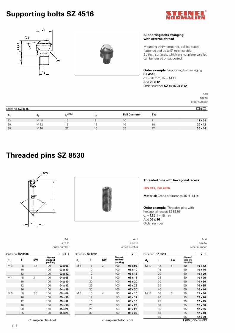
6.16
d1 d2 l1±0,02 l2 Ball Diameter SW
13 M 8 13 8 10 11 13 x 0820 M 12 18 12 16 18 20 x 1230 M 16 27 16 25 27 30 x 16
Supporting bolts SZ 4516
Supporting bolts swingingwith external thread
Mounting body tempered, ball hardened,flattened and up to 9° run movable.By that, surfaces, which are not plane parallel,can be tensed or supported.
Order example: Supporting bolt swingingSZ 4516d1 = 20 mm, d2 = M 12Add 20 x 12Order number SZ 4516.20 x 12
x Order no. SZ 4516.
Addsize to
order number
Threaded pins with hexagonal recess
DIN 913, ISO 4026
Material: Grade of firmness 45 H (14.9)
Order example: Threaded pins with hexagonal recess SZ 8530d1 = M 6, l = 16 mmAdd 06 x 16Order number
x Order no. SZ 8530.
Addsize to
order number
Threaded pins SZ 8530
Order no. SZ 8530.
Addsize to
order number
Order no. SZ 8530.
Addsize to
order number
d1 l SW
Pieces/stadard packing
M 3 8 1,5 100 03 x 0810 100 03 x 1012 100 03 x 12
M 4 8 2 100 04 x 0810 100 04 x 1012 100 04 x 1216 100 04 x 16
M 5 8 2,5 100 05 x 0810 100 05 x 1012 100 05 x 1216 100 05 x 1620 100 05 x 2025 100 05 x 25
d1 l SW
Pieces/stadard packing
M 6 8 3 100 06 x 0810 100 06 x 1012 100 06 x 1216 100 06 x 1620 100 06 x 2025 100 06 x 2530 100 06 x 30
M 8 10 4 50 08 x 1012 50 08 x 1216 50 08 x 1620 50 08 x 2025 50 08 x 2530 50 08 x 30
d1 l SW
Pieces/stadard packing
M 10 12 5 50 10 x 1216 50 10 x 1620 50 10 x 2025 50 10 x 2530 50 10 x 3035 50 10 x 3540 50 10 x 40
M 12 16 6 25 12 x 1620 25 12 x 2025 25 12 x 2530 25 12 x 3035 25 12 x 3540 25 12 x 4050 25 12 x 50
x x
Champion Die-Tool champion-dietool.com 1 (866) 957-9993
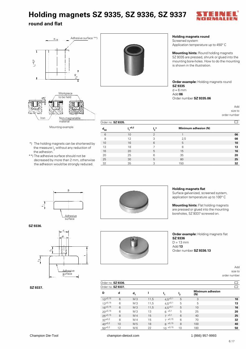
6.17
Holding magnets SZ 9335, SZ 9336, SZ 9337round and flat
Holding magnets roundScreened systemApplication temperature up to 450° C
Mounting hints: Round holding magnetsSZ 9335 are pressed, shrunk or glued into themounting bore-holes. How to do the mountingis shown in the illustration.
Order example: Holding magnets roundSZ 9335d = 6 mmAdd 06Order number SZ 9335.06
Order no. SZ 9335.
Addsize to
order number
Holding magnets flatSurface galvanized, screened system,application temperature up to 100° C
Mounting hints: Flat holding magnetsare pressed or glued into the mounting boreholes, SZ 9337 screwed on.
Order example: Holding magnets flat SZ 9336D = 13 mmAdd 13Order number SZ 9336.13
Addsize to
order number
Adhesive surface **)
SZ 9336.
Order no. SZ 9336. Order no. SZ 9337.
dh6 l1±0,2 l2* Minimum adhesion (N)
6 10 2 1 068 12 3 2,5 08
10 16 6 5 1013 18 7 8 1316 20 5 15 1620 25 6 35 2025 30 5 80 2532 35 3 150 32
D d d1l l1 l2
Minimum adhesion (N)
10±0,15 6 M 3 11,5 4,5±0,1 5 3 10
13±0,15 6 M 3 11,5 4,5±0,1 5 5 13
16±0,15 6 M 3 11,5 4,5±0,1 5 10 16
20±0,15 6 M 3 13 6 ±0,1 5 25 20
25±0,15 8 M 4 15 7 ±0,1 6 40 25
32±0,2 8 M 4 15 7 ±0,15 6 70 32
40±0,2 10 M 5 18 8 ±0,15 8 100 4050±0,2 12 M 6 22 10 ±0,15 10 180 50
Iron Non-magnetablematerial
Workpieceto be held
*) The holding magnets can be shortened by the measure l2 without any reduction of the adhesion.**) The adhesive surface should not be decreased by more than 2 mm, otherwise the adhesion would be strongly reduced.
Adhesivesurface
SZ 9337.
Adhesivesurface
Mounting example
Champion Die-Tool champion-dietool.com 1 (866) 957-9993
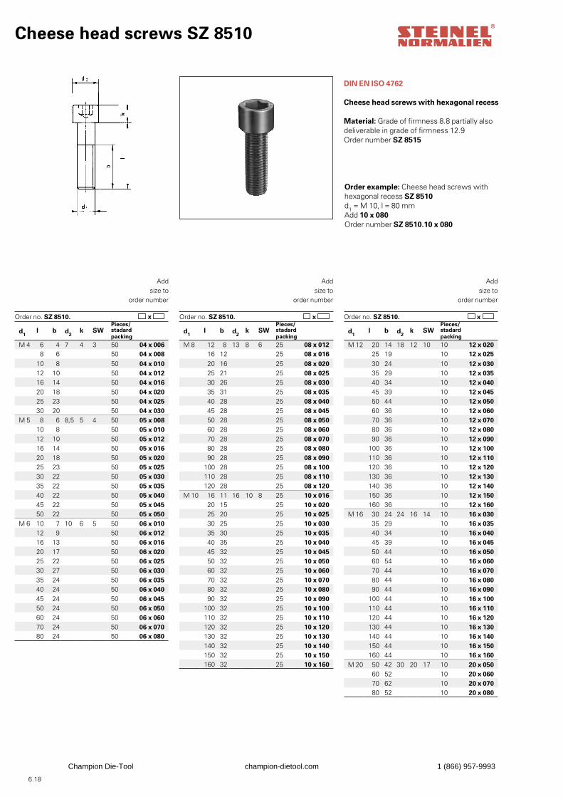
6.18
Cheese head screws SZ 8510
DIN EN ISO 4762
Cheese head screws with hexagonal recess
Material: Grade of firmness 8.8 partially also deliverable in grade of firmness 12.9Order number SZ 8515
Order example: Cheese head screws withhexagonal recess SZ 8510d1 = M 10, l = 80 mmAdd 10 x 080Order number SZ 8510.10 x 080
Order no. SZ 8510. x Order no. SZ 8510. x Order no. SZ 8510.
Addsize to
order number
x
Addsize to
order number
Addsize to
order number
d1l b d2
k SWPieces/stadard packing
M 4 6 4 7 4 3 50 04 x 0068 6 50 04 x 008
10 8 50 04 x 01012 10 50 04 x 01216 14 50 04 x 01620 18 50 04 x 02025 23 50 04 x 02530 20 50 04 x 030
M 5 8 6 8,5 5 4 50 05 x 00810 8 50 05 x 01012 10 50 05 x 01216 14 50 05 x 01620 18 50 05 x 02025 23 50 05 x 02530 22 50 05 x 03035 22 50 05 x 03540 22 50 05 x 04045 22 50 05 x 04550 22 50 05 x 050
M 6 10 7 10 6 5 50 06 x 01012 9 50 06 x 01216 13 50 06 x 01620 17 50 06 x 02025 22 50 06 x 02530 27 50 06 x 03035 24 50 06 x 03540 24 50 06 x 04045 24 50 06 x 04550 24 50 06 x 05060 24 50 06 x 06070 24 50 06 x 07080 24 50 06 x 080
d1l b d2
k SWPieces/stadard packing
M 8 12 8 13 8 6 25 08 x 01216 12 25 08 x 01620 16 25 08 x 02025 21 25 08 x 02530 26 25 08 x 03035 31 25 08 x 03540 28 25 08 x 04045 28 25 08 x 04550 28 25 08 x 05060 28 25 08 x 06070 28 25 08 x 07080 28 25 08 x 08090 28 25 08 x 090
100 28 25 08 x 100110 28 25 08 x 110120 28 25 08 x 120
M 10 16 11 16 10 8 25 10 x 01620 15 25 10 x 02025 20 25 10 x 02530 25 25 10 x 03035 30 25 10 x 03540 35 25 10 x 04045 32 25 10 x 04550 32 25 10 x 05060 32 25 10 x 06070 32 25 10 x 07080 32 25 10 x 08090 32 25 10 x 090
100 32 25 10 x 100110 32 25 10 x 110120 32 25 10 x 120130 32 25 10 x 130140 32 25 10 x 140150 32 25 10 x 150160 32 25 10 x 160
d1l b d2
k SWPieces/stadard packing
M 12 20 14 18 12 10 10 12 x 020 25 19 10 12 x 025 30 24 10 12 x 030 35 29 10 12 x 035 40 34 10 12 x 040 45 39 10 12 x 045 50 44 10 12 x 050 60 36 10 12 x 060 70 36 10 12 x 070 80 36 10 12 x 080 90 36 10 12 x 090
100 36 10 12 x 100110 36 10 12 x 110120 36 10 12 x 120130 36 10 12 x 130140 36 10 12 x 140150 36 10 12 x 150160 36 10 12 x 160
M 16 30 24 24 16 14 10 16 x 030 35 29 10 16 x 035 40 34 10 16 x 040 45 39 10 16 x 045 50 44 10 16 x 050 60 54 10 16 x 060 70 44 10 16 x 070 80 44 10 16 x 080 90 44 10 16 x 090
100 44 10 16 x 100110 44 10 16 x 110120 44 10 16 x 120130 44 10 16 x 130140 44 10 16 x 140150 44 10 16 x 150160 44 10 16 x 160
M 20 50 42 30 20 17 10 20 x 05060 52 10 20 x 06070 62 10 20 x 07080 52 10 20 x 080
Champion Die-Tool champion-dietool.com 1 (866) 957-9993
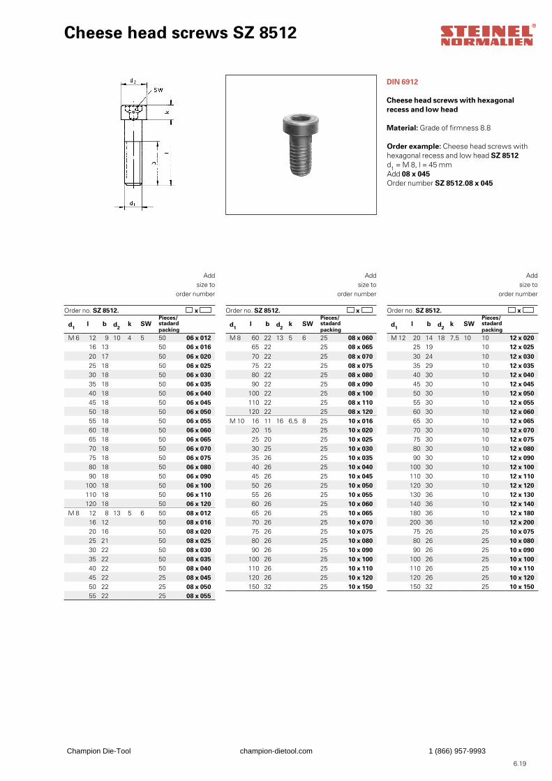
6.19
Cheese head screws SZ 8512
DIN 6912
Cheese head screws with hexagonalrecess and low head
Material: Grade of firmness 8.8
Order example: Cheese head screws withhexagonal recess and low head SZ 8512d1 = M 8, l = 45 mmAdd 08 x 045Order number SZ 8512.08 x 045
x Order no. SZ 8512. x Order no. SZ 8512.
Addsize to
order number
x
Addsize to
order number
Addsize to
order number
Order no. SZ 8512.
d1 l b d2
k SWPieces/stadard packing
M 6 12 9 10 4 5 50 06 x 01216 13 50 06 x 01620 17 50 06 x 02025 18 50 06 x 02530 18 50 06 x 03035 18 50 06 x 03540 18 50 06 x 04045 18 50 06 x 04550 18 50 06 x 05055 18 50 06 x 05560 18 50 06 x 06065 18 50 06 x 06570 18 50 06 x 07075 18 50 06 x 07580 18 50 06 x 08090 18 50 06 x 090
100 18 50 06 x 100110 18 50 06 x 110120 18 50 06 x 120
M 8 12 8 13 5 6 50 08 x 01216 12 50 08 x 01620 16 50 08 x 02025 21 50 08 x 02530 22 50 08 x 03035 22 50 08 x 03540 22 50 08 x 04045 22 25 08 x 04550 22 25 08 x 05055 22 25 08 x 055
d1 l b d2
k SWPieces/stadard packing
M 8 60 22 13 5 6 25 08 x 06065 22 25 08 x 06570 22 25 08 x 07075 22 25 08 x 07580 22 25 08 x 08090 22 25 08 x 090
100 22 25 08 x 100110 22 25 08 x 110120 22 25 08 x 120
M 10 16 11 16 6,5 8 25 10 x 01620 15 25 10 x 02025 20 25 10 x 02530 25 25 10 x 03035 26 25 10 x 03540 26 25 10 x 04045 26 25 10 x 04550 26 25 10 x 05055 26 25 10 x 05560 26 25 10 x 06065 26 25 10 x 06570 26 25 10 x 07075 26 25 10 x 07580 26 25 10 x 08090 26 25 10 x 090
100 26 25 10 x 100110 26 25 10 x 110120 26 25 10 x 120150 32 25 10 x 150
d1 l b d2
k SWPieces/stadard packing
M 12 20 14 18 7,5 10 10 12 x 02025 19 10 12 x 02530 24 10 12 x 03035 29 10 12 x 03540 30 10 12 x 04045 30 10 12 x 04550 30 10 12 x 05055 30 10 12 x 05560 30 10 12 x 06065 30 10 12 x 06570 30 10 12 x 07075 30 10 12 x 07580 30 10 12 x 08090 30 10 12 x 090
100 30 10 12 x 100110 30 10 12 x 110120 30 10 12 x 120130 36 10 12 x 130140 36 10 12 x 140180 36 10 12 x 180200 36 10 12 x 20075 26 25 10 x 07580 26 25 10 x 08090 26 25 10 x 090
100 26 25 10 x 100110 26 25 10 x 110120 26 25 10 x 120150 32 25 10 x 150
Champion Die-Tool champion-dietool.com 1 (866) 957-9993
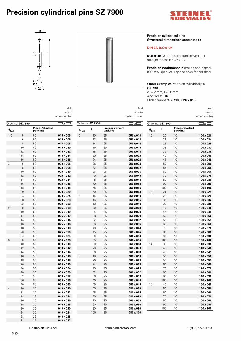
6.20
Precision cylindrical pins SZ 7900
Precision cylindrical pinsStructural dimensions according to
DIN EN ISO 8734
Material: Chrome vanadium alloyed tool steel,hardness HRC 60 ± 2
Precision workmanship ground and lapped,ISO m 5, spherical cap and chamfer polished
Order example: Precision cylindrical pinSZ 7900d1 = 2 mm, l = 16 mmAdd 020 x 016Order number SZ 7900.020 x 016
x Order no. SZ 7900. x Order no. SZ 7900.
Addsize to
order number
x
Addsize to
order number
Addsize to
order number
Order no. SZ 7900.
d1m6l Pieces/stadard
packing
1,5 5 50 015 x 0056 50 015 x 0068 50 015 x 008
10 50 015 x 01012 50 015 x 01214 50 015 x 01416 50 015 x 016
2 6 50 020 x 0068 50 020 x 008
10 50 020 x 01012 50 020 x 01214 50 020 x 01416 50 020 x 01618 50 020 x 01820 50 020 x 02024 50 020 x 02428 50 020 x 02832 50 020 x 032
2,5 8 50 025 x 00810 50 025 x 01012 50 025 x 01214 50 025 x 01416 50 025 x 01618 50 025 x 01820 50 025 x 02024 50 025 x 024
3 8 50 030 x 00810 50 030 x 01012 50 030 x 01214 50 030 x 01416 50 030 x 01618 50 030 x 01820 50 030 x 02024 50 030 x 02428 50 030 x 02832 50 030 x 03236 50 030 x 03640 50 030 x 040
4 10 25 040 x 01012 25 040 x 01214 25 040 x 01416 25 040 x 01618 25 040 x 01820 25 040 x 02024 25 040 x 02428 25 040 x 02832 25 040 x 032
d1m6l Pieces/stadard
packing
5 10 25 050 x 01012 25 050 x 01214 25 050 x 01416 25 050 x 01618 25 050 x 01820 25 050 x 02024 25 050 x 02428 25 050 x 02832 25 050 x 03236 25 050 x 03640 25 050 x 04045 25 050 x 04550 25 050 x 05055 25 050 x 05560 25 050 x 060
6 14 25 060 x 01416 25 060 x 01618 25 060 x 01820 25 060 x 02024 25 060 x 02428 25 060 x 02832 25 060 x 03236 25 060 x 03640 25 060 x 04045 25 060 x 04550 25 060 x 05055 25 060 x 05560 25 060 x 06070 25 060 x 07080 25 060 x 080
8 18 25 080 x 01820 25 080 x 02024 25 080 x 02428 25 080 x 02832 25 080 x 03236 25 080 x 03640 25 080 x 04045 25 080 x 04550 25 080 x 05055 25 080 x 05560 25 080 x 06070 25 080 x 07080 25 080 x 08090 25 080 x 090
100 25 080 x 100
d1m6l Pieces/stadard
packing
10 20 10 100 x 02024 10 100 x 02428 10 100 x 02832 10 100 x 03236 10 100 x 03640 10 100 x 04045 10 100 x 04550 10 100 x 05055 10 100 x 05560 10 100 x 06070 10 100 x 07080 10 100 x 08090 10 100 x 090
100 10 100 x 10012 24 10 120 x 024
28 10 120 x 02832 10 120 x 03236 10 120 x 03640 10 120 x 04045 10 120 x 04550 10 120 x 05055 10 120 x 05560 10 120 x 06070 10 120 x 07080 10 120 x 08090 10 120 x 090
100 10 120 x 10014 36 10 140 x 036
40 10 140 x 04045 10 140 x 04550 10 140 x 05055 10 140 x 05560 10 140 x 06070 10 140 x 07080 10 140 x 08090 10 140 x 090
100 10 140 x 10016 40 10 160 x 040
50 10 160 x 05060 10 160 x 06070 10 160 x 07080 10 160 x 08090 10 160 x 090
100 10 160 x 100
Champion Die-Tool champion-dietool.com 1 (866) 957-9993
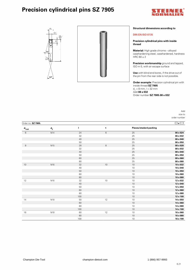
6.21
d1m6 d2 l t Pieces/stadard packing
6 M 4 24 6 25 06 x 02432 25 06 x 03240 25 06 x 04050 25 06 x 050
8 M 5 28 8 25 08 x 02832 25 08 x 03240 25 08 x 04050 25 08 x 05060 25 08 x 06080 25 08 x 080
10 M 6 32 10 10 10 x 03240 10 10 x 04050 10 10 x 05060 10 10 x 06080 10 10 x 080
12 M 6 32 10 10 12 x 03240 10 12 x 04050 10 12 x 05060 10 12 x 06080 10 12 x 080
100 10 12 x 10014 M 8 50 12 10 14 x 050
60 10 14 x 06080 10 14 x 080
100 10 14 x 100 16 M 8 60 12 10 16 x 060
80 10 16 x 080100 10 16 x 100
Precision cylindrical pins SZ 7905
Structural dimensions according to
DIN EN ISO 8735
Precision cylindrical pins with inside thread
Material: High grade chrome – alloyedcasehardening steel, casehardened, hardnessHRC 60 ± 2
Precision workmanship ground and lapped,ISO m 5, with air escape surface
Use with blind-end bores, if the drive-out of the pin from the rear side is not possible.
Order example: Precision cylindrical pin withinside thread SZ 7905d1 = 8 mm, l = 32 mmAdd 08 x 032Order number SZ 7905.08 x 032
x Order no. SZ 7905.
Addsize to
order number
Champion Die-Tool champion-dietool.com 1 (866) 957-9993
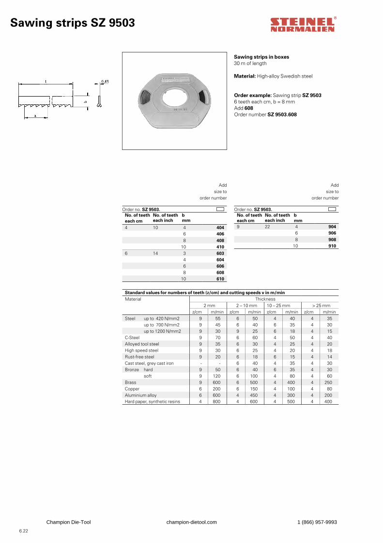
6.22
Sawing strips SZ 9503
Sawing strips in boxes30 m of length
Material: High-alloy Swedish steel
Order example: Sawing strip SZ 95036 teeth each cm, b = 8 mmAdd 608Order number SZ 9503.608
Order no. SZ 9503.
Addsize to
order number
Order no. SZ 9503.
Addsize to
order number
No. of teeth No. of teeth beach cm each inch mm
4 10 4 4046 406
8 40810 410
6 14 3 6034 6046 6068 608
10 610
No. of teeth No. of teeth beach cm each inch mm9 22 4 904
6 906 8 908
10 910
Standard values for numbers of teeth (z/cm) and cutting speeds v in m/minMaterial Thickness
2 mm 2 – 10 mm 10 – 25 mm > 25 mmz/cm m/min z/cm m/min z/cm m/min z/cm m/min
Steel up to 420 N/mm2 9 55 6 50 4 40 4 35up to 700 N/mm2 9 45 6 40 6 35 4 30up to 1200 N/mm2 9 30 9 25 6 18 4 15
C-Steel 9 70 6 60 4 50 4 40Alloyed tool steel 9 35 6 30 4 25 4 20High speed steel 9 30 6 25 4 20 4 18Rust-free steel 9 20 6 18 6 15 4 14Cast steel, grey cast iron - - 6 40 4 35 4 30Bronze hard 9 50 6 40 6 35 4 30
soft 9 120 6 100 4 80 4 60Brass 9 600 6 500 4 400 4 250Copper 6 200 6 150 4 100 4 80Aluminium alloy 6 600 4 450 4 300 4 200Hard paper, synthetic resins 4 800 4 600 4 500 4 400
Champion Die-Tool champion-dietool.com 1 (866) 957-9993
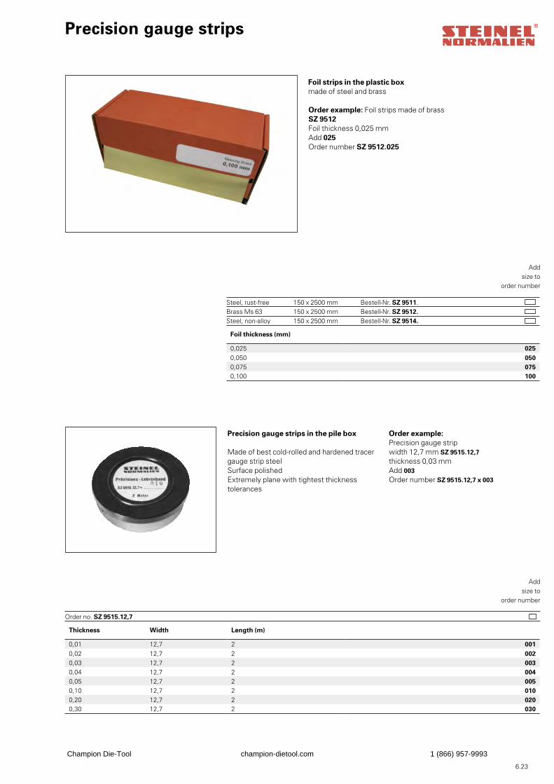
6.23
Thickness Width Length (m)
0,01 12,7 2 0010,02 12,7 2 0020,03 12,7 2 0030,04 12,7 2 0040,05 12,7 2 0050,10 12,7 2 0100,20 12,7 2 0200,30 12,7 2 030
Precision gauge strips
Foil strips in the plastic boxmade of steel and brass
Order example: Foil strips made of brassSZ 9512Foil thickness 0,025 mmAdd 025Order number SZ 9512.025
Addsize to
order number
Steel, rust-free 150 x 2500 mm Bestell-Nr. SZ 9511. Brass Ms 63 150 x 2500 mm Bestell-Nr. SZ 9512. Steel, non-alloy 150 x 2500 mm Bestell-Nr. SZ 9514.
Precision gauge strips in the pile box
Made of best cold-rolled and hardened tracergauge strip steelSurface polishedExtremely plane with tightest thicknesstolerances
Order example: Precision gauge stripwidth 12,7 mm SZ 9515.12,7thickness 0,03 mmAdd 003Order number SZ 9515.12,7 x 003
Addsize to
order number
Order no. SZ 9515.12,7
Foil thickness (mm)
0,025 0250,050 0500,075 0750,100 100
Champion Die-Tool champion-dietool.com 1 (866) 957-9993
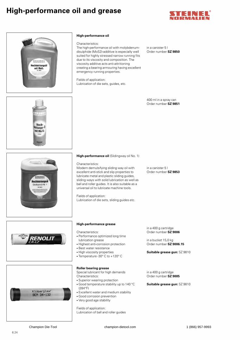
6.24
High-performance oil and grease
High-performance oil
Characteristics:The high-performance oil with molybdenum-disulphide (MoS2)-additive is especially wellsuited for highly stressed narrow running fitsdue to its viscosity and composition. The viscosity additive acts anti-attritioning creating a bearing armouring having excellent emergency running properties.
Fields of application:Lubrication of die sets, guides, etc.
in a canister 5 lOrder number SZ 9850
400 ml in a spray canOrder number SZ 9851
High-performance oil (Slidingway oil No. 1)
Characteristics:Modern demulsifying sliding way oil with excellent anti-stick and slip properties to lubricate metal and plastic sliding guides, sliding ways with solid lubrication as well as ball and roller guides. It is also suitable as a universal oil to lubricate machine tools.
Fields of application:Lubrication of die sets, sliding guides etc.
in a canister 5 lOrder number SZ 9853
High-performance grease
Characteristics:• Performance optimized long time lubrication grease• Highest anti-corrosion protection• Best water resistance• High viscosity properties• Temperature -30° C to +120° C
in a 400 g cartridgeOrder number SZ 9006
in a bucket 15,0 kgOrder number SZ 9006.15 Suitable grease gun: SZ 9810
Roller bearing greaseSpecial lubricant for high demandsCharacteristics:• Superior wearing protection• Good temperature stability up to 140 °C (284°F)• Excellent water and medium stability• Good corrosion prevention• Very good age stability
Fields of application:Lubrication of ball and roller guides
in a 400 g cartridgeOrder number SZ 9005
Suitable grease gun: SZ 9810
Champion Die-Tool champion-dietool.com 1 (866) 957-9993
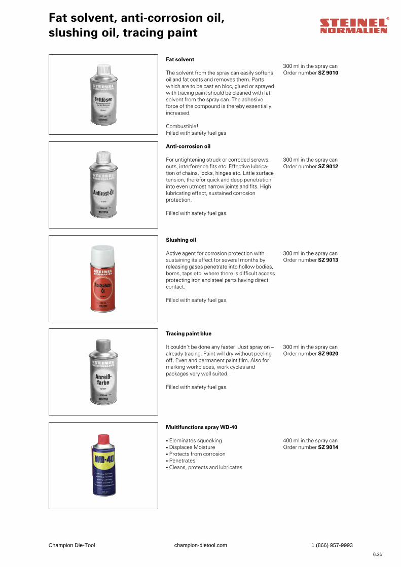
6.25
Fat solvent, anti-corrosion oil,slushing oil, tracing paint
Fat solvent
The solvent from the spray can easily softens oil and fat coats and removes them. Parts which are to be cast en bloc, glued or sprayed with tracing paint should be cleaned with fat solvent from the spray can. The adhesive force of the compound is thereby essentially increased.
Combustible!Filled with safety fuel gas
300 ml in the spray canOrder number SZ 9010
Anti-corrosion oil
For untightening struck or corroded screws,nuts, interference fits etc. Effective lubrica-tion of chains, locks, hinges etc. Little surface tension, therefor quick and deep penetration into even utmost narrow joints and fits. High lubricating effect, sustained corrosion protection.
Filled with safety fuel gas.
300 ml in the spray canOrder number SZ 9012
Slushing oil
Active agent for corrosion protection withsustaining its effect for several months byreleasing gases penetrate into hollow bodies,bores, taps etc. where there is difficult accessprotecting iron and steel parts having directcontact.
Filled with safety fuel gas.
300 ml in the spray canOrder number SZ 9013
Tracing paint blue
It couldn´t be done any faster! Just spray on –already tracing. Paint will dry without peeling off. Even and permanent paint film. Also for marking workpieces, work cycles and packages very well suited.
Filled with safety fuel gas.
300 ml in the spray canOrder number SZ 9020
Multifunctions spray WD-40
• Eleminates squeeking• Displaces Moisture• Protects from corrosion• Penetrates• Cleans, protects and lubricates
400 ml in the spray canOrder number SZ 9014
Champion Die-Tool champion-dietool.com 1 (866) 957-9993
6.26
Anaerobic bonding agents for plasticsAnaerobic bonding agents for plastics are distributed onto the mounting parts in a liquidstate. They stay liquid as long as oxygen hasgot access. Not before the parts are mountedbut with the occlusion of oxygen and metalcontact the chemical transformation is startedfrom the liquid state into a tough substanceformed by linear molecule chains.Due to its effective capillarity this plastic material fills out even smallest interspaces. It cramps fast in the surface roughness of the parts that are to be linked together. The jointing gap is so filled completely out. Due to this 100% surface contact an interlocking compound is formed which is shock and vibration-proof.
Constructional outlay of a compoundA jointing and bonding compound shouldalways be laid out in a way that only pulling,pressing and shearing forces occur – not however peel-off forces.
A high L/ D ratio (Length / Diameter) grants agood tensional distribution in the bonding gap.
Gap fillingBull noses and basils sized sufficiently bigenable an even dissipation of the product upon mounting jointing parts. In case of press-fits and of bigger sizes always moisten both surfaces thinly and evenly with the concerning LOCTITE product.
Moisten the bore of blind holes in such a wayto prevent the compressed air from driving the liquid bonding agent away upon mounting.
Activator 7649A hardening accelerator for anaerobic products LOCTITE 542, 603 and 270. Reduces time required for hardening.Simple use: spray on and let dry – and then apply the LOCTITE-product.
Product colour: light yellowContains: AcetoneHighly flammableStorability: 1 year
500 ml pump spray bottle Order number SZ 9740
Joining different materialsWhen joining different materials (for examplesteel bolts in an alu-housing) with operatingtemperatures over 50 °C the various coefficients of thermal expansion must be taken into consideration. Aluminium expands for instance twice as much as steel does.
Compatibility with other materialsThe materials used most (metals, sinteredmaterials, ceramics and glass) are chemicallynot changed by the liquid bonding agents forplastics.
The hardened layer stays chemically neutral.
The following plastic materials can be affected and show reactions after a longer period of time: vinyl, ABS-products, polysulphone, PVC, polycarbonate, polystyrene, SAN-products and lacquered surfaces.
SolubilityThe liquid anaerobic LOCTITE products aresoluble in trichlorethylene and in many otherchlorinated hydrocarbons.
Chemical constancyThe fully hardened LOCTITE products show avery good stability with regard to oil, benzene,organic solvents and coolants.
The greater the sturdiness is of a special typeof bonding agent the greater is the chemicalconstancy.
Storing timeWith room temperature the LOCTITE products are storable for at least 1 year. The content of air in the bottles is necessary in order to prevent a hardening before use. Screws, metal parts or brushes must not be dipped into the bottle. Soiled LOCTITE must not be poured back into the bottle. The activator must not be mixed with LOCTITE products to prevent any hardening.
Bonding agents
Champion Die-Tool champion-dietool.com 1 (866) 957-9993
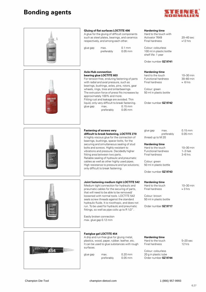
6.27
Gluing of flat surfaces LOCTITE 496A glue for the gluing of difficult componentssuch as steel plates, bearings, and ceramicsrespectively, and among each other.
glue gap max. 0.1 mm preferably 0.05 mm
Hardening timeHard to the touch with Activator 7649 20–40 secFinal hardness ≈12 hrs
Colour: colourless100 ml in plastic bottleshelf life: 1 year
Order number SZ 9741
Axle-Hub connectionbearing glue LOCTITE 603For tension-free, enduring fastening of partswith radial and axial pressure, such asbearings, bushings, axles, pins, rotors, gearwheels, rings, tires and sinterbearings.The extrusion force of press fits increases byapproximately 100% and more. Fitting rust and leakage are avoided. Thin liquid, only very difficult to break fastening.glue gap max. 0.15 mm preferably 0.05 mm
Hardening timehard to the touch 10–30 minFunctional hardness 30–60 minFinal hardness ≈ 6 hrs
Colour: green50 ml in plastic bottle
Order number SZ 9742
Fastening of screws verydifficult to break fastening, LOCTITE 270A highly viscous glue for the connection ofbearings, bushings, spacer bolts, for thesecuring and simultaneous sealing of studbolts and screws. Highly resistant to vibrations and pressure. Decidedly higher fitting area between two parts.Reliable sealing of hydraulic and pneumaticcables as well as other highly used pipes.High resistance to pressure and lye solutions;only difficult to break fastening.
glue gap max. 0.15 mm preferably 0.05 mmthread up to M 20
Hardening timeHard to the touch 10–30 minFunctional hardness 1–3 hekFinal hardness 3–6 hrs
Colour: green50 ml in plastic bottle
Order number SZ 9743
Joint fastening medium tight LOCTITE 542Medium tight connection for hydraulic andpneumatic cables for the securing of parts, that will need to be able to be removed/loosened with normal tools. LOCTITE 542 seals screw threads against the standard hydraulic fluids. It is nixothopic, and does not run. To be used for hydraulic and pneumatic fittings, so well as pipe coils up to R 1/2”.
Easily broken connectionmax. glue gap 0.12 mm
Hardening timeHard to the touch 10–30 minFinal hardness ≈ 3 hrs
Colour: brown50 ml in plastic bottle
Order number SZ 9717
Fastglue gel LOCTITE 454A drip and run-free glue for gluing metal,plastics, wood, paper, rubber. leather, etc.It can be used to glue substances with roughsurfaces.
glue gap max. 0.20 mm preferably 0.05 mm
Hardening timeHard to the touch 5–20 secFinal hardness 12 hrs
Colour: colourless20 g in plastic tubeOrder number SZ 9744
Bonding agents
Champion Die-Tool champion-dietool.com 1 (866) 957-9993
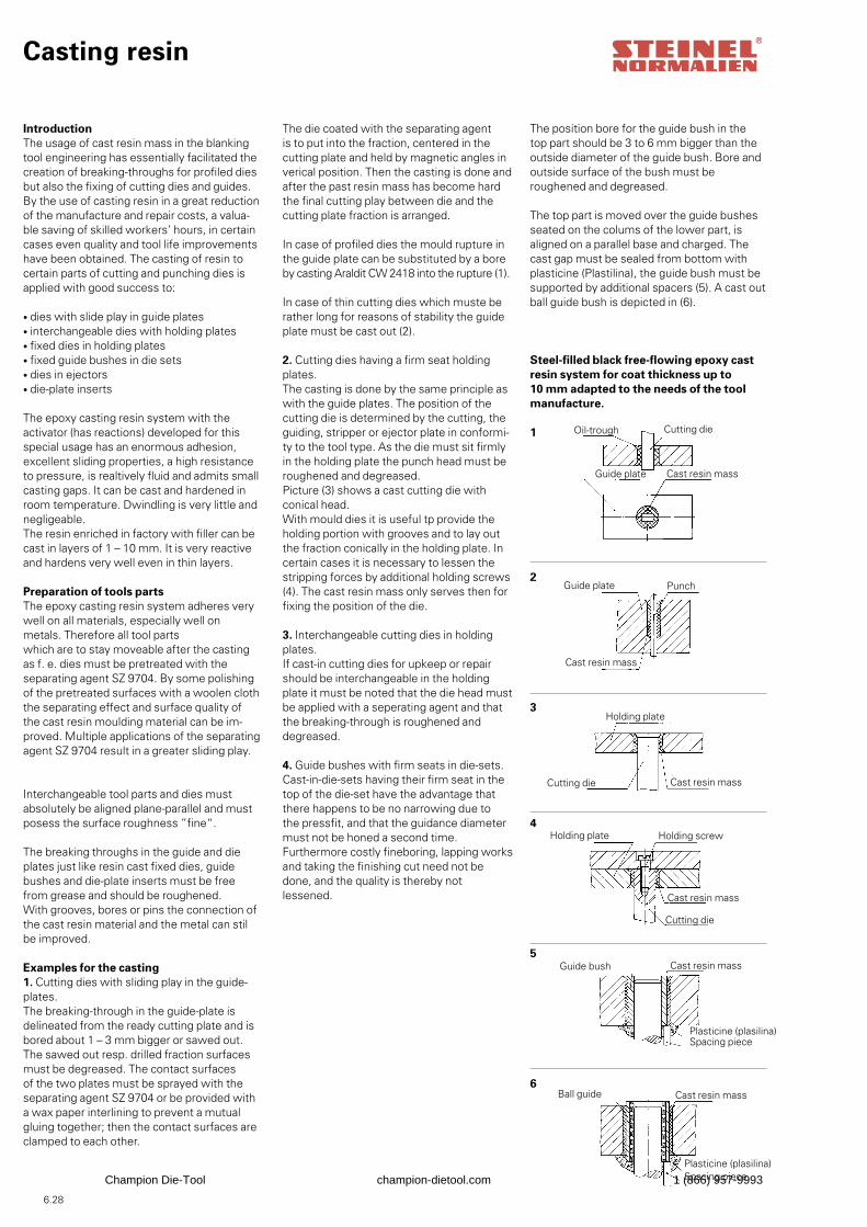
6.28
Casting resin
IntroductionThe usage of cast resin mass in the blankingtool engineering has essentially facilitated thecreation of breaking-throughs for profiled diesbut also the fixing of cutting dies and guides.By the use of casting resin in a great reductionof the manufacture and repair costs, a valua-ble saving of skilled workers’ hours, in certain cases even quality and tool life improvements have been obtained. The casting of resin to certain parts of cutting and punching dies is applied with good success to:
• dies with slide play in guide plates• interchangeable dies with holding plates• fixed dies in holding plates• fixed guide bushes in die sets• dies in ejectors• die-plate inserts
The epoxy casting resin system with the activator (has reactions) developed for this special usage has an enormous adhesion, excellent sliding properties, a high resistance to pressure, is realtively fluid and admits small casting gaps. It can be cast and hardened in room temperature. Dwindling is very little and negligeable.The resin enriched in factory with filler can becast in layers of 1 – 10 mm. It is very reactiveand hardens very well even in thin layers.
Preparation of tools partsThe epoxy casting resin system adheres very well on all materials, especially well on metals. Therefore all tool partswhich are to stay moveable after the casting as f. e. dies must be pretreated with the separating agent SZ 9704. By some polishing of the pretreated surfaces with a woolen cloth the separating effect and surface quality of the cast resin moulding material can be im-proved. Multiple applications of the separating agent SZ 9704 result in a greater sliding play.
Interchangeable tool parts and dies mustabsolutely be aligned plane-parallel and mustposess the surface roughness ”fine“.
The breaking throughs in the guide and dieplates just like resin cast fixed dies, guide bushes and die-plate inserts must be free from grease and should be roughened. With grooves, bores or pins the connection of the cast resin material and the metal can stil be improved.
Examples for the casting1. Cutting dies with sliding play in the guide-plates.The breaking-through in the guide-plate is delineated from the ready cutting plate and isbored about 1 – 3 mm bigger or sawed out.The sawed out resp. drilled fraction surfacesmust be degreased. The contact surfaces of the two plates must be sprayed with the separating agent SZ 9704 or be provided with a wax paper interlining to prevent a mutual gluing together; then the contact surfaces are clamped to each other.
The position bore for the guide bush in the top part should be 3 to 6 mm bigger than the outside diameter of the guide bush. Bore and outside surface of the bush must be roughened and degreased.
The top part is moved over the guide bushesseated on the colums of the lower part, isaligned on a parallel base and charged. Thecast gap must be sealed from bottom with plasticine (Plastilina), the guide bush must be supported by additional spacers (5). A cast out ball guide bush is depicted in (6).
Steel-filled black free-flowing epoxy castresin system for coat thickness up to10 mm adapted to the needs of the toolmanufacture.
Oil-trough
Guide plate
Holding plate
Holding plate
Guide bush
Ball guide
The die coated with the separating agent is to put into the fraction, centered in the cutting plate and held by magnetic angles in verical position. Then the casting is done and after the past resin mass has become hard the final cutting play between die and the cutting plate fraction is arranged.
In case of profiled dies the mould rupture inthe guide plate can be substituted by a bo reby casting Araldit CW 2418 into the rupture (1).
In case of thin cutting dies which muste berather long for reasons of stability the guideplate must be cast out (2).
2. Cutting dies having a firm seat holdingplates.The casting is done by the same principle aswith the guide plates. The position of the cutting die is determined by the cutting, the guiding, stripper or ejector plate in conformi-ty to the tool type. As the die must sit firmly in the holding plate the punch head must be roughened and degreased. Picture (3) shows a cast cutting die with conical head.With mould dies it is useful tp provide the holding portion with grooves and to lay out the fraction conically in the holding plate. In certain cases it is necessary to lessen the stripping forces by additional holding screws (4). The cast resin mass only serves then for fixing the position of the die.
3. Interchangeable cutting dies in holdingplates.If cast-in cutting dies for upkeep or repairshould be interchangeable in the holding plate it must be noted that the die head must be applied with a seperating agent and that the breaking-through is roughened anddegreased.
4. Guide bushes with firm seats in die-sets.Cast-in-die-sets having their firm seat in the top of the die-set have the advantage that there happens to be no narrowing due to the pressfit, and that the guidance diameter must not be honed a second time.Furthermore costly fineboring, lapping worksand taking the finishing cut need not be done, and the quality is thereby notlessened.
Cutting die
Guide plate
Cast resin mass
Punch
Cast resin mass
Cutting die Cast resin mass
Holding screw
Cast resin mass
Cutting die
Cast resin mass
Plasticine (plasilina) Spacing piece
Cast resin mass
Plasticine (plasilina) Spacing piece
1
2
3
4
5
6
Champion Die-Tool champion-dietool.com 1 (866) 957-9993
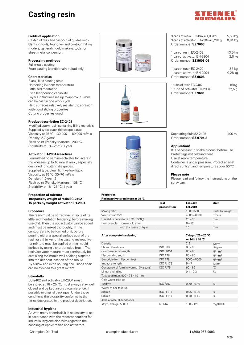
6.29
3 cans of resin EC-2042 à 1,86 kg 5,58 kg3 cans of activator EH-2904 à 0,28 kg 0,84 kgOrder number SZ 9603
1 can of resin EC-2402 13,5 kg1 can of activator EH-2904 2,0 kgOrder number SZ 9603.04
1 can of resin EC-2402 1,86 kg1 can of activator EH-2904 0,28 kgOrder number SZ 9606
1 tube of resin EC-2402 150 g1 tube of activator EH-2904 22,5 gOrder number SZ 9601
Application!It is necessary to shake product before use. Protect against cold and heat.Use at room temperature.Container is under pressure. Protect against direct sunlight and temperatures over 50 °C .
Please notePlease read and follow the instructions on the spray can.
Separating fluid 82-2405 400 mlOrder number SZ 9704.2
Fields of applicationCast-in of dies and cast-out of guides withblanking tools, foundries and contour millingmodels, general mould making, tools for sheet metal conversion.
Processing methodsFull mould castingFront casting (conditionally suited only)
CharacteristicsBlack, fluid casting resinHardening in room temperatureLittle sedimentationExcellent pouring capabilityLayers in thicknesses up to approx. 10 mm can be cast in one work cycleHard surfaces relatively resistant to abrasionwith good sliding propertiesCutting properties good
Product description EC-2402Modified epoxy resin containing filling materialsSupplied type: black thixotrope pasteViscosity at 25 °C: 130.000 – 180.000 mPa.sDensity: 2,7 g/cm3
Flash point (Pensky-Martens): 200 °CStorability at 18 – 25 °C: 1 year
Activator EH-2904 (reactive)Formulated polyamino-activator for layers inthicknesses up to 10 mm at max., especiallydesigned for cutting die guides.Supplied type: clear, light yellow liquidViscosity at 25 °C: 30–70 mPa.sDensity : 1.0 g/cm2Flash point (Pensky-Martens): 108 °CStorability at 18 – 25 °C: 1 year
Proportion of mixture100 parts by weight of resin EC-2402 15 parts by weight activator EH-2904
ProcedureThe resin must be stirred well in spite of its little sedimentation tendency, before making use of it. Then the apt activator van be added and must be mixed thoroughly. If fine contours are to be formed of it, before pouring either a special surface coat of the resin or a thin lyer of the casting resin/activa-tor mixture must be applied on the mould surface by using a short-bristled brush. The resin/activator mixture must continously be cast along the mould wall or along a spattle into the deepest location of the mould.By a slow and even pouring occlusions of aircan be avoided to a great extent.
StorabiltyEC-2402 and activator EH-2904 mustbe stored at 18 – 25 °C, must always stay wellclosed and be kept in dry circumference, if possible in original packages. Under these conditions the storability conforms to the times designated in the product description.
Industrial hygieneAs with many chemicals it is necessary to actin accordance with the reccomendations forindustrial hygiene also with regard to thehandling of epoxy resins and activators.
Casting resin
PropertiesResin/activator mixture at 25 °C
Test EC-2402 Unitprescription EH-2904
Mixing ratio 100 : 15 : 00 Parts by weightViscosity at 25 °C 4000 – 6000 mPa.sUseability period at 25 °C (1000g) 20 – 30 minRemoveable from mould after 8 – 12 h
with thickness of layer 10 mm
After complete hardening 7 days / 20 – 25 °Cor 14 h / 40 °C
Density 2,2 g/cm3
Shore D hardness ISO 868 85 – 90 DegreeCompression strength ISO R 604 85 – 90 N/mm2
Flectional strength ISO 178 80 – 85 N/mm2
E-module from flection test ISO 178 5000 – 5500 N/mm2
Impact strength ISO R 179 5 – 7 kJ/m2
Constancy of form in warmth (Martens) ISO R 75 60 – 65 °CLinear dwindling 0,1 – 0,3 ‰Test specimen: 900 x 75 x 10 mmCold water take-up10 days ISO R 62 0,20 – 0,40 %Water at boil take-up30 min ISO R 117 0,05 – 0,30 %60 min ISO R 117 0,10 – 0,45 %Abrasion (S-33-sandpaper strips, charge: 500 P) NEMA 100 – 120 mg/100 U.
Champion Die-Tool champion-dietool.com 1 (866) 957-9993
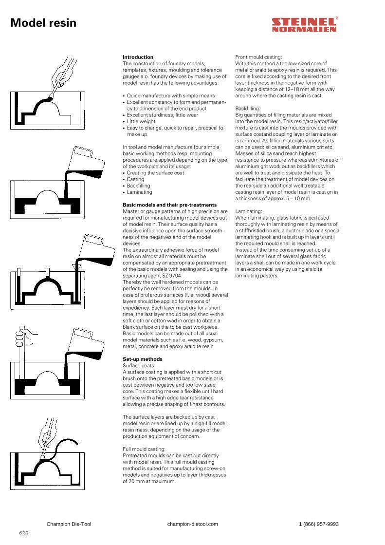
6.30
Model resin
IntroductionThe construction of foundry models, templates, fixtures, moulding and tolerance gauges a.o. foundry devices by making use of model resin has the following advantages:
• Quick manufacture with simple means• Excellent constancy to form and permanen- cy to dimension of the end product• Excellent sturdiness, little wear• Little weight• Easy to change, quick to repair, practical to make up
In tool and model manufacture four simple basic working methods resp. mounting procedures are applied depending on the type of the workpice and its usage:• Creating the surface coat• Casting• Backfilling• Laminating
Basic models and their pre-treatmentsMaster or gauge patterns of high precision arerequired for manufacturing model devices out of model resin. Their surface quality has adecisive influence upon the surface smooth-ness of the negatives and of the model devices.The extraordinary adhesive force of model resin on almost all materials must be compensated by an appropriate pretreatment of the basic models with sealing and using theseparating agent SZ 9704.Thereby the well hardened models can beperfectly be removed from the moulds. In case of proferous surfaces (f. e. wood) several layers should be applied for reasons of expediency. Each layer must dry for a short time, the last layer should be polished with a soft cloth or cotton wad in order to obtain a blank surface on the to be cast workpiece. Basic models can be made out of all usual model materials such as f.e. wood, gypsum, metal, concrete and epoxy araldite resin
Set-up methodsSurface coats:A surface coating is applied with a short cutbrush onto the pretreated basic models or iscast between negative and too low sized core. This coating makes a flexible until hard surface with a high edge tear resistance allowing a precise shaping of finest contours.
The surface layers are backed up by cast model resin or are lined up by a high-fill model resin mass, depending on the usage of the production equipment of concern.
Full mould casting:Pretreated moulds can be cast out directly with model resin. This full mould castingmethod is suited for manufacturing screw-onmodels and negatives up to layer thicknesses of 20 mm at maximum.
Front mould casting:With this method a too low sized core of metal or araldite epoxy resin is required. This core is fixed according to the desired front layer thickness in the negative form with keeping a distance of 12–18 mm all the way around where the casting resin is cast. Backfilling:Big quantities of filling materials are mixed into the model resin. This resin/activator/filler mixture is cast into the moulds provided with surface coatand coupling layer or laminate or is rammed. As filling materials various sorts can be used: silica sand, aluminium crit etc.Masses of silica sand reach highest resistance to pressure whereas admixtures of aluminium grit work out as backfillers which are well to treat and dissipate the heat. To facilitate the treatment of model devices on the rearside an additional well treatable casting resin layer of model resin is cast on in a thickness of approx. 5 – 10 mm.
Laminating:When laminating, glass fabric is perfused thoroughly with laminating resin by means of a stiffbristled brush, a ductor blade or a special laminating hook and is built up in layers until the required mould shell is reached.Instead of the time consuming set-up of a laminate shell out of several glass fabric layers a shell can be made in one work cycle in an economical way by using araldite laminating pasters.
Champion Die-Tool champion-dietool.com 1 (866) 957-9993
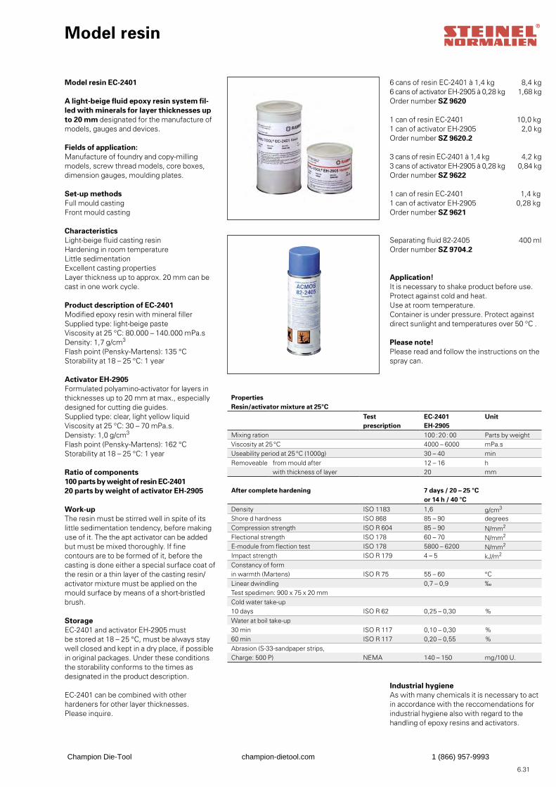
6.31
6 cans of resin EC-2401 à 1,4 kg 8,4 kg6 cans of activator EH-2905 à 0,28 kg 1,68 kgOrder number SZ 9620
1 can of resin EC-2401 10,0 kg1 can of activator EH-2905 2,0 kgOrder number SZ 9620.2
3 cans of resin EC-2401 à 1,4 kg 4,2 kg3 cans of activator EH-2905 à 0,28 kg 0,84 kgOrder number SZ 9622
1 can of resin EC-2401 1,4 kg1 can of activator EH-2905 0,28 kgOrder number SZ 9621
Separating fluid 82-2405 400 mlOrder number SZ 9704.2
Model resin EC-2401
A light-beige fluid epoxy resin system fil-led with minerals for layer thicknesses upto 20 mm designated for the manufacture ofmodels, gauges and devices.
Fields of application:Manufacture of foundry and copy-millingmodels, screw thread models, core boxes,dimension gauges, moulding plates.
Set-up methodsFull mould castingFront mould casting
CharacteristicsLight-beige fluid casting resinHardening in room temperatureLittle sedimentationExcellent casting propertiesLayer thickness up to approx. 20 mm can becast in one work cycle.
Product description of EC-2401Modified epoxy resin with mineral fillerSupplied type: light-beige pasteViscosity at 25 °C: 80.000 – 140.000 mPa.sDensity: 1,7 g/cm3
Flash point (Pensky-Martens): 135 °CStorability at 18 – 25 °C: 1 year
Activator EH-2905Formulated polyamino-activator for layers inthicknesses up to 20 mm at max., especiallydesigned for cutting die guides.Supplied type: clear, light yellow liquidViscosity at 25 °C: 30 – 70 mPa.s.Densisty: 1,0 g/cm3
Flash point (Pensky-Martens): 162 °CStorability at 18 – 25 °C: 1 year
Ratio of components100 parts by weight of resin EC-240120 parts by weight of activator EH-2905
Work-upThe resin must be stirred well in spite of its little sedimentation tendency, before making use of it. The the apt activator can be added but must be mixed thoroughly. If fine contours are to be formed of it, before the casting is done either a special surface coat of the resin or a thin layer of the casting resin/activator mixture must be applied on the mould surface by means of a short-bristled brush.
StorageEC-2401 and activator EH-2905 mustbe stored at 18 – 25 °C, must be always staywell closed and kept in a dry place, if possiblein original packages. Under these conditions the storability conforms to the times as designated in the product description.
EC-2401 can be combined with other hardeners for other layer thicknesses.Please inquire.
Model resin
PropertiesResin/activator mixture at 25°C
Test EC-2401 Unitprescription EH-2905
Mixing ration 100 : 20 : 00 Parts by weightViscosity at 25 °C 4000 – 6000 mPa.sUseability period at 25 °C (1000g) 30 – 40 minRemoveable from mould after 12 – 16 h
with thickness of layer 20 mm
After complete hardening 7 days / 20 – 25 °Cor 14 h / 40 °C
Density ISO 1183 1,6 g/cm3
Shore d hardness ISO 868 85 – 90 degreesCompression strength ISO R 604 85 – 90 N/mm2
Flectional strength ISO 178 60 – 70 N/mm2
E-module from flection test ISO 178 5800 – 6200 N/mm2
Impact strength ISO R 179 4 – 5 kJ/m2
Constancy of formin warmth (Martens) ISO R 75 55 – 60 °CLinear dwindling 0,7 – 0,9 ‰Test spedimen: 900 x 75 x 20 mmCold water take-up10 days ISO R 62 0,25 – 0,30 %Water at boil take-up30 min ISO R 117 0,10 – 0,30 %60 min ISO R 117 0,20 – 0,55 %Abrasion (S-33-sandpaper strips,Charge: 500 P) NEMA 140 – 150 mg /100 U.
Industrial hygieneAs with many chemicals it is necessary to actin accordance with the reccomendations forindustrial hygiene also with regard to thehandling of epoxy resins and activators.
Application!It is necessary to shake product before use.Protect against cold and heat.Use at room temperature.Container is under pressure. Protect against direct sunlight and temperatures over 50 °C .
Please note!Please read and follow the instructions on the spray can.
Champion Die-Tool champion-dietool.com 1 (866) 957-9993
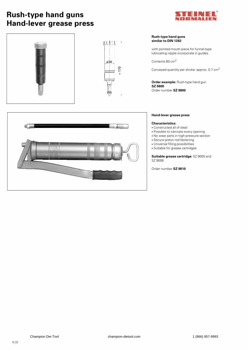
6.32
Hand-lever grease press
Characteristics:• Constructed all of steal• Possible to lubricate every opening• No wear parts in high-pressure section• Secure piston rod fastening• Universal filling possibilities• Suitable for grease cartridges
Suitable grease cartridge: SZ 9005 andSZ 9006
Order number SZ 9810
Rush-type hand gunsHand-lever grease press
Rush-type hand gunssimilar to DIN 1282
with pointed mouth piece for funnel-typelubricating nipple incorporate in guides.
Contents 60 cm3
Conveyed quantity per stroke: approx. 0.7 cm3
Order example: Rush-type hand gunSZ 9800Order number SZ 9800
≈ 17
0
ø30
Champion Die-Tool champion-dietool.com 1 (866) 957-9993
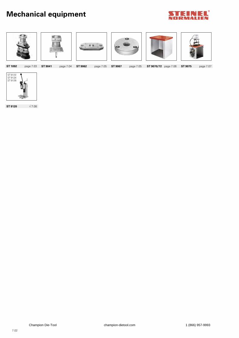
Mechanical equipment
ST 9120 √ 7.08
ST 1092 page 7.03 ST 9041 page 7.04 ST 9062 page 7.05 ST 9067 page 7.05 ST 9070/72 page 7.06 ST 9075 page 7.07
7.02
ST 9122ST 9124ST 9126
Champion Die-Tool champion-dietool.com 1 (866) 957-9993
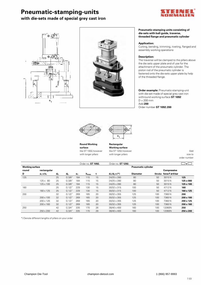
Pneumatic-stamping-unitswith die-sets made of special grey cast iron
Pneumatic-stamping units consisting ofdie-sets with ball guide, traverse,threaded flange and pneumatic cylinder
Application:Cutting, bending, trimming, riveting, flanged andassembly working operations
Description:The traverse will be clamped to the pillars abovethe die sets upper plate and of use for theattachment of the pneumatic cylinder. The piston rod of the pneumatic cylinder is fastened onto the die-sets upper plate by help of the threaded flange.
Order example: Pneumatic-stamping-unit with die-set made of special grey cast iron withround working surface ST 1092D = 200 mmAdd 200Order number ST 1092.200
x
Addsize to
order number
7.03
Working surface Pneumatic cylinderround rectangular Compressive D a1 x b1 d3 d5 e1 hmax. t d1/d2 x l*) Diameter Stroke force F at 6 bar
125 25 G 3/8” 184 115 15 24/25 x 280 80 50 3015 N 125125 x 80 25 G 3/8” 184 115 15 24/25 x 280 80 50 3015 N 125 x 080125 x 100 25 G 3/8” 184 115 15 24/25 x 280 80 50 3015 N 125 x 100
160 25 G 1/2” 229 130 15 30/32 x 315 100 50 4712 N 160160 x 125 25 G 1/2” 229 130 15 30/32 x 315 100 50 4712 N 160 x 125
200 32 G 1/2” 269 165 20 30/32 x 355 125 100 7360 N 200200 x 100 32 G 1/2” 269 165 20 30/32 x 355 125 100 7360 N 200 x 100200 x 125 32 G 1/2” 269 165 20 30/32 x 355 125 100 7360 N 200 x 125200 x 160 32 G 1/2” 269 165 20 30/32 x 355 125 100 7360 N 200 x 160
250 42 G 3/4” 335 170 28 38/40 x 400 160 100 12060N 250250 x 200 42 G 3/4” 335 170 28 38/40 x 400 160 100 12060N 250 x 200
Round Working surface: like ST 1002,however with longer pillars
Order no. ST 1092.
Rectangular Working surface like ST 1202,however with longer pillars
Order no. ST 1292.
*) Denote different lengths of pillars on your order
d 5
d2d1
l d3
e1
d 5h
max
t
a1
b1
Champion Die-Tool champion-dietool.com 1 (866) 957-9993
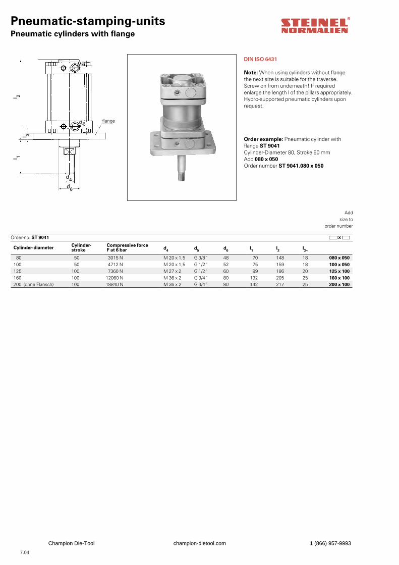
Pneumatic-stamping-unitsPneumatic cylinders with flange
DIN ISO 6431
Note: When using cylinders without flange the next size is suitable for the traverse.Screw on from underneath! If required enlarge the length l of the pillars appropriately.Hydro-supported pneumatic cylinders uponrequest.
Order example: Pneumatic cylinder with flange ST 9041Cylinder-Diameter 80, Stroke 50 mmAdd 080 x 050Order number ST 9041.080 x 050
x Order-no. ST 9041
Addsize to
order number
7.04
Cylinder-diameter Cylinder-stroke
Compressive force F at 6 bar d4 d5 d6 l1 l2 l3~
80 50 3015 N M 20 x 1,5 G 3/8” 48 70 148 18 080 x 050100 50 4712 N M 20 x 1,5 G 1/2” 52 75 159 18 100 x 050125 100 7360 N M 27 x 2 G 1/2” 60 99 186 20 125 x 100160 100 12060 N M 36 x 2 G 3/4” 80 132 205 25 160 x 100200 (ohne Flansch) 100 18840 N M 36 x 2 G 3/4” 80 142 217 25 200 x 100
flange
d4d6
l 1l 2
d 5
d 5
l 3
Champion Die-Tool champion-dietool.com 1 (866) 957-9993
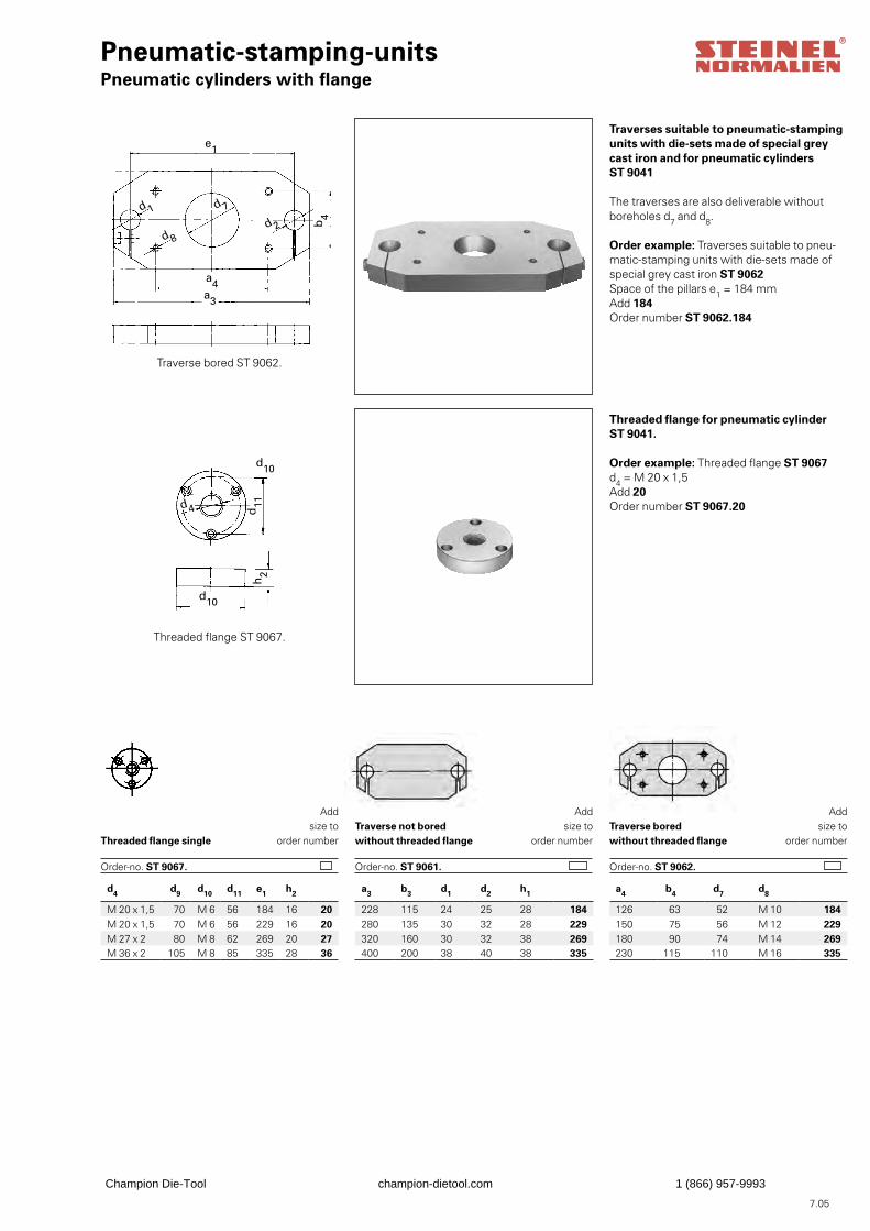
Pneumatic-stamping-unitsPneumatic cylinders with flange
Addsize to
order number
Traverses suitable to pneumatic-stampingunits with die-sets made of special greycast iron and for pneumatic cylindersST 9041
The traverses are also deliverable withoutboreholes d7 and d8.
Order example: Traverses suitable to pneu-matic-stamping units with die-sets made ofspecial grey cast iron ST 9062Space of the pillars e1 = 184 mmAdd 184Order number ST 9062.184
Traverse bored ST 9062.
Threaded flange for pneumatic cylinderST 9041.
Order example: Threaded flange ST 9067d4 = M 20 x 1,5Add 20Order number ST 9067.20
Threaded flange ST 9067.
Threaded flange single
Addsize to
order number
Addsize to
order number
Order-no. ST 9067.
7.05
d4 d9 d10 d11 e1 h2
M 20 x 1,5 70 M 6 56 184 16 20M 20 x 1,5 70 M 6 56 229 16 20M 27 x 2 80 M 8 62 269 20 27M 36 x 2 105 M 8 85 335 28 36
a3 b3 d1 d2 h1
228 115 24 25 28 184280 135 30 32 28 229320 160 30 32 38 269400 200 38 40 38 335
a4 b4 d7 d8
126 63 52 M 10 184150 75 56 M 12 229180 90 74 M 14 269230 115 110 M 16 335
Traverse not boredwithout threaded flange Order-no. ST 9061.
Traverse bored without threaded flange
Order-no. ST 9062.
d 1
d 8
d 7
a4a3
e1
b4
d 2
d11
d10
d 4
h2
d10
Champion Die-Tool champion-dietool.com 1 (866) 957-9993
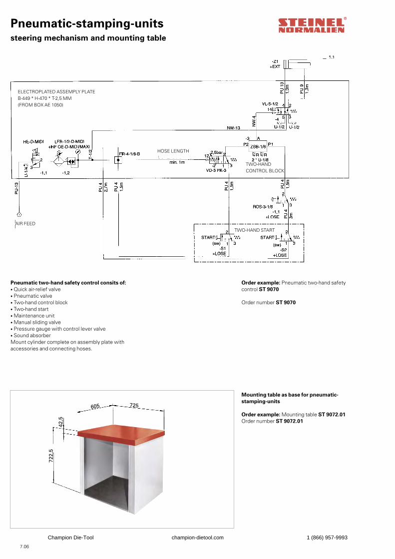
Pneumatic-stamping-unitssteering mechanism and mounting table
Pneumatic two-hand safety control consits of:• Quick air-relief valve• Pneumatic valve• Two-hand control block• Two-hand start• Maintenance unit• Manual sliding valve• Pressure gauge with control lever valve• Sound absorberMount cylinder complete on assembly plate withaccessories and connecting hoses.
Order example: Pneumatic two-hand safetycontrol ST 9070
Order number ST 9070
Order example: Mounting table ST 9072.01Order number ST 9072.01
Mounting table as base for pneumatic-stamping-units
7.06
605 725
722,
5
42,5
AIR FEEDTWO-HAND START
ELECTROPLATED ASSEMPLY PLATEB-449 * H-470 * T-2,5 MM(FROM BOX AE 1050)
HOSE LENGTH
TWO-HANDCONTROL BLOCK
Champion Die-Tool champion-dietool.com 1 (866) 957-9993
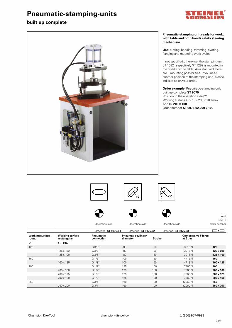
Working surface round
Working surface rectangular
Pneumatic connection
Pneumatic cylinder diameter Stroke
Compressive F force at 6 bar
D a1 x b1
125 G 3/8” 80 50 3015 N 125125 x 80 G 3/8” 80 50 3015 N 125 x 080125 x 100 G 3/8” 80 50 3015 N 125 x 100
160 G 1/2” 100 50 4712 N 160160 x 125 G 1/2” 100 50 4712 N 160 x 125
200 G 1/2” 125 100 7360 N 200200 x 100 G 1/2” 125 100 7360 N 200 x 100200 x 125 G 1/2” 125 100 7360 N 200 x 125200 x 160 G 1/2” 125 100 7360 N 200 x 160
250 G 3/4” 160 100 12060 N 250250 x 200 G 3/4” 160 100 12060 N 250 x 200
Pneumatic-stamping-unitsbuilt up complete
Pneumatic-stamping-unit ready for work,with table and both hands safety steeringmechanism
Use: cutting, bending, trimming, riveting,flanging and mounting work cycles
If not specified otherwise, the stamping-unitST 1092 respectively ST 1292 is mounted in the middle of the table. As a standard there are 3 mounting possibilities. If you need another position of the stamping-unit, please indicate so on your order.
Order example: Pneumatic-stamping-unit built up complete ST 9075Position to the operation side 02Working surface a1 x b1 = 200 x 100 mmAdd 02.200 x 100Order number ST 9075.02.200 x 100
Operation side Operation side Operation side
Order no. ST 9075.03
Addsize to
order number
7.07
Order no. ST 9075.02Order no. ST 9075.01 x
Champion Die-Tool champion-dietool.com 1 (866) 957-9993
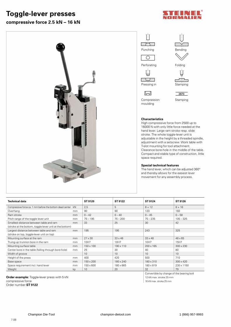
Technical data ST 9120 ST 9122 ST 9124 ST 9126
Compressive force ca. 1 mm before the bottom dead center kN 2,5 5 8 + 12 8 + 16Overhang mm 90 90 120 160Ram stroke mm 0 – 42 0 – 40 0 – 45 0 – 58Pitch range of the toggle lever unit mm 75 – 195 75 – 200 75 – 235 105 – 325Smallest distance between table and ram mm 33 25 30 42(stroke at the bottom, toggle-lever unit at the bottom)Largest distance between table and ram mm 195 195 243 325(stroke on top, toggle-lever unit on top)Mounting surface at the ram mm 27 x 30 33 x 48 33 x 48 48 x 65Truing-up trunnion bore in the ram mm 10H7 10H7 10H7 15H7Mounting surface table mm 150 x 100 190 x 110 200 x 165 300 x 230Center bore in the table (falling through bore-hole) mm 25 30 40 80Width of groove 10 10 10 10Height of the press mm 400 420 500 710Base space mm 150 x 200 180 x 240 180 x 310 300 x 420Space requirement incl. hand lever mm 150 x 600 180 x 665 180 x 819 230 x 1150Weight kp 10 20 32 79
Convertible by change of the bearing bolt12 kN max. stroke 25 mm
16 kN max. stroke 25 mm
Toggle-lever pressescompressive force 2.5 kN – 16 kN
2870
CharacteristicsHigh compressive force from 2500 up to 16000 N with only little force needed at the hand lever. Large ram stroke resp. slide stroke. The whole toggle-lever unit is adjustable in the height by a threaded spindle, adjustment with a setscrew. Work table with T-slot mounting for tool attachment. Clearance bore-hole in the middle of the table. Compact and stable type of construction, little space required.
Special technical featuresThe hand lever, which can be adjusted 360°and thereby allows for the easiest levermovement for any assembly process.
Order example: Toggle-lever press with 5 kNcompressive forceOrder number ST 9122
Punching
7.08
Bending
Perforating Folding
Pressing in Stamping
Compression moulding
Stamping
2870
Champion Die-Tool champion-dietool.com 1 (866) 957-9993
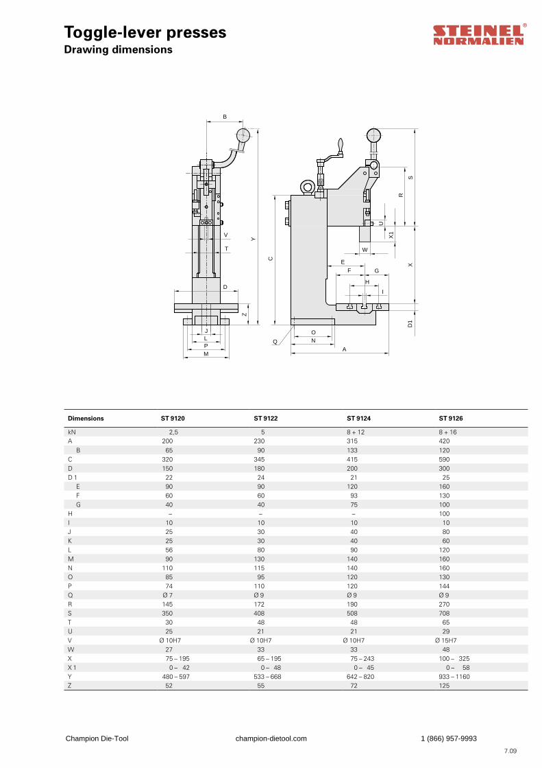
Toggle-lever pressesDrawing dimensions
B
JLPM
V
T
D
W
GF
H
I
E
ON
A
Y
Z
C
U
X1
XD
1
R
S
Q
7.09
Dimensions ST 9120 ST 9122 ST 9124 ST 9126
kN 2,5 5 8 + 12 8 + 16A 200 230 315 420
B 65 90 133 120C 320 345 415 590D 150 180 200 300D 1 22 24 21 25
E 90 90 120 160F 60 60 93 130G 40 40 75 100
H – – – 100I 10 10 10 10J 25 30 40 80K 25 30 40 60L 56 80 90 120M 90 130 140 160N 110 115 140 160O 85 95 120 130P 74 110 120 144Q Ø 7 Ø 9 Ø 9 Ø 9R 145 172 190 270S 350 408 508 708T 30 48 48 65U 25 21 21 29V Ø 10H7 Ø 10H7 Ø 10H7 Ø 15H7W 27 33 33 48X 75 – 195 65 – 195 75 – 243 100 – 325X 1 0 – 42 0 – 48 0 – 45 0 – 58Y 480 – 597 533 – 668 642 – 820 933 – 1160Z 52 55 72 125
Champion Die-Tool champion-dietool.com 1 (866) 957-9993
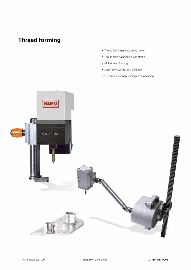
Thread forming
• Thread forming using a servo motor
• Thread forming using a press stroke
• Multi-thread forming
• Linear conveyer for part transport
• Hydraulic slide for punching and embossing
Champion Die-Tool champion-dietool.com 1 (866) 957-9993

Champion Die-Tool champion-dietool.com 1 (866) 957-9993
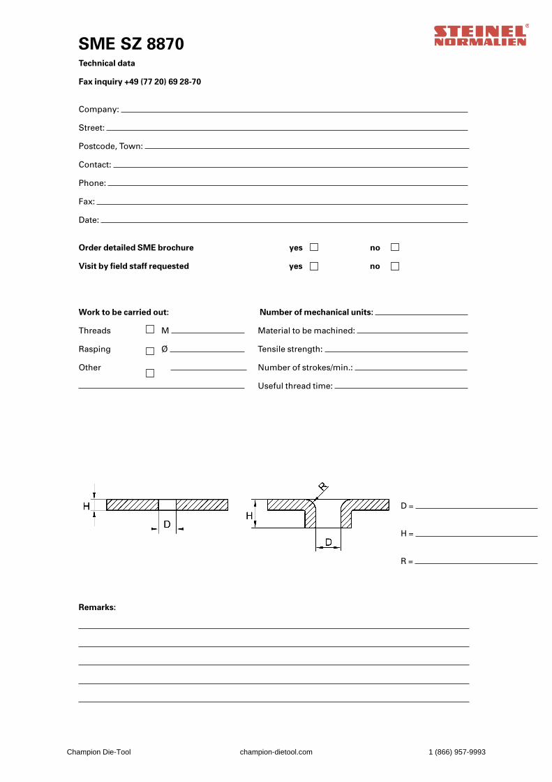
SME SZ 8870
Technical data
Fax inquiry +49 (77 20) 69 28-70
Company:
Street:
Postcode, Town:
Contact:
Phone:
Fax:
Date:
Order detailed SME brochure yes no
Visit by field staff requested yes no
Work to be carried out: Number of mechanical units:
Threads M Material to be machined:
Rasping Ø Tensile strength:
Other Number of strokes/min.:
Useful thread time:
D =
H =
R =
Remarks:
Champion Die-Tool champion-dietool.com 1 (866) 957-9993

Champion Die-Tool champion-dietool.com 1 (866) 957-9993
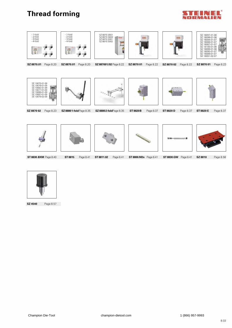
SE 19075-01-09SE 19076-01-09SE 19082-01-09SE 19077-01-09SE 19089-01-09SE 19087-01-09SE 19079-02-09
8.03
SZ 8870.SB01SZ 8870.SB02SZ 8870.S001SZ 8870.S002
SE 18097-01-08SE 18098-01-08SE 18094-01-07SE 18088-01-07SE 18087-01-07SE 18100-01-08SE 18099-01-08SE 18095-01-07SE 18089-01-07SE 18091-02-07
Thread forming
SZ 8810 Page 8.56
ST 8820 D Page 8.37
SZ 8870.01 Page 8.20
ST 8830 .BXM Page 8.40
SZ 8870 02 Page 8.23
SZ 887001/02 Page 8.22
ST 8811.02 Page 8.41
SZ 8880 2-foldPage 8.35 ST 8820 E Page 8.37
SZ 8870 01 Page 8.23SZ 8870.01 Page 8.20
ST 8815 Page 8.41
SZ 8880 1-fold Page 8.35
SZ 8870 01 Page 8.22
ST 8800.M2x Page 8.41 ST 8830.GW Page 8.41
ST 8820 B Page 8.37
SZ 8870 02 Page 8.22
- 1-fold- 2-fold- 3-fold- 4-fold
- 1-fold- 2-fold- 3-fold- 4-fold
SZ 4540 Page 8.57
Champion Die-Tool champion-dietool.com 1 (866) 957-9993

Champion Die-Tool champion-dietool.com 1 (866) 957-9993
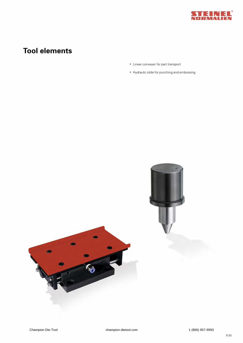
8.55
Tool elements
• Linear conveyer for part transport
• Hydraulic slide for punching and embossing
Champion Die-Tool champion-dietool.com 1 (866) 957-9993
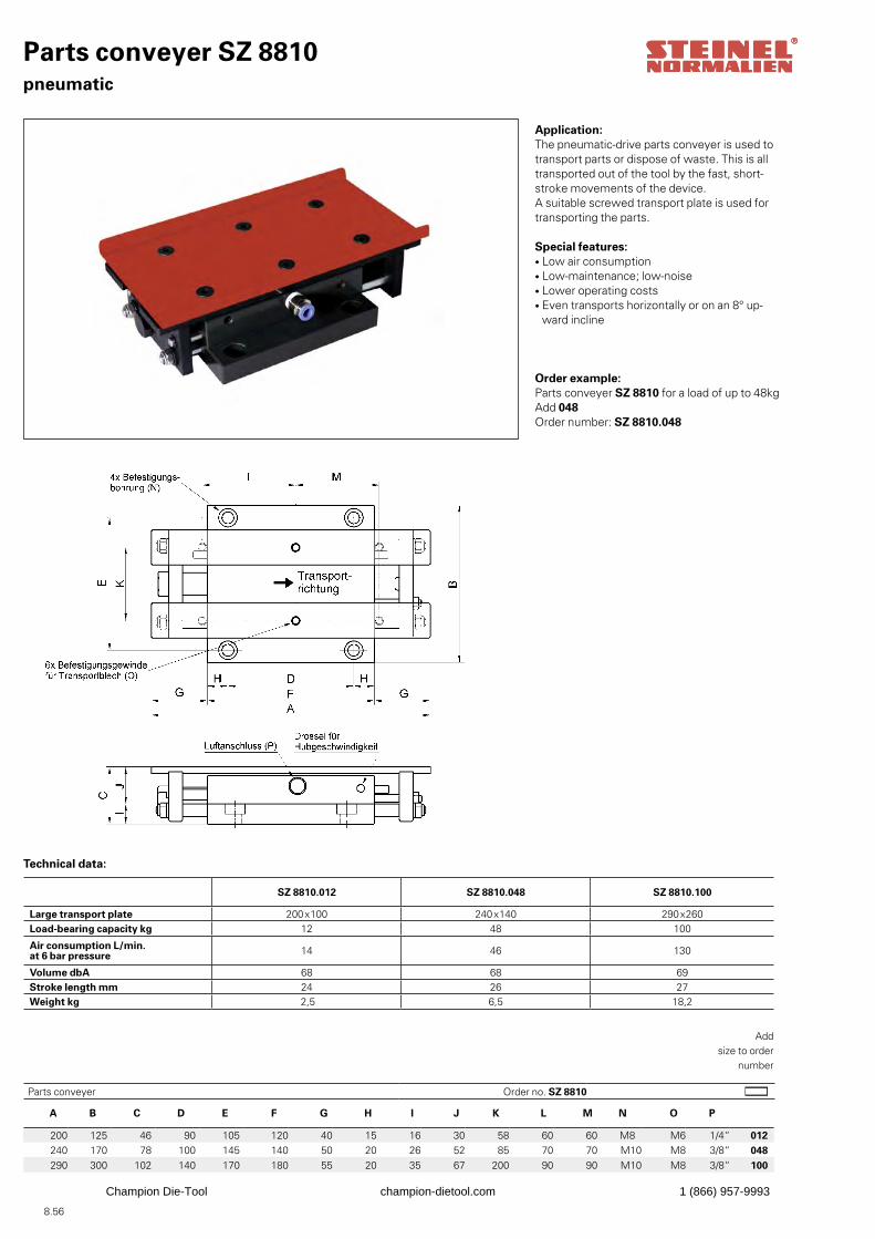
8.56
A B C D E F G H I J K L M N O P
200 125 46 90 105 120 40 15 16 30 58 60 60 M8 M6 1/4“ 012240 170 78 100 145 140 50 20 26 52 85 70 70 M10 M8 3/8“ 048290 300 102 140 170 180 55 20 35 67 200 90 90 M10 M8 3/8“ 100
Application: The pneumatic-drive parts conveyer is used to transport parts or dispose of waste. This is all transported out of the tool by the fast, short-stroke movements of the device.A suitable screwed transport plate is used for transporting the parts.
Special features: • Low air consumption• Low-maintenance; low-noise• Lower operating costs• Even transports horizontally or on an 8° up-
ward incline
Order example:Parts conveyer SZ 8810 for a load of up to 48kgAdd 048Order number: SZ 8810.048
Add size to order
number
Parts conveyer SZ 8810pneumatic
SZ 8810.012 SZ 8810.048 SZ 8810.100
Large transport plate 200x100 240x140 290x260Load-bearing capacity kg 12 48 100
Air consumption L/min.at 6 bar pressure 14 46 130
Volume dbA 68 68 69Stroke length mm 24 26 27Weight kg 2,5 6,5 18,2
Technical data:
Parts conveyer Order no. SZ 8810
Champion Die-Tool champion-dietool.com 1 (866) 957-9993
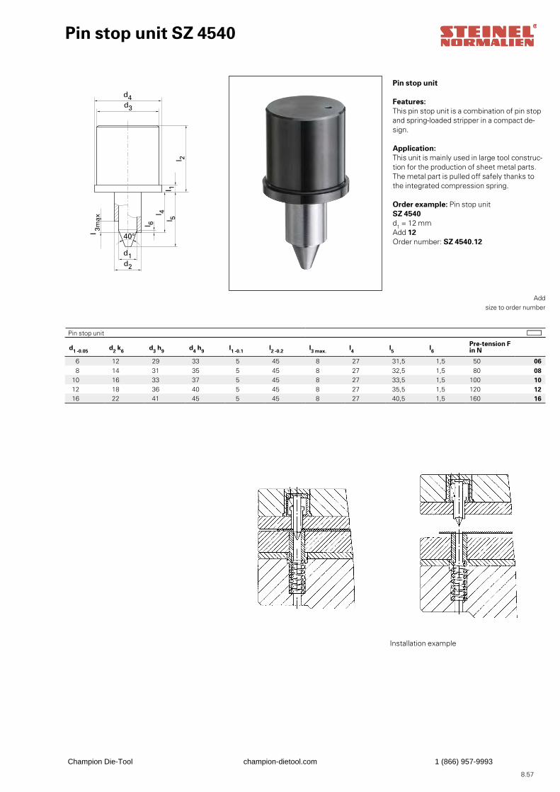
8.57
d1
d 2
d 4
d 3
l6
l 1
l 2
l 3m
ax.
40°
l 4
l 5
l 3max
d1d2
d4d3
l 2
l 1
l 4
l 6
l 5
40°
Pin stop unit SZ 4540
d1 -0.05 d2 k6 d3 h9 d4 h9 l1 -0.1 l2 -0.2 l3 max. l4 l5 l6Pre-tension F in N
6 12 29 33 5 45 8 27 31,5 1,5 50 068 14 31 35 5 45 8 27 32,5 1,5 80 08
10 16 33 37 5 45 8 27 33,5 1,5 100 1012 18 36 40 5 45 8 27 35,5 1,5 120 1216 22 41 45 5 45 8 27 40,5 1,5 160 16
Pin stop unit
Features: This pin stop unit is a combination of pin stop and spring-loaded stripper in a compact de-sign.
Application: This unit is mainly used in large tool construc-tion for the production of sheet metal parts. The metal part is pulled off safely thanks to the integrated compression spring.
Order example: Pin stop unit SZ 4540d1 = 12 mmAdd 12Order number: SZ 4540.12
Add size to order number
Pin stop unit
Installation example
Champion Die-Tool champion-dietool.com 1 (866) 957-9993
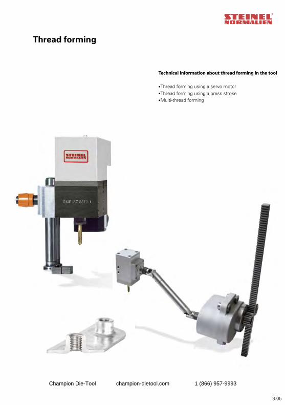
8.05
Thread forming
Technical information about thread forming in the tool
•Thread forming using a servo motor•Thread forming using a press stroke•Multi-thread forming
Champion Die-Tool champion-dietool.com 1 (866) 957-9993
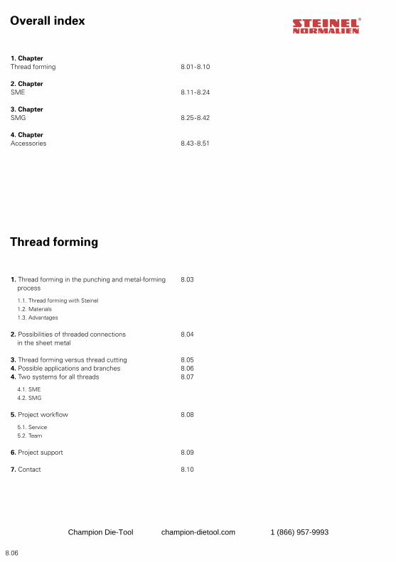
8.06
Thread forming
1. Thread forming in the punching and metal-forming 8.03 process
1.1. Thread forming with Steinel 1.2. Materials 1.3. Advantages
2. Possibilities of threaded connections 8.04 in the sheet metal
3. Thread forming versus thread cutting 8.054. Possible applications and branches 8.064. Two systems for all threads 8.07
4.1. SME 4.2. SMG
5. Project workflow 8.08
5.1. Service 5.2. Team
6. Project support 8.09
7. Contact 8.10
Overall index
1. ChapterThread forming 8.01-8.10
2. ChapterSME 8.11-8.24
3. ChapterSMG 8.25-8.42
4. ChapterAccessories 8.43-8.51
Champion Die-Tool champion-dietool.com 1 (866) 957-9993
8.07
1 3
2 4
Thread forming in the punching and metal-forming process
Thread forming in the tool – particularly in the case of series with several threads – offers you major advan-tages that have a direct effect on the quality of your products and the profitability of your company.
And it’s not only the advantages of thread forming over thread cutting that are convincing: It is even more profitable to form the threads yourself in the tool in one single production process. Saving you time and money.
Thread forming with SteinelOur aim as a manufacturer and toolmaker is to provide optimum products and solutions for your tools. We offer you two different thread-forming units: • The thread-forming unit SME • The thread-forming unit SMG Both form high-strength threads during the production process in the tool. Both optimize and accelerate the production process.
MaterialsThe SME and SMG are the thread-forming solution for the following materials:
• Hot and cold-rolled sheet metals • Aluminium • Stainless steels• TRIP steels (high-strength steel alloy)• DP steels (dual-phase steel)
AdvantagesOur thread-forming units SME and SMG have been especially designed for toolmaking. Thread forming with Steinel Standards Parts offers you convincing advantages:
More efficiency
• No additional working cycle
• Higher production rates
• Faster processing times
• Lower logistics costs
More quality
• Optimum finish
• Optimum process
More safety
• Automated production process
• Process monitoring possible
More service
• Comprehensive advice and
project support
• We are where we are
needed: Near you!
Champion Die-Tool champion-dietool.com 1 (866) 957-9993
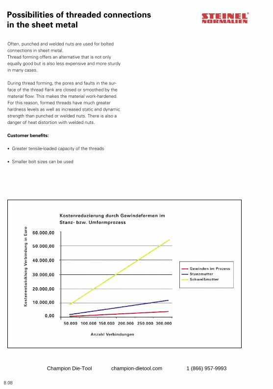
8.08
Possibilities of threaded connections in the sheet metal
During thread forming, the pores and faults in the sur-face of the thread flank are closed or smoothed by the material flow. This makes the material work-hardened. For this reason, formed threads have much greater hardness levels as well as increased static and dynamic strength than punched or welded nuts. There is also a danger of heat distortion with welded nuts.
Customer benefits:
• Greater tensile-loaded capacity of the threads
• Smaller bolt sizes can be used
Often, punched and welded nuts are used for bolted connections in sheet metal. Thread forming offers an alternative that is not only equally good but is also less expensive and more sturdy in many cases.
Champion Die-Tool champion-dietool.com 1 (866) 957-9993
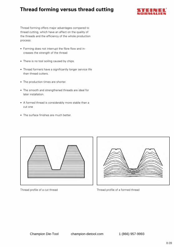
8.09
Thread forming versus thread cutting
Thread forming offers major advantages compared to thread cutting, which have an affect on the quality of the threads and the efficiency of the whole production process:
• Forming does not interrupt the fibre flow and in-creases the strength of the thread
• There is no tool soiling caused by chips.
• Thread formers have a significantly longer service life than thread cutters.
• The production times are shorter.
• The smooth and strengthened threads are ideal for later installation.
• A formed thread is considerably more stable than a cut one
• The surface finishes are much better.
Thread profile of a cut thread Thread profile of a formed thread
Champion Die-Tool champion-dietool.com 1 (866) 957-9993
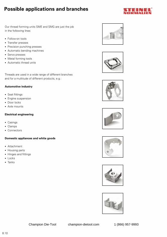
8.10
Our thread forming units SME and SMG are just the job in the following lines
• Follow-on tools• Transfer presses• Precision punching presses• Automatic bending machines• Servo presses • Metal forming tools• Automatic thread units
Threads are used in a wide range of different branches and for a multitude of different products, e.g.:
Automotive industry
• Seat fittings• Engine suspension• Door locks• Axle mounts
Electrical engineering
• Casings• Clamps• Connectors
Domestic appliances and white goods
• Attachment• Housing parts• Hinges and fittings• Locks• Tanks
Possible applications and branches
Champion Die-Tool champion-dietool.com 1 (866) 957-9993
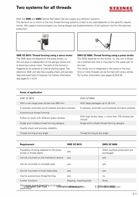
8.11
With the SME and SMG Steinel Normalien AG can supply two different systems. The decision as to which of the two thread forming systems is best to be used depends on the specific require-ments. We support and accompany you during design and implementation of the optimum tool for the planned production.
SME SZ 8870: Thread forming using a servo motorThe SME does not depend on the press stroke, i.e. the unit drive is independent of the plunger stroke and is driven by a servo motor. The path of the former is triggered by an external or internal starting signal. The electronic SME unit also has a quality check and can also rasp and insert bolts if required. For further information see pages 8.11-8.24
Two systems for all threads
SMG SZ 8880: Thread forming using a press strokeThe SMG depends on the stroke, i.e. the unit is driven via a toothed rack that is mounted to the upper part of the tool. The whole unit is integrated in the press or the tool. One or more threads can be formed with every stroke. For further information see pages 8.25-8.39
Areas of application
SME SZ 8870 SMG SZ 8880
With a very large press stroke over 600 mm With deep passages up to 35 mm
In presses, automatic punch presses and servo presses In presses, automatic punch presses and servo presses
Autonomous thread forming
Follow-on tools with different press strokesWith high stroke rates -> more than 150 strokes per minute
Single and multiple thread forming designs Single and multiple thread forming designs
Quality check and process reliability
Thread forming at any angle Thread forming at any angle
Requirement SME SZ 8870 SMG SZ 8880
Possibility of being adapted to the press stroke or thread depth
yesWhen toothed wheel pairs are exchanged
Can be mounted on the hold-down device yes yes
Can be mounted on movable seat yes yes
Can be mounted on lower base plate yes yes
Use for autonomous thread forming yes no
Further functions Rasping, inserting bolts None
Max. press speed depending on process parameters
120 strokes / min 150 strokes / minChampion Die-Tool champion-dietool.com 1 (866) 957-9993
8.12
Service We ensure that STEINEL’s thread-forming units offer maximum process reliability for your production. This is ensured not only by our technically mature systems but also by a comprehensive range of services that guaran-tees speed and high availability. We are there when you really need us. Our service is competent, fast, flexible and extremely reliable.
Project workflow at the customer’s: Project support through Steinel Normalien:
1. Part designContact and advice, checking on design drawing
2. Tool design Advice, checking on design drawing
3. Choice of thread-forming system Planning
4. Tooling constructionImplementation, acceptance test, documentation of the system
5. ProductionInstruction concerning operating instructions, training and maintenance through service technicians
Project workflow
TeamOur team always deals with your inquiries immediately and provides support throughout the whole project. This means you have one contact – from the inquiry through the offer to project planning.
Champion Die-Tool champion-dietool.com 1 (866) 957-9993

8.13
Project support
Product manager
Our subsidiaries
Switzerland
France
Field staff in Germany
Project support
Markus Aistermann (11)Mobile: 0170 / 9 13 77 87Fax: 0 52 44 / 90 32 [email protected]
Maik Didczilatis (17)Mobile: 0171 / 4 70 30 94Fax: 0 52 44 / 90 59 [email protected]
Jörg Wiedenmann (28)Mobile: 01 71 / 4 89 24 10Fax: 0 67 37 / 7107 [email protected]
Lothar Weisbach (29)Mobile: 0171 / 4 72 24 34Fax: 0 37 21 / 26 86 [email protected]
Hubert Schuhmacher (34)Mobile: 0175 / 1 80 77 98Fax: 0 74 24 / 95 68 [email protected]
Christoph Sigg (20)Mobile: 0175 / 1 80 78 02Fax: 0 70 22 / 21 27 [email protected]
SUVAG Vertriebs AGHerbstweg 77CH8050 Zürich-OerlikonTel.: +41 (0) 44 321 / 47 47Fax: +41 (0) 44 322 / 53 [email protected]
STEINEL S.A.2 rue Luigi Galvani14, Rue des Petits RuisseauxF-92160 AntonyAP Jérome GaumierTel. + 33 / (0) 1 / 46 15 48 80Fax + 33 / (0) 1 / 46 89 24 87Internet: www.steinel-sa.comE-mail: [email protected]: [email protected]
Uwe Albrecht (42)Mobile: 0160 / 90 16 64 68Fax: 0 95 62 / 40 01 [email protected]
Harald Gotzler (46)Mobile: 0160 / 97 24 60 14Fax: 0 80 62 / 80 90 [email protected]
N.N
Champion Die-Tool champion-dietool.com 1 (866) 957-9993
8.14
Steinel Normalien AG
Winkelstraße 7D-78056 Villingen-SchwenningenPhone +49 (0)7720/6928-0Fax +49 (0)7720/6928-70Internet: http://www.steinel-normalien.deE-mail: [email protected]
We do not accept liability for printing errors and mistakes. Research brings improvements, changes to design, dimensions and materials. For this reason we reserve the right to make technical changes. Copyright Steinel Normalien AG
Contact
Champion Die-Tool champion-dietool.com 1 (866) 957-9993
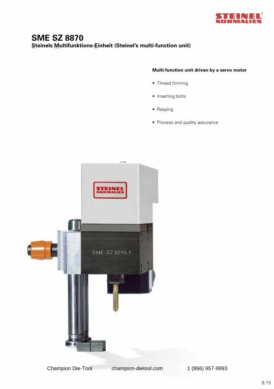
8.15
SME SZ 8870Steinels Multifunktions-Einheit (Steinel’s multi-function unit)
Multi-function unit driven by a servo motor
• Thread forming
• Inserting bolts
• Rasping
• Process and quality assurance
Champion Die-Tool champion-dietool.com 1 (866) 957-9993
8.16
SE 18097-01-08SE 18098-01-08SE 18094-01-07SE 18088-01-07SE 18087-01-07SE 18100-01-08SE 18099-01-08SE 18095-01-07SE 18089-01-07SE 18091-02-07
SE 19075-01-09SE 19076-01-09SE 19082-01-09SE 19077-01-09SE 19089-01-09SE 19087-01-09SE 19079-02-09
SZ 8870.SB01SZ 8870.SB02SZ 8870.S001SZ 8870.S002
SME SZ 8870The patented all-rounder
1. Inserting bolts, rasping, 8.17 In-process thread forming2. Advantages 8.173. Areas and possibilities of application 8.174. Control, programming, drive 8.18 and operation5. Use in different 8.18 tools6. Workflow 8.197. Process and quality assurance 8.198. Variation possibilities 8.209. Integration in the tool 8.2110. Suitable STEINEL products 8.2111. Attachment possibilities for the SME 8.21 in the tool 12. System 8.2213. Technical data of control cabinet 8.2214. Drawings and dimensions 8.23-8.2415. Accessories list 8.2516. Order and order example 8.2617. Fax inquiry 8.2718. Contact 8.28
SZ 8870 02 Page 8.22 SZ 8870 01 Page 8.23
SZ 8870 02 Page 8.23
SZ 8870.01- Page 8.20 SZ 8870.02- Page 8.20
- 1-fold- 2-fold- 3-fold- 4-fold
- 1-fold- 2-fold- 3-fold- 4-fold
SZ 887001/02 Page 8.22 SZ 8870 01 Page 8.22
Champion Die-Tool champion-dietool.com 1 (866) 957-9993
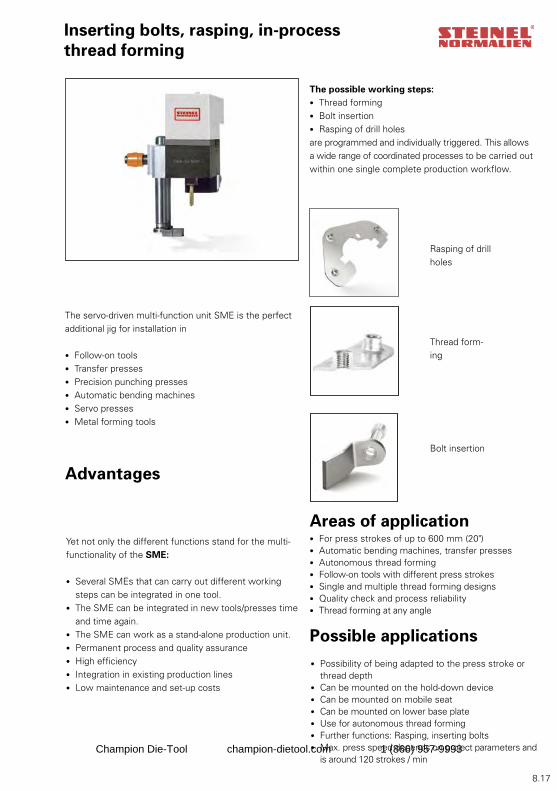
8.17
Inserting bolts, rasping, in-process thread forming
The servo-driven multi-function unit SME is the perfect additional jig for installation in
• Follow-on tools• Transfer presses• Precision punching presses• Automatic bending machines• Servo presses • Metal forming tools
The possible working steps: • Thread forming• Bolt insertion• Rasping of drill holesare programmed and individually triggered. This allows a wide range of coordinated processes to be carried out within one single complete production workflow.
Yet not only the different functions stand for the multi-functionality of the SME:
• Several SMEs that can carry out different working steps can be integrated in one tool.
• The SME can be integrated in new tools/presses time and time again.
• The SME can work as a stand-alone production unit.• Permanent process and quality assurance• High efficiency• Integration in existing production lines• Low maintenance and set-up costs
Advantages
Bolt insertion
Rasping of drill holes
Thread form-ing
Areas of application• For press strokes of up to 600 mm (20")• Automatic bending machines, transfer presses • Autonomous thread forming• Follow-on tools with different press strokes• Single and multiple thread forming designs• Quality check and process reliability• Thread forming at any angle
• Possibility of being adapted to the press stroke or thread depth
• Can be mounted on the hold-down device• Can be mounted on mobile seat• Can be mounted on lower base plate• Use for autonomous thread forming• Further functions: Rasping, inserting bolts• Max. press speed depends on project parameters and
is around 120 strokes / min
Possible applications
Champion Die-Tool champion-dietool.com 1 (866) 957-9993
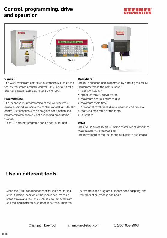
8.18
Control, programming, drive and operation
Fig. 1.1
Control:The work cycles are controlled electronically outside the tool by the stored-program control (SPC). Up to 6 SMEs can work side by side controlled by one SPC.
Programming:The independent programming of the working proc-esses is carried out using the control panel (Fig. 1.1). The control unit contains a basic program per function and parameters can be freely set depending on customer wishes. Up to 10 different programs can be set up per unit.
Operation:The multi-function unit is operated by entering the follow-ing parameters in the control panel:• Program number• Speed of the AC servo motor• Maximum and minimum torque• Maximum cycle time• Number of revolutions during insertion and removal• Start and stop ramp of the motor• Quantities
Drive: The SME is driven by an AC servo motor which drives the main spindle via a toothed belt. The movement of the tool to the strip/part is pneumatic.
Since the SME is independent of thread size, thread pitch, function, position of the workpiece, machine, press stroke and tool, the SME can be removed from one tool and installed in another in no time. Then the
Use in different tools
parameters and program numbers need adapting, and the production process can begin.
Champion Die-Tool champion-dietool.com 1 (866) 957-9993
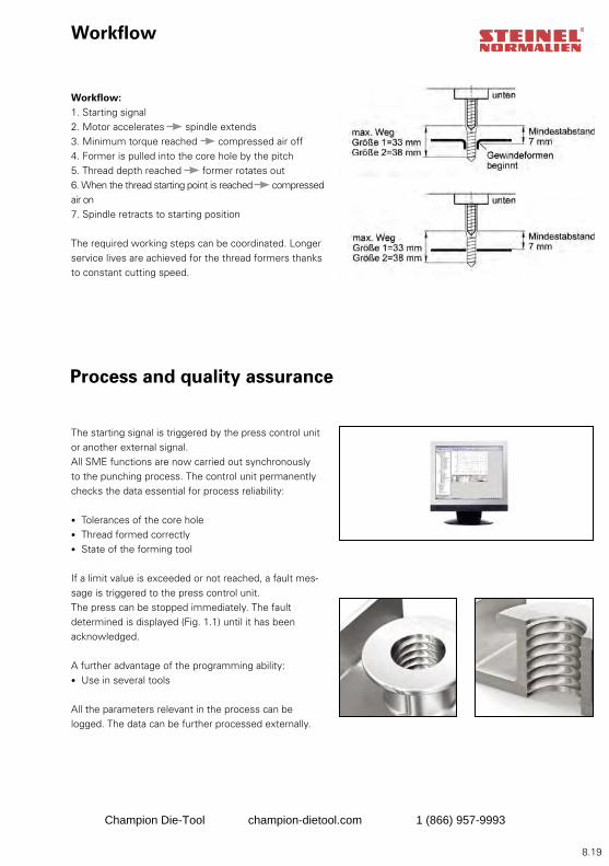
8.19
Process and quality assurance
Workflow
Workflow:1. Starting signal2. Motor accelerates spindle extends3. Minimum torque reached compressed air off4. Former is pulled into the core hole by the pitch5. Thread depth reached former rotates out6. When the thread starting point is reached compressed air on7. Spindle retracts to starting position
The required working steps can be coordinated. Longer service lives are achieved for the thread formers thanks to constant cutting speed.
The starting signal is triggered by the press control unit or another external signal. All SME functions are now carried out synchronously to the punching process. The control unit permanently checks the data essential for process reliability:
• Tolerances of the core hole• Thread formed correctly• State of the forming tool
If a limit value is exceeded or not reached, a fault mes-sage is triggered to the press control unit.The press can be stopped immediately. The fault determined is displayed (Fig. 1.1) until it has been acknowledged.
A further advantage of the programming ability:• Use in several tools
All the parameters relevant in the process can be logged. The data can be further processed externally.
Champion Die-Tool champion-dietool.com 1 (866) 957-9993
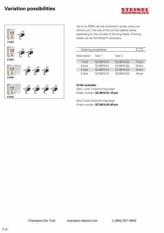
8.20
Einsatzmöglichkeiten
Up to six SMEs can be switched in series using one control unit. The size of the control cabinet varies depending on the number of forming heads. Forming heads can be retrofitted if necessary.
Variation possibilities
1-fold
2-fold
3-fold
4-fold
Ordering possibilities
Description Size 1 Size 2
1-fold SZ 8870.01- SZ 8870.02- 1Fach2-fold SZ 8870.01- SZ 8870.02- 2Fach3-fold SZ 8870.01- SZ 8870.02- 3Fach4-fold SZ 8870.01- SZ 8870.02- 4Fach
Order example:Size 1 with 1-fold forming headOrder number: SZ 8870.01-1Fach
Size 2 with 4-fold forming headOrder number: SZ 8870.02-4Fach
Champion Die-Tool champion-dietool.com 1 (866) 957-9993
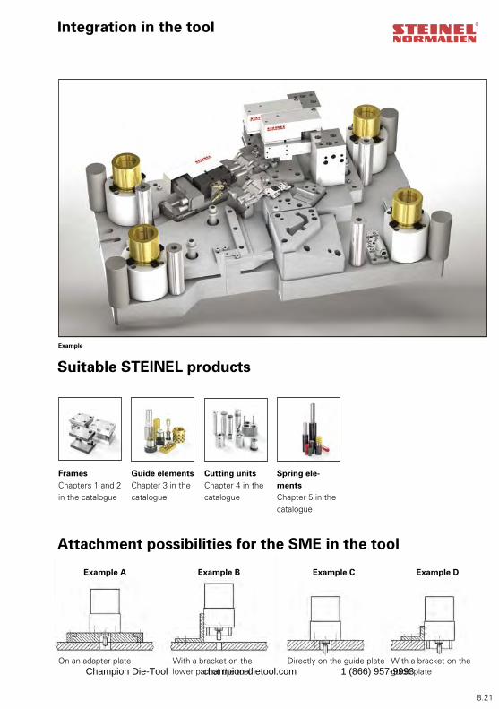
8.21
Integration in the tool
Attachment possibilities for the SME in the tool
On an adapter plate With a bracket on the lower part of the tool
Directly on the guide plate With a bracket on the guide plate
Example A Example B Example C Example D
Suitable STEINEL products
FramesChapters 1 and 2 in the catalogue
Guide elements Chapter 3 in the catalogue
Cutting unitsChapter 4 in the catalogue
Spring ele-mentsChapter 5 in the catalogue
Example
Champion Die-Tool champion-dietool.com 1 (866) 957-9993
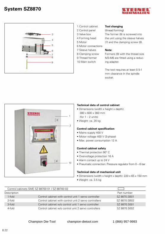
8.22
3
4
5
6
78
9
10
2
1
System SZ8870
1 Control cabinet2 Control panel3 Valve box4 Forming head5 Motor6 Motor connections7 Sleeve halves8 Clamping screw9 Thread former10 Main switch
Technical data of control cabinet • Dimensions (width x height x depth): 380 x 600 x 360 mm (for 1 – 2 units)• Weight: ca. 20 kg
Control cabinet specification• Mains supply 400 V• Motor voltage 400 V (3-phase)• Max. power consumption 12 A
Control cabinet safety• Thermal protection 90° C• Overvoltage protection 16 A• Alarm contact up to 24 V• Pneumatic connection: Pressure regulator from 0 – 6 bar
Technical data of mechanical unit• Dimensions (width x height x depth): 220 x 65 x 150 mm• Weight: ca. 3.5 kg
Tool changing (thread forming)The former (9) is screwed into the unit using the sleeve halves (7) and the clamping screw (8).
Note:Formers (9) with the thread size M3-M6 are fitted using a reduc-ing adapter.
The tool requires at least 0.5-1 mm clearance in the spindle socket.
Control cabinets SME SZ 88700 01 / SZ 88700 02 Description Part number
1-fold Control cabinet with control unit 1 servo controller SZ 8870.SB012-fold Control cabinet with control unit 2 servo controllers SZ 8870.SB023-fold Control cabinet w/o control unit 1 servo controller SZ 8870.S0014-fold Control cabinet w/o control unit 2 servo controllers SZ 8870.S002
Champion Die-Tool champion-dietool.com 1 (866) 957-9993
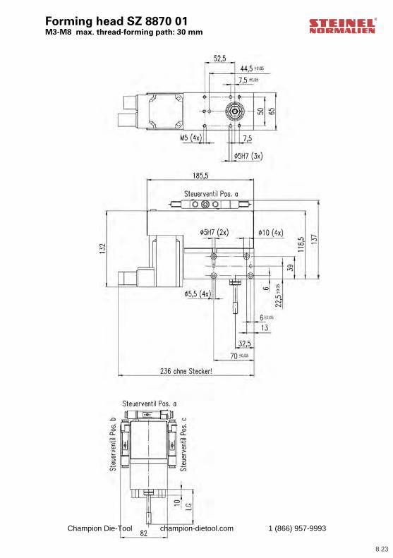
8.23
Forming head SZ 8870 01 M3-M8 max. thread-forming path: 30 mm
Champion Die-Tool champion-dietool.com 1 (866) 957-9993
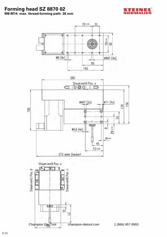
8.24
Forming head SZ 8870 02 M8-M14 max. thread-forming path: 38 mm
Champion Die-Tool champion-dietool.com 1 (866) 957-9993
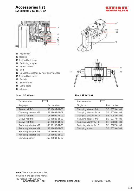
8.25
01
02
03040506
07
0809
10
11
1212
Accessories list SZ 8870 01 / SZ 8870 02
01 Main shaft02 Bearing03 Toothed belt drive04 Reducing adapter 05 Sleeve halves06 Bolt07 Sensor bracket for cylinder query sensor08 Toothed belt motor09 Switch10 Servo motor11 Valve cable12 Solenoid
Size 1 SZ 8870 01
Tool elements
Single part Part number
Sleeve half M3 SE 18097-01-08Clamping sleeves M4 SE 18098-01-08Sleeve half M5 SE 18094-01-07Sleeve half M6 SE 18088-01-07Sleeve half M8 SE 18087-01-07Reducing adapter M3 SE 18100-01-08Reducing adapter M4 SE 18099-01-08Reducing adapter M5 SE 18095-01-07Reducing adapter M6 SE 18089-01-07Clamping screw SE 18091-02-07
Size 2 SZ 8870 02
Tool elements
Single part Part number
Clamping sleeves M8 SE 19075-01-09Clamping sleeves M10 SE 19076-01-09Clamping sleeves M12 SE 19082-01-09Reducing adapter M8 SE 19077-01-09Reducing adapter M10 SE 19089-01-09Reducing adapter M12 SE 19087-01-09Clamping screw SE 19079-02-09
Note: There is a spare parts list included in the operating manual you receive with the SME.
Champion Die-Tool champion-dietool.com 1 (866) 957-9993
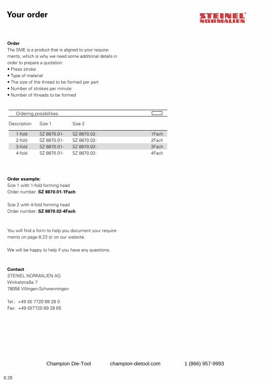
8.26
OrderThe SME is a product that is aligned to your require-ments, which is why we need some additional details in order to prepare a quotation:• Press stroke• Type of material• The size of the thread to be formed per part• Number of strokes per minute• Number of threads to be formed
Order example:Size 1 with 1-fold forming headOrder number: SZ 8870.01-1Fach
Size 2 with 4-fold forming headOrder number: SZ 8870.02-4Fach
You will find a form to help you document your require-ments on page 8.23 or on our website.
We will be happy to help if you have any questions.
ContactSTEINEL NORMALIEN AGWinkelstraße 7 78056 Villingen-Schwenningen
Tel.: +49 (0) 7720 69 28 0Fax: +49 (0)7720 69 28 65
Your order
Ordering possibilities
Description Size 1 Size 2
1-fold SZ 8870.01- SZ 8870.02- 1Fach2-fold SZ 8870.01- SZ 8870.02- 2Fach3-fold SZ 8870.01- SZ 8870.02- 3Fach4-fold SZ 8870.01- SZ 8870.02- 4Fach
Champion Die-Tool champion-dietool.com 1 (866) 957-9993
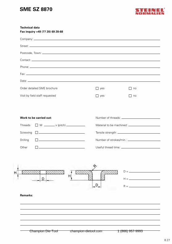
8.27
D =
H = R =
SME SZ 8870
Technical dataFax inquiry +49 (77 20) 69 28-68
Company:
Street:
Postcode, Town:
Contact:
Phone:
Fax:
Date:
Order detailed SME brochure yes no
Visit by field staff requested yes no
Work to be carried out: Number of threads:
Threads M x (pitch) Material to be machined:
Screwing Tensile strength:
Drilling Number of strokes/min.:
Other Useful thread time:
Remarks:
Champion Die-Tool champion-dietool.com 1 (866) 957-9993
8.28
Steinel Normalien AG
Winkelstraße 7D-78056 Villingen-SchwenningenPhone +49 (0)7720/6928-0Fax +49 (0)7720/6928-70Internet: http://www.steinel-normalien.deE-mail: [email protected]
We do not accept liability for printing errors and mistakes. Research brings improvements, changes to design, dimensions and materials. For this reason we reserve the right to make technical changes. Copyright Steinel Normalien AG
Contact
Champion Die-Tool champion-dietool.com 1 (866) 957-9993
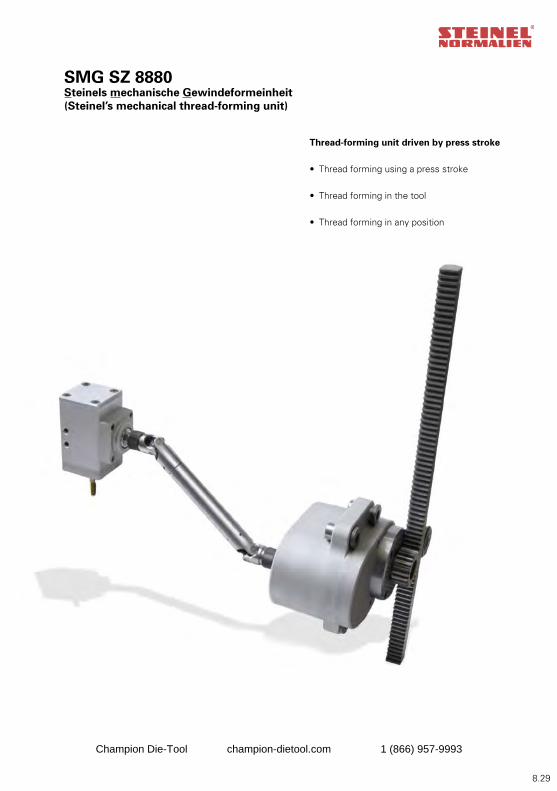
8.29
SMG SZ 8880Steinels mechanische Gewindeformeinheit (Steinel’s mechanical thread-forming unit)
Thread-forming unit driven by press stroke
• Thread forming using a press stroke
• Thread forming in the tool
• Thread forming in any position
Champion Die-Tool champion-dietool.com 1 (866) 957-9993
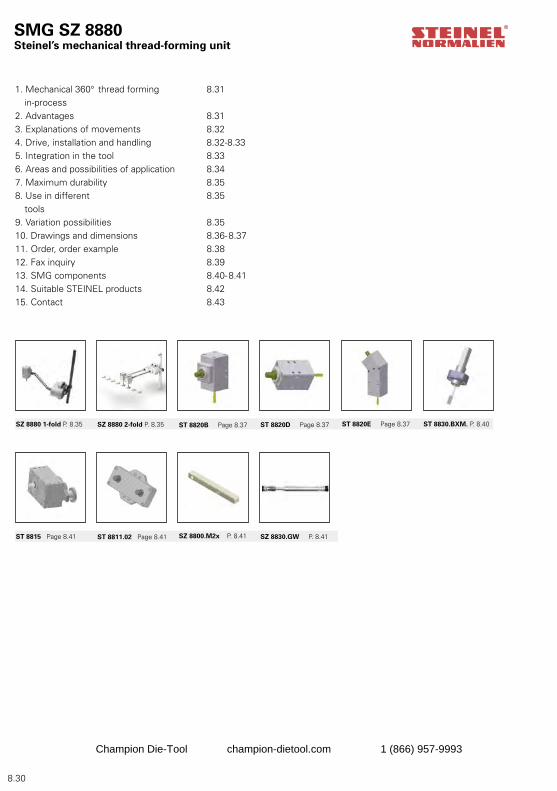
8.30
SMG SZ 8880Steinel’s mechanical thread-forming unit
1. Mechanical 360° thread forming 8.31 in-process2. Advantages 8.313. Explanations of movements 8.324. Drive, installation and handling 8.32-8.335. Integration in the tool 8.336. Areas and possibilities of application 8.347. Maximum durability 8.358. Use in different 8.35 tools 9. Variation possibilities 8.3510. Drawings and dimensions 8.36-8.3711. Order, order example 8.3812. Fax inquiry 8.3913. SMG components 8.40-8.4114. Suitable STEINEL products 8.4215. Contact 8.43
SZ 8880 1-fold P. 8.35 SZ 8880 2-fold P. 8.35 ST 8820B Page 8.37 ST 8820D Page 8.37 ST 8820E Page 8.37
ST 8811.02 Page 8.41 SZ 8800.M2x P. 8.41 SZ 8830.GW P. 8.41ST 8815 Page 8.41
ST 8830.BXM. P. 8.40
Champion Die-Tool champion-dietool.com 1 (866) 957-9993
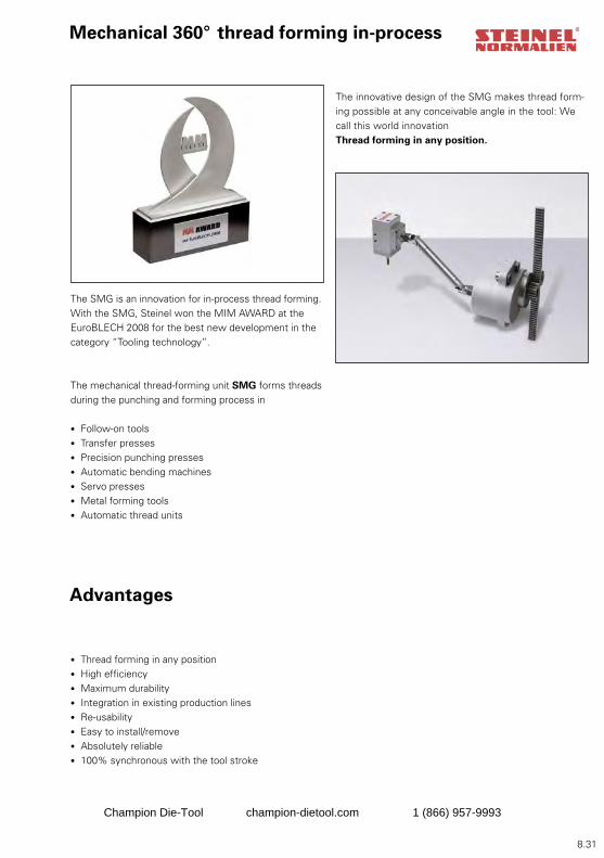
8.31
Mechanical 360° thread forming in-process
The SMG is an innovation for in-process thread forming. With the SMG, Steinel won the MIM AWARD at the EuroBLECH 2008 for the best new development in the category “Tooling technology”.
The mechanical thread-forming unit SMG forms threads during the punching and forming process in
• Follow-on tools• Transfer presses• Precision punching presses• Automatic bending machines• Servo presses • Metal forming tools• Automatic thread units
The innovative design of the SMG makes thread form-ing possible at any conceivable angle in the tool: We call this world innovation Thread forming in any position.
Advantages
• Thread forming in any position• High efficiency• Maximum durability• Integration in existing production lines• Re-usability• Easy to install/remove• Absolutely reliable• 100% synchronous with the tool stroke
Champion Die-Tool champion-dietool.com 1 (866) 957-9993
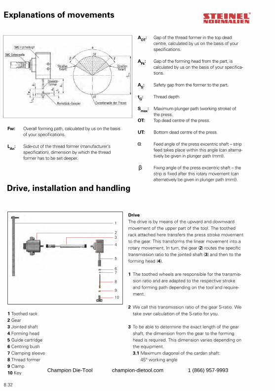
8.32
1
23
4
5
67
8
9
10
Drive, installation and handling
1 Toothed rack2 Gear3 Jointed shaft4 Forming head5 Guide cartridge6 Centring bush7 Clamping sleeve 8 Thread former9 Clamp10 Key
Fw: Overall forming path, calculated by us on the basis of your specifications.
LAn: Side-cut of the thread former (manufacturer’s specification), dimension by which the thread former has to be set deeper.
DriveThe drive is by means of the upward and downward movement of the upper part of the tool. The toothed rack attached here transfers the press stroke movement to the gear. This transforms the linear movement into a rotary movement. In turn, the gear (2) routes the specific transmission ratio to the jointed shaft (3) and then to the forming head (4).
1 The toothed wheels are responsible for the transmis-sion ratio and are adapted to the respective stroke and forming path depending on the tool and require-ment.
2 We call this transmission ratio of the gear S-ratio. We take over calculation of the S-ratio for you.
3 To be able to determine the exact length of the gear shaft, the dimension from the gear to the forming head is required. This dimension varies depending on the equipment.
3.1 Maximum diagonal of the cardan shaft: 45° working angle
AOT: Gap of the thread former in the top dead centre, calculated by us on the basis of your specifications.
AFk: Gap of the forming head from the part, is calculated by us on the basis of your specifica-tions.
AS: Safety gap from the former to the part.
tG: Thread depth
Smax: Maximum plunger path (working stroke) of the press.OT: Top dead centre of the press.
UT: Bottom dead centre of the press.
: Feed angle of the press excentric shaft – strip feed takes place within this angle (can alterna-tively be given in plunger path (mm)).
β : Fixing angle of the press excentric shaft – the strip is fixed after this rotary movement (can alternatively be given in plunger path (mm)).
Explanations of movements
Champion Die-Tool champion-dietool.com 1 (866) 957-9993
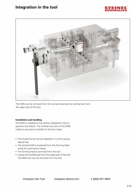
8.33
Installation and handlingThe SMG is installed at the position designed in the re-spective tool station. The modular structure of the SMG makes it very easy to handle for the tool maker:
• The thread former can be replaced in no time using a
special key. • The jointed shaft is loosened from the forming head
using the quick-action clamp. • The forming head is removed from the tool. • Loosen the toothed rack from the upper part of the tool:
The SMG can now be removed from the tool
Integration in the tool
The SMG can be removed from the tool by loosening the toothed rack from the upper part of the tool.
Champion Die-Tool champion-dietool.com 1 (866) 957-9993
8.34
Areas of application
Possible applications
• With deep passages up to 35 mm• With high stroke rates -> max. 200 strokes per minute• In presses and automatic punching machines• Single and multiple thread forming designs• Thread forming at any angle• Servo presses
• After changing the two toothed wheels it is possible to adapt the press stroke or thread depth• Can be mounted on the hold-down device• Can be mounted on mobile seat• Can be mounted on lower base plate• The max. press speed dependent on the project parameters is 200 strokes/min
Champion Die-Tool champion-dietool.com 1 (866) 957-9993
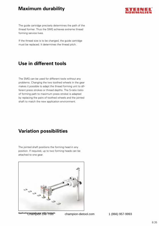
8.35
Maximum durability
The guide cartridge precisely determines the path of the thread former. Thus the SMG achieves extreme thread forming service lives.
If the thread size is to be changed, the guide cartridge must be replaced. It determines the thread pitch.
Use in different tools
Variation possibilities
The SMG can be used for different tools without any problems. Changing the two toothed wheels in the gear makes it possible to adapt the thread forming unit to dif-ferent press strokes or thread depths. The S-ratio (ratio of forming path to maximum press stroke) is adapted by replacing the pairs of toothed wheels and the jointed shaft to match the new application environment.
The jointed shaft positions the forming head in any position. If required, up to two forming heads can be attached to one gear.
Application example gear with 2 outputsChampion Die-Tool champion-dietool.com 1 (866) 957-9993
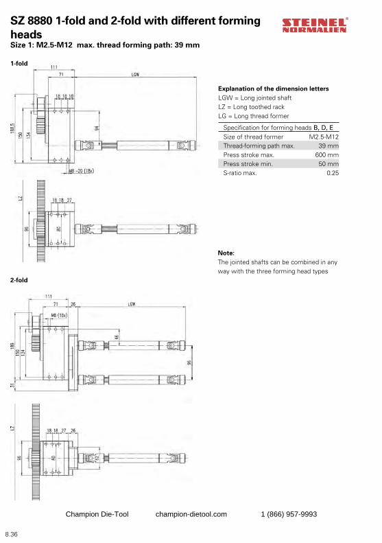
8.36
SZ 8880 1-fold and 2-fold with different forming heads Size 1: M2.5-M12 max. thread forming path: 39 mm
Note:The jointed shafts can be combined in any way with the three forming head types
Explanation of the dimension lettersLGW = Long jointed shaftLZ = Long toothed rackLG = Long thread former
Specification for forming heads B, D, ESize of thread former M2.5-M12Thread-forming path max. 39 mmPress stroke max. 600 mmPress stroke min. 50 mmS-ratio max. 0.25
1-fold
2-fold
Champion Die-Tool champion-dietool.com 1 (866) 957-9993
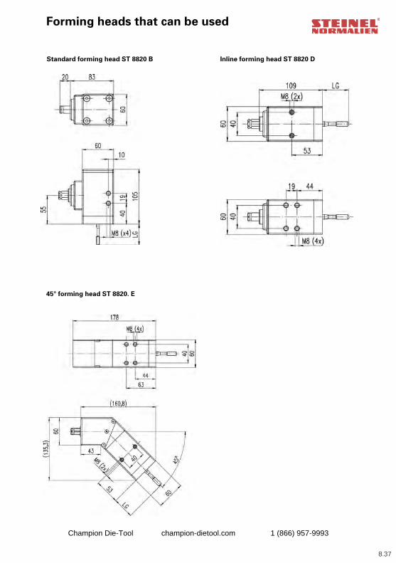
8.37
Forming heads that can be used
Standard forming head ST 8820 B Inline forming head ST 8820 D
45° forming head ST 8820. E
Champion Die-Tool champion-dietool.com 1 (866) 957-9993
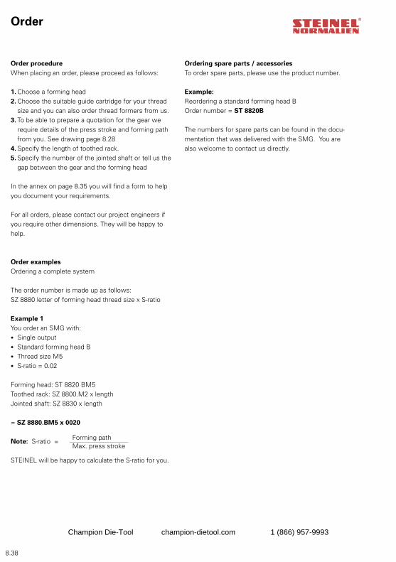
8.38
Order procedureWhen placing an order, please proceed as follows:
1. Choose a forming head 2. Choose the suitable guide cartridge for your thread
size and you can also order thread formers from us.3. To be able to prepare a quotation for the gear we
require details of the press stroke and forming path from you. See drawing page 8.28
4. Specify the length of toothed rack. 5. Specify the number of the jointed shaft or tell us the
gap between the gear and the forming head
In the annex on page 8.35 you will find a form to help you document your requirements.
For all orders, please contact our project engineers if you require other dimensions. They will be happy to help.
Order examples Ordering a complete system
The order number is made up as follows:SZ 8880 letter of forming head thread size x S-ratio
Example 1You order an SMG with:• Single output• Standard forming head B• Thread size M5• S-ratio = 0.02
Forming head: ST 8820 BM5Toothed rack: SZ 8800.M2 x lengthJointed shaft: SZ 8830 x length
= SZ 8880.BM5 x 0020
Note: S-ratio =
STEINEL will be happy to calculate the S-ratio for you.
Ordering spare parts / accessoriesTo order spare parts, please use the product number.
Example:Reordering a standard forming head BOrder number = ST 8820B
The numbers for spare parts can be found in the docu-mentation that was delivered with the SMG. You are also welcome to contact us directly.
Forming pathMax. press stroke
Order
Champion Die-Tool champion-dietool.com 1 (866) 957-9993
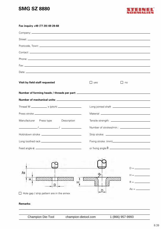
8.39
SMG SZ 8880
D =
H = R =
As =
Fax inquiry +49 (77 20) 69 28-68
Company:
Street:
Postcode, Town:
Contact:
Phone:
Fax:
Date:
Visit by field staff requested yes no
Number of forming heads / threads per part:
Number of mechanical units:
Thread M x (pitch) Long jointed shaft
Press stroke Material
Manufacturer Press type Description Tensile strength:
/ / Number of strokes/min.:
Hold-down stroke Strip stroke:
Long toothed rack Fixing stroke: (mm)
Feed angle : or fixing angle :
Hole gap / strip pattern are in the annex
Remarks:
Champion Die-Tool champion-dietool.com 1 (866) 957-9993
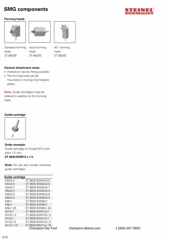
8.40
SMG components
Standard forming headST 8820B
Inline forming headST 8820D
45 ° forming headST 8820E
Forming heads
Order example:
Guide cartridge for thread M12 with pitch 1.5 mmST 8830.BXM12 x 1.5
Note: You can also reorder individual guide cartridges.
Guide cartridge
Guide cartridge M3x0.5 ST 8830.BXM3x0.5 M4x0.5 ST 8830.BXM4x0.5 M4x0.7 ST 8830.BXM4x0.7 M5x0.5 ST 8830.BXM5x0.5 M5x0.8 ST 8830.BXM5x0.8 M6x0.5 ST 8830.BXM6x0.5 M6x1 ST 8830.BXM6x1 M8x1 ST 8830.BXM8x1 M8x1.25 ST 8830.BXM8x1.25 M10x1 ST 8830.BXM10x1 M10x1.5 ST 8830.BXM10x1.5 M12x1 ST 8830.BXM12x1 M12x1.5 ST 8830.BXM12x1.5 M12x1.75 ST 8830.BXM12x1.75
General attachment notes• Hold-down device fitting possible• The forming head can be
mounted on moving intermediate plates.
Note: Guide cartridges must be ordered in addition to the forming head.
Champion Die-Tool champion-dietool.com 1 (866) 957-9993
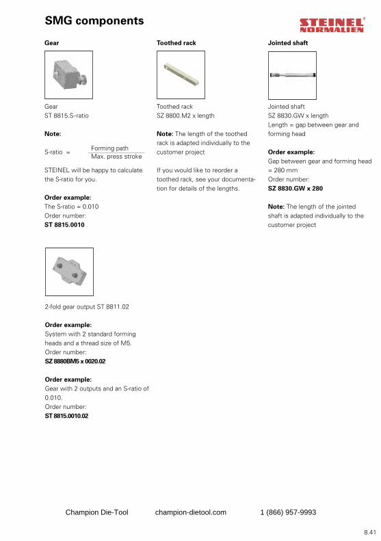
8.41
GearST 8815.S-ratio
Note:
S-ratio =
STEINEL will be happy to calculate the S-ratio for you.
Order example:The S-ratio = 0.010Order number:ST 8815.0010
Toothed rackSZ 8800.M2 x length
Note: The length of the toothed rack is adapted individually to the customer project
If you would like to reorder a toothed rack, see your documenta-tion for details of the lengths.
Jointed shaftSZ 8830.GW x lengthLength = gap between gear and forming head
Order example:Gap between gear and forming head = 280 mmOrder number: SZ 8830.GW x 280
Note: The length of the jointed shaft is adapted individually to the customer project
Gear Toothed rack Jointed shaft
2-fold gear output ST 8811.02
Order example:System with 2 standard forming heads and a thread size of M5.Order number:SZ 8880BM5 x 0020.02
Order example:Gear with 2 outputs and an S-ratio of 0.010.Order number:ST 8815.0010.02
SMG components
Forming pathMax. press stroke
Champion Die-Tool champion-dietool.com 1 (866) 957-9993
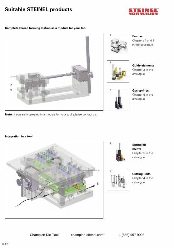
8.42
1
2
3
4
5
1
2
3
4
5
Suitable STEINEL products
Complete thread forming station as a module for your tool
Integration in a tool
FramesChapters 1 and 2 in the catalogue
Guide elements Chapter 3 in the catalogue
Gas springsChapter 5 in the catalogue
Spring ele-mentsChapter 5 in the catalogue
Cutting unitsChapter 4 in the catalogue
Note: If you are interested in a module for your tool, please contact us.
Champion Die-Tool champion-dietool.com 1 (866) 957-9993

8.43
Steinel Normalien AG
Winkelstraße 7D-78056 Villingen-SchwenningenPhone +49 (0)7720/6928-0Fax +49 (0)7720/6928-70Internet: http://www.steinel-normalien.deE-mail: [email protected]
We do not accept liability for printing errors and mistakes. Research brings improvements, changes to design, dimensions and materials. For this reason we reserve the right to make technical changes. Copyright Steinel Normalien AG
Contact
Champion Die-Tool champion-dietool.com 1 (866) 957-9993

Champion Die-Tool champion-dietool.com 1 (866) 957-9993
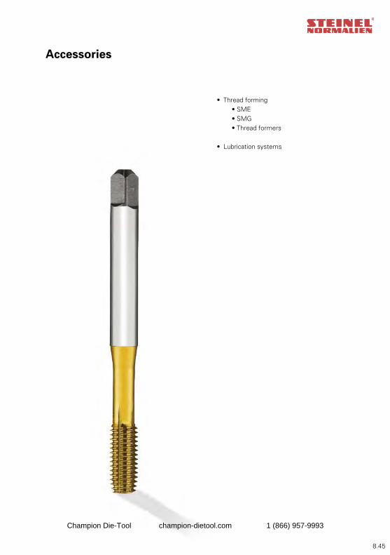
8.45
Accessories
• Thread forming • SME • SMG • Thread formers
• Lubrication systems
Champion Die-Tool champion-dietool.com 1 (866) 957-9993
8.46
Accessories
1. Thread formers 8.47-8.482. Lubrication system 8.493. Injection lubricators 8.504. Tanks 8.515. Solenoid for injection lubricator 8.516. Steel pipe for injection lubricator 8.517. Lubricating nozzle 8.528. Contact 8.53
SZ 9008.E P. 8.49 ST 9008.R Page 8.51 ST 9008.SD Page 8.52SZ 9400. Page 8.48
Champion Die-Tool champion-dietool.com 1 (866) 957-9993
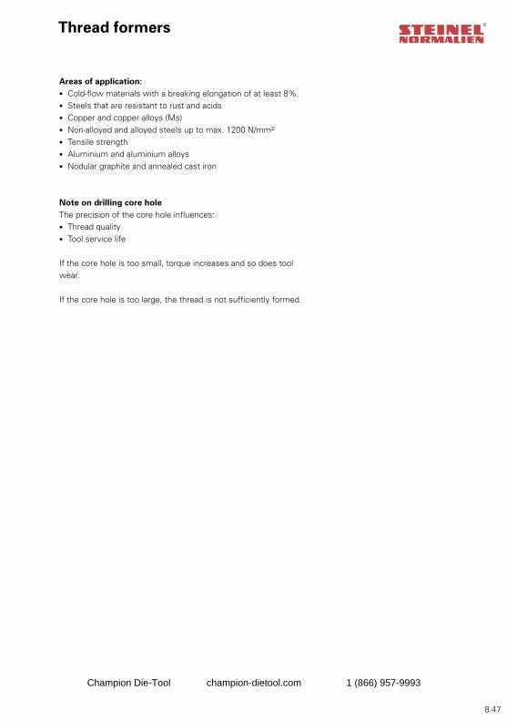
8.47
Thread formers
Areas of application:• Cold-flow materials with a breaking elongation of at least 8%.• Steels that are resistant to rust and acids• Copper and copper alloys (Ms)• Non-alloyed and alloyed steels up to max. 1200 N/mm² • Tensile strength• Aluminium and aluminium alloys• Nodular graphite and annealed cast iron
Note on drilling core holeThe precision of the core hole influences:• Thread quality• Tool service life
If the core hole is too small, torque increases and so does tool wear.
If the core hole is too large, the thread is not sufficiently formed.
Champion Die-Tool champion-dietool.com 1 (866) 957-9993
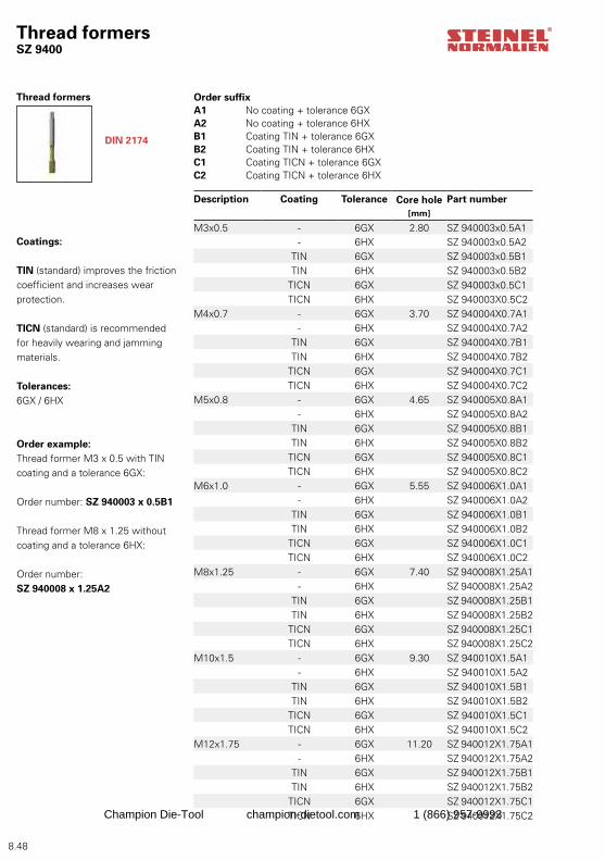
8.48
DIN 2174
Thread formersSZ 9400
Thread formers
Description Coating Tolerance Core hole[mm]
Part number
M3x0.5 - 6GX 2.80 SZ 940003x0.5A1- 6HX SZ 940003x0.5A2
TIN 6GX SZ 940003x0.5B1TIN 6HX SZ 940003x0.5B2
TICN 6GX SZ 940003x0.5C1TICN 6HX SZ 940003X0.5C2
M4x0.7 - 6GX 3.70 SZ 940004X0.7A1- 6HX SZ 940004X0.7A2
TIN 6GX SZ 940004X0.7B1TIN 6HX SZ 940004X0.7B2
TICN 6GX SZ 940004X0.7C1TICN 6HX SZ 940004X0.7C2
M5x0.8 - 6GX 4.65 SZ 940005X0.8A1- 6HX SZ 940005X0.8A2
TIN 6GX SZ 940005X0.8B1TIN 6HX SZ 940005X0.8B2
TICN 6GX SZ 940005X0.8C1TICN 6HX SZ 940005X0.8C2
M6x1.0 - 6GX 5.55 SZ 940006X1.0A1- 6HX SZ 940006X1.0A2
TIN 6GX SZ 940006X1.0B1TIN 6HX SZ 940006X1.0B2
TICN 6GX SZ 940006X1.0C1TICN 6HX SZ 940006X1.0C2
M8x1.25 - 6GX 7.40 SZ 940008X1.25A1- 6HX SZ 940008X1.25A2
TIN 6GX SZ 940008X1.25B1TIN 6HX SZ 940008X1.25B2
TICN 6GX SZ 940008X1.25C1TICN 6HX SZ 940008X1.25C2
M10x1.5 - 6GX 9.30 SZ 940010X1.5A1- 6HX SZ 940010X1.5A2
TIN 6GX SZ 940010X1.5B1TIN 6HX SZ 940010X1.5B2
TICN 6GX SZ 940010X1.5C1TICN 6HX SZ 940010X1.5C2
M12x1.75 - 6GX 11.20 SZ 940012X1.75A1- 6HX SZ 940012X1.75A2
TIN 6GX SZ 940012X1.75B1TIN 6HX SZ 940012X1.75B2
TICN 6GX SZ 940012X1.75C1TICN 6HX SZ 940012X1.75C2
Order suffix A1 No coating + tolerance 6GXA2 No coating + tolerance 6HXB1 Coating TIN + tolerance 6GXB2 Coating TIN + tolerance 6HXC1 Coating TICN + tolerance 6GXC2 Coating TICN + tolerance 6HX
Coatings:
TIN (standard) improves the friction coefficient and increases wear protection.
TICN (standard) is recommended for heavily wearing and jamming materials.
Tolerances:6GX / 6HX
Order example:Thread former M3 x 0.5 with TIN coating and a tolerance 6GX:
Order number: SZ 940003 x 0.5B1
Thread former M8 x 1.25 without coating and a tolerance 6HX:
Order number: SZ 940008 x 1.25A2
Champion Die-Tool champion-dietool.com 1 (866) 957-9993
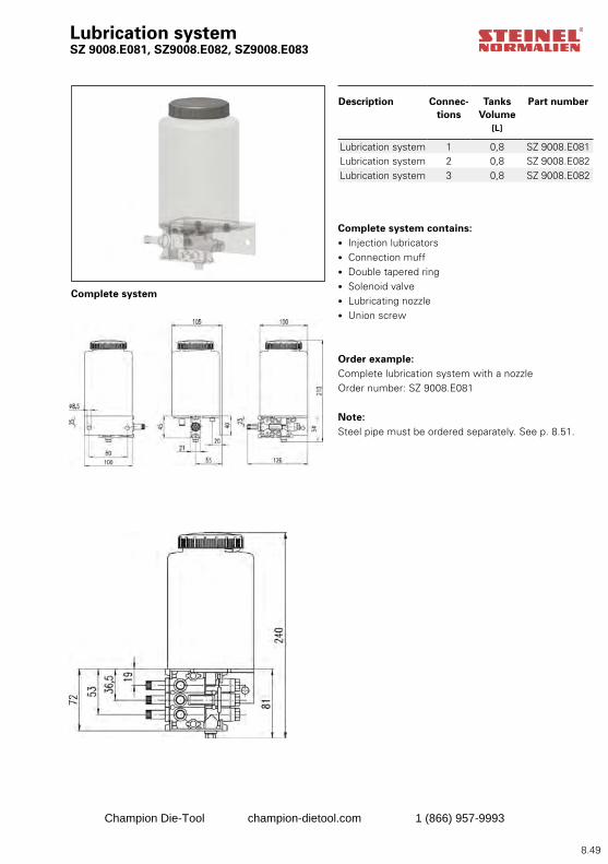
8.49
Lubrication systemSZ 9008.E081, SZ9008.E082, SZ9008.E083
Complete system contains:• Injection lubricators • Connection muff• Double tapered ring• Solenoid valve• Lubricating nozzle• Union screw
Order example: Complete lubrication system with a nozzle Order number: SZ 9008.E081
Note: Steel pipe must be ordered separately. See p. 8.51.
Description Connec-tions
TanksVolume
[L]
Part number
Lubrication system 1 0,8 SZ 9008.E081Lubrication system 2 0,8 SZ 9008.E082Lubrication system 3 0,8 SZ 9008.E082
Complete system
Champion Die-Tool champion-dietool.com 1 (866) 957-9993
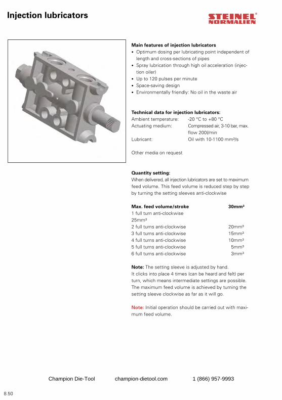
8.50
Injection lubricators
Main features of injection lubricators• Optimum dosing per lubricating point independent of
length and cross-sections of pipes• Spray lubrication through high oil acceleration (injec-
tion oiler)• Up to 120 pulses per minute • Space-saving design• Environmentally friendly: No oil in the waste air
Technical data for injection lubricators:Ambient temperature: -20 °C to +80 °CActuating medium: Compressed air, 3-10 bar, max.
flow 200l/minLubricant: Oil with 10-1100 mm²/s
Other media on request
Quantity setting:When delivered, all injection lubricators are set to maximum feed volume. This feed volume is reduced step by step by turning the setting sleeves anti-clockwise
Max. feed volume/stroke 30mm³1 full turn anti-clockwise 25mm³2 full turns anti-clockwise 20mm³3 full turns anti-clockwise 15mm³4 full turns anti-clockwise 10mm³5 full turns anti-clockwise 5mm³6 full turns anti-clockwise 3mm³
Note: The setting sleeve is adjusted by hand. It clicks into place 4 times (can be heard and felt) per turn, which means intermediate settings are possible. The maximum feed volume is achieved by turning the setting sleeve clockwise as far as it will go.
Note: Initial operation should be carried out with maxi-mum feed volume.
Champion Die-Tool champion-dietool.com 1 (866) 957-9993
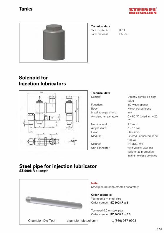
8.51
Tanks
Technical dataTank contents: 0.8 LTank material PA6-3-T
Technical dataDesign: Directly controlled seat
valveFunction: 3/2 ways openerBody: Nickel-plated brassInstallation position: anyAmbient temperature: 0 – 60 °C (dried air – 20
°C)Nominal width: 1.5 mmAir pressure: 0 – 10 barFlow: 66 Nl/min Medium: Filtered, lubricated or oil-
free airMagnet: 24 VDC, 5WUnit connector: with yellow LED and
varistor as protection against excess voltages
Solenoid for Injection lubricators
Steel pipe for injection lubricatorSZ 9008.R x length
Note: Steel pipe must be ordered separately.
Order example:You need 2 m steel pipeOrder number: SZ 9008.R x 2
You need 0.5 m steel pipeOrder number: SZ 9008.R x 0.5
Champion Die-Tool champion-dietool.com 1 (866) 957-9993
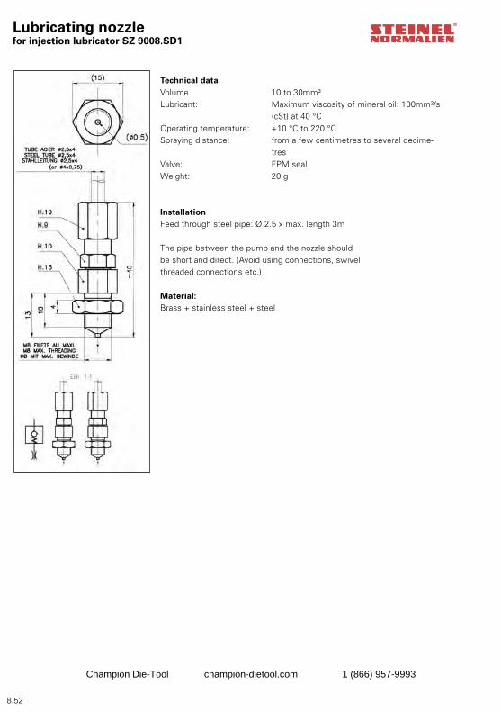
8.52
Lubricating nozzle for injection lubricator SZ 9008.SD1
Technical dataVolume 10 to 30mm³Lubricant: Maximum viscosity of mineral oil: 100mm²/s
(cSt) at 40 °COperating temperature: +10 °C to 220 °CSpraying distance: from a few centimetres to several decime-
tresValve: FPM sealWeight: 20 g
Installation Feed through steel pipe: Ø 2.5 x max. length 3m
The pipe between the pump and the nozzle should be short and direct. (Avoid using connections, swivel threaded connections etc.)
Material: Brass + stainless steel + steel
Champion Die-Tool champion-dietool.com 1 (866) 957-9993
8.53
Steinel Normalien AG
Winkelstraße 7D-78056 Villingen-SchwenningenPhone +49 (0)7720/6928-0Fax +49 (0)7720/6928-70Internet: http://www.steinel-normalien.deE-mail: [email protected]
We do not accept liability for printing errors and mistakes. Research brings improvements, changes to design, dimensions and materials. For this reason we reserve the right to make technical changes. Copyright Steinel Normalien AG
Contact
Champion Die-Tool champion-dietool.com 1 (866) 957-9993

Champion Die-Tool champion-dietool.com 1 (866) 957-9993

9.1
Champion Die-Tool champion-dietool.com 1 (866) 957-9993
9.2 9.02
Champion Die-Tool champion-dietool.com 1 (866) 957-9993
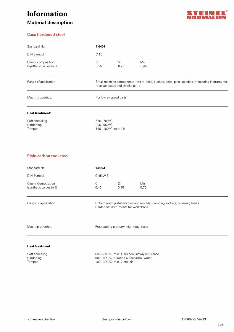
InformationMaterial description
Case hardened steel
Standard No. 1.0401 DIN-Symbol C 15
Chem. composition C Si Mn (synthetic values in %) 0,15 0,25 0,45
Range of application: Small machine components, levers, links, bushes, bolts, pins, spindles, measuring instruments, receiver plates and similiar parts
Mech. properties: For low stressed parts
Heat treatment:
Soft annealing 650 – 700 °C Hardening 900 – 950 °C Temper 150 – 180 °C, min. 1 h .
Plain carbon tool steel
Standard No. 1.0503
DIN Symbol C 45 W 3
Chem. Composition C Si Mn (synthetic values in %) 0,45 0,25 0,70
Range of application: Unhardened: plates for dies and moulds, clamping sockets, receiving tubes Hardened: instruments for workshops
Mech. properties: Free cutting property, high toughness
Heat treatment:
Soft annealing 680 – 710 °C, min. 4 hrs cool slowly in furnace Hardening 800 – 830 °C, duration 60 sec/mm, water Temper 100 – 300 °C, min. 2 hrs, air
9.03
Champion Die-Tool champion-dietool.com 1 (866) 957-9993

InformationMaterial description
Structural steel
Standard No. 1.0570
DIN Symbol ST 52-3
Chem. composition C Si Mn (synthetic values in %) 0,2 0,55 1,6
Range of application: Plates for dies and moulds, die sets made of steel, etc.
Mech. properties: Free cutting property, high toughness, weldable
Heat treatment:
Soft annealingHardening Temper
Free-cutting steel
Standard No. 1.0715
DIN Symbol 9 S Mn 28
Chem. composition C Mn P S (synthetic values in %) 0,14 1,20 0,10 0,28
Range of application: Heavy duty free-cutting steel for mass-produced parts, spacer tubes, brackets
Mech. properties: For low stressed parts
Heat treatment:
Soft annealing Hardening 800 – 920 °C, water (carburize)Temper 150 – 200 °C min. 1h
9.04
Champion Die-Tool champion-dietool.com 1 (866) 957-9993
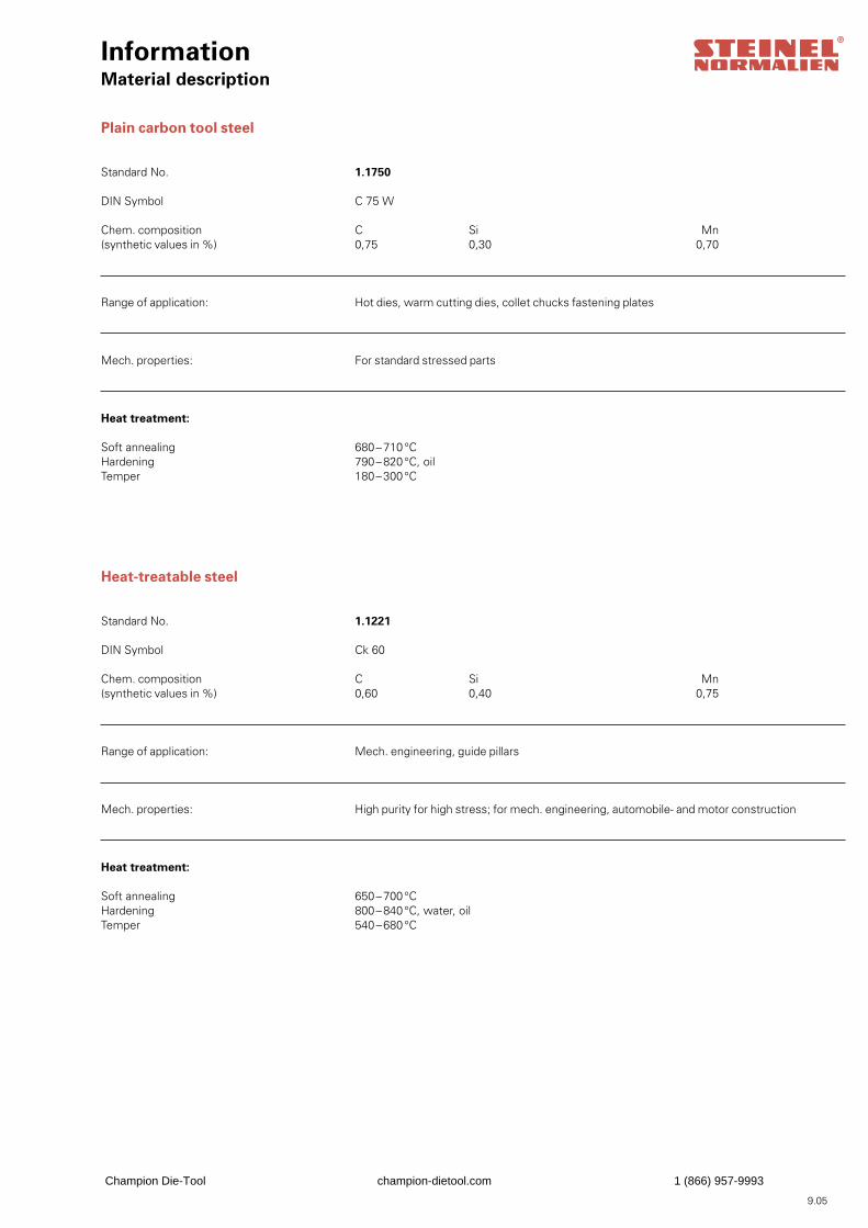
InformationMaterial description
Plain carbon tool steel
Standard No. 1.1750
DIN Symbol C 75 W
Chem. composition C Si Mn(synthetic values in %) 0,75 0,30 0,70
Range of application: Hot dies, warm cutting dies, collet chucks fastening plates
Mech. properties: For standard stressed parts
Heat treatment:
Soft annealing 680 – 710 °CHardening 790 – 820 °C, oilTemper 180 – 300 °C
Heat-treatable steel
Standard No. 1.1221
DIN Symbol Ck 60
Chem. composition C Si Mn(synthetic values in %) 0,60 0,40 0,75
Range of application: Mech. engineering, guide pillars
Mech. properties: High purity for high stress; for mech. engineering, automobile- and motor construction
Heat treatment:
Soft annealing 650 – 700 °CHardening 800 – 840 °C, water, oilTemper 540 – 680 °C
9.05
Champion Die-Tool champion-dietool.com 1 (866) 957-9993
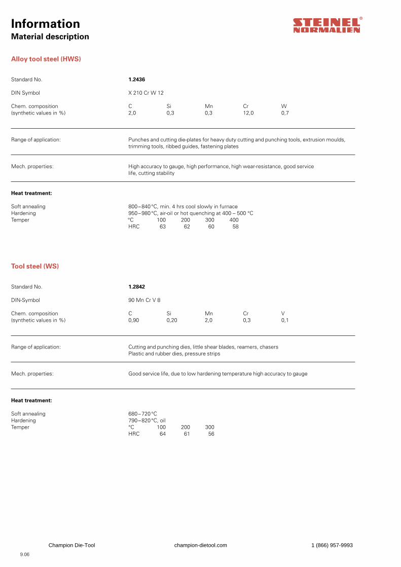
InformationMaterial description
Alloy tool steel (HWS)
Standard No. 1.2436
DIN Symbol X 210 Cr W 12
Chem. composition C Si Mn Cr W(synthetic values in %) 2,0 0,3 0,3 12,0 0,7
Range of application: Punches and cutting die-plates for heavy duty cutting and punching tools, extrusion moulds, trimming tools, ribbed guides, fastening plates
Mech. properties: High accuracy to gauge, high performance, high wear-resistance, good service life, cutting stability
Heat treatment:
Soft annealing 800 – 840 °C, min. 4 hrs cool slowly in furnaceHardening 950 – 980 °C, air-oil or hot quenching at 400 – 500 °CTemper °C 100 200 300 400 HRC 63 62 60 58
Tool steel (WS)
Standard No. 1.2842
DIN-Symbol 90 Mn Cr V 8
Chem. composition C Si Mn Cr V(synthetic values in %) 0,90 0,20 2,0 0,3 0,1
Range of application: Cutting and punching dies, little shear blades, reamers, chasers Plastic and rubber dies, pressure strips
Mech. properties: Good service life, due to low hardening temperature high accuracy to gauge
Heat treatment:
Soft annealing 680 – 720 °CHardening 790 – 820 °C, oilTemper °C 100 200 300 HRC 64 61 56
9.06
Champion Die-Tool champion-dietool.com 1 (866) 957-9993
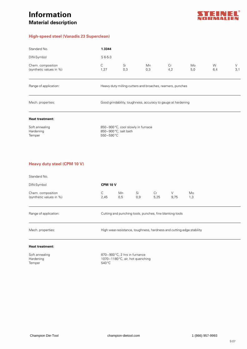
InformationMaterial description
High-speed steel (Vanadis 23 Superclean)
Standard No. 1.3344
DIN-Symbol S 6-5-3
Chem. composition C Si Mn Cr Mo W V(synthetic values in %) 1,27 0,3 0,3 4,2 5,0 6,4 3,1
Range of application: Heavy duty milling cutters and broaches, reamers, punches
Mech. properties: Good grindability, toughness, accuracy to gauge at hardening
Heat treatment:
Soft annealing 850 – 900 °C, cool slowly in furnaceHardening 850 – 900 °C, salt bathTemper 550 – 590 °C
Heavy duty steel (CPM 10 V)
Standard No.
DIN-Symbol CPM 10 V
Chem. composition C Mn Si Cr V Mo(synthetic values in %) 2,45 0,5 0,9 5,25 9,75 1,3
Range of application: Cutting and punching tools, punches, fine blanking tools
Mech. properties: High wear-resistance, toughness, hardness and cutting edge stability
Heat treatment:
Soft annealing 870 – 900 °C, 2 hrs in furnanceHardening 1070 – 1180 °C, air, hot quenchingTemper 540 °C
9.07
Champion Die-Tool champion-dietool.com 1 (866) 957-9993
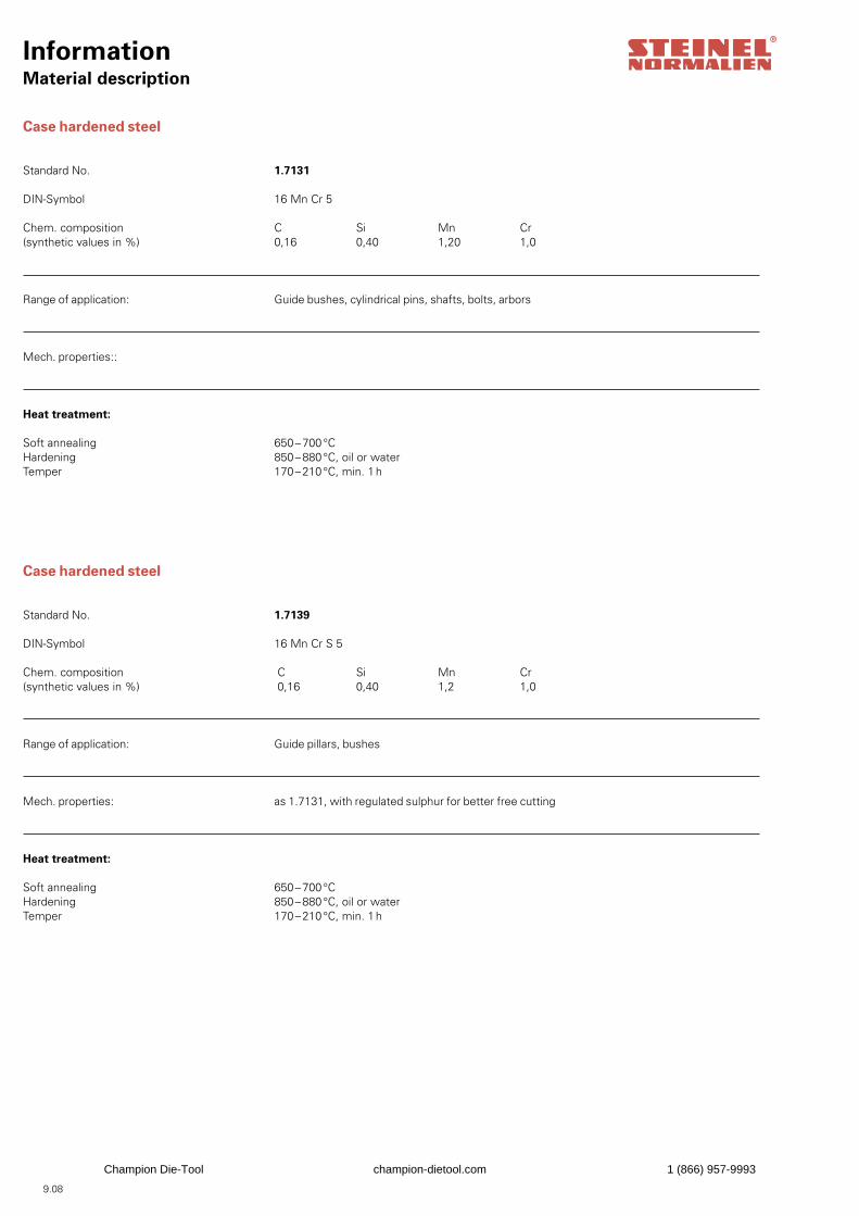
InformationMaterial description
Case hardened steel
Standard No. 1.7131
DIN-Symbol 16 Mn Cr 5
Chem. composition C Si Mn Cr(synthetic values in %) 0,16 0,40 1,20 1,0
Range of application: Guide bushes, cylindrical pins, shafts, bolts, arbors
Mech. properties::
Heat treatment:
Soft annealing 650 – 700 °CHardening 850 – 880 °C, oil or waterTemper 170 – 210 °C, min. 1 h
Case hardened steel
Standard No. 1.7139
DIN-Symbol 16 Mn Cr S 5
Chem. composition C Si Mn Cr(synthetic values in %) 0,16 0,40 1,2 1,0
Range of application: Guide pillars, bushes
Mech. properties: as 1.7131, with regulated sulphur for better free cutting
Heat treatment:
Soft annealing 650 – 700 °CHardening 850 – 880 °C, oil or waterTemper 170 – 210 °C, min. 1 h
9.08
Champion Die-Tool champion-dietool.com 1 (866) 957-9993
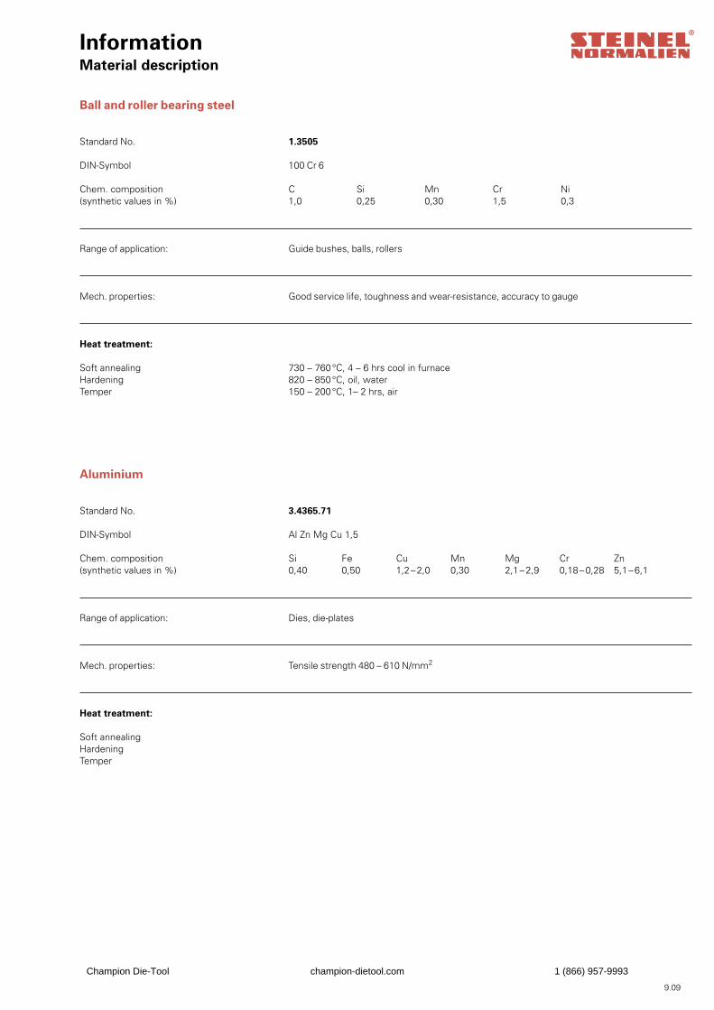
InformationMaterial description
Ball and roller bearing steel
Standard No. 1.3505
DIN-Symbol 100 Cr 6
Chem. composition C Si Mn Cr Ni(synthetic values in %) 1,0 0,25 0,30 1,5 0,3
Range of application: Guide bushes, balls, rollers
Mech. properties: Good service life, toughness and wear-resistance, accuracy to gauge
Heat treatment:
Soft annealing 730 – 760 °C, 4 – 6 hrs cool in furnaceHardening 820 – 850 °C, oil, waterTemper 150 – 200 °C, 1– 2 hrs, air
Aluminium
Standard No. 3.4365.71
DIN-Symbol Al Zn Mg Cu 1,5
Chem. composition Si Fe Cu Mn Mg Cr Zn(synthetic values in %) 0,40 0,50 1,2 – 2,0 0,30 2,1 – 2,9 0,18 – 0,28 5,1 – 6,1
Range of application: Dies, die-plates
Mech. properties: Tensile strength 480 – 610 N/mm2
Heat treatment:
Soft annealing Hardening Temper
9.09
Champion Die-Tool champion-dietool.com 1 (866) 957-9993
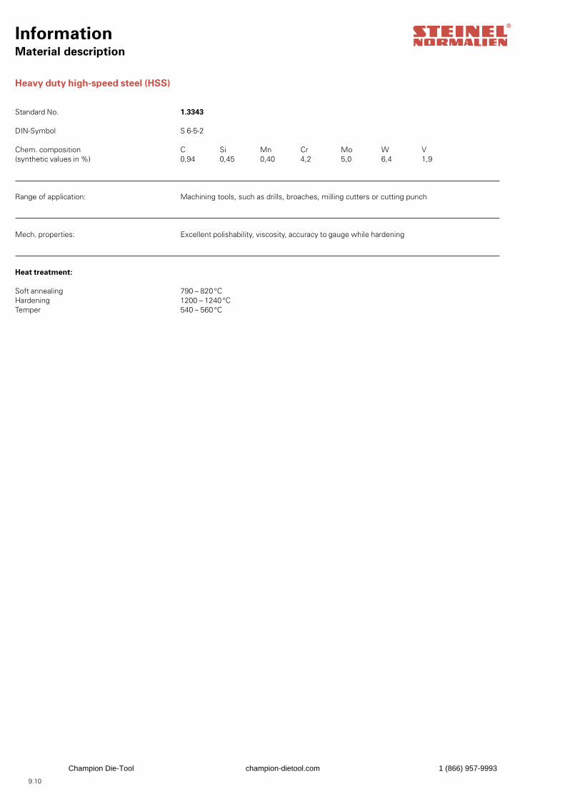
InformationMaterial description
Heavy duty high-speed steel (HSS)
Standard No. 1.3343
DIN-Symbol S 6-5-2
Chem. composition C Si Mn Cr Mo W V(synthetic values in %) 0,94 0,45 0,40 4,2 5,0 6,4 1,9
Range of application: Machining tools, such as drills, broaches, milling cutters or cutting punch
Mech. properties: Excellent polishability, viscosity, accuracy to gauge while hardening
Heat treatment:
Soft annealing 790 – 820 °CHardening 1200 – 1240 °CTemper 540 – 560 °C
9.10
Champion Die-Tool champion-dietool.com 1 (866) 957-9993
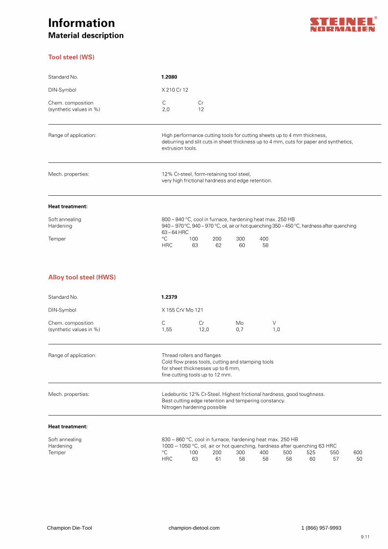
InformationMaterial description
Tool steel (WS)
Standard No. 1.2080
DIN-Symbol X 210 Cr 12
Chem. composition C Cr (synthetic values in %) 2,0 12
Range of application: High performance cutting tools for cutting sheets up to 4 mm thickness, deburring and slit cuts in sheet thickness up to 4 mm, cuts for paper and synthetics, extrusion tools.
Mech. properties: 12% Cr-steel, form-retaining tool steel, very high frictional hardness and edge retention.
Heat treatment:
Soft annealing 800 – 840 °C, cool in furnace, hardening heat max. 250 HBHardening 940 – 970 °C, 940 – 970 °C, oil, air or hot quenching 350 – 450 °C, hardness after quenching 63 – 64 HRCTemper °C 100 200 300 400 HRC 63 62 60 58
Alloy tool steel (HWS)
Standard No. 1.2379
DIN-Symbol X 155 CrV Mo 121
Chem. composition C Cr Mo V(synthetic values in %) 1,55 12,0 0,7 1,0
Range of application: Thread rollers and flanges Cold flow press tools, cutting and stamping tools for sheet thicknesses up to 6 mm, fine cutting tools up to 12 mm.
Mech. properties: Ledeburitic 12% Cr-Steel. Highest frictional hardness, good toughness. Best cutting edge retention and tempering constancy. Nitrogen hardening possible
Heat treatment:
Soft annealing 830 – 860 °C, cool in furnace, hardening heat max. 250 HBHardening 1000 – 1050 °C, oil, air or hot quenching, hardness after quenching 63 HRCTemper °C 100 200 300 400 500 525 550 600 HRC 63 61 58 58 58 60 57 50
9.11
Champion Die-Tool champion-dietool.com 1 (866) 957-9993
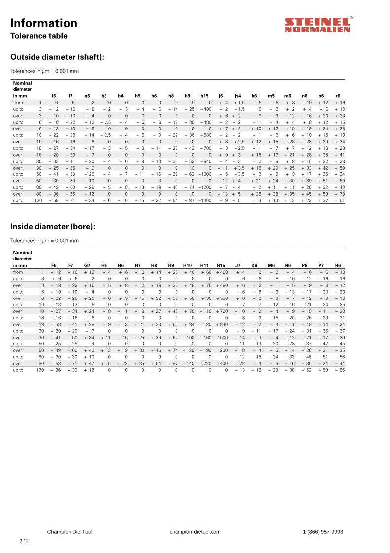
9.12
InformationTolerance table
Outside diameter (shaft):
Inside diameter (bore):
Tolerances in μm = 0.001 mm
Tolerances in μm = 0.001 mm
Nominaldiameterin mm f6 f7 g6 h3 h4 h5 h6 h8 h9 h15 j6 js4 k6 m5 m6 n6 p6 r6from 1 – 6 – 6 – 2 0 0 0 0 0 0 0 + 4 + 1,5 + 6 + 6 + 8 + 10 + 12 + 16up to 3 – 12 – 16 – 8 – 2 – 3 – 4 – 6 – 14 – 25 – 400 – 2 – 1,5 0 + 2 + 2 + 4 + 6 + 10over 3 – 10 – 10 – 4 0 0 0 0 0 0 0 + 6 + 2 + 9 + 9 + 12 + 16 + 20 + 23up to 6 – 18 – 22 – 12 – 2,5 – 4 – 5 – 8 – 18 – 30 – 480 – 2 – 2 + 1 + 4 + 4 + 8 + 12 + 15over 6 – 13 – 13 – 5 0 0 0 0 0 0 0 + 7 + 2 + 10 + 12 + 15 + 19 + 24 + 28up to 10 – 22 – 28 – 14 – 2,5 – 4 – 6 – 9 – 22 – 36 – 580 – 2 – 2 + 1 + 6 + 6 + 10 + 15 + 19over 10 – 16 – 16 – 6 0 0 0 0 0 0 0 + 8 + 2,5 + 12 + 15 + 28 + 23 + 29 + 34up to 18 – 27 – 34 – 17 – 3 – 5 – 8 – 11 – 27 – 43 – 700 – 3 – 2,5 + 1 + 7 + 7 + 12 + 18 + 23over 18 – 20 – 20 – 7 0 0 0 0 0 0 0 + 9 + 3 + 15 + 17 + 21 + 28 + 35 + 41up to 30 – 33 – 41 – 20 – 4 – 6 – 9 – 13 – 33 – 52 – 840 – 4 – 3 + 2 + 8 + 8 + 15 + 22 + 28over 30 – 25 – 25 – 9 0 0 0 0 0 0 0 + 11 + 3,5 + 18 + 20 + 25 + 33 + 42 + 50up to 50 – 41 – 50 – 25 – 4 – 7 – 11 – 16 – 39 – 62 –1000 – 5 – 3,5 + 2 + 9 + 9 + 17 + 26 + 34over 50 – 30 – 30 – 10 0 0 0 0 0 0 0 + 12 + 4 + 21 + 24 + 30 + 39 + 51 + 60up to 80 – 49 – 60 – 29 – 5 – 8 – 13 – 19 – 46 – 74 –1200 – 7 – 4 + 2 + 11 + 11 + 20 + 32 + 43over 80 – 36 – 36 – 12 0 0 0 0 0 0 0 + 13 + 5 + 25 + 28 + 35 + 45 + 59 + 73up to 120 – 58 – 71 – 34 – 6 – 10 – 15 – 22 – 54 – 87 –1400 – 9 – 5 + 3 + 13 + 13 + 23 + 37 + 51
Nominaldiameterin mm F6 F7 G7 H5 H6 H7 H8 H9 H10 H11 H15 J7 K6 M6 N6 P6 P7 R6from 1 + 12 + 16 + 12 + 4 + 6 + 10 + 14 + 25 + 40 + 60 + 400 + 4 0 – 2 – 4 – 6 – 6 – 10up to 3 + 6 + 6 + 2 0 0 0 0 0 0 0 0 – 6 – 6 – 8 – 10 – 12 – 16 – 16over 3 + 18 + 22 + 16 + 5 + 8 + 12 + 18 + 30 + 48 + 75 + 480 + 6 + 2 – 1 – 5 – 9 – 8 – 12up to 6 + 10 + 10 + 4 0 0 0 0 0 0 0 0 – 6 – 6 – 9 – 13 – 17 – 20 – 20over 6 + 22 + 28 + 20 + 6 + 9 + 15 + 22 + 36 + 58 + 90 + 580 + 8 + 2 – 3 – 7 – 12 – 9 – 16up to 10 + 13 + 13 + 5 0 0 0 0 0 0 0 0 – 7 – 7 – 12 – 16 – 21 – 24 – 25over 10 + 27 + 34 + 24 + 8 + 11 + 18 + 27 + 43 + 70 + 110 + 700 + 10 + 2 – 4 – 9 – 15 – 11 – 20up to 18 + 16 + 16 + 6 0 0 0 0 0 0 0 0 – 8 – 9 – 15 – 20 – 26 – 29 – 31over 18 + 33 + 41 + 28 + 9 + 13 + 21 + 33 + 52 + 84 + 130 + 840 + 12 + 2 – 4 – 11 – 18 – 14 – 24up to 30 + 20 + 20 + 7 0 0 0 0 0 0 0 0 – 9 – 11 – 17 – 24 – 31 – 35 – 37over 30 + 41 + 50 + 34 + 11 + 16 + 25 + 39 + 62 + 100 + 160 1000 + 14 + 3 – 4 – 12 – 21 – 17 – 29up to 50 + 25 + 25 + 9 0 0 0 0 0 0 0 0 – 11 – 13 – 20 – 28 – 37 – 42 – 45over 50 + 49 + 60 + 40 + 13 + 19 + 30 + 46 + 74 + 120 + 190 1200 + 18 + 4 – 5 – 14 – 26 – 21 – 35up to 80 + 30 + 30 + 10 0 0 0 0 0 0 0 0 – 12 – 15 – 24 – 33 – 45 – 51 – 56over 80 + 58 + 71 + 47 + 15 + 22 + 35 + 54 + 87 + 140 + 220 1400 + 22 + 4 – 6 – 16 – 30 – 24 – 44up to 120 + 36 + 36 + 12 0 0 0 0 0 0 0 0 – 13 – 18 – 28 – 38 – 52 – 59 – 66
Champion Die-Tool champion-dietool.com 1 (866) 957-9993
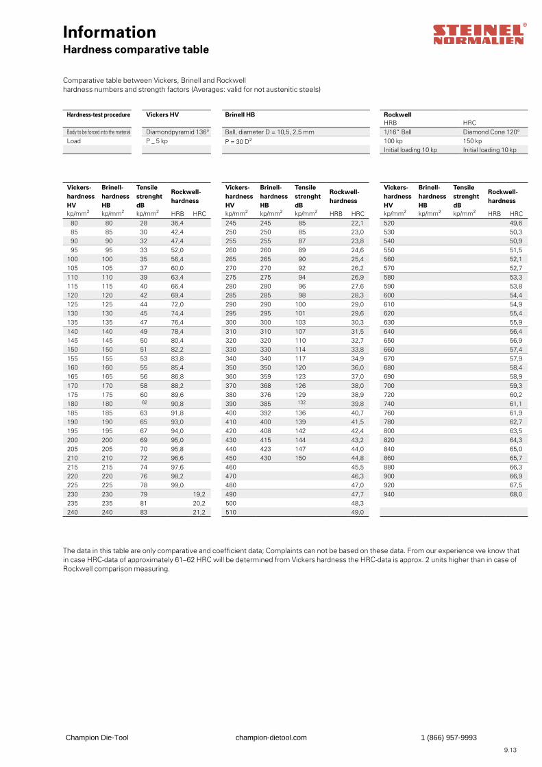
9.13
InformationHardness comparative table
Comparative table between Vickers, Brinell and Rockwellhardness numbers and strength factors (Averages: valid for not austenitic steels)
The data in this table are only comparative and coefficient data; Complaints can not be based on these data. From our experience we know that in case HRC-data of approximately 61–62 HRC will be determined from Vickers hardness the HRC-data is approx. 2 units higher than in case of Rockwell comparison measuring.
Hardness-test procedure Vickers HV Brinell HB RockwellHRB HRC
Body to be forced into the material Diamondpyramid 136° Ball, diameter D = 10,5, 2,5 mm 1/16“ Ball Diamond Cone 120°Load P _ 5 kp P = 30 D2 100 kp 150 kp
Initial loading 10 kp Initial loading 10 kp
Vickers- hardness HV
Brinell-hardness HB
Tensile strenght dB
Rockwell-hardness
kp/mm2 kp/mm2 kp/mm2 HRB HRC80 80 28 36,4 85 85 30 42,4 90 90 32 47,4 95 95 33 52,0
100 100 35 56,4105 105 37 60,0110 110 39 63,4115 115 40 66,4120 120 42 69,4125 125 44 72,0130 130 45 74,4135 135 47 76,4140 140 49 78,4145 145 50 80,4150 150 51 82,2155 155 53 83,8160 160 55 85,4165 165 56 86,8170 170 58 88,2175 175 60 89,6180 180 62 90,8185 185 63 91,8190 190 65 93,0195 195 67 94,0200 200 69 95,0205 205 70 95,8210 210 72 96,6215 215 74 97,6220 220 76 98,2225 225 78 99,0230 230 79 19,2235 235 81 20,2240 240 83 21,2
Vickers- hardness HV
Brinell-hardness HB
Tensile strenght dB
Rockwell-hardness
kp/mm2 kp/mm2 kp/mm2 HRB HRC245 245 85 22,1250 250 85 23,0255 255 87 23,8260 260 89 24,6265 265 90 25,4270 270 92 26,2275 275 94 26,9280 280 96 27,6285 285 98 28,3290 290 100 29,0295 295 101 29,6300 300 103 30,3310 310 107 31,5320 320 110 32,7330 330 114 33,8340 340 117 34,9350 350 120 36,0360 359 123 37,0370 368 126 38,0380 376 129 38,9390 385 132 39,8400 392 136 40,7410 400 139 41,5420 408 142 42,4430 415 144 43,2440 423 147 44,0450 430 150 44,8460 45,5470 46,3480 47,0490 47,7500 48,3510 49,0
Vickers- hardness HV
Brinell-hardness HB
Tensile strenght dB
Rockwell-hardness
kp/mm2 kp/mm2 kp/mm2 HRB HRC520 49,6530 50,3540 50,9550 51,5560 52,1570 52,7580 53,3590 53,8600 54,4610 54,9620 55,4630 55,9640 56,4650 56,9660 57,4670 57,9680 58,4690 58,9700 59,3720 60,2740 61,1760 61,9780 62,7800 63,5820 64,3840 65,0860 65,7880 66,3900 66,9920 67,5940 68,0
Champion Die-Tool champion-dietool.com 1 (866) 957-9993

Champion Die-Tool champion-dietool.com 1 (866) 957-9993

9.15
Champion Die-Tool champion-dietool.com 1 (866) 957-9993
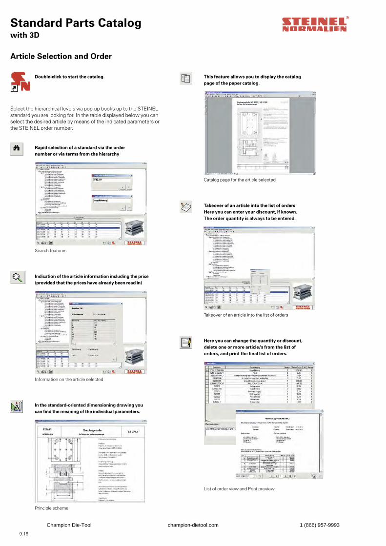
9.16
Standard Parts Catalogwith 3D
Article Selection and Order
Select the hierarchical levels via pop-up books up to the STEINELstandard you are looking for. In the table displayed below you canselect the desired article by means of the indicated parameters orthe STEINEL order number.
Search features
Information on the article selected
Catalog page for the article selected
Takeover of an article into the list of orders
List of order view and Print preview
Double-click to start the catalog.
Rapid selection of a standard via the ordernumber or via terms from the hierarchy
Indication of the article information including the price (provided that the prices have already been read in)
In the standard-oriented dimensioning drawing you can find the meaning of the individual parameters.
This feature allows you to display the catalogpage of the paper catalog.
Takeover of an article into the list of ordersHere you can enter your discount, if known.The order quantity is always to be entered.
Here you can change the quantity or discount,delete one or more article/s from the list oforders, and print the final list of orders.
Principle scheme
Champion Die-Tool champion-dietool.com 1 (866) 957-9993
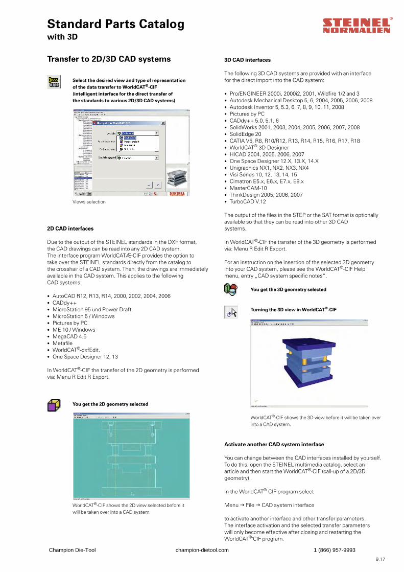
9.17
Standard Parts Catalogwith 3D
Transfer to 2D/3D CAD systems
Select the desired view and type of representationof the data transfer to WorldCAT®-CIF(intelligent interface for the direct transfer ofthe standards to various 2D/3D CAD systems)
Views selection
2D CAD interfaces
Due to the output of the STEINEL standards in the DXF format,the CAD drawings can be read into any 2D CAD system.The interface program WorldCATÆ-CIF provides the option totake over the STEINEL standards directly from the catalog tothe crosshair of a CAD system. Then, the drawings are immediatelyavailable in the CAD system. This applies to the followingCAD systems:
• AutoCAD R12, R13, R14, 2000, 2002, 2004, 2006 • CADdy++ • MicroStation 95 und Power Draft• MicroStation 5 / Windows• Pictures by PC• ME 10 / Windows• MegaCAD 4.5• Metafile• WorldCAT®-dxfEdit.• One Space Designer 12, 13
In WorldCAT®-CIF the transfer of the 2D geometry is performedvia: Menu R Edit R Export.
3D CAD interfaces
The following 3D CAD systems are provided with an interfacefor the direct import into the CAD system:
• Pro/ENGINEER 2000i, 2000i2, 2001, Wildfire 1/2 and 3• Autodesk Mechanical Desktop 5, 6, 2004, 2005, 2006, 2008• Autodesk Inventor 5, 5.3, 6, 7, 8, 9, 10, 11, 2008• Pictures by PC• CADdy++ 5.0, 5.1, 6• SolidWorks 2001, 2003, 2004, 2005, 2006, 2007, 2008• SolidEdge 20• CATIA V5, R8, R10/R12, R13, R14, R15, R16, R17, R18• WorldCAT®-3D-Designer• HICAD 2004, 2005, 2006, 2007• One Space Designer 12.X, 13.X, 14.X• Unigraphics NX1, NX2, NX3, NX4• Visi Series 10, 12, 13, 14, 15• Cimatron E5.x, E6.x, E7.x, E8.x• MasterCAM-10• ThinkDesign 2005, 2006, 2007• TurboCAD V.12
The output of the files in the STEP or the SAT format is optionallyavailable so that they can be read into other 3D CADsystems.
In WorldCAT®-CIF the transfer of the 3D geometry is performedvia: Menu R Edit R Export.
For an instruction on the insertion of the selected 3D geometryinto your CAD system, please see the WorldCAT®-CIF Helpmenu, entry „CAD system specific notes“.
Activate another CAD system interface
You can change between the CAD interfaces installed by yourself.To do this, open the STEINEL multimedia catalog, select anarticle and then start the WorldCAT®-CIF (call-up of a 2D/3Dgeometry).
In the WorldCAT®-CIF program select
Menu g File g CAD system interface
to activate another interface and other transfer parameters.The interface activation and the selected transfer parameterswill only become effective after closing and restarting theWorldCAT®-CIF program.
You get the 2D geometry selected
WorldCAT®-CIF shows the 2D view selected before it will be taken over into a CAD system.
You get the 3D geometry selected
Turning the 3D view in WorldCAT®-CIF
WorldCAT®-CIF shows the 3D view before it will be taken overinto a CAD system.
Champion Die-Tool champion-dietool.com 1 (866) 957-9993
9.18
Standard Parts Catalogwith 3D
STEINEL-Multimedia CAD Catalog
Installation instructions:
Attention: First, deinstall the old version.
1. If you insert the CD into the CD ROM drive, the set-up program will be started automatically.
Or:
1. Start MS Windows. Select „Start“, „Execute“, „Search“, CD drive. Start the „Setup.exe“ program on the CD ROM.
2. Select from the products:
• STEINEL-multimedia-catalog • WorldCAT®-dxfEdit • DAKO-View32
the one you would like to install. At any time, each of these three products can also be post-installed. If you are already using an older version of WorldCAT®-dxfEdit, install now the program anew to have the latest version on your disposal.
3. Then, follow the instructions given in the set-up program.
4. Please do not change the installation paths recommended, unless this is really necessary.
System requirements
Hardware: Pentium PC, at least 64 MB memory (RAM), CD ROM drive, graphic card 800x600 (recommended: 1024x768) True ColorSoftware: MS Windows 98, NT, 2000, MS Windows ME, XP
Kinds of installation of the STEINEL Catalog
1. CD installation Only the files required will be installed. The application only runs with the CD ROM being inserted.
2. Standard installation All files will be copied to the hard disc. This application can be run without the CD ROM.
Extension of the CAD interfaces
Here, a further interface can be installed for the geometry transfer into a supported CAD system.
Start Setup.exe on the CD ROM. Then, follow the instructions given in the set-up program.Please activate „Only CAD interfaces“ in the „Select components“ window. Select the CAD systems for which a further interface is to be installed in the „2D CAD interface“ and „3D CAD interface“ windows.The CAD interface (2D/3D) selected as the last one will be activated inWorldCAT®-CIF after closing the installation.
Champion Die-Tool champion-dietool.com 1 (866) 957-9993

9.19
Champion Die-Tool champion-dietool.com 1 (866) 957-9993
We assume no responsibility for printing er-rors or mistakes.We reserve the right to make alterations as well as design, dimension, material and technical changes at any time.Copyright Steinel Normalien AG
Steinel Normalien AGPostfach 3569D-78024 Villingen-SchwenningenStadtbezirk SchwenningenPhone +49 (0)7720/6928-0Fax +49 (0)7720/6928-70Internet: http://www.steinel-normalien.deE-mail: [email protected]
Paper BVS matt white 135g / m2
Wood-free matt coated
Catalog issue 200812. revised edition
V 401 100.1 · 3000 · 04 / 08 · LBPrinted in Germany
This product catalog has been printed on PEFC-certified paper. The PEFC process was initiated in 1998 by European forest owners in cooperation with the timber industry.Its purpose is to identify and support a sustaina-ble regional forestry system.