Development of the Centaur Type H Gas Turbine Engine
9
THE AMERICAN SOCIETY OF MECHANICAL ENGINEERS 345 E. 47 St., New York, N.Y.10017 85-GT-214 The Society shall not oe responsible for statements or opinions advanced in papers or In discussion at meetings of the Society or of its Divisions or Sections, or printed in its puolications. Discussion is printed only if the paper is published in an ASME Journal. Released for general publication upon presentation. Full credit should be given to ASME, the Technical Division, and the author(s). Papers are available from ASME for nine months after the meeting. Printed in USA. Development of the Centaur Type H Gas Turbine Engine G. L. PADGETT Manager, Gas Turbine Engineering W.W. DAVIS Manager, Centaur Gas Turbine Engineering Solar Turbines Incorporated San Diego, California ABSTRACT In response to the needs of the market place for tur- bines in the 5000 to 6000 hp class, Solar Turbines Incorporated has responded with an uprate of their Centaur engine. Discussed in this paper are the fea- tures of the uprated engine, the Development Plan and the methodology for incorporating into the design the advanced aerodynamic and mechanical technology of the Mars engine. The Mars engine is a high efficiency 12, 500 hp engine which operates at a turbine inlet temperature of 1935°F. State-of-the-art computer aided methods have been applied to produce the design, and the results from this approach are displayed. INTRODUCTION In response to customers' requirements for gas turbine engines in the 5000- to 6000-hp class, Solar is in the process of developing the Centaur® Type H gas tur- bine. This new engine is scheduled to go into produc- tion in late 1985. The Type H represents a significant advance in aerodynamic design and thermal and component efficiencies. The design also embodies many features required to increase the degree of compliance with API 616. The Type H gas turbine incorporates the advanced aerodynamic and mechanical technology and other design features of the Mars® gas turbine engines. The Mars is a high-efficiency, 12, 600 hp engine which operates at a turbine inlet temperature of 1935°F. The engineer- ing principles involved are such that it is possible to scale turbomachinery designs so that key performance and design parameters remain constant between units of different sizes. Hence, it is possible to apply lessons learned from the operating experience of one gas tur- bine to the design of other gas turbines of different sizes. This fact permits us to economically and confi- dently incorporate many advancements pioneered with the Mars turbine into the Centaur Type H turbine design. PERFORMANCE The performance objective of the Type H turbine devel- opment program was to extend the current Centaur T-4000 power to above 5000 ISO horsepower with a simple-cycle thermal efficiency of 30 percent and with the recupera- tive cycle, using the proprietary Solar recuperator, achieve a thermal efficiency above 35 percent. The original simple-cycle Centaur, designated the T-3000, was rated at approximately 3000 hp and operated with a turbine inlet temperature of 1500°F which did not require cooling of turbine nozzles and blades. The 3830 hp T-4000 series was developed by intro- ducing an internally-cooled, first-stage turbine nozzle and raising the turbine inlet temperature to 1600°F. In the process, the compressor operating speed was increased from 14, 300 to 15, 015 rpm and the compressor inlet guide vanes were opened to increase airflow by approximately five percent. The anticipated gains in power and thermal effi- ciency, for the Type H engine, are derived from a modest increase in airflow, an increase in compressor pressure ratio and an increase in turbine inlet tem- perature. The reduction in heat rate of the recuperated gas turbine is achieved by the use of Solar's primary sur- face recuperator, which increases the thermal effi- ciency by approximately 20 percent. PHYSICAL ARRANGEMENT For reference, Figures 1 and 2 show overall cross sec- tions of the Centaur Type H gas turbine and the current Centaur T-4000 gas turbine, respectively. Note that the overall design configuration has not changed signifi- cantly from the T-4000. Compressor Section Except for a few details, the Type H and current-pro- duction compressor rotors are identical. The rotor is an assembly of discs clamped together with a single bolt which connects the foreward stub shaft with the aft stub shaft. Curvic couplings (face splines) ensure concentricity between the discs and shafts, maintain alignment and balance, and transmit torque through the rotor. The eleventh-stage blades are mounted on the wheel portion of the aft stub shaft. The compressor rotor is supported on two journal bearings, just as in the current design, but additional Presented at the Gas Turbine Conference and Exhibit Houston, Texas - March 18·21, 1985 Copyright © 1985 by ASME Downloaded from http://asmedigitalcollection.asme.org/GT/proceedings-pdf/GT1985/79405/V003T10A016/2396181/v003t10a016-85-gt-214.pdf by guest on 14 January 2022
-
Upload
khangminh22 -
Category
Documents
-
view
2 -
download
0
Transcript of Development of the Centaur Type H Gas Turbine Engine

THE AMERICAN SOCIETY OF MECHANICAL ENGINEERS 345 E. 47 St., New York, N.Y.10017 85-GT-214
The Society shall not oe responsible for statements or opinions advanced in papers or In discussion at meetings of the Society or of its Divisions or Sections, or printed in its puolications. Discussion is printed only if the paper is published in an ASME Journal. Released for general publication upon presentation. Full credit should be given to ASME, the Technical Division, and the author(s). Papers are available from ASME for nine months after the meeting.
Printed in USA.
Development of the Centaur Type H Gas Turbine Engine
G. L. PADGETT Manager, Gas Turbine Engineering
W.W. DAVIS Manager, Centaur Gas Turbine Engineering
Solar Turbines Incorporated San Diego, California
ABSTRACT
In response to the needs of the market place for turbines in the 5000 to 6000 hp class, Solar Turbines Incorporated has responded with an uprate of their Centaur engine. Discussed in this paper are the features of the uprated engine, the Development Plan and the methodology for incorporating into the design the advanced aerodynamic and mechanical technology of the Mars engine. The Mars engine is a high efficiency 12, 500 hp engine which operates at a turbine inlet temperature of 1935°F. State-of-the-art computer aided methods have been applied to produce the design, and the results from this approach are displayed.
INTRODUCTION
In response to customers' requirements for gas turbine engines in the 5000- to 6000-hp class, Solar is in the process of developing the Centaur® Type H gas turbine. This new engine is scheduled to go into production in late 1985. The Type H represents a significant advance in aerodynamic design and thermal and component efficiencies. The design also embodies many features required to increase the degree of compliance with API 616.
The Type H gas turbine incorporates the advanced aerodynamic and mechanical technology and other design features of the Mars® gas turbine engines. The Mars is a high-efficiency, 12, 600 hp engine which operates at a turbine inlet temperature of 1935°F. The engineering principles involved are such that it is possible to scale turbomachinery designs so that key performance and design parameters remain constant between units of different sizes. Hence, it is possible to apply lessons learned from the operating experience of one gas turbine to the design of other gas turbines of different sizes. This fact permits us to economically and confidently incorporate many advancements pioneered with the Mars turbine into the Centaur Type H turbine design.
PERFORMANCE
The performance objective of the Type H turbine development program was to extend the current Centaur T-4000
power to above 5000 ISO horsepower with a simple-cycle thermal efficiency of 30 percent and with the recuperative cycle, using the proprietary Solar recuperator, achieve a thermal efficiency above 35 percent.
The original simple-cycle Centaur, designated the T-3000, was rated at approximately 3000 hp and operated with a turbine inlet temperature of 1500°F which did not require cooling of turbine nozzles and blades.
The 3830 hp T-4000 series was developed by introducing an internally-cooled, first-stage turbine nozzle and raising the turbine inlet temperature to 1600°F. In the process, the compressor operating speed was increased from 14, 300 to 15, 015 rpm and the compressor inlet guide vanes were opened to increase airflow by approximately five percent.
The anticipated gains in power and thermal efficiency, for the Type H engine, are derived from a modest increase in airflow, an increase in compressor pressure ratio and an increase in turbine inlet temperature.
The reduction in heat rate of the recuperated gas turbine is achieved by the use of Solar's primary surface recuperator, which increases the thermal efficiency by approximately 20 percent.
PHYSICAL ARRANGEMENT
For reference, Figures 1 and 2 show overall cross sections of the Centaur Type H gas turbine and the current Centaur T-4000 gas turbine, respectively. Note that the overall design configuration has not changed significantly from the T-4000.
Compressor Section
Except for a few details, the Type H and current-production compressor rotors are identical. The rotor is an assembly of discs clamped together with a single bolt which connects the foreward stub shaft with the aft stub shaft. Curvic couplings (face splines) ensure concentricity between the discs and shafts, maintain alignment and balance, and transmit torque through the rotor. The eleventh-stage blades are mounted on the wheel portion of the aft stub shaft.
The compressor rotor is supported on two journal bearings, just as in the current design, but additional
Presented at the Gas Turbine Conference and Exhibit
Houston, Texas - March 18·21, 1985
Copyright © 1985 by ASME
Dow
nloaded from http://asm
edigitalcollection.asme.org/G
T/proceedings-pdf/GT1985/79405/V003T10A016/2396181/v003t10a016-85-gt-214.pdf by guest on 14 January 2022

FIG. 1 CENTAUR TYPE H CROSS SECTION
FIG. 2 CENTAUR T-4000 CROSS SECTION
axial space has been provided for proximity vibration sensors near the bearing surfaces. A tapered land thrust bearing is located at the compressor outlet end, in the same housing as the No. 2 journal bearing.
The compressor stator is made of two halves which are joined vertically by a bolted flange similar to the Mars turbine compressor casing in Figure 3. This arrangement allows either half to be removed for inspection or maintenance, and permits the compressor
2
rotor to be fully assembled and balanced prior to installation.
The Centaur engine compressor was originally designed in 1965 to provide a pressure ratio of 8:1 at 14,300 rpm. Now, after two uprates, it yields a pressure ratio of 9. 4: 1 at 15, 015 rpm. The lower heat rate of the Type H engine, together with some increase in turbine inlet temperature, requires an increase in the design-point pressure ratio for the two-shaft engine.
Dow
nloaded from http://asm
edigitalcollection.asme.org/G
T/proceedings-pdf/GT1985/79405/V003T10A016/2396181/v003t10a016-85-gt-214.pdf by guest on 14 January 2022

FIG. 3 SPLIT COMPRESSOR CASING ( MARS TURBINE)
This was achieved by progressively reducing the height of the flow path starting with the fourth stage and reaching a 13-percent reduction in flow-path area at the exit from the tenth stage ( Figure 4). A side benefit is an improvement in the stall margin in the later stages. The flow path modification was achieved by simply tapering the diameter of the compressor casing and reducing the length of the blades and stator vanes.
FIG. 4 COMPRESSOR FLOW PATH REDUCTION
Compressor Diffuser
The Type H compressor diffuser design uses an axisymmetric, double-sided, step-wall configuration similar to the one used in the Mars gas turbine ( Figure 5). These improvements ensure a more even velocity and temperature distribution at the combustor exit, important to reliability and life of the first-stage vane and turbine blade.
Combustion System
Both current production and Type H Centaur engines use vortex-stabilized annular combustion chambers of the same overall dimensions. However, several modifications, used on the Mars turbine, have been incorporated into the Type H combustion system. Combustor cooling, similar to the Mars gas turbine design, has been further refined by adding additional cooling panels to the liner to decrease film air cooling lengths ( Figures 5 and 6). This provides additional margin for future
3
FIG. 5 COMPARISON OF DIFFUSER AND COMBUSTION SYSTEM
FIG. 6 COMBUSTOR
growth requ1r1ng higher combustor exit temperatures. The improved cooling design also allows the same combustor to be used in the recuperated gas turbine. An improved combustor rear seal design, combined with the diffuser improvements mentioned in the previous section, yields a lower combustion system pressure drop, thus improving engine performance.
Dow
nloaded from http://asm
edigitalcollection.asme.org/G
T/proceedings-pdf/GT1985/79405/V003T10A016/2396181/v003t10a016-85-gt-214.pdf by guest on 14 January 2022

Fuel is delivered through twelve air-blast injectors using an atomizing spray tip design similar to the Mars gas turbine, which are capable of reducing exhaust emissions and improving low-smoke characteristics on liquid fuels. (See Figure 7.) Ignition is provided by a Mars-type torch ignitor which is now used on all industrial Solar® gas turbines. A conventional spark plug is located in the torch ignitor housing away from the extreme heat of the main combustion chamber. This arrangement improves spark plug durability, and the hot torch ignitor flame quickly lights the main combustor reliably on all fuels.
FIG. 7 FUEL INJECTOR
Turbine Section
Design of the Type H turbine section incorporates much of the current Centaur gas turbine design, suitably modified in light of our experience with the highertemperature Mars gas turbine. The primary objectives were to increase power output and thermal efficiency without sacrificing reliability. This was accomplished by (1) increasing compressor pressure ratio and diffuser efficiency, and (2) increasing turbine inlet temperature. Turbine cooling techniques, proven in the Mars turbine, have been incorporated into the Type H to offset the higher turbine inlet temperature.
The turbine aerodynamic design employes modified vane and blade airfoils throughout. Type H airfoils are "surface optimized", which means that surface slopes and curvatures are carefully controlled to minimize velocity diffusion on the suction side, and to achieve smooth acceleration on the pressure side. The three blade castings are shown in Figure 8.
FIG. 8 TURBINE BLADES
4
With the exception of the first-stage turbine, the axial flow path remains almost unchanged. The first stage incorporates a contoured nozzle outer wall, similar to the Mars turbine, capitalizing on a net performance gain inherent to the design. In addition, the nozzle assembly is positioned directly from the turbine bearing housing with the blade tip shoes designed integral with the nozzle segments (Figure 9). This provides tighter blade tip clearance control.
The first-stage nozzle vanes and the first-stage turbine blades are cooled. Although the second-stage nozzle vane is not cooled, special consideration was given to the design to ensure ease of cooling in the event of a future uprate involving a further increase in turbine inlet temperature. The first-stage nozzle outer and inner endwalls are impingement cooled, as are the first-stage turbine tip shoe and all turbine discs. Compressor discharge air is used for cooling in all cases.
FIG. 9 FIRST-STAGE NOZZLE AND TIP SHOES
Turbine Nozzles. The Type H first-stage nozzle vane is similar to the Mars nozzle vane. The interior cavity contcins a sheet metal insert, with cooling air entering the insert from the combustor housing outer annulus. A portion of this air passes through holes in the leading edge of the insert to impingement cool the leading edge of the vane. The balance of the cooling air passes through metering holes in the trailing edge of the insert, mixes with the leading-edge air, and exits through trailing-edge slots in the vane itself. The exposed surface of both inner and outer endwalls are also impingement cooled. The first, second, and third stage nozzle segments are designed with two, three and one vane respectively (Figure 10). By providing a single vane in the power turbine segment, a series of different nozzle areas can be provided by machining different angles on the casting shrouds.
First-Stage Turbine Blades. The first-stage turbine blade is cooled by a three-pass convection system which incorporates trip strips to augment turbulence in order to maximize surface heat transfer and cooling effectiveness, similar to the Mars turbine blade shown in Figure 11. The cooling air exits through slots in the
Dow
nloaded from http://asm
edigitalcollection.asme.org/G
T/proceedings-pdf/GT1985/79405/V003T10A016/2396181/v003t10a016-85-gt-214.pdf by guest on 14 January 2022
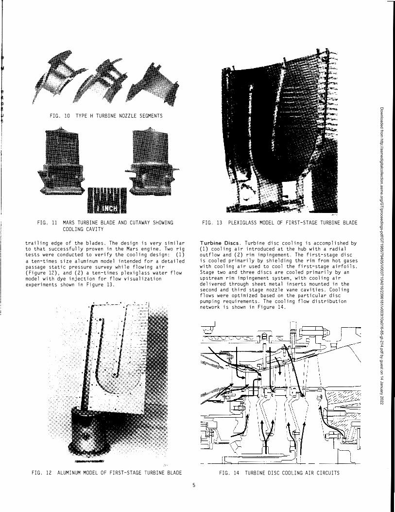
FIG. 10 TYPE H TURBINE NOZZLE SEGMENTS
FIG. 11 MARS TURBINE BLADE AND CUTAWAY SHOWING COOLING CAVITY
trailing edge of the blades. The design is very similar to that successfully proven in the Mars engine. Two rig tests were conducted to verify the cooling design: (1) a ten-times size aluminum model intended for a detailed passage static pressure survey while flowing air (Figure 12), and (2) a ten-times plexiglass water flow model with dye injection for flow visualization experiments shown in Figure 13.
FIG. 13 PLEXIGLASS MODEL OF FIRST-STAGE TURBINE BLADE
Turbine Discs. Turbine disc cooling is accomplished by (1) cooling air introduced at the hub with a radial outflow and (2) rim impingement. The first-stage disc is cooled primarily by shielding the rim from hot gases with cooling air used to cool the first-stage airfoils. Stage two and three discs are cooled primarily by an upstream rim impingement system, with cooling air delivered through sheet metal inserts mounted in the second and third stage nozzle vane cavities. Cooling flows were optimized based on the particular disc pumping requirements. The cooling flow distribution network is shown in Figure 14.
FIG. 12 ALUMINUM MODEL OF FIRST-STAGE TURBINE BLADE FIG. 14 TURBINE DISC COOLING AIR CIRCUITS
5
Dow
nloaded from http://asm
edigitalcollection.asme.org/G
T/proceedings-pdf/GT1985/79405/V003T10A016/2396181/v003t10a016-85-gt-214.pdf by guest on 14 January 2022

Power Turbine. The Type H power turbine is a singlestage design similar to the current T-4000 engine. The maximum continuous operating speed has been increased for improved flexibility in high-head gas compression applications.
The bearing arrangement is the same as the T-4000 with the added option of a Kingsbury type tilting-pad thrust bearing. The journal bearings are Solar's tilting-pad design used on the model T-4000 engine. The standard thrust bearing is the same fixed tapered-land bearing as used on the current T-4000 engine.
The power turbine assembly provides for optional radial and axial proximity probes and a shaft key phasor for vibration monitoring. Both of the journal bearings have two radial proximity probes installed in accordance with API requirements. The standard thrust bearing provides for an optional axial proximity probe and a resistance temperature detector (RTD) measuring the temperature of the loaded thrust bearing. The output coupling and the power turbine bearing housing have provisions for an optional key phasor probe.
Exhaust Diffuser
The Type H exhaust diffuser (Figure 15) was based on the Mars gas turbine design. The length has been increased slightly compared with the current Centaur gas turbine diffuser. The exhaust scroll discharge duct diameter has been increased to accommodate the increased volumetric flow. The same supporting hardware is retained, i. e. , the new exhaust diffuser will fit on the current T-4000 engine.
FIG. 15 TYPE H EXHAUST DIFFUSER AND COLLECTOR
PACKAGE DESIGN
The Type H gas turbine engine will be offered in the same complete line of compressor/mechanical drive (two-shaft) and generator (single-shaft) package configurations as the current-production Centaur T-4000
6
engine. The same selection of ancillary equipment will be retained. The philosophy used in modifying the existing Centaur turbine packages was to accommodate the increased power of the Type H gas turbine while retaining maximum commonality between the two package configurations except where changes were mandated by the higher performance of the Type H engine.
Compressor Set and Mechanical Drive Packages (Two-Shaft Gas Turbines)
The overall length of the compressor and mechanical drive packages for the Type H gas turbine will increase by approximately one foot. The same package will accommodate both the simple- and the recuperated-cycle Type H configurations. The center line height will be raised slightly but will be within the height envelope of the current enclosure (Figure 16). The increase in centerline height provides space needed for a lube oil drain line slope of one-half inch per foot and the larger oil tank volume necessary to increase lube oil system retention time, both in accordance with AP! requirements. An additional benefit of the raised centerline is to relocate package components with minimum growth of the package footprint.
-18'2"--�-
FIG. 16 TYPE H COMPRESSOR SET (TWO-SHAFT
CONFIGURATION)
Generator Set (Single-Shaft Gas Turbines)
The generator set will also be basically the same package as that for the current Centaur gas turbine (Figure 17). The torque capability of the generator reduction drive has been increased to accommodate the higher power level within the envelope of the current gear housing. Therefore, the �ew reduction-drive gearbox is physically interchangeable with the current production component. The generator has the same frame width as the T-4000 generator set with the additional generator capacity being accommodated within a two-foot extension of the generator length. The package and enclosure will exhibit the same overall width as its T-4000 predecessor. The generator set package length
9' 1"
µ_tl_lL __ _J__j___ _ _'l::====1--14; 7" j �12'0"� ------� 28'6"------ ,�7'0"�
FIG. 17 TYPE H GENERATOR SET PACKAGE (SINGLE-SHAFT
CONFIGURATION)
Dow
nloaded from http://asm
edigitalcollection.asme.org/G
T/proceedings-pdf/GT1985/79405/V003T10A016/2396181/v003t10a016-85-gt-214.pdf by guest on 14 January 2022

will increase by two feet when using the pneumatic start system and an additional three feet for diesel or electrohydraulic starters. The higher inertia generator for the Type H engine requires a rating increase for the pneumatic start system. This was accomplished by providing higher capacity starter motors that apply to both Type H and current T-4000 engines.
Recuperated Cycle
Figure 18 shows the package concept for the recuperated configuration of the Type H gas turbine. The figure outlines the compactness we expect to achieve by using Solar's proprietary primary surface recuperator configured specifically for this application. The Type H combustor was designed specifically to permit an optimum gas turbine-recuperator match.
l 9' 1"
1--lill--------______L___j_�=:::'\.._____j _l_ !�� 12' 0 "______I ------- 32 '6" �------
FIG. 18 CENTAUR TYPE H RECUPERATED PACAKGE
CONTROL
All Type H packages will use Solar's own microprocessor based Turbotronic™ control system as the standard feature. The Type H package will take advantage of the system's capabilities to provide more precise inlet guide vane and bleed valve actuation sequencing during startup and transients.
The fundamental operating concept for this alldigital control system is to collect data on the state of the gas turbine and its required operation; compute the proper output control signals; and send them to the appropriate devices, such as motor controllers, solenoid valves, and control valves. Microprocessors control the scanning, receipt, and storage of the input data, compute the desired outputs, and control the transmission of operating signals. These operations are carred out iteratively up to 30 times each second.
A cathode-ray tube and keyboard are used as the operator interface for a variety of system status displays. To start and stop the unit, and to change operating speed or load, conventional buttons are used.
Additional equipment, including vibration monitor and fire and gas detectors can be added for specific customer requirements.
DEVELOPMENT PLAN
The Type H development plan consists of four principal elements:
Development of the bas1c design Early testing of key components to verify performance In-house testing of prototype gas turbines and packages Field evaluations of the first production units
Experience with previous Centaur turbine models and the Mars gas turbine makes the use of computer-aided design techniques particularly appropriate. Key components can be designed using state-of-the-art Computer Aided Engineering (CAE) technology, and then "test" whole assemblies using parameters such as aerodynamic and thermodynamic flow characteristics and the physical properties of candidate materials to identify problem areas before proceeding to the hardware stage. Figures 19, 20 and 21, for example, show finite element models of the compressor section and the first-stage turbine nozzle, and a finite difference heat transfer model of the gas producer system. These models were used to predict the transient as well as steady-state temperatures, stresses, deflections and tip clearances.
FIG. 20 FINITE ELEMENT MODEL OF THE FIRST-STAGE
TURBINE NOZZLE
FIG. 19 FINITE ELEMENT MODEL OF THE COMPRESSOR
7
Dow
nloaded from http://asm
edigitalcollection.asme.org/G
T/proceedings-pdf/GT1985/79405/V003T10A016/2396181/v003t10a016-85-gt-214.pdf by guest on 14 January 2022

:i:_ _____ x FIG. 21
26-18 FINITE DIFFERENCE MODEL FOR HEAT TRANSFER
ANALYSIS OF THE GAS PRODUCER ROTOR SYSTEM
Our own experience and that of industry in general testifies that the intensive utilization of computeraided engineering and design significantly compresses the design cycle time and minimizes the redesigns required after verification testing of the first units.
Compressor rig evaluation is one of the key component tests. Solar's test rig (Figure 22) is unique in that it does not require the usual drive equipment and speed increasing gear, and there are none of the power limitations which often require aerodynamicists to project performance from simulated testing (i.e., at reduced inlet pressure) of the actual compressors. In effect, our compressor test rig is a specially adapted single-shaft Centaur T-4000 gas turbine with the new Type H compressor. Instead of the usual straightthrough flow path, this test rig uses the present recuperated Centaur turbine ducting and combustion
FIG. 22 COMPRESSOR TEST RIG
8
system. A variable throttle, located in the ducting, can be adjusted to all back-pressure settings needed to fully map and explore the compressor performance. The speed range of the compressor test rig is also fully adjustable over the entire operating range experienced by the Centaur Type H gas turbine.
The Type H combustion chamber is being developed in full scale in an atmospheric combustor test rig (Figure 23). This rig simulates the engine compressor discharge Mach number for correct combustor pressure drop and mixing. Measurements of combustor metal temperatures, inlet radial and circumferential pressure profiles, pressure loss, temperature rise, exhaust emissions, and circumferential and radial combustor exit temperature profile are recorded.
FIG. 23 COMBUSTOR TEST RIG
A Type H exhaust system quarter-scale model utilizing diffuser geometry scaled from the Mars gas turbine design was used to determine final exhaust diffuser and collector configuration (Figure 24).
FIG. 24 QUARTER-SCALE EXHAUST SYSTEM FLOW MODEL
Dow
nloaded from http://asm
edigitalcollection.asme.org/G
T/proceedings-pdf/GT1985/79405/V003T10A016/2396181/v003t10a016-85-gt-214.pdf by guest on 14 January 2022
Initial prototype and first production hardware is now in the manufacturing process with engine testing scheduled to begin mid 1985.
SUMMARY
The Centaur Type H gas turbine engine is an uprate of the current Centaur T-4000 engine incorporating in the standard design many special features requested by our customers. The simple-cycle configuration is expected to operate above 5000 ISO horsepower with a thermal efficiency of 30 percent. We plan to follow with a recuperated configuration featuring a thermal efficiency above 35 percent. The recuperated gas turbine
9
will use Solar's primary surface recuperator, and the total package size, including the recuperator, will be only slightly larger than the current simple cycle package.
Additional growth margin is being designed into the Centuar Type H from the very beginning. The basic frame size of the unit is the same as the present Centaur gas turbine with the additional power achieved through an increase in airflow and firing temperature. Maximum use of technology, analysis, design, hardware and operating experience, gained over the years, on the Mars and Centaur gas turbines, permits us to confidently predict the future performance, operational reliability, and life of the Centaur Type H engine.
Dow
nloaded from http://asm
edigitalcollection.asme.org/G
T/proceedings-pdf/GT1985/79405/V003T10A016/2396181/v003t10a016-85-gt-214.pdf by guest on 14 January 2022