Development of New Weathering Steel for High Salinity ...
7
JFE TECHNICAL REPORT No. 26 (Mar. 2021) Copyright © 2021 JFE Steel Corporation. All Rights Reser ved. 136 Development of New Weathering Steel for High Salinity Environment for Coastal Use MIURA Shinichi *1 HATORI Satoshi *2 KAGE Isamu *3 Abstract: The new high performance weathering steel was developed with less nickel content than conventional Ni added weathering steel to be applicable in the region of large amount of airborne salt. It was verified that the developed steel had almost same corrosion resistance as conventional Ni added weathering steel (JFE-ACL- Type1, 1.5Ni-0.3Mo bearing steel). The mechanical properties of a base material were satisfied the specifica- tion of conventional weathering steel (JIS G 3114, JIS SMA) and the weldability and properties of welded joint were equivalent to JIS SMA. Developed steel has an advantage in economical efficiency by applying the new alloy design reducing the amount of expensive alloying elements. 1. Introduction Increases in the operation and maintenance (O&M) costs and deterioration upgrade costs of social infra- structure are expected in the future, and a trial calcula- tion based on an estimate 1) by Japan’s Ministry of Land, Infrastructure, Transport and Tourism (MLIT) indicated that these costs will increase to approximately 1.2 times their current levels by around 2050. Accord- ingly, the need for reduction of the life cycle cost (LCC) of steel structures which are expected to be used over the long term is also predicted to increase in the future. In the field of bridges, weathering steels, which make it possible to reduce LCC, are currently applied to about 20% of bridges 2) . Because weathering steels can be applied in an unpainted condition, they make an important contribution to lower LCC by reducing the maintenance costs associated with repainting 3) . Conventional weathering steel (JIS G 3114, herein- after, JIS SMA) can be applied without painting in regions where the amount of airborne salt does not exceed 0.05 mg•NaCl/dm 2 /day (hereinafter, mdd) 4) . However, JIS SMA cannot be used in environments with higher amounts of airborne salt (high salinity environments), such as regions close to the coast and regions where road deicing agents are used in winter- time. Ni added weathering steels with higher corrosion resistance are applied in such areas. Ni added weather- ing steels contain approximately 1.0 to 3.0 mass% of added Ni in order to increase corrosion resistance in high salinity environments 5–8) . JFE Steel developed and commercialized two types of Ni added weathering steels, JFE-ACL-Type 1 (1.5 mass% Ni-0.3 mass% Mo) and Type 2 (0.3 mass% Cu-2.5 mass% Ni), correspond- ing to the severity of the environment where the bridge is to be constructed, and these Ni added weathering steels already have a record of use in many bridges. However, because Ni is an expensive raw material, the high content of Ni in Ni added weathering steels has become a factor in higher production costs. Although Ni added weathering steels are applied in regions that exceed the applicable range of JIS SMA, this sometimes leads cost increases because both JFE- ACL-Type 1 and Type 2 have excessive corrosion resis- tance for the corrosion environment. Therefore, a new material with excellent economy and appropriate cor- rosion resistance for intermediate corrosion environ- ments had been demanded. To meet this need, JFE Steel developed a new weathering steel (LALAC TM -HS) which holds the Ni † Originally published in JFE GIHO No. 46 (Aug. 2020), p. 44−49 *2 Staff Manager, Plate Sec., Products Design & Quality Control Dept. East Japan Works (Keihin), JFE Steel *1 Senior Researcher Deputy Manager, Steel Products Research Dept., Steel Res. Lab., JFE Steel *3 Dr. Eng., Staff Deputy General Manager, Plate Business Planning Dept., JFE Steel
-
Upload
khangminh22 -
Category
Documents
-
view
0 -
download
0
Transcript of Development of New Weathering Steel for High Salinity ...

JFE TECHNICAL REPORT No. 26 (Mar. 2021)
Copyright © 2021 JFE Steel Corporation. All Rights Reserved.
136
Development of New Weathering Steel for High Salinity Environment for Coastal UseMIURA Shinichi*1 HATORI Satoshi*2 KAGE Isamu*3
Abstract:The new high performance weathering steel was
developed with less nickel content than conventional Ni added weathering steel to be applicable in the region of large amount of airborne salt. It was verified that the developed steel had almost same corrosion resistance as conventional Ni added weathering steel (JFE-ACL-Type1, 1.5Ni-0.3Mo bearing steel). The mechanical properties of a base material were satisfied the specifica-tion of conventional weathering steel (JIS G 3114, JIS SMA) and the weldability and properties of welded joint were equivalent to JIS SMA. Developed steel has an advantage in economical efficiency by applying the new alloy design reducing the amount of expensive alloying elements.
1. Introduction
Increases in the operation and maintenance (O&M) costs and deterioration upgrade costs of social infra-structure are expected in the future, and a trial calcula-tion based on an estimate 1) by Japan’s Ministry of Land, Infrastructure, Transport and Tourism (MLIT) indicated that these costs will increase to approximately 1.2 times their current levels by around 2050. Accord-ingly, the need for reduction of the life cycle cost (LCC) of steel structures which are expected to be used over the long term is also predicted to increase in the future. In the field of bridges, weathering steels, which make it possible to reduce LCC, are currently applied to about 20% of bridges 2). Because weathering steels can be applied in an unpainted condition, they make an important contribution to lower LCC by reducing the
maintenance costs associated with repainting 3).Conventional weathering steel (JIS G 3114, herein-
after, JIS SMA) can be applied without painting in regions where the amount of airborne salt does not exceed 0.05 mg•NaCl/dm2/day (hereinafter, mdd) 4). However, JIS SMA cannot be used in environments with higher amounts of airborne salt (high salinity environments), such as regions close to the coast and regions where road deicing agents are used in winter-time. Ni added weathering steels with higher corrosion resistance are applied in such areas. Ni added weather-ing steels contain approximately 1.0 to 3.0 mass% of added Ni in order to increase corrosion resistance in high salinity environments 5–8). JFE Steel developed and commercialized two types of Ni added weathering steels, JFE-ACL-Type 1 (1.5 mass% Ni-0.3 mass% Mo) and Type 2 (0.3 mass% Cu-2.5 mass% Ni), correspond-ing to the severity of the environment where the bridge is to be constructed, and these Ni added weathering steels already have a record of use in many bridges.
However, because Ni is an expensive raw material, the high content of Ni in Ni added weathering steels has become a factor in higher production costs. Although Ni added weathering steels are applied in regions that exceed the applicable range of JIS SMA, this sometimes leads cost increases because both JFE-ACL-Type 1 and Type 2 have excessive corrosion resis-tance for the corrosion environment. Therefore, a new material with excellent economy and appropriate cor-rosion resistance for intermediate corrosion environ-ments had been demanded.
To meet this need, JFE Steel developed a new weathering steel (LALACTM-HS) which holds the Ni
† Originally published in JFE GIHO No. 46 (Aug. 2020), p. 44−49 *2 Staff Manager, Plate Sec., Products Design & Quality Control Dept. East Japan Works (Keihin), JFE Steel
*1 Senior Researcher Deputy Manager, Steel Products Research Dept., Steel Res. Lab., JFE Steel
*3 Dr. Eng., Staff Deputy General Manager, Plate Business Planning Dept., JFE Steel

Development of New Weathering Steel for High Salinity Environment for Coastal Use
JFE TECHNICAL REPORT No. 26 (Mar. 2021) 137
content to a low level and can also be used without painting in high salinity environments 9).
This report describes the corrosion resistance con-cept for securing high corrosion resistance while hold-ing the Ni content to a low level, and the results of ver-ification of the corrosion resistance of the steel designed on the basis of that concept and the mechani-cal properties required in steel for structural use.
2. Corrosion Resistance Design
Ni added weathering steels applicable to high salin-ity environments contain a large amount of added Ni, which is widely dispersed in the rust layer and forms a dense rust layer which suppresses corrosion by prevent-ing penetration of Cl to the steel surface 5–6). However, the large amount of Ni that must be added to these steels is an issue. In JIS SMA, corrosion is suppressed because added Cu, Ni and Cr form a dense rust layer with a high protective property 10–14), but among these elements, Cr has an adverse effect on corrosion resis-tance in high salinity environments in some cases.
In this development, we discovered that Sn and Nb display high corrosion resistance in high salinity envi-ronments, even when added in trace amounts, and added these elements to form a highly-protective dense rust layer without depending on heavy addition of Ni. These elements form a dense rust layer by concentrat-ing locally in the lower layer of the rust layer, thereby suppressing penetration of chloride ions to the steel surface. The protective property was enhanced by add-ing the same levels of Cu and Ni as in JIS SMA, and deterioration of corrosion resistance in high salinity environments was avoided by not adding Cr. The cor-rosion resistance design described above made it possi-ble to secure satisfactory corrosion resistance in high salinity environments, while also holding Ni addition to a low level.
Figure 1 shows a schematic diagram of the mecha-
nism of corrosion resistance. Cu and Ni are dispersed in the inner layer rust, and a dense rust layer is formed by concentration of Sn and Nb. Penetration of the chloride ion, which is a corrosion factor, is suppressed by the dense rust layer formed in this manner, and as a result, the corrosion reaction is suppressed.
3. Experimental Method
3.1 Atmospheric Exposure Test
An atmospheric exposure test was carried out to evaluate corrosion resistance in an actual environment. As the atmospheric exposure test method, assuming a severe actual environment in which deposited salt is not washed away by rain water, the under-the-eaves expo-sure test method was adopted, as rain does not fall on the samples. The test materials were the developed steel (0.3 mass% Cu-0.3 mass% Ni-Sn-Nb added steel), JIS SMA (0.3 mass% Cu-0.5 mass% Cr-0.2 mass% Ni added steel) and JFE-ACL-Type 1 (1.5 mass% Ni-0.3 mass% Mo added steel). After the test pieces were recovered and the rust was removed, the test pieces were weighed, and the amount of corrosion was evaluated by calculating the average thickness loss of one side from the difference of the steel weight before and after the test and the surface area of the test piece.
3.2 Analysis of Rust Layer
Characterization of the rust layer of the developed steel was carried out by the following procedures.1) Observation of rust layer cross section by polariza-
tion microscopeAfter the atmospheric exposure test, specimens for
observation were prepared by cutting the test pieces and embedding the specimens in epoxy resin, fol-lowed by dry-type ethanol polishing and diamond spray finishing.
2) Quantitative evaluation of rust composition by XRD
The rust layer that had formed on the test pieces was classified as an upper layer consisting of loose scale and a lower layer tightly adhering to the base steel, and was removed with a scraper and recovered. The lower layer of the recovered rust was pulverized and tested as powdery rust. The measurement was conducted using CuKα beam radiation under the conditions of 40 kV, 40 mA and a step angle of 0.02°.
3) Evaluation of elemental distribution in rust layer by EPMA
As specimens, the specimens used in the observa-tion of the rust layer cross section with the polariza-tion microscope were used. The EPMA observation Fig. 1 Corrosion resistant mechanism of developed steel
Development of New Weathering Steel for High Salinity Environment for Coastal Use
138 JFE TECHNICAL REPORT No. 26 (Mar. 2021)
conditions were an accelerating voltage of 15.0 kV, irradiation current of 5.0 × 10⁻⁷ A, beam diameter of 1 μm and irradiation time of 25 ms.
4) Fineness evaluation of rust layer by STEM selected-area electron diffraction
Specimens were prepared by cutting out a thin film from the rust layer using a focused ion beam. The conditions of the selected-area electron diffraction by STEM were 200 kV and an aperture size of 200 nm.
4. Experimental Results and Discussion
4.1 Evaluation of Corrosion Resistance by Atmospheric Exposure Tests
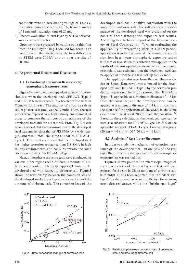
Figure 2 shows the time-dependent change of corro-sion loss when the developed steel, JFE-ACL-Type 1 and JIS SMA were exposed in a beach environment in Okinawa for 3 years. The amount of airborne salt in the exposure test area was 0.77 mdd. Here, the test pieces were exposed in a high salinity environment in order to compare the salt corrosion resistance of the developed steel and the other steels. From Fig. 2, it can be understood that the corrosion loss of the developed steel was smaller than that of JIS SMA by a wide mar-gin, and was almost the same as that of JFE-ACL-Type 1. This result confirmed that the developed steel has higher corrosion resistance than JIS SMA in high salinity environments, and has substantially the same corrosion resistance as JFE-ACL-Type 1.
Next, atmospheric exposure tests were conducted in various other regions with different amounts of air-borne salt in order to clarify the applicable limit of the developed steel with respect to airborne salt. Figure 3 shows the relationship between the corrosion loss of the developed steel after a 1-year exposure test and the amount of airborne salt. The corrosion loss of the
developed steel has a positive correlation with the amount of airborne salt. The salt resistance perfor-mance of the developed steel was evaluated on the basis of these atmospheric exposure test results. According to a Technical Report of the Japanese Soci-ety of Steel Construction 15), when evaluating the applicability of weathering steels in a short period, application is judged possible if the amount of corro-sion loss in a 1-year atmospheric exposure test is 0.03 mm or less. When this criterion was applied to the results of the atmospheric exposure tests in the present research, it was estimated that the developed steel can be applied at airborne salt levels of up to 0.27 mdd.
The applicable distance from the coastline on the Sea of Japan (Kanazawa) was estimated for the devel-oped steel and JFE-ACL-Type 1 by the corrosion pre-diction equation. The results showed that JFE-ACL-Type 1 is applicable at a minimum distance of 1.6 km from the coastline, and the developed steel can be applied at a minimum distance of 4.4 km. In contrast, the distance for application of JIS SMA in the same environment is at least 20 km from the coastline 3). Based on these calculations, the developed steel can be used as a substitute for JFE-ACL-Type 1 in 85% of the applicable range of JFE-ACL-Type 1 in coastal regions: (20 km − 4.4 km) × 100 / (20 km − 1.6 km).
4.2 Analysis of Rust Layer Structure
In order to study the mechanism of corrosion resis-tance of the developed steel, an analysis of the rust layer that formed on the specimens in the atmospheric exposure test was carried out.
Figure 4 shows polarization microscope images of the cross sections of the rust layer of test materials exposed for 2 years in Chiba (amount of airborne salt: 0.26 mdd). It has been reported that the “dark rust layer” is a dense rust layer and is effective for securing corrosion resistance, while the “bright rust layer”
Fig. 2 Time-dependent changes of corrosion lossFig. 3 Relationship between corrosion loss of developed
steel and amount of airborne salt

Development of New Weathering Steel for High Salinity Environment for Coastal Use
JFE TECHNICAL REPORT No. 26 (Mar. 2021) 139
(polarization layer) contains many cracks and has a low corrosion protection property 16). In the rust layer of JIS SMA, a polarization layer also exists close to the base steel under the rust layer, and a dark rust layer has not formed continuously in the lower layer. On the other hand, in the developed steel, a dark rust layer has formed continuously in the lower layer of the rust layer. Similarly, a dark rust layer has formed continuously in the lower layer of the rust layer of JFE-ACL-Type 1. Thus, in comparison with the rust layer of JIS SMA, it is estimated that the developed steel has a function which forms a dense rust layer, like that observed in JFE-ACL-Type 1.
Next, rust samples were taken from the test materi-als exposed for 2 years in Chiba, and a quantitative analysis was carried out by XRD. The test materials were the developed steel, JFE-ACL-Type 1, JIS SMA and JIS SM. The results are shown in Table 1. In order
to evaluate the protective property of the rust layers from the results of the quantitative analysis, the vari-ous steels were compared using the rust protection index (α + am) / γ * 17), which is an index for evaluating the protective property of rust. Here, α : α -FeOOH, am: X-ray amorphous rust and γ * : γ -FeOOH + β -FeOOH + Fe3O4. Figure 5 shows the rust protection indexes of the steels exposed for 2 year in Chiba, where larger values mean a higher rust protection property. The order of the rust protection indexes of the steels is JIS SM JIS SMA JFE-ACL-Type 1 Developed steel, indicating that the developed steel shows the highest rust protection index. Based on this, it can be inferred that the developed steel forms a rust layer with a higher protective property than JIS SMA, as in JFE-ACL-Type 1.
Figure 6 shows the EPMA elemental mapping of the cross section of the rust layer of the developed steel. The elements measured here were Cl, which is the main corrosion factor, and the corrosion resistant ele-ments Sn and Nb. The measurement range was the same position as that of the observation with the polarization microscope shown in Fig. 4. The solid white lines in the figures show the interface between the base steel and the rust layer. Cl was distributed mainly on the upper rust layer side, and the amount of Cl dis-tribution near the interface between the base steel and the rust layer was slight. On the other hand, Sn and Nb were concentrated in the region below the broken white lines, that is, in the lower layer of the rust layer. More-
Fig. 5 Rust protection index of various steelsFig. 4 Polarization microscope image of cross section of rust
a) JIS SMA b) developed steel c) JFE-ACL-Type1
Table 1 Rust composition of various steels
α -FeOOH β -FeOOH γ -FeOOH Fe3O4 X-ray amorphous rust
JIS SM 18.4 10.1 12.3 0.0 59.2
JIS SMA 15.9 13.6 7.1 0.0 63.4
Developed steel 16.6 11.5 5.7 0.0 66.3
JFE-ACL-Type1 14.7 14.9 3.5 0.0 67.0

Development of New Weathering Steel for High Salinity Environment for Coastal Use
140 JFE TECHNICAL REPORT No. 26 (Mar. 2021)
over, the position where Sn and Nb had concentrated coincided with the region observed as a dark rust layer in the polarization microscope image shown in Fig. 4. Based on these results, it can be estimated that penetra-tion of Cl to the interface between the rust layer and the base steel was suppressed by concentration of the
rust resistant elements to the lower rust layer.Figure 7 shows an electron diffraction image of the
Sn, Nb-enriched region of the rust layer. Since the image displays a halo pattern, which is obtained from the amorphous structure of the rust layer, it can be inferred that a fine, amorphous rust layer has formed.
Based on the analytical results, it is thought that the developed steel shows excellent corrosion resistance because a dense rust layer is formed by the effect of the corrosion resistant elements, and this dense rust layer suppresses penetration of the corrosion acceleration factor Cl through the rust layer.
5. Mechanical Properties of Developed Steel
The following presents the results of an evaluation of the mechanical properties required in steels for structural use, using plates of the developed steel pro-
Fig. 7 Electron diffraction image of rust layer at Sn and Nb concentrated area
Fig. 6 EPMA mapping of cross section of rust layera) Cl b) Sn c) Nb
Table 2 Chemical composition of developed steel
GradeChemical composition (mass%)
Ceq PCMC Si Mn P S Cu Ni Corrosion resistant elements
Developed steel
400 MPa 0.08 0.20 0.96 0.009 0.002 0.30 0.30Total content of Nb, Sn shall be less
than 0.15
0.26 0.15
490 MPa 0.08 0.53 1.62 0.008 0.003 0.32 0.32 0.38 0.20
570 MPa 0.08 0.48 1.57 0.008 0.003 0.31 0.31 0.36 0.19
Ceq = C + Si/24 + Mn/6 + Ni/40 + Cr/5 + Mo/4 + V/14PCM = C + Si/30 + Mn/20 + Cu/20 + Ni/60 + Cr/20 + Mo/15 + V/10 + 5B
Table 3 Mechanical properties of developed steel
GradeThickness
(mm)
Tensile test Charpy impact test
YS (N/mm2) 16 t 40
TS (N/mm2) Specimen El (%)Test temp.
(˚C)VE (J)
Developed steel
400 MPa 25 354 456 JIS 1A 29 0 268
490 MPa 25 471 549 JIS 1A 31 0 312
570 MPa 25 523 642 JIS 5 39 −5 218
JIS G 3114 Specification
SMA400CW 16 t 50 235 400 540 JIS 1A 21 0 47
SMA490CW 16 t 50 355 490 610 JIS 1A 19 0 47
SMA570W 16 t 450 570 720 JIS 5 26 −5 47
YS: yield strength, TS: tensile strength, El: elongation, vE: absorbed energy, Position of charpy impact test: 1/4t

Development of New Weathering Steel for High Salinity Environment for Coastal Use
JFE TECHNICAL REPORT No. 26 (Mar. 2021) 141
duced with actual equipment.Table 2 shows an example of the chemical composi-
tion of the developed steel. Cu, Ni, Sn and Nb were added as corrosion resistant elements. Table 3 shows an example of the tensile properties and Charpy impact properties of the developed steel for each strength grade. The developed steel satisfied the standard values for mechanical properties of JIS SMA 400CW, 490CW and 570W. Table 4 shows the results of a y-groove weld cracking test conforming to JIS Z 3158 using the tensile strength 490 MPa class and 570 MPa class developed steel. The preheating temperatures for preventing root cracking were 0˚C and 25˚C, and weldability was satis-factory.
Table 5 shows an example of the mechanical prop-erties of welded joints of the TS 490 MPa class and 570 MPa class developed steel. The welded joints were prepared using a welding consumable for use with the Ni added weathering steel (JFE-ACL-Type 1). The welded joints using the developed steel exceeded the standard values for the strength of TS 490 MPa class and 570 MPa class steel plates, and also had satisfac-tory flexural properties. From this, it can be said that welding similar to that with the conventional steel is possible in application to actual bridges.
6. Application to Actual Structures
The developed steel has already been applied to bridges in Japan. Figure 8 shows an example of appli-cation to a bridge with a length of 194 m on an expressway. In addition to bridges, the developed steel can also be applied to various other steel structures such as steel towers located in regions near the coast.
7. Conclusion
A new weathering steel (LALACTM-HS), which can be applied without painting in high salinity environ-ments near the coastline and in regions where road deicing agents are used in winter, was developed. The features and mechanical properties of the developed steel are summarized below.(1) It was found that corrosion resistance in high salin-
ity environments can be enhanced without heavy addition of nickel by adding Sn, Nb, Cu and Ni as effective elements for improvement of corrosion resistance, and a new weathering steel with corro-sion resistance approximately equal to that of JFE-
Fig. 8 Appearance of the bridge in which developed steel is applied
Table 5 Mechanical properties of developed steel
Grade GradeWeldeing process
Thickness (mm)
Welding consumable
Heat input (kJ/mm)
Tensile test Charpy impact test
TS (N/mm2)
Test temp.(˚C)
Notch position
VE0
(J)
Developed steel
490 MPa GMAW 25 DW-50WCL 2.0 556 0Weld Metal 121
HAZ1 257
570 MPa SAW 50US-W62CL
×MF-384.1 641 −5
Weld Metal 86
HAZ1 295
JIS G 3114 Speci-fication
SMA490CW − − − − 490 0 − 47
SMA570W − − − − 570 −5 − 47
GMAW: Gas Metal Arc Welding, SAW: Submerged arc welding, TS: tensile strength, vE: absorbed energy,Welding consumable: KOBE STEEL, Ltd., HAZ1: Position of 1 mm from fusion line
Table 4 Weldability of developed steel
GradeWelding process
Welding consumables
Thickness (mm)
Preheating temperature to
prevent root cracking (˚C)
Developed steel
490 MPaSMAW LB-W52CL
25 050 0
GMAW MX-50WCL25 050 0
570 MPaSMAW LB-W62CL
25 050 25
GMAW DW-60WCL25 050 0
SMAW: Self Metal Arc Welding, GMAW: Gas Metal Arc Weld-ing, Welding consumable: KOBE STEEL, Ltd.

Development of New Weathering Steel for High Salinity Environment for Coastal Use
142 JFE TECHNICAL REPORT No. 26 (Mar. 2021)
Copyright © 2021 JFE Steel Corporation. All Rights Reserved. Unauthorized reproduction prohibited.
ACL-Type 1 in high salinity environments was developed.
(2) The developed steel possesses mechanical proper-ties, weldability and welded joint performance equal to those of JIS SMA in all the strength grades of tensile strength 400, 490 and 570 MPa class, and has a product lineup equivalent to JIS SMA400AW, 400BW, 400CW, 490AW, 490BW, 490CW and 570W.
Because the developed steel can be used in steel structures in high salinity environments without paint-ing, this new product makes an important contribution to reduction of the life cycle cost (LCC) of steel struc-tures by reducing maintenance and operation costs associated with repainting, etc.
References
1) Ministry of Land, Infrastructure, Transport and Tourism. “Kokudo kostu sho shokanbunya niokeru syakaishihon no sho-rai no ijikanri/koshinhi no suikei (2018nendo)”. https://www.mlit.go.jp/sogoseisaku/maintenance/02research/02_01_01.html, (Accessed October 20, 2020).
2) Japan Bridge Association. https://www.jasbc.or.jp/technique/works/. 2020.
3) Public Works Research Institute, Ministry of Construction, Kozai Club, Japan Bridge Association. Report on Application of Weathering Steel for Bridge (XX), 1993.
4) Miki, C.; Ichikawa, A. Gendai no kyoryokogaku. Suurikogaku-sha, 2004.
5) Shiotani, K.; Tanimoto, W.; Maeda, C.; Kawabata, F.; Amano, K. Analysis for Structure of Rust Layer Formed on Weathering Steel Bridge for Bare Use Exposed in Coastal Industrial Zone for 27 Years. Zairyo-to-Kankyo. 2000, vol. 49, p. 67–71.
6) Suzuki, I.; Hisamatsu, Y.; Masuko, N. Nature of Atmospheric Rust on Iron. J. Electrochem. Soc.. 1980, vol. 127, no. 10, p. 2210.
7) Yamashita, M.; Konishi, H.; Kozakura, T.; Mizuki J.; Uchida, H. Atmospheric Rust Formation Process on Fe–Cr and Fe–Ni Alloys under Wet/Dry Cycles Observed by Synchrotron Radia-tion X-ray Diffraction. Materials Transaction. 2005, vol. 46, no. 5. p. 1004–1009.
8) Otsuka, T. Sabi no bisaika to kozai no boshokusei heno tenka-genso no kouka. Bulletin of the Iron and Steel Institute of Japan. 2007, vol. 12, no. 12, p. 795.
9) Kihira, H. Application of EIS Technique to Evaluation for Pro-tective Properties of Rust on Weathering Steel. Zairyo-to-Kan-kyo. 1999, vol. 48, p. 697–700.
10) Takemura, M.; Tanaka, K.; Shinichi, S.; Morita, K.; Fujita S. Development of Weathering Steel for Coastal Use. Materia Japan. 2001, vol. 40, no. 3, p. 289–291.
11) Shiotani, K.; Kawabata F.; Amano, K. New Weathering Steels of Extremely Low Carbon Bainitic Type with Excellent Weld-ability. Kawasaki Steel Technical Report. 2002, no. 46, p. 49–55.
12) Usami, A.; Kihira, H.; Kusunoki, T. 3%Ni-Weathering Steel Plate for Uncoated Bridges at High Air-Bone salt Environments. Shinnittetsu Giho. 2002, vol. 377, p. 19–21.
13) Nakayama, T.; Yuse, F.; Kawano, H.; Ooe, K.; Abe, K.; Sakai, M. Development of Atmospheric Corrosion-resistant Steel Plates for Unpaint for Paint Use in Chloride Environments. Kobeseiko Giho. 2001, vol. 51, no. 1, p. 29–33.
14) Miura, S.; Shiotani, K.; Kato, M.; Fujiwara, Y. Kaigan kinbo ni okeru koutaikouseikouzai (LALAC®-HS) no tekiyouseihyouka. Proceedings of the 73th Annual Conference of the Japan Society of Civil Engineers. 2019, V-316.
15) Japan Society of Steel Construction. JSSC Technical Tec. Report. no. 73, 2006.
16) Okada, H.; Hosoi, Y.; Yukawa, K.; Naito, H. Structure of the Rust Formed on Low Alloy Steels in Atmospheric Corrosion. Tetsu-to-Hagane. 1969, vol. 55, no. 5, p. 355–365.
17) Shiotani, K.; Nakayama, T.; Kihira, H.; Miyuki, H.; Takemura, M.; Kawabata, F.; Abe, K.; Kusunoki, T.; Watanabe, Y.; Matsui, K. Teiryo XRD Sihyo no kensho to riyoushishin. Proceedings of the 132th Fushoku-Boshoku symposium. 2001, p. 73–82.