Development of MEMS-IMU/GPS Integrated Navigation System
10
JPNT 3(2), 53-62 (2014) http://dx.doi.org/10.11003/JPNT.2014.3.2.053 Copyright © The Korean GNSS Society J PNT Journal of Positioning, Navigation, and Timing http://www.gnss.or.kr Print ISSN: 2288-8187 Online ISSN: 2289-0866 1. INTRODUCTION A navigation system provides position information to guided weapon systems, unmanned systems, aircraft, ships, and vehicles; and it is an important element that determines the system performance. Navigation systems are divided into an inertial navigation system and a satellite navigation system. The inertial navigation system estimates position, velocity, and attitude through the integration of the angular velocity and acceleration measured by a gyroscope and an accelerometer, which are inertial sensors. The satellite navigation system, which is represented by the Global Positioning System (GPS) of the United States, estimates position by measuring the arrival times of the radio signals broadcast from satellites and by using the principle of triangulation. Inertial navigation systems are classified depending on the type and performance of inertial sensors. They are classified into the Gimbal type, where the axis of the inertial sensor is always consistent with the navigation frame, and the Strapdown type, where the axis of the inertial sensor is Development of MEMS-IMU/GPS Integrated Navigation System Jeong Won Kim 1† , Chang Woo Nam 1 , Jae-Cheul Lee 1 , Sung Jin Yoon 2 , Jaewook Rhim 2 1 Hanwha Corporation R&D Center, Daejeon 305-156, Korea 2 Agency for Defense Development, Daejeon 305-600, Korea ABSTRACT In the guided missile and unmanned vehicle system, the navigation system is one of the most important components. Recently, low-cost effective smart projectiles and guided bomb are being developed using MEMS based navigation system which has high-G, low-cost and small size. In this paper, locally developed MEMS based GPS/INS integrated navigation system will be introduced in comparison with the state of the art of MEMS based navigation system. And technical design and development method is described to satisfy the required performance of GPS receiver, MEMS inertial sensor assembly, navigation computer and software. Keywords: MEMS, GPS/INS integrated navigation system consistent with the body frame; and can also be classified depending on the principle of the inertial sensor, such as mechanical gyroscope, optical gyroscope, and laser gyroscope. As an inertial navigation system calculates position by the principle of integration, the error of the inertial sensor accumulates, and the error diverges with time. To obtain accurate navigation information, a high- performance inertial sensor should be used. However, it has the disadvantages of increased price, power consumption, and volume, in proportion to the performance. Recently, guided weapons that improve accuracy while pursuing cost efficiency by adding guidance/navigation/ control functions to free-fall bombs and gun-launched projectiles have been developed. e representative weapon systems include smart projectiles such as Joint Direct Attack Munitions (JDAM), Extended Range Guided Munitions (ERGM), and Excalibur. e navigation system for these guided weapon systems should satisfy small size, low power, low cost, and high- shock survivability. However, existing mechanical and optical sensors cannot satisfy these conditions. With the recent development of Micro ElectroMechanical System (MEMS) technology, inertial sensors that can satisfy these conditions have been developed (Dowdle & Flueckiger 1996, Barbour 2001, Warnasch & Killen 2002, Brown 2003, Habibi et al. 2008). An MEMS inertial sensor has a number of advantages, but has lower performance than mechanical Received Mar 31, 2014 Revised May 08, 2014 Accepted May 09, 2014 † Corresponding Author E-mail: [email protected] Tel: +82-42-828-0533 Fax: +82-42-828-0420
-
Upload
khangminh22 -
Category
Documents
-
view
4 -
download
0
Transcript of Development of MEMS-IMU/GPS Integrated Navigation System
JPNT 3(2), 53-62 (2014)http://dx.doi.org/10.11003/JPNT.2014.3.2.053
Copyright © The Korean GNSS Society
JPNT Journal of Positioning,Navigation, and Timing
http://www.gnss.or.kr Print ISSN: 2288-8187 Online ISSN: 2289-0866
1. INTRODUCTION
A navigation system provides position information to
guided weapon systems, unmanned systems, aircraft, ships,
and vehicles; and it is an important element that determines
the system performance. Navigation systems are divided
into an inertial navigation system and a satellite navigation
system. The inertial navigation system estimates position,
velocity, and attitude through the integration of the angular
velocity and acceleration measured by a gyroscope and
an accelerometer, which are inertial sensors. The satellite
navigation system, which is represented by the Global
Positioning System (GPS) of the United States, estimates
position by measuring the arrival times of the radio signals
broadcast from satellites and by using the principle of
triangulation.
Inertial navigation systems are classified depending
on the type and performance of inertial sensors. They are
classified into the Gimbal type, where the axis of the inertial
sensor is always consistent with the navigation frame, and
the Strapdown type, where the axis of the inertial sensor is
Development of MEMS-IMU/GPS Integrated Navigation System Jeong Won Kim1†, Chang Woo Nam1, Jae-Cheul Lee1, Sung Jin Yoon2, Jaewook Rhim2
1Hanwha Corporation R&D Center, Daejeon 305-156, Korea2Agency for Defense Development, Daejeon 305-600, Korea
ABSTRACT
In the guided missile and unmanned vehicle system, the navigation system is one of the most important components. Recently, low-cost effective smart projectiles and guided bomb are being developed using MEMS based navigation system which has high-G, low-cost and small size. In this paper, locally developed MEMS based GPS/INS integrated navigation system will be introduced in comparison with the state of the art of MEMS based navigation system. And technical design and development method is described to satisfy the required performance of GPS receiver, MEMS inertial sensor assembly, navigation computer and software.
Keywords: MEMS, GPS/INS integrated navigation system
consistent with the body frame; and can also be classified
depending on the principle of the inertial sensor, such
as mechanical gyroscope, optical gyroscope, and laser
gyroscope. As an inertial navigation system calculates
position by the principle of integration, the error of the
inertial sensor accumulates, and the error diverges with
time. To obtain accurate navigation information, a high-
performance inertial sensor should be used. However, it has
the disadvantages of increased price, power consumption,
and volume, in proportion to the performance.
Recently, guided weapons that improve accuracy while
pursuing cost efficiency by adding guidance/navigation/
control functions to free-fall bombs and gun-launched
projectiles have been developed. The representative weapon
systems include smart projectiles such as Joint Direct Attack
Munitions (JDAM), Extended Range Guided Munitions
(ERGM), and Excalibur.
The navigation system for these guided weapon systems
should satisfy small size, low power, low cost, and high-
shock survivability. However, existing mechanical and
optical sensors cannot satisfy these conditions. With the
recent development of Micro ElectroMechanical System
(MEMS) technology, inertial sensors that can satisfy these
conditions have been developed (Dowdle & Flueckiger
1996, Barbour 2001, Warnasch & Killen 2002, Brown 2003,
Habibi et al. 2008). An MEMS inertial sensor has a number
of advantages, but has lower performance than mechanical
Received Mar 31, 2014 Revised May 08, 2014 Accepted May 09, 2014†Corresponding Author
E-mail: [email protected]: +82-42-828-0533 Fax: +82-42-828-0420
54 JPNT 3(2), 53-62 (2014)
http://dx.doi.org/10.11003/JPNT.2014.3.2.053
and optical sensors. Thus, it is difficult to independently
construct a navigation system, and it is generally developed
in the form of a GPS/INS integrated navigation system,
through combination with a GPS receiver (Schmidt 1999).
The representative MEMS-based GPS/INS integrated
navigation systems include the IGS-200 of Honeywell
International, Inc. from the United States and the SiNav of
AIS, Inc. from the United Kingdom. Their performances
have already been verified by applying them to weapon
systems. An MEMS-based navigation system can be used
for various applications in addition to guided bombs and
smart projectiles. In Korea, the development of a number of
guided weapons using MEMS-IMU or navigation system has
also been performed, and it is expected to be used in more
diverse fields in the future.
This paper introduces the status of the development of
an MEMS-based GPS/INS integrated navigation system
in Korea. The design method and applied technique of
the MEMS-IMU/GPS integrated navigation system are
described; and the developed result and its performance
are introduced. For the content of this paper, the status
of the development of navigation systems in foreign
countries is introduced in Section 2; and the design content,
development result, and performance of the MEMS-IMU/
GPS integrated navigation system are described in Sections
3 and 4. Lastly, future directions are suggested.
2. STATUS OF MEMS-IMU/GPS INTEGRATED NAVIGATION SYSTEMS IN FOREIGN COUNTRIES
The repres entat ive MEMS-IMU/GPS integrated
navigation systems include the IGS-200 of Honeywell
International, Inc. from the United States and the SiNav
of AIS, Inc. from the United Kingdom. In addition, there
are a number of integrated navigation systems developed
based on commercial MEMS sensors. However, most of
them have very low performance, and their reliability
and environmental resistance are insufficient for weapon
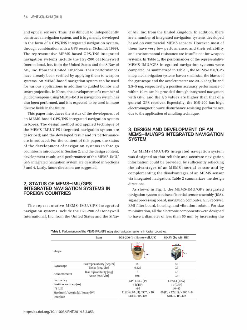
systems. In Table 1, the performances of the representative
MEMS-IMU/GPS integrated navigation systems were
compared. As summarized in Table 1, the MEMS-IMU/GPS
integrated navigation systems have a small size; the biases of
the gyroscope and the accelerometer are 20~50 deg/hr and
2.5~5 mg, respectively; a position accuracy performance of
within 10 m can be provided through integrated navigation
with GPS; and the J/S values are higher than that of a
general GPS receiver. Especially, the IGS-200 has high
electromagnetic wave disturbance resisting performance
due to the application of a nulling technique.
3. DESIGN AND DEVELOPMENT OF AN MEMS-IMU/GPS INTEGRATED NAVIGATION SYSTEM
An MEMS-IMU/GPS integrated navigation system
was designed so that reliable and accurate navigation
information could be provided, by sufficiently reflecting
the advantages of an MEMS inertial sensor and by
complementing the disadvantages of an MEMS sensor
via integrated navigation. Table 2 summarizes the design
directions.
As shown in Fig. 1, the MEMS-IMU/GPS integrated
navigation system consists of inertial sensor assembly (ISA),
signal processing board, navigation computer, GPS receiver,
EMI filter board, housing, and vibration isolator. For size
minimization, all the electronic components were designed
to have a diameter of less than 60 mm by increasing the
Table 1. Performances of the MEMS-IMU/GPS integrated navigation systems in foreign countries.
Item IGS-200 (by Honeywell, US) SiNAV (by AIS, UK)
Shape
GyroscopeBias repeatability [deg/hr]
Noise [deg/√hr]20
0.125500.5
AccelerometerBias repeatability [mg]
Noise [m/s/√hr]5
0.092.50.5
FrequencyPosition accuracy [m]J/S [dB]Size [mm]/Weight [g]/Power [W]Interface
GPS L1/L2 (P)5 (CEP)
>9571 (D) x 67 (H) / 567 / <10
SDLC / RS-422
GPS L1 (C/A)10 (CEP)
40~4580 (D) x 72 (H) / <400 / <8
SDLC / RS-422

Jeong Won Kim et al. MEMS-IMU/GPS Navigation System Development 55
http://www.gnss.or.kr
integration density using multi-layer PCB manufactured
by a build-up process, and the major modules were
manufactured by ASIC. The efficiency of HW resource usage
was increased by the development of an MEMS inertial
sensor that has high-grade performance among the grades
of MEMS, by the accurate navigation information providing
function through deep coupling with GPS, and by the
application of single CPU architecture and programmable
devices. Also, it was designed to satisfy military environment
standards so that the environmental resistance appropriate
for weapon systems could be obtained; and the structure
was designed so that it could tolerate harsh environments
such as gun-launching high impact.
The MEMS ISA consists of an MEMS sensor structure and
electronic circuits that control the structure and perform
signal processing. The gyroscope of the MEMS is a vibration
ring type, and the accelerometer is an electrostatic capacity
type. The size of the structure is very small (OxO mm), and
the performance was secured by vacuum packaging. The
electronic circuits of the gyroscope consist of preamplifier,
analog to digital converter (ADC), digital to analog converter
(DAC), field-programmable gate array (FPGA), and
frequency tuning circuit. The preamplifier is a circuit that
converts the change in electrostatic capacity, which occurs
due to the displacement of a sensing structure, into a voltage.
To sense minute changes in electrostatic capacity, a low-
noise design was applied. The output of the preamplifier is
converted to a digital signal via the differential amplifier and
ADC. Then, it is entered into FPGA, and is used as an input
signal for the four control loops within FPGA, respectively.
Among the four control circuits, the magnetic resonance
control circuit and automatic gain control circuit control
the vibration of the driving axis, and the rebalance control
circuit and quadrature control circuit control the vibration
of the sensing axis. If Coriolis force is applied to the sensing
axis due to angular velocity, the rebalance control circuit
controls so that the sensing axis can achieve force balance,
by applying a force whose magnitude is identical to that of
the Coriolis force in the anti-phase. The quadrature control
circuit was designed so that it could control the quadrature
vibration that occurs at the sensing axis due to frequency
offset and external vibration. The electronic circuit of the
accelerometer was designed as an analog voltage control
structure that can be used in a high acceleration range,
through the analysis of existing methods. The electrostatic
capacity sensing circuit used a preamplifier with an
amplitude modulation charge amplification method, and
was designed as a structure that performs feedback control
without distinguishing a sensing electrode and a driving
electrode. The control circuits excluding the amplifier, ADC,
and DAC were designed in a digital method, and the size
of the ISA was minimized through implementation using
FPGA. Fig. 2 shows the shape of the developed MEMS-ISA.
The signal processing board performs the real-time
correction of the fixed error and temperature-dependent
error included in the sensor signal of the MEMS ISA, and
outputs the inertial measurements for navigation operation
through coning/sculling compensation. To perform
many operations of real numbers at a high speed, the
signal processing board was designed based on a digital
signal processor (DSP) series processor. For the external
Table 2. Design directions of the MEMS-IMU/GPS integrated navigation system.
Item Design direction
Size minimization/Weight lighteningAccuracy
Efficiency
Environmentalresistance
High-impactsurvivability
• Device minimization through ASIC of the major modules
• High-integration/high-density HW design • High-performance MEMS inertial sensor development• Accuracy improvement through deep coupling with GPS
• HW usage efficiency improvement through the application of single CPU architecture and programmable devices• Design for satisfying the resistance to harsh environments among the military standards
• Application of the mechanical structure and parts for high-impact resistance
Fig. 1. Structure of the MEMS-IMU/GPS integrated navigation system.
Fig. 2. Shape of the MEMS ISA.

56 JPNT 3(2), 53-62 (2014)
http://dx.doi.org/10.11003/JPNT.2014.3.2.053
communication interface, an SDLC method was applied,
and flexibility was obtained through implementation based
on FPGA. Fig. 3 shows the structure and shape of the signal
processing board. For size minimization, the diameter of the
signal processing board was made to be less than 40 mm.
The GPS receiver was designed to be able to process GPS
L1/L2 and GLONASS L1 signals so that it could operate
based on multi-band frequencies. For size minimization,
the RF part and the correlator (i.e., digital signal processing
part) were developed as 1 chip, respectively, through ASIC.
OO-channel satellite signals can be received. The correlator
has an extended range correlator (ERC) structure, which
has wider tracking range than existing correlators. Also, for
high-impact resistance, a clock that is robust to high impact
was applied, and the RF part was protected with a can that
has a disturbance shielding and mechanical reinforcement
structure, as shown in Fig. 4. After the correlator of the
GPS receiver, signal processing is performed by SW, and is
operated in the navigation computer.
For an existing GPS/INS integrated navigation system,
CPU for GPS SW and CPU for integrated navigation
SW exist separately. The MEMS-IMU/GPS integrated
navigation system was designed as a single CPU based
architecture structure, and thus, one CPU operates GPS
SW and integrated navigation SW in real time. Single
CPU architecture has advantages in terms of size, power
consumption, and cost; and is known to be an optimal
H/W structure for performing deeply coupled integrated
navigation. For deeply coupled integrated navigation,
the duplicate signal generator within the GPS receiver,
a numerical controlled oscillator (NCO), should be
controlled by inertial navigation and the output of the
filter at a high refresh rate (1000 Hz), and the output of
the correlator should be processed by a pre-processing
filter or an integrated filter. If each CPU is used, data need
to be exchanged via dual port RAM or serial/parallel
communication method, and thus, the performance
could deteriorate due to the implementation loss such as
transmission delay. To operate GPS SW and integrated
navigation SW in single CPU, the navigation computer
was designed using high-performance CPU. The CPU
is a PowerPC series, and has a small size and a high
performance as it was manufactured by a 90 nm process.
It provides various functions such as 400 MHz DDR
Memory Controller, USB Dual-Role Controller, Dual
Enhanced Three-Speed Ethernet Controllers, Integrated
Programmable Interrupt Controller, Power Management
Controller, and Serial Peripheral Interface. In addition, it
belongs to a product group that is included in the product
longevity program of the manufacturer, and thus, the risk
of being discontinued is low. The major module other than
the CPU part is the external communication interface. All
the functions were designed so that easy modification of
the functions could be facilitated, through implementation
using FPGA. The navigation computer board has a size of
Fig. 3. Structure and shape of the MEMS signal processing board.
Fig. 4. Structure and shape of the GPS receiver.
Fig. 5. Structure and shape of the navigation computer.
Jeong Won Kim et al. MEMS-IMU/GPS Navigation System Development 57
http://www.gnss.or.kr
or an integrated filter. If each CPU is used, data need to be exchanged via dual port RAM or serial/parallel communication method, and thus, the performance could deteriorate due to the implementation loss such as transmission delay. To operate GPS SW and integrated navigation SW in single CPU, the navigation computer was designed using high-performance CPU. The CPU is a PowerPC series, and has a small size and a high performance as it was manufactured by a 90 nm process. It provides various functions such as 400 MHz DDR Memory Controller, USB Dual-Role Controller, Dual Enhanced Three-Speed Ethernet Controllers, Integrated Programmable Interrupt Controller, Power Management Controller, and Serial Peripheral Interface. In addition, it belongs to a product group that is included in the product longevity program of the manufacturer, and thus, the risk of being discontinued is low. The major module other than the CPU part is the external communication interface. All the functions were designed so that easy modification of the functions could be facilitated, through implementation using FPGA. The navigation computer board has a size of Φ 60 mm. To prevent the cross talk between signals that could occur in the process of size minimization, it was designed based on a signal integrity analysis. A small high-performance navigation computer was developed by the optimal arrangement of parts and by the manufacture of high-integration/high-density build-up PCB. Fig. 5 shows the structure and shape of the navigation computer.
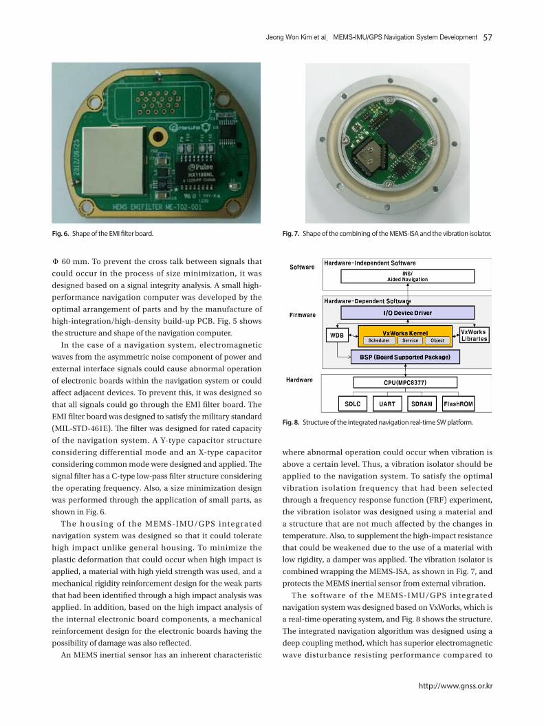
In the case of a navigation system, electromagnetic waves from the asymmetric noise component of power and external interface signals could cause abnormal operation of electronic boards within the navigation system or could affect adjacent devices. To prevent this, it was designed so that all signals could go through the EMI filter board. The EMI filter board was designed to satisfy the military standard (MIL-STD-461E). The filter was designed for rated capacity of the navigation system. A Y-type capacitor structure considering differential mode and an X-type capacitor considering common mode were designed and applied. The signal filter has a C-type low-pass filter structure considering the operating frequency. Also, a size minimization design was performed through the application of small parts, as shown in Fig. 6.
The housing of the MEMS-IMU/GPS integrated navigation system was designed so that it could tolerate high impact unlike general housing. To minimize the plastic deformation that could occur when high impact is applied, a material with high yield strength was used, and a mechanical rigidity reinforcement design for the weak parts that had been identified through a high impact analysis was applied. In addition, based on the high impact analysis of the internal electronic board components, a mechanical reinforcement design for the electronic boards having the possibility of damage was also reflected.
An MEMS inertial sensor has an inherent characteristic where abnormal operation could occur when vibration is above a certain level. Thus, a vibration isolator should be applied to the navigation system. To satisfy the optimal vibration isolation frequency that had been selected through a frequency response function (FRF) experiment, the vibration isolator was designed using a material and a structure that are not much affected by the changes in temperature. Also, to supplement the high-impact resistance that could be weakened due to the use of a material with low rigidity, a damper was applied. The vibration isolator is combined wrapping the MEMS-ISA, as shown in Fig. 7, and protects the MEMS inertial sensor from external vibration.
The software of the MEMS-IMU/GPS integrated navigation system was designed based on VxWorks, which is a real-time operating system, and Fig. 8 shows the structure. The integrated navigation algorithm was designed using a deep coupling method, which has superior electromagnetic wave disturbance resisting performance compared to existing weak coupling and strong coupling. Depending on the method of implementation, there are several kinds of deeply coupled integrated navigation algorithms. Horslund & Hooker (1999) used a method in which range and range-rate residual are used for integrated navigation by estimating them from correlation values using code phase and carrier wave frequency discriminator. Beser et al. (2002) used a method in which pre-processing filtering is performed using a Kalman filter type discriminator. Gustafson et al. (2001) used a method in which a variable gain discriminator depending on S/N is used as a pre-processing filter from ERC based correlator output. Besides, there are several kinds of known deep coupling algorithms, and they have different methods of pre-processing correlator output. In this study, an algorithm that uses ERC based correlator
60 mm. To prevent the cross talk between signals that
could occur in the process of size minimization, it was
designed based on a signal integrity analysis. A small high-
performance navigation computer was developed by the
optimal arrangement of parts and by the manufacture of
high-integration/high-density build-up PCB. Fig. 5 shows
the structure and shape of the navigation computer.
In the case of a navigation system, electromagnetic
waves from the asymmetric noise component of power and
external interface signals could cause abnormal operation
of electronic boards within the navigation system or could
affect adjacent devices. To prevent this, it was designed so
that all signals could go through the EMI filter board. The
EMI filter board was designed to satisfy the military standard
(MIL-STD-461E). The filter was designed for rated capacity
of the navigation system. A Y-type capacitor structure
considering differential mode and an X-type capacitor
considering common mode were designed and applied. The
signal filter has a C-type low-pass filter structure considering
the operating frequency. Also, a size minimization design
was performed through the application of small parts, as
shown in Fig. 6.
The housing of the MEMS-IMU/GPS integrated
navigation system was designed so that it could tolerate
high impact unlike general housing. To minimize the
plastic deformation that could occur when high impact is
applied, a material with high yield strength was used, and a
mechanical rigidity reinforcement design for the weak parts
that had been identified through a high impact analysis was
applied. In addition, based on the high impact analysis of
the internal electronic board components, a mechanical
reinforcement design for the electronic boards having the
possibility of damage was also reflected.
An MEMS inertial sensor has an inherent characteristic
where abnormal operation could occur when vibration is
above a certain level. Thus, a vibration isolator should be
applied to the navigation system. To satisfy the optimal
vibration isolation frequency that had been selected
through a frequency response function (FRF) experiment,
the vibration isolator was designed using a material and
a structure that are not much affected by the changes in
temperature. Also, to supplement the high-impact resistance
that could be weakened due to the use of a material with
low rigidity, a damper was applied. The vibration isolator is
combined wrapping the MEMS-ISA, as shown in Fig. 7, and
protects the MEMS inertial sensor from external vibration.
The software of the MEMS-IMU/GPS integrated
navigation system was designed based on VxWorks, which is
a real-time operating system, and Fig. 8 shows the structure.
The integrated navigation algorithm was designed using a
deep coupling method, which has superior electromagnetic
wave disturbance resisting performance compared to
Fig. 3. S
Fig. 4. S
Fig. 5. S
Fig. 6. S
Structure and
Structure and
Structure and
Shape of the E
shape of the
shape of the
shape of the
EMI filter bo
MEMS sign
GPS receive
navigation c
oard.
nal processing
er.
computer.
g board.
Fig. 6. Shape of the EMI filter board.
Fig. 8. Structure of the integrated navigation real-time SW platform.
Fig. 7. Shape of the combining of the MEMS-ISA and the vibration isolator.
58 JPNT 3(2), 53-62 (2014)
http://dx.doi.org/10.11003/JPNT.2014.3.2.053
existing weak coupling and strong coupling. Depending on
the method of implementation, there are several kinds of
deeply coupled integrated navigation algorithms. Horslund
& Hooker (1999) used a method in which range and range-
rate residual are used for integrated navigation by estimating
them from correlation values using code phase and carrier
wave frequency discriminator. Beser et al. (2002) used a
method in which pre-processing filtering is performed
using a Kalman filter type discriminator. Gustafson et al.
(2001) used a method in which a variable gain discriminator
depending on S/N is used as a pre-processing filter from
ERC based correlator output. Besides, there are several
kinds of known deep coupling algorithms, and they have
different methods of pre-processing correlator output. In
this study, an algorithm that uses ERC based correlator
output and that improves the jamming signal mitigation
performance by increasing integration time and using extra
correlator output was designed. It was designed as a real-
time multitasking structure so that GPS SW and integrated
navigation SW could be operated in single CPU in real time.
Fig. 9 shows the structure of the deeply coupled integrated
navigation SW.
As described above, the MEMS-IMU/GPS integrated
navigation system is a system where electronic, mechanical,
software, and MEMS technologies are integrated. It
was designed so that high performance, small size,
environmental resistance, and reliability could be secured.
M&S verification for the design content was performed
before the manufacture of a the system, and the MEMS-
IMU/GPS integrated navigation system was developed and
manufactured through verification and debugging processes
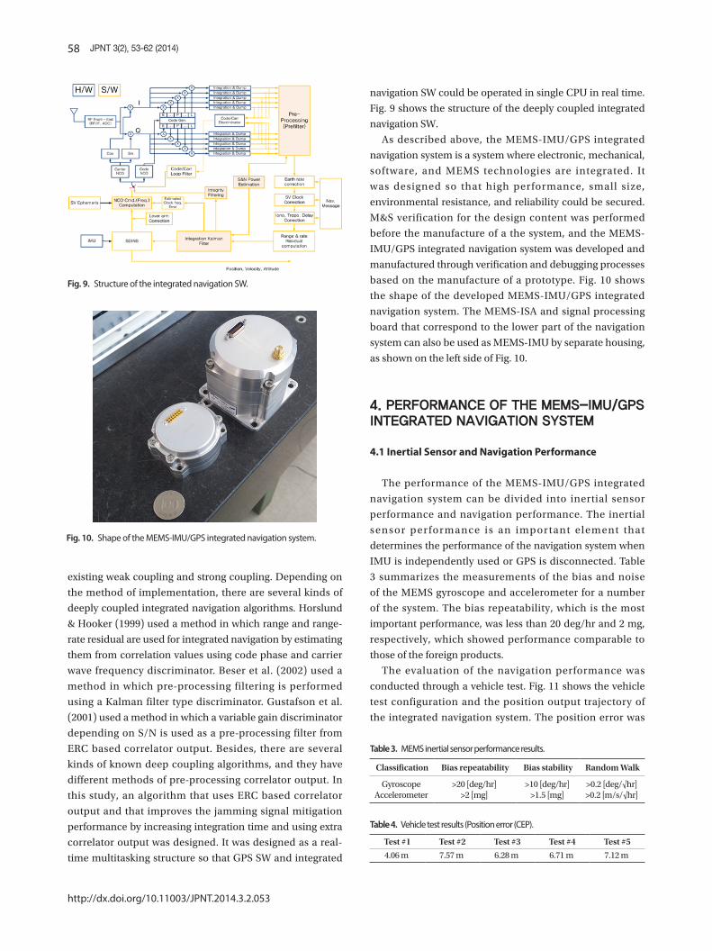
based on the manufacture of a prototype. Fig. 10 shows
the shape of the developed MEMS-IMU/GPS integrated
navigation system. The MEMS-ISA and signal processing
board that correspond to the lower part of the navigation
system can also be used as MEMS-IMU by separate housing,
as shown on the left side of Fig. 10.
4. PERFORMANCE OF THE MEMS-IMU/GPS INTEGRATED NAVIGATION SYSTEM
4.1 Inertial Sensor and Navigation Performance
The performance of the MEMS-IMU/GPS integrated
navigation system can be divided into inertial sensor
performance and navigation performance. The inertial
sensor performance is an important element that
determines the performance of the navigation system when
IMU is independently used or GPS is disconnected. Table
3 summarizes the measurements of the bias and noise
of the MEMS gyroscope and accelerometer for a number
of the system. The bias repeatability, which is the most
important performance, was less than 20 deg/hr and 2 mg,
respectively, which showed performance comparable to
those of the foreign products.
The evaluation of the navigation performance was
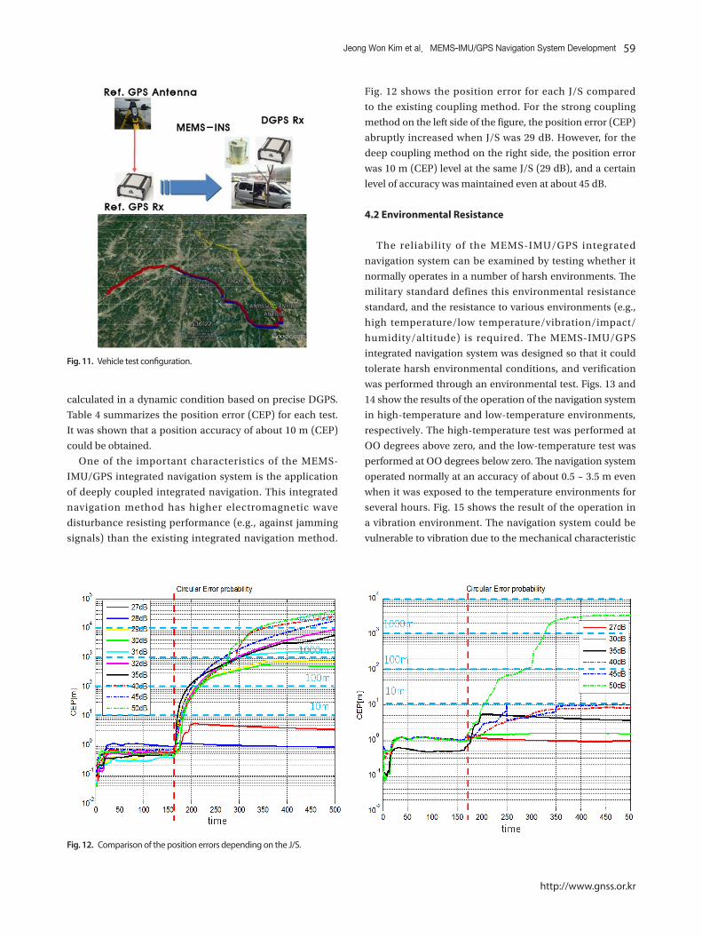
conducted through a vehicle test. Fig. 11 shows the vehicle
test configuration and the position output trajectory of
the integrated navigation system. The position error was
Fig. 10. Shape of the MEMS-IMU/GPS integrated navigation system.
Fig. 9. Structure of the integrated navigation SW.
Table 3. MEMS inertial sensor performance results.
Classification Bias repeatability Bias stability Random Walk
GyroscopeAccelerometer
>20 [deg/hr]>2 [mg]
>10 [deg/hr]>1.5 [mg]
>0.2 [deg/√hr]>0.2 [m/s/√hr]
Table 4. Vehicle test results (Position error (CEP).
Test #1 Test #2 Test #3 Test #4 Test #5
4.06 m 7.57 m 6.28 m 6.71 m 7.12 m
Jeong Won Kim et al. MEMS-IMU/GPS Navigation System Development 59
http://www.gnss.or.kr
calculated in a dynamic condition based on precise DGPS.
Table 4 summarizes the position error (CEP) for each test.
It was shown that a position accuracy of about 10 m (CEP)
could be obtained.
One of the important characteristics of the MEMS-
IMU/GPS integrated navigation system is the application
of deeply coupled integrated navigation. This integrated
navigation method has higher electromagnetic wave
disturbance resisting performance (e.g., against jamming
signals) than the existing integrated navigation method.
Fig. 12 shows the position error for each J/S compared
to the existing coupling method. For the strong coupling
method on the left side of the figure, the position error (CEP)
abruptly increased when J/S was 29 dB. However, for the
deep coupling method on the right side, the position error
was 10 m (CEP) level at the same J/S (29 dB), and a certain
level of accuracy was maintained even at about 45 dB.
4.2 Environmental Resistance
The reliability of the MEMS-IMU/GPS integrated
navigation system can be examined by testing whether it
normally operates in a number of harsh environments. The
military standard defines this environmental resistance
standard, and the resistance to various environments (e.g.,
high temperature/low temperature/vibration/impact/
humidity/altitude) is required. The MEMS-IMU/GPS
integrated navigation system was designed so that it could
tolerate harsh environmental conditions, and verification
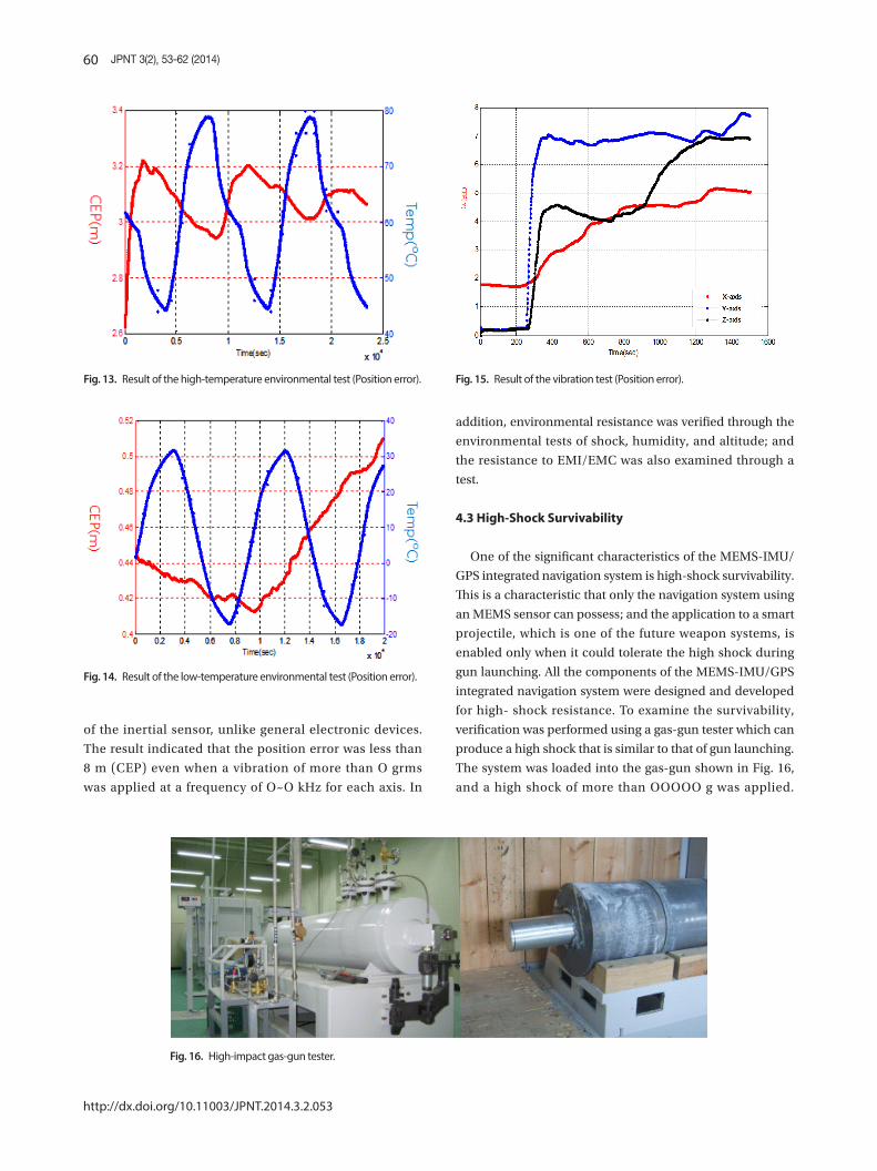
was performed through an environmental test. Figs. 13 and
14 show the results of the operation of the navigation system
in high-temperature and low-temperature environments,
respectively. The high-temperature test was performed at
OO degrees above zero, and the low-temperature test was
performed at OO degrees below zero. The navigation system
operated normally at an accuracy of about 0.5 ~ 3.5 m even
when it was exposed to the temperature environments for
several hours. Fig. 15 shows the result of the operation in
a vibration environment. The navigation system could be
vulnerable to vibration due to the mechanical characteristic
Fig. 12. Comparison of the position errors depending on the J/S.
Fig. 11. Vehicle test configuration.
60 JPNT 3(2), 53-62 (2014)
http://dx.doi.org/10.11003/JPNT.2014.3.2.053
of the inertial sensor, unlike general electronic devices.
The result indicated that the position error was less than
8 m (CEP) even when a vibration of more than O grms
was applied at a frequency of O~O kHz for each axis. In
addition, environmental resistance was verified through the
environmental tests of shock, humidity, and altitude; and
the resistance to EMI/EMC was also examined through a
test.
4.3 High-Shock Survivability
One of the significant characteristics of the MEMS-IMU/
GPS integrated navigation system is high-shock survivability.
This is a characteristic that only the navigation system using
an MEMS sensor can possess; and the application to a smart
projectile, which is one of the future weapon systems, is
enabled only when it could tolerate the high shock during
gun launching. All the components of the MEMS-IMU/GPS
integrated navigation system were designed and developed
for high- shock resistance. To examine the survivability,
verification was performed using a gas-gun tester which can
produce a high shock that is similar to that of gun launching.
The system was loaded into the gas-gun shown in Fig. 16,
and a high shock of more than OOOOO g was applied.
Fig. 16. High-impact gas-gun tester.
Fig. 13. Result of the high-temperature environmental test (Position error).
Fig. 14. Result of the low-temperature environmental test (Position error).
Fig. 15. Result of the vibration test (Position error).
Jeong Won Kim et al. MEMS-IMU/GPS Navigation System Development 61
http://www.gnss.or.kr
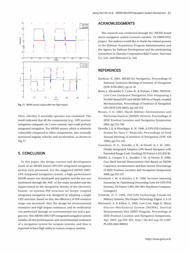
Then, whether it normally operates was examined. The
result indicated that all the components (e.g., GPS receiver,
navigation computer, etc.) were normal, and could perform
integrated navigation. The MEMS sensor, which is relatively
vulnerable compared to other components, also normally
measured angular velocity and acceleration, as shown in
Fig. 17.
5. CONCLUSION
In this paper, the design content and development
result of an MEMS-based GPS/INS integrated navigation
system were presented. For the suggested MEMS-IMU/
GPS integrated navigation system, a high-performance
MEMS sensor was developed and applied, and the size was
minimized through the ASIC of the major modules and the
improvement in the integration density of the electronic
boards. An optimal HW structure for deeply coupled
integrated navigation was designed by adopting a single
CPU structure. Based on this, the efficiency of HW resource
usage was increased. Also, the design for environmental
resistance and high-impact resistance, and its verification
was performed through an environmental test and a gas-
gun test. This MEMS-IMU/GPS integrated navigation system
satisfies all the performances and environmental resistance
of a navigation system for weapon systems, and thus is
expected to have high utility in various weapon systems.
ACKNOWLEDGMENTS
This research was conducted through the ‘MEMS-based
micro navigation system (contract number: UC100051FD)’
project. The authors would like to thank the related persons
in the Defense Acquisition Program Administration and
the Agency for Defense Development and the participating
researchers in Hanwha Corporation/R&D Center, Navcours
Co., Ltd., and Ubitronix Co., Ltd.
REFERENCES
Barbour, N. 2001, MEMS for Navigation, Proceedings of
National Technical Meeting of Institute of Navigation
(ION NTM 2001), pp.25-45
Beser, J., Alexander, S., Crane, R., & Wyman, J. 2002, TRUNAV:
Low-Cost Guidance/Navigation Unit Integrating a
SAASM-Based GPS And MEMS IMU In a Deeply coupled
Mechanization, Proceedings of Institute of Navigation
GPS (ION GPS 2002), pp.545-555
Brown, T. G. 2003, Harsh Military Environments and
Electromechanical (MEMS) Devices, Proceedings of
IEEE Position Location and Navigation Symposium
2003, pp.753-760
Dowdle, J. R. & Flueckiger, K. W. 1996, A GPS/INS Guidance
System for Navy 5” Projectile, Proceedings of 52nd
Annual Meeting of Institute of Navigation (ION AM
1996), pp.312-325
Gustafson, D. E., Dowdle, J. R., & Elwell, Jr. J. M. 2001,
Deeply Integrated Adaptive GPS-Based Navigator with
Extended Range Code Tracking, US Patent 6,331,835 B1
Habibi, S., Cooper, S. J., Stauffer, J. M., & Dutoit, B. 2008,
Gun Hard Inertial Measurement Unit Based on MEMS
Capacitive Accelerometer and Rate Sensor, Proceedings
of IEEE Position Location and Navigation Symposium
2008, pp.232-237
Horslund, J. M. & Hooker, J. R. 1999, Increase Jamming
Immunity by Optimizing Processing Gain for GPS/INS
Systems, US Patent 5,983,160 (MA: Raytheon Company,
Lexington)
Schmidt, G. T. 1999, INS/GPS Technology Trends for
Military Systems, The Draper Technology Digest, 3, 5-13
Warnasch, A. & Killen, A. 2002, Low Cost, High G, Micro
E l e c t ro - Me c ha n i ca l Sy s t e m ( M E M S ) , In e r t i a l
Measurements Unit (IMU) Program, Proceedings of
IEEE Position Location and Navigation Symposium,
Apr. 2002, pp.299-305. http://dx.doi.org/10.1109/
PLANS.2002.998922
Fig. 17. MEMS sensor output after the high impact.

62 JPNT 3(2), 53-62 (2014)
http://dx.doi.org/10.11003/JPNT.2014.3.2.053
Chang Woo Nam received the Bachelor and Master degree in Electronic Engineering, Soongsil University in 1989, 1991. He is a doctoral course student at Electronic E n g i n e e r i n g , C h u n g n a m N a t i o n a l University. He is currently a Chief Research Engineer at Defense R&D Center, Hanwha Corp. His research interest includes GNSS
receiver, Inertial Navigation System.
Jae-Cheul Lee received the Ph. D degree in Institute of Optics from University of Rochester, USA in 1990. He has been with Hanwha Corp. since 2007 and also System Engineering Department, A-Jou University as an adjunct professor since 2000. His research interests include inertial sensors, positioning & navigation system and laser
ranging system development.
Sung Jin Yoon is a Ph. D candidate of Electronics Engineering in A-Jou University. He is currently a senior researcher of Agency for Defense Development in Korea. His research interest includes inertial MEMS sensor and application of MEMS.
Jaewook Rhim received Ph. D degree in Aerospace Engineering from Graduate School of the University of Maryland, 1996. He is currently a principal researcher of Agency for Defense Development in Korea. His research interest includes inertial sensor and application of sensor.
Jeong Won Kim received the Bachelor degree, Master degree and Ph. D degree in Electronics engineering from Chugnam National University in 2002, 2004 and 2008. He is currently a chief research engineer at Defense R&D Center, Hanwha Corp. His research interest includes GNSS receiver, GNSS/INS Integrated Navigation System.
Chang Woo Nam received the Bachelor and Master degree in Electronic Engineering, Soongsil University in 1989, 1991. He is a doctoral course student at Electronic Engineering, Chungnam National University. He is currently a Chief Research Engineer at Defense R&D Center, Hanwha Corp. His research interest includes GNSS receiver, Inertial Navigation System. Jae-Cheul Lee received the Ph. D degree in Institute of Optics from University of Rochester, USA in 1990. He has been with Hanwha Corp. since 2007 and also System Engineering Department, A-Jou University as an adjunct professor since 2000. His research interests include inertial sensors, positioning & navigation system and laser ranging system development.
Sung Jin Yoon is a Ph. D candidate of Electronics Engineering in A-Jou University. He is currently a senior researcher of Agency for Defense Development in Korea. His research interest includes inertial MEMS sensor and application of MEMS.
Jaewook Rhim received Ph. D degree in Aerospace Engineering from Graduate School of the University of Maryland, 1996. He is currently a principal researcher of Agency for Defense Development in Korea. His research interest includes inertial sensor and application of sensor.
Jeong Won Kim received the Bachelor degree, Master degree and Ph. D degree in Electronics engineering from Chugnam National University in 2002, 2004 and 2008. He is currently a chief research engineer at Defense R&D Center, Hanwha Corp. His research interest includes GNSS receiver, GNSS/INS Integrated Navigation System.
Jeong Won Kim received the Bachelor degree, Master degree and Ph. D degree in Electronics engineering from Chugnam National University in 2002, 2004 and 2008. He is currently a chief research engineer at Defense R&D Center, Hanwha Corp. His research interest includes GNSS receiver, GNSS/INS Integrated Navigation System.
Chang Woo Nam received the Bachelor and Master degree in Electronic Engineering, Soongsil University in 1989, 1991. He is a doctoral course student at Electronic Engineering, Chungnam National University. He is currently a Chief Research Engineer at Defense R&D Center, Hanwha Corp. His research interest includes GNSS receiver, Inertial Navigation System. Jae-Cheul Lee received the Ph. D degree in Institute of Optics from University of Rochester, USA in 1990. He has been with Hanwha Corp. since 2007 and also System Engineering Department, A-Jou University as an adjunct professor since 2000. His research interests include inertial sensors, positioning & navigation system and laser ranging system development.
Sung Jin Yoon is a Ph. D candidate of Electronics Engineering in A-Jou University. He is currently a senior researcher of Agency for Defense Development in Korea. His research interest includes inertial MEMS sensor and application of MEMS.
Jaewook Rhim received Ph. D degree in Aerospace Engineering from Graduate School of the University of Maryland, 1996. He is currently a principal researcher of Agency for Defense Development in Korea. His research interest includes inertial sensor and application of sensor.