Soybean Oil as a Biocompatible Multifunctional Additive for Lubricating Oil
Upload
khangminh22Category
view
1download
0
JOH
AN
AG
OR
ELIUS | D
evelopment of highly biocom
patible neuro-electronic interfaces 2020:128
Department of Experimental Medical Science
Lund University, Faculty of Medicine Doctoral Dissertation Series 2020:128
ISBN 978-91-7619-991-6ISSN 1652-8220
Development of highly biocompatible neuro-electronic interfaces towards monitoring authentic neuronal signaling in the brainJOHAN AGORELIUS
DEPARTMENT OF EXPERIMENTAL MEDICAL SCIENCE | LUND UNIVERSITY
9789176
199916

1
Development of highly biocompatible neuro-electronic
interfaces towards monitoring authentic neuronal
signaling in the brain
Johan Agorelius
DOCTORAL DISSERTATION
by due permission of the Faculty of Medicine, Lund University, Sweden. To be defended at Medicon Village lecture hall, 2020-12-03 at 09:00
Faculty opponent
Professor Laura Ballerini University of Trieste, SISSA, Italy

2
Organization LUND UNIVERSITY
Document name DOCTORAL DISSERTATION Date of issue: 2020-12-03
Author: Johan Agorelius Sponsoring organization Swedish Research Council, Knut and Alice Wallenberg Foundation, Region Skåne, Nanolund, Lund University
Title and subtitle Development of highly biocompatible neuro-electronic interfaces - towards monitoring authentic neuronal signaling in the brain
Abstract Background: To understand how the neuronal circuits in the brain process information there is a need for novel neuro-electronic interfaces that can interact chronically with brain tissue with minimal disturbance of the physiological conditions in the tissue, in awake and freely moving animals. For this, there is a need for implantable neuro-electronic interfaces that are mechanically compliant with the tissue and that can remain positionally stable with respect to the neurons, despite the continuous micromotions in the brain. To reach this goal it is also important to be able to conduct a detailed analysis of the tissue reactions in the juxtapositional tissue around the implant as well as to incorporate additional strategies such as adding tissue modifying drugs to the implant.
Aim: To this end, two different types of implantable neuro-electronic interfaces, addressing the issue of mechanical compliance with two different approaches, as well as a novel method of sustained drug delivery from the neural implants were designed, manufactured and evaluated in vivo.
Method: First, arrays of thin gold leads, flexible in 3D, were cut from a 4 µm thin gold sheet, insulated with a thin layer of Parylene-C (4 µm) and then embedded and structurally locked in a stiff gelatin matrix that dissolves after implantation. These arrays were implanted in rats and evaluated electrophysiologically for 3 weeks. Second, a novel tube-like electrode with an opening on the side, comprising a conducting lead embedded in glucose enveloped by a thin layer of Parylene-C, was developed. After implantation the glucose in this protoelectrode dissolves transforming the protoelectrode into a highly flexible and low density electrode inside the tissue. Such tube electrodes were implanted in rats and evaluated by means of immunofluorescence microscopy after 6 weeks. Further, minocycline loaded nanoparticles were embedded into a gelatin matrix surrounding neural implants and the tissue reactions were evaluated in genetically modified mice exhibiting fluorescent microglia by means of immunofluorescence microscopy 3 and 7 days after implantation.
Results: The developed 3D arrays were found to be implantable with preserved conformation and electrophysiological recordings showed relatively stable recordings, with spike amplitudes over 400 µV. The tube electrode proved to be sliceable in the brain without dislocating, making it possible to analyze the tissue right outside the recording site, showing minute glia reactions and no significant loss of neurons as compared to baseline tissue, even in the inner most zone (0-20 µm). The minocycline loaded nanoparticles where successfully incorporated in gelatin-coatings of neural implants, and histological analysis showed a significant attenuation of glia reactions.
Conclusion: Two new types of mechanically compliant neuro-electronic interfaces and implantation methods, as well as a compatible embedding method of local delivery of drug content, has been successfully developed and evaluated, showing very promising biocompatibility and stability in the tissue.
Key words: Neuro-electronic Interface, Biocompatibility, Electrophysiology, in vivo Neurophysiology Classification system and/or index terms (if any) Supplementary bibliographical information Language: English ISSN and key title 1652-8220 ISBN: 978-91-7619-991-6 Recipient’s notes Number of pages 69 Price
Security classificationI, the undersigned, being the copyright owner of the abstract of the above-mentioned dissertation, hereby grant to all reference sources permission to publish and disseminate the abstract of the above-mentioned dissertation.
Signature Date 2020-10-29

3
Development of highly biocompatible neuro-electronic
interfaces towards monitoring authentic neuronal
signaling in the brain
Johan Agorelius

4
Cover photo by Johan Agorelius
Copyright pp 1-69 Johan Agorelius 2020
Paper 1 © Open access
Paper 2 © by the Authors (Manuscript unpublished)
Paper 3 © Open access
Faculty of Medicine Department of Experimental Medical Science
ISBN 978-91-7619-991-6 ISSN 1652-8220
Printed in Sweden by Media-Tryck, Lund University Lund 2020

5
“As long as our brain is a mystery, the universe, the reflection of the structure of the brain,
will also be a mystery.”
Santiago Ramón y Cajal

6
Table of Contents
Abbreviations ................................................................................................. 8 Populärvetenskaplig sammanfattning ............................................................ 9 Papers included in this thesis ....................................................................... 13
Introduction .......................................................................................................... 14 Neuro-electronic interfaces .......................................................................... 14
Definition ............................................................................................. 14 A brief history ..................................................................................... 14 State of the art ...................................................................................... 15
Tissue trauma ............................................................................................... 16 Acute trauma ....................................................................................... 16 Chronic trauma and micromotions ...................................................... 17
Foreign body response ................................................................................. 17 Astrocytes ............................................................................................ 18 Microglia ............................................................................................. 18 Time course ......................................................................................... 18 Significance of the foreign body response .......................................... 19 Analysing the tissue in the vicinity of the probe ................................. 20
Attempted solutions and remaining problems .............................................. 20 Flexible probes .................................................................................... 20 Implantation Strategies ........................................................................ 21 Local drug delivery .............................................................................. 22 Next generation of neuro-electronic interfaces ................................... 23
Aims ....................................................................................................................... 24 Methods & Development ..................................................................................... 25
Development of neuro-electronic interfaces ............................................... 25 Material considerations ....................................................................... 25 A thin electrode array flexible in three dimensions ............................. 26 A low density and flexible tube-like electrode .................................... 29 Drug coated implants ........................................................................... 31 Characterization methods .................................................................... 33
Tissue analysis ............................................................................................. 34

7
Tissue clarification .............................................................................. 34 Immunohistology ................................................................................. 35
Electrophysiology and data analysis ............................................................ 36 Electrophysiological recordings .......................................................... 37 Data analysis ........................................................................................ 37 Spike sorting and validation ................................................................ 37 Performance over time ........................................................................ 38
Animals and surgery .................................................................................... 38 Animals ............................................................................................... 38 Anaesthesia .......................................................................................... 38 Surgery and craniotomy ...................................................................... 39 Implantation ......................................................................................... 39
Results & Comments ............................................................................................ 41 An array of ultrathin electrodes flexible in 3D ............................................. 41
Implantation ......................................................................................... 41 Electrophysiological evaluation .......................................................... 43
A flexible and low-density tube electrode .................................................... 44 Implantation and sectioning ................................................................ 44 Tissue reactions ................................................................................... 45
Drug coated implants ................................................................................... 48 Effects on the brain tissue in vivo ....................................................... 48
Discussion & Conclusions .................................................................................... 51 The foreign body reaction ............................................................................ 51 Tissue analysis of the inner zone of the implant .......................................... 52 Electrophysiological recording stability ....................................................... 53 Implanting delicate electrodes with retained conformation ......................... 54 Drug release ................................................................................................. 55 Future perspectives ....................................................................................... 55 Conclusions .................................................................................................. 56
Acknowledgements ............................................................................................... 57 References ............................................................................................................. 59

8
Abbreviations
BCI Brain-computer interface
BMI Brain-machine interface
CD68 Cluster of differentiation 68
DAPI 4',6-diamidino-2-phenylindole
DBS Deep brain stimulation
EEG Electroencephalographic
ECoG Electrocorticographic
FDA Food and drug administration
GFAP Glial fibrillary acid protein
GFP Green fluorescent protein
ISI Inter spike interval
IQR Inter quartile range
NeuN Neuronal nuclei
PBS Phosphate buffered saline
PCA Principal component analysis
PCB Printed circuit board
PEG Polyethylene glycol
PFA Paraformaldehyde
PLGA Poly(lactic-co-glycolic acid)
PMMA Polymethylmethacrylate
ROI Region of interest
SEM Scanning electron microscopy
SNR Signal to noise ratio

9
Populärvetenskaplig sammanfattning Sedan det för ett par tusen år sedan föreslogs att det var hjärnan snarare än hjärtat som var centrum för vårt mentala liv, så har detta mjuka, pulserande organ fascinerat och gäckat filosofer och vetenskapsmän. Idag vet vi mer om den mänskliga hjärnan än vi någonsin gjort. Vi vet att den består av över hundra miljarder nervceller och att dessa kommunicerar med varandra med hjälp av elektricitet och vi vet allt mer om hur information bearbetas och behandlas i hjärnan, men mest av allt vet vi kanske hur lite vi egentligen vet om hur hjärnan fungerar. På så sätt är detta ”organ” kanske en större gåta idag än det någonsin varit.
Hjärnan kan undersökas på en mängd olika sätt, allt från analyser av hur blodflödet förflyttas mellan olika delar och detaljerade anatomiska studier, till beteendeexperiment och terapisoffor. Men, ett allt viktigare verktyg för att undersöka hur hjärnan fungerar på cellnivå, är att läsa av den elektriska aktiviteten hos enskilda nervceller och undersöka hur denna aktivitet hänger ihop med beteenden och upplevelser. Eftersom nervcellerna i hjärnan ligger tätt och dessutom är väldigt små, så måste ytterst små elektroder implanteras i hjärnan så att de hamnar tillräckligt nära för att känna av nervcellernas enskilda elektriska signaler. Sådana mikroelektroder har revolutionerat inte bara förståelsen av hjärnan, utan även gett upphov till behandling av en rad neurologiska sjukdomar. Parkinson-patienter kan genom en knapptryckning stimulera skadade delar i sin hjärna och bli av med merparten av sina rörelsehinder och förlamade människor kan styra robotarmar eller datorer med blotta tanken.
Traditionellt har dessa elektroder varit gjorda av styva material som kisel eller metall. Hjärnan, å andra sidan, är mycket mjuk och dessutom rör den sig hela tiden inuti kraniet, till exempel på grund av hjärtslag och pulserande blodådror, huvudrörelser och andning. Problemet som uppstår när en styv elektrod implanteras i den mjuka rörliga hjärnan är att elektroden rör sig i relation till vävnaden, och därmed skaver mot och skadar den känsliga vävnaden. Detta leder efter hand till att elektroderna kapslas in av hjärnans immunförsvar och förlorar kontakt med omkringliggande nervceller. Viktig information för att förstå vad som händer i gränssnittet mellan hjärna och elektrod kan fås genom att analysera vävnaden runt elektroden, men eftersom styva elektroder måste tas ut ur hjärnan innan vävnaden kan analyseras, så har det varit svårt att se exakt vad som faktiskt äger rum i vävnaden precis intill elektroden.
Så, trots de stora framgångarna med mikroelektroder, både vad gäller behandling av sjukdomstillstånd och undersökandet av hjärnans funktion, finns det stora begränsningar med dagens teknik. Eftersom vävnaden runt elektroden skadas kan inte längre signalerna som registreras från nervcellerna anses komma ifrån en normalt fungerande hjärna, något som är oerhört viktigt om man vill studera hur en hjärna fungerar i sitt normaltillstånd. Dessutom slutar elektroderna att fungera efter
10
ett tag vilket försvårar långtidsstudier och kan leda till att elektroderna måste tas ut ur patienter. Eftersom elektroderna inte sitter still i hjärnan, så kan de inte heller registrera från samma nervcell över tid, vilket gör det svårt att studera förloppet för neurodegenerativa sjukdomar så som Parkinsons och Alzheimers sjukdom, eller formeringen av minne och inlärning, något som är centrala delar av hjärnans funktionalitet.
Om det skulle vara möjligt för en elektrod att istället följa med hjärnans rörelser och sitta så stabilt i vävnaden att de kunde registrera från samma nervcell över tid, utan att skada vävnaden och utan att kapslas in av immunförsvaret, så skulle detta alltså kunna revolutionera inte bara vår förståelse av hjärnan, utan dessutom ge betydligt effektivare behandlingsmetoder mot en rad olika neurologiska och psykiatriska sjukdomar, så som Parkinsons sjukdom, epilepsi, depression, MS och kronisk smärta.
Med bakgrund av detta har mycket forskning och utvecklingsarbete gjorts för att utveckla nya typer av elektroder som är mjukare och flexiblare än de som vanligtvis använts. Framförallt har detta gjorts genom att göra elektroderna mycket tunna och ersätta styva material med mjukare. Sådana supertunna elektroder har mycket riktigt visat sig ge upphov till mindre vävnadsreaktioner i hjärnan, men det finns fortfarande flera utmaningar som denna strategi inte helt har löst. Till exempel, så verkar det inte som om de sitter helt förankrade i vävnaden och styrkan på de signaler de läser av tyder på att det inte finns fungerande nervceller alldeles intill elektroderna. De går inte heller att göra vävnadssnitt i hjärnan utan att elektroderna flyttar på sig, vilket försvårar analysen av vävnaden alldeles intill elektroderna.
Forskningen vid Neuronano Research Center (NRC) vid Lunds Universitet har under en längre tid fokuserat på att förstå och kartlägga de underliggande problemen kopplat till instabilitet och vävnadsskador runt neurala elektroder. Denna forskning har tidigare visat att flexibiliteten hos elektroderna är viktig, men också att densiteten är viktig och att storleken i sig självt inte är lika viktig som ofta antagits. Dessutom har det utvecklats en metod där elektroder bäddas in i hårt men upplösningsbart gelatin, ett material som visat sig minska vävnadsreaktionerna och öka nervcellsöverlevnaden runt elektroderna.
En utmaning för alla typer av flexibla elektroder är själva implanteringen. Eftersom de är alldeles för mjuka för att penetrera hjärnans vävnad, krävs någon form av hjälpmedel. För supertunna elektroder används ofta en styv guide klistrad till elektroden och på senare tid har konstruktioner utvecklats där en styvare nål används för att ”sy” in elektroden i vävnaden. Detta kan öka den initiala skadan och dessutom leda till att elektroden hamnar snett i vävnaden, vilket kan bli ett problem om man vill ha kontroll över exakt var elektroderna sitter och vilka områden de registrerar ifrån, något som är viktigt för de flesta applikationer.
För att komma runt dessa problem och på allvar inkorporera det vi hittills vet om vad som krävs för att elektroder ska kunna sitta stabilt nog i vävnaden utan att skada

11
den, presenteras i den här avhandlingen två nya typer av neurala elektroder som adresserar dessa problem från olika håll, samt en metod för att bekläda sådana elektroder med läkemedel som kan minska vävnadens reaktion mot implantatet.
Först och främst har en array av ultratunna guldelektroder utvecklats, som förutom att vara flexibel i två dimensioner, även har en följsam upphängning som gör att den är rörlig i alla tre dimensioner. Dessa elektroder kunde implanteras i hjärnan genom att bäddas in i vävnadsvänligt gelatin, som är styvt nog att penetrera hjärnvävnaden, men som sedan löser upp sig efter implantering och lämnar kvar de flexibla elektroderna i vävnaden.
Den andra elektroden är en tubliknande konstruktion med ett tunt polymerskal som är fyllt med glukos. Konstruktionen är tillräckligt styv för att elektroden ska kunna implanteras i hjärnan, men efter att glukoset löst upp sig blir den både flexibel och får en densitet nära hjärnans egen. Denna konstruktion har även den stora fördelen att möjliggöra histologiska vävnadssnitt i hjärnvävnaden utan att den rör sig, vilket gör att vävnaden närmast elektroden kan analyseras i detalj.
Slutligen har även en ny metod utvecklats för att belägga elektroder med läkemedel (i det här fallet Minocyklin, ett antibiotikum, som har visat sig dämpa hjärnans vävnadsreaktioner). Genom att ladda biovänliga nanopartiklar (som bryts ner långsamt i vävnaden) med Minocyklin och sedan bädda in dessa partiklar i en gelatinbeklädnad runt elektroden, kan frisläppningen av läkemedlet göras lokalt runt elektroden, samt utdraget över tid.
Både de nya typerna av flexibla elektroder samt elektroder beklädda med läkemedel, har sedan implanterats i försöksdjur (råttor och möss), och därefter har vävnaden utvärderats dels genom att undersöka hur cellerna ser ut, dels genom att läsa av nervcellernas signaler när djuren är vakna och fritt rörliga.
Resultaten från det första arbetet i avhandlingen visar att den tunna elektrod-arrayen, förutom att kunna implanteras utan att ändra konformation, även kan läsa av den elektriska aktiviteten från enskilda nervceller under de tre veckor som experimenten pågick. Styrkan på de inspelade signalerna indikerar att det i vissa fall ligger nervceller mycket nära elektroderna. Vidare analys av signalerna visar att stabiliteten är så god att det går att följa samma nervcell under en enskild inspelning och ger även goda indikationer på att det går att följa samma nervcell upp till en vecka i vakna fritt rörliga djur. Dessutom förbättras kvalitén av signalerna över tid vilket tyder på att nervcellerna kommer närmare elektroderna.
Analysen av vävnaden runt de tub-liknande elektroderna (det andra arbetet i avhandlingen) visade att det var mycket lite vävnadsreaktion runt implantatet, och ännu viktigare, att det i princip inte fanns någon mätbar minskning av nervceller precis intill elektroden. Dessa fynd bekräftade därmed grundantagandet att flexibla elektroder med vävnadsanpassad densitet och hög flexibilitet borde vara mycket bättre för vävnaden.

12
I det tredje arbetet undersöktes om nanopartiklarn med Minocyklin kunde minska immunförsvarets reaktion i vävnaden runt elektroder och det visade sig att reaktionen var betydligt mindre än runt elektroder utan läkemedel, vilket indikerar att läkemedlet levererades som det skulle till vävnaden runt elektroden.
Tillsammans visar dessa resultat på att det är möjligt att implantera mycket flexibla elektroder på vävnadsvänliga vis utan att de böjer av eller ändrar konformation, och att den stabilitet de uppvisar i vävnaden är lovande. De visar också att det faktiskt är möjligt att ha en tubliknande elektrod implanterad i hjärnvävnaden utan att det blir någon synlig påverkan på de intilliggande nervcellerna.
Dessa resultat indikerar att vi är på god väg att utveckla en teknologi som kan läsa av aktiviteten hos enskilda nervceller över lång tid i en vaken hjärna utan större påverkan av vävnaden och därigenom öppna upp för möjligheten att lyssna på autentiska signaler från hjärnan, något som äger en enorm potential att revolutionera behandlingen av en rad olika sjukdomstillstånd, samt öka vår förståelse av hur hjärnan fungerar.

13
Papers included in this thesis
I. J. Agorelius, F. Tsanakalis, A. Friberg, P. T. Thorbergsson, L. M. E. Pettersson, and J. Schouenborg. 2015. An array of highly flexible electrodes with a tailored configuration locked by gelatin during implantation – initial evaluation in cortex cerebri of awake rats. Frontiers of Neuroscience, vol. 9, no. SEP, 2015, doi: 10.3389/fnins.2015.00331
II. J. Agorelius, L. Gällentoft, L. M. E. Pettersson, C. Eriksson, A. Retelund and J. Schouenborg. 2020. A flexible and density-matched novel microelectrode construct minimize long-term glial reactions and prevent loss of nearby neurons. Manuscript, ready for submission 2021.
III. A. D. Holmkvist, J. Agorelius, M. Forni, U. J. Nilsson, C. E. Linsmeier, and J. Schouenborg. 2020. Local delivery of minocycline-loaded PLGA nanoparticles from gelatin-coated neural implants attenuates acute brain tissue responses in mice. Journal of Nanobiotechnology, 2020, doi: 10.1186/s12951-020-0585-9.

14
Introduction
Neuro-electronic interfaces
Definition A neuro-electronic interface, also called neural interface, brain-machine interface (BMI) or brain-computer interface (BCI), is a technology for establishing a direct communication pathway between a brain and an external device. These interfaces can be either non-invasive, such as electroencephalographic (EEG) electrodes placed on the scalp or semi-invasive such as electrocorticographic (ECoG) electrodes surgically placed on top of the brain surface. Both these methods, however, give limited spatial resolution, as the electrical signal generated mainly by individual neurons throughout the superficial layers of the cortex cerebri dilutes and mixes while spreading to the brain surface 1. To get greater specificity and/or reach deeper targets of the brain for stimulating specific group of neurons or record localized activity such as local field potentials and/or extracellular action potentials from single neurons, the interface needs to be implanted into the brain tissue and get into close proximity to individual neurons. Such neural implants has proven to be a very powerful tool both for clinical applications 2–4 and neuroscience 5–7. However, as will be discussed throughout this thesis, important challenges remain before this technology can close in on its true potential.
A brief history The concept of neuro-electronic interfaces can be traced back to the late 18th century, and Luigi Galvani’s legendary experiments with stimulating dead frog nerves to induce muscle contractions 8, something that triggered another Italian scientist Alessandro Volta, to start experimenting with stimulating his own senses with electricity. Volta discovered that electrical stimulation created the sensation of light when applied to his eyes and the perception of sound when applied to his ears 9, revealing that biological tissue can be electrically active.
This line of research trying to understand the electrical properties of nervous tissue has been continued ever since, leading up to hallmark experiments such as the

15
intracellular recording of an action potential by Hodgkin and Huxley in 1939 10, earning the famous duo the 1963 Nobel prize.
Since then implantable neuro-electronic interfaces has been an important tool for neuroscientists trying to map and understand the basic functioning of the brain 5 as well as for clinical applications, for example letting tetraplegic patients control neuroprosthetic robotic limbs and/or computer interfaces 2,4 or for deep brain stimulation (DBS), alleviating parkinsonian symptoms 3.
State of the art Since the emergence of standardized implantable microelectrodes in the 1950s and the state of the art technologies emerging in the late 80s, the most well-known being the Utah Array 11 and the Michigan probe 12, not much has actually changed in the underlying concept and design, except the possibility of fitting more channels on the same probe. Even if the field is now progressing towards the use of more compliant materials with reduced footprints (as will be discussed in greater details further on) the standard electrodes used in many of the BMI applications and neurophysiological studies are still based on metallic wires 6,13,14 or silicon probes 15–17. One important reason why these electrodes are stiff, are so they can penetrate the brain tissue and be implanted to intended target without deviating. However, the stiffness also comes with a number of serious problems, most importantly relating to the mechanical mismatch between electrode and brain tissue resulting in tissue trauma and instability of recordings 18–20.
As an effect, the progress of neuroscientific research and clinical relevance of neuro-electronic interfaces has increasingly been hampered by the poor reliability and questionable validity of the signals provided from chronic electrodes 21,22. Optimally, these interfaces should be able to record and follow single neurons over the course of a human lifetime 23,24 without affecting the physiological conditions in the surrounding tissue 25. Only then can we hope for the recorded neuronal signaling to be authentic, i.e. representing what normally occurs in an intact brain. For this to be possible, there is a need for shift of technology.
In order to grasp what would be required from such technology, it is important to understand what happens in the brain after an interface has been implanted.

16
Tissue trauma The more or less stereotypic tissue response, occurring despite type of implant, method of surgery and implantation or species used, have so far been described in numerous studies 19, with a growing consensus of what takes place. The trauma to the tissue caused by an implanted neuro-electronic interface, is usually divided into an acute and chronic trauma.
Acute trauma The very act of implanting a probe into the brain causes an acute mechanical trauma, typically by causing the rupture of blood vessels and disrupting the blood-brain barrier, as well as tissue dimpling, compression and cell ruptures 18,22,26,27. This tissue damage in turn activates an inflammatory response in the brain, most obviously detected by activation and migration of glial cells towards the implant 18,28–30. Although an acute implantation trauma might to a certain degree be unavoidable as the brain tissue needs to be penetrated in order to get the implant into contact with intended target neurons, the method of implantation do affect the severity of this trauma. For example, it is generally considered that a fine tip decrease dimpling and vessel dragging 27,31. When it comes to speed of insertion, the situation seems more complicated, as on the one hand it has been shown that straight sharp devices should preferably be inserted fast 27, minimizing the dragging of tissue. But on the other hand it seems that fast insertion speeds can lead to increased traumatic injuries 22, and that a slow insertion instead would allow for the tissue to relax and accommodate compression forces with less shock to the tissue 29. However, there are also indications that a slow insertion speed before penetration of the pia and/or dura causes dimpling and compression of the tissue 22. This suggests that a faster speed before penetration of the meninges and then a slower insertion speed down to intended target would be optimal, although more data is needed to conclude this. Further, it is also not uncommon that the implant themselves suffer mechanical failure during the implantation 32 or after 33 indicating that the method and details of surgery and implantation, is in any case of importance for the acute trauma.
The importance of the acute tissue trauma, in relation to the chronic sustained trauma, has been debated 18. However there are data showing that a stab wound to the tissue can give long lasting effects (> 1 year) in brain tissue 34,35, and that after the removal of an implant there still remain glia activation and neurodegeneration 22,36, suggesting that minimizing the acute tissue trauma would be preferable.

17
Chronic trauma and micromotions Another aspect, where there at least lately, seems to be more of a consensus 18,37, is the importance of the sustained tissue trauma around an implanted neuro-electronic interface, and that this is connected to the continuous micromotions between brain tissue and implant 28,38–40. To understand what happens at the interface between an implant and brain tissue, it is important to consider the mechanical properties of the brain itself. The elastic modulus, (i.e. a materials resistance to elastic deformation under stress) of brain tissue is on the order of 1 kPa 18. The brain is located inside the cavity of the skull, where it is suspended in cerebrospinal fluid. As an effect relative movements occur between the brain and the skull, induced mainly by respiration, heart beat and body movements 40,41, which in rats, can be in the order of at least 30-40 µm 39. Beside these relatively large movements, there are also smaller but significant micromotions inside the brain itself caused by propagating waves of blood inside the vessels 42.
Considering then that a silicon electrode has an elastic modulus in the range of at least a 100 GPa 43, and a tungsten wire even higher than that 44, and that these electrodes, in order to transduce the electrical signals from the neurons to amplifiers, needs to be tethered to the skull, after being implanted into the soft brain tissue. The majority of relative movements between the skull and the brain, will thus translate to the tissue/electrode interface, causing the stiff implant to move in relation to the tissue around it. The result of these micromotions are unstable recordings, i.e. recording from different neurons over time, as well as a continued tearing of the tissue triggering an activation of glial cells 30,36,45–48 and likely loss of neurons in the vicinity 29,36,41,49. It has been argued that many problems relating to such micromotions is connected to the flexibility of the implant 28,43,50, and the tethering mode 47, and in 2015, it was also shown that a flexible probe induce less tissue reactions as compared to an identical but non-flexible probe 38, and that there is a correlation between tissue responses and quality of recordings 51.
To better understand the connection between the tissue response and the deterioration of electrode functionality, and how to solve this problem, it is necessary to take a closer look at the underlying dynamics of the foreign body response, and especially the glia activation and so called glia scaring.
Foreign body response The ultimate failure of neuro-electronic interfaces is most obviously observed in the brain tissue by the lack of neurons in the vicinity of the implant, the very cell types that the implant is meant to record from. However, an equally visible effect in the tissue is that of the aggregation and activation of nearby glia cells. The most

18
commonly recognizable glia cells involved in this so called foreign body response, are astrocytes and microglia 52.
Astrocytes Astrocytes, making up about half of the glia cells, are star-like cells with long ranging extensions forming an interconnected network throughout the brain. Astrocytes are believed to be involved in a large number of processes, such as giving cues to neurons during development, support neuronal circuits mechanically, buffer neurotransmitters and nutrients, modifying the electrical activity of neurons 52,54 and even being involved in mechanisms such as plasticity and memory formation 55. Astrocytes can be activated by mechanical trauma to the brain tissue, resulting in an activated reactive phenotype with among other traits, increased migration and proliferation and the upregulation of glial fibrillary acid protein (GFAP) 56, a cell marker for astrocytes that is especially associated to astrocytic activation. There is evidence that activated astrocytes can prevent toxic glutamate elevations in the brain by taking up extracellular glutamate 57 and protect neurons from oxidative stress by elimination of free radicals 58. But there is also evidence, that under some circumstance such as excitatory crisis, the glutamate uptake can be reversed and contribute to neural damage 59.
Microglia Microglia are versatile, motile cells that are spread throughout the brain, where they mostly reside in a so called “resting state”, remaining positionally stable while actively monitoring the tissue via their branched and motile processes. Primarily they act as cytotoxic cells killing pathogens or as phagocytes to degrade debris after injury or normal cell turnover 52,60, but they have also been shown to for example interact with dendritic spines and engulfing synapsis during learning 61. Microglia can also secrete neurotrophic factors 62 as well as neurotoxic factors 63, and thus as the astrocytes, may also have detrimental as well as protective effects on neurons in the vicinity. In fact they are involved in a wide range of signalling pathways, making it difficult to fully map their impact on the foreign body response 28. When microglia becomes activated they upregulate the expression of a transmembrane glycoprotein called CD68, which can be detected using ED1 antibodies, commonly used to identify and quantify the level of microglial activation 64.
Time course The time course of the foreign body response around a brain implant, as mostly studied in rats, is pretty consistent. Minutes after tissue damage in the brain tissue

19
of surrounding microglia, within approximately 100 - 150 µm, can be seen extend their processes towards the site of injury and within half an hour the activated microglia starts encapsulating the implant/foreign body with lamellipodia 65. In less than 12 hours after implantation, microglia starts moving their cell bodies towards the site of injury 65,66 and within 24 hours proliferating microglia and/or macrophages with amoeboid shapes can be seen surrounding the implant 67,68. Besides the activation of resident microglia, monocytes-derived macrophages can also be recruited from the blood stream 69, however these are in most aspects indistinguishable from resident activated microglia and both are stained by ED1.
The next phase of the foreign body response involves astrocytes. Upregulation of GFAP in astrocytes surrounding tissue damage can be seen as early as 12 hours post injury, but typically peaking after 6-7 days 70. Whereas the acute tissue response to an injury eventually will decline, the presence of an implant in the tissue, sustains the tissue response. Typically, within the first week, astrocytes up to several 100 micrometres around an implanted probe are activated. Around 2-3 weeks after implantation the astrocytes have started forming a compact sheet outside the activated microglia around the probe 22,36,68 and after 5-6 weeks they have formed an even denser layer, a so called glia scar 36,68,71. It has been suggested that this layer is formed to encapsulate the site of injury and to protect the blood–brain barrier and to prevent lymphocyte infiltration 72. Even if the time-course of these events are pretty consistent, the extent of the glia scaring vary greatly, not only between different types of implants, but also within the same type of implant 73,74. This suggest that other factors, for example connected to the implantation procedures is also of great importance.
Significance of the foreign body response In parallel to the glia scaring, as discussed, there is also a loss of neurons around the implant 36,49. It has been suggested that it is the infiltration of glia cells that increase the distance between implant and nearby neurons 36,75, hindering diffusion and increasing impedance 45,74, or that the glia scar inhibit/repel neural processes from the electrode 76. As discussed above it is also known that activated microglia and astrocytes can act both neuroprotective and neurotoxic, and so the exact mechanisms and roles of astrocytes and microglia in the loss of neurons are not fully understood. On top of that, it should be mentioned, that even if the most obvious and described cell types involved in the tissue response around an implant, are microglia and astrocytes, many other cell types are likely also involved, such as fibroblasts 36, pericytes 22 and precursor oligodendrocytes 77, all interacting with each other in a myriad of processes and signaling pathways.
In the end, even if the complete mechanisms of the interplay between implant, glial cells, neurons and other cell types are far from being fully mapped or understood, the fact remains; there is a lack of recordable neurons in the close vicinity of the

20
implant. This leads to impeded recording quality and eventual failure of the implant. Further, even during the functional window, the brain tissue cannot be considered as behaving under normal physiological conditions, which is an obvious problem, not the least for researchers trying to understand the neural dynamical processing of information in a normally functioning brain.
Analysing the tissue in the vicinity of the probe To really understand what takes place in the tissue at the very interface of the neural probe, a much more detailed analysis of the juxtapositional tissue, than what is typically possible today, would be essential. Stiff neuro-electronic interfaces, for example, has to be completely pulled out before any tissue analysis can be done, ripping out and/or rearranging the tissue most interesting for analysis 36,40,48. Even if some recent very thin polymer probes 78,79, can indeed be sectioned while resident in the tissue, these probes are reported to get pulled out or dislocated while slicing the tissue, making a detailed and accurate analysis of the tissue at the recording sites after sectioning, impossible.
Attempted solutions and remaining problems
Flexible probes As discussed above, many of the known problems with state of the art neural implants are likely related to the mechanical mismatch between the brain tissue and the implant, in combination with the tethering giving rise to micromotions.
An obvious way to test this hypothesis is to build probes with softer materials and with smaller footprints. Advances in material chemistry and micro/nano fabrications technologies has made it possible to build fine featured probes in polymers 80, which have elastic modulus in the range of 1 MPA to 5 GPa, and therefore induces less stress in the tissue than does more rigid materials such as silicon or tungsten 81. This has given rise to the development of flexible neuro-electronic interfaces, where the conducting leads are made of thin metallic films inside a polymer substrate 18,78,79,
82-85.
Often, however, as these probes are thin and flat, the flexibility is only considerably improved in one or two dimensions, even if strategies with tailoring the shape by reducing the effective length for improvements in flexibility 86,87, the use open structures 46,88,89 for better tissue integration or the incorporation of protruding anchors in order to further attenuate micromotions 90–92, has been tried out. More recently there has also been progresses with extreme miniaturizations with probe-

21
thicknesses down to single micrometres in the smallest dimension 79,82,93. Indeed several of these polymer based probes shows evidence of reduced tissue scaring 18,50,78,79,86. However, preliminary results from these probes, especially with respect to amplitudes of the single unit recordings 78,79,82,93, indicates that there is still a lack of recordable neurons in very close vicinity of these implants, suggesting that just making the probes thinner and smaller does not completely solve the situation. In addition, the long term stability in the brain tissue of the this kinds of polymer implants, has been questioned, for example in relation to swelling of the polymers, delamination as well as the brittleness of thin metal films 22,94,95.
Implantation Strategies To implant highly flexible probes that themselves cannot be implanted without structural support, several different strategies have been adopted, usually encompassing either (1) the usage of stiff guiding rods, (2) materials with adaptable flexibility, and (3) bioresorbable coatings.
Stiff guiding rods The earliest implantations of flexible probes were made possible by gluing the probe to a stiff silicon guide with dissolvable polyethylene glycol (PEG) that dissolves after implantation, and then to withdraw the guide 96. This technique has been repeatedly used since then 86,97, and was recently refined by minimizing the guiding rod diameter down to 7 µm 93. Other methods of attaching the guiding-rod involves using electrostatic forces 98, gluing with caramelized sucrose 99 or sticking the guiding rod into a small hole in the end of the probe, “sewing” it into the brain 78,79,82. In some cases the probe has been designed in such a manner that the guiding rod can be placed inside the probe itself 100,101, or in the opposite manner, the probe has been implanted/injected through a larger cannula 88,102. Even if this can be an efficient method for implanting flexible probes, there are reportedly issues with the retraction of the guiding rod, displacing the probe 18,97,101, making precise positioning problematic. Also, as the retraction force has been shown to be of similar magnitude as the implantation force, acute mechanical stress to the tissue is likely increased 103,104.
Materials with adaptable flexibility Another approach for getting flexible implants into the brain without additional aid, has been to use polymers that can change flexibility, being stiff before implantation but gradually becoming more flexible after implantation, in response to the soaking 94,105,106, temperature shift 107–109, or controlled by chemical triggers 110. While interesting, the efficiency of these methods remains to be seen, as the flexibility change is either relatively small or the materials have not yet efficiently been utilized into fully functional neural electrodes evaluated in vivo.

22
Bioresorbable materials A highly promising, and nowadays relatively widespread strategy for implanting flexible probes, as reviewed by Lecomte et al 18, is to embed the probe into a matrix of bioresorbable materials that together with the electrodes is stiff enough for implantation when dry, but that softens and dissolves after implantation, leaving the flexible probe in the tissue. Several materials have been tested out, including gelatine, that was developed in our lab 111, silk 92,112,113, carboxymethyl cellulose 114, maltos 115, polyethylene-glycol (PEG)113, collagen 116, sucrose 117, maltose 115 and poly(lactic-co-glycolic acid) (PLGA) 118, among others.
Some of these materials, such as gelatin and silk that are degradable biopolymers that when first coming into contact with the warm aqueous environment of the brain, takes up liquid and swells, becoming soft, and then dissolves and/or degrades by enzymatic reactions, leaving lower molecular weight products that are removed by metabolic processes 18. In the case of gelatine there are endogenic enzymes such as gelatinases, that can break down the dissolved constituents 26. The speed of these processes depends heavily on water uptake capability, hydrophilic affinity and molecular weight 18, and the behaviour of the biopolymer can vary distinctly between in vitro and in vivo settings. For example it has been observed that carboxymethylcellulose that dissolves completely within 20 minutes in vitro, remained in vivo rat brains for several days 114. This illustrates that it is inherently hard to predict the kinetics of bioresorbable materials 18 in vivo. Biopolymers such as gelatine, chitosan or collagen tends to induce less inflammatory response than does synthesized polymers 119, such as PEG, and as has been shown in our lab, gelatine can in fact mitigate the inflammatory response on its own 38,111 and enhance repair of the blood-brain barrier 26, making it a very potent candidate for a biofriendly implantation vehicle for flexible neural electrodes.
Local drug delivery An additional strategy, beyond tailoring the mechanical properties of the neuro-electronic interface itself, has been to pharmaceutically manipulate the brain tissue surrounding the interface. The most commonly used compounds tried out so far is the steroid dexamethasone 120 or the antibiotic minocycline 121, shown to inhibit microglia activation 122,123 and to be neuroprotective 121.
A variety of methods for adding local drug delivery capabilities to neural probes has been suggested, for example by incorporating a microfluidic channel into the neural probe 124–126 making it possible to inject drugs through the probe. An inherent problem with this approach being that of an increased footprint of the neural probe as well as the requirement of an injection mechanism potentially inducing tissue damages upon injection. Another approach has been to embed the drugs into a degradable coating around the probe 113,127,128, so that it is released after

23
implantation. However, most of the drug content will be released within a time window coupled to the swelling and dissolution of the coating material. To get around this, the controlled release from a conducting polymer using electrical stimulation 129, has instead been suggested, as well as first loading the drug content into biofriendly 130 PLGA nanoparticles 127,131, that sustains the release of the drug over time. To conclude the efficiency of these strategies, it would be desirable at this point to study how a highly localised release of a tissue modifying drug, such as minocycline, around a neural probe with a prolonged release-curve, would affect the microglia and astrocytic reactions as well as the neuronal survival, over time.
Next generation of neuro-electronic interfaces Considering the highly complex milieu of the brain and complex dynamics at the tissue/implant interface, it might not be surprising that not any one single approach (such as making ultrathin flexible polymer-probes) has yet completely solved the problem of creating a truly biocompatible neuro-electronic interface. This may be due to, the multidimensionality of the problem where any single cause can lead to failure in this aspect. Thus, the next generation of neuro-electronic interfaces will likely need to incorporate a number of features rather than any single one, such as tissue matching mechanical properties and density as well as a method of tissue friendly implantation and the potential additions of protective pharmaceutics.

24
Aims
The overall aim of this thesis can be summarized in the pursue towards a truly biocompatible neuro-electronic interface that can remain chronically stable and functional in the brain without damaging the neural tissue around it. This gets down to the following specific aims:
I. The design and construction of two new types of flexible neuro-electronicinterfaces, incorporating identified key parameters for truebiocompatibility as well as the possibility for evaluating the tissue in theclose vicinity of the interface.
II. The development and evaluation of implantation methods for theseinterfaces without distortion of the implants and with minimal insertiontrauma.
III. The evaluation of these implants in vivo by assessing the surroundingtissue response with histological methods, and the quality ofelectrophysiological recordings over time.
IV. The evaluation of the effect on brain tissue surrounding neural implantsutilizing a new method of local drug delivery from the implantsthemselves.

25
Methods & Development
The methodology, when developing new pieces of technology, especially in a highly interdisciplinary field such as brain machine interfaces, is inherently a combination of using and adapting more or less established methods as well as developing new methods. In this thesis the method development has been a heavy part, deeply intertwined with experiments performed for evaluation. Typically, the results gained from pilot experiments, both in vitro and in vivo, has guided the direction of method and technology development, in turn giving rise to new experimental data, and so on. In this iterative process the continuous refinement of technology and methodology has gone hand in hand with a better understanding of the biological system that it is applied to. Therefore, this method description is also to some part an account of the developmental process during the project.
Development of Neuro-electronic interfaces In the follow section, the development and manufacturing process of two novel types of mechanically compliant neuro-electronic interfaces, as well as methods for implantation and a method for drug coating neural implants, will be described.
Material considerations For all neuro-electronic interfaces mentioned in this thesis work, the insulating polymer of choice was Parylene-C, both because of its high standard of biocompatibility and excellent barrier properties, but also as it is FDA (U.S. Food and Drug Administration) approved for use in humans, making a future transition to clinical applications easier. Another important reason for choosing Parylene-C is its compatibility with vacuum deposition at room temperature, thus not ruining temperature sensitive organic materials. This deposition method provides for a highly flexible approach, where the Parylene-C forms a tight seal around the substrate, void of layers that can delaminate. The choice of metal was gold, mainly because of its biocompatibility, corrosion resistance, relative softness and future possibilities for surface modifications based on golds ability to interact with sulphur 132.

26
A thin electrode array flexible in three dimensions In Paper I, we developed a so called 3D-array of gold electrodes flexible in all three dimensions, including a flexible tethering and with protruding recording sites for better anchorage inside the tissue. The method of production, by laser milling of thin gold sheets (4 μm thick gold foil 23 ¾ karat) makes it easy to implement new layouts and therefore to tailor the design for different applications and/or targets. In fact, over ten different layouts were developed, manufactured and evaluated before settling on the final design, as presented in Paper I.
Figure 1. Schematic drawing of the electrode array, showing the flexible suspension between brain and the tethering part and the protruding recording sites. Scale bar 250 µm. From Paper I.
Manufacturing of the 3D-array The 3D-array, consists of eight, wavy gold electrodes each individually separated and flexible/extendable in three dimensions, each equipped with a distal protruding branch from where neuronal recordings can be made (Figure 1). The dimensions and the shape of this array was designed to allow recordings from different layers of the rat somatosensory cortex, corresponding to the depths of 1800, 1400, 1000 and 600 μm below the surface of the brain.
In short (more details can be found in Paper I), the layout was designed in AutoCAD and converted into a laser milling scheme, transferred to the Laser Milling System (Laser mill 50, standard micro-milling system). To make the array, a thin gold sheet was attached to a glass slide with Polyethylene-glycol (PEG-3000) in order both to flatten and support the fragile gold sheet during subsequent handling. The shape of

27
the 3D-array was then milled from the gold sheet using pulsed laser light (50 Hz, 532 nm, 10 J/cm2), resulting in 8 individually separated gold leads, 4 μm thick and about 10 μm wide. After milling, the glass holding the array was mounted with silicon (Elastosil A07) to a metal frame, and the individual channels of the array were manually soldered to a printed circuit board (PCB). The soldering points were insulated by applying a water-resistant acrylic coating (HumiSeal) over the leads and the connectors on the PCB.
The metal frame containing the 3D-array was immersed in 70% ethanol, dissolving the PEG and making it possible to manually slide the glass away from the electrode array. As the electrodes are extremely delicate, a continuous challenge was to keep the array intact and to avoid the individual channels to adhere to each other. For this reason, different support strategies had to be developed for the different steps in the manufacturing process, and during the course of the project several methods were tested and evaluated. For example, insulating the whole glass slide with a sheet of Parylene-C and then aligning and re-milling the shape of the array once again before parylenization of the other side. However, in addition to being cumbersome and time-consuming, this process increased the width of the individual channels due to the need for dimensional margins during the second laser milling. In the end, a more efficient method proved to be the use of several holding points in the initial milling scheme, in effect connecting the individual channels by bridges, which could later be removed.
After release of the array from the glass slide, it was coated with 2 μm of Parylene-C and after this the holding points could be cut away by means of laser milling. The 2 μm Parylene-C layer proved enough to support the conformation of the array and to avoid short circuits, but in order to seal the exposed gold where the holding points had been cut, a second layer of 2 μm of Parylene-C was applied to the array.
To construct the active recording sites, the gold was exposed at the tip of each channel by selectively photo-ablating the Parylene-C coating (25 Hz, 355 nm, 1.4 J/cm2), up to around 10 μm. To serve as ground wire, a silver wire (150 μm in diameter) was soldered to the assigned animal ground channel at the PCB, and finally the array was removed from the metallic frame.
Embedding of the electrode array Very flexible electrode arrays, like the 3D-array, are too soft to be implanted into the brain on their own (in fact the 3D-array bends even upon attempting to penetrate a water surface). One strategy to overcome this issue, whilst avoiding additional support such as guiding rods or cannulas, is to embed the flexible array into a biocompatible gelatine based mix, which is hard enough to penetrate the brain when dry, but which softens and dissolves after implantation, leaving the flexible electrode array in the tissue.

28
Figure 2.Photographs (by light microscopy) of a cut out electrode array next to a five penny coin, a) before being embedded, and, b) after being embedded into a gelatine matrix. Showing the retaining of the relation and shape of the individually separated channels. Scale bar 250 μm.
Several different methods for embedding and implanting the 3D-array were evaluated during the course of this project, for example embedding the array into a whole sheet of gelatine and cutting out the shape of the implant by means of laser milling. Even if this method gives good control of thickness and the two-dimensional shape of the construct, the tip was not sharp in the 3rd dimension, and was therefore prone to cause dimpling of the brain surface before penetrating it. Other methods such as dip-coating or drop coating (basically moving a droplet of dissolved gelatine over the probe) were also evaluated, sometimes giving good results, but making it hard to reproduce the exact same shape and dimensions of the embedding. In order for the gelatine embedded construct to reliably penetrate the brain surface, while not being too large causing dimpling, but still allow for a slow and smooth implantation without conformational changes of the delicate array, a high degree of control of both dimensions and the 3D-shape of the embedding proved crucial. In the end, the best method turned out to be micro-molding, in effect giving full control over the shape and size of the implant. To accomplish this, custom made molds with sharp tips were manufactured in polymethylmethacrylate (PMMA). Four different molds were produced, with the same width (400 μm at its widest) but with different thicknesses, (75 μm, 100 μm , 125 μm and 200 μm) in order to try out the minimum thickness of the embedding required for implantation. Both 75μm and 100μm were generally too weak to reliably penetrate the pia of the brain or without deformation during implantation (leading to brain dimpling or failure to penetrate the surface all together), and 200μm although strong enough for

29
penetration, caused unnecessary large footprint and dimpling of the brain surface. The 125 μm thick probes, however, proved sufficiently stiff for reliable implantation (mean buckling force=0.373 N, SD=0.18 N, n=5), without visible dimpling of the brain surface, and (as shown later on) with retained conformation of the electrode arrays after implantation.
The material in the gelatine matrix was constituted not only of gelatine (gelatine-B 27,5%) and water (Millipore 64,2%), but also of PEG 400 (6,9%) in order to minimize shrinkage and deformation of the array conformation during drying, as well as glycerol (1,4%) serving as a plasticizer to reduce the brittleness of the matrix composition.
Basically, (more detail in Paper I), the gelatine embedding was prepared by continuous mixing of the substances during heating up to 70°C, and then slowly injecting the mix into the mold, already holding the electrode array. The mix was left to dry inside the mold in 21% humidity for 24 h, and another 24 h with the top lid of the mold removed, before the probe was dry enough to be detached. The water content in the dried implants waw estimated by weighing the probe before and after drying and was found to be below 4%. Finally, probes were dip-coated twice in 5% Kollicoat™ (polyvinyl alcohol/polyethylene) and ethanol, forming a thin film, that dissolves in contact with environments of pH > 5.5 133 in order to further delay the water uptake into the embedding 134 and avoid premature swelling and softening of the implant during insertion of the electrode array to the intended target.
A low density and flexible tube-like electrode In paper II, a tube-like electrode that consists of an outer Parylene-C shell holding an internal gold sputtered polyester wire surrounded by dry glucose that is hard enough to penetrate the brain tissue, was developed. After dissolution of the glucose core inside the target tissue, the construction becomes both very flexible and with a density close to that of the brain tissue itself. The conducting lead is protected inside the tube, and the electrical contact with the tissue outside is via the liquid interface at the orifice. This design does not only provide a flexible and low density electrode, but also enables sectioning of the electrode inside the tissue without dislocation, allowing for a detailed analysis of the tissue in direct vicinity of the tube interface as well as further out.
Manufacturing of the tube electrode A low-density conducting core was manufactured by sputtering a polyester fibre (25 µm), with a thin (50 nm) layer of gold. This conducting core was coated with glucose by electrospinning and then the whole construct was insulated with Parylene-C. Finally, an opening in the insulation was made (using focused laser) in order to enable communication between the implant and neural tissue.

30
Different materials were evaluated to serve as the dissolvable core inside the tube, including gelatine as it has proved beneficial for the tissue in previous studies. However, the swelling of gelatine tended to induce cracks and stretchmarks in the Parylene-C coating, thus invalidating this choice. Another candidate, glucose, which serves as natural fuel of neurons proved to be a promising candidate. Initial tests showed that the glucose core provide enough strength for implantation when dry, but then dissolved quickly, without swelling and causing damage or deformation to the tube.
Several approaches for coating the conducting core with glucose were evaluated, including dip coating in either melted glucose or glucose solutions of different concentrations, crystallization of glucose around the core as well as micro-molding. In the end, however, the method of electrospinning was chosen, mainly because of the high yield (many tubes could be coated at the same time), and the relatively uniform coating thickness, which after a selection process could provide tubes of similar dimensions. The glucose applied in this way also proved to form a relative solid structure, with densities (1.57 ± 0.2 g/cm3) close to that of the crystalized powder glucose (1,56 g/cm3.)
More details on the electrospinning can be found in Paper II, but in brief a glucose-based solution was ejected from a syringe (anode) to the conducting core (cathode), with a voltage of 20 kV applied in between, resulting in the wires being coated with a layer of 20-30 μm of glucose after approximately 40 minutes.
After electrospinning, the wires were insulated with a layer of Parylene-C (2 μm), manually cut to a length of 3 mm and an angle of around 45°, and then coated with one more layer of Parylene-C (2 μm), to seal the tips. This resulted in tubes with a mean diameter of 73 μm ± 9.7 μm.
The orifice (~20x60 μm) in the coating (serving both as recording site and dissolution channel for the glucose) was made around 1100 μm from the proximal end, by photo ablation (355 nm, 1.4 J/cm2). Separate in vitro tests (see characterization methods below) showed that the glucose in a 3 mm tube, dissolved from an orifice of this size, in less than 2 hours.

31
Figure 3.Schemtic drawing of a tube electrode, a) before dissolution of the glucose core (indicated as light yellow), and b) after the dissolution, leaving the Parylene-C (gray) tube hollow, exposing the conducting lead inside, as constitutedby a polyster fiber (blue) sputtered with 50 nm of gold (yellow). Scale bar 20 μm. Adapted from Paper II.
Coating of the tube-electrodes Although the tubes had enough strength when dry to be implanted without any additional support, they were coated with a thin layer of gelatine in order to provide additional strength for minimizing potential deviation during implantation, and as it has been shown that gelatine coating can alleviate the tissue reaction surrounding a neural implant 38,111. The gelatine (type A, 300 Bloom strength) was prepared as a low concentration (10 wt%) solution, that was heated to 60°C under magnetic stirring, and then drop coated onto the electrode. Basically, a drop of the solution was ejected from a syringe and slid along the tubes to form a thin (9,7 μm ± 3,3 μm, n=16) layer. Before implantation, the tubes were attached proximally to a stainless-steel needle (200 μm) with a drop of gelatine serving as a holding point to the micromanipulator used during implantation. In this manner, the gelatine holding point could be dissolved after the tube had been implanted to the intended depth, and the tube could be released from the micromanipulator without ever touching it.
Drug coated implants In Paper III, an additional strategy for pharmacological modification of the tissue response was adopted. Basically, a new method for local and sustained drug release

32
surrounding neural implants was developed. The delay of the release was controlled via the use of degradable nanoparticles loaded with drug content, and the location of the release was controlled by embedding the particles in the dissolvable gelatine coating surrounding the implant.
Drug loaded nanoparticles The nanoparticles, made of the biocompatible and biodegradable polymer PLGA 130, loaded with minocycline (an antibiotic known for inhibiting the microglia reactivity 123 were prepared by a so called single oil-in-water technique previously described 131. The resulting nanoparticles from this process were 220 ± 6 nm in size, with a drug content of 1.12 ± 0.01%, and with an in vitro release where there is an initial burst of 20% of the drug content during the first day, followed by a prolonged release during the next 30 days.
Figure 4.Schematic illustration of the method of a) first dip coating the implant in gelatine to form the coating, and then b) the immersion of the coated implant into a solution of nanoparticles, resulting in an coating that has absorbed the nanoparticles. From Paper III.
Coating of implants The implants used for drug coating, was intentionally made stiff, in order to produce an initial stab-wound trauma and elicit a measurable tissue response. Stainless steel needles (diameter= 100μm) were insulated with 4 μm Parylene-C and coated with gelatine. A 30 wt% gelatine solution was prepared by mixing gelatine (porcine, type A, 300 Bloom) in artificial cerebrospinal fluid, and then heated to 60 °C during magnetic stirring for 1 hour. The implants were dip coated in the gelatine mixture with a retraction speed of 600 μm/s and dried at room temperature (RT) in the dark together with silica gel beads (less than 1% humidity). This gave rather uniform coatings of 4.8 ± 0.9 μm. By immersing the dry gelatine coated implants into a room
33
temperature water based solution of nanoparticles containing the drug (minocycline), waiting for the gelatine to swell and then removing the implant, the nanoparticles were absorbed into the gelatine coat. After drying, the thickness of the gelatine coat was almost doubled (9.1 ± 1.2 nm, n=7), indicating trapped nanoparticles inside the gelatine coat.
Characterization of drug content In order to estimate the drug content of the coated implants, fluorescently labelled particles were manufactured. Details are described in Paper III, but in short, a fluorescent dye (Alexa Fluor 568) was conjugated to the PLGA that was used for making the nanoparticles, resulting in particles with a diameter of 150 ± 2 nm. Implants were then coated in the same manner as above, and imaged with confocal microscopy (Zeiss LSM 510), showing a relatively uniform distribution of particles in the gelatine coating. The increase in thickness of the gelatine coating was similar between fluorescently labelled particles and drug loaded particles (almost doubling), indicating that the loading efficiency was at least not radically different, further suggesting that the distribution of the drug loaded nanoparticles, although a bit larger than the fluorescent particles, was likely also rather uniform.
As the concentration of nanoparticles in the solution used for immersion was known, it was possible to estimate the drug content of the implants by measuring the diameter of the swelled gelatine by optical microscopy, in the end giving an estimate of about 1 µg of nanoparticles (34 ng minocycline) for each implant.
Characterization methods The neuro-electronic interfaces developed, were characterized by a number of methods to make sure they held up to mechanical, chemical and electrical standards suitable for functional neuro-electronic interfaces.
Impedance measurements The impedance at 1 KHz, was measured in 0,9 % saline solution, using a 3-cell system (Gamry G300) to characterize the electrical impedance of neural electrodes, making sure they were suitable for single neuron recordings, and to determine the amount of deinsulation (3D-array), and size of orifice (Tube electrode).
Compression test For evaluating the mechanical compliance of the neuro-electronic interfaces, compression tests were performed (Zwick GmbH & Co. KG). The force was measured during compression of the probe, and the flexibility was estimated by means of the buckling force, represented by the maximum force applied before the probe bends or breaks.

34
SEM-imaging All neuro-electronic interfaces were imaged with Scanning Electron Microscopy (SEM), both for ensuring the integrity of the Parylene-C coating during manufacturing and after bending and/or soaking tests, but also for confirming the size of the deinsulated area at the active recording sites.
Glucose density To evaluate the density of the glucose (applied via electrospinning) inside the tube, quantification of the glucose content was made by dissolving open tubes in 0,9% saline at 37°C, and then measure the glucose concentration with a glucose-meter (Contour next link 24). This way the glucose density could be calculated, as the volume and the concentration of the dissolved glucose, as well as the original volume of the dissolved tube were known.
Glucose dissolution To measure the dissolution-rate of the glucose content, tubes with an orifice of 20x60 μm were inserted into a 36°C agarose mix (0.2% agarose in saline 0,09%), and imaged with optical microscopy, with intervals of 1 min for up to 2 hours. In this way, as the border between dissolved glucose and undissolved glucose is visible, the dissolution time can be measured.
Tissue analysis Different aspects of the neural implants and the implantation strategies, such as the electrode conformation in the brain after implantation or the tissue reaction surrounding the implants, were evaluated by analysing the tissue. Either, by the clarification of the brain tissue, revealing the conformation of electrode while still in the tissue, or by slicing and staining the brain by means of immunohistochemistry in order to visualize specific cell types.
Tissue clarification To examine the conformation of the delicate 3D-array inside the brain, thick sections of tissue with the undisturbed 3D-array still in situ, were clarified. The method is described in Paper I, but in brief, after tissue fixation with PFA (including transcardial perfusion), the rat heads with the electrode and connector still in-situ, were snap frozen in isopentane on dry ice. This was done in order to fixate the arrays position and conformation in the tissue during subsequent handling. While frozen, the top part of the skull and upper part of the electrodes were sawed off with a high speed circular diamond-saw. Then the deeply frozen head was cut coronally in ~5

35
mm thick slices with a meat cutter in such a manner that one of the slices contained the whole electrode array.
To make the tissue slices containing the array transparent, they were rinsed in phosphate buffered saline (PBS), dehydrated through increasing concentrations of ethanol (50, 70, 99.5%), and then clarified by immersion in increasing concentrations (50, 70, 100%) of methyl salicylate in ethanol, at least 5 h in each immersion. After this, the tissue was transparent enough to clearly visualize and image the conformation of the electrode array with optical microscopy, and to compare this with the conformation of the electrode array in images taken before implantation.
Immunohistology To evaluate the biocompatibility of the neural implants, their effects on the surrounding tissue, was analysed by means of immunohistochemistry. By staining brain tissue slices, with antibodies associated with specific cell types and then connect these to fluorescent markers of different colour, it is possible to identify and image different cell types. In this case the most interesting cell types were neurons as well as microglia and astrocytes, which are important parts of the foreign body response.
Tissue preparation Before immunostaining can take place, the tissue needs to be fixed to preserve cells and tissue components by cross-linking proteins. This was done through the process of transcardial perfusion. The animals were deeply anaesthetized with pentobarbital, followed by transcardial perfusion with saline to clear away blood, and thereafter with paraformaldehyde (PFA, 4%) in phosphate buffer, followed by brain dissection and post fixation into PFA overnight. After cryoprotection by immersion into sucrose (20%) until equilibrated, brains were frozen and stored at -80°C. Brains containing tube electrodes were frozen with the tube still in situ, whereas stiffer implants required explantation. The frozen brains were horizontally sectioned (16 µm) in a cryostat and mounted onto glass slides and stored at - 80°C, until staining.
Immunohistochemistry After thawing and rinsing (3xPBS) the frozen brain sections were blocked with either goat or donkey serum in PBS, in order to prevent unspecific binding and triton X-100 for permeabilizing the cell (1h, RT). Subsequently, sections were incubatedover night at RT with primary antibodies for the specific cell types; Neurons(NeuN), Astrocytes (GFAP), microglia (Iba1) and activated microglia (ED1/CD68),and rinsed again before being incubated with secondary antibodies conjugated tofluorescent dyes (Alexa Fluor 488, 594 or 647) to visualize the cell specificlabelling, and DAPI to visualise all cell nuclei. Finally, slides were rinsed, cover

36
slipped (using polyvinyl alcohol mounting media), and stored at 4°C until evaluation and image analysis.
Imaging and quantification. Stained tissue sections, from relevant depths of the cortex, were imaged under a fluorescence microscope (Nikon eclipse 80i microscope) using a 10X or a 20X objective and photographed using a Nikon DS-Ri1 camera mounted on the microscope, or for more detailed imaging, a multiphoton laser scanning microscope (Zeiss LSM 710 NLO, MaiTaiT) with a 20X objective.
The stained cell types; neurons (NeuN), astrocytes (GFAP), and microglia (ED1/Iba1) as well as all cell nuclei (DAPI) were quantified within different regions of interest (ROIs) with a set radius measured from the border of the implants. For the tube electrode, the ROIs were 0-9, 0-20, 0-50, 20-50 and 50-100 µm, around the tube, both at the level of the tube orifice and along the shaft, as well as a similarly sized area in a peripheral area of the section to serve as baseline for the neuronal density (NeuN). For the drug loaded implants, the ROIs used were 0-50 µm and 50-100 µm.
Both the total number of cells (DAPI) and neurons (NeuN), were quantified in the regions of interest, by manually counting the stained cells. Only cells staining for NeuN with a DAPI positive cell nuclei were counted. Quantification of GFAP, ED1 and Iba1 positive cells, i.e. cells having a morphology with overlapping network-forming processes, was performed by measuring the fluorescent area fraction corresponding to the relevant colour/ wavelength of the fluorescently conjugated antibody, within the ROI´s.
Statistical Analysis For the drug loaded implants, groups were compared using Mann–Whitney test, and for the tube electrode, a non-parametric Kruskal Wallis test with Dunn’s multiple comparison test was used for analysing ED1, GFAP, NeuN and DAPI and Friedman’s test with Dunn’s multiple comparison test for the Iba1, ED1 and ED1/Iba1 comparison at different depths around tubes with an orifice. In all cases, p-values less than 0.05 were considered significant.
Electrophysiology and data analysis The most direct method of evaluating the performance of neuro-electronic interfaces, is to conduct in vivo electrophysiological recordings in awake and behaving animals, and then evaluate the quality of these recordings. This was done both by looking at basic metrics such as noise level and signal to noise rations (SNRs) over time, as well as perform estimations of the single unit stability over

37
time, something that would give indications of the mechanical stability of the probe in the tissue.
Electrophysiological recordings All in vivo electrophysiological recordings were performed inside a Faraday cage (to minimize electromagnetic disturbances). Rats with an implanted 3D-electrode array were placed inside a recording cage and the electrodes were connected to a Plexon data acquisition system (OmniPlex, Plexon Inc) with a 20x head stage. The cables were connected via a commutator (Plexon), to prevent cable entanglement and enable unhindered movements of the awake animals. Neuronal activity was recorded 2-5 times a week for up to 3 weeks (sampled at 16 bit, 40 kHz per channel, bandpass filtered 0.25 – 8 kHz). In some cases, to further verify the biological nature of recorded single units, tactile stimulations of the contralateral hind paw was trigger from a Master 8 stimulator, at least 150 event per session, and the events were recorded together with the neural recordings.
Data analysis To remove arbitrary human errors, all data processing was automated and made by in-house Matlab scripts, based on already established and published methods for spike sorting and validation 135.
The main concern for evaluation of flexible neuro-electronic interfaces, is to assess not only the basic functionality of the interface, but also to try to estimate the relative stability in the neural tissue. Thus, the analysis was focused on sorting out single neuronal activity, more specifically, single units or spikes (the extracellular representation of the individual action potentials). This requires that the spikes are filtered out from the raw data and then sorted to separate spikes originating from different neurons from each other. This is especially important when the neuro-electronic interface is biocompatible and flexible, as it is potentially in relatively close proximity to the neuronal tissue picking up activity from several neurons at the same time. During this process, reliable unit verification is important to reduce the probability of false positives of single units, contaminating the analysis.
Spike sorting and validation In short, (details in paper I), the low frequency content (< 300 Hz) was filtered away, the noise level was estimated, and then raw spikes were picked out from a simple amplitude threshold (-4*noise). These raw spikes were then sorted based on their waveshape features, by means of principal component analysis (PCA) and cluster analysis. Outliers and spikes with more than 0.5 % inter spike intervals (ISIs) shorter
38
than 1 ms (indicating that spikes are too close to each other in time to represent true neurons that have a refractory period), were removed. Further validation of the spikes was done by removing spikes that didn’t reflect known aspects of the action potential 136 and thus likely represented artefacts. Finally, the signal to noise ratio was calculated for each spike by dividing the peak-to-peak amplitude with the signal noise.
Performance over time The recording performance over time, was evaluated first of all on general metrics, such as the noise levels, SNR of valid single units, yield (number of valid single units) and the absolute amplitudes of single units and how they change over time. This gives a rough picture of the overall stability. However, to further evaluate the main issue, the capacity to record from the same neuron over time, the analysis was expanded to also include waveform cross-correlations between single units on the same channel but on different days of recording.
Animals and surgery
Animals In the experiments using rats (the 3D electrode array and the tube electrode), female Sprague-Dawley rats (Taconic) were used. In the mouse experiments (local drug delivery implants), transgenic mice (male and female; B6129P-Cx3cr1, Jackson laboratories, USA) expressing green fluorescent protein (GFP) in brain microglia were used. All animals had free access to food and water and were being kept in a 12-h light and dark cycle with a constant temperature of 21°C and 65% humidity. Their weight was monitored, making sure they followed a normal weight curve. Approval was obtained in advance from the Malmö/Lund Animal Ethics Committee for all Animal Experiments, and all experiments follows the regulations of this approval.
Anaesthesia For implantations of the 3D-electrode array (rats) and implants for local drug delivery (mice), anaesthesia was induced by placing the animals in a chamber of 2% isoflurane (Isoba®vet., Apoteksbolaget, Sweden) with 40% oxygen and 60% nitrous oxide. For implantations of the tube electrode (rats), animals were anaesthetized by intraperitoneal (i.p.), injection of a mixture of fentanyl (0.3 mg/kg

39
body weight) and Domitor vet (medetomidine hydrochloride, 0.3 mg/kg body weight).
Surgery and craniotomy After induction of anaesthesia, the surgical area of the animals head was shaved and they were attached to a stereotactic frame (KOPF instruments, USA) under a stereomicroscope (Leica Microsystems, Germany), and placed on a heating pad with continuous monitoring and feedback of the body temperature. The eyes were shielded with a wet (physiological sterile NaCl) compress, which was continually refreshed during surgery. The scalp was disinfected and the animal received local subcutaneous injection of xylocaine/adrenaline prior to a midline incision being made in the scalp. Connective tissue attached to the skull was removed and the skin deflected using forceps. Under stereotactic control, the craniotomies (ranging in number, size and shape for different preparations) were carefully drilled through the bone of the skull (with a high speed drill, Dest 300 IN, model MM 323IN, Silfradent, Italy). For rats being implanted with the 3D electrodes, three small custom-made titanium screws with a length of 1900 μm were screwed ~570 μm into the bone of the skull to serve as anchorage for the electrode and dental cement.
Implantation In rats, the dura mater was incised and deflected before the implantation, but in mice the dura was left intact as it is much thinner and can be easily penetrated by a microelectrode. All implantations were made by attaching the implant to a hydraulic micromanipulator (KOPF instruments, USA), and then carefully, under stereotactic control insert the implant into the brain tissue to the intended target depth with controlled speed. All implantations where made, using a burst mode in steps of 50 μm for the initial 100-150 μm at a burst speed of 2 mm/s, both to minimize the dimpling of the brain surface and to limit the time that the implants were exposed to fluids on the brain surface. After bursting through the pia mater (rats) and the dura mater and the pia mater (mice), the implants were being slowly implanted with speeds of 50 µm/s for the tube and 3D electrodes (rats), and 500 µm/s for the drug loaded implants (mice).
For in vivo recordings (the 3D electrode array), the animal ground wire was circled around one of the screws and then inserted under the bone in a small craniotomy on the contralateral side of the skull. A piece of collagen biomatrix (TissuDura, Baxter International Inc., USA) was positioned in the hole on top of the animal ground wire and the wire was attached with dental cement (RelyX Unicem, Elipar, 3M ESPE).

40
After implantation, animals were given postoperative analgesia, the craniotomy was sealed using dental cement and the skin was closed using surgical clips. In the case of Domitor sedation, animals were injected with an antidote to release the anaesthesia, and were supervised during awakening in their home cage.

41
Results & Comments
In this section, the mechanically compliant probes as well as the drug coating method that was developed as described in the Methods & development section, were evaluated in vivo, by being implanted into the brains of rats or mice. The evaluation was then done either by analysing the tissue response (mainly the activation of glia cells and the neuronal densities around the implants) or by performing electrophysiological recordings of single neurons in the brain and analysing the data.
An array of ultrathin electrodes flexible in 3D In line with the aims of this thesis, a neuro-electronic interface in the form of an array of thin electrodes, flexible in all three dimensions, and which could be implanted with retained conformation, was developed.
The very thin and individually separated gold leads, renders flexibility in two dimensions. The addition of a z-shaped suspension in the parts of the array located between the brain surface and the tethering point to the skull, adds flexibility in the dorso-ventral direction, resulting in an array with flexibility in all three dimensions. The reason for physical separation of the channels, beyond improving the flexibility for each lead, was to also allow for better tissue integration between the physical channels, potentially improving both electrode anchorage and diffusion in the tissue. For additional anchorage and flexibility, each channel was designed with a perpendicular, 100 µm long tip, holding the active recording sites. In the current design, the recording sites were positioned to correspond to cortical layers of the rat brain.
Implantation To test the hypothesis, that thin electrodes flexible in all three dimensions, would result in a high positional stability in the tissue and thus give rise to stable recordings from single neurons, the arrays were implanted and evaluated in awake and behaving rats. In order to implant such a flexible electrode array in the brain, and to do so with minimal insertion trauma as well as without disturbing the shape or the

42
relative positions between the single electrodes, the whole array was embedded into a biofriendly gelatine-based matrix, stiff enough for implantation when dry, but that softens and dissolves after implantation. With an embedding thickness of 125 µm, the probe could be implanted to the intended target depth of 1,8 mm into the rat brain (n=15), without visible dimpling or bleeding of the brain surface. After implantation the gelatine was readily dissolved, leaving the flexible array inside the brain. Tissue clarification of the brains with the 3D-electrode arrays still in situ, 3 weeks after implantation, showed that the conformation was kept intact (Figure 5).
Figure 5. Electrode array, a) before embedding, b) after embedding into the gelatine matrix, and c) inside clarified tissue after 3 weeks of implantation. Showing a well preserved conformation between all steps, especially between pre implantation embedding and after being implanted into the brain. Scale bar 250 µm. From Paper I.

43
Electrophysiological evaluation For proof of concept, in vivo electrophysiological recordings, in awake and behaving animals, were conducted 2-5 times a week for 3 weeks. Recordings showed generally good signal qualities throughout the whole experiment and it was clear that the 3D electrode array could readily pick up single-unit neuronal activity (spikes) on most of the channels (87,5%), with units of a higher signal to noise ratio (SNR) > 4 on 29,2% of the channels.
Short term stability Single units, during individual recording sessions (up to 50 min), showed stable amplitudes and waveforms (Figure 6). As the amplitude of a recorded spike correlates to the distance between the neuron and the recording site of the electrode the positional stability within the recording sessions was assessed by looking at the amplitude variation of the same unit (as grouped by Principal Component Analysis) over time. To reduce the influence of noise, the variation was defined as the standard deviation of a one second moving average of the spike amplitude. The analysis showed a median variation of 8.65% (IQR=6.21%) across all identified single units This indicates that the 3D-array, although not being completely still in the tissue, in any case remain stable enough to record from the same neuron within time periods that would involve the most commonly recurring types of micromotions caused for example by, breathing, normal head movements and vascular pulsation.
Figure 6. One second samples of recordings, in the beginning (0 min), middle (29 min) and end (52 min) of an hour long recording from one channel of the electrode array. Spike times are marked by the red cross on the timeline and the unit waveform (mean waveform ± standard deviation) of the highest SNR unit is shown to the right of the sample. In this case the units are highly correlated (waveform correlation > 0.99) between the samples. From Paper I.
Long term stability To assess the potential for long term stability, the units with the highest amplitudes (> 150 µV) were selected, as these are assumed to be closer to the electrode and thus have a higher susceptibility to relative movements. Such high amplitude units that originated from the same channel and that had very high waveform correlation (> 0.99) between different recording sessions, were selected. In this case, these units, were assumed to represent the same neuron (although without other metrics such as

44
firing statistic or longer continuous recordings, it can´t be entirely excluded that they are generated from different neurons). In total, 8 such highly correlated high amplitude units were identified, remaining stable from 1 up to 7 days, indicating that the 3D-array could in some circumstances remain stable enough to record from the same neuron up to a week, even when this neuron was very close to the electrode site.
Examination of the general recording metrics over time, shows that even if there was a slight increase in median noise levels during the time period (4.3–5.9 μV) the mean SNR and yield of units with high SNR also increases over time, indicating an improved situation rather than a deterioration. This suggest an ongoing integration between electrodes and tissue, in effect decreasing the distance between electrode recording sites and recordable neurons. Occasionally it was also possible to record units with exceptionally high amplitudes (up to 424 µV), suggesting that the electrode sites were in very close proximity to recordable neurons.
In total, these results, suggest that even if the 3D-array is not completely still in the tissue, it can remain very close to recordable units, and remain stable enough to follow the same neuron within a recording session and most likely also over longer periods of time.
A flexible and low-density tube electrode Another approach towards a mechanically compliant neuro-electronic interface, resulted in the design of tube-like electrode with a stiff glucose core that dissolves after implantation, leaving only a hollow tube of thin Parylene-C in the tissue. This construct was assumed to be able to accommodate both for micromotions from tissue movements due to its flexibility, as well as accelerating forces like head movements, due to the tissue matched density. Further, the hollow tube construct was hypothesized to be sliceable inside the tissue without dislocation and thus allow for a detailed analysis of the inner zone of the tissue juxtapositional to the implant.
Implantation and sectioning Tube electrodes (both gelatine-coated and un-coated) were implanted without any visible dimpling of the brain surface or bending of the probes, showing that the core of the tubes, while the glucose is dry, is stiff enough for reliable implantation without any additional aid. Stiffer and heavier tungsten electrodes of similar dimensions, insulated with Parylene-C and coated with gelatine in the same manner as the tube electrodes, were implanted contralaterally as controls.

45
The analysis of the brain tissue (after 6 weeks), showed that the tubes indeed could be sectioned in the tissue without visible dislocation or deformation (Figure 7). This made it possible to conduct a detailed analysis of the tissue in the inner zone (0-9 µm) from the border of the tube edge, both at the recording sites and along the shaft.
Figure 7. Confocal image of a brain slice with neurons stained in green (NeuN), showing the Parylene-C sheet of the tube electrode intact in the tissue slice, as well as the break in the Parylene-C, depicting the recording site. Scale bar 50 µm. From Paper II.
Tissue reactions Generally, the foreign body response as measured by activation of microglia (ED1) and astrocytes (GFAP) was minute around the tube electrode, and significantly lower compared to the tungsten control, indicating substantial beneficial effects of the density regulation and flexibility of the probe. Moreover, there were no significant decline in neuronal densities (NeuN) at all surrounding the tube, when compared to the situation in baseline tissue (tissue located further away from the implantation site) (Figure 8). As a comparison, the neuronal density in the inner region (0-20 µm) around the tungsten control was only around 70 % of that of baseline tissue, indicating a substantial loss of neurons (despite the control being both untethered and gelatine-coated). However, as stiff probes such as the tungsten

46
control have to be explanted before sectioning 36,40, pulling out and/or rearranging the tissue in the inner zones 48. This was evident also in this study, by the non-circularity of the voids left in the tissue after removal of the tungsten implants. Thus, the most accurate and interesting comparison is that between the tissue around the tube, and unaffected reference baseline tissue.
Figure 8.The neuronal densities (NeuN) normalised to reference baseline density (taken from reference tissue way from the implant), in ROIs of 0-50 µm, 50-100 µm, 0-20 µm, and 20-50 µm, around the a) tube shaft (coated with gelatine), and b) around the orifice of the tube (also coated with gelatine), showing no significant differences between the ROIs nor in comparison to the reference tissue. Boxplots indicate the 25th and 75th percentile, whiskers show min and max, line in box indicate median and plus (+) indicate mean. From Paper II.
Figure 9. Representative fluorescent images (6 weeks after implantation), with neuronal density (NeuN) in green, astrocytes (GFAP) in (red) and all cell nuclei (DAPI) in blue. In a) a slice with the tube shank, and b) a slice with the tube orifice, showing GFAP positive staining inside the tube. Scale bar 50 µm. Adapted from Paper II.
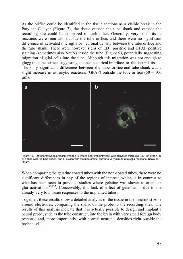
47
As the orifice could be identified in the tissue sections as a visible break in the Parylene-C layer (Figure 7), the tissue outside the tube shank and outside the recording site could be compared to each other. Generally, very small tissue reactions were seen also outside the tube orifice, and there were no significant difference of activated microglia or neuronal density between the tube orifice and the tube shank. There were however signs of ED1 positive and GFAP positive staining (sometimes also NeuN) inside the tube (Figure 9), potentially suggesting migration of glial cells into the tube. Although this migration was not enough to glogg the tube orifice, suggesting an open electrical interface to the neural tissue. The only significant difference between the tube orifice and tube shank was a slight increase in astrocytic reactions (GFAP) outside the tube orifice (50 – 100 µm).
Figure 10. Representative fluorescent images (6 weeks after implantation), with activated microlgia (ED1) in green. In a) a slice with the tube shank, and b) a slice with the tube orifice, showing very minute microglia reactions. Scale bar 50 µm.
When comparing the gelatine coated tubes with the non-coated tubes, there were no significant differences in any of the regions of interest, which is in contrast to what has been seen in previous studies where gelatine was shown to attenuate glia activation 38,137. Conceivably, this lack of effect of gelatine, is due to the already very low tissue responses to the implanted tubes.
Together, these results show a detailed analysis of the tissue in the innermost zone around electrodes, comparing the shank of the probe to the recording sites. The results of this analysis indicate that it is actually possible to design and implant a neural probe, such as the tube construct, into the brain with very small foreign body response and, more importantly, with normal neuronal densities right outside the probe itself.

48
Drug coated implants In parallel with the development of mechanically compliant probes for reducing the tissue damage and the foreign body response, an additional approach was examined. Namely, the usage of the neural probe coating as a vehicle for local and sustained drug delivery. In this initial study, minocycline, known to inhibit microglia activation and having neuroprotective properties 138,139, was delivered via this route, to evaluate if this could have effects on the foreign body response and neuronal survival around a neural implant.
Previous work has developed and evaluated the process on how to encapsulate minocycline in nanoparticles 131, for a sustained released (> 30 days) of the drug. Here, a method for embedding such nanoparticles into the gelatine coating of neural implants, to achieve local release, allowing for radically lower dosages than traditionally used, was developed and the effects on neural tissue was evaluated in vivo in mice.
Effects on the brain tissue in vivo Implants, coated with gelatine containing minocycline loaded nanoparticles, were implanted into mice brains together with implants coated with only gelatine (as controls), and the tissue was analysed at two different time points (3 and 7 days post implantation).
Figure 11. Representative immunofluorescent images of tissue reaction around gelatine coated control implants (Control), and implants coated with gelatine and minocycline loaded nanoparticles (MC-NPs), 3 and 7 days post implantation. (a-d) showing microglia activation (CD68) and (e-h) showing astrocytic activation (GFAP). Scale bar 100 µm. Adapted from Paper III.

49
At 3 days after implantation, there was a clear reduction in activated microglia (CD68) around the implant coated with minocycline loaded nanoparticles, as compared to the implant devoid of nanoparticles (Figure 12a and 11a-b). This indicates that the minocycline (known to inhibit microglia activation123) was successfully delivered to the tissue in sufficient dosage to reduce the early microglia activation normally associated with neural tissue damage. At 7 days after implantation, the microglia activation had diminished in both groups, but it was still significantly lower surrounding the drug loaded implant (Figure 11a and 12b), suggesting a sustained effect of the minocycline release.
Figure 12. Comparisons of foreign body response between gelatine coated control implants (blue), and implants coated with gelatine with minocycline loaded nanoparticles (red), in ROIs 0-50 µm and 50 -100 µm. (a-b) shows level of activation of microglia (CD68) and (c-d) level of astrocytic activation (GFAP), both represented as the fluorescent area fraction. The boxplots represents first and third quartile with median as horizontal lines, and min and max values as whiskers. Statistical significance, is indicated by * (p< 0.05) or ** (p<0.01). From Paper III.
Further, there were no difference in astrocytic response (GFAP), between the groups at 3 days post implantation (Figure 12c). However, 7 days after implantation (Figure 12d), the astrocytic response was significantly lower in the inner region around implants coated with minocycline loaded nanoparticles, as compared to the control (although the total astrocytic response had increased in both groups). This suggests

50
a delayed but indirect effect also on the astrocytic response by the minocycline, which is in line with previous studies suggesting that activated microglia can induce astrocytic activation 22.
Despite the effect on glial cell, the neuronal densities were not significantly different between the two groups at either time-point. This indicates that at least the minocycline loaded particles do not have a neurotoxic effect, but also that the reduction of glia activation did not have effect on the neuronal densities under these circumstances and time points.

51
Discussion & Conclusions
In this thesis, the challenge of designing a truly biocompatible neuro-electronicinterface that can remain stable in the tissue without effecting the physiology of the brain, has been addressed, and a number of different strategies has been proposed. These strategies connect both to the mechanical compliance of the probe itself, the method of implantation, the tissue analysis after implantation and of local drug delivery surrounding the probes. Two novel types of compliant neural probes, as well as a new method for drug delivery, were designed, manufactured, characterized and evaluated in awake and behaving animals in vivo. The results presented here show that a novel type of flexible and density regulated neuro-electronic interface, transiently stiffened by a dissolving core (allowing support during implantation), can almost totally avoid triggering the foreign body reaction and neuronal degradation in the tissue surrounding the implant, as well as enable a detailed analysis of the tissue juxtapositional to the contact of the electrodes. It was further demonstrated that an electrode array, highly flexible in three dimensions, can be implanted with preserved conformation, and that this array of microelectrodes yields very high quality recordings that remains stable despite being obtained in freely moving animals. Finally, it was shown that a new method for delivering drug content for local and sustained release, around neural brain implants, could be used to diminish the foreign body reaction.
The foreign body reaction An overarching challenge in the field of neuro-electronic interfaces, has long been the deterioration of electrode performance, as well as the neuronal degradation and foreign body response in the tissue surrounding implants 22,140,141. We know from previous studies, that both the flexibility 38 and the specific weight 48 of the neural probe are important properties effecting these conditions. Here, we show that it is possible for a flexible and density regulated tube-like probe to almost abolish the foreign body response and to preserve normal neuronal densities around the probe. Comparably, a stiff and heavy probe of the same dimension and surface structure, induced an approximate 30% reduction in neuronal density in the vicinity. The tube-like construct is implantable, without any additional aids, thanks to the inner stiff glucose core that dissolves inside the brain. After dissolution of the glucose core,

52
only a thin polymer sheet is left in contact with the tissue, resulting in a probe with both low density and high flexibility. It was hypothesized that such a probe would move with the brain-tissue, rather than in relation to it. In fact, the minimal tissue reactions seen around the tube shank, together with a small upregulation of astrocytes right outside the tube orifice, as well as glia cells growing into the orifice, gives strong indications that the tube construct has remained stably positioned inside the tissue. Although recent progress with extreme miniaturization of ultra-thin polymer based microelectrodes 78,79,82,93, has showed reductions in foreign body response and neuronal degradation 78,79, they have also shows indications of instability in the tissue, described as migration between neurons and electrode 78.
Ultimately, it is the presence of neurons, in close proximity to the electrode recording site, that is the most important observation in the tissue around the tube electrode. The interactions between microglia, astrocytes, neurons and other cell types in vivo are highly complex, and much remains unknown about how these cells influence each other. For example, both microglia and astrocytes are known to be able to exert neurotoxic effects, as well as neuroprotective effects under different circumstances 58,59,62,63. One possibility is that a minute glia response (as observed outside the tube orifice) could be beneficial, as long as it does not grow dense or large enough to interfere with the viability of neurons. In this case, as there were no signs of neuronal degradation, the small glia reactions found seem to not affect the neuronal population in a negative way. Further, there were no significant differences, either in neuronal density or glia activation, between gelatin coated and non-coated probes (in contrast to what has been shown previously with regards to gelatin 38,111), most likely due to the already very small tissue effects seen here.
Tissue analysis of the inner zone of the implant Another challenge, impeding proper analysis of the tissue immediately surrounding neural probes, is connected to the fact that a rigorous quantifiable analysis of the tissue generally requires tissue sectioning and staining. Currently, stiff probes must be pulled out from the brain 30,36,40,142 , dragging adherent tissue along 48, before the brain tissue can be sectioned. In the case of ultrathin probes that are thin and soft enough to be sectioned while remaining inside the tissue these are likely to dislocate and can even be pulled out during slicing 78,79,93. For example, we could not slice the thin 3D-array in the tissue without some displacement of the electrodes. By contrast, the tube-construct can be sliced in frozen tissue without visible dislocation, most likely because the liquid inside of the tube, is frozen together with the surrounding tissue, which sufficiently fixates the polymer sheet before slicing. This, allowed a proper analysis of the tissue slices including the inner zone (0-9 μm) of tissue around

53
the implant shaft as well as the recording sites. Notably, the recording site was identifiable in tissue sections as a small opening in the Parylene-C coating. This made it possible to compare glia activation and neuronal density in the tissue outside the recording site to that of the rest of the probe, giving an indication of a slightly increased tissue reaction outside the orifice. Moreover, analysis of the innermost zone (0-9 μm) revealed that, especially in relation to the tube orifice, there is a thin ring of microglial cells, possibly also some astrocytes, more or less adhering to the Parylene-C sheet as well as migrating into the tube. However, it appears that the glia cells do not span or clog the orifice, thus the conducting lead inside is in fluidic contact with the neural tissue outside. To what extent traditionally designed recording sites, with exposed metallic surfaces in direct contact with the tissue, would have been covered by glia cells during this highly stable situation in the tissue, can of course only be speculated about. However, the typically observed increase in impedance over time 22,143 of implanted neuro-electronic interfaces, as well as observations of glia cells adhering to explanted probes 48, suggest that such electrode contacts (positioned at the surface of the probes) often are covered by cells. Further, the possibility to perform a detailed analysis of the tissue outside the tube electrodes, enables correlation of histological analysis of single neurons outside the recording site, with qualities of electrophysiological recordings. This in turn opens up for improved identification and classification of single neurons potentially giving valuable information about the underlying functioning of the brain as well as for pathological conditions.
Electrophysiological recording stability Neuro-electronic interfaces, cannot be said to have reached optimal clinical and scientific potential, until they are able to remain stable, i.e. follow the movements of the brain well enough to record from the same neurons over long periods of time 25. Here, we present a thin electrode array, flexible in all three dimensions in contrastto most flexible probes which are straight and therefore mainly flexible in one ortwo dimensions 18–20,79,99,144. Our results show that this array could record single unitswith very high amplitudes (up to 424 μV), higher than what is typically seen forchronic electrodes in awake and behaving animals, even for the more recentlydeveloped ultrathin polymer based electrodes 79,82. This suggests the presence ofviable neurons very close to the electrode, given that the registered amplitudesdecline rapidly with distance from neurons. The absence of single units with suchhigh amplitudes, when using many of the ultrathin flexible probes developedelsewhere, can at this point only be speculated about, but it could be connected tothe potential instability in the tissue as discussed above. The short term stability ofsingle unit amplitudes in recordings using the 3D-array, indicates sufficientpositional stability for recording from the same neurons at least within recording

54
sessions. The long-term stability, measured by the longevity of highly correlated units (>0.99) with high amplitudes (> 150 μV), indicates that the array can also remain sufficiently stable for recording the same units up to a week. However, the fact that these units did not remain equally correlated for the full 3 week period, and that there were small amplitude fluctuations during single recording sessions, suggest that the array would likely benefit from even further increases in flexibility. In fact, ongoing work has already shown that the 3D-array can be made considerably thinner and smaller (at least down to ¼ of the present cross section) using the same manufacturing method as described in this thesis. Worth noting however, is that already with the current design, there was an increase in signal to noise ratio over the 3 week experimental period, suggesting an ongoing integration of tissue and electrodes, indicating that the stability is actually improving over time rather than the opposite. This will, however, require longer lasting studies to determine. Further, to verify that the same neuron is in fact followed over time, future studies should also include other metrics such as firing statistics of single units connected to behaviour and/or longer continuous recordings.
Implanting delicate electrodes with retained conformation As neural electrodes become thinner and more mechanically compliant, the challenge of implantation into the brain also becomes greater. This is especially true for delicate arrays of thin electrodes, with a conformation tailored for certain targets and/or applications. Here we present an embedding method with a gelatine-mix (previously shown to reduce the foreign body response around implants 38,111) that can provide sufficient structural support for implanting delicate electrode arrays, without changing conformation of the individual electrodes. This can be compared to a commonly adapted strategy of implanting ultrathin probes with the aid of a stiff guiding rod 78,82, which subsequently has to be explanted, potentially displacing the probes in the tissue as well as increasing the acute implantation tissue trauma 18. For single neuronal recordings to be of high scientific and/or clinical relevance, it is of utmost importance that the tissue remains undisturbed, but also that the electrode array reaches the intended target with high accuracy and with retained conformation. In other words, the array needs to preserve its shape and relation between individual electrodes during the whole implantation procedure, as well as after, to know where in the brain the signals originate from.

55
Drug release As an additional strategy to reduce the tissue reactions around neuro-electronic interfaces, a new method of coating neural implants with drug content was developed. By loading the drug into degradable nanoparticles 131 that are incorporated into the gelatine coating of an implant, a local and sustained release was achieved (> 30 days in vitro). This approach allows precise delivery with dosages substantially lower than what systemic administration requires. The results presented here shows that the usage of the drug minocycline, could decrease the glia activation around neural implants without affecting the neuronal density. This could be an interesting complement in the pursuit towards a truly biocompatible neuro-electronic interface, for example in connection with the tube-electrode. It may be worth repeating that, although the neuronal density surrounding the tube-electrode was not statistically different from normal tissue, there were indications of slight tissue effects just outside the orifice of the tube, which might or might not be of importance. Also, even if the tube orifice didn’t seem to be clogged by the migrating glia cells, it is still not known to what degree this migration could affect functionality over time. In case it proves a problem, the addition of drug release from the orifice of the tube, could be an interesting strategy for potentially clearing the tube/tube orifice of activated glia cells. In fact, the very design of the tube, with a dissolvable core and orifice, makes it highly suitable for loading with drug content for local release at the orifice. However, it is not known to what degree the activation of glial cells is actually benign rather than malign for the neuronal tissue. In fact, the modification of glia activation by the minocycline did not show any effects on neuronal survival, possibly because there were no or very little neuronal degradation around the implants, and/or the glia reactions might not have detrimental effects on neuronal survival under these circumstances and time points. In relation to this, pharmaceutical manipulation of the foreign body response can be questioned as a strategy for improving the biocompatibility of an implant. Nevertheless, the use of this highly localized and sustained drug delivery holds potential also for other applications, e.g. for locally targeted pharmaceutical treatment or very precise delivery of viral vectors for optogenetics.
Future perspectives How to define a truly biocompatible neuro-electronic interface is not obvious, and there has already been many success stories using neuro-electronic interfaces, both for clinical treatment 3,4 and for gaining information regarding brain functions 5,6. However, as has been touched upon several times throughout this thesis, there has been holdbacks to the progress connected to the instability and signal deterioration of current neuro-electronic interfaces 21,22. It is only when we can record single

56
neuronal activity from the same neurons over time, without disturbing the tissue, that we can accurately determine the modulation of this activity over time, and assume that the activity reflects a normally functioning brain, rather than that of damaged neural tissue. If possible, this would give the opportunity to, for example, follow the progression of neurodegenerative disorders such as Alzheimer’s or Parkinson´s disease, or other debilitating conditions such as epilepsy, depression or chronic pain, or for gaining a greater understanding of memory formation and learning, something that would give invaluable information aiding in the quest for understanding the brain. Further, if adapting this technology for stimulation, it could endow radically increased efficiency, specificity and longevity of treatments using deep brain stimulation, e.g. during Parkinson´s disease, multiple sclerosis, depression or epilepsy, and diminish or even abolish adverse side effects, as well as the need to replace the technology during the course of a human lifetime. The full potential of such truly biocompatible neuro-electronic interfaces, remains to be seen, but as history has shown many times, scientific progress is deeply intertwined with the advent of new tools 145, making previously impossible observations possible and thus laying the foundation for new paradigms within science.
Conclusions The results presented in this thesis, suggest that the construction of truly biocompatible neuro-electronic interfaces, might not be too far away. For example it can already be speculated that the combination of a flexible and density regulated tube-like electrode, or array, together with a highly flexible tethering point, would have the potential to remain stable in the brain without disturbing the tissue and to record from the same neurons over time. In addition, such a probe would also allow for a detailed in situ tissue analysis, making it possible to correlate histological observations, even in the area immediately outside the electrode site, with electrophysiological recordings. Long-term studies, including e.g. continuous long-term recordings, are however necessary to confirm this potential. However, when realized, such a neuro-electronic interface would overcome the limitations of currently existing technology and have the potential to radically improve clinical treatments, as well as becoming an unparalleled tool for probing the mysteries of the brain.

57
Acknowledgements
It is my belief that scientific progress can be equally attributed to the incremental heights reached by standing on the shoulder of giants, and the new grounds only accessible by taking leaps into the open air. And perhaps, if anything, a scientist should be someone who knows when to stand, and when to jump.
Jens Schouenborg, my main supervisor, as much as my mentor, is such a giant, but still always ready to jump, refusing to take established views for granted, and never ready to give up trying to push the whole field forward. Without him, I might not have ended up in science at all, and the basic foundations of everything in this thesis can be attributed to him. During the course of my PhD, it is his infernal grit and unmovable conviction that we are on the right track, that has more than anything else, kept me going, despite sometimes struggling for years without viable results.
Lina Pettersson, my secondary supervisor, an invaluable source of practical advice. No one have I spent more time in the lab together with, now with well over a hundred surgeries and implantations, taking turns during 24 hour experimental sessions, as well as pursuing many weird side-tracks, such as constructing soldering machines or adapting ham-slicers for cutting rat heads, sometimes with both brain tissue and saw blades flying through the lab. Thank you for your patients, positivity and meticulous sense for details.
Lina Gällentoft. Thank you for bringing your skills and experience of histology to the table, and for the endless brain slicing, tissue staining, imaging and cell quantification that is an integral part of Paper II in this thesis. Thank you also for contributing to the foundational knowledgebase, showing for example the impact of a stab wound to the tissue, which has been a piece of the puzzle in figuring out important mechanisms connected to the tissue response around neural electrodes, and of-course thank you for all the after works.
Alexander Holmkvist. The chemical wizard behind the drug loaded nanoparticles, and main contributor to Paper III of this thesis. You are my partner in visiting conferences as much as in lab-work. All from, singing Mariachis in Tijuana, to building complicated injection-machines or spending hours in total darkness by the multiphoton microscopy, frustratingly trying to image the modulation of the immediate microglial response to minocycline in vivo.

58
Palmi Thorbergsson. Matlab genius and NRCs own in-house AI, representing the machine side of the brain-machine interface. Thank you for catching all the experimental data that I have thrown to you during the years, and for turning it into usable metrics that brings us closer to understanding some of the underlying dynamics beneath the brain signaling, a central part of Paper I. Thank you everyone else here at NRC, for making this the most inspiring workplace, Jonas Thelin for being an integral part of much of the work here at NRC and always laying a helping hand when needed. Alle Retelund, for your excellence in electrospinning, making the manufacturing of the tube-electrode possible. Mohsin Mohammad, my man, although we haven’t worked directly together, our tracks run in parallel, and I am sure one day our projects will converge to excellence. Matilde Forni, for always being ready to jump in and help, I am eternally grateful for all the hours you have spent with laser milling and recordings, hopefully we will publish some of this in the future Lucas Kumosa, thank you for intellectually stimulating discussions and for showing that gelatine can help restoring the blood-brain barrier, Martin Garwicz, for valuable advice and feedback on everything from paper writing to journal club presentations and Nils Danielsen for insightful feedback on this thesis. Especially big thanks to Linda Eliasson and Agneta Sanmartin, for being the glue of this whole organisation, keeping everything together behind the stages, as well as on the stage, and for always being supportive guides in the labyrinthic machinery of academia, and thank you also Niclas Lindqvist, Lars Wallman, Christelle Prinz, Mengliang Zhang, Hiroyuki Watanabe, and everyone else here.
Thank you also everyone before me here at NRC, laying the foundations to the work presented in this thesis, all from showing the importance of flexibility, density and tethering mode of neural implants, to the beneficial effects of gelatine; Gustav Lind, Per Köhler, Cecilia Eriksson (for your energy and Glia expertise), Bengt Ljungquist, Annika Friberg, Fredrik Ejserholm, Leila Etemadi, Maria Christensson (introducing me to the multiphoton imaging), Lars-Åke Clementz (you are missed), Veronica Johansson, Petter Pettersson (for countless tech-hours and autocadding). Thank you also all newcomers, making sure Jens has new cannon fodder to worry about, especially my fellow “room-mates”, Robin Solnevik and Daniel Jaghobi. I also want to thank the people in the Integrative Neurophysiology group, for past good times during conference visits and for always lending a stiff tungsten wire when needed; Per Petersson, Pär Halje, Joel Sjöbom, Martin Tamté, Ulrike Richter, Sebastián Baeza and thank you of course Nela Iivica, for joining the dark side! Last, but definitely not least, thank you to my family! First and foremost, to my amazing wife Kristina, for always being supportive, and to August and Signe, for constantly forcing me to shift perspective and for making sure I don’t get too much sleep. Thank you to my sister Eva, the one and only, for always challenging my viewpoints, and to my parents, Ann and Clas, without you I wouldn’t be here and neither would this thesis. I love you all.

59
References
1. Buzsáki G, Anastassiou CA, Koch C. The origin of extracellular fields and currents-EEG, ECoG, LFP and spikes. Nat Rev Neurosci. 2012;13(6):407-420.doi:10.1038/nrn3241
2. Collinger JL, Wodlinger B, Downey JE, et al. High-performance neuroprostheticcontrol by an individual with tetraplegia. Lancet. Published online 2013.doi:10.1016/S0140-6736(12)61816-9
3. Limousin P, Pollak P, Benazzouz A, et al. Effect on parkinsonian signs andsymptoms of bilateral subthalamic nucleus stimulation. Lancet. Published online1995. doi:10.1016/S0140-6736(95)90062-4
4. Hochberg LR, Serruya MD, Friehs GM, et al. Neuronal ensemble control ofprosthetic devices by a human with tetraplegia. Nature. Published online 2006.doi:10.1038/nature04970
5. Wander JD, Rao RPN. Brain-computer interfaces: A powerful tool for scientificinquiry. Curr Opin Neurobiol. Published online 2014.doi:10.1016/j.conb.2013.11.013
6. Moser EI, Roudi Y, Witter MP, Kentros C, Bonhoeffer T, Moser MB. Grid cells andcortical representation. Nat Rev Neurosci. Published online 2014.doi:10.1038/nrn3766
7. Hong G, Lieber CM. Novel electrode technologies for neural recordings. Nat RevNeurosci. Published online 2019. doi:10.1038/s41583-019-0140-6
8. Kipnis N. Luigi galvani and the debate on animal electricity, 1791-1800. Ann Sci.Published online 1987. doi:10.1080/00033798700200151
9. Zeng FG. Trends in Cochlear Implants. Trends Amplif. Published online 2004.doi:10.1177/108471380400800102
10. Schwiening CJ. A brief historical perspective: Hodgkin and Huxley. J Physiol.Published online 2012. doi:10.1113/jphysiol.2012.230458
11. Campbell PK, Jones KE, Huber RJ, Horch KW, Normann RA. A Silicon-Based,Three-Dimensional Neural Interface: Manufacturing Processes for an IntracorticalElectrode Array. IEEE Trans Biomed Eng. Published online 1991.doi:10.1109/10.83588
12. Drake KL, Wise KD, Farraye J, Anderson DJ, BeMent SL. Performance of PlanarMultisite Microprobes in Recording Extracellular Single-Unit Intracortical Activity.IEEE Trans Biomed Eng. Published online 1988. doi:10.1109/10.7273

60
13. Lebedev MA, Nicolelis MAL. Brain-machine interfaces: From basic science toneuroprostheses and neurorehabilitation. Physiol Rev. Published online 2017.doi:10.1152/physrev.00027.2016
14. Schwartz AB. Cortical neural prosthetics. Annu Rev Neurosci. Published online2004. doi:10.1146/annurev.neuro.27.070203.144233
15. Wodlinger B, Downey JE, Tyler-Kabara EC, Schwartz AB, Boninger ML, CollingerJL. Ten-dimensional anthropomorphic arm control in a human brain-machineinterface: Difficulties, solutions, and limitations. J Neural Eng. Published online2015. doi:10.1088/1741-2560/12/1/016011
16. Downey JE, Schwed N, Chase SM, Schwartz AB, Collinger JL. Intracorticalrecording stability in human brain-computer interface users. J Neural Eng. Publishedonline 2018. doi:10.1088/1741-2552/aab7a0
17. Valero M, Cid E, Averkin RG, et al. Determinants of different deep and superficialCA1 pyramidal cell dynamics during sharp-wave ripples. Nat Neurosci. Publishedonline 2015. doi:10.1038/nn.4074
18. Lecomte A, Descamps E, Bergaud C. A review on mechanical considerations forchronically-implanted neural probes. J Neural Eng. Published online 2018.doi:10.1088/1741-2552/aa8b4f
19. Jorfi M, Skousen JL, Weder C, Capadona JR. Progress towards biocompatibleintracortical microelectrodes for neural interfacing applications. J Neural Eng.2015;12(1). doi:10.1088/1741-2560/12/1/011001
20. Weltman A, Yoo J, Meng E. Flexible, penetrating brain probes enabled by advancesin polymer microfabrication. Micromachines. 2016;7(10). doi:10.3390/mi7100180
21. Nicolelis MAL, Dimitrov D, Carmena JM, et al. Chronic, multisite, multielectroderecordings in macaque monkeys. Proc Natl Acad Sci U S A. Published online 2003.doi:10.1073/pnas.1934665100
22. Kozai TDY, Jaquins-Gerstl AS, Vazquez AL, Michael AC, Cui XT. Brain tissueresponses to neural implants impact signal sensitivity and intervention strategies.ACS Chem Neurosci. 2015;6(1):48-67. doi:10.1021/cn500256e
23. Kipke DR, Shain W, Buzsáki G, et al. Advanced neurotechnologies for chronicneural interfaces: New horizons and clinical opportunities. In: Journal ofNeuroscience. ; 2008. doi:10.1523/JNEUROSCI.3879-08.2008
24. Lebedev MA, Nicolelis MAL. Brain-machine interfaces: past, present and future.Trends Neurosci. Published online 2006. doi:10.1016/j.tins.2006.07.004
25. Schouenborg J. Biocompatible multichannel electrodes for long-termneurophysiological studies and clinical therapy-Novel concepts and design. ProgBrain Res. 2011;194:61-70. doi:10.1016/B978-0-444-53815-4.00017-0
26. Kumosa LS, Zetterberg V, Schouenborg J. Gelatin promotes rapid restoration of theblood brain barrier after acute brain injury. Acta Biomater. Published online 2018.doi:10.1016/j.actbio.2017.10.020
27. Bjornsson CS, Oh SJ, Al-Kofahi YA, et al. Effects of insertion conditions on tissuestrain and vascular damage during neuroprosthetic device insertion. J Neural Eng.Published online 2006. doi:10.1088/1741-2560/3/3/002

61
28. Polikov VS, Tresco PA, Reichert WM. Response of brain tissue to chronicallyimplanted neural electrodes. J Neurosci Methods. Published online 2005.doi:10.1016/j.jneumeth.2005.08.015
29. Edell DJ, Toi V Van, McNeil VM, Clark LD. Factors Influencing theBiocompatibility of Insertable Silicon Microshafts in Cerebral Cortex. IEEE TransBiomed Eng. Published online 1992. doi:10.1109/10.141202
30. Szarowski DH, Andersen MD, Retterer S, et al. Brain responses to micro-machinedsilicon devices. Brain Res. 2003;983(1-2):23-35. doi:10.1016/S0006-8993(03)03023-3
31. Kozai TDY, Marzullo TC, Hooi F, et al. Reduction of neurovascular damageresulting from microelectrode insertion into the cerebral cortex using in vivo two-photon mapping. J Neural Eng. Published online 2010. doi:10.1088/1741-2560/7/4/046011
32. Ward MP, Rajdev P, Ellison C, Irazoqui PP. Toward a comparison ofmicroelectrodes for acute and chronic recordings. Brain Res. Published online 2009.doi:10.1016/j.brainres.2009.05.052
33. Prasad A, Xue QS, Dieme R, et al. Abiotic-biotic characterization of Pt/Irmicroelectrode arrays in chronic implants. Front Neuroeng. Published online 2014.doi:10.3389/fneng.2014.00002
34. Gällentoft L, Pettersson LME, Danielsen N, Schouenborg J, Prinz CN, LinsmeierCE. Size-dependent long-term tissue response to biostable nanowires in the brain.Biomaterials. Published online 2015. doi:10.1016/j.biomaterials.2014.11.051
35. Sun DA, Yu H, Spooner J, et al. Postmortem analysis following 71 months of deepbrain stimulation of the subthalamic nucleus for Parkinson disease: Case report. JNeurosurg. Published online 2008. doi:10.3171/JNS/2008/109/8/0325
36. Biran R, Martin DC, Tresco PA. Neuronal cell loss accompanies the brain tissueresponse to chronically implanted silicon microelectrode arrays. Exp Neurol.2005;195:115-126. doi:10.1016/j.expneurol.2005.04.020
37. Jorfi M, Skousen JL, Weder C, Capadona JR. Progress towards biocompatibleintracortical microelectrodes for neural interfacing applications. J Neural Eng.2015;12(1). doi:10.1088/1741-2560/12/1/011001
38. Köhler P, Wolff A, Ejserholm F, Wallman L, Schouenborg J, Linsmeier CE.Influence of probe flexibility and gelatin embedding on neuronal density and glialresponses to brain implants. PLoS One. Published online 2015.doi:10.1371/journal.pone.0119340
39. Gilletti A, Muthuswamy J. Brain micromotion around implants in the rodentsomatosensory cortex. J Neural Eng. Published online 2006. doi:10.1088/1741-2560/3/3/001
40. Biran R, Martin DC, Tresco PA. The brain tissue response to implanted siliconmicroelectrode arrays is increased when the device is tethered to the skull. J BiomedMater Res - Part A. Published online 2007. doi:10.1002/jbm.a.31138
41. Kim YT, Hitchcock RW, Bridge MJ, Tresco PA. Chronic response of adult rat braintissue to implants anchored to the skull. Biomaterials. Published online 2004.doi:10.1016/j.biomaterials.2003.09.010

62
42. Wagshul ME, Eide PK, Madsen JR. The pulsating brain: A review of experimentaland clinical studies of intracranial pulsatility. Fluids Barriers CNS. Published online2011. doi:10.1186/2045-8118-8-5
43. Hopcroft MA, Nix WD, Kenny TW. What is the Young’s modulus of silicon? JMicroelectromechanical Syst. Published online 2010.doi:10.1109/JMEMS.2009.2039697
44. Škoro GP, Bennett JRJ, Edgecock TR, et al. Dynamic Young’s moduli of tungstenand tantalum at high temperature and stress. J Nucl Mater. Published online 2011.doi:10.1016/j.jnucmat.2010.12.222
45. Williams JC, Rennaker RL, Kipke DR. Long-term neural recording characteristics ofwire microelectrode arrays implanted in cerebral cortex. Brain Res Protoc. Publishedonline 1999. doi:10.1016/S1385-299X(99)00034-3
46. Seymour JP, Kipke DR. Neural probe design for reduced tissue encapsulation inCNS. Biomaterials. 2007;28:3594-3607. doi:10.1016/j.biomaterials.2007.03.024
47. Thelin J, Jörntell H, Psouni E, et al. Implant size and fixation mode stronglyinfluence tissue reactions in the CNS. PLoS One. 2011;6.doi:10.1371/journal.pone.0016267
48. Lind G, Linsmeier CE, Schouenborg J. The density difference between tissue andneural probes is a key factor for glial scarring. Sci Rep. 2013;3:2942.doi:10.1038/srep02942
49. McConnell GC, Rees HD, Levey AI, Gutekunst CA, Gross RE, Bellamkonda R V.Implanted neural electrodes cause chronic, local inflammation that is correlated withlocal neurodegeneration. J Neural Eng. Published online 2009. doi:10.1088/1741-2560/6/5/056003
50. Stice P, Gilletti A, Panitch A, Muthuswamy J. Thin microelectrodes reduce GFAPexpression in the implant site in rodent somatosensory cortex. J Neural Eng.Published online 2007. doi:10.1088/1741-2560/4/2/005
51. Nolta NF, Christensen MB, Crane PD, Skousen JL, Tresco PA. BBB leakage,astrogliosis, and tissue loss correlate with silicon microelectrode array recordingperformance. Biomaterials. Published online 2015.doi:10.1016/j.biomaterials.2015.02.081
52. Purves D, Augustine G, Fitzpatrick D, et al. Neuroscience. 2nd edition. Sunderland(MA): Sinauer Associates; 2001.
53. Nathaniel EJH, Nathaniel DR. The Reactive Astrocyte. In: ; 1981. doi:10.1016/b978-0-12-008302-2.50012-2
54. Kettenmann H, Ransom BR. Neuroglia.; 2013.doi:10.1093/acprof:oso/9780195152227.001.0001
55. Lee HS, Ghetti A, Pinto-Duarte A, et al. Astrocytes contribute to gamma oscillationsand recognition memory. Proc Natl Acad Sci U S A. Published online 2014.doi:10.1073/pnas.1410893111
56. Eng LF. Glial fibrillary acidic protein (GFAP): the major protein of glial intermediatefilaments in differentiated astrocytes. J Neuroimmunol. Published online 1985.doi:10.1016/S0165-5728(85)80063-1

63
57. Anderson CM, Swanson RA. Astrocyte glutamate transport: Review of properties,regulation, and physiological functions. Glia. Published online 2000.doi:10.1002/1098-1136(200010)32:1<1::AID-GLIA10>3.0.CO;2-W
58. Chen Y, Vartiainen NE, Ying W, Chan PH, Koistinaho J, Swanson RA. Astrocytesprotect neurons from nitric oxide toxicity by a glutathione-dependent mechanism. JNeurochem. Published online 2001. doi:10.1046/j.1471-4159.2001.00374.x
59. Pekny M, Nilsson M. Astrocyte activation and reactive gliosis. Glia. Publishedonline 2005. doi:10.1002/glia.20207
60. Helmut K, Hanisch UK, Noda M, Verkhratsky A. Physiology of microglia. PhysiolRev. Published online 2011. doi:10.1152/physrev.00011.2010
61. Tremblay MÈ, Zettel ML, Ison JR, Allen PD, Majewska AK. Effects of aging andsensory loss on glial cells in mouse visual and auditory cortices. Glia. Publishedonline 2012. doi:10.1002/glia.22287
62. Elkabes S, DiCicco-Bloom EM, Black IB. Brain microglia/macrophages expressneurotrophins that selectively regulate microglial proliferation and function. JNeurosci. Published online 1996. doi:10.1523/jneurosci.16-08-02508.1996
63. Nakajima K, Honda S, Tohyama Y, Imai Y, Kohsaka S, Kurihara T. Neurotrophinsecretion from cultured microglia. J Neurosci Res. Published online 2001.doi:10.1002/jnr.1157
64. Eric Thomas W. Brain macrophages: evaluation of microglia and their functions.Brain Res Rev. Published online 1992. doi:10.1016/0165-0173(92)90007-9
65. Kozai TDY, Vazquez AL, Weaver CL, Kim SG, Cui XT. In vivo two-photonmicroscopy reveals immediate microglial reaction to implantation of microelectrodethrough extension of processes. J Neural Eng. Published online 2012.doi:10.1088/1741-2560/9/6/066001
66. Stence N, Waite M, Dailey ME. Dynamics of microglial activation: A confocal time-lapse analysis in hippocampal slices. Glia. Published online 2001. doi:10.1002/1098-1136(200103)33:3<256::AID-GLIA1024>3.0.CO;2-J
67. Fujita T, Yoshimine T, Maruno M, Hayakawa T. Cellular dynamics of macrophagesand microglial cells in reaction to stab wounds in rat cerebral cortex. Acta Neurochir(Wien). Published online 1998. doi:10.1007/s007010050095
68. Szarowski DH, Andersen MD, Retterer S, et al. Brain responses to micro-machinedsilicon devices. Brain Res. 2003;983:23-35. doi:10.1016/S0006-8993(03)03023-3
69. Jung S, Schwartz M. Non-identical twins - microglia and monocyte-derivedmacrophages in acute injury and autoimmune inflammation. Front Immunol.Published online 2012. doi:10.3389/fimmu.2012.00089
70. Lee H-H, Park S-C, Choe I-S, Kim Y, Ha Y-S. Time Course and Characteristics ofAstrocyte Activation in the Rat Brain after Injury. Korean J Neurotrauma. Publishedonline 2015. doi:10.13004/kjnt.2015.11.2.44
71. Edell DJ, Vo Van Toi, McNeil VM, Clark LD. Factors influencing thebiocompatibility of insertable silicon microshafts in cerebral cortex. IEEE TransBiomed Eng. 1992;39:635-643. doi:10.1109/10.141202

64
72. Landis DMD. The early reactions of non-neuronal cells to brain injury. Annu RevNeurosci. Published online 1994. doi:10.1146/annurev.ne.17.030194.001025
73. Stensaas SS, Stensaas LJ. The reaction of the cerebral cortex to chronicallyimplanted plastic needles. Acta Neuropathol. Published online 1976.
74. Turner JN, Shain W, Szarowski DH, et al. Cerebral astrocyte response tomicromachined silicon implants. Exp Neurol. Published online 1999.doi:10.1006/exnr.1998.6983
75. Liu X, McCreery DB, Carter RR, Bullara LA, Yuen TGH, Agnew WF. Stability ofthe interface between neural tissue and chronically implanted intracorticalmicroelectrodes. IEEE Trans Rehabil Eng. 1999;7(3):315-326.doi:10.1109/86.788468
76. Fawcett JW, Asher RA. The glial scar and central nervous system repair. Brain ResBull. Published online 1999. doi:10.1016/S0361-9230(99)00072-6
77. Wellman SM, Cambi F, Kozai TD. The role of oligodendrocytes and theirprogenitors on neural interface technology: A novel perspective on tissueregeneration and repair. Biomaterials. 2018;183(August):200-217.doi:10.1016/j.biomaterials.2018.08.046
78. Luan L, Wei X, Zhao Z, et al. Ultraflexible nanoelectronic probes form reliable, glialscar–free neural integration. Sci Adv. Published online 2017.doi:10.1126/sciadv.1601966
79. Wei X, Luan L, Zhao Z, et al. Nanofabricated Ultraflexible Electrode Arrays forHigh-Density Intracortical Recording. Adv Sci. Published online 2018.doi:10.1002/advs.201700625
80. Fekete Z, Pongrácz A. Multifunctional soft implants to monitor and control neuralactivity in the central and peripheral nervous system: A review. Sensors Actuators, BChem. 2017;243:1214-1223. doi:10.1016/j.snb.2016.12.096
81. Sridharan A, Nguyen JK, Capadona JR, Muthuswamy J. Compliant intracorticalimplants reduce strains and strain rates in brain tissue in vivo. J Neural Eng.Published online 2015. doi:10.1088/1741-2560/12/3/036002
82. Musk E. An integrated brain-machine interface platform with thousands of channels.J Med Internet Res. Published online 2019. doi:10.2196/16194
83. Yoshida Kozai TD, Langhals NB, Patel PR, et al. Ultrasmall implantable compositemicroelectrodes with bioactive surfaces for chronic neural interfaces. Nat Mater.Published online 2012. doi:10.1038/nmat3468
84. Mercanzini A, Cheung K, Buhl DL, et al. Demonstration of cortical recording usingnovel flexible polymer neural probes. Sensors Actuators, A Phys. Published online2008. doi:10.1016/j.sna.2007.07.027
85. Castagnola V, Descamps E, Lecestre A, et al. Parylene-based flexible neural probeswith PEDOT coated surface for brain stimulation and recording. Biosens Bioelectron.Published online 2015. doi:10.1016/j.bios.2014.09.004
86. Sohal HS, Jackson A, Jackson R, et al. The sinusoidal probe: A new approach toimprove electrode longevity. Front Neuroeng. Published online 2014.doi:10.3389/fneng.2014.00010

65
87. Sankar V, Sanchez JC, McCumiskey E, et al. A highly compliant serpentine shapedpolyimide interconnect for front-end strain relief in chronic neural implants. FrontNeurol. 2013;4 SEP(September):1-11. doi:10.3389/fneur.2013.00124
88. Zhou T, Hong G, Fu TM, et al. Syringe-injectable mesh electronics integrateseamlessly with minimal chronic immune response in the brain. Proc Natl Acad SciU S A. Published online 2017. doi:10.1073/pnas.1705509114
89. Fu TM, Hong G, Zhou T, Schuhmann TG, Viveros RD, Lieber CM. Stable long-termchronic brain mapping at the single-neuron level. Nat Methods. Published online2016. doi:10.1038/nmeth.3969
90. Ejserholm F, Kohler P, Bengtsson M, Jorntell H, Schouenborg J, Wallman L. Apolymer based electrode array for recordings in the cerebellum. In: 2011 5thInternational IEEE/EMBS Conference on Neural Engineering, NER 2011. ; 2011.doi:10.1109/NER.2011.5910565
91. Köhler P, Eriksson Linsmeier C, Thelin J, et al. Flexible multi electrode brain-machine interface for recording in the cerebellum. In: Proceedings of the 31st AnnualInternational Conference of the IEEE Engineering in Medicine and Biology Society:Engineering the Future of Biomedicine, EMBC 2009. ; 2009.doi:10.1109/IEMBS.2009.5333498
92. Wu F, Im M, Yoon E. A flexible fish-bone-shaped neural probe strengthened bybiodegradable silk coating for enhanced biocompatibility. In: 2011 16th InternationalSolid-State Sensors, Actuators and Microsystems Conference, TRANSDUCERS’11. ;2011. doi:10.1109/TRANSDUCERS.2011.5969356
93. Zhao Z, Li X, He F, Wei X, Lin S, Xie C. Parallel, minimally-invasive implantationof ultra-flexible neural electrode arrays. J Neural Eng. Published online 2019.doi:10.1088/1741-2552/ab05b6
94. Ware T, Simon D, Liu C, et al. Thiol-ene/acrylate substrates for softeningintracortical electrodes. J Biomed Mater Res - Part B Appl Biomater. Publishedonline 2014. doi:10.1002/jbmb.32946
95. Ware T, Simon D, Hearon K, et al. Three-dimensional flexible electronics enabled byshape memory polymer substrates for responsive neural interfaces. Macromol MaterEng. Published online 2012. doi:10.1002/mame.201200241
96. Kipke DR, Pellinen DS, Vetter RJ. Advanced neural implants using thin-filmpolymers. In: Proceedings - IEEE International Symposium on Circuits and Systems.; 2002. doi:10.1109/iscas.2002.1010417
97. Felix S, Shah K, George D, et al. Removable silicon insertion stiffeners for neuralprobes using polyethylene glycol as a biodissolvable adhesive. In: Proceedings of theAnnual International Conference of the IEEE Engineering in Medicine and BiologySociety, EMBS. ; 2012. doi:10.1109/EMBC.2012.6346070
98. Kozai TDY, Kipke DR. Insertion shuttle with carboxyl terminated self-assembledmonolayer coatings for implanting flexible polymer neural probes in the brain. JNeurosci Methods. Published online 2009. doi:10.1016/j.jneumeth.2009.08.002
99. Ejserholm F, Köhler P, Granmo M, Schouenborg J, Bengtsson M, Wallman L. μ-FoilPolymer Electrode Array for Intracortical Neural Recordings. IEEE J Transl EngHeal Med. Published online 2014. doi:10.1109/JTEHM.2014.2326859

66
100. Tamaki S, Matsunaga T, Kuki T, Furusawa Y, Musiake H, Haga Y. Developmentand evaluation of tube-shaped neural probe with working channel. In: 2013Transducers and Eurosensors XXVII: The 17th International Conference on Solid-State Sensors, Actuators and Microsystems, TRANSDUCERS and EUROSENSORS2013. ; 2013. doi:10.1109/Transducers.2013.6626904
101. Kim BJ, Kuo JTW, Hara SA, et al. 3D Parylene sheath neural probe for chronicrecordings. J Neural Eng. Published online 2013. doi:10.1088/1741-2560/10/4/045002
102. Wang YH, Tsai D, Chen BA, et al. Micro-wing and pore design in an implantableFPC-based neural stimulation probe for minimally invasive surgery. In: Proceedingsof the IEEE International Conference on Micro Electro Mechanical Systems(MEMS). ; 2014. doi:10.1109/MEMSYS.2014.6765777
103. Hosseini NH, Hoffmann R, Kisban S, Stieglitz T, Paul O, Ruther P. Comparativestudy on the insertion behavior of cerebral microprobes. In: Annual InternationalConference of the IEEE Engineering in Medicine and Biology - Proceedings. ; 2007.doi:10.1109/IEMBS.2007.4353391
104. Welkenhuysen M, Andrei A, Ameye L, Eberle W, Nuttin B. Effect of insertion speedon tissue response and insertion mechanics of a chronically implanted silicon-basedneural probe. IEEE Trans Biomed Eng. Published online 2011.doi:10.1109/TBME.2011.2166963
105. Hess-Dunning AE, Smith RL, Zorman CA. Development of polynorbornene as astructural material for microfluidics and flexible biomems. J Appl Polym Sci.Published online 2014. doi:10.1002/app.40969
106. Hess AE, Capadona JR, Shanmuganathan K, et al. Development of a stimuli-responsive polymer nanocomposite toward biologically optimized, MEMS-basedneural probes. J Micromechanics Microengineering. Published online 2011.doi:10.1088/0960-1317/21/5/054009
107. Ejserholm F, Vastesson A, Haraldsson T, et al. A polymer neural probe with tunableflexibility. In: International IEEE/EMBS Conference on Neural Engineering, NER. ;2013. doi:10.1109/NER.2013.6696028
108. Ware T, Simon D, Rennaker RL, Voit W. Smart polymers for neural interfaces.Polym Rev. Published online 2013. doi:10.1080/15583724.2012.751924
109. Ward MA, Georgiou TK. Thermoresponsive polymers for biomedical applications.Polymers (Basel). Published online 2011. doi:10.3390/polym3031215
110. Capadona JR, Shanmuganathan K, Tyler DJ, Rowan SJ, Weder C. Stimuli-responsive polymer nanocomposites inspired by the sea cucumber dermis. Science(80- ). Published online 2008. doi:10.1126/science.1153307
111. Lind G, Linsmeier CE, Thelin J, Schouenborg J. Gelatine-embedded electrodes - Anovel biocompatible vehicle allowing implantation of highly flexiblemicroelectrodes. J Neural Eng. Published online 2010. doi:10.1088/1741-2560/7/4/046005
112. Wu F, Tien L, Chen F, Kaplan D, Berke J, Yoon E. A multi-shank silk-backedparylene neural probe for reliable chronic recording. In: 2013 Transducers andEurosensors XXVII: The 17th International Conference on Solid-State Sensors,

67
Actuators and Microsystems, TRANSDUCERS and EUROSENSORS 2013. ; 2013. doi:10.1109/Transducers.2013.6626910
113. Lecomte A, Castagnola V, Descamps E, et al. Silk and PEG as means to stiffen aparylene probe for insertion in the brain: Toward a double time-scale tool for localdrug delivery. J Micromechanics Microengineering. Published online 2015.doi:10.1088/0960-1317/25/12/125003
114. Kozai TDY, Gugel Z, Li X, et al. Chronic tissue response to carboxymethyl cellulosebased dissolvable insertion needle for ultra-small neural probes. Biomaterials.Published online 2014. doi:10.1016/j.biomaterials.2014.07.039
115. Xiang Z, Yen SC, Xue N, et al. Ultra-thin flexible polyimide neural probe embeddedin a dissolvable maltose-coated microneedle. J Micromechanics Microengineering.Published online 2014. doi:10.1088/0960-1317/24/6/065015
116. Shen W, Karumbaiah L, Liu X, et al. Extracellular matrix-based intracorticalmicroelectrodes: Toward a microfabricated neural interface based on naturalmaterials. Microsystems Nanoeng. Published online 2015.doi:10.1038/micronano.2015.10
117. Jeon M, Cho J, Kim YK, et al. Partially flexible MEMS neural probe composed ofpolyimide and sucrose gel for reducing brain damage during and after implantation. JMicromechanics Microengineering. 2014;24(2):025010. doi:10.1088/0960-1317/24/2/025010
118. Kato Y, Nishino M, Saito I, Suzuki T, Mabuchi K. Flexible intracortical neural probewith biodegradable polymer for delivering bioactive components. In: Proceedings of2006 International Conference on Microtechnologies in Medicine and Biology. ;2006. doi:10.1109/MMB.2006.251512
119. Gomes ME, Reis RL. Biodegradable polymers and composites in biomedicalapplications: From catgut to tissue engineering Part 1 Available systems and theirproperties. Int Mater Rev. Published online 2004. doi:10.1179/095066004225021918
120. Abidian MR, Martin DC. Multifunctional nanobiomaterials for neural interfaces. AdvFunct Mater. Published online 2009. doi:10.1002/adfm.200801473
121. Yong VW, Wells J, Giuliani F, Casha S, Power C, Metz LM. The promise ofminocycline in neurology. Lancet Neurol. Published online 2004.doi:10.1016/S1474-4422(04)00937-8
122. Henry CJ, Huang Y, Wynne A, et al. Minocycline attenuates lipopolysaccharide(LPS)-induced neuroinflammation, sickness behavior, and anhedonia. JNeuroinflammation. Published online 2008. doi:10.1186/1742-2094-5-15
123. Abraham J, Fox PD, Condello C, Bartolini A, Koh S. Minocycline attenuatesmicroglia activation and blocks the long-term epileptogenic effects of early-lifeseizures. Neurobiol Dis. Published online 2012. doi:10.1016/j.nbd.2012.02.006
124. Takeuchi S, Ziegler D, Yoshida Y, Mabuchi K, Suzuki T. Parylene flexible neuralprobes integrated with microfluidic channels. Lab Chip. Published online 2005.doi:10.1039/b417497f
125. Ziegler D, Suzuki T, Takeuchi S. Fabrication of flexible neural probes with built-inmicrofluidic channels by thermal bonding of Parylene. J MicroelectromechanicalSyst. Published online 2006. doi:10.1109/JMEMS.2006.879681

68
126. Canales A, Jia X, Froriep UP, et al. Multifunctional fibers for simultaneous optical,electrical and chemical interrogation of neural circuits in vivo. Nat Biotechnol.Published online 2015. doi:10.1038/nbt.3093
127. Kim DH, Martin DC. Sustained release of dexamethasone from hydrophilic matricesusing PLGA nanoparticles for neural drug delivery. Biomaterials. Published online2006. doi:10.1016/j.biomaterials.2005.12.021
128. Mercanzini A, Reddy S, Velluto D, et al. Controlled release drug coatings on flexibleneural probes. Conf Proc IEEE Eng Med Biol Soc. Published online 2007.
129. Abidian MR, Kim DH, Martin DC. Conducting-polymer nanotubes for controlleddrug release. Adv Mater. Published online 2006. doi:10.1002/adma.200501726
130. Elmowafy EM, Tiboni M, Soliman ME. Biocompatibility, biodegradation andbiomedical applications of poly(lactic acid)/poly(lactic-co-glycolic acid) micro andnanoparticles. J Pharm Investig. Published online 2019. doi:10.1007/s40005-019-00439-x
131. Holmkvist AD, Friberg A, Nilsson UJ, Schouenborg J. Hydrophobic ion pairing of aminocycline/Ca2+/AOT complex for preparation of drug-loaded PLGA nanoparticleswith improved sustained release. Int J Pharm. Published online 2016.doi:10.1016/j.ijpharm.2016.01.011
132. Zhu B, Gong S, Cheng W. Softening gold for elastronics. Chem Soc Rev. Publishedonline 2019. doi:10.1039/c8cs00609a
133. Jämstorp E, Yarra T, Cai B, Engqvist H, Bredenberg S, Strømme M. Polymerexcipients enable sustained drug release in low ph from mechanically stronginorganic geopolymers. Results Pharma Sci. Published online 2012.doi:10.1016/j.rinphs.2012.02.001
134. Etemadi L, Mohammed M, Thorbergsson PT, et al. Embedded ultrathin clusterelectrodes for long-term recordings in deep brain centers. PLoS One. Publishedonline 2016. doi:10.1371/journal.pone.0155109
135. Lewicki MS. A review of methods for spike sorting: the detection and classificationof neural action potentials. Network. 1998;9(4):R53--78.http://www.ncbi.nlm.nih.gov/pubmed/10221571
136. Suner S, Fellows MR, Vargas-Irwin C, Nakata GK, Donoghue JP. Reliability ofsignals from a chronically implanted, silicon-based electrode array in non-humanprimate primary motor cortex. IEEE Trans Neural Syst Rehabil Eng. 2005;13(4):524-541. doi:10.1109/TNSRE.2005.857687
137. Lind G, Linsmeier CE, Thelin J, Schouenborg J. Gelatine-embedded electrodes--anovel biocompatible vehicle allowing implantation of highly flexiblemicroelectrodes. J Neural Eng. 2010;7:046005. doi:10.1088/1741-2560/7/4/046005
138. Wang Z, Nong J, Shultz RB, et al. Local delivery of minocycline from metal ion-assisted self-assembled complexes promotes neuroprotection and functional recoveryafter spinal cord injury. Biomaterials. Published online 2017.doi:10.1016/j.biomaterials.2016.10.002
139. Zhang Z, Nong J, Zhong Y. Antibacterial, anti-inflammatory and neuroprotectivelayer-by-layer coatings for neural implants. J Neural Eng. Published online 2015.doi:10.1088/1741-2560/12/4/046015

69
140. Salatino JW, Ludwig KA, Kozai TDY, Purcell EK. Glial responses to implantedelectrodes in the brain. Nat Biomed Eng. 2017;1(11):862-877. doi:10.1038/s41551-017-0154-1
141. Biran R, Martin DC, Tresco PA. Neuronal cell loss accompanies the brain tissueresponse to chronically implanted silicon microelectrode arrays. Exp Neurol.Published online 2005. doi:10.1016/j.expneurol.2005.04.020
142. Turner JN, Shain W, Szarowski DH, et al. Cerebral astrocyte response tomicromachined silicon implants. Exp Neurol. 1999;156:33-49.doi:10.1006/exnr.1998.6983
143. Williams JC, Hippensteel JA, Dilgen J, Shain W, Kipke DR. Complex impedancespectroscopy for monitoring tissue responses to inserted neural implants. J NeuralEng. Published online 2007. doi:10.1088/1741-2560/4/4/007
144. Kuo JTW, Kim BJ, Hara S a, et al. Novel flexible Parylene neural probe with 3Dsheath structure for enhancing tissue integration. Lab Chip. 2013;13(4):554-561.doi:10.1039/c2lc40935f
145. Dyson FJ. Is science mostly driven by ideas or by tools? Science (80- ). Publishedonline 2012. doi:10.1126/science.1232773


Paper I


METHODSpublished: 25 September 2015doi: 10.3389/fnins.2015.00331
Frontiers in Neuroscience | www.frontiersin.org 1 September 2015 | Volume 9 | Article 331
Edited by:
Manuel Fernando Casanova,
University of Louisville, USA
Reviewed by:
Jit Muthuswamy,
Arizona State University, USA
Ulrich G. Hofmann,
Albert-Ludwigs-University Freiburg,
Germany
*Correspondence:
Johan Agorelius,
Lina M. E. Pettersson
and Jens Schouenborg,
Department of Experimental Medical
Science, Neuronano Research Center,
Lund University, BMC F10,
SE-221 84 Lund, Sweden
†These authors jointly directed this
work.
Specialty section:
This article was submitted to
Neural Technology,
a section of the journal
Frontiers in Neuroscience
Received: 05 January 2015
Accepted: 04 September 2015
Published: 25 September 2015
Citation:
Agorelius J, Tsanakalis F, Friberg A,
Thorbergsson PT, Pettersson LME
and Schouenborg J (2015) An array of
highly flexible electrodes with a
tailored configuration locked by gelatin
during implantation—initial evaluation
in cortex cerebri of awake rats.
Front. Neurosci. 9:331.
doi: 10.3389/fnins.2015.00331
An array of highly flexible electrodeswith a tailored configuration lockedby gelatin during implantation—initialevaluation in cortex cerebri ofawake ratsJohan Agorelius 1, 2*, Fotios Tsanakalis 1, Annika Friberg 1, Palmi T. Thorbergsson 1,
Lina M. E. Pettersson 1*† and Jens Schouenborg 1, 2*†
1Department of Experimental Medical Science, Neuronano Research Centre, Lund University, Lund, Sweden, 2 The
Nanometer Structure Consortium, Lund University, Lund, Sweden
Background: A major challenge in the field of neural interfaces is to overcome the
problem of poor stability of neuronal recordings, which impedes long-term studies
of individual neurons in the brain. Conceivably, unstable recordings reflect relative
movements between electrode and tissue. To address this challenge, we have
developed a new ultra-flexible electrode array and evaluated its performance in awake
non-restrained animals.
Methods: An array of eight separated gold leads (4× 10 µm), individually flexible in 3D,
were cut from a gold sheet using laser milling and insulated with Parylene C. To provide
structural support during implantation into rat cortex, the electrode array was embedded
in a hard gelatin based material, which dissolves after implantation. Recordings were
made during 3 weeks. At termination, the animals were perfused with fixative and frozen
to prevent dislocation of the implanted electrodes. A thick slice of brain tissue, with the
electrode array still in situ, was made transparent using methyl salicylate to evaluate the
conformation of the implanted electrode array.
Results: Median noise levels and signal/noise remained relatively stable during the 3
week observation period; 4.3–5.9µV and 2.8–4.2, respectively. The spike amplitudes
were often quite stable within recording sessions and for 15% of recordings where
single-units were identified, the highest-SNR unit had an amplitude higher than 150µV.
In addition, high correlations (>0.96) between unit waveforms recorded at different time
points were obtained for 58% of the electrode sites. The structure of the electrode array
was well preserved 3 weeks after implantation.
Conclusions: A new implantable multichannel neural interface, comprising electrodes
individually flexible in 3D that retain its architecture and functionality after implantation has
been developed. Since the new neural interface design is adaptable, it offers a versatile
tool to explore the function of various brain structures.
Keywords: brain machine interface, flexible electronic implant, neural probe, embedding material, brain
micro-motions, stable neural recordings, mechanical compliance, neuromodulation

Agorelius et al. Gelatin embedded neural interfaces
Introduction
A major challenge in the field of Brain-Machine Interfaces(BMIs) is that the stability of neuronal recordings often isinsufficient for studies of single neuronal activity over longperiods of time. Unstable electrode position in the tissue canoccur if the implant is too rigid to follow the movements of thebrain during for example the respiratory and cardiac cycles (Brittand Rossi, 1982) but can also be caused by body movements(Jackson and Fetz, 2007; Santhanam et al., 2007). Moreover,the quality, i.e., signal-to-noise ratio, commonly graduallydeteriorates over time (Rousche and Normann, 1998; Williamset al., 1999; Polikov et al., 2005). This deterioration may in partalso be due to instability, since micro-motions between probeand tissue are likely to cause continuous irritation or indeedinjury of the tissue that result in long-term glial activation andunfavorable effects on nearby neurons (Turner et al., 1999;Williams et al., 1999; Szarowski et al., 2003; Biran et al., 2005;Gilletti and Muthuswamy, 2006; Seymour and Kipke, 2007;Thelin et al., 2011; Lind et al., 2013). These glial reactions andeffects on nearby neurons are known to impair recording quality(Nolta et al., 2015).
The largest micro-motions occur between the brain and theskull in the awake freely moving animals (Kim et al., 2004;Gilletti and Muthuswamy, 2006; Biran et al., 2007). For thisreason, flexible leads on the cortical surface connecting theimplanted rather stiff electrodes to the electronics have beendeveloped (Rousche and Normann, 1998; Jackson and Fetz,2007; Musallam et al., 2007). However, there are also significantmicro-motions inside the brain caused by propagating wavesof blood inside the vessels (Eide, 2008; Wagshul et al., 2011).The propagating nature of these movements implies that themovements inside the brain are not uniform. On top of thesemovements, there are movements caused by respiration. If theimplanted electrodes cannot follow these tissue movements inall three dimensions, micro-forces/micro-movements betweentissue and the recording sites on the electrodes will ensue.Indeed, it is a common experience, when performing acuteelectrophysiological experiments using stiff microelectrodes forextracellular recordings, that substantial pulsative movementsinside the brain can occur as an effect of e.g., heart beats despitestabilization of the surface. As a result, such recordings tend to beshort lived if the electrode is too close to the recorded neurons.Hence, to allow close contacts with neurons for longer periods oftime, a high degree of mechanical compliance between electrodesand tissue is likely to be beneficial.
To improve mechanical compliance between electrodes andtissue, efforts have been made to increase the flexibility of theimplanted electrodes themselves (Rousche et al., 2001; Kipkeet al., 2002; Takeuchi et al., 2005; Stice et al., 2007; Bae et al.,2008; Krüger et al., 2010; Andrei et al., 2012; Felix et al., 2012;Lee et al., 2012; Kuo et al., 2013; Ejserholm et al., 2014; Kozaiet al., 2014; Sohal et al., 2014). However, some of them aretoo flexible to be implanted on their own, and thus structuralsupport in the form of a stiff guide or cannula (Kipke et al.,2002; Felix et al., 2012; Kuo et al., 2013; De Faveri et al., 2014;Sohal et al., 2014) has been used. These guides/cannulae causeadditional stab wound-like injuries on their own, and on removal
risk perturbing the position of the implanted flexible electrodes.Many of these flexible electrodes embed the conductive leadsin a polymer sheet. However, this reduces their flexibility toone dimension only, and since the electrode leads are fixed inthe polymer they cannot move independently of each other.In addition, such chip-like constructions also permanently splitthe tissue into two halves, causing an irreversible disruption ofcommunication between neural networks on the two sides andtherefore create a less than ideal situation when analyzing thefunction of neuronal networks. Hence, the challenge of providingan implantable array of independent highly flexible electrodesand that can be provided with an architecture adapted to thetarget tissue still remains.
The aim of the present project was thus to develop a fullyfunctional and implantable array of ultra-thin electrodes,individually flexible in three dimensions after implantation. Wepresent a new type of array of ultra-flexible electrodes which bybeing embedded in a hard but dissolvable gelatin based materialretains its conformation and arrangement during implantation.Preliminary performance tests in awake rats showed encouragingresults.
Materials and Methods
Design and Fabrication of the Electrode ArrayWe designed an array of eight wavy electrodes, thusflexible/extendable in three dimensions, each equipped witha distal protruding branch from where neuronal recordingscould be made (Figure 1). The electrode array conformation wasdesigned to allow recordings from different cortical laminae.The design was created using AutoCAD 2011 software anddigitally imported into a Laser Machining System (Laser mill50, standard micro-milling system, Nd:YAG laser system, NewWave Research, Inc., Fremont, CA). A 4µm-thick sheet ofgold foil (Rosenobel-Doppelgold 23 3/4 karat, J.G. EytzingerGmbH, Germany) was fastened onto a microscope glassslide using polyethylene glycol (Sigma-Aldrich). Gold leads,10µm in width were milled under a fixed 20X objective usingpulsed green laser light (wavelength 532 nm, energy density10 J/cm2).
The glass slide containing the milled electrodes was mountedwith silicon (Elastosil A07) and aligned on a metal frame towhich a printed circuit board (PCB) was attached. The individualleads were manually soldered to the PCB one by one using aflux mixture solution (62% Sn, 36% Pb, 2% Ag) applied betweenthe electrodes to be soldered and the contacts on the PCB. Thisprocess was performed under a stereomicroscope (SMZ1500,Nikon Instruments Europe BV, The Netherlands). To wash awaythe remaining flux mixture from between the PCB leads and torelease the electrode leads from the glass slide, the metal framewas immersed in 70% ethanol, after which the glass slide wascarefully removed manually.
An acrylic coating (HumiSeal advanced protective coating forelectronics) was applied as protection over the soldered leads andover the bottom part of the PCB. The electrode array, includingthe PCB, was then coated with Parylene C (4µm thick) using aCompact Bench Top Coating System (Labtop 3000, Para TechCoating Inc., CA, US).
Frontiers in Neuroscience | www.frontiersin.org 2 September 2015 | Volume 9 | Article 331

Agorelius et al. Gelatin embedded neural interfaces
FIGURE 1 | A schematic of the 3D flexible electrode array. Note the
Z-shaped proximal part of the electrode array located between the cranium
and the brain surface, and the tips (10µm) of the distal protrusions which
serve as recording sites.
There were no obvious inherent strain forces in the constructsince the gold electrodes were not displaced after being cut outfrom the gold sheet and also kept their conformation wheninsulated with parylene C.
To prepare the active recording sites on the protruding tips,the parylene coating was photo-ablated on both sides, overan area extending 10µm from each electrode lead tip, usingfocused UV radiation (wavelength 355 nm, energy density 1.4J/cm2) under a 20x objective. The successful exposure of the leadrecording sites was monitored in real time during the ablationprocess and subsequently carefully confirmed with ScanningElectron Microscopy (SEM).
A ∼40mm long, 150µm thick, un-insulated silver wire(Advent research Materials Ltd, England) was attached to thechip in the assigned “ground” position in order to be used asanimal ground for the recordings. The electrode, connected tothe chip, was finally released from the frame.
Impedance SpectroscopyThe electrical properties of each electrode lead were evaluatedby impedance spectroscopy (Gamry Instruments, SeriesG 300, USA). After immersion in 0.9% saline solution,the impedance of the individual channels was measuredby applying a 10mV AC voltage with a frequency of 1KHz, using a large Pt wire as counter electrode and anAg/AgCl electrode in phosphate buffer as reference. Themean impedance of the individual channels was 832 k�(SD = 230 k�). It should be noted that repeated impedancemeasurements did not significantly change the impedance of theelectrodes.
Embedding of the ElectrodesThe gold electrodes used in this study are highly flexible, forinstance they cannot be inserted into water without bending.To provide structural support during implantation, the ultra-flexible electrode array was embedded in a hard, but dissolvable,gelatin B based matrix material. The gelatin matrix was preparedby slowly heating a mixture of 3 g gelatin (Gelatin powderPh.Eur., 24360.368, WWR International AB, Sweden), 750mgPEG 400 (81172-1L, Sigma-Aldrich Chemie GmbH, Germany),150mg glycerol 98% (GRP Rectapur, 24 387.361, VWR, BDHProlabo, France), and 7mL Millipore water (Millipak-20 FilterUnit 0.22µm 1/4 in), to 70◦C, giving a final concentration of27.5% gelatin, 1.4% glycerol and 6.9% PEG. The mixture wasthen placed on a hot plate while stirring. The electrode array wasplaced inside a custommade Poly Methyl Methacrylate (PMMA)mold and the gelatin mixture was injected. The humidity duringdrying was held at 21%, and the gelatin was dried first 24 h insidethe mold, and then 24 h with the top lid of the mold removed.The remaining water content after drying was estimated to bebelow 4% (by measuring the weight of the probes (n = 5) beforeand after drying). This method enabled production of a probeembedded in a gelatin matrix with a sharp rigid tip that allowedfor penetration of the brain tissue (Figure 3B).
Finally, a thin coat of a water retardation material was appliedin order to delay dissolution of the matrix material until theimplant was fully implanted. In short, the gelatin-embeddedelectrode array was dip-coated in a 5% (w/w) solution of kollicoat(Fluka, Sigma-Aldrich Sweden AB) in 99.7% ethanol, two timeswith a drying interval of 24 h in between each coat, and at least1 h between the last coating and implantation.
Animal SurgeryApproval for the experiments was obtained in advance from theMalmö/Lund Animal Ethics Committee on Animal Experiments(ethical permit M60-13) and all experiments in this workconform to the regulatory standards of this approval. All rats hadfree access to food and water and were kept in a 12-h light/darkcycle at a constant environmental temperature of 21◦C and 65%humidity.
Female Sprague-Dawley rats were implanted with theembedded ultra-flexible electrode array in the hind paw areaof the primary somatosensory (SI) cortex at the followingstereotactic coordinates; 1.5mm rostral and 2.0mm lateral fromBregma. The rats weighed 222.5 g (SD = 3.8 g) at the time ofsurgery, corresponding to approximately 9–10 weeks. In short,anesthesia was induced by placing the rat in a chamber of2% isoflurane (Isoba R©vet., Apoteksbolaget, Sweden) with 40%oxygen and 60% nitrous oxide (Granmo et al., 2013). The animalwas placed on a heating pad and its body temperature wasmonitored and kept at a stable level. The head was shaved andthe rat was mounted in a stereotactic frame (KOPF Instruments,USA). After disinfection of the skin with 70% ethanol, the skullwas exposed with a midline incision. The skin was retractedand the skull was cleaned from connective tissue under astereomicroscope (Leica Microsystems, M651, Germany). Twoholes (0.8mm) were drilled anterior to bregma and one posteriorto the SI cortex using a high-speed stereotaxic drill (Dest 300
Frontiers in Neuroscience | www.frontiersin.org 3 September 2015 | Volume 9 | Article 331
Agorelius et al. Gelatin embedded neural interfaces
IN, model MM 323IN, Silfradent, Italy). Small custom-madetitanium screws with a length of 1900µmwere screwed∼570µminto the holes. The choice of material was based on the fact thattitanium is a well-known biocompatible material commonly usedin implants and which has the potential to integrate into the boneof the skull, yielding increased screw stability and thus adherenceof the implant to the skull. The screws were used as anchoringsites for the dental cement (FujuCEM, GC, Europe, Belgium),which was applied at a later stage to attach the electrode/PCBto the skull. The ground wire was wired around the screw andinserted in a separate hole so as to be in contact with the CSF, seebelow.
A craniotomy, ∼2mm in the rostro-caudal direction,and ∼3.5mm in the medio-lateral dimension was made in thebone of the skull at the SI cortex coordinates, while leaving theunderlying dura mater intact. The hind paw area in the S1 cortexwas targeted using stereotactical implantation (Kalliomäki et al.,1993). Onset latencies of tactile response were measured from thestimulation artifact. The hole was rinsed with 0.9 % sterile salinesolution to clear away any possible debris and prevent tissuesfrom drying.
The embedded electrode was mounted in a hydraulicmicromanipulator (KOPF Instruments, USA) and positionedabove the SI cortex coordinates. The dura mater was carefullyincised and deflected. Care was taken to always keep a thin layerof saline on the cortical surface to prevent it from drying. Theelectrode was implanted at the above mentioned coordinates to adepth of 1800µm with a speed of 50µm/s. After implantation,the ground wire was looped around one of the screws, andsubsequently inserted under the bone on top of the dura onthe contralateral side of the skull. A small piece of collagenbiomatrix for dura regeneration (TissuDura, Baxter InternationalInc., USA) was positioned in the hole on top of the animalground wire. The wire was secured and the hole was protectedby application of dental cement. To increase the adherence of thePCB and dental cement to the skull, a primer, RelyX™ Unicem,Aplicap™ (3M, Sollentuna; Sweden) was applied prior to dentalcement application.
In order to roughly estimate how long after implantation aneural signal could be obtained from the electrodes, a short-lasting recording was made in the anesthetized animal afterimplantation. In the three animals used for recordings (on 2–4out of 8 electrode sites in each animal), neuronal activity wasdetectable already 30–40min after implantation.
During surgery, the eyes were shielded with a compresswhich was continually refreshed with physiological saline. Inaddition, care was taken to make absolutely sure that ethanol ordisinfectant was not applied anywhere in the vicinity of the eyes.
After surgery the rat was given subcutaneous injections of0.01mg/kg of temgesic (buprenorfin; Schering-Plough, Belgium)to relieve postoperative pain and animals were monitoredduring the awakening phase. At the end of the experimentalperiod, (3 weeks post implantation), animals were killed byan intraperitoneal injection overdose of pentobarbital andtranscardially perfused with saline (0.9%) followed by ice-cold 4%paraformaldehyde (PF) in 0.1M phosphate buffer, pH 7.4. Thebrains were post fixed in PF overnight.
Tissue ClarificationTo evaluate how well the flexible electrode array maintains itsconformation after implantation, the head and brain with theprobe still in situ was sectioned and processed according to theclarification protocol described below.
In short, after fixation, the whole head was snap frozen inisopentane on dry ice and stored at −80◦C. This preparationmethod was developed in order to prevent distortion or removalof the electrode from the brain during sectioning of the skulland brain tissue. The top part of the skull bone including theupper part of the electrode was cut off using a circular diamondsaw blade mounted on a high-speed dental drill (Desk 200 In,Silfradent, Italy) at 10,000 rpm. After this, the frozen head was cutin 4.5–5.5mm thick slices with a tissue-slicing machine (ABW300 GM, 242 W, Avery Berkel, UK), while still kept deep frozen.Care was taken to make sure that the entire electrode array wascontained within a single tissue slice (Figure 3C).
For clarification the tissue slice was rinsed in 0.1M phosphatebuffered saline (3 × 5min) to remove the fixative, dehydratedthrough ethanol of increased concentration (50, 70, and 99.5%,3–4 h in each), and finally cleared in increasing concentrations(50, 70 in ethanol and 100%) of methyl salicylate (Sigma-Aldrich, Stockholm, Sweden) at least 5 h in each immersion.The conformation of the electrode within the brain slice wasexamined after clarification and compared with the conformationof the same gelatin embedded electrode before implantation,using 11.5×magnification stereomicroscope (SMZ 1500, Nikon,Japan) with 0.5x WD 136 objective (Nikon, Japan).
In-vivo Electrophysiology in Awake AnimalsTo evaluate the functionality and stability of the 3D electrode,in vivo recordings of single unit activity were made, in awake andnon-restrained animals. Neural recordings were performed 2–5times a week, starting day 1 (1 day after implantation) up to theend point at day 21.
The in-vivo recordings were performed in a faraday cage toeliminate external electromagnetic interference. Rats were brieflyanesthetized with isoflurane (as per above) to connect the PCBto a 64 channel Plexon data acquisition system via a 20X headstage, a commutator and pre-amplifier (OmniPlex, Plexon Inc,Texas, USA) with a 60 cm long cable. The anesthetic gas wasdiscontinued and signals were recorded from awake and non-restrained rats enclosed in a cage-like container.
To verify the physiological nature of the recorded activity,tactile stimulations of the glabrous skin of the contralateral hindpaw were performed by triggering a tactile stimulator connectedto a Master 8 stimulator (A.M.P.I., Jerusalem, Israel). At leastone session of tactile stimulations was performed per animal.For each session a minimum of 150 tactile stimulations wereperformed and event time stamps were registered together withthe electrophysiological recordings.
Data AnalysisThe performance of the developed electrode arrays was evaluatedby analyzing the noise levels, signal-to-noise ratio (SNR), yield(ratio of active electrodes that recorded single units and total
Frontiers in Neuroscience | www.frontiersin.org 4 September 2015 | Volume 9 | Article 331

Agorelius et al. Gelatin embedded neural interfaces
number of electrodes) and stability of the neural recordings overa period of 3 weeks.
Recording ParametersThe electrophysiological data were sampled at 16 bit and 40 kHzper channel using a Plexon data acquisition system (Plexon Inc.,Texas, USA). The signals were bandpass-filtered (0.25–8 kHz)using a noncausal filter (Quian Quiroga, 2009) and re-referencedusing Common Median Referencing (Rolston et al., 2009) toeliminate common-mode artifacts. All post-acquisition analysiswas performed automatically using in-house written Matlab(Mathworks Inc.) programs.
Unit-identificationPutative single-units were identified using an unsupervisedalgorithm consisting of a simple amplitude-threshold detector(Quiroga et al., 2004) and clustering with Gaussian MixtureModels (GMM) (Pouzat et al., 2002; Ludwig et al., 2006). Thethreshold for spike detection was set as minus four times theestimated noise level (standard deviation of background noise)and spikes were aligned temporally at the point of maximumamplitude of the detected valley (Mitra and Bokil, 2008). Thenoise level was estimated using the maximum absolute deviation(MAD) estimator for standard deviation (Quiroga et al., 2004),given by:
σ̂N = median|signal|
0.6745. (1)
As features for spike sorting, the first six principal componentanalysis (PCA) weights were used (Lewicki, 1998). To estimatethe number of units, the feature-distributions were fitted toGMMs with one to six components and the model for whichthe Bayesian Information Criterion (BIC) converged (BIC< 10%of the BIC-range for all models) was selected. The spikes wereassigned to the unit (mixture-component) according to theirmaximum posterior membership-probability. Spikes that did nothave a posterior membership-probability above 0.8 for any unitwere classified as outliers (Ludwig et al., 2006).
Signal-to noise ratio (SNR) of units was defined as:
SNR =spp
2 · σN(2)
where spp is the peak-to-peak amplitude of the unit-waveformand σN is the standard deviation of residuals after subtractingthe unit-waveform from each detected spike waveform. ISI (inter-spike interval) violation rate was defined as the percentage of ISIsthat were shorter than 1ms.
An automatic unit-validation procedure largely based onthe manual procedure described in Suner et al. (2005) wasimplemented to identify putative units that could be reasonablyassumed to represent neuronal activity. In Suner et al. (2005), thisvalidation was performed by visual inspection of unit-waveforms,and by rejecting units that did not have at least a biphasiccomponent. In order to do this in an objective and consistentmanner, we extracted several descriptive features of the unit-waveforms related to this criterion. Those were: (1) polarity
of the pre- and post-peak phases of the waveform (identifiesstrictly monophasic waveforms), (2) the amplitude-differencebetween waveform endpoints relative to themaximum amplitude(rejecting strongly unbalanced waveforms likely to be artifacts),(3) the number of zero-crossings of pre- and post-peak phasesof the waveform (rejecting waveforms with more than 3 zero-crossings in one of the phases) and (4) temporal location ofthe waveform-peak (rejecting slowly varying waveforms, usuallyrepresenting artifacts). In addition to these waveshape-relatedfeatures, we used (5) SNR (rejecting units with SNR < 2 andSNR > 20, representing noise and artifacts, respectively), (6)ISI violation rate (rejecting units with >0.5% ISI violation rate),(7) amplitude-threshold-rate (rejecting units that onlymarginallycrossed the detection threshold), and (8) amplitude (rejectingunits with amplitude < 25 uV). The thresholds for the individualmetrics were set empirically to obtain consistent rejection of unitsthat would have been likely to be rejected by a manual procedure.
The SNR was further used to classify units as good (SNR≥ 4),fair (2≤ SNR< 4), poor (1≤ SNR< 2), and no-signal (SNR< 1).In addition to these classes, we introduced a fifth class containingvery-high SNR units (SNR > 6).
Recording Performance Over TimeTo make a preliminary assessment of the recording performanceover time, we measured noise level (Equation 1), SNR of validunits (Equation 2), yield, and relative difference in amplitudebetween units with highly correlated unit-waveforms recordedon the same channel but on different days. When evaluatingperformance, the SNR of recordings was taken as the SNR ofthe highest-SNR valid single-unit identified in the recording.Yield was defined as the percentage of electrode-sites on whichat least one valid unit with SNR ≥ 2 (at least fair) or SNR ≥
4 (at least good) was identified (Ludwig et al., 2006) and wasquantified both on a per-week basis and with all days pooledtogether. To identify units recorded on the same channel but ondifferent days, that might represent the same neuron, we used amethod similar to that described in Fraser and Schwartz (2012)in which both the shapes of unit-waveforms and firing statisticswere compared between recording sessions. However, sinceour experiments were performed mainly during spontaneousbehavior, no measures related to firing statistics were includedin our procedure. Hence, we emphasize that while suggestive, theanalysis applied here does not allow safe conclusion on whetheror not pairs of valid units with a high correlation betweenwaveform shapes between different recording sessions indeedrepresent the same neuron.
For all pairs of valid units with SNR≥ 2 (at least fair) identifiedon different days, the similarity-measure was taken as the Fisher-transformed maximum value of the cross-correlation betweenthe unit-waveforms. The waveform-correlation threshold forwhat to consider as units with highly similar waveforms was set asthe 90th percentile limit of the distribution of Fisher-transformedwaveform-correlations for pairs consisting of units from separateanimals. This resulted in a waveform-correlation threshold of0.96. The correlation threshold was then applied to all same-animal, same-channel, different-day unit-pairs, and pairs withcorrelation above 0.96 were assumed to putatively represent the
Frontiers in Neuroscience | www.frontiersin.org 5 September 2015 | Volume 9 | Article 331

Agorelius et al. Gelatin embedded neural interfaces
same neuron.Whenmultiple unit-pairs were found, only the pairwith the highest waveform-correlation was considered.
Results
Design FeaturesThe resulting electrode array comprised a Z-shaped suspensionin the upper part of the shank designed to absorb the major partof the motions between the brain and the skull (SupplementaryVideo 1). Each of the electrode leads was equipped with a100µm long protrusion perpendicular to the main axis, whichserved a dual function of adding to the flexibility and anchoragein the tissue close to the recording sites. The electrode arraywas designed to obtain recordings from four different depths,each 400µm apart, corresponding to layer IV–VI of the ratprimary somatosensory cortex. SEM examination of the probeconfirmed that a∼100µm2 area of gold surface was de-insulatedat the recording sites. To assess the thickness necessary to allowimplantation we implanted probes with a thickness of 75µm(one animal), 100µm (4 animals), and 125µm (3 animals).While a thickness of 75–100µm was deemed to thin to avoidbending during implantation, 125 um thick vehicles did not bend.From these tests we deduced the minimal thickness.
A compression test (Zwick GmbH & Co. KG, MaterialsTesting Machine with load cell Zwick/Roell KAP-Z (0.04-4N),zero-point deviation 0.02% and pre-load 0.08N. Acquisitionsystem Zwick/Roell testXpert II) was performed on five gelatinembedded and coated, dummy probes (gold-sheet correspondingto the total area of all 8 leads before individual cut out). Theaverage maximum deformation force (Fmax, force at which theprobe begins to bend) was equal to 0.373 N (SD = 0.18). Thisstiffness combined with a needle shaped tip was enough to allowimplantation of the electrodes into the tissue with only minordimpling of the surface.
The shape of the gelatin matrix after molding resulted ina probe with a needle shaped tip and an oval shank diameter(∼400µm wide and ∼130µm thick). To avoid dimpling of thecortical surface during implantation, a sharp tip angle (mean tipangle 41.3◦, SD = 3.2◦) and a tapering distal part is important.The shape used here was therefore a trade-off between the needfor stabilization during implantation and a need to keep the sizeof the probe as small as possible.
Evaluation of Implantation and ElectrodeConformationThe implantation into rat cortex proved to be smooth, withoutbleeding (n = 15) or visible conformational changes ofthe flexible electrode array. The gelatin matrix remained stiffenough to withstand implantation to the intended depth of1800µm. To investigate whether any gelatin is likely to remainnon-dissolved around the implanted electrode array, gelatinembedded electrode arrays were implanted into the brains offour animals. The brain surface was kept exposed and monitoredfor 3.5 h. During this time the brain surface was covered bya thin layer of saline to mimic the conditions of the normalimplantation procedure in which the skull opening is sealed withdental cement. These experiments showed that the brain surface
had contracted around the implant with no visual trace of gelatinin any of the four animals after 3.5 h (Figure 2). Clarificationof brain tissue slices with the electrode array still in situ (3rats) confirmed that the electrode array could be implanted intothe brain and remain in the brain for 3 weeks with preservedconformation (Figure 3).
Quality of Recordings in Non-restrained AwakeAnimalsEvaluation of electrode functionality showed that single unitactivity was readily recorded during the full length of theexperiment (3 weeks in 3 rats). Single units often remainedquite stable both in amplitude and waveform during individual
FIGURE 2 | Photograph taken 3.5 h after implantation of the gelatin
embedded electrode, showing that the gelatin has dissolved and the
brain surface contracted around the electrode array.
FIGURE 3 | Electrode array comprising eight thin (4× 10 µm) gold leads
insulated with Parylene C, except for an area (10 × 10 µm) at the tip of
the 100 µm long protrusions. (A) An electrode array before embedding into
a gelatin based matrix. (B) The same electrode array after being embedded
into a gelatin matrix shaped as a needle, and in (C), same electrode array
inside a section of clarified brain tissue 3 weeks post implantation. Note that
the conformation of the electrode array is well preserved inside the gelatin
matrix as well as after implantation in the brain.
Frontiers in Neuroscience | www.frontiersin.org 6 September 2015 | Volume 9 | Article 331

Agorelius et al. Gelatin embedded neural interfaces
recording sessions (up to 50min) as shown in Figure 4,indicating that the electrode recording sites remained relativelystable in the tissue during the time-course of individualrecordings.
In order to verify the physiological nature of the detected spikeactivity tactile stimulations of the hind paw were performed andcorrelated to evoked spike activity through the calculation of aperi-stimulus time histogram (PSTH). An example of a singleunit with high correlation to tactile stimulation is shown inFigure 5.
The signal quality was good throughout the experiment withan overall median noise level of 5.42µV (IQR1 = 2.16µV)and overall median single-unit SNR of 3.30 (IQR = 2.30),respectively. As can be seen in Figure 6A, the noise levelincreased significantly (Mann-Whitney test, p < 0.001) betweenweeks 1 and 2, or from 4.27 to 5.95µV (median) but remainedstable (p > 0.05) between weeks 2 and 3. The SNR remainedstable (p > 0.05) between weeks 1 and 2, but increasedsignificantly (p < 0.01) between weeks 2 and 3, from 2.78 to4.21 (median) (Figure 6B). In some cases, units with very highSNR (SNR> 6) were identified, indicating that the correspondingelectrode sites in these cases were located very close to activeneurons. In many cases, several single units with lower SNR were
1IQR= Interquartile-range.
identified on the same channel, indicating that signals frommoredistant or electrically isolated neurons were also recorded.
Out of all electrode sites, 87.5% yielded at least one fair unit(SNR > 2), and 29.2% at least one good unit (SNR > 4) at somepoint in time. Over the course of the experiment, the weekly yieldfor both good and fair units showed a clear tendency to increase(Figure 6C).
On the Stability of Unit RecordingsTo assess the positional stability of electrodes within the time-span of individual recording sessions, we measured the variationin mean spike-amplitude for every identified single-unit withina 1-s long moving window applied to the entire recordingsession. The sliding window was applied in order to diminishthe influence of noise on the assessment of amplitude-variation.The amplitude-variation for a given unit was quantified as thestandard deviation of relative amplitude deviations across allwindow positions. This analysis showed that the spike-amplituderemained relatively stable during the time-span of individualrecordings, with an overall median standard deviation of 8.65%(IQR = 6.21%) across all identified single-units. Thus, forexample, a single-unit with average peak-to-peak amplitude ofapproximately 130µV (Figure 4) would be expected to varyaround 130µV by approximately 11.2µV (8.65% of 130µV).
Single-unit recordings obtained during different recordingsessions with a waveform correlation higher than 0.96 [see
FIGURE 4 | Samples of 1 s long recordings extracted at 0, 29, and 52min from one electrode channel in an awake non-restrained rat. The unit spike with
the highest signal to noise ratio in each segment is shown to the right of respective sample (mean waveform ± standard deviation). Note the high level of stability of
the recordings with respect to spike-waveforms (waveform correlation > 0.99 between the indicated unit waveforms of all three segments) and amplitude, as well as
the overall recording qualities. The spike-times of the indicated single-unit are marked in red below the sweeps.
FIGURE 5 | Analysis of unit responses to tactile stimulation of the hind paw in awake, non-restrained rat. (A) Peristimulus-Time-Histogram (PSTH) for an
identified single-unit (superimposed 1.6ms long spike wave-forms for the unit are shown to the right, n = 150). (B) Principal component analysis (PCA). Note that the
single unit (black stars) is well isolated from the background noise (gray dots) in the principal component (PC1 and PC2) feature space.
Frontiers in Neuroscience | www.frontiersin.org 7 September 2015 | Volume 9 | Article 331

Agorelius et al. Gelatin embedded neural interfaces
FIGURE 6 | Characterization of electrode performance over time. (A) Noise level estimated by Equation (1) (distributions shown as median and percentiles values)
including all electrode channels. The noise increased significantly (***p < 0.001) between weeks 1 and 2, but remained stable between weeks 2 and 3 (p > 0.05). (B)
Signal to noise ratio (SNR) of single-units (distribution including all identified units shown as median and percentile values) remained stable (p > 0.05) between week 1 and
2, but increased significantly between week 2 and 3 (**p < 0.01). This reflects the fact that high amplitude units were added during week 3. The increase in SNR and yield
suggest that the overall recording conditions improved during the course of the experiment. (C) Bar diagram depicting yield in percentage (number of channels with units
divided by number of channels is shown on top of each bar). It can be seen that yield increased for both good (SNR≥ 4) and fair (SNR≥ 2) units (C), although the increase
was not strictly monotonic for fair units (peaked during week 2).
Section Materials and Methods (subsection RecordingPerformance Over Time)] were obtained during the largerpart of the experimental period in all animals. The relativedifference in amplitude for such correlated waveforms wasclose to 1 (median = 1.22, IQR = 0.72) during the wholeexperiment (Figure 7A). No significant (p > 0.05) differencein relative amplitude difference was observed between week 1and 2, and week 2 and 3. However, the relative difference inamplitude tended to be smaller (closer to 1) between week 2 and3. Despite this relatively low overall difference in amplitude, wedid observe some cases where the amplitude (and thus SNR)differed significantly (up to a factor of around 3) while thewaveform remained relatively unchanged (correlation > 0.96)(Figures 7B,C).
In 13 out of 87 recordings where single-units were identified,the units with the highest-SNR had amplitudes greater than150µV. The maximum amplitude obtained for a unit was424 uV. When comparing the waveforms of those units only,and with a stricter fixed waveform-correlation threshold of0.99, 8 putative same-neuron pairs were identified, extendingacross a period of 1 day to 1 week, all within the period fromday 13 and onward. Given that units with spike amplitudes>150µV are likely to originate from units that are positionedclose to the recordings electrodes (Pettersen and Einevoll, 2008;Thorbergsson et al., 2012), the high waveform correlationsbetween recording sessions in these 8 putative same-neuron pairsis consistent with a high level of positional stability between
electrode and neuron. It should be kept in mind, however,that when comparing single-units from discontinuous sessionsexhibiting a high correlation of waveform shape (even forcases with correlations >0.99), it cannot be excluded that therecordings derive from different neurons since only spontaneousactivity was recorded.
Discussion
In the present study, we provide a viable solution to the long-standing problem of how to implant electrode arrays, whichare too flexible to be implanted without support, with retainedconformation during and after implantation. The advantage ofthis new method is that it allows a tailored architecture ofultra-thin, and therefore more biocompatible electrodes, to beimplanted in the brain. In other words, the electrode array canbe designed to match the architecture of the tissue. In addition,electrodes individually flexible in all dimensions are expectedto reduce the effects of micromotions/microforces which arelikely to trigger tissue reactions. Furthermore, the free spacebetween individual leads allows for electrode-tissue integrationand prevents the array from creating a significant diffusionbarrier. Preliminary tests in 3 animals also demonstrate that highquality recordings from single neurons can indeed by obtainedusing these electrodes, which is very encouraging.
We chose a rather simple array design with relatively fewcurved ultrathin leads as our first version. However, it should
Frontiers in Neuroscience | www.frontiersin.org 8 September 2015 | Volume 9 | Article 331

Agorelius et al. Gelatin embedded neural interfaces
FIGURE 7 | Characterization of relative amplitudes of single unit spikes with high waveform correlation (>0.96) during two consecutive weeks. (A)
Relative difference in amplitude shown as median and percentile values. The amplitude of units showed a tendency to increase over time, but this difference was not
significant (p > 0.05). (B,C) Representative recordings (100ms long) during week 2 and 3 in two different animals. Recordings are made from the same channel and
show highly correlated units (waveform correlation > 0.96). Mean waveform ± standard deviation is shown to the right of each recording. In some cases, the
amplitude of the units increased from week 2 to 3 (B), whereas in some other cases, the amplitude decreased (C).
be noted that the gelatin based vehicle can harbor practicallyany design of electrode array, including individual leads in thenanometer scales (Witteveen et al., 2010; Suyatin et al., 2013),as well as a larger number of individual channels. The design ofthe electrode array and hence relative position of recording sitescan be adapted to the anatomical structure of various target areasdemonstrating its potential for a wide range of applications inneuroscience research and in the clinic (Schouenborg, 2013).
On the Quality and Stability of the ObtainedRecordingsThe SNR and noise levels found in the present study appear tobe similar to data from other current electrodes (Ludwig et al.,2006). A fair comparison of signal quality with the performanceof other electrodes would, however, require standardizedconditions (Ward et al., 2009). The SNR (Equation 2) wasdefined on a per-unit basis, using the noise level estimationfor each unit individually and not the recording noise-levelas defined by Equation (1). The reason for this choice wasto ensure compatibility with the SNR-classes defined in Suneret al. (2005). In general, the noise-level estimate in Equation(2) was higher than that of Equation (1). Also, the factor 2 inthe denominator of Equation (2) is based on the assumptionof bipolar unit-waveforms with positive and negative phases ofequal amplitude. However, this was very seldom the case for theunits reported here, also suggesting a general underestimation ofSNR. Moreover, the generally small variation in spike amplitudewithin the recording-sessions shows that good recording stabilitycan be obtained in the freely moving animal.
For the majority of electrode sites, single-units were detectedat different points in time that, according to the waveform shapecriterion (waveform correlation > 0.96), might represent thesame neurons. For all three animals, such units were detectedover the major part of the observation-period of 3 weeks. Someof those units had high spike amplitudes (>150µV) indicatingthat the de-insulated electrode recording sites were locatedclose to the neurons. These findings are consistent with theassumption that good positional stability can be obtained whenelectrodes flexible in 3D are used. Note, however, that while ahigh correlation is a necessary criterion for classifying unit pairsas originating from same neurons it is not a sufficient criterion.Since recordings were discontinued between sessions it is stillpossible that unit pairs with a high correlation and with smallchanges in amplitudes could originate from different neurons(Fraser and Schwartz, 2012).
The presence of small amplitude fluctuations of unit spikesduring the recording sessions suggests that micro-motions, whilepresumably being significantly reduced by the flexible designof the neural interface, still remain between electrodes andrecorded neurons. Moreover, due to the embedding technologyused here, it is expected that displacement of neurons relativeto the electrodes will occur during the initial period afterimplantation when the tissue retracts as the gelatin gel isdissolved. Characterization of gelatin dissolution showed thatgelatin dissolved and the brain contracted around the implantwithin 3.5 h. The inevitable loss of cells during the implantationprocedure, as well as accompanying glial activation (Biran et al.,2005; Polikov et al., 2005; Leach et al., 2010) will also cause
Frontiers in Neuroscience | www.frontiersin.org 9 September 2015 | Volume 9 | Article 331

Agorelius et al. Gelatin embedded neural interfaces
some displacement of nearby neurons, and thus instability inrecordings, during the initial week (Ludwig et al., 2006). Thefindings that the SNR and yield of neurons recorded per channelin fact increased over time may be related to such structuralchanges in the tissue. This also suggests that longer periodsof stable and high quality recordings from the same neuronsare within reach. Nevertheless, this remains to be evaluated inlong-term studies.
Gel Embedded Electrode Arrays—Comparisonwith Chip-based Electrode ArraysIn this study, we demonstrate that the overall configuration ofthe array was well preserved after implantation. This impliesthere were no significant inherent strain forces in the electrodeconstruction, which could have resulted in non-intended changesin electrode conformation after dissolution of the gelatin.Importantly, the individually separated channels (as in contrastto electrodes embedded into a sheet of polymer) allow for betterdiffusion inside the tissue and the opportunity for the tissue tointegrate with the implant thereby creating a seamless integrationof electronics and neural networks.
Gelatin was chosen as the main embedding material due toits biocompatible properties. For example, it is well known thatneurons thrive on gelatin in cultures (Abranches et al., 2009) andcells embedded in gelatin have been implanted with no adversesigns reported in humans (Watts et al., 2003; Stover and Watts,2008). Gelatin is also known to minimize bleeding, presumablydue the hemostatic properties of collagen, which is the mainconstituent of gelatin (Marieb and Hoehn, 2010). There was novisual bleeding during and after any of the implantations of theseelectrodes (total number of implantations in this study n = 15).Thus, the minimal bleeding observed during implantation in thisstudy could be due to the hemostatic properties of collagen.
Moreover, in a previous study in our lab we found that thebrain is capable of eliminating implanted pure gelatin needleswithout forming a permanent scar (Lind et al., 2010). By contrast,a “stab wound” scar was clearly present after 12 weeks whenusing a non-gelatin embedded needle. More recently, we alsofound that gelatin coating of flexible probes not only significantlyreduces microglial activation but also appears to preserve anormal neuronal density in the area adjacent to the electrode, i.e.,a 50µm wide zone around flexible probes (Köhler et al., 2015).This is in sharp contrast to previous studies reporting a reductionin neuronal density ranging between 20 and 60% in this innerzone (Biran et al., 2005; McConnell et al., 2009; Winslow andTresco, 2010).
Limitations and Future DirectionsThe development of biocompatible neural interfaces is a verytime consuming process, involving multiple cycles of designchanges followed by in vivo testing. In fact, the present studytook several years of developmental work. The present workwas focused on evaluating the performance in vivo during arelatively short period of time. This short-term study showsthat the proposed method makes it possible to manufacture andimplant arrays of ultra-flexible, individually separated electrodeswhose recording quality is improved after 2 weeks. Given thesepromising results, long-term studies are a logical next step.
Such long-term studies are also needed to compare long-termperformance with current neural interfaces and to evaluateseveral potential improvements of the developed neural interface.For example, the exposed de-insulated tips may be provided withsurface enlargements to reduce the impedance and thereby thenoise level, e.g., by electroplating procedures (Desai et al., 2010;Ludwig et al., 2011; Ejserholm et al., 2014). Also, the flexibility,and thereby presumably stability, can be further improved bye.g., using thinner leads and/or more curvy shapes of the leads.However, thinner electrodes are more prone to break duringmanufacturing and implantation procedures and this may thuslimit the feasibility of such attempts. Notably, the previousassumption that the size of the electrodes per se is critical for long-term glial reactions (Stice et al., 2007; Thelin et al., 2011) mayhowever be erroneous since also large implanted probes elicitvery small chronic reactions provided they are truly floating inthe brain, i.e., that their specific weight is close to that of the tissue(Lind et al., 2013).
While the present results are encouraging, future long-termstudies of probe functions would benefit from being performedduring well-defined behavioral tasks to permit an analysisof possible probe induced alterations in neuronal activity.Moreover, more frequent recording sessions would make theunit-tracking procedure more reliable due to the possibility toinclude measures related to firing-characteristics (Fraser andSchwartz, 2012) and facilitate a more precise quantification of theday-to-day changes of the relative position of the electrode.
It should also be noted that, while a primary purpose ofembedding the electrodes in a hard but dissolvable matrixmaterial was to provide the necessary support for fragileelectrodes during implantation, the possibility of adding drugsto the embedding material could potentially also provide newopportunities in e.g., pharmacology (Ek et al., 2010). Moreover,by incorporating drugs in the embedding matrix material, e.g.,neurotrophic factors, which are released locally in the brainduring and after the implantation, it may be possible to promoterestitution of the neuronal circuits after the injury caused by theimplantation (Gámez et al., 2004; Chang, 2009).
Concluding Remarks
While this first design of gelatin embedded electrode arraysmost likely can be improved as discussed above, the presentresults are encouraging since they suggests that stable long-term communications with the same neurons are indeedattainable. From a research perspective, the importance ofstable communication lies in that it will open up for anextraordinarily detailed analysis of how the neuronal circuitsin the brain functions under physiological and pathologicalconditions (Schouenborg, 2011). In particular, the identificationand analysis of plastic long-term alterations in neural networks,e.g., during learning or during neurodegenerative diseases, wouldbenefit considerably by stable long-term recordings from thesame neurons.
From a clinical perspective, stable recordings of neural activityis a prerequisite for developing robust and interactive protocolsfor enhancing efficacy and safety of stimulation based treatment(for example deep brain stimulation). In addition, the finding
Frontiers in Neuroscience | www.frontiersin.org 10 September 2015 | Volume 9 | Article 331

Agorelius et al. Gelatin embedded neural interfaces
that the configuration of the highly flexible electrode array wasretained inside the cortex cerebri after 3 weeks, indicate that aseamless integration of electronics and neural circuits is possiblein the near future. Such integration, in particular if stability can beachieved over long periods of time, has the potential of enablinghighly interesting neuroengineering development in the future,aiming at, for example, restitution of neural circuits after injury.
Acknowledgments
This project was sponsored by a Linnaeus grant (project number60012701) and project 01013 from the Swedish Research Council,
The Knut and Alice Wallenberg Foundation (project number:KAW 2004.0119), grants from Skåne County Council (ALF),2014/354 and the Nanometer Structure Consortium (nmC@LU)at Lund University. The authors would like to thank PetterPettersson, Peter Paulander and Suzanne Rosander-Jönsson fortheir skillful technical assistance.
Supplementary Material
The Supplementary Material for this article can be foundonline at: http://journal.frontiersin.org/article/10.3389/fnins.2015.00331
References
Abranches, E., Silva, M., Pradier, L., Schulz, H., Hummel, O., Henrique,
D., et al. (2009). Neural differentiation of embryonic stem cells in vitro:
a road map to neurogenesis in the embryo. PLoS ONE 4:6286. doi:
10.1371/journal.pone.0006286
Andrei, A., Tutunjyan, N., Verbinnen, G., Vanput, S., Krylychkina, O., Eberle,
W., et al. (2012). “Fabrication and successful in-vivo implantation of a flexible
neural implant with a hybrid polyimide-silicon design,” in Proceedings of the
Annual International Conference of the IEEE Engineering in Medicine and
Biology Society, EMBS (San Diego, CA), 3890–3893.
Bae, W. J., Ruddy, B. P., Richardson, A. G., Hunter, I. W., and Bizzi, E. (2008).
“Cortical recording with polypyrrole microwire electrodes,” in Conference
Proceedings?: Annual International Conference of the IEEE Engineering in
Medicine and Biology Society (Vancouver, BC), 5794–5797.
Biran, R., Martin, D. C., and Tresco, P. A. (2005). Neuronal cell loss accompanies
the brain tissue response to chronically implanted silicon microelectrode
arrays. Exp. Neurol. 195, 115–126. doi: 10.1016/j.expneurol.2005.04.020
Biran, R., Martin, D. C., and Tresco, P. A. (2007). The brain tissue response to
implanted siliconmicroelectrode arrays is increased when the device is tethered
to the skull. J. Biomed. Mat. Res. Part A 82, 169–178. doi: 10.1002/jbm.a.31138
Britt, R. H., and Rossi, G. T. (1982). Quantitative analysis of methods for
reducing physiological brain pulsations. J. Neurosci. Methods 6, 219–229. doi:
10.1016/0165-0270(82)90085-1
Chang, C.-J. (2009). The effect of pulse-released nerve growth factor from genipin-
crosslinked gelatin in schwann cell-seeded polycaprolactone conduits on large-
gap peripheral nerve regeneration. Tissue Eng. Part A, 15, 547–557. doi:
10.1089/ten.tea.2007.0342
De Faveri, S., Maggiolini, E., Miele, E., De Angelis, F., Cesca, F., Benfenati, F., et al.
(2014). Bio-inspired hybridmicroelectrodes: a hybrid solution to improve long-
term performance of chronic intracortical implants. Front. Neuroeng. 7:7. doi:
10.3389/fneng.2014.00007
Desai, S. A., Rolston, J. D., Guo, L., and Potter, S. M. (2010). Improving impedance
of implantable microwire multi-electrode arrays by ultrasonic electroplating
of durable platinum black. Front. Neuroeng. 3:5. doi: 10.3389/fneng.2010.
00005
Eide, P. K. (2008). Comparison of simultaneous continuous intracranial
pressure (ICP) signals from ICP sensors placed within the brain
parenchyma and the epidural space. Med. Eng. Phys. 30, 34–40. doi:
10.1016/j.medengphy.2007.01.005
Ejserholm, F., Köhler, P., Granmo, M., Schouenborg, J., and Bengtsson, M., W. L.
(2014).µ-Foil polymer electrode array for intracortical neural recordings. IEEE
J. Trans. Eng. Health Med. 2, 1–7. doi: 10.1109/JTEHM.2014.2326859
Ek, F., Danielsen, N., Eriksson, J., Petersson, P., and Schouenborg, J.
(2010). Microelectrode and multiple microelectrodes. Patent US 8954142 B2.
PCT/SE2010/000152.
Felix, S., Shah, K., George, D., Tolosa, V., Tooker, A., Sheth, H., et al. (2012).
“Removable silicon insertion stiffeners for neural probes using polyethylene
glycol as a biodissolvable adhesive,” in Proceedings of the Annual International
Conference of the IEEE Engineering in Medicine and Biology Society, EMBS (San
Diego, CA), 871–874.
Fraser, G. W., and Schwartz, A. B. (2012). Recording from the same
neurons chronically in motor cortex. J. Neurophysiol. 107, 1970–1978. doi:
10.1152/jn.01012.2010
Gámez, E., Goto, Y., Nagata, K., Iwaki, T., Sasaki, T., and Matsuda, T.
(2004). Photofabricated gelatin-based nerve conduits: nerve tissue regeneration
potentials. Cell Transp. 13, 549–564. doi: 10.3727/000000004783983639
Gilletti, A., and Muthuswamy, J. (2006). Brain micromotion around implants in
the rodent somatosensory cortex. J. Neural Eng. 3, 189–195. doi: 10.1088/1741-
2560/3/3/001
Granmo, M., Jensen, T., and Schouenborg, J. (2013). Nociceptive transmission
to rat primary somatosensory cortex – comparison of sedative and analgesic
effects. PLoS ONE 8:e53966. doi: 10.1371/journal.pone.0053966
Jackson, A., and Fetz, E. E. (2007). Compact movable microwire array for long-
term chronic unit recording in cerebral cortex of primates. J. Neurophysiol. 98,
3109–3118. doi: 10.1152/jn.00569.2007
Kalliomäki, J., Weng, H.-R., Nilsson, H.-J., and Schouenborg, J. (1993).
Nociceptive C fibre input to the primary somatosensory cortex (SI). A
field potential study in the rat. Brain Res. 622, 262–270. doi: 10.1016/0006-
8993(93)90827-A
Kim, Y. T., Hitchcock, R. W., Bridge, M. J., and Tresco, P. A. (2004). Chronic
response of adult rat brain tissue to implants anchored to the skull. Biomaterials
25, 2229–2237. doi: 10.1016/j.biomaterials.2003.09.010
Kipke, D. R., Pellinen, D. S., and Vetter, R. J. (2002). “Advanced neural implants
using thin-film polymers,” in 2002 IEEE International Symposium on Circuits
and Systems. Proceedings (Cat. No.02CH37353) (Phoenix-Scottsdale, AZ), 4.
Köhler, P., Wolff, A., Ejserholm, F., Wallman, L., Schouenborg, J., and Linsmeier,
C. E. (2015). Influence of probe flexibility and gelatin embedding on neuronal
density and glial responses to brain implants. PLoS ONE 10:e0119340. doi:
10.1371/journal.pone.0119340
Kozai, T. D. Y., Gugel, Z., Li, X., Gilgunn, P. J., Khilwani, R., Ozdoganlar, O.
B., et al. (2014). Chronic tissue response to carboxymethyl cellulose based
dissolvable insertion needle for ultra-small neural probes. Biomaterials 35,
9255–9268. doi: 10.1016/j.biomaterials.2014.07.039
Krüger, J., Carulana, F., Volta, R. D., and Rizzolatti, G. (2010). Seven years
of recording from monkey cortex with a chronically implanted multiple
microelectrode. Front. Neuroeng. 3:6. doi: 10.3389/fneng.2010.00006
Kuo, J. T. W., Kim, B. J., Hara, S. A., Lee, C. D., Gutierrez, C. A., Hoang, T. Q.,
et al. (2013). Novel flexible Parylene neural probe with 3D sheath structure for
enhancing tissue integration. Lab. Chip. 13, 554–561. doi: 10.1039/c2lc40935f
Leach, J. B., Achyuta, A. K. H., and Murthy, S. K. (2010). Bridging the divide
between neuroprosthetic design, tissue engineering and neurobiology. Front.
Neuroeng. 2:18. doi: 10.3389/neuro.16.018.2009
Lee, S. E., Jun, S. B., Lee, H. J., Kim, J., Lee, S. W., Im, C., et al. (2012). A
flexible depth probe using liquid crystal polymer. IEEE Trans. Biomed. Eng. 59,
2085–2094. doi: 10.1109/TBME.2012.2196274
Lewicki, M. S. (1998). A review of methods for spike sorting: the detection and
classification of neural action potentials. Netw. (Bristol, England) 9, R53–R78.
Available online at: http://www.ncbi.nlm.nih.gov/pubmed/10221571
Lind, G., Linsmeier, C. E., and Schouenborg, J. (2013). The density difference
between tissue and neural probes is a key factor for glial scarring. Sci. Rep.
3:2942. doi: 10.1038/srep02942
Frontiers in Neuroscience | www.frontiersin.org 11 September 2015 | Volume 9 | Article 331

Agorelius et al. Gelatin embedded neural interfaces
Lind, G., Linsmeier, C. E., Thelin, J., and Schouenborg, J. (2010). Gelatine-
embedded electrodes–a novel biocompatible vehicle allowing implantation of
highly flexible microelectrodes. J. Neural Eng. 7:046005. doi: 10.1088/1741-
2560/7/4/046005
Ludwig, K. A., Langhals, N. B., Joseph, M. D., Richardson-Burns, S. M., Hendricks,
J. L., and Kipke, D. R. (2011). Poly(3,4-ethylenedioxythiophene) (PEDOT)
polymer coatings facilitate smaller neural recording electrodes. J. Neural Eng.
8:014001. doi: 10.1088/1741-2560/8/1/014001
Ludwig, K. A., Uram, J. D., Yang, J., Martin, D. C., and Kipke, D. R. (2006). Chronic
neural recordings using silicon microelectrode arrays electrochemically
deposited with a poly(3,4-ethylenedioxythiophene) (PEDOT) film. J. Neural
Eng. 3, 59–70. doi: 10.1088/1741-2560/3/1/007
Marieb, E. N., and Hoehn, K. (2010). Human anatomy and physiology. Physiology
7, 664–668. doi: 10.1038/nnano.2011.234
McConnell, G. C., Rees, H. D., Levey, A. I., Gutekunst, C.-A., Gross, R. E., and
Bellamkonda, R. V. (2009). Implanted neural electrodes cause chronic, local
inflammation that is correlated with local neurodegeneration. J. Neural Eng.
6:056003. doi: 10.1088/1741-2560/6/5/056003
Mitra, P., and Bokil, H. (2008).Observed Brain Dynamics.Oxford University Press.
Available online at: http://www.amazon.com/Observed-Brain-Dynamics-
Partha-Mitra/dp/0195178084
Musallam, S., Bak, M. J., Troyk, P. R., and Andersen, R. A. (2007). A floating
metal microelectrode array for chronic implantation. J. Neurosci. Methods 160,
122–127. doi: 10.1016/j.jneumeth.2006.09.005
Nolta, N. F., Christensen, M. B., Crane, P. D., Skousen, J. L., and Tresco, P.
A. (2015). BBB leakage, astrogliosis, and tissue loss correlate with silicon
microelectrode array recording performance. Biomaterials 53, 753–762. doi:
10.1016/j.biomaterials.2015.02.081
Pettersen, K. H., and Einevoll, G. T. (2008). Amplitude variability and
extracellular low-pass filtering of neuronal spikes. Biophys. J. 94, 784–802. doi:
10.1529/biophysj.107.111179
Polikov, V. S., Tresco, P. A., and Reichert, W. M. (2005). Response of brain tissue
to chronically implanted neural electrodes. J. Neurosci. Methods 148, 1–18. doi:
10.1016/j.jneumeth.2005.08.015
Pouzat, C., Mazor, O., and Laurent, G. (2002). Using noise signature to optimize
spike-sorting and to assess neuronal classification quality. J. Neurosci. Methods
122, 43–57. doi: 10.1016/S0165-0270(02)00276-5
QuianQuiroga, R. (2009).What is the real shape of extracellular spikes? J. Neurosci.
Methods 177, 194–198. doi: 10.1016/j.jneumeth.2008.09.033
Quiroga, R. Q., Nadasdy, Z., and Ben-Shaul, Y. (2004). Unsupervised spike
detection and sorting with wavelets and superparamagnetic clustering. Neural
Comput. 16, 1661–1687. doi: 10.1162/089976604774201631
Rolston, J. D., Gross, R. E., and Potter, S. M. (2009). “Common median
referencing for improved action potential detection withmultielectrode arrays,”
in Conference Proceedings: Annual International Conference of the IEEE
Engineering in Medicine and Biology Society (Minneapolis, MN), 1604–1607.
Rousche, P. J., and Normann, R. A. (1998). Chronic recording capability of the
utah intracortical electrode array in cat sensory cortex. J. Neurosci. Methods 82,
1–15. doi: 10.1016/S0165-0270(98)00031-4
Rousche, P. J., Pellinen, D. S., Pivin, D. P. Jr., Williams, J. C., Vetter, R. J.,
and Kipke, D. R. (2001). Flexible polyimide-based intracortical electrode
arrays with bioactive capability. IEEE Trans. Biomed. Eng. 48, 361–370. doi:
10.1109/10.914800
Santhanam, G., Linderman, M. D., Gilja, V., Afshar, A., Ryu, S. I., Meng,
T. H., et al. (2007). HermesB: A continuous neural recording system for
freely behaving primates. IEEE Trans. Biomed. Eng. 54, 2037–2050. doi:
10.1109/TBME.2007.895753
Schouenborg, J. (2011). Biocompatible multichannel electrodes for long-term
neurophysiological studies and clinical therapy-Novel concepts and design.
Progr. Brain Res. 194, 61–70. doi: 10.1016/B978-0-444-53815-4.00017-0
Schouenborg, J. (2013). Medical Electrode, Electrode Bundle and Electrode Bundle
Array. US 8,386,006 B2, Feb 2013.
Seymour, J. P., and Kipke, D. R. (2007). Neural probe design for
reduced tissue encapsulation in CNS. Biomaterials 28, 3594–3607. doi:
10.1016/j.biomaterials.2007.03.024
Sohal, H. S., Jackson, A., Jackson, R., Clowry, G. J., Vassilevski, K., O’Neill,
A., et al. (2014). The sinusoidal probe: a new approach to improve
electrode longevity. Front. Neuroeng. 7:10. doi: 10.3389/fneng.2014.
00010
Stice, P., Gilletti, A., Panitch, A., andMuthuswamy, J. (2007). Thinmicroelectrodes
reduce GFAP expression in the implant site in rodent somatosensory cortex.
J. Neural Eng. 4, 42–53. doi: 10.1088/1741-2560/4/2/005
Stover, N. P., and Watts, R. L. (2008). Spheramine for treatment of Parkinson’s
disease. Neurotherapeutics 5, 252–259. doi: 10.1016/j.nurt.2008.02.006
Suner, S., Fellows, M. R., Vargas-Irwin, C., Nakata, G. K., and Donoghue,
J. P. (2005). Reliability of signals from a chronically implanted, silicon-
based electrode array in non-human primate primary motor cortex. IEEE
Trans. Neural Syst. Rehabil. Eng. 13, 524–541. doi: 10.1109/TNSRE.2005.
857687
Suyatin, D. B., Wallman, L., Thelin, J., Prinz, C. N., Jörntell, H., Samuelson, L.,
et al. (2013). Nanowire-based electrode for acute in vivo neural recordings in
the brain. PLoS ONE 8:56673. doi: 10.1371/journal.pone.0056673
Szarowski, D. H., Andersen, M. D., Retterer, S., Spence, A. J., Isaacson, M.,
Craighead, H. G., et al. (2003). Brain responses to micro-machined silicon
devices. Brain Res. 983, 23–35. doi: 10.1016/S0006-8993(03)03023-3
Takeuchi, S., Ziegler, D., Yoshida, Y., Mabuchi, K., and Suzuki, T. (2005). Parylene
flexible neural probes integrated with microfluidic channels. Lab. Chip. 5,
519–523. doi: 10.1039/b417497f
Thelin, J., Jörntell, H., Psouni, E., Garwicz, M., Schouenborg, J., Danielsen, N., et al.
(2011). Implant size and fixationmode strongly influence tissue reactions in the
CNS. PLoS ONE 6:16267. doi: 10.1371/journal.pone.0016267
Thorbergsson, P. T., Garwicz, M., Schouenborg, J., and Johansson, A. J.
(2012). Computationally efficient simulation of extracellular recordings
with multielectrode arrays. J. Neurosci. Methods 211, 133–144. doi:
10.1016/j.jneumeth.2012.08.011
Turner, J. N., Shain, W., Szarowski, D. H., Andersen, M., Martins, S., Isaacson, M.,
et al. (1999). Cerebral astrocyte response to micromachined silicon implants.
Exp. Neurol. 156, 33–49. doi: 10.1006/exnr.1998.6983
Wagshul, M. E., Eide, P. K., andMadsen, J. R. (2011). The pulsating brain: a review
of experimental and clinical studies of intracranial pulsatility. Fluids Barriers
CNS 8:5. doi: 10.1186/2045-8118-8-5
Ward, M. P., Rajdev, P., Ellison, C., and Irazoqui, P. P. (2009). Toward a
comparison of microelectrodes for acute and chronic recordings. Brain Res.
1282, 183–200. doi: 10.1016/j.brainres.2009.05.052
Watts, R. L., Raiser, C. D., Stover, N. P., Cornfeldt, M. L., Schweikert, A. W.,
Allen, R. C., et al. (2003). Stereotaxic intrastriatal implantation of human retinal
pigment epithelial (hRPE) cells attached to gelatin microcarriers: a potential
new cell therapy for Parkinson’s disease. J. Neural Transm. Suppl. 65, 215–227.
doi: 10.1007/978-3-7091-0643-3_14
Williams, J. C., Rennaker, R. L., and Kipke, D. R. (1999). Long-term neural
recording characteristics of wire microelectrode arrays implanted in cerebral
cortex. Brain Res. Protoc. 4, 303–313. doi: 10.1016/S1385-299X(99)00034-3
Winslow, B. D., and Tresco, P. A. (2010). Quantitative analysis of the
tissue response to chronically implanted microwire electrodes in rat cortex.
Biomaterials 31, 1558–1567. doi: 10.1016/j.biomaterials.2009.11.049
Witteveen, J. A., Suyatin, D. B., Gällentoft, L., Schouenborg, J., Danielsen, N.,
and Prinz, C. N. (2010). Gelatin/glycerol coating to preserve mechanically
compliant nanowire electrodes from damage during brain implantation. J. Vac.
Sci. Technol. B 28, C6K13–C6K16. doi: 10.1116/1.3498764
Conflict of Interest Statement: Jens Schouenborg is an inventor of issued
patents or patent applications on flexible electrodes embedded in dissolvable
matrix materials and cofounder of Neuronano AB that owns the patents. Jens
Schouenborg did not take part in the actual data handling. The other authors have
no competing financial interests. There has been no significant financial support
for this work that could have influenced its outcome.
Copyright © 2015 Agorelius, Tsanakalis, Friberg, Thorbergsson, Pettersson and
Schouenborg. This is an open-access article distributed under the terms of
the Creative Commons Attribution License (CC BY). The use, distribution or
reproduction in other forums is permitted, provided the original author(s) or licensor
are credited and that the original publication in this journal is cited, in accordance
with accepted academic practice. No use, distribution or reproduction is permitted
which does not comply with these terms.
Frontiers in Neuroscience | www.frontiersin.org 12 September 2015 | Volume 9 | Article 331

Paper II


∼∼


Paper III


Holmkvist et al. J Nanobiotechnol (2020) 18:27 https://doi.org/10.1186/s12951-020-0585-9
RESEARCH
Local delivery of minocycline-loaded PLGA nanoparticles from gelatin-coated neural implants attenuates acute brain tissue responses in miceAlexander Dontsios Holmkvist1,2* , Johan Agorelius1,3, Matilde Forni1, Ulf J. Nilsson2, Cecilia Eriksson Linsmeier1 and Jens Schouenborg1,3*
Abstract
Background: Neural interfaces often elicit inflammatory responses and neuronal loss in the surrounding tissue which adversely affect the function and longevity of the implanted device. Minocycline, an anti-inflammatory phar-maceutics with neuroprotective properties, may be used for reducing the acute brain tissue responses after implanta-tion. However, conventional administration routes require high doses which can cause adverse systemic side effects. Therefore, the aim of this study was to develop and evaluate a new drug-delivery-system for local and sustained administration of minocycline in the brain.
Methods: Stainless steel needles insulated with Parylene-C were dip-coated with non-crosslinked gelatin and mino-cycline-loaded PLGA nanoparticles (MC-NPs) were incorporated into the gelatin-coatings by an absorption method and subsequently trapped by drying the gelatin. Parylene-C insulated needles coated only with gelatin were used as controls. The expression of markers for activated microglia (CD68), all microglia (CX3CR1-GFP), reactive astrocytes (GFAP), neurons (NeuN) and all cell nuclei (DAPI) surrounding the implantation sites were quantified at 3 and 7 days after implantation in mice.
Results: MC-NPs were successfully incorporated into gelatin-coatings of neural implants by an absorption method suitable for thermosensitive drug-loads. Immunohistochemical analysis of the in vivo brain tissue responses, showed that MC-NPs significantly attenuate the activation of microglial cells without effecting the overall population of micro-glial cells around the implantation sites. A delayed but significant reduction of the astrocytic response was also found in comparison to control implants. No effect on neurons or total cell count was found which may suggest that the MC-NPs are non-toxic to the central nervous system.
Conclusions: A novel drug-nanoparticle-delivery-system was developed for neural interfaces and thermosensitive drug-loads. The local delivery of MC-NPs was shown to attenuate the acute brain tissue responses nearby an implant and therefore may be useful for improving biocompatibility of implanted neuro-electronic interfaces. The developed
© The Author(s) 2020. This article is licensed under a Creative Commons Attribution 4.0 International License, which permits use, sharing, adaptation, distribution and reproduction in any medium or format, as long as you give appropriate credit to the original author(s) and the source, provide a link to the Creative Commons licence, and indicate if changes were made. The images or other third party material in this article are included in the article’s Creative Commons licence, unless indicated otherwise in a credit line to the material. If material is not included in the article’s Creative Commons licence and your intended use is not permitted by statutory regulation or exceeds the permitted use, you will need to obtain permission directly from the copyright holder. To view a copy of this licence, visit http://crea-tivecommons.org/licenses/by/4.0/. The Creative Commons Public Domain Dedication waiver (http://creativecommons.org/publicdo-main/zero/1.0/) applies to the data made available in this article, unless otherwise stated in a credit line to the data.
Open Access
Journal of Nanobiotechnology
*Correspondence: [email protected]; [email protected] Neuronano Research Center, Department of Experimental Medical Science, Faculty of Medicine, Lund University, Medicon Village, Building 404 A2, Scheelevägen 2, 223 81 Lund, SwedenFull list of author information is available at the end of the article

Page 2 of 12Holmkvist et al. J Nanobiotechnol (2020) 18:27
BackgroundIn order to understand how neuronal networks in the brain process information in the awake freely mov-ing animals and how such processing is changed by e.g. learning or diseases, long-term and stable recordings of multiple individual neurons are needed. In princi-ple, this can be achieved by implanting electrodes, often referred to as “neural interfaces”, into the neuronal net-works of interest. However, electrodes implanted in the brain elicit tissue responses comprising glial activation leading to the formation of a glial scar and loss of nearby neurons. Not only do these reactions and loss of neurons trigger a reorganization of the networks to be studied, they also adversely affect the quality of neuronal record-ings. Considerable efforts have therefore been made to minimize these tissue responses [1]. We have previously shown that the mechanical properties, such as flexibil-ity, size, anchoring and specific weight of the electrodes are of key importance [2–5]. However, it was only when combining ultra-flexible mechanical properties with a gelatin embedding that the ubiquitous loss of nearby neurons was, for the first time, abolished [4]. Moreover, we recently found that gelatin coating promotes healing of the blood–brain barrier [6]. Nevertheless, glial cell responses remain to some extent in the immediate vicin-ity of the electrodes. An alternative and complementary approach is to reduce glial responses by coating the elec-trodes with anti-inflammatory pharmaceutics.
A potentially useful pharmaceutic is minocycline, a broad-spectrum antibiotic, which also has anti-inflam-matory, immunomodulatory and neuroprotective effects [7–11]. It is assumed to act by inhibiting microglial acti-vation and their subsequent release of proinflamma-tory cytokines [8, 12, 13] which may be neurotoxic [14]. Even though minocycline is the most lipophilic anti-biotic within the tetracyclines, it needs to be adminis-trated repetitively at relatively high doses by conventional routes to have effects on the brain due to restricted pas-sage over the blood–brain barrier [15, 16]. Moreover, minocycline has multiple common adverse side effects [17]. To improve the therapeutic efficacy and to obtain highly localized effects with less risk of side effects as compared to systemic administration, locally delivered drug loaded biodegradable nanoparticles is an attrac-tive option [18]. Poly (d,l-lactic-co-glycolic acid) (PLGA) nanoparticles have been widely used for a range of
biomedical applications, such as drug delivery [19], vac-cination [20] and immunomodulation [21]. There is mini-mal systemic toxicity associated with using PLGA even in the CNS as the polymer undergoes hydrolysis into lac-tic acid and glycolic acid, which are eliminated from the body through common metabolic pathways [22]. On this basis, we have previously developed biodegradable mino-cycline-loaded PLGA nanoparticles that provide a sus-tained release in vitro of minocycline for several weeks [23] thus spanning the period of the most intense tissue inflammation after implantation [24, 25].
Gelatin, a protein-based hydrogel with zwitterionic properties, has proven to be a useful biomaterial for con-trolled release of several biologically active molecules [26]. However, to obtain a sustained drug release from a gelatin coating it is necessary to crosslink the gelatin [27] which often involves harsh processing conditions for sensitive molecules like minocycline [28]. Further-more, gelatin sufficiently crosslinked to ensure sustained drug release creates a long-lasting barrier between the implanted electrode and surrounding tissue, which can be detrimental for the electrode function [1]. A con-ceivable approach would thus be to use a non-cross linked gelatin coating as a carrier for drug-loaded bio-degradable nanoparticles. As gelatin is quickly dissolved and degraded after implantation, the nanoparticles are released into the adjacent tissue.
The aims of the present study were to first develop a method for embedding minocycline-loaded PLGA nano-particles into non-crosslinked gelatin-coatings and then to clarify whether the addition of the minocycline-loaded PLGA nanoparticles can mitigate the acute brain tissue responses.
We report a novel method, suitable for neural inter-faces, to incorporate minocycline-loaded nanoparticles in non-crosslinked gelatin coatings and a significant reduction in acute microglia activation and astrocytic response nearby the neural implants in mice.
Materials and methodsMinocycline‑loaded nanoparticles (MC‑NPs)The following materials were used for preparing MC-NPs: PLGA Resomer RG503H (Sigma-Aldrich, Sweden), minocycline hydrochloride (Sigma-Aldrich, Sweden), didodecyldimethylammonium bromide (DMAB) (Sigma-Aldrich, Sweden), sodium bis (2-ethylhexyl)
drug-delivery-system may potentially also be used for other pharmaceutics to provide highly localized and therefore more specific effects as compared to systemic administration.
Keywords: Neural interface, Minocycline, Gelatin, PLGA, Nanoparticles, Drug-delivery-systems, Biocompatibility, Tissue responses, Immunohistochemistry, Brain

Page 3 of 12Holmkvist et al. J Nanobiotechnol (2020) 18:27
sulfosuccinate (AOT) (Sigma-Aldrich, Sweden). All other chemicals and solvents used were of analytical grade. Milli-Q ultra-pure water (Millipore, Sweden) was exclu-sively used for the preparation of all aqueous solutions.
MC-NPs were prepared by a single oil-in-water based preparation technique previously developed by us [23]. In brief, PLGA (20 mg) and a hydrophobic ion-pair com-plex of minocycline/Ca2+/AOT (3% drug-to-polymer ratio) was dissolved in an ethyl acetate/methanol mixture (9:1, 1 mL) at room temperature (RT). The organic phase was added drop-wise to an aqueous solution contain-ing a stabilizer (DMAB, 0.10%, 10−2 M Tris–HCl buffer, pH 7.4, 1.2 mL) under magnetic stirring. The two-phase system was emulsified by sonication for 10 min using an iced ultra-sonic cleaning bath (VWR USC 300 D, 80W at 45 kHz). To this emulsion, Tris–HCl buffer (10−2 M, pH 7.4, 12 mL) was added under constant stirring, which resulted in nanoprecipitation. The suspension was then kept in an open beaker with magnetic stirring overnight to evaporate the organic solvent. The suspension was finally frozen in liquid nitrogen and lyophilized at − 55 °C and 0.050 mbar for 24 h (Freezone 4.5 model 77,510, Labconco, USA). Mannitol (200 mg) and Pluronic F-127 (1%, 10−2 M Tris–HCl buffer, pH 7.4, 1 mL) (Sigma-Aldrich, Sweden) [29, 30] were added as cryoprotectants before freeze-drying to prevent the nanoparticles from agglomerating. These procedures were identical to those described in previous work in our laboratory [23] and result in monodisperse particles 220 ± 6 nm in size, with a polydispersity index (pdi) of 0.07 ± 0.04, zeta potential of 55 ± 4 mV, drug content of 1.12 ± 0.01%, entrapment efficiency of 43 ± 1% and in vitro drug release character-ized by an initial burst of 20% of the drug load during the first 24 h followed by a sustained release over 30 days.
Fluorescently labelled nanoparticles (F‑NPs)Alexa Fluor 568 (AF568) Cadaverine (Thermo-Fisher, Sweden) was conjugated to PLGA through an amide bound between the carboxylic terminus of the PLGA and the amine group on the fluorescent dye. First, the carboxylic group of PLGA was activated through the formation of its N-succinimide ester. Dicyclohexylcar-bodiimide (11 mg, 53 μmol) and N-hydroxysuccinimide (NHS) (7 mg, 53 μmol) were added to a solution of PLGA (500 mg, 27 μmol) in anhydrous dioxane (7.5 mL) and stirred for 4 h at RT. Precipitated dicyclohexylurea was removed by filtration (0.45 µm syringe nylon-membrane filter). The activated polymer (PLGA-NHS) was pre-cipitated with diethyl ether (10 mL) and then purified by dissolving in dioxane and precipitating with diethyl ether three times and finally dried under reduced pres-sure. PLGA-NHS (10 mg, 0.54 μmol) was subsequently dissolved in dimethyl sulfoxide (DMSO, 1 mL), then
triethylamine (2.1 mmol, diluted in DMSO) and AF568 Cadaverine (0.44 mL, 0.54 μmol in DMSO) were added. The solution was stirred for 7 h at RT and then the solu-tion was poured into anhydrous diethyl ether to pre-cipitate the fluorescent polymer (AF568-PLGA). The precipitated polymer was dissolved in dichloromethane and some drops of a saturated solution of HCl in diethyl ether was added to neutralize the excess of triethylamine. AF568-PLGA was finally precipitated with methanol and purified two more times by dissolution/precipitation using dichloromethane/methanol, respectively.
F-NPs were prepared according to the particle prepara-tion method described above with the alteration of using AF568-PLGA mixed with PLGA in the ratio of 1:3 (w:w) and omitting the minocycline ion-pair complex. The hydrodynamic size, pdi and zeta potential of freshly pre-pared F-NPs (before adding cryoprotectants) were deter-mined by dynamic light scattering (Zetasizer Nano-ZS, Malvern Panalytical Ltd., UK), taking the average of three measurements.
Gelatin coating and nanoparticle absorptionStainless steel needles (100 μm diameter, Austerlitz minutiens, Agnthos AB, Sweden) were cleaned in ethanol and insulated with Parylene-C (Galxyl C, Galentis S.r.l., Italy) (4 μm thick layer) using a compact bench top coat-ing system (Labtop 3000, Para Tech Coating Inc., USA). A 30 wt% gelatin (porcine, type A, 300 Bloom, Sigma-Aldrich, Sweden) solution was prepared by adding the gelatin to cold HEPES-buffered artificial cerebrospinal fluid pH 7.3 (aCSF) [31] and allowing the mixture to swell for 5 min before heating at 60 °C for 1 h under magnetic stirring. The gelatin solution was then aliquoted into glass vials and stored at 4 °C overnight. Prior to dip-coat-ing, the gelatin solution was reheated and held at 50 °C for 30 min to get rid of any air bubbles formed. The Par-ylene-C insulated needles were then dipped 5 mm into the warm gelatin solution at an immersion and retraction speed of 600 μm/s (dip coating unit model HO-TH-01, Holmarc Opto-Mechatronics Pvt. Ltd., India). The gela-tin-coated needles were air-dried for five min at RT and then stored in a dark enclosure containing silica gel beads (less than 1% humidity, Type II, Sigma-Aldrich, Sweden).
Nanoparticles were embedded into the gelatin coating by an absorption method. One batch of freeze-dried nan-oparticles (holding 20 mg PLGA and 0.6 mg minocycline) was first resuspended in 1.5 mL water by ultrasonication. Gelatin-coated needles were then immersed 4 mm into the nanoparticle suspension for 30 s at RT (immersion and retraction speed of 600 μm/s), allowing the gelatin to swell and absorb the nanoparticle suspension. The nee-dles were air-dried for 5 min at RT and then stored in a dark dry enclosure (as described above). A schematic

Page 4 of 12Holmkvist et al. J Nanobiotechnol (2020) 18:27
illustration of the dip-coating and absorption procedure is shown in Fig. 1.
Coating characterizationThe thickness of gelatin-coated needles before and after absorption of MC-NPs was measured at 3 mm distance from the tip using a DS-2MV digital camera (Nikon, Japan) mounted on a Nikon eclipse 80i microscope with a 10× objective. Swelling of the gelatin-coating was quan-tified by measuring the radial expansion over time after applying an aqueous solution containing cryoprotect-ants. Image capture and analysis were performed using the NIS-Elements 3.1 software (Nikon, Japan).
To visualize the absorbed nanoparticles, brightfield and fluorescent images of F-NP coated needles were acquired using the Nikon eclipse 80i microscope with a ×2 objec-tive and NIS-Elements software. The radial distribution of F-NPs in the gelatin-coating was imaged using a Zeiss LSM 510 (Carl Zeiss Inc., Germany) scanning confocal microscope with an Acroplan 40×/0.8W objective. Two laser lines, 488 nm and 543 nm were used for sequential excitation of gelatin and F-NPs, respectively. Laser set-tings for each laser line was held constant for all images. Confocal images were collected using the Zeiss LSM 510 software (version 4.2, Carl Zeiss Inc., Germany). The intensity profile of a vertical cross-section at 50 μm depth at the 4 mm immersion boarder was quantified using open source software, FIJI [32].
The in-vitro release of F-NPs from coated needles was imaged using an Olympus IX51 microscope/DP21 digi-tal camera setup (Olympus, Japan) with a 1.4 × objective. The coated needles were inserted (500 μm/s, using the
same setup as for implantation described below) into an agarose-filled (0.2 wt % in aCSF) cuvette at RT. The radial spreading of F-NPs was measured using open source software, FIJI [32].
Animals23 transgenic mice (both male and female) that express green fluorescent protein (GFP) in brain microglia (B6129P-Cx3cr1, Jackson laboratories, USA) were used. All animals recovered from surgery with no apparent adverse effects and all survived for the duration of the experiment. The mice weighed 34 ± 6 g (mean ± standard deviation) at the time of surgery and they followed a nor-mal weight curve post-surgery. All mice had free access to food and water and were kept in a 12-h light/dark cycle at a constant environmental temperature of 21 °C and 65% humidity.
SurgeryAnesthesia was induced by placing the mice in a cham-ber of 2% isoflurane (Baxter Medical AB, Sweden) with 40% oxygen and 60% nitrous oxide. The head was shaved and subcutaneous injection of local analgesia (Xylocain, 3 mg/kg, Lidocain + Adrenaline, Dentsply Ltd., UK and Marcain, 1.5 mg/kg, bupivacaine, Aspen Nordic, Den-mark), was given around skull and neck area. Also 0.5 mL of saline was given subcutaneously to prevent dehydra-tion. The mouse was mounted in a stereotactic frame (KOPF Instruments, USA). A breathing mask (KOPF Instruments, USA) was attached for constant delivery of anesthesia. The concentration of isoflurane was gradually reduced to around 1% during the surgery. To keep the
a b c
Gelatin Minocycline-loaded nanoparticles Mineral oil
50°C 22°C
Hydraulic micropositioner
Plunger
Glass capillary
4 mm 3 mm5 mm
Dip-coating Absorption
Fig. 1 Schematic illustrations of dip-coating, nanoparticle absorption and implantation setup. a Dip-coating needle in gelatin (50 °C, down/up speed 600 μm/s); b absorption of minocycline-loaded nanoparticle suspension (RT, immersion time 30 s, down/up speed 600 μm/s); and c implantation setup with glass capillary and plunger mounted to a hydraulic micropositioner. Needle cut at 3 mm and glass capillary filled with mineral oil to avoid fluid uptake

Page 5 of 12Holmkvist et al. J Nanobiotechnol (2020) 18:27
temperature stable a heating pad (3.7 × 14.5 cm, Homeo-thermic Monitoring System, Agnthos, Sweden) was used (body temperature was monitored using a flexible rectal thermal probe). After disinfection of the skin with 70% ethanol, the skull was exposed with a midline incision. The skin was retracted and the skull was cleaned from connective tissue under a stereomicroscope (M651, Leica Microsystems, Germany). Craniotomies (∅1 mm) were drilled midways between bregma and lamda, around 1 mm laterally of the midline, using a high-speed stere-otaxic drill (Dest 300 IN, model MM 323IN, Silfradent, Italy). The underlying dura mater was left intact. The holes were rinsed with 0.9% sterile saline solution to clear away any possible debris and prevent the exposed tissue from drying. Care was taken to always keep a thin layer of saline on the cortical surface to prevent it from drying.
ImplantationThe needles were prepared for implantation by cut-ting them to a length of 3 mm and then placed inside a glass capillary (Microcaps, 1 μL, Drummond Scientific, USA). The glass capillary was mounted onto a hydraulic micropositioner (model 2650, KOPF Instruments, USA) together with a modified stainless-steel needle (250 μm diameter, Austerlitz, Agnthos AB, Sweden) used as plunger. The opening of the glass capillary was positioned over the craniotomy, approximately one millimeter above the brain surface. To avoid water uptake into the capillary during implantation and resulting swelling of the gelatin before entering cortex, the glass capillary was filled with paraffin oil (Sigma-Aldrich, Sweden). All needles were implanted, at a speed of 500 μm/s, to a depth of 3 mm below cortical surface. A schematic illustration of the implantation procedure is depicted in Fig. 1c.
After implantation, a drop of Agarose solution (2% in saline, type I-B, Sigma Aldrich, Sweden) was placed on top of the craniotomy and allowed to gel. The skull was then sealed using light-cured dental cement (RelyX Unicem, Elipar S10 (430–480 nm), 3M ESPE Inc., Swe-den). The skin was closed over the dental cement using surgical clips. For post-surgery analgesia, Temgesic (0.1 mg/kg, buprenorfin, Indivior UK Ltd, UK) was given subcutaneously.
ImmunohistochemistryAt 3 or 7 days post implantation, the mice were deeply anaesthetized by an intraperitoneal injection of pento-barbital and transcardially perfused with 10 mL of saline, followed by 20 mL cold 4% paraformaldehyde (PFA) (Thermo Scientific Inc., USA) in 0.1 M phosphate buffer (pH 7.4). The brains were carefully removed by dissec-tion and post-fixated in 4% PFA overnight (4 °C). For cryoprotection, the brains were further incubated in
25% sucrose until equilibrated. Subsequently, the needles were explanted, the brains were snap-frozen on dry-ice, horizontally sectioned (16 µm) on a cryostat (HM560, Microm, Germany), mounted (serially) onto glass slides (Super Frost plus, Menzel-Gläser, Germany) and stored at − 20 °C.
The sections were subsequently thawed and rehy-drated in three 10-min washes of phosphate buffered saline (PBS). Thereafter, incubated in blocking solution, i.e. 5% normal goat or donkey serum and 0.25% Tri-ton X-100 in PBS (1 h, RT), followed by incubation in primary antibodies overnight (blocking solution, RT). Primary antibodies included rabbit anti-CD68 (1:1500, Abcam Cat#AB125212) to identify activated microglia, rabbit anti-NeuN (1:500, Abcam Cat#AB104225) to identify neurons, and chicken anti-GFAP (1:1000, Milli-pore Cat#AB5541) to identify astrocytes. After overnight incubation, slides were washed (3 × 10 min in PBS) and incubated (2 h, RT) in blocking solution containing sec-ondary antibodies. Secondary antibodies included don-key anti-rabbit Alexa Fluor (AF) 647 (1:500, Invitrogen Cat#A-31573), goat anti-rabbit AF594 (1:500, Invitro-gen Cat#A-11037) and goat anti-chicken AF647 (1:500, Invitrogen Cat#A-21449). In addition, all tissue sec-tions were stained with 4′,6-diamidino-2-phenylindole dilactate (DAPI) (1:1000, Molecular Probes Cat#D3571) to visualize cell nuclei. Finally, the slides were washed (3 × 10 min in PBS) and coverslips were mounted using polyvinyl alcohol mounting solution (PVA-DABCO, Sigma–Aldrich, Sweden). The slides were stored in 4 °C until imaging.
Image acquisition and analysisFluorescent images of stained sections corresponding to a depth of approximately 400–500 µm into the cortex were acquired using a DS-Mv digital camera (Nikon, Japan) mounted on an BX53 microscope (Olympus, Japan) with a 20 × objective with identical lighting intensity and exposure time settings for each respective stain. Regions of interest (ROIs) were set to 0–50 μm and 50–100 μm from the border of the implantation site in each of the photographed sections.
To exclude unspecific staining in each individual image, intensity thresholds for CD68, CX3CR1-GFP and GFAP were set at 5.2, 7.3 and 3.8 times the background intensity, respectively. The immunoreactive response for CD68-, CX3CR1-GFP- and GFAP-positive cells was quantified by measuring the area fraction of the signal above the intensity threshold within each ROI.
The number of NeuN-positive cells (with a DAPI-positive nucleus as an inclusion criteria) was manually counted within each ROI and then expressed as num-ber of neurons divided by the ROI area. Stained cells

Page 6 of 12Holmkvist et al. J Nanobiotechnol (2020) 18:27
touching the ROI borders were assigned to the outer ROI on the right side of the image and to the inner ROI on the left side. DAPI-positive nuclei were manually counted in the same manner. Both image acquisition and analysis were done using the NIS-Elements 3.22 software (Nikon, Japan).
Statistical analysisData from 31 successful implantations and subsequent histological procedures were used for statistics. From each implantation site and staining, the mean value of available tissue sections in the target depth was used in the statistical evaluation. Mann–Whitney test was used to compare the experimental groups within each ROI and time point, p-values < 0.05 were considered significant. All analyses were performed using the GraphPad Prism 8.0.1 software (GraphPad Software Inc., USA).
ResultsGelatin coating and nanoparticle absorptionDip-coating the Parylene-C insulated stainless steel needles in gelatin resulted in uniform coatings with dry thicknesses of 4.8 ± 0.9 μm (mean ± standard deviation, n = 7). Characterization of the prepared minocycline-loaded nanoparticles (MC-NPs) including nanoparticle size (220 ± 6 nm), polydispersity index (pdi) (0.07 ± 0.04), zeta potential (55 ± 4 mV), drug content (1.12 ± 0.01%), entrapment efficiency (43 ± 1%) and in vitro drug release is described in previous work by us [23] (see also meth-ods). To optimize the absorption of MC-NPs from the suspension, the swelling behavior of the gelatin-coatings was studied. The gelatin coating swelled 9.8 ± 0.4 (n = 3) times its original thickness after applying the aque-ous solution and started to detach from the needle after 43 ± 3 s (n = 3). Therefore, the immersion time was set to 30 s. After absorption of the MC-NP suspension and drying of the gelatin coating, the coating thickness was 9.1 ± 1.2 μm (n = 7), that is almost doubled. The amounts of nanoparticles and drug absorbed in the coating can be estimated by considering the concentration of the nano-particle suspension (20 mg PLGA and 0.6 mg minocy-cline in 1.5 mL water) and volume of the gelatin coating during absorption (85 nL). The coating was found to swell approximately 10 times its original size during a dipping cycle and, assuming unhindered diffusion of the suspen-sion into the gelatin, a total amount of 1 μg nanoparticles and 34 ng minocycline is absorbed in the coating.
Fluorescently labelled nanoparticles (F-NPs) were used instead of MC-NPs for further coating characteri-zation. Dynamic light scattering analysis of freshly pre-pared F-NPs (before adding cryoprotectants) showed a mean particle diameter of 150 ± 2 nm, pdi of 0.07 ± 0.01 and zeta potential of 62 ± 3 mV. These results are similar
to the drug free nanoparticles prepared in our previous work [23], suggesting that the fluorescently labeled PLGA synthesized in this work did not interfere significantly with the formation of nanoparticles.
The gelatin coating stayed intact during F-NP absorp-tion and drying (Fig. 2a). The fluorescent intensity pro-file across the coating was found to be relatively even (Fig. 2b–d), confirming that the F-NPs were not only attached to the surface. Furthermore, no visible signs of agglomeration or clusters of nanoparticles were seen in the coating. The thickness of the coating was similar to that of MC-NP coating. This, together with similar par-ticle properties (size, pdi and zeta potential), indicate that the drug-loaded nanoparticles were absorbed in the coatings to the same extent as the fluorescently labeled nanoparticles.
By insertion of the coated needles containing F-NPs in an agarose gel, it was confirmed that the gelatin coat-ing stays intact during insertion. An additional movie file shows this in more detail (see Additional file 1). Moreo-ver, as the gelatin started to swell, the F-NPs nanopar-ticles spread radially ∼ 850 μm from the implant over 10 min.
In vivo effects on the brain tissue responseThe tissue response to implanted needles coated with gel-atin containing MC-NPs was evaluated at two different
Gelatina b c
d
F-NPs
4 m
m
GelatinF-NPs
Fig. 2 Coated implant with absorbed nanoparticles and intensity profile. a Brightfield and fluorescent image of a needle with F-NPs absorbed in the gelatin coating; b, c Two-channel confocal image (excitation wavelength for gelatin and F-NP was 488 nm and 543 nm, respectively) centered at the immersion border (box in a) and 50 μm depth; d fluorescent intensity profile of gelatin (green) and F-NPs (red) along the arrows in image (b) and (c)

Page 7 of 12Holmkvist et al. J Nanobiotechnol (2020) 18:27
time points after implantation, 3 days (n = 9) and 7 days (n = 7), and compared to controls with gelatin-coated needles at 3 days (n = 7) and 7 days (n = 8). The expres-sion of markers for activated microglia (CD68), all micro-glia (CX3CR1-GFP), reactive astrocytes (GFAP), neurons (NeuN) and all cell nuclei (DAPI) in an inner (0–50 μm from border of implant) and an outer (50–100 μm) ROI surrounding the implantation site was quantified. The diameters of the voids did not differ significantly between the groups (Kruskal–Wallis test).
Glial responseAt 3 days post implantation, there was a significant reduction in CD68-positive cells around implants with MC-NPs compared to the control in both the inner (p = 0.0079) and outer (p = 0.0052) ROIs (Figs. 3a and 4a, b). After 7 days (Figs. 3b and 4c, d), the response had markedly decreased as compared to day 3 for both groups and had almost disappeared in the outer ROI. However, there was still a significant reduction of CD68-positive cells around implants with MC-NPs compared to the control implants in the inner ROI (p = 0.0289). As for the CX3CR1-GFP-positive cells (Figs. 3c, d and 4e–h), there was no significant difference between the groups at either time point. These observations suggest that MC-NPs selectively attenuates the activation of microglial cells without effecting the overall population of CX3CR1-GFP-positive cells around the implantation sites.
The overall astrocytic response after 7 days (Figs. 3f and 5c, d) had increased for both groups in both ROIs com-pared to 3 days (Figs. 3e and 5a, b). However, there was a significantly lower astrocytic response around implants with MC-NPs compared to the control in the inner ROI (p = 0.0401) at 7 days, but not at 3 days.
Neurons and cell nucleiThe number of NeuN-positive neurons did not signifi-cantly differ between groups in either ROI or timepoints after implantation (Figs. 3g, h and 5e–h). The density of all cell nuclei (Figs. 3i, j and 4i–l) did not show any sig-nificant differences between groups within ROIs at either timepoint. These and above findings indicate that the nanoparticles do not influence neurons nor total number of cells up to 7 days in mice.
DiscussionWe have previously reported that gelatin can be used as a coating-material to provide structural support during implantation of ultrathin flexible electrodes in the brain [5, 33] and that gelatin itself can significantly reduce microglia activation but not the astrocytic response [4, 6]. Here we developed a novel method for local deliv-ery of nanoparticles from gelatin coatings allowing the amount of drug to be kept several orders of magnitude lower as compared to systemic administration. Moreo-ver, the locally delivered minocycline-loaded PLGA nanoparticles were found to considerably attenuate the acute activation of microglial cells as compared to gelatin alone and also cause a delayed reduction of the astrocytic response.
The early microglial activation at day 3 and subsequent astrocytic response on day 7 follows the normal inflam-matory progression after insertion of devices into the brain [34, 35]. Microglia begin migrating towards the damaged site after about 12 h [36, 37] whereas astro-cytes start migrating later. Upon microglia activation, pro-inflammatory cytokines are released which activate and recruit more microglial cells and appear to induce reactive astrocytes [14]. Conceivably, the substantial reduction of activated microglia (CD68-positive cells) by MC-NP in the present study is coupled to minocy-cline’s known inhibitory properties on microglia [8, 13]. There was no reduction of the overall microglial cells in the studied regions of interest, indicating no apparent effect of MC-NP on microglia migration. It remains to be determined, however, if the lowered astrocytic response at day 7 found in the present study is a direct effect from minocycline or a secondary effect from the decreased microglia activation. Reduction of both activated micro-glia and reactive astrocytes should be beneficial for neu-ronal survival as these reactive phenotypes are known to release components with neurotoxic effects [14, 38]. Nevertheless, we found no significant difference in the number of NeuN-positive cells between the MC-NP and control groups, suggesting that in this situation there is no significant neuroprotective action of MC-NP. This finding may be explained by the used study design with free floating implants and gelatin embedding, both of which known to be beneficial for neuronal survival [39, 40]. Hence, the need for neuroprotection is less. The lack
(See figure on next page.)Fig. 3 Quantitative analysis of the brain tissue responses at 3 and 7 days post implantation. Graphs with activated microglia (CD68) (a, b), CX3CR1-GFP positive microglia (GFP) (c, d) and the astrocytic response (GFAP) (e, f) are presented as the fluorescent area fraction whereas neuronal cells (NeuN) (g, h) and all cell nuclei (DAPI) (i, j) are presented as number of stained cells divided by ROI area. All graphs show the quantification of the inner (0–50 μm) and outer (50–100 μm) ROI. Boxes represent the first and third quartile with median values indicated as horizontal lines within each box and the whiskers show the minimum and maximum values. The horizontal brackets indicate statistically significant differences, p-values are labeled as **(< 0.01) or *(< 0.05)

Page 8 of 12Holmkvist et al. J Nanobiotechnol (2020) 18:27
3 days post implantation 7 days post implantation
a
c
e
g
i
b
d
f
h
j

Page 9 of 12Holmkvist et al. J Nanobiotechnol (2020) 18:27
of effect on neurons and overall microglia populations found here further suggest that the MC-NPs are non-toxic. However, there is a need for long term evaluation of the biocompatibility of MC-NP.
In the present study, we utilized the fact that gelatin swells but do not dissolve in water at room temperature. This made it possible to absorb the particles into the gela-tin without compromising the thermosensitive minocy-cline and PLGA nanoparticles. Using non-crosslinked gelatin as the load-carrying coating material, has previ-ously been shown to preserve the integrity of the neural implant without compromising its function [5]. In the present study, no traces of gelatin were seen in the sur-rounding tissue at either timepoints which is consist-ent with known rapid dissolution at body temperature
and subsequent enzymatic breakdown into amino acids by upregulation of gelatinases (MMP-2 and MMP-9) in rodent brain [6]. The voids in the brain tissue remaining after explanting the implants were of the same dimen-sions as the implanted needles, which also suggest that the tissue contract tightly around the implant after the gelatin is dissolved.
It should be noted that the estimated amount of mino-cycline in each implant is less than 10−6 of the amount usually administered by conventional routes [9, 15], thus minimizing risks for unwanted side effects [17]. Further-more, a sustained release from nanoparticles eliminates the need for repetitive drug administration [8].
The in vitro implantation video (see Additional file 1) also reveals that the gelatin coating creates a gelatin
CD68
Control
3 days post implantation 7 days post implantation
MC-NPs Control MC-NPs
a b c d
DAPI i j k l
GFP e f g h
Merge m n o p
Fig. 4 Representative immunofluorescent images of the microglial response. Tissue surrounding gelatin-coated needles with or without embedded MC-NPs at 3 days (two left columns) and 7 days (two right columns) post implantation. Images show activated microglia (CD68) (a–d), CX3CR1-GFP positive microglia (GFP) (e–h), cell nuclei (DAPI) (i–l), and merge (m–p). Scale bar = 100 μm

Page 10 of 12Holmkvist et al. J Nanobiotechnol (2020) 18:27
“track” in which the needle can be freely retracted, thus depositing a cylindrically shaped drug reservoir. This may be an interesting alternative to injection-based methods as it provides a well-defined local drug release.
ConclusionsA novel drug-nanoparticle-delivery-system was devel-oped for neural interfaces and thermosensitive drug-loads. The local delivery of MC-NPs was shown to attenuate the acute brain tissue responses nearby an implant and therefore may be useful for improving bio-compatibility of implanted neuro-electronic interfaces. The developed drug-delivery-system may potentially also be used for other pharmaceutics to provide highly
localized and therefore more specific effects as com-pared to systemic administration.
Supplementary informationSupplementary information accompanies this paper at https ://doi.org/10.1186/s1295 1-020-0585-9.
Additional file 1. In vitro implantation in agarose. Schematic illustration and video of the in vitro implantation of coated needles and spreading of fluorescently labeled nanoparticles in agarose gel.
AcknowledgementsOpen access funding provided by Lund University. The authors would like to thank Agneta SanMartin and Lina Gällentoft for assistance with perfusion and immunohistochemistry, and Lucas Kumosa for advice on gelatin coating.
GFAP
Control3 days post implantation 7 days post implantation
MC-NPs Control MC-NPs
DAPI
NeuN
Merge
a b c d
i j k l
e f g h
m n o p
Fig. 5 Representative immunofluorescent images of the astrocytic and neuronal response. Tissue surrounding gelatin-coated needles with or without embedded MC-NPs at 3 days (two left columns) and 7 days (two right columns) post implantation. Images show astrocytes (GFAP) (a–d), neurons (NeuN) (e–h), cell nuclei (DAPI) (i–l), and merge (m–p). Scale bar = 100 μm

Page 11 of 12Holmkvist et al. J Nanobiotechnol (2020) 18:27
Authors’ contributionsAH prepared and characterized the nanoparticles and gelatin coatings, performed perfusion, immunohistochemistry, image acquisition, analysis and statistical evaluation and gave technical support during surgery. JA performed the surgery and implantations. MF prepared and characterized gelatin coat-ings, performed perfusion and image analysis and gave technical support during surgery. CEL perfused and gave technical support during surgery and immunohistochemistry. All authors were involved in writing the manuscript. All authors contributed to the experimental design. All authors read and approved the final manuscript.
FundingThis work was supported by the Swedish Research Council (No. 2016-06195), NanoLund, Lund University, the Magnus Bergvalls Foundation (No. 2015-01176) and the Greta and Johan Kocks Foundation.
Availability of data and materialsThe datasets used and/or analyzed during the current study are available from the corresponding author on reasonable request.
Ethics approval and consent to participateApproval for the animal experiments was obtained in advance from the Malmö/Lund Animal Ethics Committee on Animal Experiments (ethical permit M61-13) and all experiments in this work conform to the regulatory standards of this approval.
Consent for publicationNot applicable.
Competing interests.Neuronano, A.B., of which JS is a shareholder and board member, holds patents concerning neural interface technology, including use of gelatin as a coating material for drug release and implantation aid. CEL is a co-author of one patent on neural interface technology including use of gelatin as a coat-ing material for drug release.
Author details1 Neuronano Research Center, Department of Experimental Medical Science, Faculty of Medicine, Lund University, Medicon Village, Building 404 A2, Scheelevägen 2, 223 81 Lund, Sweden. 2 Centre for Analysis and Synthesis, Department of Chemistry, Lund University, Box 124, 221 00 Lund, Sweden. 3 NanoLund, Lund University, Professorsgatan 1, 223 63 Lund, Sweden.
Received: 16 May 2019 Accepted: 27 January 2020
References 1. Lecomte A, Descamps E, Bergaud C. A review on mechanical con-
siderations for chronically-implanted neural probes. J Neural Eng. 2018;15(3):031001.
2. Thelin J, Jorntell H, Psouni E, Garwicz M, Schouenborg J, Danielsen N, et al. Implant size and fixation mode strongly influence tissue reactions in the CNS. PLoS ONE. 2011;6(1):e16267.
3. Lind G, Linsmeier CE, Schouenborg J. The density difference between tissue and neural probes is a key factor for glial scarring. Sci Rep. 2013;3:2942.
4. Kohler P, Wolff A, Ejserholm F, Wallman L, Schouenborg J, Linsmeier CE. Influence of probe flexibility and gelatin embedding on neuronal density and glial responses to brain implants. PLoS ONE. 2015;10(3):0119340.
5. Agorelius J, Tsanakalis F, Friberg A, Thorbergsson PT, Pettersson LM, Schouenborg J. An array of highly flexible electrodes with a tailored configuration locked by gelatin during implantation-initial evaluation in cortex cerebri of awake rats. Front Neurosci. 2015;9:331.
6. Kumosa LS, Zetterberg V, Schouenborg J. Gelatin promotes rapid restora-tion of the blood brain barrier after acute brain injury. Acta Biomater. 2018;65:137–49.
7. Wang Z, Nong J, Shultz RB, Zhang Z, Kim T, Tom VJ, et al. Local delivery of minocycline from metal ion-assisted self-assembled complexes promotes
neuroprotection and functional recovery after spinal cord injury. Bioma-terials. 2017;112:62–71.
8. Papa S, Caron I, Erba E, Panini N, De Paola M, Mariani A, et al. Early modu-lation of pro-inflammatory microglia by minocycline loaded nanoparti-cles confers long lasting protection after spinal cord injury. Biomaterials. 2016;75:13–24.
9. Rennaker RL, Miller J, Tang H, Wilson DA. Minocycline increases quality and longevity of chronic neural recordings. J Neural Eng. 2007;4(2):L1–L5.
10. Xue M, Mikliaeva EI, Casha S, Zygun D, Demchuk A, Yong VW. Improv-ing outcomes of neuroprotection by minocycline: guides from cell culture and intracerebral hemorrhage in mice. Am J Pathol. 2010;176(3):1193–202.
11. Zhang Z, Nong J, Zhong Y. Antibacterial, anti-inflammatory and neu-roprotective layer-by-layer coatings for neural implants. J Neural Eng. 2015;12(4):046015.
12. Tikka T, Fiebich BL, Goldsteins G, Keinänen R, Koistinaho J. Minocycline, a tetracycline derivative, is neuroprotective against excitotoxicity by inhib-iting activation and proliferation of microglia. J Neurosci. 2001;21(8):2580.
13. Kobayashi K, Imagama S, Ohgomori T, Hirano K, Uchimura K, Sakamoto K, et al. Minocycline selectively inhibits M1 polarization of microglia. Cell Death Dis. 2013;4(3):e525.
14. Liddelow SA, Guttenplan KA, Clarke LE, Bennett FC, Bohlen CJ, Schirmer L, et al. Neurotoxic reactive astrocytes are induced by activated microglia. Nature. 2017;541:481.
15. Fagan SC, Edwards DJ, Borlongan CV, Xu L, Arora A, Feuerstein G, et al. Optimal delivery of minocycline to the brain: implication for human stud-ies of acute neuroprotection. Exp Neurol. 2004;186(2):248–51.
16. Kielian T, Esen N, Liu S, Phulwani NK, Syed MM, Phillips N, et al. Minocy-cline modulates neuroinflammation independently of its antimicrobial activity in Staphylococcus aureus-induced brain abscess. Am J Pathol. 2007;171(4):1199–214.
17. Smith K, Leyden JJ. Safety of doxycycline and minocycline: a systematic review. Clin Ther. 2005;27(9):1329–42.
18. Coelho JF, Ferreira PC, Alves P, Cordeiro R, Fonseca AC, Góis JR, et al. Drug delivery systems: advanced technologies potentially applicable in personalized treatments. EPMA J. 2010;1(1):164–209.
19. Mir M, Ahmed N, Rehman AU. Recent applications of PLGA based nano-structures in drug delivery. Colloids Surf B Biointerfaces. 2017;159:217–31.
20. Silva AL, Soema PC, Slütter B, Ossendorp F, Jiskoot W. PLGA particulate delivery systems for subunit vaccines: linking particle properties to immunogenicity. Hum Vaccin Immunother. 2016;12(4):1056–69.
21. Zhao Z, Harris B, Hu Y, Harmon T, Pentel PR, Ehrich M, et al. Rational incorporation of molecular adjuvants into a hybrid nanoparticle-based nicotine vaccine for immunotherapy against nicotine addiction. Biomate-rials. 2018;155:165–75.
22. Elmowafy EM, Tiboni M, Soliman ME. Biocompatibility, biodegradation and biomedical applications of poly(lactic acid)/poly(lactic-co-glycolic acid) micro and nanoparticles. J Pharma Invest. 2019;49(4):347–80.
23. Holmkvist AD, Friberg A, Nilsson UJ, Schouenborg J. Hydrophobic ion pairing of a minocycline/Ca2+/AOT complex for preparation of drug-loaded PLGA nanoparticles with improved sustained release. Int J Pharm. 2016;499(1–2):351–7.
24. Burda JE, Sofroniew MV. Reactive gliosis and the multicellular response to CNS damage and disease. Neuron. 2014;81(2):229–48.
25. Lotti F, Ranieri F, Vadalà G, Zollo L, Di Pino G. Invasive intraneural inter-faces: foreign body reaction issues. Front Neurosci. 2017;11:497.
26. Young S, Wong M, Tabata Y, Mikos AG. Gelatin as a delivery vehicle for the controlled release of bioactive molecules. J Control Release. 2005;109(1–3):256–74.
27. Thakur G, Mitra A, Rousseau D, Basak A, Sarkar S, Pal K. Crosslinking of gelatin-based drug carriers by genipin induces changes in drug kinetic profiles in vitro. J Mater Sci Mater Med. 2011;22(1):115–23.
28. Jain N, Jain GK, Ahmad FJ, Khar RK. Validated stability-indicating densi-tometric thin-layer chromatography: application to stress degradation studies of minocycline. Anal Chim Acta. 2007;599(2):302–9.
29. Bardi G, Tognini P, Ciofani G, Raffa V, Costa M, Pizzorusso T. Pluronic-coated carbon nanotubes do not induce degeneration of cortical neurons in vivo and in vitro. Nanomed Nanotechnol Biol Med. 2009;5(1):96–104.
30. Sahu A, Kasoju N, Goswami P, Bora U. Encapsulation of curcumin in Plu-ronic block copolymer micelles for drug delivery applications. J Biomater Appl. 2011;25(6):619–39.

Page 12 of 12Holmkvist et al. J Nanobiotechnol (2020) 18:27
• fast, convenient online submission
•
thorough peer review by experienced researchers in your field
• rapid publication on acceptance
• support for research data, including large and complex data types
•
gold Open Access which fosters wider collaboration and increased citations
maximum visibility for your research: over 100M website views per year •
At BMC, research is always in progress.
Learn more biomedcentral.com/submissions
Ready to submit your research ? Choose BMC and benefit from:
31. Protocols CSH. Artificial cerebrospinal fluid, HEPES-buffered. Cold Spring Harbor Protocols. 2011. https ://doi.org/10.1101/pdb.rec06 6696.
32. Schindelin J, Arganda-Carreras I, Frise E, Kaynig V, Longair M, Pietzsch T, et al. Fiji: an open-source platform for biological-image analysis. Nat Methods. 2012;9(7):676–82.
33. Lind G, Linsmeier CE, Thelin J, Schouenborg J. Gelatine-embedded electrodes–a novel biocompatible vehicle allowing implantation of highly flexible microelectrodes. J Neural Eng. 2010;7(4):046005.
34. Donat CK, Scott G, Gentleman SM, Sastre M. Microglial activation in traumatic brain injury. Front Aging Neurosci. 2017;9:208.
35. Prodanov D, Delbeke J. Mechanical and biological interactions of implants with the brain and their impact on implant design. Front Neuro-sci. 2016;10:11.
36. Stence N, Waite M, Dailey ME. Dynamics of microglial activation: a confo-cal time-lapse analysis in hippocampal slices. Glia. 2001;33(3):256–66.
37. Wellman SM, Kozai TDY. In vivo spatiotemporal dynamics of NG2 glia activity caused by neural electrode implantation. Biomaterials. 2018;164:121–33.
38. Block ML, Zecca L, Hong J-S. Microglia-mediated neurotoxicity: uncover-ing the molecular mechanisms. Nat Rev Neurosci. 2007;8:57.
39. Thelin J, Jorntell H, Psouni E, Garwicz M, Schouenborg J, Danielsen N. Implant size and fixation mode strongly influence tissue reactions in the CNS. PLoS ONE. 2011;6:16267.
40. Köhler P, Wolff A, Ejserholm F, Wallman L, Schouenborg J, Linsmeier CE. Influence of probe flexibility and gelatin embedding on neuronal density and glial responses to brain implants. PLoS ONE. 2015;10(3):0119340.
Publisher’s NoteSpringer Nature remains neutral with regard to jurisdictional claims in pub-lished maps and institutional affiliations.


JOH
AN
AG
OR
ELIUS | D
evelopment of highly biocom
patible neuro-electronic interfaces 2020:128
Department of Experimental Medical Science
Lund University, Faculty of Medicine Doctoral Dissertation Series 2020:128
ISBN 978-91-7619-991-6ISSN 1652-8220
Development of highly biocompatible neuro-electronic interfaces towards monitoring authentic neuronal signaling in the brainJOHAN AGORELIUS
DEPARTMENT OF EXPERIMENTAL MEDICAL SCIENCE | LUND UNIVERSITY
9789176
199916
Copyright © 2022 FDOKUMEN