
DEVELOPMENT OF AN INTERNSHIP MANAGEMENT SYSTEM AND TWO WAY DATABASE SYNCHRONIZATION
109
UNIVERSITY OF BUEA FACULTY OF ENGINEERING AND TECHNOLOGY By Fokwa Tatepong Divine Matr.No: FE10A058 A project submitted to the Faculty of Engineering and Technology, University of Buea, in partial fulfillment of the requirements for the award of the degree of Bachelor of Engineering in Computer Engineering. SUPERVISOR: Dr Nde D Nguti (Lecturer) September 15, 2014 DEVELOPMENT OF AN INTERNSHIP MANAGEMENT SYSTEM AND TWO WAY DATABASE SYNCHRONIZATION
Transcript of DEVELOPMENT OF AN INTERNSHIP MANAGEMENT SYSTEM AND TWO WAY DATABASE SYNCHRONIZATION

UNIVERSITY OF BUEA FACULTY OF ENGINEERING
AND TECHNOLOGY
By
Fokwa Tatepong Divine
Matr.No: FE10A058
A project submitted to the Faculty of Engineering and Technology, University
of Buea, in partial fulfillment of the requirements for the award of the degree
of Bachelor of Engineering in Computer Engineering.
SUPERVISOR:
Dr Nde D Nguti
(Lecturer)
September 15, 2014
DEVELOPMENT OF AN INTERNSHIP
MANAGEMENT SYSTEM AND TWO WAY
DATABASE SYNCHRONIZATION

i
UNIVERSITY OF BUEA
P.O BOX 63 Buea-Cameroon
CERTIFICATE
This is to certify that the project report on Development of an Internship
Management System and Two Way Database Synchronization is a bonafide
work of FOKWA TATEPONG DIVINE, Matr. No: FE10A058, 4th Year B.Eng
in Computer Engineering of the University of Buea, carried out under my
supervision.
Supervisor’s Name: Dr Nde D Nguti
Supervisor’s Signature:
Department: Computer Engineering
Academic Designation: HOD
Date:

ii
Declaration by Author
This report has been written by me and has not received any previous academic
credit at this or any other institution. All information included from other sources
has been duly acknowledged and references to other sources have been included in
the report.
________________________________
FokwaTatepong Divine

iii
ACKNOWLEDGEMENT
I wish to acknowledge the following persons who have contributed largely to my success this far.
Firstly, I wish to thank my supervisor, Dr Nde D Nguti for guiding me throughout the entire
project and for giving me useful advice at various phases in the project. I equally want to
express my sincere gratitude to Mr Ningpah Dieudonne, Mr Daniel Edimo, Mr Djomnang Jimmy
Herve, Mr Jacques Kotto, Mr Elisee Ngan Tamba, Mr Hermann Justin Ngome, Mr Jean Sylvain
Toubou, Mr Massou Emmanuel, Mr Walter Bwemba, Madam Alice Eyabe and Mr Claude
Mbakam for various technical advice and support during my internship, and for giving me a
project topic.
Special thanks go to my lecturers in the Faculty of Engineering and Technology for providing
useful knowledge in this four years training. Also, I wish to appreciate my mother, my late
father, my uncle, my lovely brothers and sisters, and friends for their support and
encouragement.
Finally, my sincere gratitude goes to God Almighty for giving me strength and inspiration to
make all these work.

iv
LIST OF FIGURES
Figure 2.1: A Typical Collaboration of the MVC Components (Wikipedia, Model-View-
Controller) ....................................................................................................................................... 8
Figure 2.2: Visual overview of a Three-tiered application (Wikipedia, Multitier Architecture) ... 9
Figure 6.1: Use Case Diagram of the Online Application Portal ................................................ 30
Figure 6.2: Use Case Diagram of the Internship Management System ........................................ 31
Figure 6.3: Activity Diagram of the OAP ..................................................................................... 33
Figure 6.4: Activity Diagram of the IMS (Behavior of an employee and the system) ................. 34
Figure 6.5: State Chart Diagram of the OAP ................................................................................ 36
Figure 6.6: State Chart Diagram of the IMS (Behavior of the Manager and the system) ............ 37
Figure 6.7: UI for the Home Page ................................................................................................. 38
Figure 6.8: UI for the Password Recovery Page ........................................................................... 39
Figure 6.9: UI for Creating an Account ........................................................................................ 39
Figure 6.10: UI for Creating an Application ................................................................................. 40
Figure 6.11: UI for Admin Login ................................................................................................. 40
Figure 6.12: UI for Admin Profile ................................................................................................ 41
Figure 6.13: UI for Viewing Recorded Logs ................................................................................ 41
Figure 6.14: UI for Searching an Applicant.................................................................................. 42
Figure 6.15: UI for Sending an sms .............................................................................................. 42
Figure 6.16: UI for Sending an Email ........................................................................................... 43
Figure 6.17: Class Diagram of the OAP ....................................................................................... 44
Figure 6.18: Class Diagram of the IMS ........................................................................................ 45
Figure 6.19: EER Diagram of the OAP ........................................................................................ 46
Figure 6.20: EER Diagram of the IMS ......................................................................................... 47
Figure 6.21: Architecture of the OAP ........................................................................................... 52
Figure 6.22: Architecture of the IMS ............................................................................................ 53
Figure 8.1: Public Home Page ...................................................................................................... 74
Figure 8.2: Password Recoery Page .............................................................................................. 75
Figure 8.3: Account Creation Page ............................................................................................... 75
Figure 8.4: Testimonial Page ........................................................................................................ 76

v
Figure 8.5: Applicant Profile ........................................................................................................ 76
Figure 8.6: Admin Home .............................................................................................................. 77
Figure 8.7: View Log .................................................................................................................... 77
Figure 8.8: Home Screen .............................................................................................................. 78
Figure 8.9: Manager Home Screen ............................................................................................... 78
Figure 8.10: Login Logs Screen.................................................................................................... 79
Figure 8.11: Configuration Screen ................................................................................................ 79
Figure 8.12: Employee Home Screen ........................................................................................... 80
Figure 8.13: Report Generation .................................................................................................... 80

vi
LIST OF TABLES
Table 2.1: Advantages and Disadvantages of the Object Oriented Approach .............................................. 3
Table 2.2: Advantages and Disadvantages of the Structured Approach ....................................................... 4
Table 2.3: Advantages and Disadvantages of Rational Unified Process ...................................................... 5
Table 2.4: Advantages and Disadvantages of the Agile Unified Process ..................................................... 6
Table 2.5: Advantages and Disadvantages of UML ..................................................................................... 6
Table 2.6: Advantages and Disadvantages of MVC ..................................................................................... 8
Table 2.7: Advantages and Disadvantages of the 3-Tier Architecture ....................................................... 10
Table 2.8: Advantages and Disadvantages of Code Igniter ........................................................................ 11
Table 2.9: Advantages and Disadvantages of Laravel ................................................................................ 12
Table 2.10: Advantages and Disadvantages of Statement Based Replication ............................................ 13
Table 2.11: Advantages and Disadvantages of Row Based Replication..................................................... 14
Table 5.1: Functional Requirements of the Internship Management System ............................................. 23
Table 5.2: Functional Requirements of the Online Application Portal ....................................................... 25
Table 5.3: Non Functional Requirements of the IMS ................................................................................. 26
Table 5.4: Non Functional Requirements of the OAP ................................................................................ 27
Table 6.1: Sessions Table ........................................................................................................................... 48
Table 6.2: Academics Table ....................................................................................................................... 48
Table 6.3: Applicants Table ........................................................................................................................ 48
Table 6.4: Applications Table ..................................................................................................................... 49
Table 6.5: Configurations Table ................................................................................................................. 49
Table 6.6: Countries Table .......................................................................................................................... 50
Table 6.7: Documents Table ....................................................................................................................... 50
Table 6.8: Internships Table ....................................................................................................................... 50
Table 6.9: Trainings Table .......................................................................................................................... 51
Table 7.1: Web Application Threat and Prevention.................................................................................... 65
Table 8.1: Test Cases for the Online Application Portal ............................................................................ 66
Table 8.2: Test Cases for the Internship Management System ................................................................... 69
Table 8.3: Test Results for the Online Application Portal .......................................................................... 73
Table 8.4: Test Results for the Internship Management System ................................................................ 73

vii
LIST OF ABBREVIATIONS
IMS Internship Management System
OAP Online Application Portal
HR Human Resource
SRS Software Requirement Specification
SDD Software Design Description
DBMS Database Management System
RDB Relational Database
EER Extended Entity Relationship
GUI Graphical User Interface
ER Entity Relationship
WBS Work Breakdown Structure
HTML Hypertext Markup Language
RUP Rational Unified Process
AUP Agile Unified Process
UML Unified Modeling Language
DB Database
IEEE Institute of Electrical and Electronics Engineering
UI User Interface
XML eXtensible Markup Language
PHP Hypertext Preprocessor
AJAX Asynchronous Javascript and XML
SBR Statement Based Replication
RBR Row Based Replication
MBR Mixed Based Replication

viii
GTID Global Transaction Identifier
CSS Cascading Style Sheet
MVC Model View Controller
ORM Object Relational Mapper
Scp Secure copy
SSH Secure Shell
UC Use Case
Req Requirement
AES Apply Energy Service
SONEL Société Nationale d’Electricité
XSS Cross Site Scripting
SQL Structure Query Language
DDoS Distributed Denial-of-Service

ix
ABSTRACT
This project report provides a comprehensive description on how the project, Development of an
Internship Management System and Two Way Database synchronization was conducted,
explaining specifically how the project was analyze, design and eventually implemented. The
project involves two independent systems (an Internship Management System and an Online
Application Portal) which have been developed separately and how data is synchronized between
their databases.
The development of both systems iterated mainly through three phases which were the
Requirements Analysis and Specification phase, System and Software Design Phase and finally
the Implementation and Testing Phase. At the Requirements Analysis and Specification phase, a
Software Requirements Specification (SRS) document was produced and was validated by the
client. At the System and Software Design phase, a Software Design Description (SDD)
document for both systems was produced. At the Implementation and Testing phase, various test
cases were conducted and test results provided. Also, screen shots of the final system are
included in the report.
As with most software projects, a Software Development Project plan was produced and used as
a guide to successfully execute the project. This project plan is provided at the Appendix section
of the report.
Performing this project from start to end has led to a significant improvement in my skill set.
Combining various software engineering concepts together and researching further for materials
not taught in class has led to an overall boost in my self confidence as I prepare for the industry.

x
Table of Contents ACKNOWLEDGEMENT ........................................................................................................................... iii
LIST OF FIGURES ..................................................................................................................................... iv
LIST OF TABLES ....................................................................................................................................... vi
LIST OF ABBREVIATIONS ..................................................................................................................... vii
ABSTRACT ................................................................................................................................................. ix
1. INTRODUCTION ................................................................................................................................ 1
1.1. Overview ....................................................................................................................................... 1
1.2. Problem Statement ........................................................................................................................ 1
1.3. Report Architecture ....................................................................................................................... 2
2. LITERATURE REVIEW ..................................................................................................................... 3
2.1. Software Development Approach Considered .............................................................................. 3
2.1.1. Object Oriented Approach .................................................................................................... 3
2.1.2. Structured (Traditional) Approach ........................................................................................ 4
2.2. Software Development Framework Considered ........................................................................... 4
2.2.1. Rational Unified Process (RUP) ........................................................................................... 4
2.2.2. Agile Unified Process (AUP) ................................................................................................ 5
2.3. Modeling Languages Considered .................................................................................................. 6
2.3.1. Unified Modeling Language (UML) ..................................................................................... 6
2.3.2. Merise ................................................................................................................................... 7
2.4. Architecture of Implementation .................................................................................................... 7
2.4.1. Model, View and Controller (MVC) ..................................................................................... 8
2.4.2. 3-Tier Architecture ................................................................................................................ 9
2.5. Frameworks Considered ............................................................................................................. 10
2.5.1. Code Igniter ........................................................................................................................ 10
2.5.2. Laravel ................................................................................................................................ 11
2.6. Database Synchronization Technology ....................................................................................... 12
2.6.1. Replication Formats ............................................................................................................ 12
2.6.2. Replication Levels............................................................................................................... 15
2.6.3. Replication Approach ......................................................................................................... 15
2.7. File Transfer Technology ............................................................................................................ 16
2.7.1. Rsync ................................................................................................................................... 16

xi
2.7.2. Scp (Secure copy) ............................................................................................................... 16
3. IMPROVEMENTS TO THE EXISTING SYSTEM .......................................................................... 17
4. METHODOLOGY ADOPTED .......................................................................................................... 19
4.1. Rationale for Adopting the Object Oriented Approach .............................................................. 19
4.2. Rationale for Adopting the Rational Unified Process ................................................................. 19
4.3. Rationale for Choosing UML ..................................................................................................... 20
4.4. Reasons for Using Code Igniter Framework ............................................................................... 20
4.5. Replication and File Transfer Technology Adopted ................................................................... 20
5. REQUIREMENTS ANALYSIS ......................................................................................................... 22
5.1. Functional Requirements ............................................................................................................ 23
5.1.1. Functional Requirements of the Internship Management System (IMS) ............................ 23
5.1.2. Functional Requirements of the Online Application Portal (OAP) .................................... 25
5.2. Non Functional Requirements .................................................................................................... 26
5.2.1. Non Functional Requirements of the Internship Management System (IMS) .................... 26
5.2.2. Non functional Requirements of the Online Application Portal (OAP) ............................. 27
6. DESIGN .............................................................................................................................................. 29
6.1. Use Case Modeling ..................................................................................................................... 29
6.2. User Interface Design.................................................................................................................. 32
6.2.1. Activity Diagrams ............................................................................................................... 32
6.2.2. State Chart Diagrams .......................................................................................................... 35
6.2.3. Screen Shots/Sketches for UI Design ................................................................................. 38
6.3. Information Domain Modeling ................................................................................................... 43
6.3.1. Class Diagram of the Online Application Portal ................................................................. 43
6.3.2. Class Diagram of the Internship Management System ....................................................... 45
6.4. Data Modeling ............................................................................................................................ 46
6.4.1. EER Diagram of the OAP ................................................................................................... 46
6.4.2. EER Diagram of the IMS .................................................................................................... 47
6.5. Physical Database Design ........................................................................................................... 48
6.5.1. Data Dictionary for the Internship Management System .................................................... 48
6.5.2. Data Dictionary for the Online Application Portal (OAP) .................................................. 51
6.6. Choice of Architecture ................................................................................................................ 52
6.6.1. Choice of Architecture for the OAP.................................................................................... 52

xii
6.6.2. Choice of Architecture for the IMS .................................................................................... 52
6.6.3. Rationale for Choosing the Client Server Architecture ...................................................... 54
7. IMPLEMENTATION ......................................................................................................................... 56
7.1. Programming Languages and Tools Used .................................................................................. 56
7.2. C Code Used to Read a Text File of Languages in the World and Sort them in Alphabetic
Order. 57
7.3. Steps to Configure Master-Master Replication at the Table-level .............................................. 61
7.3.1. Configuration for Master2/Slave1 (IMS) ............................................................................ 61
7.3.2. Configuration for Master1/slave2 (OAP)............................................................................ 63
7.4. Shell script for file transfer between remote and local machine ................................................. 64
7.5. Security ....................................................................................................................................... 65
8. TESTING ............................................................................................................................................ 66
8.1. Test Cases ................................................................................................................................... 66
8.2. Test Results ................................................................................................................................. 73
9. CONCLUSION AND FUTURE WORKS ......................................................................................... 81
10. REFERENCES ............................................................................................................................... 82
APPENDIX A: MAJOR UI ELEMENTS FOR THE ONLINE APPLICATION PORTAL ..................... 83
APPENDIX B: MAJOR UI ELEMENTS FOR THE INTERNSHIP MANAGEMENT SYSTEM .......... 86
APPENDIX C: SOFTWARE DEVELOPMENT PROJECT PLAN .......................................................... 89
APPENDIX D: SCREEN SHOT FOR THE ONLINE APPLICATION PORTAL ................................... 90
APPENDIX E: SCREEN SHOT FOR THE INTERNSHIP MANAGEMENT SYSTEM ........................ 93

1
1. INTRODUCTION
1.1. Overview
This project report provides a comprehensive description on how the project, Development of an
Internship Management System and Two Way Database synchronization was conducted,
explaining specifically how the project was analyze, design and eventually implemented. The
project involves two independent systems (an Internship Management System and an Online
Application Portal) which have been developed separately and how data is synchronized between
their databases.
1.2. Problem Statement
In today’s world where information and communication technology systems have become
ubiquitous with different vendors providing various kinds of management software with different
range of applicability, it is rather surprising that internship at AES-SONEL is managed without
one. It is easy to find a staff typing each applicant’s internship offer letter on Microsoft word.
Given the vast number of applicant’s that are accepted per month or year, this approach is
laborious. Furthermore, the usage of Microsoft Excel as a database for storing records further
makes the whole process very difficult to manage and unwieldy.
In addition, the manual creation of various reports not only makes the process time consuming
but also is wastage of human resource effort that would have been used to perform other tasks.
Finally, the fact that one cannot apply and check the status of his application online makes the
whole process too demanding for applicants who are required in most cases to travel or go to the
agency just to submit an application.
This project attempts to provide a solution to these problems.

2
1.3. Report Architecture
This project report is organized into six main chapters. The first is the Literature Review, the
second is the Methodology, the third is the Requirements Analysis and Specification, the fourth
is the Analysis and Design, the fifth is the Implementation, and the sixth is the Testing.
The Literature Review chapter will give a description of the different methods available to solve
the problem, their merits and demerits.
The Methodology chapter will give a combination of the methods by which the project was
conducted and controlled, and also, the methods in software development that was applied.
Arguments will be provided regarding the method that was chosen.
The Requirements Analysis chapter will provide the requirements of the project, specifically the
functional and non functional requirements of the systems.
The Design chapter will provide detail description on how the system was designed. UML
diagrams will be used to show the general view of the system. A description of the User Interface
Design, the Information Domain Modeling, the Data Modeling and the Choice of Architecture
will be provided.
The Implementation chapter will provide a description on how the system was implemented
using the output from the analysis and design phase as input. An explanation of the architecture
of implementation will be provided and reasons why the architecture was chosen.
The Testing chapter will provide a description on how the test process has been implemented.
Verification/validation techniques applied will be shown. Samples of test cases and test data
explanation will be provided. Test results and outcomes will be equally provided.

3
2. LITERATURE REVIEW
This chapter of the report describes the different methods, architectures and frameworks that
were considered in order to execute the project. Their merits and demerits are also provided.
2.1. Software Development Approach Considered
In order to analyze, design and implement the software system, two approaches to software
development were considered: Object Oriented Approach and Structured Approach.
2.1.1. Object Oriented Approach
The object-oriented approach is a development strategy based on the concept that systems should
be built from a collection of reusable parts called objects (AMBLER, 2004).
Table 2.1: Advantages and Disadvantages of the Object Oriented Approach
Advantages Disadvantages
Enables development of complex systems. Significant skill set is required.
Wide industry acceptance.
No single language dominates the landscape
(although Java, C#, C++, and arguably Visual
Basic are clearly popular and here to stay).
Mature, proven technology.
Not all IT professionals, in particular some
within the data community, accept it.
Wide range of development languages and
tools to choose from.
Technical "impedance mismatch" with
structured technologies and RDBs.
Very easy to find people with object
experience.
4
2.1.2. Structured (Traditional) Approach
The structured approach is a development strategy based on the concept that a system should be
separated into two parts: data (modeled using a data model) and functionality (modeled using a
process model). Following the structured approach, you develop applications in which data are
separate from behavior both in the design model and in the system implementation (AMBLER,
2004).
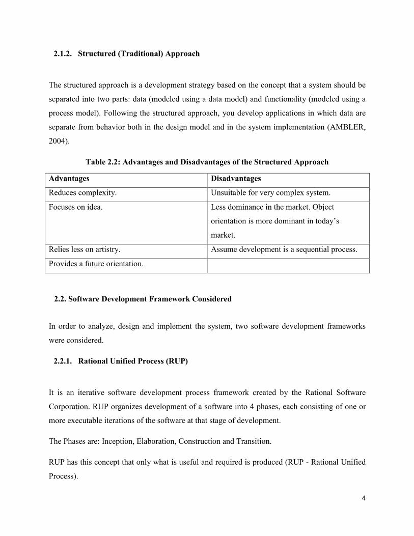
Table 2.2: Advantages and Disadvantages of the Structured Approach
Advantages Disadvantages
Reduces complexity. Unsuitable for very complex system.
Focuses on idea. Less dominance in the market. Object
orientation is more dominant in today’s
market.
Relies less on artistry. Assume development is a sequential process.
Provides a future orientation.
2.2. Software Development Framework Considered
In order to analyze, design and implement the system, two software development frameworks
were considered.
2.2.1. Rational Unified Process (RUP)
It is an iterative software development process framework created by the Rational Software
Corporation. RUP organizes development of a software into 4 phases, each consisting of one or
more executable iterations of the software at that stage of development.
The Phases are: Inception, Elaboration, Construction and Transition.
RUP has this concept that only what is useful and required is produced (RUP - Rational Unified
Process).

5
Table 2.3: Advantages and Disadvantages of Rational Unified Process
Advantages Disadvantages
Wide industry acceptance. Not well accepted by developers, increasing
the chance that they will not actually follow it.
Management seems to like it. The RUP is not (yet) complete. That is, it lacks
two phases, production and retirement. This
can how ever be addressed via extension such
Enterprise Unified Process (EUP). But, EUP
on the other hand requires significant maturity
and understanding of the RUP for
organizations to succeed at it (AMBLER,
2004).
The RUP defines comprehensive development
procedures.
RUP is missing some aspects of agile
development, such as frequent customer
interaction and increase collaboration.
Supports an evolutionary approach to
development, increasing the chance (over serial
processes) of delivering software (AMBLER,
2004).
2.2.2. Agile Unified Process (AUP)
Agile Unified Process is a simplified version of the IBM Rational Unified Process developed by
Scott Ambler. It describes a simple, easy to understand approach to developing business
application software using agile techniques and concepts yet still remaining true to the RUP. The
AUP applies agile techniques including Test-Driven Development (TDD), Agile Modeling
(AM), agile change management, and database refactoring to improve productivity (Ambler,
2006).
6
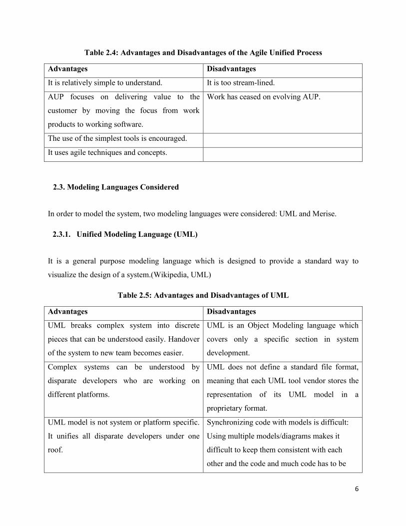
Table 2.4: Advantages and Disadvantages of the Agile Unified Process
Advantages Disadvantages
It is relatively simple to understand. It is too stream-lined.
AUP focuses on delivering value to the
customer by moving the focus from work
products to working software.
Work has ceased on evolving AUP.
The use of the simplest tools is encouraged.
It uses agile techniques and concepts.
2.3. Modeling Languages Considered
In order to model the system, two modeling languages were considered: UML and Merise.
2.3.1. Unified Modeling Language (UML)
It is a general purpose modeling language which is designed to provide a standard way to
visualize the design of a system.(Wikipedia, UML)
Table 2.5: Advantages and Disadvantages of UML
Advantages Disadvantages
UML breaks complex system into discrete
pieces that can be understood easily. Handover
of the system to new team becomes easier.
UML is an Object Modeling language which
covers only a specific section in system
development.
Complex systems can be understood by
disparate developers who are working on
different platforms.
UML does not define a standard file format,
meaning that each UML tool vendor stores the
representation of its UML model in a
proprietary format.
UML model is not system or platform specific.
It unifies all disparate developers under one
roof.
Synchronizing code with models is difficult:
Using multiple models/diagrams makes it
difficult to keep them consistent with each
other and the code and much code has to be

7
added by hand.
UML can be used to model just about any type
of application, running on any type and
combination of hardware, operating system,
programming language, and network.
It is not yet complete
2.3.2. Merise
Merise is a general purpose modeling methodology in the field of information systems
development, software engineering and project management. Merise proceeds to separate
treatment of data and processes, where the data view is modeled in three stages - from
conceptual, and logical, through to physical. Similarly, the process-oriented view passes through
the three stages of conceptual, organizational and operational. These stages in the modeling
process are paralleled by the stages of the life cycle: strategic planning, preliminary study,
detailed study, development, implementation and maintenance. It is a method of analysis based
on the entity-relationship model. By using Merise, you can design tables with relations to make a
relational database.(Wikipedia, Merise).
a. Advantages of Merise
Has some database modeling capabilities that is lacking in UML.
b. Disadvantages of Merise
Merise is a development process that didn't really catch up outside of France, and it is
being slowly abandoned in favor of UML.
2.4. Architecture of Implementation
Two software architectural patterns were considered: MVC and 3-Tier architecture.
8
2.4.1. Model, View and Controller (MVC)
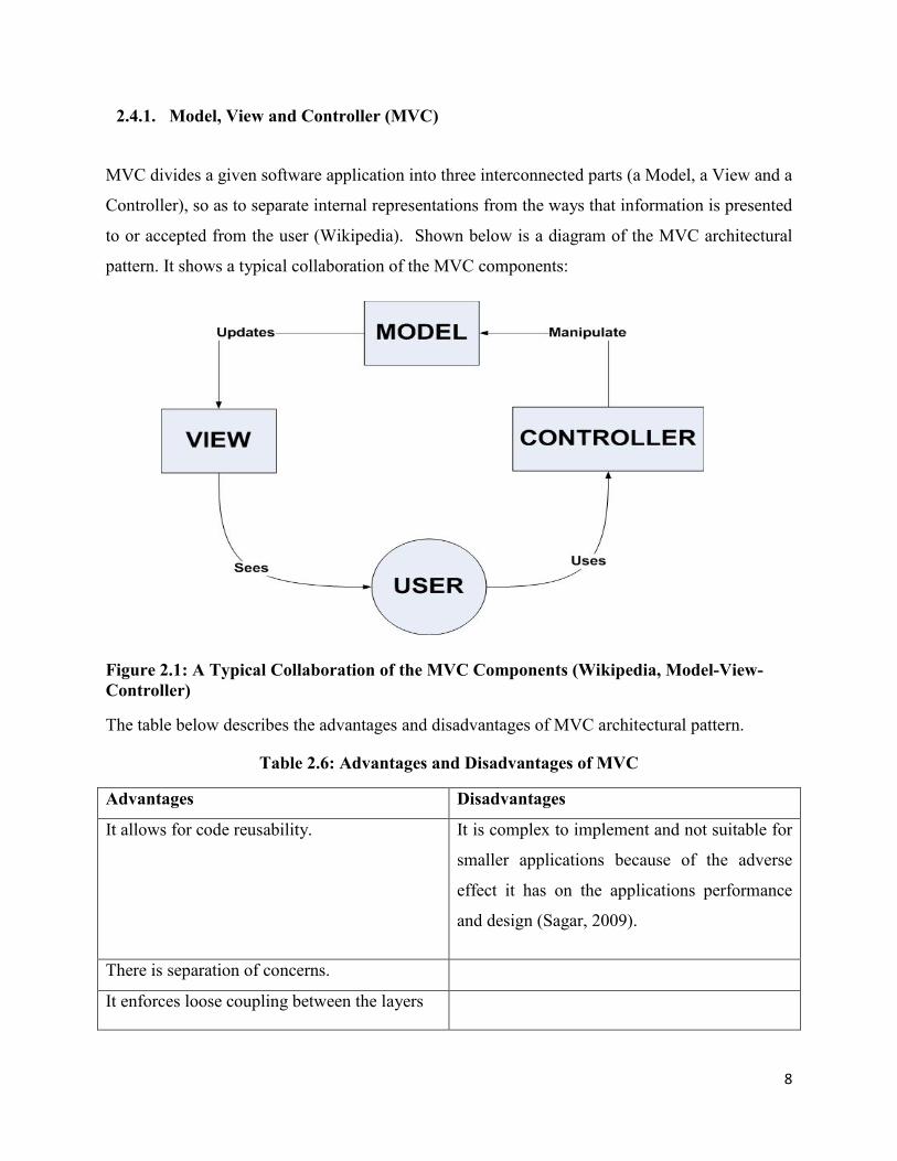
MVC divides a given software application into three interconnected parts (a Model, a View and a
Controller), so as to separate internal representations from the ways that information is presented
to or accepted from the user (Wikipedia). Shown below is a diagram of the MVC architectural
pattern. It shows a typical collaboration of the MVC components:
Figure 2.1: A Typical Collaboration of the MVC Components (Wikipedia, Model-View-Controller)
The table below describes the advantages and disadvantages of MVC architectural pattern.
Table 2.6: Advantages and Disadvantages of MVC
Advantages Disadvantages
It allows for code reusability. It is complex to implement and not suitable for
smaller applications because of the adverse
effect it has on the applications performance
and design (Sagar, 2009).
There is separation of concerns.
It enforces loose coupling between the layers

2.4.2. 3-Tier Architecture
Three-tier architecture is a client
functional process logic ("business rules"),
and maintained as independent modules
Figure 2.2: Visual overview of Architecture)
The table below describes the advantages and disadvantages of the three
pattern.
ent–server architecture in which the user interface
("business rules"), computer data storage and data access
modules.(Wikipedia, Multitier Architecture).
a Three-tiered application (Wikipedia, Multitier
The table below describes the advantages and disadvantages of the three-tiered architectural
9
user interface (presentation),
data access are developed
(Wikipedia, Multitier
tiered architectural

10
Table 2.7: Advantages and Disadvantages of the 3-Tier Architecture
Advantages Disadvantages
Managing data is independent from the
physical storage.
The physical separation of the tiers may affect
the performance between the three.
Since the client doesn’t have direct access to the database business logic is more secure
It is more difficult to build a 3-tier application.
Migration to new graphical environments is
faster.
It is more complex structure for a small
application.
As each tier is independent, it is possible to use different sets of developers.
It is possible to make changes on the
presentation level without affecting the other
two (business or data access layer).
2.5. Frameworks Considered
The programming language used for implementing the application is PHP. PHP was chosen
because of the stakeholder’s specification. In this regard, two PHP frameworks were considered:
Code Igniter and Laravel.
2.5.1. Code Igniter
CodeIgniter is an Application Development Framework - a toolkit - for people who build web
sites using PHP. Its goal is to enable you to develop projects much faster than you could if you
were writing code from scratch, by providing a rich set of libraries for commonly needed tasks,
as well as a simple interface and logical structure to access these libraries. CodeIgniter lets you
creatively focus on your project by minimizing the amount of code needed for a given task.

11
Table 2.8: Advantages and Disadvantages of Code Igniter
Advantages Disadvantages
Easy and hassle-free migration from server
hosting to server hosting.
It is not very object-oriented in some parts.
Easy to learn, adopt and deploy. PHP4 legacy code
Easy handling and customizing. Company-driven instead of community-driven.
Offers flexibility and easy management with
MVC based framework.
Irregular releases.
Active Record Implementation is simply
superb and easy to remember.
Framework itself has no built-in ORM (only
via 3rd party solutions).
Provides easier configuration and
customization of configuration files.
Facilitates easy working with a variety of
developers.
Good collection of possessed libraries.
Awesome documentation of the user guide,
which makes it easy for any coder to use the
whole framework.
Enables to incorporate its own existing scripts
as well as develop core libraries for the system.
Lightweight and extensive.
2.5.2. Laravel
Laravel is a web application framework with expressive, elegant syntax. It is a PHP framework
for web artisan. It is a framework build on a framework. Laravel attempts to take the pain out of
development by easing common tasks used in the majority of web projects, such as
authentication, routing, sessions, and caching. Laravel is accessible, yet powerful, providing
powerful tools needed for large, robust applications. A superb inversion of control container,

12
expressive migration system, and tightly integrated unit testing support enable any type of
application to be build.
Table 2.9: Advantages and Disadvantages of Laravel
Advantages Disadvantages
It supports PHP 5.3. It’s still quite new which can mean some
instability with the code.
It is more object oriented.
Because of its newness, the options for finding
answers are still limited.
It has an eloquent ORM
It has a built in authentication.
2.6. Database Synchronization Technology
In order to synchronize the databases of both systems (IMS and OAP), MySQL replication was
considered. MySQL replication enables data from one MySQL database server (the master) to be
replicated to one or more MySQL database servers (the slaves). Replication is asynchronous by
default. The slaves need not to be connected permanently to receive updates from the master.
Depending on the configuration, the whole database or selected tables within a database can be
replicated. Replication is base on the binary logging mechanism. The MySQL instance operating
as the master (the source of the database changes) writes updates as “events” to the binary log.
Slaves are configured to read the binary log from the master and to execute the events in the
binary log on the slave’s local database. Each slave must be configured with information about
the master host name, log file name, and position within that file (MySQL 5.6 Reference
Manual, 2012).
2.6.1. Replication Formats
The different replication formats considered include the following: Statement Based Replication,
Row Based Replication, Mixed Based Replication and Transactional Replication.
i. Statement Based Replication (SBR)

13
This type of replication replicates the entire SQL statements between the two servers.
Table 2.10: Advantages and Disadvantages of Statement Based Replication
Advantages Disadvantages
Proven technology that has existed in MySQL since 3.23.
Not all statements which modify data (such as INSERT, DELETE, UPDATE, and REPLACE statements) can be replicated using statement-based replication.
Less data written to log files. When updates or
deletes affect many rows, these results in much
less storage space required for log files. This
also means that taking and restoring from
backups can be accomplished more quickly.
INSERT and SELECT requires a greater
number of row-level locks than with row-based
replication.
Log files contain all statements that made any
changes, so they can be used to audit the
database.
UPDATE statements that require a table scan
(because no index is used in the WHERE
clause) must lock a greater number of rows
than with row-based replication.
For InnoDB: An INSERT statement that uses
AUTO_INCREMENT blocks other non
conflicting INSERT statements.
For complex statements, the statement must be
evaluated and executed on the slave before the
rows are updated or inserted. With row-based
replication, the slave only has to modify the
affected rows, not execute the full statement.
If there is an error in evaluation on the slave,
particularly when executing complex
statements, statement-based replication may
slowly increase the margin of error across the
affected rows over time.
Table definitions must be (nearly) identical on
master and slave.

14
ii. Row Based Replication (RBR)
This type of replication replicates only the changed rows.
Table 2.11: Advantages and Disadvantages of Row Based Replication
Advantages Disadvantages
All changes can be replicated. This is the safest
form of replication.
RBR tends to generate more data that must be
logged.
The technology is the same as in most other
database management systems.
You cannot examine the logs to see what
statements were executed, nor can you see on
the slave what statements were received from
the master and executed.
Fewer row locks are required on the master, which thus achieves higher concurrency, for the following types of statements:
• INSERT and SELECT. • INSERT statements with
AUTO_INCREMENT. • UPDATE or DELETE statements
with WHERE clauses that do not use keys or do not change most of the examined rows.
For tables using the MyISAM storage engine, a
stronger lock is required on the slave for
INSERT statements when applying them as
row-based events to the binary log than when
applying them as statements. This means that
concurrent inserts on MyISAM tables are not
supported when using row-based replication.
Fewer row locks are required on the slave for any INSERT, UPDATE, or DELETE statement.
iii. Mixed Based Replication
Mixed replication format uses SBR or RBR automatically to take advantage of the benefits of
both SBR and RBR format when appropriate. Mixed replication format provide the best
combination of data integrity and performance.

15
iv. Transactional Replication
This type of replication is based on the Global Transaction Identifier (GTID). When using this
type of replication, it is not necessary to work directly with log files or positions within these
files, which greatly simplifies many common replication tasks. Because replication using GTID
is entirely transactional, consistency between the master and slave is guaranteed as long as all
transactions committed on the master have also been applied on the slave.
2.6.2. Replication Levels
Two replication levels were considered: Database level and the Table level.
The Database Level replication option allows replication of the entire database while the Table
level replication option allows replication at the table level enabling the possibility to replicate
only specific tables.
2.6.3. Replication Approach
Two replication approaches were considered: One-way (or Master-Slave) replication and Two
way (or Master-Master or Multi master) replication.
One-way replication approach allows one server to be configured as the Master and the other as
the slave. Changes in the Master are automatically replicated to the slaves but not the other way
round.
Two-way replication allows both servers to be configured as Masters. Changes that occurred in
both servers are replicated to each other. In this approach, the 2nd Master acts as a slave to the
first while the 1st Master acts as a slave to the 2nd Master.

16
2.7. File Transfer Technology
Applicant’s documents must be fetched from the Online Application Portal to the Internship
Management System. In this regard, two file transfer technology were considered: rsync and scp
2.7.1. Rsync
Rsync is a file synchronization and file transfer program for Unix-like systems that minimizes
network data transfer by using a form of delta encoding called the rsync algorithm (Wikipedia,
rsync). Rsync can be used to copy directory in a local machine, synchronize directory in a local
machine, synchronize file between folders without overwriting file on the destination, copy file
or folder from local machine to remote machine, copy folder from remote machine to local
machine and synchronize folder from remote to local machine ( executed on local machine).
2.7.2. Scp (Secure copy)
Scp allows files to be copied to, from, or between different hosts. It uses ssh for data transfer and
provides the same authentication and same level of security as ssh.
In the next chapter, improvements that this project will bring to the existing system for the
management of internship are explained.
17
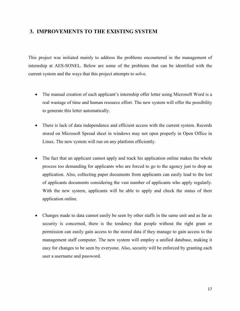
3. IMPROVEMENTS TO THE EXISTING SYSTEM
This project was initiated mainly to address the problems encountered in the management of
internship at AES-SONEL. Below are some of the problems that can be identified with the
current system and the ways that this project attempts to solve.
The manual creation of each applicant’s internship offer letter using Microsoft Word is a
real wastage of time and human resource effort. The new system will offer the possibility
to generate this letter automatically.
There is lack of data independence and efficient access with the current system. Records
stored on Microsoft Spread sheet in windows may not open properly in Open Office in
Linux. The new system will run on any platform efficiently.
The fact that an applicant cannot apply and track his application online makes the whole
process too demanding for applicants who are forced to go to the agency just to drop an
application. Also, collecting paper documents from applicants can easily lead to the lost
of applicants documents considering the vast number of applicants who apply regularly.
With the new system, applicants will be able to apply and check the status of their
application online.
Changes made to data cannot easily be seen by other staffs in the same unit and as far as
security is concerned, there is the tendency that people without the right grant or
permission can easily gain access to the stored data if they manage to gain access to the
management staff computer. The new system will employ a unified database, making it
easy for changes to be seen by everyone. Also, security will be enforced by granting each
user a username and password.

18
The new system will offer the possibility to track and trace human errors. Also, because
many aspects will be automated (such as the automatic creation of internship offer letters,
reports etc), human error is reduced.
The fact that the current system is not web-based, it is impossible to manage internship
remotely. Since the new system is web-based and will run on a webserver, remote access
is possible via a network.
The problem of data redundancy is also addressed as records will be stored in a well
normalized database. Thus, the new system benefits from the advantages of a database
management system.
In the next chapter, the methodology adopted from the review of literature is explained.

19
4. METHODOLOGY ADOPTED
This chapter provides a combination of the methods by which the project was conducted and
controlled, and also, the software development method applied. In addition, arguments are
provided regarding the methods chosen.
The object oriented approach and the Rational Unified Process (RUP) framework to software
development was adopted to analyze, design and implement the software system. Rationale for
adopting the object oriented approach and RUP framework is explained below:
4.1. Rationale for Adopting the Object Oriented Approach
The Object Oriented Approach was adopted over the Structured Approach because of the
following reasons:
The complexity of this project.
My familiarity with the approach.
Much more suitable for this project.
The dominance of object oriented paradigm and its related technologies in market and industry.
The technical and theoretical capabilities of the method.
The wide acceptance in industry.
Wide range of development languages and tools to choose from.
4.2. Rationale for Adopting the Rational Unified Process
RUP framework was adopted over the Agile Unified Process (AUP) framework because of the
following reasons:
My familiarity with the framework.
My interest in a detailed and well-defined software process.
20
RUP was much more suitable for this project. AUP encourages frequent client interaction
and increase collaboration (good idea), which was not the case in this project as clients
were usually very busy. Thus, adopting AUP will have resulted in requirements that will
suffer.
Lastly, the author of AUP (Scott Ambler) stopped work on it in 2006.
The Unified Modeling Language was used to model the system. Reasons for choosing UML over
Merise are explained below.
4.3. Rationale for Choosing UML
The Unified Modeling Language (UML) was chosen over Merise because of the following
reasons:
My Familiarity with UML.
The dominance of UML in the market. Merise is only well known in France.
Stakeholder specification.
The architecture of implementation adopted was the MVC architectural pattern. This pattern was
chosen because the application was to be developed using PHP and most PHP frameworks are
MVC based. The PHP framework used is Code Igniter. Code Igniter was chosen because of the
following reasons:
4.4. Reasons for Using Code Igniter Framework
It has been around for a long time and thus is easy to find answers on the web.
It has a light footprint.
4.5. Replication and File Transfer Technology Adopted

21
Table level replication option was adopted because only specific tables of both systems (IMS and
OAP) were to be synchronized. Furthermore, the mixed replication format was adopted because
it provides the best combination of data integrity and performance.
The replication approach adopted was the Master-Master or two way replication. Two way
replication approach was adopted because changes that occur (writes) in each database was to be
synchronize to the other.
Rsync was the technology used for file transfer. Rsync was used because it support file or folder
copy to and from local and remote machine. Additionally, after the first file transfer, only the
changed files will be copied in subsequent attempts which make the process much faster. Lastly,
rsync was highly recommended by expert in forums.
In the next chapter, detail explanation of the requirements specification for both systems is
provided.

22
5. REQUIREMENTS ANALYSIS
This chapter explains specifically how the requirements of the software systems were captured. It
provides the functional and non functional requirements of the system.
The requirements for both systems (Internship Management System and Online Application
Portal) were captured in the Requirements Analysis and Definition phase of the project. This was
done via preparation of questionnaires with sample questions for the client to answer. Also,
weekly meeting sessions were organized for face-to-face conservations with the client. In each
meeting session, audio recorder was used to capture the conversation, hence enforcing better
requirements capture.
After the requirements were captured, a Software Requirement Specification (SRS) document
was produced. The entire document was developed separately and is included in a CD attached
to this report.
Illustrated below are the functional and non functional requirements of the systems. The
following labels are used to prioritize the requirements:
Must have – Refers to those requirements that together create the core functionalities of the
system.
Should have – Refers to those requirements that although are not part of the core functionalities,
however, they can be very useful and will be implemented if the project schedule allows to do
so.
Nice to have – Refers to those requirements that do not play a main role in the functionality of
the system, at least at the scope of this project; however, they would give more facilities to the
users if the schedule allows them to be implemented.
The labels are given the following prefix: M to “Must have”, S to “Should have” and N to “Nice
to have”
23
5.1. Functional Requirements
Functional requirements are those features of the system by which the system fulfills the core
responsibility that is expected to accomplish (Hassani, 2012).
5.1.1. Functional Requirements of the Internship Management System (IMS)
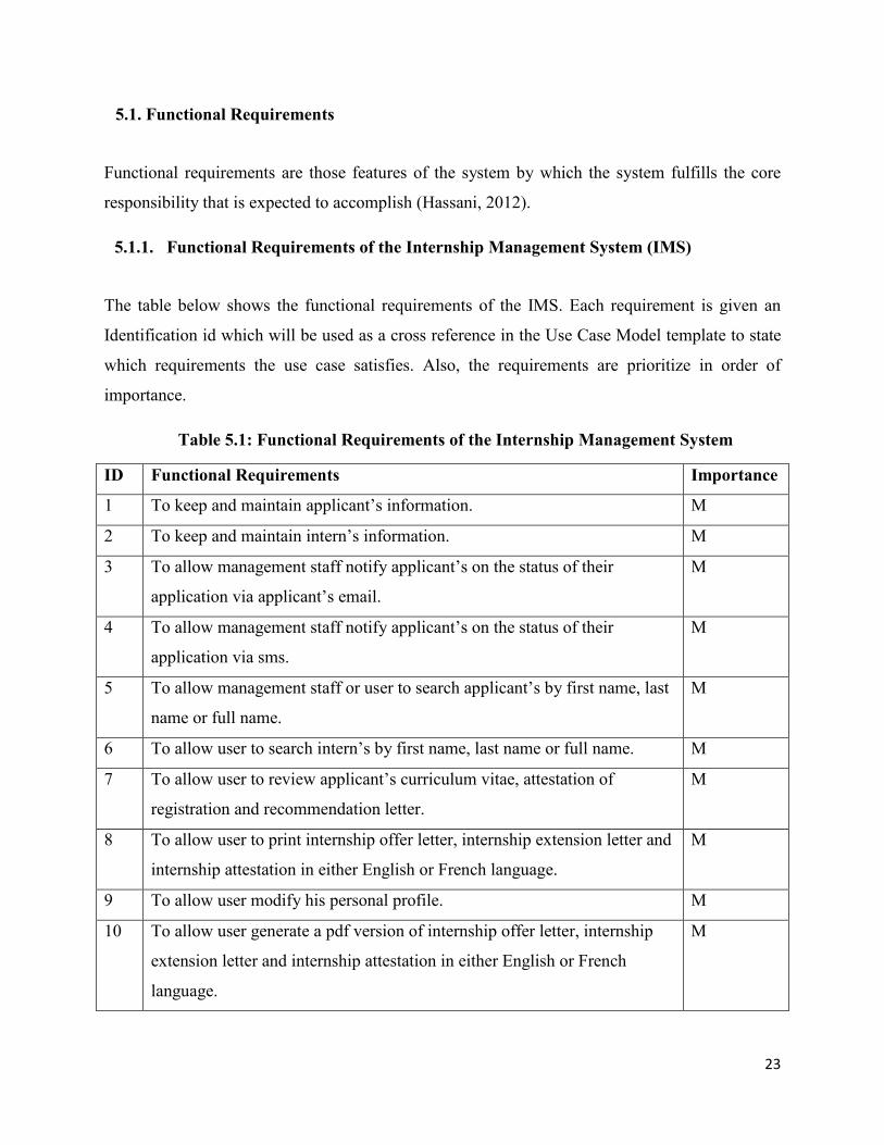
The table below shows the functional requirements of the IMS. Each requirement is given an
Identification id which will be used as a cross reference in the Use Case Model template to state
which requirements the use case satisfies. Also, the requirements are prioritize in order of
importance.
Table 5.1: Functional Requirements of the Internship Management System
ID Functional Requirements Importance
1 To keep and maintain applicant’s information. M
2 To keep and maintain intern’s information. M
3 To allow management staff notify applicant’s on the status of their
application via applicant’s email.
M
4 To allow management staff notify applicant’s on the status of their
application via sms.
M
5 To allow management staff or user to search applicant’s by first name, last
name or full name.
M
6 To allow user to search intern’s by first name, last name or full name. M
7 To allow user to review applicant’s curriculum vitae, attestation of
registration and recommendation letter.
M
8 To allow user to print internship offer letter, internship extension letter and
internship attestation in either English or French language.
M
9 To allow user modify his personal profile. M
10 To allow user generate a pdf version of internship offer letter, internship
extension letter and internship attestation in either English or French
language.
M

24
ID Functional Requirements Importance
11 To keep and maintain internship supervisors information. M
12 To keep and maintain signatories information. M
13 To keep and maintain different units in the organization. M
14 To allow manager to create or add a new staff to the system. M
15 To automatically generate report on the number of applications received
per month, per year or within a given period.
M
16 To automatically generate report on the number applicant’s accepted per
month, per year, within a given period, per fields of study, per university,
per unit of welcome and per region.
M
17 To automatically generate report on the number of internship reports
received per month, year or within a given period.
M
18 To automatically generate report on the number of intern’s evaluated per
month, year, or within a given period.
M
19 To provide reports on intern’s with an excellent remark. M
20 To provide reports on the number of evaluation files received. M
21 To provide a list of applicant’s whose internship offer letter is ready. M
22 To provide a list of intern’s whose internship attestation is ready. M
23 To fetch all applications from the Online Application Portal. M
24 To synchronize with the Online Application Portal database. That’s, they
must be data exchange between the two databases.
M
25 To allow manager to manage recorded logs. M
26 To allow other staff members to view recorded logs. M
More details are included in the Software Requirement Specification document which has been
included in the CD attached to this report.

25
5.1.2. Functional Requirements of the Online Application Portal (OAP)
The table below shows the functional requirements of the OAP. Each requirement is given an
Identification id which will be used as a cross reference in the Use Case Model template to state
which requirements the use case satisfies. Also, the requirements are prioritize in order of
importance.
Table 5.2: Functional Requirements of the Online Application Portal
ID Functional Requirements Importance
27 To allow applicant to create an account. M
28 To allow applicant to create an application. M
29 To allow applicant to edit his application. M
30 To allow applicant to save his application and complete it in different
sessions.
M
31 To allow applicant to submit his application. M
32 To allow applicant to check the status of his application. M
34 To allow applicant to modify his personal profile. M
35 To allow applicant to share a testimonial about his internship experience. M
36 To allow applicant to recover his password. M
37 To record each successful login attempts in a log file. M
38 To allow administrators to login and manage the portal. M
39 To allow an admin to add a new admin to the system. M
40 To allow an admin to modify his profile. M
More details are included in the Software Requirement Specification document which has been
included in the CD attached to this report.

26
5.2. Non Functional Requirements
Non Functional requirements define the needs in terms of performance, logical database
requirements, design constraints, standards compliance, reliability, availability, security, and
maintainability.
5.2.1. Non Functional Requirements of the Internship Management System (IMS)
The table below shows the non functional requirements of the IMS. Each non functional
requirement is indicated in the left column, while the right column indicates what the system
must fulfill to satisfy the requirement.
Table 5.3: Non Functional Requirements of the IMS
Requirements Category Description
Performance Requirement The load time for user interface screens shall take no longer than five seconds.
The login information shall be verified within five seconds.
Queries shall return results within five seconds.
Design Constraints The Internship Management System shall be a
web-based application.
Standard Compliance There shall be consistency in variable names
within the system. The graphical user interface
shall have a consistent skin.
Reliability The Internship Management System must be
highly reliable and should easily recover from
errors.
Availability The Internship Management System shall be available 99.99% of time during normal working hours.
Security Access to the individual user account will be

27
protected by a user login screen that requires a
username and password. To further enhance
the security of the system, all passwords will
be stored in encrypted format. Also, each
successful login attempt shall be recorded in a
log file.
Maintainability The system must be easy to maintain.
More details are included in the Software Requirement Specification document which has been
included in the CD attached to this report.
5.2.2. Non functional Requirements of the Online Application Portal (OAP)
The table below shows the non functional requirements of the OAP. Each non functional
requirement is indicated in the left column, while the right column indicates what the system
must fulfill to satisfy the requirement.
Table 5.4: Non Functional Requirements of the OAP
Requirements Category Description
Performance Requirement The load time for user interface screens shall take no longer than five seconds.
The login information shall be verified within five seconds.
Queries shall return results within five seconds.
Design Constraints The Online Application Portal requires each
applicant to have an email address in order to
create an account.
Standard Compliance There shall be consistency in variable names
within the system. The user interface shall have

28
a consistent skin.
Reliability The portal must be highly reliable. Instructive
messages shall be provided at various places to
guide users.
Availability The Online Application Portal shall be
available all the time.
Security Access to the individual user account will be
protected by a user login screen that requires a
username and password. To further enhance
the security of the system, all passwords will
be stored in encrypted format. Also, each
successful login attempt shall be recorded in a
log file.
Maintainability The portal must be easy to maintain
More details are included in the Software Requirement Specification document which has been
included in the CD attached to this report.
In the next chapter, explanation is provided on how both systems were analyzed and designed.

29
6. DESIGN
This chapter provides details on how both systems were analyzed and designed. Design refers to
coming out with a blueprint of the system. Also, this chapter shows how the application will
meet the requirements specified in the Software Requirements Specification (SRS) document. It
describes the rationale for design decisions taken and provides a basis for implementation and
unit test. The Object Oriented Approach and Rational Unified Process (RUP) were used
specifically to analyze and design the system. A detail Software Design Document (SDD) for
each system was produced on a separate document. Both documents are included in the CD
attached to this report.
6.1. Use Case Modeling
Use Case Modeling is a powerful modeling technique that can be used to capture and organize
requirements. Use Case Modeling has two perspectives, a Use Case Diagram and a Use Case
Model template which simplifies the explanation of the use case. Shown below is the use case
diagram for both the Internship Management System (IMS) and Online Application Portal
(OAP).

30
a. Use Case Diagram of the Online Application Portal
Figure 6.1: Use Case Diagram of the Online Application Portal
Detail explanation of the use case diagram is provided in a Use Case document which have been
developed separately and included in the CD attached to this report.

31
b. Use Case Diagram of the Internship Management System
Figure 6.2: Use Case Diagram of the Internship Management System
Detail explanation of the use case diagram is provided in a Use Case document which have been
developed separately and included in the CD attached to this report.

32
6.2. User Interface Design
User Interface Design describes the functionality of the system from the user’s perspective. That
is, it explains how the users will use the system to complete all the expected features and the
feedback information that will be displayed for the user. In this case, UML Activity diagram and
State Chart diagram are used to design the UI. Also, following the diagrams are screen sketches
of the major UI elements.
6.2.1. Activity Diagrams
Activity diagrams model the behaviors of a system and the way in which these behaviors are
related in an overall flow of the system (Sparks, 2014).

33
a. Activity Diagram of the Online Application Portal
Figure 6.3: Activity Diagram of the OAP

34
b. Activity Diagram of the Internship Management System
Figure 6.4: Activity Diagram of the IMS (Behavior of an employee and the system)
35
More activity diagrams are provided in the respective SDD documents for each system. These
documents are included in the CD attached to this report.
6.2.2. State Chart Diagrams
State Chart diagram illustrates how an element (often a Class) can move between states,
classifying its behavior according to transition triggers and constraining guards. Other aspects of
State Chart diagrams further depict and explain movement and behavior (Sparks, 2014).

36
a. State Chart Diagram of the Online Application Portal
Figure 6.5: State Chart Diagram of the OAP

37
b. State Chart Diagram of the Internship Management System
Figure 6.6: State Chart Diagram of the IMS (Behavior of the Manager and the system)

38
More state chart diagrams are provided in the respective SDD documents for each system. These
documents are included in the CD attached to this report.
6.2.3. Screen Shots/Sketches for UI Design
The screen shots below show the major UI elements of both systems. The screenshots are taken
from Mozilla Firefox and only HTML5, CSS3 and JQUERY are used in designing the user
interfaces.
a. Major UI elements for the Online Application Portal
Figure 6.7: UI for the Home Page

39
Figure 6.8: UI for the Password Recovery Page
Figure 6.9: UI for Creating an Account

40
Figure 6.10: UI for Creating an Application
Figure 6.11: UI for Admin Login

41
Figure 6.12: UI for Admin Profile
Figure 6.13: UI for Viewing Recorded Logs
More UI diagrams for the Online Application Portal are included in Appendix E.

42
b. Major UI elements for the Internship Management System
Figure 6.14: UI for Searching an Applicant
Figure 6.15: UI for Sending an sms

43
Figure 6.16: UI for Sending an Email
More UI diagrams for the Internship Management System are included in Appendix F.
6.3. Information Domain Modeling
Information Domain Modeling models the information domain of the systems. It shows how
different entities (people, things, and data) relate to each other; in other words, it shows the static
structures of the system. It typically shows the kind of things business people talk about in an
organization (Bell). Class diagram was used to model the information domain for both systems.
6.3.1. Class Diagram of the Online Application Portal
Shown below is a class diagram of the OAP. Detail explanation of each class member function is
found on page 9 and page 20 of the SDD for the OAP.

44
Figure 6.17: Class Diagram of the OAP

45
6.3.2. Class Diagram of the Internship Management System
Shown below is a class diagram of the IMS. Detail explanation of each class member function is
found in the SDD for the IMS. The SDD is included in the CD attached to this report.
Figure 6.18: Class Diagram of the IMS

46
6.4. Data Modeling
This section describes how the information domain described above is transformed into data
structures. It provides a description of how the major entities are stored, processed and
organized. Data Modeling in this context is also referred to as Conceptual Database Design.
Because an object oriented methodology is used to analyze and design the system, the classes in
the information domain modeling are mapped into Entity Relationship Diagram (ERD).
Provided, below are Extended Entity Relationship (EER) diagrams for both systems.
6.4.1. EER Diagram of the OAP
Figure 6.19: EER Diagram of the OAP

47
6.4.2. EER Diagram of the IMS
Figure 6.20: EER Diagram of the IMS

48
6.5. Physical Database Design
This refers to transforming the conceptual database design to relational tables. Here, data
dictionary is provided showing the different tables of the application.
6.5.1. Data Dictionary for the Internship Management System
Table 6.1: Sessions Table
Column Type Null Default session_id varchar(40) No 0 ip_address varchar(45) No 0 user_agent varchar(120) No last_activity int(10) No 0 user_data Text No
Table 6.2: Academics Table
Column Type Null Default Links to academic_id int(11) No applicant_id int(11) No applicants-
>applicant_id institution_name varchar(100) No institution_location varchar(100) No Field varchar(255) No Specialty varchar(45) Yes NULL Level int(2) No degree_program varchar(45) No graduation_date Date Yes NULL anticipated_graduation_date varchar(15) Yes NULL institution_country char(2) No
Table 6.3: Applicants Table
Column Type Null Default Links to applicant_id int(11) No last_name varchar(50) No first_name varchar(50) No birth_date Date No Gender char(1) No country_of_residence char(2) No countries-
country_code

49
Phone varchar(25) Yes NULL Language varchar(25) No Email varchar(50) No City varchar(255) No country_of_citizenship char(2) No countries-
country_code account_id int(11) Yes NULL
Table 6.4: Applications Table
Column Type Null Default Links to application_id int(11) No applicant_id int(11) No applicants-
>applicant_id application_code char(10) Yes NULL internship_type varchar(25) Yes NULL domain_of_interest varchar(255) Yes NULL custom_domain varchar(255) Yes NULL Motivation Text Yes NULL start_date Date Yes NULL end_date Date Yes NULL proposed_start_date Date Yes NULL proposed_end_date Date Yes NULL
submission_date int(11) Yes NULL submission_id varchar(6) Yes NULL application_status varchar(15) No statuses-
>status_code admission_acceptance varchar(3) NULL application_type char(10) No INTERNSHIP State tinyint(1) No 0 creation_date Datetime No Cancel tinyint(1) No 0
Table 6.5: Configurations Table
Column Type Null Default configuration_id int (11) No config_key varchar(255) Yes Null config_value varchar(255) Yes Null

50
Table 6.6: Countries Table
Column Type Null Default country_code int (11) No country_name varchar(45) No Currency varchar(30) No cur_code char(3) No Symbol varchar(20) Yes NULL
Table 6.7: Documents Table
Column Type Null Default Links to document_id int(11) No application_id int(11) No applications-
>application_id document_name varchar(100) No document_type varchar(100) No document_size varchar(255) No original_name varchar(45) No raw_name int(2) No upload_date varchar(45) No
Table 6.8: Internships Table
Column Type Null Default Links to internship_id int(11) No applicant_id int(11) No applicants-
>applicant_id application_id int(11) No applications-
>application_id unit_code varchar(10) No units->unit_code internship_location Text No Region varchar(45) No Town varchar(45) No Branch varchar(50) No effective_start_date Date No
presume_end_date Date No final_end_date Date No supervisor_id Int(11) No supervisors-
>supervisor_id internship_theme Text Yes NULL final_evaluation Float Yes NULL Remark varchar(25) Yes NULL report_status tinyint(1) No 0

51
admission_letter_status tinyint(1) No 0 attestation_status tinyint(1) No 0 admission_letter_creation_date Datetime Yes NULL attestation_creation_date Datetime Yes NULL intern_status tinyint(1) No 1 Intern_attendance tinyint(1) No 0
Table 6.9: Trainings Table
Column Type Null Default Links to training_id int(11) No applicant_id int(11) No applicants-
>applicant_id training_type varchar(255) Yes NULL date_completed Date Yes NULL
anticipated_completion_date varchar(15) Yes NULL
More tables for the Internship Management System are included in a separate document called
Data Dictionary. This document is included in the CD attached to this report.
6.5.2. Data Dictionary for the Online Application Portal (OAP)
The tables, Applicants, Academics, Trainings, Applications and Documents for the Online
Application Portal have the same structure as that of the Internship Management System shown
above. Those were the tables involved in data synchronization. More tables for the OAP include
the following:
Experience Table – For storing intern’s internship experience
Account Table – For storing online accounts
Page Table – For storing pages
Subject Table - For storing different subjects
Administrator Table - For storing administrators account
Detail structure for all these tables is included in a separate document called data dictionary
which has been included in the CD attached to this report.
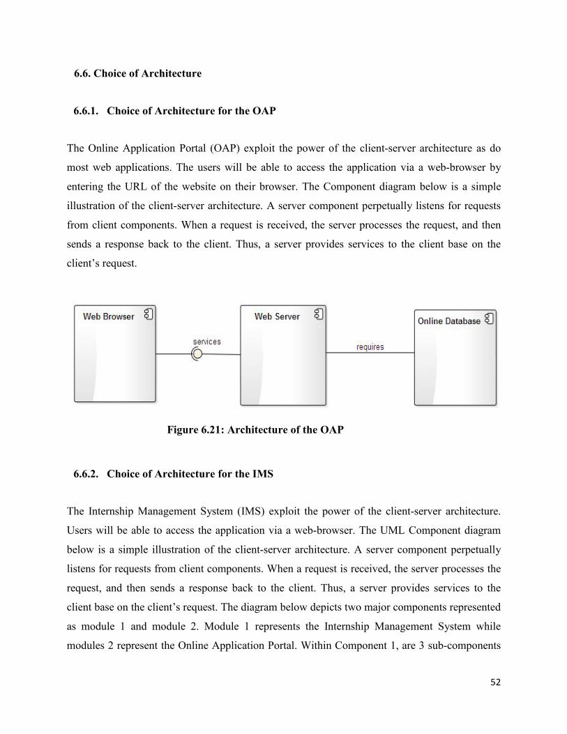
52
6.6. Choice of Architecture
6.6.1. Choice of Architecture for the OAP
The Online Application Portal (OAP) exploit the power of the client-server architecture as do
most web applications. The users will be able to access the application via a web-browser by
entering the URL of the website on their browser. The Component diagram below is a simple
illustration of the client-server architecture. A server component perpetually listens for requests
from client components. When a request is received, the server processes the request, and then
sends a response back to the client. Thus, a server provides services to the client base on the
client’s request.
Figure 6.21: Architecture of the OAP
6.6.2. Choice of Architecture for the IMS
The Internship Management System (IMS) exploit the power of the client-server architecture.
Users will be able to access the application via a web-browser. The UML Component diagram
below is a simple illustration of the client-server architecture. A server component perpetually
listens for requests from client components. When a request is received, the server processes the
request, and then sends a response back to the client. Thus, a server provides services to the
client base on the client’s request. The diagram below depicts two major components represented
as module 1 and module 2. Module 1 represents the Internship Management System while
modules 2 represent the Online Application Portal. Within Component 1, are 3 sub-components

53
which illustrate the client-server architecture of the Internship Management System. Also, the
relation called “synchronization logic” indicates that Component 1 (IMS) provide the logic for
communicating with the Online Application Portal.
Figure 6.22: Architecture of the IMS

54
6.6.3. Rationale for Choosing the Client Server Architecture
A Client-Server Architecture consists of two types of components: clients and servers. A server
component perpetually listens for requests from client components. When a request is received,
the server processes the request, and then sends a response back to the client. Below are the
benefits of the Client-Server architecture:
a. Data Processing capability despite the location
We are in an era which undergoes a transformation from machine-centred systems to user
centred systems. Through a client/server system users can directly log into a system despite of
the location or technology of the processors.
b. Easy maintenance
Since client/server architecture is a distributed model representing dispersed responsibilities
among independent computers integrated across a network, it’s an advantage in terms of
maintenance. It’s easy to replace, repair, upgrade and relocate a server while clients remain
unaffected. This unawareness of change is called encapsulation.
c. Security
Servers have better control access and resources to ensure that only authorized clients can access
or manipulate data and server-updates are administered effectively.
d. Flexibility
Client-Server architecture is flexible and hence allows new technology to be easily integrated.
e. Scalability
Client-Server architecture is scalable hence new features can be upgraded when needed.
f. Centralization

55
Access, resources and data security are controlled through the server.
g. Interoperability
All components (clients, network, and servers) work together.
Base on these benefits, the Client-Server architecture was chosen.
The next chapter explains how both systems were implemented highlighting specifically
implementation decisions.

56
7. IMPLEMENTATION
Implementation in this context refers to programming. This is the phase that gave “birth” to the
system. The outputs from the analysis and design phase are used as input in this phase. The main
activity in this phase is programming.
7.1. Programming Languages and Tools Used
a. Languages
PHP (Hypertext Preprocessor) – Language used to program the logic of the system.
Specifically, Code Igniter framework was used.
JavaScript and Jquery Library – was used to enhance the look and feel of the system. It
was also used to improve usability.
Ajax – Was used for form submission and to improve usability.
HTML5 – Was used to design the graphical user interface.
CSS3 – Was used to design the graphical user interface.
Unified Modeling Language (UML) – Language used to develop a model for the system.
C Programming Language – Was used to count the number of distinct occurrences of
languages in a text file and sort them out in alphabetical order for used in a web form.
b. Software Packages and Tools Used
Planner (version 0.14.6) – Was used to develop the software development project plan for
the project.
Microsoft Visio (version 10) - Was used in the requirements phase to design basic
templates of how the system was going to look like.

57
Enterprise Architect (version 10.0) - Was used to draw the UML diagrams.
Komodo Edit, version 8.5.3 – Text editor used for coding the system.
JetBrainsPhpStorm 6.0.2 – IDE used for coding the system.
Google Chrome (Version 32.0.1700.77), Firefox (version 28), Safari and Internet
Explorer were the browsers used for testing the system.
MySQL Workbench – Was used to develop the Extended Entity Relationship (EER)
diagram.
XAMPP for Linux (Version 1.8.3-1) - It includes the following packages:
Web Server (Apache, version 2.4.4)
PHP, version 5.5.3
Database (MySQL, version 5.6.12)
Linux mint 17 (64 bits) and Windows 7 (64bits) were the platforms used for
development.
7.2. C Code Used to Read a Text File of Languages in the World and Sort them in
Alphabetic Order.
Shown below is a c program used to sort languages of the world in disorganized order in a text
file to alphabetical order for used in a web form. The program uses the binary tree data structure.
The tree contains one node per distinct language. Each node contains:
A pointer to the text of the language
A pointer to the left child node
A pointer to the right child node
No node may have more than two children.
The tree is printed to an output file following an “in order traversal” manner so that the result is
always sorted out in alphabetic order.

58
1. #include <stdio.h>
2. #include <stdlib.h>
3. #include <string.h>
4.
5. typedef struct tnode *LANGUAGE;
6. struct tnode{
7. char *language;
8. LANGUAGE *left; /* left Child */
9. LANGUAGE *right; /* right Child */
10. };
11.
12. LANGUAGE addtree(LANGUAGE, char *);
13. void treeprint(LANGUAGE, FILE *);
14. LANGUAGE root;
15. LANGUAGE talloc(void);
16. char *dupstr(char *);
17.
18. int main(int argc, char **argv){
19. FILE *in, *out;
20. const char * fn = "languages.txt";
21. const char * dest = "sorted_languages.txt";
22. char buff[128];
23. root = NULL; /* empty tree */
24.
25. if((in = fopen(fn, "rb")) == NULL){
26. printf("Cannot open input file.\n");
27. exit(1);
28. }
29.
30. /* Read languages from the file and add to a tree node */

59
31. while (fgets(buff, sizeof buff, in)) {
32. root = addtree(root, buff);
33. }
34.
35. out = fopen(dest, "wb");
36. fprintf(out,"+----------------+\n");
37. fprintf(out,"|%16s|\n","Sorted Languages");
38. fprintf(out,"+----------------+\n");
39. treeprint(root, out);
40. printf("File Sorted!!!\n");
41. fclose(in);
42. fclose(out);
43. return 0;
44. }
45.
46. /* addtree: add a node with l, at or below p */
47. LANGUAGE addtree(LANGUAGE p, char *l){
48. int cond;
49. if (p == NULL){
50. p = talloc();
51. p -> language = dupstr(l);
52. p -> left = p -> right = NULL;
53. }else if ((cond = strcmp(l, p -> language)) < 0)
54. p -> left = addtree(p -> left, l);
55. else if (cond > 0)
56. p -> right = addtree(p -> right, l);
57. else ;
58.
59. return p;
60. }

60
61.
62. /* treeprint: in-order print of tree p */
63. void treeprint(LANGUAGE p, FILE *out){
64.
65. if (p != NULL) {
66. treeprint(p -> left, out);
67. fprintf(out,"%s\n", p -> language);
68. treeprint(p -> right, out);
69. }
70. }
71.
72. /* talloc: make a tree node */
73. LANGUAGE talloc(void) {
74. return (LANGUAGE) malloc(sizeof(struct tnode));
75. }
76.
77. /* duplicate a string */
78. char *dupstr(char *s){
79. char *p;
80. /* make a duplicate of n */
81. p = (char *) malloc(strlen(s) + 1);
82. if (p != NULL)
83. strcpy(p, s);
84. return p;
85. free(p);
86. }

61
7.3. Steps to Configure Master-Master Replication at the Table-level
In this sub section, an explanation is provided on how the two systems were synchronized.
Master-Master replication was the mechanism used to enforce synchronization. Below is an
explanation of how the two servers were configured for replication.
The Online Application Portal installed on one computer, was designated Master1/Slave2 while
the Internship Management System installed on another computer, was designated Master
2/Slave 1.
7.3.1. Configuration for Master2/Slave1 (IMS)
The ip address for this server was set to 192.168.0.1 while that of the other server was set
to 192.168.0.2.
my.cnf file was edited with the following information included under [mysqld] section
Skip-networking was disabled by commenting it.
log-bin=mysql-bin
binlog_format=MIXED (specify to use mixed replication format)
server-id=2 (each server must have unique server-id in the range 1 to 2^32 – 1)
replicate-same-server-id = 0
auto-increment-increment = 2
auto-increment-offset = 1
binlog-do-db=ims_repl (Specify the database to considered for replication – The
name of the database for both systems must be the same)
Since the Table-level replication option was adopted, the tables involved are specified.
replicate-do-table=ims_repl.applicants
replicate-do-table=ims_repl.academics
replicate-do-table=ims_repl.trainings
replicate-do-table=ims_repl.applications
replicate-do-table=ims_repl.documents

62
The configuration was saved. Next, mysql console was launched using the command
mysql –u root –p at the terminal. Once in the console, the following was performed.
Replication account was created using the command below. create user 'repl_ims'@'%' identified by 'pass1';
A replication privilege was granted using the command below. grant replication slave on *.* to 'repl_ims'@'%';
Changes were committed to tables on the filesystem. The command below was
entered to flush all tables and block writes to restrict changes during replication.
flush tables with read lock;
The Master binary log coordinates was obtained using the command below. show master status;
Once the master log coordinates were recorded, the lock on the tables was release
using the command below.
unlock tables;
The slave server for Master1/Slave2 (OAP) was then stopped and Master2 (IMS)
replication configuration was set up on the Master1/Slave2 (OAP) using the
commands below.
stop slave;
CHANGE MASTER TO MASTER_HOST='192.168.0.1',
MASTER_PORT=3306, MASTER_USER='repl_ims', MASTER_PASSWORD='pass1', MASTER_LOG_FILE='mysql-bin.000007', MASTER_LOG_POS=120;
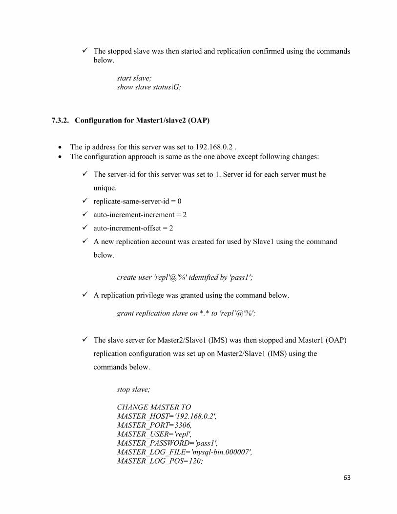
63
The stopped slave was then started and replication confirmed using the commands below.
start slave; show slave status\G;
7.3.2. Configuration for Master1/slave2 (OAP)
The ip address for this server was set to 192.168.0.2 . The configuration approach is same as the one above except following changes:
The server-id for this server was set to 1. Server id for each server must be
unique.
replicate-same-server-id = 0
auto-increment-increment = 2
auto-increment-offset = 2
A new replication account was created for used by Slave1 using the command
below.
create user 'repl'@'%' identified by 'pass1';
A replication privilege was granted using the command below. grant replication slave on *.* to 'repl’@'%';
The slave server for Master2/Slave1 (IMS) was then stopped and Master1 (OAP)
replication configuration was set up on Master2/Slave1 (IMS) using the
commands below.
stop slave;
CHANGE MASTER TO MASTER_HOST='192.168.0.2',
MASTER_PORT=3306, MASTER_USER='repl', MASTER_PASSWORD='pass1', MASTER_LOG_FILE='mysql-bin.000007', MASTER_LOG_POS=120;

64
The stopped slave was then started and replication confirmed using the commands
below. start slave; show slave status\G; The procedures above were performed on both machines simultaneously.
7.4. Shell script for file transfer between remote and local machine
1. #!/bin/sh 2. 3. # Copy files from remote machine to local machine using rsync. 4. 5. user="fokwa"; 6. host="192.168.0.2"; 7. password="Password2014"; 8. 9. # this is included the code below -> 10. /usr/bin/expect << EOD 11. set timeout -1 12. spawn rsync -avz
$user@$host:/opt/lampp/htdocs/online_portal/documents/ /opt/lampp/htdocs/local_ims/documents/
13. 14. expect { 15. timeout { send_user "TIME OUT\n"; exit 1 } 16. "*assword: " 17. } 18. send "$password\r" 19. expect { 20. "s password: " { send_user "\nIncorrect Password. Login
Failed.\n"; exit 1 } 21. "100%" 22. } 23. 24. spawn unlink /opt/lampp/htdocs/local_ims/documents/.htaccess 25. 26. sleep 1 27. send "exit\r" 28. send_user "\nFiles copied\n" 29. close 30. EOD

65
7.5. Security
Since both applications are web-based and serviced from a remote host/server, security is of
paramount importance. The following security measures were implemented to prevent some of
the common web application threats.
Table 7.1: Web Application Threat and Prevention
Web Application Threat Prevention
Cross site scripting HTML encoding of untrusted data
URL encoding of untrusted data
Javascript encoding of untrusted data
SQL injection The use of parameterized queries
Escaping all user supplied input
DDoS attacks Using a reliable and well-reviewed DDoS protection tool such as Fireblade.
Cookie poisoning Protection of cookies via encryption
CSRF Adopted the synchronizer token pattern
Brute-force attack Adoption of Captcha after successive logon attempts.
Introducing time delays between successive attempts.
Adoptions of a key derivation function such as pbkdf2 for hashing user account passwords. The stronger the hash, the longer it takes to perform a brute-force attack.
Spam The use of captcha challenge on forms The use of hidden fields User regeneration required hence
discourages spammers.
The full software product (IMS and OAP) is included in the CD attached to this report. The next chapter explains how both systems were tested.

66
8. TESTING
This chapter provides a description on how the test process has been implemented.
Verification/validation techniques applied are shown. Samples of test cases and test data
explanation are provided. Test results and outcomes are equally provided.
8.1. Test Cases
Test cases explain how the software product was tested against specific requirements in order to
show that the requirement has been fulfilled by the system or if the system failed to fulfill it.
Shown below are test cases of some main functionality of both systems.
Table 8.1: Test Cases for the Online Application Portal
ID Test Case Name
Test Subject
Test Sequence Test Data Req /UC ID
1 Test Login Login Provide Username and Password.
Click on “Login”.
First scenario:
Username: [email protected]
Password: johndoe2014
Expected Result: launch profile
Second scenario: Same data except for blank password.
Expected Result: Login failed
2 Test Account Creation
Account Creation
Click on “Create New Account”.
Enter all required data.
Click on “Next” button.
Click on “submit” button.
First scenario:
Last Name: Fokwa
Given Name(s): Divine
Birth Date: 2014-09-11
Gender: Male
Country of Residence: Cameroon
27

67
ID Test Case Name
Test Subject
Test Sequence Test Data Req /UC ID
Phone:
Language: English
City: Buea
Country of citizenship: Cameroon
Username: [email protected]
Confirm-username: [email protected]
New Password: xxxxxx
Confirm New Password: xxxxxx
Choose Security Question: In what city was your first job
Answer: Douala
Expected Result: Account created
Second scenario: Same data except that username provided already exist.
Expected Result: System gives a warning that username is already in use.
3 Test Internship Application Creation and Submission
New Internship Application
Click on “Create New Application”.
Provide all required data.
Click on “submit” button.
First scenario:
Name of Institution: University of Buea
Location of Institution: Buea
Field of Study: Computer Engineering
Specialty:
Level of Study: 4
Degree Program: Bachelor
28, 29, 30 and 31

68
ID Test Case Name
Test Subject
Test Sequence Test Data Req /UC ID
of Engineering
Graduation Date:
Specify an Anticipated Graduation Date: December-2014
Country (where the university is located): Cameroon
Number of training: None
Type of Internship: ACADEMIC
Select a domain where you want to do your internship: INFORMATION SYSTEMS
Briefly elaborate on your choice: I want internship in software department.
Start Date: 2014-09-11
End Date: 2014-09-30
CV: cv.pdf
Recommendation Letter: recommendation_letter.jpg
Attestation: attestation.jpg
Expected Result: Application submitted
Second scenario: Same data except that supporting documents have not been provided
Expected Result: System won't proceed to confirmation page.
4 Test Password
Forgotten Click on “Forgot your password”.
Username: [email protected]
36

69
ID Test Case Name
Test Subject
Test Sequence Test Data Req /UC ID
Recovery Password Provide your username.
Click on “continue”.
Provide answer to the Security question you selected when you created your account.
Click on “continue”.
Answer: Douala
Expected Result: A new password is generated and sent to the applicant's email
Second scenario:
Incorrect Username is provided
Expected Result: System gives warning that username does not exist.
Table 8.2: Test Cases for the Internship Management System
ID Test Case Name
Test Subject
Test Sequence Test Data Req/UC ID
1 Test Internship Admission
New Applicant Admission
Click “Application” on the dashboard.
Fill in all the required data.
Submit the data.
First scenario:
Last Name: John
First Name: Doe
Birth Date: 2014-09-11
Gender: Male
Country of Residence: Cameroon
Phone Number: 90136516
Language: English
Email Address: [email protected]
City: Buea
Country of Citizenship: Cameroon
Name of Institution: University of Buea
1,2

70
ID Test Case Name
Test Subject
Test Sequence Test Data Req/UC ID
Location of Institution: Buea
Field of Study: Computer Engineering
Specialty:
Level of Study: 4
Degree Program: Bachelor of Engineering
Graduation Date:
Specify an Anticipated Graduation Date: December-2014
Country (where the university is located): Cameroon
Number of training: None
Type of Internship: ACADEMIC
Select a domain where you want to do your internship: INFORMATION SYSTEMS
Briefly elaborate on your choice: I want internship in software department.
Start Date: 2014-09-11
End Date: 2014-09-30
Application Status: Accepted
Proposed Start Date:
Proposed End Date:
Unit: Direction des Services Généraux
Internship Location: Sous

71
ID Test Case Name
Test Subject
Test Sequence Test Data Req/UC ID
Direction Business Solutions/ Division Apps HR Support
Region: Littorial
Town: Douala
Branch: Koumassi
Effective Start Date: 2014-09-01
Presume End Date: 2014-09-30
Supervisor: Djomnang Jimmy Herve
Expected Result:
Intern data saved
Second scenario: Same data except that Internship Unit has not been selected
Expected Result:
System won't proceed to confirmation page.
2 Test Add User
Adding a new Management Staff
Click “Manage Users” on the dashboard.
Click on “Add New”.
Last Name: John
First Name: Eric
Role: Manager
Manager: None
Username: john
Password: xxxxxx
Confirm Password: xxxxxx
Email: [email protected]
Hire Date: 2014-09-11
14

72
ID Test Case Name
Test Subject
Test Sequence Test Data Req/UC ID
Profile Photo:
Expected Result:
New User Added
Second scenario: Same data except that Password provided is less than 6 characters.
Expected Result:
System gives a warning that password must be 6 characters and above
3 Test Add Supervisor
Add a new internship supervisor
Click on “Manage Supervisors” on the dashboard.
Click on “Add New”.
Supervisor name: Djomnang Jimmy
Supervisor Matricule: 123A4DF
Gender: Male
Expected Result:
Supervisor Added Successfully
11
4 Test Add Unit
Adding a new unit
Click on “Manage Units” on the dashboard.
Click on “Add New”.
Unit Code: NOW
Unit Title: No Opportunity Wasted
Expected Result:
Unit Added Successfully
13
5 Test Add Signatory
Adding a new signatory
Click on “Manage Signatories” on the dashboard.
Click on “Add New”.
Signatory name: Alice Eyabe
Signatory Title French: Chef de Division Recruitement
Supervisor Title English: Chief of Recruitment Division
Expected Result:
12

73
ID Test Case Name
Test Subject
Test Sequence Test Data Req/UC ID
Signatory Added Successfully
8.2. Test Results
Test results provide the results of the test cases conducted. The tables below are used to
document test results.
Table 8.3: Test Results for the Online Application Portal
Test Case ID Attempt Scenario Result
1 1 1 Pass
1 1 2 Fail – Error Message Displayed
2 1 1 Pass
2 1 2 Fail – System stop applicant from going forward unless
error is corrected
3 1 1 Pass
3 1 2 Fail – Error message displayed
4 1 2 Pass
4 1 2 Fail – System warns that the username provided does not
exist
Table 8.4: Test Results for the Internship Management System
Test Case ID Attempt Scenario Result
1 1 1 Pass
1 1 2 Fail – System won’t proceed to confirmation page unless
the field is filled out.
2 1 1 Pass
2 1 2 Fail – System gives warning that password must be at
least characters and above.

74
3 1 1 Pass
4 1 1 Pass
5 1 1 Pass
8.3. Screen Shots of the Final System
Shown below are some screenshots of the final system. More screen shots are included in
Appendix H and I.
8.3.1. Screen shots for the Online Application Portal
Figure 8.1: Public Home Page

75
Figure 8.2: Password Recoery Page
Figure 8.3: Account Creation Page

76
Figure 8.4: Testimonial Page
Figure 8.5: Applicant Profile

77
Figure 8.6: Admin Home
Figure 8.7: View Log
More screen shots for the OAP are included in appendix H.

78
8.3.2. Screen Shots for the Internship Management System
Figure 8.8: Home Screen
Figure 8.9: Manager Home Screen
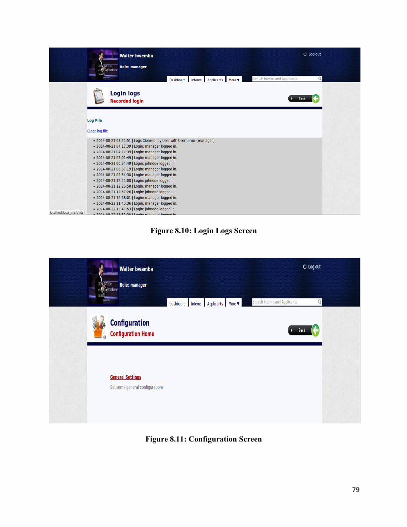
79
Figure 8.10: Login Logs Screen
Figure 8.11: Configuration Screen

80
Figure 8.12: Employee Home Screen
Figure 8.13: Report Generation
More screen shots for the IMS are included in Appendix I

81
9. CONCLUSION AND FUTURE WORKS
Conducting this project from start to end was a very challenging but rewarding exercise as it
required me to apply knowledge gain from various theoretical courses to a problem in the
industry. Furthermore, facing tasks never taught in class provoked me to learn more and hence
has led to an improvement in my skill set.
The development of the software product iterated mainly through three phases which were the
Requirements gathering phase, Analysis and Design phase, and the Implementation phase.
At each of these phases, various technical documentations were produced and are included in the
CD attached to the report.
Through thorough testing, various improvements were identified and will be included in future
versions of the product. These improvements include the following:
The addition of audio alerts to further improve applications usability.
The provision of Multilanguage support for the Internship Management System.
A further enhancement in the user interface to improvement usability.
Improvement of color schemes and styles to match company taste.

82
10. REFERENCES
Adegboyega Ojo, E. E. (n.d.). Object-Oriented Analysis and Design with UML.
Advantages of the Structured Approach. (n.d.). Retrieved from
http://www.csus.edu/indiv/m/martinm/116-DeveTools/sld007.htm
Agile Unified Process. (n.d.). Retrieved from
http://en.wikipedia.org/wiki/Agile_Unified_Process
Ambler, S. (2006). Retrieved from
http://www.ambysoft.com/unifiedprocess/agileUP.html#History
AMBLER, S. (2004). THE OBJECT PRIMER.
Bell, D. (n.d.). UML basics: The class diagram. Retrieved from
https://www.ibm.com/developerworks/rational/library/content/RationalEdge/sep04/bell/
Hassani, H. (2012). How to do the Final Year Projects.
Lecture 9: Structured Systems Development. (n.d.). Retrieved from
http://www.powershow.com/view/9bd63-
MTZjZ/Lecture_9_Structured_Systems_Development_powerpoint_ppt_presentation
RUP - Rational Unified Process. (n.d.). Retrieved from
http://www.webopedia.com/TERM/R/RUP.html
Sagar, V. (2009, 01 19). Disadvantages of MVC pattern. Retrieved from
http://www.careerride.com/MVC-disadvantages.aspx
Sparks, G. (2014). Enterprise Architect.
Wikipedia. (n.d.). Merise. Retrieved from http://en.wikipedia.org/wiki/Merise
Wikipedia. (n.d.). Model-View-Controller. Retrieved from http://en.wikipedia.org/wiki/Model-
view-controller
Wikipedia. (n.d.). Multitier Architecture. Retrieved from http://en.wikipedia.org/wiki/Three-
tier_architecture#Three-tier_architecture
Wikipedia. (n.d.). rsync.
Wikipedia. (n.d.). UML. Retrieved from
http://en.wikipedia.org/wiki/Unified_Modeling_Language

83
APPENDIX A: MAJOR UI ELEMENTS FOR THE ONLINE APPLICATION PORTAL
1. UI for Checking the Status of an Application
2. UI for Creating a Testimonial

84
3. UI for Viewing a Created Application
4. UI for Editing a Subject

85
5. UI for an Applicant’s Profile
6. UI for viewing Admin User

86
APPENDIX B: MAJOR UI ELEMENTS FOR THE INTERNSHIP
MANAGEMENT SYSTEM
1. UI for Searching Internship Supervisors
2. UI for Searching Units

87
3. UI for Searching Signatories
4. UI for Searching Interns

88
5. UI for Adding a New Applicant
6. UI for Staff Profile

89
APPENDIX C: SOFTWARE DEVELOPMENT PROJECT PLAN
1. Tasks
WBS Name Start End Duration 1 Preparing Problem Statement Jul 25 Jul 25 1 day
2 Understanding General Requirements Jul 26 Jul 30 4 days
3 Meeting with my Supervisor Jul 25 Sept 10 45days
4 Literature Review Jul 27 Jul 29 2 days
5 Literature Review Approved Jul 30 Jul 30 1 day
6 Requirements Analysis and Specification Jul 31 Aug 02 3 days
7 System and Software Design Aug 02 Aug 05 3 days
8 Implementation Aug 06 Aug 31 25days
9 Testing Sept 01 Sept 10 10days
10 Writing Project Report Jul 25 Sept 10 45days
11 Preparing Presentation Sept 15 Sept 21 6 days
12 Pre-Defence Sept 21 Sept 21 1 day
2. Resources
Name Short Name Type Email Fokwa Divine FD Work [email protected]

90
APPENDIX D: SCREEN SHOT FOR THE ONLINE APPLICATION
PORTAL
Below are some screen shots of the final system.
a. Application Status
b. New Application

91
c. Edit Subject
d. New Staff

92
e. Admin Profile

93
APPENDIX E: SCREEN SHOT FOR THE INTERNSHIP MANAGEMENT
SYSTEM
Below are some screen shots of the final system.
a. Intern Admission
b. Internship Letter
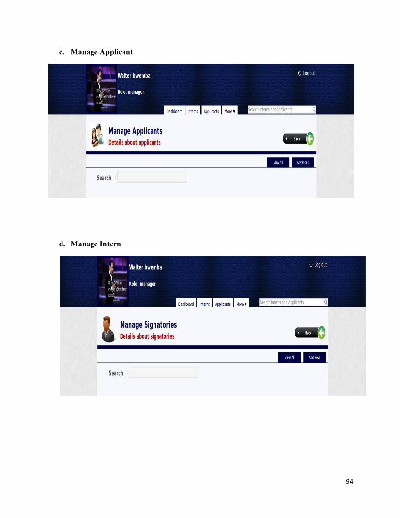
94
c. Manage Applicant
d. Manage Intern

95
e. Manage Supervisors
f. Manage Units

96
g. Manage Users
h. Generated Internship Attestation