Development of a USAR Rescue Robot for Human Detection ...
63
Development of a USAR Rescue Robot for Human Detection and Localization PER MACKEGÅRD Master of Science Thesis Stockholm, Sweden 2011
-
Upload
khangminh22 -
Category
Documents
-
view
0 -
download
0
Transcript of Development of a USAR Rescue Robot for Human Detection ...
Development of a USAR Rescue Robot for Human Detection and Localization
PER MACKEGÅRD
Master of Science Thesis Stockholm, Sweden 2011

Development of a USAR Rescue Robot for Human Detection and Localization
Per Mackegård
Master of Science Thesis MMK 2011:44 MDA 421 KTH Industrial Engineering and Management
Machine Design SE-100 44 STOCKHOLM

Master of Science Thesis MMK 2011:44 MDA 421
Development of a USAR Rescue Robot for Human Detection and Localization
Per Mackegård
Approved
2011-05-09 Examiner
Mats Hanson Supervisor
Bengt Eriksson Commissioner
Tokyo Institute of Technology Contact person
Hideyuki Tsukagoshi
Abstract This master thesis considers the redesign and further development of a mobile pneumatic rescue robot earlier developed at Kitagawa/Tsukagoshi laboratory at Tokyo Institute of Technology in Japan. The primary scope of use for the rescue robot is as a rescue aid at natural disaster sites, for example caused by earthquakes. Its purpose is to find and locate human victims who have been trapped by rubble inside damaged buildings. The aim of this thesis has been to improve the rescue robot’s human detection capability and to develop a localization system for measurement of the distance to the victims. The thesis reviews current technologies on the market as well as current research. All the different technologies and research are evaluated and based on the result a solution concept is designed and developed. The proposed solution concept contains heat sensing for human detection and an in-house developed system for localization. The proposed solution concept offers a light, simple and compact solution. The solution concept fulfills the listed requirement of human detection of victims not covered by rubble within 1.5 meters range from the rescue robot. The solution concept also fulfills the requirement of localization of victims with an error range for the distance measurement that is less than 15% of the actual distance traveled. In the thesis, potential problems like limitations in the heat detection method and how the accelerarations on the rescue robot affects the distance measurement are disussed. The thesis finally gives a conclusion and suggests future work to develop the concept further.

Examensarbete MMK 2011:44 MDA 421
Utveckling av en USAR räddningsrobot för mänsklig detektering och lokalisering
Per Mackegård
Godkänt
2011-05-09
Examinator
Mats Hanson
Handledare
Bengt Eriksson Uppdragsgivare
Tokyo Institute of Technology Kontaktperson
Hideyuki Tsukagoshi
Sammanfattning Detta examensarbete behandlar design och vidareutveckling av en mobil pneumatisk räddningsrobot som tidigare utvecklats vid Kitagawa/Tsukagoshi laboratory på Tokyo Institute of Technology i Japan. Räddningsrobotens huvudsakliga användningsområde är som hjälpmedel vid naturkatastrofer, till exempel vid jordbävningar. Målet med räddningsroboten är att kunna detektera och lokalisera överlevande som har blivit instängda av rasmassor inuti skadade byggnader. Syftet med examensarbetet har varit att utöka robotens förmåga att kunna detektera människor samt att utveckla ett lokaliseringssystem för att kunna mäta avståndet till offren. Examensarbetet inleds med en bakgrundsstudie som undersöker befintliga teknologier på marknaden samt aktuell forskning inom ämnet. Bakgrundsstudien resulterar i olika lösningsalternativ som presenteras i rapporten. Dessa utvärderas och baserat på utvärderingarna föreslås ett lösningskoncept. Det föreslagna lösningskonceptet består av värmeavkänning för mänsklig detektering samt ett egenutvecklat system för lokalisering. Det föreslagna lösningskonceptet erbjuder en lätt, enkel och kompakt lösning. Lösningskonceptet uppfyller det ställda kravet på detektering av offer som ej är täckta av rasmassor inom 1.5 meters avstånd ifrån roboten. Lösningskonceptet uppfyller även det ställda kravet på lokaliseringen av offer med en felmarginal för avståndsmätningen som är mindre än 15% av det egentliga avståndet. I examensarbetet diskuteras potentiella problem som begränsningar i den mänskliga detekteringsmetoden samt hur accelerationer på räddningsroboten påverkar distansmätningen. Examensarbetet avslutas med en slutsats samt förslag på fortsatt arbete.

Acknowledgements
First of all I would like to thank Professor Tsukagoshi and all the members ofKitagawa/Tsukagoshi laboratory at Tokyo Institute of Technology in Japan.It has been great to work together with you and I highly appreciate thesupport you have given to me. Thanks to my examiner, Mats Hanson fromKTH, for supporting me and for giving me advices during the thesis work.I would also like to thank my supervisor Bengt Eriksson for his support andthanks to Lars Wingård for making this master thesis in Japan possible.
From Kitagawa/Tsukagoshi laboratory I especially would like to thank;Eyri WatariYotaro MoriTakashi KobayashiTakayuki MiyataKenichi Hosaka
i
CONTENTS Per Mackegård
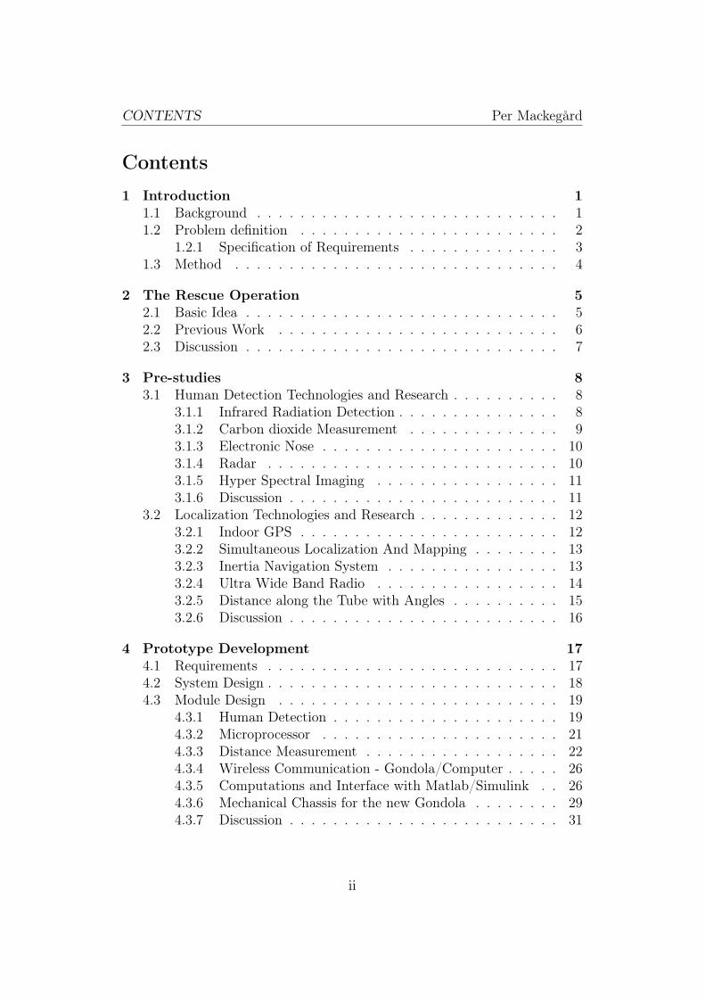
Contents
1 Introduction 11.1 Background . . . . . . . . . . . . . . . . . . . . . . . . . . . . 11.2 Problem definition . . . . . . . . . . . . . . . . . . . . . . . . 2
1.2.1 Specification of Requirements . . . . . . . . . . . . . . 31.3 Method . . . . . . . . . . . . . . . . . . . . . . . . . . . . . . 4
2 The Rescue Operation 52.1 Basic Idea . . . . . . . . . . . . . . . . . . . . . . . . . . . . . 52.2 Previous Work . . . . . . . . . . . . . . . . . . . . . . . . . . 62.3 Discussion . . . . . . . . . . . . . . . . . . . . . . . . . . . . . 7
3 Pre-studies 83.1 Human Detection Technologies and Research . . . . . . . . . . 8
3.1.1 Infrared Radiation Detection . . . . . . . . . . . . . . . 83.1.2 Carbon dioxide Measurement . . . . . . . . . . . . . . 93.1.3 Electronic Nose . . . . . . . . . . . . . . . . . . . . . . 103.1.4 Radar . . . . . . . . . . . . . . . . . . . . . . . . . . . 103.1.5 Hyper Spectral Imaging . . . . . . . . . . . . . . . . . 113.1.6 Discussion . . . . . . . . . . . . . . . . . . . . . . . . . 11
3.2 Localization Technologies and Research . . . . . . . . . . . . . 123.2.1 Indoor GPS . . . . . . . . . . . . . . . . . . . . . . . . 123.2.2 Simultaneous Localization And Mapping . . . . . . . . 133.2.3 Inertia Navigation System . . . . . . . . . . . . . . . . 133.2.4 Ultra Wide Band Radio . . . . . . . . . . . . . . . . . 143.2.5 Distance along the Tube with Angles . . . . . . . . . . 153.2.6 Discussion . . . . . . . . . . . . . . . . . . . . . . . . . 16
4 Prototype Development 174.1 Requirements . . . . . . . . . . . . . . . . . . . . . . . . . . . 174.2 System Design . . . . . . . . . . . . . . . . . . . . . . . . . . . 184.3 Module Design . . . . . . . . . . . . . . . . . . . . . . . . . . 19
4.3.1 Human Detection . . . . . . . . . . . . . . . . . . . . . 194.3.2 Microprocessor . . . . . . . . . . . . . . . . . . . . . . 214.3.3 Distance Measurement . . . . . . . . . . . . . . . . . . 224.3.4 Wireless Communication - Gondola/Computer . . . . . 264.3.5 Computations and Interface with Matlab/Simulink . . 264.3.6 Mechanical Chassis for the new Gondola . . . . . . . . 294.3.7 Discussion . . . . . . . . . . . . . . . . . . . . . . . . . 31
ii

CONTENTS Per Mackegård
5 Results 325.1 Data Collection . . . . . . . . . . . . . . . . . . . . . . . . . . 325.2 Test Results . . . . . . . . . . . . . . . . . . . . . . . . . . . . 405.3 System Validation . . . . . . . . . . . . . . . . . . . . . . . . . 405.4 Discussion . . . . . . . . . . . . . . . . . . . . . . . . . . . . . 41
6 Conclusion 436.1 Potential Problems . . . . . . . . . . . . . . . . . . . . . . . . 436.2 Further Work . . . . . . . . . . . . . . . . . . . . . . . . . . . 43
A - Decision Matrices 49
B - SolidWorks Drawings for the new Gondola 51
C - Electric Circuit on the Gondola 54
D - Simulink Model for Computations and Interface 55
iii
CONTENTS Per Mackegård
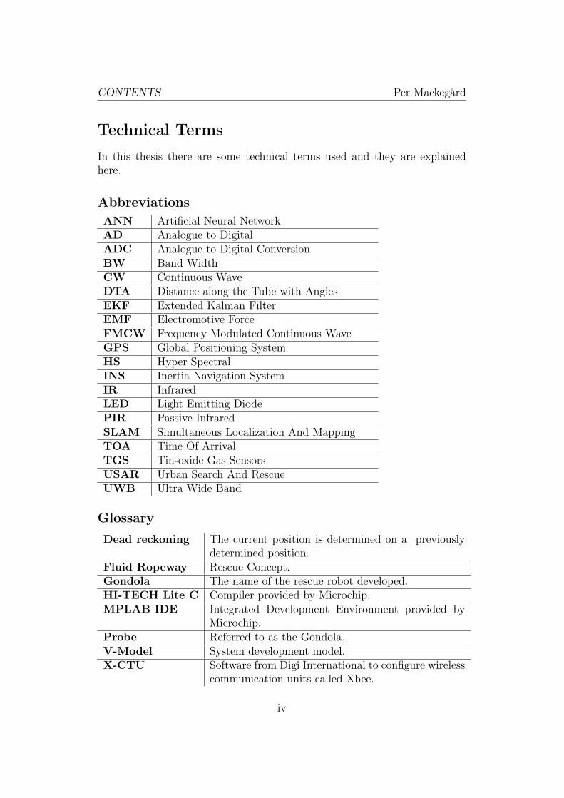
Technical Terms
In this thesis there are some technical terms used and they are explainedhere.
Abbreviations
ANN Artificial Neural NetworkAD Analogue to DigitalADC Analogue to Digital ConversionBW Band WidthCW Continuous WaveDTA Distance along the Tube with AnglesEKF Extended Kalman FilterEMF Electromotive ForceFMCW Frequency Modulated Continuous WaveGPS Global Positioning SystemHS Hyper SpectralINS Inertia Navigation SystemIR InfraredLED Light Emitting DiodePIR Passive InfraredSLAM Simultaneous Localization And MappingTOA Time Of ArrivalTGS Tin-oxide Gas SensorsUSAR Urban Search And RescueUWB Ultra Wide Band
Glossary
Dead reckoning The current position is determined on a previouslydetermined position.
Fluid Ropeway Rescue Concept.Gondola The name of the rescue robot developed.HI-TECH Lite C Compiler provided by Microchip.MPLAB IDE Integrated Development Environment provided by
Microchip.Probe Referred to as the Gondola.V-Model System development model.X-CTU Software from Digi International to configure wireless
communication units called Xbee.
iv

1 INTRODUCTION Per Mackegård
1 Introduction
This chapter describes the background, problem description, specification ofrequirements and the work method for the master thesis.
1.1 Background
In many parts of the world, earthquakes occur causing human injuries anddeath. In the last decade almost one earthquake of magnitude 8 or greaterhas occurred each year, [1]. In this period approximately 550000 people havebeen reported killed or missing due to earthquakes, [2]. This has led to anincreasing demand for rescue robots and tools. Rescue robotics is a relativelynew research field with no real development until the 1990s, [3]. Today, res-cue robots are still not widely used in actual search and rescue situations,but the development in this field is very promising, [3].
Finding and locating human victims trapped by rubble can be a very slowand complicated process and for successful rescue operations time is crucial.Therefore fast and efficient search and rescue aids are of great importance.Another aspect is that rescue operations can be dangerous for the rescueworkers themselves. When entering partially collapsed buildings the expo-sure hazard for the rescue team increases significantly. Today there are manydifferent methods how to perform USAR (Urban Search And Rescue) oper-ations. In some cases a long pole with a camera is used, but then the rangeis a problem. The ladder of fire fighter trucks can reach high altitudes, butthey have the problem of getting close enough to the damaged building. Aball with sensors attached to it, simply called a sensor ball, is also being usedto detect human victims. The idea is to throw the sensor ball into a damagedbuilding to search for human victims. The problem with this solution is thatthe detection range is limited since the sensor ball most of the time cannotmove inside the damaged building by itself. Another problem is that theimpact on the sensor ball, when it is thrown into a damaged building, mightdamage the unit, [4]. There is also the possibility of using USAR robots.Among USAR robots there are three different categories, [5];
• Aerial robots, airborne type.
• In-rubble robots, serpentine/crawling type.
• On-rubble robots, wheel/jumping type.
1

1 INTRODUCTION Per Mackegård
Aerial robots can be launched quickly and reach into tall buildings, butthey are difficult to operate accurately. In-rubble robots can be of serpen-tine type or crawling type. They can reach into rubble piles but they havedifficulties to pass larger objects. On-rubble robots can be of wheel-typeor jumping type. They have an extended area of usage but they also havedifficulties passing larger obstacles.
Another approach for USAR would be to throw a tube into damaged build-ings and let a robot slide along with it. The advantage of this method wouldbe better human detection range compared to a camera on a pole and tothe Sensor ball since the robot can move in both directions along the tube.Another advantage is that the risk for impact hardware damages is decreasedcompared to aerial robots and sensor balls. This approach might also havebetter performance of passing larger obstacles than in-rubble and on-rubblerobots since the tube can be thrown over obstacles. The rescue concept ofthrowing a tube into damaged buildings is used and described in this thesisand is called the "Fluid Ropeway". This rescue concept is more thoroughlyexplained in section 2.
1.2 Problem definition
The purpose of the thesis work was to develop an extended version of a pneu-matic mobile rescue robot called the "Gondola". The aim was to improvethe rescue robot’s ability to detect humans at disaster sites and to developa localization system to measure the distance to the victims. The thesiswork should result in a working prototype of the rescue robot with the newhuman detection and localization system installed. This includes mechani-cal construction of the rescue robot, wireless communication development tosend the detection and location data to a computer and a simple interfacefor the rescue operator to interpret the data received. This thesis is limitedin the way that it does not consider changes in the rescuing concept (FluidRopeway) or changes of the propulsion system of the rescue robot. Theseparts are the base of the prospective work and will remain the same as in theoriginal solution. The Fluid Ropeway concept and the design of the originalrescue robot can be seen in section 2. From now on the rescue robot will bereferred to as the Gondola.
2

1 INTRODUCTION Per Mackegård
1.2.1 Specification of Requirements
In order to develop the human detection and localization system, the fol-lowing specification of requirements was established. The requirements weredecided after discussions together with the people at Kitagawa/Tsukagoshilaboratory. The human detection range requirement is based on that theGondola most of the time travels along the ground. This gives that a mini-mum human detection range of 1.5 meters requirement is reasonable. How-ever it is of course wanted to have as large a detection area as possible. It isassumed that the victims are not covered by rubble since human detectionthen is very difficult. To be able to detect victims underneath rubble is ofcourse wanted and the possibilities to do that will also be investigated butit is not a requirement. The distance accuracy requirement was set to 15%based on that the Gondola normally travels up to 20 meters, see section 2,and then an acceptable error of 3 meters or less was decided after discussionswith people at the laboratory.
Functional Requirements
• The solution shall add a method of detecting victims.
• The solution shall contain a method of measuring the distance to thevictims.
• The solution shall work in both when the Gondola is traveling forwardand backwards.
• The solution shall have wireless communication for data transmissionbetween the Gondola and a computer.
• The solution should have a simple interface for the rescue operator tointerpret the data sent from the Gondola.
Non-functional Requirements
• The solution shall be safe considering both the rescue team and thevictim.
• The solution should be easy to use.
• The solution should be reliable.
• The added human detection method should be able to detect victimsthat are not covered by rubble within at least 1.5 meters distance fromthe Gondola.
3

1 INTRODUCTION Per Mackegård
• The localization method should be as accurate as possible, preferablyan error range less than 15%.
• The solution should be as light as possible, preferably less than 500grams.
• The solution should be as small as possible to be able to move in narrowspaces at disaster sites.
1.3 Method
To approach the problem, the method used is first to analyze the problemand then do a pre-study and look at current existing solutions and readabout current related research. The information about existing solutionsand current research is in first hand taken from the IEEE database withsearch words like rescue robot, human detection, localization, positioning,USAR and so on. From the pre-studies, promising concepts are generated andevaluated. After the evaluation the most promising concept is chosen. Thechosen concept is then designed and developed and finally its functionality isexperimentally tested. Section 1 analyses the problem. Section 2 describesand discusses the previous work. Section 3 reviews and discusses currentexisting technologies and current research. At the end of this section theconcepts are evaluated and discussed. Section 4 describes and discusses theselected technologies and the development of the human detection and humanlocation solutions. Section 5 describes the data collection and discusses theresults. Section 6 contains the conclusion, potential problems and futurework.
4
2 THE RESCUE OPERATION Per Mackegård
2 The Rescue Operation
This thesis is based on previous work done at Kitagawa/Tsukagoshi labo-ratory at Tokyo Institute of Technology. In this section the basic idea andthe previous work at Kitagawa/Tsukagoshi laboratory are explained. Thissection is a review of the work presented in [6]. This research project atKitagawa/Tsukagoshi laboratory has been supported in part by a grant fromthe National Institute of Fire and Disaster.
2.1 Basic Idea
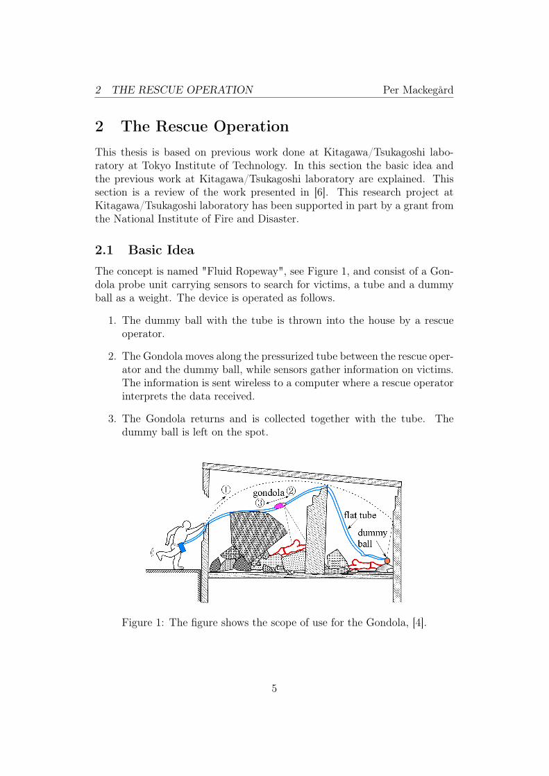
The concept is named "Fluid Ropeway", see Figure 1, and consist of a Gon-dola probe unit carrying sensors to search for victims, a tube and a dummyball as a weight. The device is operated as follows.
1. The dummy ball with the tube is thrown into the house by a rescueoperator.
2. The Gondola moves along the pressurized tube between the rescue oper-ator and the dummy ball, while sensors gather information on victims.The information is sent wireless to a computer where a rescue operatorinterprets the data received.
3. The Gondola returns and is collected together with the tube. Thedummy ball is left on the spot.
Figure 1: The figure shows the scope of use for the Gondola, [4].
5

2 THE RESCUE OPERATION Per Mackegård
To reach higher altitudes the tube can be thrown into taller buildings byusing a casting mechanism, see Figure 2. In Figure 2, the child machine iseither a device that uses under pressure to attach to windows or walls or itcan be a dummy ball with which the tube can be directly thrown into thebuilding. In Figure 2, the Gondola can in this case be seen as the "Probe".
(a) A tube is thrown into a damagedbuilding
(b) The Gondola moving into the build-ing
Figure 2: Sketch over how the Gondola is moved along the tube into thebuilding. (Allowed usage from Mr Eyri Watari, Kitagawa/Tsukagoshi lab).
2.2 Previous Work
As a base of this research a previous model of the Gondola was used as astarting point [6], see Figure 3. This version of the Gondola contained aworking propulsion system and a set of video cameras, (image and sound).The video cameras are sending their data wirelessly to a computer.
Figure 3: Sketch over the Gondola, [6].
6

2 THE RESCUE OPERATION Per Mackegård
The Gondola is driven by a pneumatic system, called Λ-drive. The pneu-matic system consists of a flat tube that passes a small gap in the Gondola.When the tube is pressurized from one side, a propulsion force is created.Depending on which side that is pressurized the Gondola can move bothforward and backwards [6], see Figure 4.
(a) Here the tube is unpressurized and theGondola is not moving.
(b) Here the tube is pressurized from theleft side and the Gondola moves to theright.
Figure 4: The Figure shows the propulsion system called Λ-drive, [6].
2.3 Discussion
The distance that the Gondola can travel is depending on how long the tubeis. In this case the assumed distance that the Gondola can travel, was set to20 meters. This is reasonable because it is difficult for a rescue operator tothrow the tube with a dummy ball, further than 20 meters using only manualpower, see Figure 1.
This version of the Gondola only uses a set of video cameras with no illu-mination. Therefore it has difficulties to detect victims in dark areas. Evenif the Gondola had for example LEDs, (Light Emitting Diode), mounted toilluminate the dark areas, this would probably not be enough to give a widedetection range for the video cameras. According to this, there was a needto improve the human detection method. Another disadvantage with thisversion of the Gondola was that it lacked a system to measure the distanceto the victims. The rescue team has consequently no information on how farinside the collapsed building the victims are. Human detection and localiza-tion are important properties for a rescue robot and to find good solutionsfor them has been the aim for this thesis.
7

3 PRE-STUDIES Per Mackegård
3 Pre-studies
This section is divided into two parts. The first part, 3.1 is an outline ofcurrent technologies and research for human detection. The second part, 3.2is an outline of current technologies and research for localization.
To be able to find the most appropriate technologies for human detectionand for localization, two so called decision matrices were made. One for thehuman detection technologies and one for the localization technologies weremade. The decision matrix is sometimes referred as "Pugh matrix" and is of-ten used in engineering. In the decision matrix several important propertiesare selected and given a weight, depending how important the property is forthe final concept. One concept is selected as a reference and all other conceptare compared to this reference. Each property of a concept is rated againstthe reference on scale consisting of -2, -1, 0, 1, 2 where higher numbers arebetter. A score is calculated based on the weight and the rating. This is donefor all concepts and all properties and the final step is to calculate the sumof all scores. The concept with the highest sum becomes the winner. Thedecisions matrices can be seen in Appendix A and are based on the reviewsbelow.
3.1 Human Detection Technologies and Research
The following technologies were considered to find a possible solution for thehuman detection problem.
• Infrared Radiation Detection
• Carbon dioxide Measurement
• Electronic Nose
• Radar
• Hyper Spectral Imaging
3.1.1 Infrared Radiation Detection
IR (infrared) sensors are one of the most common solutions for human de-tection. IR sensors can detect the thermal signal of humans and are used inmany different kinds of implementation. There are three different types of IRsensors, pyroelectric, thermoelectric and photo-polorimetric. Most commonis the pyroelectric type and they are normally called PIR (passive infrared)
8
3 PRE-STUDIES Per Mackegård
sensors. PIR sensors can be found in motion detectors, night vision and ther-mal imaging. The PIR sensor senses motion and is divided into two halves. Ifone half sees more or less IR radiation than the other, the output will swinghigh or low. The sensitivity is primary determined by the threshold valueof the electronics and the directionality is determined by a covering Fresnellens. PIR sensors are small, inexpensive, low-power, easy to use and do notwear out. Research also shows that moving humans can be detected behindobstacles with a small opening (5 cm, 10 cm and 30 cm), [7]. There are alsoother PIR implementations on rescue robots that shows good results e.g. [8],[9].
3.1.2 Carbon dioxide Measurement
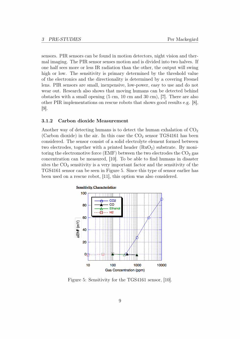
Another way of detecting humans is to detect the human exhalation of CO2
(Carbon dioxide) in the air. In this case the CO2 sensor TGS4161 has beenconsidered. The sensor consist of a solid electrolyte element formed betweentwo electrodes, together with a printed header (RuO2) substrate. By moni-toring the electromotive force (EMF) between the two electrodes the CO2 gasconcentration can be measured, [10]. To be able to find humans in disastersites the CO2 sensitivity is a very important factor and the sensitivity of theTGS4161 sensor can be seen in Figure 5. Since this type of sensor earlier hasbeen used on a rescue robot, [11], this option was also considered.
Figure 5: Sensitivity for the TGS4161 sensor, [10].
9
3 PRE-STUDIES Per Mackegård
3.1.3 Electronic Nose
The human scent is a unique signature and thus a good detection parameter.Dogs have an excellent nose and can detect very small amounts of smell,but they cannot be used in all rescue situations (tall damaged buildings etc).Long and tedious rescue operations with canines can also lead to unreliabilitydue to fatigue. Because of this an electronic nose to detect human scent wouldbe a suitable replacement. Although the e-nose will not be as sensitive as thedogs nose, it is a good replacement in certain rescue operations. It is light,small and can therefore be mounted on small robots for rescue operations.There are research done with TGS sensors (tin-oxide gas sensors) whosesignals are digitalized and fed into an ANN (artificial neural network) forscent classification, [12], with promising results.
3.1.4 Radar
To detect humans underneath rubble a rescue radar is a very interesting al-ternative. There are many different types of radar systems for example CW(Continuous Wave) radar, FMCW (Frequency Modulated Continuous Wave)radar and UWB (Ultra Wide Band) radar. The main problem with usingradar system to detect humans in disaster sites is the high signal attenuationof electromagnetic waves through ruin materials, especially concrete. Higherfrequency gives higher resolution but decreases the obstacle penetration. Theadvantage with an UWB radar is that it transmits in a wide frequency spec-trum with very low power. For a UWB radars a center frequency of about2 GHz with a frequency spectrum of at least 25% of the center frequency isoften used. Another advantage is that the low transmission power level giveslow influence on human beings. Several papers have been published aboutUWB that concludes that UWB can effectively be used to search for victimsin rubble, [13], [14], [15]. There are even some companies that already offers"see through the wall" rescue equipment using UWB technique, [16], [17],[18].
10

3 PRE-STUDIES Per Mackegård
(a) Rescue Radar 2, [17] (b) Prism 200 [18]
Figure 6: Commercial UWB radars.
3.1.5 Hyper Spectral Imaging
Today hyper spectral imaging techniques are mostly used for industrial tasksuch as quality control, fast material sorting and food analysis. Hyper spec-tral cameras can however also be used for human detection in rescue opera-tions. This technique involves a simultaneous recording of spatial and spec-tral information. Different materials can be distinguished when the spectraare analyzed. Research show that the spectra of skin is very characteristicand that even under the impact of ash layers the spectral similarity remainsvery high, [19]. One other advantage is that it is not temperature dependentand can therefore also detect cold bodies. The primary disadvantage is thecost and the complexity of analyzing the hyper spectral data. Neverthelesshyper spectral cameras are an interesting alternative for human detection.
3.1.6 Discussion
The most important property is that the human detection requirement isfulfilled. The Gondola must be able to detect victims on a distance of atleast 1.5 meters from the Gondola. According to the decision matrix inAppendix A, other important properties for the human detection conceptare the size and weight. This is because of that the propulsion force of theGondola is limited, [4], and the Gondola has to be small to be used in narrowspaces. The hyper spectral camera and the radar concepts are simply tooheavy to be implemented on the Gondola. The CO2, Electronic Nose and
11
3 PRE-STUDIES Per Mackegård
the IR concepts are all significant lighter and can therefore be practicallyimplemented. IR was chosen as the most promising concept based on theresult from the decision matrix and discussions with people in the field. Itfulfills the requirements on low weight, small size, has low development timeand is previously used in rescue equipment with good result. The secondmost promising concept was the Electronic Nose. The Electronic Nose alsohas low weight, small size, comparative low development time and promisingresearch results, [12]. The CO2 option using the TGS4161 sensor was also anoption, but is more difficult to implement and has been proven to be difficultto use in a real rescue situation, [11]. Because of this the two chosen conceptsto continue with were the IR concept and the Electrical Nose concept.
3.2 Localization Technologies and Research
The following technologies were considered to find a possible solution for thehuman localization problem.
• Indoor GPS
• Simultaneous Localization And Mapping
• Inertia Navigation System
• Ultra Wide Band Radio
• Distance along the Tube with Angles
3.2.1 Indoor GPS
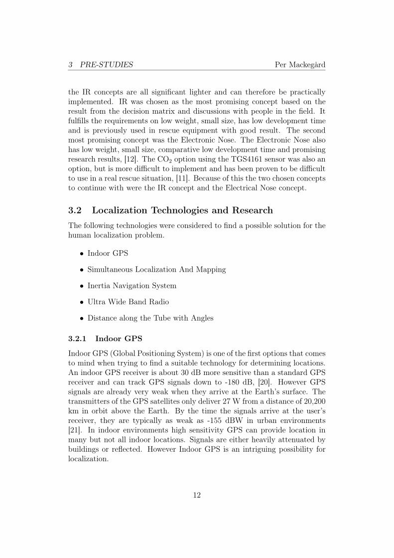
Indoor GPS (Global Positioning System) is one of the first options that comesto mind when trying to find a suitable technology for determining locations.An indoor GPS receiver is about 30 dB more sensitive than a standard GPSreceiver and can track GPS signals down to -180 dB, [20]. However GPSsignals are already very weak when they arrive at the Earth’s surface. Thetransmitters of the GPS satellites only deliver 27 W from a distance of 20,200km in orbit above the Earth. By the time the signals arrive at the user’sreceiver, they are typically as weak as -155 dBW in urban environments[21]. In indoor environments high sensitivity GPS can provide location inmany but not all indoor locations. Signals are either heavily attenuated bybuildings or reflected. However Indoor GPS is an intriguing possibility forlocalization.
12

3 PRE-STUDIES Per Mackegård
3.2.2 Simultaneous Localization And Mapping
SLAM (Simultaneous Localization And Mapping) is a concept in roboticand autonomous navigation. Place a robot in an unknown location in anunknown environment and have the robot incrementally build a map of thisenvironment while simultaneously using this map to compute location. Be-cause of this, SLAM is described as the localization problem and the mappingproblem.
• Localization problem: Robot needs to estimate its location with re-spects to objects in its environment (Map provided).
• Mapping problem: Robot need to map the positions of objects that itencounters in its environment (Robot position known).
Localization and mapping are coupled problems and a solution can onlybe obtained if the localization and mapping processes are considered to-gether. The states for the robot needs to be estimated based on the sensormeasurements and this is often done by an EKF (Extended Kalman Filter).A Robot that uses SLAM, simultaneously maps objects that it encountersand determines its position (as well as the position of the objects) by us-ing different kinds of sensors. There are several successful implementationsin 3D on even surfaces in indoor environments such as corridors and officese.g., [22]. There are even some successful 3D implementations working onuneven terrain, [23]. However these methods use odometry on the wheelsof the robot. The distance traveled is measured along the surface. In thecase of the Gondola, the tube is moving when the Gondola is moving. Thismakes it difficult to use the trajectory as a reference in the same way as theground. This makes it more difficult to create a map of the surroundings.SLAM is also complicated to implement and requires a lot of computationalpower when the map size is growing.
3.2.3 Inertia Navigation System
INS (Inertia Navigation System) is one tracking system which provides portableand cost-effective positioning solutions for different applications. INS usesa computer, accelerometers and sometimes rotation sensors (gyroscopes) tocontinuously calculate via dead reckoning the position, orientation and ve-locity of a moving object without the need for external references. To getvelocity INS systems integrates the acceleration and to get the position theacceleration is double integrated. The main advantage of INS is that it needslittle information from the environment. There are tutorials on how to create
13

3 PRE-STUDIES Per Mackegård
simple INS systems with only a microprocessor and accelerometer e.g. [24].However the main disadvantage of these systems is that they suffer froman integration drift since the acceleration is double integrated into position.Small errors in acceleration gives over time large errors in position. There-fore the position must be periodically corrected by input from some othertype of navigation system (e.g., GPS or some self-resetting method, [25]), forreducing the error accumulation. There has been big improvements in thisfield but it is still difficult to keep track of the position over a longer time.
3.2.4 Ultra Wide Band Radio
UWB (Ultra Wide Band) radio can be used as a rapidly deployable systemto track location with high precision and reliability in an unplanned andhostile radio environments. The position of the Gondola is calculated basedon the difference in time of arrival, (TOA), for different transceivers. Theadvantage with UWB radio technology is that it provides relatively longradio length, (150 meters indoors and 1 km outdoors), with satisfactory datarate, [26]. Several UWB transceivers can be made into an ad hoc system,which means that each node works as a router and forwards any data forother nodes. Minimal configuration and quick deployment makes ad hocnetworks suitable for emergency situations like natural disasters. This typeof system has been proposed in [26], see Figure 7. This makes UWB radioan interesting alternative for localization in USAR operations.
Figure 7: Overview of a UWB radio system, [26].
14

3 PRE-STUDIES Per Mackegård
3.2.5 Distance along the Tube with Angles
The DTA, (Distance along the Tube with Angles), method is an in-housedeveloped method and is based on the fact that the Gondola never leavesthe tube. The idea is to sample the distance traveled along the tube and theangles of the Gondola. The basic idea can be seen in Figure 8.
Inside damage building
Gondola
Outside
Flat tube
Side view of a building
Figure 8: Basic idea of the DTA method.
The distance traveled in every sample is calculated according to Figure9(a) and Equation 1. The distance Bi is given from a distance measurementsensor and the angle, αi from an angle sensor. The total distance traveled isthe sum of all small steps, which can be seen in Figure 9(b) and Equation 2.
A
B
C
!
(a) Partial distance calculation
C1
C1+C2+C3+C4=Ctot
C2
C3C4
(b) Total distance calculation
Figure 9: Sketch over how the distance is calculated.
15

3 PRE-STUDIES Per Mackegård
Ci = cos(αi) · Bi (1)
Ctot =i=n�
i=1
(Ci) (2)
3.2.6 Discussion
The most important factors are that the distance measurement is reliable andaccurate enough. Two other important properties are also here the weightand the size. Indoor GPS provides low weight, small size, easy to implement.The disadvantage is that it cannot be used in all indoor environments. Inareas covered by a lot of concrete the GPS signals are too weak to be de-tect even by a very sensitive Indoor GPS receiver. This option was thereforediscarded. SLAM was also an option, however as mentioned earlier one dis-advantage in this case is that the Gondola is moving along a tube that ispartly hanging in the air and moves when the Gondola is traveling. In mostSLAM implementations the robot moves along the ground. The ground canthen be used as a reference for SLAM. This is not the case with the Gondolaand makes SLAM more difficult to implement. Other disadvantages with thisconcept are the weight and that it is complicated and needs a lot of compu-tational power. This makes SLAM an inappropriate option in this case.
INS systems are light, small and quite simple to implement. However themain disadvantage is the integration drift. With this method it is thereforedifficult to keep track of the position over a longer time. There is the possibil-ity to use INS in combination with GPS. In case of a GPS signal loss the INSsystem estimates the position until GPS signal is received again. Howeverthere is still the problem with GPS signal attenuation and so this option wasalso discarded. UWB radio provides good range and accuracy. The mainproblem in this case is the need of a lot of equipment. Several transceivershave to be placed out and the distance between them measured. This canbe a very difficult task at disaster sites and therefore also this option wasdiscarded. The remaining option, DTA is light, small, relatively ease to im-plement and provides satisfactory accuracy. The disadvantage is that it onlymeasures the distance in one dimension. According to the decision matrixand discussion with other people the DTA concept was considered as mostpromising and therefore chosen to continue with.
16

4 PROTOTYPE DEVELOPMENT Per Mackegård
4 Prototype Development
This section describes the prototype development process according to thesystem development model used.
Development Process Model
As system development process model, the common "V-Model" was used.The development life cycle from requirements to system validation can beseen in Figure 10. All steps are however not declared in this master thesis.In this section the steps from Requirements to Module Design are discussed.The system validation can be found in section 5.3.
Requirements
System Design
Module Design
Implementation
Module Testing
Integration Test
System Validation
Figure 10: The figure shows the development process according to the V-Model.
4.1 Requirements
The main requirements were;
• The solution shall add a method of detecting victims.
• The solution shall contain a method of measuring the distance to thevictims.
The full specification of requirements can be seen in section 1.2.1.
17

4 PROTOTYPE DEVELOPMENT Per Mackegård
4.2 System Design
The rescue concept is the same as the original (Fluid Ropeway) and is thebase for the system design. The Fluid Ropeway concept is described insection 2.1, and can be seen in Figure 11.
PCWireless
Communication
Figure 11: The figure shows the Fluid Ropeway rescue concept. (Picturebased on: [4]).
The system overview can be seen in figure 12. It shows the differentfunctions on the gondola and on the rescue station. The human detectionfunction can be seen as "Det" and the distance measurement function as"Dist". All functions are connected to a microprocessor that can be seen as"µP". The wireless communication function can be seen as "Com".
Com
Dist
μPPC Com
Det
GondolaRescue Station
Figure 12: The figure shows the system design.
18

4 PROTOTYPE DEVELOPMENT Per Mackegård
4.3 Module Design
The module design is divided into the following sections according to Fig-ure 12. In each section the used components are explained and discussed.There is one section in addition to Figure 12, section 4.3.6 that explains themechanical construction of the new Gondola.
• 4.3.1 - Human Detection
• 4.3.2 - Microprocessor
• 4.3.3 - Distance Measurement
• 4.3.4 - Wireless Communication - Gondola/Computer
• 4.3.5 - Computations and Interface with Matlab/Simulink
• 4.3.6 - Mechanical Chassis for the new Gondola
4.3.1 Human Detection
The human detection section consists of two parts that can be seen in thelist below.
• Infrared Sensor
• Electronic Nose
Infrared Sensor
The IR sensor used was a PIR motion sensor called SE-10. The SE-10 detectsmovement of infrared light sources at 7 to 14 µm. Humans emit infraredradiation from 8 to 14 µm, which makes this a good sensor for detectinghuman movement. When the sensor is powered on it calibrates itself for 1-2seconds to match the background infrared radiation. The detection range is2 meters and the detection angle is 120 degrees according to the data sheet,[27]. The senor output has two states, high or low. The output is normallyhigh but when human movement is detected the output goes low for a coupleof seconds. This can then be detected by an interrupt on change pin onthe microprocessor and then wireless transmitted to the computer. Earlyexperiments showed that this PIR sensor reacts on very small movements.This made this sensor suitable for human detection and to progress with.
19

4 PROTOTYPE DEVELOPMENT Per Mackegård
Electronic Nose
To make an electronic nose a TGS2450 scent sensor was tested. The TGS2450sensor is light and has a diameter of 9.2 mm and a length of 17,8 mm. Itcan detect Methyl Pentane, Hydrogen Sulfide, Ethanol and Ammonia. Thesensor was heated by a pulse from 0 v to 1.6 v for 8 ms and then 0 v for242 ms, see Figure 13. This was continuously repeated to be able to achieveas accurate measurements as possible, [28]. The lowest gas concentrationpossible to detect is according to the data sheet 0.1 ppm, [28]. However atthis gas concentration level the TGS2450 sensor gives a very low output, seeFigure 14. Experiments showed at a significant gas concentration is neededfor gas detection, which is not to expect at disaster sites. This makes thissensor an unsuitable choice for human detection at disaster sites. Othersimilar sensors were also reviewed but they shared the same problem withthe need of high gas concentration levels and therefore it was decided not toproceed with the Electronic Nose concept.
8 ms 242 ms
0 v
1.6 v
Figure 13: The Figure shows the heating pulse for the TGS2450 scent sensor.
20

4 PROTOTYPE DEVELOPMENT Per Mackegård
EthanolAirHydrogen Sulfilde
Sensor resistance at various gas concentrations in the atmosphere
Sensor resistance in clean atmosphere
Ammonia
Metyl Pentane
Figure 14: The Figure shows the sensitivity characteristics .
4.3.2 Microprocessor
All the components were connected to a 20-pin, 8-bit microprocessor calledPIC16F690 from Microchip, [29]. The advantage of this microprocessor isthat it is small, has low power consumption and has many ADC channels(12) with 10 bits resolution, [29]. The disadvantage is that it is not sopowerful but since the microprocessor is only sending its values to a PCwhere all the computations are made this is no problem. The microproces-sor was programmed with a PICkit2 programmer which has a "In CircuitSerial Programming" header which makes it possible to directly program themicroprocessor on the circuit board. The used programming language wasC and the development environment was MPLAB IDE v8 together with theHI-TECH C Lite compiler. The code was in house developed and since all ofthe components were relatively easy to use, no libraries from the componentmanufactures had to be used. The code is simple and makes the microproces-sor just wait for interrupts. Changes in encoder ticks and in heat detection
21

4 PROTOTYPE DEVELOPMENT Per Mackegård
are stored as "cnt" and "heat flag" respectively. The "cnt" and "heat flag"values are sent to the computer every 65 ms by Timer1. In Timer1 the ADconversions of the accelerometer values are also made (x, y, z), and they aresent to the computer together with the other values. The flow chart of theprogram is shown in Figure 15.
Start
InitADC
Interrupt
Which?
Timer1 (65 ms)Angle ADC, x, y, z.
Send x, y, z, cnt and heat flag to
computer.Reset Heat flag.
Encoder variablecnt++
Encoder
Heat detection
Encoder variablecnt--
Yes NoMoves
forward?
Interrupt?
Set heat flag
Yes No
End
Timer1
Figure 15: Flow chart of the C program.
4.3.3 Distance Measurement
In this section consists of two different parts that can be seen in the listbelow. They describe the components used and their features. The goal isto later combine them both to create the whole DTA system.
• Distance along the Tube
• Angle Measurement
Distance along the Tube
In the DTA concept, the distance along the tube is measured. There werethree different ideas over how to accomplish that measurement. The ideaswere;
22

4 PROTOTYPE DEVELOPMENT Per Mackegård
1. The tube is marked with stripes with a certain distance between them.Then mount a LED (Light Emitting Diode) on one side of the tubeand an optical sensor on the other side. The number of the stripes canthen be counted and the total distance traveled can be calculated.
2. Use an optical sensor from a computer mouse.
3. Use an encoder.
The first option has the advantage that the sensor does not need to bein direct contact with the tube. The disadvantage is that if the tube getsdirty which is likely at a disaster site the method may not work. Anotherdisadvantage with this easy setup is that it is not possible to determine inwhich direction the Gondola is traveling. Option number two also has theadvantage that it does not need to be in direct contact with the tube. Ex-periments were made with an Agilent ADNS-2051 optical mouse sensor butaccording the manufacturer Avago Tech, this type of sensors are not meantfor this kind of application and an error about 20% is to expect for distancemeasurements. Therefore the optical mouse sensor idea was discarded.
The remaining option was the encoder option. The encoder needs to beattached to a wheel axle that is in direct contact with the tube. The advan-tage with this method is that it can be used even if the tube gets dirty andgives good accuracy. The disadvantage is that slippage can occur and thenerrors are accumulated. This problem can however be limited by applyingsticky surface on the encoder wheel. Therefore the encoder option was chosen.
The chosen encoder was an ALPS EC05E1220202 incremental encoder. Theencoder is light and has the compact dimensions of 8.7x7,5x3,3 millimeters.The encoder has two output signals (A, B), which each gives 12 pulses perrevolution. Both the rising edges and the falling edges are checked so 24 edgesper revolution were achieved. Since the diameter of the tube is changing de-pending on its pressure level, a pinching mechanism was made to ensure thatthe encoder wheel always stays in contact with the tube. The tube is there-fore pinched between the encoder wheel and a supporting wheel by usage ofone spring on each side of the Gondola. The diameter of the encoder wheelwas important since it determines the revolution speed of the encoder. Theencoder wheel should be as big as possible but not too big because then thesize of the Gondola increases. The encoder was tested up to 1200 revolu-tions per minute and in this speed it gave about 0.1% in reading error. Themaximum speed of this version of the Gondola is about 1 m/s. According toEquation 3, with a maximum speed of 1 m/s, the encoder wheel should be
23

4 PROTOTYPE DEVELOPMENT Per Mackegård
then be about 16 mm. The encoder wheel was designed to 15 mm and thena sticky surface made of latex was glued on so a diameter of almost 17 mmwas achieved.
dEncWheel =1000 · 60
π · 1200= 16mm (3)
The new Gondola with the encoder wheel, supporting wheel, encoder,pinching mechanism and the location of one pinching springs can be seen inFigure 16.
Encoder Wheel
Encoder
Pinching Mechanism Supporting Wheel
Spring
Figure 16: The Figure shows the new Gondola with the added components.
The traveling direction of the Gondola can be determined by comparingpulse A with pulse B, see Figure 17. For better accuracy both the rising andthe falling edges are used for the comparison.
B
A
Figure 17: The Figure shows the two pulses A and B from the encoder.
24

4 PROTOTYPE DEVELOPMENT Per Mackegård
The algorithm starts with checking if pulse A has a rising or falling edge.If no changes are detected the algorithm makes nothing. Then the algorithmworks like this;
1. If pulse A has a rising edge and pulse B is zero it is decided thatthe Gondola moves forward and a pulse count variable is increased,(cnt++).
2. If pulse A has a rising edge and pulse B is high it is decided that theGondola move backwards and the pulse count variable is decreased,(cnt–).
3. If pulse A has a falling edge and pulse B is zero it is decided thatthe Gondola moves forward and the pulse count variable is increased,(cnt++).
4. If pulse A has a falling edge and pulse B is high it is decided that theGondola moves backwards and the pulse count variable is decreased,(cnt–).
The encoder pulses are counted by the microprocessor by using interrupton change, which has a latency of three to four instruction cycles, [29]. TheGondola is sending the pulse count variable, cnt, wirelessly to the computerwith a frequency of 15 Hz. The count variable is later processed in Simulinkto calculate the DTA distance, see section 4.3.5.
Angle Measurement
To measure the tilt angle of the Gondola a tri-axial accelerometer, KXM52-1050 was used. The accelerometer is light and has the dimensions of 10x11x10millimeters. The output bandwidth is an important parameter when usingan accelerometer. For KXM52-1050, the output bandwidth of X and Y axisranges from DC to 3 kHz, and for the Z axis from DC to 1.5 kHz andthis is more than enough for this application. In this case, a bandwidth offBW = 50Hz was selected since no faster motion was necessary to measure.In a typical application, the desired bandwidth is based on the fastest signalneeded to be measured. The bandwidth is determined by the capacitorscapacitance connected to the accelerometer, see Equation 4, [30].
C6 = C7 = C8 =1
2 · π · 32000 · fBW(4)
25

4 PROTOTYPE DEVELOPMENT Per Mackegård
To achieve a bandwidth of 50 Hz, the capacitors capacitance should be0.1 µF. This is shown in Equation 5.
C6 = C7 = C8 =1
2 · π · 32000 · 50= 0.1µF (5)
4.3.4 Wireless Communication - Gondola/Computer
For the Gondola to be able to send its values to the computer, wirelesscommunication was needed. Therefore two Xbee 802.15.4 OEM RF moduleswere bought. One was mounted on the Gondola and the other connectedto the computer. The Xbee modules are light and have the dimensions of27,6x24,4x2.8 millimeters. The Xbee module supports point-to-point, point-to-multipoint and peer-to-peer topologies and has a maximum data rate of250kbps. The Xbee module can be bought in two versions, standard orPRO. The indoor range for the standard version is 30 meters and for thePRO version it is 90 meters. For outdoor range is up to 90 meters forthe standard version and 750 meters for the PRO version, [31]. The PROversion is slightly bigger and has a larger power consumption due to the largertransmission power level. The Xbee modules operates within the ISM 2,4GHz frequency and are pin compatible with each other which makes it easyto make an upgrade. The Xbee modules were tested in indoor environmentsand the test showed that the information from the data sheet was quiteaccurate (about 30 meters range). The Xbee modules can send data intwo different ways, as serial data, (wireless RS232), or as data frames. Inthis case the serial communication option was used. The Xbee modules wereconfigured by the free software X-CTU that is provided by the manufacturer,Digi International. With X-CTU, the transmission mode (serial or as frames),the baud rate, sleeps modes, ADC on/off, ADC sampling time and so on couldbe set.
4.3.5 Computations and Interface with Matlab/Simulink
This section consists of four different parts that can be seen in the list below.This section describes the calculations made in Simulink according to Section3.2.5. At the end the whole system with the human detection and localizationmethods is reviewed.
• Calculating the Distance traveled along the Tube
• Calculating the Tilt Angle of the Gondola
• Calculating the Distance along the Tube with Angles - DTA
26

4 PROTOTYPE DEVELOPMENT Per Mackegård
• System Review
Calculating the Distance traveled along the Tube
Since the computational power of the microprocessor is limited all the com-putations were made in the computer by the usage of Simulink. The encoderis just giving pulses so the pulses need to be converted into distance. Onepulse can be converted into distance by using Equation 6. The value 16.85is the diameter in millimeters of the encoder wheel and 24 stands for thateach revolution has 24 pulses and 1000 is a scale factor from millimeters tometers. The number of pulses (NoP) multiplied by the factor (0.0022) fromEquation 6, gives the distance traveled along the tube, see Equation 7.
PDistance =16.85 · π24 · 1000
= 2.2mm (6)
Dtube =�
(PDistance · NoP ) (7)
This is only the distance along the tube. To get the distance accordingto the DTA method the angles from the accelerometer also needs to be used.This is explained in the following step.
Calculating the Tilt Angle of the Gondola
The KXM52-1050 accelerometer is a tri-axis accelerometer but according tothe DTA method only the tilt angle is necessary. In this case the accelerome-ter was mounted so that the y axis of the accelerometer became the tilt angleof the Gondola, see Figure 18.
Figure 18: The Figure shows the accelerometer axis, [32].
27
4 PROTOTYPE DEVELOPMENT Per Mackegård
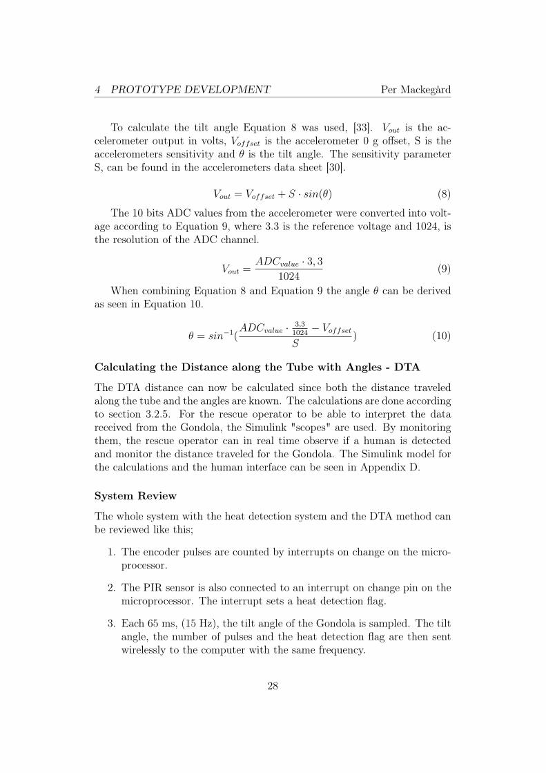
To calculate the tilt angle Equation 8 was used, [33]. Vout is the ac-celerometer output in volts, Voffset is the accelerometer 0 g offset, S is theaccelerometers sensitivity and θ is the tilt angle. The sensitivity parameterS, can be found in the accelerometers data sheet [30].
Vout = Voffset + S · sin(θ) (8)
The 10 bits ADC values from the accelerometer were converted into volt-age according to Equation 9, where 3.3 is the reference voltage and 1024, isthe resolution of the ADC channel.
Vout =ADCvalue · 3, 3
1024(9)
When combining Equation 8 and Equation 9 the angle θ can be derivedas seen in Equation 10.
θ = sin−1(
ADCvalue · 3,31024 − Voffset
S) (10)
Calculating the Distance along the Tube with Angles - DTA
The DTA distance can now be calculated since both the distance traveledalong the tube and the angles are known. The calculations are done accordingto section 3.2.5. For the rescue operator to be able to interpret the datareceived from the Gondola, the Simulink "scopes" are used. By monitoringthem, the rescue operator can in real time observe if a human is detectedand monitor the distance traveled for the Gondola. The Simulink model forthe calculations and the human interface can be seen in Appendix D.
System Review
The whole system with the heat detection system and the DTA method canbe reviewed like this;
1. The encoder pulses are counted by interrupts on change on the micro-processor.
2. The PIR sensor is also connected to an interrupt on change pin on themicroprocessor. The interrupt sets a heat detection flag.
3. Each 65 ms, (15 Hz), the tilt angle of the Gondola is sampled. The tiltangle, the number of pulses and the heat detection flag are then sentwirelessly to the computer with the same frequency.
28

4 PROTOTYPE DEVELOPMENT Per Mackegård
4. In Simulink the distance traveled for one sample is calculated as inEquation 1 in section 3.2.5.
5. In Simulink all the samples are added according to Equation 2 in section3.2.5 and the total distance traveled is then calculated and displayedin Simulink.
6. For human detection the heat detection flag can be monitored in Simulink.If the heat detection flag is high, heat is detected otherwise nothing isdetected.
4.3.6 Mechanical Chassis for the new Gondola
To fit all the new components for human detection and localization, theGondola had to be redesigned. The mechanical construction is a furtherdevelopment on the earlier version of the Gondola. The mechanical drawingswere made in the software SolidWorks 2010. The new Gondola has thedimensions of 217x38.5x30.5 millimeters and a weight with all componentsmounted of 288 grams. The new Gondola became 43 mm longer and 5 mmtaller than the original Gondola. This made it possible to fit the pinchingmechanism with the encoder wheel, the supporting wheel and the springs.In this version only one video camera was used to make space for the PIRsensor. The used material for the Gondola was Polyoxymethylene (POM).Figure 19 and Figure 20 shows how the new Gondola looks like and thelocation of the different components. The main mechanical drawings can beseen in Appendix B.
Figure 19: The Figure shows the tube and the location of the video camera,the Λ-Drive unit and the battery pack.
29

4 PROTOTYPE DEVELOPMENT Per Mackegård
Figure 20: The Figure shows the location of the electronics box, the PIRsensor and the encoder attachment.
An overview of the real Gondola can be seen in Figure 21(a). The pinch-ing mechanism with the tube inserted, the encoder wheel and the encoderattachment can be seen in Figure 21(b).
(a) Overview (b) From the back
Figure 21: The Figure shows the Gondola.
All the electronic components were first tested on a breadboard and thenlater mounted on a handmade circuit board. The circuit board containedthe microprocessor, the accelerometer and the Xbee unit as well as otherelectronic components. The electronics box can be seen in Figure 22 and thecircuit diagram can be seen in Appendix C.
30

4 PROTOTYPE DEVELOPMENT Per Mackegård
Figure 22: The Figure shows the inside of the electronics box.
4.3.7 Discussion
In this case a circuit board was handmade to fit all the components. Thecircuit board can be made significant smaller by making a PCB (Printed Cir-cuit Board). For the wireless communication the standard version of Xbeewas used because of the lower price. However in a further development it isrecommended to use the PRO version instead due to the higher transmissionpower level which gives longer range and transmission reliability at rescueoperations. An important property for the reliability of the distance mea-surement is the stiffness of the pinching springs. This is since the encoderwheel always must be in contact with the tube so that no encoder data islost. In this case the pinching mechanism was tested so that contact withthe tube always was achieved. There is the possibility that the latex surfaceon the encoder wheel will lose its stickiness after some time of usage. Thiswas however no problem during testing and the latex surface can easily bereplaced in the future if necessary.
For human detection the balance of the Gondola is also important since thevideo camera’s and the PIR sensor’s detection range becomes limited whenthe Gondola is traveling upside down. The center of mass therefore has tobe as low as possible and the weight from the equipment on the sides of theGondola has to be distributed as equally as possible. Small errors in balancecan though be corrected by adding extra weights. Another thing to consideris that since the PIR sensor only detects changes in heat radiation, it cannotdetermine whether a single victim is detected or whether two victims aredetected that are lying close to each other.
31
5 RESULTS Per Mackegård
5 Results
This section describes the different test cases and the results achieved. At theend there is an outline of the results, a system validation and a discussion.
5.1 Data Collection
To validate the system requirements, a data collection based on several testcases were made. Each test case was performed five times to see if repeatableresults were received. The distance traveled along the floor and along thetube were measured by a ruler and the accuracy was about ±1cm. Theaim for the different test cases was to get as wide a base over the system’sperformance as possible. The different test cases can be seen in the list below;
1. The Gondola travels along the floor to a distance of 3.5 meters andstarts and stops three times on its way.
2. The Gondola travels at 45 degrees.
3. The Gondola travels in almost a "U-shape". First -90 degrees down-wards and then one meter along the floor and then 90 degrees upwards.
4. The Gondola travels in a terrain environment.
5. Test to see how well the PIR sensor works at different angles and dis-tances.
6. A simulated rescue scenario. A test person acts like a victim and theGondola should detect and locate the victim.
Test Case 1:
The first test case of the DTA method was when the Gondola moved parallelwith the floor, (0 Degrees), to a distance of 3.5 meters. To simulate a morereal rescue operation the Gondola stopped three times along the way until itreached the end of the tube, see Figure 23. The result can be seen in Figure24 and the error is calculated in Equation 11. The error became about 17%in this case. The problems occurred when the Gondola was making largeaccelerations. The accelerations were then interpret as angles and this gaveincorrect calculations for the DTA method. According to Equation 1, theDTA distance and the encoder distance should be the same in this case sincethe angle is zero, cos(0) = 1. This problem was not acceptable and had tobe solved.
32

5 RESULTS Per Mackegård
3.5 m
GondolaFlat Tube
Figure 23: The Figure shows the test case when the Gondola moves incre-mental along the floor.
Figure 24: The Figure shows the difference in distance traveled when theGondola moves incremental along the ground.
error =3.5− 2.9
3.5= 17% (11)
To solve this problem a digital filter was designed in Simulink. The filteris of low pass filter type with a cutoff frequency of 2 Hz. When the filter wasapplied the effect of the large accelerations became significantly less, seenFigure 25. The error now only became about 0.2% according to Equation12.
33

5 RESULTS Per Mackegård
Figure 25: The Figure shows the DTA distance and the encoder distancewith a digital filter applied.
error =3.52− 3.51
3.52= 0.28% (12)
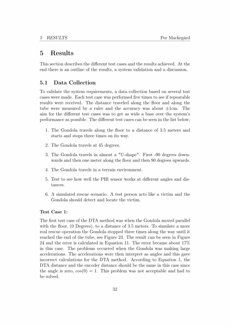
Test Case 2:
Next test case was to let the Gondola move at 45 degrees. The Gondolamoved a distance along the tube of 2.1 meters and a distance on the groundof about 1.52 meters, see Figure 26. Figure 27 shows the result of the test.The error became according to Equation 13, which was about 3% in thiscase.
1.52 m
Gondola
Flat Tube
2.10 m
45 deg
Figure 26: The Figure shows the test case when the Gondola moves at 45degrees.
34
5 RESULTS Per Mackegård
Figure 27: The Figure shows the DTA distance and the encoder distancewhen the Gondola is moving at 45 degrees.
error =1.52− 1.47
1.52= 3.29% (13)
Test Case 3:
In this test case the Gondola first moved 90 degrees downwards and then 90degrees upwards. The traveled distance along the tube was 3.1 meters andparallel with the floor the distance was 1 meter, see Figure 28. The result canbe seen in Figure 29. The error became about 10% in this case, see Equation14. This error is because the tube is flexible and when the Gondola moves,the "U-shape" changes and becomes more like a "V-shape". Because of thisthe angle changes and the Gondola "thinks" it moves at a steeper angle thanwhat it really is. But this is still a lot better than just using the encoderdistance. It this case by only measuring the encoder distance an error ofabout 300% would be received, see Figure 28.
35

5 RESULTS Per Mackegård
1 m
Gondola The tube is3.1 m long
Figure 28: The Figure shows the Gondola moving downwards and then up-wards.
Figure 29: The Figure shows the distance traveled in 90 degrees up and downaccording to the encoder and to the DTA method.
error =1− 0.9
1= 10% (14)
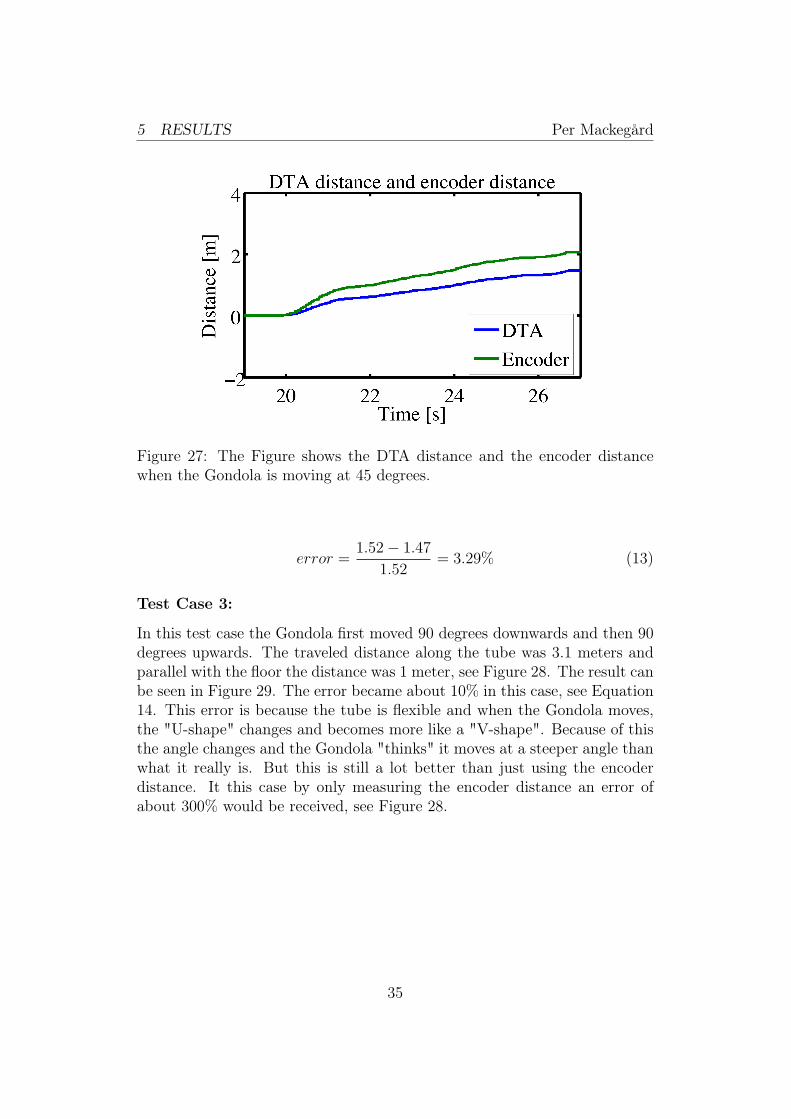
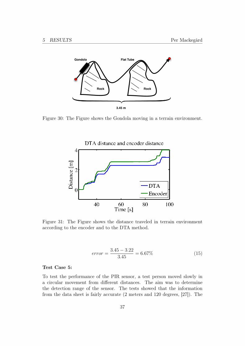
Test Case 4:
In this test case the Gondola moved along a terrain course. The distancealong the tube was 4 meters and the distance parallel to the floor was 3.45meters, see Figure 30. The result can be seen in Figure 31. The error becameaccording to Equation 15 about 7%.
36
5 RESULTS Per Mackegård
3.45 m
Gondola Flat Tube
Rock Rock
Figure 30: The Figure shows the Gondola moving in a terrain environment.
Figure 31: The Figure shows the distance traveled in terrain environmentaccording to the encoder and to the DTA method.
error =3.45− 3.22
3.45= 6.67% (15)
Test Case 5:
To test the performance of the PIR sensor, a test person moved slowly ina circular movement from different distances. The aim was to determinethe detection range of the sensor. The tests showed that the informationfrom the data sheet is fairly accurate (2 meters and 120 degrees, [27]). The
37

5 RESULTS Per Mackegård
biggest difficulty proved to be detecting something directly in front of thePIR sensor, see Figure 32.
PIR Sensor0.5 1 1.5 2 [m]
DetectionDetection
Figure 32: The Figure shows the detection range of the PIR sensor.
Test Case 6:
A final test was made where a person was lying on the floor acting as anunconscious victim, see Figure 33. The result of the distance measurementcan be seen in Figure 34. The error became according to about 6%, seeEquation 16.
1.3 m
Gondola Flat Tube
Rock Rock
Victim
Figure 33: The Figure shows the rescue situation.
38

5 RESULTS Per Mackegård
Figure 34: The Figure shows the distance traveled in terrain environmentaccording to the encoder and to the DTA method.
error =1.30− 1.22
1.3= 6.15% (16)
The result from the human detection can be seen in Figure 35. Thedistance from the Gondola to the victim was about 0.3 meters. The PIRsensor output is just high or low depending on if something is detected, seeFigure 35. The PIR sensor had no problem detecting human heat radiationeven though that the victim was laying completely still on the ground. Whenthe test person moved away, the sensor stopped detecting.
Figure 35: The Figure shows the output from the PIR sensor when a humanis detected.
39

5 RESULTS Per Mackegård
5.2 Test Results
A summary over the error in percentage for the test cases (1, 2, 3, 4 ,6),can be seen in Table 1. The digital filter was applied in all test cases expectfor the first test in test case 1. In Test Case 5 and Test Case 6 the humandetection method proved to be satisfying since the PIR sensor detected thetest person acting as a victim within the required detection range (1.5 m).
Table 1: The table shows the error in percentage for each test case.
Test Case Measured Distance [m] DTA Distance [m] Error [%]0 Deg- No Filter 3.5 2.9 170 Deg- With Filter 3.52 3.51 0.2845 Deg 1.52 1.47 3.2990 Deg 1 0.9 10Terrain 3.45 3.22 6.67Rescue Scenario 1.3 1.22 6.15
5.3 System Validation
To validate the system, the result from the different test cases were matchedagainst the specification of requirements.
Functional Requirements
The solution fulfills the functional requirements of;
• Adding a new method of detecting victims.
• Containing a method of measuring the distance to the victims.
• Working in both forward and backwards.
• Having wireless communication for data transmission.
• Having a simple interface for the rescue operator.
40
5 RESULTS Per Mackegård
Non-functional Requirements
The solution fulfills the non-functional requirements of;
• Being safe since the Gondola has no sharp edges and the propulsiveair pressure is relatively low (0.4 Mpa). The Gondola also travels inrelatively low speed, maximum 1 m/s.
• Being easy to use since the rescue operator only needs to attach theGondola on the tube, turn on the power button and monitor the in-coming data in Simulink.
• Being reliable since during all the different tests, (over 30 tests), thesystem could measure the DTA distance and send the information ofwhether a human victim was detected or not. Therefore it is reasonableto conclude that the system is reliable at least in short term.
• Fulfilling the requirement of detecting victims not covered by rubblewithin 1.5 meters range, according to the test results from the experi-ments.
• Fulfilling the requirement for the DTA method of an error range lessthan 15%.
• Weighing less (288 grams) than the maximum allowed weight of 500grams.
• Being small since that the solution only adds 43 millimeters of lengthand 5 millimeters of height.
According to this, the listed requirements are regarded as fulfilled.
5.4 Discussion
In these experiments there was one test that tested the only human detectionmethod, test case 5, and four tests that tested the localization method, testcases 1-4. There was also one combined test case, test case 6, that testedboth the human detection and localization methods. For better reliabilityand validation of the system it would of course be better if more test caseswere made. Particularly test cases that test the performance of the systemin a real rescue environment e.g. at a collapsed building.
41

5 RESULTS Per Mackegård
One limitation when testing the Gondola was the length of the tube. Thetotal length of the tube was only about four meters and this made it impos-sible to test the Gondola over a longer distance. One other difficulty was thequality of the tube. It has to be made with great precision to be as smoothas possible. If larger irregularities occur, the Gondola has problems passingthem, see Figure 36. This can be partially solved by using higher air pressure,but this is not the best solution since the effect of applying higher pressureis far less than the usage of a good quality tube. To avoid problems, a tubeof very good quality has to be used. The heat detection method proved tohave one problem. When the Gondola travels, small temperature differenceare being measured by the PIR sensor and therefore it "thinks" it detectshumans. This problem was however only a problem when the Gondola wastraveling. So this could be avoided by letting the Gondola move incremen-tally.
The accuracy of the angle measurements can also be improved. In this caseonly one axis was used to calculate the tilt angle. To achieve better accu-racy all three axis should be used, [33]. To fix this improvement no hardwarechanges are needed, only the angle measurement algorithms in Simulink haveto be remade. The sampling rate for the accelerometer sensor was also setrelatively low (15 Hz), this was set low since that the Gondola normallytravels in a low speed (< 0.5 m/s). It is however recommended in a furtherdevelopment to increase the sampling rate to achieve more accurate anglemeasurements and then indirectly achieve more accurate distance measure-ments from the DTA method.
Gondola
Flat Tube
Irregularity
Direction of Motion
Figure 36: The Figure shows a potential problem, irregularities on the tube.
42

6 CONCLUSION Per Mackegård
6 Conclusion
In this work an extended version of a rescue robot called the Gondola ispresented. Its scope of use is at disaster sites where it should find and lo-cate victims trapped by rubble. The aim of this thesis was to investigateand extend the human detection method and to investigate and develop anew localization system for the Gondola. This thesis starts with a review ofcurrent existing technologies and research. After the review and the follow-ing evaluation, a solution concept was designed a developed. The conceptincludes a human detection system based on the human heat radiation anda localization system called DTA. The results shows that it is rational toconclude that the functional and non-functional requirements have been ful-filled. The solution is light and compact and provides an extended methodfor human detection and localization within the accuracy requirements.
6.1 Potential Problems
In this solution there are however some limitations that need to be consideredwhen progressing with future work.
• The heat detection method has the constraint that the Gondola needsto move incrementally to work satisfactory. However the Gondola any-way needs to move incrementally to be able to receive clear image fromthe video camera. If this incremental movement could be avoided theefficiency in USAR operations could be increased.
• The DTA method is dependent on angle measurements from an ac-celerometer. This means that the angle measurement is affected if theGondola is not only tilting but also accelerating. This effect can besignificant decreased by filtering as in this case, however this error willstill remain to some extent.
6.2 Further Work
For the design and development process the main constraint was the weightand size. The solution had to be light and small, no heavy equipment couldbe carried. For future work an interesting part would therefore be to lookat increasing the propulsion force by developing the system for higher airpressure or usage of a larger diameter of the tube. The Gondola could thencarry heavier and more advanced equipment. This would make room for thepossibility of implementing for example a radar system for human detectionunderneath rubble. Another thing to work with in a future development is
43

6 CONCLUSION Per Mackegård
a new rescue operator interface where all the calculations also can be made.The new rescue operator interface could be written in for example C++, C#or Java. This would make it possible to make the interface more user-friendlyand eliminate the need of Matlab/Simulink. At Kitagawa/Tsukagoshi labo-ratory the research continues with the casting mechanism explained in section2.1, and another project with the aim to make a larger version of the Λ-driveexplained in section 2.2. The larger version of the Λ-drive uses a fire hoseinstead of the flat tube and can therefore probably achieve a significantlyhigher propulsion force for the Gondola and it seems like a very interestingoption for the future.
44
REFERENCES Per Mackegård
References
[1] United States Geological Survey (USGS). "Earthquake Facts andStatistics". Frequency of Occurrence of Earthquakes.http://earthquake.usgs.gov/earthquakes/eqarchives/year/
eqstats.php. Accessed 2011-04-25.
[2] United States Geological Survey (USGS). "Earthquake Facts andStatistics". Earthquakes with 1,000 or More Deaths since 1900.http://earthquake.usgs.gov/earthquakes/world/world_deaths.
php. Accessed 2011-04-26.
[3] All On Robots. "Search And Rescue Robots".http://www.allonrobots.com/rescue-robots.html.Accessed 2011-05-25.
[4] Yotaro Mori, Hideyuki Tsukagoshi, and Ato Kitagawa. "Flexible SlidingActuator Using A Flat Tube And Its Application To The Rescue Opera-tion". 2010 IEEE International Conference on Robotics and AutomationAnchorage Convention District May 3-8, 2010, Anchorage, Alaska, USA.
[5] SatoshiTadokoro. "DDT ProjectonRescueRobotsandSystems". SICE-ICASE International Joint Conference 2006. October 18-21, 2006 inBexco, Busan, Korea.
[6] Yotaro Mori, Hideyuki Tsukagoshi, and Ato Kitagawa. "Fluid PoweredRopeway: Self-Propelled Probe Sliding Along Flexible Tube". FujiTechnology Press. Journal of Robotics and Mechatronics.http://www.fujipress.jp/finder/xslt.php?mode=
present&inputfile=ROBOT002300020003.xml.Accessed 2011-04-28.
[7] Hisayuki Aoyama, Atsuhisa Himoto,Ryutaro Misumi, Ohomi Fuchi-waki, Daigo Misaki, Theodore Sumrall. "Micro Hopping Robot with IRSensor for Disaster Survivor Detection". Proceedings of the 2005 IEEEInternational Workshop on Safety, Security and Rescue Robotics Kobe,Japan, June 2005.
[8] Amon Tunwannarux, Supanunt Hirunyaphisutthikul. "Design Featuresand Characteristics of a Rescue Robot". Communications and Informa-tion Technology, 2005. ISCIT 2005. IEEE International Symposium onCommunication and Information Technologies 2005.
45

REFERENCES Per Mackegård
[9] Yasushi MAE, Atsushi Yoshida, Tatsuo Arai, Kenji Inoue, KunioMiyawaki, Hironori Adachi. "Application of Locomotive Robot to Res-cue Tasks". Proceedings of the 2000 IEEE/RSJ International Conferenceon Intelligent Robots and Systems.
[10] Figaro USA, INC. "TGS 4161 - for the detection of Carbon Dioxide".http://www.figarosensor.com/products/4161pdf.pdf.Accessed 2011-04-10.
[11] Ngujyen Huu Minh, Toshi Takamori, Shigeru Kobayashi,Shiro Takashima, Akihiro Ikeuchi. "Development of Carbon dioxidesensing system for searching victims in Large scale disasters". SICEAnnual Conference in Sapporo, August 46, 2004 Hokkaido Institute ofTechnology, Japan.
[12] A. W. Teo, H. K. Garg, S. Puthusserypady. "Detection of humans buriedin rubble: An electronic nose to detect human body odor". Proceed-ings of the Second Joint EMBS/BMES Conference Houston,TX, USAOctober.23-26, 2002.
[13] Victor Chernyak. "Signal Processing in Multisite UWB Radar Devicesfor Searching Survivors in Rubble". Proceedings of the 3rd EuropeanRadar Conference.
[14] Hugh Burchett. "Advances in Through Wall Radar for Search, Rescueand Security Applications". Crime and Security, 2006. The Institutionof Engineering and Technology Conference on Crime and Security.
[15] Jana Rovnakova, Dusan Kocur. "TOA Association for Handheld UWBRadar". Radar Symposium (IRS), 2010 11th International.
[16] Time Domain. "P400 radar".http://www.timedomain.com/p400-radar.php. Accessed 2011-04-13.
[17] Wellcrown international. "Rescue Radar 2".http://www.wellcrowninternational.com/ViewCatalog.asp?ID=
188. Accessed 2011-04-13.
[18] Cambridge Consultants. "Prism 200".http://www.cambridgeconsultants.com/news_pr150.html.Accessed 2011-04-13.
[19] Marina Trierscheid, Johannes Pellenz, Dietrich Paulus, Dirk Balthasar."Hyperspectral Imaging for Victim Detection with Rescue Robots".
46

REFERENCES Per Mackegård
IEEE International Workshop on Safety, Security and Rescue Robotics,October 21-24, 2008 Sendai, Japan.
[20] S. Schön and O. Bielenberg. "On the capability of high sensitivity GPSfor precise indoor positioning". Proceedings of the 5th Workshop onPositioning, Navigation and Communication 2008 (WPNC08).
[21] Dr. Frank van Diggelen. "Indoor GPS theory & implementation". IEEEPosition , Location & Navigation Symposium, 2002.
[22] Viet Nguyen, Ahad Harati, Roland Siegwart. "A Lightweight SLAMalgorithm using Orthogonal Planes for Indoor Mobile Robotics". Pro-ceedings of the 2007 IEEE/RSJ International Conference on IntelligentRobots and Systems San Diego, CA, USA, Oct 29 - Nov 2, 2007.
[23] Keiji Nagatani, Naoki Tokunaga, Yoshito Okada, Kazuya Yoshida."Continuous Acquisition of Three-Dimensional Environment Informa-tion for Tracked Vehicles on Uneven Terrain". Proceedings of the 2008IEEE International Workshop on Safety, Security and Rescue RoboticsSendai, Japan, October 2008.
[24] Kurt Seifert and Oscar Camacho. "Implementing Positioning Algo-rithms Using Accelerometers". Freescale Semiconductor ApplicationNote AN3397 Rev 0 02/2007. Accessed 2011-04-09.
[25] Ehad Akeila, Zoran Salcic, Akshya Swain. "A self-resetting method forreducing error accumulation in INS-based tracking". Position Locationand Navigation Symposium (PLANS), 2010 IEEE/ION.
[26] Dave Harmer, Alexander Yarovoy, Norbert Schmidt, Klaus Witrisal,Mark Russell, Ewan Frazer, Tim Bauge, Stuart Ingram, Amer Nezirovic,Anthony Lo, Liang Xia, Birgit Kull, Vedran Dizdarevic. "An Ultra-Wide Band Indoor Personnel Tracking System for Emergency Situations(Europcom)". Radar Conference, 2008. EuRAD 2008. European.
[27] Akizukidenshi. "SE-10 datasheet".http://akizukidenshi.com/download/SE-10.pdf.Accessed 2011-04-17.
[28] Figaro Sensors. "Figaro TGS2450datasheet".http://pdf1.alldatasheet.com/datasheet-pdf/view/115969/
ETC1/TGS2450.html. Accessed 2011-04-17.
47

REFERENCES Per Mackegård
[29] Microchip. "PIC16F685/687/689/690 Data Sheet".http://ww1.microchip.com/downloads/en/devicedoc/41262a.pdf.Accessed 2011-04-17.
[30] Kionix. "KXM52-1050 - Tri-Axis XYZ datasheet".http://akizukidenshi.com/download/KXM-52.pdf.Accessed 2011-04-16.
[31] Digi International. "IEEE 802.15.4 RF Modules datasheet".http://ftp1.digi.com/support/documentation/90000982_B.pdf.Accessed 2011-04-18.
[32] Michelle Clifford and Leticia Gomez. "Measuring Tilt with Low-gAccelerometers". Freescale Semiconductor Application Note AN3107Rev 0, 05/2005.http://www.freescale.com/files/sensors/doc/app_note/AN3107.
pdf. Accessed 2011-04-19.
[33] Kimberly Tuck. "Tilt Sensing Using Linear Accelerometers". FreescaleSemiconductor Application Note AN3461 Rev 2, 06/2007.http://cache.freescale.com/files/sensors/doc/app_note/
AN3461.pdf. Accessed 2011-04-19.
48
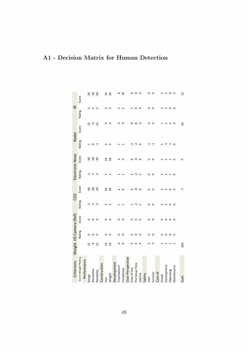
A1 - Decision Matrix for Human Detection
!"#$%"#&'(
)%#*+$
,-&"%.)%#*+$/01$#'*
01$#'*
,-&"%
01$#'*
,-&"%
01$#'*
,-&"%
01$#'*
,-&"%
01$#'*
,-&"%
2%"3&"41'-%
01'*%
56
77
898:7
898:7
556
898:7
0%(&;<$#&'
=7
789
85>
8985>
77
8985>
0%;#1?#;#$@
56
77
898:7
898:7
85856
898:7
!&'($"<-$#&'
,#A%
59
77
99B
99B
77
99B
)%#*+$
5B
77
99>
99>
77
99>
C%D%;&E4%'$
F"#%GH?%3&"%I
B7
75
B5
B5
B9
>
!&4E;%J#$@
=7
75
=5
=5
=9
5>
K(%"H2%"(E%-$#D%
L1(%H&3HK(%
B7
79
>9
>89
8>9
>
2"%H,%$<EHF#4
%B
77
898>
898>
898>
77
KE$#4
%B
77
9>
9>
77
77
,13%$@
K(%"
:7
77
77
785
8:7
7
,<"D#D&"
:7
77
77
785
8:7
7
!&($H&3
M&&G(
57
79
99
95
59
9
C%D%;&E4%'$
57
79
99
985
859
9
NE%"1$#'*
57
77
75
585
857
7
O1#'$%'1'-%
57
77
77
77
77
7
,<4
577
857
857
59
P,H!14%"1HQ0%3R
!N9
L;%-$"&'#-HS&(%
01G1"
T0H
49

A2 - Decision Matrix for Human Localization
!"#$%"#&'(
)%#*+$
,-&"%.)%#*+$/01$#'*
01$#'*
,-&"%
01$#'*
,-&"%
01$#'*
,-&"%
01$#'*
,-&"%
01$#'*
,-&"%
2%"3&"41'-%
01'*%
56
77
897
:8:97
897
897
0%(&;<$#&'
=7
78
5>
:8:5>
85>
5=
0%;#1?#;#$@
56
77
897
:5:56
897
77
!&'($"<-$#&'
,#A%
58
77
:8:8B
77
:8:8B
77
)%#*+$
5B
77
:8:8>
77
:8:8>
77
C%D%;&E4%'$
F"#%GH?%3&"%I
B7
7:8
:>7
7:5
:B:8
:>
!&4E;%J#$@
=7
7:8
:5>
77
:5:=
:5:=
K(%"H2%"(E%-$#D%
L1(%H&3HK(%
B7
7:5
:B7
7:8
:>7
7
2"%H,%$<EHF#4
%B
77
5B
77
:8:>
77
KE$#4
%B
77
:5:B
77
77
77
,13%$@
K(%"
97
77
77
7:5
:97
7
,<"D#D&"
97
77
77
7:5
:97
7
!&($H&3
M&&G(
57
7:8
:87
7:8
:8:5
:5
C%D%;&E4%'$
57
7:8
:8:5
:5:8
:8:5
:5
NE%"1$#'*
57
77
77
7:8
:87
7
O1#'$%'1'-%
57
77
77
7:5
:57
7
,<4
577
:>:PB
:5P
87
Q'G&&"HM2,HR0%3S
,TUO
QV,
K)WH01G#&
CFU
50

B1 - Compilation Drawing for the new Gondola
東京工業大学 北川・塚越研究室
Mackegaard
日 付
縮 尺 投 影 法所 属
担 当品 名
記 事
工程
質量
個数
材料
品 名
部品番号
2011-01-27
Assembly
51
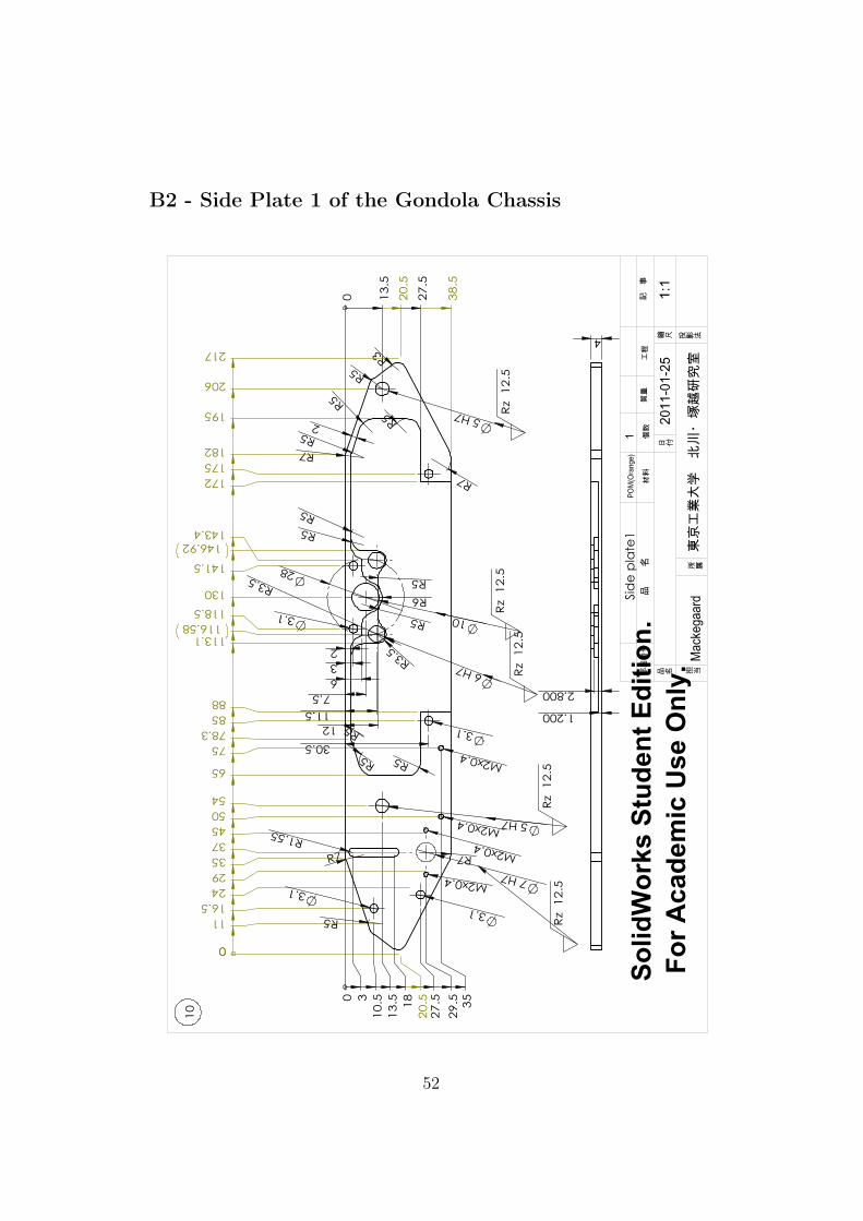
B2 - Side Plate 1 of the Gondola Chassis
東京工業大学 北川・塚越研究室
Mackegaard
日 付
縮 尺 投 影 法所 属
担 当品 名
記 事
工程
質量
個数
材料
品 名
部品番号
2011-01-25
1:1
POM(Orange)1
52

B2 - Side Plate 2 of the Gondola Chassis
東京工業大学 北川・塚越研究室
Mackegaard
日 付
縮 尺 投 影 法所 属
担 当品 名
記 事
工程
質量
個数
材料
品 名
部品番号
2011-01-25
1:1
Side Plate 2
POM(Orange)1
53
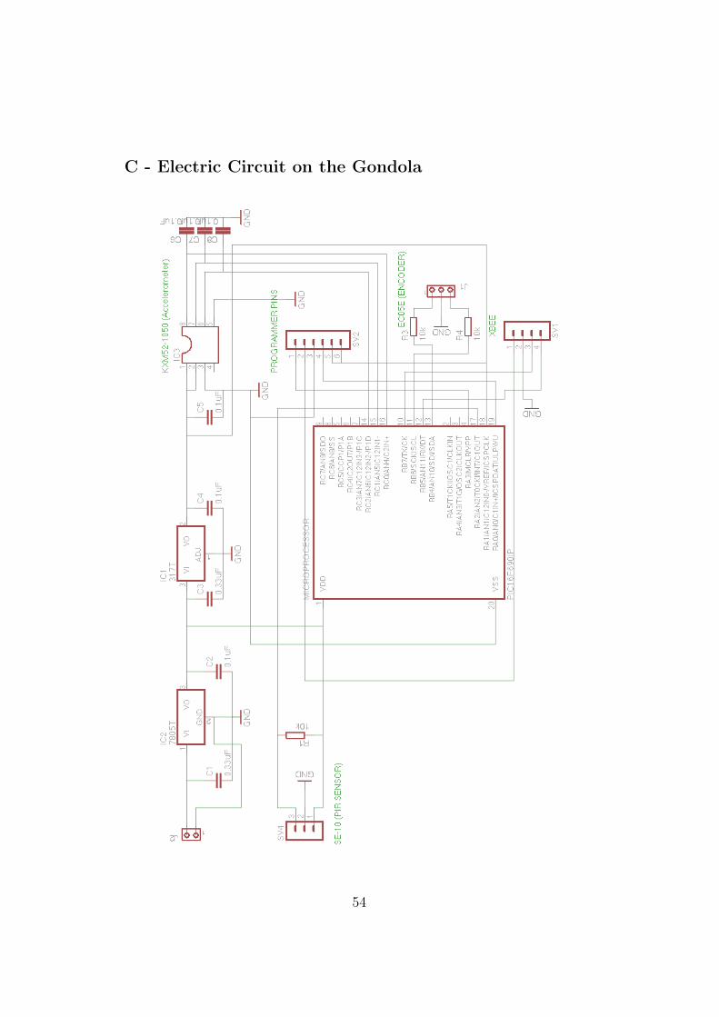
C - Electric Circuit on the Gondola
54

D - Simulink Model for Computations and Interface
calcu
late
d di
stan
ce
Z
else
if { }
In1
Out
1
Y
else
if { }
In1
Out
1
X
else
if { }
In1
Out
1
To W
orks
pace
5
calcu
late
d_di
stan
ce
To W
orks
pace
4
raw_
dist
ance
To W
orks
pace
3
heat
dete
ctio
n
To W
orks
pace
2
angl
e_z
To W
orks
pace
1
angl
e_x
To W
orks
pace
angl
e_y
Subs
yste
m
In1
In2
Out
1
Raw
dist
ance
Que
ry In
stru
men
t
Que
ryIn
stru
men
t
If
u1
if(u1
==
0)
else
if( u
1==1
)
else
if(u1
==2)
else
if( u
1==3
)
else
if( u
1==4
)
Heat
det
ectio
nHe
at
else
if { }
In1
Out
1
Dist
ance
if { }
In1
Out
1
Coun
ter
Coun
tUp
Inc
Cnt
Cloc
kAn
gle
z
Angl
e y
Angl
e x
Angl
e ca
lcula
tion
Z
In1De
gree
Angl
e ca
lcula
tion
Y
In1De
gree
Radi
ans
Angl
e ca
lcula
tion
X
In1
Out
1
55