Development of a robust scalar control system for an induction ...
9
Development of a robust scalar control system for an induction squirrel-cage motor based on a linearized vector model TSELIGOROV N.A., OZERSKY A.I., CHUBUKIN A.V., TSELIGOROVA E.N. Department of Computing Systems and Information Security Don State Technical University 1, Gagarin square, Rostov-on-Don, 344000 RUSSIA Abstract: The paper considers the problem of developing a digital system for an induction motor speed control which has a sensor and a speed regulator to increase accuracy of speed control. Speed control is carried out by a scalar method due to consistent change in the stator frequency and voltage. To obtain the uniformity of the motor overload capability in a given range the control mode is used associated with maintaining uniformity of flux linkage of the motor stator. Induction motor scalar models do not possess high accuracy and their parameters and their parameters can vary over a wide range, which complicates the controller design and achievement of robustness of the speed control system. To eliminate these disadvantages, it is proposed to use a vector model in a rotating coordinate system having subjected it to linearization at different points of the operating mode with the account of the adopted law of frequency control, to ensure robust absolute stability of the system on the basis of application of a graphical method for constructing a modified amplitude-phase characteristic. Key-Words: stability, robust absolute stability, interval polynomial, induction motor; V/f control; PID controller Received: June 25, 2021. Revised: October 31, 2021. Accepted: November 15, 2021. Published: January 3, 2022. 1 Introduction A modern frequency controlled electric drive of common application consists of an induction squirrel-cage electric motor and a static frequency- converter (SFC) with a DC link. The frequency converter generates voltage variable in frequency and amplitude from the constant voltage of the DC link. A change in the frequency of the voltage and its amplitude results in a change of rotating frequency of the stator magnetic field and, as a consequence, to a change in the shaft rotational speed of the electric motor. At present, the following laws of frequency control of an electric drive are known: – scalar control; – field-oriented control (FOC); – direct torque control (DTC). 2 Problem Formulation The following papers are known that make it possible to perform frequency control of the electric drive using scalar control [1-11]. As it is known, scalar models do not possess high accuracy and their parameters can change over a wide range which complicates the controller design and achievement of robustness of the speed control system. Field oriented frequency control (FOC) of the induction motor [12- 23] is the most promising and often used in modern industry. Diagrams of automatic control for an alternating current electric drive with discontinuous control that got the name “systems with direct torque control” (DTC) [24-26] are also widely used. The best static and dynamic characteristics within this method belong to a direct torque control using controllers on the basis of artificial neuron networks (ANNDTC) [27-29]. 3 Problem Solution Usually, modern frequency converters make it possible to implement several laws of electric motor control, for this purpose, a software switching of the known laws is factored in them. Despite the success in the field of creating highly dynamic electric drives on the basis of the field-oriented control (FOC) and DTC, scalar control systems have not lost their importance due to simplicity of implementation and adjustment [30, 31]. Scalar control systems do not always require identification of accurate parameters of the induction motor substitute diagram. A scalar control diagram is based, as a rule, on the consistent control of frequency and voltage of the induction motor stator. The generation of the required static and dynamic properties of the induction frequency-controlled electric drive is only possible in a closed control system of its coordinates. The functional diagram of the speed control system with maintaining uniformity of flux linkage of the stator in a steady state is presented in fig.1. WSEAS TRANSACTIONS on COMPUTERS DOI: 10.37394/23205.2022.21.1 Tseligorov N. A., Ozersky A. I., Chubukin A. V., Tseligorova E. N. E-ISSN: 2224-2872 1 Volume 21, 2022
-
Upload
khangminh22 -
Category
Documents
-
view
3 -
download
0
Transcript of Development of a robust scalar control system for an induction ...
Development of a robust scalar control system for an induction squirrel-cage motor based on a linearized vector model
TSELIGOROV N.A., OZERSKY A.I., CHUBUKIN A.V., TSELIGOROVA E.N. Department of Computing Systems and Information Security
Don State Technical University 1, Gagarin square, Rostov-on-Don, 344000
RUSSIA
Abstract: The paper considers the problem of developing a digital system for an induction motor speed control which has a sensor and a speed regulator to increase accuracy of speed control. Speed control is carried out by a scalar method due to consistent change in the stator frequency and voltage. To obtain the uniformity of the motor overload capability in a given range the control mode is used associated with maintaining uniformity of flux linkage of the motor stator. Induction motor scalar models do not possess high accuracy and their parameters and their parameters can vary over a wide range, which complicates the controller design and achievement of robustness of the speed control system. To eliminate these disadvantages, it is proposed to use a vector model in a rotating coordinate system having subjected it to linearization at different points of the operating mode with the account of the adopted law of frequency control, to ensure robust absolute stability of the system on the basis of application of a graphical method for constructing a modified amplitude-phase characteristic.
Key-Words: stability, robust absolute stability, interval polynomial, induction motor; V/f control; PID controller Received: June 25, 2021. Revised: October 31, 2021. Accepted: November 15, 2021. Published: January 3, 2022.
1 Introduction A modern frequency controlled electric drive of
common application consists of an induction squirrel-cage electric motor and a static frequency-converter (SFC) with a DC link. The frequency converter generates voltage variable in frequency and amplitude from the constant voltage of the DC link. A change in the frequency of the voltage and its amplitude results in a change of rotating frequency of the stator magnetic field and, as a consequence, to a change in the shaft rotational speed of the electric motor. At present, the following laws of frequency control of an electric drive are known: – scalar control; – field-oriented control (FOC); – direct torque control (DTC).
2 Problem Formulation The following papers are known that make it
possible to perform frequency control of the electric drive using scalar control [1-11]. As it is known, scalar models do not possess high accuracy and their parameters can change over a wide range which complicates the controller design and achievement of robustness of the speed control system. Field oriented frequency control (FOC) of the induction motor [12-23] is the most promising and often used in modern industry. Diagrams of automatic control for an alternating current electric drive with discontinuous control that got the name “systems with direct torque
control” (DTC) [24-26] are also widely used. The best static and dynamic characteristics within this method belong to a direct torque control using controllers on the basis of artificial neuron networks (ANNDTC) [27-29].
3 Problem Solution
Usually, modern frequency converters make it possible to implement several laws of electric motor control, for this purpose, a software switching of the known laws is factored in them. Despite the success in the field of creating highly dynamic electric drives on the basis of the field-oriented control (FOC) and DTC, scalar control systems have not lost their importance due to simplicity of implementation and adjustment [30, 31]. Scalar control systems do not always require identification of accurate parameters of the induction motor substitute diagram. A scalar control diagram is based, as a rule, on the consistent control of frequency and voltage of the induction motor stator.
The generation of the required static and dynamic properties of the induction frequency-controlled electric drive is only possible in a closed control system of its coordinates. The functional diagram of the speed control system with maintaining uniformity of flux linkage of the stator in a steady state is presented in fig.1.
WSEAS TRANSACTIONS on COMPUTERS DOI: 10.37394/23205.2022.21.1 Tseligorov N. A., Ozersky A. I., Chubukin A. V., Tseligorova E. N.
E-ISSN: 2224-2872 1 Volume 21, 2022
K
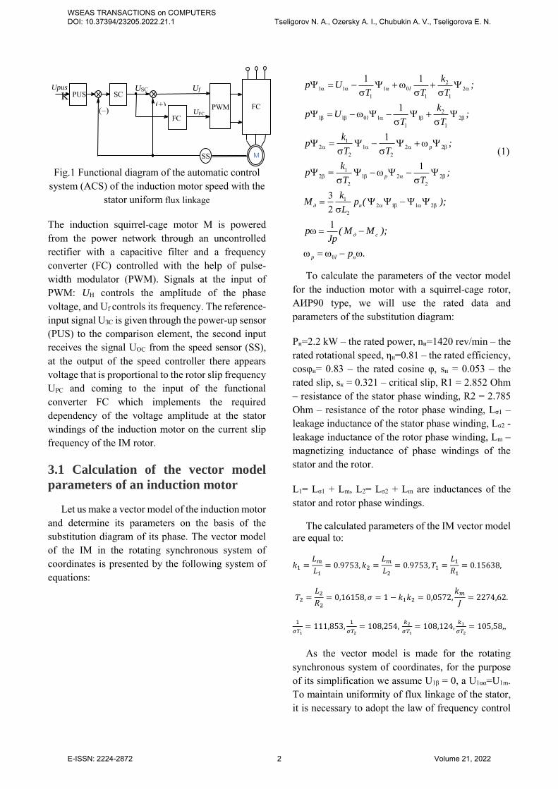
Fig.1 Functional diagram of the automatic control system (ACS) of the induction motor speed with the
stator uniform flux linkage
The induction squirrel-cage motor M is powered from the power network through an uncontrolled rectifier with a capacitive filter and a frequency converter (FC) controlled with the help of pulse-width modulator (PWM). Signals at the input of PWM: UН controls the amplitude of the phase voltage, and Uf controls its frequency. The reference-input signal UЗС is given through the power-up sensor (PUS) to the comparison element, the second input receives the signal UОС from the speed sensor (SS), at the output of the speed controller there appears voltage that is proportional to the rotor slip frequency UРС and coming to the input of the functional converter FC which implements the required dependency of the voltage amplitude at the stator windings of the induction motor on the current slip frequency of the IM rotor.
3.1 Calculation of the vector model
parameters of an induction motor
Let us make a vector model of the induction motor and determine its parameters on the basis of the substitution diagram of its phase. The vector model of the IM in the rotating synchronous system of coordinates is presented by the following system of equations:
(1)
To calculate the parameters of the vector model for the induction motor with a squirrel-cage rotor, АИР90 type, we will use the rated data and parameters of the substitution diagram:
Рн=2.2 kW – the rated power, nн=1420 rev/min – the rated rotational speed, ηн=0.81 – the rated efficiency, соsφн= 0.83 – the rated cosine φ, sн = 0.053 – the rated slip, sк = 0.321 – critical slip, R1 = 2.852 Ohm – resistance of the stator phase winding, R2 = 2.785 Ohm – resistance of the rotor phase winding, Lσ1 – leakage inductance of the stator phase winding, Lσ2 - leakage inductance of the rotor phase winding, Lm – magnetizing inductance of phase windings of the stator and the rotor.
L1= Lσ1 + Lm, L2= Lσ2 + Lm are inductances of the stator and rotor phase windings.
The calculated parameters of the IM vector model are equal to:
𝑘1 =𝐿𝑚
𝐿1= 0.9753, 𝑘2 =
𝐿𝑚
𝐿2= 0.9753, 𝑇1 =
𝐿1
𝑅1= 0.15638,
𝑇2 =𝐿2
𝑅2= 0,16158, 𝜎 = 1 − 𝑘1𝑘2 = 0,0572,
𝑘𝑚
𝐽= 2274,62.
1
𝜎𝑇1= 111,853,
1
𝜎𝑇2= 108,254,
𝑘2
𝜎𝑇1= 108,124,
𝑘1
𝜎𝑇2= 105,58,,
As the vector model is made for the rotating synchronous system of coordinates, for the purpose of its simplification we assume U1β = 0, а U1αα=U1m. To maintain uniformity of flux linkage of the stator, it is necessary to adopt the law of frequency control
М SS
FC
PUS Upus
(+) PWМ
USС SС
(–) UFC
UОС
Uf
FC
21 1 1 0 2
1 1 1
21 1 0 1 1 2
1 1
12 1 2 2
2 2
12 1 2 2
2 2
12 1 1 2
2
0
1 1
1
1
1
321
l
l
p
p
д п
д c
p l п
kp U ;
T T T
kp U ;
T T
kp ;
T T
kp ;
T T
kM p ( );
L
p ( M M );Jp
p .
WSEAS TRANSACTIONS on COMPUTERS DOI: 10.37394/23205.2022.21.1 Tseligorov N. A., Ozersky A. I., Chubukin A. V., Tseligorova E. N.
E-ISSN: 2224-2872 2 Volume 21, 2022
in the form of the following dependence of the voltage amplitude at the stator U1m = αω0д+βωр. The angular frequency of the electrical power supply voltage can be expressed in terms of the motor speed and frequency of the rotor EMF as ω0д=рпω+ωр.
Having substituted the expressions obtained for U1m and U1β into the equations of the IM vector model and having carried out the necessary transformations, we will get a vector model of the IM speed control system where ω0l represents an input signal and ω is an output value. The vector model obtained in this way can be written in a vector-matrix form, but it is non-linear due to the availability of the product of variables. Therefore, it is inapplicable in the obtained form for the speed controller design and needs linearization which can be carried out by the way of going to increments of values relative to their initial values at different points of the operation modes.
ψ1α= ψ1αn + Δψ1α; ψ1β= ψ1βn + Δψ1β; ψ2α= ψ2αn + Δψ2α;
ψ2β= ψ2βn + Δψ2β; ω=ωn+Δω; ; ωр=ωрn+Δωр.
After the corresponding transformations we obtain the linearized matrix equation of the form:
A= 1 1
1 0 2 1 1
1 10 1 2 1 1
1 11 2 2
0
00 0
0
l п n
l п n
рn
T k T p
T k T p
k T T
( ) ( )
( ) ( )
( ) ( )
1 1
1 2 2
2 2 1 1
00
рn
м n м n м n nм
k T T ( ) (
k / J k / J k / J k / J
)
x= [Δψ1αΔψ1βΔψ2αΔψ2βΔω]T;
B=[ ψ1βn +α+β - ψ1αnψ2βn - ψ2αn 0];
C=[0 0 0 0 1].
The frequency control law for an induction motor used in an electric drive has the following expression U1m = αω0l+βωр, где α=0.902, а β=1.05. Let us assume the range of motor speed control equal to 10. We assign the voltage frequency ω0'ln=31, 130 and 314 1/s and the rotor frequency ωр=0 and 50 rad/s. To determine the initial values of flux linkages of the stator and the rotor for the selected nominal design points, it is necessary to solve the matrix equation for the static mode obtained from the considered matrices at р=0: x= -A-1
4*4B4*1U1m, where A4*4 is a
square matrix of the first four columns and four rows highlighted in the matrix А, В4*1=[1 0 0 0]T.
3.2 Investigation of a continuous model
of an induction motor
Given the voltage frequency at the stator of an induction motor and the slip frequency within the specified ranges, initial values of flux linkages of the stator and the rotor are calculated. Using the values of flux linkages in the matrix А5*5 and taking into account the vectors B, C, we find a transfer function of the linearized model of the induction motor in the form of zpk. For example, for the given ω0'ln=250 1/s and ωр=0 1/s, the found transfer function has the following form:
𝑊𝜔р(𝑝) =
𝜔
𝜔р
= (2)
=6006,4(𝑝 + 174,6)(𝑝2 + 50,1𝑝 + 1,2𝑒04)
𝑝(𝑝2 + 213,9𝑝 + 1,504𝑒04)(𝑝2 + 226,3𝑝 + 4,8𝑒04).
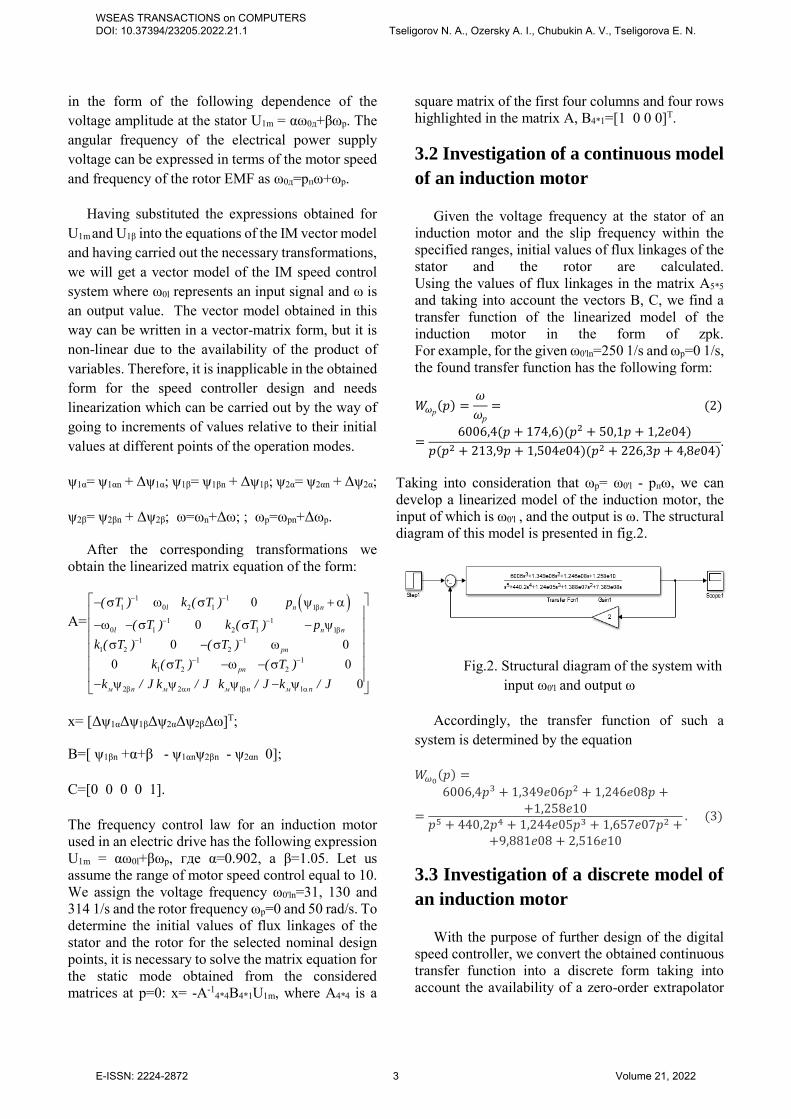
Taking into consideration that ωр= ω0'l - рпω, we can develop a linearized model of the induction motor, the input of which is ω0'l , and the output is ω. The structural diagram of this model is presented in fig.2.
Fig.2. Structural diagram of the system with input ω0'l and output ω
Accordingly, the transfer function of such a system is determined by the equation
𝑊𝜔0(𝑝) =
=
6006,4𝑝3 + 1,349𝑒06𝑝2 + 1,246𝑒08𝑝 ++1,258𝑒10
𝑝5 + 440,2𝑝4 + 1,244𝑒05𝑝3 + 1,657𝑒07𝑝2 ++9,881𝑒08 + 2,516𝑒10
. (3)
3.3 Investigation of a discrete model of
an induction motor
With the purpose of further design of the digital speed controller, we convert the obtained continuous transfer function into a discrete form taking into account the availability of a zero-order extrapolator
WSEAS TRANSACTIONS on COMPUTERS DOI: 10.37394/23205.2022.21.1 Tseligorov N. A., Ozersky A. I., Chubukin A. V., Tseligorova E. N.
E-ISSN: 2224-2872 3 Volume 21, 2022
and the discreteness period of Т=0.01s. As a result, we obtain the following discrete transfer function:
𝑊𝜔р(𝑧) =
=
0,1158𝑧4 − 0,06273𝑧3 + 0,04193𝑧2 ++0,102184𝑧 − 0,004783
𝑧5 − 1,114𝑧4 + 0,316𝑧3 + 0,006112𝑧2 ++0,02824𝑧 − 0,01225
. (4)
We will carry out a discrete PID-controller design with the help of the pidtool program, while in order to achieve robustness we ensure the maximum possible phase margin in an open digital system. The synthesis is based on the transfer function (4) as among the obtained linearized transfer functions it possesses the highest gain factor. As a result of the controller design, we will determine the controller transfer function of the following form:
𝑊Р(𝑧) =6,786𝑧2 − 8,2327𝑧 + 2,559
3𝑧2 − 4𝑧 + 1 . (5)
Let us find a discrete transfer function of the open speed control system
𝑊раз(𝑧) =
=
0,7857𝑧6 − 1,379𝑧5 + 1,097𝑧4 − 0,3505𝑧3 −
−0,105𝑧2 + 0,09526𝑧 − 0,012243𝑧7 − 7,342𝑧6 + 6,404𝑧5 − 2,36𝑧4 + 0,3763𝑧3 −
−0,1436𝑧2 + 0,07724𝑧 − 0,01225
(6)
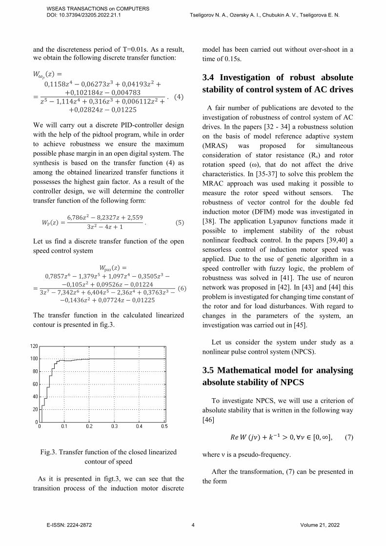
The transfer function in the calculated linearized contour is presented in fig.3.
Fig.3. Transfer function of the closed linearized contour of speed
As it is presented in figt.3, we can see that the transition process of the induction motor discrete
model has been carried out without over-shoot in a time of 0.15s.
3.4 Investigation of robust absolute
stability of control system of AC drives
A fair number of publications are devoted to the investigation of robustness of control system of AC drives. In the papers [32 - 34] a robustness solution on the basis of model reference adaptive system (MRAS) was proposed for simultaneous consideration of stator resistance (Rs) and rotor rotation speed (ω), that do not affect the drive characteristics. In [35-37] to solve this problem the MRAC approach was used making it possible to measure the rotor speed without sensors. The robustness of vector control for the double fed induction motor (DFIM) mode was investigated in [38]. The application Lyapunov functions made it possible to implement stability of the robust nonlinear feedback control. In the papers [39,40] a sensorless control of induction motor speed was applied. Due to the use of genetic algorithm in a speed controller with fuzzy logic, the problem of robustness was solved in [41]. The use of neuron network was proposed in [42]. In [43] and [44] this problem is investigated for changing time constant of the rotor and for load disturbances. With regard to changes in the parameters of the system, an investigation was carried out in [45].
Let us consider the system under study as a nonlinear pulse control system (NPCS).
3.5 Mathematical model for analysing
absolute stability of NPCS
To investigate NPCS, we will use a criterion of absolute stability that is written in the following way [46]
𝑅𝑒 𝑊 (𝑗𝜈) + 𝑘−1 > 0, ∀𝜈 ∈ [0, ∞], (7)
where ν is a pseudo-frequency.
After the transformation, (7) can be presented in the form
WSEAS TRANSACTIONS on COMPUTERS DOI: 10.37394/23205.2022.21.1 Tseligorov N. A., Ozersky A. I., Chubukin A. V., Tseligorova E. N.
E-ISSN: 2224-2872 4 Volume 21, 2022
),()()( xhBxAxP (8)
where A(x), B(x) are polynomials, h=ck, x= 2 .
Taking into consideration that the transfer function of the system under study has interval real coefficients, then the equation (7) can be represented as real interval polynomials of the form [22]
𝐴(𝑥) = ∑ 𝑎𝑖𝑥𝑖𝑛𝑖=0 , 𝑎𝑖 ∈ [𝑎𝑖, 𝑎𝑖], 𝑎𝑖 ≤ 𝑎𝑖,
𝐵(𝑥) = ∑ 𝑏𝑖𝑥𝑖𝑛𝑖=0 , 𝑏𝑖 ∈ [𝑏𝑖, 𝑏𝑖], 𝑏𝑖 ≤ 𝑏𝑖, (9)
making it possible, with their help at the variation of h parameter, to construct a root locus [47, 48] with interval coefficients.
Usually, when using interval polynomials, Kharitonov’s strong theorem is applied [49], in which it is proved that necessary and sufficient condition for robust absolute stability of interval polynomials (8) is that four Kharitonov’s polynomials are Hurwitz polynomials.
3.6 Simulation of a discrete control
system of an induction motor
To estimate robust absolute stability of the system it is necessary to perform w-transformation of the initial transfer function represented in z-form (6) into a transfer function represented in a w-form with nominal coefficients, which after the w-transformation is written in the form
𝑊𝜔р(𝑤) =
−0,1728𝑤7−98,21𝑤6−5816𝑤5+1,948𝑒6𝑤4+
+4,777𝑒8𝑤3+6,441𝑒10𝑤2+3,801𝑒12𝑤+8,091𝑒13
𝑤7+791,3𝑤6+2,605𝑒5𝑤5+4,198𝑒7𝑤4+
+3,555𝑒9𝑤3+1,548𝑒11𝑤2+2,905𝑒12𝑤+1,857
(10)
We transform this transfer function into a transfer function with interval coefficients, the values of which differ from the coefficients of the transfer function with nominal values (10) by 10%. After the transformation (10) will have the following form
𝑊𝜔р(𝑤) =
−(0,190..0,155)𝑤7−(108,031..88,389)𝑤6−
−(6397,6..5234,4)𝑤5+(1,755..2,145)𝑒6𝑤4+
+(4,299..5,254)𝑒8𝑤3+(5,796..7,085)𝑒10𝑤2+
+(3,420..4,181)𝑒12𝑤+(7.281..8,899)𝑒13
(0,9..1,1)𝑤7+(712,17..870,43)𝑤6+
+(2,344..2,865)𝑒3𝑤5+(3,785..4,626)𝑒7𝑤4+
+(3,199..3,910)𝑒9𝑤3+(1,397..1,708)𝑒11𝑤2+
+(2,619..3,201)𝑒12𝑤+(1,671..2,043)
. (11)
Obtaining an interval function (11) is done under the assumption that endogenous and exogenous changes in the parameters of the system under study are within the range of ±10%, which is reflected on the values of the transfer function coefficients [47].
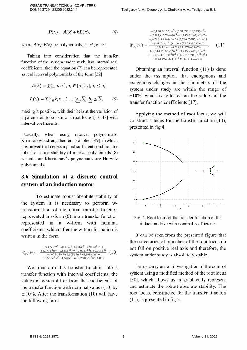
Applying the method of root locus, we will construct a locus for the transfer function (10), presented in fig.4.
Fig. 4. Root locus of the transfer function of the induction drive with nominal coefficients
It can be seen from the presented figure that the trajectories of branches of the root locus do not fall on positive real axis and therefore, the system under study is absolutely stable.
Let us carry out an investigation of the control system using a modified method of the root locus [50], which allows us to graphically represent and estimate the robust absolute stability. The root locus, constructed for the transfer function (11), is presented in fig.5.
WSEAS TRANSACTIONS on COMPUTERS DOI: 10.37394/23205.2022.21.1 Tseligorov N. A., Ozersky A. I., Chubukin A. V., Tseligorova E. N.
E-ISSN: 2224-2872 5 Volume 21, 2022
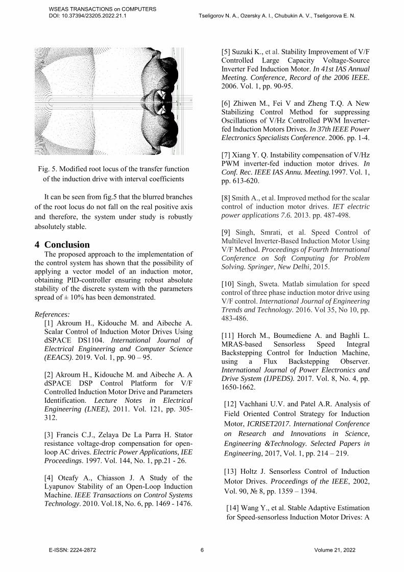
Fig. 5. Modified root locus of the transfer function of the induction drive with interval coefficients
It can be seen from fig.5 that the blurred branches of the root locus do not fall on the real positive axis and therefore, the system under study is robustly absolutely stable.
4 Conclusion The proposed approach to the implementation of
the control system has shown that the possibility of applying a vector model of an induction motor, obtaining PID-controller ensuring robust absolute stability of the discrete system with the parameters spread of ± 10% has been demonstrated.
References:
[1] Akroum H., Kidouche M. and Aibeche A. Scalar Control of Induction Motor Drives Using dSPACE DS1104. Ιnternational Journal of
Electrical Engineering and Computer Science
(EEACS). 2019. Vol. 1, pp. 90 – 95. [2] Akroum H., Kidouche M. and Aibeche A. A dSPACE DSP Control Platform for V/F Controlled Induction Motor Drive and Parameters Identification. Lecture Notes in Electrical
Engineering (LNEE), 2011. Vol. 121, pp. 305-312. [3] Francis C.J., Zelaya De La Parra H. Stator resistance voltage-drop compensation for open-loop AC drives. Electric Power Applications, IEE
Proceedings. 1997. Vol. 144, No. 1, pp.21 - 26. [4] Oteafy A., Chiasson J. A Study of the Lyapunov Stability of an Open-Loop Induction Machine. IEEE Transactions on Control Systems
Technology. 2010. Vol.18, No. 6, pp. 1469 - 1476.
[5] Suzuki K., et al. Stability Improvement of V/F Controlled Large Capacity Voltage-Source Inverter Fed Induction Motor. In 41st IAS Annual
Meeting. Conference, Record of the 2006 IEEE. 2006. Vol. 1, pp. 90-95. [6] Zhiwen M., Fei V and Zheng T.Q. A New Stabilizing Control Method for suppressing Oscillations of V/Hz Controlled PWM Inverter-fed Induction Motors Drives. In 37th IEEE Power
Electronics Specialists Conference. 2006. pp. 1-4. [7] Xiang Y. Q. Instability compensation of V/Hz PWM inverter-fed induction motor drives. In
Conf. Rec. IEEE IAS Annu. Meeting.1997. Vol. 1, pp. 613-620. [8] Smith A., et al. Improved method for the scalar control of induction motor drives. IET electric
power applications 7.6. 2013. pp. 487-498. [9] Singh, Smrati, et al. Speed Control of Multilevel Inverter-Based Induction Motor Using V/F Method. Proceedings of Fourth International
Conference on Soft Computing for Problem
Solving. Springer, New Delhi, 2015. [10] Singh, Sweta. Matlab simulation for speed control of three phase induction motor drive using V/F control. International Journal of Engineering
Trends and Technology. 2016. Vol 35, No 10, pp. 483-486. [11] Horch M., Boumediene A. and Baghli L. MRAS-based Sensorless Speed Integral Backstepping Control for Induction Machine, using a Flux Backstepping Observer. International Journal of Power Electronics and
Drive System (IJPEDS). 2017. Vol. 8, No. 4, pp. 1650-1662.
[12] Vachhani U.V. and Patel A.R. Analysis of Field Oriented Control Strategy for Induction Motor, ICRISET2017. International Conference
on Research and Innovations in Science,
Engineering &Technology. Selected Papers in
Engineering, 2017, Vol. 1, pp. 214 – 219.
[13] Holtz J. Sensorless Control of Induction Motor Drives. Proceedings of the IEEE, 2002, Vol. 90, № 8, pp. 1359 – 1394.
[14] Wang Y., et al. Stable Adaptive Estimation for Speed-sensorless Induction Motor Drives: A
WSEAS TRANSACTIONS on COMPUTERS DOI: 10.37394/23205.2022.21.1 Tseligorov N. A., Ozersky A. I., Chubukin A. V., Tseligorova E. N.
E-ISSN: 2224-2872 6 Volume 21, 2022
Geometric Approach, International Conference
on Electrical Machines (ICEM), 2020, pp.1232 –1238. [15] Bhattacharjee S., Halder S., et al. An advanced policy gradient based vector control of PMSM for ev application. In 2020 10th
International Electric Drives Production
Conference (EDPC), 2020, pp. 1–5. [16] Aamir H. O. A. Speed Sensorless Vector Control of Induction Motors Using Rotor Flux based Model Reference Adaptive System. SUST
Journal of Engineering and Computer Science
(JECS). 2015. Vol. 16, No. 3, pp. 1-4. [17] Fu X. and Li S. A novel neural network vector control technique for induction motor drive. IEEE Trans. Energy Convers. 2015. Vol. 30, No. 4, pp. 1428–1437. [18] Gadoue S. M., Giaouris D. and Finch J. W. MRAS sensorless vector control of an induction motor using new sliding-mode and fuzzy-logic adaptation mechanisms. IEEE Trans. Energy
Convers. 2010. Vol. 25, No. 2, pp. 394–402. [19] Fan B., Yang Z., et al. Rotor resistance online identification of vector controlled induction motor based on neural network. Mathematical Problems in Engineering. 2014. Vol. 2014. [20] Boldea I. Control issues in adjustable speed drives. IEEE Industrial Electronics Magazine. 2008. Vol. 2, No. 3, pp. 32 - 50. [21] Robyns B., et al. Dynamic Modeling of Induction Machines. Vector Control of
Induction Machines. Springer, London. 2012. pp.35-74. [22] Maiti S., et al. Model reference adaptive controller-based rotor resistance and speed estimation techniques for vector controlled induction motor drive utilizing reactive power. IEEE Trans. Ind. Electron., 2008, vol. 55, no. 2, pp. 594-601. [23] Gite G. and Khampariya P. Vector Controlled Sensorless Estimation and Control of
Speed of Induction Motors. International
Research Journal of Engineering and
Technology (IRJET). 2016. Vol. 3 Issue: 10, pp. 191 – 196. [24] Zelechowski M. Space vector modulated - direct torque controlled (DTC-SVM) inverter-fed induction motor drive. Ph. D. Thesis.
Warsaw. 2005. 169 p. [25] Dehghani M., Karimyan P., et al. Dynamic Behavior Control of Induction Motor with STATCOM. 2nd IEEE International conference
on power Electronics, Intelligent Control and
Energy systems (ICPEICES-2018). 2018. pp. 1-6. [26] Toufouti R., Meziane S. and Benalla H. Direct Torque Control for Induction Motor Using Fuzzy Logic. ICGST Trans. on ACSE. 2006. Vol.6, Issue 2, pp. 17-24. [27] Takahashi T. N. A new quick-response and high efficiency control strategy of an induction motor. IEEE Trans. Ind. Applications. 1986. Vol. 22. No.5, pp. 820 - 827. [28] Toufouti R., Benalla H. Direct torque control for induction motor using intelligent techniques. Journal of theoretical and applied
information technology. 2007. pp. 35-44. [29] Vasudevan M., Arumugam R. High-performance adaptive intelligent direct torque control schemes for induction motor drives. KMITL science technology Journal. 2005. Vol. 5, No.3, pp. 559-576. [30] Sokolovsky G.G. AC drives with frequency regulation: Textbook for stud. higher. study institutions. Moscow: Publishing Center "Academy", 2006. 272 p. [31] Pozdeev A.D. Electromagnetic and electromechanical processes in frequency-controlled asynchronous electric drives, Publishing house of the Chuvash University, 1998, 173 p. [32] Peng F., Fukao T. Robust speed identification for speed-sensorless vector
WSEAS TRANSACTIONS on COMPUTERS DOI: 10.37394/23205.2022.21.1 Tseligorov N. A., Ozersky A. I., Chubukin A. V., Tseligorova E. N.
E-ISSN: 2224-2872 7 Volume 21, 2022
control of induction motors. IEEE Trans. Ind.
Appl., 1994. No l. 30, pp. 1234-1240. [33] Vasic V., Vukosavic S. Robust MRAS-based algorithm for stator resistance and rotor speed identification. IEEE Power Eng. Rev., 2001. Vol. 21, No. 11, pp. 39–41. [34] Djamila C., Yahia M. and Ali T., Robust MRAS-Based Algorithm for Rotor Resistance and Rotor Speed Estimation of Indirect Vector Controlled Induction Motor Drive, International Journal on Energy
Conversion (IRECON). 2013. Vol. 1 (2), pp. 133-140. [35] Park C.W., Kwon W.H. Simple and robust speed sensorless vector control of induction motor using stator current based MRAC. Electric Power Systems Research. 2004. Vol. 71, Issue 3, pp. 257-266. [36] Srikanth M., et al. Robust MRAC Based Sensorless Rotor Speed Measurement against Variations in Stator Resistance Using Combination of Back EMF and Reactive Power Method. International Journal of
Multidisciplinary Educational Research. 2012, Vol. 1, Issue 3, pp. 38-46. [37] Srikanth M., Sreedhar L. and Madhu Ch. P. Dynamic Simulation of Robust Sensorless Speed Measurement in IM Using MRAC against Variations in Stator Resistance and Rotor-Time Constant. International Journal of Engineering
and Advanced Technology (IJEAT). 2013, Vol.2. Issue 5, pp. 52– 55. [38] Drid S., Tadjine M. and Nait-Said M.S. Robust backstepping vector control for the doubly fed induction motor. IET Control Theory
Appl., 2007. Vol. 1, No. 4, pp. 861–868. [39] Chaouch S. et al. Robust sensorless speed control purpose for induction motors. 5th
International Multi-Conference on Systems,
Signals and Devices. 2008, pp.1 – 6. [40] Kianinezhad R. et al. Robust sensorless vector control of induction machines. Iranian
Journal of Science & Technology, Transaction
B, Engineering, 2009. Vol. 33, No. B2, pp. 133-147. [41] Uddin M. N. and Rahman M. A. High-speed control of IPMSM drives using improved fuzzy logic algorithms. IEEE Trans. Ind.
Electron.2007. Vol. 54, No. 1, pp. 190–199. [42] Ren T.-J. and Chen T.-C. Robust speed-controlled induction motor drive based on recurrent neural network. Electric power
systems research. 2006. Vol. 76, No 12, pp. 1064–1074. [43] Grouni S., Ibtiouen R., et al. Improvement Approach on Rotor Time Constant Adaptation with Optimum Flux in IFOC for Induction Machines Drives. World Academy of Science,
Engineering and Technology. 2008. No 13. pp. 340-345. [44] Huang C.-Y., Chen T.-C. and Huang C.-L. Robust control of induction motor with a neural-network load torque estimator and a neural network identification. IEEE Trans. Ind.
Electron.1999.Vol. 46, No. 5, pp. 990–998. [45] Quintero-Manriquez E., Sanchez E. N., et al. Neural inverse optimal control implementation for induction motors via rapid control prototyping. IEEE Trans. Power
Electron.2018.Vol. 34, No. 6, pp. 5981–5992. [46] Tsypkin Ya.Z., Popkov Yu.S. Theory of Nonlinear Impulsive Systems, Moscow:
Nauka, 1973. 416 рр. [47] Tseligorov N.A., Tseligorova E. N. and Mafura G.M. An Assessment of the Effect of Varying Popov’s Parameter on the Region of Robust Absolute Stability of Nonlinear Impulsive Control Systems with Parametric Uncertainty. Computational Problems in
Science and Engineering.2014. Vol. 343, pp. 141-151. [48] Tseligorov N.A., Tseligorova E. N. and Mafura G.M. Using Information Technology for Computer Modeling of Nonlinear Monotonous Impulse Control System with Uncertainties. In
Proceeding of the Computer Modeling and
WSEAS TRANSACTIONS on COMPUTERS DOI: 10.37394/23205.2022.21.1 Tseligorov N. A., Ozersky A. I., Chubukin A. V., Tseligorova E. N.
E-ISSN: 2224-2872 8 Volume 21, 2022
Simulation, Saint Petersburg, Russia, 2014, pp. 75-80. [49] Kharitonov V. L. Asymptotic stability of an equilibrium position of a family of systems of linear differential equations. Differential
Equations. 1978.Vol. 14, pp. 2086-2088. [50] Tseligorov N.A. Modeling complex "Sustainability" for the study of robust absolute stability of nonlinear impulsive control systems. In Proceeding of the Computer Modeling and
Simulation, Saint Petersburg, Russia, 2012, pp. 9-14.
Contribution of individual authors to
the creation of a scientific article
(ghostwriting policy)
Author Contributions:
Tseligorov N.A. carried out investigation of the
control system of the induction drive for stability
Chubukin A.V. developed a linearized model of
the induction drive
Tseligorova E.N., Ozersky A.I. performed
simulation.
Creative Commons Attribution
License 4.0(Attribution 4.0
International , CC BY 4.0)
This article is published under the terms of the Creative Commons Attribution License 4.0 https://creativecommons.org/licenses/by/4.0/deed.en_US
WSEAS TRANSACTIONS on COMPUTERS DOI: 10.37394/23205.2022.21.1 Tseligorov N. A., Ozersky A. I., Chubukin A. V., Tseligorova E. N.
E-ISSN: 2224-2872 9 Volume 21, 2022