Scalar speed control of induction motors with difference ...
11
POLİTEKNİK DERGİSİ JOURNAL of POLYTECHNIC ISSN: 1302-0900 (PRINT), ISSN: 2147-9429 (ONLINE) URL: http://dergipark.gov.tr/politeknik Scalar speed control of induction motors with difference frequency Fark frekans ile indüksiyon motorun skaler hız denetimi Yazar (Author): Özcan OTKUN ORCID: 0000-0002-5025-1516 Bu makaleye şu şekilde atıfta bulunabilirsiniz (To cite to this article): Otkun Ö., “Scalar speed control of ınduction motors with difference frequency”, Journal of Polytechnic, 23(2): 267-276, (2020). Erişim linki (To link to this article): http://dergipark.gov.tr/politeknik/archive DOI: 10.2339/politeknik.474043
-
Upload
khangminh22 -
Category
Documents
-
view
2 -
download
0
Transcript of Scalar speed control of induction motors with difference ...
POLİTEKNİK DERGİSİ JOURNAL of POLYTECHNIC
ISSN: 1302-0900 (PRINT), ISSN: 2147-9429 (ONLINE)
URL: http://dergipark.gov.tr/politeknik
Scalar speed control of induction motors with
difference frequency
Fark frekans ile indüksiyon motorun skaler hız
denetimi
Yazar (Author): Özcan OTKUN
ORCID: 0000-0002-5025-1516
Bu makaleye şu şekilde atıfta bulunabilirsiniz (To cite to this article): Otkun Ö., “Scalar speed control
of ınduction motors with difference frequency”, Journal of Polytechnic, 23(2): 267-276, (2020).
Erişim linki (To link to this article): http://dergipark.gov.tr/politeknik/archive
DOI: 10.2339/politeknik.474043

Politeknik Dergisi, 2020; 23(2) : 267-276 Journal of Polytechnic, 2020; 23 (2): 267-276
267
Scalar Speed Control of Induction Motors with
Difference Frequency Araştırma Makalesi / Research Article
Özcan OTKUN*
Department of Electrical and Electronics, 3Nokta Academy Company, 61100, Ortahisar, Trabzon, Turkey
(Geliş/Received : 23.10.2018 ; Kabul/Accepted : 02.04.2019)
ABSTRACT
Speed monitoring of electric motors has attracted the attention of many researchers from past to present. Induction Motor (IM),
which is one of the electric motor types, falls behind the nominal speed in different loads. This study was conducted to increase
the speed control performance of IM. In the study, speed control of IMs was realized by Difference Frequency (DF). The Scalar
Control (SC) method was used in IM speed control. In order to increase the performance of SC, the frequency information received
from IM was compared with the reference frequency. The resulting DF was applied to the system input again. For the performance
analysis of the study; SC, PI + SC and DF + SC methods were compared. The results obtained from the study simulated in Matlab
software show that the proposed method can be used in speed control.
Keywords: Speed control, scalar speed control, IM, frequency, V/f.
Fark Frekans ile İndüksiyon Motorun Skaler Hız
Denetimi
ÖZ
Elektrik motorlarının hız denetimi geçmişten günümüze pek çok araştırmacının ilgisini çekmiştir. Elektrik motor çeşitlerinden biri
olan Indüksiyon Motor (IM) ya da Asenkron Motor (ASM) farklı yüklerde nominal hızın gerisinde kalmaktadır. Bu çalışmada
IM’nin hız denetim başarımını arttırmak amacıyla yapılmıştır. Yapılan çalışmada IM’lerin hız denetimi Fark Frekans (FF) ile
gerçekleştirilmiştir. IM hız denetiminde Skaler Denetim (SD) yöntemi kullanılmıştır. SD’nin başarımını arttırmak için IM’den
alınan frekans bilgisi referans frekans ile karşılaştırılmıştır. Elde edilen FF tekrar sistem girişine uygulanmıştır. Çalışmanın
performans analizi için; SD, PI + SD ve FF + SD yöntemleri karşılaştırılmıştır. Analiz sonuçları tablo ve grafikler ile sunulmuştur.
Matlab yazılımında benzetimi gerçekleştirilen çalışmadan elde edilen sonuçlar önerilen yöntemin hız denetiminde
kullanılabileceğini göstermektedir.
Anahtar Kelimeler: Hız denetimi, skaler hız denetimi, IM, Frekans, V/f.
1. INTRODUCTION
Induction Motors (IM) are preferred in industrial areas
due to advantages such as simple structure, low cost, low
maintenance requirements and high efficiency [1] - [5].
This situation reveals the need for use of IMs at different
speeds. However, the nonlinear dynamic model, the time
varying parameters and external load torque of these
motors makes the speed control quite complicated [6] -
[9]. In this context, it is expected from the control system
that to have proper behavior of location and speed at
transient and steady state, to respond well to the variable
speed, not to be affected by changes in the disruptive
input parameter such as an external force (load torque)
[1], [10], [11].
Speed control of IMs is carried out in two distinct ways:
scalar and vector [12], [13]. Considering the industrial
application; Scalar Control (SC) method is being used
because of simple structure, easy application and low
cost [14]. SC method is performed by maintaining
Voltage / frequency (V / f) rate constant. The goal here is
to keep constant the motor torque desired to be operated
at different speeds. However, when IMs operated at low
speed, torque production is reduced due to the reduction
of internal voltage drop and dynamic performance of the
motor decreases due to disruptive influences such as
external load conditions [15] - [18]. Therefore, SC
method is used in conjunction with additional control
methods such as Proportional-Integral-Derivative (PID)
[19] - [21]. However, parameter sensitivity of the PID
controls is fairly weak. If the system controller
coefficients are set well, system can be controlled in a
good way. However, any changes in system parameters
affect the performance of the controller negatively. In
this case, the PID control coefficients will need to
readjust [19], [22].
In addition to classical methods of control, many
methods have been suggested [23] - [25]. These; Kalman
filter [26], field orientation [27], [28], position [29],
adaptive [30], finite elements [31], finite differences [32],
logic [33], state feedback [34], stator voltage [35],
observer-based [36], matrix theory [37], shift mode [38],
*Sorumlu Yazar (Corresponding Author)
e-posta : [email protected]

Özcan OTKUN / POLİTEKNİK DERGİSİ, Politeknik Dergisi,2020;23(2): 267-276
268
digital signal processor [39], sensor-sensor-less [40],
robust [41] control, etc.
When the studies in recent years are examined, it is
understood that intelligent audit methods Artificial
Neural Network (ANN), Fuzzy Logic (FL), Genetic
Algorithm (GA) etc. and these methods are used together
with classical methods. In addition to the above-
mentioned methods, we observed that control methods
such as ANN, FL, GA are used [42] - [45]. Referring to
the literature, it is observed that intelligent control
systems which can be used instead of the PID have been
developed [46], [47]. These methods show the desired
performance in the nonlinear case in system [48]. Also,
the control performance system is less affected from
parameter variations [49] - [51].The aim of this study is
not to reveal the positive and negative aspects of the
known methods, but to reveal a different solution
method.
The purpose of this study is to improve the performance
of the SC method utilized in speed control of IMs without
the need for additional controller. The motor that controls
to be carried are required to reach the reference speed at
idle and load. Therefore, Difference Frequency (DF) +
SC method is recommended in control of IMs.
2. MATERIAL AND METHOD
2.1. Mathematical Expressions of IMs
In terms of ease of simulation biaxial mathematical
expressions of IMs are used. These statements are [4],
[52], [53];
The stator voltage equations of dq axis:
di r w
sd sd s sd e sqdt
di r w
sq sq s sq e sddt
v
v
(1)
Rotor voltage equations of dq axis:
di w we rrd rd rd rqdt
di w we rrq rq rq rddt
v
v
(2)
Here; 0vrd rq
v for squirrel cage IMs [1].
Stator and rotor flux given in these equations (Matrix
expression):
0 0
0 0
0 0
0 0
sq s m sq
sd s m sd
rq m r rq
rd m r rd
L L i
L L i
L L i
L L i
(3)
Flux equations in the air gap:
( )
( )
L i imq m sq rq
L i imd m sd rd
(4)
The equation of torque generated by the motor:
3( )
2 2
pT L i i i im m rd q rq sd
(5)
The equation of electrical torque generated by the motor:
2 2dT T J w Bwe L r rp dt p
(6)
2.2. Mathematical Expressions of SC
SC simulation was performed with the angle and
amplitude ratio obtained by calculating from the
reference frequency entered into the system. Reference
voltage equations are given below for three phases [12].
sin
sin 2 / 3
sin 2 / 3
a m
b m
c m
V V
V V
V V
(7)
2.3. Mathematical Expressions of DFs
DF's simple mathematical model;
_2
ewDF ref f
(8)
2.4. Methods for Control of IMs
2.4.1. SC method
IM simulation model of SC method is shown in Figure 1.
Here, SC simulation will be carried out with the angle
and amplitude ratio obtained by calculating from the
reference frequency entered into the system. Current,
torque and speed graphics will be obtained by running the
motor at idle and load [54].
Figure 1. Simulation of SC Method
SCALAR SPEED CONTROL OF INDUCTION MOTORS WITH DIFFERENCE FREQUENCY … Politeknik Dergisi, 2020; 23 (2) : 267-276
269
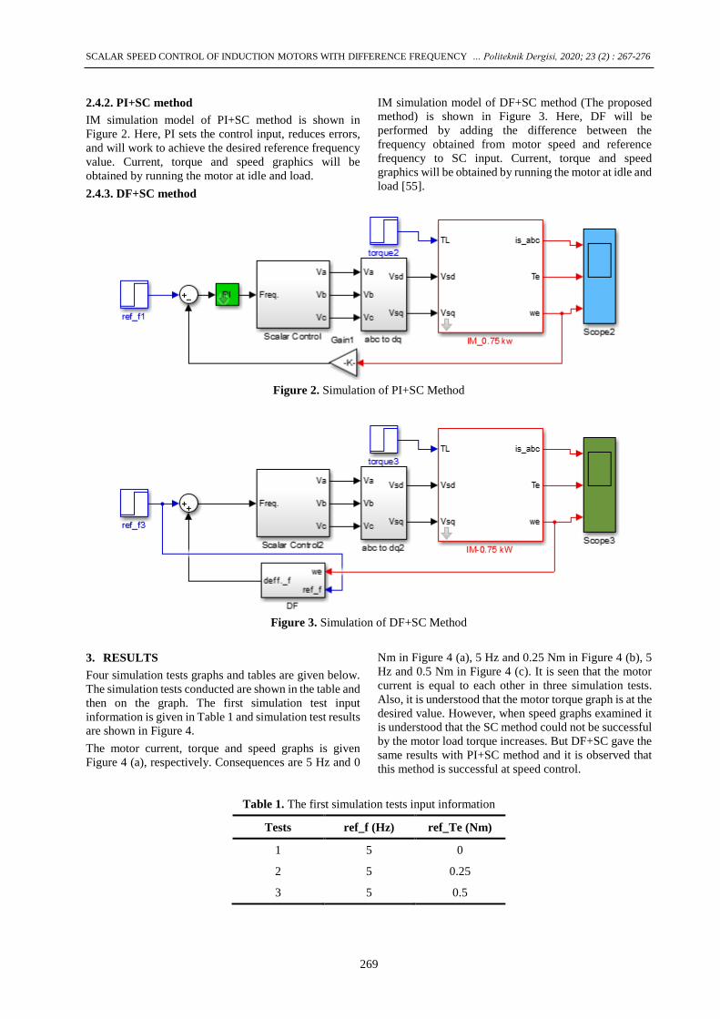
2.4.2. PI+SC method
IM simulation model of PI+SC method is shown in
Figure 2. Here, PI sets the control input, reduces errors,
and will work to achieve the desired reference frequency
value. Current, torque and speed graphics will be
obtained by running the motor at idle and load.
2.4.3. DF+SC method
IM simulation model of DF+SC method (The proposed
method) is shown in Figure 3. Here, DF will be
performed by adding the difference between the
frequency obtained from motor speed and reference
frequency to SC input. Current, torque and speed
graphics will be obtained by running the motor at idle and
load [55].
Figure 2. Simulation of PI+SC Method
Figure 3. Simulation of DF+SC Method
3. RESULTS
Four simulation tests graphs and tables are given below.
The simulation tests conducted are shown in the table and
then on the graph. The first simulation test input
information is given in Table 1 and simulation test results
are shown in Figure 4.
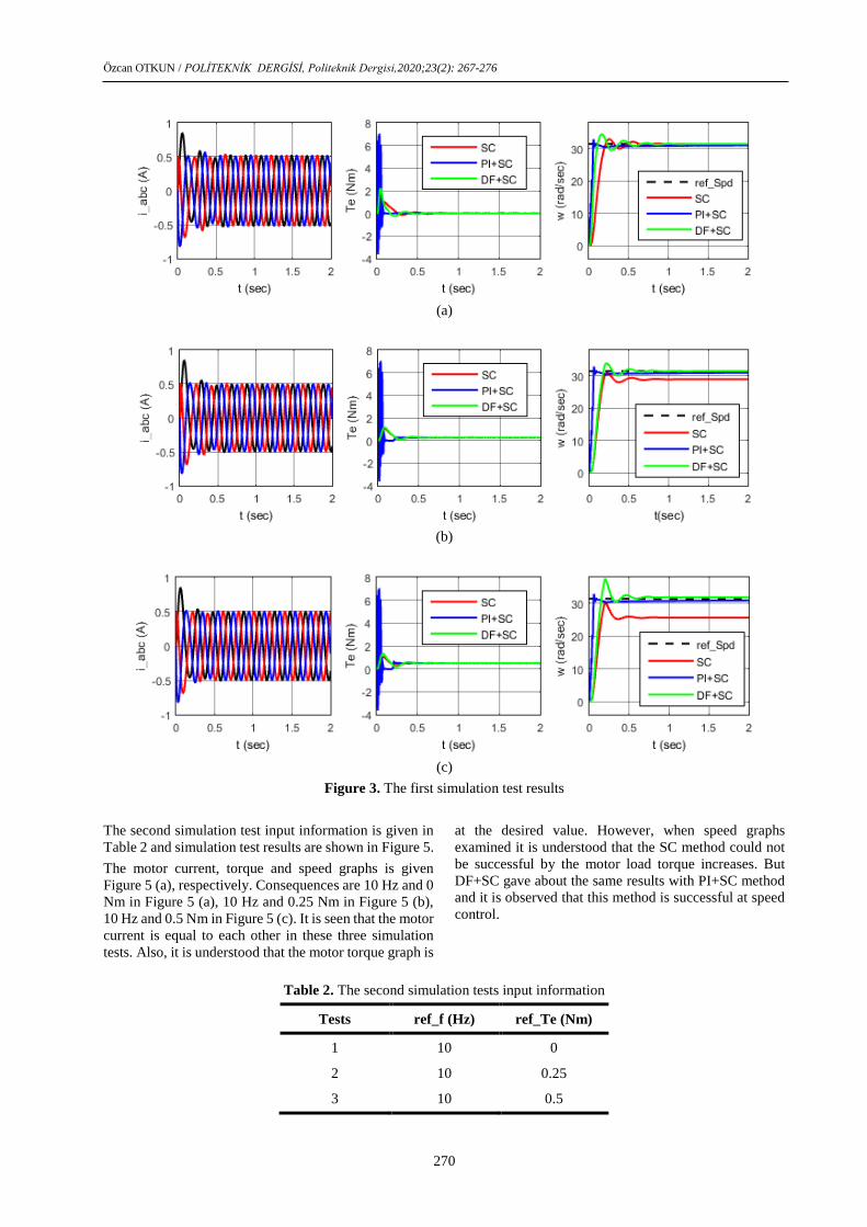
The motor current, torque and speed graphs is given
Figure 4 (a), respectively. Consequences are 5 Hz and 0
Nm in Figure 4 (a), 5 Hz and 0.25 Nm in Figure 4 (b), 5
Hz and 0.5 Nm in Figure 4 (c). It is seen that the motor
current is equal to each other in three simulation tests.
Also, it is understood that the motor torque graph is at the
desired value. However, when speed graphs examined it
is understood that the SC method could not be successful
by the motor load torque increases. But DF+SC gave the
same results with PI+SC method and it is observed that
this method is successful at speed control.
Table 1. The first simulation tests input information
Tests ref_f (Hz) ref_Te (Nm)
1 5 0
2 5 0.25
3 5 0.5
Özcan OTKUN / POLİTEKNİK DERGİSİ, Politeknik Dergisi,2020;23(2): 267-276
270
(a)
(b)
(c)
Figure 3. The first simulation test results
The second simulation test input information is given in
Table 2 and simulation test results are shown in Figure 5.
The motor current, torque and speed graphs is given
Figure 5 (a), respectively. Consequences are 10 Hz and 0
Nm in Figure 5 (a), 10 Hz and 0.25 Nm in Figure 5 (b),
10 Hz and 0.5 Nm in Figure 5 (c). It is seen that the motor
current is equal to each other in these three simulation
tests. Also, it is understood that the motor torque graph is
at the desired value. However, when speed graphs
examined it is understood that the SC method could not
be successful by the motor load torque increases. But
DF+SC gave about the same results with PI+SC method
and it is observed that this method is successful at speed
control.
Table 2. The second simulation tests input information
Tests ref_f (Hz) ref_Te (Nm)
1 10 0
2 10 0.25
3 10 0.5

SCALAR SPEED CONTROL OF INDUCTION MOTORS WITH DIFFERENCE FREQUENCY … Politeknik Dergisi, 2020; 23 (2) : 267-276
271
(a)
(b)
(c)
Figure 4. The second simulation test results
The third simulation test input information is given in
Table 3 and simulation test results are shown in Figure 6.
The motor current, torque and speed graphs is given
Figure 6 (a), respectively. Consequences are 15 Hz and 0
Nm in Figure 6 (a), 15 Hz and 0.25 Nm in Figure 6 (b),
15 Hz and 0.5 Nm in Figure 6 (c). It is seen that the motor
current is equal in these three simulation tests. Also, it is
understood that the motor torque graph is at the desired
value at SC and DF+SC methods but it is not at the
desired value at PI+SC method. When speed graphs
examined it is understood that SC and PI+SC methods
could not be successful by the motor load torque
increases. For this simulation test, it is observed that
DF+SC method is successful at speed control.
Table 3. The third simulation tests input information
Tests ref_f (Hz) ref_Te (Nm)
1 15 0
2 15 0.25
3 15 0.5

Özcan OTKUN / POLİTEKNİK DERGİSİ, Politeknik Dergisi,2020;23(2): 267-276
272
(a)
(b)
(c)
Figure 5. The third simulation test results
The fourth simulation test input information is given in
Table 4 and simulation test results are shown in Figure 7.
The motor current, torque and speed graphs is given
Figure 7 (a), respectively. Consequences are 50 Hz and 0
Nm in Figure 7 (a), 50 Hz and 0.25 Nm in Figure 7 (b),
50 Hz and 0.5 Nm in Figure 7 (c). It is seen that the motor
current is equal in these three simulation tests. When
examining torque graphs in three methods, it is seen that
the desired result is obtained by SC and DF+SC methods.
When speed graphs examined it is understood that SC
and DF+SC methods are successful by the motor running
at idle and load but PI+SC control is not successful.
Table 4. The fourth simulation tests input information
Tests ref_f (Hz) ref_Te (Nm)
1 50 0
2 50 0.25
3 50 0.5

SCALAR SPEED CONTROL OF INDUCTION MOTORS WITH DIFFERENCE FREQUENCY … Politeknik Dergisi, 2020; 23 (2) : 267-276
273
(a)
(b)
(c)
Figure 6. The fourth simulation test results
Figure 8 is presented for a better understanding of the
performance of the proposed method. A frequency of 25
Hz was applied to the IM. The results obtained from
different load moments are shown on the same graph and
the traceability of the results has been increased.
In Figure 8 (a) shows the torque graph, (b) the velocity
graph. Figure 8 (b) shows that the motor operates at a
constant speed. It is understood that the motor has 0%,
0.25% and 0.51% speed error respectively when
operating at 0, 0.25 and 0.5 Nm load torque.
4. CONCLUSION
In this study, IM’ Scalar Speed Control with Difference
Frequency were performed. The results obtained from
this study can be listed as follows.
SC: It shows desired performance in all speed
during idling. When working in load, at low
speeds it does not show the desired
performance. The desired control results are
obtained when working at high speed in idle and
load [17].
PI+SC: Coefficients determined for PI
controller shows desired performance in
specific speed ranges. Nevertheless, while the
range of speed and torque changes it does not
demonstrate the required performance [19],
[22].
DF+SC: This proposed method indicates the
desired control performance in each case tested.

Özcan OTKUN / POLİTEKNİK DERGİSİ, Politeknik Dergisi,2020;23(2): 267-276
274
The obtained results indicate that the proposed
method will contribute speed control operations
done in industrial areas.
When considering developments in this area, much more
work can be made.
(a)
(b)
Figure 8. Performance analysis of motor at constant speed and different load moments
SYMBOLS AND ABBREVIATIONS
isd, isq : dq currents
Ψsd, Ψsq : dq fluxes
Ls : Statore inductance
Lr : Rotor inductance
Lm : Mutual inductance
rs : Stator resistance
TL : Load torque

SCALAR SPEED CONTROL OF INDUCTION MOTORS WITH DIFFERENCE FREQUENCY … Politeknik Dergisi, 2020; 23 (2) : 267-276
275
we : Electric angular speed
wr : Rotor angular speed
J : Inertia constant
B : Friction constant
p : Number of poles
ACKNOWLEDGEMENT
I would like to express my gratitude to Dear Prof. Dr. A.
Sefa AKPINAR, who died in 2015 (My PhD Consultant).
REFERENCES
[1] Bose B.K., “Modern Power Electronics and AC Drives”,
Upper Saddle River, NJ: Prentice-Hall PTR, (2002).
[2] Kouro S., Bernal R., Miranda H., Silva C.A., and
Rodriquez J., ″High-Performance Torque and Flux
Control for Multilevel Inverter Fed Induction Motors”,
IEEE Transaction on Power Electronics, 22(6): 2116–
2123, (2007).
[3] Wang C.C. and Fang C. H., ″Sensorless Scalar Controlled
Induction Motor Drives with Modified Flux Observer”,
IEEE Journals & Magazines, 22(8): 61 – 61, (2002).
[4] G. Fouad, ″AC Electric Motors Control Advanced Design
Techniques and Applications”, Wiley, New Delhi, India,
2013.
[5] Paula S. J., Jeromeb J., Kakania S., ‘Active Rectifier
Based Harmonic Compensator for a Direct Torque
Controlled Induction Motor Drive’, IETE Journal of
Research, 61(6): 573-580, (2015).
[6] Tuncer S., ‘High-Performance Vector Control Strategy
For Multilevel Inverter Fed Induction Motor’, Journal of
the Faculty of Engineering and Architecture of Gazi
University, 30(1), 119-130, (2015).
[7] Zou X., Zhu P., Kang Y. and Chen J., ‘Speed
identification for vector control of induction motors with
voltage decoupling control principle’, 38th IAS Annual
Meeting, Conference Record of the Industry
Applications Conference, 12-16 Oct., (2003).
[8] A. Djahbar, B. Mazari, and M. Latroch, ‘Control strategy
of three-phase matrix converter fed induction motor drive
system’, The IEE Pulsed Power symposium, 8-8 Sept.,
Basingstoke, UK: IEEE, (2005).
[9] Singh B., Garg V., Bhuvaneshwari G., ‘A 24-pulse AC-
DC converter employing a pulse doubling technique for
vector-controlled induction motor drives’, IETE Journal
of Research, 54(4): 314-322, (2008).
[10] Sen P.C., ‘Electric Motor Drives and Control Past
Present, and Future’, IEEE Transactions on Industrial
Electronics, 37(6): 562-575, (1990).
[11] Ebrahim A., ‘Adaptive nonlinear induction motor
control.’ PhD Thesis, The University of Alabama,
Alabama, (2007).
[12] Haitham A., Atif I., Jaroslaw G., ‘High Performance
Control of AC Drives With Matlab/Simulink Models’,
Noida, India: Wiley, (2012).
[13] Bay Ö., Görgünoğlu S. "Design and Implementation of 3-
Phase Induction Motors Speed Controller by Using Low
Cost 8-Bit Microcontroller". Journal of Polytechnic,
12(3): 143-150, (2009).
[14] Irmak E. and Vadi S., “Asenkron Motorlarda Frekans
Değişimi ile Hız Kontrolü Deneyinin Bilgisayar
Üzerinden Gerçekleştirilmesi”, Journal of The Faculty
of Engineering and Architecture of Gazi University,
21(1): 57-62, (2011).
[15] Ilango G. S., Rajasekar N., “An improved energy saving
v/f control technique for solar powered single-phase
induction motor”, Energy Conversion and Management,
50(12): 2913-2918, (2009).
[16] Liu Y., Piepenbreier B., “Comparison of Stabilization
Methods for V/f controlled Induction Motor Drive
System”, PCIM Europe 2014, International Exhibition
and Conference for Power Electronics, Intelligent
Motion, 20-22 May., Nuremberg: IEEE, (2014).
[17] Bose B. K., ‘Adjustable Speed AC Drives-A Technology
Status Review’, Proceedings of the IEEE, 70(2): 116-
135, (1982).
[18] Jisha L. K., Thomas A. P., ‘A comparative study on scalar
and vector control of Induction motor drives,
International conference on Circuits’, Controls and
Communications (CCUBE), IEEE Conference
Publications; 27-28 Dec. 2013; Bengaluru, India: IEEE,
(2013).
[19] Rubaai A., Kotaru R., ‘Online identification and control
of a DC motor using learning adaptation of neural
networks’, IEEE Transactions on Industry
Applications, 36(3): 935-942, (2000).
[20] Menghal P.M., Laxmi A.J., ‘Dynamic modeling,
simulation & analysis of induction motor drives’,
International Conference on Science Engineering and
Management Research (ICSEMR), 27-29 Nov.,
Chennai: IEEE, (2014).
[21] Draou A., Miloud A., Miloud Y., ‘A Variable Gains PI
Speed Controller In a Simplified Scalar Mode Control
Induction Machine Drive - Design and Implementation’,
International Conference on Control, Automation and
Systems; 27-30 Oct., South Kore, (2010).
[22] Özçıra S., ‘Control Methods of Permanent Magnet
Synchronous Motor and Industrial Applications.’ MSc,
Yıldız Technical University, İstanbul, Turkey, (2007).
[23] Trzynadlowski A.M., Control of Induction Motors,
London, UK: Academic Press, (2001).
[24] Krishnan R., Electric Motor Drives-Modeling Analysis
and Control, NJ, USA: Prentice-Hall, (2001).
[25] Irmak E. and Vadi S., “Asenkron Motorlarda Frekans
Değişimi ile Hız Kontrolü Deneyinin Bilgisayar
Üzerinden Gerçekleştirilmesi”, Journal of The Faculty
of Engineering and Architecture of Gazi University,
21(1): 57-62, (2011).
[26] Zhang Y., ve et al., “A Novel Speed Estimation Method
of Induction Motors Using Real-Time Adaptive Extended
Kalman Filter”, Journal of Electrical Engineering &
Technology, 13(1): 287-297, (2018).
[27] Xin Z. and et al., “An improved flux observer for field-
oriented control of induction motors based on dual
second-order generalized integrator frequency-locked
loop”, IEEE Journal of Emerging and Selected Topics
in Power Electronics, 5(1): 513-525, (2017).
[28] Ehsani M., et al., Modern electric, hybrid electric, and
fuel cell vehicles, UK: CRC Press, (2018).
[29] Zhou Z. and et al., “Neural network-based discrete-time
command filtered adaptive position tracking control for
Özcan OTKUN / POLİTEKNİK DERGİSİ, Politeknik Dergisi,2020;23(2): 267-276
276
induction motors via backstepping”, Neurocomputing,
260: 203-210, (2017).
[30] Wang N., Haisheng Y. and Xudond L., “DTC of
induction motor based on adaptive sliding mode control”,
2018 Chinese Control And Decision Conference
(CCDC). IEEE, (2018).
[31] Lftisi F. and Rahman M.A., “A novel finite element
controller map for intelligent control of induction motors,
Information Technology”, Electronics and Mobile
Communication Conference (IEMCON), 2017 8th IEEE
Annual. IEEE, (2017).
[32] Nozaki Y., Takafumi K. and Eisuke M., “Analysis of
linear induction motors for HSST and linear metro using
finite difference method”, Proc. LDIA2005, Tokyo, 168-
171, (2005).
[33] Zhao J. and Bose B.K., “Evaluation of membership
functions for fuzzy logic controlled induction motor
drive”, In IECON-Proceedings, 1: 229-234, (2002).
[34] Rashed M., Peter M. and Stronach F.A., “Nonlinear
adaptive state-feedback speed control of a voltage-fed
induction motor with varying parameters”, IEEE
Transactions on Industry Applications, 42(3): 723-732,
(2006).
[35] Paice D.A., “Induction motor speed control by stator
voltage control”, IEEE Transactions on power
Apparatus and systems, 2: 585-590, (1968).
[36] Feng Y. and et al., “Speed Control of Induction Motor
Servo Drives Using Terminal Sliding-Mode Controller”,
Advances in Variable Structure Systems and Sliding
Mode Control—Theory and Applications, 115: 341-356,
(2017).
[37] Guo Y. and et al., “Speed-sensorless direct torque control
scheme for matrix converter driven induction motor”,
The Journal of Engineering, 13: 432-437, (2018).
[38] Lin F.-J., Shen P.-H. and Hsu S.-P., “Adaptive
backstepping sliding mode control for linear induction
motor drive”, IEE Proceedings-Electric Power
Applications, 149(3): 184-194, (2002).
[39] Kubota H., Kouki M. and Takayoshi N., “DSP-based
speed adaptive flux observer of induction motor”, IEEE
transactions on industry applications, 29(2): 344-348,
(1993).
[40] Holtz J., “Sensorless control of induction motor drives”,
Proceedings of the IEEE, 90(8): 1359-1394, (2002).
[41] Li J., Hai-Peng R. and Yan-Ru Z., “Robust speed control
of induction motor drives using first-order auto-
disturbance rejection controllers”, IEEE Transactions
on Industry Applications, 51(1): 712-720, (2015).
[42] Otkun Ö., Doğan R. Ö. and Akpınar A. S., “Neural
Network Based Scalar Speed Control of Linear
Permanent Magnet Synchronous Motor”, Journal of the
Faculty of Engineering & Architecture of Gazi
University, 30(3): 395-404, (2015).
[43] Rao G. M. and Srikanth G., “Comparative Study of
Maximum Torque Control by PI ANN of Induction
Motor”, International Journal of Applied Engineering
Research, 13(7): 4620-4625, (2018).
[44] Bulut M., Kurt M., Demirtaş M ., “Application of
Genetic-Fuzzy Controller to a DC Motor”, Journal of
Polytechnic, 7(4): 277-283, (2004).
[45] Hui L., Yunfei L., Xin D. and Huajug Z., “Optimization
of Adaptation Gains of Full-order Flux Observer in
Sensorless Induction Motor Drives Using Genetic
Algorithm”, Information Technology Journal, 8(4):
577-582, (2009).
[46] Douiri M. R., Belghazi O., Cherkaoui M., “Recurrent
Self-Tuning Neuro-Fuzzy for Speed Induction Motor
Drive”, Journal of Circuits, Systems and Computers,
24(9): (2015).
[47] Ustun S. V. and Demirtaş M., “Optimal tuning of PI
coefficients by using fuzzygenetic for V/f controlled
induction motor”, Expert Systems with Applications,
34(4): 2714-2720, (2008).
[48] Chen C., Lai C. and Sun W., “Fuzzy Testing for
Regression Coefficient of Fuzzy Numbers”, Journal of
Testing and Evaluation, 41(1): 1-6, (2012).
[49] Orłowska-Kowalska T., Blaabjerg F., Rodríguez J.,
Advanced and Intelligent Control in Power Electronics
and Drives, Springer, New York, (2014).
[50] Krim S., Gdaim S., Mtibaa A., et al., “Design and
Implementation of Direct Torque Control Based on an
Intelligent Technique of Induction Motor on FPGA”,
Journal of Electric Engineering and Technology, 10(4):
30-40, (2015).
[51] Shun-Yuan W., Chwan-Lu T., Shou-Chuang L., et al.,
“An Adaptive Supervisory Sliding Fuzzy Cerebellar
Model Articulation Controller for Sensorless Vector-
Controlled Induction Motor Drive Systems”, Sensors,
15(4): 7323-7348, (2015).
[52] Adiuku C.O., Beig A.R., Kanukollu S., ‘Sensorless
closed loop V/f control of medium-voltage high-power
induction motor with synchronized space vector PWM’,
IEEE 8th., GCC Conference and Exhibition (GCCCE),
1-4 Feb., Muscat: IEEE, (2015).
[53] Sarıoğlu M. K., Gökaşan M., Boğosyan O., ‘Induction
Machines and Control’, İstanbul: Birsen Press, (2003).
[54] Soliman H. M., "Studying the Steady State Performance
Characteristics of Induction Motor with Field Oriented
Control Comparing to Scalar Control." European
Journal of Engineering Research and Science, 18-25,
(2018).
[55] Kiran K., Sukanta D. and Diksha S., "Model predictive
field oriented speed control of brushless doubly-fed
reluctance motor drive." 2018 International Conference
on Power, Instrumentation, Control and Computing
(PICC). IEEE, (2018).