Development of a Real-Time Software- Defined Radio GPS ...
15
IEEE TRANSACTIONS ON INSTRUMENTATION AND MEASUREMENT (ACCEPTED WITH MAJOR CHANGES) Abstract—The ubiquitousness of location based services (LBS) has proven effective for many applications such as commercial, military, and emergency responders. Software-defined radio (SDR) has emerged as an adequate framework for development and testing of global navigational satellite systems (GNSS) such as the Global Position System (GPS). SDR receivers are constantly developing in terms of acceleration factors and accurate algorithms for precise user navigation. However, many SDR options for GPS receivers currently lack real-time operation or could be costly. This paper presents a LabVIEW (LV) and C/C++ based GPS L1 receiver platform with real-time capabilities. The system relies on LV acceleration factors as well as other C/C++ techniques such as dynamic link library (DLL) integration into LV and parallelizable loop structures, and single input multiple data (SIMD) methods which leverage host PC multi-purpose processors. A hardware testbed is presented for compactness and mobility, as well as software functionality and data flow handling inherent in LV environment. Benchmarks and other real-time results are presented as well as compared against other state-of- the-art open-source GPS receivers. Index Terms---global navigation satellite systems (GNSS), global positioning systems (GPS), software defined radio (SDR), real-time receiver, acceleration factors. I. INTRODUCTION HE success of US Global Positioning System (GPS) in enabling various location-based services triggered extensive studies in related positioning methods, baseband technologies, mitigation of errors and interference. Other similar systems referred to as Global Navigation Satellite Systems (GNSS) have been also deployed using similar signaling methods and infrastructure solutions [1], [2]. Availability of accurate source of user position, velocity, and time (PVT) significantly impacted other technologies such as wireless communication, military equipment, transportation, etc. Conventional GPS receivers operate in open-sky environments, and are challenged by signal blockages inside buildings, urban canyons, and underground. Also signal interferences and spoofing may deny GPS availability and disrupt the operation of other systems which rely on GPS data. Manuscript submitted October 13, 2017, resubmitted as new manuscript on October 31, 2017 for MAJOR CHANGES for the IEEE Transactions on Instrumentation & Measurement journal. E. Schmidt is with the University of Texas at San Antonio, San Antonio, TX 78249 USA (e-mail: [email protected]). Extensive engineering effort is directed in addressing these challenges to achieve more robust operation of the receivers and expand their coverage to as many denied areas as possible. Serious advances are achieved in increasing sensitivities of the receivers which have access to terrestrial signaling channels. Using communication links, one can retrieve orbital data of satellites, and receiver coarse position and time estimates from wireless networks which significantly helps in enhancing the operation of GPS receivers. This approach is called Assisted GPS (A-GPS) [1]-[3] and is estimated to improve start-up sensitivity by as much as 20 dB when used in combination with advanced parallel correlators. The A-GPS is standardized for telecommunication networks in terms of defining logistics of communicating various assistance data, and computing-delivering PVT information. It is also recommended by FCC E911 mandate as a solution that will assist emergency services. Many advances are also made for better immunity of GPS receivers against interferences and spoofing [4]-[7]. Despite this progress, GPS operation is still denied in many indoor and other weak signal environments. Also, despite many reported spoofing mitigation methods, these interference techniques also evolve and bring new challenges for GPS equipment. The researchers thrive to improve the performance of the receivers, address continuously evolving spoofing threats, and explore new transformative concepts, and they need proper instrumentation and software to support their efforts. As such, software-defined radio (SDR) solutions become popular because of providing full control of receiver operations, so the researchers can integrate and test their methods without redesigning all receiver chains. SDR solutions provide extended capabilities for tightly coupled integrations. In this context, SDR integrations provide research capabilities for many purposes such as indoor and vehicular navigation in GPS-denied areas. Proposed integrations include GPS and magnetic positioning systems (MPS) [8] tight coupling via an SDR system. Other SDR solutions provide access to tracking correlators for multipath studies in urban canyons on vehicular applications [9]. Ranging GPS-like radios have been explored as well for indoor positioning applications involving time-of-arrival (TOA) measurements combined with receiver signal strength (RSS) D. Akopian is with the University of Texas at San Antonio, San Antonio, TX 78249 USA (email: [email protected]). D.J. Pack is with the Department of Electrical Engineering, University of Tennessee at Chattanooga, Chattanooga, TN 37403 USA (email: daniel- [email protected]). Development of a Real-Time Software- Defined Radio GPS Receiver Exploiting a LabVIEW-based Instrumentation Environment Erick Schmidt, Student Member, IEEE, David Akopian, Senior Member, IEEE, Daniel J. Pack, Senior Member, IEEE T
-
Upload
khangminh22 -
Category
Documents
-
view
1 -
download
0
Transcript of Development of a Real-Time Software- Defined Radio GPS ...

IEEE TRANSACTIONS ON INSTRUMENTATION AND MEASUREMENT (ACCEPTED WITH MAJOR CHANGES)
Abstract—The ubiquitousness of location based services (LBS)
has proven effective for many applications such as commercial,
military, and emergency responders. Software-defined radio
(SDR) has emerged as an adequate framework for development
and testing of global navigational satellite systems (GNSS) such as
the Global Position System (GPS). SDR receivers are constantly
developing in terms of acceleration factors and accurate
algorithms for precise user navigation. However, many SDR
options for GPS receivers currently lack real-time operation or
could be costly. This paper presents a LabVIEW (LV) and C/C++
based GPS L1 receiver platform with real-time capabilities. The
system relies on LV acceleration factors as well as other C/C++
techniques such as dynamic link library (DLL) integration into LV
and parallelizable loop structures, and single input multiple data
(SIMD) methods which leverage host PC multi-purpose
processors. A hardware testbed is presented for compactness and
mobility, as well as software functionality and data flow handling
inherent in LV environment. Benchmarks and other real-time
results are presented as well as compared against other state-of-
the-art open-source GPS receivers.
Index Terms---global navigation satellite systems (GNSS),
global positioning systems (GPS), software defined radio (SDR),
real-time receiver, acceleration factors.
I. INTRODUCTION
HE success of US Global Positioning System (GPS) in
enabling various location-based services triggered
extensive studies in related positioning methods, baseband
technologies, mitigation of errors and interference. Other
similar systems referred to as Global Navigation Satellite
Systems (GNSS) have been also deployed using similar
signaling methods and infrastructure solutions [1], [2].
Availability of accurate source of user position, velocity, and
time (PVT) significantly impacted other technologies such as
wireless communication, military equipment, transportation,
etc.
Conventional GPS receivers operate in open-sky
environments, and are challenged by signal blockages inside
buildings, urban canyons, and underground. Also signal
interferences and spoofing may deny GPS availability and
disrupt the operation of other systems which rely on GPS data.
Manuscript submitted October 13, 2017, resubmitted as new manuscript on
October 31, 2017 for MAJOR CHANGES for the IEEE Transactions on
Instrumentation & Measurement journal. E. Schmidt is with the University of Texas at San Antonio, San Antonio, TX
78249 USA (e-mail: [email protected]).
Extensive engineering effort is directed in addressing these
challenges to achieve more robust operation of the receivers and
expand their coverage to as many denied areas as possible.
Serious advances are achieved in increasing sensitivities of
the receivers which have access to terrestrial signaling
channels. Using communication links, one can retrieve orbital
data of satellites, and receiver coarse position and time
estimates from wireless networks which significantly helps in
enhancing the operation of GPS receivers. This approach is
called Assisted GPS (A-GPS) [1]-[3] and is estimated to
improve start-up sensitivity by as much as 20 dB when used in
combination with advanced parallel correlators. The A-GPS is
standardized for telecommunication networks in terms of
defining logistics of communicating various assistance data,
and computing-delivering PVT information. It is also
recommended by FCC E911 mandate as a solution that will
assist emergency services. Many advances are also made for
better immunity of GPS receivers against interferences and
spoofing [4]-[7].
Despite this progress, GPS operation is still denied in many
indoor and other weak signal environments. Also, despite many
reported spoofing mitigation methods, these interference
techniques also evolve and bring new challenges for GPS
equipment. The researchers thrive to improve the performance
of the receivers, address continuously evolving spoofing
threats, and explore new transformative concepts, and they need
proper instrumentation and software to support their efforts. As
such, software-defined radio (SDR) solutions become popular
because of providing full control of receiver operations, so the
researchers can integrate and test their methods without
redesigning all receiver chains.
SDR solutions provide extended capabilities for tightly
coupled integrations. In this context, SDR integrations provide
research capabilities for many purposes such as indoor and
vehicular navigation in GPS-denied areas. Proposed
integrations include GPS and magnetic positioning systems
(MPS) [8] tight coupling via an SDR system. Other SDR
solutions provide access to tracking correlators for multipath
studies in urban canyons on vehicular applications [9]. Ranging
GPS-like radios have been explored as well for indoor
positioning applications involving time-of-arrival (TOA)
measurements combined with receiver signal strength (RSS)
D. Akopian is with the University of Texas at San Antonio, San Antonio,
TX 78249 USA (email: [email protected]).
D.J. Pack is with the Department of Electrical Engineering, University of Tennessee at Chattanooga, Chattanooga, TN 37403 USA (email: daniel-
Development of a Real-Time Software-
Defined Radio GPS Receiver Exploiting a
LabVIEW-based Instrumentation Environment Erick Schmidt, Student Member, IEEE, David Akopian, Senior Member, IEEE, Daniel J. Pack, Senior
Member, IEEE
T

IEEE TRANSACTIONS ON INSTRUMENTATION AND MEASUREMENT (ACCEPTED WITH MAJOR CHANGES)
WLAN-type measurements [10]. In this context, SDR solutions
perfectly fit and can be used for such systems. Inertial
navigation system (INS) integrations with ranging sensors and
GPS-like radios become attractive for SDR fusion applications
as well [11]-[14].
SDRs receive sampled data from peripheral RF front-ends
and apply signal processing using general purpose computing
resources such as computer processors and general-purpose
accelerators such as DSPs and FPGAs. The GPS SDRs are
currently available in various formats. Proprietary commercial
solutions are common and some of them provide application
programming interface (API) access to selected modules for 3rd
party revisions of these modules [15]. They are typically
implemented as C/C++ solutions to provide high-quality and
robust performance. The drawback of these solutions is in
constraining access to limited functionalities of the receiver.
Standalone open-source or open-reported C/C++ solutions are
also common [16] and provide full receiver control. The
operation quality is not typically guaranteed, the user interfaces
are basic, and front-end compatibility is limited. Another
interesting SDR category exploits rich library support of
dedicated frameworks such as GNU radio [17]. This concept
provides essential modular support of integrating available
SDR components for fast prototyping, supports many front-
ends including popular USRP front-ends [18]. Its excellent
development environment but requires somewhat longer
environment learning period compared to other concepts.
MATLAB/Simulink-based solutions reduce development cycle
and are convenient for research studies, but they are typically
not real-time [2] or limited to basic receiver grades. Recently
basic-grade academic GPS SDR solutions exploiting hybrid
development environments, such as C/C++ libraries integrated
into LabVIEW (LV) are reported in [19]-[21]. The SDR
computing platforms and accelerators such as FPGAs and DSPs
combined with multi-purpose processors have also gained
attention [20]-[23]. Other solutions exploiting graphical
processing unit (GPU) on host PCs for massive parallel
processing operations were reported [24] in addition to C/C++
features reported in [9].
This paper presents a new generation of LV-based GPS
receivers that achieves high performance operation exploiting
multiple strengths of LV environment. It describes and
characterizes the impact of using various inherent LV
mechanisms, such as multithreading, parallelization, and
dedicated loop-structures. It exploits C/C++ optimization
techniques for single instruction multiple data (SIMD) capable
processors in software correlators for real-time operation of
GNSS tracking loops, among other acceleration factors. It also
provides comparative analysis of LV-based receivers with
GNU-Radio and representative open-source C/C++ solutions
such as GNSS-SDR [25]. This paper also discusses performance
comparison metrics to assess general capabilities and
robustness of the receiver. It is demonstrated that LV-based
features provide competitive real-time solutions for fast
prototyping of receiver algorithms. The described GPS SDR
platform is a competitive solution capable of using advanced
user interface and visualization LV libraries in real-time
operation. The proposed receiver also exploits modularity on
SDRs by splitting GPS functionality into three main
components: acquisition, tracking, and navigation. This paper
will explain the proposed GPS L1 SDR receiver testbed and its
implementation in detail in the following sections.
The paper is organized as follows. Section II will describe
conventional GPS functionality modules. Section III will
explain the overall system architecture such as hardware and
software components that were used and chosen based on
compactness and mobility. Section IV will focus on
acceleration factors as well as SDR configurability options for
real-time receiver operation. Section V will discuss receiver
performance metrics with respect to acquisition, tracking, and
navigation modules, as well as comparisons with open-source
solutions such as fast-gps [16] and GNSS-SDR [25]. Section VI
will present conclusion remarks.
II. CONVENTIONAL GPS BASEBAND MODULES
The main communication system focus on this paper is on
the conventional L1 civilian GPS signal: a direct sequence
spread-spectrum (DSSS) signal consisting of a main binary
phase shift keying (BPSK) navigation payload signal operating
at 50 Hz, spread by a faster rate BPSK pseudorandom code
signal (PRN) at 1.023 Mchips/sec. The spreading sequence is
called the coarse acquisition (C/A) code. Finally, the signal is
mixed to a sinusoidal carrier at 1.57542 GHz corresponding to
the L1 band, forming a band-pass signal transmitted by GPS
satellites orbiting the Earth, for civilian positioning.
To successfully demodulate GPS L1 signals and receive
navigation data, the receiver synchronizes to the incoming
signal by correlating to incoming PRN code and wiping off the
L1 carrier. To do this, the receiver generates local replicas of
the code (time) and carrier (frequency), and mixes them with
the received signal. Therefore, synchronization is achieved in
both frequency and time domains, by estimating the Doppler
modulation called carrier-phase, and by aligning the signal and
PRN replica to estimate their relative shift, called code-phase,
respectively. The synchronization is typically performed in two
phases: acquisition (coarse) and tracking (fine). After fine
synchronization, navigation data are simply obtained after
sinusoidal carrier and PRN code wipe-off. Also, to estimate
user position, synchronization should be very precise to
compute distance travelled from incoming signal.
1) Conventional and advanced acquisition baseband module
The first stage of baseband signal processing is acquisition
(coarse synchronization) of GPS satellites. Conventional
receivers achieve acquisition by searching over a two-
dimensional time-frequency discrete zone for each satellite.
The receiver replicates candidate PRN code and residual carrier
modulation pairs, attempting to match those of the received
signal. Several signal replica candidates are locally generated
and correlated with incoming signal to find a match and thus to
identify input parameters. The correlation operation assumes an
element-wise multiplication of the received samples with the
samples of each replica. Then resulting products are added over
coherent integration lengths, by exploiting periodicity of GPS
PRN codes. Typically, a threshold is applied to the correlation
and integration result, to determine if a signal acquisition has
been reached. If a certain PRN is acquired, then this coarse
synchronization is terminated, and the receiver starts the
tracking (fine synchronization) stage for that satellite; if not, the

IEEE TRANSACTIONS ON INSTRUMENTATION AND MEASUREMENT (ACCEPTED WITH MAJOR CHANGES)
search continues and moves to the next code-phase/frequency
option for each satellite PRN.
Conventional GPS baseband algorithms such as coarse
acquisition could be computationally costly for real-time
operation due to its nature of typically three-dimensional search
space: code-phase, Doppler frequency, and satellite number. At
the same time several optimizations can be achieved by means
of fast-Fourier transform (FFT) implementations and other joint
algorithm computations [16]. An extended parallel code-phase
(PCS) search algorithm which leverages its modular structure
for concurrent joint search-space in code-phase and frequency
is used in the proposed SDR [26]. The algorithm implements a
massive correlator by concurrently combining code-phase and
Doppler frequency search bins while sharing computations
even for different satellites as the received signal forward FFT
output is reused for all iterations. The algorithm is effectively
implemented in C/C++ language and improves massively on
speed when compared to conventional FFT-based PCS methods
[20]. Comparative results showing algorithmic acceleration
factors will be discussed in later sections.
2) Tracking loops
Once a channel has been acquired, a fine synchronization to
keep track of the candidate channel is desired. Fig. 1 shows a
common tracking feedback loop used for GPS signals. Similar
to acquisition, but now in a finer search grid, tracking loops use
closed loops to continuously follow the PRN code and carrier
parameters of current channel. To determine code and carrier
changes of incoming signal, conventional feedback loops such
as delay lock loop (DLL) for code-phase estimation, phase lock
loop (PLL) and frequency lock loop (FLL) for Doppler
modulations, are implemented [2]. Once these loops obtain
correction measurements, the discriminator processes
correlator outputs to provide measurable quantities which are
used as feedback for next iteration, therefore achieving a
continuous lock to the incoming signal (see Fig. 7).
3) Navigation module
Well-known navigation algorithms discussed in literature
[2], [16], are implemented in the receiver such as least-squares
(LS) methods and position averaging.
III. SYSTEM ARCHITECTURE
The development and testbed platform is implemented at the
Software Communications and Navigation Systems (SCNS)
Laboratory at the University of Texas at San Antonio (UTSA).
This paper provides detailed description of a real-time LV-
based SDR receiver with various applied concepts to enable
high-performance computing. The testbed also includes a GPS
simulator which acts as a generator/transmitter of GPS signals.
Current implementation is using National Instruments (NI)
GNSS simulation toolkit [27] that can simulate different
satellites, signals strengths, Doppler effects, user movement,
among other features.
The SDR is a novel LV-based GPS receiver which
implements GPS L1 baseband processing functionalities into
C/C++ software components that have been compiled as
dynamic link libraries (DLLs). It exploits several fast
algorithms, LV-based acceleration factors, C/C++ parallel
algorithms such as SIMD matching on multi-purpose host
CPUs, and external C/C++-based application program interface
(API) optimized libraries, among other features. This section
will describe the overall development hardware and software
testbed components used in this SDR system and their
specifications as well as the overall receiver architecture and
LV functionalities.
A. Hardware components
The hardware used in the system was chosen with an effort
to achieve portability and mobility for the SDR receiver. Fig. 2
shows exemplified hardware components and their
connectivity. The hardware of choice is an Ettus USRP B200
[18] front-end along with an Intel NUC 5i5RYK [28] serving
as the host PC where the baseband software resides. Table I
shows specifications for the host PC. The host PC is a small
form-factor device. The processor is a low-power multi-
purpose CPU (it consumes 15 W). An active antenna, Talisman
TW2010 [29], which is power-driven by an in-line amplifier,
model A11 from GPS Source [30], are the RF components
connected to the front-end. The front-end is fed via an USB 3.0
for power as well as interface with the host PC (A USB Y-cable
is used to pull extra power). The front-end RF coverage is broad
and can process various GNSS signals including GPS L1 band
(1575.42 MHz) that is used for the performance evaluation of
the platform. The internal analog-to-digital (ADC) sampling
rate from the front-end can achieve speeds up to 56 Msps. Since
the GPS SDR system is tested for 5 MHz sampling rate in I-Q
interleaved format, the total throughput through the USB cable
TABLE I
INTEL NUC HOST PC DEVICE SPECIFICATIONS
Host PC Intel NUC5i5RYK
CPU Intel Core i5-5250U @ 1.6-2.7 GHz, dual-core,
3 MB cache, 15 W
RAM 16 GB RAM DDR3L @ 1600 MHz
Storage 240 GB M.2 SSD
Operating
System
Windows 7 Ultimate (64-bit)
Dimensions 115 mm × 111 mm × 32 mm
Weight ~400 g
Tallysman
TW2010 GPS Source
A11
Ettus
USRP
B200 Intel
NUC5i5RYK
LNA
Active
Antenna
SMA
conn.
USB 3.0 SMA
conn.
Fig. 2. Hardware architecture for proposed SDR.
Front-end In-line
Amp
Host PC
LabVIEW-
based SDR
Input
signal
Residual
carrier
wipe-off
Code replica
Correlator Discriminator
Correction
Fig. 1. A simplified tracking feedback loop for a single channel.

IEEE TRANSACTIONS ON INSTRUMENTATION AND MEASUREMENT (ACCEPTED WITH MAJOR CHANGES)
can reach up to 10 MB/s for INT8 data format, well suitable for
USB 3.0 capabilities and with enough resolution for GPS
samples.
Table II shows specifications for the front-end. Both front-
end and host PC of choice weight around 400-500 g each, thus
achieving small dimension and weight. Common internal RF
components of the front-end are a low-noise amplifier (LNA),
local oscillator (LO), low-pass filter (LPF), and an ADC.
Specifications for these components can be seen here [18], [31].
Budget SDR front-ends (including USRP B200) typically
come with an internal temperature-controlled crystal oscillator
(TCXO), which has limited frequency accuracy. For GNSS
satellite signals, a low frequency accuracy oscillator can
introduce uncertainties due to phase discontinuities caused by
imperfect oscillator frequency accuracy, therefore affecting
position accuracy. These phenomena are called cycle-slips [32].
The observed phenomena can cause abrupt channel loss of lock
from satellites. To avoid these phase jumps and for better
calibration on the front-end oscillator, many SDR solutions in
literature propose a 10 MHz reference signal which is used as
an external frequency source to replace or aid the local
oscillator on the front-end, which is not convenient for mobility.
Other SDR solutions propose advanced frequency-disciplined
systems based on neural model predictive filters to compensate
the local oscillator [33] which aim for ultra-high accuracy on
timing applications but require additional software and
hardware that lacks portability. Instead, for our approach, a
relatively low-cost and accurate oven-controlled crystal
oscillator (OCXO) module from Ettus [34], is added to the
front-end as a compact board-mounted kit, compatible with the
B200 board. This is also called a GPS-disciplined oscillator
(GPSDO) clock due to an additional built-in GPS unit that can
meet even higher and more accurate frequency and stability
requirements than the OCXO by itself if needed due to
synchronization with GNSS signals. The proposed GPSDO can
lock to satellites in 1 minute and provide stability to the OCXO.
The GPSDO mechanism works like a phase-lock loop (PLL) by
compensating phase and frequency changes in the local
oscillator with respect to GPS satellite signals, as well as
adapting to environmental parameters such as temperature, and
aging [35]. This board-mounted kit OCXO replaces the internal
TCXO on the B200 board, therefore three distinct types of time
references are available for experimentation: TCXO (built-in),
OCXO (board-mounted kit), and OCXO with disciplining
(OCXO + GPSDO). Experimental testing is conducted in a later
section to assess the board-mounted kit precision with and
without disciplining.
B. Host PC software architecture
The SDR receiver is shown in Fig. 3. The outermost layer of
the software part in the host PC is LV-based, which acts as a
data flow handling and visualization environment, interfacing
the front-end with the internal C/C++ DLL baseband processing
modules. The main functionality of the LV interface is in
collecting raw digitized samples from the front-end and
processing them in real-time to find PVT solution via the
baseband modules. The contribution of this paper is
demonstrating and characterizing various acceleration
techniques for real-time operation in SDR mode for cost-
effective research platform purposes. Most of the implemented
GPS algorithms are similar to common receiver
implementations such as in [2] and [16].
1) LabVIEW development environment
LV is a software development environment based on
programs called virtual instruments (VIs) which can be visually
programmed independently and attached to work either as main
or sub VIs. There is always a main VI where all the upper layer
functionality is held such as data flow and main execution of
loops. Based on this visual programming, LV becomes
effective for fast prototyping and data flow handling, thus ideal
for SDR solutions. LV has a front panel, which acts as a
graphical user interface (GUI) editor where built-in
visualizations and controls are available, and a block diagram,
where actual visual flow programming is done by wiring built-
in and customized function blocks (sub VIs) and loops to
achieve visual programming requirements. The flow
programming occurs logically from left to right, thus allowing
parallelism. LV offers several strengths such as fast prototyping
and front-end interface support, but it also presents weaknesses
such as reliance to LabVIEW only platform which constrains
full-access optimization to some extent, lack of access to its
kernel for highly specific optimizations, and its design lacking
high-end commercial solutions.
TABLE II RF FRONT-END TECHNICAL SPECIFICATIONS
RF Front-End Ettus USRP B200
RF Coverage 70 MHz to 6 GHz
Bandwidth 200 KHz to 56 MHz
ADC Resolution 12-bit
Oscillator GPSDO (OCXO), frequency stability: ±25 ppb
Interface SuperSpeed USB 3.0
Dimensions 97 mm × 155 mm × 15 mm (board only)
Weight 350 g (board only)
Host PC
NI-USRP
driver
Control Signals
Acquisition
DLL
Navigation
DLL
Visualizations
NI LabVIEW
Tracking
DLL
Frond-End
USB 3.0
Data signal
Control signal
While-loop
Fig. 3. Front-end and LabVIEW interface via NI-USRP driver. Samples
delivered in chunks to DLL baseband modules for post-processing.
Consumer loop
Producer loop
NI-USRP
Rx Fetch.vi

IEEE TRANSACTIONS ON INSTRUMENTATION AND MEASUREMENT (ACCEPTED WITH MAJOR CHANGES)
LV interfaces with native (NI-USRP) drivers to
communicate with the front-end. As seen in Fig. 3, this driver
sends control signals to the front-end and fetches data in a pre-
configured size of blocks (or chunks) and sends them to the
main LV VI, which eventually passes these samples to the DLL
baseband modules. This interface is easily handled by LV with
built-in NI-USRP configuration and sample fetching VI blocks
which configure the front-end and requests blocks of samples.
The block NI-USRP Rx Fetch.vi fetches samples from the
front-end on every iteration (see Fig. 3).
2) Main Producer/Consumer loop
The way LV controls the data flow between the front-end
interface and the baseband processing is by a common
application design architecture called the producer-consumer
loop (see Fig. 3). Based on this design pattern, LV can handle a
real-time continuous operation by acquiring data on the
producer loop in a non-restrictive and high priority way and
sending it to a data queue which allows the raw data to be
collected in memory as it is acquired. Then the consumer loop
dequeues the data from memory in a first-input-first-output
(FIFO) order and sends it to the baseband blocks, i.e. DLL
modules, for further processing. Both producer and consumer
loops are a while-loop structure each running indefinitely and
in parallel. These loops operate continuously until the user halts
the receiver execution.
The producer loop should be the highest priority of the loop-
pair, since it interfaces with the front-end by commanding it to
collect raw data chunks (NI-USRP Rx Fetch.vi) in real-time;
this, to avoid discontinuities on the incoming GPS signal. Also,
if there would be more tasks involved in each loop iteration of
the producer loop, overflows and underflows could easily be
triggered since the front-end is expected to collect data without
interruptions and typically lacks an internal buffer. The internal
queue or buffer utilized between this loop-pair is automatically
handled by LV in terms of memory allocation, thus occurring
in the background. The consumer loop should also be capable
of processing incoming data in real-time so that it outputs up-
to-date user location.
3) DLL integration
Conventional GPS baseband functionality can be divided
into three main modules: acquisition, tracking, and navigation.
Each GPS baseband module includes numerous relevant C/C++
functions which are compiled into DLLs for further integration
in LV environment. Full optimization is done at compilation by,
e.g., Visual Studio C/C++ 64-bit compiler. Once generated,
these DLLs can be accessed by LV’s built-in Call library
function node. When called upon, LV sends relevant input
arguments to these functions such as clusters of data types,
which are compatible with C/C++ data type structures. The
input arguments can be passed by reference, therefore omitting
duplicates of the input data structures on every function call.
4) Main VI block diagram data flow
Fig. 4. illustrates the contents of the main VI block diagram.
The flow inside the main VI consists of three stages:
Initialization of data structures and variables, the main loop
(multi-producer/consumer loop), and the finalize setup and
close session. The initialization part oversees allocating and
initializing memory on two main data structures (clusters in
LV) which act as pipe flows that connect to relevant function
blocks as input arguments: the system configuration which is a
structure of shared global configuration parameters relevant to
GPS L1 parameters and current receiver session (e.g., sampling
rate, receiver gain, etc.), and the channel structure containing
specific variables linked to a locked channel. Each channel
structure contains a structure of variables which keeps track of
the channel status, health, tracking loops, Doppler, Ephemeris
and other essential information associated to a satellite lock.
Eventually, all the channels are gathered into an array and
therefore flow in a single line or wire. After these two main
variable pipe flows are initialized, the USRP session is
configured. This involves communicating to the front-end via
the USB port to properly initialize and setup the receiver gain,
sampling rate, data block fetch size, data format (e.g., INT8),
Finalize Setup Main Loop Initial Setup & Variables
Initial
configuration Configure
USRP
session
Close
USRP
Session
Clear
Buffers,
Memory,
File
Sessions
Channel Health
Loop (Visualization)
Tracking Display
Loop (Visualization)
Navigation Display
Loop
(Visualization)
Main Producer Loop
(Highest priority)
Main Consumer
Loop (Baseband
processing)
STOP
While-loop
Fig. 4. SDR main VI block diagram architecture consisting of three main stages: initial setup and variables, main loop, and finalize setup. The main loop
runs infinitely and consists of while-loops running in parallel for different processes, until user halts receiver operation.

IEEE TRANSACTIONS ON INSTRUMENTATION AND MEASUREMENT (ACCEPTED WITH MAJOR CHANGES)
reference clock, and other relevant settings for current session.
Once initial configuration is done, the main producer/consumer
loop is where the receiver operates in real-time until the stop
button is toggled. When stopped, the VI goes to the finalize
setup stage where it closes current USRP session, frees
previously allocated memory on buffers and structures, and
closes input and output file sessions for log files if configured.
5) Multi-producer/consumer loop for multi-threading
As seen in Fig. 4, multiple producer and consumer loop-pairs
are being used. A multi-producer/consumer loop mechanism
was added to increase multithreading which relieves overhead
computational loads for concurrent tasks such as real-time
visualizations. Now independent rate configuration is possible
for each visualization. Multi-threading is accomplished by
creating several lower priority producer/consumer loops
generated in the main consumer loop, therefore acting as the
producer. Otherwise the main consumer loop should process the
incoming GPS signal and generate output visualizations
sequentially on each iteration. This sequential processing
affected every iteration of consumer loop processing time and
ultimately created bottle-neck effects. With multi-
producer/consumer loops added, the main consumer loop is
now responsible to send (produce) output data to other three
loop-pair queues: the tracking display loop, the channel health
loop and the navigation display loop, and its tasks are therefore
lightened. Then, these low-priority consumer loops can now
post-process, or in this case, display output visualizations at an
independent rate which can be configured.
Fig. 5. shows the interaction of these loop-pairs. Each loop-
pair is a thread in LV and can have a different priority and rate.
Also, each loop-pair is assigned a buffer that inputs data blocks
into memory (producer) and then process this data (consumer)
at different rates. Therefore, these rates can be independently
configured based on user requirements. LV uses built-in
Queue/Dequeue function blocks that are used for sending data
to buffers automatically allocated to each producer/consumer
loop-pair so independent tasks can handle data from these
buffers in an automatic multi-threading setting. Therefore,
inside the main consumer loop, there are three Queue blocks
(three producer loops inside the main consumer loop) that are
sending data to each of these three categories, but the
visualization does not execute until these lower priority
consumer loops are activated. These loops are activated with a
delay timer to control the rate.
6) Main consumer loop and baseband modules
Fig. 6 shows a detailed view on the main consumer loop
where all baseband processing occurs. This is the core of the
SDR GPS receiver where most computation processing occurs.
This flow occurs on every while-loop iteration, and quasi-
sequentially because of LV’s multi-threading and parallelism.
The Dequeue block collects a fixed-size of samples from the
first-input-first-output (FIFO) buffer coming from the producer
loop and sends it to the acquisition and tracking blocks. The two
main flow pipes: system configuration and channel parameters
are updated accordingly on each loop iteration by setting them
as shift registers (SR) as seen in Fig. 6. This means, once one
iteration is done, both pipe flows are recirculated to the initial
Main Producer
Loop
(Rx Fetch)
Main Consumer
Loop
(DLLs)
Navigation
Plots Enqueue
Tracking Plot
Enqueue
Channel Health
Enqueue
Navigation Plots
Dequeue
(Gmaps display
rate)
Tracking Plot
Dequeue
(Display rate)
Channel Health
Dequeue
(Display rate)
Fig. 5. Multi-producer/consumer loops interaction for multi-threading
and independent data flow rates.
N for-loop structure
Main consumer loop (detailed)
System Configuration (cluster)
Tracking channels (N cluster array)
Data samples (int8 array)
ACQ /CACQ
DLL
LabVIEW parallelizable loop feature* (process all tracking channels in parallel)
single
channel
cluster n
Enqueue
Tracking
Plots
Enqueue
Channel
Health Enqueue
Navigation
Plots
Plot ACQ
SR SR
SR SR
Tracking
DLL
Post-
tracking
DLL
Navigation
DLL
While-loop
Data samples (int8 array)
* LabVIEW parallelizable loop feature allows concurrent execution of DLL library on each channel if channel cluster variables are independent
to each other (see Fig. 7).
Fig. 6. Main consumer loop detailed showing all three main pipe flows: data samples, system configuration, and channels, passing through baseband modules.
Dequeue
Raw Data
sysconf
data

IEEE TRANSACTIONS ON INSTRUMENTATION AND MEASUREMENT (ACCEPTED WITH MAJOR CHANGES)
left side of the structure retaining modified value output from
the block modules, ready for next iteration.
As for the baseband modules, first the Acquisition module
checks whether the receiver is lost (i.e. no channels are being
tracked) and/or if a set of quality metrics are held, for it to run
fast acquisition algorithms. The acquisition/continuous
acquisition (ACQ/CACQ) block runs through a set of quality-
of-service (QoS) metrics when deciding to run acquisition
algorithms, all of them having same priority: (1) number of
tracking channels is less than 4 (minimum required for PVT
solution); (2) percentage number of tracking channels drop rate
(for instance, if 30% of initial number of acquired channels
drops in a short period of time, denoting a blockage or so); and
(3) at least <min_num_chans> with <min_cn0> (i.e. at least 5
channels with 40 dB-Hz). If acquisition is toggled to run (which
is always the case at initial receiver execution), it then first
requires filling its buffer depending on the coherent integration
length setting (i.e. 4 ms of data), before algorithm execution.
The N found satellites are assigned to one out of 12 total
tracking channels and the system configuration modifies the
state to Tracking. If continuous acquisition is triggered later, the
system returns to ACQ/CACQ block for a parallel acquisition
not affecting current tracking channels and assigns new
channels accordingly (see Fig. 6). When ACQ/CACQ
algorithm is executed, visualization table is updated with
results.
For Tracking and Navigation, on each consumer loop
iteration, data sample chunks (an array of raw samples)
obtained from the data queue are sent in parallel to the tracking
baseband module (as well as acquisition). There should be N
active tracking channels processed with the current data
samples. This is the most computationally intense part of the
SDR receiver as it should process data in real-time since GPS
signals are continuously being received and a missed data
sample chunk could signify a loss of lock in most channels. The
post-tracking block collects relevant data from all channels and
translates it into channel health statistics, as well as real-time
tracking plots for Doppler frequency in Hz, navigation bits vs
time, and in-phase vs. quadrature (I-vs-Q) graph also known as
constellation diagram. Finally, navigation module extracts
relevant information from all N tracking channels and computes
a PVT solution if available. Position solution is enqueued and
should be displayed in a latitude vs longitude graph, as well as
an integrated Google Maps visualization which uses a web
Google Maps API. For Google Maps display, an active internet
connection is required in the host PC to download display actual
maps from Google servers.
7) LabVIEW and C/C++ memory compatibility
Since there is an interchange of variables, clusters, and other
data structures between two programming environments, i.e.
LV and C/C++, when exchanging data between both
environments via DLLs which are typically passed as reference,
three concepts should be considered: 1) memory alignment, 2)
data type compatibility, and 3) order of data types in a structure.
Memory alignment between data types should be fully
compatible to avoid fatal errors such as data corruption and
memory access violations. LV 64-bit and Visual C++ 64-bit are
both compatible with same memory alignment method called
“natural alignment”. This type of memory alignment takes the
biggest data type in the structure, typically 8 bytes (64 bit) for
a complex data type, and uses it as a base to line up with other
data types. This means, all data types smaller than 8 bytes (i.e.
char data type which is 1 byte) will still take 8 bytes of space in
memory by adding padding or dummy bytes, thus making each
memory address a multiple of 8 bytes, for a given data structure.
Another important consideration is the data types used
interchangeably between both programming environments. LV
has its own data type names that are compatible with C/C++
data types. Table III shows data type compatibility between
both environments.
Finally, the order of the variables inside a generated data
structure is also relevant between both platforms, as they should
match on both environments to avoid data corruption. As an
example, if a cluster (struct in C/C++) is created in LV with two
I8 and then a DBL variable types, this same order should be
reflected in C/C++ as two char variables, then a double variable
sequentially.
8) LabVIEW parallelizable loops
Parallelizable loops are a LV feature that is similar to the
inherent parallel scheduling mentioned before, but should be
assigned manually onto for-loop structures. Parallelizable loop
candidates can be assessed by LV based on the block diagrams
and dependency between input and output variables, but
ultimately are assigned manually by the developer. A very
useful parallelization loop is in the tracking channels, since
each satellite channel can run independently and accomplish
speed gains to compete for real-time operation. There are ways
to parallelize code in C/C++ coding but requires high
programming skills to do so, as opposed to LV’s Parallelizable
Loops feature which can be assessed and configured within
LV’s block diagram. There should be no resource dependency
between each tracking channel, when applying this feature to
avoid fatal programming errors such as memory access
violations.
Fig. 7 shows the adjustments to the receiver to incorporate
the Parallelizable Loops accelerator feature. Initially, the
baseband tracking DLL call function was processing all
tracking channels by using an internal C/C++ for-loop
structure, therefore the input and output variables from LV to
the DLL were an array of channel structures. The DLL tracking
call function code was internally modified so that it would
process only one channel structure, thus leaving the for-loop
structure previously found in the C/C++ code, to LV, as seen in
Fig. 7. This LV for loop structure takes as input the same array
of channel structures with size N and extracts one by one to send
it to the DLL call function node, then regroups them at the end
of the structure. Of course, all channels are now processed
concurrently with the Parallelizable Loops feature, therefore
TABLE III LABVIEW AND C/C++ DATA TYPES COMPATIBILITY
C/C++ LabVIEW Size in bytes
char I8 8
uchar U8 8 char * (64-bit
pointer)
I64 (64-bit pointer) 64
int I32 32 unsigned int U32 32
double DBL 64
char[4] Cluster of four I8 32 struct Cluster variable

IEEE TRANSACTIONS ON INSTRUMENTATION AND MEASUREMENT (ACCEPTED WITH MAJOR CHANGES)
accelerating each consumer loop iteration when dealing with
tracking loops.
IV. ACCELERATION FACTORS AND CONFIGURABILITY
Table IV shows a summary of acceleration factors that
leverage the proposed SDR receiver’s computational power for
real-time operation. Most of the implemented features are
exploited from LV platform built-in features. Many SDRs use
a combination of acceleration factors as found in Table IV, so a
brief description of the proposed SDR features follows.
Algorithm accelerators include the advanced acquisition
module [26] implemented in C/C++ as a replacement to PCS
algorithms which shows dramatic gains in joint computations.
Single instruction, multiple data (SIMD) processing is also
implemented in the DLL functions and resulted in dramatic
computational gains in the tracking loops. SIMD are
specialized, built-in machine language instructions (or
opcodes), mostly found on modern Intel 64-bit processors.
These assembly-coded functions can be implemented directly
by using Intel Intrinsics [36] which are function calls in C++
language. The benefit of SIMD is the direct usage of multi-
purpose processors’ dedicated registers capable of parallel
complex arithmetic operations such as table mapping, dot
products, accumulators, and other parallel operations resulting
in speed increase. The receiver’s latest version v5.0 leverages
from SIMD features since its baseband algorithms are
developed in C/C++ language.
Optimized C/C++ libraries feature matching internal
architecture for specific resource utilization based on target host
PC. As much as threefold acceleration was achieved on
proposed SDR receiver for FFT routines by implementing
optimization libraries such as FFTW [37] when compared to
other libraries such as kissFFT [38]. Eigen [39] was another
library used which specializes in matrix operations for least-
squares (LS) computation relevant to conventional PVT
solutions. These optimized libraries have internal functions that
try to exploit as much as possible the host PCs architecture and
processor capabilities. These libraries can, for instance, apply
built-in SIMD functions to the FFT routines, or schedule
computations for multi-threading execution based on number of
cores in the processor.
LV has characteristic functionalities that effortlessly assign
parallel tasks to multi-core processors by taking advantage of
the visual block diagram programming style. Program
parallelism achieves performance gains by concurrently
running several independent block diagram paths which occur
transparently to the developer since LV’s compiler takes care
of scheduling these processes. The compiler also recognizes the
host PCs’ capabilities in terms of cores and threads available.
The SDR receiver is strongly tied to LV’s visual programming
for real-time processing and parallelization due to this feature.
In addition, the Parallelizable loops feature was used in the SDR
tracking loops as mentioned in previous section.
Based on DLL integration into LV, the proposed SDR uses
baseband modules that were successfully implemented in
C/C++ with their respective data type compatibilities.
LV uses inherent multi-threading which applies also to data
acquisition and data flow. All these concepts are integrated
when using the previously described producer/consumer loop-
pairs. Also, visualizations are included in this integration.
Many real-time SDR GPS receivers use FPGA accelerators
[21] for common functions such as FFT-based acquisition
routines. For simplicity in hardware components, this SDR was
chosen to have all functionality in software and exploit host PC
architecture as mentioned in previous sections.
N for-loop structure (parallelizable loop*)
Tracking DLL Calling Node (all channels)
Main consumer loop (zoom-in)
Tracking DLL Calling Node (single channel)
(a) (b)
tracking_function_call( channel ch[ ], int active_chans ) {
for (ch_idx = 0; ch_idx < active_chans; ch_idx++) {
correlator( ch[ch_idx] ); }
}
tracking_function_call( channel *ch )
{
correlator( ch );
}
channel cluster array in
channel cluster
array out
channel cluster
array out
channel cluster array in
single channel cluster
in
single channel cluster
out
Fig. 7. LabVIEW Parallelizable Loops feature applied to tracking baseband DLL module for individual channel processing and overall computational
acceleration. (a) shows sequential implementation of tracking channels on C/C++ for-loop, (b) shows Parallelization Loops applied to built-in LabVIEW
for-loop.
N N N N
While-loop
Main consumer loop (zoom-in)
TABLE IV PROPOSED SDR ACCELERATION FACTORS
Acceleration factor Source
Algorithmic accelerator Software-based
Single instruction, multiple data (SIMD)
C/C++ and Intel processors
Optimized libraries C/C++ libraries
Parallel/multi-core scheduling LabVIEW-based DLL integration LabVIEW-based
Inherited multithreading LabVIEW-based
Data acquisition, data flow control
LabVIEW-based
Real-time advanced
visualizations
LabVIEW-based
FPGA and DSP Hardware-based

IEEE TRANSACTIONS ON INSTRUMENTATION AND MEASUREMENT (ACCEPTED WITH MAJOR CHANGES)
A. Software configuration and instrumentation measurement
output
The proposed SDR has several configuration options that are
compatible with the USRP B200 front-end as well as the host
PC capabilities. Table V lists the available configuration
options which can be used in online (real-time) operation mode
as well as in offline mode with a pre-recorded file. The receiver
operates only in INT8 mode, and for offline mode can chose
between two types of sample inputs: in-phase (I) only, and in-
phase and quadrature (I-Q) interleaved samples. The former is
used for when an intermediate frequency (IF) is used in the
front-end such as in [40]. This IF can be specified (in Hz) when
running in offline mode, and all visualizations can be utilized
the same was as in online mode. Since the proposed front-end
(USRP B200) uses a direct down-conversion (DDC) system,
there is no IF involved and captured samples are I-Q interleaved
as follows: 0 1 20 1 2, , , , , ,Q Q QI I Is s s s s s , which are already in
baseband level. The receiver has a maximum of 12 tracking
channels, however this could be expanded in future releases.
The PVT update rate defines the number of position samples
outputted per second, and the PVT averaging depth uses an
averaging sliding window on PVT output samples, thus
smoothening final user position. The rest of the configurations
are conventional on a GPS receiver.
Table VI shows common GPS receiver instrumentation
measurement outputs as well as visualization outputs included
in the proposed SDR. Most outputs are well-known
measurements for real-time visualization and monitoring of
GPS health channels, as well as other statistics. Measurements
such as carrier-to-noise ratio (CNR), carrier-lock ratio, and
channel state, are found in the channel health display and their
refresh rate for each visualization and/or instrument can be
independently configured. Logging outputs for tracking
channels and navigation outputs such as .kml file for Google
Earth can be configured for output when session finalizes.
V. COMPARATIVE RESULTS
This chapter discusses several comparative results of the
proposed SDR against other open-source receivers such as fast-
gps [16], and GNSS-SDR [25], to assess overall performance of
the receiver. It also compares against several acceleration
factors of the receiver. Table VII summarizes the most
important acceleration factors taken into account for
comparison results, which differentiate cumulative upgrades
between proposed receiver concepts (i.e. each newer version
contains previous features). The results will be roughly divided
into the three baseband modules: acquisition, tracking, and
navigation. In most cases, the receiver was used in the
following configuration parameters: sampling rate of 5 MHz,
acquisition coherent integration of 4 milliseconds, acquisition
search radius of 10 KHz, among other settings. Also, since DLL
functions are C/C++ based, certain tests were made in
command line interface (CLI) only, as well as in the complete
LV-based receiver, since no front-end interface is required for
offline test and benchmarking can be computed for certain
tracking loops and acquisition algorithms. This final testing
scenario (offline mode) is desired to assess possible LV
overhead when compared to CLI only receiver (DLLs and
executable).
A. Open-source GPS receiver alternatives
The open-source receiver, GNSS-SDR, was selected for
comparative results against the proposed SDR. The GNSS-SDR
version used for this open-source receiver was 0.0.6. GNSS-
SDR works in Linux environment and it is heavily dependent
on GNU-radio framework [17] as well as other dependencies
for installation. This receiver alternative was chosen since it’s
one of few real-time open-source receivers available for online
comparisons against the proposed SDR. Although GNSS-SDR
is a CLI only therefore lacking advanced real-time visualization
aspects, it allows for output logging of several channel
parameters. GNSS-SDR is also compatible with same host PC
and front-end (NUC and B200), therefore, same computational
resources, sampling rates, receiver gain, and other similar
parameters can be used as a direct comparison. Several tests to
assess performance, robustness, precision, among others are
desired. The other alternative, fast-gps, was chosen and used as
a reference receiver for the development of the proposed SDR.
Since fast-gps works only in offline mode, this receiver was
used on similar comparisons for benchmarking and other
features.
TABLE V PROPOSED SDR CONFIGURATION OPTIONS
Configuration Units Options
Sampling rate MHz 2, 4, 5, 10, 20, 25
Receiver gain dB 0-30 Satellites to search integer 1-32
No. tracking channels integer 1-12
Acquisition search band KHz 10, 12, 14, 16, 18, 20 Acquisition coherent
integration length
milliseconds 1, 2, 4, 8, 16, 32
PVT update rate Hz 1, 2, 5, 10, 20 PVT averaging depth samples 0, 10, 20, 50, 100
TABLE VI LIST OF SDR INSTRUMENT MEASUREMENTS AND VISUALIZATIONS
Measurement/Visualization Details
Acquisition table PRN, Doppler frequency, code-
phase, detection ratio. Tracking display Navigation bits v. time chart,
constellation diagram, Doppler
frequency v. time chart. Channel health display PRN, carrier-to-noise ratio (CNR),
carrier lock ratio, lock failure count,
channel state, valid for PVT flag. Navigation chart Latitude v. longitude chart, GDOP,
RMS error (meters).
Google Maps Zoom level, map type. Tracking logging output file Output .log file for debugging
Navigation logging output
file
Output .log file for debugging,
output .kml file compatible with
Google Earth software.
TABLE VII
SUMMARY LIST OF SDR VERSIONS BASED ON CHARACTERISTIC
ACCELERATION FACTORS
Version Characteristic acceleration factor or feature
First version Google Maps Second version Multiple-producer/consumer loops
Third version LabVIEW Parallelizable loops
Fourth version SIMD feature

IEEE TRANSACTIONS ON INSTRUMENTATION AND MEASUREMENT (ACCEPTED WITH MAJOR CHANGES)
B. Acquisition comparative results
Significant comparisons in acquisition are made in this
section. One can summarize them into four categories: (1)
platform performance, (2) optimized libraries performance, (3)
advanced algorithm performance, and finally (4) LV overhead
performance. All said comparison dimensions are integrated
into acquisition comparison tables.
With respect to platform performance, acquisition algorithms
are developed in C/C++ compiled and optimized versions as
well as with LV-based blocks such as FFTs. This to assess
comparisons in timing when algorithms are built and compiled
with either platform. For optimized libraries comparisons,
kissFFT [38] and FFTW [37] libraries are compared as a second
dimension. For a third dimension, reference receiver fast-gps
uses a conventional PCS acquisition algorithm, and since an
advanced acquisition [26] is used in place, a comparison is
made in this respect. Finally, for a possible LV overhead
performance, a C/C++ only (CLI) version is ran to compare
optimized libraries and algorithms. For all tests, 4 milliseconds
of integration length were used, as well as 10 KHz acquisition
search band. Also, an offline recording file was used with 12
visible satellites. Only the acquisition algorithm along with data
fetching was benchmarked for a fair comparison, thus avoiding
variable initializations, and other steps in the programs. Data
fetching was included specially for LV overhead comparisons.
Table VIII shows comparisons between platforms,
algorithms, and optimized libraries. With respect to platform,
C/C++ optimized functions can be as much as 7.8 times faster
than built-in LV blocks when using fastest optimization library.
Also, between the optimized libraries kissFFT and FFTW, the
latter is more than twice as fast as the former, for all cases. For
the advanced algorithms, as much as 54 times faster can be seen
when comparing algorithms developed in LV-based blocks, and
around 22 times faster when C/C++ DLLs are used in LV
receiver. Finally, an 8 msec acquisition integration length was
compared, which show two-fold slower in timing for all
dimensions (this is expected) when compared against 4 msec
integration length, but at the same time, still maintaining drastic
improvements of up to 26 times faster than PCS algorithm with
4 msec, for LV-based algorithms, and up to 11 times faster with
C/C++ DLLs.
Table IX aims to compare acquisition algorithms, optimized
libraries, and at the same time, compare against Table VIII for
possible LV overheads, since tests in Table IX were made in
CLI only. In average, numbers seem very similar, thus showing
little to no computation overhead when using LV with DLL
integration against CLI only offline receiver for acquisition
algorithms.
C. Tracking comparative results
Since tracking is considered the highest computational cost
and most time-critical operation for GPS receivers, relevant
comparisons are made in this section. Important comparisons
were divided into two categories: online and offline tests. Tests
aim to assess proposed receiver performance, robustness,
precision, real-time operation, among others. For offline
testing, three important comparisons were made to demonstrate
robustness and configurability of the receiver. For online mode,
two comparisons were made to assess CPU load, memory, and
other metrics. In total, five comparison tests were evaluated.
1) OFFLINE: Local replica carrier wave configurability
Tracking correlators continuously generate local replicas for
carrier and code phases for synchronization, based on
discriminator output parameters. Since these local replicas
should be generated continuously and in real-time, computation
efforts for host PC can be high. Typically, quantization of
carrier waves stored in generated look-up tables (LUTs), are
used for faster computations, while at the same time sacrificing
channel quality. In addition, the proposed SDR tracking
correlators not only use integer arithmetic (INT8 for input
samples) for faster computations, but also can choose different
carrier wave generation methods. Comparative results between
several carrier wave generation methods, beginning from
conventional C/C++ floating-point sin() function, are
evaluated. The second option is a floating-point exponential
series approximation of the sin() function, which uses only the
first two terms of the sine and cosine Taylor expansions. The
next three options are related to 16, 8, and 2 value LUTs.
For carrier wave quantization tests, the tracking integration
lengths was 1 msec (epoch). Relative loss in decibels (dB)
metric compares against floating-point sin() function to assess
performance and robustness. An offline recording (same as
used in acquisition tests section) was used, running 300 seconds
and averaging dB loss for 12 channels when comparing relative
loss in carrier wave generation methods and timing to obtain an
experimental evaluation of the complexity of computations for
each method.
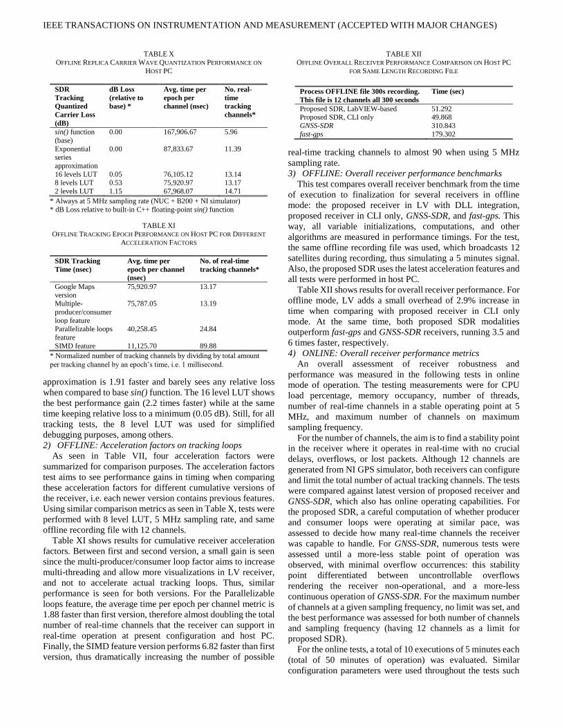
Table X shows results for carrier wave configurability in
proposed receiver in offline mode. Performance times are in
nanoseconds. The average time per epoch is 1 msec, and it is
normalized per channel, since recording file showed 12 tracking
channels during all times. The number of real-time tracking
channels shows tracking-only complexity of computations, but
lacks a possible online overhead such as LV front-end interface,
data acquisition, among others. The number of real-time
channels was found by dividing average time per epoch per
channel to a single tracking integration length (1 msec), which
would show real-time operation. The exponential series
TABLE VIII
PERFORMANCE ACQUISITION IMPLEMENTATION ON THE HOST PC WITH
LV-BASED RECEIVER
Acquisition
timing (msec)
PCS
acquisition (4
msec)
Advanced
acquisition (4
msec)
Advanced
acquisition (8
msec)
LV-based blocks
27,544.3 504.1 1,038.8
kissFFT (DLL
function)
7,982.6 331.4 674.4
FFTW (DLL
function)
3,493.6 166.3 348.3
TABLE IX
PERFORMANCE ACQUISITION IMPLEMENTATION ON THE HOST PC WITH
CLI ONLY RECEIVER
C++ CLI
acquisition
timing (msec)
PCS
acquisition (4
msec)
Advanced
acquisition (4
msec)
Advanced
acquisition (8
msec)
kissFFT 7,850.8 347.2 692.7
FFTW 3,466.8 181.9 355.5
IEEE TRANSACTIONS ON INSTRUMENTATION AND MEASUREMENT (ACCEPTED WITH MAJOR CHANGES)
approximation is 1.91 faster and barely sees any relative loss
when compared to base sin() function. The 16 level LUT shows
the best performance gain (2.2 times faster) while at the same
time keeping relative loss to a minimum (0.05 dB). Still, for all
tracking tests, the 8 level LUT was used for simplified
debugging purposes, among others.
2) OFFLINE: Acceleration factors on tracking loops
As seen in Table VII, four acceleration factors were
summarized for comparison purposes. The acceleration factors
test aims to see performance gains in timing when comparing
these acceleration factors for different cumulative versions of
the receiver, i.e. each newer version contains previous features.
Using similar comparison metrics as seen in Table X, tests were
performed with 8 level LUT, 5 MHz sampling rate, and same
offline recording file with 12 channels.
Table XI shows results for cumulative receiver acceleration
factors. Between first and second version, a small gain is seen
since the multi-producer/consumer loop factor aims to increase
multi-threading and allow more visualizations in LV receiver,
and not to accelerate actual tracking loops. Thus, similar
performance is seen for both versions. For the Parallelizable
loops feature, the average time per epoch per channel metric is
1.88 faster than first version, therefore almost doubling the total
number of real-time channels that the receiver can support in
real-time operation at present configuration and host PC.
Finally, the SIMD feature version performs 6.82 faster than first
version, thus dramatically increasing the number of possible
real-time tracking channels to almost 90 when using 5 MHz
sampling rate.
3) OFFLINE: Overall receiver performance benchmarks
This test compares overall receiver benchmark from the time
of execution to finalization for several receivers in offline
mode: the proposed receiver in LV with DLL integration,
proposed receiver in CLI only, GNSS-SDR, and fast-gps. This
way, all variable initializations, computations, and other
algorithms are measured in performance timings. For the test,
the same offline recording file was used, which broadcasts 12
satellites during recording, thus simulating a 5 minutes signal.
Also, the proposed SDR uses the latest acceleration features and
all tests were performed in host PC.
Table XII shows results for overall receiver performance. For
offline mode, LV adds a small overhead of 2.9% increase in
time when comparing with proposed receiver in CLI only
mode. At the same time, both proposed SDR modalities
outperform fast-gps and GNSS-SDR receivers, running 3.5 and
6 times faster, respectively.
4) ONLINE: Overall receiver performance metrics
An overall assessment of receiver robustness and
performance was measured in the following tests in online
mode of operation. The testing measurements were for CPU
load percentage, memory occupancy, number of threads,
number of real-time channels in a stable operating point at 5
MHz, and maximum number of channels on maximum
sampling frequency.
For the number of channels, the aim is to find a stability point
in the receiver where it operates in real-time with no crucial
delays, overflows, or lost packets. Although 12 channels are
generated from NI GPS simulator, both receivers can configure
and limit the total number of actual tracking channels. The tests
were compared against latest version of proposed receiver and
GNSS-SDR, which also has online operating capabilities. For
the proposed SDR, a careful computation of whether producer
and consumer loops were operating at similar pace, was
assessed to decide how many real-time channels the receiver
was capable to handle. For GNSS-SDR, numerous tests were
assessed until a more-less stable point of operation was
observed, with minimal overflow occurrences: this stability
point differentiated between uncontrollable overflows
rendering the receiver non-operational, and a more-less
continuous operation of GNSS-SDR. For the maximum number
of channels at a given sampling frequency, no limit was set, and
the best performance was assessed for both number of channels
and sampling frequency (having 12 channels as a limit for
proposed SDR).
For the online tests, a total of 10 executions of 5 minutes each
(total of 50 minutes of operation) was evaluated. Similar
configuration parameters were used throughout the tests such
TABLE X OFFLINE REPLICA CARRIER WAVE QUANTIZATION PERFORMANCE ON
HOST PC
SDR
Tracking
Quantized
Carrier Loss
(dB)
dB Loss
(relative to
base) *
Avg. time per
epoch per
channel (nsec)
No. real-
time
tracking
channels*
sin() function
(base)
0.00 167,906.67 5.96
Exponential series
approximation
0.00 87,833.67 11.39
16 levels LUT 0.05 76,105.12 13.14 8 levels LUT 0.53 75,920.97 13.17
2 levels LUT 1.15 67,968.07 14.71
* Always at 5 MHz sampling rate (NUC + B200 + NI simulator)
* dB Loss relative to built-in C++ floating-point sin() function
TABLE XI
OFFLINE TRACKING EPOCH PERFORMANCE ON HOST PC FOR DIFFERENT
ACCELERATION FACTORS
SDR Tracking
Time (nsec)
Avg. time per
epoch per channel
(nsec)
No. of real-time
tracking channels*
Google Maps
version
75,920.97 13.17
Multiple-
producer/consumer
loop feature
75,787.05 13.19
Parallelizable loops
feature
40,258.45 24.84
SIMD feature 11,125.70 89.88
* Normalized number of tracking channels by dividing by total amount
per tracking channel by an epoch’s time, i.e. 1 millisecond.
TABLE XII OFFLINE OVERALL RECEIVER PERFORMANCE COMPARISON ON HOST PC
FOR SAME LENGTH RECORDING FILE
Process OFFLINE file 300s recording.
This file is 12 channels all 300 seconds
Time (sec)
Proposed SDR, LabVIEW-based 51.292 Proposed SDR, CLI only 49.868
GNSS-SDR 310.843
fast-gps 179.302

IEEE TRANSACTIONS ON INSTRUMENTATION AND MEASUREMENT (ACCEPTED WITH MAJOR CHANGES)
as: NI GPS simulator broadcasting 12 satellites signal, 5 MHz
sampling frequency, similar receiver gain, same RF hardware
and antenna, 4 msec acquisition coherent integration lengths,
10 KHz acquisition search band, among other parameters.
Table XIII shows comparative performance results for online
operation for multiple acceleration factors, as well as GNSS-
SDR receiver.
From CPU load perspective, proposed SDR began gaining
load as versions increased, but on the last version with SIMD
feature the load decreased by more than two-fold. This is
because tracking correlator arithmetic operations are now
handled by internal SIMD registers on host PC, making
multiple operations at a time while consuming less CPU
resources with high efficiency. For GNSS-SDR, a quick glance
at the high load is shown due to floating-point operations in
acquisition and tracking algorithms, as well as many
configuration options and a strict dependency on GNU-Radio
and other numerous dependencies which require a high number
of threads to be instantiated when executed.
From memory occupancy, all receiver showed a similar
performance which is minimal compared to host PC’s total
memory of 16 GB. On threads’ perspective, proposed SDR
gained 5 threads since the multi-producer/consumer loop
feature version. GNSS-SDR showed higher thread occupancy,
again, due to many instantiations when executed.
At 5 MHz sampling rate, proposed SDR gained tracking
channel capacity as versions increased. If comparing online
tracking channel capacity against Table XI, one can analyze an
overhead cost from LV environment which includes data
acquisition, USRP interfacing, visualizations, among other
reasons. For the first and second versions, two real-time
tracking channels are traded for several LV-based receiver
benefits. For the maximum number of channels, since the
proposed receiver’s limit is 12 channels, sampling rate was used
as a variable for finding the maximum optimal operating point
of all versions. For the latest version of proposed SDR, a total
of 8 channels at 25 MHz were able to operate in real-time for
selected host PC and hardware.
5) ONLINE: Data interruptions and overflows statistics
For this online test, latest version of proposed SDR and
GNSS-SDR were tested for overflows, with same parameters as
previous test. A total of 10 runs of 5 minutes each (totaling 50
minutes) in real-time operation, with NI GPS simulator and 12
satellites. Using results from Table XIII to obtain stability point
on both receivers, overflows and data interruptions were
evaluated. Table XIV shows statistics for data interruptions on
both receivers. The proposed SDR showed no overflows.
GNSS-SDR showed 40 overflows on 50 minutes of operation,
which averages to 0.01 overflows per second. Another statistic
measured was the average time between overflows, which was
found to be 70 seconds. This means, when running receiver, in
average every 70 seconds it will overflow and channels will be
lost.
D. Navigation comparative results
For GPS receivers, navigation precision is an important
statistic that characterizes receiver performance. Two statistics
were evaluated for precision: root-mean square (RMS) error (in
meters), and true mean error. PVT solutions usually output user
position in several coordinate systems. The x, y, and z cartesian
coordinates for user location were used to measure both
statistics. RMS error in this evaluation corresponds to the
standard deviation, or how much position measurement
samples change between one another. For the true mean error,
since the NI GPS simulator can be configured with an exact
geolocation, the actual receiver output was compared against
the true position, and the Euclidean RMS distance error was
calculated. For one scenario, and since navigation doesn’t
require online operation, the same offline recording file used in
acquisition and tracking results was used. It contains 12
satellites and a duration of 5 minutes. Both receivers were set
with similar parameters for acquisition, tracking, and
navigation, such as: sampling rate of 5 MHz, 4 msec coherent
integration length, 10 KHz acquisition search band, 10 samples
navigation averaging window, 5 Hz navigation sampling output
rate, among others. For a second and third scenarios, real GPS
signal recordings were used, which were recorded in an exact
same location in Colorado Springs, CO during a static test.
These two scenarios were recorded with OCXO, and with
OCXO + GPSDO. These tests address receiver performance
with real signals, and at the same time with and without GPS
disciplining (GPSDO). These tests no. 2 and no. 3 do not have
true mean error, since a true geolocation was not obtained.
Table XV shows both RMS error and true mean error results
for proposed receiver and GNSS-SDR. For the true mean error,
GNSS-SDR showed a bias error in height of 12m on average.
TABLE XIII
ONLINE OVERALL RECEIVER PERFORMANCE COMPARISON ON HOST PC
FOR SEVERAL METRICS
Online
testing at 5
MHz
CPU
load
(%)
Memory
(KB)
No. of
threads
No. of
channels
in real-
time @
5 MHz
Max.
no. of
channels
in real-
time @
Fs
Google Maps version
15.99 167,864.88 34 11 11 @ 5 MHz
Multiple-
prod./cons. loop feature
15.52 155,346.13 39 11 12 @ 4
MHz
Parallelizable
loops feature
22.73 155,248.85 39 12 9 @ 10
MHz
SIMD
feature
9.85 155,613.47 39 12 8 @ 25
MHz GNSS-SDR 42.98 130,529.47 64 5 5 @ 5
MHz**
* Online testing using NUC + B200 + NI simulator.
* Online testing performed at 5 MHz sampling rate for all receivers, as
well as 4 msec. coherent integration length for acquisition. ** Maximum number of channels with minimal overflow occurrences and
stable operation.
TABLE XIV
ONLINE RECEIVER OVERFLOW ROBUSTNESS COMPARISON ON HOST PC
Overflows
(OV) in
50min run
(real-time)
No. of OVs Avg. OVs/sec Avg. time
between OVs
(sec)
Proposed SDR
0.00 0.00 0.00
GNSS-SDR 40.00 0.01 70.10

IEEE TRANSACTIONS ON INSTRUMENTATION AND MEASUREMENT (ACCEPTED WITH MAJOR CHANGES)
For RMS error, both receivers performed well, with a slight
advantage on the proposed SDR. As for tests 2 and 3, proposed
SDR showed a clear precision improvement of more than 50%
when using GPS disciplining from the board mounted kit, as
opposed to only OCXO performance, as discussed in section
III-A. As for GNSS-SDR, the receiver showed a RMS error of
19.34m for the disciplined scenario, and for the OCXO only,
the receiver was not able to acquire the signal properly. The
comparison of both receiver performances with real GPS
signals and GPSDO enabled (scenario 3) showed a gain of more
than 4 times in precision on the reference receiver. Preliminary
results show visual stability of the navigation module of the
receiver in Fig. 8 where a 8-min drive test in Colorado Springs,
CO, was conducted.
VI. CONCLUSION
This paper proposed and demonstrated a new generation
state-of-the-art GPS receiver based on LV and C/C++
integrations as DLL modules. Several acceleration factors for
SDR were discussed and leveraged in proposed SDR for real-
time operation. Conventional baseband modules for
acquisition, tracking, and navigation were used as DLL
modules integrated into LV, as well as a USRP B200 front-end
paired with an Intel NUC5i5RYK as the receiver hardware
testbed were evaluated.
An extensive comparative analysis was made with existing
open-source SDR solutions in both offline and online mode of
operation. For all three baseband modules: acquisition,
tracking, and navigation, several comparisons were made
against acceleration factors, and other receivers such as fast-gps
and GNSS-SDR. Four versions of the proposed receiver were
considered based on the acceleration factors discussed: Google
Maps, multi-producer/consumer loop, Parallelizable loops, and
SIMD features. The paper also presented an approach to
develop an advanced receiver to address various receiver tasks
including multipath measurements as reported in [9]. Different
from [9] the real-time receiver functionality is achieved by
using built-in features of the selected environment. The paper
studied the impact of various acceleration features and their
practical implementation intricacies.
For acquisition, an advanced joint-search FFT acquisition
algorithm [26] was tested in proposed receiver against the
conventional PCS acquisition algorithm. Optimization libraries
for FFT operations were also compared. Both LV-based
receiver and CLI-only receiver were compared to assess any
overhead by former receiver. For tracking, several online and
offline tests were evaluated. Tests involving quantization
carrier wave performance and relative loss, receiver versions
performance gains, and against GNSS-SDR were compared.
Metrics such as CPU load and memory occupancy were
assessed for online operation of receivers. A maximum of 8
real-time channel tracking at 25 MHz sampling rate was
achieved on latest version of proposed receiver. For navigation,
PVT solution precision was assessed for proposed SDR and
GNSS-SDR.
Eventually, we present strengths as well as weaknesses of the
proposed solution, such as relying on certain platform and thus
limiting high-end optimizations for advanced commercial-
grade solutions. The proposed solution promises fast
prototyping for determined research purposes and achieves
computational space for future plans.
REFERENCES
[1] P. Misra and P. Enge, Global Positioning System: Signals, Measurements, and Performance, Lincoln, MA: Ganga-Jamuna Press,
2011.
[2] K. Borre, D. M. Akos, N. Bertelsen, P. Rinder and J. H. Jensen, A Software-Defined GPS and Galileo Receiver: A Single-Frequency
Approach, Boston: Birkhauser Verlag, 2006.
[3] N. Agarwal, J. Basch, P. Beckmann, P. Bharti, S. Bloebaum, S. Casadei, A. Chou, P. Enge, W. Fong, N. Hathi, W. Mann, A. Sahai, J. Stone, J.
Tsitsiklis and B. Van Roy, "Algorithms for GPS operation indoors and
downtown," GPS Solutions, vol. 6, no. 3, p. 149–160, 2002.
[4] F. Dovis, GNSS Interference Threats & Countermeasures, Artech
House, 2015.
[5] T. E. Humphreys, B. M. Ledvina, M. L. Psiaki, B. W. O'Hanlon and P. M. Kintner, "Assessing the Spoofing Threat: Development of a Portable
GPS Civilian Spoofer," in Proceedings of the 21st International Technical Meeting of the Satellite Division of The Institute of Navigation
(ION GNSS 2008), Savannah, GA, 2008.
[6] D. M. Akos, "Who's Afraid of the Spoofer? GPS/GNSS Spoofing Detection via Automatic Gain Control (AGC)," NAVIGATION, Journal
of the Institute of Navigation, vol. 59, no. 4, pp. 281-290, 2012.
[7] A. Jafarnia-Jahromi, T. Lin, A. Broumandan, J. Nielsen and G. Lachapelle, "Detection and Mitigation of Spoofing Attacks on a Vector
Based Tracking GPS Receiver," in Proceedings of the 2012
International Technical Meeting of The Institute of Navigation, Newport Beach, CA, 2012.
[8] G. De Angelis et al., “An indoor AC magnetic positioning system,”
IEEE Trans. Instrum. Meas., vol. 64, no. 5, pp. 1267–1275, May 2015.
TABLE XV RECEIVER NAVIGATION PVT PRECISION COMPARISON ON HOST PC
SDR PVT
Precision
Scenarios
Scenario RMS Mean
Error (m)
True Mean
Error (m)
Proposed SDR 1 (SIM) 0.62 1.33
2 (OCXO) 10.23 N/A
3 (GPSDO) 4.28 N/A
GNSS-SDR 1 (SIM) 1.14 11.99 2 (OCXO) N/A N/A
3 (GPSDO) 19.34 N/A
* Scenario 1 comes from GPS simulator in a static environment and
known geolocation. * Scenarios 2 and 3 are from a real GPS static location in Colorado
Springs, CO, using the OCXO with and without disciplining, i.e. OCXO,
and OCXO + GPSDO. Fig. 8. Preliminary results for dynamic test in Colorado Springs, CO
with OCXO + GPSDO mode.

IEEE TRANSACTIONS ON INSTRUMENTATION AND MEASUREMENT (ACCEPTED WITH MAJOR CHANGES)
[9] P. Xie and M. G. Petovello, “Measuring GNSS multipath distributions
in urban canyon environments,” IEEE Trans. Instrum. Meas., vol. 64,
no. 2, pp. 366–377, Feb. 2015.
[10] D. Macii, A. Colombo, P. Pivato, and D. Fontanelli, “A data fusion
technique for wireless ranging performance improvement,” IEEE Trans. Instrum. Meas., vol. 62, no. 1, pp. 27–37, Jan. 2013.
[11] L. Fang et al., “Design of a wireless assisted pedestrian dead reckoning
system—The NavMote experience,” IEEE Trans. Instrum. Meas., vol. 54, no. 6, pp. 2342–2358, Dec. 2005.
[12] A. R. J. Ruiz, F. S. Granja, J. C. P. Honorato, and J. I. G. Rosas,
“Accurate pedestrian indoor navigation by tightly coupling foot-mounted IMU and RFID measurements,” IEEE Trans. Instrum. Meas.,
vol. 61, no. 1, pp. 178–189, Jan. 2012.
[13] A. Colombo, D. Fontanelli, D. Macii, and L. Palopoli, “Flexible indoor localization and tracking based on a wearable platform and sensor data
fusion,” IEEE Trans. Instrum. Meas., vol. 63, no. 4, pp. 864–876, Apr.
2014. [14] Carbone, P.; Petri, D.; Tsourdos, A., "I&M in navigation systems
[Framing I&M Topics]," IEEE Instrum. Meas. Mag., vol.18, no.3,
pp.36,39, June 2015. DOI: 10.1109/MIM.2015.7108397
[15] IFEN, "Commercial software receiver development tools from iFEN,"
IFEN, [Online]. Available: http://www.ifen.com. [Accessed 12 January
2017].
[16] S. Gleason, M. Quigley and P. Abbeel, "Chapter 5 A GPS software
receiver," in GNSS Applications and Methods, Norwood, MA: Artech
House, 2009, pp. 121-147.
[17] The GNU Radio Foundation, Inc, "GNU Radio," [Online]. Available:
www.gnuradio.org. [Accessed 15 January 2015].
[18] Ettus Research, a National Instruments (NI) company, "Ettus Research - The leader in Software Defined Radio (SDR)," [Online]. Available:
https://www.ettus.com/. [Accessed 13 January 2015].
[19] A. Soghoyan, G. Huang, J. Narisetty and D. Akopian, "A Labview-based
Assisted GPS Receiver Development, Simulation and Testing
Platform," in Proceedings of the 24th International Technical Meeting
of The Satellite Division of the Institute of Navigation (ION GNSS 2011), Portland, OR, 2011.
[20] A. Soghoyan and D. Akopian, "A LabVIEW-Based GPS Receiver
Development and Testing Platform with DSP Peripherals: Case study with C6713 DSK," Journal of Global Positioning Systems, vol. 11, no.
2, pp. 127-144, 2012.
[21] A. Soghoyan, A. Suleiman and D. Akopian, "A Development and Testing Instrumentation for GPS Software Defined Radio with Fast
FPGA Prototyping Support," IEEE Trans. Instrum. Meas., vol. 63, no.
8, pp. 2001-2012, 2014.
[22] T. E. Humphreys, M. L. Psiaki, P. M. Kintner and B. M. Ledvina,
"GNSS Receiver Implementation on a DSP: Status, Challenges, and
Prospects," in Proceedings of the 19th International Technical Meeting of the Satellite Division of The Institute of Navigation (ION GNSS
2006), Fort Worth, TX, September 2006.
[23] T. E. Humphreys, J. A. Bhatti, T. Pany, B. M. Ledvina and B. W. O'Hanlon, "Exploiting Multicore Technology in Software-Defined
GNSS Receivers," in Proceedings of 2009 ION GNSS Conference, Savannah, GA, September 2009.
[24] M. G. Petovello et al., “Architecture and Benefits of an Advanced GNSS
Software Receiver,” Journal of Global Positioning Systems, vol. 7, no. 2, pp. 156–168, 2008.
[25] C. Fernandez-Prades, J. Arribas, P. Closas, C. Aviles and L. Esteve,
"GNSS-SDR: An open source tool for researchers," in Proceedings of the 24th International Technical Meeting of The Satellite Division of the
Institute of Navigation (ION GNSS 2011), Portland, OR, September
2011.
[26] D. Akopian, "Fast FFT based GPS satellite acquisition methods," IEE
Proceedings-Radar, Sonar and Navigation, vol. 152, no. 4, pp. 277-286,
August 2005. [27] National Instruments, "NI Global Navigation Satellite System Toolkits,"
National Instruments, [Online]. Available:
http://sine.ni.com/nips/cds/view/p/lang/en/nid/204980. [Accessed July 2016].
[28] Intel Corporation, "Intel NUC Kit NUC5i5RYK," Intel Corporation,
[Online]. Available:
https://www.intel.com/content/www/us/en/products/boards-
kits/nuc/kits/nuc5i5ryk.html. [Accessed April 2016].
[29] Tallysman, "TW2010-TW2012 GPS L1 Bandwidth Antenna,"
Tallysman, [Online]. Available:
http://www.tallysman.com/index.php/gnss/products/antennas-gps-l1/tw2010-tw2012/. [Accessed 2016].
[30] GPS Source, "GPS In-line 30dB Amplifier - A11," GPS Source,
[Online]. Available: https://www.gpssource.com/products/a11-gps-in-line-30db-amplifier. [Accessed 2016].
[31] Analog Devices, "AD9364," 1 July 2014. [Online]. Available:
http://www.analog.com/media/en/technical-documentation/data-sheets/AD9364.pdf. [Accessed 10 January 2016].
[32] A. Lipp and X. Gu, "Cycle-slip detection and repair in integrated
navigation systems," in Position Location and Navigation Symposium, 1994., IEEE, Las Vegas, NV, USA, April 1994.
[33] C.-L. Cheng, F.-R. Chang, and K.-Y. Tu, “Highly accurate real-time
GPS carrier phase-disciplined oscillator,” IEEE Trans. Instrum. Meas.,
vol. 54, no. 2, pp. 819–824, Apr. 2005.
[34] Ettus Research, a National Instruments (NI) company, "Board Mounted
GPSDO (OCXO) Recommended for USRP X300/X310," [Online]. Available: https://www.ettus.com/product/details/GPSDO-MINI.
[Accessed July 2016].
[35] M. A. Lombardi, "The Use of GPS Disciplined Oscillators as Primary Frequency Standards for Calibration and Metrology Laboratories,"
NCSLI Measure, vol. 3, no. 3, pp. 56-65, September 2008.
[36] Intel Corporation, "Intel(R) C++ Intrinsic Reference," [Online]. Available: https://software.intel.com/sites/default/files/a6/22/18072-
347603.pdf. [Accessed 1 June 2017].
[37] M. Frigo and S. G. Johnson, "The Design and Implementation of FFTW3," Proceedings of the IEEE, vol. 93, no. 2, pp. 216-231, 2005.
[38] M. Borgerding, “KissFFT,”, June 2013. [Online]. Available:
https://sourceforge.net/projects/kissfft/. [Accessed 13 August 2016].
[39] Eigen, "Eigen - a C++ template library for linear algebra: matrices,
vectors, numerical solvers, and related," [Online]. Available:
http://eigen.tuxfamily.org. [Accessed 13 August 2016].
[40] GNSS @ Colorado Center for Astrodynamics Research, May 2008.
[Online]. Available: http://ccar.colorado.edu/gnss/.

IEEE TRANSACTIONS ON INSTRUMENTATION AND MEASUREMENT (ACCEPTED WITH MAJOR CHANGES)
Erick Schmidt (S’17) received
the B.Sc. degree in electronics and
computer engineering with
Honors from The Monterrey
Institute of Technology and
Higher Education, Monterrey,
Mexico, in 2011, and the M.Sc.
degree from the University of
Texas at San Antonio, San
Antonio, TX, USA, in 2015. From
2011 to 2013, he was a Systems
Engineer with Qualcomm Incorporated.
He is currently working towards the Ph.D. degree in
electrical engineering from the University of Texas at San
Antonio, San Antonio, TX, USA. His research interests include
software-defined radio, indoor navigation, global navigation
satellite system (GNSS), and fast prototyping algorithms and
accelerators for baseband communication systems. He is a
student member of the IEEE and the Institute of Navigation
(ION).
David Akopian (M’02-SM’04) is
a Professor at the University of
Texas at San Antonio (UTSA).
Prior to joining UTSA, he was a
Senior Research Engineer and
Specialist with Nokia Corporation
from 1999 to 2003. From 1993 to
1999 he was a researcher and
instructor at the Tampere
University of Technology,
Finland, where he received his
Ph.D. degree in 1997. Dr.
Akopian’s current research interests include digital signal
processing algorithms for communication and navigation
receivers, positioning, dedicated hardware architectures and
platforms for software defined radio and communication
technologies for healthcare applications.
He authored and co-authored more than 30 patents and 140
publications. He is elected as a Fellow of US National Academy
of Inventors in 2016. He served in organizing and program
committees of many IEEE conferences and co-chairs an annual
conference on Multimedia and Mobile Devices. His research
has been supported by National Science Foundation, National
Institutes of Health, USAF, US Navy, and Texas foundations.
Daniel J. Pack received the Bachelor
of Science degree in electrical
engineering from Arizona State
University, Tempe, AZ, USA, in
1988, the Master of Science degree in
engineering sciences from Harvard
University, Cambridge, MA, USA, in
1990, and the Ph.D. degree in
electrical engineering from Purdue
University, West Lafayette, IN, USA,
in 1995.
He is currently the Dean of the
College of Engineering and Computer Science, University of
Tennessee, Chattanooga (UTC), TN, USA. Prior to joining
UTC, he was a Professor and the Mary Lou Clarke Endowed
Chair of the Electrical and Computer Engineering Department,
University of Texas, San Antonio and a Professor (now
Professor Emeritus) of electrical and computer engineering at
the United States Air Force Academy, CO, USA, where he was
the founding Director of the Academy Center for Unmanned
Aircraft Systems Research. His research interests include
unmanned aerial vehicles, intelligent control, automatic target
recognition, robotics, and engineering education.