Development of a Prototype Latent Heat Thermal Energy ...
98
Development of a Prototype Latent Heat Thermal Energy Storage System by Georg Scharinger-Urschitz A thesis for the degree of Doctor tecnicae In the Doctoral Program in Engineering Sciences - Mechanical Engineering At the Faculty of Mechanical Engineering and Management, TU Wien Supervised by Heimo Walter Reviewed by Markus Haider Sophia Haussener
-
Upload
khangminh22 -
Category
Documents
-
view
1 -
download
0
Transcript of Development of a Prototype Latent Heat Thermal Energy ...

Development of a PrototypeLatent Heat Thermal EnergyStorage Systemby Georg Scharinger-Urschitz
A thesis for the degree ofDoctor tecnicae
In theDoctoral Program in Engineering Sciences - Mechanical Engineering
At theFaculty of Mechanical Engineering and Management, TU Wien
Supervised byHeimo Walter
Reviewed byMarkus Haider
Sophia Haussener

AuthorGeorg Scharinger-UrschitzMatr. Nr.: [email protected]
SupervisorHeimo WalterTU WienInstitute for Energy Systemsand ThermodynamicsGetreidemarkt 9, A-1060 Wien
ReviewersMarkus HaiderTU WienInstitute for Energy Systemsand ThermodynamicsGetreidemarkt 9A-1060 Wien
Sophia HaussenerEPFLLaboratory of Renewable EnergyScience and EngineeringME DO 2926 Station 9CH-1015 Lausanne
FundingThis work was supported by the Austrian Research Promotion Agency (FFG) withinthe framework of the projects GreenStorageGrid (#836636) and BiMeRi (#843934).
Going to pressI confirm that going to press of this thesis needs the confirmation of the examinationcommittee.
AffidavitI declare in lieu of oath, that I wrote this thesis and performed the associated researchmyself, using only literature cited in this volume. If text passages from sources are usedliterally, they are marked as such. I confirm that this work is original and has not beensubmitted elsewhere for any examination, nor is it currently under consideration for athesis elsewhere.
Vienna, October 2019 Georg Scharinger-Urschitz

AbstractThermal energy storage systems can balance volatile production and consumption ofheat at different temperature levels and time scales. The temperature target level ismedium to high, focusing on storage temperatures up to 350 ◦C with potential applica-tions in solar thermal energy production, or industrial processes. Utilizing phase changematerials as storage material, the energy density can be higher compared to other storagesystems. Because of the low thermal conductivity of many phase change materials in thesolid state, heat transfer is highly transient. Enhancing the heat transfer ability is keyto improving this storage technology; but heat transfer mechanisms and melting phe-nomena are also worth studying, especially when looking at industrial scale prototypesand the improvement of this level of technology.
This work aims to address the topic of heat transfer enhancement and attachingaluminum fins to a steel tube. For this purpose, a new fin design and a novel attachmentmethod are developed. Two test rigs in lab-scale are built and performance measure-ments of such a storage units are executed. In this this test rigs, sodium nitrate is usedas an affordable, non-toxic and highly promising phase change material (PCM). Themelting temperature is in the range of with life steam temperatures in solar thermalpower plants. The test-rigs are equipped with a single aluminum finned steel tube filledwith heat transfer fluid. The storage vessel is a cylindrical tank with a finned tube heatexchanger. The volume between the tubes and the shell is filled with PCM. Thermaloil is used as a heat transfer fluid. The temperatures and mass flows are processed in aprocess control system and analyzed later on.
The experiments provide detailed data of the melting front development in thestorage units. By employing multiple temperature testing points, energy balance andother performance indicators are provided for the two different fin geometries. The heattransfer from the heat transfer fluid into the storage material is described in detail andquantified. In addition, a new attachment method for aluminum fins is presented.
With the novel fin geometry, melting performance is improved significantly. Theheat transfer coefficient allows storage power prediction for future storage systems. Andthe highly promising manufacturing method for bimetallic finned tubes enables hexago-nal cross sections and large-scale production. With this contribution to the developmentof latent heat thermal energy storage systems, energy systems will become more efficient.Industrial scale application of this storage type will help to reduce primary energy inputsthrough reduction of fossil fuel needs which will be one of the most threatening globalchallenges in the coming decades.
i

KurzfassungThermische Energiespeicher können fluktuierende thermische Verbraucher und Produ-zenten in unterschiedlichen zeitlichen Dimensionen und Temperaturniveaus sinnvoll kop-peln. Dadurch können höhere Nutzungsgrade der eingesetzten Primärenergie erreichtwerden. Dabei steht der Temperaturbereich bis 350 ◦C im Fokus, welcher etwa für so-larthermischen Kraftwerke oder industrielle Prozesse gut einsetzbar ist. Das Speicher-konzept des Latentwärmespeichers mit dem Einsatz von Phasenwechselmaterialien alsSpeichermaterial ermöglicht hohe Energiedichtungen und dadurch geringere Speichervo-lumen. Ein häufiger Nachteil bei Phasenwechselmaterialien liegt in der schlechten Wär-meleitung im festen Zustand und im transienten Wärmeübertragungsverhalten.
Im Rahmen dieser Arbeit wurden Latentwärmespeicher Prototypen im Labormaß-stab entwickelt und experimentelle Untersuchungen durchgeführt. Der Wärmetransportwird mit Hilfe von Aluminiumrippen die auf einem Stahlrohr fixiert werden, erhöht. AlsSpeichermedium wird leicht verfügbares, konstengünstiges und ungiftiges Natriumni-trat verwendet. Der Schmelzpunktes ist passend für Anwendungen im Hochtemperatur-Solarthermiebereich und Schmelzenthalpie ist relativ groß. Das Wärmetauscherrohr wirdvertikal in einem zylinderförmigen Speicherbehälter platziert. Das Stahlrohr wird vomWärmeträgermedium durchströmt; das Phasenwechselmaterial ist zwischen den Rippenund dem Speicherbehälter angeordnet. Temperaturen und Massenströme können überein Prozessleitsystem geregelt und für eine spätere Auswertung aufgezeichnet werden.
Insgesamt wurde zwei Versuchsstände konstruiert und gebaut die sich vor allemdurch ihre Rippengeometrie unterscheiden. Auf Basis der Messungen kann die Entwick-lung der Schmelzfront rekonstruiert werden. Außerdem wird die Energiebilanz für denSpeicher aufgestellt und die wesentlichen Kenndaten wie Leistung, Kapazität aber vorallem das dynamische Verhalten gemessen. Auch der Wärmeübergang vom Wärmeträ-germedium in das Speichermaterial wird genau beschrieben. Durch die Optimierung derRippengeometrie konnte das Aufschmelzverhalten verbessert werden. Außerdem wurdeeine neue Methode zur Befestigung von Aluminiumrippen auf einem Stahlrohr entwi-ckelt. Mit ihrer Hilfe lassen sich auch sechseckige Querschnitte von Aluminium-StahlVerbundrippenrohren produzieren, die sich dadurch effizient in einem Latentwärmespei-cher anordnen lassen.
Im Rahmen dieser Dissertation wurde die Technologie für Latentwärmespeicher undRippenrohre weiter entwickelt um sie effizienter und besser zu machen. Latentwärme-speicher können den Energieverbrauch reduzieren und den Nutzungsgrad von Wärmewesentlich erhöhen. Im Hinblick auf die kommenden Jahrzehnte ist es notwendig, jedeverfügbare Maßnahme zur Verringerung der Emissionen und zum effizienteren Energie-einsatz zu ergreifen, dabei kann der Latentwärmespeicher eine wichtige Rolle spielen.
ii

AcknowledgmentsThis thesis summarizes the work in the field of thermal energy storage with phase changematerials at the Institute of Energy Systems and Thermodynamics at TU Wien in thepast six years. Most of the work was done within two nationally funded research projectsGreenStorageGrid (#836636) and BiMeRi (#843934). I would like to express my appre-ciation to the financers of those projects. Furthermore, my employment as a universityassistant at TU Wien for the past five years enabled the completion of this thesis, andit also provided many other interesting experiences such as teaching.
It gives me great pleasure in acknowledging the support of the head of the InstituteMarkus Haider. He facilitated my work at the institute and supported me during thesepast years not only with knowledge from the boiler industry, but also with understandingfor my paternity leaves. In addition, I would like to thank my supervisor Heimo Walter.With discussions and meetings on a weekly basis, he was the counterpart for the researchwork that was carried out. With his foresight and good intuition for high quality journalsand conferences, he guided me in entering the scientific world. In addition, I would liketo express my gratitude to the other professors at the Institute Andreas Werner and KarlPonweiser for their willingness to enter into scientific discussions and for their support.
A special thanks has to be delivered to the staff working in the laboratory, especiallyto Wolfgang, Michael, Roswitha, Andreas, Werner, Patrick, and all the others. Withoutyour help not a single experimental investigation would have been possible.
I would also like to thank my colleagues who accompanied me over the past years.You inspired and improved the scientific work with discussions on a daily basis. Thankyou Martin, Felix, Stefan, Viktoria, Verena and all others crossing my path in the pastyears.
Ultimately I would like to mention Sandy Tauschek who proofread this thesis.Thank you so much for finding the time to do this for me.
A special thank-you goes out to my parents, to my wife Ursula, and to my twosons, Samuel and Marian. You have all supported me in the past six years with muchunderstanding and motivation, so you have also brought this work to fruition.
iii

Contents
Nomenclature vi
1. Introduction 11.1. Energy Transition and Global Warming . . . . . . . . . . . . . . . . . . . 11.2. Thermal Energy Storage Systems . . . . . . . . . . . . . . . . . . . . . . . 3
1.2.1. Storage Parameters and Characterization . . . . . . . . . . . . . . 31.3. Thermal Energy Storage Methods . . . . . . . . . . . . . . . . . . . . . . 6
1.3.1. Sensible Heat TES Systems . . . . . . . . . . . . . . . . . . . . . . 61.3.2. Latent Heat TES Systems . . . . . . . . . . . . . . . . . . . . . . . 91.3.3. Thermochemical TES Systems . . . . . . . . . . . . . . . . . . . . 9
2. Methodology and Paper Overview 112.1. Implementation Barriers . . . . . . . . . . . . . . . . . . . . . . . . . . . . 112.2. Methodology . . . . . . . . . . . . . . . . . . . . . . . . . . . . . . . . . . 132.3. Paper Overview . . . . . . . . . . . . . . . . . . . . . . . . . . . . . . . . . 14
2.3.1. Finned Mono Tube Latent Heat TES, Paper 1 and 2 . . . . . . . . 152.3.2. Bimetallic Finned Tube Design, Paper 3, 4 and 5) . . . . . . . . . 162.3.3. Novel Fin Geometry, Paper 6, 7 and 8) . . . . . . . . . . . . . . . 17
3. Phase Change Phenomena and Materials 193.1. Phenomenological Approach . . . . . . . . . . . . . . . . . . . . . . . . . . 19
3.1.1. Solid-Liquid Phase Change . . . . . . . . . . . . . . . . . . . . . . 203.1.2. Liquid-Gaseous Phase Change . . . . . . . . . . . . . . . . . . . . 213.1.3. Solid-Solid Phase Change . . . . . . . . . . . . . . . . . . . . . . . 21
3.2. Phase Change Materials . . . . . . . . . . . . . . . . . . . . . . . . . . . . 223.2.1. Organic PCMs . . . . . . . . . . . . . . . . . . . . . . . . . . . . . 223.2.2. Inorganic PCMs . . . . . . . . . . . . . . . . . . . . . . . . . . . . 243.2.3. Mixtures, Metals and Other PCMs . . . . . . . . . . . . . . . . . . 25
3.3. Methods for Thermal Characterization of PCMs . . . . . . . . . . . . . . 263.3.1. Differential Scanning Calorimetry Measurements . . . . . . . . . . 263.3.2. Measuring Thermal Conductivity . . . . . . . . . . . . . . . . . . . 273.3.3. Other methods for determining thermophysical properties . . . . . 28
3.4. Sodium Nitrate (NaNO3) . . . . . . . . . . . . . . . . . . . . . . . . . . . 283.4.1. Thermophysical Properties of Sodium Nitrate . . . . . . . . . . . . 293.4.2. Material Compatibility and Corrosion . . . . . . . . . . . . . . . . 31
3.5. Heat Transfer Enhancement Methods . . . . . . . . . . . . . . . . . . . . . 333.5.1. Extended Heat Exchange Surfaces . . . . . . . . . . . . . . . . . . 34
iv
3.5.2. Encapsulation . . . . . . . . . . . . . . . . . . . . . . . . . . . . . . 373.5.3. Selected Heat Conductivity/Capacity Enhancements . . . . . . . . 38
4. Modeling of Phase Change Phenomena 394.1. Modeling of Material Properties . . . . . . . . . . . . . . . . . . . . . . . . 39
4.1.1. Heat Capacity and Enthalpy . . . . . . . . . . . . . . . . . . . . . 394.2. Analytical Models . . . . . . . . . . . . . . . . . . . . . . . . . . . . . . . 42
4.2.1. Approximate Analytical Solutions . . . . . . . . . . . . . . . . . . 444.3. Numerical Approaches for Melting . . . . . . . . . . . . . . . . . . . . . . 45
4.3.1. Enthalpy and Apparent Heat Capacity . . . . . . . . . . . . . . . . 454.3.2. Convection and Diffusion . . . . . . . . . . . . . . . . . . . . . . . 464.3.3. Selected Models . . . . . . . . . . . . . . . . . . . . . . . . . . . . 46
4.4. System-Level Simulations . . . . . . . . . . . . . . . . . . . . . . . . . . . 48
5. Experimental Investigations 505.1. Latent Heat TES Test Rigs . . . . . . . . . . . . . . . . . . . . . . . . . . 505.2. Bimetallic Finned Tube Investigation . . . . . . . . . . . . . . . . . . . . . 515.3. Selected Experimental Investigations . . . . . . . . . . . . . . . . . . . . . 53
5.3.1. Experimental Work at DLR . . . . . . . . . . . . . . . . . . . . . . 535.3.2. Experimental Work at Ghent University . . . . . . . . . . . . . . . 555.3.3. Experimental Work at AIT . . . . . . . . . . . . . . . . . . . . . . 56
6. Conclusion and Outlook 58
References 61
List of Figures 73
List of Tables 75
A. List of Publications 76A.1. Paper 1 . . . . . . . . . . . . . . . . . . . . . . . . . . . . . . . . . . . . . 78A.2. Paper 2 . . . . . . . . . . . . . . . . . . . . . . . . . . . . . . . . . . . . . 87A.3. Paper 3 . . . . . . . . . . . . . . . . . . . . . . . . . . . . . . . . . . . . . 98A.4. Paper 4 . . . . . . . . . . . . . . . . . . . . . . . . . . . . . . . . . . . . . 112A.5. Paper 5 . . . . . . . . . . . . . . . . . . . . . . . . . . . . . . . . . . . . . 127A.6. Paper 6 . . . . . . . . . . . . . . . . . . . . . . . . . . . . . . . . . . . . . 139A.7. Paper 7 . . . . . . . . . . . . . . . . . . . . . . . . . . . . . . . . . . . . . 152A.8. Paper 8 . . . . . . . . . . . . . . . . . . . . . . . . . . . . . . . . . . . . . 166
v

Nomenclature
Acronyms
CFD computational fluid dynamicsCSP concentrated solar powerDLR German Aerospace Center (DLR)DSC differential scanning calorimetryDSG direct steam generationHDPE high density polyethylenHFM hot flow meterHTF heat transfer fluidIB implementation barrierIET Institute of Energy Systems and Thermodynamic at TU WienIR infrared radiationLCOE levelized costs of electricityLFA laser flash apparatusLoU level of utilizationORC organic rankine cyclePA polyamidsPCM phase change materialPCS process control systemPDE partial differential equationPV photo voltaicPV photovoltaicSL-PCM solid-liquid phase change materialSM storage materialSS-PCM solid-solid phase change materialTES thermal energy storageTGA thermogravimetryTHB transient hot bridge
Greek symbols
β heating rate Kmin−1
∆Hr Reaction enthalpy Jmol−1
ε dimensionless fin factor −η dimensionless number used in derivations as a substitution −
vi

γ liquid fraction −λ heat conductivity Wm−1 Kρ density kgm−3
Subscripts
b boundarychar chargingdis discharginge extrapolatedf finali initiall liquidloss losseslrv lower range valuemelt melting pointpk peaks solidsen sensibleurv upper range value
Roman symbols
a thermal diffusivity m2 s−1
c costs e/kWhc∗p equivalent specific heat capacity kJ kg−1 K−1
cp specific isobaric heat capacity kJ kg−1 K−1
cp,app apparent specific heat capacity kJ kg−1 K−1
E energy kWhf heat flux Wm−2
k heat transfer coefficient Wm−2 K−1
kN dimensionless number in solution of Neumann’s problems −L latent heat of fusion kJ kg−1 Km mass kgP power kWSt Stefan number −T temperature ◦Ct time sU voltage mVw energy density kWhm−3
X solidification front position mx distance m
vii


1. Introduction
The increasing worldwide demand for energy, combined with the widespread use of fossilfuel resources and the global warming effect of their ensuing emissions, lead to somevery crucial questions for the coming decades. How can this energy demand be satisfiedby renewable energies? How can this energy demand be reduced and the application bemade more effective? What will be the sources of energy utilized in our future energysystems? How can all of this be considered alongside reducing the global inequity inenergy consumption? Based on these huge questions, technological development canprovide solutions for some aspects.
1.1. Energy Transition and Global WarmingAt the moment, human activities have caused a global warming of 1 ◦C above the pre-industrial level. The global mean surface temperature will likely reach 1.5 ◦C between2030 and 2052, according to the Global Warming of 1.5 ◦C report from the Intergovern-mental Panel on Climate Change [46]. This warming distribution is not homogeneous;land regions are affected more than oceans. The accumulated anthropogenic emissionswill persist for centuries to millennia and will cause long term changes in the climatesystem, but these emissions alone will not cause a global warming of 1.5 ◦C. Reachingand sustaining net zero global anthropogenic CO2 emissions would halt global warmingon a multi-decadal time scale and this is good news, but it requires a CO2 emissionreduction down to zero in the next few years in order to reach net zero between 2040and 2055.
The main impact of global warming on biodiversity and on ecosystems is the lossof climatically determined geographic ranges for many species. With less warming thisloss will be minimized and, therefore, the impact on biodiversity and the ecosystemswill also be minimized. In addition, global warming affects the oceans; rising oceantemperatures increase ocean acidity and decrease ocean oxygen levels. Marine diversity,fisheries and ecosystems, and their functions and services to humans will be less affectedwhen warming is limited. Probably the highest climate-related risks, as mentionedin the report, are: health, livelihoods, food security, water supply, human security,and economic growth. To accentuate this, heat-related morbidity and mortality willincrease, and a net reduction in yields of maize, rice, wheat and other crops will alsooccur. Summing up, the need for adaptions will decrease with lower global warming.
In order to reach this ambitious target, the International Renewable Energy Agency(IRENA) has provided a report on how to reach climate sustainability [47]. The re-port clearly states that the nationally defined climate-related policies are not ambitious
1

1. Introduction
enough to meet the target. Three pillars are mentioned for closing the sustainabilitygap:
• increasing share of renewables• reducing global energy demand• increasing electrification pathway for end-use sector
The share of renewable energy in the total primary energy supply in 2016 has to in-crease from 14% to 65% in 2050 which corresponds to a gain of 350EJ. The primaryenergy supply can be split into the power, industry, transport, and building sectors. Thepower production sector needs to be almost completely de-carbonized by 2050. This canbe achieved with using renewable energy sources, energy efficiency, and flexible powersystems. Annual additions of renewable power capacity are mentioned with 600GWglobally. In order to reach this growth, all types of renewable energy have to be uti-lized and investment into renewables has to increase drastically so that the share ofdecentralized renewable power will increase significantly. The situation is worse for theother sectors. Industry’s energy demand is provided by only 14% renewables, transporthas a 3% share in renewables, while the building sector has one third. The IRENAreport draws a clear picture of the present situation and the course of action required forthe realization of global warming reduction targets. Hence, concrete actions like policy,regulations, and financial innovation are promoted.
The total primary energy supply in Austria is based on non-renewable energies.Coal, gas, and oil count for two thirds of the primary energy demand, based on thestatistics [11]. For power production the share is reversed; two thirds is renewable powerproduction mainly from water power plants. From a global perspective, the industry,building, and transport sectors count for the majority of the CO2 emissions. Hence, thesesectors can contribute most to reducing dependence on fossil fuels, and bring Austria ontrack to contributing to the climate targets.
From a technological perspective, the IRENA Renewable Power Generation Costsreport [48] points to the direction of the technological development. Solar and windwill be the backbone of renewable power source. The main part of solar productionwill come from photovoltaic (PV), but an increasing share will also come from concen-trated solar power (CSP) plants. Prices for PV and CSP will soon reach the fossil fuelrange. While photovoltaic has dropped down to 0.10USD/kWh in 2017, CSP has reached0.22USD/kWh. In any case, a global change in energy systems involves handling volatileenergy production and consumption, as well as higher decentralized conversion. For thispurpose, energy storage systems will play a key role in future energy systems. Electricalstorage systems and thermal storage systems can increase the level of utilization of re-newable energy systems significantly. Almost all commissioned CSP plants in the pastthree years are built with thermal storage systems. Volatile high temperature waste heatfrom the cement and steel industry e.g. has high potential for further utilization withthermal storage systems. They provide the ability of load shifting and can supply otherprocesses (electricity production, heat supply, etc.) with a continuous and controlledamount of heat. Storage, electrical and thermal, can contribute in the mentioned wayto an efficient utilization of energy for present and future generations.
2

1.2. Thermal Energy Storage Systems
1.2. Thermal Energy Storage Systems
A variety of thermal energy storage (TES) systems exist for different applications andtemperature levels. Different storage methods for individual applications are availableat diverse technology readiness levels. A good introduction and overview of the topic isprovided by the book of Dinçer and Rosen in [21] or by Frazzica and Cabeza in [29] andCabeza and Tay in [14]. Energy storage devices in general and TES in particular areapplied for the following reasons:
• reducing energy effort / increasing level of energy utilization• reducing energy costs• increasing the flexibility of operation• reducing capital and operational expenditure• reducing equipment size• reducing emission and fossil fuel input
The advantage of TES systems are manifold. One of the most common applicationsmay be the household electric hot water tank. Compared to a flow-type, on demandheater, the maximum installed heating power is reduced drastically. This may result in alower connection power to the power grid and lower electricity costs for the consumer. Inaddition, the availability of hot water increases as discharging of the storage is possiblefor two or more consumers at the same time. In the specific case of cheaper electricityduring night-time hours, energy costs can be reduced when the storage capacity exceedsthe one day hot water demand and is charged during the night. Storage systems cansmooth peaks enabling a reduction in the size of the heater, independently of the usedheating system. Finally, emissions may be reduced through effective energy utilization.Depending on the heater’s energy source, fossil fuel input can be decreased compared tosystems without storage.
In thermal energy storage systems, energy is transferred to and from the storagein the form of heat. Other energy storage systems comprise of mechanical, chemical,biological and magnetic storage systems as listened in [21]. Mechanical storage systemslike flying wheels, pumped hydro, or compressed air will not be addressed within thiswork. Chemical storage systems like electrochemical batteries are also not focused onhere.
1.2.1. Storage Parameters and Characterization
Comparing different TES systems can be done with the help of technical, environmental,economical, and other criteria. Due to the huge variety of TES methods and applications,comparisons often become complex, especially when including energy storage in general(batteries, pumped-hydro, etc. ) into the analysis. Some of the criteria are discussedhere, for the others, refer to the book from Dinçer and Rosen [21]. In Table 1.1 some ofthe main parameters describing a TES system are presented.
3

1. Introduction
Table 1.1.: TES technical parameterParameter Description Unit
E Capacity kWhP Power rate kWtchar Charging time htdis Discharging time hηB Exergetic efficiency -m Mass of storage material kgTi Lower storage temperature ◦CTf Upper storage temperature ◦CPloss Losses to the surrounding kWw Energy density kWhm−3
LoU Level of utilization %SM Type of storage material -HTF Heat transfer fluid type -c Costs e/kWh
Capacity E One of the main values is the storage capacity, or the amount of energywhich can be stored. Depending on the energy storage type, the capacity can reachfrom a few Wh, like a battery, to GWh for pumped hydro storage systems. The largeTES systems, i. e. the storage for the Cerro Dominador CSP plant in Chile, can provide110MW of power for 17.5 h. Regarding the cumulative installed energy storage capacity,the global energy storage database [110] provides data for many energy storage projectsworldwide. According to the database, the largest energy storage capacity is providedby pumped hydro. A fraction amount of that capacity represents electrochemical andthermal energy storage. The TES fraction has increased with the addition of new CSPplants in the past 15 years as mentioned in the IRENA report [48], but also the elec-trochemical storage capacity has also increased with the development of new batteries.For TES, a main factor for capacity is the temperature interval in which the storageis operated, limited by the lower and upper storage temperatures. For sensible TESsystems with constant specific heat capacities, doubling this interval leads to doublecapacity. For latent heat and thermochemical TES, the sensible heat between the twotemperatures is added to the latent heat of fusion and the reaction enthalpy.
Power rate P Besides the capacity, the parameter of the power rate plays a key roleand is significant for the charging and discharging time. For most of the experimen-tal investigations, the power rate is displayed over the time and depends often on thecharging state of the storage. High power rates allow fast charging and discharging, butsometimes charging and discharging curves do not have the same behavior such as latentheat TES with PCM. Determining the power rate often depends on some heat transfercharacteristics between the HTF and the SM, when they are not the same fluid/material.
4

1.2. Thermal Energy Storage Systems
Charging and discharging time t The charging time as well as the discharging timeare determined by the capacity and the power rate. The losses to the surrounding canbe reduced with good insulation, and can be measured or calculated for different storagetemperatures and surrounding temperatures. In order to compare storage systems,energy density is a meaningful value. Attention has to be drawn to the fact that thecapacity, and consequently the energy density, mainly depends on the temperaturespread and level. TES systems may have the same capacity and energy density, but oneis operating around 100 ◦C and another one at 400 ◦C. Exergetic efficiency may offerbetter comparability for this purpose.
Exergetic efficiency The exergy, the quality of heat, depends mainly on the tempera-ture spread between the upper storage temperature to the lowest required temperaturein the system. This available energy is the one to be compared when comparing differentstorage systems.
Additional criteria for TES evaluation: Not only technical parameters, but other crite-ria like economic feasibility must also be considered for comprehensive TES evaluation.The costs can be split in capital and operational expenditures, applied to the storedamount of heat over the expected lifetime and the expected operating cycles. Economicanalysis of TES systems can be complex and will not be covered within this work. Envi-ronmental issues regarding the used materials may play a crucial role in TES evaluation.Toxic storage materials, insulation material, and required space all must be consideredin addition to a life cycle analysis of the whole storage system.
On the other hand, energy saving criteria has to be followed. Utilities operatingtheir efficient power plants in the night when electricity prices are low, allow to chargedomestic hot water storage systems with lower primary energy input. Basically, the goalis shifting consumption from peak load to off-peak load periods. For solar thermal energyand seasonal storage, the available solar energy from the summer is used in winter forspace heating and hot water demand. As mentioned above, the sizing of TES systemsis important. Size is directly connected to both the capacity and the storage durationtime of the storage system. Depending on the application, seasonal, diurnal, or hourlystorage may lead to the desired optimization of the system. The storage efficiency isaffected drastically by the storage duration. Losses are accumulated over long storagedurations (seasonal), so the level of utilization decreases notably.
Degradation of thermal energy storage systems also has to be considered. The latentheat of fusion of phase change materials may decline within a certain number of cycles. Insensible storage systems the storage material possibly is effected by degradation and thegrain size decreases. And all materials applied to high temperatures and fluids may beeffected by corrosion. Generally, storage parameters have to be compared carefully dueto a non defined standard for comparing these different technologies and applications.
5
1. Introduction
1.3. Thermal Energy Storage Methods
Different methods are available for storing thermal energy. They can be categorized intothree main storage principles: sensible heat, latent heat, and thermochemical TES sys-tems as Sharma et al. [99], Sarbu and Sebarchievici [93] and many other authors suggest.The review on thermal energy storage with phase change materials and applications fromSharma, although from the year 2009, is especially widely cited and recognized. A goodreview on the technology and methods for the individual TES methods is provided byAlva et al. [2]. He summarizes and explains a lot of the experimental investigations onTES for many applications. Although the main focus of this work is on phase changematerials, sensible and thermochemical TES systems will be outlined briefly.
1.3.1. Sensible Heat TES Systems
In sensible heat TES systems, the storage material is present in one single phase whichcan be either solid, liquid, or theoretically gaseous. Charging a sensible heat TES systemleads directly to an increasing TES temperature or revers. The storage capacity dependsmainly on the specific heat capacity cp of the storage material and the temperature dif-ference between the initial temperature Ti and and the final temperature Tf as presentedin Eq. (1.1). The isobaric specific heat capacity may change with the temperature, insome cases it is sufficiently accurate to calculate with the mean specific heat capacity.Sensible heat TES systems are widely spread and well developed. Because of their simplestorage principle, they are the furthest developed type of storage.
E =∫ Tf
Ti
mcp dT (1.1)
The heat transfer fluid (HTF), which is responsible for the convective heat transferinto and from the storage material, can be air, water or any other fluid. For the caseof liquid storage material, the HTF can be both the storage material and the HTF. Inthe case of solid storage material, the heat transfer between the HTF and the storagematerial may be crucial for the performance of a TES system. Gaseous storage materialshave low densities; therefore, large volumes or high pressure is necessary to reach highcapacities. For the specific case of steam, this storage type is called Ruths-accumulator.But in general, the gaseous sensible TES systems play a minor role.
For the low temperature range beneath 100 ◦C and for domestic applications, waterwith its high specific heat capacity, availability, and non-toxicity, is a widely appliedstorage material. For higher temperatures, thermal oils like Therminol VP1®, used inthe thermal oil plant for the experiments in this work, are available and can be usedup to 400 ◦C with the drawback of an inert overly and therefore system pressures ofup to 16 bar. For higher temperatures, molten salts and molten metals can be used assensible storage material and HTF, like Alva et al. explain in their review [2]. For hightemperature systems, solid storage materials like rocks - thermal and chemically stable- are tested with different HTFs.
6

1.3. Thermal Energy Storage Methods
Selected sensible heat TES applications and concepts are presented in the followingsection.
Molten sensible storage systems for CSP plants: Especially for CSP plants, TES sys-tems play a crucial role in times of availability. With a well dimensioned TES system,a CSP plant is able to continuously produce electricity. CSP technology had its firstboom around 2010, many projects constructed in the USA and Spain, after which thegrowth rate decreased, as the IRENA report from 2017 shows [48]. At 5GW of installedcapacity at the end of 2016, the CSP deployment remains modest, compared to otherrenewable technologies like solar PV with almost 300GW of accumulated installed ca-pacity. Almost all CSP plants under construction are built with a storage system (likepresented in (Fig. 1.1), and for this application molten salt storage tanks are the state-of-the art technology. The salt applied in these systems is often a mixture of nitrateswith low melting points and thermal stability for temperatures over 500 ◦C, as describedby Bauer et al. [8]. The common solution is a two tank system, one for the hot andone for the cold salt. A challenge for this system is the auxiliary energy demand for thetrace heating system for all salt containing components like pipes, valves, pumps etc. .Investigations on molten salt TES systems are trying to reduce the two tank system toa single tank system with thermocline.
Breidenbach et al. describe a single tank solution with an insulation membranebetween the cold and hot layer [10]. Moreover, they present a molten tank system withfiller material. The required amount of solar salt can be reduced and replaced by rocksin a packed bed, see Fig. 1.2. The molten salt serves as a heat transfer fluid and storagematerial at the same time while the crucial question of the height of the thermocline istested. Breidenbach et al. provide further literature on simulations for the thermoclineheight for filled rock molten salt tanks [10] and Hoffman et al. provide comparisons withexperiments [40]. The molten salt TES system has technically matured, and researchand development is now focusing on cost reduction of the storage system.
Packed bed regenerators and waste heat: Industrial waste heat is available at multipletemperature levels and quantities all over Europe, like the Heat Roadmap Europe [78]demonstrates. In order to make use of this heat - especially those at high temperaturelevels - sensible TES systems with rocks as storage material and air acting as HTFcould be a simple and effective solution. There are many regenerators in use, i. e. brick-flue gas regenerators in blast furnaces. At IET, packed bed regenerators filled withgravel and rocks have been under investigation for many years, and experiments withdifferent grain sizes have been conducted like this one [96], based on [3]. There aresome crucial aspects like the pressure loss over the bed height, or the geometry. Forsmall grain sizes, the pressure loss, and hence the auxiliary energy for transporting theHTF, increases. Vertical flow through packed beds are opposed to horizontal ones withindividual advantages. For vessel stability, thermal ratcheting is a key issue. Differentheat expansion coefficients of the storage material and the vessel may introduce hightensions into the vessel. Besides rock, other inventive materials for packed beds are under
7

1. Introduction
Figure 1.1.: Picture of the construction side of the110MW Cerro Dominador CSP plantin Chile with storage tank basement in2019 [121]
Figure 1.2.: Experimental investi-gation of a molten saltTES with filler mate-rial [10]
investigation like slag, as discussed by Krüger et al. [61]. Another approach is to addphase change materials to a packed bed regenerator to stabilize the outlet temperatureas Zanganeh demonstrates with experiments [124]. Beside rocks in different grain sizes,other storage technologies are considered as well for waste heat utilization. A goodreview is provided by Miró et al. [77].
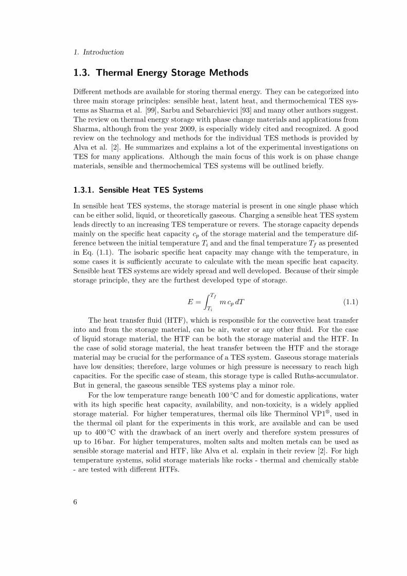
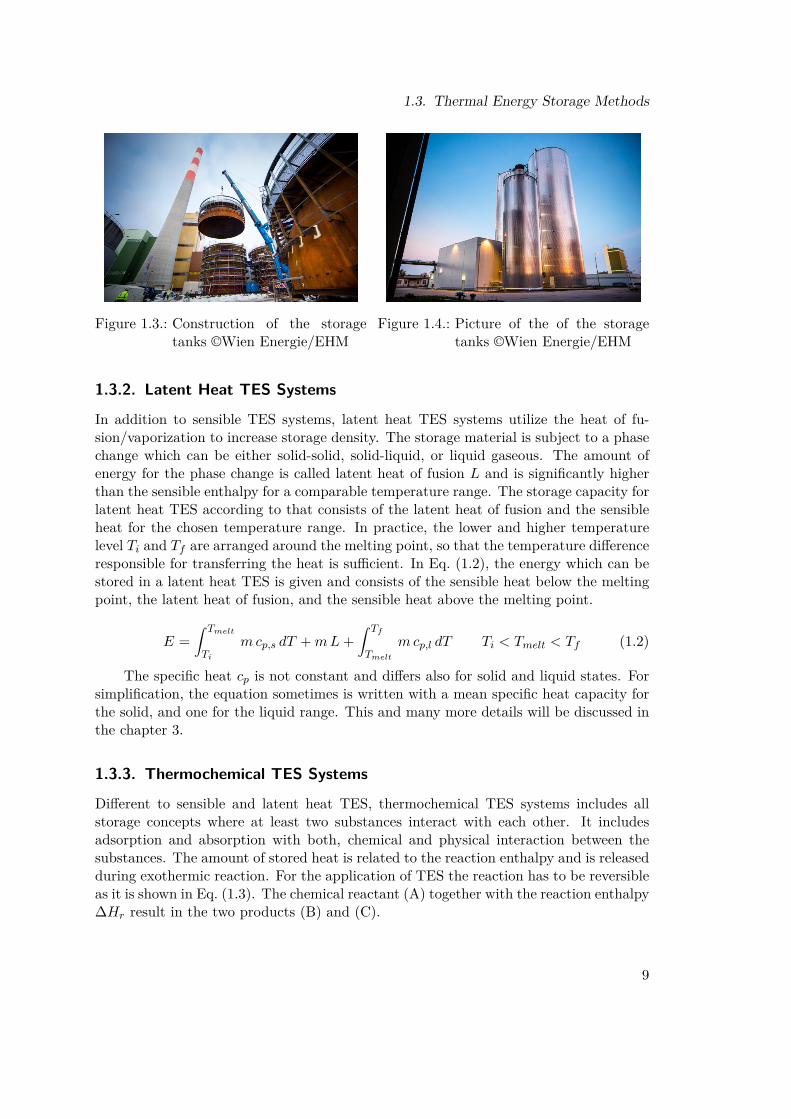
Hot water storage systems: For lower grade temperatures, from district heating downto domestic heating, water offers great storage densities and many other advantages.Hot water storage tanks can be applied for peak shaving in district heating networksin order to reduce peak load plant operation hours - since peak load plants often burnfossil fuel. This concept was applied at the district heating network in Vienna with twopressurized storage tanks with 5600m3 storage volume each [12], presented in Fig. 1.3and Fig. 1.4. With 6 bar tank pressure, 150 ◦C hot water can be stored and, as mentionedin the report, the amount of fossil fuel for peak load times in the plant was reduced. Agood review on the different sensible TES systems for hot water tanks in district heatingnetworks is presented by Dahash et al. [20]. The comparison of the different systemsreveals that technologies like hot water tanks with more height than diameter offer someadvantages when compared to pit TES such as better stratification, lower constructioncosts, etc. . The conclusion is of interest since no effective approach to evaluate one TESover another could be found. A similar issue can be seen for high temperature latentheat TES and will be discussed later.
8
1.3. Thermal Energy Storage Methods
Figure 1.3.: Construction of the storagetanks ©Wien Energie/EHM
Figure 1.4.: Picture of the of the storagetanks ©Wien Energie/EHM
1.3.2. Latent Heat TES Systems
In addition to sensible TES systems, latent heat TES systems utilize the heat of fu-sion/vaporization to increase storage density. The storage material is subject to a phasechange which can be either solid-solid, solid-liquid, or liquid gaseous. The amount ofenergy for the phase change is called latent heat of fusion L and is significantly higherthan the sensible enthalpy for a comparable temperature range. The storage capacity forlatent heat TES according to that consists of the latent heat of fusion and the sensibleheat for the chosen temperature range. In practice, the lower and higher temperaturelevel Ti and Tf are arranged around the melting point, so that the temperature differenceresponsible for transferring the heat is sufficient. In Eq. (1.2), the energy which can bestored in a latent heat TES is given and consists of the sensible heat below the meltingpoint, the latent heat of fusion, and the sensible heat above the melting point.
E =∫ Tmelt
Ti
mcp,s dT +mL+∫ Tf
Tmelt
mcp,l dT Ti < Tmelt < Tf (1.2)
The specific heat cp is not constant and differs also for solid and liquid states. Forsimplification, the equation sometimes is written with a mean specific heat capacity forthe solid, and one for the liquid range. This and many more details will be discussed inthe chapter 3.
1.3.3. Thermochemical TES Systems
Different to sensible and latent heat TES, thermochemical TES systems includes allstorage concepts where at least two substances interact with each other. It includesadsorption and absorption with both, chemical and physical interaction between thesubstances. The amount of stored heat is related to the reaction enthalpy and is releasedduring exothermic reaction. For the application of TES the reaction has to be reversibleas it is shown in Eq. (1.3). The chemical reactant (A) together with the reaction enthalpy∆Hr result in the two products (B) and (C).
9

1. Introduction
A + ∆Hr −−⇀↽−− B + C (1.3)
Potential reactants for such a reaction can be carbonate, hydroxide, redox, ammonia,or organic systems, like Pardo et al. present in their comprehensive review on hightemperature thermochemical TES systems [84]. Energy densities of up to 500 kWhm−3
can be reached, which is 5-10 times higher than with sensible or latent heat TES systems.Therefore, thermochemical TES systems can be applied to long-term storage systemssuch as seasonal solar thermal storage. Another advantage worth mentioning is theloss-free storing period. When the products are well separated after the endothermicreaction, they can be stored for long periods without degradation. Some of the mostfrequently mentioned reactions in literature are listed below in Eq. (1.4):
Ca(OH)2 −−⇀↽−− CaO + H2OCaCO3 −−⇀↽−− CaO + CO2
6 Mn2O3 −−⇀↽−− 4 Mn3O4 + O2
MgH2 −−⇀↽−− Mg + H2
2 NH3 −−⇀↽−− N2 + 3 H2
(1.4)
At present, the research focus is on the intensification of heat and mass trans-fers inside the reactor, and the reactor design in general. Pan and Zhao provide agood overview of the different heat storage reactors for gas-solid thermochemical high-temperature application in their work [83]. Among them, packed bed, continuous anddirect type reactors were investigated, whereupon the packed bed reactor was the mostextensively investigated one. Continuous and direct type reactors may have better per-formance, but they are still in the prototyping phase. In general, experimental andnumerical approaches are rarely used for investigations on particle scale. Some of theexperimental investigation is summarized by Prieto et al. for application in CSP plants[89]. They mainly mention the sulfur based cycle, metal oxides, and perovskite-formstructures for the specific application. Like the other authors, Prieto et al. recommendtesting the calcium carbonate cycle in industrial size because of its simplicity and theamount of research on that reaction. In general, thermochemical TES systems are highlypromising, especially due to their high energy densities; but lot of work has to be donein terms of reactor design and heat transfer enhancement.
10

2. Methodology and Paper OverviewFor a structured approach, the technological challenges of latent heat TES systems arefirst analyzed. These challenges are called implementation barriers and they representthe main fields of research. Based on these implementation barriers, a research method-ology and its aims are developed. The pathway of the experimental investigation isillustrated and individual implementation barriers are addressed. Finally, the individualpapers are presented and clustered to give an overview.
2.1. Implementation BarriersIn the book from Frazzica and Cabeza [29], general requirements for latent heat TES arelisted including technical, thermal and non-technical requirements. A brief summary ofthe requirements is provided here and discussed below.
• small volume change• high energy density and high phase change enthalpy• high thermal conductivity• small subcooling• chemical and thermal cycling stability• high availability, low cost, non-toxic and non-corrosive
The volume change during phase transition can be a crucial topic. The differencein volume between the solid and the liquid phase can be 10% to 15% and has to beconsidered during construction. The storage container has to be large enough, andthe PCM has to be able to expand while melting. Areas of liquid PCM without anypossibility of expansion should be avoided.
The energy density is based on the PCM density, the latent heat of fusion andthe lower and upper temperature of the cycle. Normally, the PCM is chosen for aspecific application and then the temperature range around the melting point is selectedsuitable for this application. Depending on the number of available PCM in this range,the phase change enthalpy can be optimized when selecting a PCM with higher latentheat of fusion.
Thermal conductivity is one of the main drawbacks when using PCM for latent heatTES. Already in 2005, Sharma and Sagara address the topic of heat transfer enhancementin one chapter in their often cited review [100]. Many of the popular PCM for almostall temperature levels suffer from low thermal conductivity not only in the solid, butalso in the liquid phase. In the liquid phase the convective heat transfer increases theheat transfer rate significantly. Thus, the heat transfer rate is usually limited by the
11

2. Methodology and Paper Overview
heat conductivity of the solid phase. A high number of publications in the past yearshave focused on heat transfer enhancement; a review on performance enhancement isprovided by Jegadheeswaran and Pohekar [49]. Since that review in the year 2009, manynew ideas had been developed and tested by researchers such as innovative fins, macro-and microencapsulation, foams, and many more. The most important ones are presentedand discussed in the following chapter.
Subcooling appears when the PCM can be cooled under the solidification point -some of the paraffin show this effect by nature - without solidification. Often otherreasons for subcooling can be found, such as no nucleation points in the PCM, etc. . Forhigh temperature applications in an industrial scale, subcooling does not seem to appearin sodium nitrate in lab-scale TES (100 kg < of PCM). Another interesting questionappears when modeling the phase change with subcooling and partial charging states.
Chemical and thermal stability have to be proven before applying a PCM to anindustrial scale TES plant. The degradation temperature can be determined by ther-mogravimetric analysis (TGA); the operating temperature of the TES clearly needs belower than the degradation temperature. Another method to detect chemical stabilitycan be infrared spectroscopy or X-ray diffraction. Finally, the PCM has to be available,and it has to be cheap since large amounts of PCM are necessary. For interaction withother materials, corrosion tests have to be carried out.
Based on the above listed and described requirements, five implementation barriers(IB) or main fields of research can be derived.
IB1 - PCM research and development The development and characterization of newmaterials for PCM applications at different temperature levels is the main aspect here.New materials can include mixtures of materials with their eutectic properties and melt-ing ranges instead of melting points. Especially for higher temperature levels the numberof available materials is low.
IB2 - Heat transfer enhancement Improve the heat transfer performance between theHTF and the PCM, especially in the solid state because of the low thermal conductivityis aimed here. Numerous methods have been already developed and suggested in thepast several years from micro to macro-scale in the scientific community to address thisproblem.
IB3 - Dynamic behavior and control strategy The highly transient power rate has tobe controlled for the specific application. Interestingly, this topic is rarely targeted byresearchers. This may be based on the relatively low technology readiness level so thatspecific applications may simply not exist yet.
IB4 - Modeling of phase change The melting of a PCM can be calculated analyti-cally for only the simplest of geometries; even for two dimensional problems no analyticalsolutions exist. Numerical solutions can help to model the phase change, but when con-sidering volume change, gravity, and other details, the model quickly becomes complex.
12
2.2. Methodology
Modern computational fluid dynamics (CFD) codes can calculate geometrical domainsof some centimeter size in three dimensions in acceptable time, but calculating a wholestorage system is not currently possible. For system scale analysis, the storage has tobe represented with reduced models, some of which are mentioned later with one maindrawback, they are only valid for one individual geometry and storage type.
IB5 - Up-scaling to full industrial scale geometries The actual test rigs are lab scalesized - extrapolation and industrial scale experiments are necessary. When up-scalingnew questions appear. The whole storage system will get heavy due to the high storagematerial mass. The basement and the container must be able to carry that weight andtemperature, insulation is obligatory in all direction. Increasing the number of tubesmay reduce the flow through the single tube and, therefore, the heat transfer rate. Inaddition, a high number of tubes have to be connected with inlet and overflow pipes.
2.2. MethodologyBased on the implementation barriers, a methodology and aims have been devel-oped. Under the constraints that the focus is on mid-to-high temperature applications(>150 ◦C) for industrial processes, power plants and similar applications, the followingaims have been defined. Some of them originate from this research project and wereadded later on, like the investigation on the mounting of aluminum fins on the steeltube. In brackets, the targeted implementation barrier is given for the individual aims.
1. build a lab scale prototype of a latent heat TES (IB5)• use sodium nitrate as PCM (IB1)• use vertically arranged longitudinally finned steel tubes with aluminum fins
(IB2, IB5)• detection of the melting behavior of a latent heat TES (IB2,IB3)• measure power rate and capacity (IB3)• investigate different flow direction of the HTF (IB3)
2. investigate the mounting of aluminum fins on a steel tube (IB5)• establish a durable connection between the aluminum and the steel tube with-
out using clamps or similar techniques on the outer diameter of the tube (IB3,IB5)
• develop a fin geometry with high heat transfer rates (IB3)• develop a manufacturing method for bimetallic finned tubes for large-scale
production (IB5)3. test the combination of transversal and longitudinal fins in a test rig
(IB2)• detect the influence of the HTF mass flow and temperature spread around
the melting point on the heat transfer behaviour (IB3)• determine the energy balance of the test rig (IB3)
13

2. Methodology and Paper Overview
• determine the heat transmission coefficient from the HTF into the PCM (IB3)• test novel fin geometry with bending ear (IB3, IB5)
A lab scale prototype should help to identify the challenges for up-scaling the latentheat TES technology. Designing such a storage was supposed to gain experience forfuture applications. The storage material itself was not of so much of concern. It waschosen because of its melting point of 306 ◦C, for applications in power plants steamwill be the HTF in many cases. Therefore, the live steam temperature level and thepressure level seem to be appropriate for power generation. Out of the high number ofheat transfer enhancement methods, fins were chosen because of their simplicity. Finnedtube heat exchangers are an industrial standard for many purposes. Vertically arrangedand longitudinally finned, they allow the PCM to melt and expand immediately to thetop of the storage - assuming that the fins stick out a little from the solidified PCM.The position of the melting front is content to many numerical, but also experimentalinvestigations. We aimed to detect the melting front with temperature sensors in thePCM. With sensors in the HTF, the power rate and the stored energy will be calculated.
Out of the first prototype, the topic of mounting of aluminum fins on a steel tubearose. The used hinge bold clamps for the first test rig do not allow hexagonal crosssection without huge gaps between the tubes. For an optimal spatial arrangement,the connection of the aluminum fins on the steel tube should not happen on the outerdiameter of the fins. Additionally a durable connection between the steel tube and thealuminum fins has to be guaranteed over the whole operation temperature range andthe lifetime. A novel connection design for bimetallic finned tube will be developed andtested.
Before testing the new bending ear, another novel combination of transversal andlongitudinal fins will be tested in a new lab scale test rig. With mass flow and tem-perature spread variation and a high number of testing points a lot of data should berecorded and performance improvement should be detected. For this new geometry, theheat transmission coefficient will be determined and presented in Paper 8.
2.3. Paper Overview
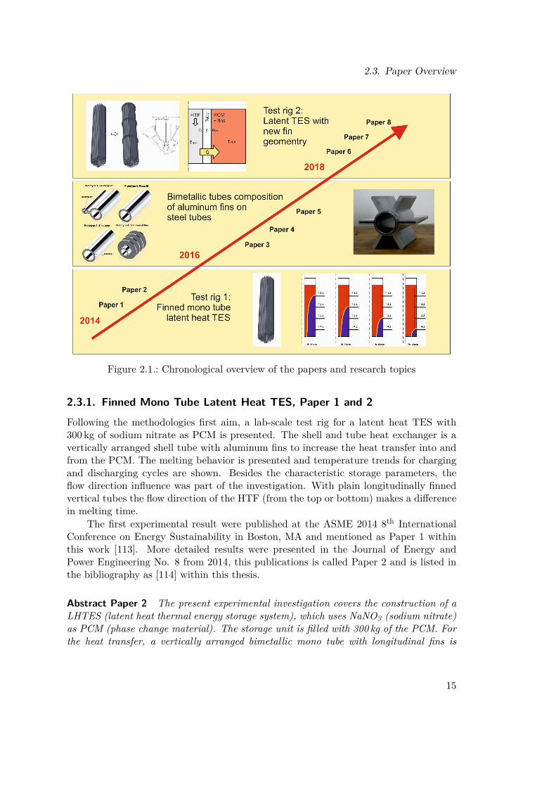
As presented in Fig. 2.1, the chronological development of the research is illustrated withthe publications and the main research topics. All together, two test rigs were erected,one in 2013 ( Paper 1 and 2) and one in 2018 ( Paper 6, 7 and 8). In between, theexperimental investigation on bimetallic finned tubes took place (Paper 3, 4 and 5)). Acomprehensive description of the main topics is provided within this section, togetherwith the paper abstracts of the papers published in journals. Out of the eight publica-tions three (Paper 2, 5 and 8)) were published in a journals, the others in conferenceproceedings, all of them underwent a peer review process.
All own publications are available in the appendix A in the print-version of thisthesis.
14
2.3. Paper Overview
Figure 2.1.: Chronological overview of the papers and research topics
2.3.1. Finned Mono Tube Latent Heat TES, Paper 1 and 2Following the methodologies first aim, a lab-scale test rig for a latent heat TES with300 kg of sodium nitrate as PCM is presented. The shell and tube heat exchanger is avertically arranged shell tube with aluminum fins to increase the heat transfer into andfrom the PCM. The melting behavior is presented and temperature trends for chargingand discharging cycles are shown. Besides the characteristic storage parameters, theflow direction influence was part of the investigation. With plain longitudinally finnedvertical tubes the flow direction of the HTF (from the top or bottom) makes a differencein melting time.
The first experimental result were published at the ASME 2014 8th InternationalConference on Energy Sustainability in Boston, MA and mentioned as Paper 1 withinthis work [113]. More detailed results were presented in the Journal of Energy andPower Engineering No. 8 from 2014, this publications is called Paper 2 and is listed inthe bibliography as [114] within this thesis.
Abstract Paper 2 The present experimental investigation covers the construction of aLHTES (latent heat thermal energy storage system), which uses NaNO3 (sodium nitrate)as PCM (phase change material). The storage unit is filled with 300 kg of the PCM. Forthe heat transfer, a vertically arranged bimetallic mono tube with longitudinal fins is
15

2. Methodology and Paper Overview
used. The fins increase the heat flux into/from the PCM. Thermal oil is used as a heattransfer medium, as it allows a working temperature up to 400 ◦C. This thermal energystorage is able to store 60 kWh of thermal energy and can be loaded with a power up to20 kW.
One part of the investigation results presented in this paper was the determinationof the storable energy and the comparison with data from literature and calculations.Additionally, the melting behavior of the PCM was measured with temperature sensorslocated at different positions over the height of the storage unit. Finally, the entrance ofthe heat transfer medium was changed from the top to the bottom of the thermal energystorage unit and a different melting behavior could be detected.
2.3.2. Bimetallic Finned Tube Design, Paper 3, 4 and 5)
For the lab scale test rig built before, the aluminum fins were split into six parts andfixed with a hinge bold clamp on the steel tube. This comes along with the disadvantageof non-hexagonal cross section - the arrangement of many finned tubes will not beas efficient as with hexagonal cross section. Therefore, a new fastening method wasdeveloped, following the second aim of the methodology. With this method, hexagonalcross sections are realizable and the manufacturing can be automated.
The two conference proceedings, Paper 3 from the ASME 2015 9th InternationalConference on Energy Sustainability in San Diego, CA [115] and Paper 4 from the 10th
Conference on Sustainable Development of Energy, Water and Environment Systems -SDEWES 2015 [112] form the foundation for Paper 5 which was published in the EnergyConversion and Management Journal Vol. 125 in 2016 [111].
Abstract Paper 5 Based on the high energy density of phase change materials, la-tent heat thermal energy storage devices can play an important role in the future energymarket. Therefore, the latent heat thermal energy storage technique is an interestingtechnology for industrial applications (e.g. batch processes) and power cycles. A keytechnology for such a storage device is the design of the heat exchanger tube, becausethe heat transfer rate by charging and discharging is the limiting factor based on thelow thermal conductivity of the phase change material. The heat exchanger tube ma-terial used for such an application should have a high thermal conductivity and also ahigh mechanical resistance. Such a behavior can be found in a combination of differentmaterials.
The present paper deals with the design of such a heat exchanger tube compositionconsisting of a plain steel tube and an aluminum tube where fins can be attached. Anovel bimetallic tube composition is presented and compared with three common compo-sitions. First, the mechanical stability of the bimetallic compositions was determined.Additionally, a creep test of the used aluminum under operation conditions for a storagedevice using sodium nitrate as phase change material confirmed its ability to be used forthe operation in a latent heat thermal energy device. One of the main challenges for thecompositions under investigation is based on the different thermal expansion coefficient
16

2.3. Paper Overview
for aluminum and steel, which results in different strain and creeping tendencies of thealuminum at operation temperature of the storage system, which is up to 340 ◦C. A goodheat transfer from the heat transfer fluid through the steel tube to the storage materialaround the fins can only be guaranteed through a close and stable connection between thetwo tubes.
Compared to former solutions, the fin circumference and the fin design are indepen-dent from the connection to the steel tube and allows individual arrangements of tubesand high packing densities. The experimental investigations have shown that the novelbimetallic tube composition is able to compensate these different strains and is capableof guaranteeing a stable connection between the steel and the aluminum tube. This highpressure and high temperature resistant bimetallic heat exchanger tube is easy to assem-ble and may play a key role for the development of thermal energy storage and other heatexchanging processes.
2.3.3. Novel Fin Geometry, Paper 6, 7 and 8)
Based on numerical simulations which where conducted simultaneously, the combinationof transversal and vertical fins together seemed promising. Another test rig was builtwith the novel fin geometry and many more temperature sensors in order to determinethe melting behavior more accurate (aim number 3 in the methodology).
This investigation is published in Paper 6 at the 13th Conference on SustainableDevelopment of Energy, Water and Environment Systems - SDEWES 2018 [97] andin Paper 7 in the proceedings of the 4th Thermal and Fluids Engineering Conference(TFEC 2019) [94]. In Paper 8, the heat transfer in the new test rig was examined and aheat transmission coefficient was calculated. This results were published in the journalEnergies Vol. 12 No. 7 in 2019 [95].
Abstract Paper 8 Thermal energy storage systems with phase change materials promisea high energy density for applications where heat is to be stored in a narrow temperaturerange. The advantage of higher capacities comes along with some challenges in terms ofbehavior prediction. The heat transfer into such a storage is highly transient and dependson the phase state, which is either liquid or solid in the present investigation. The aim isto quantify the heat transfer into the storage and to compare two different fin geometries.The novel geometry is supposed to accelerate the melting process.
For this purpose a single tube test rig was designed, built, and equipped with alu-minum fins. The phase change material temperature as well as the heat transfer fluidtemperature at the inlet and outlet were measured for charging and discharging cycles.Sodium nitrate was used as phase change material, the storage was operated ±30 ◦Caround the melting point of sodium nitrate, which is 306 ◦C.
An enthalpy function for sodium nitrate is proposed and the methodology for deter-mining the apparent heat transfer rate is provided. The phase change material tempera-ture trends are shown and analyzed, different melting in radial and axial directions and inthe individual geometry sections occurs. With the enthalpy function for sodium nitrate,
17

2. Methodology and Paper Overview
the energy balance is determined over the melting range. Values for the apparent heattransfer coefficient are derived, they allow capacity and power estimations for industrialscale latent heat thermal energy systems.
18

3. Phase Change Phenomena and Materials
3.1. Phenomenological Approach
Phase change materials undergo a phase transition within their operating range as de-fined in Fleischer’s research [27]. During phase change, the material absorbs energy fromits surrounding without a change in temperature. The absorbed energy increases the en-ergy of the constituent atoms or molecules and increases their vibrational state. For thesolid-liquid phase change, this is displayed schematically in Fig 3.1. The amount of en-ergy needed for the transition is called latent heat of fusion for the solid-liquid transition,and it is called latent heat of evaporation for the liquid-gaseous phase change.
A continuous heating process exemplar is shown in Fig. 3.2. The heating of the solidmaterial begins and the temperature increases immediately, due to the sensible heat ofthe material, until the melting temperature is reached. Additional heat will start themelting process, the temperature remains until the material has reached the liquid state.Further heating raises the temperature depending on the specific heat capacity in theliquid state, until the boiling point is reached. Further heating leads to vaporization, thetemperature begins to increase again when the material is gaseous. Additional heatingwill produce superheated vapor. Often, the latent heat of vaporization is higher than thelatent heat of fusion. For thermal applications, the volume change over the transition iscrucial, a high latent heat often competes with high changes in volume. For this reason,the liquid-gaseous phase change often is unfeasible.
Figure 3.1.: The melting/solidification pro-cess [27]
Figure 3.2.: Standard heating curve [27]
19

3. Phase Change Phenomena and Materials
3.1.1. Solid-Liquid Phase ChangeThe solid-liquid phase change is the phenomena that most latent heat TES are based on.Of all phase transitions, solid-liquid phase change comes with a minor change in volume,especially when compared to the liquid-gaseous phase transition which is intensivelystudied for water/vapor in steam power cycles. The solid-solid phase change will bediscussed in chapter 3.1.3, and is a relatively new area of focus for applications in CSPplants with most of the research papers dating back to the last few years.
When the majority of the energy is used for the phase transition, the devices arenamed latent heat TES, thermal capacitors, or similar, compared to sensible or thermo-chemical storage systems. Even so, there is usually a portion of the stored energy whichremains sensible heat, as Eq. (1.2) points out. The Energy is split into the sensible partbelow the melting point, the latent heat of fusion and the sensible heat above the meltingpoint. This energy storage principle is the same for seasonal ice storage which has beenused for ages and the high temperature latent heat TES for CSP applications [14].
As Fleischer describes in her book [27], melting is a highly transient process. Basedon the considered volume, the boundary conditions contain a heat source, and often,a heat loss to the surroundings. The volume itself is either solid, liquid, or dividedin between. This ratio is often called liquid fraction γ and is between 0 (solid) and 1(liquid). The border between the liquid and solid volume is called the melting front.The evolution of the melting front depends on the heat transfer in the solid and liquidfraction. While in the solid volume only heat conduction occurs, in the liquid fractionconvectional heat transfer increases the heat transfer coefficient at the melting front.Natural convection appears in the liquid PCM. So, the prediction of the melting frontand its evolution is complex, as Fleischer points out.
E =∫ Tmelt
Ti
mcp,s dT +mγ L Ti < Tmelt (3.1)
The stored energy E can be expressed with equation (3.1) for partial molten PCMat melting temperature. The liquid fraction corresponds to the mass fraction proportionbetween the liquid and the total mass and is shown in equation (3.2).
γ = ml
ml +ms(3.2)
Besides its application in TES systems and thermal management with PCM, thesolid-liquid phase change, more precisely the liquid-solid phase change, plays a majorrole in casting technology research. The solidification of metals during casting is theprincipal topic in the book from Stefanescu [104]. The topic of solidification of metalsis well investigated since casting is one of the basic production process technologiesin manufacturing. The main difference of PCM for TES may be the heat conductioncoefficient, although even metals as PCM have been discussed in the past years. Thetheory of solidification involves different scales, from nucleation on the nanoscale totransport phenomena on the macro scale. Compared to single PCMs, metal alloysconsist of different substances and form different states of equilibrium. Furthermore,
20

3.1. Phenomenological Approach
different cooling rates can lead to subcooling and a huge variety in crystal structures. Itwould be interesting to investigate whether approaches from casting technology can beused for PCMs and their application in TES systems.
3.1.2. Liquid-Gaseous Phase ChangeVolume expansion during vaporization is a significant challenge in using liquid-gaseousphase change for TES applications. This is the main reason why this phase changemechanism seems unsuitable for storage applications. The heat of evaporation in contrastto the latent heat of fusion would be high; for water it is about 2257 kJ kg−1 comparedto 333.5 kJ kg−1, respectively. Nevertheless, the topic of vaporization and condensation(especially with regards to water) has been widely investigated because of steam powerplant processes. Kulacki dedicated a chapter in his Handbook of Thermal Science andEngineering [63] to heat transfer with phase change. The application of the liquid-gaseous phase change is not yet reported for storage applications.
However, the so called Ruth’s accumulator is mentioned in this context. The de-vice basically consists of a steam drum, and it is capable of storing steam under highpressure and temperature. The challenge is found in up-scaling this concept since thewall thickness for large diameters must be huge and material costs are normally high forthis type of storage. In their paper, Gonzales et al. compare the application of directand indirect molten salt storage tanks with Ruth’s accumulators for their use in a CSPplant [34]. For short storage times (<3 h), the Ruth’s accumulator seems to be more costeffective when compared to sensible molten salt tanks. Another interesting applicationis mentioned in the research done by Hofmann et al. [41] and Dusek et al. [23]. Thecapacity of a Ruth’s accumulator can be increased effectively by adding a PCM layer tothe outside of the accumulator. In summary, the effective use of liquid-gaseous phasechange for storage applications does not look promising; although, individual cases canbe made for the application of Ruth’s accumulators as short term storage in processeswhich utilize steam.
3.1.3. Solid-Solid Phase ChangeThe terminology of phase change is comprised of the well known states of solid, liquid,gaseous, and plasma. However, a phase transition from solid to solid can be observedon a nano-scale level for some materials. The arrangement of atoms changes duringa solid-solid phase transition between two solid crystalline or semi-crystalline phases,e.g. monoclinic to cubic. This structure transition happens at a specific temperature,and the effect is comparable to the well known solid-liquid phase change. Differentmaterials show these effects, as Bayon et al. demonstrated [9] in reference to lithiumand sodium sulfates. In this investigation, different mixtures of sodium and lithiumsulfate were investigated with differential scanning calorimetry, high temperature In-situ X-ray diffraction and thermogravimetric analysis. The aim was to determine thephase transition temperatures, enthalpies, the specific heat capacities, and the crystallinephase composition. Based on the measured data, an economic assessment was applied to
21

3. Phase Change Phenomena and Materials
Figure 3.3.: CSP concept with solid-solid PCM TES with CO2 Brayton cycle [9]
the different mixtures. A mixing ratio of 59.17%, NaLiSO4 and 40.83% LiSO4 seemedto be promising. With the adaption of the mixing ratio, different melting temperaturescan be adjusted. They allow the combination of different PCMs and lead to a cascadedPCM storage system which is presented in figure 3.3.
Compared to the solid-liquid phase change, the solid-solid transition has some ad-vantages that are worth mentioning. The abidance in the solid state avoids leakage andthere is no need for encapsulation, no segregation is necessary (as it is with additivessuch as copper particles to a PCM), and smaller changes in volume are all advantagesdiscussed by Fallahi et al. in their review [26]. Depending on the molecular structureof the material, different solid-solid phase transitions exist and lead to a high variety oftransition enthalpies and temperatures as well as different heat conductivity values. Inclosing, the research into the TES application of solid-solid phase change is still in itsinfancy and brings with it new challenges.
3.2. Phase Change MaterialsThere are many different materials which are able to be used in phase change applica-tions, some of which are already commercially available. These materials can be clusteredinto three main categories: organic PCMs which are widely spread and are often topicof research because of their lower application temperature; inorganic PCMs which oftenhave higher melting temperatures; and, finally, metallic PCMs. The clustering often de-pends on the main focus of the literature. While Dinçer and Rosen [21] describe organicPCM exclusively with a focus on household heating systems, Fleischer [27], Frazzica andCabeza [29] and Cabeza and Tay [14] follow a wider approach with an additional focuson high temperature systems.
3.2.1. Organic PCMsOrganic PCMs are the most popular PCM type, and they include many different ma-terials such as paraffin, fatty acids, sugar alcohols, plastics, etc. . They are the most
22

3.2. Phase Change Materials
numerous group of PCMs with highly diversified properties. The main subgroups arementioned here:
Paraffins Paraffins are the most used and commercially availabe PCMs. This alkanetype compound (C2H2n+2) has melting temperatures between 0 ◦C and 120 ◦C. Themelting temperature can be adjusted by the chain length, and they show good energydensities and compatibility with metals. Compared to other organic PCMs, Paraffins donot show subcooling, but their melting point often corresponds to a melting range. In thesolid state, Paraffins are waxy. They are obtained from petroleum distillation and are acombination of different hydrocarbons. Further advantages mentioned in the review fromSharma and Sagara [100] are that they have no tendency to segregate, and they havechemical stability. Disadvantages of Paraffins may be their low thermal conductivity inthe solid state, and their high volume change and flammability. Examples of paraffins areOctadecane (Tm = 29 ◦C, L = 244 kJ kg−1), Tricosane (Tm = 48.4 ◦C, L = 302.5 kJ kg−1)or Tetracosane (Tm = 51.5 ◦C, L = 207.7 kJ kg−1) [27]. Material properties can varygreatly depending on the literature source. Sharma and Sagara i. e. provide much highervalues for the latent heat for Tetracosane (Tm = 51 ◦C, L = 255 kJ kg−1).
Fatty acids The fatty acid compounds in the form of CH3(CH2)2nCOOH tendentiouslyhave lower melting points than paraffins and this enables applications in the buildingsector. A comprehensive list of fatty acids is provided in [100]. Fatty acids are moreexpensive than paraffins, and often do not have sharp melting points. Fatty acids whichdeserve some mention are: Capric acid (Tm = 32 ◦C, L = 153 kJ kg−1), Lauric acid(Tm = 44 ◦C, L = 178 kJ kg−1) and Stearic acid (Tm = 69 ◦C, L = 202 kJ kg−1) [27].
Sugar alcohols Sugar alcohols are organic compounds derived from sugars that com-prise a class of polyols. Their advantage is a high latent of fusion as Sole et al. explainin their research [101]. Their main disadvantage is oxidation so that their storage has tobe operated in an inert atmosphere. Erythritol (Tm = 120 ◦C, L = 340 kJ kg−1 [101]),for example, has high latent heat of fusion and an interesting temperature level forsolar thermal district heating. Besides oxidation, thermal hysteresis also seems to bechallenging when utilizing sugar alcohols.
Plastics Plastics, like high density polyethylen (HDPE) or polyamids (PA), are underinvestigation as PCMs. Experimental investigations like those done by Zauner et al.[126], demonstrate their potential as PCMs for temperature levels between 105 ◦C and155 ◦C. Another review on plastics as PCMs for temperature ranges between 120 ◦Cand 200 ◦C was completed by Gasia et al. [30] and concludes that HDPE offers highpotential as a PCM. Crucial factors may be the non-sharp melting range of plastics,their flammability, and their high viscosity.
23

3. Phase Change Phenomena and Materials
3.2.2. Inorganic PCMsThe category of inorganic PCMs is mainly comprised of salts and salt hydrates. Themelting points of salt hydrates range from 5 ◦C to 130 ◦C. Salts have higher meltingtemperatures between 150 ◦C and 800 ◦C. Inorganic PCMs cover a wide range of tem-perature levels with individual properties and challenges.
Salt hydrates Salt hydrates combine inorganic salts (oxides, carbonates, sulfates, ni-trates and halides) with water and they form compounds with n ·H2O. Salt hydrateshave three dimensional structures open for water molecules to fit into the crystal lat-tice. Different crystal structures exist, and some are more open to water than others.Salt hydrates have sharp melting transitions compared to some organic PCMs, and havegenerally high latent heat of fusions. Disadvantages of salt hydrates are their subcoolingand corrosive behaviors. A comprehensive review on salt hydrates for latent heat storagesystems is provided by Kenisarin and Mahkamov [55]. 18 different salt hydrates, all mar-ket available, are presented along with their thermophysical properties and costs. Theconclusion is about missing standards in determination of the thermophysical properties.Besides their application as latent PCM, salt hydrates are often utilized as thermochem-ical energy storage materials using their hydration and dehydration reaction. A reviewfor this application is presented by Trausel et al. [109].
Salts The properties of salts are similar to the properties of salt hydrates, except thatsalts do not show phase segregation when used as a pure substance. Compared to organicPCMs, salts have higher densities which means higher energy densities. The compatibil-ity with container material has to be checked before applying salt to a storage tank. Themain advantage of salts is their great applicable temperature range, their unique sellingpoint. In temperature levels around 300 ◦C, sodium or potassium nitrate are potentialPCM candidates (NaNO3 or KNO3). Fleischer [27] mentions the high propensity towardssubcooling of inorganic PCMs. The experimental investigations carried out at IET withsodium nitrate do not support this position - at least not for sodium nitrate and largestorage sizes of 100 kg of PCM. This may predicate on the impurities of the PCM and,therefore, the high number of potential nucleation particles. The main aspects of saltscan be summarized as follows [75]:
• wide applicable temperature range (150 ◦C - 800 ◦C)• high latent heat of fusions• higher heat conductivity than organic PCMs• subcooling is possible but only a few K• low vapor pressure
Tables of salts for application in a TES are provided by many authors. Some examplesare the books [27], [29], [14] and [75]. Good reviews are also carried out by Sharma andSagara [100], Gil et al. [32], Maldonado et al. [74], and Nazir et al. [80]. In Fig. 3.4,a selection of salts and mixtures is presented with melting points higher than 150 ◦C.
24

3.2. Phase Change Materials
Figure 3.4.: PCMs for latent heat TES with temperatures higher than 150 ◦C from [29]
Nitrates are marked red, chlorides blue, and mixtures black. The total energy storedper unit cost is shown over the melting points.
3.2.3. Mixtures, Metals and Other PCMsMixtures and Eutectics Mixtures are possible between inorganic, organic, or in be-tween these groups. Mixtures can improve the properties of any PCM so it fits thedesired application. A famous mixture is the so-called solar salt, a 60% NaNO3 and40% KNO3 eutectic mixture with a melting point around 222 ◦C. The primary use forthis mixture is sensible TES in molten salt tanks. Mixtures between the two salts are wellinvestigated. When mixing two salts in non eutectic mixtures, the melting temperaturemodifies to a melting range depending on the composition.
Metals Metals are unusual PCMs and the many reasons for this are accentuated inFleischer’s work [27]. One such reason is their relatively low heat of fusion. The lowmelting point metal Gallium (Tm = 29.8 ◦C) has only 80 kJ kg−1; others are in the samerange, or even lower. Advantages of metals are their high thermal conductivity, whichmakes heat transfer easy, and their high density still leads to useful energy densities.Corrosion may be a topic, since gallium e. g. reacts with aluminum and copper. Acomprehensive review on low temperature metals is provided by Ge et al. [31]. As theypoint out, the application of metal based PCMs for low temperature applications hasbeen significantly ignored in the past decades - they believe this to be wrong. For hightemperature applications, metals are one of the few available materials. Aluminum and
25

3. Phase Change Phenomena and Materials
Figure 3.5.: Schematics of a heat flow DSC with a disk type sensor - heat flow pathsfrom [65]
other metals have excellent heat conductivity, but this comes along with high specificcosts and inter-metallic corrosion when using metal containment.
Water-salt solutions For cooling applications, water-salt solutions can be the PCM ofchoice since the melting points are below 0 ◦C. Due to the properties of water, they havehigh energy densities, and phase segregation can be aided when using eutectic mixtures.A good review on PCM for cold TES applications is provided by Oro et al. [81].
3.3. Methods for Thermal Characterization of PCMsThe thermal properties of PCMs are one of the main design criteria for latent heatTES. Based on their characteristics, the whole system can be designed. Critical designvalues include the latent heat of fusion L, the melting temperature Tm, the specific heatcapacity cp, and the heat conductivity λ. Several methods are available to determinethese parameters for individual materials, the most common ones are presented here.
3.3.1. Differential Scanning Calorimetry MeasurementsAccording to Lager [65], differential scanning calorimetry (DSC) measurement is themost commonly used method to determine the exchange of heat. Several parameterscan be obtained with DSC measurements; among them are the specific heat capacity,the latent heat of fusion, the melting temperature, and the chemical reaction enthalpy.Basically, two different type of DSC measurements are available, the heat flux and thepower compensated measurement.
As presented in Fig. 3.5, the two crucibles in the furnace can be filled with sub-stances. If both samples have the same thermal behavior while heating the furnace withthe desired heating rate, the temperature of both samples will be similar and no heatflux between the two samples will occur. For the case of different samples, a temperaturegradient and, therefore, an electrical voltage from the attached thermocouples can be
26

3.3. Methods for Thermal Characterization of PCMs
Figure 3.6.: Voltage UDSC versus temperature T during a transition with the character-istic temperatures from [65]
measured. In order to gain meaningful results with DSC, calibration has to be carriedout. Furthermore, the heating and cooling rate, the type and size of the crucibles, theposition of the sample in the crucible, the mass and size of the sample, and the thermalcontact between crucible and sensor all play a role and must be taken into consideration.Temperature, heat, and heat flow calibration have to be done before starting measure-ments, as Lager explains [65]. A schematic phase transition measurement is presentedin Fig 3.6 with the initial and final temperature Ti and Tf , the extrapolated initial andfinal temperatures Te,i and Te,f , and the peak temperature Tpk.
Challenges with DSC measurements As mentioned above, several factors potentiallyinfluence the result of DSC measurements. The heating rate β is among them. LikeLager describes, the peak temperature Tpk changes with the heating rate. Based ondefined measurement protocols, the heating rate for phase transition tests should bereduced until the change in the peak temperature is < 0.2K. Other standards likeDIN EN ISO 11357-4 recommend for the heat rate values of 10Kmin−1. Tests withthe commercially available Rubitherm RT70HC with two different heating rates of (a)0.25Kmin−1 and (b) 10Kmin−1 show diverging results. While the extrapolated initialtemperatures are similar for (a) 70.0K and (b) 69.7K, the extrapolated final temperaturediverge significantly between (a) 72.0K and b) 79.9K. The latent heat of fusion resultin (a) 228.1 kJ kg−1 and (b) 243.5 kJ kg−1. Beside the differences, the uncertainty ofthe measurements has to be observed. Generally, lower heating rates produce higheruncertainties, for the case of a heating rate of 0.25Kmin−1 the uncertainty is as high as10.5% compared to 3.3% for the higher heating rate (β).
3.3.2. Measuring Thermal Conductivity
Laser flash apparatus (LFA) The laser flash apparatus consists of a sample in the formof a slice. From one side, a short laser pulse raises the temperature. With an infraredradiation sensor, the temperature field on the other side of the sample is measured. As
27

3. Phase Change Phenomena and Materials
long as there are no chemical reactions and phase transition (heat source and sinks) thismethods offers some real advantages. The thermal contact resistance problem does notoccur, and the surface heat losses are minimized through the short measuring duration.As Lager describes in his thesis [65], modern LFA systems have highly sensitive IRdetectors, energy controlled laser or light beam, gas inlets, controlled vacuum conditions,and different furnaces for broad temperature ranges. In his experiments he measuredthe thermal diffusivity of Rubitherm RT70HC which ranges between 0.17mm2 s−1 and0.23mm2 s−1 in the solid phase and 0.13mm2 s−1 to 0.19mm2 s−1 for the liquid phase.
Transient Hot Bridge (THB) The transient hot bridge measures the thermal con-ductivity based on a thermoelectric sensor. The THB method is developed from thetransient hot strip based on electrical conducting strips which can act as joule heatersand resistance thermometers. The sample is heated with a constant current and thesensor is placed into it. The voltage over the thermal resistance of the strip is measuredand, due to the changing electrical resistance, the signal can be used to evaluate ther-mal conductivity. Like other methods, the THB has to be calibrated using referencematerials. The THB sensors are positioned between two blocks of material and fromthe measured signal the conductivity can be determined. For more details regarding theTHB method, see [36] for reference.
3.3.3. Other methods for determining thermophysical properties
For the determination of thermal conductivity, the hot flow meter (HFM) represents asteady state method for conductivities up to 2Wm−1 K−1. The test set-up consists ofa hot and a cold plate which are both temperature controlled. The sample is positionedbetween these plates. For measuring the heat flow over the plate, an equilibrium has tobe reached.
The push rod dilatometry ia a method to determine the linear thermal expansioncoefficient of a solid as a function of the temperature. A sample is placed in the furnace ona sample carrier and the thermal expansion is measured with a displacement transducerover a push-rod. All used materials expand so correction functions have to be appliedto the results. Both methods are explained well by Lager [65].
3.4. Sodium Nitrate (NaNO3)
Sodium nitrate was used as phase change material in the experimental investigationscarried out at IET. For this reason, a closer look at the material and its properties isnecessary. Sodium nitrate is a crystalline salt, inorganic, and solid at room temperature.It has a white or colorless appearance and a molar mass of 84.99 gmol−1. It is hygroscopicand soluble in water. Its main applications are in fertilizer production and industriessuch as the glass industry, explosives, etc. . It occurs in natural deposits, but is alsoproduced synthetically at a large scale.
28

3.4. Sodium Nitrate (NaNO3)
Figure 3.7.: Platinum calorimetry of sodium nitrate from 1909 [35]
The determination of the thermophysical properties of salts dates back to the 19thcentury. One of the first publications examining the properties of salts is provided byGoodwin and Kalmus in 1909 [35]. They describe an apparatus for measuring the specificheat capacities and the latent heat of fusion for salts up to a temperature of 600 ◦C, andremark upon the unreliable data availability at that time.
In Fig. 3.7 the heat temperature plot for NaNO3 from the year 1909 is presented.The temperature is given in degree Celsius and the heat in calories. The latent heat offusion of 45 calories corresponds to 188 kJ kg−1 which is remarkably accurate consideringthe measurement methods at that time.
Some years later, Kracek investigated inversions from one crystalline modificationof sodium nitrate to another. Inversions of this type come with a change in the crystallattice - today from a TES perspective the solid-solid phase change. Kracek et al.dedicated two publications to the gradual transition of sodium nitrate ([59] and [60]).They described the transition at 275.5 ◦C which happens rather gradually, and in thesecond paper they dealt with the crystal arrangement and used powder diffraction. Inany case, the solid-solid transition of sodium nitrate at 275.5 ◦C involves small amountsof enthalpy compared to the solid-liquid phase change at the melting temperature.
Measurements with modern DSC methods were realized by Carling in 1983 [17],Takahashi et al. in 1988 [105] and Jiriri et al. in 1995 [54] for sodium nitrate andpotassium nitrate. Takahashi et al. included lithium nitrate while Jiriri et al. chosecesium nitrate. All determined the heat capacities and the latent heat of transition forthe mentioned salts. Data from Carling is applied for modeling the phase change in thefollowing chapter because he published the apparent specific heat capacity from DSCmeasurement over the whole phase transition.
3.4.1. Thermophysical Properties of Sodium Nitrate
The most comprehensive review and thermophysical investigation on sodium nitrate isprovided by Bauer et al. ([6] and [8]). These reports measured and compared the different
29

3. Phase Change Phenomena and Materials
properties of sodium nitrate with many values from literature. Among the mentionedproperties, the melting temperature, the latent heat of fusion, the thermal diffusivity,the heat capacity, and the density are displayed in Fig. 3.8.
Melting temperature and latent heat of fusion The melting temperature is statedas 306 ◦C and the latent heat of fusion is given as 178 kJ kg−1, event though values inliterature differ. A comparison is provided in Paper 1. These mentioned values areapplied for data analysis of the experiments conducted in this thesis. For the solid-solidphase transition around 275 ◦C and values from 12 kJ kg−1 to 45 kJ kg−1 are reported.
Thermal stability and nitrite formation Sodium nitrate tends to form sodium nitriteat higher temperature levels. Even small amounts of nitrite can influence the thermo-physical properties of sodium nitrate, as Bauer describes in his work. Long term testsof NaNO3 at 350 ◦C and higher temperatures have been carried out in order to investi-gate the nitrite formation. The decomposition of sodium nitrate can be categorized intothree stages. Below 450 ◦C there is little nitrate formation, between 450 ◦C and 550 ◦C anitrate-nitrite equilibrium can be observed, and over 550 ◦C decomposition with a releaseof nitrogen oxides was detected. A 4% molar mass ratio of sodium nitrite in sodiumnitrate can lead to a decrease of the melting temperature and lower enthalpy of fusion.The exposure of sodium nitrate to temperatures around 500 ◦C for some ten hours willlead to approximately 4% molar mass ratio, as reported by Bauer. As a result of this in-vestigation, the maximum storage temperature for latent heat TES with sodium nitrateas PCM has to be limited to 450 ◦C. Since the experiments operate in a temperaturerange of 20 ◦C - 40 ◦C around the melting point, i.e. between 266 ◦C and 346 ◦C, nitriteformation is not a problem.
Density and thermal expansion coefficient The density of sodium nitrate is about2260 kgm−3 at 25 ◦C. The density decreases slightly until the solid-liquid phase transi-tion occurs. The volume change at the melting point is averaged from literature valuesand is about 9.7%. Further heating leads to decreasing density values, as expected.The linear thermal expansion coefficient is provided with 40× 10−6 K−1 at room tem-perature, increasing until the solid-solid transition at 275 ◦C [44]. As a design criteriaof the PCM storage tank, the crucial value is the volume change during melting - thisadditional volume has to be considered.
Heat capacity The specific heat capacity of sodium nitrate has been measured byvarious authors. It increases with the temperature and has basically two peaks whichcan be seen in the trend in Fig. 3.8. The first peak at 275 ◦C at the solid-solid transitionand the main peak at 306 ◦C, the melting. For the solid phase, the heat capacity canbe approximated with a linear function. For the liquid phase, the heat capacity can beconsidered constant with a value of 1.655 kJ kg−1 K−1.
30

3.4. Sodium Nitrate (NaNO3)
Thermal diffusivity and conductivity Thermal diffusivity can be obtained by severalmeasurement techniques such as the hot-wire method, optical techniques, and stepwiseheating and laser flash methods (the last method is used in Bauer’s work). In gen-eral, thermal diffusivity as well as conductivity can be determined for the liquid phaseprecisely as shown in Fig. 3.8. Most authors report values around 0.6Wm−1 K−1 forthe heat conductivity and 0.15mm2 s−1 for the thermal diffusivity. For the solid phase,the values scatter so much so that no reliable values can be reported. The correlationbetween the thermal conductivity and the thermal diffusivity is given in Eq. (3.3); themeasurements can be crosschecked with that equation.
a = λ
ρ cp(3.3)
3.4.2. Material Compatibility and Corrosion
Due to the low thermal conductivity of sodium nitrate, and the majority of PCMsin general, enhancing its heat transfer ability is widely discussed. With respect tothese enhancements, it is crucial to consider the applicable material’s compatibility withsodium nitrate. All materials which come into contact with sodium nitrate, includingthose materials used to enhance its heat transfer abilities, may be affected by corrosion.
Steel The containment vessel and the tube are made of carbon steel. Steel of varyingtypes is normally used for nitrate and nitrate mixtures according to the Metals Handbookof Corrosion [58]. The basicity of the melt normally prevents iron corrosion. Stainlesssteels show low corrosion rates in salt-mixtures comparable to pure sodium nitrate.For the mixture of NaNO3 –NaCl–Na2SO4 with 86.3mol%, 8.4mol% and 5.3mol%respectively, the corrosion rate for carbon steel is mentioned with 15µmyr−1. This issupported by our observations with carbon steels in sodium nitrate latent heat TES. Forlab-scale sized TES systems, carbon steel seems to be sufficient.
Aluminum Aluminum fins applied on the steel tube are in direct contact with thesolid and liquid sodium nitrate in the storage system. In his book called, Corrosion ofAluminium [116], Vargel describes, that these nitrates (sodium, potassium and ammo-nia) in molten form have no action on aluminum. The application of aluminum fins isrecommendable.
Selected other combinations and references Cabeza et al. [13] investigated the cor-rosion of stainless steel, steel, aluminum, copper and brass in combination with two salthydrates (sodium acetate trihydrate and sodium thiosulfate pentahydrate) within thetemperature range of 48 ◦C and 58 ◦C. As a result of this investigation, steel and alu-minum are recommended; although, steel has to be checked in detail. Brass and copperare not recommended at all.
31

3. Phase Change Phenomena and Materials
Figure 3.8.: Thermophysical properties of sodium nitrate from [8] (k corresponds to thethermal conductivity in the nomenclature of this source)
32
3.5. Heat Transfer Enhancement Methods
Other studies from Oro et al. [82] and Moreno et al. [79] investigated the corrosionrate of steel, stainless steel, copper, aluminum and polymer combinations with differentPCMs. The chosen PCMs focused on domestic heating and cooling applications andcold storage systems, and among them were many salt hydrates. The conclusion wassimilar in both investigations: aluminum, copper, and carbon steel show high corrosionrates (several hundred mg cm−2 yr−1), and the only applicable material for the selectedPCMs (not sodium nitrate) seemed to be stainless steel.
Qiu et al. [91] used higher temperature levels to test the suitability of stainlesssteel 316L and Inconel 625 for their application in a latent heat TES with a eutecticNaCl–NaF mixture. The steels were exposed to a temperature of 780 ◦C for 100 h and2500 h. The melting temperature of the applied PCM was at 680 ◦C. Both demonstratedlow corrosion activity, and the Inconel 625 seems appropriate for long term operation.
Similar tests using sodium nitrate and steel, stainless steal, aluminum, and copperhave been carried out at IET, but have not yet been published. Low corrosion ratesfor steel and aluminum in liquid sodium nitrate can be reported; only coppers seem tocorrode in an unacceptable manner. These findings support the above literature basedreferences.
3.5. Heat Transfer Enhancement MethodsThe majority of PCMs investigated for use in latent heat TES systems have poor heatconductivities in both the liquid and the solid phase. Only a few materials like metals donot face this challenge, as mentioned above. In the solid phase, the low heat conductivityis the only heat transfer mechanism available and is, therefore, often the bottleneck ofthe heat transmission from and to the PCM. Various authors have concentrated onheat transfer in PCMs in the past few years, and many enhancement techniques havebeen tested and evaluated experimentally as well as numerically. Many of these arealready discussed in papers, others are accentuated here. A good review on the topic ofheat transfer enhancement for PCM is provided by Jegadheeswaran and Pohekar [49] orIbrahim et al. [45].
Melting and solidification During melting, first conduction and then natural convec-tion occur in liquid PCM. Since heat transfer by conduction is lower than heat transferby natural convection, conduction becomes almost negligible for the melting process.Due to the volume change, the liquid PCM needs free space to expand into. The in-fluence of natural convection on the melting front has been studied by various authors.Often, the conclusion was that natural convection cannot be neglected for the numericalor analytical modeling of the phase change. Experiments often visually tracked phasechange fronts and compared them with calculations like in [87]. For vertically heatingsurfaces (tubes or walls), the PCM melts and accumulates at the top. Then the meltingfront evolves with inclination; the upper part melts faster. This behavior was measuredduring this work and is presented in Paper 1 and Paper 2. In contrast to melting, con-duction is the dominating effect for solidification. Interestingly, the solidified layers are
33
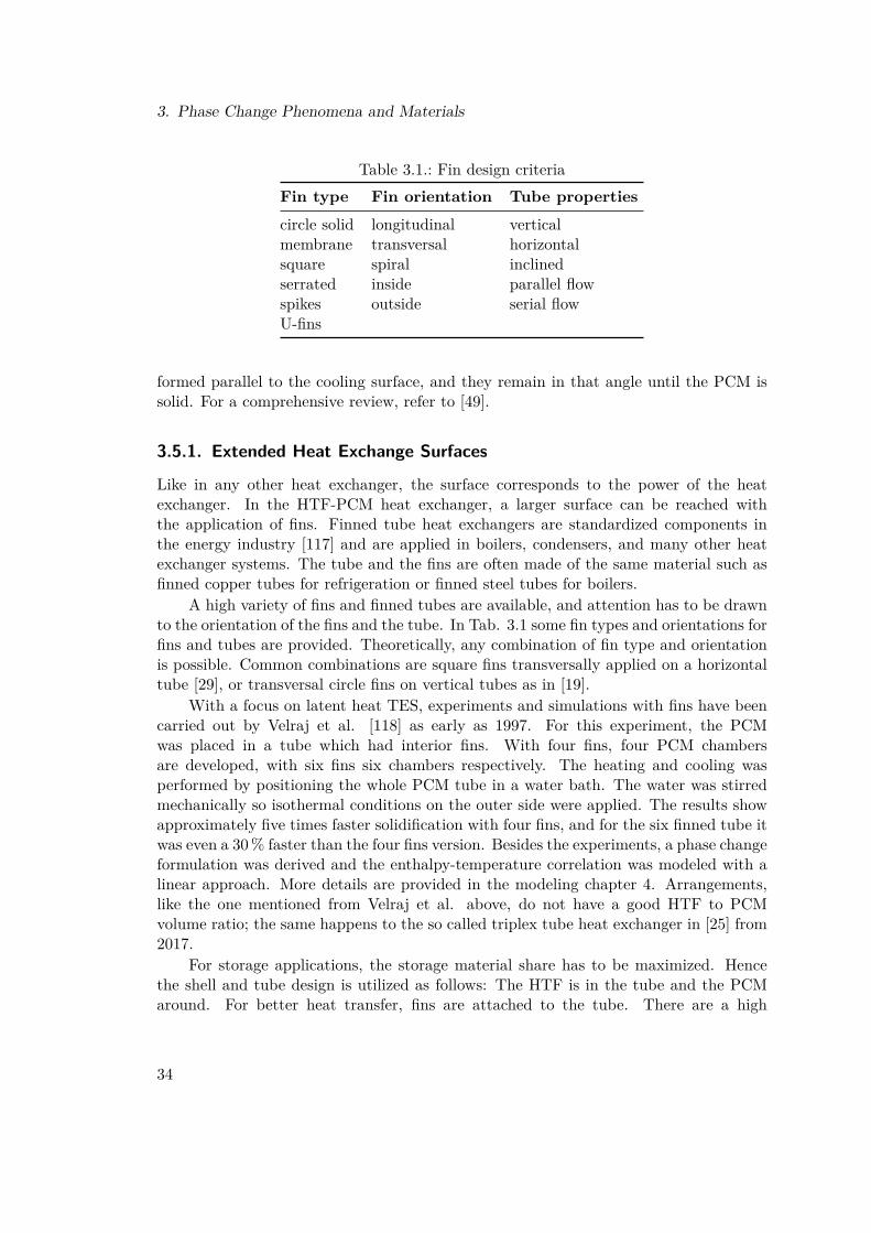
3. Phase Change Phenomena and Materials
Table 3.1.: Fin design criteriaFin type Fin orientation Tube propertiescircle solid longitudinal verticalmembrane transversal horizontalsquare spiral inclinedserrated inside parallel flowspikes outside serial flowU-fins
formed parallel to the cooling surface, and they remain in that angle until the PCM issolid. For a comprehensive review, refer to [49].
3.5.1. Extended Heat Exchange Surfaces
Like in any other heat exchanger, the surface corresponds to the power of the heatexchanger. In the HTF-PCM heat exchanger, a larger surface can be reached withthe application of fins. Finned tube heat exchangers are standardized components inthe energy industry [117] and are applied in boilers, condensers, and many other heatexchanger systems. The tube and the fins are often made of the same material such asfinned copper tubes for refrigeration or finned steel tubes for boilers.
A high variety of fins and finned tubes are available, and attention has to be drawnto the orientation of the fins and the tube. In Tab. 3.1 some fin types and orientations forfins and tubes are provided. Theoretically, any combination of fin type and orientationis possible. Common combinations are square fins transversally applied on a horizontaltube [29], or transversal circle fins on vertical tubes as in [19].
With a focus on latent heat TES, experiments and simulations with fins have beencarried out by Velraj et al. [118] as early as 1997. For this experiment, the PCMwas placed in a tube which had interior fins. With four fins, four PCM chambersare developed, with six fins six chambers respectively. The heating and cooling wasperformed by positioning the whole PCM tube in a water bath. The water was stirredmechanically so isothermal conditions on the outer side were applied. The results showapproximately five times faster solidification with four fins, and for the six finned tube itwas even a 30% faster than the four fins version. Besides the experiments, a phase changeformulation was derived and the enthalpy-temperature correlation was modeled with alinear approach. More details are provided in the modeling chapter 4. Arrangements,like the one mentioned from Velraj et al. above, do not have a good HTF to PCMvolume ratio; the same happens to the so called triplex tube heat exchanger in [25] from2017.
For storage applications, the storage material share has to be maximized. Hencethe shell and tube design is utilized as follows: The HTF is in the tube and the PCMaround. For better heat transfer, fins are attached to the tube. There are a high
34
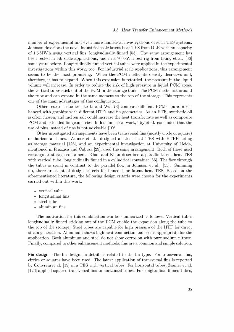
3.5. Heat Transfer Enhancement Methods
number of experimental and even more numerical investigations of such TES systems.Johnson describes the novel industrial scale latent heat TES from DLR with an capacityof 1.5MWh using vertical fins, longitudinally finned [53]. The same arrangement hasbeen tested in lab scale applications, and in a 700 kWh test rig from Laing et al. [66]some years before. Longitudinally finned vertical tubes were applied in the experimentalinvestigations within this work, too. For industrial scale applications, this arrangementseems to be the most promising. When the PCM melts, its density decreases and,therefore, it has to expand. When this expansion is retarded, the pressure in the liquidvolume will increase. In order to reduce the risk of high pressure in liquid PCM areas,the vertical tubes stick out of the PCM in the storage tank. The PCM melts first aroundthe tube and can expand in the same moment to the top of the storage. This representsone of the main advantages of this configuration.
Other research studies like Li and Wu [73] compare different PCMs, pure or en-hanced with graphite with different HTFs and fin geometries. As an HTF, synthetic oilis often chosen, and molten salt could increase the heat transfer rate as well as compositePCM and extended fin geometries. In his numerical work, Tay et al. concluded that theuse of pins instead of fins is not advisable [106].
Other investigated arrangements have been transversal fins (mostly circle or square)on horizontal tubes. Zauner et al. designed a latent heat TES with HTPE actingas storage material [126], and an experimental investigation at University of Lleida,mentioned in Frazzica and Cabeza [29], used the same arrangement. Both of these usedrectangular storage containers. Khan and Khan described a paraffin latent heat TESwith vertical tube, longitudinally finned in a cylindrical container [56]. The flow throughthe tubes is serial in contrast to the parallel flow in Johnson et al. [53]. Summingup, there are a lot of design criteria for finned tube latent heat TES. Based on theaforementioned literature, the following design criteria were chosen for the experimentscarried out within this work:
• vertical tube• longitudinal fins• steel tube• aluminum fins
The motivation for this combination can be summarized as follows: Vertical tubeslongitudinally finned sticking out of the PCM enable the expansion along the tube tothe top of the storage. Steel tubes are capable for high pressure of the HTF for directsteam generation. Aluminum shows high heat conduction and seems appropriate for theapplication. Both aluminum and steel do not show corrosion with pure sodium nitrate.Finally, compared to other enhancement methods, fins are a common and simple solution.
Fin design The fin design, in detail, is related to the fin type. For transversal fins,circles or squares have been used. The latest application of transversal fins is reportedby Couvreuret al. [19] in a TES with vertical tubes. For horizontal tubes, Zauner et al.[126] applied squared transversal fins to horizontal tubes. For longitudinal finned tubes,
35

3. Phase Change Phenomena and Materials
Figure 3.9.: Different longitudinal fin designs, 1a from [8], 1b from [51], 2a and 2b from[98], 3a from [95], 3b from [90], 4a and 4b from [86]
the geometry offers a higher degree of freedom. Basis often are star-shaped with four,six, or any other number of fins. More popular have been the arborescent geometries,like those presented in Fig. 3.9. Subfigures 1 and 3 are experimental investigation crosssections while subfigures 2 and 4 are numerically investigated geometries.
The attachment method presented in subfigure 1 was developed at DLR. An ar-borescent fin geometry divided symmetrically into two parts is fixed with spring steelclips on a steel tube. While in the version 1a the fins are extended with transversalmini-fins, the geometry was further developed for 1b. Johnson applied the version 1bin a cogeneration plant, the manufacturing process of the finned tube with steel clips isdescribed in Johnson et al. [51].
The geometry in subfigure 3 is applied for the experimental investigations at IET.The composition was achieved by using hinge bold clamps presented in 3b. They fixsix aluminum profiles, produced by extrusion molding on a steel tube. The assemblyusing the hinge bold clamps has one significant disadvantage: The cross section can’t behexagonal, and the clamp itself remains on the outside of the cylindrical shape. Hexag-onal arrangements of the finned tube would be feasible with space for the hinge boldclamp. For this reason in Paper 3, 4 and 5 the bimetallic tubes have been investigatedin detail and a new attachment principle is presented - the bending edge. In Paper 6, 7and 8 the plain longitudinally finned tube was improved by uniformly adding transver-sal fins. To be aware of the volume expansion, the transversal fins have a slot betweenthe HTF tube and the fin. The vertical expansion of the PCM is not prevented, butstill the melting front is divided into five chambers which increases the heat transfer asdescribed in the aforementioned papers. For the latent heat TES in the present work,an arborescent geometry was chosen like the one presented in 3a.
36

3.5. Heat Transfer Enhancement Methods
Subfigure 2 presents the fin geometries chosen by Sciacovelli et al. [98] for his numer-ical investigation. The more fins applied to the tube, the faster it melted. Interestingly,the chosen tube orientation was horizontal, and the upper half melted obviously faster.In subfigure 4 optimized fin geometries are presented by Pizzolato et al. [86] for hori-zontal tubes once again. While 4a is optimized for solidification, 4b is the best optionfor melting. In the large non-finned area natural convection can develop.
Based on the fin geometries presented above, the development of fins is observable.Fin stumps transverse oriented to the fins like extensively used in 1a are no longer used.A potential explanation is presented in [76] based on numerical investigations done atIET. These fin stumps prevent the flow in radial direction during melting, and meltingtakes longer. In the next step, the attachment solution for bimetallic tubes presented inPaper 3, 4 and 5 has to be tested in experimentally.
3.5.2. EncapsulationThe goal of encapsulation is to completely imbed the liquid PCM in a shell and increasethe heat transfer surface. The shell or capsule does not change its phase; it has to besolid over the whole operating temperature range. Another attribute is that they haveto manage the volume change of the PCM, which is handled with ullage space in thecapsule. The casing is supposed to have high heat conductivity. The performance isreduced by the ullage space filled with e. g. air through the high thermal resistance ofair compared to most of the PCMs [27].
Macro-encapsulation For macro-encapsulation a container of any shape is filled withPCM. The container can be either a rectangular box, a sphere, or a tube, etc. . Thematerial used for encapsulation has to be non-corrosive with the PCM and the HTF.During thermal cycling, the PCM is liquid so the sealing may become a problem. Con-tainers could be sealed permanently through welding, brazing, etc. . In the PCM volume,further heat transfer mechanisms can be applied like foams or nanoparticles. For lowertemperatures Jegadheeswaran and Pohekar [49] mention many references in their re-view. For higher temperature applications, Zhang et al. describe the encapsulation ofNaNO3 –KNO3 mixture in tubes with 75mm outer diameter and a height of 77mm[128]. Inserted metallic foam and metallic sponge was also tested. The pressure in thecontainer is far below the Young’s modulus of the utilized steel AISI 321.
Similar metal capsules but made of aluminum are developed by Höhlein et al. [42],containing the inorganic salt hydrate magnesium-chloride hexahydrate. The aluminumpipes filled with PCM are hermetically sealed. Main drawbacks are current high manu-facturing costs due to the mechanical sealing.
Alam et al. [1] developed a technique for encapsulating PCMs, with sodium nitratebeneath them, in the temperature range between 120 ◦C and 350 ◦C. The PCM is pressedin spherical shapes, then coated by a polymer. A non-vacuum based technique was thenused for coating the metal nickel on the polymer layer. The flexible coating techniqueallows the use of a very thin but sufficient strength coating. The capsule shows excellentthermal and chemical stability even after 2200 thermal cycles.
37

3. Phase Change Phenomena and Materials
Micro-encapsulation Micro-encapsulation for low temperature levels is frequently re-ported in literature [27]. The scale for particle diameters of such material is 1 µm to1000µm and smaller for nano-PCM particles. While the PCM-shell mass ration is bet-ter for macro-scale encapsulation, the micro-encapsulated PCM offer other advantageslike the embedding in other materials. For high temperature PCMs, the literature withrespect to micro-encapsulation is manageable. Only Zhang describes the process forhigh temperature PCM so far [129]. Potassium nitrate is coated with a novel water-limited silica coating. It shows excellent stability for > 100 heating/cooling cycles, goodcontrollability of shell formation and high encapsulation ratio of 95.2%.
Form stable PCMs Shape stabilized PCMs retain their stability over their meltingpoint. The PCM is applied to a carrier material, paraffin is e. g. used for HDPE whichcreates a solid scaffold in which the paraffin changes the phase without leakage. ThePCM retains due to the capillary interaction between the two materials. Different mixingrations and their stability are presented in Fleischer’s book [27]. Other approaches forhigher temperatures include inorganic salts in high temperature stable carrier materials.Minerals can be used for that purpose, and the characterization of porous minerals isprovided in [16]. Vermiculite and carbon graphite seem to be good candidates for solarsalt mixtures (NaNO3/KNO3) shape stabilized PCM. The vermiculite micro-structureappears to promote stability of the material with sufficient capillary forces for the PCMretain. Graphite improves the heat conductivity of the composition. Cost estimates andfurther details can be found in [22].
3.5.3. Selected Heat Conductivity/Capacity EnhancementsBesides fins and encapsulation, many other methods are presented in the reviews [49]and [45]. Selected methods should be mentioned in the following short summary. Yanweiet al. measure the specific heat capacities of binary salt and nano-composites [123]. Theadded particles between zero and two weight percent increased the heat capacity up to8.3%. The particles added were Al2O3 nano-particles, the increased heat capacity isbased on a change on Coulomb energy.
Other works, like Tian et al., focus on heat conductivity [107]. A ternary carbonatesalt (Li2CO3 –Na2CO3 –K2CO3 is doped with Mg particles. The melting temperatureremained stable while the thermal conductivity could be raised by 45%. As upperworking temperature 725 ◦C are specified under argon atmosphere.
The binary mixture of NaNO3/KNO3 was doped with 5%,10% and 15% massfraction of expanded graphite. The thermal conductivity could be raised to 7Wm−1 K−1
(compared to 0.5Wm−1 K−1 for the pure substance) and the composite was used inencapsulated cylinders by Xiao et al. [122]. Many more studies are referenced in theattached papers. The topic of PCM property enhancement is wide, but it is not in thescope of this work.
38

4. Modeling of Phase Change Phenomena
When designing a latent heat TES, the mathematical description of the phase change isof interest. The description of the melting and the solidification is rather complex anddifficult to solve - especially when using complex geometries. A less difficult approachis to describe the storage potential which consists of the individual energy capacities.This global approach is helpful for energy balances of the system - so called system levelsimulations. In order to do this, the material properties have to be well known. Themain properties like the specific heat capacity, the heat conduction, the density, andthe latent heat of fusion are all temperature dependent. For some geometries, analyticalsolutions for the melting and solidification are presented, and finally, numerical modelingwith the help of CFD is discussed.
4.1. Modeling of Material Properties
In order to apply proper data analysis to the material properties, mathematical for-mulations have to be developed for the temperature dependent properties. Referringto Fig. 3.8, the essential properties are related to the temperature. For simple energybalances, the specific heat capacity and the latent heat of fusion are of interest while theother properties, like density and heat conductivity, have to be known for more detailedanalytical and numerical modeling.
4.1.1. Heat Capacity and Enthalpy
The foundation for modeling the phase change is formed by expressions for the heatcapacity and the enthalpy. In Fig. 4.1, the heat capacity and the enthalpy function areillustrated schematically. Theoretically, the heat capacity function has a peak at themelting temperature and the enthalpy function jumps with the value of the latent heatof fusion. The correlation between the heat capacity and the enthalpy is given as
h(T ) =∫ Tf
Ti
cp(T ) dT . (4.1)
The heat capacity for pure substances as presented in Fig. 4.1 peaks at the meltingtemperature. At this temperature the enthalpy shows a step like increase. For mixtures,melting takes place over a temperature range.
39

4. Modeling of Phase Change Phenomena
Figure 4.1.: Schematic heat capacity and enthalpy functions
Determination of the Enthalpy Function
Based on the measurements of heat capacities and latent heat of fusion e. g. for sodiumnitrate in [54], [105] or [17], values for the specific heat capacity are known. For theliquid and the solid range, the heat capacity function can be derived easily with linearor polynomial fits. In many cases, a linear fitting function is sufficient as is presented inPaper 8 [95] for sodium nitrate. In Fig. 4.2, the functions cp,s(T ) and cp,l(T ) are shownschematically. For the melting range, following assumptions were made:
• A melting range is defined with the solidification temperature Ts and the liquefac-tion temperature Tl
• The latent heat of fusion L is distributed within the melting range using the equiv-alent heat capacity function c∗p
• The heat capacity between Ts and Tl is linearly interpolated with the function cp,m
• The equivalent heat capacity function c∗p is a forth grade polynomial used in Paper 8(but can be any other function)
The sensible heat cp,sen(T ) can be expressed with the sensible heat functions cp,s(T ),cp,m(T ) and cp,L(T ) and is given in Eq. (4.2). For the latent heat of fusion, the equivalentheat capacity function c∗p(T ) is introduced and added to the specific heat in the meltingrange. The area under c∗p(T ) correlates directly with the latent heat of fusion. Someboundary conditions have to be provided for the functions. They are listed in Paper 8and are mentioned here again. The equivalent heat capacity function c∗p is supposedto be zero at Tl and Ts. Furthermore, the first derivative has to correlate with thedifference of the first derivative of cp,s(T ) and cp,m(T ) and cp,l(T ) respectively. Thisensures continuity at Tl and Ts for the function.
cp,sen(T ) =
cp,s(T ) Tlrv ≤ T < Ts
cp,m(T ) Ts ≤ T ≤ Tl
cp,l(T ) Tl < T ≤ Turv
(4.2)
40

4.1. Modeling of Material Properties
Figure 4.2.: Schematic apparent heat capacity function and enthalpy
The heat capacity function as presented in Fig. 4.2 is called apparent specific heatcapacity cp,app(T ) and comprises both sensible and latent heat of fusion. The function isgiven in Eq. (4.3). The interesting aspect of this approach is its simplicity as all functionsare either linear or polynomial functions which can be easily integrated based on Eq. (4.1)in order to determine the enthalpy function h(T ). This enthalpy function represents adirect relation between the measured temperature T and the specific enthalpy of thePCM. With linear or polynomial cp functions, the enthalpy will also be a linear orpolynomial function and, therefore, is fast and easy to apply to any model.
cp,app(T ) =
cp,s(T ) Tlrv ≤ T < Ts
cp,m(T ) + c∗p(T ) Ts ≤ T ≤ Tl
cp,l(T ) Tl < T ≤ Turv
(4.3)
Selected Approaches
The distribution of the latent heat of fusion can be done by any arbitrary function. Inthe work from Velraj et al. [118], a simple linear function is applied. Other authors likeRösler and Brüggemann [92] use an error function for this purpose, applied to the liquidfraction γ. The error function is compared to a linear function in the mentioned litera-ture. A comparison with the polynomial approach is done in Paper 8. The foundationfor the chosen method is provided by Cao and Faghri [15]. They introduced the equiv-alent heat capacity, melting takes place over a specific temperature range and providesenthalpy functions.
One of the issues using this material property description may be the questionof how to chose Ts and Tl, as it depends on the considered volume size and heatingrates. The larger the considered volume, the larger the temperature spread will be.Similarly higher heating rates will also cause the temperature spread to be larger. Itwould be interesting to investigate the accuracy for different spreads. For applicationin the experimental analysis of the latent heat TES in Paper 6, Paper 7 and Paper 8with a radial discretization of four sections, a temperature spread of ± 6 ◦C for sodium
41

4. Modeling of Phase Change Phenomena
Figure 4.3.: Stefan problem with solidification from left to right
nitrate was chosen.Another aspect is the choice of the enthalpy zero. Due to the fact that enthalpy
differences are of interest and not absolute enthalpies, the choice could be random. Forthe enthalpy function in Paper 8 0 ◦C was chosen with lower and upper temperaturerange values of 0 ◦C and 400 ◦C.
4.2. Analytical Models
Analytical solutions of the so called Stefan problem are available only for simplifiedmodels with various assumptions. The Stefan problem is a boundary value problem fora partial differential equation which aims to describe the temperature distribution ina homogeneous medium undergoing a phase change. The Stefan condition describes asurface between the liquid and the solid phase which is unknown and drives from thesolid to the liquid end in the 1-D case, like described by Fleischer in [27] and presentedin Fig. 4.3.
The heat equation in one dimension for the solid region is provided in Eq. (4.4)and for the liquid region in Eq. (4.5). The thermal diffusivity a can be assumed to beconstant for this specific purpose.
∂Ts
∂t= as
∂2Ts
∂x2 t > 0, 0 < x < X(t) (4.4)
∂Tl
∂t= al
∂2Tl
∂x2 t > 0, X(t) < x (4.5)
At the interfaceX(t) the Stefan condition is applied (Eq. (4.6)). These and the otherrequired conditions are given in the following equations. The Stefan condition is neededto obtain closure of the PDE. Other conditions like (Eq. (4.7)) describe the temperatureon the left side Tb. Eq. (4.8) describes the Dirichlet condition at the melting front withthe constant melting temperature. Eq. (4.9) is the initial temperature distribution alongx at the starting time and Eq. (4.10) is the initial melting front position.
42

4.2. Analytical Models
Lρ∂X
∂t= λs
∂Ts
∂x− λl
∂Tl
∂xt > 0, x = X(t) (4.6)
Ts(0, t) = Tb Tb < Tm (4.7)T (X(t), t) = Tm t > 0 (4.8)
T (x, 0) = Ti x > 0 (4.9)X(0) = 0 (4.10)
The dimensionless Stefan number St is provided in Eq. (4.11) and is related to therate of melting or solidification in a semi-infinite region. Tb is the temperature at theboundary and the temperature difference to the melting point correlates to the so calleddriving temperature spread.
St = cp (Tb − Tmelt)L
t > 0 (4.11)
The solution of the Stefan problem in this simplified version can be achieved withsimilarity methods, applying the similarity variable η given in Eq. (4.12).
η = x
2√al(4.12)
The Neumann’s solution for the interface can be written as follows. kN representsthe dimensionless number in solution of Neumann’s problem:
X(t) = 2 kN
√al t (4.13)
The number kN can be derived from the transcendental equation for a given Stnumber from:
kN ek2N erf(kN ) = St/π (4.14)
The temperature in the solid phase can be written finally:
T (x, t) = Tb + (Tm − Tb)erf(
x2√
as t
)erf(
X(t)2√
as t
) (4.15)
Applying Fourier’s law, the heat flux can be written as:
f = λ (Tm − Tb)√π a erf(kN ) t
−0.5 (4.16)
As can be seen from equation (4.16), the heat flux decreases with the time due tothe increasing thermal resistance between the melting front X(t) and the left side. Thistransient behavior and the need to enhance heat transfer abilities have been discussedin the previous chapter. The mathematical foundation for the enhancement necessities
43

4. Modeling of Phase Change Phenomena
is presented here.The two-phase Stefan problem in one dimension can found here: [43]. For cylindrical
coordinates they present an exact solution using an exponential integral function. Theheat source is a line, the melting front moves in radial direction. Assumptions are madeas before with constant thermophysical material properties. Exact analytical solutionsonly exist for semi-infinite problems with constant parameters in each phase and constantinitial and boundary temperatures. For the case of constant heat flux, no exact analyticalsolution exists. Clearly then, for a realistic case, one is forced to apply approximatesolutions or numerical approaches.
4.2.1. Approximate Analytical SolutionsReferring to the simplest Stefan problem, the boundary condition of steady heat flux onone side is a problem for which no analytical solution exists. Hu and Argyropoulos [43]describe approximate solutions based on integral equations expressing the overall heatbalance of the system by integrating the one-dimensional heat conduction equation withrespect to the spatial variable x and inserting boundary conditions. The method wasused to solve single-phase melting-ice problems with various boundary conditions likeconstant heat flux. The heat balance integral method was applied to different problemswith the intention of easing and improving mathematical analysis.
Lamberg and Sirén [68] present a simplified, one-dimensional, analytical modelbased on a quasi-linear, transient, thin-fin equation. The geometry is a two-dimensionalPCM storage with internal fins for which no analytical solution had been found, but it issimply solved by numerical methods. The solutions are compared in order to determinethe accuracy of the approximate analytical solution. A high number of assumptions aremade for this purpose, such as equal initial temperature, one dimensional temperaturedistribution in the fin, two regions with one-dimensional heat transfer in x-directionand y-direction respectively, neglected sensible heat in one region, and constant ther-mophysical properties of the PCM. Lamberg and Sirén compared different fin materialsand PCMs and the one-dimensional analytical and numerical model with the two di-mensional numerical model. In addition, they introduce the liquid fraction γ. Theconclusions drawn by the authors can be summarized as follows:
• The geometry of the computational domain is one of the most important factors.• The accuracy of the analytical solutions is good; the assumptions made to enable
analytical solutions have minor influence.• The assumptions made for simplifying the two-dimensional model affect the ac-
curacy more than the assumptions made for solving the one-dimensional modelanalytically.
A different approach is presented by Bauer [7] referring to the high number of re-quired equations in the approximate analytical solution from Lamberg and Sirén. Bauerchooses a plain wall geometry with fins with isothermal heat extraction at the wall andthe thickness of zero. The other walls are considered adiabatic, symmetry conditions are
44

4.3. Numerical Approaches for Melting
applied. The approximation is that the fins and the PCM can be considered as a singlematerial with effective properties. The dimensionless fin factor ε is created, and the onedimensional steady state heat flow ratio compares the heat flow in the fin with the heatflow in the PCM. These factors are applied and results are provided for the plain wallwith fins and the finned tube with transversal fins. The volume averaging method is auseful approach for heat conduction problems in thermal equilibrium.
4.3. Numerical Approaches for MeltingBasically any numerical method can be applied to model phase change problems. Thisincludes finite differences, finite-elements, and finite-volume methods. Many numericalsimulations are carried out with the help of commercial and non-commercial softwaretools. Reviews on the modeling of phase change phenomena are provided by Dutil et al.[24], Verma et al.[119] and Hu and Argyropoulos [43] with different perspectives. Modelscalculating the exact position of the melting front as function of time and space are calledstrong formulations, while applying one set of equations to the whole domain is discussedas weak formulation. Numerical descriptions of the phase change phenomena considerthe phase change and heat conduction as well as convection/diffusion depending on thecomplexity of the model. Volume changes are often neglected because they have littleinfluence on heat transfer. The dependence of the material properties on the temperaturecan be directly implemented for weak formulations. Convection in the PCM can playa role for low-viscosity PCM and influence the heat transfer significantly. Boussinesqapproximations for laminar flows can be applied for treating the convective flow. Othereffects like hysteresis of enthalpy/temperature are not considered as well as subcoolingin many of the mentioned numerical analysis.
Fixed grid or adaptive mesh The discretization of geometries for numerical modelingcan be either done by the use of fixed grids or so called adaptive meshes. Regarding thephase change phenomena, the challenge is to estimate the melting front position withinthe grid. For fixed grids, the melting front is situated between two adjacent points. Inorder to increase accuracy, the grid should be fine. A different approach is the adaptivemesh method in which the grid density increases around the melting front. The difficultyin this is to maintain the data structure since the topology and the of grid points haveto be determined for each time step [24].
4.3.1. Enthalpy and Apparent Heat CapacityThe main advantage of the weak formulation is based on the fact that only one setof equations is necessary to describe the whole domain. The phase change itself isconsidered as a material property (apparent heat capacity) or as part of the enthalpyfunction. The apparent heat capacity method is basically adding the latent heat offusion to the sensible heat. Then, the apparent heat capacity can be used in the onedimensional heat conduction equation of e. g. this form:
45

4. Modeling of Phase Change Phenomena
ρ cp,app∂T
∂t= ∂
∂x
(λ∂T
∂x
)(4.17)
This equation can easily be discretized and solved numerically. Several authorsapplied this method with finite difference formulation for one- or two-dimensional prob-lems. Problems can occur through the punctual consideration of the latent heat whichcan lead to singularities and require small time steps as described in [43]. In order toovercome this drawback, the latent heat has to be distributed to a temperature rangewhich is not formally valid for pure substances. This distribution can be either linear[118] or any other probability distribution such as Normal, Gumbel, Weibul or Lognor-mal distribution [4]. The distribution has to fit the measured heat capacity values, andthis process is described in Paper 8.
The enthalpy method is comparable to the apparent heat capacity method. Insteadof calculating with heat capacities, the equations are enthalpy based. The correlation isprovided in Eq. (4.1). The enthalpy can be applied either at one temperature, resultingin a discontinuous function for the enthalpy, or distributed over a specific temperaturerange. The integration of the apparent heat capacity is simple for simple formulations, asdemonstrated in Paper 8 regarding polynomial distribution of the latent heat of fusion.
4.3.2. Convection and Diffusion
For solving convective heat transport in the liquid phase, the buoyancy forces can beconsidered with Navier-Stokes equations. The convection has a significant influence onthe melting behavior and can not be neglected in comprehensive numerical analysis ofphase change problems. The mass, momentum, and energy Navier-Stokes equations haveto be solved, due to their non-linearity, the solution is normally achieved by numericalmethods; analytical solution are available only for a few simple examples [43].
4.3.3. Selected Models
A rough overview of the individual mathematical formulations of the past few decadesare presented here without making the claim of being complete. In 1978, Solomon [102]proposed a weak solution and the enthalpy method for different geometries conclud-ing that natural convection cannot be neglected. Zonquin and Bejan [130] investigatedsolidification within their work, suggesting a solid subcooling parameter to better de-scribe the process. Evaluation with experiments are presented and good agreement ofthe theoretical model has been achieved. In 1989 Hirata and Nishida [39] calculated thenatural convection heat transfer in an isothermal cylinder. They demonstrated the effectof natural convection and applied an equivalent thermal conductivity. Cao and Faghri[15] concluded that the lateral conduction heat transfer rate can have a significant effecton the melting velocity.
A finite element shell and tube model was presented by Gong and Mujumdar [33].The model was limited to only conduction controlled melting and freezing and compared
46

4.3. Numerical Approaches for Melting
Figure 4.4.: Contours of the PCM liquid fraction at different time from a) [120], b) andc) from [57]
to different operation modes of the shell and tube system. Differences appear whencharging and discharging happens not from the same HTF direction.
In the past few years the so called Lattice Boltzmann method was applied for manydifferent problems including phase change such as Li et al. described in [72] and [70].A review of the application of Lattice Bolzmans methods for single and solid-liquidphase change materials was provided by He et al. [37]. Conduction and convection aretaken into account and two-dimensional solutions are compared to analytical conductioncontrolled results, and validation of the methods was presented. The two-dimensionalmodel was then extended to a three-dimensional model in 2017 [69].
Heydari and Talati [38] presented the application of the Tau method for phasechange problems. They concluded that the storage dimension has a significant impacton the melting front position, and the cell aspect ratio effects the heat transfer. TheTau method can be regarded as a simple approach with good performance.
Finite difference schemes and reduced models are still useful for modeling wholestorage systems like Barz et al. proposed [4]. System level models are necessary forcomparison and implementation of TES to energy systems. A two-dimensional shelland tube model has been validated and included detailed information about the storagesystem. A nonlinear state observer was designed for reconstructing the transient spatialtemperature field in the TES by Barz et al. [5]. The observation was validated with alab-scale test rig, and it robustly tracked the real process data with only four internalPCM temperature sensors. Part load conditions were modeled by Parhizi and Jain intheir work [85] for melting of a PCM.
Three-dimensional modeling for a section of a latent heat TES with finned heatpipes was presented by Tiari and Qiu [108]. They used the enthalpy porosity methodto simulate the phase change. Heat pipes can play a crucial role in increasing the heattransfer rate. The modeled natural convection significantly increased the heat transferrate.
Kuboth et al. [62] tried to increase the fin density at the end of a finned tube heat
47

4. Modeling of Phase Change Phenomena
exchanger and compared the results to uniformly distributed transversal fins. Numericalresults indicated a change of only 3% and, therefore, little enhancement.
The topic of multiple phase change materials filled into capsules was modeled in[71]. Depending on the PCM type and the position in the storage, the performance canbe adjusted.
Focusing on different enhancement methods, Koller et al. [57] concluded that lon-gitudinal fins are preferable to transversal fins due to the faster melting. He comparedtransversal, longitudinal fins and wired frame, the two first mentioned are shown inFig. 4.4 b) and c). Although the wired frame design showed the highest power rate forcharging, the fin design showed more constant power rates. Longitudinal arborescentfins were compared to each other with small lateral fins in between by Walter et al.[120]. This fin type (with lateral fin) is used for the experimental investigation pre-sented in the following papers. The small lateral fin hinders the PCM convection andtherefore reduces the heat transfer rate as is presented in Fig. 4.4 a). For the assemblyof the finned tube in the papers, the hinge bold clamp fixes the six fin-parts on the steeltube (Fig. 3.9). The lateral fins were applied intending to increase mechanical stability.Applying a fin design with bending ears as presented in Paper 3, Paper 4 and Paper 5would make the hinge bold clamp needless and therefore the lateral fins, too.
4.4. System-Level SimulationsWhile numerical solutions are available for small geometries and numerical domains dueto computational effort, especially for three-dimensional models, system level simulationsrequire fast and reliable storage behavior descriptions. For this purpose, reduced PCMstorage models like in Barz et al. [4] are needed.
For other TES systems, like sensible molten salt storage with filler material, reducedmodels are available in papers such as [28]. Flueckinger et al. modeled a 100MW solarthermal plant with thermocline molten salt storage tank and was able to significantlyincrease the capacity factor.
For phase change materials, la Calle et al. [64] presented the viability and theannual performance of a solar plant with latent heat TES and supercritical CO2 powerblock. The simulation suggested that the system was viable and reduced the LCOE.The over-all concept is presented in Fig. 4.5.
48

4.4. System-Level Simulations
Figure 4.5.: Schematic concept of the system level simulation of the Na - PCM - sCO2plant from [64]
49

5. Experimental Investigations
Two latent heat TES test rigs were designed and built for the experimental investigations.In addition to the test rigs, experiments with bimetallic finned tubes were also completed.This work is concisely outlined in this chapter, and similar works from other researchinstitutions are presented. This allows a classification of the experiments and provides agood overview of the experimental research in this field, without claiming to be complete.
5.1. Latent Heat TES Test RigsFor the experimental investigations carried out within this thesis, two test rigs werebuilt, one in 2013 and another one in 2018. Both rigs consisted of a shell and tube heatexchanger with a finned mono tube, vertically arranged. The main differences betweenthe two rigs exists in the fin geometry and in the higher number of temperature testingpoints of the newest test rig. The results are presented in Paper 2 and 2 and Paper 6, 7and 8 respectively. The mono tube composition was chosen after constructing a latentheat TES system with seven vertically finned tubes with serial HTF flow [90] in orderto determine a more detailed melting behavior. With serial flow through seven verticaltubes, the melting front cannot be detected accurately enough. The same longitudinalfin geometry used by Prötsch [90] is used for both test rigs.
A thermal oil plant with the HTF Therminol VP1® is used as a heat source andsink, HTF inlet flow temperatures of up to 400 ◦C are possible and a mass flow of 3 kg s−1
can be established. Therminol VP1® is a mixture of biphenyl and diphenyl oxide and isa clear liquid. It solidifies at 12 ◦C, hence the whole surrounding piping is supplied withtrace heating systems. The thermophysical properties are provided by the manufacturer[103]. The vapor pressure at 400 ◦C is about 10.90 bar, a nitrogen overlay is establishedwith a maximum pressure of 16 bar. The whole system was built using the pressureequipment directive, and was approved by a notified body. The control of the thermaloil plant was integrated in a process control system (PCS) called APROL from B&RIndustrial Automation GmbH. The PCS was programmed and configured at IET. Forthe latent heat TES test rig, automatic operations were developed whereby the wholecharging and discharging cycles were retraced automatically.
For the experimental investigations, cycle parameters were defined in order to com-pare the different geometries and measurements with each other. Charging and discharg-ing times vary as well as temperature spreads between the HTF inlet and the meltingtemperature. Furthermore, the HTF mass flow was part of the investigation. Whilein Paper 1 and 2 the main aims were the issue of the flow direction of the HTF andthe melting behavior, in Paper 6 to 8 the new fin geometry was the main focus. The
50
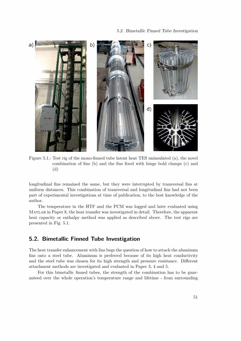
5.2. Bimetallic Finned Tube Investigation
Figure 5.1.: Test rig of the mono-finned tube latent heat TES uninsulated (a), the novelcombination of fins (b) and the fins fixed with hinge bold clamps (c) and(d)
longitudinal fins remained the same, but they were interrupted by transversal fins atuniform distances. This combination of transversal and longitudinal fins had not beenpart of experimental investigations at time of publication, to the best knowledge of theauthor.
The temperature in the HTF and the PCM was logged and later evaluated usingMatlab in Paper 8, the heat transfer was investigated in detail. Therefore, the apparentheat capacity or enthalpy method was applied as described above. The test rigs arepresented in Fig. 5.1.
5.2. Bimetallic Finned Tube Investigation
The heat transfer enhancement with fins begs the question of how to attach the aluminumfins onto a steel tube. Aluminum is preferred because of its high heat conductivityand the steel tube was chosen for its high strength and pressure resistance. Differentattachment methods are investigated and evaluated in Paper 3, 4 and 5.
For this bimetallic finned tubes, the strength of the combination has to be guar-anteed over the whole operation’s temperature range and lifetime - from surrounding
51

5. Experimental Investigations
Figure 5.2.: Prototypes for bimetallic finned tubes (a) and assembly apparatus with as-sembled tube (b) and (c)
temperature up to 350 ◦C for years. A cycling thermal load is applied to the composi-tion while charging and discharging. Since the composition is in direct contact to thePCM, corrosion has to be avoided. Finally, the whole composition has to be easy tomanufacture and assemble.
Another crucial aspect regarding the bimetallic finned tube is the different heatexpansion coefficient of steel and aluminum. The thermal expansion of aluminum istwice as high as the thermal expansion of steel; this would lead to a gap when steel andaluminum fins are manufactured with the same diameter at room-temperature.
Four different prototypes were tested like shown in Fig. 5.2 a). All prototypes hada difference in diameter in order to overcome the thermal expansion problem. Thus,the manufacturing was more challenging. One prototype with a so called bending earcould be spread and the ear would undergo elastic deformation during assembly. Theother prototype - a classical press fit - was assembled by pressing the steel tube ontoan aluminum tube. Prototype three had a zinc layer in between the steel and thealuminum, and prototype four was a press fit with transversal fins. All prototypes werepart of finite element analysis before testing them in experiments. The prototypes werethen manufactured and tested in a muffle furnace and a material testing machine. Usingthe material testing machine, the holding force of the composition was determined atsurrounding temperature and operation temperature. The measurements were repeatedat the beginning and after 260 cycles in the furnace. The only promising prototype wasthe so called bending ear. For this prototype, an assembly apparatus was constructed(Fig 5.2 b)) and a small prototype with simplified fins (Fig 5.2 c)) was assembled andtested in the muffle furnace once again. The bending ear concept seemed to be promising.The next step should be testing it in a latent heat TES test rig under real storageconditions.
52

5.3. Selected Experimental Investigations
5.3. Selected Experimental Investigations
For allocating the experimental investigations carried out within this work, the neigh-boring experimental work should be highlighted. In short, the temperature range ofmore than 300 ◦C reduces the quantity of available experiments and also the specificapplication as TES; the chosen heat transfer mechanism (fins) does the same. Not morethan a handful of experimental projects of this TES type can be found in the past tenyears. Three of the selected projects are presented here. Among them, the DLR inGermany has developed many industrial scale prototypes of TES in general, but alsolatent heat TES in particular. At Ghent University and the AIT, two smaller prototypeswere built. These are included in the attempt of drawing a more comprehensive pictureof the experiments.
5.3.1. Experimental Work at DLR
At DLR, many different PCM test rigs have been erected within the past 15 years.The experimental work focuses mainly on high temperature storage systems for CSPplants and industrial applications. The PCM storage is mostly used as vaporizer in thesteam generation process, preheater and superheater could be sensible storage systems,like Laing et al. present [67]. The storage is discharged in natural circulation modeand charged with forced circulation in the other direction. Before erecting a 700 kWhprototype, a lab scale 15 kWh test rig is tested in the lab. Sodium nitrate serves as PCMfor both systems, aluminum fins attached onto the steel tubes are used to increase theheat transfer rate into the PCM. Laing et al. present further results of this storage unit[66]. The direct steam generation (DSG) from a PCM storage is feasible for all threeoperational modes (once-through, natural circulation and forced-circulation), and theconcept is presented in Fig 5.3. In addition, a new fin geometry for longitudinal fins isdeveloped and tested in a lab scale storage. The development of the fins, especially theattachment of the aluminum fins on the steel tube, is discussed by Johnson et al. [52].A new method is proposed: the use of spring steel clips to fix two symmetric aluminumfin halves on the steel tube. The attachment of aluminum fins on a steel tube is also themain focus of Paper 5.
Based on the concept of a high power level TES by Johnson et al. [53], [50], thesefinned tubes are applied to a co-generation power plant [51]. A heat and power co-generation plant with a gas turbine and a heat recovery steam generator, which also hasa backup boiler, is equipped with a latent heat TES. For the case of tripping the gasturbine, the backup boiler, responsible for constant steam production, is supplementedby the latent heat TES in order to reduce the operational hours of the backup boiler.The latent heat TES is designed for a high power rate of up to 6MW and with a capacityof 1.5MWh which would supplement the backup boiler for approximately 15min. Onlysimulation results have been published so far, but experimental data is expected soon.Pictures of the finned tube and the storage system are displayed in Fig. 5.4.
53
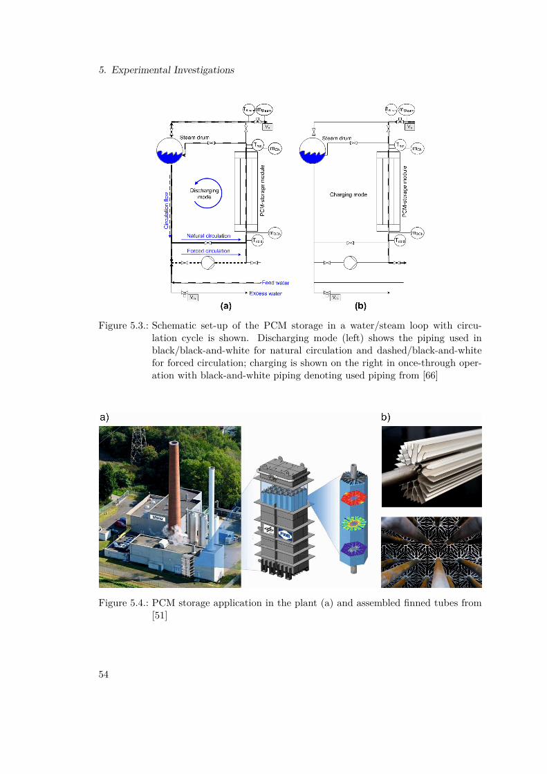
5. Experimental Investigations
Figure 5.3.: Schematic set-up of the PCM storage in a water/steam loop with circu-lation cycle is shown. Discharging mode (left) shows the piping used inblack/black-and-white for natural circulation and dashed/black-and-whitefor forced circulation; charging is shown on the right in once-through oper-ation with black-and-white piping denoting used piping from [66]
Figure 5.4.: PCM storage application in the plant (a) and assembled finned tubes from[51]
54

5.3. Selected Experimental Investigations
5.3.2. Experimental Work at Ghent University
The application of organic Rankine cycles to utilize low temperature waste heat andincrease the energy efficiency of energy intensive industries is often restrained by volatileavailability of the waste heat. In the experimental investigations at Ghent University,Couvreur et al. demonstrate the use of a latent heat TES to ensure constant inlettemperature to an ORC cycle [18]. The experimental setup consists of a storage vesselwith vertical transversal finned tubes, filled with 2m3 solar salt, a eutectic mixture ofsodium nitrate and potassium nitrate (Fig. 5.5 a) and b)). Thermal oil (Therminol 66)is used as HTF between the electrical heater, the storage and the ORC process. Thestorage capacity of 112 kWh is based on the phase transition enthalpy and 220 kWhincluding the sensible enthalpy between 180 ◦C and 250 ◦C. The TES system unit itselfis discussed by Couver et al. [19] and further tests are presented in the mentionedliterature. The dependency of the power rate from HTF mass flow is documented aswell as an approach to determine a global heat transfer coefficient from the HTF intothe storage material.
The comparison of these values with experimental investigations at TUWien is of in-terest due to the comparability of the storage systems in terms of similar PCMs, temper-ature levels, and sizes. The overall heat transfer coefficient k (named U in the mentionedliterature) reaches values between 150Wm−2 K and 300Wm−2 K which corresponds tovalues measured at TU Wien which are between 260Wm−2 K and 300Wm−2 K withdifferent fin geometry and pure sodium nitrate.
A more detailed look on the melting of PCM is presented by Plas et al. [87] basedon his master’s thesis [88]. An experimental analysis of RT35HC in an rectangularenclosure is presented and liquid fraction functions are experimentally determined. Themelting is axially non-uniform, the liquid fraction accumulates at the top of the storage,and the melting front grows from the inside out and from the top to the bottom. Forhigh temperature materials like sodium nitrate, this effect was also demonstrated at TUWien and presented in Paper 1; although, the melting front cannot be visually measuredat this temperature level.
55

5. Experimental Investigations
Figure 5.5.: Picture of the installed LHTES unit in Ghent (a) and cross sectional view(b) from from [19], latent heat TES with transversal fins and HDPE as PCMat AIT from [126] (c) and tube bundle with PCM filled tube from [127] (d)
5.3.3. Experimental Work at AIT
At AIT, different polymers have been the focus for their utilization in a latent heat TES.Zauner et al. describes the selection process of HDPE as storage material and the con-struction of a latent heat TES labor scale test rig in [126]. Heat transfer characteristicsof the experiments are provided and compared to numerical simulations. The generalaim is to reduce CO2 emissions in district heating networks or similar applications byusing a latent heat TES. The storage design consists of horizontal tubes with transversalfins in a rectangular enclosure (like shown in Fig. 5.5c), and thermal oils serve as HTF.The temperature level is lower compared to sodium nitrate, the HDPE melts around120 ◦C. The resulting experimental data are used for validation of a model developedby Barz et al. [4]. The model is supposed to be applied at system-level simulation andtherefore has to be reduced compared to full CFD simulations.
Further development led to a hybrid TES consisting of tubes filled with HDPEarranged vertically in a shell and tube heat exchanger with an HTF flow around thetubes [127]. The tubes filled with 208 kg HDPE surrounded by 515 kg of thermal oil formthe bundle as it is shown in Fig. 5.5 d). The power rate can be increased by decreasingthe tube diameter and increasing the number of tubes. Using larger diameters, the
56

5.3. Selected Experimental Investigations
sensible storage capacity increases, just as Zauner et al. explain. A possible applicationis also given in [125]. In pulp and paper production, excess steam is often condensed inan auxiliary condenser. Instead, the steam could be used for charging a latent heat TESthereby increasing the utilization of the heat. A small prototype and a storage modelare presented for this specific purpose.
57

6. Conclusion and Outlook
Several improvements of latent heat TES systems have been developed and experimen-tally investigated during the completion of this work. The most important findings aresummarized at this point. The outlook of resultant research topics and ideas is discussedto draw a rough pathway for future research projects.
Experimental work First, a prototype latent heat TES with sodium nitrate and alu-minum fins was designed and built. The capacity, the power rate and the energy densitycould be determined successfully. The melting behavior was described based on temper-ature plots and the influence of the heat transfer fluid flow direction was investigatedfor a finned vertical tube arrangement.
Then, the attachment of aluminum fins on a steel tube was investigated experimen-tally. Using hinge bold clamps works fine, the optimal spatial arrangement of hexagonalcross section bimetallic tubes is not feasible with them. A novel fin geometry with im-plemented attachment mechanism, the so called bending ear, was designed and testedat operation temperature.
For the second prototype of a latent heat TES, a novel arrangement of different fintypes was applied in order to improve the heat transfer rate. The plain longitudinalfins from the first prototype were changed to a novel combination of longitudinal andtransversal fins. Again, the main storage parameters were determined and compared tothe previous fin design.
Highlights In latent heat TES with plain longitudinal vertically finned tubes, the melt-ing occurs axial asymmetrically. The liquid storage material expands to and accumulatesat the top of the storage vessel. Furthermore, there is a slight influence of the flow di-rection of the heat transfer fluid. Charging with the hot heat transfer fluid from the topleads to shorter melting cycles, which is not observed for discharging cycles.
Connecting aluminum fins on a steel tube without additional components was re-alized successfully. The bending ear geometry - implemented in the extrusion moldingprofile geometry of the fins - allows an assembling at room temperature and ensuresa press-fit connection also at operational temperature. Hexagonal or any other crosssections are technically feasibly with the new design, the spatial arrangement is notaffected by clamps. The connection was tested successfully for creeping at operationaltemperature. A prototype assembling apparatus was designed and tested for the finnedtube production.
The experiments with the combination of two fin types - transversal and longitudinalfins - showed significantly higher melting rates than the plain longitudinally finned rig.
58

The melting is axially symmetric for the second prototype latent heat TES. With thehelp of this prototype, an apparent heat transfer coefficient for sodium nitrate latent heatTES with aluminum fins and its dependence on the charging state was determined. Withthese values and the other identified storage parameters, the behavior and especially thepower rate of similar systems can be estimated.
Reflection and Outlook Referring to the implementation barriers (IB2 heat transferenhancement and IB3 dynamic behavior) for the latent heat TES technology, significantadvances were reached for the heat transfer rate with the novel fin combination. Theasymmetric melting was demonstrated and the influence of the flow direction was shown.The dynamic behavior of this TES types was measured and can be used to develop controlstrategies. For upscaling (IB5), the measured heat transfer values allow power andcapacity estimations for large scale systems. Finally, the data is available for validationof mathematical TES models of this TES type.
For future research projects, an interesting research questions could be the designof such a storage system in general. For this purpose the prediction of the heat trans-fer coefficient and hence the expectable power rate are a determining factor. This ischallenging if there are no measured values or correlations available. A general relationbetween the fin type, the storage material and the phase state for calculating the heattransfer rate should be developed.
From an application perspective, the power rate is of high interest as mentionedbefore. But for this purpose the phase state has to be known. A relevant researchquestion may be how to determine the phase state/state-of-charge of non-lab scale latentheat TES applications based on few temperature testing points?
Latent heat TES systems show a highly transient behavior. For the use in en-ergy systems, control strategies have to be developed for a successful operation. Thiswill mainly effect the mass flow of the heat transfer fluid. When used as vaporizer ina steam generating systems, the latent heat TES may work with natural circulation.Controlled charging and discharging is important for the successful implementation inenergy systems.
The next step, from a technological point of view, is testing a storage system underreal conditions in the field. This could be either in a CSP plant or any waste heatfacility. For higher capacities and power rates, a high number of tubes is necessary.Then, the question of tubing appears. How many collector tubes at the bottom and thetop supply the heat transfer tubes and how high is the pressure loss of the individualtubes? Especially when the latent heat TES is used as vaporizer/condenser in a steamgenerator, the issue of stable flow conditions in the individual tube appears.
The bimetallic finned tube with bending ear geometry has to be tested in manufac-turing, assembly and under real conditions in the storage systems in order to gain moreexperience with this technology. Based on the actual work the tolerances for extrusionmolding may be crucial for a successful implementation of this technology.
For the application of latent heat TES models in simulations on system level scale,the behavior of the latent heat TES has to be considered or controlled, as mentioned
59

6. Conclusion and Outlook
above. Then, models of latent heat TES systems have to be developed for the differentsimulation software packages available. The mentioned research topics are essential toraise the technology readiness level of latent heat TES systems for their application infuture energy systems.
60
References[1] Tanvir E. Alam et al. „Macroencapsulation and characterization of phase change
materials for latent heat thermal energy storage systems“. In: Applied Energy 154(2015), pp. 92–101. issn: 03062619. doi: 10.1016/j.apenergy.2015.04.086.
[2] Guruprasad Alva, Yaxue Lin, and Guiyin Fang. „An overview of thermal energystorage systems“. In: Energy 144 (2018), pp. 341–378. issn: 03605442. doi: 10.1016/j.energy.2017.12.037.
[3] Andreas Michalka. „Experimentelle Untersuchungen eines Festbettregeneratorsmit feinem Kies als Speichermaterial“. Master Thesis. Wien: TU Wien, 2018.
[4] Tilman Barz et al. „Experimental Analysis and Numerical Modeling of a Shelland Tube Heat Storage Unit with Phase Change Materials“. In: Industrial &Engineering Chemistry Research 55.29 (2016), pp. 8154–8164. issn: 0888-5885.doi: 10.1021/acs.iecr.6b01080.
[5] Tilman Barz et al. „State and state of charge estimation for a latent heat storage“.In: Control Engineering Practice 72 (2018), pp. 151–166. issn: 09670661. doi:10.1016/j.conengprac.2017.11.006.
[6] T. Bauer, D. Laing, and U. Kröner. „Sodium nitrate for high temperature latentheat storage“. In: Thermal Energy Storage for Efficiency and Sustainability : 11thInternational Conference on Thermal Energy Storage. Ed. by Signhild Gehlin.2009.
[7] Thomas Bauer. „Approximate analytical solutions for the solidification of PCMsin fin geometries using effective thermophysical properties“. In: InternationalJournal of Heat and Mass Transfer 54.23-24 (2011), pp. 4923–4930. issn:00179310. doi: 10.1016/j.ijheatmasstransfer.2011.07.004.
[8] Thomas Bauer, Doerte Laing, and Rainer Tamme. „Characterization of SodiumNitrate as Phase Change Material“. In: International Journal of Thermophysics33.1 (2012), pp. 91–104. doi: 10.1007/s10765-011-1113-9.
[9] Alicia Bayon et al. „Novel solid–solid phase-change cascade systems for high-temperature thermal energy storage“. In: Solar Energy 177 (2019), pp. 274–283.issn: 0038092X. doi: 10.1016/j.solener.2018.10.085.
[10] Nils Breidenbach et al. „Thermal Energy Storage in Molten Salts: Overview ofNovel Concepts and the DLR Test Facility TESIS“. In: Energy Procedia 99 (2016),pp. 120–129. issn: 18766102. doi: 10.1016/j.egypro.2016.10.103.
[11] Bundesministerium für Nachhaltigkeit und Tourismus. Energie in Österreich2018: Zahlen, Daten, Fakten. Wien, 2018.
61
References
[12] Bundesministerium für Verkehr, Innovation und Technologie. „Wärmenetze derZukunft Österreichische Systemlösungen für die nachhaltige Energieversorgungim urbanen Raum: Aktuelle Entwicklungen und Beispiele für zukunftsfähige En-ergietechnologien“. In: energy innovation austria 1 (2015), pp. 6–7.
[13] L. F. Cabeza et al. „Immersion corrosion tests on metal-salt hydrate pairs used forlatent heat storage in the 48 to 58\textdegree C temperature range“. In:Materialsand Corrosion 53.12 (2002), pp. 902–907. issn: 09475117. doi: 10.1002/maco.200290004.
[14] Luisa F. Cabeza and Nguan H. Steven Tay, eds. High-temperature thermal storagesystems using phase change materials. London, United Kingdom: Academic Pressis an imprint of Elsevier, 2018. isbn: 9780128053232.
[15] Y. Cao and A. Faghri. „A Numerical Analysis of Phase-Change Problems Includ-ing Natural Convection“. In: Journal of Heat Transfer 112.3 (1990), p. 812. issn:00221481. doi: 10.1115/1.2910466.
[16] Carolina Cárdenas-Ramírez, Maryory Gómez, and Franklin Jaramillo. „Identi-fication of the mineralogical phases of a porous mineral: promising support forshape-stabilized phase change materials“. In: Advances in Thermal Energy Stor-age. Ed. by Universitat de Lleida. Edicions de la Universitat de Lleida, 2019,pp. 317–322. isbn: 978-84-9144-155-7.
[17] Robert W. Carling. „Heat capacities of NaNO3 and KNO3 from 350 to 800 K“.In: Thermochimica Acta 60.3 (1983), pp. 265–275. issn: 00406031. doi: 10.1016/0040-6031(83)80248-2.
[18] K. Couvreur et al. „Constant power production with an organic Rankine cyclefrom a fluctuating waste heat source by using thermal storage“. In: Proceedings ofthe Heat Powered Cycles Conference 2018. Ed. by R. Riehl et al. 2018, pp. 493–501.
[19] K. Couvreur et al. „Experimental behavior of a 100 kWhth fin-tube latent heatstorage using eutectic KNO3-NaNO3 as PCM“. In: Advances in Thermal EnergyStorage. Ed. by Universitat de Lleida. Edicions de la Universitat de Lleida, 2019,pp. 451–460. isbn: 978-84-9144-155-7.
[20] Abdulrahman Dahash et al. „Advances in seasonal thermal energy storage forsolar district heating applications: A critical review on large-scale hot-water tankand pit thermal energy storage systems“. In: Applied Energy 239 (2019), pp. 296–315. issn: 03062619. doi: 10.1016/j.apenergy.2019.01.189.
[21] İbrahim Dinçer and Marc A. Rosen. Thermal energy storage: Systems and appli-cations. 2nd ed. Hoboken, N.J: Wiley, 2011. isbn: 9780470747063.
[22] Serena Ditroia et al. „Form Stable phase change materials (PCMs) for thermalenergy storage: investigation of structure- property links with performance andcosts considerations“. In: Advances in Thermal Energy Storage. Ed. by Universitatde Lleida. Edicions de la Universitat de Lleida, 2019, pp. 395–408. isbn: 978-84-9144-155-7.
62
References
[23] Sabrina Dusek, René Hofmann, and Stephan Gruber. „Design analysis of a hybridstorage concept combining Ruths steam storage and latent thermal energy stor-age“. In: Applied Energy 251 (2019), p. 113364. issn: 03062619. doi: 10.1016/j.apenergy.2019.113364.
[24] Yvan Dutil et al. „A review on phase-change materials: Mathematical modelingand simulations“. In: Renewable and Sustainable Energy Reviews 15.1 (2011),pp. 112–130. issn: 13640321. doi: 10.1016/j.rser.2010.06.011.
[25] H. Eslamnezhad and Asghar B. Rahimi. „Enhance heat transfer for phase-changematerials in triplex tube heat exchanger with selected arrangements of fins“.In: Applied Thermal Engineering 113 (2017), pp. 813–821. issn: 13594311. doi:10.1016/j.applthermaleng.2016.11.067.
[26] Ali Fallahi et al. „Review on solid-solid phase change materials for thermal en-ergy storage: Molecular structure and thermal properties“. In: Applied Ther-mal Engineering 127 (2017), pp. 1427–1441. issn: 13594311. doi: 10.1016/j.applthermaleng.2017.08.161.
[27] Amy S. Fleischer. Thermal Energy Storage Using Phase Change Materials: Fun-damentals and Applications. SpringerBriefs in Applied Sciences and Technology.2015. isbn: 9783319209227. url: http://dx.doi.org/10.1007/978-3-319-20922-7.
[28] Scott M. Flueckiger et al. „System-level simulation of a solar power tower plantwith thermocline thermal energy storage“. In: Applied Energy 113 (2014), pp. 86–96. issn: 03062619. doi: 10.1016/j.apenergy.2013.07.004.
[29] Andrea Frazzica and Luisa F. Cabeza, eds. Recent Advancements in Materials andSystems for Thermal Energy Storage: An Introduction to Experimental Charac-terization Methods. Green Energy and Technology. Cham: Springer InternationalPublishing, 2019. isbn: 9783319966410. doi: 10.1007/978-3-319-96640-3.
[30] Jaume Gasia et al. „Phase Change Material Selection for Thermal ProcessesWorking under Partial Load Operating Conditions in the Temperature Rangebetween 120 ◦Cand 200 ◦C“. In: Applied Sciences 7.7 (2017), p. 722. issn: 2076-3417. doi: 10.3390/app7070722.
[31] Haoshan Ge et al. „Low melting point liquid metal as a new class of phase changematerial: An emerging frontier in energy area“. In: Renewable and SustainableEnergy Reviews 21 (2013), pp. 331–346. issn: 13640321. doi: 10.1016/j.rser.2013.01.008.
[32] Antoni Gil et al. „State of the art on high temperature thermal energy storage forpower generation. Part 1—Concepts, materials and modellization“. In: Renewableand Sustainable Energy Reviews 14.1 (2010), pp. 31–55. issn: 13640321. doi:10.1016/j.rser.2009.07.035.
63

References
[33] Zhen-Xiang Gong and Arun S. Mujumdar. „Finite-element analysis of cyclic heattransfer in a shell-and-tube latent heat energy storage exchanger“. In: AppliedThermal Engineering 17.6 (1997), pp. 583–591. issn: 13594311. doi: 10.1016/S1359-4311(96)00054-3.
[34] Edouard González-Roubaud, David Pérez-Osorio, and Cristina Prieto. „Review ofcommercial thermal energy storage in concentrated solar power plants: Steam vs.molten salts“. In: Renewable and Sustainable Energy Reviews 80 (2017), pp. 133–148. issn: 13640321. doi: 10.1016/j.rser.2017.05.084.
[35] H. M. Goodwin and H. T. Kalmus. „On the Latent Heat of Fusion and the SpecificHeat of Salts in the Solid and Liquid State“. In: Physical Review (Series I) 28.1(1909), pp. 1–24. issn: 1536-6065. doi: 10.1103/PhysRevSeriesI.28.1.
[36] U. Hammerschmidt and V. Meier. „New Transient Hot-Bridge Sensor to MeasureThermal Conductivity, Thermal Diffusivity, and Volumetric Specific Heat“. In:International Journal of Thermophysics 27.3 (2006), pp. 840–865. doi: 10.1007/s10765-006-0061-2.
[37] Ya-Ling He et al. „Lattice Boltzmann methods for single-phase and solid-liquidphase-change heat transfer in porous media: A review“. In: International Journalof Heat and Mass Transfer 129 (2019), pp. 160–197. issn: 00179310. doi: 10.1016/j.ijheatmasstransfer.2018.08.135.
[38] B. Heydari and F. Talati. „Numerical Solution of Heat Transfer Process in PCMStorage Using Tau Method“. In: Mathematical Problems in Engineering 2015.2(2015), pp. 1–9. doi: 10.1155/2015/805641.
[39] T. Hirata and K. Nishida. „An analysis of heat transfer using equivalent ther-mal conductivity of liquid phase during melting inside an isothermally heatedhorizontal cylinder“. In: International Journal of Heat and Mass Transfer 32.9(1989), pp. 1663–1670. issn: 00179310. doi: 10.1016/0017-9310(89)90049-5.
[40] J.-F. Hoffmann et al. „A thermocline thermal energy storage system with fillermaterials for concentrated solar power plants: Experimental data and numeri-cal model sensitivity to different experimental tank scales“. In: Applied Ther-mal Engineering 100 (2016), pp. 753–761. issn: 13594311. doi: 10 . 1016 / j .applthermaleng.2016.01.110.
[41] René Hofmann et al. „Design Optimization of a Hybrid Steam-PCM ThermalEnergy Storage for Industrial Applications“. In: Energies 12.5 (2019), p. 898.issn: 1996-1073. doi: 10.3390/en12050898.
[42] Stephan Höhlein, Andreas König-Haagen, and Dieter Brüggemann. „Macro-Encapsulation of Inorganic Phase-Change Materials (PCM) in Metal Capsules“.In: Materials (Basel, Switzerland) 11.9 (2018). issn: 1996-1944. doi: 10.3390/ma11091752.
64

References
[43] Henry Hu and Stavros A. Argyropoulos. „Mathematical modelling of solidificationand melting: A review“. In: Modelling and Simulation in Materials Science andEngineering 4.4 (1996), pp. 371–396. issn: 0965-0393. doi: 10.1088/0965-0393/4/4/004.
[44] M.Md. Ibrahim et al. „Thermal expansion of sodium nitrate (I)“. In: Journal ofPhysics and Chemistry of Solids 47.5 (1986), pp. 517–520. issn: 00223697. doi:10.1016/0022-3697(86)90051-X.
[45] Nasiru I. Ibrahim et al. „Heat transfer enhancement of phase change materialsfor thermal energy storage applications: A critical review“. In: Renewable andSustainable Energy Reviews 74 (2017), pp. 26–50. issn: 13640321. doi: 10.1016/j.rser.2017.01.169.
[46] Intergovernmental Panel on Climate Change, IPCC. „Summary for Policymak-ers“. In: Global Warming of 1.5°C. Ed. by IPCC. Geneva, Switzerland, 2018.
[47] International Renewable Energy Agency, IRENA. Climate Change and RenewableEnergy: National Policies and the role of communities, cities and regions. AbuDhabi, 2019. url: 978-92-9260-136-2.
[48] International Renewable Energy Agency, IRENA. Renewable Power GenerationCosts in 2017: International Renewable Energy Agency. Abu Dhabi, 2018.
[49] S. Jegadheeswaran and Sanjay D. Pohekar. „Performance enhancement in latentheat thermal storage system: A review“. In: Renewable and Sustainable EnergyReviews 13.9 (2009), pp. 2225–2244. issn: 13640321. doi: 10.1016/j.rser.2009.06.024.
[50] M. Johnson et al. „High Temperature Latent Heat Thermal Energy Storage In-tegration in a Co-gen Plant“. In: Energy Procedia 73 (2015), pp. 281–288. issn:18766102. doi: 10.1016/j.egypro.2015.07.689.
[51] Maike Johnson, Bernd Hachmann, and Andreas J. Dengel. „Design and integra-tion of high temperature latent heat thermal energy storage for high power levels“.In: International Mechanical Engineering Congress and Exposition IMECE2018.Ed. by ASME. ASME, 2018. isbn: 978-0-7918-5208-8.
[52] Maike Johnson et al. „Assembly and attachment methods for extended aluminumfins onto steel tubes for high temperature latent heat storage units“. In: AppliedThermal Engineering 144 (2018), pp. 96–105. issn: 13594311. doi: 10.1016/j.applthermaleng.2018.08.035.
[53] Maike Johnson et al. „Design of high temperature thermal energy storage forhigh power levels“. In: Sustainable Cities and Society 35 (2017), pp. 758–763.issn: 22106707. doi: 10.1016/j.scs.2017.09.007.
[54] T. Jriri et al. „Thermodynamic study of the condensed phases of Thermodynamicstudy of the condensed phases of NaNO_3, KNO_3 and CsNO_3 and theirtransitions“. In: Thermochimica Acta 266 (1995), pp. 147–161. issn: 00406031.
65

References
[55] Murat Kenisarin and Khamid Mahkamov. „Salt hydrates as latent heat storagematerials: Thermophysical properties and costs“. In: Solar Energy Materials andSolar Cells 145 (2016), pp. 255–286. issn: 09270248. doi: 10.1016/j.solmat.2015.10.029.
[56] Zakir Khan and Zulfiqar Ahmad Khan. „An experimental investigation of dis-charge/solidification cycle of paraffin in novel shell and tube with longitudinal finsbased latent heat storage system“. In: Energy Conversion and Management 154(2017), pp. 157–167. issn: 01968904. doi: 10.1016/j.enconman.2017.10.051.
[57] Martin Koller et al. „Comparison of Different Heat Exchanger Tube Designsused in Latent Heat Thermal Energy Storage Systems - a Numerical Study“.In: Proceedings of the 26th European Symposium on Computer Aided Pro-cess Engineering – ESCAPE 26. Ed. by Kravanja Zdravko and Bogataj Miloš.Vol. 38. Computer Aided Chemical Engineering. Elsevier, 2016, pp. 277–282. isbn:9780444634283. doi: 10.1016/B978-0-444-63428-3.50051-5.
[58] Lawrence J. Korb. Corrosion. [10. ed.], 7. print. Vol. / prepared under the direc-tion of the ASM International Handbook Committee ; Vol. 13. ASM handbook.Materials Park, Ohio: ASM International, 2001. isbn: 0871700190.
[59] F. C. Kracek. „GRADUAL TRANSITION IN SODIUMNITRATE. I. PHYSICO-CHEMICAL CRITERIA OF THE TRANSITION“. In: Journal of the AmericanChemical Society 53.7 (1931), pp. 2609–2624. issn: 0002-7863. doi: 10.1021/ja01358a022.
[60] F. C. Kracek, E. Posnjak, and S. B. Hendricks. „GRADUAL TRANSITION INSODIUM NITRATE. II. THE STRUCTURE AT VARIOUS TEMPERATURESAND ITS BEARING ON MOLECULAR ROTATION“. In: Journal of the Amer-ican Chemical Society 53.9 (1931), pp. 3339–3348. issn: 0002-7863. doi: 10.1021/ja01360a016.
[61] Michael Krüger et al. „Slag as Inventory Material for a Thermal Energy Storage(TES): Material investigation and thermo-mechanical consideration“. In: EnergyProcedia 155 (2018), pp. 454–463. issn: 18766102. doi: 10.1016/j.egypro.2018.11.034.
[62] Sebastian Kuboth, Andreas König-Haagen, and Dieter Brüggemann. „NumericalAnalysis of Shell-and-Tube Type Latent Thermal Energy Storage Performancewith Different Arrangements of Circular Fins“. In: Energies 10.3 (2017), p. 274.issn: 1996-1073. doi: 10.3390/en10030274.
[63] Francis A. Kulacki. Handbook of Thermal Science and Engineering. 2018. isbn:9783319266954. url: http://dx.doi.org/10.1007/978-3-319-26695-4.
[64] Alberto de La Calle et al. „System-level simulation of a novel solar power towerplant based on a sodium receiver, PCM storage and sCO2 power block“. In: AIPConference Proceedings 2033.1 (2018), p. 210003. doi: 10.1063/1.5067205.
66

References
[65] Daniel Lager. „Evaluation of thermophysical properties for thermal energy storagematerials - determining factors, prospects and limitations“. PhD Thesis. Wien:TU Wien, 2017.
[66] Doerte Laing et al. „Development of high temperature phase-change-materialstorages“. In: Applied Energy 109 (2013), pp. 497–504. issn: 03062619. doi: 10.1016/j.apenergy.2012.11.063.
[67] Doerte Laing et al. „Thermal energy storage for direct steam generation“. In: So-lar Energy 85.4 (2011), pp. 627–633. issn: 0038092X. doi: 10.1016/j.solener.2010.08.015.
[68] Piia Lamberg and Kai Sirén. „Approximate analytical model for solidification ina finite PCM storage with internal fins“. In: Applied Mathematical Modelling 27.7(2003), pp. 491–513. doi: 10.1016/S0307-904X(03)00080-5.
[69] Dong Li et al. „Three–dimensional lattice Boltzmann models for solid–liquidphase change“. In: International Journal of Heat and Mass Transfer 115 (2017),pp. 1334–1347. issn: 00179310. doi: 10.1016/j.ijheatmasstransfer.2017.07.048.
[70] Q. Li et al. „Lattice Boltzmann methods for multiphase flow and phase-changeheat transfer“. In: Progress in Energy and Combustion Science 52 (2016), pp. 62–105. issn: 03601285. doi: 10.1016/j.pecs.2015.10.001.
[71] Xiaoyan Li et al. „Investigation of the dynamic characteristics of a thermal energystorage unit filled with multiple phase change materials“. In: Thermal Science22.Suppl. 2 (2018), pp. 527–533. issn: 0354-9836. doi: 10.2298/TSCI171114037L.
[72] Zheng Li, Mo Yang, and Yuwen Zhang. „Numerical Simulation of Melting Prob-lems Using the Lattice Boltzmann Method with the Interfacial Tracking Method“.In: Numerical Heat Transfer, Part A: Applications 68.11 (2015), pp. 1175–1197.issn: 1040-7782. doi: 10.1080/10407782.2015.1037126.
[73] Zhuo Li and Zhi-Gen Wu. „Analysis of HTFs, PCMs and fins effects on thethermal performance of shell–tube thermal energy storage units“. In: Solar Energy122 (2015), pp. 382–395. issn: 0038092X. doi: 10.1016/j.solener.2015.09.019.
[74] José Maldonado et al. „Phase Change Material Selection for Thermal EnergyStorage at High Temperature Range between 210 ◦C and 270 ◦C“. In: Energies11.4 (2018), p. 861. issn: 1996-1073. doi: 10.3390/en11040861.
[75] Harald Mehling and Luisa F. Cabeza. Heat and cold storage with PCM. Berlin,Heidelberg: Springer Berlin Heidelberg, 2008. isbn: 978-3-540-68556-2. doi: 10.1007/978-3-540-68557-9.
[76] Michael Böswarth. „Numerische Simulation des Schmelz- und Erstar-rungsprozesses in einem Latentwärmespeicher mit Rippenrohren“. BSc Thesis.Wien: TU Wien, 2017.
67

References
[77] Laia Miró, Jaume Gasia, and Luisa F. Cabeza. „Thermal energy storage (TES) forindustrial waste heat (IWH) recovery: A review“. In: Applied Energy 179 (2016),pp. 284–301. issn: 03062619. doi: 10.1016/j.apenergy.2016.06.147.
[78] Bernd Möller et al. „Heat Roadmap Europe: Identifying local heat demand andsupply areas with a European thermal atlas“. In: Energy 158 (2018), pp. 281–292.issn: 03605442. doi: 10.1016/j.energy.2018.06.025.
[79] Pere Moreno et al. „Corrosion of metal and metal alloy containers in contact withphase change materials (PCM) for potential heating and cooling applications“.In: Applied Energy 125 (2014), pp. 238–245. issn: 03062619. doi: 10.1016/j.apenergy.2014.03.022.
[80] Hassan Nazir et al. „Recent developments in phase change materials for en-ergy storage applications: A review“. In: International Journal of Heat andMass Transfer 129 (2019), pp. 491–523. issn: 00179310. doi: 10 . 1016 / j .ijheatmasstransfer.2018.09.126.
[81] E. Oró et al. „Review on phase change materials (PCMs) for cold thermal energystorage applications“. In: Applied Energy 99 (2012), pp. 513–533. issn: 03062619.doi: 10.1016/j.apenergy.2012.03.058.
[82] Eduard Oró et al. „Corrosion of metal and polymer containers for use in PCMcold storage“. In: Applied Energy 109 (2013), pp. 449–453. issn: 03062619. doi:10.1016/j.apenergy.2012.10.049.
[83] Z. H. Pan and C. Y. Zhao. „Gas–solid thermochemical heat storage reactorsfor high-temperature applications“. In: Energy 130 (2017), pp. 155–173. issn:03605442. doi: 10.1016/j.energy.2017.04.102.
[84] P. Pardo et al. „A review on high temperature thermochemical heat energy stor-age“. In: Renewable and Sustainable Energy Reviews 32 (2014), pp. 591–610. issn:13640321. doi: 10.1016/j.rser.2013.12.014.
[85] Mohammad Parhizi and Ankur Jain. „Theoretical modeling of a phase changeheat transfer problem with a pre-melted or pre-solidified region“. In: InternationalJournal of Heat and Mass Transfer 136 (2019), pp. 635–643. issn: 00179310. doi:10.1016/j.ijheatmasstransfer.2019.02.079.
[86] Alberto Pizzolato et al. „Design of effective fins for fast PCM melting and solid-ification in shell-and-tube latent heat thermal energy storage through topologyoptimization“. In: Applied Energy 208 (2017), pp. 210–227. issn: 03062619. doi:10.1016/j.apenergy.2017.10.050.
[87] Wito Plas et al. „Tracking of the phase change front of a PCM in a rectangularenclosure“. In: Advances in Thermal Energy Storage. Ed. by Universitat de Lleida.Edicions de la Universitat de Lleida, 2019, pp. 733–742. isbn: 978-84-9144-155-7.
[88] Wito Plas et al. „Tracking of the phase change front of a phase change materialin a rectangular enclosure“. Master Thesis. Ghent: Ghent University, 2018.
68

References
[89] Cristina Prieto et al. „Review of technology: Thermochemical energy storage forconcentrated solar power plants“. In: Renewable and Sustainable Energy Reviews60 (2016), pp. 909–929. issn: 13640321. doi: 10.1016/j.rser.2015.12.364.
[90] A. Prötsch. „Auslegung und Inbetriebnahme einer Latentwärmespeicherversuch-sanlage“. MSc Thesis. Wien: TU Wien, 2012.
[91] Songgang Qiu, Laura Solomon, and Ming Fang. „Study of Material Compatibilityfor a Thermal Energy Storage System with Phase Change Material“. In: Energies11.3 (2018), p. 572. issn: 1996-1073. doi: 10.3390/en11030572.
[92] Fabian Rösler and Dieter Brüggemann. „Shell-and-tube type latent heat thermalenergy storage: Numerical analysis and comparison with experiments“. In: Heatand Mass Transfer 47.8 (2011), pp. 1027–1033. issn: 0947-7411. doi: 10.1007/s00231-011-0866-9.
[93] Ioan Sarbu and Calin Sebarchievici. „A Comprehensive Review of Thermal En-ergy Storage“. In: Sustainability 10.2 (2018), p. 191. issn: 2071-1050. doi: 10.3390/su10010191.
[94] Georg Scharinger-Urschitz, Heimo Walter, and Thomas Bauernfeind. „Novel FinGeometry for a Latent High Temperature Thermal Energy Storage - Experimen-tal Investigation“. In: Proceedings of the 4th Thermal and Fluids EngineeringConference (TFEC 2019). Ed. by ASTFE Digital Library. 2019, Paper Number27516. isbn: 978-1-56700-472-4.
[95] Georg Scharinger-Urschitz, Heimo Walter, and Markus Haider. „Heat Transferin Latent High-Temperature Thermal Energy Storage Systems—ExperimentalInvestigation“. In: Energies 12.7 (2019), p. 1264. issn: 1996-1073. doi: 10.3390/en12071264.
[96] Georg Scharinger-Urschitz, Heimo Walter, and Markus Haider. „Packed Bed Re-generator for Storing High Temperature Heat in Gravel“. In: Advances in ThermalEnergy Storage. Ed. by Universitat de Lleida. Edicions de la Universitat de Lleida,2019, pp. 767–774. isbn: 978-84-9144-155-7.
[97] Georg Scharinger-Urschitz et al. „Experimental Investigation on a High Temper-ature Latent TES with Novel Fin Geometry“. In: Proceeding of the 13th Confer-ence on Sustainable Development of Energy, Water and Environment System -SDEWES 2018. Ed. by Univeristy of Zagreb, Faculty of Mechanical Engineeringand Naval Architecture. 2018. isbn: 1847-7178.
[98] A. Sciacovelli, F. Gagliardi, and V. Verda. „Maximization of performance of aPCM latent heat storage system with innovative fins“. In: Applied Energy 137(2015), pp. 707–715. issn: 03062619. doi: 10.1016/j.apenergy.2014.07.015.
[99] Atul Sharma et al. „Review on thermal energy storage with phase change materi-als and applications“. In: Renewable and Sustainable Energy Reviews 13.2 (2009),pp. 318–345. issn: 13640321. doi: 10.1016/j.rser.2007.10.005.
69

References
[100] S. D. Sharma and Kazunobu Sagara. „Latent Heat Storage Materials and Sys-tems: A Review“. In: International Journal of Green Energy 2.1 (2005), pp. 1–56.issn: 1543-5075. doi: 10.1081/GE-200051299.
[101] Aran Solé et al. „Stability of sugar alcohols as PCM for thermal energy stor-age“. In: Solar Energy Materials and Solar Cells 126 (2014), pp. 125–134. issn:09270248. doi: 10.1016/j.solmat.2014.03.020.
[102] A. D. Solomon. „Melt time and heat flux for a simple PCM body“. In: SolarEnergy 22.3 (1978), pp. 251–257. issn: 0038092X.
[103] Solutia Europe S.A. Datasheet Therminol VP1: Vapour Phase Liquid Phase HeatTransfer Fluid 12 ◦C to 400 ◦C.
[104] Doru Michael Stefanescu. Science and engineering of casting solidification. 2. ed.New York, NY: Springer, 2009. isbn: 9780387746128.
[105] Y. Takahashi, R. Sakamoto, and M. Kamimoto. „Heat capacities and latent heatsof LiNO3, NaNO3, and KNO3“. In: International Journal of Thermophysics 9.6(1988), pp. 1081–1090. doi: 10.1007/BF01133275.
[106] N.H.S. Tay, F. Bruno, and M. Belusko. „Comparison of pinned and finned tubesin a phase change thermal energy storage system using CFD“. In: Applied Energy104 (2013), pp. 79–86. issn: 03062619. doi: 10.1016/j.apenergy.2012.10.040.
[107] Heqing Tian et al. „Enhanced thermal conductivity of ternary carbonate saltphase change material with Mg particles for solar thermal energy storage“. In: Ap-plied Energy 204 (2017), pp. 525–530. issn: 03062619. doi: 10.1016/j.apenergy.2017.07.027.
[108] Saeed Tiari and Songgang Qiu. „Three-dimensional simulation of high tempera-ture latent heat thermal energy storage system assisted by finned heat pipes“. In:Energy Conversion and Management 105 (2015), pp. 260–271. issn: 01968904.doi: 10.1016/j.enconman.2015.08.004.
[109] Fanny Trausel, Ard-Jan de Jong, and Ruud Cuypers. „A Review on the Propertiesof Salt Hydrates for Thermochemical Storage“. In: Energy Procedia 48 (2014),pp. 447–452. issn: 18766102. doi: 10.1016/j.egypro.2014.02.053.
[110] U.S. Department of Energy. DOE Global Energy Storage Database. Ed. by U.S.Department of Energy, Office of Electricity & Energy Reliability. 2019. url: www.energystorageexchange.org/projects (visited on 06/19/2019).
[111] G. Urschitz, H. Walter, and J. Brier. „Experimental Investigation on BimetallicTube Compositions for the Use in Latent Heat Thermal Energy Storage Units“.In: Energy Conversion and Management 125 (2016), pp. 368–378. issn: 01968904.doi: 10.1016/j.enconman.2016.05.054.
70

References
[112] Georg Urschitz, Heimo Walter, and Jens Brier. „Experimental Investigation onCompositions and Materials for Finned Bimetal Tubes for the use in Latent HeatThermal Energy Storage Units“. In: Proceedings of the 10th Conference on Sus-tainable Development of Energy, Water and Environment Systems - SDEWES2015. Ed. by Univeristy of Zagreb, Faculty of Mechanical Engineering and NavalArchitecture. 2015.
[113] Georg Urschitz, Heimo Walter, and Michael Hameter. „Experimental Investiga-tion of a Finned Mono Tube - Latent Heat Thermal Energy Storage (LHTES)“.In: Proceedings of the ASME 2014 8th International Conference on Energy Sus-tainability. Ed. by ASME. 2014.
[114] Georg Urschitz, Heimo Walter, and Michael Hameter. „Laboratory Test Rig of aLHTES (Latent Heat Thermal Energy Storage): Construction and First Experi-mental Results“. In: Journal of Energy and Power Engineering 8 (2014), pp. 1838–1847.
[115] Georg Urschitz et al. „New Design of a Bimetallic Finned Tube for the Use inLatent Heat Thermal Energy Storage Units“. In: Proceedings of the ASME 20159th International Conference on Energy Sustainability. Ed. by ASME. 2015.
[116] Christian Vargel. Corrosion of aluminium. 1st ed. Amsterdam: Elsevier, 2004.isbn: 9780080444956.
[117] VDI-Gesellschaft, ed. VDI Heat Atlas. 2nd ed. VDI Buch. Berlin: Springer-VerlagBerlin Heidelberg, 2010. doi: 10.1007/978-3-540-77877-6.
[118] R. Velraj et al. „Experimental analysis and numerical modelling of inward solidi-fication on a finned vertical tube for a latent heat storage unit“. In: Solar Energy60.5 (1997), pp. 281–290. issn: 0038092X. doi: 10.1016/S0038-092X(96)00167-3.
[119] P. VERMA, VARUN, and S. SINGAL. „Review of mathematical modeling onlatent heat thermal energy storage systems using phase-change material“. In:Renewable and Sustainable Energy Reviews 12.4 (2008), pp. 999–1031. issn:13640321. doi: 10.1016/j.rser.2006.11.002.
[120] Heimo Walter, Anton Beck, and Michael Hameter. „Influence of the Fin Designon the Melting and Solidification Process of NaNO3 in a Thermal Energy Stor-age System“. In: Journal of Energy and Power Engineering 9.11 (2015). issn:19348975. doi: 10.17265/1934-8975/2015.11.001.
[121] Website of the Cerro Dominador CSP project. url: https://cerrodominador.com/galeria/imagenes/ (visited on 06/17/2019).
[122] X. Xiao, P. Zhang, and M. Li. „Experimental and numerical study of heat trans-fer performance of nitrate/expanded graphite composite PCM for solar energystorage“. In: Energy Conversion and Management 105 (2015), pp. 272–284. issn:01968904. doi: 10.1016/j.enconman.2015.07.074.
71

References
[123] Hu Yanwei et al. „Effect of Al 2 O 3 nanoparticle dispersion on the specificheat capacity of a eutectic binary nitrate salt for solar power applications“. In:Energy Conversion and Management 142 (2017), pp. 366–373. issn: 01968904.doi: 10.1016/j.enconman.2017.03.062.
[124] Giw Zanganeh et al. „Stabilization of the outflow temperature of a packed-bedthermal energy storage by combining rocks with phase change materials“. In:Applied Thermal Engineering 70.1 (2014), pp. 316–320. issn: 13594311. doi: 10.1016/j.applthermaleng.2014.05.020.
[125] Christoph Zauner, Rene Hofmann, and Bernd Windholz. „Increasing Energy Ef-ficiency in Pulp and Paper Production by Employing a New Type of Latent HeatStorage“. In: 28th European Symposium on Computer Aided Process Engineering.Ed. by Anton Friedl et al. Vol. 43. Computer-aided chemical engineering. Amster-dam: Elsevier, 2018, pp. 1359–1364. isbn: 9780444642356. doi: 10.1016/B978-0-444-64235-6.50238-2.
[126] Christoph Zauner et al. „Experimental characterization and simulation of a fin-tube latent heat storage using high density polyethylene as PCM“. In: AppliedEnergy 179 (2016), pp. 237–246. issn: 03062619. doi: 10.1016/j.apenergy.2016.06.138.
[127] Christoph Zauner et al. „Experimental characterization and simulation of a hybridsensible-latent heat storage“. In: Applied Energy 189 (2017), pp. 506–519. issn:03062619. doi: 10.1016/j.apenergy.2016.12.079.
[128] H. L. Zhang et al. „Latent heat storage with tubular-encapsulated phase changematerials (PCMs)“. In: Energy 76 (2014), pp. 66–72. issn: 03605442. doi: 10.1016/j.energy.2014.03.067.
[129] Hanfei Zhang et al. „Microencapsulation of molten salt in stable silica shell viaa water-limited sol-gel process for high temperature thermal energy storage“.In: Applied Thermal Engineering 136 (2018), pp. 268–274. issn: 13594311. doi:10.1016/j.applthermaleng.2018.02.050.
[130] Zhang Zongqin and Adrian Bejan. „The problem of time-dependent natural con-vection melting with conduction in the solid“. In: International Journal of Heatand Mass Transfer 32.12 (1989), pp. 2447–2457. issn: 00179310. doi: 10.1016/0017-9310(89)90204-4.
72
List of Figures
1.1. Picture of the construction side of the 110MW Cerro Dominador CSPplant in Chile with storage tank basement in 2019 [121] . . . . . . . . . . 8
1.2. Experimental investigation of a molten salt TES with filler material [10] . 81.3. Construction of the storage tanks ©Wien Energie/EHM . . . . . . . . . . 91.4. Picture of the of the storage tanks ©Wien Energie/EHM . . . . . . . . . . 9
2.1. Chronological overview of the papers and research topics . . . . . . . . . . 15
3.1. The melting/solidification process [27] . . . . . . . . . . . . . . . . . . . . 193.2. Standard heating curve [27] . . . . . . . . . . . . . . . . . . . . . . . . . . 193.3. CSP concept with solid-solid PCM TES with CO2 Brayton cycle [9] . . . 223.4. PCMs for latent heat TES with temperatures higher than 150 ◦C from [29] 253.5. Schematics of a heat flow DSC with a disk type sensor - heat flow paths
from [65] . . . . . . . . . . . . . . . . . . . . . . . . . . . . . . . . . . . . . 263.6. Voltage UDSC versus temperature T during a transition with the charac-
teristic temperatures from [65] . . . . . . . . . . . . . . . . . . . . . . . . 273.7. Platinum calorimetry of sodium nitrate from 1909 [35] . . . . . . . . . . . 293.8. Thermophysical properties of sodium nitrate from [8] (k corresponds to
the thermal conductivity in the nomenclature of this source) . . . . . . . . 323.9. Different longitudinal fin designs, 1a from [8], 1b from [51], 2a and 2b
from [98], 3a from [95], 3b from [90], 4a and 4b from [86] . . . . . . . . . . 36
4.1. Schematic heat capacity and enthalpy functions . . . . . . . . . . . . . . . 404.2. Schematic apparent heat capacity function and enthalpy . . . . . . . . . . 414.3. Stefan problem with solidification from left to right . . . . . . . . . . . . . 424.4. Contours of the PCM liquid fraction at different time from a) [120], b)
and c) from [57] . . . . . . . . . . . . . . . . . . . . . . . . . . . . . . . . . 474.5. Schematic concept of the system level simulation of the Na - PCM - sCO2
plant from [64] . . . . . . . . . . . . . . . . . . . . . . . . . . . . . . . . . 49
5.1. Test rig of the mono-finned tube latent heat TES uninsulated (a), thenovel combination of fins (b) and the fins fixed with hinge bold clamps(c) and (d) . . . . . . . . . . . . . . . . . . . . . . . . . . . . . . . . . . . 51
5.2. Prototypes for bimetallic finned tubes (a) and assembly apparatus withassembled tube (b) and (c) . . . . . . . . . . . . . . . . . . . . . . . . . . 52
73

List of Figures
5.3. Schematic set-up of the PCM storage in a water/steam loop with cir-culation cycle is shown. Discharging mode (left) shows the piping usedin black/black-and-white for natural circulation and dashed/black-and-white for forced circulation; charging is shown on the right in once-throughoperation with black-and-white piping denoting used piping from [66] . . 54
5.4. PCM storage application in the plant (a) and assembled finned tubes from[51] . . . . . . . . . . . . . . . . . . . . . . . . . . . . . . . . . . . . . . . . 54
5.5. Picture of the installed LHTES unit in Ghent (a) and cross sectional view(b) from from [19], latent heat TES with transversal fins and HDPE asPCM at AIT from [126] (c) and tube bundle with PCM filled tube from[127] (d) . . . . . . . . . . . . . . . . . . . . . . . . . . . . . . . . . . . . . 56
74

List of Tables1.1. TES technical parameter . . . . . . . . . . . . . . . . . . . . . . . . . . . . 4
3.1. Fin design criteria . . . . . . . . . . . . . . . . . . . . . . . . . . . . . . . 34
75
A. List of Publications
Paper 1
Georg Urschitz, Heimo Walter, and Michael Hameter. „Experimental Investigation of aFinned Mono Tube - Latent Heat Thermal Energy Storage (LHTES)“. in: Proceedings ofthe ASME 2014 8th International Conference on Energy Sustainability. Ed. by ASME.2014
Paper 2
Georg Urschitz, Heimo Walter, and Michael Hameter. „Laboratory Test Rig of a LHTES(Latent Heat Thermal Energy Storage): Construction and First Experimental Results“.In: Journal of Energy and Power Engineering 8 (2014), pp. 1838–1847
Paper 3
Georg Urschitz et al. „New Design of a Bimetallic Finned Tube for the Use in Latent HeatThermal Energy Storage Units“. In: Proceedings of the ASME 2015 9th InternationalConference on Energy Sustainability. Ed. by ASME. 2015
Paper 4
Georg Urschitz, Heimo Walter, and Jens Brier. „Experimental Investigation on Com-positions and Materials for Finned Bimetal Tubes for the use in Latent Heat ThermalEnergy Storage Units“. In: Proceedings of the 10th Conference on Sustainable Develop-ment of Energy, Water and Environment Systems - SDEWES 2015. Ed. by Univeristyof Zagreb, Faculty of Mechanical Engineering and Naval Architecture. 2015
Paper 5
G. Urschitz, H. Walter, and J. Brier. „Experimental Investigation on Bimetallic TubeCompositions for the Use in Latent Heat Thermal Energy Storage Units“. In: EnergyConversion and Management 125 (2016), pp. 368–378. issn: 01968904. doi: 10.1016/j.enconman.2016.05.054
Paper 6
Georg Scharinger-Urschitz et al. „Experimental Investigation on a High TemperatureLatent TES with Novel Fin Geometry“. In: Proceeding of the 13th Conference onSustainable Development of Energy, Water and Environment System - SDEWES 2018.
76

Ed. by Univeristy of Zagreb, Faculty of Mechanical Engineering and Naval Architecture.2018. isbn: 1847-7178
Paper 7
Georg Scharinger-Urschitz, Heimo Walter, and Thomas Bauernfeind. „Novel Fin Geom-etry for a Latent High Temperature Thermal Energy Storage - Experimental Investiga-tion“. In: Proceedings of the 4th Thermal and Fluids Engineering Conference (TFEC2019). Ed. by ASTFE Digital Library. 2019, Paper Number 27516. isbn: 978-1-56700-472-4
Paper 8
Georg Scharinger-Urschitz, Heimo Walter, and Markus Haider. „Heat Transfer in LatentHigh-Temperature Thermal Energy Storage Systems—Experimental Investigation“. In:Energies 12.7 (2019), p. 1264. issn: 1996-1073. doi: 10.3390/en12071264
77

A.1. Paper 1
Georg Urschitz, Heimo Walter and Michael Hameter
Experimental Investigation of a Finned Mono Tube - LatentHeat Thermal Energy storage (LHTES)
Proceedings of the ASME 2014 8th International Conference on EnergySustainability
78

A.2. Paper 2
Georg Urschitz, Heimo Walter and Michael Hameter
Laboratory Test Rig of a LHTES (Latent Heat ThermalEnergy Storage): Construction and First Experimental
Results
Journal of Energy and Power Engineering 8 (2014), pp. 1838-1847
79
A.3. Paper 3
Georg Urschitz, Jens Brier, Heimo Walter, et al.
New Design of a Bimetallic Finned Tube for the Use inLatent Heat Thermal Energy Storage Units
Proceedings of the ASME 2015 9th International Conference on EnergySustainability
80

A.4. Paper 4
Georg Urschitz, Heimo Walter and Jens Brier
Experimental Investigation on Compositions and Materialsfor Finned Bimetal Tubes for the Use in Latent Heat
Thermal Energy Storage Units
Proceedings of the 10th Conference on Sustainable Development of Energy, Waterand Environment Systems 2015
81

A.5. Paper 5
Georg Urschitz, Heimo Walter and Jens Brier
Experimental Investigation on Bimetallic TubeCompositions for the Use in Latent Heat Thermal Energy
Storage Units
Energy Conversion and Management 125 (2016), pp. 368–378
82

A.6. Paper 6
Georg Scharinger-Urschitz, Michael Hameter, Viktoria Illýes, et al.
Experimental Investigation on a High Temperature LatentTES with Novel Fin Geometry
Proceedings of the 13th Conference on Sustainable Development of Energy, Waterand Environment System 2018
83

A.7. Paper 7
Georg Scharinger-Urschitz, Heimo Walter and Thomas Bauernfeind
Novel Fin Geometry for a Latent High TemperatureThermal Energy Storage - Experimental Investigation
Proceedings of the 4th Thermal and Fluids Engineering Conference ASTFE 2019
84
A.8. Paper 8
Georg Scharinger-Urschitz, Heimo Walter and Markus Haider
Heat Transfer in Latent High-Temperature Thermal EnergyStorage Systems - Experimental Investigation
Energies 2019, 12, 1264
85

GeorgScharinger-UrschitzCurriculum Vitae
Endresstraße 59c/26b1230 Wien
AustriaH +43 676 92 95 837
Professional experience11/2015–present University assistant, TU Wien, Vienna.
At the Institute for Energy System and Thermodynamics{ Research on thermal energy storage systems{ Design, set-up and management of various test-rigs{ Holding of the courses “Automation for Thermal Engineering”, “Advanced and Alternative
Energy Systems” and collaboration for “Thermodynamics for Mechanical Engineering -Management ”
{ Co-supervision of 3 Bachelor and 4 Master theses05/2013–11/2015 Project assistant, TU Wien, Vienna.
At the Institute for Energy System and Thermodynamics{ Research on latent heat thermal energy storage systems and bimetallic finned heat
exchanger tubes{ Design, set-up and management of a thermal energy storage test rig.
Vocational01/2009–07/2012 Private lessons teacher, Schülerhilfe and Top Learning, Wien.
Teaching mathematics, physics and mechanics for students between the 5th and the 13th
grade.Community Service
08/2006–08/2007 IT Teacher, Don Bosco Vocational Training Centre, Sunyani, Ghana.In the course of my mandatory Civilian Service1 I started up a new IT department in thevocational training centre.
Education01/2014–12/2019 Doctoral Programme Mechanical Engineering, TU Wien.
PhD thesis: “Development of a Prototype Latent Heat Thermal Energy Storage System”04/2011–08/2013 Master’s Programme Mechanical Engineering, TU Wien.
Passed with distinctionMaster thesis: “Latentwärmespeicher-Einrohr-System (LESY) : Auslegung, Konstruktion,Montage sowie Messungen”In-depth courses in Thermal Engineerung, Hydraulic Machinery , Rail Vehicle Design
01/2014–01/2015 Sociocracy Training, Soziokratie Zentrum Österreich, Wien.Module 1 and 2 completed and 5 years of experience in the sociocratic organisationMauerseglerei (see voluntary activities)
1In Austria young men can choose to work in the social sector abroad as an alternative to doing their compulsorymilitary service.

08/2012–02/2013 Semester Abroad, Universidad Tecnológica Nacional, Buenos Aires.08/2011–03/2012 TUtheTOP, TU Wien.
High Potential Programme in collaboration with EATON and VERBUND03/2010–12/2012 Lead the Change, pioneers of change, Wien.
One year training for project development, change management and personal development10/2007–04/2011 Bachelor’s Programme Mechanical Engineering, TU Wien.
Bachelor thesis: “Überlegungen zur Dimensionierung eines Flettner Rotors als Schiffs-santrieb”
09/2001–06/2006 Technical Education Institute2 – Automation Engineering, HTL Jenbach.
References{ Heimo Walter ([email protected]) Thesis supervisor{ Markus Haider ([email protected]) Head of institute I work at
Publicationshttps://orcid.org/0000-0001-6604-5779.
Hofmann, R., V. Halmschlager, M. Koller, G. Scharinger-Urschitz, F. Birkelbach, and H. Walter(2019). “Comparison of a physical and a data-driven model of a Packed Bed Regenerator for industrialapplications”. In: Journal of Energy Storage 23, pp. 558–578. doi: 10.1016/j.est.2019.04.015.
Scharinger-Urschitz, G., H. Walter, and M. Haider (2019a). “Packed Bed Regenerator for StoringHigh Temperature Heat in Gravel”. In: Advances in Thermal Energy Storage. Ed. by Universitat deLleida. Edicions de la Universitat de Lleida, pp. 767–774.
Scharinger-Urschitz, G., M. Hameter, V. Illyés, and H. Walter (2018). “Experimental Investigation ona High Temperature Latent TES with Novel Fin Geometry”. In: Proceeding of the 13th Conferenceon Sustainable Development of Energy, Water and Environment System - SDEWES 2018. Ed. byFaculty of Mechanical Engineering and Naval Architecture.
Scharinger-Urschitz, G., M. Hameter, S. Krimmel, and H. Walter (14.12.2018). Latent ThermalEnergy Storage - Numerical and Experimental Aspects. Luzern, Switzerland.
Scharinger-Urschitz, G., H. Walter, and T. Bauernfeind (2019). “Novel Fin Geometry for a LatentHigh Temperature Thermal Energy Storage - Experimental Investigation”. In: Proceedings of the 4thThermal and Fluids Engineering Conference (TFEC 2019). Ed. by American Society of Thermal andFluids Engineers, TFEC-2019–27516.
Scharinger-Urschitz, G., H. Walter, and M. Haider (2019b). “Heat Transfer in Latent High-TemperatureThermal Energy Storage Systems—Experimental Investigation”. In: Energies 12.7, p. 1264. doi:10.3390/en12071264.
Urschitz, G., H. Walter, and J. Brier (2016). “Experimental Investigation on Bimetallic Tube Com-positions for the Use in Latent Heat Thermal Energy Storage Units”. In: Energy Conversion andManagement 125, pp. 368–378. doi: 10.1016/j.enconman.2016.05.054.
Urschitz, G., J. Brier, H. Walter, R. Mertz, F. Bleicher, and M. Haider (2015). “New Design of aBimetallic Finned Tube for the Use in Latent Heat Thermal Energy Storage Units”. In: Proceedingsof the ASME 2015 9th International Conference on Energy Sustainability. Ed. by ASME.
Urschitz, G., H. Walter, and J. Brier (2015). “Experimental Investigation on Compositions and Materialsfor Finned Bimetal Tubes for the use in Latent Heat Thermal Energy Storage Units”. In: Proceedings
2A HTL (Höhere Technische Lehranstalt) is a secondary education institute, where students acquire the universityentry qualification and professional training at the same time.

of the 10th Conference on Sustainable Development of Energy, Water and Environment Systems -SDEWES 2015. Ed. by Faculty of Mechanical Engineering and Naval Architecture.
Urschitz, G., H. Walter, and M. Hameter (2014a). “Experimental Investigation of a Finned MonoTube - Latent Heat Thermal Energy Storage (LHTES)”. In: Proceedings of the ASME 2014 8thInternational Conference on Energy Sustainability. Ed. by ASME.
– (2014b). “Laboratory Test Rig of a LHTES (Latent Heat Thermal Energy Storage): Construction andFirst Experimental Results”. In: Journal of Energy and Power Engineering 8, pp. 1838–1847.
Vienna, December 5, 2019


![nokia morph phone]s prototype - 123seminarsonly.com](https://static.fdokumen.com/doc/165x107/63322002ba79697da5101deb/nokia-morph-phones-prototype-123seminarsonlycom.jpg)